Embed Size (px)
Citation preview

Recovering cylindric and conic surfaces from contours andre¯ections
Vincenzo Caglioti a,*, Eugenio Castelli b
a Dipartimento di Elettronica e Informazione, Politecnico di Milano, Piazza Leonardo da Vinci 32, 20133 Milano, Italyb Dipartimento di Meccanica, Politecnico di Milano, Milano, Italy
Received 27 May 1998; received in revised form 18 December 1998
Abstract
Cylindric and conic metallic parts are considered, which are subject to surface treatments (such as, e.g., lathe ®n-
ishing or grinding) that make both Lambertian re¯ection models and purely specular ones inadequate. A new re¯ection
model is introduced for such surface treatments, and a method is derived for the determination of the pose and the
intrinsic geometric parameter of a cylindric surface or a conic one starting from a single view. This method uses both the
projection of the outline of the surface and the re¯ection of known light sources onto it. Ó 1999 Elsevier Science B.V.
All rights reserved.
Keywords: Re¯ection models; Re¯ection; Cylinder; Cone; Outline; Localization; Surface recovery
1. Introduction
In manipulation tasks, metallic parts having cylindric or conic shapes are often encountered. Cylindricparts are geometrically characterized by the position of the axis and the radius. Conic parts are charac-terized by the position of the vertex, the axis orientation and the aperture angle. The determination of thesurface geometry for cones or cylinders (CSG problem) is addressed in this letter. It is known, that the CSGproblem cannot be solved starting from a single view of the outline of the lateral surface of the object.However, if the object surface is light re¯ecting (e.g., because it is metallic), then sometimes the knowledgeof the position of the light sources can help in solving the problem.
Some research has been conducted on the interpretation of the projection of the outlines of revolutionsurfaces (Nalwa, 1989; Glachet et al., 1991) or of straight homogeneous generalized cylinders (SHGCs) (seePonce et al., 1989). However, the outline information is not su�cient for fully recovering the geometry ofthe viewed surface. This also applies to the cylindric and conic surfaces referred to in this letter, even thoughthey are a particularization of the above-mentioned revolution surfaces or of the SHGCs. In particular,Nalwa (1989) and Glachet et al. (1991) provide methods to compute the projection of the revolution axis,since its 3D pose cannot be determined from the contours.
Pattern Recognition Letters 20 (1999) 367±382
* Corresponding author. Tel.: +39-2-23993622; fax: +39-2-23992411; e-mail: [email protected]
0167-8655/99/$ ± see front matter Ó 1999 Elsevier Science B.V. All rights reserved.
PII: S 0 1 6 7 - 8 6 5 5 ( 9 9 ) 0 0 0 0 5 - 7

If the contour of a cross section is entirely visible in the image, then the shape of an SHGC can berecovered from a single, orthographic view (Ulupinar and Nevatia, 1995). Puech et al. (1997) use theimage of two cross sections to locate a Straigh Uniform Generalized Cylinder in the 3D space. A cyl-indrical label of known height, pasted on the cylindrical surface, also provides su�cient information forthe localization of a cylinder from a single perspective view (You et al., 1992). In the approach proposedin this letter, we handle those cases, where the contour of any cross section is either not visible or itcannot be extracted reliably. We also suppose, that no contour line, internal to the cylindrical surface,can be extracted.
Sanderson et al. (1988) ®rst proposed to use the re¯ection from a set of known light sources onto aspecular surface to determine its shape. Gross and Boult (1996) recover the shape of an SHGC from bothcontour and re¯ection: this method assumes a Lambertian re¯ection model and it is based on the intensityvalues along the surface image. Wink et al. (1994) use the radius lighting direction to locate a cylinder.
However, very often metallic surfaces are subject to a treatment, as, e.g., lathe turning or grinding, thatintroduces a raggedness on the surfaces. For these kind of surfaces, which are considered in this letter,neither a purely specular re¯ection model nor a Lambertian one can be adopted (see, e.g., the lathe-®nishedobjects shown in Fig. 8).
Therefore a new re¯ection model, called axial symmetric re¯ection model, is proposed: this model isqualitative, in that it only speci®es the shape of the re¯ection region without specifying the intensity valuesalong the re¯ecting surface. The axial symmetric model (Section 2) is based on the assumption that thesurface treatment, although introducing a raggedness, preserves the axial symmetry of the ideal conic orcylindrical surface: this model is especially appropriate for surface treatments, such as lathe turning orgrinding. The re¯ection equations based on this re¯ection model are derived in Section 3.
Thereafter (Section 4), a method is derived for the determination of both the pose and the geometricparameter of a cylindric surface from both its contour and its re¯ections from known point sources. There,it is shown that for an orthoperspective projection, two point sources are needed. In Section 5, a solution tothe CSG problem for conic surfaces is presented: also in this case two point sources are needed for or-thoperspective projection. The implementation of the solution to both CSG problems is described inSection 6, where experimental results are also reported. Concluding remarks are left to Section 7.
2. The axial symmetric re¯ection model
Consider a point light source L, a viewpoint O and a re¯ecting surface S. While we indicate by S theactual surface, let us indicate by S0 the ideal (i.e., perfectly polished) surface: the ideal surface S0 is conic(or cylindrical).
A point B on the surface is called re¯ection point from L to O if a nonnull part of the light intensity fromL, that incides onto B, is re¯ected towards O. The locus of the re¯ection points from L to O on S is calledre¯ection region from L to O.
Due to the surface raggedness, the re¯ection at a surface point B cannot be analyzed simply by applyinga purely specular re¯ection model to the ideal surface S0. On the other hand, a simple Lambertian re-¯ection model cannot be adopted, since (i) the di�usion component for a metallic surface is small, com-pared with the specular re¯ection component and (ii) the surface treatment does not maintain isotropy.Therefore a qualitative re¯ection model is adopted in this work, which only speci®es the position and theshape of the re¯ecting region, and not the intensity function along it.
The main hypothesis, underlying the re¯ection model, is that the surface treatment, although introducinga surface raggedness, preserves the symmetry axis of the ideal conic or cylindrical surface S0: i.e., thesymmetry axis of S coincides with the symmetry axis a of S0. In other words, the function r � r�z� ex-pressing the radius of the circular cross section in terms of the abscissa along the symmetry axis, consists of
368 V. Caglioti, E. Castelli / Pattern Recognition Letters 20 (1999) 367±382

two superimposed contributions: a linear part r0�z� (constant in the cylinder) plus a rapidly varying con-tribution due to the raggedness dr�z�.
A further hypothesis concerns the typical dimension s of the raggedness. This dimension can be ap-proximated by the inverse of the spatial frequency mostly represented in dr�z�. We suppose that the typicaldimension of the surface raggedness is much smaller than (i) the light-surface distance, (ii) the surface-viewpoint distance and (iii) the radius of the cross section containing B. In this case, the direction of thenormal varies slowly (as 1=r) when moving along the circular cross section (see Fig. 1), while it rapidlyvaries when moving along the surface meridian (i.e., the direction normal to the cross section).
Therefore, if we consider a point B on the surface, the re¯ection normal at B, i.e., the normal to theactual surface S at B, does not coincide with the normal to the ideal surface S0: nevertheless, because ofthe axial symmetry, the re¯ection normal goes through the symmetry axis a. In other words, the re¯ectionnormal at B is contained in the plane de®ned by the surface point B and a.
Now consider a generic surface slice, obtained by cutting the surface S by means of two parallel planes,both perpendicular to the symmetry axis a, separated by a distance s: the set of normal orientations at thepoints of this slice is 2D, and it constitutes a signi®cant subset of all the possible orientations. Therefore,given a point light source L and a viewpoint O, in general there will be one of these normals, say at the pointB on the slice, which bisects the directions LB
�!and OB
�!: thus there will be a point B on the considered slice,
which is a re¯ection point from L to O.Since almost all slices will contain one re¯ection point from L to O, the locus of the re¯ection points from
L to O will be a discrete set. However, since the normal orientation varies slowly along the direction of thecross section, the re¯ection points belonging to two neighbouring slices will be close to each other.
Now we consider the image of this locus. Due to the restricted camera resolution, often two neigh-bouring re¯ection points cannot be distinguished within the digitized image. Thus the image of the locus ofthe re¯ection points from L to O will appear as the image of a continuous line (see Fig. 2). This line is calledre¯ection curve from L to O.
Fig. 1. Variability of the normal direction.
V. Caglioti, E. Castelli / Pattern Recognition Letters 20 (1999) 367±382 369
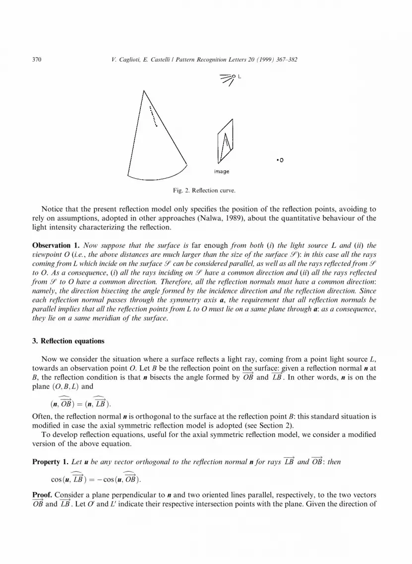
Notice that the present re¯ection model only speci®es the position of the re¯ection points, avoiding torely on assumptions, adopted in other approaches (Nalwa, 1989), about the quantitative behaviour of thelight intensity characterizing the re¯ection.
Observation 1. Now suppose that the surface is far enough from both (i) the light source L and (ii) theviewpoint O (i.e., the above distances are much larger than the size of the surface S): in this case all the rayscoming from L which incide on the surface S can be considered parallel, as well as all the rays re¯ected from Sto O. As a consequence, (i) all the rays inciding on S have a common direction and (ii) all the rays re¯ectedfrom S to O have a common direction. Therefore, all the re¯ection normals must have a common direction:namely, the direction bisecting the angle formed by the incidence direction and the re¯ection direction. Sinceeach re¯ection normal passes through the symmetry axis a, the requirement that all re¯ection normals beparallel implies that all the re¯ection points from L to O must lie on a same plane through a: as a consequence,they lie on a same meridian of the surface.
3. Re¯ection equations
Now we consider the situation where a surface re¯ects a light ray, coming from a point light source L,towards an observation point O. Let B be the re¯ection point on the surface: given a re¯ection normal n atB, the re¯ection condition is that n bisects the angle formed by OB
�!and LB
�!. In other words, n is on the
plane �O;B; L� and
� dn; OB�!� � � dn; LB
�!�:Often, the re¯ection normal n is orthogonal to the surface at the re¯ection point B: this standard situation ismodi®ed in case the axial symmetric re¯ection model is adopted (see Section 2).
To develop re¯ection equations, useful for the axial symmetric re¯ection model, we consider a modi®edversion of the above equation.
Property 1. Let u be any vector orthogonal to the re¯ection normal n for rays LB�!
and OB�!
: then
cos� du; LB�!� � ÿcos� du; OB
�!�:Proof. Consider a plane perpendicular to n and two oriented lines parallel, respectively, to the two vectorsOB�!
and LB�!
. Let O0 and L0 indicate their respective intersection points with the plane. Given the direction of
Fig. 2. Re¯ection curve.
370 V. Caglioti, E. Castelli / Pattern Recognition Letters 20 (1999) 367±382

a vector u on the plane normal to n, let us construct two oriented lines parallel, respectively to u and to ÿu,
passing through, respectively O0 and L0. The angle � dOB�!
; u� can be obtained by rigidly rotating the angle
� dLB�!
;ÿu� about the normal n (see Fig. 3). Therefore these angles are equal, and hence � dLB�!
; u� � pÿ� dOB�!
; u� whence the thesis. �
Applying the above property, one can write
j LB�!j � LB
�! � ucos� du; LB
�!� � ÿLB�! � u
cos� du; OB�!� :
Substituting LB�!
with OB�!ÿ OL
�!in the above equation, we have
jOB�!ÿ OL
�!j � OL�! � u
cos� dOB�!
; u�ÿ OB
�! � ucos� dOB
�!; u�� OL
�! � ucos� dOB
�!; u�ÿ jOB�!j:
Squaring both members of this equation, and simplifying, we derive
jOB�!j � jOL
�!j cos2� dOL�!
; u� ÿ cos2� dOB�!
; u�2cos� dOB
�!; u��cos� dOL
�!; u� ÿ cos� d
OB�!
; OL�!�cos� dOB
�!; u��
: �1�
It is recalled, that in the present approach we do not assume that the contour of a cross section is (evenpartially) visible. Therefore the recovery of the surface will only be based on the occluding contours of thelateral surface, and on the re¯ection of known light sources.
4. The cylinder
Under orthoperspective projection, the two lines constituting the image of the lateral contour of thecylinder appear approximately parallel, whatever be the actual orientation of the cylinder axis: the par-allelism of the image lines is due to the fact that interpretation planes of the lateral contour lines are nearlyparallel.
The projection of the cylinder axis is given by the intersection between the image plane and the plane,that bisects the two above interpretation planes.
Fig. 3. Re¯ection from L to O at B.
V. Caglioti, E. Castelli / Pattern Recognition Letters 20 (1999) 367±382 371

The knowledge of the two interpretation planes of the lateral contours allows to determine: (i) one of thetwo parameters representing the axis orientation and (ii) the relationships between the distance of thecylinder axis from O and the cylinder radius. Two further parameters need to be determined, namely thesecond parameter representing the axis orientation and, e.g., the distance between the cylinder axis and O.Since the re¯ection curve is a straight line parallel to the cylinder axis (Observation 1), each point lightsource corresponds to a single equation. Therefore, the re¯ection from two light point sources L1 and L2 isneeded to solve the CSG problem.
A frame reference is adopted, such that the projection of the cylinder axis is along the z-axis (notice thatthe interpretation plane of this projection bisects the two interpretation planes of the contour lines). The y-axis is selected such that the �x; y�-plane intersects both re¯ection curves: let B1 and B2 be these intersectionpoints.
Let r be the unknown radius of the observed cylinder, and let / be the unknown inclination angle of thecylinder axis with respect to the z-axis of the reference: among the in®nite normals to the cylinder axis, theone contained in the plane through O and the axis is no � �0 ÿcos/ ÿ sin/�T . Let A be the intersectionpoint between the y-axis and the cylinder axis, and let d be the unknown length of the segment OA. Let A0 bethe point of the cylinder axis, whose distance d 0 from O is minimum. Let C0 and C be the points on theimage of the cylinder contour, at the same z-value as A0 and A, respectively. Let w0 and w be the angle whichOA0 and OA form with OC0 and OC, respectively (see Fig. 4).
Given the two re¯ection points B1 and B2 on the same z as A, the angle formed by OA and the segmentOB1 (OB2) is indicated by b1 (b2). Let h1 (h2) be the angle formed by no and the normal n to the cylindersurface through B1 (B2). The coordinates of the point light sources, with respect to the adopted reference,are �x1; y1; z1� and �x2; y2; z2�.
The problem is to determine d, / and r, given �x1; y1; z1�, �x2; y2; z2�, w, b1 and b2.First, let us consider a single re¯ection, say B1, and let us use, for simplicity, �x; y; z�, h and b in place of
�x1; y1; z1�, h1 and b1. It is d 0 � d cos/ and tanw0 � tanw=cos/, from which r � d 0 sinw0 � d tanwcosw0,and hence
r � dtanwcos/�������������������������������
tan2w� cos2/p : �2�
In addition, from Fig. 5, it is d � r�cosh=cos/� sinh= tanb�, and therefore
r � dsinbcos/
sinbcosh� cosb sinhcos/; �3�
and, from dB sinb � r sinh,
d � dBsinb� cosb tanhcos/
tanhcos/: �4�
Combining Eqs. (2) and (3), we obtain
1� cotb tanhcos/ ��������������������������������tan2w� cos2/
ptanw
��������������������1� tan2h
p;
which leads to a two-degree equation on tanh, whose solutions are expressed in terms of the unknown /:
tanh � ÿ tan2wcotb��������������������������������cos2/� tan2w
p ��������������������������������cot2b tan2wÿ 1
pcot2b tan2wcos/ÿ cos/ÿ tan2w=cos/
: �5a�
The value of tanh can be approximated by the following, simpler expression:
372 V. Caglioti, E. Castelli / Pattern Recognition Letters 20 (1999) 367±382

tanh ' tanb�����������������������������sin2wÿ tan2b
q ; �5b�
which can be derived from d tanb ' r sinh ' d sinw sinh.To apply the re¯ection equation (1), the vector u orthogonal to the normal of the cylinder surface
through B has to be expressed as a function of / and h:
u � cosh100
24 35� sinh0
cos/sin/
24 35 � coshsinhcos/sinh sin/
24 35:
Fig. 4. Reference parameters for the cylindric surface.
V. Caglioti, E. Castelli / Pattern Recognition Letters 20 (1999) 367±382 373

The direction of the vector OB�!
is � sinb cosb 0�T. Now the re¯ection equation can be applied:
dB � OL2 ÿ �x� y cos/ tanh� z sin/ tanh�2=� sinb� cosbcos/ tanh�2
2�x sinb� y cosbÿ �x� y cos/ tanh� z sin/ tanh�=� sinb� cosbcos/ tanh�� : �6�
From Eq. (4), by recalling that 1=cos/ ����������������������1� tan2/
p, we can ®nd the expression of d in terms of the
unknown t�: tan /:
d � OL2
1� sinb1 coth1
������������1� t2p � cosb1�2 ÿ �x1 coth1
������������1� t2p � y1 � z1t�2
2��x1 sinb1 � y1 cosb1�� sinb1 coth1
������������1� t2p � cosb1� ÿ �x1 coth1
������������1� t2p � y1 � z1t�� : �7a�
Combining the last equation with the analogous equation for light source L2,
d � OL2
2� sinb2 coth2
������������1� t2p � cosb2�2 ÿ �x2 coth2
������������1� t2p � y2 � z2t�2
2��x2 sinb2 � y2 cosb2�� sinb2 coth2
������������1� t2p � cosb2� ÿ �x2 coth2
������������1� t2p � y2 � z2t�� ; �7b�
and equating the right-hand sides of the two, an equation in the unknown t is obtained.If an approximate value of h1 and h2 is used, which are independent of the unknown /, then dB1
� dB2
yields a six-degree equation on tan/. This condition can be satis®ed by using an iterative method in which,at each step, the expression (5a) of hi in terms of the unknown / is substituted by evaluating it at thepreviously calculated value of /. At the ®rst step, where no current value of / is available yet, the simpli®edrelation (5b) is used.
Cylinder-orthoperspective.1. for i � 1 to 2 do cothi
��������������������������������sin2wi ÿ tan2bi
q= tanbi;
2. solve system (7a) and (7b) wrt t and select the best solution for /;3. repeat
Fig. 5. Relationship between d and r.
374 V. Caglioti, E. Castelli / Pattern Recognition Letters 20 (1999) 367±382

4. substitute the value of / in (5a) to calculate tanh1 and tanh2;5. ®nd a new solution of (7a) and (7b) for t;6. until the new solution di�ers from the previous one by less than a given threshold;7. ®nd h from (5a);8. ®nd d from (7a) and (7b);9. ®nd r from (2);
10. end.
5. The cone
As usual, the projection of the cone axis is given by the intersection between the image plane and theplane, that bisects the two interpretation planes of the lateral contour lines. This plane through O containsthe cone axis.
The knowledge of the two interpretation planes of the lateral contours allows to determine: (i) one of thetwo parameters representing the axis orientation, (ii) the direction of the line joining the viewpoint O to thecone vertex A and (iii) the relationships between the distance d between A and O and the cone semiaperturea. Two further parameters need to be determined, namely the second parameter representing the axisorientation and, e.g., the distance d. Since the re¯ection curve from a point light source is a straight lineconstrained to go through the cone vertex A (Observation 1), each re¯ection yields one equation. Therefore,the re¯ection from two light point sources is needed to determine the position of A, the axis orientation andthe aperture angle.
A reference is adopted, speci®ed as follows: the y-axis joins the viewpoint O and (the projection of) thecone vertex A, the z-axis is in the plane containing (the projection of) the cone axis. Let w the angle betweenthis plane and one of the two interpretation planes of the lateral contour lines.
The orientation of the cone axis is speci®ed by the angle / it forms with the z-axis. Among the in®nitenormals to the cone axis, the one contained in the plane containing O and the axis is given byno � �0 ÿcos/ ÿ sin/�T .
Since (under orthoperspective projection) any re¯ection line goes through the vertex A, we can use are¯ection point B at an in®nitesimal distance from A along the re¯ection line. Let �k 1 k=l�T be a vectoralong the direction OB. This direction is known from the image of B: k is in®nitesimal, while l representsthe direction of the image of the re¯ection line. The distance dB between O and B coincides with the distanced between O and the vertex A (see Fig. 6(a)).
Let n be the normal to the cone axis, joining B to the axis, and let h the angle it forms with no:
n � cosh0
ÿcos/ÿ sin/
24 35� sinh100
24 35 � sinhÿcoshcos/ÿcosh sin/
24 35:The direction orthogonal to n and to the cylinder axis is given by
u � cosh100
24 35� sinh0
cos/sin/
24 35 � coshsinhcos/sinh sin/
24 35:The problem is to determine d, / and the cone semi-aperture a from the apparent semi-aperture w, theposition of the point light sources L1 � �x1; y1; z1� and L2 � �x2; y2; z2�, and the directions of the images ofthe re¯ection lines. These directions are characterized by l1 and l2.
First, we express the unknown semi-aperture a as a function of the unknown /. The normal to theinterpretation plane of the image of the (right-hand side) occluding contour is (see Fig. 6(b))
V. Caglioti, E. Castelli / Pattern Recognition Letters 20 (1999) 367±382 375

nr � �cosw 0 sinw�T . The plane containing the axis and the tangent to the cone through the aboveoccluding contour has its normal given by
nal � a� nr �ÿ sinw sin/coswcos/cosw sin/
24 35:The direction of the above occluding contour is given by the intersection between its interpretation planeand the plane normal to nal: therefore it can be found by the vector product of the normals to these planes
Fig. 6. Reference parameters for the conic surface.
376 V. Caglioti, E. Castelli / Pattern Recognition Letters 20 (1999) 367±382

l � nr � nal �sinwcoswcos/
sin/ÿcos2wcos/
24 35:The semi-aperture a is given by
cosa � a � ljlj �
������������������������������������������sin2/� cos2wcos2/
q�
�����������������������������������������sin2w sin2/� cos2w
q;
and therefore sina � sinwcos/, from which
tana � cos/������������������������������sin2/� cot2w
q : �8�
The unit vector along the cone axis is a � �0 sin/ ÿcos/�T . The vector from O to the re¯ection point Bis given by
OB�! � d
010
24 35� ka� k tanan
0@ 1A � dk tana sinh
1� k� sin/ÿ tanacos/cosh�ÿk�cos/� tana sin/cosh�
24 35; �9�
where k is a constant. The determination of k is not necessary, since the re¯ection point B is at an in®ni-tesimal distance from the vertex A.
Now, using Eq. (8), h is expressed in terms of the unknown /, by equating l to the ratio between the ®rstand third component of OB
�!:
l � ÿ sinh
sin/cosh�������������������������������sin2/� cot2w
q � ÿ tanh
sin/�������������������������������sin2/� cot2w
q ��������������������1� tan2hp :
Solving this equation with respect to tanh yields two solutions:
tanh � ÿlsin/�
��������������������������������������������������������������� sin2/� cot2w��1ÿ l2 cot2w�
q1ÿ l2� sin2/� cot2w� : �10�
Now the re¯ection equation (1) can be applied. Let �0; 1; 0�T be the unit vector along the direction OB�!
.From the re¯ection equation:
d � dB � OL2 ÿ �xcoth� y cos/� z sin/�2=cos/2
2�y ÿ �xcoth� y cos/� z sin/�=cos/� :
Simplifying it and rewriting it for both re¯ections reduces to
d � dBi ��xi cothi
���������������������1� tan2/
p� yi � zi tan/�2 ÿ OL
2
i
2�xi cothi
���������������������1� tan2/
p� zi tan/�
; i � 1; 2: �11�
If an approximate value of hi is used, which is independent of the unknown /, then dB1� dB2
� dB yields asix-degree equation on tan/. This condition can be satis®ed by using an iterative method in which, at eachstep, the (inverse of) expression (10) of hi in terms of the unknown / is substituted by evaluating it at thepreviously calculated value of /. At the ®rst step, where no current value of / is available yet, the followingsimpli®ed relation is used:
cothi ' ÿ�������������������������1ÿ l2
i cot2wp
li cotw; i � 1; 2:
V. Caglioti, E. Castelli / Pattern Recognition Letters 20 (1999) 367±382 377

This approximate relation has been derived by rewriting (10) for / � 0.
Cone-orthoperspective.1. for i � 1 to 2 do cothi � ÿ
�������������������������1ÿ l2
i cot2wp
=�li cotw�;2. solve system dB1
� dB2(11) wrt tan/ and select the best solution for /;
3. repeat4. substitute the value of / in (10) to calculate coth1 and coth2;5. ®nd a new solution of dB1
� dB2(11) for tan/;
6. until the new solution di�ers from the previous one by less than a given threshold;7. calculate a from sina sinwcos/;8. end.
6. Implementation and experimental results
We implemented a system aimed at recovering pose and geometry of metallic conic and cylindric parts,which have been subject to lathe turning or grinding. The experimental setup is shown in Fig. 7. Each of thetwo point light sources is realized by putting a lamp in an empty cylinder made of heavy paper. The cylinderheight is 45 cm. This cylinder presents eight small holes (diameter 5 mm) at di�erent heights (one hole each5 cm): only one of these holes is open, while the other seven are closed. In this way a single point source isobtained for each lamp. By changing the open hole, the height of the light source is varied.
The acquired image is processed in order to extract both the outlines of the lateral surface of the objectand the re¯ections of the point light sources on the object surface. The obtained edges, extracted by meansof a Canny edge detector, are then segmented into straight line segments. This process can produce manylines, which do neither belong to the object outline nor constitute the re¯ecting line of any light point source(think of, e.g., shadows). In order to eliminate such spurious lines, ®rst the parallelism of the line segmentsis analyzed: if a su�cient number of parallel lines is found, these are supposed either to be part of the imageof the cylinder outline or to constitute the re¯ecting lines. In this case, those lines which are not parallel tothe above lines are removed from further consideration, and the two lines whose distance inbetween is
Fig. 7. The experimental set-up.
378 V. Caglioti, E. Castelli / Pattern Recognition Letters 20 (1999) 367±382

maximum are retained as those constituting the image of the cylinder outline, while the other parallel linesare retained as associated to the re¯ection lines.
Fig. 8. Some real objects.
V. Caglioti, E. Castelli / Pattern Recognition Letters 20 (1999) 367±382 379

If a su�cient number of parallel lines is not found, then the concurrence of the line segments is examinedthrough a voting scheme. If a su�cient number of concurrent lines is found, the remaining lines are re-
Fig. 9. Edges of the images in Fig. 8.
380 V. Caglioti, E. Castelli / Pattern Recognition Letters 20 (1999) 367±382

moved from further consideration. Among the concurrent lines, those two which form the largest angle areretained as those constituting the image of the object outline. The residual lines are retained as associated tothe re¯ection lines.
Often, a pair of neighbouring edges is associated with each re¯ection line. In order to locate the re¯ectingline with good accuracy, a nonmaxima suppression is performed within the image region between the twoneighbouring edges, based on the intensity level: a pixel is retained as belonging to the re¯ection line if itsintensity is a relative maximum along the direction perpendicular to the direction of the line bisecting thetwo neighbouring edges.
Once the lateral contour lines and the re¯ection lines have been determined, one of the two methodspresented in Sections 4 and 5 is applied, according to whether the four lines are parallel or not.
Observation 2. If the application of the method in Section 5 to a set of four concurrent lines results in anaperture angle a ' 0, then the analyzed object is recognized as a cylinder, whose view has been taken accordingto a perspective projection (instead of an orthoperspective one).
In the sequel some experimental results are reported, showing the performance of the implementedsystem on real images.
A set of real images is shown in Fig. 8. The detected edges, including contours and re¯ection lines, areshown in Fig. 9. The estimated geometric parameters of the objects shown, together with their position andorientation, are reported in Table 1, where they are compared to the real parameters.
Notice that the error in the estimation of the features are within 5%. This shows the validity of the axialsymmetric re¯ection model for real objects as those used in the experiments.
7. Conclusions
A new re¯ection model is introduced to account for surface treatments, that introduce a raggednesswhich preserves the pre-existing axial symmetry. The re¯ection equation according to the introduced modelare exploited to derive a method for recovering the geometry of cylindrical and conic surfaces, whichunderwent the above described surface treatments, from a single view.
This method uses the image of the lateral occluding contours of the surface, and the re¯ection from twopoint light sources in known positions.
Table 1
Angles are in degree, distances or coordinates are in cm (real values are in the higher row, measured ones are in the lower row)
Azim. Zenith xA yA zA d r a
Cylinder 1 ÿ 90 ÿ ÿ ÿ 95 1.5 ÿ3.15 86.6 94.5 1.52
Cylinder 2 53 30 ÿ ÿ ÿ 94 1.9 ÿ51.2 27.7 90.9 1.83
Cone 1 0 60 0 83 18 ÿ ÿ 23
2 57.8 ÿ0.1 81 18.6 22.7
Cone 2 90 70 0 85 18 ÿ ÿ 23
91.8 67.5 0.1 86.2 19.1 21.8
Cone 3 120 29 4 81.5 17 ÿ ÿ 29
122 28.9 4.1 80.6 17.3 28.9
Cone 4 0 38 0.5 76 16 ÿ ÿ 29
0.2 39 0.5 77.3 15.4 30.1
V. Caglioti, E. Castelli / Pattern Recognition Letters 20 (1999) 367±382 381

Some experimental results on real images are reported, showing the accuracy of the method and theappropriateness of the introduced re¯ection model.
Future research directions involve the application of extended versions of the qualitative re¯ectionmodel to recover (metallic) solids of revolutions from single views.
References
Glachet, R., Dhome, M., Laprest�e, J.T., 1991. Finding the perspective projection of an axis of revolution. Pattern Recognition Letters
12 (11) 693±700.
Gross, A.D., Boult, T.E., 1996. Recovery of SHGCs from a single intensity view. IEEE Transactions on Pattern Analysis and Machine
Intelligence 18 (2).
Nalwa, V.S., 1989. Line-drawing interpretation: bilateral symmetry. IEEE Transactions on Pattern Analysis and Machine Intelligence
11 (10).
Ponce, J., Chelberg, D., Mann, W.B., 1989. Invariant properties of straight homogeneous generalized cylinders and their contours.
IEEE Transactions on Pattern Analysis and Machine Intelligence 11 (9).
Puech, W., Chassery, J.-M., Pites, I., 1997. Cylindrical surface localization in monocular vision. Pattern Recognition Letters 18 (8)
711±722.
Sanderson, A.C., Weiss, L.E., Nayar, S.K., 1988. Structured highlights inspections of specular surfaces. IEEE Transactions on Pattern
Analysis and Machine Intelligence 10 (1).
Ulupinar, F., Nevatia, R., 1995. Shape from contour. IEEE Transactions on Pattern Analysis and Machine Intelligence 17 (2).
Wink, O., Smeulders, A., Koelma D.C., 1994. Location estimation of cylinders from a 2D image. In: Proceedings of the 12th ICPR,
Jerusalem, Israel. Vol. I, pp. 682±684.
You, Y.C., Lee, J.Y., Chen, C.H., 1992. Determining location and orientation of a labelled cylinder using point-pair estimation
algorithm. In: Proceedings of the 11th ICPR, The Hague, The Netherlands. Vol. I, pp. 354±357.
382 V. Caglioti, E. Castelli / Pattern Recognition Letters 20 (1999) 367±382


