Embed Size (px)
Citation preview
Take Advantage of these Contractor Services from ITW RED HEADFrom job sites to engineering firms, from Safety Seminars to on-site services, we hope you take advantage of our many contractor services–at no charge! After all, it’s one thing to offer the quality products you need to do your job. It’s another to provide you with superior service, engineering expertise and total product support.
At ITW RED HEAD, we are proud of the partnerships we have built through the years with our distributor network and contractors. Thanks to quality products, innovative services and on-time delivery, we will continue to build new relationships and strengthen existing ones today...and into the next century.
g Factory representatives with years of training and service experience will go out to your job site to provide you with product, service and technical assistance.
g We provide architects and engineers with complete submittal packages which gives them the technical data needed to specify ITW RED HEAD products. Contact your ITW RED HEAD Distributor or your nearest Customer Service location to request submittal packages.
Technical Application Assistance:g Our staff of application specialists are ready to assist you with any type of application or code
approval question during any phase of your project. Call 1-800-899-7890 between 8:00 a.m. and 5:00 p.m. CST, Monday through Friday.
24-hour Product and Performance Information:g The most frequently requested ITW RED HEAD product and technical information,
performance data, approvals, MSDS, etc. are available on our website at www.itwredhead.com. If additional assistance is required, our application specialists can be reached at 1-800-899-7890 between 8:00 a.m. and 5:00 p.m. CST, Monday through Friday.
National Headquarters 2171 Executive Drive, Suite 100 Addison, IL 60101 Phone: 630-350-0370 Fax: 630-495-6158 www.itwredhead.com
Technical SupportPhone: 800-899-7890 Fax: 630-495-6204
Customer Service Locations1919 E. U.S. Hwy 12 Michigan City, IN 46360 800-348-3231 FAX: 800-368-3844
Regional Warehousesg Itasca (Chicago), IL g City of Commerce (Los Angeles), CA g Forest Park, GA
g Cranbury, NJ g Dallas, TX g Houston, TX
ITW Construction Products Canada120 Travail Road Markham, Ontario. L3S 3J1 905-471-7403 800-387-9692 FAX: 800-668-8688 www.itwconstruction.ca
A7, Boa, C6, Condrive, Dynabolt, E-Z Ancor, G5, Hammer-Set, LDT, Multi-Set II, Poly Set, Red Head, Redi-Drive, Tapcon, and Trubolt are trademarks of ITW RED HEAD and Illinois Tool Works, Inc. Hilti® is a registered trademark of Hilti, Corp. Rawl Spike® is a registered trademark of Powers Fastening, Inc.
The information and recommendations in this document are based on the best information available to us at the time of preparation. We make no other warranty, expressed or implied, as to its correctness or completeness, or as to the results or reliance of this document.
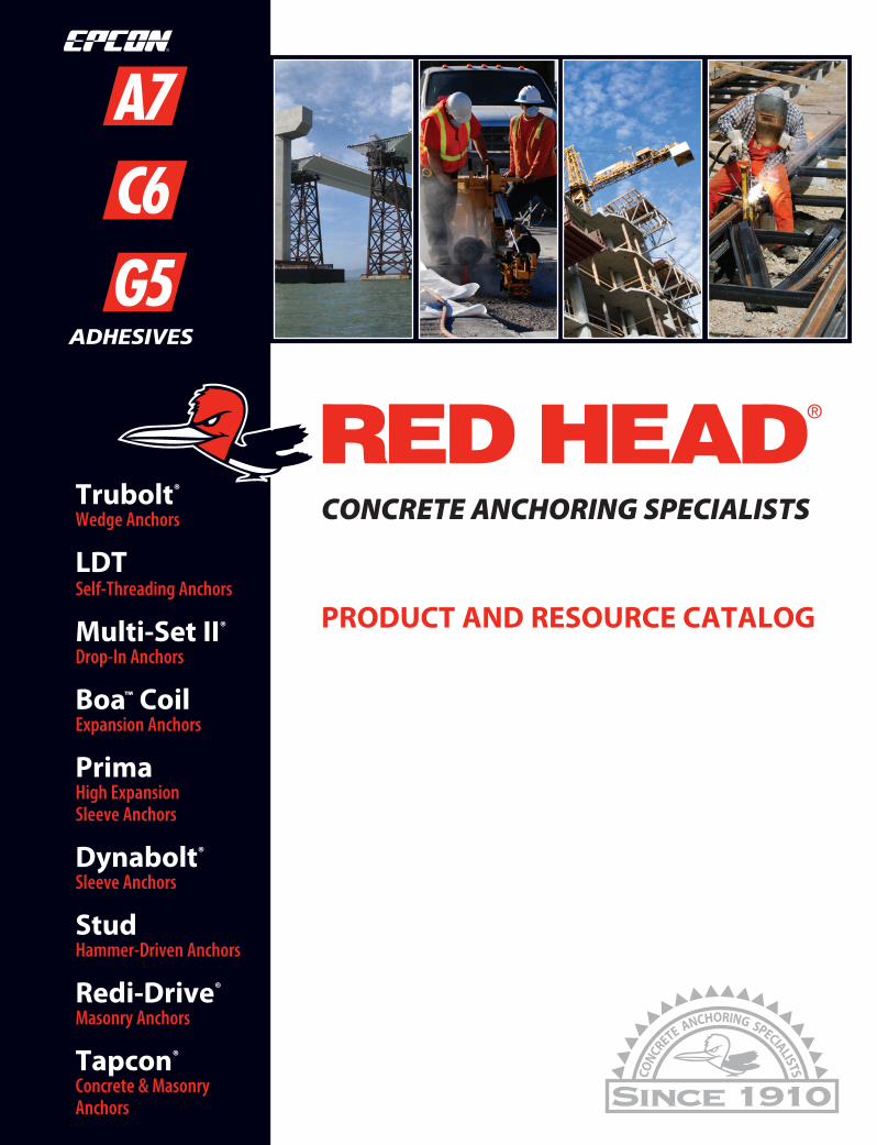
Trubolt®
Wedge Anchors
LDTSelf-Threading Anchors
Multi-Set II®
Drop-In Anchors
Boa™ CoilExpansion Anchors
PrimaHigh Expansion Sleeve Anchors
Dynabolt®
Sleeve Anchors
StudHammer-Driven Anchors
Redi-Drive®
Masonry Anchors
Tapcon®
Concrete & Masonry Anchors
CONCRETE ANCHORING SPECIALISTS
PRODUCT AND RESOURCE CATALOG
CONCRETE ANCHORING SYSTEMSPR
OD
UC
T AN
D R
ESOU
RC
E CA
TALO
G
®
© 2009 Illinois Tool Works, Inc. Form No. RHC-10/09

Our Product and Resource Book is not just a catalog of the quality
RED HEAD Anchoring Systems so many of you have come to rely on,
but a resource guide to give you the information you need to help
you work better, faster and easier.
This highly detailed Application Section allows
you to look up your trade or specialty, view a
variety of practical applications and receive
simple product recommendations. Along
with the product recommendations you’ll
notice page numbers for easy reference to the product selection
and specifications pages.
We are continuing the consolidation of our Adhesive Anchoring
System under the RED HEAD brand name. The Epcon® name is still
prominent on our labels along with our RED HEAD logo. The adhesive
anchoring products and formulas remain, providing versatile solutions.
As always this Product and Resource Book continues to provide a
wealth of valuable information including: product approvals/listings,
applications, selection charts, performance tables and installation steps.
Remember, if you ever need more information about ITW RED HEAD
products, technology and service, contact your local distributor, or look
on the back cover for a complete listing of ITW RED HEAD facilities.
We welcome your calls and feedback, and look forward to answering
any questions you might have.
www.itwredhead.com
Welcome to theRED HEAD® Productand Resource Book
2 Call our toll free number 800-899-7890 or visit our web site for the mostcurrent product and technical information atwww.itwredhead.com
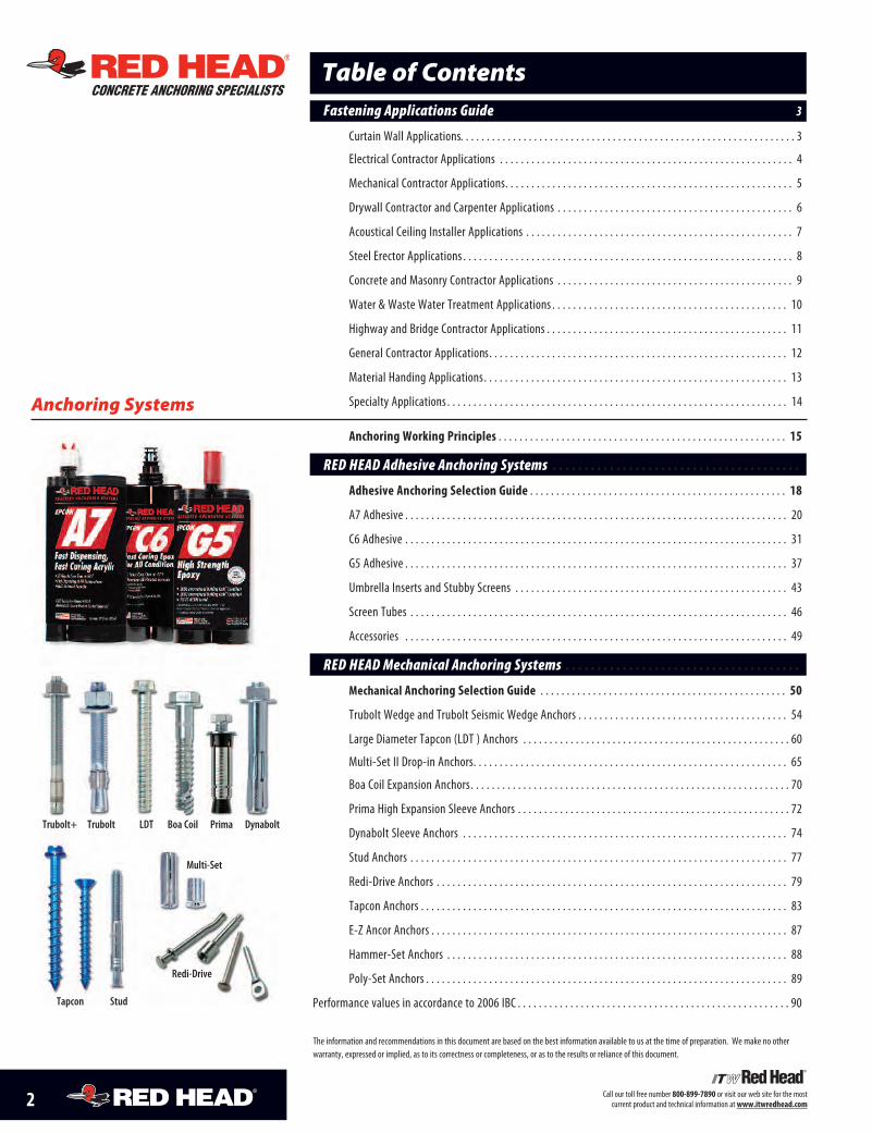
Table of ContentsCONCRETE ANCHORING SPECIALISTS
Anchoring Systems
Fastening Applications Guide . . . . . . . . . . . . . . . . . . . . . . . . . . . . . . . . . . . . . . . . . . . . . . 3
Curtain Wall Applications. . . . . . . . . . . . . . . . . . . . . . . . . . . . . . . . . . . . . . . . . . . . . . . . . . . . . . . . . . . . . . . . 3
Electrical Contractor Applications . . . . . . . . . . . . . . . . . . . . . . . . . . . . . . . . . . . . . . . . . . . . . . . . . . . . . . . . 4
Mechanical Contractor Applications. . . . . . . . . . . . . . . . . . . . . . . . . . . . . . . . . . . . . . . . . . . . . . . . . . . . . . . 5
Drywall Contractor and Carpenter Applications . . . . . . . . . . . . . . . . . . . . . . . . . . . . . . . . . . . . . . . . . . . . . 6
Acoustical Ceiling Installer Applications . . . . . . . . . . . . . . . . . . . . . . . . . . . . . . . . . . . . . . . . . . . . . . . . . . . 7
Steel Erector Applications . . . . . . . . . . . . . . . . . . . . . . . . . . . . . . . . . . . . . . . . . . . . . . . . . . . . . . . . . . . . . . . 8
Concrete and Masonry Contractor Applications . . . . . . . . . . . . . . . . . . . . . . . . . . . . . . . . . . . . . . . . . . . . . 9
Water & Waste Water Treatment Applications . . . . . . . . . . . . . . . . . . . . . . . . . . . . . . . . . . . . . . . . . . . . . 10
Highway and Bridge Contractor Applications . . . . . . . . . . . . . . . . . . . . . . . . . . . . . . . . . . . . . . . . . . . . . . 11
General Contractor Applications. . . . . . . . . . . . . . . . . . . . . . . . . . . . . . . . . . . . . . . . . . . . . . . . . . . . . . . . . 12
Material Handing Applications. . . . . . . . . . . . . . . . . . . . . . . . . . . . . . . . . . . . . . . . . . . . . . . . . . . . . . . . . . 13
Specialty Applications . . . . . . . . . . . . . . . . . . . . . . . . . . . . . . . . . . . . . . . . . . . . . . . . . . . . . . . . . . . . . . . . . 14
Anchoring Working Principles . . . . . . . . . . . . . . . . . . . . . . . . . . . . . . . . . . . . . . . . . . . . . . . . . . . . . . . 15
RED HEAD Adhesive Anchoring Systems . . . . . . . . . . . . . . . . . . . . . . . . . . . . . . . . . . . . . . .
Adhesive Anchoring Selection Guide . . . . . . . . . . . . . . . . . . . . . . . . . . . . . . . . . . . . . . . . . . . . . . . . . 18
A7 Adhesive . . . . . . . . . . . . . . . . . . . . . . . . . . . . . . . . . . . . . . . . . . . . . . . . . . . . . . . . . . . . . . . . . . . . . . . . . 20
C6 Adhesive . . . . . . . . . . . . . . . . . . . . . . . . . . . . . . . . . . . . . . . . . . . . . . . . . . . . . . . . . . . . . . . . . . . . . . . . . 31
G5 Adhesive . . . . . . . . . . . . . . . . . . . . . . . . . . . . . . . . . . . . . . . . . . . . . . . . . . . . . . . . . . . . . . . . . . . . . . . . . 37
Umbrella Inserts and Stubby Screens . . . . . . . . . . . . . . . . . . . . . . . . . . . . . . . . . . . . . . . . . . . . . . . . . . . . 43
Screen Tubes . . . . . . . . . . . . . . . . . . . . . . . . . . . . . . . . . . . . . . . . . . . . . . . . . . . . . . . . . . . . . . . . . . . . . . . . 46
Accessories . . . . . . . . . . . . . . . . . . . . . . . . . . . . . . . . . . . . . . . . . . . . . . . . . . . . . . . . . . . . . . . . . . . . . . . . . 49
RED HEAD Mechanical Anchoring Systems . . . . . . . . . . . . . . . . . . . . . . . . . . . . . . . . . . . . .
Mechanical Anchoring Selection Guide . . . . . . . . . . . . . . . . . . . . . . . . . . . . . . . . . . . . . . . . . . . . . . . 50
Trubolt Wedge and Trubolt Seismic Wedge Anchors . . . . . . . . . . . . . . . . . . . . . . . . . . . . . . . . . . . . . . . . 54
Large Diameter Tapcon (LDT ) Anchors . . . . . . . . . . . . . . . . . . . . . . . . . . . . . . . . . . . . . . . . . . . . . . . . . . . 60
Multi-Set II Drop-in Anchors. . . . . . . . . . . . . . . . . . . . . . . . . . . . . . . . . . . . . . . . . . . . . . . . . . . . . . . . . . . . 65
Boa Coil Expansion Anchors. . . . . . . . . . . . . . . . . . . . . . . . . . . . . . . . . . . . . . . . . . . . . . . . . . . . . . . . . . . . . 70
Prima High Expansion Sleeve Anchors . . . . . . . . . . . . . . . . . . . . . . . . . . . . . . . . . . . . . . . . . . . . . . . . . . . . 72
Dynabolt Sleeve Anchors . . . . . . . . . . . . . . . . . . . . . . . . . . . . . . . . . . . . . . . . . . . . . . . . . . . . . . . . . . . . . . 74
Stud Anchors . . . . . . . . . . . . . . . . . . . . . . . . . . . . . . . . . . . . . . . . . . . . . . . . . . . . . . . . . . . . . . . . . . . . . . . . 77
Redi-Drive Anchors . . . . . . . . . . . . . . . . . . . . . . . . . . . . . . . . . . . . . . . . . . . . . . . . . . . . . . . . . . . . . . . . . . . 79
Tapcon Anchors . . . . . . . . . . . . . . . . . . . . . . . . . . . . . . . . . . . . . . . . . . . . . . . . . . . . . . . . . . . . . . . . . . . . . . 83
E-Z Ancor Anchors . . . . . . . . . . . . . . . . . . . . . . . . . . . . . . . . . . . . . . . . . . . . . . . . . . . . . . . . . . . . . . . . . . . . 87
Hammer-Set Anchors . . . . . . . . . . . . . . . . . . . . . . . . . . . . . . . . . . . . . . . . . . . . . . . . . . . . . . . . . . . . . . . . . 88
Poly-Set Anchors . . . . . . . . . . . . . . . . . . . . . . . . . . . . . . . . . . . . . . . . . . . . . . . . . . . . . . . . . . . . . . . . . . . . . 89
Performance values in accordance to 2006 IBC . . . . . . . . . . . . . . . . . . . . . . . . . . . . . . . . . . . . . . . . . . . . . . . . . . . . 90
Trubolt+ Trubolt LDT Boa Coil Prima Dynabolt
Redi-Drive
Tapcon Stud
Multi-Set
The information and recommendations in this document are based on the best information available to us at the time of preparation. We make no otherwarranty, expressed or implied, as to its correctness or completeness, or as to the results or reliance of this document.
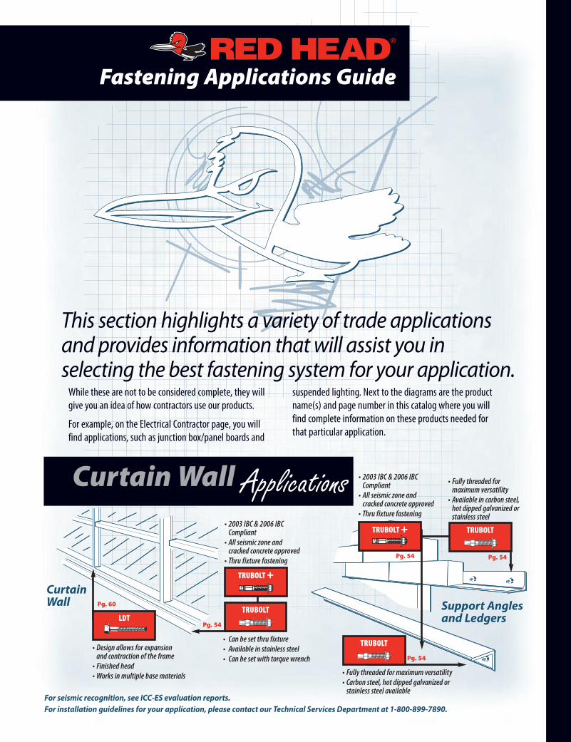
Fastening Applications Guide
While these are not to be considered complete, they willgive you an idea of how contractors use our products.
For example, on the Electrical Contractor page, you willfind applications, such as junction box/panel boards and
suspended lighting. Next to the diagrams are the productname(s) and page number in this catalog where you willfind complete information on these products needed forthat particular application.
This section highlights a variety of trade applicationsand provides information that will assist you inselecting the best fastening system for your application.
CurtainWall Applications
Support Anglesand Ledgers
For seismic recognition, see ICC-ES evaluation reports.For installation guidelines for your application, please contact our Technical Services Department at 1-800-899-7890.
TRUBOLT +
• 2003 IBC & 2006 IBCCompliant• All seismic zone andcracked concrete approved• Thru fixture fastening
LDT
• Design allows for expansionand contraction of the frame• Finished head• Works in multiple base materials
Pg. 60
CurtainWall
TRUBOLT
• Can be set thru fixture• Available in stainless steel• Can be set with torque wrench
Pg. 54
TRUBOLT
• Fully threaded formaximum versatility• Available in carbon steel,hot dipped galvanized orstainless steel
Pg. 54
TRUBOLT +
• 2003 IBC & 2006 IBCCompliant• All seismic zone andcracked concrete approved• Thru fixture fastening
Pg. 54
TRUBOLT
• Fully threaded for maximum versatility• Carbon steel, hot dipped galvanized orstainless steel available
Pg. 54
4 Call our toll free number 800-899-7890 or visit our web site for the mostcurrent product and technical information atwww.itwredhead.com
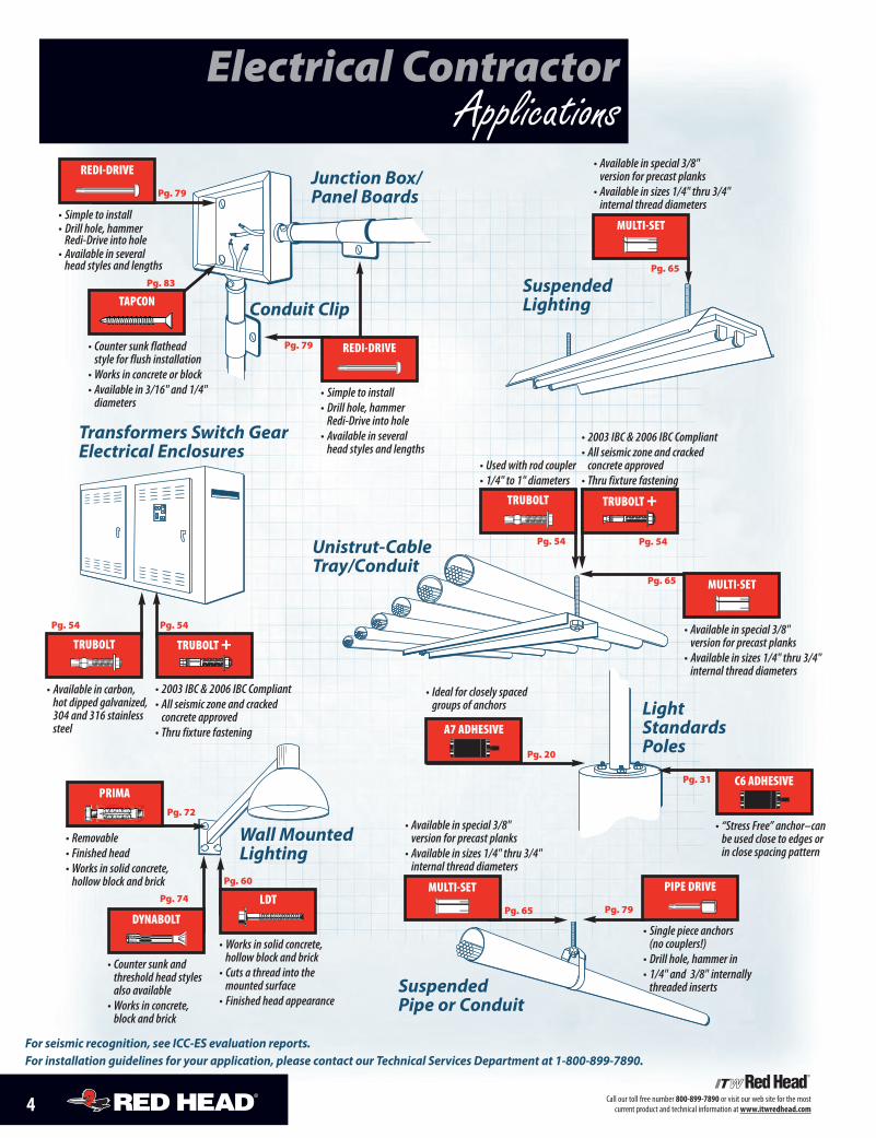
Electrical ContractorApplications
Transformers Switch GearElectrical Enclosures
LightStandardsPoles
Junction Box/Panel Boards
SuspendedPipe or Conduit
Conduit ClipSuspendedLighting
Unistrut-CableTray/Conduit
Wall MountedLighting
REDI-DRIVE
MULTI-SET
TRUBOLT
TRUBOLT +
C6 ADHESIVE
MULTI-SET
PIPE DRIVE
• 2003 IBC & 2006 IBC Compliant• All seismic zone and crackedconcrete approved• Thru fixture fastening
• Available in special 3/8"version for precast planks• Available in sizes 1/4" thru 3/4"internal thread diameters
• Simple to install• Drill hole, hammerRedi-Drive into hole• Available in severalhead styles and lengths
• Available in special 3/8"version for precast planks• Available in sizes 1/4" thru 3/4"internal thread diameters
• Single piece anchors(no couplers!)• Drill hole, hammer in• 1/4" and 3/8" internallythreaded inserts
• Used with rod coupler• 1/4" to 1" diameters
• Simple to install• Drill hole, hammerRedi-Drive into hole• Available in severalhead styles and lengths
Pg. 54
LDT
• Works in solid concrete,hollow block and brick• Cuts a thread into themounted surface• Finished head appearance
Pg. 60
Pg. 79
• “Stress Free” anchor–canbe used close to edges orin close spacing pattern
Pg. 31
Pg. 65
Pg. 65
Pg. 54
Pg. 79
Pg. 79
REDI-DRIVE
MULTI-SET
• Available in special 3/8"version for precast planks• Available in sizes 1/4" thru 3/4"internal thread diameters
Pg. 65DYNABOLT
• Counter sunk andthreshold head stylesalso available• Works in concrete,block and brick
Pg. 74
For seismic recognition, see ICC-ES evaluation reports.For installation guidelines for your application, please contact our Technical Services Department at 1-800-899-7890.
TRUBOLT +
• 2003 IBC & 2006 IBC Compliant• All seismic zone and crackedconcrete approved• Thru fixture fastening
Pg. 54
TRUBOLT
• Available in carbon,hot dipped galvanized,304 and 316 stainlesssteel
Pg. 54
A7 ADHESIVE
• Ideal for closely spacedgroups of anchors
Pg. 20
TAPCON
• Counter sunk flatheadstyle for flush installation• Works in concrete or block• Available in 3/16" and 1/4"diameters
Pg. 83
PRIMA
• Removable• Finished head• Works in solid concrete,hollow block and brick
Pg. 72
5Call our toll free number 800-899-7890 or visit our web site for the mostcurrent product and technical information atwww.itwredhead.com
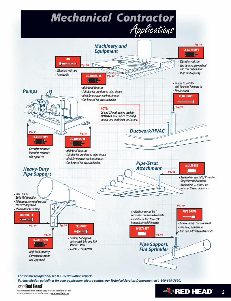
Mechanical ContractorApplications
Pumps
Heavy-DutyPipe Support
Ductwork/HVAC
Pipe Support,Fire Sprinkler
Machinery andEquipment
Pipe/StrutAttachment
REDI-DRIVE
LDT
PIPE DRIVE
MULTI-SET
TRUBOLT
C6 ADHESIVE
C6 ADHESIVE
• 1-piece design (no couplers!)• Drill hole, hammer in• 1/4" and 3/8" internal threads
Pg. 79
• Carbon, hot dippedgalvanized, 304 and 316stainless steel• 1/4" to 1" diameters
Pg. 54
• High load capacity• Corrosion resistant• NSF Approved
Pg. 31
C6 ADHESIVE
• Vibration resistant• Can be used in oversizedand core drilled holes• High load capacity
NOTE:C6 and G5 both can be used foroversized holes when repairingpumps and machinery anchoring.
Pg. 31
• Available in special 3/8" versionfor prestressed concrete• Available in 1/4" thru 3/4"internal thread diameters
Pg. 65
• Simple to install–drill hole and hammer in• Fire resistant
• Vibration resistant• Removable
• Corrosion resistant• Vibration resistant• NSF Approved
Pg. 79
Pg. 60
MULTI-SET
• Available in special 3/8"version for prestressed concrete• Available in 1/4" thru 3/4"internal thread diameters
Pg. 65
Pg. 31
For seismic recognition, see ICC-ES evaluation reports.For installation guidelines for your application, please contact our Technical Services Department at 1-800-899-7890.
TRUBOLT +
• 2003 IBC &2006 IBC Compliant• All seismic zone and crackedconcrete approved• Thru fixture fastening
Pg. 54
G5 ADHESIVE
• High Load Capacity• Suitable for use close to edge of slab• Ideal for moderate to hot climates• Can be used for oversized holes
Pg. 37
G5 ADHESIVE
• High Load Capacity• Suitable for use close to edge of slab• Ideal for moderate to hot climates• Can be used for oversized holes
Pg. 37
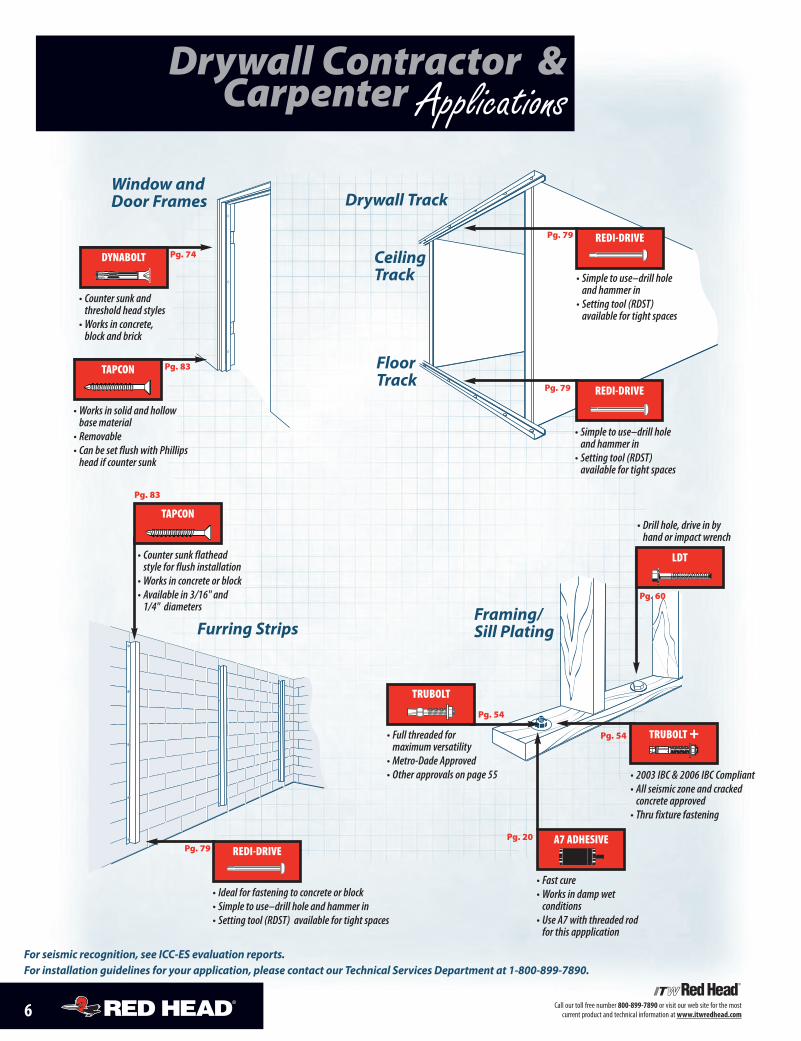
Drywall Contractor &Carpenter Applications
Window andDoor Frames
Furring StripsFraming/Sill Plating
Drywall Track
CeilingTrack
FloorTrack
REDI-DRIVEPg. 79
REDI-DRIVE
• Ideal for fastening to concrete or block• Simple to use–drill hole and hammer in• Setting tool (RDST) available for tight spaces
Pg. 79
REDI-DRIVE
• Simple to use–drill holeand hammer in• Setting tool (RDST)available for tight spaces
• Simple to use–drill holeand hammer in• Setting tool (RDST)available for tight spaces
Pg. 79
TRUBOLT
• Full threaded formaximum versatility• Metro-Dade Approved• Other approvals on page 55
Pg. 54
LDT
• Drill hole, drive in byhand or impact wrench
Pg. 60
TAPCON
• Counter sunk flatheadstyle for flush installation• Works in concrete or block• Available in 3/16" and1/4" diameters
Pg. 83
DYNABOLT
• Counter sunk andthreshold head styles• Works in concrete,block and brick
Pg. 74
TAPCON
• Works in solid and hollowbase material• Removable• Can be set flush with Phillipshead if counter sunk
Pg. 83
6 Call our toll free number 800-899-7890 or visit our web site for the mostcurrent product and technical information atwww.itwredhead.com
For seismic recognition, see ICC-ES evaluation reports.For installation guidelines for your application, please contact our Technical Services Department at 1-800-899-7890.
TRUBOLT +
• 2003 IBC & 2006 IBC Compliant• All seismic zone and crackedconcrete approved• Thru fixture fastening
Pg. 54
A7 ADHESIVE
• Fast cure• Works in damp wetconditions• Use A7 with threaded rodfor this appplication
Pg. 20
7Call our toll free number 800-899-7890 or visit our web site for the mostcurrent product and technical information atwww.itwredhead.com
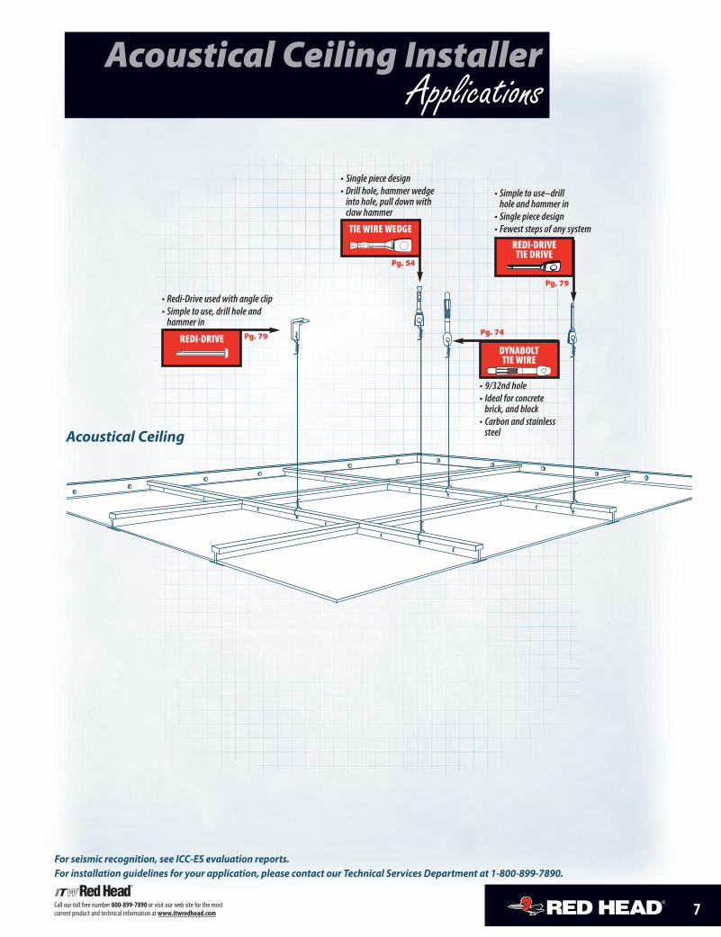
Acoustical Ceiling InstallerApplications
Acoustical Ceiling
REDI-DRIVE
• Redi-Drive used with angle clip• Simple to use, drill hole andhammer in
Pg. 79
TIE WIRE WEDGE
• Single piece design• Drill hole, hammer wedgeinto hole, pull down withclaw hammer
Pg. 54
REDI-DRIVETIE DRIVE
• Simple to use–drillhole and hammer in• Single piece design• Fewest steps of any system
Pg. 79
For seismic recognition, see ICC-ES evaluation reports.For installation guidelines for your application, please contact our Technical Services Department at 1-800-899-7890.
DYNABOLTTIE WIRE
• 9/32nd hole• Ideal for concretebrick, and block• Carbon and stainlesssteel
Pg. 74
G5 ADHESIVE
• Longer working time forpositioning of steel• Can be used in oversized holes• Works in wet/damp conditions
Pg. 37
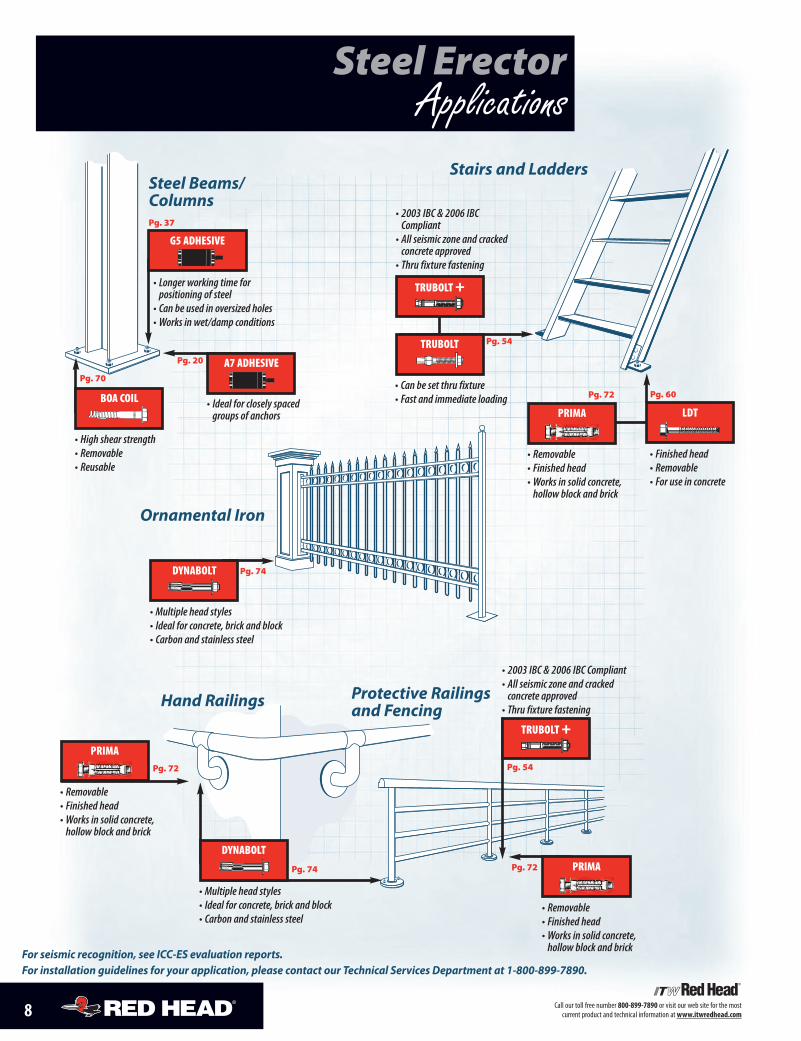
Steel Beams/Columns
A7 ADHESIVE
• Ideal for closely spacedgroups of anchors
Pg. 20
Steel ErectorApplications
Ornamental Iron
Stairs and Ladders
Protective Railingsand FencingHand Railings
DYNABOLT
• Multiple head styles• Ideal for concrete, brick and block• Carbon and stainless steel
Pg. 74
8 Call our toll free number 800-899-7890 or visit our web site for the mostcurrent product and technical information atwww.itwredhead.com
For seismic recognition, see ICC-ES evaluation reports.For installation guidelines for your application, please contact our Technical Services Department at 1-800-899-7890.
TRUBOLT +
• 2003 IBC & 2006 IBC Compliant• All seismic zone and crackedconcrete approved• Thru fixture fastening
Pg. 54
TRUBOLT +
• 2003 IBC & 2006 IBCCompliant• All seismic zone and crackedconcrete approved• Thru fixture fastening
TRUBOLT
• Can be set thru fixture• Fast and immediate loading
Pg. 54
DYNABOLT
• Multiple head styles• Ideal for concrete, brick and block• Carbon and stainless steel
Pg. 74
BOA COIL
• High shear strength• Removable• Reusable
Pg. 70
PRIMA
• Removable• Finished head• Works in solid concrete,hollow block and brick
Pg. 72
PRIMA
• Removable• Finished head• Works in solid concrete,hollow block and brick
Pg. 72
PRIMA
• Removable• Finished head• Works in solid concrete,hollow block and brick
Pg. 72
LDT
• Finished head• Removable• For use in concrete
Pg. 60
9Call our toll free number 800-899-7890 or visit our web site for the mostcurrent product and technical information atwww.itwredhead.com
Concrete &MasonryContractor Applications
Concrete FormworkStone Attachment
Concrete Block Reinforcement
Rebar Doweling
Ledger AngleAttachment
Stone Attachment
A7 ADHESIVE
COIL THREAD DROP-IN ANCHOR
A7 ADHESIVE
• Compact space• No-drip–no sagformula• Easy clean up
Pg. 20
A7 ADHESIVE
• Fast curing adhesivefor rebar doweling
Pg. 20
Pg. 20
• Designed for 1/2" and 3/4" coil rods• Ideal for 1-sided forming
• High load capacity inconcrete block• No drip–no sag formula• Easy clean up
Pg. 65
Brick Pinning
For seismic recognition, see ICC-ES evaluation reports. For installation guidelines for your application, please contact our Technical Services Department at 1-800-899-7890.
TRUBOLT +
• 2003 IBC & 2006 IBC Compliant• All seismic zone and cracked concrete approved• Thru fixture fastening
TRUBOLT
• Fully threaded for maximum versatility• Available in carbon, hot dipped galvanizedand stainless steel
Pg. 54
G5 ADHESIVE
• Fast curing adhesive–ideal for moderate tohot climates
Pg. 37C6 ADHESIVE
• NSF Approved• Vibration resistant• Corrosion resistant
Pg. 31
A7 ADHESIVE
• Fast curing adhesive–ideal for moderate tocold climates
Pg. 20
BOA COIL
• High shear strength• Removable• Reusable
Pg. 70
10 Call our toll free number 800-899-7890 or visit our web site for the most current product and technical information at www.itwredhead.com
Water & Waste WaterTreatment Applications
PUMPS
Weirs and Gates
Bar Screens
Railings and Ladders
Conveyors
Covers andDomes
Instrumentation and Controls
Diffusers
Pipe Supports
C6 ADHESIVE
• NSF Approved• Vibration resistant• Corrosion resistant
Pg. 31
C6 ADHESIVE
• NSF Approved• Vibration resistant• Corrosion resistant• Can be installed underwater
Pg. 31
C6 ADHESIVE
• NSF Approved• Vibration resistant• Corrosion resistant• Can be used in oversize holes
Pg. 31
C6 ADHESIVE
• NSF Approved• Vibration resistant• Corrosion resistant
Pg. 31
• Fully threaded for maximum versatility• Available in 304, 316stainless steel, andgalvanized steel
Pg. 54
LDT
• Finished head• Removable• Install by hand orwith impact wrench
Pg. 60MULTI-SET
• Special 3/8" version forprestressed concrete• Available in 1/4" thru3/4" internal diameters• Stainless steel available
Pg. 65
For seismic recognition, see ICC-ES evaluation reports. For installation guidelines for your application, please contact our Technical Services Department at 1-800-899-7890.
TRUBOLT +
• 2003 IBC & 2006 IBC Compliant• All seismic zone and crackedconcrete approved• Thru fixture fastening
TRUBOLT +
• 2003 IBC & 2006 IBC Compliant• All seismic zone and cracked concrete approved• Thru fixture fastening
Pg. 54
TRUBOLT +
• 2003 IBC & 2006 IBC Compliant• All seismic zone and cracked concrete approved• Thru fixture fastening
TRUBOLT +
• 2003 IBC & 2006 IBC Compliant• All seismic zone and crackedconcrete approved• Thru fixture fastening
A7 ADHESIVE
• Fast dispensing, fast curing adhesive• Works with epoxy coated dowels• NSF Approved
Pg. 22
A7 ADHESIVE
• Fast dispensing, fastcuring adhesive• Works with epoxycoated dowels
Pg. 20
A7 ADHESIVE
• Fast dispensing, fast curing adhesive• Works with epoxy coated dowels• NSF Approved
Pg. 20
C6 ADHESIVE
• NSF Approved• Vibration resistant• Corrosion resistant
Pg. 31
TRUBOLT
• Multiple head styles• Heavy duty• 360˚ hole contact• 304 and 316 stainless steel
TRUBOLT
• Multiple head styles• Heavy duty• 360˚ hole contact• 304 and 316 stainless steel
Pg. 54
TRUBOLT
• Multiple head styles• Heavy duty• 360˚ hole contact• 304 and 316 stainless steel
Pg. 54 TRUBOLT
11Call our toll free number 800-899-7890 or visit our web site for the most current product and technical information at www.itwredhead.com
Highway & BridgeContractor Applications
Concrete Pavement Lane Addition and
Joint Repair
Suspended Conduit
Steel Guard RailPost Attachment
to Concrete
DownSpouts
Mile MarkersWireLoops
Glare ScreensGuard Rail
Attachments toBridges
Temporary Fastening of Jersey Barriers to Concrete
Bridge MountedSigns
RebarDoweling
“J” Bolt
For approvals contact local engineering on a per project basis.Call your local RED HEAD sales person for more information.
A7 ADHESIVE
• Can be used overhead• Full cure in 1/2 hour at 70 degrees F
Pg. 20
A7 ADHESIVE
• Can be used in wet/damp conditions• Fast cure• Easy to pump
Pg. 20
A7 ADHESIVE
• Can be used inwet/damp conditions• Fast cure• Easy to pump
Pg. 20
• Carbon, hot dippedgalvanized, 304 or316 stainless steel
Pg. 54
5/8" MULTI-SET
• Lipped anchor–remains flush with face of concrete
Pg. 65
A7 ADHESIVE
• Fast dispensing, fastcuring adhesive• Works with epoxycoated dowels
Pg. 20
A7 ADHESIVE
• Fast curing• Can be used in dampor water filled holes
Pg. 20
A7 ADHESIVE
• Fast curing• Can be used in dampor water filled holes
Pg. 20
LDT
• Finished head• Removable• Install by hand orwith impact wrench
Pg. 60
Department of Transportation Approvals & Listings
For seismic recognition, see ICC-ES evaluation reports. For installation guidelines for your application, please contact our Technical Services Department at 1-800-899-7890.
TRUBOLT +
• 2003 IBC & 2006 IBC Compliant• All seismic zone and cracked concrete approved• Thru fixture fastening
BOA COIL
• High shear strength• Removable• Reusable
Pg. 70
G5 ADHESIVE
• High Load Capacity • Suitable for use close to edge of slab • Ideal for moderate to hot climates • Can be used for oversized holes
Pg. 37
TRUBOLT
12 Call our toll free number 800-899-7890 or visit our web site for the most current product and technical information at www.itwredhead.com
General ContractorApplications
Replacement of Misplaced Anchors
Tilt Wall Anchorage
Seismic Hold Downs
Replacement ofDamaged Anchors
Cast-In-Place Bolt inWrong Location
Damaged Cast-In-Place Anchor
TRUBOLT
• Available in 3/4" x 7"• Drill hole deeper than anchorlength, drive into hole after use
Pg. 54
A7 ADHESIVE
• Damp holes or underwater• Fastest cure (35 min. at 60°F)• Dispenses and cures faster incold weather
Pg. 20
A7 ADHESIVE
• Damp holes or underwater• Fastest cure (35 min. at 60°F)• Dispenses and cures faster incold weather
Pg. 20
G5 ADHESIVE
• Ideal for hot climates–extendedworking time formula
Pg. 37
C6 ADHESIVE
• NSF Approved• Vibration resistant• Corrosion resistant• Can be used in oversize holes
Pg. 31
A7 ADHESIVE
• Damp holes or underwater• Fastest cure (35 min. at 60°F)• Dispenses and cures faster incold weather
Pg. 20
LDT
• ICC recognized forseismic zones
Pg. 60
For seismic recognition, see ICC-ES evaluation reports. For installation guidelines for your application, please contact our Technical Services Department at 1-800-899-7890.
TRUBOLT +
• 2003 IBC & 2006 IBC Compliant• All seismic zone and crackedconcrete approved• Thru fixture fastening
Pg. 54
G5 ADHESIVE
• High Load Capacity • Suitable for use close to edge of slab • Ideal for moderate to hot climates • Can be used for oversized holes
Pg. 37
G5 ADHESIVE
• Extended working time–idealfor warm to hot climates• Can be used in oversize holes
Pg. 37
BOA COIL
• High shear strength• Removable• Reusable
Pg. 70
13Call our toll free number 800-899-7890 or visit our web site for the most current product and technical information at www.itwredhead.com
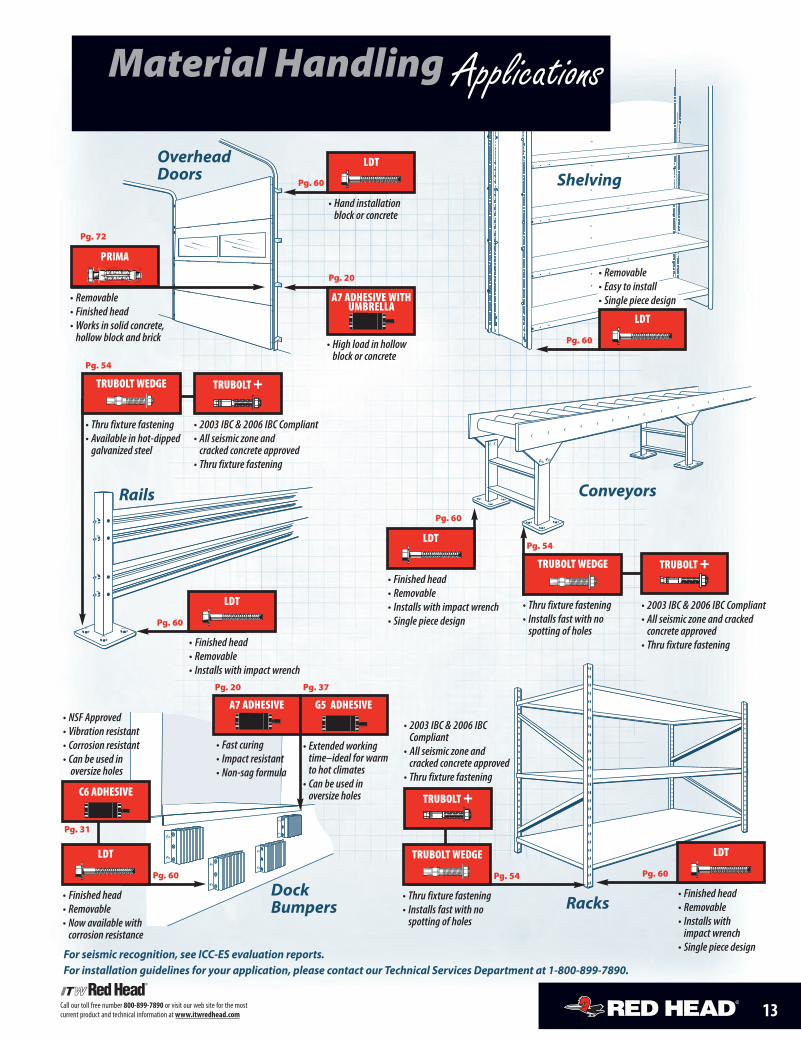
OverheadDoors
Dock Bumpers
Shelving
Rails
Racks
Conveyors
LDT
• Hand installationblock or concrete
Pg. 60
Pg. 20
A7 ADHESIVE WITHUMBRELLA
• High load in hollowblock or concrete
• Finished head• Removable• Now available with corrosion resistance
Pg. 60
LDT
• Finished head• Removable• Installs with impact wrench
Pg. 60
Pg. 60
LDT
• Finished head• Removable• Installs with impact wrench• Single piece design
Pg. 60
• Thru fixture fastening• Available in hot-dippedgalvanized steel
Pg. 54
A7 ADHESIVE
• Fast curing• Impact resistant• Non-sag formula
Pg. 20
Material Handling Applications
LDT
• Removable• Easy to install• Single piece design
For seismic recognition, see ICC-ES evaluation reports. For installation guidelines for your application, please contact our Technical Services Department at 1-800-899-7890.
• 2003 IBC & 2006 IBC Compliant• All seismic zone and cracked concrete approved• Thru fixture fastening
TRUBOLT +
• 2003 IBC & 2006 IBC Compliant• All seismic zone and crackedconcrete approved• Thru fixture fastening
TRUBOLT +
• 2003 IBC & 2006 IBCCompliant• All seismic zone andcracked concrete approved• Thru fixture fastening
LDT
• Finished head• Removable• Installs with impact wrench• Single piece design
Pg. 60
TRUBOLT WEDGE
• Thru fixture fastening• Installs fast with nospotting of holes
Pg. 54
TRUBOLT WEDGE TRUBOLT +
TRUBOLT WEDGE
• Thru fixture fastening• Installs fast with nospotting of holes
Pg. 54
• NSF Approved• Vibration resistant• Corrosion resistant• Can be used inoversize holes
Pg. 31
G5 ADHESIVE
• Extended workingtime–ideal for warmto hot climates• Can be used in oversize holes
Pg. 37
LDT
C6 ADHESIVE
PRIMA
• Removable• Finished head• Works in solid concrete,hollow block and brick
Pg. 72
14 Call our toll free number 800-899-7890 or visit our web site for the most current product and technical information at www.itwredhead.com
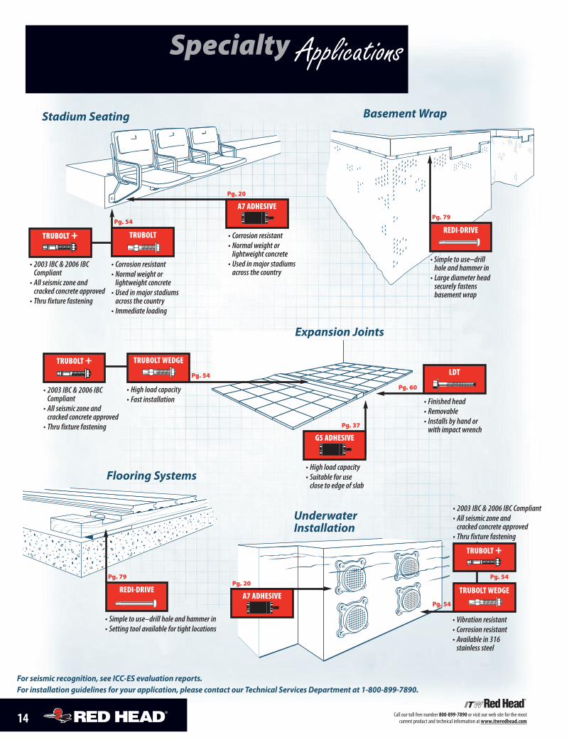
Specialty Applications
Underwater Installation
Stadium Seating Basement Wrap
Flooring Systems
For seismic recognition, see ICC-ES evaluation reports. For installation guidelines for your application, please contact our Technical Services Department at 1-800-899-7890.
Expansion Joints
REDI-DRIVE
• Simple to use–drillhole and hammer in• Large diameter headsecurely fastens basement wrap
Pg. 79
REDI-DRIVE
• Simple to use–drill hole and hammer in• Setting tool available for tight locations
Pg. 79
A7 ADHESIVE
Pg. 20
G5 ADHESIVE
• High load capacity• Suitable for useclose to edge of slab
Pg. 37
A7 ADHESIVE
• Corrosion resistant• Normal weight or lightweight concrete• Used in major stadiumsacross the country
Pg. 20
• Corrosion resistant• Normal weight or lightweight concrete• Used in major stadiums across the country• Immediate loading
Pg. 54
LDT
• Finished head• Removable• Installs by hand orwith impact wrench
Pg. 60
TRUBOLT +
• 2003 IBC & 2006 IBCCompliant• All seismic zone andcracked concrete approved• Thru fixture fastening
TRUBOLT +
• 2003 IBC & 2006 IBC Compliant• All seismic zone and cracked concrete approved• Thru fixture fastening
Pg. 54
TRUBOLT +
• 2003 IBC & 2006 IBCCompliant• All seismic zone andcracked concrete approved• Thru fixture fastening
TRUBOLT WEDGE
• High load capacity• Fast installation
Pg. 54
TRUBOLT
TRUBOLT WEDGE
• Vibration resistant• Corrosion resistant• Available in 316stainless steel
Pg. 54
Call our toll free number 800-899-7890 or visit our web site for the mostcurrent product and technical information at www.itwredhead.com
CONCRETE ANCHORING SPECIALISTS
The InsideStory AboutMechanical
and AdhesiveAnchors
Types, Base Materials,Installation Procedures
and More
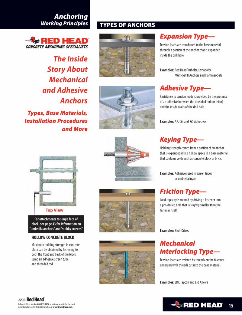
TYPES OF ANCHORS
Expansion Type—Tension loads are transferred to the base materialthrough a portion of the anchor that is expandedinside the drill hole.
Examples: Red Head Trubolts, Dynabolts,Multi-Set II Anchors and Hammer-Sets
Adhesive Type—Resistance to tension loads is provided by the presenceof an adhesive between the threaded rod (or rebar)and the inside walls of the drill hole.
Examples: A7, C6, and G5 Adhesives
Keying Type—Holding strength comes from a portion of an anchorthat is expanded into a hollow space in a base materialthat contains voids such as concrete block or brick.
Examples: Adhesives used in screen tubesor umbrella insert
Friction Type—Load capacity is created by driving a fastener intoa pre-drilled hole that is slightly smaller than thefastener itself.
Examples: Redi-Drives
MechanicalInterlocking Type—Tension loads are resisted by threads on the fastenerengaging with threads cut into the base material.
Examples: LDT, Tapcon and E-Z Ancors
AnchoringWorking Principles
Top View
HOLLOW CONCRETE BLOCKMaximum holding strength in concreteblock can be obtained by fastening toboth the front and back of the blockusing an adhesive screen tubeand threaded rod.
For attachments to single face ofblock, see page 43 for information on
“umbrella anchors” and “stubby screens”
15
16 Call our toll free number 800-899-7890 or visit our web site for the mostcurrent product and technical information at www.itwredhead.com
BASE MATERIALS
ConcreteNormal Weight Concrete is made from Portland cement, coarse and fine aggregates,water and various admixtures. The proportioning of these components controls the strengthof the concrete. In the United States, concrete strength is specified by the compressivestrength* of concrete test cylinders. These test cylinders measure six inches in diameterby 12 inches in length and are tested on the 28th day after they are produced.
Lightweight Concrete consists of the same components (cement, coarse and fineaggregates, water and admixtures) as normal weight concrete, except it is made withlightweight aggregate. One of the most common uses of lightweight concrete has beenas a structural fill of steel decking in the construction of strong, yet light floor systems.
Typical fasteners for both normal weight and lightweight concrete include TruboltWedgeAnchors, LDT Self-Threading Anchors, Dynabolt Sleeve Anchors, Multi-Set II Drop-InAnchors, Stud Anchors and Adhesive Anchoring Systems.* Compressive strengths shown in this catalog were the actual strengths at the time of testing.The load values listed were determined by testing in un-reinforced concrete.
MasonryGrout-Filled Concrete Block consists of three components: concrete, mortarand grout. The mortar is designed to join the units into an integral structure withpredictable performance properties. Typical fasteners for grout-filled block includeDynabolt Sleeve Anchors, and C6 or A7 Adhesive Anchoring Systems.
Hollow Concrete Block, Brick and Clay Tile are grouped together becausethey require special anchoring products that can be installed into a substrate that containsvoids and still provide reliable holding values. Typical fasteners used in hollow block, brickand clay tile include Dynabolt Sleeve Anchors, Tapcon Self-Tapping Concrete Anchors,Adhesives with Screen Tubes and Adhesives used with the Umbrella Insert.
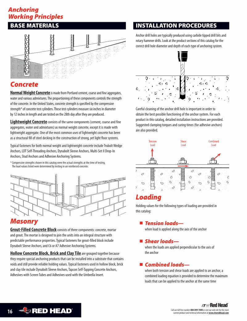
INSTALLATION PROCEDURES
Anchor drill holes are typically produced using carbide tipped drill bits androtary hammer drills. Look at the product sections of this catalog for thecorrect drill hole diameter and depth of each type of anchoring system.
Careful cleaning of the anchor drill hole is important in order toobtain the best possible functioning of the anchor system. For eachproduct in this catalog, detailed installation instructions are provided.Suggested clamping torques and curing times (for adhesive anchors)are also provided.
LoadingHolding values for the following types of loading are provided inthis catalog:
� Tension loads—when load is applied along the axis of the anchor
� Shear loads—when the loads are applied perpendicular to the axis ofthe anchor
� Combined loads—when both tension and shear loads are applied to an anchor, acombined loading equation is provided to determine the maximumloads that can be applied to the anchor at the same time
AnchoringWorking Principles
Tension Shear CombinedLoad Load Load
17Call our toll free number 800-899-7890 or visit our web site for the most current product and technical information at www.itwredhead.com
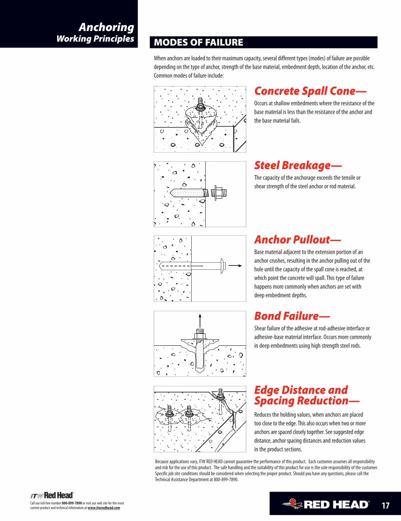
MODES OF FAILURE
When anchors are loaded to their maximum capacity, several different types (modes) of failure are possibledepending on the type of anchor, strength of the base material, embedment depth, location of the anchor, etc.Common modes of failure include:
Concrete Spall Cone—Occurs at shallow embedments where the resistance of thebase material is less than the resistance of the anchor andthe base material fails.
Steel Breakage—The capacity of the anchorage exceeds the tensile or shear strength of the steel anchor or rod material.
Anchor Pullout—Base material adjacent to the extension portion of ananchor crushes, resulting in the anchor pulling out of thehole until the capacity of the spall cone is reached, atwhich point the concrete will spall. This type of failure happens more commonly when anchors are set with deep embedment depths.
Bond Failure—Shear failure of the adhesive at rod-adhesive interface oradhesive-base material interface. Occurs more commonlyin deep embedments using high strength steel rods.
Edge Distance andSpacing Reduction—Reduces the holding values, when anchors are placed too close to the edge. This also occurs when two or moreanchors are spaced closely together. See suggested edge distance, anchor spacing distances and reduction values in the product sections.
AnchoringWorking Principles
Because applications vary, ITW RED HEAD cannot guarantee the performance of this product. Each customer assumes all responsibilityand risk for the use of this product. The safe handling and the suitability of this product for use is the sole responsibility of the customer.Specific job site conditions should be considered when selecting the proper product. Should you have any questions, please call theTechnical Assistance Department at 800-899-7890.
18 Call our toll free number 800-899-7890 or visit our web site for the mostcurrent product and technical information atwww.itwredhead.com
Adhesive AnchoringSelection Guide
Solid Concrete Applications
Dowelinginto Concretewith Rebar
Fastening toConcrete withThreaded Rod
1 Diameter x Embedment in 4000 psi concrete. 2 All loads given in pounds.
ADHESIVE ANCHORING SPECIALISTS
� Solid or hollow base materials� Dispenses easier and faster� Damp holes or underwater� Fastest cure (35 min. at 60°F)� Dispenses and cures faster in
cold weather� Can be used in smaller diameter holes� No-drip formula reduces clean-up time� Hand dispensable 28-oz. cartridge
� NEW! Base Material Temperature 15°F(cartridge temperature must be ≥ 70°F)
� Solid or hollow base materials� Hammer drilled or diamond cored holes� Oversized holes� Cold or warm weather� Damp holes or underwater� Horizontal or overhead installations� Fast curing epoxy (1 hour at 70°F)
� Solid base materials� Fire rated: tested up to 4hrs FRP� Works in dry, damp, saturated, and
underwater applications� Gives more time to install anchors� Easier to install anchors in hot weather� Odorless� Oversized and cored holes� Improved wet/water filled� Resist wind loads
ULTIMATE TENSILEPRODUCT SYSTEMS KEY FEATURES PROPERTIES PERFORMANCE1,2
26,50010,980
48,210
3/8" x 3-3/8" 5/8" x 5-5/8" 1" x 9"
24,5208,440
47,880
3/8" x 3-3/8" 5/8" x 5-5/8" 1" x 9"
20,8808,369
53,531
3/8" x 3-3/8" 5/8" x 5-5/8" 1" x 9"
C6 Fast Curing Epoxyfor All ConditionsConsistently handles allapplications
18 fluid oz. (530 ml) cartridges(see page 31)
22 fluid oz. (650 ml) cartridge(see page 37)
Best Formula Suitable Formula Not Suitable
A7 – BEST FORMULA
C6 and G5
HOT WEATHER USE
G5 – BEST FORMULA
C6 and A7
80̊ F 90˚F 100̊ F and higherand lower 0̊ F 20˚F 50̊ F
COLD WEATHER USE
Fast Dispensing, Fast Curing10:1 ACRYLIC
fast 35 minute cure time at 60˚F7 minute working time at 60˚F
NSF STANDARD 61 Certifiedfor drinking water applications
COLD WEATHER no heatingof cartridges required
Fast Curing for All Conditions1:1 EPOXY
fast 1 hour cure time at 70˚F7 minute working time at 70˚F
NSF STANDARD 61 Certifiedfor drinking water applications
Suitable for extremetemperature ranges
Extended Working Time1:1 EPOXY
24 hour cure time per (AC308)PLUS extended
15 minute working time at 70˚F
ODORLESS for indoorapplications
HOT WEATHER moretime to install anchors
18 month shelf lifeDamp holes
Underwater installationsScreens in hollow
block and brickOversized holesno reduction
Cored-drilled holes withno reduction
2 year shelf lifeDamp holes
Underwater installationsScreens in hollowblock and brickOversized holesno reduction
Cored-drilled holes withno reduction
18 month shelf lifeDamp holes
Underwater installationsScreens in hollowblock and brickOversized holes
will reduce loadsCored-drilled holes
will reduce load
BASEMATERIAL WORKING FULL(F°/C°) TIME CURE TIME
100°/ 38° 5 minutes 25 minutes80°/ 27° 5.5 minutes 30 minutes60°/ 16° 7 minutes 35 minutes40°/ 4° 15 minutes 75 minutes20°/ -7° 35 minutes 6 hours0°/ -18° 4 hours 24 hours
A7 Fast Dispensing,Fast Curing AcrylicInstall more anchorsin less time
BASEMATERIAL WORKING FULL(F°/C°) TIME CURE TIME
110°/ 43° 9 minutes 24 hours90°/ 32° 9 minutes 24 hours70°/ 20° 15 minutes 24 hours50°/ 10° 15 minutes 24 hours
5 fluid oz. (150 ml),8 fluid oz. (235 ml)10 fluid oz. (275 ml) and28 fluid oz. (825 ml) cartridges(see page 20)
REC
OGNIZED WORLDWID
EFireTestedBS476
4 Hrs FRP
InternationalStandard FireResistancePerformance
G5 High StrengthEpoxy tested in accordanceto ICC-ES AC30815 min. working time;24 hour cure time(Per AC308) (70°F)
ALL Red Head Adhesive/Epoxies comply withMade in U.S.A. requirements for Government jobs.
BASEMATERIAL1 WORKING FULL(F°/C°) TIME2 CURE TIME
120°/ 49° 4 minutes 1 hour110°/ 43° 4 minutes 1 hour90°/ 32° 5 minutes 1 hour80°/ 26° 6 minutes 1 hour70°/ 21° 7 minutes 1 hour60°/ 16° 7 minutes 2 hours50°/ 10° 7 minutes 2 hours40°/ 4° 7 minutes 24 hours15°/ -9° 6 minutes 24 hours
1 Cartridge must be ≥ 70°F.2 Working time is max time from the end of mixing towhen the insertion of the anchor into the adhesive shallbe completed.
Gel Time per ASTM D2471 = 10 minutes at 72°F
19Call our toll free number 800-899-7890 or visit our web site for the mostcurrent product and technical information atwww.itwredhead.com
1 Testing performed in hollow concrete block. 2 Diameter x Embedment.
ULTIMATE TENSILE1,2
SYSTEM ACCESSORIES KEY FEATURES PERFORMANCE (LBS)
BrickPinning
Fasteningto hollowconcrete block
(see page 46)Makes it possible to use adhesive forfastening to hollow block or brick walls
� 3/8" to 3/4" diameter sizes� 30%-50% lower cost than stainless screens� Special design makes screens easier to insert
through block or brick� Does not get bent or crushed� Corrosion resistant
2,8002,360
2,647 3,487
3/8" x 8" 3/4" x 8" 3/8" x 8" 3/4" x 8"
A7 C6
� 1/4" to 3/4" diameter sizes� Corrosion resistant� Available in multiple lengths to
accommodate various material thicknesses2,8002,360
2,647
2,458
2,543
3,487
3/8" x 8" 3/4" x 8" 3/8" x 8" 3/4" x 8"
A7 C6
� 1/4", 3/8", or 1/2" rods� 3/8" internal inserts (HBU-FS)� Fasten to front face of blocks� Creates large bearing surface
inside block to achieve high loads
Umbrella andUmbrella Inserts
1,8753,558 3,558
1,875
3/8" 1/2" 3/8" 1/2"
A7 C6
� 1/4", 3/8", 1/2", 5/8" diameter sizes� Fasten to front face of block� Anchor remains perpendicular in wall
1,8731,970
1/2 " 5/8" 1/2 " 5/8"
A7 C6
(see page 43)
(see page 46)Makes it possible to use adhesive forfastening to hollow block or brick walls
Stainless SteelScreens
Makes it possible to use adhesive forfastening to the face of hollow block or tile
Makes it possible to use adhesive forfastening to the face of hollow block or tile
(see page 43)
Umbrella Insert
HollowBaseMaterial ApplicationsUse the following accessorieswith the A7 andC6 adhesive anchoring systems for all of yourhollowbasematerial applications.
Stubby Screens
Nylon Screens
20 Call our toll free number 800-899-7890 or visit our web site for the mostcurrent product and technical information atwww.itwredhead.com
A7
ADVANTAGES
DESCRIPTION/SUGGESTED SPECIFICATIONS*
Fast Dispensing, Fast Curing Acrylic AdhesiveThe acrylic resin and hardening agent are completely mixed as they are simultaneously dispensed from thedual cartridge through a static mixing nozzle, directly into the anchor hole. A7 can be used with threaded rodor rebar (for fastening to hollow base materials, see page 43 and 46).
*Suggested Specifications see pages 23
� All weather formula
� No drip, no sag, easy clean up
� Fast & easy dispensing, even 28 ouncecartridge can be hand dispensed
� Fast curing time, 35 minutes at 60°F
� Not mix ratio sensitive
� NSF 61 approved
� Rods are easier to insert into the hole withA7 compared with other adhesives
� Works in damp holes and underwaterapplications
� Requires less adhesive—can be used in1/16" oversized or 1/8" oversized holes
� One formula for both hollow and solidbase materials
Curing Times
How CanAn AdhesiveAnchor SaveYouMoney?
� Incredibly fast dispensingand rod installation times
� Significantly fastercuring times
� Easy to use (no-heating) evenat freezing cold temperatures
� Requires less adhesive
ADHESIVE ANCHORING SPECIALISTS
Easy to Use—A7 Saves You
Time and Money
A102
A7-28
BASE MATERIAL WORKING FULL(F°/C°) TIME CURE TIME
100°/ 38° 5 minutes 25 minutes80°/ 27° 5.5 minutes 30 minutes60°/ 16° 7 minutes 35 minutes40°/ 4° 15 minutes 75 minutes20°/ -7° 35 minutes 6 hours0°/ -18° 4 hours 24 hours
21Call our toll free number 800-899-7890 or visit our web site for the mostcurrent product and technical information atwww.itwredhead.com
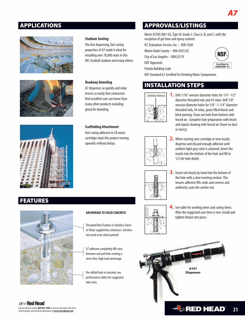
APPLICATIONS
Stadium SeatingThe fast dispensing, fast curingproperties of A7 made it ideal forinstalling over 70,000 seats in thisNFL football stadium and many others.
Roadway DowelingA7 dispenses so quickly and rebarinserts so easily that contractorsfind installed costs are lower thanmany other products includinggrout for doweling.
Scaffolding AttachmentFast curing adhesive in 28 ouncecartridges kept this project movingupwards without delays.
A7
FEATURES
ANCHORAGE TO SOLID CONCRETE
Threaded Rod (Carbon or Stainless Steel)or Rebar supplied by contractor ; rod doesnot need to be chisel pointed
A7 adhesive completely fills areabetween rod and hole creating astress free, high load anchorage
Pre-drilled hole in concrete; seeperformance tables for suggestedhole sizes
INSTALLATION STEPS
APPROVALS/LISTINGSMeets ASTM C881-02, Type IV, Grade 3, Class A, B, and C; with theexception of gel time and epoxy contentICC Evaluation Service, Inc. – #ER-5560Miami-Dade County – #06-0425.02City of Los Angeles – RR#25379DOT ApprovalsFlorida Building CodeNSF Standard 61 Certified for DrinkingWater Components
3. Insert rod slowly by hand into the bottom ofthe hole with a slow twisting motion. Thisinsures adhesive fills voids and crevices anduniformly coats the anchor rod.
4. See table for working times and curing times.After the suggested cure time is met, install andtighten fixture into place.
Solid Base Material 1. Drill 1/16" oversize diameter holes for 1/4"–1/2"diameter threaded rods and #3 rebar. Drill 1/8"oversize diameter holes for 5/8"–1-1/4" diameterthreaded rods, #4 rebar, grout filled blocks andbrick pinning. Clean out hole from bottom withforced air. Complete hole preparation with brushand repeat cleaning with forced air (leave no dustor slurry).
2. When starting new cartridge or new nozzle,dispense and discard enough adhesive untiluniform light grey color is achieved. Insert thenozzle into the bottom of the hole and fill to1/2 the hole depth.
A101Dispenser
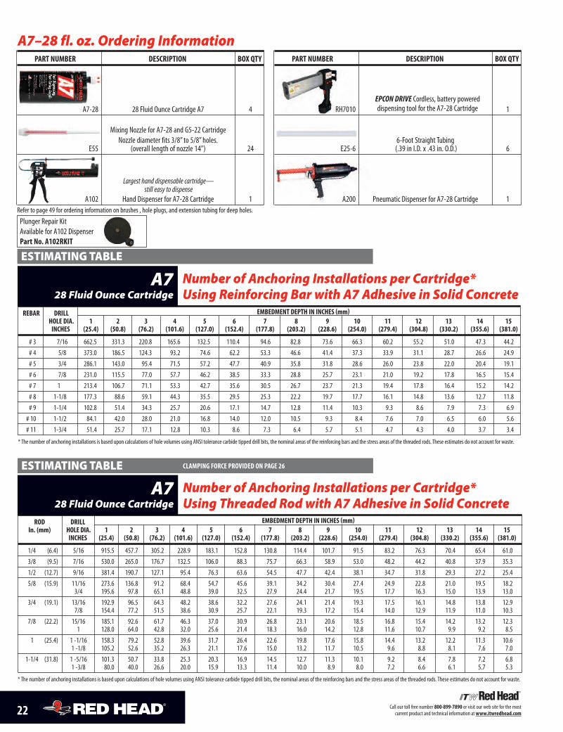
A7–28 fl. oz. Ordering InformationPART NumbER DESCRIPTION bOx QTy
A7-28 28 Fluid Ounce Cartridge A7 4
Mixing Nozzle for A7-28 and G5-22 CartridgeNozzle diameter fits 3/8” to 5/8”holes.
E55 (overall length of nozzle 14") 24
A102 Hand Dispenser for A7-28 Cartridge 1Refer to page 49 for ordering information on brushes , hole plugs, and extension tubing for deep holes.
22 Call our toll free number 800-899-7890 or visit our web site for the mostcurrent product and technical information atwww.itwredhead.com
REbAR DRILL EmbEDmENT DEPTH IN INCHES (mm)HOLE DIA. 1 2 3 4 5 6 7 8 9 10 11 12 13 14 15INCHES (25.4) (50.8) (76.2) (101.6) (127.0) (152.4) (177.8) (203.2) (228.6) (254.0) (279.4) (304.8) (330.2) (355.6) (381.0)
# 3 7/16 662.5 331.3 220.8 165.6 132.5 110.4 94.6 82.8 73.6 66.3 60.2 55.2 51.0 47.3 44.2# 4 5/8 373.0 186.5 124.3 93.2 74.6 62.2 53.3 46.6 41.4 37.3 33.9 31.1 28.7 26.6 24.9# 5 3/4 286.1 143.0 95.4 71.5 57.2 47.7 40.9 35.8 31.8 28.6 26.0 23.8 22.0 20.4 19.1# 6 7/8 231.0 115.5 77.0 57.7 46.2 38.5 33.3 28.8 25.7 23.1 21.0 19.2 17.8 16.5 15.4# 7 1 213.4 106.7 71.1 53.3 42.7 35.6 30.5 26.7 23.7 21.3 19.4 17.8 16.4 15.2 14.2# 8 1-1/8 177.3 88.6 59.1 44.3 35.5 29.5 25.3 22.2 19.7 17.7 16.1 14.8 13.6 12.7 11.8# 9 1-1/4 102.8 51.4 34.3 25.7 20.6 17.1 14.7 12.8 11.4 10.3 9.3 8.6 7.9 7.3 6.9# 10 1-1/2 84.1 42.0 28.0 21.0 16.8 14.0 12.0 10.5 9.3 8.4 7.6 7.0 6.5 6.0 5.6# 11 1-3/4 51.4 25.7 17.1 12.8 10.3 8.6 7.3 6.4 5.7 5.1 4.7 4.3 4.0 3.7 3.4
* The number of anchoring installations is based upon calculations of hole volumes using ANSI tolerance carbide tipped drill bits, the nominal areas of the reinforcing bars and the stress areas of the threaded rods. These estimates do not account for waste.
Number of Anchoring Installations per Cartridge*Using Reinforcing Bar with A7 Adhesive in Solid Concrete
A728 Fluid Ounce Cartridge
ESTIMATINGTABLE
ROD DRILL EmbEDmENT DEPTH IN INCHES (mm)In. (mm) HOLE DIA. 1 2 3 4 5 6 7 8 9 10 11 12 13 14 15
INCHES (25.4) (50.8) (76.2) (101.6) (127.0) (152.4) (177.8) (203.2) (228.6) (254.0) (279.4) (304.8) (330.2) (355.6) (381.0)
1/4 (6.4) 5/16 915.5 457.7 305.2 228.9 183.1 152.8 130.8 114.4 101.7 91.5 83.2 76.3 70.4 65.4 61.03/8 (9.5) 7/16 530.0 265.0 176.7 132.5 106.0 88.3 75.7 66.3 58.9 53.0 48.2 44.2 40.8 37.9 35.31/2 (12.7) 9/16 381.4 190.7 127.1 95.4 76.3 63.6 54.5 47.7 42.4 38.1 34.7 31.8 29.3 27.2 25.45/8 (15.9) 11/16 273.6 136.8 91.2 68.4 54.7 45.6 39.1 34.2 30.4 27.4 24.9 22.8 21.0 19.5 18.2
3/4 195.6 97.8 65.1 48.8 39.0 32.5 27.9 24.4 21.7 19.5 17.7 16.3 15.0 13.9 13.03/4 (19.1) 13/16 192.9 96.5 64.3 48.2 38.6 32.2 27.6 24.1 21.4 19.3 17.5 16.1 14.8 13.8 12.9
7/8 154.4 77.2 51.5 38.6 30.9 25.7 22.1 19.3 17.2 15.4 14.0 12.9 11.9 11.0 10.37/8 (22.2) 15/16 185.1 92.6 61.7 46.3 37.0 30.9 26.8 23.1 20.6 18.5 16.8 15.4 14.2 13.2 12.3
1 128.0 64.0 42.8 32.0 25.6 21.4 18.3 16.0 14.2 12.8 11.6 10.7 9.9 9.2 8.51 (25.4) 1 -1/16 158.3 79.2 52.8 39.6 31.7 26.4 22.6 19.8 17.6 15.8 14.4 13.2 12.2 11.3 10.6
1 -1/8 105.2 52.6 35.2 26.3 21.1 17.6 15.0 13.2 11.7 10.5 9.6 8.8 8.1 7.6 7.01-1/4 (31.8) 1 -5/16 101.3 50.7 33.8 25.3 20.3 16.9 14.5 12.7 11.3 10.1 9.2 8.4 7.8 7.2 6.8
1 -3/8 80.0 40.0 26.6 20.0 15.9 13.3 11.4 10.0 8.9 8.0 7.2 6.6 6.1 5.7 5.3
* The number of anchoring installations is based upon calculations of hole volumes using ANSI tolerance carbide tipped drill bits, the nominal areas of the reinforcing bars and the stress areas of the threaded rods. These estimates do not account for waste.
Number of Anchoring Installations per Cartridge*Using Threaded Rod with A7 Adhesive in Solid Concrete
A728 Fluid Ounce Cartridge
ESTIMATINGTABLE CLAmPING fORCE PROvIDED ON PAGE 26
Largest hand dispensable cartridge—still easy to dispense
PART NumbER DESCRIPTION bOx QTy
RH7010 1
6-Foot Straight TubingE25-6 (.39 in I.D. x .43 in. O.D.) 6
A200 Pneumatic Dispenser for A7-28 Cartridge 1
EPCON DRIVE Cordless, battery powereddispensing tool for the A7-28 Cartridge
Plunger Repair KitAvailable for A102 DispenserPart No. A102RKIT
23Call our toll free number 800-899-7890 or visit our web site for the mostcurrent product and technical information atwww.itwredhead.com
REbAR DRILL EmbEDmENT DEPTH IN INCHES (mm)HOLE DIA. 2 4 6 8INCHES (50.8) (101.6) (152.4) (203.2)
# 3 7/16 110 55 37 27# 4 5/8 63 31 20 14# 5 3/4 48 24 16 11# 6 7/8 39 18 13 9# 7 1 35 18 11 9# 8 1-1/8 29 14 9 7
Number of Anchoring Installations per Cartridge* Using ReinforcingBar and Threaded Rod with A7 Adhesive in Solid ConcreteA7
10 Fluid Ounce Cartridge
ESTIMATINGTABLES
ROD DRILL EmbEDmENT DEPTH IN INCHES (mm)In (mm) HOLE DIA. 2 4 6 8
INCHES (50.8) (101.6) (152.4) (203.2)
3/8 (9.5) 7/16 88 44 28 221/2 (12.7) 9/16 65 31 22 165/8 (15.9) 11/16 46 22 14 11
3/4 33 16 11 73/4 (19.1) 13/16 33 16 11 7
7/8 26 13 9 77/8 (22.2) 15/16 31 14 11 7
1 22 11 7 51 (25.4) 1-1/16 26 13 9 7
1-1/8 18 9 5 3
* The number of anchoring installations is based upon calculations of hole volumes using ANSI tolerance carbide tippeddrill bits, the nominal areas of the reinforcing bars and the stress areas of the threaded rods. These estimates do notaccount for waste.
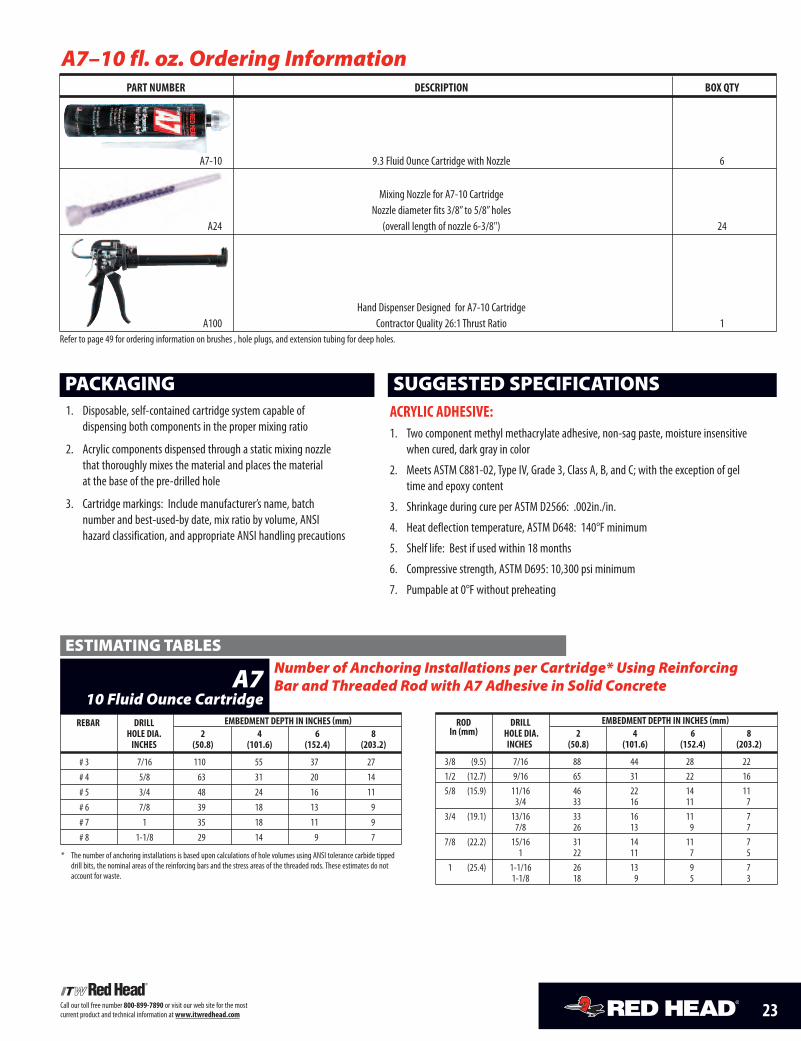
A7–10 fl. oz. Ordering InformationPART NumbER DESCRIPTION bOx QTy
A7-10 9.3 Fluid Ounce Cartridge with Nozzle 6
Mixing Nozzle for A7-10 CartridgeNozzle diameter fits 3/8” to 5/8”holes
A24 (overall length of nozzle 6-3/8") 24
Hand Dispenser Designed for A7-10 CartridgeA100 Contractor Quality 26:1 Thrust Ratio 1
Refer to page 49 for ordering information on brushes , hole plugs, and extension tubing for deep holes.
1. Disposable, self-contained cartridge system capable ofdispensing both components in the proper mixing ratio
2. Acrylic components dispensed through a static mixing nozzlethat thoroughly mixes the material and places the materialat the base of the pre-drilled hole
3. Cartridge markings: Include manufacturer’s name, batchnumber and best-used-by date, mix ratio by volume, ANSIhazard classification, and appropriate ANSI handling precautions
PACKAGINGACRyLIC ADHESIvE:1. Two component methyl methacrylate adhesive, non-sag paste, moisture insensitive
when cured, dark gray in color
2. Meets ASTM C881-02, Type IV, Grade 3, Class A, B, and C; with the exception of geltime and epoxy content
3. Shrinkage during cure per ASTM D2566: .002in./in.
4. Heat deflection temperature, ASTM D648: 140°F minimum
5. Shelf life: Best if used within 18 months
6. Compressive strength, ASTM D695: 10,300 psi minimum
7. Pumpable at 0°F without preheating
SUGGESTED SPECIFICATIONS
24 Call our toll free number 800-899-7890 or visit our web site for the mostcurrent product and technical information atwww.itwredhead.com
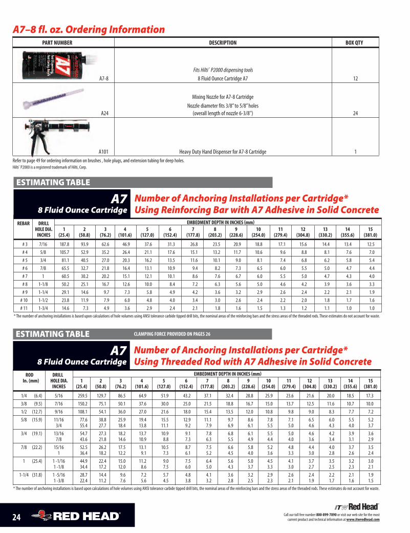
A7–8 fl. oz. Ordering InformationPART NumbER DESCRIPTION bOx QTy
A7-8 8 Fluid Ounce Cartridge A7 12
Mixing Nozzle for A7-8 CartridgeNozzle diameter fits 3/8” to 5/8”holes
A24 (overall length of nozzle 6-3/8") 24
A101 Heavy Duty Hand Dispenser for A7-8 Cartridge 1Refer to page 49 for ordering information on brushes , hole plugs, and extension tubing for deep holes.Hilti® P2000 is a registered trademark of Hilti, Corp.
Fits Hilti ® P2000 dispensing tools
REbAR DRILL EmbEDmENT DEPTH IN INCHES (mm)HOLE DIA. 1 2 3 4 5 6 7 8 9 10 11 12 13 14 15INCHES (25.4) (50.8) (76.2) (101.6) (127.0) (152.4) (177.8) (203.2) (228.6) (254.0) (279.4) (304.8) (330.2) (355.6) (381.0)
# 3 7/16 187.8 93.9 62.6 46.9 37.6 31.3 26.8 23.5 20.9 18.8 17.1 15.6 14.4 13.4 12.5# 4 5/8 105.7 52.9 35.2 26.4 21.1 17.6 15.1 13.2 11.7 10.6 9.6 8.8 8.1 7.6 7.0# 5 3/4 81.1 40.5 27.0 20.3 16.2 13.5 11.6 10.1 9.0 8.1 7.4 6.8 6.2 5.8 5.4# 6 7/8 65.5 32.7 21.8 16.4 13.1 10.9 9.4 8.2 7.3 6.5 6.0 5.5 5.0 4.7 4.4# 7 1 60.5 30.2 20.2 15.1 12.1 10.1 8.6 7.6 6.7 6.0 5.5 5.0 4.7 4.3 4.0# 8 1-1/8 50.2 25.1 16.7 12.6 10.0 8.4 7.2 6.3 5.6 5.0 4.6 4.2 3.9 3.6 3.3# 9 1-1/4 29.1 14.6 9.7 7.3 5.8 4.9 4.2 3.6 3.2 2.9 2.6 2.4 2.2 2.1 1.9# 10 1-1/2 23.8 11.9 7.9 6.0 4.8 4.0 3.4 3.0 2.6 2.4 2.2 2.0 1.8 1.7 1.6# 11 1-3/4 14.6 7.3 4.9 3.6 2.9 2.4 2.1 1.8 1.6 1.5 1.3 1.2 1.1 1.0 1.0
* The number of anchoring installations is based upon calculations of hole volumes using ANSI tolerance carbide tipped drill bits, the nominal areas of the reinforcing bars and the stress areas of the threaded rods. These estimates do not account for waste.
Number of Anchoring Installations per Cartridge*Using Reinforcing Bar with A7 Adhesive in Solid Concrete
A78 Fluid Ounce Cartridge
ESTIMATINGTABLE
ROD DRILL EmbEDmENT DEPTH IN INCHES (mm)In. (mm) HOLE DIA. 1 2 3 4 5 6 7 8 9 10 11 12 13 14 15
INCHES (25.4) (50.8) (76.2) (101.6) (127.0) (152.4) (177.8) (203.2) (228.6) (254.0) (279.4) (304.8) (330.2) (355.6) (381.0)
1/4 (6.4) 5/16 259.5 129.7 86.5 64.9 51.9 43.2 37.1 32.4 28.8 25.9 23.6 21.6 20.0 18.5 17.33/8 (9.5) 7/16 150.2 75.1 50.1 37.6 30.0 25.0 21.5 18.8 16.7 15.0 13.7 12.5 11.6 10.7 10.01/2 (12.7) 9/16 108.1 54.1 36.0 27.0 21.6 18.0 15.4 13.5 12.0 10.8 9.8 9.0 8.3 7.7 7.25/8 (15.9) 11/16 77.6 38.8 25.9 19.4 15.5 12.9 11.1 9.7 8.6 7.8 7.1 6.5 6.0 5.5 5.2
3/4 55.4 27.7 18.4 13.8 11.1 9.2 7.9 6.9 6.1 5.5 5.0 4.6 4.3 4.0 3.73/4 (19.1) 13/16 54.7 27.3 18.2 13.7 10.9 9.1 7.8 6.8 6.1 5.5 5.0 4.6 4.2 3.9 3.6
7/8 43.6 21.8 14.6 10.9 8.8 7.3 6.3 5.5 4.9 4.4 4.0 3.6 3.4 3.1 2.97/8 (22.2) 15/16 52.5 26.2 17.5 13.1 10.5 8.7 7.5 6.6 5.8 5.2 4.8 4.4 4.0 3.7 3.5
1 36.4 18.2 12.2 9.1 7.3 6.1 5.2 4.5 4.0 3.6 3.3 3.0 2.8 2.6 2.41 (25.4) 1 -1/16 44.9 22.4 15.0 11.2 9.0 7.5 6.4 5.6 5.0 4.5 4.1 3.7 3.5 3.2 3.0
1 -1/8 34.4 17.2 12.0 8.6 7.5 6.0 5.0 4.3 3.7 3.3 3.0 2.7 2.5 2.3 2.11-1/4 (31.8) 1 -5/16 28.7 14.4 9.6 7.2 5.7 4.8 4.1 3.6 3.2 2.9 2.6 2.4 2.2 2.1 1.9
1 -3/8 22.4 11.2 7.6 5.6 4.5 3.8 3.2 2.8 2.5 2.3 2.1 1.9 1.7 1.6 1.5* The number of anchoring installations is based upon calculations of hole volumes using ANSI tolerance carbide tipped drill bits, the nominal areas of the reinforcing bars and the stress areas of the threaded rods. These estimates do not account for waste.
Number of Anchoring Installations per Cartridge*Using Threaded Rod with A7 Adhesive in Solid Concrete
A78 Fluid Ounce Cartridge
ESTIMATINGTABLE CLAmPING fORCE PROvIDED ON PAGES 26
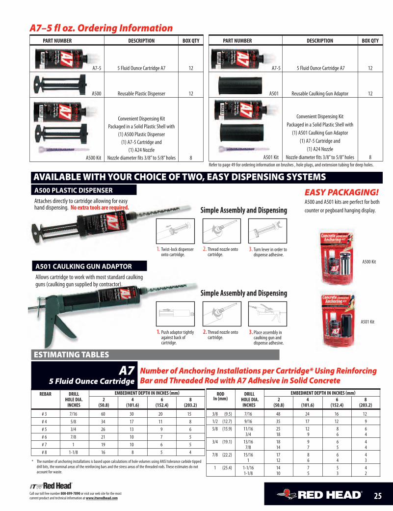
A501 CAULKING GUN ADAPTORAllows cartridge to work with most standard caulkingguns (caulking gun supplied by contractor).
3.Place assembly incaulking gun anddispense adhesive.
Simple Assembly and Dispensing
2. Thread nozzle ontocartridge.
1. Push adaptor tightlyagainst back ofcartridge.
A500 PLASTIC DISPENSERAttaches directly to cartridge allowing for easyhand dispensing. Noextra tools are required.
3. Turn lever in order todispense adhesive.
Simple Assembly and Dispensing
2. Thread nozzle ontocartridge.
1. Twist-lock dispenseronto cartridge.
25Call our toll free number 800-899-7890 or visit our web site for the mostcurrent product and technical information atwww.itwredhead.com
A7–5 fl oz. Ordering InformationPART NumbER DESCRIPTION bOx QTy
A7-5 5 Fluid Ounce Cartridge A7 12
A500 Reusable Plastic Dispenser 12
Convenient Dispensing KitPackaged in a Solid Plastic Shell with
(1) A500 Plastic Dispenser(1) A7-5 Cartridge and
(1) A24 NozzleA500 Kit Nozzle diameter fits 3/8” to 5/8”holes 8
PART NumbER DESCRIPTION bOx QTy
A7-5 5 Fluid Ounce Cartridge A7 12
A501 Reusable Caulking Gun Adaptor 12
Convenient Dispensing KitPackaged in a Solid Plastic Shell with
(1) A501 Caulking Gun Adaptor(1) A7-5 Cartridge and
(1) A24 NozzleA501 Kit Nozzle diameter fits 3/8” to 5/8”holes 8
Refer to page 49 for ordering information on brushes , hole plugs, and extension tubing for deep holes.
EASY PACKAGING!A500 and A501 kits are perfect for bothcounter or pegboard hanging display.
AVAILABLEWITHYOUR CHOICE OF TWO, EASY DISPENSING SYSTEMS
A501 Kit
REbAR DRILL EmbEDmENT DEPTH IN INCHES (mm)HOLE DIA. 2 4 6 8INCHES (50.8) (101.6) (152.4) (203.2)
# 3 7/16 60 30 20 15# 4 5/8 34 17 11 8# 5 3/4 26 13 9 6# 6 7/8 21 10 7 5# 7 1 19 10 6 5# 8 1-1/8 16 8 5 4
Number of Anchoring Installations per Cartridge* Using ReinforcingBar and Threaded Rodwith A7Adhesive in Solid Concrete
A75 Fluid Ounce Cartridge
ESTIMATINGTABLES
ROD DRILL EmbEDmENT DEPTH IN INCHES (mm)In (mm) HOLE DIA. 2 4 6 8
INCHES (50.8) (101.6) (152.4) (203.2)
3/8 (9.5) 7/16 48 24 16 121/2 (12.7) 9/16 35 17 12 95/8 (15.9) 11/16 25 12 8 6
3/4 18 9 6 43/4 (19.1) 13/16 18 9 6 4
7/8 14 7 5 47/8 (22.2) 15/16 17 8 6 4
1 12 6 4 31 (25.4) 1-1/16 14 7 5 4
1-1/8 10 5 3 2
* The number of anchoring installations is based upon calculations of hole volumes using ANSI tolerance carbide tippeddrill bits, the nominal areas of the reinforcing bars and the stress areas of the threaded rods. These estimates do notaccount for waste.
A500 Kit
26 Call our toll free number 800-899-7890 or visit our web site for the mostcurrent product and technical information atwww.itwredhead.com
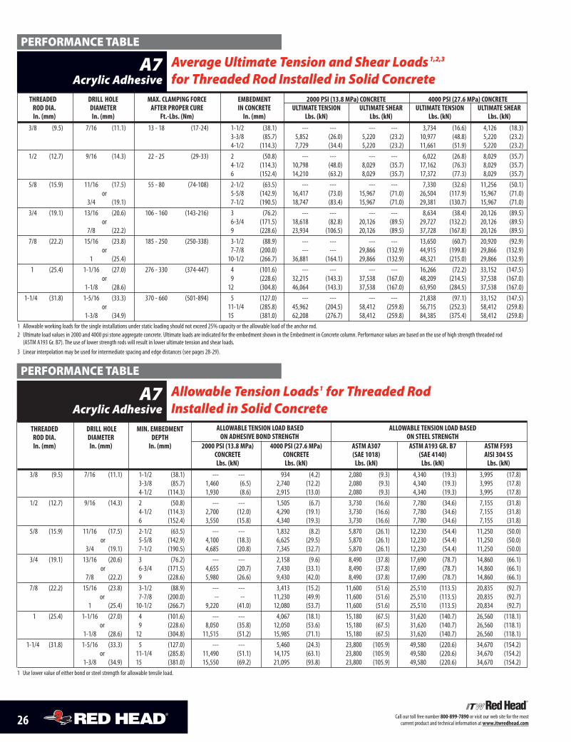
THREADED DRILL HOLE mAx. CLAmPING fORCE EmbEDmENT 2000 PSI (13.8 mPa) CONCRETE 4000 PSI (27.6 mPa) CONCRETEROD DIA. DIAmETER AfTER PROPER CuRE IN CONCRETE uLTImATE TENSION uLTImATE SHEAR uLTImATE TENSION uLTImATE SHEARIn. (mm) In. (mm) ft.-Lbs. (Nm) In. (mm) Lbs. (kN) Lbs. (kN) Lbs. (kN) Lbs. (kN)
3/8 (9.5) 7/16 (11.1) 13 - 18 (17-24) 1-1/2 (38.1) --- --- --- --- 3,734 (16.6) 4,126 (18.3)3-3/8 (85.7) 5,852 (26.0) 5,220 (23.2) 10,977 (48.8) 5,220 (23.2)4-1/2 (114.3) 7,729 (34.4) 5,220 (23.2) 11,661 (51.9) 5,220 (23.2)
1/2 (12.7) 9/16 (14.3) 22 - 25 (29-33) 2 (50.8) --- --- --- --- 6,022 (26.8) 8,029 (35.7)4-1/2 (114.3) 10,798 (48.0) 8,029 (35.7) 17,162 (76.3) 8,029 (35.7)6 (152.4) 14,210 (63.2) 8,029 (35.7) 17,372 (77.3) 8,029 (35.7)
5/8 (15.9) 11/16 (17.5) 55 - 80 (74-108) 2-1/2 (63.5) --- --- --- --- 7,330 (32.6) 11,256 (50.1)or 5-5/8 (142.9) 16,417 (73.0) 15,967 (71.0) 26,504 (117.9) 15,967 (71.0)
3/4 (19.1) 7-1/2 (190.5) 18,747 (83.4) 15,967 (71.0) 29,381 (130.7) 15,967 (71.0)3/4 (19.1) 13/16 (20.6) 106 - 160 (143-216) 3 (76.2) --- --- --- --- 8,634 (38.4) 20,126 (89.5)
or 6-3/4 (171.5) 18,618 (82.8) 20,126 (89.5) 29,727 (132.2) 20,126 (89.5)7/8 (22.2) 9 (228.6) 23,934 (106.5) 20,126 (89.5) 37,728 (167.8) 20,126 (89.5)
7/8 (22.2) 15/16 (23.8) 185 - 250 (250-338) 3-1/2 (88.9) --- --- --- --- 13,650 (60.7) 20,920 (92.9)or 7-7/8 (200.0) --- --- 29,866 (132.9) 44,915 (199.8) 29,866 (132.9)
1 (25.4) 10-1/2 (266.7) 36,881 (164.1) 29,866 (132.9) 48,321 (215.0) 29,866 (132.9)1 (25.4) 1-1/16 (27.0) 276 - 330 (374-447) 4 (101.6) --- --- --- --- 16,266 (72.2) 33,152 (147.5)
or 9 (228.6) 32,215 (143.3) 37,538 (167.0) 48,209 (214.5) 37,538 (167.0)1-1/8 (28.6) 12 (304.8) 46,064 (143.3) 37,538 (167.0) 63,950 (284.5) 37,538 (167.0)
1-1/4 (31.8) 1-5/16 (33.3) 370 - 660 (501-894) 5 (127.0) --- --- --- --- 21,838 (97.1) 33,152 (147.5)or 11-1/4 (285.8) 45,962 (204.5) 58,412 (259.8) 56,715 (252.3) 58,412 (259.8)
1-3/8 (34.9) 15 (381.0) 62,208 (276.7) 58,412 (259.8) 84,385 (375.4) 58,412 (259.8)1 Allowable working loads for the single installations under static loading should not exceed 25% capacity or the allowable load of the anchor rod.2 Ultimate load values in 2000 and 4000 psi stone aggregate concrete. Ultimate loads are indicated for the embedment shown in the Embedment in Concrete column. Performance values are based on the use of high strength threaded rod(ASTM A193 Gr. B7). The use of lower strength rods will result in lower ultimate tension and shear loads.
3 Linear interpolation may be used for intermediate spacing and edge distances (see pages 28-29).
Average Ultimate Tension and Shear Loads1,2,3
for Threaded Rod Installed in Solid ConcreteA7
Acrylic Adhesive
PERFORMANCE TABLE
THREADED DRILL HOLE mIN. EmbEDmENT ALLOWAbLE TENSION LOAD bASED ALLOWAbLE TENSION LOAD bASEDROD DIA. DIAmETER DEPTH ON ADHESIvE bOND STRENGTH ON STEEL STRENGTHIn. (mm) In. (mm) In. (mm) 2000 PSI (13.8 mPa) 4000 PSI (27.6 mPa) ASTm A307 ASTm A193 GR. b7 ASTm f593
CONCRETE CONCRETE (SAE 1018) (SAE 4140) AISI 304 SSLbs. (kN) Lbs. (kN) Lbs. (kN) Lbs. (kN) Lbs. (kN)
3/8 (9.5) 7/16 (11.1) 1-1/2 (38.1) --- --- 934 (4.2) 2,080 (9.3) 4,340 (19.3) 3,995 (17.8)3-3/8 (85.7) 1,460 (6.5) 2,740 (12.2) 2,080 (9.3) 4,340 (19.3) 3,995 (17.8)4-1/2 (114.3) 1,930 (8.6) 2,915 (13.0) 2,080 (9.3) 4,340 (19.3) 3,995 (17.8)
1/2 (12.7) 9/16 (14.3) 2 (50.8) --- --- 1,505 (6.7) 3,730 (16.6) 7,780 (34.6) 7,155 (31.8)4-1/2 (114.3) 2,700 (12.0) 4,290 (19.1) 3,730 (16.6) 7,780 (34.6) 7,155 (31.8)6 (152.4) 3,550 (15.8) 4,340 (19.3) 3,730 (16.6) 7,780 (34.6) 7,155 (31.8)
5/8 (15.9) 11/16 (17.5) 2-1/2 (63.5) --- --- 1,832 (8.2) 5,870 (26.1) 12,230 (54.4) 11,250 (50.0)or 5-5/8 (142.9) 4,100 (18.3) 6,625 (29.5) 5,870 (26.1) 12,230 (54.4) 11,250 (50.0)
3/4 (19.1) 7-1/2 (190.5) 4,685 (20.8) 7,345 (32.7) 5,870 (26.1) 12,230 (54.4) 11,250 (50.0)3/4 (19.1) 13/16 (20.6) 3 (76.2) --- --- 2,158 (9.6) 8,490 (37.8) 17,690 (78.7) 14,860 (66.1)
or 6-3/4 (171.5) 4,655 (20.7) 7,430 (33.1) 8,490 (37.8) 17,690 (78.7) 14,860 (66.1)7/8 (22.2) 9 (228.6) 5,980 (26.6) 9,430 (42.0) 8,490 (37.8) 17,690 (78.7) 14,860 (66.1)
7/8 (22.2) 15/16 (23.8) 3-1/2 (88.9) --- --- 3,413 (15.2) 11,600 (51.6) 25,510 (113.5) 20,835 (92.7)or 7-7/8 (200.0) -- -- 11,230 (49.9) 11,600 (51.6) 25,510 (113.5) 20,835 (92.7)
1 (25.4) 10-1/2 (266.7) 9,220 (41.0) 12,080 (53.7) 11,600 (51.6) 25,510 (113.5) 20,834 (92.7)1 (25.4) 1-1/16 (27.0) 4 (101.6) --- --- 4,067 (18.1) 15,180 (67.5) 31,620 (140.7) 26,560 (118.1)
or 9 (228.6) 8,050 (35.8) 12,050 (53.6) 15,180 (67.5) 31,620 (140.7) 26,560 (118.1)1-1/8 (28.6) 12 (304.8) 11,515 (51.2) 15,985 (71.1) 15,180 (67.5) 31,620 (140.7) 26,560 (118.1)
1-1/4 (31.8) 1-5/16 (33.3) 5 (127.0) --- --- 5,460 (24.3) 23,800 (105.9) 49,580 (220.6) 34,670 (154.2)or 11-1/4 (285.8) 11,490 (51.1) 14,175 (63.1) 23,800 (105.9) 49,580 (220.6) 34,670 (154.2)
1-3/8 (34.9) 15 (381.0) 15,550 (69.2) 21,095 (93.8) 23,800 (105.9) 49,580 (220.6) 34,670 (154.2)1 Use lower value of either bond or steel strength for allowable tensile load.
Allowable Tension Loads1 for Threaded RodInstalled in Solid Concrete
A7Acrylic Adhesive
PERFORMANCE TABLE
27Call our toll free number 800-899-7890 or visit our web site for the mostcurrent product and technical information atwww.itwredhead.com
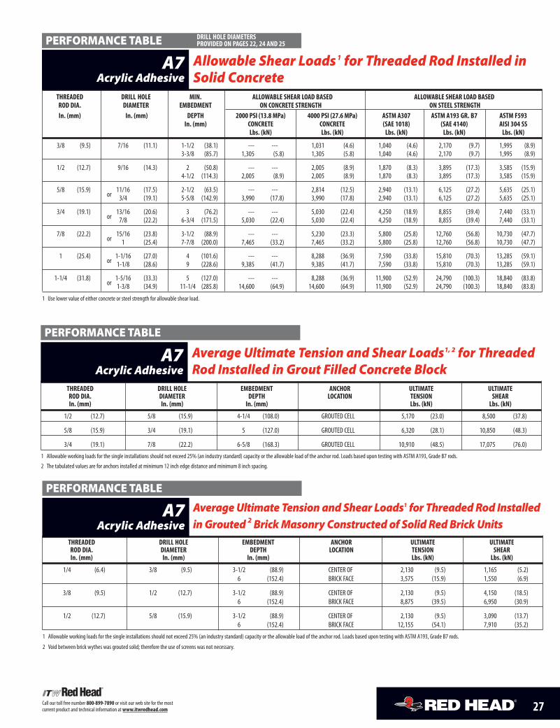
THREADED DRILL HOLE mIN. ALLOWAbLE SHEAR LOAD bASED ALLOWAbLE SHEAR LOAD bASEDROD DIA. DIAmETER EmbEDmENT ON CONCRETE STRENGTH ON STEEL STRENGTHIn. (mm) In. (mm) DEPTH 2000 PSI (13.8 mPa) 4000 PSI (27.6 mPa) ASTm A307 ASTm A193 GR. b7 ASTm f593
In. (mm) CONCRETE CONCRETE (SAE 1018) (SAE 4140) AISI 304 SSLbs. (kN) Lbs. (kN) Lbs. (kN) Lbs. (kN) Lbs. (kN)
3/8 (9.5) 7/16 (11.1) 1-1/2 (38.1) --- --- 1,031 (4.6) 1,040 (4.6) 2,170 (9.7) 1,995 (8.9)3-3/8 (85.7) 1,305 (5.8) 1,305 (5.8) 1,040 (4.6) 2,170 (9.7) 1,995 (8.9)
1/2 (12.7) 9/16 (14.3) 2 (50.8) --- --- 2,005 (8.9) 1,870 (8.3) 3,895 (17.3) 3,585 (15.9)4-1/2 (114.3) 2,005 (8.9) 2,005 (8.9) 1,870 (8.3) 3,895 (17.3) 3,585 (15.9)
5/8 (15.9) 11/16 (17.5) 2-1/2 (63.5) --- --- 2,814 (12.5) 2,940 (13.1) 6,125 (27.2) 5,635 (25.1)or 3/4 (19.1) 5-5/8 (142.9) 3,990 (17.8) 3,990 (17.8) 2,940 (13.1) 6,125 (27.2) 5,635 (25.1)
3/4 (19.1) 13/16 (20.6) 3 (76.2) --- --- 5,030 (22.4) 4,250 (18.9) 8,855 (39.4) 7,440 (33.1)or 7/8 (22.2) 6-3/4 (171.5) 5,030 (22.4) 5,030 (22.4) 4,250 (18.9) 8,855 (39.4) 7,440 (33.1)
7/8 (22.2) 15/16 (23.8) 3-1/2 (88.9) --- --- 5,230 (23.3) 5,800 (25.8) 12,760 (56.8) 10,730 (47.7)or 1 (25.4) 7-7/8 (200.0) 7,465 (33.2) 7,465 (33.2) 5,800 (25.8) 12,760 (56.8) 10,730 (47.7)
1 (25.4) 1-1/16 (27.0) 4 (101.6) --- --- 8,288 (36.9) 7,590 (33.8) 15,810 (70.3) 13,285 (59.1)or 1-1/8 (28.6) 9 (228.6) 9,385 (41.7) 9,385 (41.7) 7,590 (33.8) 15,810 (70.3) 13,285 (59.1)
1-1/4 (31.8) 1-5/16 (33.3) 5 (127.0) --- --- 8,288 (36.9) 11,900 (52.9) 24,790 (100.3) 18,840 (83.8)or 1-3/8 (34.9) 11-1/4 (285.8) 14,600 (64.9) 14,600 (64.9) 11,900 (52.9) 24,790 (100.3) 18,840 (83.8)
1 Use lower value of either concrete or steel strength for allowable shear load.
Allowable Shear Loads1 for Threaded Rod Installed inSolid Concrete
A7Acrylic Adhesive
PERFORMANCE TABLE DRILL HOLE DIAmETERSPROvIDED ON PAGES 22, 24 AND 25
THREADED DRILL HOLE EmbEDmENT ANCHOR uLTImATE uLTImATEROD DIA. DIAmETER DEPTH LOCATION TENSION SHEARIn. (mm) In. (mm) In. (mm) Lbs. (kN) Lbs. (kN)
1/4 (6.4) 3/8 (9.5) 3-1/2 (88.9) CENTER OF 2,130 (9.5) 1,165 (5.2)6 (152.4) BRICK FACE 3,575 (15.9) 1,550 (6.9)
3/8 (9.5) 1/2 (12.7) 3-1/2 (88.9) CENTER OF 2,130 (9.5) 4,150 (18.5)6 (152.4) BRICK FACE 8,875 (39.5) 6,950 (30.9)
1/2 (12.7) 5/8 (15.9) 3-1/2 (88.9) CENTER OF 2,130 (9.5) 3,090 (13.7)6 (152.4) BRICK FACE 12,155 (54.1) 7,910 (35.2)
1 Allowable working loads for the single installations should not exceed 25% (an industry standard) capacity or the allowable load of the anchor rod. Loads based upon testing with ASTM A193, Grade B7 rods.
2 Void between brick wythes was grouted solid; therefore the use of screens was not necessary.
AverageUltimate Tension and Shear Loads1 for ThreadedRod InstalledinGrouted 2 BrickMasonry Constructed of Solid RedBrickUnits
A7Acrylic Adhesive
PERFORMANCE TABLE
THREADED DRILL HOLE EmbEDmENT ANCHOR uLTImATE uLTImATEROD DIA. DIAmETER DEPTH LOCATION TENSION SHEARIn. (mm) In. (mm) In. (mm) Lbs. (kN) Lbs. (kN)
1/2 (12.7) 5/8 (15.9) 4-1/4 (108.0) GROUTED CELL 5,170 (23.0) 8,500 (37.8)
5/8 (15.9) 3/4 (19.1) 5 (127.0) GROUTED CELL 6,320 (28.1) 10,850 (48.3)
3/4 (19.1) 7/8 (22.2) 6-5/8 (168.3) GROUTED CELL 10,910 (48.5) 17,075 (76.0)
1 Allowable working loads for the single installations should not exceed 25% (an industry standard) capacity or the allowable load of the anchor rod. Loads based upon testing with ASTM A193, Grade B7 rods.
2 The tabulated values are for anchors installed at minimum 12 inch edge distance and minimum 8 inch spacing.
Average Ultimate Tension and Shear Loads1, 2 for ThreadedRod Installed in Grout Filled Concrete Block
A7Acrylic Adhesive
PERFORMANCE TABLE
28 Call our toll free number 800-899-7890 or visit our web site for the mostcurrent product and technical information atwww.itwredhead.com
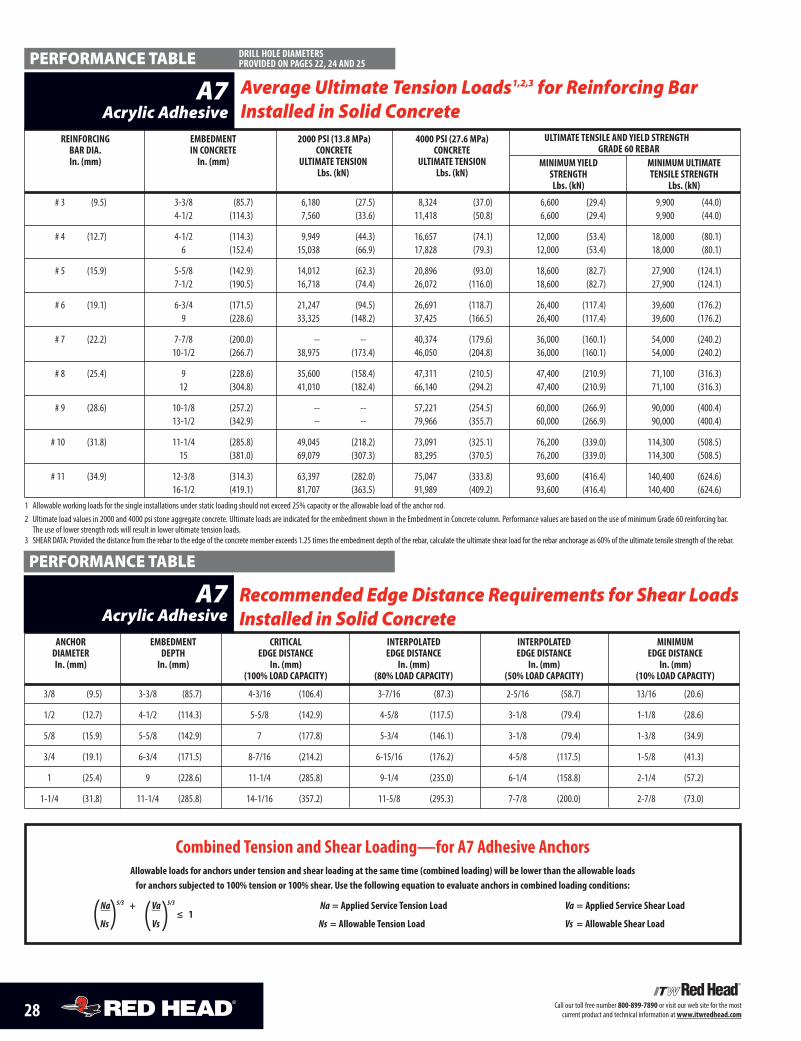
REINfORCING EmbEDmENT 2000 PSI (13.8 mPa) 4000 PSI (27.6 mPa) uLTImATE TENSILE AND yIELD STRENGTHbAR DIA. IN CONCRETE CONCRETE CONCRETE GRADE 60 REbARIn. (mm) In. (mm) uLTImATE TENSION uLTImATE TENSION mINImum yIELD mINImum uLTImATE
Lbs. (kN) Lbs. (kN) STRENGTH TENSILE STRENGTHLbs. (kN) Lbs. (kN)
# 3 (9.5) 3-3/8 (85.7) 6,180 (27.5) 8,324 (37.0) 6,600 (29.4) 9,900 (44.0)4-1/2 (114.3) 7,560 (33.6) 11,418 (50.8) 6,600 (29.4) 9,900 (44.0)
# 4 (12.7) 4-1/2 (114.3) 9,949 (44.3) 16,657 (74.1) 12,000 (53.4) 18,000 (80.1)6 (152.4) 15,038 (66.9) 17,828 (79.3) 12,000 (53.4) 18,000 (80.1)
# 5 (15.9) 5-5/8 (142.9) 14,012 (62.3) 20,896 (93.0) 18,600 (82.7) 27,900 (124.1)7-1/2 (190.5) 16,718 (74.4) 26,072 (116.0) 18,600 (82.7) 27,900 (124.1)
# 6 (19.1) 6-3/4 (171.5) 21,247 (94.5) 26,691 (118.7) 26,400 (117.4) 39,600 (176.2)9 (228.6) 33,325 (148.2) 37,425 (166.5) 26,400 (117.4) 39,600 (176.2)
# 7 (22.2) 7-7/8 (200.0) -- -- 40,374 (179.6) 36,000 (160.1) 54,000 (240.2)10-1/2 (266.7) 38,975 (173.4) 46,050 (204.8) 36,000 (160.1) 54,000 (240.2)
# 8 (25.4) 9 (228.6) 35,600 (158.4) 47,311 (210.5) 47,400 (210.9) 71,100 (316.3)12 (304.8) 41,010 (182.4) 66,140 (294.2) 47,400 (210.9) 71,100 (316.3)
# 9 (28.6) 10-1/8 (257.2) -- -- 57,221 (254.5) 60,000 (266.9) 90,000 (400.4)13-1/2 (342.9) -- -- 79,966 (355.7) 60,000 (266.9) 90,000 (400.4)
# 10 (31.8) 11-1/4 (285.8) 49,045 (218.2) 73,091 (325.1) 76,200 (339.0) 114,300 (508.5)15 (381.0) 69,079 (307.3) 83,295 (370.5) 76,200 (339.0) 114,300 (508.5)
# 11 (34.9) 12-3/8 (314.3) 63,397 (282.0) 75,047 (333.8) 93,600 (416.4) 140,400 (624.6)16-1/2 (419.1) 81,707 (363.5) 91,989 (409.2) 93,600 (416.4) 140,400 (624.6)
1 Allowable working loads for the single installations under static loading should not exceed 25% capacity or the allowable load of the anchor rod.2 Ultimate load values in 2000 and 4000 psi stone aggregate concrete. Ultimate loads are indicated for the embedment shown in the Embedment in Concrete column. Performance values are based on the use of minimum Grade 60 reinforcing bar.The use of lower strength rods will result in lower ultimate tension loads.
3 SHEAR DATA: Provided the distance from the rebar to the edge of the concrete member exceeds 1.25 times the embedment depth of the rebar, calculate the ultimate shear load for the rebar anchorage as 60% of the ultimate tensile strength of the rebar.
Average Ultimate Tension Loads1,2,3 for Reinforcing BarInstalled in Solid Concrete
A7Acrylic Adhesive
PERFORMANCE TABLE
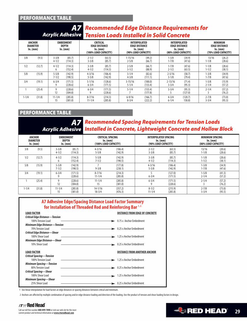
ANCHOR EmbEDmENT CRITICAL INTERPOLATED INTERPOLATED mINImumDIAmETER DEPTH EDGE DISTANCE EDGE DISTANCE EDGE DISTANCE EDGE DISTANCEIn. (mm) In. (mm) In. (mm) In. (mm) In. (mm) In. (mm)
(100% LOAD CAPACITy) (80% LOAD CAPACITy) (50% LOAD CAPACITy) (10% LOAD CAPACITy)
3/8 (9.5) 3-3/8 (85.7) 4-3/16 (106.4) 3-7/16 (87.3) 2-5/16 (58.7) 13/16 (20.6)
1/2 (12.7) 4-1/2 (114.3) 5-5/8 (142.9) 4-5/8 (117.5) 3-1/8 (79.4) 1-1/8 (28.6)
5/8 (15.9) 5-5/8 (142.9) 7 (177.8) 5-3/4 (146.1) 3-1/8 (79.4) 1-3/8 (34.9)
3/4 (19.1) 6-3/4 (171.5) 8-7/16 (214.2) 6-15/16 (176.2) 4-5/8 (117.5) 1-5/8 (41.3)
1 (25.4) 9 (228.6) 11-1/4 (285.8) 9-1/4 (235.0) 6-1/4 (158.8) 2-1/4 (57.2)
1-1/4 (31.8) 11-1/4 (285.8) 14-1/16 (357.2) 11-5/8 (295.3) 7-7/8 (200.0) 2-7/8 (73.0)
Recommended Edge Distance Requirements for Shear LoadsInstalled in Solid Concrete
A7Acrylic Adhesive
PERFORMANCE TABLE
Combined Tension and Shear Loading—for A7 Adhesive AnchorsAllowable loads for anchors under tension and shear loading at the same time (combined loading) will be lower than the allowable loadsfor anchors subjected to 100% tension or 100% shear. use the following equation to evaluate anchors in combined loading conditions:
Na 5/3 + Va 5/3
≤ 1Na = Applied Service Tension Load Va = Applied Service Shear Load
Ns Vs Ns = Allowable Tension Load Vs = Allowable Shear Load( () )
DRILL HOLE DIAmETERSPROvIDED ON PAGES 22, 24 AND 25
29Call our toll free number 800-899-7890 or visit our web site for the mostcurrent product and technical information atwww.itwredhead.com
A7 Adhesive Edge/Spacing Distance Load factor Summaryfor Installation of Threaded Rod and Reinforcing bar 1, 2
LOAD fACTOR DISTANCE fROm EDGE Of CONCRETECritical Edge Distance—Tension
100% Tension Load 0.75 x Anchor EmbedmentMinimum Edge Distance—Tension
70% Tension Load 0.25 x Anchor EmbedmentCritical Edge Distance—Shear
100% Shear Load 1.25 x Anchor EmbedmentMinimum Edge Distance—Shear
10% Shear Load 0.25 x Anchor Embedment
LOAD fACTOR DISTANCE fROm ANOTHER ANCHORCritical Spacing—Tension
100% Tension Load 1.25 x Anchor EmbedmentMinimum Spacing—Tension
80% Tension Load 0.25 x Anchor EmbedmentCritical Spacing—Shear
100% Shear Load 1.25 x Anchor EmbedmentMinimum Spacing—Shear
25% Shear Load 0.25 x Anchor Embedment
1 Use linear interpolation for load factors at edge distances or spacing distances between critical and minimum.
2 Anchors are affected by multiple combination of spacing and/or edge distance loading and direction of the loading. Use the product of tension and shear loading factors in design.
ANCHOR EmbEDmENT CRITICAL INTERPOLATED INTERPOLATED mINImumDIAmETER DEPTH EDGE DISTANCE EDGE DISTANCE EDGE DISTANCE EDGE DISTANCEIn. (mm) In. (mm) In. (mm) In. (mm) In. (mm) In. (mm)
(100% LOAD CAPACITy) (90% LOAD CAPACITy) (80% LOAD CAPACITy) (70% LOAD CAPACITy)
3/8 (9.5) 3-3/8 (85.7) 2-1/2 (63.5) 1-15/16 (49.2) 1-3/8 (34.9) 13/16 (26.2)4-1/2 (114.3) 3-3/8 (85.7) 2-5/8 (66.7) 1-7/8 (47.6) 1-1/8 (28.6)
1/2 (12.7) 4-1/2 (114.3) 3-3/8 (85.7) 2-5/8 (66.7) 1-7/8 (47.6) 1-1/8 (28.6)6 (152.4) 4-1/2 (114.3) 3-1/2 (88.9) 2-1/2 (63.5) 1-1/2 (38.1)
5/8 (15.9) 5-5/8 (142.9) 4-3/16 (106.4) 3-1/4 (82.6) 2-5/16 (58.7) 1-3/8 (34.9)7-1/2 (190.5) 5-5/8 (142.9) 4-3/8 (111.1) 3-1/8 (79.4) 1-7/8 (47.6)
3/4 (19.1) 6-3/4 (171.5) 5-1/16 (128.6) 3-15/16 (100.0) 2-13/16 (71.4) 1-5/8 (15.9)9 (228.6) 6-3/4 (171.5) 5-1/4 (133.4) 3-3/4 (95.3) 2-1/4 (57.2)
1 (25.4) 9 (228.6) 6-3/4 (171.5) 5-1/4 (133.4) 3-3/4 (95.3) 2-1/4 (57.2)12 (304.8) 9 (228.6) 7 (177.8) 5 (127.0) 3 (76.2)
1-1/4 (31.8) 11-1/4 (285.8) 8-7/16 (214.3) 6-9/16 (166.7) 4-3/4 (120.7) 2-7/8 (73.0)15 (381.0) 11-1/4 (285.8) 8-3/4 (222.2) 6-1/4 158.8) 3-3/4 (95.3)
Recommended Edge Distance Requirements forTension Loads Installed in Solid Concrete
A7Acrylic Adhesive
PERFORMANCE TABLE
ANCHOR EmbEDmENT CRITICAL SPACING INTERPOLATED SPACING mINImum SPACINGDIAmETER DEPTH In. (mm) In. (mm) In. (mm)In. (mm) In. (mm) (100% LOAD CAPACITy) (90% LOAD CAPACITy) (80% LOAD CAPACITy)
3/8 (9.5) 3-3/8 (85.7) 4-3/16 (106.4) 2-1/2 (63.5) 13/16 (20.6)4-1/2 (114.3) 5-5/8 (142.9) 3-3/8 (85.7) 1-1/8 (28.6)
1/2 (12.7) 4-1/2 (114.3) 5-5/8 (142.9) 3-3/8 (85.7) 1-1/8 (28.6)6 (152.4) 7-1/2 (190.5) 4-1/2 (114.3) 1-1/2 (38.1)
5/8 (15.9) 5-5/8 (142.9) 7 (177.8) 4-3/16 (106.4) 1-3/8 (34.9)7-1/2 (190.5) 9-3/8 (238.1) 5-5/8 (142.9) 1-7/8 (47.6)
3/4 (19.1) 6-3/4 (171.5) 8-7/16 (214.3) 5 (127.0) 1-5/8 (41.3)9 (228.6) 11-1/4 (285.8) 6-3/4 (171.5) 2-1/4 (57.2)
1 (25.4) 9 (228.6) 11-1/4 (285.8) 6-3/4 (171.5) 2-1/4 (57.2)12 (304.8) 15 (381.0) 9 (228.6) 3 (76.2)
1-1/4 (31.8) 11-1/4 (285.8) 14-1/16 (357.2) 8-1/2 (215.9) 2-7/8 (73.0)15 (381.0) 18-3/4 (476.3) 11-1/4 (285.8) 3-3/4 (95.5)
Recommended Spacing Requirements for Tension LoadsInstalled in Concrete, Lightweight Concrete and Hollow Block
A7Acrylic Adhesive
PERFORMANCE TABLE
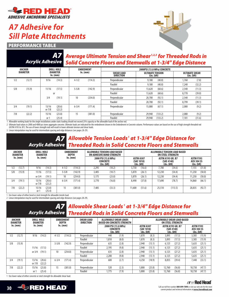
30 Call our toll free number 800-899-7890 or visit our web site for the mostcurrent product and technical information atwww.itwredhead.com
TENSION
SHEARPERPENDICULAR
SHEARPARALLEL
1
13/4"A7 Adhesive forSill Plate Attachments
ANCHOR DRILL HOLE EmbEDmENT 2000PSI (13.8 mPa) CONCRETEDIAmETER DIAmETER In. (mm) SHEAR LOAD uLTImATE TENSION uLTImATE SHEAR
In. (mm) DIRECTION Lbs. (kN) Lbs. (kN)
1/2 (12.7) 9/16 (14.3) 4-1/2 (114.3) Perpendicular 9,180 (40.8) 1,760 (7.8)
Parallel 9,180 (40.8) 7,240 (32.2)
5/8 (15.9) 11/16 (17.5) 5-5/8 (142.9) Perpendicular 13,620 (60.6) 2,540 (11.3)
or Parallel 13,620 (60.6) 8,778 (39.0)
3/4 (19.1) 10 (254.0) Perpendicular 20,700 (92.1) 2,540 (11.3)
Parallel 20,700 (92.1) 8,799 (39.1)
3/4 (19.1) 13/16 (20.6) 6-3/4 (171.4) Perpendicular 15,080 (67.1) 2,080 (9.2)or 7/8 (22.2)
7/8 (22.2) 15/16 (23.8) 15 (381.0) Perpendicular 29,940 (133.2) 2,080 (9.2)or 1 (25.4) Parallel 29,940 (133.2) 7,101 (31.6)
1 Allowable working loads for the single installations under static loading should not exceed 25% capacity or the allowable load of the anchor rod.2 Ultimate load values in 2000 and 4000 psi stone aggregate concrete. Ultimate loads are indicated for the embedment shown in the Embedment in Concrete column. Performance values are based on the use of high strength threaded rod(ASTM A193 Gr. B7). The use of lower strength rods will result in lower ultimate tension and shear loads.
3 Linear interpolation may be used for intermediate spacing and edge distances (see pages 28-29).
AverageUltimate Tension and Shear1,2,3 for Threaded Rods inSolid Concrete Floors and Stemwalls at 1-3/4" EdgeDistance
A7Acrylic Adhesive
PERFORMANCE TABLE
ADHESIVE ANCHORING SPECIALISTS
ANCHOR DRILL HOLE EmbEDmENT ALLOWAbLE TENSION LOAD bASED ALLOWAbLE TENSION LOAD bASEDDIAmETER DIAmETER DEPTH ON ADHESIvE bOND STRENGTH ON STEEL STRENGTHIn. (mm) In. (mm) In. (mm) 2000 PSI (13.8 mPa) ASTm A307 ASTm A193 GR. b7 ASTm f593
CONCRETE (SAE 1018) (SAE 4140) AISI 304 SSLbs. (kN) Lbs. (kN) Lbs. (kN) Lbs. (kN)
1/2 (12.7) 9/16 (14.3) 4-1/2 (114.3) 2,295 (10.2) 3,730 (16.6) 7,780 (34.6) 7,155 (31.8)
5/8 (15.9) 11/16 (17.5) 5-5/8 (142.9) 3,405 (10.7) 5,870 (26.1) 12,230 (54.4) 11,250 (50.0)
or 3/4 (19.1) 10 (254.0) 5,175 (23.0) 5,870 (26.1) 12,230 (54.4) 11,250 (50.0)3/4 (19.1) 13/16 (20.6) 6-3/4 (171.4) 3,770 (16.8) 8,490 (37.8) 17,690 (78.7) 14,860 (66.1)
or 7/8 (22.2)7/8 (22.2) 15/16 (23.8) 15 (381.0) 7,485 (33.3) 11,600 (51.6) 25,510 (113.5) 20,835 (92.7)
or 1 (25.4)1 Use lower value of either bond or steel strength for allowable tensile load.2 Linear interpolation may be used for intermediate spacing and edge distances (see pages 28-29).
Allowable Tension Loads1 at 1-3/4" Edge Distance forThreaded Rods in Solid Concrete Floors and Stemwalls
A7Acrylic Adhesive
ANCHOR DRILL HOLE EmbEDmENT SHEAR LOAD ALLOWAbLE SHEAR LOADS ALLOWAbLE SHEAR LOAD bASEDDIAmETER DIAmETER DEPTH DIRECTION bASED ON CONCRETE STRENGTH ON STEEL STRENGTHIn. (mm) In. (mm) In. (mm) 2000 PSI (13.8 mPa) ASTm A307 ASTm A193 GR. b7 ASTm f593
CONCRETE (SAE 1018) (SAE 4140) AISI 304 SSLbs. (kN) Lbs. (kN) Lbs. (kN) Lbs. (kN)
1/2 (12.7) 9/16 (14.3) 4-1/2 (114.3) Perpendicular 440 (1.9) 1,870 (8.3) 3,895 (17.3) 3,585 (15.9)Parallel 1,810 (8.0) 1,870 (8.3) 3,895 (17.3) 3,585 (15.9)
5/8 (15.9) 5-5/8 (142.9) Perpendicular 635 (2.8) 2,940 (13.1) 6,125 (27.2) 5,635 (25.1)11/16 (17.5) Parallel 2,195 (9.8) 2,940 (13.1) 6,125 (27.2) 5,635 (25.1)or 3/4 (19.1) 10 (254.0) Perpendicular 635 (2.8) 2,940 (13.1) 6,125 (27.2) 5,635 (25.1)
Parallel 2,200 (9.8) 2,940 (13.1) 6,125 (27.2) 5,635 (25.1)3/4 (19.1) 13/16 (20.6) 6-3/4 (171.4) Perpendicular 600 (2.7) 4,250 (18.9) 8,855 (39.4) 7,440 (33.1)
or 7/8 (22.2)7/8 (22.2) 15/16 (23.8) 15 (381.0) Perpendicular 520 (2.3) 5,800 (25.8) 12,760 (56.8) 10,730 (47.7)
or 1 (25.4) Parallel 1,775 (7.9) 5,800 (25.8) 12,760 (56.8) 10,730 (47.7)
1 Use lower value of either concrete or steel strength for allowable shear load.
Allowable Shear Loads1 at 1-3/4" Edge Distance forThreaded Rods in Solid Concrete Floors and Stemwalls
A7Acrylic Adhesive
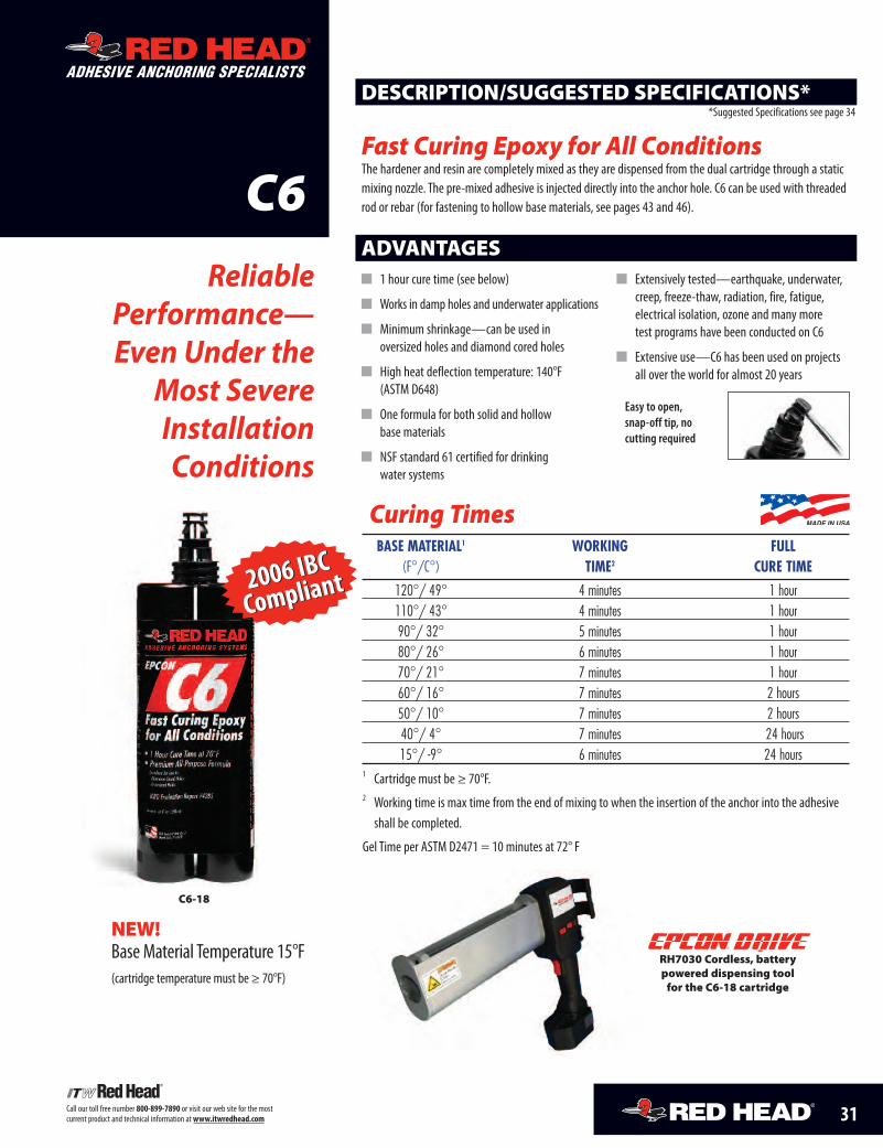
RH7030 Cordless, batterypowered dispensing toolfor the C6-18 cartridge
®
Curing Times
C6
ADHESIVE ANCHORING SPECIALISTS
ReliablePerformance—Even Under the
Most SevereInstallationConditions
ADVANTAGES
DESCRIPTION/SUGGESTED SPECIFICATIONS*
Fast Curing Epoxy for All ConditionsThe hardener and resin are completely mixed as they are dispensed from the dual cartridge through a staticmixing nozzle. The pre-mixed adhesive is injected directly into the anchor hole. C6 can be used with threadedrod or rebar (for fastening to hollow base materials, see pages 43 and 46).
*Suggested Specifications see page 34
� 1 hour cure time (see below)
� Works in damp holes and underwater applications
� Minimum shrinkage—can be used inoversized holes and diamond cored holes
� High heat deflection temperature: 140°F(ASTM D648)
� One formula for both solid and hollowbase materials
� NSF standard 61 certified for drinkingwater systems
� Extensively tested—earthquake, underwater,creep, freeze-thaw, radiation, fire, fatigue,electrical isolation, ozone and many moretest programs have been conducted on C6
� Extensive use—C6 has been used on projectsall over the world for almost 20 years
C6-18
BASE MATERIAL1 WORKING FULL(F°/C°) TIME2 CURE TIME
120°/ 49° 4 minutes 1 hour110°/ 43° 4 minutes 1 hour90°/ 32° 5 minutes 1 hour80°/ 26° 6 minutes 1 hour70°/ 21° 7 minutes 1 hour60°/ 16° 7 minutes 2 hours50°/ 10° 7 minutes 2 hours40°/ 4° 7 minutes 24 hours15°/ -9° 6 minutes 24 hours
1 Cartridge must be ≥ 70°F.2 Working time is max time from the end of mixing to when the insertion of the anchor into the adhesive
shall be completed.
Gel Time per ASTM D2471 = 10 minutes at 72° F
31Call our toll free number 800-899-7890 or visit our web site for the mostcurrent product and technical information atwww.itwredhead.com
Easy to open,snap-off tip, nocutting required
2006 IBCCompliant2006 IBCCompliant
NEW!Base Material Temperature 15°F(cartridge temperature must be ≥ 70°F)
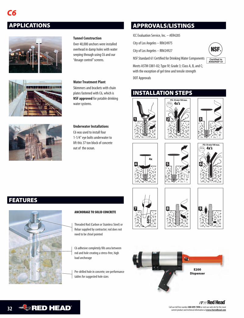
32 Call our toll free number 800-899-7890 or visit our web site for the mostcurrent product and technical information atwww.itwredhead.com
APPLICATIONS
Tunnel ConstructionOver 40,000 anchors were installedoverhead in damp holes with waterseeping through using C6 and our“dosage control” screens.
Water Treatment PlantSkimmers and brackets with chainplates fastened with C6, which isNSF approved for potable drinkingwater systems.
Underwater InstallationsC6 was used to install four1-1/4" eye bolts underwater tolift this 37 ton block of concreteout of the ocean.
APPROVALS/LISTINGS
ICC Evaluation Service, Inc. – #ER4285
City of Los Angeles – RR#24975
City of Los Angeles – RR#24927
NSF Standard 61 Certified for Drinking Water Components
Meets ASTM C881-02; Type IV; Grade 3; Class A, B, and C;with the exception of gel time and tensile strength
DOT Approvals
C6
FEATURES
ANCHORAGE TO SOLID CONCRETE
Threaded Rod (Carbon or Stainless Steel) orRebar supplied by contractor; rod does notneed to be chisel pointed
C6 adhesive completely fills area betweenrod and hole creating a stress-free, highload anchorage
Pre-drilled hole in concrete; see performancetables for suggested hole sizes
E200Dispenser
INSTALLATION STEPS
1
PSI: 50 min/100 max.
4x’s
2 3
4x
4 5
PSI: 50 min/100 max.
4x’s
6
60%
7 8 9
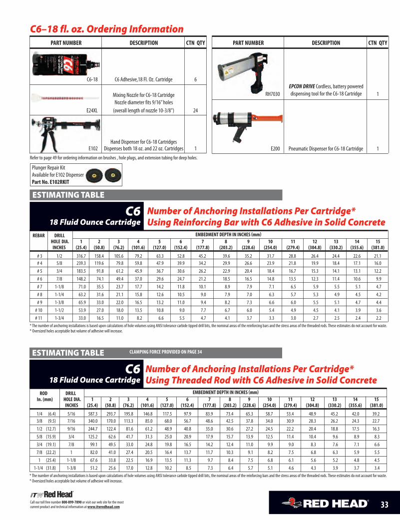
33Call our toll free number 800-899-7890 or visit our web site for the mostcurrent product and technical information atwww.itwredhead.com
C6–18 fl. oz. Ordering InformationPaRT NUmbER DESCRIPTIoN CTN QTy
C6-18 C6 Adhesive,18 Fl. Oz. Cartridge 6
E24XL (overall length of nozzle 10-3/8") 24
Hand Dispenser for C6-18 CartridgesE102 Dispenses both 18 oz. and 22 oz. Cartridges 1
Refer to page 49 for ordering information on brushes , hole plugs, and extension tubing for deep holes.
REbaR DRIll EmbEDmENT DEPTH IN INCHES (mm)HolE DIa. 1 2 3 4 5 6 7 8 9 10 11 12 13 14 15INCHES (25.4) (50.8) (76.2) (101.6) (127.0) (152.4) (177.8) (203.2) (228.6) (254.0) (279.4) (304.8) (330.2) (355.6) (381.0)
# 3 1/2 316.7 158.4 105.6 79.2 63.3 52.8 45.2 39.6 35.2 31.7 28.8 26.4 24.4 22.6 21.1# 4 5/8 239.3 119.6 79.8 59.8 47.9 39.9 34.2 29.9 26.6 23.9 21.8 19.9 18.4 17.1 16.0# 5 3/4 183.5 91.8 61.2 45.9 36.7 30.6 26.2 22.9 20.4 18.4 16.7 15.3 14.1 13.1 12.2# 6 7/8 148.2 74.1 49.4 37.0 29.6 24.7 21.2 18.5 16.5 14.8 13.5 12.3 11.4 10.6 9.9# 7 1-1/8 71.0 35.5 23.7 17.7 14.2 11.8 10.1 8.9 7.9 7.1 6.5 5.9 5.5 5.1 4.7# 8 1-1/4 63.2 31.6 21.1 15.8 12.6 10.5 9.0 7.9 7.0 6.3 5.7 5.3 4.9 4.5 4.2# 9 1-3/8 65.9 33.0 22.0 16.5 13.2 11.0 9.4 8.2 7.3 6.6 6.0 5.5 5.1 4.7 4.4
# 10 1-1/2 53.9 27.0 18.0 13.5 10.8 9.0 7.7 6.7 6.0 5.4 4.9 4.5 4.1 3.9 3.6# 11 1-3/4 33.0 16.5 11.0 8.2 6.6 5.5 4.7 4.1 3.7 3.3 3.0 2.7 2.5 2.4 2.2
* The number of anchoring installations is based upon calculations of hole volumes using ANSI tolerance carbide tipped drill bits, the nominal areas of the reinforcing bars and the stress areas of the threaded rods. These estimates do not account for waste.* Oversized holes acceptable but volume of adhesive will increase.
Number of Anchoring Installations Per Cartridge*Using Reinforcing Bar with C6 Adhesive in Solid Concrete
C618 Fluid Ounce Cartridge
ESTIMATINGTABLE
RoD DRIll EmbEDmENT DEPTH IN INCHES (mm)In. (mm) HolE DIa. 1 2 3 4 5 6 7 8 9 10 11 12 13 14 15
INCHES (25.4) (50.8) (76.2) (101.6) (127.0) (152.4) (177.8) (203.2) (228.6) (254.0) (279.4) (304.8) (330.2) (355.6) (381.0)
1/4 (6.4) 5/16 587.3 293.7 195.8 146.8 117.5 97.9 83.9 73.4 65.3 58.7 53.4 48.9 45.2 42.0 39.23/8 (9.5) 7/16 340.0 170.0 113.3 85.0 68.0 56.7 48.6 42.5 37.8 34.0 30.9 28.3 26.2 24.3 22.71/2 (12.7) 9/16 244.7 122.4 81.6 61.2 48.9 40.8 35.0 30.6 27.2 24.5 22.2 20.4 18.8 17.5 16.35/8 (15.9) 3/4 125.2 62.6 41.7 31.3 25.0 20.9 17.9 15.7 13.9 12.5 11.4 10.4 9.6 8.9 8.33/4 (19.1) 7/8 99.1 49.5 33.0 24.8 19.8 16.5 14.2 12.4 11.0 9.9 9.0 8.3 7.6 7.1 6.67/8 (22.2) 1 82.0 41.0 27.4 20.5 16.4 13.7 11.7 10.3 9.1 8.2 7.5 6.8 6.3 5.9 5.5
1 (25.4) 1-1/8 67.6 33.8 22.5 16.9 13.5 11.3 9.7 8.4 7.5 6.8 6.1 5.6 5.2 4.8 4.51-1/4 (31.8) 1-3/8 51.2 25.6 17.0 12.8 10.2 8.5 7.3 6.4 5.7 5.1 4.6 4.3 3.9 3.7 3.4
* The number of anchoring installations is based upon calculations of hole volumes using ANSI tolerance carbide tipped drill bits, the nominal areas of the reinforcing bars and the stress areas of the threaded rods. These estimates do not account for waste.* Oversized holes acceptable but volume of adhesive will increase.
Number of Anchoring Installations Per Cartridge*Using Threaded Rod with C6 Adhesive in Solid Concrete
C618 Fluid Ounce Cartridge
ESTIMATINGTABLE ClamPINg FoRCE PRovIDED oN PagE 34
Mixing Nozzle for C6-18 CartridgeNozzle diameter fits 9/16” holes
PaRT NUmbER DESCRIPTIoN CTN QTy
RH7030 1
E200 Pneumatic Dispenser for C6-18 Cartridge 1
EPCON DRIVE Cordless, battery powereddispensing tool for the C6-18 Cartridge
Plunger Repair KitAvailable for E102 DispenserPart No. E102RKIT

34 Call our toll free number 800-899-7890 or visit our web site for the mostcurrent product and technical information atwww.itwredhead.com
1. Disposable, self-contained cartridge system capable of dispensingboth epoxy components in the proper mixing ratio
2. Epoxy components dispensed through a static mixing nozzle thatthoroughly mixes the material, and places the epoxy at the baseof the pre-drilled hole
3. Cartridge markings: Include manufacturer’s name, batch numberand best-used-by date, mix ratio by volume, ANSI hazard classification,and appropriate ANSI handling precautions
PACKAGINGEPoXy aDHESIvE:1. Two component, 100% solid (containing no solvents), non-sag paste,
insensitive to moisture, grey in color2. Meets NSF Standard 61 for use in conjunction with drinking water systems3. Meets ASTM C881-02; Type IV; Grade 3; Class A, B, and C; with the exception of gel time
and tensile strength4. Shrinkage during cure per ASTM D2566: .00051 in./in. maximum5. Compressive strength, ASTM D695: 10,300 psi minimum6. Shelf life: Best if used within 2 years7. Water solubility: None8. Heat deflection temperature, ASTM D648: 140°F minimum
THREaDED maX. ClamPINg FoRCE EmbEDmENT 2000 PSI (13.8 mPa) 4000 PSI (27.6 mPa) 6000 PSI (41.4 mPa)RoD DIa. aFTER PRoPER CURE IN CoNCRETE CoNCRETE CoNCRETE CoNCRETEIn. (mm) Ft.-lbs. (Nm) In. (mm) UlTImaTE TENSIoN UlTImaTE SHEaR UlTImaTE TENSIoN UlTImaTE SHEaR UlTImaTE TENSIoN UlTImaTE SHEaR
lbs. (kN) lbs. (kN) lbs. (kN) lbs. (kN) lbs. (kN) lbs. (kN)3/8 (9.5) 13 - 18 (17.6-24.4) 3-3/8 (85.7) 7,195 (32.0) 5,209 (23.2) 8,445 (37.6) 5,869 (26.1) 10,621 (47.2) 5,941 (26.4)
4-1/2 (114.3) 8,317 (37.0) 5,209 (23.2) 10,021 (44.6) 5,869 (26.1) 10,603 (47.2) 5,941 (26.4)1/2 (12.7) 22 - 25 (29.8-33.9) 4-1/2 (114.3) 13,271 (59.0) 11,427 (50.8) 17,684 (78.7) 12,585 (56.0) 17,684 (78.7) 12,585 (56.0)
6 (152.4) 19,127 (85.1) 11,427 (50.8) 19,608 (87.2) 12,585 (56.0) 19,608 (87.2) 12,585 (56.0)5/8 (15.9) 55 - 80 (74.6-108.5) 5-5/8 (142.9) 17,704 (78.8) 18,294 (81.4) 24,526 (109.1) 19,802 (88.1) 24,526 (109.1) 19,802 (88.1)
7-1/2 (190.5) 22,642 (100.7) 18,294 (81.4) 28,766 (128.0) 19,802 (88.1) 29,456 (131.0) 19,802 (88.1)3/4 (19.1) 106-160 (143.7-216.9) 6-3/4 (171.5) 28,779 (128.0) 25,723 (114.4) 31,521 (140.2) 25,723 (114.4) 33,759 (150.2) 25,723 (114.4)
9 (228.6) 31,758 (141.3) 25,723 (114.4) 41,384 (184.0) 25,723 (114.4) 41,384 (184.0) 25,723 (114.4)7/8 (22.2) 185-250 (250.8-338.9) 7-7/8 (200.0) 35,257 (156.8) -- -- 37,714 (167.8) 30,295 (134.8) 41,023 (182.5) 32,573 (144.9)
10-1/2 (266.7) -- -- -- -- 51,211 (227.8) 30,295 (134.8) 51,211 (227.8) 32,573 (144.9)1 (25.4) 276-330 (374.2-447.4) 9 (228.6) 40,334 (179.4) 38,519 (171.3) 47,886 (213.0) 40,341 (179.5) 47,886 (213.0) 46,416 (206.5)
12 (304.8) 48,719 (216.7) 38,519 (171.3) 62,194 (276.7) 40,341 (179.5) 63,053 (280.5) 46,416 (206.5)1-1/4 (31.8) 370-660 (501.6-894.8) 11-1/4 (285.8) 55,654 (247.6) 65,085 (289.5) 56,981 (253.5) 65,085 (289.5) -- -- 65,085 (289.5)
15 (381.0) 65,728 (289.5) 65,085 (289.5) 79,726 (354.7) 65,085 (289.5) -- -- 65,085 (289.5)1 Allowable working loads for the single installations under static loading should not exceed 25% capacity or the allowable load of the anchor rod.2 Ultimate load values in 2000, 4000, and 6000 psi stone aggregate concrete. Ultimate loads are indicated for the embedment shown in the Embedment in Concrete column. Performance values are based on the use of high strength threaded rod
(ASTM A193 Gr. B7). The use of lower strength rods will result in lower ultimate tension and shear loads.3 Linear interpolation may be used for intermediate spacing and edge distances (see page 35).
Average Ultimate Tension and Shear Loads1,2,3 forThreaded Rod Installed in Solid Concrete
C6Epoxy Adhesive
PERFORMANCE TABLE DRIll HolE DIamETERSPRovIDED oN PagE 33
aNCHoR DIamETER DRIll HolE DIamETER EmbEDmENT IN CoNCRETE 3500 PSI (24.2 mPa)In. (mm) In. (mm) In. (mm) UlTImaTE TENSIoN lbs. (kN)
1/4 (6.4) 5/16 (7.9) 1 (25.4) 1,653 (7.4)
2-1/4 (57.2) 2,818 (12.5)3 (76.2) 3,599 (16.0)
3/8 (9.5) 7/16 (11.1) 1-1/2 (38.1) 3,426 (15.2)1/2 (12.7) 9/16 (14.3) 2 (50.8) 6,100 (27.1)5/8 (15.9) 3/4 (19.1) 2-1/2 (63.5) 8,775 (39.0)3/4 (19.1) 7/8 (22.2) 3 (76.2) 12,625 (56.2)7/8 (22.2) 1 (25.4) 3-1/2 (88.9) 18,650 (83.0)
1 (25.4) 1-1/8 (28.6) 4 (101.6) 25,034 (111.4)1-1/4 (31.8) 1-3/8 (34.9) 5 (127.0) 37,100 (165.0)
1 Allowable working loads for the single installations under static loading should not exceed 25% capacity or the allowable load of the anchor rod.2 Ultimate load values in 2000, 4000, and 6000 psi stone aggregate concrete. Ultimate loads are indicated for the embedment shown in the Embedment in Concrete column. Performance values are based on the use of high strength threaded rod
(ASTM A193 Gr. B7). The use of lower strength rods will result in lower ultimate tension and shear loads.3 Linear interpolation may be used for intermediate spacing and edge distances (see page 35).
Average Ultimate Tension Loads1,2,3 for Threaded RodInstalled in Solid Concrete, Shallow Embedment
C6Epoxy Adhesive
PERFORMANCE TABLE
SUGGESTED SPECIFICATIONS
35Call our toll free number 800-899-7890 or visit our web site for the mostcurrent product and technical information atwww.itwredhead.com
THREaDED EmbEDmENT alloWablE TENSIoN loaD baSED alloWablE TENSIoN loaD baSEDRoD DIa. DEPTH oN aDHESIvE boND STRENgTH oN STEEl STRENgTHIn. (mm) In. (mm) 2000 PSI (13.8 mPa) 4000 PSI (27.6 mPa) 6000 PSI (41.4 mPa) aSTm a307 aSTm a193 gR. b7 aSTm F593
CoNCRETE CoNCRETE IN CoNCRETE (SaE 1018) (SaE 4140) aISI 304 SSlbs. (kN) lbs. (kN) lbs. (kN) lbs. (kN) lbs. (kN) lbs. (kN)
3/8 (9.5) 3-3/8 (85.7) 1,800 (8.0) 2,110 (9.4) 2,655 (11.8) 2,080 (9.3) 4,340 (19.3) 3,995 (17.8)4-1/2 (114.3) 2,080 (9.2) 2,505 (11.1) 2,655 (11.8) 2,080 (9.3) 4,340 (19.3) 3,995 (17.8)
1/2 (12.7) 4-1/2 (114.3) 3,315 (14.8) 4,420 (19.7) 4,420 (19.7) 3,730 (16.6) 7,780 (34.6) 7,155 (31.8)6 (152.4) 4,780 (21.3) 4,900 (21.8) 4,900 (21.8) 3,730 (16.6) 7,780 (34.6) 7,155 (31.8)
5/8 (15.9) 5-5/8 (142.9) 4,425 (19.7) 6,130 (27.3) 6,130 (27.3) 5,870 (26.1) 12,230 (54.4) 11,250 (50.0)7-1/2 (190.5) 5,660 (25.2) 7,190 (32.0) 7,364 (32.8) 5,870 (26.1) 12,230 (54.4) 11,250 (50.0)
3/4 (19.1) 6-3/4 (171.5) 7,195 (32.0) 7,885 (35.1) 8,440 (37.5) 8,490 (37.8) 17,690 (78.7) 14,860 (66.1)9 (228.6) 7,940 (35.3) 10,345 (46.0) 10,345 (46.0) 8,490 (37.8) 17,690 (78.7) 14,860 (66.1)
7/8 (22.2) 7-7/8 (200.0) 8,810 (39.2) 9,430 (41.9) 10,260 (45.6) 11,600 (51.6) 25,510 (113.5) 20,835 (92.7)10-1/2 (266.7) -- -- 12,080 (57.0) 12,805 (57.0) 11,600 (51.6) 25,510 (113.5) 20,835 (92.7)
1 (25.4) 9 (228.6) 10,085 (44.9) 11,970 (53.3) 11,970 (53.0) 15,180 (67.5) 31,620 (140.7) 26,560 (118.1)12 (304.8) 12,180 (54.2) 15,545 (69.2) 15,760 (70.1) 15,180 (67.5) 31,620 (140.7) 26,560 (118.1)
1-1/4 (31.8) 11-1/4 (285.8) 13,915 (61.9) 14,245 (63.4) 14,245 (63.4) 23,800 (105.9) 49,580 (220.6) 34,670 (154.2)15 (381.0) 16,340 (72.7) 19,930 (88.7) 19,930 (88.7) 23,800 (105.9) 49,580 (220.6) 34,670 (154.2)
1 Use lower value of either bond or steel strength for allowable tensile load.2 Allowable loads taken from ICC Evaluation Report #4285 (formerly ICBO).3 Linear interpolation may be used for intermediate spacing and edge distances (see below).
Allowable Tension Loads1,2,3 for Threaded Rod Installedin Solid Concrete
C6Epoxy Adhesive
PERFORMANCE TABLE DRIll HolE DIamETERSPRovIDED oN PagE 33
C6 adhesive Edge/Spacing Distance load Factor Summaryfor Installation of Threaded Rod and Reinforcing bar 1, 2
loaD FaCToR DISTaNCE FRom EDgE oF CoNCRETECritical Edge Distance—Tension
100% Tension Load 1.25 x Anchor Embedment (or greater)Minimum Edge Distance—Tension
70% Tension Load 0.50 x Anchor EmbedmentCritical Edge Distance—Shear
100% Shear Load 1.25 x Anchor Embedment (or greater)Minimum Edge Distance—Shear
30% Shear Load 0.30 x Anchor Embedment
loaD FaCToR DISTaNCE FRom aNoTHER aNCHoRCritical Spacing—Tension
100% Tension Load 1.50 x Anchor Embedment (or greater)Minimum Spacing—Tension
75% Tension Load 0.75 x Anchor EmbedmentCritical Spacing—Shear
100% Shear Load 1.50 x Anchor Embedment (or greater)Minimum Spacing—Shear
30% Shear Load 0.50 x Anchor Embedment
1 Use linear interpolation for load factors at edge distances or spacing distances between critical and minimum.
2 Anchors are affected by multiple combination of spacing and/or edge distance loading and direction of the loading. Use the product of tension and shear loading factors in design.
THREaDED DRIll HolE EmbEDmENT aNCHoR UlTImaTE UlTImaTERoD DIa. DIamETER DEPTH loCaTIoN TENSIoN SHEaRIn. (mm) In. (mm) In. (mm) lbs. (kN) lbs. (kN)
3/8 (9.5) 7/16 (11.1) 3 (76.2) GROUTED CELL 4,862 (21.6) -- --1/2 (12.7) 5/8 (15.9) 3 (76.2) GROUTED CELL 4,953 (22.0) -- --1/2 (12.7) 5/8 (15.9) 6 (152.4) GROUTED CELL 8,214 (36.5) -- --5/8 (15.9) 3/4 (19.1) 5 (127.0) GROUTED CELL 7,355 (32.7) -- --3/4 (19.1) 7/8 (22.2) 6 (152.4) Note 1 17,404 (77.4) 19,588 (87.1)3/4 (19.1) 7/8 (22.2) 6 (152.4) Note 2 17,404 (77.4) 8,668 (38.6)
1 Anchor can be located in grouted cell, “T” joint, or bed joint.2 Anchor can be located in first grouted cell from edge.3 Allowable working loads for the single installations under static loading should not exceed 25% (an industry standard) capacity or the allowable load of the anchor rod. Loads based upon testing with ASTM A193, Grade B7 rods.
Average Ultimate Tension and Shear Loads1,2,3 forThreaded Rod Installed in Grout Filled Concrete Block
C6Epoxy Adhesive
PERFORMANCE TABLE
36 Call our toll free number 800-899-7890 or visit our web site for the mostcurrent product and technical information atwww.itwredhead.com
THREaDED mINImUm alloWablE SHEaR loaD baSED alloWablE SHEaR loaD baSEDRoD DIa. EmbEDmENT oN CoNCRETE STRENgTH oN STEEl STRENgTHIn. (mm) DEPTH 2000 PSI (13.8 mPa) 4000 PSI (27.6 mPa) 6000 PSI (41.4 mPa) aSTm a307 aSTm a193 gR. b7 aSTm F593
In. (mm) CoNCRETE CoNCRETE CoNCRETE (SaE 1018) (SaE 4140) aISI 304 SSlbs. (kN) lbs. (kN) lbs. (kN) lbs. (kN) lbs. (kN) lbs. (kN)
3/8 (9.5) 3-3/8 (85.7) 1,300 (5.8) 1,465 (6.5) 1,500 (6.7) 1,040 (4.6) 2,170 (9.7) 1,995 (8.9)
1/2 (12.7) 4-1/2 (114.3) 2,855 (12.7) 3,145 (14.0) 3,145 (14.0) 1,870 (8.3) 3,895 (17.3) 3,585 (15.9)
5/8 (15.9) 5-5/8 (142.9) 4,575 (20.3) 4,950 (22.0) 4,950 (22.0) 2,940 (13.1) 6,125 (27.2) 5,635 (25.1)
3/4 (19.1) 6-3/4 (171.5) 6,430 (28.6) 6,430 (28.6) 6,430 (28.6) 4,250 (18.9) 8,855 (39.4) 7,440 (33.1)
7/8 (22.2) 7-7/8 (200.0) -- -- 7,575 (33.7) 8,140 (36.2) 5,800 (25.8) 12,760 (56.8) 10,730 (47.7)
1 (25.4) 9 (228.6) 9,630 (42.8) 10,085 (44.9) 11,600 (51.6) 7,590 (33.8) 15,810 (70.3) 13,285 (59.1)
1-1/4 (31.8) 11-1/4 (285.8) 16,270 (72.4) 16,270 (72.4) 16,270 (72.4) 11,900 (52.9) 24,790 (110.3) 18,840 (83.8)
1 Use lower value of either concrete or steel strength for allowable shear load.2 Allowable loads taken from ICC Evaluation Report #4285 (formerly ICBO).3 Linear interpolation may be used for intermediate spacing and edge distances (see page 35).
Allowable Shear Loads1,2,3 for Threaded Rod Installedin Solid Concrete
C6Epoxy Adhesive
PERFORMANCE TABLE DRIll HolE DIamETERSPRovIDED oN PagE 33
REINFoRCINg EmbEDmENT 2000 PSI (13.8 mPa) 4000 PSI (27.6 mPa) UlTImaTE TENSIlE aND yIElD STRENgTHbaR IN CoNCRETE CoNCRETE CoNCRETE gRaDE 60 REbaR
In. (mm) In. (mm) UlTImaTE TENSIoN UlTImaTE TENSIoN mINImUm yIElD mINImUm UlTImaTElbs. (kN) lbs. kN) STRENgTH TENSIlE STRENgTH
lbs. (kN) lbs. (kN)
# 3 (9.5) 3-3/8 (85.7) 7,020 (31.2) 9,200 (40.9) 6,600 (29.4) 9,900 (44.0)4-1/2 (114.3) 9,000 (40.1) 11,540 (51.3) 6,600 (29.4) 9,900 (44.0)
# 4 (12.7) 4-1/2 (114.3) 11,940 (53.1) 15,140 (67.3) 12,000 (53.4) 18,000 (80.1)6 (152.4) 16,703 (74.3) 18,880 (84.0) 12,000 (53.4) 18,000 (80.1)
# 5 (15.9) 5-5/8 (142.9) 14,120 (62.8) 27,740 (123.4) 18,600 (82.7) 27,900 (124.1)7-1/2 (190.5) 20,040 (89.1) 30,727 (136.7) 18,600 (82.7) 27,900 (124.1)
# 6 (19.1) 6-3/4 (171.5) 17,940 (79.8) 29,200 (129.9) 26,400 (117.4) 39,600 (176.2)9 (228.6) 25,520 (113.5) 41,640 (185.2) 26,400 (117.4) 39,600 (176.2)
10 (254.0) -- -- 45,000 (200.2) 26,400 (117.4) 39,600 (176.2)# 7 (22.2) 7-7/8 (200.0) -- -- 45,850 (204.0) 36,000 (160.1) 54,000 (240.2)
10-1/2 (266.7) -- -- 60,375 (268.6) 36,000 (160.1) 54,000 (240.2)13 (330.2) -- -- 65,300 (290.5) 36,000 (160.1) 54,000 (240.2)
# 8 (25.4) 9 (228.6) 30,960 (137.7) 54,180 (241.1) 47,400 (210.9) 71,100 (316.3)12 (304.8) 30,960 (137.7) 65,420 (291.0) 47,400 (210.9) 71,100 (316.3)16 (406.4) -- -- 86,700 (385.7) 47,400 (210.9) 71,100 (316.3)
# 9 (28.6) 10-1/8 (257.2) -- -- 61,530 (273.7) 60,000 (266.9) 90,000 (400.4)13-1/2 (342.9) -- -- 81,240 (361.4) 60,000 (266.9) 90,000 (400.4)
19 (482.6) -- -- 108,000 (480.4) 60,000 (266.9) 90,000 (400.4)# 10 (31.8) 11-1/4 (285.8) 44,600 (198.4) 76,500 (340.3) 76,200 (339.0) 114,300 (508.5)
15 (381.0) 49,220 (218.9) 82,320 (366.2) 76,200 (339.0) 114,300 (508.5)19 (482.6) -- -- 120,000 (533.8) 76,200 (339.0) 114,300 (508.5)
1 Allowable working loads for the single installations under static loading should not exceed 25% ultimate capacity or the allowable load of the anchor rod.2 Ultimate load values in 2000 and 4000 psi stone aggregate concrete. Ultimate loads are indicated for the embedment shown in the Embedment in Concrete column. Performance values are based on minimum Grade 60 reinforcing bar.
The use of lower strength rods will result in lower ultimate tension and shear loads.3 SHEAR DATA: Provided the distance from the rebar to the edge of the concrete member exceeds 1.25 times the embedment depth of the rebar, calculate the ultimate shear load for the rebar anchorage as 60% of the ultimate tensile strength of the rebar.
Average Ultimate Tension Loads1,2,3 for Reinforcing BarInstalled in Solid Concrete
C6Epoxy Adhesive
PERFORMANCE TABLE DRIll HolE DIamETERSPRovIDED oN PagE 33
Combined Tension and Shear loading—for adhesive anchorsallowable loads for anchors under tension and shear loading at the same time (combined loading) will be lower than the allowable loads for anchors
subjected to 100% tension or 100% shear. Use the following equation to evaluate anchors in combined loading conditions:
Na 5/3 + Va 5/3
≤ 1Na = applied Service Tension load Va = applied Service Shear load
Ns Vs Ns = allowable Tension load Vs = allowable Shear load( () )
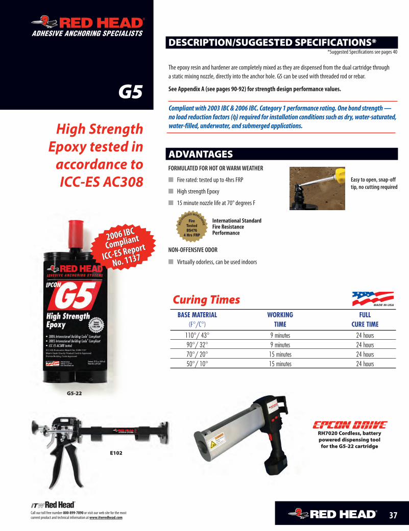
Call our toll free number 800-899-7890 or visit our web site for the mostcurrent product and technical information at www.itwredhead.com
G5
High StrengthEpoxy tested in
accordance toICC-ES AC308
ADVANTAGES
DESCRIPTION/SUGGESTED SPECIFICATIONS*
The epoxy resin and hardener are completely mixed as they are dispensed from the dual cartridge througha static mixing nozzle, directly into the anchor hole. G5 can be used with threaded rod or rebar.
See Appendix A (see pages 90-92) for strength design performance values.
*Suggested Specifications see pages 40
FORMULATED FOR HOT ORWARMWEATHER
� Fire rated: tested up to 4hrs FRP
� High strength Epoxy
� 15 minute nozzle life at 70° degrees F
NON-OFFENSIVE ODOR
� Virtually odorless, can be used indoors
Curing Times
ADHESIVE ANCHORING SPECIALISTS
Easy to open, snap-offtip, no cutting required
G5-22
E102
BASE MATERIAL WORKING FULL(F°/C°) TIME CURE TIME
110°/ 43° 9 minutes 24 hours90°/ 32° 9 minutes 24 hours70°/ 20° 15 minutes 24 hours50°/ 10° 15 minutes 24 hours
REC
OGNIZED WORLDWID
EFireTestedBS476
4 Hrs FRP
International StandardFire ResistancePerformance
Compliantwith 2003 IBC & 2006 IBC. Category 1 performance rating. One bond strength—no load reduction factors (φφ) required for installation conditions such as dry, water-saturated,water-filled, underwater, and submerged applications.
RH7020 Cordless, battery powered dispensing tool for the G5-22 cartridge
®
®
37
2006 IBC
Compliant
ICC-ES Report
No. 1137
2006 IBC
Compliant
ICC-ES Report
No. 1137
37-42_G5.qxd:37-42 4/24/10 7:31 AM Page 1
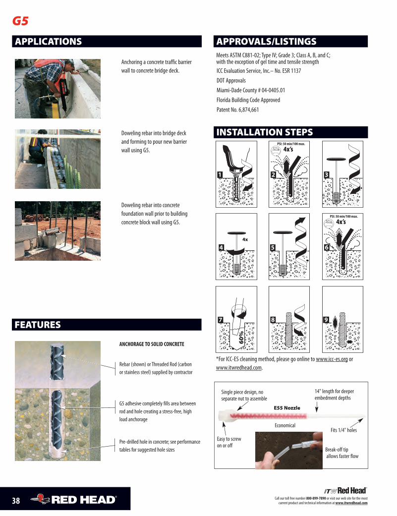
38 Call our toll free number 800-899-7890 or visit our web site for the most current product and technical information at www.itwredhead.com
APPLICATIONS
Anchoring a concrete traffic barrierwall to concrete bridge deck.
Doweling rebar into bridge deckand forming to pour new barrierwall using G5.
Doweling rebar into concrete foundation wall prior to building concrete block wall using G5.
APPROVALS/LISTINGSMeets ASTM C881-02; Type IV; Grade 3; Class A, B, and C; with the exception of gel time and tensile strengthICC Evaluation Service, Inc.– No. ESR 1137DOT Approvals Miami-Dade County # 04-0405.01Florida Building Code ApprovedPatent No. 6,874,661
G5
FEATURES
ANCHORAGE TO SOLID CONCRETE
Rebar (shown) or Threaded Rod (carbon or stainless steel) supplied by contractor
G5 adhesive completely fills area betweenrod and hole creating a stress-free, high load anchorage
Pre-drilled hole in concrete; see performancetables for suggested hole sizes
Economical
Break-off tipallows faster flow
Easy to screwon or off
Single piece design, no separate nut to assemble
14" length for deeperembedment depths
Fits 1/4" holes
E55 Nozzle
INSTALLATION STEPS
1
PSI: 50 min/100 max.
4x’s
2 3
4x
4 5
PSI: 50 min/100 max.
4x’s
660
%
7 8 9
*For ICC-ES cleaning method, please go online to www.icc-es.org orwww.itwredhead.com.
37-42_G5.qxd:37-42 4/24/10 7:31 AM Page 2
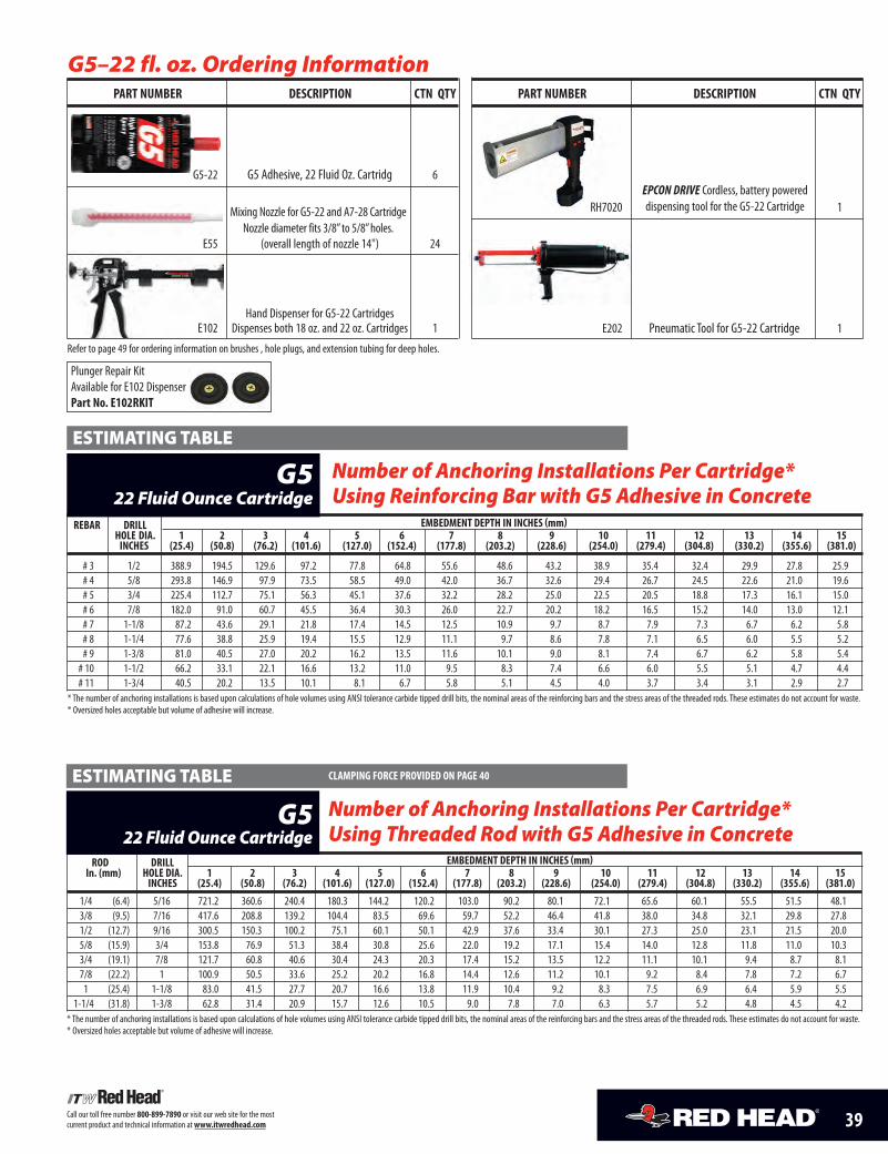
39Call our toll free number 800-899-7890 or visit our web site for the most current product and technical information at www.itwredhead.com
REbAR DRILL EmbEDmENT DEPTH IN INCHES (mm)HOLE DIA. 1 2 3 4 5 6 7 8 9 10 11 12 13 14 15
INCHES (25.4) (50.8) (76.2) (101.6) (127.0) (152.4) (177.8) (203.2) (228.6) (254.0) (279.4) (304.8) (330.2) (355.6) (381.0)
# 3 1/2 388.9 194.5 129.6 97.2 77.8 64.8 55.6 48.6 43.2 38.9 35.4 32.4 29.9 27.8 25.9# 4 5/8 293.8 146.9 97.9 73.5 58.5 49.0 42.0 36.7 32.6 29.4 26.7 24.5 22.6 21.0 19.6# 5 3/4 225.4 112.7 75.1 56.3 45.1 37.6 32.2 28.2 25.0 22.5 20.5 18.8 17.3 16.1 15.0# 6 7/8 182.0 91.0 60.7 45.5 36.4 30.3 26.0 22.7 20.2 18.2 16.5 15.2 14.0 13.0 12.1# 7 1-1/8 87.2 43.6 29.1 21.8 17.4 14.5 12.5 10.9 9.7 8.7 7.9 7.3 6.7 6.2 5.8# 8 1-1/4 77.6 38.8 25.9 19.4 15.5 12.9 11.1 9.7 8.6 7.8 7.1 6.5 6.0 5.5 5.2# 9 1-3/8 81.0 40.5 27.0 20.2 16.2 13.5 11.6 10.1 9.0 8.1 7.4 6.7 6.2 5.8 5.4# 10 1-1/2 66.2 33.1 22.1 16.6 13.2 11.0 9.5 8.3 7.4 6.6 6.0 5.5 5.1 4.7 4.4# 11 1-3/4 40.5 20.2 13.5 10.1 8.1 6.7 5.8 5.1 4.5 4.0 3.7 3.4 3.1 2.9 2.7
* The number of anchoring installations is based upon calculations of hole volumes using ANSI tolerance carbide tipped drill bits, the nominal areas of the reinforcing bars and the stress areas of the threaded rods. These estimates do not account for waste.* Oversized holes acceptable but volume of adhesive will increase.
Number of Anchoring Installations Per Cartridge*Using Reinforcing Bar with G5 Adhesive in Concrete
G522 Fluid Ounce Cartridge
ESTIMATING TABLE
ROD DRILL EmbEDmENT DEPTH IN INCHES (mm)In. (mm) HOLE DIA. 1 2 3 4 5 6 7 8 9 10 11 12 13 14 15
INCHES (25.4) (50.8) (76.2) (101.6) (127.0) (152.4) (177.8) (203.2) (228.6) (254.0) (279.4) (304.8) (330.2) (355.6) (381.0)
1/4 (6.4) 5/16 721.2 360.6 240.4 180.3 144.2 120.2 103.0 90.2 80.1 72.1 65.6 60.1 55.5 51.5 48.13/8 (9.5) 7/16 417.6 208.8 139.2 104.4 83.5 69.6 59.7 52.2 46.4 41.8 38.0 34.8 32.1 29.8 27.81/2 (12.7) 9/16 300.5 150.3 100.2 75.1 60.1 50.1 42.9 37.6 33.4 30.1 27.3 25.0 23.1 21.5 20.05/8 (15.9) 3/4 153.8 76.9 51.3 38.4 30.8 25.6 22.0 19.2 17.1 15.4 14.0 12.8 11.8 11.0 10.33/4 (19.1) 7/8 121.7 60.8 40.6 30.4 24.3 20.3 17.4 15.2 13.5 12.2 11.1 10.1 9.4 8.7 8.17/8 (22.2) 1 100.9 50.5 33.6 25.2 20.2 16.8 14.4 12.6 11.2 10.1 9.2 8.4 7.8 7.2 6.71 (25.4) 1-1/8 83.0 41.5 27.7 20.7 16.6 13.8 11.9 10.4 9.2 8.3 7.5 6.9 6.4 5.9 5.5
1-1/4 (31.8) 1-3/8 62.8 31.4 20.9 15.7 12.6 10.5 9.0 7.8 7.0 6.3 5.7 5.2 4.8 4.5 4.2* The number of anchoring installations is based upon calculations of hole volumes using ANSI tolerance carbide tipped drill bits, the nominal areas of the reinforcing bars and the stress areas of the threaded rods. These estimates do not account for waste.* Oversized holes acceptable but volume of adhesive will increase.
Number of Anchoring Installations Per Cartridge* Using Threaded Rod with G5 Adhesive in Concrete
G522 Fluid Ounce Cartridge
ESTIMATING TABLE CLAmPING FORCE PROvIDED ON PAGE 40
G5–22 fl. oz. Ordering InformationPART NumbER DESCRIPTION CTN QTy
G5-22 G5 Adhesive, 22 Fluid Oz. Cartridg 6
E55 (overall length of nozzle 14") 24
Hand Dispenser for G5-22 Cartridges E102 Dispenses both 18 oz. and 22 oz. Cartridges 1
Refer to page 49 for ordering information on brushes , hole plugs, and extension tubing for deep holes.
Mixing Nozzle for G5-22 and A7-28 CartridgeNozzle diameter fits 3/8” to 5/8” holes.
PART NumbER DESCRIPTION CTN QTy
RH7020 1
E202 Pneumatic Tool for G5-22 Cartridge 1
EPCON DRIVE Cordless, battery powered dispensing tool for the G5-22 Cartridge
Plunger Repair Kit Available for E102 DispenserPart No. E102RKIT
37-42_G5.qxd:37-42 4/24/10 7:31 AM Page 3
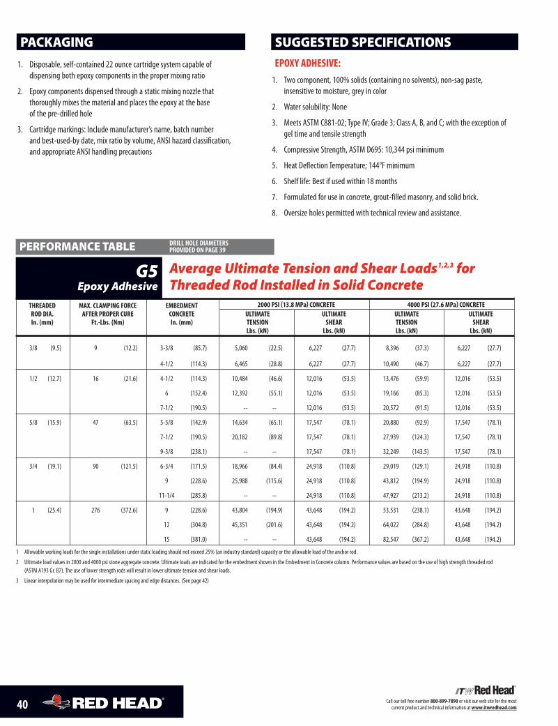
40 Call our toll free number 800-899-7890 or visit our web site for the most current product and technical information at www.itwredhead.com
EPOXy ADHESIvE:1. Two component, 100% solids (containing no solvents), non-sag paste,
insensitive to moisture, grey in color
2. Water solubility: None
3. Meets ASTM C881-02; Type IV; Grade 3; Class A, B, and C; with the exception ofgel time and tensile strength
4. Compressive Strength, ASTM D695: 10,344 psi minimum
5. Heat Deflection Temperature; 144°F minimum
6. Shelf life: Best if used within 18 months
7. Formulated for use in concrete, grout-filled masonry, and solid brick.
8. Oversize holes permitted with technical review and assistance.
1. Disposable, self-contained 22 ounce cartridge system capable of dispensing both epoxy components in the proper mixing ratio
2. Epoxy components dispensed through a static mixing nozzle that thoroughly mixes the material and places the epoxy at the base of the pre-drilled hole
3. Cartridge markings: Include manufacturer’s name, batch number and best-used-by date, mix ratio by volume, ANSI hazard classification, and appropriate ANSI handling precautions
PACKAGING
THREADED mAX. CLAmPING FORCE EmBEDmENT 2000 PSI (13.8 mPa) CONCRETE 4000 PSI (27.6 mPa) CONCRETEROD DIA. AFTER PROPER CuRE CONCRETE uLTImATE uLTImATE uLTImATE uLTImATEIn. (mm) Ft.-Lbs. (Nm) In. (mm) TENSION SHEAR TENSION SHEAR
Lbs. (kN) Lbs. (kN) Lbs. (kN) Lbs. (kN)
3/8 (9.5) 9 (12.2) 3-3/8 (85.7) 5,060 (22.5) 6,227 (27.7) 8,396 (37.3) 6,227 (27.7)
4-1/2 (114.3) 6,465 (28.8) 6,227 (27.7) 10,490 (46.7) 6,227 (27.7)
1/2 (12.7) 16 (21.6) 4-1/2 (114.3) 10,484 (46.6) 12,016 (53.5) 13,476 (59.9) 12,016 (53.5)
6 (152.4) 12,392 (55.1) 12,016 (53.5) 19,166 (85.3) 12,016 (53.5)
7-1/2 (190.5) -- -- 12,016 (53.5) 20,572 (91.5) 12,016 (53.5)
5/8 (15.9) 47 (63.5) 5-5/8 (142.9) 14,634 (65.1) 17,547 (78.1) 20,880 (92.9) 17,547 (78.1)
7-1/2 (190.5) 20,182 (89.8) 17,547 (78.1) 27,939 (124.3) 17,547 (78.1)
9-3/8 (238.1) -- -- 17,547 (78.1) 32,249 (143.5) 17,547 (78.1)
3/4 (19.1) 90 (121.5) 6-3/4 (171.5) 18,966 (84.4) 24,918 (110.8) 29,019 (129.1) 24,918 (110.8)
9 (228.6) 25,988 (115.6) 24,918 (110.8) 43,812 (194.9) 24,918 (110.8)
11-1/4 (285.8) -- -- 24,918 (110.8) 47,927 (213.2) 24,918 (110.8)
1 (25.4) 276 (372.6) 9 (228.6) 43,804 (194.9) 43,648 (194.2) 53,531 (238.1) 43,648 (194.2)
12 (304.8) 45,351 (201.6) 43,648 (194.2) 64,022 (284.8) 43,648 (194.2)
15 (381.0) -- -- 43,648 (194.2) 82,547 (367.2) 43,648 (194.2)
1 Allowable working loads for the single installations under static loading should not exceed 25% (an industry standard) capacity or the allowable load of the anchor rod.
2 Ultimate load values in 2000 and 4000 psi stone aggregate concrete. Ultimate loads are indicated for the embedment shown in the Embedment in Concrete column. Performance values are based on the use of high strength threaded rod (ASTM A193 Gr. B7). The use of lower strength rods will result in lower ultimate tension and shear loads.
3 Linear interpolation may be used for intermediate spacing and edge distances. (See page 42)
Average Ultimate Tension and Shear Loads1,2,3 forThreaded Rod Installed in Solid Concrete
G5Epoxy Adhesive
PERFORMANCE TABLE DRILL HOLE DIAmETERS PROvIDED ON PAGE 39
SUGGESTED SPECIFICATIONS
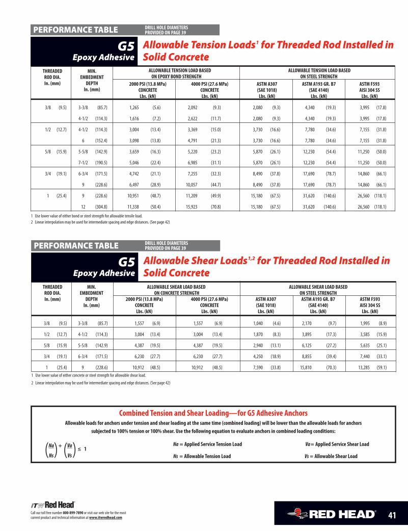
41Call our toll free number 800-899-7890 or visit our web site for the most current product and technical information at www.itwredhead.com
THREADED mIN. ALLOWABLE SHEAR LOAD BASED ALLOWABLE SHEAR LOAD BASEDROD DIA. EmBEDmENT ON CONCRETE STRENGTH ON STEEL STRENGTHIn. (mm) DEPTH 2000 PSI (13.8 mPa) 4000 PSI (27.6 mPa) ASTm A307 ASTm A193 GR. B7 ASTm F593
In. (mm) CONCRETE CONCRETE (SAE 1018) (SAE 4140) AISI 304 SSLbs. (kN) Lbs. (kN) Lbs. (kN) Lbs. (kN) Lbs. (kN)
3/8 (9.5) 3-3/8 (85.7) 1,557 (6.9) 1,557 (6.9) 1,040 (4.6) 2,170 (9.7) 1,995 (8.9)
1/2 (12.7) 4-1/2 (114.3) 3,004 (13.4) 3,004 (13.4) 1,870 (8.3) 3,895 (17.3) 3,585 (15.9)
5/8 (15.9) 5-5/8 (142.9) 4,387 (19.5) 4,387 (19.5) 2,940 (13.1) 6,125 (27.2) 5,635 (25.1)
3/4 (19.1) 6-3/4 (171.5) 6,230 (27.7) 6,230 (27.7) 4,250 (18.9) 8,855 (39.4) 7,440 (33.1)
1 (25.4) 9 (228.6) 10,912 (48.5) 10,912 (48.5) 7,590 (33.8) 15,810 (70.3) 13,285 (59.1)1 Use lower value of either concrete or steel strength for allowable shear load.
2 Linear interpolation may be used for intermediate spacing and edge distances. (See page 42)
Allowable Shear Loads1,2 for Threaded Rod Installed inSolid Concrete
G5Epoxy Adhesive
PERFORMANCE TABLE
Combined Tension and Shear Loading—for G5 Adhesive AnchorsAllowable loads for anchors under tension and shear loading at the same time (combined loading) will be lower than the allowable loads for anchors
subjected to 100% tension or 100% shear. use the following equation to evaluate anchors in combined loading conditions:
Na + Va ≤ 1Na = Applied Service Tension Load Va= Applied Service Shear Load
Ns Vs Ns = Allowable Tension Load Vs = Allowable Shear Load( () )
THREADED mIN. ALLOWABLE TENSION LOAD BASED ALLOWABLE TENSION LOAD BASEDROD DIA. EmBEDmENT ON EPOXy BOND STRENGTH ON STEEL STRENGTHIn. (mm) DEPTH 2000 PSI (13.8 mPa) 4000 PSI (27.6 mPa) ASTm A307 ASTm A193 GR. B7 ASTm F593
In. (mm) CONCRETE CONCRETE (SAE 1018) (SAE 4140) AISI 304 SSLbs. (kN) Lbs. (kN) Lbs. (kN) Lbs. (kN) Lbs. (kN)
3/8 (9.5) 3-3/8 (85.7) 1,265 (5.6) 2,092 (9.3) 2,080 (9.3) 4,340 (19.3) 3,995 (17.8)
4-1/2 (114.3) 1,616 (7.2) 2,622 (11.7) 2,080 (9.3) 4,340 (19.3) 3,995 (17.8)
1/2 (12.7) 4-1/2 (114.3) 3,004 (13.4) 3,369 (15.0) 3,730 (16.6) 7,780 (34.6) 7,155 (31.8)
6 (152.4) 3,098 (13.8) 4,791 (21.3) 3,730 (16.6) 7,780 (34.6) 7,155 (31.8)
5/8 (15.9) 5-5/8 (142.9) 3,659 (16.3) 5,220 (23.2) 5,870 (26.1) 12,230 (54.4) 11,250 (50.0)
7-1/2 (190.5) 5,046 (22.4) 6,985 (31.1) 5,870 (26.1) 12,230 (54.4) 11,250 (50.0)
3/4 (19.1) 6-3/4 (171.5) 4,742 (21.1) 7,255 (32.3) 8,490 (37.8) 17,690 (78.7) 14,860 (66.1)
9 (228.6) 6,497 (28.9) 10,057 (44.7) 8,490 (37.8) 17,690 (78.7) 14,860 (66.1)
1 (25.4) 9 (228.6) 10,951 (48.7) 11,209 (49.9) 15,180 (67.5) 31,620 (140.6) 26,560 (118.1)
12 (304.8) 11,338 (50.4) 15,923 (70.8) 15,180 (67.5) 31,620 (140.6) 26,560 (118.1)
1 Use lower value of either bond or steel strength for allowable tensile load. 2 Linear interpolation may be used for intermediate spacing and edge distances. (See page 42)
Allowable Tension Loads1 for Threaded Rod Installed inSolid Concrete
G5Epoxy Adhesive
PERFORMANCE TABLE DRILL HOLE DIAmETERS PROvIDED ON PAGE 39
DRILL HOLE DIAmETERS PROvIDED ON PAGE 39
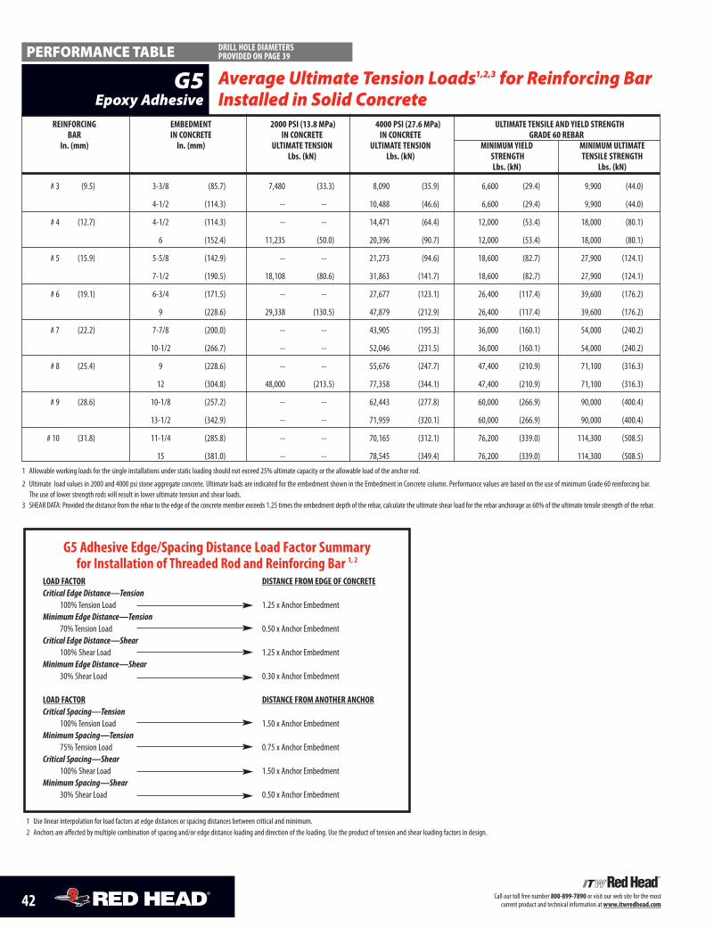
42 Call our toll free number 800-899-7890 or visit our web site for the most current product and technical information at www.itwredhead.com
REINFORCING EmbEDmENT 2000 PSI (13.8 mPa) 4000 PSI (27.6 mPa) uLTImATE TENSILE AND yIELD STRENGTHbAR IN CONCRETE IN CONCRETE IN CONCRETE GRADE 60 REbAR
In. (mm) In. (mm) uLTImATE TENSION uLTImATE TENSION mINImum yIELD mINImum uLTImATELbs. (kN) Lbs. (kN) STRENGTH TENSILE STRENGTH
Lbs. (kN) Lbs. (kN)
# 3 (9.5) 3-3/8 (85.7) 7,480 (33.3) 8,090 (35.9) 6,600 (29.4) 9,900 (44.0)
4-1/2 (114.3) -- -- 10,488 (46.6) 6,600 (29.4) 9,900 (44.0)
# 4 (12.7) 4-1/2 (114.3) -- -- 14,471 (64.4) 12,000 (53.4) 18,000 (80.1)
6 (152.4) 11,235 (50.0) 20,396 (90.7) 12,000 (53.4) 18,000 (80.1)
# 5 (15.9) 5-5/8 (142.9) -- -- 21,273 (94.6) 18,600 (82.7) 27,900 (124.1)
7-1/2 (190.5) 18,108 (80.6) 31,863 (141.7) 18,600 (82.7) 27,900 (124.1)
# 6 (19.1) 6-3/4 (171.5) -- -- 27,677 (123.1) 26,400 (117.4) 39,600 (176.2)
9 (228.6) 29,338 (130.5) 47,879 (212.9) 26,400 (117.4) 39,600 (176.2)
# 7 (22.2) 7-7/8 (200.0) -- -- 43,905 (195.3) 36,000 (160.1) 54,000 (240.2)
10-1/2 (266.7) -- -- 52,046 (231.5) 36,000 (160.1) 54,000 (240.2)
# 8 (25.4) 9 (228.6) -- -- 55,676 (247.7) 47,400 (210.9) 71,100 (316.3)
12 (304.8) 48,000 (213.5) 77,358 (344.1) 47,400 (210.9) 71,100 (316.3)
# 9 (28.6) 10-1/8 (257.2) -- -- 62,443 (277.8) 60,000 (266.9) 90,000 (400.4)
13-1/2 (342.9) -- -- 71,959 (320.1) 60,000 (266.9) 90,000 (400.4)
# 10 (31.8) 11-1/4 (285.8) -- -- 70,165 (312.1) 76,200 (339.0) 114,300 (508.5)
15 (381.0) -- -- 78,545 (349.4) 76,200 (339.0) 114,300 (508.5)
1 Allowable working loads for the single installations under static loading should not exceed 25% ultimate capacity or the allowable load of the anchor rod.
2 Ultimate load values in 2000 and 4000 psi stone aggregate concrete. Ultimate loads are indicated for the embedment shown in the Embedment in Concrete column. Performance values are based on the use of minimum Grade 60 reinforcing bar. The use of lower strength rods will result in lower ultimate tension and shear loads.
3 SHEAR DATA: Provided the distance from the rebar to the edge of the concrete member exceeds 1.25 times the embedment depth of the rebar, calculate the ultimate shear load for the rebar anchorage as 60% of the ultimate tensile strength of the rebar.
Average Ultimate Tension Loads1,2,3 for Reinforcing BarInstalled in Solid Concrete
G5Epoxy Adhesive
PERFORMANCE TABLE DRILL HOLE DIAmETERS PROvIDED ON PAGE 39
G5 Adhesive Edge/Spacing Distance Load Factor Summaryfor Installation of Threaded Rod and Reinforcing bar 1, 2
LOAD FACTOR DISTANCE FROm EDGE OF CONCRETECritical Edge Distance—Tension
100% Tension Load 1.25 x Anchor Embedment Minimum Edge Distance—Tension
70% Tension Load 0.50 x Anchor Embedment Critical Edge Distance—Shear
100% Shear Load 1.25 x Anchor Embedment Minimum Edge Distance—Shear
30% Shear Load 0.30 x Anchor Embedment
LOAD FACTOR DISTANCE FROm ANOTHER ANCHORCritical Spacing—Tension
100% Tension Load 1.50 x Anchor EmbedmentMinimum Spacing—Tension
75% Tension Load 0.75 x Anchor EmbedmentCritical Spacing—Shear
100% Shear Load 1.50 x Anchor Embedment Minimum Spacing—Shear
30% Shear Load 0.50 x Anchor Embedment
1 Use linear interpolation for load factors at edge distances or spacing distances between critical and minimum.2 Anchors are affected by multiple combination of spacing and/or edge distance loading and direction of the loading. Use the product of tension and shear loading factors in design.
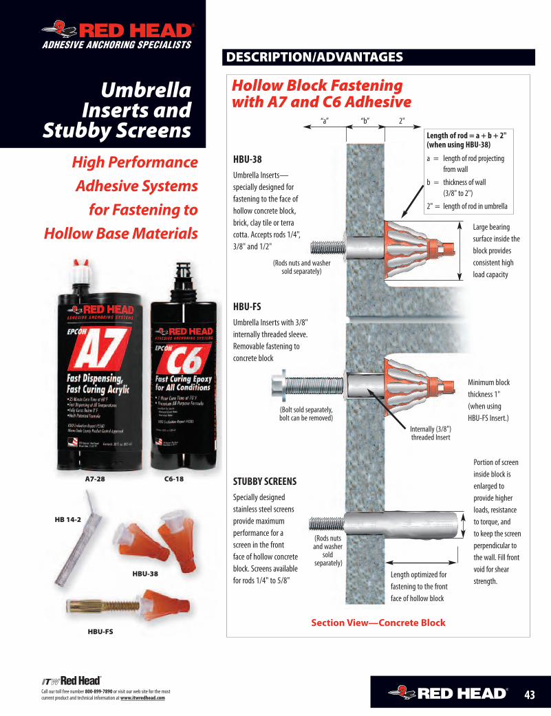
43Call our toll free number 800-899-7890 or visit our web site for the mostcurrent product and technical information atwww.itwredhead.com
UmbrellaInserts and
Stubby ScreensHigh PerformanceAdhesive Systems
for Fastening toHollow Base Materials
DESCRIPTION/ADVANTAGES
“a” “b” 2"
Section View—Concrete Block
Hollow Block Fasteningwith A7 and C6 Adhesive
HBU-38Umbrella Inserts—specially designed forfastening to the face ofhollow concrete block,brick, clay tile or terracotta. Accepts rods 1/4",3/8" and 1/2"
HBU-FSUmbrella Inserts with 3/8"internally threaded sleeve.Removable fastening toconcrete block
STUBBY SCREENSSpecially designedstainless steel screensprovide maximumperformance for ascreen in the frontface of hollow concreteblock. Screens availablefor rods 1/4" to 5/8"
Length of rod = a + b + 2"(when using HBU-38)
a = length of rod projectingfromwall
b = thickness of wall(3/8" to 2")
2" = length of rod in umbrella
Large bearingsurface inside theblock providesconsistent highload capacity
Portion of screeninside block isenlarged toprovide higherloads, resistanceto torque, andto keep the screenperpendicular tothe wall. Fill frontvoid for shearstrength.
Minimum blockthickness 1"(when usingHBU-FS Insert.)
Length optimized forfastening to the frontface of hollow block
ADHESIVE ANCHORING SPECIALISTS
A7-28 C6-18
HBU-38
HBU-FS
HB 14-2
(Rods nuts and washersold separately)
(Bolt sold separately,bolt can be removed)
Internally (3/8")threaded Insert
(Rods nutsand washersold
separately)
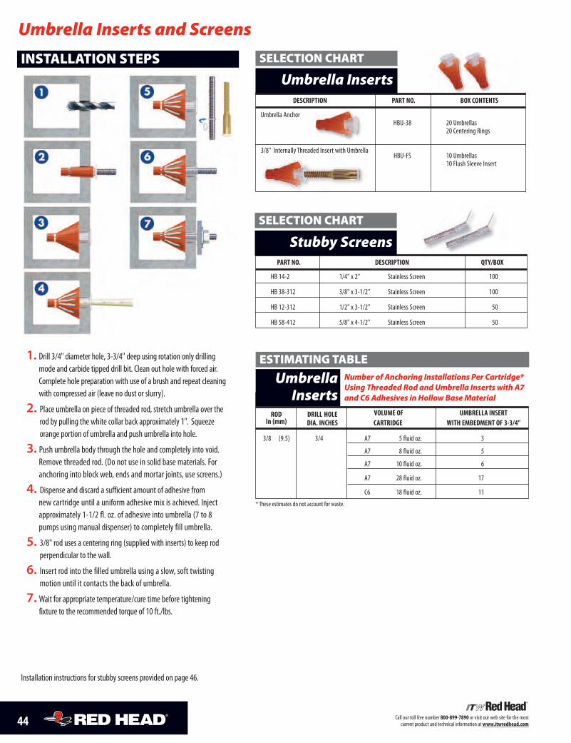
44 Call our toll free number 800-899-7890 or visit our web site for the mostcurrent product and technical information atwww.itwredhead.com
1. Drill 3/4" diameter hole, 3-3/4" deep using rotation only drillingmode and carbide tipped drill bit. Clean out hole with forced air.Complete hole preparation with use of a brush and repeat cleaningwith compressed air (leave no dust or slurry).
2. Place umbrella on piece of threaded rod, stretch umbrella over therod by pulling the white collar back approximately 1". Squeezeorange portion of umbrella and push umbrella into hole.
3. Push umbrella body through the hole and completely into void.Remove threaded rod. (Do not use in solid base materials. Foranchoring into block web, ends and mortar joints, use screens.)
4. Dispense and discard a sufficient amount of adhesive fromnew cartridge until a uniform adhesive mix is achieved. Injectapproximately 1-1/2 fl. oz. of adhesive into umbrella (7 to 8pumps using manual dispenser) to completely fill umbrella.
5. 3/8" rod uses a centering ring (supplied with inserts) to keep rodperpendicular to the wall.
6. Insert rod into the filled umbrella using a slow, soft twistingmotion until it contacts the back of umbrella.
7. Wait for appropriate temperature/cure time before tighteningfixture to the recommended torque of 10 ft./lbs.
INSTALLATION STEPS
Umbrella Inserts and Screens
PART NO. DESCRIPTION QTY/BOX
HB 14-2 1/4" x 2" Stainless Screen 100
HB 38-312 3/8" x 3-1/2" Stainless Screen 100
HB 12-312 1/2" x 3-1/2" Stainless Screen 50
HB 58-412 5/8" x 4-1/2" Stainless Screen 50
DESCRIPTION PART NO. BOX CONTENTS
Umbrella AnchorHBU-38 20 Umbrellas
20 Centering Rings
3/8" Internally Threaded Insert with UmbrellaHBU-FS 10 Umbrellas
10 Flush Sleeve Insert
Umbrella Inserts
Stubby Screens
SELECTION CHART
SELECTION CHART
Installation instructions for stubby screens provided on page 46.
Number of Anchoring Installations Per Cartridge*Using Threaded Rod andUmbrella Inserts with A7and C6Adhesives in HollowBaseMaterial
UmbrellaInserts
ESTIMATING TABLE
ROD DRILL HOLE VOLUME OF UMBRELLA INSERTIn (mm) DIA. INCHES CARTRIDGE WITH EMBEDMENT OF 3-3/4"
3/8 (9.5) 3/4 A7 5 fluid oz. 3
A7 8 fluid oz. 5
A7 10 fluid oz. 6
A7 28 fluid oz. 17
C6 18 fluid oz. 11
* These estimates do not account for waste.
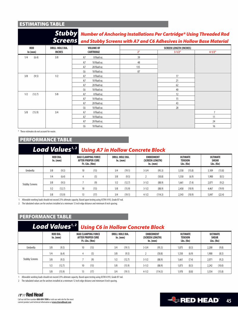
45Call our toll free number 800-899-7890 or visit our web site for the mostcurrent product and technical information atwww.itwredhead.com
ROD DIA. MAX CLAMPING FORCE DRILL HOLE DIA. EMBEDMENT ULTIMATE ULTIMATEIn. (mm) AFTER PROPER CURE In. (mm) (SCREEN LENGTH) TENSION SHEAR
Ft.-Lbs. (Nm) In. (mm) Lbs. (Kn) Lbs. (Kn)
Umbrella 3/8 (9.5) 10 (13) 3/4 (19.1) 3-3/4 (95.3) 1,875 (8.3) 2,200 (9.8)
1/4 (6.4) 4 (5) 3/8 (9.5) 2 (50.8) 1,550 (6.9) 1,900 (8.5)
3/8 (9.5) 7 (9) 1/2 (12.7) 3-1/2 (88.9) 1,661 (7.4) 2,071 (9.2)
1/2 (12.7) 10 (13) 5/8 (15.9) 3-1/2 (88.9) 1,873 (8.3) 2,242 (10.0)
5/8 (15.9) 13 (17) 3/4 (19.1) 4-1/2 (114.3) 1,970 (8.8) 3,554 (15.8)
Using C6 in Hollow Concrete BlockLoad Values1, 2
Stubby Screens
PERFORMANCE TABLE
1 Allowable working loads should not exceed 25% ultimate capacity. Based upon testing using ASTM A193, Grade B7 rod.2 The tabulated values are for anchors installed at a minimum 12 inch edge distance and minimum 8 inch spacing.
ROD DIA. MAX CLAMPING FORCE DRILL HOLE DIA. EMBEDMENT ULTIMATE ULTIMATEIn. (mm) AFTER PROPER CURE In. (mm) (SCREEN LENGTH) TENSION SHEAR
Ft.-Lbs. (Nm) In. (mm) Lbs. (Kn) Lbs. (Kn)
Umbrella 3/8 (9.5) 10 (13) 3/4 (19.1) 3-3/4 (95.3) 3,558 (15.8) 3,109 (13.8)
1/4 (6.4) 4 (5) 3/8 (9.5) 2 (50.8) 1,550 (6.9) 1,900 (8.5)
3/8 (9.5) 7 (9) 1/2 (12.7) 3-1/2 (88.9) 1,661 (7.4) 2,071 (9.2)
1/2 (12.7) 10 (13) 5/8 (15.9) 3-1/2 (88.9) 2,458 (10.9) 4,467 (19.9)
5/8 (15.9) 13 (17) 3/4 (19.1) 4-1/2 (114.3) 2,543 (10.9) 5,047 (22.4)
1 Allowable working loads should not exceed 25% ultimate capacity. Based upon testing using ASTM A193, Grade B7 rod.2 The tabulated values are for anchors installed at a minimum 12 inch edge distance and minimum 8 inch spacing.
Using A7 in Hollow Concrete BlockLoad Values1, 2PERFORMANCE TABLE
Number of Anchoring Installations Per Cartridge*Using ThreadedRod
and Stubby Screenswith A7andC6Adhesives inHollowBaseMaterial
StubbyScreens
ESTIMATING TABLE
ROD DRILL HOLE DIA. VOLUME OF SCREEN LENGTH (INCHES)In (mm) INCHES CARTRIDGE 2" 3-1/2" 4-1/2"
1/4 (6.4) 3/8 A7 8 fluid oz. 39
A7 10 fluid oz. 48A7 28 fluid oz. 135C6 18 fluid oz. 87
3/8 (9.5) 1/2 A7 8 fluid oz. 17A7 10 fluid oz. 48 21A7 28 fluid oz. 62C6 18 fluid oz. 40
1/2 (12.7) 5/8 A7 8 fluid oz. 12A7 10 fluid oz. 48 15A7 28 fluid oz. 43C6 18 fluid oz. 28
5/8 (15.9) 3/4 A7 8 fluid oz. 7A7 10 fluid oz. 48 11A7 28 fluid oz. 24
C6 18 fluid oz. 16
* These estimates do not account for waste.
Stubby Screens
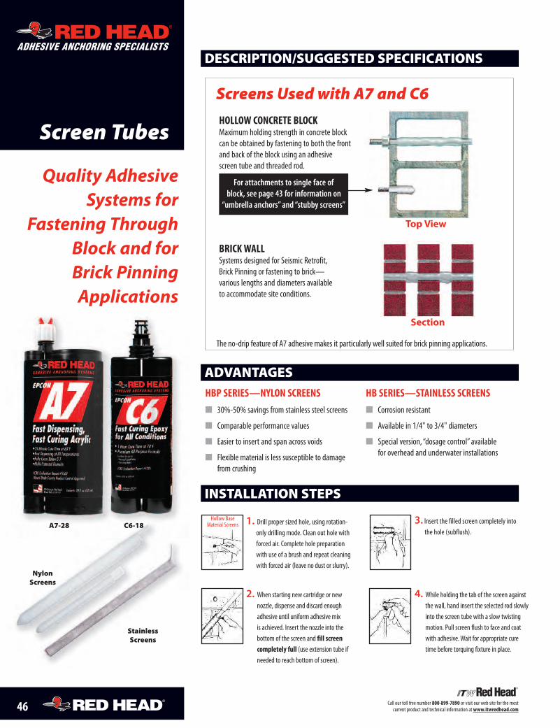
46 Call our toll free number 800-899-7890 or visit our web site for the mostcurrent product and technical information atwww.itwredhead.com
Screen Tubes
Quality AdhesiveSystems for
Fastening ThroughBlock and forBrick PinningApplications
DESCRIPTION/SUGGESTED SPECIFICATIONS
Section
Top View
HOLLOW CONCRETE BLOCKMaximum holding strength in concrete blockcan be obtained by fastening to both the frontand back of the block using an adhesivescreen tube and threaded rod.
BRICKWALLSystems designed for Seismic Retrofit,Brick Pinning or fastening to brick—various lengths and diameters availableto accommodate site conditions.
The no-drip feature of A7 adhesive makes it particularly well suited for brick pinning applications.
ADVANTAGESHBP SERIES—NYLON SCREENS� 30%-50% savings from stainless steel screens
� Comparable performance values
� Easier to insert and span across voids
� Flexible material is less susceptible to damagefrom crushing
HB SERIES—STAINLESS SCREENS� Corrosion resistant
� Available in 1/4" to 3/4" diameters
� Special version, “dosage control” availablefor overhead and underwater installations
Screens Used with A7 and C6
ADHESIVE ANCHORING SPECIALISTS
A7-28 C6-18
NylonScreens
StainlessScreens
For attachments to single face ofblock, see page 43 for information on
“umbrella anchors” and “stubby screens”
1. Drill proper sized hole, using rotation-only drilling mode. Clean out hole withforced air. Complete hole preparationwith use of a brush and repeat cleaningwith forced air (leave no dust or slurry).
2. When starting new cartridge or newnozzle, dispense and discard enoughadhesive until uniform adhesive mixis achieved. Insert the nozzle into thebottom of the screen and fill screencompletely full (use extension tube ifneeded to reach bottom of screen).
INSTALLATION STEPS
3. Insert the filled screen completely intothe hole (subflush).
4. While holding the tab of the screen againstthe wall, hand insert the selected rod slowlyinto the screen tube with a slow twistingmotion. Pull screen flush to face and coatwith adhesive.Wait for appropriate curetime before torquing fixture in place.
Hollow BaseMaterial Screens
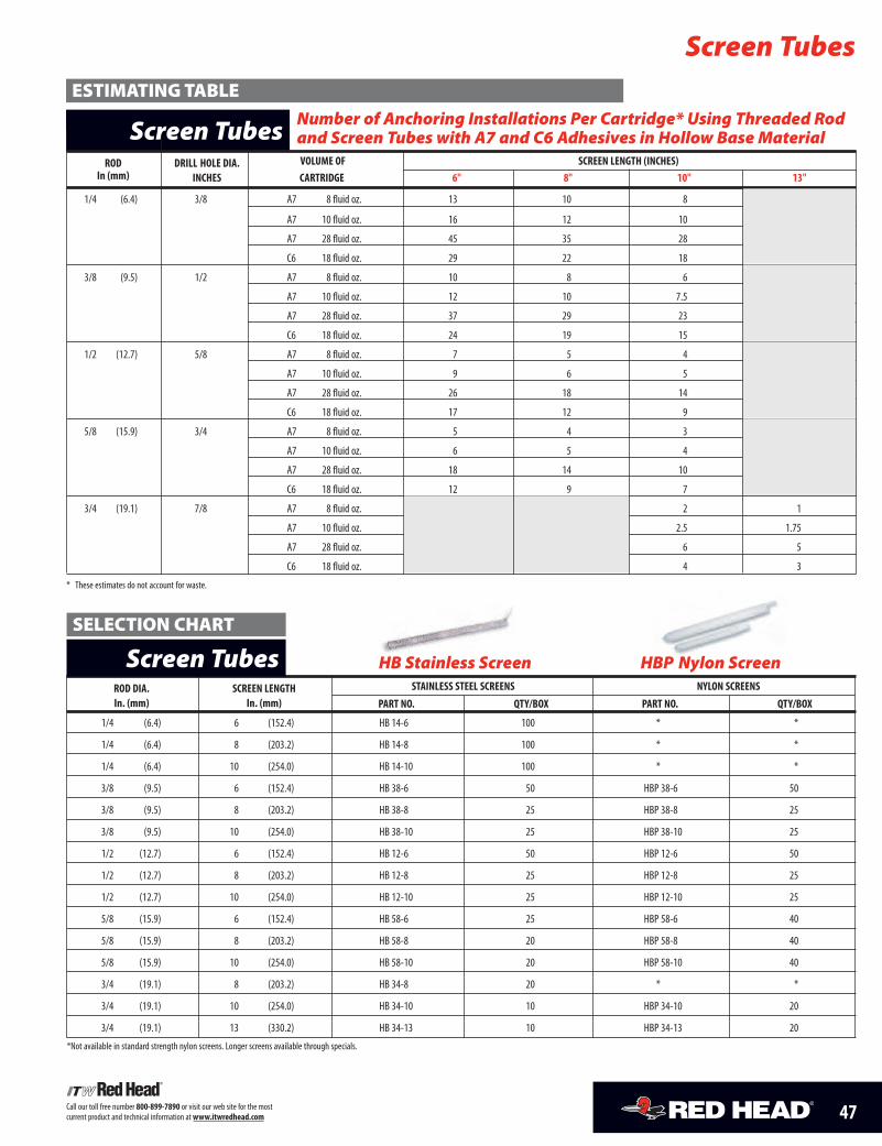
47Call our toll free number 800-899-7890 or visit our web site for the mostcurrent product and technical information atwww.itwredhead.com
Number of Anchoring Installations Per Cartridge* Using Threaded Rodand Screen Tubes with A7 and C6 Adhesives in Hollow BaseMaterialScreen Tubes
ESTIMATING TABLE
ROD DRILL HOLE DIA. VOLUME OF SCREEN LENGTH (INCHES)In (mm) INCHES CARTRIDGE 6" 8" 10" 13"
1/4 (6.4) 3/8 A7 8 fluid oz. 13 10 8
A7 10 fluid oz. 16 12 10
A7 28 fluid oz. 45 35 28
C6 18 fluid oz. 29 22 18
3/8 (9.5) 1/2 A7 8 fluid oz. 10 8 6
A7 10 fluid oz. 12 10 7.5
A7 28 fluid oz. 37 29 23
C6 18 fluid oz. 24 19 15
1/2 (12.7) 5/8 A7 8 fluid oz. 7 5 4
A7 10 fluid oz. 9 6 5
A7 28 fluid oz. 26 18 14
C6 18 fluid oz. 17 12 9
5/8 (15.9) 3/4 A7 8 fluid oz. 5 4 3
A7 10 fluid oz. 6 5 4
A7 28 fluid oz. 18 14 10
C6 18 fluid oz. 12 9 7
3/4 (19.1) 7/8 A7 8 fluid oz. 2 1
A7 10 fluid oz. 2.5 1.75
A7 28 fluid oz. 6 5
C6 18 fluid oz. 4 3
* These estimates do not account for waste.
Screen Tubes
ROD DIA. SCREEN LENGTH STAINLESS STEEL SCREENS NYLON SCREENSIn. (mm) In. (mm) PART NO. QTY/BOX PART NO. QTY/BOX
1/4 (6.4) 6 (152.4) HB 14-6 100 * *
1/4 (6.4) 8 (203.2) HB 14-8 100 * *
1/4 (6.4) 10 (254.0) HB 14-10 100 * *
3/8 (9.5) 6 (152.4) HB 38-6 50 HBP 38-6 50
3/8 (9.5) 8 (203.2) HB 38-8 25 HBP 38-8 25
3/8 (9.5) 10 (254.0) HB 38-10 25 HBP 38-10 25
1/2 (12.7) 6 (152.4) HB 12-6 50 HBP 12-6 50
1/2 (12.7) 8 (203.2) HB 12-8 25 HBP 12-8 25
1/2 (12.7) 10 (254.0) HB 12-10 25 HBP 12-10 25
5/8 (15.9) 6 (152.4) HB 58-6 25 HBP 58-6 40
5/8 (15.9) 8 (203.2) HB 58-8 20 HBP 58-8 40
5/8 (15.9) 10 (254.0) HB 58-10 20 HBP 58-10 40
3/4 (19.1) 8 (203.2) HB 34-8 20 * *
3/4 (19.1) 10 (254.0) HB 34-10 10 HBP 34-10 20
3/4 (19.1) 13 (330.2) HB 34-13 10 HBP 34-13 20
*Not available in standard strength nylon screens. Longer screens available through specials.
HB Stainless Screen HBP Nylon ScreenScreen TubesSELECTION CHART
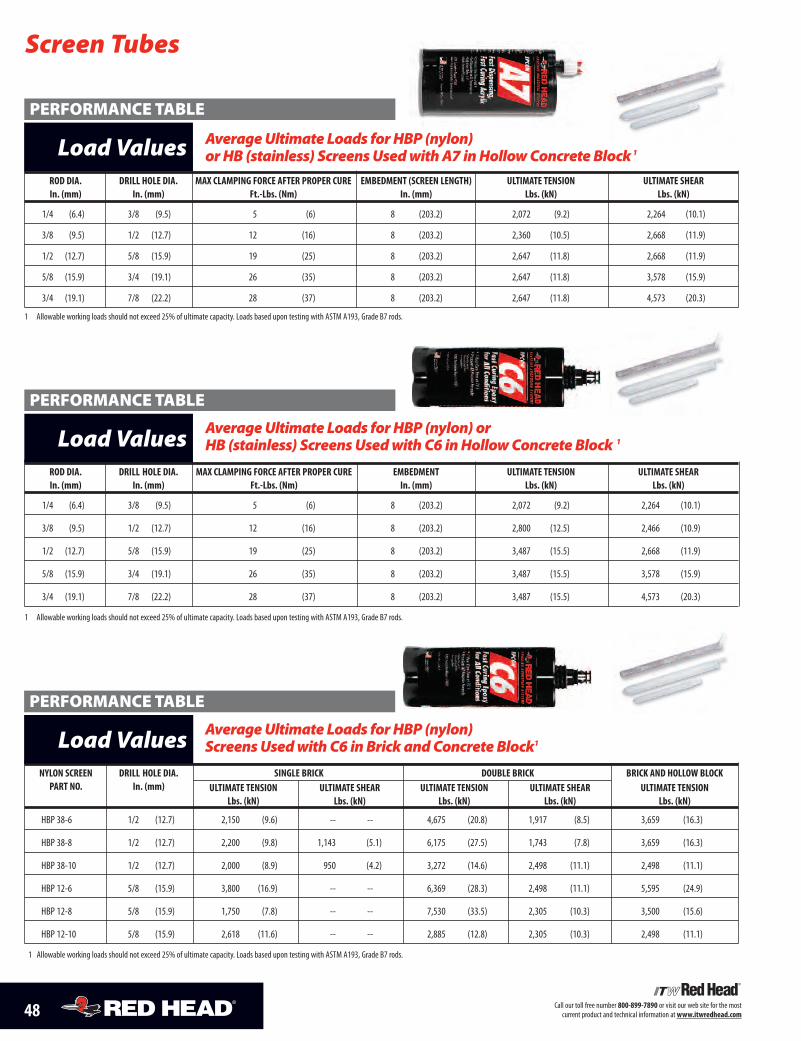
48 Call our toll free number 800-899-7890 or visit our web site for the mostcurrent product and technical information atwww.itwredhead.com
Screen Tubes
ROD DIA. DRILL HOLE DIA. MAX CLAMPING FORCE AFTER PROPER CURE EMBEDMENT ULTIMATE TENSION ULTIMATE SHEARIn. (mm) In. (mm) Ft.-Lbs. (Nm) In. (mm) Lbs. (kN) Lbs. (kN)
1/4 (6.4) 3/8 (9.5) 5 (6) 8 (203.2) 2,072 (9.2) 2,264 (10.1)
3/8 (9.5) 1/2 (12.7) 12 (16) 8 (203.2) 2,800 (12.5) 2,466 (10.9)
1/2 (12.7) 5/8 (15.9) 19 (25) 8 (203.2) 3,487 (15.5) 2,668 (11.9)
5/8 (15.9) 3/4 (19.1) 26 (35) 8 (203.2) 3,487 (15.5) 3,578 (15.9)
3/4 (19.1) 7/8 (22.2) 28 (37) 8 (203.2) 3,487 (15.5) 4,573 (20.3)
1 Allowable working loads should not exceed 25% of ultimate capacity. Loads based upon testing with ASTM A193, Grade B7 rods.
AverageUltimate Loads forHBP (nylon) orHB (stainless) ScreensUsedwithC6 inHollowConcreteBlock 1Load Values
PERFORMANCE TABLE
NYLON SCREEN DRILL HOLE DIA. SINGLE BRICK DOUBLE BRICK BRICK AND HOLLOW BLOCKPART NO. In. (mm) ULTIMATE TENSION ULTIMATE SHEAR ULTIMATE TENSION ULTIMATE SHEAR ULTIMATE TENSION
Lbs. (kN) Lbs. (kN) Lbs. (kN) Lbs. (kN) Lbs. (kN)
HBP 38-6 1/2 (12.7) 2,150 (9.6) -- -- 4,675 (20.8) 1,917 (8.5) 3,659 (16.3)
HBP 38-8 1/2 (12.7) 2,200 (9.8) 1,143 (5.1) 6,175 (27.5) 1,743 (7.8) 3,659 (16.3)
HBP 38-10 1/2 (12.7) 2,000 (8.9) 950 (4.2) 3,272 (14.6) 2,498 (11.1) 2,498 (11.1)
HBP 12-6 5/8 (15.9) 3,800 (16.9) -- -- 6,369 (28.3) 2,498 (11.1) 5,595 (24.9)
HBP 12-8 5/8 (15.9) 1,750 (7.8) -- -- 7,530 (33.5) 2,305 (10.3) 3,500 (15.6)
HBP 12-10 5/8 (15.9) 2,618 (11.6) -- -- 2,885 (12.8) 2,305 (10.3) 2,498 (11.1)
1 Allowable working loads should not exceed 25% of ultimate capacity. Loads based upon testing with ASTM A193, Grade B7 rods.
AverageUltimate Loads forHBP (nylon)ScreensUsedwithC6 inBrick andConcreteBlock1Load Values
PERFORMANCE TABLE
ROD DIA. DRILL HOLE DIA. MAX CLAMPING FORCE AFTER PROPER CURE EMBEDMENT (SCREEN LENGTH) ULTIMATE TENSION ULTIMATE SHEARIn. (mm) In. (mm) Ft.-Lbs. (Nm) In. (mm) Lbs. (kN) Lbs. (kN)
1/4 (6.4) 3/8 (9.5) 5 (6) 8 (203.2) 2,072 (9.2) 2,264 (10.1)
3/8 (9.5) 1/2 (12.7) 12 (16) 8 (203.2) 2,360 (10.5) 2,668 (11.9)
1/2 (12.7) 5/8 (15.9) 19 (25) 8 (203.2) 2,647 (11.8) 2,668 (11.9)
5/8 (15.9) 3/4 (19.1) 26 (35) 8 (203.2) 2,647 (11.8) 3,578 (15.9)
3/4 (19.1) 7/8 (22.2) 28 (37) 8 (203.2) 2,647 (11.8) 4,573 (20.3)
1 Allowable working loads should not exceed 25% of ultimate capacity. Loads based upon testing with ASTM A193, Grade B7 rods.
AverageUltimate Loads forHBP (nylon)orHB (stainless) ScreensUsedwithA7 inHollowConcreteBlock1Load Values
PERFORMANCE TABLE
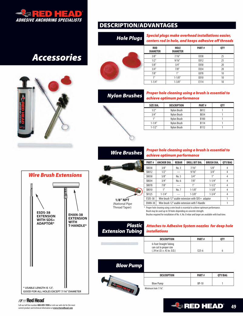
49Call our toll free number 800-899-7890 or visit our web site for the mostcurrent product and technical information atwww.itwredhead.com56
ROD HOLE PART # QTYDIAMETER DIAMETER3/8" 7/16" E038 251/2" 9/16" E012 255/8" 3/4" E058 203/4" 7/8" E034 207/8" 1" E078 101" 1-1/8" E010 10
1-1/4" 1-3/8" E114 10
Special plugsmake overhead installations easier,centers rod in hole, and keeps adhesive off threadsHole Plugs
SIZE DIA. DESCRIPTION PART # QTY1/2" Nylon Brush B012 13/4" Nylon Brush B034 11" Nylon Brush B100 1
1-1/4" Nylon Brush B114 11-1/2" Nylon Brush B112 1
Proper hole cleaning using a brush is essential toachieve optimumperformanceNylon Brushes
DESCRIPTION PART # QTY6-Foot Straight Tubingcan cut to proper size(.39 in I.D. x .43 in. O.D.) E25-6 6
Attaches to Adhesive Systemnozzles for deep holeinstallations
PlasticExtensionTubing
DESCRIPTION/ADVANTAGES
DESCRIPTION PART # QTY/BAG
Blow Pump BP-10 1
Minimum hole 7/16”.
BlowPump
Accessories
ADHESIVE ANCHORING SPECIALISTS
PART # ANCHOR DIA. REBAR DRILL BIT DIA. BRUSH DIA. QTY/BAG
SB038 3/8" No. 3 7/16" 5/8" 4SB012 1/2" — 9/16" 3/4" 4SB058 5/8" No. 5 3/4" 1" 4SB034 3/4" No. 6 7/8" 1-1/4" 4SB078 7/8" — 1" 1-1/2" 4SB010 1" No. 7 1-1/8" 1-5/8" 4SB125 1-1/4" — 1-3/8" 1-3/4" 4ESDS-38 Wire brush 12”usable extension with SDS+ adaptor 1EHAN-38 Wire brush 12”usable extension with T-Handle 1
* Proper hole cleaning using a wire brush is essential to achieve optimum performance.Brush may be used up to 50 holes depending on concrete strength.Brushes required for installation of No. 4, No. 8 rebar and larger are available with lead time.
Proper hole cleaning using a brush is essential toachieve optimumperformanceWire Brushes
1/8” NPT(National PipeThread Taper)
ESDS-38EXTENSIONWITH SDS+ADAPTOR*
EHAN-38EXTENSIONWITHT-HANDLE*
Wire Brush Extensions
* USABLE LENGTH IS 12",GOOD FOR ALL HOLES EXCEPT 7/16” DIAMETER
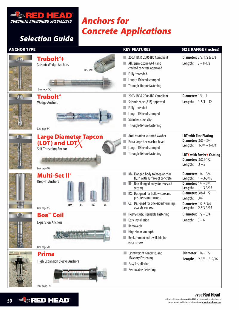
50 Call our toll free number 800-899-7890 or visit our web site for the mostcurrent product and technical information atwww.itwredhead.com
Selection Guide
Anchors forConcrete Applications
CONCRETE ANCHORING SPECIALISTS
Diameter: 1/4 – 1Length: 1-3/4 – 12
Diameter: 1/2 – 3/4Length: 3 – 6
� 2003 IBC & 2006 IBC Compliant� Seismic zone (A-B) approved� Fully-threaded� Length ID head stamped� Stainless steel clip� Through-fixture fastening
� Heavy-Duty, Reusable Fastening� Easy installation� Removable� High shear strength� Replacement coil available for
easy re-use(see page 70)
Trubolt®Wedge Anchors
(see page 54)
ANCHOR TYPE KEY FEATURES SIZE RANGE (Inches)
Boa™ CoilExpansion Anchors
(see page 65)
Diameter: 1/4 – 3/4Length: 1 – 3-3/16Diameter: 1/4 – 3/4Length: 1 – 3-3/16Diameter: 3/8 & 1/2Length: 3/4Diameter: 1/2 & 3/4Length: 2 & 3-3/16
� RM: Flanged body to keep anchorflush with surface of concrete
� RL: Non-flanged body for recessedsetting
� RX: Designed for hollow core andpost tension concrete
� CL: Designed for one-sided forming,accepts coil rod
RM RL RX CL
Multi-Set II®Drop-In Anchors
LDT with Zinc PlatingDiameter: 3/8 – 3/4Length: 1-3/4 – 6-1/4
LDTX with EnvireX CoatingDiameter: 3/8 & 1/2Length: 3 – 5
� Anti-rotation serrated washer� Extra large hex washer head� Length ID head stamped� Through-fixture fastening
(see page 60)
Diameter: 3/8, 1/2 & 5/8Length: 3 – 8-1/2
� 2003 IBC & 2006 IBC Compliant� All seismic zone (A-F) and
cracked concrete approved� Fully-threaded� Length ID head stamped� Through-fixture fastening
Trubolt®+SeismicWedge Anchors
(see page 54)
ID STAMP
Large Diameter Tapcon(LDT) and LDTSelf-Threading Anchor
Diameter: 1/4 – 1/2Length: 2-3/8 – 3-9/16
� Lightweight Concrete, andMasonry Fastening
� Easy installation� Removable fastening
(see page 72)
PrimaHigh Expansion Sleeve Anchors
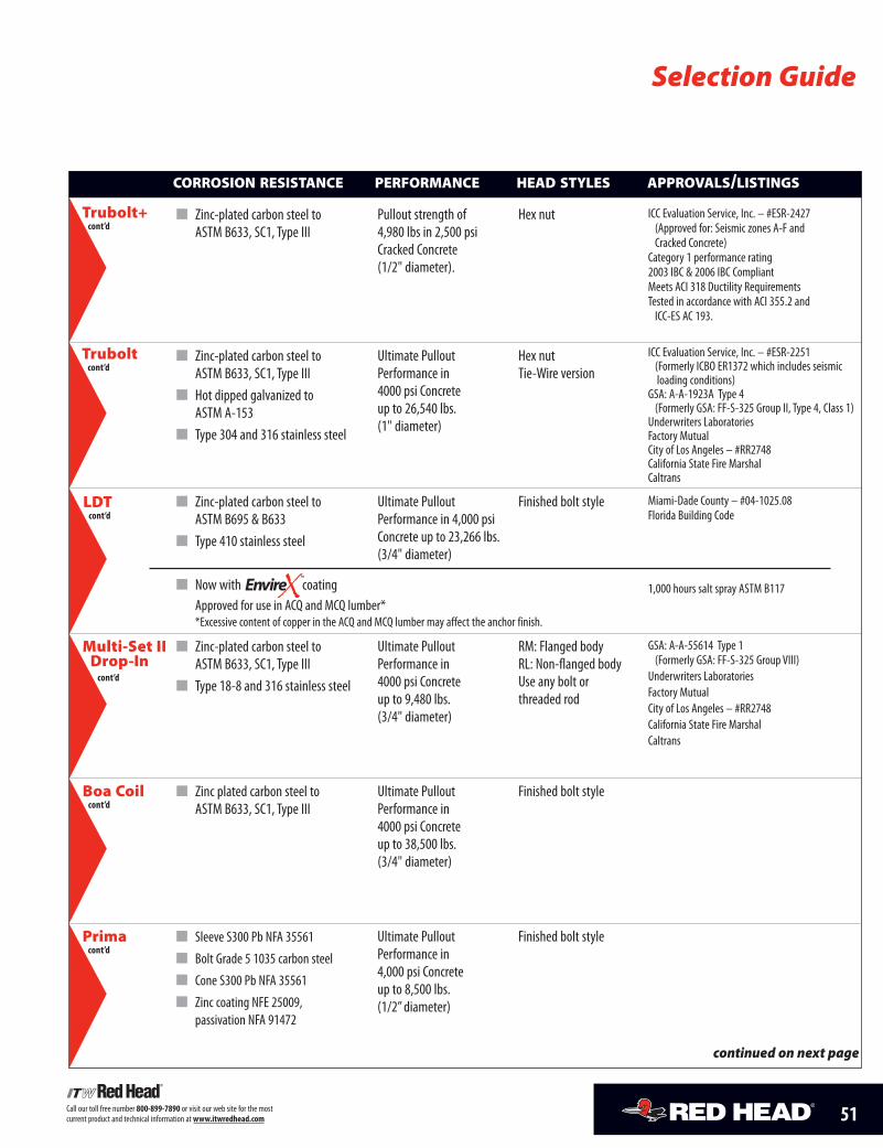
51Call our toll free number 800-899-7890 or visit our web site for the mostcurrent product and technical information atwww.itwredhead.com
Hex nutTie-Wire version
ICC Evaluation Service, Inc. – #ESR-2251(Formerly ICBO ER1372 which includes seismicloading conditions)
GSA: A-A-1923A Type 4(Formerly GSA: FF-S-325 Group II, Type 4, Class 1)
Underwriters LaboratoriesFactory MutualCity of Los Angeles – #RR2748California State Fire MarshalCaltrans
RM: Flanged bodyRL: Non-flanged bodyUse any bolt orthreaded rod
GSA: A-A-55614 Type 1(Formerly GSA: FF-S-325 Group VIII)
Underwriters LaboratoriesFactory MutualCity of Los Angeles – #RR2748California State Fire MarshalCaltrans
Finished bolt style
Ultimate PulloutPerformance in4000 psi Concreteup to 26,540 lbs.(1" diameter)
Ultimate PulloutPerformance in4000 psi Concreteup to 9,480 lbs.(3/4" diameter)
Ultimate PulloutPerformance in4000 psi Concreteup to 38,500 lbs.(3/4" diameter)
Boa Coilcont’d
CORROSION RESISTANCE PERFORMANCE HEAD STYLES APPROVALS/LISTINGS
continued on next page
� Zinc plated carbon steel toASTM B633, SC1, Type III
� Zinc-plated carbon steel toASTM B633, SC1, Type III
� Type 18-8 and 316 stainless steel
� Zinc-plated carbon steel toASTM B633, SC1, Type III
� Hot dipped galvanized toASTM A-153
� Type 304 and 316 stainless steel
Multi-Set IIDrop-Incont’d
Selection Guide
LDTcont’d
� Zinc-plated carbon steel toASTM B695 & B633
� Type 410 stainless steel
� Now with coatingApproved for use in ACQ and MCQ lumber**Excessive content of copper in the ACQ and MCQ lumber may affect the anchor finish.
Ultimate PulloutPerformance in 4,000 psiConcrete up to 23,266 lbs.(3/4" diameter)
Finished bolt style Miami-Dade County – #04-1025.08Florida Building Code
1,000 hours salt spray ASTM B117
Truboltcont’d
Hex nut ICC Evaluation Service, Inc. – #ESR-2427(Approved for: Seismic zones A-F andCracked Concrete)
Category 1 performance rating2003 IBC & 2006 IBC CompliantMeets ACI 318 Ductility RequirementsTested in accordance with ACI 355.2 andICC-ES AC 193.
Pullout strength of4,980 lbs in 2,500 psiCracked Concrete(1/2" diameter).
� Zinc-plated carbon steel toASTM B633, SC1, Type III
Trubolt+cont’d
TM
Finished bolt styleUltimate PulloutPerformance in4,000 psi Concreteup to 8,500 lbs.(1/2”diameter)
Primacont’d
� Sleeve S300 Pb NFA 35561
� Bolt Grade 5 1035 carbon steel
� Cone S300 Pb NFA 35561
� Zinc coating NFE 25009,passivation NFA 91472
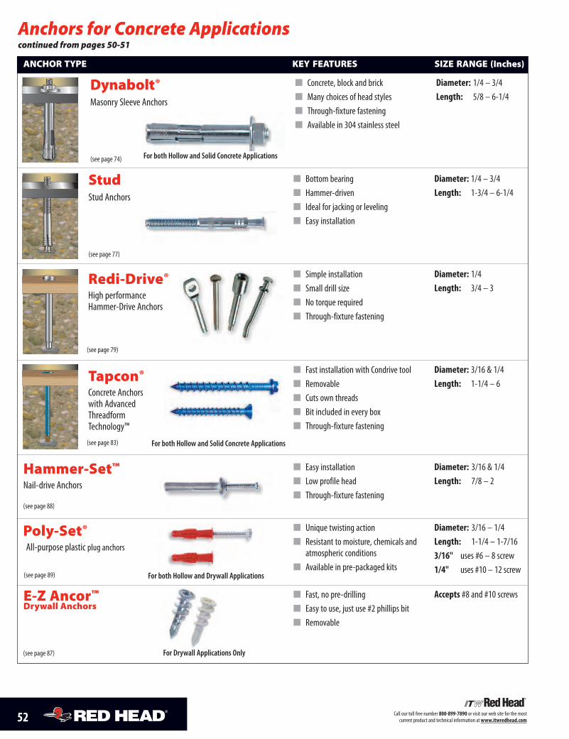
52 Call our toll free number 800-899-7890 or visit our web site for the mostcurrent product and technical information atwww.itwredhead.com
Anchors for Concrete Applicationscontinued from pages 50-51
� Simple installation� Small drill size� No torque required� Through-fixture fastening
Diameter: 1/4Length: 3/4 – 3
Diameter: 3/16 & 1/4Length: 1-1/4 – 6
Diameter: 3/16 & 1/4Length: 7/8 – 2
Diameter: 3/16 – 1/4Length: 1-1/4 – 1-7/163/16" uses #6 – 8 screw1/4" uses #10 – 12 screw
� Fast installation with Condrive tool� Removable� Cuts own threads� Bit included in every box� Through-fixture fastening
� Easy installation� Low profile head� Through-fixture fastening
Hammer-Set™Nail-drive Anchors
� Unique twisting action� Resistant to moisture, chemicals and
atmospheric conditions� Available in pre-packaged kits
Poly-Set®All-purpose plastic plug anchors
ANCHOR TYPE KEY FEATURES SIZE RANGE (Inches)
Accepts #8 and #10 screws� Fast, no pre-drilling� Easy to use, just use #2 phillips bit� Removable
(see page 87)
(see page 79)
Redi-Drive®High performanceHammer-Drive Anchors
(see page 83)
(see page 88)
(see page 89)
Tapcon®Concrete Anchorswith AdvancedThreadformTechnology™
E-Z Ancor™Drywall Anchors
For both Hollow and Solid Concrete Applications
For Drywall Applications Only
Diameter: 1/4 – 3/4Length: 1-3/4 – 6-1/4
(see page 77)
� Bottom bearing� Hammer-driven� Ideal for jacking or leveling� Easy installation
StudStud Anchors
Diameter: 1/4 – 3/4Length: 5/8 – 6-1/4
� Concrete, block and brick� Many choices of head styles� Through-fixture fastening� Available in 304 stainless steel
(see page 74)
Dynabolt®Masonry Sleeve Anchors
For both Hollow and Solid Concrete Applications
For both Hollow and Drywall Applications
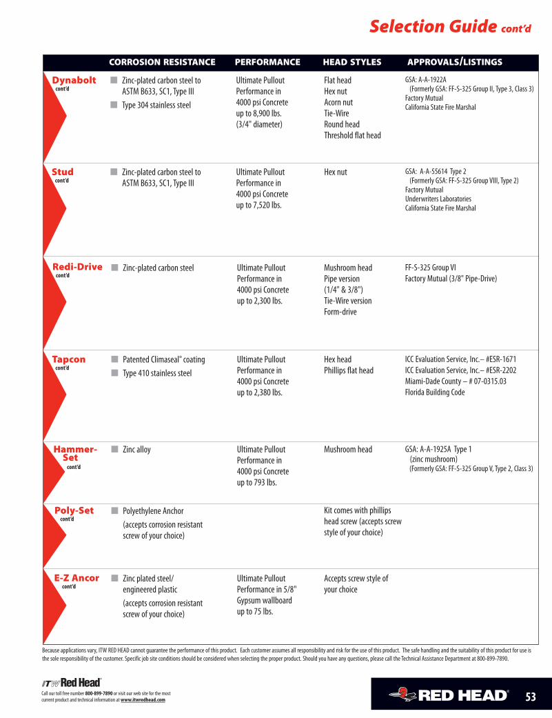
53Call our toll free number 800-899-7890 or visit our web site for the mostcurrent product and technical information atwww.itwredhead.com
Ultimate PulloutPerformance in4000 psi Concreteup to 2,300 lbs.
Mushroom headPipe version(1/4" & 3/8")Tie-Wire versionForm-drive
FF-S-325 Group VIFactory Mutual (3/8" Pipe-Drive)
Hex headPhillips flat head
ICC Evaluation Service, Inc.– #ESR-1671ICC Evaluation Service, Inc.– #ESR-2202Miami-Dade County – # 07-0315.03Florida Building Code
Mushroom head GSA: A-A-1925A Type 1(zinc mushroom)(Formerly GSA: FF-S-325 Group V, Type 2, Class 3)
Ultimate PulloutPerformance in4000 psi Concreteup to 2,380 lbs.
Ultimate PulloutPerformance in4000 psi Concreteup to 793 lbs.
CORROSION RESISTANCE PERFORMANCE HEAD STYLES APPROVALS/LISTINGS
Kit comes with phillipshead screw (accepts screwstyle of your choice)
Accepts screw style ofyour choice
Ultimate PulloutPerformance in 5/8"Gypsum wallboardup to 75 lbs.
� Zinc-plated carbon steel
� Patented Climaseal® coating� Type 410 stainless steel
� Zinc alloy
� Polyethylene Anchor(accepts corrosion resistantscrew of your choice)
� Zinc plated steel/engineered plastic(accepts corrosion resistantscrew of your choice)
Redi-Drivecont’d
E-Z Ancorcont’d
Tapconcont’d
Selection Guide cont’d
Hammer-Setcont’d
Poly-Setcont’d
Because applications vary, ITW RED HEAD cannot guarantee the performance of this product. Each customer assumes all responsibility and risk for the use of this product. The safe handling and the suitability of this product for use isthe sole responsibility of the customer. Specific job site conditions should be considered when selecting the proper product. Should you have any questions, please call the Technical Assistance Department at 800-899-7890.
Hex nut GSA: A-A-55614 Type 2(Formerly GSA: FF-S-325 Group VIII, Type 2)
Factory MutualUnderwriters LaboratoriesCalifornia State Fire Marshal
Ultimate PulloutPerformance in4000 psi Concreteup to 7,520 lbs.
Studcont’d
� Zinc-plated carbon steel toASTM B633, SC1, Type III
Flat headHex nutAcorn nutTie-WireRound headThreshold flat head
GSA: A-A-1922A(Formerly GSA: FF-S-325 Group II, Type 3, Class 3)
Factory MutualCalifornia State Fire Marshal
Ultimate PulloutPerformance in4000 psi Concreteup to 8,900 lbs.(3/4" diameter)
Dynaboltcont’d
� Zinc-plated carbon steel toASTM B633, SC1, Type III
� Type 304 stainless steel
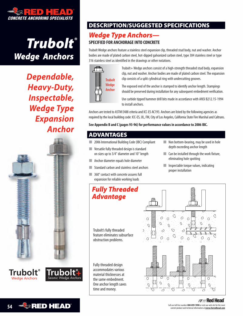
54 Call our toll free number 800-899-7890 or visit our web site for the mostcurrent product and technical information at www.itwredhead.com
ADVANTAGES� 2006 International Building Code (IBC) Compliant
� Versatile fully threaded design is standard on sizes up to 3/4" diameter and 10" length
� Anchor diameter equals hole diameter
� Standard carbon and stainless steel anchors
� 360° contact with concrete assures full expansion for reliable working loads
� Non bottom-bearing, may be used in holedepth exceeding anchor length
� Can be installed through the work fixture, eliminating hole spotting
� Inspectable torque values, indicating proper installation
Trubolt’s fully threaded feature eliminates subsurfaceobstruction problems.
Fully threaded design accommodates various material thicknesses at the same embedment. One anchor length saves time and money.
Dependable,Heavy-Duty,Inspectable,Wedge TypeExpansion
Anchor
DESCRIPTION/SUGGESTED SPECIFICATIONS
Wedge Type Anchors— specified for anchorage into concrete
Trubolt Wedge anchors feature a stainless steel expansion clip, threaded stud body, nut and washer. Anchorbodies are made of plated carbon steel, hot-dipped galvanized carbon steel, type 304 stainless steel or type316 stainless steel as identified in the drawings or other notations.
Trubolt+ Wedge anchors consist of a high-strength threaded stud body, expansionclip, nut and washer. Anchor bodies are made of plated carbon steel. The expansionclip consists of a split cylindrical ring with undercutting grooves.
The exposed end of the anchor is stamped to identify anchor length. Stampingsshould be preserved during installation for any subsequent embedment verification.
Use carbide tipped hammer drill bits made in accordance with ANSI B212.15-1994to install anchors.
Anchors are tested to ASTM E488 criteria and ICC-ES AC193. Anchors are listed by the following agencies asrequired by the local building code: ICC-ES, UL, FM, City of Los Angeles, California State Fire Marshal and Caltrans.
see appendix B and c (pages 93-96) for performance values in accordance to 2006 iBc.
TruboltWedgeAnchor
Fully ThreadedAdvantage
TruboltWedge Anchors
ADHESIVE ANCHORING SPECIALISTS
CONCRETE ANCHORING SPECIALISTS
ADHESIVE ANCHORING SPECIALISTS
CONCRETE ANCHORING SPECIALISTS
®
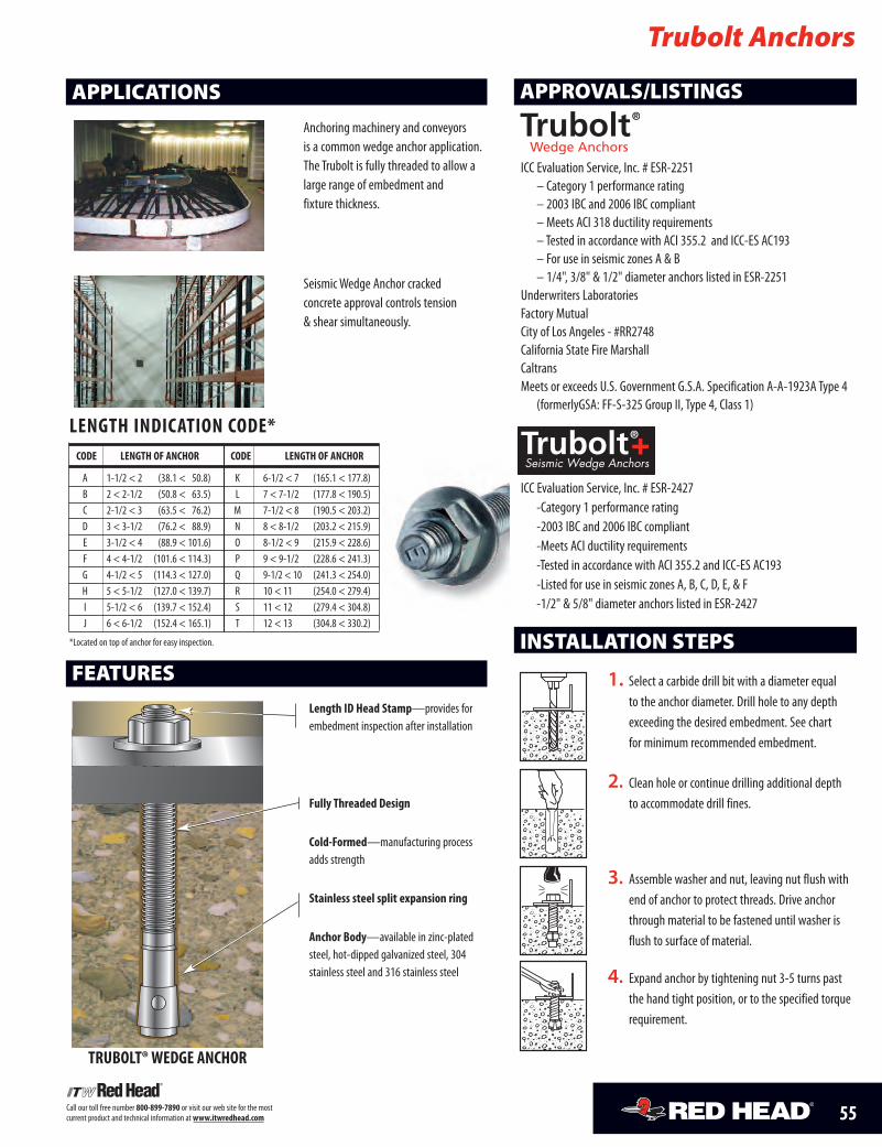
55Call our toll free number 800-899-7890 or visit our web site for the most current product and technical information at www.itwredhead.com
1. Select a carbide drill bit with a diameter equalto the anchor diameter. Drill hole to any depthexceeding the desired embedment. See chartfor minimum recommended embedment.
2. Clean hole or continue drilling additional depthto accommodate drill fines.
3. Assemble washer and nut, leaving nut flush withend of anchor to protect threads. Drive anchorthrough material to be fastened until washer isflush to surface of material.
4. Expand anchor by tightening nut 3-5 turns pastthe hand tight position, or to the specified torquerequirement.
INSTALLATION STEPS
Trubolt Anchors
APPLICATIONS
FEATURES
Anchoring machinery and conveyors is a common wedge anchor application.The Trubolt is fully threaded to allow alarge range of embedment and fixture thickness.
Seismic Wedge Anchor cracked concrete approval controls tension & shear simultaneously.
APPROVALS/LISTINGS
ICC Evaluation Service, Inc. # ESR-2251– Category 1 performance rating– 2003 IBC and 2006 IBC compliant– Meets ACI 318 ductility requirements– Tested in accordance with ACI 355.2 and ICC-ES AC193– For use in seismic zones A & B– 1/4", 3/8" & 1/2" diameter anchors listed in ESR-2251
Underwriters LaboratoriesFactory MutualCity of Los Angeles - #RR2748California State Fire MarshallCaltransMeets or exceeds U.S. Government G.S.A. Specification A-A-1923A Type 4
(formerlyGSA: FF-S-325 Group II, Type 4, Class 1)
ICC Evaluation Service, Inc. # ESR-2427-Category 1 performance rating-2003 IBC and 2006 IBC compliant-Meets ACI ductility requirements-Tested in accordance with ACI 355.2 and ICC-ES AC193-Listed for use in seismic zones A, B, C, D, E, & F-1/2" & 5/8" diameter anchors listed in ESR-2427
length indication code*code length of anchor code length of anchor
A 1-1/2 < 2 (38.1 < 50.8) K 6-1/2 < 7 (165.1 < 177.8)B 2 < 2-1/2 (50.8 < 63.5) L 7 < 7-1/2 (177.8 < 190.5)C 2-1/2 < 3 (63.5 < 76.2) M 7-1/2 < 8 (190.5 < 203.2)D 3 < 3-1/2 (76.2 < 88.9) N 8 < 8-1/2 (203.2 < 215.9)E 3-1/2 < 4 (88.9 < 101.6) O 8-1/2 < 9 (215.9 < 228.6)F 4 < 4-1/2 (101.6 < 114.3) P 9 < 9-1/2 (228.6 < 241.3)G 4-1/2 < 5 (114.3 < 127.0) Q 9-1/2 < 10 (241.3 < 254.0)H 5 < 5-1/2 (127.0 < 139.7) R 10 < 11 (254.0 < 279.4)I 5-1/2 < 6 (139.7 < 152.4) S 11 < 12 (279.4 < 304.8)J 6 < 6-1/2 (152.4 < 165.1) T 12 < 13 (304.8 < 330.2)
*Located on top of anchor for easy inspection.
length id head stamp—provides for embedment inspection after installation
fully threaded design
cold-formed—manufacturing processadds strength
stainless steel split expansion ring
anchor Body—available in zinc-platedsteel, hot-dipped galvanized steel, 304 stainless steel and 316 stainless steel
truBolt® Wedge anchor
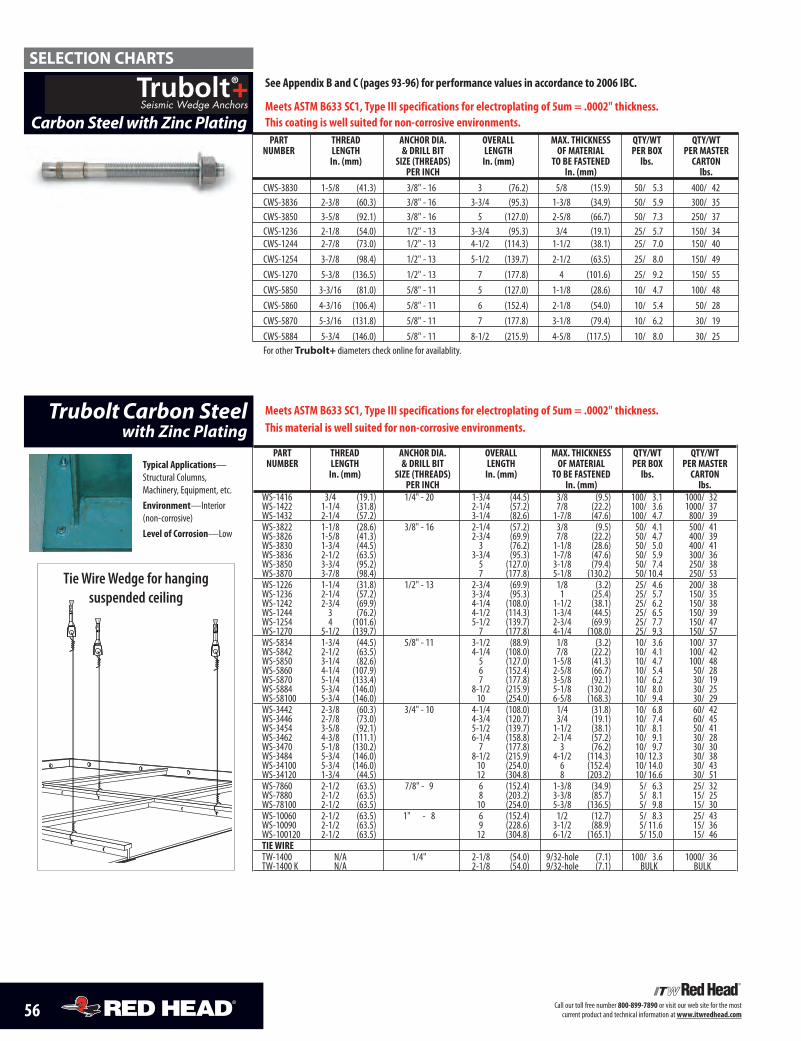
56 Call our toll free number 800-899-7890 or visit our web site for the most current product and technical information at www.itwredhead.com
Trubolt Carbon Steelwith Zinc Plating
part thread anchor dia. overall Max. thickness Qty/Wt Qty/WtnuMBer length & drill Bit length of Material per Box per Master
in. (mm) size (threads) in. (mm) to Be fastened lbs. cartonper inch in. (mm) lbs.
WS-1416 3/4 (19.1) 1/4" - 20 1-3/4 (44.5) 3/8 (9.5) 100/ 3.1 1000/ 32WS-1422 1-1/4 (31.8) 2-1/4 (57.2) 7/8 (22.2) 100/ 3.6 1000/ 37WS-1432 2-1/4 (57.2) 3-1/4 (82.6) 1-7/8 (47.6) 100/ 4.7 800/ 39WS-3822 1-1/8 (28.6) 3/8" - 16 2-1/4 (57.2) 3/8 (9.5) 50/ 4.1 500/ 41WS-3826 1-5/8 (41.3) 2-3/4 (69.9) 7/8 (22.2) 50/ 4.7 400/ 39WS-3830 1-3/4 (44.5) 3 (76.2) 1-1/8 (28.6) 50/ 5.0 400/ 41WS-3836 2-1/2 (63.5) 3-3/4 (95.3) 1-7/8 (47.6) 50/ 5.9 300/ 36WS-3850 3-3/4 (95.2) 5 (127.0) 3-1/8 (79.4) 50/ 7.4 250/ 38WS-3870 3-7/8 (98.4) 7 (177.8) 5-1/8 (130.2) 50/ 10.4 250/ 53WS-1226 1-1/4 (31.8) 1/2" - 13 2-3/4 (69.9) 1/8 (3.2) 25/ 4.6 200/ 38WS-1236 2-1/4 (57.2) 3-3/4 (95.3) 1 (25.4) 25/ 5.7 150/ 35WS-1242 2-3/4 (69.9) 4-1/4 (108.0) 1-1/2 (38.1) 25/ 6.2 150/ 38WS-1244 3 (76.2) 4-1/2 (114.3) 1-3/4 (44.5) 25/ 6.5 150/ 39WS-1254 4 (101.6) 5-1/2 (139.7) 2-3/4 (69.9) 25/ 7.7 150/ 47WS-1270 5-1/2 (139.7) 7 (177.8) 4-1/4 (108.0) 25/ 9.3 150/ 57WS-5834 1-3/4 (44.5) 5/8" - 11 3-1/2 (88.9) 1/8 (3.2) 10/ 3.6 100/ 37WS-5842 2-1/2 (63.5) 4-1/4 (108.0) 7/8 (22.2) 10/ 4.1 100/ 42WS-5850 3-1/4 (82.6) 5 (127.0) 1-5/8 (41.3) 10/ 4.7 100/ 48WS-5860 4-1/4 (107.9) 6 (152.4) 2-5/8 (66.7) 10/ 5.4 50/ 28WS-5870 5-1/4 (133.4) 7 (177.8) 3-5/8 (92.1) 10/ 6.2 30/ 19WS-5884 5-3/4 (146.0) 8-1/2 (215.9) 5-1/8 (130.2) 10/ 8.0 30/ 25WS-58100 5-3/4 (146.0) 10 (254.0) 6-5/8 (168.3) 10/ 9.4 30/ 29WS-3442 2-3/8 (60.3) 3/4" - 10 4-1/4 (108.0) 1/4 (31.8) 10/ 6.8 60/ 42WS-3446 2-7/8 (73.0) 4-3/4 (120.7) 3/4 (19.1) 10/ 7.4 60/ 45WS-3454 3-5/8 (92.1) 5-1/2 (139.7) 1-1/2 (38.1) 10/ 8.1 50/ 41WS-3462 4-3/8 (111.1) 6-1/4 (158.8) 2-1/4 (57.2) 10/ 9.1 30/ 28WS-3470 5-1/8 (130.2) 7 (177.8) 3 (76.2) 10/ 9.7 30/ 30WS-3484 5-3/4 (146.0) 8-1/2 (215.9) 4-1/2 (114.3) 10/ 12.3 30/ 38WS-34100 5-3/4 (146.0) 10 (254.0) 6 (152.4) 10/ 14.0 30/ 43WS-34120 1-3/4 (44.5) 12 (304.8) 8 (203.2) 10/ 16.6 30/ 51WS-7860 2-1/2 (63.5) 7/8" - 9 6 (152.4) 1-3/8 (34.9) 5/ 6.3 25/ 32WS-7880 2-1/2 (63.5) 8 (203.2) 3-3/8 (85.7) 5/ 8.1 15/ 25WS-78100 2-1/2 (63.5) 10 (254.0) 5-3/8 (136.5) 5/ 9.8 15/ 30WS-10060 2-1/2 (63.5) 1" - 8 6 (152.4) 1/2 (12.7) 5/ 8.3 25/ 43WS-10090 2-1/2 (63.5) 9 (228.6) 3-1/2 (88.9) 5/ 11.6 15/ 36WS-100120 2-1/2 (63.5) 12 (304.8) 6-1/2 (165.1) 5/ 15.0 15/ 46tie WireTW-1400 N/A 1/4" 2-1/8 (54.0) 9/32-hole (7.1) 100/ 3.6 1000/ 36TW-1400 K N/A 2-1/8 (54.0) 9/32-hole (7.1) BULK BULK
typical applications—Structural Columns, Machinery, Equipment, etc.environment—Interior (non-corrosive)level of corrosion—Low
Meets astM B633 sc1, type iii specifications for electroplating of 5um = .0002" thickness. this material is well suited for non-corrosive environments.
SELECTION CHARTS
Tie Wire Wedge for hanging suspended ceiling
Carbon Steel with Zinc Platingpart thread anchor dia. overall Max. thickness Qty/Wt Qty/Wt
nuMBer length & drill Bit length of Material per Box per Masterin. (mm) size (threads) in. (mm) to Be fastened lbs. carton
per inch in. (mm) lbs.CWS-3830 1-5/8 (41.3) 3/8" - 16 3 (76.2) 5/8 (15.9) 50/ 5.3 400/ 42CWS-3836 2-3/8 (60.3) 3/8" - 16 3-3/4 (95.3) 1-3/8 (34.9) 50/ 5.9 300/ 35CWS-3850 3-5/8 (92.1) 3/8" - 16 5 (127.0) 2-5/8 (66.7) 50/ 7.3 250/ 37CWS-1236 2-1/8 (54.0) 1/2" - 13 3-3/4 (95.3) 3/4 (19.1) 25/ 5.7 150/ 34CWS-1244 2-7/8 (73.0) 1/2" - 13 4-1/2 (114.3) 1-1/2 (38.1) 25/ 7.0 150/ 40CWS-1254 3-7/8 (98.4) 1/2" - 13 5-1/2 (139.7) 2-1/2 (63.5) 25/ 8.0 150/ 49CWS-1270 5-3/8 (136.5) 1/2" - 13 7 (177.8) 4 (101.6) 25/ 9.2 150/ 55CWS-5850 3-3/16 (81.0) 5/8" - 11 5 (127.0) 1-1/8 (28.6) 10/ 4.7 100/ 48CWS-5860 4-3/16 (106.4) 5/8" - 11 6 (152.4) 2-1/8 (54.0) 10/ 5.4 50/ 28CWS-5870 5-3/16 (131.8 ) 5/8" - 11 7 (177.8) 3-1/8 (79.4) 10/ 6.2 30/ 19CWS-5884 5-3/4 (146.0) 5/8" - 11 8-1/2 (215.9) 4-5/8 (117.5) 10/ 8.0 30/ 25For other Trubolt+ diameters check online for availablity.
see appendix B and c (pages 93-96) for performance values in accordance to 2006 iBc.
Meets astM B633 sc1, type iii specifications for electroplating of 5um = .0002" thickness. this coating is well suited for non-corrosive environments.
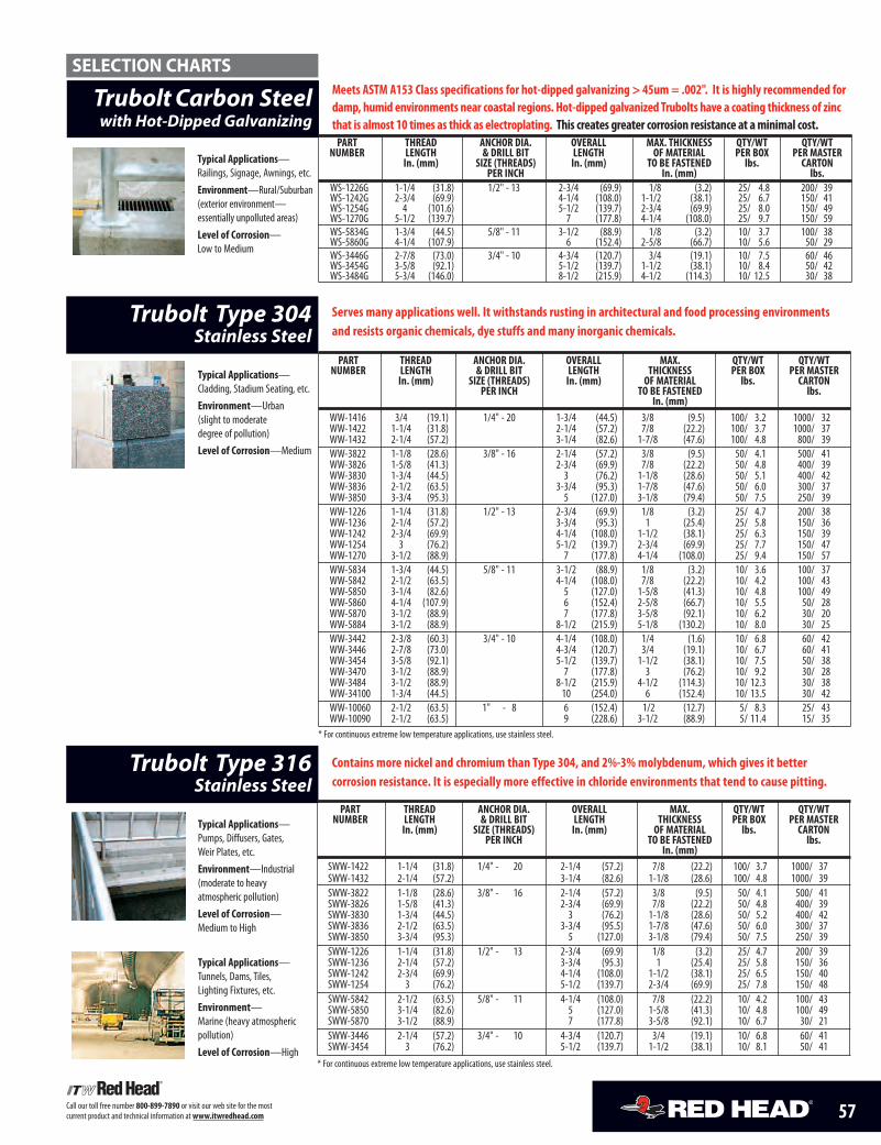
57Call our toll free number 800-899-7890 or visit our web site for the most current product and technical information at www.itwredhead.com
Trubolt Type 316 Stainless Steel
contains more nickel and chromium than type 304, and 2%-3% molybdenum, which gives it better corrosion resistance. it is especially more effective in chloride environments that tend to cause pitting.
part thread anchor dia. overall Max. Qty/Wt Qty/WtnuMBer length & drill Bit length thickness per Box per Master
in. (mm) size (threads) in. (mm) of Material lbs. cartonper inch to Be fastened lbs.
in. (mm)SWW-1422 1-1/4 (31.8) 1/4" - 20 2-1/4 (57.2) 7/8 (22.2) 100/ 3.7 1000/ 37SWW-1432 2-1/4 (57.2) 3-1/4 (82.6) 1-1/8 (28.6) 100/ 4.8 1000/ 39SWW-3822 1-1/8 (28.6) 3/8" - 16 2-1/4 (57.2) 3/8 (9.5) 50/ 4.1 500/ 41SWW-3826 1-5/8 (41.3) 2-3/4 (69.9) 7/8 (22.2) 50/ 4.8 400/ 39SWW-3830 1-3/4 (44.5) 3 (76.2) 1-1/8 (28.6) 50/ 5.2 400/ 42SWW-3836 2-1/2 (63.5) 3-3/4 (95.5) 1-7/8 (47.6) 50/ 6.0 300/ 37SWW-3850 3-3/4 (95.3) 5 (127.0) 3-1/8 (79.4) 50/ 7.5 250/ 39SWW-1226 1-1/4 (31.8) 1/2" - 13 2-3/4 (69.9) 1/8 (3.2) 25/ 4.7 200/ 39SWW-1236 2-1/4 (57.2) 3-3/4 (95.3) 1 (25.4) 25/ 5.8 150/ 36SWW-1242 2-3/4 (69.9) 4-1/4 (108.0) 1-1/2 (38.1) 25/ 6.5 150/ 40SWW-1254 3 (76.2) 5-1/2 (139.7) 2-3/4 (69.9) 25/ 7.8 150/ 48SWW-5842 2-1/2 (63.5) 5/8" - 11 4-1/4 (108.0) 7/8 (22.2) 10/ 4.2 100/ 43SWW-5850 3-1/4 (82.6) 5 (127.0) 1-5/8 (41.3) 10/ 4.8 100/ 49SWW-5870 3-1/2 (88.9) 7 (177.8) 3-5/8 (92.1) 10/ 6.7 30/ 21SWW-3446 2-1/4 (57.2) 3/4" - 10 4-3/4 (120.7) 3/4 (19.1) 10/ 6.8 60/ 41SWW-3454 3 (76.2) 5-1/2 (139.7) 1-1/2 (38.1) 10/ 8.1 50/ 41
* For continuous extreme low temperature applications, use stainless steel.
typical applications—Pumps, Diffusers, Gates, Weir Plates, etc.environment—Industrial (moderate to heavy atmospheric pollution)level of corrosion—Medium to High
Trubolt Type 304Stainless Steel
part thread anchor dia. overall Max. Qty/Wt Qty/WtnuMBer length & drill Bit length thickness per Box per Master
in. (mm) size (threads) in. (mm) of Material lbs. cartonper inch to Be fastened lbs.
in. (mm)WW-1416 3/4 (19.1) 1/4" - 20 1-3/4 (44.5) 3/8 (9.5) 100/ 3.2 1000/ 32WW-1422 1-1/4 (31.8) 2-1/4 (57.2) 7/8 (22.2) 100/ 3.7 1000/ 37WW-1432 2-1/4 (57.2) 3-1/4 (82.6) 1-7/8 (47.6) 100/ 4.8 800/ 39WW-3822 1-1/8 (28.6) 3/8" - 16 2-1/4 (57.2) 3/8 (9.5) 50/ 4.1 500/ 41WW-3826 1-5/8 (41.3) 2-3/4 (69.9) 7/8 (22.2) 50/ 4.8 400/ 39WW-3830 1-3/4 (44.5) 3 (76.2) 1-1/8 (28.6) 50/ 5.1 400/ 42WW-3836 2-1/2 (63.5) 3-3/4 (95.3) 1-7/8 (47.6) 50/ 6.0 300/ 37WW-3850 3-3/4 (95.3) 5 (127.0) 3-1/8 (79.4) 50/ 7.5 250/ 39WW-1226 1-1/4 (31.8) 1/2" - 13 2-3/4 (69.9) 1/8 (3.2) 25/ 4.7 200/ 38WW-1236 2-1/4 (57.2) 3-3/4 (95.3) 1 (25.4) 25/ 5.8 150/ 36WW-1242 2-3/4 (69.9) 4-1/4 (108.0) 1-1/2 (38.1) 25/ 6.3 150/ 39WW-1254 3 (76.2) 5-1/2 (139.7) 2-3/4 (69.9) 25/ 7.7 150/ 47WW-1270 3-1/2 (88.9) 7 (177.8) 4-1/4 (108.0) 25/ 9.4 150/ 57WW-5834 1-3/4 (44.5) 5/8" - 11 3-1/2 (88.9) 1/8 (3.2) 10/ 3.6 100/ 37WW-5842 2-1/2 (63.5) 4-1/4 (108.0) 7/8 (22.2) 10/ 4.2 100/ 43WW-5850 3-1/4 (82.6) 5 (127.0) 1-5/8 (41.3) 10/ 4.8 100/ 49WW-5860 4-1/4 (107.9) 6 (152.4) 2-5/8 (66.7) 10/ 5.5 50/ 28WW-5870 3-1/2 (88.9) 7 (177.8) 3-5/8 (92.1) 10/ 6.2 30/ 20WW-5884 3-1/2 (88.9) 8-1/2 (215.9) 5-1/8 (130.2) 10/ 8.0 30/ 25WW-3442 2-3/8 (60.3) 3/4" - 10 4-1/4 (108.0) 1/4 (1.6) 10/ 6.8 60/ 42WW-3446 2-7/8 (73.0) 4-3/4 (120.7) 3/4 (19.1) 10/ 6.7 60/ 41WW-3454 3-5/8 (92.1) 5-1/2 (139.7) 1-1/2 (38.1) 10/ 7.5 50/ 38WW-3470 3-1/2 (88.9) 7 (177.8) 3 (76.2) 10/ 9.2 30/ 28WW-3484 3-1/2 (88.9) 8-1/2 (215.9) 4-1/2 (114.3) 10/ 12.3 30/ 38WW-34100 1-3/4 (44.5) 10 (254.0) 6 (152.4) 10/ 13.5 30/ 42WW-10060 2-1/2 (63.5) 1" - 8 6 (152.4) 1/2 (12.7) 5/ 8.3 25/ 43WW-10090 2-1/2 (63.5) 9 (228.6) 3-1/2 (88.9) 5/ 11.4 15/ 35
* For continuous extreme low temperature applications, use stainless steel.
typical applications—Cladding, Stadium Seating, etc.environment—Urban (slight to moderate degree of pollution)level of corrosion—Medium
serves many applications well. it withstands rusting in architectural and food processing environmentsand resists organic chemicals, dye stuffs and many inorganic chemicals.
typical applications—Tunnels, Dams, Tiles, Lighting Fixtures, etc.environment—Marine (heavy atmosphericpollution)level of corrosion—High
typical applications—Railings, Signage, Awnings, etc.environment—Rural/Suburban(exterior environment—essentially unpolluted areas)level of corrosion—Low to Medium
Trubolt Carbon Steelwith Hot-Dipped Galvanizing
part thread anchor dia. overall Max. thickness Qty/Wt Qty/WtnuMBer length & drill Bit length of Material per Box per Master
in. (mm) size (threads) in. (mm) to Be fastened lbs. cartonper inch in. (mm) lbs.
WS-1226G 1-1/4 (31.8) 1/2" - 13 2-3/4 (69.9) 1/8 (3.2) 25/ 4.8 200/ 39WS-1242G 2-3/4 (69.9) 4-1/4 (108.0) 1-1/2 (38.1) 25/ 6.7 150/ 41WS-1254G 4 (101.6) 5-1/2 (139.7) 2-3/4 (69.9) 25/ 8.0 150/ 49WS-1270G 5-1/2 (139.7) 7 (177.8) 4-1/4 (108.0) 25/ 9.7 150/ 59WS-5834G 1-3/4 (44.5) 5/8" - 11 3-1/2 (88.9) 1/8 (3.2) 10/ 3.7 100/ 38WS-5860G 4-1/4 (107.9) 6 (152.4) 2-5/8 (66.7) 10/ 5.6 50/ 29WS-3446G 2-7/8 (73.0) 3/4" - 10 4-3/4 (120.7) 3/4 (19.1) 10/ 7.5 60/ 46WS-3454G 3-5/8 (92.1) 5-1/2 (139.7) 1-1/2 (38.1) 10/ 8.4 50/ 42WS-3484G 5-3/4 (146.0) 8-1/2 (215.9) 4-1/2 (114.3) 10/ 12.5 30/ 38
Meets astM a153 class specifications for hot-dipped galvanizing > 45um = .002". it is highly recommended fordamp, humid environments near coastal regions. hot-dipped galvanized trubolts have a coating thickness of zinc that is almost 10 times as thick as electroplating. this creates greater corrosion resistance at a minimal cost.
SELECTION CHARTS
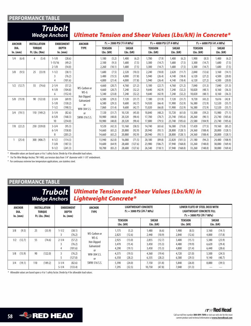
58 Call our toll free number 800-899-7890 or visit our web site for the most current product and technical information at www.itwredhead.com
anchor installation eMBedMent anchor f’c = 2000 psi (13.8 Mpa) f’c = 4000 psi (27.6 Mpa) f’c = 6000 psi (41.4 Mpa)dia. torQue depth type tension shear tension shear tension shear
in. (mm) ft. lbs. (nm) in. (mm) lbs. (kn) lbs. (kn) lbs. (kn) lbs. (kn) lbs. (kn) lbs. (kn)
1/4 (6.4) 4 (5.4) 1-1/8 (28.6) 1,180 (5.2) 1,400 (6.2) 1,780 (7.9) 1,400 (6.2) 1,900 (8.5) 1,400 (6.2)1-15/16 (49.2) 2,100 (9.3) 1,680 (7.5) 3,300 (14.7) 1,680 (7.5) 3,300 (14.7) 1,680 (7.5)2-1/8 (54.0) 2,260 (10.1) 1,680 (7.5) 3,300 (14.7) 1,680 (7.5) 3,300 (14.7) 1,680 (7.5)
3/8 (9.5) 25 (33.9) 1-1/2 (38.1) 1,680 (7.5) 2,320 (10.3) 2,240 (10.0) 2,620 (11.7) 2,840 (12.6) 3,160 (14.1)3 (76.2) 3,480 (15.5) 4,000 (17.8) 5,940 (26.4) 4,140 (18.4) 6,120 (27.2) 4,500 (20.0)4 (101.6) 4,800 (21.4) 4,000 (17.8) 5,940 (26.4) 4,140 (18.4) 6,120 (27.2) 4,500 (20.0)
1/2 (12.7) 55 (74.6) 2-1/4 (57.2) 4,660 (20.7) 4,760 (21.2) 5,100 (22.7) 4,760 (21.2) 7,040 (31.3) 7,040 (31.3)4-1/8 (104.8) 4,660 (20.7) 7,240 (32.2) 9,640 (42.9) 7,240 (32.2) 10,820 (48.1) 8,160 (36.3)6 (152.4) 5,340 (23.8) 7,240 (32.2) 9,640 (42.9) 7,240 (32.2) 10,820 (48.1) 8,160 (36.3)
5/8 (15.9) 90 (122.0) 2-3/4 (69.9) 6,580 (29.3) 7,120 (31.7) 7,180 (31.9) 7,120 (31.7) 9,720 (43.2) 9,616 (42.85-1/8 (130.2) 6,580 (29.3) 9,600 (42.7) 14,920 (66.4) 11,900 (52.9) 16,380 (72.9) 12,520 (55.7)7-1/2 (190.5) 7,060 (31.4) 9,600 (42.7) 15,020 (66.8) 11,900 (52.9) 16,380 (72.9) 12,520 (55.7)
3/4 (19.1) 110 (149.2) 3-1/4 (82.6) 7,120 (31.7) 10,120 (45.0) 10,840 (48.2) 13,720 (61.0) 13,300 (59.2) 15,980 (71.1)6-5/8 (168.3) 10,980 (48.8) 20,320 (90.4) 17,700 (78.7) 23,740 (105.6) 20,260 (90.1) 23,740 (105.6)10 (254.0) 10,980 (48.8) 20,320 (90.4) 17,880 (79.5) 23,740 (105.6) 23,580 (104.9) 23,740 (105.6)
7/8 (22.2) 250 (339.0) 3-3/4 (95.3) 9,520 (42.3) 13,160 (58.5) 14,740 (65.6) 16,580 (73.8) 17,420 (77.5) 19,160 (85.2)6-1/4 (158.8) 14,660 (65.2) 20,880 (92.9) 20,940 (93.1) 28,800 (128.1) 24,360 (108.4) 28,800 (128.1)8 (203.2) 14,660 (65.2) 20,880 (92.9) 20,940 (93.1) 28,800 (128.1) 24,360 (108.4) 28,800 (128.1)
1 (25.4) 300 (406.7) 4-1/2 (114.3) 13,940 (62.0) 16,080 (71.5) 20,180 (89.8) 22,820 (101.5) 21,180 (94.2) 24,480 (108.9)7-3/8 (187.3) 14,600 (64.9) 28,680 (127.6) 23,980 (106.7) 37,940 (168.8) 33,260 (148.0) 38,080 (169.4)9-1/2 (241.3) 18,700 (83.2) 28,680 (127.6) 26,540 (118.1) 37,940 (168.8) 33,260 (148.0) 38,080 (169.4)
* Allowable values are based upon a 4 to 1 safety factor. Divide by 4 for allowable load values.* For Tie-Wire Wedge Anchor, TW-1400, use tension data from 1/4" diameter with 1-1/8" embedment.* For continuous extreme low temperature applications, use stainless steel.
Ultimate Tension and Shear Values (Lbs/kN) in Concrete*
Ultimate Tension and Shear Values (Lbs/kN) inLightweight Concrete*
anchor installation eMBedMent anchor lightWeight concrete loWer flute of steel deck Withdia. torQue depth type f’c = 3000 psi (20.7 Mpa) lightWeight concrete fill
in. (mm) ft. lbs. (nm) in. (mm) f’c = 3000 psi (20.7 Mpa)
tension shear tension shearlbs. (kn) lbs. (kn) lbs. (kn) lbs. (kn)
3/8 (9.5) 25 (33.9) 1-1/2 (38.1) 1,175 (5.2) 1,480 (6.6) 1,900 (8.5) 3,160 (14.1)3 (76.2) 2,825 (12.6) 2,440 (10.9) 2,840 (12.6) 4,000 (17.8)
1/2 (12.7) 55 (74.6) 2-1/4 (57.2) 2,925 (13.0) 2,855 (12.7) 3,400 (15.1) 5,380 (23.9)3 (76.2) 3,470 (15.4) 3,450 (15.3) 4,480 (19.9) 6,620 (29.4)4 (101.6) 4,290 (19.1) 3,450 (15.3) 4,800 (21.4) 6,440 (28.6)
5/8 (15.9) 90 (122.0) 3 (76.2) 4,375 (19.5) 4,360 (19.4) 4,720 (21.0) 5,500 (24.5)5 (127.0) 6,350 (28.2) 6,335 (28.2) 6,580 (29.3) 9,140 (40.7)
3/4 (19.1) 110 (149.2) 3-1/4 (82.6) 5,390 (24.0) 7,150 (31.8) 5,840 (26.0) 8,880 (39.5)5-1/4 (133.4) 7,295 (32.5) 10,750 (47.8) 7,040 (31.3) --- ---
* Allowable values are based upon a 4 to 1 safety factor. Divide by 4 for allowable load values.
WS-Carbon orWS-G
Hot-DippedGalvanized
orWW-304 S.S.
or SWW-316 S.S.
WS-Carbon orWS-G
Hot-DippedGalvanized
orWW-304 S.S.
or SWW-316 S.S.
TruboltWedge Anchors
TruboltWedge Anchors
PERFORMANCE TABLE
PERFORMANCE TABLE
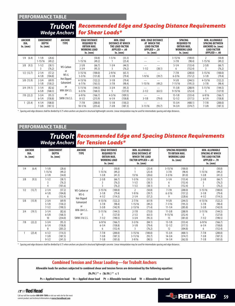
59Call our toll free number 800-899-7890 or visit our web site for the most current product and technical information at www.itwredhead.com
Recommended Edge and Spacing Distance Requirementsfor Tension Loads*
anchor eMBedMent anchor edge distance Min. alloWaBle spacing reQuired Min. alloWaBledia. depth type reQuired to edge distance at to oBtain Max. spacing at Which
in. (mm) in. (mm) oBtain Max. Which the load Working load the load factorWorking load factor applied = .65 in. (mm) applied = .70
in. (mm) in. (mm) in. (mm)
1/4 (6.4) 1-1/8 (28.6) 2 (50.8) 1 (25.4) 3-15/16 (100.0) 2 (50.8)1-15/16 (49.2) 1-15/16 (49.2) 1 (25.4) 3-7/8 (98.4) 1-15/16 (49.2)2-1/8 (54.0) 1-5/8 (41.3) 13/16 (20.6) 3-3/16 (81.0) 1-5/8 (41.3)
3/8 (9.5) 1-1/2 (38.1) 2-5/8 (66.7) 1-5/16 (33.3) 5-1/4 (133.4) 2-5/8 (66.7)3 (76.2) 3 (76.2) 1-1/2 (38.1) 6 (152.4) 3 (76.2)4 (101.6) 3 (76.2) 1-1/2 (38.1) 6 (152.4) 3 (76.2)
1/2 (12.7) 2-1/4 (57.2) 3-15/16 (100.0) 2 (50.8) 7-7/8 (200.0) 3-15/16 (100.0)4-1/8 (104.8) 3-1/8 (79.4) 1-9/16 (39.7) 6-3/16 (157.2) 3-1/8 (79.4)6 (152.4) 4-1/2 (114.3) 2-1/4 (57.2) 9 (228.6) 4-1/2 (114.3)
5/8 (15.9) 2-3/4 (69.9) 4-13/16 (122.2) 2-7/16 (61.9) 9-5/8 (244.5) 4-13/16 (122.2)5-1/8 (130.2) 3-7/8 (98.4) 1-15/16 (49.2) 7-1/16 (195.3) 3-7/8 (98.4)7-1/2 (190.5) 5-5/8 (142.9) 2-13/16 (71.4) 11-1/4 (285.8) 5-5/8 (142.9)
3/4 (19.1) 3-1/4 (82.6) 5-11/16 (144.5) 2-7/8 (73.0) 11-3/8 (288.9) 5-11/16 (144.5)6-5/8 (168.3) 5 (127.0) 2-1/2 (63.5) 9-15/16 (252.4) 5 (127.0)10 (254.0) 7-1/2 (190.5) 3-3/4 (95.3) 15 (381.0) 7-1/2 (190.5)
7/8 (22.2) 3-3/4 (95.3) 6-9/16 (166.7) 3-5/16 (84.1) 13-1/8 (333.4) 6-9/16 (166.7)6-1/4 (158.8) 6-1/4 (158.8) 3-1/8 (79.4) 12-1/2 (317.5) 6-1/4 (158.8)8 (203.2) 6 (152.4) 3 (76.2) 12 (304.8) 6 (152.4)
1 (25.4) 4-1/2 (114.3) 7-7/8 (200.0) 3-15/16 (100.0) 15-3/4 (400.1) 7-7/8 (200.0)7-3/8 (187.3) 7-3/8 (187.3) 3-11/16 (93.7) 14-3/4 (374.7) 7-3/8 (187.3)9-1/2 (241.3) 7-1/8 (181.0) 3-9/16 (90.5) 14-1/4 (362.0) 7-1/8 (181.0)
* Spacing and edge distances shall be divided by 0.75 when anchors are placed in structural lightweight concrete. Linear interpolation may be used for intermediate spacing and edge distances.
anchor eMBedMent anchor edge distance Min. edge Min. edge distance spacing Min. alloWaBledia. depth type reQuired to distance at Which at Which the reQuired to spacing BetWeen
in. (mm) in. (mm) oBtain Max. the load factor load factor oBtain Max. anchors in. (mm) Working load applied = .60 applied = .20 Working load load factor
in. (mm) in. (mm) in. (mm) in. (mm) applied = .40
1/4 (6.4) 1-1/8 (28.6) 2 (50.8) 1-5/16 (33.3) --- --- 3-15/16 (100.0) 2 (50.8)1-15/16 (49.2) 1-15/16 (49.2) 1 (25.4) --- --- 3-7/8 (98.4) 1-15/16 (49.2)
3/8 (9.5) 1-1/2 (38.1) 2-5/8 (66.7) 1-3/4 (44.5) --- --- 5-1/4 (133.4) 2-5/8 (66.7)3 (76.2) 3-3/4 (95.3) 3 (76.2) 1-1/2 (38.1) 6 (152.4) 3 (76.2)
1/2 (12.7) 2-1/4 (57.2) 3-15/16 (100.0) 2-9/16 (65.1) --- --- 7-7/8 (200.0) 3-15/16 (100.0)4-1/8 (104.8) 5-3/16 (131.8) 3-1/8 (79.4) 1-9/16 (39.7) 6-3/16 (157.2) 3-1/8 (79.4)
5/8 (15.9) 2-3/4 (69.9) 4-13/16 (122.2) 3-1/8 (79.4) --- --- 9-5/8 (244.5) 4-13/16 (122.2)5-1/8 (130.2) 6-7/16 (163.5) 3-7/8 (98.4) 1-15/16 (49.2) 7-11/16 (195.3) 3-7/8 (98.4)
3/4 (19.1) 3-1/4 (82.6) 5-11/16 (144.5) 3-3/4 (95.3) --- --- 11-3/8 (288.9) 5-11/16 (144.5)6-5/8 (168.3) 6-5/16 (160.3) 5 (127.0) 2-1/2 (63.5) 9-15/16 (252.4) 5 (127.0)
7/8 (22.2) 3-3/4 (95.3) 6-9/16 (166.7) 4-5/16 (109.5) --- --- 13-1/8 (333.4) 6-9/16 (166.7)6-1/4 (158.8) 8-1/2 (215.9) 6-1/4 (158.8) 3-1/8 (79.4) 12-1/2 (317.5) 6-1/4 (158.8)
1 (25.4) 4-1/4 (108.0) 7-7/8 (200.0) 5-1/8 (130.2) --- --- 15-3/4 (400.1) 7-7/8 (200.0)7-3/8 (187.3) 10-1/16 (255.6) 7-3/8 (187.3) 3-11/16 (93.7) 14-3/4 (374.7) 7-3/8 (187.3)
* Spacing and edge distances shall be divided by 0.75 when anchors are placed in structural lightweight concrete. Linear interpolation may be used for intermediate spacing and edge distances.
combined tension and shear loading—for trubolt anchorsallowable loads for anchors subjected to combined shear and tension forces are determined by the following equation:
(ps /pt ) 5/3 + (vs /vt ) 5/3 ≤ 1
ps = applied tension load vs = applied shear load pt = allowable tension load vt = allowable shear load
WS-Carbon or
WS-GHot-DippedGalvanized
orWW-304 S.S.
or SWW-316 S.S.
WS-Carbon orWS-G
Hot-DippedGalvanized
orWW-304 S.S.
or SWW-316 S.S.
TruboltWedge Anchors
TruboltWedge Anchors
Recommended Edge and Spacing Distance Requirementsfor Shear Loads*
PERFORMANCE TABLE
PERFORMANCE TABLE
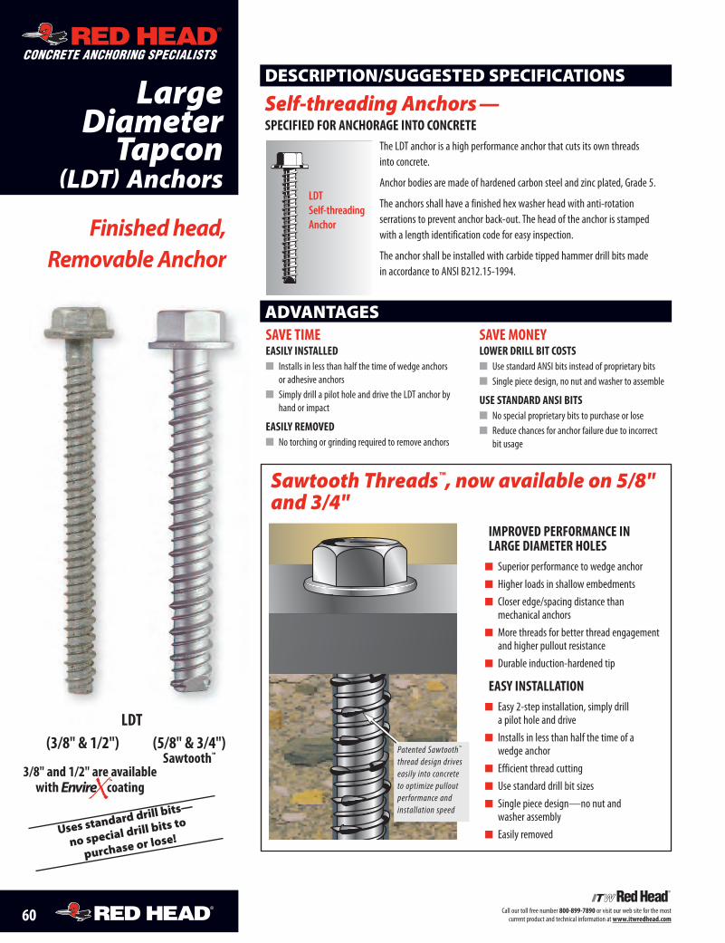
Uses standard d
rill bits—
no special drill
bits to
purchase or lose
!
60 Call our toll free number 800-899-7890 or visit our web site for the mostcurrent product and technical information atwww.itwredhead.com
SAVE TIMEEASILY INSTALLED� Installs in less than half the time of wedge anchors
or adhesive anchors� Simply drill a pilot hole and drive the LDT anchor by
hand or impact
EASILY REMOVED� No torching or grinding required to remove anchors
SAVE MONEYLOWER DRILL BIT COSTS� Use standard ANSI bits instead of proprietary bits� Single piece design, no nut and washer to assemble
USE STANDARD ANSI BITS� No special proprietary bits to purchase or lose� Reduce chances for anchor failure due to incorrect
bit usage
Finished head,Removable Anchor
DESCRIPTION/SUGGESTED SPECIFICATIONS
Self-threading Anchors—SPECIFIED FOR ANCHORAGE INTO CONCRETE
The LDT anchor is a high performance anchor that cuts its own threadsinto concrete.
Anchor bodies are made of hardened carbon steel and zinc plated, Grade 5.
The anchors shall have a finished hex washer head with anti-rotationserrations to prevent anchor back-out. The head of the anchor is stampedwith a length identification code for easy inspection.
The anchor shall be installed with carbide tipped hammer drill bits madein accordance to ANSI B212.15-1994.
LDTSelf-threadingAnchor
LargeDiameterTapcon
(LDT) Anchors
LDT(3/8" & 1/2") (5/8" & 3/4")
Sawtooth™
ADVANTAGES
Sawtooth Threads™, now available on 5/8"and 3/4"
IMPROVED PERFORMANCE INLARGE DIAMETER HOLES
� Superior performance to wedge anchor� Higher loads in shallow embedments� Closer edge/spacing distance than
mechanical anchors� More threads for better thread engagement
and higher pullout resistance� Durable induction-hardened tip
EASY INSTALLATION� Easy 2-step installation, simply drill
a pilot hole and drive� Installs in less than half the time of a
wedge anchor� Efficient thread cutting� Use standard drill bit sizes� Single piece design—no nut and
washer assembly� Easily removed
Patented Sawtooth™
thread design driveseasily into concreteto optimize pulloutperformance andinstallation speed
CONCRETE ANCHORING SPECIALISTS
3/8" and 1/2" are availablewith coating
TM
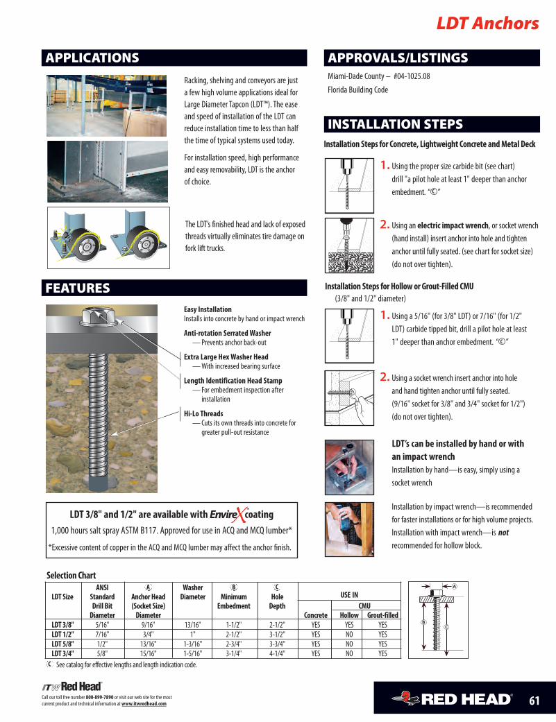
A
CB
Selection ChartANSI Washer
LDT Size Standard Anchor Head Diameter Minimum Hole USE INDrill Bit (Socket Size) Embedment Depth CMUDiameter Diameter Concrete Hollow Grout-filled
LDT 3/8" 5/16" 9/16" 13/16" 1-1/2" 2-1/2" YES YES YESLDT 1/2" 7/16" 3/4" 1" 2-1/2" 3-1/2" YES NO YESLDT 5/8" 1/2" 13/16" 1-3/16" 2-3/4" 3-3/4" YES NO YESLDT 3/4" 5/8" 15/16" 1-5/16" 3-1/4" 4-1/4" YES NO YESSee catalog for effective lengths and length indication code.
C
C
A B
61Call our toll free number 800-899-7890 or visit our web site for the mostcurrent product and technical information atwww.itwredhead.com
INSTALLATION STEPS
LDT Anchors
APPLICATIONS
FEATURES
Racking, shelving and conveyors are justa few high volume applications ideal forLarge Diameter Tapcon (LDT™). The easeand speed of installation of the LDT canreduce installation time to less than halfthe time of typical systems used today.
For installation speed, high performanceand easy removability, LDT is the anchorof choice.
APPROVALS/LISTINGSMiami-Dade County – #04-1025.08Florida Building Code
Easy InstallationInstalls into concrete by hand or impact wrench
Anti-rotation SerratedWasher—Prevents anchor back-out
Extra Large HexWasher Head—With increased bearing surface
Length Identification Head Stamp—For embedment inspection after
installation
Hi-Lo Threads—Cuts its own threads into concrete for
greater pull-out resistance
1. Using the proper size carbide bit (see chart)drill "a pilot hole at least 1" deeper than anchorembedment. “ ”C
2. Using an electric impact wrench, or socket wrench(hand install) insert anchor into hole and tightenanchor until fully seated. (see chart for socket size)(do not over tighten).
���������������
2. Using a socket wrench insert anchor into hole and hand tighten anchor until fully seated.(9/16" socket for 3/8" and 3/4" socket for 1/2")(do not over tighten).
1. Using a 5/16" (for 3/8" LDT) or 7/16" (for 1/2"LDT) carbide tipped bit, drill a pilot hole at least1" deeper than anchor embedment. “ ”C
���������������
Installation Steps for Concrete, Lightweight Concrete and Metal Deck
Installation Steps for Hollow or Grout-Filled CMU(3/8" and 1/2" diameter)
Installation by impact wrench—is recommendedfor faster installations or for high volume projects.Installation with impact wrench—is notrecommended for hollow block.
LDT’s can be installed by hand or withan impact wrenchInstallation by hand—is easy, simply using asocket wrench
The LDT’s finished head and lack of exposedthreads virtually eliminates tire damage onfork lift trucks.
LDT 3/8" and 1/2" are available with coating1,000 hours salt spray ASTM B117. Approved for use in ACQ and MCQ lumber*
*Excessive content of copper in the ACQ and MCQ lumber may affect the anchor finish.
TM
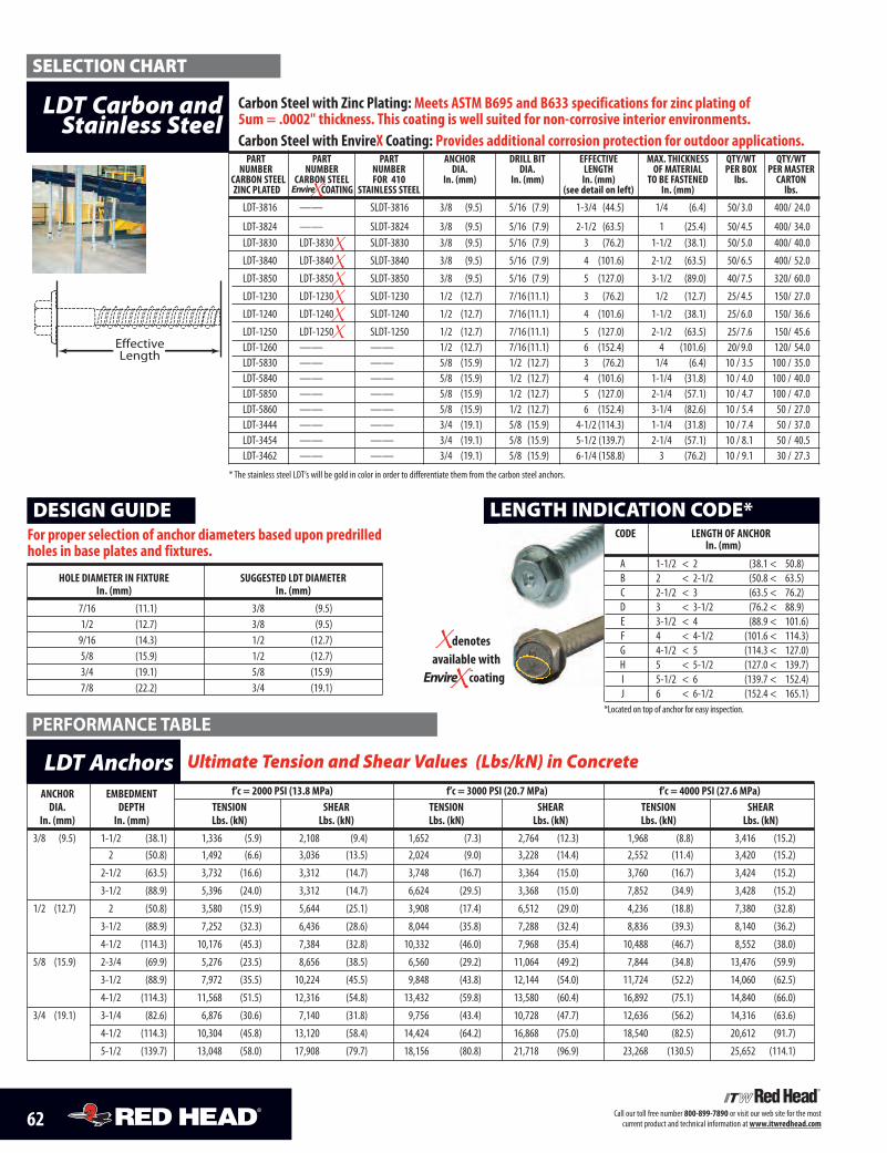
LENGTH INDICATION CODE*
CODE LENGTH OF ANCHOR In. (mm)
A 1-1/2 < 2 (38.1 < 50.8)B 2 < 2-1/2 (50.8 < 63.5)C 2-1/2 < 3 (63.5 < 76.2)D 3 < 3-1/2 (76.2 < 88.9)E 3-1/2 < 4 (88.9 < 101.6)F 4 < 4-1/2 (101.6 < 114.3)G 4-1/2 < 5 (114.3 < 127.0)H 5 < 5-1/2 (127.0 < 139.7)I 5-1/2 < 6 (139.7 < 152.4)J 6 < 6-1/2 (152.4 < 165.1)
*Located on top of anchor for easy inspection.
LENGTH INDICATION CODE*
Ultimate Tension and Shear Values (Lbs/kN) in Concrete 1
ANCHOR EMBEDMENT f’c = 2000 PSI (13.8 MPa) f’c = 3000 PSI (20.7 MPa) f’c = 4000 PSI (27.6 MPa)DIA. DEPTH TENSION SHEAR TENSION SHEAR TENSION SHEAR
In. (mm) In. (mm) Lbs. (kN) Lbs. (kN) Lbs. (kN) Lbs. (kN) Lbs. (kN) Lbs. (kN)
3/8 (9.5) 1-1/2 (38.1) 1,336 (5.9) 2,108 (9.4) 1,652 (7.3) 2,764 (12.3) 1,968 (8.8) 3,416 (15.2)2 (50.8) 1,492 (6.6) 3,036 (13.5) 2,024 (9.0) 3,228 (14.4) 2,552 (11.4) 3,420 (15.2)
2-1/2 (63.5) 3,732 (16.6) 3,312 (14.7) 3,748 (16.7) 3,364 (15.0) 3,760 (16.7) 3,424 (15.2)
3-1/2 (88.9) 5,396 (24.0) 3,312 (14.7) 6,624 (29.5) 3,368 (15.0) 7,852 (34.9) 3,428 (15.2)
1/2 (12.7) 2 (50.8) 3,580 (15.9) 5,644 (25.1) 3,908 (17.4) 6,512 (29.0) 4,236 (18.8) 7,380 (32.8)
3-1/2 (88.9) 7,252 (32.3) 6,436 (28.6) 8,044 (35.8) 7,288 (32.4) 8,836 (39.3) 8,140 (36.2)
4-1/2 (114.3) 10,176 (45.3) 7,384 (32.8) 10,332 (46.0) 7,968 (35.4) 10,488 (46.7) 8,552 (38.0)
5/8 (15.9) 2-3/4 (69.9) 5,276 (23.5) 8,656 (38.5) 6,560 (29.2) 11,064 (49.2) 7,844 (34.8) 13,476 (59.9)
3-1/2 (88.9) 7,972 (35.5) 10,224 (45.5) 9,848 (43.8) 12,144 (54.0) 11,724 (52.2) 14,060 (62.5)
4-1/2 (114.3) 11,568 (51.5) 12,316 (54.8) 13,432 (59.8) 13,580 (60.4) 16,892 (75.1) 14,840 (66.0)
3/4 (19.1) 3-1/4 (82.6) 6,876 (30.6) 7,140 (31.8) 9,756 (43.4) 10,728 (47.7) 12,636 (56.2) 14,316 (63.6)
4-1/2 (114.3) 10,304 (45.8) 13,120 (58.4) 14,424 (64.2) 16,868 (75.0) 18,540 (82.5) 20,612 (91.7)
5-1/2 (139.7) 13,048 (58.0) 17,908 (79.7) 18,156 (80.8) 21,718 (96.9) 23,268 (130.5) 25,652 (114.1)
LDT Anchors
PERFORMANCE TABLE
HOLE DIAMETER IN FIXTURE SUGGESTED LDT DIAMETERIn. (mm) In. (mm)
7/16 (11.1) 3/8 (9.5)1/2 (12.7) 3/8 (9.5)9/16 (14.3) 1/2 (12.7)5/8 (15.9) 1/2 (12.7)3/4 (19.1) 5/8 (15.9)7/8 (22.2) 3/4 (19.1)
DESIGN GUIDEFor proper selection of anchor diameters based upon predrilledholes in base plates and fixtures.
62 Call our toll free number 800-899-7890 or visit our web site for the most current product and technical information at www.itwredhead.com
PART PART PART ANCHOR DRILL BIT EFFECTIVE MAX. THICKNESS QTY/WT QTY/WTNUMBER NUMBER NUMBER DIA. DIA. LENGTH OF MATERIAL PER BOX PER MASTER
CARBON STEEL CARBON STEEL FOR 410 In. (mm) In. (mm) In. (mm) TO BE FASTENED lbs. CARTONZINC PLATED STAINLESS STEEL (see detail on left) In. (mm) lbs.
LDT-3816 —— SLDT-3816 3/8 (9.5) 5/16 (7.9) 1-3/4 (44.5) 1/4 (6.4) 50/3.0 400/ 24.0
LDT-3824 —— SLDT-3824 3/8 (9.5) 5/16 (7.9) 2-1/2 (63.5) 1 (25.4) 50/4.5 400/ 34.0LDT-3830 LDT-3830 SLDT-3830 3/8 (9.5) 5/16 (7.9) 3 (76.2) 1-1/2 (38.1) 50/5.0 400/ 40.0
LDT-3840 LDT-3840 SLDT-3840 3/8 (9.5) 5/16 (7.9) 4 (101.6) 2-1/2 (63.5) 50/6.5 400/ 52.0
LDT-3850 LDT-3850 SLDT-3850 3/8 (9.5) 5/16 (7.9) 5 (127.0) 3-1/2 (89.0) 40/7.5 320/ 60.0
LDT-1230 LDT-1230 SLDT-1230 1/2 (12.7) 7/16 (11.1) 3 (76.2) 1/2 (12.7) 25/4.5 150/ 27.0
LDT-1240 LDT-1240 SLDT-1240 1/2 (12.7) 7/16 (11.1) 4 (101.6) 1-1/2 (38.1) 25/6.0 150/ 36.6
LDT-1250 LDT-1250 SLDT-1250 1/2 (12.7) 7/16 (11.1) 5 (127.0) 2-1/2 (63.5) 25/7.6 150/ 45.6LDT-1260 —— —— 1/2 (12.7) 7/16 (11.1) 6 (152.4) 4 (101.6) 20/9.0 120/ 54.0LDT-5830 —— —— 5/8 (15.9) 1/2 (12.7) 3 (76.2) 1/4 (6.4) 10 / 3.5 100 / 35.0LDT-5840 —— —— 5/8 (15.9) 1/2 (12.7) 4 (101.6) 1-1/4 (31.8) 10 / 4.0 100 / 40.0LDT-5850 —— —— 5/8 (15.9) 1/2 (12.7) 5 (127.0) 2-1/4 (57.1) 10 / 4.7 100 / 47.0LDT-5860 —— —— 5/8 (15.9) 1/2 (12.7) 6 (152.4) 3-1/4 (82.6) 10 / 5.4 50 / 27.0LDT-3444 —— —— 3/4 (19.1) 5/8 (15.9) 4-1/2 (114.3) 1-1/4 (31.8) 10 / 7.4 50 / 37.0LDT-3454 —— —— 3/4 (19.1) 5/8 (15.9) 5-1/2 (139.7) 2-1/4 (57.1) 10 / 8.1 50 / 40.5LDT-3462 —— —— 3/4 (19.1) 5/8 (15.9) 6-1/4 (158.8) 3 (76.2) 10 / 9.1 30 / 27.3
* The stainless steel LDT‘s will be gold in color in order to differentiate them from the carbon steel anchors.
LDT Carbon andStainless Steel
Carbon Steel with Zinc Plating: Meets ASTM B695 and B633 specifications for zinc plating of 5um = .0002" thickness. This coating is well suited for non-corrosive interior environments. Carbon Steel with EnvireX Coating: Provides additional corrosion protection for outdoor applications.
SELECTION CHART
EffectiveLength
EffectiveLength
TM
COATING
denotes available with
coatingTM
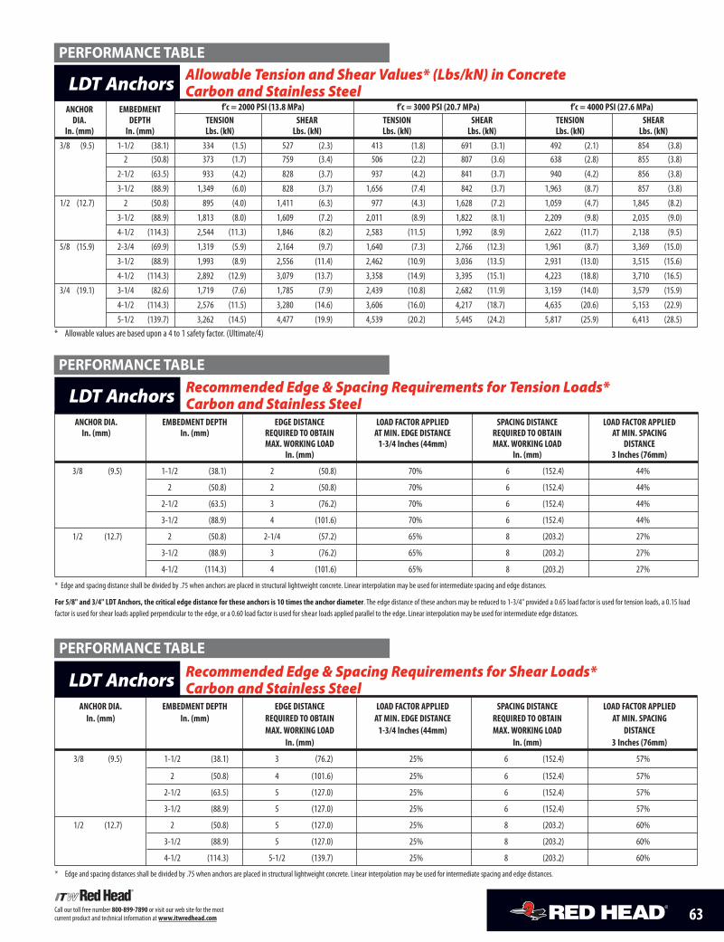
63Call our toll free number 800-899-7890 or visit our web site for the most current product and technical information at www.itwredhead.com
Allowable Tension and Shear Values* (Lbs/kN) in ConcreteCarbon and Stainless Steel 1
ANCHOR EMBEDMENT f’c = 2000 PSI (13.8 MPa) f’c = 3000 PSI (20.7 MPa) f’c = 4000 PSI (27.6 MPa)DIA. DEPTH TENSION SHEAR TENSION SHEAR TENSION SHEAR
In. (mm) In. (mm) Lbs. (kN) Lbs. (kN) Lbs. (kN) Lbs. (kN) Lbs. (kN) Lbs. (kN)
3/8 (9.5) 1-1/2 (38.1) 334 (1.5) 527 (2.3) 413 (1.8) 691 (3.1) 492 (2.1) 854 (3.8)2 (50.8) 373 (1.7) 759 (3.4) 506 (2.2) 807 (3.6) 638 (2.8) 855 (3.8)
2-1/2 (63.5) 933 (4.2) 828 (3.7) 937 (4.2) 841 (3.7) 940 (4.2) 856 (3.8)
3-1/2 (88.9) 1,349 (6.0) 828 (3.7) 1,656 (7.4) 842 (3.7) 1,963 (8.7) 857 (3.8)
1/2 (12.7) 2 (50.8) 895 (4.0) 1,411 (6.3) 977 (4.3) 1,628 (7.2) 1,059 (4.7) 1,845 (8.2)
3-1/2 (88.9) 1,813 (8.0) 1,609 (7.2) 2,011 (8.9) 1,822 (8.1) 2,209 (9.8) 2,035 (9.0)
4-1/2 (114.3) 2,544 (11.3) 1,846 (8.2) 2,583 (11.5) 1,992 (8.9) 2,622 (11.7) 2,138 (9.5)
5/8 (15.9) 2-3/4 (69.9) 1,319 (5.9) 2,164 (9.7) 1,640 (7.3) 2,766 (12.3) 1,961 (8.7) 3,369 (15.0)
3-1/2 (88.9) 1,993 (8.9) 2,556 (11.4) 2,462 (10.9) 3,036 (13.5) 2,931 (13.0) 3,515 (15.6)
4-1/2 (114.3) 2,892 (12.9) 3,079 (13.7) 3,358 (14.9) 3,395 (15.1) 4,223 (18.8) 3,710 (16.5)
3/4 (19.1) 3-1/4 (82.6) 1,719 (7.6) 1,785 (7.9) 2,439 (10.8) 2,682 (11.9) 3,159 (14.0) 3,579 (15.9)
4-1/2 (114.3) 2,576 (11.5) 3,280 (14.6) 3,606 (16.0) 4,217 (18.7) 4,635 (20.6) 5,153 (22.9)
5-1/2 (139.7) 3,262 (14.5) 4,477 (19.9) 4,539 (20.2) 5,445 (24.2) 5,817 (25.9) 6,413 (28.5)* Allowable values are based upon a 4 to 1 safety factor. (Ultimate/4)
LDT Anchors
Recommended Edge & Spacing Requirements for Tension Loads*Carbon and Stainless Steel
ANCHOR DIA. EMBEDMENT DEPTH EDGE DISTANCE LOAD FACTOR APPLIED SPACING DISTANCE LOAD FACTOR APPLIEDIn. (mm) In. (mm) REQUIRED TO OBTAIN AT MIN. EDGE DISTANCE REQUIRED TO OBTAIN AT MIN. SPACING
MAX. WORKING LOAD 1-3/4 Inches (44mm) MAX. WORKING LOAD DISTANCE In. (mm) In. (mm) 3 Inches (76mm)
3/8 (9.5) 1-1/2 (38.1) 2 (50.8) 70% 6 (152.4) 44%
2 (50.8) 2 (50.8) 70% 6 (152.4) 44%
2-1/2 (63.5) 3 (76.2) 70% 6 (152.4) 44%
3-1/2 (88.9) 4 (101.6) 70% 6 (152.4) 44%
1/2 (12.7) 2 (50.8) 2-1/4 (57.2) 65% 8 (203.2) 27%
3-1/2 (88.9) 3 (76.2) 65% 8 (203.2) 27%
4-1/2 (114.3) 4 (101.6) 65% 8 (203.2) 27%
* Edge and spacing distance shall be divided by .75 when anchors are placed in structural lightweight concrete. Linear interpolation may be used for intermediate spacing and edge distances.
For 5/8" and 3/4" LDT Anchors, the critical edge distance for these anchors is 10 times the anchor diameter. The edge distance of these anchors may be reduced to 1-3/4" provided a 0.65 load factor is used for tension loads, a 0.15 loadfactor is used for shear loads applied perpendicular to the edge, or a 0.60 load factor is used for shearshear loads applied parallel to the edge. Linear interpolation may be used for intermediate edge distances.
LDT Anchors
PERFORMANCE TABLE
PERFORMANCE TABLE
Recommended Edge & Spacing Requirements for Shear Loads*Carbon and Stainless Steel
ANCHOR DIA. EMBEDMENT DEPTH EDGE DISTANCE LOAD FACTOR APPLIED SPACING DISTANCE LOAD FACTOR APPLIEDIn. (mm) In. (mm) REQUIRED TO OBTAIN AT MIN. EDGE DISTANCE REQUIRED TO OBTAIN AT MIN. SPACING
MAX. WORKING LOAD 1-3/4 Inches (44mm) MAX. WORKING LOAD DISTANCE In. (mm) In. (mm) 3 Inches (76mm)
3/8 (9.5) 1-1/2 (38.1) 3 (76.2) 25% 6 (152.4) 57%
2 (50.8) 4 (101.6) 25% 6 (152.4) 57%
2-1/2 (63.5) 5 (127.0) 25% 6 (152.4) 57%
3-1/2 (88.9) 5 (127.0) 25% 6 (152.4) 57%
1/2 (12.7) 2 (50.8) 5 (127.0) 25% 8 (203.2) 60%
3-1/2 (88.9) 5 (127.0) 25% 8 (203.2) 60%
4-1/2 (114.3) 5-1/2 (139.7) 25% 8 (203.2) 60%
* Edge and spacing distances shall be divided by .75 when anchors are placed in structural lightweight concrete. Linear interpolation may be used for intermediate spacing and edge distances.
LDT Anchors
PERFORMANCE TABLE
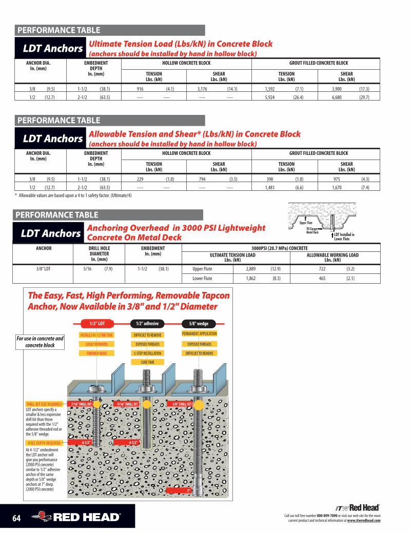
64 Call our toll free number 800-899-7890 or visit our web site for the most current product and technical information at www.itwredhead.com
Ultimate Tension Load (Lbs/kN) in Concrete Block (anchors should be installed by hand in hollow block)
ANCHOR DIA. EMBEDMENT HOLLOW CONCRETE BLOCK GROUT FILLED CONCRETE BLOCK In. (mm) DEPTH
In. (mm) TENSION SHEAR TENSION SHEARLbs. (kN) Lbs. (kN) Lbs. (kN) Lbs. (kN)
3/8 (9.5) 1-1/2 (38.1) 916 (4.1) 3,176 (14.1) 1,592 (7.1) 3,900 (17.3)
1/2 (12.7) 2-1/2 (63.5) ---- ---- ---- ---- 5,924 (26.4) 6,680 (29.7)
LDT Anchors
LDT Installed in Lower Flute
20 Gauge Metal Deck
Upper Flute
Anchoring Overhead in 3000 PSI LightweightConcrete On Metal DeckLDT Anchors
PERFORMANCE TABLE
Allowable Tension and Shear* (Lbs/kN) in Concrete Block (anchors should be installed by hand in hollow block)
ANCHOR DIA. EMBEDMENT HOLLOW CONCRETE BLOCK GROUT FILLED CONCRETE BLOCK In. (mm) DEPTH
In. (mm) TENSION SHEAR TENSION SHEARLbs. (kN) Lbs. (kN) Lbs. (kN) Lbs. (kN)
3/8 (9.5) 1-1/2 (38.1) 229 (1.0) 794 (3.5) 398 (1.8) 975 (4.3)
1/2 (12.7) 2-1/2 (63.5) ---- ---- ---- ---- 1,481 (6.6) 1,670 (7.4)* Allowable values are based upon a 4 to 1 safety factor. (Ultimate/4)
LDT Anchors
PERFORMANCE TABLE
PERFORMANCE TABLE
ANCHOR DRILL HOLE EMBEDMENT 3000PSI (20.7 MPa) CONCRETEDIAMETER In. (mm) ULTIMATE TENSION LOAD ALLOWABLE WORKING LOADIn. (mm) Lbs. (kN) Lbs. (kN)
3/8” LDT 5/16 (7.9) 1-1/2 (38.1) Upper Flute 2,889 (12.9) 722 (3.2)
Lower Flute 1,862 (8.3) 465 (2.1)
The Easy, Fast, High Performing, Removable TapconAnchor, Now Available in 3/8" and 1/2" Diameter
5/8" DRILL BIT9/16" DRILL BITDRILL BIT SIZE REQUIRED
7"
HOLE DEPTH REQUIRED
1/2" LDT 5/8" wedge1/2" adhesive
7/16" DRILL BIT
4-1/2" 4-1/2"
LDT anchors specify asmaller & less expensivedrill bit than thoserequired with the 1/2"adhesive threaded rod orthe 5/8" wedge.
DIFFICULT TO REMOVE
EXPOSED THREADS
5-STEP INSTALLATION
CURE TIME
INSTALLS IN 1/2 THE TIME
EASILY REMOVED
FINISHED HEAD
PERMANENT APPLICATION
EXPOSED THREADS
DIFFICULT TO REMOVE
At 4-1/2" embedmentthe LDT anchor will give you performance(2000 PSI concrete) similar to 1/2" adhesiveanchor of the samedepth or 5/8" wedgeanchors at 7" deep.(2000 PSI concrete)
For use in concrete andconcrete block
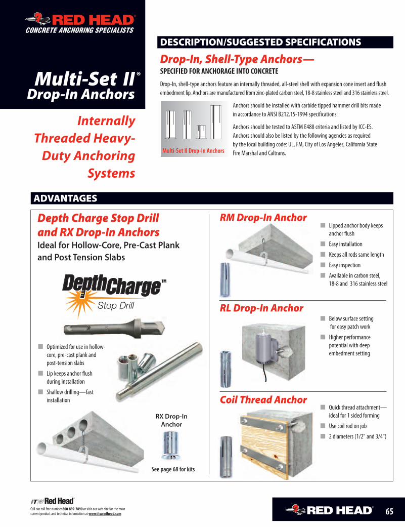
65Call our toll free number 800-899-7890 or visit our web site for the mostcurrent product and technical information at www.itwredhead.com
Multi-Set IIDrop-In Anchors
ADVANTAGES
CONCRETE ANCHORING SPECIALISTS
InternallyThreaded Heavy-
Duty AnchoringSystems
DESCRIPTION/SUGGESTED SPECIFICATIONS
Drop-In, Shell-Type Anchors—specified for anchorage into concrete
Drop-In, shell-type anchors feature an internally threaded, all-steel shell with expansion cone insert and flushembedment lip. Anchors are manufactured from zinc-plated carbon steel, 18-8 stainless steel and 316 stainless steel.
Anchors should be installed with carbide tipped hammer drill bits madein accordance to ANSI B212.15-1994 specifications.
Anchors should be tested to ASTM E488 criteria and listed by ICC-ES.Anchors should also be listed by the following agencies as requiredby the local building code: UL, FM, City of Los Angeles, California StateFire Marshal and Caltrans.Multi-Set II Drop-In Anchors
RMDrop-In Anchor
� Below surface settingfor easy patch work
� Higher performancepotential with deepembedment setting
RL Drop-In Anchor
Depth Charge Stop Drilland RX Drop-In AnchorsIdeal for Hollow-Core, Pre-Cast Plankand Post Tension Slabs
� Quick thread attachment—ideal for 1 sided forming
� Use coil rod on job
� 2 diameters (1/2" and 3/4")
Coil Thread Anchor
®
� Lipped anchor body keepsanchor flush
� Easy installation
� Keeps all rods same length
� Easy inspection
� Available in carbon steel,18-8 and 316 stainless steelTM
See page 68 for kits
RX Drop-InAnchor
� Optimized for use in hollow-core, pre-cast plank andpost-tension slabs
� Lip keeps anchor flushduring installation
� Shallow drilling—fastinstallation
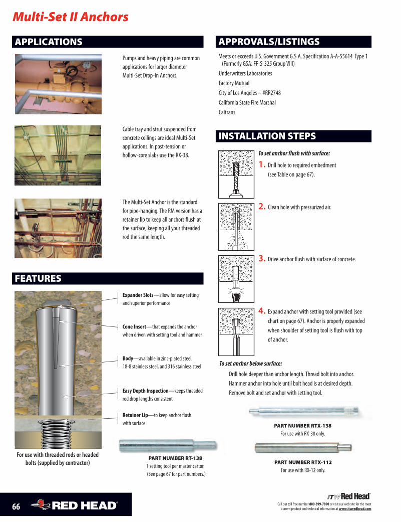
(See page 67 for part numbers.)
PART NUMBER RT-138
1 setting tool per master carton
66 Call our toll free number 800-899-7890 or visit our web site for the mostcurrent product and technical information at www.itwredhead.com
Multi-Set II Anchors
APPLICATIONS
FEATURES
Pumps and heavy piping are commonapplications for larger diameterMulti-Set Drop-In Anchors.
Cable tray and strut suspended fromconcrete ceilings are ideal Multi-Setapplications. In post-tension orhollow-core slabs use the RX-38.
The Multi-Set Anchor is the standardfor pipe-hanging. The RM version has aretainer lip to keep all anchors flush atthe surface, keeping all your threadedrod the same length.
APPROVALS/LISTINGSMeets or exceeds U.S. Government G.S.A. Specification A-A-55614 Type 1(Formerly GSA: FF-S-325 Group VIII)
Underwriters LaboratoriesFactory MutualCity of Los Angeles – #RR2748California State Fire MarshalCaltrans
expander slots—allow for easy settingand superior performance
cone insert—that expands the anchorwhen driven with setting tool and hammer
Body—available in zinc-plated steel,18-8 stainless steel, and 316 stainless steel
easy depth inspection—keeps threadedrod drop lengths consistent
retainer Lip—to keep anchor flushwith surface PART NUMBER RTX-138
For use with RX-38 only.
For use with threaded rods or headedbolts (supplied by contractor)
1. Drill hole to required embedment(see Table on page 67).
2. Clean hole with pressurized air.
3. Drive anchor flush with surface of concrete.
4. Expand anchor with setting tool provided (seechart on page 67). Anchor is properly expandedwhen shoulder of setting tool is flush with topof anchor.
To set anchor flush with surface:
INSTALLATION STEPS
To set anchor below surface:
Drill hole deeper than anchor length. Thread bolt into anchor.Hammer anchor into hole until bolt head is at desired depth.Remove bolt and set anchor with setting tool.
PART NUMBER RTX-112
For use with RX-12 only.
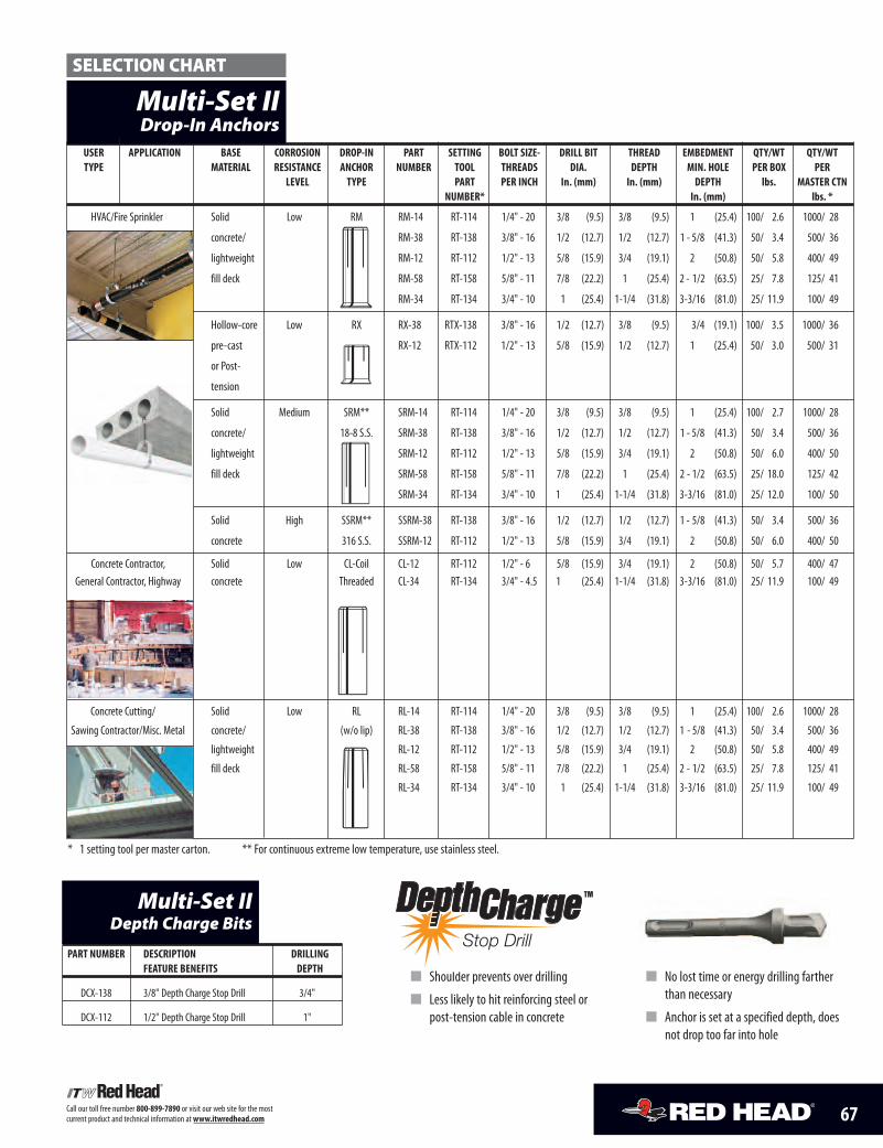
67Call our toll free number 800-899-7890 or visit our web site for the mostcurrent product and technical information at www.itwredhead.com
User appLication Base corrosion drop-in part setting BoLt siZe- driLL Bit thread eMBedMent QtY/Wt QtY/WttYpe MateriaL resistance anchor nUMBer tooL threads dia. depth Min. hoLe per BoX per
LeVeL tYpe part per inch in. (mm) in. (mm) depth lbs. Master ctnnUMBer* in. (mm) lbs. *
HVAC/Fire Sprinkler Solid Low RM RM-14 RT-114 1/4" - 20 3/8 (9.5) 3/8 (9.5) 1 (25.4) 100/ 2.6 1000/ 28
Plumber (Pipe-fitter) concrete/ RM-38 RT-138 3/8" - 16 1/2 (12.7) 1/2 (12.7) 1 - 5/8 (41.3) 50/ 3.4 500/ 36
lightweight RM-12 RT-112 1/2" - 13 5/8 (15.9) 3/4 (19.1) 2 (50.8) 50/ 5.8 400/ 49
fill deck RM-58 RT-158 5/8" - 11 7/8 (22.2) 1 (25.4) 2 - 1/2 (63.5) 25/ 7.8 125/ 41
RM-34 RT-134 3/4" - 10 1 (25.4) 1-1/4 (31.8) 3-3/16 (81.0) 25/ 11.9 100/ 49
Hollow-core Low RX RX-38 RTX-138 3/8" - 16 1/2 (12.7) 3/8 (9.5) 3/4 (19.1) 100/ 3.5 1000/ 36
pre-cast RX-12 RTX-112 1/2" - 13 5/8 (15.9) 1/2 (12.7) 1 (25.4) 50/ 3.0 500/ 31
or Post-
tension
Solid Medium SRM** SRM-14 RT-114 1/4" - 20 3/8 (9.5) 3/8 (9.5) 1 (25.4) 100/ 2.7 1000/ 28
concrete/ 18-8 S.S. SRM-38 RT-138 3/8" - 16 1/2 (12.7) 1/2 (12.7) 1 - 5/8 (41.3) 50/ 3.4 500/ 36
lightweight SRM-12 RT-112 1/2" - 13 5/8 (15.9) 3/4 (19.1) 2 (50.8) 50/ 6.0 400/ 50
fill deck SRM-58 RT-158 5/8" - 11 7/8 (22.2) 1 (25.4) 2 - 1/2 (63.5) 25/ 18.0 125/ 42
SRM-34 RT-134 3/4" - 10 1 (25.4) 1-1/4 (31.8) 3-3/16 (81.0) 25/ 12.0 100/ 50
Solid High SSRM** SSRM-38 RT-138 3/8" - 16 1/2 (12.7) 1/2 (12.7) 1 - 5/8 (41.3) 50/ 3.4 500/ 36
concrete 316 S.S. SSRM-12 RT-112 1/2" - 13 5/8 (15.9) 3/4 (19.1) 2 (50.8) 50/ 6.0 400/ 50
Concrete Contractor, Solid Low CL-Coil CL-12 RT-112 1/2" - 6 5/8 (15.9) 3/4 (19.1) 2 (50.8) 50/ 5.7 400/ 47General Contractor, Highway concrete Threaded CL-34 RT-134 3/4" - 4.5 1 (25.4) 1-1/4 (31.8) 3-3/16 (81.0) 25/ 11.9 100/ 49
Concrete Cutting/ Solid Low RL RL-14 RT-114 1/4" - 20 3/8 (9.5) 3/8 (9.5) 1 (25.4) 100/ 2.6 1000/ 28
Sawing Contractor/Misc. Metal concrete/ (w/o lip) RL-38 RT-138 3/8" - 16 1/2 (12.7) 1/2 (12.7) 1 - 5/8 (41.3) 50/ 3.4 500/ 36
lightweight RL-12 RT-112 1/2" - 13 5/8 (15.9) 3/4 (19.1) 2 (50.8) 50/ 5.8 400/ 49
fill deck RL-58 RT-158 5/8" - 11 7/8 (22.2) 1 (25.4) 2 - 1/2 (63.5) 25/ 7.8 125/ 41
RL-34 RT-134 3/4" - 10 1 (25.4) 1-1/4 (31.8) 3-3/16 (81.0) 25/ 11.9 100/ 49
Multi-Set IIDrop-In Anchors
SELECTION CHART
* 1 setting tool per master carton. ** For continuous extreme low temperature, use stainless steel.
part nUMBer description driLLingfeatUre Benefits depth
DCX-138 3/8" Depth Charge Stop Drill 3/4"
DCX-112 1/2" Depth Charge Stop Drill 1"
Multi-Set IIDepth Charge Bits
TM
� Shoulder prevents over drilling
� Less likely to hit reinforcing steel orpost-tension cable in concrete
� No lost time or energy drilling fartherthan necessary
� Anchor is set at a specified depth, doesnot drop too far into hole
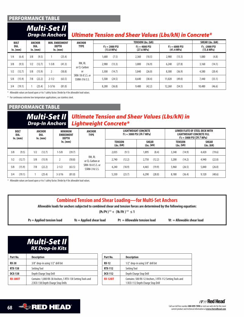
68 Call our toll free number 800-899-7890 or visit our web site for the mostcurrent product and technical information at www.itwredhead.com
BoLt anchor Min. eMBedMent anchor tension Lbs. (kn) shear Lbs. (kn)dia. dia. depth tYpe f’c = 2000 psi f’c = 4000 psi f’c = 6000 psi f’c >_ 2000 psi
in. (mm) in. (mm) in. (mm) (13.8 Mpa) (27.6 Mpa) (41.4 Mpa) (13.8 Mpa)
1/4 (6.4) 3/8 (9.5) 1 (25.4) 1,680 (7.5) 2,360 (10.5) 2,980 (13.3) 1,080 (4.8)
3/8 (9.5) 1/2 (12.7) 1-5/8 (41.3) 2,980 (13.3) 3,800 (16.9) 6,240 (27.8) 3,160 (14.1)
1/2 (12.7) 5/8 (15.9) 2 (50.8) 3,300 (14.7) 5,840 (26.0) 8,300 (36.9) 4,580 (20.4)
5/8 (15.9) 7/8 (22.2) 2-1/2 (63.5) 5,500 (24.5) 8,640 (38.4) 11,020 (49.0) 7,440 (33.1)
3/4 (19.1) 1 (25.4) 3-3/16 (81.0) 8,280 (36.8) 9,480 (42.2) 12,260 (54.5) 10,480 (46.6)
* Allowable values are based upon a 4 to 1 safety factor. Divide by 4 for allowable load values.
* For continuous extreme low temperature applications, use stainless steel.
Ultimate Tension and Shear Values (Lbs/kN) in Concrete*
RM, RLor CL-Carbon
orSRM-18-8 S.S. orSSRM-316 S.S.
Multi-Set IIDrop-In Anchors
Ultimate Tension and Shear Values (Lbs/kN) inLightweight Concrete*
BoLt anchor MiniMUM anchor LightWeight concrete LoWer fLUte of steeL decK Withdia. dia. eMBedMent tYpe f’c = 3000 psi (20.7 Mpa) LightWeight concrete fiLL
in. (mm) in. (mm) depth f’c = 3000 psi (20.7 Mpa)in. (mm) tension shear tension shear
Lbs. (kn) Lbs. (kn) Lbs. (kn) Lbs. (kn)
3/8 (9.5) 1/2 (12.7) 1-5/8 (39.7) 2,035 (9.1) 1,895 (8.4) 3,340 (14.9) 4,420 (19.6)
1/2 (12.7) 5/8 (15.9) 2 (50.8) 2,740 (12.2) 2,750 (12.2) 3,200 (14.2) 4,940 (22.0)
5/8 (15.9) 7/8 (22.2) 2-1/2 (63.5) 4,240 (18.9) 4,465 (19.9) 5,960 (26.5) 5,840 (26.0)
3/4 (19.1) 1 (25.4) 3-3/16 (81.0) 5,330 (23.7) 6,290 (28.0) 8,180 (36.4) 9,120 (40.6)
* Allowable values are based upon a 4 to 1 safety factor. Divide by 4 for allowable load values.
RM, RLor CL-Carbon orSRM-18-8 S.S. orSSRM-316 S.S.
Multi-Set IIDrop-In Anchors
combined tension and shear Loading—for Multi-set anchorsallowable loads for anchors subjected to combined shear and tension forces are determined by the following equation:
(ps /pt ) 5/3 + (Vs /Vt ) 5/3 ≤ 1
ps = applied tension load Vs = applied shear load pt = allowable tension load Vt = allowable shear load
PERFORMANCE TABLE
PERFORMANCE TABLE
part no. description
rX-38 3/8" drop-in using 1/2" drill bit
rtX-138 Setting Tool
dcX-138 Depth Charge Stop Drill
rX-38Kit Contains: 1,000 RX-38 Anchors, 5 RTX-138 Setting Tools and2 DCX-138 Depth Charge Stop Drills
Multi-Set IIRX Drop-In Kits
part no. description
rX-12 1/2" drop-in using 5/8" drill bit
rtX-112 Setting Tool
dcX-112 Depth Charge Stop Drill
rX-12Kit Contains: 500 RX-12 Anchors, 3 RTX-112 Setting Tools and1 DCX-112 Depth Charge Stop Drill
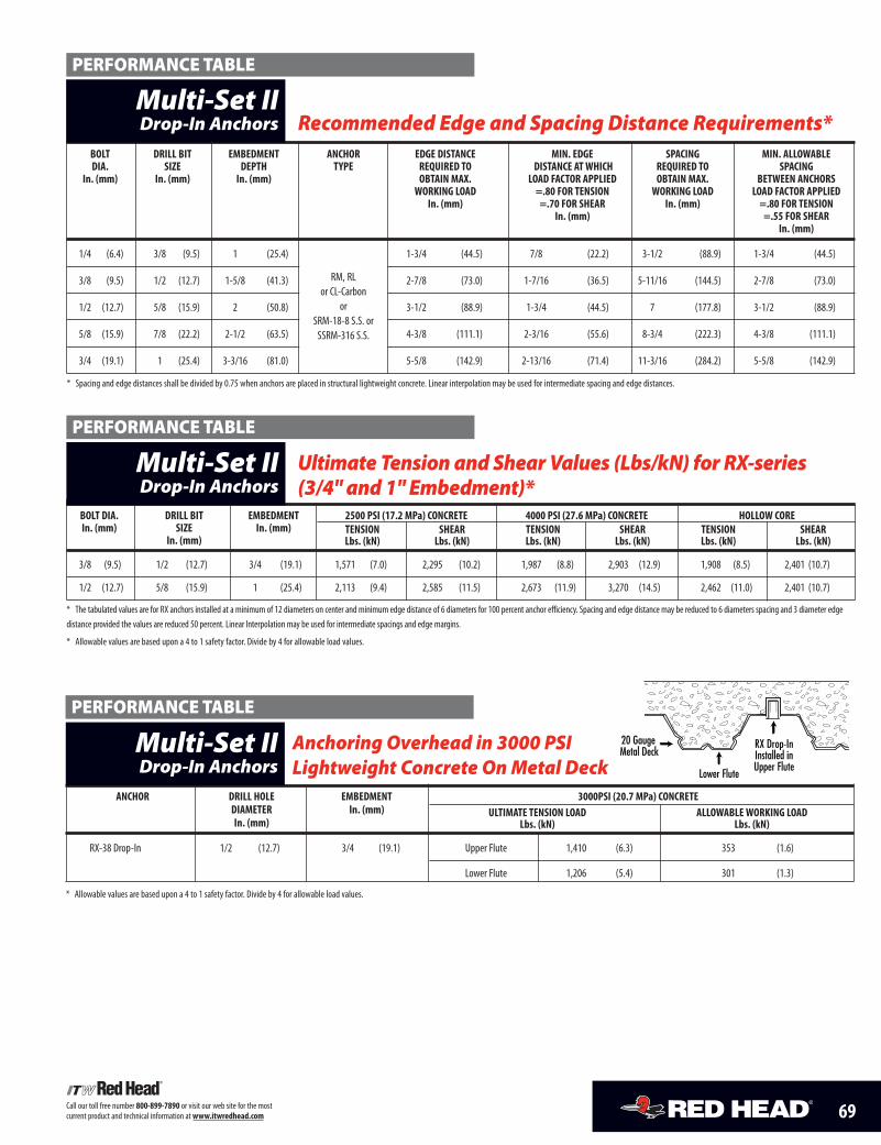
69Call our toll free number 800-899-7890 or visit our web site for the mostcurrent product and technical information at www.itwredhead.com
BoLt driLL Bit eMBedMent anchor edge distance Min. edge spacing Min. aLLoWaBLedia. siZe depth tYpe reQUired to distance at Which reQUired to spacing
in. (mm) in. (mm) in. (mm) oBtain MaX. Load factor appLied oBtain MaX. BetWeen anchorsWorKing Load =.80 for tension WorKing Load Load factor appLied
in. (mm) =.70 for shear in. (mm) =.80 for tensionin. (mm) =.55 for shear
in. (mm)
1/4 (6.4) 3/8 (9.5) 1 (25.4) 1-3/4 (44.5) 7/8 (22.2) 3-1/2 (88.9) 1-3/4 (44.5)
3/8 (9.5) 1/2 (12.7) 1-5/8 (41.3) 2-7/8 (73.0) 1-7/16 (36.5) 5-11/16 (144.5) 2-7/8 (73.0)
1/2 (12.7) 5/8 (15.9) 2 (50.8) 3-1/2 (88.9) 1-3/4 (44.5) 7 (177.8) 3-1/2 (88.9)
5/8 (15.9) 7/8 (22.2) 2-1/2 (63.5) 4-3/8 (111.1) 2-3/16 (55.6) 8-3/4 (222.3) 4-3/8 (111.1)
3/4 (19.1) 1 (25.4) 3-3/16 (81.0) 5-5/8 (142.9) 2-13/16 (71.4) 11-3/16 (284.2) 5-5/8 (142.9)
* Spacing and edge distances shall be divided by 0.75 when anchors are placed in structural lightweight concrete. Linear interpolation may be used for intermediate spacing and edge distances.
RM, RLor CL-Carbon
orSRM-18-8 S.S. orSSRM-316 S.S.
Multi-Set IIDrop-In Anchors Recommended Edge and Spacing Distance Requirements*
PERFORMANCE TABLE
PERFORMANCE TABLE
BoLt dia. driLL Bit eMBedMent 2500 psi (17.2 Mpa) concrete 4000 psi (27.6 Mpa) concrete hoLLoW corein. (mm) siZe in. (mm) tension shear tension shear tension shear
in. (mm) Lbs. (kn) Lbs. (kn) Lbs. (kn) Lbs. (kn) Lbs. (kn) Lbs. (kn)
3/8 (9.5) 1/2 (12.7) 3/4 (19.1) 1,571 (7.0) 2,295 (10.2) 1,987 (8.8) 2,903 (12.9) 1,908 (8.5) 2,401 (10.7)
1/2 (12.7) 5/8 (15.9) 1 (25.4) 2,113 (9.4) 2,585 (11.5) 2,673 (11.9) 3,270 (14.5) 2,462 (11.0) 2,401 (10.7)
* The tabulated values are for RX anchors installed at a minimum of 12 diameters on center and minimum edge distance of 6 diameters for 100 percent anchor efficiency. Spacing and edge distance may be reduced to 6 diameters spacing and 3 diameter edgedistance provided the values are reduced 50 percent. Linear Interpolation may be used for intermediate spacings and edge margins.
* Allowable values are based upon a 4 to 1 safety factor. Divide by 4 for allowable load values.
Ultimate Tension and Shear Values (Lbs/kN) for RX-series(3/4" and 1" Embedment)*
Multi-Set IIDrop-In Anchors
PERFORMANCE TABLE
RX Drop-In Installed in Upper Flute
Lower Flute
20 Gauge Metal Deck
anchor driLL hoLe eMBedMent 3000psi (20.7 Mpa) concretediaMeter in. (mm) ULtiMate tension Load aLLoWaBLe WorKing Loadin. (mm) Lbs. (kn) Lbs. (kn)
RX-38 Drop-In 1/2 (12.7) 3/4 (19.1) Upper Flute 1,410 (6.3) 353 (1.6)
Lower Flute 1,206 (5.4) 301 (1.3)
* Allowable values are based upon a 4 to 1 safety factor. Divide by 4 for allowable load values.
Anchoring Overhead in 3000 PSI Lightweight Concrete On Metal Deck
Multi-Set IIDrop-In Anchors
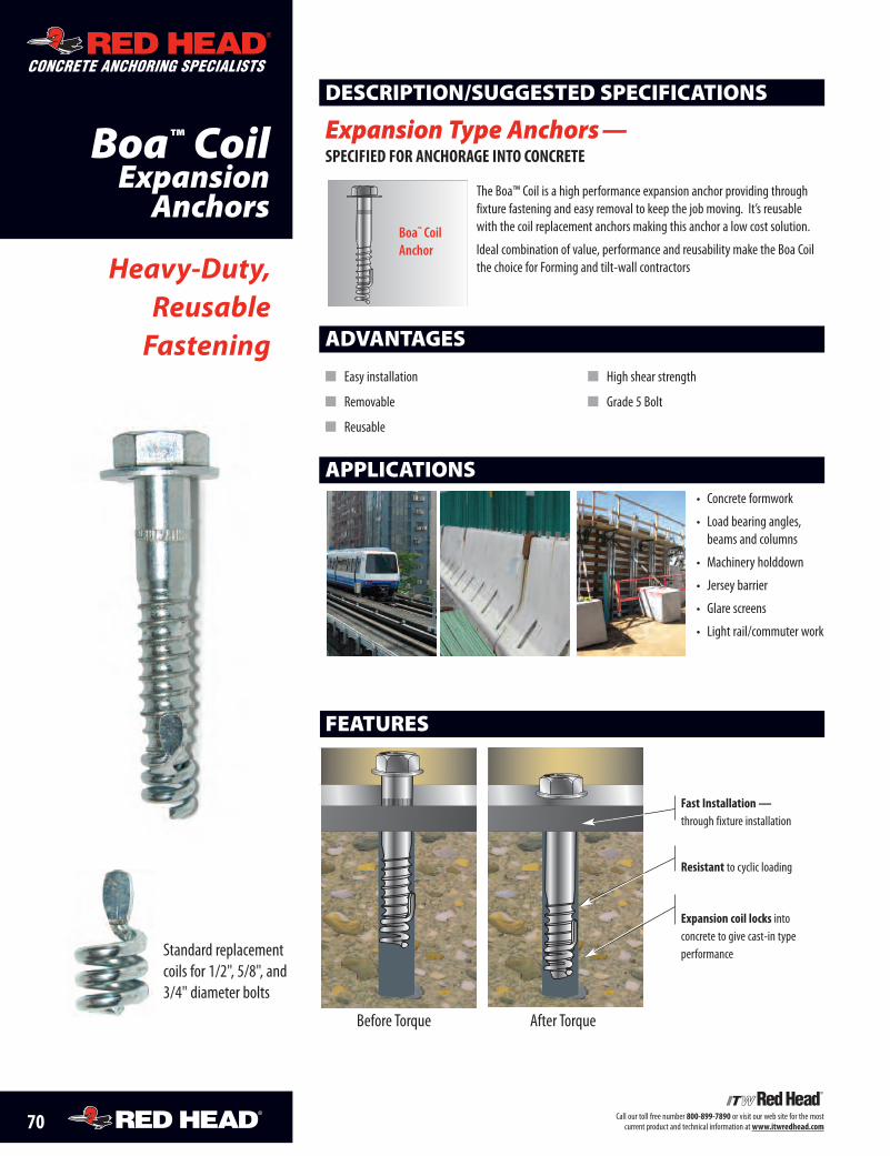
70 Call our toll free number 800-899-7890 or visit our web site for the mostcurrent product and technical information atwww.itwredhead.com
Boa™ CoilExpansion
Anchors
ADVANTAGES
� Easy installation
� Removable
� Reusable
� High shear strength
� Grade 5 Bolt
Heavy-Duty,ReusableFastening
DESCRIPTION/SUGGESTED SPECIFICATIONS
Expansion Type Anchors —SPECIFIED FOR ANCHORAGE INTO CONCRETE
The Boa™ Coil is a high performance expansion anchor providing throughfixture fastening and easy removal to keep the job moving. It’s reusablewith the coil replacement anchors making this anchor a low cost solution.
Ideal combination of value, performance and reusability make the Boa Coilthe choice for Forming and tilt-wall contractors
APPLICATIONS• Concrete formwork
• Load bearing angles,beams and columns
• Machinery holddown
• Jersey barrier
• Glare screens
• Light rail/commuter work
Boa™ CoilAnchor
CONCRETE ANCHORING SPECIALISTS
Standard replacementcoils for 1/2", 5/8", and3/4" diameter bolts
FEATURES
Fast Installation—through fixture installation
Resistant to cyclic loading
Expansion coil locks intoconcrete to give cast-in typeperformance
Before Torque After Torque
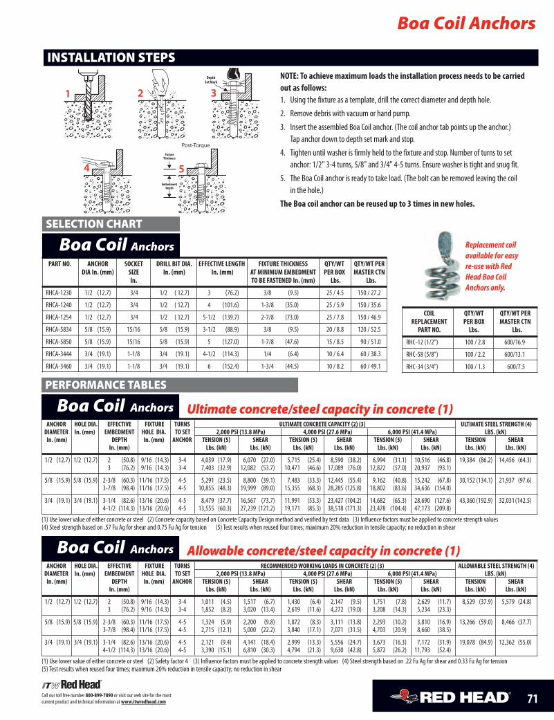
71Call our toll free number 800-899-7890 or visit our web site for the mostcurrent product and technical information atwww.itwredhead.com
PART NO. ANCHOR SOCKET DRILL BIT DIA. EFFECTIVE LENGTH FIXTURE THICKNESS QTY/WT QTY/WT PERDIA In. (mm) SIZE In. (mm) In. (mm) AT MINIMUM EMBEDMENT PER BOX MASTER CTN
In. TO BE FASTENED In. (mm) Lbs. Lbs.
RHCA-1230 1/2 (12.7) 3/4 1/2 ( 12.7) 3 (76.2) 3/8 (9.5) 25 / 4.5 150 / 27.2
RHCA-1240 1/2 (12.7) 3/4 1/2 ( 12.7) 4 (101.6) 1-3/8 (35.0) 25 / 5.9 150 / 35.6
RHCA-1254 1/2 (12.7) 3/4 1/2 ( 12.7) 5-1/2 (139.7) 2-7/8 (73.0) 25 / 7.8 150 / 46.9
RHCA-5834 5/8 (15.9) 15/16 5/8 (15.9) 3-1/2 (88.9) 3/8 (9.5) 20 / 8.8 120 / 52.5
RHCA-5850 5/8 (15.9) 15/16 5/8 (15.9) 5 (127.0) 1-7/8 (47.6) 15 / 8.5 90 / 51.0
RHCA-3444 3/4 (19.1) 1-1/8 3/4 (19.1) 4-1/2 (114.3) 1/4 (6.4) 10 / 6.4 60 / 38.3
RHCA-3460 3/4 (19.1) 1-1/8 3/4 (19.1) 6 (152.4) 1-3/4 (44.5) 10 / 8.2 60 / 49.1
COIL QTY/WT QTY/WT PERREPLACEMENT PER BOX MASTER CTNPART NO. Lbs. Lbs.
RHC-12 (1/2") 100 / 2.8 600/16.9
RHC-58 (5/8") 100 / 2.2 600/13.1
RHC-34 (3/4") 100 / 1.3 600/7.5
INSTALLATION STEPS
Boa Coil Anchors
Boa Coil Anchors
ANCHOR HOLE DIA. EFFECTIVE FIXTURE TURNS RECOMMENDEDWORKING LOADS IN CONCRETE (2) (3) ALLOWABLE STEEL STRENGTH (4)DIAMETER In. (mm) EMBEDMENT HOLE DIA. TO SET 2,000 PSI (13.8 MPa) 4,000 PSI (27.6 MPa) 6,000 PSI (41.4 MPa) LBS. (kN)In. (mm) DEPTH In. (mm) ANCHOR TENSION (5) SHEAR TENSION (5) SHEAR TENSION (5) SHEAR TENSION SHEAR
In. (mm) Lbs. (kN) Lbs. (kN) Lbs. (kN) Lbs. (kN) Lbs. (kN) Lbs. (kN) Lbs. (kN) Lbs. (kN)
1/2 (12.7) 1/2 (12.7) 2 (50.8) 9/16 (14.3) 3-4 1,011 (4.5) 1,517 (6.7) 1,430 (6.4) 2,147 (9.5) 1,751 (7.8) 2,629 (11.7) 8,529 (37.9) 5,579 (24.8)3 (76.2) 9/16 (14.3) 3-4 1,852 (8.2) 3,020 (13.4) 2,619 (11.6) 4,272 (19.0) 3,208 (14.3) 5,234 (23.3)
5/8 (15.9) 5/8 (15.9) 2-3/8 (60.3) 11/16 (17.5) 4-5 1,324 (5.9) 2,200 (9.8) 1,872 (8.3) 3,111 (13.8) 2,293 (10.2) 3,810 (16.9) 13,266 (59.0) 8,466 (37.7)3-7/8 (98.4) 11/16 (17.5) 4-5 2,715 (12.1) 5,000 (22.2) 3,840 (17.1) 7,071 (31.5) 4,703 (20.9) 8,660 (38.5)
3/4 (19.1) 3/4 (19.1) 3-1/4 (82.6) 13/16 (20.6) 4-5 2,121 (9.4) 4,141 (18.4) 2,999 (13.3) 5,556 (24.7) 3,673 (16.3) 7,172 (31.9) 19,078 (84.9) 12,362 (55.0)4-1/2 (114.3) 13/16 (20.6) 4-5 3,390 (15.1) 6,810 (30.3) 4,794 (21.3) 9,630 (42.8) 5,872 (26.2) 11,793 (52.4)
(1) Use lower value of either concrete or steel (2) Safety factor 4 (3) Influence factors must be applied to concrete strength values (4) Steel strength based on .22 Fu Ag for shear and 0.33 Fu Ag for tension(5) Test results when reused four times; maximum 20% reduction in tensile capacity; no reduction in shear
Allowable concrete/steel capacity in concrete (1)Boa Coil Anchors
SELECTION CHART
PERFORMANCE TABLES
Replacement coilavailable for easyre-use with RedHead Boa CoilAnchors only.
DepthSet Mark
Post-Torque
FixtureThickness
EmbedmentDepth
ANCHOR HOLE DIA. EFFECTIVE FIXTURE TURNS ULTIMATE CONCRETE CAPACITY (2) (3) ULTIMATE STEEL STRENGTH (4)DIAMETER In. (mm) EMBEDMENT HOLE DIA. TO SET 2,000 PSI (13.8 MPa) 4,000 PSI (27.6 MPa) 6,000 PSI (41.4 MPa) LBS. (kN)In. (mm) DEPTH In. (mm) ANCHOR TENSION (5) SHEAR TENSION (5) SHEAR TENSION (5) SHEAR TENSION SHEAR
In. (mm) Lbs. (kN) Lbs. (kN) Lbs. (kN) Lbs. (kN) Lbs. (kN) Lbs. (kN) Lbs. (kN) Lbs. (kN)
1/2 (12.7) 1/2 (12.7) 2 (50.8) 9/16 (14.3) 3-4 4,039 (17.9) 6,070 (27.0) 5,715 (25.4) 8,590 (38.2) 6,994 (31.1) 10,516 (46.8) 19,384 (86.2) 14,456 (64.3)3 (76.2) 9/16 (14.3) 3-4 7,403 (32.9) 12,082 (53.7) 10,471 (46.6) 17,089 (76.0) 12,822 (57.0) 20,937 (93.1)
5/8 (15.9) 5/8 (15.9) 2-3/8 (60.3) 11/16 (17.5) 4-5 5,291 (23.5) 8,800 (39.1) 7,483 (33.3) 12,445 (55.4) 9,162 (40.8) 15,242 (67.8) 30,152 (134.1) 21,937 (97.6)3-7/8 (98.4) 11/16 (17.5) 4-5 10,855 (48.3) 19,999 (89.0) 15,355 (68.3) 28,285 (125.8) 18,802 (83.6) 34,636 (154.0)
3/4 (19.1) 3/4 (19.1) 3-1/4 (82.6) 13/16 (20.6) 4-5 8,479 (37.7) 16,567 (73.7) 11,991 (53.3) 23,427 (104.2) 14,682 (65.3) 28,690 (127.6) 43,360 (192.9) 32,031(142.5)4-1/2 (114.3) 13/16 (20.6) 4-5 13,555 (60.3) 27,239 (121.2) 19,171 (85.3) 38,518 (171.3) 23,478 (104.4) 47,173 (209.8)
(1) Use lower value of either concrete or steel (2) Concrete capacity based on Concrete Capacity Design method and verified by test data (3) Influence factors must be applied to concrete strength values(4) Steel strength based on .57 Fu Ag for shear and 0.75 Fu Ag for tension (5) Test results when reused four times; maximum 20% reduction in tensile capacity; no reduction in shear
Ultimate concrete/steel capacity in concrete (1)Boa Coil Anchors
NOTE: To achieve maximum loads the installation process needs to be carriedout as follows:1. Using the fixture as a template, drill the correct diameter and depth hole.2. Remove debris with vacuum or hand pump.3. Insert the assembled Boa Coil anchor. (The coil anchor tab points up the anchor.)
Tap anchor down to depth set mark and stop.4. Tighten until washer is firmly held to the fixture and stop. Number of turns to set
anchor: 1/2" 3-4 turns, 5/8" and 3/4" 4-5 turns. Ensure washer is tight and snug fit.5. The Boa Coil anchor is ready to take load. (The bolt can be removed leaving the coil
in the hole.)The Boa coil anchor can be reused up to 3 times in new holes.
4 5
1 2 3
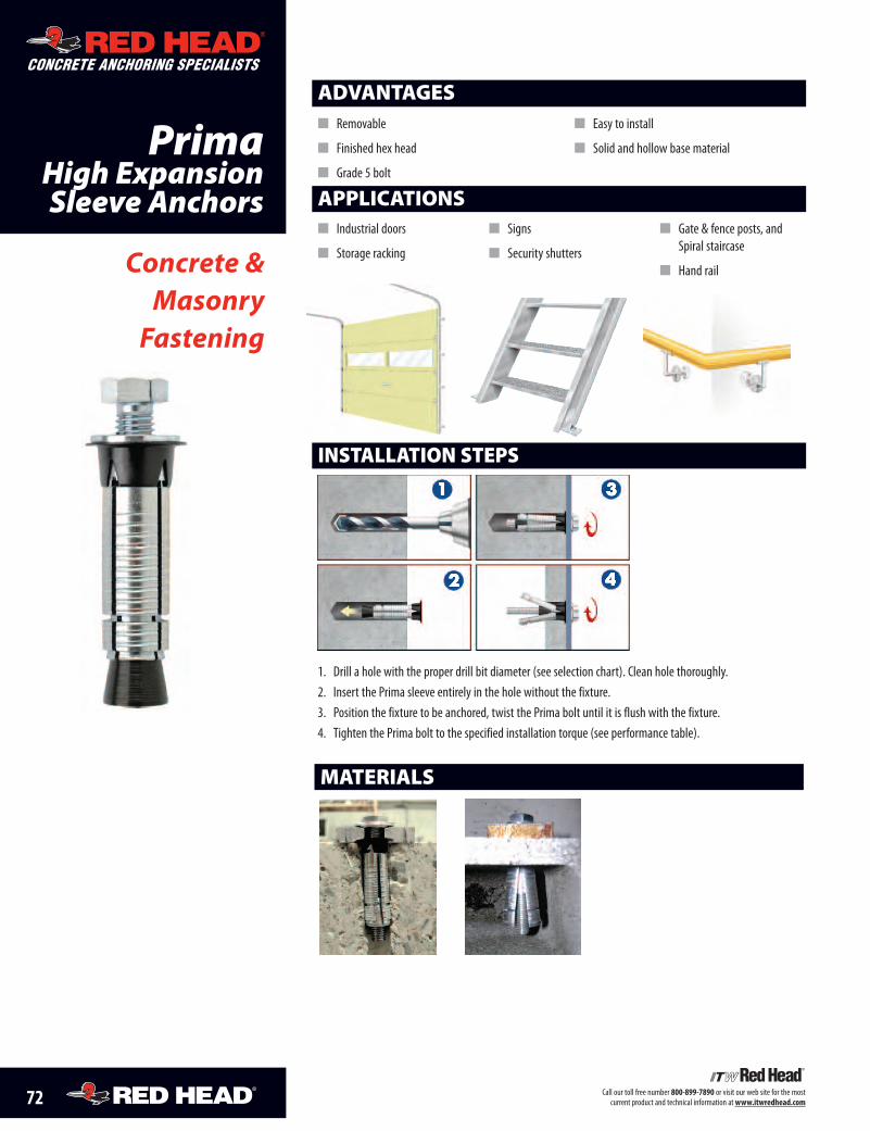
72 Call our toll free number 800-899-7890 or visit our web site for the mostcurrent product and technical information atwww.itwredhead.com
PrimaHigh ExpansionSleeve Anchors
Concrete &Masonry
Fastening
MATERIALS
INSTALLATION STEPS
CONCRETE ANCHORING SPECIALISTS
APPLICATIONS� Industrial doors
� Storage racking
� Signs
� Security shutters
� Gate & fence posts, andSpiral staircase
� Hand rail
1. Drill a hole with the proper drill bit diameter (see selection chart). Clean hole thoroughly.2. Insert the Prima sleeve entirely in the hole without the fixture.3. Position the fixture to be anchored, twist the Prima bolt until it is flush with the fixture.4. Tighten the Prima bolt to the specified installation torque (see performance table).
ADVANTAGES� Removable
� Finished hex head
� Grade 5 bolt
� Easy to install
� Solid and hollow base material
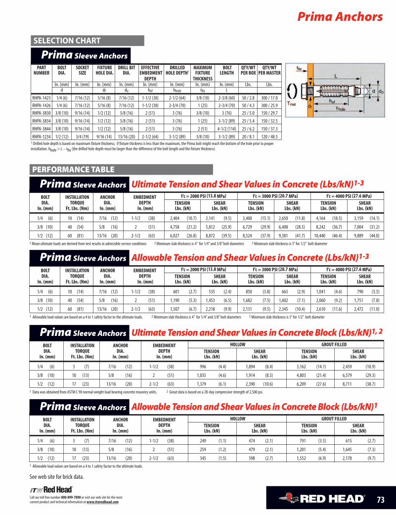
73Call our toll free number 800-899-7890 or visit our web site for the mostcurrent product and technical information atwww.itwredhead.com
Prima Anchors
SELECTION CHART
BOLT INSTALLATION ANCHOR EMBEDMENT f’c = 2000 PSI (13.8 MPa) f’c = 3000 PSI (20.7 MPa) f’c = 4000 PSI (27.6 MPa)DIA. TORQUE DIA. DEPTH TENSION SHEAR TENSION SHEAR TENSION SHEAR
In. (mm) Ft. Lbs. (Nm) In. (mm) In. (mm) Lbs. (kN) Lbs. (kN) Lbs. (kN) Lbs. (kN) Lbs. (kN) Lbs. (kN)
1/4 (6) 10 (14) 7/16 (12) 1-1/2 (38) 2,404 (10.7) 2,141 (9.5) 3,400 (15.1) 2,650 (11.8) 4,164 (18.5) 3,159 (14.1)
3/8 (10) 40 (54) 5/8 (16) 2 (51) 4,758 (21.2) 5,812 (25.9) 6,729 (29.9) 6,408 (28.5) 8,242 (36.7) 7,004 (31.2)
1/2 (12) 60 (81) 13/16 (20) 2-1/2 (63) 6,027 (26.8) 8,872 (39.5) 8,524 (37.9) 9,381 (41.7) 10,440 (46.4) 9,889 (44.0)1 Mean ultimate loads are derived from test results in admissible service conditions 2 Minimum slab thickness is 4” for 1/4”and 3/8”bolt diameters 3 Minimum slab thickness is 5” for 1/2” bolt diameter
Ultimate Tension and Shear Values in Concrete (Lbs/kN)1-3Prima Sleeve AnchorsPERFORMANCE TABLE
BOLT INSTALLATION ANCHOR EMBEDMENT f’c = 2000 PSI (13.8 MPa) f’c = 3000 PSI (20.7 MPa) f’c = 4000 PSI (27.6 MPa)DIA. TORQUE DIA. DEPTH TENSION SHEAR TENSION SHEAR TENSION SHEAR
In. (mm) Ft. Lbs. (Nm) In. (mm) In. (mm) Lbs. (kN) Lbs. (kN) Lbs. (kN) Lbs. (kN) Lbs. (kN) Lbs. (kN)
1/4 (6) 10 (14) 7/16 (12) 1-1/2 (38) 601 (2.7) 535 (2.4) 850 (3.8) 663 (2.9) 1,041 (4.6) 790 (3.5)
3/8 (10) 40 (54) 5/8 (16) 2 (51) 1,190 (5.3) 1,453 (6.5) 1,682 (7.5) 1,602 (7.1) 2,060 (9.2) 1,751 (7.8)
1/2 (12) 60 (81) 13/16 (20) 2-1/2 (63) 1,507 (6.7) 2,218 (9.9) 2,131 (9.5) 2,345 (10.4) 2,610 (11.6) 2,472 (11.0)1 Allowable load values are based on a 4 to 1 safety factor to the ultimate loads. 2 Minimum slab thickness is 4” for 1/4”and 3/8”bolt diameters 3 Minimum slab thickness is 5” for 1/2” bolt diameter
Allowable Tension and Shear Values in Concrete (Lbs/kN)1-3Prima Sleeve Anchors
BOLT INSTALLATION ANCHOR EMBEDMENT HOLLOW GROUT FILLEDDIA. TORQUE DIA. DEPTH TENSION SHEAR TENSION SHEAR
In. (mm) Ft. Lbs. (Nm) In. (mm) In. (mm) Lbs. (kN) Lbs. (kN) Lbs. (kN) Lbs. (kN)
1/4 (6) 5 (7) 7/16 (12) 1-1/2 (38) 996 (4.4) 1,894 (8.4) 3,162 (14.1) 2,459 (10.9)
3/8 (10) 10 (13) 5/8 (16) 2 (51) 1,035 (4.6) 1,914 (8.5) 4,803 (21.4) 6,579 (29.3)
1/2 (12) 17 (23) 13/16 (20) 2-1/2 (63) 1,379 (6.1) 2,390 (10.6) 6,209 (27.6) 8,711 (38.7)1 Data was obtained from ASTM C 90 normal weight load bearing concrete masonry units. 2 Grout data is based on a 28-day compressive strength of 2,500 psi.
UltimateTensionandShearValues inConcreteBlock (Lbs/kN)1,2Prima Sleeve Anchors
BOLT INSTALLATION ANCHOR EMBEDMENT HOLLOW GROUT FILLEDDIA. TORQUE DIA. DEPTH TENSION SHEAR TENSION SHEAR
In. (mm) Ft. Lbs. (Nm) In. (mm) In. (mm) Lbs. (kN) Lbs. (kN) Lbs. (kN) Lbs. (kN)
1/4 (6) 5 (7) 7/16 (12) 1-1/2 (38) 249 (1.1) 474 (2.1) 791 (3.5) 615 (2.7)
3/8 (10) 10 (13) 5/8 (16) 2 (51) 259 (1.2) 479 (2.1) 1,201 (5.4) 1,645 (7.3)
1/2 (12) 17 (23) 13/16 (20) 2-1/2 (63) 345 (1.5) 598 (2.7) 1,552 (6.9) 2,178 (9.7)1 Allowable load values are based on a 4 to 1 safety factor to the ultimate loads.
See web site for brick data.
AllowableTensionandShearValues inConcreteBlock (Lbs/kN)1Prima Sleeve Anchors
PART BOLT SOCKET FIXTURE DRILL BIT EFFECTIVE DRILLED MAXIMUM BOLT QTY/WT QTY/WTNUMBER DIA. SIZE HOLE DIA. DIA. EMBEDMENT HOLE DEPTH1 FIXTURE LENGTH PER BOX PER MASTER
DEPTH THICKNESSIn. (mm) In. (mm) In. (mm) In. (mm) In. (mm) In. (mm) In. (mm) In. (mm) Lbs. Lbs.
d df do hef hhole tfix L
RHPA-1423 1/4 (6) 7/16 (12) 5/16 (8) 7/16 (12) 1-1/2 (38) 2-1/2 (64) 3/8 (10) 2-3/8 (60) 50 / 2.8 300 / 17.0RHPA-1426 1/4 (6) 7/16 (12) 5/16 (8) 7/16 (12) 1-1/2 (38) 2-3/4 (70) 1 (25) 2-3/4 (70) 50 / 4.3 300 / 25.9RHPA-3830 3/8 (10) 9/16 (14) 1/2 (12) 5/8 (16) 2 (51) 3 (76) 3/8 (10) 3 (76) 25 / 5.0 150 / 29.7
RHPA-3834 3/8 (10) 9/16 (14) 1/2 (12) 5/8 (16) 2 (51) 3 (76) 1 (25) 3-1/2 (89) 25 / 5.4 150 / 32.5
RHPA-3844 3/8 (10) 9/16 (14) 1/2 (12) 5/8 (16) 2 (51) 3 (76) 2 (51) 4-1/2 (114) 25 / 6.2 150 / 37.3
RHPA-1234 1/2 (12) 3/4 (19) 9/16 (14) 13/16 (20) 2-1/2 (64) 3-1/2 (89) 3/8 (10) 3-1/2 (89) 20 / 8.1 120 / 48.51 Drilled hole depth is based on maximum fixture thickness; if fixture thickness is less than the maximum, the Prima bolt might reach the bottom of the hole prior to properinstallation. hhole > L – tfix (the drilled hole depth must be larger than the difference of the bolt length and the fixture thickness)
Prima Sleeve Anchors
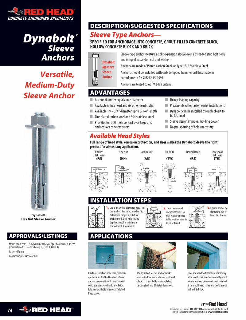
CONCRETE ANCHORING SPECIALISTS
74 Call our toll free number 800-899-7890 or visit our web site for the mostcurrent product and technical information atwww.itwredhead.com
DynaboltSleeve
Anchors
ADVANTAGES
1. Use a bit with a diameter equal tothe anchor. See selection chart todetermine proper size bit foranchor used. Drill hole to anydepth exceeding minimumembedment. Clean hole.
2. Insert assembledanchor into hole, sothat washer or headis flush with materialsto be fastened.
INSTALLATION STEPS3. Expand anchor bytightening nut orhead 2 to 3 turns.
APPLICATIONS
Electrical junction boxes are commonapplications for the Dynabolt Sleeveanchor because it works well in solidconcrete, concrete block, and brick. It is also available in several finishedhead styles.
The Dynabolt Sleeve anchor works well in hollow materials like brick andblock. It is available in zinc-plated carbon steel and 304 stainless steel.
Door and window frames are commonlyattached to the structure with DynaboltSleeve anchors because of their finished& threshold head styles and performancein block & brick.
APPROVALS/LISTINGSMeets or exceeds U.S. Government G.S.A. Specification A-A-1922A(Formerly GSA: FF-S-325 Group II, Type 3, Class 3)Factory MutualCalifornia State Fire Marshal
� Anchor diameter equals hole diameter� Available in hex head and six other head styles� Available 1/4 - 3/4" diameter up to 6-1/4" length� Zinc plated carbon steel and 304 stainless steel� Provides full 360° hole contact over large area
and reduces concrete stress
� Heavy-loading capacity� Preassembled for faster, easier installations� Dynabolt can be installed through object to
be fastened� Sleeve design improves holding power� No pre-spotting of holes necessary
Versatile,Medium-DutySleeve Anchor
Available Head Styles
Sleeve type anchors feature a split expansion sleeve over a threaded stud bolt bodyand integral expander, nut and washer.
Anchors are made of Plated Carbon Steel, or Type 18-8 Stainless Steel.
Anchors should be installed with carbide tipped hammer drill bits made in accordance to ANSI B212.15-1994.
Anchors are tested to ASTM E488 criteria.
DESCRIPTION/SUGGESTED SPECIFICATIONS
Sleeve Type Anchors— SpeciFieD For anchorage into concrete, grout-FilleD concrete block, hollow concrete block anD brick
Phillips Hex Nut Acorn Nut Tie Wire Round Head Threshold Flat Head Flat Head(FS) (HN) (AN) (TW) (RS) (TH)
DynaboltMasonrySleeve Anchor
Full range of head style, corrosion protection, and sizes makes the Dynabolt Sleeve the right product for almost any application.
Dynabolt Hex Nut Sleeve Anchor
®
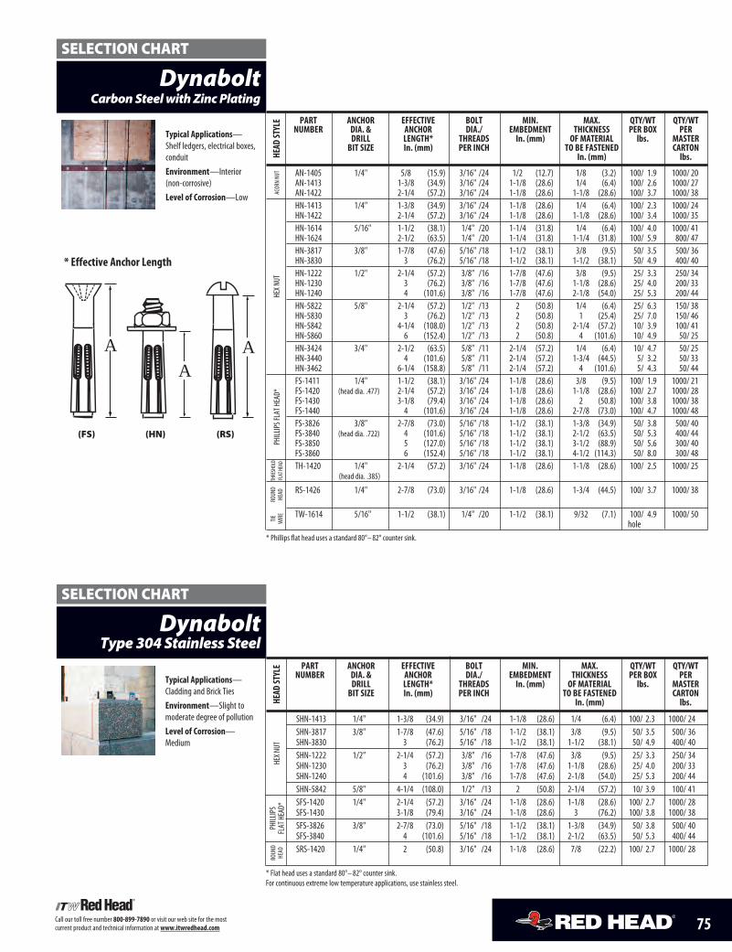
75Call our toll free number 800-899-7890 or visit our web site for the most current product and technical information at www.itwredhead.com
DynaboltCarbon Steel with Zinc Plating
part anchor eFFectiVe bolt min. max. Qty/wt Qty/wtnumber Dia. & anchor Dia./ embeDment thickneSS per box per
Drill length* threaDS in. (mm) oF material lbs. maSterbit Size in. (mm) per inch to be FaSteneD carton
in. (mm) lbs.
AN-1405 1/4" 5/8 (15.9) 3/16" /24 1/2 (12.7) 1/8 (3.2) 100/ 1.9 1000/ 20AN-1413 1-3/8 (34.9) 3/16" /24 1-1/8 (28.6) 1/4 (6.4) 100/ 2.6 1000/ 27AN-1422 2-1/4 (57.2) 3/16" /24 1-1/8 (28.6) 1-1/8 (28.6) 100/ 3.7 1000/ 38HN-1413 1/4" 1-3/8 (34.9) 3/16" /24 1-1/8 (28.6) 1/4 (6.4) 100/ 2.3 1000/ 24HN-1422 2-1/4 (57.2) 3/16" /24 1-1/8 (28.6) 1-1/8 (28.6) 100/ 3.4 1000/ 35HN-1614 5/16" 1-1/2 (38.1) 1/4" /20 1-1/4 (31.8) 1/4 (6.4) 100/ 4.0 1000/ 41HN-1624 2-1/2 (63.5) 1/4" /20 1-1/4 (31.8) 1-1/4 (31.8) 100/ 5.9 800/ 47HN-3817 3/8" 1-7/8 (47.6) 5/16" /18 1-1/2 (38.1) 3/8 (9.5) 50/ 3.5 500/ 36HN-3830 3 (76.2) 5/16" /18 1-1/2 (38.1) 1-1/2 (38.1) 50/ 4.9 400/ 40HN-1222 1/2" 2-1/4 (57.2) 3/8" /16 1-7/8 (47.6) 3/8 (9.5) 25/ 3.3 250/ 34HN-1230 3 (76.2) 3/8" /16 1-7/8 (47.6) 1-1/8 (28.6) 25/ 4.0 200/ 33HN-1240 4 (101.6) 3/8" /16 1-7/8 (47.6) 2-1/8 (54.0) 25/ 5.3 200/ 44HN-5822 5/8" 2-1/4 (57.2) 1/2" /13 2 (50.8) 1/4 (6.4) 25/ 6.3 150/ 38HN-5830 3 (76.2) 1/2" /13 2 (50.8) 1 (25.4) 25/ 7.0 150/ 46HN-5842 4-1/4 (108.0) 1/2" /13 2 (50.8) 2-1/4 (57.2) 10/ 3.9 100/ 41HN-5860 6 (152.4) 1/2" /13 2 (50.8) 4 (101.6) 10/ 4.9 50/ 25HN-3424 3/4" 2-1/2 (63.5) 5/8" /11 2-1/4 (57.2) 1/4 (6.4) 10/ 4.7 50/ 25HN-3440 4 (101.6) 5/8" /11 2-1/4 (57.2) 1-3/4 (44.5) 5/ 3.2 50/ 33HN-3462 6-1/4 (158.8) 5/8" /11 2-1/4 (57.2) 4 (101.6) 5/ 4.3 50/ 44FS-1411 1/4" 1-1/2 (38.1) 3/16" /24 1-1/8 (28.6) 3/8 (9.5) 100/ 1.9 1000/ 21FS-1420 (head dia. .477) 2-1/4 (57.2) 3/16" /24 1-1/8 (28.6) 1-1/8 (28.6) 100/ 2.7 1000/ 28FS-1430 3-1/8 (79.4) 3/16" /24 1-1/8 (28.6) 2 (50.8) 100/ 3.8 1000/ 38FS-1440 4 (101.6) 3/16" /24 1-1/8 (28.6) 2-7/8 (73.0) 100/ 4.7 1000/ 48FS-3826 3/8" 2-7/8 (73.0) 5/16" /18 1-1/2 (38.1) 1-3/8 (34.9) 50/ 3.8 500/ 40FS-3840 (head dia. .722) 4 (101.6) 5/16" /18 1-1/2 (38.1) 2-1/2 (63.5) 50/ 5.3 400/ 44FS-3850 5 (127.0) 5/16" /18 1-1/2 (38.1) 3-1/2 (88.9) 50/ 5.6 300/ 40FS-3860 6 (152.4) 5/16" /18 1-1/2 (38.1) 4-1/2 (114.3) 50/ 8.0 300/ 48TH-1420 1/4" 2-1/4 (57.2) 3/16" /24 1-1/8 (28.6) 1-1/8 (28.6) 100/ 2.5 1000/ 25
(head dia. .385)
RS-1426 1/4" 2-7/8 (73.0) 3/16" /24 1-1/8 (28.6) 1-3/4 (44.5) 100/ 3.7 1000/ 38
TW-1614 5/16" 1-1/2 (38.1) 1/4" /20 1-1/2 (38.1) 9/32 (7.1) 100/ 4.9 1000/ 50hole
* Phillips flat head uses a standard 80°–82° counter sink.
typical applications—Shelf ledgers, electrical boxes,conduitenvironment—Interior(non-corrosive)level of corrosion—Low
ACORN NUT
heaD
Styl
eTHRESHOLD
FLAT HEAD
HEX NUT
PHILLIPS FLAT HEAD*
ROUND
HEAD
TIE WIRE
DynaboltType 304 Stainless Steel
part anchor eFFectiVe bolt min. max. Qty/wt Qty/wtnumber Dia. & anchor Dia./ embeDment thickneSS per box per
Drill length* threaDS in. (mm) oF material lbs. maSterbit Size in. (mm) per inch to be FaSteneD carton
in. (mm) lbs.
SHN-1413 1/4" 1-3/8 (34.9) 3/16" /24 1-1/8 (28.6) 1/4 (6.4) 100/ 2.3 1000/ 24SHN-3817 3/8" 1-7/8 (47.6) 5/16" /18 1-1/2 (38.1) 3/8 (9.5) 50/ 3.5 500/ 36SHN-3830 3 (76.2) 5/16" /18 1-1/2 (38.1) 1-1/2 (38.1) 50/ 4.9 400/ 40SHN-1222 1/2" 2-1/4 (57.2) 3/8" /16 1-7/8 (47.6) 3/8 (9.5) 25/ 3.3 250/ 34SHN-1230 3 (76.2) 3/8" /16 1-7/8 (47.6) 1-1/8 (28.6) 25/ 4.0 200/ 33SHN-1240 4 (101.6) 3/8" /16 1-7/8 (47.6) 2-1/8 (54.0) 25/ 5.3 200/ 44SHN-5842 5/8" 4-1/4 (108.0) 1/2" /13 2 (50.8) 2-1/4 (57.2) 10/ 3.9 100/ 41SFS-1420 1/4" 2-1/4 (57.2) 3/16" /24 1-1/8 (28.6) 1-1/8 (28.6) 100/ 2.7 1000/ 28SFS-1430 3-1/8 (79.4) 3/16" /24 1-1/8 (28.6) 3 (76.2) 100/ 3.8 1000/ 38SFS-3826 3/8" 2-7/8 (73.0) 5/16" /18 1-1/2 (38.1) 1-3/8 (34.9) 50/ 3.8 500/ 40SFS-3840 4 (101.6) 5/16" /18 1-1/2 (38.1) 2-1/2 (63.5) 50/ 5.3 400/ 44SRS-1420 1/4" 2 (50.8) 3/16" /24 1-1/8 (28.6) 7/8 (22.2) 100/ 2.7 1000/ 28
* Flat head uses a standard 80°–82° counter sink.For continuous extreme low temperature applications, use stainless steel.
typical applications—Cladding and Brick Tiesenvironment—Slight tomoderate degree of pollutionlevel of corrosion—Medium
HEX NUT
heaD
Styl
ePHILLIPS
FLAT HEAD*
ROUND
HEAD
SELECTION CHART
SELECTION CHART
* effective anchor length
AA
A
(FS) (HN) (RS)
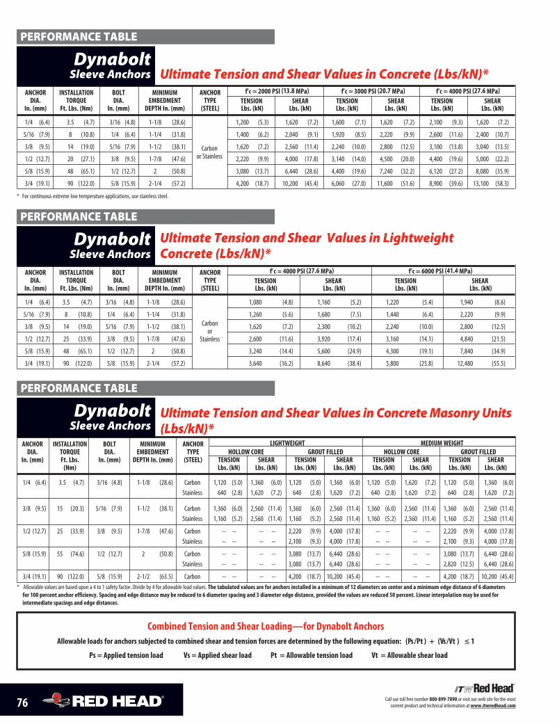
76 Call our toll free number 800-899-7890 or visit our web site for the most current product and technical information at www.itwredhead.com
anchor inStallation bolt MiniMuM anchor f’c = 2000 pSi (13.8 Mpa) f’c = 3000 pSi (20.7 Mpa) f’c = 4000 pSi (27.6 Mpa)Dia. torQue Dia. eMbeDMent tYpe tenSion Shear tenSion Shear tenSion Shear
in. (mm) Ft. lbs. (nm) in. (mm) Depth in. (mm) (Steel) lbs. (kn) lbs. (kn) lbs. (kn) lbs. (kn) lbs. (kn) lbs. (kn)
1/4 (6.4) 3.5 (4.7) 3/16 (4.8) 1-1/8 (28.6) 1,200 (5.3) 1,620 (7.2) 1,600 (7.1) 1,620 (7.2) 2,100 (9.3) 1,620 (7.2)
5/16 (7.9) 8 (10.8) 1/4 (6.4) 1-1/4 (31.8) 1,400 (6.2) 2,040 (9.1) 1,920 (8.5) 2,220 (9.9) 2,600 (11.6) 2,400 (10.7)
3/8 (9.5) 14 (19.0) 5/16 (7.9) 1-1/2 (38.1) 1,620 (7.2) 2,560 (11.4) 2,240 (10.0) 2,800 (12.5) 3,100 (13.8) 3,040 (13.5)
1/2 (12.7) 20 (27.1) 3/8 (9.5) 1-7/8 (47.6) 2,220 (9.9) 4,000 (17.8) 3,140 (14.0) 4,500 (20.0) 4,400 (19.6) 5,000 (22.2)
5/8 (15.9) 48 (65.1) 1/2 (12.7) 2 (50.8) 3,080 (13.7) 6,440 (28.6) 4,400 (19.6) 7,240 (32.2) 6,120 (27.2) 8,080 (35.9)
3/4 (19.1) 90 (122.0) 5/8 (15.9) 2-1/4 (57.2) 4,200 (18.7) 10,200 (45.4) 6,060 (27.0) 11,600 (51.6) 8,900 (39.6) 13,100 (58.3)
* For continuous extreme low temperature applications, use stainless steel.
Ultimate Tension and Shear Values in Concrete (Lbs/kN)*
Carbon or Stainless
DynaboltSleeve Anchors
anchor inStallation bolt MiniMuM anchor f’c = 4000 pSi (27.6 Mpa) f’c = 6000 pSi (41.4 Mpa)Dia. torQue Dia. eMbeDMent tYpe tenSion Shear tenSion Shear
in. (mm) Ft. lbs. (nm) in. (mm) Depth in. (mm) (Steel) lbs. (kn) lbs. (kn) lbs. (kn) lbs. (kn)
1/4 (6.4) 3.5 (4.7) 3/16 (4.8) 1-1/8 (28.6) 1,080 (4.8) 1,160 (5.2) 1,220 (5.4) 1,940 (8.6)
5/16 (7.9) 8 (10.8) 1/4 (6.4) 1-1/4 (31.8) 1,260 (5.6) 1,680 (7.5) 1,440 (6.4) 2,220 (9.9)
3/8 (9.5) 14 (19.0) 5/16 (7.9) 1-1/2 (38.1) 1,620 (7.2) 2,300 (10.2) 2,240 (10.0) 2,800 (12.5)
1/2 (12.7) 25 (33.9) 3/8 (9.5) 1-7/8 (47.6) 2,600 (11.6) 3,920 (17.4) 3,160 (14.1) 4,840 (21.5)
5/8 (15.9) 48 (65.1) 1/2 (12.7) 2 (50.8) 3,240 (14.4) 5,600 (24.9) 4,300 (19.1) 7,840 (34.9)
3/4 (19.1) 90 (122.0) 5/8 (15.9) 2-1/4 (57.2) 3,640 (16.2) 8,640 (38.4) 5,800 (25.8) 12,480 (55.5)
Ultimate Tension and Shear Values in Lightweight Concrete (Lbs/kN)*
Carbon or
Stainless
DynaboltSleeve Anchors
anchor inStallation bolt MiniMuM anchor lightweight MeDiuM weightDia. torQue Dia. eMbeDMent tYpe hollow core grout FilleD hollow core grout FilleD
in. (mm) Ft. lbs. in. (mm) Depth in. (mm) (Steel) tenSion Shear tenSion Shear tenSion Shear tenSion Shear(nm) lbs. (kn) lbs. (kn) lbs. (kn) lbs. (kn) lbs. (kn) lbs. (kn) lbs. (kn) lbs. (kn)
1/4 (6.4) 3.5 (4.7) 3/16 (4.8) 1-1/8 (28.6) Carbon 1,120 (5.0) 1,360 (6.0) 1,120 (5.0) 1,360 (6.0) 1,120 (5.0) 1,620 (7.2) 1,120 (5.0) 1,360 (6.0)Stainless 640 (2.8) 1,620 (7.2) 640 (2.8) 1,620 (7.2) 640 (2.8) 1,620 (7.2) 640 (2.8) 1,620 (7.2)
3/8 (9.5) 15 (20.3) 5/16 (7.9) 1-1/2 (38.1) Carbon 1,360 (6.0) 2,560 (11.4) 1,360 (6.0) 2,560 (11.4) 1,360 (6.0) 2,560 (11.4) 1,360 (6.0) 2,560 (11.4)Stainless 1,160 (5.2) 2,560 (11.4) 1,160 (5.2) 2,560 (11.4) 1,160 (5.2) 2,560 (11.4) 1,160 (5.2) 2,560 (11.4)
1/2 (12.7) 25 (33.9) 3/8 (9.5) 1-7/8 (47.6) Carbon -- -- -- -- 2,220 (9.9) 4,000 (17.8) -- -- -- -- 2,220 (9.9) 4,000 (17.8)Stainless -- -- -- -- 2,100 (9.3) 4,000 (17.8) -- -- -- -- 2,100 (9.3) 4,000 (17.8)
5/8 (15.9) 55 (74.6) 1/2 (12.7) 2 (50.8) Carbon -- -- -- -- 3,080 (13.7) 6,440 (28.6) -- -- -- -- 3,080 (13.7) 6,440 (28.6)Stainless -- -- -- -- 3,080 (13.7) 6,440 (28.6) -- -- -- -- 2,820 (12.5) 6,440 (28.6)
3/4 (19.1) 90 (122.0) 5/8 (15.9) 2-1/2 (63.5) Carbon -- -- -- -- 4,200 (18.7) 10,200 (45.4) -- -- -- -- 4,200 (18.7) 10,200 (45.4)* Allowable values are based upon a 4 to 1 safety factor. Divide by 4 for allowable load values. the tabulated values are for anchors installed in a minimum of 12 diameters on center and a minimum edge distance of 6 diameters
for 100 percent anchor efficiency. Spacing and edge distance may be reduced to 6 diameter spacing and 3 diameter edge distance, provided the values are reduced 50 percent. linear interpolation may be used for intermediate spacings and edge distances.
Ultimate Tension and Shear Values in Concrete Masonry Units(Lbs/kN)*
PERFORMANCE TABLE
PERFORMANCE TABLE
PERFORMANCE TABLE
DynaboltSleeve Anchors
combined tension and Shear loading—for Dynabolt anchorsallowable loads for anchors subjected to combined shear and tension forces are determined by the following equation: (ps /pt ) + (Vs /Vt ) ≤ 1
ps = applied tension load Vs = applied shear load pt = allowable tension load Vt = allowable shear load
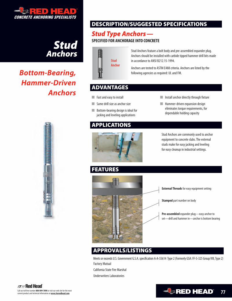
77Call our toll free number 800-899-7890 or visit our web site for the mostcurrent product and technical information at www.itwredhead.com
StudAnchors
ADVANTAGES
FEATURES
external threads for easy equipment setting
stamped part number on body
pre-assembled expander plug—easy anchor toset—drill and hammer in—anchor is bottom bearing
� Fast and easy to install
� Same drill size as anchor size
� Bottom-bearing design is ideal forjacking and leveling applications
� Install anchor directly through fixture
� Hammer-driven expansion designeliminates torque requirements, fordependable holding capacity
Bottom-Bearing,Hammer-Driven
Anchors
DESCRIPTION/SUGGESTED SPECIFICATIONS
Stud Type Anchors—specified for anchorage into concrete
Stud Anchors feature a bolt body and pre-assembled expander plug.Anchors should be installed with carbide tipped hammer drill bits madein accordance to ANSI B212.15-1994.
Anchors are tested to ASTM E488 criteria. Anchors are listed by thefollowing agencies as required: UL and FM.
APPLICATIONS
Stud Anchors are commonly used to anchorequipment to concrete slabs. The externalstuds make for easy jacking and levelingfor easy cleanup in industrial settings.
APPROVALS/LISTINGSMeets or exceeds U.S. Government G.S.A. specification A-A-55614 Type 2 (Formerly GSA: FF-S-325 GroupVIII, Type 2)Factory Mutual
California State Fire Marshal
Underwriters Laboratories
StudAnchor
CONCRETE ANCHORING SPECIALISTS
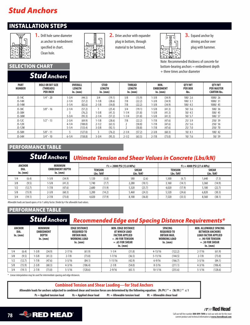
78 Call our toll free number 800-899-7890 or visit our web site for the mostcurrent product and technical information at www.itwredhead.com
part hoLe or bit siZe oVeraLL stUd thread Min. Qty/wt Qty/wtnUMber (threads) Length Length Length eMbedMent per boX per Master
per inch in. (mm) in. (mm) in. (mm) in. (mm) lbs. carton lbs.
JS-14C 1/4" - 20 1-3/4 (44.5) 3/4 (19.1) 5/8 (15.9) 1-3/8 (34.9) 100/ 2.6 1000/ 26JS-14H 2-1/4 (57.2) 1-1/8 (28.6) 7/8 (22.2) 1-3/8 (34.9) 100/ 3.1 1000/ 31JS-14M 3-1/4 (82.6) 2-1/8 (54.0) 7/8 (22.2) 1-3/8 (34.9) 100/ 4.5 1000/ 45JS-38C 3/8" - 16 2-1/4 (57.2) 1 (25.4) 3/4 (19.1) 1-5/8 (41.3) 50/ 3.6 500/ 36JS-38H 3 (76.2) 1-5/8 (41.3) 1-1/4 (31.8) 1-5/8 (41.3) 50/ 4.5 500/ 45JS-38M 3-3/4 (95.3) 2-1/4 (57.2) 1-1/4 (31.8) 1-5/8 (41.3) 50/ 5.7 500/ 57JS-12C 1/2" - 13 2-3/4 (69.9) 1-1/8 (28.6) 7/8 (22.2) 1-7/8 (47.6) 25/ 3.9 250/ 39JS-12H 4-1/4 (108.0) 2-1/2 (63.5) 2 (50.8) 1-7/8 (47.6) 25/ 5.6 250/ 56JS-12M 5-1/4 (133.4) 3-5/8 (92.1) 2 (50.8) 1-7/8 (47.6) 25/ 7.0 250/ 70JS-58H 5/8" - 11 5 (127.0) 3 (76.2) 2-1/4 (57.2) 2-3/8 (60.3) 10/ 4.1 100/ 42JS-34H 3/4" - 10 6-1/4 (158.8) 3-3/4 (95.3) 2-1/2 (63.5) 2-7/8 (73.0) 10/ 7.6 50/ 59
1. Drill hole same diameteras anchor to embedmentspecified in chart.Clean hole.
2. Drive anchor with expanderplug in bottom, throughmaterial to be fastened.
INSTALLATION STEPS3. Expand anchor by
driving anchor overplug with hammer.
Stud Anchors
StudAnchors
anchor MiniMUM f ’c = 2000 psi (13.8 Mpa) f’c = 4000 psi (27.6 Mpa)dia. eMbedMent depth tension shear tension shear
in. (mm) in. (mm) Lbs. (kn) Lbs. (kn) Lbs. (kn) Lbs. (kn)
1/4 (6.4) 1-3/8 (34.9) 1,120 (5.0) 580 (2.6) 1,500 (6.7) 1,640 (7.3)3/8 (9.5) 1-5/8 (41.3) 1,740 (7.7) 2,280 (10.1) 3,160 (14.1) 3,360 (14.9)1/2 (12.7) 1-7/8 (47.6) 2,680 (11.9) 5,320 (23.7) 4,020 (17.9) 5,100 (22.7)5/8 (15.9) 2-3/8 (60.3) 3,200 (14.2) 5,460 (24.3) 5,520 (24.6) 6,820 (30.3)3/4 (19.1) 2-7/8 (73.0) 4,020 (17.9) 8,100 (36.0) 7,520 (33.5) 8,560 (38.1)
Allowable loads are based upon a 4 to 1 safety factor. Divide by 4 for allowable load values.
Ultimate Tension and Shear Values in Concrete (Lbs/kN)StudAnchors
anchor MiniMUM edge distance Min. edge distance spacing Min. aLLowabLe spacingdia. eMbedMent reQUired to at which Load reQUired to between anchors
in. (mm) depth obtain MaX. factor appLied obtain MaX. Load factor appLiedin. (mm) worKing Load = .90 for tension worKing Load = .90 for tension
in. (mm) = .65 for shear in. (mm) = .50 for shearin. (mm) in. (mm)
1/4 (6.4) 1-3/8 (34.9) 2-7/16 (61.9) 1-1/4 (31.8) 4-13/16 (122.2) 2-7/16 (61.9)3/8 (9.5) 1-5/8 (41.3) 2-7/8 (73.0) 1-7/16 (36.5) 5-11/16 (144.5) 2-7/8 (73.0)1/2 (12.7) 1-7/8 (47.6) 3-5/16 (84.1) 1-11/16 (42.9) 6-9/16 (166.7) 3-5/16 (84.1)5/8 (15.9) 2-3/8 (60.3) 4-3/16 (106.4) 2-1/8 (54.0) 8-5/16 (211.1) 4-3/16 (106.4)3/4 (19.1) 2-7/8 (73.0) 5-1/16 (128.6) 2-9/16 (65.1) 10-1/16 (255.6) 5-1/16 (128.6)
* Linear interpolation may be used for intermediate spacing and edge distances.
StudAnchors Recommended Edge and Spacing Distance Requirements*
combined tension and shear Loading—for stud anchorsallowable loads for anchors subjected to combined shear and tension forces are determined by the following equation: (ps /pt ) 5/3 + (Vs /Vt ) 5/3 ≤ 1
ps = applied tension load Vs = applied shear load pt = allowable tension load Vt = allowable shear load
SELECTION CHART
PERFORMANCE TABLE
PERFORMANCE TABLE
Note: Recommended thickness of concrete forbottom-bearing anchors = embedment depth+ three times anchor diameter
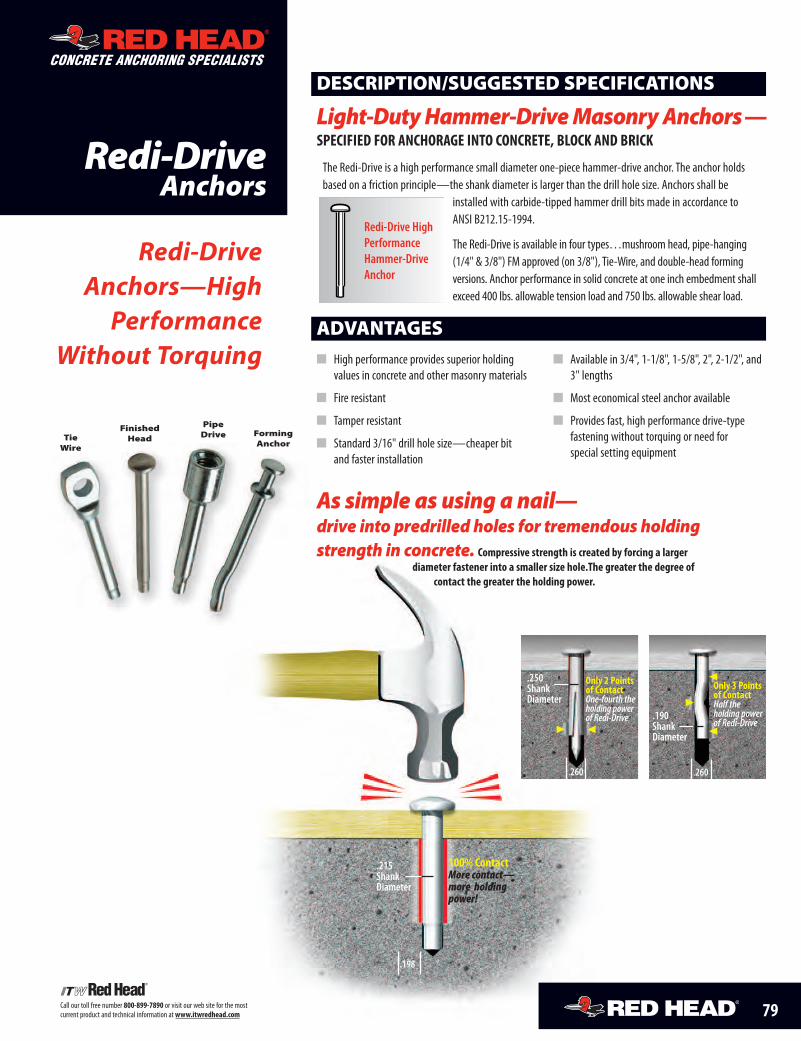
100% ContactMore contact—more holdingpower!
.215ShankDiameter
.198
ADVANTAGES� High performance provides superior holding
values in concrete and other masonry materials
� Fire resistant
� Tamper resistant
� Standard 3/16" drill hole size—cheaper bitand faster installation
� Available in 3/4", 1-1/8", 1-5/8", 2", 2-1/2", and3" lengths
� Most economical steel anchor available
� Provides fast, high performance drive-typefastening without torquing or need forspecial setting equipment
Only 3 Pointsof ContactHalf theholding powerof Redi-Drive
.190ShankDiameter
.260
Only 2 Pointsof ContactOne-fourth theholding powerof Redi-Drive
.250ShankDiameter
.260
The Redi-Drive is a high performance small diameter one-piece hammer-drive anchor. The anchor holdsbased on a friction principle—the shank diameter is larger than the drill hole size. Anchors shall be
installed with carbide-tipped hammer drill bits made in accordance toANSI B212.15-1994.
The Redi-Drive is available in four types…mushroom head, pipe-hanging(1/4" & 3/8") FM approved (on 3/8"), Tie-Wire, and double-head formingversions. Anchor performance in solid concrete at one inch embedment shallexceed 400 lbs. allowable tension load and 750 lbs. allowable shear load.
DESCRIPTION/SUGGESTED SPECIFICATIONS
Light-DutyHammer-DriveMasonryAnchors—SPECIFIED FOR ANCHORAGE INTO CONCRETE, BLOCK AND BRICK
Redi-Drive HighPerformanceHammer-DriveAnchor
Redi-DriveAnchors—High
PerformanceWithout Torquing
Redi-DriveAnchors
CONCRETE ANCHORING SPECIALISTS
As simple as using a nail—drive into predrilled holes for tremendous holdingstrength in concrete. Compressive strength is created by forcing a larger
diameter fastener into a smaller size hole.The greater the degree ofcontact the greater the holding power.
79Call our toll free number 800-899-7890 or visit our web site for the mostcurrent product and technical information atwww.itwredhead.com
TieWire
FinishedHead
PipeDrive Forming
Anchor
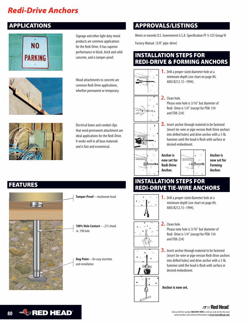
80 Call our toll free number 800-899-7890 or visit our web site for the mostcurrent product and technical information atwww.itwredhead.com
1. Drill a proper-sized diameter hole at aminimum depth (see chart on page 84,ANSI B212.15–1994).
2. Clean hole.Please note hole is 3/16" but diameter ofRedi -Drive is 1/4" (except for PD8-134and FD8-234)
Anchor isnow set forRedi-DriveAnchor.
Anchor isnow set forFormingAnchor.
3. Insert anchor through material to be fastened(insert tie-wire or pipe version Redi-Drive anchorsinto drilled holes) and drive anchor with a 3-lb.hammer until the head is flush with surface ordesired embedment.
INSTALLATION STEPS FORREDI-DRIVE & FORMING ANCHORS
Redi-Drive Anchors
FEATURES
APPROVALS/LISTINGS
Meets or exceeds U.S. Government G.S.A. Specification FF-S-325 Group VI
Factory Mutual (3/8" pipe-drive)
Tamper-Proof—mushroom head
100% Hole Contact—.215 shankin .198 hole
Dog-Point—for easy insertionand installation
APPLICATIONS
Signage and other light duty metalproducts are common applicationsfor the Redi-Drive. It has superiorperformance in block, brick and solidconcrete, and is tamper-proof.
Wood attachments to concrete arecommon Redi-Drive applications,whether permanent or temporary.
Electrical boxes and conduit clipsthat need permanent attachment areideal applications for the Redi-Drive.It works well in all base materialsand is fast and economical.
1. Drill a proper-sized diameter hole at aminimum depth (see chart on page 84,ANSI B212.15–1994).
2. Clean hole.Please note hole is 3/16" but diameter ofRedi -Drive is 1/4" (except for PD8-134and FD8-234)
Anchor is now set.
3. Insert anchor through material to be fastened(insert tie-wire or pipe version Redi-Drive anchorsinto drilled holes) and drive anchor with a 3-lb.hammer until the head is flush with surface ordesired embedment.
INSTALLATION STEPS FORREDI-DRIVE TIE-WIRE ANCHORS
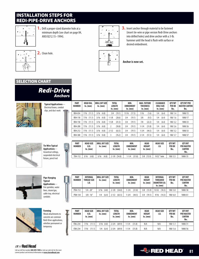
81Call our toll free number 800-899-7890 or visit our web site for the mostcurrent product and technical information atwww.itwredhead.com
Typical Applications—Electrical boxes, conduitclips, and duct work
Redi-DriveAnchors
PART HEAD DIA. DRILL BIT SIZE TOTAL MIN. MAX. FIXTURE CLEARANCE QTY/WT QTY/WT PERNUMBER In. (mm) In. (mm) LENGTH EMBEDMENT THICKNESS HOLE SIZE PER BX MASTER CARTON
In. (mm) In. (mm) In. (mm) In. (mm) lbs. lbs.
RD4-034 7/16 (11.1) 3/16 (4.8) 3/4 (19.1) 11/16 (17.5) 1/16 (1.6) 1/4 (6.4) 100/ 1.4 1000/15
RD4-118 7/16 (11.1) 3/16 (4.8) 1-1/8 (28.6) 3/4 (19.1) 3/8 (9.5) 1/4 (6.4) 100/ 1.6 1000/17
RD4-158 7/16 (11.1) 3/16 (4.8) 1-5/8 (41.3) 3/4 (19.1) 7/8 (22.2) 1/4 (6.4) 100/ 2.2 1000/23
RD4-200 7/16 (11.1) 3/16 (4.8) 2 (50.8) 3/4 (19.1) 1-1/4 (31.8) 1/4 (6.4) 100/ 2.6 1000/26
RD4-212 7/16 (11.1) 3/16 (4.8) 2-1/2 (63.5) 3/4 (19.1) 1-3/4 (44.5) 1/4 (6.4) 100/ 3.2 1000/33
RD4-300 7/16 (11.1) 3/16 (4.8) 3 (76.2) 3/4 (19.1) 2-1/4 (57.2) 1/4 (6.4) 100/ 3.7 1000/37
Pipe HangingTypicalApplications—Fire sprinkler, waterlines, steam/gas,cable tray, electricalconduits
FormingWood attachments toconcrete are commonRedi-Drive applications,whether permanent ortemporary
Tie Wire TypicalApplications—Acoustical ceilings,suspended electricalfixture, pencil rod
PART HEAD SIZE DRILL BIT SIZE TOTAL MIN. HEAD HEAD SIZE QTY/WT QTY/WTNUMBER O.D. In. (mm) LENGTH EMBEDMENT HEIGHT I.D. PER BX PER MASTER
In. (mm) In. (mm) In. (mm) In. (mm) lbs. CARTONlbs.
TD4-112 3/16 (4.8) 3/16 (4.8) 2-1/8 (54.0) 1-1/4 (31.8) 5/8 (15.9) 9/32" hole 100/ 3.5 1000/35
SELECTION CHART
PART INTERNAL DRILL BIT SIZE TOTAL MIN. HEAD INTERNAL QTY/WT QTY/WTNUMBER THREAD SIZE In. (mm) LENGTH EMBEDMENT HEIGHT THREADED PER BX PER MASTER
I.D. In. (mm) In. (mm) In. (mm) DIAMETER O.D. lbs. CARTONIn. (mm) lbs.
PD4-112 1/4 - 20" 3/16 (4.8) 2-1/8 (54.0) 1-1/4 (31.8) 5/8 (15.9) 13/32 (10.3) 100/ 3.0 1000/30
PD8-134 3/8 - 16" 1/4 (6.4) 2-1/2 (63.5) 1-3/4 (44.5) 3/4 (19.1) 9/16 (14.3) 100/ 6.0 1000/61
PART HEAD SIZE DRILL BIT SIZE TOTAL MIN. HEAD HEAD SIZE QTY/WT QTY/WTNUMBER O.D. In. (mm) LENGTH EMBEDMENT HEIGHT I.D. PER BX PER MASTER
In. (mm) In. (mm) In. (mm) In. (mm) lbs. CARTONlbs.
FD6-234 7/16 (11.1) 3/16 (4.8) 2-3/4 (69.9) 1-1/4 (31.8) N/A N/A 100/ 3.1 1000/31
FD8-234 7/16 (11.1) 1/4 (6.4) 2-3/4 (69.9) 1-1/4 (31.8) N/A N/A 100/ 5.6 1000/56
1. Drill a proper-sized diameter hole at aminimum depth (see chart on page 84,ANSI B212.15–1994).
2. Clean hole.
Anchor is now set.
3. Insert anchor through material to be fastened(insert tie-wire or pipe version Redi-Drive anchorsinto drilled holes) and drive anchor with a 3-lb.hammer until the head is flush with surface ordesired embedment.
INSTALLATION STEPS FORREDI-PIPE-DRIVE ANCHORS
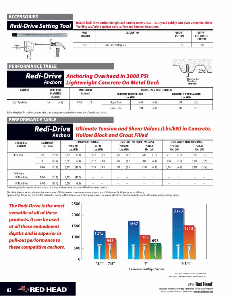
82 Call our toll free number 800-899-7890 or visit our web site for the mostcurrent product and technical information atwww.itwredhead.com
Ultimate Tension and Shear Values (Lbs/kN) in Concrete,Hollow Block and Grout Filled
SHANK DIA. EMBEDMENT 4500 PSI (31.0 MPa) CMU (HOLLOW BLOCK) PSI (MPa) CMU (GROUT FILLED) PSI (MPa)ANCHOR In. (mm) TENSION SHEAR TENSION SHEAR TENSION SHEAR
Lbs. (kN) Lbs. (kN) Lbs. (kN) Lbs. (kN) Lbs. (kN) Lbs. (kN)
Redi-Drive 3/4 (19.1) 1,215 (5.4) 1,857 (8.3) 382 (1.7) 683 (3.0) 731 (3.3) 1,614 (7.2)
1 (25.4) 1,667 (7.4) 3,112 (13.8) 392 (1.7) 987 (4.4) 870 (3.9) 1,766 (7.9)
1-1/4 (31.8) 2,373 (10.6) 3,355 (14.9) 398 (1.8) 1,381 (6.1) 1,543 (6.9) 2,778 (12.4)
Tie-Drive or1/4" Pipe-Drive 1-1/4 (31.8) 2,372 (10.6) -- -- -- -- -- -- -- -- -- --
3/8" Pipe-Drive 1-1/2 (38.1) 2,090 (9.3) -- -- -- -- -- -- -- -- -- --Safe working loads for single installations under static loading conditions should not exceed 25% of the ultimate capacity.
The tabulated values are for anchors installed in a minimum of 12 diameters on center and a minimum edge distance of 10 diameters for 100 percent anchor efficiency.Space and edge distance may be reduced to six diameters spacing and five diameter edge distance provided values are reduced 50%. Linear interpolation may be used for intermediate spacing and edge margins.
Redi-DriveAnchors
TheRedi-Drive is themostversatile of all of theseproducts. It can be usedat all these embedmentdepths and is superior inpull-out performance tothese competitive anchors.
PERFORMANCE TABLE
PERFORMANCE TABLE
*Rawl Spike ® cannot be installed in 3/4”embedmentRawl Spike® is a registered trademark of Powers Fastening, Inc.
Embedment in 4500 psi Concrete
PART DESCRIPTION QTY/WT QTY/WTNUMBER PER BOX PER MASTER
CARTON
RDST Redi-Drive Setting Tool 1/1 1/1
Redi-Drive Setting Tool
ACCESSORIESInstalls Redi-Drive anchors in tight and hard to access areas—easily and quickly. Just place anchor in rubber“holding cap,” place against work surface and hammer in anchors.
20 Gauge Metal Deck
Redi-Pipe-Drive Installed in Lower Flute
ANCHOR DRILL HOLE EMBEDMENT 3000PSI (20.7 MPa) CONCRETEDIAMETER In. (mm) ULTIMATE TENSION LOAD ALLOWABLE WORKING LOADIn. (mm) Lbs. (kN) Lbs. (kN)
3/8” Pipe Drive 1/4 (6.4) 1-1/2 (38.1) Upper Flute 1,099 (4.9) 275 (1.2)
Lower Flute 994 (4.4) 249 (1.1)Safe working loads for single installations under static loading conditions should not exceed 25% of the ultimate capacity.
Anchoring Overhead in 3000 PSILightweight Concrete On Metal Deck
Redi-DriveAnchors
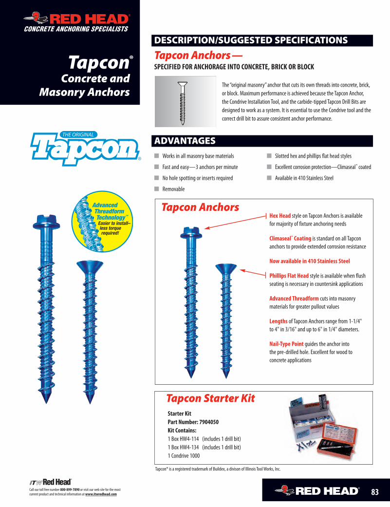
83Call our toll free number 800-899-7890 or visit our web site for the mostcurrent product and technical information atwww.itwredhead.com
TapconConcrete and
Masonry Anchors
ADVANTAGES� Works in all masonry base materials
� Fast and easy—3 anchors per minute
� No hole spotting or inserts required
� Removable
� Slotted hex and phillips flat head styles
� Excellent corrosion protection—Climaseal™ coated
� Available in 410 Stainless Steel
Hex Head style on Tapcon Anchors is availablefor majority of fixture anchoring needs
Climaseal™ Coating is standard on all Tapconanchors to provide extended corrosion resistance
Now available in 410 Stainless Steel
Phillips Flat Head style is available when flushseating is necessary in countersink applications
Advanced Threadform cuts into masonrymaterials for greater pullout values
Lengths of Tapcon Anchors range from 1-1/4"to 4" in 3/16" and up to 6" in 1/4" diameters.
Nail-Type Point guides the anchor intothe pre-drilled hole. Excellent for wood toconcrete applications
The “original masonry”anchor that cuts its own threads into concrete, brick,or block. Maximum performance is achieved because the Tapcon Anchor,the Condrive Installation Tool, and the carbide-tipped Tapcon Drill Bits aredesigned to work as a system. It is essential to use the Condrive tool and thecorrect drill bit to assure consistent anchor performance.
DESCRIPTION/SUGGESTED SPECIFICATIONS
Tapcon Anchors—SPECIFIED FOR ANCHORAGE INTO CONCRETE, BRICK OR BLOCK
®
Tapcon Starter KitStarter KitPart Number: 7904050Kit Contains:1 Box HW4-114 (includes 1 drill bit)1 Box HW4-134 (includes 1 drill bit)1 Condrive 1000
Tapcon Anchors
CONCRETE ANCHORING SPECIALISTS
®
Tapcon® is a registered trademark of Buildex, a divison of Illinois ToolWorks, Inc.
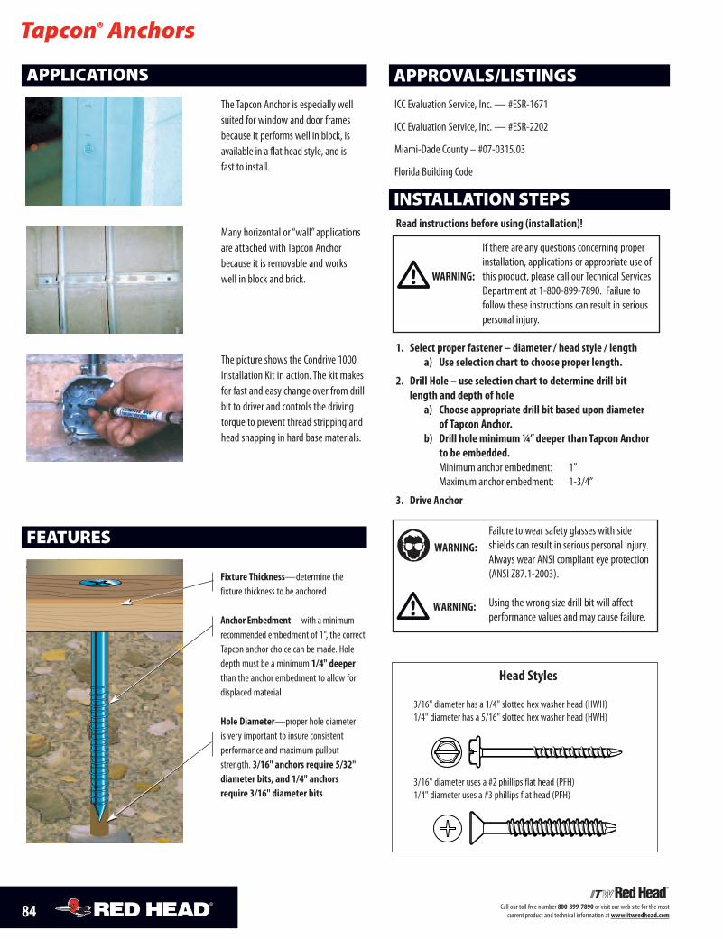
84 Call our toll free number 800-899-7890 or visit our web site for the mostcurrent product and technical information atwww.itwredhead.com
Read instructions before using (installation)!
If there are any questions concerning properinstallation, applications or appropriate use ofthis product, please call our Technical ServicesDepartment at 1-800-899-7890. Failure tofollow these instructions can result in seriouspersonal injury.
1. Select proper fastener – diameter / head style / lengtha) Use selection chart to choose proper length.
2. Drill Hole – use selection chart to determine drill bitlength and depth of hole
a) Choose appropriate drill bit based upon diameterof Tapcon Anchor.
b) Drill hole minimum¼”deeper than Tapcon Anchorto be embedded.Minimum anchor embedment: 1”Maximum anchor embedment: 1-3/4”
3. Drive Anchor
INSTALLATION STEPS
Tapcon® Anchors
APPROVALS/LISTINGS
ICC Evaluation Service, Inc.— #ESR-1671
ICC Evaluation Service, Inc.— #ESR-2202
Miami-Dade County – #07-0315.03
Florida Building Code
Fixture Thickness—determine thefixture thickness to be anchored
Anchor Embedment—with aminimumrecommended embedment of 1", the correctTapcon anchor choice can be made. Holedepth must be a minimum 1/4" deeperthan the anchor embedment to allow fordisplaced material
Hole Diameter—proper hole diameteris very important to insure consistentperformance and maximum pulloutstrength. 3/16" anchors require 5/32"diameter bits, and 1/4" anchorsrequire 3/16" diameter bits
APPLICATIONS
The Tapcon Anchor is especially wellsuited for window and door framesbecause it performs well in block, isavailable in a flat head style, and isfast to install.
Many horizontal or “wall” applicationsare attached with Tapcon Anchorbecause it is removable and workswell in block and brick.
The picture shows the Condrive 1000Installation Kit in action. The kit makesfor fast and easy change over from drillbit to driver and controls the drivingtorque to prevent thread stripping andhead snapping in hard base materials.
FEATURES
Head Styles
3/16" diameter has a 1/4" slotted hex washer head (HWH)1/4" diameter has a 5/16" slotted hex washer head (HWH)
3/16" diameter uses a #2 phillips flat head (PFH)1/4" diameter uses a #3 phillips flat head (PFH)
WARNING:
WARNING:
WARNING:
Failure to wear safety glasses with sideshields can result in serious personal injury.Always wear ANSI compliant eye protection(ANSI Z87.1-2003).
Using the wrong size drill bit will affectperformance values and may cause failure.
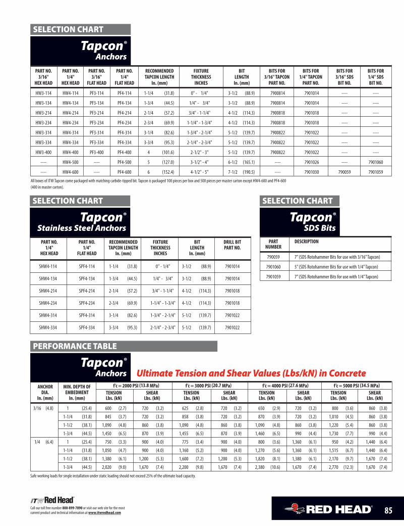
85Call our toll free number 800-899-7890 or visit our web site for the mostcurrent product and technical information atwww.itwredhead.com
PART NO. PART NO. PART NO. PART NO. RECOMMENDED FIXTURE BIT BITS FOR BITS FOR BITS FOR BITS FOR3/16" 1/4" 3/16" 1/4" TAPCON LENGTH THICKNESS LENGTH 3/16" TAPCON 1/4" TAPCON 3/16" SDS 1/4" SDS
HEX HEAD HEX HEAD FLAT HEAD FLAT HEAD In. (mm) INCHES In. (mm) PART NO. PART NO. BIT NO. BIT NO.
HW3-114 HW4-114 PF3-114 PF4-114 1-1/4 (31.8) 0" - 1/4" 3-1/2 (88.9) 7900814 7901014 ---- ----
HW3-134 HW4-134 PF3-134 PF4-134 1-3/4 (44.5) 1/4" - 3/4" 3-1/2 (88.9) 7900814 7901014 ---- ----
HW3-214 HW4-214 PF3-214 PF4-214 2-1/4 (57.2) 3/4" - 1-1/4" 4-1/2 (114.3) 7900818 7901018 ---- ----
HW3-234 HW4-234 PF3-234 PF4-234 2-3/4 (69.9) 1-1/4" - 1-3/4" 4-1/2 (114.3) 7900818 7901018 ---- ----
HW3-314 HW4-314 PF3-314 PF4-314 3-1/4 (82.6) 1-3/4" - 2-1/4" 5-1/2 (139.7) 7900822 7901022 ---- ----
HW3-334 HW4-334 PF3-334 PF4-334 3-3/4 (95.3) 2-1/4" - 2-3/4" 5-1/2 (139.7) 7900822 7901022 ---- ----
HW3-400 HW4-400 PF3-400 PF4-400 4 (101.6) 2-1/2" - 3" 5-1/2 (139.7) 7900822 7901022 ---- ----
---- HW4-500 ---- PF4-500 5 (127.0) 3-1/2" - 4" 6-1/2 (165.1) ---- 7901026 ---- 7901060
---- HW4-600 ---- PF4-600 6 (152.4) 4-1/2" - 5" 7-1/2 (190.5) ---- 7901030 790059 7901059
All boxes of ITW Tapcon come packaged with matching carbide-tipped bit. Tapcon is packaged 100 pieces per box and 500 pieces per master carton except HW4-600 and PF4-600(400 in master carton).
Tapcon®
Anchors
ANCHOR MIN. DEPTH OF f’c = 2000 PSI (13.8 MPa) f’c = 3000 PSI (20.7 MPa) f’c = 4000 PSI (27.6 MPa) f’c = 5000 PSI (34.5 MPa)DIA. EMBEDMENT TENSION SHEAR TENSION SHEAR TENSION SHEAR TENSION SHEAR
In. (mm) In. (mm) Lbs. (kN) Lbs. (kN) Lbs. (kN) Lbs. (kN) Lbs. (kN) Lbs. (kN) Lbs. (kN) Lbs. (kN)
3/16 (4.8) 1 (25.4) 600 (2.7) 720 (3.2) 625 (2.8) 720 (3.2) 650 (2.9) 720 (3.2) 800 (3.6) 860 (3.8)
1-1/4 (31.8) 845 (3.7) 720 (3.2) 858 (3.8) 720 (3.2) 870 (3.9) 720 (3.2) 1,010 (4.5) 860 (3.8)
1-1/2 (38.1) 1,090 (4.8) 860 (3.8) 1,090 (4.8) 860 (3.8) 1,090 (4.8) 860 (3.8) 1,220 (5.4) 860 (3.8)
1-3/4 (44.5) 1,450 (6.5) 870 (3.9) 1,455 (6.5) 870 (3.9) 1,460 (6.5) 990 (4.4) 1,730 (7.7) 990 (4.4)
1/4 (6.4) 1 (25.4) 750 (3.3) 900 (4.0) 775 (3.4) 900 (4.0) 800 (3.6) 1,360 (6.1) 950 (4.2) 1,440 (6.4)
1-1/4 (31.8) 1,050 (4.7) 900 (4.0) 1,160 (5.2) 900 (4.0) 1,270 (5.6) 1,360 (6.1) 1,515 (6.7) 1,440 (6.4)
1-1/2 (38.1) 1,380 (6.1) 1,200 (5.3) 1,600 (7.2) 1,200 (5.3) 1,820 (8.1) 1,380 (6.1) 2,170 (9.7) 1,670 (7.4)
1-3/4 (44.5) 2,020 (9.0) 1,670 (7.4) 2,200 (9.8) 1,670 (7.4) 2,380 (10.6) 1,670 (7.4) 2,770 (12.3) 1,670 (7.4)
Safe working loads for single installation under static loading should not exceed 25% of the ultimate load capacity.
Ultimate Tension and Shear Values (Lbs/kN) in ConcreteTapcon®
Anchors
SELECTION CHART
PART NO. PART NO. RECOMMENDED FIXTURE BIT DRILL BIT1/4" 1/4" TAPCON LENGTH THICKNESS LENGTH PART NO.
HEX HEAD FLAT HEAD In. (mm) INCHES In. (mm)
SHW4-114 SPF4-114 1-1/4 (31.8) 0" - 1/4" 3-1/2 (88.9) 7901014
SHW4-134 SPF4-134 1-3/4 (44.5) 1/4" - 3/4" 3-1/2 (88.9) 7901014
SHW4-214 SPF4-214 2-1/4 (57.2) 3/4" - 1-1/4" 4-1/2 (114.3) 7901018
SHW4-234 SPF4-234 2-3/4 (69.9) 1-1/4" - 1-3/4" 4-1/2 (114.3) 7901018
SHW4-314 SPF4-314 3-1/4 (82.6) 1-3/4" - 2-1/4" 5-1/2 (139.7) 7901022
SHW4-334 SPF4-334 3-3/4 (95.3) 2-1/4" - 2-3/4" 5-1/2 (139.7) 7901022
Tapcon®
Stainless Steel Anchors
SELECTION CHART
PERFORMANCE TABLE
Tapcon®
SDS BitsPART DESCRIPTION
NUMBER
790059 7” (SDS Rotohammer Bits for use with 3/16”Tapcon)
7901060 5” (SDS Rotohammer Bits for use with 1/4”Tapcon)
7901059 7” (SDS Rotohammer Bits for use with 1/4”Tapcon)
SELECTION CHART
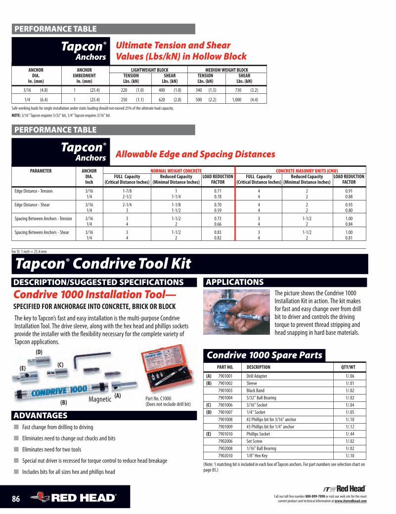
86 Call our toll free number 800-899-7890 or visit our web site for the mostcurrent product and technical information atwww.itwredhead.com
ANCHOR ANCHOR LIGHTWEIGHT BLOCK MEDIUMWEIGHT BLOCKDIA. EMBEDMENT TENSION SHEAR TENSION SHEAR
In. (mm) In. (mm) Lbs. (kN) Lbs. (kN) Lbs. (kN) Lbs. (kN)
3/16 (4.8) 1 (25.4) 220 (1.0) 400 (1.8) 340 (1.5) 730 (3.2)
1/4 (6.4) 1 (25.4) 250 (1.1) 620 (2.8) 500 (2.2) 1,000 (4.4)
Safe working loads for single installation under static loading should not exceed 25% of the ultimate load capacity.
NOTE: 3/16" Tapcon requires 5/32" bit, 1/4" Tapcon requires 3/16" bit.
Ultimate Tension and ShearValues (Lbs/kN) in Hollow Block
Tapcon®
Anchors
PART NO. DESCRIPTION QTY/WT
(A) 7901001 Drill Adapter 1/.06(B) 7901002 Sleeve 1/.01
7901003 Black Band 1/.027901004 5/32" Ball Bearing 1/.02
(C) 7901006 3/16" Socket 1/.04(D) 7901007 1/4" Socket 1/.05
7901008 #2 Phillips bit for 3/16" anchor 1/.107901009 #3 Phillips bit for 1/4" anchor 1/.12
(E) 7901010 Phillips Socket 1/.447902006 Set Screw 1/.027902008 1/16" Ball Bearing 1/.027902010 1/8" Hex Key 1/.10
(Note: 1 matching bit is included in each box of Tapcon anchors. For part numbers see selection chart onpage 85.)
Condrive 1000 Spare Parts
ADVANTAGES� Fast change from drilling to driving
� Eliminates need to change out chucks and bits
� Eliminates need for two tools
� Special nut driver is recessed for torque control to reduce head breakage
� Includes bits for all sizes hex and phillips head
DESCRIPTION/SUGGESTED SPECIFICATIONS
Condrive 1000 Installation Tool—SPECIFIED FOR ANCHORAGE INTO CONCRETE, BRICK OR BLOCKThe key to Tapcon’s fast and easy installation is the multi-purpose CondriveInstallation Tool. The drive sleeve, along with the hex head and phillips socketsprovide the installer with the flexibility necessary for the complete variety ofTapcon applications.
APPLICATIONSThe picture shows the Condrive 1000Installation Kit in action. The kit makesfor fast and easy change over from drillbit to driver and controls the drivingtorque to prevent thread stripping andhead snapping in hard base materials.
Tapcon® CondriveTool Kit
(D)
(E) (C)
(B)(A) Part No. C1000
(Does not include drill bit)
PERFORMANCE TABLE
PARAMETER ANCHOR NORMAL WEIGHT CONCRETE CONCRETE MASONRY UNITS (CMU)DIA. FULL Capacity Reduced Capacity LOAD REDUCTION FULL Capacity Reduced Capacity LOAD REDUCTIONInch (Critical Distance Inches) (Minimal Distance Inches) FACTOR (Critical Distance Inches) (Minimal Distance Inches) FACTOR
Edge Distance - Tension 3/16 1-7/8 1 0.71 4 2 0.911/4 2-1/2 1-1/4 0.78 4 2 0.88
Edge Distance - Shear 3/16 2-1/4 1-1/8 0.70 4 2 0.931/4 3 1-1/2 0.59 4 2 0.80
Spacing Between Anchors - Tension 3/16 3 1-1/2 0.73 3 1-1/2 1.001/4 4 2 0.66 4 2 0.84
Spacing Between Anchors - Shear 3/16 3 1-1/2 0.83 3 1-1/2 1.001/4 4 2 0.82 4 2 0.81
For SI: 1 inch = 25.4 mm
Allowable Edge and Spacing DistancesTapcon®
Anchors
PERFORMANCE TABLE
Magnetic
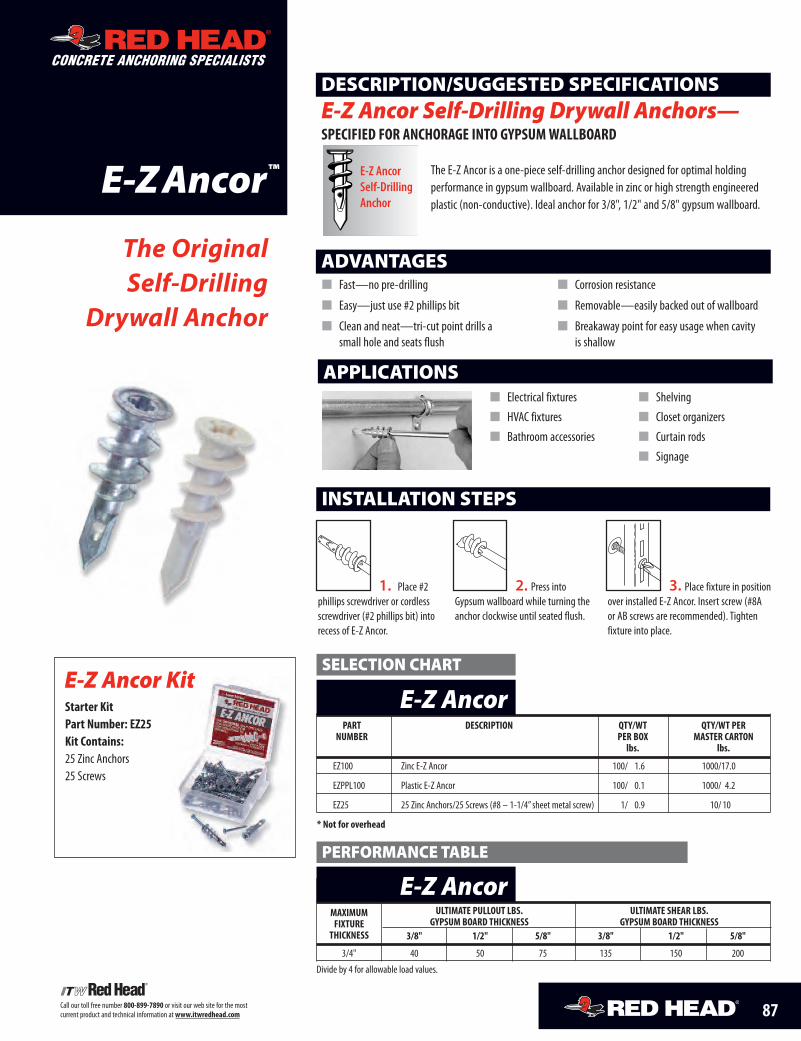
87Call our toll free number 800-899-7890 or visit our web site for the mostcurrent product and technical information atwww.itwredhead.com
E-ZAncor
ADVANTAGES� Fast—no pre-drilling
� Easy—just use #2 phillips bit
� Clean and neat—tri-cut point drills asmall hole and seats flush
� Corrosion resistance
� Removable—easily backed out of wallboard
� Breakaway point for easy usage when cavityis shallow
The OriginalSelf-Drilling
Drywall Anchor
APPLICATIONS� Electrical fixtures
� HVAC fixtures
� Bathroom accessories
� Shelving
� Closet organizers
� Curtain rods
� Signage
The E-Z Ancor is a one-piece self-drilling anchor designed for optimal holdingperformance in gypsum wallboard. Available in zinc or high strength engineeredplastic (non-conductive). Ideal anchor for 3/8", 1/2" and 5/8" gypsum wallboard.
DESCRIPTION/SUGGESTED SPECIFICATIONSE-Z Ancor Self-Drilling Drywall Anchors—SPECIFIED FOR ANCHORAGE INTO GYPSUMWALLBOARD
™ E-Z AncorSelf-DrillingAnchor
CONCRETE ANCHORING SPECIALISTS
PART DESCRIPTION QTY/WT QTY/WT PERNUMBER PER BOX MASTER CARTON
lbs. lbs.
EZ100 Zinc E-Z Ancor 100/ 1.6 1000/17.0
EZPPL100 Plastic E-Z Ancor 100/ 0.1 1000/ 4.2
EZ25 25 Zinc Anchors/25 Screws (#8 – 1-1/4” sheet metal screw) 1/ 0.9 10/ 10
* Not for overhead
E-Z Ancor
MAXIMUM ULTIMATE PULLOUT LBS. ULTIMATE SHEAR LBS.FIXTURE GYPSUM BOARD THICKNESS GYPSUM BOARD THICKNESSTHICKNESS 3/8" 1/2" 5/8" 3/8" 1/2" 5/8"
3/4" 40 50 75 135 150 200
Divide by 4 for allowable load values.
E-Z Ancor
1. Place #2phillips screwdriver or cordlessscrewdriver (#2 phillips bit) intorecess of E-Z Ancor.
2. Press intoGypsum wallboard while turning theanchor clockwise until seated flush.
3. Place fixture in positionover installed E-Z Ancor. Insert screw (#8Aor AB screws are recommended). Tightenfixture into place.
INSTALLATION STEPS
SELECTION CHART
PERFORMANCE TABLE
E-Z Ancor KitStarter KitPart Number: EZ25Kit Contains:25 Zinc Anchors25 Screws
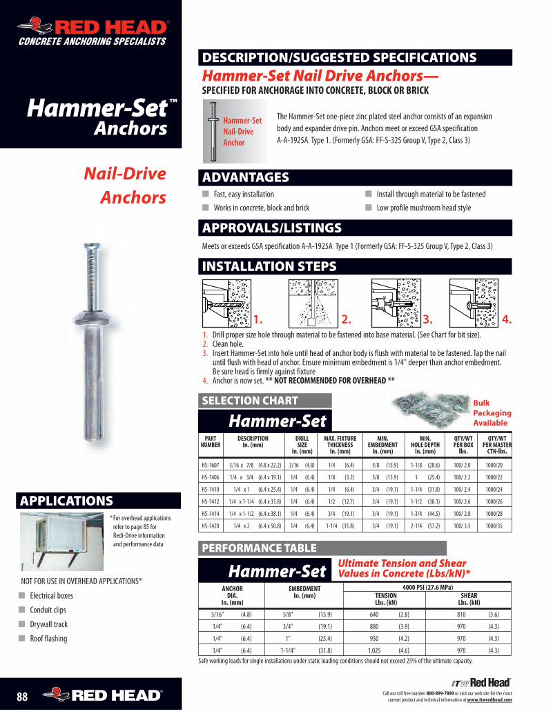
88 Call our toll free number 800-899-7890 or visit our web site for the mostcurrent product and technical information atwww.itwredhead.com
Hammer-SetAnchors
ADVANTAGES� Fast, easy installation
� Works in concrete, block and brick
� Install through material to be fastened
� Low profile mushroom head style
Nail-DriveAnchors
DESCRIPTION/SUGGESTED SPECIFICATIONSHammer-Set Nail Drive Anchors—SPECIFIED FOR ANCHORAGE INTO CONCRETE, BLOCK OR BRICK
APPLICATIONS
NOT FOR USE IN OVERHEAD APPLICATIONS*
� Electrical boxes
� Conduit clips
� Drywall track
� Roof flashing
*For overhead applicationsrefer to page 85 forRedi-Drive informationand performance data
1. Drill proper size hole through material to be fastened into base material. (See Chart for bit size).2. Clean hole.3. Insert Hammer-Set into hole until head of anchor body is flush with material to be fastened. Tap the nailuntil flush with head of anchor. Ensure minimum embedment is 1/4" deeper than anchor embedment.Be sure head is firmly against fixture
4. Anchor is now set. ** NOT RECOMMENDED FOR OVERHEAD **
� ��INSTALLATION STEPS
APPROVALS/LISTINGSMeets or exceeds GSA specification A-A-1925A Type 1 (Formerly GSA: FF-S-325 Group V, Type 2, Class 3)
The Hammer-Set one-piece zinc plated steel anchor consists of an expansionbody and expander drive pin. Anchors meet or exceed GSA specification A-A-1925A Type 1. (Formerly GSA: FF-S-325 Group V, Type 2, Class 3)
™
ADHESIVE ANCHORING SPECIALISTS
CONCRETE ANCHORING SPECIALISTS
ADHESIVE ANCHORING SPECIALISTS
CONCRETE ANCHORING SPECIALISTS
Hammer-SetNail-DriveAnchor
PART DESCRIPTION DRILL MAX. FIXTURE MIN. MIN. QTY/WT QTY/WTNUMBER In. (mm) SIZE THICKNESS EMBEDMENT HOLE DEPTH PER BOX PER MASTER
In. (mm) In. (mm) In. (mm) In. (mm) lbs. CTN-lbs.
HS-1607 3/16 x 7/8 (4.8 x 22.2) 3/16 (4.8) 1/4 (6.4) 5/8 (15.9) 1-1/8 (28.6) 100/ 2.0 1000/20
HS-1406 1/4 x 3/4 (6.4 x 19.1) 1/4 (6.4) 1/8 (3.2) 5/8 (15.9) 1 (25.4) 100/ 2.2 1000/22
HS-1410 1/4 x 1 (6.4 x 25.4) 1/4 (6.4) 1/4 (6.4) 3/4 (19.1) 1-1/4 (31.8) 100/ 2.4 1000/24
HS-1412 1/4 x 1-1/4 (6.4 x 31.8) 1/4 (6.4) 1/2 (12.7) 3/4 (19.1) 1-1/2 (38.1) 100/ 2.6 1000/26
HS-1414 1/4 x 1-1/2 (6.4 x 38.1) 1/4 (6.4) 3/4 (19.1) 3/4 (19.1) 1-3/4 (44.5) 100/ 2.8 1000/28
HS-1420 1/4 x 2 (6.4 x 50.8) 1/4 (6.4) 1-1/4 (31.8) 3/4 (19.1) 2-1/4 (57.2) 100/ 3.5 1000/35
Hammer-SetSELECTION CHART
ANCHOR EMBEDMENT 4000 PSI (27.6 MPa)DIA. In. (mm) TENSION SHEAR
In. (mm) Lbs. (kN) Lbs. (kN)
3/16" (4.8) 5/8" (15.9) 640 (2.8) 810 (3.6)
1/4" (6.4) 3/4" (19.1) 880 (3.9) 970 (4.3)
1/4" (6.4) 1" (25.4) 950 (4.2) 970 (4.3)
1/4" (6.4) 1-1/4" (31.8) 1,025 (4.6) 970 (4.3)Safe working loads for single installations under static loading conditions should not exceed 25% of the ultimate capacity.
Hammer-SetPERFORMANCE TABLE
Bulk PackagingAvailable
Ultimate Tension and Shear Values in Concrete (Lbs/kN)*
1. 2. 3. 4.
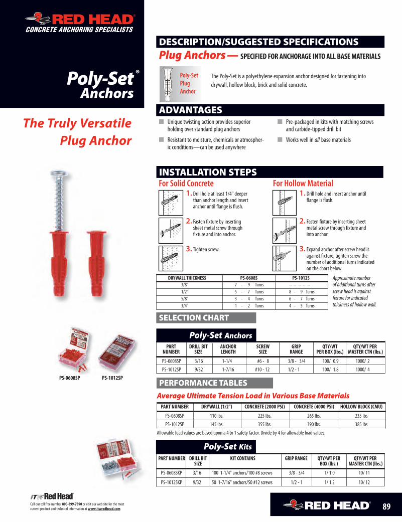
89Call our toll free number 800-899-7890 or visit our web site for the mostcurrent product and technical information atwww.itwredhead.com
PART NUMBER DRILL BIT KIT CONTAINS GRIP RANGE QTY/WT PER QTY/WT PERSIZE BOX (lbs.) MASTER CTN (lbs.)
PS-0608SKP 3/16 100 1-1/4" anchors/100 #8 screws 3/8 - 3/4 1/ 1.0 10/ 11
PS-1012SKP 9/32 50 1-7/16" anchors/50 #12 screws 1/2 - 1 1/ 1.2 10/ 12
Poly-Set Kits
ADVANTAGES� Unique twisting action provides superior
holding over standard plug anchors
� Resistant to moisture, chemicals or atmospher-ic conditions—can be used anywhere
� Pre-packaged in kits with matching screwsand carbide-tipped drill bit
� Works well in all base materials
DRYWALL THICKNESS PS-0608S PS-1012S3/8" 7 - 9 Turns – – – – –1/2" 5 - 7 Turns 8 - 9 Turns5/8" 3 - 4 Turns 6 - 7 Turns3/4" 1 - 2 Turns 4 - 5 Turns
1. Drill hole at least 1/4" deeperthan anchor length and insertanchor until flange is flush.
For Solid Concrete
�����������������������������������
@@@@@@@@@@@@@@@@@@@@@@@@@@@@@@@@@@@
�����������������������������������
ÀÀÀÀÀÀÀÀÀÀÀÀÀÀÀÀÀÀÀÀÀÀÀÀÀÀÀÀÀÀÀÀÀÀÀ
�����������������������������������
@@@@@@@@@@@@@@@@@@@@@@@@@@@@@@@@@@@
�����������������������������������
ÀÀÀÀÀÀÀÀÀÀÀÀÀÀÀÀÀÀÀÀÀÀÀÀÀÀÀÀÀÀÀÀÀÀÀ
�����������������������������������
QQQQQQQQQQQQQQQQQQQQQQQQQQQQQQQQQQQ
¢¢¢¢¢¢¢¢¢¢¢¢¢¢¢¢¢¢¢¢¢¢¢¢¢¢¢¢¢¢¢¢¢¢¢
2. Fasten fixture by insertingsheet metal screw throughfixture and into anchor.
�����������������������������������
@@@@@@@@@@@@@@@@@@@@@@@@@@@@@@@@@@@
�����������������������������������
ÀÀÀÀÀÀÀÀÀÀÀÀÀÀÀÀÀÀÀÀÀÀÀÀÀÀÀÀÀÀÀÀÀÀÀ
�����������������������������������
@@@@@@@@@@@@@@@@@@@@@@@@@@@@@@@@@@@
�����������������������������������
ÀÀÀÀÀÀÀÀÀÀÀÀÀÀÀÀÀÀÀÀÀÀÀÀÀÀÀÀÀÀÀÀÀÀÀ
�����������������������������������
QQQQQQQQQQQQQQQQQQQQQQQQQQQQQQQQQQQ
¢¢¢¢¢¢¢¢¢¢¢¢¢¢¢¢¢¢¢¢¢¢¢¢¢¢¢¢¢¢¢¢¢¢¢
3. Tighten screw.
�����������������������������������
@@@@@@@@@@@@@@@@@@@@@@@@@@@@@@@@@@@
�����������������������������������
ÀÀÀÀÀÀÀÀÀÀÀÀÀÀÀÀÀÀÀÀÀÀÀÀÀÀÀÀÀÀÀÀÀÀÀ
�����������������������������������
@@@@@@@@@@@@@@@@@@@@@@@@@@@@@@@@@@@
�����������������������������������
ÀÀÀÀÀÀÀÀÀÀÀÀÀÀÀÀÀÀÀÀÀÀÀÀÀÀÀÀÀÀÀÀÀÀÀ
�����������������������������������
QQQQQQQQQQQQQQQQQQQQQQQQQQQQQQQQQQQ
¢¢¢¢¢¢¢¢¢¢¢¢¢¢¢¢¢¢¢¢¢¢¢¢¢¢¢¢¢¢¢¢¢¢¢
1. Drill hole and insert anchor untilflange is flush.
���������
@@@@@@@@@
���������
ÀÀÀÀÀÀÀÀÀ
���������
@@@@@@@@@
���������
ÀÀÀÀÀÀÀÀÀ
���������
QQQQQQQQQ
¢¢¢¢¢¢¢¢¢������������
@@@@@@@@@@@@
������������
ÀÀÀÀÀÀÀÀÀÀÀÀ
������������
@@@@@@@@@@@@
������������
ÀÀÀÀÀÀÀÀÀÀÀÀ
������������
QQQQQQQQQQQQ
¢¢¢¢¢¢¢¢¢¢¢¢
2. Fasten fixture by inserting sheetmetal screw through fixture andinto anchor.
���������
@@@@@@@@@
���������
ÀÀÀÀÀÀÀÀÀ
���������
@@@@@@@@@
���������
ÀÀÀÀÀÀÀÀÀ
���������
QQQQQQQQQ
¢¢¢¢¢¢¢¢¢
������������
@@@@@@@@@@@@
������������
ÀÀÀÀÀÀÀÀÀÀÀÀ
������������
@@@@@@@@@@@@
������������
ÀÀÀÀÀÀÀÀÀÀÀÀ
������������
QQQQQQQQQQQQ
¢¢¢¢¢¢¢¢¢¢¢¢
3. Expand anchor after screw head isagainst fixture, tighten screw thenumber of additional turns indicatedon the chart below.
������������
@@@@@@@@@@@@
������������
ÀÀÀÀÀÀÀÀÀÀÀÀ
������������
@@@@@@@@@@@@
������������
ÀÀÀÀÀÀÀÀÀÀÀÀ
������������
QQQQQQQQQQQQ
¢¢¢¢¢¢¢¢¢¢¢¢
����������
@@@@@@@@@@
����������
ÀÀÀÀÀÀÀÀÀÀ
����������
@@@@@@@@@@
����������
ÀÀÀÀÀÀÀÀÀÀ
����������
QQQQQQQQQQ
¢¢¢¢¢¢¢¢¢¢
INSTALLATION STEPS
Approximate number of additional turns after screw head is against fixture for indicated thickness of hollow wall.
Poly-SetAnchors
The Truly Versatile Plug Anchor
DESCRIPTION/SUGGESTED SPECIFICATIONSPlug Anchors — SPECIFIED FOR ANCHORAGE INTO ALL BASE MATERIALS
The Poly-Set is a polyethylene expansion anchor designed for fastening intodrywall, hollow block, brick and solid concrete.
®
ADHESIVE ANCHORING SPECIALISTS
CONCRETE ANCHORING SPECIALISTS
ADHESIVE ANCHORING SPECIALISTS
CONCRETE ANCHORING SPECIALISTS
Poly-SetPlugAnchor
PART DRILL BIT ANCHOR SCREW GRIP QTY/WT QTY/WT PERNUMBER SIZE LENGTH SIZE RANGE PER BOX (lbs.) MASTER CTN (lbs.)
PS-0608SP 3/16 1-1/4 #6 - 8 3/8 - 3/4 100/ 0.9 1000/ 2
PS-1012SP 9/32 1-7/16 #10 - 12 1/2 - 1 100/ 1.8 1000/ 4
Poly-Set Anchors
SELECTION CHART
Average Ultimate Tension Load in Various Base MaterialsPART NUMBER DRYWALL (1/2”) CONCRETE (2000 PSI) CONCRETE (4000 PSI) HOLLOW BLOCK (CMU)
PS-0608SP 110 lbs. 225 lbs. 265 lbs. 235 lbs
PS-1012SP 145 lbs. 355 lbs. 390 lbs. 385 lbs
Allowable load values are based upon a 4 to 1 safety factor. Divide by 4 for allowable load values.
PERFORMANCE TABLES
For Hollow Material
PS-0608SP PS-1012SP
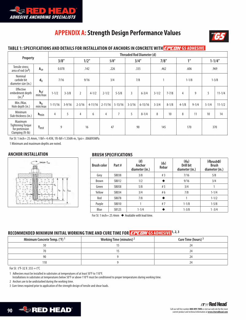
90 Call our toll free number 800-899-7890 or visit our web site for the most current product and technical information at www.itwredhead.com
ADHESIVE ANCHORING SPECIALISTS
CONCRETE ANCHORING SPECIALISTS
ADHESIVE ANCHORING SPECIALISTS
CONCRETE ANCHORING SPECIALISTS
APPENDIX A: Strength Design Performance Values
TAblE 1: SPEcIfIcATIoNS AND DETAIlS for INSTAllATIoN of ANchorS IN coNcrETE wITh G5 ADhESIVE
PropertyThreaded Rod Diameter (d)
3/8” 1/2” 5/8” 3/4” 7/8” 1” 1-1/4”Tensile stress
area of rod (in2) Ase 0.078 .142 .226 .335 .462 .606 .969
Nominal carbide bit
diameter size (in.)do 7/16 9/16 3/4 7/8 1 1-1/8 1-3/8
Effective embedment depth
(in.)1hef
min/max 1-1/2 3-3/8 2 4-1/2 2-1/2 5-5/8 3 6-3/4 3-1/2 7-7/8 4 9 5 11-1/4
Min./Max. Hole depth (in.)
ho min/max 1-11/16 3-9/16 2-3/16 4-11/16 2-11/16 5-13/16 3-3/16 6-15/16 3-3/4 8-1/8 4-1/8 9-1/4 5-1/4 11-1/2
Minimum Slab thickness (in.) hmin 4 5 4 6 4 7 5 8-1/4 8 10 8 11 10 14
Maximum Tightening Torque
for pretension Clamping (ft-lb)
Tinst 9 16 47 90 145 170 370
For SI: 1 inch= 25.4mm, 1 lbf= 4.45N, 1ft-lbf=1.356N-m, 1psi= .006895MPa1 Minimum and maximum depths are noted.
rEcommENDED mINImum INITIAl workING TImE AND curE TImE for G5 ADhESIVE 1, 2, 3
Minimum Concrete Temp. (°F) 1 Working Time (minutes) 2 Cure Time (hours) 3
50 15 24
70 15 24
90 9 24
110 9 24
For SI: t°F-32 X .555 = t°C1 Adhesives must be installed in substrates at temperatures of at least 50°F to 110°F.
Installations in substrates at temperatures below 50°F or above 110°F must be conditioned to proper temperatures during working time.2 Anchors are to be undisturbed during the working time.3 Cure times required prior to application of the strength design of tensile and shear loads.
bruSh SPEcIfIcATIoNS
Brush color Part #(d)
Anchor diameter (in.)
(dr)Rebar
(do)Drill bit
diameter (in.)
(dbrushФ) Brush
diameter (in.)Grey SB038 3/8 # 3 7/16 5/8
Brown SB012 1/2 u 9/16 3/4
Green SB058 5/8 # 5 3/4 1
Yellow SB034 3/4 # 6 7/8 1-1/4
Red SB078 7/8 u 1 1-1/2
Purple SB010 1 # 7 1-1/8 1-5/8
Blue SB125 1-1/4 u 1-3/8 1 -3/4
For SI: 1 inch= 25.4mm u Available with lead time.
ANchor INSTAllATIoN
®
®
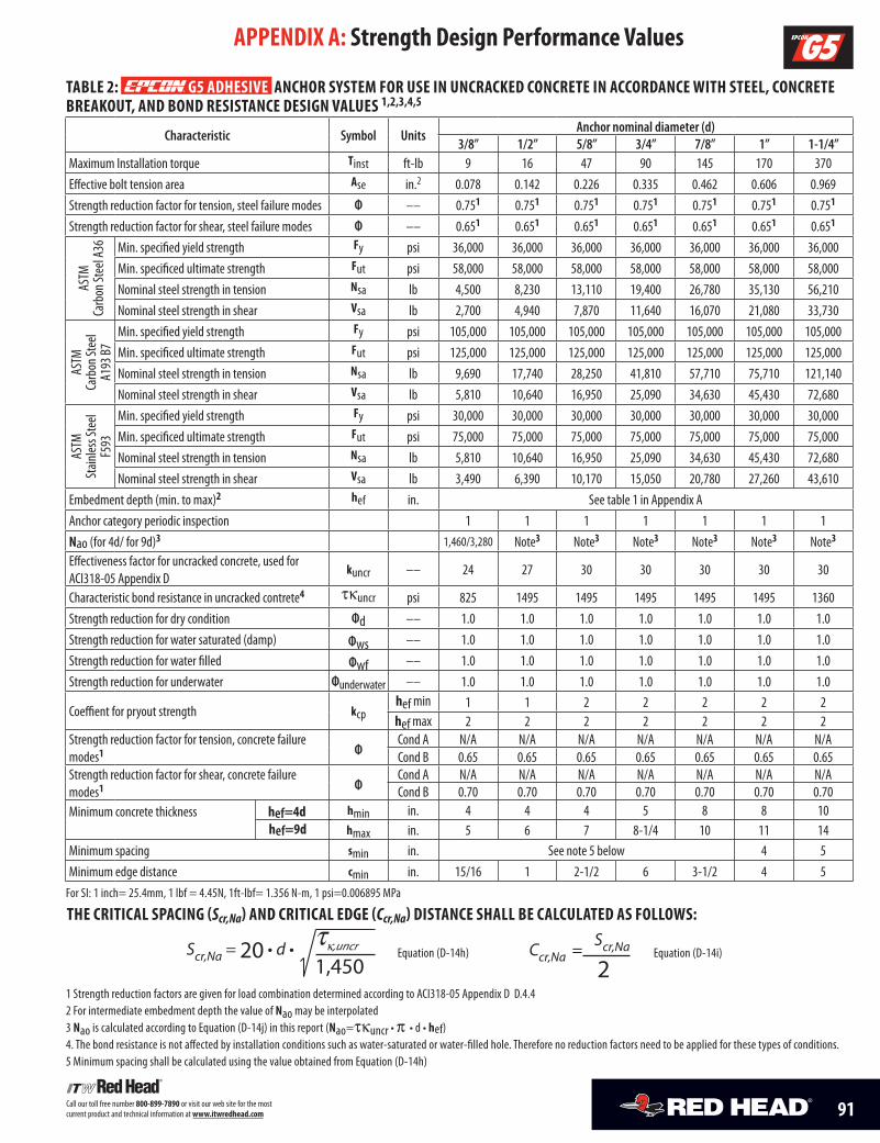
91Call our toll free number 800-899-7890 or visit our web site for the most current product and technical information at www.itwredhead.com
APPENDIX A: Strength Design Performance Values
TAblE 2: G5 ADhESIVE ANchor SYSTEm for uSE IN uNcrAckED coNcrETE IN AccorDANcE wITh STEEl, coNcrETE brEAkouT, AND boND rESISTANcE DESIGN VAluES 1,2,3,4,5
Characteristic Symbol UnitsAnchor nominal diameter (d)
3/8” 1/2” 5/8” 3/4” 7/8” 1” 1-1/4”Maximum Installation torque Tinst ft-lb 9 16 47 90 145 170 370Effective bolt tension area Ase in.2 0.078 0.142 0.226 0.335 0.462 0.606 0.969Strength reduction factor for tension, steel failure modes Ф –– 0.751 0.751 0.751 0.751 0.751 0.751 0.751
Strength reduction factor for shear, steel failure modes Ф –– 0.651 0.651 0.651 0.651 0.651 0.651 0.651
ASTM
Ca
rbon
Stee
l A36 Min. specified yield strength fy psi 36,000 36,000 36,000 36,000 36,000 36,000 36,000
Min. specificed ultimate strength fut psi 58,000 58,000 58,000 58,000 58,000 58,000 58,000Nominal steel strength in tension Nsa lb 4,500 8,230 13,110 19,400 26,780 35,130 56,210Nominal steel strength in shear Vsa lb 2,700 4,940 7,870 11,640 16,070 21,080 33,730
ASTM
Ca
rbon
Stee
l A1
93 B7
Min. specified yield strength fy psi 105,000 105,000 105,000 105,000 105,000 105,000 105,000Min. specificed ultimate strength fut psi 125,000 125,000 125,000 125,000 125,000 125,000 125,000Nominal steel strength in tension Nsa lb 9,690 17,740 28,250 41,810 57,710 75,710 121,140Nominal steel strength in shear Vsa lb 5,810 10,640 16,950 25,090 34,630 45,430 72,680
ASTM
St
ainles
s Ste
el F5
93
Min. specified yield strength fy psi 30,000 30,000 30,000 30,000 30,000 30,000 30,000Min. specificed ultimate strength fut psi 75,000 75,000 75,000 75,000 75,000 75,000 75,000Nominal steel strength in tension Nsa lb 5,810 10,640 16,950 25,090 34,630 45,430 72,680Nominal steel strength in shear Vsa lb 3,490 6,390 10,170 15,050 20,780 27,260 43,610
Embedment depth (min. to max)2 hef in. See table 1 in Appendix AAnchor category periodic inspection 1 1 1 1 1 1 1Nao (for 4d/ for 9d)3 1,460/3,280 Note3 Note3 Note3 Note3 Note3 Note3
Effectiveness factor for uncracked concrete, used for ACI318-05 Appendix D
kuncr –– 24 27 30 30 30 30 30
Characteristic bond resistance in uncracked contrete4 tkuncr psi 825 1495 1495 1495 1495 1495 1360Strength reduction for dry condition Фd –– 1.0 1.0 1.0 1.0 1.0 1.0 1.0Strength reduction for water saturated (damp) Фws –– 1.0 1.0 1.0 1.0 1.0 1.0 1.0Strength reduction for water filled Фwf –– 1.0 1.0 1.0 1.0 1.0 1.0 1.0Strength reduction for underwater Фunderwater –– 1.0 1.0 1.0 1.0 1.0 1.0 1.0
Coeffient for pryout strength kcphef min 1 1 2 2 2 2 2hef max 2 2 2 2 2 2 2
Strength reduction factor for tension, concrete failure modes1 Ф
Cond A N/A N/A N/A N/A N/A N/A N/ACond B 0.65 0.65 0.65 0.65 0.65 0.65 0.65
Strength reduction factor for shear, concrete failure modes1 Ф
Cond A N/A N/A N/A N/A N/A N/A N/ACond B 0.70 0.70 0.70 0.70 0.70 0.70 0.70
Minimum concrete thickness hef=4d hef=9d
hmin in. 4 4 4 5 8 8 10hmax in. 5 6 7 8-1/4 10 11 14
Minimum spacing smin in. See note 5 below 4 5Minimum edge distance cmin in. 15/16 1 2-1/2 6 3-1/2 4 5
For SI: 1 inch= 25.4mm, 1 lbf = 4.45N, 1ft-lbf= 1.356 N-m, 1 psi=0.006895 MPa
1 Strength reduction factors are given for load combination determined according to ACI318-05 Appendix D D.4.42 For intermediate embedment depth the value of Nao may be interpolated3 Nao is calculated according to Equation (D-14j) in this report (Nao=tkuncr • p • d • hef)4. The bond resistance is not affected by installation conditions such as water-saturated or water-filled hole. Therefore no reduction factors need to be applied for these types of conditions.5 Minimum spacing shall be calculated using the value obtained from Equation (D-14h)
Scr,Na = 20 • d • tk,uncr
1,450
ThE crITIcAl SPAcING (Scr,Na) AND crITIcAl EDGE (Ccr,Na) DISTANcE ShAll bE cAlculATED AS followS:
Ccr,Na = Scr,Na
2Equation (D-14h) Equation (D-14i)
®
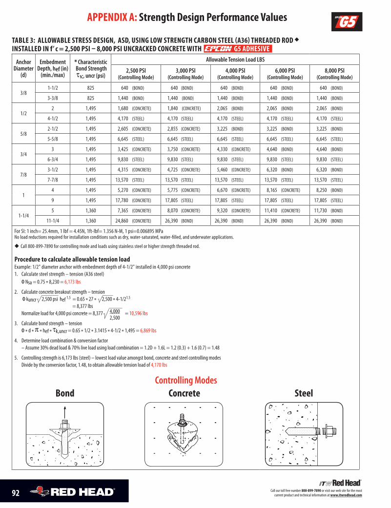
92 Call our toll free number 800-899-7890 or visit our web site for the most current product and technical information at www.itwredhead.com92 Call our toll free number 800-899-7890 or visit our web site for the most current product and technical information at www.itwredhead.com
TAblE 3: AllowAblE STrESS DESIGN, ASD, uSING low STrENGTh cArboN STEEl (A36) ThrEADED roD u INSTAllED IN f’ c = 2,500 PSI – 8,000 PSI uNcrAckED coNcrETE wITh G5 ADhESIVE
Anchor Diameter
(d)
Embedment Depth, hef (in)
(min./max)
* Characteristic Bond Strength tk, uncr (psi)
Allowable Tension Load LBS
2,500 PSI (Controlling Mode)
3,000 PSI (Controlling Mode)
4,000 PSI (Controlling Mode)
6,000 PSI (Controlling Mode)
8,000 PSI (Controlling Mode)
3/81-1/2 825 640 (BOND) 640 (BOND) 640 (BOND) 640 (BOND) 640 (BOND)
3-3/8 825 1,440 (BOND) 1,440 (BOND) 1,440 (BOND) 1,440 (BOND) 1,440 (BOND)
1/22 1,495 1,680 (CONCRETE) 1,840 (CONCRETE) 2,065 (BOND) 2,065 (BOND) 2,065 (BOND)
4-1/2 1,495 4,170 (STEEL) 4,170 (STEEL) 4,170 (STEEL) 4,170 (STEEL) 4,170 (STEEL)
5/82-1/2 1,495 2,605 (CONCRETE) 2,855 (CONCRETE) 3,225 (BOND) 3,225 (BOND) 3,225 (BOND)
5-5/8 1,495 6,645 (STEEL) 6,645 (STEEL) 6,645 (STEEL) 6,645 (STEEL) 6,645 (STEEL)
3/43 1,495 3,425 (CONCRETE) 3,750 (CONCRETE) 4,330 (CONCRETE) 4,640 (BOND) 4,640 (BOND)
6-3/4 1,495 9,830 (STEEL) 9,830 (STEEL) 9,830 (STEEL) 9,830 (STEEL) 9,830 (STEEL)
7/83-1/2 1,495 4,315 (CONCRETE) 4,725 (CONCRETE) 5,460 (CONCRETE) 6,320 (BOND) 6,320 (BOND)
7-7/8 1,495 13,570 (STEEL) 13,570 (STEEL) 13,570 (STEEL) 13,570 (STEEL) 13,570 (STEEL)
14 1,495 5,270 (CONCRETE) 5,775 (CONCRETE) 6,670 (CONCRETE) 8,165 (CONCRETE) 8,250 (BOND)
9 1,495 17,780 (CONCRETE) 17,805 (STEEL) 17,805 (STEEL) 17,805 (STEEL) 17,805 (STEEL)
1-1/45 1,360 7,365 (CONCRETE) 8,070 (CONCRETE) 9,320 (CONCRETE) 11,410 (CONCRETE) 11,730 (BOND)
11-1/4 1,360 24,860 (CONCRETE) 26,390 (BOND) 26,390 (BOND) 26,390 (BOND) 26,390 (BOND)
For SI: 1 inch= 25.4mm, 1 lbf = 4.45N, 1ft-lbf= 1.356 N-M, 1 psi=0.006895 MPa No load reductions required for installation conditions such as dry, water-saturated, water-filled, and underwater applications.
u Call 800-899-7890 for controlling mode and loads using stainless steel or higher strength threaded rod.
Procedure to calculate allowable tension loadExample: 1/2" diameter anchor with embedment depth of 4-1/2" installed in 4,000 psi concrete1. Calculate steel strength – tension (A36 steel) Ф Nsa = 0.75 * 8,230 = 6,173 lbs
2. Calculate concrete breakout strength – tension Ф kuncr 2,500 psi hef 1.5 = 0.65 * 27 * 2,500 * 4-1/21.5
= 8,377 lbs Normalize load for 4,000 psi concrete = 8,377 = 10,596 lbs
3. Calculate bond strength – tension Ф * d * p * hef * tk,uncr = 0.65 * 1/2 * 3.1415 * 4-1/2 * 1,495 = 6,869 lbs
4. Determine load combination & conversion factor – Assume 30% dead load & 70% live load using load combination = 1.2D + 1.6L = 1.2 (0.3) + 1.6 (0.7) = 1.48
5. Controlling strength is 6,173 lbs (steel) – lowest load value amongst bond, concrete and steel controlling modes Divide by the conversion factor, 1.48, to obtain allowable tension load of 4,170 lbs
APPENDIX A: Strength Design Performance Values
®
Controlling Modes bond concrete Steel
4,0002,500
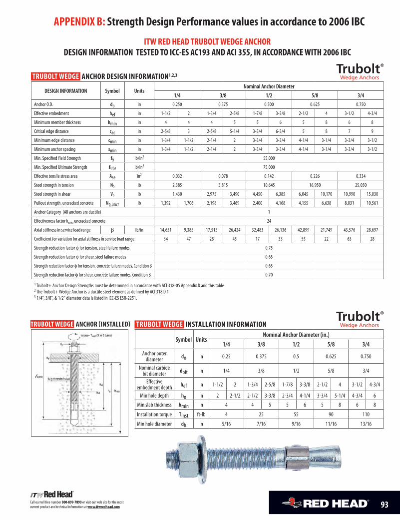
93Call our toll free number 800-899-7890 or visit our web site for the most current product and technical information at www.itwredhead.com
APPENDIX b: Strength Design Performance values in accordance to 2006 Ibc
ITw rED hEAD TrubolT wEDGE ANchor DESIGN INformATIoN TESTED To Icc-ES Ac193 AND AcI 355, IN AccorDANcE wITh 2006 Ibc
TrubolT wEDGE ANchor DESIGN INformATIoN1,2,3
DESIGN INFORMATION Symbol UnitsNominal Anchor Diameter
1/4 3/8 1/2 5/8 3/4
Anchor O.D. do in 0.250 0.375 0.500 0.625 0.750
Effective embedment hef in 1-1/2 2 1-3/4 2-5/8 1-7/8 3-3/8 2-1/2 4 3-1/2 4-3/4
Minimum member thickness hmin in 4 4 4 5 5 6 5 8 6 8
Critical edge distance cac in 2-5/8 3 2-5/8 5-1/4 3-3/4 6-3/4 5 8 7 9
Minimum edge distance cmin in 1-3/4 1-1/2 2-1/4 2 3-3/4 3-3/4 4-1/4 3-1/4 3-3/4 3-1/2
Minimum anchor spacing smin in 1-3/4 1-1/2 2-1/4 2 3-3/4 3-3/4 4-1/4 3-1/4 3-3/4 3-1/2
Min. Specified Yield Strength fy lb/in2 55,000
Min. Specified Ultimate Strength futa lb/in2 75,000
Effective tensile stress area Ase in2 0.032 0.078 0.142 0.226 0.334
Steel strength in tension Ns lb 2,385 5,815 10,645 16,950 25,050
Steel strength in shear Vs lb 1,430 2,975 3,490 4,450 6,385 6,045 10,170 10,990 15,030
Pullout strength, uncracked concrete Np,uncr lb 1,392 1,706 2,198 3,469 2,400 4,168 4,155 6,638 8,031 10,561
Anchor Category (All anchors are ductile) 1
Effectiveness factor kuncr uncracked concrete 24
Axial stiffness in service load range b lb/in 14,651 9,385 17,515 26,424 32,483 26,136 42,899 21,749 43,576 28,697
Coefficient for variation for axial stiffness in service load range 34 47 28 45 17 33 55 22 63 28
Strength reduction factor f for tension, steel failure modes 0.75
Strength reduction factor f for shear, steel failure modes 0.65
Strength reduction factor f for tension, concrete failure modes, Condition B 0.65
Strength reduction factor f for shear, concrete failure modes, Condition B 0.70
1 Trubolt+ Anchor Design Strengths must be determined in accordance with ACI 318-05 Appendix D and this table2 The Trubolt+ Wedge Anchor is a ductile steel element as defined by ACI 318 D.13 1/4", 3/8", & 1/2" diameter data is listed in ICC-ES ESR-2251.
TrubolT wEDGE ANchor (INSTAllED) TrubolT wEDGE INSTAllATIoN INformATIoN
Symbol UnitsNominal Anchor Diameter (in.)
1/4 3/8 1/2 5/8 3/4Anchor outer
diameter do in 0.25 0.375 0.5 0.625 0.750
Nominal carbide bit diameter dbit in 1/4 3/8 1/2 5/8 3/4
Effective embedment depth hef in 1-1/2 2 1-3/4 2-5/8 1-7/8 3-3/8 2-1/2 4 3-1/2 4-3/4
Min hole depth ho in 2 2-1/2 2-1/2 3-3/8 2-3/4 4-1/4 3-3/4 5-1/4 4-3/4 6
Min slab thickness hmin in 4 4 5 5 6 5 8 6 8
Installation torque Tinst ft-lb 4 25 55 90 110
Min hole diameter dh in 5/16 7/16 9/16 11/16 13/16
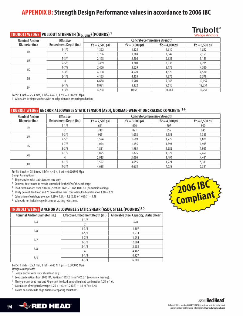
94 Call our toll free number 800-899-7890 or visit our web site for the most current product and technical information at www.itwredhead.com
APPENDIX b: Strength Design Performance values in accordance to 2006 Ibc
TrubolT wEDGE PullouT STrENGTh (Np, unc) (PouNDS) 1 Nominal Anchor
Diameter (in.)Effective
Embedment Depth (in.)Concrete Compressive Strength
f’c = 2,500 psi f’c = 3,000 psi f’c = 4,000 psi f’c = 6,500 psi
1/41-1/2 1,392 1,525 1,610 1,822
2 1,706 1,869 1,947 2,151
3/81-3/4 2,198 2,408 2,621 3,1532-5/8 3,469 3,800 3,936 4,275
1/21-7/8 2,400 2,629 3,172 4,5203-3/8 4,168 4,520 4,520 4,520
5/82-1/2 4,155 4,155 4,376 5,578
4 6,638 6,900 7,968 10,157
3/43-1/2 8,031 8,322 9,610 12,2514-3/4 10,561 10,561 10,561 12,251
For SI: 1 inch = 25.4 mm, 1 lbf = 4.45 N, 1 psi = 0.006895 Mpa 1 Values are for single anchors with no edge distance or spacing reduction.
TrubolT wEDGE ANchor AllowAblE STATIc TENSIoN (ASD), NormAl-wEIGhT uNcrAckED coNcrETE 1-6
Nominal Anchor Diameter (in.)
Effective Embedment Depth (in.)
Concrete Compressive Strengthf’c = 2,500 psi f’c = 3,000 psi f’c = 4,000 psi f’c = 6,500 psi
1/41-1/2 611 670 707 800
2 749 821 855 945
3/81-3/4 965 1,058 1,151 1,3852-5/8 1,524 1,669 1,729 1,878
1/21-7/8 1,054 1,155 1,393 1,9853-3/8 1,831 1,985 1,985 1,985
5/82-1/2 1,825 1,825 1,922 2,450
4 2,915 3,030 3,499 4,461
3/43-1/2 3,527 3,655 4,221 5,3814-3/4 4,638 4,638 4,638 5,381
For SI: 1 inch = 25.4 mm, 1 lbf = 4.45 N, 1 psi = 0.006895 Mpa Design Assumptions:1 Single anchor with static tension load only. 2 Concrete determined to remain uncracked for the life of the anchorage.3 Load combinations from 2006 IBC, Sections 1605.2.1 and 1605.3.1 (no seismic loading).4 Thirty percent dead load and 70 percent live load, controlling load combination 1.2D + 1.6L5 Calculation of weighted average: 1.2D + 1.6L = 1.2 (0.3) + 1.6 (0.7) = 1.486 Values do not include edge distance or spacing reductions.
TrubolT wEDGE ANchor AllowAblE STATIc ShEAr (ASD), STEEl (PouNDS)1-5 Nominal Anchor Diameter (in.) Effective Embedment Depth (in.) Allowable Steel Capacity, Static Shear
1/41-1/2
6282
3/81-3/4 1,3072-5/8 1,533
1/21-7/8 1,9543-3/8 2,804
5/82-1/2 2,655
4 4,467
3/43-1/2 4,8274-3/4 6,601
For SI: 1 inch = 25.4 mm, 1 lbf = 4.45 N, 1 psi = 0.006895 Mpa Design Assumptions:1 Single anchor with static shear load only. 3 Load combinations from 2006 IBC, Sections 1605.2.1 and 1605.3.1 (no seismic loading).3 Thirty percent dead load and 70 percent live load, controlling load combination 1.2D + 1.6L 4 Calculation of weighted average: 1.2D + 1.6L = 1.2 (0.3) + 1.6 (0.7) = 1.485 Values do not include edge distance or spacing reductions.
2006 IBC
Compliant
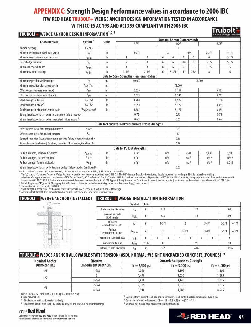
TrubolT+ wEDGE ANchor DESIGN INformATIoN1,2,3 characteristic Symbol 4 units Nominal Anchor Diameter inch
3/8" 1/2" 5/8"Anchor category 1, 2 or 3 — 1Minimum effective embedment depth hef in 1-5/8 2 3-1/4 2-3/4 4-1/4Minimum concrete member thickness hmin in 4 5 4 6 6 8 6 6-1/4Critical edge distance cac in 5 3 6 6 7-1/2 6 7-1/2 6-1/2Minimum edge distance cmin in 3 3 6 6 6 6 7-1/2 5Minimum anchor spacing smin in 3-1/2 2-1/2 6 5-3/4 4 5-3/4 8 6
Data for Steel Strengths - Tension and ShearMinimum specified yield strength fy psi 60,000 55,000Minimum specified ultimate strength futa (fut) psi 75,000 Effective tensile stress area (neck) Ase in2 0.056 0.119 0.183Effective tensile stress area (thread) Ase in2 0.075 0.142 0.217Steel strength in tension Nsa (Ns) lbf 4,200 8,925 13,725Steel strength in shear 5 Vsa (Vs) lbf 2,550 5,175 8,955Steel strength in shear for seismic loads Veq (Vsa,seis) lbf 1,785 5,175 8,955Strength reduction factor f for tension, steel failure modes 2 0.75 0.75 0.75Strength reduction factor f for shear, steel failure modes 2 0.60 0.65 0.65
Data for Concrete Breakout Concrete Pryout StrengthsEffectiveness factor for uncracked concrete kuncr — 24Effectiveness factor for cracked concrete kcr — 17Strength reduction factor f for tension, concrete failure modes, Condition B 2 0.65Strength reduction factor f for shear, concrete failure modes, Condition B 2 0.70
Data for Pullout StrengthsPullout strength, uncracked concrete Np,uncr lbf n/a 6 n/a 6 6,540 5,430 8,900Pullout strength, cracked concrete Np,cr lbf n/a 6 n/a 6 n/a 6 n/a 6 n/a 6
Pullout strength for seismic loads Neq lbf n/a 6 n/a 6 n/a 6 n/a 6 6,715Strength reduction factor f for tension, pullout failure modes, Condition B 2 0.65For SI: 1 inch = 25.4 mm, 1 in2 = 645.16mm2, 1 lbf = 4.45 N, 1 psi = 0.006895 MPa, 1 lbf • 102/in - 17,500 N/m.1 The 1/2” and 5/8” diameter Trubolt + Wedge Anchors are ductile steel elements as defined by ACI 318 D.1. The 3/8” diameter Trubolt + is considered ductile under tension loading and brittle under shear loading. 2 All values of f apply to the load combinations of IBC Section 1605.2, ACI 318 Section 9.2 or UBC Section 1612.2. If the load combinations of Appendix C or UBC Section 1909.2 are used, the appropriate value of f must be determined in
accordance with ACI 318 D.4.5. For installations where reinforcement that complies with ACI 318 Appendix D requirements for Condition A is present, the appropriate f factor must be determined in accordance with ACI 318 D.4.4. 3 For all design cases Ψc,N = 1.0. The appropriate effectiveness factor for cracked concrete (kcr) or uncracked concrete (kuncr) must be used. 4 The notations in brackets are for 2003 IBC. 5 Steel strength in shear values are based on test results per ACI 355.2, Section 9.4 and must be used for design. 6 Anchor pullout strength does not control anchor design. Determine steel and concrete capacity only.
95Call our toll free number 800-899-7890 or visit our web site for the most current product and technical information at www.itwredhead.com
APPENDIX c: Strength Design Performance values in accordance to 2006 Ibc ITw rED hEAD TrubolT+ wEDGE ANchor DESIGN INformATIoN TESTED IN AccorDANcE
wITh Icc-ES Ac 193 AND AcI 355 comPlIANT wITh 2006 Ibc
TrubolT + wEDGE INSTAllATIoN INformATIoN Symbol Units
Anchor outer diameter do in 3/8 1/2 5/8Nominal carbide
bit diameter dbit in 3/8 1/2 5/8
Effective embedment depth hef in 1-5/8 2 3-1/4 2-3/4 4-1/4
Anchor embedment depth hnom in 2 2-1/2 3-3/4 3-1/4 4-3/4
Minimum slab thickness hmin in 4 5 4 6 6 8 8
Installation torque Tinst ft-lb 30 45 90
Reference hole diameter dh in 1/2 9/16 11/16
TrubolT + wEDGE ANchor (INSTAllED)
TrubolT+ wEDGE ANchor AllowAblE STATIc TENSIoN (ASD), NormAl-wEIGhT uNcrAckED coNcrETE (PouNDS)1-5
Nominal Anchor Diameter (in.)
Effective Embedment Depth (in.)
Concrete Compressive Strengthf’c = 2,500 psi f’c = 3,000 psi f’c = 4,000 psi
3/8 1-5/8 1,090 1,195 1,380
1/22 1,490 1,630 1,885
3-1/4 2,870 3,145 3,635
5/82-3/4 2,385 2,610 3,0154-1/4 3,910 4,285 4,945
For SI: 1 inch = 25.4 mm, 1 lbf = 4.45 N, 1 psi = 0.006895 Mpa Design Assumptions: 3 Assumed thirty percent dead load and 70 percent live load, controlling load combination 1.2D + 1.61 Single anchor with static tension load only. 4 Calculation of weighted average: 1.2D + 1.6L = 1.2 (0.3) + 1.6 (0.7) = 1.42 Load combinations from 2006 IBC, Sections 1605.2.1 and 1605.3.1 (no seismic loading). 5 Values do not include edge distance or spacing reductions.
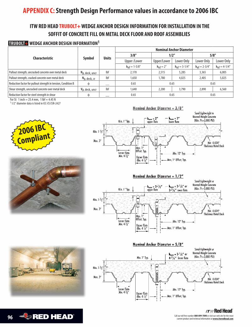
96 Call our toll free number 800-899-7890 or visit our web site for the most current product and technical information at www.itwredhead.com
APPENDIX c: Strength Design Performance values in accordance to 2006 Ibc
TrubolT+ wEDGE ANchor DESIGN INformATIoN1
characteristic Symbol units
Nominal Anchor Diameter3/8" 1/2" 5/8"
Upper /Lower Upper/Lower Lower Only Lower Only Lower Onlyhef = 1-5/8" hef = 2" hef = 3-1/4" hef = 2-3/4" hef = 4-1/4"
Pullout strength, uncracked concrete over metal deck Np, deck, uncr lbf 2,170 2,515 5,285 3,365 6,005
Pullout strength, cracked concrete over metal deck Np, deck, cr lbf 1,650 1,780 4,025 2,405 5,025
Reduction factor for pullout strength in tension, Condition B f __ 0.65 0.65 0.65
Shear strength, uncracked concrete over metal deck Vp, deck, uncr lbf 1,640 2,200 3,790 2,890 6,560
Reduction factor for steel strength in shear f __ 0.65 0.65 0.65For SI: 1 inch = 25.4 mm, 1 lbf = 4.45 N1 1/2" diameter data is listed in ICC-ES ESR-2427
2006 IBC
Compliant
Min. 0.034” Thickness Metal Deck
Min. 1-1/2”
Min. 1” Typ.
Max. 3”
Lower FluteMin. 4-1/2”
Min. 12” Typ.
Max. 1” Offset, Typ.
Sand-Lightweight orNormal Weight Concrete
(Min. f1c=3,000 PSI)
Upper FluteMin. 4-1/2”
Max. 1” Offset, Typ.
hnom = 2-1/2” or3-3/4” lower flute
hnom = 2-1/2” upper flute
Min. 0.034” Thickness Metal Deck
Min. 1-1/2”
Max. 3”
Lower FluteMin. 4-1/2”
Min. 12” Typ.
Max. 1” Offset, Typ.
Sand-Lightweight orNormal Weight Concrete
(Min. f1c=3,000 PSI)
Upper FluteMin. 4-1/2”
hnom = 3-1/4” or4-3/4” lower flute
Min. 0.034” Thickness Metal Deck
Min. 1-1/2”
Min. 1” Typ.
Max. 3”
Lower FluteMin. 4-1/2”
Min. 12” Typ.
Max. 1” Offset, Typ.
Sand-Lightweight orNormal Weight Concrete
(Min. f1c=3,000 PSI)
Upper FluteMin. 4-1/2”
Max. 1” Offset, Typ.
hnom = 2” lower flute
hnom = 2” upper flute
Nominal Anchor Diameter = 3/8”
Nominal Anchor Diameter = 1/2”
Nominal Anchor Diameter = 5/8”
Min. 1” Typ.
ITw rED hEAD TrubolT+ wEDGE ANchor DESIGN INformATIoN for INSTAllATIoN IN ThE SoffIT of coNcrETE fIll oN mETAl DEck floor AND roof ASSEmblIES

Take Advantage of theseContractor Services fromITW RED HEADFrom job sites to engineering firms, from Safety Seminars to on-site services, we hope you takeadvantage of our many contractor services–at no charge! After all, it’s one thing to offer the qualityproducts you need to do your job. It’s another to provide you with superior service, engineeringexpertise and total product support.
At ITW RED HEAD, we are proud of the partnerships we have built through the years with our distributornetwork and contractors. Thanks to quality products, innovative services and on-time delivery, we willcontinue to build new relationships and strengthen existing ones today...and into the next century.
� Factory representatives with years of training and service experience will go out to your job siteto provide you with product, service and technical assistance.
� We provide architects and engineers with complete submittal packages which gives them thetechnical data needed to specify ITW RED HEAD products. Contact your ITW RED HEAD Distributoror your nearest Customer Service location to request submittal packages.
Technical Application Assistance:� Our staff of application specialists are ready to assist you with any type of application or codeapproval question during any phase of your project. Call 1-800-899-7890 between 8:00 a.m.and 5:00 p.m. CST, Monday through Friday.
24-hour Product and Performance Information:� The most frequently requested ITW RED HEAD product and technical information,performance data, approvals, MSDS, etc. are available on our website atwww.itwredhead.com. If additional assistance is required, our application specialistscan be reached at 1-800-899-7890 between 8:00 a.m. and 5:00 p.m. CST, Mondaythrough Friday.
National Headquarters2171 Executive Drive, Suite 100Addison, IL 60101Phone: 630-350-0370Fax: 630-495-6158www.itwredhead.com
Technical SupportPhone: 800-899-7890Fax: 630-495-6204
Customer Service Locations1919 E. U.S. Hwy 12Michigan City, IN 46360800-348-3231FAX: 800-368-3844
Regional Warehouses� Itasca (Chicago), IL� City of Commerce (Los Angeles), CA� Forest Park, GA� Cranbury, NJ� Dallas, TX� Houston, TX
ITW Construction Products Canada120 Travail RoadMarkham, Ontario. L3S 3J1905-471-7403800-387-9692FAX: 800-668-8688www.itwconstruction.ca
A7, Boa, C6, Condrive, Dynabolt, E-Z Ancor, G5, Hammer-Set, LDT, Multi-Set II, Poly Set, Red Head, Redi-Drive, Tapcon, and Trubolt aretrademarks of ITW RED HEAD and Illinois ToolWorks, Inc. Hilti® is a registered trademark of Hilti, Corp. Rawl Spike® is a registeredtrademark of Powers Fastening, Inc.
The information and recommendations in this document are based on the best information available to us at the time of preparation.We make no other warranty, expressed or implied, as to its correctness or completeness, or as to the results or reliance of this document.
CONCRETE ANCHORING SPECIALISTS
PRODUCT AND RESOURCE CATALOG
Trubolt®Wedge Anchors
LDTSelf-Threading Anchors
Multi-Set II®Drop-In Anchors
Boa™ CoilExpansion Anchors
PrimaHigh ExpansionSleeve Anchors
Dynabolt®Sleeve Anchors
StudHammer-Driven Anchors
Redi-Drive®
Masonry Anchors
Tapcon®
Concrete & MasonryAnchors
PR
OD
UC
TA
ND
RESO
UR
CE
CA
TALO
G
®
© 2009 Illinois ToolWorks, Inc.Form No. RHC-09/09


