Embed Size (px)
Citation preview

Journal of Nuclear Materials 337–339 (2005) 839–846
www.elsevier.com/locate/jnucmat
Redeposition of hydrocarbon layers in fusion devices
Wolfgang Jacob *
Centre for Interdisciplinary Plasma Science, Max-Planck-Institut fur Plasmaphysik, Abt. OP, Geb. D3, Postfach 1533,
EURATOM Association, Boltzmannstr. 2, D-85748 Garching, Germany
Abstract
Co-deposition of hydrogen isotopes with carbon in nuclear fusion experiments is a topic of paramount importance
for a next-step device. Physical sputtering, chemical erosion, and chemical sputtering of carbon by hydrogen isotopes
lead to release of hydrocarbon species which are transported to plasma shaded regions and lead there to deposition of
co-deposited layers. Co-deposition is generally believed to be the dominant tritium retention mechanism in a next-step
device. The article reviews recent experimental results regarding co-deposition in fusion devices, and basic low-tempera-
ture plasma and particle-beam experiments relevant to co-deposition of hydrocarbon layers in nuclear fusion devices.
� 2004 Published by Elsevier B.V.
PACS: 52.40.Hf; 68.55.Jk; 81.15.Gh; 82.65.+rKeywords: Amorphous films; Chemical erosion; Co-deposition; Deuterium inventory; Erosion and deposition; Hydrocarbons;
Hydrogen inventory; Sputtering; Surface analysis; Thermal desorption; Tritium
1. Introduction
One of the most crucial plasma–wall-interaction is-
sues for a next-step device such as ITER is tritium reten-
tion via tritium co-deposition with eroded carbon. This
is expected to be the dominant tritium retention mecha-
nism [1]. In most existing fusion experiments the divertor
surface consists of graphite tiles or carbon fiber compos-
ites which are exposed to a substantial incoming flux of
ions and neutrals from the main plasma. This impinging
species flux leads to erosion of the divertor tiles emitting
carbon and hydrocarbon compounds into the gas phase.
Most of the carbon and hydrocarbon species released in
the divertor will redeposit in relative close proximity to
their place of origin. This balance between deposition
0022-3115/$ - see front matter � 2004 Published by Elsevier B.V.
doi:10.1016/j.jnucmat.2004.10.035
* Tel.: +49 89 3299 2618; fax: +49 89 3299 1149.
E-mail address: [email protected]
and erosion is crucial for the performance of a divertor
in a next-step device, since the total lifetime before
replacement strongly depends on the ability to control
this redeposition. However, the small fraction of carbon
and hydrocarbon species that is not redeposited in the
divertor may escape from the divertor and also from
the boundary plasma and cause deposition of hydrocar-
bon layers – often called redeposited or co-deposited lay-
ers – on surfaces not in direct contact with the plasma.
Indeed, thick redeposited layers were observed on re-
mote surfaces of JET [2]. More recent investigations re-
sulted in the detection of much thinner, but measurable,
redeposited layers in other tokamaks (e.g., TEXTOR [3]
and ASDEX Upgrade [4–8]). On many of these surfaces
only neutral carbon-carrying growth precursors can
contribute to film deposition, because only they can
traverse the magnetic field lines. A major concern is
the large amount of hydrogen isotopes trapped in these
redeposited films [1] because in a future fusion reactor

840 W. Jacob / Journal of Nuclear Materials 337–339 (2005) 839–846
this trapped hydrogen will partly be tritium. One aim of
a future design is, therefore, to reduce this tritium reten-
tion for economy and safety reasons.
2. Co-deposited layers in fusion devices
Plasma–material interactions in current tokamaks
were comprehensively reviewed in 2001 by Federici
et al. [1] and the hydrogen inventories in nuclear fusion
devices have been reviewed by Mayer et al. [3]. In this
section, more recent results of the analysis of co-depos-
ited carbon layers in nuclear fusion experiments will be
briefly summarized. Thereby, the main emphasis will
be put on the following questions: Where does the main
deposition occur? What are the species leading to depo-
sition? And, how can we explain the observed deposition
patterns?
Thick co-deposits of up to 90lm thickness were
found at the inner wall of the divertor tiles of JET fol-
lowing the experimental period from 1999 to 2001 [9].
In general, the inner divertor is deposition dominated
while the outer divertor is a net erosion area [2,9]. Ion
beam analysis and secondary ion mass spectroscopy
(SIMS) of deposited layers on the inner JET divertor
tiles which have plasma contact indicate that C is prob-
ably eroded from these deposits, leaving behind films
rich in Be and other metals [2,9]. In adjacent regions
shadowed from direct plasma contact thick carbon
deposits with high D content (up to D/C = 0.8), but no
beryllium, are found [2,10,11]. In addition, thick co-
deposits substantially contributing to the fuel inventory
in the torus were found in tile gaps [8]. It is further inter-
esting to note that the deposition/erosion behavior of
carbon in JET significantly changed when the wall tem-
perature was reduced in 2001 [9]. For the last three
months of operation prior to the 2001 shutdown, the
vessel wall temperature was reduced to 470K from the
normally used 590K and it appears that this significantly
reduced the removal of carbon by chemical erosion. In
addition, investigations applying cavity substrates [12–
14] led to the conclusion that a large fraction of high
sticking species contributes to the deposition in the
JET divertor [11].
A rather comprehensive investigation of carbon
deposition and erosion on ASDEX Upgrade divertor
tiles was performed for the experimental campaign
2002/2003 [7]. It was found that the inner divertor is a
net carbon deposition area while the outer divertor is
erosion dominated. Deposition is maximal at the inner
strike point positions (up to 6lm thick layers), but there
also exist areas with high deposition where the strike
point was never positioned. The deuterium content in
the layer shows large variations and appears to be
mostly influenced by the temperature history of the tiles.
In areas not in direct line of sight to the plasma deute-
rium rich layers with D/C up to 1 are observed. In con-
trast to JET, where most carbon is found under the
divertor, e.g., on the louvers, most of the carbon deposi-
tion is on the divertor tiles. In ASDEX Upgrade only
about 10% of the deposited carbon is found under the
divertor structure [7]. These deposits in remote areas
are soft hydrocarbon layers with high D content [6,15].
As in JET, investigations applying cavity substrates indi-
cate that the deposition under the divertor is dominated
by high sticking species [16]. The same conclusion is
drawn by Rohde et al. [15] who analyzed long term sam-
ples exposed under the divertor during the last campaign
in ASDEX Upgrade. In addition, they found large
asymmetries in the deposition pattern on samples ex-
posed at comparable locations, but facing different
directions. Although the occurrence of a parasitic plas-
ma [4] underneath the divertor complicates the interpre-
tation of the data, it appears that these asymmetries can
only be explained by erosion processes.
In TEXTOR-94 hydrogen-rich co-deposited layers
with thicknesses of up to 1mm have been found on re-
cessed parts of the limiters [3]. On the ALT-II limiter
thick deposited layers (up to 50lm) were found in the
net deposition areas. This is particularly remarkable be-
cause most of the limiter area is erosion dominated.
These layers posses a relatively low D content which
can be attributed to temperature excursions, e.g., during
disruptions or long pulse discharges [2]. The deposited
layers contain hydrogen isotopes of up to (H + D)/
C = 0.4. Layers deposited far away from the plasma,
e.g., in the pump ducts show H isotope contents of up
to (H + D)/C � 2; their contribution to the total inven-
tory remains, however, low, i.e., of the order of a few
percent [17].
In addition to these postmortem analyses of tokamak
tiles and long term samples, investigations with quartz
microbalances (QMB) in JET [18] and ASDEX Upgrade
[15] provide time-resolved measurements on a shot-to-
shot basis. These investigations revealed that the growth
of redeposited layers on the QMB�s is a continuous pro-
cess. The growth rate varies depending on the plasma
scenario; the growth rate is particularly high if the
QMB is in line of sight to the main particle source,
i.e., the inner divertor strike point.
3. Investigations using low-temperature laboratory
plasmas
Experiments applying low-temperature laboratory
plasmas for investigation of deposition and erosion in
the hydrogen–carbon system can be separated in two
groups: (i) plasma simulators and (ii) small scale stan-
dard low-temperature plasmas (LTP). The first group
consists of two major experimental efforts, the PISCES
facility at the University of San Diego [19] and PSI-2

W. Jacob / Journal of Nuclear Materials 337–339 (2005) 839–846 841
now at the Humbold University, Berlin [20,21]. These
two experiments are dedicated to the investigation of
plasma–surface-interaction (PSI) processes relevant for
nuclear fusion plasmas. They provide very valuable
information about PSI processes in parameter ranges
relevant for ITER. The second group of experiments
spans a huge range of very different groups and setups.
Most of them are dedicated to the deposition of a–
C:H layers for technological applications. Here I will
limit the discussion to small-scale laboratory LTP exper-
iments relevant to co-deposited layers in fusion devices.
The primary source for hydrocarbon species that lead to
co-deposition in fusion devices is erosion of carbon sur-
faces through interaction with a hydrogen plasma.
Therefore it is also necessary to have a closer look to
the erosion processes in this system.
The temperature dependence of the deposition of a–
C:H films was investigated by von Keudell and Jacob
[22]. Deposition was performed in an electron cyclotron
resonance (ECR) plasma using methane as working gas.
Erosion and deposition was measured using in situ, real-
time ellipsometry. With increasing temperature the
deposition rate decreases and for temperatures greater
than 500K erosion occurs; see Fig. 1. The temperature
dependence of the erosion rate is also shown in Fig. 1.
It is clearly evident from Fig. 1 that the temperature
dependence is the same in both processes. The conclu-
sion from this experiment is that the temperature depen-
dence observed for deposition of a–C:H layers is given
by the temperature dependence of the erosion process.
Responsible for the erosion is the copiously available
hydrogen in the plasma which is produced by electron-
induced dissociation of the working gas [23]. The net
deposition is the difference of a temperature-indepen-
Fig. 1. Comparison of the deposition and erosion rates of a–
C:H films in methane and hydrogen low-temperature plasmas,
respectively, as a function of temperature [22]. Deposition and
erosion were measured by real-time ellipsometry with the
substrate at floating potential which corresponds to ion energies
of about 15eV. The left-hand scale is for the deposition and the
right-hand scale for the erosion experiment. Note the different
scales, especially the shift in the zero position for the two cases.
dent deposition process and a temperature-dependent
erosion process. Increasing the substrate temperature
under constant particle fluxes enhances the erosion effi-
ciency and the net deposition decreases. This can also
explain the change-over from net deposition to net ero-
sion shown in Fig. 1. It is clear that the change-over tem-
perature for this effect depends on the relative fluxes of
deposition and erosion species.
It is well known that the structure and physical prop-
erties of a–C:H layers depend sensitively on the deposi-
tion conditions [23]. The most important deposition
parameter is the energy of ions impinging on the grow-
ing film surface during deposition [23,24]. At low ion
energies (<50eV), soft, polymer-like layers with high
hydrogen content grow, while at high ion energies
(>50eV), hard, amorphous layers with a hydrogen con-
tent of typically H/C � 0.4 are deposited. The erosion
rates for different a–C:H layers differ significantly
[22,25,26]. The actual erosion rate for a specific a–C:H
layer depends, however, not only on its bulk properties,
but also on the actual dynamic state of the surface dur-
ing interaction with the plasma [22,23]. This is demon-
strated in Figs. 2 and 3, where the erosion rates are
shown for soft and hard a–C:H layers, respectively, as
a function of temperature.
In Fig. 2 the erosion rate of soft a–C:H layers is plot-
ted as a function of temperature at floating potential
(solid line) and with an additional substrate bias of
�100V [22]. Erosion was measured in an ECR hydrogen
plasma using real-time ellipsometry. The erosion rate at
floating potential is negligible for low temperature
(<350K), but increases exponentially with increasing
Fig. 2. Erosion rate of a soft a–C:H layer as a function of
temperature at floating potential (solid line) and with an
additional substrate bias of 100V. Erosion was measured in an
ECR hydrogen plasma using real-time ellipsometry [22]. At
point 1 the bias voltage was switched off. At point 2 the same
rate as for the run without bias is measured. The eroded layer
thickness between points 1 and 2 is 4.7nm.
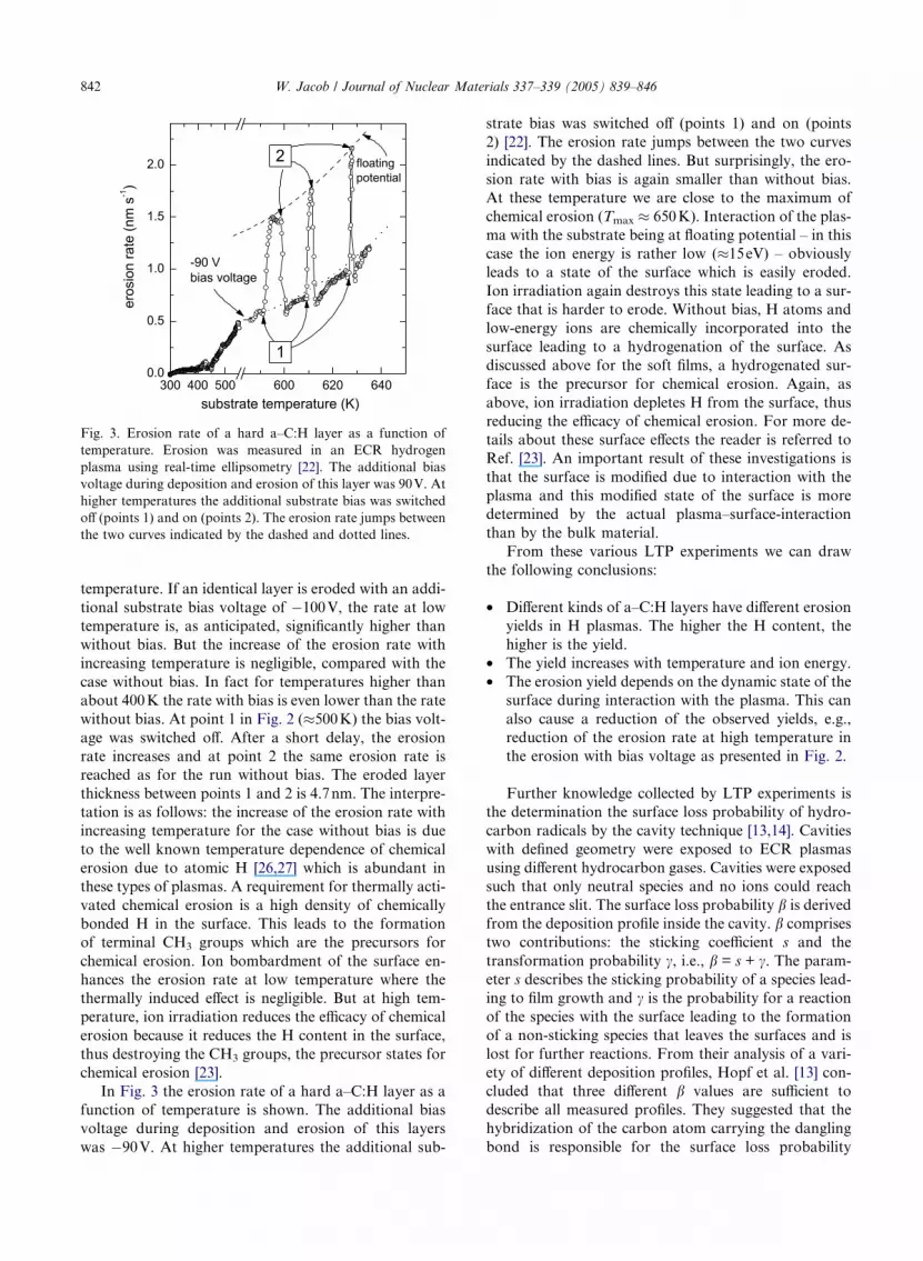
Fig. 3. Erosion rate of a hard a–C:H layer as a function of
temperature. Erosion was measured in an ECR hydrogen
plasma using real-time ellipsometry [22]. The additional bias
voltage during deposition and erosion of this layer was 90V. At
higher temperatures the additional substrate bias was switched
off (points 1) and on (points 2). The erosion rate jumps between
the two curves indicated by the dashed and dotted lines.
842 W. Jacob / Journal of Nuclear Materials 337–339 (2005) 839–846
temperature. If an identical layer is eroded with an addi-
tional substrate bias voltage of �100V, the rate at low
temperature is, as anticipated, significantly higher than
without bias. But the increase of the erosion rate with
increasing temperature is negligible, compared with the
case without bias. In fact for temperatures higher than
about 400K the rate with bias is even lower than the rate
without bias. At point 1 in Fig. 2 (�500K) the bias volt-
age was switched off. After a short delay, the erosion
rate increases and at point 2 the same erosion rate is
reached as for the run without bias. The eroded layer
thickness between points 1 and 2 is 4.7nm. The interpre-
tation is as follows: the increase of the erosion rate with
increasing temperature for the case without bias is due
to the well known temperature dependence of chemical
erosion due to atomic H [26,27] which is abundant in
these types of plasmas. A requirement for thermally acti-
vated chemical erosion is a high density of chemically
bonded H in the surface. This leads to the formation
of terminal CH3 groups which are the precursors for
chemical erosion. Ion bombardment of the surface en-
hances the erosion rate at low temperature where the
thermally induced effect is negligible. But at high tem-
perature, ion irradiation reduces the efficacy of chemical
erosion because it reduces the H content in the surface,
thus destroying the CH3 groups, the precursor states for
chemical erosion [23].
In Fig. 3 the erosion rate of a hard a–C:H layer as a
function of temperature is shown. The additional bias
voltage during deposition and erosion of this layers
was �90V. At higher temperatures the additional sub-
strate bias was switched off (points 1) and on (points
2) [22]. The erosion rate jumps between the two curves
indicated by the dashed lines. But surprisingly, the ero-
sion rate with bias is again smaller than without bias.
At these temperature we are close to the maximum of
chemical erosion (Tmax � 650K). Interaction of the plas-
ma with the substrate being at floating potential – in this
case the ion energy is rather low (�15eV) – obviously
leads to a state of the surface which is easily eroded.
Ion irradiation again destroys this state leading to a sur-
face that is harder to erode. Without bias, H atoms and
low-energy ions are chemically incorporated into the
surface leading to a hydrogenation of the surface. As
discussed above for the soft films, a hydrogenated sur-
face is the precursor for chemical erosion. Again, as
above, ion irradiation depletes H from the surface, thus
reducing the efficacy of chemical erosion. For more de-
tails about these surface effects the reader is referred to
Ref. [23]. An important result of these investigations is
that the surface is modified due to interaction with the
plasma and this modified state of the surface is more
determined by the actual plasma–surface-interaction
than by the bulk material.
From these various LTP experiments we can draw
the following conclusions:
• Different kinds of a–C:H layers have different erosion
yields in H plasmas. The higher the H content, the
higher is the yield.
• The yield increases with temperature and ion energy.
• The erosion yield depends on the dynamic state of the
surface during interaction with the plasma. This can
also cause a reduction of the observed yields, e.g.,
reduction of the erosion rate at high temperature in
the erosion with bias voltage as presented in Fig. 2.
Further knowledge collected by LTP experiments is
the determination the surface loss probability of hydro-
carbon radicals by the cavity technique [13,14]. Cavities
with defined geometry were exposed to ECR plasmas
using different hydrocarbon gases. Cavities were exposed
such that only neutral species and no ions could reach
the entrance slit. The surface loss probability b is derived
from the deposition profile inside the cavity. b comprises
two contributions: the sticking coefficient s and the
transformation probability c, i.e., b = s + c. The param-
eter s describes the sticking probability of a species lead-
ing to film growth and c is the probability for a reaction
of the species with the surface leading to the formation
of a non-sticking species that leaves the surfaces and is
lost for further reactions. From their analysis of a vari-
ety of different deposition profiles, Hopf et al. [13] con-
cluded that three different b values are sufficient to
describe all measured profiles. They suggested that the
hybridization of the carbon atom carrying the dangling
bond is responsible for the surface loss probability

W. Jacob / Journal of Nuclear Materials 337–339 (2005) 839–846 843
of a hydrocarbon radical. The following values were
determined: b(C2H) = 0.80 ± 0.05 (sp1 hybridization),
b(C2H3) = 0.35 ± 0.15 (sp2 hybridization), and b(C2H5
or CH3) < 10�3 (sp3 hybridization). b represents an
upper limit for the sticking coefficient. As a first approx-
imation it can be assumed that s � b, i.e., c � 0. The
most probable anticipated transformation reaction is
abstraction of H from the surface leading to the forma-
tion of a stable hydrocarbon radical. These reactions are
of Eley-Rideal type and posses in general a rather low
reaction cross-section. Since these cross-sections are
not known for most hydrocarbon radicals, we consider
the abstraction of surface-bonded H by atomic H. This
reaction was studied by Kuppers and co-workers [27]
and a reaction probability of the order of 1% was found.
The abstraction cross-section for H by impinging CH3
was determined to be at least one order of magnitude
lower [28]. On the other hand, we have to assume that
the abstraction probability for radicals with higher reac-
tion probability is also higher. As long as no quantita-
tive measurements for the sticking coefficient of the
various hydrocarbon radicals exist, this ambiguity re-
mains. It is, however, reasonable to assume that c repre-sents only a minor contribution to the total surface loss
probability.
LTP experiments significantly enhanced our under-
standing of growth and erosion of hydrocarbon layers.
Although many results are only qualitative, it was possi-
ble to determine in some favorable cases quantitative
data. One such example is the determination of surface
loss probabilities presented above. These results can
serve as input parameters for edge simulation codes to
assess co-deposition in nuclear fusion devices. A deeper
and mostly quantitative understanding of microscopic
plasma–surface-interaction processes can be achieved
in experiments using quantified particles beams. Results
from this approach are presented in the following
section.
4. Investigations with particle beams
Plasma–surface-interaction processes in low-temper-
ature plasmas as well as in nuclear fusion devices involve
heterogeneous reactions of various radicals and ions,
which interact simultaneously with a substrate. Thereby,
chemisorption of a specific neutral growth precursor
might be enhanced due to surface activation by other
incident species. Surface activation depends on identity
and energy of incident species, which is illustrated by
two examples:
• Ion-induced chemisorption of neutral radicals: The
kinetic energy of incident ions is dissipated in a colli-
sion cascade in the solid. Within this cascade, target
atoms are displaced and chemical bonds are broken.
If such a broken bond (dangling bond) is created at
the physical surface, it might serve as a chemisorption
site for incident neutral radicals from the plasma,
thus enhancing the sticking probability of impinging
species. This process is called ion-induced
chemisorption.
• H-atom-induced chemisorption of neutral radicals:
dangling bonds at the physical surface can also be
created by chemical reactions [27]. In many low-tem-
perature plasmas, but in particular, in nuclear fusion
divertor plasmas, atomic H is an important constitu-
ent. The abstraction of surface-bonded H by incident
H atoms creates dangling bonds, which then serve as
preferred chemisorption sites for incident neutral
radicals. This mechanism is called H-atom-induced
chemisorption.
Due to the complexity of these heterogeneous surface
processes, any quantitative prediction of reaction rates
based on elementary mechanisms has so far been very
limited. A number of such mutual interactions between
different types of species has recently been investigated
in a particle-beam experiment [29,30]. In addition to
the above mentioned processes, the simultaneous inter-
action of energetic ions and atomic H with carbon sur-
faces leads to chemical sputtering of the surface; see
for example [31–33]. Recent reviews of chemical sputter-
ing include [29,34]. Although no further discussion of
chemical sputtering will be presented here, it is impor-
tant to note that chemical sputtering is the process that
causes the erosion of carbon surfaces through the release
of hydrocarbon species which in turn are the precursors
for redeposition in remote areas.
The sticking coefficient, s, of CH3 on a hydrocarbon
surface was determined to be between 10�5 (perpendicu-
lar incidence) and 10�4 (45� incidence) [28,35,36]. Theseexperimental results are in excellent agreement with
molecular dynamics simulations [37,38]. It was further
shown that a simultaneous flux of CH3 and atomic H
causes a significant increase of s (H-atom-induced chemi-
sorption). The sticking coefficient of CH3 increases with
increasing H flux and saturates for high H fluxes (H/CH3
flux ratio P100) at about 10�2 [28,35,36].
Similar to surface activation by atomic H, ion-in-
duced dangling-bond formation at the physical surface
also provides chemisorption sites for incident radicals
from the plasma [39–41]. An ion flux of the order of
10% of the CH3 flux can increase the sticking coefficient
of CH3 to some 10�2. In this case the net growth rate
corresponds to a balance between the rate for ion-
induced chemisorption minus the sputtering rate. The
incident ion bombardment also causes a change of film
stoichiometry. Due to the lower displacement threshold
for H compared with carbon [23], bonded H is predom-
inantly displaced within a collision cascade. Displaced H
atoms recombine locally forming H2 molecules, which

Table 1
844 W. Jacob / Journal of Nuclear Materials 337–339 (2005) 839–846
diffuse to the surface and desorb [42]. This subsurface H2
formation leads to a decrease of the H content within the
ion penetration range and to cross-linking of the remain-
ing carbon network. Summarizing, one can state that the
influence of the ion bombardment on film formation is
dominated by two processes, the ion-induced surface
activation which influences the deposition rate and the
subsurface hydrogen depletion which determines the
film properties.
Another set of beam experiments was performed by
Zecho et al. [43,44]. They exposed a thin hard a–C:H
layer (H/C about 0.4) to a beam of atomic H and mea-
sured the erosion products by a line-of-sight mass spec-
trometer. The dominant erosion products are C1, C2,
and C3 hydrocarbons. The erosion yield exhibits a max-
imum of about 0.01 eroded C per incident H around
750K. Higher hydrocarbons (C4 to C8) were found
as minority species. Above 750K the erosion yield
decreases again due to thermally activated dehydrogena-
tion of the layer. Thermal annealing of as-deposited a–
C:H layers leads to desorption of H2 (about 90% of
the H is released as H2) and hydrocarbon products with
a similar distribution as seen during chemical erosion of
the film [43,44]. In this case only about 1% of the carbon
atoms in the layer are removed. Above 900K, graphiti-
zation of the layer sets in. H atoms rapidly rehydro-
genate the surface of an annealed a–C:H film at
temperatures as high as 800K. But this process is re-
stricted to a thin surface layer. Chemical erosion of pre-
annealed layers is rather similar to that of as-deposited
layers. It should be mentioned here that thermal decom-
position of soft layers proceeds significantly differently
than that of hard layers. Increasing H content in the soft
layers leads to a decrease of the release temperature, a
drastic change of the species distribution, and an in-
crease in the total number of released carbon atoms
[45]. While for hard layers H2 is by far the dominating
released product, soft layers dominantly release hydro-
carbons with large contributions of long chain hydrocar-
bons. A large fraction of the carbon atoms can thus be
mobilized leading in extreme cases to the evaporation
of the complete layer.
Compilation of recommended values for sticking coefficients for
hydrocarbon radicals on a–C:H surfaces
Radical s Ref. Remarks
C 1
CH 1 [54]
CH2 0.025 [55] Measured in plasma
CH3 10�4 [13,28] Surface not activated
CH3 10�2 [28] Surface activated, e.g.,
co-bombardment with H or ions
C2H 0.80 [13] Measured in plasma
C2H3 0.35 [13] Measured in plasma
C2H5 0.03 [56] Measured in plasma
The values determined in plasmas are surface loss probabilities
and represent an upper limit for s.
5. Conclusion
Although the primary source of carbon in the diver-
tor region of tokamaks remains unclear, the transport in
the plasma boundary layer seems to cause a migration
from the outer divertor along the main chamber wall
to the inner divertor. On its way to the inner divertor,
carbon is deposited and eroded multiple times. If it
comes to rest in a plasma shaded region in the main
chamber there is a high probability that it is not ree-
roded and remains permanently deposited. This leads
to film deposition in tile gaps and other plasma shaded
regions. Most carbon is, however, transported to the in-
ner divertor leading to thick co-deposits close to the
strike point. Depending on the actual plasma conditions
(e.g., attached or detached) different kinds of a–C:H lay-
ers can form which in turn have different erosion prop-
erties. Most of the permanent net deposition occurs in
line of sight to the main erosion or recycling areas with
steep thickness gradients. But because the depositing
species have to cross magnetic field lines, it is evident
that most of them have to be neutral species. It is there-
fore concluded that neutral hydrocarbon radicals are
precursors for film growth in remote areas. These hydro-
carbon radicals may be produced by electron-induced
dissociation of stable molecules released during the
chemical sputtering process or be directly produced at
the surface. The production of stable molecules has
clearly been shown in several experiments [43,44,46–48].
It was further shown that different types of hydrocar-
bon species have largely different sticking probabilities
[13]. The sticking probability depends mostly on the
hybridization of the carbon atom carrying the dangling
bond. It is very high for sp1 hybridization, intermediate
for sp2 hybridization, and very low for sp3 hybridization.
Measured and estimated sticking probabilities for a vari-
ety of hydrocarbon radicals are summarized in Table 1.
The variety and amount of CH species produced dur-
ing chemical sputtering depends sensitively on the plas-
ma conditions. It appears that for low ion energies the
contribution of higher CH species increases. Also, for
intermediate temperatures (�500 to 700K), a high con-
tribution of long chain CH species is anticipated. This is,
for example, seen in optical spectroscopy of laboratory
[49] and divertor plasmas [50,51] through the increase
of the C2 band and was demonstrated in the laboratory
experiments by Zecho et al. [43,44]. Based on this obser-
vation we may hypothesize that the huge deposition seen
in JET louvers occurred because JET was operating at
that time in a plasma regime (wall temperature about

W. Jacob / Journal of Nuclear Materials 337–339 (2005) 839–846 845
600 K and low ion energies) that led to the production of
many CH species.
Low-temperature laboratory plasma experiments
have shown that net deposition is always a competition
between deposition and erosion. It is reasonable to as-
sume that this is also true in fusion devices. This means
that deposition occurs at all surfaces which are in line
of sight to the source of particle generation and the
boundary plasma. But on plasma facing surfaces that
are intersecting magnetic field lines the high impinging
ion flux causes strong reerosion so that the net deposi-
tion decreases and may even change to net erosion.
This can, for example, explain the observed torodial
asymmetric deposition patterns on the JET divertor
tiles reported in [52]. From this we can conclude that
the pattern formation of co-deposited layers is signifi-
cantly influenced, if not dominated, by reerosion. The
situation remains, however, rather complicated due to
the strong synergistic effects between different types
of species. We can assume that most of the deposition
close to the main erosion sources in the inner divertor,
i.e., the strike zone, is caused by high-sticking species.
Only this assumption can explain the steep gradients
and the absolute amounts observed experimentally in
remote areas of the inner divertor [4–6,11,53]. How-
ever, as has been shown in the particle-beam experi-
ments, the sticking coefficient of low-sticking species
can be enhanced by up to 2 orders of magnitude if
atomic H or ion bombardment activates the surface.
This means that at least a part of the observed pattern
in remote areas, such as under the divertor structure of
ASDEX Upgrade, might be influenced by the parasitic
plasma [4,5] which can cause surface activation. If this
were to be the case, then deposition of low-sticking
species would be just a measure of the surface activa-
tion and the deposition profile might be caused by
the plasma density profile in front of the surface be-
cause the plasma density determines the ion flux den-
sity which in turn determines the degree of activation
of the surface.
Although much progress has been made in under-
standing the redeposition process in fusion devices, it
is obvious that many open questions remain. These have
to be addressed in further experiments in low-tempera-
ture laboratory plasmas as well as in fusion devices.
Dedicated experiments to determine the particle fluxes
to relevant deposition areas in tokamaks would be very
helpful to clarify the dominant processes.
References
[1] G. Federici, C.H. Skinner, J.N. Brooks, J.P. Goad, C.
Grisolia, A.A. Haasz, A. Hassanein, V. Philipps, C.S.
Pitcher, J. Roth, et al., Nucl. Fus. 41 (2001)
1967.
[2] J.P. Goad, N. Bekris, J.D. Elder, S. Erents, D. Hole, K.
Lawson, G. Matthews, R. Penzhorn, P. Stangeby, J. Nucl.
Mater. 290–293 (2001) 224.
[3] M. Mayer, V. Phillips, P. Wienhold, H. Esser, J. von
Seggern, M. Rubel, J. Nucl. Mater. 290–293 (2001) 381.
[4] V. Rohde, M. Mayer, the ASDEX Upgrade Team, J.
Nucl. Mater. 313–316 (2003) 337.
[5] V. Rohde, M. Mayer, the ASDEX Upgrade Team, Phys.
Scr. T103 (2003) 25.
[6] M. Mayer, V. Rohde, A. von Keudell, the ASDEX
Upgrade Team, J. Nucl. Mater. 313–316 (2003) 429.
[7] M. Mayer, V. Rohde, J. Likonen, E. Vainonen-Ahlgren, K.
Krieger, X. Gong, J. Chen, ASDEX Upgrade Team, in:
Proceedings PSI-16, 2004. doi:10.1016/j.jnucmat.2004.10.
046.
[8] M. Rubel, J.P. Goad, P. Wienhold, G. Matthews, V.
Phillips, M. Stamp, T. Tanabe, Phys. Scr., in press.
[9] J.P. Goad, P. Andrew, D. Hole, S. Lehto, J. Likonen, G.
Matthews, M. Rubel Contributors to the EFDA-JET work
programme, J. Nucl. Mater. 313–316 (2003) 419.
[10] M. Rubel, J.P. Goad, N. Bekris, S. Erents, D. Hole, G.
Matthews, R. Penzhorn Contributors to the EFDA-JET
work programme, J. Nucl. Mater. 313–316 (2003) 321.
[11] M. Mayer, A. von Keudell, V. Rohde, P. Goad, J.
contributors, in: R. Koch, S. Lebedev (Eds.), Proceedings
of the 30th EPS Conference, European Physical Society,
2003, p. O2.6A.
[12] C. Hopf, K. Letourneur, W. Jacob, T. Schwarz-Selinger,
A. von Keudell, Appl. Phys. Lett. 74 (1999) 3800.
[13] C. Hopf, T. Schwarz-Selinger, W. Jacob, A. von Keudell,
J. Appl. Phys 87 (2000) 2719.
[14] A. von Keudell, C. Hopf, T. Schwarz-Selinger, W. Jacob,
Nucl. Fus. 39 (1999) 1451.
[15] V. Rohde, M. Mayer, J. Likonen, R. Neu, T. Puetterich, E.
Vainonen-Ahlgren, the ASDEX Upgrade Team, in: Pro-
ceedings PSI-16, 2004. doi:10.1016/j.jnucmat.2004.10.110.
[16] C.H. Skinner, unpublished results, 2004.
[17] von Seggern et al., J. Nucl. Mater. 313–316 (2003) PSI15.
[18] H.-G. Esser et al., in Proceedings PSI-16, 2004. doi:10.
1016/j.jnucmat.2004.10.112.
[19] D. Whyte, G. Tynan, R. Doerner, J. Brooks, Nucl. Fus. 41
(2001) 47.
[20] P. Kornejew, W. Bohmeyer, H.-D. Reiner, C.H. Wu,
Phys. Scr. T 91 (2001) 29.
[21] I. Arkhipov, W.B. et al., Tech. Rep., EFDA Task, Final
Report, 2003.
[22] A. von Keudell, W. Jacob, J. Appl. Phys. 79 (1996) 1092.
[23] W. Jacob, Thin Solid Films 326 (1998) 1.
[24] T. Schwarz-Selinger, A. von Keudell, W. Jacob, J. Appl.
Phys. 86 (1999) 3988.
[25] E. Vietzke, K. Flaskamp, V. Phillips, G. Esser, P.
Wienhold, J. Winter, J. Nucl. Mater. 145–147 (1987) 443.
[26] E. Vietzke, A.A. Haasz, in: W. Hofer, J. Roth (Eds.),
Physical Processes of the Interaction of Fusion Plasmas
with Solids, Academic Press, 1996, p. 135.
[27] J. Kiippers, Surf. Sci. Rep. 22 (1995) 249.
[28] M. Meier, A. von Keudell, J. Appl. Phys. 90 (2001) 3585.
[29] W. Jacob, C. Hopf, M. Meier, T. Schwarz-Selinger, in:
Interaction of Low-energy Ions and Hydrocarbon Radicals
with Carbon Surfaces, Springer, 2004 (Chapter. 3.3).
[30] A. von Keudell, W. Jacob, Prog. Surf. Sci., in press.

846 W. Jacob / Journal of Nuclear Materials 337–339 (2005) 839–846
[31] A.A. Haasz, J.W. Davis, Phys. Scr. in press.
[32] J.W. Davis, A.A. Haasz, P.C. Stangeby, J. Nucl. Mater.
155–157 (1988) 234.
[33] E. Vietzke, K. Flaskamp, V. Philipps, J. Nucl. Mater.
111&112 (1982) 763.
[34] C. Hopf, A. von Keudell, W. Jacob, J. Appl. Phys. 94
(2003) 2373.
[35] A. von Keudell, T. Schwarz-Selinger, W. Jacob, J. Appl.
Phys. 89 (2001) 2979.
[36] M. Meier, R. Preuss, V. Dose, New J. Phys. 5 (2003)
133.1.
[37] P. Traskelin, E. Salonen, K. Nordlund, A. Krasheninni-
kov, J. Keinonen, C. Wu, J. Appl. Phys. 93 (2003)
1826.
[38] P. Traskelin, E. Salonen, K. Nordlund, J. Keinonen, C.H.
Wu, J. Nucl. Mater. 334 (2004) 65.
[39] C. Hopf, A. von Keudell, W. Jacob, Diamond Relat.
Mater. 12 (2003) 85.
[40] C. Hopf, A. von Keudell, W. Jacob, J. Appl. Phys. 93
(2003) 3352.
[41] C. Hopf, PhD thesis, Universitat Bayreuth, 2003.
[42] W. Moller, B.M.U. Scherzer, Appl. Phys. Lett. 50 (1987)
1870.
[43] T. Zecho, B.D. Brandner, J. Biener, J. Kiippers, J. Phys.
Chem. B 105 (2001) 6194.
[44] T. Zecho, B.D. Brandner, J. Biener, J. Kiippers, J. Phys.
Chem. B 106 (2002) 610.
[45] W. Jacob, C. Hopf, A. von Keudell, T. Schwarz-Selinger,
in: Hydrogen Recycling at Plasma Facing Materials,
Kluwer Academic, 2000, p. 331.
[46] B.V. Mech, A.A. Haasz, J.W. Davis, J. Appl. Phys. 84
(1998) 1655.
[47] B.V. Mech, A.A. Haasz, J.W. Davis, J. Nucl. Mater. 255
(1998) 153.
[48] E. Vietzke, V. Phillips, K. Flaskamp, C. Wild, in: P.
Koidl, P. Oelhafen (Eds.), E-MRS Proceedings XVII, Les
Edition de Physique, 1987, p. 351.
[49] U. Fantz, H. Paulin, Phys. Scr. T 91 (2001) 25.
[50] R. Pugno, A. Kallenbach, J. Likonen, E. Vainonen-
Ahlgren, D. Coster, R. Dux, A. Kirschner, K. Krieger,
V. Rohde, U. Fantz, et al., in: Proceedings PSI-16, 2004, p.
PI-34. doi:10.1016/j.jnucmat.2004.09.053.
[51] S. Brezinsek, in: Proceedings PSI-16, 2004. doi:10.1016/j.
jnucmat.2004.10.114.
[52] K. Sugiyama, K. Miyasaka, T. Tanabe, M. Glugla, N.
Bekris, J.P. Goad, J. Nucl. Mater. 313–316 (2003) 507.
[53] M. Mayer, V. Rohde, T. Puetterich, P. Goad, P. Wienhold,
JET-EFDA Contributors, ASDEX Upgrade Team, Phys.
Scr., in press.
[54] M. Bauer, PhD thesis, Universitat Bayreuth, 2004.
[55] H. Kojima, H. Toyoda, H. Sugai, Appl. Phys. Lett. 55
(1989) 1507.
[56] J. Perrin, M. Shiratani, P. Kae-Nune, H. Videlot, J. Jolly,
J. Guillon, J. Vac. Sci. Technol. A 16 (1998) 278.


