Embed Size (px)
Citation preview
Optimizer
www.trinnov.com
REFERENCEMANUAL


Thank you for choosing a Trinnov digital audio processor. As a company, our goal is to offer a range of products that meet the audio monitoring and metering requirements of the most
demanding audio professionals. Our solutions enable them to produce the highest quality sound for music, broadcast and film.

Trinnov Audio

REFERENCE MANUAL
IMPORTANT SAFETY INSTRUCTIONS
1. Read the following instructions carefully. Save all instructions for future reference. 2. Follow all warnings and instructions. 3. TRINNOV Audio expressly forbids unauthorized modification of this equipment. 4. Using the unit in the following locations can result in a malfunction:
• In direct sunlight • Locations of extreme temperature or humidity • Excessively dusty or dirty locations • Locations of excessive vibration • Close to magnetic fields
5. Condensation can form on the inside of the apparatus if it is suddenly moved from a cold environment to a warmer location. Before switching the unit on, it is recommended that the unit be allowed to reach room temperature.
6. Clean only with a dry cloth. Do not use liquid solvent-based cleaners. 7. Do not cover of bloc ventilation slots or openings. Never push objects of any kind into ventilation slots on the
equipment casing. 8. Install in conformance with the manufacturer's instructions. 9. Maximum permissible operating conditions: 0°C to 40°C, 20-65% relative humidity. 10. Protect the power chord from being walked on or pinched particularly at plugs, convenience receptacles, and the
point where they exit from the apparatus. 11. Always replace damaged fuses with the correct rating and type. 12. Unplug this apparatus during lightning storms or when unused for long periods of time. 13. Do not open the equipment case. There are no user serviceable parts in this equipment. Refer all servicing to
qualified service personnel. 14. Please connect the designated AC/AC power supply to an AC outlet of the correct voltage. Do not connect it to
an AC outlet of voltage other than that for which your unit is intended.
TO COMPLETELY DISCONNECT THIS APPARATUS FROM THE AC MAINS, DISCONNECT THE POWER SUPPLY CORD PLUG FROM THE AC RECEPTACLE.
THIS SYMBOL IS INTENDED TO ALERT THE USER TO THE PRESENCE OF UNINSULATED ‘DANGEROUS VOLTAGE’ WITHIN THE PRODUCT'S ENCLOSURE THAT MAY BE SUFFICIENT MAGNITUDE TO CONSTITUTE A RISK OF ELECTRIC SHOCK.
Trinnov Audio
IMPORTANT SAFETY INSTRUCTIONS 5
TABLE OF CONTENT 6
1. INTRODUCTION 11
1.1 INTEGRATED MONITORING SOLUTION.......................................................................................................................121.1.1 Modular Architecture .............................................................................................................................................................................................................121.1.2 Synoptic .....................................................................................................................................................................................................................................13
1.2 MAIN FEATURES OF THE SYSTEM SOFTWARE ..........................................................................................................141.2.1 Manual Equalization .............................................................................................................................................................................................................. 141.2.2 Active Crossovers ..................................................................................................................................................................................................................141.2.3 DRC/Submixes .......................................................................................................................................................................................................................14
1.3 MAIN FEATURES OF THE OPTIMIZER MODULE .........................................................................................................151.3.1 Level and Time Alignment .................................................................................................................................................................................................. 15
1.4 AUTOMATIC OPTIMIZATION ........................................................................................................................................151.4.1 Loudspeaker Positions Remapping ................................................................................................................................................................................ 15
1.5 MAIN FEATURES OF THE SMARTMETER MODULE ....................................................................................................15
2. GETTING STARTED 17
2.1 POWER ON AND SHUTDOWN ......................................................................................................................................172.1.1 Power on ................................................................................................................................................................................................................................... 172.1.2 Shutdown .................................................................................................................................................................................................................................. 17
2.2 USER INTERFACE ..........................................................................................................................................................182.2.1 Multiview Mode ......................................................................................................................................................................................................................182.2.2 Using an external display, mouse and keyboard .......................................................................................................................................................182.2.3 Using an external touch screen .......................................................................................................................................................................................19TOUCHSCREEN CALIBRATION .................................................................................................................................................................................................192.2.4 Using a VNC Client through the local network ........................................................................................................................................................... 192.2.5 Screenshots ............................................................................................................................................................................................................................20
2.3 OPTIMIZER - CALIBRATION PROCEDURE ..................................................................................................................212.3.1 Calibration settings ...............................................................................................................................................................................................................212.3.2 Important recommendation for microphone placement .......................................................................................................................................21
2.3.3 Calibration 21
2.4 SMARTMETER - SOURCES SETUP ............................................................................................................................ 232.4.1 Hardware source selection ................................................................................................................................................................................................232.4.2 Sources configuration and software routing ..............................................................................................................................................................23
3. HARDWARE 26
3.1 AUDIO INTERFACES & CHASSIS ................................................................................................................................. 263.1.1 2U and 4U Chassis ................................................................................................................................................................................................................263.1.2 Audio interfaces in each Trinnov processor .................................................................................................................................................................27
3.2 ST2 PRO ....................................................................................................................................................................... 273.2.1 Technical Description...........................................................................................................................................................................................................273.2.2 Front Panel ..............................................................................................................................................................................................................................273.2.3 Rear Panel................................................................................................................................................................................................................................28
3.3 MC PROCESSO RS ..................................................................................................................................................... 283.3.1 Technical Description...........................................................................................................................................................................................................283.3.2 TAC-based MC processors ...............................................................................................................................................................................................293.3.4 DB25 connectivity .................................................................................................................................................................................................................29
REFERENCE MANUAL
3.3.4 Connector Pinouts ................................................................................................................................................................................................................30
3.4 STARTUP OPTIONS ..................................................................................................................................................... 303.4.1 Startup Menu ..........................................................................................................................................................................................................................303.4.2 Startup Modes .......................................................................................................................................................................................................................31
3.5 3D MEASUREMENT MICROPHONE ............................................................................................................................ 323.5.1 Position and orientation of the microphone ................................................................................................................................................................323.5.2 Power supply ..........................................................................................................................................................................................................................32
3.6 IR MODULE & GPIO ...................................................................................................................................................... 33
3.7 SOFTWARE UPDATES & REMOTE SUPPORT ............................................................................................................. 33
4. SYSTEM SOFTWARE GUIDE 34
4.1 HOME ............................................................................................................................................................................ 344.1.1 Monitoring Control ................................................................................................................................................................................................................ 344.1.2 Select ..........................................................................................................................................................................................................................................354.1.3 Meters ........................................................................................................................................................................................................................................354.1.4 Profiles Config .........................................................................................................................................................................................................................36
4.2 SETUP ........................................................................................................................................................................... 384.2.1 Sources .................................................................................................................................................................................................................................... 38STANDARD SETTINGS .................................................................................................................................................................................................................394.2.2 Speakers .................................................................................................................................................................................................................................. 404.2.3 Active X-overs ....................................................................................................................................................................................................................... 444.2.4 Clock Settings ........................................................................................................................................................................................................................474.2.5 Sources Routing ....................................................................................................................................................................................................................494.2.6 Speakers Routing ................................................................................................................................................................................................................. 504.2.7 Config Editor ............................................................................................................................................................................................................................514.2.8 Network ....................................................................................................................................................................................................................................514.2.9 System Status ....................................................................................................................................................................................................................... 53
4.3 PROCESSOR ................................................................................................................................................................. 544.3.1 Meters ....................................................................................................................................................................................................................................... 544.3.2 Levels and Delays adjustments .......................................................................................................................................................................................554.3.3 FIR EQ....................................................................................................................................................................................................................................... 584.3.4 31 band Graphic Eqs ............................................................................................................................................................................................................594.3.5 DRC ............................................................................................................................................................................................................................................61ABOUT LATENCY ............................................................................................................................................................................................................................614.3.6 Submixes .................................................................................................................................................................................................................................62
4.4 PRESETS ...................................................................................................................................................................... 654.4.1 Presets 1-29 ............................................................................................................................................................................................................................654.4.2 Preset Info ................................................................................................................................................................................................................................664.4.3 Backup/Restore presets .....................................................................................................................................................................................................66
4.5 HELP ............................................................................................................................................................................. 684.5.1 About ......................................................................................................................................................................................................................................... 684.5.2 Log in / Log out ......................................................................................................................................................................................................................69
5. OPTIMIZER GUIDE ......................................................................................................................................................... 72
5.1 OPTIMIZER SETTINGS ................................................................................................................................................. 725.1.1 Runtime .....................................................................................................................................................................................................................................725.1.2 Settings .....................................................................................................................................................................................................................................735.1.3 Positions ...................................................................................................................................................................................................................................785.1.4 Calibration .................................................................................................................................................................................................................................82
5.2 OPTIMIZER GRAPHS ................................................................................................................................................... 85
8
6. SMARTMETER GUIDE 87
6.1 SYSTEM OPERATION ................................................................................................................................................... 876.1.1 Time Code Synchronization ...............................................................................................................................................................................................876.1.2 Instruments activation .........................................................................................................................................................................................................916.1.3 Backup/Restore sessions ...................................................................................................................................................................................................92
6.2 DYNAMIC ALERTS SYSTEM ........................................................................................................................................ 956.2.1 Alert Profiles ............................................................................................................................................................................................................................956.2.2 Alerts Table ..............................................................................................................................................................................................................................966.2.3 Alerts Display ..........................................................................................................................................................................................................................976.2.4 SNMP Control.........................................................................................................................................................................................................................976.2.5 PDF Report ........................................................................................................................................................................................................................... 100
6.3 MULTIVIEW MODE ..................................................................................................................................................... 1006.3.1 Display options .................................................................................................................................................................................................................... 1006.3.2 Multiview activation ........................................................................................................................................................................................................... 1016.3.3 Multiview setup ................................................................................................................................................................................................................... 102
6.4 LOUDNESS ................................................................................................................................................................. 1046.4.1 Loudness Timeline ............................................................................................................................................................................................................. 1066.4.2 Meter ....................................................................................................................................................................................................................................... 1086.4.3 M Stats ................................................................................................................................................................................................................................... 1096.4.4 Overview .................................................................................................................................................................................................................................110
6.5 METERS .......................................................................................................................................................................1106.5.1 RMS Meters ...........................................................................................................................................................................................................................1116.5.2 Peak Program Meter / Quasi Peak Meter ...................................................................................................................................................................1116.5.3 True Peak Meter...................................................................................................................................................................................................................1136.5.4 Display parameters ............................................................................................................................................................................................................113
6.6 SCOPES .......................................................................................................................................................................1146.6.1 Surroundscope .....................................................................................................................................................................................................................1146.6.2 Vectorscope ..........................................................................................................................................................................................................................115
7. KNOWN ISSUES AND TROUBLE-SHOOTING 116
7.1 KNOWN ISSUES ...........................................................................................................................................................1167.1.1 Using the option ‘Send LFE to L+R’ ................................................................................................................................................................................1167.1.2 Calibration with wide bandwidth Subwoofers ...........................................................................................................................................................1167.1.3 Clicks and Sync losses .......................................................................................................................................................................................................116
7.2 TROUBLESHOOTING ...................................................................................................................................................1177.2.1 Calibration ...............................................................................................................................................................................................................................1177.2.2 Network Connection for Software Updates & Remote Support ........................................................................................................................117
8. USEFUL TIPS 119
8.1 AVOIDING FEEDBACK LOOPS.....................................................................................................................................119
8.2 POSITIONING AND ORIENTATING THE MICROPHONE ............................................................................................119
8.3 REDUCING LATENCY ..................................................................................................................................................119
8.4 AUTOMATIC START-UP ON POWER ON ....................................................................................................................120
9. VERSION HISTORY 121
9.1 SOFTWARE VERSION 3.8 ............................................................................................................................................1219.1.1 New Features........................................................................................................................................................................................................................ 1219.1.2 Improvements ...................................................................................................................................................................................................................... 1219.1.3 Changes ................................................................................................................................................................................................................................. 121
9
REFERENCE MANUAL
9.2 SOFTWARE VERSION 3.6 ...........................................................................................................................................1219.2.1 New Features ....................................................................................................................................................................................................................... 1219.2.2 Improvements ..................................................................................................................................................................................................................... 1229.2.3 Changes................................................................................................................................................................................................................................. 122
9.3 SOFTWARE VERSION 3.5 ...........................................................................................................................................1229.3.1 New Features ....................................................................................................................................................................................................................... 1229.3.2 Improvements ..................................................................................................................................................................................................................... 1229.3.3 Changes ................................................................................................................................................................................................................................ 122
9.4 SOFTWARE VERSION 3.4 ...........................................................................................................................................1229.4.1 New Features ....................................................................................................................................................................................................................... 1229.4.2 Improvements ..................................................................................................................................................................................................................... 1239.4.3 Changes ................................................................................................................................................................................................................................. 123
9.5 SOFTWARE VERSION 3.3 ...........................................................................................................................................1239.5.1 New features ........................................................................................................................................................................................................................ 1239.5.2 Improvements ..................................................................................................................................................................................................................... 1239.5.3 Changes................................................................................................................................................................................................................................. 123
9.6 SOFTWARE VERSION 3.2 ...........................................................................................................................................1239.6.1 New Features ........................................................................................................................................................................................................................1249.6.2 Improvements ......................................................................................................................................................................................................................124
9.7 SOFTWARE VERSION 3.1 ............................................................................................................................................1249.7.1 New features ..........................................................................................................................................................................................................................1249.7.2 Improvements .......................................................................................................................................................................................................................1249.7.3 Changes ..................................................................................................................................................................................................................................124
9.8 SOFTWARE VERSION 3.0 ...........................................................................................................................................1249.8.1 New features ........................................................................................................................................................................................................................ 1259.8.2 Improvements ..................................................................................................................................................................................................................... 1259.8.3 Changes ................................................................................................................................................................................................................................ 125
10. APPENDIX 126
10.1 ARBORESCENCE OF THE MENUS ............................................................................................................................126
10.2 SIGNAL FLOW OF THE TRINNOV PROCESSOR .......................................................................................................12710.2.1 TAC-based processor .................................................................................................................................................................................................... 12710.2.2 RME-based processor ................................................................................................................................................................................................... 128
10.3 PROFILES/PRESETS .................................................................................................................................................129
10.4 BYPASS ......................................................................................................................................................................130
11. LEGAL MENTIONS 131

10
11
REFERENCE MANUAL
1. INTRODUCTION This document is a generic reference manual for Trinnov audio professional range of products
and covers Hardware stereo and multichannel platforms: ST2 Pro and MC processors, the system software, installed on every Trinnov processors, the optional software module Optimizer,
the optional software module SmartMeter.
This User Guide is organized in the following chapters:
INTRODUCTION Main features of the Optimizer and SmartMeter.
GETTING STARTED A step-by-step guide to set up your system and configure the metering solution.
HARDWARE GUIDE Describes the range of audio interfaces used in Trinnov products, the 3D measurement microphone, the different remote
options and update/support procedure;
SOFTWARE GUIDE: SYSTEM SOFTWARE Describes all the pages of the processor module, the core software of all Trinnov products.
SOFTWARE GUIDE: OPTIMIZER Describes all the pages of the loudspeaker/room optimization module (optional).
SOFTWARE GUIDE: SMARMETER Describes all the pages of the SmartMeter module (optional).
KNOWN ISSUES Describes some limitations that have been identified.
TROUBLESHOOTING Answers to the most common problems that may be encountered during installation or operation.
USEFUL TIPS Useful tips regarding the system
VERSION HISTORY List of new features and changes of the most recent versions of the software.
APPENDIX
GLOSSARY
12
1.1 INTEGRATED MONITORING SOLUTION
1.1.1 Modular Architecture
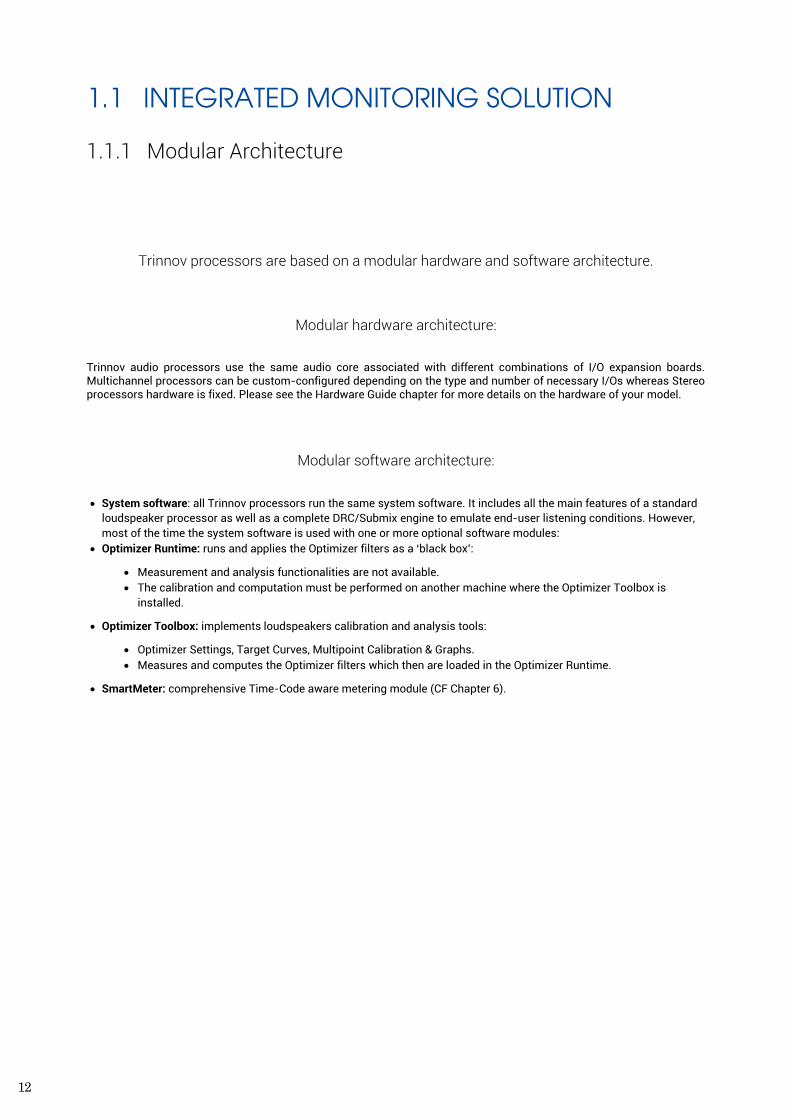
Trinnov processors are based on a modular hardware and software architecture.
Modular hardware architecture:
Trinnov audio processors use the same audio core associated with different combinations of I/O expansion boards. Multichannel processors can be custom-configured depending on the type and number of necessary I/Os whereas Stereo processors hardware is fixed. Please see the Hardware Guide chapter for more details on the hardware of your model.
Modular software architecture:
• System software: all Trinnov processors run the same system software. It includes all the main features of a standard loudspeaker processor as well as a complete DRC/Submix engine to emulate end-user listening conditions. However, most of the time the system software is used with one or more optional software modules:
• Optimizer Runtime: runs and applies the Optimizer filters as a ‘black box’:
• Measurement and analysis functionalities are not available. • The calibration and computation must be performed on another machine where the Optimizer Toolbox is
installed.
• Optimizer Toolbox: implements loudspeakers calibration and analysis tools:
• Optimizer Settings, Target Curves, Multipoint Calibration & Graphs. • Measures and computes the Optimizer filters which then are loaded in the Optimizer Runtime.
• SmartMeter: comprehensive Time-Code aware metering module (CF Chapter 6).
13
REFERENCE MANUAL
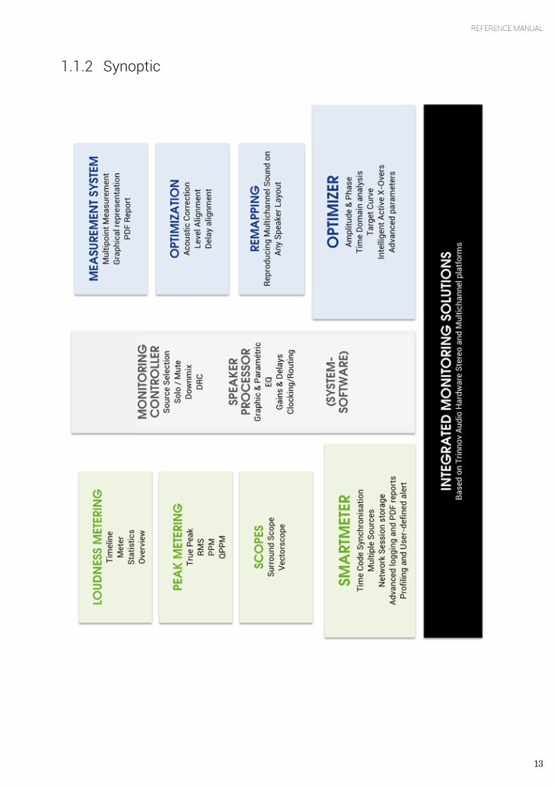
1.1.2 Synoptic
14
1.2 MAIN FEATURES OF THE SYSTEM SOFTWARE The Trinnov processor provides all the basic functionalities expected from a digital audio processor:
• routing and level settings of inputs and outputs (Audio Matrix functionality) • word clock input and output • remote control options via an Ethernet network or via GPIO commands • presets save, backup and restore • basic peak level metering of inputs and outputs • calibrated, global gain/volume adjustments • monitoring controller
This allows to integrate the Trinnov processor into any professional studio environment and to meet the highest standards for sound quality and system flexibility and reliability.
1.2.1 Manual Equalization The processor is very useful in addition to the Optimizer as it offers a comprehensive set of tools to fine-tune the results of the automated correction. This is usually done by using a separate acoustic measurements system to measure the results of the automatic optimization and improve them.
Two different tools are offered:
• State-of-the-art FIR EQ: based on Finite Impulse Response filters, the Optimizer's FIR EQ allows for accurate equalization without introducing additional phase problems.
• 1/3-octave EQ: 31 band Graphic Equalizers are also provided in order to support established methodologies and standards.
1.2.2 Active Crossovers The processor features 2-way, 3-way and 4-way active crossovers. Depending on the chosen audio interface, these crossovers may be used on up to 64 output channels (MADI). This makes Trinnov processors a comprehensive equalization and crossover solution for high-end sound systems.
1.2.3 DRC/Submixes The DRC/Submixes complete the list of features of our integrated monitoring solution for professional applications. These features combined allow for emulating end-viewer listening conditions. It consists of a Dynamic Range Control as well as a flexible downmix system.
15
REFERENCE MANUAL
1.3 MAIN FEATURES OF THE OPTIMIZER MODULE The Optimizer Runtime and the Optimizer Toolbox are complementary. As a whole, we simply call it the Optimizer module. Its main features are as follows.
1.3.1 Level and Time Alignment Based on its own acoustic measurements, the Optimizer automatically aligns the relative levels of each loudspeaker, and applies delays to time-align the system. This can be disabled in the Optimizer Settings/Runtime page, and may be configured separately for the front and surround loudspeakers in the Optimizer Settings/Settings/Advanced Settings page.
The Optimizer also calibrate the absolute level of the system.
1.4 AUTOMATIC OPTIMIZATION The Optimizer uses state-of-the-art time-frequency algorithms to analyse calibration measurements and uses specific methods to compensate for direct sound, first reflections, late reflections/reverberation and room modes. All the subtlety of the Optimizer resides in knowing which defects may be corrected without creating additional problems.
• Improved Phase Response: the Optimizer corrects the frequency response of the speakers, both in amplitude and phase. This means that the Optimizer corrects both the tonal balance to obtain a neutral timbre for every speaker and it also works in the time domain to achieve a high resolution stereophonic image with well-focused phantom sources.
• Target Curves: the Optimizer automatically defines the filters that will achieve the required frequency response defined by a target curve. This is particularly useful in Film Studios in order to comply with the X-Curve SMPTE and ISO standards. Phase and Group Delay targets may also be defined, making the Optimizer a unique tool for sound system designers.
• Fine-tuning options: the Optimizer provides over 12 different parameters, such as maximum boost/attenuation, to customize the behaviour of the room correction algorithms. This opens many possibilities for fine-tuning the sound according to loudspeaker capabilities and listening tests.
1.4.1 Loudspeaker Positions Remapping Thanks to its measurement probe with 4 capsules, the Optimizer determines in 3D the relative position of each loudspeaker. From the Input Format setting, the Optimizer knows the reference loudspeaker positions defined by the standard for the target system, for example ITU 775. The Optimizer computes the remapping matrix that must be applied to the input signal to create the same acoustic field that would be obtained if the speakers were positioned correctly.
For an in-depth description of Trinnov’s remapping technology, please read the AES Paper 6375, Reproducing Multichannel Sound on Any Speaker Layout, available in the download section of our website at http://www.trinnov.com.
1.5 MAIN FEATURES OF THE SMARTMETER MODULE
The SmartMeter is a time code-aware metering system. It includes a set of instruments and features that make it one of the most cost-efficient and innovative solution on the market, saving precious time during mixing when constrained to the new Loudness recommendation in any kind of environment. Synchronizing the measurement to an external time code also allows for unique possibilities such as measurement session recall and real-time alerts system integrated with every instrument.

16
The SmartMeter's comprehensive set of instruments includes:
• Loudness Metering suite (EBU R128):
• Loudness Timeline • Loudness Meter • Loudness Overview • Loudness Statistics
• True Peak Meter (EBU R128) • Quasi-Peak Meter (DIN 45406) • Peak Meter (Sample-peak) • Real-Time Analyzer: 1/3rd octave with source and channel selection • Vectorscope and Surround Analyser
17
REFERENCE MANUAL
2. GETTING STARTED 2.1 POWER ON AND SHUTDOWN
2.1.1 Power on
IMPORTANT NOTE Don’t forget that the speakers/amplifiers should always be powered up last.
Every Trinnov processors have power switches on both back panel and front panel.
The back panel power switch always needs to be pressed first to supply the processor with electricity.
The front power button shall then be used to start the processor. It should illuminate after a few seconds.
NOTE Trinnov 2U chassis have a permanent power switch. Trinnov 4U chassis have a momentary power switch.
The optional 4U chassis with built-in touch screen has a separate power switch, on the left side of the front panel and is labeled ‘PW’. The menu button shows the OSD for LCD screen setup. The reset function can be used to recall factory settings.
2.1.2 Shutdown Shutdown differs depending on your processor model:
• Processors mounted in the Trinnov 2U chassis require pushing the power button only once to initiate normal shut down.
• The 4U processors shut down procedure requires pushing the power button a first time then a second time or selecting the yes option on the graphical interface.
About pops coming off the loudspeakers at power on and shutdown:
• RME analog boards generate pops, therefore, you should switch the monitors on after the Trinnov is powered on. And you should power the monitors off before shutting down the Trinnov.
• The Trinnov analog boards are equipped with relays on the outputs to prevent electrical discharges and protect your speakers. Shutting down the Optimizer does no longer require switching off amplifiers.
NOTE It is not recommended to cut the AC power (back panel), as the system saves several ‘last used’ settings.
18
2.2 USER INTERFACE Trinnov processors open architecture offers a variety of solutions to access the user interface:
• from an external monitor with a keyboard and a mouse, • via an external touch screen (recommended with the SmartMeter), • from a VNC Client running on remote device (laptop, smartphone or tablet) connected through the network to the
Trinnov processor
IMPORTANT NOTE Because of network latency, using VNC is not recommended for metering purpose.
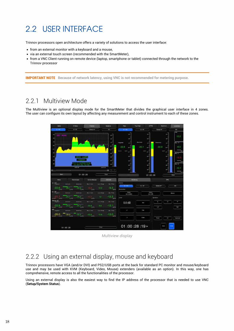
2.2.1 Multiview Mode The Multiview is an optional display mode for the SmartMeter that divides the graphical user interface in 4 zones. The user can configure its own layout by affecting any measurement and control instrument to each of these zones.
Multiview display
2.2.2 Using an external display, mouse and keyboard Trinnov processors have VGA (and/or DVI) and PS2/USB ports at the back for standard PC monitor and mouse/keyboard use and may be used with KVM (Keyboard, Video, Mouse) extenders (available as an option). In this way, one has comprehensive, remote access to all the functionalities of the processor.
Using an external display is also the easiest way to find the IP address of the processor that is needed to use VNC (Setup/System Status).
19
REFERENCE MANUAL
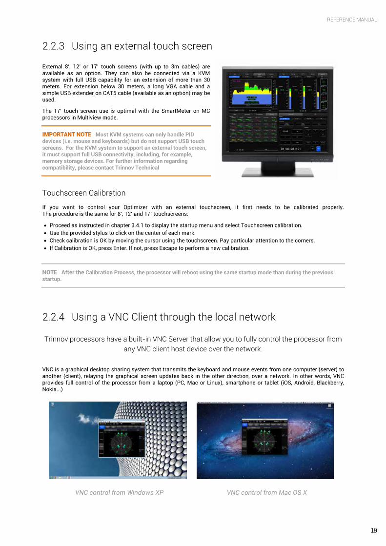
2.2.3 Using an external touch screen External 8’, 12’ or 17’ touch screens (with up to 3m cables) are available as an option. They can also be connected via a KVM system with full USB capability for an extension of more than 30 meters. For extension below 30 meters, a long VGA cable and a simple USB extender on CAT5 cable (available as an option) may be used.
The 17’ touch screen use is optimal with the SmartMeter on MC processors in Multiview mode.
IMPORTANT NOTE Most KVM systems can only handle PID devices (i.e. mouse and keyboards) but do not support USB touch screens. For the KVM system to support an external touch screen, it must support full USB connectivity, including, for example, memory storage devices. For further information regarding compatibility, please contact Trinnov Technical
Touchscreen Calibration
If you want to control your Optimizer with an external touchscreen, it first needs to be calibrated properly. The procedure is the same for 8’, 12’ and 17’ touchscreens:
• Proceed as instructed in chapter 3.4.1 to display the startup menu and select Touchscreen calibration. • Use the provided stylus to click on the center of each mark. • Check calibration is OK by moving the cursor using the touchscreen. Pay particular attention to the corners. • If Calibration is OK, press Enter. If not, press Escape to perform a new calibration.
NOTE After the Calibration Process, the processor will reboot using the same startup mode than during the previous startup.
2.2.4 Using a VNC Client through the local network
Trinnov processors have a built-in VNC Server that allow you to fully control the processor from any VNC client host device over the network.
VNC is a graphical desktop sharing system that transmits the keyboard and mouse events from one computer (server) to another (client), relaying the graphical screen updates back in the other direction, over a network. In other words, VNC provides full control of the processor from a laptop (PC, Mac or Linux), smartphone or tablet (iOS, Android, Blackberry, Nokia...)
VNC control from Windows XP VNC control from Mac OS X
20
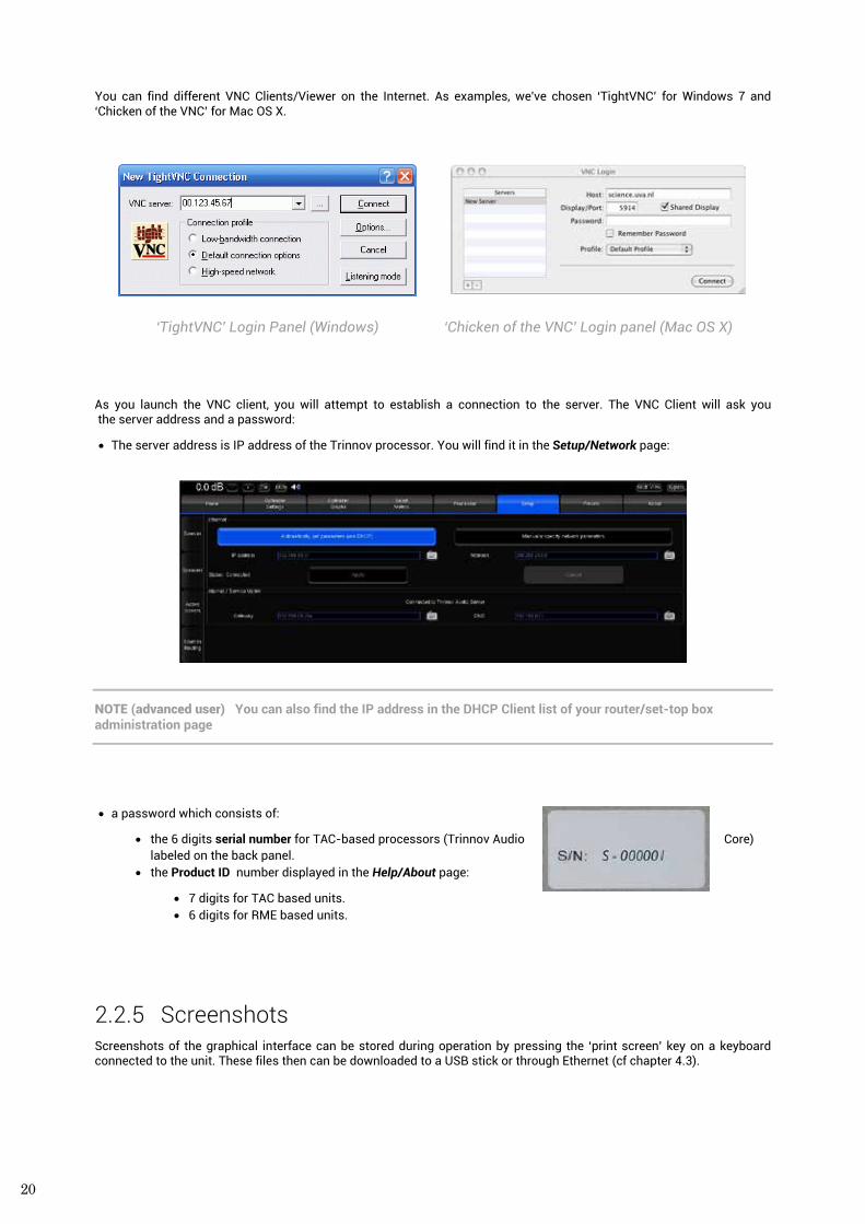
You can find different VNC Clients/Viewer on the Internet. As examples, we've chosen ‘TightVNC’ for Windows 7 and ‘Chicken of the VNC’ for Mac OS X.
‘TightVNC’ Login Panel (Windows) ‘Chicken of the VNC’ Login panel (Mac OS X)
As you launch the VNC client, you will attempt to establish a connection to the server. The VNC Client will ask you the server address and a password:
• The server address is IP address of the Trinnov processor. You will find it in the Setup/Network page:
NOTE (advanced user) You can also find the IP address in the DHCP Client list of your router/set-top box administration page
• a password which consists of:
• the 6 digits serial number for TAC-based processors (Trinnov Audio Core) labeled on the back panel.
• the Product ID number displayed in the Help/About page:
• 7 digits for TAC based units. • 6 digits for RME based units.
2.2.5 Screenshots Screenshots of the graphical interface can be stored during operation by pressing the ‘print screen’ key on a keyboard connected to the unit. These files then can be downloaded to a USB stick or through Ethernet (cf chapter 4.3).
21
REFERENCE MANUAL
2.3 OPTIMIZER - CALIBRATION PROCEDURE
2.3.1 Calibration settings The following parameters must be configured correctly before calibration:
• Hardware (Home/Profiles Config for MC processors only) and Software source routing (Setup/Sources Routing) based on the connection of the microphone;
• Number of Speakers/Subwoofers of the reproduction system (Setup/Speakers Settings); • Speaker routing according to the output connections (Setup/Speakers Routing); • Clock mode set to Master 48 kHz (Setup/Clock Settings).
2.3.2 Important recommendation for microphone placement At least a few basic environment rules should be respected to ensure a robust measurement:
• No obstacle between the speaker and the microphone; • No highly reflecting surface (leather sofa, glass table…) close to the microphone; • No background noise during the measurements (Air conditioning, open doors, windows etc…); • No movement during the calibration (disturbs speaker localisation).
Trinnov processors supports single-point and multi-point calibrations. In both scenarios, a reference measurement position should be chosen carefully since it will be used by the Optimizer for:
• Cross-over drivers alignment; • Loudspeaker 3D localization; • Loudspeaker 2D/3D remapping; • Loudspeaker relative delay/level alignment; • Master delay/level calculation.
The calibration microphone should be placed at the listening position, using the listener’s ears as a reference for its height. A red led shows the front of the microphone. The red led must be pointed to the front of the sound stage, towards the center speaker.
During the calibration process the microphone should be screwed on a microphone or camera stand.
2.3.3 Calibration
IMPORTANT NOTE Active Crossovers need to be calibrated prior to the main calibration. Please refer to chapter 4.2.3.
The Optimizer requires a minimum Sound Pressure Level for proper calibration. Until that minimum SPL is reached, the test signal will keep playing through the same speaker. For safety matters, we recommend to perform that first calibration as if it were a test. Start with a Master Level of -40 dB and increase it until the test signal pass on the second speaker, meaning you reached that minimum SPL. If not too loud for your system you can even increase that level to get a better quality measurement.
22
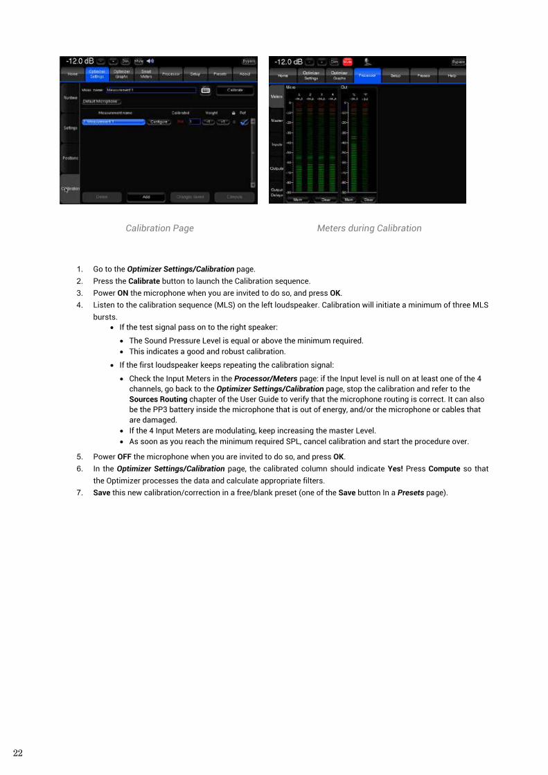
Calibration Page Meters during Calibration
1. Go to the Optimizer Settings/Calibration page. 2. Press the Calibrate button to launch the Calibration sequence. 3. Power ON the microphone when you are invited to do so, and press OK. 4. Listen to the calibration sequence (MLS) on the left loudspeaker. Calibration will initiate a minimum of three MLS
bursts. • If the test signal pass on to the right speaker:
• The Sound Pressure Level is equal or above the minimum required. • This indicates a good and robust calibration.
• If the first loudspeaker keeps repeating the calibration signal:
• Check the Input Meters in the Processor/Meters page: if the Input level is null on at least one of the 4 channels, go back to the Optimizer Settings/Calibration page, stop the calibration and refer to the Sources Routing chapter of the User Guide to verify that the microphone routing is correct. It can also be the PP3 battery inside the microphone that is out of energy, and/or the microphone or cables that are damaged.
• If the 4 Input Meters are modulating, keep increasing the master Level. • As soon as you reach the minimum required SPL, cancel calibration and start the procedure over.
5. Power OFF the microphone when you are invited to do so, and press OK. 6. In the Optimizer Settings/Calibration page, the calibrated column should indicate Yes! Press Compute so that
the Optimizer processes the data and calculate appropriate filters. 7. Save this new calibration/correction in a free/blank preset (one of the Save button In a Presets page).
23
REFERENCE MANUAL
2.4 SMARTMETER - SOURCES SETUP In order to apprehend the SmartMeter correctly, the following example describes the software configuration of two 5.1 sources and a stereo source sent to the AES inputs of a MC processor.
2.4.1 Hardware source selection Trinnov MC processors consist of two distinct level of audio routing:
• The Hardware routing is handled by the core audio and route audio signals from the physical inputs to the processing section. Up to 24 simultaneous physical inputs can be selected amongst a maximum of 32 physical available inputs.
• The Software routing is done through a routing matrix and is used to organize and route channels available at the inputs and to affect them to the physical outputs.
IMPORTANT NOTE In the following cases, the hardware routing and the dedicated pages do not exist:
- ST2 Pros do not require hardware source selection since the Trinnov audio core can handle every physical input simultaneously.
- MADI processors use RME interface, which transport every physical input to the processing section.
The Hardware source selection and configuration is done through the Profiles in the Home Page.
In our example, we want to select the AES inputs 1 to 16:
• In the Home/Profiles Config page, the different profiles are represented as vertical tabs and the Input Connector setting indicated the hardware inputs selected for the profile. The default input connector of the DIG I/O profile is DIG 1-16
• Hardware source selection is done by pressing the DIG I/O button in the Home/Select page
For further information, please refer to chapter 4.1.
2.4.2 Sources configuration and software routing Each source is measured independently. Instruments can be activated independently.
Software sources configuration is a two-step process:
1. Declare the number of source and their respective format. For each source, the channel order can be modified if necessary (Setup/Sources).
2. Routing physical inputs to software channels in the source routing matrix (Setup/Sources Routing).
Standard formats from mono to 7.1 and specific formats up to 24 channels are supported
24
2.4.2.1 Sources configuration
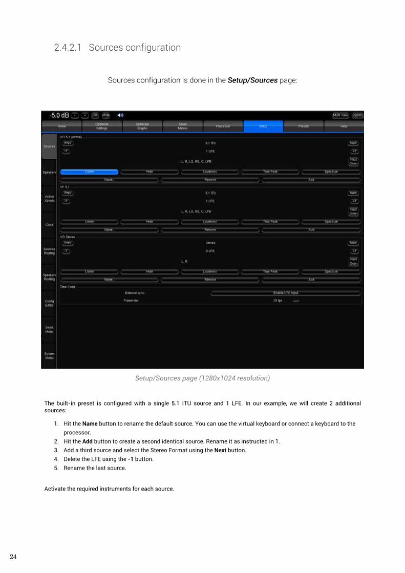
Sources configuration is done in the Setup/Sources page:
Setup/Sources page (1280x1024 resolution)
The built-in preset is configured with a single 5.1 ITU source and 1 LFE. In our example, we will create 2 additional sources:
1. Hit the Name button to rename the default source. You can use the virtual keyboard or connect a keyboard to the processor.
2. Hit the Add button to create a second identical source. Rename it as instructed in 1. 3. Add a third source and select the Stereo Format using the Next button. 4. Delete the LFE using the -1 button. 5. Rename the last source.
Activate the required instruments for each source.
25
REFERENCE MANUAL
2.4.2.2 Sources routing
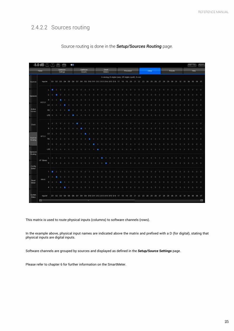
Source routing is done in the Setup/Sources Routing page.
This matrix is used to route physical inputs (columns) to software channels (rows).
In the example above, physical input names are indicated above the matrix and prefixed with a D (for digital), stating that physical inputs are digital inputs.
Software channels are grouped by sources and displayed as defined in the Setup/Source Settings page.
Please refer to chapter 6 for further information on the SmartMeter.
26
3. HARDWARE
A wide range of hardware options makes the Optimizer easy to integrate in your studio’s environment. The Hardware guide provides a description and technical specifications of each
processor.
3.1 AUDIO INTERFACES & CHASSIS
Trinnov processors currently use different types of audio.
• Trinnov ST2-Pro and MC second generation of processors are equipped with the new, high performance, Trinnov audio boards:
• The Trinnov Audio Core (TAC) is the central audio component inside the processor. It provides routing of the audio between the physical inputs/outputs and the software, activation of the relays when instructed by the user allowing safe shut-down, hardware source selection and clocking up to 192 kHz when available.
• The Trinnov ADA4 is connected to the TAC, executes AD/DA conversions and offers 4 inputs and outputs analog channels.
• The Trinnov AES4 is connected to the TAC and can manage up to 4 digital inputs and outputs. • The Trinnov AES8 is connected to the TAC and allows the connection of up to 24 digital inputs and 8 digital
outputs. However, it can only manage 8 digital inputs and outputs simultaneously. The 8 digital inputs will be chosen via a profile, amongst groups of inputs 1-8, 9-16 or 17-24.
• The Trinnov GPIO 8I4O provides 8 AON (All or Nothing) inputs and 4 outputs. As an example: remote profile selection.
• Trinnov MC first generation use AES, ADAT or MADI RME HDSP audio boards.
NOTE The type of audio interface is indicated in the Help page.
3.1.1 2U and 4U Chassis
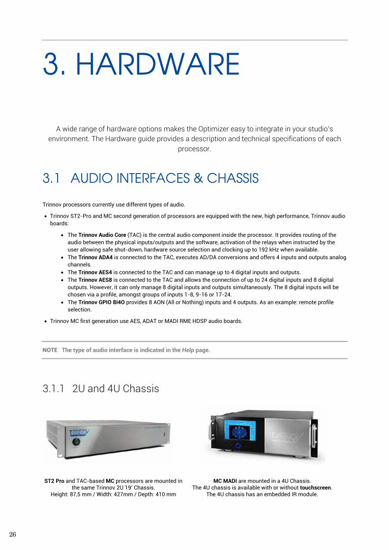
ST2 Pro and TAC-based MC processors are mounted in the same Trinnov 2U 19’ Chassis.
Height: 87,5 mm / Width: 427mm / Depth: 410 mm
MC MADI are mounted in a 4U Chassis. The 4U chassis is available with or without touchscreen.
The 4U chassis has an embedded IR module.
27
REFERENCE MANUAL
3.1.2 Audio interfaces in each Trinnov processor TRINNOV PROCESSORS AUDIO INTERFACE DESCRIPTION
ST2 PRO Trinnov Audio Core + Trinnov ADA4 + Trinnov AES4
4 channels with analog and digital (AES) I/O via XLR connectors.
MC PROCESSOR One or two Trinnov Audio Core + up to 4 ADA4 + up to 2 AES8
Up to 16 analog i/o channels through SUB D25 or XLR for the first set of 8 outputs.
Up to 24 digital inputs and 16 outputs channels through SUB D25. 16 simultaneous I/O maximum.
OPTIMIZER MADI RME HDSP MADI Up to 64 channels with MADI I/O via MADI optical or MADI coaxial (BNC)
3.2 ST2 PRO
3.2.1 Technical Description The ST2 Pro comes with an Optimizer Bundle 4, which is a 4 Channels Licence for Optimizer Runtime and Toolbox. The ST2 Pro can also be upgraded with the SmartMeter module and is eligible to the GPIO 8I4O option.
The ST2 Pro achieve the following audio performance:
• A/D signal-to-noise ratio: 119 dB (A-Weighted) • D/A signal-to-noise ratio: 118 dB (A-Weighted) • 24 bits/96kkHz A/D conversion and processing • 24 bits/192kHz D/A conversion and processing • Clock Recovery: jitter attenuation better than 50dB
above 100Hz
Based on a Intel Atom 510 (Multithread - 64 bit floating point), ST2 processors have a powerful CPU and are very silent thanks to efficient heat-sinks and one big, slow fan. It uses flash disk technology, removing the need for a mechanical hard drive, and ensuring mechanical robustness.
NOTE Please refer to chapter 8.3 for information about sampling rate and latency
3.2.2 Front Panel
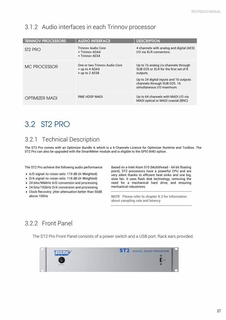
The ST2 Pro Front Panel consists of a power switch and a USB port. Rack ears provided.
28
3.2.3 Rear Panel
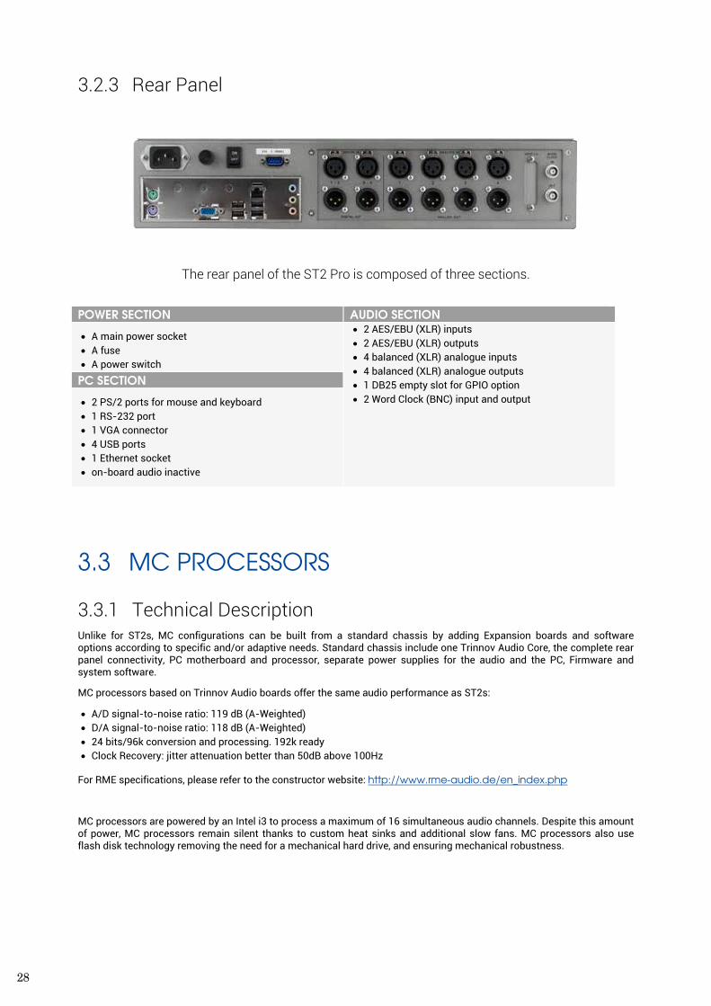
The rear panel of the ST2 Pro is composed of three sections.
POWER SECTION AUDIO SECTION
• A main power socket • A fuse • A power switch
• 2 AES/EBU (XLR) inputs • 2 AES/EBU (XLR) outputs • 4 balanced (XLR) analogue inputs • 4 balanced (XLR) analogue outputs • 1 DB25 empty slot for GPIO option • 2 Word Clock (BNC) input and output
PC SECTION
• 2 PS/2 ports for mouse and keyboard • 1 RS-232 port • 1 VGA connector • 4 USB ports • 1 Ethernet socket • on-board audio inactive
3.3 MC PROCESSORS
3.3.1 Technical Description Unlike for ST2s, MC configurations can be built from a standard chassis by adding Expansion boards and software options according to specific and/or adaptive needs. Standard chassis include one Trinnov Audio Core, the complete rear panel connectivity, PC motherboard and processor, separate power supplies for the audio and the PC, Firmware and system software.
MC processors based on Trinnov Audio boards offer the same audio performance as ST2s:
• A/D signal-to-noise ratio: 119 dB (A-Weighted) • D/A signal-to-noise ratio: 118 dB (A-Weighted) • 24 bits/96k conversion and processing. 192k ready • Clock Recovery: jitter attenuation better than 50dB above 100Hz
For RME specifications, please refer to the constructor website: http://www.rme-audio.de/en_index.php
MC processors are powered by an Intel i3 to process a maximum of 16 simultaneous audio channels. Despite this amount of power, MC processors remain silent thanks to custom heat sinks and additional slow fans. MC processors also use flash disk technology removing the need for a mechanical hard drive, and ensuring mechanical robustness.
29
REFERENCE MANUAL
3.3.2 TAC-based MC processors
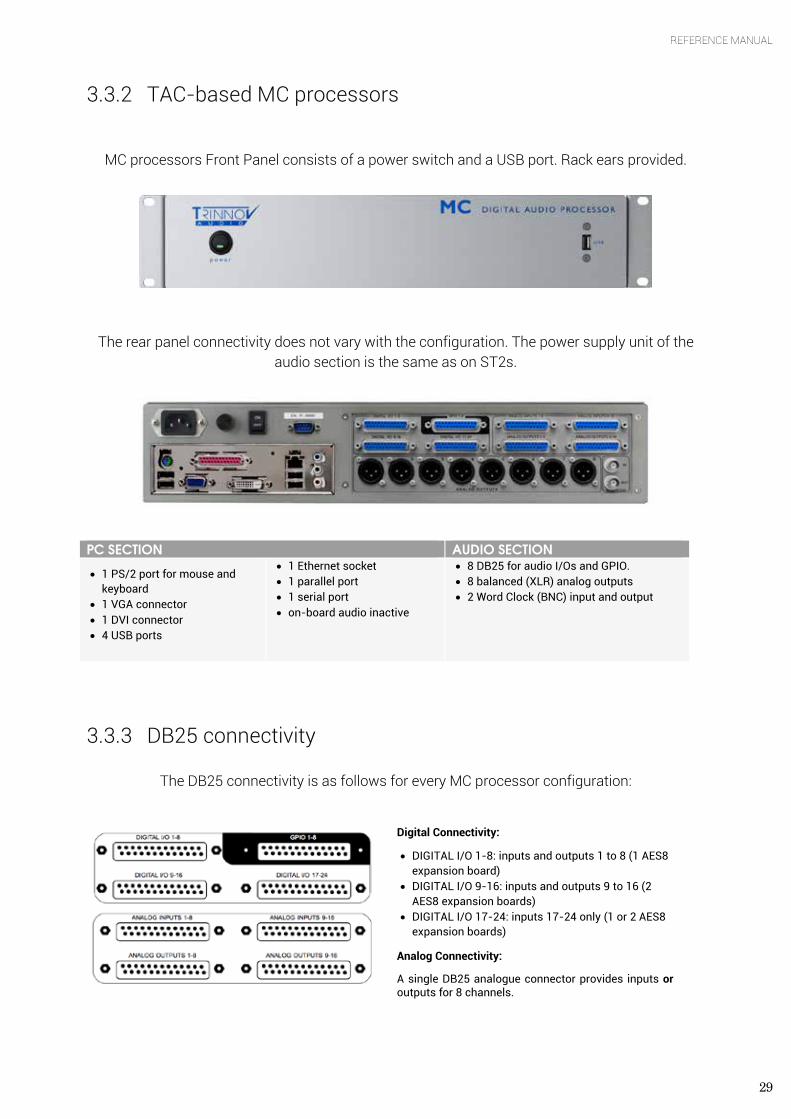
MC processors Front Panel consists of a power switch and a USB port. Rack ears provided.
The rear panel connectivity does not vary with the configuration. The power supply unit of the
audio section is the same as on ST2s.
PC SECTION AUDIO SECTION
• 1 PS/2 port for mouse and keyboard
• 1 VGA connector • 1 DVI connector • 4 USB ports
• 1 Ethernet socket • 1 parallel port • 1 serial port • on-board audio inactive
• 8 DB25 for audio I/Os and GPIO. • 8 balanced (XLR) analog outputs • 2 Word Clock (BNC) input and output
3.3.3 DB25 connectivity
The DB25 connectivity is as follows for every MC processor configuration:
Digital Connectivity:
• DIGITAL I/O 1-8: inputs and outputs 1 to 8 (1 AES8 expansion board)
• DIGITAL I/O 9-16: inputs and outputs 9 to 16 (2 AES8 expansion boards)
• DIGITAL I/O 17-24: inputs 17-24 only (1 or 2 AES8 expansion boards)
Analog Connectivity:
A single DB25 analogue connector provides inputs or outputs for 8 channels.
30
However, only the combination of expansion boards mounted in the processor will determine which SUB D25 are connected.
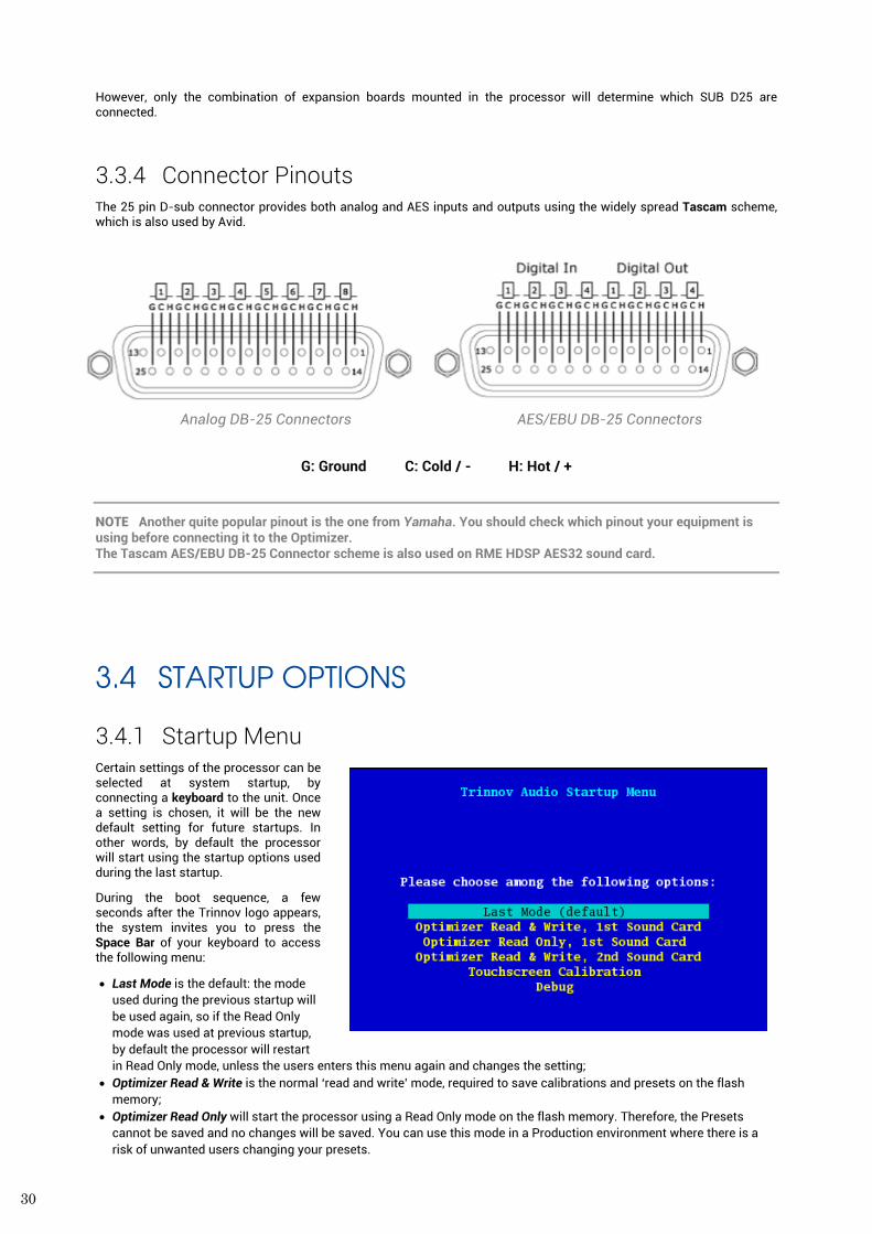
3.3.4 Connector Pinouts The 25 pin D-sub connector provides both analog and AES inputs and outputs using the widely spread Tascam scheme, which is also used by Avid.
Analog DB-25 Connectors AES/EBU DB-25 Connectors
G: Ground C: Cold / - H: Hot / +
NOTE Another quite popular pinout is the one from Yamaha. You should check which pinout your equipment is using before connecting it to the Optimizer. The Tascam AES/EBU DB-25 Connector scheme is also used on RME HDSP AES32 sound card.
3.4 STARTUP OPTIONS
3.4.1 Startup Menu Certain settings of the processor can be selected at system startup, by connecting a keyboard to the unit. Once a setting is chosen, it will be the new default setting for future startups. In other words, by default the processor will start using the startup options used during the last startup.
During the boot sequence, a few seconds after the Trinnov logo appears, the system invites you to press the Space Bar of your keyboard to access the following menu:
• Last Mode is the default: the mode used during the previous startup will be used again, so if the Read Only mode was used at previous startup, by default the processor will restart in Read Only mode, unless the users enters this menu again and changes the setting;
• Optimizer Read & Write is the normal ‘read and write’ mode, required to save calibrations and presets on the flash memory;
• Optimizer Read Only will start the processor using a Read Only mode on the flash memory. Therefore, the Presets cannot be saved and no changes will be saved. You can use this mode in a Production environment where there is a risk of unwanted users changing your presets.
31
REFERENCE MANUAL
• If an additional audio interface is installed on the second PCI slot, the Optimizer Read & Write, 2nd Sound Card will start up the processor using that additional RME audio interface. Please note that both audio interfaces cannot be used at the same time, so the choice has to be made at startup.
• Touchscreen Calibration starts the touchscreen calibration process. Details on chapter 2.2.3. • Debug is for Trinnov use only for support debugging purposes.
3.4.2 Startup Modes
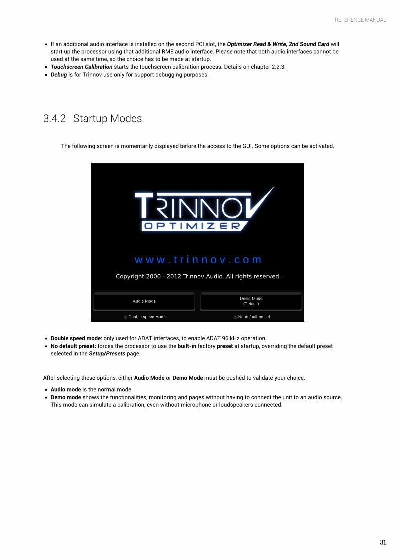
The following screen is momentarily displayed before the access to the GUI. Some options can be activated.
• Double speed mode: only used for ADAT interfaces, to enable ADAT 96 kHz operation. • No default preset: forces the processor to use the built-in factory preset at startup, overriding the default preset
selected in the Setup/Presets page.
After selecting these options, either Audio Mode or Demo Mode must be pushed to validate your choice.
• Audio mode is the normal mode • Demo mode shows the functionalities, monitoring and pages without having to connect the unit to an audio source.
This mode can simulate a calibration, even without microphone or loudspeakers connected.
32
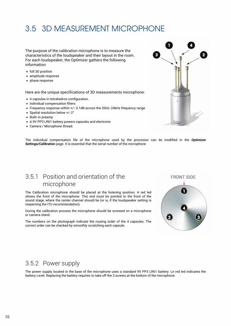
3.5 3D MEASUREMENT MICROPHONE The purpose of the calibration microphone is to measure the characteristics of the loudspeaker and their layout in the room. For each loudspeaker, the Optimizer gathers the following information:
• full 3D position • amplitude response • phase response
Here are the unique specifications of 3D measurements microphone:
• 4 capsules in tetrahedron configuration. • Individual compensation filters • Frequency response within +/- 0.1dB across the 20Hz-24kHz frequency range • Spatial resolution below +/-2° • Built-in preamp • A 9V PP3 LR61 battery powers capsules and electronic • Camera / Microphone thread.
The individual compensation file of the microphone used by the processor can be modified in the Optimizer Settings/Calibration page. It is essential that the serial number of the microphone
3.5.1 Position and orientation of the microphone
The Calibration microphone should be placed at the listening position. A red led shows the front of the microphone. This end must be pointed to the front of the sound stage, where the center channel should be (or is, if the loudspeaker setting is respecting the ITU recommendation).
During the calibration process the microphone should be screwed on a microphone or camera stand.
The numbers on the photograph indicate the routing order of the 4 capsules. The correct order can be checked by smoothly scratching each capsule.
3.5.2 Power supply The power supply located in the base of the microphone uses a standard 9V PP3 LR61 battery. Le red led indicates the battery Level. Replacing the battery requires to take off the 3 screws at the bottom of the microphone.
33
REFERENCE MANUAL
3.6 IR MODULE & GPIO
Remote control of profiles, by two different means:
• optional GPIO card, by programming a button on the mixing desk to send a GPI command, • IR Remote Control, available on the models based on the 4U chassis and as an option on 2U chassis. It also controls
volume, dim, mute and runtime modes;
Profiles switch via GPIO
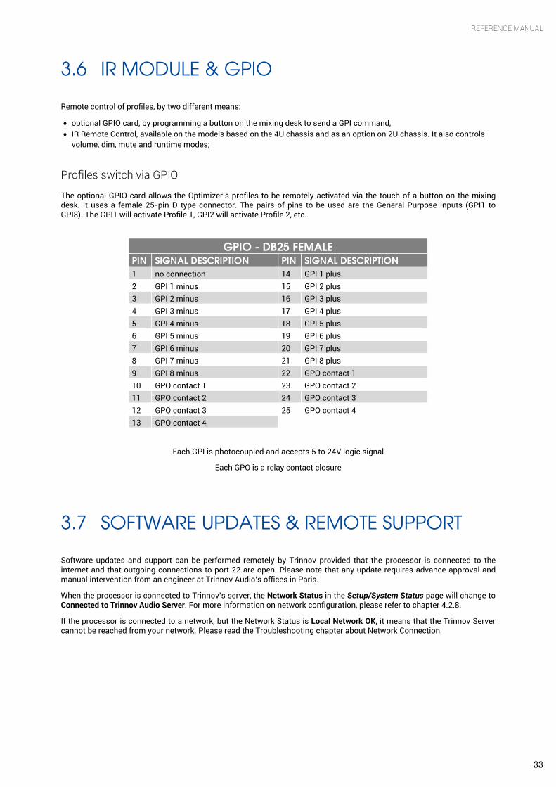
The optional GPIO card allows the Optimizer’s profiles to be remotely activated via the touch of a button on the mixing desk. It uses a female 25-pin D type connector. The pairs of pins to be used are the General Purpose Inputs (GPI1 to GPI8). The GPI1 will activate Profile 1, GPI2 will activate Profile 2, etc…
GPIO - DB25 FEMALE
PIN SIGNAL DESCRIPTION PIN SIGNAL DESCRIPTION 1 no connection 14 GPI 1 plus 2 GPI 1 minus 15 GPI 2 plus 3 GPI 2 minus 16 GPI 3 plus 4 GPI 3 minus 17 GPI 4 plus 5 GPI 4 minus 18 GPI 5 plus 6 GPI 5 minus 19 GPI 6 plus 7 GPI 6 minus 20 GPI 7 plus 8 GPI 7 minus 21 GPI 8 plus 9 GPI 8 minus 22 GPO contact 1 10 GPO contact 1 23 GPO contact 2 11 GPO contact 2 24 GPO contact 3 12 GPO contact 3 25 GPO contact 4 13 GPO contact 4
Each GPI is photocoupled and accepts 5 to 24V logic signal
Each GPO is a relay contact closure
3.7 SOFTWARE UPDATES & REMOTE SUPPORT
Software updates and support can be performed remotely by Trinnov provided that the processor is connected to the internet and that outgoing connections to port 22 are open. Please note that any update requires advance approval and manual intervention from an engineer at Trinnov Audio’s offices in Paris.
When the processor is connected to Trinnov’s server, the Network Status in the Setup/System Status page will change to Connected to Trinnov Audio Server. For more information on network configuration, please refer to chapter 4.2.8.
If the processor is connected to a network, but the Network Status is Local Network OK, it means that the Trinnov Server cannot be reached from your network. Please read the Troubleshooting chapter about Network Connection.
34
4. SYSTEM SOFTWARE GUIDE
4.1 HOMEPAGE
The Home Page of the processor is displayed at start-up.
4.1.1 Monitoring Control
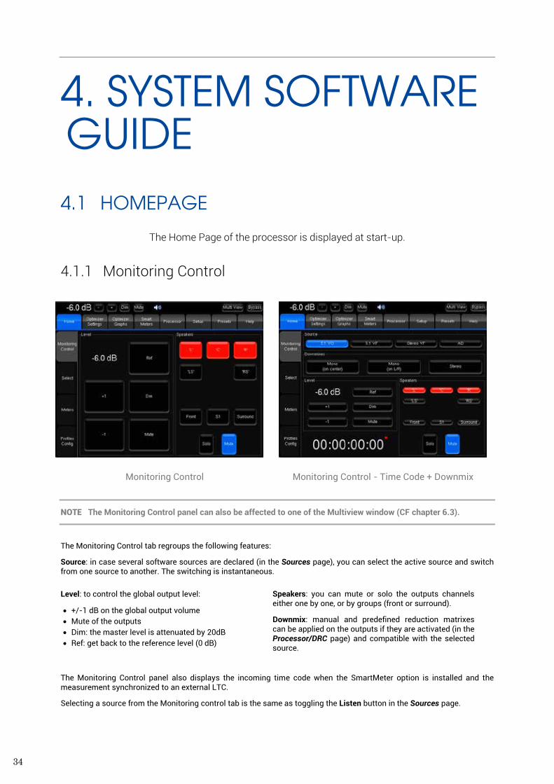
Monitoring Control Monitoring Control - Time Code + Downmix
NOTE The Monitoring Control panel can also be affected to one of the Multiview window (CF chapter 6.3).
The Monitoring Control tab regroups the following features:
Source: in case several software sources are declared (in the Sources page), you can select the active source and switch from one source to another. The switching is instantaneous.
Level: to control the global output level:
• +/-1 dB on the global output volume • Mute of the outputs • Dim: the master level is attenuated by 20dB • Ref: get back to the reference level (0 dB)
Speakers: you can mute or solo the outputs channels either one by one, or by groups (front or surround).
Downmix: manual and predefined reduction matrixes can be applied on the outputs if they are activated (in the Processor/DRC page) and compatible with the selected source.
The Monitoring Control panel also displays the incoming time code when the SmartMeter option is installed and the measurement synchronized to an external LTC.
Selecting a source from the Monitoring control tab is the same as toggling the Listen button in the Sources page.
35
REFERENCE MANUAL
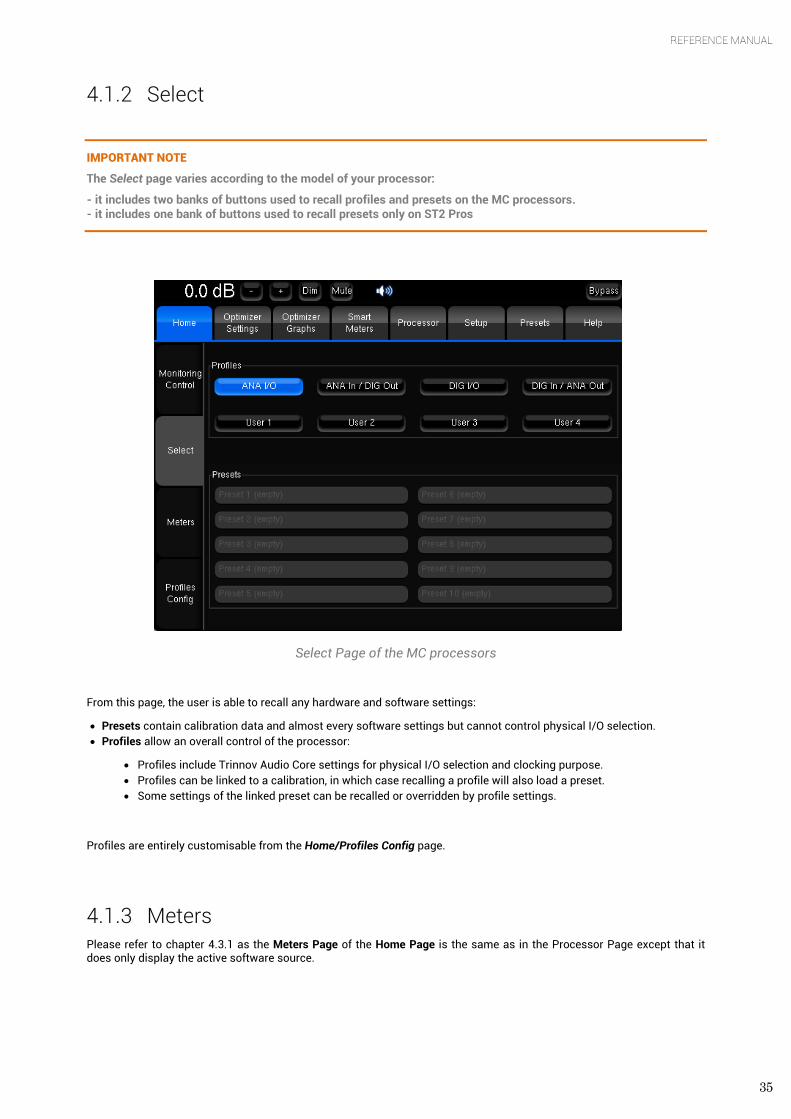
4.1.2 Select
IMPORTANT NOTE
The Select page varies according to the model of your processor:
- it includes two banks of buttons used to recall profiles and presets on the MC processors. - it includes one bank of buttons used to recall presets only on ST2 Pros
Select Page of the MC processors
From this page, the user is able to recall any hardware and software settings:
• Presets contain calibration data and almost every software settings but cannot control physical I/O selection. • Profiles allow an overall control of the processor:
• Profiles include Trinnov Audio Core settings for physical I/O selection and clocking purpose. • Profiles can be linked to a calibration, in which case recalling a profile will also load a preset. • Some settings of the linked preset can be recalled or overridden by profile settings.
Profiles are entirely customisable from the Home/Profiles Config page.
4.1.3 Meters Please refer to chapter 4.3.1 as the Meters Page of the Home Page is the same as in the Processor Page except that it does only display the active software source.
36
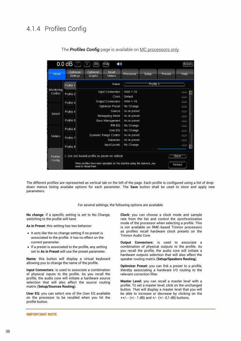
4.1.4 Profiles Config
The Profiles Config page is available on MC processors only.
The different profiles are represented as vertical tab on the left of the page. Each profile is configured using a list of drop-down menus listing availabe options for each parameter. The Save button shall be used to store and apply new parameters.
For several settings, the following options are available:
No change: if a specific setting is set to No Change, switching to the profile will have
As in Preset: this setting has two behavior:
• It acts like the no change setting if no preset is associated to the profile: it has no effect on the current parameter.
• If a preset is associated to the profile, any setting set to As in Preset will use the preset parameter.
Name: this button will display a virtual keyboard allowing you to change the name of the profile.
Input Connectors: is used to associate a combination of physical inputs to the profile. As you recall the profile, the audio core will initiate a hardware source selection that will also affect the source routing matrix (Setup/Sources Routing).
User EQ: you can select one of the User EQ available on the processor to be recalled when you hit the profile button.
Clock: you can choose a clock mode and sample rate from the list and control the synchronization mode of the processor when selecting a profile. This is not available on RME-based Trinnov processors as profiles recall hardware clock presets on the Trinnov Audio Core.
Output Connectors: is used to associate a combination of physical outputs to the profile. As you recall the profile, the audio core will initiate a hardware outputs selection that will also affect the speaker routing matrix (Setup/Speakers Routing).
Optimizer Preset: you can link a preset to a profile, thereby associating a hardware I/O routing to the relevant correction filter.
Master Level: you can recall a master level with a profile. To set a master level, click on the unchanged button. That will display a master level that you will be able to increase or decrease by clicking on the ++/-- (+/- 1 dB) and +/- (+/- 0,1 dB) buttons.
IMPORTANT NOTE
37
REFERENCE MANUAL
The following settings interact with the preset associated to the profile.
The list of available options for the Source, Bass Management and Submixes.
Source: you can select one of the software source of the preset associated to the profile. If no preset is associated, the only available option will be As in preset.
Remapping mode: you can associate a remapping mode to a profile, force it over the current settings or use the remapping mode of the linked preset.
Bass Management: you can switch off the Bass Management or use the config editor over the current settings. You can also select one of the Bass Management option from a specific preset when linked to the profile.
FIR EQ: you can select a FIR EQ file or use the FIR EQ of a specific preset when associated to the profile.
Submixes: you can recall and activate any preconfigured and manually edited submix matrix, use the submixes settings of the associated Optimizer preset or activate none of the available submixes.
Dynamic Range Control: you can turn DRC on/off, select a DRC Mode or use the DRC settings of the associated Optimizer preset.
Input Levels: you can select an input control file or use the input levels of a specific preset when associated to the profile.
Output Delays: you can choose whether you want to user the Output Delays of the associated Optimizer preset or not by selecting As in Preset or Inhibit.
As for presets, you can choose to start the processor with the profile of your choice by selecting the profile tab and clicking on the Power-on Default button, which is the last element of the parameters list. You can also decide to Use last loaded profile as power-on default. This option is displayed at the left of the ‘Save button’ at the bottom of the screen.
IMPORTANT NOTE
You need to press the ‘Save’ button to apply changes.
The ‘Reload’ button cancel changes made before saving.
NOTE
For MC processors, input and output connectors lists do not take the mounted card into consideration.
If a preset is set as default but the default profile is linked to another preset, the preset associated to the profile will be prior and thereby loaded at start-up.
MC MADI processors use RME HDSP sound card and do not offer input and output connector settings in the Profiles Config Page.
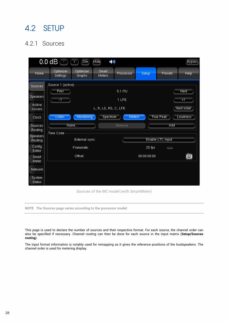
38
4.2 SETUP
4.2.1 Sources
Sources of the MC model (with SmartMeter)
NOTE The Sources page varies according to the processor model.
This page is used to declare the number of sources and their respective format. For each source, the channel order can also be specified if necessary. Channel routing can then be done for each source in the input matrix (Setup/Sources routing).
The input format information is notably used for remapping as it gives the reference positions of the loudspeakers. The channel order is used for metering display.
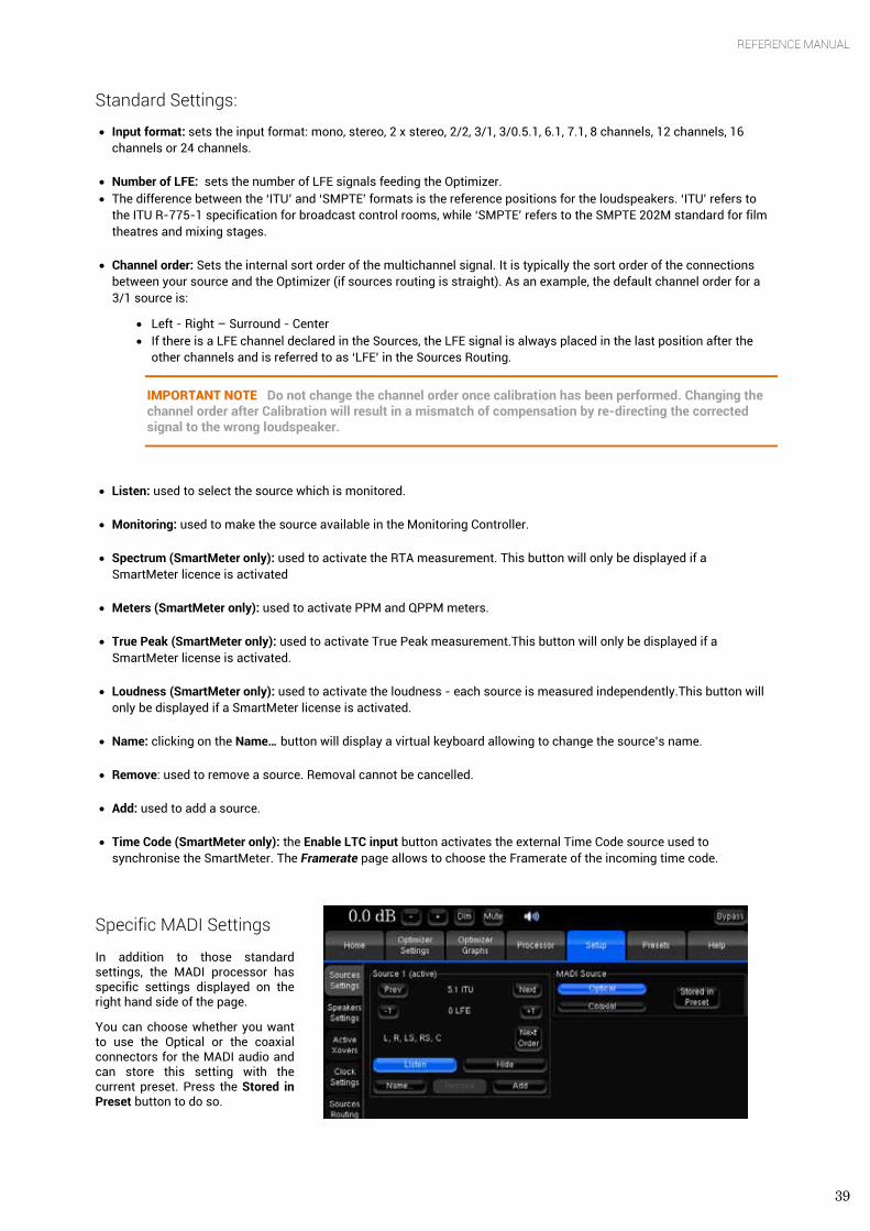
39
REFERENCE MANUAL
Standard Settings:
• Input format: sets the input format: mono, stereo, 2 x stereo, 2/2, 3/1, 3/0.5.1, 6.1, 7.1, 8 channels, 12 channels, 16 channels or 24 channels.
• Number of LFE: sets the number of LFE signals feeding the Optimizer. • The difference between the ‘ITU’ and ‘SMPTE’ formats is the reference positions for the loudspeakers. ‘ITU’ refers to
the ITU R-775-1 specification for broadcast control rooms, while ‘SMPTE’ refers to the SMPTE 202M standard for film theatres and mixing stages.
• Channel order: Sets the internal sort order of the multichannel signal. It is typically the sort order of the connections between your source and the Optimizer (if sources routing is straight). As an example, the default channel order for a 3/1 source is:
• Left - Right – Surround - Center • If there is a LFE channel declared in the Sources, the LFE signal is always placed in the last position after the
other channels and is referred to as ‘LFE’ in the Sources Routing.
IMPORTANT NOTE Do not change the channel order once calibration has been performed. Changing the channel order after Calibration will result in a mismatch of compensation by re-directing the corrected signal to the wrong loudspeaker.
• Listen: used to select the source which is monitored.
• Monitoring: used to make the source available in the Monitoring Controller.
• Spectrum (SmartMeter only): used to activate the RTA measurement. This button will only be displayed if a SmartMeter licence is activated
• Meters (SmartMeter only): used to activate PPM and QPPM meters.
• True Peak (SmartMeter only): used to activate True Peak measurement.This button will only be displayed if a SmartMeter license is activated.
• Loudness (SmartMeter only): used to activate the loudness - each source is measured independently.This button will only be displayed if a SmartMeter license is activated.
• Name: clicking on the Name… button will display a virtual keyboard allowing to change the source’s name.
• Remove: used to remove a source. Removal cannot be cancelled.
• Add: used to add a source.
• Time Code (SmartMeter only): the Enable LTC input button activates the external Time Code source used to synchronise the SmartMeter. The Framerate page allows to choose the Framerate of the incoming time code.
Specific MADI Settings
In addition to those standard settings, the MADI processor has specific settings displayed on the right hand side of the page.
You can choose whether you want to use the Optical or the coaxial connectors for the MADI audio and can store this setting with the current preset. Press the Stored in Preset button to do so.
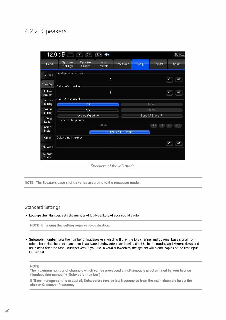
40
4.2.2 Speakers
Speakers of the MC model
NOTE The Speakers page slightly varies according to the processor model.
Standard Settings:
• Loudspeaker Number: sets the number of loudspeakers of your sound system.
NOTE Changing this setting requires re-calibration.
• Subwoofer number: sets the number of loudspeakers which will play the LFE channel and optional bass signal from
other channels if bass management is activated. Subwoofers are labeled S1, S2… in the routing and Meters views and are placed after the other loudspeakers. If you use several subwoofers, the system will create copies of the first input LFE signal.
NOTE The maximum number of channels which can be processed simultaneously is determined by your license (‘loudspeaker number’ + ‘Subwoofer number’).
If ‘Bass management’ is activated, Subwoofers receive low frequencies from the main channels below the chosen Crossover Frequency.
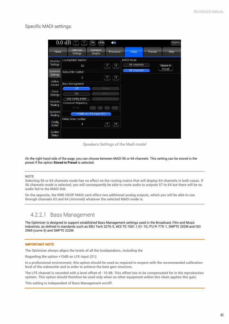
41
REFERENCE MANUAL
Specific MADI settings:
Speakers Settings of the Madi model
On the right hand side of the page, you can choose between MADI 56 or 64 channels. This setting can be stored in the preset if the option Stored in Preset is selected.
NOTE Selecting 56 or 64 channels mode has no effect on the routing matrix that will display 64 channels in both cases. If 56 channels mode is selected, you will consequently be able to route audio to outputs 57 to 64 but there will be no audio fed to the MADI link.
On the opposite, the RME HDSP MADI card offers two additional analog outputs, which you will be able to use through channels 63 and 64 (mirrored) whatever the selected MADI mode is.
4.2.2.1 Bass Management The Optimizer is designed to support established Bass Management settings used in the Broadcast, Film and Music industries, as defined in standards such as EBU Tech 3276-E, AES TD 1001.1.01-10, ITU R-775-1, SMPTE 202M and ISO 2969 (curve X) and SMPTE 222M.
IMPORTANT NOTE
The Optimizer always aligns the levels of all the loudspeakers, including the
Regarding the option +10dB on LFE input (S1):
In a professional environment, this option should be used as required in respect with the recommended calibration level of the subwoofer and in order to achieve the best gain structure.
The LFE channel is recorded with a level offset of -10 dB. This offset has to be compensated for in the reproduction system. This option should therefore be used only when no other equipment within this chain applies this gain.
This setting is independent of Bass Management on/off.
42
NOTE - The +10dB on LFE input (S1) is not affected by the bypass mode.
- Implication: if a Bypass mode is required, make a Bypass Preset with appropriate LFE setting/level, rather than using the Bypass switch located in upper right corner.
- Recommendation: for optimized gain structure, set LFE amp at +10dB SPL relative to other channels before calibration. Activate ‘+10dB on LFE Input’ in the Optimized preset and deactivate it in the bypass’ preset.
The bass management modes are as follows:
• Off: this means that no bass management is performed. In other words, the main speaker will reproduce the low frequency components of their respective channels, and the Subwoofer(s) will only reproduce the LFE channel.
• On: on each of the main channels the low frequencies are filtered at the cross-over frequency, summed with the LFE and sent to the Subwoofer(s). As defined in the industry standards, the LFE channel is not filtered. It is therefore sent full range to the Subwoofers.
• Mono: this is the standard bass management mode, the same signal is sent to all the subwoofers. • Stereo: this bass management feature maintains stereo bass: the low frequencies from the Left channels (for example
L and Ls) are sent to the first Subwoofer (S1) and the low frequencies from the Right channels are sent to the second Subwoofer (S2). The low frequencies from the Center channel are distributed equally between both subwoofers.
• Send LFE to L+R: this bass management feature is useful when no subwoofer is available to monitor the LFE channel. The processor will equally distribute the LFE channel between the L and R loudspeakers. Particular care should be taken to make sure that the monitors can handle the additional power required to reproduce the LFE.
IMPORTANT NOTE Particularly on ported bass drivers, it is imperative to set an appropriate hi pass filter (Target Curve or in Advanced Settings), so as to not damage the woofer from over excursion.
NOTE - Bass management can be set up and activated before or after calibration. It does not require computation and its effect is audible instantly. Bass management filtering is not represented in the Optimizer Graphs.
- Bass management uses 4th order Butterworth filters.
- Bass management modes can be controlled with Profiles.
- The button Use config editor is used for backward compatibility with previous versions of the software, in which the bass management settings are defined in the XML file.
4.2.2.2 Delay Lines Delay lines are provided in order to delay additional audio monitoring systems with the outputs of the Trinnov processor without being affected by the Optimization. Delay lines typically are used in broadcast environment to align audio monitoring between audio and video control rooms.
Once created in the Speaker page, delay lines can be set up in sources and speakers routing grids such as in the following example.
In the example below, we created 5 delay lines to align a 5.0 monitoring system with the Trinnov Optimized speakers. The first screenshot shows that five additional lines are consequently created in the Sources Routing grid. Inputs 1 to 5 have been affected to the active software source while inputs 6 to 10 as alternative sources to be routed to the Delay Lines outputs. To set a mirrored output of the main source, we would just have selected Inputs 1 to 5 instead.
In the Speakers Routing Page, selecting Outputs for the Delay Lines will define the Outputs towards which the previously selected Delay Lines Inputs will be sent. In the example, Inputs 6 to 10 are routed to the Outputs 6 to 10.
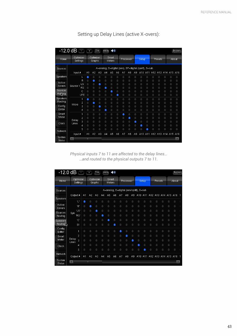
43
REFERENCE MANUAL
Setting up Delay Lines (active X-overs):
Physical inputs 7 to 11 are affected to the delay lines…
…and routed to the physical outputs 7 to 11.
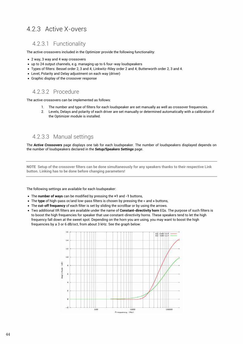
44
4.2.3 Active X-overs
4.2.3.1 Functionality The active crossovers included in the Optimizer provide the following functionality:
• 2 way, 3 way and 4 way crossovers • up to 24 output channels, e.g. managing up to 6 four-way loudspeakers • Types of filters: Bessel order 2, 3 and 4; Linkwitz-Riley order 2 and 4; Butterworth order 2, 3 and 4. • Level, Polarity and Delay adjustment on each way (driver) • Graphic display of the crossover response
4.2.3.2 Procedure The active crossovers can be implemented as follows:
1. The number and type of filters for each loudspeaker are set manually as well as crossover frequencies. 2. Levels, Delays and polarity of each driver are set manually or determined automatically with a calibration if
the Optimizer module is installed.
4.2.3.3 Manual settings The Active Crossovers page displays one tab for each loudspeaker. The number of loudspeakers displayed depends on the number of loudspeakers declared in the Setup/Speakers Settings page.
NOTE Setup of the crossover filters can be done simultaneously for any speakers thanks to their respective Link button. Linking has to be done before changing parameters!
The following settings are available for each loudspeaker:
• The number of ways can be modified by pressing the +1 and -1 buttons, • The type of high-pass or/and low-pass filters is chosen by pressing the < and > buttons, • The cut-off frequency of each filter is set by sliding the scrollbar or by using the arrows. • Two additional IIR filters are available under the name of Constant-directivity horn EQs. The purpose of such filters is
to boost the high frequencies for speaker that use constant-directivity horns. These speakers tend to let the high frequency fall down at the sweet spot. Depending on the horn you are using, you may want to boost the high frequencies by a 3 or 6 dB/oct, from about 3 kHz. See the graph below:
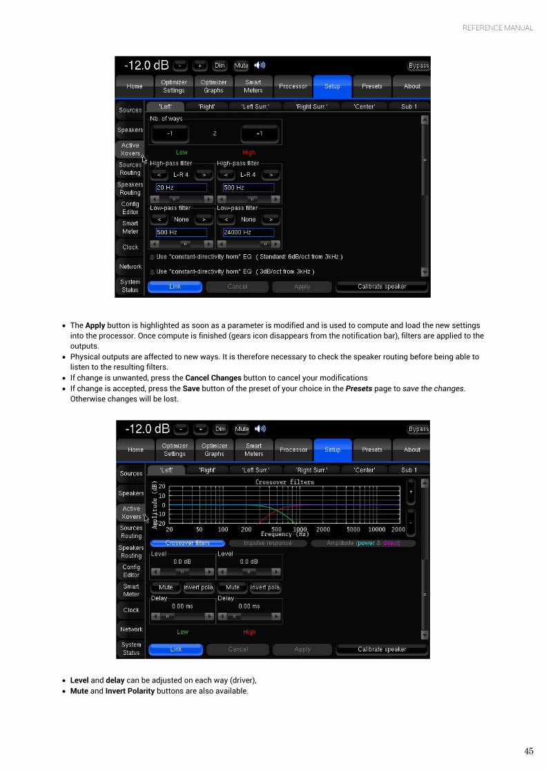
45
REFERENCE MANUAL
• The Apply button is highlighted as soon as a parameter is modified and is used to compute and load the new settings into the processor. Once compute is finished (gears icon disappears from the notification bar), filters are applied to the outputs.
• Physical outputs are affected to new ways. It is therefore necessary to check the speaker routing before being able to listen to the resulting filters.
• If change is unwanted, press the Cancel Changes button to cancel your modifications • If change is accepted, press the Save button of the preset of your choice in the Presets page to save the changes.
Otherwise changes will be lost.
• Level and delay can be adjusted on each way (driver), • Mute and Invert Polarity buttons are also available.
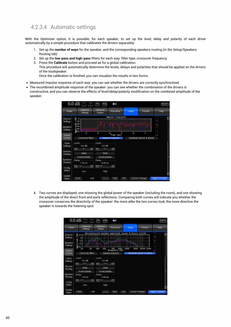
46
4.2.3.4 Automatic settings With the Optimizer option, it is possible, for each speaker, to set up the level, delay and polarity of each driver automatically by a simple procedure that calibrates the drivers separately:
1. Set up the number of ways for the speaker, and the corresponding speakers routing (in the Setup/Speakers Routing tab)
2. Set up the low-pass and high-pass filters for each way: filter type, crossover frequency. 3. Press the Calibrate button and proceed as for a global calibration.
This procedure will automatically determine the levels, delays and polarities that should be applied on the drivers of the loudspeaker. Once the calibration is finished, you can visualize the results in two forms:
• Measured impulse response of each way: you can see whether the drivers are correctly synchronized. • The recombined amplitude response of the speaker: you can see whether the combination of the drivers is
constructive, and you can observe the effects of level/delay/polarity modification on the combined amplitude of the speaker.
4. Two curves are displayed, one showing the global power of the speaker (including the room), and one showing the amplitude of the direct front and early reflections. Comparing both curves will indicate you whether the crossover conserves the directivity of the speaker: the more alike the two curves look, the more directive the speaker is towards the listening spot.
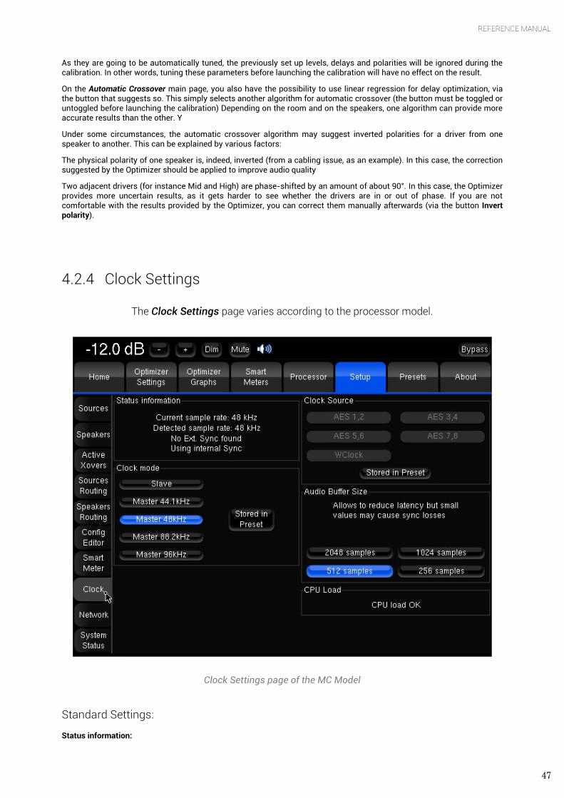
47
REFERENCE MANUAL
As they are going to be automatically tuned, the previously set up levels, delays and polarities will be ignored during the calibration. In other words, tuning these parameters before launching the calibration will have no effect on the result.
On the Automatic Crossover main page, you also have the possibility to use linear regression for delay optimization, via the button that suggests so. This simply selects another algorithm for automatic crossover (the button must be toggled or untoggled before launching the calibration) Depending on the room and on the speakers, one algorithm can provide more accurate results than the other. Y
Under some circumstances, the automatic crossover algorithm may suggest inverted polarities for a driver from one speaker to another. This can be explained by various factors:
The physical polarity of one speaker is, indeed, inverted (from a cabling issue, as an example). In this case, the correction suggested by the Optimizer should be applied to improve audio quality
Two adjacent drivers (for instance Mid and High) are phase-shifted by an amount of about 90°. In this case, the Optimizer provides more uncertain results, as it gets harder to see whether the drivers are in or out of phase. If you are not comfortable with the results provided by the Optimizer, you can correct them manually afterwards (via the button Invert polarity).
4.2.4 Clock Settings
The Clock Settings page varies according to the processor model.
Clock Settings page of the MC Model
Standard Settings:
Status information:
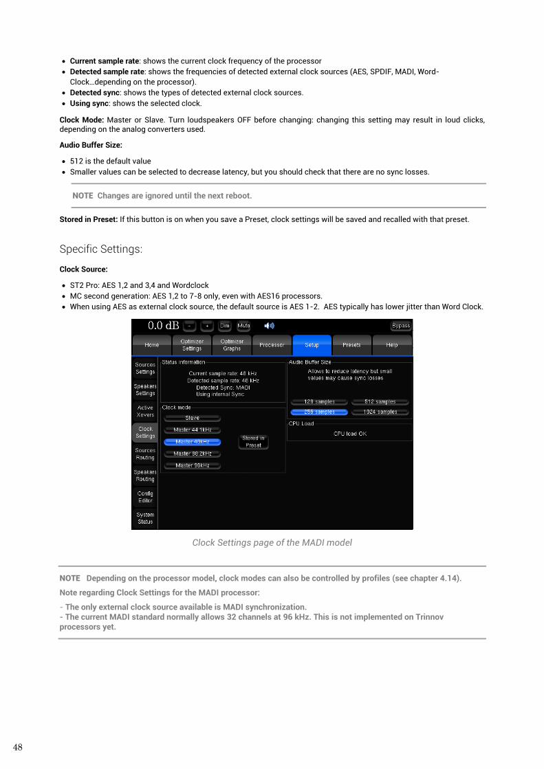
48
• Current sample rate: shows the current clock frequency of the processor • Detected sample rate: shows the frequencies of detected external clock sources (AES, SPDIF, MADI, Word-
Clock…depending on the processor). • Detected sync: shows the types of detected external clock sources. • Using sync: shows the selected clock.
Clock Mode: Master or Slave. Turn loudspeakers OFF before changing: changing this setting may result in loud clicks, depending on the analog converters used.
Audio Buffer Size:
• 512 is the default value • Smaller values can be selected to decrease latency, but you should check that there are no sync losses.
NOTE Changes are ignored until the next reboot.
Stored in Preset: If this button is on when you save a Preset, clock settings will be saved and recalled with that preset.
Specific Settings:
Clock Source:
• ST2 Pro: AES 1,2 and 3,4 and Wordclock • MC second generation: AES 1,2 to 7-8 only, even with AES16 processors. • When using AES as external clock source, the default source is AES 1-2. AES typically has lower jitter than Word Clock.
Clock Settings page of the MADI model
NOTE Depending on the processor model, clock modes can also be controlled by profiles (see chapter 4.14).
Note regarding Clock Settings for the MADI processor:
- The only external clock source available is MADI synchronization. - The current MADI standard normally allows 32 channels at 96 kHz. This is not implemented on Trinnov processors yet.
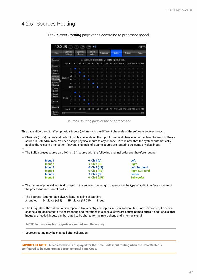
49
REFERENCE MANUAL
4.2.5 Sources Routing
The Sources Routing page varies according to processor model.
Sources Routing page of the MC processor
This page allows you to affect physical inputs (columns) to the different channels of the software sources (rows).
• Channels (rows) names and order of display depends on the input format and channel order declared for each software source in Setup/Sources. You can assign physical inputs to any channel. Please note that the system automatically applies the relevant attenuation if several channels of a same source are routed to the same physical input.
• • The Builtin preset source on a MC is a 5.1 source with the following channel order and therefore routing:
Input 1 Input 2 Input 3 Input 4 Input 5 Input 6
Ch 1 (L) Ch 2 (R) Ch 3 (LS) Ch 4 (RS) Ch 5 (C) Ch 6 (LFE)
Left Right Left Surround Right Surround Center Subwoofer
• The names of physical inputs displayed in the sources routing grid depends on the type of audio interface mounted in the processor and current profile.
• The Sources Routing Page always features a line of caption: A=analog D=digital (AES) SP=digital (SPDIF) S=sub
• The 4 signals of the calibration microphone, like any physical inputs, must also be routed. For convenience, 4 specific channels are dedicated to the microphone and regrouped in a special software source named Micro If additional signal inputs are needed, inputs can be routed to be shared for the microphone and a normal signal.
NOTE In this case, both signals are routed simultaneously.
• Sources routing may be changed after calibration.
IMPORTANT NOTE A dedicated line is displayed for the Time Code input routing when the SmartMeter is configured to be synchronized to an external Time Code.
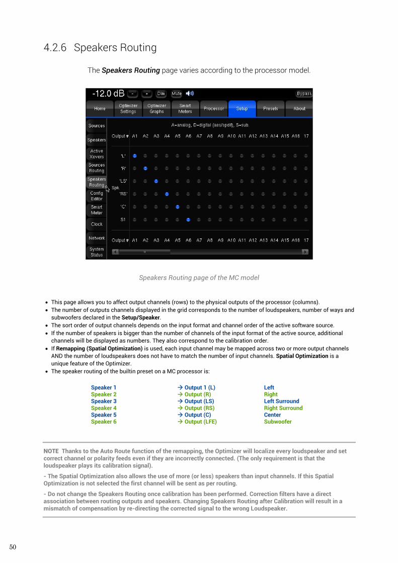
50
4.2.6 Speakers Routing
The Speakers Routing page varies according to the processor model.
Speakers Routing page of the MC model
• This page allows you to affect output channels (rows) to the physical outputs of the processor (columns). • The number of outputs channels displayed in the grid corresponds to the number of loudspeakers, number of ways and
subwoofers declared in the Setup/Speaker. • The sort order of output channels depends on the input format and channel order of the active software source. • If the number of speakers is bigger than the number of channels of the input format of the active source, additional
channels will be displayed as numbers. They also correspond to the calibration order. • If Remapping (Spatial Optimization) is used, each input channel may be mapped across two or more output channels
AND the number of loudspeakers does not have to match the number of input channels. Spatial Optimization is a unique feature of the Optimizer.
• The speaker routing of the builtin preset on a MC processor is:
Speaker 1 Speaker 2 Speaker 3 Speaker 4 Speaker 5 Speaker 6
Output 1 (L) Output (R) Output (LS) Output (RS) Output (C) Output (LFE)
Left Right Left Surround Right Surround Center Subwoofer
NOTE Thanks to the Auto Route function of the remapping, the Optimizer will localize every loudspeaker and set correct channel or polarity feeds even if they are incorrectly connected. (The only requirement is that the loudspeaker plays its calibration signal).
- The Spatial Optimization also allows the use of more (or less) speakers than input channels. If this Spatial Optimization is not selected the first channel will be sent as per routing.
- Do not change the Speakers Routing once calibration has been performed. Correction filters have a direct association between routing outputs and speakers. Changing Speakers Routing after Calibration will result in a mismatch of compensation by re-directing the corrected signal to the wrong Loudspeaker.
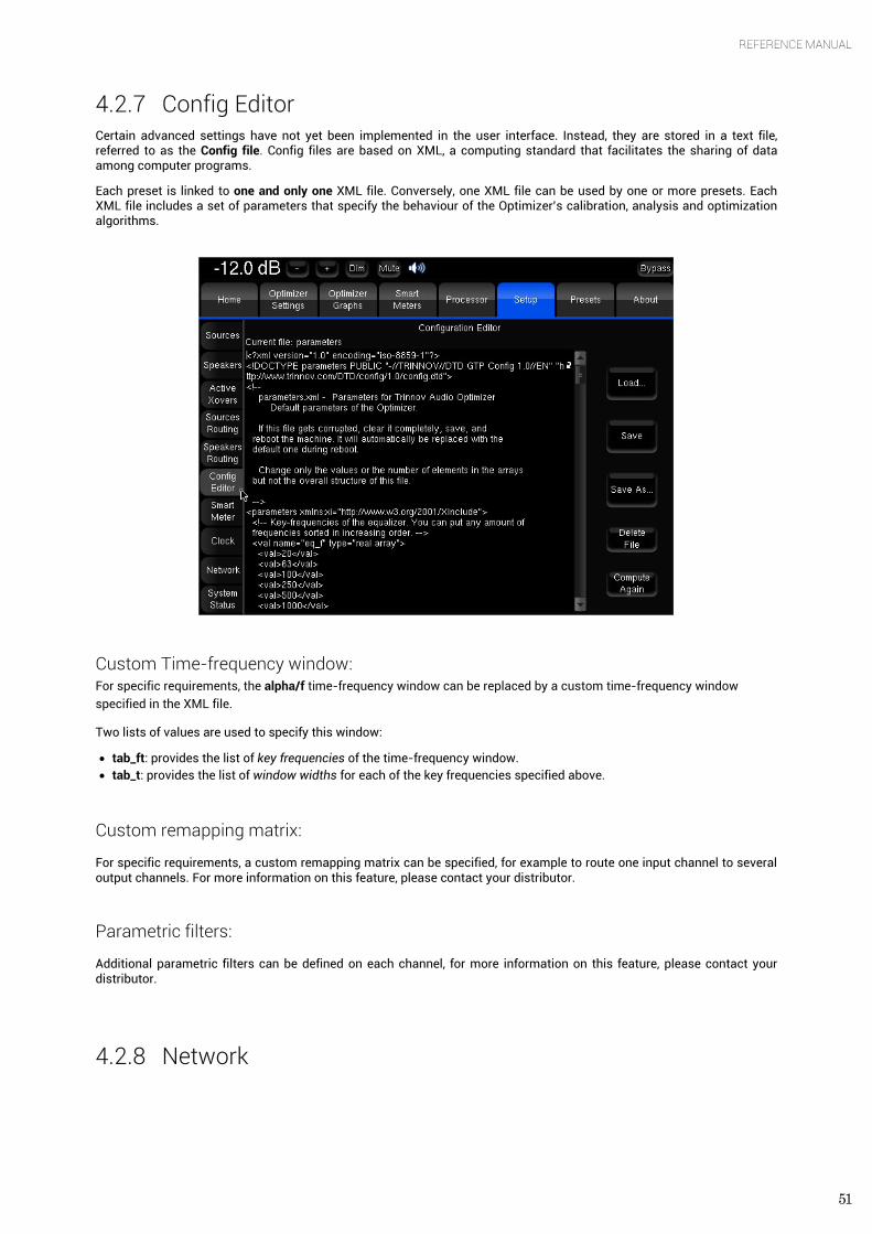
51
REFERENCE MANUAL
4.2.7 Config Editor Certain advanced settings have not yet been implemented in the user interface. Instead, they are stored in a text file, referred to as the Config file. Config files are based on XML, a computing standard that facilitates the sharing of data among computer programs.
Each preset is linked to one and only one XML file. Conversely, one XML file can be used by one or more presets. Each XML file includes a set of parameters that specify the behaviour of the Optimizer’s calibration, analysis and optimization algorithms.
Custom Time-frequency window: For specific requirements, the alpha/f time-frequency window can be replaced by a custom time-frequency window specified in the XML file. Two lists of values are used to specify this window:
• tab_ft: provides the list of key frequencies of the time-frequency window. • tab_t: provides the list of window widths for each of the key frequencies specified above.
Custom remapping matrix:
For specific requirements, a custom remapping matrix can be specified, for example to route one input channel to several output channels. For more information on this feature, please contact your distributor.
Parametric filters:
Additional parametric filters can be defined on each channel, for more information on this feature, please contact your distributor.
4.2.8 Network
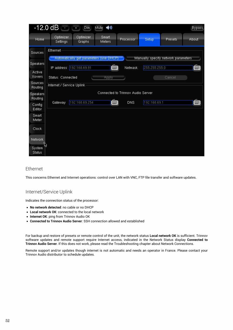
52
Ethernet
This concerns Ethernet and Internet operations: control over LAN with VNC, FTP file transfer and software updates.
Internet/Service Uplink
Indicates the connection status of the processor:
• No network detected: no cable or no DHCP • Local network OK: connected to the local network • Internet OK: ping from Trinnov Audio OK • Connected to Trinnov Audio Server: SSH connection allowed and established
For backup and restore of presets or remote control of the unit, the network status Local network OK is sufficient. Trinnov software updates and remote support require Internet access, indicated in the Network Status display Connected to Trinnov Audio Server. If this does not work, please read the Troubleshooting chapter about Network Connections.
Remote support and/or updates though internet is not automatic and needs an operator in France. Please contact your Trinnov Audio distributor to schedule updates.
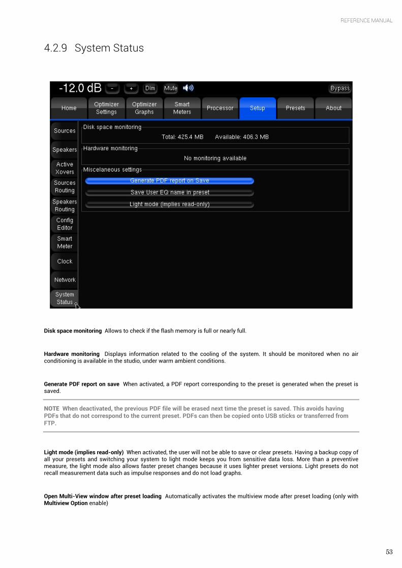
53
REFERENCE MANUAL
4.2.9 System Status
Disk space monitoring Allows to check if the flash memory is full or nearly full.
Hardware monitoring Displays information related to the cooling of the system. It should be monitored when no air conditioning is available in the studio, under warm ambient conditions.
Generate PDF report on save When activated, a PDF report corresponding to the preset is generated when the preset is saved.
NOTE When deactivated, the previous PDF file will be erased next time the preset is saved. This avoids having PDFs that do not correspond to the current preset. PDFs can then be copied onto USB sticks or transferred from FTP.
Light mode (implies read-only) When activated, the user will not be able to save or clear presets. Having a backup copy of all your presets and switching your system to light mode keeps you from sensitive data loss. More than a preventive measure, the light mode also allows faster preset changes because it uses lighter preset versions. Light presets do not recall measurement data such as impulse responses and do not load graphs.
Open Multi-View window after preset loading Automatically activates the multiview mode after preset loading (only with Multiview Option enable)
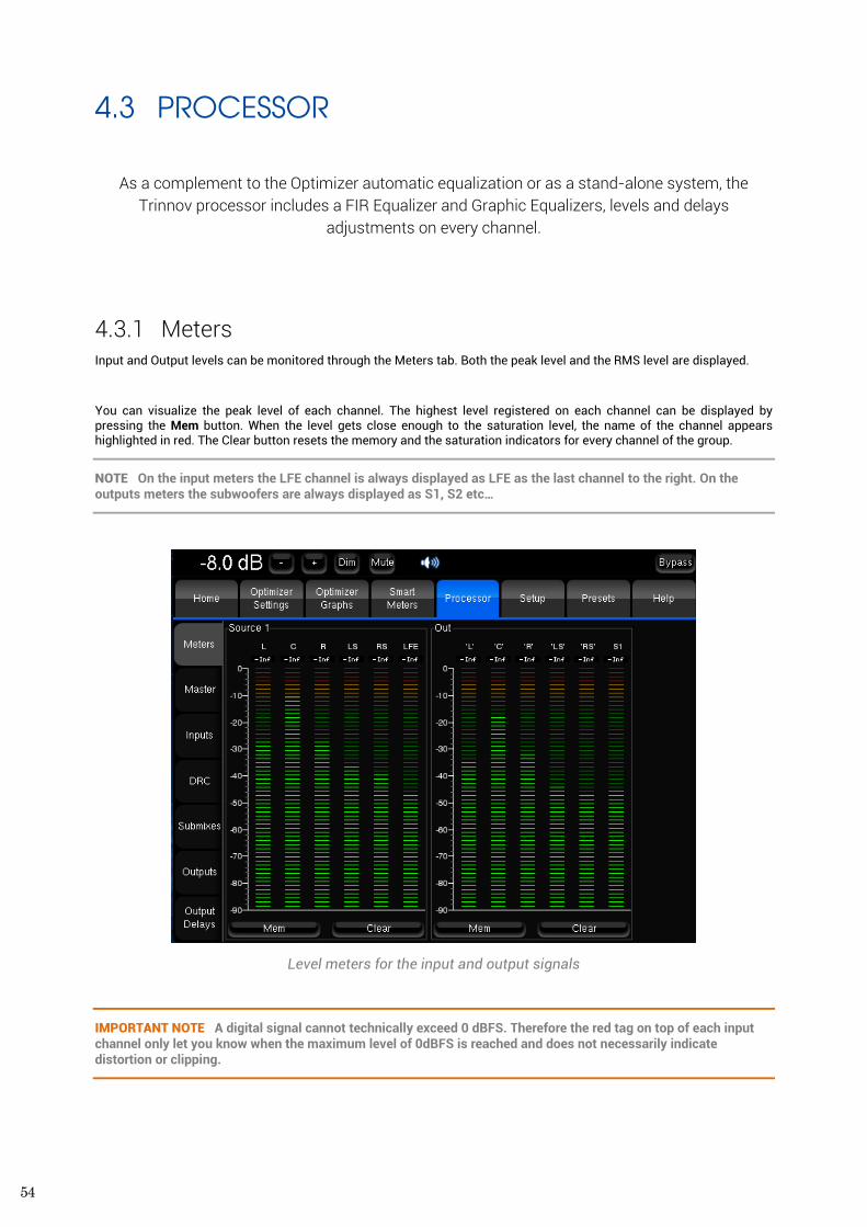
54
4.3 PROCESSOR
As a complement to the Optimizer automatic equalization or as a stand-alone system, the
Trinnov processor includes a FIR Equalizer and Graphic Equalizers, levels and delays adjustments on every channel.
4.3.1 Meters Input and Output levels can be monitored through the Meters tab. Both the peak level and the RMS level are displayed.
You can visualize the peak level of each channel. The highest level registered on each channel can be displayed by pressing the Mem button. When the level gets close enough to the saturation level, the name of the channel appears highlighted in red. The Clear button resets the memory and the saturation indicators for every channel of the group.
NOTE On the input meters the LFE channel is always displayed as LFE as the last channel to the right. On the outputs meters the subwoofers are always displayed as S1, S2 etc…
Level meters for the input and output signals
IMPORTANT NOTE A digital signal cannot technically exceed 0 dBFS. Therefore the red tag on top of each input channel only let you know when the maximum level of 0dBFS is reached and does not necessarily indicate distortion or clipping.
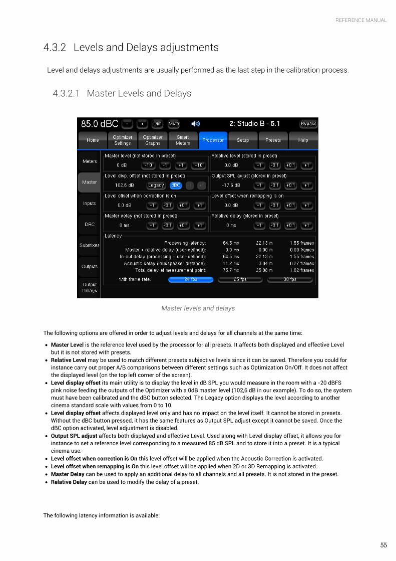
55
REFERENCE MANUAL
4.3.2 Levels and Delays adjustments
Level and delays adjustments are usually performed as the last step in the calibration process.
4.3.2.1 Master Levels and Delays
Master levels and delays
The following options are offered in order to adjust levels and delays for all channels at the same time:
• Master Level is the reference level used by the processor for all presets. It affects both displayed and effective Level but it is not stored with presets.
• Relative Level may be used to match different presets subjective levels since it can be saved. Therefore you could for instance carry out proper A/B comparisons between different settings such as Optimization On/Off. It does not affect the displayed level (on the top left corner of the screen).
• Level display offset its main utility is to display the level in dB SPL you would measure in the room with a -20 dBFS pink noise feeding the outputs of the Optimizer with a 0dB master level (102,6 dB in our example). To do so, the system must have been calibrated and the dBC button selected. The Legacy option displays the level according to another cinema standard scale with values from 0 to 10.
• Level display offset affects displayed level only and has no impact on the level itself. It cannot be stored in presets. Without the dBC button pressed, it has the same features as Output SPL adjust except it cannot be saved. Once the dBC option activated, level adjustment is disabled.
• Output SPL adjust affects both displayed and effective Level. Used along with Level display offset, it allows you for instance to set a reference level corresponding to a measured 85 dB SPL and to store it into a preset. It is a typical cinema use.
• Level offset when correction is On this level offset will be applied when the Acoustic Correction is activated. • Level offset when remapping is On this level offset will be applied when 2D or 3D Remapping is activated. • Master Delay can be used to apply an additional delay to all channels and all presets. It is not stored in the preset. • Relative Delay can be used to modify the delay of a preset.
The following latency information is available:
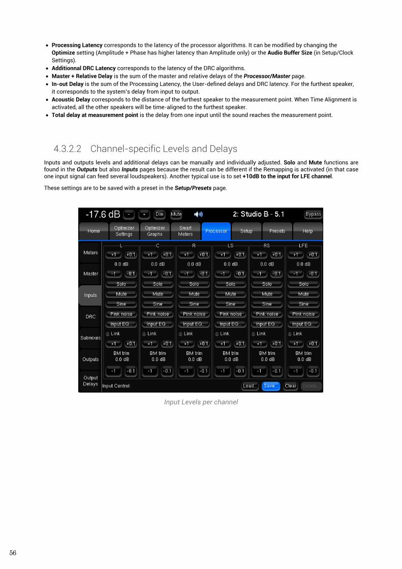
56
• Processing Latency corresponds to the latency of the processor algorithms. It can be modified by changing the Optimize setting (Amplitude + Phase has higher latency than Amplitude only) or the Audio Buffer Size (in Setup/Clock Settings).
• Additionnal DRC Latency corresponds to the latency of the DRC algorithms. • Master + Relative Delay is the sum of the master and relative delays of the Processor/Master page. • In-out Delay is the sum of the Processing Latency, the User-defined delays and DRC latency. For the furthest speaker,
it corresponds to the system’s delay from input to output. • Acoustic Delay corresponds to the distance of the furthest speaker to the measurement point. When Time Alignment is
activated, all the other speakers will be time-aligned to the furthest speaker. • Total delay at measurement point is the delay from one input until the sound reaches the measurement point.
4.3.2.2 Channel-specific Levels and Delays Inputs and outputs levels and additional delays can be manually and individually adjusted. Solo and Mute functions are found in the Outputs but also Inputs pages because the result can be different if the Remapping is activated (in that case one input signal can feed several loudspeakers). Another typical use is to set +10dB to the input for LFE channel.
These settings are to be saved with a preset in the Setup/Presets page.
Input Levels per channel
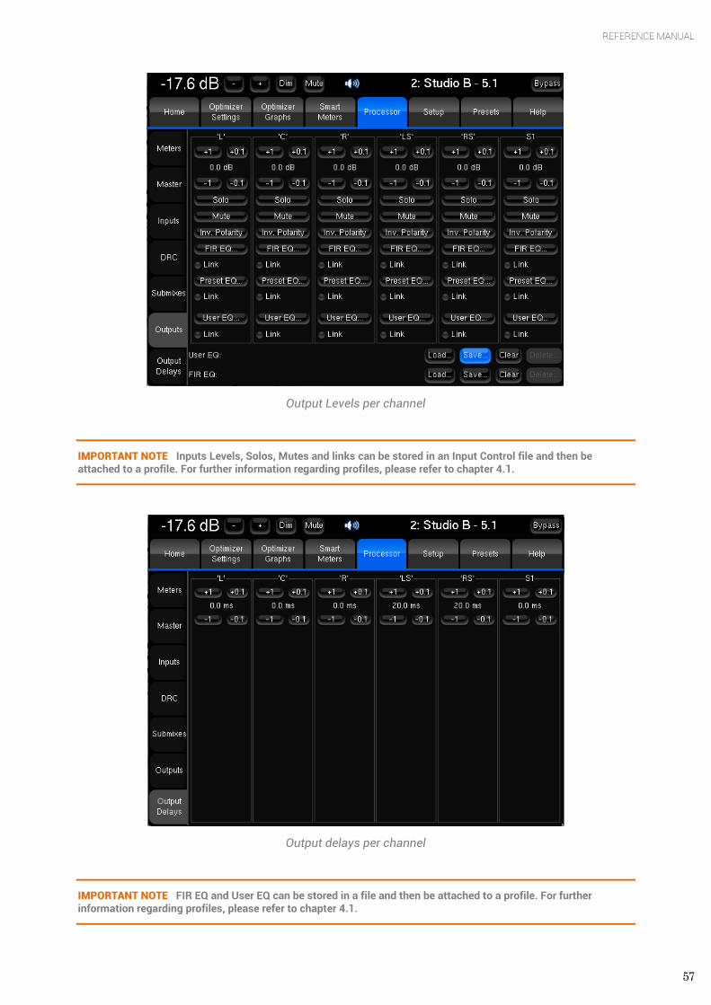
57
REFERENCE MANUAL
Output Levels per channel
IMPORTANT NOTE Inputs Levels, Solos, Mutes and links can be stored in an Input Control file and then be attached to a profile. For further information regarding profiles, please refer to chapter 4.1.
Output delays per channel
IMPORTANT NOTE FIR EQ and User EQ can be stored in a file and then be attached to a profile. For further information regarding profiles, please refer to chapter 4.1.
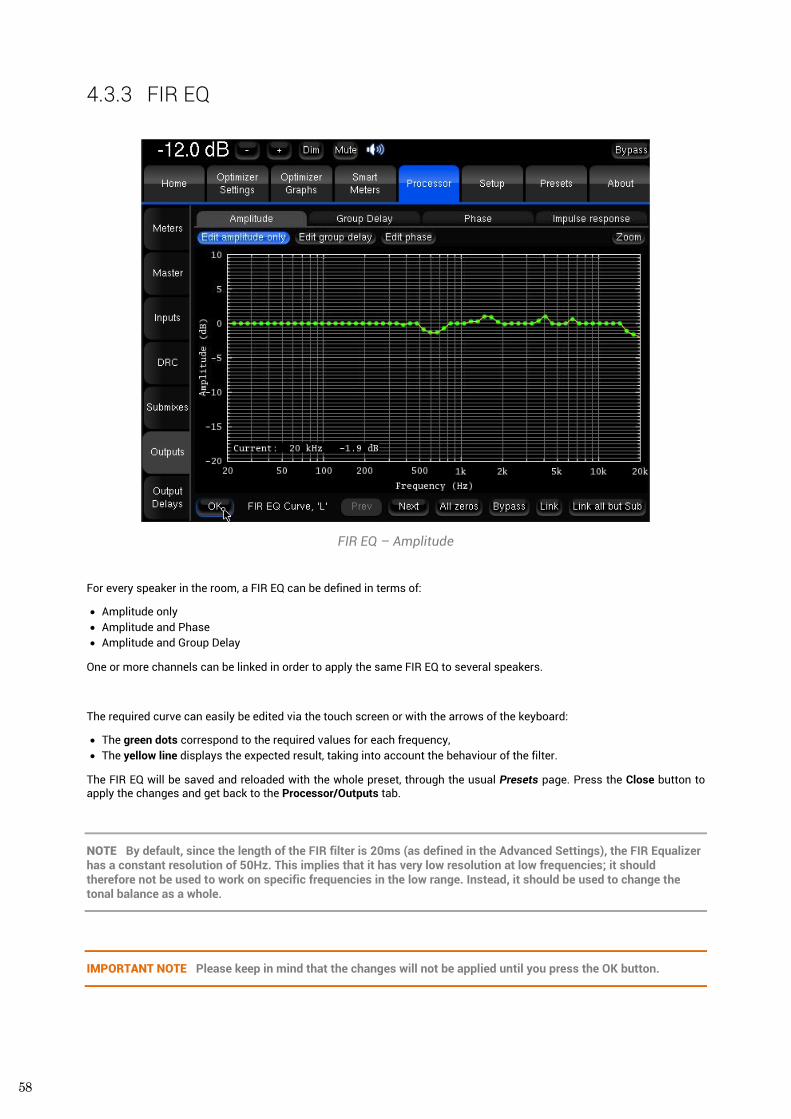
58
4.3.3 FIR EQ
FIR EQ – Amplitude
For every speaker in the room, a FIR EQ can be defined in terms of:
• Amplitude only • Amplitude and Phase • Amplitude and Group Delay
One or more channels can be linked in order to apply the same FIR EQ to several speakers.
The required curve can easily be edited via the touch screen or with the arrows of the keyboard:
• The green dots correspond to the required values for each frequency, • The yellow line displays the expected result, taking into account the behaviour of the filter.
The FIR EQ will be saved and reloaded with the whole preset, through the usual Presets page. Press the Close button to apply the changes and get back to the Processor/Outputs tab.
NOTE By default, since the length of the FIR filter is 20ms (as defined in the Advanced Settings), the FIR Equalizer has a constant resolution of 50Hz. This implies that it has very low resolution at low frequencies; it should therefore not be used to work on specific frequencies in the low range. Instead, it should be used to change the tonal balance as a whole.
IMPORTANT NOTE Please keep in mind that the changes will not be applied until you press the OK button.
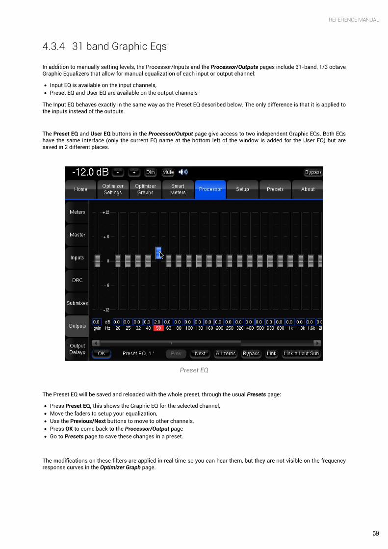
59
REFERENCE MANUAL
4.3.4 31 band Graphic Eqs In addition to manually setting levels, the Processor/Inputs and the Processor/Outputs pages include 31-band, 1/3 octave Graphic Equalizers that allow for manual equalization of each input or output channel:
• Input EQ is available on the input channels, • Preset EQ and User EQ are available on the output channels
The Input EQ behaves exactly in the same way as the Preset EQ described below. The only difference is that it is applied to the inputs instead of the outputs.
The Preset EQ and User EQ buttons in the Processor/Output page give access to two independent Graphic EQs. Both EQs have the same interface (only the current EQ name at the bottom left of the window is added for the User EQ) but are saved in 2 different places.
Preset EQ
The Preset EQ will be saved and reloaded with the whole preset, through the usual Presets page:
• Press Preset EQ, this shows the Graphic EQ for the selected channel, • Move the faders to setup your equalization, • Use the Previous/Next buttons to move to other channels, • Press OK to come back to the Processor/Output page • Go to Presets page to save these changes in a preset.
The modifications on these filters are applied in real time so you can hear them, but they are not visible on the frequency response curves in the Optimizer Graph page.
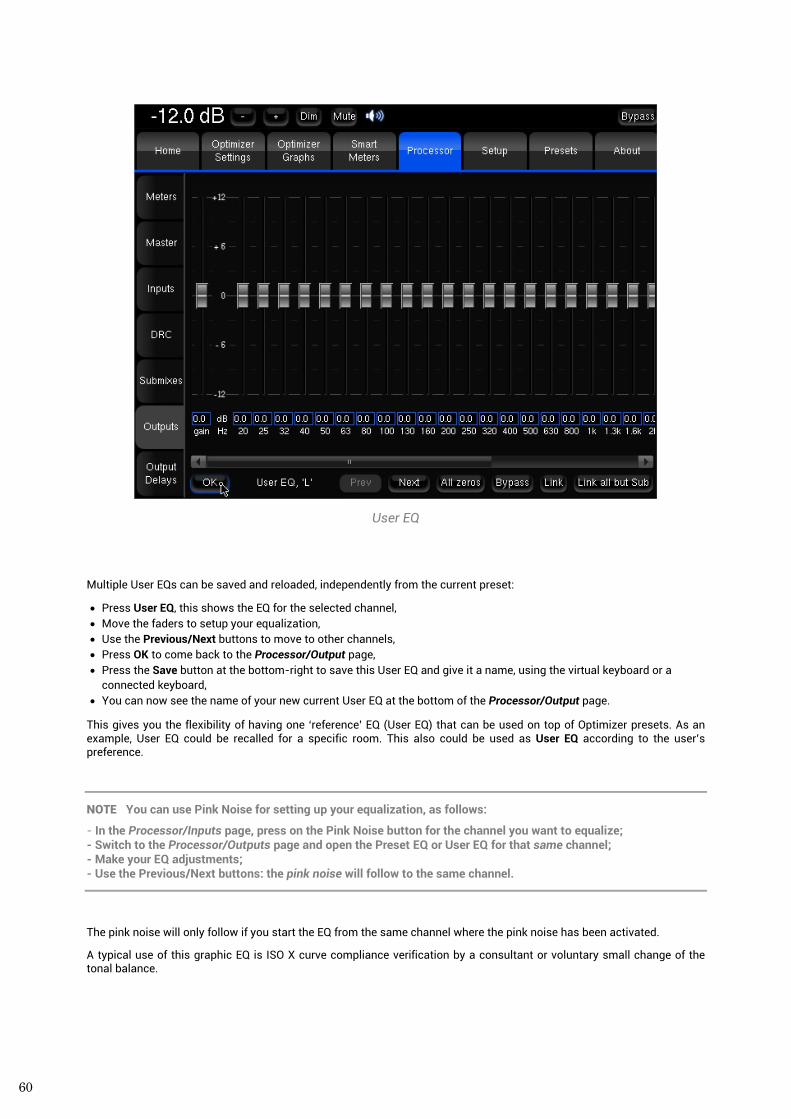
60
User EQ
Multiple User EQs can be saved and reloaded, independently from the current preset:
• Press User EQ, this shows the EQ for the selected channel, • Move the faders to setup your equalization, • Use the Previous/Next buttons to move to other channels, • Press OK to come back to the Processor/Output page, • Press the Save button at the bottom-right to save this User EQ and give it a name, using the virtual keyboard or a
connected keyboard, • You can now see the name of your new current User EQ at the bottom of the Processor/Output page.
This gives you the flexibility of having one ‘reference’ EQ (User EQ) that can be used on top of Optimizer presets. As an example, User EQ could be recalled for a specific room. This also could be used as User EQ according to the user’s preference.
NOTE You can use Pink Noise for setting up your equalization, as follows:
- In the Processor/Inputs page, press on the Pink Noise button for the channel you want to equalize; - Switch to the Processor/Outputs page and open the Preset EQ or User EQ for that same channel; - Make your EQ adjustments; - Use the Previous/Next buttons: the pink noise will follow to the same channel.
The pink noise will only follow if you start the EQ from the same channel where the pink noise has been activated.
A typical use of this graphic EQ is ISO X curve compliance verification by a consultant or voluntary small change of the tonal balance.
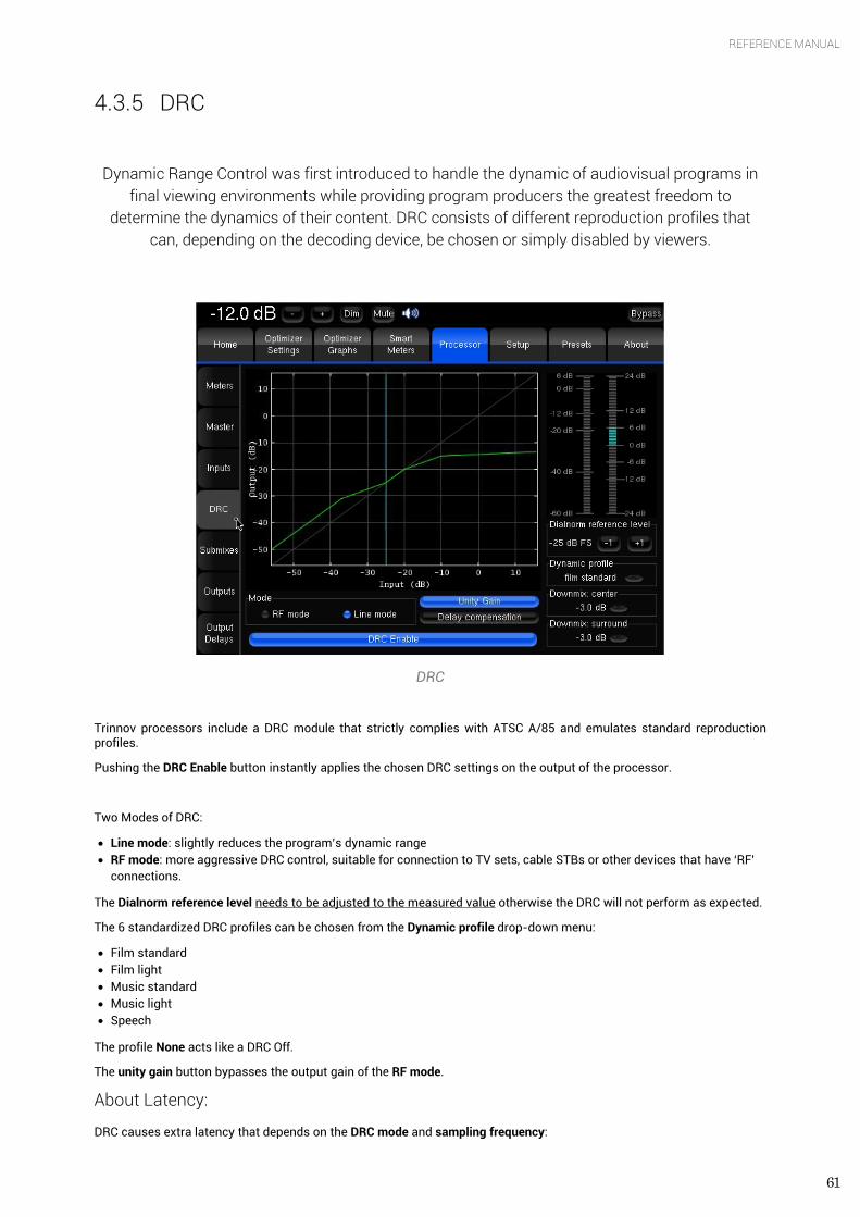
61
REFERENCE MANUAL
4.3.5 DRC
Dynamic Range Control was first introduced to handle the dynamic of audiovisual programs in
final viewing environments while providing program producers the greatest freedom to determine the dynamics of their content. DRC consists of different reproduction profiles that
can, depending on the decoding device, be chosen or simply disabled by viewers.
DRC
Trinnov processors include a DRC module that strictly complies with ATSC A/85 and emulates standard reproduction profiles.
Pushing the DRC Enable button instantly applies the chosen DRC settings on the output of the processor.
Two Modes of DRC:
• Line mode: slightly reduces the program’s dynamic range • RF mode: more aggressive DRC control, suitable for connection to TV sets, cable STBs or other devices that have ‘RF’
connections.
The Dialnorm reference level needs to be adjusted to the measured value otherwise the DRC will not perform as expected.
The 6 standardized DRC profiles can be chosen from the Dynamic profile drop-down menu:
• Film standard • Film light • Music standard • Music light • Speech
The profile None acts like a DRC Off.
The unity gain button bypasses the output gain of the RF mode.
About Latency:
DRC causes extra latency that depends on the DRC mode and sampling frequency:
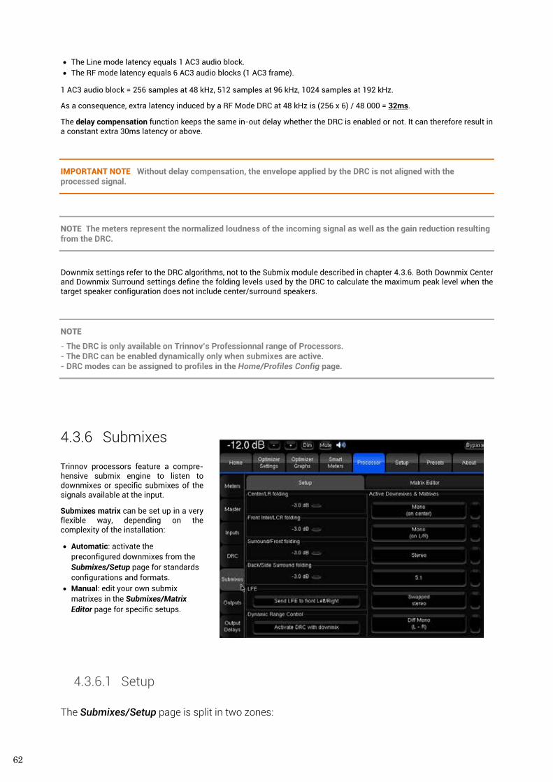
62
• The Line mode latency equals 1 AC3 audio block. • The RF mode latency equals 6 AC3 audio blocks (1 AC3 frame).
1 AC3 audio block = 256 samples at 48 kHz, 512 samples at 96 kHz, 1024 samples at 192 kHz.
As a consequence, extra latency induced by a RF Mode DRC at 48 kHz is (256 x 6) / 48 000 = 32ms.
The delay compensation function keeps the same in-out delay whether the DRC is enabled or not. It can therefore result in a constant extra 30ms latency or above.
IMPORTANT NOTE Without delay compensation, the envelope applied by the DRC is not aligned with the processed signal.
NOTE The meters represent the normalized loudness of the incoming signal as well as the gain reduction resulting from the DRC.
Downmix settings refer to the DRC algorithms, not to the Submix module described in chapter 4.3.6. Both Downmix Center and Downmix Surround settings define the folding levels used by the DRC to calculate the maximum peak level when the target speaker configuration does not include center/surround speakers.
NOTE
- The DRC is only available on Trinnov’s Professionnal range of Processors. - The DRC can be enabled dynamically only when submixes are active. - DRC modes can be assigned to profiles in the Home/Profiles Config page.
4.3.6 Submixes Trinnov processors feature a compre-hensive submix engine to listen to downmixes or specific submixes of the signals available at the input.
Submixes matrix can be set up in a very flexible way, depending on the complexity of the installation:
• Automatic: activate the preconfigured downmixes from the Submixes/Setup page for standards configurations and formats.
• Manual: edit your own submix matrixes in the Submixes/Matrix Editor page for specific setups.
4.3.6.1 Setup
The Submixes/Setup page is split in two zones:
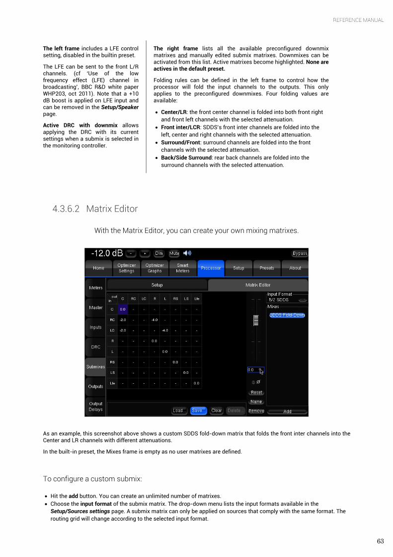
63
REFERENCE MANUAL
The left frame includes a LFE control setting, disabled in the builtin preset.
The LFE can be sent to the front L/R channels. (cf ‘Use of the low frequency effect (LFE) channel in broadcasting’, BBC R&D white paper WHP203, oct 2011). Note that a +10 dB boost is applied on LFE input and can be removed in the Setup/Speaker page.
Active DRC with downmix allows applying the DRC with its current settings when a submix is selected in the monitoring controller.
The right frame lists all the available preconfigured downmix matrixes and manually edited submix matrixes. Downmixes can be activated from this list. Active matrixes become highlighted. None are actives in the default preset.
Folding rules can be defined in the left frame to control how the processor will fold the input channels to the outputs. This only applies to the preconfigured downmixes. Four folding values are available:
• Center/LR: the front center channel is folded into both front right and front left channels with the selected attenuation.
• Front inter/LCR: SDDS’s front inter channels are folded into the left, center and right channels with the selected attenuation.
• Surround/Front: surround channels are folded into the front channels with the selected attenuation.
• Back/Side Surround: rear back channels are folded into the surround channels with the selected attenuation.
4.3.6.2 Matrix Editor
With the Matrix Editor, you can create your own mixing matrixes.
As an example, this screenshot above shows a custom SDDS fold-down matrix that folds the front inter channels into the Center and LR channels with different attenuations.
In the built-in preset, the Mixes frame is empty as no user matrixes are defined.
To configure a custom submix:
• Hit the add button. You can create an unlimited number of matrixes. • Choose the input format of the submix matrix. The drop-down menu lists the input formats available in the
Setup/Sources settings page. A submix matrix can only be applied on sources that comply with the same format. The routing grid will change according to the selected input format.
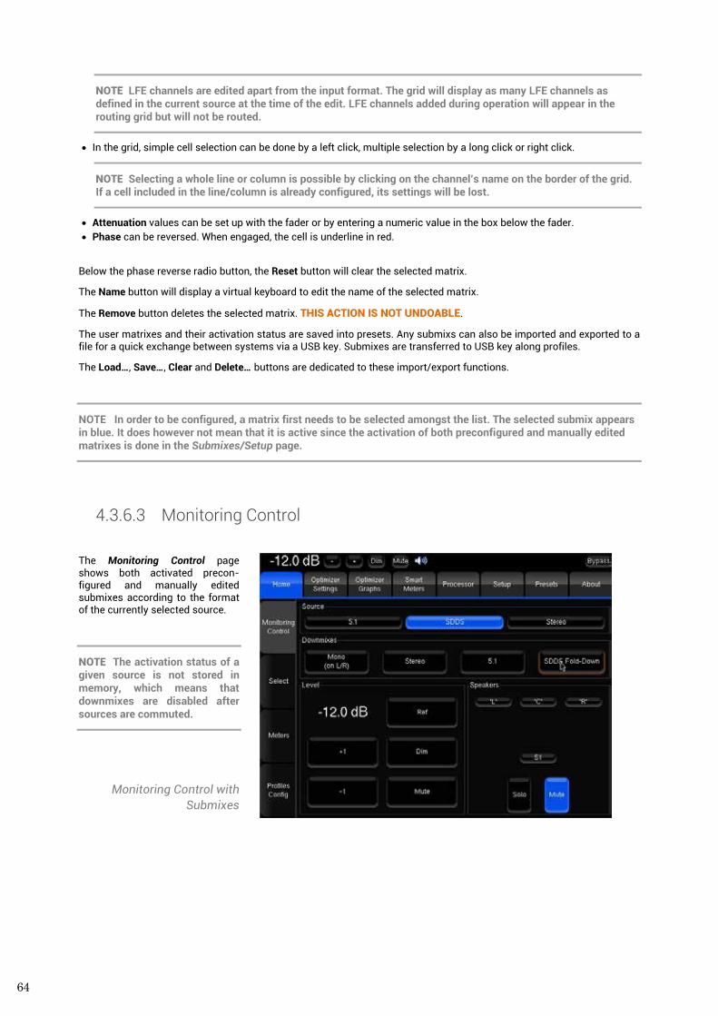
64
NOTE LFE channels are edited apart from the input format. The grid will display as many LFE channels as defined in the current source at the time of the edit. LFE channels added during operation will appear in the routing grid but will not be routed.
• In the grid, simple cell selection can be done by a left click, multiple selection by a long click or right click.
NOTE Selecting a whole line or column is possible by clicking on the channel’s name on the border of the grid. If a cell included in the line/column is already configured, its settings will be lost.
• Attenuation values can be set up with the fader or by entering a numeric value in the box below the fader. • Phase can be reversed. When engaged, the cell is underline in red.
Below the phase reverse radio button, the Reset button will clear the selected matrix.
The Name button will display a virtual keyboard to edit the name of the selected matrix.
The Remove button deletes the selected matrix. THIS ACTION IS NOT UNDOABLE.
The user matrixes and their activation status are saved into presets. Any submixs can also be imported and exported to a file for a quick exchange between systems via a USB key. Submixes are transferred to USB key along profiles.
The Load…, Save…, Clear and Delete… buttons are dedicated to these import/export functions.
NOTE In order to be configured, a matrix first needs to be selected amongst the list. The selected submix appears in blue. It does however not mean that it is active since the activation of both preconfigured and manually edited matrixes is done in the Submixes/Setup page.
4.3.6.3 Monitoring Control
The Monitoring Control page shows both activated precon-figured and manually edited submixes according to the format of the currently selected source.
NOTE The activation status of a given source is not stored in memory, which means that downmixes are disabled after sources are commuted.
Monitoring Control with Submixes
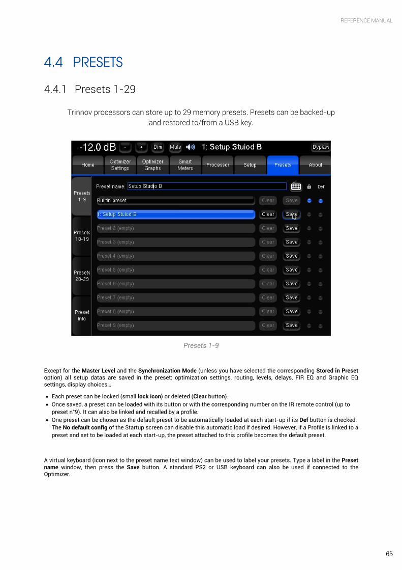
65
REFERENCE MANUAL
4.4 PRESETS
4.4.1 Presets 1-29
Trinnov processors can store up to 29 memory presets. Presets can be backed-up and restored to/from a USB key.
Presets 1-9
Except for the Master Level and the Synchronization Mode (unless you have selected the corresponding Stored in Preset option) all setup datas are saved in the preset: optimization settings, routing, levels, delays, FIR EQ and Graphic EQ settings, display choices…
• Each preset can be locked (small lock icon) or deleted (Clear button). • Once saved, a preset can be loaded with its button or with the corresponding number on the IR remote control (up to
preset n°9). It can also be linked and recalled by a profile. • One preset can be chosen as the default preset to be automatically loaded at each start-up if its Def button is checked.
The No default config of the Startup screen can disable this automatic load if desired. However, if a Profile is linked to a preset and set to be loaded at each start-up, the preset attached to this profile becomes the default preset.
A virtual keyboard (icon next to the preset name text window) can be used to label your presets. Type a label in the Preset name window, then press the Save button. A standard PS2 or USB keyboard can also be used if connected to the Optimizer.
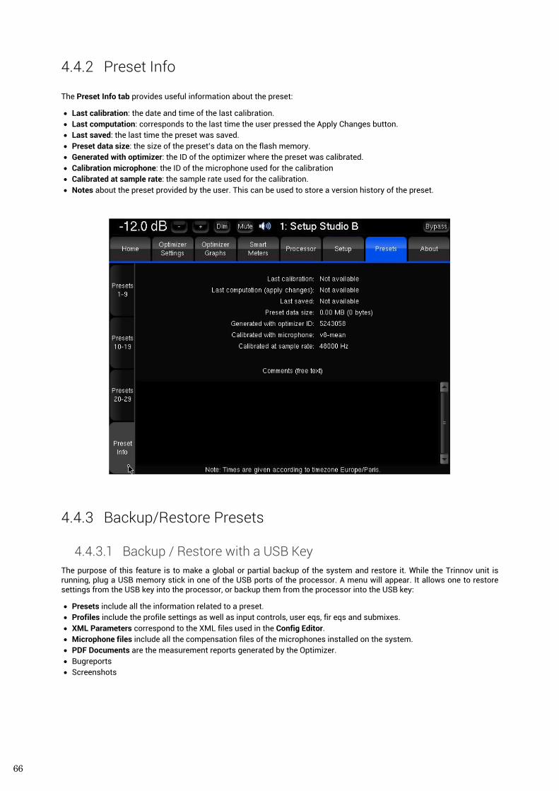
66
4.4.2 Preset Info The Preset Info tab provides useful information about the preset:
• Last calibration: the date and time of the last calibration. • Last computation: corresponds to the last time the user pressed the Apply Changes button. • Last saved: the last time the preset was saved. • Preset data size: the size of the preset’s data on the flash memory. • Generated with optimizer: the ID of the optimizer where the preset was calibrated. • Calibration microphone: the ID of the microphone used for the calibration • Calibrated at sample rate: the sample rate used for the calibration. • Notes about the preset provided by the user. This can be used to store a version history of the preset.
4.4.3 Backup/Restore Presets
4.4.3.1 Backup / Restore with a USB Key The purpose of this feature is to make a global or partial backup of the system and restore it. While the Trinnov unit is running, plug a USB memory stick in one of the USB ports of the processor. A menu will appear. It allows one to restore settings from the USB key into the processor, or backup them from the processor into the USB key:
• Presets include all the information related to a preset. • Profiles include the profile settings as well as input controls, user eqs, fir eqs and submixes. • XML Parameters correspond to the XML files used in the Config Editor. • Microphone files include all the compensation files of the microphones installed on the system. • PDF Documents are the measurement reports generated by the Optimizer. • Bugreports • Screenshots
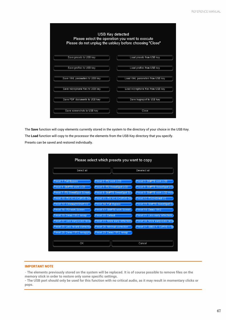
67
REFERENCE MANUAL
The Save function will copy elements currently stored in the system to the directory of your choice in the USB Key.
The Load function will copy to the processor the elements from the USB Key directory that you specify.
Presets can be saved and restored individually.
IMPORTANT NOTE
- The elements previously stored on the system will be replaced. It is of course possible to remove files on the memory stick in order to restore only some specific settings. - The USB port should only be used for this function with no critical audio, as it may result in momentary clicks or pops.
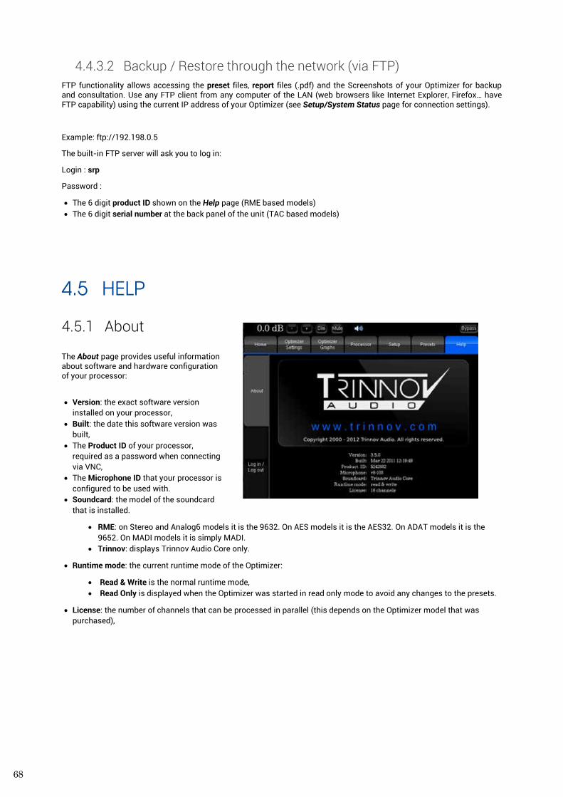
68
4.4.3.2 Backup / Restore through the network (via FTP) FTP functionality allows accessing the preset files, report files (.pdf) and the Screenshots of your Optimizer for backup and consultation. Use any FTP client from any computer of the LAN (web browsers like Internet Explorer, Firefox… have FTP capability) using the current IP address of your Optimizer (see Setup/System Status page for connection settings).
Example: ftp://192.198.0.5
The built-in FTP server will ask you to log in:
Login : srp
Password :
• The 6 digit product ID shown on the Help page (RME based models) • The 6 digit serial number at the back panel of the unit (TAC based models)
4.5 HELP
4.5.1 About The About page provides useful information about software and hardware configuration of your processor:
• Version: the exact software version installed on your processor,
• Built: the date this software version was built,
• The Product ID of your processor, required as a password when connecting via VNC,
• The Microphone ID that your processor is configured to be used with.
• Soundcard: the model of the soundcard that is installed.
• RME: on Stereo and Analog6 models it is the 9632. On AES models it is the AES32. On ADAT models it is the 9652. On MADI models it is simply MADI.
• Trinnov: displays Trinnov Audio Core only.
• Runtime mode: the current runtime mode of the Optimizer:
• Read & Write is the normal runtime mode, • Read Only is displayed when the Optimizer was started in read only mode to avoid any changes to the presets.
• License: the number of channels that can be processed in parallel (this depends on the Optimizer model that was purchased),
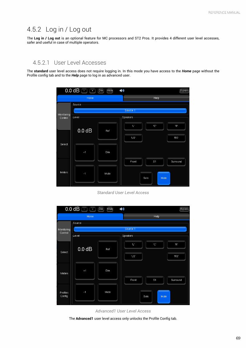
69
REFERENCE MANUAL
4.5.2 Log in / Log out The Log in / Log out is an optional feature for MC processors and ST2 Pros. It provides 4 different user level accesses, safer and useful in case of multiple operators.
4.5.2.1 User Level Accesses The standard user level access does not require logging in. In this mode you have access to the Home page without the Profile config tab and to the Help page to log in as advanced user.
Standard User Level Access
Advanced1 User Level Access
The Advanced1 user level access only unlocks the Profile Config tab.
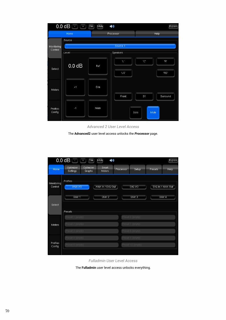
70
Advanced 2 User Level Access
The Advanced2 user level access unlocks the Processor page.
Fulladmin User Level Access
The Fulladmin user level access unlocks everything.
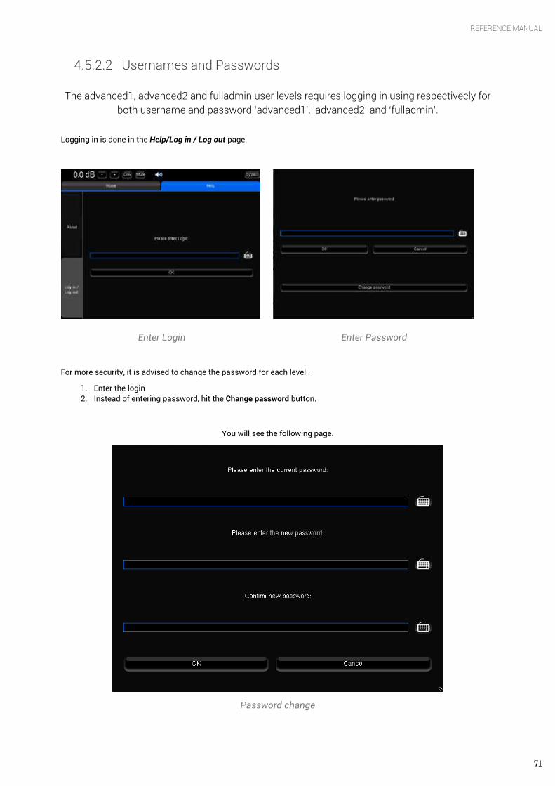
71
REFERENCE MANUAL
4.5.2.2 Usernames and Passwords
The advanced1, advanced2 and fulladmin user levels requires logging in using respectivecly for both username and password ‘advanced1’, ‘advanced2’ and ‘fulladmin’.
Logging in is done in the Help/Log in / Log out page.
Enter Login Enter Password
For more security, it is advised to change the password for each level .
1. Enter the login 2. Instead of entering password, hit the Change password button.
You will see the following page.
Password change
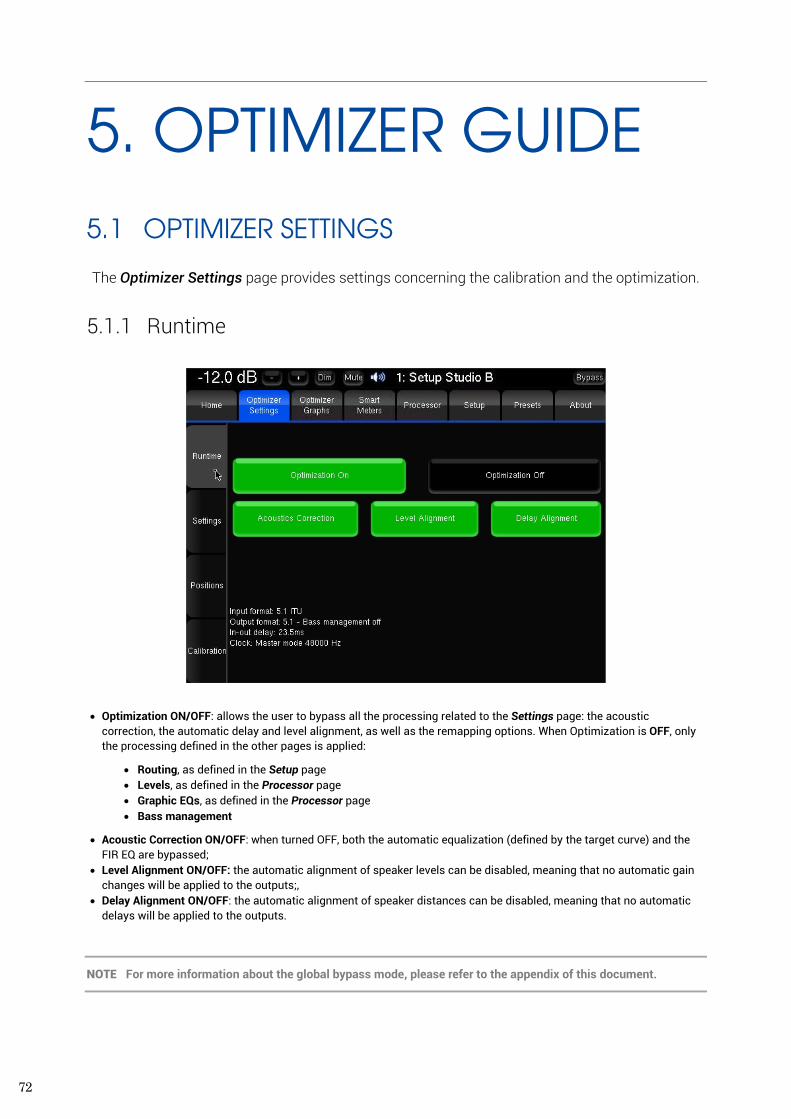
72
5. OPTIMIZER GUIDE 5.1 OPTIMIZER SETTINGS
The Optimizer Settings page provides settings concerning the calibration and the optimization.
5.1.1 Runtime
• Optimization ON/OFF: allows the user to bypass all the processing related to the Settings page: the acoustic correction, the automatic delay and level alignment, as well as the remapping options. When Optimization is OFF, only the processing defined in the other pages is applied:
• Routing, as defined in the Setup page • Levels, as defined in the Processor page • Graphic EQs, as defined in the Processor page • Bass management
• Acoustic Correction ON/OFF: when turned OFF, both the automatic equalization (defined by the target curve) and the FIR EQ are bypassed;
• Level Alignment ON/OFF: the automatic alignment of speaker levels can be disabled, meaning that no automatic gain changes will be applied to the outputs;,
• Delay Alignment ON/OFF: the automatic alignment of speaker distances can be disabled, meaning that no automatic delays will be applied to the outputs.
NOTE For more information about the global bypass mode, please refer to the appendix of this document.
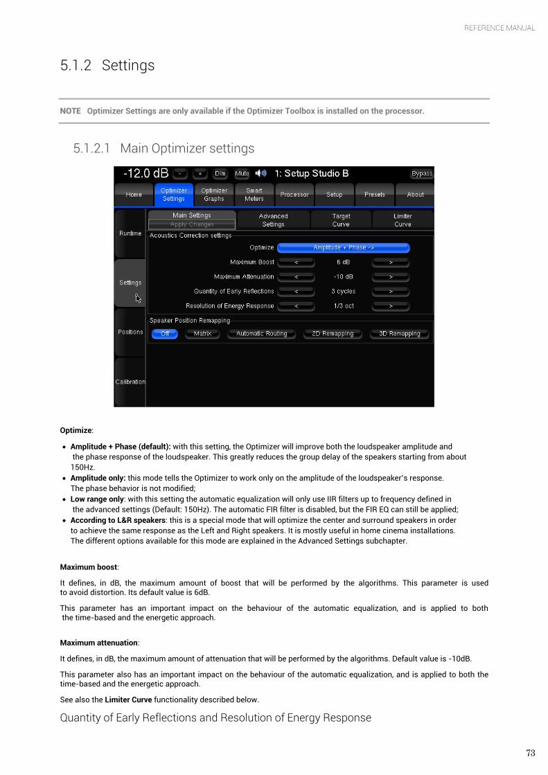
73
REFERENCE MANUAL
5.1.2 Settings
NOTE Optimizer Settings are only available if the Optimizer Toolbox is installed on the processor.
5.1.2.1 Main Optimizer settings
Optimize:
• Amplitude + Phase (default): with this setting, the Optimizer will improve both the loudspeaker amplitude and the phase response of the loudspeaker. This greatly reduces the group delay of the speakers starting from about 150Hz.
• Amplitude only: this mode tells the Optimizer to work only on the amplitude of the loudspeaker’s response. The phase behavior is not modified;
• Low range only: with this setting the automatic equalization will only use IIR filters up to frequency defined in the advanced settings (Default: 150Hz). The automatic FIR filter is disabled, but the FIR EQ can still be applied;
• According to L&R speakers: this is a special mode that will optimize the center and surround speakers in order to achieve the same response as the Left and Right speakers. It is mostly useful in home cinema installations. The different options available for this mode are explained in the Advanced Settings subchapter.
Maximum boost:
It defines, in dB, the maximum amount of boost that will be performed by the algorithms. This parameter is used to avoid distortion. Its default value is 6dB.
This parameter has an important impact on the behaviour of the automatic equalization, and is applied to both the time-based and the energetic approach.
Maximum attenuation:
It defines, in dB, the maximum amount of attenuation that will be performed by the algorithms. Default value is -10dB.
This parameter also has an important impact on the behaviour of the automatic equalization, and is applied to both the time-based and the energetic approach.
See also the Limiter Curve functionality described below.
Quantity of Early Reflections and Resolution of Energy Response
74
The Optimizer uses two different approaches for the Optimization of Loudspeaker/Room Acoustics:
1/ A time-based approach for the correction of Early Reflections (ER). The main parameter that defines the behaviour of this algorithm is the width of the time-frequency window Quantity of Early Reflections.
2/ An energetic approach for the correction of Late Reverberation (LR), whose main parameter, Resolution of Energy Response is the smoothing applied to the energy response.
• Quantity of Early Reflections (default is 3 cycles): • A simple parameter that characterizes the quantity of early reflections that the Optimizer tries to compensate
is the width of the time-frequency window. The size of this window is defined by a number of cycles, hence the naming ‘α/f’, where α (alpha) is the number of cycles and f the frequency (1/f being one cycle).
• The meaning of the time-frequency window is as follows: for each frequency a different duration (or width of the time window) is taken into account. At low frequencies the window typically starts at 150ms for 20 Hz, and decreases constantly to be as low as 0.3ms at 10 kHz.
• Resolution of Energy Response (default is ½ octave): • It defines, in number of octaves, how the room’s energy response is smoothed, and modifies the behaviour of
the equalization performed by the Optimizer on the Late Reverberation. Its default value is 0.5 (half an octave). Note that this is smoother than the 1/3 octave smoothing more commonly used.
• The behaviour of the energy optimization algorithm varies according to the smoothing applied to the room’s response. If the response is less smoothed, sharp peaks in the response will be more taken into account for the correction, while with more smoothing only the overall tonal balance of the room will be corrected.
• Speaker position remapping:
• Off (default): remapping is disabled. • Matrix: specifies that the I/O routing to be taken into account is in the Config Editor. To be used by advanced
users. • Automatic routing: This option uses the Optimizer's 3D speaker position information (from the calibration) to
automatically route each channel to the speaker closest to the reference position. Auto-route works with all input formats (defined in Setup ->). For example, to find out which loudspeaker corresponds to the Left channel (reference position = 30°), the Optimizer will look which of the measured loudspeakers is closest to 30°. If the nearest one is loudspeaker number 4 at 25°, then the Optimizer will ‘auto-route’ the Left channel to Loudspeaker 4.
• This feature frees the user from having to manually verify that the speakers routing is correct. When activated, the Optimizer automatically sends each channel to the loudspeaker that is nearest to its intended position.
• This option can be more convenient when no remapping is required but you don’t want to manually verify that each loudspeaker is cabled on the right output.
• 2D Remapping: this feature performs a remapping of the loudspeakers positions, but only in the horizontal plane. This allows for :
• Compensating for incorrect loudspeakers position, but only with respect to horizontal angles (azimuth). • Rendering a signal format (stereo, 5.1, 7.1…) on any number of loudspeakers. This includes up-mixes and
down-mixes.
• 3D Remapping: This mode enables the full spatial optimization in 3D. This allows for:
• Compensating for incorrect loudspeaker position in azimuth and elevation. • Rendering a signal format (stereo, 5.1, 7.1…) on any number of loudspeakers. This includes up-mixes and down-
mixes.
IMPORTANT NOTE Speakers Remapping mode can be controlled with Profiles. Please refer to chapter 4.1.4.
5.1.2.2 Target curves The Optimizer implements Target Curves as a powerful tool for achieving the required frequency response from your sound system. For every speaker in the room, a target curve can be defined in terms of:
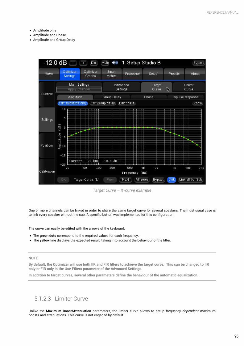
75
REFERENCE MANUAL
• Amplitude only • Amplitude and Phase • Amplitude and Group Delay
Target Curve – X-curve example
One or more channels can be linked in order to share the same target curve for several speakers. The most usual case is to link every speaker without the sub. A specific button was implemented for this configuration.
The curve can easily be edited with the arrows of the keyboard:
• The green dots correspond to the required values for each frequency, • The yellow line displays the expected result, taking into account the behaviour of the filter.
NOTE
By default, the Optimizer will use both IIR and FIR filters to achieve the target curve. This can be changed to IIR only or FIR only in the Use Filters parameter of the Advanced Settings.
In addition to target curves, several other parameters define the behaviour of the automatic equalization.
5.1.2.3 Limiter Curve Unlike the Maximum Boost/Attenuation parameters, the limiter curve allows to setup frequency-dependent maximum boosts and attenuations. This curve is not engaged by default.
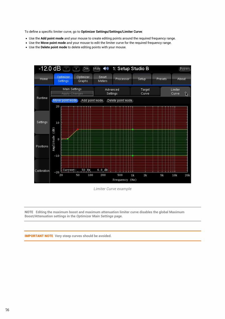
76
To define a specific limiter curve, go to Optimizer Settings/Settings/Limiter Curve:
• Use the Add point mode and your mouse to create editing points around the required frequency range. • Use the Move point mode and your mouse to edit the limiter curve for the required frequency range. • Use the Delete point mode to delete editing points with your mouse.
Limiter Curve example
NOTE Editing the maximum boost and maximum attenuation limiter curve disables the global Maximum Boost/Attenuation settings in the Optimizer Main Settings page.
IMPORTANT NOTE Very steep curves should be avoided.
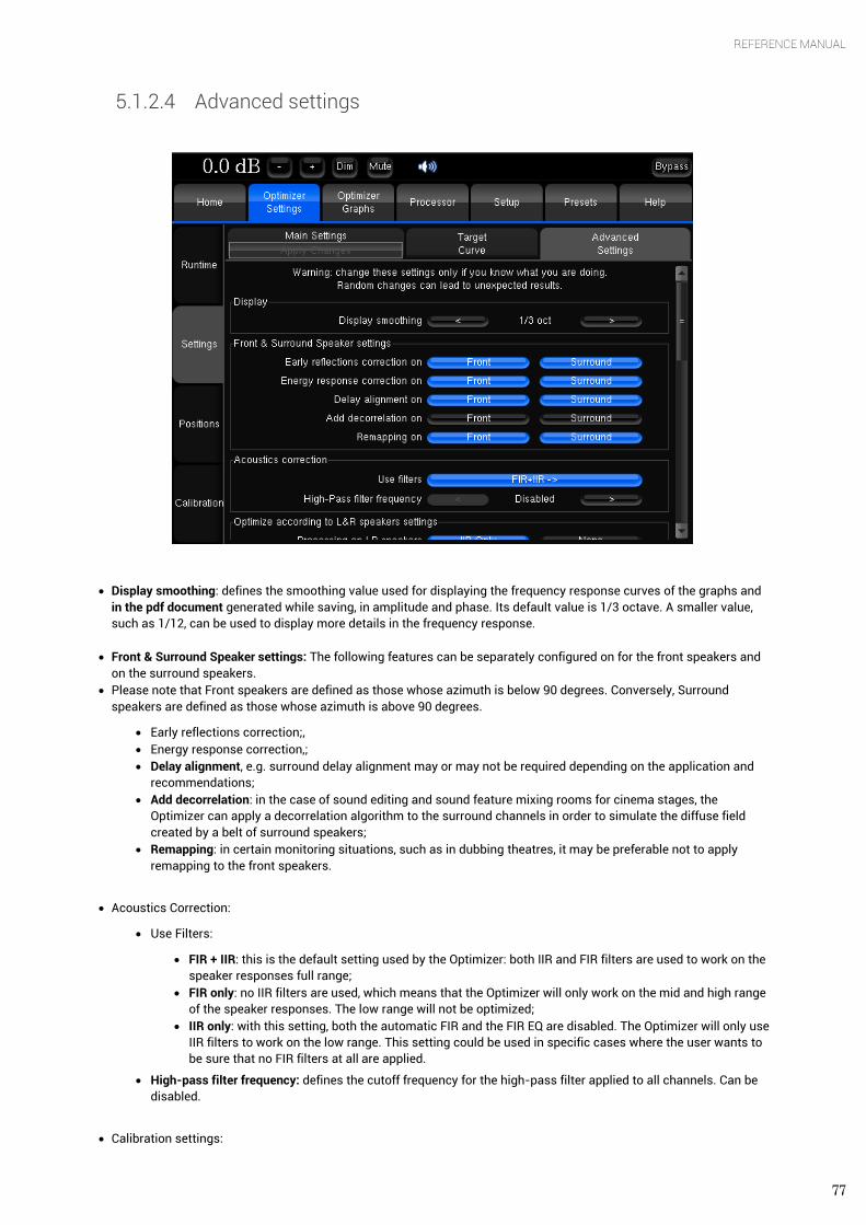
77
REFERENCE MANUAL
5.1.2.4 Advanced settings
• Display smoothing: defines the smoothing value used for displaying the frequency response curves of the graphs and in the pdf document generated while saving, in amplitude and phase. Its default value is 1/3 octave. A smaller value, such as 1/12, can be used to display more details in the frequency response.
• Front & Surround Speaker settings: The following features can be separately configured on for the front speakers and on the surround speakers.
• Please note that Front speakers are defined as those whose azimuth is below 90 degrees. Conversely, Surround speakers are defined as those whose azimuth is above 90 degrees.
• Early reflections correction;, • Energy response correction,; • Delay alignment, e.g. surround delay alignment may or may not be required depending on the application and
recommendations; • Add decorrelation: in the case of sound editing and sound feature mixing rooms for cinema stages, the
Optimizer can apply a decorrelation algorithm to the surround channels in order to simulate the diffuse field created by a belt of surround speakers;
• Remapping: in certain monitoring situations, such as in dubbing theatres, it may be preferable not to apply remapping to the front speakers.
• Acoustics Correction:
• Use Filters:
• FIR + IIR: this is the default setting used by the Optimizer: both IIR and FIR filters are used to work on the speaker responses full range;
• FIR only: no IIR filters are used, which means that the Optimizer will only work on the mid and high range of the speaker responses. The low range will not be optimized;
• IIR only: with this setting, both the automatic FIR and the FIR EQ are disabled. The Optimizer will only use IIR filters to work on the low range. This setting could be used in specific cases where the user wants to be sure that no FIR filters at all are applied.
• High-pass filter frequency: defines the cutoff frequency for the high-pass filter applied to all channels. Can be disabled.
• Calibration settings:
78
• Threshold for resp begin detect: is the threshold below the peak level of the impulse that is taken into consideration to determine the onset of the response. -15 dB is the default value and works in most cases. However, a lower threshold is recommended in a room with a huge amount of early reflections where the peak might not be detected correctly.
• Optimize according to L&R speakers:
• Processing on L&R speakers (default is IIR only): if the optimize mode is set to ‘Optimize according to L&R speakers’ in the main settings tab, the Optimizer will only use IIR filters on the L&R speakers. This can be switched to None to make sure the L&R speakers are not optimized at all.
• Align L&R on target (default is On): If this setting is on, the Optimizer will optimizer the Left & Right speaker using their average response as target. If this setting is off, only the center and surround channels will be optimized
• Optimizer Phase (default is On): Determines whether the Optimizer should optimize the phase response of the speakers or not when the According to L&R speakers mode is on.
• FIR and IIR:
• FIR filter length (default is 20ms): defines the length or number of taps of the FIR filter. The default setting of 20ms corresponds to 1024 taps at 48 kHz and 2048 taps at 96kHz.
• Number of IIR filters (default is 15): the number of IIR filters that will be used on every channel. • IIR filters minimal/maximal frequency (default is 20Hz/300Hz): IIR filters will be positioned from the minimal
frequency up to the maximal frequency.
NOTE In Automatic, the lower frequency of your speaker’s bandwidth will be set as the minimal frequency used for the IIR filter.
• Low-freq auto transition bandwidth: This settings determines the number of octaves over which the max limiter is progressively inhibited. The special value Disabled allows completely disable this automatic behavior of the limiters.
• Level alignment:
• Weighting used for levels (default is dBA): sets the type of weighting used by the optimizer for level alignment. • Width of level window (default is 16/f): this time-frequency window is used to compute the perceptual level of
every speaker. Its width can be modified to improve the automatic level alignment. • Maximum/minimum gain on speakers (default is 10dB/-20dB): defines the maximum/minimum gain that will be
applied for the automatic level alignment. • Minimal/maximal bandwidth frequency (default is 10Hz/Unlimited): defines the high end/ low end of the
bandwidth that is used as the starting point for level computations.
• Subwoofer low-pass filter:
• Cutoff frequency (default is disabled): defines the cutoff frequency for the low-pass filter that can be applied to the subwoofer.
• Filter type (default is Butterworth): defines the type of filter used at the cutoff frequency. The elliptic filter is sharper than the Butterworth but shows ripples in the whole bandwidth.
• Filter order (default is 4): defines the steepness of the filter. The slope gets stiffer as you increase the filter order. Please be aware that such changes may result in significant phase shifts
• Rp value (for elliptic filter) (default is 0.1 dB): sets a maximum amplitude ripple above the cutoff frequency. • Rs value (for elliptic filter) (default is 80 dB): defines the attenuation below the cutoff frequency.
• Decimation: It is strongly recommended not to change these settings unless you have been requested to do so by your Distributor.
• Advanced FIR: It is strongly recommended not to change these settings unless you have been requested to do so by your Trinnov Distributor.
5.1.3 Positions
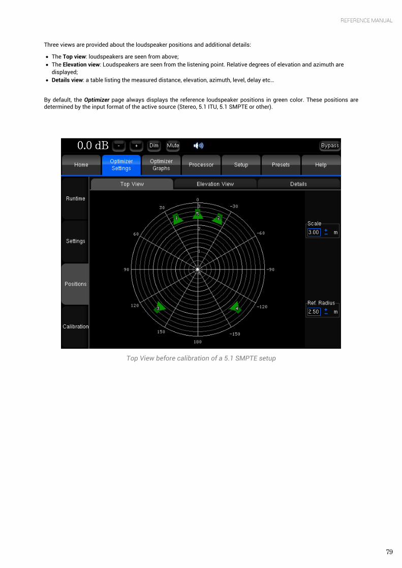
79
REFERENCE MANUAL
Three views are provided about the loudspeaker positions and additional details:
• The Top view: loudspeakers are seen from above; • The Elevation view: Loudspeakers are seen from the listening point. Relative degrees of elevation and azimuth are
displayed; • Details view: a table listing the measured distance, elevation, azimuth, level, delay etc…
By default, the Optimizer page always displays the reference loudspeaker positions in green color. These positions are determined by the input format of the active source (Stereo, 5.1 ITU, 5.1 SMPTE or other).
Top View before calibration of a 5.1 SMPTE setup
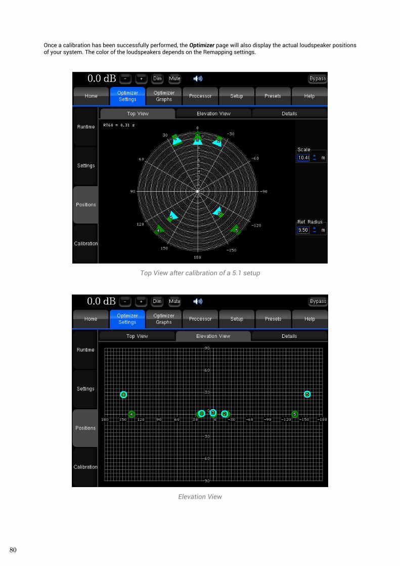
80
Once a calibration has been successfully performed, the Optimizer page will also display the actual loudspeaker positions of your system. The color of the loudspeakers depends on the Remapping settings.
Top View after calibration of a 5.1 setup
Elevation View

81
REFERENCE MANUAL
Loudspeaker Details view
Measurement details:
• Distance is the distance of the speaker (in meters) to the measurement point; • Elevation is the elevation of the speaker (in degrees) to the measurement point; • Azimuth is the azimuth of the speaker (in degrees) to the measurement point; • Level A corresponds to the A-weighted level of the speaker (in dBFS); • Level C corresponds to the C-weighted level of the speaker (in dBSPL); • Level A Compensated correspond to the corrected A-weighted level of the speaker (in dBFS); • Level C Compensated correspond to the corrected C-weighted level of the speaker (in dBSPL); • Delay corresponds to the distance of the speaker; • BM Delay may be added to the subwoofer to improve the crossover with the satellites. More rarely, if the subwoofer is
in advance, all the satellites are delayed; • Delay Compensation is the delay that is added to every speaker to time align the system; • Crest Factor helps evaluating the quality of the measurement. It should be higher than 30dB; Low values could indicate
background noise problems; • 6dB Bandwidth is the bandwidth of the speakers measured by the system (in Hz);
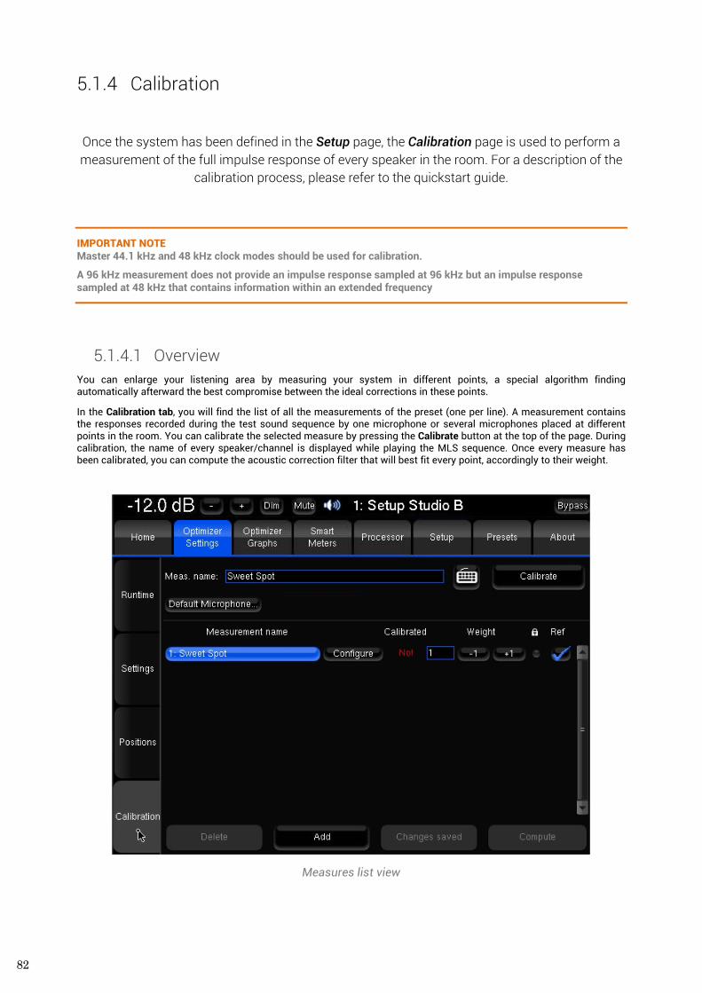
82
5.1.4 Calibration
Once the system has been defined in the Setup page, the Calibration page is used to perform a measurement of the full impulse response of every speaker in the room. For a description of the
calibration process, please refer to the quickstart guide.
IMPORTANT NOTE Master 44.1 kHz and 48 kHz clock modes should be used for calibration.
A 96 kHz measurement does not provide an impulse response sampled at 96 kHz but an impulse response sampled at 48 kHz that contains information within an extended frequency
5.1.4.1 Overview You can enlarge your listening area by measuring your system in different points, a special algorithm finding automatically afterward the best compromise between the ideal corrections in these points.
In the Calibration tab, you will find the list of all the measurements of the preset (one per line). A measurement contains the responses recorded during the test sound sequence by one microphone or several microphones placed at different points in the room. You can calibrate the selected measure by pressing the Calibrate button at the top of the page. During calibration, the name of every speaker/channel is displayed while playing the MLS sequence. Once every measure has been calibrated, you can compute the acoustic correction filter that will best fit every point, accordingly to their weight.
Measures list view
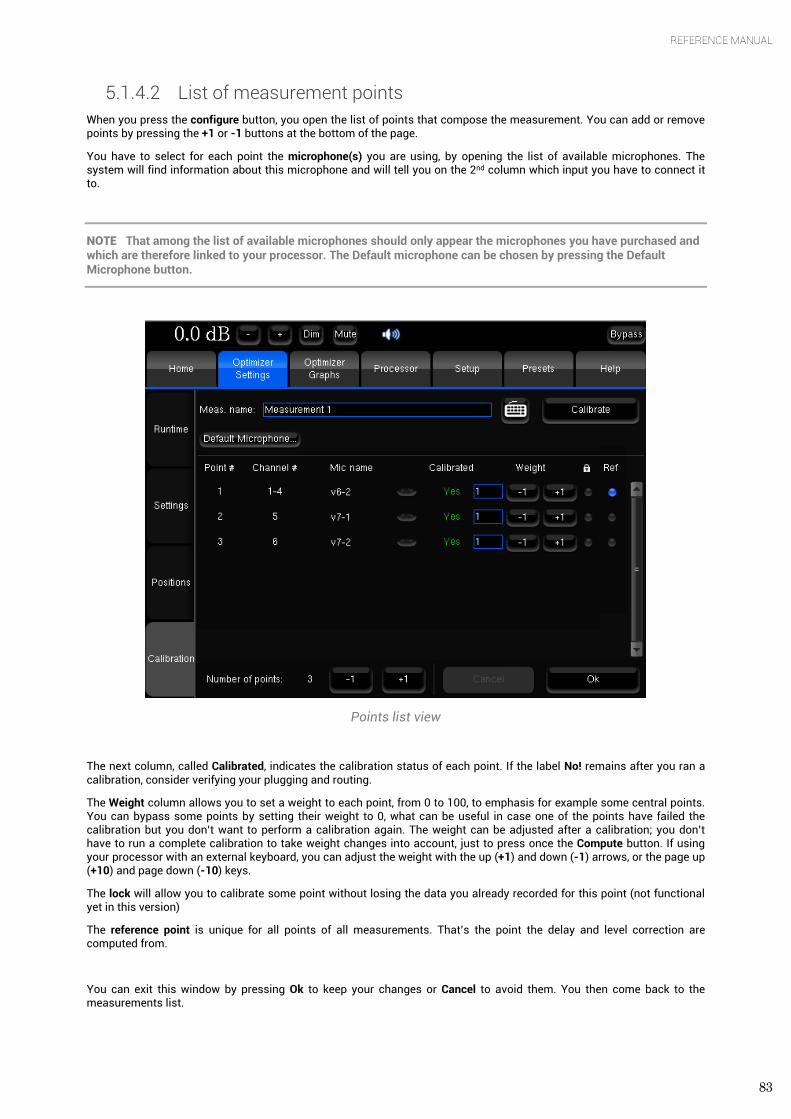
83
REFERENCE MANUAL
5.1.4.2 List of measurement points When you press the configure button, you open the list of points that compose the measurement. You can add or remove points by pressing the +1 or -1 buttons at the bottom of the page.
You have to select for each point the microphone(s) you are using, by opening the list of available microphones. The system will find information about this microphone and will tell you on the 2nd column which input you have to connect it to.
NOTE That among the list of available microphones should only appear the microphones you have purchased and which are therefore linked to your processor. The Default microphone can be chosen by pressing the Default Microphone button.
Points list view
The next column, called Calibrated, indicates the calibration status of each point. If the label No! remains after you ran a calibration, consider verifying your plugging and routing.
The Weight column allows you to set a weight to each point, from 0 to 100, to emphasis for example some central points. You can bypass some points by setting their weight to 0, what can be useful in case one of the points have failed the calibration but you don’t want to perform a calibration again. The weight can be adjusted after a calibration; you don’t have to run a complete calibration to take weight changes into account, just to press once the Compute button. If using your processor with an external keyboard, you can adjust the weight with the up (+1) and down (-1) arrows, or the page up (+10) and page down (-10) keys.
The lock will allow you to calibrate some point without losing the data you already recorded for this point (not functional yet in this version)
The reference point is unique for all points of all measurements. That’s the point the delay and level correction are computed from.
You can exit this window by pressing Ok to keep your changes or Cancel to avoid them. You then come back to the measurements list.
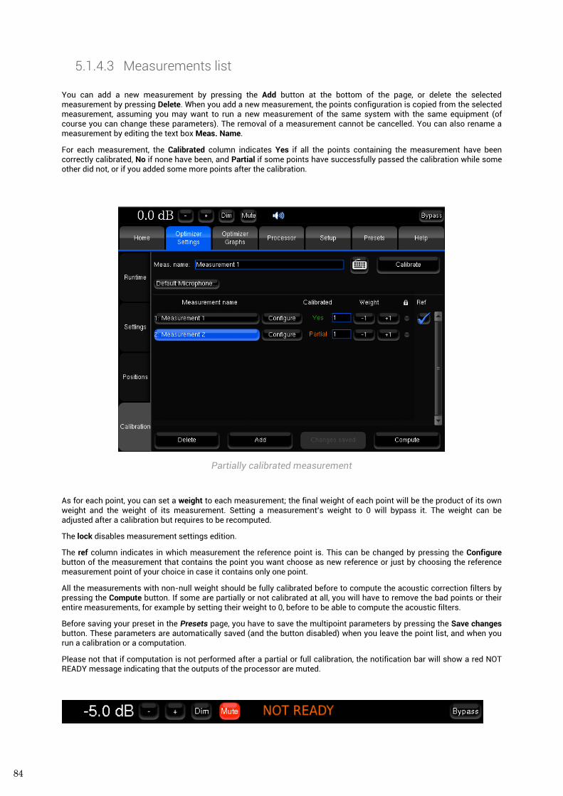
84
5.1.4.3 Measurements list You can add a new measurement by pressing the Add button at the bottom of the page, or delete the selected measurement by pressing Delete. When you add a new measurement, the points configuration is copied from the selected measurement, assuming you may want to run a new measurement of the same system with the same equipment (of course you can change these parameters). The removal of a measurement cannot be cancelled. You can also rename a measurement by editing the text box Meas. Name.
For each measurement, the Calibrated column indicates Yes if all the points containing the measurement have been correctly calibrated, No if none have been, and Partial if some points have successfully passed the calibration while some other did not, or if you added some more points after the calibration.
Partially calibrated measurement
As for each point, you can set a weight to each measurement; the final weight of each point will be the product of its own weight and the weight of its measurement. Setting a measurement’s weight to 0 will bypass it. The weight can be adjusted after a calibration but requires to be recomputed.
The lock disables measurement settings edition.
The ref column indicates in which measurement the reference point is. This can be changed by pressing the Configure button of the measurement that contains the point you want choose as new reference or just by choosing the reference measurement point of your choice in case it contains only one point.
All the measurements with non-null weight should be fully calibrated before to compute the acoustic correction filters by pressing the Compute button. If some are partially or not calibrated at all, you will have to remove the bad points or their entire measurements, for example by setting their weight to 0, before to be able to compute the acoustic filters.
Before saving your preset in the Presets page, you have to save the multipoint parameters by pressing the Save changes button. These parameters are automatically saved (and the button disabled) when you leave the point list, and when you run a calibration or a computation.
Please not that if computation is not performed after a partial or full calibration, the notification bar will show a red NOT READY message indicating that the outputs of the processor are muted.
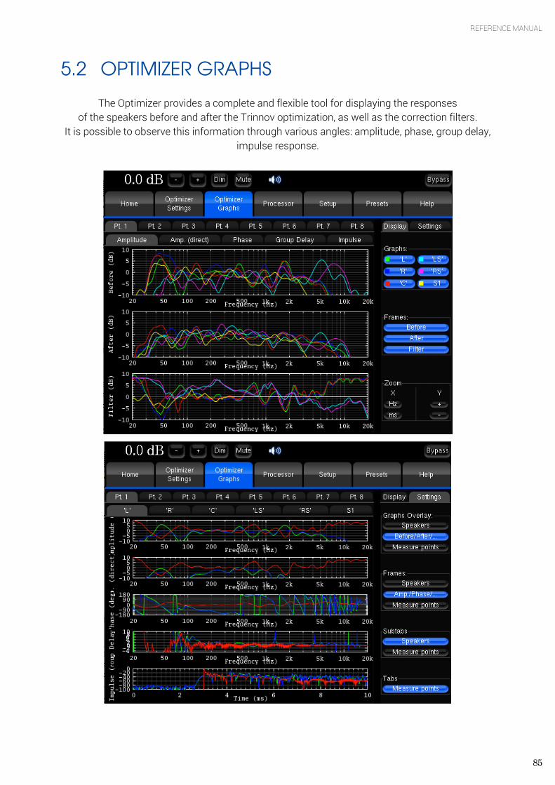
85
REFERENCE MANUAL
5.2 OPTIMIZER GRAPHS
The Optimizer provides a complete and flexible tool for displaying the responses of the speakers before and after the Trinnov optimization, as well as the correction filters.
It is possible to observe this information through various angles: amplitude, phase, group delay, impulse response.
86
The flexibility of this feature allows you to visualize on a same screen various type of data, which you can organize as you wish by a few parameters accessible in the Settings tab on the right:
• The Graphs Overlay: type of data you want to overlay on a same graph (or Frame) • The Frames: type of data disposed vertically on a same tab • The type of data you want to visualize on each tab and subtab.
For each level, you have the possibility to order the data through various criteria:
• The speaker (L, R, C, Sub, ...) • The point of measurement: in the case of a multipoint configuration, you can visualize the response measured on each
position, and the effect the optimization has on it • The type of response: speaker response before optimization, speaker response after optimization, or filter response
The type of visualization: amplitude, amplitude of the direct front and early reflections only, phase, group delay, or impulse response.
Zoom options allows modifying amplitude, frequency and time scales according to the type of representation.
NOTE The display settings will be saved in preset. This display only takes under consideration the automatic filters provided by the Optimizer, not the manual additional adjustments.
87
REFERENCE MANUAL
6. SMARTMETER GUIDE
6.1 SYSTEM OPERATION
6.1.1 Time Code Synchronization
The SmartMeter has 2 working modes:
Manual mode Automatic mode
Measurement is not synchronized with the incoming audio and must be launched and paused manually. In order to obtain consistent Integrated Loudness and LRA values, the program must be measured from its beginning to its end without roll backs or time jumps.
Measurement starts automatically with an external Time Code detected and read at 100% playing speed +/-5 %. Every Loudness and True Peak values are recorded and time stamped throughout the session. Rollbacks do not corrupt the measurement and Loudness/LRA values are always consistent.
IMPORTANT NOTE The incoming time code must be read at nominal speed +/- 5% for 250ms minimum to enable the measurement. As a consequence, it is highly recommended to start playing at least one second before the intended measurement starting point.
6.1.1.1 Synchronization activation
The automatic mode is activated by enabling the Time Code source in the Setup/Sources page.
IMPORTANT NOTE The only recognized Time Code format is LTC (Longitudinal Time Code). Time Code can therefore not be read when the source player is stopped.
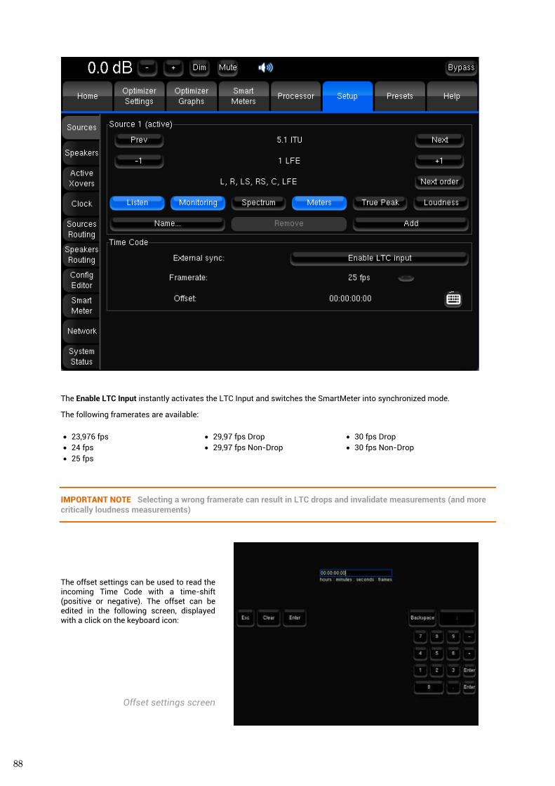
88
The Enable LTC Input instantly activates the LTC Input and switches the SmartMeter into synchronized mode.
The following framerates are available:
• 23,976 fps • 24 fps • 25 fps
• 29,97 fps Drop • 29,97 fps Non-Drop
• 30 fps Drop • 30 fps Non-Drop
IMPORTANT NOTE Selecting a wrong framerate can result in LTC drops and invalidate measurements (and more critically loudness measurements)
The offset settings can be used to read the incoming Time Code with a time-shift (positive or negative). The offset can be edited in the following screen, displayed with a click on the keyboard icon:
Offset settings screen
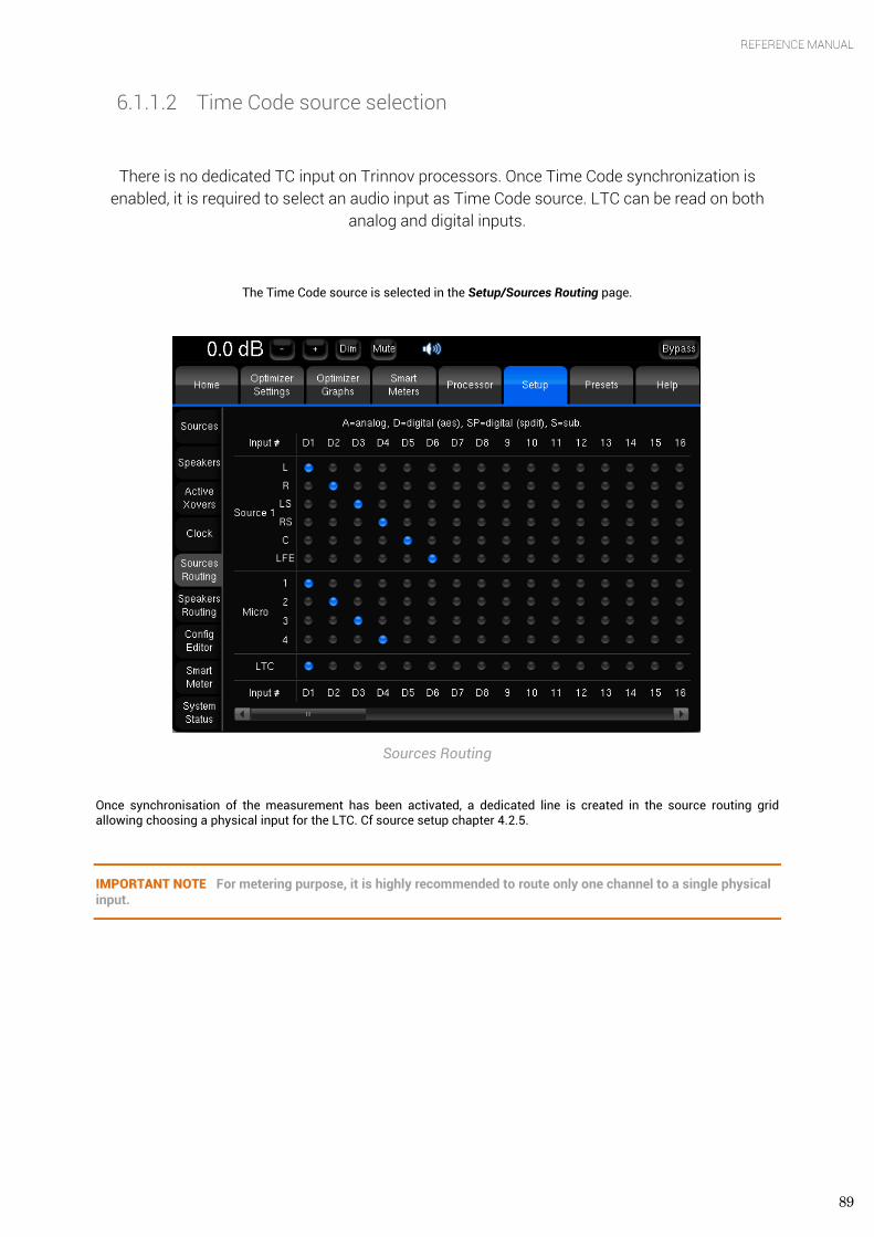
89
REFERENCE MANUAL
6.1.1.2 Time Code source selection
There is no dedicated TC input on Trinnov processors. Once Time Code synchronization is enabled, it is required to select an audio input as Time Code source. LTC can be read on both
analog and digital inputs.
The Time Code source is selected in the Setup/Sources Routing page.
Sources Routing
Once synchronisation of the measurement has been activated, a dedicated line is created in the source routing grid allowing choosing a physical input for the LTC. Cf source setup chapter 4.2.5.
IMPORTANT NOTE For metering purpose, it is highly recommended to route only one channel to a single physical input.
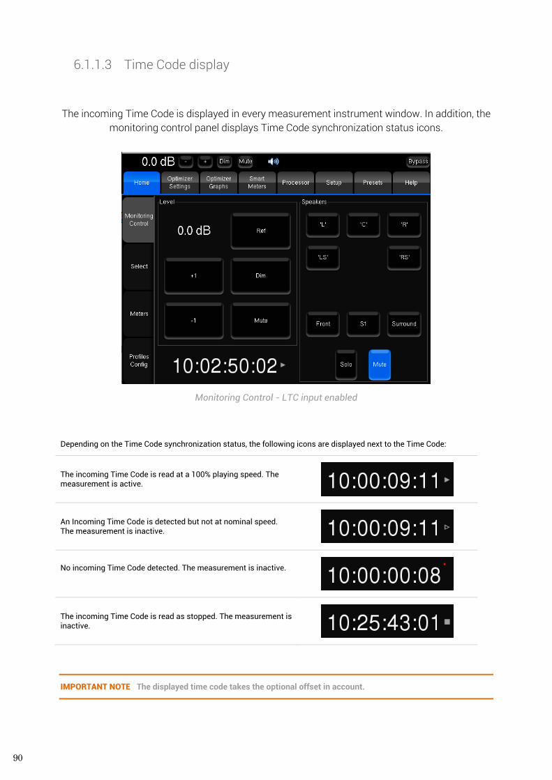
90
6.1.1.3 Time Code display
The incoming Time Code is displayed in every measurement instrument window. In addition, the monitoring control panel displays Time Code synchronization status icons.
Monitoring Control - LTC input enabled
Depending on the Time Code synchronization status, the following icons are displayed next to the Time Code:
The incoming Time Code is read at a 100% playing speed. The measurement is active.
An Incoming Time Code is detected but not at nominal speed. The measurement is inactive.
No incoming Time Code detected. The measurement is inactive.
The incoming Time Code is read as stopped. The measurement is inactive.
IMPORTANT NOTE The displayed time code takes the optional offset in account.
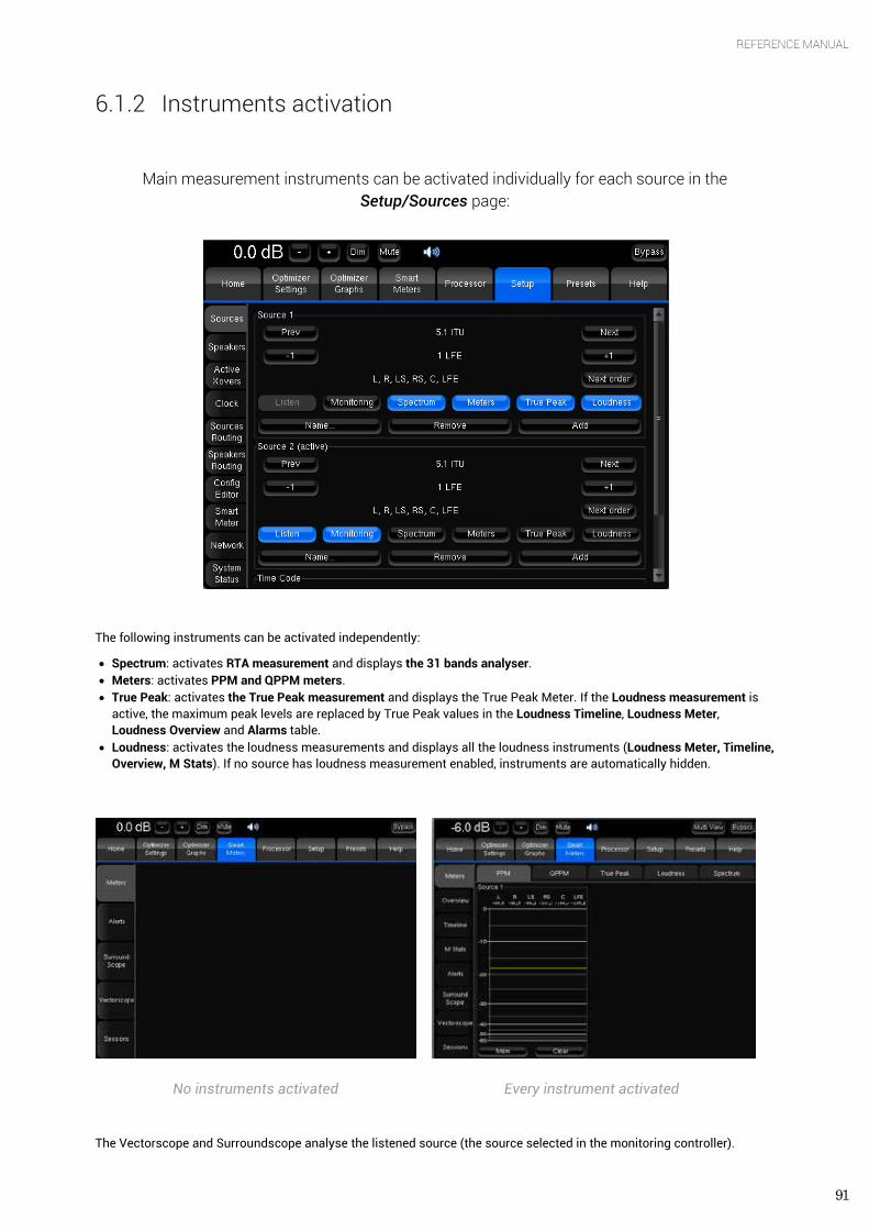
91
REFERENCE MANUAL
6.1.2 Instruments activation
Main measurement instruments can be activated individually for each source in the Setup/Sources page:
The following instruments can be activated independently:
• Spectrum: activates RTA measurement and displays the 31 bands analyser. • Meters: activates PPM and QPPM meters. • True Peak: activates the True Peak measurement and displays the True Peak Meter. If the Loudness measurement is
active, the maximum peak levels are replaced by True Peak values in the Loudness Timeline, Loudness Meter, Loudness Overview and Alarms table.
• Loudness: activates the loudness measurements and displays all the loudness instruments (Loudness Meter, Timeline, Overview, M Stats). If no source has loudness measurement enabled, instruments are automatically hidden.
No instruments activated Every instrument activated
The Vectorscope and Surroundscope analyse the listened source (the source selected in the monitoring controller).
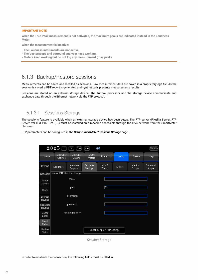
92
IMPORTANT NOTE
When the True Peak measurement is not activated, the maximum peaks are indicated instead in the Loudness Meter.
When the measurement is inactive:
- The Loudness instruments are not active. - The Vectorscope and surround analyser keep working. - Meters keep working but do not log any measurement (max peak).
6.1.3 Backup/Restore sessions Measurements can be saved and recalled as sessions. Raw measurement data are saved in a proprietary ogz file. As the session is saved, a PDF report is generated and synthetically presents measurements results.
Sessions are stored on an external storage device. The Trinnov processor and the storage device communicate and exchange data through the Ethernet network via the FTP protocol.
6.1.3.1 Sessions Storage The sessions feature is available when an external storage device has been setup. The FTP server (Filezilla Server, FTP Server, vsFTPd, ProFTPd...)...) must be installed on a machine accessible through the IPv4 network from the SmartMeter platform.
FTP parameters can be configured in the Setup/SmartMeter/Sessions Storage page.
Session Storage
In order to establish the connection, the following fields must be filled in:
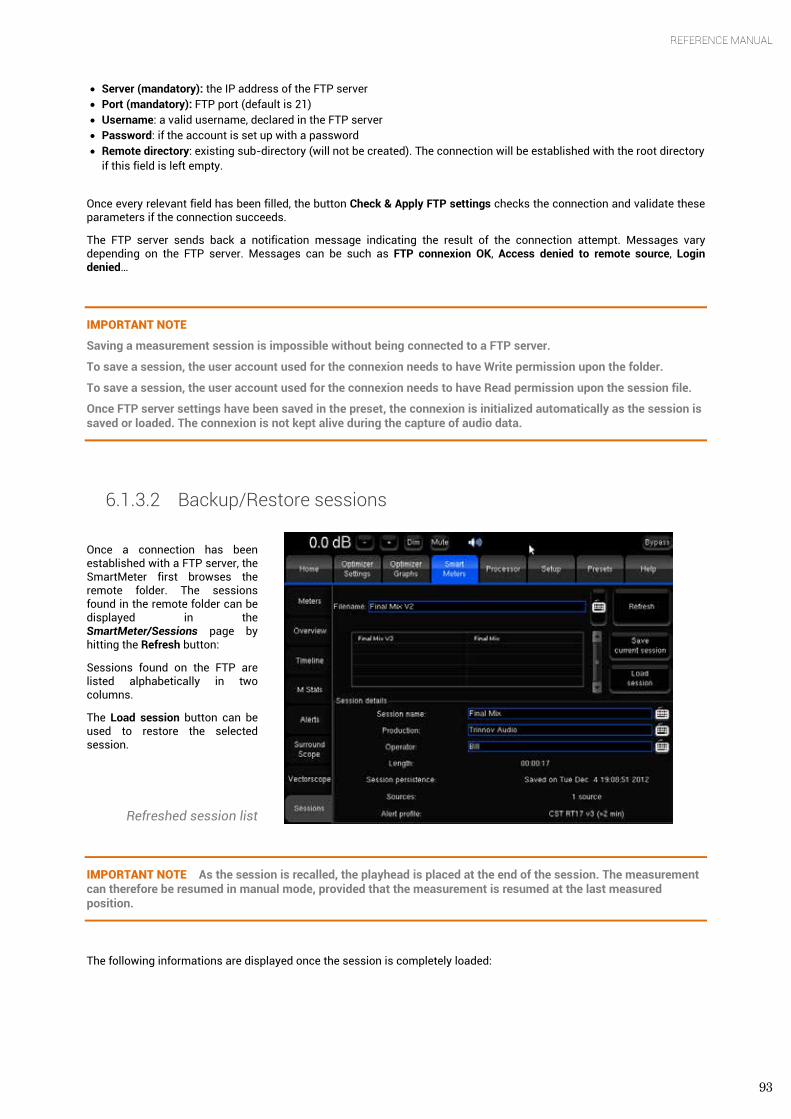
93
REFERENCE MANUAL
• Server (mandatory): the IP address of the FTP server • Port (mandatory): FTP port (default is 21) • Username: a valid username, declared in the FTP server • Password: if the account is set up with a password • Remote directory: existing sub-directory (will not be created). The connection will be established with the root directory
if this field is left empty.
Once every relevant field has been filled, the button Check & Apply FTP settings checks the connection and validate these parameters if the connection succeeds.
The FTP server sends back a notification message indicating the result of the connection attempt. Messages vary depending on the FTP server. Messages can be such as FTP connexion OK, Access denied to remote source, Login denied…
IMPORTANT NOTE
Saving a measurement session is impossible without being connected to a FTP server.
To save a session, the user account used for the connexion needs to have Write permission upon the folder.
To save a session, the user account used for the connexion needs to have Read permission upon the session file.
Once FTP server settings have been saved in the preset, the connexion is initialized automatically as the session is saved or loaded. The connexion is not kept alive during the capture of audio data.
6.1.3.2 Backup/Restore sessions
Once a connection has been established with a FTP server, the SmartMeter first browses the remote folder. The sessions found in the remote folder can be displayed in the SmartMeter/Sessions page by hitting the Refresh button:
Sessions found on the FTP are listed alphabetically in two columns.
The Load session button can be used to restore the selected session.
Refreshed session list
IMPORTANT NOTE As the session is recalled, the playhead is placed at the end of the session. The measurement can therefore be resumed in manual mode, provided that the measurement is resumed at the last measured position.
The following informations are displayed once the session is completely loaded:
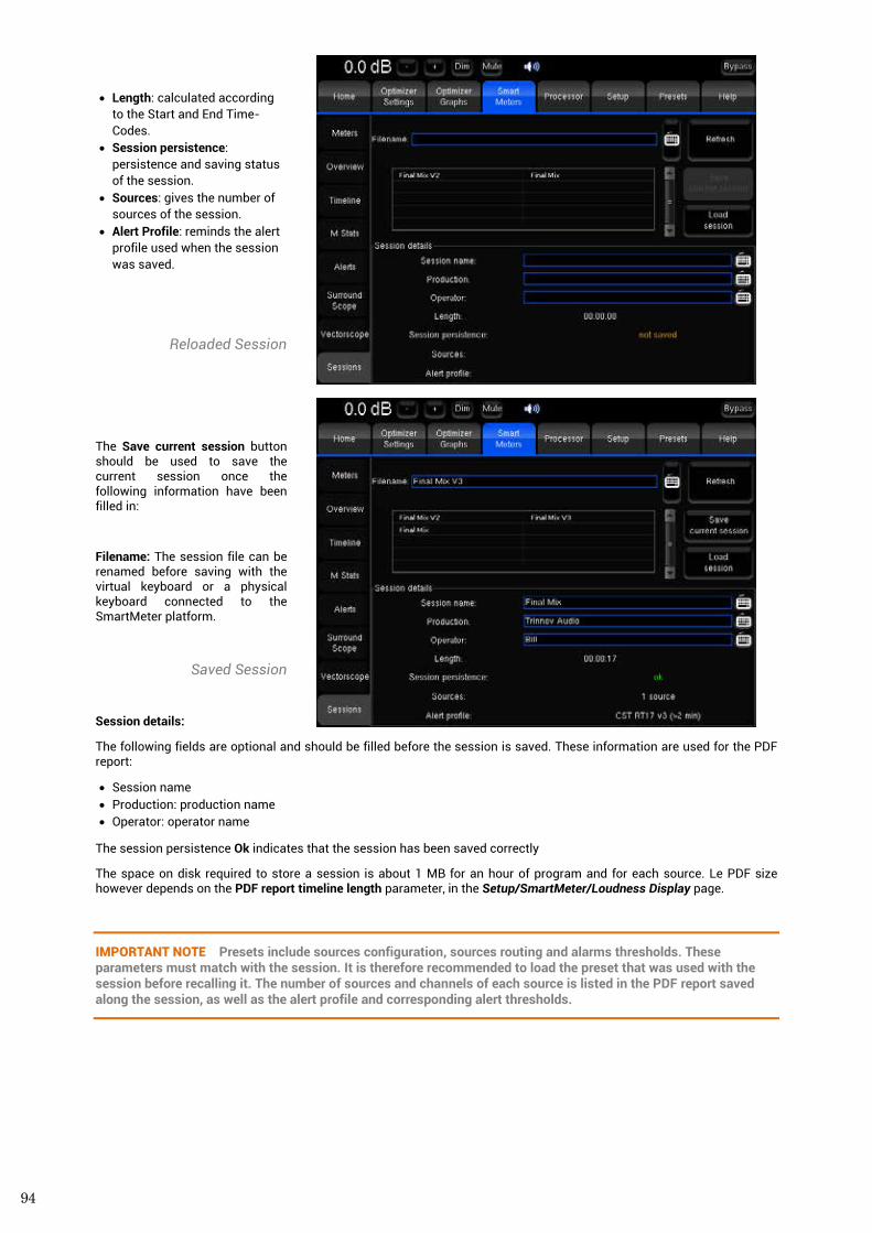
94
• Length: calculated according to the Start and End Time-Codes.
• Session persistence: persistence and saving status of the session.
• Sources: gives the number of sources of the session.
• Alert Profile: reminds the alert profile used when the session was saved.
Reloaded Session
The Save current session button should be used to save the current session once the following information have been filled in:
Filename: The session file can be renamed before saving with the virtual keyboard or a physical keyboard connected to the SmartMeter platform.
Saved Session
Session details:
The following fields are optional and should be filled before the session is saved. These information are used for the PDF report:
• Session name • Production: production name • Operator: operator name
The session persistence Ok indicates that the session has been saved correctly
The space on disk required to store a session is about 1 MB for an hour of program and for each source. Le PDF size however depends on the PDF report timeline length parameter, in the Setup/SmartMeter/Loudness Display page.
IMPORTANT NOTE Presets include sources configuration, sources routing and alarms thresholds. These parameters must match with the session. It is therefore recommended to load the preset that was used with the session before recalling it. The number of sources and channels of each source is listed in the PDF report saved along the session, as well as the alert profile and corresponding alert thresholds.
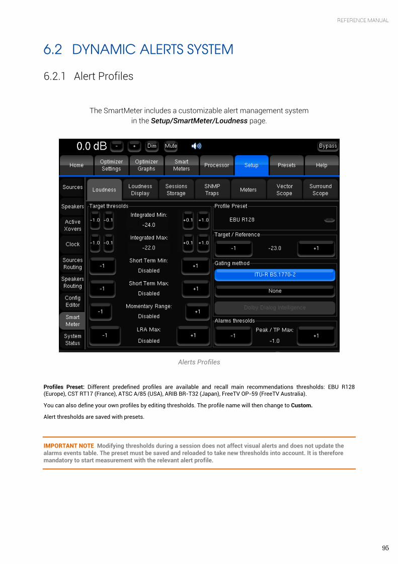
95
REFERENCE MANUAL
6.2 DYNAMIC ALERTS SYSTEM
6.2.1 Alert Profiles
The SmartMeter includes a customizable alert management system in the Setup/SmartMeter/Loudness page.
Alerts Profiles
Profiles Preset: Different predefined profiles are available and recall main recommendations thresholds: EBU R128 (Europe), CST RT17 (France), ATSC A/85 (USA), ARIB BR-T32 (Japan), FreeTV OP-59 (FreeTV Australia).
You can also define your own profiles by editing thresholds. The profile name will then change to Custom.
Alert thresholds are saved with presets.
IMPORTANT NOTE Modifying thresholds during a session does not affect visual alerts and does not update the alarms events table. The preset must be saved and reloaded to take new thresholds into account. It is therefore mandatory to start measurement with the relevant alert profile.
96
Alert profile parameters
Target / Reference: Target value for the Loudness Integrated measurement. This parameters determines the reference value 0 for the Timeline display in the LU scale. Loudness Integrated alerts are triggered by the Integrated Min and Integrated Max parameters. The EBU Mode label is displayed in the Timeline when the Target is -23.
Gating Method: Determines the method used to measure the Integrated Loudness:
• ITU-R BS.1770-2: algorithm used when applying the EBU R128 recommendation. This method implies measuring the whole program rather than Anchor Elements.
• None: every Loudness values are taken into account for the Loudness Integrated measurement. This method is used when measuring Anchor Elements (ATSC A/85).
Alarms thresholds: Determines the True-Peak Max threshold or the Peak Max when the True Peak measurement is not activated.
Target thresholds:
• Integrated Min / Max: determines Loudness Integrated Min and Max thresholds.
NOTE The EBU-Tech 3341 specifies an accepted tolerance of +/- 0,1LU for the integrated loudness measurement.
• Short Term Min / Short Term Max: determines Loudness Short Term thresholds. • Momentary Range: Momentary tolerance relative to the integrated target defined in Loudness Units. An alarm is
triggered when a Loudness Momentary value is measured past or below the thresholds for more than 5 sec.. • LRA Max: determines the maximum Loudness Range. An alarm is triggered when the measured LRA goes past this
value.
NOTE The EBU-Tech 3342 specifies an accepted tolerance of +/-1 LU for the Loudness Range measurement.
IMPORTANT NOTE Maximum Peak/True Peak thresholds are not related to the meters display parameters described in chapter 6.5.4.
6.2.2 Alerts Table The Peak/True Peak, Short Term and Momentary Loudness levels of every source measured above and/or below the session’s thresholds are displayed in an alert table in real-time.
Each line corresponds to a single alert and includes the following information displayed in columns from left to right:
• Time Code: includes the alert time code and a colour block to identify the source more easily • Type: displays the type of the alert • Source: provides the source affected by the alert (and the channel for Peak/True Peak). • Value: indicates the detected value and displays a red block to indicate Peak/True Peak alerts
Alerts can be filtered by type or source to help reading. The table can be scanned using the vertical scrolling bar and/or a mouse wheel.
Alerts are updated in real-time according to newly measured values.
The same table, filtered by source, is included in the PDF report saved with the session.
IMPORTANT NOTE LTC drop alerts indicate a sync loss and therefore an unmeasured region. LTC drop alerts are displayed in the table in plain red and cannot be filtered. These regions must be measured to obtain relevant information.
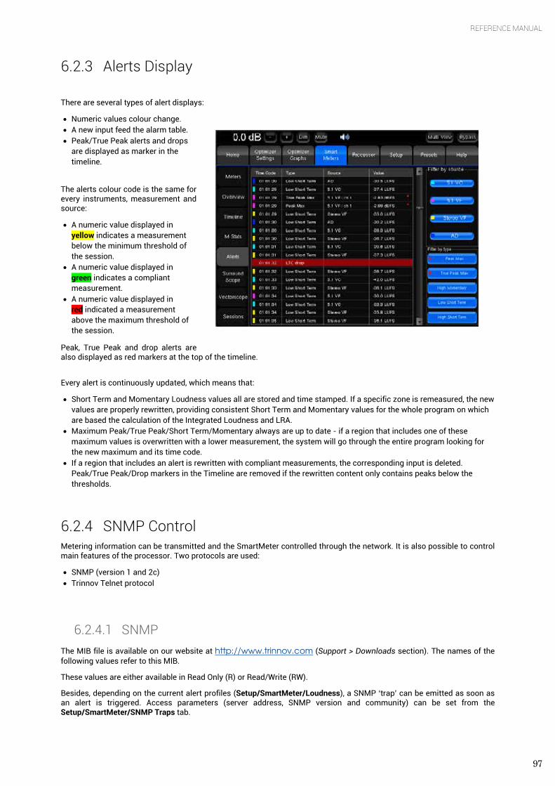
97
REFERENCE MANUAL
6.2.3 Alerts Display
There are several types of alert displays:
• Numeric values colour change. • A new input feed the alarm table. • Peak/True Peak alerts and drops
are displayed as marker in the timeline.
The alerts colour code is the same for every instruments, measurement and source:
• A numeric value displayed in yellow indicates a measurement below the minimum threshold of the session.
• A numeric value displayed in green indicates a compliant measurement.
• A numeric value displayed in red indicated a measurement above the maximum threshold of the session.
Peak, True Peak and drop alerts are also displayed as red markers at the top of the timeline.
Every alert is continuously updated, which means that:
• Short Term and Momentary Loudness values all are stored and time stamped. If a specific zone is remeasured, the new values are properly rewritten, providing consistent Short Term and Momentary values for the whole program on which are based the calculation of the Integrated Loudness and LRA.
• Maximum Peak/True Peak/Short Term/Momentary always are up to date - if a region that includes one of these maximum values is overwritten with a lower measurement, the system will go through the entire program looking for the new maximum and its time code.
• If a region that includes an alert is rewritten with compliant measurements, the corresponding input is deleted. Peak/True Peak/Drop markers in the Timeline are removed if the rewritten content only contains peaks below the thresholds.
6.2.4 SNMP Control Metering information can be transmitted and the SmartMeter controlled through the network. It is also possible to control main features of the processor. Two protocols are used:
• SNMP (version 1 and 2c) • Trinnov Telnet protocol
6.2.4.1 SNMP The MIB file is available on our website at http://www.trinnov.com (Support > Downloads section). The names of the following values refer to this MIB.
These values are either available in Read Only (R) or Read/Write (RW).
Besides, depending on the current alert profiles (Setup/SmartMeter/Loudness), a SNMP ‘trap’ can be emitted as soon as an alert is triggered. Access parameters (server address, SNMP version and community) can be set from the Setup/SmartMeter/SNMP Traps tab.
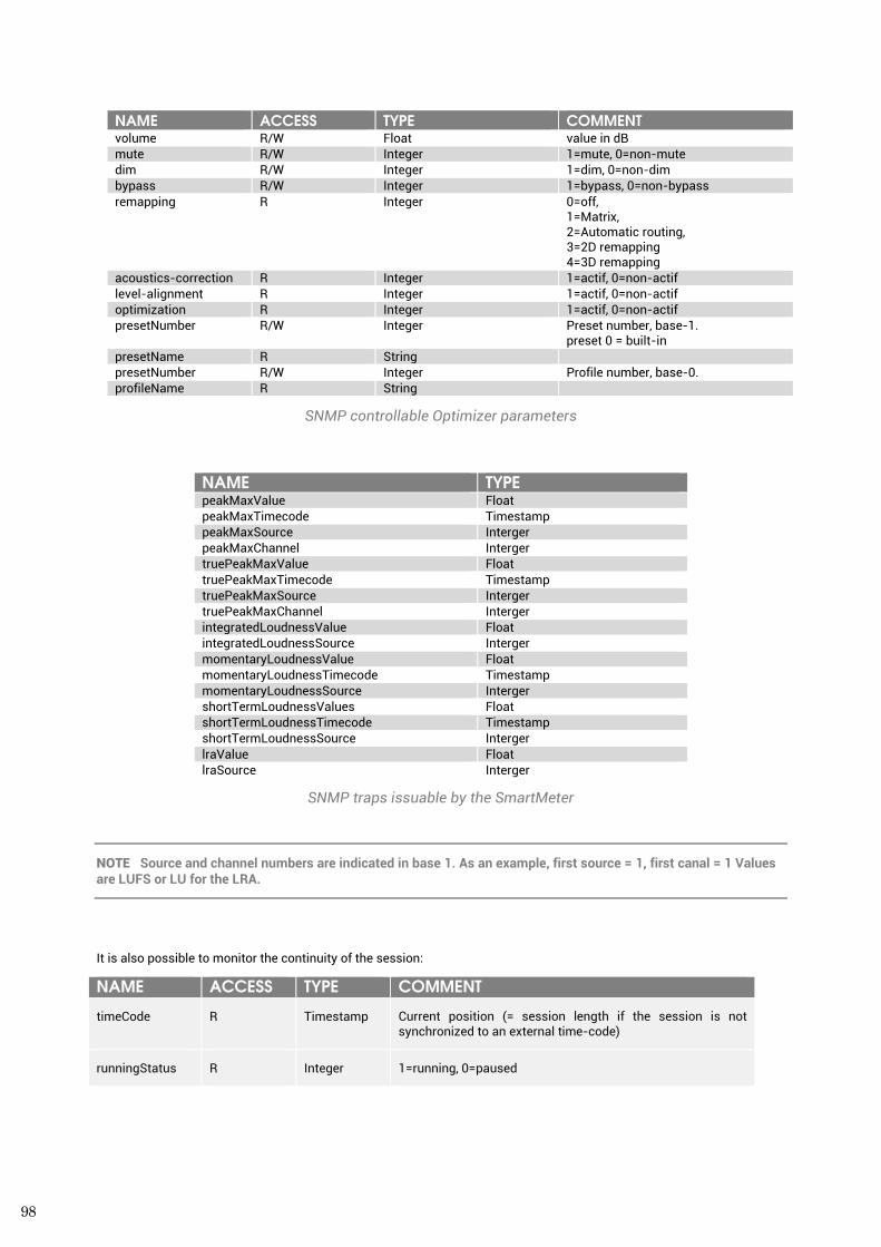
98
NAME ACCESS TYPE COMMENT volume R/W Float value in dB mute R/W Integer 1=mute, 0=non-mute dim R/W Integer 1=dim, 0=non-dim bypass R/W Integer 1=bypass, 0=non-bypass remapping R Integer 0=off,
1=Matrix, 2=Automatic routing, 3=2D remapping 4=3D remapping
acoustics-correction R Integer 1=actif, 0=non-actif level-alignment R Integer 1=actif, 0=non-actif optimization R Integer 1=actif, 0=non-actif presetNumber R/W Integer Preset number, base-1.
preset 0 = built-in presetName R String presetNumber R/W Integer Profile number, base-0. profileName R String
SNMP controllable Optimizer parameters
NAME TYPE peakMaxValue Float peakMaxTimecode Timestamp peakMaxSource Interger peakMaxChannel Interger truePeakMaxValue Float truePeakMaxTimecode Timestamp truePeakMaxSource Interger truePeakMaxChannel Interger integratedLoudnessValue Float integratedLoudnessSource Interger momentaryLoudnessValue Float momentaryLoudnessTimecode Timestamp momentaryLoudnessSource Interger shortTermLoudnessValues Float shortTermLoudnessTimecode Timestamp shortTermLoudnessSource Interger lraValue Float lraSource Interger
SNMP traps issuable by the SmartMeter
NOTE Source and channel numbers are indicated in base 1. As an example, first source = 1, first canal = 1 Values are LUFS or LU for the LRA.
It is also possible to monitor the continuity of the session:
NAME ACCESS TYPE COMMENT
timeCode R Timestamp Current position (= session length if the session is not synchronized to an external time-code)
runningStatus R Integer 1=running, 0=paused
99
REFERENCE MANUAL
6.2.4.2 Trinnov Telnet protocol This simple proprietary protocol allows controlling the Trinnov processor with a script or an external program. The access is based on a telnet mode (text) and is established using the IP address of the unit on the TCP port 44100. The line terminator characters is ‘\n’ Commands are formatted on a line with a space separating the name of the command from the possible argument. Following every command, the Optimizer returns a validation ‘OK\n’ or an error message. The end of the session is initiated by the command ‘bye\n’.
IMPORTANT NOTE No access protection is handled on the Optimizer end. It is the user's responsibility to secure the access to port 44100 with a properly configured firewall.
Use example of the Trinnov Telnet protocol
It is possible to establish a connection with the unit using a telnet client as follows:
telnet <ip> 44100
<ip> is the ip address of the machine
Followed by a connection status log sequence:
Trying <ip>... Connected to <ip> Escape character is '^]'. Welcome on Trinnov Optimizer (Version 3.6.0pre3+, ID 807649)
The first command is mandatory and corresponds to the designation of the appellant by typing ‘id’ followed by the name of the appellant. This name can be chosen freely among [a-z/A-Z]. For example:
id test
NOTE An exhaustive Telnet protocol documentation is available upon request from Trinnov.
Use example of controlling the SmartMeter
It is possible to control the main features of both the Optimizer and the SmartMeter using this protocol.
As an example, the following commands allow loading a profile, clearing measurements of the current session, starting measurements (supposing that measurements are not synchronized to an external timecode), stopping measurements, and saving the current session on the FTP server defined in the current preset/profile with the name provided as argument of this command.
Profile 1 // Load Profile number 1
smartmeter_session_clear // Clear measurements of the current session
smartmeter_session_start // Start measurements
smartmeter_session_pause // Stop measurements
smartmeter_session_save session_name // Save the session with the name ‘session_name’
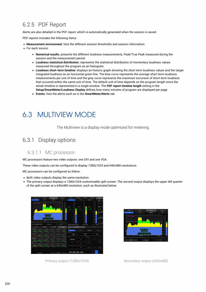
100
6.2.5 PDF Report Alerts are also detailed in the PDF report, which is automatically generated when the session is saved.
PDF reports includes the following items:
• Measurement environment: lists the different session thresholds and session information. • For each source:
• Numerical results: presents the different loudness measurements, Peak/True Peak measured during the session and the measurement period.
• Loudness statistical distribution: represents the statistical distribution of momentary loudness values measured throughout the program as an histogram.
• Loudness short-term timeline: displays an historic graph showing the short term loudness values and the target integrated loudness as an horizontal green line. The blue curve represents the average short term loudness measurements per unit of time and the grey curve represents the maximum excursion of short term loudness that occurred within the same unit of time. The default unit of time depends on the program length since the whole timeline is represented in a single window. The PDF report timeline length setting in the Setup/SmartMeter/Loudness Display defines how many minutes of program are displayed per page.
• Events: lists the alerts such as in the SmartMeter/Alerts tab.
6.3 MULTIVIEW MODE
The Multiview is a display mode optimized for metering.
6.3.1 Display options
6.3.1.1 MC processor MC processors feature two video outputs: one DVI and one VGA.
These video outputs can be configured to display 1280x1024 and 640x480 resolutions.
MC processors can be configured as follow:
• Both video outputs display the same resolution. • The primary output displays a 1280x1024 customisable split screen. The second output displays the upper left quarter
of the split screen at a 640x480 resolution, such as illustrated below:
Primary output (1280x1024) Secondary output (640x480)
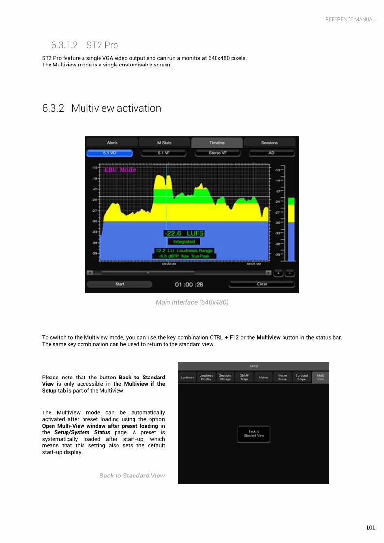
101
REFERENCE MANUAL
6.3.1.2 ST2 Pro ST2 Pro feature a single VGA video output and can run a monitor at 640x480 pixels. The Multiview mode is a single customisable screen.
6.3.2 Multiview activation
Main Interface (640x480)
To switch to the Multiview mode, you can use the key combination CTRL + F12 or the Multiview button in the status bar. The same key combination can be used to return to the standard view.
Please note that the button Back to Standard View is only accessible in the Multiview if the Setup tab is part of the Multiview.
The Multiview mode can be automatically activated after preset loading using the option Open Multi-View window after preset loading in the Setup/System Status page. A preset is systematically loaded after start-up, which means that this setting also sets the default start-up display.
Back to Standard View
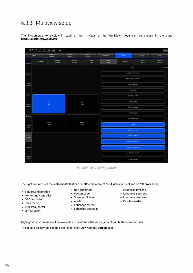
102
6.3.3 Multiview setup
The instruments to display in each of the 4 views of the Multiview mode can be chosen in the page Setup/SmartMeter/Multiview:
MC Multiview Configuration
The right column lists the instruments that can be affected to any of the 4 views (left column on MC processors):
• Setup/Configuration • Monitoring Controller • DRC controller • Peak meter • True Peak Meter • QPPM Meter
• RTA spectrum • Vectorscope • Surround Scope • Alerts • Loudness Meter • Loudness statistics
• Loudness timeline • Loudness sessions • Loudness overview • Profiles loader
Highlighted instruments will be available in one of the 4 the views (left column buttons) as subtabs.
The default display tab can be selected for each view with the Default bullet.
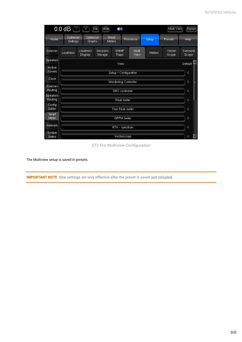
103
REFERENCE MANUAL
ST2 Pro Multiview Configuration
The Multiview setup is saved in presets.
IMPORTANT NOTE New settings are only effective after the preset is saved and reloaded.
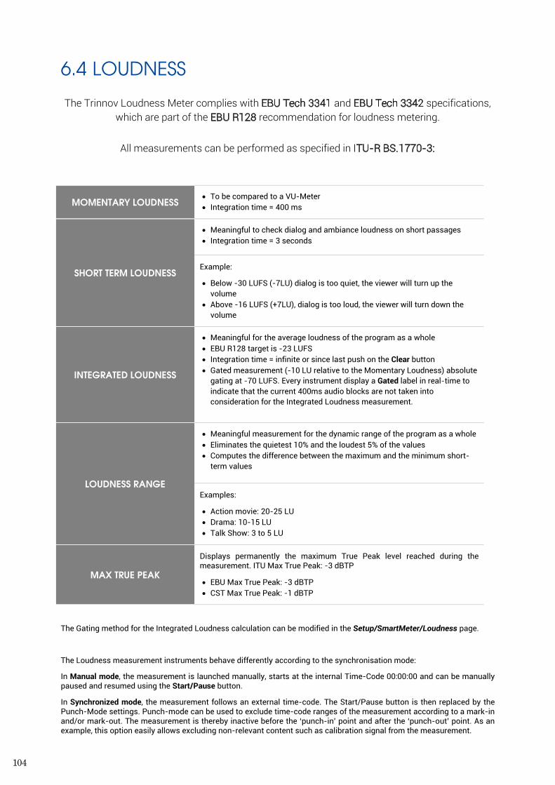
104
6.4 LOUDNESS
The Trinnov Loudness Meter complies with EBU Tech 3341 and EBU Tech 3342 specifications, which are part of the EBU R128 recommendation for loudness metering.
All measurements can be performed as specified in ITU-R BS.1770-3:
MOMENTARY LOUDNESS • To be compared to a VU-Meter • Integration time = 400 ms
SHORT TERM LOUDNESS
• Meaningful to check dialog and ambiance loudness on short passages • Integration time = 3 seconds
Example:
• Below -30 LUFS (-7LU) dialog is too quiet, the viewer will turn up the volume
• Above -16 LUFS (+7LU), dialog is too loud, the viewer will turn down the volume
INTEGRATED LOUDNESS
• Meaningful for the average loudness of the program as a whole • EBU R128 target is -23 LUFS • Integration time = infinite or since last push on the Clear button • Gated measurement (-10 LU relative to the Momentary Loudness) absolute
gating at -70 LUFS. Every instrument display a Gated label in real-time to indicate that the current 400ms audio blocks are not taken into consideration for the Integrated Loudness measurement.
LOUDNESS RANGE
• Meaningful measurement for the dynamic range of the program as a whole • Eliminates the quietest 10% and the loudest 5% of the values • Computes the difference between the maximum and the minimum short-
term values
Examples:
• Action movie: 20-25 LU • Drama: 10-15 LU • Talk Show: 3 to 5 LU
MAX TRUE PEAK
Displays permanently the maximum True Peak level reached during the measurement. ITU Max True Peak: -3 dBTP
• EBU Max True Peak: -3 dBTP • CST Max True Peak: -1 dBTP
The Gating method for the Integrated Loudness calculation can be modified in the Setup/SmartMeter/Loudness page.
The Loudness measurement instruments behave differently according to the synchronisation mode:
In Manual mode, the measurement is launched manually, starts at the internal Time-Code 00:00:00 and can be manually paused and resumed using the Start/Pause button.
In Synchronized mode, the measurement follows an external time-code. The Start/Pause button is then replaced by the Punch-Mode settings. Punch-mode can be used to exclude time-code ranges of the measurement according to a mark-in and/or mark-out. The measurement is thereby inactive before the ‘punch-in’ point and after the ‘punch-out’ point. As an example, this option easily allows excluding non-relevant content such as calibration signal from the measurement.
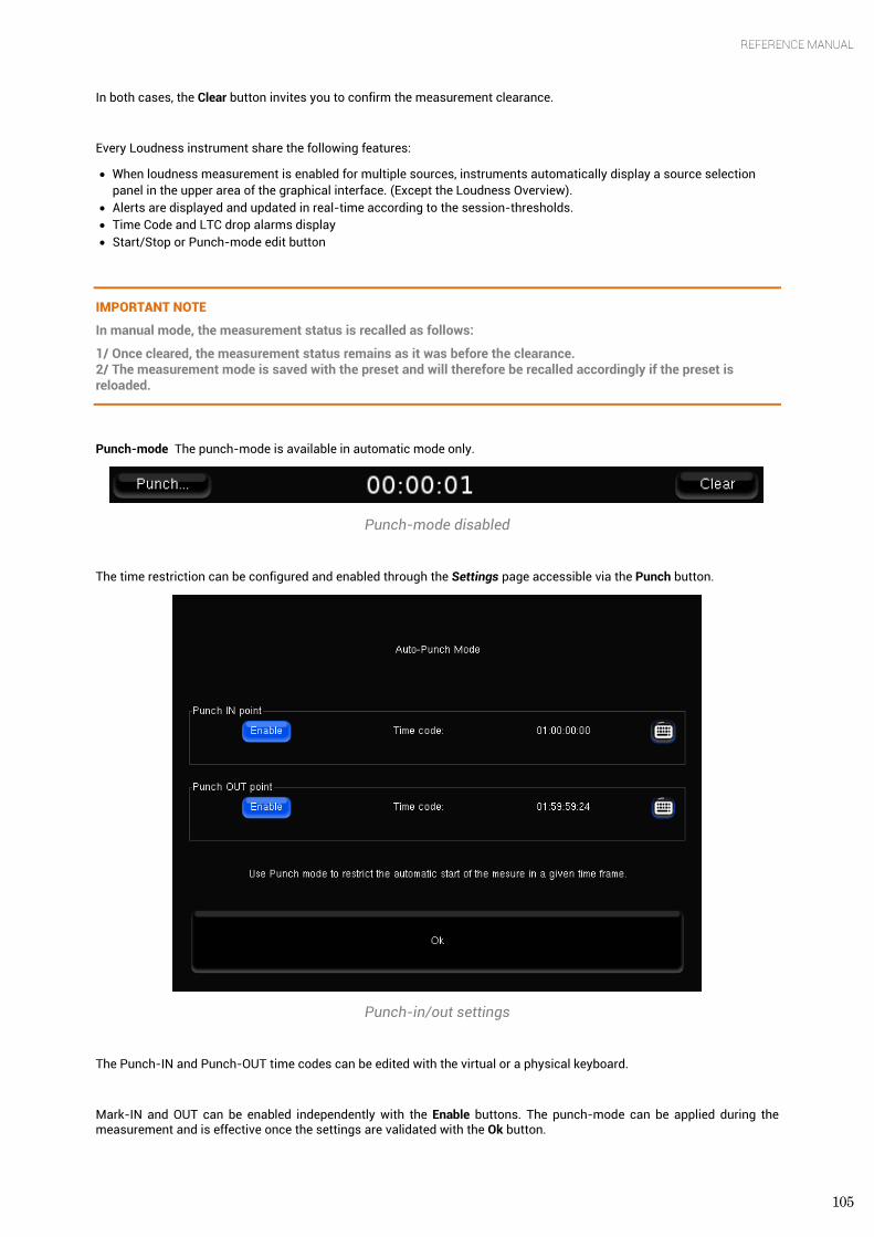
105
REFERENCE MANUAL
In both cases, the Clear button invites you to confirm the measurement clearance.
Every Loudness instrument share the following features:
• When loudness measurement is enabled for multiple sources, instruments automatically display a source selection panel in the upper area of the graphical interface. (Except the Loudness Overview).
• Alerts are displayed and updated in real-time according to the session-thresholds. • Time Code and LTC drop alarms display • Start/Stop or Punch-mode edit button
IMPORTANT NOTE
In manual mode, the measurement status is recalled as follows:
1/ Once cleared, the measurement status remains as it was before the clearance. 2/ The measurement mode is saved with the preset and will therefore be recalled accordingly if the preset is reloaded.
Punch-mode The punch-mode is available in automatic mode only.
Punch-mode disabled
The time restriction can be configured and enabled through the Settings page accessible via the Punch button.
Punch-in/out settings
The Punch-IN and Punch-OUT time codes can be edited with the virtual or a physical keyboard.
Mark-IN and OUT can be enabled independently with the Enable buttons. The punch-mode can be applied during the measurement and is effective once the settings are validated with the Ok button.
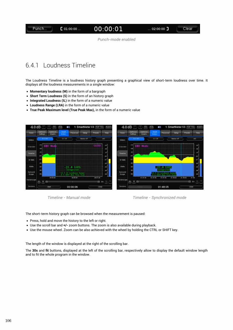
106
Punch-mode enabled
6.4.1 Loudness Timeline
The Loudness Timeline is a loudness history graph presenting a graphical view of short-term loudness over time. It displays all the loudness measurements in a single window:
• Momentary loudness (M) in the form of a bargraph • Short Term Loudness (S) in the form of an history graph • Integrated Loudness (IL) in the form of a numeric value • Loudness Range (LRA) in the form of a numeric value • True Peak Maximum level (True Peak Max), in the form of a numeric value
Timeline - Manual mode Timeline - Synchronized mode
The short-term history graph can be browsed when the measurement is paused:
• Press, hold and move the history to the left or right. • Use the scroll bar and +/- zoom buttons. The zoom is also available during playback. • Use the mouse wheel. Zoom can be also achieved with the wheel by holding the CTRL or SHIFT key.
The length of the window is displayed at the right of the scrolling bar.
The 30s and fit buttons, displayed at the left of the scrolling bar, respectively allow to display the default window length and to fit the whole program in the window.
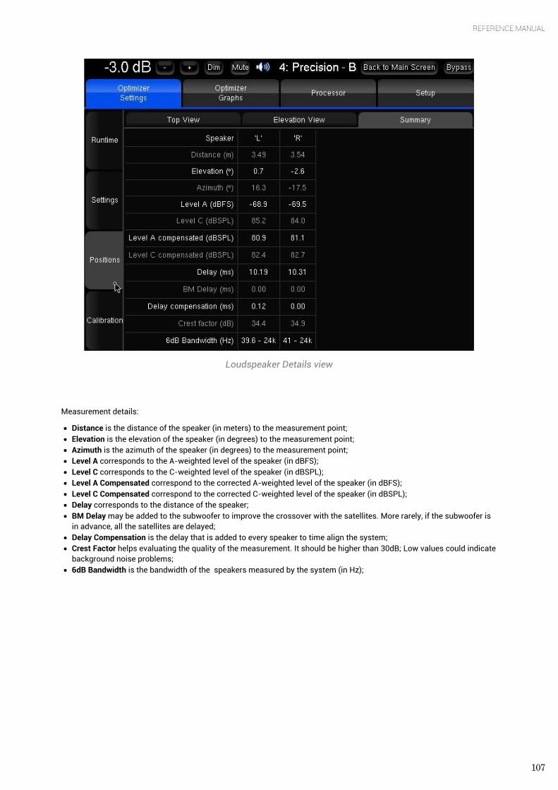
107
REFERENCE MANUAL
Loudspeaker Details view
Measurement details:
• Distance is the distance of the speaker (in meters) to the measurement point; • Elevation is the elevation of the speaker (in degrees) to the measurement point; • Azimuth is the azimuth of the speaker (in degrees) to the measurement point; • Level A corresponds to the A-weighted level of the speaker (in dBFS); • Level C corresponds to the C-weighted level of the speaker (in dBSPL); • Level A Compensated correspond to the corrected A-weighted level of the speaker (in dBFS); • Level C Compensated correspond to the corrected C-weighted level of the speaker (in dBSPL); • Delay corresponds to the distance of the speaker; • BM Delay may be added to the subwoofer to improve the crossover with the satellites. More rarely, if the subwoofer is
in advance, all the satellites are delayed; • Delay Compensation is the delay that is added to every speaker to time align the system; • Crest Factor helps evaluating the quality of the measurement. It should be higher than 30dB; Low values could indicate
background noise problems; • 6dB Bandwidth is the bandwidth of the speakers measured by the system (in Hz);
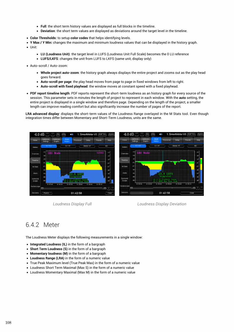
108
• Full: the short term history values are displayed as full blocks in the timeline. • Deviation: the short term values are displayed as deviations around the target level in the timeline.
• Color Thresholds: to setup color codes that helps identifying levels. • Y Max / Y Min: changes the maximum and minimum loudness values that can be displayed in the history graph. • Unit:
• LU (Loudness Unit): the target level in LUFS (Loudness Unit Full Scale) becomes the 0 LU reference • LUFS/LKFS: changes the unit from LUFS to LKFS (same unit, display only)
• Auto-scroll / Auto-zoom:
• Whole project auto-zoom: the history graph always displays the entire project and zooms out as the play head goes forward.
• Auto-scroll per page: the play head moves from page to page in fixed windows from left to right. • Auto-scroll with fixed playhead: the window moves at constant speed with a fixed playhead.
• PDF report timeline length: PDF reports represent the short-term loudness as an history graph for every source of the session. This parameter sets in minutes the length of project to represent in each window. With the auto setting, the entire project is displayed in a single window and therefore page. Depending on the length of the project, a smaller length can improve reading comfort but also significantly increase the number of pages of the report.
LRA advanced display: displays the short-term values of the Loudness Range overlayed in the M Stats tool. Even though integration times differ between Momentary and Short-Term Loudness, units are the same.
Loudness Display Full Loudness Display Deviation
6.4.2 Meter The Loudness Meter displays the following measurements in a single window:
• Integrated Loudness (IL) in the form of a bargraph • Short Term Loudness (S) in the form of a bargraph • Momentary loudness (M) in the form of a bargraph • Loudness Range (LRA) in the form of a numeric value • True Peak Maximum level (True Peak Max) in the form of a numeric value • Loudness Short Term Maximal (Max S) in the form of a numeric value • Loudness Momentary Maximal (Max M) in the form of a numeric value
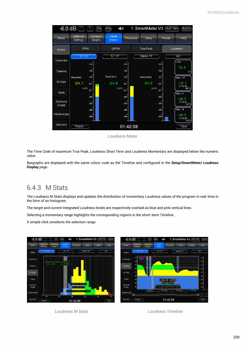
109
REFERENCE MANUAL
Loudness Meter
The Time Code of maximum True Peak, Loudness Short Term and Loudness Momentary are displayed below the numeric value.
Bargraphs are displayed with the same colour code as the Timeline and configured in the Setup/SmartMeter/ Loudness Display page.
6.4.3 M Stats The Loudness M Stats displays and updates the distribution of momentary Loudness values of the program in real-time in the form of an histogram.
The target and current Integrated Loudness levels are respectively overlaid as blue and pink vertical lines.
Selecting a momentary range highlights the corresponding regions in the short-term Timeline.
A simple click unselects the selection range.
Loudness M Stats Loudness Timeline
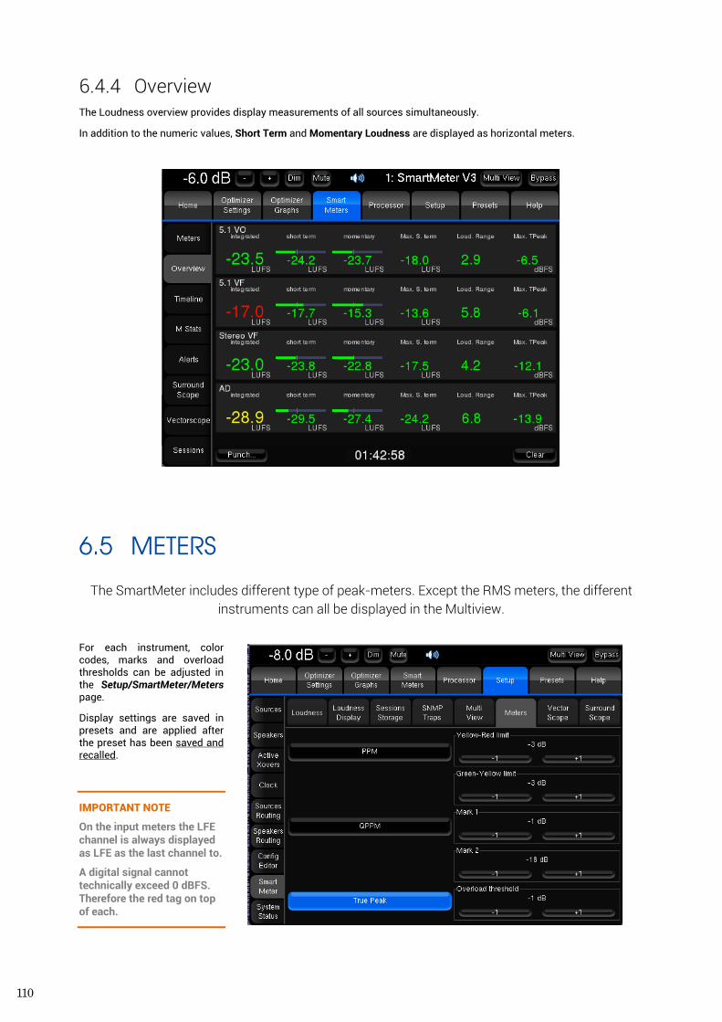
110
6.4.4 Overview The Loudness overview provides display measurements of all sources simultaneously.
In addition to the numeric values, Short Term and Momentary Loudness are displayed as horizontal meters.
6.5 METERS
The SmartMeter includes different type of peak-meters. Except the RMS meters, the different instruments can all be displayed in the Multiview.
For each instrument, color codes, marks and overload thresholds can be adjusted in the Setup/SmartMeter/Meters page.
Display settings are saved in presets and are applied after the preset has been saved and recalled.
IMPORTANT NOTE
On the input meters the LFE channel is always displayed as LFE as the last channel to.
A digital signal cannot technically exceed 0 dBFS. Therefore the red tag on top of each.
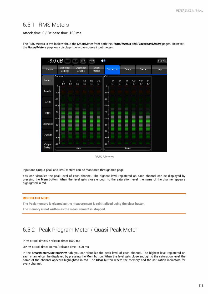
111
REFERENCE MANUAL
6.5.1 RMS Meters Attack time: 0 / Release time: 100 ms
The RMS Meters is available without the SmartMeter from both the Home/Meters and Processor/Meters pages. However, the Home/Meters page only displays the active source input meters.
RMS Meters
Input and Output peak and RMS meters can be monitored through this page.
You can visualize the peak level of each channel. The highest level registered on each channel can be displayed by pressing the Mem button. When the level gets close enough to the saturation level, the name of the channel appears highlighted in red.
IMPORTANT NOTE
The Peak memory is cleared as the measurement is reinitialized using the clear button.
The memory is not written as the measurement is stopped.
6.5.2 Peak Program Meter / Quasi Peak Meter PPM attack time: 0 / release time: 1500 ms
QPPM attack time: 10 ms / release time: 1500 ms
In the SmartMeters/Meters/PPM tab, you can visualize the peak level of each channel. The highest level registered on each channel can be displayed by pressing the Mem button. When the level gets close enough to the saturation level, the name of the channel appears highlighted in red. The Clear button resets the memory and the saturation indicators for every channel.
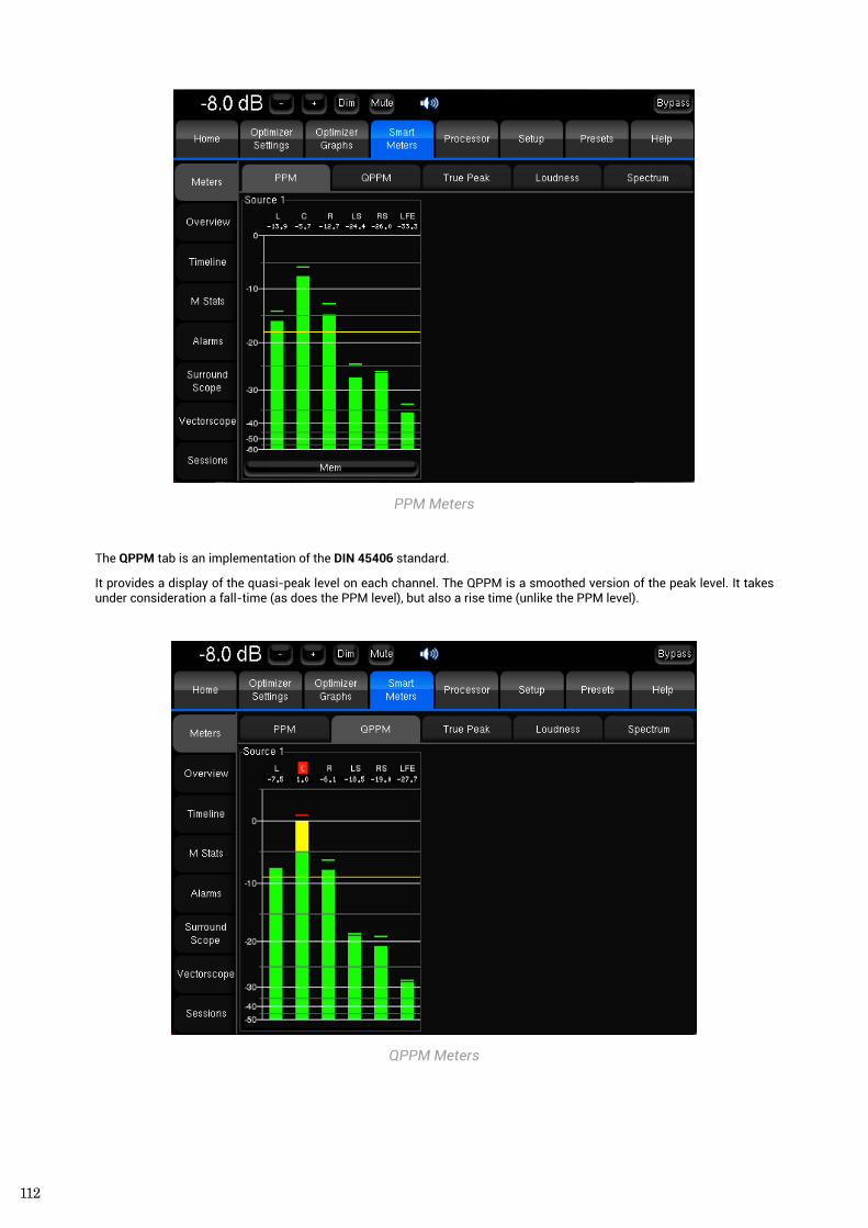
112
PPM Meters
The QPPM tab is an implementation of the DIN 45406 standard.
It provides a display of the quasi-peak level on each channel. The QPPM is a smoothed version of the peak level. It takes under consideration a fall-time (as does the PPM level), but also a rise time (unlike the PPM level).
QPPM Meters
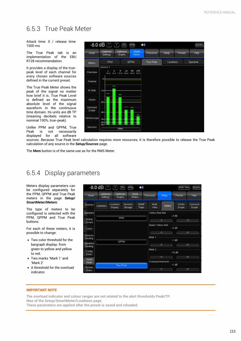
113
REFERENCE MANUAL
6.5.3 True Peak Meter Attack time: 0 / release time: 1500 ms
The True Peak tab is an implementation of the EBU R128 recommendation.
It provides a display of the true-peak level of each channel for every chosen software sources defined in the current preset.
The True Peak Meter shows the peak of the signal no matter how brief it is. True Peak Level is defined as the maximum absolute level of the signal waveform in the continuous time domain. Its units are dB TP (meaning decibels relative to nominal 100%, true-peak).
Unlike PPM and QPPM, True Peak is not necessarily displayed for all software sources. Because True Peak level calculation requires more resources, it is therefore possible to release the True Peak calculation of any source in the Setup/Sources page.
The Mem button is of the same use as for the RMS Meter.
6.5.4 Display parameters Meters display parameters can be configured separately for the PPM, QPPM and True Peak meters in the page Setup/ SmartMeter/Meters:
The type of meters to be configured is selected with the PPM, QPPM and True Peak buttons.
For each of these meters, it is possible to change:
• Two color threshold for the bargraph display: from green to yellow and yellow to red.
• Two marks ‘Mark 1’ and ‘Mark 2’
• A threshold for the overload indicator.
IMPORTANT NOTE
The overload indicator and colour ranges are not related to the alert thresholds Peak/TP. Max of the Setup/SmartMeter/Loudness page. These parameters are applied after the preset is saved and reloaded.
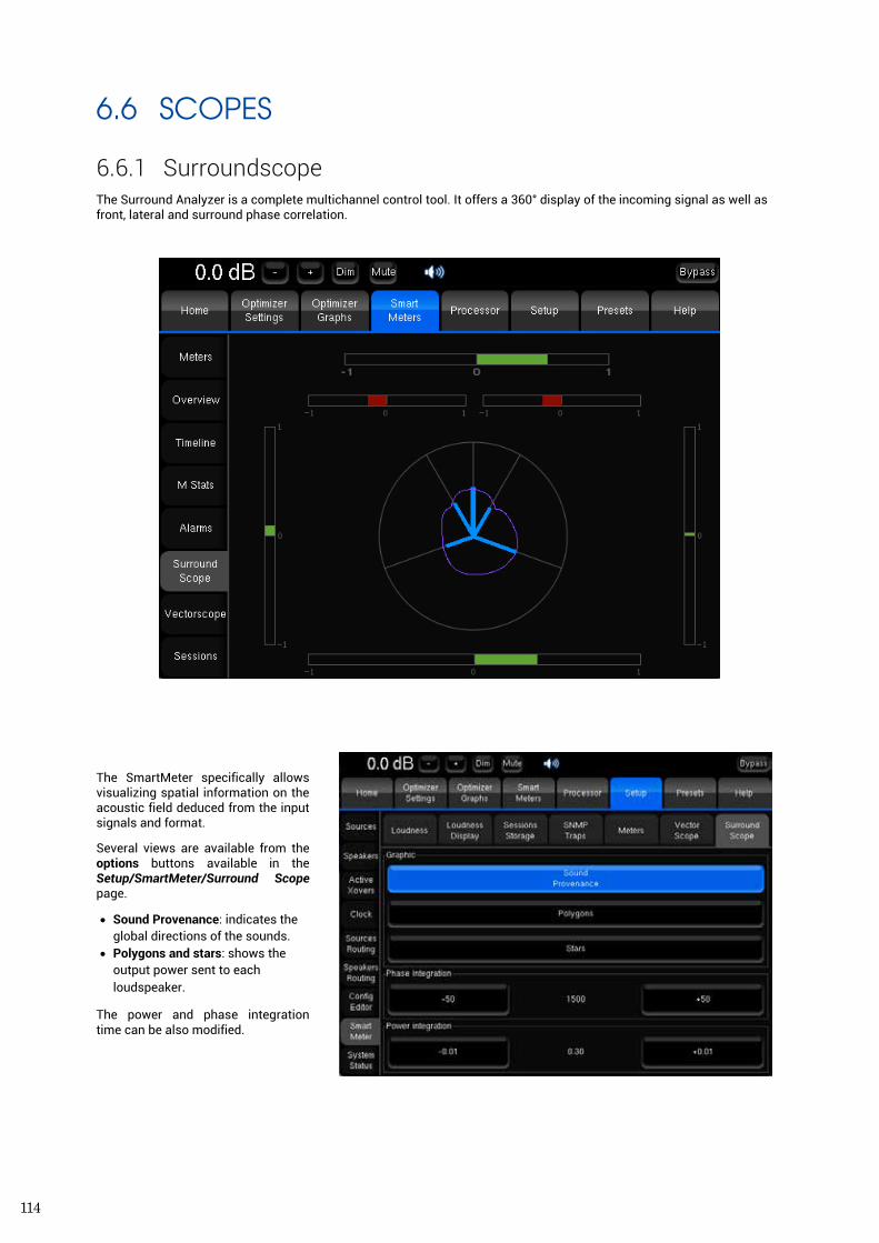
114
6.6 SCOPES
6.6.1 Surroundscope The Surround Analyzer is a complete multichannel control tool. It offers a 360° display of the incoming signal as well as front, lateral and surround phase correlation.
The SmartMeter specifically allows visualizing spatial information on the acoustic field deduced from the input signals and format.
Several views are available from the options buttons available in the Setup/SmartMeter/Surround Scope page.
• Sound Provenance: indicates the global directions of the sounds.
• Polygons and stars: shows the output power sent to each loudspeaker.
The power and phase integration time can be also modified.
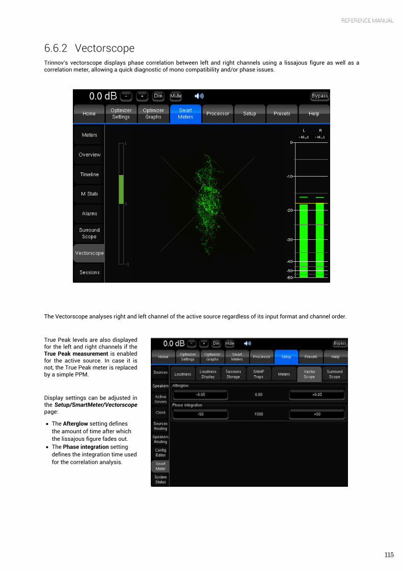
115
REFERENCE MANUAL
6.6.2 Vectorscope Trinnov's vectorscope displays phase correlation between left and right channels using a lissajous figure as well as a correlation meter, allowing a quick diagnostic of mono compatibility and/or phase issues.
The Vectorscope analyses right and left channel of the active source regardless of its input format and channel order.
True Peak levels are also displayed for the left and right channels if the True Peak measurement is enabled for the active source. In case it is not, the True Peak meter is replaced by a simple PPM.
Display settings can be adjusted in the Setup/SmartMeter/Vectorscope page:
• The Afterglow setting defines the amount of time after which the lissajous figure fades out.
• The Phase integration setting defines the integration time used for the correlation analysis.
116
7. KNOWN ISSUES AND TROUBLE-SHOOTING
7.1 KNOWN ISSUES
7.1.1 Using the option Send LFE to L+R Although the Send LFE to L+R option is designed for installations where no subwoofer is present, please note that in the current software version, the bass management option Send LFE to L+R can only be activated if one Subwoofer is defined in the Subwoofer number setting.
7.1.2 Calibration with wide bandwidth Subwoofers In certain cases, with wide bandwidth subwoofers – going beyond 300Hz – the level calculation of the Optimizer may not work properly.
We strongly recommend to check the frequency response of the subwoofer after compensation to make sure that it has been calibrated correctly.
7.1.3 Clicks and Sync losses Every Trinnov processor was designed to run at sampling rate up to 96 kHz. However, depending on the amount of processing power that is used by the Optimizer, running at the highest sampling rate can result in CPU overload, the audio outputs will click constantly and Optimizer will lose the Sync.
This problem can easily be avoided by increasing the buffer size in the Setup/Clock Settings page. You can also try to change the Optimize setting to Amplitude only or Low range only.

117
REFERENCE MANUAL
7.2 TROUBLESHOOTING
7.2.1 Calibration
Here is a list of settings to check if your calibration does not succeed.
Loudspeaker number
Page: Setup Speakers Speaker number
Check: Does the number of connected loudspeakers match this number?
Input channel order
Page: Setup Sources Input format, and
Page: Setup Sources routing
Check: is this the right order of the connections between the source and the Optimizer (also regarding possible modifications of the sources routing)?
Output Channel order
Page: Setup Speakers routing
Check: does the speakers routing (lines) correspond to the wiring of the loudspeakers (columns)?
Synchronisation
Page: Setup Clock Sync
Check: Is ‘Current sample rate’ information correct and stable?
Microphone signals
Once the calibration is started and if you can hear the test signals, you should see the 4 input signals on the level meters corresponding to what the microphone is recording. If not, check the microphone routing:
Setup Sources routing Micro
Check also the power switch and the battery of the microphone.
Warning message at start-up
You may have chosen a default preset at startup, which could cause problem after changing your installation (synchronization for example). It is then possible to choose not to load this preset by pressing ‘no default config’ on the startup screen, without forgetting to press ‘audio mode’ just after to validate your choice.
7.2.2 Network Connection for Software Updates & Remote Support
In order to be able to perform software updates, and connect the processor for remote support, the Network Status in the Setup/System Status page must display Connected to Trinnov Audio Server.
If the processor is connected to a network, but the Network Status is ‘Local Network OK’, it means that the Trinnov Server cannot be reached from your network. The Trinnov Server, located in Trinnov’s offices near Paris, is listening on port 22 on the internet address ‘bry.trinnov.com’. To check whether your firewall is blocking outgoing connections to port 22, you can perform the following command from your computer’s terminal:
telnet srpserver.trinnov.com 22
The result should be:

118
Trying 217.128.95.110... Connected to bry.trinnov.com. Escape character is '^]'. SSH-2.0-OpenSSH_4.6
If you cannot connect from your own computer to the Trinnov Server, then the processor will not be able to connect either. You should contact your network administrator and ask him to open outgoing connection to port 22. Please note that it is not necessary to open incoming connections, only outgoing connections to port 22.
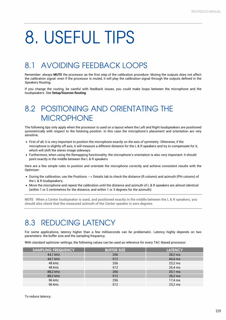
119
REFERENCE MANUAL
8. USEFUL TIPS 8.1 AVOIDING FEEDBACK LOOPS Remember: always MUTE the processor as the first step of the calibration procedure. Muting the outputs does not affect the calibration signal: even if the processor is muted, it will play the calibration signal through the outputs defined in the Speakers Routing;
If you change the routing, be careful with feedback issues, you could make loops between the microphone and the loudspeakers. See Setup/Sources Routing.
8.2 POSITIONING AND ORIENTATING THE MICROPHONE
The following tips only apply when the processor is used on a layout where the Left and Right loudspeakers are positioned symmetrically with respect to the listening position. In this case the microphone’s placement and orientation are very sensitive.
• First of all, it is very important to position the microphone exactly on the axis of symmetry. Otherwise, if the microphone is slightly off axis, it will measure a different distance for the L & R speakers and try to compensate for it, which will shift the stereo image sideways.
• Furthermore, when using the Remapping functionality, the microphone’s orientation is also very important: it should point exactly in the middle between the L & R speakers
Here are a few simple rules to position and orientate the microphone correctly and achieve consistent results with the Optimizer:
• During the calibration, use the Positions --> Details tab to check the distance (R column) and azimuth (Phi column) of the L & R loudspeakers;
• Move the microphone and repeat the calibration until the distance and azimuth of L & R speakers are almost identical (within 1 or 2 centimetres for the distance, and within 1 or 3 degrees for the azimuth)
NOTE When a Center loudspeaker is used, and positioned exactly in the middle between the L & R speakers, you should also check that the measured azimuth of the Center speaker is zero degrees.
8.3 REDUCING LATENCY For some applications, latency higher than a few milliseconds can be problematic. Latency highly depends on two parameters: the buffer size and the sampling frequency.
With standard optimizer settings, the following values can be used as reference for every TAC-Based processor:
To reduce latency:
SAMPLING FREQUENCY BUFFER SIZE LATENCY 44,1 kHz 256 28,2 ms 44,1 kHz 512 44,4 ms 48 kHz 256 23,2 ms 48 kHz 512 25,4 ms
88,2 kHz 256 20,1 ms 88,2 kHz 512 28,2 ms 96 kHz 256 17,4 ms 96 kHz 512 23,2 ms
120
• You can change the sampling frequency and the buffer size of your unit according to the table above. This can be done in the Setup/Clock Settings tab. Changing the buffer size requires rebooting the processor. Switching to a smaller buffer size can result in clicks and sync loss depending on the amount of CPU resources of your unit.
• In the Optimizer Settings/Settings/Main settings tab you can also try to change the Optimize setting to Amplitude or Low range only. Don’t forget to hit Apply changes.
• If no latency is allowed and that you don’t have an insert S&R on your mixing desk that can be made inactive, you can just bypass the Optimizer using the bypass button at the top of the screen. The resulting latency is the AD/DA conversion latency only as the processing section is bypassed. On the other hand, turning the Optimization Off in the Optimizer Settings/Runtime tab does not reduce latency since the audio still pass through the PC.
NOTE Latency can be monitored in details in the Processor/Master page.
8.4 AUTOMATIC START-UP ON POWER ON Automatically starting-up TAC-based units on power on can easily be achieved. You just need to let the front panel switch on, that will start the Trinnov Audio Core, which will then switch the PC on.
RME-based processors have a push button and require a BIOS setting.
The following instructions are relevant for 2010 models.
• Start the machine with a keyboard connected • During the Intel screen, press F2 to enter the BIOS setup • Use the Left/Right arrows to go to the Power menu • Use the Up/Down arrows to select the parameter After Power Failure and press Enter • Change the value to Power On and press Enter. • Press F10 to save the settings. • Exit the BIOS setup. The system will restart. • During the Intel screen, turn Off the power button on the back panel. (this is done to create a ‘power failure’ on
purpose).
NOTE This step is very important, if you skip this step, then the system will start automatically after power failure, but will not start automatically on power on after normal shutdown.
• Turn On the power button on the back panel: the system starts automatically. • Once the Trinnov is On, use the power button on the Front panel to power off the system. • Turn off the power button on the back panel, and switch it back On: the system should start automatically.
The following instructions were relevant before 2010.
• Start the machine with a keyboard connected • During the BIOS screen, press DELETE to enter the BIOS setup • Use the Up/Down arrows to go to Power Management Setup and press Enter • Use the Up/Down arrows to select the parameter AC Back Function and press Enter • change the value to Full-On and press Enter. • Press F10 to save settings. • Exit the BIOS setup. The system will restart. • Turn off the system, and turn on the power: the system should start automatically.
121
REFERENCE MANUAL
9. VERSION HISTORY 9.1 SOFTWARE VERSION 3.8 -Released: Mai 2013-
9.1.1 New Features Limiter curve: Provides a total flexible maximum boost and attenuation over the entire bandwidth
9.1.2 Improvements • Align to L&R Target: integrated new settings to configure this Optimizer mode:
• Processing on L&R Target • Align L&R on target • Optimize Phase
• FIR & IIR Settings: new settings :
• IIR filters minimal frequency: Automatic • Low-freq auto transition bandwidth
9.1.3 Changes • Improvement of the algorithm • Default value of some parameters have changed
9.2 SOFTWARE VERSION 3.6 -Released: October 2012-
9.2.1 New Features SmartMeter v3: brand new version:
• New system:
• SmartMeter synchronized to an external Time Code • Multi Source Loudness measurement • Save/Restore measurement sessions • Dynamic alerts system • PDF report / SNMP traps
• New instruments:
• Loudness Meter • Loudness Overview • Loudness Statistics • Real-Time 1/3rd octave analyzer
122
9.2.2 Improvements • Loudness Timeline rewritten to support Time Code synchronization:
• Different scrolling and zoom modes • Peak/True Peak alerts integration • Gated zones are highlighted • Zones including momentary values selected in the M Stats instruments are highlighted in the Timeline.
• MultiView:
• New instruments support • Every instrument can be assigned to any of the 4 views
9.2.3 Changes • Various renaming of Instruments and pages • Arborescence of the SmartMeter pages modified • New dedicated setup page for the SmartMeter
9.3 SOFTWARE VERSION 3.5 -Released: June 2012-
9.3.1 New Features • DRC: provides a comprehensive set-top box emulation module fully compliant with ATSC A/85 recommendations. • Submixes: provides a flexible downmix engine with preconfigured matrixes for standard installations and a matrix
editor to answer specific needs.
9.3.2 Improvements • Monitoring Control: integrates selection of predefined and manual compatibles matrixes with currently selected
source. • Multiview: new setting to configure automatic switching to multiview when loading a preset/profile.
9.3.3 Changes • Calibration threshold: the threshold below the peak for determining the onset of the response setting is moved from the
config editor to the Optimizer/Advance Settings page. • Network settings can be modified with a virtual keyboard.
9.4 SOFTWARE VERSION 3.4 -Released: November 2011-
9.4.1 New Features • Multiple TAC Support: this release includes a new audio core firmware that allows 2 TAC chaining and better
performance for single TAC units. MC processor can therefore manage up to 16 simultaneous digital I/Os. • SmartMeter 2.0: includes brand-new tools:
• The True Peak Meter showing the maximum absolute level of the signal in the continuous time domain. It is an implementation of the EBU recommendation R128.
123
REFERENCE MANUAL
• The Vectorscope is a phase-meter to control mono compatibility of stereo signal. Integration time of the correlation meter and the afterglow for the lissajous figure can be set manually.
• The Surround Analyser for multichannel signal monitoring. It shows a 360° display of your multichannel signal as well as the correlation between adjacent signals.
• Login: different user levels with limited access to sensitive features are now available as an option for MC processors and ST2 Pros.
9.4.2 Improvements • Non Audio data detection: encoded streams (ac3, DTS…) played through SPDIF or AES are detected as non-audio data.
A visual alert is displayed and the outputs are muted. • Target Curves: button ‘link all but subwoofer’. • Multiview: ‘swap’ button to switch between multiview and standard display from the interface. • Backup/Restore USB: presets can be backed up and restored individually.
9.4.3 Changes Monitoring Control: is now available without the SmartMeter option.
• The Monitoring Control tab is in the Home Page. • A reduced Home Page has been implemented in the ST2 Pro.
9.5 SOFTWARE VERSION 3.3 -Released: March 2011-
9.5.1 New features • Profiles:
• Profiles are programmable buttons that have been implemented to recall both hardware and software settings. • Presets are fully integrated to profiles. Profiles allow a totall recall of every parameter of the processor.
• FIR EQ: can now be saved in a file, saved and linked to a profile. • Input Controls: Input levels, solos, mutes and links can now be saved in a file, saved and linked to a profile.
9.5.2 Improvements • Home Page: a new tab hosts the Select and Profiles Config pages. It also provides Meters. • Listen button: in the Sources page, a listen button has been added to each source in order to select the active source. • Current calibrated HP: the name of the channel/HP being calibrated is displayed during calibration. • Active Crossover: the active crossover tab has been redesigned and regroups every settings within the same page with
one tab per speaker.
9.5.3 Changes • GPIO: GPIO commands now control profiles instead of presets. • Page Names: to avoid any confusion with input and output connectors, which refer to hardware I/Os, Input
Settings/Routing and Output Settings/Routing pages have respectively be renamed Sources /Routing and Speakers Settings/Routing.
9.6 SOFTWARE VERSION 3.2 -Released: February 2011-
124
9.6.1 New Features SmartMeter Multi-View: provides a split screen with 4 customizable windows displaying monitoring and/or metering tools. (Available on MC units only).
9.6.2 Improvements New Graphic User Interface:
• Redistribution of the tabs: Main tabs are displayed horizontally at the top of the screen. Sub tabs are displayed vertically on the left hand side of the interface.
• The dark theme better suits studio environments.
9.7 SOFTWARE VERSION 3.1 -Released: July 2010-
9.7.1 New features • Hardware Support for ST2-Pro: this release includes full integration of the Trinnov Audio Core, ADA4 and AES4 boards:
input selection, routing, synchronization, GPIOs… • SmartMeter 1.5: now features an EBU R128 compliant Loudness meter:
• Displays integrated, momentary, short term measurements and Loudness Range all at once according to the EBU recommendation R128.
• Specific ‘EBU mode’ tag displayed when the Target Level is -23 LUFS for Integrated Loudness. • Flexible display:
• color zones can be set by the user • adjustable time and loudness scales
9.7.2 Improvements • Main page (ST2 HIFI only): a new home page has been designed to offer quick access to essential functionalities such
as sources selection and presets recall. • The default microphone can be set within the interface (Optimizer Settings/Calibration) by the user with no need for
remote intervention by Trinnov. • Multiple sources: can be set in the Sources page. • Remapping matrix: enables the optimizer to take a user-manually-defined matrix (through config editor) into account
for remapping. • Light mode for presets load: this option can be activated in the Setup/System Status page.
9.7.3 Changes The system is now able to play sound without prior calibration. (Built-in preset)
9.8 SOFTWARE VERSION 3.0 -Released: November 2009-.
125
REFERENCE MANUAL
9.8.1 New features • Multipoint Measurements: the Optimizer can now be calibrated using multiple measurement points. Weights can be
assigned to each individual point. Measurements can be performed sequentially with one microphone, or simultaneously with multiple microphones.
• New Graphs have been added to the acoustic measurements: the filter's responses, the amplitude of the direct field, the group delay and the impulse response.
• SmartMeter 1.0: this is a new option for the Trinnov processor. A comprehensive meter and monitor controller with a touchscreen user interface. It features a PPM (Peak Program Meter), a QPPM (Quasi-Peak), a Spacescope and a Timeline.
NOTE Loudness metering will be implemented in the next release.
9.8.2 Improvements • Graphs overlay: the new graphs display engine offer full flexibility to overlay multiple graphs of different points,
different speakers, before/after correction etc... • Performance: the Optimizer ST can run 4 output channels at 96kHz. • Multiple Sources can be defined in the Input Settings. This is mostly useful for the SmartMeter option. • Number of Delay Lines is adjustable in the Setup/Output Settings page. It should be set to zero when delay lines are
not needed.
9.8.3 Changes • Modular Architecture:
• The Trinnov processor offers all the standard functionality of an audio processor: routing, levels, delays, parametric, graphic and FIR EQs;
• The Trinnov Optimizer is now an option, its functionality is distributed over two pages: Optimizer Graphs and Optimizer Settings;
• The new Trinnov SmartMeter option has its own page.
• When only the processor license is installed, the pages available are: processor, Setup, Presets and Help; • When only the Optimizer Runtime license is installed, the machine can run a preset which was calibrated and computed
on another machine. The user can turn On/Off the optimization in the Runtime tab but can't modify the settings. • When only the Optimizer Toolbox license is installed, the user can perform measurements, compute the filters, and
modify all the settings, but the machine can't run the preset. • When both the Optimizer Runtime and Toolbox licenses are installed, all the Optimizer functionality is available. • The FIR EQs have moved to the Processor page; • The Level Meter from V2.0 has moved to the Processor page; • Timeline and Spacescope (Time monitoring and Spatial monitoring) have moved to the SmartMeter option;
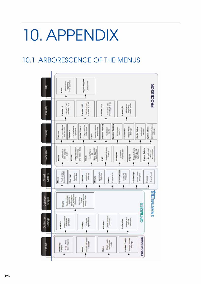
126
10. APPENDIX 10.1 ARBORESCENCE OF THE MENUS
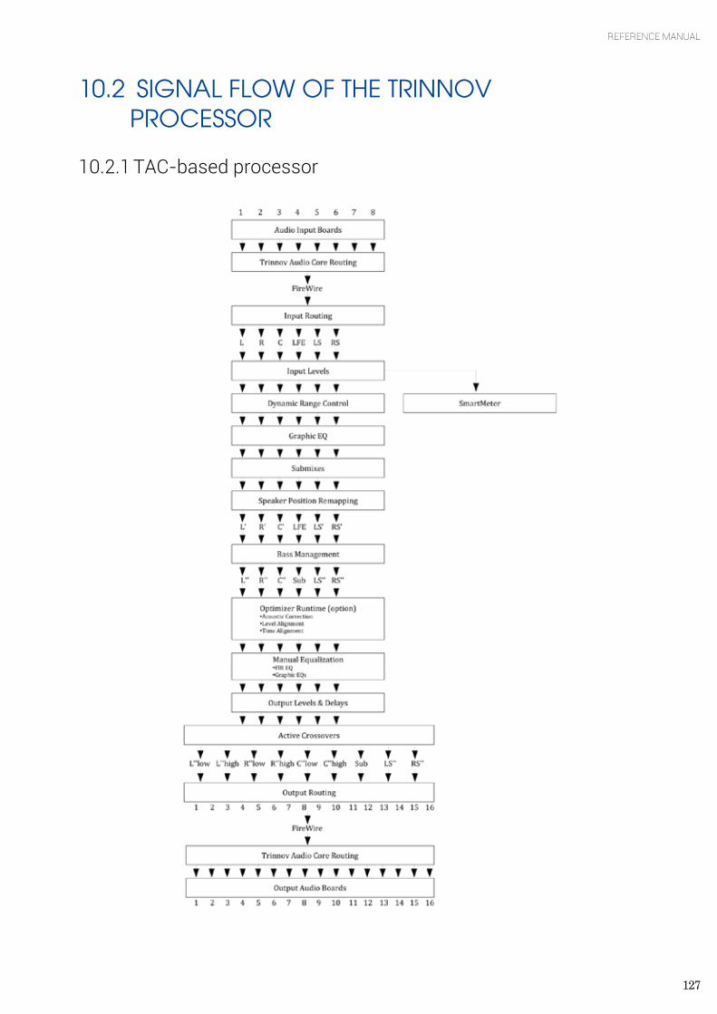
127
REFERENCE MANUAL
10.2 SIGNAL FLOW OF THE TRINNOV PROCESSOR
10.2.1 TAC-based processor
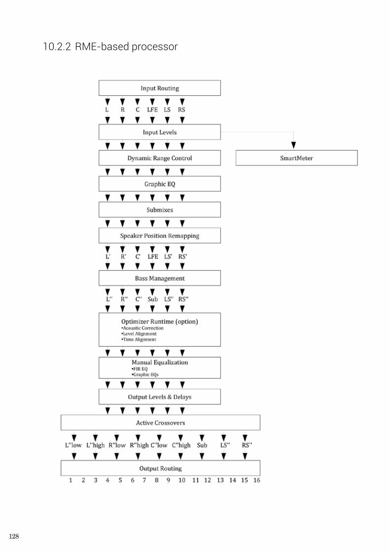
128
10.2.2 RME-based processor
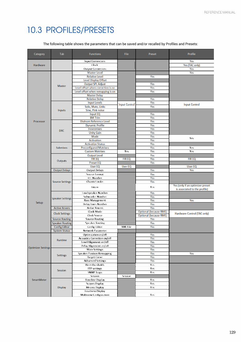
129
REFERENCE MANUAL
10.3 PROFILES/PRESETS
The following table shows the parameters that can be saved and/or recalled by Profiles and Presets:
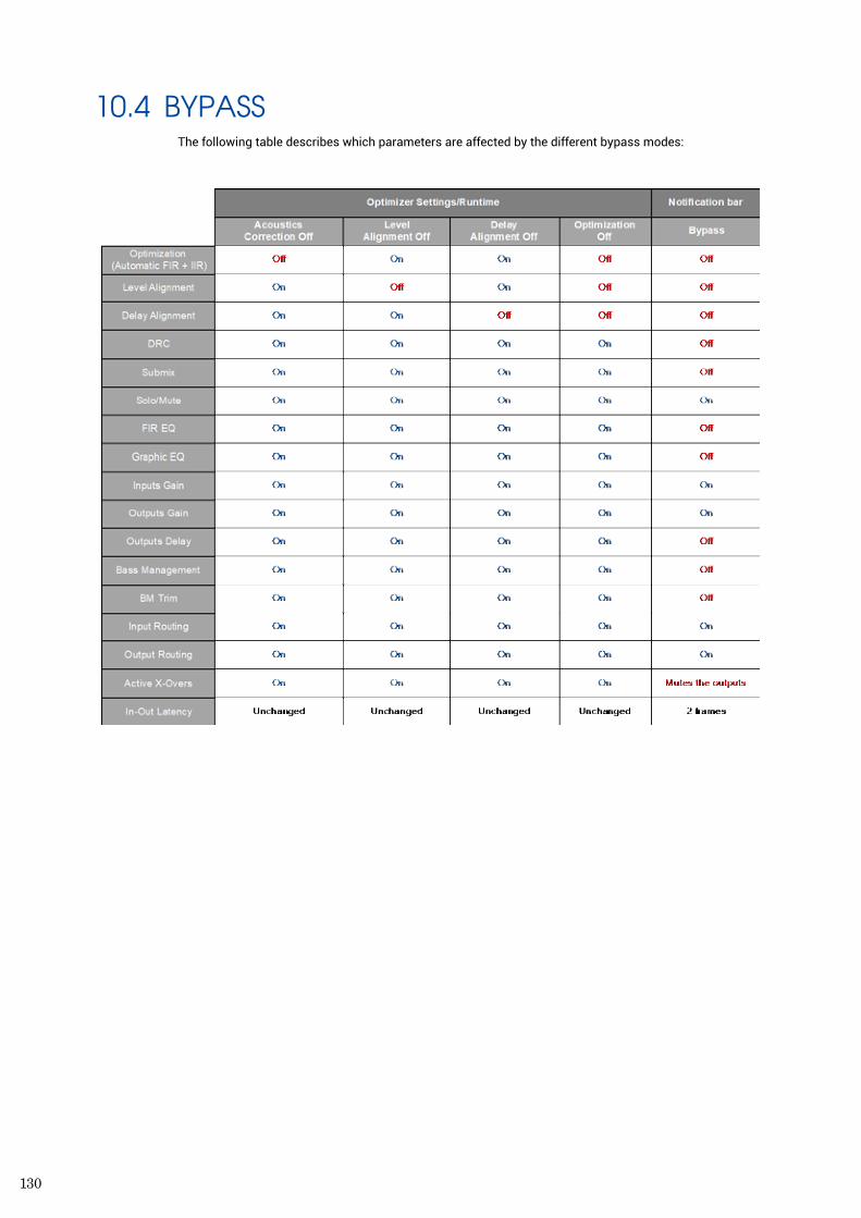
130
10.4 BYPASS The following table describes which parameters are affected by the different bypass modes:
131
REFERENCE MANUAL
11. LEGAL MENTIONS
LIABILITY
The legal guarantees of conformity and latent defects under no circumstances cover any damage arising from accidents, misuse or an assembly error, negligence or considerable modification of the appearance or functioning of the returned equipment. Trinnov Audio reserves the right to refuse any guaranteed return for a damaged product on account of misuse.
TERMS OF GUARANTEE I Duration All the Trinnov products include a guarantee which lasts for two (2) years (extensible to three (3) years) as from the invoice date. In the event of a malfunction subsequent to a fault detected in the device, the guarantee is total and no sum may be claimed from the acquiring party in terms of its replacement or repair, subject to the terms below. Any replaced parts and the repair of the malfunction are guaranteed for six (6) months. This guarantee applies to the Trinnov Audio product, provided that it has been purchased in mainland France. II Conditions
1. The guarantee applies only if the product is confirmed as being faulty by the technical services of Trinnov Audio. 2. This guarantee applies if the faulty product is presented during the guarantee period, accompanied by a copy of the
invoice (which indicates the purchase date, the model of the device and its serial number). Trinnov reserves the right to refuse the free application of the guarantee if these documents are not submitted or if they are incomplete or illegible. This guarantee will not apply if the name of the model or the serial number appearing on the product has been modified, deleted, removed or rendered illegible.
3. To prevent any damage or loss/deletion of data stored on the device, you must have saved them prior to returning your device to the services responsible hereunder.
4. The transport cost to Trinnov is to be met by the customer, including any return in mainland France. The device is transported at the risks of the customer. In the event of any damage observed upon its return, all the reservations must be made by the recipient with the carriers.
5. This guarantee does not cover any of the following points: 6. Regular repair and maintenance work or replacements of parts subsequent to normal wear and tear, 7. Consumables (elements of limited use, to be replaced on a regular basis) 8. Damage or modifications brought about by:
a) Misuse, including:
b) Handling which brings about a physical, aesthetic or superficial modification or damage to the product or damage to the display;
c) An installation or a use of the product not in keeping with its intended purpose or the instructions of installation or use of Trinnov Audio;
d) Maintenance work to the product not in keeping with the instructions of Trinnov Audio; e) An installation or a use of the product not in keeping with standards or technical or safety regulations applicable
in the country in which it is installed or used.
f) Viral infections or use of the product with software not provided or incorrectly installed, g) The condition or faults of the systems with which the product is used or on which it is integrated, unless these
are other Trinnov Audio products intended for use with the product, h) The use of the product with accessories, peripheral devices and other products whose kind, condition and
standards do not meet with the requirements of Trinnov Audio, i) Any repair work carried out or attempted by any persons other than the repairmen of Trinnov Audio, j) Any modifications or alterations made without the prior written consent of Trinnov, including:
132
• The upgrade of the product not in keeping with the specifications or functionalities described in the user manual,
• The replacement of sub-elements in relation to its original configuration, without the prior written consent of Trinnov Audio,
• Any modifications made to the product to bring it into line with technical or safety standards, whether at a national or local level, applicable in any country other than those for which the product has been originally designed and manufactured.
• Any accidents, fires, liquids, chemical products, other substances, floods, vibrations, excessive heat, unsuitable air supply, over voltage, an excessive or inadequate power supply, radiation, electrostatic discharge, including lightning and other forces and external effects,
• Unsuitable storage conditions for this kind of product.
9. This guarantee only covers the hardware components of the product. It does not cover the software (of the Trinnov brand or other but installed by Trinnov).
10. A normal repair period of a maximum of 4 weeks (excluding transport time) must be accepted, but if this period is exceeded, and on demand, equivalent hardware may be loaned which gives entitlement to an extended guarantee of an equivalent duration. Trinnov Audio reserves the right to replace any parts or products which are deemed to be faulty with new parts or products reviewed in the factory without any other obligation for us as regards any direct or indirect consequences of the malfunction of this hardware both in relation to people and the goods. All replaced parts and products will become the property of Trinnov.
11. In the event that a latent defect is detected, the Purchaser must immediately notify Trinnov Audio of the same in writing by a detailed note explaining the circumstances in which he/she became aware of it, not later than eight (8) days from the time it is discovered, failing which, he/she loses the right to any guarantee.
III Exclusions and restrictions Excluding the considerations above, Trinnov Audio offers no guarantee (explicit, implicit, statutory or otherwise) for the product or the software that it contains or which accompanies it, concerning the quality, functioning, accuracy, reliability, suitability for a particular purpose or otherwise. If this exclusion is not, or only partially, permitted by applicable regulations, Trinnov Audio excludes or restricts its guarantees exclusively to the maximum extent permitted by applicable regulations. Any guarantee which is unable to be fully excluded will be limited (to the extent permitted by applicable regulations) to the duration hereof. Under this guarantee, the only obligation for Trinnov Audio is to repair or replace products which meet with the conditions hereof. Trinnov Audio is in no way liable for any loss or damage related to the products, service, this guarantee or otherwise, including - financial or intangible losses - the price paid for the product - a loss of profit, income, data, enjoyment or use of the product or any associated product - an indirect or unforeseen loss or damage. This restriction is applicable, whether the loss or damage is attributable to:
• A malfunction or failure to operate of the product or related products on account of faults or unavailability while it/they is/are at the premises of Trinnov Audio, thereby resulting in delays, wasted time for the user or a discontinuation of activity;
• An error in the production of the product or related products; • Damage or loss of software or data; • A virus and other causes.
This applies to loss and damage in any legal context, including negligence and other torts, the termination of a contract, the explicit or implicit guarantee, and the unconditional liability (even when Trinnov Audio has been informed of the possibility of this damage). When the applicable regulations forbid or limit these exclusions of liability, Trinnov Audio excludes or limits its liability only to the extent permitted by the applicable regulations. Some countries forbid, for instance, the exclusion or the restriction of damage arising from negligence, gross negligence, deliberate breach of contract, deceit and similar acts. Under this guarantee, the liability of Trinnov Audio will, under no circumstances, surpass the price paid for this product, but if the applicable regulations allow more significant restrictions of liability, the more significant restrictions will apply. IV Protection of your legal rights By virtue of the national regulations in force, the customers enjoy legal (statutory) rights concerning the sale of the product. This guarantee in no way limits your statutory rights, if applicable, which may not be excluded or restricted, or your rights vis-à-vis the seller of the product. You are permitted to assert your rights at your sole discretion.
V Intellectual Property Due to constant improvement, all products specifications and design may change without notice. Photos and illustrations are non-contractual. ©Trinnov Audio, all rights reserved. All other trademarks and other protected materials remains the sole propety of their respective owners.

133
REFERENCE MANUAL

134
TRINNOV AUDIO Headquarters- 5 rue Edmond Michelet - 93360 Neuilly-Plaisance - FRANCEPhone: +33 (0)1 47 06 61 37Email: [email protected] - www.trinnov.com


