Embed Size (px)
Citation preview
14 Relevance of the Core Hole Alignment to Auger–Photo-electron Pair Angular Distributions in Solids
Giovanni Stefani, Roberto Gotter, Alessandro Ruocco, Francesco Offi, Fabiana Da Pieve,Alberto Verdini, Andrea Liscio, Stefano Iacobucci, Hua Yao, and Robert Bartynski
Auger–photoelectron coincidence spectroscopy (APECS) has shown that singling out Augerspectra individual components on the basis of the related photoelectron, i.e., defining the par-ent core ionic state, increases the energy discrimination capability of both Auger and photo-electron spectroscopy. Angle resolved APECS (AR-APECS) on Ge(100) surface has shownpeculiar new features of the electron pair angular distribution with Auger detection angle. Itwas speculated that these features were to be ascribed to the alignment of the core-hole stateinduced by selection of the angle of the photoelectron. Recent results on Ge(100) and Cu(111)have drawn attention to the possibility of selecting specific magnetic sublevels of both Augerand photoelectron wavefunctions. Good use of this capability has been made in singling outotherwise overlapping components of both Ge L3V V and Cu M3V V multiplet split spectra,thus demonstrating that resolution in angle improves discrimination in the energy scale aswell.
14.1 Introduction
To develop nanoscale aggregates often requires characterizations with discrimination, both inenergy and space, that are beyond the capabilities of well-established spectroscopies. Thisis the main motivation for the progress in the fine analysis of matter that has occured overthe past decade. Spatial, energy and time resolution have been improved by exploiting theunprecedented brightness of third generation synchrotron radiation sources. Among theseachievements, Auger–photoelectron coincidence spectroscopy (APECS) has its own indivi-dual status as it accesses information that is not merely a refinement of what individual Augerand photoemission spectroscopy would access. An APECS experiment detects, correlated intime and selected in energy, electron pairs generated by the creation–relaxation process of acore hole in a specific atomic site of a solid. APECS combines in a unique way the Auger(AES) sensitivity to valence (shallow core) density of states with the atomic site selectiv-ity of core photoemission (XPS) and has been shown to gain considerable discrimination inprobing electron correlation and charge transfer phenomena on the femtosecond time scale.Coster–Kronig transitions are the natural candidate for experiments aimed at studying elec-tron correlation but not even APECS is capable of distinguishing individual components of thelifetime broadened multiplet structure generated by their two holes final states. In this chapterwe propose to use the angular correlation between the two electrons (Auger and photoelec-
Correlation Spectroscopy of Surfaces, Thin Films, and Nanostructures. Edited by Jamal Berakdar, Jürgen Kirschner
Copyright c© 2004 Wiley-VCH Verlag GmbH & Co. KGaA, Weinheim
ISBN: 3-527-40477-5
184 14 Relevance of the Core Hole Alignment to Auger–Photoelectron Pair Angular Distributions
tron) in order to gain further discrimination in disentangling individual multiplet componentsthat are separated in energy by less than their lifetime broadening. This idea steams from theobservation that the amount of information obtained from photoemission spectra is vastly in-creased when one measures the angular distribution of photoemitted electrons as well as theirenergy. For example, ultraviolet photoemission (UPS) gives information about the valence-band density of states of a solid, while angle resolved UPS enables one to directly map theenergy bands. Similarly, from XPS and AES one can obtain information about the chemicalstate of a surface, while angle-resolved measurements (i.e. photoelectron (PED) and Augerelectron diffraction (AED)) enable one to perform surface structural measurements and pro-duce holographic images of surface geometry. In a similar way AR-APECS is expected toadd an important level of discrimination to the APECS technique. This capability has beenextensively applied to investigate atoms and molecules in the gas phase, and the extra discrim-ination originated by resolving in angle, the electron pair probability distribution, has givenaccess to fine details of the core ionization dynamics such as core state polarization, postcollisional electron–electron interaction, and quantum interference between continuum finalstates [1]. The main goal of the present chapter is to show that a similar level of discriminationcan also be achieved in solids. This will be done by discussing recent AR-APECS results onGe(100) and Cu(111) surfaces. To perform an AR-APECS experiment amounts at measur-ing the multiple differential cross section dIAu, angular (dΩAu and dΩph) and energy (dEph)resolved, as
dIAu
dΩAudΩphdEAu
∼= Γ (EAu, E0Au)|Tβα|2 (14.1)
where Γ (EAu, E0Au) is the Auger lineshape and Tβα is the Auger decay amplitude. It is there-
fore evident that several different modes are available for such an experiment depending uponthe various parameters that are kept fixed while varying the others. Here we shall report ontwo different modes:
(i) Energy mode: by fixing the direction of detection for the two electrons and by scanningthe Auger energy a “selected” Auger line shape is measured.
(ii) Angular mode: by fixing the Auger energy, the direction of detection of the photoelectronand by scanning the Auger ejection angle a “selected” AED is measured.
Both modes will amount to select and control core hole state magnetic sublevels occu-pancy, hence inducing an apparent variable alignment of the intermediate state of the process.It will be shown that this selectivity enables discrimination of multiplet components overlap-ping in energy. Finally, the extreme surface sensitivity of an AR-APECS experiment will bedemonstrated with the help of measurements done on the Cu(111) surface.
14.2 AR-APECS Two Step Model
To interpret the main features of AR-APECS in solids, we propose to use a two-step model.The first step describes the core ionization process and the following Auger decay as if it werehappening in an isolated atom. In this step, the energy, the angular moments and magnetic
14.2 AR-APECS Two Step Model 185
quantum numbers that describe the wavefunctions of the two outgoing electrons are defined.These atomic wavefunctions will act as source waves for the following interaction with thecrystal lattice. The interaction is assumed to be elastic, hence well described by a diffrac-tion process that ultimately will determine the flux of probability reaching, at infinity, the twoelectron analyzers used to select (in angle and energy) and detect the Auger–Photoelectronpair distributions. In the first atomic step, the core ionization process will be described withinthe dipole approximation and for linearly polarized light. In calculating the Auger decayprobability and the angular correlation between the two final electrons, the approach proposedin Ref. [2] will be adopted and extended to open shell atoms. This straightforward extensionis of particular relevance in the solid matter, where open shell systems are mostly studied, andthe closed shell description, so far used for isolated atoms, will be inadequate.
14.2.1 Atomic Core Ionization and Relaxation
At the atomic site where core ionization takes place, the angular distribution of the electronpair describing the correlation source wavefunction can be obtained using spherical tensorstheory [3]. The anisotropy of the initial emission is determined by the angular momentumcomponents which describe the outgoing electrons and by the radial matrix elements whichgovern the process.
Let us consider the photoionization and decay as independent processes:
hν(jγ) + A(J0) −→A+(α1J1, α′1J
′1) + e−1 (j1)
→ A++(α2J2, α′2J
′2) + e−2 (j2)
(14.2)
where J0, jγ are the angular momenta related to the initial atom and to the photon, α1J1,α′
1J′1 and α2J2, α
′2J
′2 are related to the ions A+, A++ that can be created in different angular
states, and j1, j2 are the angular momenta of the phototelectron and Auger electron.Using the dipole approximation and in the reference frame in which the polarization vector
is parallel to the z axis, the statistical tensors [2] of the photoionized state A+ that describethe distribution of the subsequent Auger electrons can be written as:
ρk1q1(α1J1, α′1J
′1) =
∑keqekrqr
12J0 + 1
√4π
2ke + 1Ykeqe(θe, φe)
× (k1q1, keqe|krqr)ρkγqγIkek1kr
(14.3)
where ρkγqγare the statistical tensors related to the photon, Ykeqe(θe, φe) are the spherical har-
monics of the photoelectron, and (k1q1, keqe|krqr) are the Clebsch–Gordan coefficients. Thedynamical parameters Ikek1kr are related to the dipole matrix elements through the relation:
Ikek1kr =14π
k1ke
∑l1l′1j1j′
1JrJ′r
(−1)Jr+J0+kr+j′1− 1
2 JrJ′r l1 l
′1j1j
′1(l10l′10|ke0)
×
j1 l112
l′1 j′1 ke
1 Jr J0
J ′r 1 kr
J1 j1 Jr
J ′1 j′1 J ′
r
k1 ke kr
× DJ1j1JrJ0D∗J′1j′
1J′rJ0
(14.4)
186 14 Relevance of the Core Hole Alignment to Auger–Photoelectron Pair Angular Distributions
where the notation used for dipole matrix elements DJ1j1JrJ0 implies that the angular mo-mentum J1 is coupled to the photoelectron momentum j1 through a resonant state Jr, whichin turn is determined by coupling J0 with jγ . The angular correlation function between Augerand photoelectrons can be obtained by combining these statistical tensors with the tensors [4]that describe spin-unresolved detection efficiency:
W =∑
k1q1J1J′1
J1−1
4πρk1q1(α1J1α
′1J
′1)Rk1(J1J
′1; J2)
√4π
2k1 + 1Yk1q1(θ2, φ2) (14.5)
where Yk1q1(θ2, φ2) are the spherical harmonic of the Auger electron and the Auger parameterRk1(J1, J
′1; J2) is related to the Auger matrix elements VJ2j2J1 as follows:
Rk1(J1J′1; J2) =
∑l2l′2j2j′
2
(−1)J1+J2+K1− 12 l2 l
′2j2j
′2J1(l20l′20|k10)
×
J1 j2 J2
j′2 J ′1 k1
l2 j2
12
j′2 l′2 k1
VJ2j2J1V
∗J2j′
2J′1
(14.6)
The angular correlation function (14.5) describes the anisotropy of the initial emission atthe atomic site and takes into account, for both electrons, all the possible angular momentapermitted by the selection rules. The resulting distribution of the correlated electrons repre-sents the source wave that will be diffracted from the periodic potential of the crystal. Relation(14.5) shows that different angular components contributes in a different way to the intensitymeasured at given detection angles. We also note that the weight of the different angular com-ponents is largely determined by sums of Clebsch–Gordan coefficients, that explicitly dependon the magnetic quantum number ml. Hence, selecting specific ejection direction for the elec-tron pairs amounts to selecting dominant l and ml values for the wavefunctions that describe,separately, the Auger–electron and the photoelectron.
14.2.2 Diffraction from Crystal Lattice
The features of the source wavefunctions are relevant for the scattering process since the po-tential describing the interaction with the atoms of the crystal is determined by an attractiveCoulomb part and a repulsive barrier which depends on the orbital momentum of the elec-trons. For electrons with high orbital momentum, the potential has a non-negligible repulsivebarrier outside the attractive well. Simulations of the diffraction pattern show that the angulardistributions depend on both orbital and magnetic quantum numbers l and ml [5]. The ml
dependence can be generated by a non statistical distribution of initial sublevels (as happensin magnetic materials) or by excitation through light of specific polarization (which permitsemission from certain sublevels). In both cases, the features of the final state reflect the dif-ferent non-statistical weights of the partial waves. Through the introduction of a quantizationaxis, we can obtain the non-statistical contributions of the different sublevels, even in non-magnetic materials [6].
In our case, where we are interested in the emission of electron pairs, we could select aparticular angular component of the wave related to the first electron by revealing it at a certain
14.2 AR-APECS Two Step Model 187
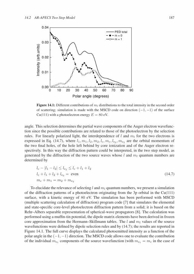
Figure 14.1: Different contributions of ml distributions to the total intensity in the second orderof scattering; simulation is made with the MSCD code on direction (−1,−1) of the surfaceCu(111) with a photoelectron energy E = 80 eV.
angle. This selection determines the partial wave components of the Auger electron wavefunc-tion since the possible contributions are related to those of the photoelectron by the selectionrules. For linearly polarized light, the interdependence of l and ml for the two electrons isexpressed in Eq. (14.7), where l1, m1, l2, m2, lc, mc, le2 , me2 are the orbital momentum ofthe two final holes, of the hole left behind by core ionization and of the Auger electron re-spectively. In this way the diffraction pattern could be interpreted, in the two step model, asgenerated by the diffraction of the two source waves whose l and ml quantum numbers aredetermined by
lc − |l1 − l2| ≤ le2 ≤ lc + l1 + l2
lc + l1 + l2 + le2 = even (14.7)
mc + m1 = m2 + me2
To elucidate the relevance of selecting l and ml quantum numbers, we present a simulationof the diffraction patterns of a photoelectron originating from the 3p orbital in the Cu(111)surface, with a kinetic energy of 80 eV. The simulation has been performed with MSCD(multiple scattering calculation of diffraction) program code [7] that simulates the elementaland state-specific core-level photoelectron diffraction pattern from a solid; it is based on theRehr–Albers separable representation of spherical-wave propagators [8]. The calculation wasperformed using a muffin-tin potential, the dipole matrix elements have been derived in frozencore approximation from the Hermann–Skillmann tables. The l and ml values of the sourcewavefunctions were defined by dipole selection rules and by (14.7); the results are reported inFigure 14.1. The full curve displays the calculated photoemitted intensity as a function of thepolar angle in the (−1,−1) direction. The MSCD code allows one to evaluate the contributionof the individual me1 components of the source wavefunction (with me1 = mc in the case of
188 14 Relevance of the Core Hole Alignment to Auger–Photoelectron Pair Angular Distributions
linearly polarized light) to the total angular distribution probability, that are shown by dashedcurves in the figure. From the figure it is evident that different l, ml partial source wavescontribute with different weight to the probability of emitting the photoelectron at a givenangle. Similar results are obtained by applying the MSCD code to calculate the Auger electrondiffraction pattern. Hence, to detect a pair of photo–Auger electrons at specific azimuthal andpolar angle with respect to light polarization and surface orientation, amounts to highlightingthe contribution of a specific subset of partial source waves among those which are allowedby selection rules (14.7). Moreover, always through relations (14.7), it is evident that toselect l and ml components for the final electrons results in selecting lc, mc, i.e. differentmagnetic sublevels of the core hole states. In other words, we can expect that even in thesolid state the polarization of the ion state created by the photoionization process reflects itselfin the emission of the electrons in preferential directions. From this observation comes aninterest in studying how the selectivity in the core hole state sublevels, that is characteristicof an AR-APECS experiment, will reflect itself in the angular and energy distribution of theelectron pairs. This subject will be addressed in the following discussion of the results oftwo AR-APECS experiments on Ge(100) and Cu(111) performed in angular and energy moderespectively.
14.3 Experimental Results
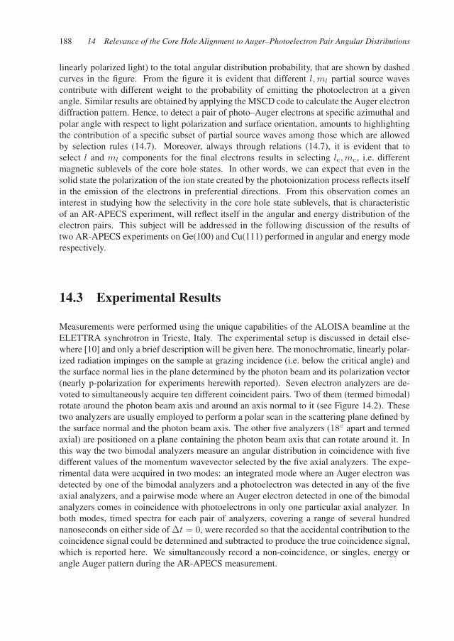
Measurements were performed using the unique capabilities of the ALOISA beamline at theELETTRA synchrotron in Trieste, Italy. The experimental setup is discussed in detail else-where [10] and only a brief description will be given here. The monochromatic, linearly polar-ized radiation impinges on the sample at grazing incidence (i.e. below the critical angle) andthe surface normal lies in the plane determined by the photon beam and its polarization vector(nearly p-polarization for experiments herewith reported). Seven electron analyzers are de-voted to simultaneously acquire ten different coincident pairs. Two of them (termed bimodal)rotate around the photon beam axis and around an axis normal to it (see Figure 14.2). Thesetwo analyzers are usually employed to perform a polar scan in the scattering plane defined bythe surface normal and the photon beam axis. The other five analyzers (18 apart and termedaxial) are positioned on a plane containing the photon beam axis that can rotate around it. Inthis way the two bimodal analyzers measure an angular distribution in coincidence with fivedifferent values of the momentum wavevector selected by the five axial analyzers. The expe-rimental data were acquired in two modes: an integrated mode where an Auger electron wasdetected by one of the bimodal analyzers and a photoelectron was detected in any of the fiveaxial analyzers, and a pairwise mode where an Auger electron detected in one of the bimodalanalyzers comes in coincidence with photoelectrons in only one particular axial analyzer. Inboth modes, timed spectra for each pair of analyzers, covering a range of several hundrednanoseconds on either side of ∆t = 0, were recorded so that the accidental contribution to thecoincidence signal could be determined and subtracted to produce the true coincidence signal,which is reported here. We simultaneously record a non-coincidence, or singles, energy orangle Auger pattern during the AR-APECS measurement.
14.3 Experimental Results 189
Figure 14.2: Schematics of the rotating frames of analyzers of the ALOISA multicoincidenceend station. The S1 plane (bimodal plane) contains two analyzers that are moved by combiningband g rotations. The S2 plane (axial plane) rotates around the photon beam axis and containsfive analyzers. If the bimodal analyzers detect the Auger electrons, the axial analyzers detectthe photoelectrons. Auger electrons detected by each individual bimodal (axial) analyzer arecorrelated in time with photoelectrons detected by whichever axial (bimodal) analyzer.
14.3.1 Angular Discrimination
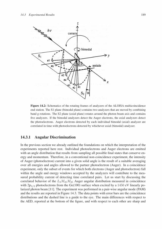
In the previous section we already outlined the foundations on which the interpretation of theexperiments reported here rest. Individual photoelectrons and Auger electrons are emittedwith an angle distribution that results from sampling all possible final states that conserve en-ergy and momentum. Therefore, in a conventional non-coincidence experiment, the intensityof Auger (photoelectron) current into a given solid angle is the result of a suitable averagingover all energies and angles allowed to the partner photoelectron (Auger). In a coincidenceexperiment, only the subset of events for which both electrons (Auger and photoelectron) fallwithin the angle and energy windows accepted by the analyzers will contribute to the mea-sured probability current of detecting time correlated pairs. Let us start by discussing thecorrelated behavior of the L3M45M45 Auger angular distribution measured in coincidencewith 2p3/2 photoelectrons from the Ge(100) surface when excited by a 1450 eV linearly po-larized photon beam [11]. The experiment was performed in a pair-wise angular mode (PAM)and the results are reported in Figure 14.3. The data points with error bars are the coincidencedistributions and the dashed line is a guide to the eye. The main differences with respect tothe AED, reported at the bottom of the figure, and with respect to each other are sharp and
190 14 Relevance of the Core Hole Alignment to Auger–Photoelectron Pair Angular Distributions
Figure 14.3: Data points are the Pairwise Angular Mode AR-APECS angular distribution ofGe L3M4,5M4,5 Auger electrons measured in coincidence with Ge 2p3/2 core photoelectronsdetected by each individual axial analyzer. Error bars are statistical uncertainties. The non-coincidence Auger angular distribution AED was measured at the same time and by the samebimodal analyzers used to collect the AR-APECS signal.
beyond statistical uncertainty. The differences between these coincidence distributions col-lected in PAM can be understood using the two-step model described in the previous section.This approach is justified by the long lifetime of the core hole and the well-defined parity andangular momentum of the final state [12]. In this experiment, we are detecting a 2p photoelec-tron, so from dipole approximation we infer that lc = 1. Furthermore, the L3M45M45 Augertransition leaves two 3d holes (i.e. l1 = l2 = 2) in the final state and from relations (14.7) le2may assume the value of 1, 3, or 5. AED studies of similar transitions indicate that the Augerelectron is predominantly le2 = 3. This limitation, together with the conditions imposed by(14.7), enable us to specify that
me2 = m1 − m2 if mc = 0 (14.8)
me2 = m1 − m2 + 1 if mc = 1 (14.9)
me2 = m1 − m2 − 1 if mc = −1 (14.10)
14.3 Experimental Results 191
In the coincidence measurement we detect only Auger electrons associated with the 1G4
configuration of the two hole final state. Therefore, the Auger final state has L = 4 andmL = 0,±1,±2,±3, and ±4. These sublevels are given by the particular combinations of|l1m1〉, |l2m2〉 product states specified by the appropriate Clebsch–Gordan coefficients. Wecan therefore determine the relative probability for each possible value of me2 for a givenvalue of mc. In the coincidence measurements here reported, the five axial analyzers, tunedon the 2p3/2 photoline, detected events at different emission angles, and therefore will havedifferent relative weightings of mc = 0 or ±1. As discussed in the previous paragraph,Auger electrons with different values of me2 have different angular distributions; hence weexpect that each PAM angular distribution will have a different profile. In effect, regarding themaximum near Θ = 0, the experiment reported in Figure 14.3 shows that for axial analyzers1 and 5 this feature is on the positive-angle side of the surface normal while for analyzer 3is on the negative side. The curves from analyzers 2 and 4 are intermediate in this respect.Although less pronounced, the feature near Θ = 20 appears to exhibit a similar trend. PAMinvestigations on Ag(4p) and Si(2p) gave rise to similar observations of sharp differencesbetween coincidence and non-coincidence Auger angular distributions. This was not the casefor C(1s) where no l and ml selectivity is introduced by the time correlated detection of thetwo final electrons. All these findings are well accounted for by the proposed two-step modeland support the hypothesis that in solids and atoms alike, by measuring coincidence angulardistributions different “alignment” for the intermediate core hole state can be selected.
14.3.2 Energy Discrimination
LV V and MV V Auger transitions in solid Cu involve two final holes in the valence band.However, since the d band is quite narrow, the holes remain localized, and the spectrum canbe interpreted in terms of angular momentum coupled two particle atomic states taking intoaccount all the associate multiplet terms transition. In the following we will focus our attentionon the transition M3M4,5M4,5 in Cu(111): the possible partial waves for the photoelectronare le1 = 0, 2 while for the Auger electron we obtain le2 = 1, 3, 5. The azimuthal quantumnumbers of the two electrons are related by relations (14.7).
The possible final multiplet terms related to the ion A++ in the configuration 3d84sare: 1S0(le2 = p1/2,3/2),1 G4(le2 = f5/2,7/2h9/2,11/2),1 D2(le2 = p1/2,3/2),3 P0,1,2(le2 =p1/2,3/2),3 F2,3,4(le2 = f5/2,7/2) where in parenthesis we have indicated the possible par-tial waves for the Auger electron. Theoretical calculations and experimental evidence showthat the dominant multiplet terms are 1G4(le2 = f5/2,7/2h9/2,11/2) and 3F2,3,4(le2 =f5/2,7/2) [13, 14] and that the dominant partial wave for the Auger electron is consequentlyle2 = 3. In the following we will consider only this two multiplet terms. In LS coupling,which is appropriate for these transitions [13], each multiplet term can be written in terms ofthe states |l1m1〉|l2m2〉 of the two holes through the coupling coefficients:
|LM〉 =∑
l1+l2=L,m1+m2=M
CLMl1m1l2m2
|l1m1〉|l2m2〉. (14.11)
Taking into account the linear polarization of the light and the l, ml selectivity expectedfrom AR-APECS, it is foreseen that the relative contribution of the 1G and 3F to the coinci-dence Auger line shape changes when changing the angles at which Auger and photoelectrons
192 14 Relevance of the Core Hole Alignment to Auger–Photoelectron Pair Angular Distributions
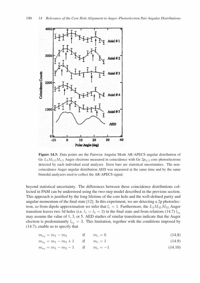
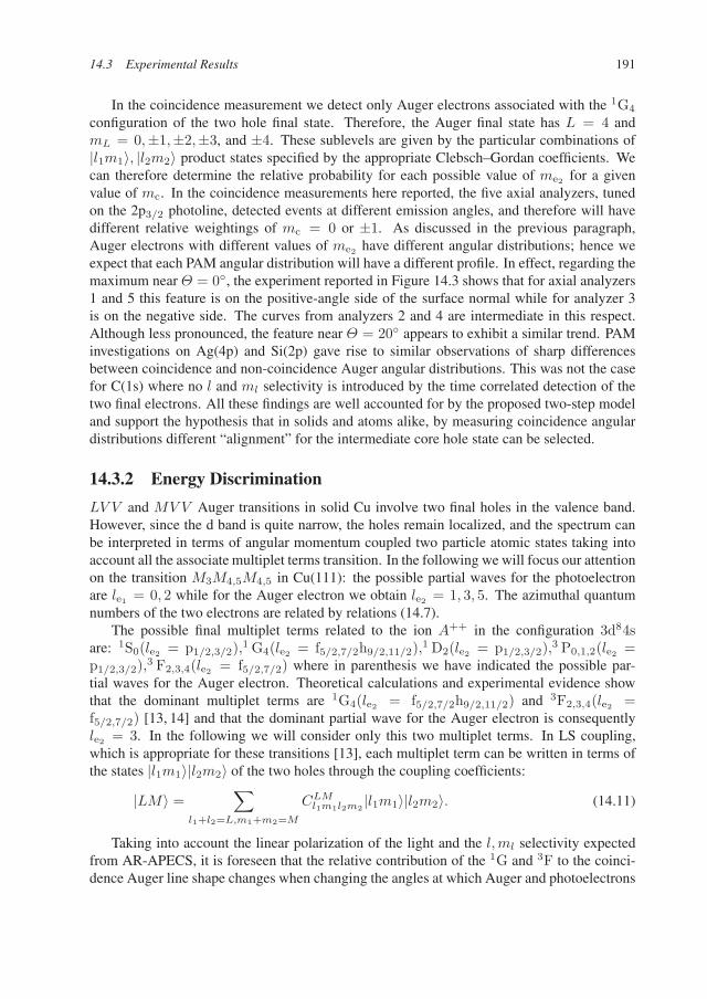
Figure 14.4: Data points are the Cu(111) AR-APECS spectrum measured in integrated energymode; i.e. the energy distribution of the M3V V Auger electron (measured by bimodal analyz-ers) in coincidence with a 3p3/2 photoelectron (see text for details). Error bars are statisticaluncertainties while the thick solid line is the best fit obtained taking into account 1G and 3F
components only (dash dotted lines). The thin full line is the non-coincidence Auger spectrummeasured at the same time and by the same bimodal analyzers used to collect the AR-APECSsignal.
are revealed. To verify this hypothesis, we have chosen two different experimental config-urations (configurations A and B) of the analyzers. Simulations performed with the afore-mentioned MSCD code indicate that by selecting one of the two configurations, the relativerelevance of the me1 = me2 = 0 and me1 = 0, me2 = 1 final substates changes. In partic-ular, in configuration A where contribution from me1 = me2 = 0 components is dominant,the 3F term should not contribute to the AR-APECS Auger lineshape. The experiment hasconfirmed such a prediction, indicating variations of the intensity ratio 1G/3F as functionof the detection angles; in particular, 1G/3F is larger in configuration A than in B, as ex-pected. This effect is clearly shown in Figure 14.4 where the coincidence M3V V spectrummeasured in configuration A, that enhances contributions from me1 = me2 = 0 is reported.The measured lineshape is well accounted for by 1G and 3F contributions only (peaks shownby dash dotted line in the figure) plus a modest monotonic multiple losses background. Thenon-coincidence spectrum, as measured together with the coincidence one, is also shown inthe figure. The calculated intensities for 1G and 3F components are found to be in excel-lent agreement with the measured non-coincidence spectrum, while the coincidence spectrumyields a ratio larger than 4. A similar discrepancy between coincidence and non-coincidence1G/3F ratios has been found for the four different configurations investigated. Moreover, byadopting the simple two-step model described in the previous section, we predict ratios ofintensity that, within error bars, always match the experiment [15]. We can then conclude thatAR-APECS actually introduces a selectivity in the intermediate core hole state sublevels that
14.3 Experimental Results 193
allows for discrimination of individual components of the multiplet split Auger spectrum thatare otherwise overlapping.
Correlation between the two electrons has also been observed by the energy shift of theAuger electrons in the coincidence acquisition. In the experiment reported in Figure 14.4,the photoelectron analyzer was tuned to an energy 2 eV higher than the 3p3/2 transition. Thisavoids any contribution in the AR-APECS spectrum from the 3p1/2 core state and, at the sametime, shows that in this experiment the energy is conserved collectively by the electrons pairrather than by the photo and Auger electron separately. The peak intensity for the 1G transi-tion is indeed observed at an energy lower than the corresponding non-coincidence transition.The Auger energy shift matches the photoelectron effective distribution detuning (which is,however, less than 2 eV), as expected and already observed [13].
14.3.3 Surface Sensitivity
Enhanced surface sensitivity of electron–electron coincidence experiments has been claimedsince early works in this field and a model has been developed to account for it [16]. But itwas not until recently that experimental evidences have been acquired [11, 17].
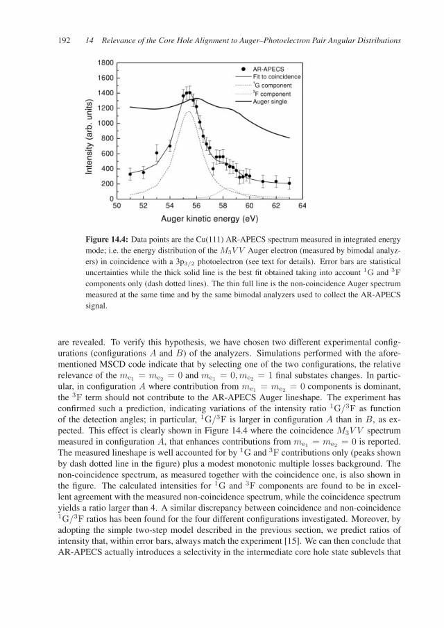
Figure 14.5: Data points are AR-APECS measured in integrated angular mode on the Cu(111)surface; i.e. the angular distribution of the 3p3/2 photoelectron (measured by bimodal analyzers)in coincidence with M3V V Auger electron (see text for details). The axial plane is rotated by35 with respect to the X axis (see Figure 14.2). The photon beam impinges onto the surface ata 3 grazing angle. Zero of the bimodal angle scale corresponds to the surface normal. Errorsbars are statistical uncertainties on the coincidence events. The full line is the non-coincidencephotoelectron angular distribution (PED) as measured together with the coincidence signal.
This AR-APECS feature has been studied by an AR-APECS experiment where the 2p3/2
photoelectron (kinetic energy 160 eV) angular distribution is measured in coincidence withthe M3V V Auger electron (kinetic energy 55 eV) on the Cu(111) surface. We have measuredthe Cu 2p3/2 photoelectron polar angle distribution, emitted from the Cu(111) sample on the
194 14 Relevance of the Core Hole Alignment to Auger–Photoelectron Pair Angular Distributions
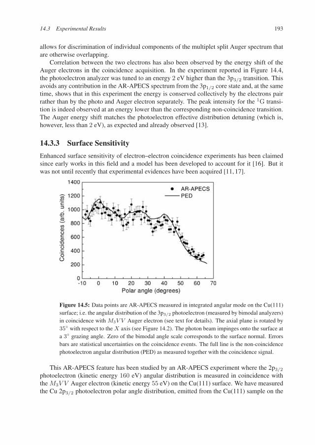
Figure 14.6: MSCD simulations of the 3p3/2 PED. The polar angle distributions are simulatedfor several different effective target thicknesses (layers) while the cluster size is kept fixed.
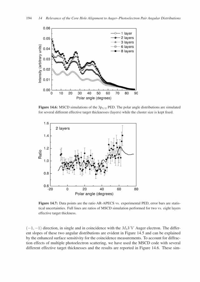
Figure 14.7: Data points are the ratio AR-APECS vs. experimental PED, error bars are statis-tical uncertainties. Full lines are ratios of MSCD simulation performed for two vs. eight layerseffective target thickness.
(−1,−1) direction, in single and in coincidence with the M3V V Auger electron. The differ-ent slopes of these two angular distributions are evident in Figure 14.5 and can be explainedby the enhanced surface sensitivity for the coincidence measurements. To account for diffrac-tion effects of multiple photoelectron scattering, we have used the MSCD code with severaldifferent effective target thicknesses and the results are reported in Figure 14.6. These sim-
14.4 Conclusions 195
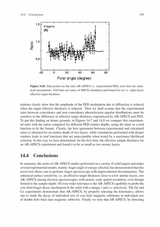
Figure 14.8: Data points are the ratio AR-APECS vs. experimental PED, error bars are statis-tical uncertainties. Full lines are ratios of MSCD simulation performed for six vs. eight layerseffective target thickness.
ulations clearly show that the amplitude of the PED modulation due to diffraction is reducedwhen the target effective thickness is reduced. Then we shall assume that the experimentalratio between coincidence and non-coincidence photoelectron angular distributions must besensitive to the difference in effective target thickness experienced by AR-APECS and PED.To put this finding on firmer grounds, in Figures 14.7 and 14.8 we compare this experimen-tal ratio with the ratios computed for different PED emitter depths, using the latter as a trialfunction to fit the former. Clearly, the best agreement between experimental and calculatedratios is obtained for an emitter depth of two layers, while simulations performed with deeperemitters leads to trial functions that are unacceptable when tested by a maximum likelihoodcriterion. In this way we have determined, for the first time, the effective sample thickness foran AR-APECS experiment and found it to be as small as two atomic layers.
14.4 Conclusions
In summary, the series of AR-APECS studies performed on a variety of solid targets and underseveral experimental modes, mainly Auger angle or energy selected, has demonstrated that thisnovel tool allows one to perform Auger spectroscopy with unprecedented discrimination. Theenhanced surface sensitivity, i.e. an effective target thickness close to a few atomic layers, setsAR-APECS among electron spectroscopies with atomic scale spatial resolution, even thoughlimited to the sample depth. Of even wider relevance is the AR-APECS capability to probe thecore hole/Auger decay mechanism in the solid with a unique l and ml selectivity. The Ge andCu experiments demonstrate that AR-APECS, by properly selecting the kinematics, allowsone to study the decay of individual sets of core hole magnetic substrates in individual setsof double hole final state magnetic sublevels. Finally we note that AR-APECS, by detecting
196 14 Relevance of the Core Hole Alignment to Auger–Photoelectron Pair Angular Distributions
the coincident photoelectron, preserves the chirality of the ionization event and then opensthe possibility of measuring dichroic effects in the Auger emission, thus providing a possiblenovel tool for the study of surface magnetic phenomena.
Acknowledgments
The authors are grateful to the ALOISA beamline staff members for the valuable support pro-vided during the AR-APECS experiments performed at the ELETTRA synchrotron radiationfacility, and they are also indebted to INFM for financial support provided through the “Sup-porto ELETTRA” program. Two of us (H.Y. and R.A.B.) acknowledge support by the NSFunder Grant No. DMR98-01681.
References
[1] G. Stefani, “Recent Advances in Electron-Electron Coincidence Experiments” in NewDirections in Atomic Physics, edited by C. T. Whelan, R. M. Dreizler, J. H. Macek, andH. R. J. Walters, Kluwer Academic/Plenum Publishers, New York, 1998.
[2] N. M. Kabachnik, J. Phys. B: At. Mol. Opt. Phys. 25 (1992) L389.[3] U. Fano and G. Racah, Irreducible Tensorial Sets, Academic Press, New York, 1959.[4] V. V. Balashov, A. N. Grum-Grzhimailo, and N. M. Kabachnik Polarization and Cor-
relation Phenomena in Atomic collisions, Kluwer Academic/Plenum Press, New York,2000.
[5] Y. U. Idzerda, Surf. Rev. Lett. 4 (1997) 161.[6] D. E. Ramaker, H. Yang, and Y. U. Ydzerda, J. Electron Spectrosc. Relat. Phenom. 68
(1994) 64.[7] Y. Chen and M. A. Van Hove, Mscd Package Overview, Lawrence Berkeley National
Laboratory, 1997.[8] J. J. Rehr and R. C. Albers, Phys. Rev. B 41 (1990) 8139.[9] F. Hermann and S. Skillman, Atomic Structure Calculations, Prentice Hall Inc., Engle-
wood Cliffs, New Jersey, 1963.[10] R. Gotter, A. Ruocco, A. Morgante, D. Cvetko, L. Floreano, F. Tommasini, and G. Ste-
fani, Nucl. Instr. and Meth. A, 467 (2001) 1468.[11] R. Gotter, A. Ruocco, M. T. Butterfield, S. Iacobucci, G. Stefani, and R. A. Bartynski,
Phys. Rev. B 67 (2003) 033303.[12] E. Antonides, Phys. Rev. B 15 (1977) 1669.[13] E. Jensen, R. A. Bartynski, S. L. Hulbert, E. D. Johnson, and R. Garrett, Phys. Rev. Lett.
62 (1989) 71.[14] R. Kleiman, private communication.[15] G. Stefani, R. Gotter, A. Ruocco, F. Offi, F. Da Pieve, S. Iacobucci, A. Morgante, A.
Verdini, A. Liscio, H. Yao, and R. A. Bartynski, submitted to J. Electron Spectrosc.Relat. Phenom. (2004).
[16] W. S. M. Werner, H. Störi, and H. Winter, Surf. Sci. 518 (2002) L569.[17] A. Liscio, R. Gotter, A. Ruocco, S. Iacobucci, A. G. Danese, R. A. Bartynski, and G.
Stefani, J. Electron Spectrosc. Relat. Phenom. in press (2004).


