Embed Size (px)
Citation preview
Republic of Uzbekistan Preparatory Survey
on Tashkent Heat Supply Power Plant
Modernization Project
Final Report
(Main Report)
June, 2009
Japan International Cooperation Agency (JICA)
Tokyo Electric Power Services Co., LTD
No.
ECC
CR(5)
09-002

Preface
Japanese Government determined to conduct the Preparatory Survey on Tashkent Heat
Supply Power Plant Modernization Project on request from Republic of Uzbekistan and Japan International Corporation Agency (collectively called as JICA hereafter) performed the Study.
JICA dispatched the study team to the site, which is headed by Mr. Kenji MIKATA of Tokyo Electric Power Services Company, Limited, one time during February 2009 to June 2009.
The study team conducted the site survey as well as the discussion with the related authorities of Uzbekistan Government and SJSC Uzbekenergo and has completed the study report through study works in Japan.
JICA wishes that this report will be contributable for promotion of the project and helpful for more development of the friendship between both countries.
In conclusion, JICA extends heartfelt thanks to related authorities and persons who cooperatively supported for this Study. June, 2009
Seiichi NAGATSUKA Vice-President
Japan International Cooperation Agency

June, 2009
Mr. Seiichi NAGATSUKA Vice-President Japan International Cooperation Agency Tokyo, Japan
Letter of Transmittal
The Study Team is pleased to transmit the report on Preparatory Survey on Tashkent Heat Supply Power Plant Modernization Project. The Study Team has performed this study pursuant to the contract with JICA during February 2009 to June 2009.
The Study Team established the plan to introduce the gas turbine cogeneration system into the Tashkent Heat Supply Power Plant, which is located in the center of the capital city of Uzbekistan and plays important roles, because of its superannuation. It is definitely expected that the energy conversion efficiency will be elevated and that the operational reliability of the plant and the impact on environment will be improved due to introduction of such system. In turn, the introduction of the system will contribute to the further economical development of Uzbekistan.
The Study Team strongly wishes that Republic of Uzbekistan will employ in priority the conclusion of the report completed through this examination.
Taking this opportunity, the Study Team extends heartfelt thanks to JICA and Ministry of Foreign Affairs, which cooperatively supported for this study. In addition, the Study Team extends heartfelt thanks to the related authorities of Uzbekistan Government, SJSC Uzbekenergo and other related authorities.
Preparatory Survey on Tashkent Heat Supply Power Plant Modernization Project Team Leader Kenji MIKATA
Republic of Uzbekistan
Preparatory Survey on Tashkent Heat Supply Power Plant Modernization Project Final Report
i
Table of Contents
Overall Evaluation and Recommendation Chapter 1 Overview of the Heat and Power Sector in the Republic of Uzbekistan
1.1 Overvier of power sector in the Republic of Uzbekistan 1-1 1.1.1 Organization 1-1 1.1.2 Overview of existing power generation facilities 1-2 1.1.3 Overview of power transmission facilities 1-4 1.1.4 Power demand 1-8 1.1.5 Power generation development plan 1-10 1.1.6 Power demand forecast 1-11 1.1.7 Financial situation of the Tashkent Heat and Power Generation Company 1-12
1.2 Overview of heat sector in Tashkent 1-15 1.2.1 Current situation of heat supply in Tashkent 1-15 1.2.2 Overview of the existing heat supply facilities 1-15 1.2.3 Transition of heat demand 1-16 1.2.4 Assumption of heat demand and heat supply plant development plan 1-17
1.3 Electricity and heat tariff system 1-18 1.3.1 Tariff system 1-18 1.3.2 Tariff level 1-18
1.4 Briefing of Gas and Coal Sector 1-20 1.4.1 Briefing of Gas Sector 1-20 1.4.2 Briefing of Coal Sector 1-21
1.5 Overview of the cadidate project for Japanese ODA Loan 1-22 1.5.1 Angre Power Plant 1-22 1.5.2 Tarimarjan Power Plant 1-46 1.5.3 Heat Supply Plant for Tashkent 1-50
Chapter 2 Tashkent Heat Supply Power Plant
2.1 Present Condtions of the Project Site 2-1 2.1.1 Location 2-1 2.1.2 Project site 2-2 2.1.3 Present conditions of the plant environment 2-2
2.2 Operating Conditions of Existing Facilities 2-2 2.2.1 Overview 2-2 2.2.2 Plant layout 2-4 2.2.3 Main facility specifications 2-5 2.2.4 Operation records of the existing Tashkent CHP Plant 2-11
Republic of Uzbekistan
Preparatory Survey on Tashkent Heat Supply Power Plant Modernization Project Final Report
ii
Chapter 3 Implementation Plan of Japanese ODA Loan Project
3.1 Concept Design 3-1 3.1.1 Prior Conditions 3-1 3.1.2 Cogeneration system 3-1 3.1.3 Gas turbine cogeneration system 3-2 3.1.4 Selection of gas turbine 3-3 3.1.5 Scope of facilities of the Project 3-5 3.1.6 Major performance of the facilities 3-5
3.2 Layout Plan 3-6 3.3 Equipment and Material Transportation 3-6 3.4 Fuel Supply Plan 3-7
3.4.1 Gas source 3-7 3.4.2 Supply capacity 3-7
3.5 Electric facilities plan 3-7 3.6 Coordination with the NEDO project 3-9 3.7 Project Implementation Schedule 3-10 3.8 Project Implementation Organization 3-10 3.9 Project Effect 3-12
3.9.1 Energy Saving Effect 3-12 3.9.2 Greenhouse gas reduction effect 3-17 3.9.3 Effects of environment improvement and others 3-19
3.10 Feasibility study toward introduction of the STEP 3-21 Chapter 4 Economic and Financial Analysis and Key Performance Indicators
4.1 Power Plant Operation Conditions 4-1 4.1.1 Operational Conditions of the GTCS for the Tashkent Supply Power Plant 4-1
4.2 Project Cost 4-2 4.2.1 Price Trend of Combined Cycle Power Plant 4-2 4.2.2 Estimation of the Project Costs 4-3
4.3 Financial Analysis 4-4 4.3.1 Financial resource 4-4 4.3.2 Assumption for financial analysis 4-4 4.3.3 Indicators of financial analysis 4-5 4.3.4 Sensitivity analysis 4-8 4.3.5 Financial evaluation 4-8
4.4 Economic analysis 4-8 4.4.1 Caluculation of benefit 4-8 4.4.2 Indicators of economic evaluation 4-9
Republic of Uzbekistan
Preparatory Survey on Tashkent Heat Supply Power Plant Modernization Project Final Report
iii
4.4.3 Sensitivity analysis 4-10 4.5 Conclusion of economic and financial analysis 4-10 4.6 Key Performance Indicators 4-11
Chapter 5 Environmental and Social Consideration
5.1 Legal system relating to environment 5-1 5.1.1 Environmental Asministration 5-1 5.1.2 System of legal restriction on the environment 5-1 5.1.3 The major environmental restriction 5-2
5.2 The general outline of the Environmental Impact Assessment 5-8 5.2.1 The EIA in Uzbekistan 5-8 5.2.2 The overview of the Environmental Impact Assessment 5-11
5.3 EIA schedule for Tashkent Heat Supply Plant 5-16 Chapter 6 CDM Application Study
6.1 CDM procedure 6-1 6.1.1 Institutional structure 6-1 6.1.2 CDM procedure outline 6-2
6.2 CDM Application 6-4 6.2.1 CDM Application 6-4 6.2.2 Methodology 6-5 6.2.3 Exam. w/Methodology 6-5 6.2.4 Project with CDM application 6-11

Republic of Uzbekistan
Preparatory Survey on Tashkent Heat Supply Power Plant Modernization Project Final Report
iv
Abbreviation
B/C Benefit Cost BOP Balance of Plant CCPP Combined Cycle Power Plant CDM Clean Development Mechanism CER Certified Emission Reduction COP Conference of Parties
COP/MOP the Conference of Parties serving as the meeting of the Parties to the Kyoto Protocol
CPI Consumer Price Index CRT Cathode Ray Tube DCS Distribution Control System DNA Designated National Authority DOE Designated Operational Entity EIA Environmental Impact Assessment EIRR Economic Internal Rate of Return EPC Engineering, Procurement and Construction F/S Feasibility Study FIRR Financial Internal Rate of Return FOB Free on Board GHG Green House Gas GT Gas Turbine GTCS Gas Turbine Co-generation System HRSG Heat Recovery Steam Generator IFC International Finance Corporation IMF International Monetary Fund JBIC Japan Bank for International Cooperation JETRO Japan External Trade Organization JICA Japan International Cooperation Agency MAC Maximum Allowable Concentration MCC Motor Control Center NEDO New Energy and Industrial Technology Development Organization NPV Net Present Value ODA Official Development Assistance PDD Project Design Document PIN Project Idea Note Pre-FS Pre Feasibility Study TEP Teploelektroproekt TashTEZ Tashkent Heat and Power Supply Plant

Republic of Uzbekistan
Preparatory Survey on Tashkent Heat Supply Power Plant Modernization Project Final Report
v
UNFCCC the UN Framework Convention on Climate Change UPS Uninterruptible Power Supply System
Republic of Uzbekistan
Preparatory Survey on Tashkent Heat Supply Power Plant Modernization Project Final Report
vi
Units
Prefixes : micro- = 10-6 m : milli- = 10-3 c : centi- = 10-2 d : deci- = 10-1 da : deca- = 10 h : hecto- = 102 k : kilo- = 103 M : mega- = 106 G : giga- = 109 Units of Length m : meter mm : millimeter cm : centimeter km : kilometer in : inch ft : feet yd : yard Units of Area cm2 : square centimeter m2 : square meter km2 : square kilometer ft2 : square feet (foot) yd2 : square yard ha : hectare Units of Volume m3 : cubic meter l : liter kl : kiloliter Units of Mass g : gram kg : kilogram t : ton (metric) lb : pound Units of Density kg/m3 : kilogram per cubic meter t/m3 : ton per cubic meter mg/m3N : milligram per normal cubic meter
Republic of Uzbekistan
Preparatory Survey on Tashkent Heat Supply Power Plant Modernization Project Final Report
vii
g/m3N : gram per normal cubic meter ppm : parts per million g/scm : microgram per standard cubic meter Units of Pressure kg/cm2 : kilogram per square centimeter (gauge) lb/in2 : pound per square inch mmHg : millimeter of mercury mmHg abs : millimeter of mercury absolute mAq : meter of aqueous lb/in2, psi : pounds per square inches atm : atmosphere Pa : Pascal bara : bar absolute Units of Energy kcal : kilocalorie Mcal : megacalorie MJ : mega joule TJ : tera joule kWh : kilowatt-hour MWh : megawatt-hour GWh : gigawatt-hour Btu : British thermal unit Units of Heating Value kcal/kg : kilocalorie per kilogram kJ/kg : kilojoule per kilogram Btu/lb : British thermal unit per pound Units of Heat Flux kcal/m2h : kilocalorie per square meter hour Btu/ft2H : British thermal unit per square feet hour Units of Temperature deg : degree : degree C : Celsius or Centigrade C : degree Celsius or Centigrade F : Fahrenheit F : degree Fahrenheit Units of Electricity W : watt kW : kilowatt A : ampere
Republic of Uzbekistan
Preparatory Survey on Tashkent Heat Supply Power Plant Modernization Project Final Report
viii
kA : kiloampere V : volt kV : kilovolt kVA : kilovolt ampere MVA : megavolt ampere Mvar : megavar (mega volt-ampere-reactive) kHz : kilohertz Units of Time s : second min : minute h : hour d : day y : year Units of Flow Rate t/h : ton per hour t/d : ton per day t/y : ton per year m3/s : cubic meter per second m3/min : cubic meter per minute m3/h : cubic meter per hour m3/d : cubic meter per day lb/h : pound per hour m3N/s : cubic meter per second at normal condition m3N/h : cubic meter per hour at normal condition Units of Conductivity S/cm : microSiemens per centimeter Units of Sound Power Level dB : deci-bell Units of Currency Sum : Uzbekistan Sum US$ : US Dollar ¥ : Japanese Yen
Republic of Uzbekistan
Preparatory Survey on Tashkent Heat Supply Power Plant Modernization Project Final Report
ix
List of Tables
No. Title of Tables Table 1-1-1 Overview of the facilities in the existing thermal power plants Table 1-1-2 Overview of the facilities in the existing hydraulic power plants Table 1-1-3 Fuel Consumption at Thermal Power Plants Table 1-1-4 Overall extension of transmission lines Table 1-1-5 Power generation development plan up to 2015
Table 1-1-6 Power generation plan by the thermal power plants of Uzbekenergo up to 2015
Table 1-1-7 Balance sheet of Tashkent Heat and Power Generation Company Table 1-1-8 Profit and Loss Statement (as of Jan 1, 2009)
Table 1-2-1 Installed capacity and generation capacity of each heat supply plant in Tashkent (as of February 2009)
Table 1-2-2 Assumption of subsequent heat demand in Tashkent Table 1-2-3 Heat supply facilities construction plan Table 1-3-1 Tariff of electricity and heat (as of 2009) Table 1-3-2 Comparison of monthly average household expenditure composition Table 1-5-1 Particulars of major power generation facilities Table 1-5-2 Generator equipment specifications list Table 1-5-3 Overall operation time for each unit of the steam turbine/generator
Table 1-5-4 Operation conditions of the steam turbine/generator for the past five years
Table 1-5-5 Transition of the operation and maintenance cost at Angren thermal power plant for the past five years (1,000 US dollars)
Table 1-5-6 Effect of reducing the greenhouse gas emission Table 1-5-7 Comparison of emissions of air contaminants
Table 1-5-8 Overall working expenses (as of December 2005) (Unit: Thousand US $)
Table 1-5-9 25 MW-class GTCS installation plan at each cogeneration power plant Table 1-5-10 Condition of each heat plant and neighboring substation Table 2-2-1 Primary specifications of the steam boilers Table 2-2-2 Primary specifications of the steam turbine generator Table 2-2-3 Primary specifications of the hot water boilers Table 2-2-4 Total operating hours and current capacity of the boilers and turbine
Table 2-2-5 Generated electric energy and hot-water/steam heat supply during the past 10 years
Table 2-2-6 Generated output power and steam/hot-water heat supply in 2008 by month
Republic of Uzbekistan
Preparatory Survey on Tashkent Heat Supply Power Plant Modernization Project Final Report
x
Table 2-2-7 Operation records of main facilities for the past five years Table 2-2-8 Fuel consumption of the boilers for the past five years
Table 2-2-9 Operation and maintenance costs and unit wholesale energy prices for the past five years
Table 3-1-1 Comparison of each GTCS
Table 3-1-2 25 MW-class standard gas turbine performances of heavy-duty structure for industrial use
Table 3-1-3 15 MW-class standard gas turbine performances of heavy-duty structure for industrial use
Table 3-1-4 Scope of facilities of this project
Table 3-9-1 Amount of energy supply and the amount of energy usage in the base line
Table 3-9-2 Amount of energy supply and amount of energy usage after implementation of the project
Table 3-9-3 Annual amount of energy saving effect, effective period and cumulative amount
Table 3-9-4 Annual amount of greenhouse gas reduction effect, effective period and cumulative amount
Table 3-9-5 NOx emission rate per unit energy consumption (as NO2) Table 3-9-6 Increase or Decrease of NOx Emission (as NO2) Table 3-9-7 Reduction of SOx Emission (as SO2) Table 4-1-1 Operational conditions of the GTCS for the Tashkent CHP Plant Table 4-2-1 Estimated costs for this project (as of March 2009) Table 4-3-1 Fund lending conditions Table 4-3-2 CO2 reduction Table 4-3-3 FIRR (Financial Internal Rate of Return) Table 4-3-4 Sensitivity analysis Table 4-4-1 Quantity of natural gas saved Table 4-4-2 Economic indicators Table 4-4-3 Sensitivity analysis Table 4-6-1 Operational and Effect Indicators
Table 5-1-1 MAC and Class of Danger of Main Pollutants Formed by Power Stations Emissions
Table 5-1-2 Territorial Rates for Assessment on Pollutants, Being Discharged into Atmosphere
Table 5-1-3 (1) Standard value of main pollutants maximum ground concentration (Tashkent CHP Plant)
Republic of Uzbekistan
Preparatory Survey on Tashkent Heat Supply Power Plant Modernization Project Final Report
xi
Table 5-1-3 (2) Standard value of main pollutants maximum ground concentration (Tarimarjan)
Table 5-1-3 (3) Standard value of main pollutants maximum ground concentration (Angren)
Table 5-1-4 Environmental Standard for discharged water (drinking water and water usage)
Table 5-1-5 Environmental standard for noise (housing Area) Table 5-1-6 Standard for Noise (Working Area) Table 5-2-1 EIA explanation meeting
Table 5-2-2 Draft EIA preparation: Index, entry, points of consideration and information source
Table 6-2-1 Facility, input, output of the project Table 6-2-2 Facility, input, output assumed in AM0048 Table 6-2-3 Summary of additionality
Republic of Uzbekistan
Preparatory Survey on Tashkent Heat Supply Power Plant Modernization Project Final Report
xii
List of Figures
No. Title of Figures Figure 1-1-1 Uzbekenergo organization chart Figure 1-1-2 Fuel ratio in thermal power plants (2008) Figure 1-1-3 Power grid system diagram for the Republic of Uzbekistan Figure 1-1-4 Power flow in the Uzbekistan power system Figure 1-1-5 Transition of power transmission and distribution loss rate
Figure 1-1-6 Transition of electricity generation and electricity consumption in the last ten years
Figure 1-1-7 Transition of the imported and exported electric power in the last ten years
Figure 1-1-8 Transition of the maximum demand for electric power and generation capacities in the last ten years
Figure 1-1-9 Power Demand Forecast up to 2018 Figure 1-2-1 Transition of heat demand in Tashkent for the last ten years Figure 1-3-1 Transition of electricity and heat tariff (unit: Soum/kwh) Figure 1-4-1 Record of Natural Gas Production Figure 1-4-2 Record of Natural Gas Consumption Figure 1-4-3 Coal Supply Record and Plan
Figure 1-5-1 Geographical relationship between the Angren thermal power plant and Angren coal mine
Figure 1-5-2 Overall layout plan of power plant premises Figure 1-5-3 Schematic diagram representing the entire view of the power plant Figure 1-5-4 Bus Configuration of Switch Yard in Angren Power Plant Figure 1-5-5 Existing plant single-line diagram Figure 1-5-6 Schematic diagram of newly installed power generation facilities
Figure 1-5-7 Single-line connection diagram in the plant of newly installed power generation facilities
Figure 1-5-8 New facilities layout plan in the premises Figure 1-5-9 Position of the Tarimarjan power plant Figure 1-5-10 Tarimarjan power plant Figure 1-5-11 Tarimarjan TPP Existing Plant Single Diagram Figure 1-5-12 Single line Diagram for New Plant Figure 1-5-13 Layout of Tarimarjan Power Plant Figure 1-5-14 Layout drawing for No.2 heat supply plant premises Figure 1-5-15 Layout drawing for No.4 heat supply plant premises Figure 1-5-16 Layout drawing for No.9 heat supply plant premises Figure 1-5-17 Layout drawing for No.10 heat supply plant premises
Republic of Uzbekistan
Preparatory Survey on Tashkent Heat Supply Power Plant Modernization Project Final Report
xiii
Figure 2-1-1 Outline location map of the power plant Figure 2-2-1 Layout of the Tashkent CHP Plant Figure 2-2-2 Schematic diagram of the Tashkent CHP Plant system Figure 2-2-3 Single Line Diagram of Existing Plant
Figure 2-2-4 Generated electric energy and hot-water/steam heat supply during the past 10 years
Figure 2-2-5 Generated electric energy and hot-water/steam heat supply in 2008 by month
Figure 2-2-6 Generated output power in 2008 by month Figure 2-2-7 Yearly average availability of main facilities Figure 2-2-8 Load factors of main facilities Figure 3-2-1 Layout plan of New facilities Figure 3-5-1 Single Line Diagram of New Plant Figure 3-7-1 Project implementation schedule Figure 3-8-1 Newly installed power generation facility construction organization Figure 4-2-1 Trend of FOB prices for the CCPP consisting of two H25 GTs
Figure 5-2-1 Procedure for EIA document submission by project conductor and review of the document by Goskomprirody
Figure 6-1-1 CDM institutional structure Figure 6-1-2 CDM project appraisal, examination steps Figure 6-2-1 Additionality exam. flow
Republic of Uzbekistan
Preparatory Survey on Tashkent Heat Supply Power Plant Modernization Project Final Report
i
Overall Evaluation and Recommendation
As the results of overall evaluation, it is feasible from the technical, economical and environmental points of view to promote the Tashkent Heat Supply Power Plant Modernization Project (hereinafter referred to as "the Project") as a Japanese ODA Loan Project. I. Overall Evaluation 1. Technical Feasibility
(1) Construction Plan It is necessary to renew or replace the existing facilities of Tashkent Heat Supply Power Plant to keep the operating reliabilities since almost of them have passed 40 to 50 years from commencement of commercial operation. In Uzbekistan, during the last ten years, the maximum power demand has remained almost same, but in the future it is expected that the power demand will increase because the plant is located in the central area of Tashkent City and it is necessary to provide the important public facilities such as Tashkent Air Port with electric power. Thus it is necessary to develop the reliable and stable power resource in consideration of such situation. From the point of heat supply, it is significant to install higher efficient gas turbine cogeneration system (hereinafter referred to as "GTCS") to cope with increasing heat demand due to population growth of Tashkent City and higher level of lifestyle of residents. Therefore from the view of power and heat supply, implementation of the Project is judged feasibile.
(2) Installation System
The generated power output of GTCS is larger than existing boiler and turbine system for the same amount of heat supply capacity. As the result, the equivalent thermal efficiency of the part of power generation system is larger than the latest large capacity combined cycle power plant. It means that GTCS is suitable as distributed power source.
(3) Layout Plan
The area for new plant is 76m x 195m, this area is enough for installation of two GTCS. But it is necessary to optimized study of layout included NEDO scope (total GTCSs are three) and 110kV switchyard.
(4) Fuel Supply Plan
Uzbekistan has natural gas reserves estimated at 65 Trillion Cubic Feet on January. According to the natural gas supply agreement with Uzgazbyt, the maximum flow to the plant is 130,000m3/h. The maximum supply record to the plant in 2008 was about 59,000m3/h. After the Project, the peak consumption of natural gas will increase to about 12,000m3/h. The total value is still smaller than the contracted maximum supply.
(5) Connection Plans to the Power Network System
It makes judgments that it is possible to transmission in order to install new switchyard and 110kV transmission line already renewed on 2005.
Republic of Uzbekistan
Preparatory Survey on Tashkent Heat Supply Power Plant Modernization Project Final Report
ii
2. Environmental and Social Consideration There is no impact to the fauna / flora and with no resident relocation since the candidate land is already reclaimed. Appropriate management is conducted through monitoring on regular basis regarding emission gas / discharged water at each existing power plant. Upon additional construction, detailed consideration is necessary not to increase the amount of emission air pollutants as power plant as a whole, including shutdown of the existing plant. The details with regard to this matter shall be properly studied at the stage of preparation of EIA. However, it can be judged that the impacts on circumferential environment and residents will be minimized as the study results at this stage. 3. Financial Feasibility Necessity to promote the Project was confirmed by the indicator of EIRR as the result of financial analysis for the purpose to select the project from the viewpoints of optimum allocation of resources on national standpoints. It can't be concluded that the Project is financially profitable enough from the indicators of FIRR and others. Thus, it can be desirable to apply the Japanese ODA Loan with low interest and long terms of grace period. At present, the annual interest of the loan for the project applied the preferential terms for least developed countries is at the level of 0.55%. Therefore, if the Project is financed by the Japanese ODA Loan, the indicator of FIRR exceeds enough the annual interest of the loan, as the result, the Tashkent Heat and Power Generation Company will ensure profit performance. 4. CDM Applicability It is highly possible to apply AM0048 (New cogeneration facilities supplying electricity and/or steam to multiple customers and displacing grid/off-grid steam and electricity generation with more carbon-intensive fuels – Version 2) for approved methodology of baseline monitoring. It can be judged that the application of CDM to the Project is definitely possible as the results of investment analysis and barrier analysis of alternatives to the Project in accordance with “Tool for the demonstration and assessment of alternatives” approved by CDM Executive Board. II. Recommendation 1. It is necessary to promote this project in a coordinative manner with NEDO project. The
following points have to be especially coordinated
Total layout of two GTCS and 110kV switchyard. Type of HRSG (High pressure steam or low pressure steam or hot water recovery) Total plant system considering the retirement of existing facilities in future.
2. It is necessary to ensure the terminal pressure high enough to cope with the total fuel gas
consumption including NEDO project. 3. The pre-FS and EIA of NEDO project is to be soon approved by related governmental
authorities of Uzbekistan. The pre-FS and EIA of the Project shall be prepared and approved in a similar manner.
Republic of Uzbekistan
Preparatory Survey on Tashkent Heat Supply Power Plant Modernization Project Final Report
1-1
Chapter 1 Overview of the Heat and Power Sector in the Republic of Uzbekistan
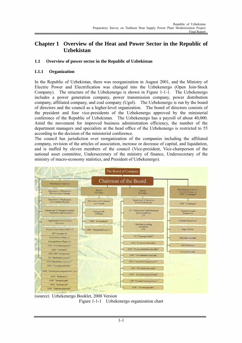
1.1 Overview of power sector in the Republic of Uzbekistan 1.1.1 Organization In the Republic of Uzbekistan, there was reorganization in August 2001, and the Ministry of Electric Power and Electrification was changed into the Uzbekenergo (Open Join-Stock Company). The structure of the Uzbekenergo is shown in Figure 1-1-1. The Uzbekenergo includes a power generation company, power transmission company, power distribution company, affiliated company, and coal company (Ugol). The Uzbekenergo is run by the board of directors and the council as a higher-level organization. The board of directors consists of the president and four vice-presidents of the Uzbekenergo approved by the ministerial conference of the Republic of Uzbekistan. The Uzbekenergo has a payroll of about 40,000. Amid the movement for improved business administration efficiency, the number of the department managers and specialists at the head office of the Uzbekenergo is restricted to 55 according to the decision of the ministerial conference. The council has jurisdiction over reorganization of the companies including the affiliated company, revision of the articles of association, increase or decrease of capital, and liquidation, and is staffed by eleven members of the council (Vice-president, Vice-chairperson of the national asset committee, Undersecretary of the ministry of finance, Undersecretary of the ministry of macro-economy statistics, and President of Uzbekenergo).
(source) Uzbekenergo Booklet, 2008 Version
Figure 1-1-1 Uzbekenergo organization chart
Republic of Uzbekistan
Preparatory Survey on Tashkent Heat Supply Power Plant Modernization Project Final Report
1-2
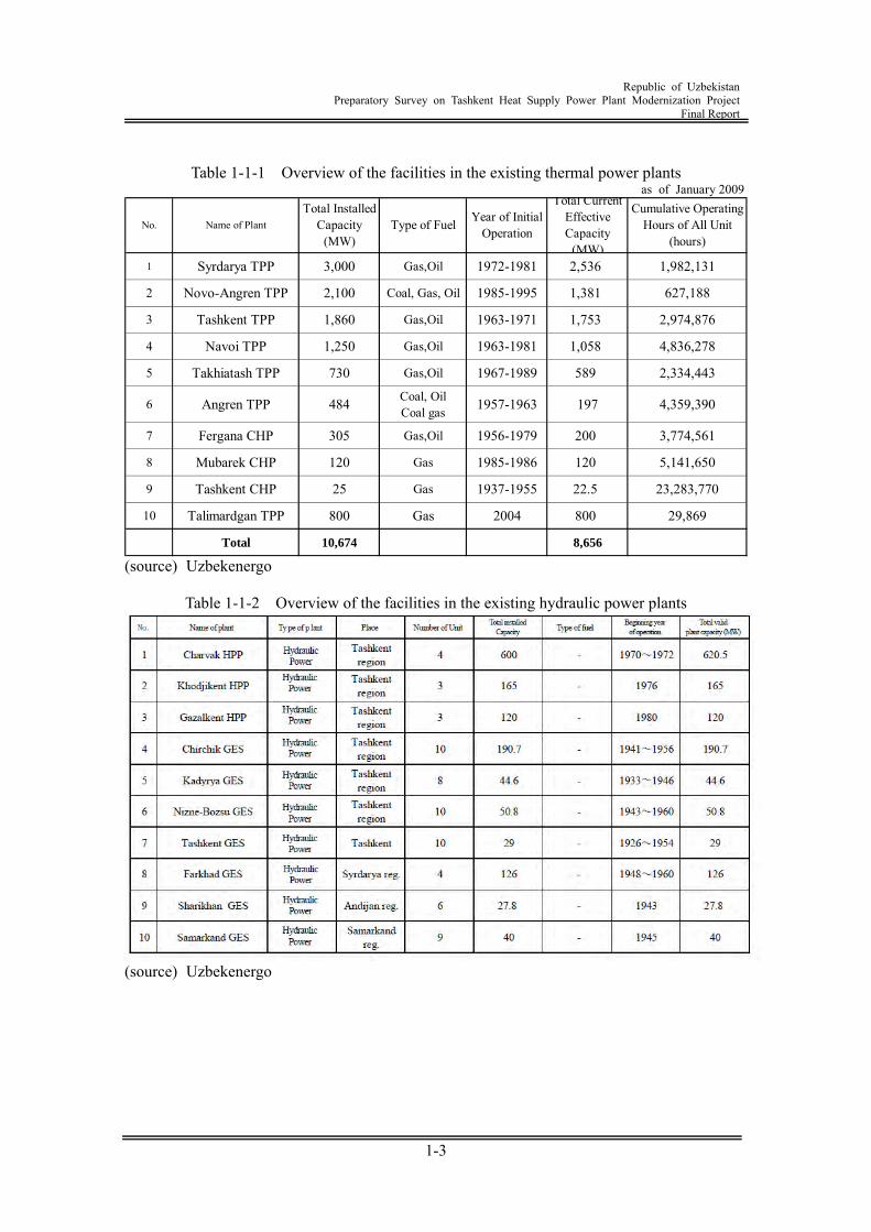
1.1.2 Overview of existing power generation facilities In 2008, the Uzbekenergo produces 50.158 GWh of electric power, of which 799.2 GWhr was exported. In the meantime, the Uzbekenergo imported 898.5 GWh of electric power. The generation capacity of all the power generation facilities in the Republic of Uzbekistan exceeds 12,300 MW. The thermal power plants accounting for 85.6% and the hydraulic power plant accounting for 11.5% are run by the Uzbekenergo, and the remaining power generation facilities accounting for 2.5% are run by other organizations. The Uzbekenergo anticipates a substantial increase in electricity demand. To meet this growing demand, the company is planning to maintain the capacity of self support through introduction of new facilities, to improve the reliability and quality of power supply, to save power, and to enhance operation efficiency of fuel and power. Further, to maintain the ecosystem and to enhance global environment, the company is making efforts to develop an on-site power generation technology and renewable energy source. Table 1-1-1 and Table 1-1-2 show the overview of the existing thermal power plants and hydraulic power plants. Power generation facilities in Uzbekistan consist of ten thermal power plants (of which three are cogeneration power plants) and twenty-eight hydraulic power plants. The overall installed capacity is 12,090MW (10,700MW by thermal power plants plus 1,390MW by hydraulic power plants). Of these, the following four power plants each have an installed capacity of over 1,000MW: These power plants are the Syrdarya thermal power plant (with an installed capacity of 3,000MW), the Navo-Angren thermal power plant (with an installed capacity of 2,100MW), the Tashkent thermal power plant (with an installed capacity of 1,860MW), and the Navoi thermal power plant (with an installed capacity of 1,250MW). Further, three cogeneration power plants as well as thermal power plants supply heat to thirteenth regions. Many of these power plants have been operating for 40 through 50 years after commencement of commercial operation, and require renewal or replacement due to degradation. However, no plants have been renewed or replaced since commencement of commercial operation of the Tarimarjan thermal power plant, unit-1 (having a generation capacity of 800 MW) in 2004, and reinforcement of 300 MW facilities by rehabilitation of the Syrdaria thermal power plant units-7 and -8 in 2005.
Republic of Uzbekistan
Preparatory Survey on Tashkent Heat Supply Power Plant Modernization Project Final Report
1-3
Table 1-1-1 Overview of the facilities in the existing thermal power plants
as of January 2009
1 Syrdarya TPP 3,000 Gas,Oil 1972-1981 2,536 1,982,131
2 Novo-Angren TPP 2,100 Coal, Gas, Oil 1985-1995 1,381 627,188
3 Tashkent TPP 1,860 Gas,Oil 1963-1971 1,753 2,974,876
4 Navoi TPP 1,250 Gas,Oil 1963-1981 1,058 4,836,278
5 Takhiatash TPP 730 Gas,Oil 1967-1989 589 2,334,443
6 Angren TPP 484 Coal, OilCoal gas 1957-1963 197 4,359,390
7 Fergana CHP 305 Gas,Oil 1956-1979 200 3,774,561
8 Mubarek CHP 120 Gas 1985-1986 120 5,141,650
9 Tashkent CHP 25 Gas 1937-1955 22.5 23,283,770
10 Talimardgan TPP 800 Gas 2004 800 29,869
Total 10,674 8,656
Total InstalledCapacity
(MW)Type of Fuel Year of Initial
OperationNo. Name of Plant
Total CurrentEffectiveCapacity
(MW)
Cumulative OperatingHours of All Unit
(hours)
(source) Uzbekenergo
Table 1-1-2 Overview of the facilities in the existing hydraulic power plants
(source) Uzbekenergo
Republic of Uzbekistan
Preparatory Survey on Tashkent Heat Supply Power Plant Modernization Project Final Report
1-4
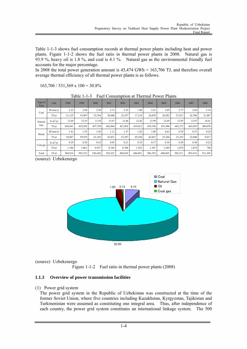
Table 1-1-3 shows fuel consumption records at thermal power plants including heat and power plants. Figure 1-1-2 shows the fuel ratio in thermal power plants in 2008. Natural gas is 93.9 %, heavy oil is 1.8 %, and coal is 4.1 %. Natural gas as the environmental friendly fuel accounts for the major percentage. In 2008 the total power generation amount is 45,474 GWh = 163,706 TJ, and therefore overall average thermal efficiency of all thermal power plants is as follows.
163,706 / 531,369 x 100 = 30.8%
Table 1-1-3 Fuel Consumption at Thermal Power Plants Type of
FuelUnit 1998 1999 2000 2001 2002 2003 2004 2005 2006 2007 2008
M tons/yr 2.22 2.04 2.50 2.15 2.35 1.80 2.61 2.05 2.77 2.66 2.18
TJ/yr 21,125 19,407 23,764 20,408 22,357 17,118 24,839 20,582 27,811 26,706 21,887
G m3/yr 12.69 12.55 13.54 13.67 12.46 12.42 12.99 12.69 12.95 12.97 14.61
TJ/yr 428,841 424,205 457,750 462,064 421,065 419,812 439,196 433,490 442,372 443,055 499,078
M tons/yr 1.41 1.53 1.56 1.12 1.37 1.26 1.09 0.63 0.78 0.57 0.24
TJ/yr 54,947 59,919 61,105 43,851 53,387 49,160 42,667 25,244 31,255 22,840 9,617
G m3/yr 0.29 0.28 0.25 0.05 0.21 0.35 0.37 0.36 0.30 0.30 0.22
TJ/yr 1.106 1.061 0.937 0.186 0.788 1.343 1.387 1,289 1,074 1,074 788
Total TJ/yr 504,914 503,532 542,620 526,323 496,810 486,091 506,703 480,605 502,511 493,676 531,369
Coal
NaturalGas
Mazut
Coal gas
(source) Uzbekenergo
4.1%
93.9%
0.1%1.8%
Coal
Natural Gas
Oil
Coal gas
(source) Uzbekenergo
Figure 1-1-2 Fuel ratio in thermal power plants (2008) 1.1.3 Overview of power transmission facilities (1) Power grid system
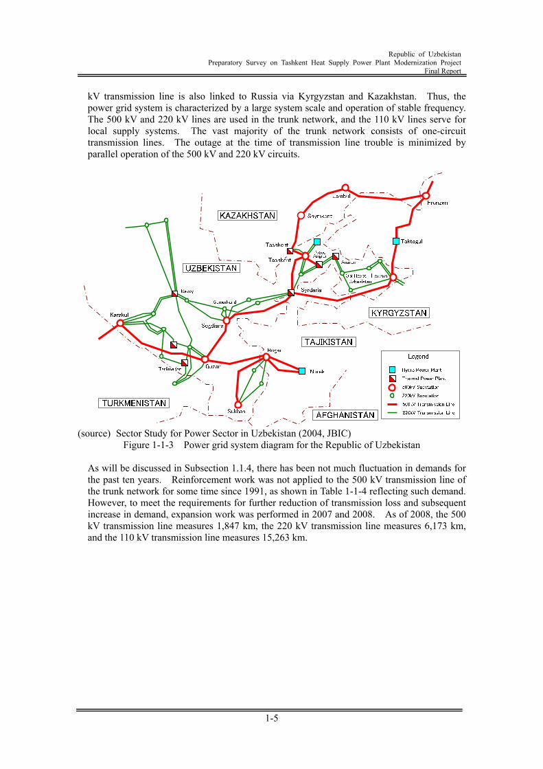
The power grid system in the Republic of Uzbekistan was constructed at the time of the former Soviet Union, where five countries including Kazakhstan, Kyrgyzstan, Tajikistan and Turkmenistan were assumed as constituting one integral area. Thus, after independence of each country, the power grid system constitutes an international linkage system. The 500
Republic of Uzbekistan
Preparatory Survey on Tashkent Heat Supply Power Plant Modernization Project Final Report
1-5
kV transmission line is also linked to Russia via Kyrgyzstan and Kazakhstan. Thus, the power grid system is characterized by a large system scale and operation of stable frequency. The 500 kV and 220 kV lines are used in the trunk network, and the 110 kV lines serve for local supply systems. The vast majority of the trunk network consists of one-circuit transmission lines. The outage at the time of transmission line trouble is minimized by parallel operation of the 500 kV and 220 kV circuits.
(source) Sector Study for Power Sector in Uzbekistan (2004, JBIC)
Figure 1-1-3 Power grid system diagram for the Republic of Uzbekistan
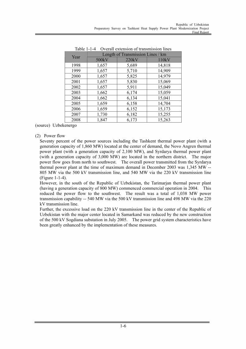
As will be discussed in Subsection 1.1.4, there has been not much fluctuation in demands for the past ten years. Reinforcement work was not applied to the 500 kV transmission line of the trunk network for some time since 1991, as shown in Table 1-1-4 reflecting such demand. However, to meet the requirements for further reduction of transmission loss and subsequent increase in demand, expansion work was performed in 2007 and 2008. As of 2008, the 500 kV transmission line measures 1,847 km, the 220 kV transmission line measures 6,173 km, and the 110 kV transmission line measures 15,263 km.
Republic of Uzbekistan
Preparatory Survey on Tashkent Heat Supply Power Plant Modernization Project Final Report
1-6
Table 1-1-4 Overall extension of transmission lines
Length of Transmission Lines / km Year 500kV 220kV 110kV 1998 1,657 5,689 14,818 1999 1,657 5,710 14,909 2000 1,657 5,825 14,979 2001 1,657 5,830 15,069 2002 1,657 5,911 15,049 2003 1,662 6,174 15,059 2004 1,662 6,134 15,041 2005 1,659 6,158 14,704 2006 1,659 6,152 15,173 2007 1,730 6,182 15,255 2008 1,847 6,173 15,263
(source) Uzbekenergo (2) Power flow
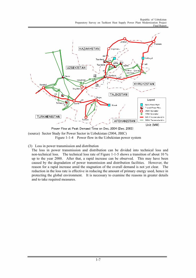
Seventy percent of the power sources including the Tashkent thermal power plant (with a generation capacity of 1,860 MW) located at the center of demand, the Novo Angren thermal power plant (with a generation capacity of 2,100 MW), and Syrdarya thermal power plant (with a generation capacity of 3,000 MW) are located in the northern district. The major power flow goes from north to southwest. The overall power transmitted from the Syrdarya thermal power plant at the time of maximum demand in December 2003 was 1,345 MW -- 805 MW via the 500 kV transmission line, and 540 MW via the 220 kV transmission line (Figure 1-1-4). However, in the south of the Republic of Uzbekistan, the Tarimarjan thermal power plant (having a generation capacity of 800 MW) commenced commercial operation in 2004. This reduced the power flow to the southwest. The result was a total of 1,038 MW power transmission capability -- 540 MW via the 500 kV transmission line and 498 MW via the 220 kV transmission line. Further, the excessive load on the 220 kV transmission line in the center of the Republic of Uzbekistan with the major center located in Samarkand was reduced by the new construction of the 500 kV Sogdiana substation in July 2005. The power grid system characteristics have been greatly enhanced by the implementation of these measures.
Republic of Uzbekistan
Preparatory Survey on Tashkent Heat Supply Power Plant Modernization Project Final Report
1-7
(source) Sector Study for Power Sector in Uzbekistan (2004, JBIC)
Figure 1-1-4 Power flow in the Uzbekistan power system (3) Loss in power transmission and distribution
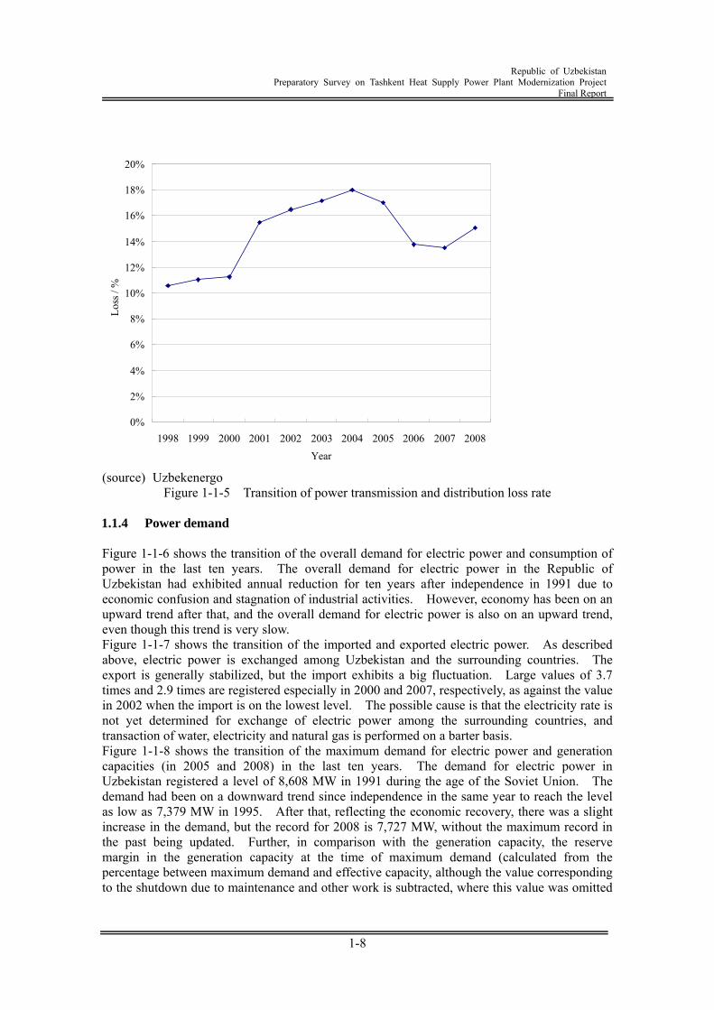
The loss in power transmission and distribution can be divided into technical loss and non-technical loss. The technical loss rate of Figure 1-1-5 shows a transition of about 10 % up to the year 2000. After that, a rapid increase can be observed. This may have been caused by the degradation of power transmission and distribution facilities. However, the reason for a rapid increase amid the stagnation of the overall demand is not yet clear. The reduction in the loss rate is effective in reducing the amount of primary energy used, hence in protecting the global environment. It is necessary to examine the reasons in greater details and to take required measures.
Republic of Uzbekistan
Preparatory Survey on Tashkent Heat Supply Power Plant Modernization Project Final Report
1-8
0%
2%
4%
6%
8%
10%
12%
14%
16%
18%
20%
1998 1999 2000 2001 2002 2003 2004 2005 2006 2007 2008Year
Loss
/ %
(source) Uzbekenergo
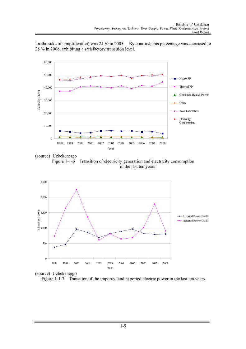
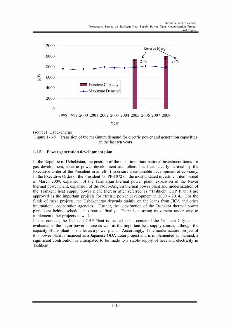
Figure 1-1-5 Transition of power transmission and distribution loss rate 1.1.4 Power demand Figure 1-1-6 shows the transition of the overall demand for electric power and consumption of power in the last ten years. The overall demand for electric power in the Republic of Uzbekistan had exhibited annual reduction for ten years after independence in 1991 due to economic confusion and stagnation of industrial activities. However, economy has been on an upward trend after that, and the overall demand for electric power is also on an upward trend, even though this trend is very slow. Figure 1-1-7 shows the transition of the imported and exported electric power. As described above, electric power is exchanged among Uzbekistan and the surrounding countries. The export is generally stabilized, but the import exhibits a big fluctuation. Large values of 3.7 times and 2.9 times are registered especially in 2000 and 2007, respectively, as against the value in 2002 when the import is on the lowest level. The possible cause is that the electricity rate is not yet determined for exchange of electric power among the surrounding countries, and transaction of water, electricity and natural gas is performed on a barter basis. Figure 1-1-8 shows the transition of the maximum demand for electric power and generation capacities (in 2005 and 2008) in the last ten years. The demand for electric power in Uzbekistan registered a level of 8,608 MW in 1991 during the age of the Soviet Union. The demand had been on a downward trend since independence in the same year to reach the level as low as 7,379 MW in 1995. After that, reflecting the economic recovery, there was a slight increase in the demand, but the record for 2008 is 7,727 MW, without the maximum record in the past being updated. Further, in comparison with the generation capacity, the reserve margin in the generation capacity at the time of maximum demand (calculated from the percentage between maximum demand and effective capacity, although the value corresponding to the shutdown due to maintenance and other work is subtracted, where this value was omitted
Republic of Uzbekistan
Preparatory Survey on Tashkent Heat Supply Power Plant Modernization Project Final Report
1-9
for the sake of simplification) was 21 % in 2005. By contrast, this percentage was increased to 28 % in 2008, exhibiting a satisfactory transition level.
0
10,000
20,000
30,000
40,000
50,000
60,000
1998 1999 2000 2001 2002 2003 2004 2005 2006 2007 2008
Year
Elec
trici
ty /
GW
h
Hydro PP
Thermal PP
Combined Heat & Power
Other
Total Generation
ElectricityConsumption
(source) Uzbekenergo
Figure 1-1-6 Transition of electricity generation and electricity consumption in the last ten years
0
500
1,000
1,500
2,000
2,500
1998 1999 2000 2001 2002 2003 2004 2005 2006 2007 2008Year
Elec
trici
ty /
GW
hr
Exported Power(GWh)Imported Power(GWh)
(source) Uzbekenergo
Figure 1-1-7 Transition of the imported and exported electric power in the last ten years
Republic of Uzbekistan
Preparatory Survey on Tashkent Heat Supply Power Plant Modernization Project Final Report
1-10
0
2000
4000
6000
8000
10000
12000
1998 1999 2000 2001 2002 2003 2004 2005 2006 2007 2008
Year
MW
Effective CapacityMaximum Demand
(source) Uzbekenergo Figure 1-1-8 Transition of the maximum demand for electric power and generation capacities
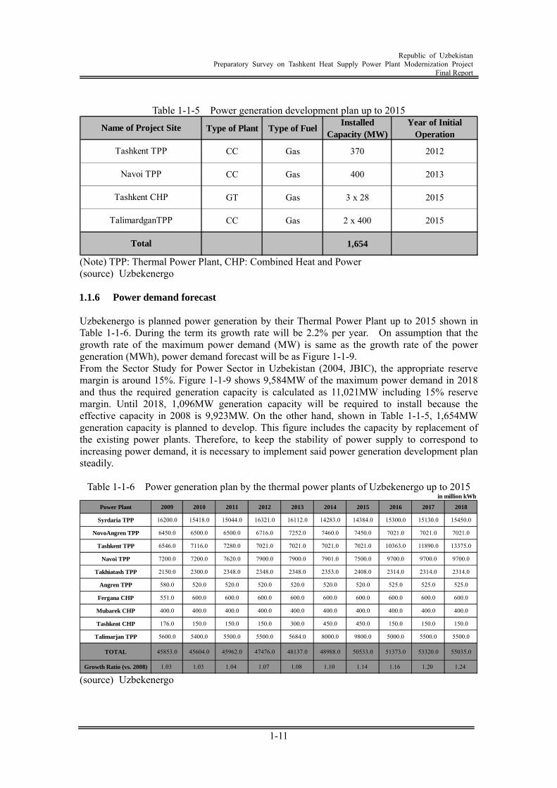
in the last ten years 1.1.5 Power generation development plan In the Republic of Uzbekistan, the position of the most important national investment items for gas development, electric power development and others has been clearly defined by the Executive Order of the President in an effort to ensure a sustainable development of economy. In the Executive Order of the President No.PP-1072 on the most updated investment item issued in March 2009, expansion of the Tarimarjan thermal power plant, expansion of the Navoi thermal power plant, expansion of the Novo-Angren thermal power plant and modernization of the Tashkent heat supply power plant (herein after referred as “Tashkent CHP Plant”) are approved as the important projects for electric power development in 2009 - 2014. For the funds of these projects, the Uzbekenergo depends mainly on the loans from JICA and other international cooperation agencies. Further, the construction of the Tashkent thermal power plant kept behind schedule has started finally. There is a strong movement under way to implement other projects as well. In this context, the Tashkent CHP Plant is located at the center of the Tashkent City, and is evaluated as the major power source as well as the important heat supply source, although the capacity of this plant is smaller as a power plant. Accordingly, if the modernization project of this power plant is financed as a Japanese ODA Loan project and is implemented as planned, a significant contribution is anticipated to be made to a stable supply of heat and electricity in Tashkent.
21% 28%
Reserve Margin
Republic of Uzbekistan
Preparatory Survey on Tashkent Heat Supply Power Plant Modernization Project Final Report
1-11
Table 1-1-5 Power generation development plan up to 2015
Type of Plant Type of FuelInstalled
Capacity (MW)Year of Initial
Operation
CC Gas 370 2012
CC Gas 400 2013
GT Gas 3 x 28 2015
CC Gas 2 x 400 2015
1,654
Navoi TPP
Total
Name of Project Site
Tashkent TPP
Tashkent CHP
TalimardganTPP
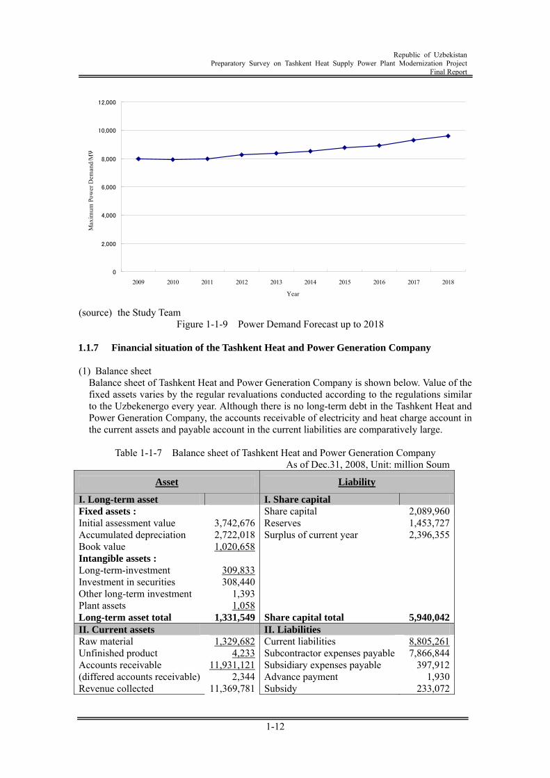
(Note) TPP: Thermal Power Plant, CHP: Combined Heat and Power (source) Uzbekenergo 1.1.6 Power demand forecast Uzbekenergo is planned power generation by their Thermal Power Plant up to 2015 shown in Table 1-1-6. During the term its growth rate will be 2.2% per year. On assumption that the growth rate of the maximum power demand (MW) is same as the growth rate of the power generation (MWh), power demand forecast will be as Figure 1-1-9. From the Sector Study for Power Sector in Uzbekistan (2004, JBIC), the appropriate reserve margin is around 15%. Figure 1-1-9 shows 9,584MW of the maximum power demand in 2018 and thus the required generation capacity is calculated as 11,021MW including 15% reserve margin. Until 2018, 1,096MW generation capacity will be required to install because the effective capacity in 2008 is 9,923MW. On the other hand, shown in Table 1-1-5, 1,654MW generation capacity is planned to develop. This figure includes the capacity by replacement of the existing power plants. Therefore, to keep the stability of power supply to correspond to increasing power demand, it is necessary to implement said power generation development plan steadily.
Table 1-1-6 Power generation plan by the thermal power plants of Uzbekenergo up to 2015 in million kWh
Power Plant 2009 2010 2011 2012 2013 2014 2015 2016 2017 2018
Syrdaria TPP 16200.0 15418.0 15044.0 16321.0 16112.0 14283.0 14384.0 15300.0 15130.0 15450.0
NovoAngren TPP 6450.0 6500.0 6500.0 6716.0 7252.0 7460.0 7450.0 7021.0 7021.0 7021.0
Tashkent TPP 6546.0 7116.0 7280.0 7021.0 7021.0 7021.0 7021.0 10363.0 11890.0 13375.0
Navoi TPP 7200.0 7200.0 7620.0 7900.0 7900.0 7901.0 7500.0 9700.0 9700.0 9700.0
Takhiatash TPP 2150.0 2300.0 2348.0 2348.0 2348.0 2353.0 2408.0 2314.0 2314.0 2314.0
Angren TPP 580.0 520.0 520.0 520.0 520.0 520.0 520.0 525.0 525.0 525.0
Fergana CHP 551.0 600.0 600.0 600.0 600.0 600.0 600.0 600.0 600.0 600.0
Mubarek CHP 400.0 400.0 400.0 400.0 400.0 400.0 400.0 400.0 400.0 400.0
Tashkent CHP 176.0 150.0 150.0 150.0 300.0 450.0 450.0 150.0 150.0 150.0
Talimarjan TPP 5600.0 5400.0 5500.0 5500.0 5684.0 8000.0 9800.0 5000.0 5500.0 5500.0
TOTAL 45853.0 45604.0 45962.0 47476.0 48137.0 48988.0 50533.0 51373.0 53320.0 55035.0
Growth Ratio (vs. 2008) 1.03 1.03 1.04 1.07 1.08 1.10 1.14 1.16 1.20 1.24 (source) Uzbekenergo
Republic of Uzbekistan
Preparatory Survey on Tashkent Heat Supply Power Plant Modernization Project Final Report
1-12
0
2,000
4,000
6,000
8,000
10,000
12,000
2009 2010 2011 2012 2013 2014 2015 2016 2017 2018
Year
Max
imum
Pow
er D
eman
d/M
W
(source) the Study Team
Figure 1-1-9 Power Demand Forecast up to 2018 1.1.7 Financial situation of the Tashkent Heat and Power Generation Company (1) Balance sheet
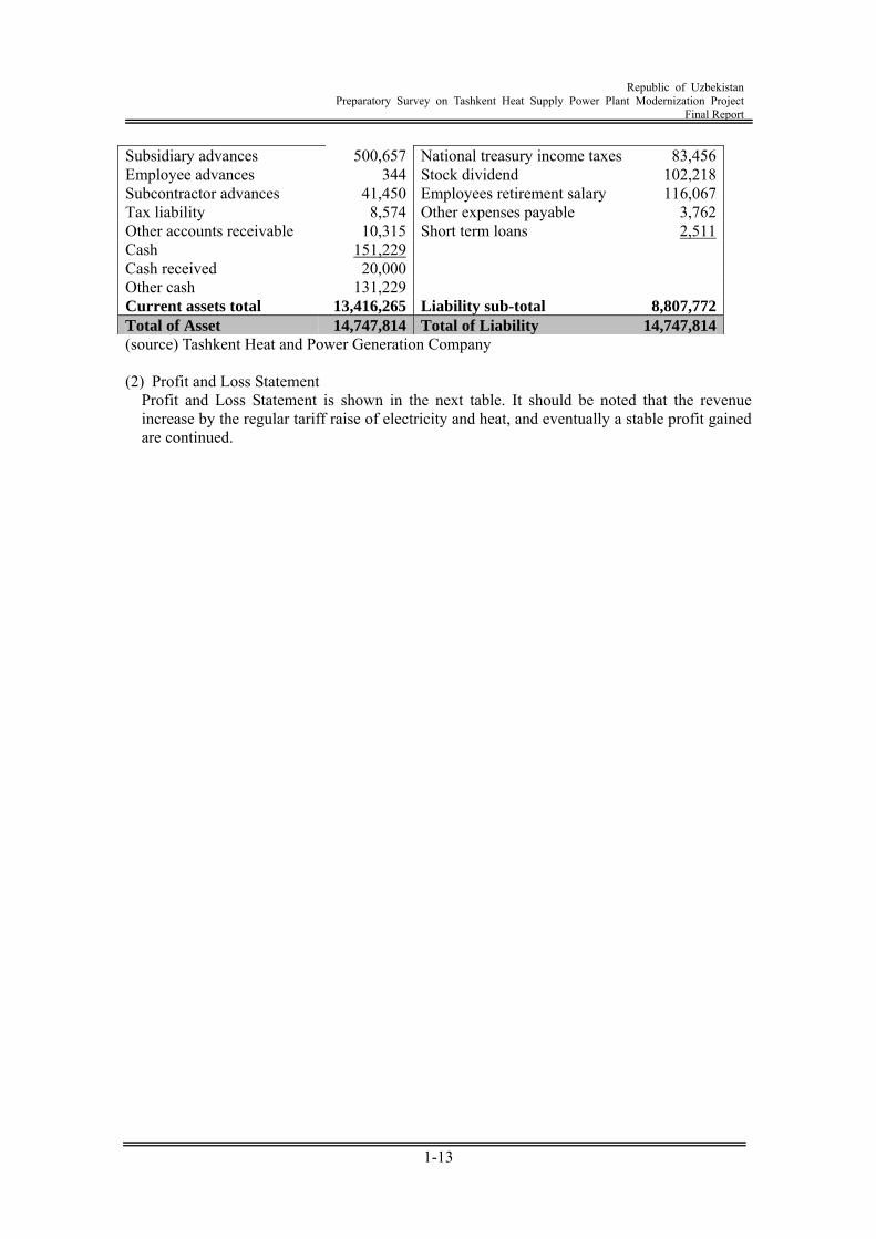
Balance sheet of Tashkent Heat and Power Generation Company is shown below. Value of the fixed assets varies by the regular revaluations conducted according to the regulations similar to the Uzbekenergo every year. Although there is no long-term debt in the Tashkent Heat and Power Generation Company, the accounts receivable of electricity and heat charge account in the current assets and payable account in the current liabilities are comparatively large.
Table 1-1-7 Balance sheet of Tashkent Heat and Power Generation Company
As of Dec.31, 2008, Unit: million Soum
Asset Liability
I. Long-term asset I. Share capital Fixed assets : Share capital 2,089,960 Initial assessment value 3,742,676 Reserves 1,453,727 Accumulated depreciation 2,722,018 Surplus of current year 2,396,355 Book value 1,020,658 Intangible assets : Long-term-investment 309,833 Investment in securities 308,440 Other long-term investment 1,393 Plant assets 1,058 Long-term asset total 1,331,549 Share capital total 5,940,042 II. Current assets II. Liabilities Raw material 1,329,682 Current liabilities 8,805,261 Unfinished product 4,233 Subcontractor expenses payable 7,866,844 Accounts receivable 11,931,121 Subsidiary expenses payable 397,912 (differed accounts receivable) 2,344 Advance payment 1,930 Revenue collected 11,369,781 Subsidy 233,072
Republic of Uzbekistan
Preparatory Survey on Tashkent Heat Supply Power Plant Modernization Project Final Report
1-13
Subsidiary advances 500,657 National treasury income taxes 83,456 Employee advances 344 Stock dividend 102,218 Subcontractor advances 41,450 Employees retirement salary 116,067 Tax liability 8,574 Other expenses payable 3,762 Other accounts receivable 10,315 Short term loans 2,511 Cash 151,229 Cash received 20,000 Other cash 131,229 Current assets total 13,416,265 Liability sub-total 8,807,772 Total of Asset 14,747,814 Total of Liability 14,747,814 (source) Tashkent Heat and Power Generation Company (2) Profit and Loss Statement
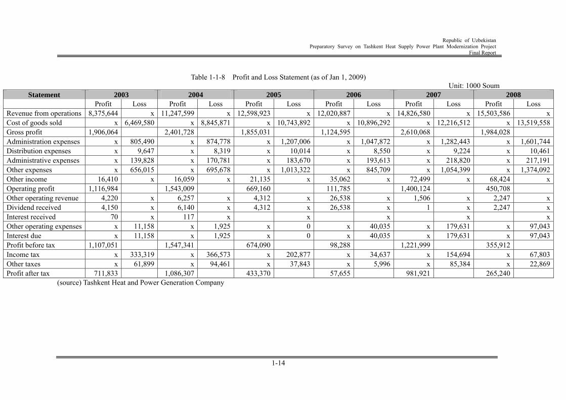
Profit and Loss Statement is shown in the next table. It should be noted that the revenue increase by the regular tariff raise of electricity and heat, and eventually a stable profit gained are continued.
Republic of Uzbekistan
Preparatory Survey on Tashkent Heat Supply Power Plant Modernization Project Final Report
1-14
Table 1-1-8 Profit and Loss Statement (as of Jan 1, 2009)
Unit: 1000 Soum Statement 2003 2004 2005 2006 2007 2008
Profit Loss Profit Loss Profit Loss Profit Loss Profit Loss Profit Loss Revenue from operations 8,375,644 x 11,247,599 x 12,598,923 x 12,020,887 x 14,826,580 x 15,503,586 x Cost of goods sold x 6,469,580 x 8,845,871 x 10,743,892 x 10,896,292 x 12,216,512 x 13,519,558 Gross profit 1,906,064 2,401,728 1,855,031 1,124,595 2,610,068 1,984,028 Administration expenses x 805,490 x 874,778 x 1,207,006 x 1,047,872 x 1,282,443 x 1,601,744 Distribution expenses x 9,647 x 8,319 x 10,014 x 8,550 x 9,224 x 10,461 Administrative expenses x 139,828 x 170,781 x 183,670 x 193,613 x 218,820 x 217,191 Other expenses x 656,015 x 695,678 x 1,013,322 x 845,709 x 1,054,399 x 1,374,092 Other income 16,410 x 16,059 x 21,135 x 35,062 x 72,499 x 68,424 x Operating profit 1,116,984 1,543,009 669,160 111,785 1,400,124 450,708 Other operating revenue 4,220 x 6,257 x 4,312 x 26,538 x 1,506 x 2,247 x Dividend received 4,150 x 6,140 x 4,312 x 26,538 x 1 x 2,247 x Interest received 70 x 117 x x x x x Other operating expenses x 11,158 x 1,925 x 0 x 40,035 x 179,631 x 97,043 Interest due x 11,158 x 1,925 x 0 x 40,035 x 179,631 x 97,043 Profit before tax 1,107,051 1,547,341 674,090 98,288 1,221,999 355,912 Income tax x 333,319 x 366,573 x 202,877 x 34,637 x 154,694 x 67,803 Other taxes x 61,899 x 94,461 x 37,843 x 5,996 x 85,384 x 22,869 Profit after tax 711,833 1,086,307 433,370 57,655 981,921 265,240
(source) Tashkent Heat and Power Generation Company
Republic of Uzbekistan
Preparatory Survey on Tashkent Heat Supply Power Plant Modernization Project Final Report
1-15
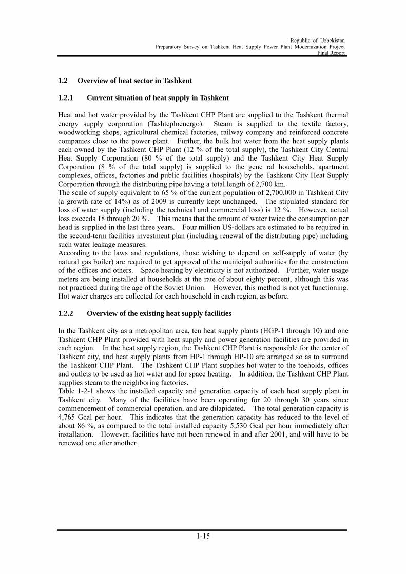
1.2 Overview of heat sector in Tashkent 1.2.1 Current situation of heat supply in Tashkent Heat and hot water provided by the Tashkent CHP Plant are supplied to the Tashkent thermal energy supply corporation (Tashteploenergo). Steam is supplied to the textile factory, woodworking shops, agricultural chemical factories, railway company and reinforced concrete companies close to the power plant. Further, the bulk hot water from the heat supply plants each owned by the Tashkent CHP Plant (12 % of the total supply), the Tashkent City Central Heat Supply Corporation (80 % of the total supply) and the Tashkent City Heat Supply Corporation (8 % of the total supply) is supplied to the gene ral households, apartment complexes, offices, factories and public facilities (hospitals) by the Tashkent City Heat Supply Corporation through the distributing pipe having a total length of 2,700 km. The scale of supply equivalent to 65 % of the current population of 2,700,000 in Tashkent City (a growth rate of 14%) as of 2009 is currently kept unchanged. The stipulated standard for loss of water supply (including the technical and commercial loss) is 12 %. However, actual loss exceeds 18 through 20 %. This means that the amount of water twice the consumption per head is supplied in the last three years. Four million US-dollars are estimated to be required in the second-term facilities investment plan (including renewal of the distributing pipe) including such water leakage measures. According to the laws and regulations, those wishing to depend on self-supply of water (by natural gas boiler) are required to get approval of the municipal authorities for the construction of the offices and others. Space heating by electricity is not authorized. Further, water usage meters are being installed at households at the rate of about eighty percent, although this was not practiced during the age of the Soviet Union. However, this method is not yet functioning. Hot water charges are collected for each household in each region, as before. 1.2.2 Overview of the existing heat supply facilities In the Tashkent city as a metropolitan area, ten heat supply plants (HGP-1 through 10) and one Tashkent CHP Plant provided with heat supply and power generation facilities are provided in each region. In the heat supply region, the Tashkent CHP Plant is responsible for the center of Tashkent city, and heat supply plants from HP-1 through HP-10 are arranged so as to surround the Tashkent CHP Plant. The Tashkent CHP Plant supplies hot water to the toeholds, offices and outlets to be used as hot water and for space heating. In addition, the Tashkent CHP Plant supplies steam to the neighboring factories. Table 1-2-1 shows the installed capacity and generation capacity of each heat supply plant in Tashkent city. Many of the facilities have been operating for 20 through 30 years since commencement of commercial operation, and are dilapidated. The total generation capacity is 4,765 Gcal per hour. This indicates that the generation capacity has reduced to the level of about 86 %, as compared to the total installed capacity 5,530 Gcal per hour immediately after installation. However, facilities have not been renewed in and after 2001, and will have to be renewed one after another.
Republic of Uzbekistan
Preparatory Survey on Tashkent Heat Supply Power Plant Modernization Project Final Report
1-16
Table 1-2-1 Installed capacity and generation capacity of each heat supply plant in Tashkent
(as of February 2009) Total Installed
HeatingCapacity
Total AvailableHeatingCapacity
Hot Water Hot Water
1HGP-1 North EastMirzo Ulugbek District
6 Natural Gas500
(2x50+4x100)400
(2x32+4x84)
No. 1PTVM-50
1968
No. 2PTVM-50
1969
No. 3PTVM-100
1970
No. 4PTVM-100
1975
No. 5PTVM-100
1978
No. 6PTVM-100
1999
2HGP-2 KarasuMirzo Ulugbek District
3 Natural Gas300
(3x100)252
(3x84)
No. 1PTVM-100
1978
No. 2PTVM-100
1980
No. 3PTVM-100
1997
3HGP-3 WestShaykhantohur District
5 Natural Gas400
(2x50+3x100)316
(2x32+3x84)
No. 1PTVM-50
1971
No. 2PTVM-50
1971
No. 3PTVM-100
1972
No. 4PTVM-100
1978
No. 5PTVM-100
1978
4HGP-4 NorthYunus Abad District
10Natural Gas/Mazut Oil
900(2x50+8x100)
832(2x32+1x100+2x84+
5x100)
No. 1PTVM-50
1970
No. 2PTVM-50
1970
No. 3PTVM-100
1970
No. 4PTVM-100
1975
No. 5PTVM-100
1976
No. 6PTVM-100
1981
No. 7PTVM-100
1981
No. 8PTVM-100
1991
No. 9PTVM-100
1997
No. 10PTVM-100
1998
5HGP-5 ChilanzarAkmal Ikramov District
8 Natural Gas700
(2x50+6x100)568
(2x32+6x84)
No. 1PTVM-50
1969
No. 2PTVM-50
1970
No. 3PTVM-100
1971
No. 4PTVM-100
1975
No. 5PTVM-100
1977
No. 6PTVM-100
1981
No. 7PTVM-100
1981
No. 8PTVM-100
2001
6HGP-6 South EastMirabad District
4 Natural Gas300
(2x50+2x100)232
(2x32+2x84)
No. 1PTVM-50
1973
No. 2PTVM-50
1973
No. 3PTVM-100
1981
No. 4PTVM-100
2000
7HGP-7 AviastroiteleyKhamza District
5 Natural Gas400
(2x50+3x100)348
(2x32+1x82+2x100)
No. 1PTVM-50
1976
No. 2PTVM-50
1978
No. 3PTVM-100
1980
No. 4PTVM-100
1988
No. 5PTVM-100
1997
8HGP-8 SergeliSergeli District
4Natural Gas
/Mazut300
(2x50+2x100)300
(2x50+2x100)
No. 1PTVM-50
1980
No. 2PTVM-50
1981
No. 3KVGM-100
1990
No. 4KVGM-100
1993
9HGP-9 Novo-Chilanzarskaya TashkentProvince
3Natural Gas
/Mazut540
(3x180)540
(3x180)
No. 1KVGM-180
1986
No. 2KVGM-180
1987
No. 3KVGM-180
1988
10HGP-10 North WestTashkent Province
3Natural Gas
/Mazut540
(3x180)540
(3x180)
No. 1KVGM-180
1986
No. 2KVGM-180
1987
No. 3KVGM-180
1988
11Tashkent HPGPAirport Area
7Natural Gas
/Mazut650
(1x50+6x100)437
(1x32+6x84)
No. 6PTVM-50
1965
No. 7PTVM-100
1968
No. 8PTVM-100
1970
No. 9PTVM-100
1970
No. 10PTVM-100
1974
No. 11PTVM-100
1977
No. 12PTVM-100
1980
58 - 5530 4765Total
Boiler No., Model, Installation YearType of
FuelNumber of
BoilersName of Heat Generation Plant:
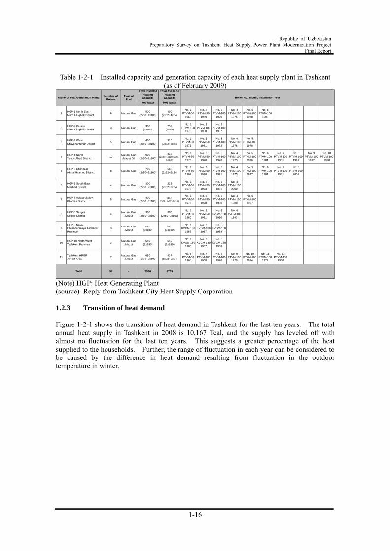
(Note) HGP: Heat Generating Plant (source) Reply from Tashkent City Heat Supply Corporation 1.2.3 Transition of heat demand Figure 1-2-1 shows the transition of heat demand in Tashkent for the last ten years. The total annual heat supply in Tashkent in 2008 is 10,167 Tcal, and the supply has leveled off with almost no fluctuation for the last ten years. This suggests a greater percentage of the heat supplied to the households. Further, the range of fluctuation in each year can be considered to be caused by the difference in heat demand resulting from fluctuation in the outdoor temperature in winter.
Republic of Uzbekistan
Preparatory Survey on Tashkent Heat Supply Power Plant Modernization Project Final Report
1-17
02000400060008000
100001200014000
1999 2000 2001 2002 2003 2004 2005 2006 2007 2008
Year
Hea
t Dem
and
/ Tca
l/y
(source) Reply from Tashkent City Heat Supply Corporation
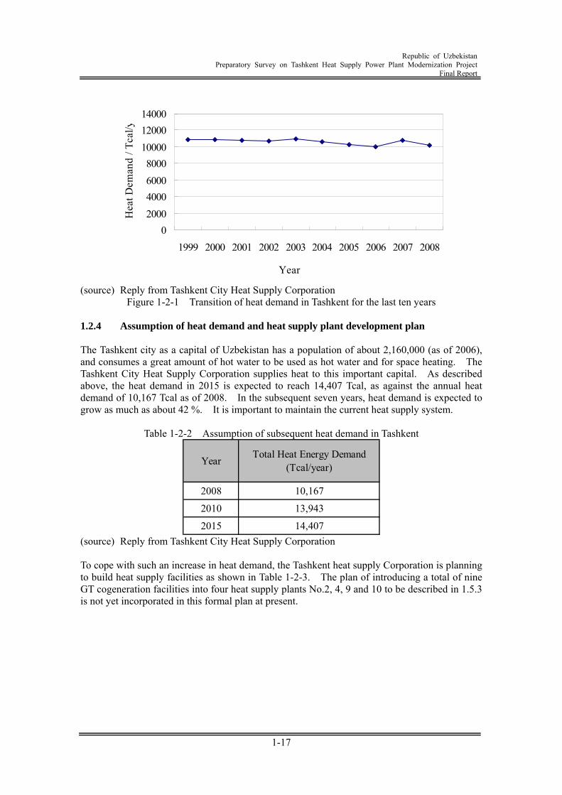
Figure 1-2-1 Transition of heat demand in Tashkent for the last ten years 1.2.4 Assumption of heat demand and heat supply plant development plan The Tashkent city as a capital of Uzbekistan has a population of about 2,160,000 (as of 2006), and consumes a great amount of hot water to be used as hot water and for space heating. The Tashkent City Heat Supply Corporation supplies heat to this important capital. As described above, the heat demand in 2015 is expected to reach 14,407 Tcal, as against the annual heat demand of 10,167 Tcal as of 2008. In the subsequent seven years, heat demand is expected to grow as much as about 42 %. It is important to maintain the current heat supply system.
Table 1-2-2 Assumption of subsequent heat demand in Tashkent
Year Total Heat Energy Demand(Tcal/year)
2008 10,167
2010 13,943
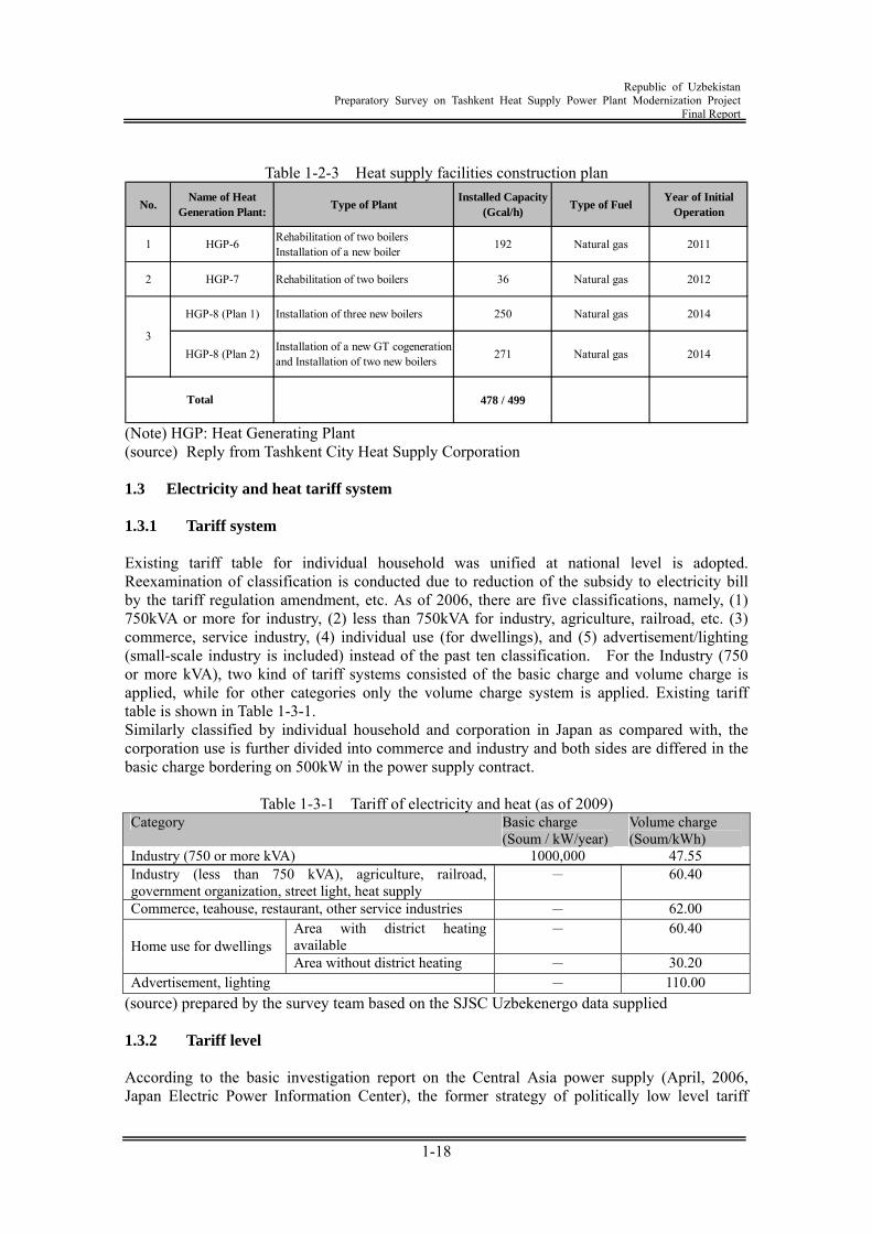
2015 14,407 (source) Reply from Tashkent City Heat Supply Corporation To cope with such an increase in heat demand, the Tashkent heat supply Corporation is planning to build heat supply facilities as shown in Table 1-2-3. The plan of introducing a total of nine GT cogeneration facilities into four heat supply plants No.2, 4, 9 and 10 to be described in 1.5.3 is not yet incorporated in this formal plan at present.
Republic of Uzbekistan
Preparatory Survey on Tashkent Heat Supply Power Plant Modernization Project Final Report
1-18
Table 1-2-3 Heat supply facilities construction plan
No.Name of Heat
Generation Plant:Type of Plant
Installed Capacity(Gcal/h)
Type of FuelYear of Initial
Operation
1 HGP-6 Rehabilitation of two boilersInstallation of a new boiler 192 Natural gas 2011
2 HGP-7 Rehabilitation of two boilers 36 Natural gas 2012
HGP-8 (Plan 1) Installation of three new boilers 250 Natural gas 2014
HGP-8 (Plan 2) Installation of a new GT cogenerationand Installation of two new boilers 271 Natural gas 2014
478 / 499
3
Total
(Note) HGP: Heat Generating Plant (source) Reply from Tashkent City Heat Supply Corporation 1.3 Electricity and heat tariff system 1.3.1 Tariff system Existing tariff table for individual household was unified at national level is adopted. Reexamination of classification is conducted due to reduction of the subsidy to electricity bill by the tariff regulation amendment, etc. As of 2006, there are five classifications, namely, (1) 750kVA or more for industry, (2) less than 750kVA for industry, agriculture, railroad, etc. (3) commerce, service industry, (4) individual use (for dwellings), and (5) advertisement/lighting (small-scale industry is included) instead of the past ten classification. For the Industry (750 or more kVA), two kind of tariff systems consisted of the basic charge and volume charge is applied, while for other categories only the volume charge system is applied. Existing tariff table is shown in Table 1-3-1. Similarly classified by individual household and corporation in Japan as compared with, the corporation use is further divided into commerce and industry and both sides are differed in the basic charge bordering on 500kW in the power supply contract.
Table 1-3-1 Tariff of electricity and heat (as of 2009) Category Basic charge
(Soum / kW/year) Volume charge (Soum/kWh)
Industry (750 or more kVA) 1000,000 47.55 Industry (less than 750 kVA), agriculture, railroad, government organization, street light, heat supply
- 60.40
Commerce, teahouse, restaurant, other service industries - 62.00 Area with district heating available
- 60.40 Home use for dwellings
Area without district heating - 30.20 Advertisement, lighting - 110.00
(source) prepared by the survey team based on the SJSC Uzbekenergo data supplied 1.3.2 Tariff level According to the basic investigation report on the Central Asia power supply (April, 2006, Japan Electric Power Information Center), the former strategy of politically low level tariff
Republic of Uzbekistan
Preparatory Survey on Tashkent Heat Supply Power Plant Modernization Project Final Report
1-19
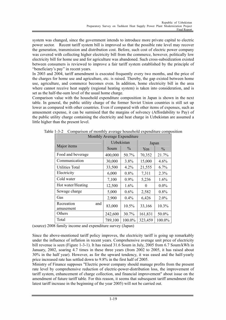
system was changed, since the government intends to introduce more private capital to electric power sector. Recent tariff system bill is improved so that the possible rate level may recover the generation, transmission and distribution cost. Before, such cost of electric power company was covered with collecting higher electricity bill from the commerce, however, politically low electricity bill for home use and for agriculture was abandoned. Such cross-subsidization existed between consumers is reviewed to improve a fair tariff system established by the principle of “beneficiary’s pay” in recent years. In 2003 and 2004, tariff amendment is executed frequently every two months, and the price of the charges for home use and agriculture, etc. is raised. Thereby, the gap existed between home use, agriculture, and commerce becomes even. In addition, home electricity bill in the area where cannot receive heat supply (regional heating system) is taken into consideration, and is set as the half-the-sum level of the usual home charge. Comparison value with the household expenditure composition in Japan is shown in the next table. In general, the public utility charge of the former Soviet Union countries is still set up lower as compared with other countries. Even if compared with other items of expenses, such as amusement expense, it can be surmised that the margins of solvency (Affordability to Pay) of the public utility charge containing the electricity and heat charge in Uzbekistan are assumed a little higher than the present level.
Table 1-3-2 Comparison of monthly average household expenditure composition Monthly Average Expenditure
Uzbekistan Japan Major items Soum % Yen % Food and beverage 400,000 50.7% 70,352 21.7% Communication 30,000 3.8% 15,000 4.6% Utilities Total 33,500 4.2% 21,555 6.7% Electricity 6,000 0.8% 7,311 2.3% Cold water 7,100 0.9% 5,236 1.6% Hot water/Heating 12,500 1.6% 0 0.0% Sewage charge 5,000 0.6% 2,582 0.8% Gas 2,900 0.4% 6,426 2.0% Recreation and amusement 83,000 10.5% 33,166 10.3%
Others 242,600 30.7% 161,831 50.0% Total 789,100 100.0% 323,459 100.0%
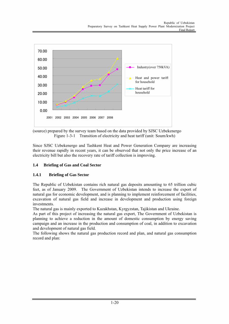
(source) 2008 family income and expenditure survey (Japan) Since the above-mentioned tariff policy improves, the electricity tariff is going up remarkably under the influence of inflation in recent years. Comprehensive average unit price of electricity bill revenue is seen (Figure 1-3-1). It has raised 31.6 Soum in July, 2005 from 6.7 Soum/kWh in January, 2002, soaring 4.7 times in these three years (from 2002 to 2005, it has raised about 30% in the half year). However, as for the upward tendency, it was eased and the half-yearly price increased rate has settled down to 9.8% in the first half of 2005. Ministry of Finance supposes "Electric power company should manage profits from the present rate level by comprehensive reduction of electric-power-distribution loss, the improvement of tariff system, enhancement of charge collection, and financial improvement" about issue on the amendment of future tariff table. For this reason, it seems that subsequent tariff amendment (the latest tariff increase in the beginning of the year 2005) will not be carried out.
Republic of Uzbekistan
Preparatory Survey on Tashkent Heat Supply Power Plant Modernization Project Final Report
1-20
(source) prepared by the survey team based on the data provided by SJSC Uzbekenergo Figure 1-3-1 Transition of electricity and heat tariff (unit: Soum/kwh)
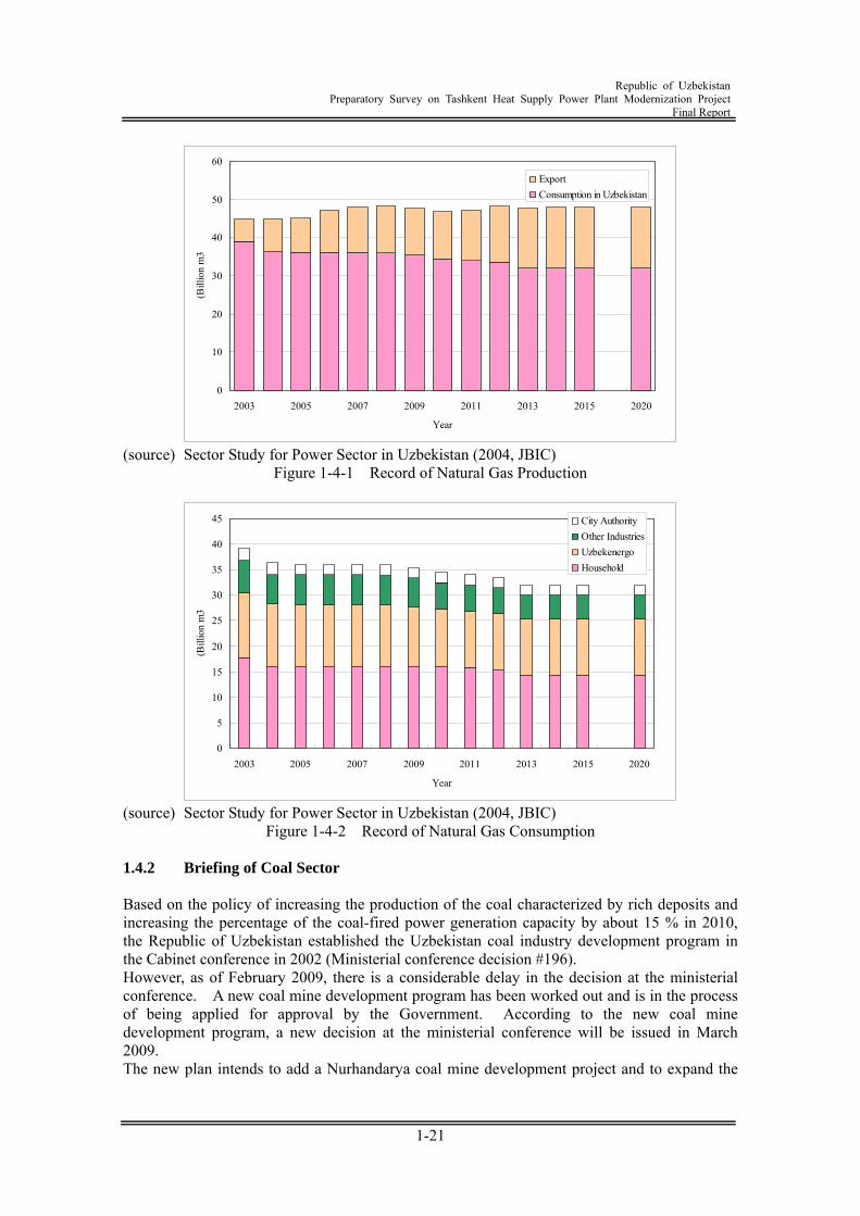
Since SJSC Uzbekenergo and Tashkent Heat and Power Generation Company are increasing their revenue rapidly in recent years, it can be observed that not only the price increase of an electricity bill but also the recovery rate of tariff collection is improving. 1.4 Briefing of Gas and Coal Sector 1.4.1 Briefing of Gas Sector The Republic of Uzbekistan contains rich natural gas deposits amounting to 65 trillion cubic feet, as of January 2009. The Government of Uzbekistan intends to increase the export of natural gas for economic development, and is planning to implement reinforcement of facilities, excavation of natural gas field and increase in development and production using foreign investments. The natural gas is mainly exported to Kazakhstan, Kyrgyzstan, Tajikistan and Ukraine. As part of this project of increasing the natural gas export, The Government of Uzbekistan is planning to achieve a reduction in the amount of domestic consumption by energy saving campaign and an increase in the production and consumption of coal, in addition to excavation and development of natural gas field. The following shows the natural gas production record and plan, and natural gas consumption record and plan:
0.00
10.00
20.00
30.00
40.00
50.00
60.00
70.00
2001 2002 2003 2004 2005 2006 2007 2008
Industry(over 750kVA)
Heat and power tariff for household
Heat tariff for household
Republic of Uzbekistan
Preparatory Survey on Tashkent Heat Supply Power Plant Modernization Project Final Report
1-21
0
10
20
30
40
50
60
2003 2005 2007 2009 2011 2013 2015 2020
Year
(Bill
ion
m3
ExportConsumption in Uzbekistan
(source) Sector Study for Power Sector in Uzbekistan (2004, JBIC)
Figure 1-4-1 Record of Natural Gas Production
0
5
10
15
20
25
30
35
40
45
2003 2005 2007 2009 2011 2013 2015 2020
Year
(Bill
ion
m3
City AuthorityOther IndustriesUzbekenergoHousehold
(source) Sector Study for Power Sector in Uzbekistan (2004, JBIC)
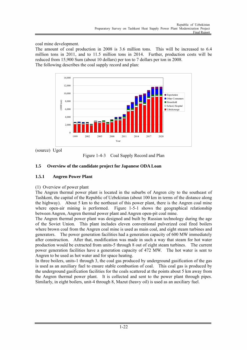
Figure 1-4-2 Record of Natural Gas Consumption 1.4.2 Briefing of Coal Sector Based on the policy of increasing the production of the coal characterized by rich deposits and increasing the percentage of the coal-fired power generation capacity by about 15 % in 2010, the Republic of Uzbekistan established the Uzbekistan coal industry development program in the Cabinet conference in 2002 (Ministerial conference decision #196). However, as of February 2009, there is a considerable delay in the decision at the ministerial conference. A new coal mine development program has been worked out and is in the process of being applied for approval by the Government. According to the new coal mine development program, a new decision at the ministerial conference will be issued in March 2009. The new plan intends to add a Nurhandarya coal mine development project and to expand the
Republic of Uzbekistan
Preparatory Survey on Tashkent Heat Supply Power Plant Modernization Project Final Report
1-22
coal mine development. The amount of coal production in 2008 is 3.6 million tons. This will be increased to 6.4 million tons in 2011, and to 11.5 million tons in 2014. Further, production costs will be reduced from 15,900 Sum (about 10 dollars) per ton to 7 dollars per ton in 2008. The following describes the coal supply record and plan:
0
2,000
4,000
6,000
8,000
10,000
12,000
14,000
1999 2002 2005 2008 2011 2014 2017 2020
Year
(100
0 to
n)
ExportationOther ConsumersHouseholdSchool, HospitalUzbekenergo
(source) Ugol
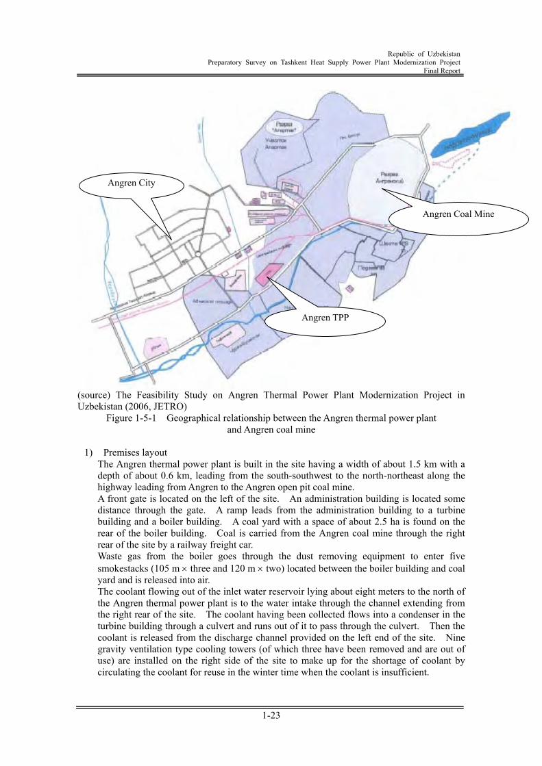
Figure 1-4-3 Coal Supply Record and Plan 1.5 Overview of the candidate project for Japanese ODA Loan 1.5.1 Angren Power Plant (1) Overview of power plant The Angren thermal power plant is located in the suburbs of Angren city to the southeast of Tashkent, the capital of the Republic of Uzbekistan (about 100 km in terms of the distance along the highway). About 5 km to the northeast of this power plant, there is the Angren coal mine where open-air mining is performed. Figure 1-5-1 shows the geographical relationship between Angren, Angren thermal power plant and Angren open-pit coal mine. The Angren thermal power plant was designed and built by Russian technology during the age of the Soviet Union. This plant includes eleven conventional pulverized coal fired boilers where brown coal from the Angren coal mine is used as main coal, and eight steam turbines and generators. The power generation facilities had a generation capacity of 600 MW immediately after construction. After that, modification was made in such a way that steam for hot water production would be extracted from units-5 through 8 out of eight steam turbines. The current power generation facilities have a generation capacity of 472 MW. The hot water is sent to Angren to be used as hot water and for space heating. In three boilers, units-1 through 3, the coal gas produced by underground gasification of the gas is used as an auxiliary fuel to ensure stable combustion of coal. This coal gas is produced by the underground gasification facilities for the coals scattered at the points about 5 km away from the Angren thermal power plant. It is collected and sent to the power plant through pipes. Similarly, in eight boilers, unit-4 through 8, Mazut (heavy oil) is used as an auxiliary fuel.
Republic of Uzbekistan
Preparatory Survey on Tashkent Heat Supply Power Plant Modernization Project Final Report
1-23
(source) The Feasibility Study on Angren Thermal Power Plant Modernization Project in Uzbekistan (2006, JETRO)
Figure 1-5-1 Geographical relationship between the Angren thermal power plant and Angren coal mine
1) Premises layout
The Angren thermal power plant is built in the site having a width of about 1.5 km with a depth of about 0.6 km, leading from the south-southwest to the north-northeast along the highway leading from Angren to the Angren open pit coal mine. A front gate is located on the left of the site. An administration building is located some distance through the gate. A ramp leads from the administration building to a turbine building and a boiler building. A coal yard with a space of about 2.5 ha is found on the rear of the boiler building. Coal is carried from the Angren coal mine through the right rear of the site by a railway freight car. Waste gas from the boiler goes through the dust removing equipment to enter five smokestacks (105 m three and 120 m two) located between the boiler building and coal yard and is released into air. The coolant flowing out of the inlet water reservoir lying about eight meters to the north of the Angren thermal power plant is to the water intake through the channel extending from the right rear of the site. The coolant having been collected flows into a condenser in the turbine building through a culvert and runs out of it to pass through the culvert. Then the coolant is released from the discharge channel provided on the left end of the site. Nine gravity ventilation type cooling towers (of which three have been removed and are out of use) are installed on the right side of the site to make up for the shortage of coolant by circulating the coolant for reuse in the winter time when the coolant is insufficient.
Angren TPP
Angren City
Angren Coal Mine
Republic of Uzbekistan
Preparatory Survey on Tashkent Heat Supply Power Plant Modernization Project Final Report
1-24
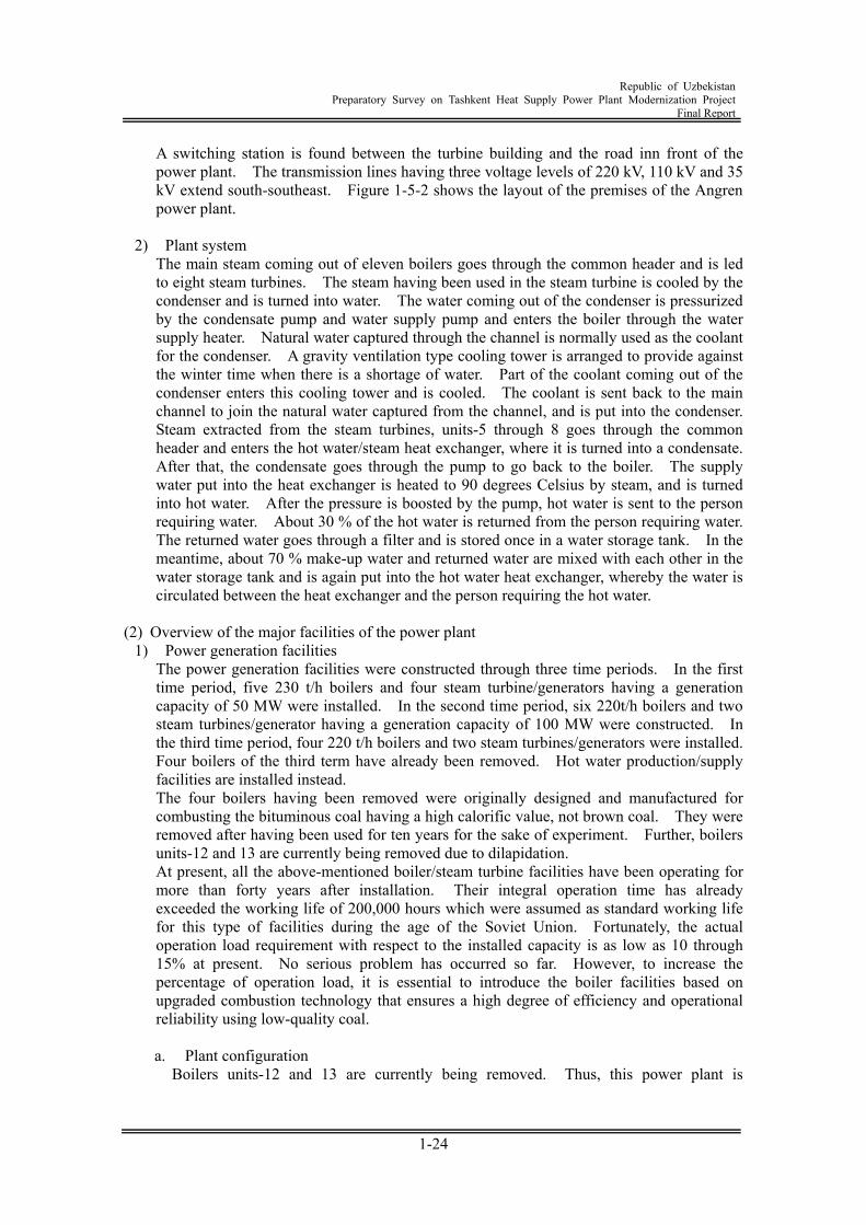
A switching station is found between the turbine building and the road inn front of the power plant. The transmission lines having three voltage levels of 220 kV, 110 kV and 35 kV extend south-southeast. Figure 1-5-2 shows the layout of the premises of the Angren power plant.
2) Plant system
The main steam coming out of eleven boilers goes through the common header and is led to eight steam turbines. The steam having been used in the steam turbine is cooled by the condenser and is turned into water. The water coming out of the condenser is pressurized by the condensate pump and water supply pump and enters the boiler through the water supply heater. Natural water captured through the channel is normally used as the coolant for the condenser. A gravity ventilation type cooling tower is arranged to provide against the winter time when there is a shortage of water. Part of the coolant coming out of the condenser enters this cooling tower and is cooled. The coolant is sent back to the main channel to join the natural water captured from the channel, and is put into the condenser. Steam extracted from the steam turbines, units-5 through 8 goes through the common header and enters the hot water/steam heat exchanger, where it is turned into a condensate. After that, the condensate goes through the pump to go back to the boiler. The supply water put into the heat exchanger is heated to 90 degrees Celsius by steam, and is turned into hot water. After the pressure is boosted by the pump, hot water is sent to the person requiring water. About 30 % of the hot water is returned from the person requiring water. The returned water goes through a filter and is stored once in a water storage tank. In the meantime, about 70 % make-up water and returned water are mixed with each other in the water storage tank and is again put into the hot water heat exchanger, whereby the water is circulated between the heat exchanger and the person requiring the hot water.
(2) Overview of the major facilities of the power plant
1) Power generation facilities The power generation facilities were constructed through three time periods. In the first time period, five 230 t/h boilers and four steam turbine/generators having a generation capacity of 50 MW were installed. In the second time period, six 220t/h boilers and two steam turbines/generator having a generation capacity of 100 MW were constructed. In the third time period, four 220 t/h boilers and two steam turbines/generators were installed. Four boilers of the third term have already been removed. Hot water production/supply facilities are installed instead. The four boilers having been removed were originally designed and manufactured for combusting the bituminous coal having a high calorific value, not brown coal. They were removed after having been used for ten years for the sake of experiment. Further, boilers units-12 and 13 are currently being removed due to dilapidation. At present, all the above-mentioned boiler/steam turbine facilities have been operating for more than forty years after installation. Their integral operation time has already exceeded the working life of 200,000 hours which were assumed as standard working life for this type of facilities during the age of the Soviet Union. Fortunately, the actual operation load requirement with respect to the installed capacity is as low as 10 through 15% at present. No serious problem has occurred so far. However, to increase the percentage of operation load, it is essential to introduce the boiler facilities based on upgraded combustion technology that ensures a high degree of efficiency and operational reliability using low-quality coal.
a. Plant configuration
Boilers units-12 and 13 are currently being removed. Thus, this power plant is

Republic of Uzbekistan
Preparatory Survey on Tashkent Heat Supply Power Plant Modernization Project Final Report
1-25
operated by eleven boilers units-1 through 11 and eight steam turbines at present. In terms of series, they can be classified into two series -- a series composed of the boilers units 1 through 5 and steam turbine/generators 1 through 4 (hereinafter referred to as "series I" for the sake of expediency), and a series make up of the boilers units 6 through 11 and steam turbine/generators 5 through 8 (hereinafter referred to as "series II"). The main steam design conditions for these two series are the same as those of pressure, except that steam temperature is 500 degrees Celsius and 535 degrees Celsius.
Republic of Uzbekistan
Preparatory Survey on Tashkent Heat Supply Power Plant Modernization Project Final Report
1-26
(sou
rce)
The
Fea
sibi
lity
Stud
y on
Ang
ren
Ther
mal
Pow
er P
lant
Mod
erni
zatio
n Pr
ojec
t in
Uzb
ekis
tan
(200
6, JE
TRO
) Fi
gure
1-5
-2
Ove
rall
layo
ut p
lan
of p
ower
pla
nt p
rem
ises
NO
.D
escr
ipti
onN
O.
Des
crip
tion
①B
oile
r S
hop
(#1
~#5
)⑪
Wat
er T
ank
②B
oile
r S
hop
(#6
~#1
3)⑫
Wat
er C
ooli
ng
Tow
er③
Sta
ck (
#1~
#5)
⑬W
ater
In
take
④H
ot W
ater
Su
pply
Sys
tem
Sh
op⑭
Wat
er D
isch
arge
⑤T
urb
ine
Sh
op (
#1~
#4)
⑮C
oal
Yar
d⑥
Tu
rbin
e S
hop
(#5
~#8
)⑯
Coa
l C
onve
yer
⑦S
tep-
up
Tra
ns.
Bay
(#1
~#4
)⑰
Fu
el O
il T
ank
⑧S
tep-
up
Tra
ns.
Bay
(#5
~#8
)⑱
Adm
inis
trat
ive
Off
ice
Bu
ildi
ng
⑨T
ran
sfor
mer
s Y
ard
⑲R
epai
rin
g W
orks
hop
⑩S
wic
th Y
ard
⑳C
ooli
ng
Wat
er P
um
p S
tati
on
Republic of Uzbekistan
Preparatory Survey on Tashkent Heat Supply Power Plant Modernization Project Final Report
1-27
However, the main steam of these two series is forms a header system connected through a communication valve. In the actual operation, both series are formed in one integral body by adjusting the main steam temperature. The amount of evaporation from each boiler in the series I is 230 tons per hour (1,150 tons per hour in total). That in the series II is 220 tons per hour (1,320 tons per hour in total). In the meantime, the steam turbine output is 50 MW in the units-1 through 4, and 100 MW in the units-5 through 8. The amount of steam consumption in a single unit at the time of the maximum load of each series is 191 tons per hour (1,150 tons per hour in total) and 377 tons per hour (1,508 tons per hour in total). Hot water heating steam is supplied by extraction from the turbine; however, it can be supplied only from the turbines units 5 through 8 in the series II. The drain of the steam having been supplied is completely recovered into the condenser. Each turbine is connected with one generator (eight generators in total). All the generators are cooled by hydrogen and supplies power to the 220 kV and 110 kV switching stations through a step-up transformer. The condenser coolant system forms a common facility for all the turbines. Coolant is supplied from the water channel of the water reservoir located about 8 km away, after coolant flow is diverted. Normally, this system is operated as a once through system. The coolant goes through the condenser and is discharged directly to the drain outlet at the end of the power plant. However, in the winter time when there is shortage of water, restrictions may be imposed on the usage of water. Accordingly, it is possible to employ the circulating water cooling method using six natural draft type wet type cooling towers. Figure 1-5-3 is a schematic diagram representing the entire view of the Angren thermal power plant. Table 1-5-1 shows the design particulars of the major facilities.
b. Boiler facilities
All the boilers are pulverized coal fired boilers where brown coal is mainly used as fuel, and is provided with a heavy oil stabilizing burner of about 20 % capacity. Further, the boilers units 1 through 3 are designed in such a way that coal gas can be combusted. The coal gas is produced almost in a fixed amount at all times, independently of the season of the year. For the combustion of coal gas, at least one of the boilers units 1 through 3 must be operated at all times. The average amount of gas supplied is approximately 40,000 Nm3 per hour. Each boiler is provided with a gas burner having a capacity of 20,000 Nm3 per hour. Accordingly, all the gas can be processed by one boiler. Each boiler is provided with three coal bunkers (250 ton/unit) and four pulverized coal mills (100% by four mills without standby unit). These mills are horizontal impact type hammer mills, and are subjected to serious abrasion due to rigid stone contained in the coal. In recent years, the quality of the supplied coal tends to be poorer (characterized by increased amount of ash and water), and this results in reduced boiler efficiency and reduced evaporation capacity.
c. Steam turbine facilities
Turbines units 1 through 4 are designed as single turbine casing type non-reheat turbines, and turbines units 5 through 8 are double turbine casing tandem compound non-reheat turbines. The high-low pressure water supply heater systems each are built into each turbine independently of each other. The deaerator is a common facility within each series. Incidentally, the number of steps of the water supply heater including the deaerator is
Republic of Uzbekistan
Preparatory Survey on Tashkent Heat Supply Power Plant Modernization Project Final Report
1-28
five in the series I, and is nine in the series II. The pure water producing evaporator and auxiliary steam producing steam converter are also built in the water supply heater system in parallel. However, they are not used at present.
d. Coolant facilities
The coolant is diverted from the water channel where water is supplied from the water reservoir located close to the coal mine about 8 km away from the power plant, and is supplied to the power plant. The amount of water that can be used from this water channel is normally in the range of 15 through 20 m3/sec. When the power plant is operating under the normal load, this amount of water provides a sufficient amount of required coolant. The coolant used in the once through system is directly discharged out of the power plant. However, in the winter time, restrictions are imposed on the usage of water. For this season, the system is based on the circulation method using six cooling towers. The channel diverted from the main channel is provided with a stationary screen for screening a bulky waste in the first stage. A water intake equipped with six power-driven drum type screens is arranged in the wake. Coolant is supplied to the eight turbines from this water intake through the three steel-made coolant pipes having a diameter of 1.2 meters. The difference in the level between the water intake and condenser is about 8 meters. Water is supplied by gravity without using a pump.
e. Coal receiving, storing and unloading facilities
Two car dumpers are used to receive the coal. The coal is carried to the outdoor coal yard by the underground belt conveyor. It can also be supplied to a coal bunker without passing through the coal yard. An indoor coat storage facility is not provided. The coal storage area measures 25,680 m2, and is capable of storing about 190,000 tons of coal. Six bulldozers are used to load the coal in the coal yard and to unload it from the yard. The unloaded coal passes through a crusher and is carried into the coal bunker of the stoke hold by a belt conveyor. The system of supply coal from the coal yard to the coal bunker is divided into two sub-systems; one for the boiler group units 1 through 9, and the other for the boiler group units 10 through 13. Each series is provided with two belt conveyor sets. The former sub-system is provided with four crushers and the latter one is equipped with two crushers. The coal carried into the boiler building is transferred onto the belt conveyor running over the coal bunker of stoke hold and is then distributed into the coal bunker of each boiler. Each of the boiler group (units 1 through 9) and boiler group (units 10 through 13) has two distribution conveyors. Coal on the conveyors is dropped into the bunker by the oblique plow on the conveyor. Since the coal dressing work at the mine is not sufficient, the coal having been sent contains large-sized stone, and coal separation work is done by a bulldozer or by hand at the receiving yard or coal yard. However, this work is not satisfactory. A considerable amount of ill-prepared coal is sent to the boiler to cause abrasion or capacity deterioration of the coal pulverizer.
f. Heat supply facilities
The hot water supply facilities are installed at the site in the building occupied previously by boilers units 13 and 14. These facilities include the facility that heats the filtrate water and sends it to the feed water treatment equipment, and the facility that heats the return water and make-up water and supplies the hot water to the city. The heat is provided by the steam extracted from the turbines, units 5, 6, 7 and 8.
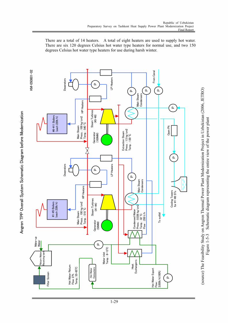
Republic of Uzbekistan
Preparatory Survey on Tashkent Heat Supply Power Plant Modernization Project Final Report
1-29
There are a total of 14 heaters. A total of eight heaters are used to supply hot water. There are six 120 degrees Celsius hot water type heaters for normal use, and two 150 degrees Celsius hot water type heaters for use during harsh winter.
(sou
rce)
The
Fea
sibi
lity
Stud
y on
Ang
ren
Ther
mal
Pow
er P
lant
Mod
erni
zatio
n Pr
ojec
t in
Uzb
ekis
tan
(200
6, JE
TRO
) Fi
gure
1-5
-3
Sche
mat
ic d
iagr
am re
pres
entin
g th
e en
tire
view
of t
he p
ower
pla
nt
Ang
ren
TPP O
vera
ll Sys
tem
Sch
emat
ic D
iagr
am b
efor
e M
oder
niza
tion
KM
-050
801-
02
P
P
P P
P
Ret
urn
Wat
erRec
eivi
ng tan
k
Hot
Wat
erCon
sum
ers Hea
tExc
hang
errs
#1-
#5 B
oile
rs(e
ach
230t
/h)
Ste
am T
urbi
nes
(#1-
#4)
Ste
am T
urbi
nes
(#5-
#8)
Gen
erat
or(5
0MW
)
Gen
erat
or(1
00M
W) #
6-#1
1 Boi
lers
(eac
h 22
0t/h
)
Coo
ling
Tow
ers
for #1
-#8
STsMai
n Ste
amCon
dens
ers
Mai
n Ste
amCon
dens
ers
Dea
erat
ors
Dea
erat
ors
HP H
eate
rsHP H
eate
rs
LP H
eate
rsLP
Hea
ters
Hot
Wat
er E
xpor
tFl
ow :
3,00
0t/h
(100
%)℃
Hot
Wat
er R
etur
nFl
ow: 2
7%Tem
p.: 5
5-65
℃
Ext
ract
ion
Ste
amPre
ss. :
1.5
kg/
cm2
Tem
p. :
130
℃
Con
dens
ed W
ater
Pre
ss. :
0.0
36 k
g/cm
2Tem
p. :
32 ℃
Flo
w : 2
50 t/h
Mak
e-up
Wat
er
P
P
Filt
er S
cree
n
Mai
n Ste
amPre
ss. :
100
kg/
cm2
Tem
p. :
540
℃
Mai
n Ste
amPre
ss. :
100
kg/
cm2
Tem
p. :
510
℃
Wat
er in
let
Tem
p. :
8-13
℃
P
Fro
m C
anal
To
outfal
l
PP
Ope
n Pit
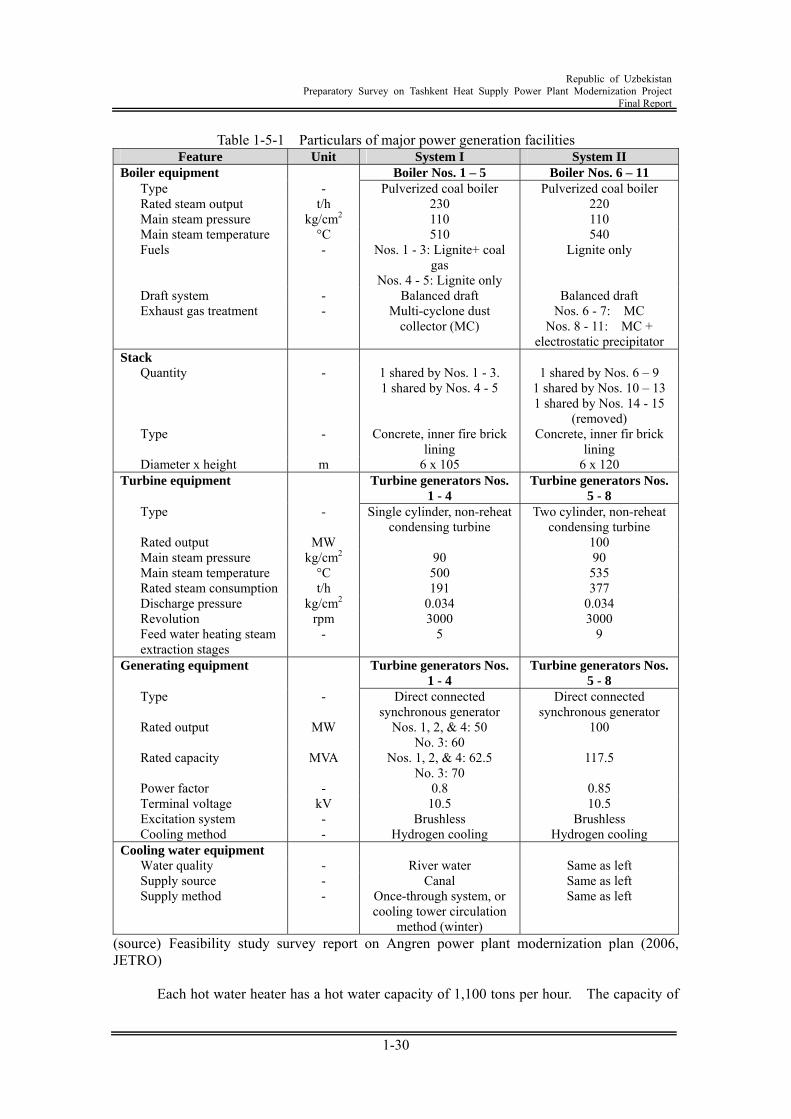
Republic of Uzbekistan
Preparatory Survey on Tashkent Heat Supply Power Plant Modernization Project Final Report
1-30
Table 1-5-1 Particulars of major power generation facilities Feature Unit System I System II
Boiler equipment Boiler Nos. 1 – 5 Boiler Nos. 6 – 11 Type - Pulverized coal boiler Pulverized coal boiler Rated steam output t/h 230 220 Main steam pressure kg/cm2 110 110 Main steam temperature °C 510 540 Fuels - Nos. 1 - 3: Lignite+ coal
gas Nos. 4 - 5: Lignite only
Lignite only
Draft system - Balanced draft Balanced draft Exhaust gas treatment - Multi-cyclone dust
collector (MC) Nos. 6 - 7: MC
Nos. 8 - 11: MC + electrostatic precipitator
Stack Quantity - 1 shared by Nos. 1 - 3.
1 shared by Nos. 4 - 5 1 shared by Nos. 6 – 9
1 shared by Nos. 10 – 13 1 shared by Nos. 14 - 15
(removed) Type - Concrete, inner fire brick
lining Concrete, inner fir brick
lining Diameter x height m 6 x 10⁵ 6 x 120
Turbine equipment Turbine generators Nos. 1 - 4
Turbine generators Nos. 5 - 8
Type - Single cylinder, non-reheat condensing turbine
Two cylinder, non-reheat condensing turbine
Rated output MW 100 Main steam pressure kg/cm2 90 90 Main steam temperature °C 500 535 Rated steam consumption t/h 191 377 Discharge pressure kg/cm2 0.034 0.034 Revolution rpm 3000 3000 Feed water heating steam extraction stages
- 5 9
Generating equipment Turbine generators Nos. 1 - 4
Turbine generators Nos. 5 - 8
Type - Direct connected synchronous generator
Direct connected synchronous generator
Rated output MW Nos. 1, 2, & 4: 50 No. 3: 60
100
Rated capacity MVA Nos. 1, 2, & 4: 62.5 No. 3: 70
117.5
Power factor - 0.8 0.85 Terminal voltage kV 10.5 10.5 Excitation system - Brushless Brushless Cooling method - Hydrogen cooling Hydrogen cooling
Cooling water equipment Water quality - River water Same as left Supply source - Canal Same as left Supply method - Once-through system, or
cooling tower circulation method (winter)
Same as left
(source) Feasibility study survey report on Angren power plant modernization plan (2006, JETRO)
Each hot water heater has a hot water capacity of 1,100 tons per hour. The capacity of
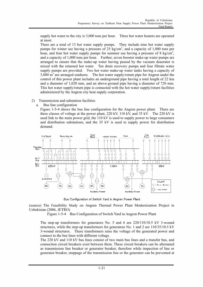
Republic of Uzbekistan
Preparatory Survey on Tashkent Heat Supply Power Plant Modernization Project Final Report
1-31
supply hot water to the city is 3,000 tons per hour. Three hot water heaters are operated at most. There are a total of 13 hot water supply pumps. They include nine hot water supply pumps for winter use having a pressure of 25 kg/cm2, and a capacity of 1,000 tons per hour, and four hot water supply pumps for summer use having a pressure of 8 kg/cm2, and a capacity of 1,000 tons per hour. Further, seven booster make-up water pumps are arranged to ensure that the make-up water having passed by the vacuum deaerator is mixed with the returned hot water. Ten drain recovery pumps and four filtrate water supply pumps are provided. Two hot water make-up water tanks having a capacity of 3,000 m3 are arranged outdoors. The hot water supply/return pipe for Angren under the control of this power plant includes an underground pipe having a total length of 22 km and a diameter of 1,020 mm, and an above-ground pipe having a diameter of 720 mm. This hot water supply/return pipe is connected with the hot water supply/return facilities administered by the Angren city heat supply corporation.
2) Transmission and substation facilities
a. Bus line configuration Figure 1-5-4 shows the bus line configuration for the Angren power plant. There are three classes of voltage at the power plant, 220 kV, 110 kV, and 35 kV. The 220 kV is used link to the main power grid, the 110 kV is used to supply power to large consumers and distribution substations, and the 35 kV is used to supply power for distribution demand.
(source) The Feasibility Study on Angren Thermal Power Plant Modernization Project in Uzbekistan (2006, JETRO)
Figure 1-5-4 Bus Configuration of Switch Yard in Angren Power Plant
The step-up transformers for generators No. 5 and 6 are 220/110/10.5 kV 3-wound structures, while the step-up transformers for generators No. 1 and 2 are 110/35/10.5 kV 3-wound structures. These transformers raise the voltage of the generated power and connect to the bus lines with different voltage. The 220 kV and 110 kV bus lines consist of two main bus lines and a transfer bus, and connection circuit breakers exist between them. These circuit breakers can be alternated as transmission line breaker or generator breaker, therefore while inspection of line or generator breaker, stoppage of the transmission line or the generator can be prevented at
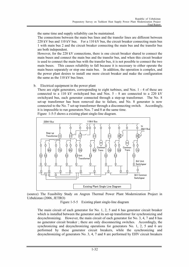
Republic of Uzbekistan
Preparatory Survey on Tashkent Heat Supply Power Plant Modernization Project Final Report
1-32
the same time and supply reliability can be maintained. The connections between the main bus lines and the transfer lines are different between 220 kV bus and 110 kV bus. For a 110 kV bus, the circuit breaker connecting main bus 1 with main bus 2 and the circuit breaker connecting the main bus and the transfer bus are both independent. However, for the 220 kV connections, there is one circuit breaker shared to connect the main buses and connect the main bus and the transfer bus, and when this circuit breaker is used to connect the main bus with the transfer bus, it is not possible to connect the two main buses. This causes reliability to fall because it is necessary to either operate the main buses separately or stop one main bus. In addition, the operation is complex, and the power plant desires to install one more circuit breaker and make the configuration the same as the 110 kV bus lines.
b. Electrical equipment in the power plant
There are eight generators, corresponding to eight turbines, and Nos. 1 - 4 of these are connected to a 110 kV switchyard bus and Nos. 5 - 8 are connected to a 220 kV switchyard bus, each generator connected through a step-up transformer. The No. 8 set-up transformer has been removed due to failure, and No. 8 generator is now connected to the No. 7 set-up transformer through a disconnecting switch. Accordingly, it is impossible to run generators Nos. 7 and 8 at the same time. Figure 1-5-5 shows a existing plant single-line diagram.
110kV Bus220kV Bus
8G 1G7G 6G 5G 4G 3G 2G
Step-upTransformer
3kV CommonSwitchgear
3kV UnitSwitchgear
Common
UnitTransformer
TransTransCommon
Existing Plant Single Line Diagram
to35kV Bus
(source) The Feasibility Study on Angren Thermal Power Plant Modernization Project in Uzbekistan (2006, JETRO)
Figure 1-5-5 Existing plant single-line diagram
The main circuit of each generator for No. 1, 2, 5 and 6 has generator circuit breaker which is installed between the generator and its set-up transformer for synchronizing and desynchronizing. However, the main circuit of each generator for No. 3, 4, 7 and 8 has no generator circuit breaker ; there are only disconnecting switches. Accordingly, the synchronizing and desynchronizing operations for generators No. 1, 2, 5 and 6 are performed by these generator circuit breakers, while the synchronizing and desynchronizing of generators No. 3, 4, 7 and 8 are performed by EHV circuit breakers
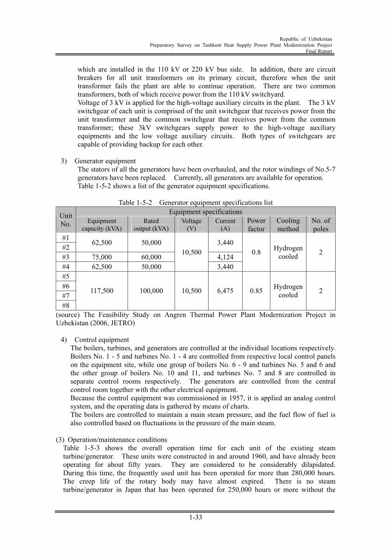
Republic of Uzbekistan
Preparatory Survey on Tashkent Heat Supply Power Plant Modernization Project Final Report
1-33
which are installed in the 110 kV or 220 kV bus side. In addition, there are circuit breakers for all unit transformers on its primary circuit, therefore when the unit transformer fails the plant are able to continue operation. There are two common transformers, both of which receive power from the 110 kV switchyard. Voltage of 3 kV is applied for the high-voltage auxiliary circuits in the plant. The 3 kV switchgear of each unit is comprised of the unit switchgear that receives power from the unit transformer and the common switchgear that receives power from the common transformer; these 3kV switchgears supply power to the high-voltage auxiliary equipments and the low voltage auxiliary circuits. Both types of switchgears are capable of providing backup for each other.
3) Generator equipment
The stators of all the generators have been overhauled, and the rotor windings of No.5-7 generators have been replaced. Currently, all generators are available for operation. Table 1-5-2 shows a list of the generator equipment specifications.
Table 1-5-2 Generator equipment specifications list
Equipment specifications Unit No. Equipment
capacity (kVA) Rated
output (kVA) Voltage
(V) Current
(A) Power factor
Cooling method
No. of poles
#1 #2
62,500 50,000 3,440
#3 75,000 60,000 4,124 #4 62,500 50,000
10,500
3,440
0.8 Hydrogen cooled 2
#5 #6 #7 #8
117,500 100,000 10,500 6,475 0.85 Hydrogen cooled 2
(source) The Feasibility Study on Angren Thermal Power Plant Modernization Project in Uzbekistan (2006, JETRO)
4) Control equipment The boilers, turbines, and generators are controlled at the individual locations respectively. Boilers No. 1 - 5 and turbines No. 1 - 4 are controlled from respective local control panels on the equipment site, while one group of boilers No. 6 - 9 and turbines No. 5 and 6 and the other group of boilers No. 10 and 11, and turbines No. 7 and 8 are controlled in separate control rooms respectively. The generators are controlled from the central control room together with the other electrical equipment. Because the control equipment was commissioned in 1957, it is applied an analog control system, and the operating data is gathered by means of charts. The boilers are controlled to maintain a main steam pressure, and the fuel flow of fuel is also controlled based on fluctuations in the pressure of the main steam.
(3) Operation/maintenance conditions
Table 1-5-3 shows the overall operation time for each unit of the existing steam turbine/generator. These units were constructed in and around 1960, and have already been operating for about fifty years. They are considered to be considerably dilapidated. During this time, the frequently used unit has been operated for more than 280,000 hours. The creep life of the rotary body may have almost expired. There is no steam turbine/generator in Japan that has been operated for 250,000 hours or more without the
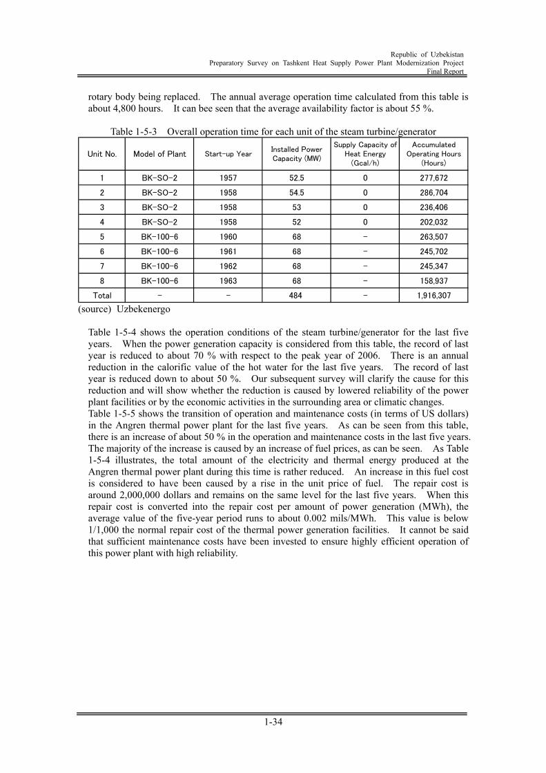
Republic of Uzbekistan
Preparatory Survey on Tashkent Heat Supply Power Plant Modernization Project Final Report
1-34
rotary body being replaced. The annual average operation time calculated from this table is about 4,800 hours. It can bee seen that the average availability factor is about 55 %.
Table 1-5-3 Overall operation time for each unit of the steam turbine/generator
1 BK-SO-2 1957 52.5 0 277,672
2 BK-SO-2 1958 54.5 0 286,704
3 BK-SO-2 1958 53 0 236,406
4 BK-SO-2 1958 52 0 202,032
5 BK-100-6 1960 68 - 263,507
6 BK-100-6 1961 68 - 245,702
7 BK-100-6 1962 68 - 245,347
8 BK-100-6 1963 68 - 158,937
Total - - 484 - 1,916,307
Unit No.Installed PowerCapacity (MW)
Model of PlantSupply Capacity of
Heat Energy(Gcal/h)
AccumulatedOperating Hours
(Hours)Start-up Year
(source) Uzbekenergo
Table 1-5-4 shows the operation conditions of the steam turbine/generator for the last five years. When the power generation capacity is considered from this table, the record of last year is reduced to about 70 % with respect to the peak year of 2006. There is an annual reduction in the calorific value of the hot water for the last five years. The record of last year is reduced down to about 50 %. Our subsequent survey will clarify the cause for this reduction and will show whether the reduction is caused by lowered reliability of the power plant facilities or by the economic activities in the surrounding area or climatic changes. Table 1-5-5 shows the transition of operation and maintenance costs (in terms of US dollars) in the Angren thermal power plant for the last five years. As can be seen from this table, there is an increase of about 50 % in the operation and maintenance costs in the last five years. The majority of the increase is caused by an increase of fuel prices, as can be seen. As Table 1-5-4 illustrates, the total amount of the electricity and thermal energy produced at the Angren thermal power plant during this time is rather reduced. An increase in this fuel cost is considered to have been caused by a rise in the unit price of fuel. The repair cost is around 2,000,000 dollars and remains on the same level for the last five years. When this repair cost is converted into the repair cost per amount of power generation (MWh), the average value of the five-year period runs to about 0.002 mils/MWh. This value is below 1/1,000 the normal repair cost of the thermal power generation facilities. It cannot be said that sufficient maintenance costs have been invested to ensure highly efficient operation of this power plant with high reliability.
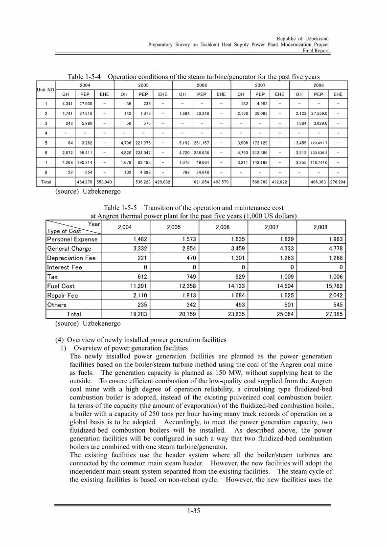
Republic of Uzbekistan
Preparatory Survey on Tashkent Heat Supply Power Plant Modernization Project Final Report
1-35
Table 1-5-4 Operation conditions of the steam turbine/generator for the past five years
OH PEP EHE OH PEP EHE OH PEP EHE OH PEP EHE OH PEP EHE
1 4,341 77,030 - 36 235 - - - - 182 4,982 - - - -
2 4,741 87,616 - 142 1,015 - 1,684 30,348 - 2,150 35,093 - 2,122 27,559.0 -
3 248 5,990 - 58 575 - - - - - - - 1,384 3,029.0 -
4 - - - - - - - - - - - - - - -
5 84 3,262 - 4,796 221,976 - 5,192 261,157 - 3,908 172,129 - 3,455 123,491.7 -
6 2,872 99,411 - 4,820 224,047 - 4,720 246,636 - 4,793 213,386 - 3,512 133,536.2 -
7 4,268 190,314 - 1,679 83,482 - 1,076 49,064 - 3,211 143,198 - 3,255 118,747.0 -
8 22 654 - 103 4,898 - 768 34,648 - - - - - - -
Total 464,278 553,940 536,228 429,082 621,854 403,579 568,788 412,622 406,363 276,204
20082007Unit NO.
2004 2005 2006
(source) Uzbekenergo
Table 1-5-5 Transition of the operation and maintenance cost at Angren thermal power plant for the past five years (1,000 US dollars)
YearType of Cost
Personel Expense 1,482 1,573 1,635 1,829 1,963
General Charge 3,332 2,854 3,459 4,333 4,778
Depreciation Fee 221 470 1,301 1,263 1,268
Interest Fee 0 0 0 0 0
Tax 612 749 929 1,009 1,006
Fuel Cost 11,291 12,358 14,133 14,504 15,782
Repair Fee 2,110 1,813 1,684 1,625 2,042
Others 235 342 493 501 545
Total 19,283 20,159 23,635 25,064 27,385
2,004 2,005 2,006 2,007 2,008
(source) Uzbekenergo (4) Overview of newly installed power generation facilities
1) Overview of power generation facilities The newly installed power generation facilities are planned as the power generation facilities based on the boiler/steam turbine method using the coal of the Angren coal mine as fuels. The generation capacity is planned as 150 MW, without supplying heat to the outside. To ensure efficient combustion of the low-quality coal supplied from the Angren coal mine with a high degree of operation reliability, a circulating type fluidized-bed combustion boiler is adopted, instead of the existing pulverized coal combustion boiler. In terms of the capacity (the amount of evaporation) of the fluidized-bed combustion boiler, a boiler with a capacity of 250 tons per hour having many track records of operation on a global basis is to be adopted. Accordingly, to meet the power generation capacity, two fluidized-bed combustion boilers will be installed. As described above, the power generation facilities will be configured in such a way that two fluidized-bed combustion boilers are combined with one steam turbine/generator. The existing facilities use the header system where all the boiler/steam turbines are connected by the common main steam header. However, the new facilities will adopt the independent main steam system separated from the existing facilities. The steam cycle of the existing facilities is based on non-reheat cycle. However, the new facilities uses the
Republic of Uzbekistan
Preparatory Survey on Tashkent Heat Supply Power Plant Modernization Project Final Report
1-36
reheating cycle intended to achieve higher efficiency. The main steam pressure is raised from the current 90 atm to 169 atm., and the steam temperature is 538 degrees Celsius for the main steam and 538 degrees Celsius for the reheating steam. The following describes the basic plan conditions of the power generation facilities:
Maximum generation capacity of the plant:
150 MW (without external steam supply)
Plant configuration: Two boilers and one steam turbine/generator Cycle configuration: One step for reheating and seven steps for water
supply and heating Maximum possible amount of external steam supply:
about 280 tons per hour (210 Gcal per hour)
Boiler combustion method: Circulating fluidized-bed combustion method Turbine condenser cooling method: River water one-through or cooling tower
circulation method Waste gas processing measures:
NOx: Low NOx combustion by circulating fluidized-bed SOx: In-furnace desulfurization by lime Soot and dust: Installation of bug filter
Power transmission voltage 220 kV Fuel Multi-fuel combustion of coal + coal gas
Combustion improvement by heavy oil
Figure 1-5-6 is a schematic diagram representing the newly installed power generation facilities.
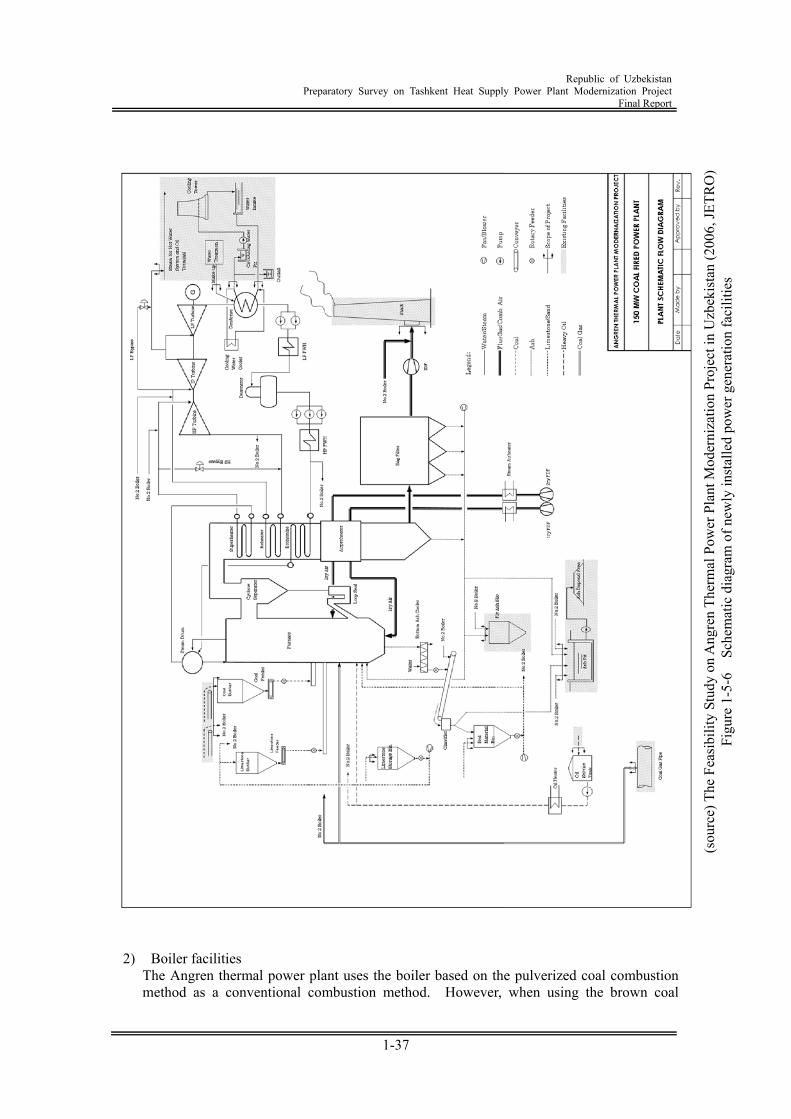
Republic of Uzbekistan
Preparatory Survey on Tashkent Heat Supply Power Plant Modernization Project Final Report
1-37
2) Boiler facilities The Angren thermal power plant uses the boiler based on the pulverized coal combustion method as a conventional combustion method. However, when using the brown coal
(sou
rce)
The
Fea
sibi
lity
Stud
y on
Ang
ren
Ther
mal
Pow
er P
lant
Mod
erni
zatio
n Pr
ojec
t in
Uzb
ekis
tan
(200
6, JE
TRO
) Fi
gure
1-5
-6
Sche
mat
ic d
iagr
am o
f new
ly in
stal
led
pow
er g
ener
atio
n fa
cilit
ies
Republic of Uzbekistan
Preparatory Survey on Tashkent Heat Supply Power Plant Modernization Project Final Report
1-38
(lignite) supplied from the Angren coal mine containing a great deal of ash components having a lower melting points, a great furnace volume is required to reduce the temperature at the furnace outlet. This is economically disadvantageous. Further, because suspended combustion is required, if there is a great change in fuel properties, instability of combustion may result. In actual practice, combustion stability of the existing boiler is decreased due to a reduction in the calorific value of the coal (increased amount of ash) in recent years. It is reported that stable operation is difficult if there is no assistant such as heavy oil or coal gas at all times. Further, an increase in the amount of using the coal caused by reduction in the calorific value results in a shortage of the capacity of the coal pulverizer. Mixture of rigid soil and stone accelerates abrasion of the coal pulverizer. Insufficient level of pulverization of the combustion coal as a result is one of the factors accelerating the combustion instability. With consideration given to these factors, to ensure high-efficiency combustion of low-quality coal supplied from the Angren coal mine with a high degree of reliability, the new power generation facilities adopted the boiler based on the circulating fluidized-bed combustion method characterized by the following advantages:
Stable operation is ensured against possible changes in fuel properties including the
increased amount of ash and fluctuation of water content, without using the assistant of oil or gas fuel.
There is no need of worrying about ash slagging trouble that may occur on the furnace or heat transfer surface, due to low combustion temperature.
Low NOx due to low combustion temperature Easy desulfurization within the furnace can be achieved by putting limestone into the
furnace. From the viewpoint of environment protection, this will provide excellent facilities.
3) Steam turbine facilities
A tandem compound type condensate type steam turbine divided into two high/intermediate casing and low-pressure casing is used as the steam turbine. This is directly coupled to the generator. This steam turbine is operated as a complete condensate turbine during the summer. In winter, it has an important role of supply hot water heating steam for local heating. The hot water heating steam can be extracted from the connecting pipe between the high/intermediate pressure and the low pressure turbine. Further, to ensure that the maximum possible amount of steam can be extracted, a control valve is arranged at the inlet of the low pressure turbine to control the steam feed pressure.
4) Coolant facilities
River water is directly used as a steam turbine condenser coolant. An enclosed cycle circulating coolant is used as auxiliary equipment coolant. The enclosed cycle circulating coolant is cooled by a coolant cooler which uses the water diverted from the steam turbine condenser coolant. The amount of coolant for steam turbine condenser and above-mentioned coolant cooler required for newly installed power generation facilities is about 17,000 tons per hour on the assumption that the rise of coolant temperature by a condenser is 10 degrees Celsius. The coolant diverts from the two existing coolant pipes having a diameter of 1.2 m, and is supplied to each of the condenser water boxes. The coolant return pipe leading from the outlet of the water box is connected with the existing 2-meter square concrete culvert. Water to the enclosed cycle coolant cooler is diverted from the condenser inlet coolant pipe and is fed by a booster pump. It is then recovered into the coolant return pipe at the outlet of the condenser.
Republic of Uzbekistan
Preparatory Survey on Tashkent Heat Supply Power Plant Modernization Project Final Report
1-39
5) Major generating equipment The generator will be applied with air-cooled type. An air-cooled generator does not use hydrogen gas as a cooling medium, so there is no need for sealing oil equipment to prevent hydrogen gas leaks from the generator bearings, nor hydrogen gas supply equipment, nor carbon dioxide supply equipment for discharging the hydrogen gas during internal inspections of the generator. Thus, the construction and operating costs are both reduced, and daily operation and maintenance are also simplified. Conventionally, air-cooled generators have been limited to small-capacity generators due to the large windage loss. Therefore, hydrogen gas cooled generator have been used for medium and large-capacity generators. However, in recent years, windage loss reduction technology has advanced to the point that the efficiency of medium-capacity air-cooled generators has reached the level of hydrogen gas-cooled generators, and today air-cooling is increasingly applied for generators up to the 200 MW class.
6) Power plant electrical equipment
The generator will be connected to the existing 220kV switchyard bus via a step-up transformer. However, extension of the 220 kV bus will be required. In the future, if it becomes possible to remove existing equipment in the implementation phase of this project, the vacated space will be used for new plant connection. The voltage of the power plant's high voltage auxiliary circuits will be applied with 6kV because 3 kV electrical equipment products are no longer being produced in Uzbekistan or neighboring countries and in order to reduce the auxiliary power consumption of the plant. Furthermore, the power plant’s engineers agreed that 6 kV voltage will be applied. Therefore, both the existing unit switchgear and new plant switchgear will not be connected because voltage level of both the high voltage auxiliary circuits will have different. Figure 1-5-7 shows the single-line diagram for the new plant. Regarding the power sources configuration for the new plant, a dedicated unit transformer and a common transformer for startup/shutdown/backup uses will be installed. The unit transformer will receive power from the generator's main circuit, and the common transformer will receive power from the 220 kV bus of the existing switchyard. However, same as the generator circuit, an extension of the 220 kV bus will be required. It is more economical if the common transformer is connected to the 110 kV bus, so this possibility will be reconsidered when the space required for a 110 kV switchyard can be made available in the implementation phase of this project.
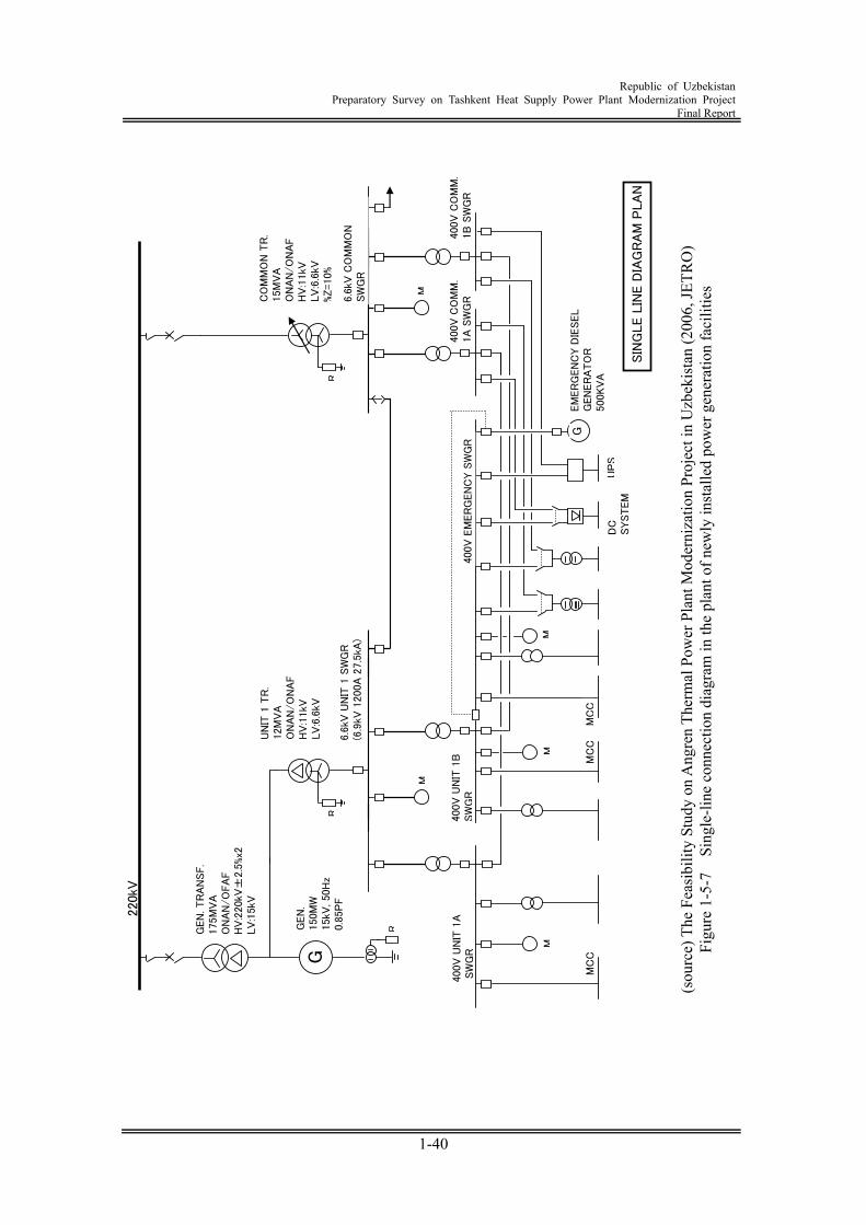
Republic of Uzbekistan
Preparatory Survey on Tashkent Heat Supply Power Plant Modernization Project Final Report
1-40
SIN
GLE L
INE D
IAG
RA
M P
LA
N
G
220kV
GEN
. TR
AN
SF.
175M
VA
ON
AN
/O
FA
FH
V:2
20kV
±2.5
%x2
LV
:15kV
GEN
.150M
W15kV
, 50H
z0.8
5P
F
R
UN
IT 1
TR
.12M
VA
ON
AN
/O
NA
FH
V:1
1kV
LV
:6.6
kV
CO
MM
ON
TR
.15M
VA
ON
AN
/O
NA
FH
V:1
1kV
LV
:6.6
kV%Z=10%
6.6
kV U
NIT
1 S
WG
R(6
.9kV
1200A
27.5
kA)
6.6
kV C
OM
MO
NSW
GR
400V
UN
IT 1
A S
WG
R400V
UN
IT 1
BSW
GR
400V
EM
ER
GEN
CY S
WG
R400V
CO
MM
.1A
SW
GR
400V
CO
MM
.1B
SW
GR
UP
S
MC
CM
CM
CC
MC
CG
EM
ER
GEN
CY D
IESEL
GEN
ER
ATO
R500KV
A
MM
RR
DC
SYSTEM
MM
M
(sou
rce)
The
Fea
sibi
lity
Stud
y on
Ang
ren
Ther
mal
Pow
er P
lant
Mod
erni
zatio
n Pr
ojec
t in
Uzb
ekis
tan
(200
6, JE
TRO
) Fi
gure
1-5
-7
Sing
le-li
ne c
onne
ctio
n di
agra
m in
the
plan
t of n
ewly
inst
alle
d po
wer
gen
erat
ion
faci
litie
s
Republic of Uzbekistan
Preparatory Survey on Tashkent Heat Supply Power Plant Modernization Project Final Report
1-41
Regarding power supply to the low voltage auxiliary circuits, power to the 400 V switchgear is supplied from the 6 kV switchgears via the auxiliary transformers. The power will then be supplied to the motor control center (MCC) and to the other low-voltage auxiliary equipment. As an emergency source of power allowing the unit to safely shutdown in the event of a loss of power in the plant, an emergency diesel generator will be installed. The 400V switchgear will be divided into the use of the emergency bus and the normal bus, and the emergency diesel generator will be connected to the emergency bus. Any equipment that are required for plant safe shutdown will be connected to this emergency bus, and in the even of a loss of power in the power plant, the power will be supplied from the emergency diesel generator via the emergency bus to these equipment that are required for plant sage shutdown.
7) Control equipment
In the existing plant, the boilers, turbines, and generators are controlled from separate locations respectively, and the BOPs will be centrally controlled and monitored from one control room. Specifically, a digital instrumentation and control system (distributed control system: DCS) will be applied. The control room will be located between the turbine/generator room and the boiler room. DCS is a digital system for measurement and control that has features such as monitor, feedback control and sequence control. In order to reduce plant monitoring equipment and centralize monitoring and operation functions, a CRT operation system is applied for operation. For monitoring, a large screen is applied to centrally display a large amount of information.
8) Transmission and substation facilities
a. Linking voltage of new generator The new generator will be linked to the existing 220 kV bus of the Angren power plant, for the following reasons. The rated output is large, at 150 MW, so the generator is capable of supplying power not to the region but to the network as a whole. To connect the new generator to the system, an extension to the existing bus line will be necessary, but the 110 kV bus is closed in on both sides by the 220 kV bus and the 35 kV bus, linking to the 110 kV bus would require moving the 220 kV bus or the 35 kV bus. This would require large-scale works and be uneconomic.
b. Location of new generator's link to the system
The empty zone for the No. 8 generator step-up transformer could be a candidate for the zone to use to connect the new generator to the network, but this is a plan that involves reinstalling the step-up transformer or installing another circuit breaker in the zone and separating the functions currently shared by the circuit breaker, namely the connection between the two bus lines and the connection between the bus lines and the transfer bus line. Therefore, this option is not considered, and the bus line will be extended to connect to the new generator.
(5) Layout plan
It has been verified that there is no problem with the installation of new boilers at the site of the existing boiler facilities units 12 and 13 having been removed already, and the existing boiler facilities unit 11 currently in the process of being removed. Thus, the green zone of the power plant premises can be maintained by effective use of the site of the existing
Republic of Uzbekistan
Preparatory Survey on Tashkent Heat Supply Power Plant Modernization Project Final Report
1-42
facilities having been removed. Further, the existing coal supply facilities and smokestack facilities can be effectively utilized. A further advantage is that the connection pipes can be shortened because of the location adjacent to the candidate construction site for newly installed steam turbine facility and other existing facilities. The newly installed steam turbine and generator facilities are planned to be installed at the site which is adjacent to the existing team turbine and generator facilities unit 8 inside the existing turbine building and in which installation of the steam turbine and generator facilities unit 9 was previously planned. It has been verified that there is no problem with this plan. To implement this plan, extension of the existing turbine building is required and air compressor facilities located outside should be relocated for this extension work. It has been confirmed that there is no problem. The candidate site allows diversion of the existing condenser coolant water intake and discharge facilities and is located adjacent to the transformer, power transmission facilities candidate and the other existing electricity facilities, and the length of the connection pipe and cable can be reduced. Thus, this site is considered as appropriate as the candidate site for installation of the new steam turbine and generator facilities. The electric and control rooms are planned to be installed between the new steam turbine and generator facilities and boiler building. The site where new transformer facilities are adjacent to the existing transformer facilities and the new power transmission facilities are also adjacent to the existing power transmission facilities is planned as a candidate site. It has been confirmed that there is no problem. It has also been confirmed that sufficient consideration is given to the new facilities installation site to ensure that the length of the pipe and cable connected with the existing facilities can be minimized, and there is no problem with the operation of the equipment as well as installation, loading, unloading, maintenance and inspection. Figure 1-5-8 is an equipment layout drawing for the new facilities.
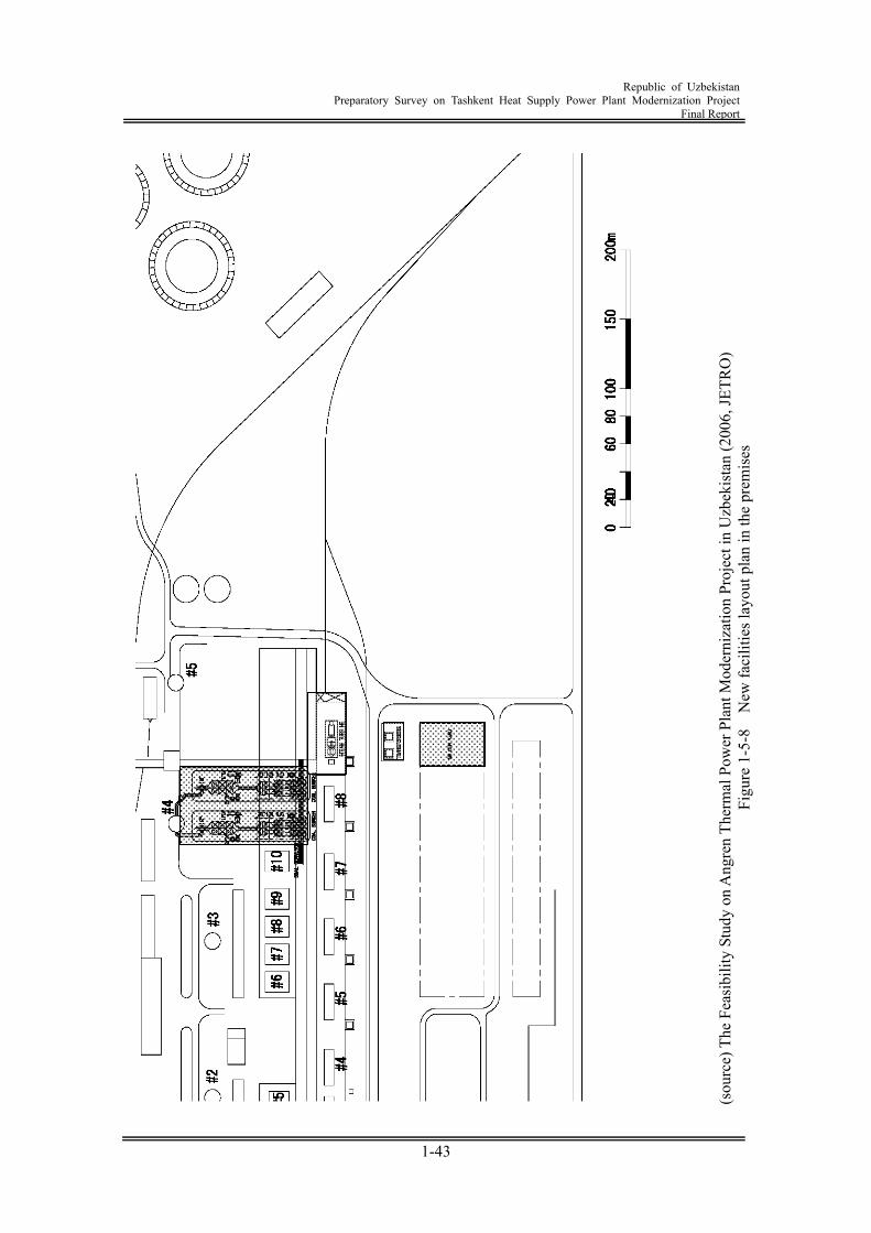
Republic of Uzbekistan
Preparatory Survey on Tashkent Heat Supply Power Plant Modernization Project Final Report
1-43
(sou
rce)
The
Fea
sibi
lity
Stud
y on
Ang
ren
Ther
mal
Pow
er P
lant
Mod
erni
zatio
n Pr
ojec
t in
Uzb
ekis
tan
(200
6, JE
TRO
) Fi
gure
1-5
-8
New
faci
litie
s lay
out p
lan
in th
e pr
emis
es
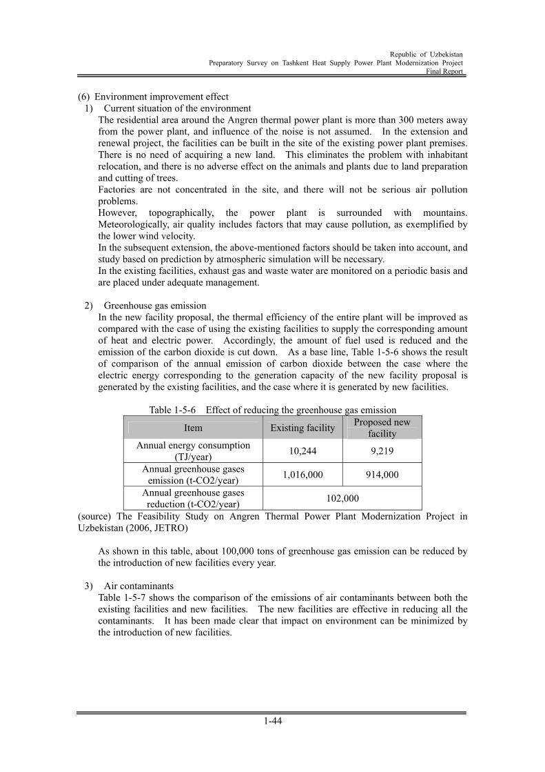
Republic of Uzbekistan
Preparatory Survey on Tashkent Heat Supply Power Plant Modernization Project Final Report
1-44
(6) Environment improvement effect 1) Current situation of the environment
The residential area around the Angren thermal power plant is more than 300 meters away from the power plant, and influence of the noise is not assumed. In the extension and renewal project, the facilities can be built in the site of the existing power plant premises. There is no need of acquiring a new land. This eliminates the problem with inhabitant relocation, and there is no adverse effect on the animals and plants due to land preparation and cutting of trees. Factories are not concentrated in the site, and there will not be serious air pollution problems. However, topographically, the power plant is surrounded with mountains. Meteorologically, air quality includes factors that may cause pollution, as exemplified by the lower wind velocity. In the subsequent extension, the above-mentioned factors should be taken into account, and study based on prediction by atmospheric simulation will be necessary. In the existing facilities, exhaust gas and waste water are monitored on a periodic basis and are placed under adequate management.
2) Greenhouse gas emission
In the new facility proposal, the thermal efficiency of the entire plant will be improved as compared with the case of using the existing facilities to supply the corresponding amount of heat and electric power. Accordingly, the amount of fuel used is reduced and the emission of the carbon dioxide is cut down. As a base line, Table 1-5-6 shows the result of comparison of the annual emission of carbon dioxide between the case where the electric energy corresponding to the generation capacity of the new facility proposal is generated by the existing facilities, and the case where it is generated by new facilities.
Table 1-5-6 Effect of reducing the greenhouse gas emission
Item Existing facility Proposed new facility
Annual energy consumption (TJ/year) 10,244 9,219
Annual greenhouse gases emission (t-CO2/year) 1,016,000 914,000
Annual greenhouse gases reduction (t-CO2/year) 102,000
(source) The Feasibility Study on Angren Thermal Power Plant Modernization Project in Uzbekistan (2006, JETRO)
As shown in this table, about 100,000 tons of greenhouse gas emission can be reduced by the introduction of new facilities every year.
3) Air contaminants
Table 1-5-7 shows the comparison of the emissions of air contaminants between both the existing facilities and new facilities. The new facilities are effective in reducing all the contaminants. It has been made clear that impact on environment can be minimized by the introduction of new facilities.
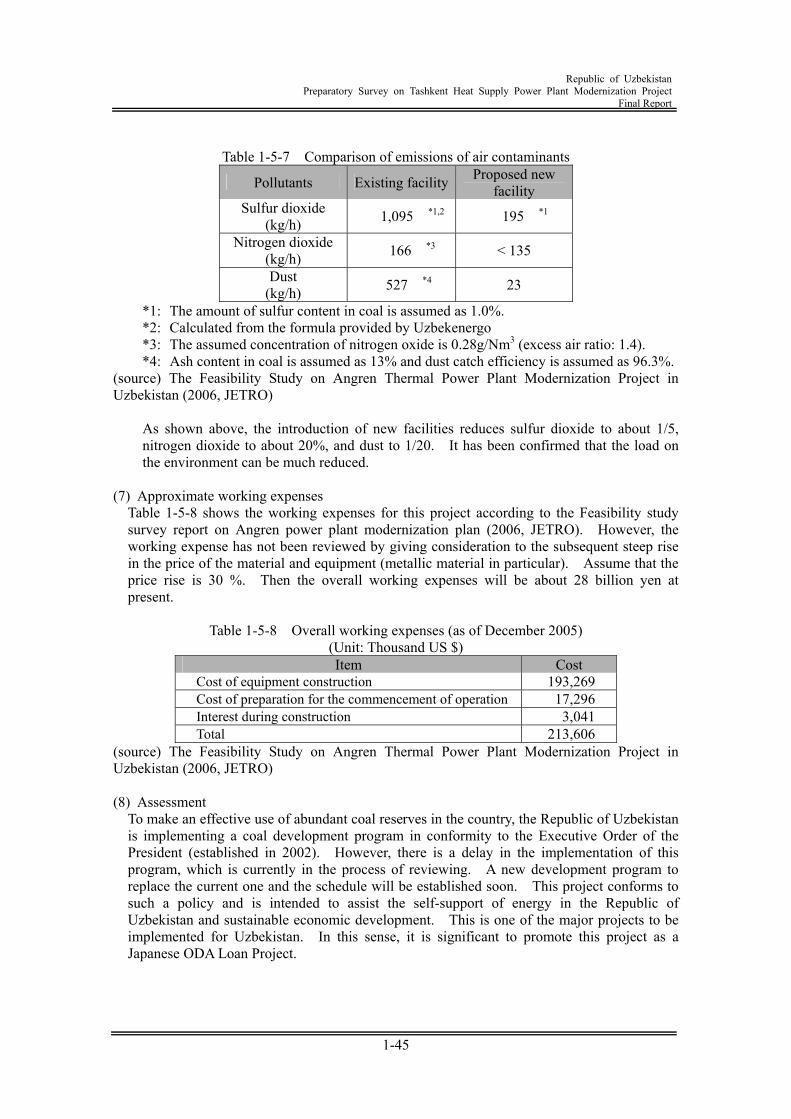
Republic of Uzbekistan
Preparatory Survey on Tashkent Heat Supply Power Plant Modernization Project Final Report
1-45
Table 1-5-7 Comparison of emissions of air contaminants
Pollutants Existing facility Proposed new facility
Sulfur dioxide (kg/h) 1,095 *1,2 195 *1
Nitrogen dioxide (kg/h) 166 *3 < 135
Dust (kg/h) 527 *4 23
*1: The amount of sulfur content in coal is assumed as 1.0%. *2: Calculated from the formula provided by Uzbekenergo *3: The assumed concentration of nitrogen oxide is 0.28g/Nm3 (excess air ratio: 1.4). *4: Ash content in coal is assumed as 13% and dust catch efficiency is assumed as 96.3%.
(source) The Feasibility Study on Angren Thermal Power Plant Modernization Project in Uzbekistan (2006, JETRO)
As shown above, the introduction of new facilities reduces sulfur dioxide to about 1/5, nitrogen dioxide to about 20%, and dust to 1/20. It has been confirmed that the load on the environment can be much reduced.
(7) Approximate working expenses
Table 1-5-8 shows the working expenses for this project according to the Feasibility study survey report on Angren power plant modernization plan (2006, JETRO). However, the working expense has not been reviewed by giving consideration to the subsequent steep rise in the price of the material and equipment (metallic material in particular). Assume that the price rise is 30 %. Then the overall working expenses will be about 28 billion yen at present.
Table 1-5-8 Overall working expenses (as of December 2005)
(Unit: Thousand US $) Item Cost
Cost of equipment construction 193,269 Cost of preparation for the commencement of operation 17,296 Interest during construction 3,041 Total 213,606
(source) The Feasibility Study on Angren Thermal Power Plant Modernization Project in Uzbekistan (2006, JETRO) (8) Assessment
To make an effective use of abundant coal reserves in the country, the Republic of Uzbekistan is implementing a coal development program in conformity to the Executive Order of the President (established in 2002). However, there is a delay in the implementation of this program, which is currently in the process of reviewing. A new development program to replace the current one and the schedule will be established soon. This project conforms to such a policy and is intended to assist the self-support of energy in the Republic of Uzbekistan and sustainable economic development. This is one of the major projects to be implemented for Uzbekistan. In this sense, it is significant to promote this project as a Japanese ODA Loan Project.
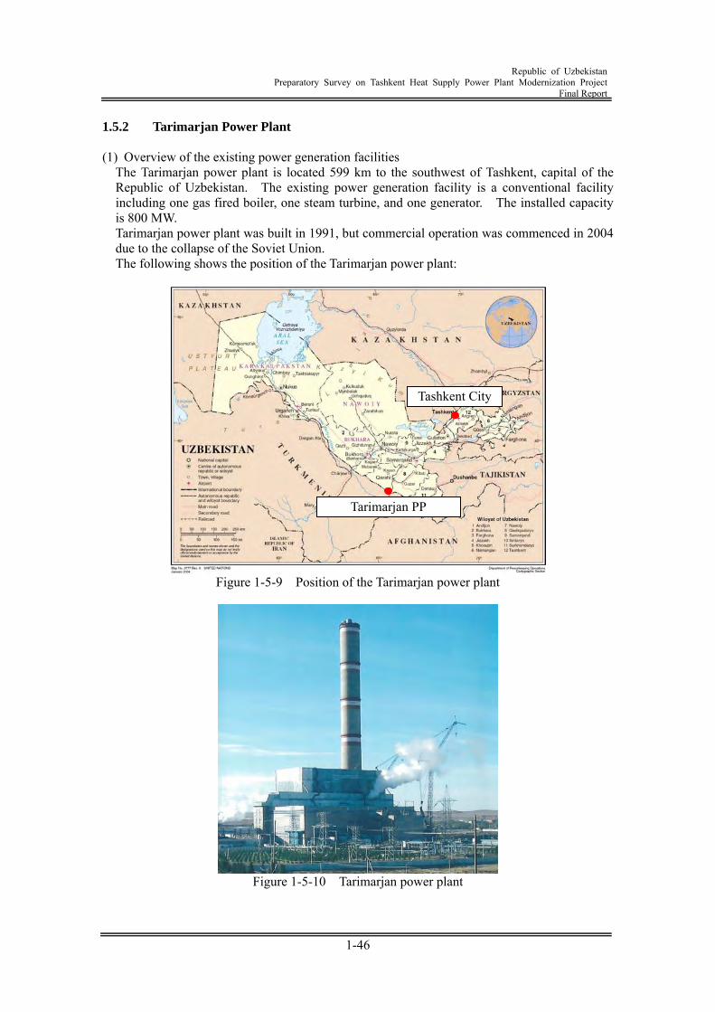
Republic of Uzbekistan
Preparatory Survey on Tashkent Heat Supply Power Plant Modernization Project Final Report
1-46
1.5.2 Tarimarjan Power Plant (1) Overview of the existing power generation facilities
The Tarimarjan power plant is located 599 km to the southwest of Tashkent, capital of the Republic of Uzbekistan. The existing power generation facility is a conventional facility including one gas fired boiler, one steam turbine, and one generator. The installed capacity is 800 MW. Tarimarjan power plant was built in 1991, but commercial operation was commenced in 2004 due to the collapse of the Soviet Union. The following shows the position of the Tarimarjan power plant:
Figure 1-5-9 Position of the Tarimarjan power plant
Figure 1-5-10 Tarimarjan power plant
Tarimarjan PP
Tashkent City
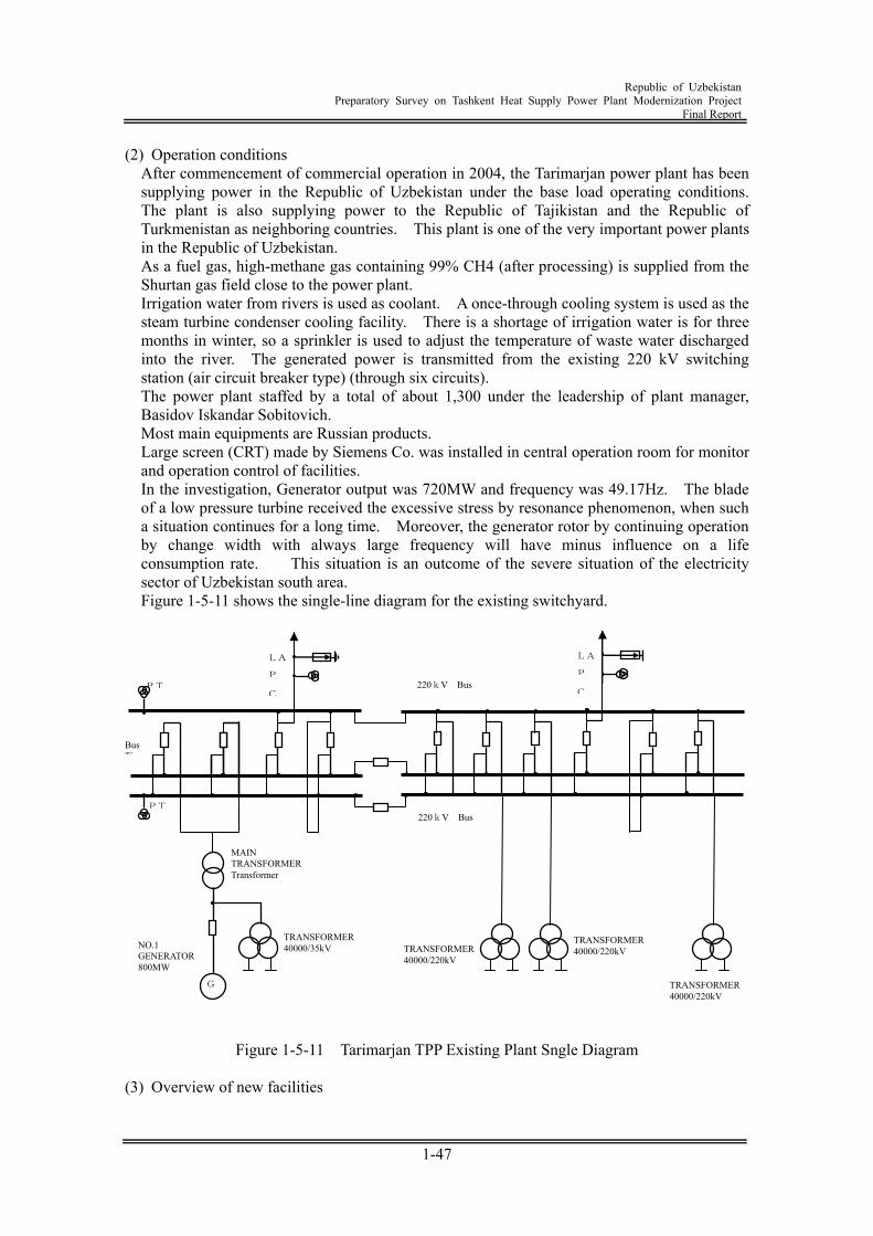
Republic of Uzbekistan
Preparatory Survey on Tashkent Heat Supply Power Plant Modernization Project Final Report
1-47
(2) Operation conditions After commencement of commercial operation in 2004, the Tarimarjan power plant has been supplying power in the Republic of Uzbekistan under the base load operating conditions. The plant is also supplying power to the Republic of Tajikistan and the Republic of Turkmenistan as neighboring countries. This plant is one of the very important power plants in the Republic of Uzbekistan. As a fuel gas, high-methane gas containing 99% CH4 (after processing) is supplied from the Shurtan gas field close to the power plant. Irrigation water from rivers is used as coolant. A once-through cooling system is used as the steam turbine condenser cooling facility. There is a shortage of irrigation water is for three months in winter, so a sprinkler is used to adjust the temperature of waste water discharged into the river. The generated power is transmitted from the existing 220 kV switching station (air circuit breaker type) (through six circuits). The power plant staffed by a total of about 1,300 under the leadership of plant manager, Basidov Iskandar Sobitovich. Most main equipments are Russian products. Large screen (CRT) made by Siemens Co. was installed in central operation room for monitor and operation control of facilities. In the investigation, Generator output was 720MW and frequency was 49.17Hz. The blade of a low pressure turbine received the excessive stress by resonance phenomenon, when such a situation continues for a long time. Moreover, the generator rotor by continuing operation by change width with always large frequency will have minus influence on a life consumption rate. This situation is an outcome of the severe situation of the electricity sector of Uzbekistan south area. Figure 1-5-11 shows the single-line diagram for the existing switchyard.
Figure 1-5-11 Tarimarjan TPP Existing Plant Sngle Diagram
(3) Overview of new facilities
G
PT
PT
Bus Tie
MAIN TRANSFORMER Transformer
LA
P
C
LA
P
C
TRANSFORMER40000/220kV
TRANSFORMER 40000/220kV
TRANSFORMER40000/220kV
NO.1 GENERATOR 800MW
TRANSFORMER 40000/35kV
220kV Bus
220kV Bus
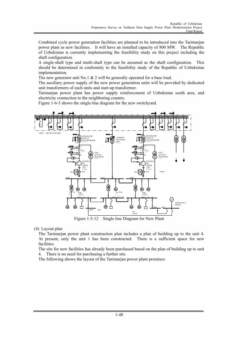
Republic of Uzbekistan
Preparatory Survey on Tashkent Heat Supply Power Plant Modernization Project Final Report
1-48
Combined cycle power generation facilities are planned to be introduced into the Tarimarjan power plant as new facilities. It will have an installed capacity of 800 MW. The Republic of Uzbekistan is currently implementing the feasibility study on this project including the shaft configuration. A single-shaft type and multi-shaft type can be assumed as the shaft configuration. This should be determined in conformity to the feasibility study of the Republic of Uzbekistan implementation. The new generator unit No.1 & 2 will be generally operated for a base load. The auxiliary power supply of the new power generation units will be provided by dedicated unit transformers of each units and start-up transformer. Tarimarjan power plant has power supply reinforcement of Uzbekistan south area, and electricity connection to the neighboring country. Figure 1-6-5 shows the single-line diagram for the new switchyard.
Figure 1-5-12 Single line Diagram for New Plant
(4) Layout plan
The Tarimarjan power plant construction plan includes a plan of building up to the unit 4. At present, only the unit 1 has been constructed. There is a sufficient space for new facilities. The site for new facilities has already been purchased based on the plan of building up to unit 4. There is no need for purchasing a further site. The following shows the layout of the Tarimarjan power plant premises:
500kV GIS SWITCHYARD
G GENERATOR 400MW 11kV 0 85PF
GENERATOR STEP-UP TRANSFORMER 470MVA
GC
NGTNG
LA
Aux.Trans.
High Voltage
400V L/C &
GGENERATOR 400MW 11kV 0 85PF
GC
NGTNG
LA
Aux.Trans. 6 3kV/40
Low Voltage
High Voltage
400V L/C & D
UNIT AUX.IlIY TRANSFORMER
6.3kV 6.3kV
400V ESS 400V ESS
GENERATOR STEP-UP TRANSFORMER470MVA
UNIT AUX.IlIY TRANSFORMER
Figure -
400V CL/C &
EMERGENCY DIESEL GENERATOR
COMMONTRANSFORMER 25 MVA
6.3kV
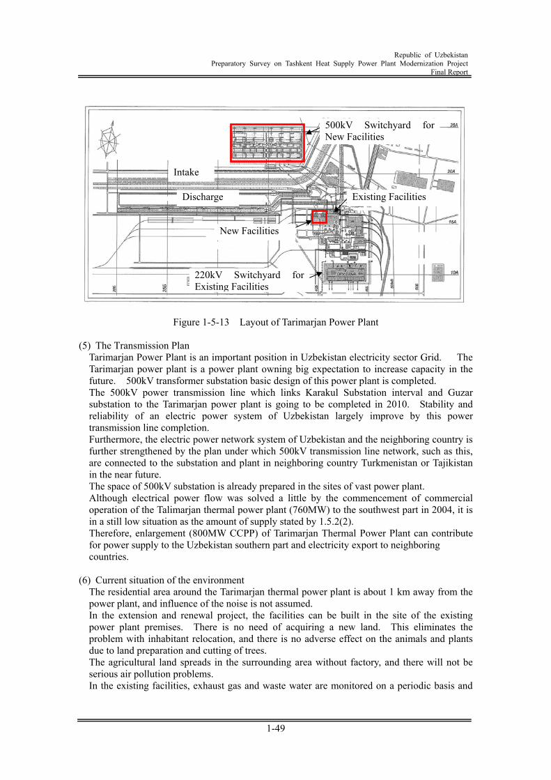
Republic of Uzbekistan
Preparatory Survey on Tashkent Heat Supply Power Plant Modernization Project Final Report
1-49
Figure 1-5-13 Layout of Tarimarjan Power Plant
(5) The Transmission Plan
Tarimarjan Power Plant is an important position in Uzbekistan electricity sector Grid. The Tarimarjan power plant is a power plant owning big expectation to increase capacity in the future. 500kV transformer substation basic design of this power plant is completed. The 500kV power transmission line which links Karakul Substation interval and Guzar substation to the Tarimarjan power plant is going to be completed in 2010. Stability and reliability of an electric power system of Uzbekistan largely improve by this power transmission line completion. Furthermore, the electric power network system of Uzbekistan and the neighboring country is further strengthened by the plan under which 500kV transmission line network, such as this, are connected to the substation and plant in neighboring country Turkmenistan or Tajikistan in the near future. The space of 500kV substation is already prepared in the sites of vast power plant. Although electrical power flow was solved a little by the commencement of commercial operation of the Talimarjan thermal power plant (760MW) to the southwest part in 2004, it is in a still low situation as the amount of supply stated by 1.5.2(2). Therefore, enlargement (800MW CCPP) of Tarimarjan Thermal Power Plant can contribute for power supply to the Uzbekistan southern part and electricity export to neighboring countries.
(6) Current situation of the environment
The residential area around the Tarimarjan thermal power plant is about 1 km away from the power plant, and influence of the noise is not assumed. In the extension and renewal project, the facilities can be built in the site of the existing power plant premises. There is no need of acquiring a new land. This eliminates the problem with inhabitant relocation, and there is no adverse effect on the animals and plants due to land preparation and cutting of trees. The agricultural land spreads in the surrounding area without factory, and there will not be serious air pollution problems. In the existing facilities, exhaust gas and waste water are monitored on a periodic basis and
500kV Switchyard for New Facilities
220kV Switchyard for Existing Facilities
Existing Facilities
New Facilities
Discharge
Intake
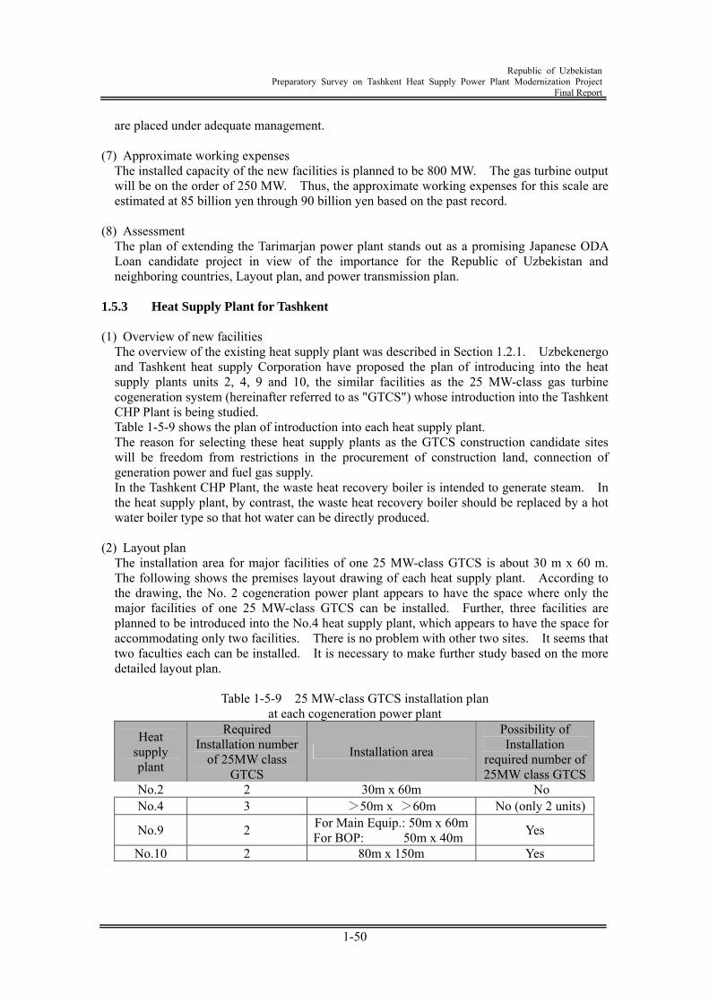
Republic of Uzbekistan
Preparatory Survey on Tashkent Heat Supply Power Plant Modernization Project Final Report
1-50
are placed under adequate management. (7) Approximate working expenses
The installed capacity of the new facilities is planned to be 800 MW. The gas turbine output will be on the order of 250 MW. Thus, the approximate working expenses for this scale are estimated at 85 billion yen through 90 billion yen based on the past record.
(8) Assessment
The plan of extending the Tarimarjan power plant stands out as a promising Japanese ODA Loan candidate project in view of the importance for the Republic of Uzbekistan and neighboring countries, Layout plan, and power transmission plan.
1.5.3 Heat Supply Plant for Tashkent (1) Overview of new facilities
The overview of the existing heat supply plant was described in Section 1.2.1. Uzbekenergo and Tashkent heat supply Corporation have proposed the plan of introducing into the heat supply plants units 2, 4, 9 and 10, the similar facilities as the 25 MW-class gas turbine cogeneration system (hereinafter referred to as "GTCS") whose introduction into the Tashkent CHP Plant is being studied. Table 1-5-9 shows the plan of introduction into each heat supply plant. The reason for selecting these heat supply plants as the GTCS construction candidate sites will be freedom from restrictions in the procurement of construction land, connection of generation power and fuel gas supply. In the Tashkent CHP Plant, the waste heat recovery boiler is intended to generate steam. In the heat supply plant, by contrast, the waste heat recovery boiler should be replaced by a hot water boiler type so that hot water can be directly produced.
(2) Layout plan
The installation area for major facilities of one 25 MW-class GTCS is about 30 m x 60 m. The following shows the premises layout drawing of each heat supply plant. According to the drawing, the No. 2 cogeneration power plant appears to have the space where only the major facilities of one 25 MW-class GTCS can be installed. Further, three facilities are planned to be introduced into the No.4 heat supply plant, which appears to have the space for accommodating only two facilities. There is no problem with other two sites. It seems that two faculties each can be installed. It is necessary to make further study based on the more detailed layout plan.
Table 1-5-9 25 MW-class GTCS installation plan
at each cogeneration power plant
Heat supply plant
Required Installation number
of 25MW class GTCS
Installation area
Possibility of Installation
required number of 25MW class GTCS
No.2 2 30m x 60m No No.4 3 >50m x >60m No (only 2 units)
No.9 2 For Main Equip.: 50m x 60mFor BOP: 50m x 40m Yes
No.10 2 80m x 150m Yes
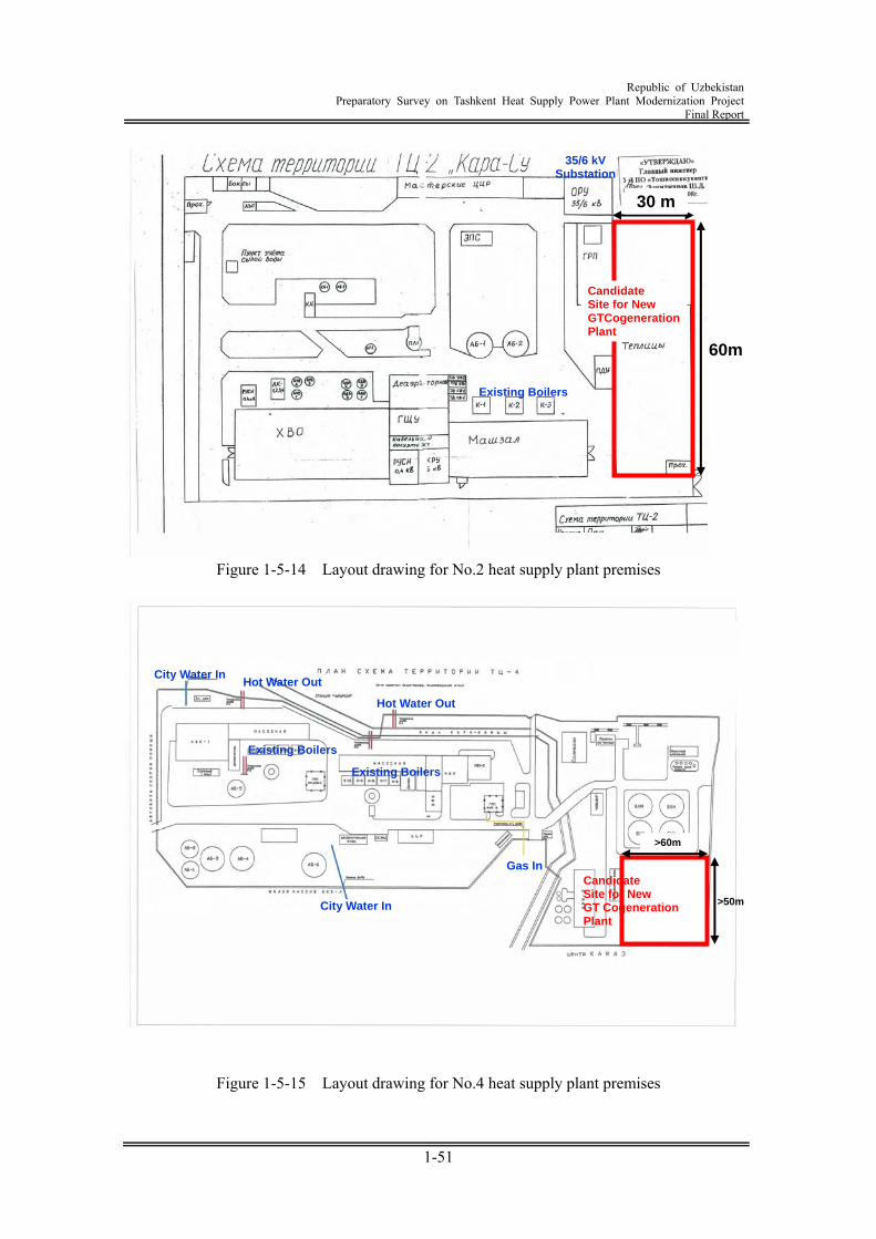
Republic of Uzbekistan
Preparatory Survey on Tashkent Heat Supply Power Plant Modernization Project Final Report
1-51
Figure 1-5-14 Layout drawing for No.2 heat supply plant premises
Figure 1-5-15 Layout drawing for No.4 heat supply plant premises
Candidate Site for New GT Cogeneration Plant
>60m
>50m
Existing Boilers
Existing Boilers
City Water In
Gas In
Hot Water Out
Hot Water Out City Water In
30 m
60m
35/6 kV Substation
Existing Boilers
Candidate Site for New GTCogeneration Plant
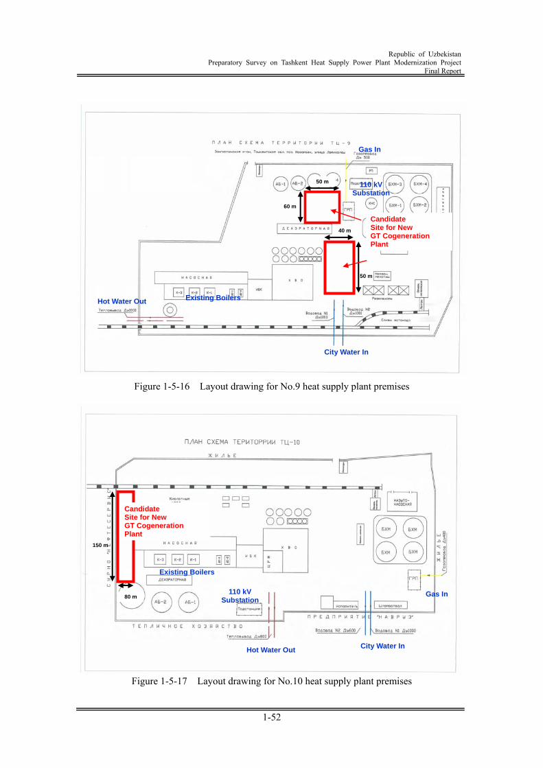
Republic of Uzbekistan
Preparatory Survey on Tashkent Heat Supply Power Plant Modernization Project Final Report
1-52
Figure 1-5-16 Layout drawing for No.9 heat supply plant premises
Figure 1-5-17 Layout drawing for No.10 heat supply plant premises
Candidate Site for New GT Cogeneration Plant
80 m
150 m
City Water In
Existing Boilers
Hot Water Out
Gas In 110 kV Substation
Candidate Site for New GT Cogeneration Plant
50 m
60 m
City Water In
Existing BoilersHot Water Out
Gas In
110 kV Substation
40 m
50 m
Republic of Uzbekistan
Preparatory Survey on Tashkent Heat Supply Power Plant Modernization Project Final Report
1-53
(3) The transmission Plan Uzubekenergo has already supplied electricity by 110kV power transmission line to No. 4, No. 9, No.10 (without No.2 plant) heat supply power plant. Therefore,Uzubekenergo will build new 110kV power transmission line between No. 2 heat supply plant and nearby subplant when design facilities. In neither heat supply plant, site of New Switchyard does not have a problem. The present conditions between each heat supply plant and neighborhood substations are as follows.
Table 1-5-10 Condition of each heat plant and neighboring substation
No. of Heat Plant Supply Substation Voltage Class No.2 110kV Transmission Line not
Available 35kV
No.4 Supplied from Beshkurgan Substation by 110kV transmission line
110kV / 35kV / 10kV / 6kV
No.9 Supplied from Nazarvek Substation by 110kV transmission line
110kV / 35kV / 6kV
No.10 Supplied from Shimoli - Garbiy Substation by 110kV transmission line
110kV / 6kV
(4) Current situation of the environment
In the extension and renewal project of three stations Nos. 4, 9 and 10, the facilities can be built in the site of the existing power plant premises. There is no need of acquiring a new land. This eliminates the problem with inhabitant relocation, and there is no adverse effect on the animals and plants due to land preparation and cutting of trees. The No.4 station is adjacent to the residential area, and there have been complaints about the noise of the existing facilities. So before implementing the extension and renewal project, it is necessary to makes arrangements to minimize the impact of noise. In the existing facilities, exhaust gas and waste water are monitored on a periodic basis and are placed under adequate management.
(5) Approximate working expenses
Approximate working expenses for the introduction of nine 25 MW-class GTCSs are estimated at 55 billion yen through 60 billion yen when the current market conditions are taken into account.
(6) Assessment
As discussed in Section 1.2.3, the demand for head in Tashkent is assumed to exhibit a steady growth in future. This requires renewal of the facilities one after another. Introduction of the GTCS in place of the renewal plan centering on the conventional boiler given in Table 1-2-3 is very effective in saving energy from the viewpoint of power supply, and is considered as the optimum selection for the Republic of Uzbekistan provided with an advanced large-sized heat supply system. However, when recent plant market conditions are taken into account, the massive construction cost is required and sales price of heat is lower. Much profit cannot be expected, and economic advantages on the private investment level cannot be anticipated. For this reason, use of the Japanese ODA Loan is considered as essential.
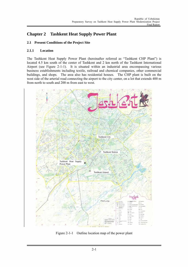
Republic of Uzbekistan
Preparatory Survey on Tashkent Heat Supply Power Plant Modernization Project Final Report
2-1
Chapter 2 Tashkent Heat Supply Power Plant 2.1 Present Conditions of the Project Site 2.1.1 Location The Tashkent Heat Supply Power Plant (hereinafter referred as “Tashkent CHP Plant”) is located 4.5 km south of the center of Tashkent and 2 km north of the Tashkent International Airport (see Figure 2-1-1). It is situated within an industrial area encompassing various business establishments including textile, railroad and chemical companies, other commercial buildings, and shops. The area also has residential houses. The CHP plant is built on the west side of the arterial road connecting the airport to the city center, on a lot that extends 400 m from north to south and 200 m from east to west.
Figure 2-1-1 Outline location map of the power plant
Tashkent Heat Supply Power Plant
Tashkent Station
Tashkent Airport
Tashkent City
Republic of Uzbekistan
Preparatory Survey on Tashkent Heat Supply Power Plant Modernization Project Final Report
2-2
2.1.2 Project site The site for this project is the area that is in the southwest part of the power plant compound, and lies between an existing water treatment facility to the north and a textile factory to the south. This site had been an old coal-storage yard, which is now a practically vacant lot with partially remaining coal storage facilities and railroad siding used for coal transportation. The site measures 76 m from north to south by 195 m from east to west, and is planned to be used for both this project and the project that will be undertaken by NEDO. The power plant is equipped with a tie-in point in the southeast part of its compound linked to the natural gas supply sector, and an installation space is reserved within the compound for gas supply equipment (e.g. gas compressors) that is planned to be used for the projects. The plant's 110 kV power line was originally installed within the eastern boundary of the compound and ran in the north-south direction. It was then moved in 2005 to its current location, 10-15 m outside the western border of the plant compound, in the north-south direction. 2.1.3 Present conditions of the plant environment Since the site is located in the center of Tashkent city in the industrial area near the airport, residential area are near side, so attention must be given to the noise control. It is necessary to detail study of layout coordination with NEDO project for implementation project. As a result of abovementioned, it is necessary to purchase new land. But site acquisition is to purchase industrial area not to purchase residence. There is no impact to the fauna / flora since the land is already reclaimed. Appropriate management is conducted through monitoring on regular basis regarding any emissions from each existing Power plant. For emission gas, SO2 and CO level is complied with the regulation value but NOx level is not complied with the regulation value. Upon additional construction, detailed consideration has to be made not to increase the amount of emission air pollutants as a whole plant including demolition of the existing plants. The pre-FS and EIA of NEDO project is to be soon approved by related governmental authorities of Uzbekistan. 2.2 Operating Conditions of Existing Facilities 2.2.1 Overview The Tashkent CHP Plant is one of four heat generation plants managed by the Ministry of Energy and Electrification, and is operated on a self-supporting basis. The plant produces and supplies electricity and heat (hot water and steam) using natural gas as the fuel provided by the Tashkent City gas supply corporation. The plant uses about 30% of the generated electricity as the auxiliary power of its equipment, and transmits the rest to the outside. It also provides hot water to certain areas in Tashkent City for heating homes and buildings, or for hot tap water supply. The plant distributes its generated steam to the textile factory and other plants around the plant to be used for their processes. Five steam boilers (total steam production 415 t/h) to be used for power generation and steam supply were installed between 1939 and 1955, one steam turbine generator (rated output 30 MW) in 1954, and seven hot water boilers (total heat output 650 Gcal/h) between 1963 and 1969. All of this equipment is still in operation today. The plant's equipment is designed to run on natural gas or heavy oil, and natural gas is provided by the state-owned gas supply corporation (Uzbekneftegaz) via the Tashkent City gas supply
Republic of Uzbekistan
Preparatory Survey on Tashkent Heat Supply Power Plant Modernization Project Final Report
2-3
agency (Tashgas). Heavy oil has not been used as a fuel at the plant since 1997. The hot water boilers in the plant take in water supplied by the Tashkent waterworks bureau (Tashvodakanal), and the heated water from the boilers is sent to the Tashkent City thermal energy supply corporation (Tashteploenergo). Since there is usually no demand for central heating in homes and buildings in the region except from October through March, the plant runs its hot water boilers only during these winter months. A portion of the electricity produced by the steam turbine generator is consumed within the plant for powering equipment such as hot water pumps. The remaining portion of the electricity is then transmitted to the power system of the local power distribution company (The State Enterprise TashgorPEC) managed by the Ministry of Energy and Electrification, as well as to the Tashkent International Airport. The generated steam from the steam boilers is sent to the steam turbine and used for power generation. Some of the steam is depressurized in order to be used as heating steam for the hot water heater. The steam is also supplied to industrial establishments in the region, including the neighboring textile factory (Tashkent Textile Plant), woodworking plant (Tashkent Wood-working Plant), agricultural chemical plant (Agrokhimplast), railroad company (Rolling Stock Maintenance Dept.), and reinforced concrete manufacturing company (Ferroconcrete Material Plant). The Tashkent CHP Plant was established in 1936 originally for the purpose of producing steam to be supplied to the textile factory, and its operation began in 1939. An additional boiler was installed in 1948 to increase the plant capacity. The plant had belonged to the Ministry of Light Industry until it was incorporated into the Ministry of Energy and Electrification in 1951, as the result of its facility upgrade during that year to have a 30 MW power generation capacity. New boilers were added in the plant in stages over the next several years, all of which are still in operation today. Depending on the equipment, after 40 to 70 years of use, the existing facilities are all becoming increasingly worn out. While the plan is to shut down the steam boilers and steam turbine generator in the future, for the time being they will be kept in operation with the necessary maintenance.
Republic of Uzbekistan
Preparatory Survey on Tashkent Heat Supply Power Plant Modernization Project Final Report
2-4
2.2.2 Plant layout The layout of the Tashkent CHP Plant is illustrated in Figure 2-2-1. The power plant compound is divided into four main areas. The power generation and steam supply facility including the turbine and generator, and steam boilers is positioned on the north side of the main building located in the center of the compound. The area on the west side of the power generation facilities is comprised of transformers and power switchgear equipment which boost and transmit the generated electricity. The northern end of the compound is the area where the hot water boilers and supply facilities are built, which are used to heat the treated municipal water to a specified temperature and deliver it through water pumps. The water treatment facilities to process municipal water are located in the area on the other side of the main building, across the access road that runs within the plant compound in the east-west direction on the south side of the main building. The south side of the water treatment facility is a former coal storage and transportation yard, which has been selected as the site for this planned project.
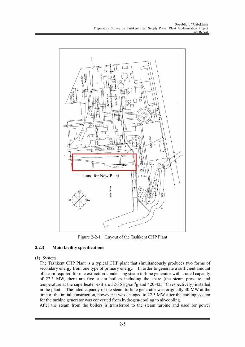
Republic of Uzbekistan
Preparatory Survey on Tashkent Heat Supply Power Plant Modernization Project Final Report
2-5
Figure 2-2-1 Layout of the Tashkent CHP Plant
2.2.3 Main facility specifications (1) System
The Tashkent CHP Plant is a typical CHP plant that simultaneously produces two forms of secondary energy from one type of primary energy. In order to generate a sufficient amount of steam required for one extraction-condensing steam turbine generator with a rated capacity of 22.5 MW, there are five steam boilers including the spare (the steam pressure and temperature at the superheater exit are 32-36 kg/cm2g and 420-425 C respectively) installed in the plant. The rated capacity of the steam turbine generator was originally 30 MW at the time of the initial construction, however it was changed to 22.5 MW after the cooling system for the turbine generator was converted from hydrogen-cooling to air-cooling. After the steam from the boilers is transferred to the steam turbine and used for power
Land for New Plant
Republic of Uzbekistan
Preparatory Survey on Tashkent Heat Supply Power Plant Modernization Project Final Report
2-6
generation, it is conveyed to the steam condenser and becomes water. The condensed water then goes through the condensate pump, deaerator and boiler feed pump, and is used again as the feed-water for the boilers. The steam extracted from the middle stage of the steam turbine (pressure 9 kg/cm2g, temperature 320 C) is sent to the textile factory and other plants in the region to be used in their processes. One of the advanced features of this system is that it uses the municipal water supplied for producing hot water as the cooling water for the steam turbine condenser. This feature significantly improves the energy conversion efficiency of the system, as a large volume of exhaust heat energy from the steam turbine is effectively recovered instead of being dispersed outside the system. The water supplied for producing hot water (maximum 3,200m3/h) is treated with ion-exchange resin to ensure proper water quality, after it is used in the steam turbine condenser to recover the heat energy from the steam turbine exhaust steam. The treated water is then transferred to the hot water heater, in which it is heated to approximately 70 C using the steam extracted from the steam turbine or depressurized after being generated by the steam boilers. The water is further heated to 100-150 C in the hot water boilers (total capacity 650 Gcal/h) as necessary. There are two 3,000 m3 water storage tanks connected to the piping between the hot water heaters and hot water boilers that function as accumulators. Whenever the hot water supply from the plant is not able to meet sudden fluctuations in demand, these accumulators compensate for the fluctuations. The plant's system also includes hot water piping and a set of hot water makeup system equipment. Figure 2-2-2 represents a schematic diagram of the current system at the Tashkent CHP Plant.
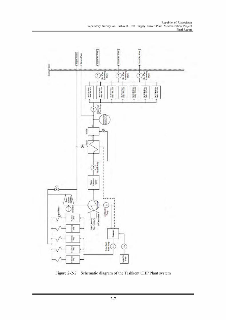
Republic of Uzbekistan
Preparatory Survey on Tashkent Heat Supply Power Plant Modernization Project Final Report
2-7
Figure 2-2-2 Schematic diagram of the Tashkent CHP Plant system
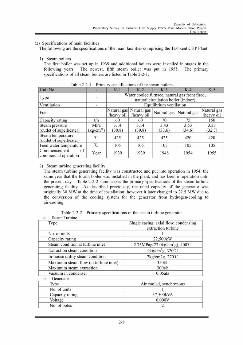
Republic of Uzbekistan
Preparatory Survey on Tashkent Heat Supply Power Plant Modernization Project Final Report
2-8
(2) Specifications of main facilities The following are the specifications of the main facilities comprising the Tashkent CHP Plant.
1) Steam boilers
The first boiler was set up in 1939 and additional boilers were installed in stages in the following years. The newest, fifth steam boiler was put in 1955. The primary specifications of all steam boilers are listed in Table 2-2-1.
Table 2-2-1 Primary specifications of the steam boilers
Unit No. - K-1 K-2 K-3 K-4 K-5
Type - Water cooled furnace, natural gas front fired, natural circulation boiler (indoor)
Ventilation - Equilibrium ventilation
Fuel - Natural gas/heavy oil
Natural gas/heavy oil Natural gas Natural gas Natural gas
/heavy oilCapacity rating t/h 60 60 70 75 150 Steam pressure (outlet of superheater)
MPa (kg/cm2)
3.14 (30.8)
3.14 (30.8)
3.43 (33.6)
3.53 (34.6)
3.33 (32.7)
Steam temperature (outlet of superheater) ℃ 425 425 425 420 420
Feed water temperature ℃ 105 105 105 105 105 Commencement of commercial operation Year 1939 1939 1948 1954 1955
2) Steam turbine generating facility
The steam turbine generating facility was constructed and put into operation in 1954, the same year that the fourth boiler was installed in the plant, and has been in operation until the present day. Table 2-2-2 summarizes the primary specifications of the steam turbine generating facility. As described previously, the rated capacity of the generator was originally 30 MW at the time of installation; however it later changed to 22.5 MW due to the conversion of the cooling system for the generator from hydrogen-cooling to air-cooling.
Table 2-2-2 Primary specifications of the steam turbine generator
a. Steam Turbine Type Single casing, axial flow, condensing
extraction turbine No. of units 1 Capacity rating 22,500kW Steam condition at turbine inlet 2.75MPag(27.0kg/cm2g), 400℃ Extraction steam condition 9kg/cm2g, 320℃ In-house utility steam condition 7kg/cm2g, 270℃ Maximum steam flow (at turbine inlet) 350t/h Maximum steam extraction 300t/h Vacuum in condenser 0.05ata
b. Generator Type Air cooled, synchronous No. of units 1 Capacity rating 37,500kVA Voltage 6,000V No. of poles 2
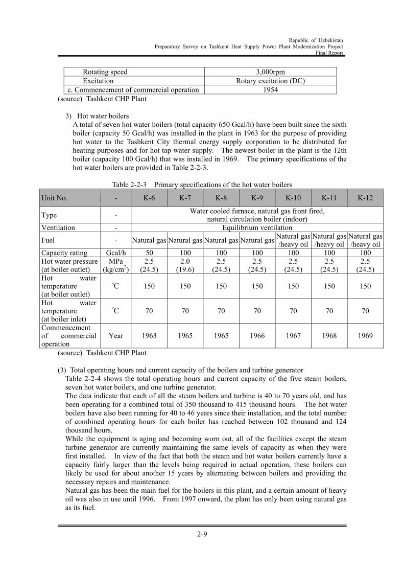
Republic of Uzbekistan
Preparatory Survey on Tashkent Heat Supply Power Plant Modernization Project Final Report
2-9
Rotating speed 3,000rpm Excitation Rotary excitation (DC)
c. Commencement of commercial operation 1954 (source) Tashkent CHP Plant
3) Hot water boilers A total of seven hot water boilers (total capacity 650 Gcal/h) have been built since the sixth boiler (capacity 50 Gcal/h) was installed in the plant in 1963 for the purpose of providing hot water to the Tashkent City thermal energy supply corporation to be distributed for heating purposes and for hot tap water supply. The newest boiler in the plant is the 12th boiler (capacity 100 Gcal/h) that was installed in 1969. The primary specifications of the hot water boilers are provided in Table 2-2-3.
Table 2-2-3 Primary specifications of the hot water boilers
Unit No. - K-6 K-7 K-8 K-9 K-10 K-11 K-12
Type - Water cooled furnace, natural gas front fired, natural circulation boiler (indoor)
Ventilation - Equilibrium ventilation
Fuel - Natural gas Natural gas Natural gas Natural gas Natural gas /heavy oil
Natural gas/heavy oil
Natural gas/heavy oil
Capacity rating Gcal/h 50 100 100 100 100 100 100 Hot water pressure (at boiler outlet)
MPa (kg/cm2)
2.5 (24.5)
2.0 (19.6)
2.5 (24.5)
2.5 (24.5)
2.5 (24.5)
2.5 (24.5)
2.5 (24.5)
Hot water temperature (at boiler outlet)
℃ 150 150 150 150 150 150 150
Hot water temperature (at boiler inlet)
℃ 70 70 70 70 70 70 70
Commencement of commercial operation
Year 1963 1965 1965 1966 1967 1968 1969
(source) Tashkent CHP Plant (3) Total operating hours and current capacity of the boilers and turbine generator
Table 2-2-4 shows the total operating hours and current capacity of the five steam boilers, seven hot water boilers, and one turbine generator. The data indicate that each of all the steam boilers and turbine is 40 to 70 years old, and has been operating for a combined total of 350 thousand to 415 thousand hours. The hot water boilers have also been running for 40 to 46 years since their installation, and the total number of combined operating hours for each boiler has reached between 102 thousand and 124 thousand hours. While the equipment is aging and becoming worn out, all of the facilities except the steam turbine generator are currently maintaining the same levels of capacity as when they were first installed. In view of the fact that both the steam and hot water boilers currently have a capacity fairly larger than the levels being required in actual operation, these boilers can likely be used for about another 15 years by alternating between boilers and providing the necessary repairs and maintenance. Natural gas has been the main fuel for the boilers in this plant, and a certain amount of heavy oil was also in use until 1996. From 1997 onward, the plant has only been using natural gas as its fuel.
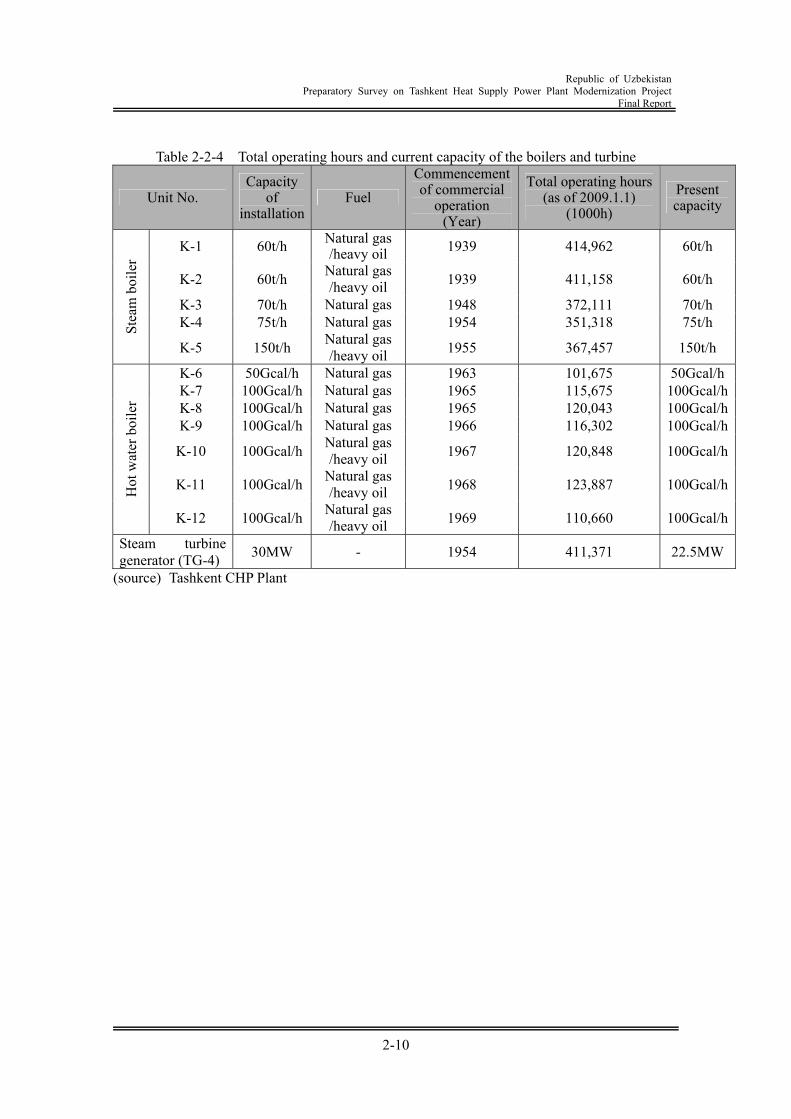
Republic of Uzbekistan
Preparatory Survey on Tashkent Heat Supply Power Plant Modernization Project Final Report
2-10
Table 2-2-4 Total operating hours and current capacity of the boilers and turbine
Unit No. Capacity
of installation
Fuel Commencement of commercial
operation (Year)
Total operating hours (as of 2009.1.1)
(1000h) Present capacity
K-1 60t/h Natural gas /heavy oil 1939 414,962 60t/h
K-2 60t/h Natural gas /heavy oil 1939 411,158 60t/h
K-3 70t/h Natural gas 1948 372,111 70t/h K-4 75t/h Natural gas 1954 351,318 75t/h St
eam
boi
ler
K-5 150t/h Natural gas /heavy oil 1955 367,457 150t/h
K-6 50Gcal/h Natural gas 1963 101,675 50Gcal/hK-7 100Gcal/h Natural gas 1965 115,675 100Gcal/hK-8 100Gcal/h Natural gas 1965 120,043 100Gcal/hK-9 100Gcal/h Natural gas 1966 116,302 100Gcal/h
K-10 100Gcal/h Natural gas /heavy oil 1967 120,848 100Gcal/h
K-11 100Gcal/h Natural gas /heavy oil 1968 123,887 100Gcal/hH
ot w
ater
boi
ler
K-12 100Gcal/h Natural gas /heavy oil 1969 110,660 100Gcal/h
Steam turbine generator (TG-4) 30MW - 1954 411,371 22.5MW
(source) Tashkent CHP Plant
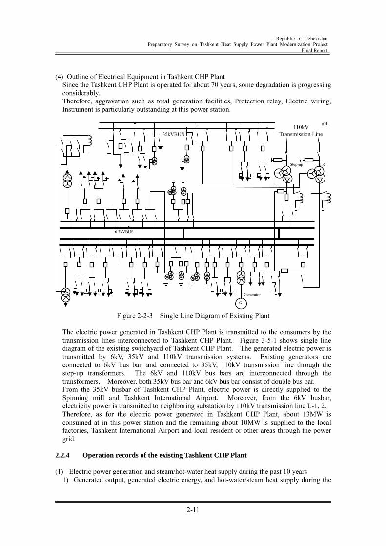
Republic of Uzbekistan
Preparatory Survey on Tashkent Heat Supply Power Plant Modernization Project Final Report
2-11
(4) Outline of Electrical Equipment in Tashkent CHP Plant
Since the Tashkent CHP Plant is operated for about 70 years, some degradation is progressing considerably. Therefore, aggravation such as total generation facilities, Protection relay, Electric wiring, Instrument is particularly outstanding at this power station.
Figure 2-2-3 Single Line Diagram of Existing Plant
The electric power generated in Tashkent CHP Plant is transmitted to the consumers by the transmission lines interconnected to Tashkent CHP Plant. Figure 3-5-1 shows single line diagram of the existing switchyard of Tashkent CHP Plant. The generated electric power is transmitted by 6kV, 35kV and 110kV transmission systems. Existing generators are connected to 6kV bus bar, and connected to 35kV, 110kV transmission line through the step-up transformers. The 6kV and 110kV bus bars are interconnected through the transformers. Moreover, both 35kV bus bar and 6kV bus bar consist of double bus bar. From the 35kV busbar of Tashkent CHP Plant, electric power is directly supplied to the Spinning mill and Tashkent International Airport. Moreover, from the 6kV busbar, electricity power is transmitted to neighboring substation by 110kV transmission line L-1, 2. Therefore, as for the electric power generated in Tashkent CHP Plant, about 13MW is consumed at in this power station and the remaining about 10MW is supplied to the local factories, Tashkent International Airport and local resident or other areas through the power grid.
2.2.4 Operation records of the existing Tashkent CHP Plant (1) Electric power generation and steam/hot-water heat supply during the past 10 years
1) Generated output, generated electric energy, and hot-water/steam heat supply during the
G
6.3kVBUS
110kV Transmission Line
#2L
Generator
Step-up TR
35kVBUS
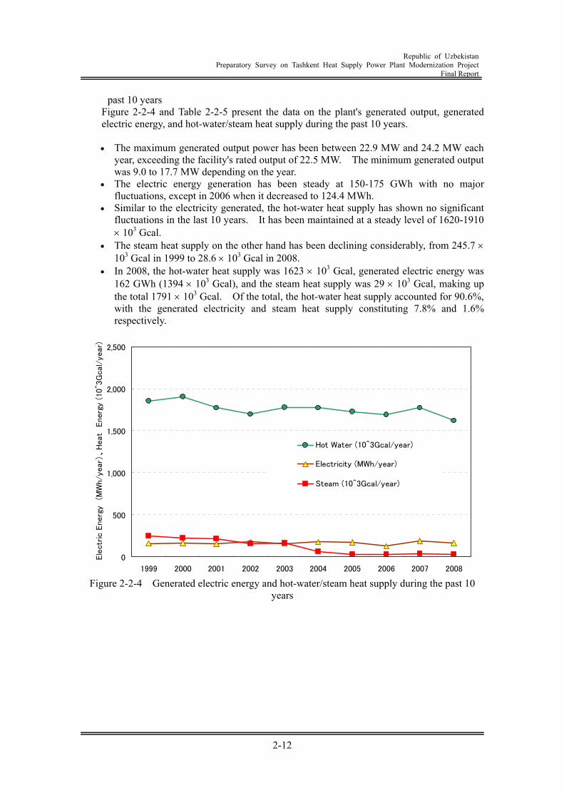
Republic of Uzbekistan
Preparatory Survey on Tashkent Heat Supply Power Plant Modernization Project Final Report
2-12
past 10 years Figure 2-2-4 and Table 2-2-5 present the data on the plant's generated output, generated electric energy, and hot-water/steam heat supply during the past 10 years.
The maximum generated output power has been between 22.9 MW and 24.2 MW each
year, exceeding the facility's rated output of 22.5 MW. The minimum generated output was 9.0 to 17.7 MW depending on the year.
The electric energy generation has been steady at 150-175 GWh with no major fluctuations, except in 2006 when it decreased to 124.4 MWh.
Similar to the electricity generated, the hot-water heat supply has shown no significant fluctuations in the last 10 years. It has been maintained at a steady level of 1620-1910 103 Gcal.
The steam heat supply on the other hand has been declining considerably, from 245.7 103 Gcal in 1999 to 28.6 103 Gcal in 2008.
In 2008, the hot-water heat supply was 1623 103 Gcal, generated electric energy was 162 GWh (1394 103 Gcal), and the steam heat supply was 29 103 Gcal, making up the total 1791 103 Gcal. Of the total, the hot-water heat supply accounted for 90.6%, with the generated electricity and steam heat supply constituting 7.8% and 1.6% respectively.
0
500
1,000
1,500
2,000
2,500
1999 2000 2001 2002 2003 2004 2005 2006 2007 2008
Ele
ctr
ic E
nerg
y (M
Wh/yea
r)、
Heat
Energ
y (
10^3
Gcal/
year)
Hot Water (10^3Gcal/year)
Electricity (MWh/year)
Steam (10^3Gcal/year)
Figure 2-2-4 Generated electric energy and hot-water/steam heat supply during the past 10
years
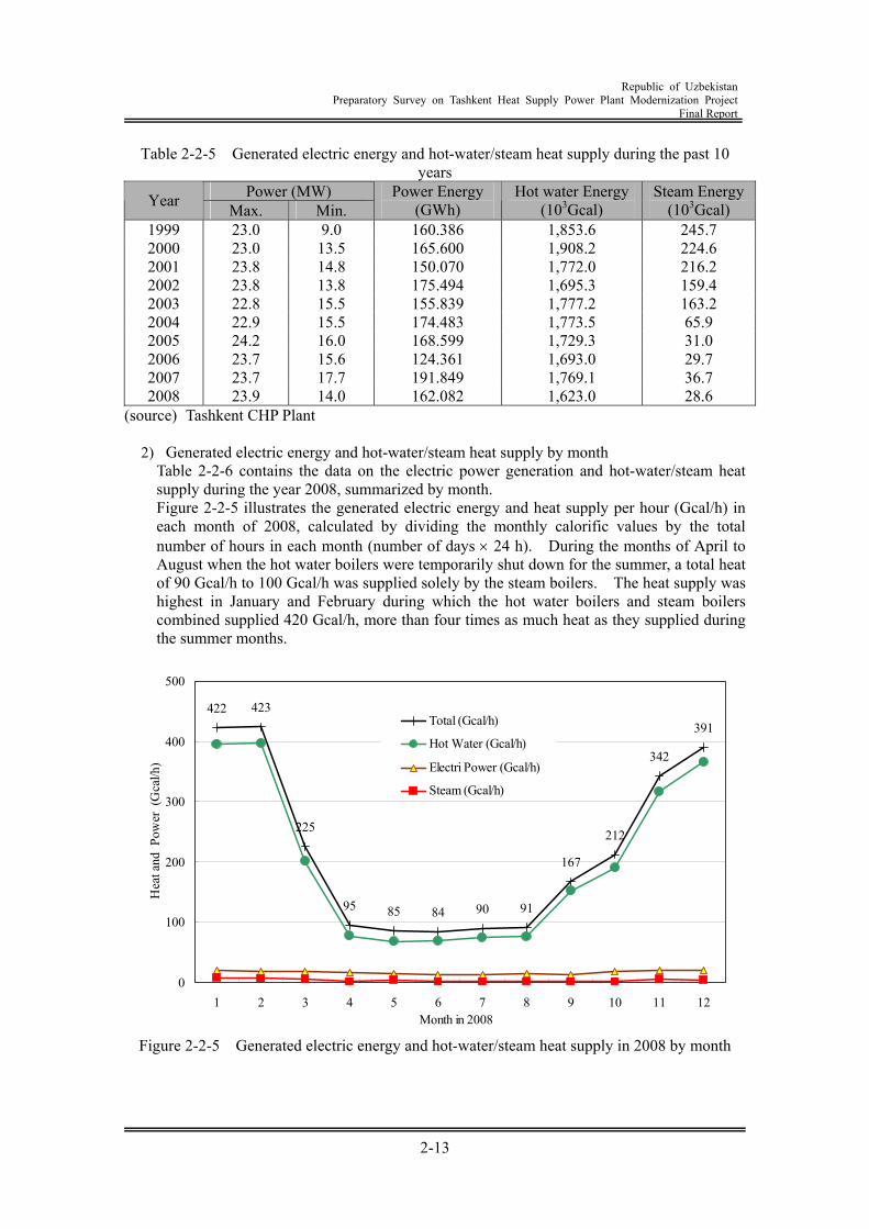
Republic of Uzbekistan
Preparatory Survey on Tashkent Heat Supply Power Plant Modernization Project Final Report
2-13
Table 2-2-5 Generated electric energy and hot-water/steam heat supply during the past 10 years
Power (MW) Year Max. Min. Power Energy
(GWh) Hot water Energy
(103Gcal) Steam Energy
(103Gcal) 1999 23.0 9.0 160.386 1,853.6 245.7 2000 23.0 13.5 165.600 1,908.2 224.6 2001 23.8 14.8 150.070 1,772.0 216.2 2002 23.8 13.8 175.494 1,695.3 159.4 2003 22.8 15.5 155.839 1,777.2 163.2 2004 22.9 15.5 174.483 1,773.5 65.9 2005 24.2 16.0 168.599 1,729.3 31.0 2006 23.7 15.6 124.361 1,693.0 29.7 2007 23.7 17.7 191.849 1,769.1 36.7 2008 23.9 14.0 162.082 1,623.0 28.6
(source) Tashkent CHP Plant
2) Generated electric energy and hot-water/steam heat supply by month Table 2-2-6 contains the data on the electric power generation and hot-water/steam heat supply during the year 2008, summarized by month. Figure 2-2-5 illustrates the generated electric energy and heat supply per hour (Gcal/h) in each month of 2008, calculated by dividing the monthly calorific values by the total number of hours in each month (number of days 24 h). During the months of April to August when the hot water boilers were temporarily shut down for the summer, a total heat of 90 Gcal/h to 100 Gcal/h was supplied solely by the steam boilers. The heat supply was highest in January and February during which the hot water boilers and steam boilers combined supplied 420 Gcal/h, more than four times as much heat as they supplied during the summer months.
422 423
225
95 85 84 90 91
167
212
342
391
0
100
200
300
400
500
1 2 3 4 5 6 7 8 9 10 11 12Month in 2008
Hea
t and
Pow
er (G
cal/h
)
Total (Gcal/h)
Hot Water (Gcal/h)
Electri Power (Gcal/h)
Steam (Gcal/h)
Figure 2-2-5 Generated electric energy and hot-water/steam heat supply in 2008 by month
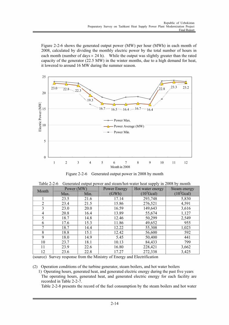
Republic of Uzbekistan
Preparatory Survey on Tashkent Heat Supply Power Plant Modernization Project Final Report
2-14
Figure 2-2-6 shows the generated output power (MW) per hour (MWh) in each month of 2008, calculated by dividing the monthly electric power by the total number of hours in each month (number of days 24 h). While the output was slightly greater than the rated capacity of the generator (22.5 MW) in the winter months, due to a high demand for heat, it lowered to around 16 MW during the summer season.
23.0 22.8 22.3
19.3
16.7 16.5 16.4 16.7 16.4
22.8 23.3 23.2
0
5
10
15
20
25
1 2 3 4 5 6 7 8 9 10 11 12Month in 2008
Elec
tric
Pow
er (M
W)
Power Max.
Power Average (MW)
Power Min.
Figure 2-2-6 Generated output power in 2008 by month
Table 2-2-6 Generated output power and steam/hot-water heat supply in 2008 by month
Power (MW) Month Max. Min. Power Energy
(GWh) Hot water energy
(103Gcal) Steam energy
(103Gcal) 1 23.5 21.6 17.14 293,748 5,830 2 23.4 21.5 15.86 276,521 4,591 3 23.0 20.0 16.59 149,643 3,616 4 20.8 16.4 13.89 55,674 1,127 5 18.7 14.8 12.46 50,299 2,549 6 17.6 15.3 11.86 49,652 955 7 18.7 14.4 12.22 55,308 1,023 8 18.8 15.1 12.42 56,600 592 9 18.0 14.9 5.45 50,400 441
10 23.7 18.1 10.13 84,433 799 11 23.9 22.6 16.80 228,421 3,662 12 23.6 22.8 17.27 272,338 3,425
(source) Survey response from the Ministry of Energy and Electrification (2) Operation conditions of the turbine generator, steam boilers, and hot water boilers
1) Operating hours, generated heat, and generated electric energy during the past five years The operating hours, generated heat, and generated electric energy for each facility are recorded in Table 2-2-7. Table 2-2-8 presents the record of the fuel consumption by the steam boilers and hot water
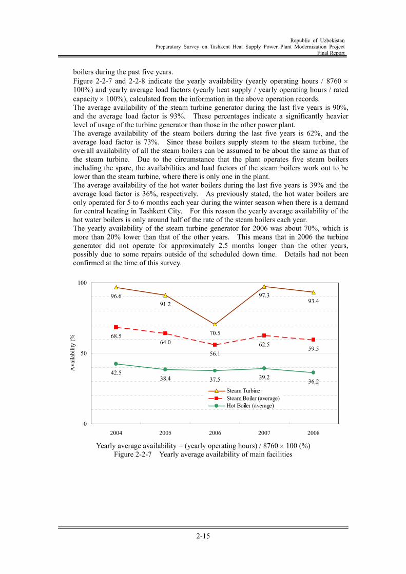
Republic of Uzbekistan
Preparatory Survey on Tashkent Heat Supply Power Plant Modernization Project Final Report
2-15
boilers during the past five years. Figure 2-2-7 and 2-2-8 indicate the yearly availability (yearly operating hours / 8760 100%) and yearly average load factors (yearly heat supply / yearly operating hours / rated capacity 100%), calculated from the information in the above operation records. The average availability of the steam turbine generator during the last five years is 90%, and the average load factor is 93%. These percentages indicate a significantly heavier level of usage of the turbine generator than those in the other power plant. The average availability of the steam boilers during the last five years is 62%, and the average load factor is 73%. Since these boilers supply steam to the steam turbine, the overall availability of all the steam boilers can be assumed to be about the same as that of the steam turbine. Due to the circumstance that the plant operates five steam boilers including the spare, the availabilities and load factors of the steam boilers work out to be lower than the steam turbine, where there is only one in the plant. The average availability of the hot water boilers during the last five years is 39% and the average load factor is 36%, respectively. As previously stated, the hot water boilers are only operated for 5 to 6 months each year during the winter season when there is a demand for central heating in Tashkent City. For this reason the yearly average availability of the hot water boilers is only around half of the rate of the steam boilers each year. The yearly availability of the steam turbine generator for 2006 was about 70%, which is more than 20% lower than that of the other years. This means that in 2006 the turbine generator did not operate for approximately 2.5 months longer than the other years, possibly due to some repairs outside of the scheduled down time. Details had not been confirmed at the time of this survey.
96.691.2
70.5
97.393.4
68.564.0
56.162.5
59.5
42.538.4 37.5 39.2
36.2
0
50
100
2004 2005 2006 2007 2008
Ava
ilabi
lity
(%
Steam TurbineSteam Boiler (average)Hot Boiler (average)
Yearly average availability = (yearly operating hours) / 8760 100 (%)
Figure 2-2-7 Yearly average availability of main facilities
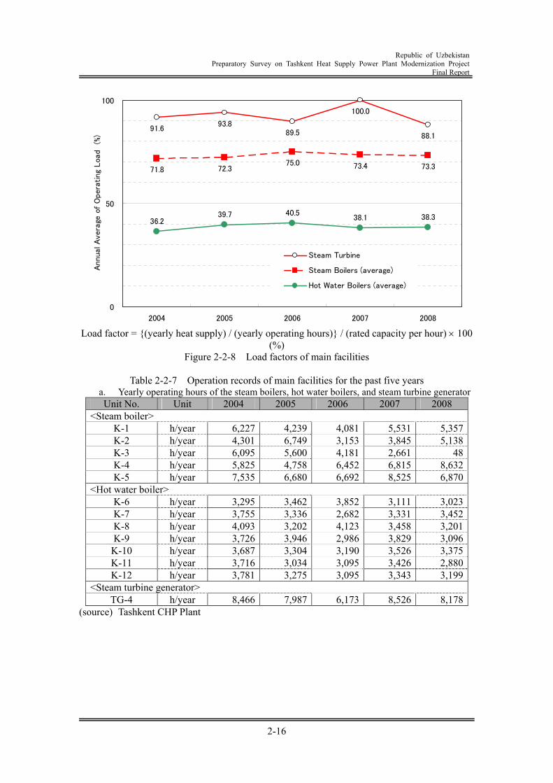
Republic of Uzbekistan
Preparatory Survey on Tashkent Heat Supply Power Plant Modernization Project Final Report
2-16
91.693.8
89.5
100.0
88.1
71.8 72.375.0 73.4 73.3
36.239.7 40.5
38.1 38.3
0
50
100
2004 2005 2006 2007 2008
Annua
l A
ver
age
of
Opera
ting
Load
(%)
Steam Turbine
Steam Boilers (average)
Hot Water Boilers (average)
Load factor = {(yearly heat supply) / (yearly operating hours)} / (rated capacity per hour) 100
(%) Figure 2-2-8 Load factors of main facilities
Table 2-2-7 Operation records of main facilities for the past five years
a. Yearly operating hours of the steam boilers, hot water boilers, and steam turbine generator Unit No. Unit 2004 2005 2006 2007 2008
<Steam boiler> K-1 h/year 6,227 4,239 4,081 5,531 5,357K-2 h/year 4,301 6,749 3,153 3,845 5,138K-3 h/year 6,095 5,600 4,181 2,661 48K-4 h/year 5,825 4,758 6,452 6,815 8,632K-5 h/year 7,535 6,680 6,692 8,525 6,870
<Hot water boiler> K-6 h/year 3,295 3,462 3,852 3,111 3,023K-7 h/year 3,755 3,336 2,682 3,331 3,452K-8 h/year 4,093 3,202 4,123 3,458 3,201K-9 h/year 3,726 3,946 2,986 3,829 3,096
K-10 h/year 3,687 3,304 3,190 3,526 3,375K-11 h/year 3,716 3,034 3,095 3,426 2,880K-12 h/year 3,781 3,275 3,095 3,343 3,199
<Steam turbine generator> TG-4 h/year 8,466 7,987 6,173 8,526 8,178
(source) Tashkent CHP Plant
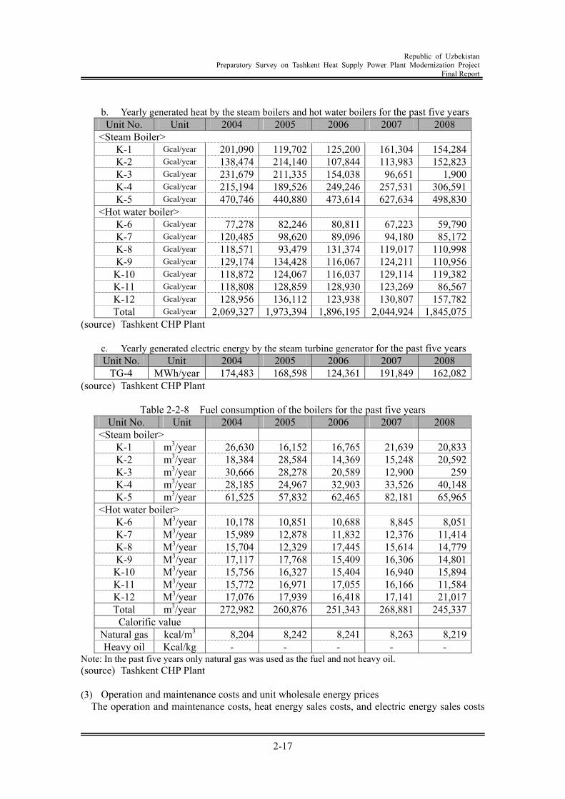
Republic of Uzbekistan
Preparatory Survey on Tashkent Heat Supply Power Plant Modernization Project Final Report
2-17
b. Yearly generated heat by the steam boilers and hot water boilers for the past five years Unit No. Unit 2004 2005 2006 2007 2008
<Steam Boiler> K-1 Gcal/year 201,090 119,702 125,200 161,304 154,284 K-2 Gcal/year 138,474 214,140 107,844 113,983 152,823 K-3 Gcal/year 231,679 211,335 154,038 96,651 1,900 K-4 Gcal/year 215,194 189,526 249,246 257,531 306,591 K-5 Gcal/year 470,746 440,880 473,614 627,634 498,830
<Hot water boiler> K-6 Gcal/year 77,278 82,246 80,811 67,223 59,790 K-7 Gcal/year 120,485 98,620 89,096 94,180 85,172 K-8 Gcal/year 118,571 93,479 131,374 119,017 110,998 K-9 Gcal/year 129,174 134,428 116,067 124,211 110,956
K-10 Gcal/year 118,872 124,067 116,037 129,114 119,382 K-11 Gcal/year 118,808 128,859 128,930 123,269 86,567 K-12 Gcal/year 128,956 136,112 123,938 130,807 157,782 Total Gcal/year 2,069,327 1,973,394 1,896,195 2,044,924 1,845,075
(source) Tashkent CHP Plant
c. Yearly generated electric energy by the steam turbine generator for the past five years Unit No. Unit 2004 2005 2006 2007 2008
TG-4 MWh/year 174,483 168,598 124,361 191,849 162,082 (source) Tashkent CHP Plant
Table 2-2-8 Fuel consumption of the boilers for the past five years Unit No. Unit 2004 2005 2006 2007 2008
<Steam boiler> K-1 m3/year 26,630 16,152 16,765 21,639 20,833 K-2 m3/year 18,384 28,584 14,369 15,248 20,592 K-3 m3/year 30,666 28,278 20,589 12,900 259 K-4 m3/year 28,185 24,967 32,903 33,526 40,148 K-5 m3/year 61,525 57,832 62,465 82,181 65,965
<Hot water boiler> K-6 M3/year 10,178 10,851 10,688 8,845 8,051 K-7 M3/year 15,989 12,878 11,832 12,376 11,414 K-8 M3/year 15,704 12,329 17,445 15,614 14,779 K-9 M3/year 17,117 17,768 15,409 16,306 14,801
K-10 M3/year 15,756 16,327 15,404 16,940 15,894 K-11 M3/year 15,772 16,971 17,055 16,166 11,584 K-12 M3/year 17,076 17,939 16,418 17,141 21,017 Total m3/year 272,982 260,876 251,343 268,881 245,337
Calorific value Natural gas kcal/m3 8,204 8,242 8,241 8,263 8,219 Heavy oil Kcal/kg - - - - -
Note: In the past five years only natural gas was used as the fuel and not heavy oil. (source) Tashkent CHP Plant (3) Operation and maintenance costs and unit wholesale energy prices
The operation and maintenance costs, heat energy sales costs, and electric energy sales costs
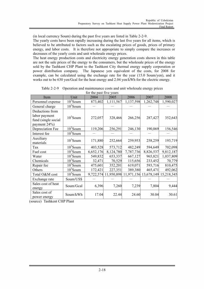
Republic of Uzbekistan
Preparatory Survey on Tashkent Heat Supply Power Plant Modernization Project Final Report
2-18
(in local currency Soum) during the past five years are listed in Table 2-2-9. The yearly costs have been rapidly increasing during the last five years for all items, which is believed to be attributed to factors such as the escalating prices of goods, prices of primary energy, and labor costs. It is therefore not appropriate to simply compare the increases or decreases of the yearly costs and unit wholesale energy prices. The heat energy production costs and electricity energy generation costs shown in this table are not the sale prices of the energy to the consumers, but the wholesale prices of the energy sold by the Tashkent CHP Plant to the Tashkent City thermal energy supply corporation or power distribution company. The Japanese yen equivalent of the costs, for 2008 for example, can be calculated using the exchange rate for the year (15.0 Soum/yen), and it works out to be 630 yen/Gcal for the heat energy and 2.04 yen/kWh for the electric energy.
Table 2-2-9 Operation and maintenance costs and unit wholesale energy prices
for the past five years Item Unit 2004 2005 2006 2007 2008
Personnel expense 103Soum 873,402 1,111,567 1,137,598 1,262,748 1,590,027General charge 103Soum - - - - - Deductions from labor payment fund (single social payment 24%)
103Soum 272,057 328,466 266,256 287,427 352,643
Depreciation Fee 103Soum 119,206 256,291 246,130 190,069 156,546Interest fee 103Soum - - - - - Auxiliary materials 103Soum 171,880 252,664 259,953 258,259 193,719
Tax 103Soum 403,528 573,712 482,249 594,649 702,098Fuel cost 103Soum 6,652,176 8,124,780 7,787,736 8,826,537 9,812,187Water 103Soum 549,832 653,337 667,127 965,821 1,037,809Chemicals 103Soum 32,471 70,529 115,656 233,452 70,779Repair fee 103Soum 475,601 352,201 619,071 593,716 810,475Others 103Soum 172,421 227,351 389,380 465,471 492,062Total O&M cost 103Soum 9,722,574 11,950,898 11,971,156 13,678,149 15,218,345Exchange rate Soum/US$ - - - - - Sales cost of heat energy Soum/Gcal 6,396 7,260 7,239 7,804 9,444
Sales cost of power energy Soum/kWh 17.04 22.44 24.60 30.04 30.61
(source) Tashkent CHP Plant
Republic of Uzbekistan
Preparatory Survey on Tashkent Heat Supply Power Plant Modernization Project Final Report
3-1
Chapter 3 Implementation Plan of Japanese ODA Loan Project 3.1 Concept Design 3.1.1 Prior Conditions In the process of the modernization project using the GT cogeneration system (hereinafter referred to as "GTCS") of the Tashkent Heat and Power Supply Plant (hereinafter referred to as " Tashkent CHP Plant"), "Feasibility Study for Tashkent Heat and Power Plant Modernizing Project " -- a Basic Research for the Promotion of Joint Implementation Program to be operated by NEDO for the fiscal year 2000. Based on that, in fiscal 2004, the Republic of Uzbekistan applied a Japanese ODA Loan for the project. In fiscal 2006, the "Preliminary Feasibility Study of Investment Project of Construction of Gas Turbine Unit at Tashkent Heat and Power Supply Plant" (hereinafter referred to as "Pre-FS") was implemented and approved in the Republic of Uzbekistan. In this Pre-FS, the scale of the new plant to be introduced was set at 80 MW in terms of electric power generation capacity and 100 Gcal per hour in terms of heat energy generation capacity. Installation of three 25 MW-class GTCS was included in the Pre-FS. After that, the "Feasibility study on energy saving model business at cogeneration power plant" was conducted by NEDO in fiscal 2007. This was followed by the "Feasibility study on high-efficiency gas turbine cogeneration model business at cogeneration power plant (Uzbekistan)" in fiscal 2008 and the installation of one 25 MW-class GTCS is currently under consideration (hereinafter referred to as "NEDO Project"). Based on the above-mentioned activities, the following study has been made assuming that introduction of two 25 MW class GTCSs (electric power generation capacity of 50 MW and heat energy generation capacity of 70 Gcal/h) would be considered in the Japanese ODA Loan Project (hereinafter referred to as "the Project") for the Tashkent Heat and Power Supply Plant. 3.1.2 Cogeneration system The cogeneration system is a system for simultaneous production of electricity and heat from one type of primary energy, and is characterized by extremely high energy usage efficiency. In the system currently put into commercial use, electric power is generated by a gas turbine, diesel engine and boiler-steam turbine as the main equipments and heat is supplied as hot water and steam. In the system where a gas turbine and boiler-steam turbine are used as the main equipments, the generated heat is utilized in a large-sized regional heat supply network for urban areas, on the one hand. On the other hand, in the system where a diesel engine is used as the main equipment, the ratio of heat energy generation with respect to electric power generation (ratio of heat to electricity = heat/electricity ratio of the identical heat unit) is small (one or less). The heat is used at most in a hot water supply system or space heating equipment within the power plant. Thus, the system using the diesel engine as the main equipment is not included in this survey. In the cogeneration system, the energy usage efficiency is increased as the heat-to-electricity ratio is higher. Accordingly, the heat-to-electricity ratio plays the major factor in selecting a cogeneration system. In the cogeneration system using a boiler-steam turbine as the main equipment, the steam meeting the steam requirements is generally extracted from the intermediate stage of the steam turbine. When this system is adopted, designing is possible until the heat-to-electricity ratio is 10 or more. It is selected when a greater amount of heat supply is required. The heat supply capacity of new plant required in the Project is 70 Gcal per hour (equivalent to 80 MW). Thus, in the cogeneration system using the boiler-steam turbine as the main equipment, the capacity of
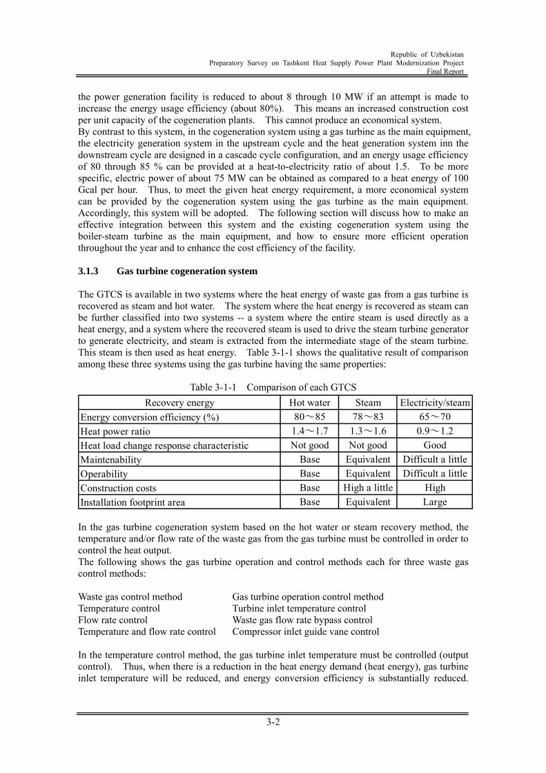
Republic of Uzbekistan
Preparatory Survey on Tashkent Heat Supply Power Plant Modernization Project Final Report
3-2
the power generation facility is reduced to about 8 through 10 MW if an attempt is made to increase the energy usage efficiency (about 80%). This means an increased construction cost per unit capacity of the cogeneration plants. This cannot produce an economical system. By contrast to this system, in the cogeneration system using a gas turbine as the main equipment, the electricity generation system in the upstream cycle and the heat generation system inn the downstream cycle are designed in a cascade cycle configuration, and an energy usage efficiency of 80 through 85 % can be provided at a heat-to-electricity ratio of about 1.5. To be more specific, electric power of about 75 MW can be obtained as compared to a heat energy of 100 Gcal per hour. Thus, to meet the given heat energy requirement, a more economical system can be provided by the cogeneration system using the gas turbine as the main equipment. Accordingly, this system will be adopted. The following section will discuss how to make an effective integration between this system and the existing cogeneration system using the boiler-steam turbine as the main equipment, and how to ensure more efficient operation throughout the year and to enhance the cost efficiency of the facility. 3.1.3 Gas turbine cogeneration system The GTCS is available in two systems where the heat energy of waste gas from a gas turbine is recovered as steam and hot water. The system where the heat energy is recovered as steam can be further classified into two systems -- a system where the entire steam is used directly as a heat energy, and a system where the recovered steam is used to drive the steam turbine generator to generate electricity, and steam is extracted from the intermediate stage of the steam turbine. This steam is then used as heat energy. Table 3-1-1 shows the qualitative result of comparison among these three systems using the gas turbine having the same properties:
Table 3-1-1 Comparison of each GTCS
In the gas turbine cogeneration system based on the hot water or steam recovery method, the temperature and/or flow rate of the waste gas from the gas turbine must be controlled in order to control the heat output. The following shows the gas turbine operation and control methods each for three waste gas control methods: Waste gas control method Gas turbine operation control method Temperature control Turbine inlet temperature control Flow rate control Waste gas flow rate bypass control Temperature and flow rate control Compressor inlet guide vane control In the temperature control method, the gas turbine inlet temperature must be controlled (output control). Thus, when there is a reduction in the heat energy demand (heat energy), gas turbine inlet temperature will be reduced, and energy conversion efficiency is substantially reduced.
Recovery energy Hot water Steam Electricity/steamEnergy conversion efficiency (%) 80~85 78~83 65~70Heat power ratio 1.4~1.7 1.3~1.6 0.9~1.2Heat load change response characteristic Not good Not good GoodMaintenability Base Equivalent Difficult a littleOperability Base Equivalent Difficult a littleConstruction costs Base High a little HighInstallation footprint area Base Equivalent Large
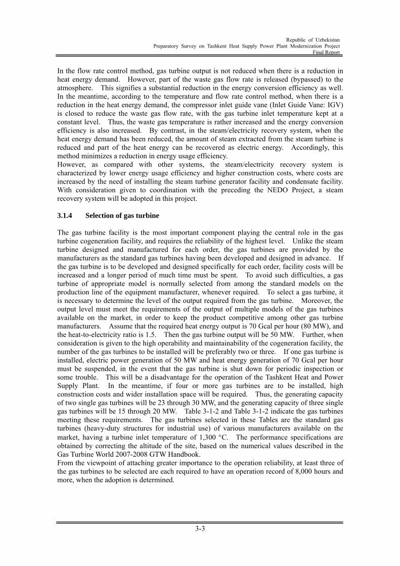
Republic of Uzbekistan
Preparatory Survey on Tashkent Heat Supply Power Plant Modernization Project Final Report
3-3
In the flow rate control method, gas turbine output is not reduced when there is a reduction in heat energy demand. However, part of the waste gas flow rate is released (bypassed) to the atmosphere. This signifies a substantial reduction in the energy conversion efficiency as well. In the meantime, according to the temperature and flow rate control method, when there is a reduction in the heat energy demand, the compressor inlet guide vane (Inlet Guide Vane: IGV) is closed to reduce the waste gas flow rate, with the gas turbine inlet temperature kept at a constant level. Thus, the waste gas temperature is rather increased and the energy conversion efficiency is also increased. By contrast, in the steam/electricity recovery system, when the heat energy demand has been reduced, the amount of steam extracted from the steam turbine is reduced and part of the heat energy can be recovered as electric energy. Accordingly, this method minimizes a reduction in energy usage efficiency. However, as compared with other systems, the steam/electricity recovery system is characterized by lower energy usage efficiency and higher construction costs, where costs are increased by the need of installing the steam turbine generator facility and condensate facility. With consideration given to coordination with the preceding the NEDO Project, a steam recovery system will be adopted in this project. 3.1.4 Selection of gas turbine The gas turbine facility is the most important component playing the central role in the gas turbine cogeneration facility, and requires the reliability of the highest level. Unlike the steam turbine designed and manufactured for each order, the gas turbines are provided by the manufacturers as the standard gas turbines having been developed and designed in advance. If the gas turbine is to be developed and designed specifically for each order, facility costs will be increased and a longer period of much time must be spent. To avoid such difficulties, a gas turbine of appropriate model is normally selected from among the standard models on the production line of the equipment manufacturer, whenever required. To select a gas turbine, it is necessary to determine the level of the output required from the gas turbine. Moreover, the output level must meet the requirements of the output of multiple models of the gas turbines available on the market, in order to keep the product competitive among other gas turbine manufacturers. Assume that the required heat energy output is 70 Gcal per hour (80 MW), and the heat-to-electricity ratio is 1.5. Then the gas turbine output will be 50 MW. Further, when consideration is given to the high operability and maintainability of the cogeneration facility, the number of the gas turbines to be installed will be preferably two or three. If one gas turbine is installed, electric power generation of 50 MW and heat energy generation of 70 Gcal per hour must be suspended, in the event that the gas turbine is shut down for periodic inspection or some trouble. This will be a disadvantage for the operation of the Tashkent Heat and Power Supply Plant. In the meantime, if four or more gas turbines are to be installed, high construction costs and wider installation space will be required. Thus, the generating capacity of two single gas turbines will be 23 through 30 MW, and the generating capacity of three single gas turbines will be 15 through 20 MW. Table 3-1-2 and Table 3-1-2 indicate the gas turbines meeting these requirements. The gas turbines selected in these Tables are the standard gas turbines (heavy-duty structures for industrial use) of various manufacturers available on the market, having a turbine inlet temperature of 1,300 C. The performance specifications are obtained by correcting the altitude of the site, based on the numerical values described in the Gas Turbine World 2007-2008 GTW Handbook. From the viewpoint of attaching greater importance to the operation reliability, at least three of the gas turbines to be selected are each required to have an operation record of 8,000 hours and more, when the adoption is determined.
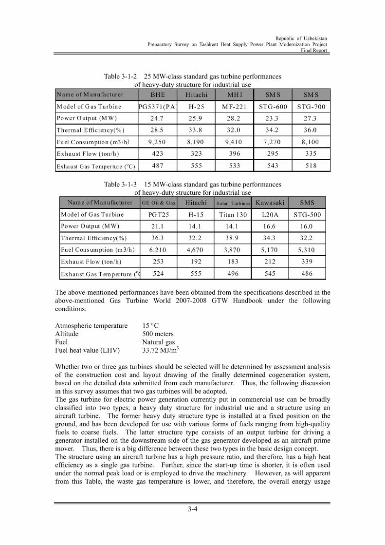
Republic of Uzbekistan
Preparatory Survey on Tashkent Heat Supply Power Plant Modernization Project Final Report
3-4
Table 3-1-2 25 MW-class standard gas turbine performances
of heavy-duty structure for industrial use N ame of M anufacturer BHE Hitachi MH I SM S SM S
M odel of G as Turbine PG5371(PA) H-25 M F-221 STG-600 STG-700
Power O utput (M W) 24.7 25.9 28.2 23.3 27.3
Thermal Efficiency(%) 28.5 33.8 32.0 34.2 36.0
Fuel Consumption (m3/h) 9,250 8,190 9,410 7,270 8,100
Exhaust F low ( ton/h) 423 323 396 295 335
Exhaust Gas Te mper ture (oC) 487 555 533 543 518
Table 3-1-3 15 MW-class standard gas turbine performances of heavy-duty structure for industrial use
Nam e of M anufacturer GE Oil & Gas Hitachi Solar Turb ines Kawasaki SMS
Model of Gas Turbine PG T25 H-15 Titan 130 L20A STG-500
Power Output (MW) 21.1 14.1 14.1 16.6 16.0
Thermal Efficiency(%) 36.3 32.2 38.9 34.3 32.2
Fuel Consum ption (m 3/h) 6,210 4,670 3,870 5,170 5,310
Exhaust F low (ton/h) 253 192 183 212 339
Exhaust Gas T em perture (oC 524 555 496 545 486 The above-mentioned performances have been obtained from the specifications described in the above-mentioned Gas Turbine World 2007-2008 GTW Handbook under the following conditions: Atmospheric temperature 15 C Altitude 500 meters Fuel Natural gas Fuel heat value (LHV) 33.72 MJ/m3 Whether two or three gas turbines should be selected will be determined by assessment analysis of the construction cost and layout drawing of the finally determined cogeneration system, based on the detailed data submitted from each manufacturer. Thus, the following discussion in this survey assumes that two gas turbines will be adopted. The gas turbine for electric power generation currently put in commercial use can be broadly classified into two types; a heavy duty structure for industrial use and a structure using an aircraft turbine. The former heavy duty structure type is installed at a fixed position on the ground, and has been developed for use with various forms of fuels ranging from high-quality fuels to coarse fuels. The latter structure type consists of an output turbine for driving a generator installed on the downstream side of the gas generator developed as an aircraft prime mover. Thus, there is a big difference between these two types in the basic design concept. The structure using an aircraft turbine has a high pressure ratio, and therefore, has a high heat efficiency as a single gas turbine. Further, since the start-up time is shorter, it is often used under the normal peak load or is employed to drive the machinery. However, as will apparent from this Table, the waste gas temperature is lower, and therefore, the overall energy usage
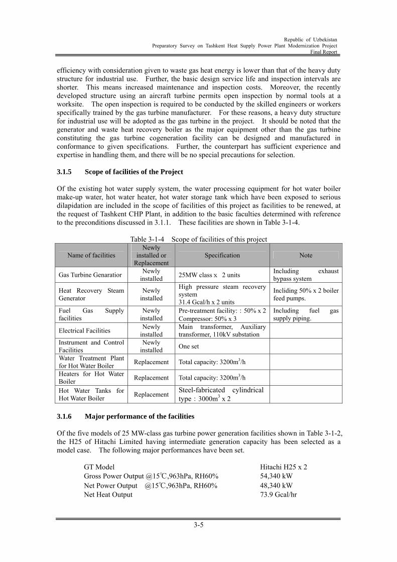
Republic of Uzbekistan
Preparatory Survey on Tashkent Heat Supply Power Plant Modernization Project Final Report
3-5
efficiency with consideration given to waste gas heat energy is lower than that of the heavy duty structure for industrial use. Further, the basic design service life and inspection intervals are shorter. This means increased maintenance and inspection costs. Moreover, the recently developed structure using an aircraft turbine permits open inspection by normal tools at a worksite. The open inspection is required to be conducted by the skilled engineers or workers specifically trained by the gas turbine manufacturer. For these reasons, a heavy duty structure for industrial use will be adopted as the gas turbine in the project. It should be noted that the generator and waste heat recovery boiler as the major equipment other than the gas turbine constituting the gas turbine cogeneration facility can be designed and manufactured in conformance to given specifications. Further, the counterpart has sufficient experience and expertise in handling them, and there will be no special precautions for selection. 3.1.5 Scope of facilities of the Project Of the existing hot water supply system, the water processing equipment for hot water boiler make-up water, hot water heater, hot water storage tank which have been exposed to serious dilapidation are included in the scope of facilities of this project as facilities to be renewed, at the request of Tashkent CHP Plant, in addition to the basic faculties determined with reference to the preconditions discussed in 3.1.1. These facilities are shown in Table 3-1-4.
Table 3-1-4 Scope of facilities of this project
Name of facilities Newly
installed or Replacement
Specification Note
Gas Turbine Genaratior Newly installed 25MW classx 2 units Including exhaust
bypass system
Heat Recovery Steam Generator
Newly installed
High pressure steam recovery system 31.4 Gcal/h x 2 units
Incliding 50% x 2 boiler feed pumps.
Fuel Gas Supply facilities
Newly installed
Pre-treatment facility::50% x 2Compressor: 50% x 3
Including fuel gas supply piping.
Electrical Facilities Newly installed
Main transformer, Auxiliary transformer, 110kV substation
Instrument and Control Facilities
Newly installed One set
Water Treatment Plant for Hot Water Boiler Replacement Total capacity: 3200m3/h
Heaters for Hot Water Boiler Replacement Total capacity: 3200m3/h
Hot Water Tanks for Hot Water Boiler Replacement Steel-fabricated cylindrical
type:3000m3 x 2
3.1.6 Major performance of the facilities Of the five models of 25 MW-class gas turbine power generation facilities shown in Table 3-1-2, the H25 of Hitachi Limited having intermediate generation capacity has been selected as a model case. The following major performances have been set.
GT Model Hitachi H25 x 2 Gross Power Output @15℃,963hPa, RH60% 54,340 kW Net Power Output @15℃,963hPa, RH60% 48,340 kW Net Heat Output 73.9 Gcal/hr

Republic of Uzbekistan
Preparatory Survey on Tashkent Heat Supply Power Plant Modernization Project Final Report
3-6
GT Net Heat Rate (LHV) 12,898 kJ/KWhr Total Net Thermal Efficiency (LHV) 77.5% Plant Load Factor 85% Plant Life 30 years
3.2 Layout Plan The following shows the positions of new facilities to be installed inside Tashkent CHP Plant. In the NEDO project, one gas turbine 25 MW-class GTCS (including the HRSG and generator) will be installed. In the Japanese ODA loan project, two gas turbines 25 MW-class GTCSs (including the HRSG and generator) and 110kV switchyard will also be installed. Because 110 kV transmission line runs towards the west from the candidate site, 110kV switchyard should be located west side of the site. The site for new installation will measure 76 m by 195 m. A study will be required to achieve optimization of the layout of the three 25 MW-class GTCSs (including the HRSG and generator) including those of the NEDO project and 110kV switchyard.
NEDO Scope : One GTCS
JICA Scope: Two GTCS
Feed Water Pipeline
Steam Pipeline
Gas Pipeline
Switchyard
Transmission Line
Figure 3-2-1 Layout plan of New facilities
3.3 Equipment and Material Transportation The study is carried out on the conditions that all equipment required for the project is exported from Japan. Uzbekistan is a landlocked country and the equipment and material is transported to a neighboring country by sea and then to the site by railway and/or truck. Some component packages weigh over 150 tons. It is necessary to use any port as can handle such heavy components. Considering such requirements of transportation, the following route is recommendable as a candidate route.
Republic of Uzbekistan
Preparatory Survey on Tashkent Heat Supply Power Plant Modernization Project Final Report
3-7
Candidate transportation route for heavy objects
Ilychevsk (the Black Sea, Ukraine) Canal transportation
Turkmenbashi (the Caspian Sea, Turkmenistan) Land transportation
Tashkent CHP Plant The canal route between Ilychevsk and Turkmenbashi is unavailable from mid September to late March, so the transportation is possible only during April to early September.
Candidate transportation route for other than heavy objects Antwerp (Belgium) Land transportation
Tashkent CHP Plant This project will be implemented provided that the above mentioned routes will be used. The routes are subject to change depending on the season when the transportation will be conducted. 3.4 Fuel Supply Plan 3.4.1 Gas source The Tashkent CHP Plant uses gas from Bukhara field about 600km west-southwest of Tashkent city. The natural gas development and supply service is under the control of a gas development corporation (Uzgazbyt). The Tashkent CHP Plant receives the fuel gas at the pressure of 1kg/cm2(g). To operate gas turbine on natural gas, it is necessary to install gas compressor to pressurize the gas to approximately 1kg/cm2(g). 3.4.2 Supply capacity According to the natural gas supply agreement with Uzgazbyt, the maximum contract flow rate to the plant is 130,000m3/h. The maximum supply record to the plant in 2008 was about 59,000m3/h. After introduction of this project, the peak consumption of natural gas will increase to about 12,000m3/h. The total value is still smaller than the maximum contract flow rate. 3.5 Electric facilities plan (1) Auxiliary Electrical Facilities
To meet the requirements of the Tashkent CHP Plant side wishing to adopt a form corresponding to the operation of the existing equipment will require changing the generator voltage into 6kV or so. But there will be great constraints due to the distance between the coal yard and the connection point of the outlet of the existing generator. That is, to plan a cable having a large cross section to reduce the voltage drop in long-distance connection cannot be a realistic plan when considered in view of the limitations in the cable bending radius and the difficulty in route selection. Although not in accordance to the Tashkent CHP Plant side's requirements, generator voltage will be set to 11kV, which is a standard value based on the equipment capacity. After the voltage in the same area is increased to 110kV,
Republic of Uzbekistan
Preparatory Survey on Tashkent Heat Supply Power Plant Modernization Project Final Report
3-8
which is voltage used in the new switchyard, via a main transformer, the cable will be buried and led into the switching station. To supply power to the 6kV bus of the existing switchyard, the power will be passed through the 110kV line bus and then reduced in voltage to 6kV and 35kV by the divert existing transformer. In the transmission of power from the generator installed in the new plant site, it is appropriate to install a group of auxiliary components and their controllers nearby. The main equipment configuration will be characterized by the fact that the group of components will be separated in distance from the existing equipment. In consequence, there is no inconvenience in actual operation (Human errors are hard to imagine) even if the new plant differs from the design concept of the existing electrical equipment. The local high-voltage circuit will not be made redundant in view of economic efficiency. This project will be based on a standard configuration, which is much proven in Japan. The auxiliary power supply of the new power generation units will be provided by dedicated unit transformers of each unit. These unit transformers also work as starting transformers. When started, they will cause a reverse receiving flow from the main transformer, thus minimizing the number of switchgears (circuit breakers) of the 110kV circuit. The power supply into the lower-level low-voltage line will be provided with auxiliary transformers designed specifically for each unit and will be reduced to a voltage for the motor control center (MCC) designed specifically for each unit. To maintain the independent operability of the units, an emergency MCC for emergency power supply will be installed specially for each unit. On the other hand, the common load to the three units (include NEDO’s plant) will be provided with a common transformer and will be made operable by switching over power supplies from the abovementioned unit transformers. One emergency generator will be installed for the three units as common equipment. The DC power and UPS equipment will also be installed as common equipment similarly to the emergency generator, and those power will be supplied from the emergency MCC. Power source of them is changeable between the emergency MCC of the two units. Such are the concept and ideas of the main power supply equipment. The power supply for illumination, maintenance, and other distribution boards will be similar or supplied by the common MCC.
(2) Control Systems for Heat and Power Station
Operation and control of the gas turbines, exhaust heat recovery boilers and other equipment to be newly installed uses the operation console and CRT screen located in the operation control room to be constructed adjacent to the gas turbine building. The operation and control of this equipment uses the latest digital DCS control technology. The existing operation and control room should be equipped with a remote control and monitoring board for the new equipment. To ensure smooth and appropriate control of the Tashkent Plant after modernization, it is necessary to establish communication system between the existing and new equipment so that they can receive and send control signals. For this purpose, input/output signal converters should be installed.
(3) Transmission and Substation Facilities
In this project, two 25MW class gas turbine of heat and power supply plant are newly installed. The new power plant is to be installed in the new site and so interconnection will be made by 110kV from the distance-restrictions to the existing switchyard. When the 25 MW class new generators No. 1 or 2 are connected to 110kV bus bar, the existing plant output as much as those new generator output will be stopped. However, the existing generator are connected to the 6kV bus bar of existing switchyard, and this bus bar supplies electric power to 6kV loads, such as 6kv consumers, such as the
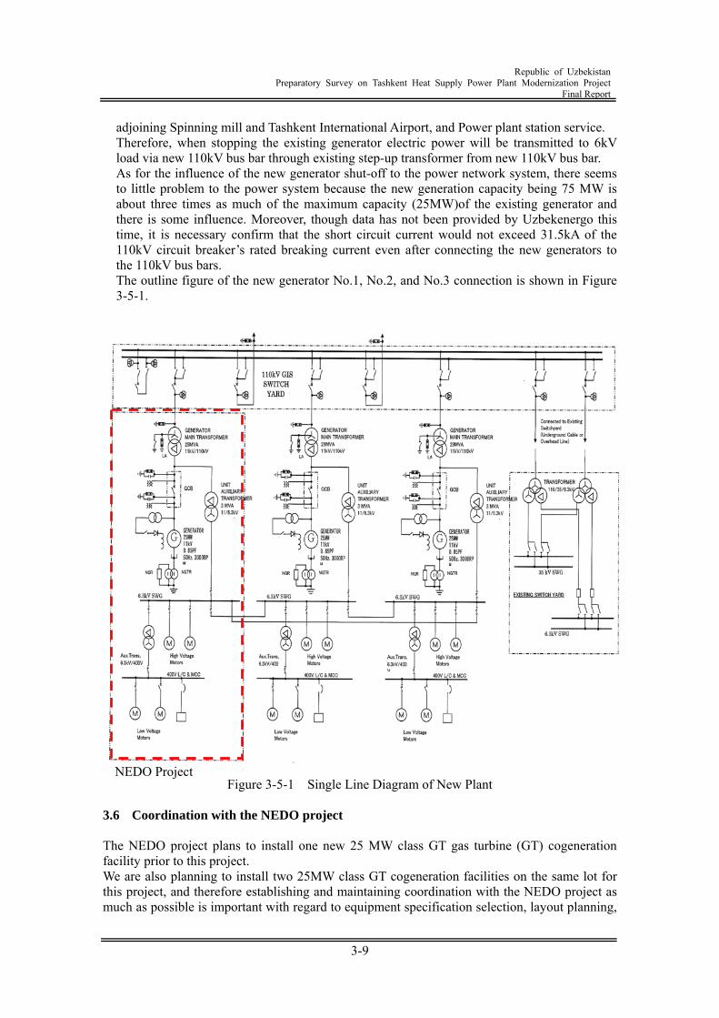
Republic of Uzbekistan
Preparatory Survey on Tashkent Heat Supply Power Plant Modernization Project Final Report
3-9
adjoining Spinning mill and Tashkent International Airport, and Power plant station service. Therefore, when stopping the existing generator electric power will be transmitted to 6kV load via new 110kV bus bar through existing step-up transformer from new 110kV bus bar. As for the influence of the new generator shut-off to the power network system, there seems to little problem to the power system because the new generation capacity being 75 MW is about three times as much of the maximum capacity (25MW)of the existing generator and there is some influence. Moreover, though data has not been provided by Uzbekenergo this time, it is necessary confirm that the short circuit current would not exceed 31.5kA of the 110kV circuit breaker’s rated breaking current even after connecting the new generators to the 110kV bus bars. The outline figure of the new generator No.1, No.2, and No.3 connection is shown in Figure 3-5-1.
Figure 3-5-1 Single Line Diagram of New Plant
3.6 Coordination with the NEDO project The NEDO project plans to install one new 25 MW class GT gas turbine (GT) cogeneration facility prior to this project. We are also planning to install two 25MW class GT cogeneration facilities on the same lot for this project, and therefore establishing and maintaining coordination with the NEDO project as much as possible is important with regard to equipment specification selection, layout planning,
NEDO Project
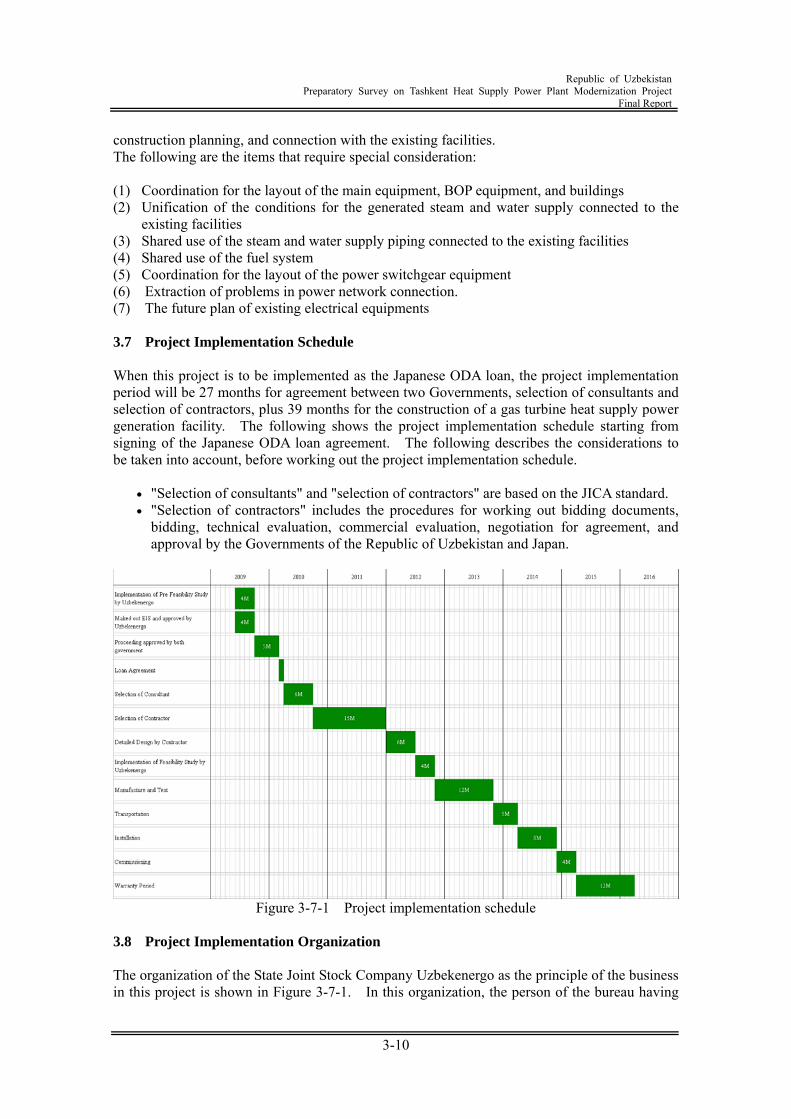
Republic of Uzbekistan
Preparatory Survey on Tashkent Heat Supply Power Plant Modernization Project Final Report
3-10
construction planning, and connection with the existing facilities. The following are the items that require special consideration: (1) Coordination for the layout of the main equipment, BOP equipment, and buildings (2) Unification of the conditions for the generated steam and water supply connected to the
existing facilities (3) Shared use of the steam and water supply piping connected to the existing facilities (4) Shared use of the fuel system (5) Coordination for the layout of the power switchgear equipment (6) Extraction of problems in power network connection. (7) The future plan of existing electrical equipments 3.7 Project Implementation Schedule When this project is to be implemented as the Japanese ODA loan, the project implementation period will be 27 months for agreement between two Governments, selection of consultants and selection of contractors, plus 39 months for the construction of a gas turbine heat supply power generation facility. The following shows the project implementation schedule starting from signing of the Japanese ODA loan agreement. The following describes the considerations to be taken into account, before working out the project implementation schedule.
"Selection of consultants" and "selection of contractors" are based on the JICA standard. "Selection of contractors" includes the procedures for working out bidding documents,
bidding, technical evaluation, commercial evaluation, negotiation for agreement, and approval by the Governments of the Republic of Uzbekistan and Japan.
Figure 3-7-1 Project implementation schedule
3.8 Project Implementation Organization The organization of the State Joint Stock Company Uzbekenergo as the principle of the business in this project is shown in Figure 3-7-1. In this organization, the person of the bureau having
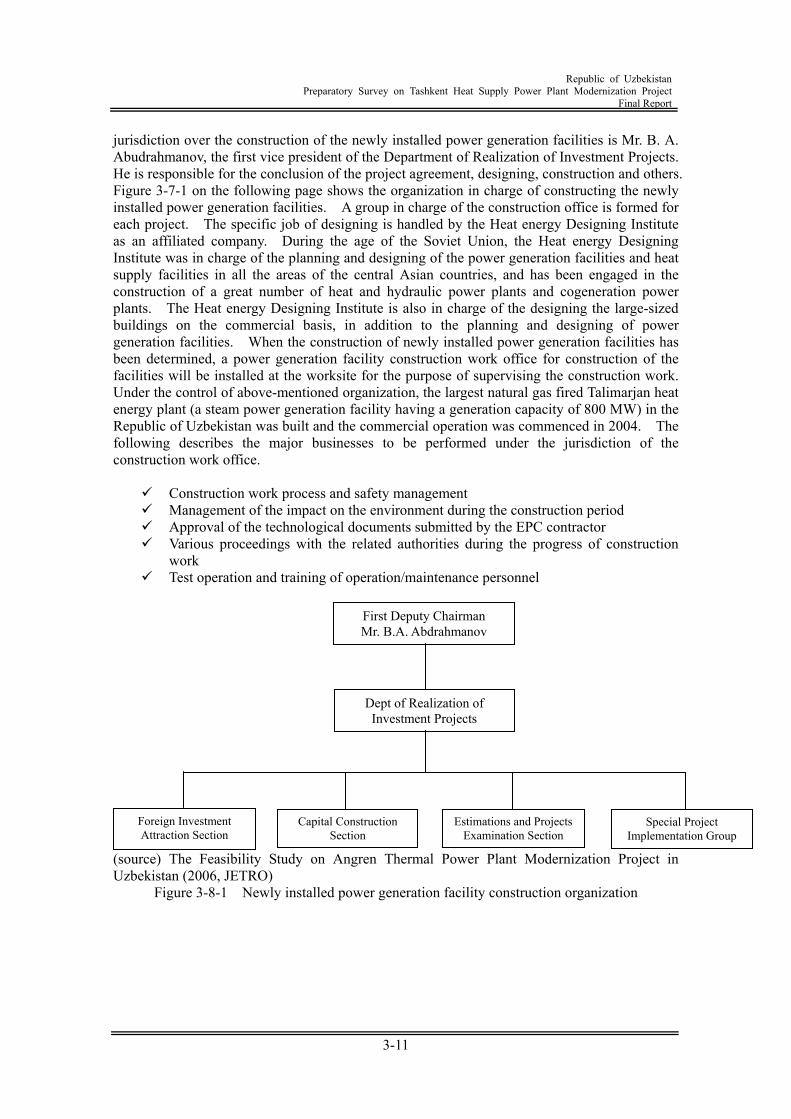
Republic of Uzbekistan
Preparatory Survey on Tashkent Heat Supply Power Plant Modernization Project Final Report
3-11
jurisdiction over the construction of the newly installed power generation facilities is Mr. B. A. Abudrahmanov, the first vice president of the Department of Realization of Investment Projects. He is responsible for the conclusion of the project agreement, designing, construction and others. Figure 3-7-1 on the following page shows the organization in charge of constructing the newly installed power generation facilities. A group in charge of the construction office is formed for each project. The specific job of designing is handled by the Heat energy Designing Institute as an affiliated company. During the age of the Soviet Union, the Heat energy Designing Institute was in charge of the planning and designing of the power generation facilities and heat supply facilities in all the areas of the central Asian countries, and has been engaged in the construction of a great number of heat and hydraulic power plants and cogeneration power plants. The Heat energy Designing Institute is also in charge of the designing the large-sized buildings on the commercial basis, in addition to the planning and designing of power generation facilities. When the construction of newly installed power generation facilities has been determined, a power generation facility construction work office for construction of the facilities will be installed at the worksite for the purpose of supervising the construction work. Under the control of above-mentioned organization, the largest natural gas fired Talimarjan heat energy plant (a steam power generation facility having a generation capacity of 800 MW) in the Republic of Uzbekistan was built and the commercial operation was commenced in 2004. The following describes the major businesses to be performed under the jurisdiction of the construction work office.
Construction work process and safety management Management of the impact on the environment during the construction period Approval of the technological documents submitted by the EPC contractor Various proceedings with the related authorities during the progress of construction
work Test operation and training of operation/maintenance personnel
(source) The Feasibility Study on Angren Thermal Power Plant Modernization Project in Uzbekistan (2006, JETRO)
Figure 3-8-1 Newly installed power generation facility construction organization
Dept of Realization of Investment Projects
Foreign Investment Attraction Section
Capital Construction Section
Estimations and Projects Examination Section
Special Project Implementation Group
First Deputy Chairman Mr. B.A. Abdrahmanov
Republic of Uzbekistan
Preparatory Survey on Tashkent Heat Supply Power Plant Modernization Project Final Report
3-12
3.9 Project Effect 3.9.1 Energy Saving Effect (1) Technical ground for energy saving effect
In the conventional cogeneration power plant composed of a boiler and steam turbine generator, the temperature of working fluid that can be used ranges from 10 through 450 C. The temperature utilized for power generation and thermal energy production are overlapped in this case. By contrast, in the GTCS, the temperature of working fluid that can be used ranges from 120 through 1,300 C. This wide range ensures that power is generated at a high-temperature portion (gas turbine) and thermal energy is produced at a low temperature portion. In the case of cascade usage of the thermal energy in this manner, thermal energy that has failed to be used in the high-temperature portion is allowed to be used in the low temperature portion. So thermal energy conversion efficiency at the high-temperature portion is a 100 percent. Thus, the energy conversion efficiency of GTCS is higher than that of the conventional cogeneration power plants (former one). Accordingly, the energy conversion efficiency as a power plants is higher than that of existing old power plants in the power grid. As a result, the amount of energy usage can be reduced by the amount corresponding to the difference in energy conversion efficiency (energy saving effect).
(2) Base line for calculating the energy saving effect
1) Definition of base line The thermal energy supply capacity of this cogeneration power plant is not changed by the implementation of this project. However, electric energy supply capacity increases. Thus, the amount of electric energy corresponding to the increase in the electric energy supply capacity resulting from implementation of this project is reduced by decreasing the utilization factor of the dilapidated steam turbine power generation plants of other power plants in the same system or by suspending these plants. As a result, the base line for calculating the energy saving effect is provided by the sum of the amount of energy usage of the existing Tashkent CHP Plant and the amount of energy usage when the other existing thermal power plants should generate the same electric energy as of the gas turbine CHP plant introduced by this Project.
2) Calculation method
a) Amount of energy usage in the existing Tashkent CHP Plant The amounts of fuel (natural gas) and fuel calorific value consumed in 2008 in Tashkent CHP Plant are 245.337 103m3 and 8,219kcal/m3, as shown in Table 2-2-8. Accordingly, the amount of energy usage is calculated as follows: Amount of energy usage in the existing Tashkent CHP Plant
= 245.337 103 8,219 10-6 = 2,016.4 103 Gcal/year Incidentally, the annually supplied amounts of hot water, steam and electric energy are as following as given in Table 2-2-5.
Hot water supply energy 1,623.0 103 Gcal/year Steam supply energy 28.6 103 Gcal/year Electricity supply energy 139.4 103 Gcal/year (162.1GWh/year)
Republic of Uzbekistan
Preparatory Survey on Tashkent Heat Supply Power Plant Modernization Project Final Report
3-13
b) Increase of electric energy supply capacity by implementation of this project
In the cogeneration power system made up of a combination of the existing cogeneration power system and the gas turbine cogeneration power system, it is assumed that the heat generation of hot water and steam and the existing steam turbine generator end output do not change from those before implementation of this project. The output of two gas turbine generators (net thermal efficiency) is 48.34 MW. Thus, the annual electric energy is calculated as follows, where the utilization factor is assumed as 85 %: Annual electric energy generated by gas turbine generator = 48.34 8,760 0.85 10-3 = 359.9 GWh/year
The unit conversion by 1.000GWh/y = 859.85 Gcal yields: = 359.9 859.85 = 309.5 103 Gcal/year
Here the annual electric energy produced by the existing steam turbine generator remains unchanged before and after implementation of this project. Accordingly, the value obtained in the above-mentioned procedure corresponds to the increase of the supply capacity of the electric energy by implementation of this project.
c) Increase of energy usage by implementation of this project
The input of the energy used by two gas turbines is 12,898 kJ/kWh 48,340 kW = 148.92 Gcal/h. The annual energy usage is obtained by the following calculation:
Energy used by gas turbines = 148.92 8,760 0.85 10-3 = 1,108.9 103 Gcal/year
In the meantime, the heat recovered from the gas turbine waste gas by the heat recovery boilers is sent to the existing cogeneration power system, and is used to supply heat of the hot water and steam. There is no change in the thermal energy of the hot water and steam supplied by the existing cogeneration power system before and after the implementation of this project. For the thermal energy recovered by the heat recovery boilers, the operation is performed by stopping some of the existing steam boilers or by reducing their loads. Thus, the energy used by the existing steam boilers is reduced. The annual reduction of the energy used by the existing steam boilers is obtained by the following calculation.
Heat recovery by the heat recovery boilers = reduction in the amount of heat outputted by the existing steam boilers = 36.96 Gcal/h 2 boilers = 73.92 Gcal/h Annual reduction in the calorific value outputted by the existing steam boiler = 73.92 8,760 0.85 = 550.4 103 Gcal/year
The thermal efficiency of the existing steam boilers is assumed as 92.0 %, based on the operation record shown in Chapter 2 (where annual average thermal efficiency in the last five years is 91.85 %)
Thus, the annual reduction in the energy used by the existing steam boilers = 550.4 103/0.920 = 598.2 103 Gcal/year
Thus, the increase in the amount of energy usage in Tashkent CHP Plant resulting from the implementation of this project is given as follows, when consideration is given to the increase in the gas turbines and the decrease in the existing steam boilers:
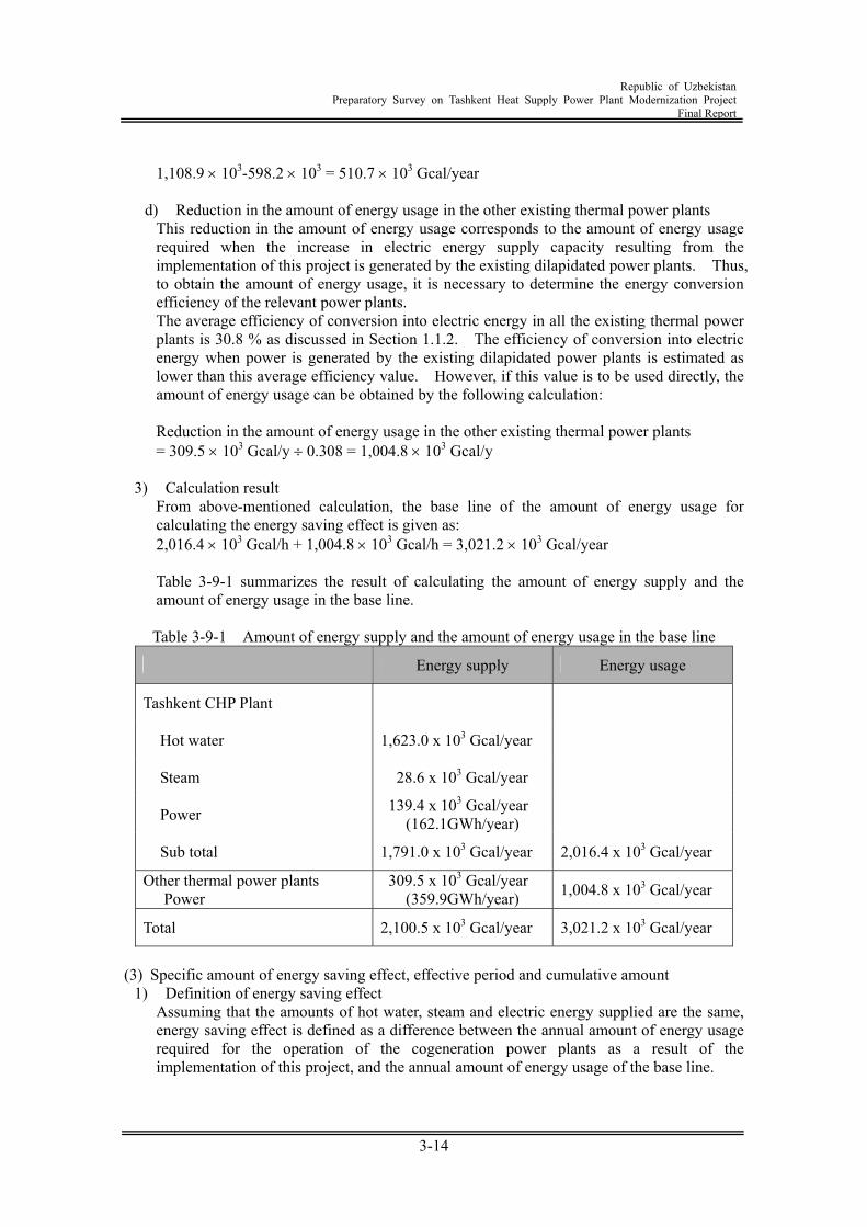
Republic of Uzbekistan
Preparatory Survey on Tashkent Heat Supply Power Plant Modernization Project Final Report
3-14
1,108.9 103-598.2 103 = 510.7 103 Gcal/year
d) Reduction in the amount of energy usage in the other existing thermal power plants
This reduction in the amount of energy usage corresponds to the amount of energy usage required when the increase in electric energy supply capacity resulting from the implementation of this project is generated by the existing dilapidated power plants. Thus, to obtain the amount of energy usage, it is necessary to determine the energy conversion efficiency of the relevant power plants. The average efficiency of conversion into electric energy in all the existing thermal power plants is 30.8 % as discussed in Section 1.1.2. The efficiency of conversion into electric energy when power is generated by the existing dilapidated power plants is estimated as lower than this average efficiency value. However, if this value is to be used directly, the amount of energy usage can be obtained by the following calculation:
Reduction in the amount of energy usage in the other existing thermal power plants = 309.5 103 Gcal/y 0.308 = 1,004.8 103 Gcal/y
3) Calculation result
From above-mentioned calculation, the base line of the amount of energy usage for calculating the energy saving effect is given as: 2,016.4 103 Gcal/h + 1,004.8 103 Gcal/h = 3,021.2 103 Gcal/year
Table 3-9-1 summarizes the result of calculating the amount of energy supply and the amount of energy usage in the base line.
Table 3-9-1 Amount of energy supply and the amount of energy usage in the base line
Energy supply Energy usage
Tashkent CHP Plant
Hot water 1,623.0 x 103 Gcal/year
Steam 28.6 x 10³ Gcal/year
Power 139.4 x 10³ Gcal/year (162.1GWh/year)
Sub total 1,791.0 x 103 Gcal/year 2,016.4 x 103 Gcal/year
Other thermal power plants Power
309.5 x 10³ Gcal/year (359.9GWh/year) 1,004.8 x 103 Gcal/year
Total 2,100.5 x 103 Gcal/year 3,021.2 x 103 Gcal/year
(3) Specific amount of energy saving effect, effective period and cumulative amount
1) Definition of energy saving effect Assuming that the amounts of hot water, steam and electric energy supplied are the same, energy saving effect is defined as a difference between the annual amount of energy usage required for the operation of the cogeneration power plants as a result of the implementation of this project, and the annual amount of energy usage of the base line.
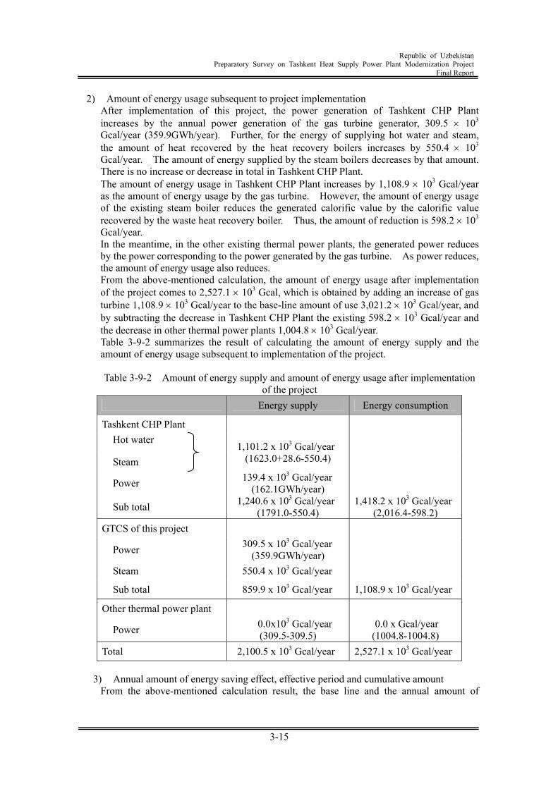
Republic of Uzbekistan
Preparatory Survey on Tashkent Heat Supply Power Plant Modernization Project Final Report
3-15
2) Amount of energy usage subsequent to project implementation After implementation of this project, the power generation of Tashkent CHP Plant increases by the annual power generation of the gas turbine generator, 309.5 103 Gcal/year (359.9GWh/year). Further, for the energy of supplying hot water and steam, the amount of heat recovered by the heat recovery boilers increases by 550.4 103 Gcal/year. The amount of energy supplied by the steam boilers decreases by that amount. There is no increase or decrease in total in Tashkent CHP Plant. The amount of energy usage in Tashkent CHP Plant increases by 1,108.9 103 Gcal/year as the amount of energy usage by the gas turbine. However, the amount of energy usage of the existing steam boiler reduces the generated calorific value by the calorific value recovered by the waste heat recovery boiler. Thus, the amount of reduction is 598.2 103 Gcal/year. In the meantime, in the other existing thermal power plants, the generated power reduces by the power corresponding to the power generated by the gas turbine. As power reduces, the amount of energy usage also reduces. From the above-mentioned calculation, the amount of energy usage after implementation of the project comes to 2,527.1 103 Gcal, which is obtained by adding an increase of gas turbine 1,108.9 103 Gcal/year to the base-line amount of use 3,021.2 103 Gcal/year, and by subtracting the decrease in Tashkent CHP Plant the existing 598.2 103 Gcal/year and the decrease in other thermal power plants 1,004.8 103 Gcal/year. Table 3-9-2 summarizes the result of calculating the amount of energy supply and the amount of energy usage subsequent to implementation of the project.
Table 3-9-2 Amount of energy supply and amount of energy usage after implementation
of the project Energy supply Energy consumption
Tashkent CHP Plant Hot water
Steam 1,101.2 x 103 Gcal/year
(1623.0+28.6-550.4)
Power 139.4 x 10³ Gcal/year (162.1GWh/year)
Sub total 1,240.6 x 103 Gcal/year (1791.0-550.4)
1,418.2 x 103 Gcal/year (2,016.4-598.2)
GTCS of this project
Power 309.5 x 10³ Gcal/year (359.9GWh/year)
Steam 550.4 x 10³ Gcal/year
Sub total 859.9 x 10³ Gcal/year 1,108.9 x 103 Gcal/year
Other thermal power plant
Power 0.0x10³ Gcal/year (309.5-309.5)
0.0 x Gcal/year (1004.8-1004.8)
Total 2,100.5 x 103 Gcal/year 2,527.1 x 103 Gcal/year
3) Annual amount of energy saving effect, effective period and cumulative amount From the above-mentioned calculation result, the base line and the annual amount of
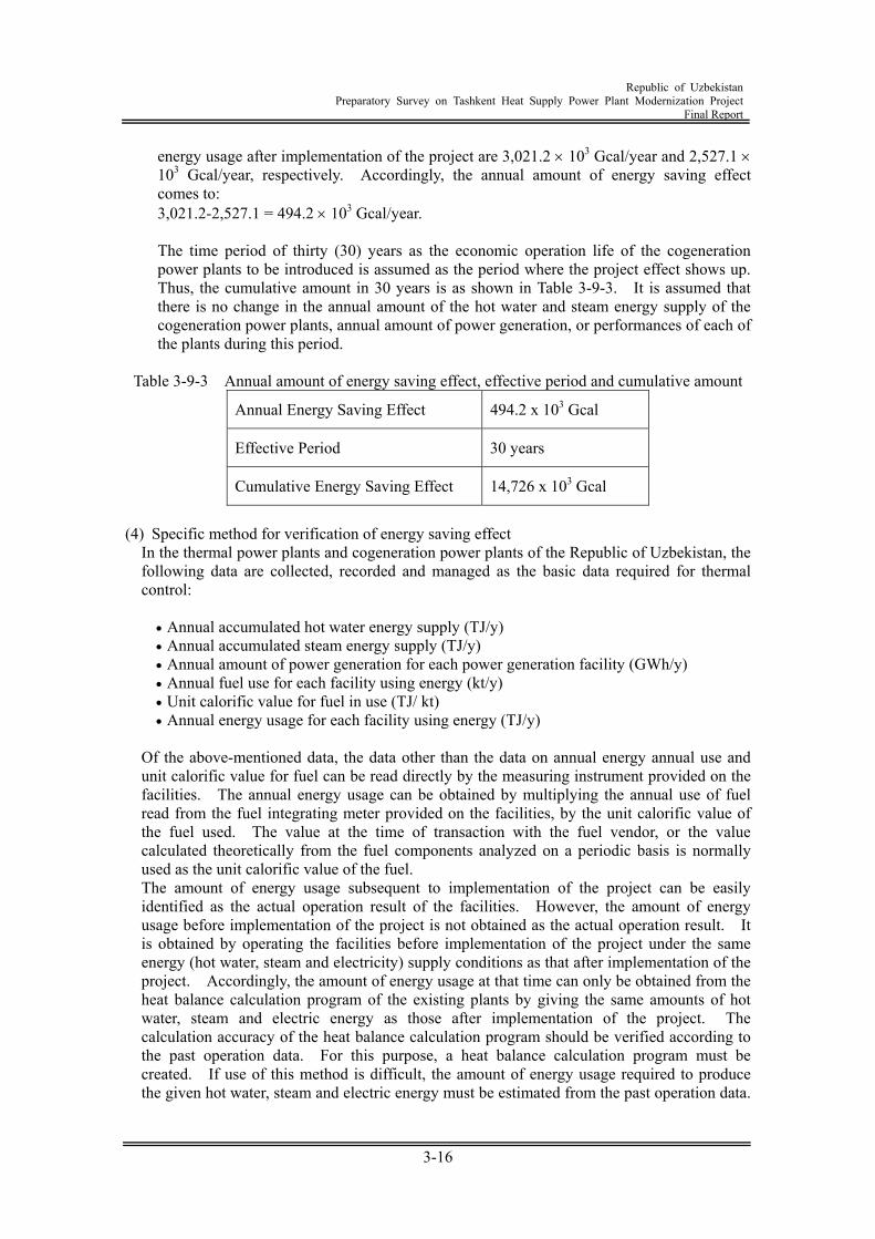
Republic of Uzbekistan
Preparatory Survey on Tashkent Heat Supply Power Plant Modernization Project Final Report
3-16
energy usage after implementation of the project are 3,021.2 103 Gcal/year and 2,527.1 103 Gcal/year, respectively. Accordingly, the annual amount of energy saving effect comes to: 3,021.2-2,527.1 = 494.2 103 Gcal/year.
The time period of thirty (30) years as the economic operation life of the cogeneration power plants to be introduced is assumed as the period where the project effect shows up. Thus, the cumulative amount in 30 years is as shown in Table 3-9-3. It is assumed that there is no change in the annual amount of the hot water and steam energy supply of the cogeneration power plants, annual amount of power generation, or performances of each of the plants during this period.
Table 3-9-3 Annual amount of energy saving effect, effective period and cumulative amount
Annual Energy Saving Effect 494.2 x 10³ Gcal
Effective Period 30 years
Cumulative Energy Saving Effect 14,726 x 103 Gcal
(4) Specific method for verification of energy saving effect
In the thermal power plants and cogeneration power plants of the Republic of Uzbekistan, the following data are collected, recorded and managed as the basic data required for thermal control:
Annual accumulated hot water energy supply (TJ/y) Annual accumulated steam energy supply (TJ/y) Annual amount of power generation for each power generation facility (GWh/y) Annual fuel use for each facility using energy (kt/y) Unit calorific value for fuel in use (TJ/ kt) Annual energy usage for each facility using energy (TJ/y)
Of the above-mentioned data, the data other than the data on annual energy annual use and unit calorific value for fuel can be read directly by the measuring instrument provided on the facilities. The annual energy usage can be obtained by multiplying the annual use of fuel read from the fuel integrating meter provided on the facilities, by the unit calorific value of the fuel used. The value at the time of transaction with the fuel vendor, or the value calculated theoretically from the fuel components analyzed on a periodic basis is normally used as the unit calorific value of the fuel. The amount of energy usage subsequent to implementation of the project can be easily identified as the actual operation result of the facilities. However, the amount of energy usage before implementation of the project is not obtained as the actual operation result. It is obtained by operating the facilities before implementation of the project under the same energy (hot water, steam and electricity) supply conditions as that after implementation of the project. Accordingly, the amount of energy usage at that time can only be obtained from the heat balance calculation program of the existing plants by giving the same amounts of hot water, steam and electric energy as those after implementation of the project. The calculation accuracy of the heat balance calculation program should be verified according to the past operation data. For this purpose, a heat balance calculation program must be created. If use of this method is difficult, the amount of energy usage required to produce the given hot water, steam and electric energy must be estimated from the past operation data.
Republic of Uzbekistan
Preparatory Survey on Tashkent Heat Supply Power Plant Modernization Project Final Report
3-17
Further, the amount of energy used by the gas turbine power plants corresponding to the amount of power generation before the implementation of the project must be calculated assuming that the amount of power generation is generated in the existing thermal power plant other than this heat supply power plant. For this purpose, we will specify the existing plants whose operation is suspended or availability factor is reduced after implementation of the project. The energy conversion efficiency of the plants will be used to calculate the amount of energy usage. If the amount of energy usage before and after implementation of the project is obtained in above-mentioned procedure, the difference can be verified as the energy saving effect.
3.9.2 Greenhouse gas reduction effect (1) Technical ground for greenhouse gas reduction effect
Carbon dioxide gas (CO2) as a major greenhouse gas occurring in a cogeneration power plant is produced by use of energy. It can be reduced by the following two methods:
Improve the energy conversion efficiency and reduce the amount of energy usage. Use the fuel having lower carbon content per unit calorific value.
The technical ground why energy conversion efficiency is improved by the implementation of this project is described in Section 3.8.1 "Technical ground for energy saving effect". The amount of power generated in the other existing thermal power plants can be reduced by the amount of power in excess of the amount having been generated so far in Tashkent CHP Plant, out of the amount of power generated by the implementation of this project. Tashkent CHP Plant uses natural gas. In the existing thermal power plant, natural gas, heavy oil and coal are used at certain percentages. Accordingly, in the reduced amount of power to be generated in the existing thermal power plant, power generation by heavy oil and coal can be replaced by that by natural gas. As will be apparent from above-mentioned discussion, implementation of this project allows the greenhouse gas to be reduced using the above-mentioned two methods. The greenhouse gas other than the carbon oxide discharged from the power plant includes the methane that may leak out of the sealed portions of the natural gas supply facilities. However, it is difficult to estimate the amount of leaking methane. Further, the leakage is assumed to be very small. Accordingly, methane is not included in the scope of this survey.
(2) Base line for calculating the greenhouse gas reduction effect
1) Concept of base line The emission of greenhouse gas (CO2 alone) can be obtained by multiplying the annual amount of energy used in the plants using the relevant energy, by the coefficient specified for each type of energy. Accordingly, the base line serving as a foundation for calculating the greenhouse gas reduction effect is provided by multiplying the amount of use for each energy type obtained according to Section 3.8.1 "Base line for calculating the energy saving effect" by the coefficient. The coefficient is specified for each type in the IPCC Guideline (Basic Calculation in the IPCC Guideline for National Greenhouse Gas Inventories Reference Manual/1.4.1 Approaches For Estimating CO2 Emission).
2) Calculation method
Greenhouse gas emission (tC/year) = fuel consumption (equivalent calorific value: TJ) unit consumption rate of carbon emission (tC/TJ) oxidation percentage coefficient of carbon unit conversion coefficient of carbon oxide Here, coefficients are specified for each fuel in the IPCC guideline as follows:
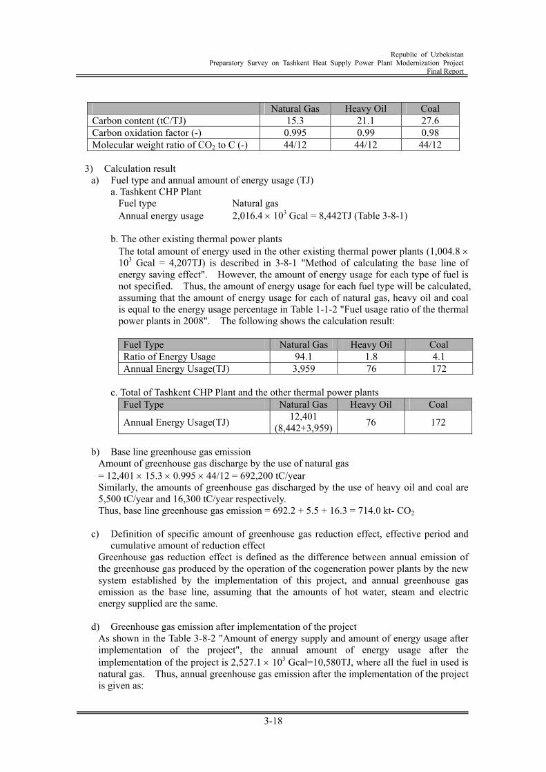
Republic of Uzbekistan
Preparatory Survey on Tashkent Heat Supply Power Plant Modernization Project Final Report
3-18
Natural Gas Heavy Oil Coal Carbon content (tC/TJ) 15.3 21.1 27.6 Carbon oxidation factor (-) 0.995 0.99 0.98 Molecular weight ratio of CO2 to C (-) 44/12 44/12 44/12
3) Calculation result
a) Fuel type and annual amount of energy usage (TJ) a. Tashkent CHP Plant
Fuel type Natural gas Annual energy usage 2,016.4 103 Gcal = 8,442TJ (Table 3-8-1)
b. The other existing thermal power plants
The total amount of energy used in the other existing thermal power plants (1,004.8 103 Gcal = 4,207TJ) is described in 3-8-1 "Method of calculating the base line of energy saving effect". However, the amount of energy usage for each type of fuel is not specified. Thus, the amount of energy usage for each fuel type will be calculated, assuming that the amount of energy usage for each of natural gas, heavy oil and coal is equal to the energy usage percentage in Table 1-1-2 "Fuel usage ratio of the thermal power plants in 2008". The following shows the calculation result:
Fuel Type Natural Gas Heavy Oil Coal Ratio of Energy Usage 94.1 1.8 4.1 Annual Energy Usage(TJ) 3,959 76 172
c. Total of Tashkent CHP Plant and the other thermal power plants
Fuel Type Natural Gas Heavy Oil Coal
Annual Energy Usage(TJ) 12,401 (8,442+3,959) 76 172
b) Base line greenhouse gas emission
Amount of greenhouse gas discharge by the use of natural gas = 12,401 15.3 0.995 44/12 = 692,200 tC/year Similarly, the amounts of greenhouse gas discharged by the use of heavy oil and coal are 5,500 tC/year and 16,300 tC/year respectively. Thus, base line greenhouse gas emission = 692.2 + 5.5 + 16.3 = 714.0 kt- CO2
c) Definition of specific amount of greenhouse gas reduction effect, effective period and
cumulative amount of reduction effect Greenhouse gas reduction effect is defined as the difference between annual emission of the greenhouse gas produced by the operation of the cogeneration power plants by the new system established by the implementation of this project, and annual greenhouse gas emission as the base line, assuming that the amounts of hot water, steam and electric energy supplied are the same.
d) Greenhouse gas emission after implementation of the project
As shown in the Table 3-8-2 "Amount of energy supply and amount of energy usage after implementation of the project", the annual amount of energy usage after the implementation of the project is 2,527.1 103 Gcal=10,580TJ, where all the fuel in used is natural gas. Thus, annual greenhouse gas emission after the implementation of the project is given as:
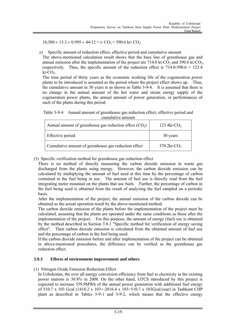
Republic of Uzbekistan
Preparatory Survey on Tashkent Heat Supply Power Plant Modernization Project Final Report
3-19
10,580 15.3 0.995 44/12 = t- CO2 = 590.6 kt- CO2.
e) Specific amount of reduction effect, effective period and cumulative amount The above-mentioned calculation result shows that the base line of greenhouse gas and annual emission after the implementation of the project are 714.0 kt-CO2 and 590.6 kt-CO2, respectively. Thus, the specific amount of the reduction effect is 714.0-590.6 = 123.4 kt-CO2. The time period of thirty years as the economic working life of the cogeneration power plants to be introduced is assumed as the period where the project effect shows up. Thus, the cumulative amount in 30 years is as shown in Table 3-9-4. It is assumed that there is no change in the annual amount of the hot water and steam energy supply of the cogeneration power plants, the annual amount of power generation, or performances of each of the plants during this period.
Table 3-9-4 Annual amount of greenhouse gas reduction effect, effective period and
cumulative amount
Annual amount of greenhouse gas reduction effect (CO2) 123.4kt-CO2
Effective period 30 years
Cumulative amount of greenhouse gas reduction effect 370.2kt-CO2
(3) Specific verification method for greenhouse gas reduction effect
There is no method of directly measuring the carbon dioxide emission in waste gas discharged from the plants using energy. However, the carbon dioxide emission can be calculated by multiplying the amount of fuel used at this time by the percentage of carbon contained in the fuel being in use. The amount of fuel use is directly read from the fuel integrating meter mounted on the plants that use fuels. Further, the percentage of carbon in the fuel being used is obtained from the result of analyzing the fuel sampled on a periodic basis. After the implementation of the project, the annual emission of the carbon dioxide can be obtained as the actual operation result by the above-mentioned method. The carbon dioxide emission of the plants before the implementation of the project must be calculated, assuming that the plants are operated under the same conditions as those after the implementation of the project. For this purpose, the amount of energy (fuel) use is obtained by the method described in Section 3.8.1 "Specific method for verification of energy saving effect". Then carbon dioxide emission is calculated from the obtained amount of fuel use and the percentage of carbon in the fuel being used. If the carbon dioxide emission before and after implementation of the project can be obtained in above-mentioned procedures, the difference can be verified as the greenhouse gas reduction effect.
3.9.3 Effects of environment improvement and others (1) Nitrogen Oxide Emission Reduction Effect
In Uzbekistan, the over all energy conversion efficiency from fuel to electricity in the existing power stations is 30.8% in 2008. On the other hand, GTCS introduced by this project is expected to increase 359.9MWh of the annual power generation with additional fuel energy of 510.7 x 10³ Gcal (1418.2 x 103+-2016.4 x 103=510.7 x 10³Gcal/year) in Tashkent CHP plant as described in Tables 3-9-1 and 3-9-2, which means that the effective energy
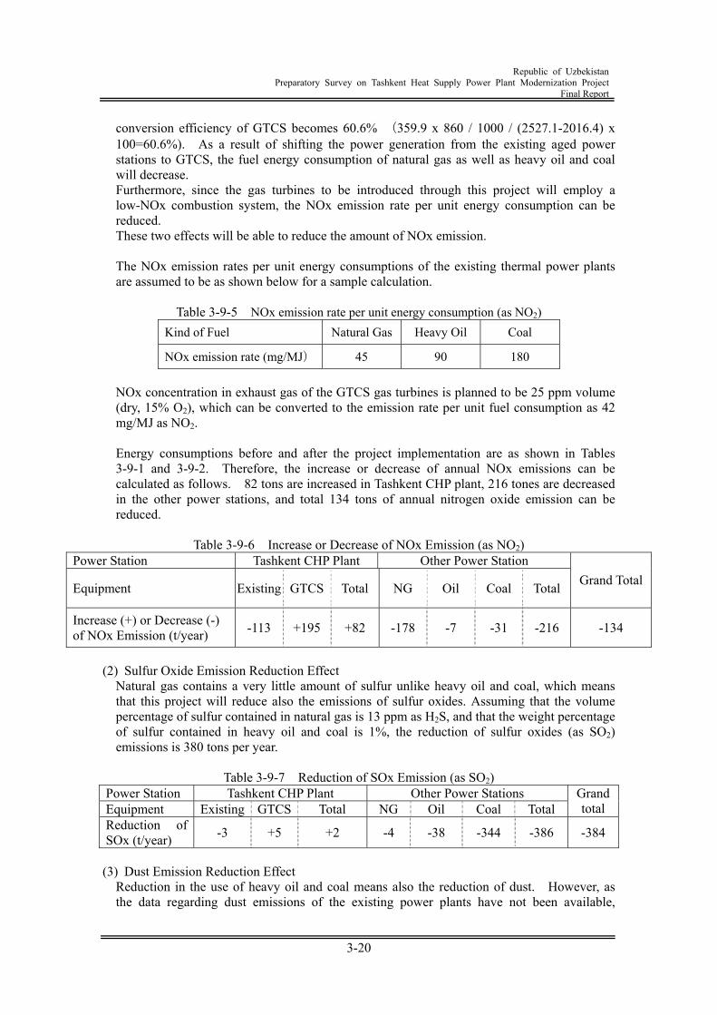
Republic of Uzbekistan
Preparatory Survey on Tashkent Heat Supply Power Plant Modernization Project Final Report
3-20
conversion efficiency of GTCS becomes 60.6% (359.9 x 860 / 1000 / (2527.1-2016.4) x 100=60.6%). As a result of shifting the power generation from the existing aged power stations to GTCS, the fuel energy consumption of natural gas as well as heavy oil and coal will decrease. Furthermore, since the gas turbines to be introduced through this project will employ a low-NOx combustion system, the NOx emission rate per unit energy consumption can be reduced. These two effects will be able to reduce the amount of NOx emission.
The NOx emission rates per unit energy consumptions of the existing thermal power plants are assumed to be as shown below for a sample calculation.
Table 3-9-5 NOx emission rate per unit energy consumption (as NO2)
Kind of Fuel Natural Gas Heavy Oil Coal
NOx emission rate (mg/MJ) 45 90 180
NOx concentration in exhaust gas of the GTCS gas turbines is planned to be 25 ppm volume (dry, 15% O2), which can be converted to the emission rate per unit fuel consumption as 42 mg/MJ as NO2.
Energy consumptions before and after the project implementation are as shown in Tables 3-9-1 and 3-9-2. Therefore, the increase or decrease of annual NOx emissions can be calculated as follows. 82 tons are increased in Tashkent CHP plant, 216 tones are decreased in the other power stations, and total 134 tons of annual nitrogen oxide emission can be reduced.
Table 3-9-6 Increase or Decrease of NOx Emission (as NO2)
Power Station Tashkent CHP Plant Other Power Station
Equipment Existing GTCS Total NG Oil Coal Total Grand Total
Increase (+) or Decrease (-) of NOx Emission (t/year) -113 +195 +82 -178 -7 -31 -216 -134
(2) Sulfur Oxide Emission Reduction Effect
Natural gas contains a very little amount of sulfur unlike heavy oil and coal, which means that this project will reduce also the emissions of sulfur oxides. Assuming that the volume percentage of sulfur contained in natural gas is 13 ppm as H2S, and that the weight percentage of sulfur contained in heavy oil and coal is 1%, the reduction of sulfur oxides (as SO2) emissions is 380 tons per year.
Table 3-9-7 Reduction of SOx Emission (as SO2)
Power Station Tashkent CHP Plant Other Power Stations Equipment Existing GTCS Total NG Oil Coal Total
Grand total
Reduction of SOx (t/year) -3 +5 +2 -4 -38 -344 -386 -384
(3) Dust Emission Reduction Effect
Reduction in the use of heavy oil and coal means also the reduction of dust. However, as the data regarding dust emissions of the existing power plants have not been available,
Republic of Uzbekistan
Preparatory Survey on Tashkent Heat Supply Power Plant Modernization Project Final Report
3-21
calculation of the dust reduction effect shall be refrained. 3.10 Feasibility study toward introduction of the STEP The major equipment constituting GTCS for the Project includes a gas turbine, HRSG and generator. Of these pieces of equipment, the HRSG and generator are based on the matured and commonly known technology. It cannot be said that the technology, material and equipment inherent to the Japanese business operators are essential to the implementation and are utilized in real terms. At the present moment, the gas turbine is making a continued progress through the development of heat resistant materials, high-temperature component cooling technology and low-NOx combustion technology, for the purpose of achieving increased temperature intended to improve the performances. However, the greater part of the major technology supporting the progress of the gas turbine has derived from the technology applied to the jet engine. Further, the combustion temperature on the level of maintenance temperature will be adopted in the 25 MW class gas turbine to be applied to this business. Thus, it cannot be said that the technology, material and equipment inherent to the Japanese business operators are utilized for the gas turbine. This business is related to a cogeneration system that generates two types of energy -- electric energy and heat energy -- using a primary energy. The cogeneration system is generated operated in conformity to the heat energy demand and electric energy is outputted as the result of meeting the operating conditions. In the gas turbine cogeneration system, the gas turbine has to be operated at low loads to meet the heat energy demand, especially during the low-demand time zone. This will result in reduced operation efficiency. To avoid such an operation procedure, it is possible to consider a system where excess steam contained in the heat energy produced in the HRSG is led into the gas turbine as a working fluid. However, it is unlikely that the Japanese business operator assumed to take part in this business should introduce such a system, and the technology inherent to the business operator should be used for the system. As described above, it is unlikely that the technology, material and equipment inherent to the Japanese business operators will be essential to the implementation of the implementation of the business and will be utilized in real terms.
Republic of Uzbekistan
Preparatory Survey on Tashkent Heat Supply Power Plant Modernization Project Final Report
4-1
Chapter 4 Economic and Financial Analysis and Key Performance Indicators
4.1 Power Plant Operational Conditions 4.1.1 Operational Conditions of the GTCS for the Tashkent Heat Supply Power Plant Before starting the economic and financial analysis, it is necessary to assume the generation capacity of the power plant, thermal efficiency and other factors. They are slightly different according to the supplier of the power plant. Further, the power plants are normally ordered according to the EPC contract. Selection of the EPC contractor is performed by international competitive bidding. In this case, bidding price is evaluated by giving consideration to the difference in bidding specifications, the power output and difference in thermal efficiency, so the bidder of the lowest price is not always a successful bidder. In this Chapter, out of five models of 25 MW-class GT power plants shown in Table 3-1-2, Model H25 of Hitachi Limited having an intermediate-level power output was selected as a model case for the following discussion. Table 4-1-1 shows the operational conditions of the GTCS for the Tashkent Heat Supply Power Plant (hereinafter referred as “Tashkent CHP Plant”) financed by Japanese ODA Loan used for the economic and financial analysis. The results of the study made with reference to Section 3.1.4 are used as the assumed power output and thermal efficiency of this model under the site conditions. The construction period is 39 months as recommended with reference to Section 3.6. Further, the Tashkent CHP Plant is planned as an important power source and heat supply source at the center of Tashkent and high-efficiency GTCS are utilized. Accordingly, the operation is assumed to be performed on the base load. Thus, eighty-five percent set as an indicator of the operation with reference to Section 4.3 is used as the base case for the plant load factor. The project period is assumed as twenty-five years, judging from the plant life as set in Section 3.1.4. Table 4-1-1 Operational conditions of the GTCS for the Tashkent CHP Plant
GT Model Hitachi H25 x 2
Gross Power Output @15℃,963hPa, RH60% 54,340 kW
Net Power Output @15℃,963hPa, RH60% 48,340 kW
Net Heat Output 73.9 Gcal/hr
Total Net Thermal Efficiency (LHV) 77.5%
Construction Period 39 months
Plant Load Factor 85%
Project Life 25 years
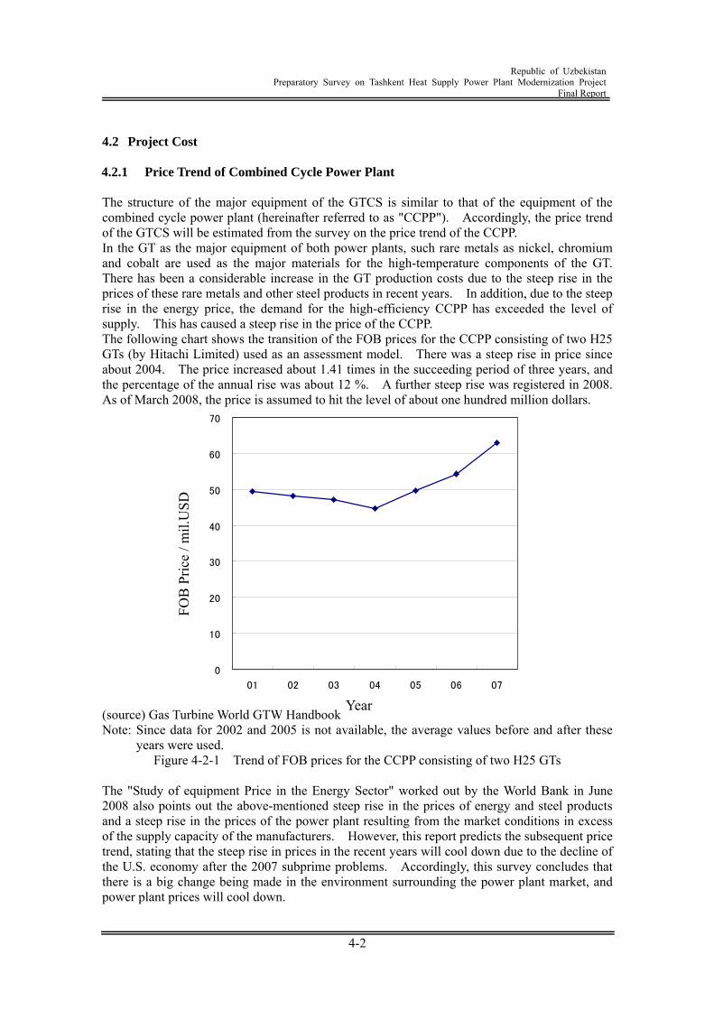
Republic of Uzbekistan
Preparatory Survey on Tashkent Heat Supply Power Plant Modernization Project Final Report
4-2
4.2 Project Cost 4.2.1 Price Trend of Combined Cycle Power Plant The structure of the major equipment of the GTCS is similar to that of the equipment of the combined cycle power plant (hereinafter referred to as "CCPP"). Accordingly, the price trend of the GTCS will be estimated from the survey on the price trend of the CCPP. In the GT as the major equipment of both power plants, such rare metals as nickel, chromium and cobalt are used as the major materials for the high-temperature components of the GT. There has been a considerable increase in the GT production costs due to the steep rise in the prices of these rare metals and other steel products in recent years. In addition, due to the steep rise in the energy price, the demand for the high-efficiency CCPP has exceeded the level of supply. This has caused a steep rise in the price of the CCPP. The following chart shows the transition of the FOB prices for the CCPP consisting of two H25 GTs (by Hitachi Limited) used as an assessment model. There was a steep rise in price since about 2004. The price increased about 1.41 times in the succeeding period of three years, and the percentage of the annual rise was about 12 %. A further steep rise was registered in 2008. As of March 2008, the price is assumed to hit the level of about one hundred million dollars.
0
10
20
30
40
50
60
70
01 02 03 04 05 06 07
(source) Gas Turbine World GTW Handbook Note: Since data for 2002 and 2005 is not available, the average values before and after these
years were used. Figure 4-2-1 Trend of FOB prices for the CCPP consisting of two H25 GTs
The "Study of equipment Price in the Energy Sector" worked out by the World Bank in June 2008 also points out the above-mentioned steep rise in the prices of energy and steel products and a steep rise in the prices of the power plant resulting from the market conditions in excess of the supply capacity of the manufacturers. However, this report predicts the subsequent price trend, stating that the steep rise in prices in the recent years will cool down due to the decline of the U.S. economy after the 2007 subprime problems. Accordingly, this survey concludes that there is a big change being made in the environment surrounding the power plant market, and power plant prices will cool down.
FOB
Pric
e / m
il.U
SD
Year
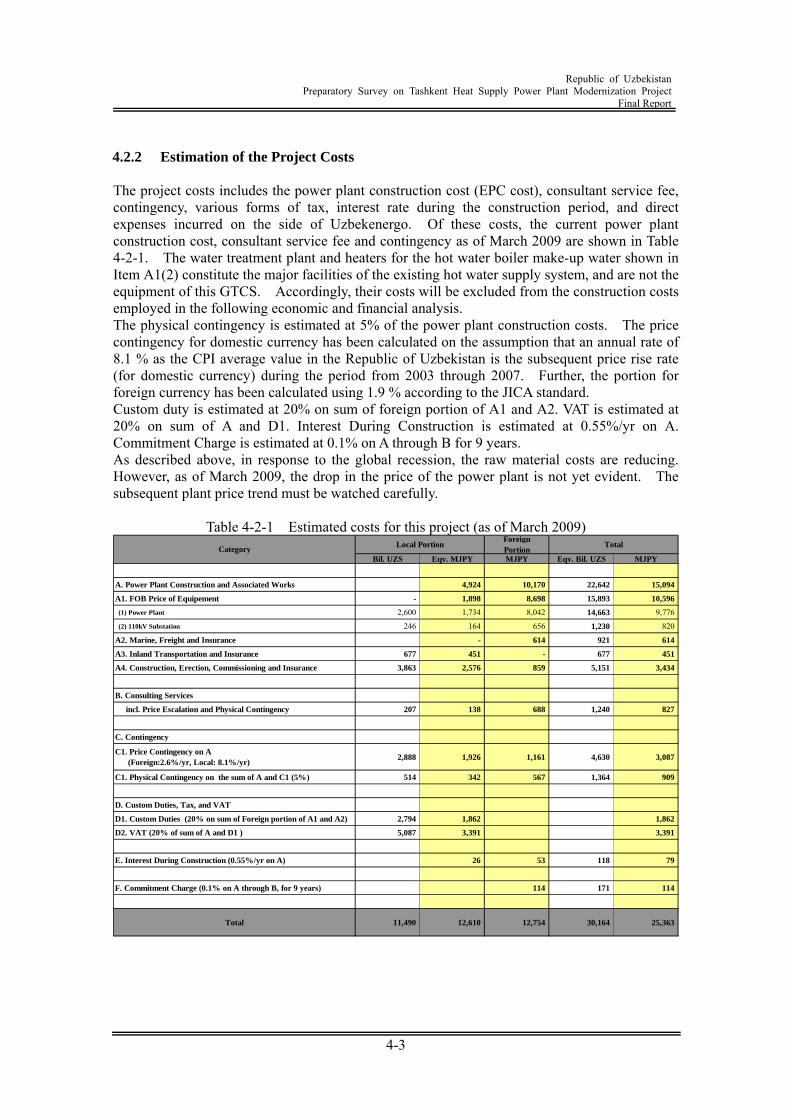
Republic of Uzbekistan
Preparatory Survey on Tashkent Heat Supply Power Plant Modernization Project Final Report
4-3
4.2.2 Estimation of the Project Costs The project costs includes the power plant construction cost (EPC cost), consultant service fee, contingency, various forms of tax, interest rate during the construction period, and direct expenses incurred on the side of Uzbekenergo. Of these costs, the current power plant construction cost, consultant service fee and contingency as of March 2009 are shown in Table 4-2-1. The water treatment plant and heaters for the hot water boiler make-up water shown in Item A1(2) constitute the major facilities of the existing hot water supply system, and are not the equipment of this GTCS. Accordingly, their costs will be excluded from the construction costs employed in the following economic and financial analysis. The physical contingency is estimated at 5% of the power plant construction costs. The price contingency for domestic currency has been calculated on the assumption that an annual rate of 8.1 % as the CPI average value in the Republic of Uzbekistan is the subsequent price rise rate (for domestic currency) during the period from 2003 through 2007. Further, the portion for foreign currency has been calculated using 1.9 % according to the JICA standard. Custom duty is estimated at 20% on sum of foreign portion of A1 and A2. VAT is estimated at 20% on sum of A and D1. Interest During Construction is estimated at 0.55%/yr on A. Commitment Charge is estimated at 0.1% on A through B for 9 years. As described above, in response to the global recession, the raw material costs are reducing. However, as of March 2009, the drop in the price of the power plant is not yet evident. The subsequent plant price trend must be watched carefully.
Table 4-2-1 Estimated costs for this project (as of March 2009)
Bil. UZS Eqv. MJPY MJPY Eqv. Bil. UZS MJPY
A. Power Plant Construction and Associated Works 4,924 10,170 22,642 15,094
A1. FOB Price of Equipement - 1,898 8,698 15,893 10,596
(1) Power Plant 2,600 1,734 8,042 14,663 9,776
(2) 110kV Substation 246 164 656 1,230 820
A2. Marine, Freight and Insurance - 614 921 614
A3. Inland Transportation and Insurance 677 451 - 677 451
A4. Construction, Erection, Commissioning and Insurance 3,863 2,576 859 5,151 3,434
B. Consulting Services
incl. Price Escalation and Physical Contingency 207 138 688 1,240 827
C. Contingency
C1. Price Contingency on A (Foreign:2.6%/yr, Local: 8.1%/yr)
2,888 1,926 1,161 4,630 3,087
C1. Physical Contingency on the sum of A and C1 (5%) 514 342 567 1,364 909
D. Custom Duties, Tax, and VAT
D1. Custom Duties (20% on sum of Foreign portion of A1 and A2) 2,794 1,862 1,862
D2. VAT (20% of sum of A and D1 ) 5,087 3,391 3,391
E. Interest During Construction (0.55%/yr on A) 26 53 118 79
F. Commitment Charge (0.1% on A through B, for 9 years) 114 171 114
Total 11,490 12,610 12,754 30,164 25,363
CategoryTotalLocal Portion
ForeignPortion
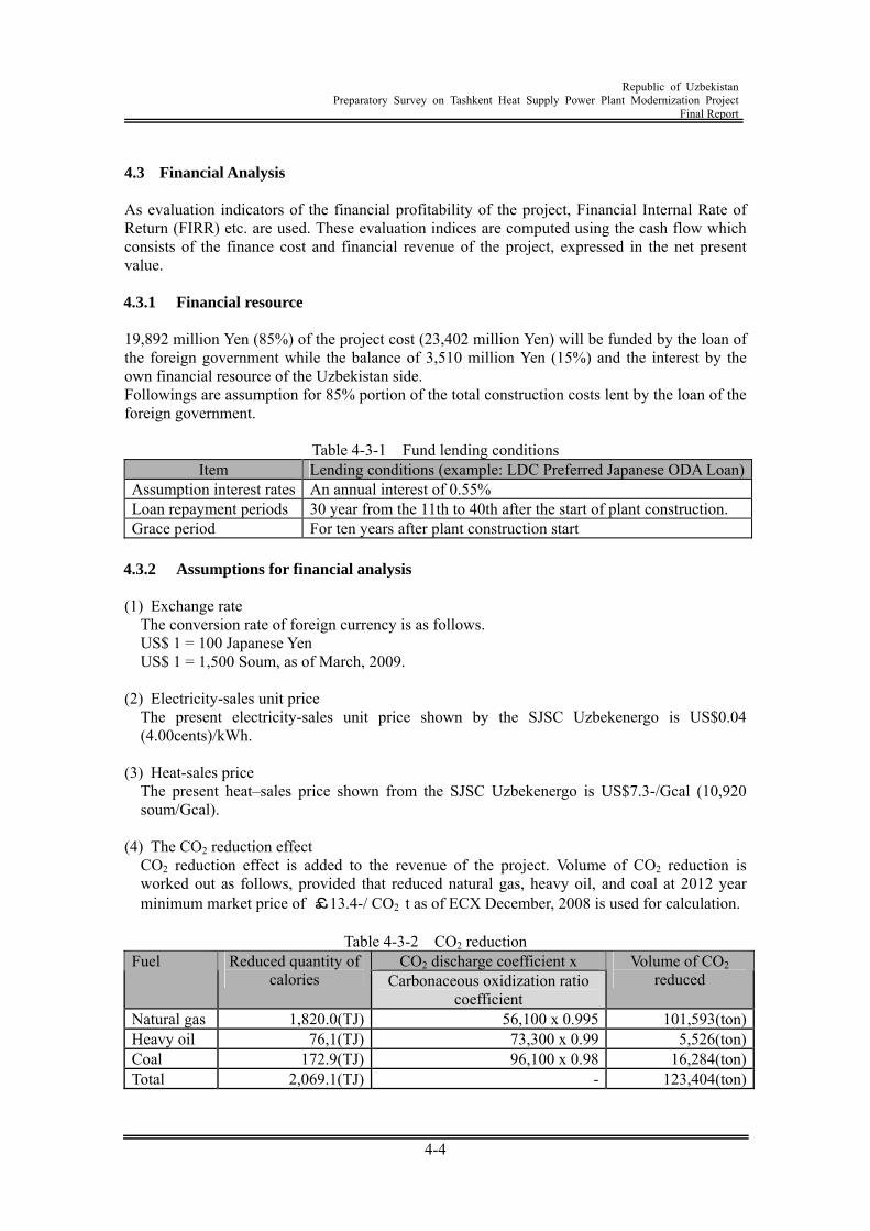
Republic of Uzbekistan
Preparatory Survey on Tashkent Heat Supply Power Plant Modernization Project Final Report
4-4
4.3 Financial Analysis As evaluation indicators of the financial profitability of the project, Financial Internal Rate of Return (FIRR) etc. are used. These evaluation indices are computed using the cash flow which consists of the finance cost and financial revenue of the project, expressed in the net present value. 4.3.1 Financial resource 19,892 million Yen (85%) of the project cost (23,402 million Yen) will be funded by the loan of the foreign government while the balance of 3,510 million Yen (15%) and the interest by the own financial resource of the Uzbekistan side. Followings are assumption for 85% portion of the total construction costs lent by the loan of the foreign government.
Table 4-3-1 Fund lending conditions Item Lending conditions (example: LDC Preferred Japanese ODA Loan)
Assumption interest rates An annual interest of 0.55% Loan repayment periods 30 year from the 11th to 40th after the start of plant construction. Grace period For ten years after plant construction start 4.3.2 Assumptions for financial analysis (1) Exchange rate
The conversion rate of foreign currency is as follows. US$ 1 = 100 Japanese Yen US$ 1 = 1,500 Soum, as of March, 2009.
(2) Electricity-sales unit price
The present electricity-sales unit price shown by the SJSC Uzbekenergo is US$0.04 (4.00cents)/kWh.
(3) Heat-sales price
The present heat–sales price shown from the SJSC Uzbekenergo is US$7.3-/Gcal (10,920 soum/Gcal).
(4) The CO2 reduction effect
CO2 reduction effect is added to the revenue of the project. Volume of CO2 reduction is worked out as follows, provided that reduced natural gas, heavy oil, and coal at 2012 year minimum market price of £13.4-/ CO2 t as of ECX December, 2008 is used for calculation.
Table 4-3-2 CO2 reduction
CO2 discharge coefficient x Fuel Reduced quantity of calories Carbonaceous oxidization ratio
coefficient
Volume of CO2 reduced
Natural gas 1,820.0(TJ) 56,100 x 0.995 101,593(ton) Heavy oil 76,1(TJ) 73,300 x 0.99 5,526(ton) Coal 172.9(TJ) 96,100 x 0.98 16,284(ton) Total 2,069.1(TJ) - 123,404(ton)
Republic of Uzbekistan
Preparatory Survey on Tashkent Heat Supply Power Plant Modernization Project Final Report
4-5
(5) Fuel unit cost
Fuel unit cost provided by SJSC Uzbekenergo is US$4.6 / Gcal (US$0.0376/Nm3). (6) Operation maintenance expense
1) Aggregate total cost for operation maintenance expense of the new equipment including operation maintenance staff salary (21 persons), annual maintenance and repairs, water supply, chemical treatment, etc. is US$2,757,000-/year.
(7) Tax
1) Import duty (20%) shall be exempted. 2) Value-added tax (20%) shall be exempted. 3) Corporate income tax is 10% of taxable income.
(8) Price increase ratio
Price increase ratio in the project period is not taken into consideration for FIRR calculation. (9) Construction period, project period
In this analysis, construction and project period are assumed as follows. 1) Construction period: Four years 2) Project analysis period: 25 years
(10) Interest during Construction, Commitment charges for Japanese ODA Loan
Interest during Construction or Commitment charges for Japanese ODA Loan is not included in the project cost for financial analysis.
4.3.3 Indicators of financial analysis As analysis indicators of financial evaluation of the project, following 3 indicators are used. (1) Net Present Value (NPV)
This indicator is calculated by the difference between the current-value total of the revenue during project period and the current-value total of expense, using discount rate (opportunity cost of capital: 12% is applied for the project). If NPV is larger than 0, it will be judged that a project is profitable.
(2) Benefit Cost ratio (B/C)
Under the discount given (opportunity cost of capital: same as the above), this is the ratio of the current-value total of the revenue during project period and the current-value total of expense. If B/C Ratio is larger than 1, it will be judged that the project is profitable.
(3) Financial Internal Rate of Return (FIRR)
"NPV=0", i.e., the discount rate that the sum total of the current value of revenue and expense becomes equal, is called internal rate of return. If FIRR is larger than the interest rates of the currency concerned, it will usually be judged that the project concerned is feasible.
NPV in the project period (for 25 years) computed from the financial cost and financial revenue as above, B/C, and FIRR are shown in Table 4-3-3 (account flow is shown in the following page).

Republic of Uzbekistan
Preparatory Survey on Tashkent Heat Supply Power Plant Modernization Project Final Report
4-6
Table 4-3-3 FIRR (Financial Internal Rate of Return)
NPV(Discount Rate:12%) B/C(DC:12%) FIRR-42.3 Mil. $ 0.7 3.7%
Those 3 parameters of above NPV, B/C Ratio, and FIRR will be used as the critical standard which judges adoption or rejection of a single project. As for the integral relation of indicators, since NPV is smaller than 0 and B/ C Ratio is also smaller than 1, it cannot be said that the financial profitability of the project concerned is sufficient.
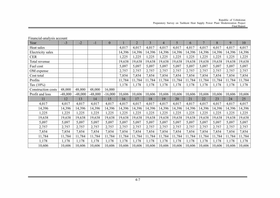
Republic of Uzbekistan
Preparatory Survey on Tashkent Heat Supply Power Plant Modernization Project Final Report
4-7
Financial-analysis account Year -3 -2 -1 0 1 2 3 4 5 6 7 8 9 10 Heat sales 4,017 4,017 4,017 4,017 4,017 4,017 4,017 4,017 4,017 4,017 Electricity sales 14,396 14,396 14,396 14,396 14,396 14,396 14,396 14,396 14,396 14,396 CER 1,225 1,225 1,225 1,225 1,225 1,225 1,225 1,225 1,225 1,225 Total revenue 19,638 19,638 19,638 19,638 19,638 19,638 19,638 19,638 19,638 19,638 Fuel cost 5,097 5,097 5,097 5,097 5,097 5,097 5,097 5,097 5,097 5,097 OM expense 2,757 2,757 2,757 2,757 2,757 2,757 2,757 2,757 2,757 2,757 Cost total 7,854 7,854 7,854 7,854 7,854 7,854 7,854 7,854 7,854 7,854 Profits 11,784 11,784 11,784 11,784 11,784 11,784 11,784 11,784 11,784 11,784 Tax (10%) 1,178 1,178 1,178 1,178 1,178 1,178 1,178 1,178 1,178 1,178 Construction costs 48,000 48,000 48,000 16,000 Profit and loss -48,000 -48,000 -48,000 -16,000 10,606 10,606 10,606 10,606 10,606 10,606 10,606 10,606 10,606 10,606
11 12 13 14 15 16 17 18 19 20 21 22 23 24 25 4,017 4,017 4,017 4,017 4,017 4,017 4,017 4,017 4,017 4,017 4,017 4,017 4,017 4,017 4,017
14,396 14,396 14,396 14,396 14,396 14,396 14,396 14,396 14,396 14,396 14,396 14,396 14,396 14,396 14,396 1,225 1,225 1,225 1,225 1,225 1,225 1,225 1,225 1,225 1,225 1,225 1,225 1,225 1,225 1,225
19,638 19,638 19,638 19,638 19,638 19,638 19,638 19,638 19,638 19,638 19,638 19,638 19,638 19,638 19,638 5,097 5,097 5,097 5,097 5,097 5,097 5,097 5,097 5,097 5,097 5,097 5,097 5,097 5,097 5,097 2,757 2,757 2,757 2,757 2,757 2,757 2,757 2,757 2,757 2,757 2,757 2,757 2,757 2,757 2,757 7,854 7,854 7,854 7,854 7,854 7,854 7,854 7,854 7,854 7,854 7,854 7,854 7,854 7,854 7,854 11,784 11,784 11,784 11,784 11,784 11,784 11,784 11,784 11,784 11,784 11,784 11,784 11,784 11,784 11,784 1,178 1,178 1,178 1,178 1,178 1,178 1,178 1,178 1,178 1,178 1,178 1,178 1,178 1,178 1,178
10,606 10,606 10,606 10,606 10,606 10,606 10,606 10,606 10,606 10,606 10,606 10,606 10,606 10,606 10,606
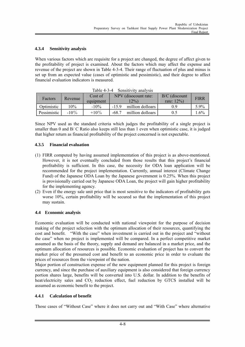
Republic of Uzbekistan
Preparatory Survey on Tashkent Heat Supply Power Plant Modernization Project Final Report
4-8
4.3.4 Sensitivity analysis When various factors which are requisite for a project are changed, the degree of affect given to the profitability of project is examined. About the factors which may affect the expense and revenue of the project are shown in Table 4-3-4. Their range of fluctuation of plus and minus is set up from an expected value (cases of optimistic and pessimistic), and their degree to affect financial evaluation indicators is measured.
Table 4-3-4 Sensitivity analysis
Factors Revenue Cost of equipment
NPV (disocount rate: 12%)
B/C (discount rate: 12%) FIRR
Optimistic 10% -10% -15.9 million dolloars 0.9 5.9% Pessimistic -10% +10% -68.7 million dolloars 0.5 1.6%
Since NPV used as the standard criteria which judges the profitability of a single project is smaller than 0 and B/ C Ratio also keeps still less than 1 even when optimistic case, it is judged that higher return as financial profitability of the project concerned is not expectable. 4.3.5 Financial evaluation (1) FIRR computed by having assumed implementation of this project is as above-mentioned.
However, it is not eventually concluded from those results that this project’s financial profitability is sufficient. In this case, the necessity for ODA loan application will be recommended for the project implementation. Currently, annual interest (Climate Change Fund) of the Japanese ODA Loan by the Japanese government is 0.25%. When this project is provisionally carried out by Japanese ODA Loan, the project will gain higher profitability for the implementing agency.
(2) Even if the energy sale unit price that is most sensitive to the indicators of profitability gets worse 10%, certain profitability will be secured so that the implementation of this project may sustain.
4.4 Economic analysis Economic evaluation will be conducted with national viewpoint for the purpose of decision making of the project selection with the optimum allocation of their resources, quantifying the cost and benefit. “With the case” when investment is carried out in the project and “without the case” when no project is implemented will be compared. In a perfect competitive market assumed as the basis of the theory, supply and demand are balanced in a market price, and the optimum allocation of resources is possible. Economic evaluation of project has to convert the market price of the presumed cost and benefit to an economic price in order to evaluate the prices of resources from the viewpoint of the nation. Major portion of construction expense of the new equipment planned for this project is foreign currency, and since the purchase of auxiliary equipment is also considered that foreign currency portion shares large, benefits will be converted into U.S. dollar. In addition to the benefits of heat/electricity sales and CO2 reduction effect, fuel reduction by GTCS installed will be assumed as economic benefit to the project. 4.4.1 Calculation of benefit Those cases of “Without Case” where it does not carry out and “With Case” where alternative
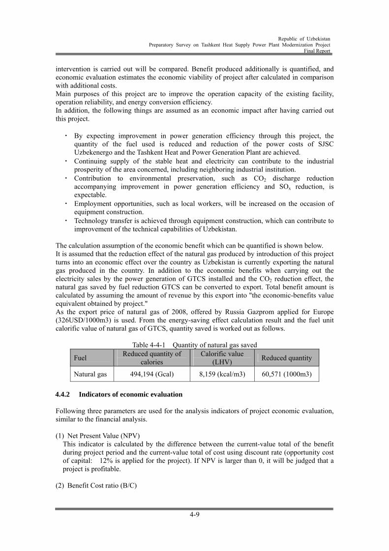
Republic of Uzbekistan
Preparatory Survey on Tashkent Heat Supply Power Plant Modernization Project Final Report
4-9
intervention is carried out will be compared. Benefit produced additionally is quantified, and economic evaluation estimates the economic viability of project after calculated in comparison with additional costs. Main purposes of this project are to improve the operation capacity of the existing facility, operation reliability, and energy conversion efficiency. In addition, the following things are assumed as an economic impact after having carried out this project. ・ By expecting improvement in power generation efficiency through this project, the
quantity of the fuel used is reduced and reduction of the power costs of SJSC Uzbekenergo and the Tashkent Heat and Power Generation Plant are achieved.
・ Continuing supply of the stable heat and electricity can contribute to the industrial prosperity of the area concerned, including neighboring industrial institution.
・ Contribution to environmental preservation, such as CO2 discharge reduction accompanying improvement in power generation efficiency and SOx reduction, is expectable.
・ Employment opportunities, such as local workers, will be increased on the occasion of equipment construction.
・ Technology transfer is achieved through equipment construction, which can contribute to improvement of the technical capabilities of Uzbekistan.
The calculation assumption of the economic benefit which can be quantified is shown below. It is assumed that the reduction effect of the natural gas produced by introduction of this project turns into an economic effect over the country as Uzbekistan is currently exporting the natural gas produced in the country. In addition to the economic benefits when carrying out the electricity sales by the power generation of GTCS installed and the CO2 reduction effect, the natural gas saved by fuel reduction GTCS can be converted to export. Total benefit amount is calculated by assuming the amount of revenue by this export into "the economic-benefits value equivalent obtained by project." As the export price of natural gas of 2008, offered by Russia Gazprom applied for Europe (326USD/1000m3) is used. From the energy-saving effect calculation result and the fuel unit calorific value of natural gas of GTCS, quantity saved is worked out as follows.
Table 4-4-1 Quantity of natural gas saved
Fuel Reduced quantity of calories
Calorific value (LHV) Reduced quantity
Natural gas 494,194 (Gcal) 8,159 (kcal/m3) 60,571 (1000m3)
4.4.2 Indicators of economic evaluation Following three parameters are used for the analysis indicators of project economic evaluation, similar to the financial analysis. (1) Net Present Value (NPV)
This indicator is calculated by the difference between the current-value total of the benefit during project period and the current-value total of cost using discount rate (opportunity cost of capital: 12% is applied for the project). If NPV is larger than 0, it will be judged that a project is profitable.
(2) Benefit Cost ratio (B/C)
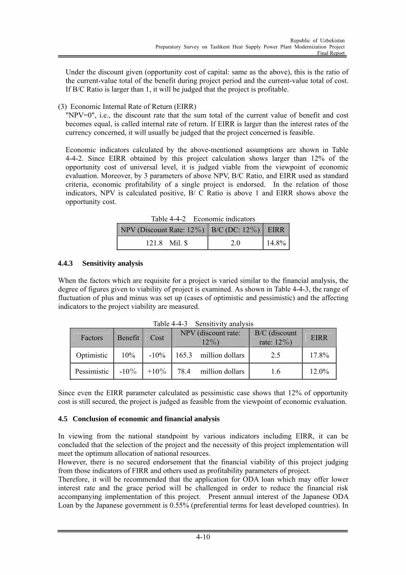
Republic of Uzbekistan
Preparatory Survey on Tashkent Heat Supply Power Plant Modernization Project Final Report
4-10
Under the discount given (opportunity cost of capital: same as the above), this is the ratio of the current-value total of the benefit during project period and the current-value total of cost. If B/C Ratio is larger than 1, it will be judged that the project is profitable.
(3) Economic Internal Rate of Return (EIRR)
"NPV=0", i.e., the discount rate that the sum total of the current value of benefit and cost becomes equal, is called internal rate of return. If EIRR is larger than the interest rates of the currency concerned, it will usually be judged that the project concerned is feasible.
Economic indicators calculated by the above-mentioned assumptions are shown in Table 4-4-2. Since EIRR obtained by this project calculation shows larger than 12% of the opportunity cost of universal level, it is judged viable from the viewpoint of economic evaluation. Moreover, by 3 parameters of above NPV, B/C Ratio, and EIRR used as standard criteria, economic profitability of a single project is endorsed. In the relation of those indicators, NPV is calculated positive, B/ C Ratio is above 1 and EIRR shows above the opportunity cost.
Table 4-4-2 Economic indicators
NPV (Discount Rate: 12%) B/C (DC: 12%) EIRR
121.8 Mil. $ 2.0 14.8% 4.4.3 Sensitivity analysis When the factors which are requisite for a project is varied similar to the financial analysis, the degree of figures given to viability of project is examined. As shown in Table 4-4-3, the range of fluctuation of plus and minus was set up (cases of optimistic and pessimistic) and the affecting indicators to the project viability are measured.
Table 4-4-3 Sensitivity analysis
Factors Benefit Cost NPV (discount rate: 12%)
B/C (discount rate: 12%) EIRR
Optimistic 10% -10% 165.3 million dollars 2.5 17.8%
Pessimistic -10% +10% 78.4 million dollars 1.6 12.0%
Since even the EIRR parameter calculated as pessimistic case shows that 12% of opportunity cost is still secured, the project is judged as feasible from the viewpoint of economic evaluation. 4.5 Conclusion of economic and financial analysis In viewing from the national standpoint by various indicators including EIRR, it can be concluded that the selection of the project and the necessity of this project implementation will meet the optimum allocation of national resources. However, there is no secured endorsement that the financial viability of this project judging from those indicators of FIRR and others used as profitability parameters of project. Therefore, it will be recommended that the application for ODA loan which may offer lower interest rate and the grace period will be challenged in order to reduce the financial risk accompanying implementation of this project. Present annual interest of the Japanese ODA Loan by the Japanese government is 0.55% (preferential terms for least developed countries). In
Republic of Uzbekistan
Preparatory Survey on Tashkent Heat Supply Power Plant Modernization Project Final Report
4-11
case this project is provisionally carried out by Japanese ODA Loan, FIRR indicators of this project sufficiently exceeds the annual interest rate of Japanese ODA Loan, and eventually the profitability of the implementing agency can be secured. 4.6 Key Performance Indicators The operational and effect indicators shown below are set to verify the power plant performance management monitoring, operation maintenance management and their effects. Operational indicators
Rating Net Power Output Rating Heating Output Net Overall Efficiency Plant Load Factor Outages by Human Error Outages by Machine Failure Planned Outages
Effect indicators
Rating Net Power Output Annual Total Heat Output
The target value of each indicator is set according to the international experience of the survey team. The target value may be set to a lower level in the initial phase. The indicator item values are checked on a periodic basis and are assessed every year. Higher target values will be achieved toward the final targets. As shown in the following table, each target value should be checked and assessed. Indicators have been set according to the "Operational and Effect Indicators Reference, 2nd Edition, Established by JBIC, October 2002".
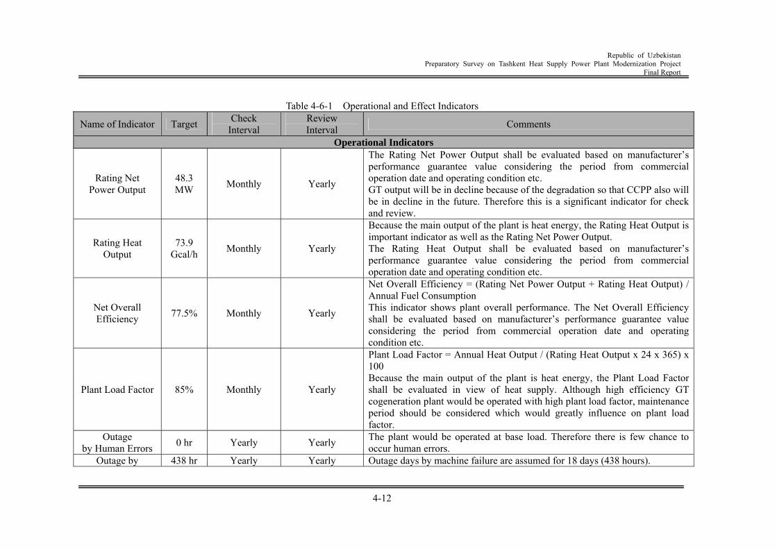
Republic of Uzbekistan
Preparatory Survey on Tashkent Heat Supply Power Plant Modernization Project Final Report
4-12
Table 4-6-1 Operational and Effect Indicators
Name of Indicator Target Check Interval
Review Interval Comments
Operational Indicators
Rating Net Power Output
48.3 MW Monthly Yearly
The Rating Net Power Output shall be evaluated based on manufacturer’s performance guarantee value considering the period from commercial operation date and operating condition etc. GT output will be in decline because of the degradation so that CCPP also will be in decline in the future. Therefore this is a significant indicator for check and review.
Rating Heat Output
73.9 Gcal/h Monthly Yearly
Because the main output of the plant is heat energy, the Rating Heat Output is important indicator as well as the Rating Net Power Output. The Rating Heat Output shall be evaluated based on manufacturer’s performance guarantee value considering the period from commercial operation date and operating condition etc.
Net Overall Efficiency 77.5% Monthly Yearly
Net Overall Efficiency = (Rating Net Power Output + Rating Heat Output) / Annual Fuel Consumption This indicator shows plant overall performance. The Net Overall Efficiency shall be evaluated based on manufacturer’s performance guarantee value considering the period from commercial operation date and operating condition etc.
Plant Load Factor 85% Monthly Yearly
Plant Load Factor = Annual Heat Output / (Rating Heat Output x 24 x 365) x 100 Because the main output of the plant is heat energy, the Plant Load Factor shall be evaluated in view of heat supply. Although high efficiency GT cogeneration plant would be operated with high plant load factor, maintenance period should be considered which would greatly influence on plant load factor.
Outage by Human Errors 0 hr Yearly Yearly The plant would be operated at base load. Therefore there is few chance to
occur human errors. Outage by 438 hr Yearly Yearly Outage days by machine failure are assumed for 18 days (438 hours).
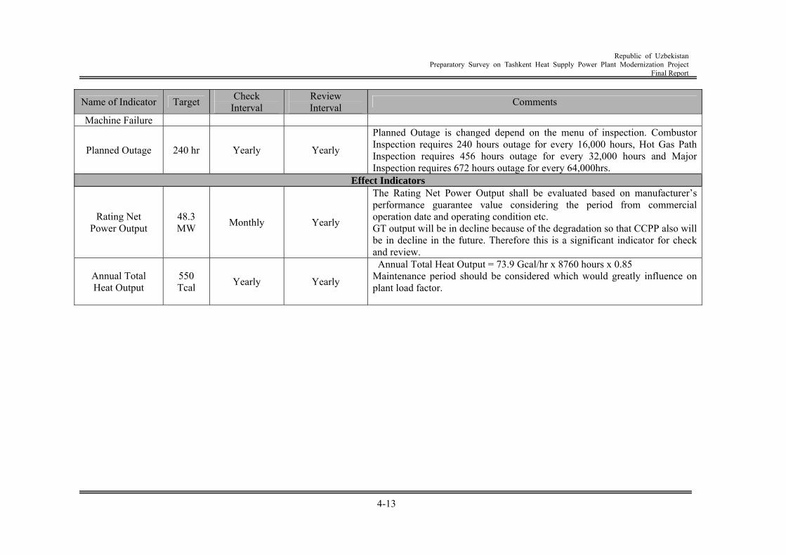
Republic of Uzbekistan
Preparatory Survey on Tashkent Heat Supply Power Plant Modernization Project Final Report
4-13
Name of Indicator Target Check Interval
Review Interval Comments
Machine Failure
Planned Outage 240 hr Yearly Yearly
Planned Outage is changed depend on the menu of inspection. Combustor Inspection requires 240 hours outage for every 16,000 hours, Hot Gas Path Inspection requires 456 hours outage for every 32,000 hours and Major Inspection requires 672 hours outage for every 64,000hrs.
Effect Indicators
Rating Net Power Output
48.3 MW Monthly Yearly
The Rating Net Power Output shall be evaluated based on manufacturer’s performance guarantee value considering the period from commercial operation date and operating condition etc. GT output will be in decline because of the degradation so that CCPP also will be in decline in the future. Therefore this is a significant indicator for check and review.
Annual Total Heat Output
550 Tcal Yearly Yearly
Annual Total Heat Output = 73.9 Gcal/hr x 8760 hours x 0.85 Maintenance period should be considered which would greatly influence on plant load factor.
Republic of Uzbekistan
Preparatory Survey on Tashkent Heat Supply Power Plant Modernization Project Final Report
5-1
Chapter 5 Environmental and Social Consideration 5.1 Legal system relating to environment 5.1.1 Environmental Administration (1) Province
Following governmental agencies play primary roles regarding the Environmental Administration in the Republic of Uzbekistan. The President — Act as a decision maker on major environmental issues and the as a
leader to promote international cooperation on environmental conservation. The Diet --- Clarifying the environmental conservation policies,
making decision in the Diet, acting as liaison with the State Nature Conservancy council, establishing sanctuary and disaster area, developing legal systems.
The Cabinet --- Implementing environmental conservation policy, making decision and supervising operation on environmental conservation plan, and allocating natural resources.
(2) Implementing Agencies
Based on the above role-sharing, the actual implementing body mainly managing the environment issue is the State Committee for Nature Protection “Goskomprirody” which was established in 1989 in the Cabinet office and is reporting to the Diet. Also as local organization of the State Committee for Nature Protection, the local Committee for Nature Protection exists in each province and major cities. State and local Committee for Nature Protection implements and manages environmental conservation. The primary responsibilities held by the State Committee for Nature Protection are as follows.
1) Legal surveillance regarding environmental conservation 2) Promotion on environmental conservation plan 3) Guidance on environmental tests implemented by the state 4) Approval of environmental standards 5) Issue and nullification of license for emission/storage of pollutant and industrial waste 6) Implementation of environmental measurement 7) System for international cooperation on environmental issues
Other than the State Committee for Nature Protection environmental management is conducted by Industrial, Labor and Safety Committee, Ministry of Health, State Department, Ministry of Agricultural Water Utilization under the scope of each jurisdiction respectively. Also, Sate Land Use Committee, State Forestry Committee, Uzbek Hydrometeorological Institution “ Uzgidromet ” are obliged to conduct environmental conservation. Monitoring on air /water quality in the general environment is actually measured by Uzbek Hydrometeorological Institution “Uzgidromet” under State Nature Conservatory Committee.
5.1.2 System of legal restriction on the environment Laws regarding nature conservation, utilization of natural resources, environmental conservation are composed of act, presidential decree, legislative decree, and enactment. The legal system regarding environmental conservation is composed of not only from the aspect of environmental conservation, but also from the aspects of laws regarding ecological conservation
Republic of Uzbekistan
Preparatory Survey on Tashkent Heat Supply Power Plant Modernization Project Final Report
5-2
of land, water, wildlife and plant. Followings are the Basic Laws and the established years. The Law of the Republic of Uzbekistan “On Nature Protection” (9 December 1992 ref,
754-XII) The Law of the Republic of Uzbekistan “On Water and Water Use” (6 May 1993, ref.
837-XII) The Law of the Republic of Uzbekistan “On Ambient Air Protection” (27 December
1996, ref. 353-I) The Law of the Republic of Uzbekistan “On Fauna Use and Protection” (26 December
1997, ref. 545-I) The Law of the Republic of Uzbekistan “On Flora Use and Protection” (26 December
1997, ref. 543-I) Land Code of the Republic of Uzbekistan (30 April 1998, ref. 599-I) The Law of the Republic of Uzbekistan “On Forest” (15 April 1999, ref. 770-I) The Law of the Republic of Uzbekistan “On Protection of Population and Areas from
Emergency Conditions of Natural and Technogenic Character” (20 August 1999, ref. 824-I)
The Law of the Republic of Uzbekistan “On Environmental Audit” (25 May 2000, ref. 73-II)
The Law of the Republic of Uzbekistan “On Radiation Safety” (31 August 2000, ref. 120-II)
he Law of the Republic of Uzbekistan “On Protection of Agricultural Plants from Pests, Diseases and Agrestals” (31 August 2000, ref. 116-II)
The Law of the Republic of Uzbekistan “On Solid Waste Disposal” (5 April 2002, ref. 362-II)
The Law of the Republic of Uzbekistan “On Subsoil” (new edition), (13 December 2002, ref. 444-II)
The Law of the Republic of Uzbekistan “On Preserved Natural Territories” (3 December 2004, ref. 710-II)
The above are primary Basic Laws and there are numbers of decrees and regulations which deal with specific restrictions. 5.1.3 The major environmental restriction As a major environmental restriction in `Uzbekistan, standard value / restriction regarding air, water and noise at thermal power plant shall be noted. (1) Atmosphere
1) Environment Standard In the Republic of Uzbekistan, maximum allowable concentration (MAC)(such as NO2、NO、CO, and soot) for protecting human health is established for the general/ working area. As for general area (Ambient Air), the standard value is established for maximum one time average of 30 minutes and for daily average. The MAC for the primary pollutants discharged from the gas- fired power plant is listed in the Table5-1-1. Aside from these, MAC for vanadium and benzpyrene are established which are all associated with power plant using mainly oil and coal as fuel.
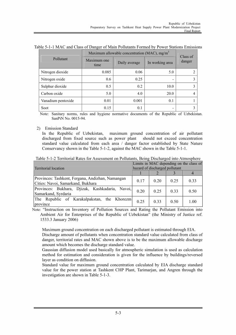
Republic of Uzbekistan
Preparatory Survey on Tashkent Heat Supply Power Plant Modernization Project Final Report
5-3
Table 5-1-1 MAC and Class of Danger of Main Pollutants Formed by Power Stations Emissions
Maximum allowable concentration (MAC), mg/m3 Pollutant Maximum one
time Daily average In working area Class of danger
Nitrogen dioxide 0.085 0.06 5.0 2
Nitrogen oxide 0.6 0.25 - 3
Sulphur dioxide 0.5 0.2 10.0 3
Carbon oxide 5.0 4.0 20.0 4
Vanadium pentoxide 0.01 0.001 0.1 1
Soot 0.15 0.1 - 3Note: Sanitary norms, rules and hygiene normative documents of the Republic of Uzbekistan.
SanPiN No. 0015-94.
2) Emission Standard In the Republic of Uzbekistan, maximum ground concentration of air pollutant discharged from fixed source such as power plant should not exceed concentration standard value calculated from each area / danger factor established by State Nature Conservancy shown in the Table 5-1-2, against the MAC shown in the Table 5-1-1.
Table 5-1-2 Territorial Rates for Assessment on Pollutants, Being Discharged into Atmosphere
Limits in MAC depending on the class of hazard of discharged pollutant Territorial location
1 2 3 4 Provinces: Tashkent, Fergana, Andizhan, Namangan Cities: Navoi, Samarkand, Bukhara 0.17 0.20 0.25 0.33
Provinces: Bukhara, Djizak, Kashkadaria, Navoi, Samarkand, Syrdaria 0.20 0.25 0.33 0.50
The Republic of Karakalpakstan, the Khorezm province 0.25 0.33 0.50 1.00
Note: “Instruction on Inventory of Pollution Sources and Rating the Pollutant Emission into Ambient Air for Enterprises of the Republic of Uzbekistan” (the Ministry of Justice ref. 1533.3 January 2006)
Maximum ground concentration on each discharged pollutant is estimated through EIA. Discharge amount of pollutants when concentration standard value calculated from class of danger, territorial rates and MAC shown above is to be the maximum allowable discharge amount which becomes the discharge standard value. Gaussian diffusion model used basically for atmospheric simulation is used as calculation method for estimation and consideration is given for the influence by buildings/reversed layer as condition on diffusion. Standard value for maximum ground concentration calculated by EIA discharge standard value for the power station at Tashkent CHP Plant, Tarimarjan, and Angren through the investigation are shown in Table 5-1-3.
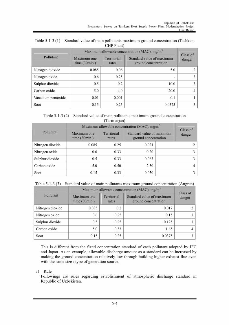
Republic of Uzbekistan
Preparatory Survey on Tashkent Heat Supply Power Plant Modernization Project Final Report
5-4
Table 5-1-3 (1) Standard value of main pollutants maximum ground concentration (Tashkent CHP Plant)
Maximum allowable concentration (MAC), mg/m3 Pollutant Maximum one
time (30min.) Territorial
rates Standard value of maximum
ground concentration
Class of danger
Nitrogen dioxide 0.085 0.06 5.0 2
Nitrogen oxide 0.6 0.25 - 3
Sulphur dioxide 0.5 0.2 10.0 3
Carbon oxide 5.0 4.0 20.0 4
Vanadium pentoxide 0.01 0.001 0.1 1
Soot 0.15 0.25 0.0375 3
Table 5-1-3 (2) Standard value of main pollutants maximum ground concentration (Tarimarjan)
Maximum allowable concentration (MAC), mg/m3 Pollutant Maximum one
time (30min.) Territorial
rates Standard value of maximum
ground concentration
Class of danger
Nitrogen dioxide 0.085 0.25 0.021 2
Nitrogen oxide 0.6 0.33 0.20 3
Sulphur dioxide 0.5 0.33 0.063 3
Carbon oxide 5.0 0.50 2.50 4
Soot 0.15 0.33 0.050 3
Table 5-1-3 (3) Standard value of main pollutants maximum ground concentration (Angren) Maximum allowable concentration (MAC), mg/m3
Pollutant Maximum one time (30min.)
Territorial rates
Standard value of maximum ground concentration
Class of danger
Nitrogen dioxide 0.085 0.2 0.017 2
Nitrogen oxide 0.6 0.25 0.15 3
Sulphur dioxide 0.5 0.25 0.125 3
Carbon oxide 5.0 0.33 1.65 4
Soot 0.15 0.25 0.0375 3
This is different from the fixed concentration standard of each pollutant adopted by IFC and Japan. As an example, allowable discharge amount as a standard can be increased by making the ground concentration relatively low through building higher exhaust flue even with the same size / type of generation source.
3) Rule
Followings are rules regarding establishment of atmospheric discharge standard in Republic of Uzbekistan.
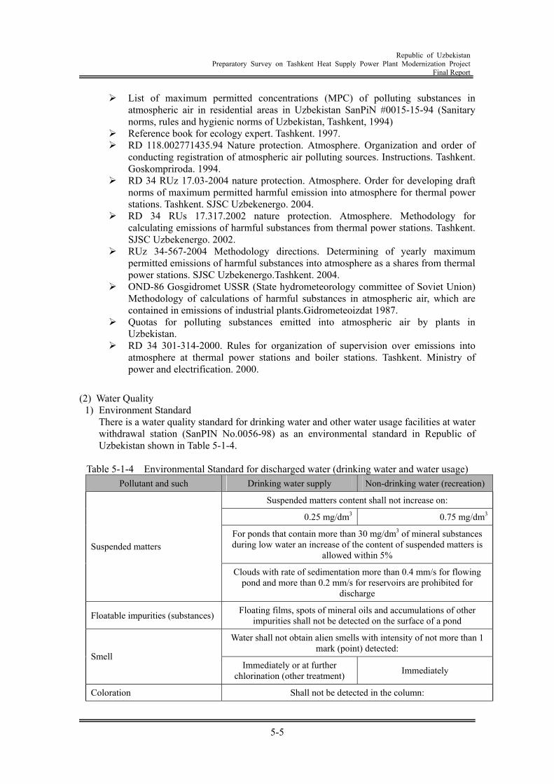
Republic of Uzbekistan
Preparatory Survey on Tashkent Heat Supply Power Plant Modernization Project Final Report
5-5
List of maximum permitted concentrations (MPC) of polluting substances in atmospheric air in residential areas in Uzbekistan SanPiN #0015-15-94 (Sanitary norms, rules and hygienic norms of Uzbekistan, Tashkent, 1994)
Reference book for ecology expert. Tashkent. 1997. RD 118.002771435.94 Nature protection. Atmosphere. Organization and order of
conducting registration of atmospheric air polluting sources. Instructions. Tashkent. Goskompriroda. 1994.
RD 34 RUz 17.03-2004 nature protection. Atmosphere. Order for developing draft norms of maximum permitted harmful emission into atmosphere for thermal power stations. Tashkent. SJSC Uzbekenergo. 2004.
RD 34 RUs 17.317.2002 nature protection. Atmosphere. Methodology for calculating emissions of harmful substances from thermal power stations. Tashkent. SJSC Uzbekenergo. 2002.
RUz 34-567-2004 Methodology directions. Determining of yearly maximum permitted emissions of harmful substances into atmosphere as a shares from thermal power stations. SJSC Uzbekenergo.Tashkent. 2004.
OND-86 Gosgidromet USSR (State hydrometeorology committee of Soviet Union) Methodology of calculations of harmful substances in atmospheric air, which are contained in emissions of industrial plants.Gidrometeoizdat 1987.
Quotas for polluting substances emitted into atmospheric air by plants in Uzbekistan.
RD 34 301-314-2000. Rules for organization of supervision over emissions into atmosphere at thermal power stations and boiler stations. Tashkent. Ministry of power and electrification. 2000.
(2) Water Quality
1) Environment Standard There is a water quality standard for drinking water and other water usage facilities at water withdrawal station (SanPIN No.0056-98) as an environmental standard in Republic of Uzbekistan shown in Table 5-1-4.
Table 5-1-4 Environmental Standard for discharged water (drinking water and water usage)
Pollutant and such Drinking water supply Non-drinking water (recreation)
Suspended matters content shall not increase on:
0.25 mg/dm3 0.75 mg/dm3
For ponds that contain more than 30 mg/dm3 of mineral substances during low water an increase of the content of suspended matters is
allowed within 5% Suspended matters
Clouds with rate of sedimentation more than 0.4 mm/s for flowing pond and more than 0.2 mm/s for reservoirs are prohibited for
discharge
Floatable impurities (substances) Floating films, spots of mineral oils and accumulations of other impurities shall not be detected on the surface of a pond
Water shall not obtain alien smells with intensity of not more than 1 mark (point) detected:
Smell Immediately or at further
chlorination (other treatment) Immediately
Coloration Shall not be detected in the column:
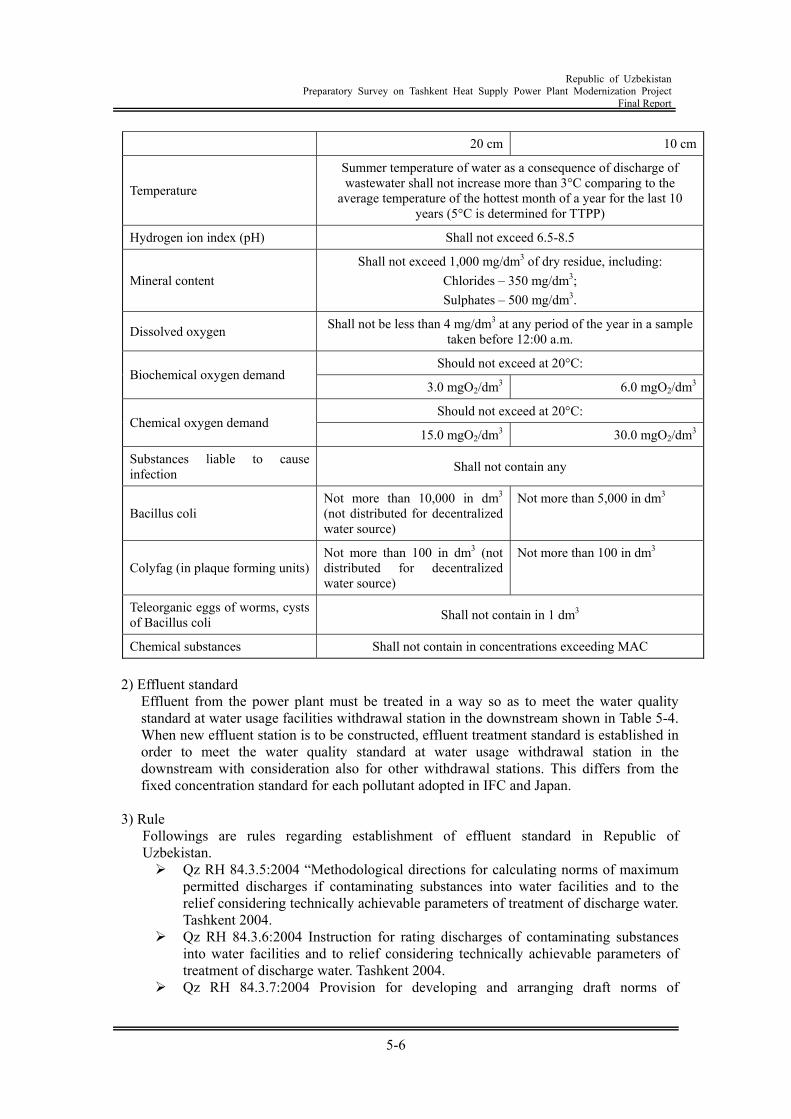
Republic of Uzbekistan
Preparatory Survey on Tashkent Heat Supply Power Plant Modernization Project Final Report
5-6
20 cm 10 cm
Temperature
Summer temperature of water as a consequence of discharge of wastewater shall not increase more than 3°C comparing to the
average temperature of the hottest month of a year for the last 10 years (5°C is determined for TTPP)
Hydrogen ion index (pH) Shall not exceed 6.5-8.5
Mineral content Shall not exceed 1,000 mg/dm3 of dry residue, including:
Chlorides – 350 mg/dm3; Sulphates – 500 mg/dm3.
Dissolved oxygen Shall not be less than 4 mg/dm3 at any period of the year in a sample taken before 12:00 a.m.
Should not exceed at 20°C: Biochemical oxygen demand
3.0 mgO2/dm3 6.0 mgO2/dm3
Should not exceed at 20°C: Chemical oxygen demand
15.0 mgO2/dm3 30.0 mgO2/dm3
Substances liable to cause infection Shall not contain any
Bacillus coli Not more than 10,000 in dm3 (not distributed for decentralized water source)
Not more than 5,000 in dm3
Colyfag (in plaque forming units) Not more than 100 in dm3 (not distributed for decentralized water source)
Not more than 100 in dm3
Teleorganic eggs of worms, cysts of Bacillus coli Shall not contain in 1 dm3
Chemical substances Shall not contain in concentrations exceeding MAC
2) Effluent standard Effluent from the power plant must be treated in a way so as to meet the water quality standard at water usage facilities withdrawal station in the downstream shown in Table 5-4. When new effluent station is to be constructed, effluent treatment standard is established in order to meet the water quality standard at water usage withdrawal station in the downstream with consideration also for other withdrawal stations. This differs from the fixed concentration standard for each pollutant adopted in IFC and Japan.
3) Rule
Followings are rules regarding establishment of effluent standard in Republic of Uzbekistan. Qz RH 84.3.5:2004 “Methodological directions for calculating norms of maximum
permitted discharges if contaminating substances into water facilities and to the relief considering technically achievable parameters of treatment of discharge water. Tashkent 2004.
Qz RH 84.3.6:2004 Instruction for rating discharges of contaminating substances into water facilities and to relief considering technically achievable parameters of treatment of discharge water. Tashkent 2004.
Qz RH 84.3.7:2004 Provision for developing and arranging draft norms of
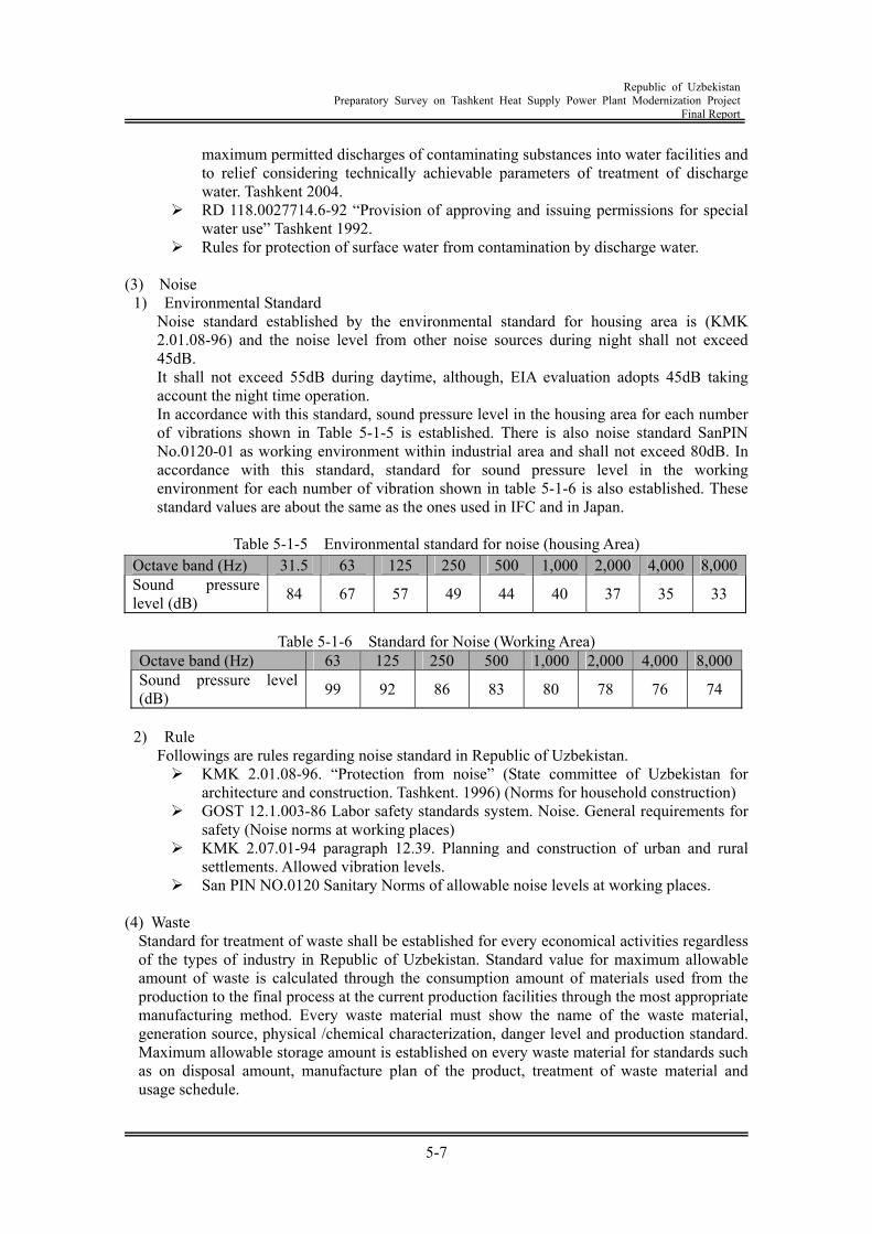
Republic of Uzbekistan
Preparatory Survey on Tashkent Heat Supply Power Plant Modernization Project Final Report
5-7
maximum permitted discharges of contaminating substances into water facilities and to relief considering technically achievable parameters of treatment of discharge water. Tashkent 2004.
RD 118.0027714.6-92 “Provision of approving and issuing permissions for special water use” Tashkent 1992.
Rules for protection of surface water from contamination by discharge water. (3) Noise
1) Environmental Standard Noise standard established by the environmental standard for housing area is (KMK 2.01.08-96) and the noise level from other noise sources during night shall not exceed 45dB. It shall not exceed 55dB during daytime, although, EIA evaluation adopts 45dB taking account the night time operation. In accordance with this standard, sound pressure level in the housing area for each number of vibrations shown in Table 5-1-5 is established. There is also noise standard SanPIN No.0120-01 as working environment within industrial area and shall not exceed 80dB. In accordance with this standard, standard for sound pressure level in the working environment for each number of vibration shown in table 5-1-6 is also established. These standard values are about the same as the ones used in IFC and in Japan.
Table 5-1-5 Environmental standard for noise (housing Area)
Table 5-1-6 Standard for Noise (Working Area)
Octave band (Hz) 63 125 250 500 1,000 2,000 4,000 8,000Sound pressure level (dB) 99 92 86 83 80 78 76 74
2) Rule
Followings are rules regarding noise standard in Republic of Uzbekistan. KMK 2.01.08-96. “Protection from noise” (State committee of Uzbekistan for
architecture and construction. Tashkent. 1996) (Norms for household construction) GOST 12.1.003-86 Labor safety standards system. Noise. General requirements for
safety (Noise norms at working places) KMK 2.07.01-94 paragraph 12.39. Planning and construction of urban and rural
settlements. Allowed vibration levels. San PIN NO.0120 Sanitary Norms of allowable noise levels at working places.
(4) Waste
Standard for treatment of waste shall be established for every economical activities regardless of the types of industry in Republic of Uzbekistan. Standard value for maximum allowable amount of waste is calculated through the consumption amount of materials used from the production to the final process at the current production facilities through the most appropriate manufacturing method. Every waste material must show the name of the waste material, generation source, physical /chemical characterization, danger level and production standard. Maximum allowable storage amount is established on every waste material for standards such as on disposal amount, manufacture plan of the product, treatment of waste material and usage schedule.
Octave band (Hz) 31.5 63 125 250 500 1,000 2,000 4,000 8,000Sound pressure level (dB) 84 67 57 49 44 40 37 35 33
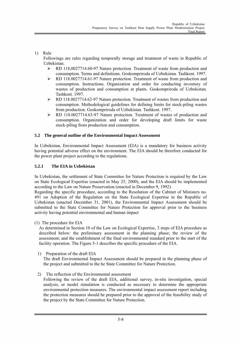
Republic of Uzbekistan
Preparatory Survey on Tashkent Heat Supply Power Plant Modernization Project Final Report
5-8
1) Rule
Followings are rules regarding temporally storage and treatment of waste in Republic of Uzbekistan. RD 118,0027714.60-97 Nature protection. Treatment of waste from production and
consumption. Terms and definitions. Goskompriroda of Uzbekistan. Tashkent. 1997. RD 118.0027714.61-97 Nature protection. Treatment of waste from production and
consumption. Instructions. Organization and order for conducting inventory of wastes of production and consumption at plants. Goskompriroda of Uzbekistan. Tashkent. 1997.
RD 118.0027714.62-97 Nature protection. Treatment of wastes from production and consumption. Methodological guidelines for defining limits for stock-piling wastes from production. Goskompriroda of Uzbekistan. Tashkent. 1997.
RD 118.0027714.63-97 Nature protection. Treatment of wastes of production and consumption. Organization and order for developing draft limits for waste stock-piling from production and consumption.
5.2 The general outline of the Environmental Impact Assessment In Uzbekistan, Environmental Impact Assessment (EIA) is a mandatory for business activity having potential adverse effect on the environment. The EIA should be therefore conducted for the power plant project according to the regulations. 5.2.1 The EIA in Uzbekistan In Uzbekistan, the settlement of State Committee for Nature Protection is required by the Law on State Ecological Expertise (enacted in May 25, 2000), and the EIA should be implemented according to the Law on Nature Preservation (enacted in December 9, 1992). Regarding the specific procedure, according to the Resolution of the Cabinet of Ministers no. 491 on Adoption of the Regulation on the State Ecological Expertise in the Republic of Uzbekistan (enacted December 31, 2001), the Environmental Impact Assessment should be submitted to the State Committee for Nature Protection for approval prior to the business activity having potential environmental and human impact (1) The procedure for EIA
As determined in Section 10 of the Law on Ecological Expertise, 3 steps of EIA procedure as described below: the preliminary assessment in the planning phase; the review of the assessment; and the establishment of the final environmental standard prior to the start of the facility operation. The Figure 5-1 describes the specific procedure of the EIA.
1) Preparation of the draft EIA
The draft Environmental Impact Assessment should be prepared in the planning phase of the project and submitted to the he State Committee for Nature Protection.
2) The reflection of the Environmental assessment
Following the review of the draft EIA, additional survey, in-situ investigation, special analysis, or model simulation is conducted as necessary to determine the appropriate environmental protection measures. The environmental impact assessment report including the protection measures should be prepared prior to the approval of the feasibility study of the project by the State Committee for Nature Protection.
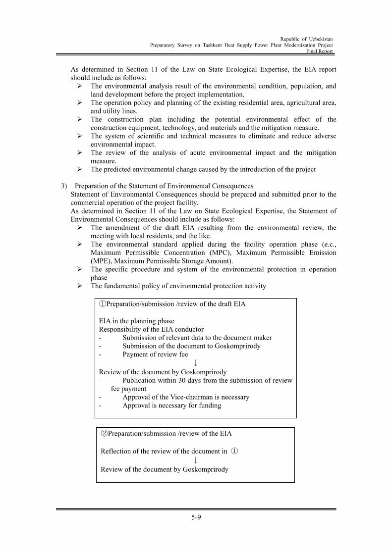
Republic of Uzbekistan
Preparatory Survey on Tashkent Heat Supply Power Plant Modernization Project Final Report
5-9
As determined in Section 11 of the Law on State Ecological Expertise, the EIA report should include as follows: The environmental analysis result of the environmental condition, population, and
land development before the project implementation. The operation policy and planning of the existing residential area, agricultural area,
and utility lines. The construction plan including the potential environmental effect of the
construction equipment, technology, and materials and the mitigation measure. The system of scientific and technical measures to eliminate and reduce adverse
environmental impact. The review of the analysis of acute environmental impact and the mitigation
measure. The predicted environmental change caused by the introduction of the project
3) Preparation of the Statement of Environmental Consequences
Statement of Environmental Consequences should be prepared and submitted prior to the commercial operation of the project facility. As determined in Section 11 of the Law on State Ecological Expertise, the Statement of Environmental Consequences should include as follows: The amendment of the draft EIA resulting from the environmental review, the
meeting with local residents, and the like. The environmental standard applied during the facility operation phase (e.c.,
Maximum Permissible Concentration (MPC), Maximum Permissible Emission (MPE), Maximum Permissible Storage Amount).
The specific procedure and system of the environmental protection in operation phase
The fundamental policy of environmental protection activity
①Preparation/submission /review of the draft EIA EIA in the planning phase Responsibility of the EIA conductor - Submission of relevant data to the document maker - Submission of the document to Goskomprirody - Payment of review fee
↓ Review of the document by Goskomprirody - Publication within 30 days from the submission of review
fee payment - Approval of the Vice-chairman is necessary - Approval is necessary for funding
②Preparation/submission /review of the EIA Reflection of the review of the document in ①
↓ Review of the document by Goskomprirody
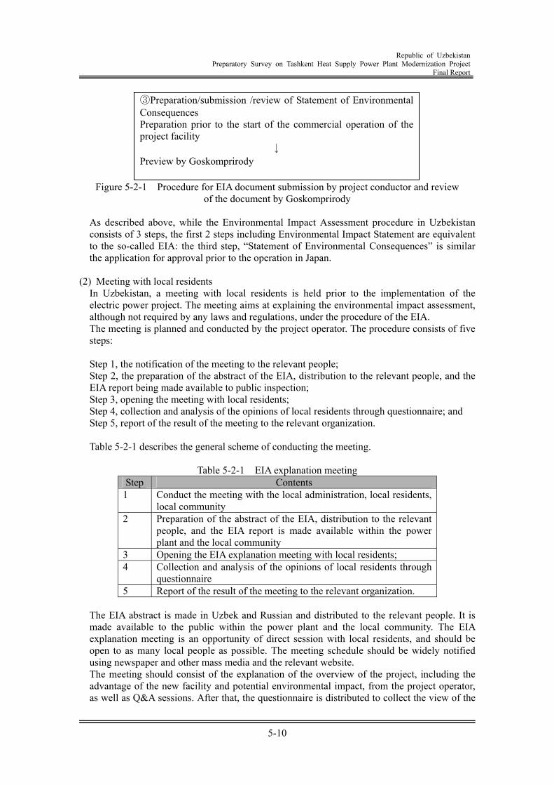
Republic of Uzbekistan
Preparatory Survey on Tashkent Heat Supply Power Plant Modernization Project Final Report
5-10
Figure 5-2-1 Procedure for EIA document submission by project conductor and review
of the document by Goskomprirody
As described above, while the Environmental Impact Assessment procedure in Uzbekistan consists of 3 steps, the first 2 steps including Environmental Impact Statement are equivalent to the so-called EIA: the third step, “Statement of Environmental Consequences” is similar the application for approval prior to the operation in Japan.
(2) Meeting with local residents
In Uzbekistan, a meeting with local residents is held prior to the implementation of the electric power project. The meeting aims at explaining the environmental impact assessment, although not required by any laws and regulations, under the procedure of the EIA. The meeting is planned and conducted by the project operator. The procedure consists of five steps:
Step 1, the notification of the meeting to the relevant people; Step 2, the preparation of the abstract of the EIA, distribution to the relevant people, and the EIA report being made available to public inspection; Step 3, opening the meeting with local residents; Step 4, collection and analysis of the opinions of local residents through questionnaire; and Step 5, report of the result of the meeting to the relevant organization.
Table 5-2-1 describes the general scheme of conducting the meeting.
Table 5-2-1 EIA explanation meeting
Step Contents 1 Conduct the meeting with the local administration, local residents,
local community 2 Preparation of the abstract of the EIA, distribution to the relevant
people, and the EIA report is made available within the power plant and the local community
3 Opening the EIA explanation meeting with local residents; 4 Collection and analysis of the opinions of local residents through
questionnaire 5 Report of the result of the meeting to the relevant organization.
The EIA abstract is made in Uzbek and Russian and distributed to the relevant people. It is made available to the public within the power plant and the local community. The EIA explanation meeting is an opportunity of direct session with local residents, and should be open to as many local people as possible. The meeting schedule should be widely notified using newspaper and other mass media and the relevant website. The meeting should consist of the explanation of the overview of the project, including the advantage of the new facility and potential environmental impact, from the project operator, as well as Q&A sessions. After that, the questionnaire is distributed to collect the view of the
③Preparation/submission /review of Statement of Environmental Consequences Preparation prior to the start of the commercial operation of the project facility
↓ Preview by Goskomprirody
Republic of Uzbekistan
Preparatory Survey on Tashkent Heat Supply Power Plant Modernization Project Final Report
5-11
local people and ensure their understanding of the project concept. The result of the meetings is reported to the relevant organization through the summary report of the meetings published by the project operator, and publicized through the mass media. The opinion from the local residents will be reflected in the final Statement of Environmental Consequences as described above.
5.2.2 The overview of the Environmental Impact Assessment (1) The index of the Draft EIA and required data
The EIA procedure will be required in the later stage for the retrofit and upgrade of Angren Power plant, Tarimarjan power plant , three Heat Supply Plants in Tashkent and Tashkent CHP Plant. The tables below provide the general view of the index and main points of issue for preparing the Environmental Impact Assessment document (draft EIA at this phase) for the power plant construction. The general view below was compiled taking into account the existing survey result in Uzbekistan, the contents of the check list in JICA guideline, and the discussion with the State Committee for Nature Protection and EIA expert in the power plant. The local characteristics and fuel characteristics of Tashkent CHP Plant, Tarimarjan Gas Power Plant, and Angren Coal Power Plant are taken into consideration. The index and required information are listed in Table 5-2-2. The explanation is given on the former checklist provided by JBIC (Japan Bank for International Cooperation), and it is confirmed that the similar endpoint will be checked in the future EIA for power plant. For the details, further consideration will be necessary on site.
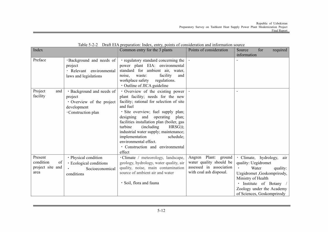
Republic of Uzbekistan
Preparatory Survey on Tashkent Heat Supply Power Plant Modernization Project Final Report
5-12
Table 5-2-2 Draft EIA preparation: Index, entry, points of consideration and information source
Index Common entry for the 3 plants Points of consideration Source for required information
Preface ・Background and needs of project ・ Relevant environmental laws and legislations
・regulatory standard concerning the power plant EIA: environmental standard for ambient air, water, noise, waste: facility and workplace safety regulations. ・Outline of JICA guideline
- -
Project and facility
・Background and needs of project ・Overview of the project development ・Construction plan
・Overview of the existing power plant facility; needs for the new facility; rational for selection of site and fuel ・Site overview; fuel supply plan; designing and operating plan; facilities installation plan (boiler, gas turbine (including HRSG)); industrial water supply; maintenance; implementation schedule; environmental effect. ・ Construction and environmental effect
- -
Present condition of project site and area
・Physical condition ・Ecological conditions ・ Socioeconomical conditions
・Climate / meteorology, landscape, geology, hydrology, water quality, air quality, noise, main contamination source of ambient air and water ・Soil, flora and fauna
Angren Plant: ground water quality should be assessed in association with coal ash disposal.
・ Climate, hydrology, air quality: Uzgidromet ・ Water quality: Uzgidromet ,Goskomprirody,Ministry of Health ・ Institute of Botany / Zoology under the Academy of Sciences, Goskomprirody
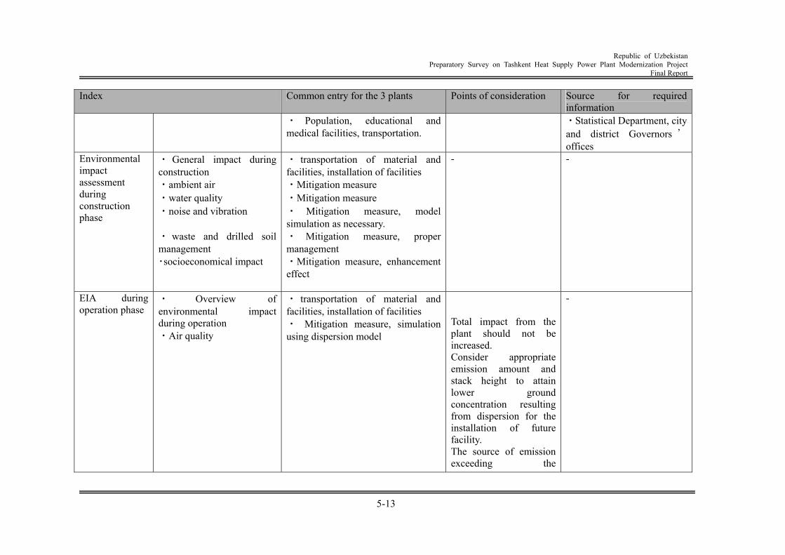
Republic of Uzbekistan
Preparatory Survey on Tashkent Heat Supply Power Plant Modernization Project Final Report
5-13
Index Common entry for the 3 plants Points of consideration Source for required information
・ Population, educational and medical facilities, transportation.
・Statistical Department, city and district Governors ’offices
Environmental impact assessment during construction phase
・ General impact during construction ・ambient air ・water quality ・noise and vibration ・ waste and drilled soil management ・socioeconomical impact
・ transportation of material and facilities, installation of facilities ・Mitigation measure ・Mitigation measure ・ Mitigation measure, model simulation as necessary. ・ Mitigation measure, proper management ・Mitigation measure, enhancement effect
- -
EIA during operation phase
・ Overview of environmental impact during operation ・Air quality
・ transportation of material and facilities, installation of facilities ・ Mitigation measure, simulation using dispersion model
Total impact from the plant should not be increased. Consider appropriate emission amount and stack height to attain lower ground concentration resulting from dispersion for the installation of future facility. The source of emission exceeding the
-
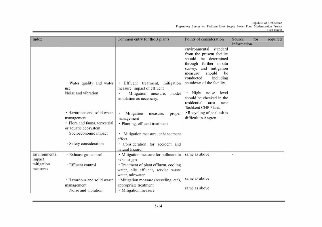
Republic of Uzbekistan
Preparatory Survey on Tashkent Heat Supply Power Plant Modernization Project Final Report
5-14
Index Common entry for the 3 plants Points of consideration Source for required information
・Water quality and water use Noise and vibration ・Hazardous and solid waste management ・Flora and fauna, terrestrial or aquatic ecosystem ・Socioeconomic impact ・Safety consideration
・ Effluent treatment, mitigation measure, impact of effluent ・ Mitigation measure, model simulation as necessary. ・ Mitigation measure, proper management ・Planting, effluent treatment ・ Mitigation measure, enhancement effect ・ Consideration for accident and natural hazard
environmental standard from the present facility should be determined through further in-situ survey, and mitigation measure should be conducted including shutdown of the facility. ・ Night noise level should be checked in the residential area near Tashkent CHP Plant. ・Recycling of coal ash is difficult in Angren.
Environmental impact mitigation measures
・Exhaust gas control ・Effluent control ・Hazardous and solid waste management ・Noise and vibration
・Mitigation measure for pollutant in exhaust gas ・Treatment of plant effluent, cooling water, oily effluent, service waste water, rainwater. ・Mitigation measure (recycling, etc), appropriate treatment ・Mitigation measure
same as above same as above same as above
-
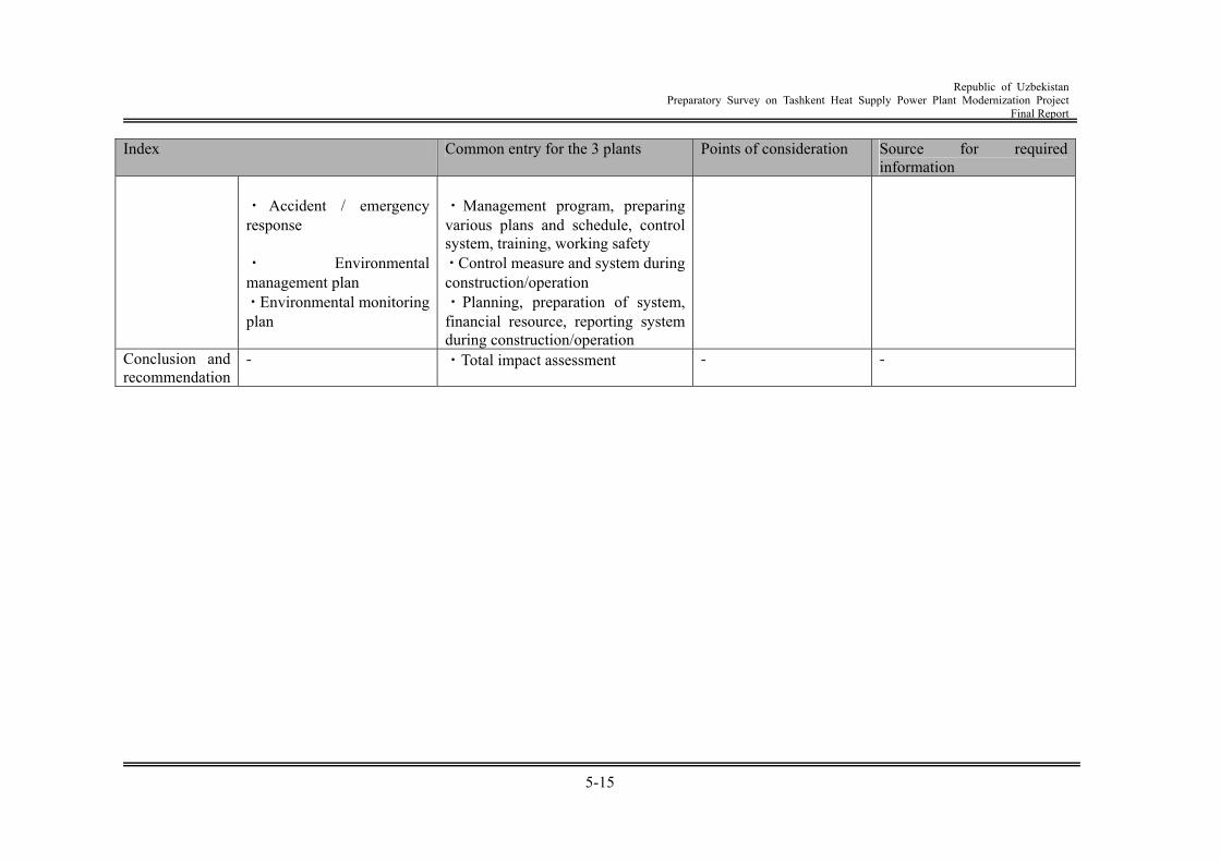
Republic of Uzbekistan
Preparatory Survey on Tashkent Heat Supply Power Plant Modernization Project Final Report
5-15
Index Common entry for the 3 plants Points of consideration Source for required information
・ Accident / emergency response ・ Environmental management plan ・Environmental monitoring plan
・Management program, preparing various plans and schedule, control system, training, working safety ・Control measure and system during construction/operation ・Planning, preparation of system, financial resource, reporting system during construction/operation
Conclusion and recommendation
- ・Total impact assessment - -
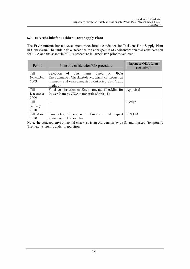
Republic of Uzbekistan
Preparatory Survey on Tashkent Heat Supply Power Plant Modernization Project Final Report
5-16
5.3 EIA schedule for Tashkent Heat Supply Plant The Environmenta Impact Assessment procedure is conducted for Tashkent Heat Supply Plant in Uzbekistan. The table below describes the checkpoints of socioenvironmental consideration for JICA and the schedule of EIA procedure in Uzbekistan prior to yen credit.
Period Point of consideration/EIA procedure Japanese ODA Loan (tentative)
Till November 2009
Selection of EIA items based on JICA Environmental Checklist/development of mitigation measures and environmental monitoring plan (item, method)
Till December 2009
Final confirmation of Environmental Checklist for Power Plant by JICA (temporal) (Annex-1)
Appraisal
Till January 2010
- Pledge
Till March 2010
Completion of review of Environmental Impact Statement in Uzbekistan
E/N,L/A
Note: the attached environmental checklist is an old version by JBIC and marked “temporal”. The new version is under preparation.
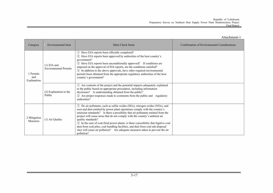
Republic of Uzbekistan
Preparatory Survey on Tashkent Heat Supply Power Plant Modernization Project Final Report
5-17
Attachment-1
Category Environmental Item Main Check Items Confirmation of Environmental Considerations
(1) EIA and Environmental Permits
① Have EIA reports been officially completed? ② Have EIA reports been approved by authorities of the host country’s government? ③ Have EIA reports been unconditionally approved? If conditions are imposed on the approval of EIA reports, are the conditions satisfied? ④ In addition to the above approvals, have other required environmental permits been obtained from the appropriate regulatory authorities of the host country’s government?
1 Permits and
Explanation
(2) Explanation to the Public
① Are contents of the project and the potential impacts adequately explained to the public based on appropriate procedures, including information disclosure? Is understanding obtained from the public? ② Are proper responses made to comments from the public and regulatory authorities?
2 Mitigation Measures (1) Air Quality
① Do air pollutants, such as sulfur oxides (SOx), nitrogen oxides (NOx), and soot and dust emitted by power plant operations comply with the country’s emission standards? Is there a possibility that air pollutants emitted from the project will cause areas that do not comply with the country’s ambient air quality standards? ② In the case of coal-fired power plants, is there a possibility that fugitive coal dust from coal piles, coal handling facilities, and dust from coal ash disposal sites will cause air pollution? Are adequate measures taken to prevent the air pollution?
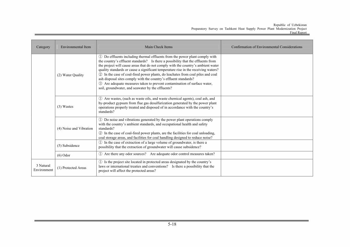
Republic of Uzbekistan
Preparatory Survey on Tashkent Heat Supply Power Plant Modernization Project Final Report
5-18
Category Environmental Item Main Check Items Confirmation of Environmental Considerations
(2) Water Quality
① Do effluents including thermal effluents from the power plant comply with the country’s effluent standards? Is there a possibility that the effluents from the project will cause areas that do not comply with the country’s ambient water quality standards or cause a significant temperature rise in the receiving waters?② In the case of coal-fired power plants, do leachates from coal piles and coal ash disposal sites comply with the country’s effluent standards? ③ Are adequate measures taken to prevent contamination of surface water, soil, groundwater, and seawater by the effluents?
(3) Wastes
① Are wastes, (such as waste oils, and waste chemical agents), coal ash, and by-product gypsum from flue gas desulfurization generated by the power plant operations properly treated and disposed of in accordance with the country’s standards?
(4) Noise and Vibration
① Do noise and vibrations generated by the power plant operations comply with the country’s ambient standards, and occupational health and safety standards? ② In the case of coal-fired power plants, are the facilities for coal unloading, coal storage areas, and facilities for coal handling designed to reduce noise?
(5) Subsidence ① In the case of extraction of a large volume of groundwater, is there a possibility that the extraction of groundwater will cause subsidence?
(6) Odor ① Are there any odor sources? Are adequate odor control measures taken?
3 Natural Environment (1) Protected Areas
① Is the project site located in protected areas designated by the country’s laws or international treaties and conventions? Is there a possibility that the project will affect the protected areas?
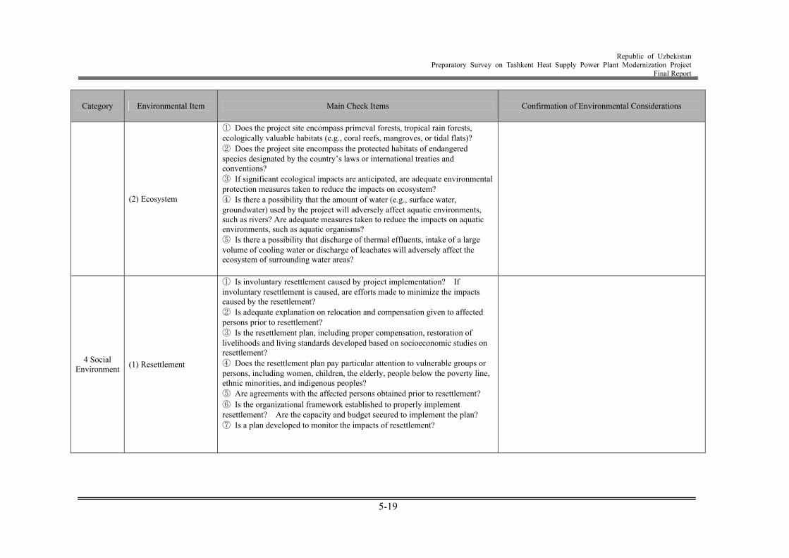
Republic of Uzbekistan
Preparatory Survey on Tashkent Heat Supply Power Plant Modernization Project Final Report
5-19
Category Environmental Item Main Check Items Confirmation of Environmental Considerations
(2) Ecosystem
① Does the project site encompass primeval forests, tropical rain forests, ecologically valuable habitats (e.g., coral reefs, mangroves, or tidal flats)? ② Does the project site encompass the protected habitats of endangered species designated by the country’s laws or international treaties and conventions? ③ If significant ecological impacts are anticipated, are adequate environmental protection measures taken to reduce the impacts on ecosystem? ④ Is there a possibility that the amount of water (e.g., surface water, groundwater) used by the project will adversely affect aquatic environments, such as rivers? Are adequate measures taken to reduce the impacts on aquatic environments, such as aquatic organisms? ⑤ Is there a possibility that discharge of thermal effluents, intake of a large volume of cooling water or discharge of leachates will adversely affect the ecosystem of surrounding water areas?
4 Social Environment (1) Resettlement
① Is involuntary resettlement caused by project implementation? If involuntary resettlement is caused, are efforts made to minimize the impacts caused by the resettlement? ② Is adequate explanation on relocation and compensation given to affected persons prior to resettlement? ③ Is the resettlement plan, including proper compensation, restoration of livelihoods and living standards developed based on socioeconomic studies on resettlement? ④ Does the resettlement plan pay particular attention to vulnerable groups or persons, including women, children, the elderly, people below the poverty line, ethnic minorities, and indigenous peoples? ⑤ Are agreements with the affected persons obtained prior to resettlement? ⑥ Is the organizational framework established to properly implement resettlement? Are the capacity and budget secured to implement the plan? ⑦ Is a plan developed to monitor the impacts of resettlement?
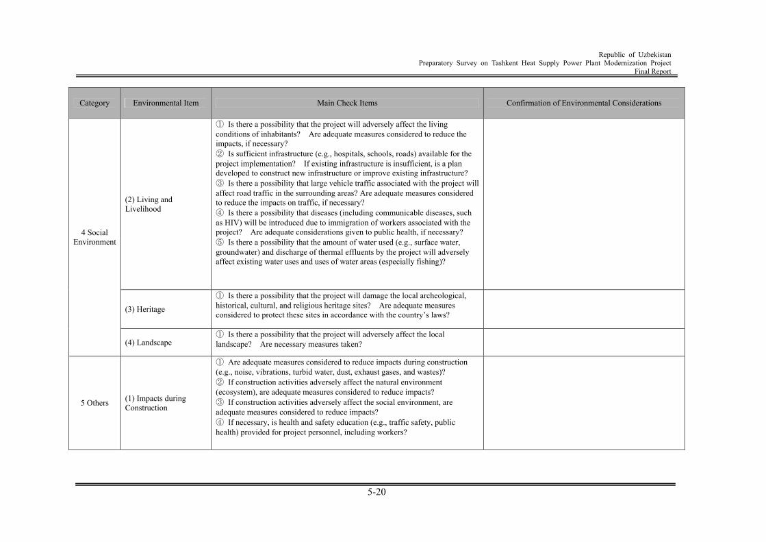
Republic of Uzbekistan
Preparatory Survey on Tashkent Heat Supply Power Plant Modernization Project Final Report
5-20
Category Environmental Item Main Check Items Confirmation of Environmental Considerations
(2) Living and Livelihood
① Is there a possibility that the project will adversely affect the living conditions of inhabitants? Are adequate measures considered to reduce the impacts, if necessary? ② Is sufficient infrastructure (e.g., hospitals, schools, roads) available for the project implementation? If existing infrastructure is insufficient, is a plan developed to construct new infrastructure or improve existing infrastructure? ③ Is there a possibility that large vehicle traffic associated with the project will affect road traffic in the surrounding areas? Are adequate measures considered to reduce the impacts on traffic, if necessary? ④ Is there a possibility that diseases (including communicable diseases, such as HIV) will be introduced due to immigration of workers associated with the project? Are adequate considerations given to public health, if necessary? ⑤ Is there a possibility that the amount of water used (e.g., surface water, groundwater) and discharge of thermal effluents by the project will adversely affect existing water uses and uses of water areas (especially fishing)?
(3) Heritage
① Is there a possibility that the project will damage the local archeological, historical, cultural, and religious heritage sites? Are adequate measures considered to protect these sites in accordance with the country’s laws?
4 Social Environment
(4) Landscape ① Is there a possibility that the project will adversely affect the local landscape? Are necessary measures taken?
5 Others (1) Impacts during Construction
① Are adequate measures considered to reduce impacts during construction (e.g., noise, vibrations, turbid water, dust, exhaust gases, and wastes)? ② If construction activities adversely affect the natural environment (ecosystem), are adequate measures considered to reduce impacts? ③ If construction activities adversely affect the social environment, are adequate measures considered to reduce impacts? ④ If necessary, is health and safety education (e.g., traffic safety, public health) provided for project personnel, including workers?
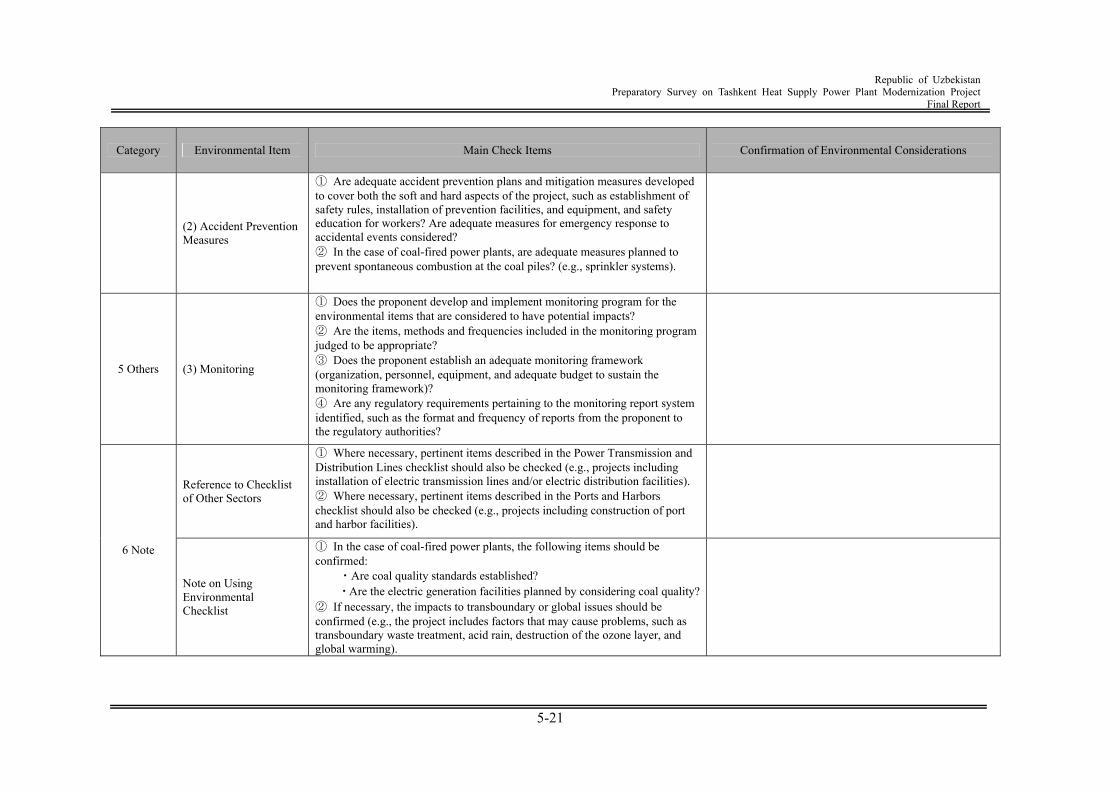
Republic of Uzbekistan
Preparatory Survey on Tashkent Heat Supply Power Plant Modernization Project Final Report
5-21
Category Environmental Item Main Check Items Confirmation of Environmental Considerations
(2) Accident Prevention Measures
① Are adequate accident prevention plans and mitigation measures developed to cover both the soft and hard aspects of the project, such as establishment of safety rules, installation of prevention facilities, and equipment, and safety education for workers? Are adequate measures for emergency response to accidental events considered? ② In the case of coal-fired power plants, are adequate measures planned to prevent spontaneous combustion at the coal piles? (e.g., sprinkler systems).
5 Others (3) Monitoring
① Does the proponent develop and implement monitoring program for the environmental items that are considered to have potential impacts? ② Are the items, methods and frequencies included in the monitoring program judged to be appropriate? ③ Does the proponent establish an adequate monitoring framework (organization, personnel, equipment, and adequate budget to sustain the monitoring framework)? ④ Are any regulatory requirements pertaining to the monitoring report system identified, such as the format and frequency of reports from the proponent to the regulatory authorities?
Reference to Checklist of Other Sectors
① Where necessary, pertinent items described in the Power Transmission and Distribution Lines checklist should also be checked (e.g., projects including installation of electric transmission lines and/or electric distribution facilities). ② Where necessary, pertinent items described in the Ports and Harbors checklist should also be checked (e.g., projects including construction of port and harbor facilities).
6 Note
Note on Using Environmental Checklist
① In the case of coal-fired power plants, the following items should be confirmed: ・Are coal quality standards established? ・Are the electric generation facilities planned by considering coal quality? ② If necessary, the impacts to transboundary or global issues should be confirmed (e.g., the project includes factors that may cause problems, such as transboundary waste treatment, acid rain, destruction of the ozone layer, and global warming).

Republic of Uzbekistan
Preparatory Survey on Tashkent Heat Supply Power Plant Modernization Project Final Report
6-1
Chapter 6 CDM Application Study 6.1 CDM procedure 6.1.1 Institutional structure Uzbekistan ratified the Kyoto Protocol as a Party not included in Annex I in 1999. The Interagency Council of CDM was established under the Cabinet and the Ministry of Economy was designated as the Designated National Authority (DNA) for the CDM by Presidential Resolution No.525 on December 6, 2006. Furthermore, Cabinet Resolution No.9 on the basic procedure for CDM investment project implementation was enforced in January, 2007, and the CDM project development in Uzbekistan has come in the concrete implementation stage. (1) Interagency Council
Interagency Council chaired by Deputy Prime Minister is a deliberative body, examine and approving CDM projects, organized under the Cabinet which has 21 representatives from state-owned enterprises and ministries/agencies. The following roles are given to the Council.
Identifying priority areas for application of CDM Approving rules and procedures for selecting and approving of CDM projects at the
national level Approving CDM projects at the national level after DNA appraisal Approving draft Emission Reduction Purchase Agreements among the CDM project
participants (2) Designated National Authority
The Designated National Authority (DNA) of Uzbekistan is the Ministry of Economy. As a role of DNA, the followings are stipulated in the Presidential Resolution.
Development and selection of projects to be implemented in the framework of CDM
taking account the economic, environmental, social and technological interests of the Republic of Uzbekistan, formation of the relevant database;
Coordination of the activity of authorized ministries and agencies on the appraisal of the projects proposed for implementation in the framework of CDM, to conform the terms and procedure, specified in Article 12 of the Kyoto Protocol, international agreements and legislation of the Republic of Uzbekistan, as well as international and national criteria on stainable development.
Submission of investment projects, proposed for implementation in the framework of CDM, for the approval of the Interagency Council;
Submission of investment projects, proposed for implementation in the framework of CDM, after their approval by the Interagency Council, to the Executive Board of CDM at the Secretariat of the UNFCCC of implementation of the investment projects carried out in the framework of CDM;
Monitoring of implementation of the investment projects carried out in the framework of CDM;
Addressing other issues related to implementation of the investment projects applying the CDM.
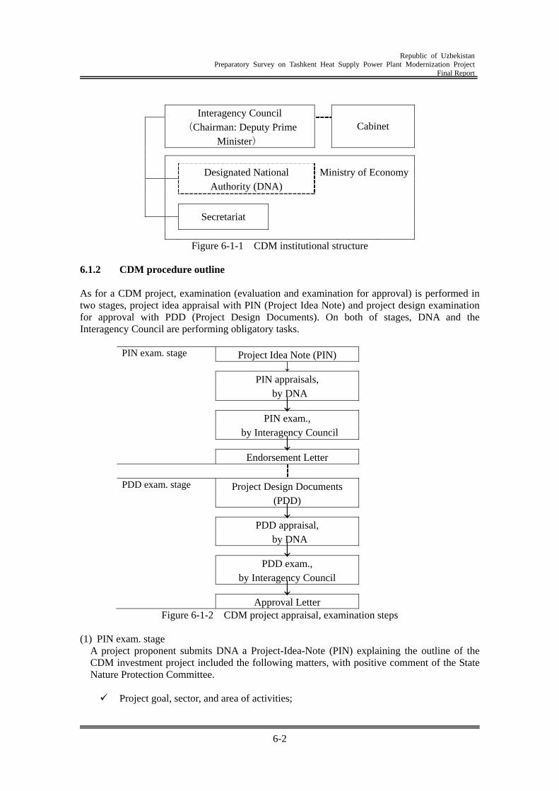
Republic of Uzbekistan
Preparatory Survey on Tashkent Heat Supply Power Plant Modernization Project Final Report
6-2
Interagency Council (Chairman: Deputy Prime
Minister)
Cabinet
Ministry of Economy
Designated National Authority (DNA)
Secretariat
Figure 6-1-1 CDM institutional structure
6.1.2 CDM procedure outline As for a CDM project, examination (evaluation and examination for approval) is performed in two stages, project idea appraisal with PIN (Project Idea Note) and project design examination for approval with PDD (Project Design Documents). On both of stages, DNA and the Interagency Council are performing obligatory tasks.
PIN exam. stage Project Idea Note (PIN) ↓
PIN appraisals, by DNA
↓
PIN exam., by Interagency Council
↓ Endorsement Letter
PDD exam. stage Project Design Documents
(PDD)
↓ PDD appraisal,
by DNA
↓ PDD exam.,
by Interagency Council
↓ Approval Letter
Figure 6-1-2 CDM project appraisal, examination steps (1) PIN exam. stage
A project proponent submits DNA a Project-Idea-Note (PIN) explaining the outline of the CDM investment project included the following matters, with positive comment of the State Nature Protection Committee.
Project goal, sector, and area of activities;
Republic of Uzbekistan
Preparatory Survey on Tashkent Heat Supply Power Plant Modernization Project Final Report
6-3
Detail information on project participants indicating their form of ownership; Object’s location; Information on current activities; Detail project description; Annual historical and estimated baseline volume of GHG emissions; Information on technologies and equipment planned for project implementation; Information on expected total cost the project, equipment, and needs for additional
investments; Preliminary schedule of project implementation; Expected volume of GHG emission reduction; Preliminary estimates of economic viability of the project, environmental and social
impact of project implementation; Proposed sources and mechanism for project implementation; Conformity of the project with the National Criteria for Sustainable Development.
After submitting the PIN, DNA carries out, within two weeks, appraisal focusing on if the proposed project would go with the national criteria of the sustainable development (which is required by the CDM),
National Criteria of Sustainable Development for the CDM projects Economic:
Reduction and raw material consumption per unit of finished products; Enhancing efficiency of operation or utilization of natural resources by
implementation of modern technologies; Facilitating private sector development in Uzbekistan.
Environmental: Facilitating conservation and prevention of environmental degradation; Minimizing use of natural resources and manufacturing waste; Implementation of technologies focused on re-use of raw materials and/or use of
renewable natural resources; Reducing negative environmental impact.
Social: Creating new jobs and increasing peoples real incomes; Improving the health of workers involved in project implementation and of
communities around project implantation site; Enhancing public awareness of on the issues of rational utilization of natural
resources.
DNA will send the Interagency Council the PIN which is considered being satisfied with the national criteria of sustainable development and other matter required with CDM projects, together with documents of project implementation procedure and bidding for selecting investors. Interagency Council examines the project with the information and data in PIN, and makes a decision if the project is to be approved or the project criteria shall be altered. When the Interagency Council approves the project at the PIN examination stage, DNA officially notifies the project proposer the result with a document including the project implementation method proposed to within three days, and the necessary information including bidding documents. After the PIN stage, although the project is to proceed with the implementation criteria of a carbon fund or an international financing organization, the project shall follow the procedure of Uzbekistan for the project implementation.
Republic of Uzbekistan
Preparatory Survey on Tashkent Heat Supply Power Plant Modernization Project Final Report
6-4
When DNA judges that the project is required about an investor selection through bidding, the project proponent notifies to-be-investors about bidding with conditions set up by the Interagency Council. In addition, there is no restriction in bidding in terms of number of participants.
(2) PDD exam.stage
The CDM project passed through the PIN examination stage, a project proponent shall submit the application documents having following information and data to DNA.
Bidding result, including top and bottom comparison, etc.) PDD (in Russian and English) Project implementation schedule Affirmative comments on the project, of the Center of Water and Weather Service; Affirmative comments on EIA of the project, of National Nature Projection
Committee.
Within two weeks after the documents of the project which has passed PIN stage, including PDD, are submitted by the project proponent to DNA, DNA carries out exam on the project, based on the standard and procedure of CDM with focusing on submitted PDD. After the exam, DNA submits documents on the project to the Interagency Council. Based on the information and data on submitted documents, the Interagency Council examines, within two weeks, and determines the propriety of implementation of a project. When it is considered eligible, DNA issues the approval letter for the CDM project, which is to be sent to the United Nations. The points of the project evaluation by the Interagency Council Economic feasibility and implementing efficiency of the project; Compliance of the project with ecological requirements; Compliance of the technological equipment with modern quality standards
(3) Project application
After passing through the procedure above mentioned, an OE is to be named by the project proponent for the project validation. When the project is passed validation by the DOE, validation report, together with approval letter of Uzbekistan and party of Annex I who is a investment country, other required documents, is submitted by DOE to CDM-EB. In addition, submitting the documents will serve as a request for CDM project registration. With CDM promotional arrangements such as establishment of institutional structure and development of implementation procedures since 2006, six (6) CDM projects from Uzbekistan were submitted to CDM-EB in 2008, and four (4) of them have been registered at UNFCC-CDM-EB by April 2009.
DOE (Designated Operational Entity): It is a legal entity or an international organization recommended, by the CDM-EB, to and designated by the COP/MOP, to confirm whether a CDM project fulfils required conditions of Article 12 of Kyoto Protocol and relevant guidelines, and to conduct accreditation of the additional emission reduction by the project.
6.2 CDM Application 6.2.1 CDM Application In mid-term plan of SJSC UzbekEnergo, it is stated implementing gas-turbine co-generation system at some combined heat and power plants (CHPPs). Thus, it is possible to assume that a
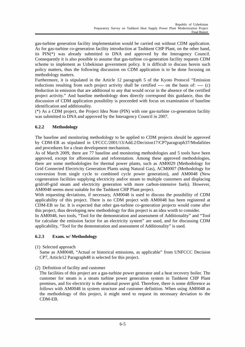
Republic of Uzbekistan
Preparatory Survey on Tashkent Heat Supply Power Plant Modernization Project Final Report
6-5
gas-turbine generation facility implementation would be carried out without CDM application. As for gas-turbine co-generation facility introduction at Tashkent CHP Plant, on the other hand, its PIN(*) was already submitted to DNA and approved by the Interagency Council. Consequently it is also possible to assume that gas-turbine co-generation facility requests CDM scheme to implement as Uzbekistan government policy. It is difficult to discuss herein such policy matters, thus the following discussion on CDM application is to be done focusing on methodology matters. Furthermore, it is stipulated in the Article 12 paragraph 5 of the Kyoto Protocol “Emission reductions resulting from each project activity shall be certified ---- on the basis of: ---- (c) Reduction in emission that are additional to any that would occur in the absence of the certified project activity.” And baseline methodology does directly correspond this guidance, thus the discussion of CDM application possibility is proceeded with focus on examination of baseline identification and additionality. (*) As a CDM project, the Project Idea Note (PIN) with one gas-turbine co-generation facility was submitted to DNA and approved by the Interagency Council in 2007. 6.2.2 Methodology The baseline and monitoring methodology to be applied to CDM projects should be approved by CDM-EB as stipulated in UFCCC/2001/13/Add.2/Decision17/CP7paragraph37/Modalities and procedures for a clean development mechanism. As of March 2009, there are 77 baseline and monitoring methodologies and 5 tools have been approved, except for afforestation and reforestation. Among these approved methodologies, there are some methodologies for thermal power plants, such as AM0029 (Methodology for Grid Connected Electricity Generation Plants using Natural Gas), ACM0007 (Methodology for conversion from single cycle to combined cycle power generation), and AM0048 (New cogeneration facilities supplying electricity and/or steam to multiple customers and displacing grid/off-grid steam and electricity generation with more carbon-intensive fuels). However, AM0048 seems most suitable for the Tashkent CHP Plant project. With requesting deviations, if necessary, AM0048 is used to discuss the possibility of CDM applicability of this project. There is no CDM project with AM0048 has been registered at CDM-EB so far. It is expected that other gas-turbine co-generation projects would come after this project, thus developing new methodology for this project is an idea worth to consider. In AM0048, two tools, “Tool for the demonstration and assessment of Additionality” and “Tool for calculate the emission factor for an electricity system” are used, and for discussing CDM applicability, “Tool for the demonstration and assessment of Additionality” is used. 6.2.3 Exam. w/ Methodology (1) Selected approach
Same as AM0048, “Actual or historical emissions, as applicable” from UNFCCC Decision CP7, Article12 Paragraph48 is selected for this project.
(2) Definition of facility and customer
The facilities of this project are a gas-turbine power generator and a heat recovery boiler. The customer for steam is a steam turbine power generation system in Tashkent CHP Plant premises, and for electricity is the national power grid. Therefore, there is some difference as follows with AM0048 in system structure and customer definition. When using AM0048 as the methodology of this project, it might need to request its necessary deviation to the CDM-EB.
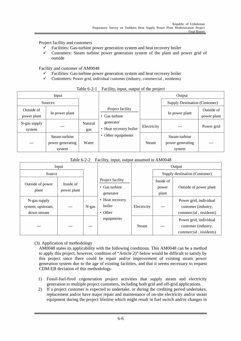
Republic of Uzbekistan
Preparatory Survey on Tashkent Heat Supply Power Plant Modernization Project Final Report
6-6
Project facility and customers Facilities: Gas-turbine power generation system and heat recovery boiler Customers: Steam turbine power generation system of the plant and power grid of
outside
Facility and customer of AM0048 Facilities: Gas-turbine power generation system and heat recovery boiler Customers: Power grid, individual customer (industry, commercial , residents)
Table 6-2-1 Facility, input, output of the project
Input Output
Sources Supply Destination (Customer)
Outside of
power plant In power plant
In power plant
Outside of
power plant
N-gas supply
system ---
Natural
gas Electricity --- Power grid
---
Steam turbine
power generating
system
Water
Project facility
• Gas turbine
generator
• Heat recovery boiler
• Other equipments
Steam
Steam turbine
power generating
system
---
Table 6-2-2 Facility, input, output assumed in AM0048
Input Output
Source Supply destination (Customer)
Outside of power
plant
Inside of
power plant
Inside of
power
plant
Outside of power plant
N-gas supply
system, upstream,
down stream
--- N-gas Electricity ---
Power grid, individual
customer (industry,
commercial , residents)
--- --- ---
Project facility
• Gas turbine
generator
• Heat recovery
boiler
• Other
equipments
Steam ---
Power grid, individual
customer (industry,
commercial , residents)
(3) Application of methodology
AM0048 states its applicability with the following conditions. This AM0048 can be a method to apply this project, however, condition of “Article 2)” below would be difficult to satisfy by this project since there could be repair and/or improvement of existing steam power generation system due to the age of existing facilities, and that it seems necessary to request CDM-EB deviation of this methodology.
1) Fossil-fuel-fired cogeneration project activities that supply steam and electricity
generation to multiple project customers, including both grid and off-grid applications. 2) If a project customer is expected to undertake, or during the crediting period undertakes,
replacement and/or have major repair and maintenance of on-site electricity and/or steam equipment during the project lifetime which might result in fuel switch and/or changes in
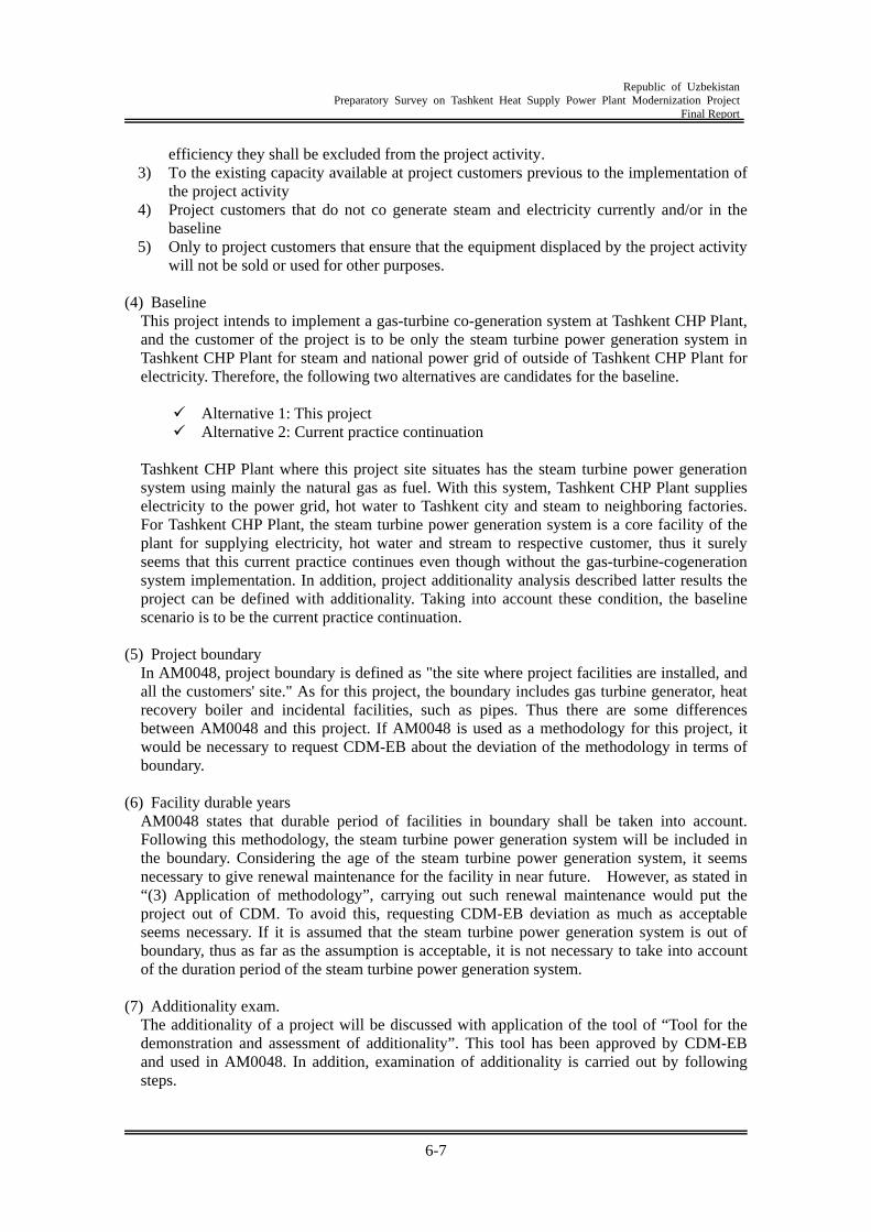
Republic of Uzbekistan
Preparatory Survey on Tashkent Heat Supply Power Plant Modernization Project Final Report
6-7
efficiency they shall be excluded from the project activity. 3) To the existing capacity available at project customers previous to the implementation of
the project activity 4) Project customers that do not co generate steam and electricity currently and/or in the
baseline 5) Only to project customers that ensure that the equipment displaced by the project activity
will not be sold or used for other purposes. (4) Baseline
This project intends to implement a gas-turbine co-generation system at Tashkent CHP Plant, and the customer of the project is to be only the steam turbine power generation system in Tashkent CHP Plant for steam and national power grid of outside of Tashkent CHP Plant for electricity. Therefore, the following two alternatives are candidates for the baseline.
Alternative 1: This project Alternative 2: Current practice continuation
Tashkent CHP Plant where this project site situates has the steam turbine power generation system using mainly the natural gas as fuel. With this system, Tashkent CHP Plant supplies electricity to the power grid, hot water to Tashkent city and steam to neighboring factories. For Tashkent CHP Plant, the steam turbine power generation system is a core facility of the plant for supplying electricity, hot water and stream to respective customer, thus it surely seems that this current practice continues even though without the gas-turbine-cogeneration system implementation. In addition, project additionality analysis described latter results the project can be defined with additionality. Taking into account these condition, the baseline scenario is to be the current practice continuation.
(5) Project boundary
In AM0048, project boundary is defined as "the site where project facilities are installed, and all the customers' site." As for this project, the boundary includes gas turbine generator, heat recovery boiler and incidental facilities, such as pipes. Thus there are some differences between AM0048 and this project. If AM0048 is used as a methodology for this project, it would be necessary to request CDM-EB about the deviation of the methodology in terms of boundary.
(6) Facility durable years
AM0048 states that durable period of facilities in boundary shall be taken into account. Following this methodology, the steam turbine power generation system will be included in the boundary. Considering the age of the steam turbine power generation system, it seems necessary to give renewal maintenance for the facility in near future. However, as stated in “(3) Application of methodology”, carrying out such renewal maintenance would put the project out of CDM. To avoid this, requesting CDM-EB deviation as much as acceptable seems necessary. If it is assumed that the steam turbine power generation system is out of boundary, thus as far as the assumption is acceptable, it is not necessary to take into account of the duration period of the steam turbine power generation system.
(7) Additionality exam.
The additionality of a project will be discussed with application of the tool of “Tool for the demonstration and assessment of additionality”. This tool has been approved by CDM-EB and used in AM0048. In addition, examination of additionality is carried out by following steps.
Republic of Uzbekistan
Preparatory Survey on Tashkent Heat Supply Power Plant Modernization Project Final Report
6-8
1) Alternative identification
As mentioned in the baseline identification, there are two alternatives, and first one is this project and another is the current practice continuation.
2) Compliance with laws and regulations
It is acceptable that current practices, which is the second alternative, satisfy the current laws and regulations. As for first one, that is the project, its PIN has been appraised by DNA and approved by the Interagency Council of Uzbekistan. Thus, it can be said that the project does not deviated from and comes under the enforced law and regulations.
Identification ofalternatives
Investment analysis Barrier analysis
Common practice analysis
Additionality --- Yes
optional NY
Y
N
Y
N
Investment barrier
Technological barrier
Barriers due to prevailingpractice
Additionality --- No
Figure 6-2-1 Additionality exam.flow
3) Investment analysis
The investment analysis, which has three constituents of simple cost comparison, investment comparison analysis and benchmark analysis, is for analyzing and examining if the project has additionality from the investment point of view. With any analysis of these constituents, if the project satisfies two conditions below, the project will have additionality. In addition an investment comparative analysis and benchmark analysis shall be followed by a sensitivity analysis.
The project is not the most attractive one for investors; The project financial performance won’t turn to positive without revenue by CER.
A “certified emission reduction” or “CER” is a unit issued pursuant to Article 12 and requirements thereunder, and is equal to one metric ton of carbon dioxide equivalent, calculated using global warning potentials defined by decision 2/CP.3 or as subsequently reviced in accordance with Article 5.
Republic of Uzbekistan
Preparatory Survey on Tashkent Heat Supply Power Plant Modernization Project Final Report
6-9
As financial indicators of this project are as follows. FIRR is 3.7%, NPV is minus and B/C ration below one (1). Thus this project will not come in attractive for the investment, and it can be said that the project has additionality. In addition, by approved methodology, although it might be necessary further investment analysis for examining additionality, if additionality of the project is determined in subsequent barrier analysis, the further investment analysis will be unnecessary.
4) Barrier analysis
In barrier analysis, if there is/are one or more barriers against implementation of a project that would be a CDM project and there is/are one or more project alternatives which are not influenced by these barriers, it is supposed that such project has additionality. The barrier analysis of approved methodology is one of analysis for clarifying if there is a barrier, related to additionality, to prevent the project implementation. And, herein, it is analyzed from three angles of investment barrier, technological barriers and barriers due to prevailing practices. In addition, when the project is concluded having additionality by investment barrier or technological barrier or barriers due to prevailing practice, and then it is possible to state that there is additionality in the project.
a. Investment barriers
Since all the power plants in Uzbekistan supplying electric power to a grid are possessed by public establishments, there is a barrier for free investments and consequently the project will have additionality by this meaning.
Basic points for judging whether there is a barrier in “investment”: Similar practices in the same situation have been carried out by grants-in-aid fund
or public funds. Investment risk is recognized highly and widely in own and foreign countries,
consequently no private investment can be expected.
b. Technological barriers There is no cogeneration power facilities with a gas-turbine in Uzbekistan up to present, and there are also many unknowns in technological capacity for engineering and technological matters of the gas-turbine power unit. Consequently, there seems the technological barriers in implementing and operating the gas turbine power generation facility which is planned to implement by the project, and it can be said there is additionality in this project.
Basic points for judging whether there is a barrier in “technology”: Skilled and/or properly trained labor to operate and maintain technology is not
available; Lack of infrastructure for implementation and logistics for maintenance of the
technology; Risk of technology failure; The particular technology used in the proposed project activity is not available in
the relevant region;
c. Barriers due to prevailing practice The common technology of the thermal power generation in the Uzbekistan is with a steam turbine. There is, up to present in the country, no power generation facility equipped with a gas turbine. Consequently it can be said that there is an additionality in
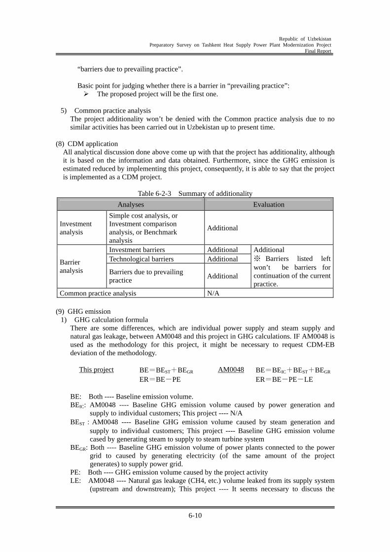
Republic of Uzbekistan
Preparatory Survey on Tashkent Heat Supply Power Plant Modernization Project Final Report
6-10
“barriers due to prevailing practice”.
Basic point for judging whether there is a barrier in “prevailing practice”: The proposed project will be the first one.
5) Common practice analysis
The project additionality won’t be denied with the Common practice analysis due to no similar activities has been carried out in Uzbekistan up to present time.
(8) CDM application
All analytical discussion done above come up with that the project has additionality, although it is based on the information and data obtained. Furthermore, since the GHG emission is estimated reduced by implementing this project, consequently, it is able to say that the project is implemented as a CDM project.
Table 6-2-3 Summary of additionality
Analyses Evaluation
Investment analysis
Simple cost analysis, or Investment comparison analysis, or Benchmark analysis
Additional
Investment barriers Additional Technological barriers Additional Barrier
analysis Barriers due to prevailing practice
Additional
Additional ※ Barriers listed left won’t be barriers for continuation of the current practice.
Common practice analysis N/A (9) GHG emission
1) GHG calculation formula There are some differences, which are individual power supply and steam supply and natural gas leakage, between AM0048 and this project in GHG calculations. IF AM0048 is used as the methodology for this project, it might be necessary to request CDM-EB deviation of the methodology.
This project BE=BEST+BEGR
ER=BE-PE AM0048 BE=BEIC+BEST+BEGR
ER=BE-PE-LE
BE: Both ---- Baseline emission volume. BEIC: AM0048 ---- Baseline GHG emission volume caused by power generation and
supply to individual customers; This project ---- N/A BEST:AM0048 ---- Baseline GHG emission volume caused by steam generation and
supply to individual customers; This project ---- Baseline GHG emission volume cased by generating steam to supply to steam turbine system
BEGR: Both ---- Baseline GHG emission volume of power plants connected to the power grid to caused by generating electricity (of the same amount of the project generates) to supply power grid.
PE: Both ---- GHG emission volume caused by the project activity LE: AM0048 ---- Natural gas leakage (CH4, etc.) volume leaked from its supply system
(upstream and downstream); This project ---- It seems necessary to discuss the
Republic of Uzbekistan
Preparatory Survey on Tashkent Heat Supply Power Plant Modernization Project Final Report
6-11
impact on GHG emission, but it also seems very small volume and it is supposed not leakage by the project.
ER: Both ---- GHG emission reduction volume.
2) GHG emission reduction volume With this project implementation, it is expected that GHG emission will reduce by 123.4 thousands tCO2/Year.
6.2.4 Project with CDM application In either case, with or without CDM application to the project, by this project with GTCS, the fuel (natural gas) reduction amounting yearly to 60,571,000 m3 and the GHG emission reduction amounting yearly to 123.4 thousands tCO2.are expected. On the other hand, followings should come only with this project with CDM application.
Contribution to improving the financial condition of the Tashkent CHP Plant. In addition to the income by selling generated electricity to the power grid, the income with GHG certified emission reduction (*1) is expected, that the financial condition of theTashkent CHP Plant more favorable.
With this project, the income from GHG certified emission reduction would work as an incentive for more amount of power supplying to the power grid, that more amount of the GHG certified emission reduction in other thermal power plants would be expected. Power generation capacity of the Tashkent CHP Plant is merely less than 1% of whole power generation capacity of the Uzbekistan, that all generated power is supposed able to supply to the grid.
(*1) GHG certified emission reduction (= CER credit) is able to realize after this project being registered at the UN and passed the verification after the project operation.
In addition, GTCS project for the Tashkent CHP Plant has been approved at the PIN stage by the government of the Uzbekistan. Thus, this project is supposed standing along with the government policy. And with CDM system, this project has been taken having additionality of CDM methodology approved by the CDM-Executive Board. Taking these mentioned herein into account, thus, this project is to be appropriate being implemented under CDM application. Additional study Studies and discussion on following items are considered relevant to conduct to make conditions clear regarding that the project is to be implemented with CDM application.
Developing a pilot PDD of this project CDM project institutional system


