Embed Size (px)
Citation preview

ROLL-OVER-WEB COATING OF PSEUDOPLASTIC
AND VISCOPLASTIC SHEETS USING
THE LUBRICATION APPROXIMATION
Souzanna Sofou and Evan Mitsoulis*School of Mining Engineering & Metallurgy
National Technical University of Athens
Zografou, 157 80, Athens, Greece
ABSTRACT: The Lubrication Approximation Theory (LAT) is used to providenumerical results in roll coating over a moving flat web. The Herschel–Bulkleymodel of viscoplasticity is used, which reduces with appropriate modificationsto the Bingham, power-law, and Newtonian models. Results are obtained forsuch quantities as coating thickness, separation point, and the volumetric flowrate required for various values of the power-law index (in the case ofpseudoplasticity) and of the Bingham number (in the case of viscoplasticity).All these values increase substantially with the increasing non-Newtoniancharacter of the fluid. Yielded and unyielded areas are quantitatively shown forseveral cases of viscoplasticity. Pressure gradient and pressure distributions aregiven for all cases. Integrated quantities of engineering interest are alsocalculated. These include the maximum pressure, the roll/sheet separating force,and the power input to the roll. These quantities increase substantially andmonotonically in a dimensionless form, as the power-law index decreases or theBingham number increases.
KEY WORDS: roll-over-web coating, pseudoplasticity, viscoplasticity, yield stress,yield line, Herschel–Bulkley model.
INTRODUCTION
ROLL COATING IS a process used in a variety of industries – producingphotographic films, paper and coated products, magnetic recording
*Author to whom correspondence should be addressed. E-mail: [email protected] 1, 3 and 14 appear in color online: http://jpf.sagepub.com
JOURNAL OF PLASTIC FILM & SHEETING, VOL. 21—OCTOBER 2005 307
8756-0879/05/04 0307–27 $10.00/0 DOI: 10.1177/8756087905059963� 2005 SAGE Publications

media – for the production of thin layers of specific thickness and finalappearance, coated over a thin moving sheet (sometimes referred to asthe web). This procedure was theoretically introduced by Middleman [1]and concerns the case where the sheet has the same velocity as theperipheral roll speed and moves in the same direction (see Figure 1) [1].
Many materials used in roll coating are non-Newtonian, exhibitingeither pseudoplastic (shear-thinning or -thickening) [1] or viscoplastic(presence of a yield stress) behavior (see, e.g., Bird et al. [2]). Modelsdescribing pseudoplastic behavior include the power-law, Carreau,Cross, etc. Models describing viscoplastic behavior include theBingham, Herschel–Bulkley, and Casson. The Herschel–Bulkley modelhas the advantage of reducing – with an appropriate choice ofparameters – to the Bingham, power-law, or Newtonian model.In simple shear flow, it takes the form ([2]; see also Figure 2):
� ¼ K _���� ��n�1
_�� � �y, for j�j > �y, ð1aÞ
_�� ¼ 0, for j�j � �y, ð1bÞ
where � is the shear stress, _�� is the shear rate (¼ du/dy), �y is theyield stress, K is the consistency index, and n is the power-law index.Note that when n¼ 1 and K¼� (a constant), the Herschel–Bulkleymodel reduces to the Bingham model. When �y¼ 0, the power-lawmodel is recovered, and when �y¼ 0 and n¼ 1, the Newtonian modelis obtained.
It should be noted that in viscoplastic models, when the shear stress� falls below �y, a solid structure is formed (unyielded). Also, inviscoplasticity, the yield stress can be expressed as a function of thepressure gradient and the yield line, that is, a line separating the yielded
0
h(x)
R
U
H0
x, x
(x1, 0 .5h)y,h
U
H
H
y
− xf
Hf
Figure 1. Schematic representation of the process of roll coating over a moving web anddefinition of variables.
308 S. SOFOU AND E. MITSOULIS

from the unyielded material. This equation, however, strongly dependson the geometry of the flow field.
An early analysis of roll coating has been carried out by Middleman [1]for the case of roll-over-web coating pseudoplastic fluids from an infinitereservoir. Coyle [3] presented results for both the forward [4] andreverse [5] case of roll-over-roll coating, for the asymmetric caseincluding the effects of pseudoplasticity and viscoelasticity. It appears,therefore, that no work has been done for the process of roll-over-webcoating for viscoplastic materials. It is the purpose of this work toprovide numerical results for this process, for such quantities as coatingthickness, separation point, and the volumetric flow rate required forboth pseudoplastic and viscoplastic materials. The results will be givenfor full parametric studies of the power-law index and the Binghamnumber or dimensionless yield stress. For pseudoplastic fluids, theresults of Middleman [1] are verified and extended, while for viscoplasticfluids the results are new.
MATHEMATICAL MODELING
Governing Equations
As explained by Middleman [1] and with regard to Figure 1, thelubrication approximation theory (LAT) regards locally fully developed
Shear rate (g )S
hear
str
ess
(t)
.
H - B, n = 0.5
Bingham, n = 1
H - B, n = 2
P - L, n = 0.5
Newtonian, n = 1
P - L, n = 2
Viscoplastic
Pseudoplastic
Shear-thinningShear-thickening
Yieldstress
−ty
+ty
0
Figure 2. Shear stress vs shear rate for various pseudoplastic and viscoplastic fluids.
Roll-over-web Coating Using Lubrication Approximation 309

shear flow between the roll and the web. The conservation ofmomentum then gives
dP
dx¼
d�xy
dy, ð2Þ
where �xy¼ � is the shear stress in the transverse direction. The shearstress is given by the Herschel–Bulkley model in the present work(Equation (1)).
In roll-over-web coating, the following dimensionless parameters areintroduced [1,6]:
� ¼xffiffiffiffiffiffiffiffiffiffi
RH0
p , h ¼ H0 1þx2
2RH0
� �, � ¼
y
H0, P0 ¼
P
K
H0
U
� �n H0
R
� �1=2
,
u ¼ux
U, ~hh ¼
h
H0, � ¼
Q
UH0,
ð3Þ
where l is a dimensionless flow rate, and the rest of the symbols aredefined in Figure 1.
According to Middleman [1], it is assumed that the materialsplits evenly at point (n1, 0.5 h) to coat both the roll and the sheet.Then the volumetric flow rate, Q, the coating thickness H, and l arerelated by
Q ¼ 2UH, ð4Þ
and
� ¼2H
H0: ð5Þ
For the case of viscoplastic fluids, it is customary to define theBingham number [7]:
Bn ¼�y
K
H0
U
� �n
, ð6Þ
where Bn¼ 0 corresponds to purely viscous fluids and Bn!1corresponds to purely plastic solids.
310 S. SOFOU AND E. MITSOULIS

Pseudoplastic Fluids
In the present work, we use the equations proposed by Middleman [1]for pseudoplastic power-law fluids. More precisely, the equation for thepressure gradient becomes:
dP0
d�¼
2nþ 1
n
� �n
2nþ1
~hh� �� �2� �n�1=2
~hh� �� �
~hh2nþ1: ð7Þ
Moreover, the separation point, n1, is found by asserting that thepressure vanishes there, at which point u also vanishes [1]. Settinguð�1, 1=2 ~hhÞ ¼ 0, gives the separation point n1 as a function of thedimensionless coating thickness, l, and of the power-law index, n:
�1 ¼ 22nþ 1
n�� 1
� �� �1=2
: ð8Þ
It should be noted that the above boundary conditions used are onechoice of conditions, and other types have been proposed in theliterature [3–5]. The results depend on the boundary conditionsassumed, but the overall trends, based on the rheology of the material,are the same.
Viscoplastic Fluids
Bingham Plastics
By integrating Equation (2), and after using Equation (3) we obtain:
�1þ1
Bn
du
d�¼ �
dP0
d�
1
Bn�0 � �ð Þ, ð9Þ
where �0 is the position of zero shear stress.From the Newtonian analysis, we know that there are three flow
regions in the x-direction: one region near the nip, which has a negativepressure gradient (dP0/dn<0), and two other regions away from the nipat the entrance and at the exit with an opposite sign (dP0/dn>0),as shown in Figure 3(a). For viscoplastic materials, we know thatthere are also three flow regions in the y-direction: one region wherethe material is unyielded (�p2� �� �p1) and two regions whereit is yielded (0� �� �p2 and �p1� �� ~hh), as shown in Figure 3(b).
Roll-over-web Coating Using Lubrication Approximation 311

�( ) 0, 0h xλ− > >
�( ) 0h λ− <
�( ) 0, 0h xλ− > <
I. Yielded area
II. Unyielded area
III. Yielded area
Unyielded
Unyielded Unyielded
1pη
2pη
1pη
2pη
1pη
2pη
(b)
dP’/dξ > 0 dP’/dξ > 0
dP’/dξ < 0
U
U0Web
Rollη
ξ
(a)
Figure 3. (a) Flow regions in the x-direction: pressure-gradient distribution and (b) flowregions in the y-direction: yielded/unyielded regions and velocity profiles.
312 S. SOFOU AND E. MITSOULIS

The location of the two yield lines, which separate the yielded from theunyielded material, can be found by setting du/d�¼ 0 in Equation (9).Thus, we obtain:
�p1 ¼ �0 þBn
dP0=d�, for � ¼ K _�� þ �y ð10aÞ
�p2 ¼ �0 �Bn
dP0=d�, for � ¼ K _�� � �y ð10bÞ
We integrate Equation (9) by applying the following boundaryconditions
ux ¼ U for y ¼ 0 ðu ¼ 1 for � ¼ 0Þ, ð11aÞ
ux ¼ U for y ¼ hðxÞ ðu ¼ 1 for � ¼ ~hhÞ: ð11bÞ
Furthermore, as the sign of the pressure gradient changes, so doesthe relation between (�p1,�p2), and therefore the sign of �y for each flowfield in the y-direction must be considered. After the appropriatemanipulations, the velocity profile is as follows:
. Region with positive pressure gradient (dP0/dn> 0), (�p1 > �p2)
u ¼
1�dP0
d��0 þ Bn
� ��� ~hh� �
þdP0
d�
�2 � ~hh2� �
2, �p1 � � � ~hh ð12aÞ
1�1
2
dP0
d��2
0 þ Bn �0 �Bn2
2 dP0=d�ð Þ, �p2 � � � �p1 ð12bÞ
1þ Bn�dP0
d��0
� ��þ
dP0
d�
1
2�2, 0 � � � �p2 ð12cÞ
8>>>>>>>>>><>>>>>>>>>>:
. Region with negative pressure gradient (dP0/dn<0), (�p1 < �p2)
u ¼
1þ �dP0
d��0 þ Bn
� ��� ~hh� �
þdP0
d�
�2 � ~hh2� �
2, �p2 � � � ~hh ð13aÞ
1�1
2
dP0
d��2
0 � Bn �0 �Bn2
2 dP0=d�ð Þ, �p1 � � � �p2 ð13bÞ
1�dP0
d��0 þ Bn
� ��þ
dP0
d�
1
2�2, 0 � � � �p1 ð13cÞ
8>>>>>>>>>><>>>>>>>>>>:
Roll-over-web Coating Using Lubrication Approximation 313

At this point, �0 remains unknown. It can be found by consideringthe following methodology [7]: for the region with a negative pressuregradient, Equations (13a) for �¼ �p2 and (13c) for �¼ �p1 shouldgive the same result (plug profile). For both cases, the result of thecalculations is:
�0 ¼~hh
2, ð14Þ
which suggests that the line where the shear stress equals zero is at themiddle of the distance of the web from the roll. This should be expected,since the velocities of the roll and the web are equal.
Integration of the velocity profile gives the dimensionless volumetricflow rate l:
. Region with positive pressure gradient (dP0/dn> 0), (�p1 > �p2)
�¼ ~hhþ1
6
dP0
d��3
p2� �3p1
� �þ �
~hh2
8
dP0
d��
1
2
Bn2
dP0=d�ð Þþ
~hh
2Bn
!�p1� �p2
�1
12
dP0
d�~hh3þ
~hh
4
dP0
d��2
p1� �2p2
� �þ
Bn
2�2
p1þ �2p2
� �þ
~hh2
2Bn�Bn h �p1
ð15aÞ
. Region with negative pressure gradient (dP0/dn<0), (�p1<�p2)
�¼ ~hh�1
6
dP0
d��3
p2� �3p1
� �þ þ
~hh2
8
dP0
d�þ
1
2
Bn2
dP0=d�ð Þþ
~hh
2Bn
!�p1� �p2
�1
12
dP0
d�~hh3�
~hh
4
dP0
d��2
p1� �2p2
� ��
Bn
2�2
p1þ �2p2
� ��
~hh2
2BnþBn h �p2
ð15bÞ
From Equation (15), the pressure gradient dP0/dn can now be found.
Note that for Bn¼ 0 the above equations and also the velocityprofiles – Equations (12a), (12c) and (13a), (13c) – are reduced to theones given by Middleman [1] for Newtonian fluids.
After numerically calculating the pressure gradients, their integrationrequires a boundary condition for the pressure P. The standard
314 S. SOFOU AND E. MITSOULIS

condition used in the analysis assumes zero pressure at the separationpoint [1], i.e.,
P ¼ 0 at � ¼ �1: ð16Þ
Then the pressure distribution is given by the integral:
P0 ¼
Z �1
��f
dP0
d�
� �d�, ð17aÞ
or
P0 ¼
Z �1
��f
I Bnð Þd�, ð17bÞ
where – nf is the entry point (¼ �1 in the case of an infinite reservoir).
Herschel–Bulkley Fluids
The above analysis can be also applied to the viscoplasticHerschel–Bulkley fluids. To do this, it is necessary to derive an equationfor the pressure gradient, making use of the constitutive relation(Equation (1)) and the dimensionless generalized Bingham number(Equation (6)) for the expression of the dimensionless yield stress. Afterthe appropriate manipulations, the following velocity profiles areobtained:
. Region with positive pressure gradient (dP0/dn> 0), (�p1 > �p2)
u¼
1þn
nþ1
dP0
d�
��������ð1=nÞ�1 dP0
d���
~hh
2�
Bn
dP0=d�ð Þ
!ð1=nÞþ1
�~hh
2�
Bn
dP0=d�ð Þ
!ð1=nÞþ18<:
9=;,
�p1��� ~hh ð18aÞ
1�n
nþ1
dP0
d�
��������ð1=nÞ�1 dP0
d�
~hh
2�
Bn
dP0=d�ð Þ
!ð1=nÞþ1
, �p2����p1 ð18bÞ
1þn
nþ1
dP0
d�
��������ð1=nÞ�1 dP0
d���
~hh
2þ
Bn
dP0=d�ð Þ
!ð1=nÞþ1
�~hh
2�
Bn
dP0=d�ð Þ
!ð1=nÞþ18<:
9=;,
0����p2 ð18cÞ
8>>>>>>>>>>>>>>>>>>>>>>><>>>>>>>>>>>>>>>>>>>>>>>:
Roll-over-web Coating Using Lubrication Approximation 315

. Region with negative pressure gradient (dP0/dn<0), (�p1 < �p2)
u¼
1þn
nþ1
dP0
d�
��������ð1=nÞ�1 dP0
d���
~hh
2þ
Bn
ðdP0=d�Þ
!ð1=nÞþ1
�~hh
2þ
Bn
ðdP0=d�Þ
!ð1=nÞþ18<:
9=;,
�p2��� ~hh ð19aÞ
1�n
nþ1
dP0
d�
��������ð1=nÞ�1 dP0
d�
~hh
2þ
Bn
ðdP0=d�Þ
!ð1=nÞþ1
, �p1����p2 ð19bÞ
1þn
nþ1
dP0
d�
��������ð1=nÞ�1 dP0
d���
~hh
2�
Bn
ðdP0=d�Þ
!ð1=nÞþ1
�~hh
2þ
Bn
ðdP0=d�Þ
!ð1=nÞþ18<:
9=;,
0����p1 ð19cÞ
8>>>>>>>>>>>>>>>>>>>>>>><>>>>>>>>>>>>>>>>>>>>>>>:
Equations (18) and (19) are reduced for n¼ 1 to the equations of theprevious paragraph for Bingham plastics, as they should. Integratingthe velocity profiles, we obtain the volumetric flow rate. After theappropriate manipulations these are:
. Region with positive pressure gradient (dP0/dn> 0), ( ~hh� l) > 0
�¼ ~hh�2n
2nþ 1
dP0
d�
��������ð1=nÞ�1 dP0
d�
� � ~hh
2�
Bn
ðdP0=d�Þ
!ð1=nÞþ1~hh
2þ
n
nþ 1
Bn
ðdP0=d�Þ
!,
ð20aÞ
. Region with negative pressure gradient (dP0/dn<0), ( ~hh�l)<0
�¼ ~hh�2n
2nþ 1
dP0
d�
��������ð1=nÞ�1 dP0
d�
� � ~hh
2þ
Bn
ðdP0=d�Þ
!ð1=nÞþ1 ~hh
2�
n
nþ 1
Bn
ðdP0=d�Þ
!:
ð20bÞ
For n¼ 1 the above equation reduces to Equation (15), valid forBingham plastics, while for Bn¼ 0 it reduces to Equation (7), valid forpseudoplastic fluids obeying the power-law model.
It should be noted that deriving analytically the expressions for theHerschel-Bulkley fluids, one must take into account that (1/n)þ 1 hasto be an even number.
Finally, Equations (16) and (17) are also valid for the Herschel–Bulkley fluids.
316 S. SOFOU AND E. MITSOULIS

Yield-line Location
Once the pressure gradient distribution is obtained, it is easy tocalculate the location of the yield lines separating the yielded/unyieldedregions. Considering Equations (10a), (10b), and (14), we obtain thefollowing for the dimensionless yield lines:
�p1 ¼~hh
2þ
Bn
dP0=d��� �� , ð21aÞ
�p2 ¼~hh
2�
Bn
dP0=d��� �� : ð21bÞ
Sheet Thickness
The entering sheet thickness Hf is given by:
Hf
H0¼ 1þ
1
2�2
f , ð22Þ
and in the case of a flooded (infinite) reservoir, it is infinity (or a very bignumber).
The resulting exit coating thickness is given by:
H
H0¼�
2: ð23Þ
The analysis is still not complete at this point, since a relation betweenthe dimensionless flow rate l, and the separation point n1, should befound, as in the case of pseudoplastic fluids [1]. The same boundaryconditions are assumed, i.e., the velocity vanishes at the separationpoint (the first stagnation point), which explains the formation of ameniscus. Moreover, as Figure 1 suggests, the film splits evenly, so thatthe separation point is at (n1, ~hh/2). This assumption can be accepted dueto the fact that the roll and the sheet move with the same velocity.In any other case, the surface moving faster would take up a bigger partof the material.
In the case of viscoplastic fluids, the corresponding equation foundanalytically connects the separation point n1 with the dimensionless flowrate l and the rheological parameters, as expected. It should bementioned though, that since it also includes the unknown value of the
Roll-over-web Coating Using Lubrication Approximation 317

pressure gradient dP0/dn at the separation point, it cannot be used in thesame manner as Equation (8) and so the problem requires a numericalsolution.
In particular, and regarding the more general case of viscoplasticHerschel–Bulkley fluids, the expression connecting the separation pointn1, with the dimensionless coating thickness l, and the power-lawindex n, is (by combining Equations (18b) and (20a) and setting thevelocity equal to zero):
�1 ¼ 22nþ 1
n�� 1þ
2Bn
dP0=d�
� �� �1=2
: ð24Þ
For Bn¼ 0, Equation (24) reduces to Equation (8) valid forpseudoplastic fluids obeying the power-law model.
Operating Variables
Once the pressure gradient and pressure distributions are found asfunctions of n or Bn, then all other quantities of interest are readilyavailable. The operating variables used in engineering calculations arecomputed in the following manner [1]:
(i) the maximum pressure, P(n, Bn), defined by:
Pðn, BnÞ ¼
Z �1
� 2 ��1ð Þ½ �0:5
I n, Bnð Þd�, ð25Þ
where �½2ð�� 1Þ�0:5corresponds to the point where the pressurereaches a maximum.
(ii) the roll-separating force per unit width W, F/W(n, Bn), defined by:
F
W¼
Z x1
�xf
PðxÞdx ¼ KU
H0
� �n
R F n, Bnð Þ ð26aÞ
with
F n, Bnð Þ ¼
Z �1
��f
Z � 1
�
Iðn, BnÞd�
� �d�, ð26bÞ
(iii) the power input, _WWðn, BnÞ, defined by:
_WWðn,BnÞ ¼WU
Z x 1
�xf
�xy y¼hðxÞ
�� dx¼WUK
2
U
H0
� �n ffiffiffiffiffiffiffiffiffiffiRH0
pEðn,BnÞ, ð27aÞ
318 S. SOFOU AND E. MITSOULIS
with
Eðn, BnÞ ¼
Z � 1
��f
Iðn, BnÞ 1þ1
2�2
� �d�, ð27bÞ
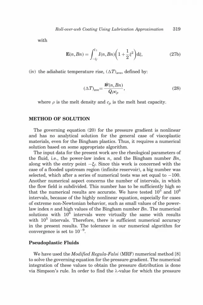
(iv) the adiabatic temperature rise, (�T)ave, defined by:
�Tð Þave¼_WW n, Bnð Þ
Q�cp, ð28Þ
where � is the melt density and cp is the melt heat capacity.
METHOD OF SOLUTION
The governing equation (20) for the pressure gradient is nonlinearand has no analytical solution for the general case of viscoplasticmaterials, even for the Bingham plastics. Thus, it requires a numericalsolution based on some appropriate algorithm.
The input data for the present work are the rheological parameters ofthe fluid, i.e., the power-law index n, and the Bingham number Bn,along with the entry point �nf. Since this work is concerned with thecase of a flooded upstream region (infinite reservoir), a big number wasselected, which after a series of numerical tests was set equal to �100.Another numerical aspect concerns the number of intervals, in whichthe flow field is subdivided. This number has to be sufficiently high sothat the numerical results are accurate. We have tested 105 and 106
intervals, because of the highly nonlinear equation, especially for casesof extreme non-Newtonian behavior, such as small values of the power-law index n and high values of the Bingham number Bn. The numericalsolutions with 106 intervals were virtually the same with resultswith 105 intervals. Therefore, there is sufficient numerical accuracyin the present results. The tolerance in our numerical algorithm forconvergence is set to 10�9.
Pseudoplastic Fluids
We have used the Modified Regula-Falsi (MRF) numerical method [8]to solve the governing equation for the pressure gradient. The numericalintegration of these values to obtain the pressure distribution is donevia Simpson’s rule. In order to find the l-value for which the pressure
Roll-over-web Coating Using Lubrication Approximation 319

is zero at the separation point, we use again the MRF method.The separation point n1 is expressed as a function of l and n, usingEquation (8).
Viscoplastic Fluids
In this case, both the separation point and the dimensionless flow ratehave to be calculated. The problem is solved as in the previous case, withthe added feature of an external loop, based on the MRF method, whichkeeps changing the separation point, until there exists a pair of values(l, n1) for which both the fluid velocity and the pressure are zero at theseparation point.
It should be noted that this algorithm was first tested for thepseudoplastic fluids, for which the relation between (l, n1) is explicitlygiven by Equation (8). More specifically, the MRF method was used forthe calculation of the separation point, disregarding Equation (8). Acomparison for the results (l, n1) between the two methods (Equation (8)and numerical solution) showed that the maximum difference was0.043% for l and 0.025% for n1. Thus, confidence was established in thenumerical algorithm to also use it for viscoplastic fluids.
The yield lines are calculated via Equations (21a,b) using the pressuregradient values. Finally, the exit coating thickness H/H0 is calculatedfrom Equation (23) for all cases.
RESULTS AND DISCUSSION
Pseudoplastic Fluids
First the calculations are pursued for pseudoplastic power-law fluids,both shear-thinning (0�n� 1) and shear-thickening (1�n� 2). Thenumerical results for the volumetric flow rate l, the exit coatingthickness H/H0, and the separation point n1, are presented in Table 1.Numerical results for the maximum pressure and the minimumpressure gradient are given in Table 2.
The results for the dimensionless pressure gradient distributionare shown in Figure 4, while the results for the dimensionlesspressure distribution are shown in Figure 5. The smaller the power-law index n the bigger the dimensionless maximum pressure, and thesteeper the pressure gradient curves. Also, the smaller the power-lawindex n the bigger the flow domain, and the bigger the exit coatingthickness.
320 S. SOFOU AND E. MITSOULIS

This last observation is verified in Figure 6, which shows thedimensionless volumetric flow rate l, and the exit coating thicknessH/H0, as a function of the power-law index n. The well-knownNewtonian value (for n¼ 1) of l¼ 1.3015 [3] is a starting point, afterwhich it is noted that shear-thinning increases the values, reaching forn¼ 0.1, l¼ 1.6395. On the other hand, shear-thickening decreases thevalues, reaching for n¼ 2, l¼ 1.2560. Thus, the maximum coatingthickness H/H0, can be as high as 0.8197 for extremely shear-thinningfluids (n¼ 0.1), 0.6507 for Newtonian fluids (n¼ 1), and 0.6280 forshear-thickening fluids with n¼ 2.
In Figure 7 the separation point n1, and the exit coating thicknessH/H0, are depicted, as obtained from a full parametric range of thepower-law index n. We observe that the smaller the power-law index,the bigger the values of the separation point, and thus the bigger theflow domain.
Finally, Figure 8 shows the engineering quantities P, F, and E.A decrease of the power-law index n increases these dimensionlessquantities. The Newtonian values (n¼ 1) are F¼ 2.5959, P¼ 1.9208,and E¼ 10.4141.
Table 1. Dimensionless volumetric flow rate k, exit coating thickness H/H0,and separation point n1, for roll-over-web coating pseudoplastic
power-law fluids from an infinite reservoir.
n l H/H0 n1
0.1 1.6395 0.8197 6.11130.2 1.5208 0.7604 4.39210.3 1.4526 0.7263 3.67350.4 1.4083 0.7041 3.26720.5 1.3771 0.6885 3.00280.6 1.3540 0.6770 2.81590.7 1.3363 0.6681 2.67640.8 1.3223 0.6611 2.56800.9 1.3109 0.6554 2.48131.0 1.3015 0.6507 2.4102
1.1 1.2936 0.6468 2.35081.2 1.2869 0.6435 2.30051.3 1.2811 0.6406 2.25731.4 1.2761 0.6381 2.21981.5 1.2717 0.6359 2.18691.6 1.2678 0.6339 2.15781.7 1.2644 0.6322 2.13191.8 1.2613 0.6306 2.10871.9 1.2585 0.6293 2.08782.0 1.2560 0.6280 2.0688
Roll-over-web Coating Using Lubrication Approximation 321
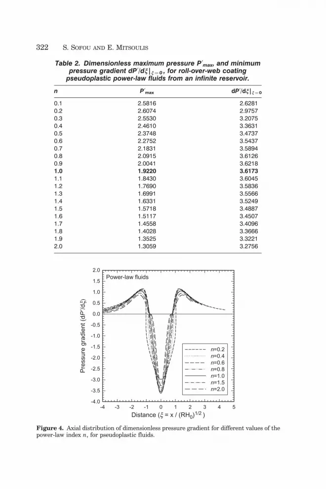
Table 2. Dimensionless maximum pressure P0max, and minimumpressure gradient dP0/dn|n¼ 0 , for roll-over-web coating
pseudoplastic power-law fluids from an infinite reservoir.
n P0max dP0/dn|n¼0
0.1 2.5816 �2.62810.2 2.6074 �2.97570.3 2.5530 �3.20750.4 2.4610 �3.36310.5 2.3748 �3.47370.6 2.2752 �3.54370.7 2.1831 �3.58940.8 2.0915 �3.61260.9 2.0041 �3.62181.0 1.9220 �3.6173
1.1 1.8430 �3.60451.2 1.7690 �3.58361.3 1.6991 �3.55661.4 1.6331 �3.52491.5 1.5718 �3.48871.6 1.5117 �3.45071.7 1.4558 �3.40961.8 1.4028 �3.36661.9 1.3525 �3.32212.0 1.3059 �3.2756
-4 -3 -2 -1 0 1 2 3 4 5-4.0
-3.5
-3.0
-2.5
-2.0
-1.5
-1.0
-0.5
0.0
0.5
1.0
1.5
2.0
n=0.2n=0.4n=0.6n=0.8n=1.0n=1.5n=2.0
Distance (x = x / (RH0)1/2 )
Power-law fluids
Pre
ssur
e gr
adie
nt (
dP′/d
x)
Figure 4. Axial distribution of dimensionless pressure gradient for different values of thepower-law index n, for pseudoplastic fluids.
322 S. SOFOU AND E. MITSOULIS

Viscoplastic Fluids
Calculations were performed next for viscoplastic fluids, and inparticular for Bingham plastics, with 0�Bn� 15. Numerical results forthe dimensionless volumetric flow rate l, final coating thickness H/H0,
-12 -10 -8 -6 -4 -2 0 2 4-2.5
-2.0
-1.5
-1.0
-0.5
3.0
2.5
2.0
1.5
1.0
0.5
0.0
n=0.2n=0.4n=0.6n=0.8n=1.0n=1.5n=2.0
Pre
ssur
e (P
')
Distance (x = x / (RH0)1/2)
Power-law fluids
Figure 5. Axial distribution of dimensionless pressure for different values of the power-law index n, for pseudoplastic fluids.
Power-law index (n)0.00.20.40.60.81.01.21.41.61.82.0
1.20
1.25
1.30
1.35
1.40
1.45
1.50
1.55
1.60
1.65
1.70
Coating thickness (H
/H0 )
0.620.640.660.680.700.720.740.760.780.800.820.84
Flo
w r
ate
(l)
Power-law fluids
H/H0l
Figure 6. Dimensionless flow rate l, and exit coating thickness H/H0, as a function of thepower-law index n, for pseudoplastic fluids.
Roll-over-web Coating Using Lubrication Approximation 323

and separation point n1, are presented in Table 3, while numericalresults for the maximum pressure and the minimum pressure gradientare presented in Table 4.
Figure 9 shows the dimensionless pressure gradient distribution fordifferent values of the Bingham number Bn, while Figure 10 shows thecorresponding dimensionless pressure distribution. As was the case forpseudoplastic shear-thinning fluids, increasing Bn leads to higher valuesfor the maximum pressure, while the curves for the pressure gradient
0.0 0.2 0.4 0.6 0.8 1.0 1.2 1.4 1.6 1.8 2.00.1
1
10
100
F
P
Power-law index (n)
Power-law fluids
E/10
Figure 8. Operating variables (maximum pressure P, force factor F, and power factor E)as a function of the power-law index n, for pseudoplastic fluids.
Power-law index (n)0.00.20.40.60.81.01.21.41.61.82.0
1.01.52.02.53.03.54.04.55.05.56.06.57.0
Coating thickness (H
/H0 )
0.62
0.640.660.68
0.700.72
0.740.760.780.800.82
0.84
Sep
arat
ion
poin
t (x 1
)Power-law fluids
x1 H/H0
Figure 7. Dimensionless separation point n1, and exit coating thickness H/H0, as afunction of the power-law index n, for pseudoplastic fluids.
324 S. SOFOU AND E. MITSOULIS

are getting steeper near the minimum gap H0. Thus, as the materialbecomes more viscoplastic, the deformations in the flow domain becomesmaller, the material behaves more solid-like and requires higherpressures and a larger domain to flow and deform.
Figure 11 shows the values for the dimensionless volumetric flow ratel, and the exit coating thickness H/H0, as a function of Bn. For Bn¼ 0the well-known Newtonian value l¼ 1.3015 [3] is the starting point forthe calculations of viscoplastic fluids. Further increasing Bn leadsto higher increases of these values. For Bn¼ 10, the coating thicknessH/H0, is 0.8175.
Figure 12 shows the separation point n1, and the coating thicknessH/H0, for 0�Bn� 15. Increasing Bn, and hence the viscoplasticcharacter of the material, leads again to higher values of the separationpoint, and hence the flow domain.
Figure 13 shows results for the operating variables, P, F, and E.For Bn¼ 0, the Newtonian values are obtained which were mentionedabove, while increasing Bn leads again to increasing these values, ina dimensionless form.
Table 3. Dimensionless volumetric flow rate l, exit coating thickness H/H0,and separation point n1, for roll-over-web coating viscoplastic
Bingham fluids from an infinite reservoir.
Bn k H/H0 �1
0 1.3015 0.6507 2.4102
0.001 1.3017 0.6508 2.41200.01 1.3032 0.6516 2.42810.05 1.3098 0.6549 2.49900.1 1.3175 0.6588 2.58580.5 1.3666 0.6833 3.22521 1.4095 0.7048 3.92392 1.4673 0.7337 5.11673 1.5068 0.7534 6.13934 1.5364 0.7682 7.05045 1.5602 0.7801 7.88256 1.5798 0.7899 8.65297 1.5966 0.7983 9.37498 1.6109 0.8055 10.05569 1.6236 0.8118 10.702310 1.6349 0.8175 11.320511 1.6449 0.8224 11.911812 1.6540 0.8270 12.481113 1.6623 0.8312 13.031114 1.6703 0.8352 13.566215 1.6773 0.8387 14.0824
Roll-over-web Coating Using Lubrication Approximation 325

Table 4. Dimensionless maximum pressure P0max, and minimum pressuregradient dP0/dn|n¼0, for roll-over-web coating viscoplastic
Bingham fluids from an infinite reservoir.
Bn P0max dP0/d�|�¼ 0
0 1.9220 �3.6173
0.001 1.9249 �3.62310.01 1.9607 �3.66860.05 2.1173 �3.86760.1 2.3092 �4.11010.5 3.7422 �5.88491 5.3861 �7.84932 8.4357 �11.35853 11.3218 �14.57334 14.1018 �17.61155 16.8330 �20.53756 19.4974 �23.37817 22.1351 �26.15038 24.7420 �28.87449 27.3298 �31.553110 29.8877 �34.197511 32.4316 �36.807512 34.9645 �39.396013 37.4763 �41.955114 39.9998 �44.500915 42.4852 �47.0197
-4 -2 0 2 4-9
-8
-7
-6
-5
-4
-3
-2
-1
0
1
2
3
4
Bn= 1Bn=0.5 Bn=0.1Bn=0.05Bn=0
Pre
ssur
e gr
adie
nt (
dP'/d
x)
Distance (x = x/(RH0)1/2)
Bingham plastics
Figure 9. Axial distribution of dimensionless pressure gradient for different values of theBingham number Bn, for viscoplastic fluids.
326 S. SOFOU AND E. MITSOULIS

Figure 14 shows the yielded and unyielded regions for various valuesof Bn. The dashed line corresponds to the ‘symmetry’ line of the presentproblem, or in other words the locus of the points where the shear stressis zero. It should be noted that the two yield lines are symmetric withregard to this line, as evidenced from Equations (21a) and (21b).
-10 -8 -6 -4 -2 0 2 4-5
-4
-3
-2
-1
0
1
2
3
4
5
6
Bn= 1Bn=0.5Bn=0.1Bn=0.05Bn=0
Pre
ssur
e (P
')
Distance (x = x/(RH0)1/2)
Bingham plastics
Figure 10. Axial distribution of dimensionless pressure for different values of theBingham number Bn, for viscoplastic fluids.
Bingham number (Bn)0 1 2 3 4 5 6 7 8 9 10 11 12 13 14 15
1.3
1.4
1.5
1.6
1.7
Coating thickness (H
/H0 )
0.65
0.70
0.75
0.80
0.85
0.90
Flo
w r
ate
(l)
Bingham plastics
H/H0
l
Figure 11. Dimensionless flow rate l, and exit coating thickness H/H0, as a function ofthe Bingham number Bn, for viscoplastic fluids.
Roll-over-web Coating Using Lubrication Approximation 327

Increasing the Bn number changes the shape and extent of theyielded/unyielded regions. In particular, increasing Bn (a dimensionlessyield stress) leads to a progressive development of unyieldedregions. The points (on the flow axis) having a plug velocity profile,i.e., {�p1 ¼
~hh, �p2 ¼ 0}, are those for which the pressure shows extrema:��1 ¼ ½2ð�� 1Þ�0:5, ��2 ¼ �½2ð�� 1Þ�0:5. Thus, as the increase in Bn leadsto higher l values, these points get farther away from the minimum gapH0, which produces a gradual change in the shape of the unyieldedregions.
0 1 2 3 4 5 6 7 8 9 10 11 12 13 14 15
P
1
10
100
1000
Bingham plastics
Bingham number (Bn)
F
E /10
Figure 13. Operating variables (maximum pressure P, force factor F, and power factor E)as a function of the Bingham number Bn, for viscoplastic fluids.
Bingham number (Bn)0 1 2 3 4 5 6 7 8 9 10 11 12 13 14 15
2
4
6
8
10
12
14
16
Coating thickness (H
/H0 )
0.65
0.70
0.75
0.80
0.85
Sep
arat
ion
poin
t (x 1
)Bingham plastics
ξ1
H/H0
Figure 12. Dimensionless separation point n1, and exit coating thickness H/H0,as a function of the Bingham number Bn, for viscoplastic fluids.
328 S. SOFOU AND E. MITSOULIS

Figure 14. Progressive growth of the unyielded zones as the dimensionless Binghamnumber Bn, increases in roll-over-web coating of viscoplastic materials obeying theBingham plastic model. The shaded regions are unyielded.
Roll-over-web Coating Using Lubrication Approximation 329

The parametric study for Bingham plastics would have been complete,if a Bn number were found for which the velocity profile were plug forthe whole flow field, something which is not observed for Bn¼ 15.However, it is noteworthy that a comparison of the viscoplastic resultsfor Bn� 10 for the coating thickness and the dimensionless flow ratewith those for the pseudoplastic shear-thinning fluids with n¼ 0.1revealed that these are about the same. On the other hand, theseparation point is much larger for viscoplastic fluids. After a series ofnumerical tests, it became clear that a further increase in the Bnnumber led to very high values of the separation point (see Table 3),but it did not lead to a fully plug velocity profile and did not increasethe values for the coating thickness and the volumetric flow rateaccordingly. This can be explained by the fact that for large values of theseparation point, the flow domain cannot be considered as that betweentwo flat plates, and the assumptions of LAT, uy�ux and dx� dy,are not valid. We have, therefore, come across the limitations of LATfor extracting useful numerical results.
The effect of pseudoplasticity within viscoplasticity is examinedin Figure 15, where the pressure distribution is depicted for severalHerschel-Bulkley fluids at Bn¼ 1. Changing the value of the power-lawindex n, has no dramatic effect over the maximum pressure value,
-10 -8 -6 -4 -2 0 2 4 6-5
-4
-3
-2
-1
0
1
2
3
4
5
6
n=0.2n=0.5n=1n=1.2
Pre
ssur
e (P
')
Distance (x = x/(RH0)1/2)
Heschel-Bulkley fluidsBn=1
Figure 15. Axial distribution of dimensionless pressure for different values of the power-law index n, for Herschel–Bulkley fluids with Bn¼ 1.
330 S. SOFOU AND E. MITSOULIS

and it does not change the shape of the pressure curve. The decreaseof the power-law index does however lead to a bigger domain, and biggervalues for the dimensionless flow rate l. For n¼ 0.2, the acquiredvalues for l and n1 are 1.642 and 6.618 respectively, that is, 16.5% and68.6% bigger than the ones presented in Table 3 for a Bingham plasticwith Bn¼ 1. Once again, the sensitivity of n1 is more pronounced. Theseresults confirm that the meniscus location is one of the most sensitivefeatures in modeling this type of flow.
Critique on the Lubrication Approximation
The key assumption for obtaining the above results has been thelubrication approximation theory (LAT), which assumes locally fullydeveloped flow and reduces the conservation equations by using only theaxial velocity component. This assumption is known to give good resultsfor the pressure distribution in calendering of power-law fluids [9] andhence for all integrated quantities resulting from that. It is thereforereasonable to assume that it also does well for viscoplastic fluids, suchas the ones used in the present work.
However, a closer look at the physics of the viscoplastic problem andin particular the interesting yielded/unyielded regions found here,reveals that these cannot be so and that Figure 14 is contentious. Theshaded areas cannot be rigid plugs, since the speeds at entry and exit aredifferent, and there is no chance that a constant speed occurs along theline where the shear stress equals zero. However, the domain length,the pressure distribution, and the ensuing operating variables are notexpected to change much (within a few percent) from the values foundby LAT, as was the case in calendering [10].
It is therefore obvious that the introduction of LAT in lubrication flowswith viscoplastic fluids is not valid for such quantities as the yielded/unyielded regions, since it leads to a ‘paradox’, as pointed out byLipscomb and Denn [11]. A 2-D analysis is therefore essential forobtaining the correct regions, and such an analysis is currently under wayby the authors. However, it is not expected to change drastically the otherresults shown here, especially the pressure distribution and integratedquantities, since roll-over-web coating is primarily a lubrication flow.
CONCLUSIONS
In the present work, the Lubrication Approximation Theory (LAT)was used along with the power-law, Bingham, and Herschel–Bulkley
Roll-over-web Coating Using Lubrication Approximation 331

rheological models, in order to obtain numerical results for theprocess of roll coating over a moving flat web fed from an infinitereservoir. For the pseudoplastic fluids, the results by Middleman [1,6]were verified and extended, while for viscoplastic fluids, a newmethodology was presented and gave new results for Bingham plasticsand Herschel–Bulkley fluids.
Reducing the power-law index n, or increasing the Bingham numberBn, leads to higher coating thickness, separation point (hence domainlength) and volumetric flow rate. Furthermore, engineering quantitiesof the process, such as the maximum pressure, the separating force andthe required power to the roll, all increase with a reduction in n or anincrease in Bn. Finally, the determination of yielded/unyielded regionsshowed a progressive growth of unyielded regions by increasing the Bnnumber. It was argued that this last finding is a direct result of theapproximation within LAT, and that these unyielded regions shoulddisappear in a full 2-D analysis of the process. Such an analysis remainsto be done for roll-over-web coating of viscoplastic fluids.
The present results are offered as a quick reference for engineersworking on roll-over-web coating of such materials to determine theresulting coating thickness of the coatings produced and the correspond-ing values for important engineering quantities.
ACKNOWLEDGMENTS
Financial support from NTUA in the form of a research scholarshipfor basic research for S. Sofou is gratefully acknowledged.
REFERENCES
1. Middleman, S. (1977). Fundamentals of Polymer Processing, McGraw-Hill,New York.
2. Bird, R.B., Dai, G.C. and Yarusso, B.J. (1983). The Rheology and Flowof Viscoplastic Materials, Rev. Chem. Eng., 1(1): 1–70.
3. Coyle, D.J. (1984). The Fluid Mechanics of Roll Coating: Steady Flows,Stability, and Rheology, PhD Thesis, University of Minnesota,Minneapolis, MN.
4. Coyle, D.J., Macosko, C.W. and Scriven, L.E. (1987). Film-Splitting Flowsof Shear-Thinning Liquids in Forward Roll Coating, AIChE J., 33(3): 741–746.
5. Coyle, D.J., Macosko, C.W. and Scriven, L.E. (1990). Reverse Roll Coatingof Non-Newtonian Liquids, J. Rheol., 34(5): 615–636.
332 S. SOFOU AND E. MITSOULIS

6. Greener, J. and Middleman, S. (1975). A Theory of Roll Coating of Viscousand Viscoelastic Fluids, Polym. Eng. Sci., 15(1): 1–10.
7. Loest, H., Lipp, R. and Mitsoulis, E. (1994). Numerical Flow Simulationof Viscoplastic Slurries and Design Criteria for a Tape Casting Unit,J. Amer. Ceram. Soc., 77(1): 254–262.
8. Gerald, C.F. and Wheatley, P.O. (1985). Applied Numerical Analysis,Addison-Wesley, Reading, Massachusetts.
9. Mitsoulis, E., Vlachopoulos, J. and Mirza, F.A. (1985). Calendering Analysiswithout the Lubrication Approximation, Polym. Eng. Sci., 25(1): 6–18.
10. Sofou, S. and Mitsoulis, E. (2004). Calendering of Pseudoplasticand Viscoplastic Sheets of Finite Thickness, J. Plast. Film & Sheeting,20(3): 185–222.
11. Lipscomb, G.G. and Denn, M.M. (1984). Flow of Bingham Fluids in ComplexGeometries, J. Non-Newtonian Fluid Mech., 14(1): 337–346.
BIOGRAPHIES
Evan Mitsoulis
Evan Mitsoulis received his Diploma in Chemical Engineering fromthe National Technical University of Athens (NTUA), Greece, beforeobtaining his MScE from the University of New Brunswick (Canada)and then his PhD in ChE from McMaster University (Canada). From1984–2000 he was a Professor in the Department of ChemicalEngineering at the University of Ottawa, Canada, and since 1998 hehas been with the School of Mining Engineering and Metallurgyat NTUA, where he is the Director of CAMP-R&D (Computer-AidedMaterials Processing – Rheology & Design) Laboratory. He is the authorof over 100 refereed papers and over 185 presentations in Conferenceson polymer processing, rheology, and design.
Souzanna Sofou
Souzanna Sofou received her Diploma in Mining Engineering &Metallurgy from the National Technical University of Athens (NTUA),Greece, before obtaining her MEng at the same University. She is now aPhD candidate in the School of Mining Engineering and Metallurgy atNTUA working on ‘‘Calendering of Viscoplastic Materials’’.
Roll-over-web Coating Using Lubrication Approximation 333


