Embed Size (px)
Citation preview
Rough Design of a Double-Stator Axial Flux
Permanent Magnet Generator
for a Rim-Driven Marine Current Turbine
Sofiane Djebarri1, Jean Frédéric Charpentier1, Franck Scuiller1, Mohamed Benbouzid2 and Sylvain Guemard3 1French Naval Academy, IRENav EA 3634, 29240 Brest Cedex 9, France
e-mail: [email protected] 2University of Brest, EA 4325 LBMS, Rue de Kergoat, CS 93837, 29238 Brest Cedex 03, France
e-mail: [email protected] 3ECA-EN Company, Bvd Marcel Paul, Saint Herblain, France
e-mail: [email protected]
Abstract—This paper deals with the rough design of a
Double-Stator Axial Flux Permanent Magnet Machine
(DSAFPM) for a rim-driven Marine Current Turbine (MCT).
The DSAFPM machine will be compared to a previously
developed and realized Radial Flux Permanent Magnet Machine
(RFPM); given the same rim-driven MCT specifications. For that
purpose, a first-order electromagnetic design model and a
thermal one are developed and used to compare active part mass,
cost, and thermal behavior of the two machines.
The obtained results show that such a structure of poly-air
gap axial flux machine can be more interesting in terms of
compactness and thermal behavior for rim-driven marine
current turbines.
Index Terms—Marine current turbine, rim-driven concept,
permanent magnet machine, axial flux machine, electromagnetic
model, thermal model.
I. INTRODUCTION
Tidal energy is a renewable source of energy which is
predictable many years in advance. It constitutes a good
alternative to be combined with other renewable sources of
energy [1-2]. The predictability of marine currents makes the
connection to the electrical grid very easy. There are also other
advantages such as low visual exposure, no noise for the
public and reduced environment considerations. Nonetheless,
some disadvantages must be noted such as conflicts with other
users of the sea and the need for a salt and water proof
technologies due to sea immersion [2-4].
The energy conversion of marine current is quite similar in
principle to wind energy. Kinetic energy from marine currents
is harnessed using similar systems to those developed to
extract wind energy [3]. This is particularly the case of the
first developed MCTs [2]. However, because of tides low
speed and to avoid blades cavitation, the turbine rotational
speed is typically below 100 rpm.
For conventional generators, the rated speed is very high
and the use of a multistage gearbox is needed. This decreases
the drive train efficiency and increases maintenance
requirements. To make the tidal current energy conversion
economically interesting, the MCT will need to have an
approximately 30 year’s lifespan with maintenance inspections
every 5 years [5]. Therefore, MCTs should be highly efficient
and reliable.
Hence, for the electric machine side, direct-drive
permanent magnet generators appear as the solution that
fulfills these requirements especially in terms of reduced
maintenance. In direct-drive current turbine systems the
electrical generator is directly connected to the turbine. Thus,
a direct-drive turbine is operated at low speed and the gearbox
is eliminated [6]. Consequently, the maintenance requirements
are significantly reduced and the efficiency of the drive train is
improved. However, the generator active parts mass and cost
are expected to be higher if compared with more conventional
generators including gearbox.
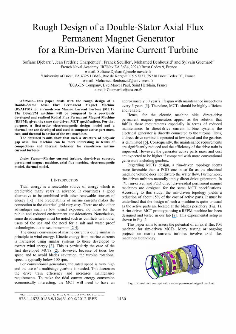
Regarding MCTs design, a rim-driven topology seems
more favorable than a POD one in so far as the electrical
machine volume does not disturb the water flow. Furthermore,
rim-driven turbines naturally imply direct-drive generators. In
[7], rim-driven and POD direct drive-radial permanent magnet
machines are designed for the same MCT specifications.
According to this study, the rim-driven topology yields a
reduction of about 15% of the cost of active parts. It must be
underlined that the design of such a machine is quite unusual
as the active parts are located at the blades periphery (Fig. 1).
A rim-driven MCT prototype using a RFPM machine has been
designed and tested in our lab [8]. This experimental setup is
shown in Fig. 2.
This paper aims to assess the potential of an axial flux PM
machine for rim-driven MCTs. Many testing or ongoing
projects on marine currents turbines involve axial flux
machines technology.
Fig.1. Rim-driven concept with a radial permanent magnet machine.
This work was supported by French Navy and ECA-EN Company.
YWXMQMTVWSMPQUXMYOQRODSQNPP@ᄅRPQR@ieee QTUP
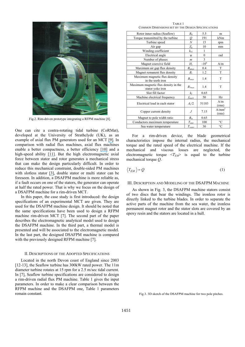
Fig.2. Rim-driven prototype integrating a RFPM machine [8].
One can cite a contra-rotating tidal turbine (CoRMat),
developed at the University of Strathclyde (UK), as an
example of axial flux PM generators used for an MCT [9]. In
comparison with radial flux machines, axial flux machines
enable a better compactness, a better efficiency [10] and a
high-speed ability [11]. But the high electromagnetic axial
force between stator and rotor generates a mechanical stress
that can make the design particularly difficult. In order to
reduce this mechanical constraint, double-sided PM machines
with slotless stator [3], double stator or multi stator can be
foreseen. In addition, a DSAFPM machine is more reliable as,
if a fault occurs on one of the stators, the generator can operate
at half the rated power. That is why we focus on the design of
a DSAFPM machine for a rim-driven MCT.
In this paper, the case study is first introduced: the design
specifications of an experimental MCT are given. They are
used for the DSAFPM machine design. It should be noted that
the same specifications have been used to design a RFPM
machine rim-driven MCT [7]. The second part of the paper
describes the electromagnetic analytical model used to design
the DSAFPM machine. In the third part, a thermal model is
presented and will be associated to the electromagnetic model.
In the last part, the designed DSAFPM machine is compared
with the previously designed RFPM machine [7].
II. DESCRIPTIONS OF THE ADOPTED SPECIFICATIONS
Located in the north Devon coast of England since 2003
[12-13], the Seaflow turbine has 300kW rated power. The 11m
diameter turbine rotates at 15 rpm for a 2.5 m/sec tidal current.
In [7], Seaflow turbine specifications are considered to design
a rim-driven radial flux PM machine. Table 1 gives the input
parameters. In order to make a clear comparison between the
RFPM machine and the DSAFPM one, Table 1 parameters
remain constant.
TABLE 1
COMMON DIMENSIONS SET BY THE DESIGN SPECIFICATIONS
Rotor inner radius (Seaflow) R0 5.5 m
Torque transmitted by the turbine Q 191 kNm
Turbine speed N 15 rpm
Air gap Zg 10 mm
Winding coefficient kb1 1
Electrical angle ψ 0 rad
Number of phases m 3
Magnet coercive field Hc -106 A/m
Maximum air gap flux density Bgmax 0.4 T
Magnet remanent flux density Br 1.2 T
Maximum magnetic flux density
in the teeth iron Btmax 1.4 T
Maximum magnetic flux density in the
stator yoke iron BYmax 1.4 T
Slot fill factor kf 0.65
Machine electrical frequency fmach 50 Hz
Electrical load in each stator AL/2 51183 A/m
(rms)
Copper current density J 7.15 A/mm2
(rms)
Magnet to pole width ratio Βm 0.65
Conductors maximum temperature Tmax 100 °C
Sea water temperature Twater 30 °C
For a rim-driven device, the blade geometrical
characteristics impose the internal radius, the mechanical
torque and the rated speed of the electrical machine. If the
mechanical and viscous losses are neglected, the
electromagnetic torque <TEM> is equal to the turbine
mechanical torque Q.
EMT Q= (1)
III. DESCRIPTION AND MODELING OF THE DSAFPM MACHINE
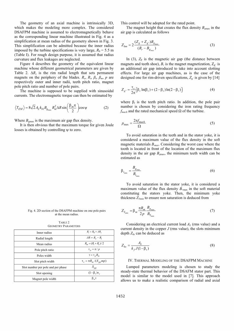
As shown in Fig. 3, the DSAFPM machine stators consist
of two discs that bear the windings. The ironless rotor is
directly linked to the turbine blades. In order to separate the
active parts of the machine from the sea water, the ironless
permanent magnet rotor and the stator slots are covered by an
epoxy resin and the stators are located in a hull.
Fig.3. 3D sketch of the DSAFPM machine for two pole pitches.
QTUQ
The geometry of an axial machine is intrinsically 3D,
which makes the modeling more complex. The considered
DSAFPM machine is assumed to electromagnetically behave
as the corresponding linear machine illustrated in Fig. 4 as a
simplification at mean radius of the geometry shown in Fig. 3.
This simplification can be admitted because the inner radius
imposed by the turbine specifications is very large, R0 = 5.5 m
(Table I). For rough design purpose, it is assumed that radius
curvature and flux leakages are neglected.
Figure 4 describes the geometry of the equivalent linear
machine whose different geometrical parameters are given by
Table 2. ΔRs is the rim radial length that sets permanent
magnets on the periphery of the blades. Re, Ri, βt, βm, p are
respectively outer and inner radii, teeth pitch ratio, magnet
pole pitch ratio and number of pole pairs.
The machine is supposed to be supplied with sinusoidal
currents. The electromagnetic torque can then be estimated by
max
21 g8 2 sin cos
2
mEM L b mT A k B R R
β π⎛ ⎞= Δ ψ⎜ ⎟⎝ ⎠ (2)
Where Bgmax is the maximum air gap flux density.
It is then obvious that the maximum torque for given Joule
losses is obtained by controlling ψ to zero.
Fig. 4. 2D section of the DSAFPM machine on one pole pairs
at the mean radius.
TABLE 2
GEOMETRY PARAMETERS
Inner radius 0i sR R ΔR= +
Radial length e iΔR R R= −
Mean radius ( ) / 2m i eR R R= +
Pole pitch ratio /p pτ = π
Poles width p mRτ = τ
Slot pitch width /( )s m ppR S mpτ = π
Slot number per pole and per phase ppS
Slot opening (1 )t s−β τ
Magnet pole width mβ τ
This control will be adopted for the rated point.
The magnet height that creates the flux density Bgmax in the
air gap is calculated as follows
'( )2
( )
max
max
g g g
hmr g
Z Z BZ
B B
+= − (3)
In (3), Zg is the magnetic air gap (the distance between
magnets and teeth shoe), Br is the magnet magnetization, Zg’ is
an additional air gap introduced to take into account slotting
effects. For large air gap machines, as is the case of the
designed one for rim-driven specifications, Zg’ is given by [14]
' ln( ) (2 ) ln(2 )2
sg t t t tZ
τ= β β + −β −β⎡ ⎤⎣ ⎦π (4)
where βt is the teeth pitch ratio. In addition, the pole pair
number is chosen by considering the iron rating frequency
fmach and the rated mechanical speed Ω of the turbine.
max
2 machfp
π= Ω (5)
To avoid saturation in the teeth and in the stator yoke, it is
considered a maximum value of the flux density in the soft
magnetic materials Btmax. Considering the worst case where the
tooth is located in front of the location of the maximum flux
density in the air gap Bgmax, the minimum teeth width can be
estimated as
max
min
max
g
tt
B
Bβ = (6)
To avoid saturation in the stator yoke, it is considered a
maximum value of the flux density BYmax in the soft material
constituting the stators yoke. Then, the minimum yoke
thickness ZYmin to ensure non saturation is deduced from
max
min
max2
gmY m
Y
BRZ
p B
π= β (7)
Considering an electrical current load AL (rms value) and a
current density in the copper J (rms value), the slots minimum
depth Zhs can be deduced as
(1 )
Lhs
f t
AZ
k J= −β (8)
IV. THERMAL MODELING OF THE DSAFPM MACHINE
Lumped parameters modeling is chosen to study the
steady-state thermal behavior of the DSAFM stator part. This
model is similar to the model used in [7]. This approach
allows us to make a realistic comparison of radial and axial
QTUR
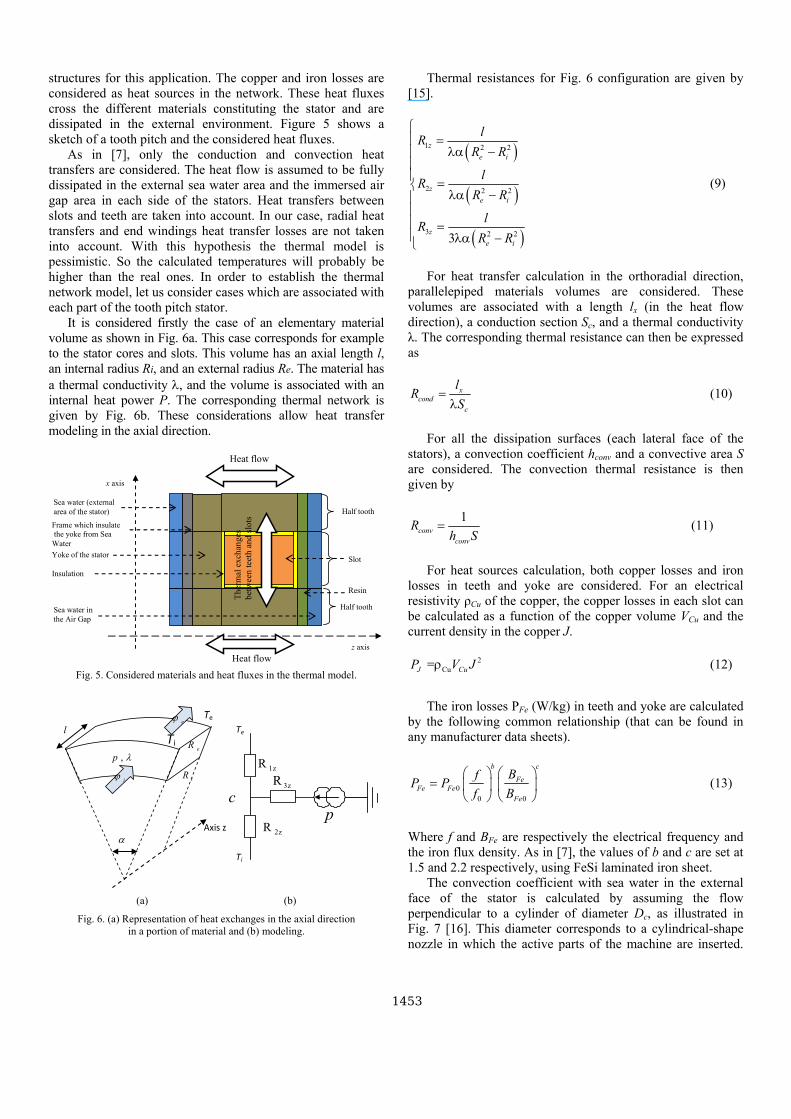
structures for this application. The copper and iron losses are
considered as heat sources in the network. These heat fluxes
cross the different materials constituting the stator and are
dissipated in the external environment. Figure 5 shows a
sketch of a tooth pitch and the considered heat fluxes.
As in [7], only the conduction and convection heat
transfers are considered. The heat flow is assumed to be fully
dissipated in the external sea water area and the immersed air
gap area in each side of the stators. Heat transfers between
slots and teeth are taken into account. In our case, radial heat
transfers and end windings heat transfer losses are not taken
into account. With this hypothesis the thermal model is
pessimistic. So the calculated temperatures will probably be
higher than the real ones. In order to establish the thermal
network model, let us consider cases which are associated with
each part of the tooth pitch stator.
It is considered firstly the case of an elementary material
volume as shown in Fig. 6a. This case corresponds for example
to the stator cores and slots. This volume has an axial length l,
an internal radius Ri, and an external radius Re. The material has
a thermal conductivity λ, and the volume is associated with an
internal heat power P. The corresponding thermal network is
given by Fig. 6b. These considerations allow heat transfer
modeling in the axial direction.
Frame which insulate
the yoke from Sea
Water
Sea water (external
area of the stator)
z axis
x axis
Heat flow
Heat flow
Insulation
Yoke of the stator Slot
Sea water in
the Air Gap
Half tooth
Half tooth
Resin
Th
erm
al e
xch
ang
es
bet
wee
n t
eeth
and
slo
ts
Fig. 5. Considered materials and heat fluxes in the thermal model.
α
Ti
Te
,p λ
eϕ
iϕ
l
eR
iR
Axis z
1zR
2zR
Te
Ti
3zR
pc
(a) (b)
Fig. 6. (a) Representation of heat exchanges in the axial direction
in a portion of material and (b) modeling.
Thermal resistances for Fig. 6 configuration are given by
[15].
( )( )( )
1 2 2
2 2 2
3 2 23
z
e i
z
e i
z
e i
lR
R R
lR
R R
lR
R R
⎧⎪ = λα −⎪⎪⎪ =⎨ λα −⎪⎪⎪ =⎪ λα −⎩
(9)
For heat transfer calculation in the orthoradial direction,
parallelepiped materials volumes are considered. These
volumes are associated with a length lx (in the heat flow
direction), a conduction section Sc, and a thermal conductivity
λ. The corresponding thermal resistance can then be expressed
as
x
cond
c
lR
S= λ (10)
For all the dissipation surfaces (each lateral face of the
stators), a convection coefficient hconv and a convective area S
are considered. The convection thermal resistance is then
given by
1conv
conv
Rh S
= (11)
For heat sources calculation, both copper losses and iron
losses in teeth and yoke are considered. For an electrical
resistivity ρCu of the copper, the copper losses in each slot can
be calculated as a function of the copper volume VCu and the
current density in the copper J.
2
Cu =J CuP V Jρ (12)
The iron losses PFe (W/kg) in teeth and yoke are calculated
by the following common relationship (that can be found in
any manufacturer data sheets).
0
0 0
b c
Fe
Fe Fe
Fe
BfP P
f B
⎛ ⎞ ⎛ ⎞= ⎜ ⎟ ⎜ ⎟⎝ ⎠ ⎝ ⎠ (13)
Where f and BFe are respectively the electrical frequency and
the iron flux density. As in [7], the values of b and c are set at
1.5 and 2.2 respectively, using FeSi laminated iron sheet.
The convection coefficient with sea water in the external
face of the stator is calculated by assuming the flow
perpendicular to a cylinder of diameter Dc, as illustrated in
Fig. 7 [16]. This diameter corresponds to a cylindrical-shape
nozzle in which the active parts of the machine are inserted.
QTUS
[17], which study a case close to the air gap geometry, is used
to estimate the Nusselt number in the gap. The convection
coefficient is then calculated.
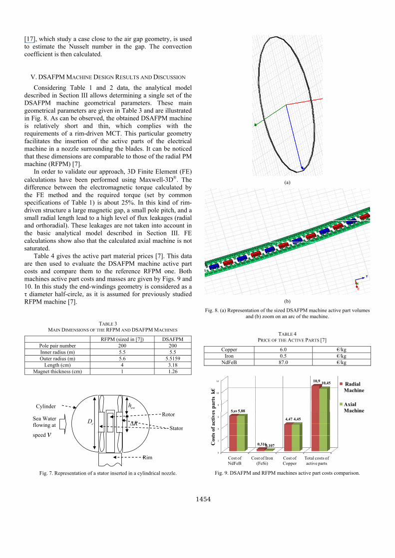
V. DSAFPM MACHINE DESIGN RESULTS AND DISCUSSION
Considering Table 1 and 2 data, the analytical model
described in Section III allows determining a single set of the
DSAFPM machine geometrical parameters. These main
geometrical parameters are given in Table 3 and are illustrated
in Fig. 8. As can be observed, the obtained DSAFPM machine
is relatively short and thin, which complies with the
requirements of a rim-driven MCT. This particular geometry
facilitates the insertion of the active parts of the electrical
machine in a nozzle surrounding the blades. It can be noticed
that these dimensions are comparable to those of the radial PM
machine (RFPM) [7].
In order to validate our approach, 3D Finite Element (FE)
calculations have been performed using Maxwell-3D®. The
difference between the electromagnetic torque calculated by
the FE method and the required torque (set by common
specifications of Table 1) is about 25%. In this kind of rim-
driven structure a large magnetic gap, a small pole pitch, and a
small radial length lead to a high level of flux leakages (radial
and orthoradial). These leakages are not taken into account in
the basic analytical model described in Section III. FE
calculations show also that the calculated axial machine is not
saturated.
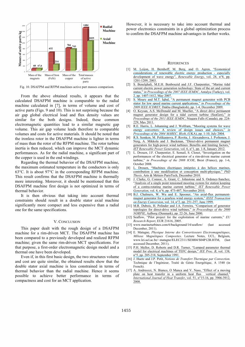
Table 4 gives the active part material prices [7]. This data
are then used to evaluate the DSAFPM machine active part
costs and compare them to the reference RFPM one. Both
machines active part costs and masses are given by Figs. 9 and
10. In this study the end-windings geometry is considered as a
τ diameter half-circle, as it is assumed for previously studied
RFPM machine [7].
TABLE 3
MAIN DIMENSIONS OF THE RFPM AND DSAFPM MACHINES
RFPM (sized in [7]) DSAFPM
Pole pair number 200 200
Inner radius (m) 5.5 5.5
Outer radius (m) 5.6 5.5159
Length (cm) 4 3.18
Magnet thickness (cm) 1 1.26
Stator
Sea Water
flowing at
speed v
RΔewh
cD
Cylinder
Rotor
Rim
Fig. 7. Representation of a stator inserted in a cylindrical nozzle.
(a)
(b)
Fig. 8. (a) Representation of the sized DSAFPM machine active part volumes
and (b) zoom on an arc of the machine.
TABLE 4
PRICE OF THE ACTIVE PARTS [7]
Copper 6.0 €/kg
Iron 0.5 €/kg
NdFeB 87.0 €/kg
0
2
4
6
8
10
12
Cost of
NdFeB
Cost of Iron
(FeSi)
Cost of
Copper
Total costs of
active parts
5,89
0,316
4,47
10,9
5,88
0,107
4,45
10,45
Cost
s of
act
ives
part
s k
€
Radial
Machine
Axial
Machine
Fig. 9. DSAFPM and RFPM machines active part costs comparison.
QTUT
0
200
400
600
800
1000
1200
1400
1600
Mass of the
magnets
Mass of Iron
(FeSi)
Mass of the
copper
Total masses
of active parts
68
632
784
1484
67,6
214
743
1025
Ma
sses
of
act
ive
part
s k
g
Radial
Machine
Axial
Machine
Fig. 10. DSAFPM and RFPM machines active part masses comparison.
From the above obtained results, it appears that the
calculated DSAFPM machine is comparable to the radial
machine calculated in [7], in terms of volume and cost of
active parts (Figs. 9 and 10). This is not surprising because the
air gap global electrical load and flux density values are
similar for the both designs. Indeed, these common
electromagnetic quantities lead to a similar magnetic gap
volume. This air gap volume leads therefore to comparable
volumes and costs for active materials. It should be noted that
the ironless rotor in the DSAFPM machine is lighter in terms
of mass than the rotor of the RFPM machine. The rotor turbine
inertia is then reduced, which can improve the MCT dynamic
performances. As for the radial machine, a significant part of
the copper is used in the end windings.
Regarding the thermal behavior of the DSAFPM machine,
the maximum estimated temperature in the conductors is only
63°C. It is about 97°C in the corresponding RFPM machine.
This result confirms that the DSAFPM machine is thermally
more interesting. Moreover, it should be mentioned that this
DSAFPM machine first design is not optimized in terms of
thermal behavior.
It is then obvious that taking into account thermal
constraints should result in a double stator axial machine
significantly more compact and less expensive than a radial
one for the same specifications.
V. CONCLUSION
This paper dealt with the rough design of a DSAFPM
machine for a rim-driven MCT. The DSAFPM machine has
been compared to a previously developed and realized RFPM
machine; given the same rim-driven MCT specifications. For
that purpose, a first-order electromagnetic design model and a
thermal one have been developed.
Even if, in this first basic design, the two structures volume
and cost are quite similar, the obtained results show that the
double stator axial machine is less constrained in terms of
thermal behavior than the radial machine. Hence it seems
possible to achieve better performance in terms of
compactness and cost for an MCT application.
However, it is necessary to take into account thermal and
power electronics constraints in a global optimization process
to confirm the DSAFPM machine advantages in further works.
REFERENCES
[1] M. Leijon, H. Bernhoff, M. Berg, and O. Agren, “Economical
considerations of renewable electric energy production - especially
development of wave energy”, Renewable Energy, vol. 28, n°8, pp.
1201-1209, 2003.
[2] S. Benelghali, M.E.H. Benbouzid and J.F. Charpentier, “Marine tidal
current electric power generation technology: State of the art and current
status,” in Proceedings of the 2007 IEEE IEMDC, Antalya (Turkey), vol.
2, pp. 1407-1412, May 2007.
[3] S. Moury and M.T. Iqbal, “A permanent magnet generator with PCB
stator for low speed marine current applications,” in Proceedings of the
2009 IEEE ICDRET, Dakha (Bangladesh), pp. 1-4, December 2009.
[4] O. Keysan, A.S. McDonald and M. Mueller, “A direct drive permanent
magnet generator design for a tidal current turbine (SeaGen),” in
Proceedings of the 2011 IEEE IEMDC, Niagara Falls (Canada), pp. 224-
229, May 2011.
[5] R.E. Harris, L. Johanning and J. Wolfram, “Mooring systems for wave
energy converters: A review of design issues and choices,” in
Proceedings of the 2004 MAREC, Blyth, (UKA), pp. 1-10, July 2004.
[6] R.S. Semken, M. Polikarpova, P. Roytta, J. Alexandrova, J. Pyrhonen, J.
Nerg, A. Mikkola and J. Backman, “Direct-drive permanent magnet
generators for high-power wind turbines: Benefits and limiting factors,”
IET Renewable Power Generation, vol. 6, n°1, pp. 1-8, January 2012.
[7] L. Drouen, J.F. Charpentier, E. Semail, S. Clenet, “Investigation on the
performances of the electrical generator of a rim-driven marine current
turbine,” in Proceedings of the 2008 ICOE, Brest (France), pp. 1-6,
October 2008.
[8] L. Drouen, “Machines électriques intégrées à des hélices marines,
contribution à une modélisation et conception multi-physique,” PhD
Thesis, Arts & Métiers ParisTech, December 2010.
[9] J. Clarke, G. Connor, A. Grant, C. Johnstone and S. Ordonez-Sanchez,
“Analysis of a single point tensioned mooring system for station keeping
of a contra-rotating marine current turbine,” IET Renewable Power
Generation, vol. 4, n°6, pp. 473-487, November 2010.
[10] B.J. Chalmers, W. Wu and E. Spooner, “An axial-flux permanent-
magnet generator for a gearless wind energy system,” IEEE Transaction
on Energy Conversion, vol. 14, n°2, pp. 251-257, June 1999.
[11] M.R. Dubois, H. Polinder and J.A. Ferreira, “Comparison of generator
topologies for direct-drive wind turbines,” in Proceedings of the 2000
NORPIE, Aalborg (Denmark), pp. 22-26, June 2000.
[12] Seaflow, “Pilot project for the exploitation of marine currents,” EU
Research Report, EUR 21616, 2005.
[13] www.marineturbines.com/6/background/14/seaflow/ (last accessed
December, 2011).
[14] E. Matagne, Physique Interne des Convertisseurs Electromagnétiques,
Milieux Magnétiques Composites. Lecture Notes, UCL, Belgium,
www.lei.ucl.ac.be/~matagne/ELEC2311/SEM04/S04P12B.HTM, (last
accessed December, 2011).
[15] P.H. Mellor, D. Roberts and D.R. Turner, “Lumped parameter thermal
model for electrical machines of TEFC design,” IEE Proc. B, vol. 138,
n°5, pp. 205-218, September 1991.
[16] J. Huetz and J.P. Petit, Notions de Transfert Thermique par Convection.
Technique de l’Ingénieur, Traité de Génie Energétique, A 1540 (in
French).
[17] A. Andreozzi, N. Bianco, O Manca and V. Naso, “Effect of a moving
plate on heat transfer in a uniform heat flux vertical channel,”
International Journal of Heat Transfer, vol. 51, n°15-16, pp. 3906-3912,
2008.
QTUU
pッキ・イ・、@「ケ@tcpdf@HキキキNエ」ー、ヲNッイァI


