Embed Size (px)
Citation preview

Rule based design
Draft
Stef Joosten
November 1, 2007

2


ii

Contents
1 Inspired by Information 1
1.1 A vision . . . . . . . . . . . . . . . . . . . . . . . . . . . . . . . . 1
1.2 Background . . . . . . . . . . . . . . . . . . . . . . . . . . . . . . 4
1.3 Practice . . . . . . . . . . . . . . . . . . . . . . . . . . . . . . . . 7
1.4 Further research . . . . . . . . . . . . . . . . . . . . . . . . . . . 8
1.5 Acknowledgements . . . . . . . . . . . . . . . . . . . . . . . . . . 9
1.6 Reading Guide . . . . . . . . . . . . . . . . . . . . . . . . . . . . 10
I Practice 11
2 Ampersand 13
2.1 Rules in Business . . . . . . . . . . . . . . . . . . . . . . . . . . . 13
2.2 An example . . . . . . . . . . . . . . . . . . . . . . . . . . . . . . 15
2.3 Control Principle . . . . . . . . . . . . . . . . . . . . . . . . . . . 17
2.4 Case Study: Order process . . . . . . . . . . . . . . . . . . . . . . 19
2.5 Consequences . . . . . . . . . . . . . . . . . . . . . . . . . . . . . 22
iii

iv CONTENTS
II Theory 25
3 Rules, Relations and Concepts 27
3.1 Why? . . . . . . . . . . . . . . . . . . . . . . . . . . . . . . . . . 28
3.2 Preliminaries . . . . . . . . . . . . . . . . . . . . . . . . . . . . . 29
3.3 Relations . . . . . . . . . . . . . . . . . . . . . . . . . . . . . . . 30
3.4 Operators . . . . . . . . . . . . . . . . . . . . . . . . . . . . . . . 34
3.5 Rules . . . . . . . . . . . . . . . . . . . . . . . . . . . . . . . . . . 40
3.6 Derivations . . . . . . . . . . . . . . . . . . . . . . . . . . . . . . 44
3.7 Multiplicities . . . . . . . . . . . . . . . . . . . . . . . . . . . . . 46
3.8 Functions . . . . . . . . . . . . . . . . . . . . . . . . . . . . . . . 49
3.9 Homogeneous relations . . . . . . . . . . . . . . . . . . . . . . . . 50
4 Working with rules 55
4.1 Reading . . . . . . . . . . . . . . . . . . . . . . . . . . . . . . . . 55
4.2 Laws for Relations . . . . . . . . . . . . . . . . . . . . . . . . . . 59
4.3 More Laws: Complement . . . . . . . . . . . . . . . . . . . . . . 61
4.4 Laws about Inclusion . . . . . . . . . . . . . . . . . . . . . . . . . 64
4.5 Laws about Multiplicities . . . . . . . . . . . . . . . . . . . . . . 65
4.6 Translating . . . . . . . . . . . . . . . . . . . . . . . . . . . . . . 69
III Tools 75
5 ADL manual 77
5.1 A computer language for business rules . . . . . . . . . . . . . . . 77
5.2 How to install . . . . . . . . . . . . . . . . . . . . . . . . . . . . . 78
5.3 Your first ADL script . . . . . . . . . . . . . . . . . . . . . . . . 81
5.4 Example: Delivery . . . . . . . . . . . . . . . . . . . . . . . . . . 83
5.5 When you make mistakes . . . . . . . . . . . . . . . . . . . . . . 86
5.6 ADL Syntax . . . . . . . . . . . . . . . . . . . . . . . . . . . . . . 93

CONTENTS v
6 ADL 97
6.1 Terminology . . . . . . . . . . . . . . . . . . . . . . . . . . . . . . 97
6.2 Formal Specifications . . . . . . . . . . . . . . . . . . . . . . . . . 103
6.3 Language . . . . . . . . . . . . . . . . . . . . . . . . . . . . . . . 112
Chapter 1
Inspired by Information
What inspires people to use Second Life, Apple computers or Google? Why arePixar and Dreamworks successful in animation? Which buzz draws scores ofpeople to e-Bay and Amazon? How did Skype get where it is today? Theseare questions that occupy the minds of great designers of information systems.Inspiration, beauty, and fun are the common denominator of information tech-nology today and in the years to come. Feelings, perceptions and experiencesof users will increasingly drive the design of successful information systems.
Inspired design is demanding, however. It requires designers to express them-selves, very much like a violinist. Before creating music that touches the heartsof your audience you must have full control over the instrument. This truthholds for any creative profession. Room for creativity comes, once your skillsno longer require your attention. Designing business processes and informationsystems is no exception. Craftsmanship precedes art.
Rule based design was developed as a contribution to the profession of designinginformation systems and business processes. It offers hope to designers who wishto lift their work to the level of artistry. This book proposes a way to produceflawless (i.e. correct, consistent and complete) designs. It shows how you canbe sure that your design fully complies with the requirements of your patrons.It promises you can save time by automating design activities and showing youhow to get it right the first time. That should free some mental space to spendon inspiration...
1.1 A vision
This book is written in a firm belief that one day, information systems willbe designed and built rapidly, at low cost, and 100% compliant to the rules of
1

2 CHAPTER 1. INSPIRED BY INFORMATION
the organization who ordered the system. Guaranteed functionality and morepredictable innovation projects are part of that professionalism. One day, infor-mations systems will be a commodity, abundantly available at predictable (low)cost, defined quality and immediate delivery. Such professionalism will createroom for inspired design, leading to beautiful information systems.
This book was written for designers who share this desire and are willing toinvest in this vision. Besides inspiration and talent, genuine artistry requiresknowledge, labor, and craftsmanship. This book aims at making you successful,by providing the knowledge. Labor requires you to practice your techniquesuntil you can do them effortlessly and correctly. Craftsmanship is what you getwhen doing it for real.
The next few sections share with you a vision on business rules in differentperspectives: business processes, coherence, information technology, and formalmethods.
1.1.1 On business processes
Business rules have a high potential for changing the way we design businessprocesses. Since business rules can be communicated so much easier, rule basedBPM carries the promise of bringing BPM closer to the business. This solvesthe problem of confining process modeles, imposed by workflow technology.Case management [37, 9], which is generally seen as the successor of workflowtechnology because it provides much more flexibility, still requires businesses toinvest in process modeling.
Rule based BPM does not have these limitations. It enforces nothing but busi-ness rules that are required by the business itself. As a consequence, the designcan be automated further. It has also become clear that the power of businessrules, when represented in a relation algebra, goes well beyond business processmanagement alone.
1.1.2 On coherence
Coherence among stakeholders of an organisation, both internal and external,grows on clear commitments which are kept. After all, commitments bind peo-ple. Each commitment contributes to a coherent organisation from the momentit is maintained. Maintaining a commitment requires explicit and controllablephrasing. To distinguish any agreement from an explicitly and controllablyphrased commitment, we reserve the word ”rule” for the latter. A rule thatreflects a commitment from the business is consequently called a business rule.business rule
You will find lots of theory, leads and inspiration about business rules by readingthe Business Rules Manifesto (www.businessrulesgroup.org/brmanifesto.htm)
1.1. A VISION 3
and consulting the world wide web. This book uses business rules as require-ments (article 1 of the manifesto) from the business (article 9.1), of the business(article 10.1) and for the business (article 8). Besides, we will take it one stepfurther, and enable you to specify software services using business rules.
1.1.3 On information technology
Rules apply across processes and procedures. There should be one cohesivebody of rules, enforced consistently across all relevant areas of business activity(article 2.3 of the manifesto). This is precisely how information technologycontributes to coherence. Computers can enforce all self-evident rules, sincethese do not require human interference. All other rules, which are the moreinteresting ones, are maintained by people. Rule violations can then be signalledby computers, prompting people to take action. The entire system of peopleand computers then shows coherent behavior, which is determined by the setof rules they are maintaining. The role of information technology is to supportthat. Because each little rule being maintained is one worry less, this visionbrings about simplicity and transparency. Consistent implementation of thisvision yields unpolluted databases and demonstrable compliance.
1.1.4 On formalism
Formal logics, such as predicate logic, are fundamental to well-formed expressionof rules in business terms, as well as to the technologies that implement businessrules (article 5.3 of the manifesto). This book uses a relation algebra to analyserequirements and formulate rules, a formalism equivalent to predicate logic buteasier to use.
Relation algebras were invented in the nineteenth century by mathematicians,such as De Morgan, Peirce, and Schroder [8, 27, 32]. Their efforts have beenstudied, maintained and enhanced throughout the twentieth century, providing awell established language and well understood language for describing businessrules today. Relation algebras enable professionals of today to describe andmanipulate relations effectively, quickly, and without mistakes. Proficiency inthis skill will allow you to make specifications, conduct conceptual analyses, andsearch for and invent new rules.
This book makes an effort to introduce a relation algebra slowly, taking thereader on the path to understanding one step at a time. The introduction torelation algebras is found in part ‘Theory’ of this book. If you are new to thistopic, prepare for some effort, but rest assured that it will be worthwhile.

4 CHAPTER 1. INSPIRED BY INFORMATION
1.1.5 On methods
Design methods were proposed in the early seventies as an answer to the prob-lem of size and complexity. Today, design methods recognize that several per-spectives on an information system are required to get a design right. Designpatterns are being advocated in order to reuse design knowledge. Designers ofinformation systems even use the word architecture to underscore the complex-ity of their task. Progress is being made, but very slowly. If anything, designmethods have exposed the full scale of the problem. Different representations ofa design, depicted graphically, textually or otherwise, have allowed designers toshare the full complexity of the task they embarked in. As a reaction, we haveseen the advent of packaged enterprise information systems, promising out-of-the-box solutions on an enterprise scale. This promise too has proven difficult toachieve. By and large, many organisations still have difficulties designing infor-mation systems reliably and repeatably. This is precisely the problem addressedby this book.
1.2 Background
Many business rule engines that are available in the marketplace use rules of thetype condition-action, or event-condition-action, both of which can be executedby a computer. Such rules are called ”imperative”, because they contain anaction that tells a computer what to do (similar to programming languages).The Business Rules Manifesto [29] stresses the importance of declarative rules(as opposed to imperative rules) for the purpose of capturing the rules of thebusiness. This book does not make business analysts write conditions and ac-tions. We will focus on the commitments, rules and agreements of the businessinstead, and let conditions and actions be derived by computers. This works,presuming we have the technology to generate software for that purpose.
Business rules are as close to the business as one can get. They enlarge thescope of requirements engineering to include business goals [24]. Examples ofbusiness rules are:
• Applications for a new pension plan are decided upon within three days.(e.g. in the context of a life insurance company)
• Applications for green cards are put aside if the identity of applicantscannot be established legally. (e.g. in the context of immigration)
• Payments must be authorized by two different staff, both of whom areauthorized for the full amount paid. (e.g. in the context of a medicalbenefits administrator)

1.2. BACKGROUND 5
Business rules formalize mutual agreements between stakeholders, commitmentsof managers, rights and obligations of employees, etc. into ‘laws’, intended toserve the purpose(s) of an organization. The creation and withdrawal of rulesis an ongoing process, similar to a legislative process in a state.
This book introduces an approach, Ampersand, which is inspired by the beliefthat compliance with business rules should come automatically, once agreementabout rules has been established. Design artifacts such as data models and ser-vice specifications ought to be derived from business rules, rather than drawnup by designers. This requires a formal method supplemented with tools, inwhich designers represent business rules in heterogeneous relation algebra [31].The Ampersand approach, a successor of CC [10, 20], was developed for thatvery purpose. In conjunction with this approach, software has been developedthat generates functional specifications directly from business rules. Also, thereexists software that generates a protype application to enforce all business rules.For practical reasons, Ampersand has been designed such that any formal lan-guage is used exclusively by designers only. At no occasion the need arises toconfront users with the formalism. Yet, business analists and software architectsmust learn how to use it, though. Our experience in teaching the method hasshown that they can learn to use the language in a 100 hour course.
Rule based design draws on research on business rules, software engineering,relation algebra, and design methodology. Let us look at each of these topicsbriefly.
Research on business rules has a long tradition. Much of the research is relatedto active databases [7], that use the ECA pattern (event-condition-action) todescribe rules. In research aimed at automating software design, such as [39],this leads to the assumption that business rules must be executable. From abusiness perspective, this is not necessarily true. A counterexample: the rule‘every action performed must be authorized by a superior’, would become quiteunworkable if every action performed would trigger an authorization requestto a superior. In the Ampersand approach, actions are not specified, but de-rived. It is a purely declarative approach. All ECA-rules required to makecomputers work are derived (by a tool), enabling an error-free implementationof requirements.
In a comparison of available methodologies for representing business rules, Herbstet.al. [14] show that common methods are insufficient or at least inconvenientfor a complete and systematic modeling of business rules. That study remarksthat rules in all methodologies can be interpreted as ECA-rules. However, theauthors do not identify the imperative nature of ECA-rules as an explanationfor the shortcomings of methodologies. Methodologists generally place businessrules on the data side of business models [34]. The Ampersand approach usesbusiness rules to actually define the business process, making them relevant toboth the data and the process side of information systems. The fact that this

6 CHAPTER 1. INSPIRED BY INFORMATION
requires a formal method has consequences [40]. It means that system bound-aries can be articulated, the functional behaviour of the system is defined, andthere is proof that the system meets its specification.
Outside academia, business rules are increasingly acknowledged as an importantdevelopment. Several interest groups exist:Business Rules Forum http://www.businessrulesforum.com/
Business Rules Group http://www.businessrulesgroup.org/brghome.htm
European Business RulesConference
http://www.eurobizrules.org/
Business Rules Commu-nity
http://www.brcommunity.com/index.shtml
Market researcher Gartner expects licence revenue in business rules technologyto grow by 9.1% until 2010. Most rule engines that are available in the mar-ket place provide decision support by means of separating business rules fromprocess logic. Current research on business rules takes similar directions, e.g.[2, 35, 26]. An advantage of separating business rules from process logic is thatbusiness processes (such as a mortgage application procedure) can be kept stableas rules and regulations change. By the same count, however, this separationrestricts the use of business rules to applications in which the process is notaffected, leaving designers with two tasks: rule modeling and process modeling.The Ampersand approach lifts this restriction, because the process is derivedfrom business rules.
Our finding that business rules are sufficient to define business processes, cor-roborates the claim of the Business Rules Group [29] that rules are a first-classcitizen of the requirements world (article 1.1 of the manifesto). The phrase‘sufficient to define business processes’ implies that designers need not commu-nicate with the business in any other way. If desired, they can avoid to discusstechnical artifacts (data models, etc.) with the business. As a consequence,requirements engineering can stay much closer to the business, by using thelanguage of the business proper. This supports the Business Rules Group inher claims that business rules are a vital business asset, that rules are moreimportant to the business than hardware/software platforms, and that businessrules, and the ability to change them effectively, are fundamental to improvingbusiness adaptability.
Using relation algebra to describe the rules of an organization is a novel contri-bution of Ampersand. The formalism has been studied extensively and is wellknown for over a century [8, 27, 32]. Computer professionals are made familiarwith it as part of their discrete mathematics courses. The information systemscommunity is aware (e.g. [28]) that mathematical representations of businessrules can be useful. Date [6] has criticized SQL for being unfaithful to relationalgebra and advocates declarative business rules instead as an instrument forapplication development. This book implements some of Date’s ideas, by usingrelation algebra faithfully to describe business rules and define the applicationboth at the same time.

1.3. PRACTICE 7
1.3 Practice
Various research projects and projects in business have supplied a significantamount of evidence that supports the power of business rules. These projectshave been conducted in various locations. Research at the Open University ofthe Netherlands (OUNL) has focused on two things: developing the method, de-veloping the course, and building a violation detector. Research at Ordina andTNO Informatie- en Communicatie Technologie has been conducted to establishthe usability of ADL-rules for representing genuine business rules in genuine en-terprises. Collaboration with the university of Eindhoven has produced a firstdesign of a rule base. Experiments conducted at TNO, KPN, Bank MeesPierson,ING-Bank, Rabobank and Delta Lloyd have provided experimental corrobora-tion of the method and insight in the limitations and practicalities involved.This section discusses some of these projects, pointing out which evidence hasbeen acquired by each one of them.
The CC-method, the predecessor of Ampersand, was conceived in 1996, result-ing in a conceptual model called WorkPAD [19]. The method used relationalrules to analyze complex problems in a conceptual way. WorkPAD was usedas the foundation of process architecture as conducted in a company calledAnaxagoras, which was founded in 1997 and is now part of Ordina. Conceptualanalyses, which frequently drew on the WorkPAD heritage, applied in practi-cal situations resulted in the PAM method for business process management[22], which is now frequently used by process architects at Ordina and withinher customer organizations. Another early result of the CC-method is an in-teresting study of van Beek [36], who used CC to provide formal evidence fortool integration problems; work that led to a major policy shift in IT-projects.The early work on CC has provided evidence that an important architecturaltool had been found: using business rules to solve architectural issues is largeprojects.
For lack of funding, the CC-method has long been restricted to be used in con-ceptual analysis and metamodeling [21, 11], although its potential for violationdetection became clear as early as 1998. Metamodeling in CC was first usedin a large scale, user-oriented investigation into the state of the art of BPMtools [12], which was performed for 12 governmental departments. In 2000, aviolation detector was written for the ING-Sharing project, which proved thetechnology to be effective and even efficient on the scale of such a large softwaredevelopment project. After that, the approach started to take off.
In the meantime, TNO Informatie- en Communicatie Technologie (at that timestill known as KPN Research) has used CC modeling for various other purposes.For example, CC modeling has been used to create consensus between groupsof people with different ideas on various topics related to information security,leading to a security architecture for residential gateways [18]. Another purposethat TNO used CC modeling for was the study of international standardizations
8 CHAPTER 1. INSPIRED BY INFORMATION
efforts such as RBAC (Role Based Access Control) in 2003 and architecture(IEEE 1471-2000) [15] in 2004. Several inconsistencies have been found in thelast (draft) RBAC standard [3]. Also, it was noticed that for conformance,the draft standard does not require to enforce protection of objects, which onewould expect to be the very purpose of any RBAC system.
The analysis of the IEEE 1471-2000 recommendation has uncovered ambiguitiesin some of the crucial notions defined therein. Fixing these ambiguities and mak-ing the rules governing architectural descriptions explicit has resulted in a smalland elegant procedure for creating (parts of) such architectural descriptions inan efficient and effective way [17]. Additional research at TNO [38] currentlyinvestigates the possibilities for creating context dependent ’cookbooks’ for cre-ating architectural descriptions in a given context, based on CC-modelling.
The efforts at TNO have provided the evidence that the CC-method works forits intended purpose, which is to accellerate discussions about complex subjectsand produce concrete results from them in practical situations.
In 2002 research at the OUNL was launched to further this work in the directionof an educative tool. This resulted in the ADL language, which was first used inpractice by Bank MeesPierson [5]. The researcher described rules that governthe trade in securities at MeesPierson. He found that business rules can verywell be used to do perpetual audit, solving many problems where control overthe business and tolerance in daily operations are in conflict. At Rabobank, ina large project for designing a credit management service center, debates overterminology were settled on the basis of metamodels built in CC. These meta-models resulted in a noticable simplification of business processes and showedhow system designs built in Rational Rose should be linked to process models[4]. The entire design of the process architecture [25] was validated in CC. Atthe same time, CC was used to define the notion of skill based distribution.This study led to the design by Ordina of a skill based insurance back-officefor Interpolis. The same CC-models that founded the design at Interpolis werereused in 2004 to design an insurance back office for Delta Lloyd. This workprovided useful insights about reuse of design knowledge. It also demonstratedthat a collection of business rules may be used as a design pattern [13] for thepurpose of reusing design knowledge. In 2005 Ordina started a project to makeknowledge reuse in the style demonstrated at Delta Lloyd into a repeatable ef-fort. In 2006, the CC-method was refined into the Ampersand approach at theOUNL by adding the capability to generate functional specifications from rules.
1.4 Further research
This research shows that business rules have a high potential for changing theway business processes and information systems are designed. Since business

1.5. ACKNOWLEDGEMENTS 9
rules can be communicated so much easier, rule based BPM carries the promiseof bringing BPM closer to the business. The process control principle introducedin this chapter 2 takes business rules one step further: it shows that businessrules can be used to control processes without using a process model. This isachieved by exploiting the implicit temporal constraints that can be derived from(static) business rules. This solves the problem of restrictively ordered activities,imposed by workflow technology. Currently, process modeling techniques forcean ordering of activities upon the organization, which can sometimes be tooconfining. Where case management [37, 9] provides much more flexibility, itstill requires process modeling and still requires a significant design effort. Rulebased BPM does not have these limitations. It enforces only the rules thatan organization is bound to, either by outside sources (e.g. legislation) or bycreating rules internally.
To use rule based process control, designers must learn to represent businessrules in relation algebra. Evidence gathered so far suggests this can be done,but more work is required to make it easy. Further research is planned to maketools that help designers formulate business rules in a graphical manner.
Potential benefits are possible in compliance and governance, as required forinstance by Sarbanes-Oxley [1] and other legislature. Our findings support atighter integration of formal methods in software engineering [40]. The increasedquality of specifications can make offshoring much easier.
It has also become clear that the power of business rules, when represented inrelational algebra, goes well beyond business process management alone. Ruleshave also been used in architectural studies, reusing knowledge in design pat-terns. Also, rules can be used to describe the modeling techniques and methodsthemselves; this is referred to as Metamodeling. The Open University of theNetherlands is currently teaching a metamodeling course and a business rulecourse, both of which employ the tools described in this book.
Further research is required to bring this work from principle to production.Work on a business rules repository is ongoing. The ADL-language will beextended beyond relation algebra to enhance support for process design. Theprototype generator is being made suitable for use by business analysts, toenhance their ability to make good designs.
1.5 Acknowledgements
I wish to thank all of Ordina’s customers who have contributed to this work. Thefact that they must remain anonymous does not diminish their contributions.The issues they raised in their projects have inspired Ampersand directly andindirectly. Besides, I wish to thank TNO in Groningen (the Netherlands) forbeing the first user of Ampersand.
10 CHAPTER 1. INSPIRED BY INFORMATION
1.6 Reading Guide
(NOG SCHRIJVEN...) Section 2.1 introduced a process control principle thatemploys business rules, which was illustrated in section 2.2. Section 2.3 ex-plained how this principle is used in an organization. Section 2.4 showed thatthis principle works in a case study. The consequences of this new principlewere addressed in section 2.5 and finally section 1.3 gave an overview of furtherevidence that has been gathered in practice.

Part I
Practice
11


Chapter 2
Ampersand
An Approach to Control Business Processes
Abstract
This chapter shows how to use business rules for specifying bothbusiness processes and the software that supports them. This ap-proach yields a consistent design, which is derived directly from busi-ness rules. This leads to software that complies with the rules of thebusiness.
The approach, called Ampersand, is specifically suited for businessprocesses with strong compliance requirements, such as financial pro-cesses or government processes that execute legislature. Features ofAmpersand are: rules define a process, no process modeling is re-quired, compliance with the rules is guaranteed, and rules are main-tained by systematically signalling participants in the process.
Evidence that this principle works in practice is given by a casestudy.
2.1 Rules in Business
Business rules can be used to manage and control business processes. In thissense, business rules actually define the process. This yields compliant systemsand compliant processes. This chapter explains the principle, which can besummarized as: signal violations (in real time) and act to resolve them. This
13

14 CHAPTER 2. AMPERSAND
defines a process engine that complies with all business rules. The consequenceis that business rules are sufficient as an instrument to design compliant businessprocesses and information systems.
Whenever and whereever people work together, they connect to one anotherby making agreements and commitments. These agreements and commitmentsconstitute the rules of the business [29]. A logical consequence is that the busi-ness rules must be known and understood by all who have to live by them. Fromthis perspective business rules are the cement that ties a group of individuals to-gether to form a genuine organization. In practice, many rules are documented,especially in larger organizations. Life of a business analist can hardly be madeeasier: rules are known and discussed in the organization’s own language andall stakeholders know (or are supposed to know) the rules.
The role of information technology is to help maintain business rules. That is:if any rule is violated, a computer can signal that and prompt people (insideand outside the organization) to resolve the issue. The Ampersand approachuses this as a principle for controlling business processes. For that purpose twokinds of rules are distinguished: rules that are maintained by people and rulesthat are maintained by computers.
A rule maintained by people may be violated temporarily, for the time requiredto fix the situation. For example, if a rule says that each benefit applicationrequires a decision, this rule is violated from the moment an application arrivesuntil the corresponding decision is made. This temporary violation allows aperson to make a decision. For that purpose, a computer monitors all rulesmaintained by people and signals them to take appropriate action. Signals gen-erated by the system represent (temporary) violations, which are communicatedto people as a trigger for action.
A rule maintained by computers need never be violated. Any violation is eithercorrected or prevented. If for example a credit approval is checked by someonewithout the right authorization, this can be signalled as a violation of the rulethat such work requires authorization. An appropriate reaction is to prevent thetransaction (of checking the credit application) from taking place. In anotherexample the credit approval might violate a rule saying that name, address, zipand city should be filled in. In that case, a computer might correct the violationby filling out the credit approval automatically.
Since all rules (both the ones maintained by people and the ones maintained bycomputers) are monitored, computers and persons together form a system thatlives by the rules. This establishes compliance. Business process management(BPM) is also included, based on the assumption BPM is all about handlingcases. Each case (for instance a credit approval) is governed by a set of rules.This set is called the procedure by which the case is handled (e.g. the creditapproval procedure). Actions on that case are triggered by signals, which in-form users that one of these rules is (temporarily) violated. When all rules are

2.2. AN EXAMPLE 15
satisfied (i.e. no violations with respect to that case remain), the case is closed.This yields the controlling principle of BPM.
This principle rests solely on rules. Computer software is used to derive theactions, generating the business processs directly from the rules of the business.In comparison: workflow management derives actions from a workflow model,which models the procedure in terms of actions. Workflow models are built bymodelers, who transform the rules of the business into actions and place theseactions in the appropriate order to establish the desired result.
This new approach has two advantages: the work to make a workflow model canbe saved and potential mistakes made by process modelers can be avoided. Itsheds a different light on process models, whose role is reduced to documentingand explaining a process to human participants in the process. Process modelsno longer serve as a ‘recipe for action’, as is the case in workflow management.
The following section discusses an example, that illustrates this process controlprinciple.
2.2 An example
Consider the handling of permit applications by a procedure based solely onrules. Each permit application is seen as a case to be handled, using the principleof rule based process control (section 2.1). First the business rules are given thatdefine the situation. We subsequently discuss a scenario of the demonstrationthat is given with the generated software and the data model (also generatedfrom the rules) on which that application is based.
The example consists of the following business rules.
1. An application for a permit is accepted only from individuals whose iden-tity is authenticated.
2. Applications for permits are treated by authorized personnel only.
3. Every application leads to a decision.
4. An application for a particular product (the type of permit) leads to adecision about that same product.
5. Employees get assigned to particular areas. This means that an assignedemployee treats request from these areas only.
First, we establish that each statement is indeed a business rule by showing thateach rule is falsifiable. For that purpose, one example is given of a violation foreach rule:

16 CHAPTER 2. AMPERSAND
1. An application for a permit from an individual whose identity is unknown.
2. An application that is treated by unauthorized personnel.
3. A permit application without a decision.
4. An application for a building permit that leads to a decision about ahunting permit.
5. An employee assigned to Soho who treats a request from East End.
As for the IT consequences, notice that violation 4 can be prevented by a com-puter, by consistently choosing the type of the permit as the type of the corre-sponding decision. This causes rule 4 to be free of violations all the time. Rule3 may be violated for some time, but in the end a decision must be made. Sothe work is assigned to an employee who makes that decision. Rules 1, 2, and 5are enforced by blocking any transaction that violates the rules. Thus, a systememerges that complies with all five rules.
An application that controls this process has been built by representing therules in the language ADL, a syntactically sugared version of relation algebra[23]. The functional specification was generated by software that translatesa set of relational algebra rules into a conceptual model, a data model (seefigure 2.1), and a catalog of services with their services defined formally. Thisspecification defines a software system that maintains all rules mentioned above.The specification guarantees that rules 1, 2, 4, and 5 can never be violated andrule 3 yields a signal as long as a decision on the application is pending. Acompliant implementation was obtained by building a prototype generator thatproduces a database application according to the given specification.
A dialog1 between user and computer might proceed as follows:
1. an employee creates a new application for ‘Joosten’, who wants to have a‘building permit’.
2. the system returns an error message for violating rule 1. This means thatan application for a permit from an individual whose identity is unknownis not accepted.
3. the employee remembers he should have checked the identity of the appli-cant. He asks for identification and enters the applicant’s passport numberinto the system.
4. Now the employee can register the new application. As far as this employeeis concerned, he is done with the application.
1This is an actual scenario, that is used in demonstrations of information systems generatedby business rules.

2.3. CONTROL PRINCIPLE 17
5. Now an employee must be allocated for making the decision. If an em-ployee is chosen in violation of rules 2 or 5, that transaction is blocked.
6. The employee who makes the decision registers it in the system. The factthat this decision is about a building permit is copied (by the computer)from the application, without any interference from the employee.
Notice that this system may be criticized for picking an employee ‘by hand’.This behavior is a logical consequence of not having the rules in place for pickingemployees. One could argue that the system is incomplete, because there aretoo few rules. Adding appropriate rules will yield a process in which employeesare assigned automatically. This illustrates how a limited (even partial) set ofrules can be used already to generate process control. In practice, this meansthat process control may be implemented incrementally.
Automated data analysis also yields a class diagram, generated from the businessrules. The result is shown in figure 2.1. The generator also produces a formal
Figure 2.1: Data structure of permit applications
specification of the software services required to maintain all rules. This servicecatalog is not reproduced here for the sake of brevity.
2.3 Control Principle
After discussing rule based design (section 2.1) and illustrating it with an exam-ple (section 2.2), let us discuss the consequences of rule based control of businessprocesses in some more detail.
The principle of rule based BPM is that any violation of a business rule may beused to trigger actions. This principle implements Shewhart’s Plan-Do-Check-Act cycle (often attributed to Deming) [33]. Figure 2.2 illustrates the princi-

18 CHAPTER 2. AMPERSAND
Figure 2.2: Principle of rule based process management
ple. Assume the existence of an electronic infrastructure that contains datacollections, functional components, user interface components and whatever isnecessary to support the work. An adapter observes the business by drawinginformation from any available source (e.g. a data warehouse, interaction withusers, or interaction with information systems). The observations are fed to adetector, which checks them against business rules in a rule base. If rules arefound to be violated, the detector signals a process engine. The process enginedistributes work to people and computers, who take appropriate actions. Theseactions can cause new signals, causing subsequent actions, and so on until theprocess is completed.
The system as a whole cycles repeatedly through the phases shown in figure 2.3.The detector detects when rules are violated and signals this by analyzing eventsas they occur. The logic to detect violations dynamically is derived from thebusiness rules. This results in systematic and perpetual monitoring of businessrules.

2.4. CASE STUDY: ORDER PROCESS 19
Figure 2.3: Engine cycle for a rule based process engine
Signals that are sent to specific actors (either automated or human) will triggeractions. These actions can cause other rules to produce signals by which otheractors are triggered. So the actual order of events is determined dynamically.
2.4 Case Study: Order process
This section provides evidence in support of the Ampersand approach. Proofthat a business process can be represented in relation algebra is given by showingthe actual code in relation algebra. Proof that the corresponding applicationexists is available on http://86.88.190.85/orderprocess.php, where it can betried out by the reader. This section supplements that by a screenshot (figure2.4) and a dialog scenario, for those readers not in a position to inspect theapplication for themselves.
The case study defines an order process between providers and clients. It illus-trates a multi-step process involving orders, deliveries, and invoices. First anenumeration of all business rules is given. That constitutes the order process.Then the formal representation is presented in relation algebra. Subsequently,a scenario is presented in which one order is processed from beginning to theend.
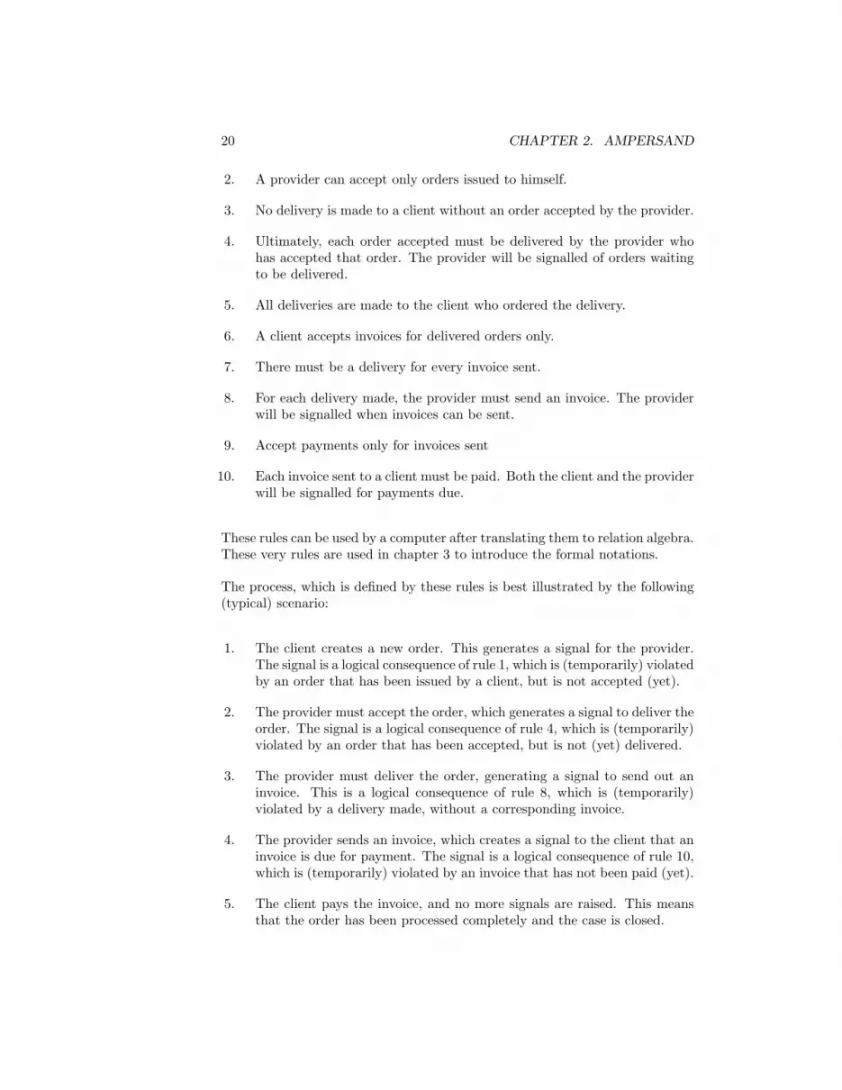
The process is defined by the following ten business rules:
1. Ultimately all orders issued to a provider must be accepted by that veryprovider. The provider will be signalled of orders waiting to be accepted.
20 CHAPTER 2. AMPERSAND
2. A provider can accept only orders issued to himself.
3. No delivery is made to a client without an order accepted by the provider.
4. Ultimately, each order accepted must be delivered by the provider whohas accepted that order. The provider will be signalled of orders waitingto be delivered.
5. All deliveries are made to the client who ordered the delivery.
6. A client accepts invoices for delivered orders only.
7. There must be a delivery for every invoice sent.
8. For each delivery made, the provider must send an invoice. The providerwill be signalled when invoices can be sent.
9. Accept payments only for invoices sent
10. Each invoice sent to a client must be paid. Both the client and the providerwill be signalled for payments due.
These rules can be used by a computer after translating them to relation algebra.These very rules are used in chapter 3 to introduce the formal notations.
The process, which is defined by these rules is best illustrated by the following(typical) scenario:
1. The client creates a new order. This generates a signal for the provider.The signal is a logical consequence of rule 1, which is (temporarily) violatedby an order that has been issued by a client, but is not accepted (yet).
2. The provider must accept the order, which generates a signal to deliver theorder. The signal is a logical consequence of rule 4, which is (temporarily)violated by an order that has been accepted, but is not (yet) delivered.
3. The provider must deliver the order, generating a signal to send out aninvoice. This is a logical consequence of rule 8, which is (temporarily)violated by a delivery made, without a corresponding invoice.
4. The provider sends an invoice, which creates a signal to the client that aninvoice is due for payment. The signal is a logical consequence of rule 10,which is (temporarily) violated by an invoice that has not been paid (yet).
5. The client pays the invoice, and no more signals are raised. This meansthat the order has been processed completely and the case is closed.

2.4. CASE STUDY: ORDER PROCESS 21
Figure 2.4: Service layer interface for order process example
The prototype generator was used to generate a service layer for rule basedprocess control. It derives the temporal logic as shown above. Together with ageneric interface, the service layer yields a fully functional application as shownin figure 2.4. The following scenario gives the flavour for readers who cannottry this for themselves. Initially all four signals (see figure 2.4) are void.
1. The client creates a new order for ‘Gates Inc.’. He does so by filling outthe fields ‘addressedTo’ and ‘from’2. The effect of this action is that a neworder number is issued and a signal is raised for ‘Gates Inc.’ to accept thisorder.
2. Provider ‘Gates Inc.’ can accept the order by filling in the name ‘GatesInc.’ in field ‘accepted’. The effect of this action is that a signal is givento ‘Gates Inc.’ for delivering the order.
3. Provider ‘Gates Inc.’ will see a delivery record, which is partially filledin: it contains only the order number. The moment the provider tries tofill out the empty fields in this form, the computer fills out all fields inthe delivery form which are uniquely determined. That is the name of theclient and the name of the provider. For a user, this is natural behaviour,because the computer ‘already knows’ these facts. In the meantime, asignal is raised saying that an invoice can be sent.
4. When the provider tries to fill out the invoice, again the computer will fillout all know (i.e. uniquely determined) facts. This yields a partially filledinvoice registration, and a signal to the client that an invoice is due forpayment.
2These fields correspond with the relations used in the formalization.

22 CHAPTER 2. AMPERSAND
5. When the client pays the invoice, the field ”paidBy” can be filled in andthe case is closed. By this time, all signals are empty again.
In the actual application, different orders of events can be tried. For example,a delivery can be made before an order is accepted, or the client can be filled inlong after the delivery has been made. The application will accept any order ofevents until it leads to violations.
2.5 Consequences
Controlling business processes directly by means of business rules has conse-quences for designers, who will encounter a simplified design process. From adesigner’s perspective, the design process is depicted in figure 2.5. The effort of
Figure 2.5: Design process for rule based process management
design focuses on requirements engineering. The main task of a designer is tocollect rules to be maintained. From that point onwards, a generator (G) pro-duces various design artifacts, such as data models, process models etc. Thesedesign artifacts can then be fed into a information system development environ-ment (the other generator, G). That produces the actual system. Alternatively,the design can be built in the conventional way as a database application. Therule base (RAP, currently under development) will help the designer by storing,managing and checking rules, to generate specifications, analyze rule violations,and validate the design. For that purpose, the designer must formalize eachbusiness rule (in ADL). He must also describe each rule in natural language forthe purpose of communication to users, patrons and other stakeholders.

2.5. CONSEQUENCES 23
From the perspective of an organization, the design process looks like figure2.6. At the focus of attention is the dialogue between a problem owner and
Figure 2.6: Design process for rule based process management
a designer. The former decides which requirements he wants and the lattermakes sure they are captured accurately and completely. The designer helps theproblem owner to make requirements explicit. Ownership of the requirementsremains in the business. The designer can tell with the help of his tools whetherthe requirements are sufficiently complete and concrete to make a buildablespecification. The designer sticks to the principle of one-requirement-one-rule,enabling him to explain the correspondence of the specification to the business.

24 CHAPTER 2. AMPERSAND

Part II
Theory
25


Chapter 3
Rules, Relations and
Concepts
From this chapter you can learn how to express rules in terms of relations andconcepts. But why would you?
The main reason is that rules can describe your business and they can serve asa specification for applications and processes. So, rules are pivotal in bridgingthe gap between business and IT. They can describe governance issues in banks,pricing policies of retailers, or network security at telecom providers. Any rulethat is worth to live by is a rule worth to be described: for example, in thebanking business a check must be signed and may not bounce, in the retailbusiness the price on the shelf must cover cost plus profit, and in the telecombusiness information may not cross the border of a security ring unless sealed andauthorized. We call any rule that is used to govern the business a business rule. business rule
Essentially, a business rule can be any verifiable agreement among stakeholders.
If rules are to specify computer applications and business processes, they mustbe formalized. Specification is however not the only benefit of formalization.It allows inconsistencies to be uncovered, audits to be held, and differencesof interpretation to be exposed. By studying this chapter, you may learn toidentify, formulate, and use rules to various ends. For the purpose of writingrules, you will learn to use a relation algebra, a lesser known, but well establishedbranch of mathematics. This text helps you to formulate rules correctly andprecisely, establish their relevance, and use them to make useful and relevantspecifications.
This chapter introduces a relation algebra from the very beginning, assumingonly that you have a basic understanding of sets. The text is aimed at engineers
27

28 CHAPTER 3. RULES, RELATIONS AND CONCEPTS
and designers who are interested in solving business problems in terms of busi-ness rules. If you are already familiar with relation algebras, you can safely skipthis chapter. This primer was designed for professionals who want to learn justenough formalism to cope. Examples illustrate most of the theory, helping youto understand the formalism. There are numerous textbooks, readers, and sci-entific literature about relation algebras. In fact, many excellent introductionsexist to date. The ”Background Material” of Jipsen, Brink, and Schmidt1 [16]deserves recommendation as a reference manual for relation algebras in general.We will specifically use heterogeneous relation algebras [31]. Both references[16] and [31] are in the same book. Roger Maddux’s book on relation algebras[23] is an excellent encyclopedic resource for those interested in studying thetopic itself.
3.1 Why?
Your skills in rule based design will make you a better information systemsdesigner. But how do rules, relations and concepts help you to specify solutionsto real problems? This question has many answers: you can make solutionsexplicit, make rules specific, make designs precise, and disambiguate discussions.Let us discuss each of these answers briefly, identifying their benefits on the way.
Explicitly specifying a solution to the real problems of your business can requiresubstantial skills, effort, and perseverance. If you are one of those people whoare supposed to deliver solutions, your skill to make things explicit is invaluable.Your learning effort will pay off from the moment you start making rules explicit.Whether your organization has to live up to agreements in an SLA (service levelagreement), whether the law or internal regulatory bodies enforce rules uponthe organization, or whether people simply agree on a particular way of working,rules represent the mortar that brings people (and institutions) together.
A business rule is called specific if it is clear in which case the rule is violated.specific
All other business rules are called generic. For instance, the rule “We alwaysdo fair trade” is generic, because it does not specify under which circumstanceswe consider the trade unfair. On the other hand: “We give associated farmersat least a yearly defined minimum price for every bag of coffee” is a specificbusiness rule, because every bag of coffee that makes less than the yearly definedminimum price is obviously in violation. Rule based design uses specific businessrules literally as a set of requirements to define the functionality of computerapplications and the allowable behaviour in business processes. By writingbusiness rules in a relation algebra, each rule you write is specific to begin with.Used as a specification language, relation algebras have the power to capture allspecific business rules. The formalism gives much ‘for free’. There are tools that
1In this introduction, the reader may recognize some of the skillfully crafted sentences andformulas from Jipsen, Brink, and Schmidt, whose work is gratefully acknowledged.

3.2. PRELIMINARIES 29
check rules for consistency errors. With other tools, you can even generate afunctional specification for such an application, saving you the effort of desigingit yourself. As a specification language, relation algebras have shown great valuein analyzing conceptual problems.
Precision is required if you want to re-use (parts of) other people’s designs. Acar manufacturer uses highly standardized technical drawings to avoid misinter-pretations, ensuring that for instance a backlight-assembly can be built in Koreaand assembled in Detroit. A pharmaceutical company uses chemical formulae toensure that a drug is manufactured consistently to specification. Professionalsmust be able to rely on their notations to ensure that a specification can beinterpreted in a unique way. Being a formal language, a relation algebra en-sures just that. Thus, rule based design takes business rule technology one stepfurther than condition-action rules and event-condition-action rules, which aretypically used for decision-making only. Relation algebras provide rules that aresuitable for deriving an entire information system, including decision making.
Unambigously agreeing over something, whatever that something might be, canprevent many discussions. If you can bring a group of people to adopt a specificrule, any dispute can be settled by checking whether that rule is violated. Asrelation algebras are perfectly suited for manipulation by computers, you caneven employ automated support to settle possible disputes. This frees the roadto flawless business operations, thus removing an important obstacle towardsinspired design, artistic beauty, and creativity in information technology.
3.2 Preliminaries
In order to define relations, you need to be familiar with sets. This section set
merely defines the notations used in the sequel, assuming that you have previ-ously learned about sets. The following typographic conventions are meant toease your reading effort: Sets are written with names starting with a capitalletter, such as Book , A, and PDC . The name itself (e.g. Book) may provideyou with a clue as to which kind of elements are in the set. Lowercase letters,possibly suffixed by apostrophes, denote these elements. Where appropriate,such a lowercase letter will match the first letter of the set.
The expression b ∈ Book states the fact that there is a book, which is representedby b. We pronounce: ”b is an instance of Book”, or ”b is an element of Book”, instance
or ”b is a member of Book”.
Given a set X and a property P , the set of all instances of X that satisfy P isdenoted by:
{x ∈ X| P (x)} or {x|x ∈ X and P (x)} (3.1)

30 CHAPTER 3. RULES, RELATIONS AND CONCEPTS
The property P is often described informally, but is understood to be an abbre-viation for a precise expression in some formal language.
The following relations and operations on sets are used throughout this book:
• equality: X = Y if X and Y contain the same instances,
• inclusion: X ⊆ Y if every instance of X is also an instance of Y ,
• union: X ∪ Y is the set of instances in X or Y ,
• intersection: X ∩ Y is the set of instances in X and Y ,
• complement: X is the set of instances that are not in X,
These notations allow us to manipulate with sets in a formal way, using thewell-established laws of set theory. Some of the best known ones are capturedby equations 3.2 through 3.10. For any set X, Y , and Z
X ⊆ X (⊆ is reflexive) (3.2)
X ⊆ Y and Y ⊆ Z imply X ⊆ Z (⊆ is transitive) (3.3)
X ⊆ Y and Y ⊆ X imply X = Y (⊆ is antisymmetric) (3.4)
X ∪ Y = Y ∪ X (∪ is commutative) (3.5)
X ∩ Y = Y ∩ X (∩ is commutative) (3.6)
(X ∪ Y ) ∪ Z = X ∪ (Y ∪ Z) (∪ is associative) (3.7)
(X ∩ Y ) ∩ Z = X ∩ (Y ∩ Z) (∩ is associative) (3.8)
(X ∩ Y ) ∪ Z = (X ∪ Z) ∩ (Y ∪ Z) (∪ distributes over ∩) (3.9)
(X ∪ Y ) ∩ Z = (X ∩ Z) ∪ (Y ∩ Z) (∩ distributes over ∪) (3.10)
Such laws are useful, because they allow you to manipulate with sets withoutany reference to their contents.
3.3 Relations
Relations are the ‘bricks’ out of which specifications are built. Think of table3.1 as an example of a relation that shows which client has paid which invoice.Let us call this relation paid . It actually stands for three facts: Client Applegatehas paid invoice number 5362a, Brown has paid invoice 721i, and Conway haspaid invoice 9443a. Being so small a relation, paid can be shown in its entirety.However, quoting an entire telephone directory in this way would be very im-practical. Relations allow us to talk about the contents without actually quoting

3.3. RELATIONS 31
Client InvoiceApplegate 5362aBrown 721iConway 9443a
Table 3.1: Contents of paid
those contents. This allows us to discuss large, realistic relations from real life,such as telephone directories, account administrations, and land registries.
In this example, paid is a relation that relates two concepts: Client and Invoice.Client is called the source of paid and Invoice is called the target of the relation.Any relation has a name, a source, a target, and contents. By convention, names relation
of relations start with a lowercase letter and names of concepts (i.e. source and concept
target) start with an uppercase letter.
If we interpret concepts Client and Invoice as sets, the relation paid is a set ofpairs (syn: tuples).
In order to introduce (syn: declare) a relation (e.g. paid), we write:
paid : Client×Invoice (3.11)
This is called a declaration, which means that there exists a relation paid with declaration
source Client and target Invoice. If relations r and s have identical name,source, and target, they are actually the same relation and consequently theyhave the same contents. Different relations may therefore have identical names,provided one or both concepts (either source or target) are different. So name,source, and target determine the contents of a relation uniquely. The notationr[A,B] is always sufficient to refer to a relation. When the context excludes anyconfusion, it is sufficient to use r to refer to the relation.
Actually, the notation A × B denotes a set of pairs. Every pair 〈a, b〉 that is pair
an instance of A × B satisfies a ∈ A and b ∈ B. So, every relation rel that hassource A and target B, is a subset of A × B:
rel[A,B] ⊆ A × B (3.12)
Instead of 〈x, y〉 ∈ rel , the shorter notation x rel y is commonly used. Forexample, the fact that Applegate and 5362a are related in the relation paid , iswritten as:
Applegate paid 5362a (3.13)
A relation can be represented in many different ways, such as mathematicalforms, tabular forms, in matrix forms, and various graphical forms. Let us look

32 CHAPTER 3. RULES, RELATIONS AND CONCEPTS
at an example. The mathematical notation of a relation provided reads as mathematical
follows:
provided : Provider × Deliveryprovided = {〈Candy’s candy, Cookies #0382〉,
〈Carter, Jelly beans #4921〉 ,
〈Carter, Peanut butter #1993〉 }(3.14)
This relation means that a delivery of cookies, marked with delivery number0382, has come from Candy’s candy, whereas Carter has provided both the jellybeans (delivery number 4921) and the peanut butter (#1993) in two distinctdeliveries. Provider and Delivery both are sets. They might be defined by (forinstance):
Provider = {Candy’s candy, Carter, Walmart}Delivery = {Cookies #0382 ,
Jelly beans #4921 ,
Peanut butter #1993}(3.15)
Example (3.14) represents the relation provided in a mathematical form. Atabular representation of the same relation looks like this:tabular form
Provider Delivery
Candy’s candy Cookies #0382
Carter Jelly beans #4921
Carter Peanut butter #1993
(3.16)
A matrix representation looks like this:matrix form
Candy’s candy Carter Walmart
Cookies #0382 ×Jelly beans #4921 ×Peanut butter #1993 ×
(3.17)
A Venn-diagram is a graphical form of representing a relation, which is showngraphical form
in figure 3.1. Venn-diagrams show the contents of a relation and its source andtarget.
In practice, people write relations in many different forms. A telephone direc-tory relates names and addresses to telephone numbers in a tabular mannerand a dictionary does the same with words and their meanings. Still, the repre-sentations of telephone directories and dictonaries may vary, even though bothare in essence tabular forms. The effort people spend in communicating thecontents of such relations underlines the importance of carefully choosing yourrepresentations. As a designer, you too will spend that effort once you exposethe contents of a relation to the public. Before that time, however, you willwork with relations without bothering about their contents.

3.3. RELATIONS 33
Figure 3.1: Graphical representation of provided
By abstracting away from the contents, you can oversee the structure of manyrelations at the same time. For that purpose, you may find it useful to drawconceptual diagrams. Figure 3.2 contains an example2, which represents tenconceptual diagram
Figure 3.2: conceptual model of trading
relations in one diagram. In conceptual diagrams, arcs represent declarations.
2The entire example, including the rules in section 3.5, was communicated to the authorby Rieks Joosten.

34 CHAPTER 3. RULES, RELATIONS AND CONCEPTS
Figure 3.2 represents the following declarations:
paid : Client × Invoice (3.18)
sent : Invoice × Client (3.19)
deliveredto : Delivery × Client (3.20)
for : Invoice × Delivery (3.21)
from : Order × Client (3.22)
from : Invoice × Provider (3.23)
provided : Provider × Delivery (3.24)
of : Delivery × Order (3.25)
accepted : Provider × Order (3.26)
issued : Order × Provider (3.27)
Each dot in the diagram represents a concept, which is used as source or targetof relations. The name of a relation is written near the arc, located such that itis clear which name belongs to which arc. A little arrowhead in the middle ofan arc points from source to target. Thus, each arc corresponds to precisely onedeclaration. The little arrowhead in the middle of an arc helps you to rememberwhich concept is source and which is target. Note that each arc determines acorresponding relation uniquely, because name, source, and target are knownfor each line (cf. page 31).
3.4 Operators
In order to work with relations, we use the following operators: ∪, ∩, , V, ;,`, I, †, ⊢, and ≡. These operators are called relational because they all yieldrelations. In this section we introduce all but the last two (⊢ and ≡), which areintroduced in section 3.5. We define the relational operators in terms of sets3.
Relational operators ∪ (union) and ∩ (intersection) are already known as setoperators, due to the fact that relations may be perceived as sets. The expressionr ∪ s is the set of pairs in r or in s and r ∩ s is the set of pairs in r and in s.Let an example illustrate this.
If candyprice = {〈Jelly, 1.05〉, 〈Chocolate, 0.80〉, 〈Apples, 2.50〉}, for example,and groceryprice = {〈Chocolate, 0.80〉, 〈Apples, 2.95〉}, then
candyprice ∪ groceryprice = {〈Jelly, 1.05〉, 〈Chocolate, 0.80〉,〈Apples, 2.50〉, 〈Apples, 2.95〉}
candyprice ∩ groceryprice = {〈Chocolate, 0.80〉}3an algebraic definition is given on page ??.

3.4. OPERATORS 35
Union and intersection are defined as follows:
• Let r : A×B and s : A×B , then r∪ s (the union of r and s) is defined by: union
r ∪ s : A×B and r ∪ s = {〈a, b〉| a r b or a s b} (3.28)
• Let r : A×B and s : A×B , then r ∩ s (the intersection of r and s) is intersection
defined by:
r ∩ s : A×B and r ∩ s = {〈a, b〉| a r b and a s b} (3.29)
The complement operator is also known from set theory. We define it by:
• Let r : A×B , then r (the complement of r) is defined by: complement
r : A×B and r = {〈a, b〉| not(a r b)} (3.30)
So if a tuple 〈a, b〉 is in relation r, then 〈a, b〉 is not in relation r and vice versa.The pronunciation of r is “all pairs not in r”.
The relation V[A,B] represents the universal relation, which means that it con-tains every conceivable pair 〈a, b〉, provided a ∈ A and b ∈ B.
• V[A,B] (the universal relation over A and B) is defined by: universal relation
V[A,B] : A×B and V[A,B] = {〈a, b〉| a ∈ A and b ∈ B} (3.31)
By convention, if [A,B] is evident from the context or irrelevant for the pointto be made, we write V instead of V[A,B]. Take care, however! In cases where V
is compared to V, it may not be clear whether V = V. In any situation with arisk of ambiguity, V[A,B] should be written in full to expose the difference withfor instance V[B,C]. So there are as many universal relations as there are [A,B]pairs in a given context.
Notice that V represents the empty relation. Here too, one empty relation is empty relation
not necessarily the same as another: V[A,B] is not the same as V[B,C].
Besides the set operators ∪, , and V, a relation algebra must contain the follow-
ing three relational operators: ` (conversion), ; (composition), and I (identityrelation). That is a minimum requirement for claiming the title of relation alge-bra. These operators are standard in relation algebras, although their notationsmay vary across different publications and different relation algebras.
The conversion operator is denoted by ` and is pronounced as ‘flip’. Conversionmerely swaps the left hand side and the right hand side:

36 CHAPTER 3. RULES, RELATIONS AND CONCEPTS
• Let r : A×B , then r` (the conversion of r) is a relation, which is defined conversio
by:
r` : B×A and r` = {〈b, a〉| a r b} (3.32)
The conversion of a relation swaps the left column and the right column in thetabular form. It mirrors the matrix form of a relation along its diagonal. Letus look at some examples, based on provided (relation 3.14 on page 32), paid(relation 3.1 on page 31), and the relation for[Invoice,Delivery], which is definedby:
for : Invoice × Deliveryfor = {〈721i, Cookies #0382〉 ,
〈5362a, Jelly beans #4921〉 ,
〈9443a, Peanut butter #1993〉}(3.33)
The conversion of for is:
for` : Delivery × Invoice
for` = {〈Cookies #0382, 721i〉 ,
〈Jelly beans #4921, 5362a〉 ,
〈Peanut butter #1993, 9443a〉}
(3.34)
The composition operator is denoted by a semicolon (;). It is pronounced as‘composed with’. Composition turns two relations into one. Here is the defini-tion:
• Let r : A×B and s : B×C , then r; s (the composition of r with s) is acomposition
relation, which is defined by:
(r; s) : A × C
r; s = {〈a, c〉| there exists b such that a r b and b s c} (3.35)
Figure 3.3 illustrates this definition. The left part of this figure shows paid . Theright part shows for . Each invoice that connects a client with a delivery causesthat client and delivery to be en element of the composition. So if c paid i andi for d implies that 〈c, d〉 ∈ paid ; for Based on the contents of paid (3.1) andfor (3.33), the composition of paid and for is obtained by applying definition3.35.
paid ; for : Client × Deliverypaid ; for = {〈Brown, Cookies #0382〉 ,
〈Applegate, Jelly beans #4921〉,〈Conway, Peanut butter #1993〉 }
(3.36)
So paid ; for represents a relation that connects those clients to deliveries forwhich there is an invoice that connects both. If (different example) name :

3.4. OPERATORS 37
Figure 3.3: relations paid and for
String×Person defines which names belong to which person, and age : Person×Intdefines the age of each person, then name; age is a relation that contains namesand corresponding ages. If you are familiar with relational databases, you mightlike to know that composition corresponds to the natural join operator.
You cannot compose just any relation. The relation provided ; for is not defined,because definition 3.35 requires the target of provided to be the same as thesource of for . Delivery , being the target of provided , is clearly not the same asInvoice, which is the source of for . Nevertheless, composing provided with for`
is defined, and the result can be obtained by applying definition 3.35:
provided ; for` : Provider × Invoice
provided ; for` = {〈Candy’s candy, 721i〉,〈Carter, 5362a〉 ,
〈Carter, 9443a〉 }
(3.37)
An identity relation IA is implicitly defined for every concept A. which meansthat it contains every conceivable pair 〈a, a〉, provided a ∈ A.
• IA (the identity relation over A) is defined by: identity relation
IA : A × A and IA = {〈a, a〉| a ∈ A} (3.38)
By convention, if [A] is evident from the context or irrelevant for the point tobe made, we write I instead of IA. Take care, however! In cases where I iscompared to I, it may not be clear whether I = I. In any situation with arisk of ambiguity, IA should be written in full to expose the difference with forinstance IB . So there are as many identity relations as there are concepts in agiven context.

38 CHAPTER 3. RULES, RELATIONS AND CONCEPTS
In practice, IA stands for equality between elements of A. Only if a and b areequal, then a I b is true. The complement of identity, I is known as diversityrelation. diversity relation
Related to composition is the relative addition (†).
• Let r : A×B and s : B×C , then r † s (the relative addition of r with s) isrelative addition
a relation, which is defined by:
(r † s) : A × C
r † s = {〈a, c〉| for all b, a r b or b s c} (3.39)
Relative addition is often used in combination with the complement operator.Therefore, † is best explained using the following equation, which is equivalentto definition 3.39:
r † s = {〈a, c〉| for all b, a r b implies b s c} (3.40)
In order to gain some understanding, let us consider an example in which stu-dents go on a study tour. The school offers three different tours, but the re-quirements for each study tour differ. Figure 3.4 shows two relations. Onthe left side a relation tour is given between destinations and subjects. It isdeclared as tour :Destination×Subject and says which subjects are mandatoryfor which study tour. On the right we have a relation between subjects andstudents, which we call passed :Subject×Student . It says which subjects havebeen completed successfully by which students. In order to qualify for a tour,
Figure 3.4: relations tour and passed
a student must have passed all subjects that are required for that particulartour. It may be obvious that student Conway qualifies for the study tour toHawaii, because he has completed the subject Surfing successfully. For the tripto Rome, students need two subjects. Student Brown has completed all three
3.4. OPERATORS 39
subjects, so she qualifies for Rome. In fact, the set of subjects needed to goto Rome is included in the set of subjects completed by student Brown. Thatis precisely what definition 3.39 says. Student Applegate is less fortunate. Shecannot go to Rome, because she has missed out on Latin. The set of subjectsrequired for Rome is not included in the set of subjects passed by Applegate.Luckily, all students qualify for the Amsterdam study tour, irrespective of theirachievements in class.
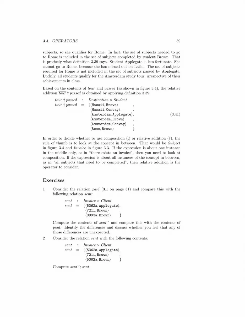
Based on the contents of tour and passed (as shown in figure 3.4), the relativeaddition tour † passed is obtained by applying definition 3.39.
tour † passed : Destination × Studenttour † passed = {〈Hawaii, Brown〉 ,
〈Hawaii, Conway〉 ,
〈Amsterdam, Applegate〉,〈Amsterdam, Brown〉 ,
〈Amsterdam, Conway〉 ,
〈Rome, Brown〉 }
(3.41)
In order to decide whether to use composition (;) or relative addition (†), therule of thumb is to look at the concept in between. That would be Subjectin figure 3.4 and Invoice in figure 3.3. If the expression is about one instancein the middle only, as in “there exists an invoice”, then you need to look atcomposition. If the expression is about all instances of the concept in between,as in “all subjects that need to be completed”, then relative addition is theoperator to consider.
Exercises
1 Consider the relation paid (3.1 on page 31) and compare this with thefollowing relation sent :
sent : Invoice × Clientsent = {〈5362a, Applegate〉,
〈721i, Brown〉 ,
〈8993a, Brown〉 }
Compute the contents of sent` and compare this with the contents ofpaid . Identify the differences and discuss whether you feel that any ofthose differences are unexpected.
2 Consider the relation sent with the following contents:
sent : Invoice × Clientsent = {〈5362a, Applegate〉,
〈721i, Brown〉 ,
〈5362a, Brown〉 }
Compute sent`; sent .

40 CHAPTER 3. RULES, RELATIONS AND CONCEPTS
3.5 Rules
After an introduction to relations (section 3.3) and the introduction to rela-tional operators (section 3.4), let us turn to rules. A rule is a relation algebrarule
expression that remains true at all times. What that means is elaborated inthis section, based on the example of figure 3.2. In that situation, clients andproviders are trading according to a simple pattern of orders, deliveries andinvoices. The figure proper does not contain any rules; it is merely a picture inwhich ten different relations are represented by their declarations. This sectionproposes rules represented in a relation algebra. The presentation emphasizesyour line of reasoning, taking you from informal text to precise formulas. Wehave tried to present the matter so that you can learn how to write rules of yourown, by carefully studying and reproducing the examples in this section.
A first example: consider relations accepted and issued from figure 3.2. If pair〈p, o〉 exists in relation accepted , which we denote as p accepted o, this meansthat provider p has accepted order o. Similarly, pairs 〈o, p〉 contained in relationissued represent orders that have been issued to a provider. Now suppose thereis a business rule saying that a provider does not accept any order issued tosomeone other than himself. How we represent that?
For that purpose, we introduce the operator ⊢, which is called implication orimplication
inclusion.
• Let r : A×B and s : A×B , then r ⊢ s (the implication of r with s) is arelation, which is defined by:
(r ⊢ s) : A × B
r ⊢ s = {〈a, b〉| a r b implies a s b} (3.42)
Now let us return to our example, to see what it does. The rule states thatproviders shall not accept all orders; they are supposed to accept only thoseorders that were issued to them. If a pair 〈p, o〉 is in the relation accepted , thenit is also a pair in issued`. In other words, p accepted o implies p issued` o.We can write this rule as:
accepted ⊢ issued` (3.43)
Notice that the set of orders that have been accepted by a provider must alwaysbe a subset of the orders that were issued to him. In fact the operator ⊢ isclosely related to the subset operator ⊆:
r ⊢ s = V ⇔ r ⊆ s (3.44)
If a rule r ⊢ s is to be kept true at all times, we are saying that we want r ⊢ s
to be equal to V at all times. By stating that equation 3.43 is a law, meaning

3.5. RULES 41
that accepted ⊢ issued` is to be kept true (i.e. equal to V) at all times, we haveeffectively formalized our business rule. So here you have a first example of arule that represents business knowledge.
Let us reflect for a moment on what we have done. Technically, equation 3.43is just an expression with relations in it. Depending on the contents of acceptedand issued , this expression can be either true or false. By stating that this is arule, you declare that you want this expression to be true all the time. So a rule rule
is a statement about the real world, whose truth we choose to maintain. Con-sequently, a tuple that makes the rule false is said to violate the rule. Inserting violation
a tuple in a relation that makes the rule false causes a violation. In other partsof this book, you can learn how to use computers for signalling violations andmaintaining the truth of a rule.
Turning back to the example, rule 3.43 can be violated by a pair 〈p, o〉 in therelation accepted that is absent in issued`. This single pair in accepted thatis not in issued` already constitutes a violation. For any rule you write down,you can try to invent violations to assert that these are examples of things youdo not want. Exercise 3.3 is something you can do with every rule you propose.A solution is presented by way of example.
Exercise 3.3. Give an example of contents of accepted and issued that violatesrule 3.43. Show formally why your example violates this rule. Also, argueinformally why this is a violation.
Solution
accepted = {〈Candy’s candy, order#49〉}issued = V
motivation (argued both formally and informally):
• Formally, rule 3.43 says that accepted must be included in issued .This is clearly not the case; {〈Candy’s candy, order#49〉} is defi-nitely not included in the empty relation V. So, this contents vio-lates rule 3.43. The pair 〈Candy’s candy, order#49〉 constitutes aviolation because it is in accepted and not in issued .
• Informally speaking, this situation represents a situation in whichCandy’s candy has accepted an order that was never issued to them.That is a clear violation of the business rule that a provider onlyaccepts an order if it is issued to himself.
Having successfully represented a first rule, let us try another one. How can westate that no client should ever pay an invoice that was not addressed to him?First, we establish that this rule involves the relations sent and paid . Then we
42 CHAPTER 3. RULES, RELATIONS AND CONCEPTS
reformulate the rule, stating that invoices paid by a client can be only thoseinvoices that are sent to that client. In other words, every pair 〈c, i〉 in therelation paid is also a pair in sent`. This is represented by:
paid ⊢ sent` (3.45)
This rule is quite similar to rule 3.43, because the reasoning that leads to thisrule is quite similar. Note that any invoice paid by a client but not sent to thatclient constitutes a violation of rule 3.45. Any invoice sent to one client but paidby another client also constitutes a violation. However, an invoice that was sentbut not paid does not yield a violation. This is precisely what we want, becausethe invoice might be still in the mail or waiting on a desk.
Exercise 3.4. Give an example of contents of paid and sent that violates rule3.45. Show formally why your example violates this rule. Also, argueinformally why this is a violation.
Let us see if other rules can be identified. How can we describe that no deliveryis provided without an order? First, let us establish that this rule involvesthe relations provided , accepted , and of . The relation provided states whichprovider has provided which delivery. Relation accepted says which provider hasaccepted which order, and of relates a delivery to an order. If a pair 〈p, d〉 is inthe relation provided , then it must also be a pair in the relation accepted ; of `
that says that there is an order, which was accepted by the provider and uponwhich the delivery was made. This rule is written as:
provided ⊢ accepted ; of ` (3.46)
Let us verify that this is exactly the rule we want. The second part of this rule,accepted ; of `, represents the relation that contains pairs 〈p, d〉 of Provider ×Delivery for which there exist o ∈ Order such that p accepted o and o (of `) d.You may verify this by checking on definition 3.35. Note that o (of `) d isequivalent to d of o (by definition 3.32). So, this third rule represents preciselywhat we intended. Note that a violation of rule 3.46 occurs every time a deliveryis made without an order.
Exercise 3.5. Give an example of contents of accepted , of and provided thatviolates rule 3.46. Show formally why your example violates this rule.Also, argue informally why this is a violation.
The client, of course, will not accept invoices for orders undelivered. Can werepresent that in a fourth rule? Apparently, this involves the relations sent ,for , and deliveredto. Relation sent tells us which invoice was sent to whichclient; relation for tells us for which delivery the invoice was made; and relationdeliveredto specifies which delivery was delivered to which client. If there is

3.5. RULES 43
an invoice for delivery d, which was sent to client c, then 〈d, c〉 must be indeliveredto. Therefore, we can write:
for`; sent ⊢ deliveredto (3.47)
This rule is useful to expose violations just like the previous ones. If an invoiceis sent to a client different from the one who received the delivery, we havea violation. If an invoice is about a delivery that was never delivered, thattoo constitutes a violation. If there is no invoice, there is no violation of thisparticular rule. It might still be in the mail, after all.
Exercise 3.6. Give an example of contents of for , deliveredto and sent thatviolates rule 3.47. Show formally why your example violates this rule.Also, argue informally why this is a violation.
After discussing four rules, let us look back at figure 3.2. You may have noticedthat every time we discussed a rule, the relations involved in that rule form acycle in figure 3.2. This is no coincidence. Each rule has a relation in the lefthand side and a relation on the right hand side. These two relations form twodifferent paths in figure 3.2 between the same concepts. Hence, the relationsinvolved form a cycle, which encloses an area in figure 3.2.
By turning this principle around, we can chase cycles to discover new rules. For cycle chasing
instance, let us investigate the relations from[Invoice,Provider], for , and provided .These three relations form a cycle in figure 3.2, which has not been covered byany of the previous rules. Can we propose a rule, using these three relations?If there is an invoice for delivery d that comes from provider p, then 〈p, d〉 mustbe in provided . One part of this rule, which says whether there is an invoicefor delivery d that comes from provider p, is represented by from`; for (bydefinition 3.35). In relational terms, we are saying that any pair 〈p, d〉 that is infrom`; for is also in provided . However, the other way around is also useful: forany pair 〈p, d〉 that is in provided there must be an invoice for delivery d thatcomes from provider p. The rule works in two directions: the relations providedand from`; for are both included in each other. Using property 3.4, we get:
provided = from`; for (3.48)
Reflecting on this result, you may have noticed that this rule was discoveredmerely by following the procedure of inspecting relations in a cycle. Therewas no flash of ingenuity, no spectacular discovery involved. Also notice thatequation 3.48 can be used to define the relation provided . If relations from andfor are known, the contents of provided can be computed from their contents.
Exercise 3.7. Give an example of contents of from, for and provided thatviolates rule 3.48. Show formally why your example violates this rule.Also, argue informally why this is a violation.

44 CHAPTER 3. RULES, RELATIONS AND CONCEPTS
You might wonder how to represent the rule that all deliveries on an invoice areprovided by the sender of that invoice. This rule is clearly different from rule3.48, but uses the same cycle. Rephrasing this rule yields: If an invoice comesfrom a provider, all deliveries on that invoice are provided by that provider andvice versa. As this rule is about an invoice from a provider, figure 3.2 gives twopaths. One path is directly over from and the other path consists of relationsfor and provided . The statement is about all deliveries instead of a delivery.Therefore we look at † rather than ; to link for and provided together. Theexpression for † provided represents every invoice-provider pair 〈i, p〉 for whichall deliveries d are provided by p or invoice i is not for d (i for d). So this ruleyields:
from = for † provided (3.49)
Each of the previous rules 3.43 through 3.47 might have been discovered in asimilar way, systematically inspecting the cycles in figure 3.2. In fact, most areasin figure 3.2 are enclosed by the cycles discussed so far. Only the area enclosedby relations from[Order,Client], of and deliveredto remains to be analyzed. Sothese three relations are a candidate for a rule. By similar reasoning as in theprevious rule, our proposal will be:
deliveredto = of ; from (3.50)
This rule says: if a pair 〈d, c〉 is in deliveredto, there must be an order for deliveryd that comes from client c. Reversely, if there is an order for delivery d thatcomes from client c, 〈d, c〉 must be in deliveredto. So this rule too is a propercandidate for agreement among stakeholders in the business.
After studying the rules presented so far, you will have acquired the idea ofinventing rules by chasing cycles. This skill is fundamental in your analysis ofrule proposals of various stakeholders and making your own proposals concrete.
3.6 Derivations
Let us pursue the following idea: if larger cycles are made up from smallerones, and if cycles correspond to rules, can we use that to create new rules?The answer is yes, but why take the trouble? After all, if we can derive a newrule from existing ones, the new rule is not something that stakeholders shouldhave to approve. If stakeholders have approved the existing rules, the newlyassembled rule is merely a consequence of their own choosing. So derivationsare useful to discuss and confront consequences of chosen rules.
In this section we show how a derivation works. You can learn to do derivationsderivation
by yourself by carefully tracing derivations in this book, making exercises, and

3.6. DERIVATIONS 45
Figure 3.5: conceptual model of trading
by trying. So let us see how it works. Let us take two rules that correspond toadjacent areas and combine them to form a new rule.
For example, the cycles that correspond to rules 3.47 and 3.50, drawn againin figure 3.5, form adjacent areas. The relation deliveredto is shared betweenthem. This observation inspires the following derivation:
for`; sent⊢ {rule 3.47}
deliveredto= {rule 3.50}
of ; from
As a result, we may conclude:
for`; sent ⊢ of ; from (3.51)
This result says: if there is an invoice for a delivery, which has been sent to someclient c, then there is an order for that delivery, which has come from client c.So the idea has worked: adjacent areas in a conceptual diagram may inspirenew rules. The new rule 3.51 is a logical consequence of the existing rules 3.47and 3.50.
In a similar fashion we can explore other parts of 3.2, and do some more rea-

46 CHAPTER 3. RULES, RELATIONS AND CONCEPTS
soning with rules:
from`; for= {rule 3.48}
provided⊢ {rule 3.46}
accepted ; of `
⊢ {rule 3.43}issued`; of `
This derivation says: if there is an invoice for a delivery, that came from someprovider p, then there is an order for that delivery, which was issued to providerp. Or, in relational terms:
from`; for ⊢ issued`; of ` (3.52)
3.7 Multiplicities
On many occasions, relations are qualified in terms of phrases like ”one-to-many”, ”surjective”, ”1..n”, and the like. Such properties are called multiplic-ities, because they provide bits of information about the number of items in amultiplicity
relation. Multiplicities occur in a majority of all relations. For example, therelation paid (3.1) might not allow any combination of clients and invoices. Therequirement that each invoice is sent to one customer only yields a many-to-one relation. To be precise: for every invoice mentioned in the relation paid ,there is precisely one client. Stated in human language: every invoice carriesthe information of exactly one client. Multiplicities occur so often, that each ofthem has been given a name of their own: univalent, total, functional, injective,surjective and bijective.
In this section we will give their definitions. For now, it is sufficient to knowthat multiplicities can be expressed as rules, just like any other rule. Later onin this book, we will calculate with rules, using these multiplicity definitionsfrequently.
• univalent
A relation r : A×B is univalent if each instance of A corresponds to atmost one instance of B. This property is defined by:
r`; r ⊢ IB (3.53)
The definition says that a r b and a r b′ imply b = b′ for all a, b, and b′.

3.7. MULTIPLICITIES 47
• total
A relation r : A×B is total if each instance of A corresponds to at leastone instance of B. This property is defined by:
IA ⊢ r; r` (3.54)
The definition says that for all a ∈ A there exists b ∈ B such that a r b.To denote that relation r is total, we write total(r).
• function
A relation is a function if it is both univalent and total. That is: a relationr : A×B is functional if every instance of A corresponds to precisely oneinstance of B. A functional relation is also called a function If r is univalentbut not total then it is called a partial function. partial
• injective
A relation r : A×B is injective if each instance of B corresponds to atmost one instance of A. This property is defined by:
r; r` ⊢ IA (3.55)
The definition says that b r a and b r a′ imply a = a′ for all a, a′, andb. Notice that the property injective is defined conversely to the propertyunivalent.
• surjective
A relation r : A×B is surjective if each instance of B corresponds to atleast one instance of A. This property is defined by:
IB ⊢ r`; r (3.56)
The definition says that for all b ∈ B there exists a ∈ A such that a r b.Notice that the property surjective is defined conversely to the propertytotal.
• bijective
A relation is bijective if it is univalent, total, injective and surjective. Thatis: every instance of A corresponds to precisely one instance of B and everyinstance of B corresponds to precisely one instance of A. Notice that abijective relation is a function, because it is univalent and total.
In our example we can restrict the relations with these properties. We propose

48 CHAPTER 3. RULES, RELATIONS AND CONCEPTS
the following:
uni tot inj surpaid : Client × Invoice
√ √
sent : Invoice × Client√ √
deliveredto : Delivery × Client√ √
for : Invoice × Delivery√ √ √
from : Order × Client√ √
from : Invoice × Provider√ √
provided : Provider × Delivery√ √
of : Delivery × Order√ √ √
accepted : Provider × Order√ √
issued : Order × Provider√ √
The relation paid is made both injective and surjective, as discussed. Sinceeach invoice is sent to precisely one client, the relation sent is required to be afunction, i.e. both univalent and total. The same goes for deliveredto, becauseeach delivery is made to one client exactly. The relation for is made injectiveand surjective only, because although we want one delivery to be mentioned onprecisely one invoice, we allow that one invoice is sent for multiple deliveries.Besides, we insist on having an invoice for each delivery. Both relations from arefunctions, and so is issued , for similar reasons. The relation provided is injectiveand surjective, because a delivery comes from one provider. This implies that acomplex delivery that comes from different providers is treated as a number ofsmaller deliveries, even though they arrive during the same ride. The relationof is restricted such that for every delivery there is an order and for every orderthere is a delivery. This leaves room for orders that combine multiple deliveries,although every delivery comes from one order only. The relation accepted isrestricted to the case that an order is accepted by precisely one provider.
Database designers are familiar with multiplicities, because these propertieshave significant impact on implementation choices. Figure 3.6 shows two pop-ular ways in which multiplicities are shown in database models. The left handside shows the convention in the Universal Modelling Language (UML) [30]. Onthe right, you can see the ”crow’s foot” notation, which has become popular inentity relationship modelling (e.g. James Martin). Multiplicity notations maydiffer from one graphical modelling technique to another. In some graphicalmodeling techniques it may not be clear which side of a relation is source andwhich is target. In those techniques, you may want to write the name of a re-lation near its target, so you can easily remember the source and target of thatrelation. In conceptual diagrams (e.g. in figure 3.2) the little arrowhead givesdirection to every relation.

3.8. FUNCTIONS 49
Figure 3.6: Graphical notations of multiplicities
Exercises
8 Consider relation for (from example 3.33):
for : Invoice × Deliveryfor = {〈721i, Cookies #0382〉 ,
〈5362a, Jelly beans #4921〉 ,
〈9443a, Peanut butter #1993〉}
If this relation is required to be injective, is any of the three pairs inconflict with that requirement? What if the requirement is that for beunivalent? Please explain your answer.
9 Based only on the information provided in exercise 3.8, can you tellwhether for satisfies the requirement for being total?
3.8 Functions
Functions are relations that are total and univalent. This allows for a convenientnotation, which makes functions special. If r : A×B is a function, we writer : A→B . We will normally use the symbols f , g, h instead of relationalsymbols, and the notation b = f(a) instead of a f b. In a conceptual diagram

50 CHAPTER 3. RULES, RELATIONS AND CONCEPTS
Figure 3.7: multiplicities in conceptual diagrams
functions are depicted by an arrow (f in figure 3.7). Every other relation isdepicted with the little arrowhead (r in figure 3.7).
For example, we may rewrite the relation provided (see 3.14 on page 32) as afunction provider : Delivery→Provider in the following way:
provider(Cookies #0382) = Candy’s candy
provider(Jelly beans #4921) = Carter
provider(Peanut butter #1993) = Carter
(3.57)
Notice the difference. In example 3.14, we defined a relation with no restrictions.In example 3.57 we require provided to be a function, i.e. both univalent andtotal. This restriction means that each delivery has precisely one provider.Notice that both examples, provided (3.14) and provider (3.57), have the samecontent, i.e. a provided b ⇔ b = provider(a).
Throughout this book, relations that are both univalent and total (i.e. func-tions) are written in the functional notation, whereas other relations are denotedin the relational notation (3.11).
3.9 Homogeneous relations
Relations with identical source and target are special. Well known examplesare = and <. Both their source and target concepts are the same. A relationspouse : Person ∗ Person, which relates two persons that are married, is an-other example. In fact, such relations are special enough to deserve a name oftheir own: homogeneous relations. They show up in a conceptual diagram asthe smallest possible cycle (figure 3.8), being the cycle from a concept to itself.Homogeneous relations have the form r[C,C]. As a notational convention, when-ever we write r[C] we mean r[C,C]. This section discusses a number of propertiesthat are defined on homogeneous relations only. The most common ones aretransitive, symmetric, antisymmetric, and reflexive. They are defined as follows:
reflexive I ⊢ r (3.58)
transitive r; r ⊢ r (3.59)
symmetric r = r` (3.60)
antisymmetric r ∩ r` ⊢ IC (3.61)

3.9. HOMOGENEOUS RELATIONS 51
Figure 3.8: Graphical representation of provided
Let us discuss these defintions in order.
Reflexivity is a way to state that every instance is in the relation with itself, forexample the relation that links two persons when they have voted for the sameparty. Definition 3.58 states that a relation is reflexive if it contains the identityrelation. So each instance is in the relation with itself. Well known examplesare = (this is the identity relation, everything equals itself), ≤ (it contains theidentity relation, any number is less than or equal to itself), and ⊆ (since everyset is its own subset). A reflexive relation is recognized in its matrix-form bythe diagonal, which is completely filled.
A relation is transitive (definition 3.59) if the composition with itself is partof the relation. For example, if Albert is older than Betty, and Betty is olderthan Chris, then Albert is older than Chris. In fact, we would expect thisto be true for other persons too. If the older than relation is represented asolder : Person ∗ Person, and a, b, and c are persons, this is what we want: Ifa older b, and b older c, then a older c. In our relation algebra, we say thatthe composition of older with itself (which is older ; older) is contained in older .That is precisely what definition 3.59 says.
The relation ⊢ is a transitive relation too. If a ⊢ b and b ⊢ c, then a ⊢ c.Well known examples of transitive relations are < (smaller than), = (equal), ⇒(implies), ⇔ (logical equivalence), ⊆ (subset), and ⊂ (proper subset).
A transitive relation has the attraction of making it possible to reason in steps.Consider for example ⊢. Recall the following derivation from page 46
provided⊢ {rule 3.46}
accepted ; of `
⊢ {rule 3.43}issued`; of `
From this derivation we may conclude that provided ⊢ issued`; of ` because ⊢is transitive. transitive
A relation is symmetric (definition 3.60) if it equals its own converse. For symmetric
example, if John is married to Jane, we would expect Jane to be married withJohn. So the relation married : Person ∗ Person must be be symmetric. When

52 CHAPTER 3. RULES, RELATIONS AND CONCEPTS
put in its matrix-form, a symmetric relation can be mirrored4 over its diagonal.In the graphical form, any arrow from one instance to another is matched withan arrow in the other direction. Other examples of symmetric relations are =and ⇔. Clearly, ≤ is not symmetric, because 2 ≤ 3 but not 3 ≤ 2.
Antisymmetry is used to avoid cycles in a relation. For example the ancestorrelation cannot contain cycles; if John is an ancestor of Mary, Mary cannot bean ancestor of John. So if a pair 〈a, b〉 occurs in a relation, the reversed pair〈b, a〉 does not occur in that relation except when a = b. Definition 3.61 saysthat 〈a, b〉 and the reversed pair 〈b, a〉 cannot occur both in an antisymmetricrelation, unless a = b. Examples of antisymmetric relations are <, ≤ and ⊢.This is not difficult to see. Since 2 ≤ 3, we know that not 3 ≤ 2. In fact for anytwo numbers a and b, if a ≤ b and b ≤ a we know that a = b. The same goesfor sets: if a ⊢ b and b ⊢ a we know that a = b. Actually, < is antisymmetrictoo. Even though a < b and b < a cannot occur simultaneously, this relationsatisfies definition 3.61.
A relation that is symmetric, transitive, and reflexive is called an equivalencerelation. The best known equivalence relation is =, also known as IC for anyequivalence relation
concept C. But there are many more examples. Suppose we would define arelation r between bags of money, saying that a r b if bag a contains the sameamount of money as b. Even if one bag contains coins only and another just afew notes, if they contain the same amount of money, they are in the relationr. You can easily verify that r is an equivalence relation, by checking that itis symmetric, transitive and reflexive. We could also define a different relation,s between bags of money, saying that a s b if bag a contains the same numberof coins as b. Even though this is a different relation, it is still an equivalencerelation.
A relation that is antisymmetric, transitive, and reflexive is called an partialorder. A well known partial order is ⊢, which imposes a hierarchy on sets. Inpartial order
real life, hierarchical relations are common. For instance, the relation ”answersto” in the army follows the military ranks. Anyone answers to him- or herself(reflexive). If person a answers to b, and b answers to c, then a answers to c(transitive). Finally, if a answers to b and b answers to a, a and b must bethe same person. Nobody in the army answers to anyone lower in rank... Sothis relation is a partial order. Examples of partial orders in the real worldare directory hierarchies on computers, organizational structures, and ancestorrelationships.
A relation that is both antisymmetric and symmetric is called a property. Theproperty
4Informally stated, mirroring means that matrix element (i, j) is the same as matrix element(j, i).

3.9. HOMOGENEOUS RELATIONS 53
following derivation illustrates why, starting with the antisymmetry of r
r ∩ r` ⊢ IC
= {r = r` (definition of symmetry)}r ∩ r ⊢ IC
=r ⊢ IC
The first step in this derivation is to substitute r` by r, which is allowed as r issymmetric. Then, the subexpression r∩r is replaced by r, which is allowed sincethe intersection of a relation with itself is the relation (A well known property of∩). The result is that any relation r that is both antisymmetric and symmetricis included in I. This means that all pairs in r are in relation I and thereforehave identical left and right elements. For every element c ∈ C, if 〈c, c〉 is in r
we say that c has property r. That is precisely why r can be called a property.
Solutions to exercises in 3.3
3.1
sent` : Client × Invoice
provided ; for` = {〈Applegate, 5362a〉,〈Brown, 721i〉 ,
〈Brown, 8993a〉 }
The differences are:
•sent` contains 〈Brown, 8993a〉, which paid does not. This soundsreasonable when it represents the situation in which we are waitingfor the payment of invoice 8993a.
•paid contains 〈Conway, 9443a〉, which sent` does not. This is unex-pected, because it seems strange that Conway would have paid aninvoice that was never sent.
Solutions to exercises in 3.1
3.8 If relation for is required to be univalent, for every invoice in for (721i,5362a, and 9443a) there can be at most one delivery. This happens to bethe case. Similarly, the requirement for injectivity is satisfied, because forevery delivery in for there is at most one invoice.
3.9 No. Only if 721i, 5362a, and 9443a are the only invoices in Invoice, therelation would satisfy this requirement. If any invoice other than the threementioned in for exist, this relation is not total.

54 CHAPTER 3. RULES, RELATIONS AND CONCEPTS
Chapter 4
Working with rules
The joy of using a relation algebra comes by using it. But first you have to readand write rules fluently. This chapter helps you to acquire those skills. Youreffort will be worth your while.
We start in section 4.1 with a neat little trick that helps you explain your rulesto yourself and to others. Then you can familiarize yourself with a number oflaws (section 4.2), that allow you to manipulate with relations by transformingone expression into another without changing the meaning. Section 4.5 studiesmultiplicity properties, especially how they ”propagate” through expressions.This allows you to derive some useful consequences from your specifications.Finally, we provide a way to translate any relation algebra to predicate logic.
4.1 Reading
Understanding formulas from paper is easier when you know the natural lan-guage it stands for. For example, expression exam; class can stand for thesentence: “there is a student who has taken an exam without attending class”.From this section you can learn how to interpret a formula in natural language.Such translations are useful when you have to explain your formulas, verifywhether a rule represents a business requirement correctly, or simply to checkyour own work.
Table 6.3 contains translation laws, using the operators from chapter 3. Asan example, let us observe how the property of univalence (3.53) is translatedsystematically to natural language. Recall the definition, which states that arelation r is univalent if:
r`; r ⊢ I (4.1)
55

56 CHAPTER 4. WORKING WITH RULES
name notation translation in natural languageexistence c ∈ C there is a C, which is represented by c (sct. 3.2).
Also: c is an instance of C.fact x r y there is a pair between x and y in relation r.
Also: the pair 〈x, y〉 is an element of r, (〈x, y〉 ∈r).
declaration r : A×B There is a relation r with source A and targetB. (eqn. 3.11)
implication r ⊢ s For every x and y, if x r y then x s y (sct. 3.4).Alternatively: x r y implies x s y. Alternatively:r is included in s or s includes r.
equality r = s For every x and y, x r y is equal to x s y
cartesianproduct
A × B all pairs 〈x, y〉 with x ∈ A and y ∈ B
complement r all pairs not in r. Also: all pairs 〈a, b〉 for whichx r y is not true. (eqn. 3.30)
conversion r` all pairs 〈y, x〉 for which x r y. (eqn. 3.32)union r ∪ s x(r ∪ s)y means that x r y or x s y. (eqn. 3.28)intersection r ∩ s x(r∩s)y means that x r y and x s y. (eqn. 3.29)composition r; s x(r; s)y means that there is a z such that x r z
and z s y. (eqn. 3.35)relative ad-dition
r † s x(r † s)y means that for all z, x r z or z s y istrue. (eqn. 3.39)
r † s x(r †s)y means that for all z, x r z implies z s y.(eqn. 3.40)
r † s x(r †s)y means that for all z, z s y implies x r z.(eqn. 3.40)
identity I equals. Also: a I b means a = b. (eqn. 3.38)
Table 4.1: Translation to natural language
The procedure to translate a relational algebra expression into natural languageis straightforward: fill in the meaning of each symbol, one step at a time. Letus try this with equation 4.60:
r`; r ⊢ I
means (translate the implication, by literally copying text from the table)
For every x and y, if x (r`; r) y then x I y.means (translate x (r` ; r) y, by the translation for composition.)
For every x and y, if there exists z such that x r` z and z r y,then x equals y.
means (translate x r` z, by the translation of conversion.)
For every x and y, if there exists z such that z r x and z r y, thenx equals y.

4.1. READING 57
The relation r itself also has a meaning in natural language. Although thatmeaning is not relevant for mathematical manipulation, it is very relevant fortranslating an expression in to natural language. Suppose, for instance, thata r b means that person a has social security number b, then the translationbecomes:
For every x and y, if there exists z such that person z has socialsecurity number x and person z has social security number y, thenx equals y.
means (reformulate)
For every x, y, and z, if person z has social security number x andperson z has social security number y then x and y are the samesocial security number.
means (reformulate)
Everone has at most one social security number.
Notice that the last few steps are of a different nature than the first series ofsteps. The translation started with a series of quasi-mechanical steps, whereyou apply the translation laws like a robot. In the last few steps, we actuallyreformulated the language for human use. That requires human understandingof the sentence. In practice, you will always use your intelligent understandingfor the last few steps, whereas the first steps can well be automated.
Summarizing, the procedure for translating relation algebra expressions to nat-ural language is:
1. translate each operator according to the translation table; (do not forgetto write ‘for every x, y’ when translating ⊢) and repeat this step until alloperators have been translated.
2. translate each relation according to its meaning in practice;
3. consider simplifications;
4. put into decent english.
This recipe was followed in the example above. By following the same recipe,you can get a proper translation for any of your rules. Let us elaborate anexample: An insurance company distributes work among employees in the formof work packages. Consider the following three relations:
policyNr : Workpackage → Policyproduct : Workpackage → Producttype : Policy → Product
The interpretation of each relation is important for translating it to naturallanguage, so we must know which interpretation the insurance company givesto each relation. The following interpretations are given.
58 CHAPTER 4. WORKING WITH RULES
The expression w policyNr n means that work package w is about policy numbern, For instance, work package “assess claim 3314” is about policy number“NL084728839”.The expression w product p means that work package w follows the procedurefor product p. For instance, work package “assess claim 3314” follows theprocedure for product “car insurance”.The expression n type p means that the policy numbered n represents a productof type n. For instance, policy number “NL084728839” is a product of type “carinsurance”.
In this situation, you might propose the following rule:
policyNr ⊢ product ; type`
The systematic translation (table 4.1) follows the procedure meticulously.
policyNr ⊢ product ; type`.Translate ⊢ to natural language (implication, table 6.3)
For each work package w and every policy n:If w policyNr n then w (product ; type`) n.
Translate ; to natural language (composition, table 6.3)For each work package w and every policy n:If w policyNr n then there exists a product type t such thatw product t and t (type`) n.
Translate ` to natural language (conversion, table 6.3)For each work package w and every policy n:If w policyNr n then there exists a product type t such thatw product t and n type t.
Translate each relation to natural languageFor each work package w and every policy n:If w is about policy number n then there exists a product type t
such that w follows the rules of product type t and n is of type t.since type is a function, there is precisely one product type, which is the typeof policy n.
For each work package w and every policy n:If w is about policy number n then w follows the rules of theproduct type of n.
In english, we leave out the ”For each work ...” part and use an article instead.If a work package w is about policy number n then w follows therules of the product type of n.
Work on the english phrasing and make sure your audience understands.Any work package must follow the rules of the product. Theserules are defined through the policy number of that work package,because each policy has a unique product type.
Performing a fair number of translations carefully according to the translation

4.2. LAWS FOR RELATIONS 59
table is recommended as an exercise. Soon, you will get the feeling that youcan do without the translation table. Please, beware of mistakes, which lureespecially in that stage of being halfway proficient.
These translations can provide assurance that a rule actually represents an in-tended commitment, assuming that the business analyst has made no mistakes.This makes correct translations into an essential skill.
The procedure shows why every relation must be related to natural language,defining the relation between the formalism and the pragmatic ‘real world’.
4.2 Laws for Relations
Laws are used to transform formulas into other formulas, while maintaining theirmeaning. A first (albeit implicit) use of laws was given previously in section3.6. Transforming formulas is useful, for example, to establish equivalence. Forexample:
1. for`; sent ⊢ deliveredto meaning: ‘A client will accept an invoice only ifthe order was delivered.’
2. deliveredto; sent` ⊢ for` meaning: ‘If a delivery was not made to aclient who did get an invoice, that invoice can never be for that client.’
How do we know whether these two formulas have the same meaning? Theanswer lies a law, which says that q; r ⊢ s means the same as s; r` ⊢ q forany relation q, r, and s. Based on this law (theorem K, introduced on page62), we can answer the question affirmatively. This involves manipulating (i.e.reasoning with) formulas, just like you would manipulate numbers if you haveto compute the total on a bill.
This section introduces a number of laws for you to work with. They are alsoused in subsequent sections for deriving other useful results. Reasoning thisway, your work will become traceable and verifiable.
The first two laws (4.2 and 4.3) state that composition and relative additionare associative operators. This means that it does not matter how brackets areplaced in an expression with two or more of the same associative operators. Asa consequence, brackets may be omitted and the expression looks less cluttered.
(p; q); r = p; (q; r) = p; q; r (4.2)
(p † q) † r = p † (q † r) = p † q † r (4.3)
r; I = r (4.4)
I; r = r (4.5)
r † I = r (4.6)
I † r = r (4.7)

60 CHAPTER 4. WORKING WITH RULES
Equation 4.4 and 4.5 state that the identity relation may be removed if it appearsnext to a composition. Similarly (eqn. 4.6 and 4.7) you may remove the diversityrelation, I, if it appears next to relative addition. The following laws show howthe conversion operator behaves.
r``
= r (4.8)
(r ∪ q)`
= r` ∪ q` (4.9)
(r ∩ q)`
= r` ∩ q` (4.10)
(r; s)`
= s`; r` (4.11)
(r † s)`
= s` † r` (4.12)
To demonstrate the use of these laws, let us derive (for instance) that the con-version of an injective relation is univalent. Let r be injective (definition 3.55):
r; r` ⊢ I
= {r = r``
by law 4.8}r`
`
; r` ⊢ I
The last line in this derivation says that r` is univalent (definition 3.53). Sothe derivation proves that
injective(r) ⇔ univalent(r`) (4.13)
Another useful law is the following:
p ⊢ r = p ∪ r (4.14)
It shows how to remove an inclusion operator (⊢) from any equation. Of similaruse is a law to replace an equality1 by two subsets.
(p = r) = p ⊢ r ∪ r ⊢ p (4.15)
The following law shows how the union operator can be removed from compo-sitions of relations.
p; (q ∪ r); s = p; q; s ∪ p; r; s (4.16)
1equality between two relations yields a relation, which is known as the symmetric differ-ence.
4.3. MORE LAWS: COMPLEMENT 61
It would have been nice if the same distribution property holds for the intersectoperator, ∩, but this is not always the case. This property holds only for aunivalent p and injective s:
if s is injective (q ∩ r); s = q; s ∩ r; s (4.17)
if p is univalent p; (q ∩ r) = p; q ∩ p; r (4.18)
Another way to formulate these laws in an unconditional way is:
p; (q ∩ r); s ⊢ p; q; s ∩ p; r; s (4.19)
Two other useful laws allow you to move relations across the ⊢ symbol. However,this law is conditional too. If f is a function (that is: a univalent and totalrelation) then
r ⊢ s; f` = r; f ⊢ s (4.20)
r ⊢ f ; s = f`; r ⊢ s (4.21)
f † r = f ; r (4.22)
r † f` = r; f` (4.23)
4.3 More Laws: Complement
The complement operator is used to discuss which elements are not in a relation.If t mentor s means that teacher t is mentor of student s, then t mentor s meansthat teacher t is not mentor of student s. This section introduces the mostimportant laws concerning complement. At the end, we elaborate an examplein which a rule is ”invented” to capture a real life situation.
The best known law concerning the complement operator is:
r ⇔ r (4.24)
Other laws were discovered by the famous mathematician De Morgan:
r ∪ s = r ∩ s
r ∩ s = r ∪ s(4.25)
De Morgan’s equivalences turn out to be among the most frequently used laws,because the allow you to ‘move around’ the complement operator. Similar lawsexist that concern the operators ; and †:
r; s = r † s
r † s = r; s(4.26)

62 CHAPTER 4. WORKING WITH RULES
Equations 4.25 and 4.26 are all known as De Morgan’s laws.
Less well known, but equally important are the following equivalences, whichDe Morgan called “Theorem K”.
p; q ⊢ r
⇔p`; r ⊢ q
⇔r; q` ⊢ p
(4.27)
All three parts are equivalent. Like De Morgan’s laws, theorem K too is usedfor ‘moving around’ the complement operator in formulas. The use of theoremK and De Morgan’s laws is illustrated in the following example.
The following section discusses an example, in which theorem K plays a key role.The elaboration of the exercise shows thoughts and arguments, illustrating anactual attempt to formulate a business rule.
Exercise 4.1. Suppose a mentor gets a bonus if all of his students have com-pleted their year. Propose a rule in terms of the following relations:
mentor : Student → Mentor (4.28)
bonus : Mentor × Year (4.29)
completed : Student × Year (4.30)
The expression s mentor m means that student s has m as a mentor.Expression m bonus y means that mentor m has been awarded a bonusfor year y. Expression s completed y means that student s has completedyear y.
In order to find a rule that describes the situation, we start with the obvious.When a mentor m has reaped a bonus for a year in which he mentored students, then surely s has completed year y. So:
mentor ; bonus ⊢ completed (4.31)
Although this describes the situation correctly, it is not obvious whether allviolations can be caught by this rule. A way to find out is to reason the otherway around. If a student s of mentor m did not complete year y, there is nobonus for m. So:
mentor`; completed ⊢ bonus (4.32)
According to De Morgan’s theorem ‘K’ however, equations 4.31 and 4.32 areequivalent. So this brings us no further.

4.3. MORE LAWS: COMPLEMENT 63
Another guess might be to reverse the ⊢:
completed ⊢ mentor ; bonus (4.33)
Together with equation 4.31, the rule becomes an equivalence (completed =mentor ; bonus). This means: if a student has completed a year, there is amentor who got a bonus. Obviously, this differs from the original statement, sowe reject this proposal.
What if we reverse the ⊢ in equation 4.32?
bonus ⊢ mentor`; completed (4.34)
This reads: if mentor m did not get a bonus for the class of year y, then m
had a student who did not complete year y. This is obviously something we dowant. The question remains whether this equation (4.34) differs from equation4.32
In order to find out whether all violations are covered, we need some inspiration.Let us investigate one specific example: a situation where only Kersten, Joosten,and 2005 exist:
mentor = { 〈Joosten,Kersten〉 }bonus = V
completed = { 〈Joosten, 2005 〉 }
This situation means that Joosten completed the class of 2005 and had Kerstenas a mentor. Kersten, however, received no bonus. Since all students havecompleted the class of 2005, surely he is entitled to a bonus. This constitutes aviolation of the business rule.
This situation satisfies equation 4.31, because relation bonus is empty. Equation4.34 is not satisfied, however, because the left hand side, bonus, contains anelement and the right hand side, mentor`; completed , does not. So the exampleproves that both rules are different, even though we want both ?? and 4.32 toserve as business rules. So, let us combine the two rules into one:
(mentor`; completed ⊢ bonus) ∩ (bonus ⊢ mentor`; completed)⇔ {⊢ is antisymmetric (3.4)}
bonus = mentor`; completed⇔ {formulate positively}
bonus = mentor`; completed⇔ {De Morgan}
bonus = mentor` † completed
This result describes that a mentor gets a bonus if all students either havecompleted a year or are not mentored by him. Restated in understandableEnglish: a mentor gets a bonus over a year if all students that are mentored by

64 CHAPTER 4. WORKING WITH RULES
him have completed the year. The other way around, if all students of a mentorhave completed the year, that mentor is entitled to a bonus over that year. Thisdefines precisely when the mentor is entitled to a bonus and when he is not.
Exercise 4.1 and its elaboration illustrate some of the thoughts you might havewhen analyzing real life situations. If you are new to business rules, we suggestyou try to replay this example carefully, in order to re-live the arguments andthoughts described. If you have already done this a couple of times before, youmay find the argumentation too elaborate. This means you are proficient inusing the laws that govern relations.
4.4 Laws about Inclusion
This section provides some laws about ⊢. The name of this operator, inclusion,is well suited for the following laws. In expressions with intersection, inclusionmeans that an intersection with anything is included in itself:
r ∩ s ⊢ r
r ∩ s ⊢ s(4.35)
Combined with union, inclusion means that any relation is included in a unionwith itself:
r ⊢ r ∪ s
r ⊢ s ∪ s(4.36)
Other important laws are called monotonicity.monotonicity
r ⊢ s ⇒ r; t ⊢ s; t (4.37)
r ⊢ s ⇒ t; r ⊢ t; s
r ⊢ s ⇒ r † t ⊢ s † t (4.38)
r ⊢ s ⇒ t † r ⊢ t † s
r ⊢ s ⇒ r ∪ t ⊢ s ∪ t (4.39)
r ⊢ s ⇒ r ∩ t ⊢ s ∩ t (4.40)
r ⊢ s ⇔ r` ⊢ s` (4.41)
r ⊢ s ⇔ s ⊢ r (4.42)
The only funny one is the last monotonicity law, because the order of r and s
are reversed.

4.5. LAWS ABOUT MULTIPLICITIES 65
4.5 Laws about Multiplicities
This section investigates how multiplicities (i.e. the properties univalent, total,surjective and injective introduced in section 3.7) behave. Especially interestingis how these properties propagate through formulas. For instance, if r and s
are both functions, then r; s is a function as well. Such laws are important, forexample in designing data structures in software. But you will also find themuseful in establishing whether or not an object exists, according to your ownrules. The laws introduced in this section will be derived from laws introducedearlier in this chapter.
One property of multiplicities, equation 4.13, has already been derived in sec-tion 4.2. It says that the conversion of an injective relation is univalent. Forreasons of symmetry, it is evident that the conversion of a univalent relation isinjective. In a similar fashion we can show the conversion of a total relation tobe surjective. Let r be total (definition 3.54):
I ⊢ r; r`
⇔ {law 4.8}I ⊢ r`
`
; r`
This last line says that r` is surjective (definition 3.56). For reasons of sym-metry, we have also proven that the conversion of a surjective relation is total.Summarizing, the following results are now proven.
injective(r) ⇔ univalent(r`) (4.43)
surjective(r) ⇔ total(r`) (4.44)
Slightly longer is a derivation that shows that the combination of two univalentrelations is univalent. Let r and s be arbitrary relations that can be combinedinto r; s. This requires that the target of r equals the source of s. Recall theleft hand side of the definition of univalence (definition 3.53) applied to r; s.
(r; s)`
; (r; s)
= {apply law 4.11 on (r; s)`}
(s`; r`); (r; s)= {; is associative (law 4.2)}
s`; (r`; r); s⊢ {assume r`; r ⊢ I (r is univalent)}
s`; I; s= {by 4.4}
s`; s⊢ {assume s`; s ⊢ I (s is univalent)}
I

66 CHAPTER 4. WORKING WITH RULES
This derivation shows that (r; s)`
; (r; s) ⊢ I, which means that r; s is univalent(check definition 3.53 when in doubt). However, on the way to deriving thisresult, we have made the assumption that both r and s are univalent. So theresult we have is::
if (s`; s ⊢ I) and (r`; r ⊢ I) then ((r; s)`
; (r; s) ⊢ I) (4.45)
Turning the derivation upside down (reversing the argument) inspires an inter-esting new result about surjective relations:
I
⊢ {assume I ⊢ s`; s (s is surjective)}s`; s
= {by 4.4}s`; I; s
⊢ {assume I ⊢ r`; r (r is surjective)}s`; (r`; r); s
= {; is associative (law 4.2)}(s`; r`); (r; s)
= {apply law 4.11 on (r; s)`}
(r; s)`
; (r; s)
From this derivation, we can conclude that the combination of two surjective re-lations r and s produces a surjective relation r; s. Using the results of equations4.43 and 4.44, it is evident that the combination of two total relations r ands produces a total relation r; s and the combination of two injective relationsr and s produces a injective relation r; s. Together with result 4.45 we havederived four properties of the composition operator:
univalent(s) ∧ univalent(r) ⇒ univalent(r; s) (4.46)
surjective(s) ∧ surjective(r) ⇒ surjective(r; s) (4.47)
total(s) ∧ total(r) ⇒ total(r; s) (4.48)
injective(s) ∧ injective(r) ⇒ injective(r; s) (4.49)
The previous results inspire to do similar derivations for r ∩ s and r ∪ s. Let usstart with r ∩ s, deriving the conditions under which it is univalent.
(r ∩ s)`
; (r ∩ s)
= {apply law 4.10 on (r ∩ s)`}
(r` ∩ s`); (r ∩ s)⊢ {distribute (law 4.19)}
(s`; r) ∩ (r`; r) ∩ (s`; s) ∩ (r`; s)⊢ {assume r is univalent}
(s`; r) ∩ I ∩ (s`; s) ∩ (r`; s)⊢ {by inclusion wrt ∩ (law 4.35)}
I

4.5. LAWS ABOUT MULTIPLICITIES 67
This derivation says that (r ∩ s)`
; (r ∩ s) ⊢ I, meaning that r ∩ s is univalent,under the assumption that r is univalent. So we may conclude:
univalent(r) ⇒ univalent(r ∩ s)
Since r ∩ s = s ∩ r, we may conclude:
univalent(r) ∨ univalent(s) ⇒ univalent(r ∩ s) (4.50)
Again, by reversing the derivation, we can derive another result.
I
⊢ {assume r is total}r; r`
⊢(r; r`) ∪ (s; r`) ∪ (r; s`) ∪ (s; s`)
= {distribute (law 4.16)}(r ∪ s); (r` ∪ s`)
= {apply law 4.9 to r` ∪ s`}(r ∪ s); (r ∪ s)
`
This derivation produces the following result:
total(r) ⇒ total(r ∪ s)
Since r ∪ s = s ∪ r we may rephrase this as:
total(r) ∨ total(s) ⇒ total(r ∪ s) (4.51)
The following derivation studies the univalence of r ∪ s:
(r ∪ s)`
; (r ∪ s) ⊢ I
⇔ {apply law 4.9 on (r ∪ s)`}
(r` ∪ s`); (r ∪ s) ⊢ I
⇔ {distribute (law 4.16)}(r`; r) ∪ (s`; r) ∪ (r`; s) ∪ (s`; s) ⊢ I
⇒(r`; r) ∪ (s`; s) ⊢ I
⇔ {A ∪ B ⊢ C ⇔ A ⊢ C ∧ B ⊢ C}(r`; r ⊢ I) ∧ (s`; s ⊢ I)
This derivation shows that if r∪ s is univalent, then r and s are both univalent:
univalent(r ∪ s) ⇒ univalent(r) ∧ univalent(s) (4.52)

68 CHAPTER 4. WORKING WITH RULES
Now let us investigate r ∩ s for totality
I
⊢ {Let r ∩ s be total}(r ∩ s); (r ∩ s)
`
= {apply law 4.10 on (r ∩ s)`}
(r ∩ s); (r` ∩ s`)⊢ {distribute (law 4.19)}
r; r` ∩ s; r` ∩ r; s` ∩ s; s`
⊢ {inclusion (law 4.35)}r; r` ∩ s; s`
We get a result by putting the first and last lines of this derivation together,and make one more step:
I ⊢ (r; r` ∩ s; s`)⇔ { }
(I ⊢ r; r`) ∧ (I ⊢ s; s`)
The entire derivation yields:
total(r ∩ s) ⇒ total(r) ∧ total(s) (4.53)
There are two more derivations, we’d like to share with you
I
⊢ {Assume s is total}s; s`
⊢ {Let s ⊢ r}r; r`
This derivation yields:
total(s) ∧ s ⊢ r ⇒ total(r) (4.54)
Similarly, we derive:
r`; r ⊢ I
⊢ {Let s ⊢ r}s`; s ⊢ I
This derivation yields:
univalent(r) ∧ s ⊢ r ⇒ univalent(s) (4.55)

4.6. TRANSLATING 69
The results obtained yield:
univalent(r) ∧ univalent(s) ⇒ univalent(r; s) (4.46)
surjective(s) ∧ surjective(r) ⇒ surjective(r; s) (4.47)
total(s) ∧ total(r) ⇒ total(r; s) (4.48)
injective(s) ∧ injective(r) ⇒ injective(r; s) (4.49)
univalent(r) ∨ univalent(s) ⇒ univalent(r ∩ s) (4.50)
injective(r) ∨ injective(s) ⇒ injective(r ∩ s) (??)
total(r) ∧ total(s) ⇒ total(r ∪ s) (4.51)
univalent(r ∪ s) ⇒ univalent(r) ∧ univalent(s) (4.52)
injective(r ∪ s) ⇒ injective(r) ∧ injective(s)
surjective(r ∪ s) ⇒ surjective(r) ∧ surjective(s) (??)
total(r ∪ s) ⇒ total(r) ∧ total(s)
4.6 Translating
This section provides a procedure for translating rules to predicate logic. Youwill find this section to resemble section 4.1, with the big difference that thetranslation is not to natural language any more. For a proper explanation ofpredicate logic, we refer to [xxx]2. In this section we assume this to be known.
Every expression in a relation algebra can be translated to predicate logic. Forexample, this is what you get when you translate definitions 3.58 – 3.61 (page50):
reflexive ∀a : a r a (4.56)
transitive ∀a, b, c : a r b ∧ b r c → a r c (4.57)
symmetric ∀a, b : a r b ↔ b r a (4.58)
antisymmetric ∀a, b : a r b ∧ b r a → a = b (4.59)
This section shows how to perform such translations.
As an example, let us observe how the property of univalence (3.53) is translated.Recall the definition, which states that a relation r is univalent if:
r`; r ⊢ I (4.60)
Translated to predicate logic, this property is written as
∀a, b, c : c r a ∧ c r b → a = b (4.61)
2The symbol ∀ means ‘for all’, ∃ means ‘there exists’, ∧ means ‘and’, ∨ means ‘or’, →
means ‘implies’, and ↔ means ‘is equivalent’.

70 CHAPTER 4. WORKING WITH RULES
Equation 4.61 reads as follows: For every possible value of a, b, c: if c r a andc r b then a = b. In other words, if two right hand side elements, a and b, areboth related to the same c, they must be the same element.
Translation procedure for predicate logic
For every rule r to be maintained, start your translation with ∀a, b : a r b .As long as there is a boxed expression in your translation, look it up in thetranslation table and substitute accordingly. Repeat until no boxes remain.
expression translate by
a (r ∪ s) b a r b ∨ a s b (4.62)
a (r ∩ s) b a r b ∧ a s b (4.63)
a (r; s) c ∃b : a r b ∧ b s c (4.64)
a (r; s) c ∃b : ¬( b s c → a r b ) (4.65)
a (r; s) c ∃b : ¬( a r b → b s c ) (4.66)
a (r; s) c ∃b : ¬( a r b ∨ b s c ) (4.67)
a (r † s) c ∀b : a r b ∨ b s c (4.68)
a (r † s) c ∀b : a r b → b s c (4.69)
a (r † s) c ∀b : b s c → a r b (4.70)
a (r † s) c ∀b : ¬( a r b ∧ b s c ) (4.71)
a r` b b r a (4.72)
a r b ¬( b r a ) (4.73)
a I b a = b (4.74)
a (r ⊢ s) b a r b → a s b (4.75)
a (r = s) b a r b ↔ a s b (4.76)
a r b a r b, if r is a relation (4.77)
The procedure is straightforward and can be done entirely by computers. Theselaws allow us to perfom any translation in steps. Consider for instance the

4.6. TRANSLATING 71
translation from equation 4.60 to predicate logic:
∀a, b : a (r`; r ⊢ I) b
⇔ {law 4.75}∀a, b : a (r`; r) b → a I b
⇔ {apply law 4.64 to a (r` ; r) b and law 4.74 to a I b}∀a, b : (∃c : a r` c ∧ c r b ) → a = b
⇔ {apply law 4.72 to a r` c}∀a, b : (∃c : c r a ∧ c r b) → a = b
⇔ {predicate logic}∀a, b, c : c r a ∧ c r b → a = b
The resulting expression is in fact equation 4.61. This derivation proves thatthe first line and the last line are equivalent:
r`; r ⊢ I ⇔ ∀a, b, c : c r a ∧ c r b → a = b (4.78)
This result has been obtained systematically by applying the appropriate lawswhere possible. In the first step of the derivation, only law 4.75 (page 70)was applicable. In the second step, laws 4.64 and 4.74 were both applicable,which we did. The third step allowed us to apply only law 4.72. Finally, weused a law from predicate logic to bring the expression in its final shape. Inthis translation we systematically work our way from the ’outer’ structure (theentire expression) to smaller structures in every step we take, until no applicabletranslation law remains. This way of translating works for every expression ina relation algebra.
Now let us do another example, in which you can verify the procedure for your-self. We translate the definition of surjective step by step, explaining the line ofthought as we go. This time, we omit the boxes. First, we quote the definitionof surjective (equation 3.56), and put it in the starting form for translation:
∀a, b : a (I ⊢ r`; r) b
When looking at the translation laws, you can see that law 4.75 is applicable.We use this law to substitute the expression of surjectivity into the followingexpression.
∀a, b : a I b → a (r`; r) b
Notice that we have used no interpretation; we have just “moved characters” asprescribed by equation 4.75. Also, you can establish that equation 4.75 is theonly translation (out of all laws in the translation table) that applies here. Soyou can do this translation without even knowing what it means.
For the next step, we can see two laws that may be applied. Law 4.74 canbe applied to subexpression a I b and a (r`; r) b can be transformed using

72 CHAPTER 4. WORKING WITH RULES
law 4.64. Let us do both transformations simultaneously, yielding the followingexpression.
∀a, b : a = b → (∃c : a r` c ∧ c r b)
Again, the transformation was done purely on the basis of laws. Again, we hadno choice but to apply the appropriate laws. This is the case in the next steptoo, because we can only apply law 4.72:
∀a, b : a = b → (∃c : c r a ∧ c r b)
Now we are done. The entire expression has been rewritten to predicate logic.Considering that a = b, this result can be simplified further in predicate logic:
∀b : b = b → (∃c : c r b ∧ c r b)⇔ {predicate logic}
∀b : ∃c : c r b ∧ c r b
⇔ {simplify}∀b : ∃c : c r b
The last step is precisely the definition of surjective as we would expect it inpredicate logic.
We get the entire derivation by putting all steps together, linking them by thelogical connectives from the laws we used (in this case ⇔ and ⇒):
∀a, b : a (I ⊢ r`; r) b
⇔ {law 4.75}∀a, b : a I b → a (r`; r) b
⇔ {law 4.74 and 4.64}∀a, b : a = b → (∃c : a r` c ∧ c r b)
⇔ {law 4.72}∀a, b : a = b → (∃c : c r a ∧ c r b)
⇒ {Let a = b}∀b : b = b → (∃c : c r b ∧ c r b)
⇔ {predicate logic}∀b : ∃c : c r b ∧ c r b
⇔ {simplify}∀b : ∃c : c r b
This derivation yields as a result:
I ⊢ r`; r ⇒ ∀b : ∃c : c r b (4.79)
Exercise 4.2. Derive the translation of total, meaning that I ⊢ r; r` translatesto ∀a : ∃b : a r b
Exercise 4.3. Derive the translation of injective, meaning that r; r` ⊢ I
translates to ∀a, b, c : a r c ∧ b r c ⇒ a = b

4.6. TRANSLATING 73
As an illustration of using translations, we will show that f †r and f ; r translateto the same predicate logic expression for every function f and relation r (law4.22).
x (f † r) y
⇔ {equation 4.69}∀z : x f z → z r y
⇔ {f is a function}∀z : z = f(x) → z r y
⇔ {predicate logic}f(x) r y
Likewise, we translate f ; r
x (f ; r) y
⇔ {equation 4.64}∃z : x f z ∧ z r y
⇔ {f is a function}∃z : z = f(x) ∧ z r y
⇔ {predicate logic}f(x) r y
Together, these derivations prove law 4.22
The following exercise shows how to derive the same result without resorting topredicate logic.
Exercise 4.4. Using only the laws of relation algebra, prove f † r ⇔ f ; r forevery function f and relation r (law 4.22)
Answer:
f ; r⇔ {introduce the empty relation V by law 4.36}
V ∪ f ; r⇔ {equation 4.14}
V ⊢ f ; r⇔ {use law 4.21, using the condition that f is a function}
f`; V ⊢ r
⇔ {theorem K (eqn. 4.27)}f ; r ⊢ V
⇔ {equation 4.14}f ; r ∪ V
⇔ {De Morgan (eqn. 4.26) and remove V by law 4.36}f † r
⇔ {remove double complement (eqn. 4.24)}f † r

74 CHAPTER 4. WORKING WITH RULES
This derivation proves that f ; r ⇔ f † r, under the condition that f is afunction. This proves law 4.22, as required.
The following exercise is left for the reader to do:
Exercise 4.5. Using only the laws of relation algebra, prove r † f` ⇔ r; f`
for every function f and relation r (law 4.23)

Part III
Tools
75


Chapter 5
ADL manual
The language ADL (A Description Language) allows you to specify patternsand contexts in a relation algebra. This document contains the instructions forusing the ADL language on your computer. We assume that you know howto use relation algebras for specifying patterns, for example by having studiedchapter 3 about rules, relations and contexts.
5.1 A computer language for business rules
ADL is a computer language that helps to design information systems better,faster, and cheaper. ADL performs conceptual analysis, generates data models,and produces the contents of a functional specification. Thus it allows analyststo focus on their business.
• If you want to learn about relation algebras, turn to chapter 3.
• If you need to install ADL on your computer, start with section 5.2.
• If you are a first time user learning how to use ADL, you can work your waythrough a number of examples in section 5.3 and further. These examplesintroduce you the tool on a step-by-step basis, letting you create morecomplex examples as you go.
• If you are stuck in an error, in dire need of help, consult section 5.5.
• The grammar (syntax) of ADL is summarised in section 5.6. This sectionis superfluous if you just want to use ADL, but if you want to build toolsfor ADL or study the language, you will need it.
77

78 CHAPTER 5. ADL MANUAL
5.2 How to install
The ADL tool is fed with ASCII files, which you write yourself1 We advise Win-dows users to use a simple, dedicated editor for ASCII files such as EditPAD2.You might even use NotePAD instead. Unix users (including Linux, Apple, etc.)have sufficient access to such editors already (vi, emacs, etc.) Mainstream wordprocessors are less suitable, because they tend to bring about excess work ifused for ASCII editing only.
There are two ways of using ADL: directly from Internet or from a CD rom.The former is described in section 5.2.1, the latter in 5.2.2.
5.2.1 Using ADL from Internet
Please check whether you have
1. access to internet by means of a browser, such as Internet Explorer orFirefox;
2. login permission to the site www.sig-cc.org/Adl granted to you by yourlocal ADL authority.
If you login for the first time, your password is Welkom. Your are advised tochange it to a password of your choice the first time you log in.
Once logged in, you can submit an ADL file and view the analysis produced byyour file. If the analysis is to your liking, you can download it in the form of aZIPped website.
5.2.2 Installing ADL on your Windows PC
Please check the following requirements to see whether ADL will work properlyon your system.
You need Microsoft Windows with an Internet Explorer 4.0 or higher. Your In-ternet Explorer must be Javascript enabled. When in doubt, check the internetoptions of your browser. On Windows-2000 and -XP you need administratorrights in order to install ADL.
1At the time of writing, there are no graphical tools for ADL.2by Jan Goyvaerts. EditPad-lite is freely available for non commercial use from
http://www.editpadlite.com (by JGSoft), but always remember to send Jan a thankyou note.

5.2. HOW TO INSTALL 79
1. Unzip the file ADL distr vs<x.x.x>.zip in an empty directory, so youcan see the contents, one file called ADL.exe, three .adl files and a direc-tory called treemenutils. ADL.exe is the actual program. The .adl filesare examples. treemenutils contains a number of images and Javascripts.
2. Create a new directory, for example C:\Program Files\ADL\bin\, andmove the file ADL.exe into this directory.
3. Add C:\Program Files\ADL\bin\ to the environment variable $PATH. (Itis found in the Advanced tab of the system settings screen, which you canget from the properties of ”This Computer” on your desktop. If you havetrouble finding it on your version of Windows, ask Windows for help bysearching for ”environment variable”. Once you have found PATH, editit adding ;C:\Program Files\ADL\bin\ at the end.) Now ADL can becalled from any working directory.
4. Make a new working directory for your ADL project, for example C:\projects\tryADL\.
5. Copy the directory treemenutils into this working directory3. Now, in-side C:\projects\tryADL\ you have the directory treemenutils. Do notrename the directory treemenutils.
6. Download graphviz from http://www.graphviz.org/Download.php andinstall it. (This software produces drawings after ADL has done concep-tual analysis and data models)
7. You are now ready to use ADL from within your project.
To test the installation, follow these steps:
1. Copy all files *.adl into your working directory, which we assume isC:\projects\tryADL\.
2. Open a new DOS window.
3. Change the current directory into C:\projects\tryADL\.
4. Call ADL Delivery1. This analyses the file Delivery1.adl and return errormessages if there are any. In this particular example (which you can findin the distribution) there are no errors4.
5. Now call index.html. This generates a number of .png files which containconceptual diagrams.
3For the time being, you need a copy of this directory in every working directory you have.Also, you need one working directory per project. Yes, this creates a number of copies ofthe directory treemenutils. This is ugly, and a following version will undoubtedly do better.(Sorry for any inconvenience.)
4The excessive amount of output will be maintained during the research and developmentof ADL

80 CHAPTER 5. ADL MANUAL
If all went well, this is the dialogue you see in your DOS window:
C:> cd \projects\tryADL
C:> ADL Delivery1
ADL vs. 0.7.9 (experimental)
Arguments: Delivery1
Switches:
Delivery1.adl is read.
Delivery1.adl has been parsed.
Concepts:
Client
Invoice
Delivery
Order
Provider
No type errors or cyclic specializations were found.
Generating Atlas for Delivery in the current directory.
...
HTML code for REL_Delivery_fromInvoiceProvider.html written
HTML code for REL_Delivery_providedDeliveryProvider.html written
HTML code for REL_Delivery_ofDeliveryOrder.html written
HTML code for REL_Delivery_acceptedProviderOrder.html written
HTML code for REL_Delivery_issuedOrderProvider.html written
Done.
C:>index.html
The command index.html calls your browser and displays the result. Actu-ally, index.html is the main file of a website which has been generated insideyour current working directory. If you take it out to move it elsewhere, makesure you take all .html, .gif, .png, and .map files. Do not forget the direc-tory treemenutils, which is also part of the website. Together, all these filesconstitute a piece of documentation generated by ADL.exe5
We advise Windows users to enlarge the command line window. Right click onthe top bar of this window. Choose Properties to enlarge the number of linesto the maximum, which is 9999 lines. (The standard size is too small for theamount of error messages.)
5.dot files generated by ADL.exe are intermediate files. They may be deleted withoutconsequences.

5.3. YOUR FIRST ADL SCRIPT 81
5.2.3 Using ADL
Once you have executed the test run successfully, you use the same procedurefor analyzing your business rules:
1. Edit your .adl file, using your favourite editor
2. Compile it in a command line window, using the ADL command
3. Show the results in your browser, by displaying index.html
Exercise 5.1. Define a relation r::A*B [UNI]. and a relation s::B*C. Also,define a rule containing r;s. Compile and show that the result contains’there exists a B called b’. Then, add the multiplicity TOT to the definitionof r and observe the ’exists’ disappears.
The following sections introduce you to ADL in a step-by-step fashion, intro-ducing features on the way. You may want to run each example to see whatADL does on your computer.
5.3 Your first ADL script
Some computer programmers check whether a computer language works bywriting a program that only prints the phrase ”Hello World!”. Since little can gowrong, it proves that you have succeeded in installing the language and using thecompiler. Your ’hello world!’ consists of a single relation hello : Person×City .This is what it looks like in ADL:
CONTEXT Test
PATTERN Test
hello :: Person * City.
ENDPATTERN
ENDCONTEXT
An ADL file consists of a context which contains any number of patterns. Youare required to give that context a name. In this example the context Test
contains one pattern only, which is also named Test. The relation hello isdeclared in that context, your way of letting your computer know this relationexists. Please pay attention to the dot at the end of a declaration. It is required Attention!
and causes irritating syntax errors if you forget.
The following example is slightly more elaborate. It includes three pairs topopulate the relation.

82 CHAPTER 5. ADL MANUAL
CONTEXT Test
PATTERN Test
hello :: Person * City
= [ ("John", "Oklahoma City")
; ("Jill", "Newcastle under Lyme")
; ("Jack", "Perth")
].
ENDPATTERN
ENDCONTEXT
Providing a few examples each time you declare a relation makes your codemuch more accessible to others. It is a good habit to do so. Your exampleseffectively help others to imagine your concepts.
You can also specify the meaning of your relation in natural language.
hello :: Person * City
PRAGMA "Person " " says hello to " " on the radio"
= [ ("John", "Oklahoma City")
; ("Jill", "Newcastle under Lyme")
; ("Jack", "Perth")
].
By supplying the pragma, you define the meaning of a relation in the real world.This particular example represents three facts:. Person ‘John’ says hello to ‘Oklahoma City’ on the radio.. Person ‘Jill’ says hello to ‘Newcastle under Lyme’ on the radio.. Person ‘Jack’ says hello to ‘Perth’ on the radio.
The PRAGMA annotation is required to specify what you mean by a relation.Even though ADL uses this only in documentation, the pragma is of paramountimportance to link your relations to your real world. We advise you never toforget the pragma, except when talking about relations in an abstract manner(uncoupled from the real world).
Multiplicity restrictions can be added right after the type, and before the pragma(if present):
hello :: Person * City [UNI,SUR]
PRAGMA "Person " " says hello to " " on the radio"
= [ ("John", "Oklahoma City")
; ("Jill", "Newcastle under Lyme")
; ("Jack", "Perth")
].

5.4. EXAMPLE: DELIVERY 83
The available restrictions are UNI, TOT, SUR, INJ, TRN, RFX, SYM and ASY. Thelast four of these are available for homogeneous relations only.
Notice that the symbols used in ADL resembles the mathematics used in chapter3, but they are restricted to the ASCII alphabet.
ADL relation algebra:: :* ×
5.4 Example: Delivery
The delivery example of chapter 3 (figure 3.2 on page 33) is basically representedby:
CONTEXT Delivery
PATTERN Deliveries
paid :: Client * Invoice.
sent :: Invoice * Client.
deliveredTo :: Delivery * Client.
for :: Invoice * Delivery.
from :: Order * Client.
from :: Invoice * Provider.
provided :: Delivery * Provider.
of :: Delivery * Order.
accepted :: Provider * Order.
issued :: Order * Provider.
ENDPATTERN
ENDCONTEXT
However, if you study the surrounding text carefully, these declarations carrypragmatics and there are numerous examples. This yields:
CONTEXT Trading
PATTERN Deliveries
paid :: Client * Invoice PRAGMA "Client " " has paid invoice "
= [ ("Applegate", "5362a");("Brown", "721i")
; ("Conway", "9443a")
].
sent :: Invoice * Client PRAGMA "Invoice " " was paid by ".
deliveredto :: Delivery * Client.
for :: Invoice * Delivery PRAGMA "Invoice " " covers delivery "
= [ ("721i", "Cookies #0382")

84 CHAPTER 5. ADL MANUAL
; ("5362a", "Jelly beans #4921")
; ("9443a", "Peanut butter #1993")
].
from :: Order * Client.
from :: Invoice * Provider.
provided :: Provider * Delivery
PRAGMA "Provider " " has delivered delivery "
= [ ("Candy’s candy", "Cookies #0382")
; ("Carter", "Jelly beans #4921")
; ("Carter", "Peanut butter #1993")
].
of :: Delivery * Order.
accepted :: Provider * Order
PRAGMA "Provider " " has accepted order ".
issued :: Order * Provider
PRAGMA "Order " " was issued to provider ".
ENDPATTERN
ENDCONTEXT
For representing rules, we use the following ADL notations
ADL prio relation algebra meaningr\/s 2 r ∪ s union of r and s
r/\s 3 r ∩ s intersection of r and s
-r 6 r complement of r
V V full relationr;s 5 r; s composition of r and s
r~ 6 r` converse of r
I I identity relationr!s 4 r † s relational addition of r and s
r|-s 1 r ⊢ s r is included in s
r=s 0 r ≡ s r equals s
Using these symbols, the entire example from chapter 3 is represented as:
CONTEXT Trading
PATTERN Deliveries
accepted :: Provider * Order
PRAGMA "Provider " " has accepted order ".
issued :: Order * Provider
PRAGMA "Order " " was issued to provider ".
accepted |- issued~
EXPLANATION "A provider does not accept an order issued
to someone other than himself. (2.36)"

5.4. EXAMPLE: DELIVERY 85
paid :: Client * Invoice PRAGMA "Client " " has paid invoice "
= [ ("Applegate", "5362a")
; ("Brown", "721i")
; ("Conway", "9443a")
].
sent :: Invoice * Client PRAGMA "Invoice " " was paid by ".
paid |- sent~
EXPLANATION "No client should ever pay an invoice that
was not addressed to him. (2.37)"
provided :: Provider * Delivery
PRAGMA "Provider " " has delivered delivery "
= [ ("Candy’s candy", "Cookies #0382")
; ("Carter", "Jelly beans #4921")
; ("Carter", "Peanut butter #1993")
].
of :: Delivery * Order.
provided |- accepted;of~
EXPLANATION "No delivery is provided without an order. (2.38)"
deliveredto :: Delivery * Client.
for :: Invoice * Delivery PRAGMA "Invoice " " covers delivery "
= [ ("721i", "Cookies #0382")
; ("5362a", "Jelly beans #4921")
; ("9443a", "Peanut butter #1993")
].
for~;sent |- deliveredto
EXPLANATION "A client accepts invoices for delivered orders
only. (1.39)"
from :: Order * Client.
provided = from~;for
EXPLANATION "Every delivery corresponds to an invoice from
the provider of that delivery. (1.40)"
from :: Invoice * Provider.
deliveredto = of;from
EXPLANATION "Every delivery to a customer must correspond to
an order by that customer. (1.41)"
ENDPATTERN
ENDCONTEXT

86 CHAPTER 5. ADL MANUAL
5.5 When you make mistakes
ADL signals many kinds of mistakes, meant to help you create flawless specifi-cations. You need to distinguish between three kinds of mistake
• syntax errors
• type errors
• mistakes in calling the program ADL
A syntax error is recognized by an excessive amount of question marks. Exam-ples:
????????????????????????????????????????????????????????????
?? Error : before ";" at line 12, column 8 of file "try.adl"
?? Expecting : symbol ) or (symbol , ...)*
?? Repaired by: inserting symbol symbol )
????????????????????????????????????????????????????????????
A single mistake causes the compiler to stop. Find the location of the mistake inyour file and study the error message carefully. The compiler tells what it wouldhave expected you to write at that specific location. It also makes a suggestionfor you to repair the mistake. These suggestions are helpful in some cases, butmay be totally out of your way in other cases. After correcting your mistake,repeat this procedure until you have corrected all syntax errors.
The second type of mistakes are type errors. The compiler looks for type errorsonly if there are no syntax errors in the file. You get all type errors at once, butno output is produced as long as type errors remain. There are several kindsof type error, each of which may have different causes. We discuss each type oftype error individually. Every type error carries a number identifying the typeof error made, which corresponds to the following list.
5.5.1 Error: Mismatch in rule
ADL requires that types to the left and the right of the |- or = symbols arecompatible. If not, the following error message occurs:
!Error of type 1 in line <line number>, file <file name>
Mismatch in rule:
<left hand side> :: <list of possible types>
does not match
<right hand side> :: <list of possible types>

5.5. WHEN YOU MAKE MISTAKES 87
Here is an example of this type of error:
!Error of type 1 in line 29, file "myRules.adl"
Mismatch in rule:
sender;lineSender~ :: [(Message,Line)]
does not match
calls~;scope;type~ :: [(Method,Object)]
This message says that the left hand side and right hand side of the rule do notmatch. ADL checks all possible allocations of types, both for the left- and righthand sides.
Questions you may use for diagnosis:
• Make a drawing (conceptual diagram) for this rule only. Are all relationsin a cycle?
• Are any relations missing to the left or the right of either the left handside or right hand side of this rule?
• Are the types you intended for either the left hand side or right hand sidepresent in the error message?
If your answers to these questions did not expose your problem, and studyingyour code, error message and your diagram have not yielded a solution, youmight carry out the following experiment. Add a type to one of the relationsin the erroneous rule. This limits the possibilities for ADL. You may start withone of the relations of which you are sure you know the type. For every type youadd, run ADL immediately in order to study the effect on the error message. Ifthis does not lead you to finding a solution, repeat this for the other relationsin the rule.
5.5.2 Error: Ambiguous types
ADL requires all relations that are used in a rule are unambiguously determined.Since every relation is determined by its name, source and target, ADL recon-structs the sources and targets of all relations used in a rule. An ambiguousrule results in the following error message
!Error of type 2 in line <line number>, file <file name>
Ambiguous types: <list of types>
in right hand side: <expression>
and left hand side: <expression>.

88 CHAPTER 5. ADL MANUAL
Here is an example of this type of error:
!Error of type 2 in line 31, file "myRules.adl"
Ambiguous types: [Component*Component] or [Comp*Comp]
in right hand side: sees;sees
and left hand side: sees.
The left hand side and right hand side of a rule can be matched in more thanone way. The error message gives all possibilities. If several possibilities remain,this is signalled as an ambiguity. ADL requires a unique match.
Questions you may use for diagnosis:
• Make a drawing (conceptual diagram) for this rule only. Did you choosenames for relations that occur in other patterns as well?
• Are names of relations sufficiently distinctive?
• Might your rule be more understandable by adding a type to one of therelations used in this rule?
Study the error message and compare it to your code and to your diagram forthis particular rule. Your mistake can always be fixed by adding a type to theoffending relation. However, sometimes it may be more appropriate to choosedifferent names for different relations, thus resolving your ambiguity. If you addtypes to relations, this restricts the possibilities for ADL. For every type youadd, run ADL immediately in order to study the effect on the error message.In this way, you can remove all ambiguity step by step.
5.5.3 Error: Relation not defined
All relations that are used in any rule must be defined. If not, ADL generatesthe following message.
!Error of type 3 in line <line number>, file <file name>
Relation <relation name> is not defined.
Here is an example of this type of error:
!Error of type 3 in line 33, file "myRules.adl"
Relation sendr is not defined.

5.5. WHEN YOU MAKE MISTAKES 89
Your code contains no defination of the relation mentioned in this message.
Questions you may use for diagnosis:
• Where did you define this relation?
• Is the spelling correct (case sensitive!)?
You must either correct (if misspelled) or define this relation.
5.5.4 Error: Incompatible comparison
In \/ or /\ expressions, types must be compatible. If not, ADL produces thefollowing message:
!Error of type 4 in line <line number>, file <file name>
Incompatible types in comparing
<expression with list of possible types> with
<expression with list of possible types>
Here is an example of this type of error:
!Error of type 4 in line 49, file "myRules.adl"
Incompatible types in comparing
lineReceiver~;method :: [(Object,Method)] with
sees :: [Comp*Comp] or [Component*Comp]
The types of the two expressions mentioned in this message are not compatible.The error message points out which expressions have caused the problem andgives their possible types.
Questions you may use for diagnosis:
• Make a drawing (conceptual diagram) for the two subexpressions men-tioned in the error message. Are both expressions in a cycle?
• Are relations missing in order to complete the cycle?
• Are the types mentioned in the error message the ones you intended?
If your answers to these questions did not expose your problem, and studyingyour code, error message and your diagram have not yielded a solution, youmight carry out the following experiment. Add a type to one of the relationsin the erroneous rule. This limits the possibilities for ADL. You may start withone of the relations of which you are sure you know the type. For every type youadd, run ADL immediately in order to study the effect on the error message. Ifthis does not lead you to finding a solution, repeat this for the other relationsin the rule.

90 CHAPTER 5. ADL MANUAL
5.5.5 Error: Incompatible composition of relations
The combination operator (;), when used in an expression (e.g. r;s), requiresthat the target from its left argument (r) corresponds to the source of its rightargument (s)
!Error of type 5 in line <line number>, file <file name>
Type error in composing
<expression with list of possible types> with
<expression with list of possible types>
Here is an example of this type of error:
!Error of type 5 in line 51, file "myRules.adl"
Type error in composing
lineSender[(Line,Object)] with
method[(Line,Method)]
Somewhere in the middle of an expression, you have used a combination operator(semicolon) where the relation left of it does not link to the relation on its right.The two concepts should be compatible. In the example, the concept Object isnot compatible with Line.
Questions you may use for diagnosis:
• In which rule does this occur? Locate the relations in your code. Find thesemicolon with the problem.
• Are the relations in the error message the ones you intended (comparetypes)?
• The problem may be cause by a missing (or superfluous) ~. Are theycorrect?
Drawing the conceptual diagram helps. Check the direction of the relationscarefully, and check whether your ~ operators are correct. You may experimentby adding types to the relations to the left and right of the semicolon. This limitsthe possibilities for ADL. You may start with one of the relations of which youare sure you know the type. For every type you add, run ADL immediatelyin order to study the effect on the error message. If this does not lead you tofinding a solution, repeat this for the other relations in the rule.

5.5. WHEN YOU MAKE MISTAKES 91
5.5.6 Error: Ambiguous composition of relations
The combination operator (;), when used in an expression (e.g. r;s), requiresthat the target from its left argument (r) corresponds to the source of its rightargument (s) in only one way6.
!Error of type 6 in line <line number>, file <file name>
Ambiguous composition over concepts <list of concepts> of
<expression with list of possible types> with
<expression with list of possible types>
Here is an example of this type of error:
!Error of type 6 in line 49, file "myRules.adl"
Ambiguous composition over concepts [Object,Method] of
meth :: [Line*Object] or [Line*Method] and
send~ :: [Object*Comp] or [Method*Comp]
Somewhere in the middle of an expression, you have used a combination operator(semicolon) where the relation left of it can link to the relation on its right ina number of different ways. The list of concepts in the error message givesyou the available options. That list is often the most helpful part of the errormessage There should be only one concept possible, over which combinationtakes place. In the example, the concept Object and Method would both do, sothat constitutes a mistake.
Questions you may use for diagnosis:
• In which rule does this occur? Locate the relations in your code. Find thesemicolon with the problem.
• Are the relations in the error message the ones you intended (comparetypes)?
• The problem may be cause by a missing (or superfluous) ~. Are theycorrect?
Drawing the conceptual diagram helps. Check the direction of the relationscarefully, and check whether your ~ operators are correct. You may experimentby adding types to the relations to the left and right of the semicolon. This limitsthe possibilities for ADL. You may start with one of the relations of which youare sure you know the type. For every type you add, run ADL immediatelyin order to study the effect on the error message. If this does not lead you tofinding a solution, repeat this for the other relations in the rule.
6The reason is: the compiler must be able to allocate precisely one relation to each argu-ment of ;

92 CHAPTER 5. ADL MANUAL
5.5.7 Error: Properties
The properties transitive (TRN), reflexive (RFX), symmetric (SYM) and antisym-metric (ASY) are reserved for homogeneous relations. If you specify them for aheterogeneous relation, you get the following error message.
!Error of type 7 in line <line number>, file <file name>
Heterogeneous relation <relation with type>
may not be defined <properties>.
(This relation is heterogeneous because <Concept> and
<Concept> are different concepts).
Here is an example of this type of error:
!Error of type 7 in line 56, file "myRules.adl"
Heterogeneous relation calls[Component*Service]
may not be defined transitive and reflexive.
(This relation is heterogeneous because Component
and Service are different concepts).
A relation is homogeneous if its source and target are the same. Otherwise,the relation is called heterogeneous. For each occurrence of this error message,your file contains a relation with different source and target concepts, which isspecified to be transitive, reflexive, symmetric or antisymmetric.
Questions you may use for diagnosis:
• Did you intend this relation to be heterogeneous?
• If you meant it to be homogeneous, is there a spelling error in the typewhich might explain this message?
• If you meant it to be heterogeneous, why did you specify TRN, RFX, SYM orASY in the property list?
If you meant the relation to be homogeneous, correct the type and make sourceand targets identical (case sensitive!) If you meant the relation to be heteroge-neous, correct the property list and remove all occurrences of TRN, RFX, SYM andASY.
This concludes the list of possible type errors.

5.6. ADL SYNTAX 93
5.5.8 ADL errors
The last category of errors are caused by mistakes in calling the program ADL.ADL expects you to say in which file you have described your contexts.
Please provide a filename (.adl) and a context name.
Apparently, you have called the program ADL without specifying an argument.ADL expects the name of a .adl file (such as filename.adl). By the way, youmay leave out the extension (.adl).
Here are some examples of calling the program:
C> ADL mymodels.adl
C> ADL mymodels
C> ADL mymodels Petrinet
In your file you may specify more than one context. If you do so, ADL expectsyou to state the name of one context as the second argument. The exampleshows Petrinet in this position. Failure to do so or specifying a name that isnot an available context yields the following error message:
Please specify the name of a context.
Available contexts: <list of context names>.
The following example illustrates this message:
Please specify the name of a context.
Available contexts: Skillbased and DocMan.
If you get such a message, your .adl file contains more than one context. ADLrequires you to specify the context to be analyzed in the second argument onthe command line. If you specified a second argument, check its spelling. Allpossible choices you have are given in this message.
5.6 ADL Syntax
This section describes the syntax of ADL for reference purposes only.
ADL is a case sensitive language. There are two different types of comment:nested comments and line comments. A nested comment is any text between

94 CHAPTER 5. ADL MANUAL
comment brackets ({- and -}). Nested comments may be enclosed in other(larger) nested comments. A line comment is the character sequence followinga double hyphen (--) until the next end of line. ADL ignores both types ofcomment.
Tokens (also known as ’terminal symbols’) are identified from the input, andsubsequently parsed by ADL. The language distinguishes between keywords,special symbols, strings and identifiers, all of which are considered tokens.
ADL contains the following keywords:
ASY CONCEPT CONTEXT ENDCONTEXT ENDPATTERN
EXPLANATION INJ PATTERN PRAGMA RFX
SUR SYM TOT TRN UNI
The following special symbols are used in ADL:
|- = ; ~ * :: \/ /\ - -> ( ) [ ] . ,
ADL has two types of identifiers: A C_identifier begins with a capital letterand an L_identifier begins with a lower case letter. A String is a sequenceof characters enclosed by double quotes, with quotes themselves escaped by abackslash.
The nonterminal symbols of ADL are enclosed in sharp brackets. The startsymbol of ADL is <context>. The metasyntax of the production rules reads(in ascending order of precedence):
n ::= e . nonterminal n is defined by expression e
[ e ] optionally expression e
n | m either expression n or expression m
n ; m expression n followed by expression m
n+tok nonterminal n repeated once or more, separated by token tok
n+ nonterminal n repeated once or moren*tok any number of nonterminals n, separated by token tok
n* any number of nonterminals n
The production rules of ADL are listed below.
<context> ::= "CONTEXT" ; C_identifier ;
<contextElement>* ;
"ENDCONTEXT" .
<contextElement>
::= <pattern> | <morphism> | <conceptDef> .
<pattern>

5.6. ADL SYNTAX 95
::= "PATTERN" ; <concept> ; <patElem>* ; "ENDPATTERN" .
<concept> ::= C_identifier | String .
<patElem>
::= <rule> | <morphism> | <conceptDef> .
<rule>
::= <expr> ; "|-" ; <expr> ; [ "EXPLANATION" ; String ] |
<morph> ; "=" ; <expr> ; [ "EXPLANATION" ; String ] |
"ALWAYS" ; <expr> ; [ "EXPLANATION" ; String ] .
<expr> ::= <factorI>+"\/" .
<factorI> ::= <factor>+"/\" .
<factor> ::= <term>+";" .
<term> ::= <morph> |
<term> ; "~" |
"-" ; <term> |
<term> ; "*" |
<term> ; "+" |
"(" ; <expr> ; ")" .
<morph> ::= L_identifier ; [ "[" ; <concept> ; "*" ;
<concept> ; "]" ] |
L_identifier ; [ "[" ; <concept> ; "]" ] .
<conceptDef> ::= "CONCEPT" ; <concept> ; String ; String .
<morphism>
::= L_identifier ; "::" ; <concept> ; "*" ; <concept> ;
[ <props> ] ;
[ <pragma> ] ;
[ <content> ] ;
"." .
<content> ::= "=" ; "[" ; <record>*";" ; "]" .
<props> ::= "[" ; <prop>*"," ; "]" .
<prop> ::= "UNI" | "INJ" | "SUR" | "TOT" |
"SYM" | "ASY" | "TRN" | "RFX" .
<pragma> ::= "PRAGMA" ; String ; String |

96 CHAPTER 5. ADL MANUAL
"PRAGMA" ; String ; String ; String .
<record> ::= "(" ; String ; "," ; String ; ")" .

Chapter 6
ADL
This chapter defines the structure, the syntax and the semantics of ADL. Asabbreviation, ADL stands for A Description Language. This specification canbe used to define a repository in which to store rules in their contexts.
This chapter defines ADL in a formal way. Any implementation that satisfiesthe properties defined in this chapter is a valid implementation of ADL.
This chapter is built up as follows. The first section specifies the terminologyof concepts, relations, rules, patterns and contexts informally. It is meant asan introduction to the language used to describe ADL. Section 6.2 specifies theterminology of concepts, relations, rules, valuations, and patterns formally, ina way that a rule repository can be built. Finally, section 6.3 specifies a familyof languages that can be used to fill the repository. Any language and anyrepository that satisfies this specification is a proper implementation of ADL.
6.1 Terminology
This section starts with informal definitions of the words used in ADL. Afterthat, all words are introduced formally, with explanations on the way.
The following words are used
Atom An object that cannot be divided in smaller parts.Concept A collection of things of one kind. A concept corresponds
to a set of atoms.Context A set of rules with power of law (within that context).
97

98 CHAPTER 6. ADL
Declaration A statement saying that a relation exists by mentioning thename, source- and target concepts of that relation. (syn-onym: Relation definition, or Definition)
Identifier A string that identifies a concept (if it starts with a capitalletter) or a relation (if it starts with a lower case letter).
Pair A combination of two atoms, one to the left and one to theright.
Pattern A set of rules inside an architecture that represents a genericsolution to a design problem. A pattern has a name andcan be used within a context. Patterns can be inserted intoor removed from an architecture.
Relation A set R of pairs, where each pair p contains two atoms,s and t. Pair p represents a fact factR(p). Atom s is aninstance of a concept source(R) and t is an instance of aconcept target(R).
RelationRef part of a rule that denotes one relation in any context wherethis rule applies. Usually, the name alone is sufficient toidentify the relation uniquely. In some cases it is necessaryto write the full signature (i.e. the name together withsource- and target concepts) to prevent ambiguity.
Rule A statement in relation algebra that restricts the possibleinterpretations of relations used in the rule.
Set A collection of atoms.Valuation An assignment of pairs to every relation reference in a rela-
tion. Every particular valuation makes a rule true or falsewithin its context.
6.1.1 Concepts
Concepts are treated as sets. For example, you may think of the concept Person,as a set with elements Abraham, Bob, and Charlotte. All known properties ofsets are valid for concepts as well. For instance, if a concept C has elementBob and C ⊆ C ′, then Bob is an element of C ′ also. The statement Bob ∈ C
is pronounced ”Bob is an element of C” and it means that there exists a Ccalled Bob. Elements of concepts are called atom, indicating that these elementsatom
are the smallest things to consider. The collection of all conceivable atoms issometimes called ‘universe of discourse’ in the literature. We talk about thetype of an atom as in Abraham, Bob, and Charlotte have type Person. The settype
of atoms that corresponds to a concept is called the population of that concept.population
Since relations are (by definition) sets, a relation has elements too. For example,the pair (Bush, USA) might be an element of a relation president. Two pairs areequal if their left atoms are equal and their right atoms are equal. All pairs in

6.1. TERMINOLOGY 99
a relation have the same types. That is: the left atoms of all pairs in a relationhave the same type, and so do the right atoms. The concept to the left is calledsource and the concept to the right is the target. Within a context, every relation source
targetis defined uniquely by its name and the source and target concepts. We writer[A,B] to denote the relation with name r, source A and target B, The type of type
r[A,B] is defined as [A × B]. We write [A × B] ⊓ [C × D] to denote the mostspecific of two types [A × B] and [C × D]. The notation [A × B] ⊔ [C × D]denotes the most generic of both types.
6.1.2 Rules
ADL uses the idea of patterns to collect a number of rules that describe oneparticular theme1. So rules are defined within a pattern, which is therefore acollection of rules. When that pattern is used in a context, all rules defined inthat pattern apply within the context. Within the context itself, extra rulesmay be defined for the purpose of glueing patterns together2. So, all rules thatapply in a context are the ones defined in patterns used by the context plus therules defined within that context.
The syntax of rules is given in Backus Naur Form (BNF):
Rule ::= Expression "|-" Expression "." .
Rule ::= RelationRef "=" Expression "." .
You can read the first line as: a rule can be an expression followed by the|- symbol, followed by another expression and terminated by a dot (full stopsymbol). An example of a rule is elem;subset |- elem, in which elem;subset
is an expression and elem is an expression too. Similarly, you read the secondline as: a rule can be a RelationRef followed by the = symbol, followed by anexpression and terminated by a dot.
The syntax of expressions is given by: expression
Expression ::= RelationRef .
Expression ::= Expression "~" .
Expression ::= "-" Expression .
Expression ::= Expression ";" Expression .
Expression ::= Expression "/\" Expression .
Expression ::= Expression "\/" Expression .
Expression ::= "(" Expression ")" .
1Patterns are discussed in section 6.1.52Glueing of patterns is discussed in ??

100 CHAPTER 6. ADL
The unary operators ~ and - bind stronger than any other operator, so theexpression r;s~ is different from (r;s)~. Of all three infix operators, ; bindsthe strongest, followed by /\ and finally \/. This means that r/\s;p is readr/\(s;p) and r/\s\/p is read (r/\s)\/p.
A relation reference (RelationRef) is part of a rule that denotes one relation inany context where this rule applies. For instance, the rule elem;subset |- elem
contains relation references elem and subset. The source- and target conceptstogether are called the type. ADL requires that the type of every relation refer-type
ence is determined, in order to bind that reference to one specific relation. AsADL can often deduce the type from the context, the name alone is often suf-ficient to identify a relation uniquely. To prevent ambiguities, you may write arelation reference in full, i.e. the name together with source- and target conceptsas (for example) elem[Atom*Set].
Identifiers of a relation always start with a lower case letter (mIdent), but namesthat identify concepts always start with a capital letter (cIdent). ADL has onespecial relation: I, represents the identity relation. It is predefined in ADL forevery concept. The syntax of relation references is given by:
RelationRef ::= mIdent .
RelationRef ::= mIdent "[" cIdent "*" cIdent "]" .
RelationRef ::= mIdent "[" cIdent "]" .
RelationRef ::= "I" .
RelationRef ::= "I" "[" cIdent "]" .
If you specify the type, as in president[Name*Country], you know for surethat this is the type used by ADL. If you specify only one concept, as infriend[Name], ADL interprets this as friend[Name*Name]. If you do not spec-ify any concepts, ADL will try to find out which type you mean.
Rules, expressions, and relation references have types. The type of r is denotedby T r. Types are defined as follows:
T m[A*B] = [A× B]T I[A] = [A× A]T r[A*B];s[B*C] = [A× C]T r[A*B]~ = [B× A]T r/\s = T r ⊓ T s
T r\/s = T r ⊓ T s
T r|-s = T r ⊓ T s
T m=r = T m ⊓ T r
T -r = T r
You always work in one particular context, called the current context. Everycurrent context
6.1. TERMINOLOGY 101
relation reference is bound to precisely one relation in your current context.Notice that the same relation reference may be bound to different relations indifferent contexts, because one rule (which is defined in a pattern) applies in allcontexts that use this rule.
If you work in a context (e.g. the context of Marlays bank) you may define a newcontext (e.g. Mortgages) as an extension of an existing context. This meansthat all rules that apply in the context ‘Marlays bank’ apply in the context‘Mortgages’ as well. The rules that apply in the generic context (‘Marlaysbank’) are a subset of the rules that apply in the specific context (‘Mortgages’).
6.1.3 Relations
Any relation is a set of pairs. For example:
president = { ("Bush","USA"),
("Clinton","USA"),
("Sarkozy","France") }
This defines the contents of a relation. The following statement is called adeclaration. It introduces a new relation and states its type: declaration
president :: Name * Country
The concept on the left hand side is called the source and the right hand side source
concept is called target. target
The left atom of every pair in a relation r is an element of the source of r.Similarly every right atom in r is an element of the target concept. Within anycontext, the name, source and target determine a relation uniquely. A tuple ina relation matches the type of that relation. That is: the left atom of a tupleis atom of the source of the relation in which that tuple resides. Idem for thetarget.
Any pair in relation r is also in relations of which r is a subrelation. The reasonis that a relation is a set of pairs, so subsets are subrelations.
6.1.4 Valuations
Any rule is a statement that can be applied to many different atoms. Forexample, the rule:

102 CHAPTER 6. ADL
president |- citizen .
This rule says specifies that the relation president is included in the relationcitizen. So it says that you can be a president only if you are a citizen. We canapply this rule to different atoms, to see whether it is true or not. For instance,let
president = {("Bush","USA"), ("Clinton","USA"),
("Chirac","France")}
citizen = {("Bush","USA"), ("Clinton","USA"),
("Chirac","France"), ("Joosten","Netherlands")}
In this example, the rule is obviously true. For every value we choose, we getthe expected true or false statement: e.g.
"Bush" president "USA" impliesthat "Bush" citizen "USA".
is clearly true. On the other hand:
"Joosten" president "USA" impliesthat "Chirac" citizen "France".
is clearly false.
In order to discuss semantics of rules precisely, we introduce the notion of valua-tion. A valuation is one particular assignment of atoms to a rule that makes thevaluation
rule true or false. For that purpuse, a valuation needs to allocate a value (i.e. apair) to each relation reference in the rule. In the example we have two relationreferences (president and citizen), so a valuation gives values to each one.In the first example the following valuation was used:
president -> ("Bush","USA"); citizen -> ("Bush","USA")
The second example used a different valuation:
president->("Joosten","USA"); citizen->("Chirac","France")
For every valuation of rule r that contains a pair l, this pair is an element of arelation in each context in which r applies.

6.2. FORMAL SPECIFICATIONS 103
6.1.5 Patterns
Every relation used in a rule is defined in the same pattern as that rule.
A relation is bound to its definition, which is written inside a pattern used inthe relation’s context.
Any relation in a context is also known in more generic contexts. The reason isthat a relation is a set of pairs, so subsets are subrelations.
A pattern used by a context is implicitly used by more specific contexts.
If one relation is a subrelation of another one (the super-relation), it means thatthey have compatible types and the subrelation is in the same or a more specificcontext than the super-relation.
In the following sections, formal specifications are elaborated that define ADL.
6.2 Formal Specifications
This section defines concepts, relations, rules, valuations, and patterns onceagain, but now formally.
6.2.1 Concepts
A concept is a collection of things of one kind.
The symbol ⊑ is called the ‘isa’ relation3 when applied to concepts. For instanceJudge ⊑ Person means that the concept Judge is more specific than the conceptPerson. The set of judges (corresponding to Judge) is included in the set ofpersons (which corresponds to Person). We write A ⊓ B to denote the mostspecific of two concepts A and B. The notation A⊔B denotes the most genericof both concepts.
The relation ⊑ (isa) expresses that one concept may be more specific thananother.
⊑ :: Concept × Concept (6.1)
For instance: Teacher ⊑ Person means that Teacher is a more specific conceptthan Person. Just like ⊆, ⊑ is reflexive, transitive, and antisymmetric. Therelation ⊑ applies to concepts, whereas ⊆ applies to sets.
3This relation is familiar to object-oriented programmers and artificial intelligence profes-sionals.

104 CHAPTER 6. ADL
The correspondence between concepts and sets is obtained by the function pop,which associates a set to every concept.
pop :: Concept → Set (6.2)
The relation ⊑ must satisfy the following property, for all concepts c and c′:
c ⊑ c′ ⇒ pop(c) ⊆ pop(c′) (6.3)
This property says for instance that Teacher ⊑ Person implies that the set ofteachers (corresponding to Teacher) is included in the set of persons (whichcorresponds to Person). That is: every atom in the set of teachers is also amember of the set of persons.
For any atom a that is element of a set that corresponds to a concept c, we saythat a has type c. We use the following relation.
type :: Atom × Concept (6.4)
This relation is total, since every atom has a type. A type is a concept in whosepopulation the atom occurs. It is defined by:
∀a :: Atom; c :: Concept : a type c ⇔ a ∈ pop(c) (6.5)
A combination of two atoms that occurs in a relation is called a pair. One atompair
is called the left atom and the other one is the right atom. The functions leftleft atom
right atom and right yield the respective atoms.
left , right :: Pair → Atom (6.6)
Each pair is fully determined by its left and right atoms.
∀l, l′ :: Pair : l = l′ ⇔ right(l) = right(l′) ∧ left(l) = left(l′) (6.7)
When two atoms are linked in a relation, a pair implicitly links two concepts.The left concept is called the source and the right concept target. Functions srcsource
target and trg map a pair to either concept.
src, trg :: Pair → Concept (6.8)
These functions are defined by:
∀l :: Pair : src(l) = type(left(l)) ∧ trg(l) = type(right(l)) (6.9)
Figure 6.1 illustrates the structure of the previously defined rules. This diagramshows an arrow for every function and a line for every relation. The tiny arrowhalfway a line determines the order of arguments in each relation.
The following fragment represents the specification in terms of ADL:

6.2. FORMAL SPECIFICATIONS 105
Figure 6.1: Structure of Concepts
PATTERN Concepts
elem :: Atom * Set.
subset :: Set * Set [RFX,TRN,ASY].
isa :: Concept * Concept [RFX,TRN,ASY].
pop :: Concept * Set [UNI,TOT].
isa |- pop ; subset ; pop~.
type :: Atom * Concept [TOT].
type = elem ; pop~.
left :: Pair * Atom [UNI,TOT].
right :: Pair * Atom [UNI,TOT].
I[Pair] = right ; right~ /\ left ; left~.
src :: Pair*Concept [UNI,TOT].
trg :: Pair*Concept [UNI,TOT].
left |- src ; pop ; elem~.
right |- trg ; pop ; elem~.
ENDPATTERN
6.2.2 Rules
Rules are the most prominent feature of ADL. They are defined in patterns anda pattern is used by any number of contexts. Which rule is defined in whichpattern is represented by the function definedIn.
definedIn :: Rule → Pattern (6.10)
Which context uses which pattern is given by the relation uses:
uses :: Context × Pattern (6.11)
When a pattern is used in a context, all rules of that pattern apply within thatcontext. So, we introduce a third relation, appliesIn, to express which rulesapply in which context:
appliesIn :: Rule × Context (6.12)

106 CHAPTER 6. ADL
These relations satisfy equation 6.13, which states that for each rule r and everycontext c:
r appliesIn c ⇔ c uses definedIn(r) (6.13)
Within the context itself, extra rules may be defined for the purpose of glueingpatterns together. So all rules that apply in a context are the ones defined inpatterns used by the context plus the rules defined within that context.
New contexts can be defined as extensions of existing contexts. This is repre-sented by the relation specializes.
specializes :: Context × Context (6.14)
This relation is reflexive, transitive, and antisymmetric. If you work in a con-text (e.g. the context of Marlays bank) you may define a new context (e.g.Mortgages) as an extension of an existing context. This means that all rulesthat apply in the context Marlays apply in the context Mortgages as well. Therules that apply in the generic context (Marlays) are a subset of the rules thatapply in the specific context (Mortgages). This property is defined for everyrule r and all contexts c and c′ by equation 6.15.
r appliesIn c′ ∧ c specializes c′ ⇒ r appliesIn c (6.15)
Relations are defined in a context. This information is available by means ofthe function in:
in :: Relation → Context (6.16)
If, for example (‘Relation 1’, ‘RAP’) occurs in relation in, this means thatrelation ‘Relation 1’ is available in context ‘RAP’.
A relation reference is part of a rule that denotes a relation in the context ofrelation reference
this rule. The relation in tells us which relation references are used in whichrule.
in :: RelationRef × Rule (6.17)
This relation is surjective and total, since every relation reference is used in atleast one rule and every rule contains at least one relation reference. The typeof a relation reference is given by the function sign:
sign :: RelationRef → Definition (6.18)
Likewise, the type of a relation reference is given by another function sign:
sign :: Relation → Declaration (6.19)

6.2. FORMAL SPECIFICATIONS 107
This allows us to express in property 6.20 that every relation reference in a ruleis bound to a relation in the applicable context. For every rule r, context c, andrelation reference m
m in r ∧ r appliesIn c ⇒∃r′ :: Relation : sign(m) = sign(r′) ∧ in(r′) = c
(6.20)
You always work in one particular context, called the current context. Everycurrent
relation reference is bound to precisely one relation in the current context4.
Figure 6.2: Structure of Rules
The following fragment represents the specification in terms of ADL:
PATTERN Rules
definedIn :: Rule -> Pattern.
uses :: Context * Pattern.
appliesIn :: Rule * Context.
appliesIn = definedIn;uses~.
specializes :: Context * Context [RFX,TRN,ASY].
appliesIn ; specializes~ |- appliesIn.
sign :: RelationRef -> Declaration.
in :: RelationRef * Rule [SUR,TOT].
sign :: Relation -> Declaration.
in :: Relation -> Context.
in ; appliesIn |- sign ; sign~ ; in.
ENDPATTERN
4TBD: insert proof here

108 CHAPTER 6. ADL
6.2.3 Relations
Within any context, the name, source, and target determine a relation uniquely.All relations r and s satisfy property 6.21.
r = s ⇔ sign(r) = sign(s) ∧ in(r) = in(s) (6.21)
The definition of in and sign are given in section 6.16 (pg. 106). We introducethe notion of subrelation to express that any pair in a subrelation of r is also insubrelation
r itself. Since a relation is a set of pairs, this corresponds to the subset relation.For this purpose we introduce the relation sub.
sub :: Relation × Relation (6.22)
This relation is reflexive, transitive, and antisymmetric. It satisfies property6.23 for every pair l and all relations r and s:
l ∈ r ∧ r sub s ⇒ l ∈ s (6.23)
Note that this property has the following consequence. For all relations s andr:
s sub r ⇒ s ⊢ r (6.24)
Since a relation is a set, we use the notation l ∈ r to express that a pair l
is an element of relation r. Every relation has a type, being the source- andtype
target concepts of that relation. The following functions are used to retrievethe individual components of a declaration:
source, target :: Declaration → Concept (6.25)
name :: Declaration → Identifier (6.26)
A name, source and target identify a relation uniquely, which is expressed forall declarations s and s′ by equation 6.27:
s = s′ ⇔ name(s)=name(s′) ∧source(s)=source(s′) ∧target(s)=target(s′)
(6.27)
Every tuple in a relation must match the declaration of that relation. That is:the type of the left atom of a tuple must be compatible with the source of therelation in which that tuple resides. Idem for the target. This rule states thatyou cannot put just anything in a relation, but the types of atoms must respectthe type of the relation. For every pair l and relation r property 6.28 must hold.
l ∈ r ⇒ src(l) = source(sign(r)) ∧ trg(l) = target(sign(r)) (6.28)

6.2. FORMAL SPECIFICATIONS 109
Relations src and trg are discussed in section 6.8 (pg. 104).
One declaration may be more generic than another, which is defined in therelation
sub :: Declaration × Declaration (6.29)
Like before, this relation is reflexive, transitive, and antisymmetric.
If one relation s is a subrelation of another relation r, both must have compatibletypes and s must be in the same or a more specific context than r. Thisrequirement is given by equation 6.30
s sub r ⇔ sign(s) sub sign(r) ∧ in(s) specializes in(r) (6.30)
The relations sign, in, and specializes are discussed in section 6.14.
The structure of these rules is given in figure 6.3.
Figure 6.3: Structure of Relations
The following fragment represents the specification in terms of ADL:
PATTERN Relations
source :: Declaration -> Concept.
target :: Declaration -> Concept.
in :: Pair * Relation.
in ; sign |- src ; source~ /\ trg ; target~.
I[Relation] = sign;sign~ /\ in;in~.
sub :: Relation * Relation [RFX,TRN,ASY].
in ; sub |- in.
name :: Declaration -> Identifier.
I[Declaration] = name; name~ /\
source; source~ /\
target; target~.
sub :: Declaration * Declaration [RFX,TRN,ASY].
sub = sign;sub;sign~ /\ in;specializes;in~.
ENDPATTERN

110 CHAPTER 6. ADL
6.2.4 Valuations
In order to discuss semantics of rules precisely, we introduce the notion of val-uation. A valuation is one particular assignment of atoms to a rule that makesvaluation
the rule true or false (see also section 6.1.4). For this purpuse, a valuation needsto allocate a value (i.e. a pair) to each relation reference in the rule.
val :: RelationRef × Pair (6.31)
All pairs in a valuation are registered in the relation in
in :: Pair × Valuation (6.32)
The following definition relates rules to valuations.
val :: Rule × Valuation (6.33)
For each rule r, pair l and relation reference m, these relations must satisfyproperty 6.34.
m in r ∧ m val l ⇒ ∃v :: Valuation : r val v ∧ l in v (6.34)
The definition of in[RelationRef,Rule] is given in section 6.17 (pg. 106).
For every valuation of rule r that contains a pair l, and every valuation v, l isan element of a relation in each context c in which r applies.
l in v ∧ r val v ∧ r appliesIn c ⇒∃r′ :: Relation : l ∈ r′ ∧ in(r′) = c
(6.35)
The definition of appliesIn is given in section 6.12 (pg. 105) and in is discussedin section 6.16 (pg. 106).
The structure of these definitions is illustrated in figure 6.4.
The following fragment represents the specification in terms of ADL:
PATTERN Valuations
val :: Rule * Valuation.
val :: RelationRef * Pair.
in :: Pair * Valuation.
in~;val |- val;in~.
in;val~;appliesIn |- in;in.
ENDPATTERN
Valuations are used to define the semantics of ADL. We introduce the notationC � a r b to denote that the value a r b of a relation r is true in context C.

6.2. FORMAL SPECIFICATIONS 111
Figure 6.4: Structure of Valuations
C � a m b iff m val (a, b) ∧∃r :: Rule : m in r ∧ r appliesIn C ∧∃r :: Relation : (a, b) in r ∧ in(r) = C
C � a (r;s) b iff there exists c such that C � a r c ∧ C � c s b
C � a (r!s) b iff for all c such that C � a r c ∨ C � c s b
C � a (r/\s) b iff C � a r b ∧ C � a s b
C � a (r\/s) b iff C � a r b ∨ C � a s b
C � a (r~) b iff C � b r a
C � a (-r) b iff C 6� b r a
C � a I b iff C � a = b
6.2.5 Patterns
A pattern is a collection of rules plus the declarations of all relation referencesused in these rules. The structure of the following definitions is illustrated infigure 6.2 on page 107. The function definedIn for rules is discussed on page 105.Besides that one, we need the following function to convey which declarationsare defined in which patterns:
definedIn :: Declaration → Pattern (6.36)
Every relation reference m used in a rule r is defined in the same pattern as thatrule and every declaration defined in that pattern is used in one of its rules.
m in r ⇔ definedIn(sign(m)) = definedIn(r) (6.37)
The relations in and sign are discussed in section 6.17 (pg. 106).

112 CHAPTER 6. ADL
A relation r is bound to a declaration, which is defined in a pattern used in therelation’s context.
in(r) uses definedIn(sign(r)) (6.38)
The relations in, sign, and uses in this property are discussed in section 6.16.
Any relation r in a context c is also known in more generic contexts than c. Thereason is that a relation is a set of pairs, so subsets are subrelations.
in(r) specializes c ⇒ in(r) = c (6.39)
The definition of specializes is given in section 6.14 (pg. 106).
A pattern p used by a context c is implicitly used by more specific contexts c′:
c′ specializes c ∧ c uses p ⇒ c′ uses p (6.40)
The following fragment represents the specification in terms of ADL:
PATTERN Patterns
definedIn :: Declaration -> Pattern.
in |- sign ; definedIn ; definedIn~.
in~;sign |- uses ; definedIn~
in ; specializes |- in
specializes ; uses |- uses
ENDPATTERN
The structure of the complete specification is illustrated in figure 6.5.
6.3 Language
ADL is a relation algebra [23], which is used to express business rules. Everybusiness rule is a formal representation of a business requirement.
Using definitions from [23], this section introduces a family of languages forexpressing business rules suitable for use in the Ampersand approach. Thelanguage ADL satisfies the requirements for such a language and is therefore asuitable language for Ampersand. The presentation in this paper assumes thatthe reader is familiar with relation algebras.
Rules are represented in an algebra 〈R,∪, , ; , `, I〉, in which R is a set of re-
lations, ∪ and ; are binary operators of type R × R → R, and ` are unary

6.3. LANGUAGE 113
Figure 6.5: Entire Structure of ADL
operators of type R → R and I represents an identity relation, and satisfyingthe following axioms for all relations r, s, t ∈ R:
r ∪ s = s ∪ r (6.41)
(r ∪ s) ∪ t = r ∪ (s ∪ t) (6.42)
x ∪ y ∪ x ∪ y = x (6.43)
(r; s); t = r; (s; t) (6.44)
(r ∪ s); t = r; t ∪ s; t (6.45)
r; I = r (6.46)
r``
= r (6.47)
(r ∪ s)`
= r` ∪ s` (6.48)
(r; s)`
= s`; r` (6.49)
r`; r; y ∪ s = s (6.50)
To enrich the expressive power for users, other operators are used as well. Theseare the binary operators ∩, †, ⊢, and ≡, all of which are of type R×R → R.

114 CHAPTER 6. ADL
They are defined by:
r ∩ s = s ∪ r (6.51)
r † s = s; r (6.52)
r ⊢ s = r ∪ s (6.53)
r ≡ s = (r ⊢ s) ∩ (s ⊢ r) (6.54)
An algebra of concepts 〈C,⊑,⊤,⊥〉 is used to represent relations, in which Cis a set of Concepts, ⊑: C × C, and ⊤ ∈ C and ⊥ ∈ C, satisfying the followingaxioms for all classes A,B, C ∈ C:
A ⊑ ⊤ (6.55)
⊥ ⊑ A (6.56)
A ⊑ A (6.57)
A ⊑ B ∧ B ⊑ A ⇒ A = B (6.58)
A ⊑ B ∧ B ⊑ C ⇒ A ⊑ C (6.59)
Concept ⊥ is called ‘anything’ and ⊤ is called ‘nothing’. Predicate ⊑ is calledisa. It lets the user specify things such as ‘an affidavit is a document’.
A binary relation r : A×B is a subset of the cartesian product A×B, in whichA and B are Concepts. In English: a relation r : A×B is a set of pairs 〈a, b〉with a ∈ A and b ∈ B. We call r the name of the relation, A the source of therelation, and B the target of the relation. A relation that is a function (i.e. aunivalent and total relation) is denoted as r : A→B
For the purpose of defining types, operator ⊓ : C×C → C and predicate ⋄ : C×Care defined:
A ⋄ B ⇔ A ⊑ B ∨ B ⊑ A (6.60)
A ⊑ B ⇒ A ⊓ B = B (6.61)
B ⊑ A ⇒ A ⊓ B = A (6.62)
¬(A ⋄ B) ⇒ A ⊓ B = ⊤ (6.63)
Predicate ⋄ defines whether two types are compatible and operator ⊓ (the leastupper bound) gives the most specific of two compatible types. Note that theconditions at the left of equations 6.61 through 6.63 are complete, so ⊓ is definedin all cases. Also, in case of overlapping conditions A ⊑ B ∧B ⊑ A, axiom 6.59says that A = B. causing A ⊓ B to be unique. ADL is restricted to conceptsthat are not ⊥ nor ⊤, but the two are needed to signal type errors.

6.3. LANGUAGE 115
Let r : A×B and s : P×Q
name notation condition type
relation r [A, B]implication r ⊢ s A ⋄ P ∧ B ⋄ Q [A ⊓ P, B ⊓ Q]equality r ≡ s A ⋄ P ∧ B ⋄ Q [A ⊓ P, B ⊓ Q]complement r [A, B]conversion r` [A, B]union r ∪ s A ⋄ P ∧ B ⋄ Q [A ⊓ P, B ⊓ Q]intersection r ∩ s A ⋄ P ∧ B ⋄ Q [A ⊓ P, B ⊓ Q]composition r; s B ⋄ C [A, C]relative addition r † s B ⋄ C [A, C]identity IA [A, A]
Table 6.2: Definitions for typing
Any language with operators that satisfy axioms 6.41 through 6.59 is a suitablelanguage for Ampersand. Table 6.2 gives the names and types of all operators.Not all expressions that can be written are type correct. An expression mustsatisfy the condition mentioned in table 6.2, otherwise it is undefined. A com-piler for a language to be used for this purpose must therefore contain a typechecker to ensure that all expressions satisfy the condtions mentioned in table6.2.
notation meaning
fact x r y there is a pair between x and y in relation r. Also: thepair 〈x, y〉 is an element of r, (〈x, y〉 ∈ r).
declaration r : A×B There is a relation r with type [A, B].declaration f : A→B There is a function f with type [A, B]. (A function is a
relation)implication r ⊢ s if x r y then x s y. Alternatively: x r y implies x s y.
Alternatively: r is included in s or s includes r.equality r ≡ s x r y is equal to x s y
complement r all pairs not in r. Also: all pairs 〈a, b〉 for which x r y isnot true.
conversion r` all pairs 〈y, x〉 for which x r y.union r ∪ s x(r ∪ s)y means that x r y or x s y.intersection r ∩ s x(r ∩ s)y means that x r y and x s y.composition r; s x(r; s)y means that there is a z such that x r z and z s y.r. addition r † s x(r † s)y means that for all z, x r z or z s y.
r † s x(r † s)y means that for all z, x r z implies z s y.r † s x(r † s)y means that for all z, z s y implies x r z.
identity I equals. Also: a I b means a = b.
Table 6.3: Semantics
The complete list of notations with meanings attached to them is given in table

116 CHAPTER 6. ADL
6.3. In some cases, alternative meanings are also given. If x, y, and z are usedin an unbound manner, universal quantification (i.e. “for all x, y, and z”) isassumed.

Bibliography
[1] Sarbanes-Oxley Act of 2002.
[2] S. Ali, B. Soh, and T. Torabi. A novel approach toward integration ofrules into business processes using an agent-oriented framework. IEEETransactions on Industrial Informatics, 2(3):145– 154, August 2006.
[3] ANSI/INCITS 359: Information Technology. Role Based Access ControlDocument Number: ANSI/INCITS 359-2004. InterNational Committee forInformation Technology Standards (formerly NCITS), February 2004.
[4] Eric Baardman and Stef Joosten. Procesgericht systeemontwerp. Infor-matie, 47(1):50–55, January 2005.
[5] Ron Barends. Activeren van de administratieve organisatie. Research re-port, Bank MeesPierson and Open University of the Netherlands, Novem-ber 26, 2003.
[6] Chris J. Date. What not how: the business rules approach to applicationdevelopment. Addison-Wesley Longman Publishing Co., Inc., Boston, MA,USA, 2000.
[7] Umeshwar Dayal, Alejandro P. Buchmann, and Dennis R. McCarthy. Rulesare objects too: A knowledge model for an active, object-oriented databas-esystem. In Lecture notes in computer science on Advances in object-oriented database systems, pages 129–143, New York, NY, USA, 1988.Springer-Verlag New York, Inc.
[8] Augustus De Morgan. On the syllogism: Iv, and on the logic of rela-tions. Transactions of the Cambridge Philosophical Society, 10(read in1860, reprinted in 1966):331–358, 1883.
[9] R. Deen. Het nut van case-handling - flexibel afhandelen. Workflow mag-azine, 6(4):10–12, 2000.
[10] Remco M. Dijkman, Luis Ferreira Pires, and Stef M.M. Joosten. Calcu-lating with concepts: a technique for the development of business process
117

118 BIBLIOGRAPHY
support. In A. Evans, editor, Proceedings of the UML 2001 Workshopon Practical UML - Basesd Rigorous Development Methods Counteringor Integrating the eXstremists, volume 7 of Lecture Notes in Informatics,Karlsruhe, 2001. FIZ.
[11] Remco M. Dijkman and Stef M.M. Joosten. An algorithm to derive usecase diagrams from business process models. In Proceedings IASTED-SEA2002, 2002.
[12] W. van Dommelen and S. Joosten. Vergelijkend onderzoek hulpmiddelenbeheersing bedrijfsprocessen. Technical report, Anaxagoras and EDP AuditPool, 1999.
[13] M. Fowler. Analysis Patterns - Reusable Object Models. Addison-Wesley,Menlo Park, 1997.
[14] Holger Herbst, Gerhard Knolmayer, Thomas Myrach, and MarkusSchlesinger. The specification of business rules: A comparison of selectedmethodologies. In Proceedings of the IFIP WG8.1 Working Conferenceon Methods and Associated Tools for the Information Systems Life Cycle,pages 29–46, New York, NY, USA, 1994. Elsevier Science Inc.
[15] IEEE: Architecture Working Group of the Software Engineering Commit-tee. Standard 1471-2000: Recommended Practice for Architectural Descrip-tion of Software Intensive Systems. IEEE Standards Department, 2000.
[16] Peter Jipsen, Chris Brink, and Gunther Schmidt. Background Material,chapter 1, pages 1–21. Advances in Computing Science. Springer-Verlag,1997.
[17] Rieks Joosten and Berco Beute. Requirements for personal network securityarchitecture specifications. Technical Report Freeband/PNP2008/D2.4,TNO, The Netherlands, 2005.
[18] Rieks Joosten, Jan-Wiepke Knobbe, Peter Lenoir, Henk Schaafsma, andGeert Kleinhuis. Specifications for the RGE security architecture. TechnicalReport Deliverable D5.2 Project TSIT 1021, TNO Telecom and PhilipsResearch, The Netherlands, August 2003.
[19] S. Joosten. Workpad - a conceptual framework for workflow process analysisand design. Unpublished, 1996.
[20] Stef M.M. Joosten. Rekenen met taal. Informatie, 42:26–32, juni 2000.
[21] Stef M.M. Joosten and Sandeep R. Purao. A rigorous approach for mappingworkflows to object-oriented is models. Journal of Database Management,13:1–19, October-December 2002.
[22] S.M.M. Joosten et.al. Praktijkboek voor Procesarchitecten. Kon. van Gor-cum, Assen, 1st edition, September 2002.

BIBLIOGRAPHY 119
[23] R.D. Maddux. Relation Algebras, volume 150 of Studies in Logic and theFoundations of Mathematics. Elsevier Science, 2006.
[24] Tony Morgan. Business Rules and Information Systems: Aligning IT withBusiness Goals. Addison Wesley, 2002.
[25] Ordina and Rabobank. Procesarchitectuur van het servicecentrum fi-nancieren. Technical report, Ordina and Rabobank, October 2003. pre-sented at NK-architectuur 2004, www.cibit.nl.
[26] Bart Orriens and Jian Yang. A rule driven approach for developing adap-tive service oriented business collaboration. In 2006 IEEE InternationalConference on Services Computing (SCC 2006), 18-22 September 2006,Chicago, Illinois, USA, pages 182–189. IEEE Computer Society, 2006.
[27] Charles Sanders Peirce. Note b: the logic of relatives. In C.S. Peirce, editor,Studies in Logic by Members of the Johns Hopkins University (Boston).Little, Brown & Co., 1883.
[28] Sudha Ram and Vijay Khatri. A comprehensive framework for model-ing set-based business rules during conceptual database design. Inf. Syst.,30(2):89–118, 2005.
[29] Ronald G. Ross. Principles of the Business Rules Approach. Addison-Wesley, Reading, Massachussetts, 1 edition, February 2003.
[30] James Rumbaugh, Ivar Jakobson, and Grady Booch. The Unified ModelingLanguage Reference Manual. Addison-Wesley, Reading, Mass., 1999.
[31] Gunther Schmidt, Claudia Hattensperger, and Michael Winter. Heteroge-neous Relation Algebra, chapter 3, pages 39–53. Advances in ComputingScience. Springer-Verlag, 1997.
[32] Friedrich Wilhelm Karl Ernst Schroder. Algebra und logik der relative. InVorlesungen uber die Algebra der Logik (exacte Logik), volume 3 of 1966.Chelsea, first published in Leipzig, 1895.
[33] Walter A. Shewhart. Statistical Method From the Viewpoint of QualityControl. Dover Publications, New York, 1988 (originally published in 1939).
[34] J. F. Sowa and J. A. Zachman. Extending and formalizing the frameworkfor information systems architecture. IBM Systems Journal, 31(3):590–616,1992.
[35] Irma Valatkaite and Olegas Vasilecas. On business rules automation: Thebr-centric is development framework. In Johann Eder, Hele-Mai Haav,Ahto Kalja, and Jaan Penjam, editors, Advances in Databases and In-formation Systems, 9th East European Conference, ADBIS 2005, Tallinn,Estonia, September 12-15, 2005, Proceedings, volume 3631 of Lecture Notesin Computer Science, pages 349–364. Springer, 2005.

120 BIBLIOGRAPHY
[36] J. van Beek. Generation workflow - how staffware workflow models canbe generated from protos business models. Master’s thesis, University ofTwente, 2000.
[37] R. van der Tol. Workflow-systemen zijn niet flexibel genoeg. Automatiser-ings Gids, (11):21, 2000.
[38] Erik van Essen, Berco Beute, and Rieks Joosten. Service domain design.Technical Report Freeband/PNP2008/D3.2, TNO, The Netherlands, 2005.
[39] Wan M. N. Wan-Kadir and Pericles Loucopoulos. Relating evolving busi-ness rules to software design. Journal of Systems Architecture, 50(7):367–382, 2004.
[40] Jeannette M. Wing. A symbiotic relationship between formal methods andsecurity. In CSDA ’98: Proceedings of the Conference on Computer Secu-rity, Dependability, and Assurance, pages 26–38, Washington, DC, USA,1998. IEEE Computer Society.

Index
atom, 98Attention, 81
bijective, 47business rule, 2, 27
complement, 35composition, 36concept, 31conceptual diagram, 33contents, 31context, 99conversion, 36current, 107current context, 100cycle chasing, 43
declaration, 31, 101derivation, 44diversity relation, 38
empty relation, 35equivalence relation, 52Error of type 1, 86Error of type 2, 87Error of type 3, 88Error of type 4, 89Error of type 5, 90Error of type 6, 91Error of type 7, 92expression, 99
function, 47
generic, 28graphical form, 32
identity relation, 37
implication, 40inclusion, 40injective, 47instance, 29intersection, 35isa, 114
left atom, 104
mathematical form, 32matrix form, 32monotonicity, 64multiplicity, 46
name, 31
pair, 31, 104partial, 47partial order, 52pattern, 99population, 98property, 52
relation, 31relation reference, 106relational, 34relative addition, 38right atom, 104rule, 40, 41
set, 29source, 31, 99, 101, 104specific, 28subrelation, 108surjective, 47symmetric, 51
tabular form, 32
121

122 INDEX
target, 31, 99, 101, 104total, 47transitive, 51type, 98–100, 108
union, 35univalent, 46universal relation, 35
valuation, 102, 110violation, 41


