Embed Size (px)
Citation preview

CArbon-14 Source Term
CAST
3rd Annual WP3 Progress Report (D3.13)
Author(s): Sophia NECIB, David BOTTOMLEY, Mohamed Ali BAHRI, Véronique BROUDIC, Crina BUCUR, Nadège CARON, Florence COCHIN, Frank DRUYTS, Manuela FULGER, Michel
HERM, Viktor JOBBAGY, Laëtitia KASPRZAK, Solène LEGAND, Constantin Lorgulis, Volker METZ, Stéphane PERRIN, Tomofumi SAKURAGI, Tomo SUZUKI-MURESAN,
Hiromi TANABE
Date of issue of this report: 19/09/2016
The project has received funding from the European Union’s Seventh Framework Programme for
research, technological development and demonstration under grant agreement no. 604779, the CAST project
Dissemination Level PU Public X RE Restricted to the partners of the CAST project CO Confidential, only for specific distribution list defined on this document

CAST 3rd annual WP3 progress report (D3.13)
CAST – Project Overview
The CAST project (CArbon-14 Source Term) aims to develop understanding of the
potential release mechanisms of carbon-14 from radioactive waste materials under
conditions relevant to waste packaging and disposal to underground geological disposal
facilities. The project focuses on the release of carbon-14 as dissolved and gaseous species
from irradiated metals (steels, Zircaloys), irradiated graphite and from ion-exchange
materials.
The CAST consortium brings together 33 partners with a range of skills and competencies
in the management of radioactive wastes containing carbon-14, geological disposal
research, safety case development and experimental work on gas generation. The
consortium consists of national waste management organisations, research institutes,
universities and commercial organisations.
The objectives of the CAST project are to gain new scientific understanding of the rate of
release of carbon-14 from the corrosion of irradiated steels and Zircaloys and from the
leaching of ion-exchange resins and irradiated graphites under geological disposal
conditions, its speciation and how these relate to carbon-14 inventory and aqueous
conditions. These results will be evaluated in the context of national safety assessments and
disseminated to interested stakeholders. The new understanding should be of relevance to
national safety assessment stakeholders and will also provide an opportunity for training for
early career researchers.
For more information, please visit the CAST website at: http://www.projectcast.eu


CAST 3rd annual WP3 progress report (D3.13)
i
CAST Work Package: 3 CAST Document no. : Document type: Task: 3.3 CAST-2016-D3.13 R = report Issued by: Andra Document status: Internal no. DRPFSCM160035 Final
Document title 3rd Annual WP3 Progress Report
Executive Summary
Work Package 3 (WP3) is related to Zircaloy in the CAST project. It aims to better
understand C-14 behaviour in waste Zr fuel claddings under disposal conditions with regard
to C-14 inventory (and origins), release from waste packages and speciation of released C-
14. In order to achieve these objectives, WP3 has been divided into four tasks (from 3.1 to
3.4) and 20 deliverables (from D3.1 to D3.20).
Tasks 3.1 and 3.2 are completed and were devoted to the State of the Art review and
analytical development respectively. Task 3.3 is ongoing and aims to characterise the C-14
inventory and C-14 release from leaching experiments and corrosion experiments in alkaline
media representative of disposal conditions. Finally, Task 3.4 will summarise and synthesise
the work performed during the previous Tasks.
During the third year of the CAST project, WP3 participants have essentially worked on
Task 3.2. In total 3 deliverables, including this one, have been submitted to the coordinator
of the CAST project for review. For Task 3.2, deliverable D3.9 was submitted after a 9
month delay. It presents the quantification of C-14 in liquid and gas.
Overall, the analytical strategy has highlighted the possible analytical techniques to
measure C-14 inventory and speciation. LSC (Liquid Scintillation Counting) is used to
determine carbon mass balance from solution sampled after 14 days onwards. AMS
(Accelerated Mass Spectrometry) is foreseen to quantify C-14 inorganic and organic
molecules.

CAST 3rd annual WP3 progress report (D3.13)
ii
To determine the speciation of organic molecules, spectroscopic methods such as Infra-red
have been used to identify the main families of chemical functions (carboxylic acids,
aromatic compounds, ketones, alcohols etc...). Chromatographic techniques have been used
to detect and quantify families of molecules with low mass molecules. Electrospray – mass
spectrometry analysis (ESI-MS) will be attempted by CEA to detect the molecules with
higher molecular weight. Gas chromatography (GC) is also foreseen by SCK.CEN to
determine C-14 speciation in Ca(OH)2 solution.
Some groups (KIT, and RWMC) have performed gas analyses by using gas
chromatography.
For Task 3.3, WP3 participants have run leaching tests in an acidic medium (for C-14
inventory purposes) as well as in alkaline medium (repository pH conditions). Deliverable
D3.12 describes the work on corrosion performed in 2016.
Corrosion experiments will be performed on both, non-irradiated and irradiated Zr, in the
reference solution or in Ca(OH)2. Electrochemical measurements (Linear Polarisation
Resistance (LPR) and hydrogen measurement techniques have been carried out to measure
the corrosion rates of irradiated and unirradiated Zircaloy. A technique involving Co-60
gamma counting of the leaching solution will also be experimented to estimate the corrosion
rate of Zircaloy.
• JRC/ITU intends to launch leaching experiment on irradiated Zircaloy in an
autoclave filled with a solution of NaOH (pH 12) at different temperatures up to
80°C. The corrosion rate will be measured as well as C-14 quantified (gas + liquid)
•RATEN ICN has started the leaching experiment on irradiated Zircaloy -4. The first
sample has been taken after 6 months of exposure. Corrosion rate measurements
will be conducted by using electrochemical techniques. C-14 (total + inorganic /
organic partition) will be measured by LSC.
• RWMC performed corrosion rate measurements by the gas ampoule method on
unirradiated zirconium exposed to pure water at 30, 50 and 80°C for 1.5 years.

CAST 3rd annual WP3 progress report (D3.13)
iii
• SCK.CEN has launched preliminary polarisation measurements were conducted to
study the electrochemical behaviour of the material.
The role of zirconia and its part in the instant release fraction is being investigated. It seems
that considering zirconia as IRF only is too conservative according to:
•the low corrosion rate of zirconium
•the C-14 activity in the metal and zirconia
•the released rate of C-14 in alkaline media


CAST 3rd annual WP3 progress report (D3.13)
v
List of Contents
Executive Summary i List of Contents v 1 Introduction 7 2 Progress 7
2.1 Andra 7 2.2 Armines/Subatech contribution in WP3 8
2.2.1 Analytical strategy: principle 8 2.2.2 Radiochemical composition of the irradiated Zircaloy leaching solution 10 2.2.3 Leaching solution treatments 11 2.2.3.1 Removal of cesium 11 2.2.3.2 Removal of cobalt, nickel, iron, chromium and manganese 12 2.2.3.3 Removal of antimony 13
2.2.4 Leaching solution from irradiated Zircaloy hulls 14 2.2.4.1 Decontamination using K2[CuFe(CN)6] without binder polymer 14
2.2.5 Ion chromatography of the decontaminated leachate 16 2.2.6 Quantification of C-14 carboxylic acids in the decontaminated leachate by
LSC 17 2.3 CEA contribution in WP3 18
2.3.1 Materials Characterisations 18 2.3.2 Leaching experiments 20 2.3.2.1 Preliminary test 20 2.3.2.2 Leaching test 21
2.3.3 Analytical strategy 22 2.3.3.1 Carbon mass balance 22 Total organic and inorganic carbon 22 Total 14C determination 23 Organic and inorganic 14C partition 23
2.3.4 Speciation 25 2.3.5 Conclusions 27
2.4 ITU / JRC contribution in WP3 28 2.4.1 Non irradiated materials 28 2.4.2 Modelling 30 2.4.3 Leaching test 30 2.4.3.1 Samples 30 2.4.3.2 Autoclaves for leaching tests 31
2.4.4 C-14 analyses 32 2.4.4.1 Glove box 32 2.4.4.2 Total carbon content measurements 34
2.4.5 Overall schedule 35 2.5 KIT contribution in WP3 35
2.5.1 Introduction 35 2.5.2 Improvement of the separation technique 36 2.5.3 Inventory and chemical form of C-14 37 2.5.4 Summary and conclusions regarding the inventory and chemical form of C-14
in Zircaloy-4 40

CAST 3rd annual WP3 progress report (D3.13)
vi
2.6 RATEN ICN contribution in WP3 41 2.6.1 Leaching tests on irradiated Zy-4 samples 41 2.6.2 Modelling the C-14 accumulation in CANDU Zy-4 tube during fuel irradiation
45 2.7 RWMC contribution in WP3 50
2.7.1 Distribution of 14C in irradiated cladding 50 2.7.2 Released 14C from irradiated cladding 52 2.7.3 Acknowledgement 57
2.8 SCK.CEN contribution in WP3 58 2.8.1 Materials 58 2.8.2 Corrosion test 63 2.8.2.1 Static tests 63 2.8.2.2 Polarised corrosion tests 64
2.8.3 Gas chromatography 65 3 Summary 66
3.1 Introduction 66 3.2 Task 3.1 67 3.1 Tasks 3.2 and 3.3 68
3.1.1 Materials 68 3.1.2 Task 3.2 73 3.1.3 Task 3.3 75
4 Conclusions and perspectives 83 References 84

CAST 3rd annual WP3 progress report (D3.13)
7
1 Introduction
Work Package 3 (WP3) is related to Zircaloy in the CAST project. It aims to obtain a better
understanding of C-14 behaviour in waste Zr fuel claddings under disposal conditions with
regard to C-14 inventory (and origins), release from waste packages and speciation of
released C-14. In order to achieve these objectives, WP3 has been divided into four tasks
(from 3.1 to 3.4) and 20 deliverables (from D3.1 to D3.20).
Task 3.1 has been completed and was devoted to reviewing and establishing the current
State of the Art on the C-14 release from zirconium alloy fuel claddings. Task 3.2 is devoted
to developing analytical methods for the characterisation of C-14 organic and inorganic
molecules. Task 3.3 is devoted to characterising the C-14 inventory and C-14 release from
irradiated zirconium alloy fuel claddings sampled from different BWRs and PWRs. This is
being determined from corrosion of activated materials (Zircaloy-2 (Zr2), Zircaloy-4 (Zr4)
and Zircaloy M5™) in experiments under conditions relevant to deep geological disposal
(cementitious/argillaceous media, aerobic/anaerobic). Acid dissolution of irradiated hulls
has been used to measure total amounts of C-14. Finally, Task 3.4 will synthesise the work
undertaken in the other tasks into a final report, to develop an interpretation of C-14
behaviour in zirconium alloy fuel claddings (C-14 inventories, release rates and speciation
of released C-14) under disposal conditions.
This annual report summarises the work undertaken during the 3nd year of the CAST Project
by all the organisations involved in WP3; Andra, Areva, Armines/Subatech, CEA,
ITU/JRC, KIT, RATEN ICN, RWMC and SCK/CEN. It focuses mainly on Tasks 3.2 and
3.3.
2 Progress
This section describes the contributions from July 2015 to July 2016 for each participant
involved in WP3.
2.1 Andra
Andra is in charge of coordinating WP3. This also involves the production of five
deliverables over a period of four years (2014-2017): D3.1 (issued in 2014); D3.5 (issued in

CAST 3rd annual WP3 progress report (D3.13)
8
2014); D3.11 (issued in 2015); D3.13 (due in 2016) and D3.20 (due in 2017). A joint
progress meeting with WP2 of CAST was organised and held on 1 and 2 June 2016.
Overall, the third year was dedicated to discuss and clarify the following points:
•The experimental set-up for the leaching experiments on irradiated Zircaloys
•The reference time for the leaching experiments
•The analytical strategy including the use of AMS
•The techniques to measure the corrosion rate (CR) of Zr
•The first results obtained on C-14 measurements (inventory + speciation)
•The role of zirconia in C-14 release (IRF, dissolution rate)
2.2 Armines/Subatech contribution in WP3 During the 3rd year of the CAST project, Armines / Subatech was in charge of D3.9 in Task
3.2 entitled “Quantification of C-14 in liquid and gas phases”. It consists of describing the
analytical method foreseen to analyse the organic carbon compounds released from
irradiated materials containing 14C. The deliverable was submitted in June 2016 after a 9
month delay due to ongoing development of a strategy to analyse the small organic acids in
contaminated solutions (see D3.9 report).
In WP3, Armines / Subatech works in collaboration with CEA Marcoule for the leaching
experiment and shipment of solution, as well as CEA-LASE and CEA-LRMO for the
speciation and quantification of C-14 in solution. Gas analysis was supposed to be
developed by Subatech based on the availability of the gas samples from the leaching
experiments run by CEA. During the first year of the CAST project, discussions with the
laboratories involved Task 3.2, as well as during the second technical meeting in Brussels, it
was agreed that gas sampling would be difficult to operate and therefore any gas samples
would not be collected. Subatech/ARMINES needed to face to another difficulty which was
to decontaminate a radioactive leaching solution without modifying carboxylic acids to send
at the final stage to an AMS for analysis.
2.2.1 Analytical strategy: principle
The proposed strategy aims to detect and quantify low molecular weight organic compounds
released with extremely low concentrations, in presence with other radionuclides such as

CAST 3rd annual WP3 progress report (D3.13)
9
activated products, fission products and actinides. Characterization of carboxylic acids with
low carbon chain length is of importance since they are preferentially released compounds
from Zircaloy alloys and steels [SASOH, 2008; TAKAHASHI, 2013; HEIKOLA, 2014].
Such characterizations will be performed thanks to the combination of Ion Chromatography
(IC) and Liquid Scintillation Counting (LSC). The IC technique will be used for the
separation and fractionation of the carboxylic acids present in the leachates. However, this
technique is not sensitive enough to quantify the very low concentrations of small
carboxylic acids expected in the leaching solution. Therefore, collected carboxylic acids
fractions will be transferred to the LSC device for the quantification of carbon-14 activity.
LSC is a sensitive analytical technique (DL 0.04 Bq/mL). For extremely low activity level
of leached C-14 in the collected fractions, below the detection limit of the LSC technique,
accelerator mass spectrometry (AMS) is being considered with an external laboratory in
CEA Saclay.
A second major objective developed at Armines/Subatech is to implement one simple and
adapted method for the extraction of the main water soluble radionuclides other than C-14
in the leaching solution by using ion exchange resins (IER). The resin treatment stage has
several goals:
i) to reduce the total activity in leachates to avoid further dilution of the leaching
solutions to meet the activity acceptance limits of the analytical laboratories and to
make handling the leachates easier;
ii) to limit the contamination of analytical equipment, especially for AMS analyses
where institutions equipped with AMS cannot accept ‘hot’ samples;
iii) to remove beta emitter radionuclides which interfere with the measurement of C-14
activity by LSC. Indeed, some soluble radionuclides are negatively charged in the
hydroxides or oxo-anions forms and thus may appear in the collected fractions
preventing an accurate quantification of C-14 using LSC.
The developed extraction method based on IER meets two essential criteria:
(1) minimization of the number of treatment stages inducing a loss of C-14 and (2) no
alteration of C-14 target molecules. Figure 1 shows the overview of this strategy.

CAST 3rd annual WP3 progress report (D3.13)
10
Figure 1: analytical strategy for the speciation of carbon-14 in solution.
2.2.2 Radiochemical composition of the irradiated Zircaloy leaching solution
The method for the extraction of main water soluble radionuclides in the leachates
developed at SUBATECH took into account most reported radionuclides from the leaching
of irradiated Zircaloy. Leaching experiments at RWMC on irradiated Zircaloy-2 from BWR
cladding show a substantial presence of Co-60 in addition to Cs-137 and Sb-125
[JOBBAGY, 2014]. Yamaguchi et al [YAMAGUCHI, 1999] reported the presence of Co-
60, Cs-134, Cs-137, Eu-154, Ru-106, Rh-106 and Sb-125 in the leachates of Zircaloy-4
cladding from a PWR. The analyses performed on leachates from the leaching experiment
carried out by CEA Marcoule on M5-type (UOX) Zircaloy hulls in NaOH, revealed a high
activity mainly related to Sb-125, Cs-137 and Ru-106/Rh-106. Radiochemical analysis
detected also minor activities from the presence of Cs-134, and Cr-51. The results are
reported in Table 1 and details on the experimental conditions and characteristics of the
used Zircaloy cladding are presented in the D3.2 report [CARON, 2014].

CAST 3rd annual WP3 progress report (D3.13)
11
Table 1: Radiochemical composition (Bq/mL) of the leaching solution of M5-type (UOX) Zircaloy cladding in NaOH pH 12 solution, sampled at 14 days, PTFE 0.45 µm Filtration. (DTCD/SECM/LMPA laboratory).
alpha counting Total activity (Bq/mL) accuracy
59 24
beta counting Total activity (Bq/mL) accuracy
2300 115
gamma spectrometry Total activity (Bq/mL)
134Cs 137Cs 125Sb 241Am 106Ru/106Rh 60Co 155Eu 154Eu 51Cr
2430 30 996 691 12 659 5,1 <0,5 6,4 33
2.2.3 Leaching solution treatments
2.2.3.1 Removal of cesium The cesium removal can be ensured by using inorganic ion exchangers such as potassium
hexacyanocobalt(II) ferrate(II), potassium hexacyanonickel(II) ferrate(II) and potassium
hexacyanocopper(II) ferrate(II). These are good candidates for a rapid and quantitative
fixation of cesium, stable for the entire pH range, efficient for any pH value ranging from
acidic to alkaline conditions, radiation resistant and have weak interaction with nonmetallic
ions [COLLINS, 1995; MIMURA, 1997; KAMENIK, 2012].
In this work, commercial potassium hexacyanocopper(II) ferrate(II) K2[CuFe(CN)6]
(KCFC) was tested for radionuclides extraction tests. An organic binding polymer based on
polyacrylonitrile is added to the active component to improve its mechanical and
granulometric properties. Nevertheless, the free residual cyano groups of the polymer
support are reactive towards carboxylic groups and lead to a significant loss of the target
carboxylic acids in the leaching solution. Thus, K2[CuFe(CN)6] without binding polymer
supplied by Areva STMI is considered in the experiments. The sorption measurements were
made in batch equilibration tests containing 100 Bq of Cs-137. A large excess of resin (1 g

CAST 3rd annual WP3 progress report (D3.13)
12
of dry resin) was added into the sample containing 100 Bq of Cs-137 in 20 mL of milliQ
water. The remaining activity in the solution after contact with the ion exchanger was
measured by LSC. The same experiment was reproduced with C-14 labelled short chain
mono- and di-carboxylic acids to verify the absence of interaction with KCFC. Table 2
summarizes the recovery of Cs-137 and C-14 labelled carboxylic acids after contact for one
hour. These results validate the quantitative removal of cesium and the selectivity of KCFC
to allow the separation of caesium from small carboxylic acids.
Table 2: Recovery of Cs-137 and C-14 labelled carboxylic acids after 1 hour in contact with KCFC resin. The initial activity was 100 Bq.
Radionuclides % Recovery Cs-137 1%
C-14 formate 100% C-14 propanoate 99.5%
C-14 butyrate 100% C-14 oxalate 96%
2.2.3.2 Removal of cobalt, nickel, iron, chromium and manganese Chelex 100 resin has a strong retention of multivalent transition metals and is usually used
for the removal of trace metal contaminants in natural waters. It is stable over a wide pH
range, weakly interacts with organic anions, is radiation resistant and is used for extraction
and pre-concentration of radionuclides [PAI, 1988-a; PAI, 1988-b; BIORAD; ALLIOT,
2013; PAKALNS, 1980].
When it is in sodium form, Chelex 100 acts as a cation exchanger and allows the removal of
polyvalent transition metals [PAI, 1988-a; PAI-b, 1988], and more specifically Co, Ni, Fe,
Cr and Mn, from solution. Unlike KCFC, Chelex 100 efficiency is strongly pH dependent,
the equilibrium pH value of the system affects greatly the fixation of polyvalent transition
metals [PAI, 1988-b]. In this work, the pH value of the leaching solution, initially equal to
12, has to be adjusted to neutral pH to ensure free metal cations and avoid hydroxide
complexes that cannot enter the pore structure of the resin [PAI, 1988-a]. At this neutral pH,
carboxylic acids remain ionized as the pH is higher than their pKa (mostly lower than 5).
Chelex 100 (Analytical Grade Chelex 100 Resin, 50-100 mesh, supplied by Biorad) tests
were made using a batch method. A solution of 30 mL containing radionuclides (Co-60, Ni-

CAST 3rd annual WP3 progress report (D3.13)
13
63 and C-14) was put in contact with 1 g of Chelex 1 00 under agitation for at least 24
hours. After centrifugation, the supernatant was recovered and the remaining radionuclide
activity of quantified by LSC. The measurements summarized in Table 3 confirm the high
efficiency of Co-60 and Ni-63 removal with Chelex 100 and the absence of significant
interaction with C-14 labelled carboxylic acids.
Table 3: Recovery of Co-60, Ni-63 and C-14 labelled carboxylic acids after 24 hours in contact with Chelex 100 resin. The initial activity was 100 Bq.
Radionuclides % Recovery
Co-60 5%
Ni-63 3%
C-14 formate 100%
C-14 propanoate 93%
C-14 butyrate 98%
C-14 oxalate 98%
2.2.3.3 Removal of antimony To remove antimony, Chelex 100 needs to be used in the ferric form. According to Chanda
and al. [CHANDA, 1988], oxoanion species of arsenic (III) and (V) are efficiently removed
from aqueous solution by ligand sorption on Chelex-Fe(III) complex. Due to similarities in
the coordinating properties between arsenic and antimony, one could expect an efficient
removal of antimony using Chelex 100 doped with Fe(III) cations. Under oxic conditions
and in diluted solutions, SbO3- is the main species present in alkaline conditions [FILELLA,
2002; PITMAN, 1957; TAKENO, 2005; FILELLA, 2003].
To optimize the pH for Sb(V) retention with Chelex-Fe(III), a solution of Sb(V) was made
by oxidizing SbCl3 in presence of goethite as a catalyst. Isotherm sorption experiments were
performed from pH 5 to 12. From Figure 2, there is an effective retention of Sb(V) when pH
is between 5 and 6. Above these values, the retention of Sb(V) on Chelex-Fe(III) drops
drastically since Chelex-Fe(III) decomposes at high pH values and forms hydroxide
complexes. C-14 labelled carboxylic acids were contacted with Chelex-Fe(III) at pH 6 to
determine any interaction with the target molecules. The obtained values of retention rate
are represented in Table 4. A significant retention activity of carboxylic acids with Chelex-

CAST 3rd annual WP3 progress report (D3.13)
14
Fe(III) at up to 91% for oxalate is observed, which prevents the use of Chelex-Fe(III) for the
decontamination of antimony from the leaching solution.
0
20
40
60
80
100
4 5 6 7 8 9 10 11 12 13
% ré
tent
ion
Sb(V
)
pH
Figure 2: Retention variation of Sb(V) at different pH ranging from 5 to 12
Table 4 Retention of carboxylic acids with Chelex-Fe(III) at pH 6.
Carboxylic acids % retention Formate 4
Propanoate 25 Butyrate 48 Oxalate 91 Sb(V) > 99
2.2.4 Leaching solution from irradiated Zircaloy hulls
2.2.4.1 Decontamination using K2[CuFe(CN)6] without binder polymer
After 14 days of leaching experiments on irradiated Zircaloy M5TM, CEA-Marcoule shipped
leachate solution filtered through a PTFE membrane filter (pore size 0.45 µm). The solution
was decontaminated by the resin K2[CuFe(CN)6] without binder polymer due to its short
time to reach equilibrium (one hour) and for its capacity to decontaminate several
radionuclides encountered in the leaching solution. For optimal sorption on resin, the pH of
the leaching solution, initially equal to 12, was reduced to pH 9 by adding HCl. Table 5
summarizes the activities measured before and after the decontamination of the leachate.

CAST 3rd annual WP3 progress report (D3.13)
15
Table 5 Radiochemical composition of the leaching solution of M5-type (UOX) Zircaloy cladding before and after contact with K2[CuFe(CN)6]. Activity unit: Becquerels per mL.
Activities in the leaching solution before K2[CuFe(CN)6] contact
Activities in the leaching solution after K2[CuFe(CN)6] contact
alpha counting
Total activity
accuracy
59
24
0.07
0.03
beta counting
Total activity
accuracy
2300
115
50
4
gamma spectrometry
Total activity
134Cs
137Cs
125Sb
241Am
106Ru-106Rh
60Co
155Eu
154Eu
51Cr
2430
30
996
691
12
659
5.1
<0,5
6.4
33
< LD (0.2)
2.1
54.7
< LD (0.1)
3.4
< LD (0.2)
< LD (0.2)
< LD (0.2)
0.4
After contact with K2[CuFe(CN)6], effective removal of actinides was performed as
evidenced by a marked decrease of the total alpha activity. Likewise, total beta activity was
considerably lowered to reach 50 Bq/mL. For gamma emitters initially present in the

CAST 3rd annual WP3 progress report (D3.13)
16
leaching solution, most noteworthy was the remaining activity due to Sb-125 and Ru-
106/Rh-106 which were substantially decreased compared to their activities before contact
with K2[CuFe(CN)6].
After decontamination of the leachate, ion chromatography was used for the separation and
fractionation of the anionic carboxylic acids present in the leachates.
2.2.5 Ion chromatography of the decontaminated leachate Decontaminated leachate was injected into the chromatographic device with the following
characteristics: eluent/mobile phase Na2CO3 (7.5 mM) and NaOH (0.75 mM), suppressed
conductivity detection, separation column Metrosep Asupp 16 250-2.0, injected volume 250
µl, pump flow maintained at 0.15 mL/min to maximize the separation peaks. To analyse C-
14 related to 1 mL of the leachate, fractionation of the decontaminated leachates was
repeated four times and the carboxylic acids were collected separately based on the retention
time of the carboxylic acids standards. Figure 3 shows the chromatograms of the
decontaminated leachate and the mixture of carboxylic acids standards. The presence of the
Cl peak is due to the acidification process with HCl. The fraction collection was performed
over five minutes to ensure a full coverage of the carboxylic acids contained in the leachate.
For the analysis of C-14 activity in the collected fractions, two peaks were selected: oxalate
and butyrate with a total collected volume equal to 3 mL. C-14 quantification was
performed with LSC.

CAST 3rd annual WP3 progress report (D3.13)
17
2
7
12
17
5 15 25 35 45 552
7
12
17
5 15 25 35 45 55
Time (min)
Cond
uctiv
ity (µ
S)
formate/acetate
propanoate
oxalate
butyrate
chloride
nitrate
sulfate
Figure 3 Chromatograms of the decontaminated leachate (solid line) and mixture of carboxylic acids (dotted line). Mobile phase: Na2CO3 (7.5 mM) and NaOH (0.75 mM). Injected volume 250 µL.
2.2.6 Quantification of C-14 carboxylic acids in the decontaminated leachate by LSC
The quantification of C-14 organic compounds was performed by using a typical Tri-Carb
counter for the three fractions collected with a detection limit of 0.04 Bq/mL and an
efficiency of detection of 72% in Ultima Gold LLT Liquid scintillation cocktail. Table 6
summarizes the activity obtained for 2 collected carboxylic acids expressed as CPM.
Table 6 Activities in the carboxylic acids collected fractions.
C-14 carboxylic acids CPM Bq/mL Blank 3
F4 - Oxalate 7 → 4 0.03 F5 - Butyrate 5 → 2 0.02
The activities measured in the carboxylic acids collected fractions were extremely low and
under the detection limit of the device. These results confirm that C-14 carboxylic acid
contents are lower than the detection limit of LSC. Consequently, the use of AMS is being

CAST 3rd annual WP3 progress report (D3.13)
18
considered to allow the quantification of C-14 present as carboxylic acids in the collected
fractions.
2.3 CEA contribution in WP3 CEA is in charge of three deliverables; D3.2 (issued in 2014), D3.7 (issued in May 2015)
and D3.18 (due in January 2017). In 2016, CEA has launched leaching experiments under
deaerated alkaline conditions on Zircaloy-based alloy hulls, supplied by AREVA and
developed analyses for speciation of 14C and characterization of small organic molecules.
2.3.1 Materials Characterisations
As described in the previous annual report [NECIB, 2015], two different Zircaloy-based
hulls supplied by AREVA have been studied: M5-type (UOX) and Zy-4-type (DUPLEX,
MOX). After removal from PWR, these materials were treated in AREVA-La Hague. A
second rinse treatment with nitric acid was also performed at Atalante facility in order to
decrease the activity of the leaching samples.
Raman spectroscopy has been used to characterise the oxide layers formed at the metal
surface. Several spectra were acquired at different locations on a M5 hull. Two examples
are presented in Figure 4. The Raman bands correspond to ZrO2 monoclinic phase
[BARBERIS, 1997]. The spectra are very close to those obtained after zirconium alloy
oxidation in PWR primary water conditions [VERLET, 2015]. Consequently, the acidic
treatments performed at Areva La Hague and at Atalante have not changed the structure of
the oxide layer that formed during irradiation in the PWR.

CAST 3rd annual WP3 progress report (D3.13)
19
1500
2000
2500
3000
3500
4000
4500
5000
5500
100 200 300 400 500 600 700 800
Coque M5 1 25-01-2016 x5 Pmax+F1 5x120s 18In
teni
sty
Wave number (cm-1)
176
188
219
188
331
378
475
535
556
617
701
500
1000
1500
2000
2500
100 200 300 400 500 600 700 800
Coque M5 2 26-01-2016 x5 Pmax+F1 5x120s 29
Inten
sity
Wave number (cm-1)
176
187
265
220
331
383
477 617
704
536562
Figure 4 Raman spectra on irradiated M5TM hulls after acidic treatment during reprocessing

CAST 3rd annual WP3 progress report (D3.13)
20
Likewise, Zy-4 hulls will be characterised in order to compare the oxide structure of the two
different materials. In addition, optical observations on cross sections of the hull will be
carried out in order to estimate the oxide thickness before the leaching experiments.
2.3.2 Leaching experiments
2.3.2.1 Preliminary test
Leaching experiments of the hulls have been performed in the DHA laboratory in Atalante
facility (located in CEA Marcoule).
As described in CAST report D3.11 (NECIB, 2015), a preliminary test in aerated and
alkaline solution of NaOH (235 ml) at pH 12 has been carried out on a M5-type hull during
14 days. The aims of this experiment were to check the feasibility of the radiochemical
analysis in NaOH environment and to determine the activity of the solution according to the
experimental parameters (volume, time, number of hulls…). From a safety point of view,
this test validated the sampling to allow shipping to the laboratories in charge of C-14
analyses (CEA Saclay and Subatech Nantes).
After each sampling of solution, βγ activities and α activity were measured by
radiochemical counting. Figure 5 presents the results for a 30 ml sampling solution.
The maximum βγ activities were about 840 Bq.mL-1 and 50.6 kBq. As shown in Figure 5
(red line) this value is below the βγ activity limit acceptable at Subatech (1Mq). The
maximum α activity was observed at the beginning of the experiment and is about 30
Bq.mL-1. For two hulls and a 30 mL sampling solution, the activity is equal to 1800 Bq
which is below the α activity limit acceptable at Subatech (2000 Bq).

CAST 3rd annual WP3 progress report (D3.13)
21
Figure 5 Evolution of total βγ activities (top) and α activity (bottom) during the preliminary test
2.3.2.2 Leaching test
The experimental set up for the leaching experiment was described in D3.11 [NECIB,
2015]. A volume of 235 mL of alkaline NaOH solution, pH 12, was introduced in the
reactor with two M5-type hulls (total mass = 7.7g ; surface area ~ 40 cm2). After closing the
leaching reactor, argon was sparged to de-aerate the medium. The final pressure was

CAST 3rd annual WP3 progress report (D3.13)
22
maintained at 4.6 bar of argon. The temperature of the leaching test was about 30°C. The
experiment started on 02/02/2016 under static condition (no renewal of solution) and two
samplings of solution have been planned: one after 14 days and one after 5.5 months.
The first solution sampling (20 mL) and filtration (« millipore IC Millex-LH,PTFE
hydrophile 0,45µm » filter) was carried out on 16/02/16. The measurement of the activity
revealed an α activity of 60 Bq/mL and a βγ activity of 2300 Bq/mL. Consequently,
between 5 and 6 mL of solution were sent to each laboratory in charge of C-14 analyses
(CEA/DEN/DPC/SECR/LRMO, CEA/DEN/DPC/SEARS/LASE and Subatech).
Sampling after 5.5 month was performed early in August. Counting measurements revealed
total activities below the limit of acceptability at the laboratories, therefore 30 mL of
solution were sent to the three laboratories.
The leaching test of Zy-4-type hulls started early in September 2016.
2.3.3 Analytical strategy
Analyses have been carried out on a 14 day – leachate solution sampled from the leaching
experiment performed with two M5-type hulls. In parallel, analyses have been carried out
on a blank NaOH solution.
2.3.3.1 Carbon mass balance
Total organic and inorganic carbon
The analyses of organic (TOC) and inorganic (TIC) total carbon have been realized with a
TC analyzer in a glove box. In 2015, the first calibration led to a detection limit around
1 mgC/Lsolution in TOC and TIC (without sample dilution). The TIC and TOC results of
blank and leachate samples are presented in Table 7.
Table 7 TIC/TOC results of blank and leachate samples.
TOC (mgC/L) TIC (mgC/L)
10-2 M NaOH (Blank) 6 ± 1 7 ± 3 COQ M5B 14J A (Leachate) 11 ± 1 18 ± 2
Organic and inorganic carbon in the leachate of M5-type hulls after 14 days could be
detected.

CAST 3rd annual WP3 progress report (D3.13)
23
After subtraction of the amount of carbon detected in the blank sample, 5 mgC/Lsolution were
measured in the organic form in the leachate sample. It corresponds to 153 mgC/kghull.
If it is considered that all the TOC is in the form of oxalic acid form (carboxylic acid quoted
in other leaching studies), it corresponds to 0.57 gacid/kghull, namely 19mgacide/Lsolution. This
content is above the detection and quantitation limits of ion chromatography (IC).
Total 14C determination
The determination of total 14C in the leachate sample has been realised on a tri-tube
pyrolysis furnace manufactured by ERALY et associés. 14C trapped in the CarboSorb
solution has been measured by Liquid Scintillation Counting (LSC) on a Tricarb 2910TR
apparatus. The detection limit is around 0.3-0.5 Bq/mL of sample in the ceramic boat.
The total 14C results of blank and leachate samples are presented in Table 8.
Table 8 : Total 14C results of blank and leachate sample.
Sample Total 14C (Bq/g)
10-2 M NaOH (Blank) < LD LSC
COQ M5B 14J A (Leachate) 6.1 ± 0.5
6 Bq/g of total 14C in the leachate of M5-type hulls (14 days) could be detected. This
corresponds to 3.7.10-2 ng/g of total 14C in solution.
So, 186 Bq of 14C was released in leachate per gram of M5-type hull after 14 days. It
corresponds to the release of 1.1 ng of total 14C per gram of M5-type hull. In term of the M5
surface area, 36 Bq of 14C was released in leachate per cm2 of M5-type hull after 14 days. It
corresponds to the release of 0.217 ng of total 14C per cm2 of M5-type hull.
Organic and inorganic 14C partition
A method has been developed by the LASE laboratory. Tests were first conducted on a
individual solution and on a mixture of two labelled organic and inorganic molecules
(glucose 14C6H12O6 and Na214CO3) acidified with a solution of 25% H3PO4 under N2

CAST 3rd annual WP3 progress report (D3.13)
24
bubbling. The released CO2 (inorganic C) was retained in a NaOH trap solution. The
concentrations of the two carbon molecules were 70 Bq/g for glucose and carbonate at 110
Bq/g for carbonate in the mixture.
An aliquot of the NaOH trap solution was analysed by LSC to determine the inorganic 14C.
The remaining solution in the reaction vessel was pyrolysed to measure the organic 14C. The
organic and inorganic 14C partition results for the tests with the labelled molecules are
presented in Table 9.
Table 9 Organic and inorganic 14C partition results of labelled molecules.
Sample Inorganic 14C Organic 14C
Na214CO3 85 % 0 %
14C6H12O6 0 % 100 %
Na214CO3 + 14C6H12O6 70 % 100 %
85 % of the inorganic 14C was trapped in the NaOH solution from the solution containing
only 14C-carbonate and 70 % for the mixture. 100 % of organic 14C were detected by this
method for the solution containing only 14C-glucose and for the mixture of the two labelled
molecules.
So, inorganic 14C will be determined by the subtraction of measured organic 14C from the
total measured 14C in the leachate sample.
This method was then applied to the M5-type leachate sample. Organic and inorganic 14C
partition results of blank and leachate sample are presented in Table 10.
Table 10 Organic and inorganic 14C partition results of blank and leachate sample of M5-type hull.
Sample Organic 14C (Bq/g) Inorganic 14C (Bq/g)
10-2 M NaOH (Blank) < LD LSC: 0.5 Bq/ml < LD LSC: 0.5 Bq/ml
COQ M5B 14J A (Leachate) 2.8 ± 0.4 (meas) 3.3 ± 0.4 (calc)

CAST 3rd annual WP3 progress report (D3.13)
25
2.8 Bq/g of organic 14C in the leachate of M5-type hulls (14 days) was detected. It
corresponds to 1.7.10-2 ng/g of organic 14C. Inorganic 14C in trap solution was below the
detection limit of LSC, and the value indicated in Table 10 was calculated from the
measured total 14C given in Table 8 and the organic 14C. The trap solution will also be
measured by accelerator mass spectrometry (AMS).
In the leachate of M5-type hulls, 6.1 Bq/g of total 14C were detected and the partition of 14C
was: 46 % organic and 54 % inorganic.
The organic C-14 is not overestimated as when a carbonate solution is used alone, all the C-
14 is detected in the trapped solution and no inorganic C-14 is kept in the vessel reaction.
To explain the results for the carbonate solution, a 2M NAOH solution can be used. To have
a better recovery, a 5 M NAOH solution was used. However, with a 5M NAOH solution, it
is not possible to do the LSC directly. Dilution is performed on the trap solution. With these
tests it was shown that the acidification by H3PO4 has no effect on organic C-14 and the
inorganic C-14 is released as CO2 with no remaining in the vessel.
2.3.4 Speciation
IC was used to identify and quantify carboxylic acids in the leachate sample in a glove box.
One method was already developed for the detection of 10 carboxylic acids in high NaOH
concentrations, as shown in Figure 6. The detection limit was estimated at 1 mgacide/Lsolution
NaOH solution. A calibration curve was also realised between 1 and 10 mgacide/Lsolution.
The blank and leachate sample were analysed with the same IC. The results are presented in
Figure 6.

CAST 3rd annual WP3 progress report (D3.13)
26
Figure 6 Results obtained by IC (blank sample in purple, leachate sample in red and standards for carboxylic acids in green)
Many peaks could be detected for the leachate sample, despite the very low signal. Black
crosses highlight the peaks also present in the blank sample. At a retention time of 30
minutes, one peak was observed in the leachate sample only. It corresponds to oxalic acid.
From the calibration curve a concentration of 2 mgacide/Lsolution can be estimated, which
represents 0.5 mgC/Lsolution namely 10.6 % of the TOC.

CAST 3rd annual WP3 progress report (D3.13)
27
2.3.5 Conclusions
Table 11 summarises the analytical strategy at CEA as well as the progress in 2016.
Table 11 Analytical techniques and associated goals obtained since the 2nd annual report (D3.11).
Table 12 summarises the results obtained for the leachate sample of M5-type hull after 14
days.
Table 12 Results of leachate sample of M5-type hulls after 14 days.
Figure 7 presents the carbon mass balance (CMB) of the leachate sample.
Technique Advance
CARBON MASS
BALANCE
TIC/TOC Detection limit around 1 mgC/Lsolution
Total 14C
Detection limit by LSC around 0.5 Bq/mL and by AMS around 0.5 mBq/mL
Recovery of 14C by pyrolysis above 90% for liquid samples
TIC/TOC 14C 100 % of organic 14C is detected by the method – inorganic 14C is calculated
SAMPLE PREPARATION Filtration No improvement of desalination with ion exchange resin:
30-40 % of carbon is always lost
ORGANIC SPECIATION
FTIR Detection limit too high
IC Analysis of 10 carboxylic acids without 14C detection Detection limit around 1mgacide/Lsolution
GC-MS According to sample activities for experiments in the glove box
ESI-MS ESI-MS could be done but without filtration
Sample Total 14C (pg/g) Organic / inorganic partition
COQ M5B 14J A
37 ± 3 46 % 54 %
Total Carbone (mgC/L) TOC (mgC/L) TIC (mgC/L)
16 ± 4 5 ± 1 11 ± 3

CAST 3rd annual WP3 progress report (D3.13)
28
Figure 7 Carbon mass balance of the leachate sample
TIC corresponds to 69 % of CMB and the 14C represents 0.0002 % of TIC. TOC
corresponds to 31 % and 14C represents 0.0003 %. Oxalic acid represents 10.6 % of TOC.
Around 90 % of TOC has not been identified and quantified yet. To complete the CMB,
GC-MS analyses have been carried out.
2.4 ITU / JRC contribution in WP3
Within WP3, ITU/JRC is in charge of two deliverables; D3.6 (issued in 2015) and D3.14
(due in January 2017).
2.4.1 Non irradiated materials
The irradiated cladding test material from the Gösgen reactor is a duplex cladding of
Zircaloy-4 with a thin external Zr-2.5Nb cladding. Details of the fuel were given in a
previous report (D3.6). As it is important to know the C, N & O contents of the cladding,
non-irradiated samples of a commercial Zircaloy-4 cladding was analysed at ITU for these
values as well as verifying the major metallic elements.
The main analytical technique was ICP-MS for the metallic elements, while the inorganic
elements (C, N, O) were measured by a metallurgical hot extraction technique to more
accurately determine the elements that are responsible for C-14 production in the cladding.
The values are shown in Table 13 and Table 14. It shows 1.2Sn -0.2Fe-0.1 Cr as expected
from the specifications. It is noted that the C determination was imprecise in the first
Unknown

CAST 3rd annual WP3 progress report (D3.13)
29
determination (only an upper limit could be given) due to a poor functioning of the device.
However the impurities, N and O have been determined with more accuracy. Table 14
shows O ~1200ppm C <500ppm, N ~ 45ppm.
Table 13 Chemical composition from ICPMS measurements (these are given as an uncertainty range of 2k= 2x standard deviation and so represents 95% confidence level within this range)
Table 14 Chemical composition from ELemental ANAlysis (ELANA) measurements (hot extraction)
Nitrogen and carbon were remeasured and Table 15 indicates that the actual carbon
concentration is in fact far lower than the upper limit from the first measurements and is
approximately 90 ppm.

CAST 3rd annual WP3 progress report (D3.13)
30
Table 15 Retesting of non-irradiated small ring samples of Zircaloy-4 (firm Bruker AXS GmbH, Karlsruhe).
Cladding Carbon Content (ppm) Nitrogen content (ppm)
1st test Retesting 1st test Retesting
Zircaloy -4 <500 ppm 91 +/- 3 ppm
(3 samples x
0.4g)
44 +/-10 ppm
(4 samples x
0.5g)
31 +/-5 ppm
(5x 0.1g samples)
2.4.2 Modelling
The above values could be used (including now the lowered C content of 90 ppm for
Zircaloy-4 and the slightly revised N content: 31ppm instead of 44ppm) for modelling the
expected inventory for the cladding materials. KIT-INR has already performed some initial
calculations using this data and for that of INE's irradiated cladding (D3.8) [HERM, 2015-
a]. This preliminary data suggests an approximate value of 1.3 x 10⁴ Bq /g Zircaloy-4
cladding (based on estimated 270 ppm C). There are no measurements at ITU to compare
with these modelled values. Modelled estimates of INE's samples (with a more accurate C
value) appear to correspond well to their measurements. It is difficult to say what is the
relative impact the slight change in N would have on the overall C-14 value, as both C and
N values were lowered and would both reduce the modelled C-14 estimate.
2.4.3 Leaching test
2.4.3.1 Samples
Samples have been cut as 3mm long rings (1-0.5g). The Zircaloy-4 cladding has been
defueled. 4 Zircaloy samples were cut at fuel height from the upper end of the rod. The fuel
has been pressed out with a die, followed by HNO3 immersion for removal of the remaining
fuel (2x 15 mins in 8M HNO3), rinsed followed by a final ultrasonic clean in distilled water
for 15mins then finally dried in air. This may affect the external oxide film. However the
inner surface appears to be clean and to have a bluish hue to the inner metallic surface (see
Figure 8).
The samples have been weighed, then before testing, the samples will have dose rate
measurements and then gamma spectroscopy. Measurements on samples or the solutions

CAST 3rd annual WP3 progress report (D3.13)
31
after leaching will be used to detect any corrosion/estimate corrosion rates. For comparison
non-irradiated samples will be degreased in alcohol, rinsed in water and then air-dried and
weighed before testing.
Figure 8 (left): Dark film on inner surface seen after first acid clean. Little difference is seen after second acid clean; (right): pieces of fuel after defueling.
2.4.3.2 Autoclaves for leaching tests
ITU will use an existing stainless steel autoclave that has been adapted by replacing the
PTFE lining by a PEEK lining (Figure 9). A heating plate & jacket is available (one inside
the cell and another in reserve) and will be used for the higher temperature test at 80°C by
using the thermocouple in the heating block for approximate but more robust temperature
control. The other tests at 30°C will be effectively at ambient hot cell temperatures. Tests
will be of 3 months length with a single sampling (gas & liquid) at the end of the test. The
pressure will be 1-2 bars. A gas mouse with special connections was fabricated for ease of
connection and detachment and the autoclave was designed with matching connections.
However during a visit to INE (July 16) to examine the method in detail, it was noted that
the connection system was not sufficiently airtight to take a good sample from the autoclave
without contamination transfer to the glove box. Therefore, new connectors for the gas
mouse were ordered; new connectors were also needed for the autoclave and glove box.

CAST 3rd annual WP3 progress report (D3.13)
32
Figure 9 Autoclave with gas mouse attached. The connection requires improvement in order to allow optimum sampling and avoid transfer of contamination to the C-14 analytical glove box.
In order to try to recover time, new autoclaves have been purchased to perform the non-
irradiated testing capable of 10 bar up to 100°C; they have a borosilicate glass base and a
PTFE cover with a sampling port. They need an injection/extraction system adding for
sampling and transfer to the glove box line.
In addition, the purchase of further 150ml (200bar) stainless steel autoclave with PEEK
lining is underway in order to increase the capacity for testing for the irradiated cladding
samples.
2.4.4 C-14 analyses
2.4.4.1 Glove box
The analytical glove box is under preparation for C-14 analyses. The following tasks have
been performed:
• The furnace & round–bottomed flask heating have been tested; the balance was
tested, stand for wash bottles set up, bottles mounted and gas lines connected (clasps
to be ordered). Flowmeters and pumps installed and tested,
Quickfit connector needing
replacement

CAST 3rd annual WP3 progress report (D3.13)
33
• Water cooling for the condenser of the flask (& pump) have been installed along
with glove box filters on top of the glove box,
• Protective metallic grids have been installed to prevent glove contact from hot
surfaces on furnaces and tested.
Testing still needs to be on the gas line tightness with better clamps (already ordered).
The glove box will be set up in wing B on a gallery area behind the hot cells together
with its atmosphere purification system. The gas mouse connection system on the glove
box needs to be added as well as fabrication of the gas mouse itself (see Figure 10 and
Figure 11).

CAST 3rd annual WP3 progress report (D3.13)
34
Figure 10 Photograph showing the additional work on the glove box roof: glove box filter system and glove box lighting placed on top.
Figure 11 Horizontal view with the heating element and furnace with the additional shielding for protection against hot areas during operation of the furnaces.
2.4.4.2 Total carbon content measurements
A HF ICARUS G4 device has been purchased from Bruker, Karlsruhe. It can measure total
inorganic carbon content of metallic samples. It has been designed specially with the
transformer & rectifier separated from the induction furnace (where the sample is oxidised
and CO2 produced) and placed outside. In addition, much of the analytical components will
remain outside the hot cell. After construction and initial testing at Bruker, delivery and
successful commissioning took place at JRC-ITU-Karlsruhe in July 2016. The device is now
awaiting for final cleaning of the lead hot cell. The hot cell can then be opened and the
device installed and connected up. A small glove box will be added (in front of the hot cell

CAST 3rd annual WP3 progress report (D3.13)
35
next to the analysis unit) to include a filter on the exhaust gas line, collect all the CO2 in the
line for transfer to the C-14 analytical GB for analysis. It is expected that the installation in
the hot cell of the device will take place by the end of the year with active operation in
2017.
2.4.5 Overall schedule
The first irradiated test is planned to start by October 2016 on 3 Zry samples. Non-irradiated
samples will be done in parallel. This assumes post-test analysis (gamma–spectroscopy) as
well as metallography & SEM-EDS of selected samples.
The next aspect is the operation of the glove box. If this is ready by late 2016 with testing
by using C-14 calibration sources for verification, then it could be in operation from early
2017 to do all C-14 analyses of the gases and leach solutions.
Finally the installation of the Bruker device in the hot cell is due to be carried out by the end
of the year; final adaptations to the glove box for the C-14 collection in the molecular sieve
could be completed by early 2017. This could then be used for doing the key samples by
April- June 2017.
2.5 KIT contribution in WP3 Within WP3, KIT is in charge of three deliverables; D3.3 (issued in 2014), D3.8 (issued in
2015) and D3.15 (due in January 2017).
2.5.1 Introduction
After the commissioning of a specifically manufactured glove box in May 2014 and the
successful development of the C-14 separation, quantification and speciation methods in the
beginning of 2015, KIT started acidic dissolution experiments involving irradiated Zircaloy-
4 cladding specimens sampled from the plenum of a fuel rod segment irradiated in the Swiss
Gösgen PWR. Following further improvements of the separation and analysis methods, C-
14 was successfully separated in aqueous and gaseous samples in the second half of 2015.
In parallel, Monte Carlo N-particle (MCNP-X) activation calculations were performed to

CAST 3rd annual WP3 progress report (D3.13)
36
determine the radionuclide inventory in the irradiated material taking into account the
specific irradiation history of the plenum cladding in the Gösgen PWR.
In 2016, focus was given on the evaluation of the data obtained from the separation and
analysis of C-14. The improvement of the C-14 extraction/separation technique as well as
the results obtained for the C-14 inventory present in irradiated Zircaloy cladding and the
chemical form of C-14 after release from irradiated material are summarized in the
following sections.
2.5.2 Improvement of the separation technique
Tritium as gaseous 1H–3H (HT) is quantitatively released during digestion of irradiated
Zircaloy [NEEB, 1997]. In contrast to 1H–3H–O (HTO), large amounts of gaseous HT
passes through the first four washing bottles of the extraction system [HERM, 2015-a]
unaffectedly. A catalytic furnace, installed after the first four washing bottles, oxidizes the
HT to HTO. This HTO is then absorbed in alkaline washing bottles after the furnace and
disturbs significantly the quantification of C-14 present in these traps. In order to remove
the HTO, two additional washing bottles containing dilute sulphuric acid were added to the
extraction system between the furnace and the alkaline C-14 traps.
In Figure 12 the LSC spectrum obtained from the first alkaline washing bottle after the
furnace is shown. Since no additional tritium trap after the furnace was used, the vast
majority of HT was oxidized to HTO in the furnace and trapped together with C-14 (as 14CO2) in the alkaline bottle. The installation of one additional tritium trap after the furnace
shows already a significant improvement. However, a tritium peak is still visible in the LSC
spectrum of the C-14 trap following the tritium trap (see Figure 12b). Therefore, a second
tritium trap after the furnace was installed. Figure 12c shows the LSC spectrum received for
the alkaline C-14 trap after the furnace and the two tritium traps. Only a single peak
attributed to C-14 was obtained and as a consequence, C-14 was successfully separated
from tritium and all other radionuclides present in the digestion liquor or gas phase.

CAST 3rd annual WP3 progress report (D3.13)
37
Figure 12: LSC spectra obtained from first alkaline washing bottle after the furnace of the C-14 extraction system. a) LSC spectrum obtained for the alkaline C-14 trap without additional tritium trap after the furnace; b) LSC spectrum of the C-14 trap with one additional tritium trap after the furnace; c) LSC spectrum obtained for the C-14 trap with two additional tritium traps installed after the furnace.
2.5.3 Inventory and chemical form of C-14
Results of the experimental inventory analysis of each of six Zircaloy-4 cladding specimens
are shown in Table 16. A good reproducibility of the determined C-14, Fe-55, Sb-125, and
Cs-137 activities within the analytical uncertainty can be seen. The results demonstrate the
reliability of the C-14 extraction and analysis method for both dissolution approaches (glass
reactor/autoclave) used in this work [HERM, 2015-b].
Table 16 Results obtained from LSC and γ-measurements from six Zircaloy-4 cladding specimens.
sample no. total C-14 Fe-55 Cs-137 Sb-125 [Bq/g Zry-4] [Bq/g Zry-4] [Bq/g Zry-4] [Bq/g Zry-4]
#1 3.9 (±0.4)×104 1.3 (±0.1)×105 3.7 (±0.2)×106 2.6 (±0.1)×105 #2 4.2 (±0.4)×104 ND 3.2 (±0.2)×106 2.4 (±0.1)×105 #3 3.4 (±0.3)×104 ND 3.8 (±0.2)×106 2.5 (±0.1)×105 #4 3.2 (±0.3)×104 ND 3.8 (±0.2)×106 2.3 (±0.1)×105 #5 ND 1.7 (±0.2)×105 3.3 (±0.2)×106 2.5 (±0.1)×105 #6 3.8 (±0.4)×104 ND 2.6 (±0.1)×106 2.2 (±0.1)×105
ND: not determined
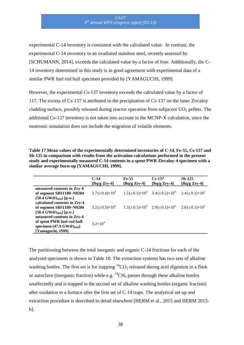
Furthermore, mean values of the experimentally determined radionuclide inventories are
shown in Table 17 and compared to the MCNP-X calculations performed in this study.
Within the analytical uncertainty, the experimentally obtained results in this study for the
inventories of C-14, Fe-55 and Sb-125 are in very good agreement with calculation. The
CAST 3rd annual WP3 progress report (D3.13)
38
experimental C-14 inventory is consistent with the calculated value. In contrast, the
experimental C-14 inventory in an irradiated stainless steel, recently assessed by
[SCHUMANN, 2014], exceeds the calculated value by a factor of four. Additionally, the C-
14 inventory determined in this study is in good agreement with experimental data of a
similar PWR fuel rod hull specimen provided by [YAMAGUCHI, 1999].
However, the experimental Cs-137 inventory exceeds the calculated value by a factor of
117. The excess of Cs-137 is attributed to the precipitation of Cs-137 on the inner Zircaloy
cladding surface, possibly released during reactor operation from subjacent UO2 pellets. The
additional Cs-137 inventory is not taken into account in the MCNP-X calculation, since the
neutronic simulation does not include the migration of volatile elements.
Table 17 Mean values of the experimentally determined inventories of C-14, Fe-55, Cs-137 and Sb-125 in comparison with results from the activation calculations performed in the present study and experimentally measured C-14 contents in a spent PWR Zircaloy-4 specimen with a similar average burn-up [YAMAGUCHI, 1999].
C-14 [Bq/g Zry-4]
Fe-55 [Bq/g Zry-4]
Cs-137 [Bq/g Zry-4]
Sb-125 [Bq/g Zry-4]
measured contents in Zry-4 of segment SBS1108–N0204 (50.4 GWd/tHM) [p.w.]
3.7 (± 0.4)×104 1.5 (± 0.1)×105 3.4 (± 0.2)×106 2.4 (± 0.1)×105
calculated contents in Zry-4 of segment SBS1108–N0204 (50.4 GWd/tHM) [p.w.]
3.2 (± 0.3)×104 1.3 (± 0.1)×105 2.9 (± 0.1)×104 2.6 (± 0.1)×105
measured contents in Zry-4 of spent PWR fuel rod hull specimen (47.9 GWd/tHM) [Yamaguchi, 1999]
3.2×10⁴
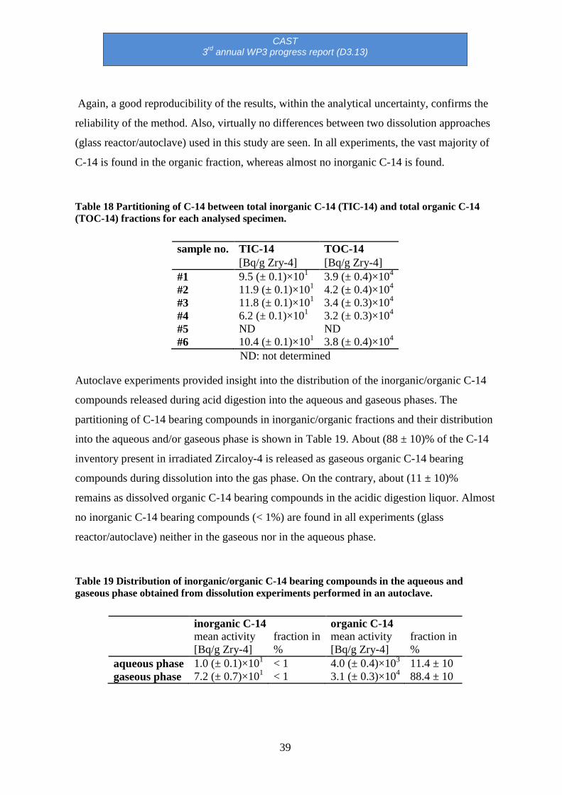
The partitioning between the total inorganic and organic C-14 fractions for each of the
analysed specimens is shown in Table 18. The extraction systems has two sets of alkaline
washing bottles. The first set is for trapping 14CO2 released during acid digestion in a flask
or autoclave (inorganic fraction) while e.g. 14CH4 passes through these alkaline bottles
unaffectedly and is trapped in the second set of alkaline washing bottles (organic fraction)
after oxidation in a furnace after the first set of C-14 traps. The analytical set-up and
extraction procedure is described in detail elsewhere [HERM et al., 2015 and HERM 2015-
b].
CAST 3rd annual WP3 progress report (D3.13)
39
Again, a good reproducibility of the results, within the analytical uncertainty, confirms the
reliability of the method. Also, virtually no differences between two dissolution approaches
(glass reactor/autoclave) used in this study are seen. In all experiments, the vast majority of
C-14 is found in the organic fraction, whereas almost no inorganic C-14 is found.
Table 18 Partitioning of C-14 between total inorganic C-14 (TIC-14) and total organic C-14 (TOC-14) fractions for each analysed specimen.
sample no. TIC-14 TOC-14 [Bq/g Zry-4] [Bq/g Zry-4]
#1 9.5 (± 0.1)×101 3.9 (± 0.4)×104 #2 11.9 (± 0.1)×101 4.2 (± 0.4)×104 #3 11.8 (± 0.1)×101 3.4 (± 0.3)×104 #4 6.2 (± 0.1)×101 3.2 (± 0.3)×104 #5 ND ND #6 10.4 (± 0.1)×101 3.8 (± 0.4)×104
ND: not determined
Autoclave experiments provided insight into the distribution of the inorganic/organic C-14
compounds released during acid digestion into the aqueous and gaseous phases. The
partitioning of C-14 bearing compounds in inorganic/organic fractions and their distribution
into the aqueous and/or gaseous phase is shown in Table 19. About (88 ± 10)% of the C-14
inventory present in irradiated Zircaloy-4 is released as gaseous organic C-14 bearing
compounds during dissolution into the gas phase. On the contrary, about (11 ± 10)%
remains as dissolved organic C-14 bearing compounds in the acidic digestion liquor. Almost
no inorganic C-14 bearing compounds (< 1%) are found in all experiments (glass
reactor/autoclave) neither in the gaseous nor in the aqueous phase.
Table 19 Distribution of inorganic/organic C-14 bearing compounds in the aqueous and gaseous phase obtained from dissolution experiments performed in an autoclave.
inorganic C-14 organic C-14 mean activity
[Bq/g Zry-4] fraction in %
mean activity [Bq/g Zry-4]
fraction in %
aqueous phase 1.0 (± 0.1)×101 < 1 4.0 (± 0.4)×103 11.4 ± 10 gaseous phase 7.2 (± 0.7)×101 < 1 3.1 (± 0.3)×104 88.4 ± 10

CAST 3rd annual WP3 progress report (D3.13)
40
2.5.4 Summary and conclusions regarding the inventory and chemical form of C-14 in Zircaloy-4
Using the C-14 separation and analysis techniques developed in this work for gaseous and
aqueous samples derived from acid digestion of irradiated Zircaloy-4 specimens, it was
possible to quantify the C-14 content in these samples. Furthermore, the partitioning of C-14
between inorganic and organic C-14 bearing compounds and their distribution between
solution and gas phase was investigated. In addition to C-14, the contents of Fe-55, Sb-125
and Cs-137 in irradiated Zircaloy-4 were analysed and also compared to MCNP-X
calculations.
The vast majority of C-14 is released from irradiated Zircaloy-4 as hydrocarbons into the
gas phase (about 88%) and aqueous phase (> 11%). Almost no (< 1%) inorganic C-14
bearing compounds (e.g. carbonates, bicarbonates) were found in all experiments (glass
reactor as well as autoclave) conducted with irradiated Zircaloy-4. Also remarkable is the
similar ratio between inorganic and organic C-14 bearing compounds in the aqueous phase
(1:390) and gas phase (1:430).
The comparison of experimental and theoretically predicted contents of various
radionuclides (C-14, Fe-55, and Sb-125) and their good agreement further proves the
reliability of the obtained data. The experimentally determined activities of the activation
products in the irradiated Zircaloy-4 agrees within a factor < 2 with the MCNP-X
calculation, except for the fission product Cs-137. The difference is considered as relatively
small taking into account the limited availability of data for the calculations.
Despite extensive testing of the separation technique by dissolving non-irradiated Zircaloy,
the interference of gaseous HT, quantitatively released from irradiated Zircaloy-4 during
digestion, and its oxidation to HTO was not taken into account and modifications of the
separation technique were necessary.
Although the digestion experiments were performed under acidic conditions, clearly outside
of repository-relevant conditions, little impact on the chemical form of C-14 released from
irradiated Zircaloy under repository relevant conditions is expected. The vast majority of C-
14 is found as dissolved/gaseous hydrocarbons and almost no dependency on the pH is
expected for the speciation of organic compounds. In addition, strongly reducing conditions

CAST 3rd annual WP3 progress report (D3.13)
41
potentially developing in a deep underground repository for nuclear waste favours the
formation of reduced/organic C-14 compounds. The similar outcome of experiments
performed in this study under acidic conditions, room temperature and N2 or Ar atmosphere
and [BLEIER, 1988] using HF, NaCl or NaCl–NaF, 200°C and air atmosphere further
support this assumption.
The developed C-14 extraction and analysis methods described in this study for irradiated
Zircaloy-4 are not only very reliable but can also be applied in future investigations with
other structural parts such as stainless steel or SNF itself of a fuel rod.
Leaching experiments under neutral/alkaline conditions are foreseen. However, these
experiments will be conducted likely outside of the CAST project since the final reports in
WP3 are already due in January 2017. KIT is currently dealing with irradiated steel (WP2)
which is, due to the high dose rate (> 100 mSv/h per specimen), a much more
demanding/time-consuming task.
2.6 RATEN ICN contribution in WP3
RATEN ICN is in charge of D3.16 (due in January 2017).
2.6.1 Leaching tests on irradiated Zy-4 samples
The leaching tests started in April 2016 for the irradiated samples and in June 2016 for un-
irradiated samples.
6 samples of irradiated Zy-4 were available for the leaching tests. These samples were
obtained from a CANDU spent fuel bundle that was irradiated for 1 year in the Cernavoda
NPP Unit 2 and kept for cooling 4 more years in the Spent Fuel cooling bay. After the
cooling period, the fuel bundle was transported to RATEN ICN for different investigations
and in the last 2 years it was stored in the ICN hot cells.
Preliminary SEM investigations on the CANDU spent fuel were performed. The thickness
of the zirconium oxide layer measured along the fuel tube was between 3 μm and 3.5 μm.
Based on the communication of the fuel producers (FCN Pitesti), the nitrogen content in Zy-
4 is 30 ppm.

CAST 3rd annual WP3 progress report (D3.13)
42
To be able to correlate the C-14 content with the Co-60 content, gamma measurements were
carried out on the samples before starting the leaching tests. Gamma scanning will also be
performed to measure the Co-60 content in the leachate solution.
Due to the high content of Cs-137 in the irradiated Zy-4 samples, gamma measurements
were performed on small rings cut from the irradiated Zy-4 to be used in the long term
leaching tests. An ORTEC Gamma spectrometer with HPGe detector was used for these
measurements and results are reported as Bq per gram of irradiated Zy-4 as presented in
Table 20. Figure 13 presents a spectrum showing the main gamma emitters.
Table 20 Main gamma emitters identified in the irradiated Zy-4
Radionuclide Co-60 Cs-137 Cs-134 Sb-125
Activity [Bq/g] 1.601 E+05 5.4895 E+06 5.676 E+05 6.193 E+06

CAST 3rd annual WP3 progress report (D3.13)
43
Figure 13 Spectrum with the main gamma emitters
Each of the six samples, available for the experimental programme proposed under CAST,
was cut in two pieces: a small one for C-14 measurement and a larger one to be immersed in
deaerated NaOH solution (pH ~ 12).
Static leaching tests have been run under N2 atmosphere. Six glass tubes (2 tubes for three
different leaching time: 6 months, 8 months and 12 months) were adapted to allow N2
purging for 24 hours in order to ensure anoxic conditions (Figure 14). Due to the high
radiation dose, the glass tubes were placed inside of a lead castle. The total C-14 content
and its inorganic / organic partition in the leachate solution will be carried out by the end of
the year 2016.
After 6 months (by October 2016), the first two tubes will be open to sample the leachates
in order to measure both total C-14 and its inorganic / organic partition. Before opening the
tubes, N2 will be purged and the gas will be washed in gas washing bottles in order to
absorb the inorganic C-14 that could be released as gas during these six months. The LSC
technique will be used to quantify C-14.

CAST 3rd annual WP3 progress report (D3.13)
44
After the removal of the leachate solution, two irradiated Zy-4 samples will be used for
electrochemical tests. The experimental setup consists of an AUTOLAB 302 electrical
potentiostat/galvanostat connected to a glass cell equipped with a Pt counter electrode, an
Ag/AgCl reference electrode and the Zy-4 working electrode.
Figure 14 View of the six glass bottles used in the leaching tests
C-14 released in the liquid phase will be analysed by LSC using a TRICARB 3110 TR
counter allowing C-14 measurements in ultra-low levels with typical count rate in the range
of 1-20 CPM above the background. To measure the inorganic and organic C-14, a method
based on a combination of acid stripping and wet oxidation will be used.
CAST 3rd annual WP3 progress report (D3.13)
45
2.6.2 Modelling the C-14 accumulation in CANDU Zy-4 tube during fuel irradiation
The accumulation of the C-14 in the CANDU Zy-4 tube was evaluated by using the
ORIGEN code. The simulation gives a C-14 inventory in the Zy-4 cladding around 1.776
104 Bq/g (0.481 µCi/g) of Zy-4.
Modeling of the C-14 accumulation was achieved by using ORIGEN-S and SCALE 4.4
codes for an irradiation time of CANDU fuel of 890 days and a thermal flux of 4.5E13 nv.
CANDU fuel assembly contains 37 elements comprising of sintered UO2 pellets (30 pellets
of natural uranium) in Zy-4 tubes. The 37 elements are circularly arranged on three rings of
18, 12 and 6 elements respectively, around a central element. A particularity of CANDU
fuel is the colloidal graphite (CANLUB) deposited on the inside surface of the Zy-4 tubes
(the average thickness of the graphite layer is 5 µm with a minimum of 3 µm). Therefore,
the C-14 accumulated in the irradiated Zy-4 is a combination of the C-14 formed or attached
on the oxide layer, the C-14 formed in the Zy-4 metal but also small amount of C-14 formed
in the graphite layer.
The characteristics of CANDU core and fuel bundle are presented in Table 21, while the
composition of the Zy-4 in Table 22.

CAST 3rd annual WP3 progress report (D3.13)
46
Table 21 CANDU core and fuel bundle characteristics
Natural uranium weight 18.7 kg
Fuel bundle weight 23.5 kg
No of fuel bundles in a fuel channel 12.0
Number of fuel channels 380
Number of fuel bundles in the core 4560
Average burn up 7 MWd/kgU
Weight of Zy-4 in a fuel bundle 2 kg
Exterior radius of Zy-4 tube 0.654 cm
Interior radius of Zy-4 tube 0.612 cm
Mass of colloidal graphite in a fuel
bundle
5g

CAST 3rd annual WP3 progress report (D3.13)
47
Table 22 Composition of Zy-4 (wt%)
Major elements (wt%)
Sn 1.2 – 1.7
Fe 0.07 – 0.20
Cr 0.05 – 0.015
Ni 0.03 – 0.08
Zr up to 100%
Minor elements (wt%)
Al 0.0075 H 0.0025 Si 0.0120
B 0.00005 Hf 0.0200 Na 0.0020
C 0.0270 Pb 0.0130 Ti 0.0050
Cd 0.00005 Mg 0.0020 W 0.0100
Co 0.0020 Mn 0.0050 U ( total) 0.00035
Cu 0.0050 N 0.0080 U- 235 0.0000025
Neutronic calculations were carried out for burn up of 0 MWD/kgU and 6 MWD/kgU to get
the neutron fluxes (Table 23) and from these data an average flux were calculated (4.5E+13

CAST 3rd annual WP3 progress report (D3.13)
48
nv) to be used as input for the ORIGEN code. The values fluxes presented in Table 23 in red
are for the neutron fluxes in the fuel while those in blue are for the neutron fluxes in the Zy-
4. Also, using epithermal and fast neutron fluxes the spectral factors were computed on
three groups by using the following relations:
Therm = (n/4To/T)^1/2 for thermal < 0.5eV
Res = 0.069 flux-res/flux-therm < 1MeV
Fast = 1.45 flux-fast/flux-therm < 15MeV
Table 23 Neutron fluxes (nv) in CANDU fuel for a burn up of 0.0 MWD/kg U and 6.0
MWD/kgU (in red: value for neutron flux in fuel; in blue: values for neutron flux in Zr-4)
Four cases were modelled by using the ORIGEN-S code, in order to see their impact on C-
14 generation:
Case 1: all elements included
Burn up = 0.0 MWD/kg U
1.314E+12 7.743E+12 1.455E+13 1.813E+13 1.226E+12 7.218E+12 1.352E+13 1.673E+13
3.575E+12 2.101E+13 3.988E+13 5.418E+13 3.565E+12 2.095E+13 3.966E+13 5.364E+13
2.760E+12 1.713E+13 3.736E+13 6.537E+13 2.857E+12 1.773E+13 3.860E+13 6.730E+13
Burn up = 6.0 MWD/kg U
1.749E+12 1.030E+13 1.936E+13 2.412E+13 1.632E+12 9.604E+12 1.799E+13 2.226E+13
4.760E+12 2.797E+13 5.305E+13 7.208E+13 4.748E+12 2.787E+13 5.277E+13 7.136E+13
3.660E+12 2.274E+13 4.961E+13 8.684E+13 3.789E+12 2.353E+13 5.126E+13 8.941E+13

CAST 3rd annual WP3 progress report (D3.13)
49
Case 2: N impurities were not considered
Case 3: C was not considered (CANLUB graphite and C as impurity in Zy-4)
Case 4: N and C were not considered
The results obtained for Case 1 and Case 2 are presented in Table 24. Particularly, the
results obtained for C-14 are presented in Table 25 both as mass and as radioactivity.
Table 24 Calculated radionuclide concentrations in irradiated Zy-4 from CANDU fuel at a burn up of 6MWD/kg U
Radionuclide Mass (g/kg of Zy-4)
Case 1 Case 2 charge discharge charge discharge
B 10 9.26E-05 3.03E-07 9.26E-05 3.03E-07
B 11 4.07E-04 4.11E-04 4.07E-04 4.07E-04
C 12 2.24E+00 2.24E+00 2.24E+00 2.24E+00
C 13 2.73E-02 2.73E-02 2.73E-02 2.73E-02
C 14 0.00E+00 1.08E-04 0.00E+00 1.97E-07
N 14 3.98E-02 3.97E-02 0.00E+00 2.90E-11
N 15 1.57E-04 1.62E-04 0.00E+00 6.32E-09
O 16 1.30E+00 1.30E+00 1.30E+00 1.30E+00
O 17 5.25E-04 5.25E-04 5.25E-04 5.25E-04
O 18 2.98E-03 2.98E-03 2.98E-03 2.98E-03
F 19 0.00E+00 1.31E-09 0.00E+00 1.31E-09

CAST 3rd annual WP3 progress report (D3.13)
50
Table 25 Calculated C-14 accumulated in irradiated Zy-4 from CANDU fuel at a burn up of 6MWD/kg U
C-14 Case 1 Case 2
g/kg of Zy-4 Bq/kg Zy-4 g/kg Zy-4 Bq/kg Zy-4
Discharge 1.08E-04 1.78E+07 1.97E-07 8.79E-07
The results obtained for Case 3 are very similar to those obtained for Case 1 while those
obtained for Case 4 are similar with those resulted for Case 2. These data indicate that the
carbon (both from colloidal graphite and from impurity in Zy-4) has low influence on the
total C-14 generation in CANDU Zy-4 tubes.
2.7 RWMC contribution in WP3
RWMC contributed to D3.1 (issued in 2014). It is also in charge of D3.19 due in January
2017.
2.7.1 Distribution of 14C in irradiated cladding
A spent BWR fuel rod (STEP 1 type) located at the circumference of the assembly was
obtained. The STEP I type fuel is an older fuel type in Japan that uses an 8×8 array in a
lattice configuration. The average burnup was 39.4 GWd/tU for the fuel assembly and 41.6
GWd/tU for the fuel rod. After the fuel components were removed, the Zircaloy-2 claddings
were washed with 6 M of HNO3 in a warm bath and cut to an appropriate size. The
thickness of the surface oxide layer was measured based on external observations. As shown
in Figure 15, four types of samples were obtained for specific activity measurements of C-
14. The external oxide layer of Zircaloy was peeled off through vertical compression of the
columnar cladding (approximately 2 cm high) whose interior layer had previously been

CAST 3rd annual WP3 progress report (D3.13)
51
removed. As a consequence, approximately 0.05 g of oxide was recovered as a powdery
fragment.
The C-14 radioactivity in the cladding specimens was measured as follows: Firstly, the ring-
shaped claddings and oxide samples were dissolved in an HNO3 + HF solution with heating.
Carbon components were evaporated by air bubbling for 30 min and oxidised by CuO in
CO2 at 1073 K. The material was then passed through three steps of a dry-ice cold trap to
remove tritium and three steps of an alkaline trap (1 M of NaOH) to collect carbon dioxide
(14CO2). The potential contamination by radioiodine in a volatile state was removed by an
AgI precipitation. The 14C radioactivity in the alkaline traps was measured by LSC
(PerkinElmer Tri-Carb 2900TR).
Figure 15 External appearance of irradiated claddings for 14C measurement: (a) with internal and external oxide layers in place, (b) with internal oxide removed, (c) with internal and external oxide removed, (d) (external) oxide fragment removed from the cladding [SAKURAGI, 2016].
Table 26 shows the results of 14C specific activity (Bq/g) for the irradiated cladding
specimen shown in Figure 15. For the external oxide, units of grams in the specific activity
of oxide are converted into grams of zirconium metal in order to facilitate comparison with
the base metal. The average values of (a), (b), (c) and (d) are 1.49×10⁴, 1.53×10⁴, 1.49×10⁴
and 4.04×10⁴ Bq/g, respectively.
The radionuclides in cladding oxide are regarded as a source of instant release fraction
(IRF) in the preliminary Japanese safety case, in which 20% of 14C in cladding was assumed
as IRF and the remaining 80% was assumed as the corrosion-related congruent release from
the base Zircaloy metal [FEPC, 2007]. In Table 26, the specific activity between oxide and
base Zircaloy differs by a factor of 2.8. The 14C in Zircaloy is mainly generated from the
a b c d
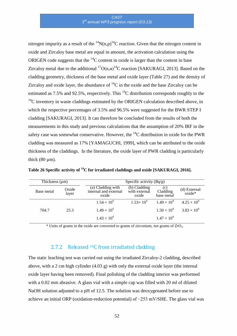
CAST 3rd annual WP3 progress report (D3.13)
52
nitrogen impurity as a result of the 14N(n,p)14C reaction. Given that the nitrogen content in
oxide and Zircaloy base metal are equal in amount, the activation calculation using the
ORIGEN code suggests that the 14C content in oxide is larger than the content in base
Zircaloy metal due to the additional 17O(n,α)14C reaction [SAKURAGI, 2013]. Based on the
cladding geometry, thickness of the base metal and oxide layer (Table 27) and the density of
Zircaloy and oxide layer, the abundance of 14C in the oxide and the base Zircaloy can be
estimated as 7.5% and 92.5%, respectively. This 14C distribution corresponds roughly to the 14C inventory in waste claddings estimated by the ORIGEN calculation described above, in
which the respective percentages of 3.5% and 96.5% were suggested for the BWR STEP I
cladding [SAKURAGI, 2013]. It can therefore be concluded from the results of both the
measurements in this study and previous calculations that the assumption of 20% IRF in the
safety case was somewhat conservative. However, the 14C distribution in oxide for the PWR
cladding was measured as 17% [YAMAGUCHI, 1999], which can be attributed to the oxide
thickness of the claddings. In the literature, the oxide layer of PWR cladding is particularly
thick (80 µm).
Table 26 Specific activity of 14C for irradiated claddings and oxide [SAKURAGI, 2016].
Thickness (µm) Specific activity (Bq/g)
Base metal Oxide layer
(a) Cladding with internal and external
oxide
(b) Cladding with external
oxide
(c) Cladding
base metal (d) External
oxide*
704.7 25.3
1.54 × 10⁴ 1.53× 10⁴ 1.49 × 10⁴ 4.25 × 10⁴ 1.49 × 10⁴ 1.50 × 10⁴ 3.83 × 10⁴ 1.43 × 10⁴ 1.47 × 10⁴
* Units of grams in the oxide are converted to grams of zirconium, not grams of ZrO2.
2.7.2 Released 14C from irradiated cladding
The static leaching test was carried out using the irradiated Zircaloy-2 cladding, described
above, with a 2 cm high cylinder (4.03 g) with only the external oxide layer (the internal
oxide layer having been removed). Final polishing of the cladding interior was performed
with a 0.02 mm abrasive. A glass vial with a simple cap was filled with 20 ml of diluted
NaOH solution adjusted to a pH of 12.5. The solution was deoxygenated before use to
achieve an initial ORP (oxidation-reduction potential) of −253 mV/SHE. The glass vial was

CAST 3rd annual WP3 progress report (D3.13)
53
placed inside a stainless steel container and sealed by gasket to maintain the initial inert
condition and to prevent leakage of volatile 14C. This immersion procedure was carried out
under nitrogen atmosphere inside a glove box. The experimental setup of the leaching test is
shown in Figure 16.
After 6.5 years of immersion at room temperature (approximately 293 K), the outer and
inner vessels were opened in a glove bag with a vacuum tube attached. The gaseous 14C was
collected through the tube by using the three steps of an alkaline trap after passing through
an oxidation furnace. A portion of the liquid phase was provided for measurement of total
dissolved 14C and dissolved organic and inorganic 14C. In the total 14C measurement, an
aliquot of leachate was mixed with a carrier carbon (Na2CO3 and C2H5OH), an oxidant
(potassium persulfate, K2S2O8), a catalyst (AgNO3), and an acid (H2SO4) in a warm vessel.
In the organic / inorganic separation method, the inorganic 14C was fractionated from
another aliquot by bubbling for 30 minutes under acidification. Then, the remaining
organics were oxidised with the same reagents used for total 14C measurement and the
volatile 14C (14CO2) was collected by an alkaline trap in the same manner as described for
total 14C measurement. Leached 14C in the alkaline traps was measured by a liquid
scintillation counter (PerkinElmer Tri-Carb 3100TR).

CAST 3rd annual WP3 progress report (D3.13)
54
Figure 16 External view of outer vessel (left) and cladding immersed in glass vessel (right) for long-term static leaching test.
Table 27 shows the results of the leached amount of 14C for the respective fractions after 6.5
years of aqueous immersion. The gaseous released 14C (0.317 Bq) is less than the dissolved 14C species (2.00 Bq in total fraction). The sum of the dissolved inorganic and organic 14C is
1.64 Bq, which corresponds roughly to the total dissolved 14C. The leached organic 14C in
solution is 3 times the amount of the inorganic 14C.
The leaching ratio is shown in Figure 17. It is equivalent to the leached amount (gaseous +
dissolved) divided by the initial inventory, and is less than 3.8×10⁻⁵. It is consistent with the
previous short-term leaching tests, described above, involving PWRs or BWRs STEP III
claddings [YAMAGUCHI, 1999] [YAMASHITA, 2014], which showed small 14C leaching
ratios.
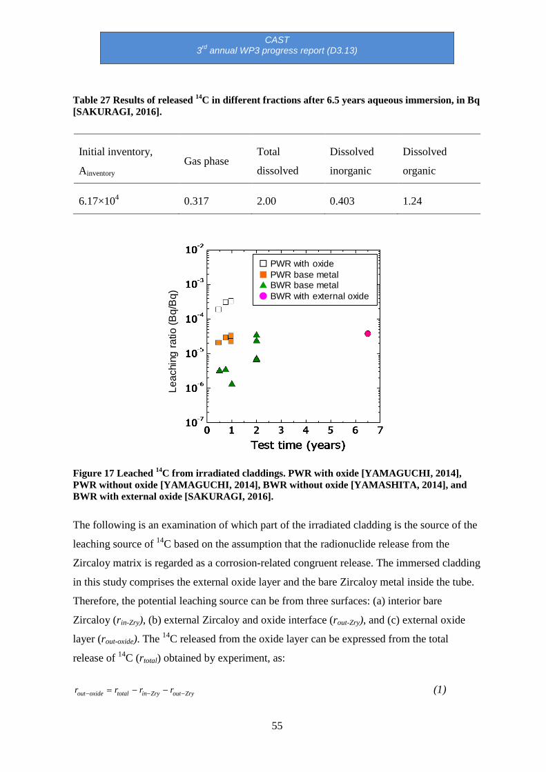
CAST 3rd annual WP3 progress report (D3.13)
55
Table 27 Results of released 14C in different fractions after 6.5 years aqueous immersion, in Bq [SAKURAGI, 2016].
Initial inventory,
Ainventory Gas phase
Total
dissolved
Dissolved
inorganic
Dissolved
organic
6.17×10⁴ 0.317 2.00 0.403 1.24
Leac
hing
ratio
(Bq/
Bq)
□ PWR with oxide■ PWR base metal▲ BWR base metal● BWR with external oxide
Figure 17 Leached 14C from irradiated claddings. PWR with oxide [YAMAGUCHI, 2014], PWR without oxide [YAMAGUCHI, 2014], BWR without oxide [YAMASHITA, 2014], and BWR with external oxide [SAKURAGI, 2016].
The following is an examination of which part of the irradiated cladding is the source of the
leaching source of 14C based on the assumption that the radionuclide release from the
Zircaloy matrix is regarded as a corrosion-related congruent release. The immersed cladding
in this study comprises the external oxide layer and the bare Zircaloy metal inside the tube.
Therefore, the potential leaching source can be from three surfaces: (a) interior bare
Zircaloy (rin-Zry), (b) external Zircaloy and oxide interface (rout-Zry), and (c) external oxide
layer (rout-oxide). The 14C released from the oxide layer can be expressed from the total
release of 14C (rtotal) obtained by experiment, as:
ZryoutZryintotaloxideout rrrr −−− −−= (1)

CAST 3rd annual WP3 progress report (D3.13)
56
The matrix corrosion rate was obtained from out-of-pile study in the temperature range of
approximately 561 K to 673 K [HILLNER, 1977]. Here, the pre-transition cubic rate
constant, kC, is applied to the inside bare Zircaloy (rin-Zry) and the post-transition liner rate
constant, kL, is applied to the external Zircaloy (rout-Zry) because the corrosion kinetics of
Zircaloy follows a cubic rate law before transition (“breakaway”), and then, once corrosion
has progressed for 1 or 2 µm, the corrosion kinetics changes linearly with time [HILLNER,
1977]. The details are described elsewhere [SAKURAGI, 2016].
Figure 18 shows the estimated release ratios from the possible source surfaces at 293 K and
6.5 years of immersion. Due to the low corrosion rate of Zircaloy, especially the extremely
slow post-transition corrosion, the leached 14C from Zircaloy is negligible. This leads to the
conclusion that the main source of 14C release is the oxide. By applying the concept of a
corrosion-related congruent release described above, the 14C release from the oxide layer is
almost 100% of the amount in the previous short-term PWR test [YAMAGUCHI, 2014], for
which the cladding has both post-transition internal and external oxide layers of 10 µm and
80 µm respectively.
In conclusion, the oxide layer is dominant in the 14C release from irradiated cladding.
However, regarding the 14C in oxide as IRF would be too conservative because the released 14C is less than 0.01% of the total after 6.5 years of immersion. Both the low amount of 14C
in oxide and the low leaching rate indicate that the 14C in oxide does not have a major
impact on the instant release fraction in the safety case.
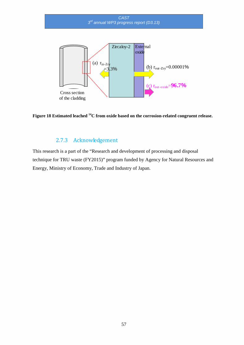
CAST 3rd annual WP3 progress report (D3.13)
57
Zircaloy-2
Cross section of the cladding
External oxide
(a) rin-Zry=3.3% (b) rout-Zry=0.00001%
(c) rout-oxide=96.7%
Figure 18 Estimated leached 14C from oxide based on the corrosion-related congruent release.
2.7.3 Acknowledgement
This research is a part of the “Research and development of processing and disposal
technique for TRU waste (FY2015)” program funded by Agency for Natural Resources and
Energy, Ministry of Economy, Trade and Industry of Japan.

CAST 3rd annual WP3 progress report (D3.13)
58
2.8 SCK.CEN contribution in WP3
In 2016, SCK.CEN was in charge of D3.12 in Task 3.3, entitled “3nd year progress report”.
This deliverable consists of describing a complete material characterisation on unirradiated
Zr-4, as well as the experimental setups for corrosion rate measurements and C-14
speciation. Within WP3, SCK-CEN is in charge of four deliverables; D3.4 (issued in 2014),
D3.10 (issued in 2015), D3.12 (submitted in June 2016), and D3.17 (due in 2017).
2.8.1 Materials
Metallographic characterisation of unirradiated Zr-4 was performed. Figure 19 presents the
grain structure observed with a scanning electron microscope (SEM) in BSE mode. The
grain size number was estimated at 11.8, which corresponds to an average grain diameter of
6 µm and surface of 36.4 µm². The small black spots can be attributed to Zr(Fe,Cr)2 Laves
phases.

CAST 3rd annual WP3 progress report (D3.13)
59
Figure 19 SEM image (BSE mode)revealing the grain structure of an unirradiated Zr-4.
Typical images of the defect structure of Zr-4 is shown in Figure 20. The main defects are
line dislocations with a density of 4.1×10¹³ / m². The grain orientation can be determined
from the diffraction pattern as shown in Figure 20. Most grains have a comparable
orientation following the [1-210] zone axis. During the manufacturing process the grains
become textured, which results in grains having a similar orientation.

CAST 3rd annual WP3 progress report (D3.13)
60
Figure 20 Top left: Bright field; Top right: dark field image of the typical defect structure in unirradiated Zr-4; Bottom: Typical diffraction pattern showing the grain orientation following the [1-210] zone axis.
Most precipitates present in Zr-4 are Laves phases with a nominal composition of
Zr(Fe,Cr)2. The composition is confirmed by the EDS analysis on this particle. Apart from
the Zr signal, peaks corresponding to Fe and Cr were measured as well. Carbon is
considered to result from surface contamination during the analysis as it was not initially
present in this sample.
Figure 21 shows a second type of precipitate. The bright and dark field images show that
these precipitates are elongated along the (0002) planes with needle or platelet shapes. The
EDS spectrum in Figure 21 e) shows the composition of the precipitate in comparison to the
bulk material of Zr-4. For a better visual comparison, the spectrum was renormalized so

CAST 3rd annual WP3 progress report (D3.13)
61
that both spectra have the same total number of counts. The bulk metal is mainly Zr. Small
amounts of C and O were detected as well, which can be attributed to the expected
contamination of the surface and a slight oxidation of Zr, which is very reactive. When
magnifying the spectrum between 2 and 6 keV, a small Sn peak could be found, in
agreement with the 1.2wt% of Sn added to Zr-4. Cr and Fe were not detected in the bulk as
they contribute to the formation of Laves phases. The spectrum of the precipitate contains
only Fe and C. The C content is significantly higher in the precipitate compared to the bulk
material. This may result from higher local contamination while recording the spectrum or it
can be an indication that carbon is present in the precipitate.
Crystallographic structure can help identify the precipitate from the diffraction pattern
(Figure 21 d). Because of the small size of the precipitate, the appearance of diffraction
spots from the bulk Zircaloy could not be avoided and the 0002, -1011 and -1010
reflections, typical for the [1-210] zone, are also indicated. The additional reflections agree
with the [110] zone axis of a face centred cubic (FCC) structure with a lattice parameter of
4.6 ± 0.2 Å. Several phases, including ZrC, ZrN or ZrH2, were found to have the right
crystal structure. In combination with the EDS results, it is most likely that this phase is a
ZrC precipitate.

CAST 3rd annual WP3 progress report (D3.13)
62
a) b)
c) d)
e)

CAST 3rd annual WP3 progress report (D3.13)
63
Figure 21 a) bright field and b,c) dark field images of a second type of precipitate in Zr-4, presumably a ZrC. d) The corresponding diffraction pattern and e) the EDS analysis. The inset shows a magnified part of the bulk metal spectrum, clarifying the presence of Sn peaks.
2.8.2 Corrosion test
Two types of corrosion tests have been performed by SCK.CEN:
• Static corrosion tests to allow for a more realistic corrosion behaviour and measure the
resulting released 14C and its speciation
• Accelerated corrosion tests involving polarisation, which mainly serve for preliminary
speciation determination.
2.8.2.1 Static tests
Figure 22 shows the experimental setup of a static corrosion test. It consists of a PEEK-
coated steel vessel with an internal volume of 50 cm³. The vessel is filled with a Ca(OH)2
solution at pH 12.5 in which a Zr-4 sample (irradiated or unirradiated) is immersed. Tests
will be run for a period of 6 months. After the test, both liquid and gaseous samples will be
analysed by gas chromatography (GC).

CAST 3rd annual WP3 progress report (D3.13)
64
Figure 22 Experimental setup of the static corrosion tests performed at SCK.CEN.
2.8.2.2 Polarised corrosion tests
Figure 23 shows the experimental setup of a polarised corrosion test. A three-electrode cell
is used, including a working electrode (Zr-4), a house-made Ag/AgCl reference electrode,
and a platinum counter electrode. During preliminary tests, potentiodynamic polarization
measurements have been carried out by applying a potential range from the cathodic to the
anodic region. The resulting current density was recorded. A representative I-E polarization
curve, showing a broad passive range is presented in Figure 24.

CAST 3rd annual WP3 progress report (D3.13)
65
Figure 23 Experimental setup of a polarised corrosion test.
Figure 24 I-E Polarization curve of unirradiated Zr in a solution of Ca(OH)2 at pH 12.5.
2.8.3 Gas chromatography

CAST 3rd annual WP3 progress report (D3.13)
66
To determine 14C speciation released from Zr-4 in Ca(OH)2, a GC system will be installed
by the end of 2016. The acquired system is a Shimadzu GC-2010 Plus, which is tailor-made
to meet the requirements of the CAST project. Detectors include a Flame Ionization
Detector (FID), a Barrier Discharge Ionization Detector (BID), and a Pulse Discharge
Helium Ionisation Detector (PDHID). The detection limit of the PDHID detector is 50 ppb
(ng/l).
3 Summary
3.1 Introduction
During the third year of the CAST project, WP3 participants have worked on Tasks 3.2 and
3.3. The leaching and corrosion experiments have been launched by most participants on
both irradiated and unirradiated materials. However, the experimental setups have taken
more time than initially planned. Therefore, the coordinator has been informed that an
extension of 3 months will be required to complete the objectives of CAST WP3. This will
be discussed for agreement at the October 2016 General Assembly Meeting.
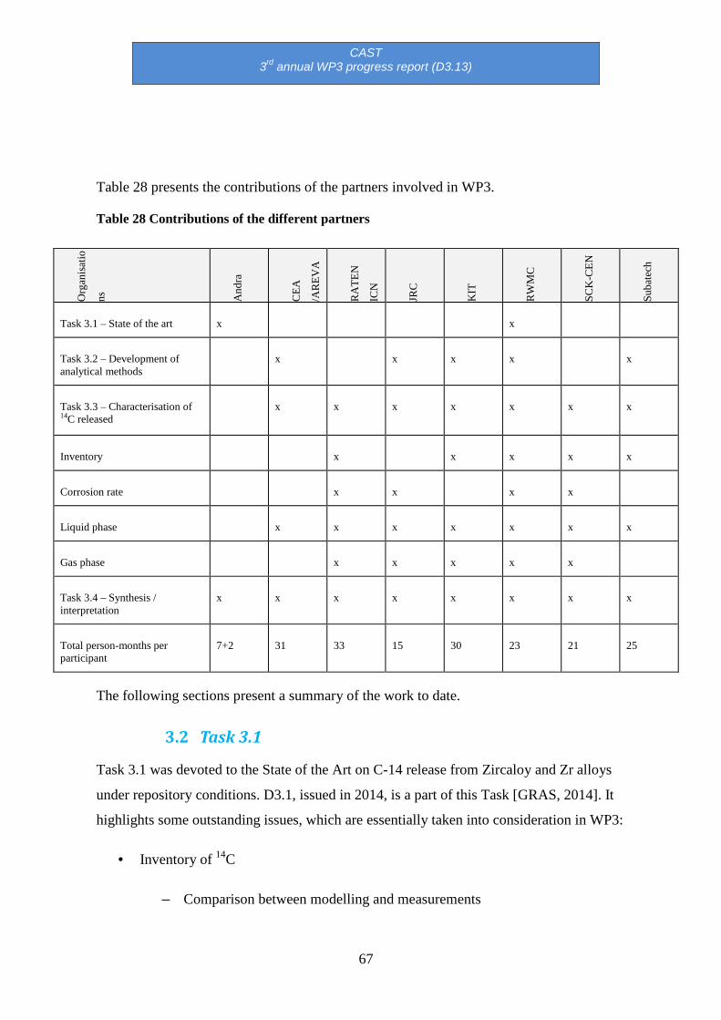
CAST 3rd annual WP3 progress report (D3.13)
67
Table 28 presents the contributions of the partners involved in WP3.
Table 28 Contributions of the different partners
Org
anis
atio
ns
And
ra
CEA
/AR
EVA
RA
TEN
ICN
JRC
KIT
RW
MC
SCK
-CEN
Suba
tech
Task 3.1 – State of the art x x
Task 3.2 – Development of analytical methods
x x x x x
Task 3.3 – Characterisation of 14C released
x x x x x x x
Inventory x x x x x
Corrosion rate x x x x
Liquid phase x x x x x x x
Gas phase x x x x x
Task 3.4 – Synthesis / interpretation
x x x x x x x x
Total person-months per participant
7+2 31 33 15 30 23 21 25
The following sections present a summary of the work to date.
3.2 Task 3.1
Task 3.1 was devoted to the State of the Art on C-14 release from Zircaloy and Zr alloys
under repository conditions. D3.1, issued in 2014, is a part of this Task [GRAS, 2014]. It
highlights some outstanding issues, which are essentially taken into consideration in WP3:
• Inventory of 14C
– Comparison between modelling and measurements

CAST 3rd annual WP3 progress report (D3.13)
68
– 14C speciation into the metal and oxide layers
• Corrosion of Zircaloy at low temperatures
– Regime of corrosion for oxide thickness (tox) >> 2.5 µm
– Consequences of the dense surface layer of hydrides (hydrogen pick-up ratio
∼ 90 %).1
– Low dissolution rate of ZrO2 layers in alkaline solutions in the presence of
any complexing species (in relationship with the chemistry of disposal sites’
groundwater) 1
• Leaching
– Feedback of reprocessing plants (e.g. leaching of claddings in pools) 1
– Chemical forms of released 14C
– Rates of release of 14C
3.1 Tasks 3.2 and 3.3 3.1.1 Materials
Table 29 and Table 30 summarise, respectively, the unirradiated and irradiated materials
available for use in WP3. These materials have been considered for the leaching and
corrosion experiments in alkaline media involved in Tasks 3.2 and 3.3. Analyses have been
conducted on liquid and / or gas samples. The determination of the inventory and speciation
of C-14 released from Zircaloy in alkaline conditions is in progress. Zircaloy–2, Zircaloy–4
and M5TM materials were available for the CAST project. The different suppliers are
European and Japanese, which allows a variety in terms of history of the materials and
conditions in nuclear power plants. For most materials, the nitrogen content has been
1 Not studied in CAST

CAST 3rd annual WP3 progress report (D3.13)
69
determined experimentally. Metallography has been carried out to identify the
microstructure of the materials, both irradiated and unirradiated. Knowing that the
dissolution of zirconia is involved in C-14 release, the thickness, properties and
microstructure of zirconia has been investigated for irradiated materials. From a corrosion
point of view, unirradiated materials are also studied as they allow further investigation on
the corrosion kinetics for different oxide thickness, especially above 2 µm to study the post-
transition kinetics. The cleaning of the samples has been minimised in order to be
representative of the disposal conditions. Therefore, for unirradiated materials, cleaning
with ethanol followed by rinsing with water and air drying was generally performed.
Regarding irradiated materials, rinsing in HNO3 was carried out on spent fuel hulls (which
contains other radioelements), followed by rinsing with water and air drying.

CAST 3rd annual WP3 progress report (D3.13)
70
Table 29 Unirradiated materials.
Participants Zr alloys
types
Chemical
composition
(real N)
Metallography Pre-treatment of the
surface specimen
Oxide
thickness
(µm)
ITU/JRC Zr-4 30-40 ppm To be done As-received ~ 3
RATEN ICN
(ex. INR)
Zr-4 10 ppm OM, SEM Oxidation 1.7 – 2.7
RWMC Zr-4 (plate),
Zr-2,
Zr
28 ppm
32ppm
10ppm
OM, SEM Cold-rolling, and vacuum
annealing
Surface condition: alumina
powder polishing (0.02 mm)
0.005 – 0.02
Zr-4 (tube)
30ppm
OM, SEM
Mean Diameter of
intermetallic
compound: 0.16μm
(outer side)
As-received ~ 0.005
(naturally
formed in air)
SCK.CEN Zr-4 17 – 25 ppm OM, SEM TEM As-received naturally
formed in air

CAST 3rd annual WP3 progress report (D3.13)
71
Table 30 Irradiated materials.
Participants Zr alloys types
Chemical composition (real N)
Microstructure
Activation history (known)
14C Inventory
(Bq/g)
Pre-treatment of specimen, i.e. surface condition etc.
Areva Supply the materials to CEA
CEA M5TM
Zr4
(inner layer )
Zr-0.8%Sn (outer layer)
Tube shape
27 ppm (estimated)
34 ppm
(estimated)
OM
(planned)
46.570 GWd/tHM
/
54.500 GWd/tHM
Modelling in progress
(Round Robin test)
Industrial treatment (shearing, fuel dissolution in boiling HNO3, rinsing)
ITU/JRC Zr-4 with Zr-2.5Nb (external cladding)
Ring shape
30 – 40 ppm
OM + SEM
(planned)
Max 100.5GWd/tHM
1.3 x 10⁴ Acid cleaning with HNO3 and /or 15%H2SO4
(depending on their original location)
+ water and drying in air
KIT Zr-4 + Zr-
Nominal: OM 50.4 Calculated: wash cycle

CAST 3rd annual WP3 progress report (D3.13)
72
0.8%Sn (outer layer)
Ring shape
50 ppm GWd/tHM 3.2(±0.3)×104
Experimental:
3.7(±0.4)×104
with ultrapure water / ultrasonic bath
RATEN ICN
(ex. INR)
Zr-4
Tube shape
30 ppm OM
7.5GWday/tHM
1.776 x 10⁴ spent fuel dissolution using HNO3; rinsing with pure water
RWMC Zr-2
STEP3
Not available
OM 39.7 GWd/tHM
3 cycles
Metal ; 1.74 x10⁴
Polishing and rinsing with pure water, (removal of the oxide layer)
Zr-2
STEP1
Not available
OM 41.6 GWd/tHM
5 cycles
Metal ; 2.48 x10⁴
Polishing and rinsing with pure water, (removal of the oxide layer)
Zr-2
STEP 1
Not available
OM 40.4
34.2
41.6
Metal + outer oxide film;
3.57x10⁴,
1.53 x10⁴
3.42 x10⁴
Polishing inner surface and rinsing with pure water. (samples with oxide outer layer)
Zr-2 Not OM Oxide (outer Remove

CAST 3rd annual WP3 progress report (D3.13)
73
STEP 1 available
34.2
41.6
37.4
layer)
4.04 x10⁴
5.69 x10⁴
5.82 x10⁴
(Bq/gr)*
*Bq/gr is in terms of Zr metal weight
d from Zr-2 tube
SCK-CEN Zr-4 17-25 ppm
(measured) OM + TEM
49 GWd/tHM
Calculated:
1.33 x10⁴
1.95 x10⁴
Rinsing with water + drying in air
Subatech/Armines
M5 + Zr-4 (Identical to CEA)
3.1.2 Task 3.2
Task 3.2 is devoted to the analytical development based on the needs highlighted in Task
3.1. The main contributors to this task are CEA, KIT and Subatech / Armines who are
responsible for D3.3, D3.7 and D3.9 respectively. JRC / ITU, RATEN ICN, RWMC and
SCK.CEN are also involved at a lower level. In 2016, Subatech submitted the D3.9
deliverable describing the analytical strategy to measure C-14 organic molecules in NaOH
solution containing irradiated Zircaloy.
Overall, CEA and Subatech have been working in alkaline solution and confirmed that
inorganic / organic partition can be determined by LSC after 14 days of immersion. By
contrast, C-14 speciation requires AMS as the released C-14 is below the detection limit of
LSC.
Subatech have proposed an analytical strategy for the analysis of C-14 carboxylic acids
released from irradiated Zircaloy (WP3) and steels (WP2). This strategy is based on the use
of IC for separation of carboxylic acids and LSC for the quantification of C-14 in the IC
collected fractions. The proposed method is based on the use of K2[CuFe(CN)6] without
binding polymer resin characterized by its selectivity for the identified radionuclides and the
absence of interaction with target C-14 carboxylic acids. However, the experimental
protocol combining IC and LSC further to filtration and resin treatment stages of the

CAST 3rd annual WP3 progress report (D3.13)
74
leaching solution shows that the C-14 carboxylic acid activities are below the quantification
limits of LSC i.e. 0.04 Bq/mL and that AMS, a more sensitive technique, will be required to
determine C-14 in the chromatographic fractions.
KIT has been working in acid solution to determine C-14 inventory as well as the gaseous /
aqueous partition. Using the C-14 separation and analysis techniques developed in WP3 for
gaseous and aqueous samples derived from acid digestion of irradiated Zircaloy-4
specimens, it was possible to quantify the C-14 content in these samples. Furthermore, the
partitioning of C-14 between inorganic and organic C-14 bearing compounds and their
distribution between solution and gas phase was investigated. In addition to C-14, the
contents of Fe-55, Sb-125 and Cs-137 in irradiated Zircaloy-4 were analysed and also
compared to MCNP-X calculations.
Table 31 summarises the analytical development in WP3.

CAST 3rd annual WP3 progress report (D3.13)
75
Table 31 Analytical development.
Participants Sampling (gas/liquid)
C-14 speciation Techniques Aims
CEA Liquid yes TC analyser (TIC + TOC) LSC + AMS IR IC GC-MS ESI – MS
Total Carbon Quantification of C-14 Speciation (organic molecules) Quantification of carboxylic acids Low molecular weight molecules High molecular weight
ITU/JRC Gas and liquid Only gas /liquid phase separation
LSC ICP-MS GC-MS
TIC-14/TOC-14
KIT Gas and liquid yes LSC ICP-MS GC-MS α-γ-spectrometry
TIC-14/TOC-14 Inventory + partition Activity
RATEN ICN Liquid Only inorganic/ organic partition
LSC TIC-14/TOC-14
RWMC Gas and liquid yes LSC γ-spectrometry IC-MS
Partition Activity Organic/Inorganic
SCK-CEN Gas and liquid yes
γ-spectrometry LSC / AMS TOC GC IC
Activity Inventory Speciation
Subatech / Armines Liquid yes LSC + AMS IC
TIC-14/TOC-14 Speciation
3.1.3 Task 3.3
This task involves 15 deliverables (D3.2, D3.4-6, and D3.8-19). In 2016, the activities have
been focused on launching the leaching experiments in alkaline solutions and start C-14
measurements in terms of inventory and speciation. Following the progress meeting held in
Madrid on 1-2 June 2016, the planning for the leaching experiments and subsequent
corrosion measurements will have to be adjusted to meet the requirements of the CAST
project. Indeed, the purchase of the equipment, as well as the time required for the
experimental setups delayed the launch of most leaching experiments. The deliverables due
by February 2017 (D3.14-D3.19) will have to be postponed. According to the experience of

CAST 3rd annual WP3 progress report (D3.13)
76
RWMC, 6 months is a reasonable duration to run the leaching experiment and measure
released C-14, therefore an extension of three months is necessary to achieve the objectives
of WP3.
Table 32 and Table 33 summarise the conditions for the leaching experiments in WP3 for
irradiated and unirradiated materials.
Surface characterisations, including internal and external oxide layers observations by using
scanning electron microscopy (SEM) and transmission electron microscopy (TEM), have
been conducted prior to running the leaching experiments. Additional surface
characterisations will be carried out following the leaching experiments to identify the
impact of corrosion and dissolution of Zirconia.
To measure the corrosion rate (CR), specific experiments have been considered involving
electrochemical measurements to determine the polarisation resistance (Rp) by using the
linear polarisation resistance (LPR) technique. Moreover, Co60 counting is also carried out
for the leaching experiment, which gives an estimation of the corrosion rate.
Table 34 and Table 35 summarise the current corrosion experiments carried out in WP3 for
irradiated and unirradiated materials.
The results obtained during 2016 in terms of CR are summarised in Table 36 and Table 37.
The current results on C-14 analyses (inventory and speciation) are summarised in Table 38.
KIT has shown that in acid solution, the vast majority of C-14 released from irradiated
Zircaloy-4 is present as hydrocarbons into the gas phase (about 88%) and aqueous phase
(> 11%). Almost no (< 1%) inorganic C-14 bearing compounds (e.g. carbonates,
bicarbonates) were found in all experiments (glass reactor as well as autoclave) conducted
with irradiated Zircaloy-4. Also remarkable is the similar ratio between inorganic and
organic C-14 bearing compounds in the aqueous phase (1:390) and gas phase (1:430).
The comparison of experimental and theoretically predicted contents of various
radionuclides (C-14, Fe-55, and Sb-125) and their good agreement further prove the
reliability of the obtained data. The experimentally determined activities of the activation
products in the irradiated Zircaloy-4 agrees within a factor < 2 with the MCNP-X

CAST 3rd annual WP3 progress report (D3.13)
77
calculation, except for the fission product Cs-137. The difference is considered as relatively
small taking into account the limited availability of data for the calculations.
Despite extensive testing of the separation technique by dissolving non-irradiated Zircaloy,
the interference of gaseous HT, quantitatively released from irradiated Zircaloy-4 during
digestion, and its oxidation to HTO was not taken into account and modifications of the
separation technique were necessary.
Although the digestion experiments were performed under acidic conditions, clearly outside
of repository-relevant conditions, little impact on the chemical form of C-14 released from
irradiated Zircaloy under repository relevant conditions is expected.
RWMC performed leaching experiments over 6.5 years on Zr-2 and Zr-4 hulls in NaOH
solution at pH 12 under deaerated conditions. The experiments were performed on materials
exempt of oxide layers in order to determine the released C-14 fraction. According to their
results, most C-14 is released by the oxide. In addition, the estimation of an instant release
fraction (IRF) of 20%, considered from a safety assessment point of view, is far too
conservative. Investigation on the dissolution rate of zirconia in alkaline media should be
conducted.
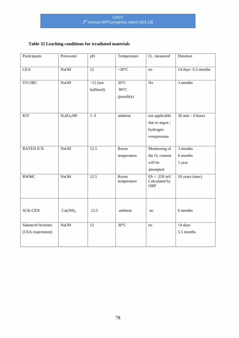
CAST 3rd annual WP3 progress report (D3.13)
78
Table 32 Leaching conditions for irradiated materials
Participants Porewater pH Temperature O2 measured Duration
CEA NaOH 12 ~30°C no 14 days -5.5 months
ITU/JRC NaOH ~12 (not
buffered)
30°C
80°C
(possibly)
No 3 months
KIT H2SO4/HF 1–3 ambient not applicable
due to argon /
hydrogen
overpressure
30 min – 6 hours
RATEN ICN NaOH 12.5 Room
temperature
Monitoring of
the O2 content
will be
attempted
3 months
6 months
1 year
RWMC NaOH 12.5 Room temperature
Eh < -250 mV Calculated by ORP
10 years (max)
SCK-CEN Ca(OH)2 12.5 ambient no 6 months
Subatech/Armines
(CEA experiment)
NaOH 12 30°C no 14 days
5.5 months

CAST 3rd annual WP3 progress report (D3.13)
79
Table 33 Leaching solution for unirradiated materials
Participants Porewater pH Temperature O2 measured Duration
ITU/JRC NaOH ~12 (not
buffered)
30°C No ~3 months
RATEN ICN NaOH 12.5 Ambient
80°C
O2
measurements
3 months
6 months
RWMC pure water,
NaOH,
Ca(OH)2,
7 – 8
12.5
30°C, 50°C, 80°C
160°C
< 0.1 ppm
1 - 60 months
pure water 7 - 8 180°C, 270°C < 8ppm up to 200days
(30days interval)
SCK.CEN Ca(OH)2 12 Ambient no 3 months
Table 34 Corrosion experiments for irradiated materials
Participants Corrosion rate
ITU/JRC Co60 counting
RATEN ICN Co60 counting + LPR
RWMC Estimated by C-14 released fraction SCK-CEN LPR

CAST 3rd annual WP3 progress report (D3.13)
80
Table 35 Corrosion experiment for unirradiated materials
Participants Corrosion rate
SCK-CEN LPR
ITU/JRC Possible (from H2 measurements)
RWMC H2 measurements
RATEN ICN LPR
Table 36 Current results for corrosion rate (CR) measurements on irradiated materials in alkaline solutions
Participants Materials Solution CR (nm/yr)
SCK-CEN Zr-4 Ca(OH)2 To be determined
ITU/JRC Zr-4 NaOH To be determined
RWMC Zr-2
Zr-4
NaOH ~10
RATEN ICN Zr-4 NaOH To be determined

CAST 3rd annual WP3 progress report (D3.13)
81
Table 37 Current results for corrosion rate (CR) measurements on unirradiated materials in alkaline solutions under deaerated conditions at room temperature.
Participants Materials Solution CR (nm/yr)
RATEN ICN Zr-4 NaOH 3 – 480 (LPR)
RWMC Zr-2
Zr-4
NaOH ~ 5 (H2 measurements)
SCK-CEN Zr-4 Ca(OH)2 To be determined

CAST 3rd annual WP3 progress report (D3.13)
82
Table 38 Current results on C-14 analyses (inventory + leached in NaOH solution).
Participants Electrolyte Temperature Duration Materials C-14
Bq/gr
Inorganic
Bq/gr
Organic
Bq/gr
KIT H2SO4/HF
(30°C)
pH 1-3
30°C 30 min
5 hours
Zr-4 Calculated Inventory :
3.2(±0.3)×104
Experimental Inventory:
3.7(±0.4)×104
Liquid:1.0(±0.1)×101
Gas: 7.2(±0.7)×101
Liquid: 4.0 (±0.4)×103
(11.4%)
Gas: 3.1(±0.3)×104
(88.4%)
RWMC NaOH
pH 12.5
25°C 1-5
years
Zr-2 0.007 – 0.1815 Bq/gr of solution
0.0047 – 0.0153 Bq/gr of
solution
(18 – 73%)
0.0017 – 0.0357 Bq/gr of
solution
(27 – 82%)
CEA NaOH pH 12 30°C 14 days M5TM 6.1 ± 0,5 (solution) 3.3 ± 0,4 (solution) 2.8± 0,4 (solution)
RATEN
ICN
- Ambient - CANDU Calculated inventory:
1.776 x 10⁴
- -
JRC / ITU - Ambient - Zr-4 Calculated inventory:
1.3 x 10⁴
- -

CAST 3rd annual WP3 progress report (D3.13)
83
4 Conclusions and perspectives
In 2016, WP3 activities have focused on Tasks 3.2 and 3.3; aiming towards the analytical
development, C-14 analyses and corrosion rate measurements from irradiated Zircaloys in
disposal conditions.
Three deliverables (D3.9, D3.12 and D3.13) have been submitted to the coordinator for
review.
Most participants have finalised their experimental setup for the leaching and corrosion
experiments. Leaching experiments on irradiated materials have been launched and
corrosion rates have been measured using different techniques. However, the experiments
on irradiated materials have been delayed for several groups. Some results are already
available in terms of C-14 inventory and / or corrosion rate measurements in H2SO4/HF,
NaOH (pH 12), Ca(OH)2 (pH 12) and pure water for irradiated Zr-2 and Zr-4. Modelling
will be performed by Nagra to determine C-14 inventories on the available materials in
WP3. The interested groups will supply Nagra with the required data (N content, location of
the cladding, geometry… ) for modelling.
2017 will be devoted to the completion of Tasks 3.3 and 3.4.
A joint technical WP2&3 progress meeting will be held on 25 October 2016 to discuss the
ongoing work.

CAST 3rd annual WP3 progress report (D3.13)
84
References
ALLIOT C., AUDOUIN N., BONRAISIN A.C., BOSSÉ V., LAIZÉ J., BOURDEAU C., MOKILI B.M., MICHEL N., HADDAD F. [2013]. 82Sr purification procedure using Chelex-100 resin. Applied Radiation and Isotopes. 74, p56–60.
Bahri M., Suzuki-Muresan T., Landesman C., Abdelouas A., Moliki M.B., Magnin M., Broudic V. [in preparation]. Quantification of C-14 in liquid and gas (D3.9). CArbon-14 Source Term – CAST, Available from http://www.projectcast.eu
BARBERIS P. ET AL. [1997]. On Raman spectroscopy of zirconium oxide films. Journal of Nuclear Materials, Vol. 246, 232-243.
BIORAD Chelex100 and Chelex 20 Chelating Ion Exchange Resin, Instruction Manual.
BLEIER, A., BEUERLE, M., ELLINGER, M., AND BOHLEN, D. [1988]. Untersuchungen zum chemischen Status von C14 nach Auslaugung mit einer Salzlösung aus Hüllmaterial bestrahlter DWR- und SWR-Brennelemente. Siemens, KWU, U9 414/88/001. BOTTOMLEY D., WEGEN. D, KNOCHE D., DE WEERD W., METZ V. [2015]. Intermediate report on the analysis of samples total C14 content (D3.6). CArbon-14 Source Term – CAST, Available from http://www.projectcast.eu.
CARON N., VEILLER L., BUCUR C., FULGER M. JOBBAGY V., TANABE H., SAKURAGI T., BOTTOMLEY D. [2014]. Definition of operating conditions and presentation of the leaching experiments (D3.2). CArbon-14 Source Term – CAST, Available from http://www.projectcast.eu.
CHANDA M., ODRISCOLL K., REMPEL G. [1988]. Ligand exchange sorption of arsenate and arsenite anions by chelating resins in ferric ion form: II. Iminodiacetic chelating resin Chelex 100. Reactive Polymers, Ion Exchangers, Sorbents. Vol. 8 (1) p85–95.
COLLINS J. L., EGAN B. Z., ANDERSON K. K., CHASE C. W., MROCHEK J. E., BELL J. T., JERNIGAN G. E. [1995]. Evaluation of selected ion exchangers for the removal of cesium from MVST W-25 supernate. Oak Ridge National Lab., TN (United States). Funding organisation: USDOE, Washington, DC (United States), ORNUTM-12938, p60.
FEDERATION OF ELECTRIC POWER COMPANIES (FEPC) AND JAPAN ATOMIC ENERGY AGENCY
(JAEA). [2007]. Second progress report on research and development for TRU waste disposal in Japan. FILELLA M., BELZILE N., CHEN Y. W. [2002]. Antimony in the environment: a review focused on natural waters II. Relevant solution chemistry. Earth-Science Reviews Vol.59, p265–285.

CAST 3rd annual WP3 progress report (D3.13)
85
FILELLA M., MAY P. M. [2003]. Computer simulation of the low-molecular-weight inorganic species distribution of antimony(III) and antimony(V) in natural waters. Geochimica et Cosmochimica Acta. Vol. 67, No. 21, p4013–403.
GRAS J.M, [2014]. State of the art of 14C in Zircaloy and Zr alloys – C-14 release from zirconium alloy hulls (D3.1). CArbon-14 Source Term – CAST, Available from http://www.projectcast.eu.
HEIKOLA T. [2014]. Leaching of C-14 in repository conditions. Transport and speciation. Vtt - Julkaisija - Utgivare. 157.
HERM, M., GONZÁLEZ-ROBLES, E., BÖTTLE, M., MÜLLER, N., PAPAIOANNOU, D., WEGEN, D. H., DAGAN, R., KIENZLER, B., AND METZ, V. [2015-a]. Description of Zircaloy-4 dissolution experiment in a shielded box (D3.8). CArbon-14 Source Term – CAST, Available from http://www.projectcast.eu/cms-file/get/iFileId/2493.
HERM, M. [2015-b]. Study on the effect of speciation on radionuclide mobilization – C-14 speciation in irradiated Zircaloy-4 cladding and nitrate/chloride interaction with An(III)/Ln(III). Karlsruhe Institute of Technology (KIT). Available from http://dx.doi.org/10.5445/IR/1000051441.
HILLNER, E. [1977]. Corrosion of zirconium-base alloys–An overview. Zirconium in the Nuclear Industry, 3rd Int. Symp., ASTM STP, Vol. 633, 211-235. JOBBAGY V., DRUYTS F., TANABE H., BOTTOMLEY D. [2014]. Progress report on corrosion tests in the hot cell-experimental setup (D3.4). CArbon-14 Source Term – CAST, Available from http://www.projectcast.eu.
KAMENÍK J., DULAIOVA H., ŠEBESTA F., & ŠŤASTNÁ K. [2012]. Fast concentration of dissolved forms of cesium radioisotopes from large seawater samples. J Radioanal Nucl Chem. DOI 10.1007/s10967-012-2007-4.
MIMURA H., LEHTO J., HARJULA R. [1997]. Chemical and Thermal Stability of Potassium Nickel Hexacyanoferrate (II), Journal of Nuclear Science and Technology, Vol.34:6, p582–587.
NECIB S., BOTTOMLEY D., ALI BAHRI M., BUCUR C., CARON N., COCHIN F., FULGER M., HERM M., JOBAGGY V., KASPRZAK L., LEGAND S., MAGNIN M., METZ V., SAKURAGI T., SUZUKI T., TANABE H.[2015]. 2nd year Annual WP3 progress report (D3.11). CArbon-14 Source Term – CAST, Available from http://www.projectcast.eu/cms-file/get/iFileId/2493.
NEEB, K. H. [1997]. The radiochemistry of nuclear power plants with light water reactors (Berlin: de Gruyter). PAI S.-C. [1988-a]. Pre-concentration efficiency of chelex-100 resin for heavy metals in seawater : Part 2. Distribution of Heavy Metals on a Chelex-100 Column and Optimization

CAST 3rd annual WP3 progress report (D3.13)
86
of the Column Efficiency by a Plate Simulation Method. Analytica Chimica Acta. Vol. 211 p271–280.
PAI S.-C., WHUNG P.-Y., LAI R.-L. [1988-b]. Pre-concentration efficiency of chelex-100 resin for heavy metals in seawater : Part 1. Effects of pH and Salts on the Distribution Ratios of Heavy Metals. Analytica Chimica Acta. Vol. 211 p257–270.
PAKALNS P. [1980]. Separation of uranium from natural waters on chelex-100 resin. Analytica Chimica Acta. 120, p289–296.
PITMAN A.L., POURBAIX M., DE ZOUBOV N. [1957]. Potential-pH diagram of the antimony– water system. Its applications to properties of the metal, its compounds, its corrosion, and antimony electrodes. J. Electrochem. Soc. 104, p594–600.
SAKURAGI, T., YAMASHITA, Y., AKAGI, M., and TAKAHASHI, Y. [2016]. Carbon 14 distribution in irradiated BWR fuel cladding and released carbon 14 after aqueous immersion of 6.5 years, Procedia Chemistry, Proceedings of the 5th International ATALANTE Conference on Nuclear Chemistry for Sustainable Fuel Cycles. (in Press).
SAKURAGI, T., TANABE, H., HIROSE, E., SAKASHITA, A., and NISHIMURA, T. [2013]. Estimation of carbon 14 inventory in hull and end-piece wastes from Japanese commercial reprocessing operation. Proc. 15th International Conference on Environmental Remediation and Radioactive Waste Management, ICEM2013, Brussels, Belgium. SASOH M. [2008]. The study of the chemical forms of C-14 released from activated metals, pp. 19-21 in NAGRA Working Report NAB 08-22.
SCHUMANN, D., STOWASSER, T., VOLMERT, B., GÜNTHER-LEOPOLD, I., LINDER, H. P., AND
WIELAND, E. [2014]. Determination of the 14C Content in Activated Steel Components from a Neutron Spallation Source and a Nuclear Power Plant. Anal. Chem., Vol. 86, 5448-5454. TAKAHASHI R., SASOH M., YAMASHITA Y., TANABE H., SAKURAGI T. [2013]. Improvement of inventory and leaching rate measurements of C-14 in hull waste, and separation of organic compounds for chemical species identification, paper (draft) presented at MRS 2013.
TAKENO N. [2005]. Atlas of Eh-pH diagrams, Intercomparison of thermodynamic databases, Geological Survey of Japan Open File Report No.419, National Institute of Advanced Industrial Science and Technology, May 2005.
VERLET R. [2015]. Influence de l'irradiation et de la radiolyse sur la vitesse et les mécanismes de corrosion des alliages de zirconium. École Nationale Supérieure des Mines de Saint-Étienne. YAMAGUCHI R. ET AL. [1999]. A study on chemical forms and migration behavior of radionuclides in hull wastes. Radioactive Waste Management and Environmental Remediation, ASME 1999.
CAST 3rd annual WP3 progress report (D3.13)
87
YAMASHITA, Y., TANABE, H., SAKURAGI, T., TAKAHASHI, Y., AND SASOH, M. [2014]. C-14 release behavior and chemical species from irradiated hull waste under geological disposal conditions, Mater. Res. Soc. Symp. Proc., Vol. 1665, 187-194.
Glossary
AMS: Accelerated Mass Spectrometer
Département de traitement et de conditionnement des déchets/Scanning electroChemical
Microscopy/Laboratoire de Modélisation des Plasmas Astrophysique
(DTCD/SECM/LMPA)
BWR: Boiling Water Reactor
GC: Gas Chromatography
GMS: Gas Mass spectrometer
HLPC: High Performance Liquid Chromatography
IC: Ion Chromatography
ICP-MS: Inductively coupled plasma mass spectrometry
IR: Infra-Red Spectroscopy
LASE: Laboratoire d’Analyses en Soutien aux Exploitants
LRMO: Laboratoire de Radiolyse et de la Matière Organique
LPR : Linear Polarisation Resistance
LSC: Liquid Scintillation Counting
OM: Optical Microscopy
PWR: Pressurised Water Reactor
CAST 3rd annual WP3 progress report (D3.13)
88
SEM: Scanning Electron Microscopy
Zry-2, Zr-2: Zircaloy-2
Zry-4, Zr-4: Zircaloy-4


