Embed Size (px)
Citation preview

SG24-5942-00
International Technical Support Organization
www.redbooks.ibm.com
S/390 Crypto PCI Implementation Guide
Moon Kim, Pekka Hanninen, Patrick Kappeler, Robert Malaval, Peter Quizau, Zacharie Zanni

S/390 Crypto PCI Implementation Guide
June 2000
SG24-5942-00
International Technical Support Organization

© Copyright International Business Machines Corporation 2000. All rights reserved.Note to U.S Government Users – Documentation related to restricted rights – Use, duplication or disclosure issubject to restrictions set forth in GSA ADP Schedule Contract with IBM Corp.
First Edition (June 2000)
This edition applies to the IBM S/390 Cryptographic Coprocessor (Feature Code 0860) and OS/390Version 2 Release 9 (Program Number 5647-A01).
Comments may be addressed to:IBM Corporation, International Technical Support OrganizationDept. HYJ Mail Station P0992455 South RoadPoughkeepsie, NY 12601-5400
When you send information to IBM, you grant IBM a non-exclusive right to use or distribute theinformation in any way it believes appropriate without incurring any obligation to you.
Before using this information and the product it supports, be sure to read the general information inAppendix D, “Special notices” on page 151.
Take Note!
Contents
Figures . . . . . . . . . . . . . . . . . . . . . . . . . . . . . . . . . . . . . . . . . . . . . . . . . . . vii
Tables. . . . . . . . . . . . . . . . . . . . . . . . . . . . . . . . . . . . . . . . . . . . . . . . . . . . .xi
Preface . . . . . . . . . . . . . . . . . . . . . . . . . . . . . . . . . . . . . . . . . . . . . . . . . . . xiiiThe team that wrote this redbook. . . . . . . . . . . . . . . . . . . . . . . . . . . . . . . . . . . xiiiComments welcome. . . . . . . . . . . . . . . . . . . . . . . . . . . . . . . . . . . . . . . . . . . . . xiv
Chapter 1. Introduction . . . . . . . . . . . . . . . . . . . . . . . . . . . . . . . . . . . . . . 11.1 IBM Cryptographic Common Architecture (CCA) . . . . . . . . . . . . . . . . . 11.2 CCA key management functions . . . . . . . . . . . . . . . . . . . . . . . . . . . . . 11.3 Implementation of the CCA key management concepts in S/390 . . . . . 3
1.3.1 S/390 Cryptographic Coprocessor Facility (CCF) . . . . . . . . . . . . . 31.3.2 S/390 PCI Cryptographic Coprocessor (PCICC) . . . . . . . . . . . . . . 3
1.4 S/390 integrated cryptography implementation . . . . . . . . . . . . . . . . . . . 31.4.1 S/390 integrated cryptography implementation . . . . . . . . . . . . . . . 41.4.2 Enablement of the cryptographic coprocessors. . . . . . . . . . . . . . . 61.4.3 LPAR domains and TKE . . . . . . . . . . . . . . . . . . . . . . . . . . . . . . . . 6
1.5 Industry standards for cryptographic modules . . . . . . . . . . . . . . . . . . . 8
Chapter 2. PCICC product overview . . . . . . . . . . . . . . . . . . . . . . . . . . . . 92.1 Description of hardware . . . . . . . . . . . . . . . . . . . . . . . . . . . . . . . . . . . . 9
2.1.1 Introduction to the S/390 PCI Cryptographic Coprocessor . . . . . . 92.1.2 PCICC data flow . . . . . . . . . . . . . . . . . . . . . . . . . . . . . . . . . . . . . 122.1.3 PCICC card: physical security, handling, and shipping . . . . . . . . 15
2.2 Adjunct Processor (AP) management . . . . . . . . . . . . . . . . . . . . . . . . . 182.2.1 Introduction to Adjunct Processor architecture . . . . . . . . . . . . . . 182.2.2 AP management and PCICC initialization . . . . . . . . . . . . . . . . . . 19
2.3 PCICC microcode load . . . . . . . . . . . . . . . . . . . . . . . . . . . . . . . . . . . . 212.3.1 The IBM 4758 CCA application . . . . . . . . . . . . . . . . . . . . . . . . . . 212.3.2 The software hierarchy in the coprocessor . . . . . . . . . . . . . . . . . 222.3.3 PCICC microcode patches . . . . . . . . . . . . . . . . . . . . . . . . . . . . . 232.3.4 Function Control Vector (FCV) enablement . . . . . . . . . . . . . . . . 24
2.4 OS/390 2.9 and the Integrated Cryptographic Services Facility (ICSF)252.4.1 OS/390 2.9 support for PCICC . . . . . . . . . . . . . . . . . . . . . . . . . . 252.4.2 ICSF overview . . . . . . . . . . . . . . . . . . . . . . . . . . . . . . . . . . . . . . 252.4.3 New SMF Record Type 82 subtypes. . . . . . . . . . . . . . . . . . . . . . 292.4.4 The new TKE workstation (TKE V3.0). . . . . . . . . . . . . . . . . . . . . 30
Chapter 3. Planning . . . . . . . . . . . . . . . . . . . . . . . . . . . . . . . . . . . . . . . . 313.1 Hardware requirements . . . . . . . . . . . . . . . . . . . . . . . . . . . . . . . . . . . 31
© Copyright IBM Corp. 2000 iii
3.2 Feature codes . . . . . . . . . . . . . . . . . . . . . . . . . . . . . . . . . . . . . . . . . . 313.3 The PCICC installation task . . . . . . . . . . . . . . . . . . . . . . . . . . . . . . . . 33
3.3.1 Our installation . . . . . . . . . . . . . . . . . . . . . . . . . . . . . . . . . . . . . . 333.3.2 Concurrent installation of the PCICC . . . . . . . . . . . . . . . . . . . . . 353.3.3 Adding a second PCICC . . . . . . . . . . . . . . . . . . . . . . . . . . . . . . . 363.3.4 Removing one PCICC . . . . . . . . . . . . . . . . . . . . . . . . . . . . . . . . 38
3.4 The 9672 channel. . . . . . . . . . . . . . . . . . . . . . . . . . . . . . . . . . . . . . . . 413.4.1 The 9672 G6 internal structure . . . . . . . . . . . . . . . . . . . . . . . . . . 413.4.2 The 9672 channel plugging rules . . . . . . . . . . . . . . . . . . . . . . . . 443.4.3 I/O cage and channel number topology . . . . . . . . . . . . . . . . . . . 45
3.5 Planning list items . . . . . . . . . . . . . . . . . . . . . . . . . . . . . . . . . . . . . . . 493.5.1 System microcode . . . . . . . . . . . . . . . . . . . . . . . . . . . . . . . . . . . 493.5.2 Capacity planning considerations . . . . . . . . . . . . . . . . . . . . . . . . 503.5.3 Installation of the ordered PCICCs . . . . . . . . . . . . . . . . . . . . . . . 50
3.6 Software requirements . . . . . . . . . . . . . . . . . . . . . . . . . . . . . . . . . . . . 513.6.1 OS/390 V2R9 . . . . . . . . . . . . . . . . . . . . . . . . . . . . . . . . . . . . . . . 513.6.2 CKDS and PKDS sharing considerations . . . . . . . . . . . . . . . . . . 52
3.7 PR/SM setup . . . . . . . . . . . . . . . . . . . . . . . . . . . . . . . . . . . . . . . . . . . 533.8 Migrating from TKE V2.x to TKE V3.0. . . . . . . . . . . . . . . . . . . . . . . . . 53
3.8.1 Host definitions. . . . . . . . . . . . . . . . . . . . . . . . . . . . . . . . . . . . . . 533.8.2 CCF crypto modules, domains, and authority definitions. . . . . . . 533.8.3 Authority signature keys on IBM Personal Security Card (PSC) . 533.8.4 Authority signature key in the TKE workstation key storage . . . . 543.8.5 IMP-PKA keys in the workstation key storage . . . . . . . . . . . . . . . 543.8.6 Migration of master or operational key parts on PSC . . . . . . . . . 54
3.9 Site security policy . . . . . . . . . . . . . . . . . . . . . . . . . . . . . . . . . . . . . . . 54
Chapter 4. Installation, configuration and startup of ICSF . . . . . . . . . 554.1 PCI Cryptographic Coprocessor Card plugging . . . . . . . . . . . . . . . . . 554.2 PCICC enablement . . . . . . . . . . . . . . . . . . . . . . . . . . . . . . . . . . . . . . 56
4.2.1 Function Control Vector (FCV) overview . . . . . . . . . . . . . . . . . . . 564.2.2 Import FCV . . . . . . . . . . . . . . . . . . . . . . . . . . . . . . . . . . . . . . . . . 564.2.3 Hardware status of the PCICC . . . . . . . . . . . . . . . . . . . . . . . . . . 59
4.3 LPAR setup . . . . . . . . . . . . . . . . . . . . . . . . . . . . . . . . . . . . . . . . . . . . 614.3.1 The image profile processor page. . . . . . . . . . . . . . . . . . . . . . . . 614.3.2 Dedicated central processors . . . . . . . . . . . . . . . . . . . . . . . . . . . 644.3.3 The Crypto page. . . . . . . . . . . . . . . . . . . . . . . . . . . . . . . . . . . . . 644.3.4 The PCI Crypto page . . . . . . . . . . . . . . . . . . . . . . . . . . . . . . . . . 674.3.5 PCICC and cryptographic domains . . . . . . . . . . . . . . . . . . . . . . . 68
4.4 Integrated Cryptographic Services Facility (ICSF) setup . . . . . . . . . . . 684.4.1 Changes from previous release . . . . . . . . . . . . . . . . . . . . . . . . . 684.4.2 TSO procedure . . . . . . . . . . . . . . . . . . . . . . . . . . . . . . . . . . . . . . 694.4.3 Started task and the first time start . . . . . . . . . . . . . . . . . . . . . . . 70
iv S/390 Crypto PCI Implementation Guide
4.4.4 Master Keys . . . . . . . . . . . . . . . . . . . . . . . . . . . . . . . . . . . . . . . . 704.4.5 Initial Master Key entry with the pass phrase initialization utility . 714.4.6 Changing the Master Keys for CCF and PCICC via ICSF panels 784.4.7 Management of the PCI Cryptographic Coprocessors. . . . . . . . . 85
Chapter 5. Customizing PCICC and CCF using a TKE V3.0 . . . . . . . . . 895.1 Introduction to the new TKE workstation. . . . . . . . . . . . . . . . . . . . . . . 89
5.1.1 Major changes . . . . . . . . . . . . . . . . . . . . . . . . . . . . . . . . . . . . . . 895.1.2 Before using the new TKE . . . . . . . . . . . . . . . . . . . . . . . . . . . . . 915.1.3 The TKE V3.0 software. . . . . . . . . . . . . . . . . . . . . . . . . . . . . . . . 915.1.4 TKE workstation installation generalities. . . . . . . . . . . . . . . . . . . 925.1.5 TKE definitions . . . . . . . . . . . . . . . . . . . . . . . . . . . . . . . . . . . . . . 92
5.2 TKE workstation TCP/IP setup . . . . . . . . . . . . . . . . . . . . . . . . . . . . . . 945.2.1 OS/390 TCP/IP Host Transaction Program . . . . . . . . . . . . . . . . . 975.2.2 TKE workstation 4758 setup . . . . . . . . . . . . . . . . . . . . . . . . . . . . 975.2.3 Starting the TKE application . . . . . . . . . . . . . . . . . . . . . . . . . . . 104
5.3 TKE application: managing host Crypto coprocessors . . . . . . . . . . . 1045.3.1 Managing modules . . . . . . . . . . . . . . . . . . . . . . . . . . . . . . . . . . 1045.3.2 PCICC and CCF setup on the TKE workstation . . . . . . . . . . . . 1065.3.3 Manage and update the Crypto module notebook on TKE . . . . 1115.3.4 PCICC modules notebook . . . . . . . . . . . . . . . . . . . . . . . . . . . . 1155.3.5 Creating roles and authorities in the PCICC . . . . . . . . . . . . . . . 1175.3.6 Backing up the TKE files. . . . . . . . . . . . . . . . . . . . . . . . . . . . . . 134
5.4 4753 Key Token Migration facility . . . . . . . . . . . . . . . . . . . . . . . . . . . 135
Chapter 6. Support functions . . . . . . . . . . . . . . . . . . . . . . . . . . . . . . . 1376.1 RACF access control to ICSF services . . . . . . . . . . . . . . . . . . . . . . . 137
6.1.1 New profiles . . . . . . . . . . . . . . . . . . . . . . . . . . . . . . . . . . . . . . . 1376.1.2 CSFSERV profiles - cryptographic coprocessor administration . 137
6.2 Crypto usage measurement . . . . . . . . . . . . . . . . . . . . . . . . . . . . . . . 138
Appendix A. Exploiting the PCICC . . . . . . . . . . . . . . . . . . . . . . . . . . . . . 139A.1 The IBM exploiters . . . . . . . . . . . . . . . . . . . . . . . . . . . . . . . . . . . . . . . . . 139
Appendix B. Support functions: ICSF services . . . . . . . . . . . . . . . . . . 141B.1 Enhanced callable services . . . . . . . . . . . . . . . . . . . . . . . . . . . . . . . . . . 141
B.1.1 PKA Key Generation (CSNDPKG) . . . . . . . . . . . . . . . . . . . . . . . . . 141B.1.2 PKA Key Token Build (CSNDPKB). . . . . . . . . . . . . . . . . . . . . . . . . 141B.1.3 PKA Key Import (CSNDPKI) . . . . . . . . . . . . . . . . . . . . . . . . . . . . . . 141B.1.4 PKA Public Key Extract (CSNDPKX) . . . . . . . . . . . . . . . . . . . . . . . 142B.1.5 Digital Signature Generate (CSNDDSG) . . . . . . . . . . . . . . . . . . . . 142B.1.6 Symmetric Key Generate (CSNDSYG) . . . . . . . . . . . . . . . . . . . . . 142B.1.7 Symmetric Key Export (CSNDSYX) . . . . . . . . . . . . . . . . . . . . . . . . 142B.1.8 Symmetric Key Import (CSNDSYI) . . . . . . . . . . . . . . . . . . . . . . . . . 142
v
B.1.9 SET Block Compose (CSNDSBC) . . . . . . . . . . . . . . . . . . . . . . . . . 142B.1.10 SET Block Decompose (CSNDSBD) . . . . . . . . . . . . . . . . . . . . . . 143B.1.11 PKA Encrypt (CSNDPKE). . . . . . . . . . . . . . . . . . . . . . . . . . . . . . . 143B.1.12 PKA Decrypt (CSNDPKD) . . . . . . . . . . . . . . . . . . . . . . . . . . . . . . 143B.1.13 PKDS callable services. . . . . . . . . . . . . . . . . . . . . . . . . . . . . . . . . 143
B.2 New callable services . . . . . . . . . . . . . . . . . . . . . . . . . . . . . . . . . . . . . . . 143B.2.1 Retained Key Delete (CSNDRKD) . . . . . . . . . . . . . . . . . . . . . . . . . 143B.2.2 Retained Key List (CSNDRKL) . . . . . . . . . . . . . . . . . . . . . . . . . . . . 143
Appendix C. TKE host TCP/IP server setup. . . . . . . . . . . . . . . . . . . . . . 145C.1 The main TCP/IP files to check and modify . . . . . . . . . . . . . . . . . . . . . . 145
C.1.1 TCPIP.HOSTS.LOCAL. . . . . . . . . . . . . . . . . . . . . . . . . . . . . . . . . . 145C.1.2 TCPIP.DATA . . . . . . . . . . . . . . . . . . . . . . . . . . . . . . . . . . . . . . . . . 145C.1.3 TCPIP.PROFILE. . . . . . . . . . . . . . . . . . . . . . . . . . . . . . . . . . . . . . . 145
C.2 TKE Host Transaction Program installation . . . . . . . . . . . . . . . . . . . . . . 147C.2.1 CSFTTCP started procedure installation . . . . . . . . . . . . . . . . . . . . 147C.2.2 The CSFTTKE module . . . . . . . . . . . . . . . . . . . . . . . . . . . . . . . . . . 148C.2.3 The CSFTHTP3 REXX exec . . . . . . . . . . . . . . . . . . . . . . . . . . . . . 148
C.3 Starting the TKE Host Transaction Program . . . . . . . . . . . . . . . . . . . . . 149
Appendix D. Special notices . . . . . . . . . . . . . . . . . . . . . . . . . . . . . . . . . . 151
Appendix E. Related publications . . . . . . . . . . . . . . . . . . . . . . . . . . . . . . 155E.1 IBM Redbooks publications . . . . . . . . . . . . . . . . . . . . . . . . . . . . . . . . . . 155E.2 IBM Redbooks collections. . . . . . . . . . . . . . . . . . . . . . . . . . . . . . . . . . . . 155E.3 Other resources . . . . . . . . . . . . . . . . . . . . . . . . . . . . . . . . . . . . . . . . . . . 155E.4 Referenced Web site . . . . . . . . . . . . . . . . . . . . . . . . . . . . . . . . . . . . . . . 156
How to get IBM Redbooks . . . . . . . . . . . . . . . . . . . . . . . . . . . . . . . . . . 157IBM Redbooks fax order form . . . . . . . . . . . . . . . . . . . . . . . . . . . . . . . . . . . . 158
Index . . . . . . . . . . . . . . . . . . . . . . . . . . . . . . . . . . . . . . . . . . . . . . . . . . . 159
IBM Redbooks review . . . . . . . . . . . . . . . . . . . . . . . . . . . . . . . . . . . . . . 163
vi S/390 Crypto PCI Implementation Guide
Figures
1. Example of IBM CCA Master Key and key separation concepts . . . . . . . . . 22. S/390 Cryptographic Coprocessors . . . . . . . . . . . . . . . . . . . . . . . . . . . . . . . 53. Physical coprocessor domains and logical coprocessors . . . . . . . . . . . . . . 74. CCF and PCICC hardware data flow on S/390 G5/G6 . . . . . . . . . . . . . . . 125. 4758-based Crypto coprocessor hardware data flow . . . . . . . . . . . . . . . . 136. PCICC card . . . . . . . . . . . . . . . . . . . . . . . . . . . . . . . . . . . . . . . . . . . . . . . . 137. PCICC card: end view . . . . . . . . . . . . . . . . . . . . . . . . . . . . . . . . . . . . . . . . 148. 4758-based card on S/390: longitudinal section . . . . . . . . . . . . . . . . . . . . 159. AP architecture: high-level view. . . . . . . . . . . . . . . . . . . . . . . . . . . . . . . . . 1910. Crypto software architecture in the IBM 4758 Technology . . . . . . . . . . . . 2211. Crypto feature codes . . . . . . . . . . . . . . . . . . . . . . . . . . . . . . . . . . . . . . . . . 3312. CHPID Report . . . . . . . . . . . . . . . . . . . . . . . . . . . . . . . . . . . . . . . . . . . . . . 3513. PCICC status before FCV loaded in PCI CC Number 1 . . . . . . . . . . . . . . 3714. PCI CC status after FCV selected and CHPID configured online . . . . . . . 3815. Nondisruptive Hardware Change panel at the Support Element . . . . . . . . 3916. Msg. after PCICC Card removed by Nondisruptive Hardware Change . . . 4017. AP Management - AP1 release . . . . . . . . . . . . . . . . . . . . . . . . . . . . . . . . . 4118. 9672 G6 internal system structure . . . . . . . . . . . . . . . . . . . . . . . . . . . . . . . 4319. 9672 G5 and G6 channel capacity support . . . . . . . . . . . . . . . . . . . . . . . . 4620. 9672 I/O Domains and STI assignment . . . . . . . . . . . . . . . . . . . . . . . . . . . 4821. PCICC configuration main panel view . . . . . . . . . . . . . . . . . . . . . . . . . . . . 5722. PCI Cryptographic Coprocessor detail view . . . . . . . . . . . . . . . . . . . . . . . 5823. The result from the Random Number Generator test . . . . . . . . . . . . . . . . 5924. Right-clicked object on CPC Work Area view . . . . . . . . . . . . . . . . . . . . . . 6025. PCI Crypto selected from the CPC Work Area view . . . . . . . . . . . . . . . . . 6126. The Activation Profiles List. . . . . . . . . . . . . . . . . . . . . . . . . . . . . . . . . . . . . 6227. Customize Image Profile page of a selected image. . . . . . . . . . . . . . . . . . 6328. Customizing Image Profile: the processor page . . . . . . . . . . . . . . . . . . . . 6329. Crypto page of the image profile . . . . . . . . . . . . . . . . . . . . . . . . . . . . . . . . 6530. PCI Crypto page of the image profile. . . . . . . . . . . . . . . . . . . . . . . . . . . . . 6731. A new PCICC added to Candidate List . . . . . . . . . . . . . . . . . . . . . . . . . . . 6832. The first-time ICSF startup messages . . . . . . . . . . . . . . . . . . . . . . . . . . . 7033. Selecting Pass Phrase Option on the ICSF primary menu panel . . . . . . . 7234. Entering options on the Pass Phrase MK/CKDS Initialization panel . . . . . 7235. Pass phrase initialization complete messages . . . . . . . . . . . . . . . . . . . . . 7336. Coprocessor Status Display selection panel . . . . . . . . . . . . . . . . . . . . . . . 7337. Cryptographic Coprocessor Feature hardware status, panel 1 . . . . . . . . . 7438. Cryptographic Coprocessor Feature hardware status, panel 2 . . . . . . . . . 7539. Cryptographic Coprocessor Feature hardware status, panel 3 . . . . . . . . . 7540. The PCICC selection panel . . . . . . . . . . . . . . . . . . . . . . . . . . . . . . . . . . . . 76
© Copyright IBM Corp. 2000 vii
41. The PCICC hardware status, panel 1 . . . . . . . . . . . . . . . . . . . . . . . . . . . . 7742. The PCICC hardware status, panel 2 . . . . . . . . . . . . . . . . . . . . . . . . . . . . 7743. Message on the ICSF startup before the first write to PKDS. . . . . . . . . . . 7844. PCICC does not accept weak keys . . . . . . . . . . . . . . . . . . . . . . . . . . . . . . 7945. Master Key change failed . . . . . . . . . . . . . . . . . . . . . . . . . . . . . . . . . . . . . 8046. The clear Master Key entry for only one PCICC . . . . . . . . . . . . . . . . . . . . 8147. Select the correct PCICC for the clear Master Key entry. . . . . . . . . . . . . . 8148. Entering the first key part values . . . . . . . . . . . . . . . . . . . . . . . . . . . . . . . . 8249. After the final key part was entered . . . . . . . . . . . . . . . . . . . . . . . . . . . . . . 8250. The Master Key change was successful . . . . . . . . . . . . . . . . . . . . . . . . . . 8351. Change the CKDSN value in the Options Data Set . . . . . . . . . . . . . . . . . . 8352. The final ASYM-MK key part is loaded . . . . . . . . . . . . . . . . . . . . . . . . . . . 8453. PCICC hardware status after the PKA Master Key changed. . . . . . . . . . . 8554. Selecting the PCICC management from the ICSF main panel . . . . . . . . . 8655. Select to see the hardware status of the PCICC card . . . . . . . . . . . . . . . . 8656. Deactivate the PCICC card . . . . . . . . . . . . . . . . . . . . . . . . . . . . . . . . . . . . 8657. Deactivated PCICC card . . . . . . . . . . . . . . . . . . . . . . . . . . . . . . . . . . . . . . 8758. TKE workstation configuration according to CMOS models . . . . . . . . . . . 9059. TKE workstation and host system . . . . . . . . . . . . . . . . . . . . . . . . . . . . . . . 9160. TCP/IP configuration notebook . . . . . . . . . . . . . . . . . . . . . . . . . . . . . . . . . 9461. TCP/IP routing tab . . . . . . . . . . . . . . . . . . . . . . . . . . . . . . . . . . . . . . . . . . . 9562. Autostart tab. . . . . . . . . . . . . . . . . . . . . . . . . . . . . . . . . . . . . . . . . . . . . . . . 9663. Host Names tab . . . . . . . . . . . . . . . . . . . . . . . . . . . . . . . . . . . . . . . . . . . . . 9664. TKE workstation predefined roles and profiles . . . . . . . . . . . . . . . . . . . . . 9865. TKE workstation CNM utility panel. . . . . . . . . . . . . . . . . . . . . . . . . . . . . . . 9966. CNM utility logon as default TKEADM user with default passphrase . . . 10067. TKE workstation profile example: TKEUSER default profile . . . . . . . . . . 10168. TKE workstation role example: TKEUSER default role . . . . . . . . . . . . . . 10269. TKE workstation MK - first part generate and load . . . . . . . . . . . . . . . . . 10370. TKE MK - first part successfully loaded . . . . . . . . . . . . . . . . . . . . . . . . . . 10371. Set TKE workstation Master Key successful panel . . . . . . . . . . . . . . . . . 10472. Host Crypto module access logon sequence from TKE . . . . . . . . . . . . . 10673. Trusted Key Entry workstation logon panel . . . . . . . . . . . . . . . . . . . . . . . 10774. TKE V3.0 application main panel. . . . . . . . . . . . . . . . . . . . . . . . . . . . . . . 10775. Load signature key; Source: default signature key . . . . . . . . . . . . . . . . . 10876. Create a new host panel on TKE workstation example: NTPREP. . . . . . 10977. Host logon panel on TKE workstation . . . . . . . . . . . . . . . . . . . . . . . . . . . 10978. New Crypto module authentication panel . . . . . . . . . . . . . . . . . . . . . . . . 11079. Create New Group panel . . . . . . . . . . . . . . . . . . . . . . . . . . . . . . . . . . . . . 11180. CCF and PCICC command families . . . . . . . . . . . . . . . . . . . . . . . . . . . . 11581. PCICC notebook general page on TKE. . . . . . . . . . . . . . . . . . . . . . . . . . 11682. PCICC initial role & profile after new card install or card zeroize from SE11783. PCICC Roles commands . . . . . . . . . . . . . . . . . . . . . . . . . . . . . . . . . . . . . 118
viii S/390 Crypto PCI Implementation Guide
84. PCICC module administration notebook roles definition entry. . . . . . . . . 11985. Create Role: SYMMKP1 will load 1st part of SYM MK (DES), domain 5. 12086. PCICC Create Roles and Authorities example . . . . . . . . . . . . . . . . . . . . 12187. PCICC Roles page after new roles have been created . . . . . . . . . . . . . . 12288. PCICC module notebook authority management main panel . . . . . . . . . 12389. Create Authority: JOHN, Authority 03 mapped to SYMMKP2 role . . . . . 12490. PCICC Authorities panel after some authorities have been created . . . . 12591. PCICC Domain 5 general page . . . . . . . . . . . . . . . . . . . . . . . . . . . . . . . . 12692. PCICC Domain 5 keys page . . . . . . . . . . . . . . . . . . . . . . . . . . . . . . . . . . 12793. PCICC Domain 5 control panel . . . . . . . . . . . . . . . . . . . . . . . . . . . . . . . . 12894. Pending command message panel . . . . . . . . . . . . . . . . . . . . . . . . . . . . . 12995. Co-sign panel: co-sign pending for create authority issued by TOM . . . . 12996. TKE CCF Crypto Module Details view . . . . . . . . . . . . . . . . . . . . . . . . . . . 13097. TKE CCF Crypto Module Authorities view . . . . . . . . . . . . . . . . . . . . . . . . 13198. TKE CCF Crypto Module Access Control view . . . . . . . . . . . . . . . . . . . . 13299. TKE CCF Crypto Module Co-Sign view . . . . . . . . . . . . . . . . . . . . . . . . . . 133100.KE CCF Crypto Module Domain: new Master Keys first part done. . . . . 134
ix

x S/390 Crypto PCI Implementation Guide

Tables
1. PCICC card: Not operational and Test complete indicators . . . . . . . . . . . 142. Indicator status. . . . . . . . . . . . . . . . . . . . . . . . . . . . . . . . . . . . . . . . . . . . . . 143. The PCICC status values. . . . . . . . . . . . . . . . . . . . . . . . . . . . . . . . . . . . . . 87
© Copyright IBM Corp. 2000 xi

xii S/390 Crypto PCI Implementation Guide

Preface
This redbook is designed to help you understand and implement the S/390Cryptographic PCICC card.
Although this book is focused on the enablement of the S/390 PCICCproduct, cryptography and the available services on S/390 are also discussedand explained, with special attention given to the new Trusted Key Entry(TKE) workstation. Reader familiarity with the previous S/390cryptography-related redbook: Exploiting S/390 Hardware Cryptography withTKE, SG24-5455, is assumed.
The team that wrote this redbook
This redbook was produced by a team of specialists from around the worldworking at the International Technical Support Organization PoughkeepsieCenter.
Moon J Kim is a Senior Technical Staff Member at the InternationalTechnical Support Organization, Poughkeepsie Center.
Pekka J Hanninen is a Service Specialist in Finland. He has 25 years ofexperience in IBM Large Systems software. He has worked at IBM for fouryears. His areas of expertise include RACF, cryptography andsecurityadministration. He holds certificates for CISSP and CISA.
Patrick Kappeler is a former computer speciallist in the French Air Force andjoined IBM in 1970 as a diagnostic programs designer. He has held severalspecialist and management positions as well as international assignments, alldealing with S/390 technical support. He joined the EMEA S/390 NewTechnology Center in Montpellier in 1996, where he now provides consultingand presale technical supports in the area of e-business security.
Robert Malaval is a Product Engineer at the Montpellier System Laboratoryin France. He has 12 years of experience as a Product Engineer in the powerarea of the large systems, and seven years in the CEC area of CMOS. Heholds a degree in Electronics from Montpellier University.
Peter Quitzau is an IT specialist in S/390 Hardware support Nordic, workingin Copenhagen, Denmark for IBM IGS/ITS. He has 20 years of experience inthe ES9000 - S/390 field. From 1988 to 1992 he worked as an IDT specialistin the EMEA Product Support Group - S/390 (EPSG), Montpellier.
© Copyright IBM Corp. 2000 xiii
Zacharie Zanni is a Product Engineer at the Montpellier Systems Laboratoryin France. He has 18 years of experience in Product Engineering,specializing in the CEC area of large systems. He holds a degree inPhysics/Chemistry from Strasbourg, France. His areas of expertise includehardware and microcode related to CP, memory, system controller, and cryptochips. He has written extensively on numerous new hardware products. He iscurrently expanding his area of expertise to system capacity planning andperformance.
Comments welcome
Your comments are important to us!
We want our Redbooks to be as helpful as possible. Please send us yourcomments about this or other Redbooks in one of the following ways:
• Fax the evaluation form found in “IBM Redbooks review” on page 163 tothe fax number shown on the form.
• Use the online evaluation form found at http://www.redbooks.ibm.com/
• Send your comments in an Internet note to [email protected]
xiv S/390 Crypto PCI Implementation Guide
Chapter 1. Introduction
In this chapter we provide an overview of IBM cryptography, starting with adiscussion of the IBM Common Cryptographic Architecture (CCA).
1.1 IBM Cryptographic Common Architecture (CCA)
The IBM Common Cryptographic Architecture defines a set of cryptographicfunctions, external interfaces, and a set of key management rules which pertainboth to the Data Encryption Standard (DES)-based symmetric algorithms and thePublic Key Algorithm (PKA) asymmetric algorithms. These provide a consistent,end-to-end, cryptographic architecture across different IBM platforms, such asOS/390, AIX, OS/400, OS/2, and Windows NT, which conforms to American andInternational Standards.
Functions of the Common Cryptographic Architecture define services for thefollowing:
• Key Management, which includes generation and exchange of keys securelyacross networks and between application programs. The exchanged key issecurely encrypted using either DES or a Public Key Algorithm used in thecontext of symmetric key management.
• Data Integrity with the use of a Message Authentication Code (MAC),Modification Detection Code (MDC), or digital signature.
• Data Confidentiality with the use of encryption and decryption capabilitiesaccessible at all levels of a network protocol stack.
• Personal Authentication with PIN generation, verification, and translation.
CCA was introduced in October 1989 with the IBM Transaction Security Systemand the IBM Integrated Cryptographic Facility (IBM ICRF) with its supportingIntegrated Cryptographic Services Facility/MVS (ICSF/MVS). These products andtheir follow-ons (for ES/9000 ICRF, the CMOS Enterprise Server/MultipriseCrypto Coprocessor Facility or CCF, and the new 9672 PCI Crypto Coprocessoror PCICC), conform to the IBM CCA Application Programming Interface.
1.2 CCA key management functions
Key management is essential to successful cryptography. Since the algorithm isusually public knowledge, the security of the data depends on the security of thekey used to encipher the data. Enciphered data may be obtained by anadversary, but without access to the cryptographic key, the data remains secure.Key management in the IBM CCA includes the following:
• Master Key Concept - Each cryptographic system has a Master Key that iskept in the clear inside the cryptographic facility, which is a highly securedphysical repository. Each operational DES key is encrypted under theappropriate Master Key variant (see next item). This allows an installation toprotect many keys while providing physical protection for only one key.
The concept of Master Key is also applied to PKA keys that are encryptedunder the PKA Master Key.
© Copyright IBM Corp. 2000 1
• Key Separation - Cryptographic keys should be used only for their intendedfunction. For DES keys, the IBM CCA enforces key separation through the use
of control vectors (CV). A control vector is a fixed pattern defined for eachkey type that the cryptographic facility exclusively ORs with the Master Keyto produce a Master Key variant that is used to encrypt the key. Effectively,this produces a unique Master Key for each key type. The Master Keyvariants protect keys operating on the system; these are called operationalkeys. Note that the control vector concept also applies to the securetransportation of symmetric keys, where the transported key is encryptedunder a variant of the key-encrypting-key.
Note also that the control vector concept is not relevant to the PKA keys;instead, “key usage flag bits” are associated to the PKA key to restrict itsusage to signature and/or symmetric key management.
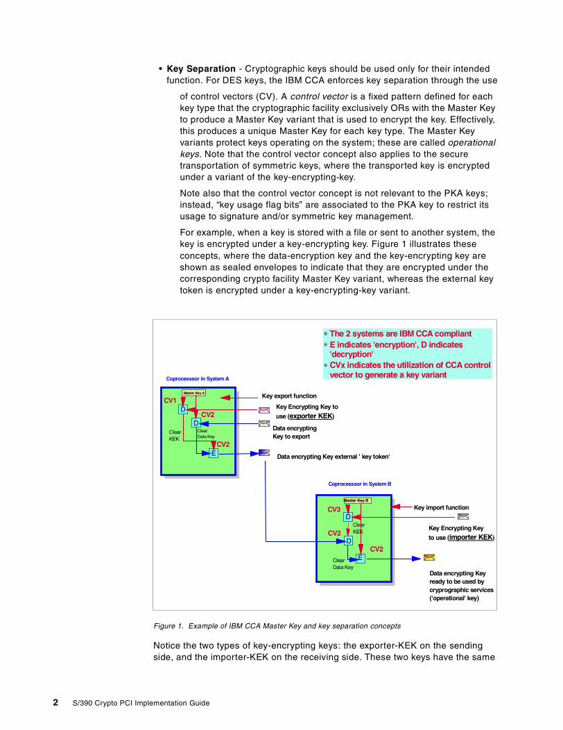
For example, when a key is stored with a file or sent to another system, thekey is encrypted under a key-encrypting key. Figure 1 illustrates theseconcepts, where the data-encryption key and the key-encrypting key areshown as sealed envelopes to indicate that they are encrypted under thecorresponding crypto facility Master Key variant, whereas the external keytoken is encrypted under a key-encrypting-key variant.
Figure 1. Example of IBM CCA Master Key and key separation concepts
Notice the two types of key-encrypting keys: the exporter-KEK on the sendingside, and the importer-KEK on the receiving side. These two keys have the same
Master Key A
Coprocesssor in System A
Key Encrypting Key to
use (exporter KEK)D
DClearData Key
Key export function
Data encryptingKey to export
E Data encrypting Key external ' key token'
ClearKEK
Master Key B
Key Encrypting Key
to use (importer KEK)
D
D
ClearData Key
Key import function
Data encrypting Keyready to be used bycryprographic services('operational' key)
E
ClearKEK
The 2 systems are IBM CCA compliantE indicates 'encryption', D indicates'decryption'CVx indicates the utilization of CCA controlvector to generate a key variant
Coprocesssor in System B
CV1
CV2
CV2
CV3
CV2
CV2
2 S/390 Crypto PCI Implementation Guide
clear value but they have an associated control vector which restricts theirfunction to exportation or importation of other keys.
For more information on the Common Cryptographic Architecture, refer to thefollowing publications:
• Common Cryptographic Architecture: Cryptographic Application ProgrammingInterface Reference, SC40-1675
1.3 Implementation of the CCA key management concepts in S/390
This section describes the concepts underlining CCA key management in S/390.
1.3.1 S/390 Cryptographic Coprocessor Facility (CCF)The S/390 CCF implements three Master Keys:
• The DES Master Key
• The PKA Signature Master Key (SMK)
• The PKA Key Management Master Key (KMMK)
PKA private keys are protected under two layers of DES encryption. They areencrypted under an Object Protection Key (OPK) that in turn is encrypted underthe SMK or KMMK. The OPK is generated for each private key at import time.
1.3.2 S/390 PCI Cryptographic Coprocessor (PCICC)The S/390 PCICC implements two Master Keys:
• The DES Master Key, called the Symmetric Master Key
• The PKA Master Key, called the Asymmetric Master Key
The SMK and KMMK scheme has not been implemented in the PCICC, whichhas a single PKA Master Key. It is required that the PCICC Asymmetric MasterKey has the same value as the CCF SMK, and it is strongly recommended thatyou set the CCF SMK and KMMK to the same value when at least one PCICCcard is also installed in the system.
1.4 S/390 integrated cryptography implementation
IBM led the industry by offering the first CMOS cryptographic coprocessor as astandard feature on the S/390 G4, G5, and G6 servers, and as a priced featureon the G3 server models, in order to meet the increasing needs for data securityand integrity.
The S/390 Cryptographic Coprocessor Facility is implemented in CMOStechnology on a single chip providing more capability than any previouscryptographic offering. Included in the design is battery-backed non-volatilememory storage, laser delete chip personalization, integrated tamper detectionand response, and high speed DES, Triple DES, DSS, RSA, Pseudo RandomNumber Generation, and hashing algorithms. Depending on the system model,there may be one or two coprocessor chips in operation.
Chapter 1. Introduction 3

This hardware runs all current Integrated Cryptographic Feature (ICRF) functionspreviously offered on ES/9000 ® 9021 processors and includes in addition thePublic Key Algorithms (RSA) with digital signature generation and verification.
The software that enables this solution and provides the ApplicationProgramming Interface (API) is a follow-up release of the ICSF/MVS product.This release is integrated into the base of OS/390 Version 2 Release 5. Thisenhanced software release supports new functions built into the chip andcontinues to support all previous ICSF/MVS functions found on prior 9021machines.
OS/390 Version 2 Release 5 also provides support for applications using SETprotocol and Visa/Mastercard CVV/CVC card-verification values including TDESand Double Key MAC. The software supports all the current standards andrequirements, as did the previous versions.
Starting June 2000, the PCI Cryptographic Coprocessor (PCICC) is an orderablefeature that adds additional cryptographic function and cryptographicperformance to G5/G6 servers. Up to 8 PCICC features may be ordered for a G5or G6 server. Each PCICC feature comprises a 4758 Technology-basedcryptographic coprocessor card embedded in an adapter package for installingwithin a G5 or G6 server. Support for PCICC is provided in OS/390 V2R9 by newICSF functions.
The PCI Cryptographic Coprocessor feature coexists and augments CMOS CCFfunctions. ICSF transparently routes application requests for cryptographicservices to one of the integrated cryptographic engines, either a CCCF or aPCICC, depending on performance or requested cryptographic function. Forexample, RSA signature generation and verification operations (with 1024-bit orshorter keys), such as those typically used by SSL, are routed to both CCF andPCICC engines. On the other hand, RSA Key Generation is performed only onPCICC engines.
1.4.1 S/390 integrated cryptography implementationFigure 2 on page 5 provides a very high-level representation of how thecryptographic coprocessors work in S/390 G5 and G6.
4 S/390 Crypto PCI Implementation Guide
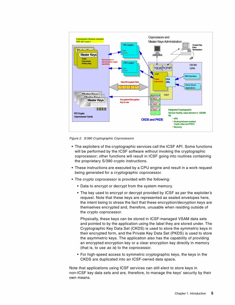
Figure 2. S/390 Cryptographic Coprocessors
• The exploiters of the cryptographic services call the ICSF API. Some functionswill be performed by the ICSF software without invoking the cryptographiccoprocessor; other functions will result in ICSF going into routines containingthe proprietary S/390 crypto instructions.
• These instructions are executed by a CPU engine and result in a work requestbeing generated for a cryptographic coprocessor.
• The crypto coprocessor is provided with the following:
• Data to encrypt or decrypt from the system memory.
• The key used to encrypt or decrypt provided by ICSF as per the exploiter’srequest. Note that these keys are represented as sealed envelopes here,the intent being to stress the fact that these encryption/decryption keys arethemselves encrypted and, therefore, unusable when residing outside ofthe crypto coprocessor.
Physically, these keys can be stored in ICSF-managed VSAM data setsand pointed to by the application using the label they are stored under. TheCryptographic Key Data Set (CKDS) is used to store the symmetric keys intheir encrypted form, and the Private Key Data Set (PKDS) is used to storethe asymmetric keys. The application also has the capability of providingan encrypted encryption key or a clear encryption key directly in memory(that is, to use as is) to the coprocessor.
• For high-speed access to symmetric cryptographic keys, the keys in theCKDS are duplicated into an ICSF-owned data space.
Note that applications using ICSF services can still elect to store keys innon-ICSF key data sets and are, therefore, to manage the keys’ security by theirown means.
Integrated CryptographicService Facility, base element in OS/390R9
APIsRoutingbetweenenabledCryptochipsandPCICCRecovery
ICSF
CCAAPIs
IBMExploiters
HomeGrownApplications
CryptoInstructions
OS/390V2R9
Key A
Key B
Key C
RACF
Clear/Encrypted Data
? ? ? ? ?...
....
CPUengine
CryptoControls
Encryption/Decryptionkey to use
CryptographicModules evaluatedFIPS 140-1 level 4
CPU engine
CryptoControls
Synchronous orasynchronous cryptooperations
CryptoCoprocessorFacility (chip)
Master Keys
CryptoCoprocessorFacility (chip)
Master Keys
PCI CryptoCoprocessor Cards
Master KeysMaster Keys
Master Keys
TSO/ETCP/IP
Trusted KeyEntryWorkstation
Coprocesors andMaster KeysAdministration
CKDSandPKDS
Chapter 1. Introduction 5
The Trusted Key Entry (TKE) Workstation is an optionally-priced feature. Thisworkstation provides a secure, remote, and flexible method of providing MasterKey Part Entry and to remotely manage the cryptographic coprocessors. Thealgorithm utilizes Digital Signature, Diffie-Hellman, and DES functions to providea highly secure, auditable, and remote method of key entry, and it can be used bythose customers requiring very high security for key entry.
Note that a new model of TKE is required to support the PCICC. Differencesbetween this new model and the previous one are described in detail in Chapter5, “Customizing PCICC and CCF using a TKE V3.0”, on page 89.
1.4.2 Enablement of the cryptographic coprocessorsThe S/390 CCF and PCICC are generic cryptographic coprocessors in that theycan run various algorithms with different key lengths. However, to conform toexport regulations, they are shipped non-enabled, meaning that the final user, inthe country of use, needs to enable the coprocessors using diskettes provided byIBM. These diskettes allow activation of the algorithms that the customerrequested and of which use is granted by US and local regulations.
The diskettes need to be loaded only once and are customized so that they loadonly on the user’s machine. The diskettes consist of the following:
• One enablement diskette for the CCFs installed in the system. The LicensedInternal Code (LIC) in this diskette allows the setting of the CCF CryptoConfiguration Controls (CCC) register. This diskette is customized to the CCFchip’s serial number.
• One enablement diskette for the PCICCs installed in the system, for settingthe PCICC Functions Control Vector (FCV). This diskette is customized to themachine’s serial number.
Further details on the cryptographic coprocessors’ enablement are given inChapter 4, “Installation, configuration and startup of ICSF”, on page 55.
1.4.3 LPAR domains and TKEThis section provides an overview of the relationships between logical partitions,physical crypto coprocessors, and domains. It also gives information on defining,controlling and managing these elements.
1.4.3.1 OverviewA cryptographic coprocessor actually has 16 physical sets of Master Keyregisters, each set belonging to a domain. A domain is allocated to a logicalpartition via the definition of the partition in its image profile; the same domainmust also be allocated to the ICSF instance running in the logical partition via theOptions Data Set.
Figure 3 illustrates how logical partitions, physical crypto coprocessors anddomains interact:
6 S/390 Crypto PCI Implementation Guide
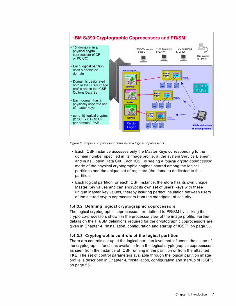
Figure 3. Physical coprocessor domains and logical coprocessors
• Each ICSF instance accesses only the Master Keys corresponding to thedomain number specified in its image profile, at the system Service Element,and in its Option Data Set. Each ICSF is seeing a logical crypto coprocessormade of the physical cryptographic engines shared among the logicalpartitions and the unique set of registers (the domain) dedicated to thispartition.
• Each logical partition, or each ICSF instance, therefore has its own uniqueMaster Key values and can encrypt its own set of users’ keys with theseunique Master Key values, thereby insuring perfect insulation between usersof the shared crypto coprocessors from the standpoint of security.
1.4.3.2 Defining logical cryptographic coprocessorsThe logical cryptographic coprocessors are defined to PR/SM by clicking thecrypto co-processors shown in the processor view of the image profile. Furtherdetails on the PR/SM definitions required for the cryptographic coprocessors aregiven in Chapter 4, “Installation, configuration and startup of ICSF”, on page 55.
1.4.3.3 Cryptographic controls of the logical partitionThere are controls set up at the logical partition level that influence the scope ofthe cryptographic functions available from the logical cryptographic coprocessor,as seen from the instance of ICSF running in the partition or from the attachedTKE. The set of control parameters available through the logical partition imageprofile is described in Chapter 4, “Installation, configuration and startup of ICSF”,on page 55.
IBM S/390 Cryptographic Coprocessors and PR/SM
Physical CryptoCoprocessor
Master Key
DOMAIN 0 LOGICALPARTITION X
OS/390ICSF
OS/390ICSF
LogicalCrypto
DOMAIN 1
Master Key
Master Key
DOMAIN 2
LOGICALPARTITION Y
OS/390ICSF
OS/390ICSF
LogicalCrypto
OS/390ICSF
OS/390ICSF
LogicalCrypto
CryptoEngine
Up to 15LPARs
LOGICALPARTITION Z
CKDSOPTIONSDATASET
CKDS PKDS
CKDSOPTIONSDATASET
CKDS PKDS
CKDSOPTIONSDATASET
CKDS PKDS LPARs definitionsin image profiles
16 'domains' in aphysical cryptocoprocessor (CCFor PCICC)
Each logical partitionuses a dedicateddomain
Domain is designatedboth in the LPAR imageprofile and in the ICSFOptions Data Set
Each domain has aphysically separate setof master keys
up to 10 'logical cryptos'(2 CCF + 8 PCICC)per domain/LPAR
TSO TerminalsLPAR Y
TSO TerminalsLPAR X
TSO TerminalsLPAR Z
TKE coversall LPARs
Chapter 1. Introduction 7
1.4.3.4 Cryptographic services management through the TKEThe Trusted Key Entry (TKE) Workstation provides a centralized control point foradministering the multiple physical or logical crypto coprocessors in a single ormulti-system configuration. The TKE communicates with one OS/390 instancecalled the TKE Host System. If the TKE Host System is a logical partition, severaldomains, corresponding to other partitions in this physical system, can becontrolled from the Master Keys’ administration standpoint by a single TKE. Thisis achieved securely by having the TKE supporting software in the TKE hostissue proprietary calls to the PR/SM microcode for cross-domain Master Keysadministration.
This cross-domain capability is available only when using the TKE Workstation,as opposed to the ICSF ISPF panels. However, ICSF ISPF panels can still beused to administer the local Master Keys, whether a TKE is present in theconfiguration or not.
1.5 Industry standards for cryptographic modules
As the need for computer security grew, the industry needed evaluation criteriafor assessing the logical and physical robustness of cryptographic devices. Toaddress this need, the National Institute of Standards and Technology issued theFederal Information Processing Standard (FIPS) 140-1 standard in June 1994.FIPS 140-1 addresses the security requirements of cryptographic modules, thatis, cryptographic engines, whether in software, firmware or hardwareimplementation.
This standard covers 11 areas related to the design and implementation of acryptographic module. Within most areas, a cryptographic module receives asecurity level rating (1 to 4, from lowest to highest), depending on whatrequirements are met. For other areas that do not provide for different levels ofsecurity, a cryptographic module receives a rating that reflects fulfillment of all ofthe requirements for that area.
Cryptographic modules that comply with this standard employ cryptographicalgorithms, cryptographic key generation algorithms, key distribution techniques,and authentication techniques that have been FIPS-approved for protectingFederal Government unclassified information.
The S/390 CCF hardware single chip cryptographic module has received the thehighest level of FIPS 140-1 (Level 4) certified by both the National Institute ofStandards and Technology (NIST) and the Communications SecurityEstablishment (CSE) of Canada. The FIPS 140-1 certification is under way for theS/390 PCICC, as of the time of writing.
A formal list of all FIPS 140-1 products and their associated certification levelscan be found at:
http://csrc.ncsl.nist.gov/cryptval/140-1/1401val.htm
The S/390 cryptographic coprocessors are physically secure. They provide atamper-sensing and tamper-responding environment fitting the needs of sensitiveapplications. Upon detection of physical attack, including penetration, radiation,voltage, excessive cold or heat, the device is “zeroized” and the sensitiveinformation erased.
8 S/390 Crypto PCI Implementation Guide
Chapter 2. PCICC product overview
This chapter provides an overview of the PCI Cryptographic Coprocessor(PCICC) product provided in the S/390 platform. It briefly describes the IBM 4758Technology as used in the S/390 PCICC implementation, as well as thecryptographic coprocessor enablement concept, the new functions of the ICSFcomponent of OS/390, and the new workstation feature.
2.1 Description of hardware
This section explains IBM 4758 technology and gives an overview of thehardware data flow implemented in the S/390 PCICC facility.
2.1.1 Introduction to the S/390 PCI Cryptographic CoprocessorThe following definitions will introduce you to S/390 PCICC concepts.
Cryptographic Coprocessor Facility (CCF) refers to the CMOS cryptographiccoprocessor feature logic attached to a central processor on S/390 G3, G4, G5,and G6 systems. There are one or two CCFs per system, and each CCF has 16domains which each hold the following set of Master Keys:
• DES Master Key
• PKA KMMK key management MK
• PKA SMK signature MK
Peripheral Component Interconnect Cryptographic Coprocessor (PCICC) -each PCICC feature is built around the IBM 4758 card technology embedded in aSelf-Timed Interface (STI)-attached controller card for installing within a G5 or G6server. The STI-attached controller package allows STI-to-PCI interface busconversion and also provides for PCI controller functions.
From a system implementation perspective, the PCICC unit is an AdjunctProcessor (AP). Note that AP designates the processor, while AP ID specifies thenumber associated with it. The number of APs is limited to 8 on G5/G6, and aPCICC is therefore given an AP number between 0 and 7.
The PCICC has 16 cryptographic domains, each holding a set of the followingMaster Keys:
• One symmetric Master Key (SYM-MK)
• One PKA Master Key (ASYM-MK)
Another concept introduced to S/390 cryptography by the PCICC is the retainedkey, which is an RSA private key generated by the PCICC upon request of theuser. The retained key is kept inside the secure area of the coprocessor and isnever to leave the secure area of the coprocessor. It is therefore physically tied tothe PCICC it has been generated in and is never backed up.
© Copyright IBM Corp. 2000 9

Support for PCICC is provided by OS/390 V2R9 with the new ICSF functions. TheIBM PCI Cryptographic Coprocessor feature coexists with the CCF, but it alsoprovides additional cryptographic processing power as well as additionalcapabilities (such as RSA Key Generation) above and beyond the CCF.
2.1.1.1 PCICC general characteristicsWhen ordered on a G5/G6 system, PCICC is always considered as acomplement to the CCF that is shipped today--in fact, the ICSF software requiresas a prerequisite at least one CCF installed in the CEC in order for the PCICC tobe functional.
The PCICC provides two major advantages over today's Crypto CoprocessorFacility:
1. You can improve cryptographic performance by simply adding more PCICCcards.
2. As a statement of direction, IBM will allow the programmable implementationof different cryptographic algorithms on PCICC (the CCF currently doesn'toffer that capability). This answers the need to quickly implement newcryptographic algorithms generated from the industry.
The S/390 PCICC was announced on 2/29/2000 and will be available for G5 andG6 CMOS models starting 6/30/2000. It uses IBM 4758 technology packaged inan STI-attached controller card (the PCICC card assembly), with a longer batterylife and delivers signals at a different voltage level (3.3 volt) than the IBM 4758-2card. From a functional standpoint, the PCICC assembly also implements theconcept of cryptographic “domains”, which is not relevant to the workstationversion of the 4758 cryptographic coprocessor.
With the introduction of the PCICC into the S/390 G5/G6 systems, the TKEworkstation is enhanced to allow remote administration of the PCICC cards, whilecontinuing to support the CCF. The new TKE workstation includes a 4758-2cryptographic adapter card for its own cryptographic needs, as a replacement tothe former 4755 cryptographic adapter. See Chapter 5, “Customizing PCICC andCCF using a TKE V3.0” on page 89 for details on the utilization of the TKEworkstation.
The PCICC, when plugged in the system, is referred to in three ways:
1. It has an eight-character serial number, for reference in a variety of panelsand to keep track of the retained keys.
2. It has a two-digit Adjunct Processor (AP) number or ID. This number is anindex used by the system LIC and ICSF.
3. Because of the way it is connected in the system, it has a CHPID number.The CHPID number is not known nor relevant to ICSF, but is used forhardware management of the card.
“Nature” of the PCICC
10 S/390 Crypto PCI Implementation Guide
2.1.1.2 STI and CHPID plugging rules overview on G5/G6Two types of STI channel attachments are used to connect the CEC and thesystem’s channels:
• STI non-direct attached adapters for parallel and ESCON channels,Coupling Facility links, and OSA-2 adapters. These adapters require a FastInterface Buffer (FIB) card between the STI and the adapter.
• STI direct attached adapters for FICON, OSA Express, and PCICryptographic Coprocessor feature cards.
The STI attached controller cards plug into existing I/O cage card slots andare directly connected to a high-speed STI link. This direct STI attachmenteliminates the need for an FIB card and increases processing speed. Up tofour STI attached adapters cards can be “chained” together on a single STIlink.
Each PCICC feature card is assigned a CHPID number based on which STI isused and where it appears in the STI chain. Because the CHPID number isattributed to the card, it will no longer be available for normal CHPID use andcannot be used in an IOCDS definition.
Refer to Chapter 3, “Planning” on page 31 for a more detailed explanation of theplugging rules. Also refer to the IBM Configurator output and to the systemdocumentation for accurate STI and CHPID assignments in the system.
2.1.1.3 CCF and PCICC hardware data flow on S/390 G5/G6Figure 4 on page 12 shows a 9672 G5/G6 CPC cage with two CCFs that are twintail-attached to CPs. All the logic elements shown, except for the memory, areinside the multichip module (MCM).
It also shows a 9672 I/O cage with the following components:
• An FIB card used to interface CEC with standard channels through STInon-direct attachment
• Two STI attached controller cards (STI direct attachment) with:
• One PCICC card• One FICON Adapter card holding a FICON card
Chapter 2. PCICC product overview 11
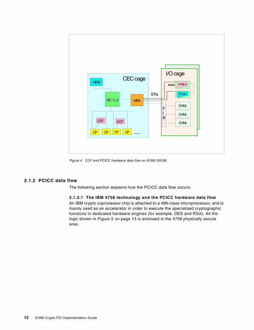
Figure 4. CCF and PCICC hardware data flow on S/390 G5/G6
2.1.2 PCICC data flowThe following section explains how the PCICC data flow occurs.
2.1.2.1 The IBM 4758 technology and the PCICC hardware data flowAn IBM crypto coprocessor chip is attached to a 486-class microprocessor, and ismainly used as an accelerator in order to execute the specialized cryptographicfunctions in dedicated hardware engines (for example, DES and RSA). All thelogic shown in Figure 5 on page 13 is enclosed in the 4758 physically securearea.
MEM
SC / L 2
CP CPCPCP .....
CCF CCF
MBA
CEC cage
STIs
MBAMBA
CHNL
CHNL
CHNL
I/O cage
4758-2
Ficon
PCICC
FIB
12 S/390 Crypto PCI Implementation Guide
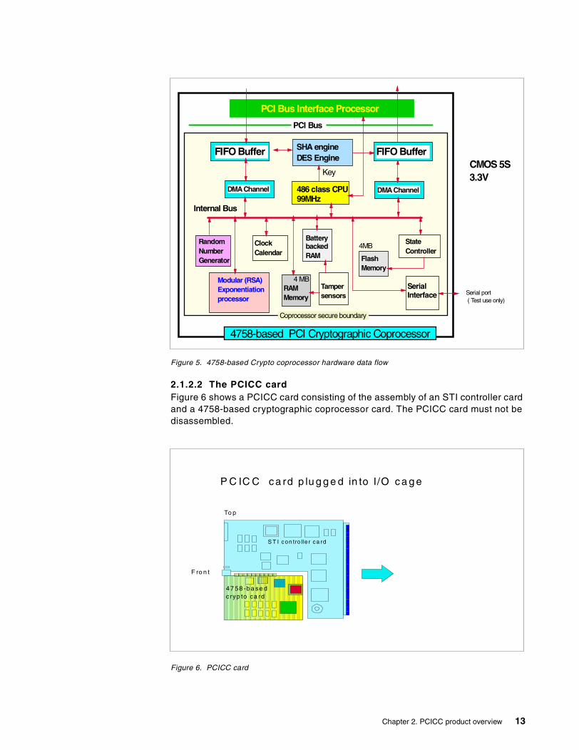
Figure 5. 4758-based Crypto coprocessor hardware data flow
2.1.2.2 The PCICC cardFigure 6 shows a PCICC card consisting of the assembly of an STI controller cardand a 4758-based cryptographic coprocessor card. The PCICC card must not bedisassembled.
Figure 6. PCICC card
PCI Bus Interface Processor
SHA engineDES Engine
FIFO Buffer
486 class CPU99MHz
DMAChannelDMAChannel
RandomNumberGenerator
Modular (RSA)Exponentiationprocessor
FlashMemory
SerialInterface
StateController
ClockCalendar
RAMMemory
BatterybackedRAM
Tampersensors
Coprocessor secure boundary
PCI Bus
Internal Bus
Key
4758-based PCI Cryptographic Coprocessor
4MB
4 MB
Serial port( Test use only)
CMOS 5S3.3V
FIFO Buffer
B o tto m
P C IC C c a rd p lu g g e d in to I/O c a g e
S T I c on tro lle r c a rd
To p
F ro n t
47 58 -ba se dcryp to ca rd
Chapter 2. PCICC product overview 13
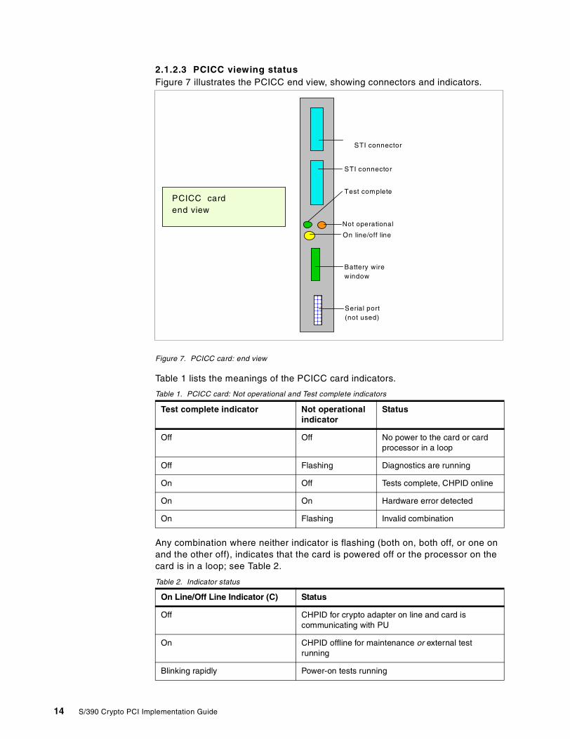
2.1.2.3 PCICC viewing statusFigure 7 illustrates the PCICC end view, showing connectors and indicators.
Figure 7. PCICC card: end view
Table 1 lists the meanings of the PCICC card indicators.
Table 1. PCICC card: Not operational and Test complete indicators
Any combination where neither indicator is flashing (both on, both off, or one onand the other off), indicates that the card is powered off or the processor on thecard is in a loop; see Table 2.
Table 2. Indicator status
Test complete indicator Not operationalindicator
Status
Off Off No power to the card or cardprocessor in a loop
Off Flashing Diagnostics are running
On Off Tests complete, CHPID online
On On Hardware error detected
On Flashing Invalid combination
On Line/Off Line Indicator (C) Status
Off CHPID for crypto adapter on line and card iscommunicating with PU
On CHPID offline for maintenance or external testrunning
Blinking rapidly Power-on tests running
STI connector
Not operational
STI connector
Test complete
Battery wirewindow
Serial port(not used)
On line/off line
PCICC cardend view
14 S/390 Crypto PCI Implementation Guide
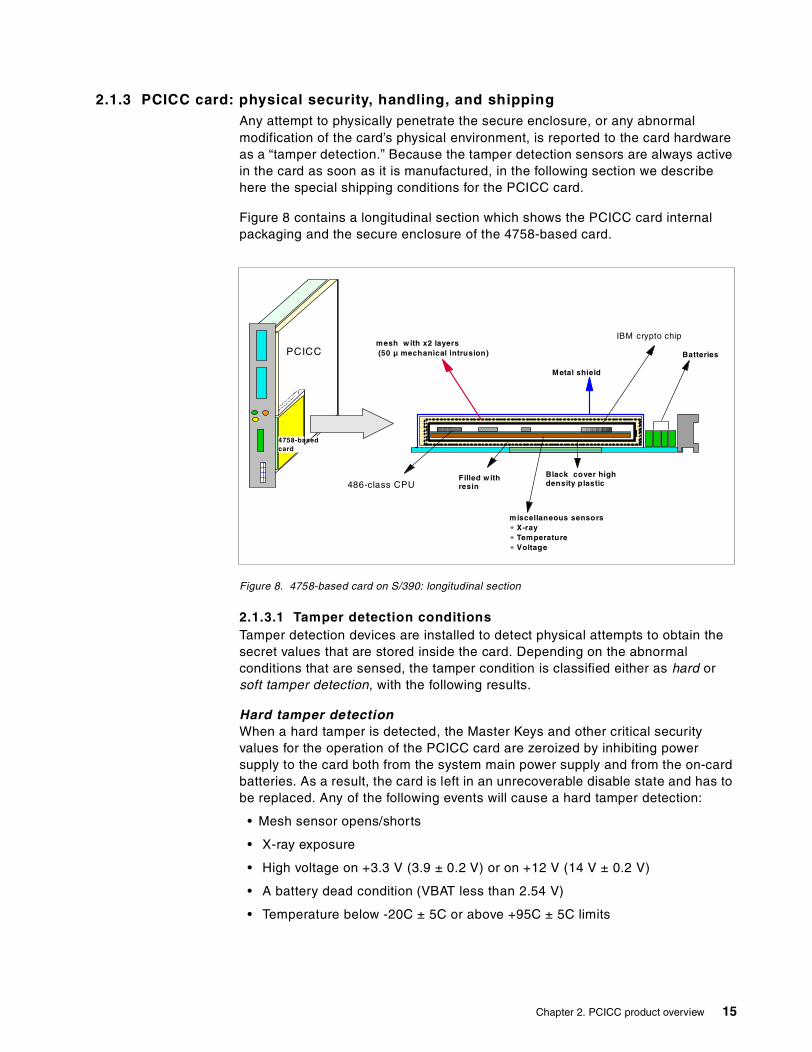
2.1.3 PCICC card: physical security, handling, and shippingAny attempt to physically penetrate the secure enclosure, or any abnormalmodification of the card’s physical environment, is reported to the card hardwareas a “tamper detection.” Because the tamper detection sensors are always activein the card as soon as it is manufactured, in the following section we describehere the special shipping conditions for the PCICC card.
Figure 8 contains a longitudinal section which shows the PCICC card internalpackaging and the secure enclosure of the 4758-based card.
Figure 8. 4758-based card on S/390: longitudinal section
2.1.3.1 Tamper detection conditionsTamper detection devices are installed to detect physical attempts to obtain thesecret values that are stored inside the card. Depending on the abnormalconditions that are sensed, the tamper condition is classified either as hard orsoft tamper detection, with the following results.
Hard tamper detectionWhen a hard tamper is detected, the Master Keys and other critical securityvalues for the operation of the PCICC card are zeroized by inhibiting powersupply to the card both from the system main power supply and from the on-cardbatteries. As a result, the card is left in an unrecoverable disable state and has tobe replaced. Any of the following events will cause a hard tamper detection:
• Mesh sensor opens/shorts
• X-ray exposure
• High voltage on +3.3 V (3.9 ± 0.2 V) or on +12 V (14 V ± 0.2 V)
• A battery dead condition (VBAT less than 2.54 V)
• Temperature below -20C ± 5C or above +95C ± 5C limits
PCICC
4758-basedcard
486-class CPU
mesh w ith x2 layers(50 µ mechanical intrusion)
Black cover highdensity plastic
Metal shield
Filled w ithresin
IBM crypto chip
Batteries
miscellaneous sensorsX-rayTemperatureVoltage
Chapter 2. PCICC product overview 15

Special care should be taken to avoid these environmental conditions during cardshipment. Refer to shipping conditions in 2.1.3.5, “PCICC card shippingconditions” on page 18 for more information.
Soft tamper detectionWhen a soft tamper is detected, the card enters an internal reset state. The cardappears temporarily unavailable to all external requests when in this state. Oncethe soft tamper condition is removed, the internal reset condition is dropped andthe card becomes usable again. The keys and secret values are not zeroized ona soft tamper condition.
Any of the following events will cause an internal card reset:
• Low voltage on +3.3 V (2.9 V ± 0.1 V)
• Low voltage on +12V (10.5 V ± 0.15 V)
• Crypto module internal operating temperature out of window limits(0C±2C/75C± 3C)
• An attempt to load unauthorized code in the PCICC
2.1.3.2 System-detected conditionsEither of these events will cause a warning at the system console issued by thesystem’s licensed internal code. These events are explained in detail in followingsections:
• An intrusion latch trip
• A battery low condition (VBAT less than 2.70 V)
Intrusion latchThe intrusion latch is part of the 4758-based card logic and is used to detectwhen the card is unplugged from the system board. On a subsequent replug, thesecret values in the card will be zeroized. Note the following points:
• When the PCICC card is removed from the system board, the intrusion latch isset.
• The CCA code which runs on the crypto microprocessor checks and resets theintrusion latch at each card power on. The code will zeroize the secret valuesif it finds that the intrusion latch has been set since the last card power on. Ifthe intrusion latch has not been set, the code proceeds with the cardinitialization without zeroizing the secret values.
• The intrusion latch will not be set if the cage is moved and the PCICC remainsplugged into the cage.
16 S/390 Crypto PCI Implementation Guide
A battery low conditionBecause the PCICC card contains enough batteries to last for the expected cardlife (which is 8 to 10 years, under normal usage), a battery low condition shouldnormally not occur. The S/390 licensed internal code monitors the low battery bit,so if this unexpected condition is detected, a timely warning is issued to theoperator.
A service action should then be taken relatively soon to replace the PCICC cardassembly FRU, as the card will likely fail and become permanently disabled intwo to four weeks if the FRU is not replaced.
Note that in this case, the PCICC card must be replaced with a new cardcontaining fresh batteries; the customer will have to be present to reinstall thecryptographic keys in the new card.
2.1.3.3 ZeroizingZeroizing the card results in the following values being rendered permanentlyuseless:
• The SYM-MK and ASYM-MK Master Keys in all domains.
• The users’ retained keys in all domains.
• All the roles and profiles defined. The DEFAULT role is reset to the initial state.Roles and profiles are further explained in 5.3, “TKE application: managing hostCrypto coprocessors” on page 104.
Note that, as for the CCF, you must differentiate coprocessor zeroizing from domainzeroizing. Coprocessor zeroize is either invoked from the system Support Elementcryptographic controls, or is automatically triggered when the card detects duringpower on that the intrusion latch has been set. In contrast, domain zeroize can beinvoked from the TKE workstation only, and has its effects limited to the selecteddomain, as explained in 5.3.5.5, “PCICC notebook DOMAINS page” on page 125.
1. The PCICC card should be pulled out of the system I/O cage only ifnecessary. If the PCICC card is unplugged for any reason (maintenance orCHPID MES upgrades), the customer will have to be present to reinstall thekeys back into the PCICC card.
2. The intrusion latch mechanism will also trigger the card zeroizing if the4758-based card is pulled out of the PCICC assembly and is, for instance,re-installed in a workstation.
3. All retained RSA private keys are permanently lost when the PCICC iszeroized. There is, by definition, no backup capability for a retained key.
Notes
Chapter 2. PCICC product overview 17
2.1.3.4 Cutting the card disable wire loopNormally when a PCICC card is to be returned to IBM due to a hardware problem,an upgrade, or for some other reason, the customer’s keys are zeroized via aSupport Element panel before the card is removed.
To assure customers that keys have actually been destroyed and that the cardhas been disabled before IBM removes it from their premises, the card disablewire loop can be cut by service personnel to ensure destruction of the secretvalues by removing all power to the card. Be aware, though, that cutting this wireloop not only destroys the keys, but also permanently disables the card.
The wire loop can be accessed by removing a sticker on the tailstock of thePCICC card and reaching through a small hole in the tailstock with a pair of wirecutters. This wire loop is white, about a half-inch long, and is erectedperpendicular to the PCICC card printed circuit.
2.1.3.5 PCICC card shipping conditionsThe PCICC card is shipped in such a way that the temperature-sensitive resistersinside the card are not exposed to less than 5 degrees F (-15C). Also the cardshould not be exposed to above 80% humidity, as condensation may causetamper detection circuits to falsely trip. Each PCICC card is shipped in one largethermal container with five pounds of thermal gel inside the container.
2.2 Adjunct Processor (AP) management
In this section, we develop the concept of the Adjunct Processor as implementedin the 9672 G5/G6 and the related system management tasks.
2.2.1 Introduction to Adjunct Processor architectureThe system sees the PCICC as an “Adjunct Processor”, that is, a coprocessorreachable through the STI cable. Therefore, each PCICC card installed in thesystem is assigned an AP number between 0 and 7. The system also establishesthe correspondence between the AP number assigned to a card and this PCICCcard serial number.
There are two buttons in the Support Element panel for zeroizing the PCICC:one button is for zeroizing one individual PCICC card, and the other button isfor zeroizing all installed PCICC cards. Choosing to zeroize all PCICC cardsalso deletes the FCV in HSA. A subsequent attempt to initialize a PCICC cardwill put the card in check stop state, as there is no FCV to be loaded from HSA.
Important
IBM support should not perform this procedure unless the customer requests itbecause Engineering will not be able to perform failure analysis after the wireis cut.
Note
18 S/390 Crypto PCI Implementation Guide
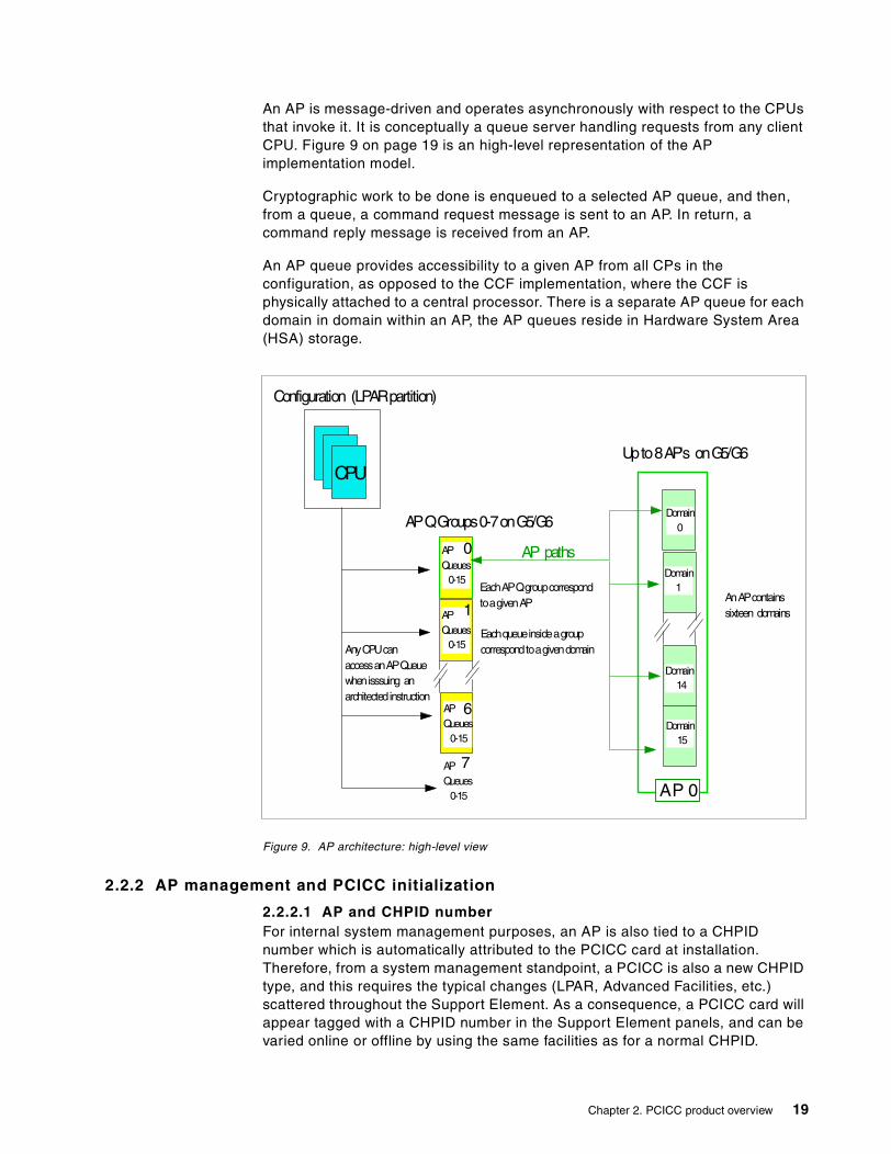
An AP is message-driven and operates asynchronously with respect to the CPUsthat invoke it. It is conceptually a queue server handling requests from any clientCPU. Figure 9 on page 19 is an high-level representation of the APimplementation model.
Cryptographic work to be done is enqueued to a selected AP queue, and then,from a queue, a command request message is sent to an AP. In return, acommand reply message is received from an AP.
An AP queue provides accessibility to a given AP from all CPs in theconfiguration, as opposed to the CCF implementation, where the CCF isphysically attached to a central processor. There is a separate AP queue for eachdomain in domain within an AP, the AP queues reside in Hardware System Area(HSA) storage.
Figure 9. AP architecture: high-level view
2.2.2 AP management and PCICC initialization
2.2.2.1 AP and CHPID numberFor internal system management purposes, an AP is also tied to a CHPIDnumber which is automatically attributed to the PCICC card at installation.Therefore, from a system management standpoint, a PCICC is also a new CHPIDtype, and this requires the typical changes (LPAR, Advanced Facilities, etc.)scattered throughout the Support Element. As a consequence, a PCICC card willappear tagged with a CHPID number in the Support Element panels, and can bevaried online or offline by using the same facilities as for a normal CHPID.
APQueues
0-15
APQueues
0-15
APQueues
0-15
APQueues
0-15
0
7
6
1EachqueueinsideagroupcorrespondtoagivendomainAnyCPUcan
accessanAPQueuewhenisssuing anarchitectedinstruction
Configuration (LPARpartition)
APQGroups0-7onG5/G6
CPU
Domain0
Domain15
Domain14
Domain1
AP 0
Upto8AP's onG5/G6
AnAPcontainssixteen domains
AP paths
EachAPQgroupcorrespondtoagivenAP
Chapter 2. PCICC product overview 19

Note, however, that OS/390 will never see the PCICC as an S/390 CHPID, butonly as an AP.
2.2.2.2 AP number assignmentThe AP number assignment for a newly installed PCICC card is done at systempower-on time or during the PCICC concurrent installation procedure (note thatwe did not practice the concurrent installation process, as it was not available atthe time of this residency). The AP numbers are assigned to the PCICC cards insequence, starting with AP 00. From this point on the AP number is bound to thePCICC card serial number.
At system power-on reset, the following occurs:
• The SE (support element) passes the cryptographic configuration informationto the system Licensed Internal Code (LIC), including the AP IDs-to-CHPIDassignment information.
• The system LIC allocates the Hardware System Area space needed for themaximum possible number of PCICC APs (which is eight), whether they areactually installed or not. This will allow the hotplugging of additional cards inthe future.
Releasing an AP ID--that is, severing the relationship between an AP number andthe PCICC card serial number--can only be done by a manual intervention at thesystem Support Element. This has to be done when replacing the PCICC card, asan AP/PCICC card affinity should not be changed even if card is moved around ina system. 3.3.4, “Removing one PCICC” on page 38 contains an example of APID release.
2.2.2.3 Moving PCICC cardsThe following sections describe how and why PCICC cards can be moved withina system.
Adding a PCI card (hotplugging or powering off)This card addition can take place either while the system is running (hotplugging),or while it is powered off. Note, however, that if the system is powered off, the APassignment will not occur until the system is powered on. The AP assignmentlooks for any unassigned AP IDs and assigns one of them to the newly installedcard.
Moving a PCICC card within a systemA PCICC feature card can be moved in the system (and this may possibly be anMES installation requirement) without changing the AP ID-to-PCICC card serialnumber relationship.
Crypto PCIs will not be defined in an IOCDS. However, if there are CHPIDdefinition conflicts in the IOCDS (that is, if a CHPID is defined in the IOCDSwith a number that matches the CHPID number attributed to the PCICC asper the plugging rules), a system power-on reset will cause both the alreadyIOCDS-defined CHPID and the PCICC to not come online, and an errormessage will be displayed.
Note
20 S/390 Crypto PCI Implementation Guide
To uninstall a PCICC card, IBM service personnel first use the NondestructiveHardware Change icon (in the CPC Configuration task) at the system SupportElement, then the Remove function. Note that this does not free up the AP ID.
Repairing or replacing a PCICC cardIf you repair or replace a PCICC card, the new PCICC card gets assigned thesame AP number as the old card.
Moving a PCICC card between systemsWhen a PCICC card is removed from the system, either by an MES or as theresult of a repair action, service personnel use the AP Manager window on thesystem Support Element and use the Release function to release the AP ID of thecard being removed.
2.3 PCICC microcode load
In the following sections we describe the organization of the firmware in the4758-based PCICC and the related installation and system management tasks.
2.3.1 The IBM 4758 CCA applicationThe IBM 4758 CCA application is a set of firmware which resides in the4758-based card memory. This firmware implements the CCA functions that canbe performed by the card. The CCA application firmware uses the 4758 hardwareengines to perform DES, RSA, and other cryptographic functions. The relatedfunctions are architected according to a requestor/server model where:
• The server is in a secure processing environment coprocessor.
• The major components of the server are a command distributor, commandprocessors, an access control manager, and a Master Key manager.
• The requests, as served by the card, are atomic units of work.
• The coprocessor maintains the state of:
• The Function Control Vector (FCV)• The roles and profiles• The Master Keys and associated registers• The retained keys
The 4758-based card contains firmware to manage its specialized hardware andto control the loading of additional software. The supporting firmware includes theIBM CP/Q++ control program, that is the operating system for the 486 processor,which provides the base for cryptographic application support within the card.The integrity of the card firmware is controlled by digital signature when it isloaded.
The PCICC hardware on G5/G6 supports the secure loading into the PCICCfirmware of user-customized extensions to the cryptographic functions provided.Software support to enable this capability will be provided in a future release ofOS/390: the User Defined Extension (UDX) facility can be used to add customfunctions to the standard CCA command set. Custom functions are executedinside the secure module of the 4758-based card with the same security as theother CCA functions.
Chapter 2. PCICC product overview 21
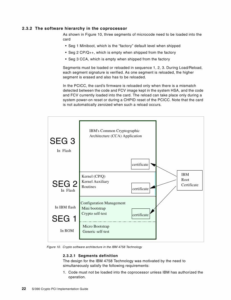
2.3.2 The software hierarchy in the coprocessorAs shown in Figure 10, three segments of microcode need to be loaded into thecard
• Seg 1 Miniboot, which is the “factory” default level when shipped
• Seg 2 CP/Q++, which is empty when shipped from the factory
• Seg 3 CCA, which is empty when shipped from the factory
Segments must be loaded or reloaded in sequence 1, 2, 3. During Load/Reload,each segment signature is verified. As one segment is reloaded, the highersegment is erased and also has to be reloaded.
In the PCICC, the card’s firmware is reloaded only when there is a mismatchdetected between the code and FCV image kept in the system HSA, and the codeand FCV currently loaded into the card. The reload can take place only during asystem power-on reset or during a CHPID reset of the PCICC. Note that the cardis not automatically zeroized when such a reload occurs.
Figure 10. Crypto software architecture in the IBM 4758 Technology
2.3.2.1 Segments definitionThe design for the IBM 4758 Technology was motivated by the need tosimultaneously satisfy the following requirements:
1. Code must not be loaded into the coprocessor unless IBM has authorized theoperation.
Micro BootstrapGeneric self-testIn ROM
Configuration ManagementMini bootstrapCrypto self-test certificate
certificate
Kernel (CP/Q)Kernel AuxiliaryRoutines
certificate
IBM's Common CryptographicArchitecture (CCA) Application
In IBM flash
In Flash
IBMRootCertificate
In Flash
SEG 3
SEG 2
SEG 1
22 S/390 Crypto PCI Implementation Guide
2. Once loaded into the coprocessor, the code must not run or accumulate stateunless the environment in which it runs is trustworthy.
3. Agents outside the coprocessor that interact with code running on thecoprocessor must be able to verify that the code is legitimate and that thecoprocessor is authentic and has not been tampered with.
4. The shipment and configuration of coprocessors, their maintenance, andupgrades to the code inside a coprocessor must not require trusted couriers orsecurity officers.
To satisfy these requirements, the card design defines four “segments”:
• Segment 0 is in ROM and contains one portion of “Miniboot”. Miniboot0 is themost privileged software in the coprocessor and, among other things, runs abasic health test of the card and securely loads segment 1, if needed.
• Segment 1 is in flash memory and contains the other portion of “Miniboot”.The division of Miniboot into a ROM portion and a Flash portion preservesflexibility (the Flash portion can be changed if necessary), while guaranteeinga basic level of security implemented in the unmodified ROM portion.
Miniboot 1 runs a more extensive health test (POST) on the card and securelyloads segment 1 (itself), segment 2, and segment 3, if required.
• Segment 2 is in flash memory and contains the 486 operating system with thedevice drivers that are used to control the cryptographic engines and the PCIbus interface.
• Segment 3 is in flash memory and contains the CCA applications.
Detailed information on the 4758 Technology code segments concepts andmechanisms can be found at the IBM 4758 PCI Cryptographic Coprocessor site:
http://www.ibm.com/security/cryptocards
You then click the Library link.
2.3.2.2 Code-Signing Key HierarchyThe code-signing key hierarchy consists of a pair of asymmetric keys assigned toeach segment, the principle being that segment level n verifies the signature ofsegment level n+1 contents and associated information. This mechanism is usedto guarantee both the integrity of the code executed inside the coprocessor, andthat the code is executed on an identified and known coprocessor.
2.3.3 PCICC microcode patchesYou can patch PCICC code, when necessary, by using the standard microcodechange process (MCL). The microcode changes can affect the 4758-based cardmicrocode itself and/or the STI adapter and controller unit in the PCICC. Suchchanges are not expected to be disruptive to the system, because activating apatch requires you to reset the PCICC, which makes it only temporarilyunavailable to the applications.
As usual, patch apply is concurrent whenever possible. In some special cases,when both the 4758-based card and the STI controller need a microcode update,then the patch is flagged as disruptive and can only be applied with a POR.
Chapter 2. PCICC product overview 23
Segments 1 to 3 of the PCICC can be Licenced Internal Code (LIC)-updatedthrough the MCL process.
2.3.4 Function Control Vector (FCV) enablementThis section briefly describes the PCICC enablement concept using the FCVdiskette. The diskette must be ordered from IBM and installed either by thecustomer or by IBM service.
As for the CCF enablement diskette, it is intended to enable the cryptographiccapabilities of the device while still meeting export and country of use regulations.3.2, “Feature codes” on page 31 provides information about the feature codespertaining to the PCICC FCV diskette.
2.3.4.1 Enablement of the CCFSince its original implementation on G3 systems, the CCF Crypto ConfigurationControl (CCC) bits are set according to a Crypto configuration file installed on thesystem Support Element hard disk. The CCC bits dictate to the CCF hardwarewhich algorithms and key lengths are enabled. The system is shipped out ofmanufacturing with the CCF CCC bits reset.
The Crypto configuration files are installed by “importing” to the Support Elementhard disk the contents of the Crypto Enablement Diskette obtained from IBM. TheCCF CCC bits will be set during the system Power-on reset which follows, if theimported file has been selected by the “Select for Next Activation” option on theSupport Element.
If the CCF was already enabled and if the just-imported diskette corresponds to anew CCC bits configuration, then the system power-on reset will set the newvalue in the CCC bits but will also zeroize the CCF (that is, Master Keys andauthorities will have to be entered again).
Each Crypto configuration file is unique and intended for a specific CCF CryptoModule ID (CMID), which is the number that uniquely identifies a CCF chip. Inpractice, there is a CCF enablement diskette per system that contains theconfiguration files applying to the two CCF chips installed on that system.
2.3.4.2 Enablement of the PCICCThe equivalent PCICC configuration value is known as the Function ControlVector (FCV). Note that an FCV is not unique to each PCICC, but it is unique tothe S/390 machine serial number.
The FCV is delivered on a diskette. Because it is specific to the machine serialnumber, it is common to all PCICC cards installed in this system. As aconsequence, there is no need to import a new FCV during a PCICC repair orwhen installing an additional PCICC. As a matter of fact, in contrast to the CCF, aspare PCICC card from the stock will not come with an FCV diskette.
The FCV enablement processThe FCV enablement process consists of the following steps:
1. The Import FCV function at the Support Element copies the PCICC Cryptoconfiguration files to the Support Element hard disk.
24 S/390 Crypto PCI Implementation Guide
2. The FCV is then uploaded into the system Hardware System Area (HSA),either as a result of a system power-on reset, or by an option named LoadFCV to HSA Immediately at the Support Element.
3. The FCV is downloaded from the HSA into the PCICC cards as a result ofeither a system power-on reset or of a CHPID reset (that is, by varying aCHPID offline, then online, at the Support Element).
4.2.2, “Import FCV” on page 56 provides more details on PCICC enablementoperations.
2.4 OS/390 2.9 and the Integrated Cryptographic Services Facility (ICSF)
This section contains a brief description of the changes implemented in OS/3902.9 and its Integrated Cryptographic Service Facility (ICSF) component tosupport the PCICC and the new version of the TKE workstation.
2.4.1 OS/390 2.9 support for PCICCOS/390 2.9 provides for the support of the PCI Crypto coprocessor in two ways:
1. The IO Supervisor functions have been enhanced to detect and report thechange in card condition when the card is being varied online from theSupport Element menu.
2. ICSF 2.3 is part of the OS/390 2.9 base. ICSF 2.3 provides the functionsrequired to support the PCI Crypto Coprocessor (PCICC) along with theCrypto Coprocessor Facility (CCF) chip. It also provides the software piecerequired to establish connectivity between the TKE and the Cryptocoprocessors via TCP/IP protocol.
Note that, starting with OS/390 2.4, ICSF is an OS/390 “exclusive” product,meaning that it cannot be delivered outside of the base OS/390; thereforeICSF 2.3 should be referred to externally as OS/390 2.9 ICSF in order to avoidany confusion.
2.4.2 ICSF overviewICSF provides support for the following:
• The Commercial Data Masking Facility (CDMF), an exportable version of DEScryptography
• DES and Triple DES encryption for privacy
• The transport of data keys through the use of the Rivest-Shamir-Adelman(RSA) public key algorithm
1. Installed PCICC cards go into a check stop state if there is no FCV in HSAwhen performing a system power-on reset or a CHPID reset.
2. Replacing an existing FCV with a new one can only be done by a systempower-on reset. The PCICC card is not zeroized as a consequence ofreplacing the FCV.
Important
Chapter 2. PCICC product overview 25

• The generation and verification of digital signatures through the use of boththe RSA and the Digital Signature Standard (DSS) algorithm
• The generation of RSA and DSS key.
• The SET Secure Electronic Transaction standard, which was created by VisaInternational and MasterCard
• The PKA Encrypt and PKA Decrypt callable services that can be used toenhance the security and performance of Secure Sockets Layer (SSL)security protocol applications
2.4.2.1 ICSF 2.3ICSF 2.3 contains FMID HCRP230 (product 5647-A01) and supports both theCCF and the PCI CC in terms of providing cryptographic services to therequesting applications; providing device specific management facilities;providing routing to the best fit device (that is, either the Crypto chip or the PCIcard, based on the requested service and/or an attempt to balance thecryptographic workload between the installed coprocessors).
As with previous releases, ICSF provides an interface to manage thecryptographic coprocessors via TSO/E ISPF panels and/or the TKE applicationmenus. The TKE application menus are discussed in 5.3, “TKE application:managing host Crypto coprocessors” on page 104.
Among the new ICSF ISPF panels, the PCICC management panel allows you todo the following:
• Display the state of PCICCs• Online/Offline• Active• Temporarily Unavailable• Deactivated• Hardware Error detected• Unknown
• Deactivate a PCICC• Activate a PCICC
2.4.2.2 Managing Master KeysThere are new hardware status panels to display detailed status and verificationpatterns of the PCI Crypto coprocessor Master Key registers. The display isprovided for all PCICCs or for each PCICC individually, and the panels allow youto enter Master Keys again for all PCICCs or for each PCICC individually.The format and structure of the panels are the same as for the CCFs, with twocoprocessors per panel.
2.4.2.3 Enhanced Pass Phrase InitializationUsing Pass Phrase Initialization is an easy way to initialize Master Keys (both forDES and PKA Master Keys) and the Cryptographic Key Data Set (CKDS) for thefirst time: by having the user enter a pass phrase, the system will automaticallygenerate related Master Key values (both for the DES and the PKA Master Keys).It will also install them in the CCFs and initialize the target empty CKDS with thejust-generated DES Master Key.
Pass phrase initialization at OS/390 2.9 is extended to install Master Keys for allonline PCICCs. Furthermore, as new PCICCs are installed, the Pass Phrase can
26 S/390 Crypto PCI Implementation Guide

also be used to initialize the new PCICCs (the same Pass Phrase yields the samekey value).
Pass Phrase Initialization offers the option of setting the CCF SMK equal toKMMK, which is the recommended option when PCICCs are in operation in thesystem.
2.4.2.4 RSA key token changeA new private key section, with identifier X'08', is now available for internal andexternal key tokens. This is the optimized Chinese Remainder Theorem form ofthe private key, which yields better performance than the Modulus-Exponent (ME)tokens for modulus of the same length. The supported modulus bit length is 512to 2048.
Note: CRT tokens are only usable by the PCICC.
A new ME form of the private key internal token, X'06', can be used on CCF orPCICC. This new form is intended for compatibility purpose with the existing 4758applications. The supported modulus bit length is 512 to 1024.
The current external form of the private key token, X'02', is left unchanged, andcan be converted to the X’06’ form through re-import of the token on a systemwith PCICC.
The Symmetric Key Generate/Export/Import and the PKA Encrypt/Decryptservices allow you to specify a new RSA key usage indicator in the rules array:KM-ONLY. This keyword indicates that the key may only be used for keydistribution functions and not for digital signatures.
2.4.2.5 Retained keys supportRetained keys are generated in a PCICC and the private key never appearsoutside the secure hardware in any form. The public key token of the retained keyis written to the Public Key Data Set (PKDS) with the serial number of the PCICCthat contains the private key. A retained key may only be used from the samedomain it was created in, and applications that use the retained key will fail if thespecific PCICC is not online.
A request for retained key generation is routed by ICSF to any ACTIVE PCICC.Two new services are made available for retained key management: RetainedKey Delete (CSNDRKD) and Retained Key List (CSNDRKL).
2.4.2.6 Routing work between CCF and PCICCThe routing of work between CCF and PCICC is based on the following criteria:
• The functional capability required for the requested service.• The best performance in accomplishing the requested service.• The best security environment provided when performing the service.
Functional capabilitiesThe following functions use the PCICC:
• Utilization of CRT tokens• Utilization of retained keys• RSA key generation
The following functions use the CCF:
Chapter 2. PCICC product overview 27
• Utilization of the Digital Signature Standard (DSS)• Utilization of the existing ME X'02' tokens
Considerations for performanceThe following existing synchronous CCF functions perform considerably faster onCCF:
• DES, MAC, and the hashing function• PIN functions• DES key management functions
Public key operations which perform considerably better on CCF are DigitalSignature Verify and PKA Encrypt.
Considerations for securityThe functions Set Block Compose/Decompose and Symmetric KeyGenerate/Export/Import, as implemented with the CCF, allow the symmetric DESkey to be briefly exposed in storage.
In contrast, the PCICC implementation of these functions keeps the symmetricDES keys in the coprocessor secure area at all times.
Where function, performance, or security are not issues (such as with DigitalSignature Generate and PKA Decrypt), calls will be routed to CCFs or PCICCsusing the ICSF internal work balancing algorithm.
2.4.2.7 Enhanced callable servicesThe following PKA services have been enhanced to take into account the newCRT form tokens and the preferred coprocessor type to execute these services..
• PKA Key Generate (CSNDPKG)• PKA Key Token Build (CSNDPKB)• PKA Key Import (CSNDPKI)• PKA Public Key Extract (CSNDPKX)• Digital Signature Generate (CSNDDSG)• Symmetric Key Generate (CSNDSYG)• Symmetric Key Export (CSNDSYX)• Symmetric Key Import (CSNDSYI)• Set Block Compose (CSNDSBC)• Set Block Decompose (CSNDSBD)• PKA Encrypt (CSNDPKE)• PKA Decrypt (CSNDPKD)• PKDS Record Create (CSNDKRC)• PKDS Record Delete (CSNDKRD)• PKDS Record Write (CSNDKRW)
These services are documented in OS/390 ICSF Application Programmer’sGuide, SC23-3976. A high-level overview of these enhancements is provided inAppendix B, “Support functions: ICSF services” on page 141.
For maximum flexibility, the CCF Signature Master Key (SMK) should be thesame as the Key Management Master Key (KMMK).
Note
28 S/390 Crypto PCI Implementation Guide
2.4.2.8 New callable servicesThe following new PKA services have been implemented to take into account thespecific capabilities of the PCICC.
• Retained Key Delete (CSNDRKD)• Retained Key List (CSNDRKL)• PCI Interface Service (CSFPCI) - this service is the equivalent, for the PCICC,
of the Public Key Secure Cable (PKSC) service that is used for securecommunication between the CCF and the TKE. As for the PKSC service,PCICC is not intended to be documented to ICSF users.
These services are documented in OS/390 ICSF Application Programmer’sGuide, SC23-3976. A high-level overview of these new services is provided inAppendix B, “Support functions: ICSF services” on page 141.
2.4.2.9 ICSF/TSS Reason code conversion optionICSF and TSS have consistent API for callable services. Their return codes areconsistent, but the reason codes are mostly specific to either one of them. Thereis a reason code conversion option available via new variables in the OptionsData Set:
• REASONCODE(ICSF) is the default option. It indicates that all reason codesreturned by the callable services abide with the reason code valuesdesignated for ICSF.
• REASONCODE(TSS) indicates that the reason codes returned by the callableservices match the TSS reason codes. This option is intended to facilitate themigration of TSS applications onto S/390.
Note: There is no one-to-one correspondence between ICSF and TSS reasoncodes; in fact, there is often a one-to-many or many-to-one relationship, or theremay be no correspondence at all.
Keep this in mind when using REASONCODE(TSS); you may have to modify themigrated applications so they will properly handle ambiguous results.
2.4.2.10 System symbol recognitionICSF 2.3 supports system symbol recognition in the Installation Options Data Setparameters. This allows customers to manage multiple LPARs or systems usingthe same options data set and one startup procedure.
The logical records of the options data set are echoed into the diagnostic data setCSFLIST in the startup procedure. Each record is listed before and after symbolsubstitution. Therefore, the CSFLIST must not be shared between ICSFinstances.
2.4.3 New SMF Record Type 82 subtypesThis release also includes support for the following new subtypes for SMF RecordType 82:
• Subtype 14 – PCI Cryptographic Coprocessor Clear Master Key Entry
• Subtype 15 – PCI Cryptographic Coprocessor Retained Key Create/DeleteSubtype 16 – PCI Cryptographic Coprocessor TKE
• Subtype 17 – PCI Cryptographic Coprocessor Timing
Chapter 2. PCICC product overview 29
• Subtype 18 – PCI Cryptographic Coprocessor Configuration
2.4.4 The new TKE workstation (TKE V3.0)A new TKE workstation version (TKE V3.0) is required to support the PCICC.Details are provided in Chapter 5, “Customizing PCICC and CCF using a TKEV3.0” on page 89.
You can check your current TKE level; it is briefly displayed at the bottom of thescreen when the TKE application starts.
1. TKE V3.0 communicates with the OS/390 host using TCP/IP.
2. It uses a 4758-2 cryptographic adapter card.
3. The Key Transfer function, which enabled the secure extraction of a MasterKey from one system and its transfer to another system, is no longeravailable.
4. The TKE V3.0 does not support a smart card reader, as of the writing of thisbook.
5. The previous TKE versions are not upgradable to the new TKE V3.0.
Notes
30 S/390 Crypto PCI Implementation Guide
Chapter 3. Planning
In this chapter we describe the hardware requirements when installing thePCICC, as well as the feature codes you should order and the 9672 pluggingrules.
3.1 Hardware requirements
The hardware requirements for PCICC installation are as follows:
• The PCICC is only supported by 9672 G5, G6, and follow-on systems.
• The maximum number of PCI Cards that can be installed in a 9672 G5 orG6 is eight.
• The 9672 minimum LIC level required is Driver 26.
• The PCICC cannot operate if the CCF itself is not enabled and inoperation.
• The HSA space consumed by the PCICC is 14.5 MB. This value isindependent of the number of installed cards.
IBM Customer Engineers are responsible for installing the hardware byfollowing the Installation Instructions that are generated for a specific systemserial number. These instructions describe the card movements which maybe required on the specific system to perform the PCICC card installation,and they are therefore dependent on the accuracy of the systemconfiguration as recorded in the IBM Vital Product Data (VPD) database.
3.2 Feature codes
Figure 11 on page 33 summarizes the CCF and PCICC feature codes. Notethe following points:
• Because CCF enablement is a prerequisite to the installation of a PCICC,the feature codes 0814, 0815, 0834, or 0835 must have been ordered andinstalled. These are the features corresponding to the CCF enablementdiskette, as the CCF hardware feature (0800) is standard on G4 systemsand above.
• The TKE enablement feature pertains only to the CCF feature codes. TKEenablement is specified by ordering CCF feature code 0815 or 0835.
• The TKE hardware itself (TKE V3.0) is orderable by selecting the featurecode 0866 (TKE workstation with a token ring adapter), or the featurecode 0869 (TKE workstation with an ethernet adapter).
© Copyright IBM Corp. 2000 31

• As of the time of writing, a Security Interface Unit (SIU) is not proposed forattachment to the TKE V3.0.
• Each PCICC card to be installed in the system has feature code 0860.
• The PCICC enablement diskette (FCV) is orderable by using the featurecode 0864 (DES with PKA) or 0865 (T-DES with PKA). This feature codemust also match the encryption strength ordered for the CCF. As alreadymentioned, there is no PCICC feature code pertaining to the TKEenablement. Also, you only order the feature code once, since a singleFCV diskette covers all possible PCICC cards in a given system serialnumber.
In Figure 11 on page 33, the valid feature codes for a 9672 G5 or G6 areinside the box marked with a double asterisk (**). For example, for a PCICCcard enabled for T-DES and managed by a TKE, the following feature codeshave to be ordered:
• 0865• 0866 or 0869• 0860
32 S/390 Crypto PCI Implementation Guide
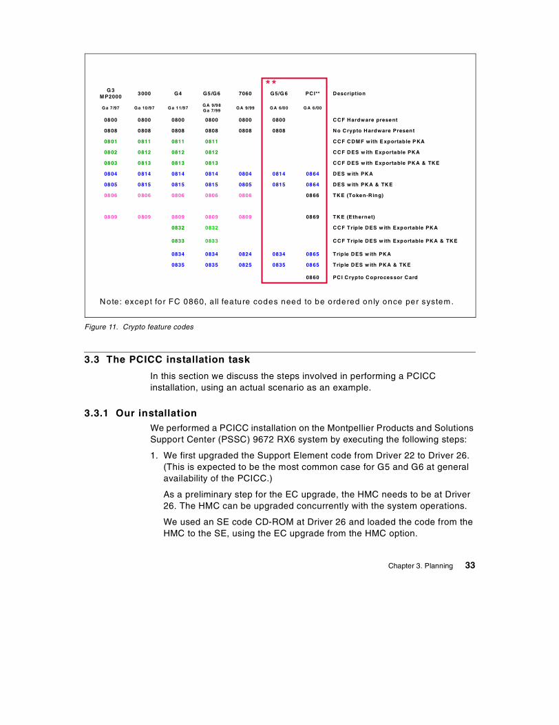
Figure 11. Crypto feature codes
3.3 The PCICC installation task
In this section we discuss the steps involved in performing a PCICCinstallation, using an actual scenario as an example.
3.3.1 Our installationWe performed a PCICC installation on the Montpellier Products and SolutionsSupport Center (PSSC) 9672 RX6 system by executing the following steps:
1. We first upgraded the Support Element code from Driver 22 to Driver 26.(This is expected to be the most common case for G5 and G6 at generalavailability of the PCICC.)
As a preliminary step for the EC upgrade, the HMC needs to be at Driver26. The HMC can be upgraded concurrently with the system operations.
We used an SE code CD-ROM at Driver 26 and loaded the code from theHMC to the SE, using the EC upgrade from the HMC option.
G 3M P2000
3000 G4 G5/G6 7060 G5/G 6 PCI** Description
G a 7/97 G a 10/97 G a 11/97G A 9/98G a 7/99
G A 9/99 G A 6/00 G A 6/00
0800 0800 0800 0800 0800 0800 CCF Hardware present
0808 0808 0808 0808 0808 0808 No Crypto Hardware Present
0801 0811 0811 0811 CCF CDM F with E xportable P KA
0802 0812 0812 0812 CCF DES w ith Exportable PKA
0803 0813 0813 0813 CCF DES w ith Exportable PKA & TKE
0804 0814 0814 0814 0804 0814 0864 DES w ith PKA
0805 0815 0815 0815 0805 0815 0864 DES w ith PKA & TKE
0806 0806 0806 0806 0806 0866 TKE (Token-R ing)
0809 0809 0809 0809 0809 0869 TKE (Ethernet)
0832 0832 CCF Triple DES w ith Exportable PKA
0833 0833 CCF Triple DES w ith Exportable PKA & TKE
0834 0834 0824 0834 0865 Triple DES w ith PKA
0835 0835 0825 0835 0865 Triple DES w ith PKA & TKE
0860 PCI Crypto Coprocessor Card
**
Note: except for FC 0860, a ll feature codes need to be ordered only once per system.
Chapter 3. Planning 33
Note: Driver 26 installation on the SE is disruptive for the system.
2. We obtained the latest MCLs, then installed and activated them. In mostcases these MCLs are pre-pulled into a Service Update Level - Read OnlyCartridge (SUL-ROC).
3. We then verified that the correct CCF cryptographic configuration hadbeen enabled by using the Cryptographic Coprocessor Configuration iconon the SE.
In our case we wanted to install PCICC feature code 0865, which requiredCCF feature code 0835 (as we also intended to use the TKE). The CCFfeature code was actually 0812, so we had to get and import a CCFenablement diskette with feature code 0835. The enablement wascompleted by a system power-on reset.
All the SE-related tasks are described in Support Element OperationsGuide, GC38-0608.
4. At the time of our residency, there was no concurrent plug capability forthe PCICC card; therefore, we installed our PCICC MES with the systembeing powered off. We installed the PCICC card at a pre-defined locationas indicated in the MES Installation Instructions, where the configuratorCFREPORT/CHPID REPORT outputs are given. The STI cable was alsoplugged in according to the locations given by the MES InstallationInstructions.
Refer to Figure 12 on page 35 for the CFREPORT/CHPID REPORT thatwas produced for our system.
5. We imported the FCV diskette and selected the FCV at the SE. Thisenabled the PCICC cryptographic functions at the following power-onreset.
6. We then updated the image profiles of the logical partitions that neededaccess to the cryptographic coprocessors. 4.3, “LPAR setup” on page 61provides further details on how to set up the logical partition imageprofiles.
7. The system was activated.
34 S/390 Crypto PCI Implementation Guide
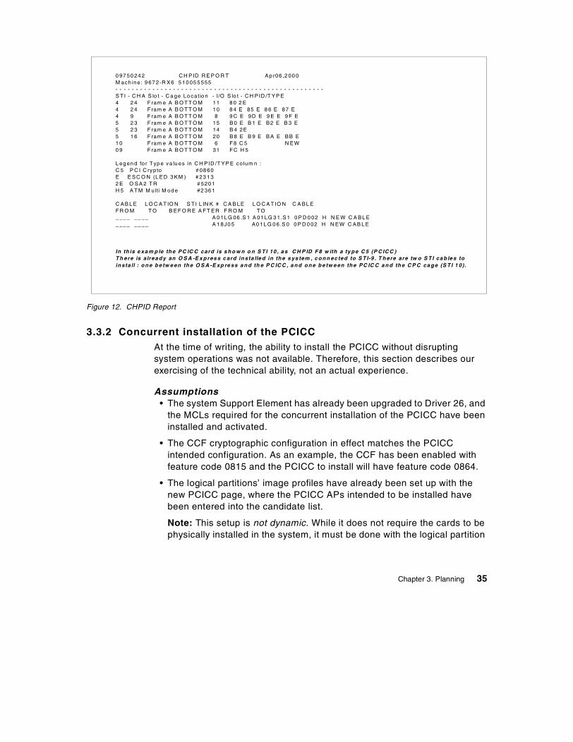
Figure 12. CHPID Report
3.3.2 Concurrent installation of the PCICCAt the time of writing, the ability to install the PCICC without disruptingsystem operations was not available. Therefore, this section describes ourexercising of the technical ability, not an actual experience.
Assumptions• The system Support Element has already been upgraded to Driver 26, and
the MCLs required for the concurrent installation of the PCICC have beeninstalled and activated.
• The CCF cryptographic configuration in effect matches the PCICCintended configuration. As an example, the CCF has been enabled withfeature code 0815 and the PCICC to install will have feature code 0864.
• The logical partitions’ image profiles have already been set up with thenew PCICC page, where the PCICC APs intended to be installed havebeen entered into the candidate list.
Note: This setup is not dynamic. While it does not require the cards to bephysically installed in the system, it must be done with the logical partition
0 97 50 24 2 C H P ID R E P O R T Ap r06 ,2 00 0M ach ine : 9 67 2-R X6 5 10 05 5 555- - - - - - - - - - - - - - - - - - - - - - - - - - - - - - - - - - - - - - - - - - - - - - - - - - -S T I - C H A S lo t - C a ge Lo cat io n - I/O S lo t - C H PID /T YP E4 2 4 F ram e A B O T T O M 11 8 0 2 E4 2 4 F ram e A B O T T O M 10 8 4 E 85 E 8 6 E 87 E4 9 F ram e A B O T T O M 8 9 C E 9D E 9 E E 9 F E5 2 3 F ram e A B O T T O M 15 B 0 E B 1 E B2 E B 3 E5 2 3 F ram e A B O T T O M 14 B 4 2E5 1 6 F ram e A B O T T O M 20 B 8 E B 9 E BA E BB E1 0 F ram e A B O T T O M 6 F 8 C 5 N EW0 9 F ram e A B O T T O M 31 F C H 5
L eg en d for T yp e va lu es in C H PID /T YP E co lum n :C 5 P C I C ryp to # 08 60E E SC O N (L ED 3 KM ) # 23 1 32 E O SA 2 T R # 520 1H 5 A T M M ulti M od e #2 36 1
C AB L E L O C A T IO N S T I L IN K # C A B LE L O C A T IO N C A BL EF R O M T O B EF O R E A F T ER F R O M T O_ __ _ __ __ A 0 1L G 06 .S 1 A 01 LG 3 1.S1 0 P D 0 02 H N E W C A BL E_ __ _ __ __ A 1 8J0 5 A0 1L G 0 6.S 0 0 P D 0 02 H N EW C AB L E
In th is e xa m p le th e PC IC C card is s h o w n o n S T I 10 , a s C H P ID F 8 w ith a ty p e C 5 (P C IC C )T h ere is a lrea d y an O S A -E x p res s c ard in sta lle d in th e s ys tem , c o n n ec ted to S T I-9 . T h ere are tw o S T I ca b le s toin sta ll : o n e b e tw e en th e O S A -E xp re ss a n d th e P C IC C , a n d o n e b e tw e en th e PC IC C a n d th e C P C ca g e (S T I 1 0).
Chapter 3. Planning 35
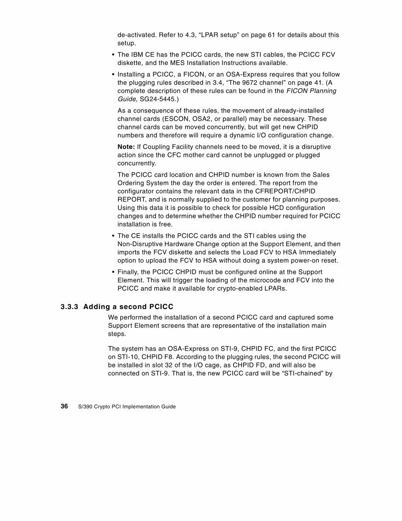
de-activated. Refer to 4.3, “LPAR setup” on page 61 for details about thissetup.
• The IBM CE has the PCICC cards, the new STI cables, the PCICC FCVdiskette, and the MES Installation Instructions available.
• Installing a PCICC, a FICON, or an OSA-Express requires that you followthe plugging rules described in 3.4, “The 9672 channel” on page 41. (Acomplete description of these rules can be found in the FICON PlanningGuide, SG24-5445.)
As a consequence of these rules, the movement of already-installedchannel cards (ESCON, OSA2, or parallel) may be necessary. Thesechannel cards can be moved concurrently, but will get new CHPIDnumbers and therefore will require a dynamic I/O configuration change.
Note: If Coupling Facility channels need to be moved, it is a disruptiveaction since the CFC mother card cannot be unplugged or pluggedconcurrently.
The PCICC card location and CHPID number is known from the SalesOrdering System the day the order is entered. The report from theconfigurator contains the relevant data in the CFREPORT/CHPIDREPORT, and is normally supplied to the customer for planning purposes.Using this data it is possible to check for possible HCD configurationchanges and to determine whether the CHPID number required for PCICCinstallation is free.
• The CE installs the PCICC cards and the STI cables using theNon-Disruptive Hardware Change option at the Support Element, and thenimports the FCV diskette and selects the Load FCV to HSA Immediatelyoption to upload the FCV to HSA without doing a system power-on reset.
• Finally, the PCICC CHPID must be configured online at the SupportElement. This will trigger the loading of the microcode and FCV into thePCICC and make it available for crypto-enabled LPARs.
3.3.3 Adding a second PCICCWe performed the installation of a second PCICC card and captured someSupport Element screens that are representative of the installation mainsteps.
The system has an OSA-Express on STI-9, CHPID FC, and the first PCICCon STI-10, CHPID F8. According to the plugging rules, the second PCICC willbe installed in slot 32 of the I/O cage, as CHPID FD, and will also beconnected on STI-9. That is, the new PCICC card will be “STI-chained” by
36 S/390 Crypto PCI Implementation Guide
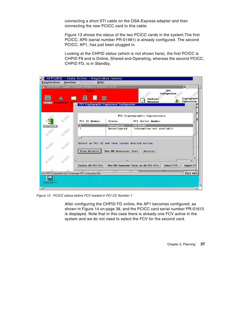
connecting a short STI cable on the OSA-Express adapter and thenconnecting the new PCICC card to this cable.
Figure 13 shows the status of the two PCICC cards in the system.The firstPCICC, AP0 (serial number PR-01481) is already configured. The secondPCICC, AP1, has just been plugged in.
Looking at the CHPID status (which is not shown here), the first PCICC isCHPID F8 and is Online, Shared and Operating, whereas the second PCICC,CHPID FD, is in Standby.
Figure 13. PCICC status before FCV loaded in PCI CC Number 1
After configuring the CHPID FD online, the AP1 becomes configured, asshown in Figure 14 on page 38, and the PCICC card serial number PR-01612is displayed. Note that in this case there is already one FCV active in thesystem and we do not need to select the FCV for the second card.
Chapter 3. Planning 37
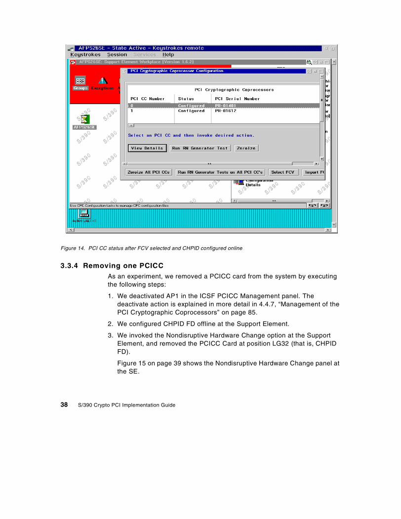
Figure 14. PCI CC status after FCV selected and CHPID configured online
3.3.4 Removing one PCICCAs an experiment, we removed a PCICC card from the system by executingthe following steps:
1. We deactivated AP1 in the ICSF PCICC Management panel. Thedeactivate action is explained in more detail in 4.4.7, “Management of thePCI Cryptographic Coprocessors” on page 85.
2. We configured CHPID FD offline at the Support Element.
3. We invoked the Nondisruptive Hardware Change option at the SupportElement, and removed the PCICC Card at position LG32 (that is, CHPIDFD).
Figure 15 on page 39 shows the Nondisruptive Hardware Change panel atthe SE.
38 S/390 Crypto PCI Implementation Guide
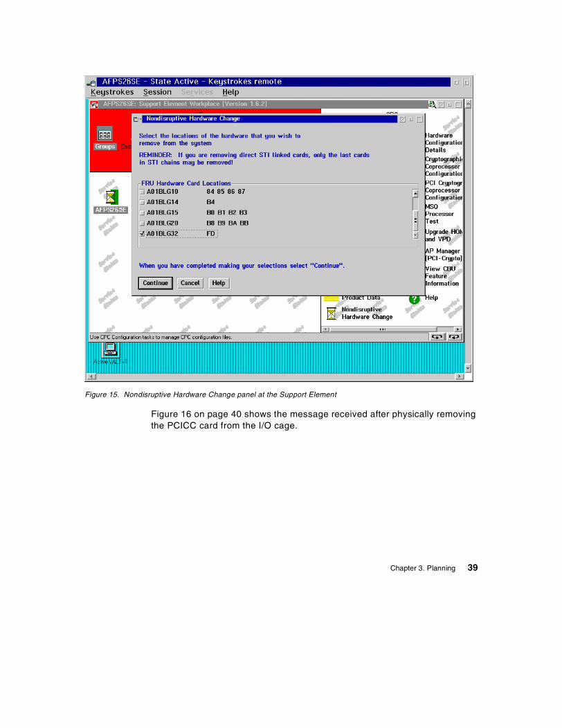
Figure 15. Nondisruptive Hardware Change panel at the Support Element
Figure 16 on page 40 shows the message received after physically removingthe PCICC card from the I/O cage.
Chapter 3. Planning 39
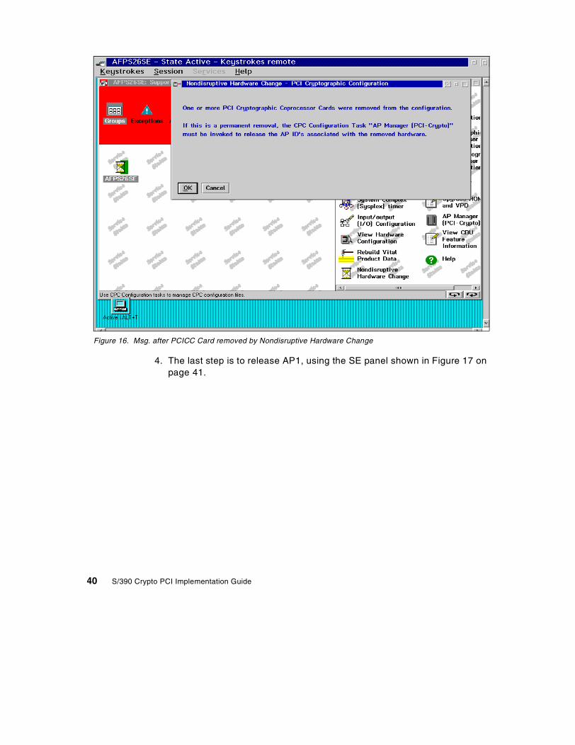
Figure 16. Msg. after PCICC Card removed by Nondisruptive Hardware Change
4. The last step is to release AP1, using the SE panel shown in Figure 17 onpage 41.
40 S/390 Crypto PCI Implementation Guide
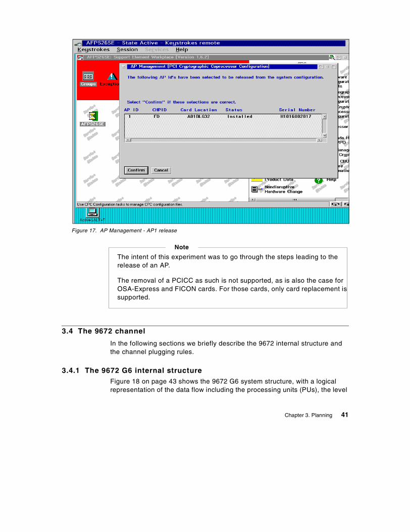
Figure 17. AP Management - AP1 release
3.4 The 9672 channel
In the following sections we briefly describe the 9672 internal structure andthe channel plugging rules.
3.4.1 The 9672 G6 internal structureFigure 18 on page 43 shows the 9672 G6 system structure, with a logicalrepresentation of the data flow including the processing units (PUs), the level
The intent of this experiment was to go through the steps leading to therelease of an AP.
The removal of a PCICC as such is not supported, as is also the case forOSA-Express and FICON cards. For those cards, only card replacement issupported.
Note
Chapter 3. Planning 41

2 cache (L2), the memory cards, and the memory bus adapters (MBAs) whichconnect to the channels through Self-Timed Interconnect (STI) cables.
All 9672 G6 models have two processor sets, with each set having sevenPUs, two MBAs and an 8 MB L2 shared cache. Therefore, a complete systemhas 14 PUs, 4 MBAs and 16 MB L2 cache. Each PU has its own 256 KBcache level 1 (L1), designed as a store-through cache, meaning that thealtered data must also be stored into the next upper-level cache.
42 S/390 Crypto PCI Implementation Guide
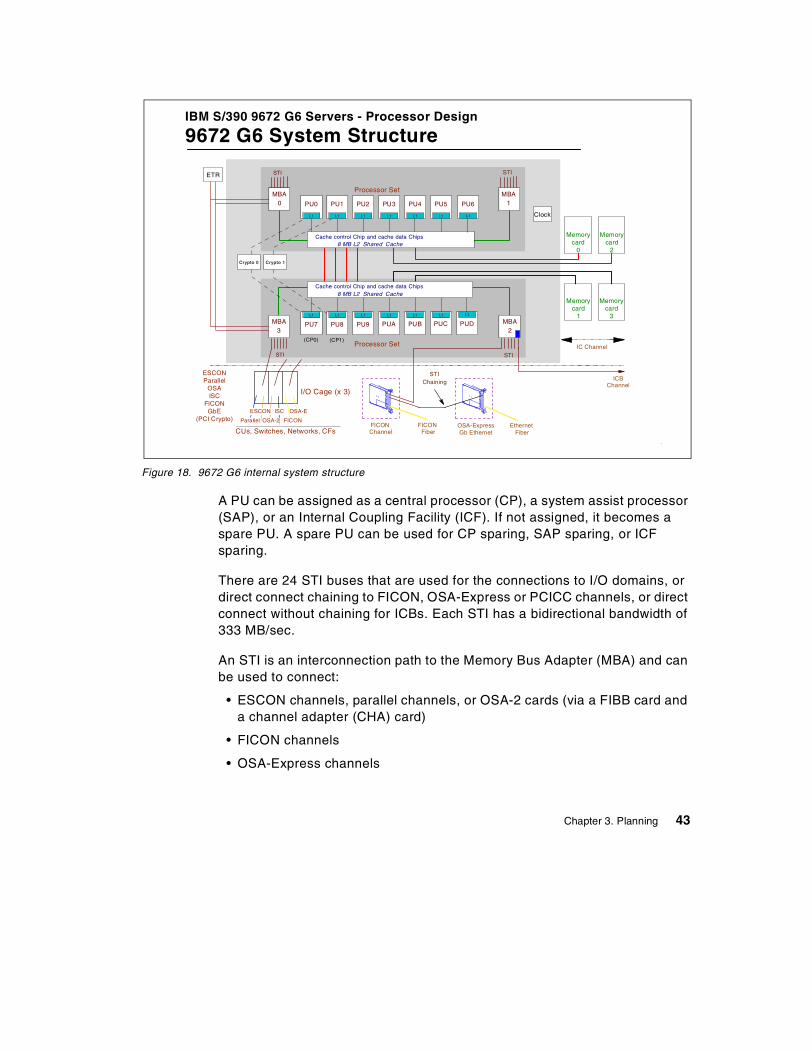
Figure 18. 9672 G6 internal system structure
A PU can be assigned as a central processor (CP), a system assist processor(SAP), or an Internal Coupling Facility (ICF). If not assigned, it becomes aspare PU. A spare PU can be used for CP sparing, SAP sparing, or ICFsparing.
There are 24 STI buses that are used for the connections to I/O domains, ordirect connect chaining to FICON, OSA-Express or PCICC channels, or directconnect without chaining for ICBs. Each STI has a bidirectional bandwidth of333 MB/sec.
An STI is an interconnection path to the Memory Bus Adapter (MBA) and canbe used to connect:
• ESCON channels, parallel channels, or OSA-2 cards (via a FIBB card anda channel adapter (CHA) card)
• FICON channels
• OSA-Express channels
IBM S/390 9672 G6 Servers - Processor Design
9672 G6 System Structure
Crypto 1
Clock
Crypto 0
ETR
Processor Set
Memorycard
0
Memorycard
1
Memorycard
2
Memorycard
3
Processor Set
MBA0
MBA2
MBA1
MBA3
L1
PU7
L1
PUC
L1
PU8
L1
PU9
L1
PUA
L1
PUB
L1
PU0
L1
PU5
L1
PU1
L1
PU2
L1
PU3
L1
PU4
I/O Cage (x 3)
Cache control Chip and cache data Chips8 MB L2 Shared Cache
Cache control Chip and cache data Chips8 MB L2 Shared Cache
STI
STI
ESCONParallel
OSAISC
FICONGbE
(PCI Crypto)
CUs, Switches, Networks, CFs
ESCON
Parallel OSA-2
ISC
FICON
(CP0) (CP1)
L1
PU6
L1
PUD
IC ChannelSTI
STI
FICONChannel
FICONFiber
ICBChannel
EthernetFiber
OSA-ExpressGb Ethernet
OSA-E
STIChaining
Chapter 3. Planning 43
• PCICCs
• ISCs (coupling links) via an Intersystem Channel Adapter (ISC-M) cardand a FIBB card
• Integrated Cluster Buses (ICBs) channels
Up to four FICON, OSA-Express or PCICC channels (which are highbandwidth channels) can be chained in the same STI; this is called four-deepchaining.
All 9672 G6 models have internal dual Cryptographic Coprocessors (CCFs)with dual paths to each processor set on a twin-tailed configuration. Thisallows continuity of cryptographic operations should the attached CP incontrol fail by sparing this CP at the next power-on reset.
Note: Only one of the attached CPs is in control of the CCF at a given time.The system structure shown in Figure 18 on page 43 is similar for the 9672G5, with the exception that the 9672 G5 only has twelve PUs and a smallercache size.
3.4.2 The 9672 channel plugging rulesThe 9672 internal connections between FICON channels, OSA-Express orPCICC, and the CPC cage are via direct connect chaining STI connections.The following rules apply to making these connections:
• A direct connect chaining STI can support up to four FICON orOSA-Express or PCICC channels, or any mix of these channels (up to atotal of four), in an STI chain.
• Each STI chain requires one STI connector at the CPC cage.
• Each direct connect STI chain is assigned four channel numbers(CHPIDs), one for each channel that can be potentially installed in the STIchain
• The FICON, OSA-Express or PCICC channels are installed across anassigned pair of STIs:
- FICON, OSA-Express or PCICC channels 1, 3, and 5 are installed onthe first STI of the pair.
- FICON, OSA-Express or PCICC channels 2, 4, and 6 are installed onthe second STI of the pair.
- Later two more FICON, OSA-Express or PCICC channels can beinstalled, where the seventh channel is installed on the first STI and theeighth channel is installed on the second STI of the pair.
44 S/390 Crypto PCI Implementation Guide
• In all cases, the last channel installed on the first STI is “chained” to thelast channel installed on the second STI of the pair. This cross-chainingbetween STI is for recovery or repair purposes. For example, if the firstFICON channel fails, then the second STI of the pair automatically takesover control of the FICON, OSA-Express and PCICC channels 2, 4, 6, 8,7, 5, and 3.
The 9672 internal connection paths to ESCON channels are via “I/O domain”,with STI connections to the I/O cages on the basis of the I/O domainstructure. Note the following points:
• There can be from one to three I/O cages in the total system configuration,each with three I/O domains.
• Each I/O domain requires one STI connection.
• Each I/O domain STI supports 16, 24, or 32 I/O domain channels.
3.4.3 I/O cage and channel number topologyFigure 19 on page 46 is a graphic representation of the I/O cage layout, witha summary of the cage configuration characteristics.
Chapter 3. Planning 45
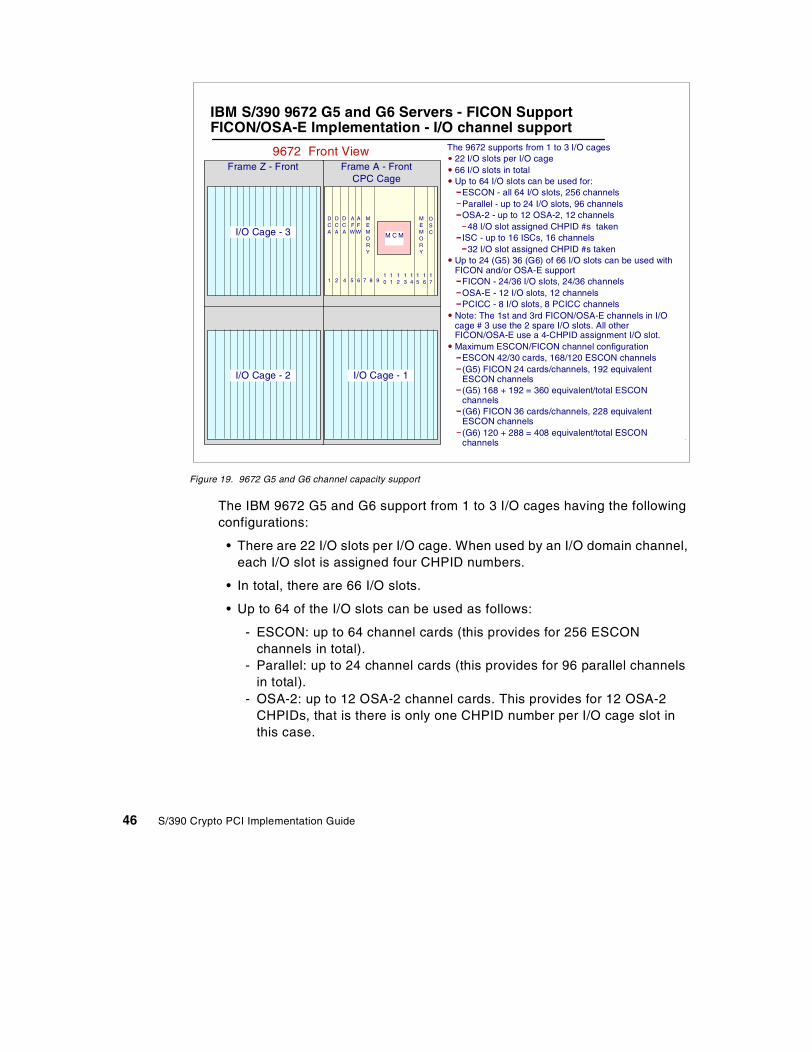
Figure 19. 9672 G5 and G6 channel capacity support
The IBM 9672 G5 and G6 support from 1 to 3 I/O cages having the followingconfigurations:
• There are 22 I/O slots per I/O cage. When used by an I/O domain channel,each I/O slot is assigned four CHPID numbers.
• In total, there are 66 I/O slots.
• Up to 64 of the I/O slots can be used as follows:
- ESCON: up to 64 channel cards (this provides for 256 ESCONchannels in total).
- Parallel: up to 24 channel cards (this provides for 96 parallel channelsin total).
- OSA-2: up to 12 OSA-2 channel cards. This provides for 12 OSA-2CHPIDs, that is there is only one CHPID number per I/O cage slot inthis case.
9672 Front ViewFrame A - Front
AFW
MEMORY
M C M
OSC
DCA
DCA
1 2 4 5 6 7 8 910
11
12
13
14
15
16
17
MEMORY
AFW
DCA
CPC CageFrame Z - Front
I/O Cage - 3
I/O Cage - 2 I/O Cage - 1
The 9672 supports from 1 to 3 I/O cages22 I/O slots per I/O cage66 I/O slots in totalUp to 64 I/O slots can be used for:
ESCON - all 64 I/O slots, 256 channelsParallel - up to 24 I/O slots, 96 channelsOSA-2 - up to 12 OSA-2, 12 channels
48 I/O slot assigned CHPID #s takenISC - up to 16 ISCs, 16 channels
32 I/O slot assigned CHPID #s takenUp to 24 (G5) 36 (G6) of 66 I/O slots can be used withFICON and/or OSA-E support
FICON - 24/36 I/O slots, 24/36 channelsOSA-E - 12 I/O slots, 12 channelsPCICC - 8 I/O slots, 8 PCICC channels
Note: The 1st and 3rd FICON/OSA-E channels in I/Ocage # 3 use the 2 spare I/O slots. All otherFICON/OSA-E use a 4-CHPID assignment I/O slot.Maximum ESCON/FICON channel configuration
ESCON 42/30 cards, 168/120 ESCON channels(G5) FICON 24 cards/channels, 192 equivalentESCON channels(G5) 168 + 192 = 360 equivalent/total ESCONchannels(G6) FICON 36 cards/channels, 228 equivalentESCON channels(G6) 120 + 288 = 408 equivalent/total ESCONchannels
IBM S/390 9672 G5 and G6 Servers - FICON SupportFICON/OSA-E Implementation - I/O channel support
46 S/390 Crypto PCI Implementation Guide
- ISC: up to 32 ISCs channel adapter cards in total. Each ISC adaptercard receives one or two ISC channels; that is, there are one or twoCHPID numbers per slot in this case.
• On 9672 G5, up to 24 of 66 I/O slots can be used to plug FICON,OSA-Express or PCICC cards.
- FICON: up to 24 channel cards (for a total of 24 CHPIDs, each of themconsuming an I/O slot).
- OSA-Express: up to 12 channel cards (for a total of 12 CHPIDs, eachof them consuming one I/O slot).
- PCICC: up to 8 channel cards (for a total of 8 CHPIDs, each of themconsuming one I/O slot).
• On 9672 G6, up to 36 of 66 I/O slots can be used to plug FICON,OSA-Express or PCICC cards.
- FICON: up to 36 channel cards (for a total of 36 CHPIDs, each of themconsuming one I/O slot).
- OSA-Express: up to 12 channel cards (for a total of 12 CHPIDs, eachof them consuming one I/O slot).
- PCICC: up to 8 channel cards (for a total of 8 CHPIDs, each of themconsuming one I/O slot).
Note: The first and third FICON, OSA-Express or PCICC channels in I/Ocage # 3 use the two spare I/O slots (I/O slot number 31 and 32). All otherFICON, OSA-Express and PCICC channels use a 4-CHPID number assignedI/O slot.
The 24 STI connections in the 9672 G5 and G6 processors are assigned asfollows:
- STI numbers 0 to 8 are usually assigned to I/O domains. STIs 9 to 23are available as “direct connect” STIs for FICON, OSA-Express andPCICC channels, which means that the cards will be “chained” over theSTI connection.
- STIs 9 to 23 can also be used as direct connect STIs for the connectionof ICB channels; however, in the case of ICBs, there is no STI chainingcapability.
Figure 20 on page 48 summarizes the relationships between STI cables andCHPID numbers.
• It shows STIs 0 to 8 assigned to I/O domains, as well as the CHPIDnumbers that would be assigned to each of these STIs.
Chapter 3. Planning 47
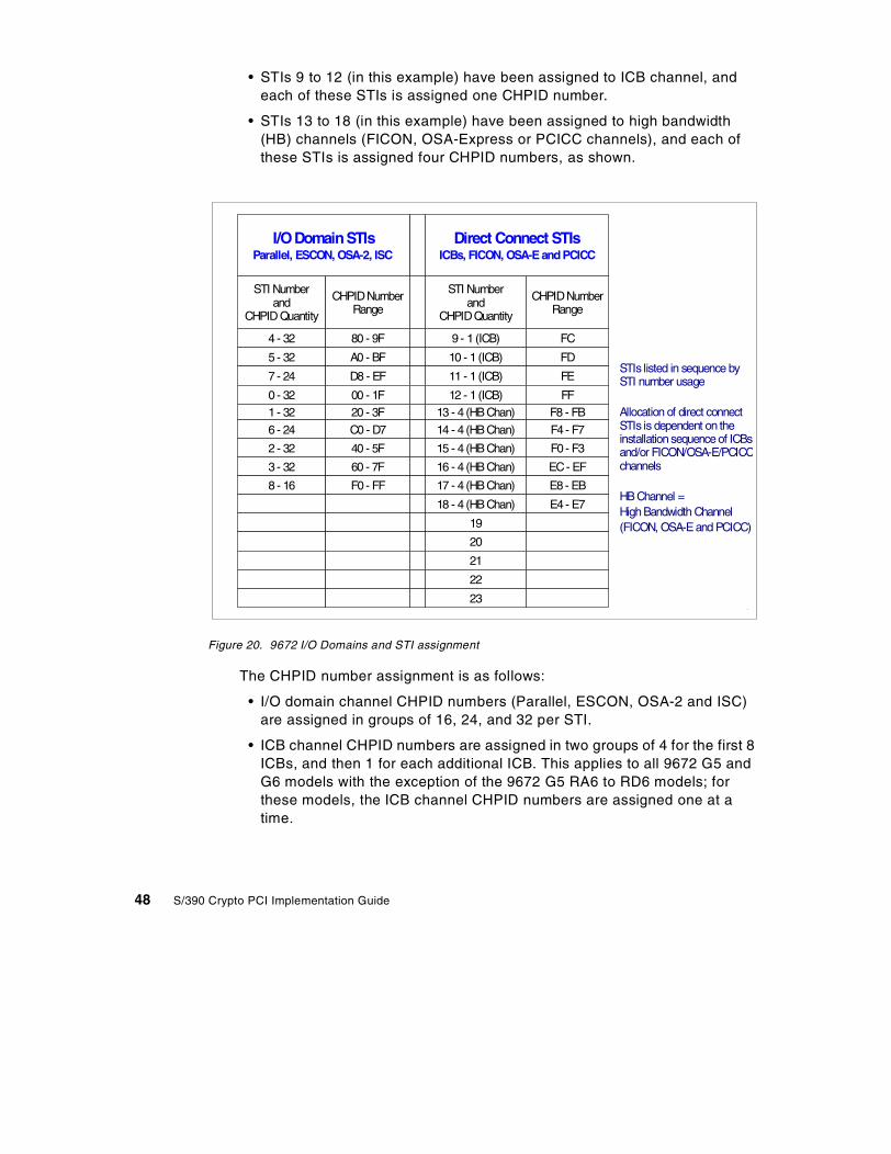
• STIs 9 to 12 (in this example) have been assigned to ICB channel, andeach of these STIs is assigned one CHPID number.
• STIs 13 to 18 (in this example) have been assigned to high bandwidth(HB) channels (FICON, OSA-Express or PCICC channels), and each ofthese STIs is assigned four CHPID numbers, as shown.
Figure 20. 9672 I/O Domains and STI assignment
The CHPID number assignment is as follows:
• I/O domain channel CHPID numbers (Parallel, ESCON, OSA-2 and ISC)are assigned in groups of 16, 24, and 32 per STI.
• ICB channel CHPID numbers are assigned in two groups of 4 for the first 8ICBs, and then 1 for each additional ICB. This applies to all 9672 G5 andG6 models with the exception of the 9672 G5 RA6 to RD6 models; forthese models, the ICB channel CHPID numbers are assigned one at atime.
STI Numberand
CHPID Quantity
CHPIDNumberRange
STI Numberand
CHPIDQuantity
CHPIDNumberRange
4 - 32 80 - 9F 9 - 1 (ICB) FC
5 - 32 A0 - BF 10 - 1 (ICB) FD
7 - 24 D8 - EF 11 - 1 (ICB) FE
0 - 32 00 - 1F 12 - 1 (ICB) FF1 - 32 20 - 3F 13 - 4 (HB Chan) F8 - FB
6 - 24 C0 - D7 14 - 4 (HB Chan) F4 - F7
2 - 32 40 - 5F 15 - 4 (HB Chan) F0 - F3
3 - 32 60 - 7F 16 - 4 (HB Chan) EC- EF
8 - 16 F0 - FF 17 - 4 (HB Chan) E8 - EB
18 - 4 (HB Chan) E4 - E7
19
20
21
22
23
I/ODomainSTIsParallel, ESCON, OSA-2, ISC
Direct Connect STIsICBs, FICON, OSA-E and PCICC
STIs listed in sequence bySTI number usage
Allocation of direct connectSTIs is dependent on theinstallation sequence of ICBsand/or FICON/OSA-E/PCICCchannels
HB Channel =High Bandwidth Channel(FICON, OSA-E and PCICC)
48 S/390 Crypto PCI Implementation Guide
• FICON, OSA-Express and PCICC channel CHPID numbers are assignedin groups of 4, and they are used one at a time when one of these channeltypes are installed.
• IC Channel CHPID numbers are assigned by the customer.
The FICON, OSA-Express and PCICC CHPID numbers are assigned fromthe highest group of 4 CHPID numbers not already assigned or reserved byany other direct connect STI (direct connect STIs are used by FICON,OSA-Express, PCICC and ICB).
3.5 Planning list items
In the following sections we describe microcode level requirements andcapacity planning and installation considerations.
3.5.1 System microcodeThe minimum LIC requirement for PCICC support on the G5 and G6 9672Enterprise server is Driver 26, that is:
• CPC System Code EC F99939A (Common Group B/M for SE Code)
• CPC level: EC F99918 + MCLs
• PCI Crypto level: EC F99905 + MCLs. The base PCI crypto level is 1.18.
• HMC System Code EC F99938 (Common Group B/M for HMC)
• HMC level: EC F99933 + MCLs
Chapter 3. Planning 49

3.5.2 Capacity planning considerationsAs of the time of writing, there is no capacity planning data available.
3.5.3 Installation of the ordered PCICCsNote the following installation considerations.
3.5.3.1 On new build machines• All PCI crypto cards (FC 0860 PCICC) are shipped in thermal containers
to avoid the risk of thermal tamper detection during shipment.
• The PCICC cards are removed from the machine after testing at thesystem manufacturing plant, and the Customer Engineer has to replug thePCICC cards and the STI cables at the customer’s site according to theinstructions given in theinstallation manual.
• The FCV crypto enablement diskette is also imported during theinstallation, once per system only, even if more than one feature code0860 is installed.
• If the TKE has been ordered with feature code 0869 or 0866, the 4758adapter is removed from the workstation at the plant of manufacture andshipped in a thermal container. The Customer Engineer has to replug the4758 crypto adapter at the customer’s site.
3.5.3.2 MES upgradeInstallation of the PCICC cards can be done concurrent with systemoperations if all of the following conditions are met:
• At a minimum, LIC Driver 26 is already installed, with the concurrentinstallation MCL activated.
• At least one CCF is enabled and in operation, with an enablement featurematching the PCICC-intended cryptographic configuration.
• The machine configuration does not require that an ISC adapter bemoved.
• Because MES Installation Instructions are always generated for a specificmachine serial number, it is very important that the last Vital Product Data(VPD) transmitted to IBM for this machine be accurate.
3.5.3.3 Miscellaneous recommendations• If you have to move channel cards, refer to the redbook Fiber Channel
(FICON) Implementation Planning, SG24-5445, for card sequencing ormovement and cabling requirements.
50 S/390 Crypto PCI Implementation Guide
• Make sure that any unique customer requirements have been conveyedthrough the ordering process and taken into consideration prior to startinginstallation.
• If you move PCICC cards, those cards will be zeroized. Refer to 2.1.3.3,“Zeroizing” on page 17.
• The PCICC CHPID is not defined in the IOCDS, but a CHPID definitionconflict may occur if a CHPID is already defined in the IOCDS with thesame number as the PCICC. This will prevent I/O dynamicreconfiguration, and if a system power-on reset is performed, neither thedefined CHPID nor the PCICC will come online and a POR error messagewill be received.
• In addition to FCV load at POR, FCV can also be loaded during a reset tothe PCICC (CHPID reset), provided that the FCV already resides in HSA.That is the case for a hotplugged PCICC card which gets its FCV loadedwhen the CHPID is being configured on at the Support Element.
3.6 Software requirements
In the following sections we give an overview of the software requirements forthe support of the PCICC.
3.6.1 OS/390 V2R9OS/390 2.9 is the minimum OS/390 level needed to support the PCICC.OS/390 2.9 includes ICSF 2.3 as an exclusive feature: that is, ICSF 2.3cannot be ordered separately and cannot be installed on prior OS/390releases.
3.6.1.1 TCP/IP enablement in OS/390If using the TKE workstation, there are two implications:
1. Only TKE V3.0 supports the PCICC.
2. TKE V3.0 supports only TCP/IP as the communication network with theTKE OS/390 host.
The only way to change the FCV data is to import the new FCV into theSupport Element and run a system Power-on reset. The PCICC is notzeroized when it loads a new FCV.
Changing the FCV value
Chapter 3. Planning 51

3.6.1.2 Migrating from prior OS/390 levels• When migrating from ICSF 2.2 (which is the level of ICSF delivered with
OS/390 releases 6, 7 and 8), the PKDS has to be installed (if not alreadydone), as ICSF 2.3 will not initialize if there is no PKDS defined in theOptions Data Set.
- In order to provide maximum flexibility in the dynamic selection of thecrypto coprocessor by ICSF, we strongly recommend that the value forthe Signature Master Key and the Key Management Master Key in theCCF (s) be the same.
• The following considerations pertain to applications:
- Existing X'02' RSA internal key tokens must be re-imported to beusable on PCICC, where they become X’06’ internal key tokens usableboth on CCF and PCICC. Both tokens are in the modulus-exponentformat.
- You should consider converting from the modulus-exponent tokens tothe Chinese Remainder Theorem (CRT) format X’08’ internal tokens forbetter performance. ICSF routes all services using the CRT formattokens to the PCICC only.
3.6.2 CKDS and PKDS sharing considerationsNote the following considerations:
• The OS/390 2.9 ICSF CKDS may be shared with pre-OS/390 2.9 systems.There have been no new key types added since OS/390 2.6 (that is, sinceICSF 2.2).
• However, sharing the OS/390 2.9 PKDS with pre-2.9 systems requires atoleration PTF which has the following functions:
- It does not allow use of any token > 1024 bytes.
- It does not allow updates to PKDS records of retained keys.
- It converts the new 2.9 X'06' token to the existing X'02' token to use onCCF. Be aware that this token may still not be usable on CCF if thePKA Signature Master Key (SMK) does not have the same value as thePKA Key Management Master Key (KMMK).
The ICSF System Programmer ’s Guide, SC23-3974, provides the APARnumbers to be installed on the sharing systems.
52 S/390 Crypto PCI Implementation Guide
3.7 PR/SM setup
This item is discussed in detail in 4.3, “LPAR setup” on page 61. Note,however, that the PCICC candidate list in the partition image profile cannot beupdated dynamically.
3.8 Migrating from TKE V2.x to TKE V3.0
There are no migration tools provided for migrating to TKE V3.0. You mustconsider the impact on the following and perform the appropriate actions.
3.8.1 Host definitionsThe V2 host definitions are for VTAM APPC-connected hosts. You mustredefine these hosts for the TKE V3.0 support of TCP/IP only.
3.8.2 CCF crypto modules, domains, and authority definitionsThe TKE V2.x TKECM dataset is not compatible with the TKE V3.0 data set.You must redefine the CCF crypto modules, domains, and authority in thenew TKECM data set. If you plan to use the same dataset name for V3.0 asyou used for V2.0, you must delete or rename the existing data set.
3.8.3 Authority signature keys on IBM Personal Security Card (PSC)Authority signature keys on PSC cannot be used on the TKE V3.0. Thefollowing alternatives are suggested:
1. While still working with the TKE 2.x workstation: change the signaturerequirements so that signature keys stored in PSCs are not needed anymore. From the Crypto Module window, update the appropriate commandswith the new signature requirements. Remove any authority whosesignature key was stored on PSCs.
Note: Be careful however not to create security exposures by removingthese signature requirements.
2. As an alternative, still on the TKE 2.x workstation, you can generate andload new signature keys to the host as follows:
- From the Authority Administration window, generate a new signaturekey and save it to a binary file. Read the public modulus. Send theupdated authority definition the host, copy the binary file to a diskette,and restore the diskette files to the new TKE workstation.
Chapter 3. Planning 53
3.8.4 Authority signature key in the TKE workstation key storageThere is no direct migration for PKA tokens from the 4755 crypto adapter cardto the 4758. You must perform the same operations as in 3.8.3, “Authoritysignature keys on IBM Personal Security Card (PSC)” on page 53.
3.8.5 IMP-PKA keys in the workstation key storageYou must generate and load new IMP-PKA tokens in the TKE V3.0 keystorage.
3.8.6 Migration of master or operational key parts on PSCBecause TKE V3.0 does not support the 4754 SIU or the PSC, you need tomigrate the PSC data blocks to files. You can accomplish this while stillworking with TKE V2 by using the TSS HIKM utility. The TKE WorkstationUser ’s Guide 2000, GA22-7430, describes this operation in detail in thechapter “Migrating from TKE V2 to TKE V3”.
3.9 Site security policy
The site security policy must take into account the following:
• The impact of new concepts in the cryptographic services (such as“retained keys”), in terms of the availability of services.
• The new RACF profiles pertaining to the PCICC-specific panels andfunctions. Refer to 6.1, “RACF access control to ICSF services” on page137 for details on the RACF profiles.
• The changes brought by the new TKE workstation, as follows:
- The communication network is a TCP/IP network. A “listener” hosttransaction program runs in the host OS/390 and can be secured usingnew RACF profiles (see Appendix C, “TKE host TCP/IP server setup”on page 145, for further details).
- Both the TKE cryptographic adapter and the PCICC managementintroduce the notion of roles and profiles. These notions are furtherexplained in Chapter 5, “Customizing PCICC and CCF using a TKEV3.0” on page 89.
54 S/390 Crypto PCI Implementation Guide
Chapter 4. Installation, configuration and startup of ICSF
In this chapter we describe the physical installation of the PCICC card and all theinitialization and setup steps to be performed to enable the customer to use thenewly installed PCICC card. We do not describe the TKE workstation setup,which is done in Chapter 5, ”Customizing PCICC and CCF using a TKE V3.0” onpage 89.
The first steps of the initialization are performed at the Support Element orHardware Management Console (HMC). This includes the cryptographiccoprocessor assignment and authorization setup in the logical partitions imageprofiles, which must be done before activating the partitions.
• ICSF is used to enter the Master Keys in the hardware and to initialize andmanage the cryptographic keys data sets.
• The Cryptographic Coprocessor Facility (CCF) must be in operation beforeusing the PCICC cards, and the CCF cryptographic configuration must matchthe PCICC FCV feature codes.
4.1 PCI Cryptographic Coprocessor Card plugging
We briefly stress the following points again:
• It is mandatory to follow the Installation Instructions provided with the MES, aspart movements specific to the machine serial number are involved.
• The STI-attached PCICC cards are installed in channel card slots, so thecorresponding CHPID number must be free, that is: not used in the IOCDSdefinition, otherwise a configuration conflict will occur.
Several manuals that we used during the writing of this book refer to “operatorcommand” to vary the PCICC online or offline. There is no such command forthe OS/390 operator that would allow configuring a PCICC online or offlinefrom the system console. Configuring a PCICC online or offline can only beaccomplished at the system Support Element or HMC.
Warning 1
The term “online” when applied to the PCICC requires precision regarding thecontext in which it is used:
• If referring to the PCICC CHPID, the meaning is the same as for a CHPIDbeing in an online or standby state. A device in the online state is accessibleto the software running in the partition or in the system, whereas a device inthe standby state is no longer accessible.
• If referring to the PCICC facility as seen by ICSF, “online” means that thedevice is accessible but needs to have its master keys properly set. APCICC is fully operational when in the “active” state, as described in 4.4.7,“Management of the PCI Cryptographic Coprocessors”, on page 85.
Warning 2
© Copyright IBM Corp. 2000 55
• A PCICC card serial number is automatically associated to a free adjunctprocessor (AP) number, starting with number 0.
• Relocating a PCI card to another system: the Master KeyMaster Keys arezeroized when the card is replugged. The customer has to reinstall the MasterKeys.
• A card can be moved inside the system without changing its AP number.
• There is no explicit declaration of the PCICC card to ICSF; OS/390 2.9 notifiesICSF of the physical presence of a PCICC card via an ENF signal.
4.2 PCICC enablement
The following sections describe how to enable the PCICC.
4.2.1 Function Control Vector (FCV) overview• The Function Control Vector (FCV) enables the specific cryptographic
functions with the authorized key lengths in the PCICC hardware.
• The FCV is shipped from manufacturing on a diskette, according to therequested feature code, when the first PCICC card is ordered or when thecurrent cryptographic configuration needs to be changed.
• The PCICC FCV is specific to the system serial number and as such appearscommon to all PCI cards installed in the system.
• The installation of the FCV is a two-step process:
1. The FCV files are imported from the diskette onto the Support Elementhard disk. This has to be done only when installing the first PCICC in thesystem or when changing the current cryptographic configuration. It can bedone concurrently with system operations.
2. During the next system Power-on reset the FCV is first uploaded to thesystem HSA, then downloaded into each PCICC card. Or, if it is the firstFCV imported to the system, it can be immediately loaded into HSA as anoption in the Support Element panel.
• If the FCV already resides in the HSA, it can be loaded or reloaded into thecard without a system Power On Reset. This is achieved by configuring thePCICC CHPID offline, then online at the Support Element (CHPID reset). Toselect a PCICC at the support element:
• Right-click the CPC icon in the CPC Work Area. A drop-down menuappears with these options: CPs, CHPIDs and PCI Crypto.
• Select PCI Crypto; this displays the PCICCs installed in the system.
From this point on you can refer to the Support Element Operations Guide,GC38-0608, for a description of how to configure a CHPID on or off.
4.2.2 Import FCVThe Support Element must be logged on in SERVICE or SYSPROG, and the CPClogic must be powered on to get access to this panel.
• Select the CPC icon in the CPC Work Area.
• In the CPC configuration task list, select the PCI Cryptographic Coprocessor Configuration task.
56 S/390 Crypto PCI Implementation Guide
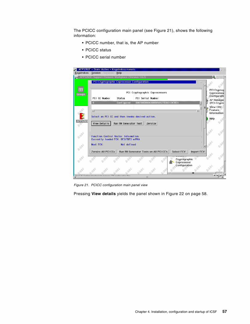
The PCICC configuration main panel (see Figure 21), shows the followinginformation:
• PCICC number, that is, the AP number
• PCICC status
• PCICC serial number
Figure 21. PCICC configuration main panel view
Pressing View details yields the panel shown in Figure 22 on page 58.
Chapter 4. Installation, configuration and startup of ICSF 57
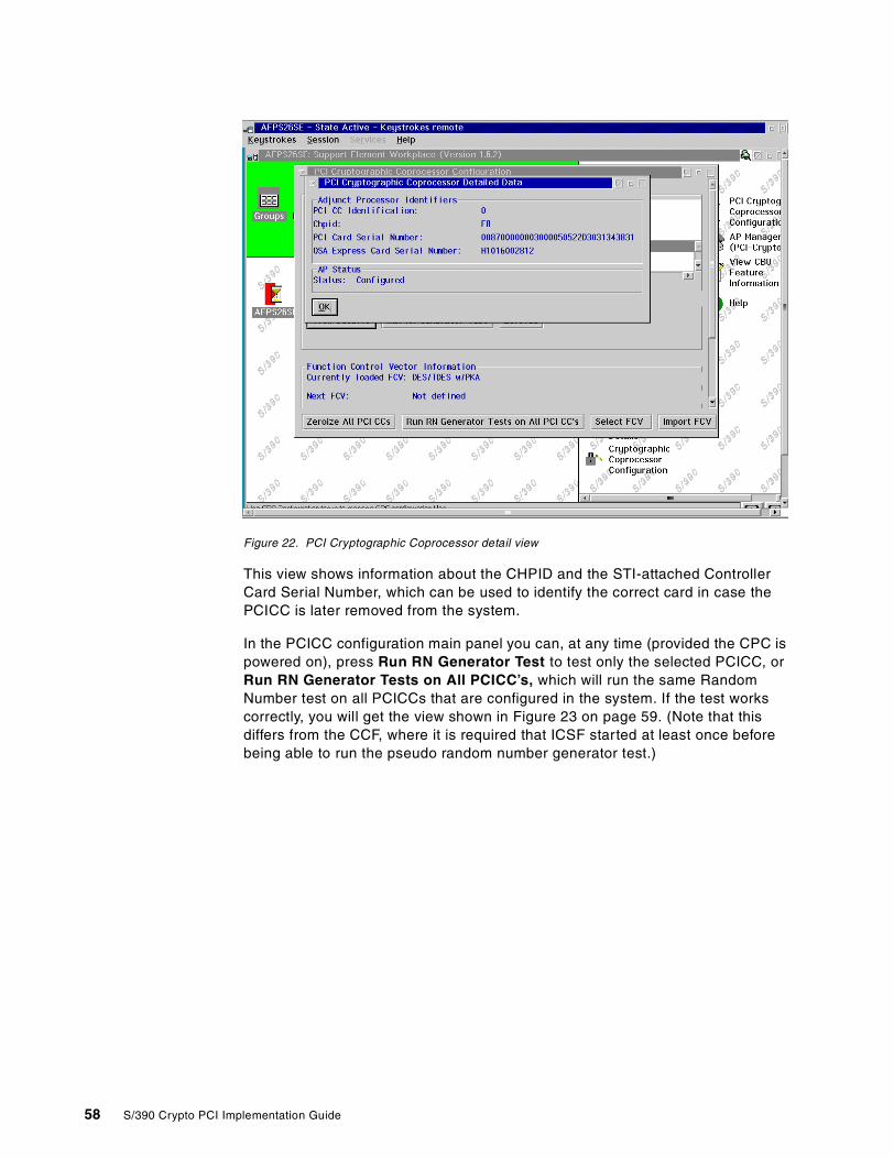
Figure 22. PCI Cryptographic Coprocessor detail view
This view shows information about the CHPID and the STI-attached ControllerCard Serial Number, which can be used to identify the correct card in case thePCICC is later removed from the system.
In the PCICC configuration main panel you can, at any time (provided the CPC ispowered on), press Run RN Generator Test to test only the selected PCICC, orRun RN Generator Tests on All PCICC’s, which will run the same RandomNumber test on all PCICCs that are configured in the system. If the test workscorrectly, you will get the view shown in Figure 23 on page 59. (Note that thisdiffers from the CCF, where it is required that ICSF started at least once beforebeing able to run the pseudo random number generator test.)
58 S/390 Crypto PCI Implementation Guide
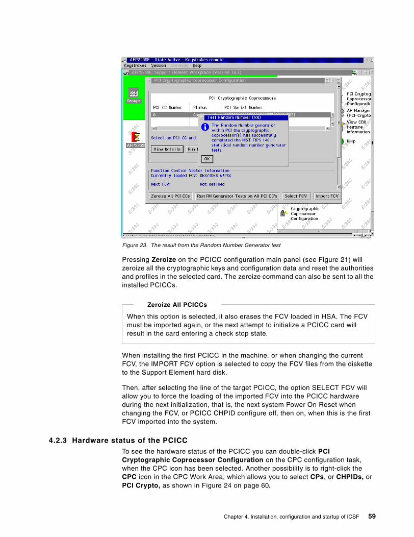
Figure 23. The result from the Random Number Generator test
Pressing Zeroize on the PCICC configuration main panel (see Figure 21) willzeroize all the cryptographic keys and configuration data and reset the authoritiesand profiles in the selected card. The zeroize command can also be sent to all theinstalled PCICCs.
When installing the first PCICC in the machine, or when changing the currentFCV, the IMPORT FCV option is selected to copy the FCV files from the disketteto the Support Element hard disk.
Then, after selecting the line of the target PCICC, the option SELECT FCV willallow you to force the loading of the imported FCV into the PCICC hardwareduring the next initialization, that is, the next system Power On Reset whenchanging the FCV, or PCICC CHPID configure off, then on, when this is the firstFCV imported into the system.
4.2.3 Hardware status of the PCICCTo see the hardware status of the PCICC you can double-click PCICryptographic Coprocessor Configuration on the CPC configuration task,when the CPC icon has been selected. Another possibility is to right-click theCPC icon in the CPC Work Area, which allows you to select CPs, or CHPIDs, orPCI Crypto, as shown in Figure 24 on page 60.
When this option is selected, it also erases the FCV loaded in HSA. The FCVmust be imported again, or the next attempt to initialize a PCICC card willresult in the card entering a check stop state.
Zeroize All PCICCs
Chapter 4. Installation, configuration and startup of ICSF 59
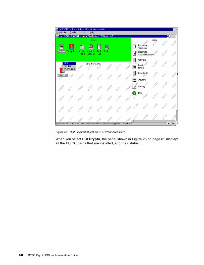
Figure 24. Right-clicked object on CPC Work Area view
When you select PCI Crypto, the panel shown in Figure 25 on page 61 displaysall the PCICC cards that are installed, and their status.
60 S/390 Crypto PCI Implementation Guide
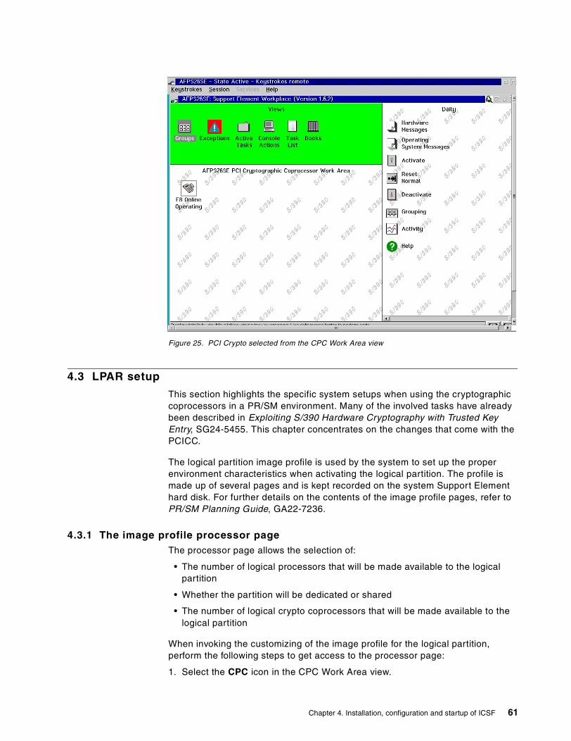
Figure 25. PCI Crypto selected from the CPC Work Area view
4.3 LPAR setup
This section highlights the specific system setups when using the cryptographiccoprocessors in a PR/SM environment. Many of the involved tasks have alreadybeen described in Exploiting S/390 Hardware Cryptography with Trusted KeyEntry, SG24-5455. This chapter concentrates on the changes that come with thePCICC.
The logical partition image profile is used by the system to set up the properenvironment characteristics when activating the logical partition. The profile ismade up of several pages and is kept recorded on the system Support Elementhard disk. For further details on the contents of the image profile pages, refer toPR/SM Planning Guide, GA22-7236.
4.3.1 The image profile processor pageThe processor page allows the selection of:
• The number of logical processors that will be made available to the logicalpartition
• Whether the partition will be dedicated or shared
• The number of logical crypto coprocessors that will be made available to thelogical partition
When invoking the customizing of the image profile for the logical partition,perform the following steps to get access to the processor page:
1. Select the CPC icon in the CPC Work Area view.
Chapter 4. Installation, configuration and startup of ICSF 61
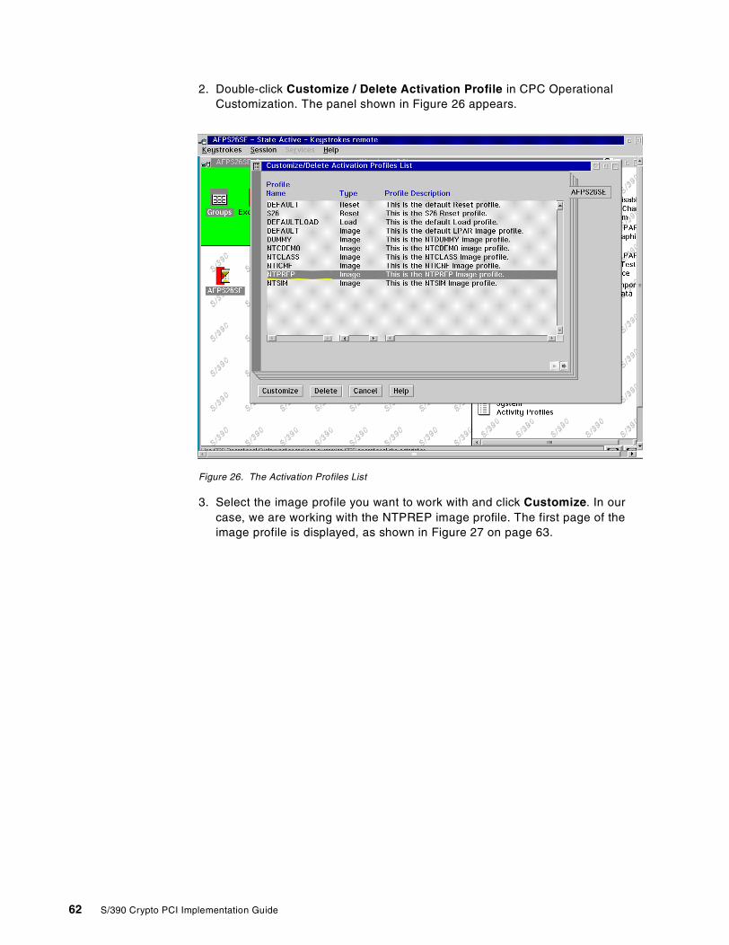
2. Double-click Customize / Delete Activation Profile in CPC OperationalCustomization. The panel shown in Figure 26 appears.
Figure 26. The Activation Profiles List
3. Select the image profile you want to work with and click Customize. In ourcase, we are working with the NTPREP image profile. The first page of theimage profile is displayed, as shown in Figure 27 on page 63.
62 S/390 Crypto PCI Implementation Guide
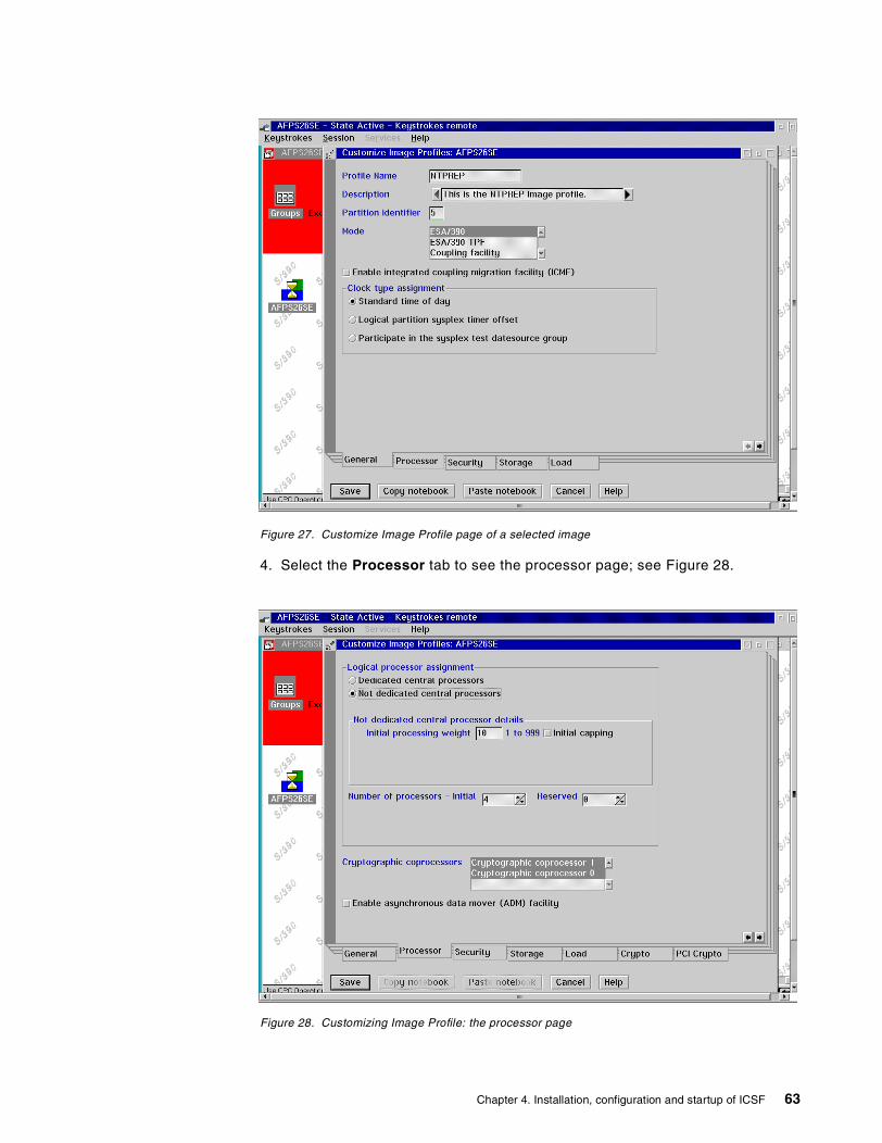
Figure 27. Customize Image Profile page of a selected image
4. Select the Processor tab to see the processor page; see Figure 28.
Figure 28. Customizing Image Profile: the processor page
Chapter 4. Installation, configuration and startup of ICSF 63
The Image Profile processor page in Figure 28 contains the Cryptographiccoprocessors window, indicating how many CCFs are physically available in thesystem. Selecting one or two of these chips allocates one or two logical cryptocoprocessors for the logical partition. These logical crypto coprocessors willactually be backed up by physical resources only when the logical partition isactivated. Note that there are initially no Crypto and PCI Crypto tabs offered forselection at the bottom of the pages. As soon as a logical processor has beenallocated to the partition, the Crypto and PCI Crypto tabs appear as shown inFigure 28.
4.3.2 Dedicated central processorsElecting to run a logical partition with dedicated central processors andcryptographic coprocessors has a very dramatic effect on the rest of the systemwhen this logical partition is activated, because there is a physical affinitybetween the crypto chips and two physical processors in the system. The PR/SMmicrocode will allocate one or two of these physical processors, depending onthe number of logical cryptographic coprocessors selected, to the dedicatedlogical partition, thus making these physical processors unavailable to otherlogical partitions. This can also result in not being able to activate the dedicatedpartition because of other shared partitions already sharing the physical cryptochips.
4.3.3 The Crypto pageThe Crypto page allows the selection of parameters for the cryptographic setup ofthe logical partition. These setup parameters are taken into account at logicalpartition activation. Note that these selections, except for the contents of thecontrol and usage domain lists, can be dynamically changed without needing todeactivate and then reactivate the logical partition, using the “Change LPARCryptographic Controls” in the CPC Operational Customization task list.
The selections shown in Figure 29 on page 65 were made on the Crypto page ofthe image profile of our NTPREP partition.
The concept of coprocessor dedication does not apply to PCICC. A PCICC isby nature accessible from several partitions as directed by the online andcandidate lists, regardless of the shared or dedicated status given to the CCF.
Important
64 S/390 Crypto PCI Implementation Guide
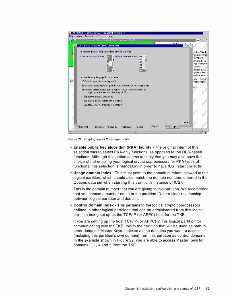
Figure 29. Crypto page of the image profile
• Enable public key algorithm (PKA) facility - The original intent of thisselection was to select PKA-only functions, as opposed to the DES-basedfunctions. Although this option seems to imply that you may also have thechoice of not enabling your logical crypto coprocessors for PKA types offunctions, this selection is mandatory in order to have ICSF start correctly.
• Usage domain index - This must point to the domain numbers allowed to thislogical partition, which should also match the domain numbers entered in theOptions data set when starting this partition’s instance of ICSF.
This is the domain number that you are giving to this partition. We recommendthat you choose a number equal to the partition ID for a clear relationshipbetween logical partition and domain.
• Control domain index - This pertains to the logical crypto coprocessorsdefined in other logical partitions that can be administered from this logicalpartition being set up as the TCP/IP (or APPC) host for the TKE.
If you are setting up the host TCP/IP (or APPC) in this logical partition forcommunicating with the TKE, this is the partition that will be used as path toother domains’ Master Keys. Indicate all the domains you want to access(including this partition’s own domain) from this partition as control domains.In the example shown in Figure 29, you are able to access Master Keys fordomains 0, 1, 4 and 5 from the TKE.
Chapter 4. Installation, configuration and startup of ICSF 65
• Enable cryptographic functions - This actually pertains to the DES-basedICRF functions as they were known in the ES/9000-9021, but also includesthe DES Master Key management functions.
It must be selected for normal operation of the logical cryptographiccoprocessors.
• Enable special security mode - This is the mode of operation required forKGUP to permit generation or entry of clear keys, and to enable the securekey import or clear pin generate callable services. ICSF will work with theclear keys (as opposed to keys encrypted under a Master Key or a TransportKey) only if Special Security Mode (SSM) is selected on this page of the imageprofile and also specified as SSM YES in the Options data set. Onlydeselecting this option in the image profile is enough to prevent ICSF fromaccepting clear keys. Note that the status of the SSM can also be modified forthe domain at the TKE. This is accomplished by the setting of the SSM bit inthe ECM.
The setting of this selection is actually a matter of security policies andprocedures at the installation. Refer to these customer procedures to decidewhat to do.
• Enable integrated cryptographic facility (ICRF) key entry - This optionmust be selected to permit the loading of Master Keys in the usage domainfrom the TKE. No selection implies that the Master Keys can only be enteredfrom the ICSF ISPF panels. Select whether you want to use the TKE to enterMaster Keys into the usage domain of this partition.
• Enable public key secure cable (PKSC) and integrated cryptographicservice facility ( ICSF) - Do not be misled, there is no choice here: This hasto be selected. Furthermore, it gives access to the last three options.
• Enable modify authority - There can be only one active logical partition atone time with this option selected. The definitions of authority and authoritysignatures will be transmitted into the physical cryptographic coprocessor fromthe TKE through this logical partition, if this is selected. Refer to the securitypolicies and procedures for the installation before selecting.
• Enable query signature controls - This enables the TKE to get, through thislogical partition, the status of the multi-signature command in progress; inother words, what are the multi-signature commands defined by theinstallation? What is the one in progress? Has the crypto coprocessorreceived all the necessary signatures? Refer to the security policies andprocedures for the installation.
• Enable query transport controls - This allows the logical partition toparticipate in a key transfer operation with the TKE workstation. Refer to thesecurity policies and procedures for the installation.
As of a recently identified problem, domain 0 must always be specified inthe TKE host Control Domains list when working with the TKE V3.0 andPCICC cards. Failure to do so results in the TKE not being able to open theRoles and Authorities pages for any domain.
This problem is expected to be resolved in the second half of year 2000.
Current problem
66 S/390 Crypto PCI Implementation Guide
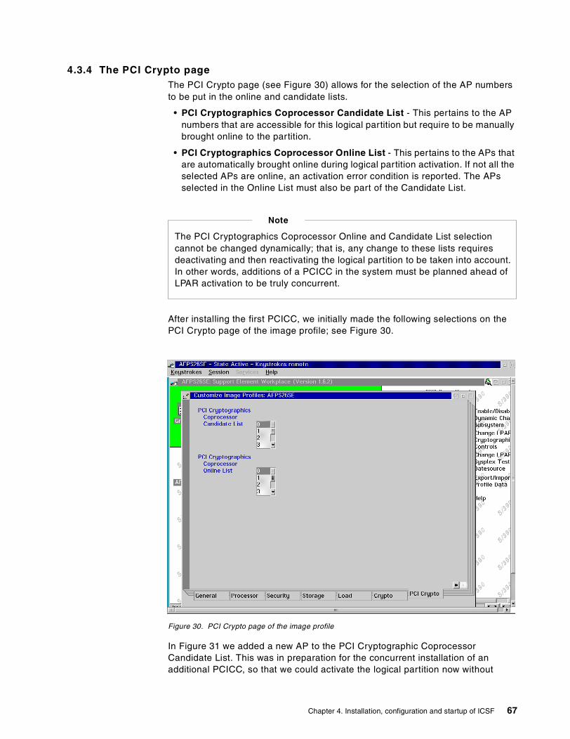
4.3.4 The PCI Crypto pageThe PCI Crypto page (see Figure 30) allows for the selection of the AP numbersto be put in the online and candidate lists.
• PCI Cryptographics Coprocessor Candidate List - This pertains to the APnumbers that are accessible for this logical partition but require to be manuallybrought online to the partition.
• PCI Cryptographics Coprocessor Online List - This pertains to the APs thatare automatically brought online during logical partition activation. If not all theselected APs are online, an activation error condition is reported. The APsselected in the Online List must also be part of the Candidate List.
After installing the first PCICC, we initially made the following selections on thePCI Crypto page of the image profile; see Figure 30.
Figure 30. PCI Crypto page of the image profile
In Figure 31 we added a new AP to the PCI Cryptographic CoprocessorCandidate List. This was in preparation for the concurrent installation of anadditional PCICC, so that we could activate the logical partition now without
The PCI Cryptographics Coprocessor Online and Candidate List selectioncannot be changed dynamically; that is, any change to these lists requiresdeactivating and then reactivating the logical partition to be taken into account.In other words, additions of a PCICC in the system must be planned ahead ofLPAR activation to be truly concurrent.
Note
Chapter 4. Installation, configuration and startup of ICSF 67
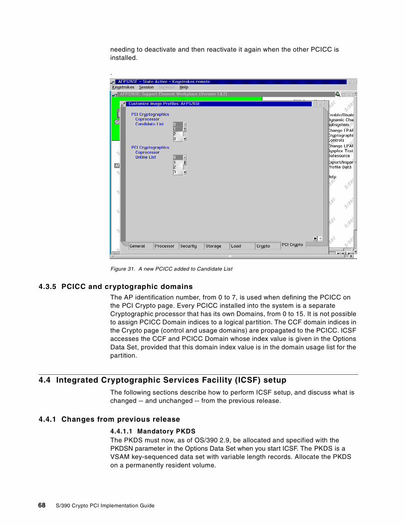
needing to deactivate and then reactivate it again when the other PCICC isinstalled.
.
Figure 31. A new PCICC added to Candidate List
4.3.5 PCICC and cryptographic domainsThe AP identification number, from 0 to 7, is used when defining the PCICC onthe PCI Crypto page. Every PCICC installed into the system is a separateCryptographic processor that has its own Domains, from 0 to 15. It is not possibleto assign PCICC Domain indices to a logical partition. The CCF domain indices inthe Crypto page (control and usage domains) are propagated to the PCICC. ICSFaccesses the CCF and PCICC Domain whose index value is given in the OptionsData Set, provided that this domain index value is in the domain usage list for thepartition.
4.4 Integrated Cryptographic Services Facility (ICSF) setup
The following sections describe how to perform ICSF setup, and discuss what ischanged -- and unchanged -- from the previous release.
4.4.1 Changes from previous release
4.4.1.1 Mandatory PKDSThe PKDS must now, as of OS/390 2.9, be allocated and specified with thePKDSN parameter in the Options Data Set when you start ICSF. The PKDS is aVSAM key-sequenced data set with variable length records. Allocate the PKDSon a permanently resident volume.
68 S/390 Crypto PCI Implementation Guide
4.4.1.2 Options Data SetStarting with OS/390 2.9, support is provided for the use of system symbols in theinstallation Options Data Set. System symbols can be used as values for any of theparameters. They are specified in the IEASYMxx member of SYS1.PARMLIB; theIEASYM statement of the LOADxx member specifies the IEASYMxx members to beused for their resolution. We defined the symbol PARDOM in our IEASYMxx:
SYSDEF SYMDEF(&PARDOM='5')
And we used the following symbol in our Options Data Set:
DOMAIN(&PARDOM.)
Note that viewing the system options via the ISPF panel shows the substitutionfor the symbolic values.
A new installation option is available that specifies the set of reason codes to bereturned from callable services: ICSF or TSS reason codes. We set:
REASONCODES(ICSF)
4.4.1.3 ICSF ISPF panelsThe panels and options referring to the PCICC will be visible only if at least onePCICC card has been detected in the system. Otherwise, these panels look verymuch the same as the panels in the previous ICSF release.
4.4.1.4 Initialize CKDS optionThis option now combines, at ICSF 2.3, the following functions:
• Write of the header record
• Set of Master Keys
• Write system keys
In previous ICSF releases, the “Initialize an empty CKDS” option was only writingthe header record.
4.4.2 TSO procedureFor convenience we set up a TSO procedure, CRYPTO, for the residents. Wespecified the ICSF libraries in the files allocations executed by CRYPTO:
• SCSFTLIB goes to ISPTLIB.
• SCSFCLI0 goes to SYSPROC.
• SCSFPNL0 goes to ISPPLIB.
At OS/390 2.9, the following is still in effect:
• The CKDS content is loaded into an in-storage CKDS, which gives thecapability to dynamically reencipher the CKDS. The PKDS content residesonly in the PKDS data set and there is no dynamic reenciphering capabilityfor the PKDS.
• It takes a manual procedure to synchronize or resynchronize the in-storageCKDSs in a parallel sysplex configuration.
Still the same
Chapter 4. Installation, configuration and startup of ICSF 69
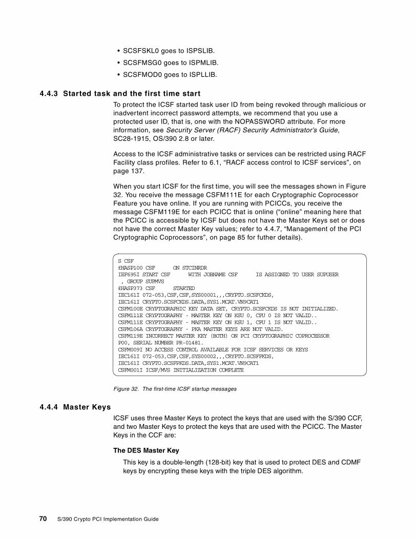
• SCSFSKL0 goes to ISPSLIB.
• SCSFMSG0 goes to ISPMLIB.
• SCSFMOD0 goes to ISPLLIB.
4.4.3 Started task and the first time startTo protect the ICSF started task user ID from being revoked through malicious orinadvertent incorrect password attempts, we recommend that you use aprotected user ID, that is, one with the NOPASSWORD attribute. For moreinformation, see Security Server (RACF) Security Administrator’s Guide,SC28-1915, OS/390 2.8 or later.
Access to the ICSF administrative tasks or services can be restricted using RACFFacility class profiles. Refer to 6.1, “RACF access control to ICSF services”, onpage 137.
When you start ICSF for the first time, you will see the messages shown in Figure32. You receive the message CSFM111E for each Cryptographic CoprocessorFeature you have online. If you are running with PCICCs, you receive themessage CSFM119E for each PCICC that is online (“online” meaning here thatthe PCICC is accessible by ICSF but does not have the Master Keys set or doesnot have the correct Master Key values; refer to 4.4.7, “Management of the PCICryptographic Coprocessors”, on page 85 for futher details).
Figure 32. The first-time ICSF startup messages
4.4.4 Master KeysICSF uses three Master Keys to protect the keys that are used with the S/390 CCF,and two Master Keys to protect the keys that are used with the PCICC. The MasterKeys in the CCF are:
The DES Master Key
This key is a double-length (128-bit) key that is used to protect DES and CDMFkeys by encrypting these keys with the triple DES algorithm.
S CSF£HASP100 CSF ON STCINRDRIEF695I START CSF WITH JOBNAME CSF IS ASSIGNED TO USER SUPUSER, GROUP SUPMVS£HASP373 CSF STARTEDIEC161I 072-053,CSF,CSF,SYS00001,,,CRYPTO.SCSFCKDS,IEC161I CRYPTO.SCSFCKDS.DATA,SYS1.MCAT.VN9CAT1CSFM100E CRYPTOGRAPHIC KEY DATA SET, CRYPTO.SCSFCKDS IS NOT INITIALIZED.CSFM111E CRYPTOGRAPHY - MASTER KEY ON KSU 0, CPU 0 IS NOT VALID..CSFM111E CRYPTOGRAPHY - MASTER KEY ON KSU 1, CPU 1 IS NOT VALID..CSFM106A CRYPTOGRAPHY - PKA MASTER KEYS ARE NOT VALID.CSFM119E INCORRECT MASTER KEY (BOTH) ON PCI CRYPTOGRAPHIC COPROCESSORP00, SERIAL NUMBER PR-01481.CSFM009I NO ACCESS CONTROL AVAILABLE FOR ICSF SERVICES OR KEYSIEC161I 072-053,CSF,CSF,SYS00002,,,CRYPTO.SCSFPKDS,IEC161I CRYPTO.SCSFPKDS.DATA,SYS1.MCAT.VN9CAT1CSFM001I ICSF/MVS INITIALIZATION COMPLETE
70 S/390 Crypto PCI Implementation Guide

The PKA Key Management Master Key
This key (KMMK) is a triple-length (192-bit) key. The KMMK protects PKA privatekeys that are used in both the digital signature services and in the CDMF andDES data key distribution functions.
The PKA Signature Master Key
This key (SMK) is a triple-length (192-bit) key. The SMK protects PKA privatekeys that are used only in digital signature services.
The Master Keys in the PCICC are:
Symmetric-keys Master Key
This key (SYM-MK) is a double-length (128-bit) key that is used to protectDES keys used on the PCI Cryptographic Coprocessor. The SYM-MK isactually a triple-length (192-bit) Master Key inside the PCICC that ICSFenforces to be equivalent to a double-length (128-bit) Master Key. This keymust have the same value as the DES Master Key in the CCF.
Asymmetric-keys Master Key
This key (ASYM-MK) is a triple-length (192-bit) key. The ASYM-MK protects PKAprivate keys that are used on the PCI Cryptographic Coprocessor. This key musthave the same value as the SMK in the CCF.
4.4.5 Initial Master Key entry with the pass phrase initialization utilityThe pass phrase initialization utility can be used to initialize the CKDS and thecoprocessor. You can also use this utility to install both the SYM-MK and theASYM-MK on all PCI Cryptographic Coprocessors on S/390 G5 Enterprise Servers,or later.
To use this utility, the special secure mode must be enabled, and all the MasterKey registers in the targeted coprocessors must be empty. Also, the designatedCKDS must not be already initialized, that is, it is just an empty VSAM data set.Therefore, you cannot use this utility to change the Master Keys.
When you access the ICSF panels, the primary menu panel appears, as shown inFigure 33 on page 72.
Chapter 4. Installation, configuration and startup of ICSF 71

Figure 33. Selecting Pass Phrase Option on the ICSF primary menu panel
Select option 8, PPINIT, and press Enter to begin the pass phrase initializationutility. Then type the pass phrase and the data set name in the provided spaces.
Answer Y to the Signature MK = Key Management MK? question: the signatureMaster Key and the Key Management Master Key in the CCFs will have the samevalue as the ASYM-MK on the PCI Cryptographic Coprocessors.
Figure 34. Entering options on the Pass Phrase MK/CKDS Initialization panel
Press Enter to run the utility. Its progress is indicated by messages, as shown inFigure 35 on page 73.
------------------- Integrated Cryptographic Service Facility---------------
Enter the number of the desired option.
1 MASTER KEY - Set or change the system master key2 KGUP - Key Generator Utility processes3 OPSTAT - Installation options and Hardware status4 OPKEY - Operational key direct input5 UTILITY - OS/390 ICSF Utilities6 CKDS - CKDS Refresh and Initialization7 USERCNTL - User Control Functions8 PPINIT - Pass Phrase Master Key/CKDS Initialization9 PCICC MGMT - Management of PCI Cryptographic Coprocessors
Licensed Materials - Property of IBM
This product contains "Restricted Materials of IBM"5647-A01 (C) Copyright IBM Corp. 2000. All rights reserved.US Government Users Restricted Rights - Use, duplication ordisclosure restricted by GSA ADP Schedule Contract with IBM Corp.
OPTION ===> 8
--------------- OS/390 ICSF - Pass Phrase MK/CKDS Initialization ----
Enter your pass phrase and the name of the CKDS:
Pass Phrase (16 to 64 characters)===> The PCI Implementation Guide residency in Montpellier
CKDS===> 'CRYPTO.SCSFCKDS'
Initialize the CKDS? (Y/N) ===> YSignature MK = Key Management MK? (Y/N) ===> Y
Press ENTER to process.COMMAND ===>
72 S/390 Crypto PCI Implementation Guide
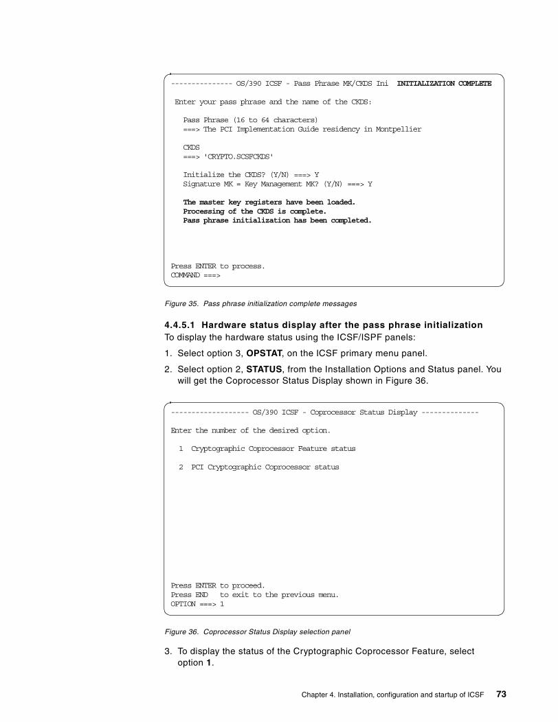
Figure 35. Pass phrase initialization complete messages
4.4.5.1 Hardware status display after the pass phrase initializationTo display the hardware status using the ICSF/ISPF panels:
1. Select option 3, OPSTAT, on the ICSF primary menu panel.
2. Select option 2, STATUS, from the Installation Options and Status panel. Youwill get the Coprocessor Status Display shown in Figure 36.
Figure 36. Coprocessor Status Display selection panel
3. To display the status of the Cryptographic Coprocessor Feature, selectoption 1.
--------------- OS/390 ICSF - Pass Phrase MK/CKDS Ini INITIALIZATION COMPLETE
Enter your pass phrase and the name of the CKDS:
Pass Phrase (16 to 64 characters)===> The PCI Implementation Guide residency in Montpellier
CKDS===> 'CRYPTO.SCSFCKDS'
Initialize the CKDS? (Y/N) ===> YSignature MK = Key Management MK? (Y/N) ===> Y
The master key registers have been loaded.Processing of the CKDS is complete.Pass phrase initialization has been completed.
Press ENTER to process.COMMAND ===>
------------------- OS/390 ICSF - Coprocessor Status Display --------------
Enter the number of the desired option.
1 Cryptographic Coprocessor Feature status
2 PCI Cryptographic Coprocessor status
Press ENTER to proceed.Press END to exit to the previous menu.OPTION ===> 1
Chapter 4. Installation, configuration and startup of ICSF 73
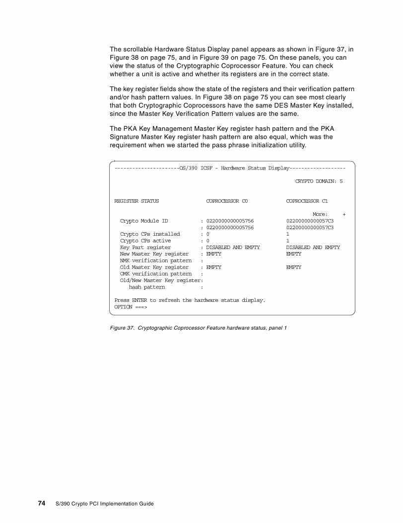
The scrollable Hardware Status Display panel appears as shown in Figure 37, inFigure 38 on page 75, and in Figure 39 on page 75. On these panels, you canview the status of the Cryptographic Coprocessor Feature. You can checkwhether a unit is active and whether its registers are in the correct state.
The key register fields show the state of the registers and their verification patternand/or hash pattern values. In Figure 38 on page 75 you can see most clearlythat both Cryptographic Coprocessors have the same DES Master Key installed,since the Master Key Verification Pattern values are the same.
The PKA Key Management Master Key register hash pattern and the PKASignature Master Key register hash pattern are also equal, which was therequirement when we started the pass phrase initialization utility.
Figure 37. Cryptographic Coprocessor Feature hardware status, panel 1
----------------------OS/390 ICSF - Hardware Status Display-------------------
CRYPTO DOMAIN: 5
REGISTER STATUS COPROCESSOR C0 COPROCESSOR C1
More: +Crypto Module ID : 0220000000005756 02200000000057C3
: 0220000000005756 02200000000057C3Crypto CPs installed : 0 1Crypto CPs active : 0 1Key Part register : DISABLED AND EMPTY DISABLED AND EMPTYNew Master Key register : EMPTY EMPTYNMK verification pattern :Old Master Key register : EMPTY EMPTYOMK verification pattern :Old/New Master Key register:
hash pattern :
Press ENTER to refresh the hardware status display.OPTION ===>
74 S/390 Crypto PCI Implementation Guide
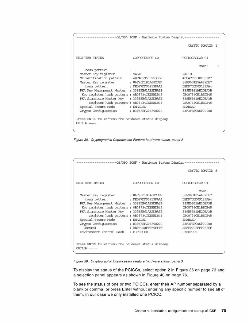
Figure 38. Cryptographic Coprocessor Feature hardware status, panel 2
Figure 39. Cryptographic Coprocessor Feature hardware status, panel 3
To display the status of the PCICCs, select option 2 in Figure 36 on page 73 anda selection panel appears as shown in Figure 40 on page 76.
To see the status of one or two PCICCs, enter their AP number separated by ablank or comma, or press Enter without entering any specific number to see all ofthem. In our case we only installed one PCICC.
----------------------OS/390 ICSF - Hardware Status Display-------------------
CRYPTO DOMAIN: 5
REGISTER STATUS COPROCESSOR C0 COPROCESSOR C1
More: - +hash pattern :
Master Key register : VALID VALIDMK verification pattern : 4BCACF95302533B7 4BCACF95302533B7Master Key register : 86F90D1B5A682DE7 86F90D1B5A682DE7
hash pattern : DEDF7DDD0913FAA4 DEDF7DDD0913FAA4PKA Key Management Master : 339E5B61AE2DBA3B 339E5B61AE2DBA3BKey register hash pattern : 0B08734CE1BBDB45 0B08734CE1BBDB45PKA Signature Master Key : 339E5B61AE2DBA3B 339E5B61AE2DBA3B
register hash pattern : 0B08734CE1BBDB45 0B08734CE1BBDB45Special Secure Mode : ENABLED ENABLEDCrypto Configuration : B3F3FEFC06F00000 B3F3FEFC06F00000
Press ENTER to refresh the hardware status display.OPTION ===>
----------------------OS/390 ICSF - Hardware Status Display-------------------
CRYPTO DOMAIN: 5
REGISTER STATUS COPROCESSOR C0 COPROCESSOR C1
More: -Master Key register : 86F90D1B5A682DE7 86F90D1B5A682DE7
hash pattern : DEDF7DDD0913FAA4 DEDF7DDD0913FAA4PKA Key Management Master : 339E5B61AE2DBA3B 339E5B61AE2DBA3BKey register hash pattern : 0B08734CE1BBDB45 0B08734CE1BBDB45PKA Signature Master Key : 339E5B61AE2DBA3B 339E5B61AE2DBA3B
register hash pattern : 0B08734CE1BBDB45 0B08734CE1BBDB45Special Secure Mode : ENABLED ENABLEDCrypto Configuration : B3F3FEFC06F00000 B3F3FEFC06F00000Control : ABFF000FFFF0FFFF ABFF000FFFF0FFFF
Environment Control Mask : F3FEFCF0 F3FEFCF0
Press ENTER to refresh the hardware status display.OPTION ===>
Chapter 4. Installation, configuration and startup of ICSF 75

Figure 40. The PCICC selection panel
The scrollable PCI Hardware Status Display panel appears as shown in Figure 41on page 77 and in Figure 42 on page 77. On these panels, you can view thestatus of the PCI Cryptographic Coprocessors. If you selected to view all PCICCs,you can also scroll right and left with the PFkeys, to see information pertaining tothe other PCICCs.
Note that the Symmetric-Keys Master Key Verification pattern in Figure 41 onpage 77 matches the DES MK verification pattern shown in Figure 38 on page 75.Also, the Asymmetric-Keys Master Key Hash pattern in Figure 42 on page 77matches the PKA KMMK and SMK register hash patterns in Figure 39 on page75.
--------------------- OS/390 ICSF - Coprocessor Selection ---------------
These are the online PCI Cryptographic Coprocessors.
1. P00
Enter the number of one or two coprocessors to see the status ofspecific coprocessors. Separate the numbers with a comma or a blank.
Press ENTER to see the status of all online coprocessors.
Press END to exit to the previous menu.
OPTION ===> 1
76 S/390 Crypto PCI Implementation Guide
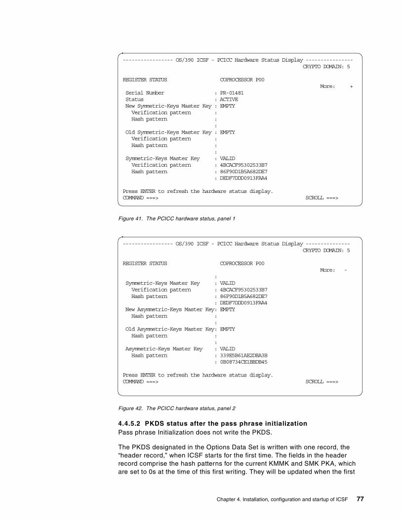
Figure 41. The PCICC hardware status, panel 1
Figure 42. The PCICC hardware status, panel 2
4.4.5.2 PKDS status after the pass phrase initializationPass phrase Initialization does not write the PKDS.
The PKDS designated in the Options Data Set is written with one record, the“header record,” when ICSF starts for the first time. The fields in the headerrecord comprise the hash patterns for the current KMMK and SMK PKA, whichare set to 0s at the time of this first writing. They will be updated when the first
----------------- OS/390 ICSF - PCICC Hardware Status Display ----------------CRYPTO DOMAIN: 5
REGISTER STATUS COPROCESSOR P00More: +
Serial Number : PR-01481Status : ACTIVENew Symmetric-Keys Master Key : EMPTYVerification pattern :Hash pattern :
:Old Symmetric-Keys Master Key : EMPTYVerification pattern :Hash pattern :
:Symmetric-Keys Master Key : VALIDVerification pattern : 4BCACF95302533B7Hash pattern : 86F90D1B5A682DE7
: DEDF7DDD0913FAA4
Press ENTER to refresh the hardware status display.COMMAND ===> SCROLL ===>
----------------- OS/390 ICSF - PCICC Hardware Status Display ---------------CRYPTO DOMAIN: 5
REGISTER STATUS COPROCESSOR P00More: -
:Symmetric-Keys Master Key : VALIDVerification pattern : 4BCACF95302533B7Hash pattern : 86F90D1B5A682DE7
: DEDF7DDD0913FAA4New Asymmetric-Keys Master Key: EMPTYHash pattern :
:Old Asymmetric-Keys Master Key: EMPTYHash pattern :
:Asymmetric-Keys Master Key : VALIDHash pattern : 339E5B61AE2DBA3B
: 0B08734CE1BBDB45
Press ENTER to refresh the hardware status display.COMMAND ===> SCROLL ===>
Chapter 4. Installation, configuration and startup of ICSF 77

key is stored in the PKDS. If you stop and restart ICSF before this first storing ofa key in the PKDS, you will see the message shown in Figure 43. The otherimplication of this situation is that ICSF automatically disallows read and writeaccess to the PKDS by the application. It takes a manual intervention via theICSF USERCNTL panel to enable these accesses.
Figure 43. Message on the ICSF startup before the first write to PKDS
You can avoid this problem, if deemed necessary, by either writing a record intothe PKDS via your own coded routine or by importing an RSA key. Before writingthe record to the PKDS, insure that the write to PKDS is enabled, as indicatedbefore. The CKDS is completely initialized, with system keys written in the dataset, during the pass phrase initialization process.
4.4.6 Changing the Master Keys for CCF and PCICC via ICSF panelsThe pass phrase initialization utility is intended to get you started easily andquickly with ICSF and coprocessor initialization. However, this is not a secureway of administering Master Keys since the pass phrase character string is the“synonym” of the clear key values. It is therefore recommended that you proceedwith a Master Key change, using new Master Keys generated and enteredaccording to your site security policy. Also, for security reasons, you may want toperiodically change your Master Keys.
If the Master Keys have been cleared from the crypto coprocessors due to atamper detection, or if you zeroized the domain from the TKE workstation, thekeys in the CKDS that are still enciphered under that Master Key must berecovered. In order to do this, you must reenter the same Master Keys as beforeand activate them, and then you may change the Master Keys if desired.
4.4.6.1 Weak Master KeysThe PCICC tests whether the entered new Master Key is a DES “weak key”. ADES weak key is a bit string with such a configuration that the so-called“subkeys”, generated in the DES algorithm internal process, do not have thevariance level required to insure maximum security. This test is done after thefinal part of the new Master Key has been entered and combined with theprevious parts. If the new Master Key, be it the SYM-MK or the ASYM-MK, is aDES weak key, then the Master Key has to be entered with new values.
To illustrate this, here is an example (see Figure 44 on page 79), where the newMaster Key is rejected because it is a DES weak key.
CSFM405A AUTHENTICATION CODE IN PKDS HEADER RECORD DOES NOT MATCHCOMPUTED VALUE.
78 S/390 Crypto PCI Implementation Guide
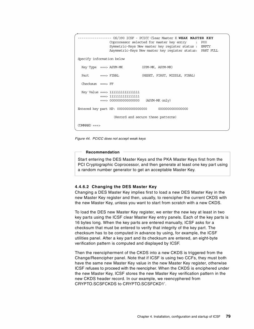
Figure 44. PCICC does not accept weak keys
4.4.6.2 Changing the DES Master KeyChanging a DES Master Key implies first to load a new DES Master Key in thenew Master Key register and then, usually, to reencipher the current CKDS withthe new Master Key, unless you want to start from scratch with a new CKDS.
To load the DES new Master Key register, we enter the new key at least in twokey parts using the ICSF clear Master Key entry panels. Each of the key parts is16 bytes long. When the key parts are entered manually, ICSF asks for achecksum that must be entered to verify that integrity of the key part. Thechecksum has to be computed in advance by using, for example, the ICSFutilities panel. After a key part and its checksum are entered, an eight-byteverification pattern is computed and displayed by ICSF.
Then the reencipherment of the CKDS into a new CKDS is triggered from theChange/Reencipher panel. Note that if ICSF is using two CCFs, they must bothhave the same new Master Key value in the new Master Key register, otherwiseICSF refuses to proceed with the reencipher. When the CKDS is enciphered underthe new Master Key, ICSF stores the new Master Key verification pattern in thenew CKDS header record. In our example, we reencyphered fromCRYPTO.SCSFCKDS to CRYPTO.SCSFCKD1’.
------------------ OS/390 ICSF - PCICC Clear Master K WEAK MASTER KEYCoprocessor selected for master key entry : P00Symmetric-Keys New master key register status : EMPTYAsymmetric-Keys New master key register status: PART FULL
Specify information below
Key Type ===> ASYM-MK (SYM-MK, ASYM-MK)
Part ===> FINAL (RESET, FIRST, MIDDLE, FINAL)
Checksum ===> FF
Key Value ===> 1111111111111111===> 1111111111111111===> 0000000000000000 (ASYM-MK only)
Entered key part HP: 0000000000000000 0000000000000000
(Record and secure these patterns)
COMMAND ===>
Start entering the DES Master Keys and the PKA Master Keys first from thePCI Cryptographic Coprocessor, and then generate at least one key part usinga random number generator to get an acceptable Master Key.
Recommendation
Chapter 4. Installation, configuration and startup of ICSF 79

At this point the new Master Key is still in the new Master Key register. It must beloaded in the current DES Master Key register using the CHANGE option in theChange/Reencipher panel. It is required that all the new Master Key registers,new DES Master Key registers, and SYM-MK registers have the same value,otherwise ICSF refuses to change the Master Key with the error message shownin Figure 45.
Figure 45. Master Key change failed
The process to load the new Master Key in the PCICC is similar to that of theCCF. The entry process starts from the ICSF main panel selecting option 1, andyou will get the panel shown in Figure 46 on page 81. There you can selectwhether the Master Key entry will affect all PCICCs that are online, or whether theMaster Key entry affects only a specific PCICC. We recommend that you selectoption 4 to easily enter the new Master Key in all PCICCs. We selected in ourcase option 3, because we had only one PCICC.
----------------------- OS/390 ICSF - Change Master K PCICC NMK INCORRECT
Enter the name of the new CKDS below.
New CKDS ===> 'CRYPTO.SCSFCKD1'
When the master key is changed, the new CKDS will become active.
Press ENTER to change the master key.Press END to exit to the previous menu.COMMAND ===>
80 S/390 Crypto PCI Implementation Guide

Figure 46. The clear Master Key entry for only one PCICC
After selecting option 3 and pressing Enter, the panel shown in Figure 47appears. Here we select option 1.
Figure 47. Select the correct PCICC for the clear Master Key entry
In the next panel, shown in Figure 48 on page 82, the new key type is entered,along with the usual information on the key part position and the clear key partvalue. The final key part is loaded in Figure 49 on page 82.
----------------- OS/390 ICSF Master Key Coprocessor Selection -----------
Enter the number of the desired option.
1 Cryptographic Coprocessor Feature Clear Master Key Entry - Enterthe DES and PKA master keys via panels.
2 Trusted Key Entry - Complete loading of DES new master key registerfrom the key part registers queued from the TKE workstation.
3 PCI Cryptographic Coprocessor Clear Master Key Entry - Enter themaster keys for one coprocessor via panels.
4 All PCI Cryptographic Coprocessor Clear Master Key Entry - Enter themaster keys on all online coprocessors via panels.
Press ENTER to proceed.OPTION ===> 3
--------------------- OS/390 ICSF - Coprocessor Selection --------------
These are the online PCI Cryptographic Coprocessors.
1. P00
Select one coprocessor and press ENTER to proceed to master key entry.
Press END to exit to the previous menu.
OPTION ===> 1
Chapter 4. Installation, configuration and startup of ICSF 81
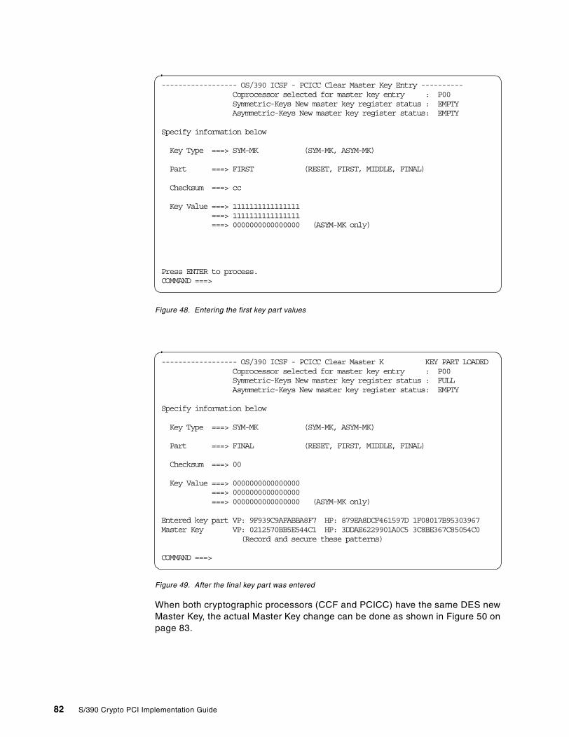
Figure 48. Entering the first key part values
Figure 49. After the final key part was entered
When both cryptographic processors (CCF and PCICC) have the same DES newMaster Key, the actual Master Key change can be done as shown in Figure 50 onpage 83.
------------------ OS/390 ICSF - PCICC Clear Master Key Entry ----------Coprocessor selected for master key entry : P00Symmetric-Keys New master key register status : EMPTYAsymmetric-Keys New master key register status: EMPTY
Specify information below
Key Type ===> SYM-MK (SYM-MK, ASYM-MK)
Part ===> FIRST (RESET, FIRST, MIDDLE, FINAL)
Checksum ===> cc
Key Value ===> 1111111111111111===> 1111111111111111===> 0000000000000000 (ASYM-MK only)
Press ENTER to process.COMMAND ===>
------------------ OS/390 ICSF - PCICC Clear Master K KEY PART LOADEDCoprocessor selected for master key entry : P00Symmetric-Keys New master key register status : FULLAsymmetric-Keys New master key register status: EMPTY
Specify information below
Key Type ===> SYM-MK (SYM-MK, ASYM-MK)
Part ===> FINAL (RESET, FIRST, MIDDLE, FINAL)
Checksum ===> 00
Key Value ===> 0000000000000000===> 0000000000000000===> 0000000000000000 (ASYM-MK only)
Entered key part VP: 9F939C9AFABBA8F7 HP: 879EA8DCF461597D 1F08017B95303967Master Key VP: 0212570BB5E544C1 HP: 3DDAE6229901A0C5 3C8BE367C85054C0
(Record and secure these patterns)
COMMAND ===>
82 S/390 Crypto PCI Implementation Guide
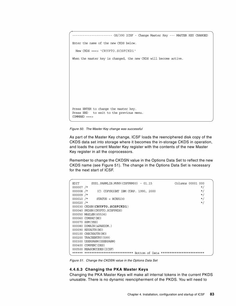
Figure 50. The Master Key change was successful
As part of the Master Key change, ICSF loads the reenciphered disk copy of theCKDS data set into storage where it becomes the in-storage CKDS in operation,and loads the current Master Key register with the contents of the new MasterKey register in all the coprocessors.
Remember to change the CKDSN value in the Options Data Set to reflect the newCKDS name (see Figure 51). The change in the Options Data Set is necessaryfor the next start of ICSF.
Figure 51. Change the CKDSN value in the Options Data Set
4.4.6.3 Changing the PKA Master KeysChanging the PKA Master Keys will make all internal tokens in the current PKDSunusable. There is no dynamic reencipherment of the PKDS. You will need to
----------------------- OS/390 ICSF - Change Master Key --- MASTER KEY CHANGED
Enter the name of the new CKDS below.
New CKDS ===> 'CRYPTO.SCSFCKD1'
When the master key is changed, the new CKDS will become active.
Press ENTER to change the master key.Press END to exit to the previous menu.COMMAND ===>
EDIT SYS1.PARMLIB.MVN9(CSFPRM00) - 01.15 Columns 00001 000000007 /* */000008 /* (C) COPYRIGHT IBM CORP. 1990, 2000 */000009 /* */000010 /* STATUS = HCRP230 */000020 /* */000030 CKDSN(CRYPTO.SCSFCKD1)000040 PKDSN(CRYPTO.SCSFPKDS)000050 MAXLEN(65536)000060 COMPAT(NO)000070 SSM(YES)000080 DOMAIN(&PARDOM.)000090 KEYAUTH(NO)000100 CHECKAUTH(NO)000200 TRACEENTRY(599)000300 USERPARM(USERPARM)000400 COMPENC(DES)000500 REASONCODES(ICSF)****** **************************** Bottom of Data *************************
Chapter 4. Installation, configuration and startup of ICSF 83

re-create the PKA application key tokens manually under the new PKA MasterKeys in order to use them with the changed Master Key.
To change the PKA Master Keys, go to the user control functions by selectingoption 7, USERCNTL on the primary menu panel, and disable the PKA callableservices by selecting option 4 and pressing Enter.
We entered all PKA Master Key parts starting with the PCICC, then we enteredthe same two values into the CCFs. This was motivated by PCICC needing atleast two key parts, first and final, whereas CCF, although not recommended, canhave only one PKA Master Key part. The differences in the loading process of thePKA Master Key between the CCF and the PCICC are:
• The CCF requires that you:
1. RESET the PKA Master Key register to be loaded.
2. Proceed with entering the key parts, at least one key part. The key partsare combined in the PKA Master Key register.
• The PCICC has three ASYM-MK registers: a new register, the current MasterKey and the old Master Key register. These registers are visible in thehardware status panel, which shows the hash patterns of all three registers.
1. The RESET affects the new ASYM-MK register only.
2. The new ASYM-MK key parts are loaded and combined into the newMaster Key register. The system requires at least two key parts.
3. When the key part entered is flagged as FINAL, the new Master Key istested for a DES weak key value. If not a weak key, the current ASYM-MKregister is automatically loaded with the contents of the new Master Keyregister. Figure 52 illustrates this process.
Figure 52. The final ASYM-MK key part is loaded
------------------ OS/390 ICSF - PCICC Clear Master K KEY PART LOADEDCoprocessor selected for master key entry : P00Symmetric-Keys New master key register status : EMPTYAsymmetric-Keys New master key register status: EMPTY
Specify information below
Key Type ===> ASYM-MK (SYM-MK, ASYM-MK)
Part ===> FINAL (RESET, FIRST, MIDDLE, FINAL)
Checksum ===> 81
Key Value ===> A10E524307233261===> EA8A73F8F1B94F85===> 0E328A589E15924C (ASYM-MK only)
Entered key part HP: 5F9979D41055491B 585443B7EB5A3F6AMaster Key HP: 3B209BBBC9D7CC3C 00244634AEFCB391
(Record and secure these patterns)
COMMAND ===>
84 S/390 Crypto PCI Implementation Guide
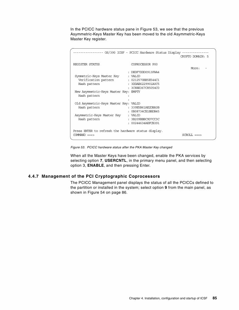
In the PCICC hardware status pane in Figure 53, we see that the previousAsymmetric-Keys Master Key has been moved to the old Asymmetric-KeysMaster Key register.
Figure 53. PCICC hardware status after the PKA Master Key changed
When all the Master Keys have been changed, enable the PKA services byselecting option 7, USERCNTL, in the primary menu panel, and then selectingoption 3, ENABLE, and then pressing Enter.
4.4.7 Management of the PCI Cryptographic CoprocessorsThe PCICC Management panel displays the status of all the PCICCs defined tothe partition or installed in the system; select option 9 from the main panel, asshown in Figure 54 on page 86.
----------------- OS/390 ICSF - PCICC Hardware Status Display ---------------CRYPTO DOMAIN: 5
REGISTER STATUS COPROCESSOR P00More: -
: DEDF7DDD0913FAA4Symmetric-Keys Master Key : VALIDVerification pattern : 0212570BB5E544C1Hash pattern : 3DDAE6229901A0C5
: 3C8BE367C85054C0New Asymmetric-Keys Master Key: EMPTYHash pattern :
:Old Asymmetric-Keys Master Key: VALIDHash pattern : 339E5B61AE2DBA3B
: 0B08734CE1BBDB45Asymmetric-Keys Master Key : VALIDHash pattern : 3B209BBBC9D7CC3C
: 00244634AEFCB391
Press ENTER to refresh the hardware status display.COMMAND ===> SCROLL ===>
Chapter 4. Installation, configuration and startup of ICSF 85
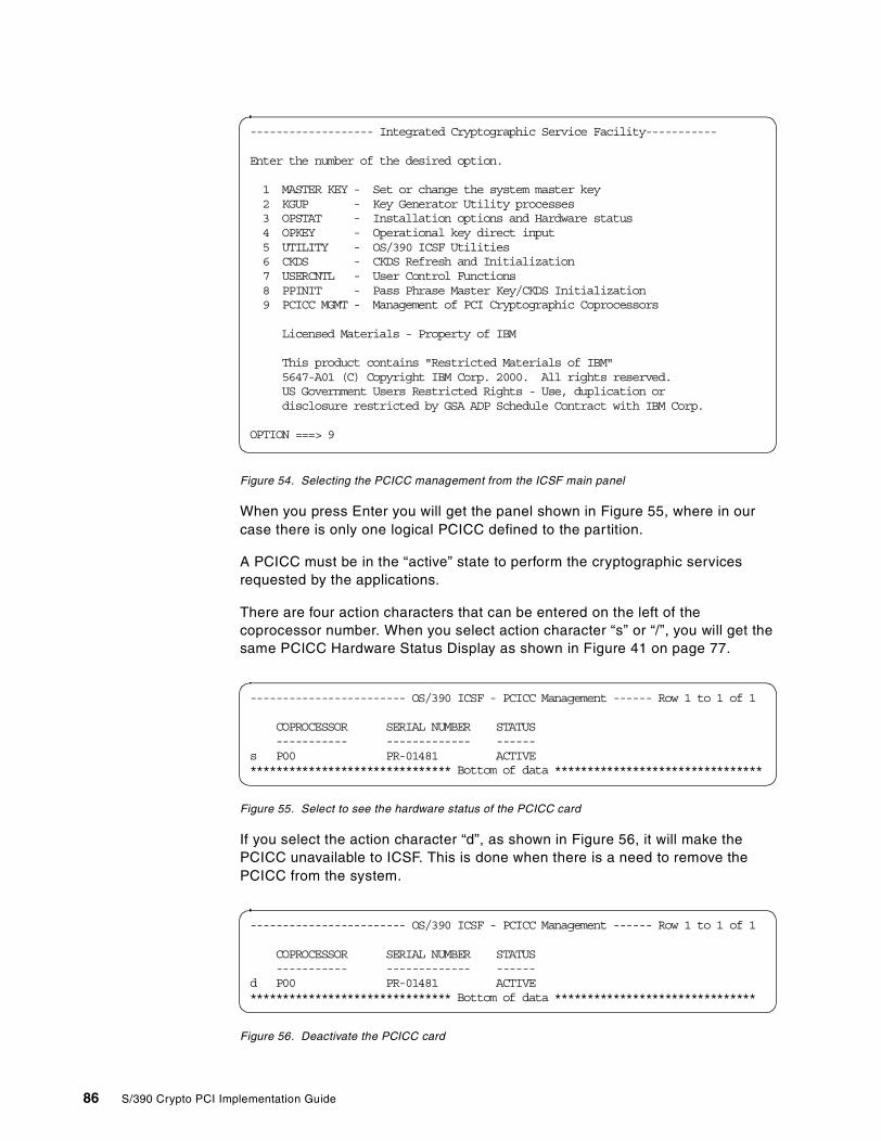
Figure 54. Selecting the PCICC management from the ICSF main panel
When you press Enter you will get the panel shown in Figure 55, where in ourcase there is only one logical PCICC defined to the partition.
A PCICC must be in the “active” state to perform the cryptographic servicesrequested by the applications.
There are four action characters that can be entered on the left of thecoprocessor number. When you select action character “s” or “/”, you will get thesame PCICC Hardware Status Display as shown in Figure 41 on page 77.
Figure 55. Select to see the hardware status of the PCICC card
If you select the action character “d”, as shown in Figure 56, it will make thePCICC unavailable to ICSF. This is done when there is a need to remove thePCICC from the system.
Figure 56. Deactivate the PCICC card
------------------- Integrated Cryptographic Service Facility-----------
Enter the number of the desired option.
1 MASTER KEY - Set or change the system master key2 KGUP - Key Generator Utility processes3 OPSTAT - Installation options and Hardware status4 OPKEY - Operational key direct input5 UTILITY - OS/390 ICSF Utilities6 CKDS - CKDS Refresh and Initialization7 USERCNTL - User Control Functions8 PPINIT - Pass Phrase Master Key/CKDS Initialization9 PCICC MGMT - Management of PCI Cryptographic Coprocessors
Licensed Materials - Property of IBM
This product contains "Restricted Materials of IBM"5647-A01 (C) Copyright IBM Corp. 2000. All rights reserved.US Government Users Restricted Rights - Use, duplication ordisclosure restricted by GSA ADP Schedule Contract with IBM Corp.
OPTION ===> 9
------------------------ OS/390 ICSF - PCICC Management ------ Row 1 to 1 of 1
COPROCESSOR SERIAL NUMBER STATUS----------- ------------- ------
s P00 PR-01481 ACTIVE******************************* Bottom of data ********************************
------------------------ OS/390 ICSF - PCICC Management ------ Row 1 to 1 of 1
COPROCESSOR SERIAL NUMBER STATUS----------- ------------- ------
d P00 PR-01481 ACTIVE******************************* Bottom of data *******************************
86 S/390 Crypto PCI Implementation Guide

When the request is made, the status of the PCICC becomes DEACTIVATED asshown in Figure 57. To make the deactivated PCICC available, you can use theaction character “a”. When the request is made and if the PCICC is online and theMaster Keys are correct, the status will be ACTIVE.
Figure 57. Deactivated PCICC card
Table 3 shows the status values and their explanations.
Table 3. The PCICC status values
Status Explanation
ONLINE The PCICC is available for certaincommands, but either one or both of theMaster Keys are incorrect. That is, there isno SYM-MK or ASYM-MK entered, or theyrespectively do not match the CCF DES MKand SMK.
OFFLINE A PCICC may be physically present but it isnot available to the operating system. Eitherit has never been configured online or it hasbeen configured offline at the SupportElement.
ACTIVE The PCICC has correct Master Keys, that is,both SYM-MK and ASYM-MK match theCCF DES MK and SMK, and can be usedfor all eligible commands.
DEACTIVATED The PCICC is online and may have correctMaster Keys, but it has been removed fromservice with this management panel.
DISABLED A Trusted Key Entry (TKE) workstation hasremoved the PCICC from service. Only aTKE workstation can enable the PCICCagain.
UNKNOWN: CODE = cccc/ssss The PCICC has returned an unrecognizablecode in response to an attempt to determineits status. The return/reason code appearsas the value of CODE.
TEMPORARILY UNAVAILABLE An unexpected error has been returnedfrom the card. The system goes intorecovery to try to reset the card. If the resetis successful, the card is usable again. Theuser must press Enter to refresh the status.
------------------------ OS/390 ICSF - PCICC Management ------ Row 1 to 1 of 1
COPROCESSOR SERIAL NUMBER STATUS----------- ------------- ------
. P00 PR-01481 DEACTIVATED******************************* Bottom of data *******************************
Chapter 4. Installation, configuration and startup of ICSF 87
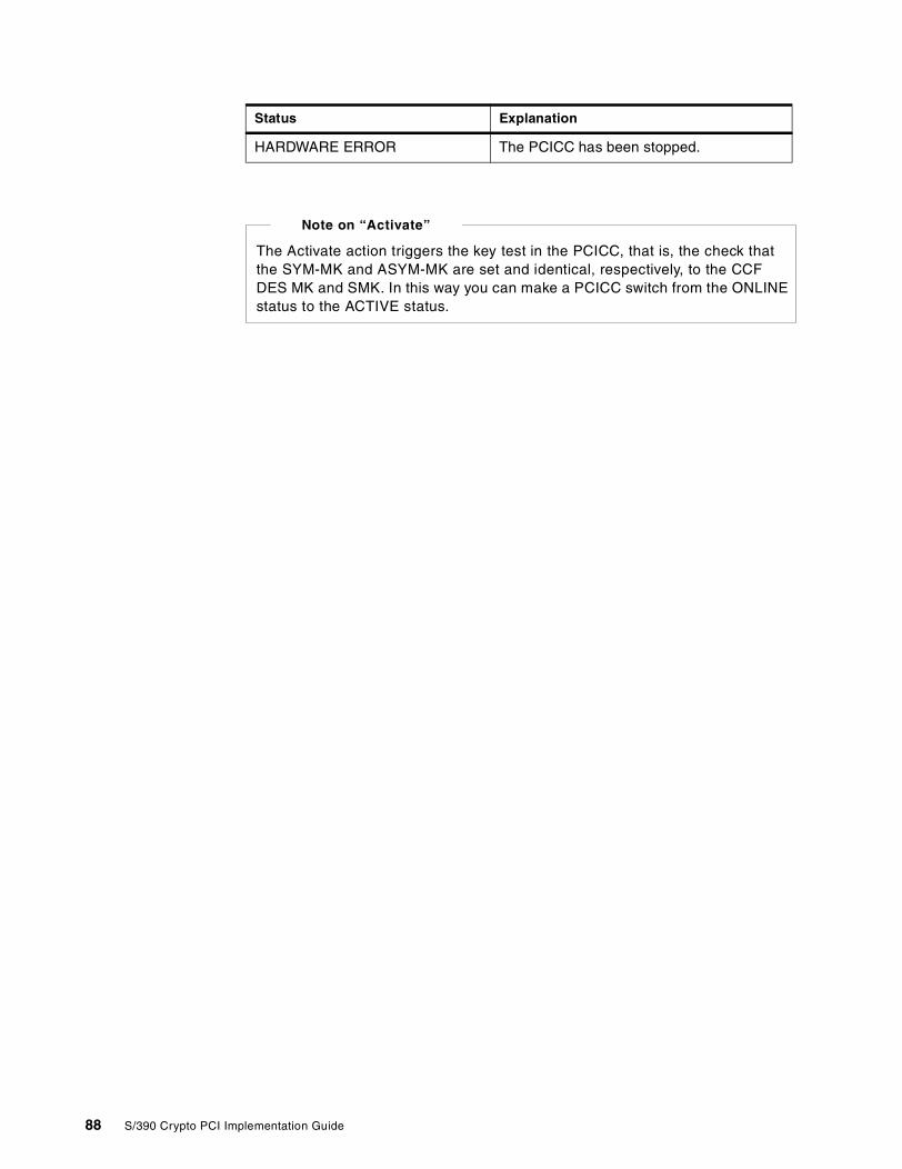
HARDWARE ERROR The PCICC has been stopped.
Status Explanation
The Activate action triggers the key test in the PCICC, that is, the check thatthe SYM-MK and ASYM-MK are set and identical, respectively, to the CCFDES MK and SMK. In this way you can make a PCICC switch from the ONLINEstatus to the ACTIVE status.
Note on “Activate”
88 S/390 Crypto PCI Implementation Guide
Chapter 5. Customizing PCICC and CCF using a TKE V3.0
This chapter provides an overview of the management and operations of the newTrusted Key Entry (TKE) workstation (TKE V3.0).
5.1 Introduction to the new TKE workstation
With the introduction of the PCICC card for 9672 G5/G6 processors, the TKEworkstation has been enhanced to allow remote administration of the PCI card(s).It also continues to support the standard Cryptographic Coprocessor Feature.
Security and secrecy are provided by encrypted and signed transactions betweenthe TKE and the remote Crypto coprocessors. Diffie-Hellman generated keys areused to protect the key parts transported between the TKE and the S/390 hostcryptographic coprocessors, and requests and responses flowing over thenetwork are authenticated using public key cryptography.
The graphical interface has also been revisited, so users should find the modulemanagement panels and menus of the TKE V3.0 application friendlier to use.More details can be found in the TKE Workstation User’s Guide 2000,GA22-7430.
5.1.1 Major changesFollowing are brief descriptions of the major changes to this workstation.
• The cryptographic functions in the TKE V3.0 are performed by an IBM 4758model 002 cryptographic coprocessor installed in the workstation (the TKEV2.x uses a 4755 cryptographic adapter).
• The TKE V3.0 can manage both PCICCS and CCFs. (The TKE V2.x supportsonly the CCF modules, and there is no upgrade path between TKE V2 andTKE V3.)
Figure 58 on page 90 illustrates the compatibility between the TKE versionsand models of the 9672 Enterprise Server.
© Copyright IBM Corp. 2000 89
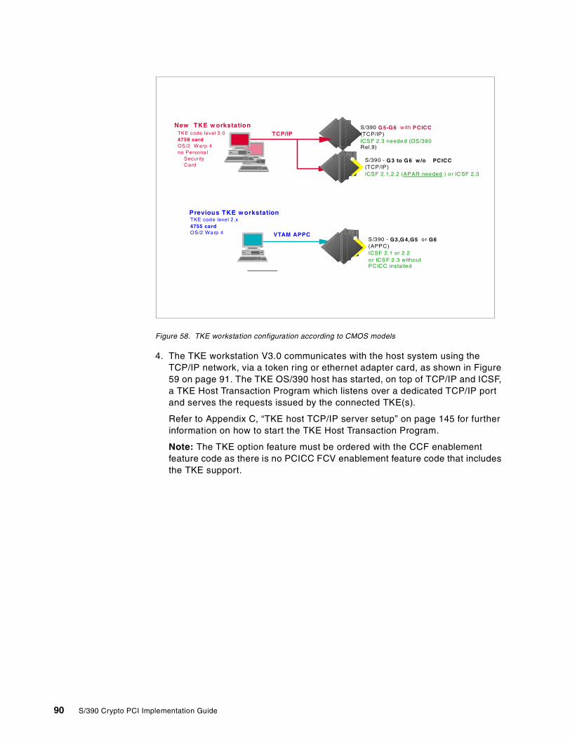
Figure 58. TKE workstation configuration according to CMOS models
4. The TKE workstation V3.0 communicates with the host system using theTCP/IP network, via a token ring or ethernet adapter card, as shown in Figure59 on page 91. The TKE OS/390 host has started, on top of TCP/IP and ICSF,a TKE Host Transaction Program which listens over a dedicated TCP/IP portand serves the requests issued by the connected TKE(s).
Refer to Appendix C, “TKE host TCP/IP server setup” on page 145 for furtherinformation on how to start the TKE Host Transaction Program.
Note: The TKE option feature must be ordered with the CCF enablementfeature code as there is no PCICC FCV enablement feature code that includesthe TKE support.
S/390 - G 3 to G 6 w /o PCICC(TCP/IP)ICSF 2.1,2.2 (APAR needed ) or ICSF 2.3
New TKE w orkstation S/390 G 5-G 6 with PCICC(TCP/IP)ICSF 2.3 needed (OS/390Rel.9)
TKE code level 3 .04758 cardOS/2 Warp 4no Persona l
SecurityCard
TCP/IP
Previous TKE w orkstationTKE code level 2.x4755 cardOS/2 Warp 4
S/390 - G3,G 4,G5 or G6(APPC)ICSF 2.1 or 2.2or ICSF 2.3 withoutPCICC installed
VTAM APPC
90 S/390 Crypto PCI Implementation Guide
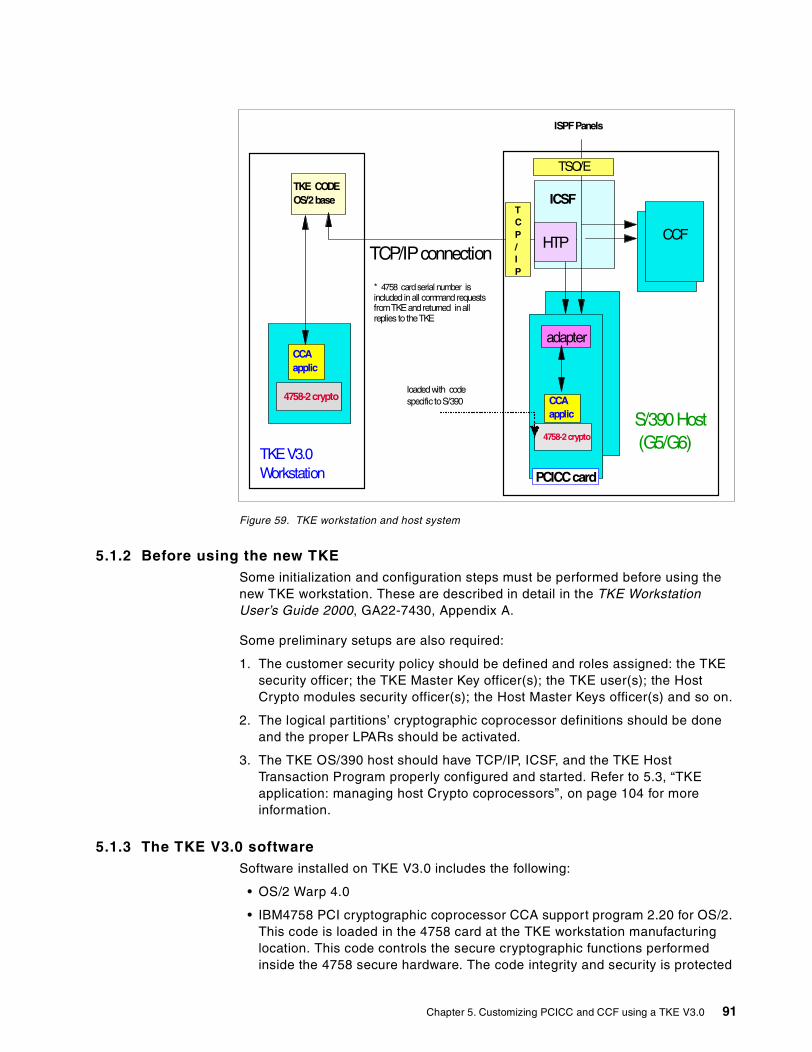
Figure 59. TKE workstation and host system
5.1.2 Before using the new TKESome initialization and configuration steps must be performed before using thenew TKE workstation. These are described in detail in the TKE WorkstationUser’s Guide 2000, GA22-7430, Appendix A.
Some preliminary setups are also required:
1. The customer security policy should be defined and roles assigned: the TKEsecurity officer; the TKE Master Key officer(s); the TKE user(s); the HostCrypto modules security officer(s); the Host Master Keys officer(s) and so on.
2. The logical partitions’ cryptographic coprocessor definitions should be doneand the proper LPARs should be activated.
3. The TKE OS/390 host should have TCP/IP, ICSF, and the TKE HostTransaction Program properly configured and started. Refer to 5.3, “TKEapplication: managing host Crypto coprocessors”, on page 104 for moreinformation.
5.1.3 The TKE V3.0 softwareSoftware installed on TKE V3.0 includes the following:
• OS/2 Warp 4.0
• IBM4758 PCI cryptographic coprocessor CCA support program 2.20 for OS/2.This code is loaded in the 4758 card at the TKE workstation manufacturinglocation. This code controls the secure cryptographic functions performedinside the 4758 secure hardware. The code integrity and security is protected
TKE CODEOS/2base
CCAapplic
4758-2crypto
S/390Host(G5/G6)
TKEV3.0Workstation
ISPFPanels
ICSF
* 4758 cardserial number isincluded inall commandrequestsfromTKEandreturned inallreplies to theTKE
loadedwith codespecific toS/390
adapter
CCAapplic
4758-2crypto
PCICCcard
CCFTCP/IPconnection
HTP
TCP/IP
TSO/E
Chapter 5. Customizing PCICC and CCF using a TKE V3.0 91
by the IBM private key signature when loaded into the card. Any further reloador update of this code will be integrity-guaranteed by the same mechanism.
• Trusted Key Entry Version 3.0 (versus 2.x)
• Java runtime environment 1.1.8
5.1.4 TKE workstation installation generalitiesDuring the manufacturing process, the TKE workstation application is loaded inthe PC (currently, an IBM 6862l) hard disk. TKE IBM4758 mod 002 card internalCCA code segments 1, 2, 3, and FCV are also loaded in the cryptographic card.
The TKE is then tested. Just before shipment, the cryptographic coprocessorcard IBM 4758 is removed from the workstation and shipped in a special thermal-protected container. When received at the customer location, it is re-plugged inthe TKE workstation by an IBM representative.
Note: When manipulating the 4758 card, never remove the batteries; otherwise,the tamper protection mechanism will definitively disable the card.
The following are shipped along with the workstation: a CD-ROM containing theTKE code; a TKE backup diskette; a TKE binary diskette; the TKE WorkstationUser’s Guide 2000, GA22-7430.The TKE workstation application can be reloadedfrom the TKE CD-ROM and the previously saved backup diskette.
If, for any reason, the IBM 4758 Crypto card has to be replaced, then the internalCCA code segments 1, 2, and 3 have to be reloaded because new spare 4758cards only have the minimum code bootstrap loaded at the card manufacturingplant. It will also be necessary to reload the FCV. You can accomplish this usingthe procedure described in the document Workstation Maintenance, GC38-3115,to load the code files that are kept on the workstation hard disk.
5.1.5 TKE definitionsIn this section we explain TKE terminology.
5.1.5.1 TKE workstation access controlThe TKE 4758 cryptographic card access control mechanisms use the roles andprofiles concept. When necessary, these roles and profiles are defined using theCrypto Node Management (CNM) software facility. This is done under the controlof a TKE administrator and according to customer security policy. This facility,included in TKE code, is started from an OS\2 window session as shown inFigure 65 on page 99.
ROLEA role defines a class of TKE users. When creating or changing a role, the TKEadministrator will define the TKE 4758 Crypto card commands that will beauthorized for users mapped to this role. There are 128 commands available,also called “control access points”, which can be authorized or unauthorized tothe role being created. See the IBM4758 CCA code support documentation fordetails on the control access points.
Predefined roles are set up during TKE initialization, and there is no need tochange these roles for normal use of the TKE application, as shown in Figure 64on page 98.
92 S/390 Crypto PCI Implementation Guide
PROFILEA profile defines a specific user. It contains a user name and a logon passphraseand is mapped to one role, and only one role. However, as many profiles asneeded can be created and mapped to the same role. After logging on underhis/her profile, the TKE user will be able to perform only the commandsauthorized by the role mapped to the profile. Validity dates may also be definedon a role basis to enforce specific security policies.
Default profiles are set up during TKE initialization and have a default knownpassphrase. We therefore recommend that you change this passphrase afterTKE setup to insure full access security.
The TKE administrator will have to create all user profiles required by the securitypolicy in effect; see Figure 67 on page 101.
TKE Master KeyThe TKE IBM4758 card contains one Master Key (referred to as the “DES MasterKey”) to encrypt the TKE operational DES keys, and one Master Key (referred toas the “PKA Master Key”) to encrypt the PKA keys. The CNM utility is used to setthese two Master Keys.
You enter the DES Master Key in several key parts loaded by different keyofficers (generally two officers) through the CNM utility. The entered key partscan be imported from a file, or manually keyed, or randomly generated.
Once the last Master Key part is loaded, the officer sets the Master Key via theCNM utility, which causes both the DES Master Key and the PKA Master Key tobe set from these key part values in the TKE 4758. Then the officer uses CNM toencipher or re-encipher the key storages.
TKE workstation key storagesThe TKE workstation key storages are files on hard disk where the operationalkeys encrypted under the TKE IBM 4758 Master Key are stored. When thesekeys need to be used, they are loaded into the 4758 secure hardware, so thatthey never appear in clear outside of the TKE 4758 secure hardware.
There are two key storages implemented in the TKE:
• DES key storage to store symmetric keys (C:\ibm4758\DESSTORE.DAT)
• PKA key storage to store asymmetric keys (C:\ibm4758\PKASTORE.DAT)
The PCICC cards and CCF chips in the host system use a very similar accesscontrol concept. They also use roles and authorities. However, these roles andauthorities apply to the S/390 coprocessors and must not be confused with theTKE 4758 roles and profiles.
To summarize:
• The TKE workstation has its own ROLES and USERS PROFILES.
• The PCICC modules have their own ROLES and AUTHORITIES.
• The CCF modules have their own AUTHORITIES.
Caution
Chapter 5. Customizing PCICC and CCF using a TKE V3.0 93
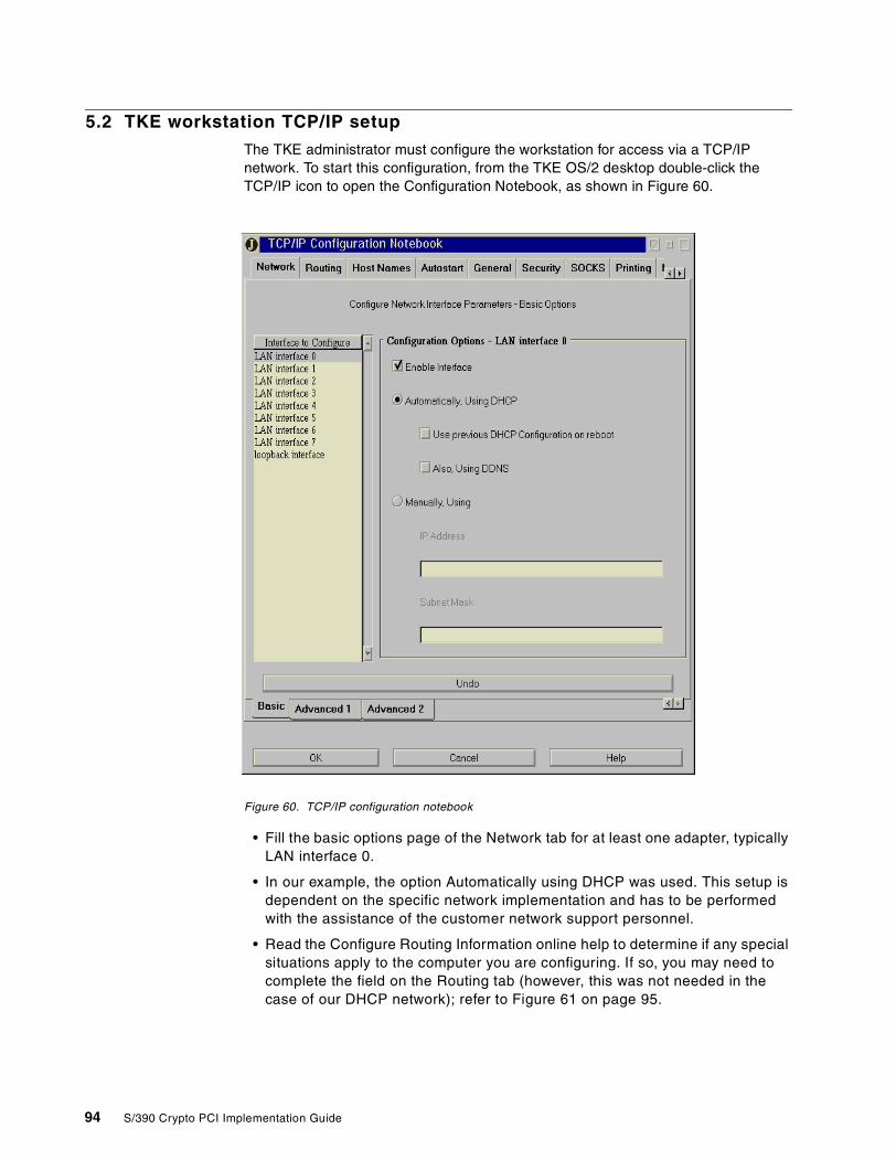
5.2 TKE workstation TCP/IP setup
The TKE administrator must configure the workstation for access via a TCP/IPnetwork. To start this configuration, from the TKE OS/2 desktop double-click theTCP/IP icon to open the Configuration Notebook, as shown in Figure 60.
Figure 60. TCP/IP configuration notebook
• Fill the basic options page of the Network tab for at least one adapter, typicallyLAN interface 0.
• In our example, the option Automatically using DHCP was used. This setup isdependent on the specific network implementation and has to be performedwith the assistance of the customer network support personnel.
• Read the Configure Routing Information online help to determine if any specialsituations apply to the computer you are configuring. If so, you may need tocomplete the field on the Routing tab (however, this was not needed in thecase of our DHCP network); refer to Figure 61 on page 95.
94 S/390 Crypto PCI Implementation Guide
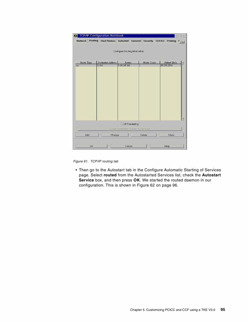
Figure 61. TCP/IP routing tab
• Then go to the Autostart tab in the Configure Automatic Starting of Servicespage. Select routed from the Autostarted Services list, check the AutostartService box, and then press OK. We started the routed daemon in ourconfiguration. This is shown in Figure 62 on page 96.
Chapter 5. Customizing PCICC and CCF using a TKE V3.0 95
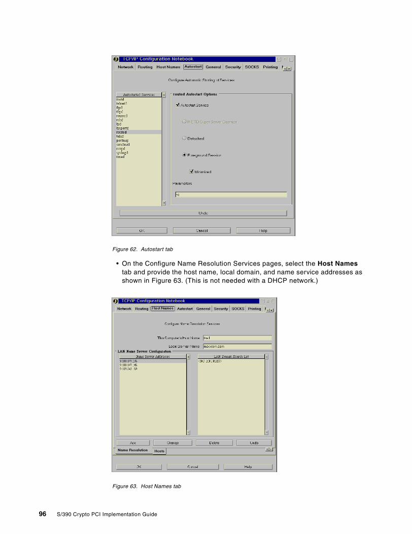
Figure 62. Autostart tab
• On the Configure Name Resolution Services pages, select the Host Namestab and provide the host name, local domain, and name service addresses asshown in Figure 63. (This is not needed with a DHCP network.)
Figure 63. Host Names tab
96 S/390 Crypto PCI Implementation Guide
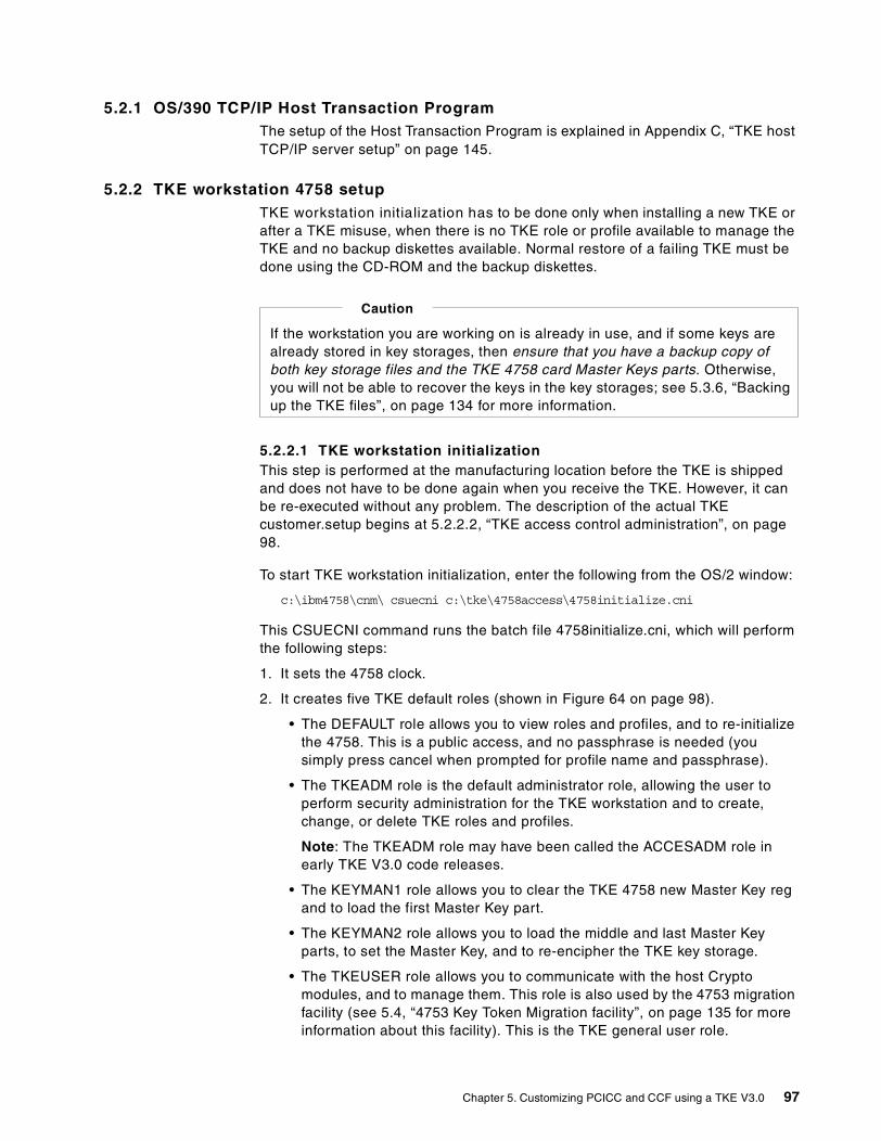
5.2.1 OS/390 TCP/IP Host Transaction ProgramThe setup of the Host Transaction Program is explained in Appendix C, “TKE hostTCP/IP server setup” on page 145.
5.2.2 TKE workstation 4758 setupTKE workstation initialization has to be done only when installing a new TKE orafter a TKE misuse, when there is no TKE role or profile available to manage theTKE and no backup diskettes available. Normal restore of a failing TKE must bedone using the CD-ROM and the backup diskettes.
5.2.2.1 TKE workstation initializationThis step is performed at the manufacturing location before the TKE is shippedand does not have to be done again when you receive the TKE. However, it canbe re-executed without any problem. The description of the actual TKEcustomer.setup begins at 5.2.2.2, “TKE access control administration”, on page98.
To start TKE workstation initialization, enter the following from the OS/2 window:
c:\ibm4758\cnm\ csuecni c:\tke\4758access\4758initialize.cni
This CSUECNI command runs the batch file 4758initialize.cni, which will performthe following steps:
1. It sets the 4758 clock.
2. It creates five TKE default roles (shown in Figure 64 on page 98).
• The DEFAULT role allows you to view roles and profiles, and to re-initializethe 4758. This is a public access, and no passphrase is needed (yousimply press cancel when prompted for profile name and passphrase).
• The TKEADM role is the default administrator role, allowing the user toperform security administration for the TKE workstation and to create,change, or delete TKE roles and profiles.
Note: The TKEADM role may have been called the ACCESADM role inearly TKE V3.0 code releases.
• The KEYMAN1 role allows you to clear the TKE 4758 new Master Key regand to load the first Master Key part.
• The KEYMAN2 role allows you to load the middle and last Master Keyparts, to set the Master Key, and to re-encipher the TKE key storage.
• The TKEUSER role allows you to communicate with the host Cryptomodules, and to manage them. This role is also used by the 4753 migrationfacility (see 5.4, “4753 Key Token Migration facility”, on page 135 for moreinformation about this facility). This is the TKE general user role.
If the workstation you are working on is already in use, and if some keys arealready stored in key storages, then ensure that you have a backup copy ofboth key storage files and the TKE 4758 card Master Keys parts. Otherwise,you will not be able to recover the keys in the key storages; see 5.3.6, “Backingup the TKE files”, on page 134 for more information.
Caution
Chapter 5. Customizing PCICC and CCF using a TKE V3.0 97
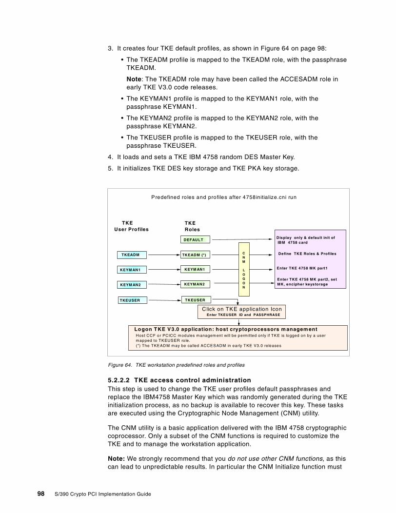
3. It creates four TKE default profiles, as shown in Figure 64 on page 98:
• The TKEADM profile is mapped to the TKEADM role, with the passphraseTKEADM.
Note: The TKEADM role may have been called the ACCESADM role inearly TKE V3.0 code releases.
• The KEYMAN1 profile is mapped to the KEYMAN1 role, with thepassphrase KEYMAN1.
• The KEYMAN2 profile is mapped to the KEYMAN2 role, with thepassphrase KEYMAN2.
• The TKEUSER profile is mapped to the TKEUSER role, with thepassphrase TKEUSER.
4. It loads and sets a TKE IBM 4758 random DES Master Key.
5. It initializes TKE DES key storage and TKE PKA key storage.
Figure 64. TKE workstation predefined roles and profiles
5.2.2.2 TKE access control administrationThis step is used to change the TKE user profiles default passphrases andreplace the IBM4758 Master Key which was randomly generated during the TKEinitialization process, as no backup is available to recover this key. These tasksare executed using the Cryptographic Node Management (CNM) utility.
The CNM utility is a basic application delivered with the IBM 4758 cryptographiccoprocessor. Only a subset of the CNM functions is required to customize theTKE and to manage the workstation application.
Note: We strongly recommend that you do not use other CNM functions, as thiscan lead to unpredictable results. In particular the CNM Initialize function must
Predefined roles and profiles after 4758initialize.cni run
Logon TKE V3.0 application: host cryptoprocessors m anagem entHost CCF or PCICC modules m anagem ent will be perm itted only if TKE is logged on by a usermapped to TKEUSER ro le.(*) The TKEAD M m ay be called ACCESADM in early TKE V3.0 releases
DEFAULT
TKEADM (*)
KEYM AN1
KEYMAN2
TKEUSER
Display only & default init ofIBM 4758 card
Define TKE Roles & Profiles
Enter TKE 4758 MK part2, setMK, encipher keystorage
Enter TKE 4758 MK part1
TKEADM
TKEUSER
KEYM AN1
KEYM AN2
TKEUser Profiles
TKERoles
Click on TKE application Icon
CNM
LOGON
Enter TKEUSER ID and PASSPHRASE
98 S/390 Crypto PCI Implementation Guide
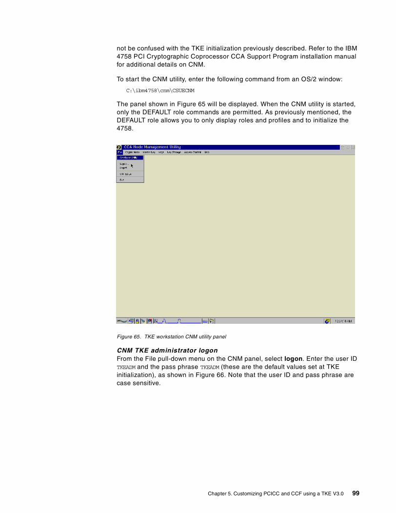
not be confused with the TKE initialization previously described. Refer to the IBM4758 PCI Cryptographic Coprocessor CCA Support Program installation manualfor additional details on CNM.
To start the CNM utility, enter the following command from an OS/2 window:
C:\ibm4758\cnm\CSUECNM
The panel shown in Figure 65 will be displayed. When the CNM utility is started,only the DEFAULT role commands are permitted. As previously mentioned, theDEFAULT role allows you to only display roles and profiles and to initialize the4758.
Figure 65. TKE workstation CNM utility panel
CNM TKE administrator logonFrom the File pull-down menu on the CNM panel, select logon. Enter the user IDTKEADM and the pass phrase TKEADM (these are the default values set at TKEinitialization), as shown in Figure 66. Note that the user ID and pass phrase arecase sensitive.
Chapter 5. Customizing PCICC and CCF using a TKE V3.0 99
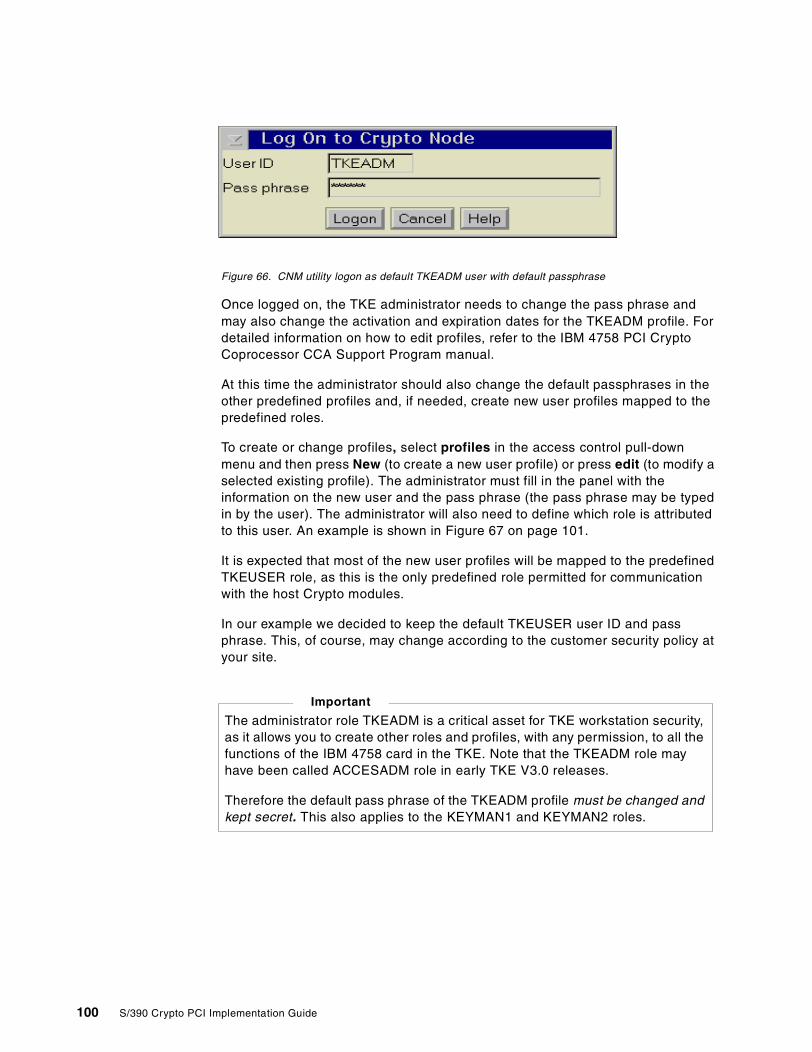
Figure 66. CNM utility logon as default TKEADM user with default passphrase
Once logged on, the TKE administrator needs to change the pass phrase andmay also change the activation and expiration dates for the TKEADM profile. Fordetailed information on how to edit profiles, refer to the IBM 4758 PCI CryptoCoprocessor CCA Support Program manual.
At this time the administrator should also change the default passphrases in theother predefined profiles and, if needed, create new user profiles mapped to thepredefined roles.
To create or change profiles, select profiles in the access control pull-downmenu and then press New (to create a new user profile) or press edit (to modify aselected existing profile). The administrator must fill in the panel with theinformation on the new user and the pass phrase (the pass phrase may be typedin by the user). The administrator will also need to define which role is attributedto this user. An example is shown in Figure 67 on page 101.
It is expected that most of the new user profiles will be mapped to the predefinedTKEUSER role, as this is the only predefined role permitted for communicationwith the host Crypto modules.
In our example we decided to keep the default TKEUSER user ID and passphrase. This, of course, may change according to the customer security policy atyour site.
The administrator role TKEADM is a critical asset for TKE workstation security,as it allows you to create other roles and profiles, with any permission, to all thefunctions of the IBM 4758 card in the TKE. Note that the TKEADM role mayhave been called ACCESADM role in early TKE V3.0 releases.
Therefore the default pass phrase of the TKEADM profile must be changed andkept secret. This also applies to the KEYMAN1 and KEYMAN2 roles.
Important
100 S/390 Crypto PCI Implementation Guide
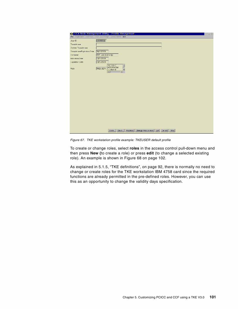
Figure 67. TKE workstation profile example: TKEUSER default profile
To create or change roles, select roles in the access control pull-down menu andthen press New (to create a role) or press edit (to change a selected existingrole). An example is shown in Figure 68 on page 102.
As explained in 5.1.5, “TKE definitions”, on page 92, there is normally no need tochange or create roles for the TKE workstation IBM 4758 card since the requiredfunctions are already permitted in the pre-defined roles. However, you can usethis as an opportunity to change the validity days specification.
Chapter 5. Customizing PCICC and CCF using a TKE V3.0 101
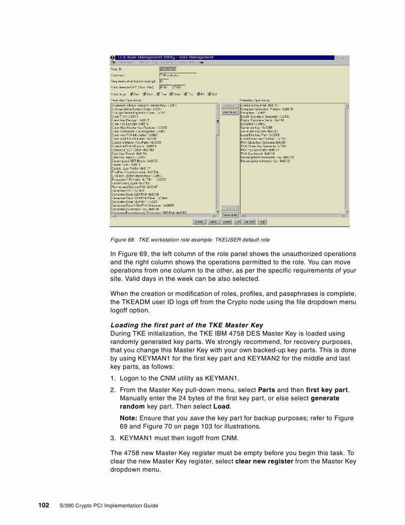
Figure 68. TKE workstation role example: TKEUSER default role
In Figure 69, the left column of the role panel shows the unauthorized operationsand the right column shows the operations permitted to the role. You can moveoperations from one column to the other, as per the specific requirements of yoursite. Valid days in the week can be also selected.
When the creation or modification of roles, profiles, and passphrases is complete,the TKEADM user ID logs off from the Crypto node using the file dropdown menulogoff option.
Loading the first part of the TKE Master KeyDuring TKE initialization, the TKE IBM 4758 DES Master Key is loaded usingrandomly generated key parts. We strongly recommend, for recovery purposes,that you change this Master Key with your own backed-up key parts. This is doneby using KEYMAN1 for the first key part and KEYMAN2 for the middle and lastkey parts, as follows:
1. Logon to the CNM utility as KEYMAN1.
2. From the Master Key pull-down menu, select Parts and then first key part.Manually enter the 24 bytes of the first key part, or else select generaterandom key part. Then select Load.
Note: Ensure that you save the key part for backup purposes; refer to Figure69 and Figure 70 on page 103 for illustrations.
3. KEYMAN1 must then logoff from CNM.
The 4758 new Master Key register must be empty before you begin this task. Toclear the new Master Key register, select clear new register from the Master Keydropdown menu.
102 S/390 Crypto PCI Implementation Guide
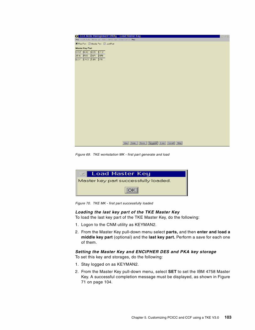
Figure 69. TKE workstation MK - first part generate and load
Figure 70. TKE MK - first part successfully loaded
Loading the last key part of the TKE Master KeyTo load the last key part of the TKE Master Key, do the following:
1. Logon to the CNM utility as KEYMAN2.
2. From the Master Key pull-down menu select parts, and then enter and load amiddle key part (optional) and the last key part. Perform a save for each oneof them.
Setting the Master Key and ENCIPHER DES and PKA key storageTo set this key and storages, do the following:
1. Stay logged on as KEYMAN2.
2. From the Master Key pull-down menu, select SET to set the IBM 4758 MasterKey. A successful completion message must be displayed, as shown in Figure71 on page 104.
Chapter 5. Customizing PCICC and CCF using a TKE V3.0 103
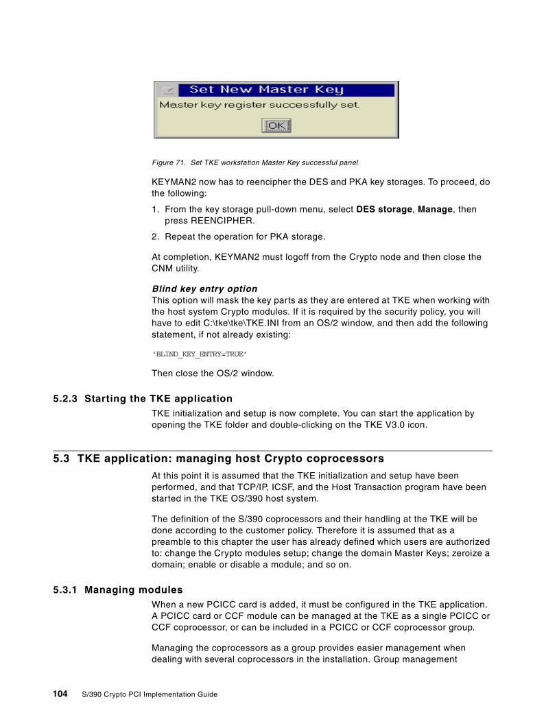
Figure 71. Set TKE workstation Master Key successful panel
KEYMAN2 now has to reencipher the DES and PKA key storages. To proceed, dothe following:
1. From the key storage pull-down menu, select DES storage, Manage, thenpress REENCIPHER.
2. Repeat the operation for PKA storage.
At completion, KEYMAN2 must logoff from the Crypto node and then close theCNM utility.
Blind key entry optionThis option will mask the key parts as they are entered at TKE when working withthe host system Crypto modules. If it is required by the security policy, you willhave to edit C:\tke\tke\TKE.INI from an OS/2 window, and then add the followingstatement, if not already existing:
‘BLIND_KEY_ENTRY=TRUE’
Then close the OS/2 window.
5.2.3 Starting the TKE applicationTKE initialization and setup is now complete. You can start the application byopening the TKE folder and double-clicking on the TKE V3.0 icon.
5.3 TKE application: managing host Crypto coprocessors
At this point it is assumed that the TKE initialization and setup have beenperformed, and that TCP/IP, ICSF, and the Host Transaction program have beenstarted in the TKE OS/390 host system.
The definition of the S/390 coprocessors and their handling at the TKE will bedone according to the customer policy. Therefore it is assumed that as apreamble to this chapter the user has already defined which users are authorizedto: change the Crypto modules setup; change the domain Master Keys; zeroize adomain; enable or disable a module; and so on.
5.3.1 Managing modulesWhen a new PCICC card is added, it must be configured in the TKE application.A PCICC card or CCF module can be managed at the TKE as a single PCICC orCCF coprocessor, or can be included in a PCICC or CCF coprocessor group.
Managing the coprocessors as a group provides easier management whendealing with several coprocessors in the installation. Group management
104 S/390 Crypto PCI Implementation Guide
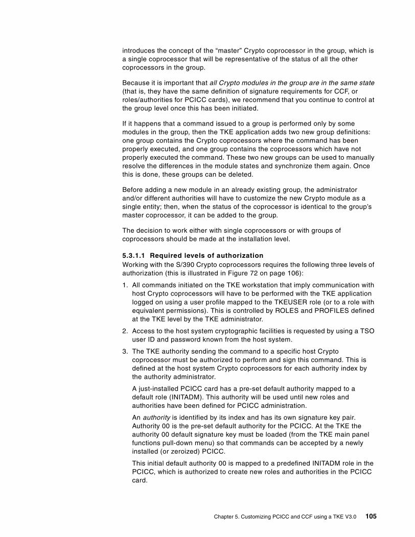
introduces the concept of the “master” Crypto coprocessor in the group, which isa single coprocessor that will be representative of the status of all the othercoprocessors in the group.
Because it is important that all Crypto modules in the group are in the same state(that is, they have the same definition of signature requirements for CCF, orroles/authorities for PCICC cards), we recommend that you continue to control atthe group level once this has been initiated.
If it happens that a command issued to a group is performed only by somemodules in the group, then the TKE application adds two new group definitions:one group contains the Crypto coprocessors where the command has beenproperly executed, and one group contains the coprocessors which have notproperly executed the command. These two new groups can be used to manuallyresolve the differences in the module states and synchronize them again. Oncethis is done, these groups can be deleted.
Before adding a new module in an already existing group, the administratorand/or different authorities will have to customize the new Crypto module as asingle entity; then, when the status of the coprocessor is identical to the group’smaster coprocessor, it can be added to the group.
The decision to work either with single coprocessors or with groups ofcoprocessors should be made at the installation level.
5.3.1.1 Required levels of authorizationWorking with the S/390 Crypto coprocessors requires the following three levels ofauthorization (this is illustrated in Figure 72 on page 106):
1. All commands initiated on the TKE workstation that imply communication withhost Crypto coprocessors will have to be performed with the TKE applicationlogged on using a user profile mapped to the TKEUSER role (or to a role withequivalent permissions). This is controlled by ROLES and PROFILES definedat the TKE level by the TKE administrator.
2. Access to the host system cryptographic facilities is requested by using a TSOuser ID and password known from the host system.
3. The TKE authority sending the command to a specific host Cryptocoprocessor must be authorized to perform and sign this command. This isdefined at the host system Crypto coprocessors for each authority index bythe authority administrator.
A just-installed PCICC card has a pre-set default authority mapped to adefault role (INITADM). This authority will be used until new roles andauthorities have been defined for PCICC administration.
An authority is identified by its index and has its own signature key pair.Authority 00 is the pre-set default authority for the PCICC. At the TKE theauthority 00 default signature key must be loaded (from the TKE main panelfunctions pull-down menu) so that commands can be accepted by a newlyinstalled (or zeroized) PCICC.
This initial default authority 00 is mapped to a predefined INITADM role in thePCICC, which is authorized to create new roles and authorities in the PCICCcard.
Chapter 5. Customizing PCICC and CCF using a TKE V3.0 105
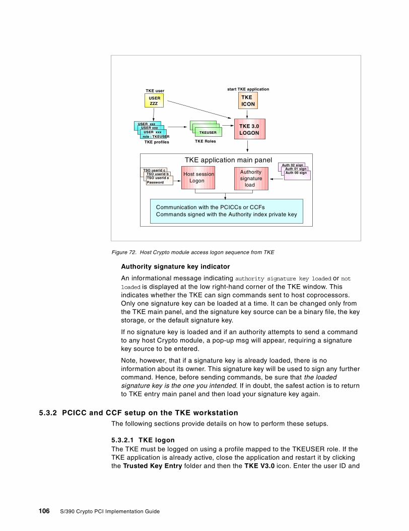
Figure 72. Host Crypto module access logon sequence from TKE
Authority signature key indicator
An informational message indicating authority signature key loaded or notloaded is displayed at the low right-hand corner of the TKE window. Thisindicates whether the TKE can sign commands sent to host coprocessors.Only one signature key can be loaded at a time. It can be changed only fromthe TKE main panel, and the signature key source can be a binary file, the keystorage, or the default signature key.
If no signature key is loaded and if an authority attempts to send a commandto any host Crypto module, a pop-up msg will appear, requiring a signaturekey source to be entered.
Note, however, that if a signature key is already loaded, there is noinformation about its owner. This signature key will be used to sign any furthercommand. Hence, before sending commands, be sure that the loadedsignature key is the one you intended. If in doubt, the safest action is to returnto TKE entry main panel and then load your signature key again.
5.3.2 PCICC and CCF setup on the TKE workstationThe following sections provide details on how to perform these setups.
5.3.2.1 TKE logonThe TKE must be logged on using a profile mapped to the TKEUSER role. If theTKE application is already active, close the application and restart it by clickingthe Trusted Key Entry folder and then the TKE V3.0 icon. Enter the user ID and
USER zzzUSER yyy
USER xxxrole : TKEUSER
USERZZZ
TKE 3.0LOGON
Host sessionLogon
Authoritysignature
load
TKE profiles TKE Roles
TKEUSER
TKEICON
Communication with the PCICCs or CCFsCommands signed with the Authority index private key
TKE application main panel
TKE user start TKE application
Auth 02 signAuth 01 signAuth 00 sign
TSO userid cTSO userid bTSO userid aPassword
106 S/390 Crypto PCI Implementation Guide
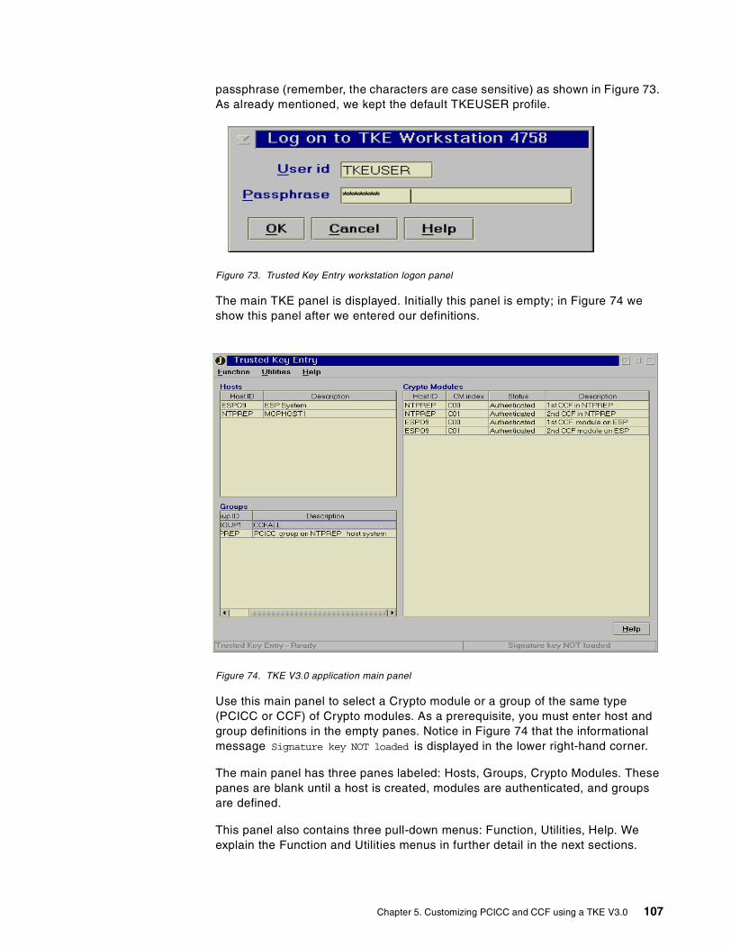
passphrase (remember, the characters are case sensitive) as shown in Figure 73.As already mentioned, we kept the default TKEUSER profile.
Figure 73. Trusted Key Entry workstation logon panel
The main TKE panel is displayed. Initially this panel is empty; in Figure 74 weshow this panel after we entered our definitions.
Figure 74. TKE V3.0 application main panel
Use this main panel to select a Crypto module or a group of the same type(PCICC or CCF) of Crypto modules. As a prerequisite, you must enter host andgroup definitions in the empty panes. Notice in Figure 74 that the informationalmessage Signature key NOT loaded is displayed in the lower right-hand corner.
The main panel has three panes labeled: Hosts, Groups, Crypto Modules. Thesepanes are blank until a host is created, modules are authenticated, and groupsare defined.
This panel also contains three pull-down menus: Function, Utilities, Help. Weexplain the Function and Utilities menus in further detail in the next sections.
Chapter 5. Customizing PCICC and CCF using a TKE V3.0 107
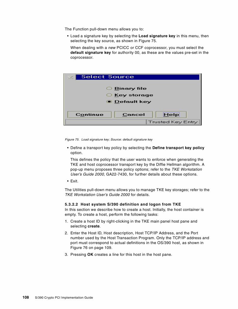
The Function pull-down menu allows you to:
• Load a signature key by selecting the Load signature key in this menu, thenselecting the key source, as shown in Figure 75.
When dealing with a new PCICC or CCF coprocessor, you must select thedefault signature key for authority 00, as these are the values pre-set in thecoprocessor.
Figure 75. Load signature key; Source: default signature key
• Define a transport key policy by selecting the Define transport key policyoption.
This defines the policy that the user wants to enforce when generating theTKE and host coprocessor transport key by the Diffie Hellman algorithm. Apop-up menu proposes three policy options; refer to the TKE WorkstationUser’s Guide 2000, GA22-7430, for further details about these options.
• Exit.
The Utilities pull-down menu allows you to manage TKE key storages; refer to theTKE Workstation User’s Guide 2000 for details.
5.3.2.2 Host system S/390 definition and logon from TKEIn this section we describe how to create a host. Initially, the host container isempty. To create a host, perform the following tasks:
1. Create a host ID by right-clicking in the TKE main panel host pane andselecting create.
2. Enter the Host ID, Host description, Host TCP/IP Address, and the Portnumber used by the Host Transaction Program. Only the TCP/IP address andport must correspond to actual definitions in the OS/390 host, as shown inFigure 76 on page 109.
3. Pressing OK creates a line for this host in the host pane.
108 S/390 Crypto PCI Implementation Guide
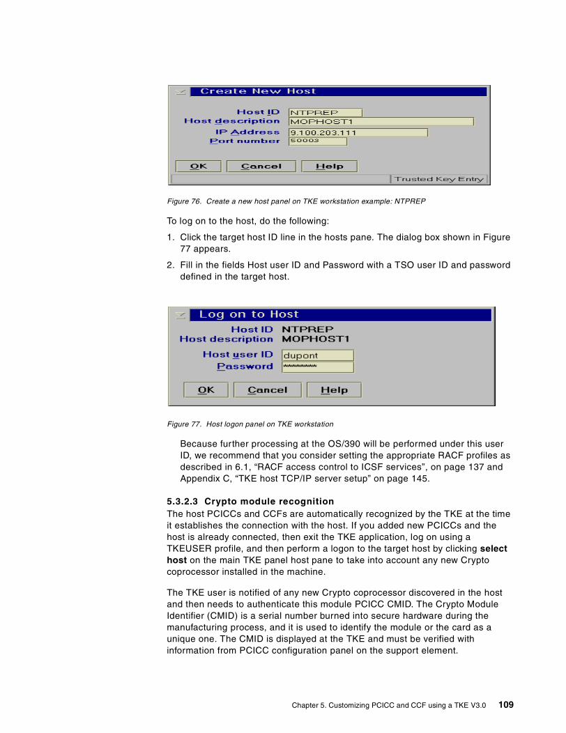
Figure 76. Create a new host panel on TKE workstation example: NTPREP
To log on to the host, do the following:
1. Click the target host ID line in the hosts pane. The dialog box shown in Figure77 appears.
2. Fill in the fields Host user ID and Password with a TSO user ID and passworddefined in the target host.
Figure 77. Host logon panel on TKE workstation
Because further processing at the OS/390 will be performed under this userID, we recommend that you consider setting the appropriate RACF profiles asdescribed in 6.1, “RACF access control to ICSF services”, on page 137 andAppendix C, “TKE host TCP/IP server setup” on page 145.
5.3.2.3 Crypto module recognitionThe host PCICCs and CCFs are automatically recognized by the TKE at the timeit establishes the connection with the host. If you added new PCICCs and thehost is already connected, then exit the TKE application, log on using aTKEUSER profile, and then perform a logon to the target host by clicking selecthost on the main TKE panel host pane to take into account any new Cryptocoprocessor installed in the machine.
The TKE user is notified of any new Crypto coprocessor discovered in the hostand then needs to authenticate this module PCICC CMID. The Crypto ModuleIdentifier (CMID) is a serial number burned into secure hardware during themanufacturing process, and it is used to identify the module or the card as aunique one. The CMID is displayed at the TKE and must be verified withinformation from PCICC configuration panel on the support element.
Chapter 5. Customizing PCICC and CCF using a TKE V3.0 109
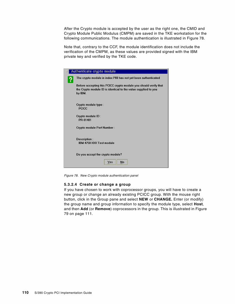
After the Crypto module is accepted by the user as the right one, the CMID andCrypto Module Public Modulus (CMPM) are saved in the TKE workstation for thefollowing communications. The module authentication is illustrated in Figure 78.
Note that, contrary to the CCF, the module identification does not include theverification of the CMPM, as these values are provided signed with the IBMprivate key and verified by the TKE code.
Figure 78. New Crypto module authentication panel
5.3.2.4 Create or change a groupIf you have chosen to work with coprocessor groups, you will have to create anew group or change an already existing PCICC group. With the mouse rightbutton, click in the Group pane and select NEW or CHANGE. Enter (or modify)the group name and group information to specify the module type, select Host,and then Add (or Remove) coprocessors in the group. This is illustrated in Figure79 on page 111.
110 S/390 Crypto PCI Implementation Guide
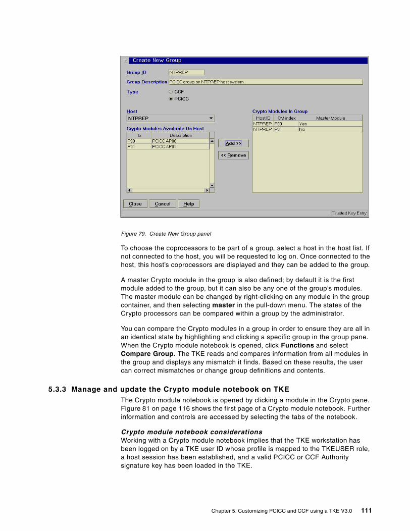
Figure 79. Create New Group panel
To choose the coprocessors to be part of a group, select a host in the host list. Ifnot connected to the host, you will be requested to log on. Once connected to thehost, this host’s coprocessors are displayed and they can be added to the group.
A master Crypto module in the group is also defined; by default it is the firstmodule added to the group, but it can also be any one of the group’s modules.The master module can be changed by right-clicking on any module in the groupcontainer, and then selecting master in the pull-down menu. The states of theCrypto processors can be compared within a group by the administrator.
You can compare the Crypto modules in a group in order to ensure they are all inan identical state by highlighting and clicking a specific group in the group pane.When the Crypto module notebook is opened, click Functions and selectCompare Group. The TKE reads and compares information from all modules inthe group and displays any mismatch it finds. Based on these results, the usercan correct mismatches or change group definitions and contents.
5.3.3 Manage and update the Crypto module notebook on TKEThe Crypto module notebook is opened by clicking a module in the Crypto pane.Figure 81 on page 116 shows the first page of a Crypto module notebook. Furtherinformation and controls are accessed by selecting the tabs of the notebook.
Crypto module notebook considerationsWorking with a Crypto module notebook implies that the TKE workstation hasbeen logged on by a TKE user ID whose profile is mapped to the TKEUSER role,a host session has been established, and a valid PCICC or CCF Authoritysignature key has been loaded in the TKE.
Chapter 5. Customizing PCICC and CCF using a TKE V3.0 111
The Crypto module notebook contains all the information related to a Cryptomodule (CCF or PCICC): the CMID, OS/390 host, all the authorized commands,the authorities signature keys, the LPAR domain controls, and so on.
Updating a group of modulesIf working with a newly created group made of empty or zeroized modules, selectthe group from the group container and then click any Crypto module in themodule container to open the Crypto module notebook. The notebook will in factinternally refer to the group’s master coprocessor, but all actions initiated via thenotebook will be propagated to all the modules in the group.
Updating a single moduleTo access a single module (as opposed to a group), select the host in the hostpane and then select the desired Crypto module in the Crypto modules pane. Thedifference with the group access is that you went through the host selectioninstead of a group selection.
Once you have selected a Crypto module or group of Crypto modules, the Cryptomodule notebook opens on the general page. The Crypto module informationdisplayed is related to the master Crypto module in the group or to a singleselected module. The title line of the notebook will state if you are dealing with agroup or an individual coprocessor.
The notebook opens in one of the following notebook modes:
• In update mode, you have exclusive control of the module or group ofmodules. Other TKE users subsequently opening the notebook will get accessin read-only mode.
• In read only mode, the notebook is already opened by another TKE user. Theother user’s exclusive control can be released by selecting release in theFunction pull-down menu.
Note: Be aware, though, that release, because it is designed to exit from anunrecoverable lockup situation, may seriously interfere with the work ofanother TKE with an open notebook for the module.
• In pending command mode, the module or group this notebook pertains to hasrecorded that there is a pending command waiting to be co-signed.
• In locked read-only mode, the notebook for a group opens in this mode if oneor more module in the group cannot be accessed from the TKE.
The notebook mode is indicated in the lower right-hand corner of the notebookwindow.
PCICC and CCF Crypto module notebook pages• General displays only the coprocessor type and index and the host name, as
shown in Figure 81 on page 116.
• Details shows five pages of information for the CCF, and two pages for thePCICC. No changes are allowed in any of these pages.
• Access control (CCF only) are the definitions of the signature requirements foreach signed command, with the relevant masks. The contents are unchangedfrom the previous TKE V2, only the presentation differs. Note however thatkey extract and transfer is not available with the TKE V3.0.
112 S/390 Crypto PCI Implementation Guide

• Roles (PCICC only): The PCICC uses role-based access control. From theTKE workstation, an administrator defines in the PCICC a set of roles whichcorrespond to classes of TKE users (also known as authorities).
Each role defines a set of commands to be permitted. Each TKE authority hasa profile in the PCICC, designated by an authority index, mapped to one of thedefined roles.
The authority can perform only the commands permitted by the role, and thesecommands have to be signed by the authority signature key at the TKE.PCICC Roles and profiles are further explained in 5.3.5.3, “Roles and profilesstructure example”, on page 120.
Figure 83 on page 118 shows the commands accessible to the roles in thePCICC.
• Authorities is a common function used to define authorities and to manage thekey pair associated with an authority. Private and public key parts will bestored in TKE key storage and/or stored on media (diskette or TKE hard disk)protected by a password. Note that only one signature key can reside at onetime in the key storage.
Before sending or signing a command to a host Crypto module, the authorityhas to load his/her signature key. This page also allows you to sent the publicmodulus of the authorities to the Crypto modules. This is a prerequisite beforesending any signed command to the Crypto modules (except for the defaultauthority key, for which the public modulus is initially known by the Cryptomodules).
• The CCF has a fixed number of sixteen authority indices (00 to 15) in effect.We recommend you use the same indices consistently across allcoprocessors in the installation.
• The PCICC can record up to 100 authority indices (00 to 99). The number ofauthority indices in effect is not fixed; it varies with the administratorinterventions to add or delete authorities. We recommend, for consistency,that you only use indices 00 to 15.
• Domains: This entry defines the LPAR domains that can have DES and PKAMaster Keys (CCF and PCICCC notebooks) and operational keys (CCFnotebook only) loaded and changed from the TKEs. It also provides domaincontrols.
For each of the 16 domains, there are three pages that can be selected withthe tabs at the bottom of the window: the domain general page, the domainkeys page, and the domain controls page.
• Co-sign: Pending commands are processed from this page. When a commandrequiring multiple signatures (up to 16 signatures for the CCF, or up to two
The manipulation of roles in the PCICC can only be executed from the TKEworkstation. Any command performed from the ICSF ISPF panel, or anycryptographic service requested by an application, will be executed underthe pre-set DEFAULT role in the PCICC. This DEFAULT role is notaccessible for setup.
Attention
Chapter 5. Customizing PCICC and CCF using a TKE V3.0 113

signatures for the PCICC) is issued by one authority, this command stays inpending status until all the signature requirements are completed. The co-signpage displays the pending command details and the signature requirementstatus. The co-signing authority can either sign the command in this page ordelete the pending command.
There is a difference in the co-sign mechanism between CCF and PCICC formultiple signature commands:
• All authorities defined in the CCF signature requirements panel canindifferently issue or co-sign a command. There is no restriction on whichauthorities must be the ones requesting the command first in sequence,and which authorities can subsequently co-sign the issued command.
• Unlike the CCF authority, a PCICC authority is mapped to a PCICC role asbeing the issuer of a command or as the co-signer of a command. Note thatthere can be only one co-signer to an issued command; while severalauthorities could co-sign the command, only one co-sign of the commandis required.
However, a PCICC role can be given both issuer and co-signer privileges.When an authority mapped to such a role issues a command, thecommand is executed at once since it is implicitly co-signed.
Figure 80 on page 115 establishes a parallel between the multi-signaturecommands in the CCF and the PCICC functions. Using this table, you candetermine how to maintain consistency between the authorities defined in theCCF and the ones defined in the PCICC.
For example, the LAP and LCB commands on CCF and the Access Control Roleon PCICC may have the same authorities index because of the similarities of thefunctions.The LKP (CCF) and SYM MK (PCICC) may also have the sameauthorities index.
114 S/390 Crypto PCI Implementation Guide
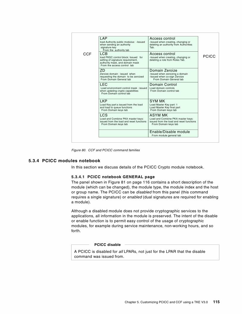
Figure 80. CCF and PCICC command families
5.3.4 PCICC modules notebookIn this section we discuss details of the PCICC Crypto module notebook.
5.3.4.1 PCICC notebook GENERAL pageThe panel shown in Figure 81 on page 116 contains a short description of themodule (which can be changed), the module type, the module index and the hostor group name. The PCICC can be disabled from this panel (this commandrequires a single signature) or enabled (dual signatures are required for enablinga module).
Although a disabled module does not provide cryptographic services to theapplications, all information in the module is preserved. The intent of the disableor enable function is to permit easy control of the usage of cryptographicmodules, for example during service maintenance, non-working hours, and soforth.
LAPload Authority public modulus: -Issuedwhen sending an authoritysignature key
From the authority tab
Access control-Issued when creating, changing ordeleting an authority from AuthoritiesTab.
LCBload PKSC control block: Issued forsetting of signature requirement,authority mask, and domain maskFrom the access control tab
Access control-Issued when creating, changing ordeleting a role from Roles Tab.
ZDZeroize domain : issued whenrequesting the domain to be zeroizedFrom Domain General tab
Domain Zeroize-Issued when zeroizing a domain-Issued when co-sign Zeroize
From Domain General tab
LECLoad environment control mask : issued
when updating crypto capabilitiesFrom Domain control tab
Domain ControlLoad domain controlsFrom Domain control tab
LKPLoad Key part:s issued from the loadand load to queue functions
From Domain keys tab
SYM MKLoad Master Key part: 1Load Master Key final partFrom Domain keys tab
LCSLoad and Combine PKA master keys:issued from the load and reset functions
From Domain keys tab
ASYM MKLoad and Combine PKA master keys:issued from the load and reset functions
From Domain keys tab
Enable/Disable moduleFrom module general tab
CCFPCICC
A PCICC is disabled for all LPARs, not just for the LPAR that the disablecommand was issued from.
PCICC disable
Chapter 5. Customizing PCICC and CCF using a TKE V3.0 115
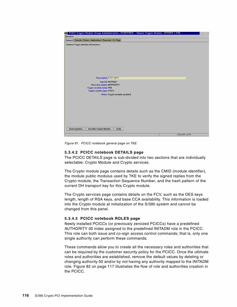
Figure 81. PCICC notebook general page on TKE
5.3.4.2 PCICC notebook DETAILS pageThe PCICC DETAILS page is sub-divided into two sections that are individuallyselectable: Crypto Module and Crypto services.
The Crypto module page contains details such as the CMID (module identifier),the module public modulus used by TKE to verify the signed replies from theCrypto module, the Transaction Sequence Number, and the hash pattern of thecurrent DH transport key for this Crypto module.
The Crypto services page contains details on the FCV, such as the DES keyslength, length of RSA keys, and base CCA availability. This information is loadedinto the Crypto module at initialization of the S/390 system and cannot bechanged from this panel.
5.3.4.3 PCICC notebook ROLES pageNewly installed PCICCs (or previously zeroized PCICCs) have a predefinedAUTHORITY 00 index assigned to the predefined INITADM role in the PCICC.This role can both issue and co-sign access control commands; that is, only onesingle authority can perform these commands.
These commands allow you to create all the necessary roles and authorities thatcan be required by the customer security policy for the PCICC. Once the ultimateroles and authorities are established, remove the default values by deleting orchanging authority 00 and/or by not having any authority mapped to the INITADMrole. Figure 82 on page 117 illustrates the flow of role and authorities creation inthe PCICC.
116 S/390 Crypto PCI Implementation Guide
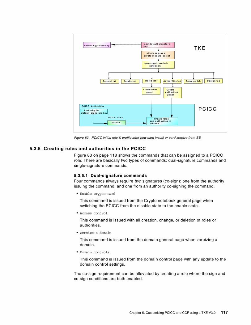
Figure 82. PCICC initial role & profile after new card install or card zeroize from SE
5.3.5 Creating roles and authorities in the PCICCFigure 83 on page 118 shows the commands that can be assigned to a PCICCrole. There are basically two types of commands: dual-signature commands andsingle-signature commands.
5.3.5.1 Dual-signature commandsFour commands always require two signatures (co-sign): one from the authorityissuing the command, and one from an authority co-signing the command.
• Enable crypto card
This command is issued from the Crypto notebook general page whenswitching the PCICC from the disable state to the enable state.
• Access control
This command is issued with all creation, change, or deletion of roles orauthorities.
• Zeroize a domain
This command is issued from the domain general page when zeroizing adomain.
• Domain controls
This command is issued from the domain control page with any update to thedomain control settings.
The co-sign requirement can be alleviated by creating a role where the sign andco-sign conditions are both enabled.
A u tho rity 0 0d efau lt s ig na ture ke y
P C IC C A uth o rit ies
P C IC C ro le s
In ita d m
lo a d de fau lt s ig n atu rek ey
s in g le o r g ro u pc rypto m o du le se lec t
o pe n cryp to m o d u leno teb o o k
G e n era l tab D eta ils tab D o m a in s tab C os ig n ta bR oles ta b
cre ate rolesp a ne l
A u tho rit ie s tab
C rea teau th orit ie s
p an e l
de fau lt s ig n atu re k ey
C re ate rolesan d a uth o rit ies inthe P C IC C
P C IC C
T K E
Chapter 5. Customizing PCICC and CCF using a TKE V3.0 117
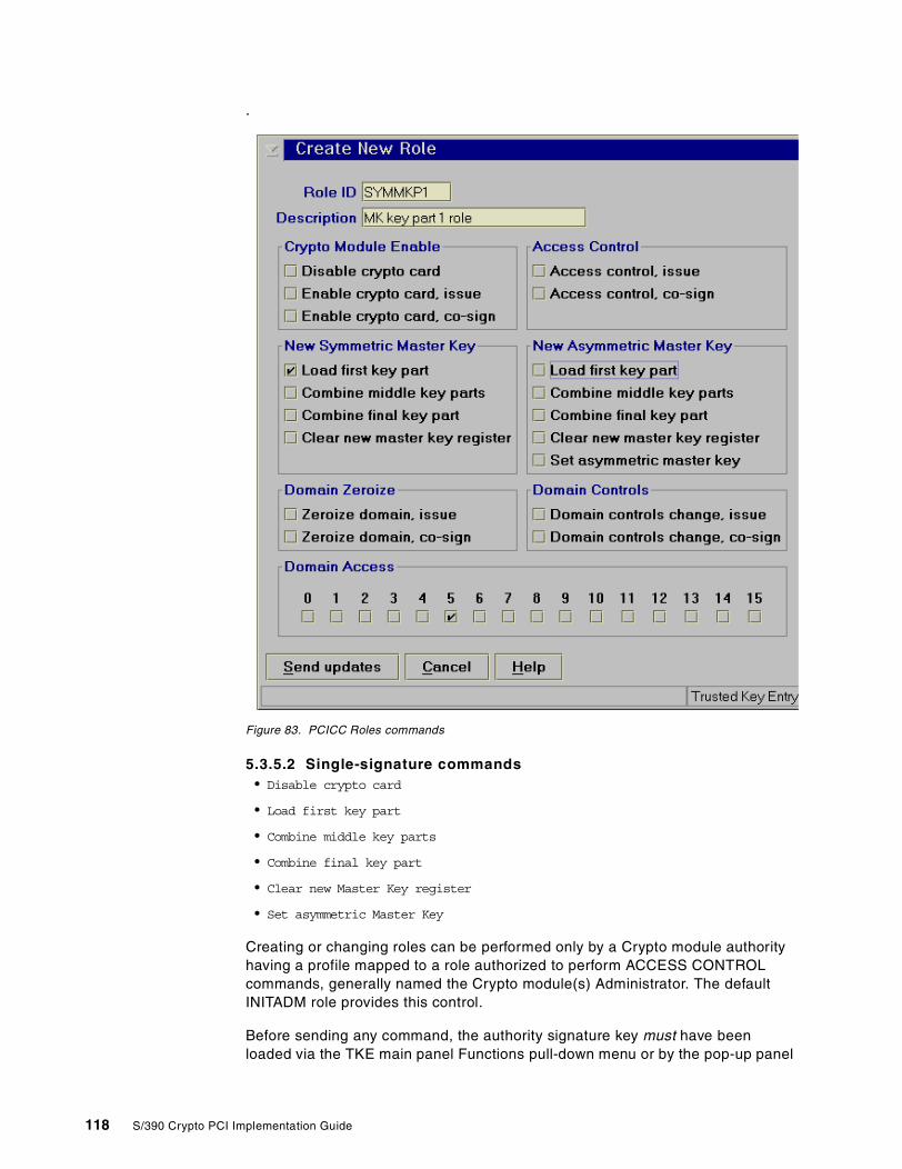
.
Figure 83. PCICC Roles commands
5.3.5.2 Single-signature commands• Disable crypto card
• Load first key part
• Combine middle key parts
• Combine final key part
• Clear new Master Key register
• Set asymmetric Master Key
Creating or changing roles can be performed only by a Crypto module authorityhaving a profile mapped to a role authorized to perform ACCESS CONTROLcommands, generally named the Crypto module(s) Administrator. The defaultINITADM role provides this control.
Before sending any command, the authority signature key must have beenloaded via the TKE main panel Functions pull-down menu or by the pop-up panel
118 S/390 Crypto PCI Implementation Guide
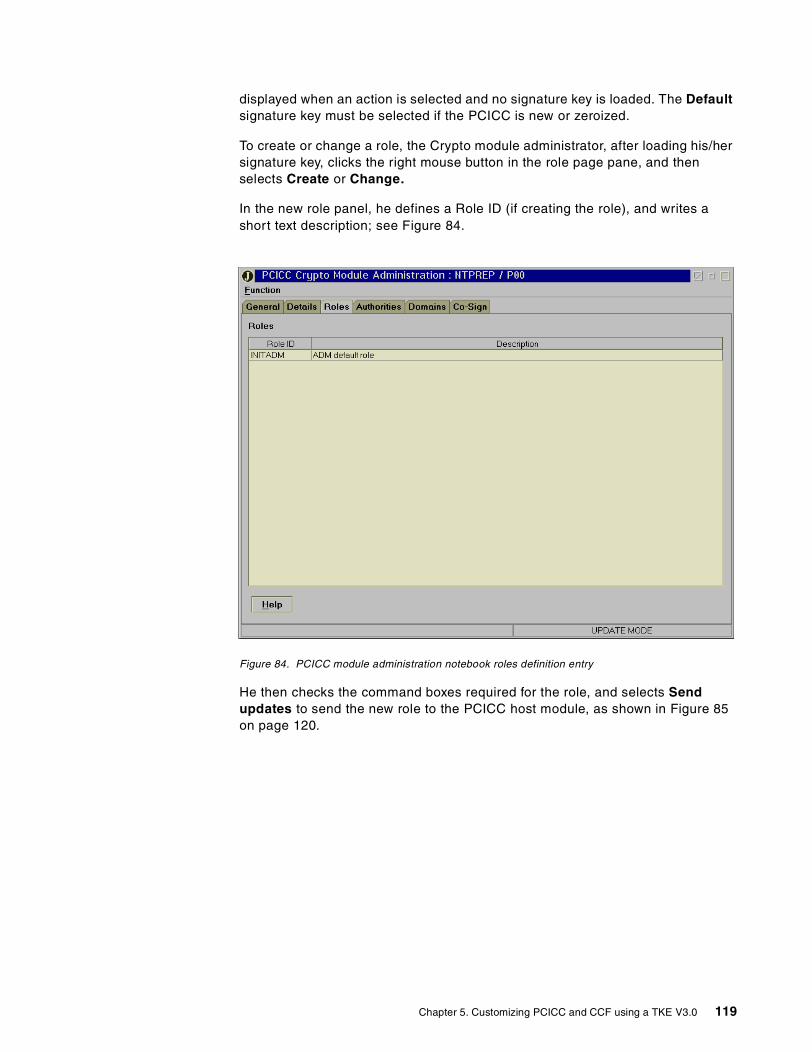
displayed when an action is selected and no signature key is loaded. The Defaultsignature key must be selected if the PCICC is new or zeroized.
To create or change a role, the Crypto module administrator, after loading his/hersignature key, clicks the right mouse button in the role page pane, and thenselects Create or Change.
In the new role panel, he defines a Role ID (if creating the role), and writes ashort text description; see Figure 84.
Figure 84. PCICC module administration notebook roles definition entry
He then checks the command boxes required for the role, and selects Sendupdates to send the new role to the PCICC host module, as shown in Figure 85on page 120.
Chapter 5. Customizing PCICC and CCF using a TKE V3.0 119
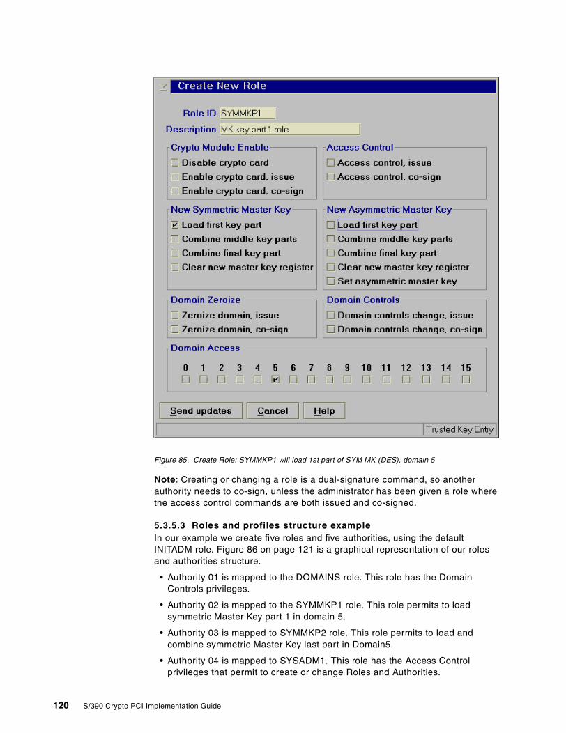
Figure 85. Create Role: SYMMKP1 will load 1st part of SYM MK (DES), domain 5
Note: Creating or changing a role is a dual-signature command, so anotherauthority needs to co-sign, unless the administrator has been given a role wherethe access control commands are both issued and co-signed.
5.3.5.3 Roles and profiles structure exampleIn our example we create five roles and five authorities, using the defaultINITADM role. Figure 86 on page 121 is a graphical representation of our rolesand authorities structure.
• Authority 01 is mapped to the DOMAINS role. This role has the DomainControls privileges.
• Authority 02 is mapped to the SYMMKP1 role. This role permits to loadsymmetric Master Key part 1 in domain 5.
• Authority 03 is mapped to SYMMKP2 role. This role permits to load andcombine symmetric Master Key last part in Domain5.
• Authority 04 is mapped to SYSADM1. This role has the Access Controlprivileges that permit to create or change Roles and Authorities.
120 S/390 Crypto PCI Implementation Guide
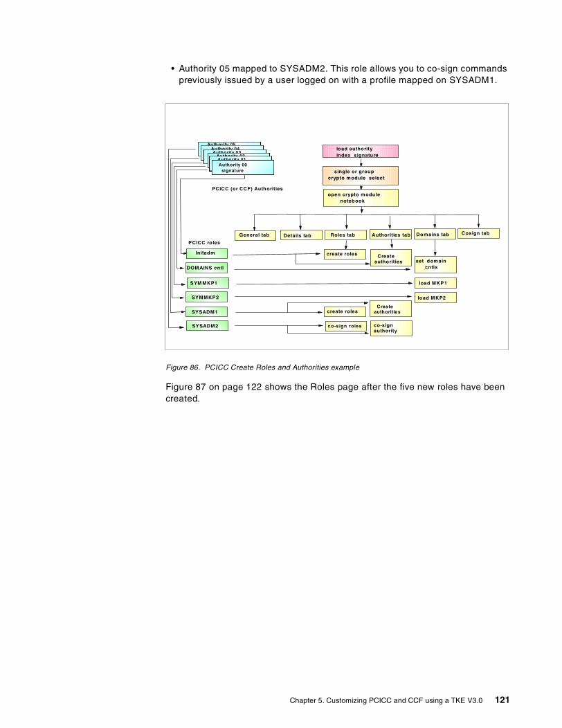
• Authority 05 mapped to SYSADM2. This role allows you to co-sign commandspreviously issued by a user logged on with a profile mapped on SYSADM1.
Figure 86. PCICC Create Roles and Authorities example
Figure 87 on page 122 shows the Roles page after the five new roles have beencreated.
load authorityindex signature
PCICC (or CCF) Authorities
single or groupcrypto module select
Authority 05Authority 04Authority 03
Authority 02Authority 01Authority 00
signature
PCICC roles
Initadm
DOMAINS cntl
SYM MKP1
SYMMKP2
open crypto modulenotebook
General tab Details tab Cosign tabRoles tab
create roles
Authorities tab
Createauthorities
Domains tab
set domaincntls
load MKP1
load MKP2
SYSADM1
SYSADM2
create roles
co-signauthority
Createauthorities
co-sign roles
Chapter 5. Customizing PCICC and CCF using a TKE V3.0 121
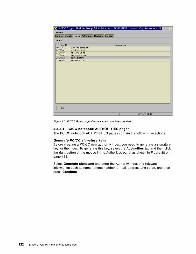
Figure 87. PCICC Roles page after new roles have been created
5.3.5.4 PCICC notebook AUTHORITIES pagesThe PCICC notebook AUTHORITIES pages contain the following selections:
Generate PCICC signature keysBefore creating a PCICC new authority index, you need to generate a signaturekey for the index. To generate this key, select the Authorities tab and then clickthe right button of the mouse in the Authorities pane, as shown in Figure 88 onpage 123.
Select Generate signature and enter the Authority index and relevantinformation such as name, phone number, e-mail, address and so on, and thenpress Continue.
122 S/390 Crypto PCI Implementation Guide
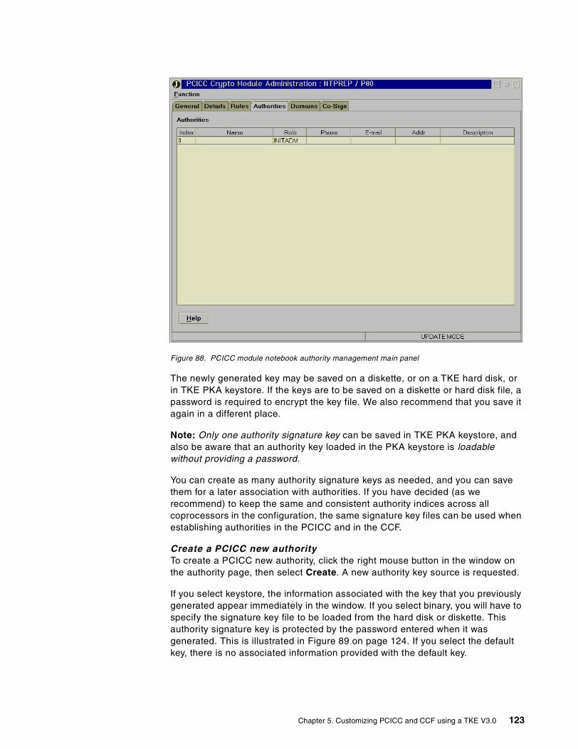
Figure 88. PCICC module notebook authority management main panel
The newly generated key may be saved on a diskette, or on a TKE hard disk, orin TKE PKA keystore. If the keys are to be saved on a diskette or hard disk file, apassword is required to encrypt the key file. We also recommend that you save itagain in a different place.
Note: Only one authority signature key can be saved in TKE PKA keystore, andalso be aware that an authority key loaded in the PKA keystore is loadablewithout providing a password.
You can create as many authority signature keys as needed, and you can savethem for a later association with authorities. If you have decided (as werecommend) to keep the same and consistent authority indices across allcoprocessors in the configuration, the same signature key files can be used whenestablishing authorities in the PCICC and in the CCF.
Create a PCICC new authorityTo create a PCICC new authority, click the right mouse button in the window onthe authority page, then select Create. A new authority key source is requested.
If you select keystore, the information associated with the key that you previouslygenerated appear immediately in the window. If you select binary, you will have tospecify the signature key file to be loaded from the hard disk or diskette. Thisauthority signature key is protected by the password entered when it wasgenerated. This is illustrated in Figure 89 on page 124. If you select the defaultkey, there is no associated information provided with the default key.
Chapter 5. Customizing PCICC and CCF using a TKE V3.0 123
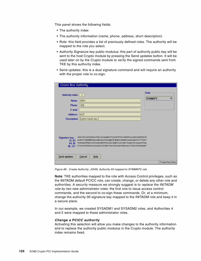
This panel shows the following fields:
• The authority index
• The authority information (name, phone, address, short description)
• Role: this field provides a list of previously defined roles. The authority will bemapped to the role you select.
• Authority Signature key public modulus: this part of authority public key will besent to the host Crypto module by pressing the Send updates button. It will beused later on by the Crypto module to verify the signed commands sent fromTKE by this authority index.
• Send updates: this is a dual signature command and will require an authoritywith the proper role to co-sign.
Figure 89. Create Authority: JOHN, Authority 03 mapped to SYMMKP2 role
Note: TKE authorities mapped to the role with Access Control privileges, such asthe INITADM default PCICC role, can create, change, or delete any other role andauthorities. A security measure we strongly suggest is to replace the INITADMrole by two new administrator roles: the first one to issue access controlcommands, and the second to co-sign these commands. Or, at a minimum,change the authority 00 signature key mapped to the INITADM role and keep it ina secure place.
In our example, we created SYSADM1 and SYSADM2 roles, and Authorities 4and 5 were mapped to these administrator roles.
Change a PCICC authorityActivating this selection will allow you make changes to the authority informationand to replace the authority public modulus in the Crypto module. The authorityindex remains fixed.
124 S/390 Crypto PCI Implementation Guide
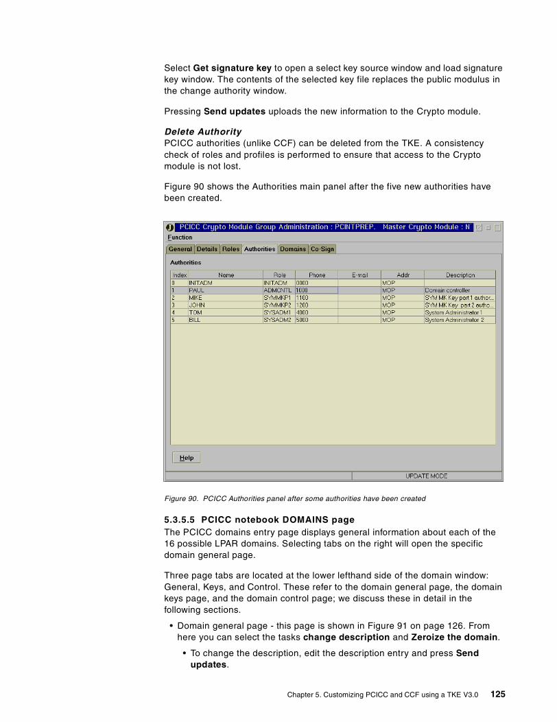
Select Get signature key to open a select key source window and load signaturekey window. The contents of the selected key file replaces the public modulus inthe change authority window.
Pressing Send updates uploads the new information to the Crypto module.
Delete AuthorityPCICC authorities (unlike CCF) can be deleted from the TKE. A consistencycheck of roles and profiles is performed to ensure that access to the Cryptomodule is not lost.
Figure 90 shows the Authorities main panel after the five new authorities havebeen created.
Figure 90. PCICC Authorities panel after some authorities have been created
5.3.5.5 PCICC notebook DOMAINS pageThe PCICC domains entry page displays general information about each of the16 possible LPAR domains. Selecting tabs on the right will open the specificdomain general page.
Three page tabs are located at the lower lefthand side of the domain window:General, Keys, and Control. These refer to the domain general page, the domainkeys page, and the domain control page; we discuss these in detail in thefollowing sections.
• Domain general page - this page is shown in Figure 91 on page 126. Fromhere you can select the tasks change description and Zeroize the domain.
• To change the description, edit the description entry and press Sendupdates.
Chapter 5. Customizing PCICC and CCF using a TKE V3.0 125
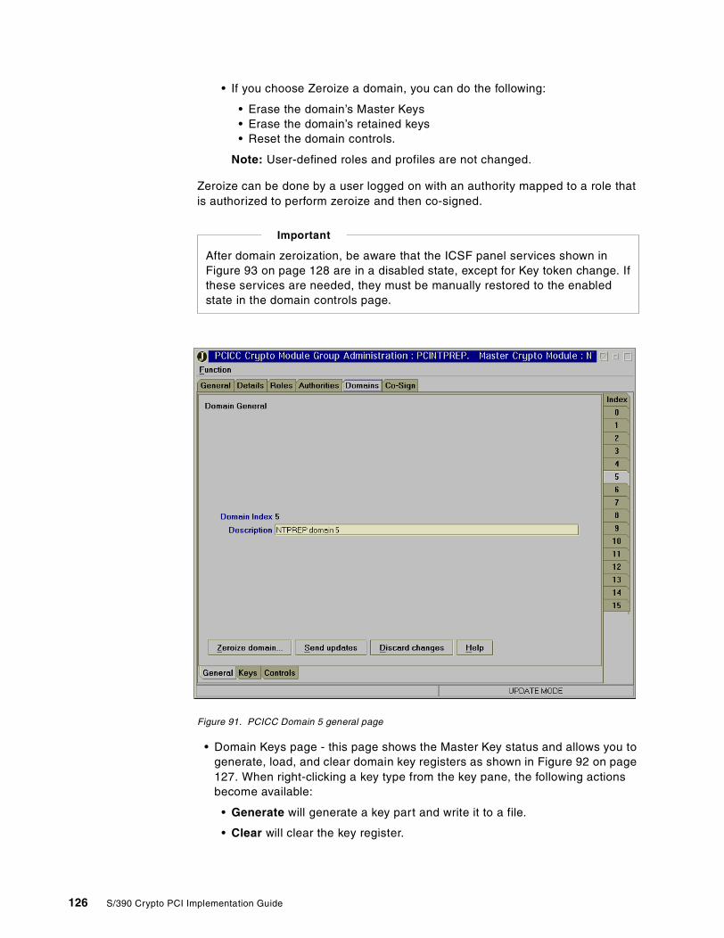
• If you choose Zeroize a domain, you can do the following:
• Erase the domain’s Master Keys• Erase the domain’s retained keys• Reset the domain controls.
Note: User-defined roles and profiles are not changed.
Zeroize can be done by a user logged on with an authority mapped to a role thatis authorized to perform zeroize and then co-signed.
Figure 91. PCICC Domain 5 general page
• Domain Keys page - this page shows the Master Key status and allows you togenerate, load, and clear domain key registers as shown in Figure 92 on page127. When right-clicking a key type from the key pane, the following actionsbecome available:
• Generate will generate a key part and write it to a file.
• Clear will clear the key register.
After domain zeroization, be aware that the ICSF panel services shown inFigure 93 on page 128 are in a disabled state, except for Key token change. Ifthese services are needed, they must be manually restored to the enabledstate in the domain controls page.
Important
126 S/390 Crypto PCI Implementation Guide
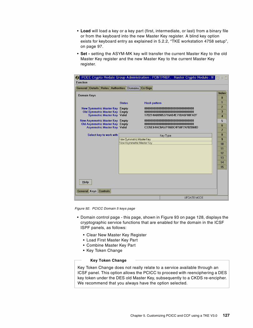
• Load will load a key or a key part (first, intermediate, or last) from a binary fileor from the keyboard into the new Master Key register. A blind key optionexists for keyboard entry as explained in 5.2.2, “TKE workstation 4758 setup”,on page 97.
• Set - setting the ASYM-MK key will transfer the current Master Key to the oldMaster Key register and the new Master Key to the current Master Keyregister.
Figure 92. PCICC Domain 5 keys page
• Domain control page - this page, shown in Figure 93 on page 128, displays thecryptographic service functions that are enabled for the domain in the ICSFISPF panels, as follows:
• Clear New Master Key Register• Load First Master Key Part• Combine Master Key Part• Key Token Change
Key Token Change does not really relate to a service available through anICSF panel. This option allows the PCICC to proceed with reenciphering a DESkey token under the DES old Master Key, subsequently to a CKDS re-encipher.We recommend that you always have the option selected.
Key Token Change
Chapter 5. Customizing PCICC and CCF using a TKE V3.0 127
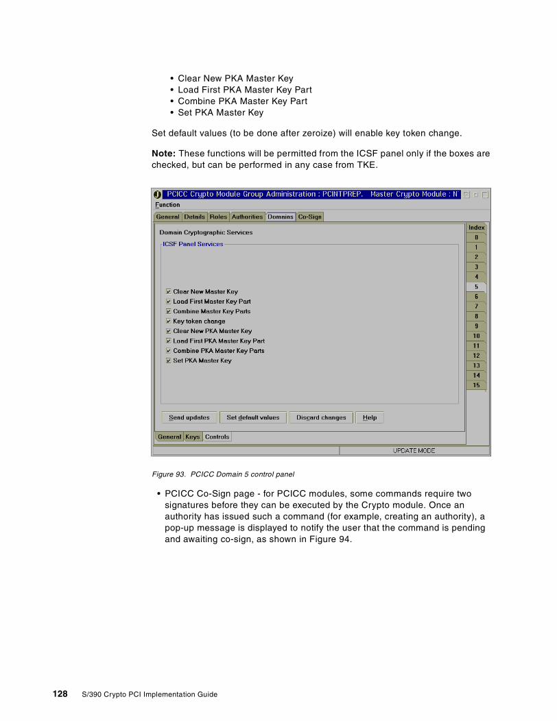
• Clear New PKA Master Key• Load First PKA Master Key Part• Combine PKA Master Key Part• Set PKA Master Key
Set default values (to be done after zeroize) will enable key token change.
Note: These functions will be permitted from the ICSF panel only if the boxes arechecked, but can be performed in any case from TKE.
Figure 93. PCICC Domain 5 control panel
• PCICC Co-Sign page - for PCICC modules, some commands require twosignatures before they can be executed by the Crypto module. Once anauthority has issued such a command (for example, creating an authority), apop-up message is displayed to notify the user that the command is pendingand awaiting co-sign, as shown in Figure 94.
128 S/390 Crypto PCI Implementation Guide
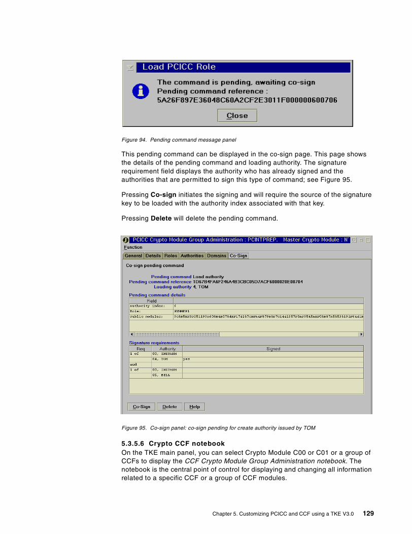
Figure 94. Pending command message panel
This pending command can be displayed in the co-sign page. This page showsthe details of the pending command and loading authority. The signaturerequirement field displays the authority who has already signed and theauthorities that are permitted to sign this type of command; see Figure 95.
Pressing Co-sign initiates the signing and will require the source of the signaturekey to be loaded with the authority index associated with that key.
Pressing Delete will delete the pending command.
Figure 95. Co-sign panel: co-sign pending for create authority issued by TOM
5.3.5.6 Crypto CCF notebookOn the TKE main panel, you can select Crypto Module C00 or C01 or a group ofCCFs to display the CCF Crypto Module Group Administration notebook. Thenotebook is the central point of control for displaying and changing all informationrelated to a specific CCF or a group of CCF modules.
Chapter 5. Customizing PCICC and CCF using a TKE V3.0 129
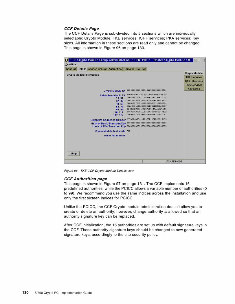
CCF Details PageThe CCF Details Page is sub-divided into 5 sections which are individuallyselectable: Crypto Module; TKE services; ICRF services; PKA services; Keysizes. All information in these sections are read only and cannot be changed.This page is shown in Figure 96 on page 130.
Figure 96. TKE CCF Crypto Module Details view
CCF Authorities pageThis page is shown in Figure 97 on page 131. The CCF implements 16predefined authorities, while the PCICC allows a variable number of authorities (0to 99). We recommend you use the same indices across the installation and useonly the first sixteen indices for PCICC.
Unlike the PCICC, the CCF Crypto module administration doesn’t allow you tocreate or delete an authority; however, change authority is allowed so that anauthority signature key can be replaced.
After CCF initialization, the 16 authorities are set up with default signature keys inthe CCF. These authority signature keys should be changed to new generatedsignature keys, accordingly to the site security policy.
130 S/390 Crypto PCI Implementation Guide
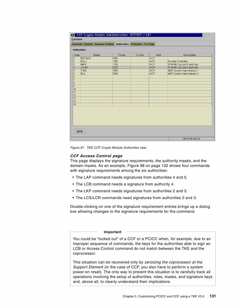
Figure 97. TKE CCF Crypto Module Authorities view
CCF Access Control pageThis page displays the signature requirements, the authority masks, and thedomain masks. As an example, Figure 98 on page 132 shows four commandswith signature requirements among the six authorities:
• The LAP command needs signatures from authorities 4 and 5.
• The LCB command needs a signature from authority 4.
• The LKP command needs signatures from authorities 2 and 3.
• The LCS/LCR commands need signatures from authorities 2 and 3.
Double-clicking on one of the signature requirement entries brings up a dialogbox allowing changes to the signature requirements for the command.
You could be “locked out” of a CCF or a PCICC when, for example, due to animproper sequence of commands, the keys for the authorities able to sign anLCB or Access Control command do not match between the TKE and thecoprocessor.
This situation can be recovered only by zeroizing the coprocessor at theSupport Element (in the case of CCF, you also have to perform a systempower-on reset). The only way to prevent this situation is to carefully track alloperations involving the setup of authorities, roles, masks, and signature keysand, above all, to clearly understand their implications.
Important
Chapter 5. Customizing PCICC and CCF using a TKE V3.0 131
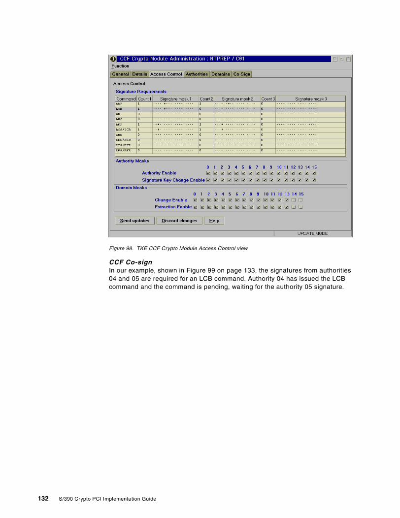
Figure 98. TKE CCF Crypto Module Access Control view
CCF Co-signIn our example, shown in Figure 99 on page 133, the signatures from authorities04 and 05 are required for an LCB command. Authority 04 has issued the LCBcommand and the command is pending, waiting for the authority 05 signature.
132 S/390 Crypto PCI Implementation Guide
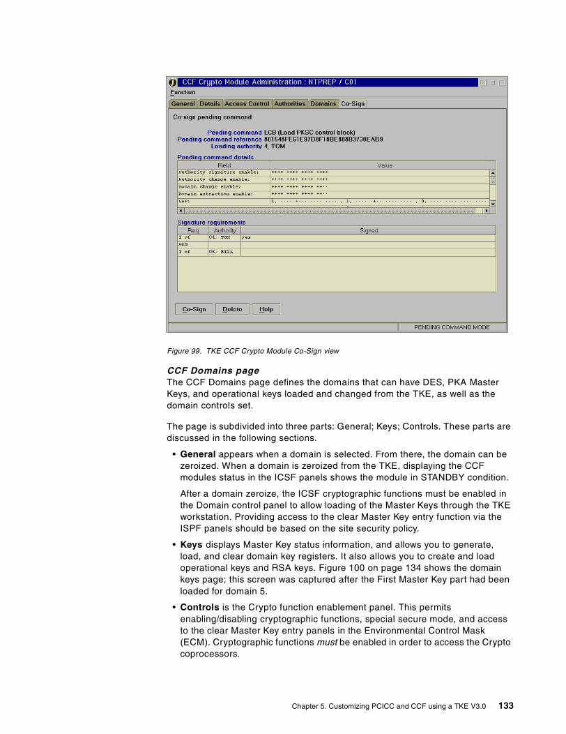
Figure 99. TKE CCF Crypto Module Co-Sign view
CCF Domains pageThe CCF Domains page defines the domains that can have DES, PKA MasterKeys, and operational keys loaded and changed from the TKE, as well as thedomain controls set.
The page is subdivided into three parts: General; Keys; Controls. These parts arediscussed in the following sections.
• General appears when a domain is selected. From there, the domain can bezeroized. When a domain is zeroized from the TKE, displaying the CCFmodules status in the ICSF panels shows the module in STANDBY condition.
After a domain zeroize, the ICSF cryptographic functions must be enabled inthe Domain control panel to allow loading of the Master Keys through the TKEworkstation. Providing access to the clear Master Key entry function via theISPF panels should be based on the site security policy.
• Keys displays Master Key status information, and allows you to generate,load, and clear domain key registers. It also allows you to create and loadoperational keys and RSA keys. Figure 100 on page 134 shows the domainkeys page; this screen was captured after the First Master Key part had beenloaded for domain 5.
• Controls is the Crypto function enablement panel. This permitsenabling/disabling cryptographic functions, special secure mode, and accessto the clear Master Key entry panels in the Environmental Control Mask(ECM). Cryptographic functions must be enabled in order to access the Cryptocoprocessors.
Chapter 5. Customizing PCICC and CCF using a TKE V3.0 133
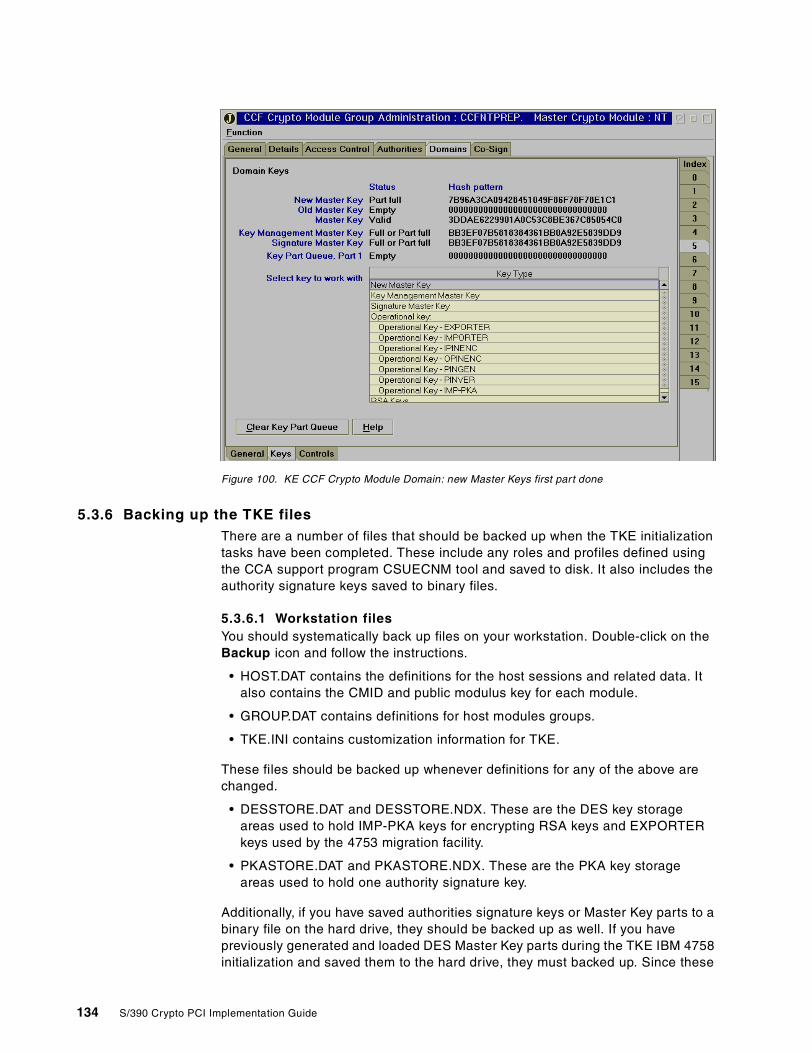
Figure 100. KE CCF Crypto Module Domain: new Master Keys first part done
5.3.6 Backing up the TKE filesThere are a number of files that should be backed up when the TKE initializationtasks have been completed. These include any roles and profiles defined usingthe CCA support program CSUECNM tool and saved to disk. It also includes theauthority signature keys saved to binary files.
5.3.6.1 Workstation filesYou should systematically back up files on your workstation. Double-click on theBackup icon and follow the instructions.
• HOST.DAT contains the definitions for the host sessions and related data. Italso contains the CMID and public modulus key for each module.
• GROUP.DAT contains definitions for host modules groups.
• TKE.INI contains customization information for TKE.
These files should be backed up whenever definitions for any of the above arechanged.
• DESSTORE.DAT and DESSTORE.NDX. These are the DES key storageareas used to hold IMP-PKA keys for encrypting RSA keys and EXPORTERkeys used by the 4753 migration facility.
• PKASTORE.DAT and PKASTORE.NDX. These are the PKA key storageareas used to hold one authority signature key.
Additionally, if you have saved authorities signature keys or Master Key parts to abinary file on the hard drive, they should be backed up as well. If you havepreviously generated and loaded DES Master Key parts during the TKE IBM 4758initialization and saved them to the hard drive, they must backed up. Since these
134 S/390 Crypto PCI Implementation Guide

files are named by you, there is no automated procedure to back them up. Youmust manually copy the files to the TKE binary diskette that is shipped with theTKE workstation.
Note: Do not use the backup diskette for this purpose.
5.3.6.2 Host filesThe Crypto module (CM) data set on the MVS Host system must be backed up.The name of the data set is defined in the parameters of the Host TransactionProgram. Refer to Appendix C, “TKE host TCP/IP server setup” on page 145, tofind out the name given to this file in your installation.
This data set contains definitions for the Crypto modules, domains, andauthorities. It is updated any time the user makes changes in the TKE applicationwindows and Crypto module notebooks.
5.4 4753 Key Token Migration facility
A facility is provided in the TKE V3.0 to migrate 4753 key tokens into the ICSFcryptographic key data set. It runs a migration utility in the TKE workstation andprovides the transfer facility, so that the migrated tokens can be transferred intothe host CKDS.
We did not practice with this utility during the residency; therefore, thisinformation is provided for reference only and to point you to the TKE WorkstationUser’s Guide 2000, GA22-7430, which provides the detailed procedure in itsAppendix F.
Chapter 5. Customizing PCICC and CCF using a TKE V3.0 135

136 S/390 Crypto PCI Implementation Guide
Chapter 6. Support functions
In this chapter we describe the additional support functions provided by OS/390for the PCICC.
6.1 RACF access control to ICSF services
These sections describe changes in RACF profiles.
6.1.1 New profilesThe following new profiles have been added in the CSFSERV general resourceclass:
CSFDKCS Protects the clear Master Key entry panel for the PCICC
CSFPCI Protects the TKE interface functions for communicating with thePCICC
CSFPCM Protects the PCICC management panel
CSFRKD Protects the Retained Key Delete callable service
CSFRKL Protects the Retained Key List callable service
6.1.2 CSFSERV profiles - cryptographic coprocessor administrationThis section describes how RACF profiles can be used to restrict thecoprocessors’ administration services to a selected set of users. The restrictionsare enforced only when the CSFSERV general resource class is active; toactivate the class, enter the following commands:
SETROPTS CLASSACT(CSFSERV)
SETROPTS RACLIST(CSFSERV)
After permitting specific users to the profile, the RACF administrator must refreshthe in-storage profiles by issuing this command:
SETROPTS RACLIST(CSFSERV) REFRESH
6.1.2.1 CSFDKCS and CSFDKEFWhen not permitted to these profiles, the user cannot enter the Master Key’sparts into the new Master Key registers or the PKA Master Key registers.
6.1.2.2 CSFPMCIThis profile allows you to initialize the coprocessors’ Master Keys and the CKDSby using a passphrase.
6.1.2.3 CSFPCI and CSFPKSCThe TKE host TCP/IP server (in our case, user ID TKEUSER) must be permittedto these two profiles. CSFPCI allows interactions between the TKE and thePCICC, while CSFPKSC allows interactions between the TKE and the CCF.
6.1.2.4 CSFSMK and CSFPCMCSFSMK allows you to get access to the set Master Key panel. CSFPCM givesaccess to the PCICC Management panel.
© Copyright IBM Corp. 2000 137
6.1.2.5 CSFREFR and CSFRENCCSFREFR allows you to access the CKDS Refresh function. CSFRENC allowsyou to access the Re-encipher CKDS function.
6.2 Crypto usage measurement
As of today, there is no specific measurement or instrumentation facility providedwith ICSF. Instead, you have to exploit the contents of SMF records type 30 ortype 82 to observe OS/390 ICSF activity.
138 S/390 Crypto PCI Implementation Guide
Appendix A. Exploiting the PCICC
In this appendix we list the software products you can use to take advantageof the PCI Cryptographic Coprocessor functions.
A.1 The IBM exploiters
The following software products exploit the S/390 cryptographic solution:
• IBM HTTP Server for OS/390
• OS/390 System SSL
• OS/390 LDAP Server
• CICS Transaction Gateway
• IBM Payment Suite e-commerce solutions on OS/390
• OS/390 TN3270 Server
• OS/390 Firewall Technology IPsec and Internet Key Exchange (IKE)
• DCE Security Server
• VTAM Session Level Encryption
• BSAFE Toolkit for OS/390
• OS/390 Open Cryptographic Services Facility
• CBT (Crypto Based Transactions) banking solution
• RACF
• Financial Institution Applications
© Copyright IBM Corp. 2000 139

140 S/390 Crypto PCI Implementation Guide
Appendix B. Support functions: ICSF services
ICSF provides callable services that perform cryptographic functions. Thisappendix describes these enhanced callable services.
B.1 Enhanced callable services
The enhanced callable services are detailed in the following sections.
B.1.1 PKA Key Generation (CSNDPKG)
• Adds support for the generation of the RSA key in CRT and ME form for amodulus length of 512 to 2048 bits
• The public exponent may be 3, 216 +1, or random.• There are new rule array keywords:
• CLEAR means the RSA token will be generated in the clear.• MASTER means the RSA key is generated in internal form.• RETAIN means the RSA key is retained in the PCICC.• CLONE means the Retained key may be cloned from one PCICC to
another securely (future function).• Regeneration data may be supplied to always generate the same key (for RSA
keys only).• The generated key may be written directly to the PKDS.• The routing is as follows: RSA key generation on PCICC, DSS generation on
CCF.
B.1.2 PKA Key Token Build (CSNDPKB)
• Adds support to build external PKA clear, encrypted, or skeleton tokens for anew CRT form.
• There are new rule array keywords:• RSA-CRT builds an RSA private key in optimized CRT form.• KM-ONLY is a new key usage specification that indicates a key may be
used only in key distribution services and not in any digital signatureservices.
• There is a new key value structure for CRT tokens.• This is not a cryptographic function; it executes in ICSF.
B.1.3 PKA Key Import (CSNDPKI)
• This service imports a PKA token from an external form to an internal form.• For DSS tokens, this service is routed to a CCF.• For RSA tokens, this service is routed to an ACTIVE PCICC if available for
both CRT and ME tokens.• Exception for an ME token if modulus length is <512 bits.• If no PCICC is available, this service is routed to CCF. The service will fail
for CRT tokens.• The target key identifier may be a labelname, in which case the imported key
is written directly to the PKDS.
© Copyright IBM Corp. 2000 141
B.1.4 PKA Public Key Extract (CSNDPKX)
• This service now executes in the ICSF address space (previously it executedin the caller's address space). RACF checking of service call, pre-processing,and post-processing exits are now enabled.
• The new CRT and ME tokens are supported.• PKDS labelname is now supported for source key identifier.• If labelname is used, the caller must be in task mode (not SRB mode).• A new CSNDPKX stub module is shipped, but the old stub and the new stub
will both call the new service module.• This is not a cryptographic function; it executes in ICSF.
B.1.5 Digital Signature Generate (CSNDDSG)
• This service now supports the new CRT and ME tokens and retained keys.• Routing of this service depends on the form of the input private key identifier,
as follows:• If the source is a DSS token - route to CCF.• If the source is an RSA token:
• ME x'02' - route to CCF.• CRT - route to PCICC.• ME x'06' - use round robin to CCF and PCICC, if possible.
• For a rule array keyword of ZERO-PAD, the maximum hash length supportedis 32 bytes.
B.1.6 Symmetric Key Generate (CSNDSYG)
• This service has a preference for PCICC, so that the symmetric key neverappears in host storage.
• This service will be routed to an ACTIVE PCICC unless the modulus bit length< 512, or if no PCICC is available.
B.1.7 Symmetric Key Export (CSNDSYX)
• This service has a preference for PCICC in order that the symmetric key neverappears in host storage
• Service will be routed to an ACTIVE PCICC unless the modulus bit length <512, or if no PCICC is available.
B.1.8 Symmetric Key Import (CSNDSYI)
• This service has a preference for PCICC, so that the symmetric key neverappears in host storage.
• CRT and retained keys are routed to PCICC.• For ME x'02' tokens - route to CCF.• For ME x'06' - route to PCICC if available; otherwise route to CCF if SMK =
KMMK.
B.1.9 SET Block Compose (CSNDSBC)
• This service has a preference for PCICC, so that the symmetric key neverappears in host storage.
• This service will be routed to an ACTIVE PCICC for OAEP processing unlessthe modulus bit length < 512, or if no PCICC is available.
• DES encryption and hashing are always executed on CCF.
142 S/390 Crypto PCI Implementation Guide
B.1.10 SET Block Decompose (CSNDSBD)
• This service has a preference for PCICC, so that the symmetric key neverappears in host storage.
• It the RSA token is ME x'02' - route to CCF.• If the RSA token is CRT or retained key - route to PCICC for OAEP
processing.• If the RSA token is ME x'06' - route to PCICC, if available; otherwise route to
CCF.• DES encryption and hashing is always executed on CCF.
B.1.11 PKA Encrypt (CSNDPKE)
• This is an RSA public key function with no security requirements.• This service is always routed to CCF for better performance for modulus bit
length <= 1024 bits.
B.1.12 PKA Decrypt (CSNDPKD)
• This service support CRT and retained keys on PCICC.• For ME x'02' tokens or modulus bit length < 512 bits - route to CCF.• For ME x'06' - route to PCICC if available; otherwise route to CCF if SMK =
KMMK.
B.1.13 PKDS callable services
PKDS callable services cannot be used to create/update/delete the PKDS records ofretained keys. This is enforced in the PKDS Record Create/Write/Delete services(CSNDKRC, CSNDKRW, CSNDKRD).
B.2 New callable services
The following callable services have been added.
B.2.1 Retained Key Delete (CSNDRKD)
• This service will delete the PKDS record and retained key in the PCICC of thekey label supplied.
• Delete must be done from the same domain as the creation of the retainedkey.
• This service will delete a record of a retained key in the PKDS even if there isno retained key in the specified PCICC.
• This service will also delete a retained key in the specified PCICC even ifthere is no PKDS record:
• Use the FORCE keyword with the Serial Number in the rule array.
B.2.2 Retained Key List (CSNDRKL)
• This service returns a list of retained keys for each ACTIVE PCICC created inthis domain.
• Each PCICC is identified with a /*serial number, followed by list of keylabels ofretained keys in that PCICC. This structure differs from other CSNDRKLimplementations, since other platforms do not support multiple PCICCs.
Appendix B. Support functions: ICSF services 143

• You must supply a labelname mask, optionally terminated with a wild cardsymbol (*), to filter the list of labelnames returned.
• A mask of (*) will return all retained keys in all ACTIVE PCICCs created fromthat domain.
144 S/390 Crypto PCI Implementation Guide
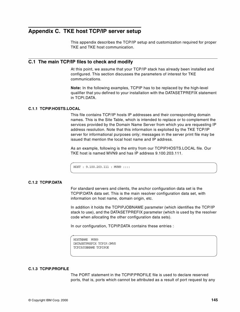
Appendix C. TKE host TCP/IP server setup
This appendix describes the TCP/IP setup and customization required for properTKE and TKE host communication.
C.1 The main TCP/IP files to check and modify
At this point, we assume that your TCP/IP stack has already been installed andconfigured. This section discusses the parameters of interest for TKEcommunications.
Note: In the following examples, TCPIP has to be replaced by the high-levelqualifier that you defined to your installation with the DATASETPREFIX statementin TCPI.DATA.
C.1.1 TCPIP.HOSTS.LOCAL
This file contains TCP/IP hosts IP addresses and their corresponding domainnames. This is the Site Table, which is intended to replace or to complement theservices provided by the Domain Name Server from which you are requesting IPaddress resolution. Note that this information is exploited by the TKE TCP/IPserver for informational purposes only; messages in the server print file may beissued that mention the local host name and IP address.
As an example, following is the entry from our TCPIP.HOSTS.LOCAL file. OurTKE host is named MVN9 and has IP address 9.100.203.111.
C.1.2 TCPIP.DATA
For standard servers and clients, the anchor configuration data set is theTCPIP.DATA data set. This is the main resolver configuration data set, withinformation on host name, domain origin, etc.
In addition it holds the TCPIPJOBNAME parameter (which identifies the TCP/IPstack to use), and the DATASETPREFIX parameter (which is used by the resolvercode when allocating the other configuration data sets).
In our configuration, TCPIP.DATA contains these entries :
C.1.3 TCPIP.PROFILE
The PORT statement in the TCPIP.PROFILE file is used to declare reservedports, that is, ports which cannot be attributed as a result of port request by any
HOST : 9.100.203.111 : MVN9 ::::
HOSTNAME MVN9DATASETPREFIX TCPIP.OMVSTCPIPJOBNAME TCPIPOE
© Copyright IBM Corp. 2000 145
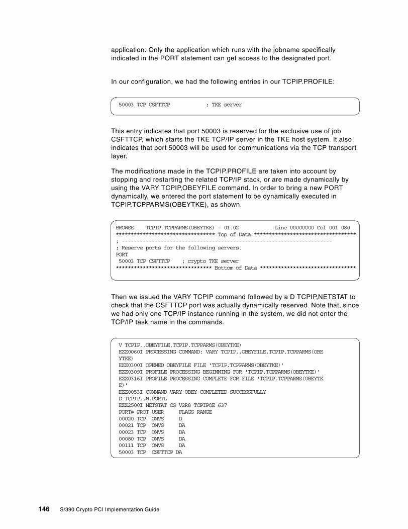
application. Only the application which runs with the jobname specificallyindicated in the PORT statement can get access to the designated port.
In our configuration, we had the following entries in our TCPIP.PROFILE:
This entry indicates that port 50003 is reserved for the exclusive use of jobCSFTTCP, which starts the TKE TCP/IP server in the TKE host system. It alsoindicates that port 50003 will be used for communications via the TCP transportlayer.
The modifications made in the TCPIP.PROFILE are taken into account bystopping and restarting the related TCP/IP stack, or are made dynamically byusing the VARY TCPIP,OBEYFILE command. In order to bring a new PORTdynamically, we entered the port statement to be dynamically executed inTCPIP.TCPPARMS(OBEYTKE), as shown.
Then we issued the VARY TCPIP command followed by a D TCPIP,NETSTAT tocheck that the CSFTTCP port was actually dynamically reserved. Note that, sincewe had only one TCP/IP instance running in the system, we did not enter theTCP/IP task name in the commands.
50003 TCP CSFTTCP ; TKE server
BROWSE TCPIP.TCPPARMS(OBEYTKE) - 01.02 Line 00000000 Col 001 080********************************* Top of Data **********************************; ----------------------------------------------------------------------; Reserve ports for the following servers.PORT50003 TCP CSFTTCP ; crypto TKE server******************************** Bottom of Data ********************************
V TCPIP,,OBEYFILE,TCPIP.TCPPARMS(OBEYTKE)EZZ0060I PROCESSING COMMAND: VARY TCPIP,,OBEYFILE,TCPIP.TCPPARMS(OBEYTKE)EZZ0300I OPENED OBEYFILE FILE 'TCPIP.TCPPARMS(OBEYTKE)'EZZ0309I PROFILE PROCESSING BEGINNING FOR 'TCPIP.TCPPARMS(OBEYTKE)'EZZ0316I PROFILE PROCESSING COMPLETE FOR FILE 'TCPIP.TCPPARMS(OBEYTKE)'EZZ0053I COMMAND VARY OBEY COMPLETED SUCCESSFULLYD TCPIP,,N,PORTLEZZ2500I NETSTAT CS V2R8 TCPIPOE 637PORT# PROT USER FLAGS RANGE00020 TCP OMVS D00021 TCP OMVS DA00023 TCP OMVS DA00080 TCP OMVS DA00111 TCP OMVS DA50003 TCP CSFTTCP DA
146 S/390 Crypto PCI Implementation Guide
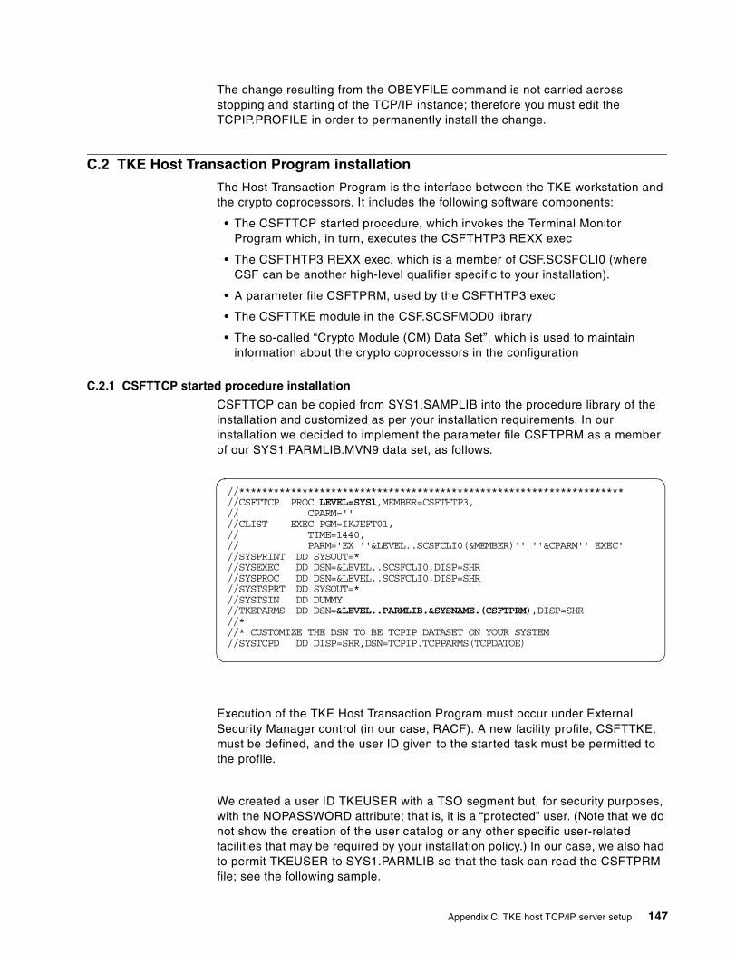
The change resulting from the OBEYFILE command is not carried acrossstopping and starting of the TCP/IP instance; therefore you must edit theTCPIP.PROFILE in order to permanently install the change.
C.2 TKE Host Transaction Program installation
The Host Transaction Program is the interface between the TKE workstation andthe crypto coprocessors. It includes the following software components:
• The CSFTTCP started procedure, which invokes the Terminal MonitorProgram which, in turn, executes the CSFTHTP3 REXX exec
• The CSFTHTP3 REXX exec, which is a member of CSF.SCSFCLI0 (whereCSF can be another high-level qualifier specific to your installation).
• A parameter file CSFTPRM, used by the CSFTHTP3 exec
• The CSFTTKE module in the CSF.SCSFMOD0 library
• The so-called “Crypto Module (CM) Data Set”, which is used to maintaininformation about the crypto coprocessors in the configuration
C.2.1 CSFTTCP started procedure installation
CSFTTCP can be copied from SYS1.SAMPLIB into the procedure library of theinstallation and customized as per your installation requirements. In ourinstallation we decided to implement the parameter file CSFTPRM as a memberof our SYS1.PARMLIB.MVN9 data set, as follows.
Execution of the TKE Host Transaction Program must occur under ExternalSecurity Manager control (in our case, RACF). A new facility profile, CSFTTKE,must be defined, and the user ID given to the started task must be permitted tothe profile.
We created a user ID TKEUSER with a TSO segment but, for security purposes,with the NOPASSWORD attribute; that is, it is a “protected” user. (Note that we donot show the creation of the user catalog or any other specific user-relatedfacilities that may be required by your installation policy.) In our case, we also hadto permit TKEUSER to SYS1.PARMLIB so that the task can read the CSFTPRMfile; see the following sample.
//*******************************************************************//CSFTTCP PROC LEVEL=SYS1,MEMBER=CSFTHTP3,// CPARM=''//CLIST EXEC PGM=IKJEFT01,// TIME=1440,// PARM='EX ''&LEVEL..SCSFCLI0(&MEMBER)'' ''&CPARM'' EXEC'//SYSPRINT DD SYSOUT=*//SYSEXEC DD DSN=&LEVEL..SCSFCLI0,DISP=SHR//SYSPROC DD DSN=&LEVEL..SCSFCLI0,DISP=SHR//SYSTSPRT DD SYSOUT=*//SYSTSIN DD DUMMY//TKEPARMS DD DSN=&LEVEL..PARMLIB.&SYSNAME.(CSFTPRM),DISP=SHR//*//* CUSTOMIZE THE DSN TO BE TCPIP DATASET ON YOUR SYSTEM//SYSTCPD DD DISP=SHR,DSN=TCPIP.TCPPARMS(TCPDATOE)
Appendix C. TKE host TCP/IP server setup 147
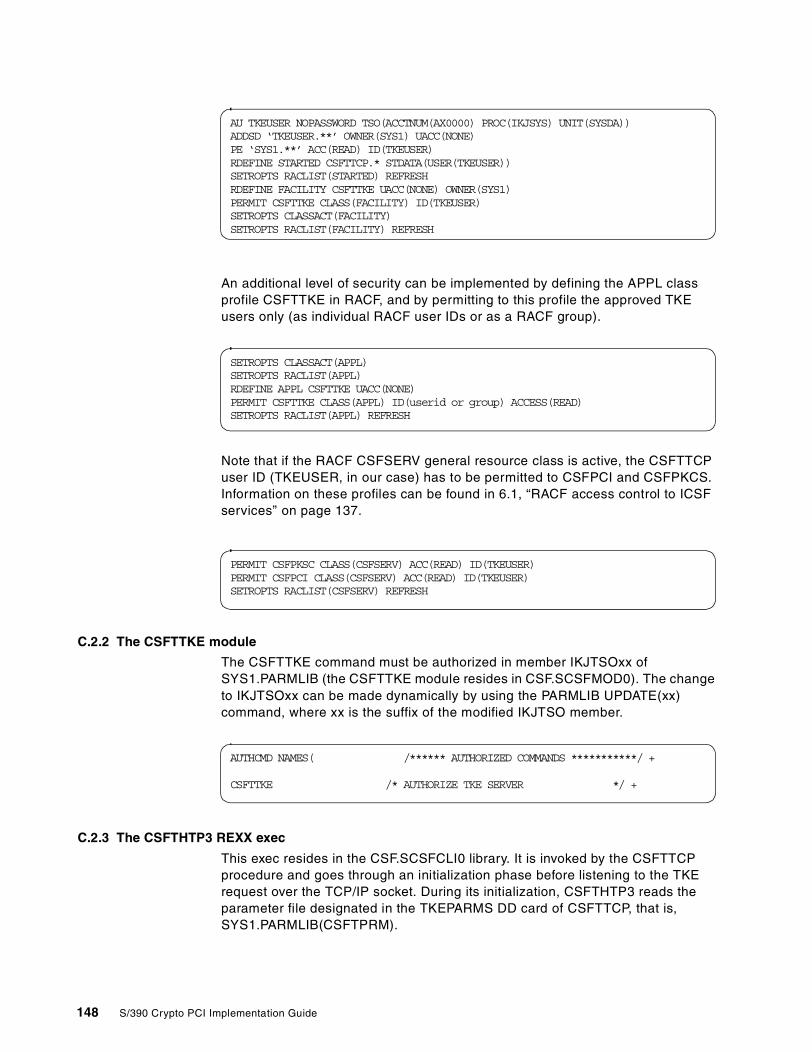
An additional level of security can be implemented by defining the APPL classprofile CSFTTKE in RACF, and by permitting to this profile the approved TKEusers only (as individual RACF user IDs or as a RACF group).
Note that if the RACF CSFSERV general resource class is active, the CSFTTCPuser ID (TKEUSER, in our case) has to be permitted to CSFPCI and CSFPKCS.Information on these profiles can be found in 6.1, “RACF access control to ICSFservices” on page 137.
C.2.2 The CSFTTKE module
The CSFTTKE command must be authorized in member IKJTSOxx ofSYS1.PARMLIB (the CSFTTKE module resides in CSF.SCSFMOD0). The changeto IKJTSOxx can be made dynamically by using the PARMLIB UPDATE(xx)command, where xx is the suffix of the modified IKJTSO member.
C.2.3 The CSFTHTP3 REXX exec
This exec resides in the CSF.SCSFCLI0 library. It is invoked by the CSFTTCPprocedure and goes through an initialization phase before listening to the TKErequest over the TCP/IP socket. During its initialization, CSFTHTP3 reads theparameter file designated in the TKEPARMS DD card of CSFTTCP, that is,SYS1.PARMLIB(CSFTPRM).
AU TKEUSER NOPASSWORD TSO(ACCTNUM(AX0000) PROC(IKJSYS) UNIT(SYSDA))ADDSD ‘TKEUSER.**’ OWNER(SYS1) UACC(NONE)PE ‘SYS1.**’ ACC(READ) ID(TKEUSER)RDEFINE STARTED CSFTTCP.* STDATA(USER(TKEUSER))SETROPTS RACLIST(STARTED) REFRESHRDEFINE FACILITY CSFTTKE UACC(NONE) OWNER(SYS1)PERMIT CSFTTKE CLASS(FACILITY) ID(TKEUSER)SETROPTS CLASSACT(FACILITY)SETROPTS RACLIST(FACILITY) REFRESH
SETROPTS CLASSACT(APPL)SETROPTS RACLIST(APPL)RDEFINE APPL CSFTTKE UACC(NONE)PERMIT CSFTTKE CLASS(APPL) ID(userid or group) ACCESS(READ)SETROPTS RACLIST(APPL) REFRESH
PERMIT CSFPKSC CLASS(CSFSERV) ACC(READ) ID(TKEUSER)PERMIT CSFPCI CLASS(CSFSERV) ACC(READ) ID(TKEUSER)SETROPTS RACLIST(CSFSERV) REFRESH
AUTHCMD NAMES( /****** AUTHORIZED COMMANDS ***********/ +
CSFTTKE /* AUTHORIZE TKE SERVER */ +
148 S/390 Crypto PCI Implementation Guide
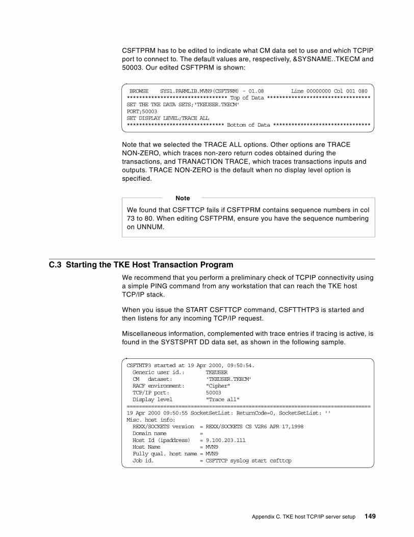
CSFTPRM has to be edited to indicate what CM data set to use and which TCPIPport to connect to. The default values are, respectively, &SYSNAME..TKECM and50003. Our edited CSFTPRM is shown:
Note that we selected the TRACE ALL options. Other options are TRACENON-ZERO, which traces non-zero return codes obtained during thetransactions, and TRANACTION TRACE, which traces transactions inputs andoutputs. TRACE NON-ZERO is the default when no display level option isspecified.
C.3 Starting the TKE Host Transaction Program
We recommend that you perform a preliminary check of TCPIP connectivity usinga simple PING command from any workstation that can reach the TKE hostTCP/IP stack.
When you issue the START CSFTTCP command, CSFTTHTP3 is started andthen listens for any incoming TCP/IP request.
Miscellaneous information, complemented with trace entries if tracing is active, isfound in the SYSTSPRT DD data set, as shown in the following sample.
BROWSE SYS1.PARMLIB.MVN9(CSFTPRM) - 01.08 Line 00000000 Col 001 080********************************* Top of Data **********************************SET THE TKE DATA SETS;'TKEUSER.TKECM'PORT;50003SET DISPLAY LEVEL;TRACE ALL******************************** Bottom of Data ********************************
We found that CSFTTCP fails if CSFTPRM contains sequence numbers in col73 to 80. When editing CSFTPRM, ensure you have the sequence numberingon UNNUM.
Note
CSFTHTP3 started at 19 Apr 2000, 09:50:54.Generic user id.: TKEUSERCM dataset: 'TKEUSER.TKECM'RACF environment: "Cipher"TCP/IP port: 50003Display level "Trace all"
================================================================================19 Apr 2000 09:50:55 SocketSetList: ReturnCode=0, SocketSetList: ''Misc. host info:REXX/SOCKETS version = REXX/SOCKETS CS V2R6 APR 17,1998Domain name =Host Id (ipaddress) = 9.100.203.111Host Name = MVN9Fully qual. host name = MVN9Job id. = CSFTTCP syslog start csfttcp
Appendix C. TKE host TCP/IP server setup 149

150 S/390 Crypto PCI Implementation Guide

Appendix D. Special notices
This publication is intended to help systems programmers and securitypersonnel enable the S/390 PCICC. The information in this publication is notintended as the specification of any programming interfaces that are providedby the OS/390 operating system. See the PUBLICATIONS section of the IBMProgramming Announcement for the OS/390 operating system for moreinformation about what publications are considered to be productdocumentation.
References in this publication to IBM products, programs or services do notimply that IBM intends to make these available in all countries in which IBMoperates. Any reference to an IBM product, program, or service is notintended to state or imply that only IBM's product, program, or service may beused. Any functionally equivalent program that does not infringe any of IBM'sintellectual property rights may be used instead of the IBM product, programor service.
Information in this book was developed in conjunction with use of theequipment specified, and is limited in application to those specific hardwareand software products and levels.
IBM may have patents or pending patent applications covering subject matterin this document. The furnishing of this document does not give you anylicense to these patents. You can send license inquiries, in writing, to the IBMDirector of Licensing, IBM Corporation, North Castle Drive, Armonk, NY10504-1785.
Licensees of this program who wish to have information about it for thepurpose of enabling: (i) the exchange of information between independentlycreated programs and other programs (including this one) and (ii) the mutualuse of the information which has been exchanged, should contact IBMCorporation, Dept. 600A, Mail Drop 1329, Somers, NY 10589 USA.
Such information may be available, subject to appropriate terms andconditions, including in some cases, payment of a fee.
The information contained in this document has not been submitted to anyformal IBM test and is distributed AS IS. The information about non-IBM("vendor") products in this manual has been supplied by the vendor and IBMassumes no responsibility for its accuracy or completeness. The use of thisinformation or the implementation of any of these techniques is a customerresponsibility and depends on the customer's ability to evaluate and integratethem into the customer's operational environment. While each item may have
© Copyright IBM Corp. 2000 151

been reviewed by IBM for accuracy in a specific situation, there is noguarantee that the same or similar results will be obtained elsewhere.Customers attempting to adapt these techniques to their own environmentsdo so at their own risk.
Any pointers in this publication to external Web sites are provided forconvenience only and do not in any manner serve as an endorsement ofthese Web sites.
Any performance data contained in this document was determined in acontrolled environment, and therefore, the results that may be obtained inother operating environments may vary significantly. Users of this documentshould verify the applicable data for their specific environment.
This document contains examples of data and reports used in daily businessoperations. To illustrate them as completely as possible, the examplescontain the names of individuals, companies, brands, and products. All ofthese names are fictitious and any similarity to the names and addressesused by an actual business enterprise is entirely coincidental.
Reference to PTF numbers that have not been released through the normaldistribution process does not imply general availability. The purpose ofincluding these reference numbers is to alert IBM customers to specificinformation relative to the implementation of the PTF when it becomesavailable to each customer according to the normal IBM PTF distributionprocess.
The following terms are trademarks of the International Business MachinesCorporation in the United States and/or other countries:
The following terms are trademarks of other companies:
Tivoli, Manage. Anything. Anywhere.,The Power To Manage., Anything.Anywhere.,TME, NetView, Cross-Site, Tivoli Ready, Tivoli Certified, PlanetTivoli, and Tivoli Enterprise are trademarks or registered trademarks of TivoliSystems Inc., an IBM company, in the United States, other countries, or both.In Denmark, Tivoli is a trademark licensed from Kjøbenhavns Sommer - TivoliA/S.
IBM � SPPR/SM SP1RACF System/390RETAIN VTAMRS/6000 400S/390 LotusSecureWay Notes
152 S/390 Crypto PCI Implementation Guide

C-bus is a trademark of Corollary, Inc. in the United States and/or othercountries.
Java and all Java-based trademarks and logos are trademarks or registeredtrademarks of Sun Microsystems, Inc. in the United States and/or othercountries.
Microsoft, Windows, Windows NT, and the Windows logo are trademarks ofMicrosoft Corporation in the United States and/or other countries.
PC Direct is a trademark of Ziff Communications Company in the UnitedStates and/or other countries and is used by IBM Corporation under license.
ActionMedia, LANDesk, MMX, Pentium and ProShare are trademarks of IntelCorporation in the United States and/or other countries.
UNIX is a registered trademark in the United States and other countrieslicensed exclusively through The Open Group.
SET, SET Secure Electronic Transaction, and the SET Logo are trademarksowned by SET Secure Electronic Transaction LLC.
Other company, product, and service names may be trademarks or servicemarks of others.
Appendix D. Special notices 153

154 S/390 Crypto PCI Implementation Guide
Appendix E. Related publications
The publications listed in this section are considered particularly suitable for amore detailed discussion of the topics covered in this redbook.
E.1 IBM Redbooks publications
For information on ordering these publications see “How to get IBM Redbooks” onpage 157.
• Fiber Channel (FICON) Implementation Planning, SG24-5445
• Exploiting S/390 Hardware Cryptography with Trusted Key Entry, SG24-5455
E.2 IBM Redbooks collections
Redbooks are also available on the following CD-ROMs. Click the CD-ROMsbutton at http://www.redbooks.ibm.com/ for information about all the CD-ROMsoffered, updates and formats.
E.3 Other resources
These publications are also relevant as further information sources:
• Common Cryptographic Architecture: Cryptographic Application ProgrammingInterface Reference, SC40-1675
• Support Element Operations Guide, GC38-0608
• ICSF System Programmer’s Guide, SC23-3974
• Workstation Maintenance, GC38-3115
• PR/SM Planning Guide, GA22-7236
• Security Server (RACF) Security Administrator’s Guide, SC28-1915
• TKE Workstation User’s Guide 2000, GA22-7430
CD-ROM Title Collection KitNumber
System/390 Redbooks Collection SK2T-2177
Networking and Systems Management Redbooks Collection SK2T-6022
Transaction Processing and Data Management Redbooks Collection SK2T-8038
Lotus Redbooks Collection SK2T-8039
Tivoli Redbooks Collection SK2T-8044
AS/400 Redbooks Collection SK2T-2849
Netfinity Hardware and Software Redbooks Collection SK2T-8046
RS/6000 Redbooks Collection (BkMgr) SK2T-8040
RS/6000 Redbooks Collection (PDF Format) SK2T-8043
Application Development Redbooks Collection SK2T-8037
IBM Enterprise Storage and Systems Management Solutions SK3T-3694
© Copyright IBM Corp. 2000 155

E.4 Referenced Web site
This Web site is also relevant as a further information source:
• http://csrc.ncsl.nist.gov/cryptval/140-1/1401val.htm
156 S/390 Crypto PCI Implementation Guide

How to get IBM Redbooks
This section explains how both customers and IBM employees can find out about IBM Redbooks,redpieces, and CD-ROMs. A form for ordering books and CD-ROMs by fax or e-mail is also provided.
• Redbooks Web Site http://www.redbooks.ibm.com/
Search for, view, download, or order hardcopy/CD-ROM Redbooks from the Redbooks Web site.Also read redpieces and download additional materials (code samples or diskette/CD-ROM images)from this Redbooks site.
Redpieces are Redbooks in progress; not all Redbooks become redpieces and sometimes just a fewchapters will be published this way. The intent is to get the information out much quicker than theformal publishing process allows.
• E-mail Orders
Send orders by e-mail including information from the IBM Redbooks fax order form to:
• Telephone Orders
• Fax Orders
This information was current at the time of publication, but is continually subject to change. The latestinformation may be found at the Redbooks Web site.
In United StatesOutside North America
e-mail [email protected] information is in the “How to Order” section at this site:http://www.elink.ibmlink.ibm.com/pbl/pbl
United States (toll free)Canada (toll free)Outside North America
1-800-879-27551-800-IBM-4YOUCountry coordinator phone number is in the “How to Order”section at this site:http://www.elink.ibmlink.ibm.com/pbl/pbl
United States (toll free)CanadaOutside North America
1-800-445-92691-403-267-4455Fax phone number is in the “How to Order” section at this site:http://www.elink.ibmlink.ibm.com/pbl/pbl
IBM employees may register for information on workshops, residencies, and Redbooks by accessingthe IBM Intranet Web site at http://w3.itso.ibm.com/ and clicking the ITSO Mailing List button.Look in the Materials repository for workshops, presentations, papers, and Web pages developedand written by the ITSO technical professionals; click the Additional Materials button. Employees mayaccess MyNews at http://w3.ibm.com/ for redbook, residency, and workshop announcements.
IBM Intranet for Employees
© Copyright IBM Corp. 2000 157

IBM Redbooks fax order form
Please send me the following:
We accept American Express, Diners, Eurocard, Master Card, and Visa. Payment by credit card notavailable in all countries. Signature mandatory for credit card payment.
Title Order Number Quantity
First name Last name
Company
Address
City Postal code
Telephone number Telefax number VAT number
Invoice to customer number
Country
Credit card number
Credit card expiration date SignatureCard issued to
158 S/390 Crypto PCI Implementation Guide
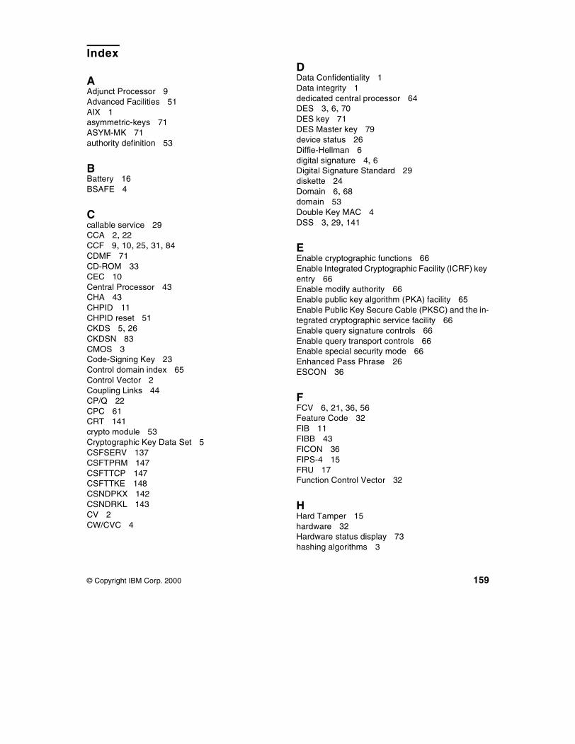
Index
AAdjunct Processor 9Advanced Facilities 51AIX 1asymmetric-keys 71ASYM-MK 71authority definition 53
BBattery 16BSAFE 4
Ccallable service 29CCA 2, 22CCF 9, 10, 25, 31, 84CDMF 71CD-ROM 33CEC 10Central Processor 43CHA 43CHPID 11CHPID reset 51CKDS 5, 26CKDSN 83CMOS 3Code-Signing Key 23Control domain index 65Control Vector 2Coupling Links 44CP/Q 22CPC 61CRT 141crypto module 53Cryptographic Key Data Set 5CSFSERV 137CSFTPRM 147CSFTTCP 147CSFTTKE 148CSNDPKX 142CSNDRKL 143CV 2CW/CVC 4
© Copyright IBM Corp. 2000
DData Confidentiality 1Data integrity 1dedicated central processor 64DES 3, 6, 70DES key 71DES Master key 79device status 26Diffie-Hellman 6digital signature 4, 6Digital Signature Standard 29diskette 24Domain 6, 68domain 53Double Key MAC 4DSS 3, 29, 141
EEnable cryptographic functions 66Enable Integrated Cryptographic Facility (ICRF) keyentry 66Enable modify authority 66Enable public key algorithm (PKA) facility 65Enable Public Key Secure Cable (PKSC) and the in-tegrated cryptographic service facility 66Enable query signature controls 66Enable query transport controls 66Enable special security mode 66Enhanced Pass Phrase 26ESCON 36
FFCV 6, 21, 36, 56Feature Code 32FIB 11FIBB 43FICON 36FIPS-4 15FRU 17Function Control Vector 32
HHard Tamper 15hardware 32Hardware status display 73hashing algorithms 3
159
HCRP230 26HMC 33hotplugged PCICC card 51HSA 19, 25
II/O cage 45I/O domain 47I/O slot 46IBM Integrated Cryptographic Facility 1IBM Transaction Security System 1ICB 49ICRF 1, 4ICSF 5, 6, 142ICSF/MVS 1IEASYM 69Image Profile 64IML 20Impor 24Integrated Cluster Buses 44Integrated Cryptographic Services Facility/MVS 1Internal Coupling Facility 43Intersystem Channel Adapter 44Intrusion Latch 16IO Supervisor 25IOCDS 36
KKey Management 1Key Separation 2
LLIC 6logical crypto coprocessor 64logical partition 64LPAR 55LPAR image 36
MMAC 29Master Key 71Master Key Concept 1MasterCard 26MBA 42MDC 29Memory Bus Adapter 42MES 17, 34, 55
MES upgrade 50Miniboot 22MVN9 145
NNOPASSWORD 70
OOAEP 142OBEYTKE 146Online List 67OPK 3Option Data Set 7OS/390 1OS/390 R9 56OS/390 V2R9 10OS/400 1OSA-2 11OSA2 36
PPass Phrase 77PCICC 10, 55, 84Personal Authentication 1personal identification number 29PIN 29PING 149PKA 65, 74PKA Key management 3PKDS 5, 141, 143PORT 145Power On 20, 34PPINIT 72PR/SM 7, 8, 61Private Key Data Set 5PSC 53Pseudo Random Number Generation 3public key algorithm 65Public Key Algorithms (RSA) 4
RRACF 137, 142, 147REASONCODE 29REENCHIPER 80RESET 84Retained key 27routing 27
160 S/390 Crypto PCI Implementation Guide
RSA 3, 4, 21, 29, 141
SSales Ordering System 36SAP 43SE 20SecureWay 3segment 23SET 4signature key 53SMF 29Soft Tamper 16STI 34STI chain 44SUL-ROC 34Support Element 25, 61symmetric-keys 71
TTCP/IP 30, 145, 149TDES 36Thermal container 18thermal container 18thermal gel 18TKE 8, 9, 55, 71TKE Workstation 6Toggle 56Triple DES 3TSO 30, 147TSO/E ISPF 26
UUDX 21Usage domain index 65User Defined Extension 21USERCNTL 84
VVBAT 15Visa 26Visa/Mastercard CW/CVC card-verification 4
XX-ray exposure 15
Zzeroize 17ZERO-PAD 142
161

162 S/390 Crypto PCI Implementation Guide

© Copyright IBM Corp. 2000 163
IBM Redbooks review
Your feedback is valued by the Redbook authors. In particular we are interested in situations where aRedbook "made the difference" in a task or problem you encountered. Using one of the followingmethods, please review the Redbook, addressing value, subject matter, structure, depth andquality as appropriate.
• Use the online Contact us review redbook form found at http://www.redbooks.ibm.com/• Fax this form to: USA International Access Code + 1 914 432 8264• Send your comments in an Internet note to [email protected]
Document NumberRedbook Title
SG24-5942-00S/390 Crypto PCI Implementation Guide
Review
What other subjects would youlike to see IBM Redbooksaddress?
Please rate your overallsatisfaction:
O Very Good O Good O Average O Poor
Please identify yourself asbelonging to one of thefollowing groups:
O Customer O Business Partner O Solution DeveloperO IBM, Lotus or Tivoli EmployeeO None of the above
Your email address:The data you provide here maybe used to provide you withinformation from IBM or ourbusiness partners about ourproducts, services or activities.
O Please do not use the information collected here for futuremarketing or promotional contacts or other communications beyondthe scope of this transaction.
Questions about IBM’s privacypolicy?
The following link explains how we protect your personal information.http://www.ibm.com/privacy/yourprivacy/
Printed in the U.S.A.
SG24-5942-00
S/390C
ryptoP
CI
Implem
entationG
uideS
G24-5942-00
®


