Embed Size (px)
Citation preview
S7 for Windows S5 for Windows
Manual
S5 / S7 for Windows User’s Guide
Information in this document is subject to change without notice and does not represent a commitment on the part of IBH softec GmbH. The software and/or databases, described in this document, are furnished under a license agreement or non-disclosure agreement. The software and/or databases may be used or copied only in accordance with the terms of the agreement. It is against the law to copy the software on any medium except as specifically allowed in the license or non-disclosure agreement. The purchaser may make one copy of the software for backup purposes. No part of this manual and/or databases may be reproduced or transmitted in any form or by any means, (electronic or mechanical, including photocopying, recording, or information storage and retrieval systems), for any purpose other than the purchaser's personal use, without the express written permission of IBH softec GmbH.
© Copyright 1993 - 2007 IBH softec GmbH. All rights reserved.
Gesellschaft für Automatisierungstechnik mbH Turmstraße 77 D - 64743 Beerfelden / Odw. Germany Telefon +49 60 68 / 30 01 Telefax +49 60 68 / 30 74 Internet: www.IBHsoftec.de E-Mail: [email protected] Windows™, Windows NT™ are trademarks of the Microsoft® Corporation in the USA and/or other countries. Simatic® S5, Step® 5, Step® 7 and GRAPH® 5 are registered trademarks of Siemens AG, München and Berlin.
S5 / S7 for Windows User’s Guide
Contents Page III
S5 / S7 for Windows User’s Guide
Contents
Contents .................................................................................. III
Part 1.........................................................................................1
1 Installing S5 / S7 for Windows ..........................................2
1.1 System Requirements .............................................................. 2
1.2 Installation Program ................................................................. 3
1.2.1 Start Installation................................................................................. 4 1.3 Running S5 / S7 for Windows the First Time........................ 11
1.3.1 Entering the Authorization Code...................................................... 12
2 Introduction ......................................................................14
2.1 Notation and Conventions ..................................................... 15
3 PC Block List ....................................................................16
3.1 PC Block List Window ............................................................ 16
3.1.1 Marking Blocks ................................................................................ 20 3.2 File (File Menu - PC Block List)............................................. 21
3.2.1 New (New Project).......................................................................... 21 3.2.2 Open (Open Project) ...................................................................... 23
3.2.2.1 Converting PLC programs into Projects........................... 24 3.2.3 Save (Save Project)........................................................................ 25 3.2.4 Save As (Save Project As) ............................................................. 26 3.2.5 Name (Project File Names) ............................................................ 28
3.2.5.1 Assigning Files to a Project.............................................. 28 3.2.5.2 Assigning a Hardware Configuration File to a Project ..... 30
3.2.6 Import (Import a PLC Program)...................................................... 31 3.2.6.1 S5 for Windows Import Filter............................................ 32 3.2.6.2 S7 for Windows Import Filter............................................ 33
3.2.7 Export (Export a PLC Program)...................................................... 38 3.2.7.1 Export S5 for Windows → S5 PU Files (*s5d) ................ 39 3.2.7.2 Export S7 for Windows → S7 PU Files (*awl)................. 40
3.2.8 Program File .................................................................................... 41 3.2.8.1 New (New Program File)................................................. 41
Page IV Contents
S5 / S7 for Windows User’s Guide
3.2.8.2 Open (Open Program File).............................................. 42 3.2.8.3 Save (Save Program File) ............................................... 42 3.2.8.4 Save As (Save Program File As)..................................... 43
3.2.9 Symbolic Table File.......................................................................... 44 3.2.9.1 New (New Symbolic Table File) ...................................... 44 3.2.9.2 Open (Open Symbolic Table File) ................................... 45 3.2.9.3 Save (Save Symbolic Table File) .................................... 45 3.2.9.4 Save As (Save Symbolic Table File As).......................... 46
3.2.10 Compare two Files ........................................................................... 47 3.2.11 Preferences...................................................................................... 47
3.2.11.1 Interface (Preference Dialog Box) ................................... 48 3.2.11.2 Editor (Preference Dialog Box)........................................ 53 3.2.11.3 Listings (Preference Dialog Box)..................................... 65 3.2.11.4 Presentation Fonts (Preference Dialog Box)................... 70 3.2.11.5 Miscellaneous (Preference Dialog Box) .......................... 72
3.2.12 Printer Setup .................................................................................... 76 3.2.13 Documentation Layout..................................................................... 78
3.2.13.1 Presentation (Documentation Layout Dialog Box) .......... 79 3.2.13.2 Font Type (Documentation Layout Dialog Box) .............. 83 3.2.13.3 Margins (Documentation Layout Dialog Box).................. 86 3.2.13.4 Header / Footer (Documentation Layout Dialog Box) ..... 87 3.2.13.5 STL Columns (Documentation Layout Dialog Box)......... 88 3.2.13.6 Step Sequence (Documentation Layout Dialog Box)...... 90
3.2.14 Print.................................................................................................. 91 3.3 Block (Block Menu – PC Block List) ..................................... 95
3.3.1 New Block (Block Menu)................................................................. 96 3.3.2 New Step Sequence Block (Block Menu)..................................... 100 3.3.3 Modify Block (Block Menu) ........................................................... 101 3.3.4 Rename Block (Block Menu) ........................................................ 103 3.3.5 Copy to (Block Menu) ................................................................... 104 3.3.6 Convert S5 S7 (Block Menu) ................................................... 106
3.3.6.1 S5 Instructions not Converted into S7 for Windows....... 107 3.3.6.2 S7 Block Names............................................................. 108 3.3.6.3 Block Name Assignment ................................................ 108
3.3.7 Print Block (Block Menu) .............................................................. 109 3.3.8 Properties (Block Menu) ............................................................... 110 3.3.9 DB - Masks (Block Menu) ............................................................. 115
3.3.9.1 DB 1 for Peripheral assignments.................................... 116 3.3.9.2 DX 0 for PLC 135 U........................................................ 117 3.3.9.3 DX 0 for 155 U................................................................ 118 3.3.9.4 DX 0 for 155 H................................................................ 119
3.3.10 Transfer Blocks to PLC (Block Menu)........................................... 119
Contents Page V
S5 / S7 for Windows User’s Guide
3.3.11 Transfer all Blocks to PLC (Block Menu)...................................... 120 3.3.12 Transfer Block to EPROM (Block Menu)...................................... 121 3.3.13 Transfer all Blocks to EPROM (Block Menu) ............................... 122 3.3.14 Compare with File (Block Menu) .................................................. 123 3.3.15 Compare all Blocks with File (Block Menu) .................................. 123 3.3.16 Copy Block (Block Menu) ............................................................. 124 3.3.17 Paste Block (Block Menu) ............................................................ 124 3.3.18 Cut Block (Block Menu) ................................................................ 124 3.3.19 ASCII Format (Block Menu).......................................................... 125
3.3.19.1 Import a Block (ASCII Format) ...................................... 128 3.3.19.2 Import Several Blocks (ASCII Format).......................... 129 3.3.19.3 Export Marked Blocks (Absolute Identifiers)
(ASCII Format) ............................................................... 130 3.3.19.4 Export Marked Blocks (Symbolic Identifiers)
(ASCII Format) ............................................................... 131 3.3.19.5 Export all Blocks (Absolute Identifiers) and generate
an .S5A File.................................................................... 133 3.3.19.6 Export all Blocks (Symbolic Identifiers) and generate
an .S5A File.................................................................... 134 3.4 Options (Options Menu - PC Block List) ............................ 135
3.4.1 Rewire (Options Menu)................................................................. 135 3.4.2 Configuration List (Option Menu).................................................. 140 3.4.3 Building an H1 Connection (Option Menu)................................... 142 3.4.4 Building an TCP/IP Connection (Option Menu)............................ 143 3.4.5 Terminate the H1 connection (Option Menu) ............................... 143 3.4.6 Terminate the TCP/IP connection (Option Menu) ........................ 143 3.4.7 Step Sequence Diagnostics (Option Menu) ................................. 144
3.4.7.1 Diagnostics - Step Sequence Diagnosis Window.......... 144 3.4.8 PLC Write Protection ON (Option Menu) ..................................... 145 3.4.9 PLC Write Protection OFF (Option Menu).................................... 146 3.4.10 PLC Write Protection Password (Option Menu) ........................... 146 3.4.11 S7 CPU Selection (Option Menu)................................................. 147 3.4.12 S7 CPU’s: Copy from RAM to ROM (Option Menu)..................... 149 3.4.13 Open S7 Hardware Configuration (Option Menu) ........................ 150
3.5 Windows Menu (PC Block List) .......................................... 151
3.5.1 Cascade (Windows Menu) ........................................................... 151 3.5.2 Tile (Windows Menu).................................................................... 152 3.5.3 Arrange Icons (Windows Menu) ................................................... 153 3.5.4 Close All (Windows Menu) ........................................................... 153 3.5.5 Cross Reference (Windows Menu)............................................... 153 3.5.6 PLC Status (Windows Menu) ....................................................... 153
Page VI Contents
S5 / S7 for Windows User’s Guide
3.5.7 Symbolic Table (Windows Menu) ................................................. 153 3.5.8 PLC Block List (Windows Menu) .................................................. 154 3.5.9 PLC Inputs, Outputs, etc. (Windows Menu) ................................. 154 3.5.10 PLC Interrupt Stack (Windows Menu) .......................................... 154 3.5.11 S5 Simulation PLC (Windows Menu)............................................ 154 3.5.12 EPROMMER (Windows Menu)..................................................... 154 3.5.13 PC Block List (Windows Menu) .................................................... 155
3.6 Help Menu .............................................................................. 155
3.6.1 Index (Help Menu) ........................................................................ 155 3.6.2 Keyboard Shortcuts ....................................................................... 157 3.6.3 How to use Help............................................................................. 157 3.6.4 Information About S5 / S7 for Windows......................................... 158
4 PC Block Editor ..............................................................159
4.1 Editor Window ....................................................................... 159
4.2 Common Functions (Editor) ................................................. 160
4.2.1 Block (Block Menu - Editor Window) ............................................ 162 4.2.1.1 Save Block...................................................................... 162 4.2.1.2 Save Symbolic Table...................................................... 163 4.2.1.3 Undo Symbolic Table Modifications ............................... 163 4.2.1.4 Exit.................................................................................. 163
4.2.2 Modify (Modify Menu - Editor Window)......................................... 164 4.2.2.1 Undo (Modify Menu)...................................................... 164 4.2.2.2 Cut, Copy, Paste (Modify Menu) ................................... 165 4.2.2.3 Delete (Modify Menu) .................................................... 166 4.2.2.4 Add New Segment (Modify Menu) ................................ 166 4.2.2.5 Insert Segment (Modify Menu) ...................................... 166 4.2.2.6 Negate (Modify Menu)................................................... 166 4.2.2.7 Delete Input (Contact) (Modify Menu) ........................... 168 4.2.2.8 Format (Modify Menu) ................................................... 168 4.2.2.9 Next Window (Modify Menu) ......................................... 169 4.2.2.10 Change Type (Modify Menu)......................................... 169
4.2.3 Search (Search Menu - Editor Window) ....................................... 169 4.2.3.1 Search for (Search Menu) ............................................. 170 4.2.3.2 Replace (Search Menu) ................................................ 172 4.2.3.3 Search Again (Search Menu) ........................................ 175 4.2.3.4 Search Operand (Search Menu) ................................... 175 4.2.3.5 Search Operand Again (Search Menu)......................... 176 4.2.3.6 Next Segment (Search Menu)....................................... 177 4.2.3.7 Previous Segment (Search Menu) ................................ 177 4.2.3.8 Go to (Go to Segment) (Search Menu) ........................ 178
Contents Page VII
S5 / S7 for Windows User’s Guide
4.2.4 Insert (Insert Menu - Editor Window)............................................ 179 4.2.5 Presentation (Presentation Menu - Editor Window) ..................... 180
4.2.5.1 Statement List (STL) (Presentation Menu) ................... 181 4.2.5.2 Control System Flowchart (CSF) (Presentation Menu). 181 4.2.5.3 Ladder Diagram (LAD) (Presentation Menu) ................ 182 4.2.5.4 Block Statement List [Source Text]
(Presentation Menu)....................................................... 182 4.2.5.5 Symbolic Operands (Presentation Menu) ..................... 183 4.2.5.6 Display Symbolic Comments (Presentation Menu)....... 185 4.2.5.7 Display Symbolic Table (Presentation Menu) ............... 185 4.2.5.8 Display Comments (Presentation Menu) ...................... 185 4.2.5.9 Format STL Automatically (Presentation Menu) ........... 186 4.2.5.10 Enlarge (Presentation Menu) ........................................ 186 4.2.5.11 Reduce (Presentation Menu) ........................................ 187 4.2.5.12 Enlarge Lower Window to Full Screen
(Presentation Menu)....................................................... 187 4.2.5.13 Display Variable Table (Presentation Menu) ................ 187 4.2.5.14 Font Type (Presentation Menu) - Step Sequence
programming .................................................................. 187 4.2.5.15 Column Width (Presentation Menu) - Step Sequence
programming .................................................................. 188 4.2.5.16 With Comments (Presentation Menu) - Step Sequence
programming .................................................................. 189 4.2.5.17 Comment Area (Presentation Menu) - Step Sequence
programming .................................................................. 189 4.2.5.18 Enlarge Detail Display to Full Screen
(Presentation Menu)....................................................... 190 4.2.6 Window (Window Menu - Editor Window) .................................... 190 4.2.7 Help (Help Menu - Editor Window)............................................... 190
5 S7 Block Editor...............................................................191
5.1 Editing an S7 Statement List (STL) ..................................... 191
5.2 S7 Statement List Instructions ............................................ 191
5.3 S7 STL Editor Window.......................................................... 194
5.3.1 Tool Bar II – Statement List (STL) Editor ...................................... 194 5.3.2 Keyboard and Mouse Functions (STL Editor) ............................... 195 5.3.3 Block (Block Menu – S7 STL Presentation) ................................. 197 5.3.4 Modify (Modify Menu – S7 STL Presentation).............................. 197 5.3.5 Search (Search Menu – S7 STL Presentation) ............................ 197
5.4 Insert Menu (STL - Presentation)......................................... 198
5.4.1 S7 Block Call (Insert Menu).......................................................... 198 5.4.2 Variable Declaration (Insert Menu)............................................... 201
Page VIII Contents
S5 / S7 for Windows User’s Guide
5.5 Editing an S7 Block Statement List (Source Text) ............ 212
5.5.1 Block Protection ............................................................................. 218 5.5.2 Presentation (Presentation Menu - S7 STL Presentation) .......... 220 5.5.3 Window (Window Menu - Editor Window) .................................... 220 5.5.4 Help (Help Menu - Editor Window) ............................................... 220
5.6 Editing an S7 Control System Flowchart (CSF).................. 221
5.6.1 Keyboard and Mouse Functions (CSF Editor)............................... 222 5.6.2 Tool Bar II – S7 Control System Flowchart (CSF) Editor .............. 223 5.6.3 Block (Block Menu – S7 CSF Presentation)................................. 225 5.6.4 Modify (Modify Menu - S7 CSF Presentation) .............................. 225
5.6.4.1 Negate (Modify Menu)................................................... 226 5.6.4.2 Delete Input (Modify Menu) ........................................... 227 5.6.4.3 Format (Modify Menu) ................................................... 228 5.6.4.4 Change Type (Modify Menu)......................................... 228
5.6.5 Search (Search Menu – S7 CSF Presentation)............................ 229 5.6.6 Insert (Insert Menu – S7 CSF Presentation) ................................ 230
5.6.6.1 Input (Insert an additional Input).................................... 231 5.6.6.2 AND (Insert an AND Function Symbol) ......................... 231 5.6.6.3 OR..(Insert an OR Function Symbol) ............................. 232 5.6.6.4 SR Flip Flop (Insert a SR Flip Flop (Latch)
Function Symbol)............................................................ 232 5.6.6.5 RS Flip Flop (Insert a RS Flip Flop (Latch)
Function Symbol)............................................................ 232 5.6.6.6 Timer (Insert a Timer Function Symbol)........................ 233 5.6.6.7 Counter (Insert a Counter Function Symbol) ................ 237 5.6.6.8 Comparator (Insert a Comparator Function Symbol) .... 238 5.6.6.9 FB Call (Insert a Block Call Symbol) ............................. 240 5.6.6.10 Assignment (Coil) (Insert an Assignment)..................... 243 5.6.6.11 XOR (Insert an XOR Function Symbol)......................... 244 5.6.6.12 Positive Edge (Insert an Positive Edge Evaluation
Function Symbol)............................................................ 244 5.6.6.13 Negative Edge (Insert an Negative Edge Evaluation Function
Symbol) .......................................................................... 245 5.6.7 Presentation (Presentation Menu - S7 CSF Presentation).......... 246 5.6.8 Window (Window Menu - Editor Window) .................................... 247 5.6.9 Help (Help Menu - Editor Window) ............................................... 247
5.7 Editing an S7 Ladder Diagram (LAD)................................... 248
5.7.1 Keyboard and Mouse Functions (LAD Editor) ............................... 249 5.7.2 Tool Bar II – S7 Ladder Diagram (LAD) Editor .............................. 251 5.7.3 Block (Block Menu – S7 LAD Presentation) ................................. 253 5.7.4 Modify (Modify Menu - S7 LAD Presentation) .............................. 254
5.7.4.1 Negate (Modify Menu)................................................... 254
Contents Page IX
S5 / S7 for Windows User’s Guide
5.7.4.2 Delete Input (Contact) (Modify Menu)........................... 255 5.7.4.3 Format (Modify Menu)................................................... 256 5.7.4.4 Change Type (Modify Menu)......................................... 256
5.7.5 Search (Search Menu – S7 LAD Presentation)............................ 258 5.7.6 Insert (Insert Menu – S7 LAD Presentation) ................................ 258
5.7.6.1 SR Flip Flop (Insert a SR Flip Flop (Latch) Function Symbol) .......................................................................... 259
5.7.6.2 RS Flip Flop (Insert a RS Flip Flop (Latch) Function Symbol) .......................................................................... 260
5.7.6.3 Timer (Insert a Timer Function Symbol) ....................... 261 5.7.6.4 Counter (Insert a Counter Function Symbol) ................ 265 5.7.6.5 Comparator (Insert a Comparator Function Symbol).... 267 5.7.6.6 FB Call (Insert a Block Call Symbol) ............................. 268 5.7.6.7 Assignment (Coil) (Insert an Assignment) .................... 272
5.7.7 Presentation (Presentation Menu - S7 LAD Presentation).......... 273 5.7.8 Window (Window Menu - Editor Window) .................................... 273 5.7.9 Help (Help Menu - Editor Window)............................................... 273
6 S5 Block Editor...............................................................274
6.1 Editing an S5 Statement List (STL) ..................................... 274
6.2 S5 Statement List Instructions ............................................ 274
6.2.1 Block Structure .............................................................................. 275 6.2.1.1 Data Block (DB, DX) call ................................................ 277 6.2.1.2 Creating a Data Block (DB, DX)..................................... 277 6.2.1.3 Changing the Data Word Format ................................... 279 6.2.1.4 Creating a Data Block (DB, DX) automatically............... 280
6.2.2 Tool Bar II – Statement List (STL) Editor ...................................... 281 6.2.3 Keyboard and Mouse Functions (S5 STL Editor).......................... 281 6.2.4 Block (Block Menu – S5 STL Presentation) ................................. 283 6.2.5 Modify (Modify Menu – S5 STL Presentation).............................. 283 6.2.6 Search (Search Menu – S5 STL Presentation) ............................ 284 6.2.7 Insert Menu (S5 STL - Presentation)............................................. 284
6.2.7.1 Insert FB / FX Formal Operands.................................... 284 6.2.8 Presentation (Presentation Menu - S5 STL Presentation) .......... 286 6.2.9 Window (Window Menu - Editor Window) .................................... 286 6.2.10 Help (Help Menu - Editor Window)............................................... 286
6.3 Editing an S5 Control System Flowchart (CSF) ................. 287
6.3.1 Keyboard and Mouse Functions (CSF Editor)............................... 287 6.3.2 Tool Bar II – S5 Control System Flowchart (CSF) Editor .............. 289 6.3.3 Block (Block Menu – S5 CSF Presentation)................................. 291 6.3.4 Modify (Modify Menu – S5 CSF Presentation) ............................. 291
Page X Contents
S5 / S7 for Windows User’s Guide
6.3.4.1 Negate (Modify Menu)................................................... 292 6.3.4.2 Delete Input (Modify Menu) ........................................... 292 6.3.4.3 Format (Modify Menu) ................................................... 293 6.3.4.4 Change Type (Modify Menu)......................................... 293
6.3.5 Search (Search Menu – S5 CSF Presentation)............................ 294 6.3.6 Insert (Insert Menu – S5 CSF Presentation) ................................ 295
6.3.6.1 Input (Insert an additional Input).................................... 296 6.3.6.2 AND (Insert an AND Function Symbol) ......................... 296 6.3.6.3 OR..(Insert an OR Function Symbol) ............................. 297 6.3.6.4 SR Flip Flop (Insert a SR Flip Flop (Latch) Function
Symbol) .......................................................................... 297 6.3.6.5 RS Flip Flop (Insert a RS Flip Flop (Latch) Function
Symbol) .......................................................................... 297 6.3.6.6 Timer (Insert a Timer Function Symbol)........................ 298 6.3.6.7 Counter (Insert a Counter Function Symbol) ................ 302 6.3.6.8 Comparator (Insert a Comparator Function Symbol) .... 304 6.3.6.9 FB Call (Insert a Function Block Call Symbol) .............. 306 6.3.6.10 Assignment (Coil) (Insert an Assignment)..................... 307
6.3.7 Presentation (Presentation Menu - S5 CSF Presentation).......... 308 6.3.8 Window (Window Menu - Editor Window) .................................... 308 6.3.9 Help (Help Menu - Editor Window) ............................................... 308
6.4 Editing an S5 Ladder Diagram (LAD)................................... 309
6.4.1 Keyboard and Mouse Functions (LAD Editor) ............................... 310 6.4.2 Tool Bar II – S5 Ladder Diagram (LAD) Editor .............................. 311 6.4.3 Block (Block Menu – S5 LAD Presentation) ................................. 314 6.4.4 Modify (Modify Menu – S5 LAD Presentation) ............................. 314
6.4.4.1 Negate (Modify Menu)................................................... 315 6.4.4.2 Delete Contact (Input) (Modify Menu) ........................... 316 6.4.4.3 Format (Modify Menu) ................................................... 316 6.4.4.4 Change Type (Modify Menu)......................................... 316
6.4.5 Search (Search Menu – S5 LAD Presentation)............................ 318 6.4.6 Insert (Insert Menu – S5 LAD Presentation)................................. 318
6.4.6.1 Assignment (Coil) (Insert an Assignment)..................... 320 6.4.7 Presentation (Presentation Menu - S5 LAD Presentation) .......... 320
6.5 Editing a S5 Block Statement List (Block-STL) .................. 321
6.5.1 Modify Menu (S5 Block-STL - Presentation) ................................. 322 6.5.2 Search Menu (S5 Block-STL - Presentation) ................................ 323 6.5.3 Insert Menu (S5 Block-STL - Presentation) ................................... 323 6.5.4 Presentation Menu (S5 Block-STL - Presentation)........................ 324
7 Cross Reference .............................................................325
Contents Page XI
S5 / S7 for Windows User’s Guide
7.1 Cross Reference Window..................................................... 325
7.2 Cross Reference Menu (S7 Cross Reference Window) .... 327
7.2.1 Search (Cross-Reference Menu).................................................. 327 7.3 Cross Reference Menu (S5 Cross Reference Window) .... 330
7.3.1 Search (Cross-Reference Menu).................................................. 331 7.3.2 Print Window (Cross Reference Menu)........................................ 333 7.3.3 Exit (Cross Reference Menu) ....................................................... 333
7.4 Block Menu (Cross Reference Window) ............................ 333
7.4.1 Modify Block (Block Menu) ........................................................... 334 7.4.2 Print (Block Menu) ........................................................................ 334
7.5 Window (Window Menu - Cross Reference Window) ....... 334
7.6 Help (Help Menu - Cross Reference Window) ................... 334
8 Symbolic Table ...............................................................335
8.1 Symbolic Table Editor Window............................................ 335
8.2 The S7 Symbolic Table Format............................................ 336
8.3 The S5 Symbolic Table Format............................................ 339
8.4 Keyboard and Mouse Functions (Symbolic Table Editor). 341
8.5 Symbolic Table Menu (Symbolic Table Window) .............. 343
8.5.1 Save (Symbolic Table Menu) ....................................................... 343 8.5.2 Print (Symbolic Table Menu) ........................................................ 344 8.5.3 Test for Double use (Symbolic Table Menu) ................................ 344 8.5.4 Complete (Symbolic Table Menu) ................................................ 345 8.5.5 Arrange (Symbolic Table Menu)................................................... 345
8.5.5.1 Sort by Absolute Operands ............................................ 345 8.5.5.2 Sort by Symbolic Operands ........................................... 345 8.5.5.3 Sort by Comments ......................................................... 345
8.5.6 Exit (Symbolic Table Menu).......................................................... 346 8.6 Modify Menu (Symbolic Table Window)............................. 346
8.6.1 Undo (Modify Menu) ..................................................................... 346 8.6.2 Cut, Copy, Paste (Modify Menu) .................................................. 346 8.6.3 Delete (Modify Menu) ................................................................... 347 8.6.4 Format (Modify Menu) .................................................................. 348
8.7 Search Menu (Symbolic Table Window) ............................ 348
8.7.1 Search for (Search Menu) ............................................................ 348
Page XII Contents
S5 / S7 for Windows User’s Guide
8.7.2 Replace (Search Menu)................................................................ 350 8.7.3 Search Again (Search Menu) ....................................................... 353
8.8 Window Menu (Symbolic Table Window) ........................... 353
8.9 Help Menu (Symbolic Table Window)................................. 353
9 PLC Block List ................................................................354
9.1 PLC Block List Window ........................................................ 354
9.2 PLC Menu (PLC Block List Window)................................... 357
9.2.1 Refresh PLC Block List (PLC Menu) ............................................ 358 9.2.2 Compress (PLC Menu) ................................................................. 358 9.2.3 CPU Start (PLC Menu) ................................................................. 358 9.2.4 CPU Stop (PLC Menu).................................................................. 358 9.2.5 Save PLC Configuration and Programs (PLC Menu) ................... 359 9.2.6 Exit (PLC Menu)............................................................................ 359
9.3 Block Menu (PLC Block List Window)................................ 359
9.3.1 New Block (Block Menu, PLC Block List Window) ....................... 360 9.3.2 New Step Sequence Block (Block Menu)..................................... 362 9.3.3 Modify Block (Block Menu) ........................................................... 362 9.3.4 DB - Masks (Block Menu) ............................................................. 364 9.3.5 Transfer Blocks to PC (Block Menu)............................................. 364 9.3.6 Transfer all Blocks to PC (Block Menu) ........................................ 364 9.3.7 S5 Data Blocks Transfer to the PC................................................ 365 9.3.8 Delete Block (Block Menu) ........................................................... 366 9.3.9 Delete All Blocks (Block Menu)..................................................... 367 9.3.10 Compare Blocks (Block Menu) ..................................................... 368 9.3.11 Compare All Blocks (Block Menu) ................................................ 368 9.3.12 Extended Comparison (Block Menu) ............................................ 368 9.3.13 Compare with File (Block Menu)................................................... 369 9.3.14 Compare all Blocks with File (Block Menu) .................................. 369 9.3.15 Window Menu (PLC Block List Window) ...................................... 369 9.3.16 Help Menu (PLC Block List Window)............................................ 369
9.4 Block Compare Window ....................................................... 370
9.4.1 Block Compare Menu - Block Compare Window .......................... 371 9.4.1.1 Extended Comparison.................................................... 371 9.4.1.2 Print Window .................................................................. 371 9.4.1.3 Exit (Block Compare Window)....................................... 372
9.4.2 Window Menu (Block Compare Window) ..................................... 372 9.4.3 Help Menu (Block Compare Window)........................................... 372
Contents Page XIII
S5 / S7 for Windows User’s Guide
10 PLC Status ......................................................................373
10.1 PLC Status Window .............................................................. 373
10.2 Status Display Menu (PLC Status Window)........................ 378
10.2.1 Set Operand (Status Display Menu)............................................. 378 10.2.2 Reset Operand (Status Display Menu)......................................... 378 10.2.3 Change Value (Status Display Menu) .......................................... 379 10.2.4 Exit (Status Display Menu) ........................................................... 382
10.3 Block Menu (PLC Status Window)....................................... 382
10.3.1 Modify Block (Block Menu) ........................................................... 382 10.3.2 Called Block (Block Menu) ........................................................... 382
10.4 Search Menu (PLC Status Window) ................................... 384
10.4.1 Next Segment (Search Menu) ...................................................... 384 10.4.2 Previous Segment (Search Menu) ............................................... 384 10.4.3 Go to (Go to Segment) (Search Menu) ....................................... 385
10.5 Presentation Menu (PLC Status Window)........................... 385
10.5.1 Statement List (STL) (Presentation Menu)................................... 386 10.5.2 Control System Flowchart (CSF) (Presentation Menu) ................ 388 10.5.3 Ladder Diagram (LAD) (Presentation Menu)................................ 390 10.5.4 Print Window (Presentation Menu)............................................... 392 10.5.5 Symbolic Operands (Presentation Menu) .................................... 393 10.5.6 Display Symbolic Table (Presentation Menu) .............................. 394
10.5.6.1 Enlarge (Presentation Menu) ........................................ 395 10.5.6.2 Reduce (Presentation Menu) ........................................ 395
10.6 Picture Blocks (BB) (PLC Status Window) ........................ 396
10.6.1 Changing Values in a Picture Block .............................................. 396 10.7 Window Menu (PLC Status Window).................................. 397
10.8 Help Menu (PLC Status Window)........................................ 397
11 External PLC Status .......................................................398
11.1 External PLC Status Window............................................... 398
11.2 PLC Menu (External PLC Status Window) ......................... 401
11.2.1 Change Value (PLC Menu) .......................................................... 401 11.2.2 Save Setup (PLC Menu)............................................................... 404 11.2.3 Exit (PLC Menu) ........................................................................... 405
11.3 Window Menu (External PLC Status Window)................... 405
Page XIV Contents
S5 / S7 for Windows User’s Guide
11.4 Help Menu (External PLC Status Window) ......................... 405
12 Interrupt Stack ................................................................406
12.1 S7 Interrupt Stack Display.................................................... 406
12.2 S7 Diagnostic Buffer ............................................................. 409
12.3 S7 Block Stack (B-Stack) ...................................................... 410
12.4 S5 Interrupt Stack Display.................................................... 411
12.5 S5 Extended Interrupt Stack................................................. 414
12.6 S5 Block Stack (B-Stack) ...................................................... 415
13 S7 Hardware Configuration ...........................................417
13.1 S7 Hardware Configuration Window ................................... 417
13.2 Configuration Menu (S7 Hardware Configuration) ............ 420
13.2.1 Save Configuration (Configuration Menu - S7 Hardware Configuration) ................................................................................ 420
13.2.2 New Configuration (Configuration Menu - S7 Hardware Configuration) ................................................................................ 421
13.2.3 New Profibus (Configuration Menu - S7 Hardware Configuration) ................................................................................ 421
13.2.4 Transfer to PC (Configuration Menu - S7 Hardware Configuration) ................................................................................ 421
13.2.5 Transfer to PLC (Configuration Menu - S7 Hardware Configuration) ................................................................................ 422
13.2.6 Open Hardware Catalog (Configuration Menu - S7 Hardware Configuration) ................................................................................ 422
13.2.7 Transfer from RAM to ROM (Configuration Menu - S7 Hardware Configuration) ................................................................................ 423
13.2.8 Modify (Configuration Menu - S7 Hardware Configuration).......... 424 13.2.9 Print (Configuration Menu - S7 Hardware Configuration)............. 426 13.2.10 Print Overview (Configuration Menu - S7 Hardware
Configuration) ................................................................................ 427 13.2.11 Page Setup (Configuration Menu - S7 Hardware Configuration) .427 13.2.12 Printer Fonts (Configuration Menu - S7 Hardware Configuration)429 13.2.13 Exit (Configuration Menu - S7 Hardware Configuration) .............. 429
13.3 Module Menu (S7 Hardware Configuration) ....................... 430
13.3.1 Insert (Module Menu - S7 Hardware Configuration)..................... 430 13.3.2 Delete (Module Menu - S7 Hardware Configuration) ................... 430 13.3.3 Specify (Module Menu - S7 Hardware Configuration) .................. 430
Contents Page XV
S5 / S7 for Windows User’s Guide
13.4 Preferences Menu (S7 Hardware Configuration)............... 431
13.4.1 MPI Address (Preferences Menu - S7 Hardware Configuration) . 431 13.4.2 PLC Date and Time (Preferences Menu - S7 Hardware
Configuration) ................................................................................ 433 13.4.3 Address Display S5 Conform (Preferences Menu - S7 Hardware
Configuration) ................................................................................ 434 13.5 Windows Menu (S7 Hardware Configuration) ................... 434
13.5.1 Cascade (Windows Menu - S7 Hardware Configuration) ............ 435 13.5.2 Tile Horizontal (Windows Menu - S7 Hardware Configuration).... 435 13.5.3 Tile (Windows Menu - S7 Hardware Configuration) ..................... 435 13.5.4 Arrange Icons (Windows Menu - S7 Hardware Configuration) .... 435
13.6 Help Menu (S7 Hardware Configuration) ........................... 436
13.6.1 Help Index (Help Menu - S7 Hardware Configuration)................. 436 13.6.2 Keyboard Shortcuts (Help Menu - S7 Hardware Configuration) .. 436 13.6.3 How to use Help (Help Menu - S7 Hardware Configuration) ....... 437 13.6.4 About Hardware Configuration (Help Menu - S7 Hardware
Configuration) ................................................................................ 437 13.7 S7 Hardware Configuration Example .................................. 437
14 Integrated S5 Simulation PLC .......................................446
14.1 Integrated S5 Simulation PLC Window ............................... 447
14.2 S5 Simulation PLC Menu – S5 Simulation PLC -................ 451
14.2.1 Change Value (S5 Simulation PLC Menu) ................................... 452 14.2.2 Exit (S5 Simulation PLC Menu) .................................................... 454
14.3 Preferences Menu – S5 Simulation PLC - ........................... 454
14.3.1 Set PLC Execution Time (Preferences Menu) ............................. 454 14.3.2 Ignore Unknown Commands (Preferences Menu) ....................... 455 14.3.3 Save Settings (Preferences Menu)............................................... 455
14.4 Window Menu – S5 Simulation PLC - .................................. 455
14.5 Help Menu – S5 Simulation PLC -........................................ 455
Appendix ..............................................................................456
1 Exporting an S7 for Windows PLC Program................456
1.1 Generating the S7 Project S7W-S7...................................... 458
1.2 Importing a Symbolic Table into an existing Project......... 464
Page XVI Contents
S5 / S7 for Windows User’s Guide
2 Dynamic Data Exchange (DDE) .....................................466
2.1 DDE Access ........................................................................... 466
3 S5 Simulation PLC Commands .....................................468
3.1 Basic Operations................................................................... 468
3.2 Supplementary Operations................................................... 470
4 S5 Current Loop Converter............................................471
5 S5 Constant Current Adapter ........................................472
6 Null Modem Cable ..........................................................473

S5 / S7 for Windows User’s Guide
Part 1
S5 for Windows
S7 for Windows
Technical Details
Page 2 System Requirements Chapter 1.1
S5 / S7 for Windows User’s Guide
1 Installing S5 / S7 for Windows
This Chapter will explain how to install S5 / S7 for Windows on the hard disk of your personal computer. Beginning with Version 4.0, S5 / S7 for Windows is a 32 Bit Application and requires a 32 bit operating system from Microsoft such as Microsoft® Windows 95, Microsoft® Windows 98 or Microsoft® Windows NT (with Service Release #3 or higher).
To unlock S5 / S7 for Windows and the selected options, a serial number and a PIN code is required for each option. You will also need an authorization code that will be sent to you by IBH softec. The authorization code is based on the S5 / S7 for Windows plus the selected options installed and an identification number generated by your PC. This unique number ensures that S5 / S7 for Windows cannot be installed on any other PC.
You can work with the S5 / S7 for Windows software even though you have not installed the authorization code. During the operation of S5 / S7 for Windows, periodically the system checks for the existence of an authorization code and if you have not entered the code, this search takes a few seconds; the result of the search will be displayed on your CRT. The overall performance will be somewhat slower due to the search function but the full performance will be available as soon as you enter the code.
1.1 System Requirements
S5 / S7 for Windows does not require any special hardware to be executed on your PC (Personal Computer). The installation may be performed using a Notebook, a Laptop, a Desktop, or a Workstation. The installation on a File Server is also possible. To execute S5 / S7 for Windows, Microsoft® Windows 95, Microsoft® Windows 98 or Microsoft® Windows NT (with Service Release #3 or higher) must be installed on your PC. S5 / S7 for Windows Version 4.0 and higher will not run under Windows 3.1x.
Although S5 / S7 for Windows is fully operable without a mouse (shop floor environment) a mouse is highly recommended to take full advantage of the graphical interface.
To install S5 / S7 for Windows, a CD drive is required.
To work online with an external PLC the PC must have an open serial port available. (COM1 - COM4).
Chapter 1 Installing S5 / S7 for Windows Page 3
S5 / S7 for Windows User’s Guide
1.2 Installation Program
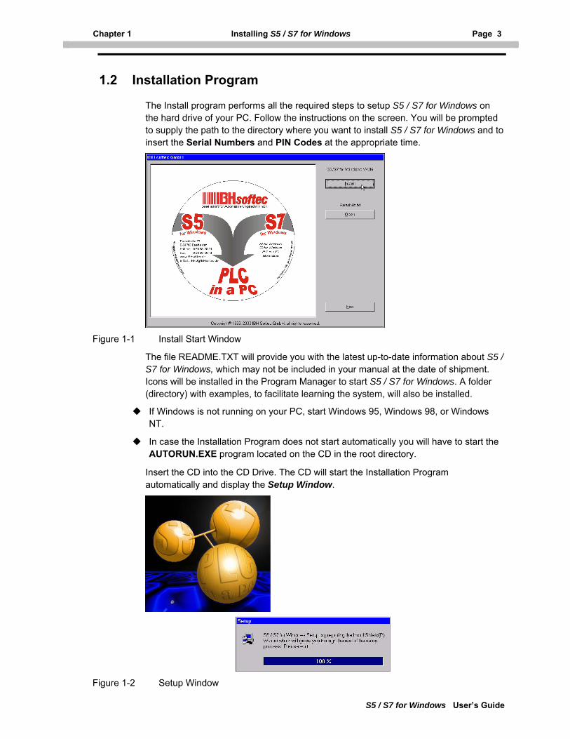
The Install program performs all the required steps to setup S5 / S7 for Windows on the hard drive of your PC. Follow the instructions on the screen. You will be prompted to supply the path to the directory where you want to install S5 / S7 for Windows and to insert the Serial Numbers and PIN Codes at the appropriate time.
Figure 1-1 Install Start Window
The file README.TXT will provide you with the latest up-to-date information about S5 / S7 for Windows, which may not be included in your manual at the date of shipment. Icons will be installed in the Program Manager to start S5 / S7 for Windows. A folder (directory) with examples, to facilitate learning the system, will also be installed.
If Windows is not running on your PC, start Windows 95, Windows 98, or Windows NT.
In case the Installation Program does not start automatically you will have to start the AUTORUN.EXE program located on the CD in the root directory.
Insert the CD into the CD Drive. The CD will start the Installation Program automatically and display the Setup Window.
Figure 1-2 Setup Window
Page 4 Installation Program Chapter 1.2
S5 / S7 for Windows User’s Guide
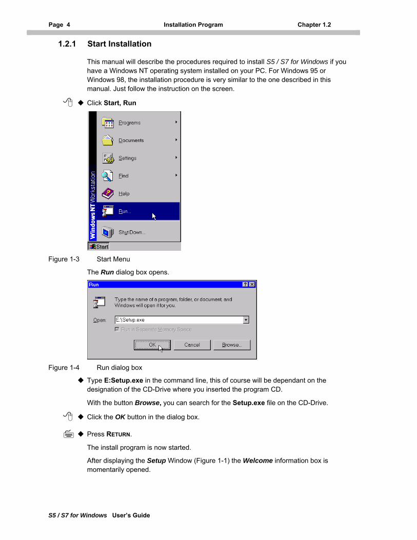
1.2.1 Start Installation
This manual will describe the procedures required to install S5 / S7 for Windows if you have a Windows NT operating system installed on your PC. For Windows 95 or Windows 98, the installation procedure is very similar to the one described in this manual. Just follow the instruction on the screen.
Click Start, Run
Figure 1-3 Start Menu
The Run dialog box opens.
Figure 1-4 Run dialog box
Type E:Setup.exe in the command line, this of course will be dependant on the designation of the CD-Drive where you inserted the program CD.
With the button Browse, you can search for the Setup.exe file on the CD-Drive.
Click the OK button in the dialog box.
Press RETURN.
The install program is now started.
After displaying the Setup Window (Figure 1-1) the Welcome information box is momentarily opened.
Chapter 1 Installing S5 / S7 for Windows Page 5
S5 / S7 for Windows User’s Guide
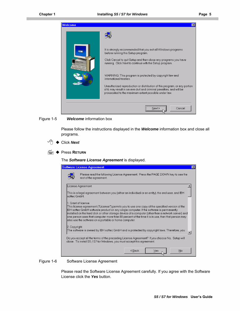
Figure 1-5 Welcome information box
Please follow the instructions displayed in the Welcome information box and close all programs.
Click Next
Press RETURN
The Software License Agreement is displayed.
Figure 1-6 Software License Agreement
Please read the Software License Agreement carefully. If you agree with the Software License click the Yes button.
Page 6 Installation Program Chapter 1.2
S5 / S7 for Windows User’s Guide
If you don't agree with the Software License click the No button. The installation will be aborted. Only if you agree with the Software License will the installation continue.
Click Yes
Press RETURN
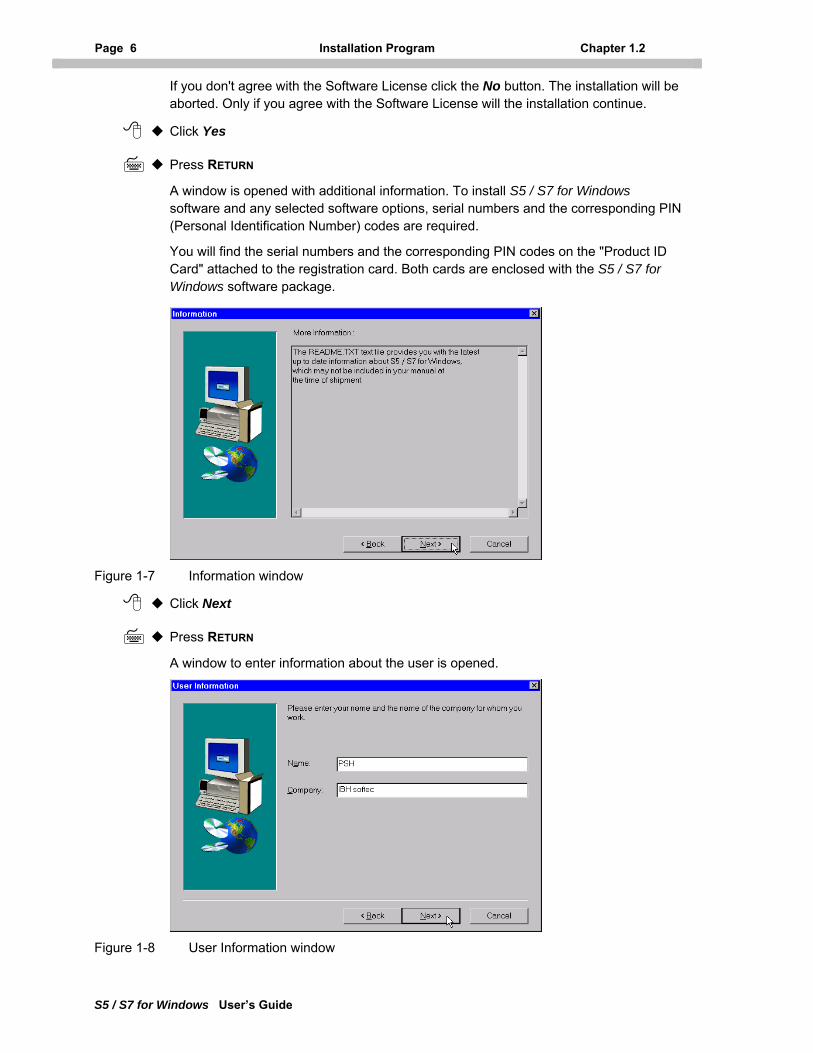
A window is opened with additional information. To install S5 / S7 for Windows software and any selected software options, serial numbers and the corresponding PIN (Personal Identification Number) codes are required.
You will find the serial numbers and the corresponding PIN codes on the "Product ID Card" attached to the registration card. Both cards are enclosed with the S5 / S7 for Windows software package.
Figure 1-7 Information window
Click Next
Press RETURN
A window to enter information about the user is opened.
Figure 1-8 User Information window
Chapter 1 Installing S5 / S7 for Windows Page 7
S5 / S7 for Windows User’s Guide
Please enter your name and the name of your company. Both information fields must be filed in to enable the Next button to continue the installation.
Click Next
Press RETURN
A dialog box where you select the destination folder is opened.
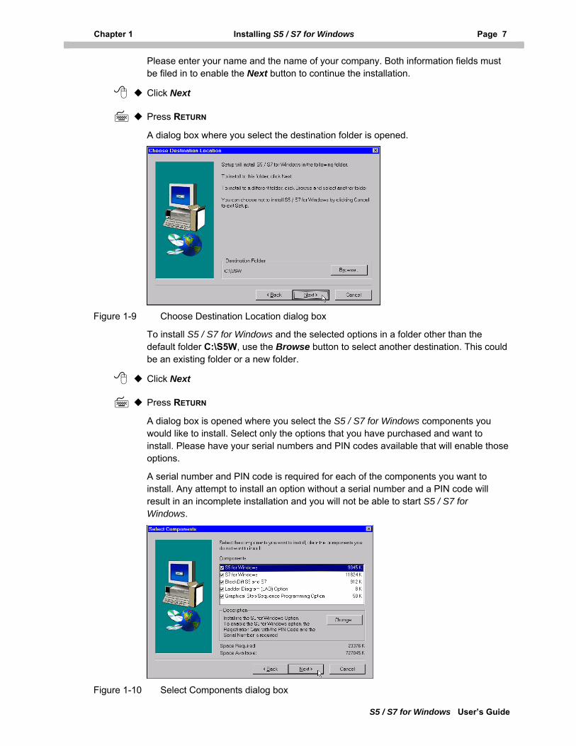
Figure 1-9 Choose Destination Location dialog box
To install S5 / S7 for Windows and the selected options in a folder other than the default folder C:\S5W, use the Browse button to select another destination. This could be an existing folder or a new folder.
Click Next
Press RETURN
A dialog box is opened where you select the S5 / S7 for Windows components you would like to install. Select only the options that you have purchased and want to install. Please have your serial numbers and PIN codes available that will enable those options.
A serial number and PIN code is required for each of the components you want to install. Any attempt to install an option without a serial number and a PIN code will result in an incomplete installation and you will not be able to start S5 / S7 for Windows.
Figure 1-10 Select Components dialog box
Page 8 Installation Program Chapter 1.2
S5 / S7 for Windows User’s Guide
Check all the options you want to install. Some of the components are made up of several sub-components. Clicking the Change button will open an additional dialog box to select (deselect) the sub-components of an option.
Click Next
Press RETURN
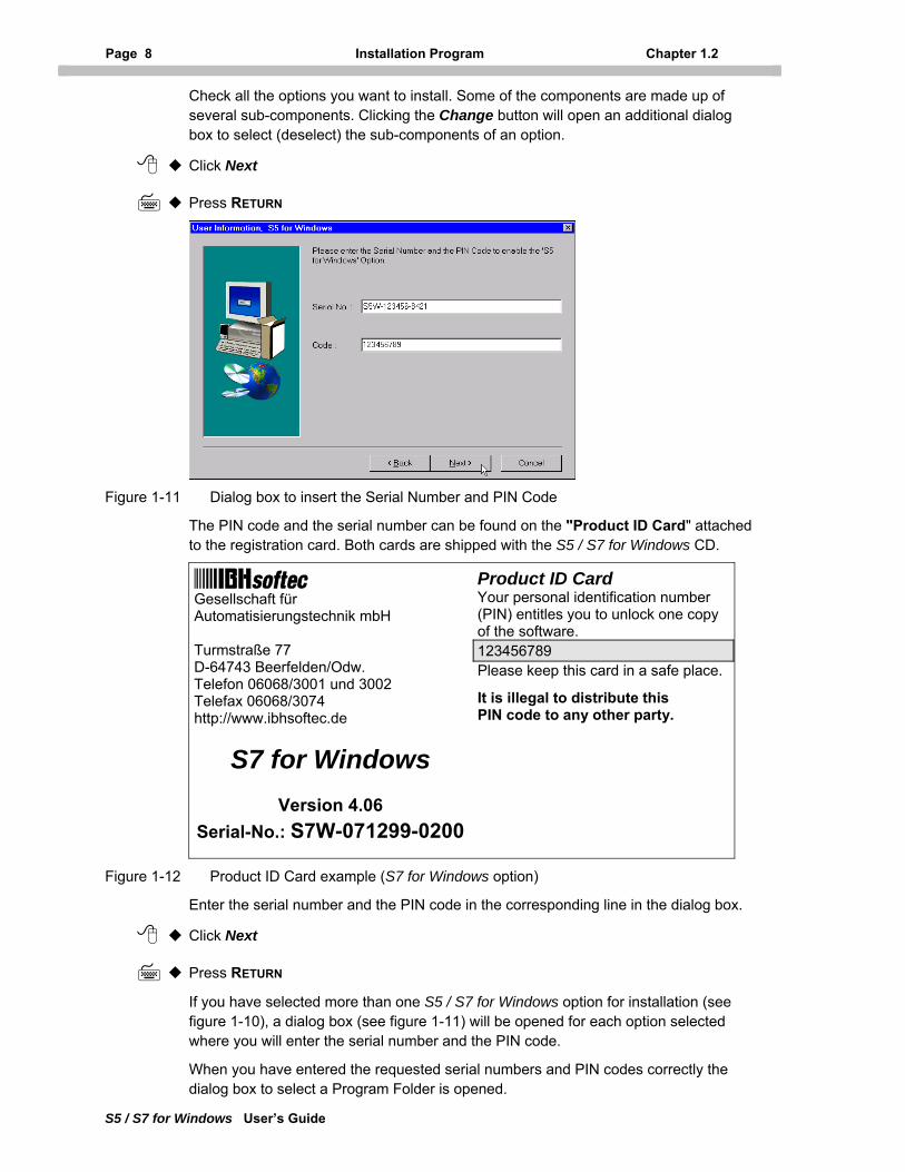
Figure 1-11 Dialog box to insert the Serial Number and PIN Code
The PIN code and the serial number can be found on the "Product ID Card" attached to the registration card. Both cards are shipped with the S5 / S7 for Windows CD.
Gesellschaft für Automatisierungstechnik mbH Turmstraße 77 D-64743 Beerfelden/Odw. Telefon 06068/3001 und 3002 Telefax 06068/3074 http://www.ibhsoftec.de
Product ID Card Your personal identification number (PIN) entitles you to unlock one copy of the software. 123456789 Please keep this card in a safe place.
It is illegal to distribute this PIN code to any other party.
S7 for Windows
Version 4.06
Serial-No.: S7W-071299-0200
Figure 1-12 Product ID Card example (S7 for Windows option)
Enter the serial number and the PIN code in the corresponding line in the dialog box.
Click Next
Press RETURN
If you have selected more than one S5 / S7 for Windows option for installation (see figure 1-10), a dialog box (see figure 1-11) will be opened for each option selected where you will enter the serial number and the PIN code.
When you have entered the requested serial numbers and PIN codes correctly the dialog box to select a Program Folder is opened.
Chapter 1 Installing S5 / S7 for Windows Page 9
S5 / S7 for Windows User’s Guide
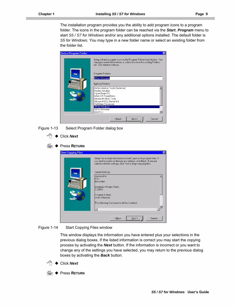
The installation program provides you the ability to add program icons to a program folder. The icons in the program folder can be reached via the Start, Program menu to start S5 / S7 for Windows and/or any additional options installed. The default folder is S5 for Windows. You may type in a new folder name or select an existing folder from the folder list.
Figure 1-13 Select Program Folder dialog box
Click Next
Press RETURN
Figure 1-14 Start Copying Files window
This window displays the information you have entered plus your selections in the previous dialog boxes. If the listed information is correct you may start the copying process by activating the Next button. If the information is incorrect or you want to change any of the settings you have selected, you may return to the previous dialog boxes by activating the Back button.
Click Next
Press RETURN
Page 10 Installation Program Chapter 1.2
S5 / S7 for Windows User’s Guide
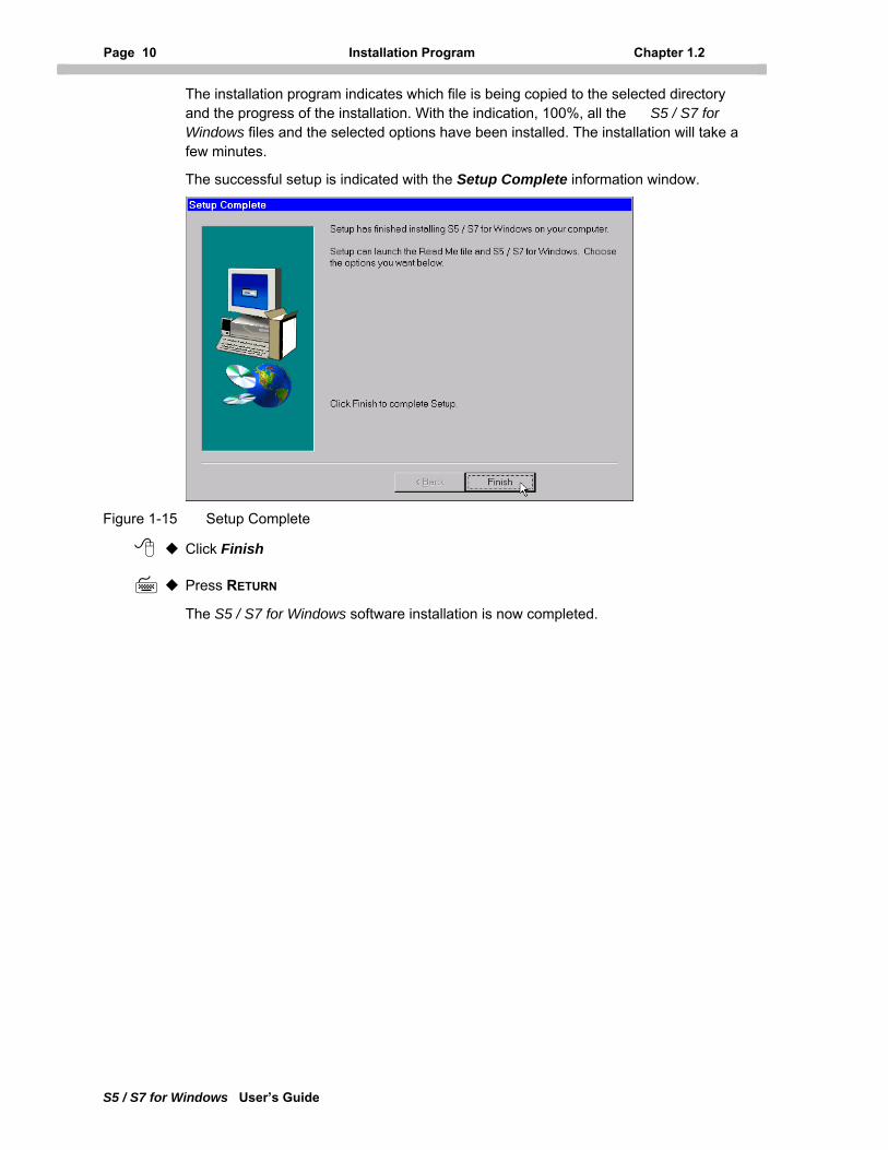
The installation program indicates which file is being copied to the selected directory and the progress of the installation. With the indication, 100%, all the S5 / S7 for Windows files and the selected options have been installed. The installation will take a few minutes.
The successful setup is indicated with the Setup Complete information window.
Figure 1-15 Setup Complete
Click Finish
Press RETURN
The S5 / S7 for Windows software installation is now completed.
Chapter 1 Installing S5 / S7 for Windows Page 11
S5 / S7 for Windows User’s Guide
1.3 Running S5 / S7 for Windows the First Time
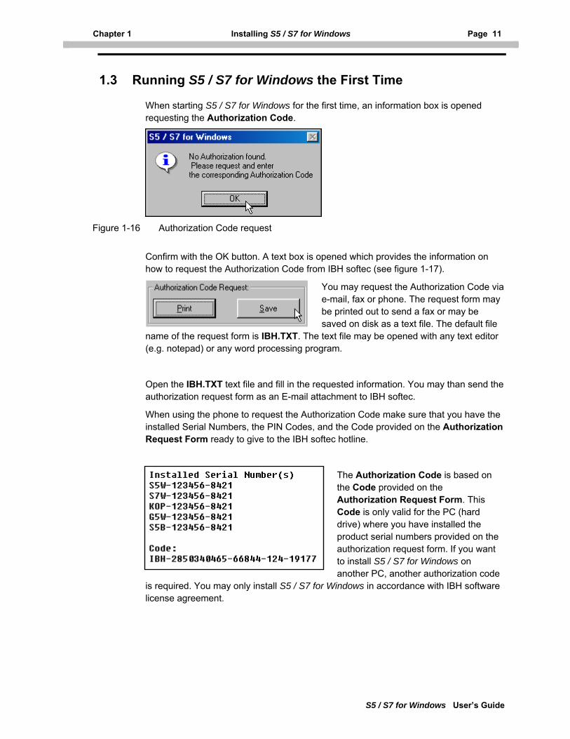
When starting S5 / S7 for Windows for the first time, an information box is opened requesting the Authorization Code.
Figure 1-16 Authorization Code request
Confirm with the OK button. A text box is opened which provides the information on how to request the Authorization Code from IBH softec (see figure 1-17).
You may request the Authorization Code via e-mail, fax or phone. The request form may be printed out to send a fax or may be saved on disk as a text file. The default file
name of the request form is IBH.TXT. The text file may be opened with any text editor (e.g. notepad) or any word processing program.
Open the IBH.TXT text file and fill in the requested information. You may than send the authorization request form as an E-mail attachment to IBH softec.
When using the phone to request the Authorization Code make sure that you have the installed Serial Numbers, the PIN Codes, and the Code provided on the Authorization Request Form ready to give to the IBH softec hotline.
The Authorization Code is based on the Code provided on the Authorization Request Form. This Code is only valid for the PC (hard drive) where you have installed the product serial numbers provided on the authorization request form. If you want to install S5 / S7 for Windows on another PC, another authorization code
is required. You may only install S5 / S7 for Windows in accordance with IBH software license agreement.
Page 12 Running S5 / S7 for Windows the First Time Chapter 1.3
S5 / S7 for Windows User’s Guide
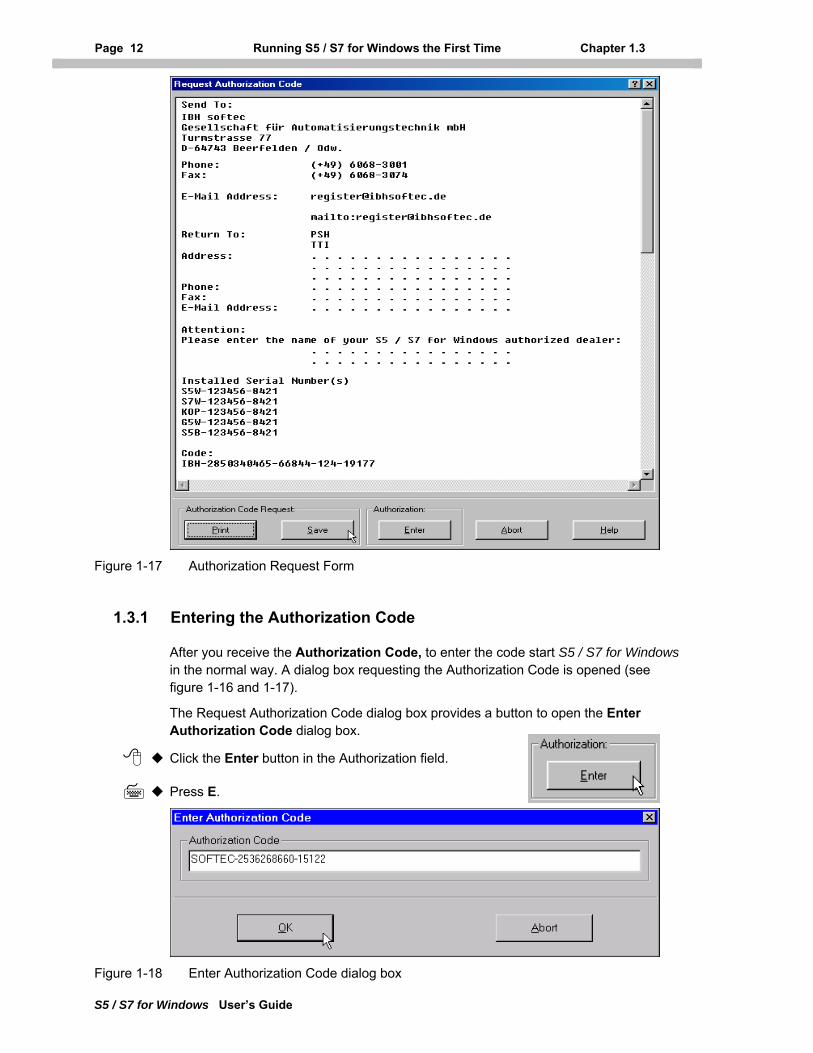
Figure 1-17 Authorization Request Form
1.3.1 Entering the Authorization Code
After you receive the Authorization Code, to enter the code start S5 / S7 for Windows in the normal way. A dialog box requesting the Authorization Code is opened (see figure 1-16 and 1-17).
The Request Authorization Code dialog box provides a button to open the Enter Authorization Code dialog box.
Click the Enter button in the Authorization field.
Press E.
Figure 1-18 Enter Authorization Code dialog box
Chapter 1 Installing S5 / S7 for Windows Page 13
S5 / S7 for Windows User’s Guide
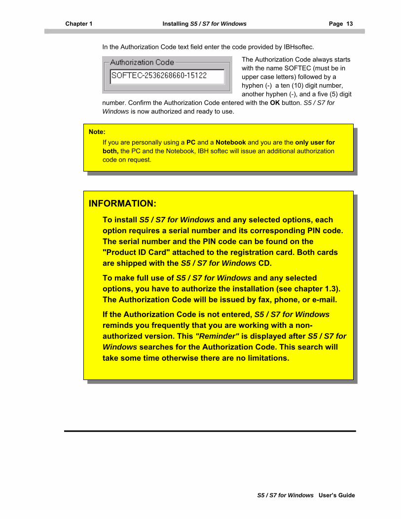
In the Authorization Code text field enter the code provided by IBHsoftec.
The Authorization Code always starts with the name SOFTEC (must be in upper case letters) followed by a hyphen (-) a ten (10) digit number, another hyphen (-), and a five (5) digit
number. Confirm the Authorization Code entered with the OK button. S5 / S7 for Windows is now authorized and ready to use.
Note: If you are personally using a PC and a Notebook and you are the only user for both, the PC and the Notebook, IBH softec will issue an additional authorization code on request.
INFORMATION:
To install S5 / S7 for Windows and any selected options, each option requires a serial number and its corresponding PIN code. The serial number and the PIN code can be found on the "Product ID Card" attached to the registration card. Both cards are shipped with the S5 / S7 for Windows CD.
To make full use of S5 / S7 for Windows and any selected options, you have to authorize the installation (see chapter 1.3). The Authorization Code will be issued by fax, phone, or e-mail.
If the Authorization Code is not entered, S5 / S7 for Windows reminds you frequently that you are working with a non-authorized version. This "Reminder" is displayed after S5 / S7 for Windows searches for the Authorization Code. This search will take some time otherwise there are no limitations.
Page 14 Notation and Conventions Chapter 2.1
S5 / S7 for Windows User’s Guide
2 Introduction
Two software packages are available. With S5 for Windows you can program the complete S5 PLC series and use the on-line functions when connecting the PC (serial port COM1 – 4), via a current loop converter cable, with an S5 PLC
With the S7 for Windows software you can program the S7 300 / 400 series of PLC’s from Siemens. When the PC is connected (serial port COM1 – 4), via a PC-MPI cable, with an S7-300 / 400 PLC's, you will have full use of the on-line functions.
With the software package S7 for Windows and S5 for Windows installed on one PC, you may program the S7 300 / 400 series of PLC’s from Siemens as well as the S5 series of PLC's, using the same editor. Also the on-line functions are provided when the PC is connected (serial port) with the PLC via an adapter (S7 PC-MPI cable or S5 Current loop converter) with a S7-300 / 400 or a S5 series PLC.
Of course if only one of the software packages (S7 for Windows or S5 for Windows) is installed on your PC you will only be able to program either the Siemens S7-300 / 400 series of PLC or the S5 series of PLC and make use of the on-line functions.
S5 for Windows provides an editor that understands the STEP® 5 PLC language for programming the S5 series of PLC's. S7 for Windows uses an editor that understands the STEP® 7 PLC language and can generate PLC programs for the S7-300 / 400 series of PLC's. If both software packages, S7 for Windows and S5 for Windows, are installed on one PC you may also use the STEP® 5 PLC language to generate PLC blocks for an S7-300 / 400 PLC. These Blocks may be converted into STEP® 7 PLC language and back into STEP® 5 code. Some restrictions apply when converting a PLC program from the STEP® 5 code into STEP® 7 code (see chapter 3.3.6).
It is also possible to download a PLC program, written in the STEP® 5 PLC language, to an S7-300 / 400 PLC. During the transfer of the programmed data to the S7 PLC, the S7 for Windows software package translates the program so the S7 CPU can understand the data.
If data is transferred from an S7 PLC to S7 for Windows the data is displayed in the STEP® 7 PLC language. In case the PLC program opened with S7 for Windows has the STEP® 5 PLC language format, the PLC Blocks are converted back to display it in the STEP® 5 PLC language format. In other words, you can program and test (on-line) an S7 for Windows PLC without changing to the S7 programming language. In this mode only the instructions provided by the STEP® 5 PLC language may be used. Additional STEP® 7 functions can only be used in conjunction with the STEP® 7 PLC language editor.
The following chapters explain how to handle S5 / S7 for Windows. Also the conversion functions used to convert S5 code to S7 code and S7 code to S5 code are explained.
Chapter 2 Installing S5 / S7 for Windows Page 15
S5 / S7 for Windows User’s Guide
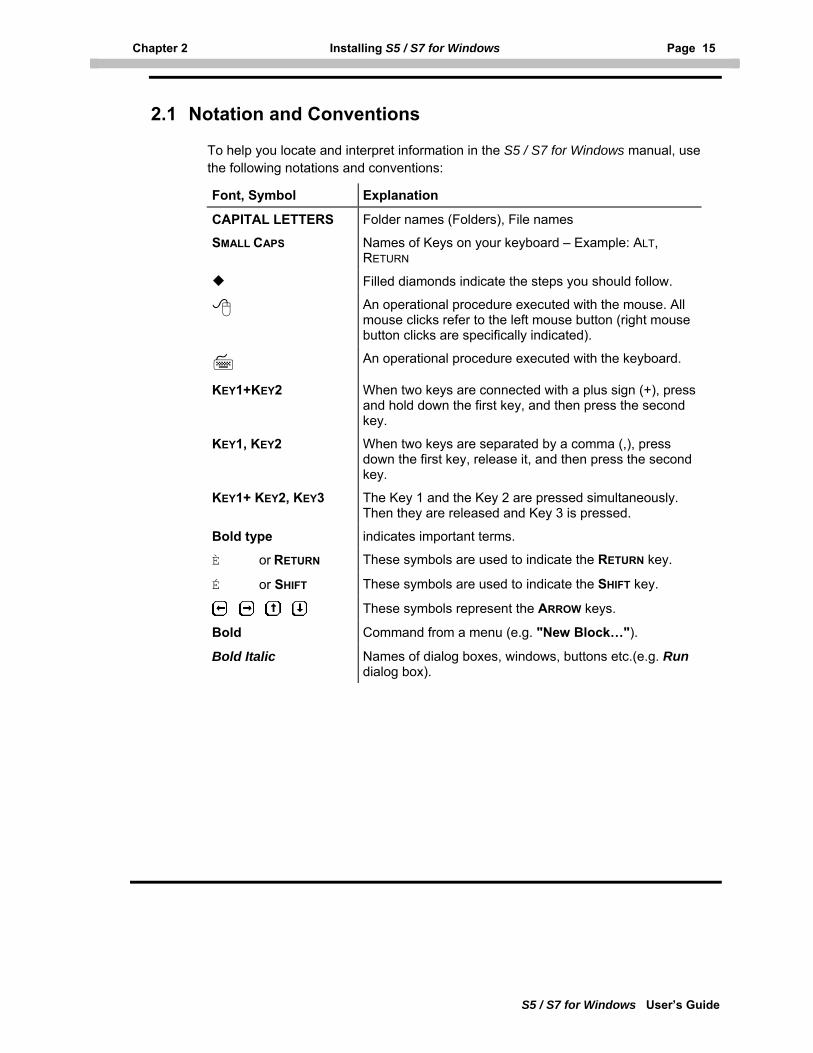
2.1 Notation and Conventions
To help you locate and interpret information in the S5 / S7 for Windows manual, use the following notations and conventions:
Font, Symbol Explanation
CAPITAL LETTERS Folder names (Folders), File names
SMALL CAPS Names of Keys on your keyboard – Example: ALT, RETURN
Filled diamonds indicate the steps you should follow.
An operational procedure executed with the mouse. All mouse clicks refer to the left mouse button (right mouse button clicks are specifically indicated).
An operational procedure executed with the keyboard.
KEY1+KEY2 When two keys are connected with a plus sign (+), press and hold down the first key, and then press the second key.
KEY1, KEY2 When two keys are separated by a comma (,), press down the first key, release it, and then press the second key.
KEY1+ KEY2, KEY3 The Key 1 and the Key 2 are pressed simultaneously. Then they are released and Key 3 is pressed.
Bold type indicates important terms.
È or RETURN These symbols are used to indicate the RETURN key.
É or SHIFT These symbols are used to indicate the SHIFT key.
These symbols represent the ARROW keys.
Bold Command from a menu (e.g. "New Block…").
Bold Italic Names of dialog boxes, windows, buttons etc.(e.g. Run dialog box).
Page 16 PC Block List Window Chapter 3.1
S5 / S7 for Windows User’s Guide
3 PC Block List
The PC block list window will be opened when ever you start S5 / S7 for Windows. If S5 / S7 for Windows displays another window you may open the PC block list window as followed.
Click the PC Block List icon in the tool bar.
Press ALT + W, 1.
3.1 PC Block List Window
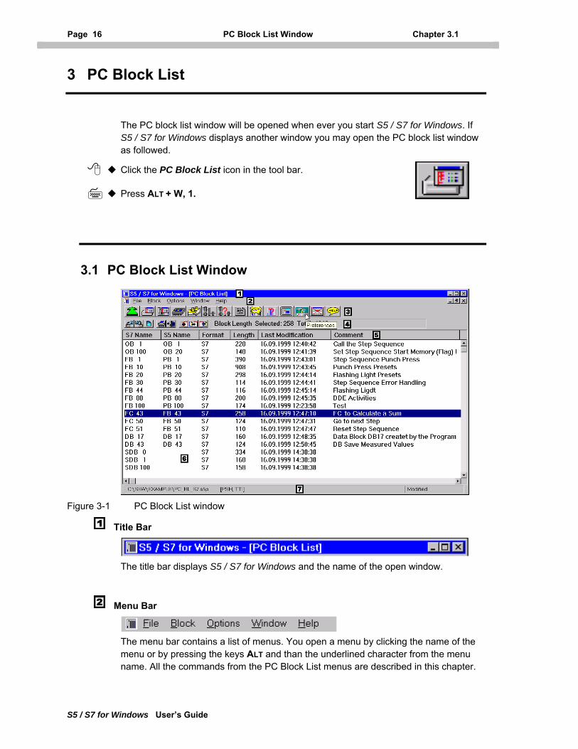
Figure 3-1 PC Block List window
Title Bar
The title bar displays S5 / S7 for Windows and the name of the open window.
Menu Bar
The menu bar contains a list of menus. You open a menu by clicking the name of the menu or by pressing the keys ALT and than the underlined character from the menu name. All the commands from the PC Block List menus are described in this chapter.
Chapter 3 PC Block List Page 17
S5 / S7 for Windows User’s Guide
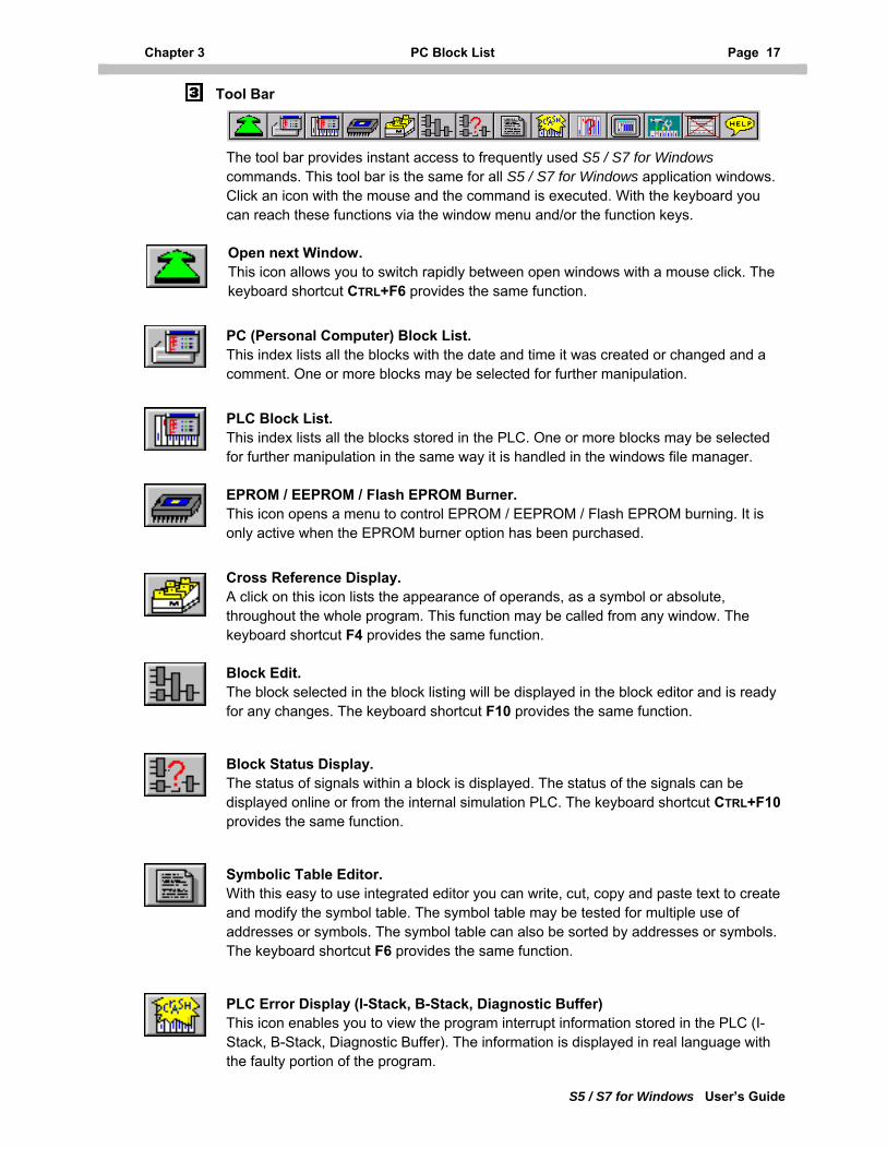
Tool Bar
The tool bar provides instant access to frequently used S5 / S7 for Windows commands. This tool bar is the same for all S5 / S7 for Windows application windows. Click an icon with the mouse and the command is executed. With the keyboard you can reach these functions via the window menu and/or the function keys.
Open next Window. This icon allows you to switch rapidly between open windows with a mouse click. The keyboard shortcut CTRL+F6 provides the same function.
PC (Personal Computer) Block List. This index lists all the blocks with the date and time it was created or changed and a comment. One or more blocks may be selected for further manipulation.
PLC Block List. This index lists all the blocks stored in the PLC. One or more blocks may be selected for further manipulation in the same way it is handled in the windows file manager.
EPROM / EEPROM / Flash EPROM Burner. This icon opens a menu to control EPROM / EEPROM / Flash EPROM burning. It is only active when the EPROM burner option has been purchased.
Cross Reference Display. A click on this icon lists the appearance of operands, as a symbol or absolute, throughout the whole program. This function may be called from any window. The keyboard shortcut F4 provides the same function.
Block Edit. The block selected in the block listing will be displayed in the block editor and is ready for any changes. The keyboard shortcut F10 provides the same function.
Block Status Display. The status of signals within a block is displayed. The status of the signals can be displayed online or from the internal simulation PLC. The keyboard shortcut CTRL+F10 provides the same function.
Symbolic Table Editor. With this easy to use integrated editor you can write, cut, copy and paste text to create and modify the symbol table. The symbol table may be tested for multiple use of addresses or symbols. The symbol table can also be sorted by addresses or symbols. The keyboard shortcut F6 provides the same function.
PLC Error Display (I-Stack, B-Stack, Diagnostic Buffer) This icon enables you to view the program interrupt information stored in the PLC (I-Stack, B-Stack, Diagnostic Buffer). The information is displayed in real language with the faulty portion of the program.
Page 18 PC Block List Window Chapter 3.1
S5 / S7 for Windows User’s Guide
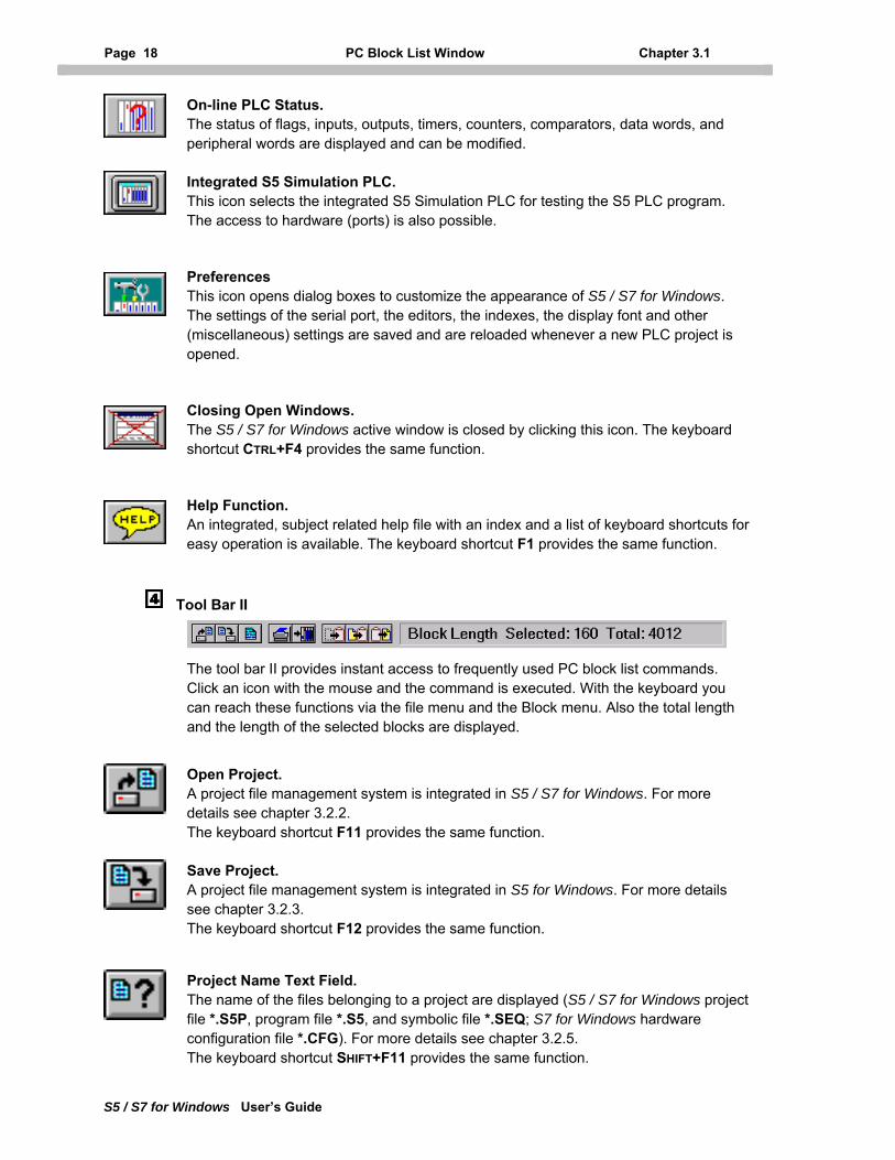
On-line PLC Status. The status of flags, inputs, outputs, timers, counters, comparators, data words, and peripheral words are displayed and can be modified.
Integrated S5 Simulation PLC. This icon selects the integrated S5 Simulation PLC for testing the S5 PLC program. The access to hardware (ports) is also possible.
Preferences This icon opens dialog boxes to customize the appearance of S5 / S7 for Windows. The settings of the serial port, the editors, the indexes, the display font and other (miscellaneous) settings are saved and are reloaded whenever a new PLC project is opened.
Closing Open Windows. The S5 / S7 for Windows active window is closed by clicking this icon. The keyboard shortcut CTRL+F4 provides the same function.
Help Function. An integrated, subject related help file with an index and a list of keyboard shortcuts for easy operation is available. The keyboard shortcut F1 provides the same function.
Tool Bar II
The tool bar II provides instant access to frequently used PC block list commands. Click an icon with the mouse and the command is executed. With the keyboard you can reach these functions via the file menu and the Block menu. Also the total length and the length of the selected blocks are displayed.
Open Project. A project file management system is integrated in S5 / S7 for Windows. For more details see chapter 3.2.2. The keyboard shortcut F11 provides the same function.
Save Project. A project file management system is integrated in S5 for Windows. For more details see chapter 3.2.3. The keyboard shortcut F12 provides the same function.
Project Name Text Field. The name of the files belonging to a project are displayed (S5 / S7 for Windows project file *.S5P, program file *.S5, and symbolic file *.SEQ; S7 for Windows hardware configuration file *.CFG). For more details see chapter 3.2.5. The keyboard shortcut SHIFT+F11 provides the same function.
Chapter 3 PC Block List Page 19
S5 / S7 for Windows User’s Guide
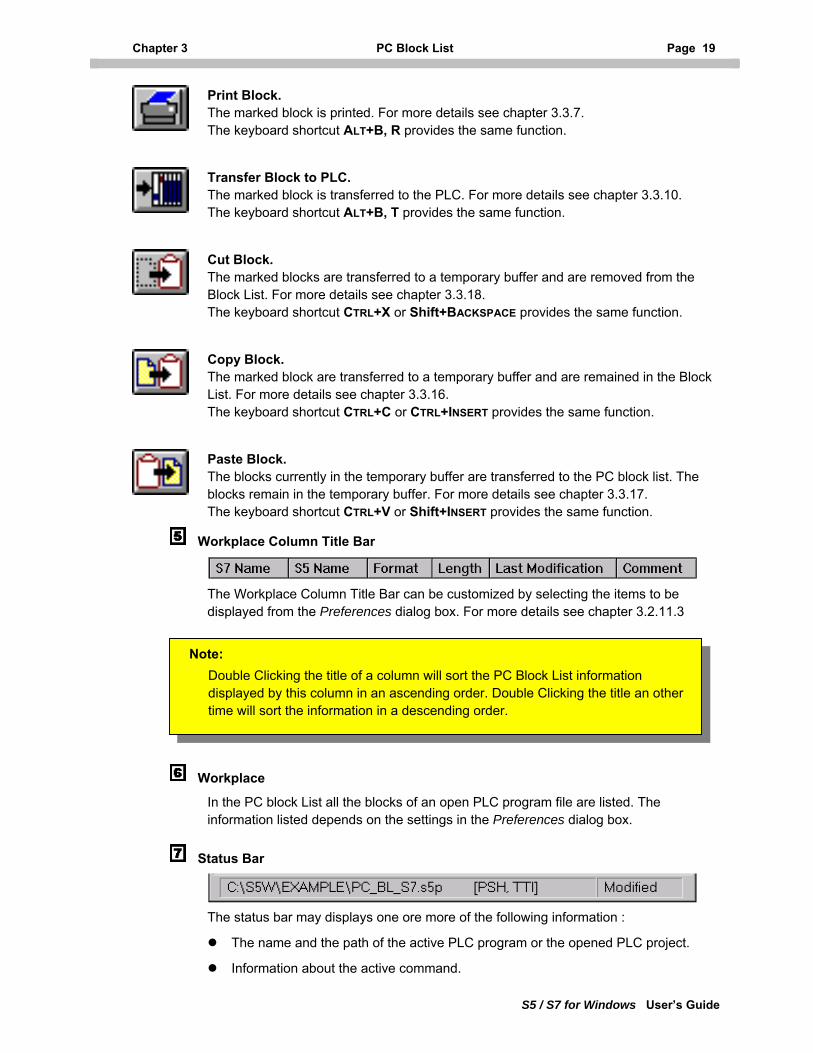
Print Block. The marked block is printed. For more details see chapter 3.3.7. The keyboard shortcut ALT+B, R provides the same function.
Transfer Block to PLC. The marked block is transferred to the PLC. For more details see chapter 3.3.10. The keyboard shortcut ALT+B, T provides the same function.
Cut Block. The marked blocks are transferred to a temporary buffer and are removed from the Block List. For more details see chapter 3.3.18. The keyboard shortcut CTRL+X or Shift+BACKSPACE provides the same function.
Copy Block. The marked block are transferred to a temporary buffer and are remained in the Block List. For more details see chapter 3.3.16. The keyboard shortcut CTRL+C or CTRL+INSERT provides the same function.
Paste Block. The blocks currently in the temporary buffer are transferred to the PC block list. The blocks remain in the temporary buffer. For more details see chapter 3.3.17. The keyboard shortcut CTRL+V or Shift+INSERT provides the same function.
Workplace Column Title Bar
The Workplace Column Title Bar can be customized by selecting the items to be displayed from the Preferences dialog box. For more details see chapter 3.2.11.3
Note: Double Clicking the title of a column will sort the PC Block List information displayed by this column in an ascending order. Double Clicking the title an other time will sort the information in a descending order.
Workplace
In the PC block List all the blocks of an open PLC program file are listed. The information listed depends on the settings in the Preferences dialog box.
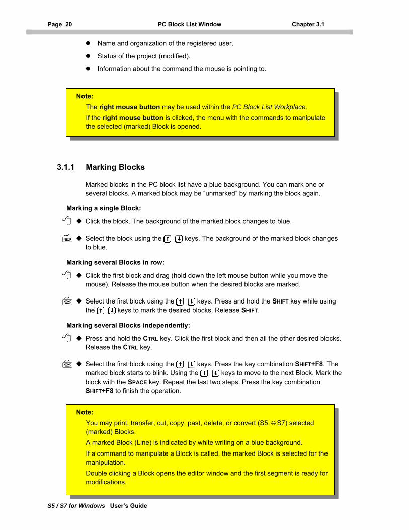
Status Bar
The status bar may displays one ore more of the following information :
The name and the path of the active PLC program or the opened PLC project.
Information about the active command.
Page 20 PC Block List Window Chapter 3.1
S5 / S7 for Windows User’s Guide
Name and organization of the registered user.
Status of the project (modified).
Information about the command the mouse is pointing to.
3.1.1 Marking Blocks
Marked blocks in the PC block list have a blue background. You can mark one or several blocks. A marked block may be “unmarked” by marking the block again.
Marking a single Block:
Click the block. The background of the marked block changes to blue.
Select the block using the keys. The background of the marked block changes to blue.
Marking several Blocks in row:
Click the first block and drag (hold down the left mouse button while you move the mouse). Release the mouse button when the desired blocks are marked.
Select the first block using the keys. Press and hold the SHIFT key while using the keys to mark the desired blocks. Release SHIFT.
Marking several Blocks independently:
Press and hold the CTRL key. Click the first block and then all the other desired blocks. Release the CTRL key.
Select the first block using the keys. Press the key combination SHIFT+F8. The marked block starts to blink. Using the keys to move to the next Block. Mark the block with the SPACE key. Repeat the last two steps. Press the key combination SHIFT+F8 to finish the operation.
The right mouse button may be used within the PC Block List Workplace. If the right mouse button is clicked, the menu with the commands to manipulate the selected (marked) Block is opened.
Note: You may print, transfer, cut, copy, past, delete, or convert (S5 S7) selected (marked) Blocks. A marked Block (Line) is indicated by white writing on a blue background. If a command to manipulate a Block is called, the marked Block is selected for the manipulation. Double clicking a Block opens the editor window and the first segment is ready for modifications.
Note:
Chapter 3 PC Block List Page 21
S5 / S7 for Windows User’s Guide
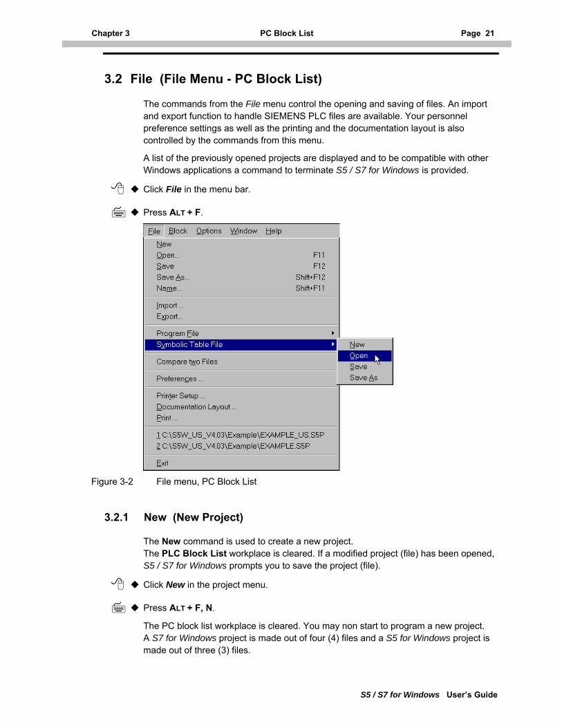
3.2 File (File Menu - PC Block List)
The commands from the File menu control the opening and saving of files. An import and export function to handle SIEMENS PLC files are available. Your personnel preference settings as well as the printing and the documentation layout is also controlled by the commands from this menu.
A list of the previously opened projects are displayed and to be compatible with other Windows applications a command to terminate S5 / S7 for Windows is provided.
Click File in the menu bar.
Press ALT + F.
Figure 3-2 File menu, PC Block List
3.2.1 New (New Project)
The New command is used to create a new project. The PLC Block List workplace is cleared. If a modified project (file) has been opened, S5 / S7 for Windows prompts you to save the project (file).
Click New in the project menu.
Press ALT + F, N.
The PC block list workplace is cleared. You may non start to program a new project. A S7 for Windows project is made out of four (4) files and a S5 for Windows project is made out of three (3) files.
Page 22 File (File Menu - PC Block List) Chapter 3.2
S5 / S7 for Windows User’s Guide
Project File (S5 / S7 for Windows)
The project related data (header, footer, document and display settings, preferences, Block information, etc.) are saved in this file. When opening the project at a later time, the project settings are active again. The project file name is made out of the project name and the file name extension .s5p. The project file also holds the information about the program file a the symbolic file belonging to the project
Usually the project file, the program file, the symbolic file and the hardware configuration file (S7 for Windows only) have the same file name and different file name extensions. It is also possible to have a program file and / or symbolic file, hardware configuration file with different names assigned to a project. S5 / S7 for Windows supports long file names with up to eighty (80) characters including the file name extension. The following characters are not permitted in a file name: / \ : * ? " > < |
Program File (S5 / S7 for Windows)
The actual PLC program is saved in the program file. S5 / S7 for Windows uses its own file format. The program file name is made out of the program name and the file name extension .s5.
Symbolic File (S5 / S7 for Windows)
The symbolic definitions and the comments appointed to the absolute operands in the symbolic table are saved in the symbolic file. The file name is made out of the name and the file name extension .seq. The file is saved in ASCII text format. It is the identical format used by the SIEMENS S5 symbolic file. This file format can directly be imported by the S7 programming software.
Hardware Configuration File (S7 for Windows)
The S7 Hardware Configuration generated with the S7 for Windows Hardware Configuration is saved in a file with the file name extension .cf7. The configuration data is stored in the SDB format (Special Data Blocks). These Blocks are displayed in the PC Block List and the PLC Block List.
Program, Symbolic, and / or Hardware Configuration files may be assigned to one or more project files.
Special care must be taken when modifying a file (Program, Symbolic, Hardware Configuration) being assigned to more than one (1) project. Any modification will effect all projects.
Note:
Chapter 3 PC Block List Page 23
S5 / S7 for Windows User’s Guide
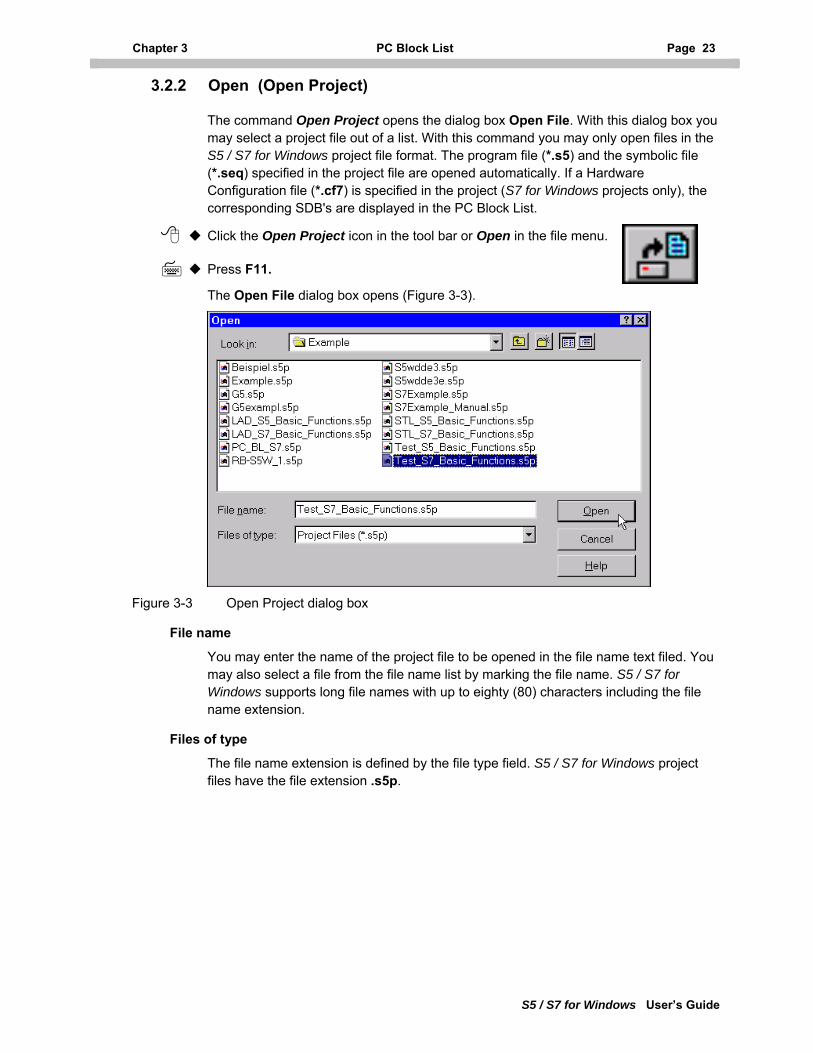
3.2.2 Open (Open Project)
The command Open Project opens the dialog box Open File. With this dialog box you may select a project file out of a list. With this command you may only open files in the S5 / S7 for Windows project file format. The program file (*.s5) and the symbolic file (*.seq) specified in the project file are opened automatically. If a Hardware Configuration file (*.cf7) is specified in the project (S7 for Windows projects only), the corresponding SDB's are displayed in the PC Block List.
Click the Open Project icon in the tool bar or Open in the file menu.
Press F11.
The Open File dialog box opens (Figure 3-3).
Figure 3-3 Open Project dialog box
File name
You may enter the name of the project file to be opened in the file name text filed. You may also select a file from the file name list by marking the file name. S5 / S7 for Windows supports long file names with up to eighty (80) characters including the file name extension.
Files of type
The file name extension is defined by the file type field. S5 / S7 for Windows project files have the file extension .s5p.
Page 24 File (File Menu - PC Block List) Chapter 3.2
S5 / S7 for Windows User’s Guide
3.2.2.1 Converting PLC programs into Projects
You may convert a PLC program saved with an earlier version of S5 for Windows (version 2.1x or earlier) or any other S5 / S7 for Windows PLC program file and its corresponding symbolic table file into a project. To do so you must open the s5w.ini file belonging to the program file.
Open the program file (and its symbolic table file) you want to convert into a project by using the Open command from the Program File menu (see chapter 3.2.8.2).
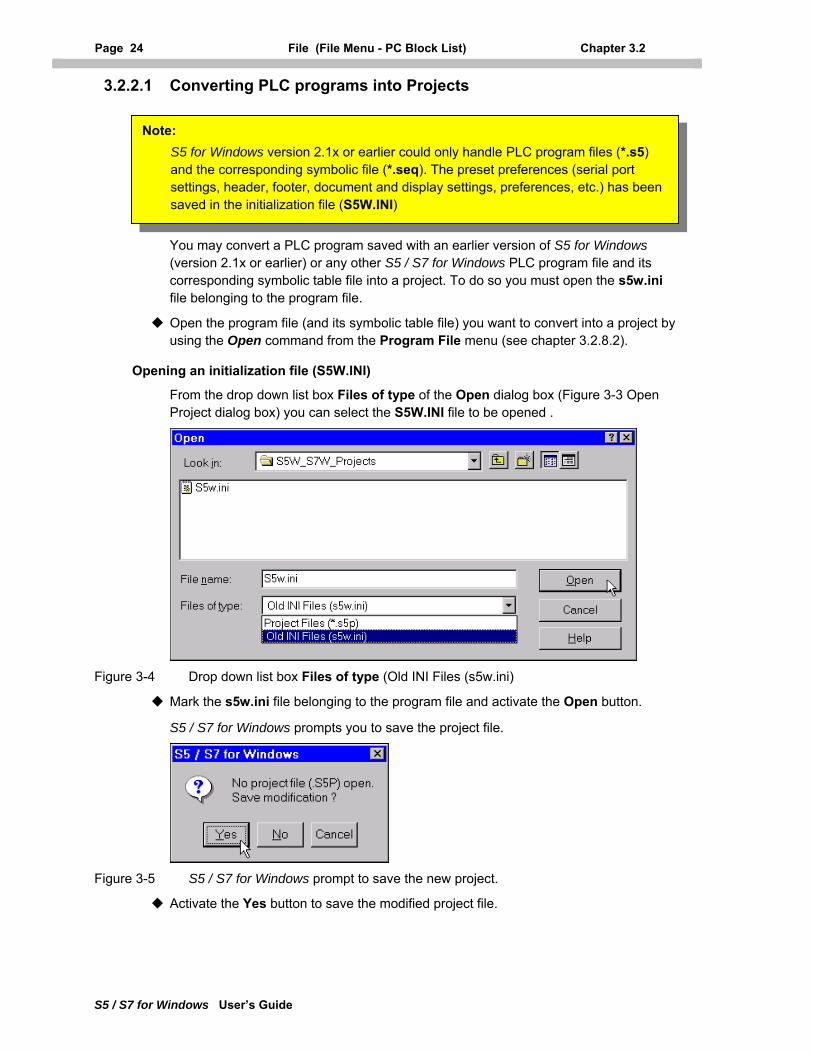
Opening an initialization file (S5W.INI)
From the drop down list box Files of type of the Open dialog box (Figure 3-3 Open Project dialog box) you can select the S5W.INI file to be opened .
Note: S5 for Windows version 2.1x or earlier could only handle PLC program files (*.s5) and the corresponding symbolic file (*.seq). The preset preferences (serial port settings, header, footer, document and display settings, preferences, etc.) has been saved in the initialization file (S5W.INI)
Figure 3-4 Drop down list box Files of type (Old INI Files (s5w.ini)
Mark the s5w.ini file belonging to the program file and activate the Open button.
S5 / S7 for Windows prompts you to save the project file.
Figure 3-5 S5 / S7 for Windows prompt to save the new project.
Activate the Yes button to save the modified project file.
Chapter 3 PC Block List Page 25
S5 / S7 for Windows User’s Guide
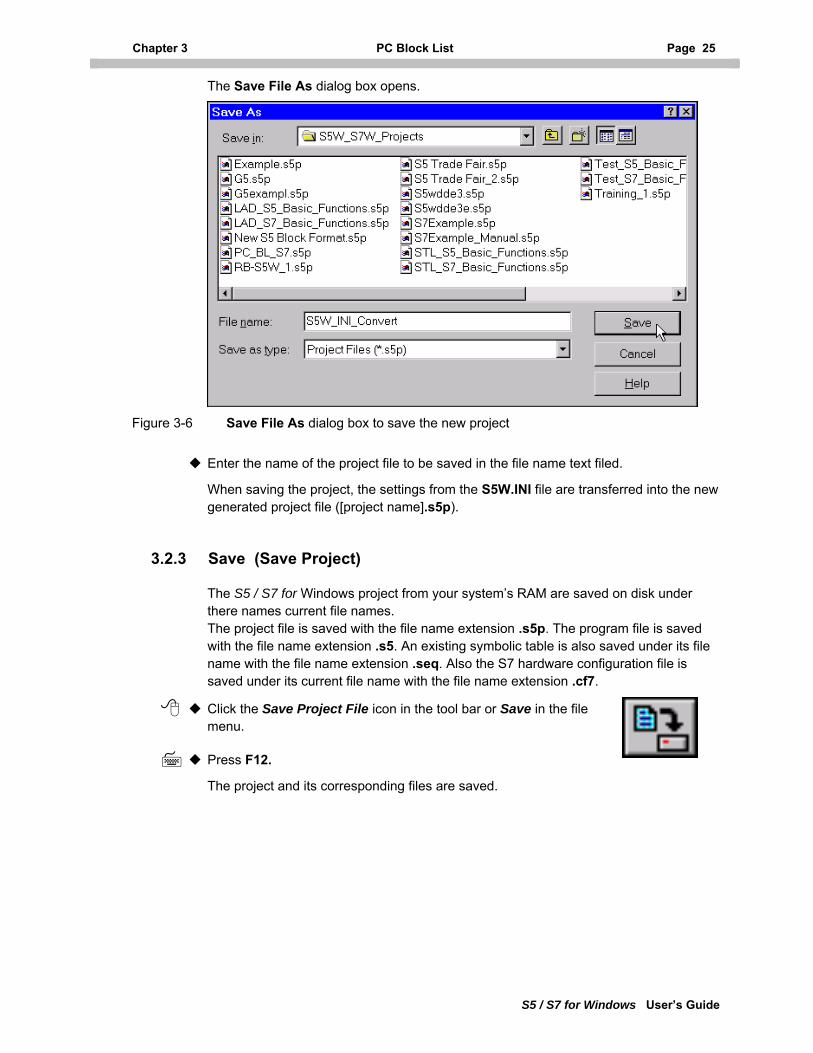
The Save File As dialog box opens.
Figure 3-6 Save File As dialog box to save the new project
Enter the name of the project file to be saved in the file name text filed.
When saving the project, the settings from the S5W.INI file are transferred into the new generated project file ([project name].s5p).
3.2.3 Save (Save Project)
The S5 / S7 for Windows project from your system’s RAM are saved on disk under there names current file names. The project file is saved with the file name extension .s5p. The program file is saved with the file name extension .s5. An existing symbolic table is also saved under its file name with the file name extension .seq. Also the S7 hardware configuration file is saved under its current file name with the file name extension .cf7.
Click the Save Project File icon in the tool bar or Save in the file menu.
Press F12.
The project and its corresponding files are saved.
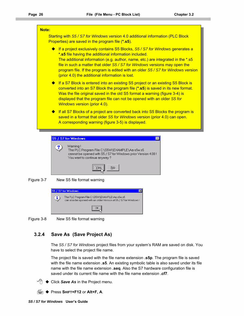
Page 26 File (File Menu - PC Block List) Chapter 3.2
S5 / S7 for Windows User’s Guide
If a S7 Block is entered into an existing S5 project or an existing S5 Block is converted into an S7 Block the program file (*.s5) is saved in its new format. Was the file original saved in the old S5 format a warning (figure 3-4) is displayed that the program file can not be opened with an older S5 for Windows version (prior 4.0).
If all S7 Blocks of a project are converted back into S5 Blocks the program is saved in a format that older S5 for Windows version (prior 4.0) can open. A corresponding warning (figure 3-5) is displayed.
Note: Starting with S5 / S7 for Windows version 4.0 additional information (PLC Block Properties) are saved in the program file (*.s5).
If a project exclusively contains S5 Blocks, S5 / S7 for Windows generates a *.s5 file having the additional information included. The additional information (e.g. author, name, etc.) are integrated in the *.s5 file in such a matter that older S5 / S7 for Windows versions may open the program file. If the program is edited with an older S5 / S7 for Windows version (prior 4.0) the additional information is lost.
Figure 3-7 New S5 file format warning
Figure 3-8 New S5 file format warning
3.2.4 Save As (Save Project As)
The S5 / S7 for Windows project files from your system’s RAM are saved on disk. You have to select the project file name.
The project file is saved with the file name extension .s5p. The program file is saved with the file name extension .s5. An existing symbolic table is also saved under its file name with the file name extension .seq. Also the S7 hardware configuration file is saved under its current file name with the file name extension .cf7.
Click Save As in the Project menu.
Press SHIFT+F12 or Alt+F, A.
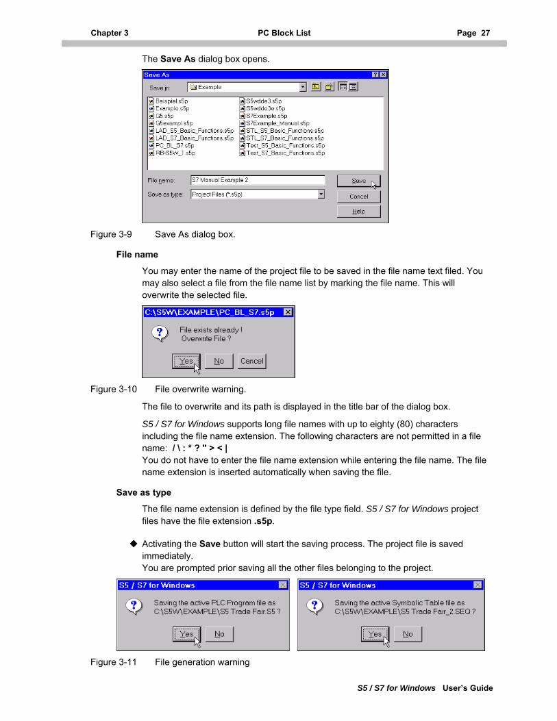
Chapter 3 PC Block List Page 27
S5 / S7 for Windows User’s Guide
The Save As dialog box opens.
Figure 3-9 Save As dialog box.
File name
You may enter the name of the project file to be saved in the file name text filed. You may also select a file from the file name list by marking the file name. This will overwrite the selected file.
Figure 3-10 File overwrite warning.
The file to overwrite and its path is displayed in the title bar of the dialog box.
S5 / S7 for Windows supports long file names with up to eighty (80) characters including the file name extension. The following characters are not permitted in a file name: / \ : * ? " > < | You do not have to enter the file name extension while entering the file name. The file name extension is inserted automatically when saving the file.
Save as type
The file name extension is defined by the file type field. S5 / S7 for Windows project files have the file extension .s5p.
Activating the Save button will start the saving process. The project file is saved immediately. You are prompted prior saving all the other files belonging to the project.
Figure 3-11 File generation warning
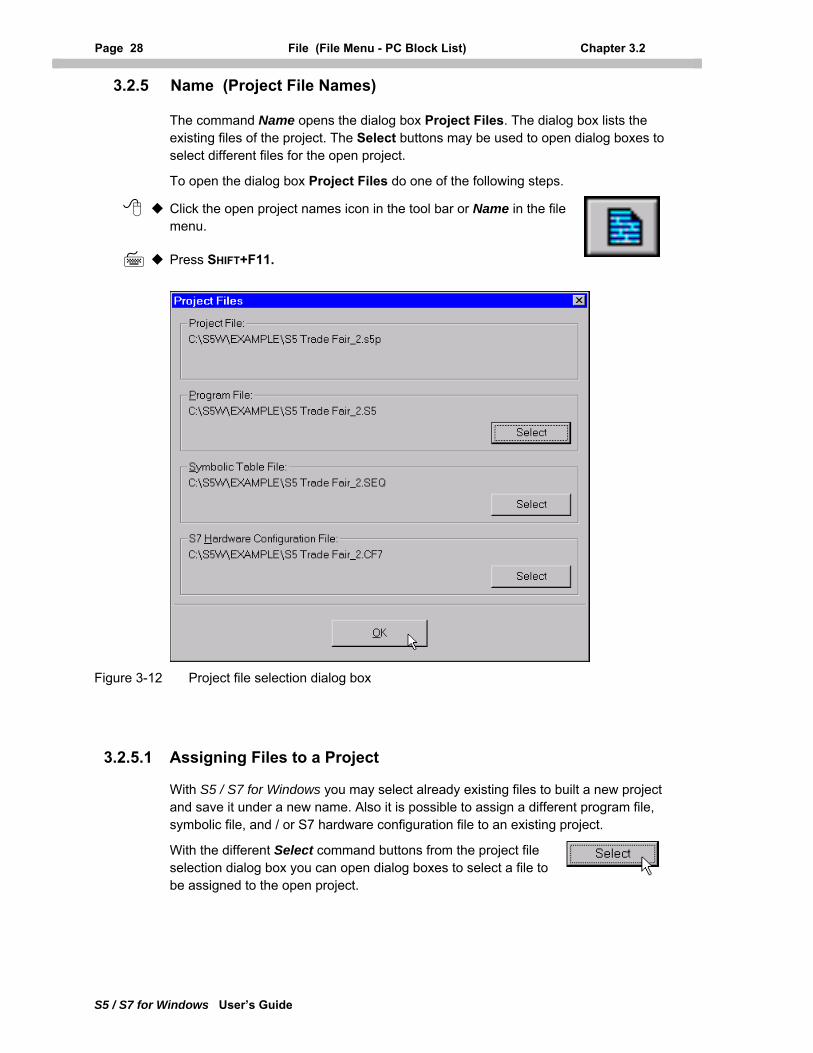
Page 28 File (File Menu - PC Block List) Chapter 3.2
S5 / S7 for Windows User’s Guide
3.2.5 Name (Project File Names)
The command Name opens the dialog box Project Files. The dialog box lists the existing files of the project. The Select buttons may be used to open dialog boxes to select different files for the open project.
To open the dialog box Project Files do one of the following steps.
Click the open project names icon in the tool bar or Name in the file menu.
Press SHIFT+F11.
Figure 3-12 Project file selection dialog box
3.2.5.1 Assigning Files to a Project
With S5 / S7 for Windows you may select already existing files to built a new project and save it under a new name. Also it is possible to assign a different program file, symbolic file, and / or S7 hardware configuration file to an existing project.
With the different Select command buttons from the project file selection dialog box you can open dialog boxes to select a file to be assigned to the open project.
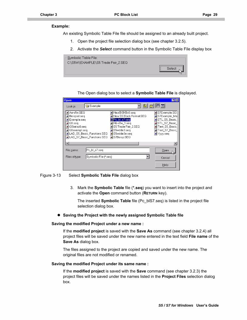
Chapter 3 PC Block List Page 29
S5 / S7 for Windows User’s Guide
Example:
An existing Symbolic Table File file should be assigned to an already built project.
1. Open the project file selection dialog box (see chapter 3.2.5).
2. Activate the Select command button in the Symbolic Table File display box
The Open dialog box to select a Symbolic Table File is displayed.
Figure 3-13 Select Symbolic Table File dialog box
3. Mark the Symbolic Table file (*.seq) you want to insert into the project and
activate the Open command button (RETURN key).
The inserted Symbolic Table file (Pc_blS7.seq) is listed in the project file selection dialog box.
Saving the Project with the newly assigned Symbolic Table file
Saving the modified Project under a new name :
If the modified project is saved with the Save As command (see chapter 3.2.4) all project files will be saved under the new name entered in the text field File name of the Save As dialog box.
The files assigned to the project are copied and saved under the new name. The original files are not modified or renamed.
Saving the modified Project under its same name :
If the modified project is saved with the Save command (see chapter 3.2.3) the project files will be saved under the names listed in the Project Files selection dialog box.
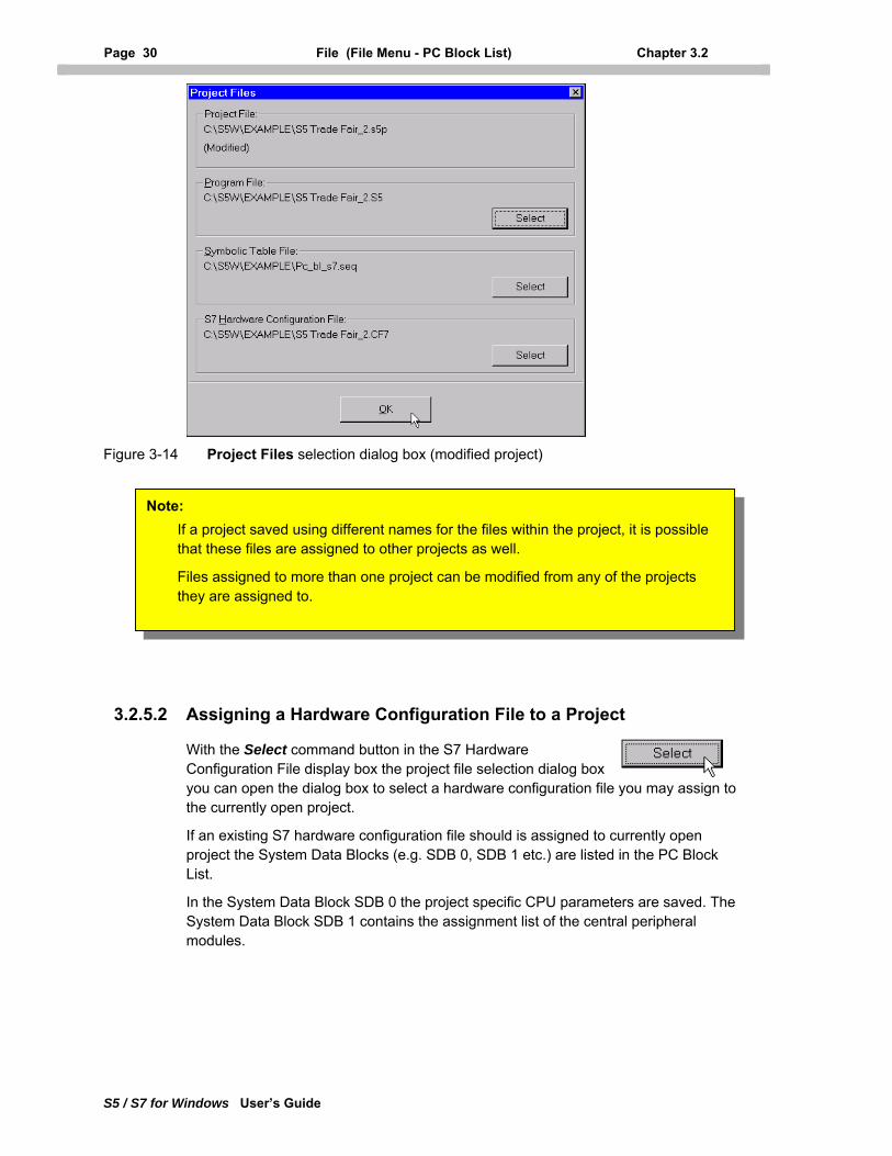
Page 30 File (File Menu - PC Block List) Chapter 3.2
S5 / S7 for Windows User’s Guide
Figure 3-14 Project Files selection dialog box (modified project)
If a project saved using different names for the files within the project, it is possible that these files are assigned to other projects as well.
Files assigned to more than one project can be modified from any of the projects they are assigned to.
Note:
3.2.5.2 Assigning a Hardware Configuration File to a Project
With the Select command button in the S7 Hardware Configuration File display box the project file selection dialog box you can open the dialog box to select a hardware configuration file you may assign to the currently open project.
If an existing S7 hardware configuration file should is assigned to currently open project the System Data Blocks (e.g. SDB 0, SDB 1 etc.) are listed in the PC Block List.
In the System Data Block SDB 0 the project specific CPU parameters are saved. The System Data Block SDB 1 contains the assignment list of the central peripheral modules.
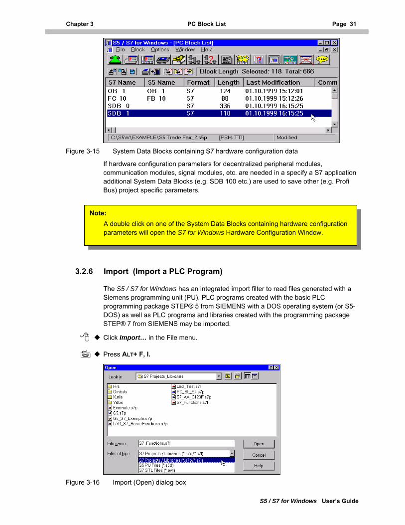
Chapter 3 PC Block List Page 31
S5 / S7 for Windows User’s Guide
Figure 3-15 System Data Blocks containing S7 hardware configuration data
If hardware configuration parameters for decentralized peripheral modules, communication modules, signal modules, etc. are needed in a specify a S7 application additional System Data Blocks (e.g. SDB 100 etc.) are used to save other (e.g. Profi Bus) project specific parameters.
Note: A double click on one of the System Data Blocks containing hardware configuration parameters will open the S7 for Windows Hardware Configuration Window.
3.2.6 Import (Import a PLC Program)
The S5 / S7 for Windows has an integrated import filter to read files generated with a Siemens programming unit (PU). PLC programs created with the basic PLC programming package STEP® 5 from SIEMENS with a DOS operating system (or S5-DOS) as well as PLC programs and libraries created with the programming package STEP® 7 from SIEMENS may be imported.
Click Import… in the File menu.
Press ALT+ F, I.
Figure 3-16 Import (Open) dialog box
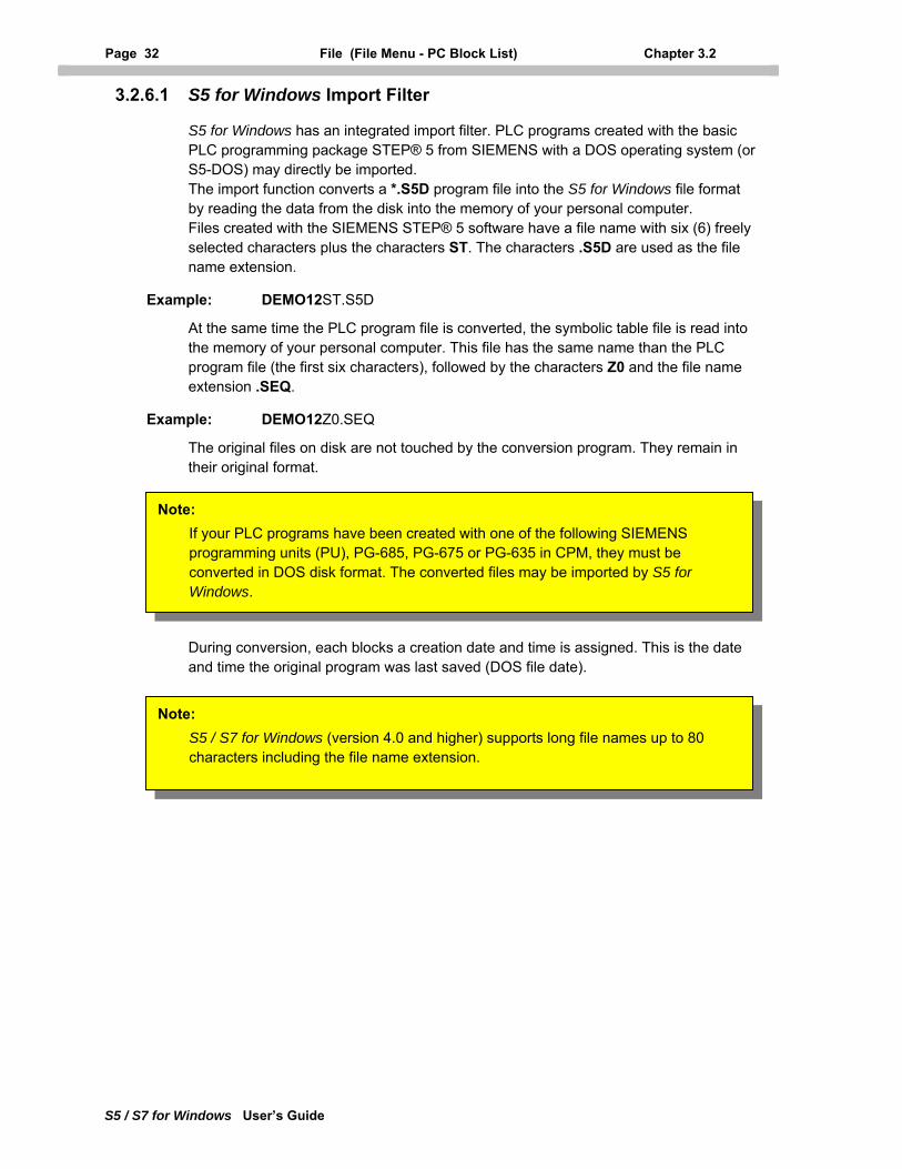
Page 32 File (File Menu - PC Block List) Chapter 3.2
S5 / S7 for Windows User’s Guide
3.2.6.1 S5 for Windows Import Filter
S5 for Windows has an integrated import filter. PLC programs created with the basic PLC programming package STEP® 5 from SIEMENS with a DOS operating system (or S5-DOS) may directly be imported. The import function converts a *.S5D program file into the S5 for Windows file format by reading the data from the disk into the memory of your personal computer. Files created with the SIEMENS STEP® 5 software have a file name with six (6) freely selected characters plus the characters ST. The characters .S5D are used as the file name extension.
Example: DEMO12ST.S5D
At the same time the PLC program file is converted, the symbolic table file is read into the memory of your personal computer. This file has the same name than the PLC program file (the first six characters), followed by the characters Z0 and the file name extension .SEQ.
Example: DEMO12Z0.SEQ
The original files on disk are not touched by the conversion program. They remain in their original format.
During conversion, each blocks a creation date and time is assigned. This is the date and time the original program was last saved (DOS file date).
Note: If your PLC programs have been created with one of the following SIEMENS programming units (PU), PG-685, PG-675 or PG-635 in CPM, they must be converted in DOS disk format. The converted files may be imported by S5 for Windows.
Note: S5 / S7 for Windows (version 4.0 and higher) supports long file names up to 80 characters including the file name extension.
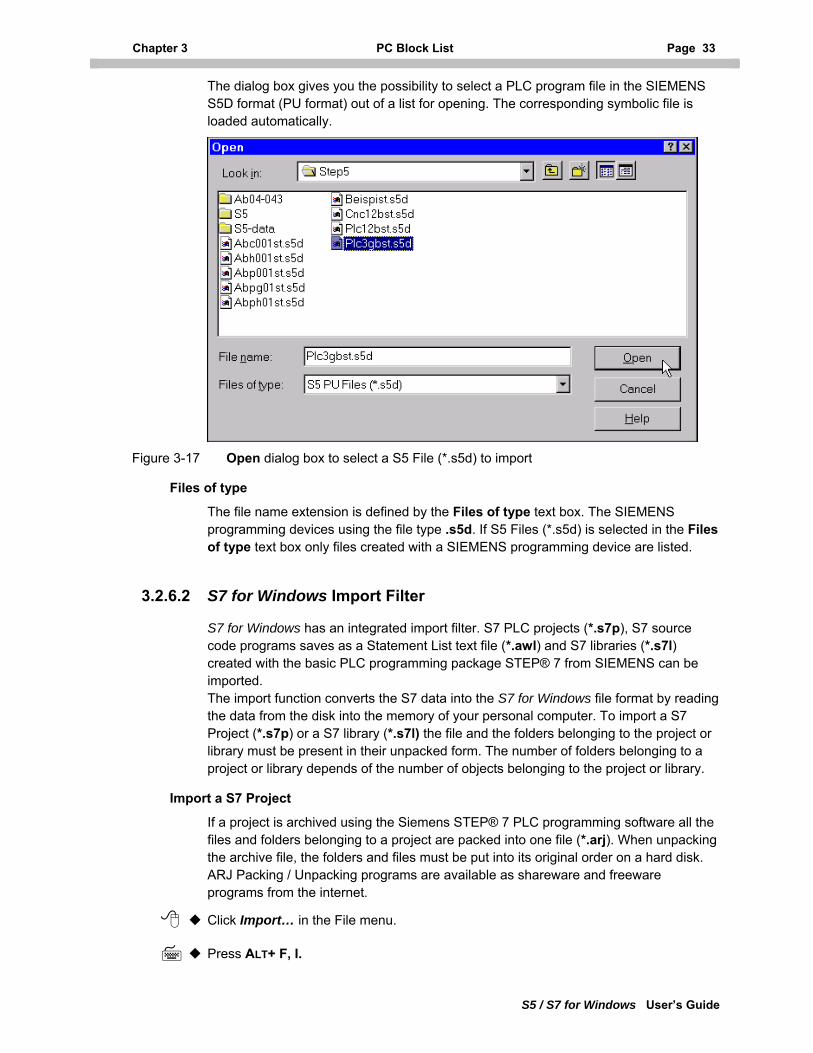
Chapter 3 PC Block List Page 33
S5 / S7 for Windows User’s Guide
The dialog box gives you the possibility to select a PLC program file in the SIEMENS S5D format (PU format) out of a list for opening. The corresponding symbolic file is loaded automatically.
Figure 3-17 Open dialog box to select a S5 File (*.s5d) to import
Files of type
The file name extension is defined by the Files of type text box. The SIEMENS programming devices using the file type .s5d. If S5 Files (*.s5d) is selected in the Files of type text box only files created with a SIEMENS programming device are listed.
3.2.6.2 S7 for Windows Import Filter
S7 for Windows has an integrated import filter. S7 PLC projects (*.s7p), S7 source code programs saves as a Statement List text file (*.awl) and S7 libraries (*.s7l) created with the basic PLC programming package STEP® 7 from SIEMENS can be imported. The import function converts the S7 data into the S7 for Windows file format by reading the data from the disk into the memory of your personal computer. To import a S7 Project (*.s7p) or a S7 library (*.s7l) the file and the folders belonging to the project or library must be present in their unpacked form. The number of folders belonging to a project or library depends of the number of objects belonging to the project or library.
Import a S7 Project
If a project is archived using the Siemens STEP® 7 PLC programming software all the files and folders belonging to a project are packed into one file (*.arj). When unpacking the archive file, the folders and files must be put into its original order on a hard disk. ARJ Packing / Unpacking programs are available as shareware and freeware programs from the internet.
Click Import… in the File menu.
Press ALT+ F, I.
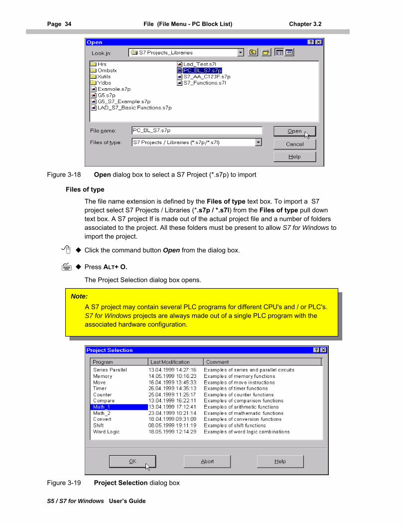
Page 34 File (File Menu - PC Block List) Chapter 3.2
S5 / S7 for Windows User’s Guide
Figure 3-18 Open dialog box to select a S7 Project (*.s7p) to import
Files of type
The file name extension is defined by the Files of type text box. To import a S7 project select S7 Projects / Libraries (*.s7p / *.s7l) from the Files of type pull down text box. A S7 project If is made out of the actual project file and a number of folders associated to the project. All these folders must be present to allow S7 for Windows to import the project.
Click the command button Open from the dialog box.
Press ALT+ O.
The Project Selection dialog box opens.
Note: A S7 project may contain several PLC programs for different CPU's and / or PLC's. S7 for Windows projects are always made out of a single PLC program with the associated hardware configuration.
Figure 3-19 Project Selection dialog box
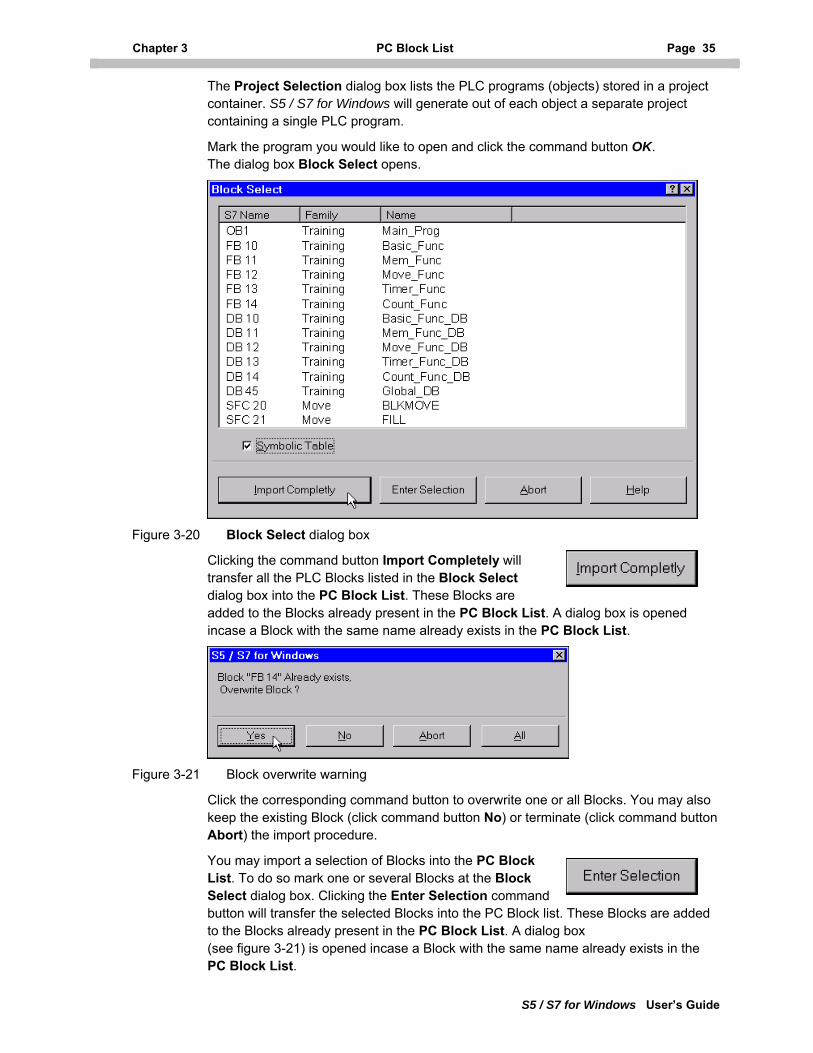
Chapter 3 PC Block List Page 35
S5 / S7 for Windows User’s Guide
The Project Selection dialog box lists the PLC programs (objects) stored in a project container. S5 / S7 for Windows will generate out of each object a separate project containing a single PLC program.
Mark the program you would like to open and click the command button OK. The dialog box Block Select opens.
Figure 3-20 Block Select dialog box
Clicking the command button Import Completely will transfer all the PLC Blocks listed in the Block Select dialog box into the PC Block List. These Blocks are added to the Blocks already present in the PC Block List. A dialog box is opened incase a Block with the same name already exists in the PC Block List.
Figure 3-21 Block overwrite warning
Click the corresponding command button to overwrite one or all Blocks. You may also keep the existing Block (click command button No) or terminate (click command button Abort) the import procedure.
You may import a selection of Blocks into the PC Block List. To do so mark one or several Blocks at the Block Select dialog box. Clicking the Enter Selection command button will transfer the selected Blocks into the PC Block list. These Blocks are added to the Blocks already present in the PC Block List. A dialog box (see figure 3-21) is opened incase a Block with the same name already exists in the PC Block List.
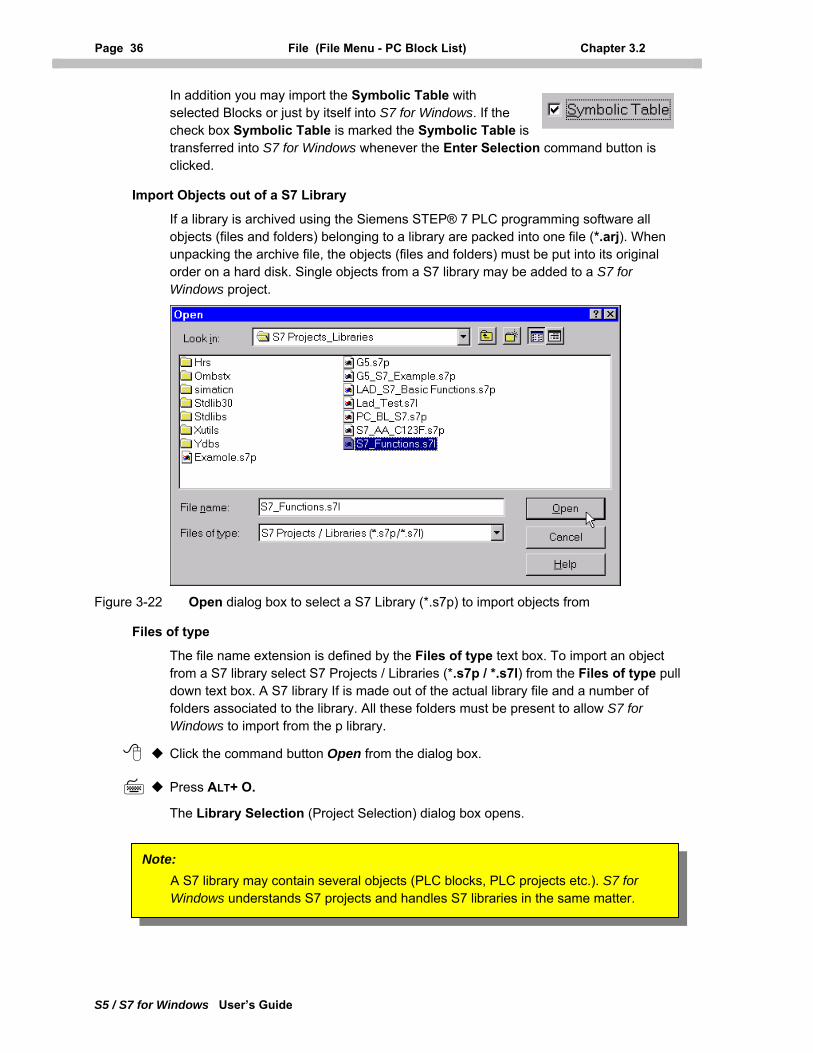
Page 36 File (File Menu - PC Block List) Chapter 3.2
S5 / S7 for Windows User’s Guide
In addition you may import the Symbolic Table with selected Blocks or just by itself into S7 for Windows. If the check box Symbolic Table is marked the Symbolic Table is transferred into S7 for Windows whenever the Enter Selection command button is clicked.
Import Objects out of a S7 Library
If a library is archived using the Siemens STEP® 7 PLC programming software all objects (files and folders) belonging to a library are packed into one file (*.arj). When unpacking the archive file, the objects (files and folders) must be put into its original order on a hard disk. Single objects from a S7 library may be added to a S7 for Windows project.
Figure 3-22 Open dialog box to select a S7 Library (*.s7p) to import objects from
Files of type
The file name extension is defined by the Files of type text box. To import an object from a S7 library select S7 Projects / Libraries (*.s7p / *.s7l) from the Files of type pull down text box. A S7 library If is made out of the actual library file and a number of folders associated to the library. All these folders must be present to allow S7 for Windows to import from the p library.
Click the command button Open from the dialog box.
Press ALT+ O.
The Library Selection (Project Selection) dialog box opens.
Note: A S7 library may contain several objects (PLC blocks, PLC projects etc.). S7 for Windows understands S7 projects and handles S7 libraries in the same matter.
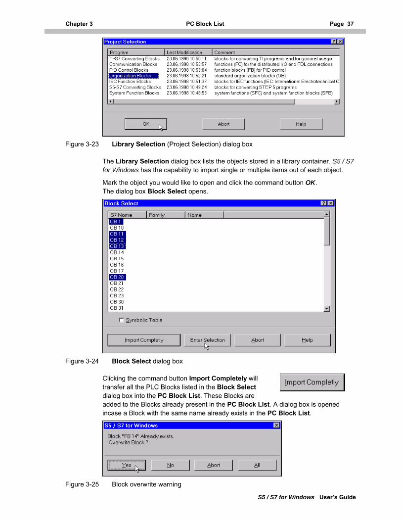
Chapter 3 PC Block List Page 37
S5 / S7 for Windows User’s Guide
Figure 3-23 Library Selection (Project Selection) dialog box
The Library Selection dialog box lists the objects stored in a library container. S5 / S7 for Windows has the capability to import single or multiple items out of each object.
Mark the object you would like to open and click the command button OK. The dialog box Block Select opens.
Figure 3-24 Block Select dialog box
Clicking the command button Import Completely will transfer all the PLC Blocks listed in the Block Select dialog box into the PC Block List. These Blocks are added to the Blocks already present in the PC Block List. A dialog box is opened incase a Block with the same name already exists in the PC Block List.
Figure 3-25 Block overwrite warning
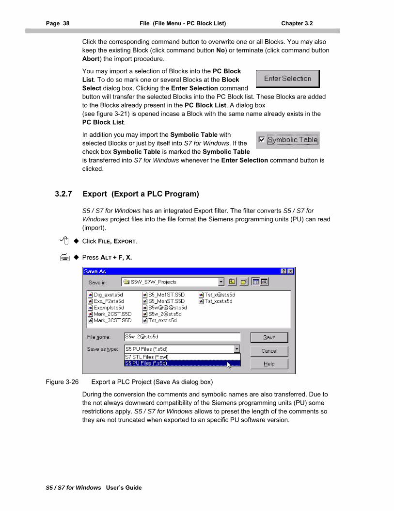
Page 38 File (File Menu - PC Block List) Chapter 3.2
S5 / S7 for Windows User’s Guide
Click the corresponding command button to overwrite one or all Blocks. You may also keep the existing Block (click command button No) or terminate (click command button Abort) the import procedure.
You may import a selection of Blocks into the PC Block List. To do so mark one or several Blocks at the Block Select dialog box. Clicking the Enter Selection command button will transfer the selected Blocks into the PC Block list. These Blocks are added to the Blocks already present in the PC Block List. A dialog box (see figure 3-21) is opened incase a Block with the same name already exists in the PC Block List.
In addition you may import the Symbolic Table with selected Blocks or just by itself into S7 for Windows. If the check box Symbolic Table is marked the Symbolic Table is transferred into S7 for Windows whenever the Enter Selection command button is clicked.
3.2.7 Export (Export a PLC Program)
S5 / S7 for Windows has an integrated Export filter. The filter converts S5 / S7 for Windows project files into the file format the Siemens programming units (PU) can read (import).
Click FILE, EXPORT.
Press ALT + F, X.
Figure 3-26 Export a PLC Project (Save As dialog box)
During the conversion the comments and symbolic names are also transferred. Due to the not always downward compatibility of the Siemens programming units (PU) some restrictions apply. S5 / S7 for Windows allows to preset the length of the comments so they are not truncated when exported to an specific PU software version.
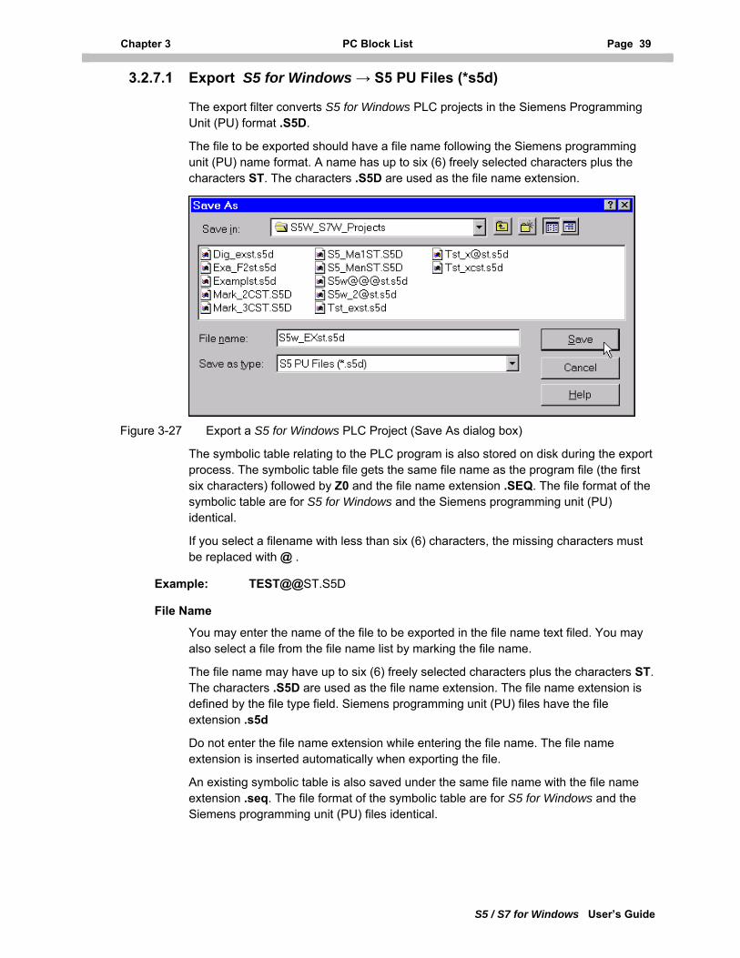
Chapter 3 PC Block List Page 39
S5 / S7 for Windows User’s Guide
3.2.7.1 Export S5 for Windows → S5 PU Files (*s5d)
The export filter converts S5 for Windows PLC projects in the Siemens Programming Unit (PU) format .S5D.
The file to be exported should have a file name following the Siemens programming unit (PU) name format. A name has up to six (6) freely selected characters plus the characters ST. The characters .S5D are used as the file name extension.
Figure 3-27 Export a S5 for Windows PLC Project (Save As dialog box)
The symbolic table relating to the PLC program is also stored on disk during the export process. The symbolic table file gets the same file name as the program file (the first six characters) followed by Z0 and the file name extension .SEQ. The file format of the symbolic table are for S5 for Windows and the Siemens programming unit (PU) identical.
If you select a filename with less than six (6) characters, the missing characters must be replaced with @ .
Example: TEST@@ST.S5D
File Name
You may enter the name of the file to be exported in the file name text filed. You may also select a file from the file name list by marking the file name.
The file name may have up to six (6) freely selected characters plus the characters ST. The characters .S5D are used as the file name extension. The file name extension is defined by the file type field. Siemens programming unit (PU) files have the file extension .s5d
Do not enter the file name extension while entering the file name. The file name extension is inserted automatically when exporting the file.
An existing symbolic table is also saved under the same file name with the file name extension .seq. The file format of the symbolic table are for S5 for Windows and the Siemens programming unit (PU) files identical.
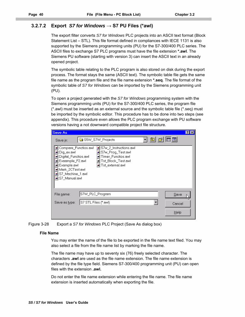
Page 40 File (File Menu - PC Block List) Chapter 3.2
S5 / S7 for Windows User’s Guide
3.2.7.2 Export S7 for Windows → S7 PU Files (*awl)
The export filter converts S7 for Windows PLC projects into an ASCII text format (Block Statement List – STL). This file format defined in compliances with IECE 1131 is also supported by the Siemens programming units (PU) for the S7-300/400 PLC series. The ASCII files to exchange S7 PLC programs must have the file extension *.awl. The Siemens PU software (starting with version 3) can insert the ASCII text in an already opened project.
The symbolic table relating to the PLC program is also stored on disk during the export process. The format stays the same (ASCII text). The symbolic table file gets the same file name as the program file and the file name extension *.seq. The file format of the symbolic table of S7 for Windows can be imported by the Siemens programming unit (PU).
To open a project generated with the S7 for Windows programming system with the Siemens programming units (PU) for the S7-300/400 PLC series, the program file (*.awl) must be inserted as an external source and the symbolic table file (*.seq) must be imported by the symbolic editor. This procedure has to be done into two steps (see appendix). This procedure even allows the PLC program exchange with PU software versions having a not downward compatible project file structure.
Figure 3-28 Export a S7 for Windows PLC Project (Save As dialog box)
File Name
You may enter the name of the file to be exported in the file name text filed. You may also select a file from the file name list by marking the file name.
The file name may have up to seventy six (76) freely selected character. The characters .awl are used as the file name extension. The file name extension is defined by the file type field. Siemens S7-300/400 programming unit (PU) can open files with the extension .awl.
Do not enter the file name extension while entering the file name. The file name extension is inserted automatically when exporting the file.
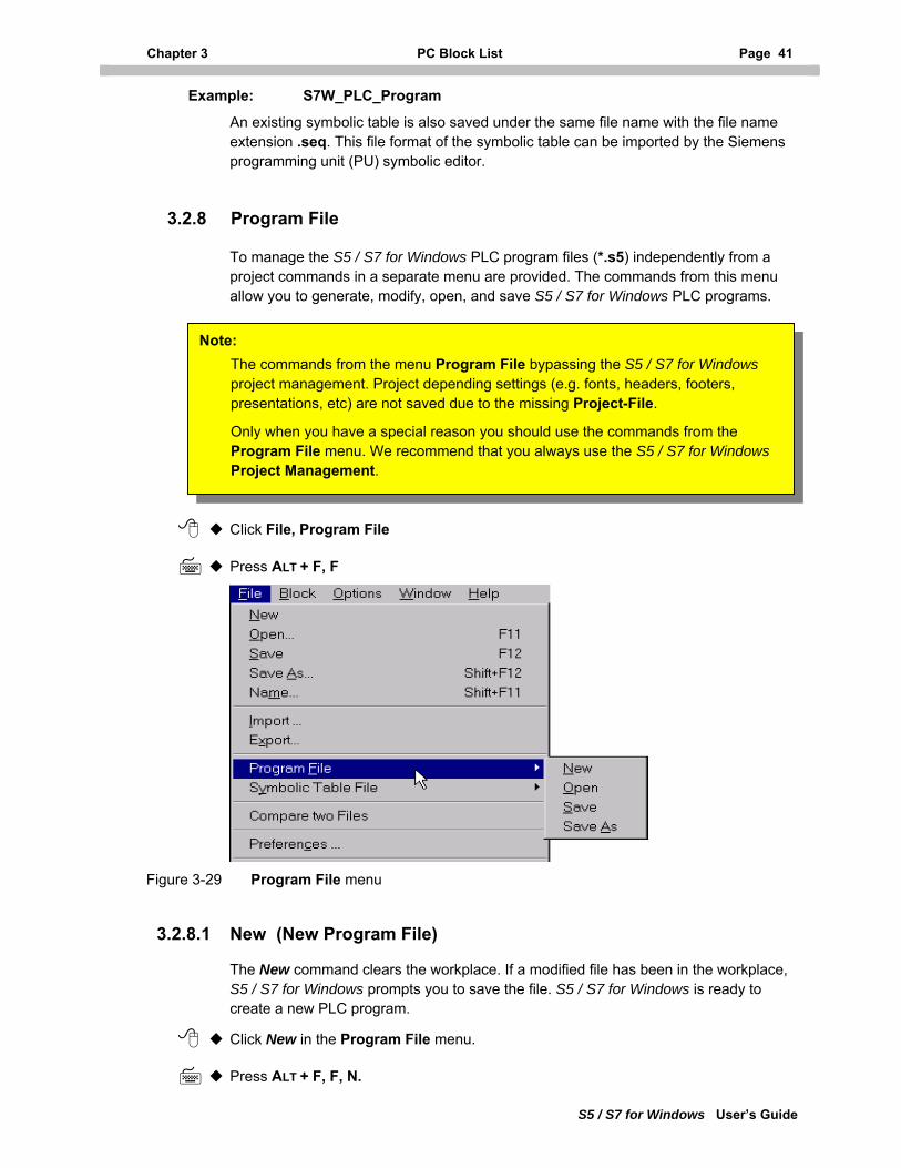
Chapter 3 PC Block List Page 41
S5 / S7 for Windows User’s Guide
Example: S7W_PLC_Program
An existing symbolic table is also saved under the same file name with the file name extension .seq. This file format of the symbolic table can be imported by the Siemens programming unit (PU) symbolic editor.
3.2.8 Program File
To manage the S5 / S7 for Windows PLC program files (*.s5) independently from a project commands in a separate menu are provided. The commands from this menu allow you to generate, modify, open, and save S5 / S7 for Windows PLC programs.
Click File, Program File
Press ALT + F, F
The commands from the menu Program File bypassing the S5 / S7 for Windows project management. Project depending settings (e.g. fonts, headers, footers, presentations, etc) are not saved due to the missing Project-File.
Only when you have a special reason you should use the commands from the Program File menu. We recommend that you always use the S5 / S7 for Windows Project Management.
Note:
Figure 3-29 Program File menu
3.2.8.1 New (New Program File)
The New command clears the workplace. If a modified file has been in the workplace, S5 / S7 for Windows prompts you to save the file. S5 / S7 for Windows is ready to create a new PLC program.
Click New in the Program File menu.
Press ALT + F, F, N.
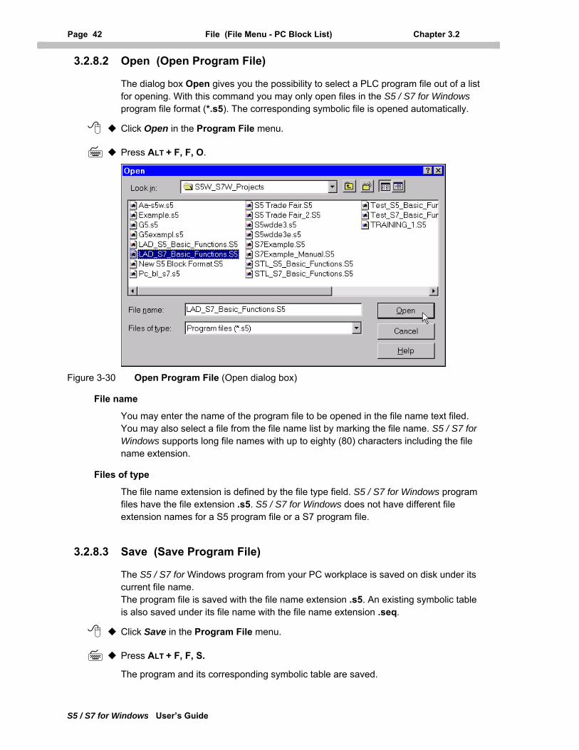
Page 42 File (File Menu - PC Block List) Chapter 3.2
S5 / S7 for Windows User’s Guide
3.2.8.2 Open (Open Program File)
The dialog box Open gives you the possibility to select a PLC program file out of a list for opening. With this command you may only open files in the S5 / S7 for Windows program file format (*.s5). The corresponding symbolic file is opened automatically.
Click Open in the Program File menu.
Press ALT + F, F, O.
Figure 3-30 Open Program File (Open dialog box)
File name
You may enter the name of the program file to be opened in the file name text filed. You may also select a file from the file name list by marking the file name. S5 / S7 for Windows supports long file names with up to eighty (80) characters including the file name extension.
Files of type
The file name extension is defined by the file type field. S5 / S7 for Windows program files have the file extension .s5. S5 / S7 for Windows does not have different file extension names for a S5 program file or a S7 program file.
3.2.8.3 Save (Save Program File)
The S5 / S7 for Windows program from your PC workplace is saved on disk under its current file name. The program file is saved with the file name extension .s5. An existing symbolic table is also saved under its file name with the file name extension .seq.
Click Save in the Program File menu.
Press ALT + F, F, S.
The program and its corresponding symbolic table are saved.
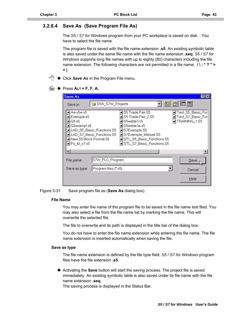
Chapter 3 PC Block List Page 43
S5 / S7 for Windows User’s Guide
3.2.8.4 Save As (Save Program File As)
The S5 / S7 for Windows program from your PC workplace is saved on disk. . You have to select the file name.
The program file is saved with the file name extension .s5. An existing symbolic table is also saved under the same file name with the file name extension .seq. S5 / S7 for Windows supports long file names with up to eighty (80) characters including the file name extension. The following characters are not permitted in a file name: / \ : * ? " > < |
Click Save As in the Program File menu.
Press ALT + F, F, A.
Figure 3-31 Save program file as (Save As dialog box)
File Name
You may enter the name of the program file to be saved in the file name text filed. You may also select a file from the file name list by marking the file name. This will overwrite the selected file.
The file to overwrite and its path is displayed in the title bar of the dialog box.
You do not have to enter the file name extension while entering the file name. The file name extension is inserted automatically when saving the file.
Save as type
The file name extension is defined by the file type field. S5 / S7 for Windows program files have the file extension .s5.
Activating the Save button will start the saving process. The project file is saved immediately. An existing symbolic table is also saved under its file name with the file name extension .seq. The saving process is displayed in the Status Bar.
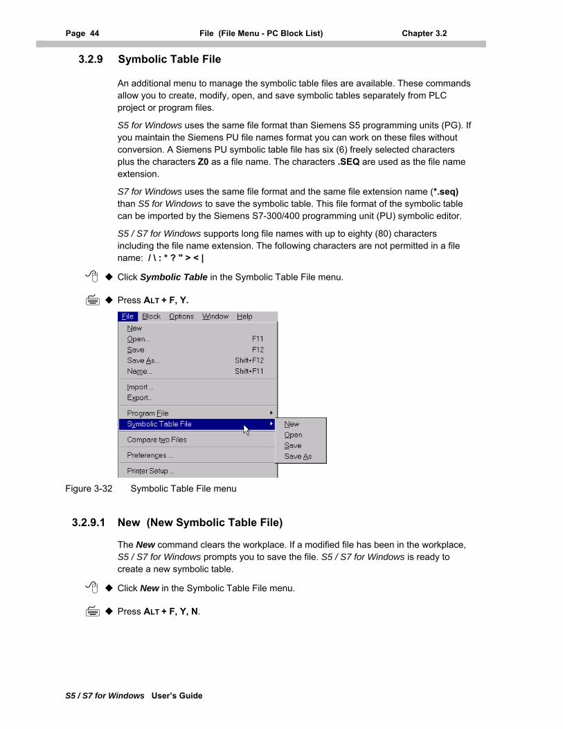
Page 44 File (File Menu - PC Block List) Chapter 3.2
S5 / S7 for Windows User’s Guide
3.2.9 Symbolic Table File
An additional menu to manage the symbolic table files are available. These commands allow you to create, modify, open, and save symbolic tables separately from PLC project or program files.
S5 for Windows uses the same file format than Siemens S5 programming units (PG). If you maintain the Siemens PU file names format you can work on these files without conversion. A Siemens PU symbolic table file has six (6) freely selected characters plus the characters Z0 as a file name. The characters .SEQ are used as the file name extension.
S7 for Windows uses the same file format and the same file extension name (*.seq) than S5 for Windows to save the symbolic table. This file format of the symbolic table can be imported by the Siemens S7-300/400 programming unit (PU) symbolic editor.
S5 / S7 for Windows supports long file names with up to eighty (80) characters including the file name extension. The following characters are not permitted in a file name: / \ : * ? " > < |
Click Symbolic Table in the Symbolic Table File menu.
Press ALT + F, Y.
Figure 3-32 Symbolic Table File menu
3.2.9.1 New (New Symbolic Table File)
The New command clears the workplace. If a modified file has been in the workplace, S5 / S7 for Windows prompts you to save the file. S5 / S7 for Windows is ready to create a new symbolic table.
Click New in the Symbolic Table File menu.
Press ALT + F, Y, N.
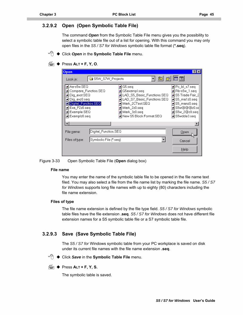
Chapter 3 PC Block List Page 45
S5 / S7 for Windows User’s Guide
3.2.9.2 Open (Open Symbolic Table File)
The command Open from the Symbolic Table File menu gives you the possibility to select a symbolic table file out of a list for opening. With this command you may only open files in the S5 / S7 for Windows symbolic table file format (*.seq).
Click Open in the Symbolic Table File menu.
Press ALT + F, Y, O.
Figure 3-33 Open Symbolic Table File (Open dialog box)
File name
You may enter the name of the symbolic table file to be opened in the file name text filed. You may also select a file from the file name list by marking the file name. S5 / S7 for Windows supports long file names with up to eighty (80) characters including the file name extension.
Files of type
The file name extension is defined by the file type field. S5 / S7 for Windows symbolic table files have the file extension .seq. S5 / S7 for Windows does not have different file extension names for a S5 symbolic table file or a S7 symbolic table file.
3.2.9.3 Save (Save Symbolic Table File)
The S5 / S7 for Windows symbolic table from your PC workplace is saved on disk under its current file names with the file name extension .seq.
Click Save in the Symbolic Table File menu.
Press ALT + F, Y, S.
The symbolic table is saved.
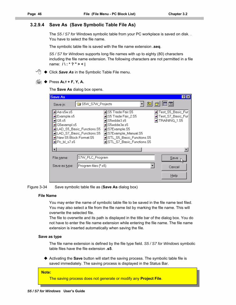
Page 46 File (File Menu - PC Block List) Chapter 3.2
S5 / S7 for Windows User’s Guide
3.2.9.4 Save As (Save Symbolic Table File As)
The S5 / S7 for Windows symbolic table from your PC workplace is saved on disk. . You have to select the file name.
The symbolic table file is saved with the file name extension .seq.
S5 / S7 for Windows supports long file names with up to eighty (80) characters including the file name extension. The following characters are not permitted in a file name: / \ : * ? " > < |
Click Save As in the Symbolic Table File menu.
Press ALT + F, Y, A.
The Save As dialog box opens.
Figure 3-34 Save symbolic table file as (Save As dialog box)
File Name
You may enter the name of symbolic table file to be saved in the file name text filed. You may also select a file from the file name list by marking the file name. This will overwrite the selected file. The file to overwrite and its path is displayed in the title bar of the dialog box. You do not have to enter the file name extension while entering the file name. The file name extension is inserted automatically when saving the file.
Save as type
The file name extension is defined by the file type field. S5 / S7 for Windows symbolic table files have the file extension .s5.
Activating the Save button will start the saving process. The symbolic table file is saved immediately. The saving process is displayed in the Status Bar.
Note: The saving process does not generate or modify any Project File.
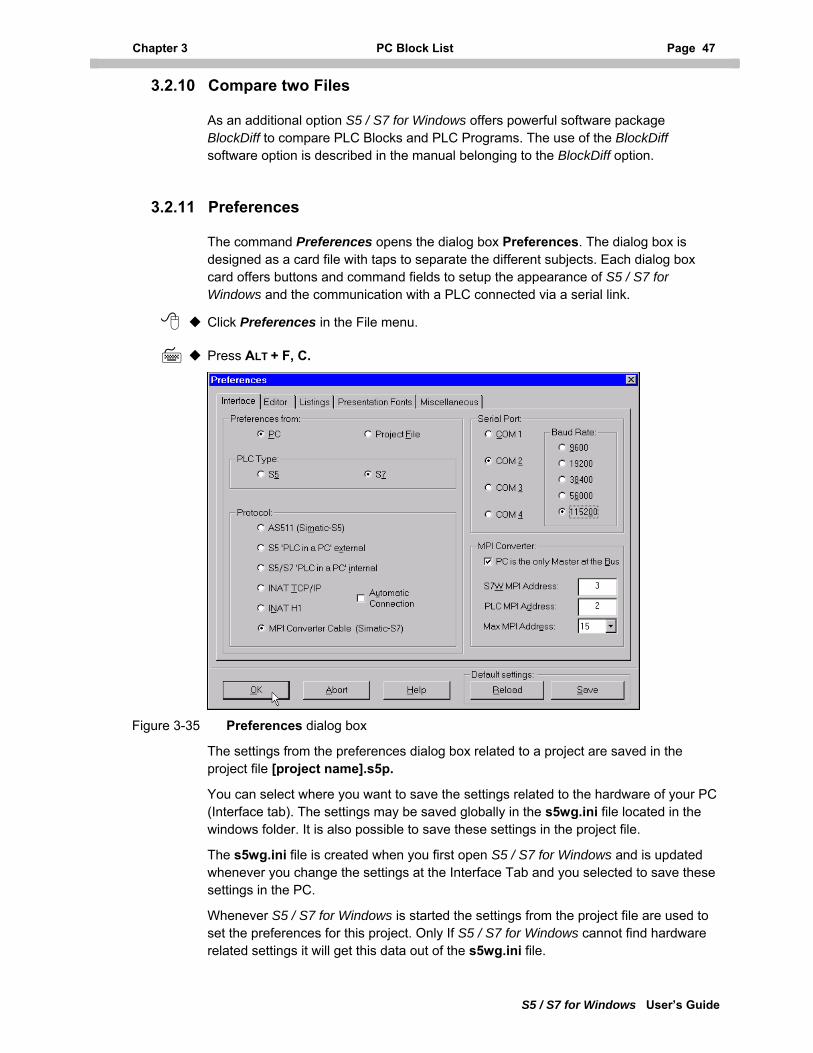
Chapter 3 PC Block List Page 47
S5 / S7 for Windows User’s Guide
3.2.10 Compare two Files
As an additional option S5 / S7 for Windows offers powerful software package BlockDiff to compare PLC Blocks and PLC Programs. The use of the BlockDiff software option is described in the manual belonging to the BlockDiff option.
3.2.11 Preferences
The command Preferences opens the dialog box Preferences. The dialog box is designed as a card file with taps to separate the different subjects. Each dialog box card offers buttons and command fields to setup the appearance of S5 / S7 for Windows and the communication with a PLC connected via a serial link.
Click Preferences in the File menu.
Press ALT + F, C.
Figure 3-35 Preferences dialog box
The settings from the preferences dialog box related to a project are saved in the project file [project name].s5p.
You can select where you want to save the settings related to the hardware of your PC (Interface tab). The settings may be saved globally in the s5wg.ini file located in the windows folder. It is also possible to save these settings in the project file.
The s5wg.ini file is created when you first open S5 / S7 for Windows and is updated whenever you change the settings at the Interface Tab and you selected to save these settings in the PC.
Whenever S5 / S7 for Windows is started the settings from the project file are used to set the preferences for this project. Only If S5 / S7 for Windows cannot find hardware related settings it will get this data out of the s5wg.ini file.
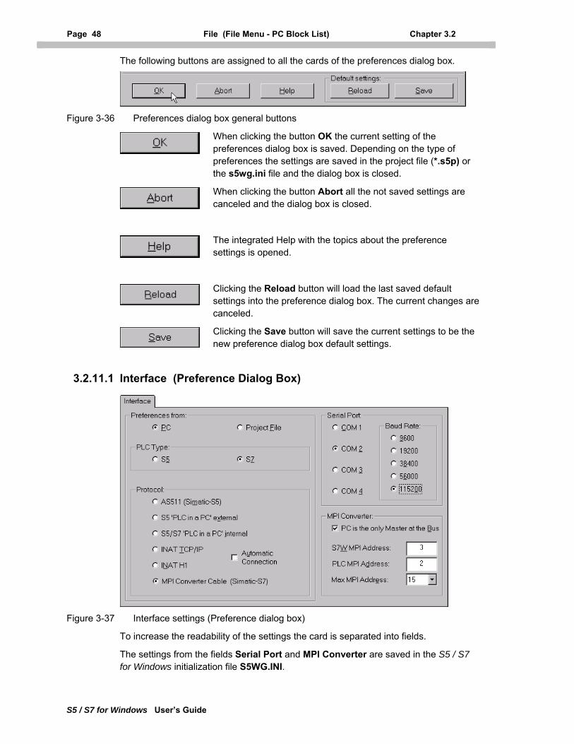
Page 48 File (File Menu - PC Block List) Chapter 3.2
S5 / S7 for Windows User’s Guide
The following buttons are assigned to all the cards of the preferences dialog box.
Figure 3-36 Preferences dialog box general buttons
When clicking the button OK the current setting of the preferences dialog box is saved. Depending on the type of preferences the settings are saved in the project file (*.s5p) or the s5wg.ini file and the dialog box is closed.
When clicking the button Abort all the not saved settings are canceled and the dialog box is closed.
The integrated Help with the topics about the preference settings is opened.
Clicking the Reload button will load the last saved default settings into the preference dialog box. The current changes are canceled.
Clicking the Save button will save the current settings to be the new preference dialog box default settings.
3.2.11.1 Interface (Preference Dialog Box)
Figure 3-37 Interface settings (Preference dialog box)
To increase the readability of the settings the card is separated into fields.
The settings from the fields Serial Port and MPI Converter are saved in the S5 / S7 for Windows initialization file S5WG.INI.
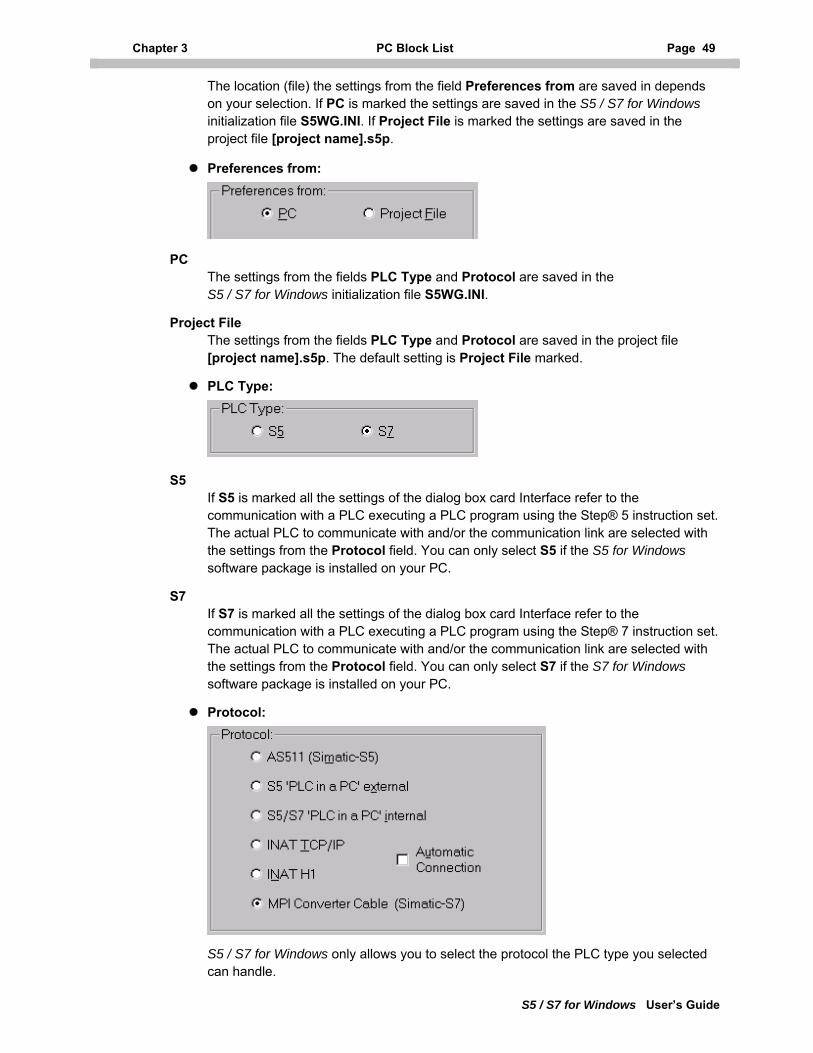
Chapter 3 PC Block List Page 49
S5 / S7 for Windows User’s Guide
The location (file) the settings from the field Preferences from are saved in depends on your selection. If PC is marked the settings are saved in the S5 / S7 for Windows initialization file S5WG.INI. If Project File is marked the settings are saved in the project file [project name].s5p.
Preferences from:
PC The settings from the fields PLC Type and Protocol are saved in the S5 / S7 for Windows initialization file S5WG.INI.
Project File The settings from the fields PLC Type and Protocol are saved in the project file [project name].s5p. The default setting is Project File marked.
PLC Type:
S5 If S5 is marked all the settings of the dialog box card Interface refer to the communication with a PLC executing a PLC program using the Step® 5 instruction set. The actual PLC to communicate with and/or the communication link are selected with the settings from the Protocol field. You can only select S5 if the S5 for Windows software package is installed on your PC.
S7 If S7 is marked all the settings of the dialog box card Interface refer to the communication with a PLC executing a PLC program using the Step® 7 instruction set. The actual PLC to communicate with and/or the communication link are selected with the settings from the Protocol field. You can only select S7 if the S7 for Windows software package is installed on your PC.
Protocol:
S5 / S7 for Windows only allows you to select the protocol the PLC type you selected can handle.
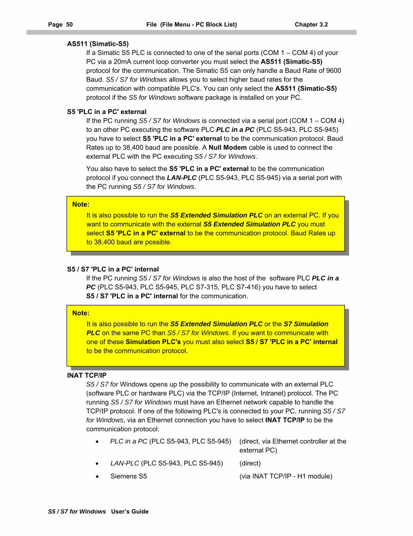
Page 50 File (File Menu - PC Block List) Chapter 3.2
S5 / S7 for Windows User’s Guide
AS511 (Simatic-S5) If a Simatic S5 PLC is connected to one of the serial ports (COM 1 – COM 4) of your PC via a 20mA current loop converter you must select the AS511 (Simatic-S5) protocol for the communication. The Simatic S5 can only handle a Baud Rate of 9600 Baud. S5 / S7 for Windows allows you to select higher baud rates for the communication with compatible PLC's. You can only select the AS511 (Simatic-S5) protocol if the S5 for Windows software package is installed on your PC.
S5 'PLC in a PC' external If the PC running S5 / S7 for Windows is connected via a serial port (COM 1 – COM 4) to an other PC executing the software PLC PLC in a PC (PLC S5-943, PLC S5-945) you have to select S5 'PLC in a PC' external to be the communication protocol. Baud Rates up to 38,400 baud are possible. A Null Modem cable is used to connect the external PLC with the PC executing S5 / S7 for Windows.
You also have to select the S5 'PLC in a PC' external to be the communication protocol if you connect the LAN-PLC (PLC S5-943, PLC S5-945) via a serial port with the PC running S5 / S7 for Windows.
Note: It is also possible to run the S5 Extended Simulation PLC on an external PC. If you want to communicate with the external S5 Extended Simulation PLC you must select S5 'PLC in a PC' external to be the communication protocol. Baud Rates up to 38,400 baud are possible.
S5 / S7 'PLC in a PC' internal If the PC running S5 / S7 for Windows is also the host of the software PLC PLC in a PC (PLC S5-943, PLC S5-945, PLC S7-315, PLC S7-416) you have to select S5 / S7 'PLC in a PC' internal for the communication.
Note: It is also possible to run the S5 Extended Simulation PLC or the S7 Simulation PLC on the same PC than S5 / S7 for Windows. If you want to communicate with one of these Simulation PLC's you must also select S5 / S7 'PLC in a PC' internal to be the communication protocol.
INAT TCP/IP S5 / S7 for Windows opens up the possibility to communicate with an external PLC (software PLC or hardware PLC) via the TCP/IP (Internet, Intranet) protocol. The PC running S5 / S7 for Windows must have an Ethernet network capable to handle the TCP/IP protocol. If one of the following PLC's is connected to your PC, running S5 / S7 for Windows, via an Ethernet connection you have to select INAT TCP/IP to be the communication protocol:
• PLC in a PC (PLC S5-943, PLC S5-945) (direct, via Ethernet controller at the external PC)
• LAN-PLC (PLC S5-943, PLC S5-945) (direct)
• Siemens S5 (via INAT TCP/IP - H1 module)
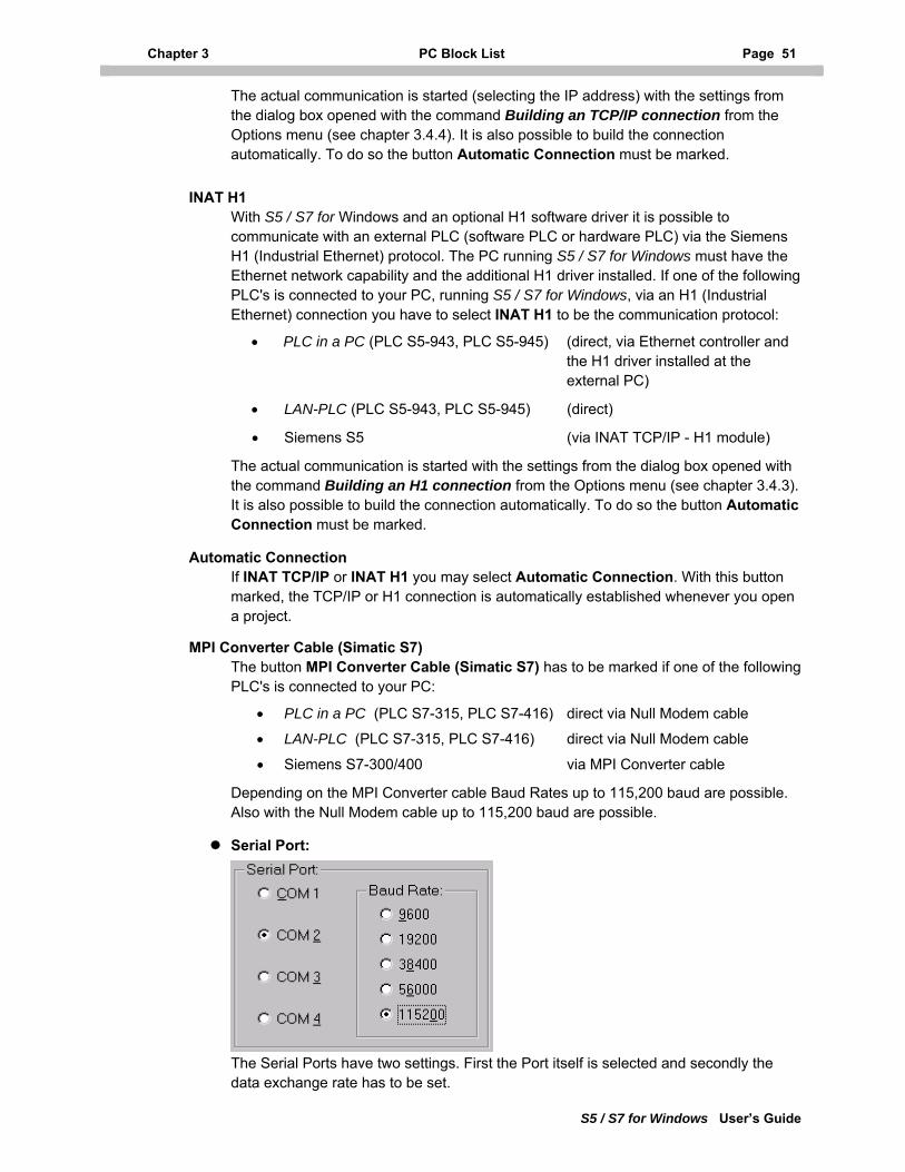
Chapter 3 PC Block List Page 51
S5 / S7 for Windows User’s Guide
The actual communication is started (selecting the IP address) with the settings from the dialog box opened with the command Building an TCP/IP connection from the Options menu (see chapter 3.4.4). It is also possible to build the connection automatically. To do so the button Automatic Connection must be marked.
INAT H1 With S5 / S7 for Windows and an optional H1 software driver it is possible to communicate with an external PLC (software PLC or hardware PLC) via the Siemens H1 (Industrial Ethernet) protocol. The PC running S5 / S7 for Windows must have the Ethernet network capability and the additional H1 driver installed. If one of the following PLC's is connected to your PC, running S5 / S7 for Windows, via an H1 (Industrial Ethernet) connection you have to select INAT H1 to be the communication protocol:
• PLC in a PC (PLC S5-943, PLC S5-945) (direct, via Ethernet controller and the H1 driver installed at the external PC)
• LAN-PLC (PLC S5-943, PLC S5-945) (direct)
• Siemens S5 (via INAT TCP/IP - H1 module)
The actual communication is started with the settings from the dialog box opened with the command Building an H1 connection from the Options menu (see chapter 3.4.3). It is also possible to build the connection automatically. To do so the button Automatic Connection must be marked.
Automatic Connection If INAT TCP/IP or INAT H1 you may select Automatic Connection. With this button marked, the TCP/IP or H1 connection is automatically established whenever you open a project.
MPI Converter Cable (Simatic S7) The button MPI Converter Cable (Simatic S7) has to be marked if one of the following PLC's is connected to your PC:
• PLC in a PC (PLC S7-315, PLC S7-416) direct via Null Modem cable
• LAN-PLC (PLC S7-315, PLC S7-416) direct via Null Modem cable
• Siemens S7-300/400 via MPI Converter cable
Depending on the MPI Converter cable Baud Rates up to 115,200 baud are possible. Also with the Null Modem cable up to 115,200 baud are possible.
Serial Port:
The Serial Ports have two settings. First the Port itself is selected and secondly the data exchange rate has to be set.
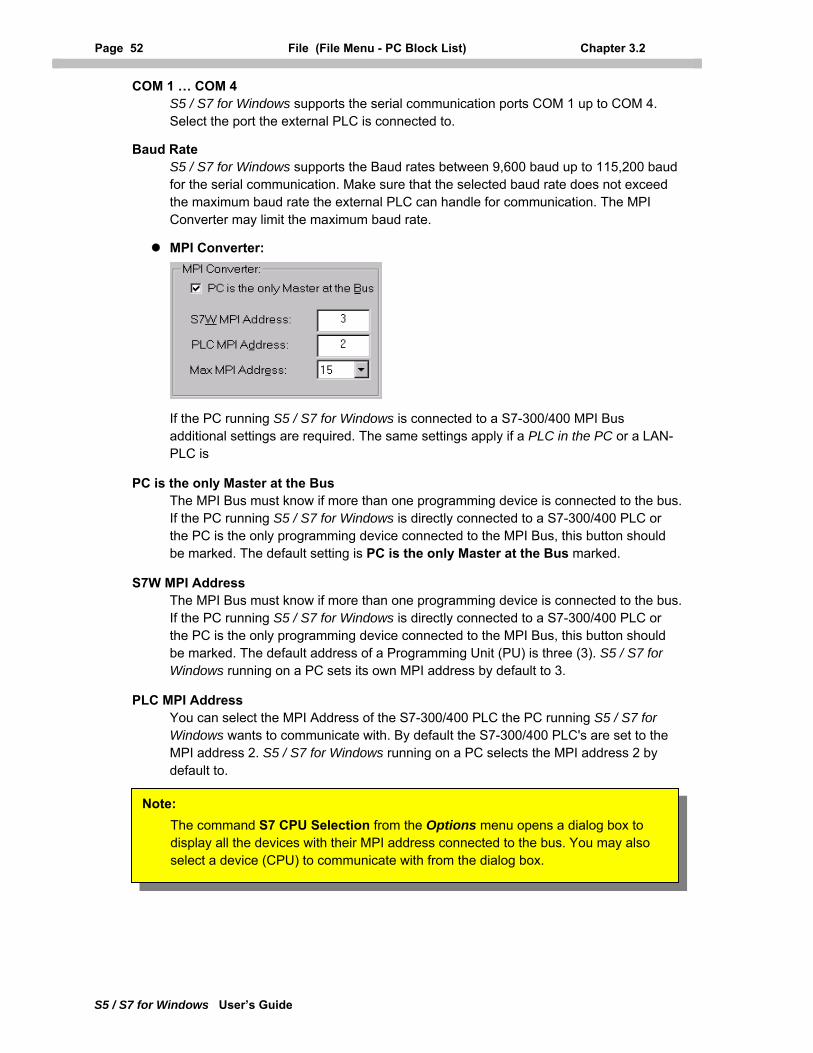
Page 52 File (File Menu - PC Block List) Chapter 3.2
S5 / S7 for Windows User’s Guide
COM 1 … COM 4 S5 / S7 for Windows supports the serial communication ports COM 1 up to COM 4. Select the port the external PLC is connected to.
Baud Rate S5 / S7 for Windows supports the Baud rates between 9,600 baud up to 115,200 baud for the serial communication. Make sure that the selected baud rate does not exceed the maximum baud rate the external PLC can handle for communication. The MPI Converter may limit the maximum baud rate.
MPI Converter:
If the PC running S5 / S7 for Windows is connected to a S7-300/400 MPI Bus additional settings are required. The same settings apply if a PLC in the PC or a LAN-PLC is
PC is the only Master at the Bus The MPI Bus must know if more than one programming device is connected to the bus. If the PC running S5 / S7 for Windows is directly connected to a S7-300/400 PLC or the PC is the only programming device connected to the MPI Bus, this button should be marked. The default setting is PC is the only Master at the Bus marked.
S7W MPI Address The MPI Bus must know if more than one programming device is connected to the bus. If the PC running S5 / S7 for Windows is directly connected to a S7-300/400 PLC or the PC is the only programming device connected to the MPI Bus, this button should be marked. The default address of a Programming Unit (PU) is three (3). S5 / S7 for Windows running on a PC sets its own MPI address by default to 3.
PLC MPI Address You can select the MPI Address of the S7-300/400 PLC the PC running S5 / S7 for Windows wants to communicate with. By default the S7-300/400 PLC's are set to the MPI address 2. S5 / S7 for Windows running on a PC selects the MPI address 2 by default to.
Note: The command S7 CPU Selection from the Options menu opens a dialog box to display all the devices with their MPI address connected to the bus. You may also select a device (CPU) to communicate with from the dialog box.
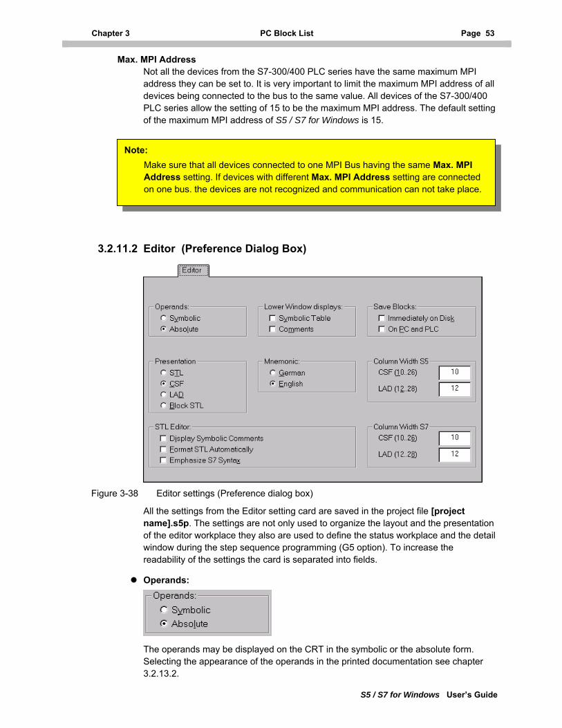
Chapter 3 PC Block List Page 53
S5 / S7 for Windows User’s Guide
Max. MPI Address Not all the devices from the S7-300/400 PLC series have the same maximum MPI address they can be set to. It is very important to limit the maximum MPI address of all devices being connected to the bus to the same value. All devices of the S7-300/400 PLC series allow the setting of 15 to be the maximum MPI address. The default setting of the maximum MPI address of S5 / S7 for Windows is 15.
Note: Make sure that all devices connected to one MPI Bus having the same Max. MPI Address setting. If devices with different Max. MPI Address setting are connected on one bus. the devices are not recognized and communication can not take place.
3.2.11.2 Editor (Preference Dialog Box)
Figure 3-38 Editor settings (Preference dialog box)
All the settings from the Editor setting card are saved in the project file [project name].s5p. The settings are not only used to organize the layout and the presentation of the editor workplace they also are used to define the status workplace and the detail window during the step sequence programming (G5 option). To increase the readability of the settings the card is separated into fields.
Operands:
The operands may be displayed on the CRT in the symbolic or the absolute form. Selecting the appearance of the operands in the printed documentation see chapter 3.2.13.2.
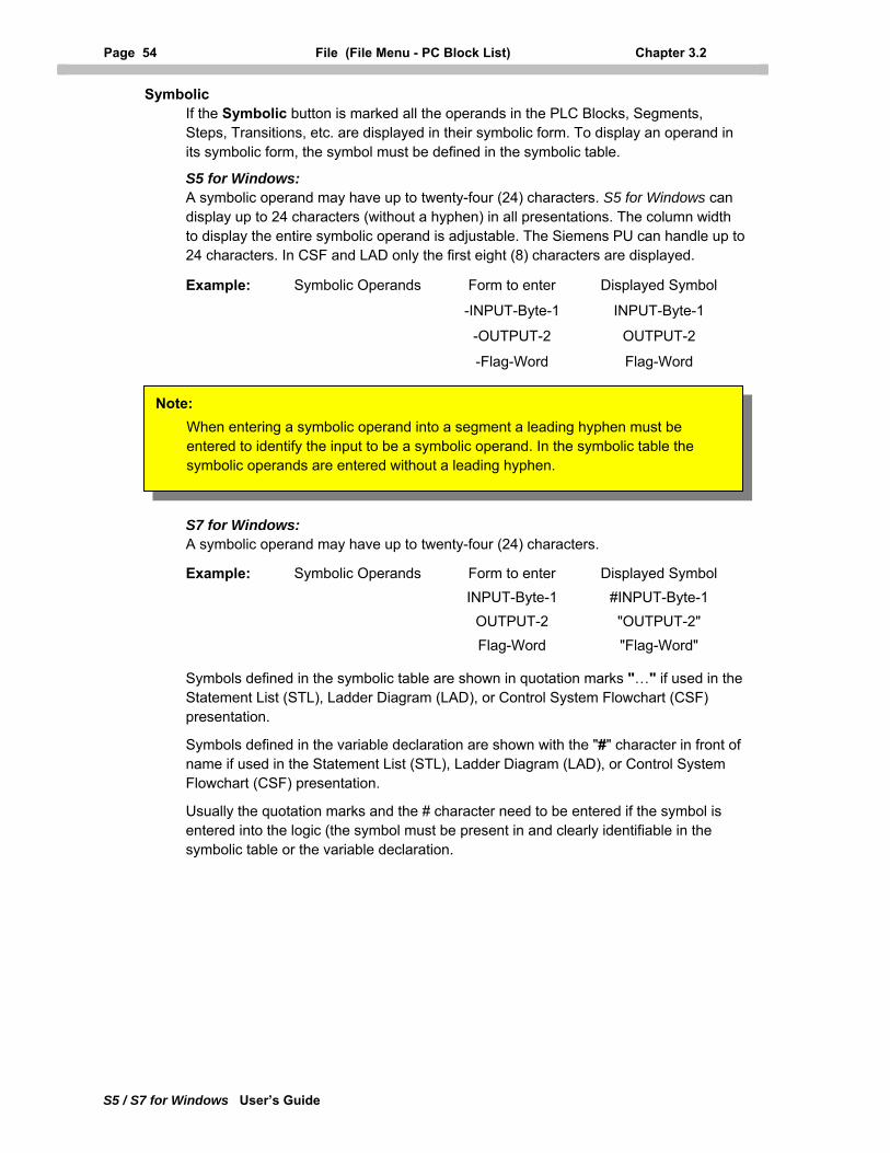
Page 54 File (File Menu - PC Block List) Chapter 3.2
S5 / S7 for Windows User’s Guide
Symbolic If the Symbolic button is marked all the operands in the PLC Blocks, Segments, Steps, Transitions, etc. are displayed in their symbolic form. To display an operand in its symbolic form, the symbol must be defined in the symbolic table.
S5 for Windows: A symbolic operand may have up to twenty-four (24) characters. S5 for Windows can display up to 24 characters (without a hyphen) in all presentations. The column width to display the entire symbolic operand is adjustable. The Siemens PU can handle up to 24 characters. In CSF and LAD only the first eight (8) characters are displayed.
Example: Symbolic Operands Form to enter Displayed Symbol
-INPUT-Byte-1 INPUT-Byte-1
-OUTPUT-2 OUTPUT-2
-Flag-Word Flag-Word
Note: When entering a symbolic operand into a segment a leading hyphen must be entered to identify the input to be a symbolic operand. In the symbolic table the symbolic operands are entered without a leading hyphen.
S7 for Windows: A symbolic operand may have up to twenty-four (24) characters.
Example: Symbolic Operands Form to enter Displayed Symbol INPUT-Byte-1 #INPUT-Byte-1 OUTPUT-2 "OUTPUT-2" Flag-Word "Flag-Word"
Symbols defined in the symbolic table are shown in quotation marks "…" if used in the Statement List (STL), Ladder Diagram (LAD), or Control System Flowchart (CSF) presentation.
Symbols defined in the variable declaration are shown with the "#" character in front of name if used in the Statement List (STL), Ladder Diagram (LAD), or Control System Flowchart (CSF) presentation.
Usually the quotation marks and the # character need to be entered if the symbol is entered into the logic (the symbol must be present in and clearly identifiable in the symbolic table or the variable declaration.
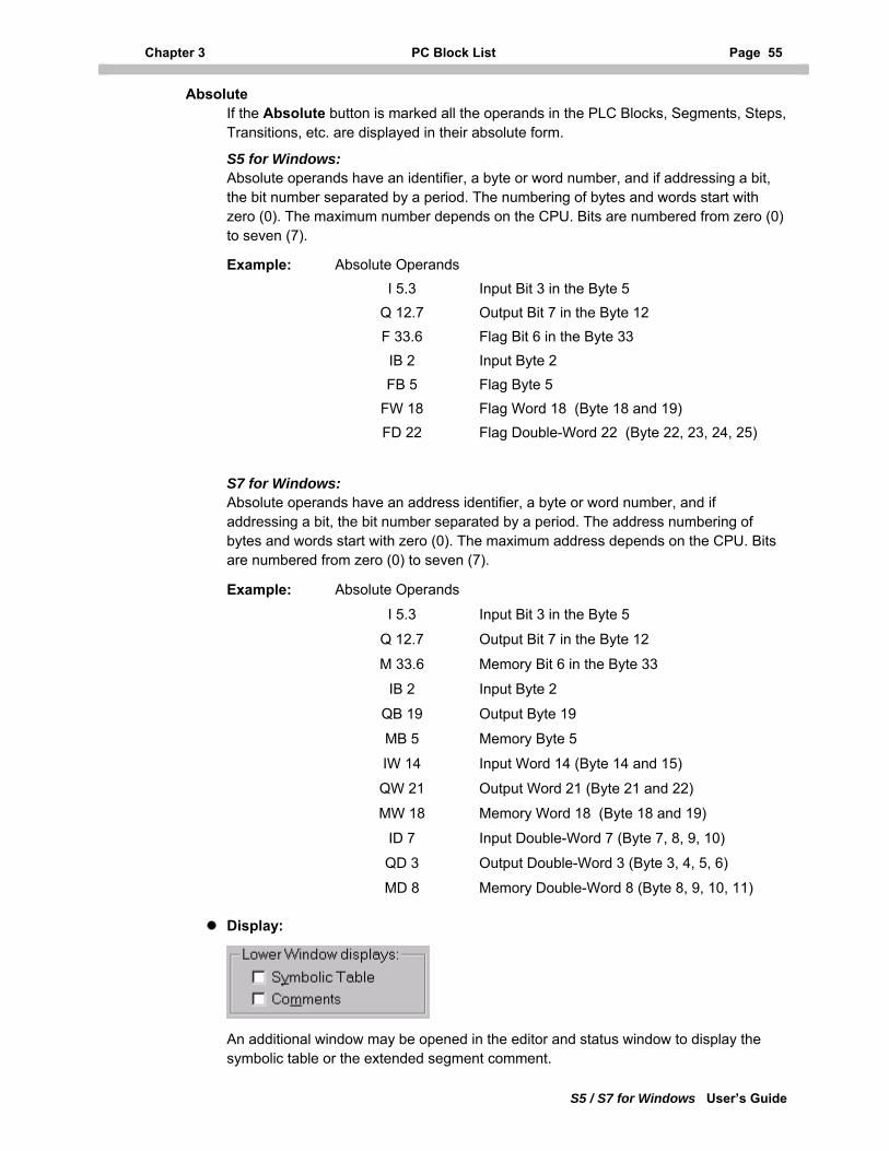
Chapter 3 PC Block List Page 55
S5 / S7 for Windows User’s Guide
Absolute If the Absolute button is marked all the operands in the PLC Blocks, Segments, Steps, Transitions, etc. are displayed in their absolute form.
S5 for Windows: Absolute operands have an identifier, a byte or word number, and if addressing a bit, the bit number separated by a period. The numbering of bytes and words start with zero (0). The maximum number depends on the CPU. Bits are numbered from zero (0) to seven (7).
Example: Absolute Operands I 5.3 Input Bit 3 in the Byte 5 Q 12.7 Output Bit 7 in the Byte 12 F 33.6 Flag Bit 6 in the Byte 33 IB 2 Input Byte 2 FB 5 Flag Byte 5 FW 18 Flag Word 18 (Byte 18 and 19) FD 22 Flag Double-Word 22 (Byte 22, 23, 24, 25)
S7 for Windows: Absolute operands have an address identifier, a byte or word number, and if addressing a bit, the bit number separated by a period. The address numbering of bytes and words start with zero (0). The maximum address depends on the CPU. Bits are numbered from zero (0) to seven (7).
Example: Absolute Operands
I 5.3 Input Bit 3 in the Byte 5
Q 12.7 Output Bit 7 in the Byte 12
M 33.6 Memory Bit 6 in the Byte 33
IB 2 Input Byte 2
QB 19 Output Byte 19
MB 5 Memory Byte 5
IW 14 Input Word 14 (Byte 14 and 15)
QW 21 Output Word 21 (Byte 21 and 22)
MW 18 Memory Word 18 (Byte 18 and 19)
ID 7 Input Double-Word 7 (Byte 7, 8, 9, 10)
QD 3 Output Double-Word 3 (Byte 3, 4, 5, 6)
MD 8 Memory Double-Word 8 (Byte 8, 9, 10, 11)
Display:
An additional window may be opened in the editor and status window to display the symbolic table or the extended segment comment.
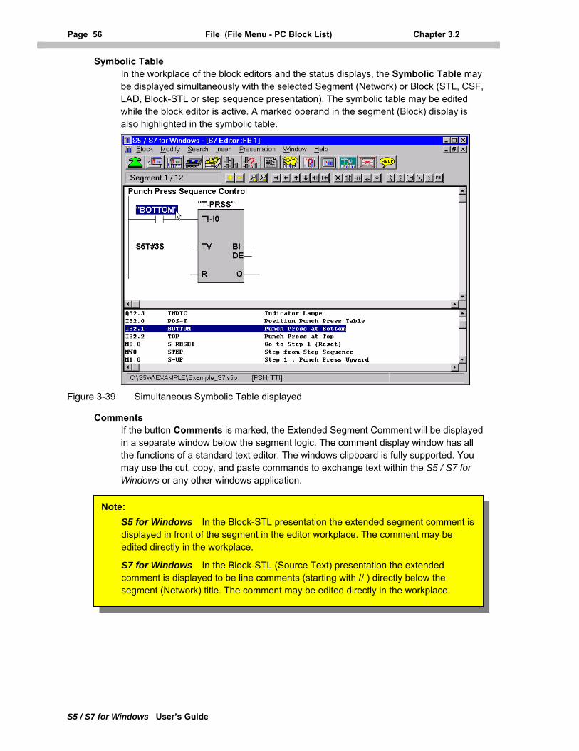
Page 56 File (File Menu - PC Block List) Chapter 3.2
S5 / S7 for Windows User’s Guide
Symbolic Table In the workplace of the block editors and the status displays, the Symbolic Table may be displayed simultaneously with the selected Segment (Network) or Block (STL, CSF, LAD, Block-STL or step sequence presentation). The symbolic table may be edited while the block editor is active. A marked operand in the segment (Block) display is also highlighted in the symbolic table.
Figure 3-39 Simultaneous Symbolic Table displayed
Comments If the button Comments is marked, the Extended Segment Comment will be displayed in a separate window below the segment logic. The comment display window has all the functions of a standard text editor. The windows clipboard is fully supported. You may use the cut, copy, and paste commands to exchange text within the S5 / S7 for Windows or any other windows application.
S5 for Windows In the Block-STL presentation the extended segment comment is displayed in front of the segment in the editor workplace. The comment may be edited directly in the workplace.
S7 for Windows In the Block-STL (Source Text) presentation the extended comment is displayed to be line comments (starting with // ) directly below the segment (Network) title. The comment may be edited directly in the workplace.
Note:
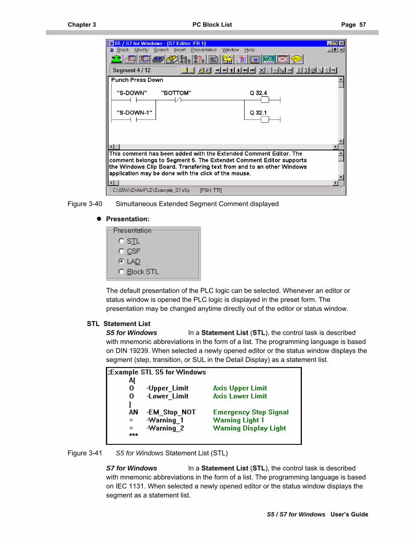
Chapter 3 PC Block List Page 57
S5 / S7 for Windows User’s Guide
Figure 3-40 Simultaneous Extended Segment Comment displayed
Presentation:
The default presentation of the PLC logic can be selected. Whenever an editor or status window is opened the PLC logic is displayed in the preset form. The presentation may be changed anytime directly out of the editor or status window.
STL Statement List S5 for Windows In a Statement List (STL), the control task is described with mnemonic abbreviations in the form of a list. The programming language is based on DIN 19239. When selected a newly opened editor or the status window displays the segment (step, transition, or SUL in the Detail Display) as a statement list.
Figure 3-41 S5 for Windows Statement List (STL)
S7 for Windows In a Statement List (STL), the control task is described with mnemonic abbreviations in the form of a list. The programming language is based on IEC 1131. When selected a newly opened editor or the status window displays the segment as a statement list.
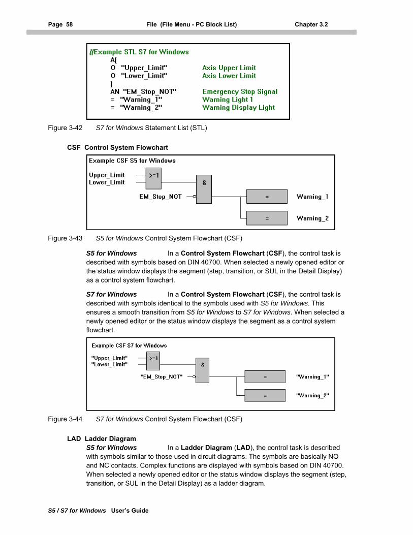
Page 58 File (File Menu - PC Block List) Chapter 3.2
S5 / S7 for Windows User’s Guide
Figure 3-42 S7 for Windows Statement List (STL)
CSF Control System Flowchart
Figure 3-43 S5 for Windows Control System Flowchart (CSF)
S5 for Windows In a Control System Flowchart (CSF), the control task is described with symbols based on DIN 40700. When selected a newly opened editor or the status window displays the segment (step, transition, or SUL in the Detail Display) as a control system flowchart.
S7 for Windows In a Control System Flowchart (CSF), the control task is described with symbols identical to the symbols used with S5 for Windows. This ensures a smooth transition from S5 for Windows to S7 for Windows. When selected a newly opened editor or the status window displays the segment as a control system flowchart.
Figure 3-44 S7 for Windows Control System Flowchart (CSF)
LAD Ladder Diagram S5 for Windows In a Ladder Diagram (LAD), the control task is described with symbols similar to those used in circuit diagrams. The symbols are basically NO and NC contacts. Complex functions are displayed with symbols based on DIN 40700. When selected a newly opened editor or the status window displays the segment (step, transition, or SUL in the Detail Display) as a ladder diagram.
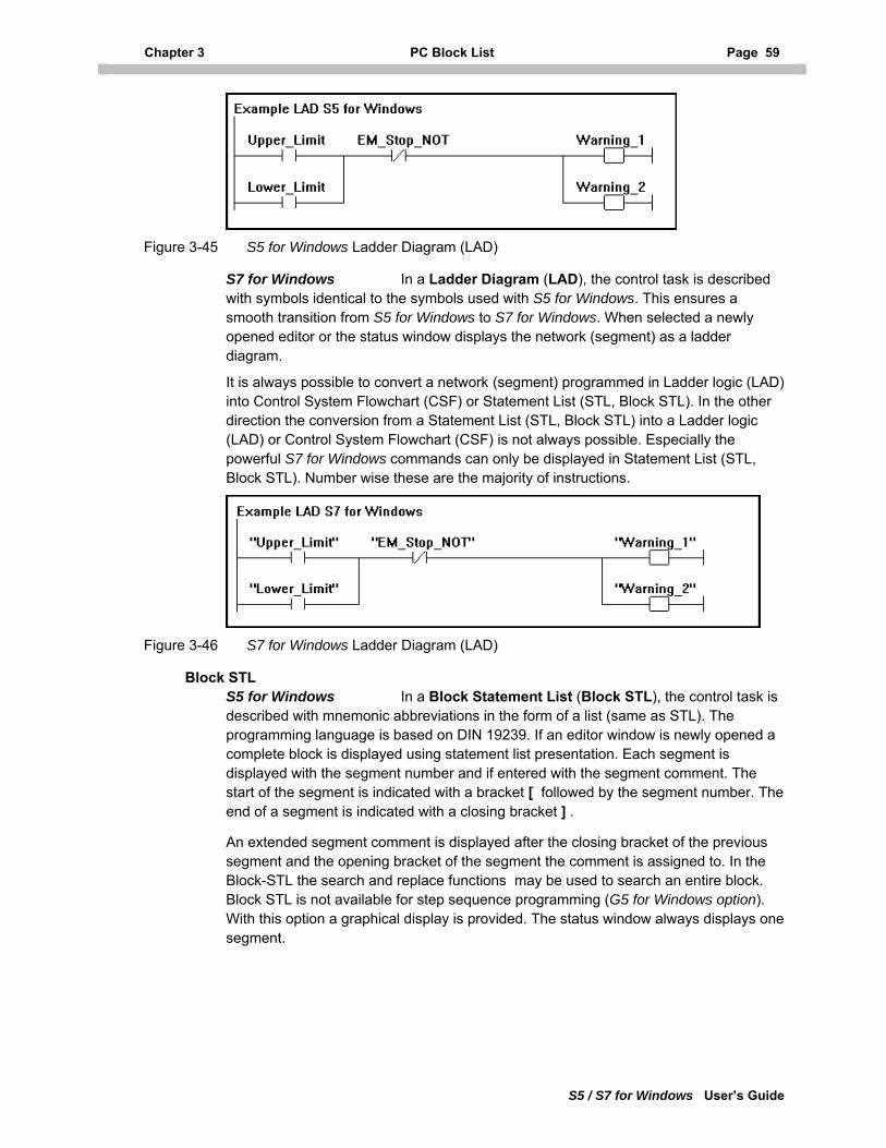
Chapter 3 PC Block List Page 59
S5 / S7 for Windows User’s Guide
Figure 3-45 S5 for Windows Ladder Diagram (LAD)
S7 for Windows In a Ladder Diagram (LAD), the control task is described with symbols identical to the symbols used with S5 for Windows. This ensures a smooth transition from S5 for Windows to S7 for Windows. When selected a newly opened editor or the status window displays the network (segment) as a ladder diagram.
It is always possible to convert a network (segment) programmed in Ladder logic (LAD) into Control System Flowchart (CSF) or Statement List (STL, Block STL). In the other direction the conversion from a Statement List (STL, Block STL) into a Ladder logic (LAD) or Control System Flowchart (CSF) is not always possible. Especially the powerful S7 for Windows commands can only be displayed in Statement List (STL, Block STL). Number wise these are the majority of instructions.
Figure 3-46 S7 for Windows Ladder Diagram (LAD)
Block STL S5 for Windows In a Block Statement List (Block STL), the control task is described with mnemonic abbreviations in the form of a list (same as STL). The programming language is based on DIN 19239. If an editor window is newly opened a complete block is displayed using statement list presentation. Each segment is displayed with the segment number and if entered with the segment comment. The start of the segment is indicated with a bracket [ followed by the segment number. The end of a segment is indicated with a closing bracket ] .
An extended segment comment is displayed after the closing bracket of the previous segment and the opening bracket of the segment the comment is assigned to. In the Block-STL the search and replace functions may be used to search an entire block. Block STL is not available for step sequence programming (G5 for Windows option). With this option a graphical display is provided. The status window always displays one segment.
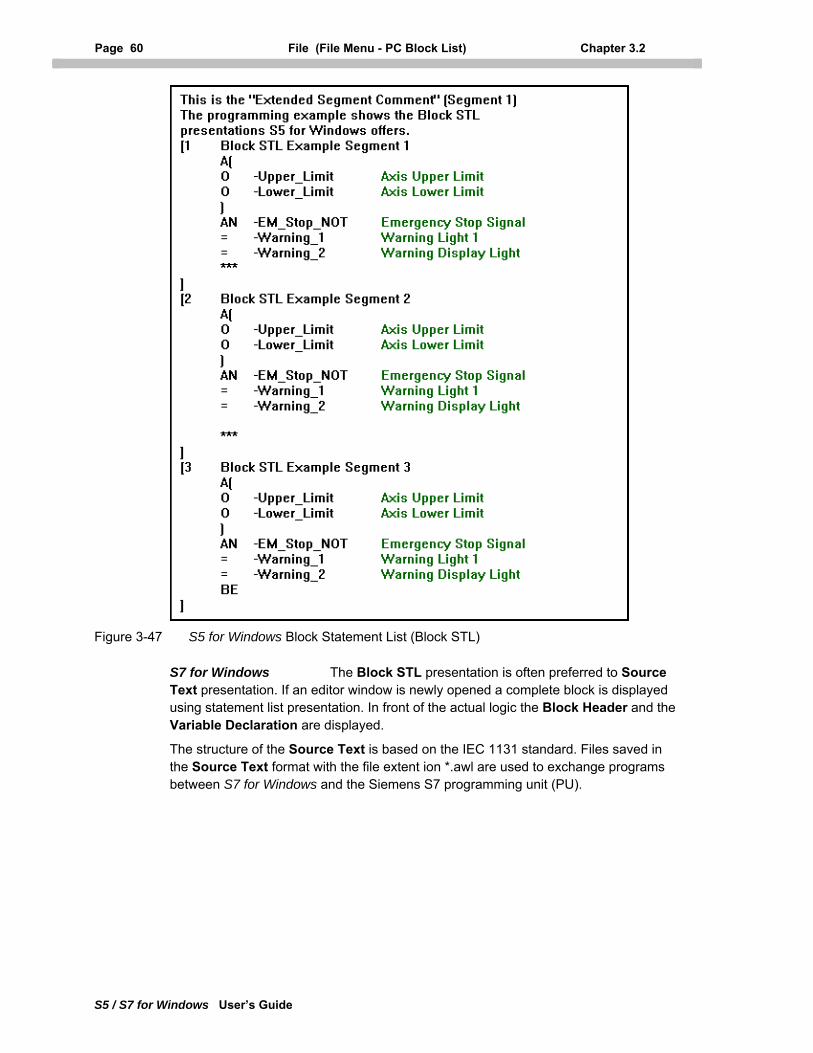
Page 60 File (File Menu - PC Block List) Chapter 3.2
S5 / S7 for Windows User’s Guide
Figure 3-47 S5 for Windows Block Statement List (Block STL)
S7 for Windows The Block STL presentation is often preferred to Source Text presentation. If an editor window is newly opened a complete block is displayed using statement list presentation. In front of the actual logic the Block Header and the Variable Declaration are displayed.
The structure of the Source Text is based on the IEC 1131 standard. Files saved in the Source Text format with the file extent ion *.awl are used to exchange programs between S7 for Windows and the Siemens S7 programming unit (PU).
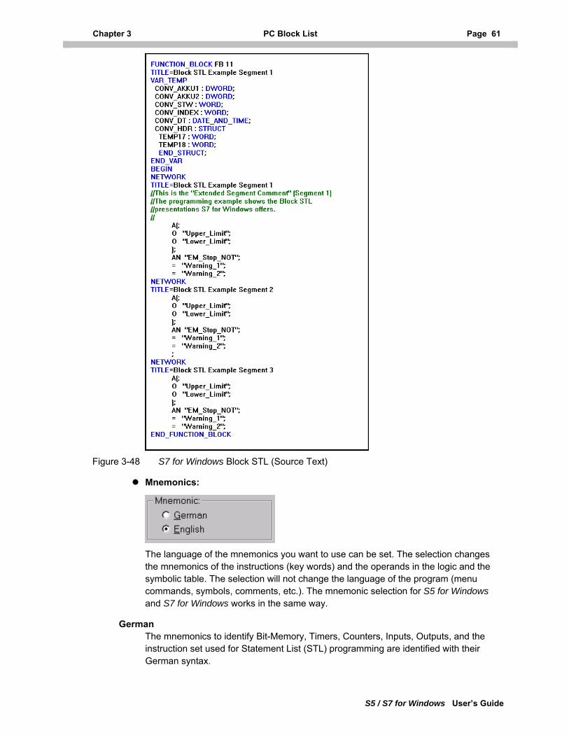
Chapter 3 PC Block List Page 61
S5 / S7 for Windows User’s Guide
Figure 3-48 S7 for Windows Block STL (Source Text)
Mnemonics:
The language of the mnemonics you want to use can be set. The selection changes the mnemonics of the instructions (key words) and the operands in the logic and the symbolic table. The selection will not change the language of the program (menu commands, symbols, comments, etc.). The mnemonic selection for S5 for Windows and S7 for Windows works in the same way.
German The mnemonics to identify Bit-Memory, Timers, Counters, Inputs, Outputs, and the instruction set used for Statement List (STL) programming are identified with their German syntax.
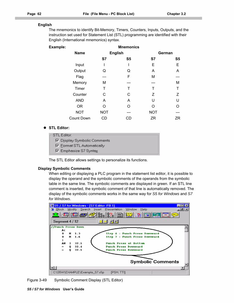
Page 62 File (File Menu - PC Block List) Chapter 3.2
S5 / S7 for Windows User’s Guide
English The mnemonics to identify Bit-Memory, Timers, Counters, Inputs, Outputs, and the instruction set used for Statement List (STL) programming are identified with their English (International mnemonics) syntax.
Example: Mnemonics Name English German S7 S5 S7 S5
Input I I E E Output Q Q A A Flag --- F M --- Memory M --- --- M Timer T T T T Counter C C Z Z AND A A U U OR O O O O NOT NOT --- NOT --- Count Down CD CD ZR ZR
STL Editor:
The STL Editor allows settings to personalize its functions.
Display Symbolic Comments When editing or displaying a PLC program in the statement list editor, it is possible to display the operand and the symbolic comments of the operands from the symbolic table in the same line. The symbolic comments are displayed in green. If an STL line comment is inserted, the symbolic comment of that line is automatically removed. The display of the symbolic comments works in the same way for S5 for Windows and S7 for Windows.
Figure 3-49 Symbolic Comment Display (STL Editor)
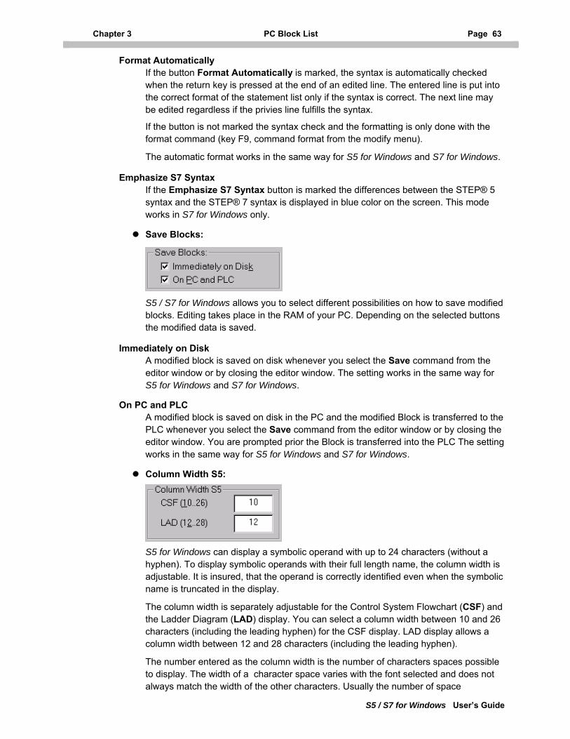
Chapter 3 PC Block List Page 63
S5 / S7 for Windows User’s Guide
Format Automatically If the button Format Automatically is marked, the syntax is automatically checked when the return key is pressed at the end of an edited line. The entered line is put into the correct format of the statement list only if the syntax is correct. The next line may be edited regardless if the privies line fulfills the syntax.
If the button is not marked the syntax check and the formatting is only done with the format command (key F9, command format from the modify menu).
The automatic format works in the same way for S5 for Windows and S7 for Windows.
Emphasize S7 Syntax If the Emphasize S7 Syntax button is marked the differences between the STEP® 5 syntax and the STEP® 7 syntax is displayed in blue color on the screen. This mode works in S7 for Windows only.
Save Blocks:
S5 / S7 for Windows allows you to select different possibilities on how to save modified blocks. Editing takes place in the RAM of your PC. Depending on the selected buttons the modified data is saved.
Immediately on Disk A modified block is saved on disk whenever you select the Save command from the editor window or by closing the editor window. The setting works in the same way for S5 for Windows and S7 for Windows.
On PC and PLC A modified block is saved on disk in the PC and the modified Block is transferred to the PLC whenever you select the Save command from the editor window or by closing the editor window. You are prompted prior the Block is transferred into the PLC The setting works in the same way for S5 for Windows and S7 for Windows.
Column Width S5:
S5 for Windows can display a symbolic operand with up to 24 characters (without a hyphen). To display symbolic operands with their full length name, the column width is adjustable. It is insured, that the operand is correctly identified even when the symbolic name is truncated in the display.
The column width is separately adjustable for the Control System Flowchart (CSF) and the Ladder Diagram (LAD) display. You can select a column width between 10 and 26 characters (including the leading hyphen) for the CSF display. LAD display allows a column width between 12 and 28 characters (including the leading hyphen).
The number entered as the column width is the number of characters spaces possible to display. The width of a character space varies with the font selected and does not always match the width of the other characters. Usually the number of space
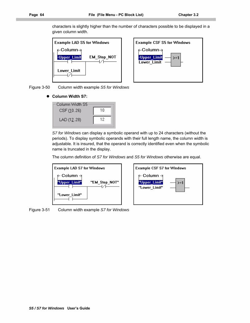
Page 64 File (File Menu - PC Block List) Chapter 3.2
S5 / S7 for Windows User’s Guide
characters is slightly higher than the number of characters possible to be displayed in a given column width.
Figure 3-50 Column width example S5 for Windows
Column Width S7:
S7 for Windows can display a symbolic operand with up to 24 characters (without the periods). To display symbolic operands with their full length name, the column width is adjustable. It is insured, that the operand is correctly identified even when the symbolic name is truncated in the display.
The column definition of S7 for Windows and S5 for Windows otherwise are equal.
Figure 3-51 Column width example S7 for Windows
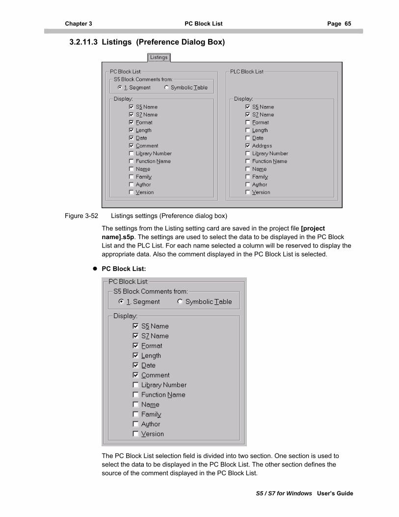
Chapter 3 PC Block List Page 65
S5 / S7 for Windows User’s Guide
3.2.11.3 Listings (Preference Dialog Box)
Figure 3-52 Listings settings (Preference dialog box)
The settings from the Listing setting card are saved in the project file [project name].s5p. The settings are used to select the data to be displayed in the PC Block List and the PLC List. For each name selected a column will be reserved to display the appropriate data. Also the comment displayed in the PC Block List is selected.
PC Block List:
The PC Block List selection field is divided into two section. One section is used to select the data to be displayed in the PC Block List. The other section defines the source of the comment displayed in the PC Block List.
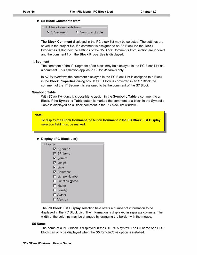
Page 66 File (File Menu - PC Block List) Chapter 3.2
S5 / S7 for Windows User’s Guide
S5 Block Comments from:
The Block Comment displayed in the PC block list may be selected. The settings are saved in the project file. If a comment is assigned to an S5 Block via the Block Properties dialog box the settings of the S5 Block Comments from section are ignored and the comment from the Block Properties is displayed.
1. Segment The comment of the 1st Segment of an block may be displayed in the PC Block List as a comment. This selection applies to S5 for Windows only.
In S7 for Windows the comment displayed in the PC Block List is assigned to a Block in the Block Properties dialog box. If a S5 Block is converted in an S7 Block the comment of the 1st Segment is assigned to be the comment of the S7 Block.
Symbolic Table With S5 for Windows it is possible to assign in the Symbolic Table a comment to a Block. If the Symbolic Table button is marked the comment to a block in the Symbolic Table is displayed as a Block comment in the PC block list window.
Note: To display the Block Comment the button Comment in the PC Block List Display selection field must be marked.
Display (PC Block List):
The PC Block List Display selection field offers a number of information to be displayed in the PC Block List. The information is displayed in separate columns. The width of the columns may be changed by dragging the border with the mouse.
S5 Name The name of a PLC Block is displayed in the STEP® 5 syntax. The S5 name of a PLC Block can only be displayed when the S5 for Windows option is installed.
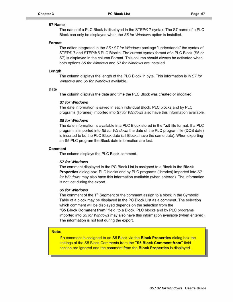
Chapter 3 PC Block List Page 67
S5 / S7 for Windows User’s Guide
S7 Name The name of a PLC Block is displayed in the STEP® 7 syntax. The S7 name of a PLC Block can only be displayed when the S5 for Windows option is installed.
Format The editor integrated in the S5 / S7 for Windows package "understands" the syntax of STEP® 7 and STEP® 5 PLC Blocks. The current syntax format of a PLC Block (S5 or S7) is displayed in the column Format. This column should always be activated when both options S5 for Windows and S7 for Windows are installed.
Length The column displays the length of the PLC Block in byte. This information is in S7 for Windows and S5 for Windows available.
Date The column displays the date and time the PLC Block was created or modified.
S7 for Windows The date information is saved in each individual Block. PLC blocks and by PLC programs (libraries) imported into S7 for Windows also have this information available.
S5 for Windows The date information is available in a PLC Block stored in the *.s5 file format. If a PLC program is imported into S5 for Windows the date of the PLC program file (DOS date) is inserted to be the PLC Block date (all Blocks have the same date). When exporting an S5 PLC program the Block date information are lost.
Comment The column displays the PLC Block comment.
S7 for Windows The comment displayed in the PC Block List is assigned to a Block in the Block Properties dialog box. PLC blocks and by PLC programs (libraries) imported into S7 for Windows may also have this information available (when entered). The information is not lost during the export.
S5 for Windows The comment of the 1st Segment or the comment assign to a block in the Symbolic Table of a block may be displayed in the PC Block List as a comment. The selection which comment will be displayed depends on the selection from the "S5 Block Comment from" field. to a Block. PLC blocks and by PLC programs imported into S5 for Windows may also have this information available (when entered). The information is not lost during the export.
Note: If a comment is assigned to an S5 Block via the Block Properties dialog box the settings of the S5 Block Comments from the "S5 Block Comment from" field section are ignored and the comment from the Block Properties is displayed.
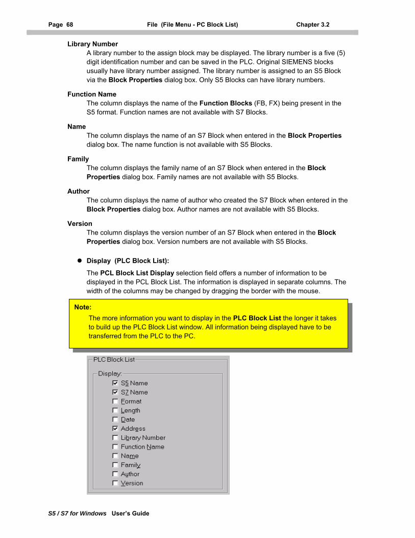
Page 68 File (File Menu - PC Block List) Chapter 3.2
S5 / S7 for Windows User’s Guide
Library Number A library number to the assign block may be displayed. The library number is a five (5) digit identification number and can be saved in the PLC. Original SIEMENS blocks usually have library number assigned. The library number is assigned to an S5 Block via the Block Properties dialog box. Only S5 Blocks can have library numbers.
Function Name The column displays the name of the Function Blocks (FB, FX) being present in the S5 format. Function names are not available with S7 Blocks.
Name The column displays the name of an S7 Block when entered in the Block Properties dialog box. The name function is not available with S5 Blocks.
Family The column displays the family name of an S7 Block when entered in the Block Properties dialog box. Family names are not available with S5 Blocks.
Author The column displays the name of author who created the S7 Block when entered in the Block Properties dialog box. Author names are not available with S5 Blocks.
Version The column displays the version number of an S7 Block when entered in the Block Properties dialog box. Version numbers are not available with S5 Blocks.
Display (PLC Block List):
The PCL Block List Display selection field offers a number of information to be displayed in the PCL Block List. The information is displayed in separate columns. The width of the columns may be changed by dragging the border with the mouse.
Note: The more information you want to display in the PLC Block List the longer it takes to build up the PLC Block List window. All information being displayed have to be transferred from the PLC to the PC.
Chapter 3 PC Block List Page 69
S5 / S7 for Windows User’s Guide
S5 Name The PLC Block being recognized in the online PLC is displayed in the STEP® 5 name. The S5 name of a PLC Block can only be displayed online when the S5 for Windows option is installed.
S7 Name The PLC Block being recognized in the online PLC is displayed with its STEP® 7 name. The S7 name of a PLC Block can only be displayed online when the S7 for Windows option is installed.
Format This column indicates in which format the corresponding PLC Block is currently present in the PC Block List. Blocks being present in the S5 format may be displayed in the status display in their S5 syntax even being online with an S7-300/400 PLC. This column should always be activated when both options S5 for Windows and S7 for Windows are installed.
Length The column displays the amount of memory the PLC Block occupies in the PLC in byte. This information is online available with an S7-300/400 as well as with an S5 PLC.
Date The column displays the date and time the PLC Block was created or modified online. This information is only in conjunction with S7 Blocks online available.
Address The column displays the PLC Block addresses.
S7 for Windows The address displayed in the PLC Block List online is the relative address within the Block. The S7-300/400 PLC does not support absolute addresses.
S5 for Windows The address displayed in the PLC Block List online is the absolute address within the PLC Memory. The addresses change whenever additional Blocks are loaded into the PLC.
Library Number The library number is a five (5) digit identification number saved in the PLC. Only S5 PLC's know library numbers.
Function Name The column displays the name of the Function Blocks (FB, FX) being present in the S5 PLC if an identical Function Block (FB, FX) is present in the PC Block List. Function names are not available with S7 Blocks.
Name The column displays the name of S7 Block online when the name is saved in the S7-300/400 PLC. The name function is not available with S5 Blocks.
Family This column displays the family name of S7 Block online when the family name is saved in the S7-300/400 PLC. Family names are not available with S5 Blocks.
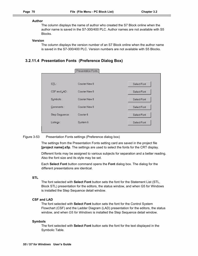
Page 70 File (File Menu - PC Block List) Chapter 3.2
S5 / S7 for Windows User’s Guide
Author The column displays the name of author who created the S7 Block online when the author name is saved in the S7-300/400 PLC. Author names are not available with S5 Blocks.
Version The column displays the version number of an S7 Block online when the author name is saved in the S7-300/400 PLC. Version numbers are not available with S5 Blocks.
3.2.11.4 Presentation Fonts (Preference Dialog Box)
Figure 3-53 Presentation Fonts settings (Preference dialog box)
The settings from the Presentation Fonts setting card are saved in the project file [project name].s5p. The settings are used to select the fonts for the CRT display.
Different fonts may be assigned to various subjects for separation and a better reading. Also the font size and its style may be set.
Each Select Font button command opens the Font dialog box. The dialog for the different presentations are identical.
STL The font selected with Select Font button sets the font for the Statement List (STL, Block STL) presentation for the editors, the status window, and when G5 for Windows is installed the Step Sequence detail window.
CSF and LAD The font selected with Select Font button sets the font for the Control System Flowchart (CSF) and the Ladder Diagram (LAD) presentation for the editors, the status window, and when G5 for Windows is installed the Step Sequence detail window.
Symbols The font selected with Select Font button sets the font for the text displayed in the Symbolic Table.
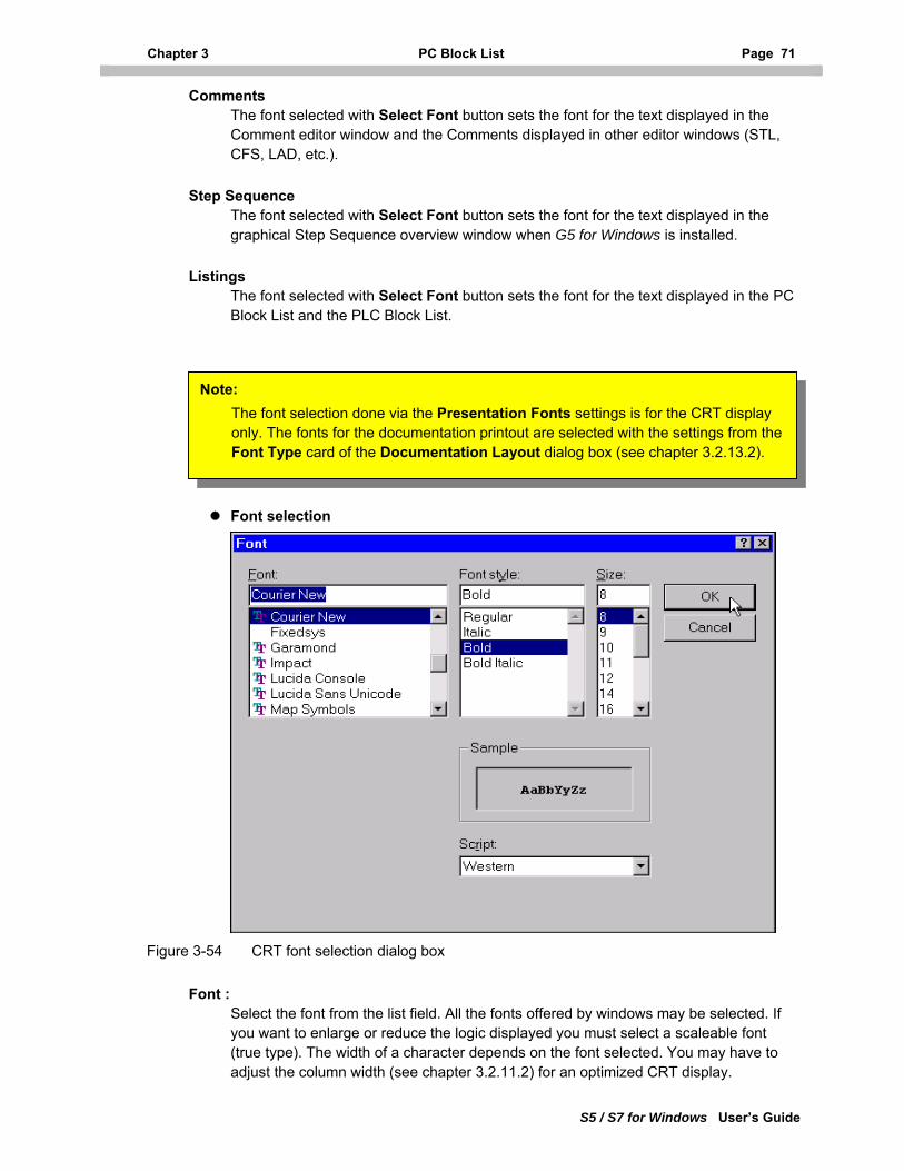
Chapter 3 PC Block List Page 71
S5 / S7 for Windows User’s Guide
Comments The font selected with Select Font button sets the font for the text displayed in the Comment editor window and the Comments displayed in other editor windows (STL, CFS, LAD, etc.).
Step Sequence The font selected with Select Font button sets the font for the text displayed in the graphical Step Sequence overview window when G5 for Windows is installed.
Listings The font selected with Select Font button sets the font for the text displayed in the PC Block List and the PLC Block List.
Note: The font selection done via the Presentation Fonts settings is for the CRT display only. The fonts for the documentation printout are selected with the settings from the Font Type card of the Documentation Layout dialog box (see chapter 3.2.13.2).
Font selection
Figure 3-54 CRT font selection dialog box
Font : Select the font from the list field. All the fonts offered by windows may be selected. If you want to enlarge or reduce the logic displayed you must select a scaleable font (true type). The width of a character depends on the font selected. You may have to adjust the column width (see chapter 3.2.11.2) for an optimized CRT display.
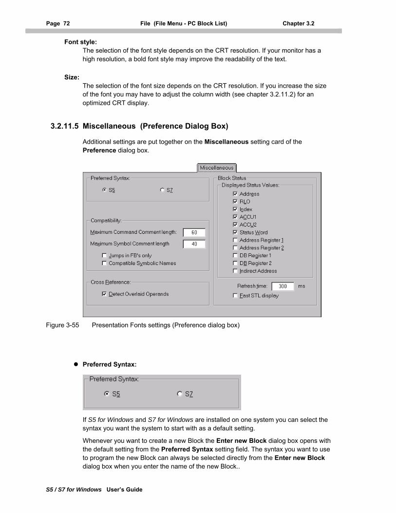
Page 72 File (File Menu - PC Block List) Chapter 3.2
S5 / S7 for Windows User’s Guide
Font style: The selection of the font style depends on the CRT resolution. If your monitor has a high resolution, a bold font style may improve the readability of the text.
Size: The selection of the font size depends on the CRT resolution. If you increase the size of the font you may have to adjust the column width (see chapter 3.2.11.2) for an optimized CRT display.
3.2.11.5 Miscellaneous (Preference Dialog Box)
Additional settings are put together on the Miscellaneous setting card of the Preference dialog box.
Figure 3-55 Presentation Fonts settings (Preference dialog box)
Preferred Syntax:
If S5 for Windows and S7 for Windows are installed on one system you can select the syntax you want the system to start with as a default setting.
Whenever you want to create a new Block the Enter new Block dialog box opens with the default setting from the Preferred Syntax setting field. The syntax you want to use to program the new Block can always be selected directly from the Enter new Block dialog box when you enter the name of the new Block..
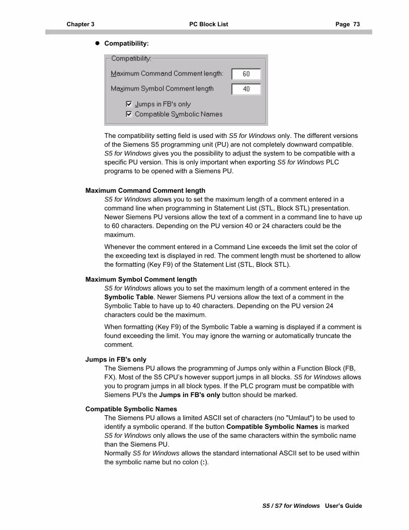
Chapter 3 PC Block List Page 73
S5 / S7 for Windows User’s Guide
Compatibility:
The compatibility setting field is used with S5 for Windows only. The different versions of the Siemens S5 programming unit (PU) are not completely downward compatible. S5 for Windows gives you the possibility to adjust the system to be compatible with a specific PU version. This is only important when exporting S5 for Windows PLC programs to be opened with a Siemens PU.
Maximum Command Comment length S5 for Windows allows you to set the maximum length of a comment entered in a command line when programming in Statement List (STL, Block STL) presentation. Newer Siemens PU versions allow the text of a comment in a command line to have up to 60 characters. Depending on the PU version 40 or 24 characters could be the maximum.
Whenever the comment entered in a Command Line exceeds the limit set the color of the exceeding text is displayed in red. The comment length must be shortened to allow the formatting (Key F9) of the Statement List (STL, Block STL).
Maximum Symbol Comment length S5 for Windows allows you to set the maximum length of a comment entered in the Symbolic Table. Newer Siemens PU versions allow the text of a comment in the Symbolic Table to have up to 40 characters. Depending on the PU version 24 characters could be the maximum.
When formatting (Key F9) of the Symbolic Table a warning is displayed if a comment is found exceeding the limit. You may ignore the warning or automatically truncate the comment.
Jumps in FB's only The Siemens PU allows the programming of Jumps only within a Function Block (FB, FX). Most of the S5 CPU’s however support jumps in all blocks. S5 for Windows allows you to program jumps in all block types. If the PLC program must be compatible with Siemens PU's the Jumps in FB's only button should be marked.
Compatible Symbolic Names The Siemens PU allows a limited ASCII set of characters (no "Umlaut") to be used to identify a symbolic operand. If the button Compatible Symbolic Names is marked S5 for Windows only allows the use of the same characters within the symbolic name than the Siemens PU. Normally S5 for Windows allows the standard international ASCII set to be used within the symbolic name but no colon (:).
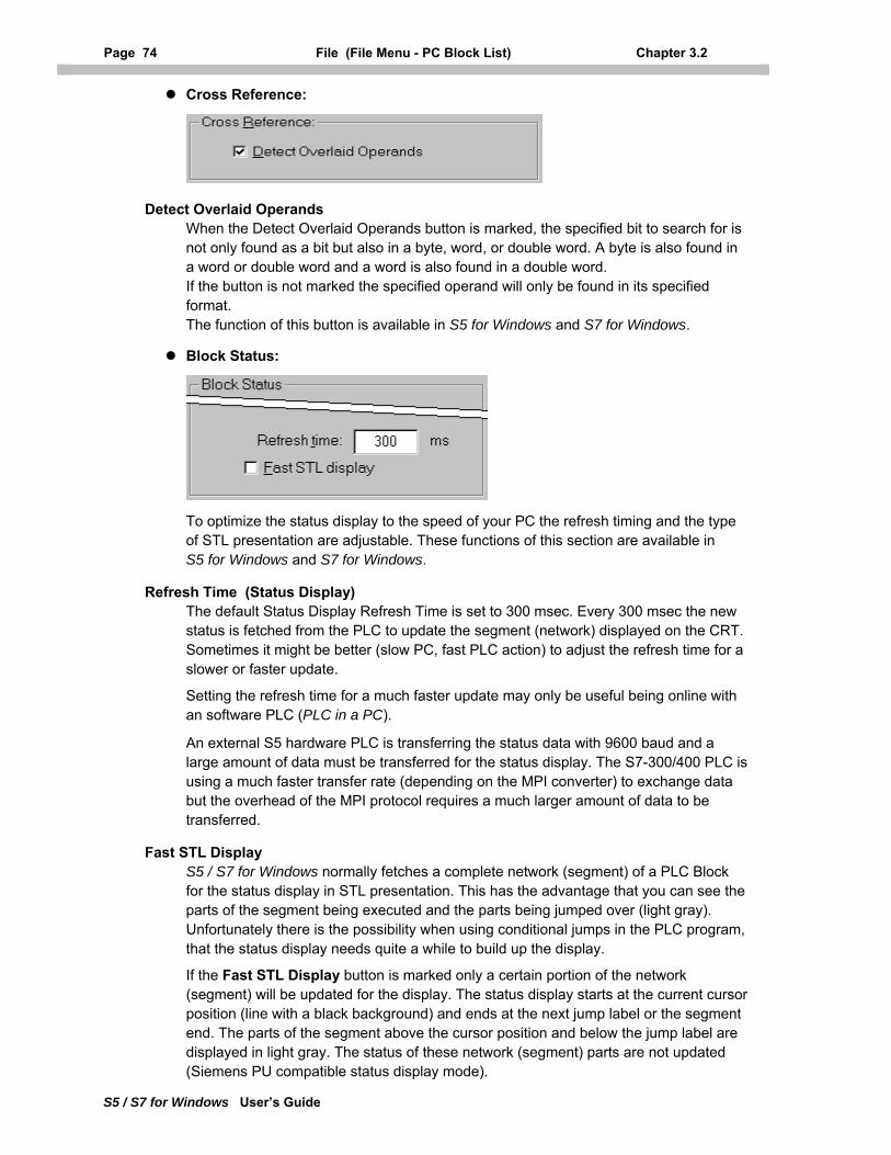
Page 74 File (File Menu - PC Block List) Chapter 3.2
S5 / S7 for Windows User’s Guide
Cross Reference:
Detect Overlaid Operands When the Detect Overlaid Operands button is marked, the specified bit to search for is not only found as a bit but also in a byte, word, or double word. A byte is also found in a word or double word and a word is also found in a double word. If the button is not marked the specified operand will only be found in its specified format. The function of this button is available in S5 for Windows and S7 for Windows.
Block Status:
To optimize the status display to the speed of your PC the refresh timing and the type of STL presentation are adjustable. These functions of this section are available in S5 for Windows and S7 for Windows.
Refresh Time (Status Display) The default Status Display Refresh Time is set to 300 msec. Every 300 msec the new status is fetched from the PLC to update the segment (network) displayed on the CRT. Sometimes it might be better (slow PC, fast PLC action) to adjust the refresh time for a slower or faster update.
Setting the refresh time for a much faster update may only be useful being online with an software PLC (PLC in a PC).
An external S5 hardware PLC is transferring the status data with 9600 baud and a large amount of data must be transferred for the status display. The S7-300/400 PLC is using a much faster transfer rate (depending on the MPI converter) to exchange data but the overhead of the MPI protocol requires a much larger amount of data to be transferred.
Fast STL Display S5 / S7 for Windows normally fetches a complete network (segment) of a PLC Block for the status display in STL presentation. This has the advantage that you can see the parts of the segment being executed and the parts being jumped over (light gray). Unfortunately there is the possibility when using conditional jumps in the PLC program, that the status display needs quite a while to build up the display.
If the Fast STL Display button is marked only a certain portion of the network (segment) will be updated for the display. The status display starts at the current cursor position (line with a black background) and ends at the next jump label or the segment end. The parts of the segment above the cursor position and below the jump label are displayed in light gray. The status of these network (segment) parts are not updated (Siemens PU compatible status display mode).
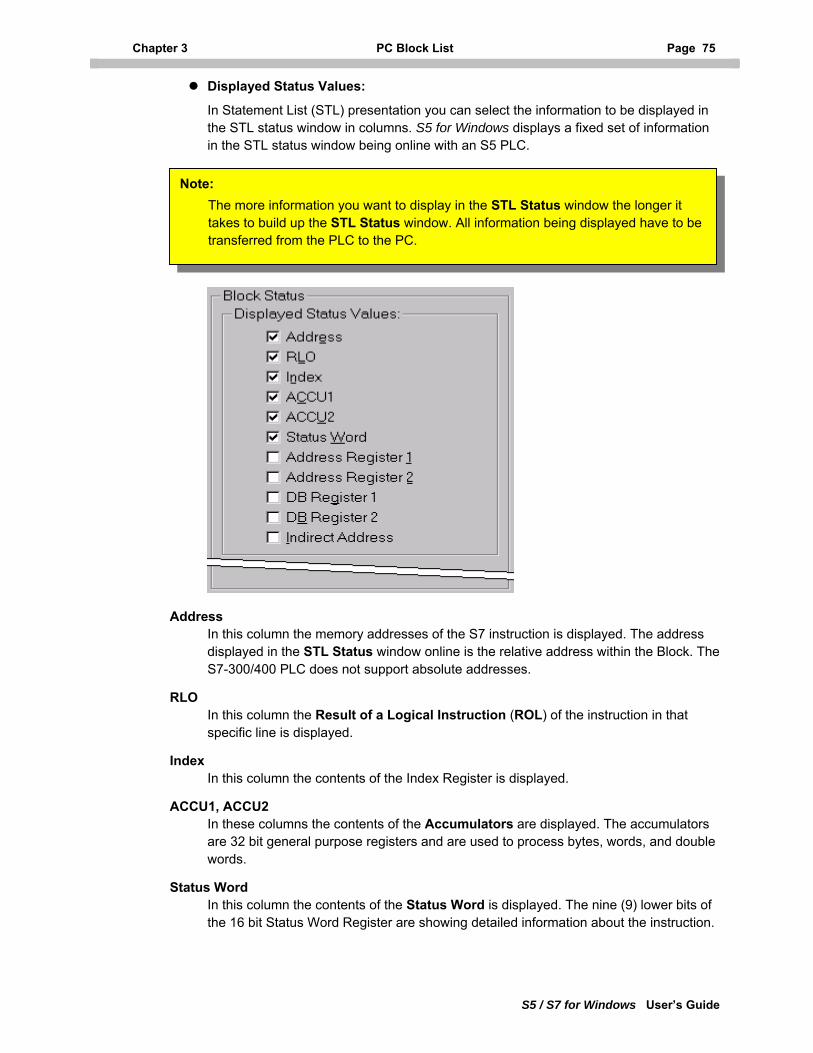
Chapter 3 PC Block List Page 75
S5 / S7 for Windows User’s Guide
Displayed Status Values:
In Statement List (STL) presentation you can select the information to be displayed in the STL status window in columns. S5 for Windows displays a fixed set of information in the STL status window being online with an S5 PLC.
Note: The more information you want to display in the STL Status window the longer it takes to build up the STL Status window. All information being displayed have to be transferred from the PLC to the PC.
Address In this column the memory addresses of the S7 instruction is displayed. The address displayed in the STL Status window online is the relative address within the Block. The S7-300/400 PLC does not support absolute addresses.
RLO In this column the Result of a Logical Instruction (ROL) of the instruction in that specific line is displayed.
Index In this column the contents of the Index Register is displayed.
ACCU1, ACCU2 In these columns the contents of the Accumulators are displayed. The accumulators are 32 bit general purpose registers and are used to process bytes, words, and double words.
Status Word In this column the contents of the Status Word is displayed. The nine (9) lower bits of the 16 bit Status Word Register are showing detailed information about the instruction.
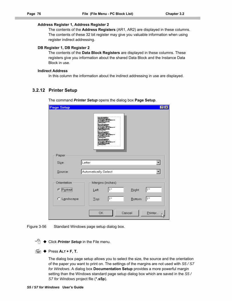
Page 76 File (File Menu - PC Block List) Chapter 3.2
S5 / S7 for Windows User’s Guide
Address Register 1, Address Register 2 The contents of the Address Registers (AR1, AR2) are displayed in these columns. The contents of these 32 bit register may give you valuable information when using register indirect addressing.
DB Register 1, DB Register 2 The contents of the Data Block Registers are displayed in these columns. These registers give you information about the shared Data Block and the Instance Data Block in use.
Indirect Address In this column the information about the indirect addressing in use are displayed.
3.2.12 Printer Setup
The command Printer Setup opens the dialog box Page Setup.
Figure 3-56 Standard Windows page setup dialog box.
Click Printer Setup in the File menu.
Press ALT + F, T.
The dialog box page setup allows you to select the size, the source and the orientation of the paper you want to print on. The settings of the margins are not used with S5 / S7 for Windows. A dialog box Documentation Setup provides a more powerful margin setting than the Windows standard page setup dialog box which are saved in the S5 / S7 for Windows project file (*.s5p).
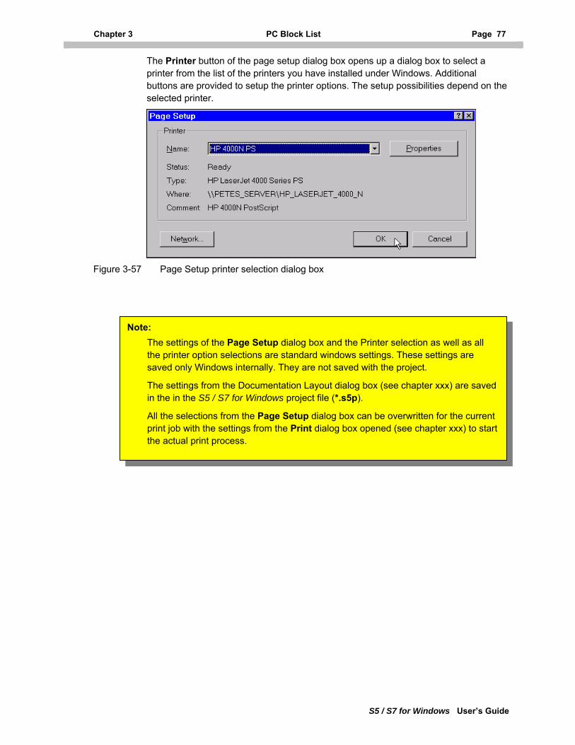
Chapter 3 PC Block List Page 77
S5 / S7 for Windows User’s Guide
The Printer button of the page setup dialog box opens up a dialog box to select a printer from the list of the printers you have installed under Windows. Additional buttons are provided to setup the printer options. The setup possibilities depend on the selected printer.
Figure 3-57 Page Setup printer selection dialog box
The settings from the Documentation Layout dialog box (see chapter xxx) are saved in the in the S5 / S7 for Windows project file (*.s5p).
All the selections from the Page Setup dialog box can be overwritten for the current print job with the settings from the Print dialog box opened (see chapter xxx) to start the actual print process.
Note: The settings of the Page Setup dialog box and the Printer selection as well as all the printer option selections are standard windows settings. These settings are saved only Windows internally. They are not saved with the project.
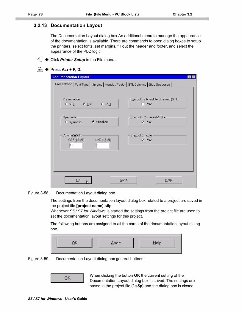
Page 78 File (File Menu - PC Block List) Chapter 3.2
S5 / S7 for Windows User’s Guide
3.2.13 Documentation Layout
The Documentation Layout dialog box An additional menu to manage the appearance of the documentation is available. There are commands to open dialog boxes to setup the printers, select fonts, set margins, fill out the header and footer, and select the appearance of the PLC logic.
Click Printer Setup in the File menu.
Press ALT + F, D.
Figure 3-58 Documentation Layout dialog box
The settings from the documentation layout dialog box related to a project are saved in the project file [project name].s5p. Whenever S5 / S7 for Windows is started the settings from the project file are used to set the documentation layout settings for this project.
The following buttons are assigned to all the cards of the documentation layout dialog box.
Figure 3-59 Documentation Layout dialog box general buttons
When clicking the button OK the current setting of the Documentation Layout dialog box is saved. The settings are saved in the project file (*.s5p) and the dialog box is closed.
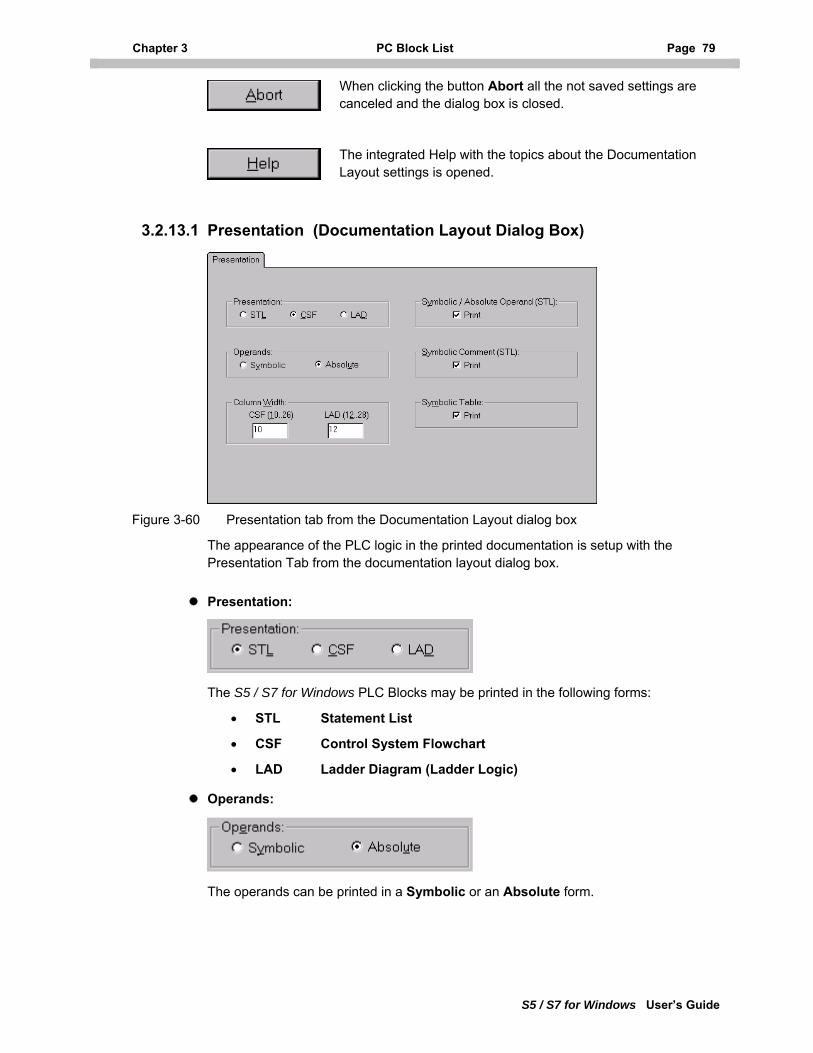
Chapter 3 PC Block List Page 79
S5 / S7 for Windows User’s Guide
When clicking the button Abort all the not saved settings are canceled and the dialog box is closed.
The integrated Help with the topics about the Documentation Layout settings is opened.
3.2.13.1 Presentation (Documentation Layout Dialog Box)
Figure 3-60 Presentation tab from the Documentation Layout dialog box
The appearance of the PLC logic in the printed documentation is setup with the Presentation Tab from the documentation layout dialog box.
Presentation:
The S5 / S7 for Windows PLC Blocks may be printed in the following forms:
• STL Statement List
• CSF Control System Flowchart
• LAD Ladder Diagram (Ladder Logic)
Operands:
The operands can be printed in a Symbolic or an Absolute form.
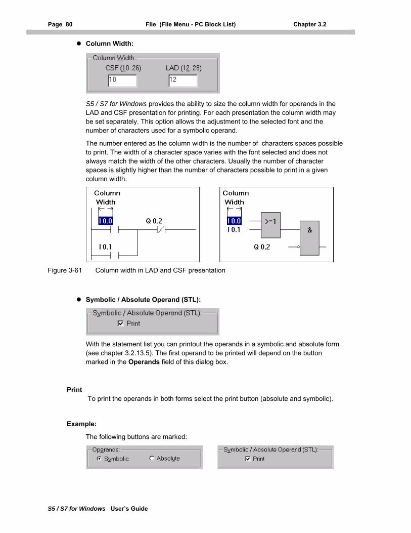
Page 80 File (File Menu - PC Block List) Chapter 3.2
S5 / S7 for Windows User’s Guide
Column Width:
S5 / S7 for Windows provides the ability to size the column width for operands in the LAD and CSF presentation for printing. For each presentation the column width may be set separately. This option allows the adjustment to the selected font and the number of characters used for a symbolic operand.
The number entered as the column width is the number of characters spaces possible to print. The width of a character space varies with the font selected and does not always match the width of the other characters. Usually the number of character spaces is slightly higher than the number of characters possible to print in a given column width.
Figure 3-61 Column width in LAD and CSF presentation
Symbolic / Absolute Operand (STL):
With the statement list you can printout the operands in a symbolic and absolute form (see chapter 3.2.13.5). The first operand to be printed will depend on the button marked in the Operands field of this dialog box.
Print To print the operands in both forms select the print button (absolute and symbolic).
Example:
The following buttons are marked:
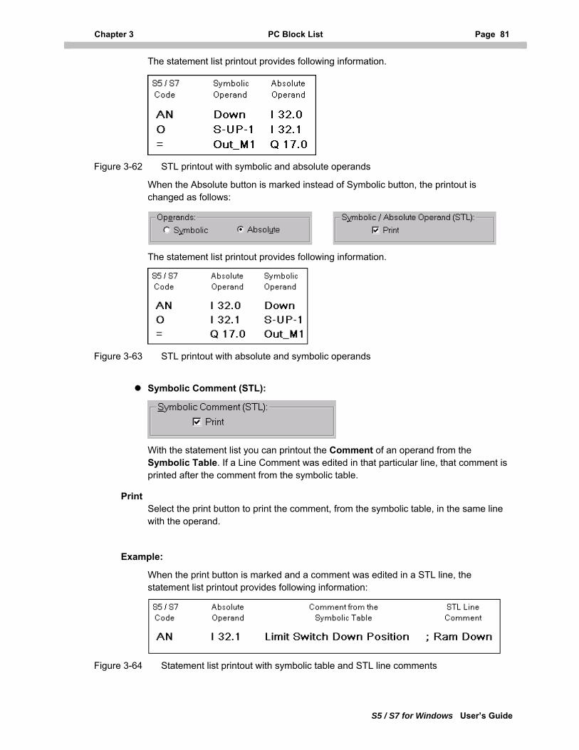
Chapter 3 PC Block List Page 81
S5 / S7 for Windows User’s Guide
The statement list printout provides following information.
Figure 3-62 STL printout with symbolic and absolute operands
When the Absolute button is marked instead of Symbolic button, the printout is changed as follows:
The statement list printout provides following information.
Figure 3-63 STL printout with absolute and symbolic operands
Symbolic Comment (STL):
With the statement list you can printout the Comment of an operand from the Symbolic Table. If a Line Comment was edited in that particular line, that comment is printed after the comment from the symbolic table.
Print Select the print button to print the comment, from the symbolic table, in the same line with the operand.
Example:
When the print button is marked and a comment was edited in a STL line, the statement list printout provides following information:
Figure 3-64 Statement list printout with symbolic table and STL line comments
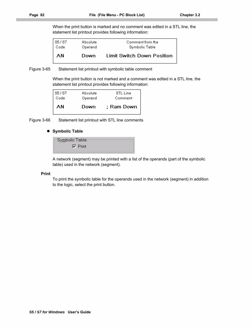
Page 82 File (File Menu - PC Block List) Chapter 3.2
S5 / S7 for Windows User’s Guide
When the print button is marked and no comment was edited in a STL line, the statement list printout provides following information:
Figure 3-65 Statement list printout with symbolic table comment
When the print button is not marked and a comment was edited in a STL line, the statement list printout provides following information:
Figure 3-66 Statement list printout with STL line comments
Symbolic Table
A network (segment) may be printed with a list of the operands (part of the symbolic table) used in the network (segment).
Print To print the symbolic table for the operands used in the network (segment) in addition to the logic, select the print button.
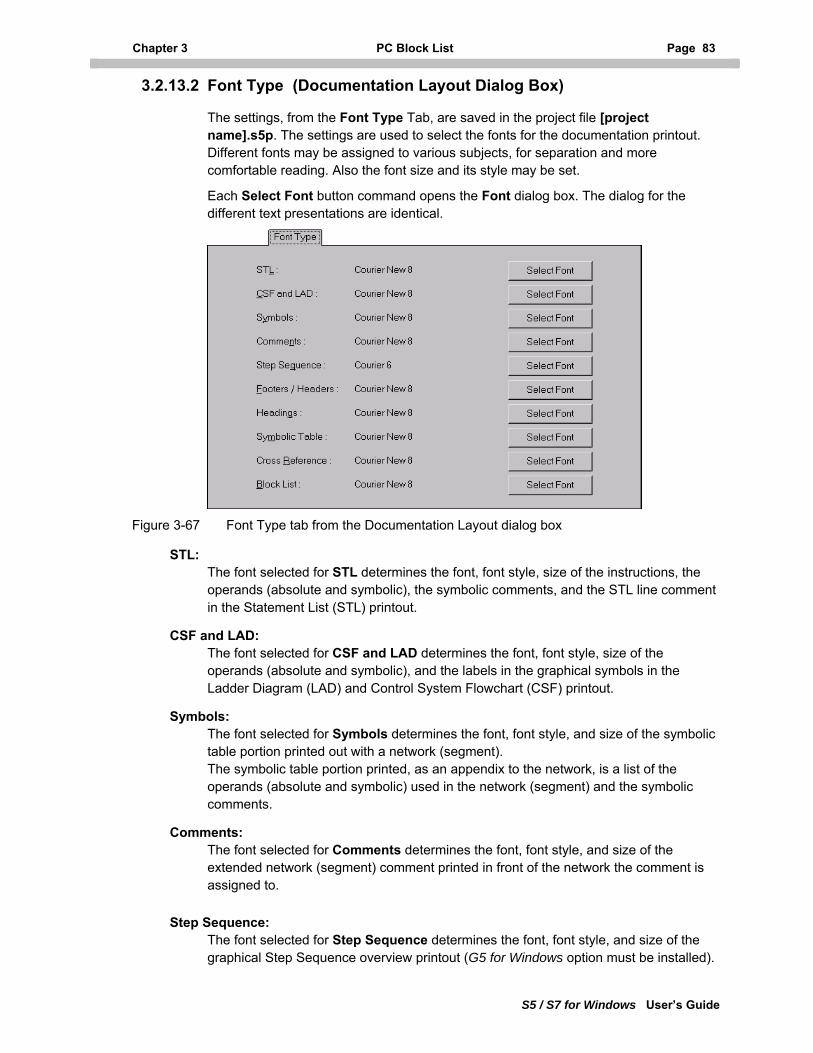
Chapter 3 PC Block List Page 83
S5 / S7 for Windows User’s Guide
3.2.13.2 Font Type (Documentation Layout Dialog Box)
The settings, from the Font Type Tab, are saved in the project file [project name].s5p. The settings are used to select the fonts for the documentation printout. Different fonts may be assigned to various subjects, for separation and more comfortable reading. Also the font size and its style may be set.
Each Select Font button command opens the Font dialog box. The dialog for the different text presentations are identical.
Figure 3-67 Font Type tab from the Documentation Layout dialog box
STL: The font selected for STL determines the font, font style, size of the instructions, the operands (absolute and symbolic), the symbolic comments, and the STL line comment in the Statement List (STL) printout.
CSF and LAD: The font selected for CSF and LAD determines the font, font style, size of the operands (absolute and symbolic), and the labels in the graphical symbols in the Ladder Diagram (LAD) and Control System Flowchart (CSF) printout.
Symbols: The font selected for Symbols determines the font, font style, and size of the symbolic table portion printed out with a network (segment). The symbolic table portion printed, as an appendix to the network, is a list of the operands (absolute and symbolic) used in the network (segment) and the symbolic comments.
Comments: The font selected for Comments determines the font, font style, and size of the extended network (segment) comment printed in front of the network the comment is assigned to.
Step Sequence: The font selected for Step Sequence determines the font, font style, and size of the graphical Step Sequence overview printout (G5 for Windows option must be installed).
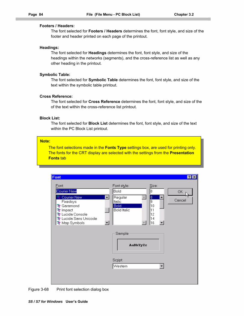
Page 84 File (File Menu - PC Block List) Chapter 3.2
S5 / S7 for Windows User’s Guide
Footers / Headers: The font selected for Footers / Headers determines the font, font style, and size of the footer and header printed on each page of the printout.
Headings: The font selected for Headings determines the font, font style, and size of the headings within the networks (segments), and the cross-reference list as well as any other heading in the printout.
Symbolic Table: The font selected for Symbolic Table determines the font, font style, and size of the text within the symbolic table printout.
Cross Reference: The font selected for Cross Reference determines the font, font style, and size of the of the text within the cross-reference list printout.
Block List: The font selected for Block List determines the font, font style, and size of the text within the PC Block List printout.
Note: The font selections made in the Fonts Type settings box, are used for printing only. The fonts for the CRT display are selected with the settings from the Presentation Fonts tab
Figure 3-68 Print font selection dialog box
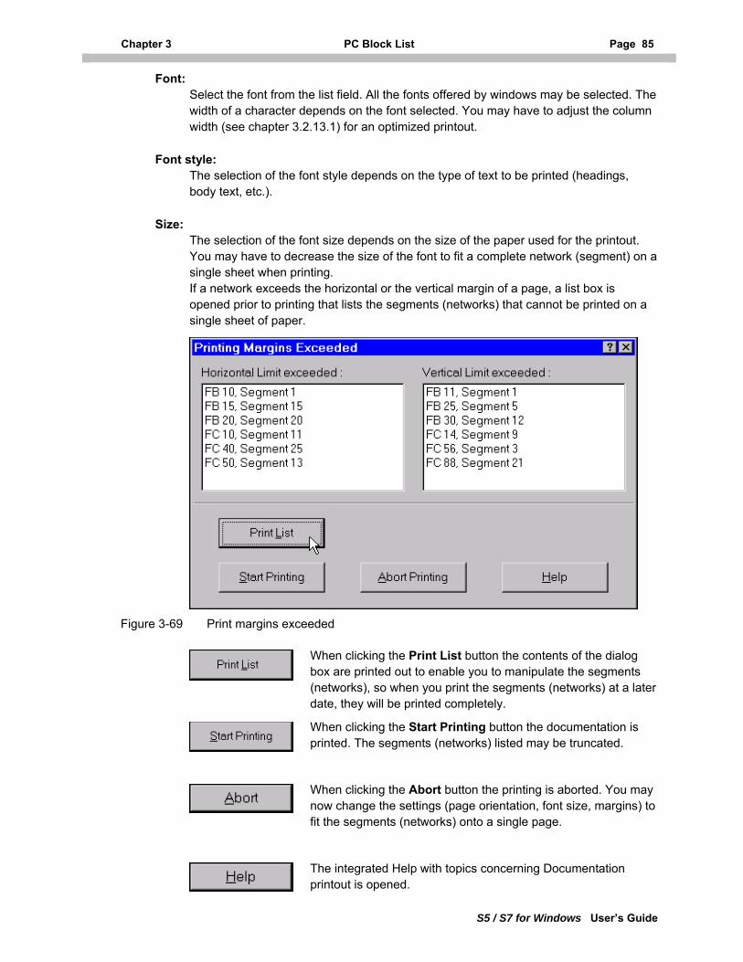
Chapter 3 PC Block List Page 85
S5 / S7 for Windows User’s Guide
Font: Select the font from the list field. All the fonts offered by windows may be selected. The width of a character depends on the font selected. You may have to adjust the column width (see chapter 3.2.13.1) for an optimized printout.
Font style: The selection of the font style depends on the type of text to be printed (headings, body text, etc.).
Size: The selection of the font size depends on the size of the paper used for the printout. You may have to decrease the size of the font to fit a complete network (segment) on a single sheet when printing. If a network exceeds the horizontal or the vertical margin of a page, a list box is opened prior to printing that lists the segments (networks) that cannot be printed on a single sheet of paper.
Figure 3-69 Print margins exceeded
When clicking the Print List button the contents of the dialog box are printed out to enable you to manipulate the segments (networks), so when you print the segments (networks) at a later date, they will be printed completely.
When clicking the Start Printing button the documentation is printed. The segments (networks) listed may be truncated.
When clicking the Abort button the printing is aborted. You may now change the settings (page orientation, font size, margins) to fit the segments (networks) onto a single page.
The integrated Help with topics concerning Documentation printout is opened.
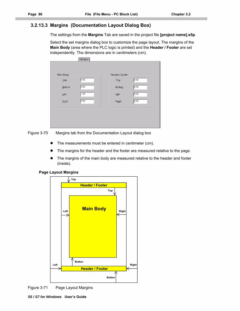
Page 86 File (File Menu - PC Block List) Chapter 3.2
S5 / S7 for Windows User’s Guide
3.2.13.3 Margins (Documentation Layout Dialog Box)
The settings from the Margins Tab are saved in the project file [project name].s5p.
Select the set margins dialog box to customize the page layout. The margins of the Main Body (area where the PLC logic is printed) and the Header / Footer are set independently. The dimensions are in centimeters (cm).
Figure 3-70 Margins tab from the Documentation Layout dialog box
The measurements must be entered in centimeter (cm).
The margins for the header and the footer are measured relative to the page.
The margins of the main body are measured relative to the header and footer (inside).
Page Layout Margins
Main Body
Header / Footer
Header / Footer
Top
BottonLeft Right
RightLeft
Botton
Top
Figure 3-71 Page Layout Margins
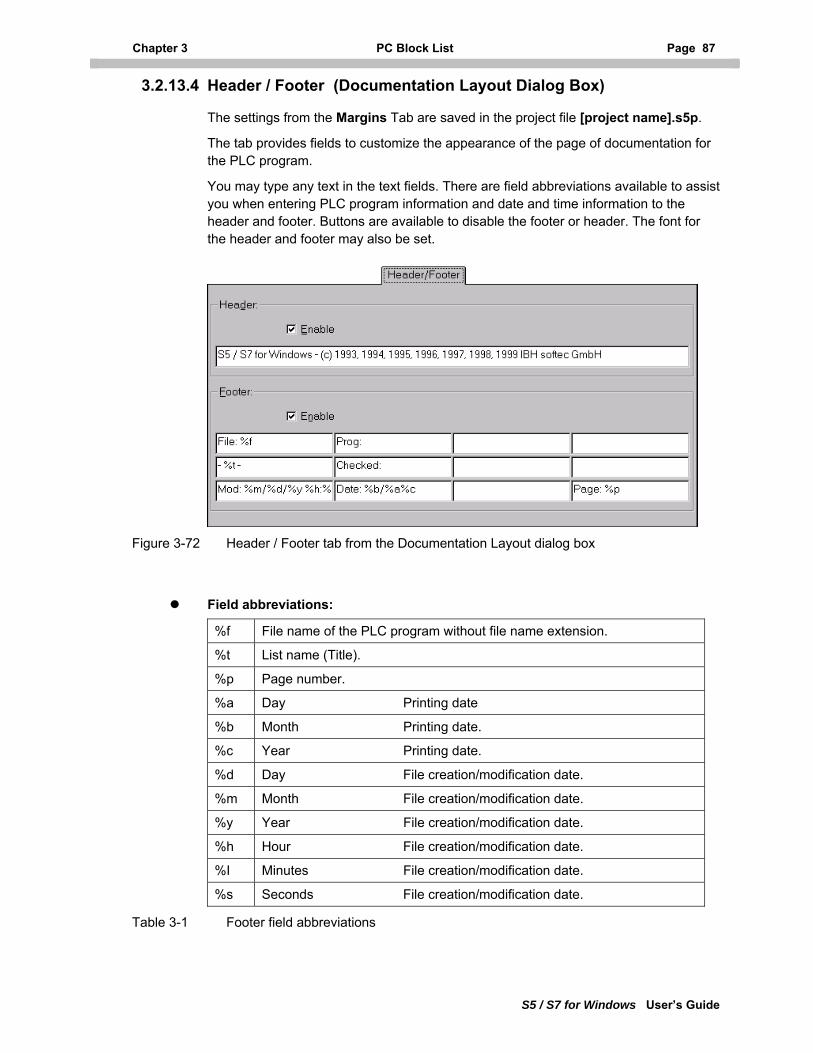
Chapter 3 PC Block List Page 87
S5 / S7 for Windows User’s Guide
3.2.13.4 Header / Footer (Documentation Layout Dialog Box)
The settings from the Margins Tab are saved in the project file [project name].s5p.
The tab provides fields to customize the appearance of the page of documentation for the PLC program.
You may type any text in the text fields. There are field abbreviations available to assist you when entering PLC program information and date and time information to the header and footer. Buttons are available to disable the footer or header. The font for the header and footer may also be set.
Figure 3-72 Header / Footer tab from the Documentation Layout dialog box
Field abbreviations:
%f File name of the PLC program without file name extension.
%t List name (Title).
%p Page number.
%a Day Printing date
%b Month Printing date.
%c Year Printing date.
%d Day File creation/modification date.
%m Month File creation/modification date.
%y Year File creation/modification date.
%h Hour File creation/modification date.
%I Minutes File creation/modification date.
%s Seconds File creation/modification date.
Table 3-1 Footer field abbreviations
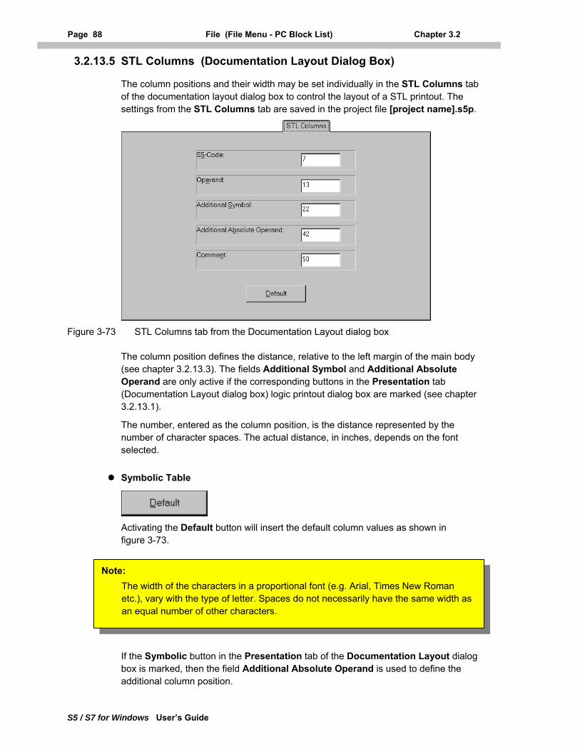
Page 88 File (File Menu - PC Block List) Chapter 3.2
S5 / S7 for Windows User’s Guide
3.2.13.5 STL Columns (Documentation Layout Dialog Box)
The column positions and their width may be set individually in the STL Columns tab of the documentation layout dialog box to control the layout of a STL printout. The settings from the STL Columns tab are saved in the project file [project name].s5p.
Figure 3-73 STL Columns tab from the Documentation Layout dialog box
The column position defines the distance, relative to the left margin of the main body (see chapter 3.2.13.3). The fields Additional Symbol and Additional Absolute Operand are only active if the corresponding buttons in the Presentation tab (Documentation Layout dialog box) logic printout dialog box are marked (see chapter 3.2.13.1).
The number, entered as the column position, is the distance represented by the number of character spaces. The actual distance, in inches, depends on the font selected.
Symbolic Table
Activating the Default button will insert the default column values as shown in figure 3-73.
Note: The width of the characters in a proportional font (e.g. Arial, Times New Roman etc.), vary with the type of letter. Spaces do not necessarily have the same width as an equal number of other characters.
If the Symbolic button in the Presentation tab of the Documentation Layout dialog box is marked, then the field Additional Absolute Operand is used to define the additional column position.
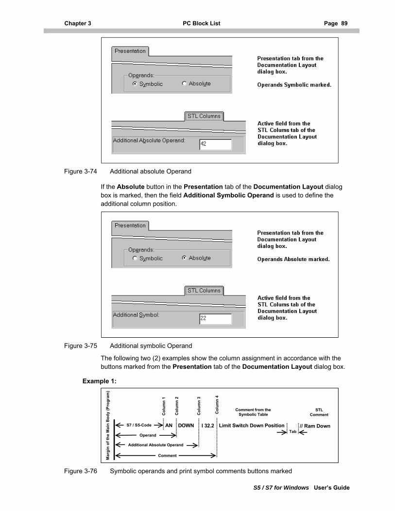
Chapter 3 PC Block List Page 89
S5 / S7 for Windows User’s Guide
Figure 3-74 Additional absolute Operand
If the Absolute button in the Presentation tab of the Documentation Layout dialog box is marked, then the field Additional Symbolic Operand is used to define the additional column position.
Figure 3-75 Additional symbolic Operand
The following two (2) examples show the column assignment in accordance with the buttons marked from the Presentation tab of the Documentation Layout dialog box.
Example 1:
Additional Absolute Operand
Comment
AN DOWN I 32.2 Limit Switch Down Position
STL Comment
Comment from the Symbolic Table
Mar
gin
of th
e M
ain
Bod
y (P
rogr
am)
Col
umn
1
Col
umn
2
Col
umn
3
Col
umn
4
S7 / S5-Code
Operand
// Ram DownTab
Figure 3-76 Symbolic operands and print symbol comments buttons marked
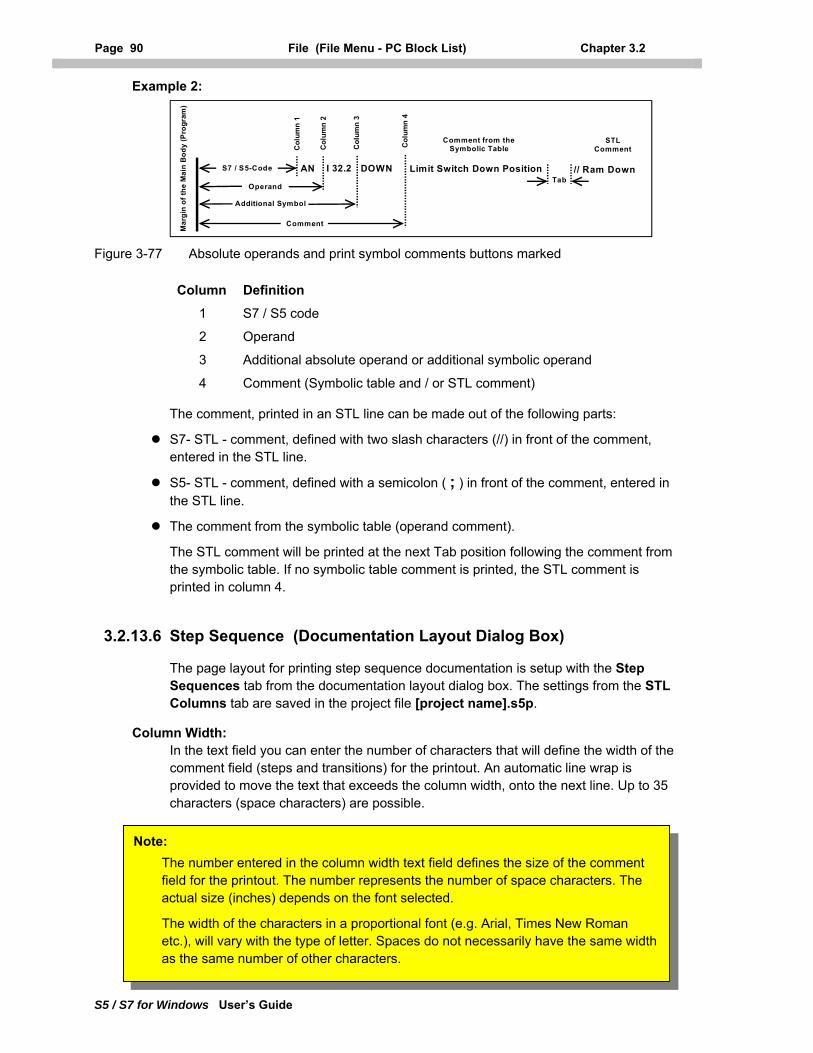
Page 90 File (File Menu - PC Block List) Chapter 3.2
S5 / S7 for Windows User’s Guide
Example 2:
Additional Symbol
Comment
AN DOWNI 32.2 Limit Switch Down Position
STL Comment
Comment from the Symbolic Table
Mar
gin
of th
e M
ain
Bod
y (P
rogr
am)
Col
umn
1
Col
umn
2
Col
umn
3
Col
umn
4
S7 / S5-Code
Operand
// Ram DownTab
Figure 3-77 Absolute operands and print symbol comments buttons marked
Column Definition
1 S7 / S5 code
2 Operand
3 Additional absolute operand or additional symbolic operand
4 Comment (Symbolic table and / or STL comment)
The comment, printed in an STL line can be made out of the following parts:
S7- STL - comment, defined with two slash characters (//) in front of the comment, entered in the STL line.
S5- STL - comment, defined with a semicolon ( ; ) in front of the comment, entered in the STL line.
The comment from the symbolic table (operand comment).
The STL comment will be printed at the next Tab position following the comment from the symbolic table. If no symbolic table comment is printed, the STL comment is printed in column 4.
3.2.13.6 Step Sequence (Documentation Layout Dialog Box)
The page layout for printing step sequence documentation is setup with the Step Sequences tab from the documentation layout dialog box. The settings from the STL Columns tab are saved in the project file [project name].s5p.
Column Width: In the text field you can enter the number of characters that will define the width of the comment field (steps and transitions) for the printout. An automatic line wrap is provided to move the text that exceeds the column width, onto the next line. Up to 35 characters (space characters) are possible.
The number entered in the column width text field defines the size of the comment field for the printout. The number represents the number of space characters. The actual size (inches) depends on the font selected.
The width of the characters in a proportional font (e.g. Arial, Times New Roman etc.), will vary with the type of letter. Spaces do not necessarily have the same width as the same number of other characters.
Note:
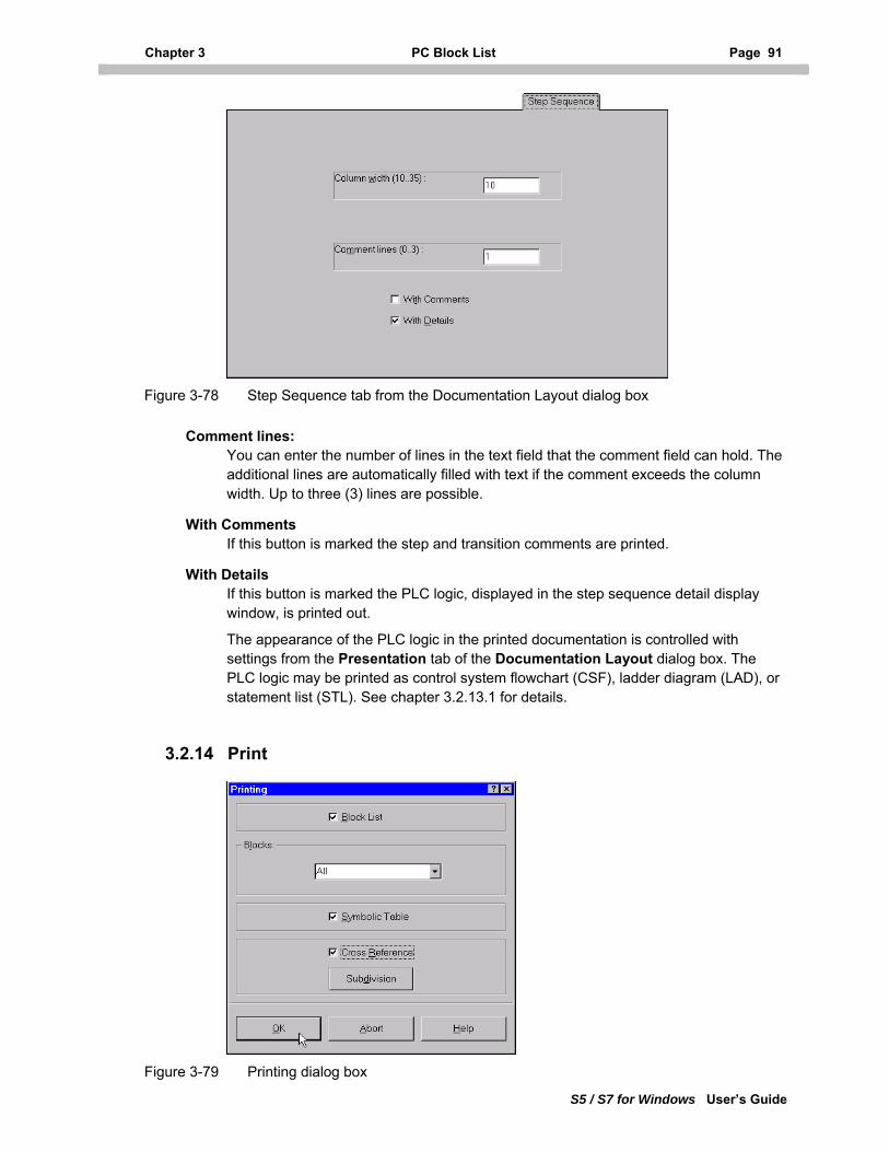
Chapter 3 PC Block List Page 91
S5 / S7 for Windows User’s Guide
Figure 3-78 Step Sequence tab from the Documentation Layout dialog box
Comment lines: You can enter the number of lines in the text field that the comment field can hold. The additional lines are automatically filled with text if the comment exceeds the column width. Up to three (3) lines are possible.
With Comments If this button is marked the step and transition comments are printed.
With Details If this button is marked the PLC logic, displayed in the step sequence detail display window, is printed out.
The appearance of the PLC logic in the printed documentation is controlled with settings from the Presentation tab of the Documentation Layout dialog box. The PLC logic may be printed as control system flowchart (CSF), ladder diagram (LAD), or statement list (STL). See chapter 3.2.13.1 for details.
3.2.14 Print
Figure 3-79 Printing dialog box
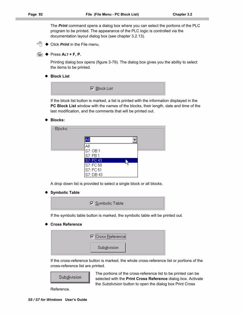
Page 92 File (File Menu - PC Block List) Chapter 3.2
S5 / S7 for Windows User’s Guide
The Print command opens a dialog box where you can select the portions of the PLC program to be printed. The appearance of the PLC logic is controlled via the documentation layout dialog box (see chapter 3.2.13).
Click Print in the File menu.
Press ALT + F, P.
Printing dialog box opens (figure 3-79). The dialog box gives you the ability to select the items to be printed.
Block List
If the block list button is marked, a list is printed with the information displayed in the PC Block List window with the names of the blocks, their length, date and time of the last modification, and the comments that will be printed out.
Blocks:
A drop down list is provided to select a single block or all blocks.
Symbolic Table
If the symbolic table button is marked, the symbolic table will be printed out.
Cross Reference
If the cross-reference button is marked, the whole cross-reference list or portions of the cross-reference list are printed.
The portions of the cross-reference list to be printed can be selected with the Print Cross Reference dialog box. Activate the Subdivision button to open the dialog box Print Cross
Reference.
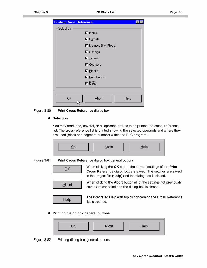
Chapter 3 PC Block List Page 93
S5 / S7 for Windows User’s Guide
Figure 3-80 Print Cross Reference dialog box
Selection
You may mark one, several, or all operand groups to be printed the cross- reference list. The cross-reference list is printed showing the selected operands and where they are used (block and segment number) within the PLC program.
Figure 3-81 Print Cross Reference dialog box general buttons
When clicking the OK button the current settings of the Print Cross Reference dialog box are saved. The settings are saved in the project file (*.s5p) and the dialog box is closed.
When clicking the Abort button all of the settings not previously saved are canceled and the dialog box is closed.
The integrated Help with topics concerning the Cross Reference list is opened.
Printing dialog box general buttons
Figure 3-82 Printing dialog box general buttons
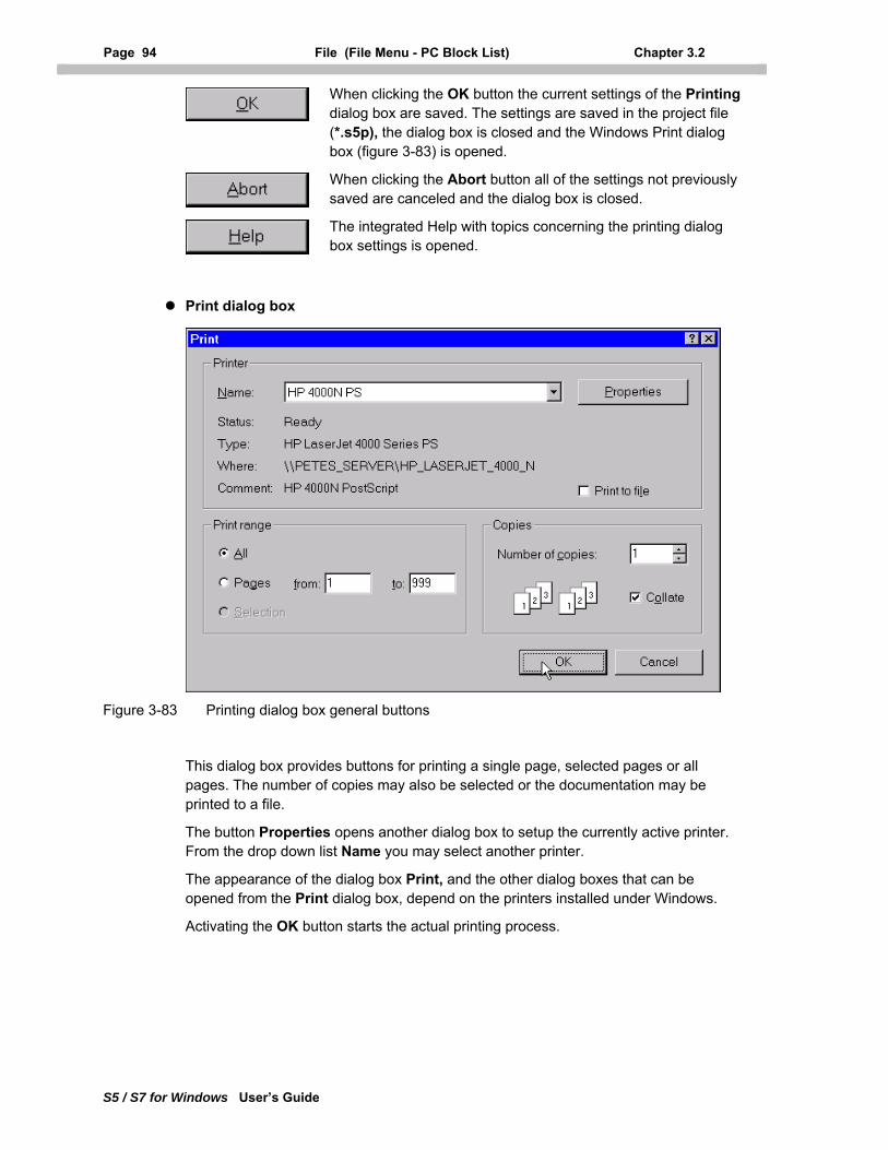
Page 94 File (File Menu - PC Block List) Chapter 3.2
S5 / S7 for Windows User’s Guide
When clicking the OK button the current settings of the Printing dialog box are saved. The settings are saved in the project file (*.s5p), the dialog box is closed and the Windows Print dialog box (figure 3-83) is opened.
When clicking the Abort button all of the settings not previously saved are canceled and the dialog box is closed.
The integrated Help with topics concerning the printing dialog box settings is opened.
Print dialog box
Figure 3-83 Printing dialog box general buttons
This dialog box provides buttons for printing a single page, selected pages or all pages. The number of copies may also be selected or the documentation may be printed to a file.
The button Properties opens another dialog box to setup the currently active printer. From the drop down list Name you may select another printer.
The appearance of the dialog box Print, and the other dialog boxes that can be opened from the Print dialog box, depend on the printers installed under Windows.
Activating the OK button starts the actual printing process.
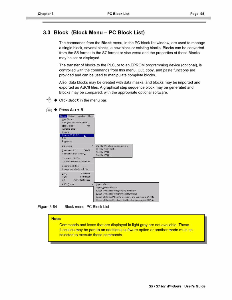
Chapter 3 PC Block List Page 95
S5 / S7 for Windows User’s Guide
3.3 Block (Block Menu – PC Block List)
The commands from the Block menu, in the PC block list window, are used to manage a single block, several blocks, a new block or existing blocks. Blocks can be converted from the S5 format to the S7 format or vise versa and the properties of these Blocks may be set or displayed.
The transfer of blocks to the PLC, or to an EPROM programming device (optional), is controlled with the commands from this menu. Cut, copy, and paste functions are provided and can be used to manipulate complete blocks.
Also, data blocks may be created with data masks, and blocks may be imported and exported as ASCII files. A graphical step sequence block may be generated and Blocks may be compared, with the appropriate optional software.
Click Block in the menu bar.
Press ALT + B.
Figure 3-84 Block menu, PC Block List
Note: Commands and icons that are displayed in light gray are not available. These functions may be part to an additional software option or another mode must be selected to execute these commands.
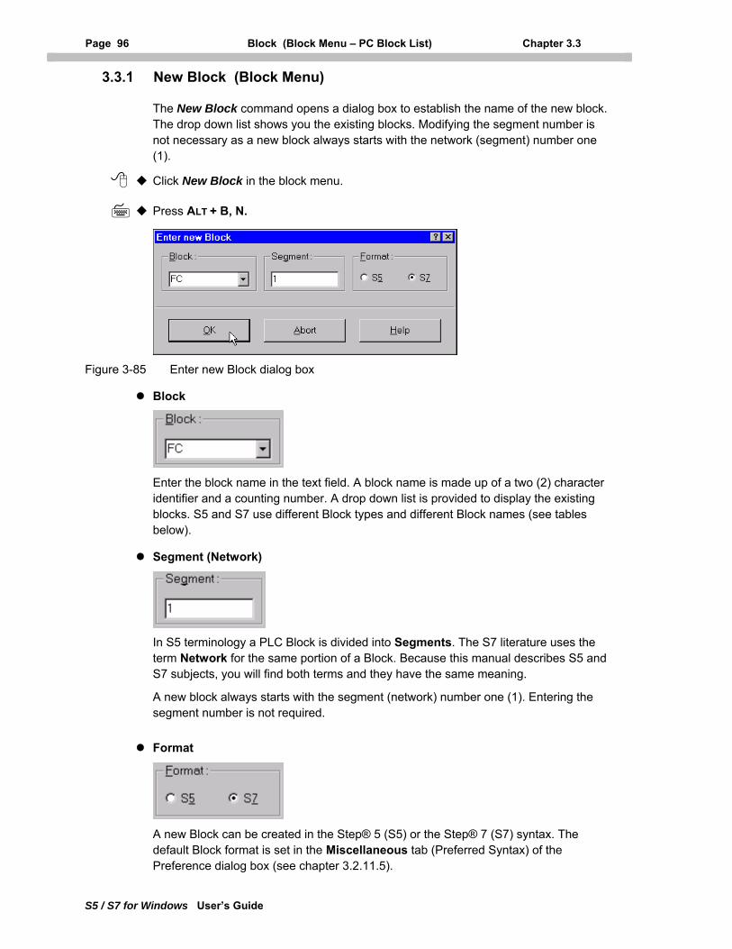
Page 96 Block (Block Menu – PC Block List) Chapter 3.3
S5 / S7 for Windows User’s Guide
3.3.1 New Block (Block Menu)
The New Block command opens a dialog box to establish the name of the new block. The drop down list shows you the existing blocks. Modifying the segment number is not necessary as a new block always starts with the network (segment) number one (1).
Click New Block in the block menu.
Press ALT + B, N.
Figure 3-85 Enter new Block dialog box
Block
Enter the block name in the text field. A block name is made up of a two (2) character identifier and a counting number. A drop down list is provided to display the existing blocks. S5 and S7 use different Block types and different Block names (see tables below).
Segment (Network)
In S5 terminology a PLC Block is divided into Segments. The S7 literature uses the term Network for the same portion of a Block. Because this manual describes S5 and S7 subjects, you will find both terms and they have the same meaning.
A new block always starts with the segment (network) number one (1). Entering the segment number is not required.
Format
A new Block can be created in the Step® 5 (S5) or the Step® 7 (S7) syntax. The default Block format is set in the Miscellaneous tab (Preferred Syntax) of the Preference dialog box (see chapter 3.2.11.5).
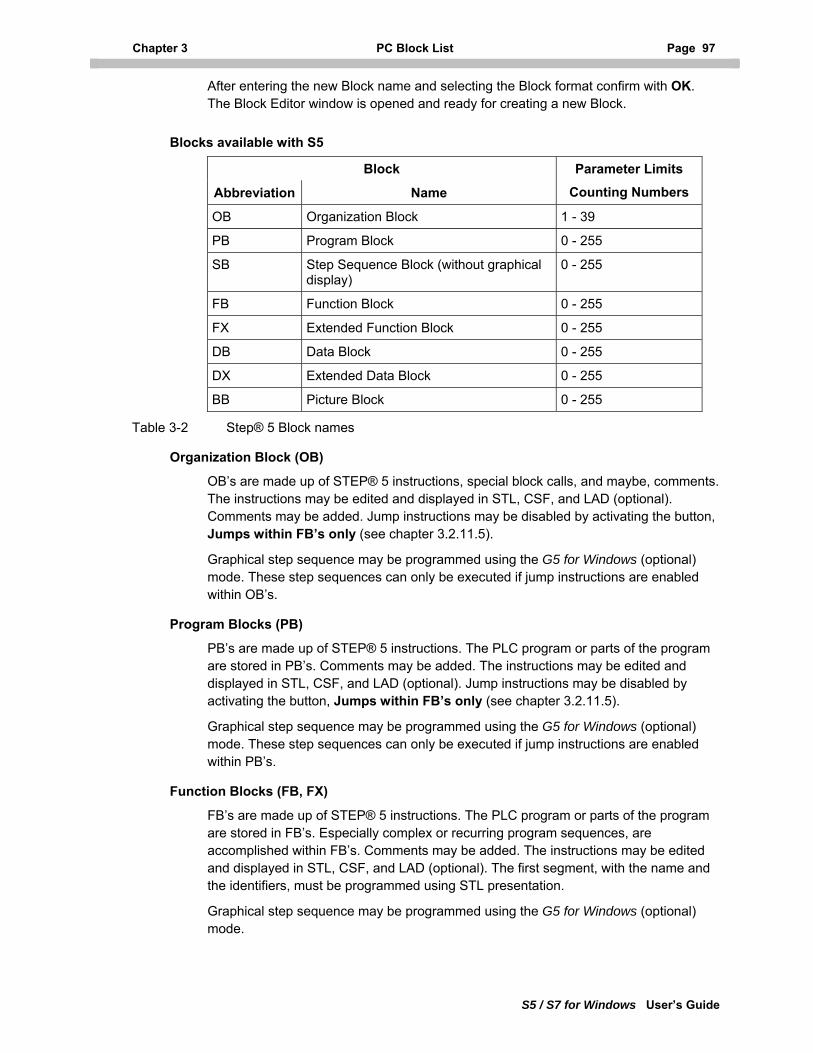
Chapter 3 PC Block List Page 97
S5 / S7 for Windows User’s Guide
After entering the new Block name and selecting the Block format confirm with OK. The Block Editor window is opened and ready for creating a new Block.
Blocks available with S5
Block
Abbreviation Name
Parameter Limits
Counting Numbers
OB Organization Block 1 - 39
PB Program Block 0 - 255
SB Step Sequence Block (without graphical display)
0 - 255
FB Function Block 0 - 255
FX Extended Function Block 0 - 255
DB Data Block 0 - 255
DX Extended Data Block 0 - 255
BB Picture Block 0 - 255
Table 3-2 Step® 5 Block names
Organization Block (OB)
OB’s are made up of STEP® 5 instructions, special block calls, and maybe, comments. The instructions may be edited and displayed in STL, CSF, and LAD (optional). Comments may be added. Jump instructions may be disabled by activating the button, Jumps within FB’s only (see chapter 3.2.11.5).
Graphical step sequence may be programmed using the G5 for Windows (optional) mode. These step sequences can only be executed if jump instructions are enabled within OB’s.
Program Blocks (PB)
PB’s are made up of STEP® 5 instructions. The PLC program or parts of the program are stored in PB’s. Comments may be added. The instructions may be edited and displayed in STL, CSF, and LAD (optional). Jump instructions may be disabled by activating the button, Jumps within FB’s only (see chapter 3.2.11.5).
Graphical step sequence may be programmed using the G5 for Windows (optional) mode. These step sequences can only be executed if jump instructions are enabled within PB’s.
Function Blocks (FB, FX)
FB’s are made up of STEP® 5 instructions. The PLC program or parts of the program are stored in FB’s. Especially complex or recurring program sequences, are accomplished within FB’s. Comments may be added. The instructions may be edited and displayed in STL, CSF, and LAD (optional). The first segment, with the name and the identifiers, must be programmed using STL presentation.
Graphical step sequence may be programmed using the G5 for Windows (optional) mode.
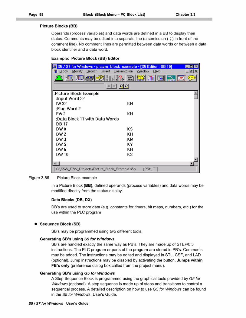
Page 98 Block (Block Menu – PC Block List) Chapter 3.3
S5 / S7 for Windows User’s Guide
Picture Blocks (BB)
Operands (process variables) and data words are defined in a BB to display their status. Comments may be edited in a separate line (a semicolon ( ; ) in front of the comment line). No comment lines are permitted between data words or between a data block identifier and a data word.
Example: Picture Block (BB) Editor
Figure 3-86 Picture Block example
In a Picture Block (BB), defined operands (process variables) and data words may be modified directly from the status display.
Data Blocks (DB, DX)
DB’s are used to store data (e.g. constants for timers, bit maps, numbers, etc.) for the use within the PLC program
Sequence Block (SB)
SB’s may be programmed using two different tools.
Generating SB’s using S5 for Windows SB’s are handled exactly the same way as PB’s. They are made up of STEP® 5 instructions. The PLC program or parts of the program are stored in PB’s. Comments may be added. The instructions may be edited and displayed in STL, CSF, and LAD (optional). Jump instructions may be disabled by activating the button, Jumps within FB’s only (preference dialog box called from the project menu).
Generating SB’s using G5 for Windows A Step Sequence Block is programmed using the graphical tools provided by G5 for Windows (optional). A step sequence is made up of steps and transitions to control a sequential process. A detailed description on how to use G5 for Windows can be found in the S5 for Windows User's Guide.
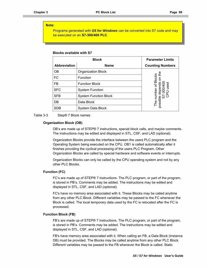
Chapter 3 PC Block List Page 99
S5 / S7 for Windows User’s Guide
Note: Programs generated with G5 for Windows can be converted into S7 code and may be executed on an S7-300/400 PLC.
Blocks available with S7
Block Parameter Limits
Abbreviation Name Counting Numbers
OB Organization Block
FC Function
FB Function Block
SFC System Function
SFB System Function Block
DB Data Block
SDB System Data Block
The
num
ber o
f Blo
cks
poss
ible
dep
ends
on
the
S
7-30
0/40
0
CP
U u
sed
Table 3-3 Step® 7 Block names
Organization Block (OB)
OB’s are made up of STEP® 7 instructions, special block calls, and maybe comments. The instructions may be edited and displayed in STL, CSF, and LAD (optional).
Organization Blocks provide the interface between the users PLC program and the Operating System being executed on the CPU. OB1 is called automatically after it finishes providing the cyclical processing of the users PLC Program. Other Organization Blocks are called by special hardware and software events or interrupts.
Organization Blocks can only be called by the CPU operating system and not by any other PLC Blocks.
Function (FC)
FC’s are made up of STEP® 7 instructions. The PLC program, or part of the program, is stored in PB’s. Comments may be added. The instructions may be edited and displayed in STL, CSF, and LAD (optional).
FC's have no memory area associated with it. These Blocks may be called anytime from any other PLC Block. Different variables may be passed to the FC whenever the Block is called. The local temporary data used by the FC is relocated after the FC is processed.
Function Block (FB)
FB’s are made up of STEP® 7 instructions. The PLC program, or part of the program, is stored in PB’s. Comments may be added. The instructions may be edited and displayed in STL, CSF, and LAD (optional).
FB's have memory area associated with it. When calling an FB, a Data Block (Instance DB) must be provided. The Blocks may be called anytime from any other PLC Block. Different variables may be passed to the FB whenever the Block is called. Static
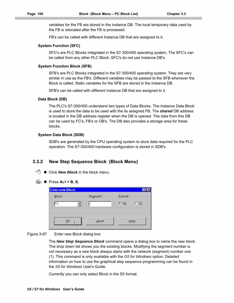
Page 100 Block (Block Menu – PC Block List) Chapter 3.3
S5 / S7 for Windows User’s Guide
variables for the FB are stored in the Instance DB. The local temporary data used by the FB is relocated after the FB is processed.
FB's can be called with different Instance DB that are assigned to it.
System Function (SFC)
SFC's are PLC Blocks integrated in the S7-300/400 operating system. The SFC's can be called from any other PLC Block. SFC's do not use Instance DB's.
System Function Block (SFB)
SFB's are PLC Blocks integrated in the S7-300/400 operating system. They are very similar in use as the FB's. Different variables may be passed to the SFB whenever the Block is called. Static variables for the SFB are stored in the Instance DB.
SFB's can be called with different Instance DB that are assigned to it.
Data Block (DB)
The PLC's S7-300/400 understand two types of Data Blocks. The Instance Data Block is used to store the data to be used with the its assigned FB. The shared DB address is located in the DB address register when the DB is opened. The data from this DB can be used by FC's, FB's or OB's. The DB also provides a storage area for these blocks.
System Data Block (SDB)
SDB's are generated by the CPU operating system to store data required for the PLC operation. The S7-300/400 hardware configuration is stored in SDB's.
3.3.2 New Step Sequence Block (Block Menu)
Click New Block in the block menu.
Press ALT + B, S.
Figure 3-87 Enter new Block dialog box
The New Step Sequence Block command opens a dialog box to name the new block. The drop down list shows you the existing blocks. Modifying the segment number is not necessary as a new block always starts with the network (segment) number one (1). This command is only available with the G5 for Windows option. Detailed information on how to use the graphical step sequence programming can be found in the S5 for Windows User's Guide.
Currently you can only select Block in the S5 format.
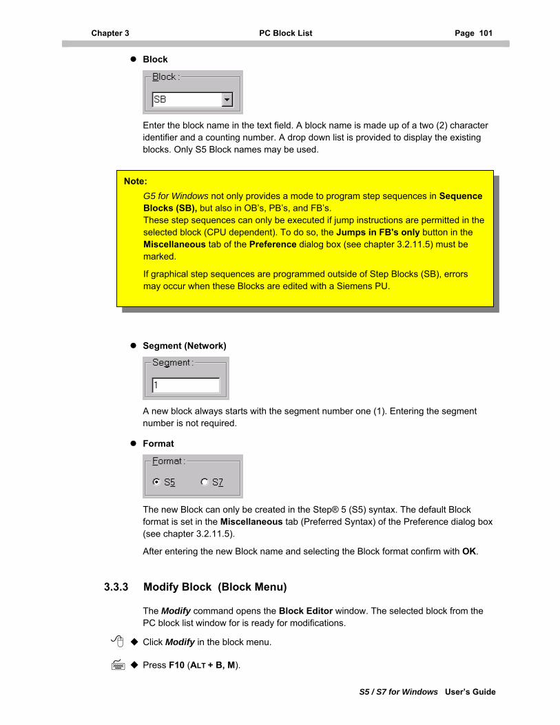
Chapter 3 PC Block List Page 101
S5 / S7 for Windows User’s Guide
Block
Enter the block name in the text field. A block name is made up of a two (2) character identifier and a counting number. A drop down list is provided to display the existing blocks. Only S5 Block names may be used.
G5 for Windows not only provides a mode to program step sequences in Sequence Blocks (SB), but also in OB’s, PB’s, and FB’s. These step sequences can only be executed if jump instructions are permitted in theselected block (CPU dependent). To do so, the Jumps in FB's only button in the Miscellaneous tab of the Preference dialog box (see chapter 3.2.11.5) must be marked.
If graphical step sequences are programmed outside of Step Blocks (SB), errors may occur when these Blocks are edited with a Siemens PU.
Note:
Segment (Network)
A new block always starts with the segment number one (1). Entering the segment number is not required.
Format
The new Block can only be created in the Step® 5 (S5) syntax. The default Block format is set in the Miscellaneous tab (Preferred Syntax) of the Preference dialog box (see chapter 3.2.11.5).
After entering the new Block name and selecting the Block format confirm with OK.
3.3.3 Modify Block (Block Menu)
The Modify command opens the Block Editor window. The selected block from the PC block list window for is ready for modifications.
Click Modify in the block menu.
Press F10 (ALT + B, M).
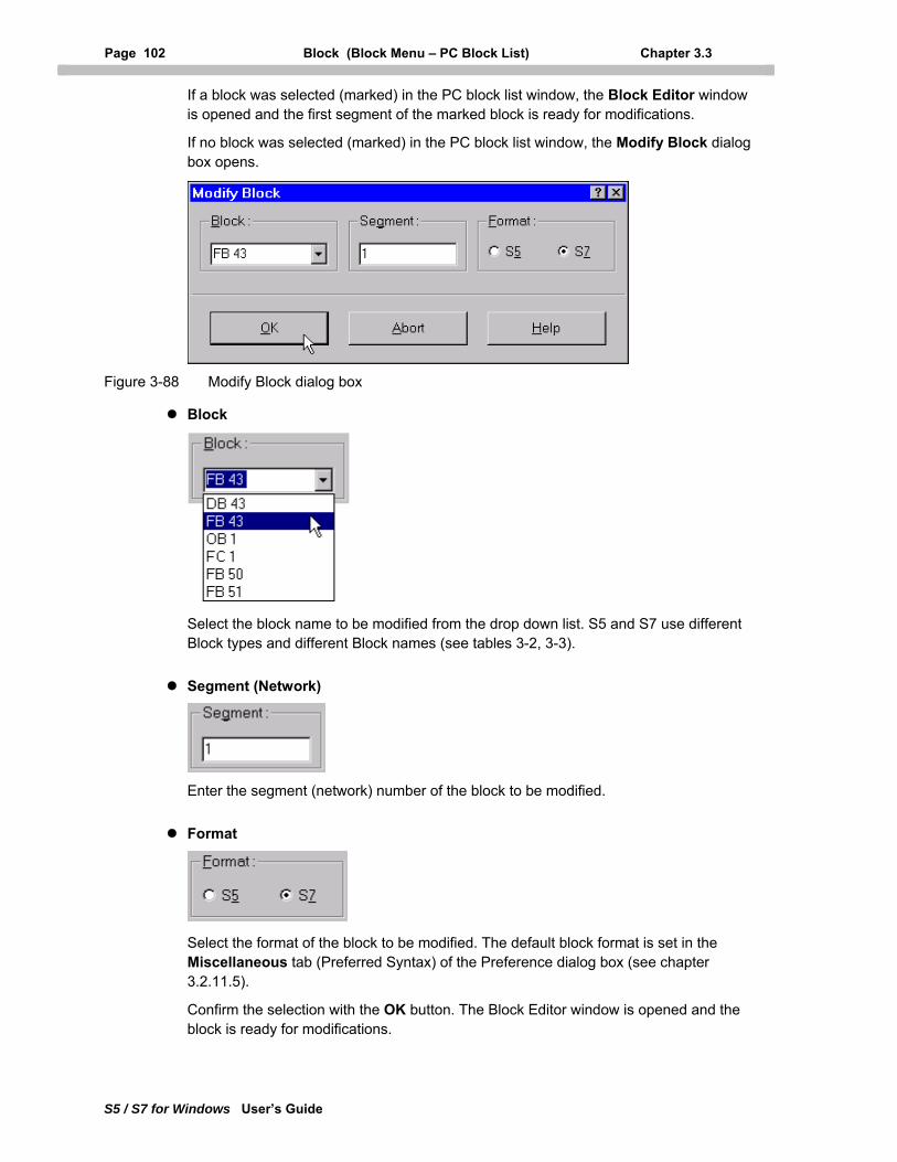
Page 102 Block (Block Menu – PC Block List) Chapter 3.3
S5 / S7 for Windows User’s Guide
If a block was selected (marked) in the PC block list window, the Block Editor window is opened and the first segment of the marked block is ready for modifications.
If no block was selected (marked) in the PC block list window, the Modify Block dialog box opens.
Figure 3-88 Modify Block dialog box
Block
Select the block name to be modified from the drop down list. S5 and S7 use different Block types and different Block names (see tables 3-2, 3-3).
Segment (Network)
Enter the segment (network) number of the block to be modified.
Format
Select the format of the block to be modified. The default block format is set in the Miscellaneous tab (Preferred Syntax) of the Preference dialog box (see chapter 3.2.11.5).
Confirm the selection with the OK button. The Block Editor window is opened and the block is ready for modifications.
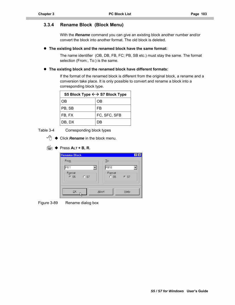
Chapter 3 PC Block List Page 103
S5 / S7 for Windows User’s Guide
3.3.4 Rename Block (Block Menu)
With the Rename command you can give an existing block another number and/or convert the block into another format. The old block is deleted.
The existing block and the renamed block have the same format:
The name identifier (OB, DB, FB, FC; PB, SB etc.) must stay the same. The format selection (From:, To:) is the same.
The existing block and the renamed block have different formats:
If the format of the renamed block is different from the original block, a rename and a conversion take place. It is only possible to convert and rename a block into a corresponding block type.
S5 Block Type S7 Block Type
OB OB
PB, SB FB
FB, FX FC, SFC, SFB
DB, DX DB
Table 3-4 Corresponding block types
Click Rename in the block menu.
Press ALT + B, R.
Figure 3-89 Rename dialog box
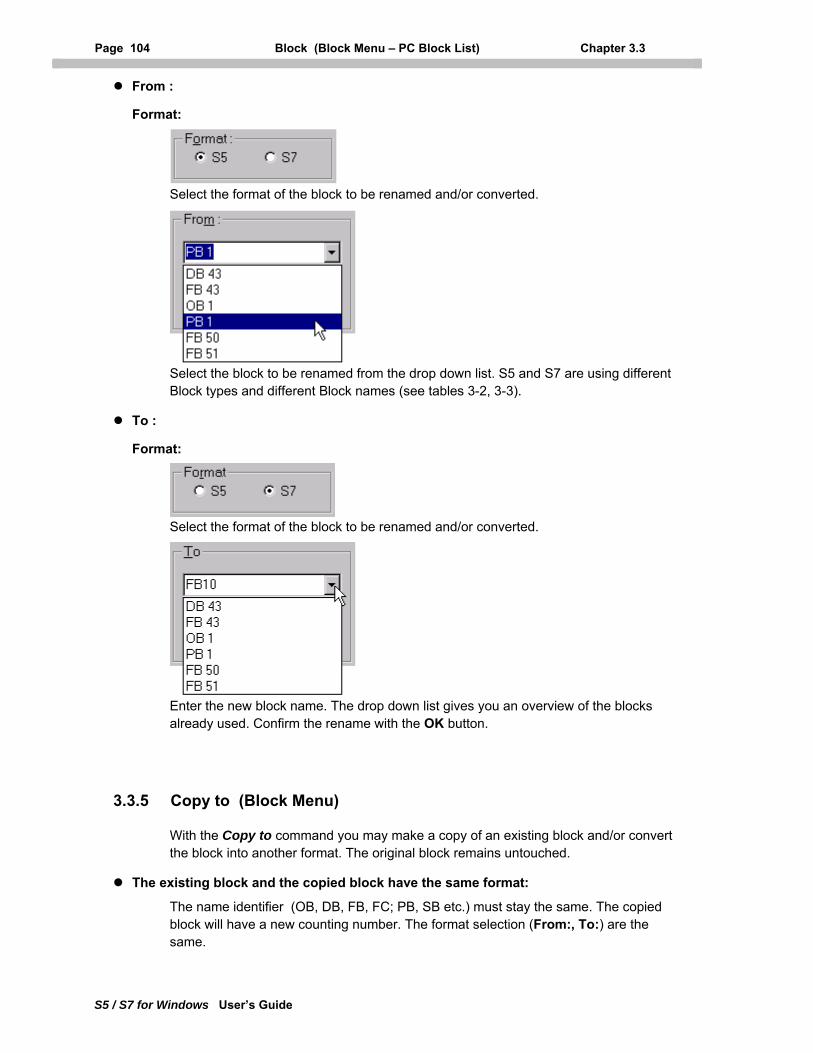
Page 104 Block (Block Menu – PC Block List) Chapter 3.3
S5 / S7 for Windows User’s Guide
From :
Format:
Select the format of the block to be renamed and/or converted.
Select the block to be renamed from the drop down list. S5 and S7 are using different Block types and different Block names (see tables 3-2, 3-3).
To :
Format:
Select the format of the block to be renamed and/or converted.
Enter the new block name. The drop down list gives you an overview of the blocks already used. Confirm the rename with the OK button.
3.3.5 Copy to (Block Menu)
With the Copy to command you may make a copy of an existing block and/or convert the block into another format. The original block remains untouched.
The existing block and the copied block have the same format:
The name identifier (OB, DB, FB, FC; PB, SB etc.) must stay the same. The copied block will have a new counting number. The format selection (From:, To:) are the same.

Chapter 3 PC Block List Page 105
S5 / S7 for Windows User’s Guide
The existing block and the copied block have different formats:
If the format of the copied block is different from the original block, the copying and the conversion take place. It is only possible to convert and copy a block into a corresponding block type.
S5 Block Type S7 Block Type
OB OB
PB, SB FB
FB, FX FC, SFC, SFB
DB, DX DB
Table 3-5 Corresponding block types
Click Copy to in the block menu.
Press ALT + B, Y.
Figure 3-90 Copy to Block dialog box
From :
Format:
Select the format of the block to be copied and/or converted.
Select the block to be copied and/or converted from the drop down list. S5 and S7 use different Block types and different Block names (see tables 3-2, 3-3).
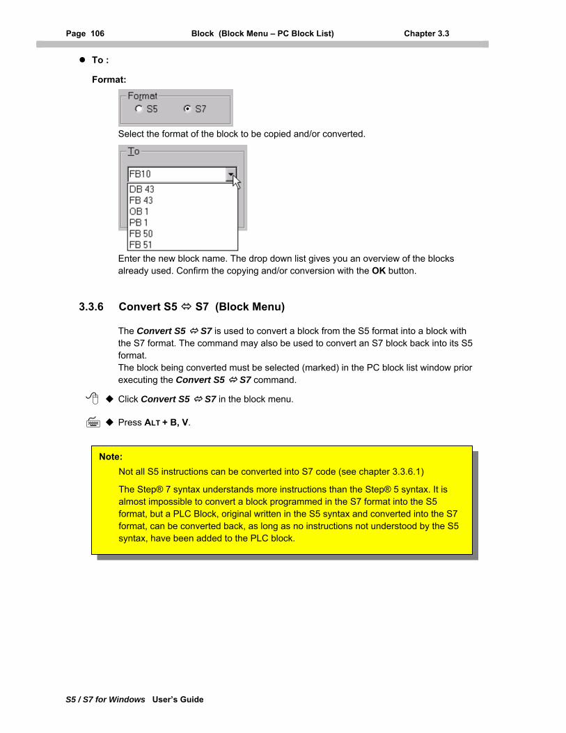
Page 106 Block (Block Menu – PC Block List) Chapter 3.3
S5 / S7 for Windows User’s Guide
To :
Format:
Select the format of the block to be copied and/or converted.
Enter the new block name. The drop down list gives you an overview of the blocks already used. Confirm the copying and/or conversion with the OK button.
3.3.6 Convert S5 S7 (Block Menu)
The Convert S5 S7 is used to convert a block from the S5 format into a block with the S7 format. The command may also be used to convert an S7 block back into its S5 format. The block being converted must be selected (marked) in the PC block list window prior executing the Convert S5 S7 command.
Click Convert S5 S7 in the block menu.
Press ALT + B, V.
Not all S5 instructions can be converted into S7 code (see chapter 3.3.6.1)
The Step® 7 syntax understands more instructions than the Step® 5 syntax. It is almost impossible to convert a block programmed in the S7 format into the S5 format, but a PLC Block, original written in the S5 syntax and converted into the S7 format, can be converted back, as long as no instructions not understood by the S5 syntax, have been added to the PLC block.
Note:
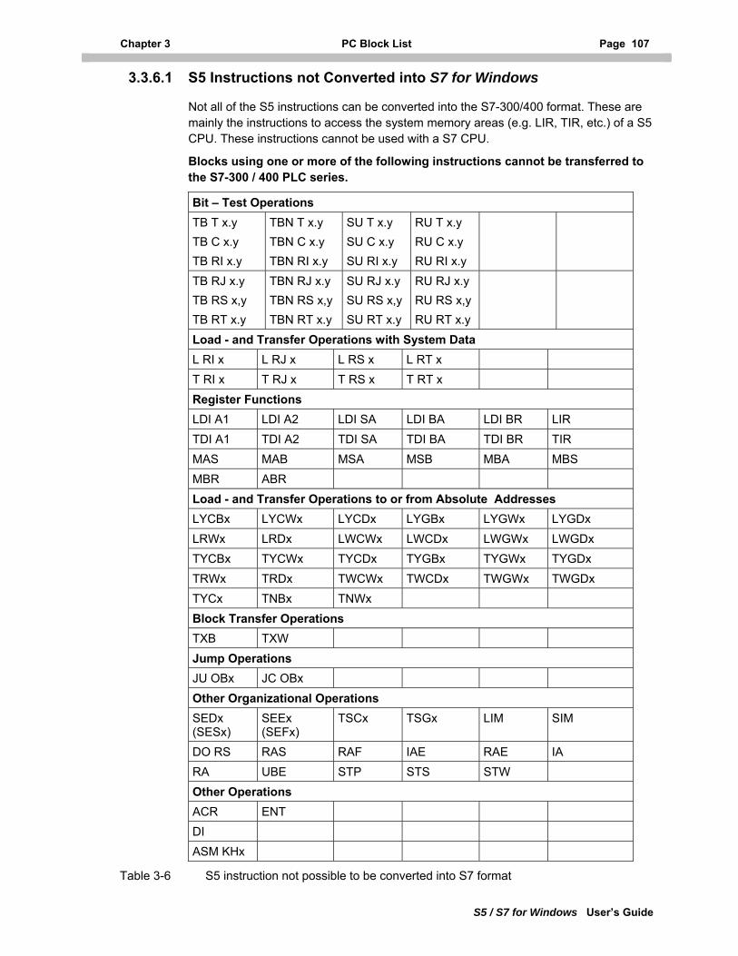
Chapter 3 PC Block List Page 107
S5 / S7 for Windows User’s Guide
3.3.6.1 S5 Instructions not Converted into S7 for Windows
Not all of the S5 instructions can be converted into the S7-300/400 format. These are mainly the instructions to access the system memory areas (e.g. LIR, TIR, etc.) of a S5 CPU. These instructions cannot be used with a S7 CPU.
Blocks using one or more of the following instructions cannot be transferred to the S7-300 / 400 PLC series.
Bit – Test Operations TB T x.y TB C x.y TB RI x.y
TBN T x.y TBN C x.y TBN RI x.y
SU T x.y SU C x.y SU RI x.y
RU T x.y RU C x.y RU RI x.y
TB RJ x.y TB RS x,y TB RT x.y
TBN RJ x.y TBN RS x,y TBN RT x.y
SU RJ x.y SU RS x,y SU RT x.y
RU RJ x.y RU RS x,y RU RT x.y
Load - and Transfer Operations with System Data L RI x L RJ x L RS x L RT x T RI x T RJ x T RS x T RT x Register Functions LDI A1 LDI A2 LDI SA LDI BA LDI BR LIR TDI A1 TDI A2 TDI SA TDI BA TDI BR TIR MAS MAB MSA MSB MBA MBS MBR ABR Load - and Transfer Operations to or from Absolute Addresses LYCBx LYCWx LYCDx LYGBx LYGWx LYGDx LRWx LRDx LWCWx LWCDx LWGWx LWGDx TYCBx TYCWx TYCDx TYGBx TYGWx TYGDx TRWx TRDx TWCWx TWCDx TWGWx TWGDx TYCx TNBx TNWx Block Transfer Operations TXB TXW Jump Operations JU OBx JC OBx Other Organizational Operations SEDx (SESx)
SEEx (SEFx)
TSCx TSGx LIM SIM
DO RS RAS RAF IAE RAE IA RA UBE STP STS STW Other Operations ACR ENT DI ASM KHx
Table 3-6 S5 instruction not possible to be converted into S7 format
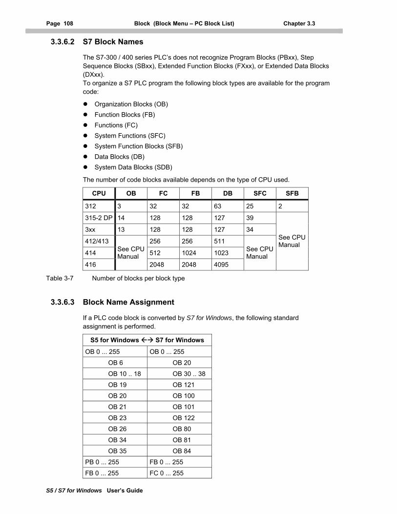
Page 108 Block (Block Menu – PC Block List) Chapter 3.3
S5 / S7 for Windows User’s Guide
3.3.6.2 S7 Block Names
The S7-300 / 400 series PLC’s does not recognize Program Blocks (PBxx), Step Sequence Blocks (SBxx), Extended Function Blocks (FXxx), or Extended Data Blocks (DXxx). To organize a S7 PLC program the following block types are available for the program code:
Organization Blocks (OB) Function Blocks (FB) Functions (FC) System Functions (SFC) System Function Blocks (SFB) Data Blocks (DB) System Data Blocks (SDB)
The number of code blocks available depends on the type of CPU used.
CPU OB FC FB DB SFC SFB
312 3 32 32 63 25 2
315-2 DP 14 128 128 127 39
3xx 13 128 128 127 34
412/413 256 256 511
414 512 1024 1023
416
See CPU Manual
2048 2048 4095
See CPU Manual
See CPU Manual
Table 3-7 Number of blocks per block type
3.3.6.3 Block Name Assignment
If a PLC code block is converted by S7 for Windows, the following standard assignment is performed.
S5 for Windows S7 for Windows
OB 0 ... 255 OB 0 ... 255
OB 6 OB 20
OB 10 .. 18 OB 30 .. 38
OB 19 OB 121
OB 20 OB 100
OB 21 OB 101
OB 23 OB 122
OB 26 OB 80
OB 34 OB 81
OB 35 OB 84
PB 0 ... 255 FB 0 ... 255
FB 0 ... 255 FC 0 ... 255
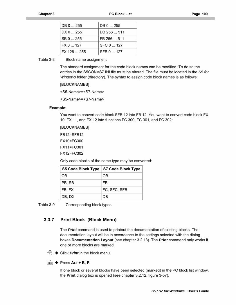
Chapter 3 PC Block List Page 109
S5 / S7 for Windows User’s Guide
DB 0 ... 255 DB 0 ... 255
DX 0 ... 255 DB 256 ... 511
SB 0 ... 255 FB 256 ... 511
FX 0 ... 127 SFC 0 ... 127
FX 128 ... 255 SFB 0 ... 127
Table 3-8 Block name assignment
The standard assignment for the code block names can be modified. To do so the entries in the S5CONVS7.INI file must be altered. The file must be located in the S5 for Windows folder (directory). The syntax to assign code block names is as follows:
[BLOCKNAMES]
<S5-Name>=<S7-Name>
<S5-Name>=<S7-Name>
Example:
You want to convert code block SFB 12 into FB 12. You want to convert code block FX 10, FX 11, and FX 12 into functions FC 300, FC 301, and FC 302:
[BLOCKNAMES]
FB12=SFB12 FX10=FC300 FX11=FC301 FX12=FC302
Only code blocks of the same type may be converted:
S5 Code Block Type S7 Code Block Type
OB OB
PB, SB FB
FB, FX FC, SFC, SFB
DB, DX DB
Table 3-9 Corresponding block types
3.3.7 Print Block (Block Menu)
The Print command is used to printout the documentation of existing blocks. The documentation layout will be in accordance to the settings selected with the dialog boxes Documentation Layout (see chapter 3.2.13). The Print command only works if one or more blocks are marked.
Click Print in the block menu.
Press ALT + B, P.
If one block or several blocks have been selected (marked) in the PC block list window, the Print dialog box is opened (see chapter 3.2.12, figure 3-57).
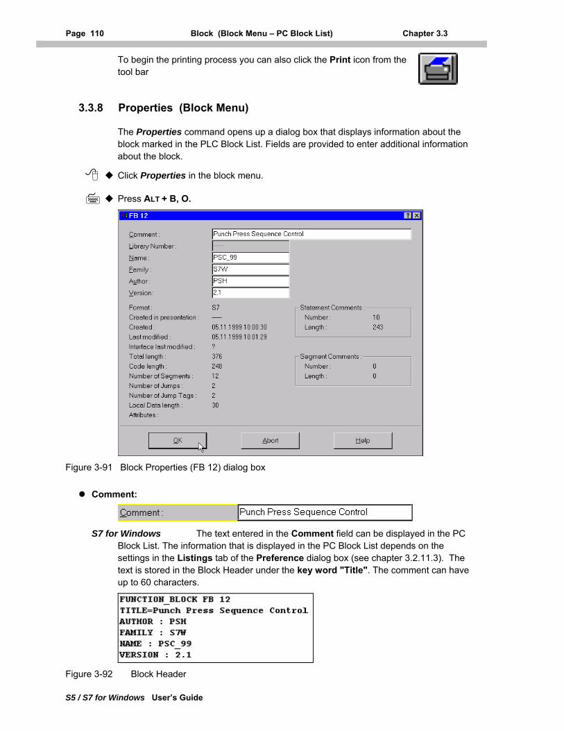
Page 110 Block (Block Menu – PC Block List) Chapter 3.3
S5 / S7 for Windows User’s Guide
To begin the printing process you can also click the Print icon from the tool bar
3.3.8 Properties (Block Menu)
The Properties command opens up a dialog box that displays information about the block marked in the PLC Block List. Fields are provided to enter additional information about the block.
Click Properties in the block menu.
Press ALT + B, O.
Figure 3-91 Block Properties (FB 12) dialog box
Comment:
S7 for Windows The text entered in the Comment field can be displayed in the PC Block List. The information that is displayed in the PC Block List depends on the settings in the Listings tab of the Preference dialog box (see chapter 3.2.11.3). The text is stored in the Block Header under the key word "Title". The comment can have up to 60 characters.
Figure 3-92 Block Header
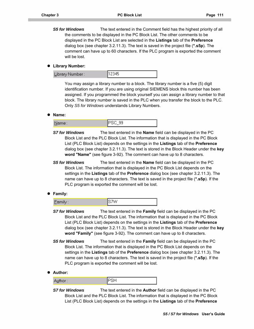
Chapter 3 PC Block List Page 111
S5 / S7 for Windows User’s Guide
S5 for Windows The text entered in the Comment field has the highest priority of all the comments to be displayed in the PC Block List. The other comments to be displayed in the PC Block List are selected in the Listings tab of the Preference dialog box (see chapter 3.2.11.3). The text is saved in the project file (*.s5p). The comment can have up to 60 characters. If the PLC program is exported the comment will be lost.
Library Number:
You may assign a library number to a block. The library number is a five (5) digit identification number. If you are using original SIEMENS block this number has been assigned. If you programmed the block yourself you can assign a library number to that block. The library number is saved in the PLC when you transfer the block to the PLC. Only S5 for Windows understands Library Numbers.
Name:
S7 for Windows The text entered in the Name field can be displayed in the PC Block List and the PLC Block List. The information that is displayed in the PC Block List (PLC Block List) depends on the settings in the Listings tab of the Preference dialog box (see chapter 3.2.11.3). The text is stored in the Block Header under the key word "Name" (see figure 3-92). The comment can have up to 8 characters.
S5 for Windows The text entered in the Name field can be displayed in the PC Block List. The information that is displayed in the PC Block List depends on the settings in the Listings tab of the Preference dialog box (see chapter 3.2.11.3). The name can have up to 8 characters. The text is saved in the project file (*.s5p). If the PLC program is exported the comment will be lost.
Family:
S7 for Windows The text entered in the Family field can be displayed in the PC Block List and the PLC Block List. The information that is displayed in the PC Block List (PLC Block List) depends on the settings in the Listings tab of the Preference dialog box (see chapter 3.2.11.3). The text is stored in the Block Header under the key word "Family" (see figure 3-92). The comment can have up to 8 characters.
S5 for Windows The text entered in the Family field can be displayed in the PC Block List. The information that is displayed in the PC Block List depends on the settings in the Listings tab of the Preference dialog box (see chapter 3.2.11.3). The name can have up to 8 characters. The text is saved in the project file (*.s5p). If the PLC program is exported the comment will be lost.
Author:
S7 for Windows The text entered in the Author field can be displayed in the PC Block List and the PLC Block List. The information that is displayed in the PC Block List (PLC Block List) depends on the settings in the Listings tab of the Preference
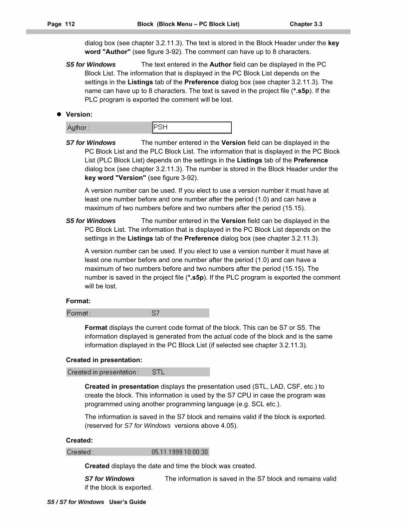
Page 112 Block (Block Menu – PC Block List) Chapter 3.3
S5 / S7 for Windows User’s Guide
dialog box (see chapter 3.2.11.3). The text is stored in the Block Header under the key word "Author" (see figure 3-92). The comment can have up to 8 characters.
S5 for Windows The text entered in the Author field can be displayed in the PC Block List. The information that is displayed in the PC Block List depends on the settings in the Listings tab of the Preference dialog box (see chapter 3.2.11.3). The name can have up to 8 characters. The text is saved in the project file (*.s5p). If the PLC program is exported the comment will be lost.
Version:
S7 for Windows The number entered in the Version field can be displayed in the PC Block List and the PLC Block List. The information that is displayed in the PC Block List (PLC Block List) depends on the settings in the Listings tab of the Preference dialog box (see chapter 3.2.11.3). The number is stored in the Block Header under the key word "Version" (see figure 3-92).
A version number can be used. If you elect to use a version number it must have at least one number before and one number after the period (1.0) and can have a maximum of two numbers before and two numbers after the period (15.15).
S5 for Windows The number entered in the Version field can be displayed in the PC Block List. The information that is displayed in the PC Block List depends on the settings in the Listings tab of the Preference dialog box (see chapter 3.2.11.3).
A version number can be used. If you elect to use a version number it must have at least one number before and one number after the period (1.0) and can have a maximum of two numbers before and two numbers after the period (15.15). The number is saved in the project file (*.s5p). If the PLC program is exported the comment will be lost.
Format:
Format displays the current code format of the block. This can be S7 or S5. The information displayed is generated from the actual code of the block and is the same information displayed in the PC Block List (if selected see chapter 3.2.11.3).
Created in presentation:
Created in presentation displays the presentation used (STL, LAD, CSF, etc.) to create the block. This information is used by the S7 CPU in case the program was programmed using another programming language (e.g. SCL etc.).
The information is saved in the S7 block and remains valid if the block is exported. (reserved for S7 for Windows versions above 4.05).
Created:
Created displays the date and time the block was created.
S7 for Windows The information is saved in the S7 block and remains valid if the block is exported.
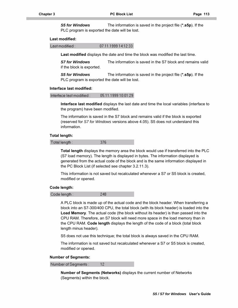
Chapter 3 PC Block List Page 113
S5 / S7 for Windows User’s Guide
S5 for Windows The information is saved in the project file (*.s5p). If the PLC program is exported the date will be lost.
Last modified:
Last modified displays the date and time the block was modified the last time.
S7 for Windows The information is saved in the S7 block and remains valid if the block is exported.
S5 for Windows The information is saved in the project file (*.s5p). If the PLC program is exported the date will be lost.
Interface last modified:
Interface last modified displays the last date and time the local variables (interface to the program) have been modified.
The information is saved in the S7 block and remains valid if the block is exported (reserved for S7 for Windows versions above 4.05). S5 does not understand this information.
Total length:
Total length displays the memory area the block would use if transferred into the PLC (S7 load memory). The length is displayed in bytes. The information displayed is generated from the actual code of the block and is the same information displayed in the PC Block List (if selected see chapter 3.2.11.3).
This information is not saved but recalculated whenever a S7 or S5 block is created, modified or opened.
Code length:
A PLC block is made up of the actual code and the block header. When transferring a block into an S7-300/400 CPU, the total block (with its block header) is loaded into the Load Memory. The actual code (the block without its header) is than passed into the CPU RAM. Therefore, an S7 block will need more space in the load memory than in the CPU RAM. Code length displays the length of the code of a block (total block length minus header).
S5 does not use this technique; the total block is always saved in the CPU RAM.
The information is not saved but recalculated whenever a S7 or S5 block is created, modified or opened.
Number of Segments:
Number of Segments (Networks) displays the current number of Networks (Segments) within the block.
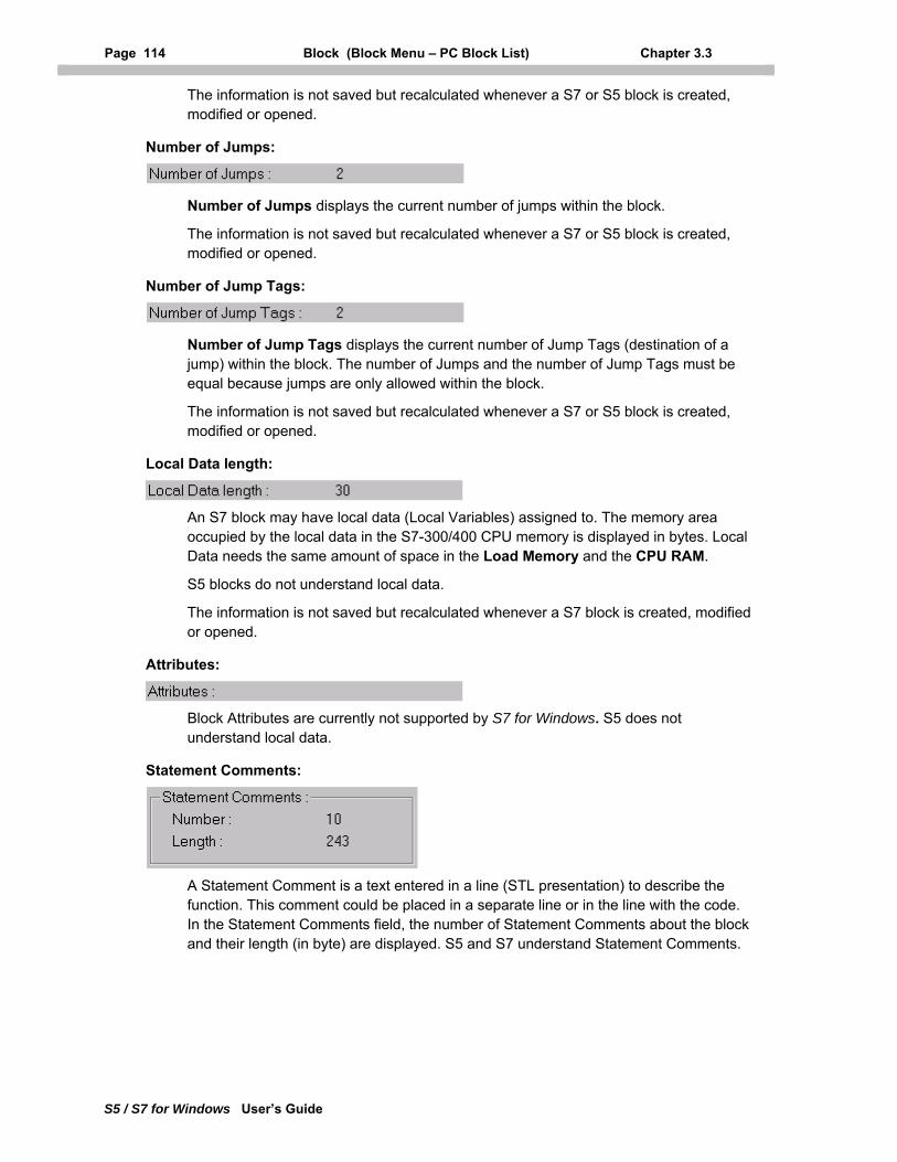
Page 114 Block (Block Menu – PC Block List) Chapter 3.3
S5 / S7 for Windows User’s Guide
The information is not saved but recalculated whenever a S7 or S5 block is created, modified or opened.
Number of Jumps:
Number of Jumps displays the current number of jumps within the block.
The information is not saved but recalculated whenever a S7 or S5 block is created, modified or opened.
Number of Jump Tags:
Number of Jump Tags displays the current number of Jump Tags (destination of a jump) within the block. The number of Jumps and the number of Jump Tags must be equal because jumps are only allowed within the block.
The information is not saved but recalculated whenever a S7 or S5 block is created, modified or opened.
Local Data length:
An S7 block may have local data (Local Variables) assigned to. The memory area occupied by the local data in the S7-300/400 CPU memory is displayed in bytes. Local Data needs the same amount of space in the Load Memory and the CPU RAM.
S5 blocks do not understand local data.
The information is not saved but recalculated whenever a S7 block is created, modified or opened.
Attributes:
Block Attributes are currently not supported by S7 for Windows. S5 does not understand local data.
Statement Comments:
A Statement Comment is a text entered in a line (STL presentation) to describe the function. This comment could be placed in a separate line or in the line with the code. In the Statement Comments field, the number of Statement Comments about the block and their length (in byte) are displayed. S5 and S7 understand Statement Comments.
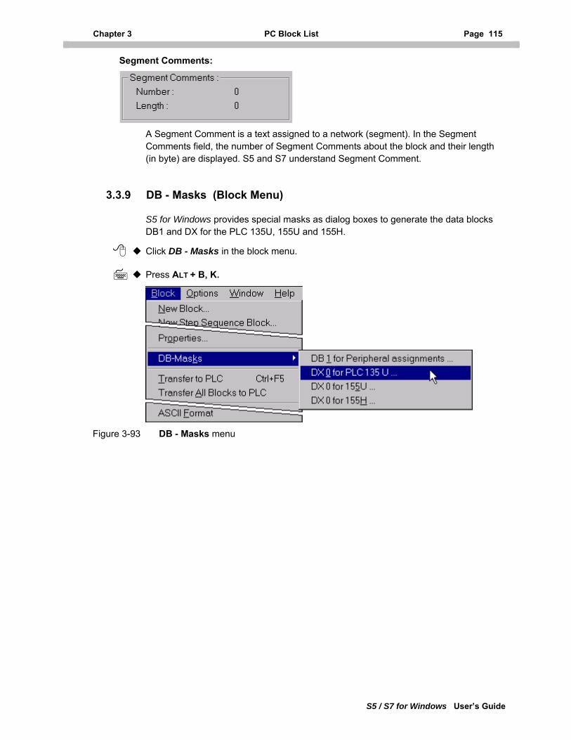
Chapter 3 PC Block List Page 115
S5 / S7 for Windows User’s Guide
Segment Comments:
A Segment Comment is a text assigned to a network (segment). In the Segment Comments field, the number of Segment Comments about the block and their length (in byte) are displayed. S5 and S7 understand Segment Comment.
3.3.9 DB - Masks (Block Menu)
S5 for Windows provides special masks as dialog boxes to generate the data blocks DB1 and DX for the PLC 135U, 155U and 155H.
Click DB - Masks in the block menu.
Press ALT + B, K.
Figure 3-93 DB - Masks menu
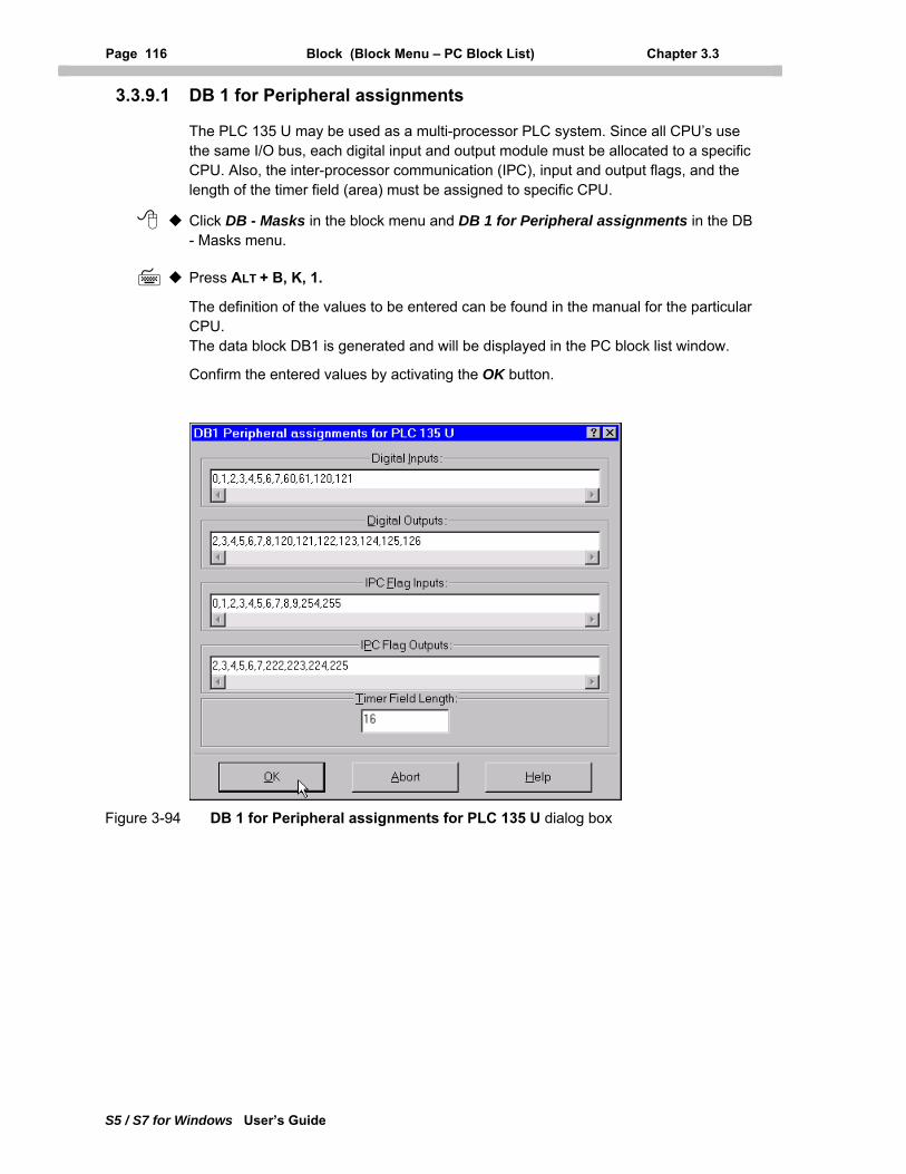
Page 116 Block (Block Menu – PC Block List) Chapter 3.3
S5 / S7 for Windows User’s Guide
3.3.9.1 DB 1 for Peripheral assignments
The PLC 135 U may be used as a multi-processor PLC system. Since all CPU’s use the same I/O bus, each digital input and output module must be allocated to a specific CPU. Also, the inter-processor communication (IPC), input and output flags, and the length of the timer field (area) must be assigned to specific CPU.
Click DB - Masks in the block menu and DB 1 for Peripheral assignments in the DB - Masks menu.
Press ALT + B, K, 1.
The definition of the values to be entered can be found in the manual for the particular CPU. The data block DB1 is generated and will be displayed in the PC block list window.
Confirm the entered values by activating the OK button.
Figure 3-94 DB 1 for Peripheral assignments for PLC 135 U dialog box
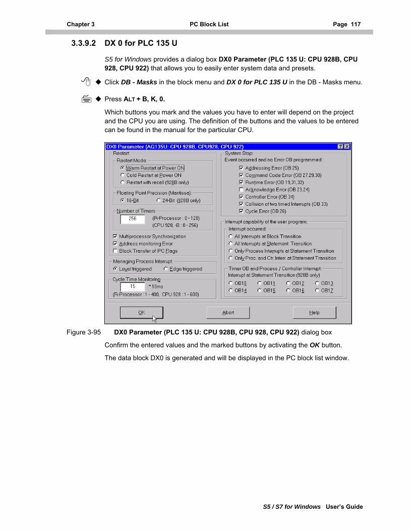
Chapter 3 PC Block List Page 117
S5 / S7 for Windows User’s Guide
3.3.9.2 DX 0 for PLC 135 U
S5 for Windows provides a dialog box DX0 Parameter (PLC 135 U: CPU 928B, CPU 928, CPU 922) that allows you to easily enter system data and presets.
Click DB - Masks in the block menu and DX 0 for PLC 135 U in the DB - Masks menu.
Press ALT + B, K, 0.
Which buttons you mark and the values you have to enter will depend on the project and the CPU you are using. The definition of the buttons and the values to be entered can be found in the manual for the particular CPU.
Figure 3-95 DX0 Parameter (PLC 135 U: CPU 928B, CPU 928, CPU 922) dialog box
Confirm the entered values and the marked buttons by activating the OK button.
The data block DX0 is generated and will be displayed in the PC block list window.
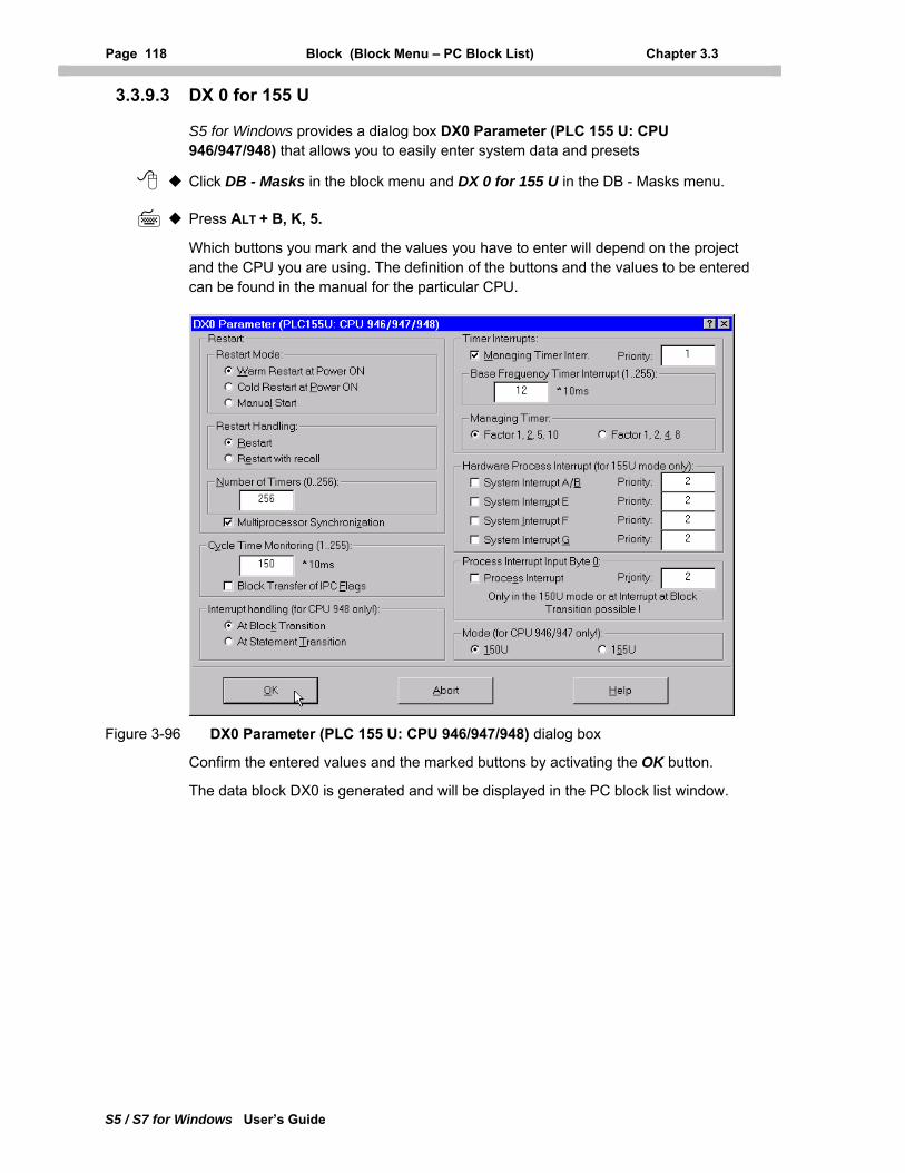
Page 118 Block (Block Menu – PC Block List) Chapter 3.3
S5 / S7 for Windows User’s Guide
3.3.9.3 DX 0 for 155 U
S5 for Windows provides a dialog box DX0 Parameter (PLC 155 U: CPU 946/947/948) that allows you to easily enter system data and presets
Click DB - Masks in the block menu and DX 0 for 155 U in the DB - Masks menu.
Press ALT + B, K, 5.
Which buttons you mark and the values you have to enter will depend on the project and the CPU you are using. The definition of the buttons and the values to be entered can be found in the manual for the particular CPU.
Figure 3-96 DX0 Parameter (PLC 155 U: CPU 946/947/948) dialog box
Confirm the entered values and the marked buttons by activating the OK button.
The data block DX0 is generated and will be displayed in the PC block list window.
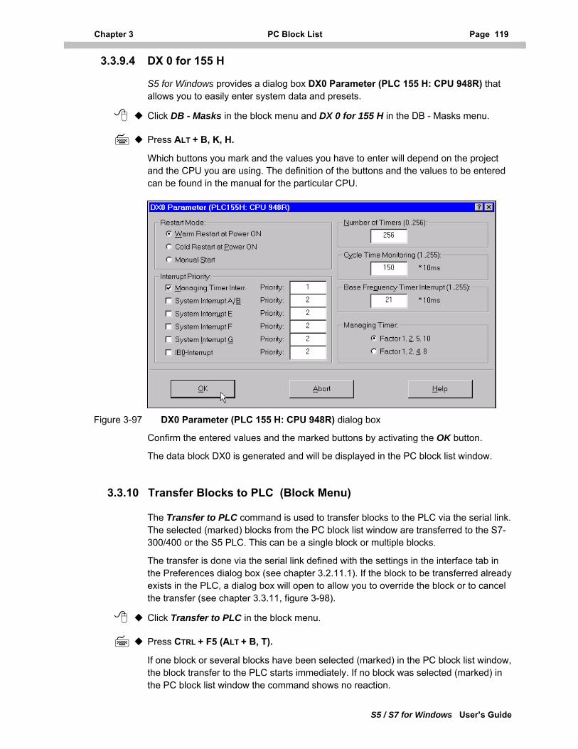
Chapter 3 PC Block List Page 119
S5 / S7 for Windows User’s Guide
3.3.9.4 DX 0 for 155 H
S5 for Windows provides a dialog box DX0 Parameter (PLC 155 H: CPU 948R) that allows you to easily enter system data and presets.
Click DB - Masks in the block menu and DX 0 for 155 H in the DB - Masks menu.
Press ALT + B, K, H.
Which buttons you mark and the values you have to enter will depend on the project and the CPU you are using. The definition of the buttons and the values to be entered can be found in the manual for the particular CPU.
Figure 3-97 DX0 Parameter (PLC 155 H: CPU 948R) dialog box
Confirm the entered values and the marked buttons by activating the OK button.
The data block DX0 is generated and will be displayed in the PC block list window.
3.3.10 Transfer Blocks to PLC (Block Menu)
The Transfer to PLC command is used to transfer blocks to the PLC via the serial link. The selected (marked) blocks from the PC block list window are transferred to the S7-300/400 or the S5 PLC. This can be a single block or multiple blocks.
The transfer is done via the serial link defined with the settings in the interface tab in the Preferences dialog box (see chapter 3.2.11.1). If the block to be transferred already exists in the PLC, a dialog box will open to allow you to override the block or to cancel the transfer (see chapter 3.3.11, figure 3-98).
Click Transfer to PLC in the block menu.
Press CTRL + F5 (ALT + B, T).
If one block or several blocks have been selected (marked) in the PC block list window, the block transfer to the PLC starts immediately. If no block was selected (marked) in the PC block list window the command shows no reaction.
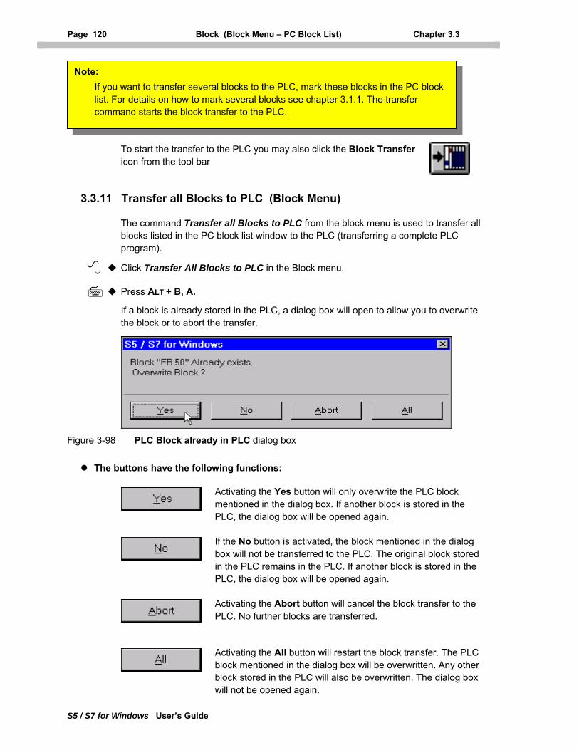
Page 120 Block (Block Menu – PC Block List) Chapter 3.3
S5 / S7 for Windows User’s Guide
Note: If you want to transfer several blocks to the PLC, mark these blocks in the PC block list. For details on how to mark several blocks see chapter 3.1.1. The transfer command starts the block transfer to the PLC.
To start the transfer to the PLC you may also click the Block Transfer icon from the tool bar
3.3.11 Transfer all Blocks to PLC (Block Menu)
The command Transfer all Blocks to PLC from the block menu is used to transfer all blocks listed in the PC block list window to the PLC (transferring a complete PLC program).
Click Transfer All Blocks to PLC in the Block menu.
Press ALT + B, A.
If a block is already stored in the PLC, a dialog box will open to allow you to overwrite the block or to abort the transfer.
Figure 3-98 PLC Block already in PLC dialog box
The buttons have the following functions:
Activating the Yes button will only overwrite the PLC block mentioned in the dialog box. If another block is stored in the PLC, the dialog box will be opened again.
If the No button is activated, the block mentioned in the dialog box will not be transferred to the PLC. The original block stored in the PLC remains in the PLC. If another block is stored in the PLC, the dialog box will be opened again.
Activating the Abort button will cancel the block transfer to the PLC. No further blocks are transferred.
Activating the All button will restart the block transfer. The PLC block mentioned in the dialog box will be overwritten. Any other block stored in the PLC will also be overwritten. The dialog box will not be opened again.
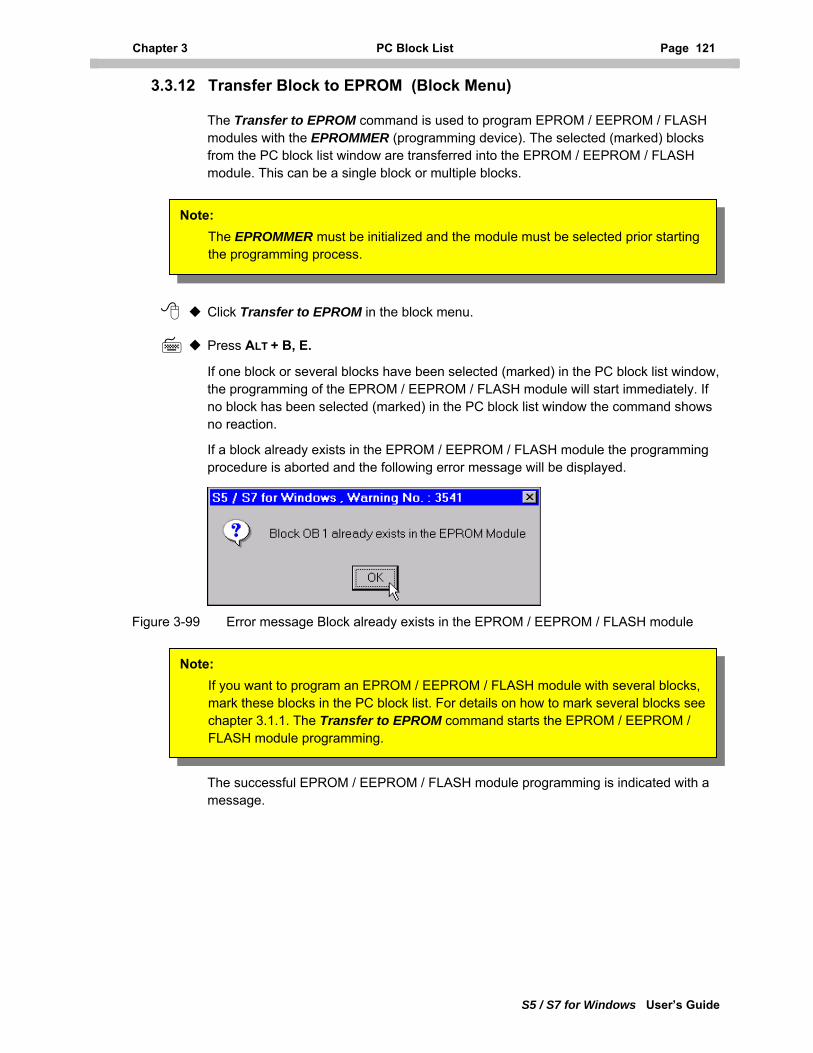
Chapter 3 PC Block List Page 121
S5 / S7 for Windows User’s Guide
3.3.12 Transfer Block to EPROM (Block Menu)
The Transfer to EPROM command is used to program EPROM / EEPROM / FLASH modules with the EPROMMER (programming device). The selected (marked) blocks from the PC block list window are transferred into the EPROM / EEPROM / FLASH module. This can be a single block or multiple blocks.
Click Transfer to EPROM in the block menu.
Press ALT + B, E.
If one block or several blocks have been selected (marked) in the PC block list window, the programming of the EPROM / EEPROM / FLASH module will start immediately. If no block has been selected (marked) in the PC block list window the command shows no reaction.
If a block already exists in the EPROM / EEPROM / FLASH module the programming procedure is aborted and the following error message will be displayed.
Note: The EPROMMER must be initialized and the module must be selected prior starting the programming process.
Figure 3-99 Error message Block already exists in the EPROM / EEPROM / FLASH module
Note: If you want to program an EPROM / EEPROM / FLASH module with several blocks, mark these blocks in the PC block list. For details on how to mark several blocks see chapter 3.1.1. The Transfer to EPROM command starts the EPROM / EEPROM / FLASH module programming.
The successful EPROM / EEPROM / FLASH module programming is indicated with a message.
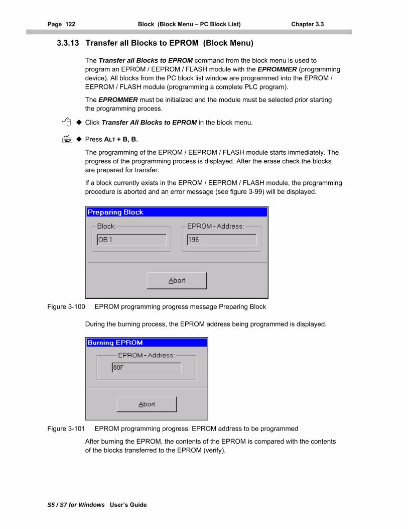
Page 122 Block (Block Menu – PC Block List) Chapter 3.3
S5 / S7 for Windows User’s Guide
3.3.13 Transfer all Blocks to EPROM (Block Menu)
The Transfer all Blocks to EPROM command from the block menu is used to program an EPROM / EEPROM / FLASH module with the EPROMMER (programming device). All blocks from the PC block list window are programmed into the EPROM / EEPROM / FLASH module (programming a complete PLC program).
The EPROMMER must be initialized and the module must be selected prior starting the programming process.
Click Transfer All Blocks to EPROM in the block menu.
Press ALT + B, B.
The programming of the EPROM / EEPROM / FLASH module starts immediately. The progress of the programming process is displayed. After the erase check the blocks are prepared for transfer.
If a block currently exists in the EPROM / EEPROM / FLASH module, the programming procedure is aborted and an error message (see figure 3-99) will be displayed.
Figure 3-100 EPROM programming progress message Preparing Block
During the burning process, the EPROM address being programmed is displayed.
Figure 3-101 EPROM programming progress. EPROM address to be programmed
After burning the EPROM, the contents of the EPROM is compared with the contents of the blocks transferred to the EPROM (verify).
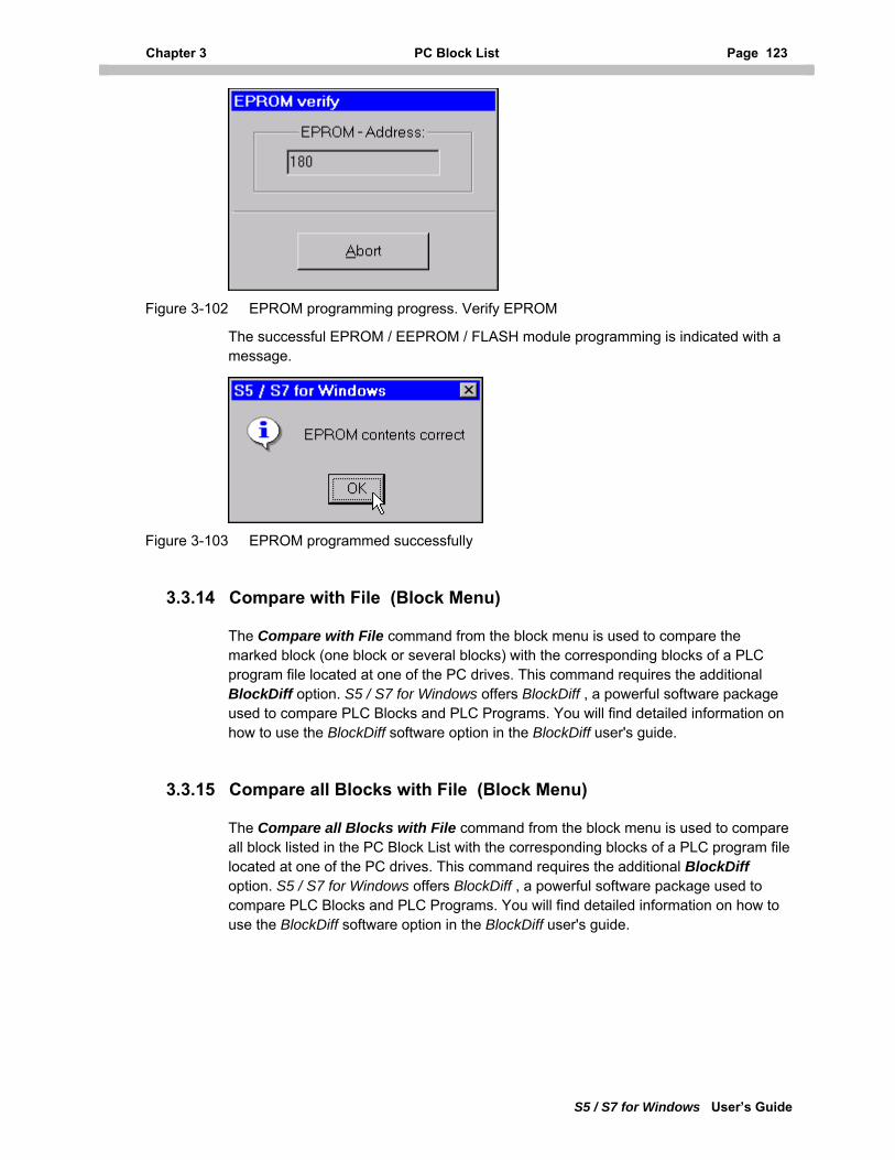
Chapter 3 PC Block List Page 123
S5 / S7 for Windows User’s Guide
Figure 3-102 EPROM programming progress. Verify EPROM
The successful EPROM / EEPROM / FLASH module programming is indicated with a message.
Figure 3-103 EPROM programmed successfully
3.3.14 Compare with File (Block Menu)
The Compare with File command from the block menu is used to compare the marked block (one block or several blocks) with the corresponding blocks of a PLC program file located at one of the PC drives. This command requires the additional BlockDiff option. S5 / S7 for Windows offers BlockDiff , a powerful software package used to compare PLC Blocks and PLC Programs. You will find detailed information on how to use the BlockDiff software option in the BlockDiff user's guide.
3.3.15 Compare all Blocks with File (Block Menu)
The Compare all Blocks with File command from the block menu is used to compare all block listed in the PC Block List with the corresponding blocks of a PLC program file located at one of the PC drives. This command requires the additional BlockDiff option. S5 / S7 for Windows offers BlockDiff , a powerful software package used to compare PLC Blocks and PLC Programs. You will find detailed information on how to use the BlockDiff software option in the BlockDiff user's guide.
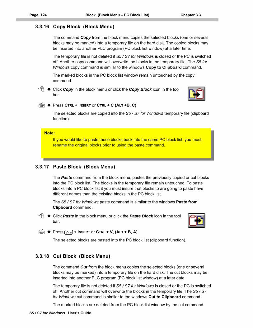
Page 124 Block (Block Menu – PC Block List) Chapter 3.3
S5 / S7 for Windows User’s Guide
3.3.16 Copy Block (Block Menu)
The command Copy from the block menu copies the selected blocks (one or several blocks may be marked) into a temporary file on the hard disk. The copied blocks may be inserted into another PLC program (PC block list window) at a later time.
The temporary file is not deleted if S5 / S7 for Windows is closed or the PC is switched off. Another copy command will overwrite the blocks in the temporary file. The S5 for Windows copy command is similar to the windows Copy to Clipboard command.
The marked blocks in the PC block list window remain untouched by the copy command.
Click Copy in the block menu or click the Copy Block icon in the tool bar.
Press CTRL + INSERT or CTRL + C (ALT +B, C)
The selected blocks are copied into the S5 / S7 for Windows temporary file (clipboard function).
Note: If you would like to paste those blocks back into the same PC block list, you must rename the original blocks prior to using the paste command.
3.3.17 Paste Block (Block Menu)
The Paste command from the block menu, pastes the previously copied or cut blocks into the PC block list. The blocks in the temporary file remain untouched. To paste blocks into a PC block list it you must insure that blocks to are going to paste have different names than the existing blocks in the PC block list.
The S5 / S7 for Windows paste command is similar to the windows Paste from Clipboard command.
Click Paste in the block menu or click the Paste Block icon in the tool bar.
Press + INSERT or CTRL + V, (ALT + B, A)
The selected blocks are pasted into the PC block list (clipboard function).
3.3.18 Cut Block (Block Menu)
The command Cut from the block menu copies the selected blocks (one or several blocks may be marked) into a temporary file on the hard disk. The cut blocks may be inserted into another PLC program (PC block list window) at a later date.
The temporary file is not deleted if S5 / S7 for Windows is closed or the PC is switched off. Another cut command will overwrite the blocks in the temporary file. The S5 / S7 for Windows cut command is similar to the windows Cut to Clipboard command.
The marked blocks are deleted from the PC block list window by the cut command.
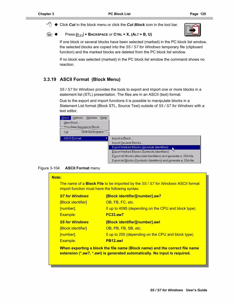
Chapter 3 PC Block List Page 125
S5 / S7 for Windows User’s Guide
Click Cut in the block menu or click the Cut Block icon in the tool bar.
Press + BACKSPACE or CTRL + X, (ALT + B, U)
If one block or several blocks have been selected (marked) in the PC block list window, the selected blocks are copied into the S5 / S7 for Windows temporary file (clipboard function) and the marked blocks are deleted from the PC block list window.
If no block was selected (marked) in the PC block list window the command shows no reaction.
3.3.19 ASCII Format (Block Menu)
S5 / S7 for Windows provides the tools to export and import one or more blocks in a statement list (STL) presentation. The files are in an ASCII (text) format. Due to the export and import functions it is possible to manipulate blocks in a Statement List format (Block STL, Source Text) outside of S5 / S7 for Windows with a text editor.
Figure 3-104 ASCII Format menu
Example: PB12.awl
When exporting a block the file name (Block name) and the correct file name extension (*.aw7, *.awl) is generated automatically. No input is required.
Note: The name of a Block File to be imported by the S5 / S7 for Windows ASCII format import function must have the following syntax:
S7 for Windows [Block identifier][number].aw7 [Block identifier] OB, FB, FC, etc. [number]. 0 up to 4095 (depending on the CPU and block type) Example: FC33.aw7
S5 for Windows [Block identifier][number].awl [Block identifier] OB, PB, FB, SB, etc. [number]. 0 up to 255 (depending on the CPU and block type)
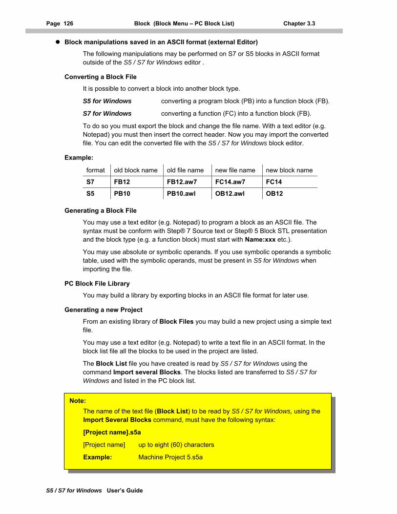
Page 126 Block (Block Menu – PC Block List) Chapter 3.3
S5 / S7 for Windows User’s Guide
Block manipulations saved in an ASCII format (external Editor)
The following manipulations may be performed on S7 or S5 blocks in ASCII format outside of the S5 / S7 for Windows editor .
Converting a Block File
It is possible to convert a block into another block type.
S5 for Windows converting a program block (PB) into a function block (FB).
S7 for Windows converting a function (FC) into a function block (FB).
To do so you must export the block and change the file name. With a text editor (e.g. Notepad) you must then insert the correct header. Now you may import the converted file. You can edit the converted file with the S5 / S7 for Windows block editor.
Example:
format old block name old file name new file name new block name
S7 FB12 FB12.aw7 FC14.aw7 FC14
S5 PB10 PB10.awl OB12.awl OB12
Generating a Block File
You may use a text editor (e.g. Notepad) to program a block as an ASCII file. The syntax must be conform with Step® 7 Source text or Step® 5 Block STL presentation and the block type (e.g. a function block) must start with Name:xxx etc.).
You may use absolute or symbolic operands. If you use symbolic operands a symbolic table, used with the symbolic operands, must be present in S5 for Windows when importing the file.
PC Block File Library
You may build a library by exporting blocks in an ASCII file format for later use.
Generating a new Project
From an existing library of Block Files you may build a new project using a simple text file.
You may use a text editor (e.g. Notepad) to write a text file in an ASCII format. In the block list file all the blocks to be used in the project are listed.
The Block List file you have created is read by S5 / S7 for Windows using the command Import several Blocks. The blocks listed are transferred to S5 / S7 for Windows and listed in the PC block list.
[Project name] up to eight (60) characters
Example: Machine Project 5.s5a
Note: The name of the text file (Block List) to be read by S5 / S7 for Windows, using the Import Several Blocks command, must have the following syntax:
[Project name].s5a
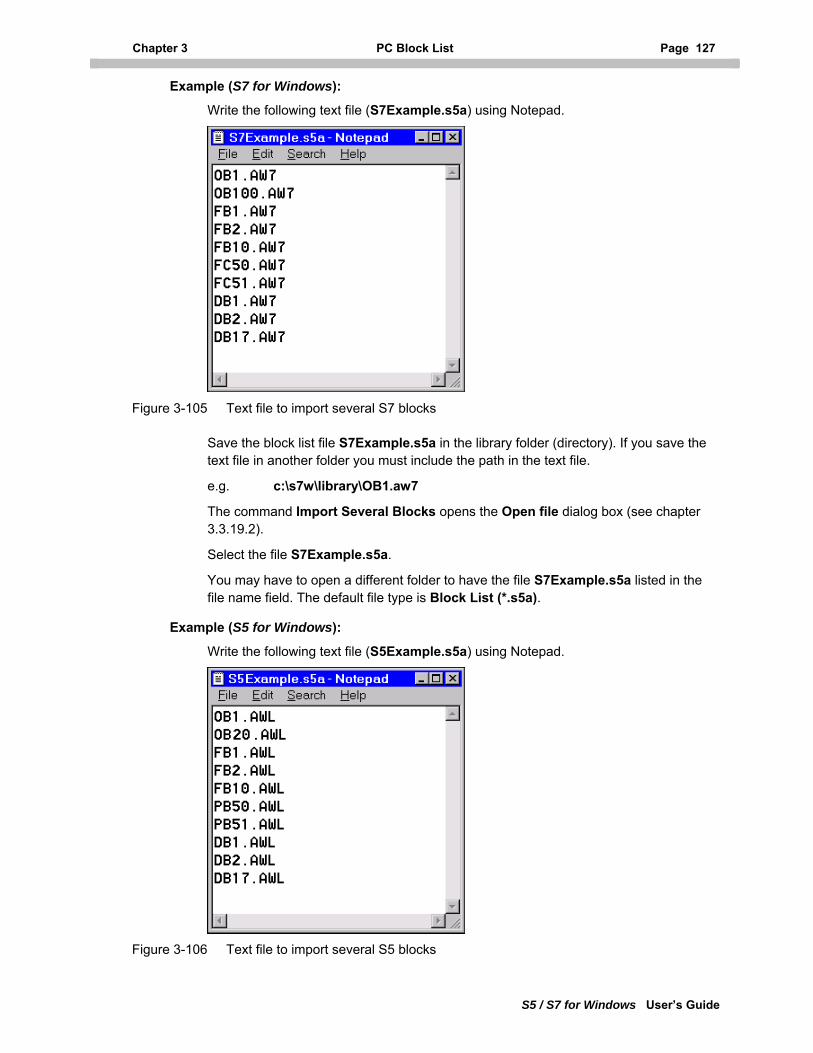
Chapter 3 PC Block List Page 127
S5 / S7 for Windows User’s Guide
Example (S7 for Windows):
Write the following text file (S7Example.s5a) using Notepad.
Figure 3-105 Text file to import several S7 blocks
Save the block list file S7Example.s5a in the library folder (directory). If you save the text file in another folder you must include the path in the text file.
e.g. c:\s7w\library\OB1.aw7
The command Import Several Blocks opens the Open file dialog box (see chapter 3.3.19.2).
Select the file S7Example.s5a.
You may have to open a different folder to have the file S7Example.s5a listed in the file name field. The default file type is Block List (*.s5a).
Example (S5 for Windows):
Write the following text file (S5Example.s5a) using Notepad.
Figure 3-106 Text file to import several S5 blocks
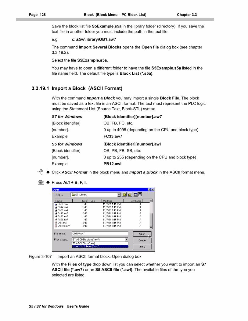
Page 128 Block (Block Menu – PC Block List) Chapter 3.3
S5 / S7 for Windows User’s Guide
Save the block list file S5Example.s5a in the library folder (directory). If you save the text file in another folder you must include the path in the text file.
e.g. c:\s5w\library\OB1.aw7
The command Import Several Blocks opens the Open file dialog box (see chapter 3.3.19.2).
Select the file S5Example.s5a.
You may have to open a different folder to have the file S5Example.s5a listed in the file name field. The default file type is Block List (*.s5a).
3.3.19.1 Import a Block (ASCII Format)
With the command Import a Block you may import a single Block File. The block must be saved as a text file in an ASCII format. The text must represent the PLC logic using the Statement List (Source Text, Block-STL) syntax.
S7 for Windows [Block identifier][number].aw7 [Block identifier] OB, FB, FC, etc. [number]. 0 up to 4095 (depending on the CPU and block type) Example: FC33.aw7
S5 for Windows [Block identifier][number].awl [Block identifier] OB, PB, FB, SB, etc. [number]. 0 up to 255 (depending on the CPU and block type) Example: PB12.awl
Click ASCII Format in the block menu and Import a Block in the ASCII format menu.
Press ALT + B, F, I.
Figure 3-107 Import an ASCII format block. Open dialog box
With the Files of type drop down list you can select whether you want to import an S7 ASCII file (*.aw7) or an S5 ASCII file (*.awl). The available files of the type you selected are listed.
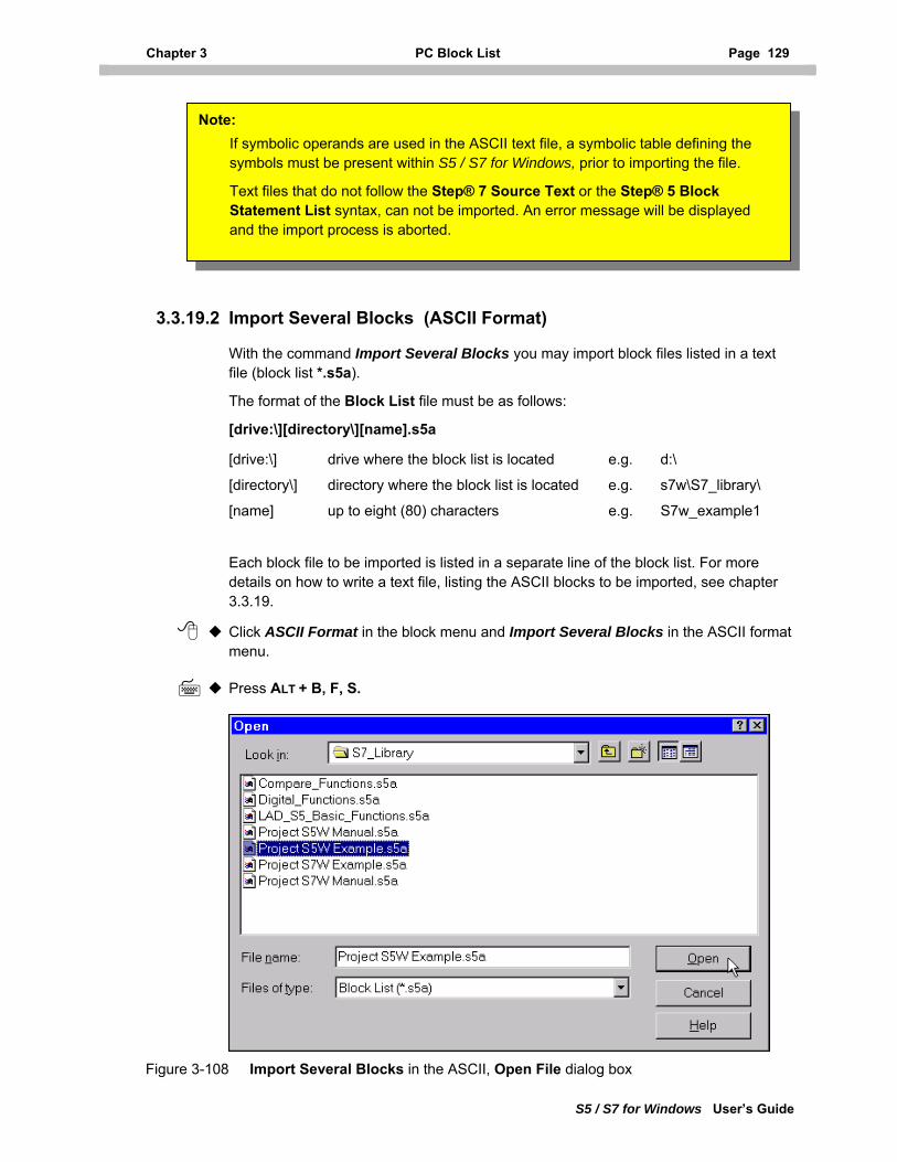
Chapter 3 PC Block List Page 129
S5 / S7 for Windows User’s Guide
If symbolic operands are used in the ASCII text file, a symbolic table defining the symbols must be present within S5 / S7 for Windows, prior to importing the file.
Text files that do not follow the Step® 7 Source Text or the Step® 5 Block Statement List syntax, can not be imported. An error message will be displayed and the import process is aborted.
Note:
3.3.19.2 Import Several Blocks (ASCII Format)
With the command Import Several Blocks you may import block files listed in a text file (block list *.s5a).
The format of the Block List file must be as follows:
[drive:\][directory\][name].s5a
[drive:\] drive where the block list is located e.g. d:\
[directory\] directory where the block list is located e.g. s7w\S7_library\
[name] up to eight (80) characters e.g. S7w_example1
Each block file to be imported is listed in a separate line of the block list. For more details on how to write a text file, listing the ASCII blocks to be imported, see chapter 3.3.19.
Click ASCII Format in the block menu and Import Several Blocks in the ASCII format menu.
Press ALT + B, F, S.
Figure 3-108 Import Several Blocks in the ASCII, Open File dialog box
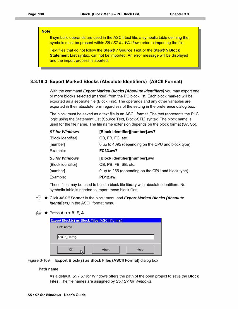
Page 130 Block (Block Menu – PC Block List) Chapter 3.3
S5 / S7 for Windows User’s Guide
If symbolic operands are used in the ASCII text file, a symbolic table defining the symbols must be present within S5 / S7 for Windows prior to importing the file.
Text files that do not follow the Step® 7 Source Text or the Step® 5 Block Statement List syntax, can not be imported. An error message will be displayed and the import process is aborted.
Note:
3.3.19.3 Export Marked Blocks (Absolute Identifiers) (ASCII Format)
With the command Export Marked Blocks (Absolute Identifiers) you may export one or more blocks selected (marked) from the PC block list. Each block marked will be exported as a separate file (Block File). The operands and any other variables are exported in their absolute form regardless of the setting in the preference dialog box.
The block must be saved as a text file in an ASCII format. The text represents the PLC logic using the Statement List (Source Text, Block-STL) syntax. The block name is used for the file name. The file name extension depends on the block format (S7, S5).
S7 for Windows [Block identifier][number].aw7 [Block identifier] OB, FB, FC, etc. [number] 0 up to 4095 (depending on the CPU and block type) Example: FC33.aw7
S5 for Windows [Block identifier][number].awl [Block identifier] OB, PB, FB, SB, etc. [number]. 0 up to 255 (depending on the CPU and block type) Example: PB12.awl
These files may be used to build a block file library with absolute identifiers. No symbolic table is needed to import these block files
Click ASCII Format in the block menu and Export Marked Blocks (Absolute Identifiers) in the ASCII format menu.
Press ALT + B, F, A.
Figure 3-109 Export Block(s) as Block Files (ASCII Format) dialog box
Path name
As a default, S5 / S7 for Windows offers the path of the open project to save the Block Files. The file names are assigned by S5 / S7 for Windows.
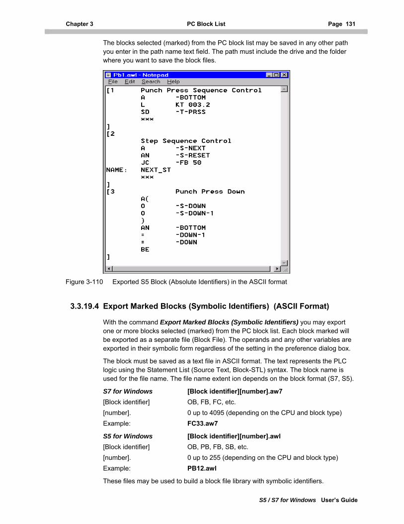
Chapter 3 PC Block List Page 131
S5 / S7 for Windows User’s Guide
The blocks selected (marked) from the PC block list may be saved in any other path you enter in the path name text field. The path must include the drive and the folder where you want to save the block files.
Figure 3-110 Exported S5 Block (Absolute Identifiers) in the ASCII format
3.3.19.4 Export Marked Blocks (Symbolic Identifiers) (ASCII Format)
With the command Export Marked Blocks (Symbolic Identifiers) you may export one or more blocks selected (marked) from the PC block list. Each block marked will be exported as a separate file (Block File). The operands and any other variables are exported in their symbolic form regardless of the setting in the preference dialog box.
The block must be saved as a text file in ASCII format. The text represents the PLC logic using the Statement List (Source Text, Block-STL) syntax. The block name is used for the file name. The file name extent ion depends on the block format (S7, S5).
S7 for Windows [Block identifier][number].aw7 [Block identifier] OB, FB, FC, etc. [number]. 0 up to 4095 (depending on the CPU and block type) Example: FC33.aw7
S5 for Windows [Block identifier][number].awl [Block identifier] OB, PB, FB, SB, etc. [number]. 0 up to 255 (depending on the CPU and block type) Example: PB12.awl
These files may be used to build a block file library with symbolic identifiers.
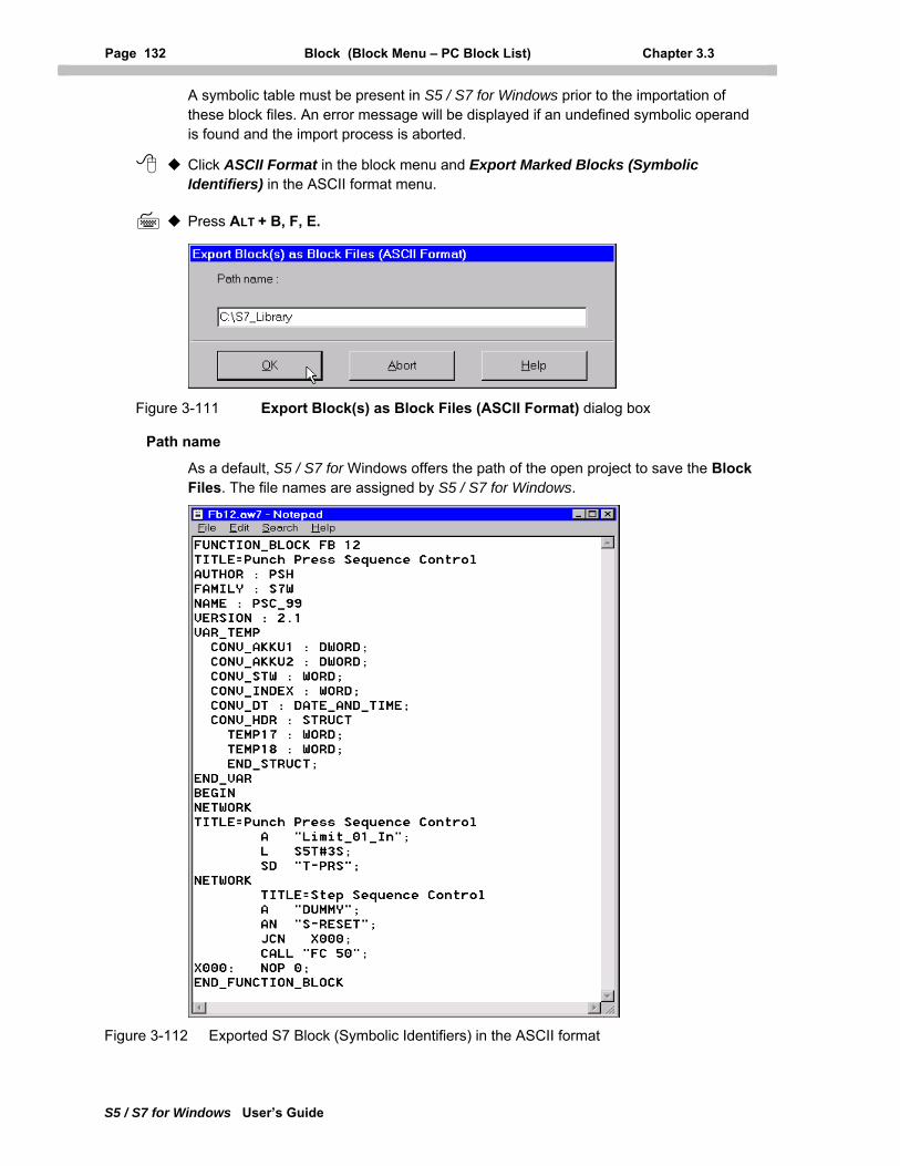
Page 132 Block (Block Menu – PC Block List) Chapter 3.3
S5 / S7 for Windows User’s Guide
A symbolic table must be present in S5 / S7 for Windows prior to the importation of these block files. An error message will be displayed if an undefined symbolic operand is found and the import process is aborted.
Click ASCII Format in the block menu and Export Marked Blocks (Symbolic Identifiers) in the ASCII format menu.
Press ALT + B, F, E.
Figure 3-111 Export Block(s) as Block Files (ASCII Format) dialog box
Path name
As a default, S5 / S7 for Windows offers the path of the open project to save the Block Files. The file names are assigned by S5 / S7 for Windows.
Figure 3-112 Exported S7 Block (Symbolic Identifiers) in the ASCII format
Chapter 3 PC Block List Page 133
S5 / S7 for Windows User’s Guide
The blocks selected (marked) from the PC block list may be saved in any other path you enter in the path name text field. The path must include the drive and the folder you want to save the block files in.
3.3.19.5 Export all Blocks (Absolute Identifiers) and generate an .S5A File
With the command Export all Blocks (Absolute Identifiers) and generate an .S5A File you may export all the blocks from the PC block list. Each block will be exported as a separate file (Block File).
In addition, a Block List file (*.S5A) will be generated and saved. The Block List file is an ASCII text file listing all the files from the PC block list. S5 / S7 for Windows automatically assigns a project name to the Block List file.
You may import all block files listed in the Block List file using the Import Several Blocks command.
The blocks are saved as a text file in ASCII format. The text represents the PLC logic using the Statement List (Source Text, Block-STL) syntax. The block name is used for the file name. The file name extension depends on the block format (S7, S5).
S7 for Windows [Block identifier][number].aw7 [Block identifier] OB, FB, FC, etc. [number]. 0 up to 4095 (depending on the CPU and block type) Example: FC33.aw7
S5 for Windows [Block identifier][number].awl [Block identifier] OB, PB, FB, SB, etc. [number]. 0 up to 255 (depending on the CPU and block type) Example: PB12.awl
These files may be used to build a block file library with absolute identifiers.
Click ASCII Format in the block menu and Export all Blocks (Absolute Identifiers) and generate a .S5A File in the ASCII format menu.
Press ALT + B, F, X.
The Export Block(s) as Block Files (ASCII Format) dialog box is opened (see figure 3-109).
Path name
As a default, S5 / S7 for Windows offers the path of the open project to save the Block Files. The file names are assigned by S5 / S7 for Windows.
The blocks selected (marked) from the PC block list may be saved in any other path you enter in the path name text field. The path must include the drive and the folder you want to save the block files in.
Note: No symbolic table is needed to import these block files.
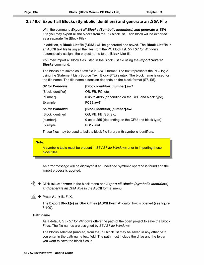
Page 134 Block (Block Menu – PC Block List) Chapter 3.3
S5 / S7 for Windows User’s Guide
3.3.19.6 Export all Blocks (Symbolic Identifiers) and generate an .S5A File
With the command Export all Blocks (Symbolic Identifiers) and generate a .S5A File you may export all the blocks from the PC block list. Each block will be exported as a separate file (Block File).
In addition, a Block List file (*.S5A) will be generated and saved. The Block List file is an ASCII text file listing all the files from the PC block list. S5 / S7 for Windows automatically assigns the project name to the Block List file.
You may import all block files listed in the Block List file using the Import Several Blocks command.
The blocks are saved as a text file in ASCII format. The text represents the PLC logic using the Statement List (Source Text, Block-STL) syntax. The block name is used for the file name. The file name extension depends on the block format (S7, S5).
S7 for Windows [Block identifier][number].aw7 [Block identifier] OB, FB, FC, etc. [number]. 0 up to 4095 (depending on the CPU and block type) Example: FC33.aw7
S5 for Windows [Block identifier][number].awl [Block identifier] OB, PB, FB, SB, etc. [number]. 0 up to 255 (depending on the CPU and block type) Example: PB12.awl
These files may be used to build a block file library with symbolic identifiers.
An error message will be displayed if an undefined symbolic operand is found and the import process is aborted.
Click ASCII Format in the block menu and Export all Blocks (Symbolic Identifiers) and generate an .S5A File in the ASCII format menu.
Press ALT + B, F, X.
The Export Block(s) as Block Files (ASCII Format) dialog box is opened (see figure 3-109).
Path name
As a default, S5 / S7 for Windows offers the path of the open project to save the Block Files. The file names are assigned by S5 / S7 for Windows.
The blocks selected (marked) from the PC block list may be saved in any other path you enter in the path name text field. The path must include the drive and the folder you want to save the block files in.
Note: A symbolic table must be present in S5 / S7 for Windows prior to importing these block files.
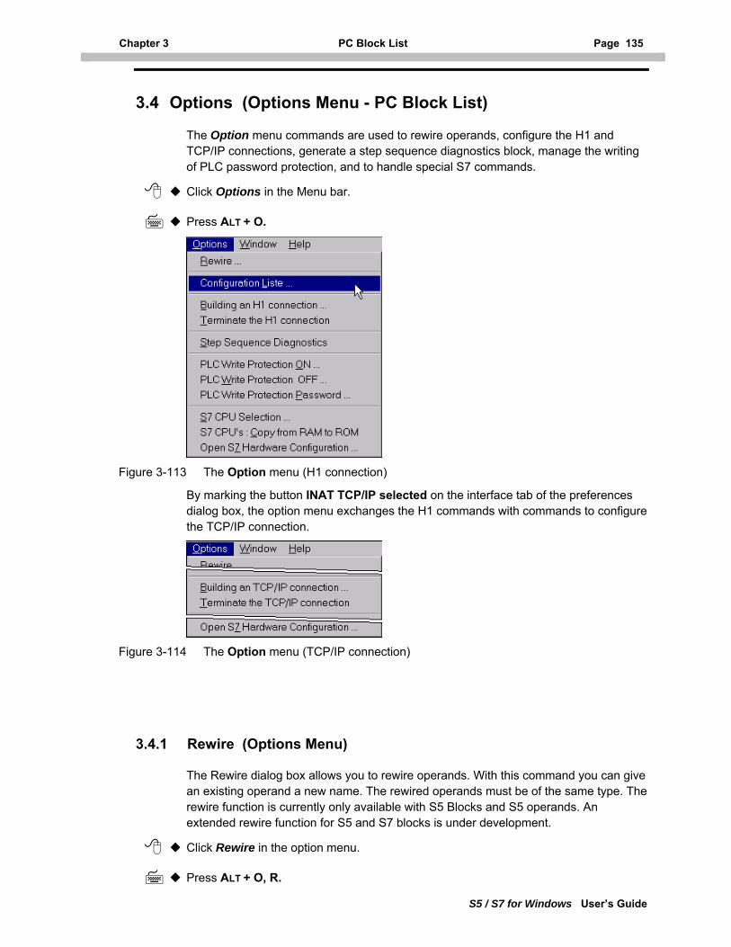
Chapter 3 PC Block List Page 135
S5 / S7 for Windows User’s Guide
3.4 Options (Options Menu - PC Block List)
The Option menu commands are used to rewire operands, configure the H1 and TCP/IP connections, generate a step sequence diagnostics block, manage the writing of PLC password protection, and to handle special S7 commands.
Click Options in the Menu bar.
Press ALT + O.
Figure 3-113 The Option menu (H1 connection)
By marking the button INAT TCP/IP selected on the interface tab of the preferences dialog box, the option menu exchanges the H1 commands with commands to configure the TCP/IP connection.
Figure 3-114 The Option menu (TCP/IP connection)
3.4.1 Rewire (Options Menu)
The Rewire dialog box allows you to rewire operands. With this command you can give an existing operand a new name. The rewired operands must be of the same type. The rewire function is currently only available with S5 Blocks and S5 operands. An extended rewire function for S5 and S7 blocks is under development.
Click Rewire in the option menu.
Press ALT + O, R.
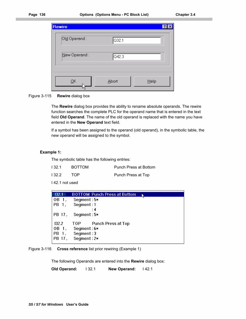
Page 136 Options (Options Menu - PC Block List) Chapter 3.4
S5 / S7 for Windows User’s Guide
Figure 3-115 Rewire dialog box
The Rewire dialog box provides the ability to rename absolute operands. The rewire function searches the complete PLC for the operand name that is entered in the text field Old Operand. The name of the old operand is replaced with the name you have entered in the New Operand text field.
If a symbol has been assigned to the operand (old operand), in the symbolic table, the new operand will be assigned to the symbol.
Example 1:
The symbolic table has the following entries:
I 32.1 BOTTOM Punch Press at Bottom
I 32.2 TOP Punch Press at Top
I 42.1 not used
Figure 3-116 Cross reference list prior rewiring (Example 1)
The following Operands are entered into the Rewire dialog box:
Old Operand: I 32.1 New Operand: I 42.1
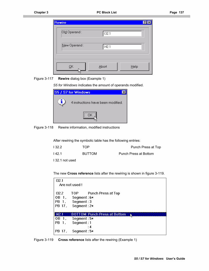
Chapter 3 PC Block List Page 137
S5 / S7 for Windows User’s Guide
Figure 3-117 Rewire dialog box (Example 1)
S5 for Windows indicates the amount of operands modified.
Figure 3-118 Rewire information, modified instructions
After rewiring the symbolic table has the following entries:
I 32.2 TOP Punch Press at Top
I 42.1 BUTTOM Punch Press at Bottom
I 32.1 not used
The new Cross reference lists after the rewiring is shown in figure 3-119.
Figure 3-119 Cross reference lists after the rewiring (Example 1)
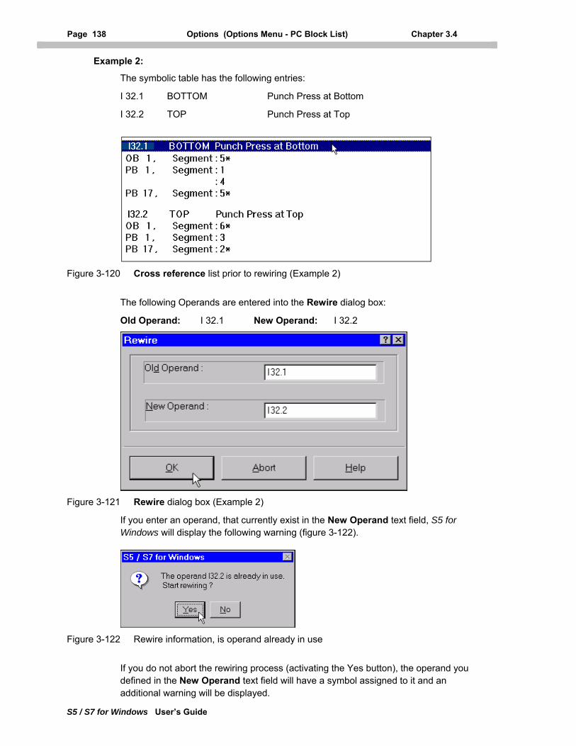
Page 138 Options (Options Menu - PC Block List) Chapter 3.4
S5 / S7 for Windows User’s Guide
Example 2:
The symbolic table has the following entries:
I 32.1 BOTTOM Punch Press at Bottom
I 32.2 TOP Punch Press at Top
Figure 3-120 Cross reference list prior to rewiring (Example 2)
The following Operands are entered into the Rewire dialog box:
Old Operand: I 32.1 New Operand: I 32.2
Figure 3-121 Rewire dialog box (Example 2)
If you enter an operand, that currently exist in the New Operand text field, S5 for Windows will display the following warning (figure 3-122).
Figure 3-122 Rewire information, is operand already in use
If you do not abort the rewiring process (activating the Yes button), the operand you defined in the New Operand text field will have a symbol assigned to it and an additional warning will be displayed.
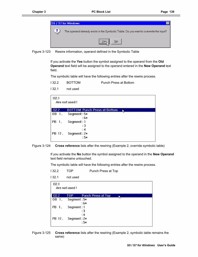
Chapter 3 PC Block List Page 139
S5 / S7 for Windows User’s Guide
Figure 3-123 Rewire information, operand defined in the Symbolic Table
If you activate the Yes button the symbol assigned to the operand from the Old Operand text field will be assigned to the operand entered in the New Operand text field.
The symbolic table will have the following entries after the rewire process.
I 32.2 BOTTOM Punch Press at Bottom
I 32.1 not used
Figure 3-124 Cross reference lists after the rewiring (Example 2, override symbolic table)
If you activate the No button the symbol assigned to the operand in the New Operand text field remains untouched.
The symbolic table will have the following entries after the rewire process.
I 32.2 TOP Punch Press at Top
I 32.1 not used
Figure 3-125 Cross reference lists after the rewiring (Example 2, symbolic table remains the same)
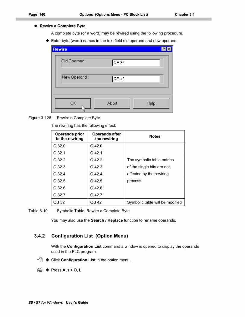
Page 140 Options (Options Menu - PC Block List) Chapter 3.4
S5 / S7 for Windows User’s Guide
Rewire a Complete Byte
A complete byte (or a word) may be rewired using the following procedure.
Enter byte (word) names in the text field old operand and new operand.
Figure 3-126 Rewire a Complete Byte
The rewiring has the following effect:
Operands prior to the rewiring
Operands after the rewiring Notes
Q 32.0 Q 42.0
Q 32.1 Q 42.1
Q 32.2 Q 42.2
Q 32.3 Q 42.3
Q 32.4 Q 42.4
Q 32.5 Q 42.5
Q 32.6 Q 42.6
Q 32.7 Q 42.7
The symbolic table entries
of the single bits are not
affected by the rewiring
process
QB 32 QB 42 Symbolic table will be modified
Table 3-10 Symbolic Table, Rewire a Complete Byte
You may also use the Search / Replace function to rename operands.
3.4.2 Configuration List (Option Menu)
With the Configuration List command a window is opened to display the operands used in the PLC program.
Click Configuration List in the option menu.
Press ALT + O, L
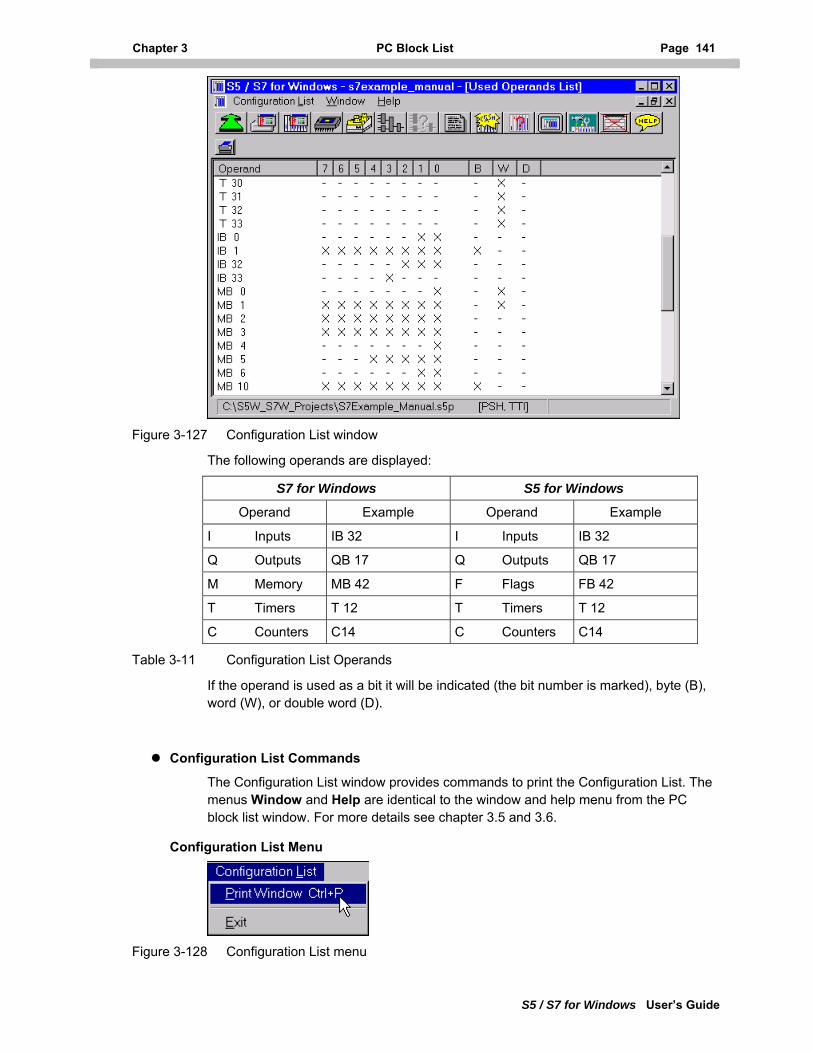
Chapter 3 PC Block List Page 141
S5 / S7 for Windows User’s Guide
Figure 3-127 Configuration List window
The following operands are displayed:
S7 for Windows S5 for Windows
Operand Example Operand Example
I Inputs IB 32 I Inputs IB 32
Q Outputs QB 17 Q Outputs QB 17
M Memory MB 42 F Flags FB 42
T Timers T 12 T Timers T 12
C Counters C14 C Counters C14
Table 3-11 Configuration List Operands
If the operand is used as a bit it will be indicated (the bit number is marked), byte (B), word (W), or double word (D).
Configuration List Commands
The Configuration List window provides commands to print the Configuration List. The menus Window and Help are identical to the window and help menu from the PC block list window. For more details see chapter 3.5 and 3.6.
Configuration List Menu
Figure 3-128 Configuration List menu
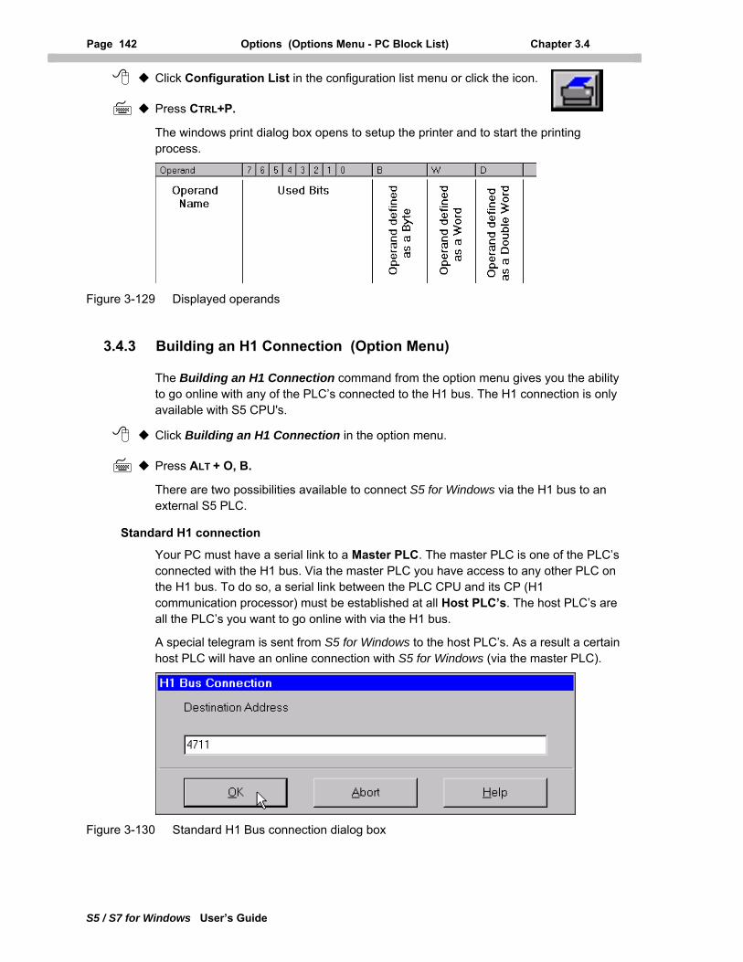
Page 142 Options (Options Menu - PC Block List) Chapter 3.4
S5 / S7 for Windows User’s Guide
Click Configuration List in the configuration list menu or click the icon.
Press CTRL+P.
The windows print dialog box opens to setup the printer and to start the printing process.
Figure 3-129 Displayed operands
3.4.3 Building an H1 Connection (Option Menu)
The Building an H1 Connection command from the option menu gives you the ability to go online with any of the PLC’s connected to the H1 bus. The H1 connection is only available with S5 CPU's.
Click Building an H1 Connection in the option menu.
Press ALT + O, B.
There are two possibilities available to connect S5 for Windows via the H1 bus to an external S5 PLC.
Standard H1 connection
Your PC must have a serial link to a Master PLC. The master PLC is one of the PLC’s connected with the H1 bus. Via the master PLC you have access to any other PLC on the H1 bus. To do so, a serial link between the PLC CPU and its CP (H1 communication processor) must be established at all Host PLC’s. The host PLC’s are all the PLC’s you want to go online with via the H1 bus.
A special telegram is sent from S5 for Windows to the host PLC’s. As a result a certain host PLC will have an online connection with S5 for Windows (via the master PLC).
Figure 3-130 Standard H1 Bus connection dialog box
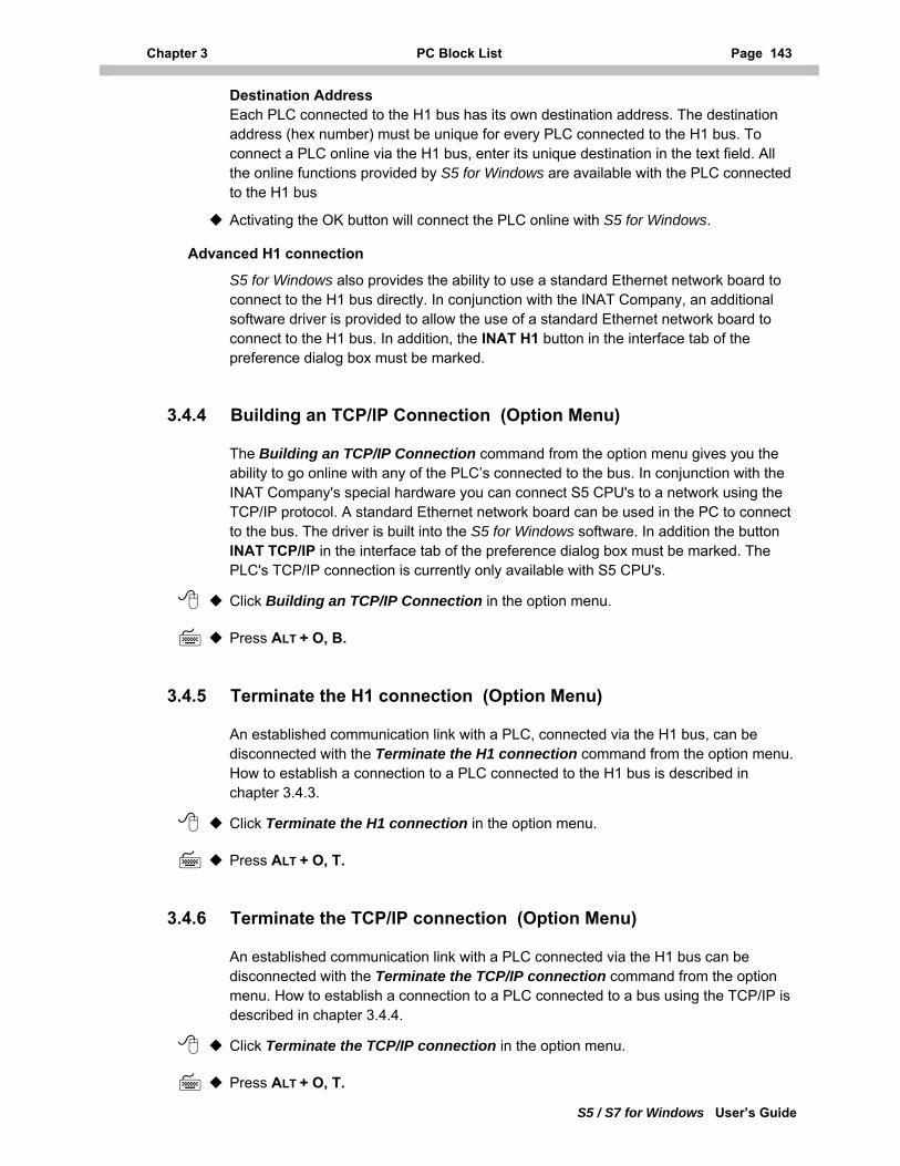
Chapter 3 PC Block List Page 143
S5 / S7 for Windows User’s Guide
Destination Address Each PLC connected to the H1 bus has its own destination address. The destination address (hex number) must be unique for every PLC connected to the H1 bus. To connect a PLC online via the H1 bus, enter its unique destination in the text field. All the online functions provided by S5 for Windows are available with the PLC connected to the H1 bus
Activating the OK button will connect the PLC online with S5 for Windows.
Advanced H1 connection
S5 for Windows also provides the ability to use a standard Ethernet network board to connect to the H1 bus directly. In conjunction with the INAT Company, an additional software driver is provided to allow the use of a standard Ethernet network board to connect to the H1 bus. In addition, the INAT H1 button in the interface tab of the preference dialog box must be marked.
3.4.4 Building an TCP/IP Connection (Option Menu)
The Building an TCP/IP Connection command from the option menu gives you the ability to go online with any of the PLC’s connected to the bus. In conjunction with the INAT Company's special hardware you can connect S5 CPU's to a network using the TCP/IP protocol. A standard Ethernet network board can be used in the PC to connect to the bus. The driver is built into the S5 for Windows software. In addition the button INAT TCP/IP in the interface tab of the preference dialog box must be marked. The PLC's TCP/IP connection is currently only available with S5 CPU's.
Click Building an TCP/IP Connection in the option menu.
Press ALT + O, B.
3.4.5 Terminate the H1 connection (Option Menu)
An established communication link with a PLC, connected via the H1 bus, can be disconnected with the Terminate the H1 connection command from the option menu. How to establish a connection to a PLC connected to the H1 bus is described in chapter 3.4.3.
Click Terminate the H1 connection in the option menu.
Press ALT + O, T.
3.4.6 Terminate the TCP/IP connection (Option Menu)
An established communication link with a PLC connected via the H1 bus can be disconnected with the Terminate the TCP/IP connection command from the option menu. How to establish a connection to a PLC connected to a bus using the TCP/IP is described in chapter 3.4.4.
Click Terminate the TCP/IP connection in the option menu.
Press ALT + O, T.
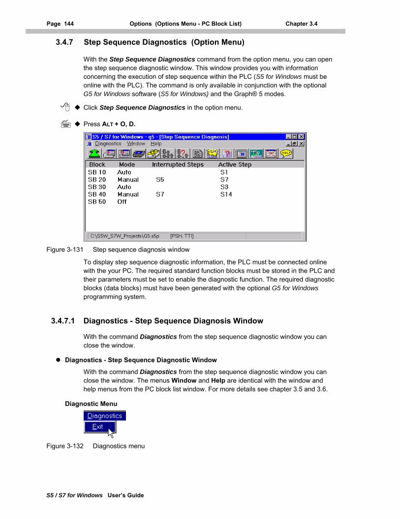
Page 144 Options (Options Menu - PC Block List) Chapter 3.4
S5 / S7 for Windows User’s Guide
3.4.7 Step Sequence Diagnostics (Option Menu)
With the Step Sequence Diagnostics command from the option menu, you can open the step sequence diagnostic window. This window provides you with information concerning the execution of step sequence within the PLC (S5 for Windows must be online with the PLC). The command is only available in conjunction with the optional G5 for Windows software (S5 for Windows) and the Graph® 5 modes.
Click Step Sequence Diagnostics in the option menu.
Press ALT + O, D.
Figure 3-131 Step sequence diagnosis window
To display step sequence diagnostic information, the PLC must be connected online with the your PC. The required standard function blocks must be stored in the PLC and their parameters must be set to enable the diagnostic function. The required diagnostic blocks (data blocks) must have been generated with the optional G5 for Windows programming system.
3.4.7.1 Diagnostics - Step Sequence Diagnosis Window
With the command Diagnostics from the step sequence diagnostic window you can close the window.
Diagnostics - Step Sequence Diagnostic Window
With the command Diagnostics from the step sequence diagnostic window you can close the window. The menus Window and Help are identical with the window and help menus from the PC block list window. For more details see chapter 3.5 and 3.6.
Diagnostic Menu
Figure 3-132 Diagnostics menu
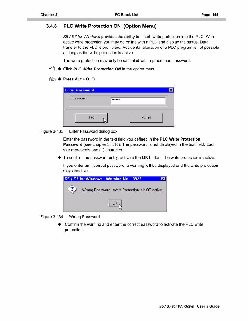
Chapter 3 PC Block List Page 145
S5 / S7 for Windows User’s Guide
3.4.8 PLC Write Protection ON (Option Menu)
S5 / S7 for Windows provides the ability to insert write protection into the PLC. With active write protection you may go online with a PLC and display the status. Data transfer to the PLC is prohibited. Accidental alteration of a PLC program is not possible as long as the write protection is active.
The write protection may only be canceled with a predefined password.
Click PLC Write Protection ON in the option menu.
Press ALT + O, O.
Figure 3-133 Enter Password dialog box
Enter the password in the text field you defined in the PLC Write Protection Password (see chapter 3.4.10). The password is not displayed in the text field. Each star represents one (1) character.
To confirm the password entry, activate the OK button. The write protection is active.
If you enter an incorrect password, a warning will be displayed and the write protection stays inactive.
Figure 3-134 Wrong Password
Confirm the warning and enter the correct password to activate the PLC write protection.
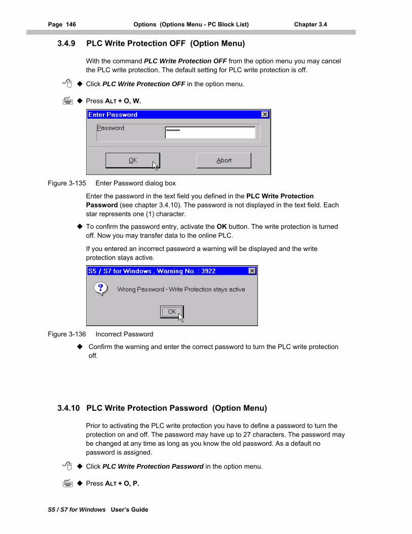
Page 146 Options (Options Menu - PC Block List) Chapter 3.4
S5 / S7 for Windows User’s Guide
3.4.9 PLC Write Protection OFF (Option Menu)
With the command PLC Write Protection OFF from the option menu you may cancel the PLC write protection. The default setting for PLC write protection is off.
Click PLC Write Protection OFF in the option menu.
Press ALT + O, W.
Figure 3-135 Enter Password dialog box
Enter the password in the text field you defined in the PLC Write Protection Password (see chapter 3.4.10). The password is not displayed in the text field. Each star represents one (1) character.
To confirm the password entry, activate the OK button. The write protection is turned off. Now you may transfer data to the online PLC.
If you entered an incorrect password a warning will be displayed and the write protection stays active.
Figure 3-136 Incorrect Password
Confirm the warning and enter the correct password to turn the PLC write protection off.
3.4.10 PLC Write Protection Password (Option Menu)
Prior to activating the PLC write protection you have to define a password to turn the protection on and off. The password may have up to 27 characters. The password may be changed at any time as long as you know the old password. As a default no password is assigned.
Click PLC Write Protection Password in the option menu.
Press ALT + O, P.
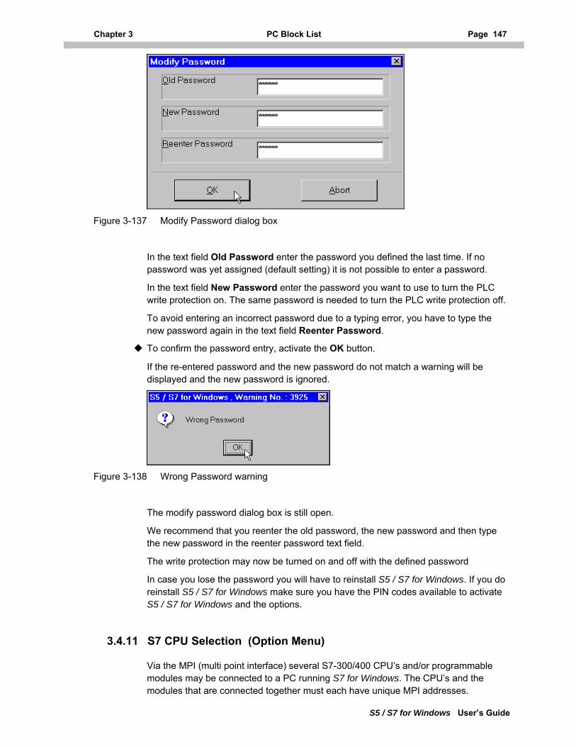
Chapter 3 PC Block List Page 147
S5 / S7 for Windows User’s Guide
Figure 3-137 Modify Password dialog box
In the text field Old Password enter the password you defined the last time. If no password was yet assigned (default setting) it is not possible to enter a password.
In the text field New Password enter the password you want to use to turn the PLC write protection on. The same password is needed to turn the PLC write protection off.
To avoid entering an incorrect password due to a typing error, you have to type the new password again in the text field Reenter Password.
To confirm the password entry, activate the OK button.
If the re-entered password and the new password do not match a warning will be displayed and the new password is ignored.
Figure 3-138 Wrong Password warning
The modify password dialog box is still open.
We recommend that you reenter the old password, the new password and then type the new password in the reenter password text field.
The write protection may now be turned on and off with the defined password
In case you lose the password you will have to reinstall S5 / S7 for Windows. If you do reinstall S5 / S7 for Windows make sure you have the PIN codes available to activate S5 / S7 for Windows and the options.
3.4.11 S7 CPU Selection (Option Menu)
Via the MPI (multi point interface) several S7-300/400 CPU’s and/or programmable modules may be connected to a PC running S7 for Windows. The CPU’s and the modules that are connected together must each have unique MPI addresses.
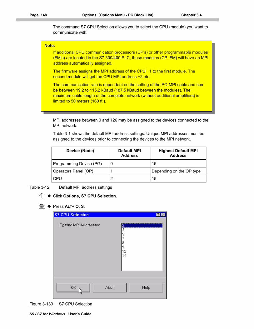
Page 148 Options (Options Menu - PC Block List) Chapter 3.4
S5 / S7 for Windows User’s Guide
The command S7 CPU Selection allows you to select the CPU (module) you want to communicate with.
MPI addresses between 0 and 126 may be assigned to the devices connected to the MPI network.
Table 3-1 shows the default MPI address settings. Unique MPI addresses must be assigned to the devices prior to connecting the devices to the MPI network.
The firmware assigns the MPI address of the CPU +1 to the first module. The second module will get the CPU MPI address +2 etc.
The communication rate is dependent on the setting of the PC-MPI cable and can be between 19.2 to 115,2 kBaud (187.5 kBaud between the modules). The maximum cable length of the complete network (without additional amplifiers) is limited to 50 meters (160 ft.).
Note: If additional CPU communication processors (CP’s) or other programmable modules (FM’s) are located in the S7 300/400 PLC, these modules (CP, FM) will have an MPI address automatically assigned.
Device (Node) Default MPI Address
Highest Default MPI Address
Programming Device (PG) 0 15
Operators Panel (OP) 1 Depending on the OP type
CPU 2 15
Table 3-12 Default MPI address settings
Click Options, S7 CPU Selection.
Press ALT+ O, S.
Figure 3-139 S7 CPU Selection
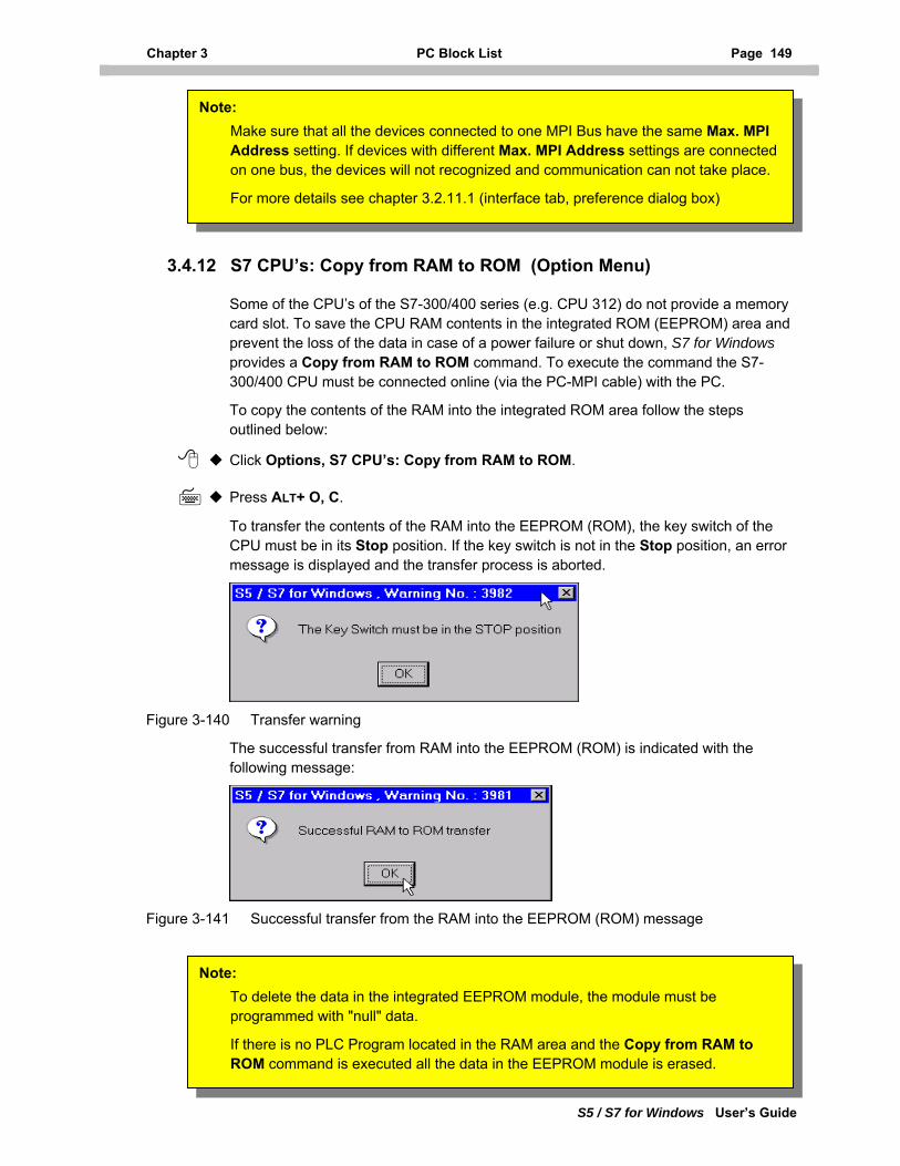
Chapter 3 PC Block List Page 149
S5 / S7 for Windows User’s Guide
Make sure that all the devices connected to one MPI Bus have the same Max. MPI Address setting. If devices with different Max. MPI Address settings are connected on one bus, the devices will not recognized and communication can not take place.
For more details see chapter 3.2.11.1 (interface tab, preference dialog box)
Note:
3.4.12 S7 CPU’s: Copy from RAM to ROM (Option Menu)
Some of the CPU’s of the S7-300/400 series (e.g. CPU 312) do not provide a memory card slot. To save the CPU RAM contents in the integrated ROM (EEPROM) area and prevent the loss of the data in case of a power failure or shut down, S7 for Windows provides a Copy from RAM to ROM command. To execute the command the S7-300/400 CPU must be connected online (via the PC-MPI cable) with the PC.
To copy the contents of the RAM into the integrated ROM area follow the steps outlined below:
Click Options, S7 CPU’s: Copy from RAM to ROM.
Press ALT+ O, C.
To transfer the contents of the RAM into the EEPROM (ROM), the key switch of the CPU must be in its Stop position. If the key switch is not in the Stop position, an error message is displayed and the transfer process is aborted.
Figure 3-140 Transfer warning
The successful transfer from RAM into the EEPROM (ROM) is indicated with the following message:
Figure 3-141 Successful transfer from the RAM into the EEPROM (ROM) message
To delete the data in the integrated EEPROM module, the module must be programmed with "null" data.
If there is no PLC Program located in the RAM area and the Copy from RAM to ROM command is executed all the data in the EEPROM module is erased.
Note:
Page 150 Options (Options Menu - PC Block List) Chapter 3.4
S5 / S7 for Windows User’s Guide
3.4.13 Open S7 Hardware Configuration (Option Menu)
S7 for Windows provides a separate window to configure the hardware and set the parameters.
Click Options, Open S7 Hardware Configuration.
Press ALT + O, 7.
The S7 Hardware Configuration program has all the tools integrated, for an easy hardware configuration. The built in Hardware Catalog lets you select the hardware used in specific applications.
The functions of the Hardware configuration window are explained in detail in chapter 13.
Note: If a project has a hardware configuration file assigned to it, the command S7 Hardware Configuration opens this file and is ready for modifications (see chapter 3.2.5.2).
If there is no hardware configuration file assigned to the project, a new S7 hardware configuration file may be generated and assigned to the project. The hardware configuration file is saved using the project name with the file name extension *.CF7.
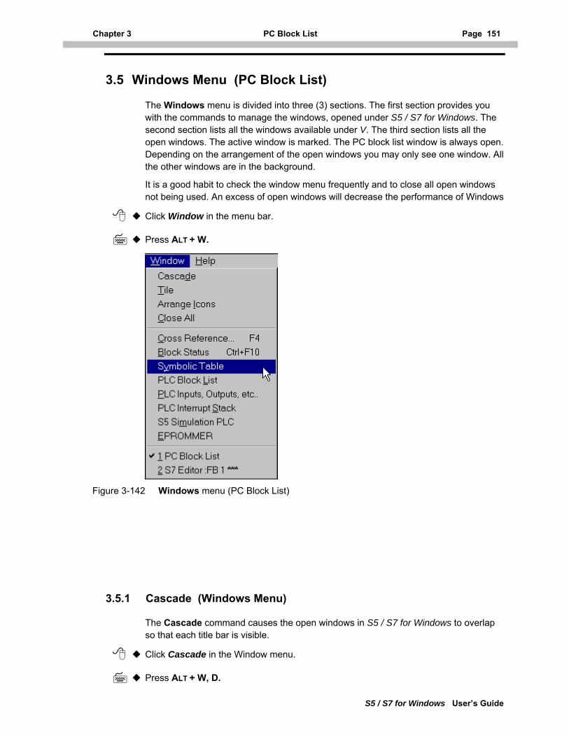
Chapter 3 PC Block List Page 151
S5 / S7 for Windows User’s Guide
3.5 Windows Menu (PC Block List)
The Windows menu is divided into three (3) sections. The first section provides you with the commands to manage the windows, opened under S5 / S7 for Windows. The second section lists all the windows available under V. The third section lists all the open windows. The active window is marked. The PC block list window is always open. Depending on the arrangement of the open windows you may only see one window. All the other windows are in the background.
It is a good habit to check the window menu frequently and to close all open windows not being used. An excess of open windows will decrease the performance of Windows
Click Window in the menu bar.
Press ALT + W.
Figure 3-142 Windows menu (PC Block List)
3.5.1 Cascade (Windows Menu)
The Cascade command causes the open windows in S5 / S7 for Windows to overlap so that each title bar is visible.
Click Cascade in the Window menu.
Press ALT + W, D.
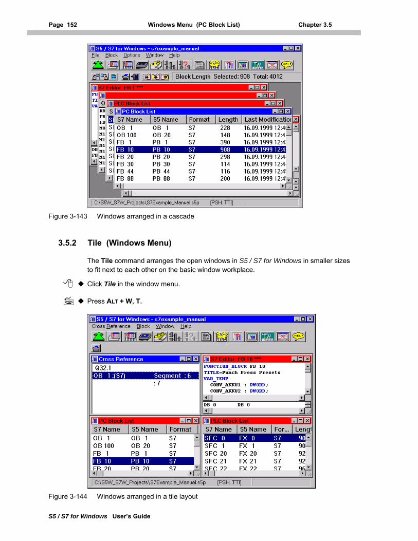
Page 152 Windows Menu (PC Block List) Chapter 3.5
S5 / S7 for Windows User’s Guide
Figure 3-143 Windows arranged in a cascade
3.5.2 Tile (Windows Menu)
The Tile command arranges the open windows in S5 / S7 for Windows in smaller sizes to fit next to each other on the basic window workplace.
Click Tile in the window menu.
Press ALT + W, T.
Figure 3-144 Windows arranged in a tile layout
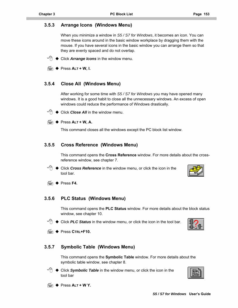
Chapter 3 PC Block List Page 153
S5 / S7 for Windows User’s Guide
3.5.3 Arrange Icons (Windows Menu)
When you minimize a window in S5 / S7 for Windows, it becomes an icon. You can move these icons around in the basic window workplace by dragging them with the mouse. If you have several icons in the basic window you can arrange them so that they are evenly spaced and do not overlap.
Click Arrange Icons in the window menu.
Press ALT + W, I.
3.5.4 Close All (Windows Menu)
After working for some time with S5 / S7 for Windows you may have opened many windows. It is a good habit to close all the unnecessary windows. An excess of open windows could reduce the performance of Windows drastically.
Click Close All in the window menu.
Press ALT + W, A.
This command closes all the windows except the PC block list window.
3.5.5 Cross Reference (Windows Menu)
This command opens the Cross Reference window. For more details about the cross-reference window, see chapter 7.
Click Cross Reference in the window menu, or click the icon in the tool bar.
Press F4.
3.5.6 PLC Status (Windows Menu)
This command opens the PLC Status window. For more details about the block status window, see chapter 10.
Click PLC Status in the window menu, or click the icon in the tool bar.
Press CTRL+F10.
3.5.7 Symbolic Table (Windows Menu)
This command opens the Symbolic Table window. For more details about the symbolic table window, see chapter 8.
Click Symbolic Table in the window menu, or click the icon in the tool bar
Press ALT + W Y.
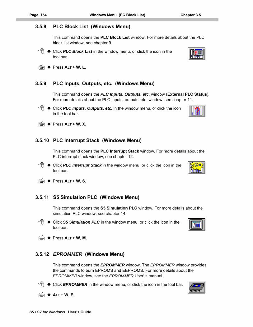
Page 154 Windows Menu (PC Block List) Chapter 3.5
S5 / S7 for Windows User’s Guide
3.5.8 PLC Block List (Windows Menu)
This command opens the PLC Block List window. For more details about the PLC block list window, see chapter 9.
Click PLC Block List in the window menu, or click the icon in the tool bar.
Press ALT + W, L.
3.5.9 PLC Inputs, Outputs, etc. (Windows Menu)
This command opens the PLC Inputs, Outputs, etc. window (External PLC Status). For more details about the PLC inputs, outputs, etc. window, see chapter 11.
Click PLC Inputs, Outputs, etc. in the window menu, or click the icon in the tool bar.
Press ALT + W, X.
3.5.10 PLC Interrupt Stack (Windows Menu)
This command opens the PLC Interrupt Stack window. For more details about the PLC interrupt stack window, see chapter 12.
Click PLC Interrupt Stack in the window menu, or click the icon in the tool bar.
Press ALT + W, S.
3.5.11 S5 Simulation PLC (Windows Menu)
This command opens the S5 Simulation PLC window. For more details about the simulation PLC window, see chapter 14.
Click S5 Simulation PLC in the window menu, or click the icon in the tool bar.
Press ALT + W, M.
3.5.12 EPROMMER (Windows Menu)
This command opens the EPROMMER window. The EPROMMER window provides the commands to burn EPROMS and EEPROMS. For more details about the EPROMMER window, see the EPROMMER User' s manual.
Click EPROMMER in the window menu, or click the icon in the tool bar.
ALT + W, E.
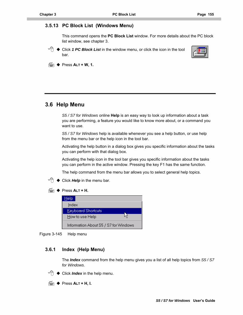
Chapter 3 PC Block List Page 155
S5 / S7 for Windows User’s Guide
3.5.13 PC Block List (Windows Menu)
This command opens the PC Block List window. For more details about the PC block list window, see chapter 3.
Click 1 PC Block List in the window menu, or click the icon in the tool bar.
Press ALT + W, 1.
3.6 Help Menu
S5 / S7 for Windows online Help is an easy way to look up information about a task you are performing, a feature you would like to know more about, or a command you want to use.
S5 / S7 for Windows help is available whenever you see a help button, or use help from the menu bar or the help icon in the tool bar.
Activating the help button in a dialog box gives you specific information about the tasks you can perform with that dialog box.
Activating the help icon in the tool bar gives you specific information about the tasks you can perform in the active window. Pressing the key F1 has the same function.
The help command from the menu bar allows you to select general help topics.
Click Help in the menu bar.
Press ALT + H.
Figure 3-145 Help menu
3.6.1 Index (Help Menu)
The Index command from the help menu gives you a list of all help topics from S5 / S7 for Windows.
Click Index in the help menu.
Press ALT + H, I.
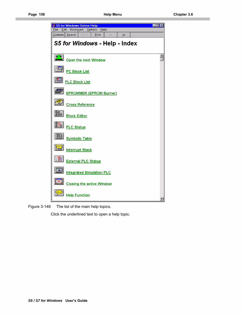
Page 156 Help Menu Chapter 3.6
S5 / S7 for Windows User’s Guide
Figure 3-146 The list of the main help topics.
Click the underlined text to open a help topic.
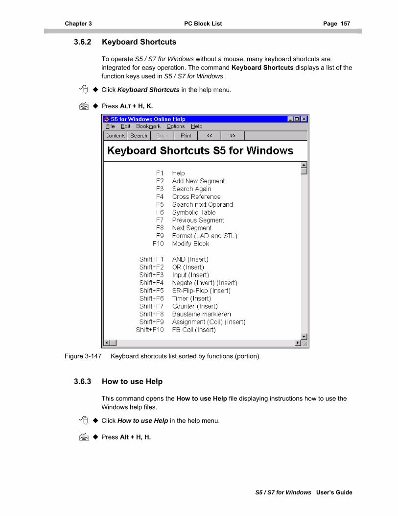
Chapter 3 PC Block List Page 157
S5 / S7 for Windows User’s Guide
3.6.2 Keyboard Shortcuts
To operate S5 / S7 for Windows without a mouse, many keyboard shortcuts are integrated for easy operation. The command Keyboard Shortcuts displays a list of the function keys used in S5 / S7 for Windows .
Click Keyboard Shortcuts in the help menu.
Press ALT + H, K.
Figure 3-147 Keyboard shortcuts list sorted by functions (portion).
3.6.3 How to use Help
This command opens the How to use Help file displaying instructions how to use the Windows help files.
Click How to use Help in the help menu.
Press Alt + H, H.
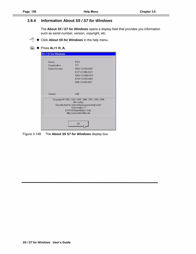
Page 158 Help Menu Chapter 3.6
S5 / S7 for Windows User’s Guide
3.6.4 Information About S5 / S7 for Windows
The About S5 / S7 for Windows opens a display field that provides you information such as serial number, version, copyright, etc.
Click About S5 for Windows in the help menu.
Press ALT+ H, A.
Figure 3-148 The About S5 S7 for Windows display box
Chapter 4 PC Block Editor Page 159
S5 / S7 for Windows User’s Guide
4 PC Block Editor
S5 / S7 for Windows provides two block editors. With the PC Block Editor you can create and/or modify blocks stored in your PC (Personal Computer). The operation and the tools provided in the PLC Block Editor are basically the same as the PC editor. The differences are: The PC block editor allows you to work with blocks stored in the PC. The PLC block editor allows you to work with blocks stored in the PLC.
There are some differences in the way you save modified Blocks in the PLC. Therefore, we recommend that you use the PC block editor to create new blocks and to modify existing blocks.
Dependant on the set-up of your programming system, the software options, the two editors "understand" the STEP® 5 syntax and/or the STEP® 7 syntax.
The S5 for Windows software, allows you to create and modify PLC programs using the STEP® 5 syntax. The PLC logic may be displayed in Statement List (STL, Source Text), Ladder Diagram (LAD), or Control System Flowchart (CSF) presentation.
The S7 for Windows software allows you to create and modify PLC programs using the STEP® 7 syntax. The PLC logic may be displayed in Statement List (STL, Source Text), Ladder Diagram (LAD) , or Control System Flowchart (CSF) presentation.
If only one of the software packages, S5 for Windows or S7 for Windows, has been installed, the Block Editors will only understand the syntax that is used with that software package.
Special features required to "understand" both the STEP® 5 syntax and the STEP® 7 syntax such as e.g. converting blocks from one syntax format into the other syntax form are not available.
In this chapter we will explain how to use the Block Editor. These explanations will be based on the PC block editor. Differences in how to manipulate the PLC Block Editor are specifically explained.
4.1 Editor Window
The Functions of the PC Editor and the PLC Editor may be divided into several groups:
Common functions
Editing a Statement Lists (STL)
Editing a Block-STL (Source Text)
Editing Ladder Diagrams (LAD)
Editing a Control System Flowcharts (CSF)
Editing a Step Sequence (G5 for Windows)
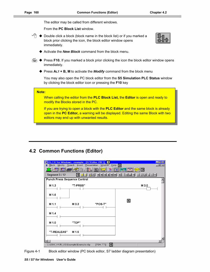
Page 160 Common Functions (Editor) Chapter 4.2
S5 / S7 for Windows User’s Guide
The editor may be called from different windows.
From the PC Block List window.
Double click a block (block name in the block list) or if you marked a block prior clicking the icon, the block editor window opens immediately.
Activate the New Block command from the block menu.
Press F10. If you marked a block prior clicking the icon the block editor window opens immediately.
Press ALT + B, M to activate the Modify command from the block menu
You may also open the PC block editor from the S5 Simulation PLC Status window by clicking the block editor icon or pressing the F10 key
You may use the same procedures as described above to open PLC block editor from the PLC block list.
Note: When calling the editor from the PLC Block List, the Editor is open and ready to modify the Blocks stored in the PC.
If you are trying to open a block with the PLC Editor and the same block is already open in the PC Editor, a warning will be displayed. Editing the same Block with two editors may end up with unwanted results.
4.2 Common Functions (Editor)
Figure 4-1 Block editor window (PC block editor, S7 ladder diagram presentation)
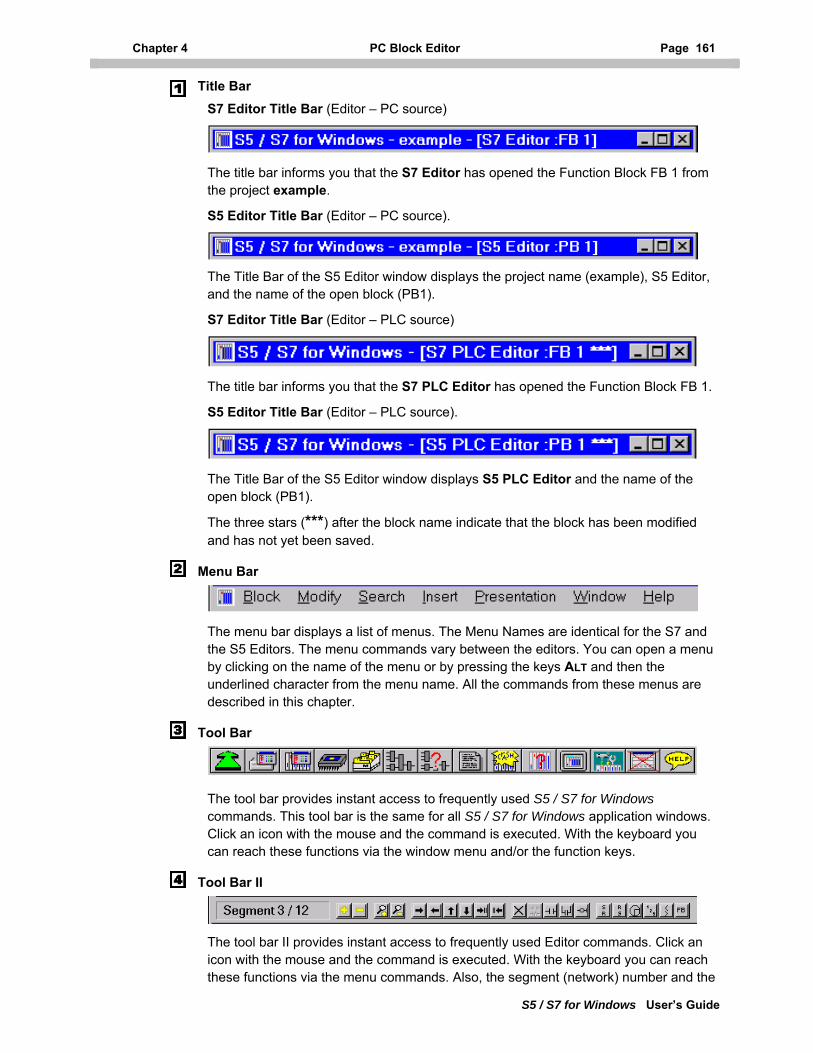
Chapter 4 PC Block Editor Page 161
S5 / S7 for Windows User’s Guide
Title Bar S7 Editor Title Bar (Editor – PC source)
The title bar informs you that the S7 Editor has opened the Function Block FB 1 from the project example.
S5 Editor Title Bar (Editor – PC source).
The Title Bar of the S5 Editor window displays the project name (example), S5 Editor, and the name of the open block (PB1).
S7 Editor Title Bar (Editor – PLC source)
The title bar informs you that the S7 PLC Editor has opened the Function Block FB 1.
S5 Editor Title Bar (Editor – PLC source).
The Title Bar of the S5 Editor window displays S5 PLC Editor and the name of the open block (PB1).
The three stars (***) after the block name indicate that the block has been modified and has not yet been saved.
Menu Bar
The menu bar displays a list of menus. The Menu Names are identical for the S7 and the S5 Editors. The menu commands vary between the editors. You can open a menu by clicking on the name of the menu or by pressing the keys ALT and then the underlined character from the menu name. All the commands from these menus are described in this chapter.
Tool Bar
The tool bar provides instant access to frequently used S5 / S7 for Windows commands. This tool bar is the same for all S5 / S7 for Windows application windows. Click an icon with the mouse and the command is executed. With the keyboard you can reach these functions via the window menu and/or the function keys.
Tool Bar II
The tool bar II provides instant access to frequently used Editor commands. Click an icon with the mouse and the command is executed. With the keyboard you can reach these functions via the menu commands. Also, the segment (network) number and the
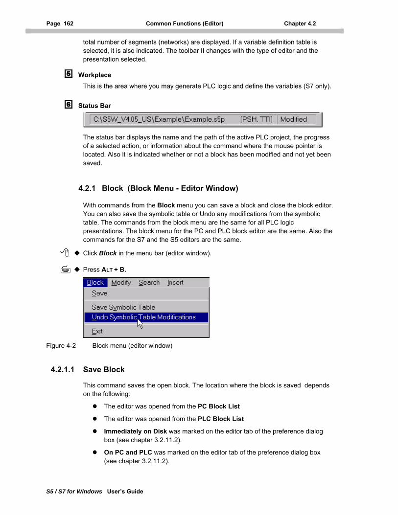
Page 162 Common Functions (Editor) Chapter 4.2
S5 / S7 for Windows User’s Guide
total number of segments (networks) are displayed. If a variable definition table is selected, it is also indicated. The toolbar II changes with the type of editor and the presentation selected.
Workplace This is the area where you may generate PLC logic and define the variables (S7 only).
Status Bar
The status bar displays the name and the path of the active PLC project, the progress of a selected action, or information about the command where the mouse pointer is located. Also it is indicated whether or not a block has been modified and not yet been saved.
4.2.1 Block (Block Menu - Editor Window)
With commands from the Block menu you can save a block and close the block editor. You can also save the symbolic table or Undo any modifications from the symbolic table. The commands from the block menu are the same for all PLC logic presentations. The block menu for the PC and PLC block editor are the same. Also the commands for the S7 and the S5 editors are the same.
Click Block in the menu bar (editor window).
Press ALT + B.
Figure 4-2 Block menu (editor window)
4.2.1.1 Save Block
This command saves the open block. The location where the block is saved depends on the following:
The editor was opened from the PC Block List
The editor was opened from the PLC Block List
Immediately on Disk was marked on the editor tab of the preference dialog box (see chapter 3.2.11.2).
On PC and PLC was marked on the editor tab of the preference dialog box (see chapter 3.2.11.2).
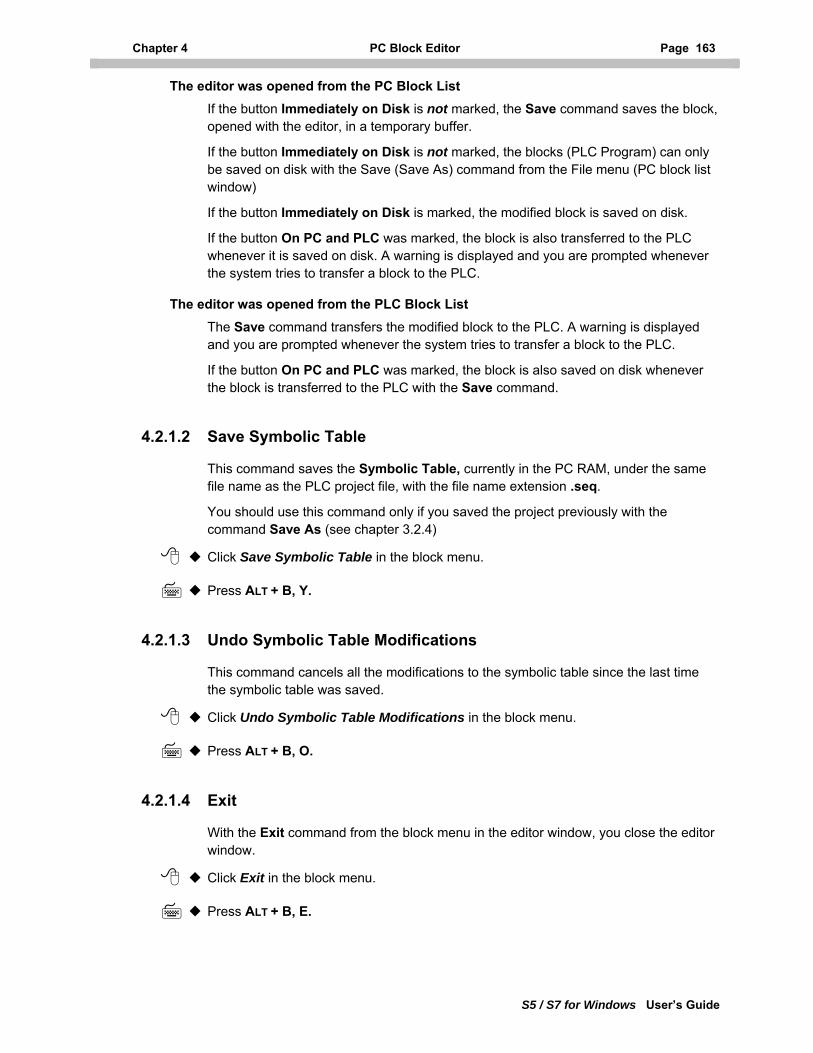
Chapter 4 PC Block Editor Page 163
S5 / S7 for Windows User’s Guide
The editor was opened from the PC Block List If the button Immediately on Disk is not marked, the Save command saves the block, opened with the editor, in a temporary buffer.
If the button Immediately on Disk is not marked, the blocks (PLC Program) can only be saved on disk with the Save (Save As) command from the File menu (PC block list window)
If the button Immediately on Disk is marked, the modified block is saved on disk.
If the button On PC and PLC was marked, the block is also transferred to the PLC whenever it is saved on disk. A warning is displayed and you are prompted whenever the system tries to transfer a block to the PLC.
The editor was opened from the PLC Block List The Save command transfers the modified block to the PLC. A warning is displayed and you are prompted whenever the system tries to transfer a block to the PLC.
If the button On PC and PLC was marked, the block is also saved on disk whenever the block is transferred to the PLC with the Save command.
4.2.1.2 Save Symbolic Table
This command saves the Symbolic Table, currently in the PC RAM, under the same file name as the PLC project file, with the file name extension .seq.
You should use this command only if you saved the project previously with the command Save As (see chapter 3.2.4)
Click Save Symbolic Table in the block menu.
Press ALT + B, Y.
4.2.1.3 Undo Symbolic Table Modifications
This command cancels all the modifications to the symbolic table since the last time the symbolic table was saved.
Click Undo Symbolic Table Modifications in the block menu.
Press ALT + B, O.
4.2.1.4 Exit
With the Exit command from the block menu in the editor window, you close the editor window.
Click Exit in the block menu.
Press ALT + B, E.
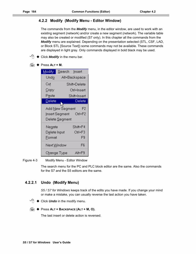
Page 164 Common Functions (Editor) Chapter 4.2
S5 / S7 for Windows User’s Guide
4.2.2 Modify (Modify Menu - Editor Window)
The commands from the Modify menu, in the editor window, are used to work with an existing segment (network) and/or create a new segment (network). The variable table may also be created or modified (S7 only). In this chapter all the commands from the Modify menu are explained. Depending on the presentation selected (STL, CSF, LAD, or Block STL [Source Text]) some commands may not be available. These commands are displayed in light gray. Only commands displayed in bold black may be used.
Click Modify in the menu bar.
Press ALT + M.
Figure 4-3 Modify Menu - Editor Window
The search menu for the PC and PLC block editor are the same. Also the commands for the S7 and the S5 editors are the same.
4.2.2.1 Undo (Modify Menu)
S5 / S7 for Windows keeps track of the edits you have made. If you change your mind or make a mistake, you can usually reverse the last action you have taken.
Click Undo in the modify menu.
Press ALT + BACKSPACE (ALT + M, O).
The last insert or delete action is reversed.
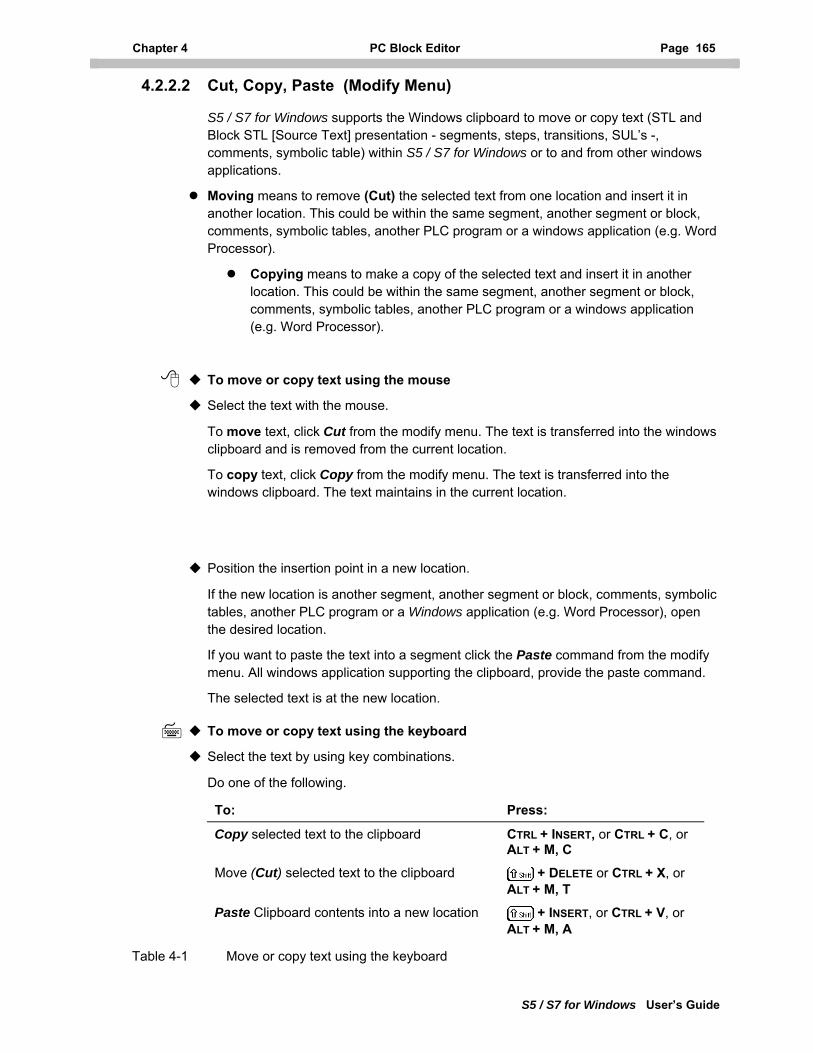
Chapter 4 PC Block Editor Page 165
S5 / S7 for Windows User’s Guide
4.2.2.2 Cut, Copy, Paste (Modify Menu)
S5 / S7 for Windows supports the Windows clipboard to move or copy text (STL and Block STL [Source Text] presentation - segments, steps, transitions, SUL’s -, comments, symbolic table) within S5 / S7 for Windows or to and from other windows applications.
Moving means to remove (Cut) the selected text from one location and insert it in another location. This could be within the same segment, another segment or block, comments, symbolic tables, another PLC program or a windows application (e.g. Word Processor).
Copying means to make a copy of the selected text and insert it in another location. This could be within the same segment, another segment or block, comments, symbolic tables, another PLC program or a windows application (e.g. Word Processor).
To move or copy text using the mouse
Select the text with the mouse.
To move text, click Cut from the modify menu. The text is transferred into the windows clipboard and is removed from the current location.
To copy text, click Copy from the modify menu. The text is transferred into the windows clipboard. The text maintains in the current location.
Position the insertion point in a new location.
If the new location is another segment, another segment or block, comments, symbolic tables, another PLC program or a Windows application (e.g. Word Processor), open the desired location.
If you want to paste the text into a segment click the Paste command from the modify menu. All windows application supporting the clipboard, provide the paste command.
The selected text is at the new location.
To move or copy text using the keyboard
Select the text by using key combinations.
Do one of the following.
To: Press:
Copy selected text to the clipboard CTRL + INSERT, or CTRL + C, or ALT + M, C
Move (Cut) selected text to the clipboard + DELETE or CTRL + X, or ALT + M, T
Paste Clipboard contents into a new location + INSERT, or CTRL + V, or ALT + M, A
Table 4-1 Move or copy text using the keyboard
Page 166 Common Functions (Editor) Chapter 4.2
S5 / S7 for Windows User’s Guide
4.2.2.3 Delete (Modify Menu)
The Delete command from the modify menu is used to delete marked (selected) text. The Windows clipboard contents are not modified by this command. Deleted text may only be returned to its original location by executing the Undo command directly after the deleting the text.
Click Delete in the modify menu.
Press the DELETE key (ALT + M, D).
The marked text is deleted.
4.2.2.4 Add New Segment (Modify Menu)
The Add New Segment command from the modify menu adds a new segment (network) at the end of the block. The new segment is assigned a segment number - the last segment number in the block plus (1) one.
Click Add New Segment in the modify menu.
Press the F2 key (ALT + M, N).
The new network (segment) is opened and ready for editing.
The Add New Segment command is also used to add a segment to a step, transition or SUL.
4.2.2.5 Insert Segment (Modify Menu)
The Insert Segment (network) command from the modify menu inserts a new segment directly behind the displayed segment. The new segment is assigned the segment number of the displayed segment plus (1) one. All segments after the inserted segment are assigned a new segment number (the old segment number plus (1) one).
Click Insert Segment in the modify menu.
Press ALT + M, I.
The segment is deleted.
The Insert Segment command is also used to insert a segment in a step, transition or SUL.
4.2.2.6 Negate (Modify Menu)
The Negate command, from the modify menu, changes the selected input from a normal input to an inverted input or vice versa (inverted input to normal input).
The Negate / Invert command is also used to invert a normally open contact (NO) into a normally closed contact (NC) or vice versa. To do so the operand must be marked.
Click Negate in the modify menu.
Press +F4 (ALT + M, G).
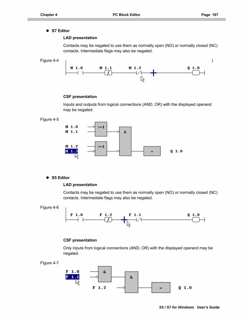
Chapter 4 PC Block Editor Page 167
S5 / S7 for Windows User’s Guide
S7 Editor LAD presentation
Contacts may be negated to use them as normally open (NO) or normally closed (NC) contacts. Intermediate flags may also be negated.
Figure 4-4 NO (M1.0) and NC (M1.2) contacts and negated intermediate memory bit (M1.1)
CSF presentation
Inputs and outputs from logical connections (AND, OR) with the displayed operand may be negated.
Figure 4-5 Negated (Inverted) inputs and outputs
S5 Editor LAD presentation
Contacts may be negated to use them as normally open (NO) or normally closed (NC) contacts. Intermediate flags may also be negated.
Figure 4-6 NO (F1.0) and NC (F1.1) contacts and negated intermediate flag (F1.2)
CSF presentation
Only inputs from logical connections (AND, OR) with the displayed operand may be negated.
Figure 4-7 Negated (Inverted) inputs
Page 168 Common Functions (Editor) Chapter 4.2
S5 / S7 for Windows User’s Guide
4.2.2.7 Delete Input (Contact) (Modify Menu)
The Delete Input command is used to delete contacts in the Ladder Diagram presentation and inputs in the Control System Flowchart presentation. Other logical elements cannot be deleted by using this command.
LAD presentation The Delete Input command, from the modify menu, deletes the selected contact to the right of the insertion point (blue cross). Only contacts may be deleted.
CSF presentation The Delete Input (Contact) command, from the modify menu, deletes the selected input or the selected logical connection. A selected input or logical connection is displayed in dark blue. Only inputs from AND’s and OR’s may be deleted.
Click Delete Input in the modify menu.
Press CTRL+F3 (ALT + M, E).
The input (logical connection) or contact is deleted.
4.2.2.8 Format (Modify Menu)
The Format command, from the modify menu, formats the created PLC logic (LAD, STL, and Block-STL [Source Text]) and performs a syntax check. If S5 / S7 for Windows detects an error, an error message is displayed indicating the incorrect syntax.
In STL (Block-STL [Source Text]) presentation prompting the error message will highlight the incorrect syntax.
Click Format in the modify menu.
Press F9 (ALT + M, F).
Note: STL, Block-STL [Source Text] programming
If the button Format Automatically is marked (Editor tab, Preference dialog box chapter 3.2.11.2) the syntax is automatically checked when the RETURN key is pressed at the end of an edited line. The line is only formatted if the syntax is correct.
The next line may be edited whether or not the previous line fulfills the syntax.
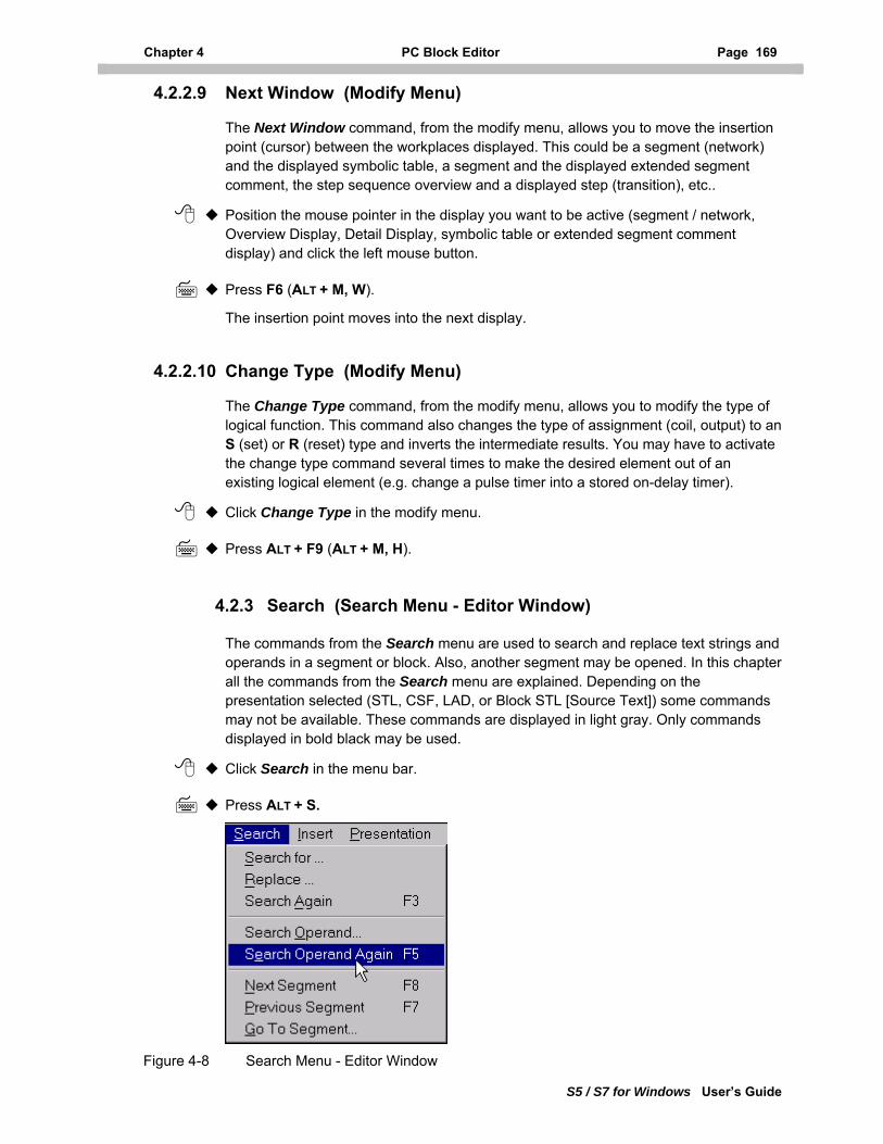
Chapter 4 PC Block Editor Page 169
S5 / S7 for Windows User’s Guide
4.2.2.9 Next Window (Modify Menu)
The Next Window command, from the modify menu, allows you to move the insertion point (cursor) between the workplaces displayed. This could be a segment (network) and the displayed symbolic table, a segment and the displayed extended segment comment, the step sequence overview and a displayed step (transition), etc..
Position the mouse pointer in the display you want to be active (segment / network, Overview Display, Detail Display, symbolic table or extended segment comment display) and click the left mouse button.
Press F6 (ALT + M, W).
The insertion point moves into the next display.
4.2.2.10 Change Type (Modify Menu)
The Change Type command, from the modify menu, allows you to modify the type of logical function. This command also changes the type of assignment (coil, output) to an S (set) or R (reset) type and inverts the intermediate results. You may have to activate the change type command several times to make the desired element out of an existing logical element (e.g. change a pulse timer into a stored on-delay timer).
Click Change Type in the modify menu.
Press ALT + F9 (ALT + M, H).
4.2.3 Search (Search Menu - Editor Window)
The commands from the Search menu are used to search and replace text strings and operands in a segment or block. Also, another segment may be opened. In this chapter all the commands from the Search menu are explained. Depending on the presentation selected (STL, CSF, LAD, or Block STL [Source Text]) some commands may not be available. These commands are displayed in light gray. Only commands displayed in bold black may be used.
Click Search in the menu bar.
Press ALT + S.
Figure 4-8 Search Menu - Editor Window
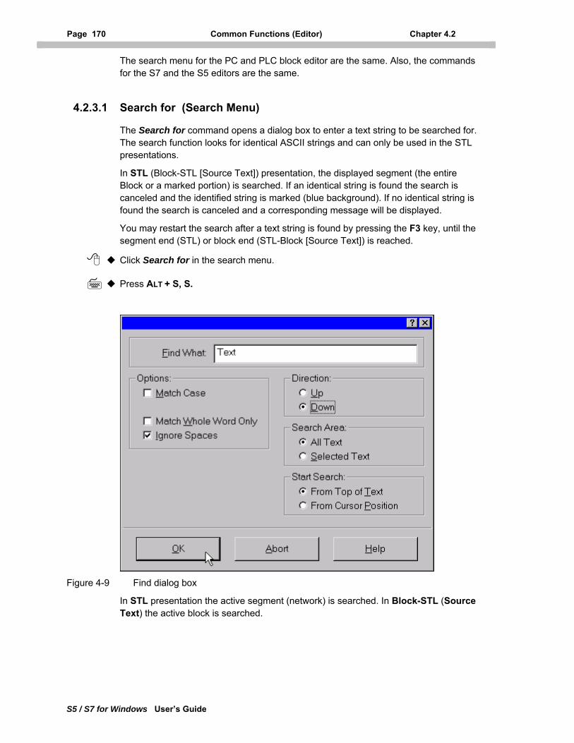
Page 170 Common Functions (Editor) Chapter 4.2
S5 / S7 for Windows User’s Guide
The search menu for the PC and PLC block editor are the same. Also, the commands for the S7 and the S5 editors are the same.
4.2.3.1 Search for (Search Menu)
The Search for command opens a dialog box to enter a text string to be searched for. The search function looks for identical ASCII strings and can only be used in the STL presentations.
In STL (Block-STL [Source Text]) presentation, the displayed segment (the entire Block or a marked portion) is searched. If an identical string is found the search is canceled and the identified string is marked (blue background). If no identical string is found the search is canceled and a corresponding message will be displayed.
You may restart the search after a text string is found by pressing the F3 key, until the segment end (STL) or block end (STL-Block [Source Text]) is reached.
Click Search for in the search menu.
Press ALT + S, S.
Figure 4-9 Find dialog box
In STL presentation the active segment (network) is searched. In Block-STL (Source Text) the active block is searched.
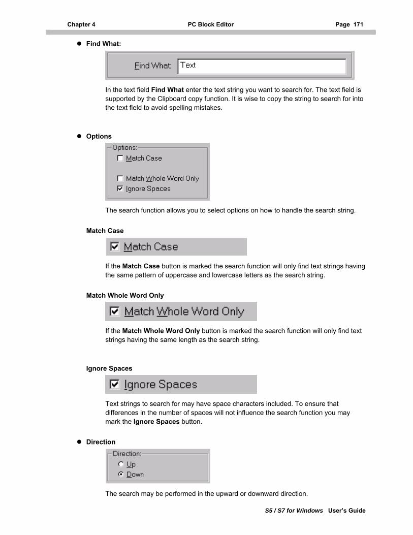
Chapter 4 PC Block Editor Page 171
S5 / S7 for Windows User’s Guide
Find What:
In the text field Find What enter the text string you want to search for. The text field is supported by the Clipboard copy function. It is wise to copy the string to search for into the text field to avoid spelling mistakes.
Options
The search function allows you to select options on how to handle the search string.
Match Case
If the Match Case button is marked the search function will only find text strings having the same pattern of uppercase and lowercase letters as the search string.
Match Whole Word Only
If the Match Whole Word Only button is marked the search function will only find text strings having the same length as the search string.
Ignore Spaces
Text strings to search for may have space characters included. To ensure that differences in the number of spaces will not influence the search function you may mark the Ignore Spaces button.
Direction
The search may be performed in the upward or downward direction.
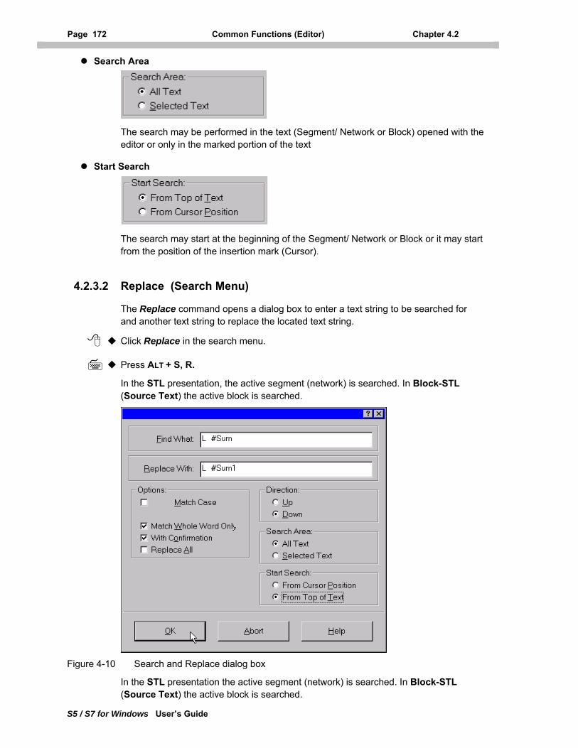
Page 172 Common Functions (Editor) Chapter 4.2
S5 / S7 for Windows User’s Guide
Search Area
The search may be performed in the text (Segment/ Network or Block) opened with the editor or only in the marked portion of the text
Start Search
The search may start at the beginning of the Segment/ Network or Block or it may start from the position of the insertion mark (Cursor).
4.2.3.2 Replace (Search Menu)
The Replace command opens a dialog box to enter a text string to be searched for and another text string to replace the located text string.
Click Replace in the search menu.
Press ALT + S, R.
In the STL presentation, the active segment (network) is searched. In Block-STL (Source Text) the active block is searched.
Figure 4-10 Search and Replace dialog box
In the STL presentation the active segment (network) is searched. In Block-STL (Source Text) the active block is searched.
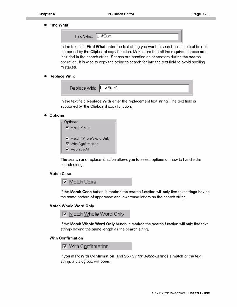
Chapter 4 PC Block Editor Page 173
S5 / S7 for Windows User’s Guide
Find What:
In the text field Find What enter the text string you want to search for. The text field is supported by the Clipboard copy function. Make sure that all the required spaces are included in the search string. Spaces are handled as characters during the search operation. It is wise to copy the string to search for into the text field to avoid spelling mistakes.
Replace With:
In the text field Replace With enter the replacement text string. The text field is supported by the Clipboard copy function.
Options
The search and replace function allows you to select options on how to handle the search string.
Match Case
If the Match Case button is marked the search function will only find text strings having the same pattern of uppercase and lowercase letters as the search string.
Match Whole Word Only
If the Match Whole Word Only button is marked the search function will only find text strings having the same length as the search string.
With Confirmation
If you mark With Confirmation, and S5 / S7 for Windows finds a match of the text string, a dialog box will open.
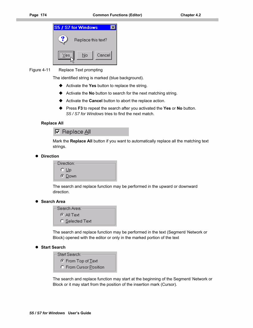
Page 174 Common Functions (Editor) Chapter 4.2
S5 / S7 for Windows User’s Guide
Figure 4-11 Replace Text prompting
The identified string is marked (blue background).
Activate the Yes button to replace the string.
Activate the No button to search for the next matching string.
Activate the Cancel button to abort the replace action.
Press F3 to repeat the search after you activated the Yes or No button. S5 / S7 for Windows tries to find the next match.
Replace All
Mark the Replace All button if you want to automatically replace all the matching text strings.
Direction
The search and replace function may be performed in the upward or downward direction.
Search Area
The search and replace function may be performed in the text (Segment/ Network or Block) opened with the editor or only in the marked portion of the text
Start Search
The search and replace function may start at the beginning of the Segment/ Network or Block or it may start from the position of the insertion mark (Cursor).
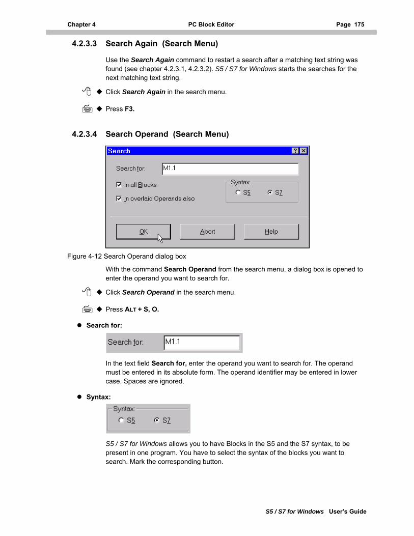
Chapter 4 PC Block Editor Page 175
S5 / S7 for Windows User’s Guide
4.2.3.3 Search Again (Search Menu)
Use the Search Again command to restart a search after a matching text string was found (see chapter 4.2.3.1, 4.2.3.2). S5 / S7 for Windows starts the searches for the next matching text string.
Click Search Again in the search menu.
Press F3.
4.2.3.4 Search Operand (Search Menu)
Figure 4-12 Search Operand dialog box
With the command Search Operand from the search menu, a dialog box is opened to enter the operand you want to search for.
Click Search Operand in the search menu.
Press ALT + S, O.
Search for:
In the text field Search for, enter the operand you want to search for. The operand must be entered in its absolute form. The operand identifier may be entered in lower case. Spaces are ignored.
Syntax:
S5 / S7 for Windows allows you to have Blocks in the S5 and the S7 syntax, to be present in one program. You have to select the syntax of the blocks you want to search. Mark the corresponding button.
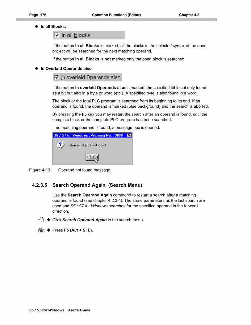
Page 176 Common Functions (Editor) Chapter 4.2
S5 / S7 for Windows User’s Guide
In all Blocks:
If the button In all Blocks is marked, all the blocks in the selected syntax of the open project will be searched for the next matching operand.
If the button In all Blocks is not marked only the open block is searched.
In Overlaid Operands also
If the button In overlaid Operands also is marked, the specified bit is not only found as a bit but also in a byte or word (etc.). A specified byte is also found in a word.
The block or the total PLC program is searched from its beginning to its end. If an operand is found, the operand is marked (blue background) and the search is aborted.
By pressing the F5 key you may restart the search after an operand is found, until the complete block or the complete PLC program has been searched.
If no matching operand is found, a message box is opened.
Figure 4-13 Operand not found message
4.2.3.5 Search Operand Again (Search Menu)
Use the Search Operand Again command to restart a search after a matching operand is found (see chapter 4.2.3.4). The same parameters as the last search are used and S5 / S7 for Windows searches for the specified operand in the forward direction.
Click Search Operand Again in the search menu.
Press F5 (ALT + S, E).
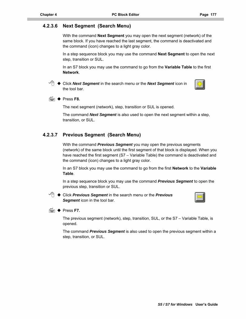
Chapter 4 PC Block Editor Page 177
S5 / S7 for Windows User’s Guide
4.2.3.6 Next Segment (Search Menu)
With the command Next Segment you may open the next segment (network) of the same block. If you have reached the last segment, the command is deactivated and the command (icon) changes to a light gray color.
In a step sequence block you may use the command Next Segment to open the next step, transition or SUL.
In an S7 block you may use the command to go from the Variable Table to the first Network.
Click Next Segment in the search menu or the Next Segment icon in the tool bar.
Press F8.
The next segment (network), step, transition or SUL is opened.
The command Next Segment is also used to open the next segment within a step, transition, or SUL.
4.2.3.7 Previous Segment (Search Menu)
With the command Previous Segment you may open the previous segments (network) of the same block until the first segment of that block is displayed. When you have reached the first segment (S7 – Variable Table) the command is deactivated and the command (icon) changes to a light gray color.
In an S7 block you may use the command to go from the first Network to the Variable Table.
In a step sequence block you may use the command Previous Segment to open the previous step, transition or SUL.
Click Previous Segment in the search menu or the Previous Segment icon in the tool bar.
Press F7.
The previous segment (network), step, transition, SUL, or the S7 – Variable Table, is opened.
The command Previous Segment is also used to open the previous segment within a step, transition, or SUL.
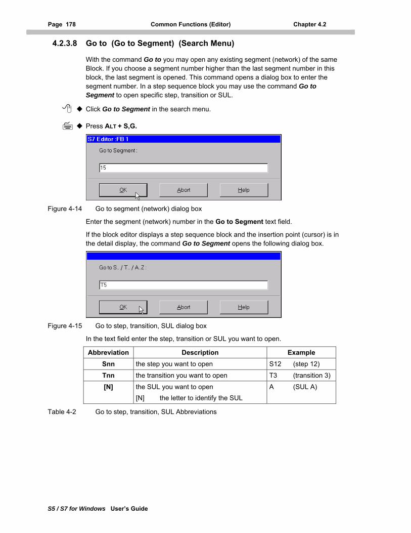
Page 178 Common Functions (Editor) Chapter 4.2
S5 / S7 for Windows User’s Guide
4.2.3.8 Go to (Go to Segment) (Search Menu)
With the command Go to you may open any existing segment (network) of the same Block. If you choose a segment number higher than the last segment number in this block, the last segment is opened. This command opens a dialog box to enter the segment number. In a step sequence block you may use the command Go to Segment to open specific step, transition or SUL.
Click Go to Segment in the search menu.
Press ALT + S,G.
Figure 4-14 Go to segment (network) dialog box
Enter the segment (network) number in the Go to Segment text field.
If the block editor displays a step sequence block and the insertion point (cursor) is in the detail display, the command Go to Segment opens the following dialog box.
Figure 4-15 Go to step, transition, SUL dialog box
In the text field enter the step, transition or SUL you want to open.
Abbreviation Description Example Snn the step you want to open S12 (step 12)
Tnn the transition you want to open T3 (transition 3)
[N] the SUL you want to open [N] the letter to identify the SUL
A (SUL A)
Table 4-2 Go to step, transition, SUL Abbreviations
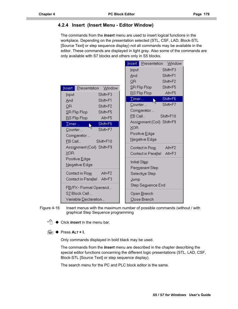
Chapter 4 PC Block Editor Page 179
S5 / S7 for Windows User’s Guide
4.2.4 Insert (Insert Menu - Editor Window)
The commands from the Insert menu are used to insert logical functions in the workplace. Depending on the presentation selected (STL, CSF, LAD, Block-STL [Source Text] or step sequence display) not all commands may be available in the editor. These commands are displayed in light gray. Also some of the commands are only available with S7 blocks and others only in S5 blocks.
Figure 4-16 Insert menus with the maximum number of possible commands (without / with graphical Step Sequence programming
Click Insert in the menu bar.
Press ALT + I.
Only commands displayed in bold black may be used.
The commands from the Insert menu are described in the chapter describing the special editor functions concerning the different logic presentations (STL, LAD, CSF, Block-STL [Source Text] or step sequence display).
The search menu for the PC and PLC block editor is the same.
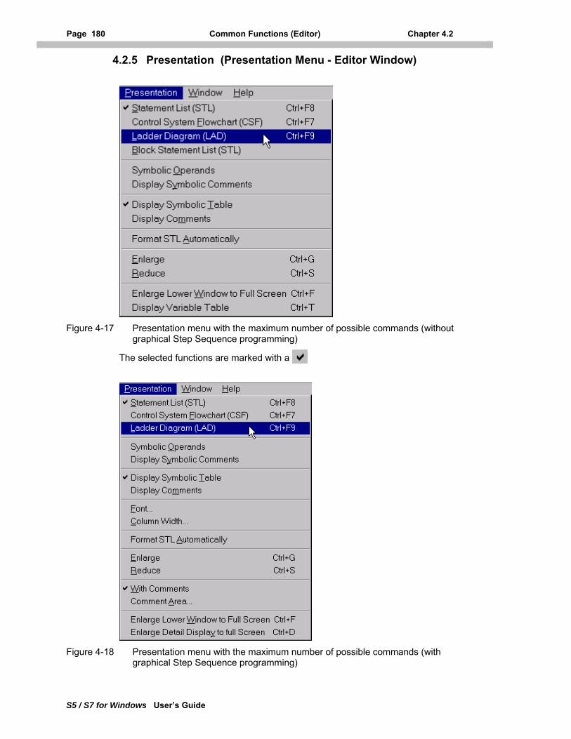
Page 180 Common Functions (Editor) Chapter 4.2
S5 / S7 for Windows User’s Guide
4.2.5 Presentation (Presentation Menu - Editor Window)
Figure 4-17 Presentation menu with the maximum number of possible commands (without graphical Step Sequence programming)
The selected functions are marked with a
Figure 4-18 Presentation menu with the maximum number of possible commands (with graphical Step Sequence programming)
Chapter 4 PC Block Editor Page 181
S5 / S7 for Windows User’s Guide
The commands from the Presentation menu are used to select the logic presentation (STL, CSF, LAD, etc.) additional commands are available to configure the appearance of the presentations. Not all commands may always be available.
Only commands displayed in bold black may be used.
The commands from the Presentation menu are described in this chapter. Two different Presentation menus are available, one for the STL, LAD, CSF, Block-STL [Source Text] presentation, and the other for the step sequence editor.
The presentation menu for the PC and PLC block editor are the same.
Click Presentation in the menu bar.
Press ALT + P.
Note: All these adjustments are only for the active Editor window. As soon as this window is closed the default presets are valid (see chapter 3.2.11.2).
4.2.5.1 Statement List (STL) (Presentation Menu)
In a Statement List, the control task is described with mnemonic abbreviations in the form of a list. For more details see chapter 3.2.11.2.
S7 for Windows In a Statement List (STL), the control task is described with mnemonic abbreviations in the form of a list. The programming language is based on IEC 1131. When selected, the editor window displays the network (segment) as a statement list.
S5 for Windows In a Statement List (STL), the control task is described with mnemonic abbreviations in the form of a list. The programming language is based on DIN 19239. When selected, the editor window displays the segment (step, transition, or SUL in the Detail Display) as a statement list.
Click Statement List (STL) in the presentation menu.
Press CTRL + F8 (ALT + P, S).
4.2.5.2 Control System Flowchart (CSF) (Presentation Menu)
In a Control System Flowchart, the control task is described with symbols. For more details see chapter 3.2.11.2.
S7 for Windows
In a Control System Flowchart (CSF), the control task is described with symbols identical to the symbols used with S5 for Windows. This ensures a smooth transition from S5 for Windows to S7 for Windows. When selected, the editor window displays the network (segment) as a control system flowchart.
Page 182 Common Functions (Editor) Chapter 4.2
S5 / S7 for Windows User’s Guide
S5 for Windows In a Control System Flowchart (CSF), the control task is described with symbols based on DIN 40700. When selected, the editor window displays the segment (step, transition, or SUL in the Detail Display) as a control system flowchart.
Click Control System Flowchart (CSF) in the presentation menu.
Press CTRL + F7 (ALT + P, F).
4.2.5.3 Ladder Diagram (LAD) (Presentation Menu)
In a Ladder Diagram, the control task is described with symbols similar to those used in circuit diagrams. For more details see chapter 3.2.11.2.
S7 for Windows
In a Ladder Diagram (LAD), the control task is described with symbols identical to the symbols used with S5 for Windows. This ensures a smooth transition from S5 for Windows to S7 for Windows. When selected, the editor window displays the network (segment) as a ladder diagram.
S5 for Windows In a Ladder Diagram (LAD), the control task is described with symbols similar to those used in circuit diagrams. The symbols are basically NO and NC contacts. Complex functions are displayed with symbols based on DIN 40700. When selected, the editor window displays the segment (step, transition, or SUL in the Detail Display) as a ladder diagram.
Click Ladder Diagram (LAD) in the presentation menu.
Press CTRL + F9 (ALT + P, L).
4.2.5.4 Block Statement List [Source Text] (Presentation Menu)
A complete block is displayed in the editor window. In the Block-STL, the search and replace functions may be used to search within an entire block.
Click Block Statement List in the presentation menu.
Press ALT + P, B.
S7 for Windows
The Block STL presentation is often preferred to Source Text presentation. If the editor window is open, a complete block is displayed using statement list presentation. In front of the actual logic, the Block Header and the Variable Declaration are displayed.
The structure of the Source Text is based on the IEC 1131 standard. Files saved in the Source Text format with the file extension *.awl are used to exchange programs between S7 for Windows and the Siemens S7 programming unit (PU).
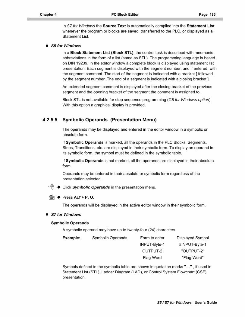
Chapter 4 PC Block Editor Page 183
S5 / S7 for Windows User’s Guide
In S7 for Windows the Source Text is automatically compiled into the Statement List whenever the program or blocks are saved, transferred to the PLC, or displayed as a Statement List.
S5 for Windows In a Block Statement List (Block STL), the control task is described with mnemonic abbreviations in the form of a list (same as STL). The programming language is based on DIN 19239. In the editor window a complete block is displayed using statement list presentation. Each segment is displayed with the segment number, and if entered, with the segment comment. The start of the segment is indicated with a bracket [ followed by the segment number. The end of a segment is indicated with a closing bracket ].
An extended segment comment is displayed after the closing bracket of the previous segment and the opening bracket of the segment the comment is assigned to.
Block STL is not available for step sequence programming (G5 for Windows option). With this option a graphical display is provided.
4.2.5.5 Symbolic Operands (Presentation Menu)
The operands may be displayed and entered in the editor window in a symbolic or absolute form.
If Symbolic Operands is marked, all the operands in the PLC Blocks, Segments, Steps, Transitions, etc. are displayed in their symbolic form. To display an operand in its symbolic form, the symbol must be defined in the symbolic table.
If Symbolic Operands is not marked, all the operands are displayed in their absolute form.
Operands may be entered in their absolute or symbolic form regardless of the presentation selected.
Click Symbolic Operands in the presentation menu.
Press ALT + P, O.
The operands will be displayed in the active editor window in their symbolic form.
S7 for Windows
Symbolic Operands
A symbolic operand may have up to twenty-four (24) characters.
Example: Symbolic Operands Form to enter Displayed Symbol INPUT-Byte-1 #INPUT-Byte-1 OUTPUT-2 "OUTPUT-2" Flag-Word "Flag-Word"
Symbols defined in the symbolic table are shown in quotation marks "…" , if used in Statement List (STL), Ladder Diagram (LAD), or Control System Flowchart (CSF) presentation.
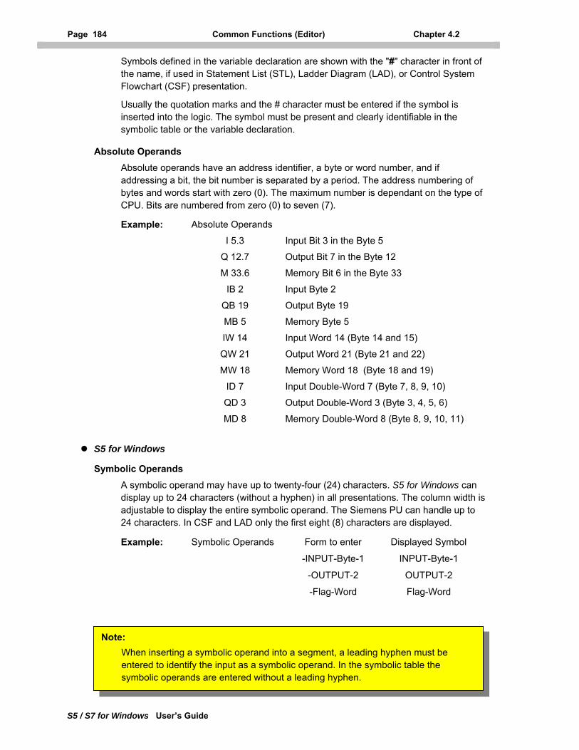
Page 184 Common Functions (Editor) Chapter 4.2
S5 / S7 for Windows User’s Guide
Symbols defined in the variable declaration are shown with the "#" character in front of the name, if used in Statement List (STL), Ladder Diagram (LAD), or Control System Flowchart (CSF) presentation.
Usually the quotation marks and the # character must be entered if the symbol is inserted into the logic. The symbol must be present and clearly identifiable in the symbolic table or the variable declaration.
Absolute Operands
Absolute operands have an address identifier, a byte or word number, and if addressing a bit, the bit number is separated by a period. The address numbering of bytes and words start with zero (0). The maximum number is dependant on the type of CPU. Bits are numbered from zero (0) to seven (7).
Example: Absolute Operands
I 5.3 Input Bit 3 in the Byte 5
Q 12.7 Output Bit 7 in the Byte 12
M 33.6 Memory Bit 6 in the Byte 33
IB 2 Input Byte 2
QB 19 Output Byte 19
MB 5 Memory Byte 5
IW 14 Input Word 14 (Byte 14 and 15)
QW 21 Output Word 21 (Byte 21 and 22)
MW 18 Memory Word 18 (Byte 18 and 19)
ID 7 Input Double-Word 7 (Byte 7, 8, 9, 10)
QD 3 Output Double-Word 3 (Byte 3, 4, 5, 6)
MD 8 Memory Double-Word 8 (Byte 8, 9, 10, 11)
S5 for Windows
Symbolic Operands
A symbolic operand may have up to twenty-four (24) characters. S5 for Windows can display up to 24 characters (without a hyphen) in all presentations. The column width is adjustable to display the entire symbolic operand. The Siemens PU can handle up to 24 characters. In CSF and LAD only the first eight (8) characters are displayed.
Example: Symbolic Operands Form to enter Displayed Symbol
-INPUT-Byte-1 INPUT-Byte-1
-OUTPUT-2 OUTPUT-2
-Flag-Word Flag-Word
Note: When inserting a symbolic operand into a segment, a leading hyphen must be entered to identify the input as a symbolic operand. In the symbolic table the symbolic operands are entered without a leading hyphen.
Chapter 4 PC Block Editor Page 185
S5 / S7 for Windows User’s Guide
Absolute Operands
Absolute operands have an identifier, a byte or word number, and if addressing a bit, the bit number is separated by a period. The numbering scheme of bytes and words start with zero (0). The maximum number is dependant on the type of CPU. Bits are numbered from zero (0) to seven (7).
Example: Absolute Operands
I 5.3 Input Bit 3 in the Byte 5
Q 12.7 Output Bit 7 in the Byte 12
F 33.6 Flag Bit 6 in the Byte 33
IB 2 Input Byte 2
FB 5 Flag Byte 5
FW 18 Flag Word 18 (Byte 18 and 19)
FD 22 Flag Double-Word 22 (Byte 22, 23, 24, 25)
4.2.5.6 Display Symbolic Comments (Presentation Menu)
When editing or displaying a PLC program in the statement list editor, it is possible to display the operand and the symbolic comments, of the operands from the symbolic table, in the same line. The symbolic comments are displayed in green. If an STL line comment is inserted, the symbolic comment of that line is automatically removed. The display of symbolic comments works in the same way for S5 for Windows and S7 for Windows.
Click Display Symbolic Comments in the presentation menu.
Press ALT + P, Y.
4.2.5.7 Display Symbolic Table (Presentation Menu)
The Symbolic Table may be displayed simultaneously with the selected segment (STL, CSF, LAD, Block-STL [Source Text] or step sequence presentation). The symbolic table may also be edited. A marked operand in the segment display is also highlighted in the symbolic table.
All editor windows display the Symbolic Table in the same form.
Click Display Symbolic Table in the presentation menu.
Press ALT + P, T.
4.2.5.8 Display Comments (Presentation Menu)
If the command Display Comments is marked, the extended segment comment will be displayed in a separate window below the segment logic. The comment display window has all the functions of a standard text editor. The windows clipboard is fully supported. You may use the cut, copy, and paste commands to exchange text within the S5 / S7 for Windows application or any other windows application.
Page 186 Common Functions (Editor) Chapter 4.2
S5 / S7 for Windows User’s Guide
Click Display Comments in the presentation menu.
Press ALT + P, D.
Note: S5 for Windows In Block-STL presentation, the extended comment is displayed in front of the segment in the editor workplace. The comment may be edited directly in the workplace.
S7 for Windows In Block-STL (Source Text) presentation, the extended comment is displayed as a line comment (starting with // ) directly below the segment (Network) title. The comment may be edited directly in the workplace.
4.2.5.9 Format STL Automatically (Presentation Menu)
If the command Format STL Automatically is marked, the syntax is automatically checked when the return key is pressed at the end of an edited line. The entered line is put into the correct format of statement list only if the syntax is correct. The next line may be edited whether or not the previous line fulfills the syntax.
The automatic format works the same way for S5 for Windows and S7 for Windows.
If the command is not marked, the syntax check and formatting is only done with the format command (key F9, command format from the modify menu).
Click Format STL Automatically in the presentation menu.
Press ALT + P, A.
4.2.5.10 Enlarge (Presentation Menu)
This command allows you to adjust the size of the displayed PLC logic (CSF and LAD). Each time you use the Enlarge command, the logic will be displayed in a larger scale. The Enlarge and the Reduce command provide the tools to momentarily scale the display of the logic.
Click Enlarge in the presentation menu or click the icon in the tool bar.
Press CTRL + G, (Alt + P, E).
Note: Only scaleable fonts may be enlarged or reduced. All True Type fonts are scaleable. The default System font is not scaleable
The Reduce and Enlarge function works in the same way for S5 for Windows and S7 for Windows.
The Reduce and Enlarge function is also available in the Status window.
Chapter 4 PC Block Editor Page 187
S5 / S7 for Windows User’s Guide
4.2.5.11 Reduce (Presentation Menu)
This command allows you to adjust the size of the displayed PLC logic (CSF and LAD). Each time you use the Reduce command, the logic will be displayed in a smaller scale. The Enlarge and the Reduce command provide the tools to momentarily scale the display of the logic.
Click Reduce in the presentation menu or click the icon in the tool bar.
Press CTRL + S, (Alt + P, R).
4.2.5.12 Enlarge Lower Window to Full Screen (Presentation Menu)
This command enlarges the lower window, displaying a portion of the symbolic table or the extended segment (network) comment, to fill the complete editor workspace for easier editing.
If the command is activated again, the window is reduced to its normal size.
Click Enlarges the Lower Window to Full Screen in the presentation menu
Press CTRL + F, (Alt + P, W).
4.2.5.13 Display Variable Table (Presentation Menu)
This command opens up the variable table assigned to the block opened with the editor.
This command can only be used in conjunction with S7 Blocks having a variable table assigned to.
Click Display Variable Table in the presentation menu
Press CTRL + T, (Alt + P, V).
4.2.5.14 Font Type (Presentation Menu) - Step Sequence programming
You can select the fonts for the selected PLC logic presentation (CSF and LAD) within the step sequence programming detail window. This allows you to momentarily adjust the fonts. As soon as the editor window is closed the preset font (chapter 3.2.11.4) will be active again. To enlarge or reduce the displayed PLC logic, a scaleable font (true type) must be selected. A dialog box will open to select the desired font
Click Font Type in the presentation menu.
Press ALT + P, N.
This command can only be used when an S5 graphical step sequence block is open in the editor window.
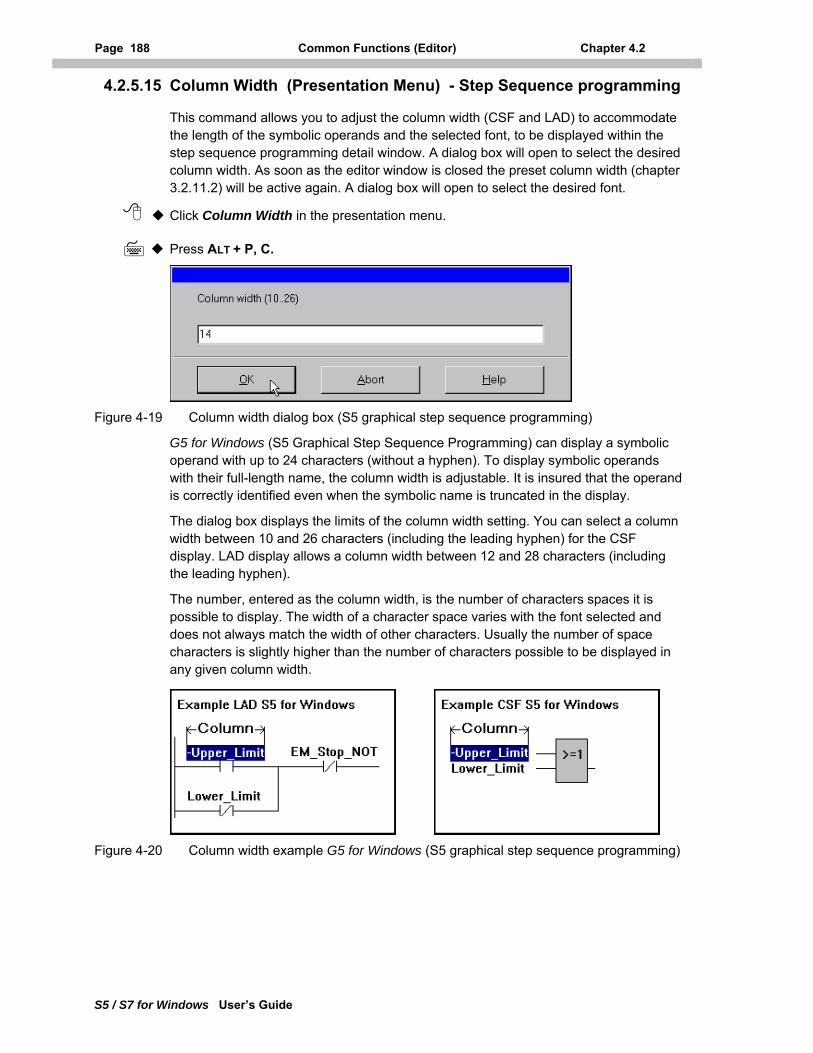
Page 188 Common Functions (Editor) Chapter 4.2
S5 / S7 for Windows User’s Guide
4.2.5.15 Column Width (Presentation Menu) - Step Sequence programming
This command allows you to adjust the column width (CSF and LAD) to accommodate the length of the symbolic operands and the selected font, to be displayed within the step sequence programming detail window. A dialog box will open to select the desired column width. As soon as the editor window is closed the preset column width (chapter 3.2.11.2) will be active again. A dialog box will open to select the desired font.
Click Column Width in the presentation menu.
Press ALT + P, C.
Figure 4-19 Column width dialog box (S5 graphical step sequence programming)
G5 for Windows (S5 Graphical Step Sequence Programming) can display a symbolic operand with up to 24 characters (without a hyphen). To display symbolic operands with their full-length name, the column width is adjustable. It is insured that the operand is correctly identified even when the symbolic name is truncated in the display.
The dialog box displays the limits of the column width setting. You can select a column width between 10 and 26 characters (including the leading hyphen) for the CSF display. LAD display allows a column width between 12 and 28 characters (including the leading hyphen).
The number, entered as the column width, is the number of characters spaces it is possible to display. The width of a character space varies with the font selected and does not always match the width of other characters. Usually the number of space characters is slightly higher than the number of characters possible to be displayed in any given column width.
Figure 4-20 Column width example G5 for Windows (S5 graphical step sequence programming)
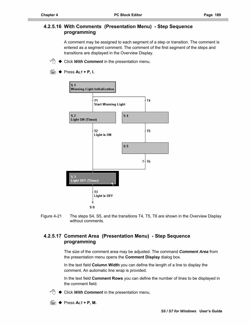
Chapter 4 PC Block Editor Page 189
S5 / S7 for Windows User’s Guide
4.2.5.16 With Comments (Presentation Menu) - Step Sequence programming
A comment may be assigned to each segment of a step or transition. The comment is entered as a segment comment. The comment of the first segment of the steps and transitions are displayed in the Overview Display.
Click With Comment in the presentation menu.
Press ALT + P, I.
Figure 4-21 The steps S4, S5, and the transitions T4, T5, T6 are shown in the Overview Display without comments.
4.2.5.17 Comment Area (Presentation Menu) - Step Sequence programming
The size of the comment area may be adjusted. The command Comment Area from the presentation menu opens the Comment Display dialog box.
In the text field Column Width you can define the length of a line to display the comment. An automatic line wrap is provided.
In the text field Comment Rows you can define the number of lines to be displayed in the comment field.
Click With Comment in the presentation menu.
Press ALT + P, M.
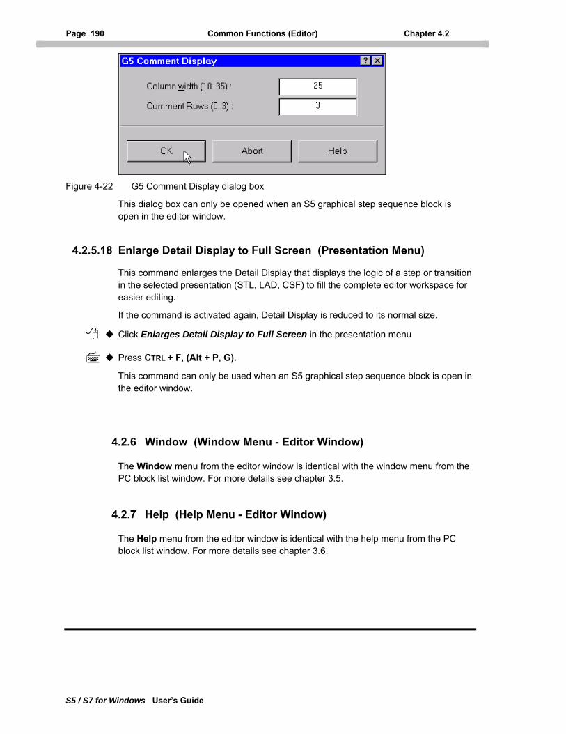
Page 190 Common Functions (Editor) Chapter 4.2
S5 / S7 for Windows User’s Guide
Figure 4-22 G5 Comment Display dialog box
This dialog box can only be opened when an S5 graphical step sequence block is open in the editor window.
4.2.5.18 Enlarge Detail Display to Full Screen (Presentation Menu)
This command enlarges the Detail Display that displays the logic of a step or transition in the selected presentation (STL, LAD, CSF) to fill the complete editor workspace for easier editing.
If the command is activated again, Detail Display is reduced to its normal size.
Click Enlarges Detail Display to Full Screen in the presentation menu
Press CTRL + F, (Alt + P, G).
This command can only be used when an S5 graphical step sequence block is open in the editor window.
4.2.6 Window (Window Menu - Editor Window)
The Window menu from the editor window is identical with the window menu from the PC block list window. For more details see chapter 3.5.
4.2.7 Help (Help Menu - Editor Window)
The Help menu from the editor window is identical with the help menu from the PC block list window. For more details see chapter 3.6.
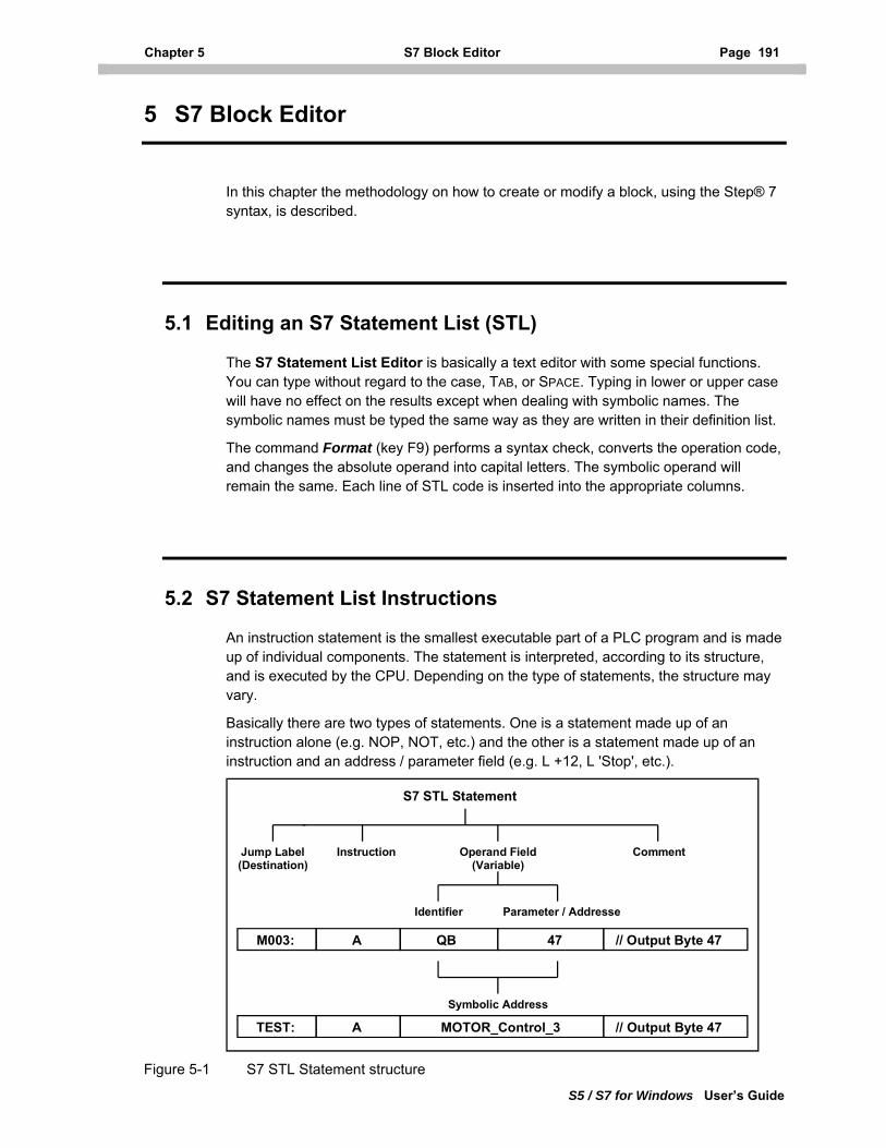
Chapter 5 S7 Block Editor Page 191
S5 / S7 for Windows User’s Guide
5 S7 Block Editor
In this chapter the methodology on how to create or modify a block, using the Step® 7 syntax, is described.
5.1 Editing an S7 Statement List (STL)
The S7 Statement List Editor is basically a text editor with some special functions. You can type without regard to the case, TAB, or SPACE. Typing in lower or upper case will have no effect on the results except when dealing with symbolic names. The symbolic names must be typed the same way as they are written in their definition list.
The command Format (key F9) performs a syntax check, converts the operation code, and changes the absolute operand into capital letters. The symbolic operand will remain the same. Each line of STL code is inserted into the appropriate columns.
5.2 S7 Statement List Instructions
An instruction statement is the smallest executable part of a PLC program and is made up of individual components. The statement is interpreted, according to its structure, and is executed by the CPU. Depending on the type of statements, the structure may vary.
Basically there are two types of statements. One is a statement made up of an instruction alone (e.g. NOP, NOT, etc.) and the other is a statement made up of an instruction and an address / parameter field (e.g. L +12, L 'Stop', etc.).
Jump Label(Destination)
Instruction Operand Field(Variable)
Comment
Identifier Parameter / Addresse
S7 STL Statement
M003: A QB 47 // Output Byte 47
Symbolic Address
TEST: A MOTOR_Control_3 // Output Byte 47
Figure 5-1 S7 STL Statement structure
Page 192 S7 Statement List Instructions Chapter 5.2
S5 / S7 for Windows User’s Guide
Jump Label The destination of a jump instruction is indicated with a label. The label may have up to four (4) characters. The first character must be an alpha character. The destination label itself is terminated with a colon (:) (e.g. TEST:).
Instruction
In the instruction field of a statement what the CPU should execute is defined (e.g. A for AND, O for OR, XOR for an excusive OR, T for a transfer, etc.).
The S7 for Windows Format (F9) command converts all typed characters into capital letters and puts them into the instruction field column.
S7 for Windows supports all the instructions available in the Siemens S7-300 / 400 PLC series. A list of the instructions that your particular CPU can support will be found in the instruction list manual for that CPU.
Operand Field
In the operand field of a statement who should participate, when the instruction is executed by the CPU, is defined. This could be an addressed absolute operand (e.g. QB47), a defined symbolic variable (e.g. Limit_Switch), or a constant (e.g. DW#16#87000000), etc. Some instructions do not require an operand.
Absolute Operands
Identifiers: S7 for Windows supports all the instructions available in the Siemens S7-300 / 400 PLC series.
The S7 for Windows command Format (F9) converts all identifier characters into capital letters and puts inserts them into the appropriate column.
Parameters: A parameter is an address made up of numbers. The S7 for Windows Format (F9) command does not change the address but inserts it into the appropriate column.
Symbolic Addresses
The S7 programming syntax differentiates between global and local symbols. These symbols are referred to in the literature as a Global Variable or a Local Variable, respectively. Symbolic Addresses (global and local variables must be typed in the statement in the same form as they are declared, with regard to lower and upper case letters. The S7 for Windows Format (F9) command does not change the variable but inserts them into the appropriate column.
Global Variable: Global symbols (symbolic operands) are defined in the symbolic table. A symbolic operand is assigned to an absolute operand. This declaration must be done prior to using the symbolic operands in the STL editor. A Global variable must be clearly defined for all blocks and may be used throughout the whole PLC program.
Local Variable: A Local variable is defined in the variable table assigned to a specific block and can only be used during the execution of that block. An exception to this rule is local
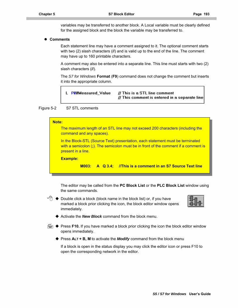
Chapter 5 S7 Block Editor Page 193
S5 / S7 for Windows User’s Guide
variables may be transferred to another block. A Local variable must be clearly defined for the assigned block and the block the variable may be transferred to.
Comments
Each statement line may have a comment assigned to it. The optional comment starts with two (2) slash characters (//) and is valid up to the end of the line. The comment may have up to 160 printable characters.
A comment may also be entered into a separate line. This line must starts with two (2) slash characters (//).
The S7 for Windows Format (F9) command does not change the comment but inserts it into the appropriate column.
Figure 5-2 S7 STL comments
Note: The maximum length of an STL line may not exceed 200 characters (including the command and any spaces).
In the Block-STL (Source Text) presentation, each statement must be terminated with a semicolon (;). The semicolon must be in front of the comment if a comment is present in a line.
Example:
M003: A Q 3.4; //This is a comment in an S7 Source Text line
The editor may be called from the PC Block List or the PLC Block List window using the same commands.
Double click a block (block name in the block list) or, if you have marked a block prior clicking the icon, the block editor window opens immediately.
Activate the New Block command from the block menu.
Press F10. If you have marked a block prior clicking the icon the block editor window opens immediately.
Press ALT + B, M to activate the Modify command from the block menu
If a block is open in the status display you may click the editor icon or press F10 to open the corresponding network in the editor.
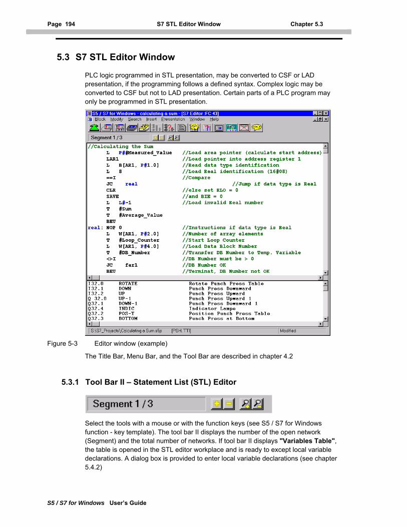
Page 194 S7 STL Editor Window Chapter 5.3
S5 / S7 for Windows User’s Guide
5.3 S7 STL Editor Window
PLC logic programmed in STL presentation, may be converted to CSF or LAD presentation, if the programming follows a defined syntax. Complex logic may be converted to CSF but not to LAD presentation. Certain parts of a PLC program may only be programmed in STL presentation.
Figure 5-3 Editor window (example)
The Title Bar, Menu Bar, and the Tool Bar are described in chapter 4.2
5.3.1 Tool Bar II – Statement List (STL) Editor
Select the tools with a mouse or with the function keys (see S5 / S7 for Windows function - key template). The tool bar II displays the number of the open network (Segment) and the total number of networks. If tool bar II displays "Variables Table", the table is opened in the STL editor workplace and is ready to except local variable declarations. A dialog box is provided to enter local variable declarations (see chapter 5.4.2)
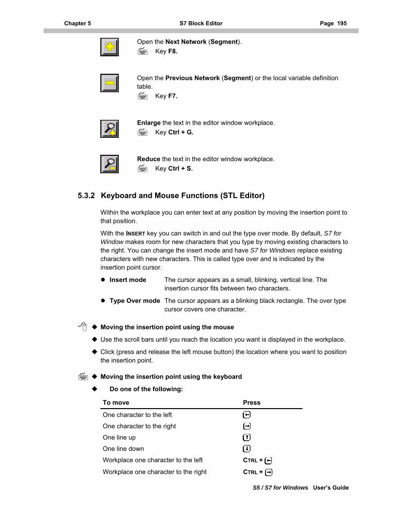
Chapter 5 S7 Block Editor Page 195
S5 / S7 for Windows User’s Guide
Open the Next Network (Segment). Key F8.
Open the Previous Network (Segment) or the local variable definition table.
Key F7.
Enlarge the text in the editor window workplace.
Key Ctrl + G.
Reduce the text in the editor window workplace.
Key Ctrl + S.
5.3.2 Keyboard and Mouse Functions (STL Editor)
Within the workplace you can enter text at any position by moving the insertion point to that position.
With the INSERT key you can switch in and out the type over mode. By default, S7 for Window makes room for new characters that you type by moving existing characters to the right. You can change the insert mode and have S7 for Windows replace existing characters with new characters. This is called type over and is indicated by the insertion point cursor.
Insert mode The cursor appears as a small, blinking, vertical line. The insertion cursor fits between two characters.
Type Over mode The cursor appears as a blinking black rectangle. The over type cursor covers one character.
Moving the insertion point using the mouse
Use the scroll bars until you reach the location you want is displayed in the workplace.
Click (press and release the left mouse button) the location where you want to position the insertion point.
Moving the insertion point using the keyboard
Do one of the following:
To move Press
One character to the left
One character to the right
One line up
One line down
Workplace one character to the left CTRL +
Workplace one character to the right CTRL +
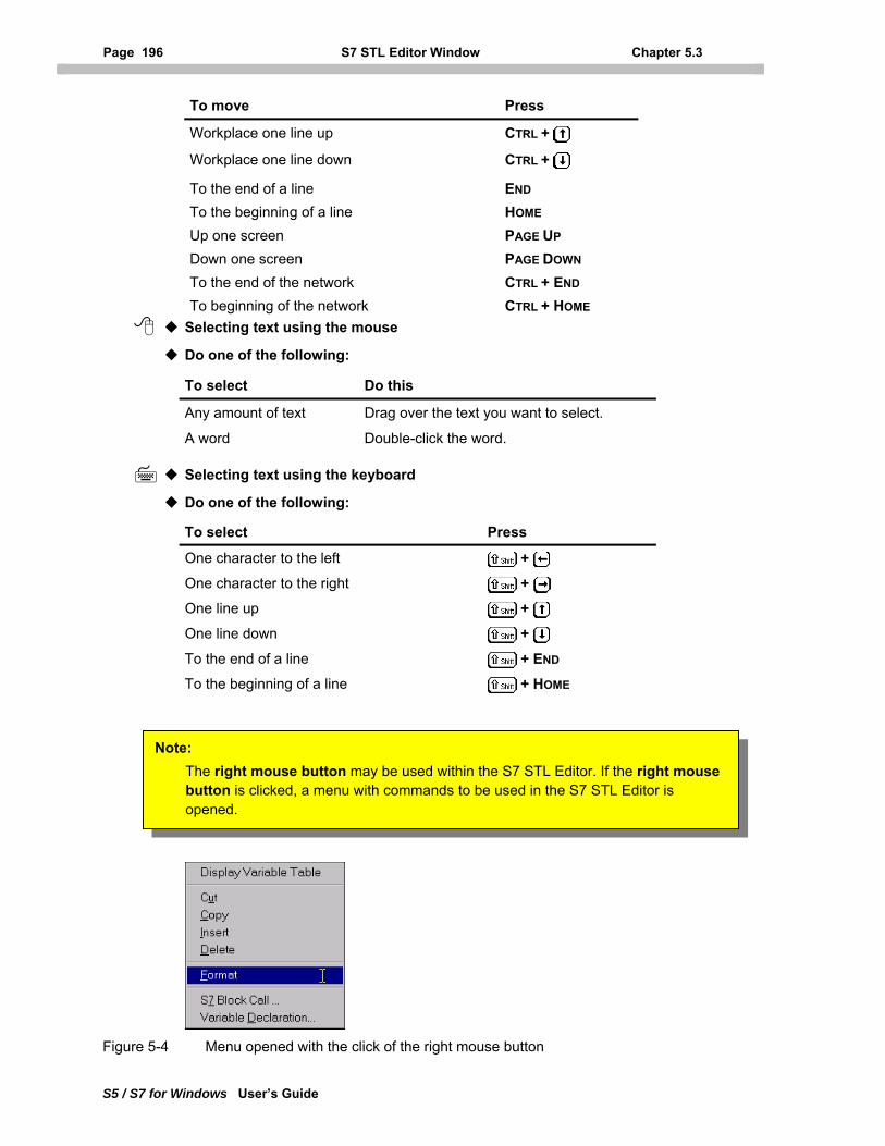
Page 196 S7 STL Editor Window Chapter 5.3
S5 / S7 for Windows User’s Guide
To move Press
Workplace one line up CTRL +
Workplace one line down CTRL +
To the end of a line END To the beginning of a line HOME Up one screen PAGE UP Down one screen PAGE DOWN To the end of the network CTRL + END To beginning of the network CTRL + HOME
Selecting text using the mouse
Do one of the following:
To select Do this
Any amount of text Drag over the text you want to select.
A word Double-click the word.
Selecting text using the keyboard
Do one of the following:
To select Press
One character to the left + One character to the right + One line up + One line down + To the end of a line + END To the beginning of a line + HOME
Note: The right mouse button may be used within the S7 STL Editor. If the right mouse button is clicked, a menu with commands to be used in the S7 STL Editor is opened.
Figure 5-4 Menu opened with the click of the right mouse button
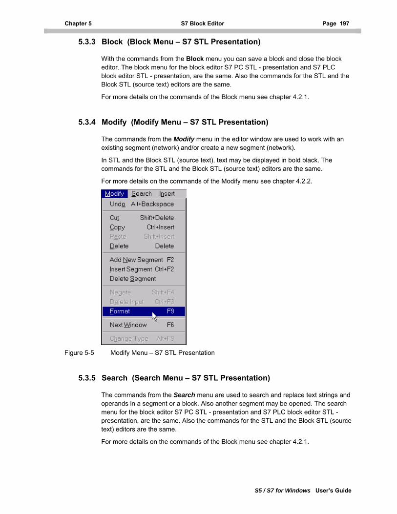
Chapter 5 S7 Block Editor Page 197
S5 / S7 for Windows User’s Guide
5.3.3 Block (Block Menu – S7 STL Presentation)
With the commands from the Block menu you can save a block and close the block editor. The block menu for the block editor S7 PC STL - presentation and S7 PLC block editor STL - presentation, are the same. Also the commands for the STL and the Block STL (source text) editors are the same.
For more details on the commands of the Block menu see chapter 4.2.1.
5.3.4 Modify (Modify Menu – S7 STL Presentation)
The commands from the Modify menu in the editor window are used to work with an existing segment (network) and/or create a new segment (network).
In STL and the Block STL (source text), text may be displayed in bold black. The commands for the STL and the Block STL (source text) editors are the same.
For more details on the commands of the Modify menu see chapter 4.2.2.
Figure 5-5 Modify Menu – S7 STL Presentation
5.3.5 Search (Search Menu – S7 STL Presentation)
The commands from the Search menu are used to search and replace text strings and operands in a segment or a block. Also another segment may be opened. The search menu for the block editor S7 PC STL - presentation and S7 PLC block editor STL - presentation, are the same. Also the commands for the STL and the Block STL (source text) editors are the same.
For more details on the commands of the Block menu see chapter 4.2.1.
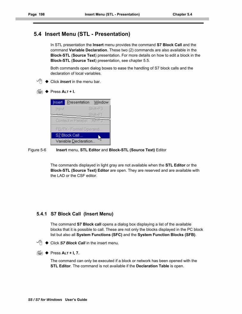
Page 198 Insert Menu (STL - Presentation) Chapter 5.4
S5 / S7 for Windows User’s Guide
5.4 Insert Menu (STL - Presentation)
In STL presentation the Insert menu provides the command S7 Block Call and the command Variable Declaration. These two (2) commands are also available in the Block-STL (Source Text) presentation. For more details on how to edit a block in the Block-STL (Source Text) presentation, see chapter 5.5.
Both commands open dialog boxes to ease the handling of S7 block calls and the declaration of local variables.
Click Insert in the menu bar.
Press ALT + I.
Figure 5-6 Insert menu, STL Editor and Block-STL (Source Text) Editor
The commands displayed in light gray are not available when the STL Editor or the Block-STL (Source Text) Editor are open. They are reserved and are available with the LAD or the CSF editor.
5.4.1 S7 Block Call (Insert Menu)
The command S7 Block call opens a dialog box displaying a list of the available blocks that it is possible to call. These are not only the blocks displayed in the PC block list but also all System Functions (SFC) and the System Function Blocks (SFB).
Click S7 Block Call in the insert menu.
Press ALT + I, 7.
The command can only be executed if a block or network has been opened with the STL Editor. The command is not available if the Declaration Table is open.
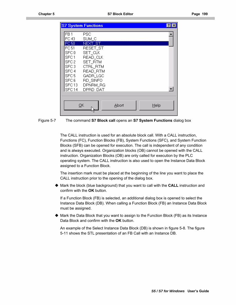
Chapter 5 S7 Block Editor Page 199
S5 / S7 for Windows User’s Guide
Figure 5-7 The command S7 Block call opens an S7 System Functions dialog box
The CALL instruction is used for an absolute block call. With a CALL instruction, Functions (FC), Function Blocks (FB), System Functions (SFC), and System Function Blocks (SFB) can be opened for execution. The call is independent of any condition and is always executed. Organization blocks (OB) cannot be opened with the CALL instruction. Organization Blocks (OB) are only called for execution by the PLC operating system. The CALL instruction is also used to open the Instance Data Block assigned to a Function Block.
The insertion mark must be placed at the beginning of the line you want to place the CALL instruction prior to the opening of the dialog box.
Mark the block (blue background) that you want to call with the CALL instruction and confirm with the OK button.
If a Function Block (FB) is selected, an additional dialog box is opened to select the Instance Data Block (DB). When calling a Function Block (FB) an Instance Data Block must be assigned.
Mark the Data Block that you want to assign to the Function Block (FB) as its Instance Data Block and confirm with the OK button.
An example of the Select Instance Data Block (DB) is shown in figure 5-8. The figure 5-11 shows the STL presentation of an FB Call with an Instance DB.
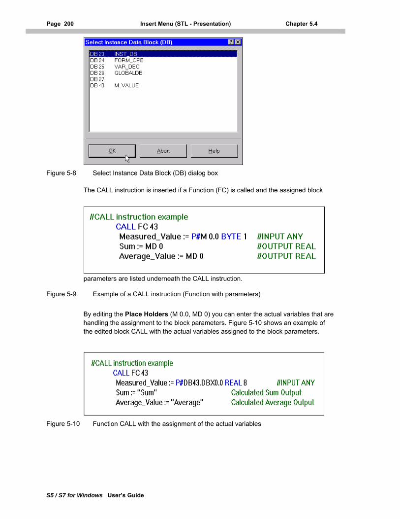
Page 200 Insert Menu (STL - Presentation) Chapter 5.4
S5 / S7 for Windows User’s Guide
Figure 5-8 Select Instance Data Block (DB) dialog box
The CALL instruction is inserted if a Function (FC) is called and the assigned block
parameters are listed underneath the CALL instruction.
Figure 5-9 Example of a CALL instruction (Function with parameters)
By editing the Place Holders (M 0.0, MD 0) you can enter the actual variables that are handling the assignment to the block parameters. Figure 5-10 shows an example of the edited block CALL with the actual variables assigned to the block parameters.
Figure 5-10 Function CALL with the assignment of the actual variables
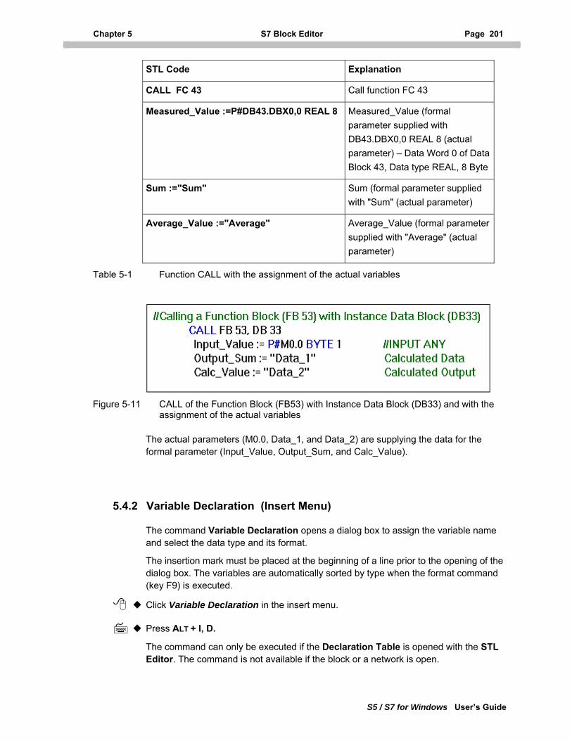
Chapter 5 S7 Block Editor Page 201
S5 / S7 for Windows User’s Guide
STL Code Explanation
CALL FC 43 Call function FC 43
Measured_Value :=P#DB43.DBX0,0 REAL 8 Measured_Value (formal parameter supplied with DB43.DBX0,0 REAL 8 (actual parameter) – Data Word 0 of Data Block 43, Data type REAL, 8 Byte
Sum :="Sum" Sum (formal parameter supplied with "Sum" (actual parameter)
Average_Value :="Average" Average_Value (formal parameter supplied with "Average" (actual parameter)
Table 5-1 Function CALL with the assignment of the actual variables
Figure 5-11 CALL of the Function Block (FB53) with Instance Data Block (DB33) and with the assignment of the actual variables
The actual parameters (M0.0, Data_1, and Data_2) are supplying the data for the formal parameter (Input_Value, Output_Sum, and Calc_Value).
5.4.2 Variable Declaration (Insert Menu)
The command Variable Declaration opens a dialog box to assign the variable name and select the data type and its format.
The insertion mark must be placed at the beginning of a line prior to the opening of the dialog box. The variables are automatically sorted by type when the format command (key F9) is executed.
Click Variable Declaration in the insert menu.
Press ALT + I, D.
The command can only be executed if the Declaration Table is opened with the STL Editor. The command is not available if the block or a network is open.
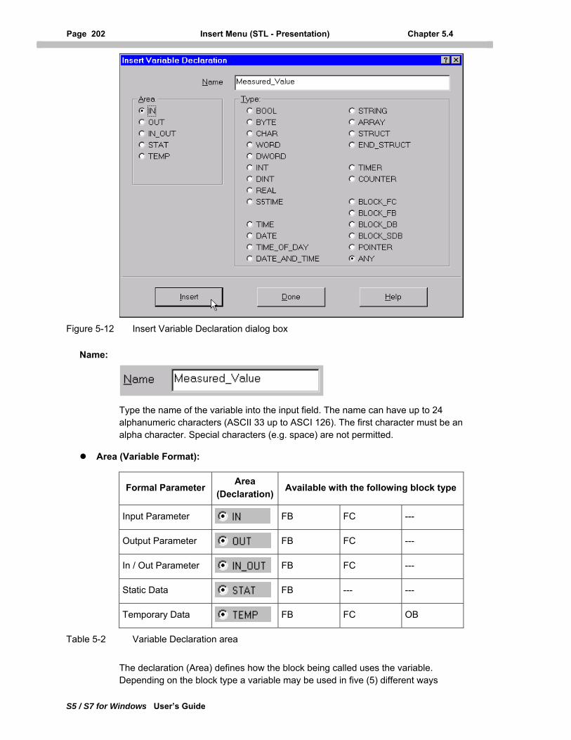
Page 202 Insert Menu (STL - Presentation) Chapter 5.4
S5 / S7 for Windows User’s Guide
Figure 5-12 Insert Variable Declaration dialog box
Name:
Type the name of the variable into the input field. The name can have up to 24 alphanumeric characters (ASCII 33 up to ASCI 126). The first character must be an alpha character. Special characters (e.g. space) are not permitted.
Area (Variable Format):
Formal Parameter Area (Declaration) Available with the following block type
Input Parameter FB FC ---
Output Parameter FB FC ---
In / Out Parameter FB FC ---
Static Data FB --- ---
Temporary Data FB FC OB
Table 5-2 Variable Declaration area
The declaration (Area) defines how the block being called uses the variable. Depending on the block type a variable may be used in five (5) different ways
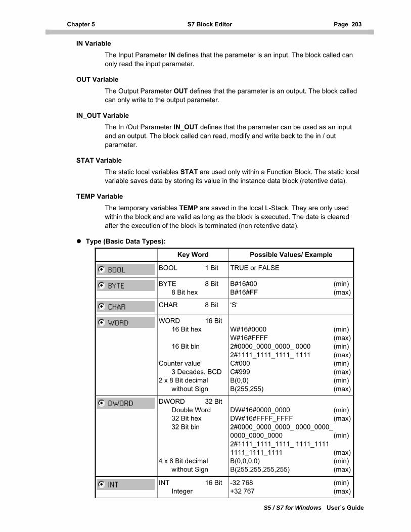
Chapter 5 S7 Block Editor Page 203
S5 / S7 for Windows User’s Guide
IN Variable
The Input Parameter IN defines that the parameter is an input. The block called can only read the input parameter.
OUT Variable
The Output Parameter OUT defines that the parameter is an output. The block called can only write to the output parameter.
IN_OUT Variable
The In /Out Parameter IN_OUT defines that the parameter can be used as an input and an output. The block called can read, modify and write back to the in / out parameter.
STAT Variable
The static local variables STAT are used only within a Function Block. The static local variable saves data by storing its value in the instance data block (retentive data).
TEMP Variable
The temporary variables TEMP are saved in the local L-Stack. They are only used within the block and are valid as long as the block is executed. The date is cleared after the execution of the block is terminated (non retentive data).
Type (Basic Data Types):
Key Word Possible Values/ Example
BOOL 1 Bit TRUE or FALSE
BYTE 8 Bit 8 Bit hex
B#16#00 (min)B#16#FF (max)
CHAR 8 Bit ‘S‘
WORD 16 Bit 16 Bit hex 16 Bit bin Counter value 3 Decades. BCD 2 x 8 Bit decimal without Sign
W#16#0000 (min)W#16#FFFF (max)2#0000_0000_0000_ 0000 (min)2#1111_1111_1111_ 1111 (max)C#000 (min)C#999 (max)B(0,0) (min)B(255,255) (max)
DWORD 32 Bit Double Word 32 Bit hex 32 Bit bin 4 x 8 Bit decimal without Sign
DW#16#0000_0000 (min)DW#16#FFFF_FFFF (max)2#0000_0000_0000_ 0000_0000_ 0000_0000_0000 (min)2#1111_1111_1111_ 1111_1111 1111_1111_1111 (max)B(0,0,0,0) (min)B(255,255,255,255) (max)
INT 16 Bit Integer
-32 768 (min)+32 767 (max)
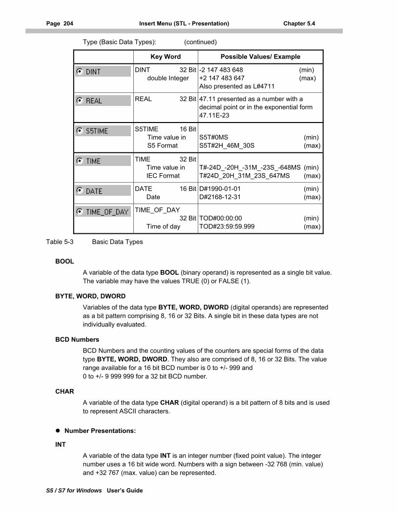
Page 204 Insert Menu (STL - Presentation) Chapter 5.4
S5 / S7 for Windows User’s Guide
Type (Basic Data Types): (continued)
Key Word Possible Values/ Example
DINT 32 Bit double Integer
-2 147 483 648 (min) +2 147 483 647 (max) Also presented as L#4711
REAL 32 Bit 47.11 presented as a number with a
decimal point or in the exponential form 47.11E-23
S5TIME 16 Bit Time value in S5 Format
S5T#0MS (min) S5T#2H_46M_30S (max)
TIME 32 Bit Time value in IEC Format
T#-24D_-20H_-31M_-23S_-648MS (min) T#24D_20H_31M_23S_647MS (max)
DATE 16 Bit Date
D#1990-01-01 (min) D#2168-12-31 (max)
TIME_OF_DAY 32 Bit Time of day
TOD#00:00:00 (min) TOD#23:59:59.999 (max)
Table 5-3 Basic Data Types
BOOL
A variable of the data type BOOL (binary operand) is represented as a single bit value. The variable may have the values TRUE (0) or FALSE (1).
BYTE, WORD, DWORD Variables of the data type BYTE, WORD, DWORD (digital operands) are represented as a bit pattern comprising 8, 16 or 32 Bits. A single bit in these data types are not individually evaluated.
BCD Numbers
BCD Numbers and the counting values of the counters are special forms of the data type BYTE, WORD, DWORD. They also are comprised of 8, 16 or 32 Bits. The value range available for a 16 bit BCD number is 0 to +/- 999 and 0 to +/- 9 999 999 for a 32 bit BCD number.
CHAR
A variable of the data type CHAR (digital operand) is a bit pattern of 8 bits and is used to represent ASCII characters.
Number Presentations:
INT
A variable of the data type INT is an integer number (fixed point value). The integer number uses a 16 bit wide word. Numbers with a sign between -32 768 (min. value) and +32 767 (max. value) can be represented.
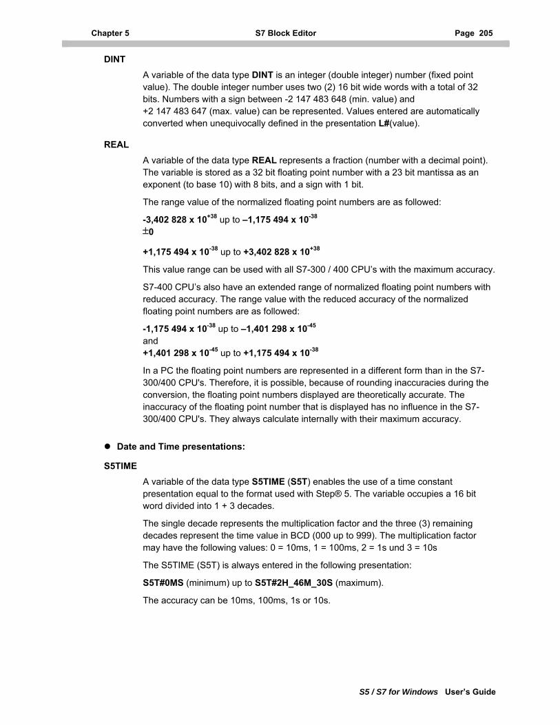
Chapter 5 S7 Block Editor Page 205
S5 / S7 for Windows User’s Guide
DINT
A variable of the data type DINT is an integer (double integer) number (fixed point value). The double integer number uses two (2) 16 bit wide words with a total of 32 bits. Numbers with a sign between -2 147 483 648 (min. value) and +2 147 483 647 (max. value) can be represented. Values entered are automatically converted when unequivocally defined in the presentation L#(value).
REAL
A variable of the data type REAL represents a fraction (number with a decimal point). The variable is stored as a 32 bit floating point number with a 23 bit mantissa as an exponent (to base 10) with 8 bits, and a sign with 1 bit.
The range value of the normalized floating point numbers are as followed:
-3,402 828 x 10+38 up to –1,175 494 x 10-38
±0
+1,175 494 x 10-38 up to +3,402 828 x 10+38
This value range can be used with all S7-300 / 400 CPU’s with the maximum accuracy.
S7-400 CPU’s also have an extended range of normalized floating point numbers with reduced accuracy. The range value with the reduced accuracy of the normalized floating point numbers are as followed:
-1,175 494 x 10-38 up to –1,401 298 x 10-45
and +1,401 298 x 10-45 up to +1,175 494 x 10-38
In a PC the floating point numbers are represented in a different form than in the S7-300/400 CPU's. Therefore, it is possible, because of rounding inaccuracies during the conversion, the floating point numbers displayed are theoretically accurate. The inaccuracy of the floating point number that is displayed has no influence in the S7-300/400 CPU's. They always calculate internally with their maximum accuracy.
Date and Time presentations:
S5TIME
A variable of the data type S5TIME (S5T) enables the use of a time constant presentation equal to the format used with Step® 5. The variable occupies a 16 bit word divided into 1 + 3 decades.
The single decade represents the multiplication factor and the three (3) remaining decades represent the time value in BCD (000 up to 999). The multiplication factor may have the following values: 0 = 10ms, 1 = 100ms, 2 = 1s und 3 = 10s
The S5TIME (S5T) is always entered in the following presentation:
S5T#0MS (minimum) up to S5T#2H_46M_30S (maximum).
The accuracy can be 10ms, 100ms, 1s or 10s.
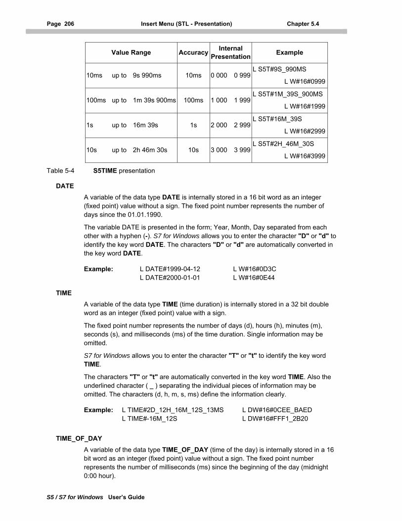
Page 206 Insert Menu (STL - Presentation) Chapter 5.4
S5 / S7 for Windows User’s Guide
Value Range Accuracy Internal Presentation Example
10ms up to 9s 990ms 10ms 0 000 0 999L S5T#9S_990MS
L W#16#0999
100ms up to 1m 39s 900ms 100ms 1 000 1 999L S5T#1M_39S_900MS
L W#16#1999
1s up to 16m 39s 1s 2 000 2 999L S5T#16M_39S
L W#16#2999
10s up to 2h 46m 30s 10s 3 000 3 999L S5T#2H_46M_30S
L W#16#3999
Table 5-4 S5TIME presentation
DATE
A variable of the data type DATE is internally stored in a 16 bit word as an integer (fixed point) value without a sign. The fixed point number represents the number of days since the 01.01.1990.
The variable DATE is presented in the form; Year, Month, Day separated from each other with a hyphen (-). S7 for Windows allows you to enter the character "D" or "d" to identify the key word DATE. The characters "D" or "d" are automatically converted in the key word DATE.
Example: L DATE#1999-04-12 L W#16#0D3C L DATE#2000-01-01 L W#16#0E44
TIME
A variable of the data type TIME (time duration) is internally stored in a 32 bit double word as an integer (fixed point) value with a sign.
The fixed point number represents the number of days (d), hours (h), minutes (m), seconds (s), and milliseconds (ms) of the time duration. Single information may be omitted.
S7 for Windows allows you to enter the character "T" or "t" to identify the key word TIME.
The characters "T" or "t" are automatically converted in the key word TIME. Also the underlined character ( _ ) separating the individual pieces of information may be omitted. The characters (d, h, m, s, ms) define the information clearly.
Example: L TIME#2D_12H_16M_12S_13MS L DW#16#0CEE_BAED L TIME#-16M_12S L DW#16#FFF1_2B20
TIME_OF_DAY
A variable of the data type TIME_OF_DAY (time of the day) is internally stored in a 16 bit word as an integer (fixed point) value without a sign. The fixed point number represents the number of milliseconds (ms) since the beginning of the day (midnight 0:00 hour).
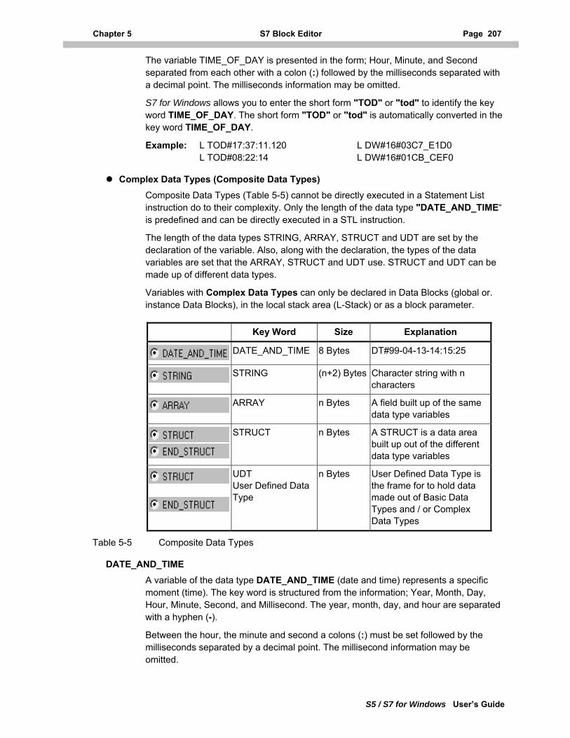
Chapter 5 S7 Block Editor Page 207
S5 / S7 for Windows User’s Guide
The variable TIME_OF_DAY is presented in the form; Hour, Minute, and Second separated from each other with a colon (:) followed by the milliseconds separated with a decimal point. The milliseconds information may be omitted.
S7 for Windows allows you to enter the short form "TOD" or "tod" to identify the key word TIME_OF_DAY. The short form "TOD" or "tod" is automatically converted in the key word TIME_OF_DAY.
Example: L TOD#17:37:11.120 L DW#16#03C7_E1D0 L TOD#08:22:14 L DW#16#01CB_CEF0
Complex Data Types (Composite Data Types) Composite Data Types (Table 5-5) cannot be directly executed in a Statement List instruction do to their complexity. Only the length of the data type "DATE_AND_TIME“ is predefined and can be directly executed in a STL instruction.
The length of the data types STRING, ARRAY, STRUCT and UDT are set by the declaration of the variable. Also, along with the declaration, the types of the data variables are set that the ARRAY, STRUCT and UDT use. STRUCT and UDT can be made up of different data types.
Variables with Complex Data Types can only be declared in Data Blocks (global or. instance Data Blocks), in the local stack area (L-Stack) or as a block parameter.
Key Word Size Explanation
DATE_AND_TIME 8 Bytes DT#99-04-13-14:15:25
STRING (n+2) Bytes Character string with n
characters
ARRAY n Bytes A field built up of the same
data type variables
STRUCT n Bytes A STRUCT is a data area built up out of the different data type variables
UDT User Defined Data Type
n Bytes User Defined Data Type is the frame for to hold data made out of Basic Data Types and / or Complex Data Types
Table 5-5 Composite Data Types
DATE_AND_TIME
A variable of the data type DATE_AND_TIME (date and time) represents a specific moment (time). The key word is structured from the information; Year, Month, Day, Hour, Minute, Second, and Millisecond. The year, month, day, and hour are separated with a hyphen (-).
Between the hour, the minute and second a colons (:) must be set followed by the milliseconds separated by a decimal point. The millisecond information may be omitted.
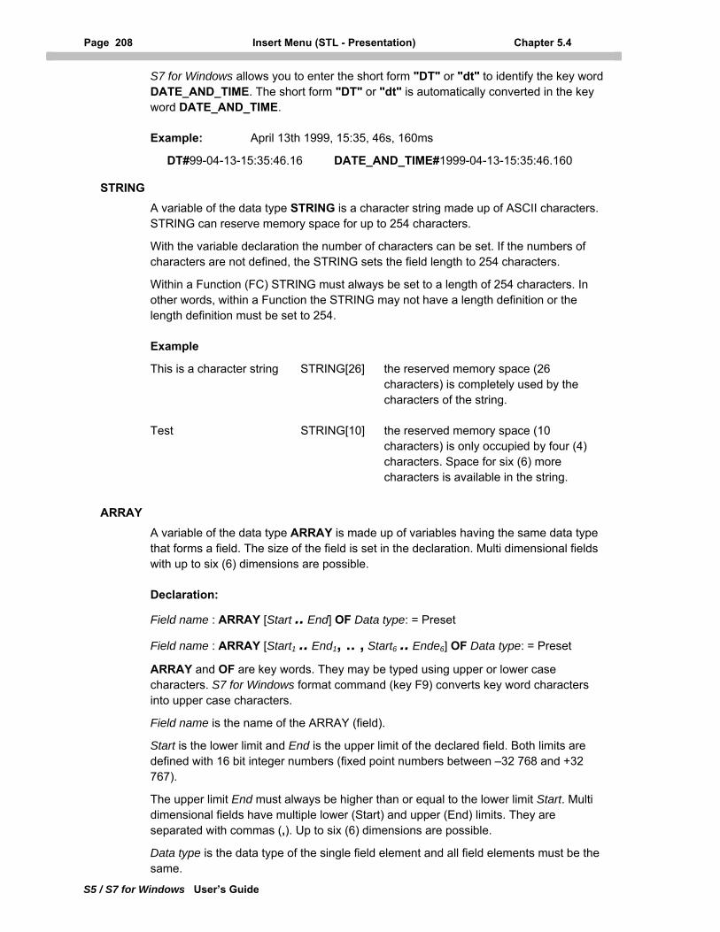
Page 208 Insert Menu (STL - Presentation) Chapter 5.4
S5 / S7 for Windows User’s Guide
S7 for Windows allows you to enter the short form "DT" or "dt" to identify the key word DATE_AND_TIME. The short form "DT" or "dt" is automatically converted in the key word DATE_AND_TIME.
Example: April 13th 1999, 15:35, 46s, 160ms
DT#99-04-13-15:35:46.16 DATE_AND_TIME#1999-04-13-15:35:46.160
STRING
A variable of the data type STRING is a character string made up of ASCII characters. STRING can reserve memory space for up to 254 characters.
With the variable declaration the number of characters can be set. If the numbers of characters are not defined, the STRING sets the field length to 254 characters.
Within a Function (FC) STRING must always be set to a length of 254 characters. In other words, within a Function the STRING may not have a length definition or the length definition must be set to 254.
Example
This is a character string STRING[26] the reserved memory space (26 characters) is completely used by the characters of the string.
Test STRING[10] the reserved memory space (10 characters) is only occupied by four (4) characters. Space for six (6) more characters is available in the string.
ARRAY
A variable of the data type ARRAY is made up of variables having the same data type that forms a field. The size of the field is set in the declaration. Multi dimensional fields with up to six (6) dimensions are possible.
Declaration:
Field name : ARRAY [Start .. End] OF Data type: = Preset
Field name : ARRAY [Start1 .. End1, .. , Start6 .. Ende6] OF Data type: = Preset
ARRAY and OF are key words. They may be typed using upper or lower case characters. S7 for Windows format command (key F9) converts key word characters into upper case characters.
Field name is the name of the ARRAY (field).
Start is the lower limit and End is the upper limit of the declared field. Both limits are defined with 16 bit integer numbers (fixed point numbers between –32 768 and +32 767).
The upper limit End must always be higher than or equal to the lower limit Start. Multi dimensional fields have multiple lower (Start) and upper (End) limits. They are separated with commas (,). Up to six (6) dimensions are possible.
Data type is the data type of the single field element and all field elements must be the same.
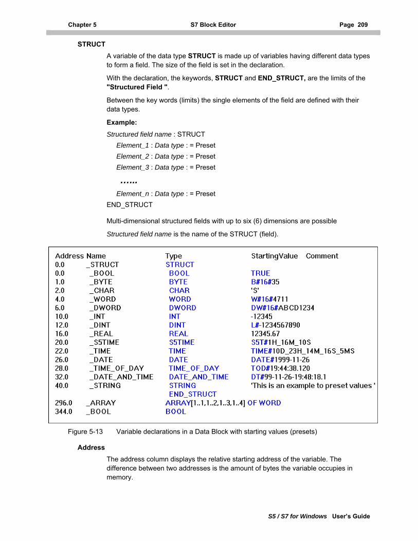
Chapter 5 S7 Block Editor Page 209
S5 / S7 for Windows User’s Guide
STRUCT
A variable of the data type STRUCT is made up of variables having different data types to form a field. The size of the field is set in the declaration.
With the declaration, the keywords, STRUCT and END_STRUCT, are the limits of the "Structured Field ".
Between the key words (limits) the single elements of the field are defined with their data types.
Example:
Structured field name : STRUCT Element_1 : Data type : = Preset Element_2 : Data type : = Preset Element_3 : Data type : = Preset
…... Element_n : Data type : = Preset END_STRUCT
Multi-dimensional structured fields with up to six (6) dimensions are possible
Structured field name is the name of the STRUCT (field).
Figure 5-13 Variable declarations in a Data Block with starting values (presets)
Address The address column displays the relative starting address of the variable. The difference between two addresses is the amount of bytes the variable occupies in memory.
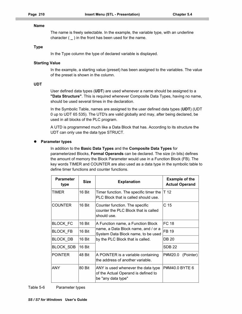
Page 210 Insert Menu (STL - Presentation) Chapter 5.4
S5 / S7 for Windows User’s Guide
Name The name is freely selectable. In the example, the variable type, with an underline character ( _ ) in the front has been used for the name.
Type In the Type column the type of declared variable is displayed.
Starting Value
In the example, a starting value (preset) has been assigned to the variables. The value of the preset is shown in the column.
UDT
User defined data types (UDT) are used whenever a name should be assigned to a "Data Structure". This is required whenever Composite Data Types, having no name, should be used several times in the declaration.
In the Symbolic Table, names are assigned to the user defined data types (UDT) (UDT 0 up to UDT 65 535). The UTD's are valid globally and may, after being declared, be used in all blocks of the PLC program.
A UTD is programmed much like a Data Block that has. According to its structure the UDT can only use the data type STRUCT.
Parameter types In addition to the Basic Data Types and the Composite Data Types for parameterized Blocks, Formal Operands can be declared. The size (in bits) defines the amount of memory the Block Parameter would use in a Function Block (FB). The key words TIMER and COUNTER are also used as a data type in the symbolic table to define timer functions and counter functions.
Parameter type Size Explanation Example of the
Actual Operand
TIMER 16 Bit Timer function. The specific timer the PLC Block that is called should use.
T 12
COUNTER 16 Bit Counter function. The specific counter the PLC Block that is called should use.
C 15
BLOCK_FC 16 Bit FC 18
BLOCK_FB 16 Bit FB 19
BLOCK_DB 16 Bit DB 20
BLOCK_SDB 16 Bit
A Function name, a Function Block name, a Data Block name, and / or a System Data Block name, to be used by the PLC Block that is called.
SDB 22
POINTER 48 Bit A POINTER is a variable containing the address of another variable.
P#M20.0 (Pointer)
ANY 80 Bit ANY is used whenever the data type of the Actual Operand is defined to be "any data type"
P#M40.0 BYTE 6
Table 5-6 Parameter types
Chapter 5 S7 Block Editor Page 211
S5 / S7 for Windows User’s Guide
Timer, Counter These parameter types are used to define the Formal Operand parameter of the timer functions (TIMER) and the counter functions (COUNTER).
BLOCKxx PLC Blocks (Code Blocks) can be transferred with the help of the parameter types BLOCK_FC or BLOCK_FB as a parameter of the called Block. Only Blocks not having a transfer parameter and / or static variables (BLOCK_FB), can be transferred (handed over) as an Actual Operand (FCn; FBn).
From the Block that is called the formal PLC Blocks (Code Blocks) can only be called by using the instructions UC or CC. It is not permitted to use the instruction "CALL" to call the formal PLC Block (Code Block)
The transfer (hand over) of Data Blocks (DBn) and System Data Blocks (SDBn) and the transfer of the related instructions has no limitations according to the formal parameter.
POINTER
A pointer of the type POINTER is a variable containing the address of another variable. If a formal parameter of the type POINTER is defined, the address is given by the actual parameter.
Example: P#M20.0 The POINTER points to the memory bit M20.0. Starting with this position the memory bit M20.0 the contents of the memory is interpreted to be data.
ANY
In a pointer of the type ANY, the data type of the actual parameter can be "any data type". An actual parameter transferred (handed over) as a pointer that has the type ANY, defines the beginning and the size of a data area.
Example: P#M40.0 BYTE6 The pointer type ANY points to the memory bit M40.0 and defines the data area size with six (6) bytes. The contents of the memory bytes MB40 up to MB45 are interpreted to be data.
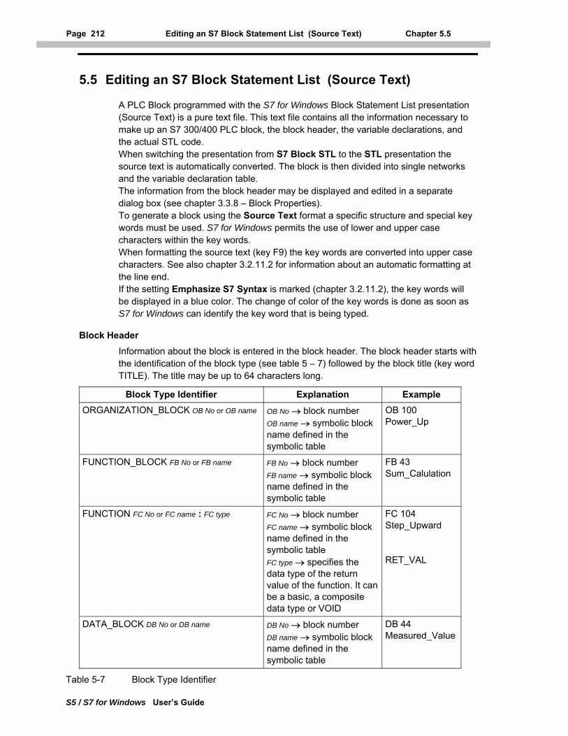
Page 212 Editing an S7 Block Statement List (Source Text) Chapter 5.5
S5 / S7 for Windows User’s Guide
5.5 Editing an S7 Block Statement List (Source Text)
A PLC Block programmed with the S7 for Windows Block Statement List presentation (Source Text) is a pure text file. This text file contains all the information necessary to make up an S7 300/400 PLC block, the block header, the variable declarations, and the actual STL code. When switching the presentation from S7 Block STL to the STL presentation the source text is automatically converted. The block is then divided into single networks and the variable declaration table. The information from the block header may be displayed and edited in a separate dialog box (see chapter 3.3.8 – Block Properties). To generate a block using the Source Text format a specific structure and special key words must be used. S7 for Windows permits the use of lower and upper case characters within the key words. When formatting the source text (key F9) the key words are converted into upper case characters. See also chapter 3.2.11.2 for information about an automatic formatting at the line end. If the setting Emphasize S7 Syntax is marked (chapter 3.2.11.2), the key words will be displayed in a blue color. The change of color of the key words is done as soon as S7 for Windows can identify the key word that is being typed.
Block Header Information about the block is entered in the block header. The block header starts with the identification of the block type (see table 5 – 7) followed by the block title (key word TITLE). The title may be up to 64 characters long.
Block Type Identifier Explanation Example ORGANIZATION_BLOCK OB No or OB name OB No → block number
OB name → symbolic block name defined in the symbolic table
OB 100 Power_Up
FUNCTION_BLOCK FB No or FB name FB No → block number FB name → symbolic block name defined in the symbolic table
FB 43 Sum_Calulation
FUNCTION FC No or FC name : FC type FC No → block number FC name → symbolic block name defined in the symbolic table FC type → specifies the data type of the return value of the function. It can be a basic, a composite data type or VOID
FC 104 Step_Upward RET_VAL
DATA_BLOCK DB No or DB name DB No → block number DB name → symbolic block name defined in the symbolic table
DB 44 Measured_Value
Table 5-7 Block Type Identifier
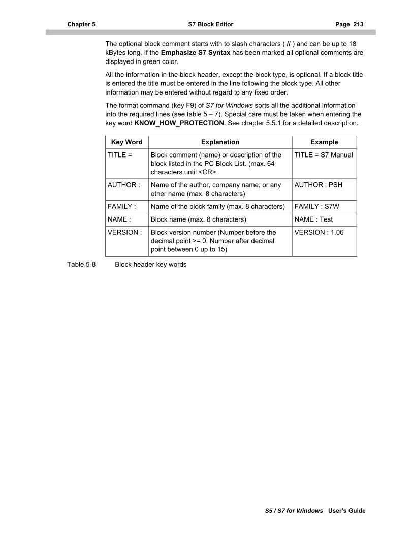
Chapter 5 S7 Block Editor Page 213
S5 / S7 for Windows User’s Guide
The optional block comment starts with to slash characters ( // ) and can be up to 18 kBytes long. If the Emphasize S7 Syntax has been marked all optional comments are displayed in green color.
All the information in the block header, except the block type, is optional. If a block title is entered the title must be entered in the line following the block type. All other information may be entered without regard to any fixed order.
The format command (key F9) of S7 for Windows sorts all the additional information into the required lines (see table 5 – 7). Special care must be taken when entering the key word KNOW_HOW_PROTECTION. See chapter 5.5.1 for a detailed description.
Key Word Explanation Example
TITLE = Block comment (name) or description of the block listed in the PC Block List. (max. 64 characters until <CR>
TITLE = S7 Manual
AUTHOR : Name of the author, company name, or any other name (max. 8 characters)
AUTHOR : PSH
FAMILY : Name of the block family (max. 8 characters) FAMILY : S7W
NAME : Block name (max. 8 characters) NAME : Test
VERSION : Block version number (Number before the decimal point >= 0, Number after decimal point between 0 up to 15)
VERSION : 1.06
Table 5-8 Block header key words
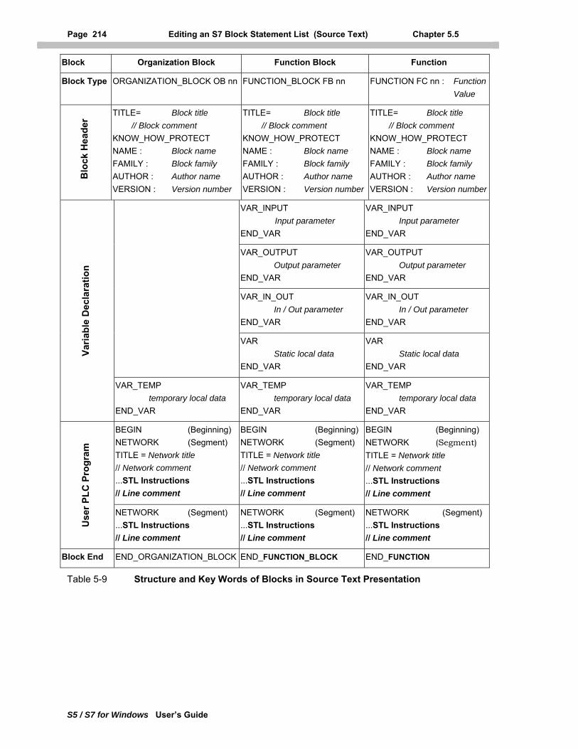
Page 214 Editing an S7 Block Statement List (Source Text) Chapter 5.5
S5 / S7 for Windows User’s Guide
Block Organization Block Function Block Function
Block Type ORGANIZATION_BLOCK OB nn FUNCTION_BLOCK FB nn FUNCTION FC nn : Function Value
Blo
ck H
eade
r
TITLE= Block title // Block comment KNOW_HOW_PROTECT NAME : Block name FAMILY : Block family AUTHOR : Author name VERSION : Version number
TITLE= Block title // Block comment KNOW_HOW_PROTECT NAME : Block name FAMILY : Block family AUTHOR : Author name VERSION : Version number
TITLE= Block title // Block comment KNOW_HOW_PROTECT NAME : Block name FAMILY : Block family AUTHOR : Author name VERSION : Version number
VAR_INPUT Input parameter END_VAR
VAR_INPUT Input parameter END_VAR
VAR_OUTPUT Output parameter END_VAR
VAR_OUTPUT Output parameter END_VAR
VAR_IN_OUT In / Out parameter END_VAR
VAR_IN_OUT In / Out parameter END_VAR
VAR Static local data END_VAR
VAR Static local data END_VAR
Varia
ble
Dec
lara
tion
VAR_TEMP temporary local data END_VAR
VAR_TEMP temporary local data END_VAR
VAR_TEMP temporary local data END_VAR
BEGIN (Beginning) NETWORK (Segment) TITLE = Network title // Network comment ...STL Instructions // Line comment
BEGIN (Beginning)NETWORK (Segment) TITLE = Network title // Network comment ...STL Instructions // Line comment
BEGIN (Beginning) NETWORK (Segment) TITLE = Network title // Network comment ...STL Instructions // Line comment
Use
r PLC
Pro
gram
NETWORK (Segment) ...STL Instructions // Line comment
NETWORK (Segment) ...STL Instructions // Line comment
NETWORK (Segment)...STL Instructions // Line comment
Block End END_ORGANIZATION_BLOCK END_FUNCTION_BLOCK END_FUNCTION
Table 5-9 Structure and Key Words of Blocks in Source Text Presentation
Chapter 5 S7 Block Editor Page 215
S5 / S7 for Windows User’s Guide
Variable Declaration
In the Variable Declaration all the local variables of the block are defined. The variable types must be defined in the order given in the table 5 – 7. No order within the variable type is required. Unused variable types must be omitted. Not all variable types can be used in all blocks.
A variable is declared as followed:
Variable Name Data Type Preset // Comment
The Preset of the variable and the Comment can be omitted. Not all variables can have a preset value. Specifically, temporary local variables cannot have a preset value.
Example of a Variable Declaration:
Sum : INT = +4711; //Calculated Sum
Spaces between the single components can be omitted. The format command (key F9) of S7 for Windows puts additional spaces into the variable declaration for easier reading and deletes spaces not required.
User PLC Program The key word BEGIN indicates the beginning of the actual User PLC Program written in the STEP® 7 Statement List (STL) syntax. The end of the block (user PLC program code) is indicated with the key word END_xxx.
The character xxx stand for the name of the block type (ORGANIZATION_BLOCK, FUNCTION_BLOCK, FUNCTION, or DATA_BLOCK). S7 for Windows permits the use of lower and upper case characters within the key words.
When formatting the source text (key F9), the key words are converted into upper case characters. Also, spaces between the single components can be omitted.
The format command (key F9) of S7 for Windows puts additional spaces between the components for ease of reading and deletes spaces not required and checks the syntax. Incorrect components are marked.
Each instruction must be in a separate line and has to be terminated with a semicolon (;). An optional comment, indicated with two (2) slash characters (//), may follow the semicolon (instruction) in the same line.
An additional line comment may also be inserted. The optional line comment starts with two (2) slash characters (//) at the beginning of the line and may be up to 160 characters long. Special control characters (e.g. TAB, Ctrl + … etc.), those which usually can not be printed, are not permitted.
The complete block, including the header, the variable declarations, and all the comments may be up to 64 kByte.
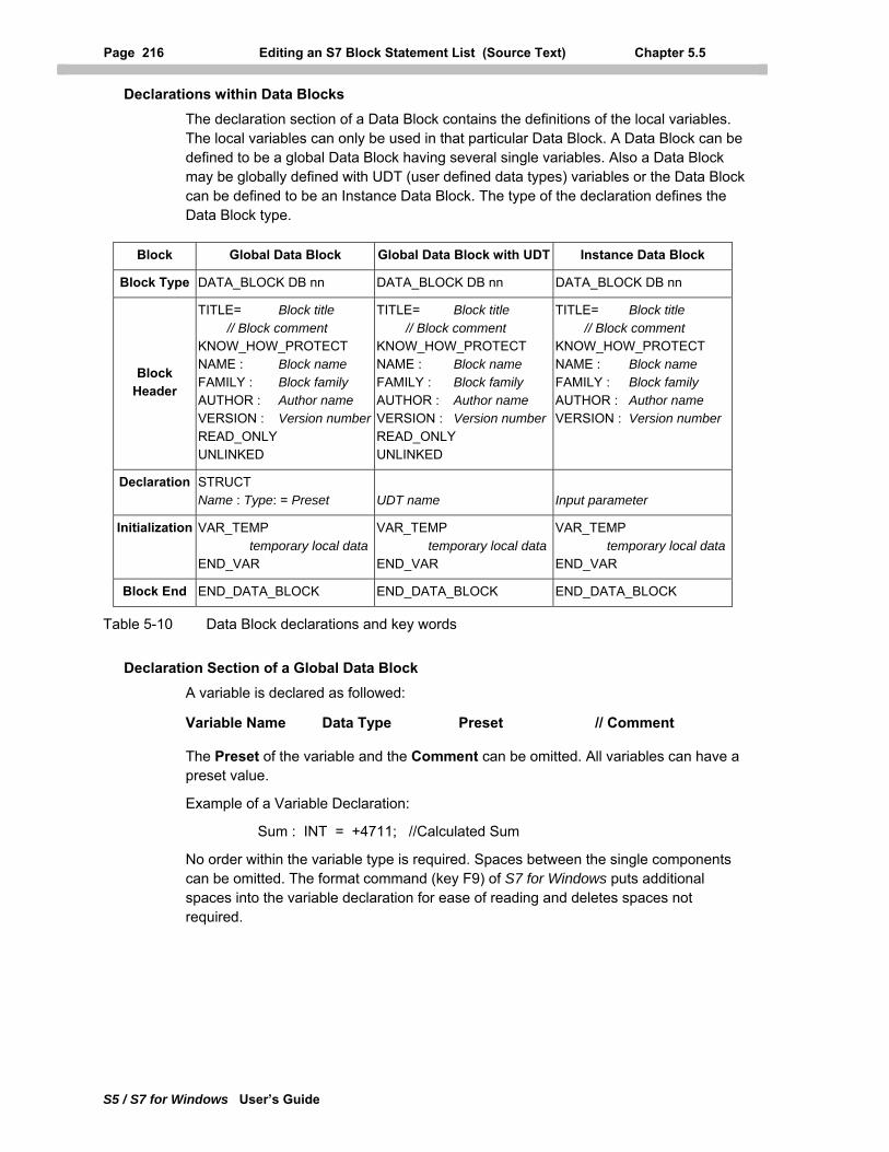
Page 216 Editing an S7 Block Statement List (Source Text) Chapter 5.5
S5 / S7 for Windows User’s Guide
Declarations within Data Blocks
The declaration section of a Data Block contains the definitions of the local variables. The local variables can only be used in that particular Data Block. A Data Block can be defined to be a global Data Block having several single variables. Also a Data Block may be globally defined with UDT (user defined data types) variables or the Data Block can be defined to be an Instance Data Block. The type of the declaration defines the Data Block type.
Block Global Data Block Global Data Block with UDT Instance Data Block
Block Type DATA_BLOCK DB nn DATA_BLOCK DB nn DATA_BLOCK DB nn
Block Header
TITLE= Block title // Block comment KNOW_HOW_PROTECT NAME : Block name FAMILY : Block family AUTHOR : Author name VERSION : Version numberREAD_ONLY UNLINKED
TITLE= Block title // Block comment KNOW_HOW_PROTECT NAME : Block name FAMILY : Block family AUTHOR : Author name VERSION : Version numberREAD_ONLY UNLINKED
TITLE= Block title // Block comment KNOW_HOW_PROTECT NAME : Block name FAMILY : Block family AUTHOR : Author name VERSION : Version number
Declaration STRUCT Name : Type: = Preset
UDT name
Input parameter
Initialization VAR_TEMP temporary local dataEND_VAR
VAR_TEMP temporary local dataEND_VAR
VAR_TEMP temporary local dataEND_VAR
Block End END_DATA_BLOCK END_DATA_BLOCK END_DATA_BLOCK
Table 5-10 Data Block declarations and key words
Declaration Section of a Global Data Block A variable is declared as followed:
Variable Name Data Type Preset // Comment
The Preset of the variable and the Comment can be omitted. All variables can have a preset value.
Example of a Variable Declaration:
Sum : INT = +4711; //Calculated Sum
No order within the variable type is required. Spaces between the single components can be omitted. The format command (key F9) of S7 for Windows puts additional spaces into the variable declaration for ease of reading and deletes spaces not required.
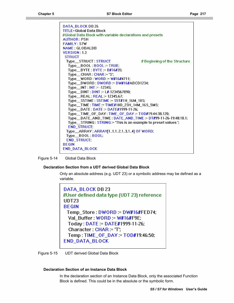
Chapter 5 S7 Block Editor Page 217
S5 / S7 for Windows User’s Guide
Figure 5-14 Global Data Block
Declaration Section from a UDT derived Global Data Block
Only an absolute address (e.g. UDT 23) or a symbolic address may be defined as a variable.
Figure 5-15 UDT derived Global Data Block
Declaration Section of an Instance Data Block
In the declaration section of an Instance Data Block, only the associated Function Block is defined. This could be in the absolute or the symbolic form.
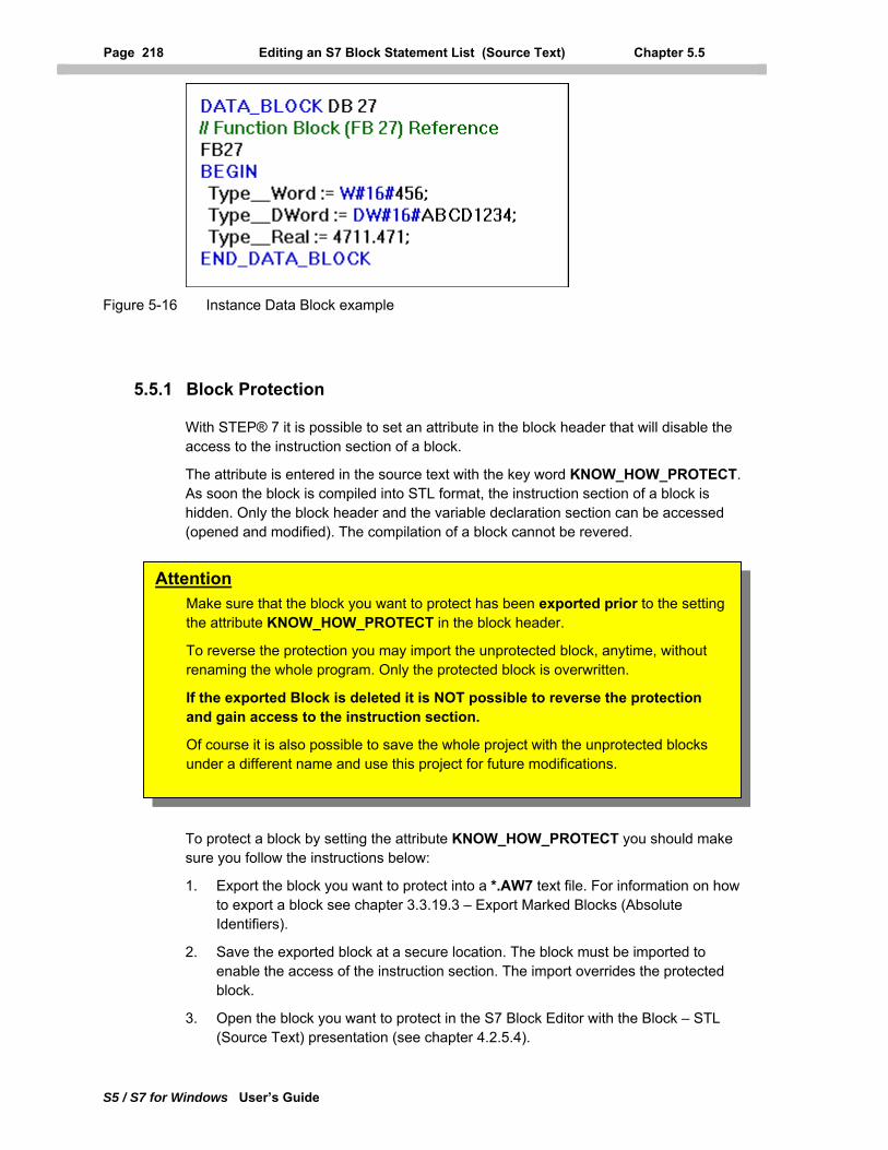
Page 218 Editing an S7 Block Statement List (Source Text) Chapter 5.5
S5 / S7 for Windows User’s Guide
Figure 5-16 Instance Data Block example
5.5.1 Block Protection
With STEP® 7 it is possible to set an attribute in the block header that will disable the access to the instruction section of a block.
The attribute is entered in the source text with the key word KNOW_HOW_PROTECT. As soon the block is compiled into STL format, the instruction section of a block is hidden. Only the block header and the variable declaration section can be accessed (opened and modified). The compilation of a block cannot be revered.
To protect a block by setting the attribute KNOW_HOW_PROTECT you should make sure you follow the instructions below:
Attention Make sure that the block you want to protect has been exported prior to the setting the attribute KNOW_HOW_PROTECT in the block header.
To reverse the protection you may import the unprotected block, anytime, without renaming the whole program. Only the protected block is overwritten.
If the exported Block is deleted it is NOT possible to reverse the protection and gain access to the instruction section.
Of course it is also possible to save the whole project with the unprotected blocks under a different name and use this project for future modifications.
1. Export the block you want to protect into a *.AW7 text file. For information on how to export a block see chapter 3.3.19.3 – Export Marked Blocks (Absolute Identifiers).
2. Save the exported block at a secure location. The block must be imported to enable the access of the instruction section. The import overrides the protected block.
3. Open the block you want to protect in the S7 Block Editor with the Block – STL (Source Text) presentation (see chapter 4.2.5.4).
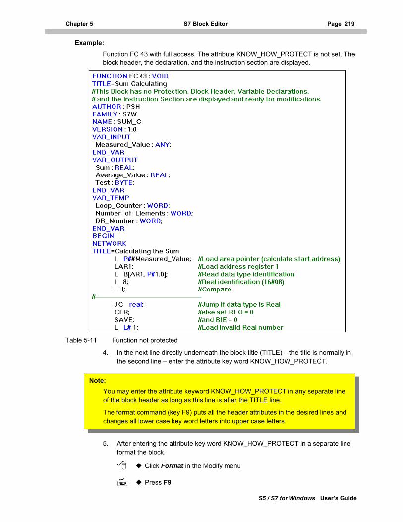
Chapter 5 S7 Block Editor Page 219
S5 / S7 for Windows User’s Guide
Example: Function FC 43 with full access. The attribute KNOW_HOW_PROTECT is not set. The block header, the declaration, and the instruction section are displayed.
Table 5-11 Function not protected
4. In the next line directly underneath the block title (TITLE) – the title is normally in the second line – enter the attribute key word KNOW_HOW_PROTECT.
Note: You may enter the attribute keyword KNOW_HOW_PROTECT in any separate line of the block header as long as this line is after the TITLE line.
The format command (key F9) puts all the header attributes in the desired lines and changes all lower case key word letters into upper case letters.
5. After entering the attribute key word KNOW_HOW_PROTECT in a separate line format the block.
Click Format in the Modify menu
Press F9
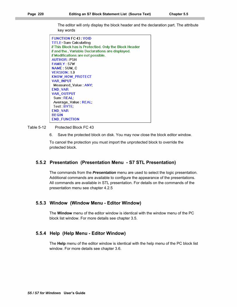
Page 220 Editing an S7 Block Statement List (Source Text) Chapter 5.5
S5 / S7 for Windows User’s Guide
The editor will only display the block header and the declaration part. The attribute key words
Table 5-12 Protected Block FC 43
6. Save the protected block on disk. You may now close the block editor window.
To cancel the protection you must import the unprotected block to override the protected block.
5.5.2 Presentation (Presentation Menu - S7 STL Presentation)
The commands from the Presentation menu are used to select the logic presentation. Additional commands are available to configure the appearance of the presentations. All commands are available in STL presentation. For details on the commands of the presentation menu see chapter 4.2.5
5.5.3 Window (Window Menu - Editor Window)
The Window menu of the editor window is identical with the window menu of the PC block list window. For more details see chapter 3.5.
5.5.4 Help (Help Menu - Editor Window)
The Help menu of the editor window is identical with the help menu of the PC block list window. For more details see chapter 3.6.
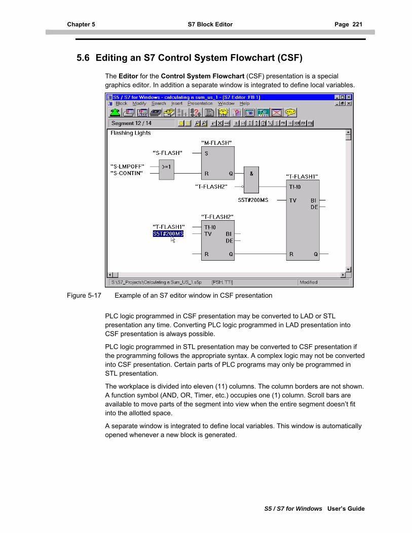
Chapter 5 S7 Block Editor Page 221
S5 / S7 for Windows User’s Guide
5.6 Editing an S7 Control System Flowchart (CSF)
The Editor for the Control System Flowchart (CSF) presentation is a special graphics editor. In addition a separate window is integrated to define local variables.
Figure 5-17 Example of an S7 editor window in CSF presentation
PLC logic programmed in CSF presentation may be converted to LAD or STL presentation any time. Converting PLC logic programmed in LAD presentation into CSF presentation is always possible.
PLC logic programmed in STL presentation may be converted to CSF presentation if the programming follows the appropriate syntax. A complex logic may not be converted into CSF presentation. Certain parts of PLC programs may only be programmed in STL presentation.
The workplace is divided into eleven (11) columns. The column borders are not shown. A function symbol (AND, OR, Timer, etc.) occupies one (1) column. Scroll bars are available to move parts of the segment into view when the entire segment doesn’t fit into the allotted space.
A separate window is integrated to define local variables. This window is automatically opened whenever a new block is generated.
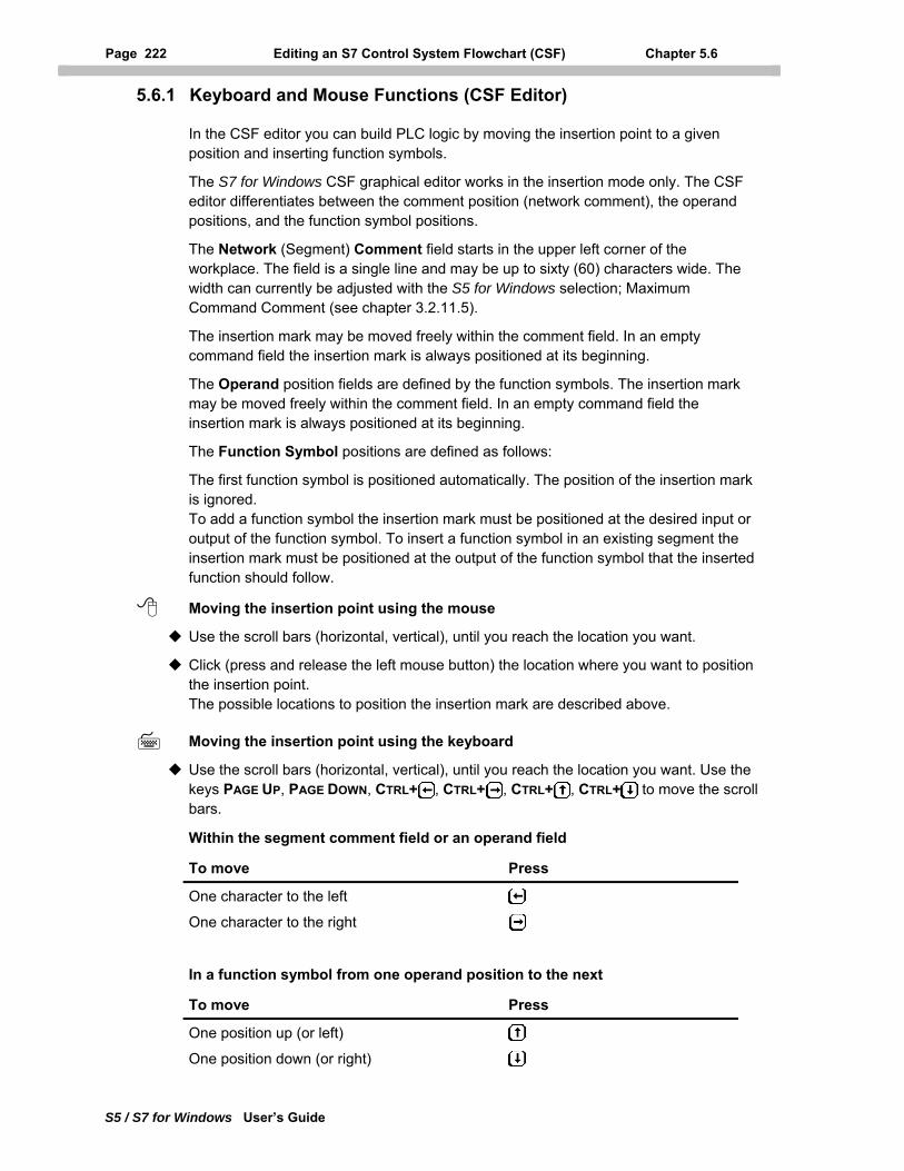
Page 222 Editing an S7 Control System Flowchart (CSF) Chapter 5.6
S5 / S7 for Windows User’s Guide
5.6.1 Keyboard and Mouse Functions (CSF Editor)
In the CSF editor you can build PLC logic by moving the insertion point to a given position and inserting function symbols.
The S7 for Windows CSF graphical editor works in the insertion mode only. The CSF editor differentiates between the comment position (network comment), the operand positions, and the function symbol positions.
The Network (Segment) Comment field starts in the upper left corner of the workplace. The field is a single line and may be up to sixty (60) characters wide. The width can currently be adjusted with the S5 for Windows selection; Maximum Command Comment (see chapter 3.2.11.5).
The insertion mark may be moved freely within the comment field. In an empty command field the insertion mark is always positioned at its beginning.
The Operand position fields are defined by the function symbols. The insertion mark may be moved freely within the comment field. In an empty command field the insertion mark is always positioned at its beginning.
The Function Symbol positions are defined as follows:
The first function symbol is positioned automatically. The position of the insertion mark is ignored. To add a function symbol the insertion mark must be positioned at the desired input or output of the function symbol. To insert a function symbol in an existing segment the insertion mark must be positioned at the output of the function symbol that the inserted function should follow.
Moving the insertion point using the mouse
Use the scroll bars (horizontal, vertical), until you reach the location you want.
Click (press and release the left mouse button) the location where you want to position the insertion point. The possible locations to position the insertion mark are described above.
Moving the insertion point using the keyboard
Use the scroll bars (horizontal, vertical), until you reach the location you want. Use the keys PAGE UP, PAGE DOWN, CTRL+ , CTRL+ , CTRL+ , CTRL+ to move the scroll bars.
Within the segment comment field or an operand field
To move Press
One character to the left
One character to the right
In a function symbol from one operand position to the next
To move Press
One position up (or left)
One position down (or right)
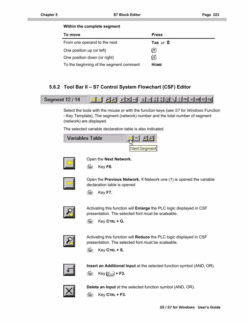
Chapter 5 S7 Block Editor Page 223
S5 / S7 for Windows User’s Guide
Within the complete segment
To move Press
From one operand to the next TAB or È
One position up (or left)
One position down (or right) To the beginning of the segment comment HOME
5.6.2 Tool Bar II – S7 Control System Flowchart (CSF) Editor
Select the tools with the mouse or with the function keys (see S7 for Windows Function - Key Template). The segment (network) number and the total number of segment (network) are displayed.
The selected variable declaration table is also indicated.
Open the Next Network.
Key F8.
Open the Previous Network. If Network one (1) is opened the variable declaration table is opened
Key F7.
Activating this function will Enlarge the PLC logic displayed in CSF presentation. The selected font must be scaleable.
Key CTRL + G.
Activating this function will Reduce the PLC logic displayed in CSF presentation. The selected font must be scaleable.
Key CTRL + S.
Insert an Additional Input at the selected function symbol (AND, OR).
Key + F3.
Delete an Input at the selected function symbol (AND, OR).
Key CTRL + F3.
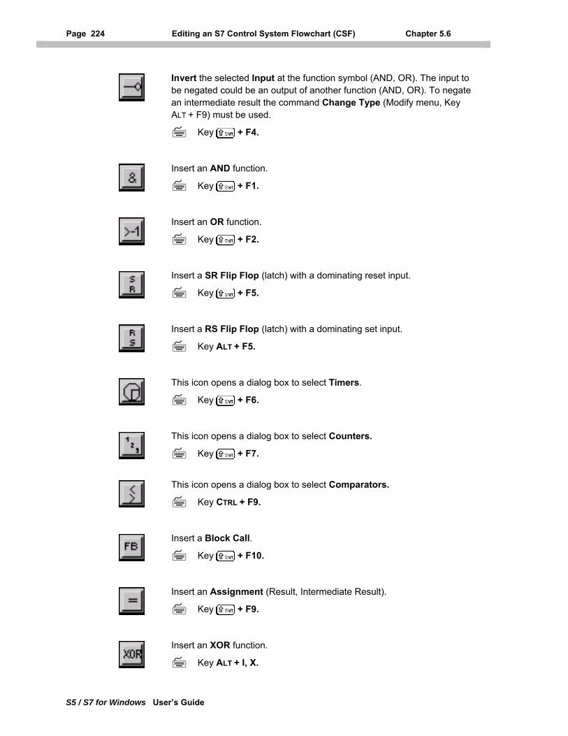
Page 224 Editing an S7 Control System Flowchart (CSF) Chapter 5.6
S5 / S7 for Windows User’s Guide
Invert the selected Input at the function symbol (AND, OR). The input to be negated could be an output of another function (AND, OR). To negate an intermediate result the command Change Type (Modify menu, Key ALT + F9) must be used.
Key + F4.
Insert an AND function.
Key + F1.
Insert an OR function.
Key + F2.
Insert a SR Flip Flop (latch) with a dominating reset input.
Key + F5.
Insert a RS Flip Flop (latch) with a dominating set input.
Key ALT + F5.
This icon opens a dialog box to select Timers.
Key + F6.
This icon opens a dialog box to select Counters.
Key + F7.
This icon opens a dialog box to select Comparators.
Key CTRL + F9.
Insert a Block Call.
Key + F10.
Insert an Assignment (Result, Intermediate Result).
Key + F9.
Insert an XOR function.
Key ALT + I, X.
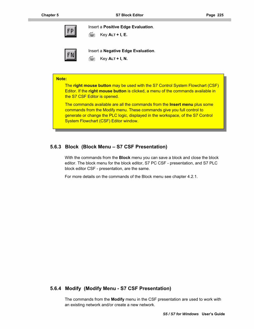
Chapter 5 S7 Block Editor Page 225
S5 / S7 for Windows User’s Guide
Insert a Positive Edge Evaluation.
Key ALT + I, E.
Insert a Negative Edge Evaluation.
Key ALT + I, N.
Note: The right mouse button may be used with the S7 Control System Flowchart (CSF) Editor. If the right mouse button is clicked, a menu of the commands available in the S7 CSF Editor is opened.
The commands available are all the commands from the Insert menu plus some commands from the Modify menu. These commands give you full control to generate or change the PLC logic, displayed in the workspace, of the S7 Control System Flowchart (CSF) Editor window.
5.6.3 Block (Block Menu – S7 CSF Presentation)
With the commands from the Block menu you can save a block and close the block editor. The block menu for the block editor, S7 PC CSF - presentation, and S7 PLC block editor CSF - presentation, are the same.
For more details on the commands of the Block menu see chapter 4.2.1.
5.6.4 Modify (Modify Menu - S7 CSF Presentation)
The commands from the Modify menu in the CSF presentation are used to work with an existing network and/or create a new network.
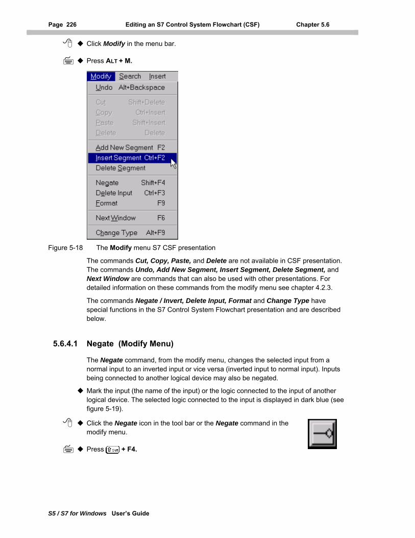
Page 226 Editing an S7 Control System Flowchart (CSF) Chapter 5.6
S5 / S7 for Windows User’s Guide
Click Modify in the menu bar.
Press ALT + M.
Figure 5-18 The Modify menu S7 CSF presentation
The commands Cut, Copy, Paste, and Delete are not available in CSF presentation. The commands Undo, Add New Segment, Insert Segment, Delete Segment, and Next Window are commands that can also be used with other presentations. For detailed information on these commands from the modify menu see chapter 4.2.3.
The commands Negate / Invert, Delete Input, Format and Change Type have special functions in the S7 Control System Flowchart presentation and are described below.
5.6.4.1 Negate (Modify Menu)
The Negate command, from the modify menu, changes the selected input from a normal input to an inverted input or vice versa (inverted input to normal input). Inputs being connected to another logical device may also be negated.
Mark the input (the name of the input) or the logic connected to the input of another logical device. The selected logic connected to the input is displayed in dark blue (see figure 5-19).
Click the Negate icon in the tool bar or the Negate command in the modify menu.
Press + F4.
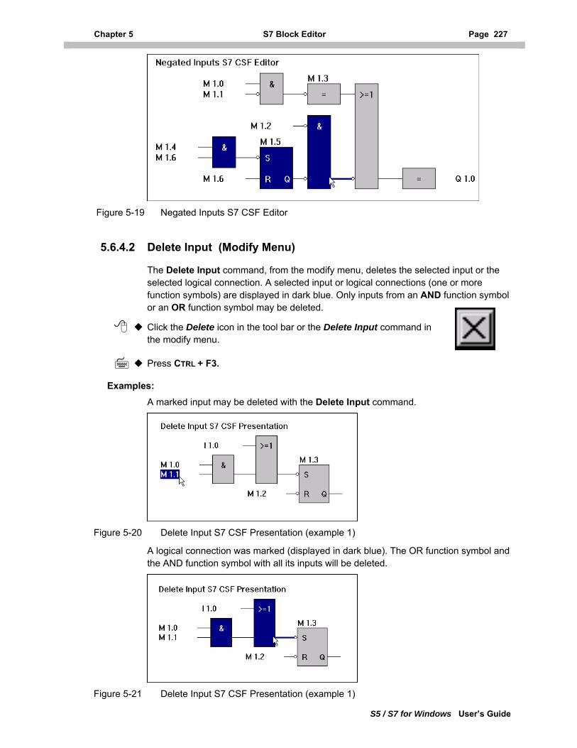
Chapter 5 S7 Block Editor Page 227
S5 / S7 for Windows User’s Guide
Figure 5-19 Negated Inputs S7 CSF Editor
5.6.4.2 Delete Input (Modify Menu)
The Delete Input command, from the modify menu, deletes the selected input or the selected logical connection. A selected input or logical connections (one or more function symbols) are displayed in dark blue. Only inputs from an AND function symbol or an OR function symbol may be deleted.
Click the Delete icon in the tool bar or the Delete Input command in the modify menu.
Press CTRL + F3.
Examples: A marked input may be deleted with the Delete Input command.
Figure 5-20 Delete Input S7 CSF Presentation (example 1)
A logical connection was marked (displayed in dark blue). The OR function symbol and the AND function symbol with all its inputs will be deleted.
Figure 5-21 Delete Input S7 CSF Presentation (example 1)
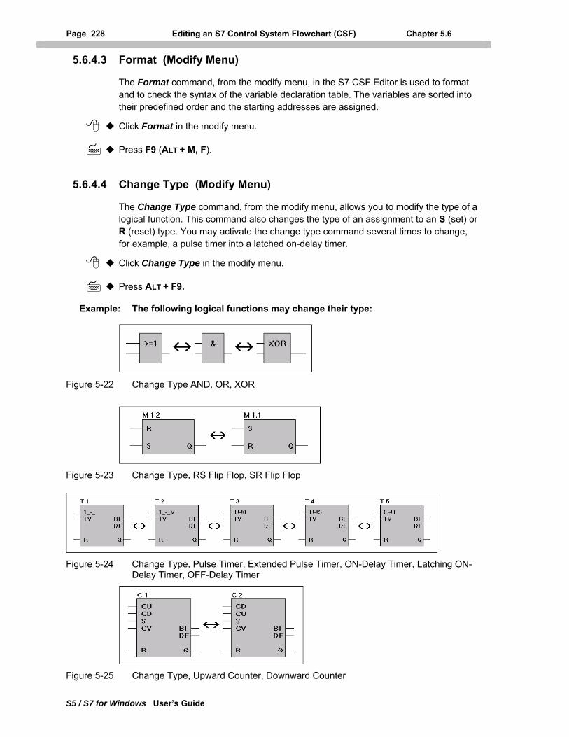
Page 228 Editing an S7 Control System Flowchart (CSF) Chapter 5.6
S5 / S7 for Windows User’s Guide
5.6.4.3 Format (Modify Menu)
The Format command, from the modify menu, in the S7 CSF Editor is used to format and to check the syntax of the variable declaration table. The variables are sorted into their predefined order and the starting addresses are assigned.
Click Format in the modify menu.
Press F9 (ALT + M, F).
5.6.4.4 Change Type (Modify Menu)
The Change Type command, from the modify menu, allows you to modify the type of a logical function. This command also changes the type of an assignment to an S (set) or R (reset) type. You may activate the change type command several times to change, for example, a pulse timer into a latched on-delay timer.
Click Change Type in the modify menu.
Press ALT + F9.
Example: The following logical functions may change their type:
Figure 5-22 Change Type AND, OR, XOR
Figure 5-23 Change Type, RS Flip Flop, SR Flip Flop
Figure 5-24 Change Type, Pulse Timer, Extended Pulse Timer, ON-Delay Timer, Latching ON-Delay Timer, OFF-Delay Timer
Figure 5-25 Change Type, Upward Counter, Downward Counter
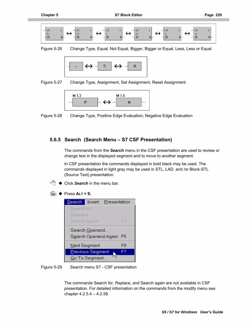
Chapter 5 S7 Block Editor Page 229
Figure 5-26 Change Type, Equal, Not Equal, Bigger, Bigger or Equal, Less, Less or Equal
Figure 5-27 Change Type, Assignment, Set Assignment, Reset Assignment
Figure 5-28 Change Type, Positive Edge Evaluation, Negative Edge Evaluation
5.6.5 Search (Search Menu – S7 CSF Presentation)
The commands from the Search menu in the CSF presentation are used to review or change text in the displayed segment and to move to another segment.
In CSF presentation the commands displayed in bold black may be used. The commands displayed in light gray may be used in STL, LAD, and /or Block-STL (Source Text) presentation.
Click Search in the menu bar.
Press ALT + S.
Figure 5-29 Search menu S7 - CSF presentation
The commands Search for, Replace, and Search again are not available in CSF presentation. For detailed information on the commands from the modify menu see chapter 4.2.5.4 – 4.2.58.
S5 / S7 for Windows User’s Guide
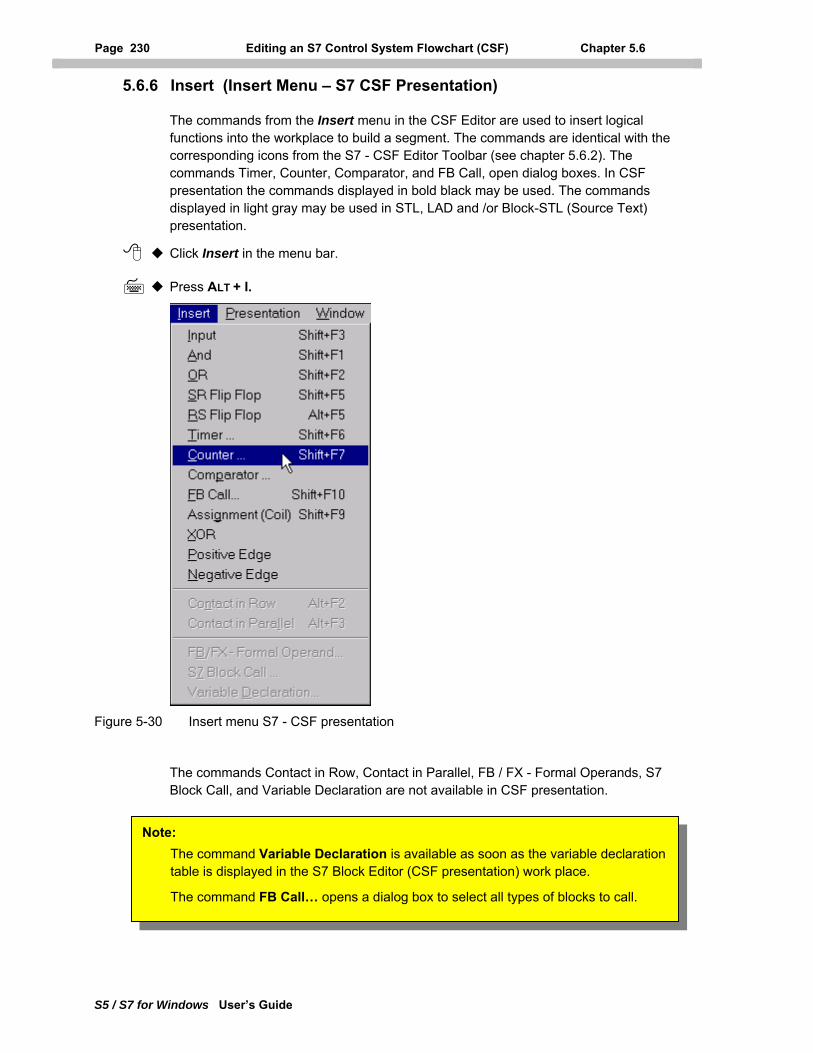
Page 230 Editing an S7 Control System Flowchart (CSF) Chapter 5.6
S5 / S7 for Windows User’s Guide
5.6.6 Insert (Insert Menu – S7 CSF Presentation)
The commands from the Insert menu in the CSF Editor are used to insert logical functions into the workplace to build a segment. The commands are identical with the corresponding icons from the S7 - CSF Editor Toolbar (see chapter 5.6.2). The commands Timer, Counter, Comparator, and FB Call, open dialog boxes. In CSF presentation the commands displayed in bold black may be used. The commands displayed in light gray may be used in STL, LAD and /or Block-STL (Source Text) presentation.
Click Insert in the menu bar.
Press ALT + I.
Figure 5-30 Insert menu S7 - CSF presentation
The commands Contact in Row, Contact in Parallel, FB / FX - Formal Operands, S7 Block Call, and Variable Declaration are not available in CSF presentation.
Note: The command Variable Declaration is available as soon as the variable declaration table is displayed in the S7 Block Editor (CSF presentation) work place.
The command FB Call… opens a dialog box to select all types of blocks to call.
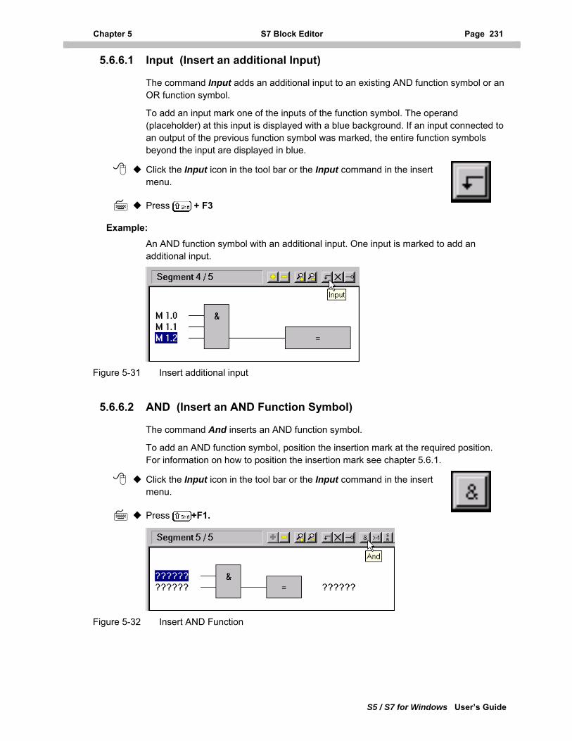
Chapter 5 S7 Block Editor Page 231
S5 / S7 for Windows User’s Guide
5.6.6.1 Input (Insert an additional Input)
The command Input adds an additional input to an existing AND function symbol or an OR function symbol.
To add an input mark one of the inputs of the function symbol. The operand (placeholder) at this input is displayed with a blue background. If an input connected to an output of the previous function symbol was marked, the entire function symbols beyond the input are displayed in blue.
Click the Input icon in the tool bar or the Input command in the insert menu.
Press + F3
Example: An AND function symbol with an additional input. One input is marked to add an additional input.
Figure 5-31 Insert additional input
5.6.6.2 AND (Insert an AND Function Symbol)
The command And inserts an AND function symbol.
To add an AND function symbol, position the insertion mark at the required position. For information on how to position the insertion mark see chapter 5.6.1.
Click the Input icon in the tool bar or the Input command in the insert menu.
Press +F1.
Figure 5-32 Insert AND Function
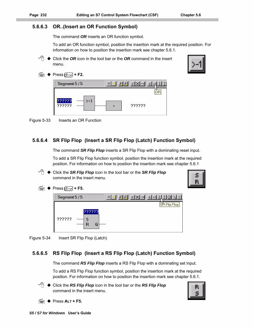
Page 232 Editing an S7 Control System Flowchart (CSF) Chapter 5.6
S5 / S7 for Windows User’s Guide
5.6.6.3 OR..(Insert an OR Function Symbol)
The command OR inserts an OR function symbol.
To add an OR function symbol, position the insertion mark at the required position. For information on how to position the insertion mark see chapter 5.6.1.
Click the OR icon in the tool bar or the OR command in the insert menu.
Press + F2.
Figure 5-33 Inserts an OR Function
5.6.6.4 SR Flip Flop (Insert a SR Flip Flop (Latch) Function Symbol)
The command SR Flip Flop inserts a SR Flip Flop with a dominating reset input.
To add a SR Flip Flop function symbol, position the insertion mark at the required position. For information on how to position the insertion mark see chapter 5.6.1
Click the SR Flip Flop icon in the tool bar or the SR Flip Flop command in the insert menu.
Press + F5.
Figure 5-34 Insert SR Flip Flop (Latch)
5.6.6.5 RS Flip Flop (Insert a RS Flip Flop (Latch) Function Symbol)
The command RS Flip Flop inserts a RS Flip Flop with a dominating set input.
To add a RS Flip Flop function symbol, position the insertion mark at the required position. For information on how to position the insertion mark see chapter 5.6.1.
Click the RS Flip Flop icon in the tool bar or the RS Flip Flop command in the insert menu.
Press ALT + F5.
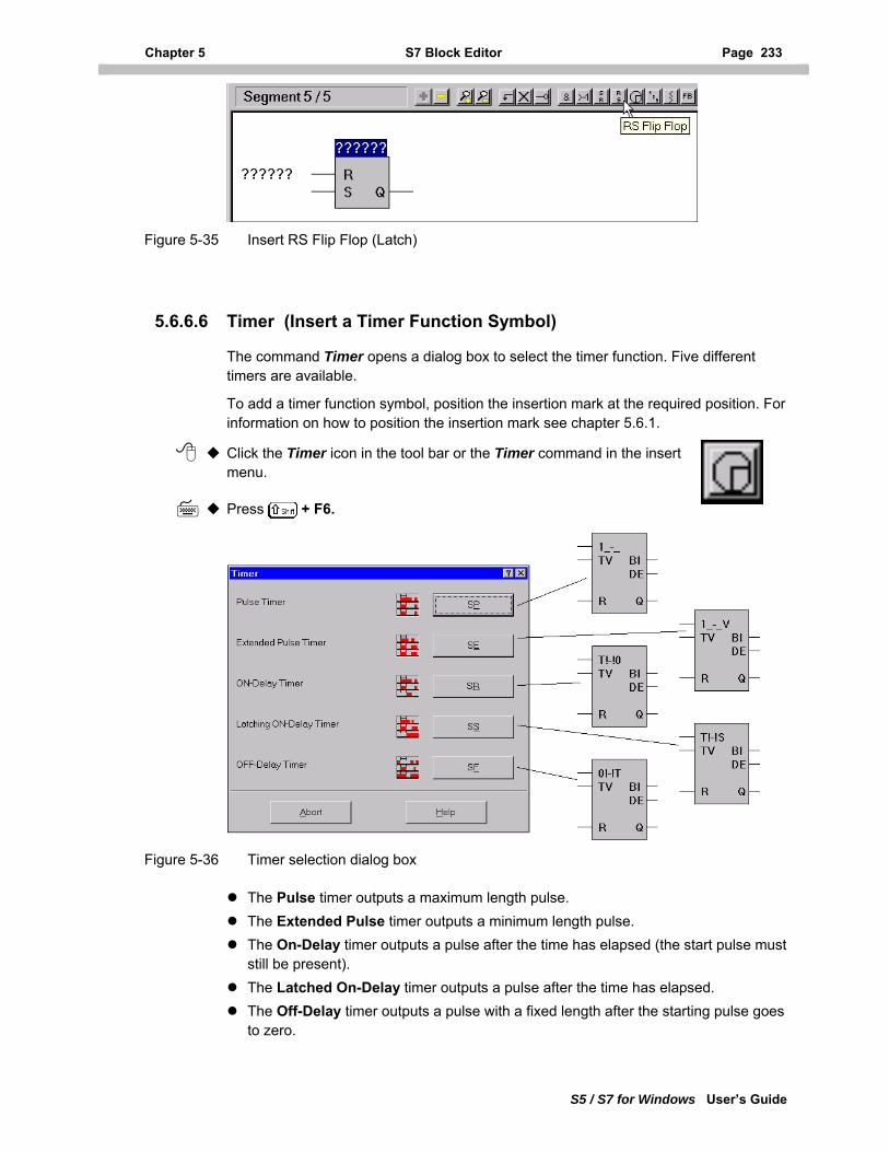
Chapter 5 S7 Block Editor Page 233
S5 / S7 for Windows User’s Guide
Figure 5-35 Insert RS Flip Flop (Latch)
5.6.6.6 Timer (Insert a Timer Function Symbol)
The command Timer opens a dialog box to select the timer function. Five different timers are available.
To add a timer function symbol, position the insertion mark at the required position. For information on how to position the insertion mark see chapter 5.6.1.
Click the Timer icon in the tool bar or the Timer command in the insert menu.
Press + F6.
Figure 5-36 Timer selection dialog box
The Pulse timer outputs a maximum length pulse. The Extended Pulse timer outputs a minimum length pulse. The On-Delay timer outputs a pulse after the time has elapsed (the start pulse must
still be present). The Latched On-Delay timer outputs a pulse after the time has elapsed. The Off-Delay timer outputs a pulse with a fixed length after the starting pulse goes
to zero.
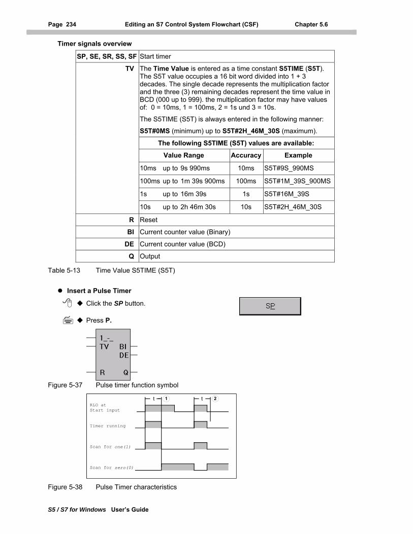
Page 234 Editing an S7 Control System Flowchart (CSF) Chapter 5.6
S5 / S7 for Windows User’s Guide
Timer signals overview
SP, SE, SR, SS, SF Start timer
TV The Time Value is entered as a time constant S5TIME (S5T). The S5T value occupies a 16 bit word divided into 1 + 3 decades. The single decade represents the multiplication factor and the three (3) remaining decades represent the time value in BCD (000 up to 999). the multiplication factor may have values of: 0 = 10ms, 1 = 100ms, 2 = 1s und 3 = 10s.
The S5TIME (S5T) is always entered in the following manner:
S5T#0MS (minimum) up to S5T#2H_46M_30S (maximum).
The following S5TIME (S5T) values are available:
Value Range Accuracy Example
10ms up to 9s 990ms 10ms S5T#9S_990MS
100ms up to 1m 39s 900ms 100ms S5T#1M_39S_900MS
1s up to 16m 39s 1s S5T#16M_39S
10s up to 2h 46m 30s 10s S5T#2H_46M_30S
R Reset
BI Current counter value (Binary)
DE Current counter value (BCD)
Q Output
Table 5-13 Time Value S5TIME (S5T)
Insert a Pulse Timer
Click the SP button.
Press P.
Figure 5-37 Pulse timer function symbol
RLO atStart input
Timer running
Scan for one(1)
Scan for zero(0)
1 2t t
Figure 5-38 Pulse Timer characteristics
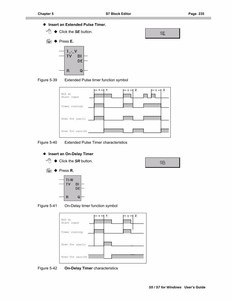
Chapter 5 S7 Block Editor Page 235
S5 / S7 for Windows User’s Guide
Insert an Extended Pulse Timer.
Click the SE button.
Press E.
Figure 5-39 Extended Pulse timer function symbol
RLO atStart input
Timer running
Scan for one(1)
Scan for zero(0)
t 1 2 t 3t
Figure 5-40 Extended Pulse Timer characteristics
Insert an On-Delay Timer
Click the SR button.
Press R.
Figure 5-41 On-Delay timer function symbol
RLO atStart input
Timer running
Scan for one(1)
Scan for zero(0)
t 1 2t
Figure 5-42 On-Delay Timer characteristics
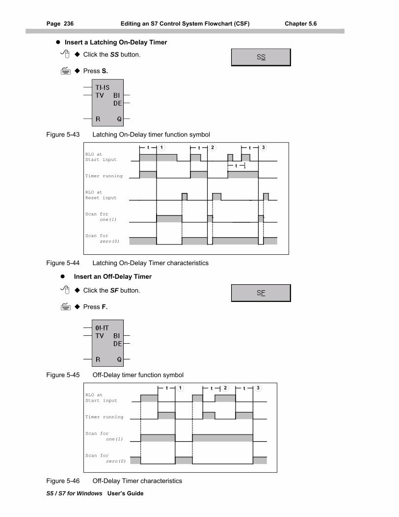
Page 236 Editing an S7 Control System Flowchart (CSF) Chapter 5.6
S5 / S7 for Windows User’s Guide
Insert a Latching On-Delay Timer
Click the SS button.
Press S.
Figure 5-43 Latching On-Delay timer function symbol
RLO atStart input
Timer running
RLO atReset input
Scan for one(1)
Scan for zero(0)
t 1 2t t 3
t
Figure 5-44 Latching On-Delay Timer characteristics
Insert an Off-Delay Timer
Click the SF button.
Press F.
Figure 5-45 Off-Delay timer function symbol
RLO atStart input
Timer running
Scan for one(1)
Scan for zero(0)
t 1 2t t 3
Figure 5-46 Off-Delay Timer characteristics
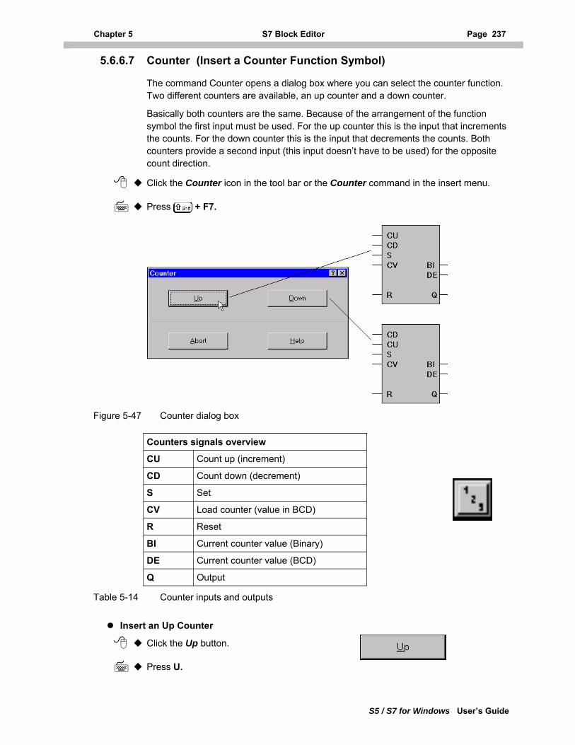
Chapter 5 S7 Block Editor Page 237
S5 / S7 for Windows User’s Guide
5.6.6.7 Counter (Insert a Counter Function Symbol)
The command Counter opens a dialog box where you can select the counter function. Two different counters are available, an up counter and a down counter.
Basically both counters are the same. Because of the arrangement of the function symbol the first input must be used. For the up counter this is the input that increments the counts. For the down counter this is the input that decrements the counts. Both counters provide a second input (this input doesn’t have to be used) for the opposite count direction.
Click the Counter icon in the tool bar or the Counter command in the insert menu.
Press + F7.
Figure 5-47 Counter dialog box
Counters signals overview
CU Count up (increment)
CD Count down (decrement)
S Set
CV Load counter (value in BCD)
R Reset
BI Current counter value (Binary)
DE Current counter value (BCD)
Q Output
Table 5-14 Counter inputs and outputs
Insert an Up Counter
Click the Up button.
Press U.
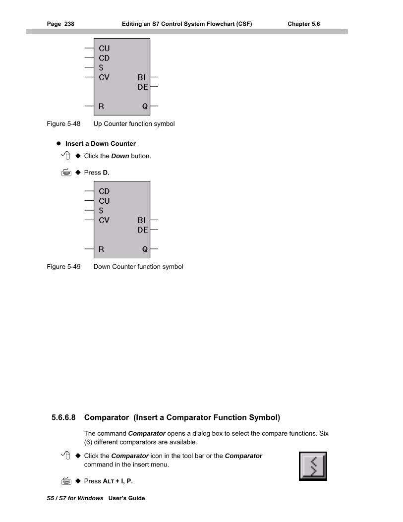
Page 238 Editing an S7 Control System Flowchart (CSF) Chapter 5.6
S5 / S7 for Windows User’s Guide
Figure 5-48 Up Counter function symbol
Insert a Down Counter
Click the Down button.
Press D.
Figure 5-49 Down Counter function symbol
5.6.6.8 Comparator (Insert a Comparator Function Symbol)
The command Comparator opens a dialog box to select the compare functions. Six (6) different comparators are available.
Click the Comparator icon in the tool bar or the Comparator command in the insert menu.
Press ALT + I, P.
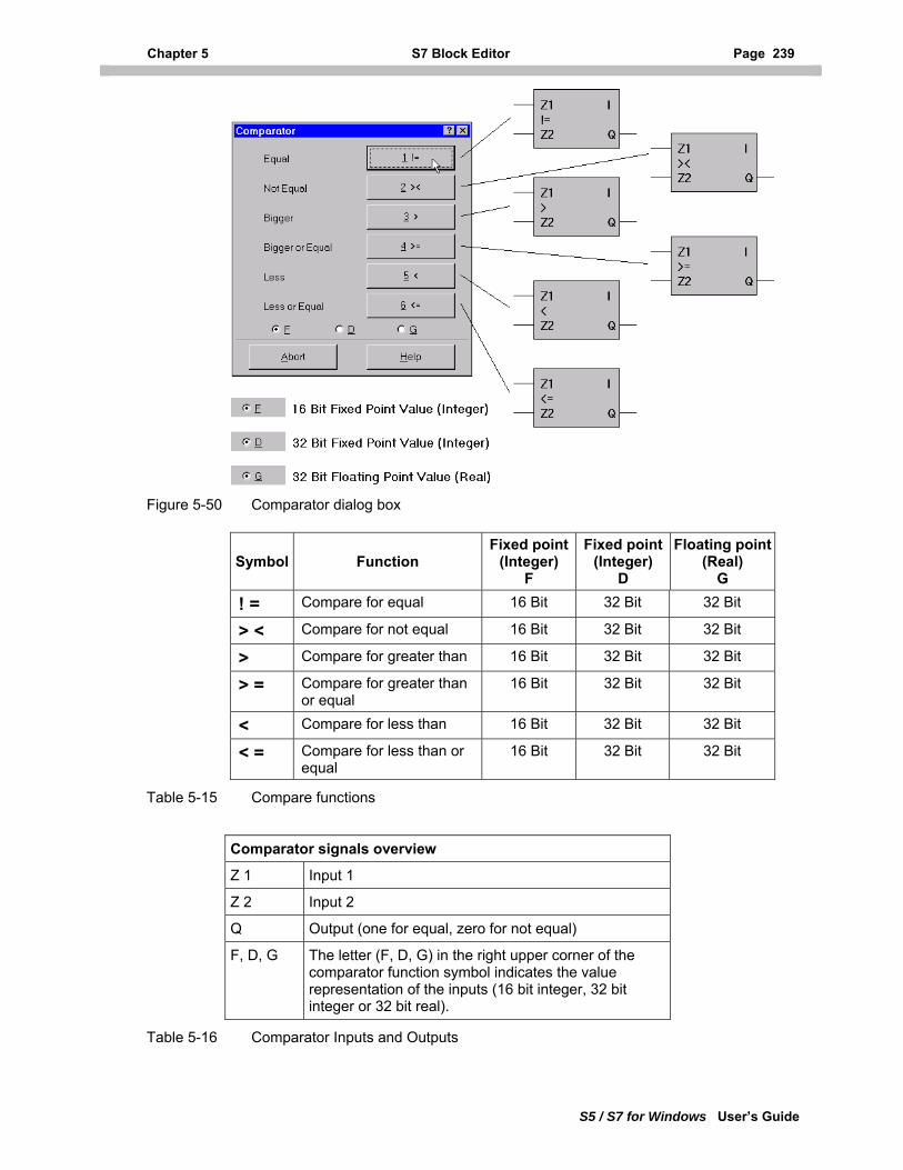
Chapter 5 S7 Block Editor Page 239
S5 / S7 for Windows User’s Guide
Figure 5-50 Comparator dialog box
Symbol Function Fixed point
(Integer) F
Fixed point (Integer)
D
Floating point(Real)
G
! = Compare for equal 16 Bit 32 Bit 32 Bit
> < Compare for not equal 16 Bit 32 Bit 32 Bit
> Compare for greater than 16 Bit 32 Bit 32 Bit
> = Compare for greater than or equal
16 Bit 32 Bit 32 Bit
< Compare for less than 16 Bit 32 Bit 32 Bit
< = Compare for less than or equal
16 Bit 32 Bit 32 Bit
Table 5-15 Compare functions
Comparator signals overview
Z 1 Input 1
Z 2 Input 2
Q Output (one for equal, zero for not equal)
F, D, G The letter (F, D, G) in the right upper corner of the comparator function symbol indicates the value representation of the inputs (16 bit integer, 32 bit integer or 32 bit real).
Table 5-16 Comparator Inputs and Outputs
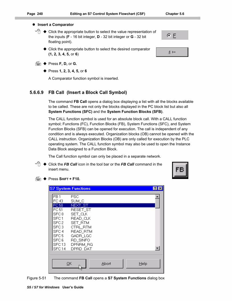
Page 240 Editing an S7 Control System Flowchart (CSF) Chapter 5.6
S5 / S7 for Windows User’s Guide
Insert a Comparator
Click the appropriate button to select the value representation of the inputs (F - 16 bit integer, D - 32 bit integer or G - 32 bit floating point).
Click the appropriate button to select the desired comparator (1, 2, 3, 4, 5, or 6)
Press F, D, or G.
Press 1, 2, 3, 4, 5, or 6
A Comparator function symbol is inserted.
5.6.6.9 FB Call (Insert a Block Call Symbol)
The command FB Call opens a dialog box displaying a list with all the blocks available to be called. These are not only the blocks displayed in the PC block list but also all System Functions (SFC) and the System Function Blocks (SFB).
The CALL function symbol is used for an absolute block call. With a CALL function symbol; Functions (FC), Function Blocks (FB), System Functions (SFC), and System Function Blocks (SFB) can be opened for execution. The call is independent of any condition and is always executed. Organization blocks (OB) cannot be opened with the CALL instruction. Organization Blocks (OB) are only called for execution by the PLC operating system. The CALL function symbol may also be used to open the Instance Data Block assigned to a Function Block.
The Call function symbol can only be placed in a separate network.
Click the FB Call icon in the tool bar or the FB Call command in the insert menu.
Press SHIFT + F10.
Figure 5-51 The command FB Call opens a S7 System Functions dialog box
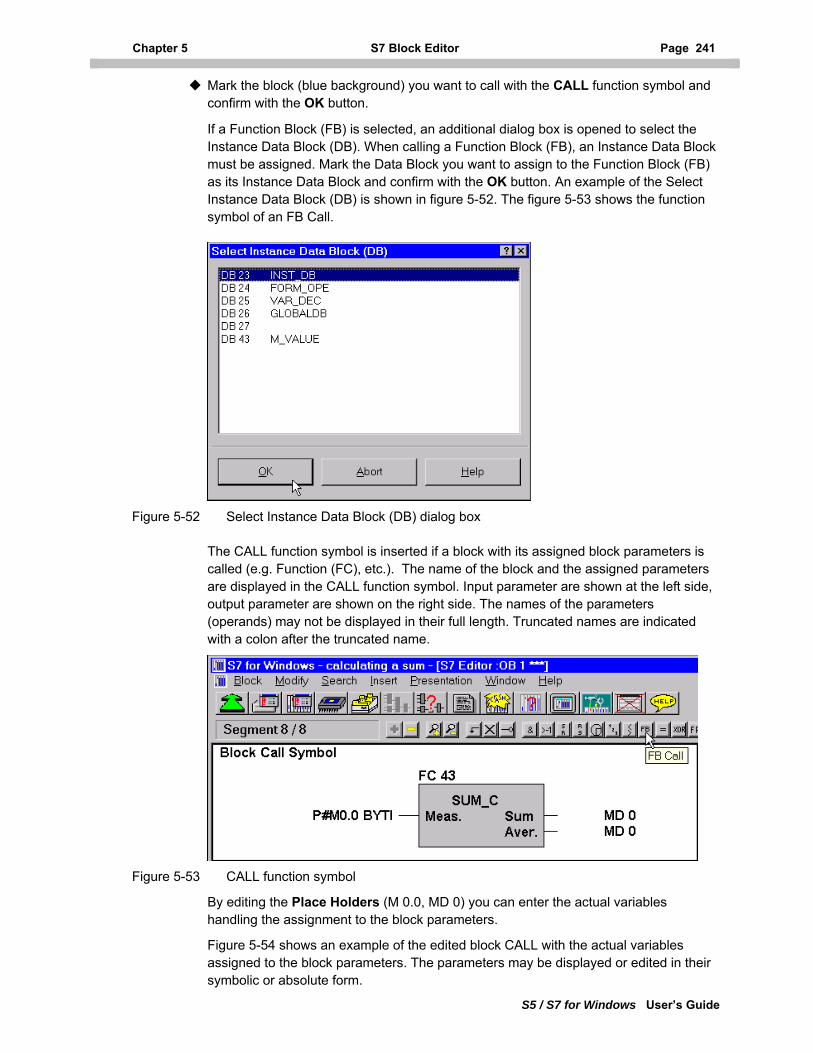
Chapter 5 S7 Block Editor Page 241
S5 / S7 for Windows User’s Guide
Mark the block (blue background) you want to call with the CALL function symbol and confirm with the OK button.
If a Function Block (FB) is selected, an additional dialog box is opened to select the Instance Data Block (DB). When calling a Function Block (FB), an Instance Data Block must be assigned. Mark the Data Block you want to assign to the Function Block (FB) as its Instance Data Block and confirm with the OK button. An example of the Select Instance Data Block (DB) is shown in figure 5-52. The figure 5-53 shows the function symbol of an FB Call.
Figure 5-52 Select Instance Data Block (DB) dialog box
The CALL function symbol is inserted if a block with its assigned block parameters is called (e.g. Function (FC), etc.). The name of the block and the assigned parameters are displayed in the CALL function symbol. Input parameter are shown at the left side, output parameter are shown on the right side. The names of the parameters (operands) may not be displayed in their full length. Truncated names are indicated with a colon after the truncated name.
Figure 5-53 CALL function symbol
By editing the Place Holders (M 0.0, MD 0) you can enter the actual variables handling the assignment to the block parameters.
Figure 5-54 shows an example of the edited block CALL with the actual variables assigned to the block parameters. The parameters may be displayed or edited in their symbolic or absolute form.
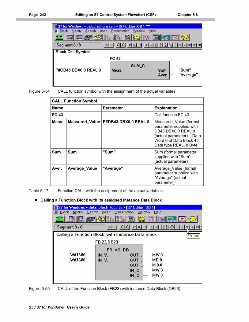
Page 242 Editing an S7 Control System Flowchart (CSF) Chapter 5.6
S5 / S7 for Windows User’s Guide
Figure 5-54 CALL function symbol with the assignment of the actual variables
CALL Function Symbol Name Parameter Explanation FC 43 Call function FC 43
Meas. Measured_Value P#DB43.DBX0,0 REAL 8 Measured_Value (formal parameter supplied with DB43.DBX0,0 REAL 8 (actual parameter) – Data Word 0 of Data Block 43, Data type REAL, 8 Byte
Sum Sum "Sum" Sum (formal parameter supplied with "Sum" (actual parameter)
Aver. Average_Value "Average" Average_Value (formal parameter supplied with "Average" (actual parameter)
Table 5-17 Function CALL with the assignment of the actual variables
Calling a Function Block with its assigned Instance Data Block
Figure 5-55 CALL of the Function Block (FB23) with instance Data Block (DB23)
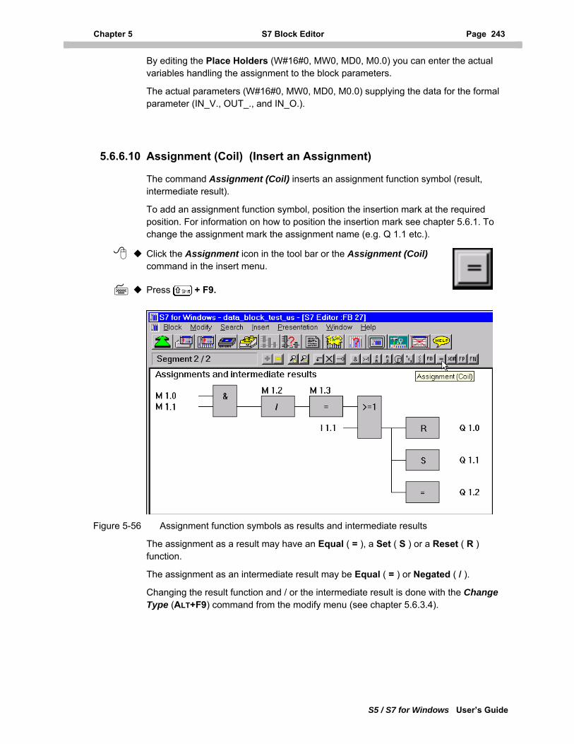
Chapter 5 S7 Block Editor Page 243
S5 / S7 for Windows User’s Guide
By editing the Place Holders (W#16#0, MW0, MD0, M0.0) you can enter the actual variables handling the assignment to the block parameters.
The actual parameters (W#16#0, MW0, MD0, M0.0) supplying the data for the formal parameter (IN_V., OUT_., and IN_O.).
5.6.6.10 Assignment (Coil) (Insert an Assignment)
The command Assignment (Coil) inserts an assignment function symbol (result, intermediate result).
To add an assignment function symbol, position the insertion mark at the required position. For information on how to position the insertion mark see chapter 5.6.1. To change the assignment mark the assignment name (e.g. Q 1.1 etc.).
Click the Assignment icon in the tool bar or the Assignment (Coil) command in the insert menu.
Press + F9.
Figure 5-56 Assignment function symbols as results and intermediate results
The assignment as a result may have an Equal ( = ), a Set ( S ) or a Reset ( R ) function.
The assignment as an intermediate result may be Equal ( = ) or Negated ( / ).
Changing the result function and / or the intermediate result is done with the Change Type (ALT+F9) command from the modify menu (see chapter 5.6.3.4).
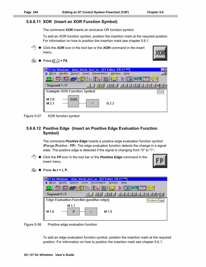
Page 244 Editing an S7 Control System Flowchart (CSF) Chapter 5.6
S5 / S7 for Windows User’s Guide
5.6.6.11 XOR (Insert an XOR Function Symbol)
The command XOR inserts an exclusive OR function symbol.
To add an XOR function symbol, position the insertion mark at the required position. For information on how to position the insertion mark see chapter 5.6.1.
Click the XOR icon in the tool bar or the XOR command in the insert menu.
Press + F9.
Figure 5-57 XOR function symbol
5.6.6.12 Positive Edge (Insert an Positive Edge Evaluation Function Symbol)
The command Positive Edge inserts a positive edge evaluation function symbol (Flange Positive - FP). The edge evaluation function detects the change in a signal state. The positive edge is detected if the signal is changing from "0" to "1".
Click the FP icon in the tool bar or the Positive Edge command in the insert menu.
Press ALT + I, P.
Figure 5-58 Positive edge evaluation function
To add an edge evaluation function symbol, position the insertion mark at the required position. For information on how to position the insertion mark see chapter 5.6.1.
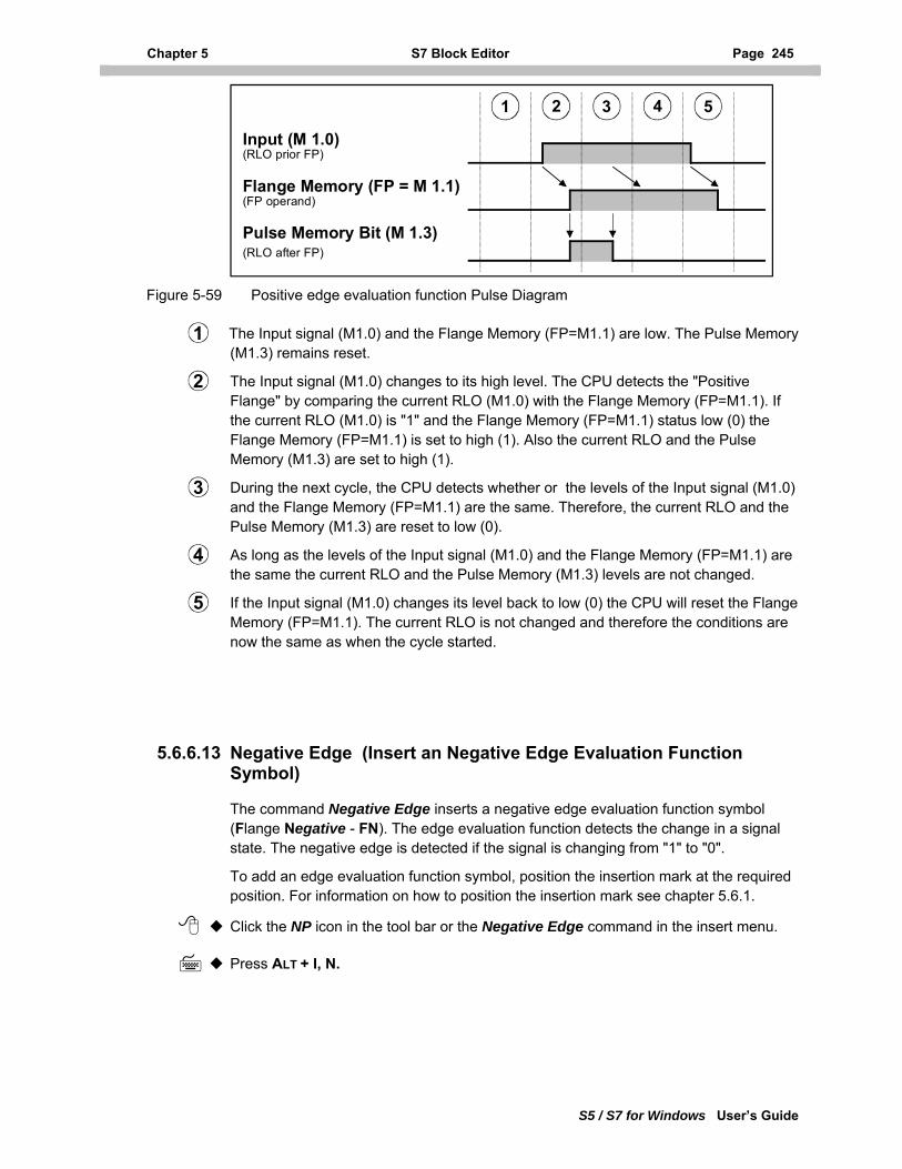
Chapter 5 S7 Block Editor Page 245
S5 / S7 for Windows User’s Guide
Input (M 1.0)(RLO prior FP)
Flange Memory (FP = M 1.1)(FP operand)
Pulse Memory Bit (M 1.3)(RLO after FP)
2 3 541
Figure 5-59 Positive edge evaluation function Pulse Diagram
The Input signal (M1.0) and the Flange Memory (FP=M1.1) are low. The Pulse Memory (M1.3) remains reset.
1
The Input signal (M1.0) changes to its high level. The CPU detects the "Positive Flange" by comparing the current RLO (M1.0) with the Flange Memory (FP=M1.1). If the current RLO (M1.0) is "1" and the Flange Memory (FP=M1.1) status low (0) the Flange Memory (FP=M1.1) is set to high (1). Also the current RLO and the Pulse Memory (M1.3) are set to high (1).
2
During the next cycle, the CPU detects whether or the levels of the Input signal (M1.0) and the Flange Memory (FP=M1.1) are the same. Therefore, the current RLO and the Pulse Memory (M1.3) are reset to low (0).
3
As long as the levels of the Input signal (M1.0) and the Flange Memory (FP=M1.1) are the same the current RLO and the Pulse Memory (M1.3) levels are not changed.
4
If the Input signal (M1.0) changes its level back to low (0) the CPU will reset the Flange Memory (FP=M1.1). The current RLO is not changed and therefore the conditions are now the same as when the cycle started.
5
5.6.6.13 Negative Edge (Insert an Negative Edge Evaluation Function Symbol)
The command Negative Edge inserts a negative edge evaluation function symbol (Flange Negative - FN). The edge evaluation function detects the change in a signal state. The negative edge is detected if the signal is changing from "1" to "0".
To add an edge evaluation function symbol, position the insertion mark at the required position. For information on how to position the insertion mark see chapter 5.6.1.
Click the NP icon in the tool bar or the Negative Edge command in the insert menu.
Press ALT + I, N.
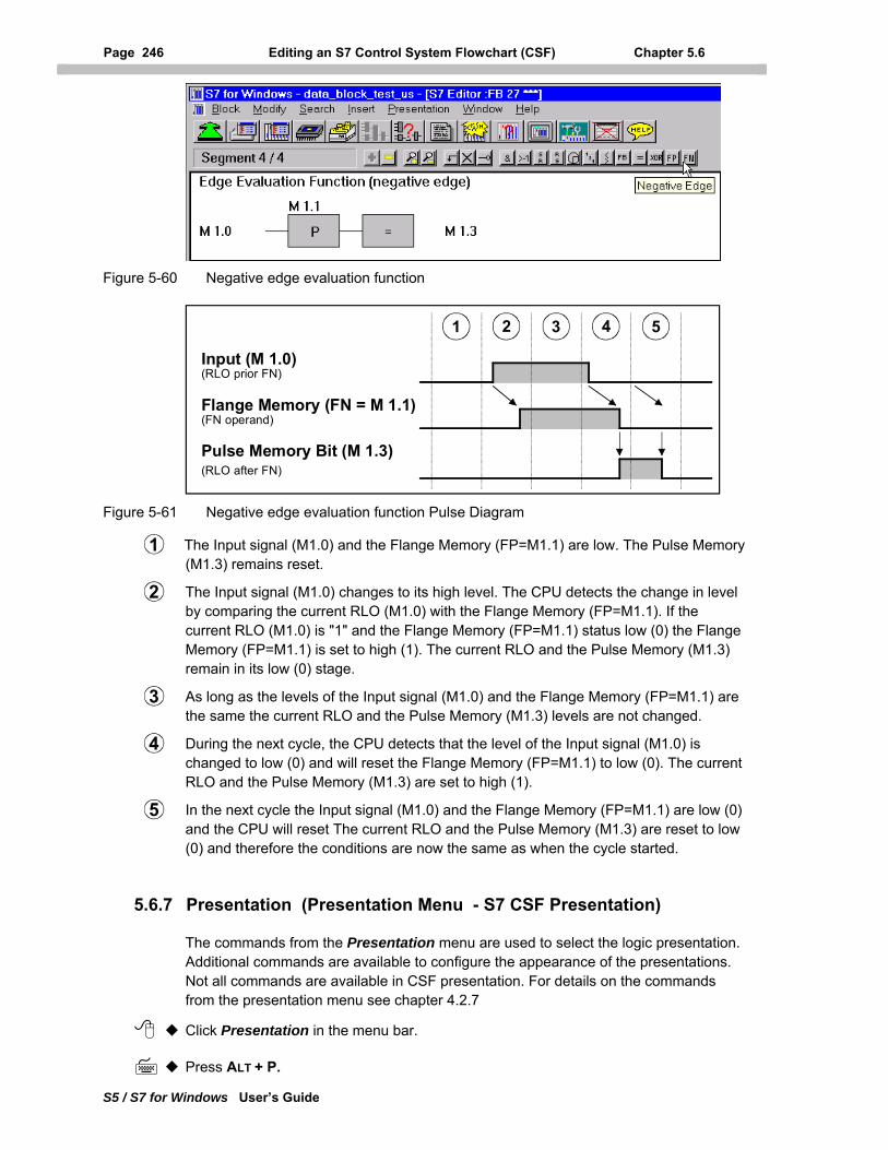
Page 246 Editing an S7 Control System Flowchart (CSF) Chapter 5.6
S5 / S7 for Windows User’s Guide
Figure 5-60 Negative edge evaluation function
Input (M 1.0)(RLO prior FN)
Flange Memory (FN = M 1.1)(FN operand)
Pulse Memory Bit (M 1.3)(RLO after FN)
2 3 541
Figure 5-61 Negative edge evaluation function Pulse Diagram
The Input signal (M1.0) and the Flange Memory (FP=M1.1) are low. The Pulse Memory (M1.3) remains reset.
1
The Input signal (M1.0) changes to its high level. The CPU detects the change in level by comparing the current RLO (M1.0) with the Flange Memory (FP=M1.1). If the current RLO (M1.0) is "1" and the Flange Memory (FP=M1.1) status low (0) the Flange Memory (FP=M1.1) is set to high (1). The current RLO and the Pulse Memory (M1.3) remain in its low (0) stage.
2
As long as the levels of the Input signal (M1.0) and the Flange Memory (FP=M1.1) are the same the current RLO and the Pulse Memory (M1.3) levels are not changed.
3
During the next cycle, the CPU detects that the level of the Input signal (M1.0) is changed to low (0) and will reset the Flange Memory (FP=M1.1) to low (0). The current RLO and the Pulse Memory (M1.3) are set to high (1).
4
In the next cycle the Input signal (M1.0) and the Flange Memory (FP=M1.1) are low (0) and the CPU will reset The current RLO and the Pulse Memory (M1.3) are reset to low (0) and therefore the conditions are now the same as when the cycle started.
5
5.6.7 Presentation (Presentation Menu - S7 CSF Presentation)
The commands from the Presentation menu are used to select the logic presentation. Additional commands are available to configure the appearance of the presentations. Not all commands are available in CSF presentation. For details on the commands from the presentation menu see chapter 4.2.7
Click Presentation in the menu bar.
Press ALT + P.
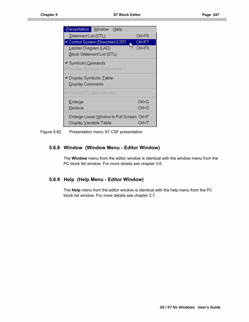
Chapter 5 S7 Block Editor Page 247
S5 / S7 for Windows User’s Guide
Figure 5-62 Presentation menu S7 CSF presentation
5.6.8 Window (Window Menu - Editor Window)
The Window menu from the editor window is identical with the window menu from the PC block list window. For more details see chapter 3.6.
5.6.9 Help (Help Menu - Editor Window)
The Help menu from the editor window is identical with the help menu from the PC block list window. For more details see chapter 3.7.
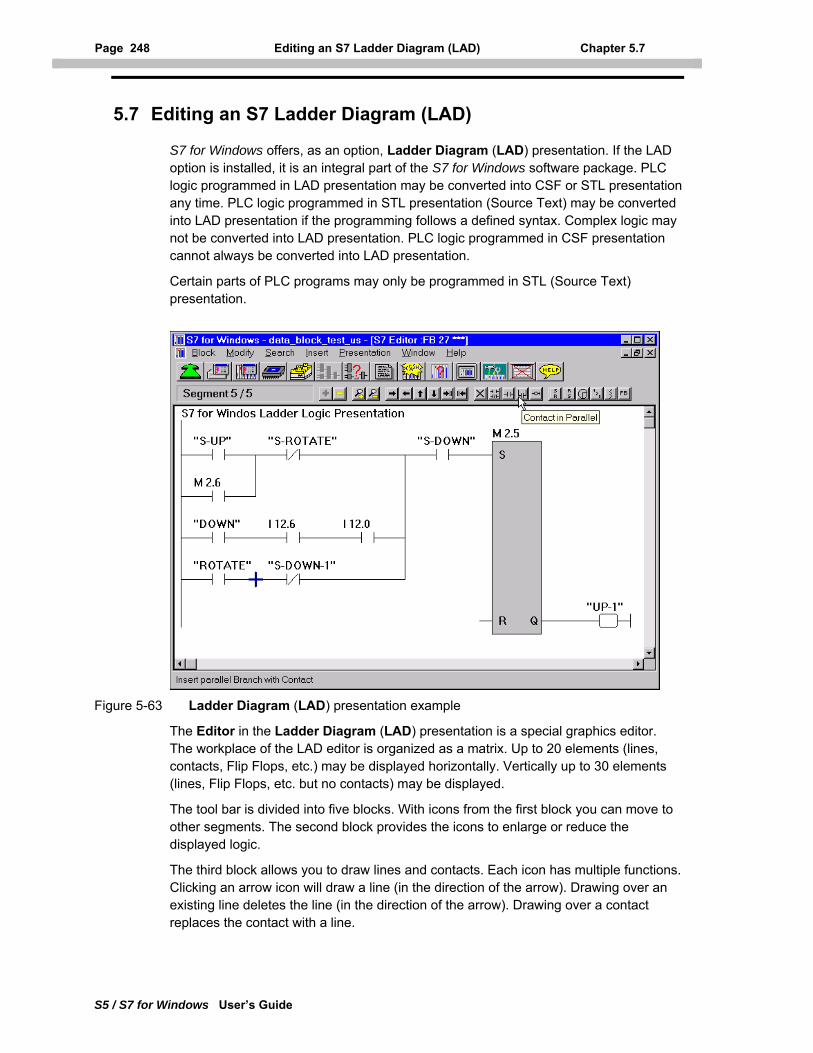
Page 248 Editing an S7 Ladder Diagram (LAD) Chapter 5.7
S5 / S7 for Windows User’s Guide
5.7 Editing an S7 Ladder Diagram (LAD)
S7 for Windows offers, as an option, Ladder Diagram (LAD) presentation. If the LAD option is installed, it is an integral part of the S7 for Windows software package. PLC logic programmed in LAD presentation may be converted into CSF or STL presentation any time. PLC logic programmed in STL presentation (Source Text) may be converted into LAD presentation if the programming follows a defined syntax. Complex logic may not be converted into LAD presentation. PLC logic programmed in CSF presentation cannot always be converted into LAD presentation.
Certain parts of PLC programs may only be programmed in STL (Source Text) presentation.
Figure 5-63 Ladder Diagram (LAD) presentation example
The Editor in the Ladder Diagram (LAD) presentation is a special graphics editor. The workplace of the LAD editor is organized as a matrix. Up to 20 elements (lines, contacts, Flip Flops, etc.) may be displayed horizontally. Vertically up to 30 elements (lines, Flip Flops, etc. but no contacts) may be displayed.
The tool bar is divided into five blocks. With icons from the first block you can move to other segments. The second block provides the icons to enlarge or reduce the displayed logic.
The third block allows you to draw lines and contacts. Each icon has multiple functions. Clicking an arrow icon will draw a line (in the direction of the arrow). Drawing over an existing line deletes the line (in the direction of the arrow). Drawing over a contact replaces the contact with a line.
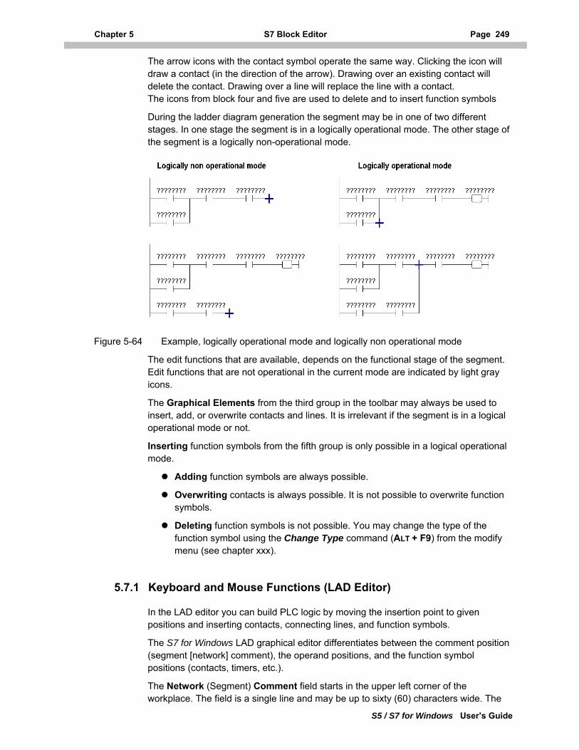
Chapter 5 S7 Block Editor Page 249
S5 / S7 for Windows User’s Guide
The arrow icons with the contact symbol operate the same way. Clicking the icon will draw a contact (in the direction of the arrow). Drawing over an existing contact will delete the contact. Drawing over a line will replace the line with a contact. The icons from block four and five are used to delete and to insert function symbols
During the ladder diagram generation the segment may be in one of two different stages. In one stage the segment is in a logically operational mode. The other stage of the segment is a logically non-operational mode.
Figure 5-64 Example, logically operational mode and logically non operational mode
The edit functions that are available, depends on the functional stage of the segment. Edit functions that are not operational in the current mode are indicated by light gray icons.
The Graphical Elements from the third group in the toolbar may always be used to insert, add, or overwrite contacts and lines. It is irrelevant if the segment is in a logical operational mode or not.
Inserting function symbols from the fifth group is only possible in a logical operational mode.
Adding function symbols are always possible.
Overwriting contacts is always possible. It is not possible to overwrite function symbols.
Deleting function symbols is not possible. You may change the type of the function symbol using the Change Type command (ALT + F9) from the modify menu (see chapter xxx).
5.7.1 Keyboard and Mouse Functions (LAD Editor)
In the LAD editor you can build PLC logic by moving the insertion point to given positions and inserting contacts, connecting lines, and function symbols.
The S7 for Windows LAD graphical editor differentiates between the comment position (segment [network] comment), the operand positions, and the function symbol positions (contacts, timers, etc.).
The Network (Segment) Comment field starts in the upper left corner of the workplace. The field is a single line and may be up to sixty (60) characters wide. The
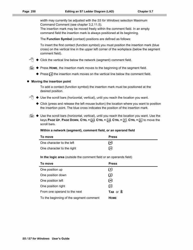
Page 250 Editing an S7 Ladder Diagram (LAD) Chapter 5.7
S5 / S7 for Windows User’s Guide
width may currently be adjusted with the S5 for Windows selection Maximum Command Comment (see chapter 3.2.11.5). The insertion mark may be moved freely within the comment field. In an empty command field the insertion mark is always positioned at its beginning.
The Function Symbol (contact) positions are defined as follows:
To insert the first contact (function symbol) you must position the insertion mark (blue cross) on the vertical line in the upper left corner of the workplace (below the segment comment field).
Click the vertical line below the network (segment) comment field.
Press HOME, the insertion mark moves to the beginning of the segment field.
Press the insertion mark moves on the vertical line below the comment field.
Moving the insertion point To add a contact (function symbol) the insertion mark must be positioned at the desired position.
Use the scroll bars (horizontal, vertical), until you reach the location you want.
Click (press and release the left mouse button) the location where you want to position the insertion point. The blue cross indicates the position of the insertion mark.
Use the scroll bars (horizontal, vertical), until you reach the location you want. Use the keys PAGE UP, PAGE DOWN, CTRL + , CTRL + , CTRL + , CTRL + to move the scroll bars.
Within a network (segment), comment field, or an operand field
To move Press
One character to the left
One character to the right In the logic area (outside the comment field or an operands field)
To move Press
One position up
One position down
One position left
One position right From one operand to the next TAB or È To the beginning of the segment comment HOME
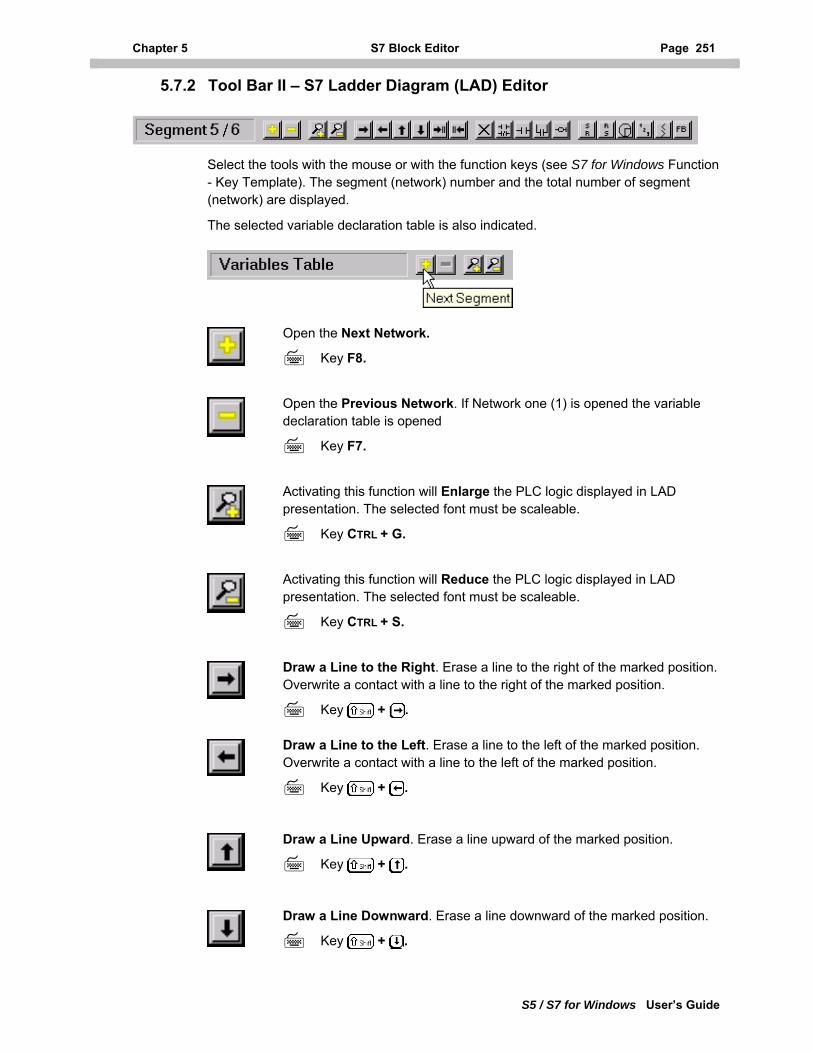
Chapter 5 S7 Block Editor Page 251
S5 / S7 for Windows User’s Guide
5.7.2 Tool Bar II – S7 Ladder Diagram (LAD) Editor
Select the tools with the mouse or with the function keys (see S7 for Windows Function - Key Template). The segment (network) number and the total number of segment (network) are displayed.
The selected variable declaration table is also indicated.
Open the Next Network.
Key F8.
Open the Previous Network. If Network one (1) is opened the variable declaration table is opened
Key F7.
Activating this function will Enlarge the PLC logic displayed in LAD presentation. The selected font must be scaleable.
Key CTRL + G.
Activating this function will Reduce the PLC logic displayed in LAD presentation. The selected font must be scaleable.
Key CTRL + S.
Draw a Line to the Right. Erase a line to the right of the marked position. Overwrite a contact with a line to the right of the marked position.
Key + .
Draw a Line to the Left. Erase a line to the left of the marked position. Overwrite a contact with a line to the left of the marked position.
Key + .
Draw a Line Upward. Erase a line upward of the marked position.
Key + .
Draw a Line Downward. Erase a line downward of the marked position.
Key + .
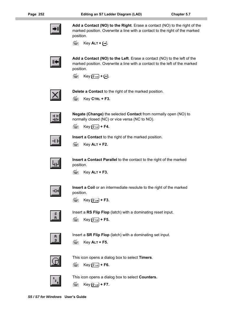
Page 252 Editing an S7 Ladder Diagram (LAD) Chapter 5.7
S5 / S7 for Windows User’s Guide
Add a Contact (NO) to the Right. Erase a contact (NO) to the right of the marked position. Overwrite a line with a contact to the right of the marked position.
Key ALT + .
Add a Contact (NO) to the Left. Erase a contact (NO) to the left of the marked position. Overwrite a line with a contact to the left of the marked position.
Key + .
Delete a Contact to the right of the marked position.
Key CTRL + F3.
Negate (Change) the selected Contact from normally open (NO) to normally closed (NC) or vice versa (NC to NO).
Key + F4.
Insert a Contact to the right of the marked position.
Key ALT + F2.
Insert a Contact Parallel to the contact to the right of the marked position.
Key ALT + F3.
Insert a Coil or an intermediate resolute to the right of the marked position.
Key + F3.
Insert a RS Flip Flop (latch) with a dominating reset input.
Key + F5.
Insert a SR Flip Flop (latch) with a dominating set input.
Key ALT + F5.
This icon opens a dialog box to select Timers.
Key + F6.
This icon opens a dialog box to select Counters.
Key + F7.
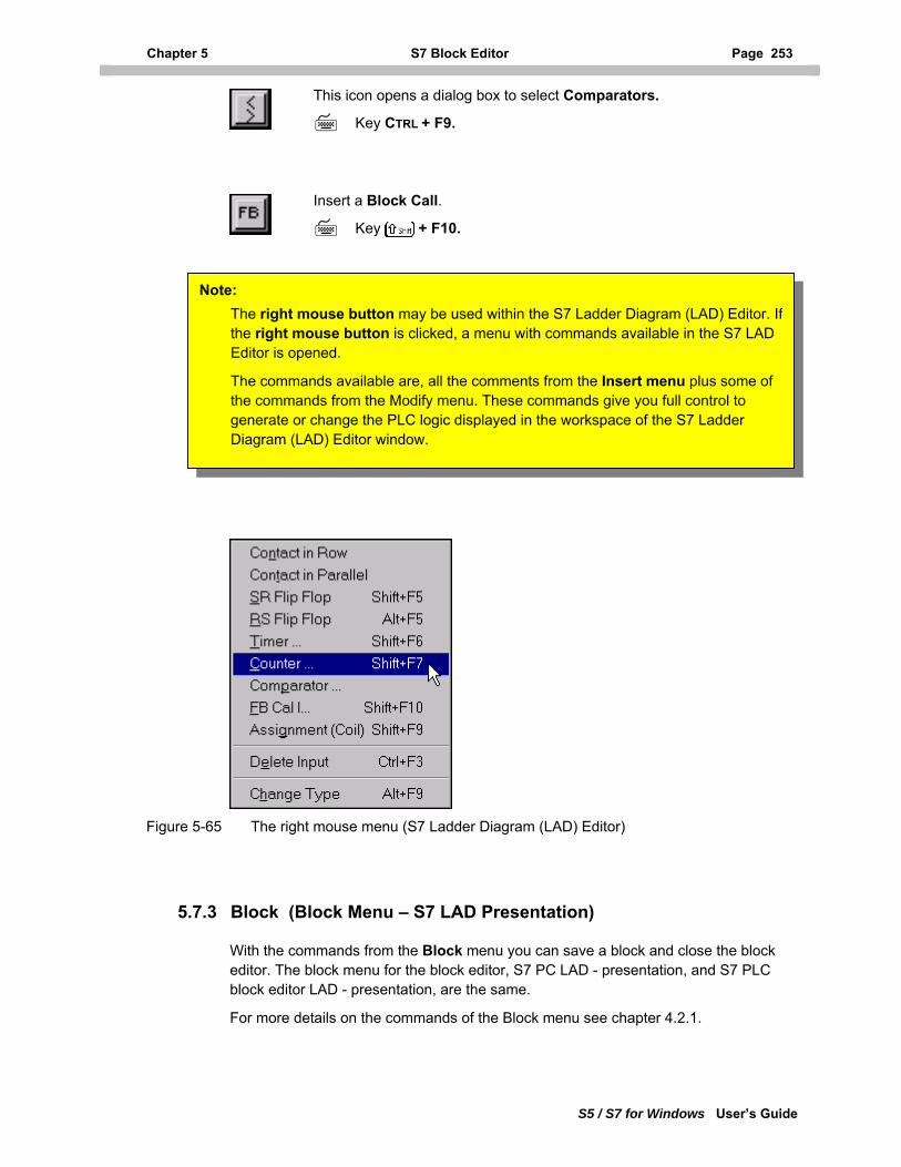
Chapter 5 S7 Block Editor Page 253
S5 / S7 for Windows User’s Guide
This icon opens a dialog box to select Comparators.
Key CTRL + F9.
Insert a Block Call.
Key + F10.
Note: The right mouse button may be used within the S7 Ladder Diagram (LAD) Editor. Ifthe right mouse button is clicked, a menu with commands available in the S7 LAD Editor is opened.
The commands available are, all the comments from the Insert menu plus some of the commands from the Modify menu. These commands give you full control to generate or change the PLC logic displayed in the workspace of the S7 Ladder Diagram (LAD) Editor window.
Figure 5-65 The right mouse menu (S7 Ladder Diagram (LAD) Editor)
5.7.3 Block (Block Menu – S7 LAD Presentation)
With the commands from the Block menu you can save a block and close the block editor. The block menu for the block editor, S7 PC LAD - presentation, and S7 PLC block editor LAD - presentation, are the same.
For more details on the commands of the Block menu see chapter 4.2.1.
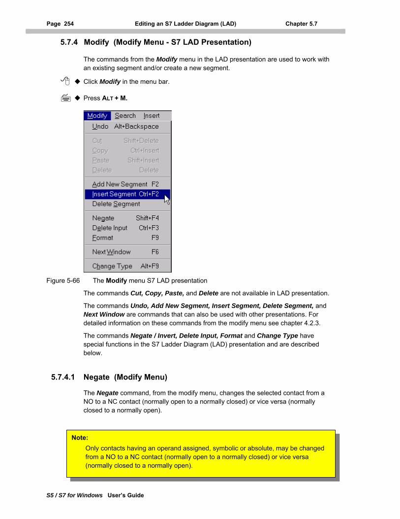
Page 254 Editing an S7 Ladder Diagram (LAD) Chapter 5.7
S5 / S7 for Windows User’s Guide
5.7.4 Modify (Modify Menu - S7 LAD Presentation)
The commands from the Modify menu in the LAD presentation are used to work with an existing segment and/or create a new segment.
Click Modify in the menu bar.
Press ALT + M.
Figure 5-66 The Modify menu S7 LAD presentation
The commands Cut, Copy, Paste, and Delete are not available in LAD presentation.
The commands Undo, Add New Segment, Insert Segment, Delete Segment, and Next Window are commands that can also be used with other presentations. For detailed information on these commands from the modify menu see chapter 4.2.3.
The commands Negate / Invert, Delete Input, Format and Change Type have special functions in the S7 Ladder Diagram (LAD) presentation and are described below.
5.7.4.1 Negate (Modify Menu)
The Negate command, from the modify menu, changes the selected contact from a NO to a NC contact (normally open to a normally closed) or vice versa (normally closed to a normally open).
Note: Only contacts having an operand assigned, symbolic or absolute, may be changed from a NO to a NC contact (normally open to a normally closed) or vice versa (normally closed to a normally open).
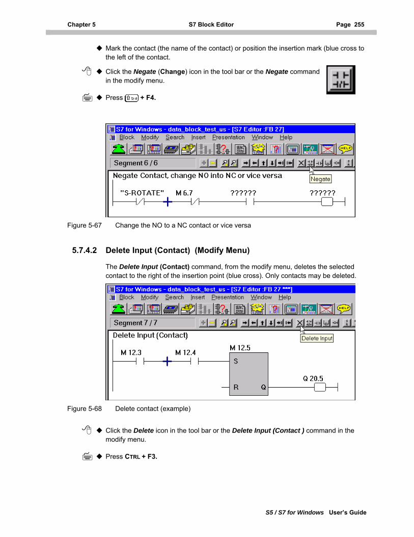
Chapter 5 S7 Block Editor Page 255
S5 / S7 for Windows User’s Guide
Mark the contact (the name of the contact) or position the insertion mark (blue cross to the left of the contact.
Click the Negate (Change) icon in the tool bar or the Negate command in the modify menu.
Press + F4.
Figure 5-67 Change the NO to a NC contact or vice versa
5.7.4.2 Delete Input (Contact) (Modify Menu)
The Delete Input (Contact) command, from the modify menu, deletes the selected contact to the right of the insertion point (blue cross). Only contacts may be deleted.
Figure 5-68 Delete contact (example)
Click the Delete icon in the tool bar or the Delete Input (Contact ) command in the modify menu.
Press CTRL + F3.
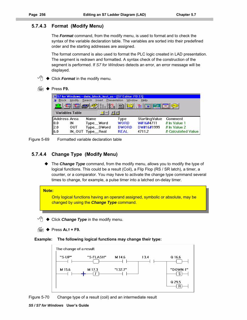
Page 256 Editing an S7 Ladder Diagram (LAD) Chapter 5.7
S5 / S7 for Windows User’s Guide
5.7.4.3 Format (Modify Menu)
The Format command, from the modify menu, is used to format and to check the syntax of the variable declaration table. The variables are sorted into their predefined order and the starting addresses are assigned.
The format command is also used to format the PLC logic created in LAD presentation. The segment is redrawn and formatted. A syntax check of the construction of the segment is performed. If S7 for Windows detects an error, an error message will be displayed.
Click Format in the modify menu.
Press F9.
Figure 5-69 Formatted variable declaration table
5.7.4.4 Change Type (Modify Menu)
The Change Type command, from the modify menu, allows you to modify the type of logical functions. This could be a result (Coil), a Flip Flop (RS / SR latch), a timer, a counter, or a comparator. You may have to activate the change type command several times to change, for example, a pulse timer into a latched on-delay timer.
Note: Only logical functions having an operand assigned, symbolic or absolute, may be changed by using the Change Type command.
Click Change Type in the modify menu.
Press ALT + F9.
Example: The following logical functions may change their type:
Figure 5-70 Change type of a result (coil) and an intermediate result
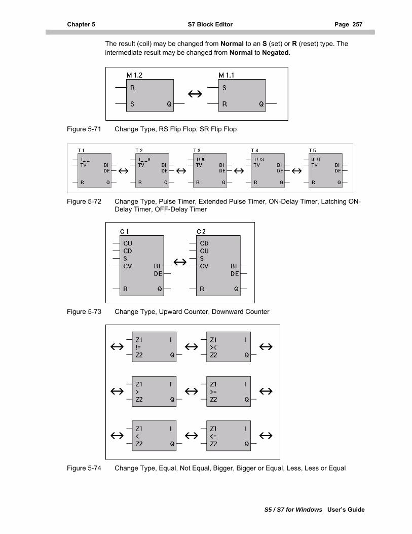
Chapter 5 S7 Block Editor Page 257
S5 / S7 for Windows User’s Guide
The result (coil) may be changed from Normal to an S (set) or R (reset) type. The intermediate result may be changed from Normal to Negated.
Figure 5-71 Change Type, RS Flip Flop, SR Flip Flop
Figure 5-72 Change Type, Pulse Timer, Extended Pulse Timer, ON-Delay Timer, Latching ON-Delay Timer, OFF-Delay Timer
Figure 5-73 Change Type, Upward Counter, Downward Counter
Figure 5-74 Change Type, Equal, Not Equal, Bigger, Bigger or Equal, Less, Less or Equal
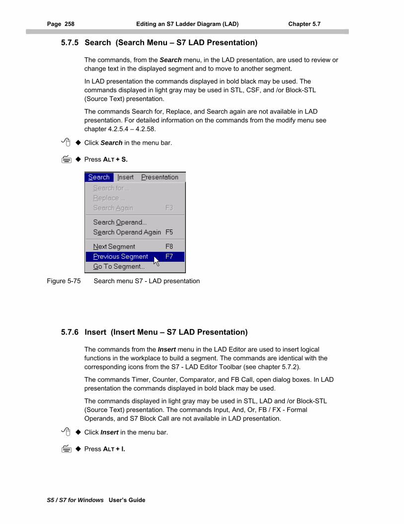
Page 258 Editing an S7 Ladder Diagram (LAD) Chapter 5.7
S5 / S7 for Windows User’s Guide
5.7.5 Search (Search Menu – S7 LAD Presentation)
The commands, from the Search menu, in the LAD presentation, are used to review or change text in the displayed segment and to move to another segment.
In LAD presentation the commands displayed in bold black may be used. The commands displayed in light gray may be used in STL, CSF, and /or Block-STL (Source Text) presentation.
The commands Search for, Replace, and Search again are not available in LAD presentation. For detailed information on the commands from the modify menu see chapter 4.2.5.4 – 4.2.58.
Click Search in the menu bar.
Press ALT + S.
Figure 5-75 Search menu S7 - LAD presentation
5.7.6 Insert (Insert Menu – S7 LAD Presentation)
The commands from the Insert menu in the LAD Editor are used to insert logical functions in the workplace to build a segment. The commands are identical with the corresponding icons from the S7 - LAD Editor Toolbar (see chapter 5.7.2).
The commands Timer, Counter, Comparator, and FB Call, open dialog boxes. In LAD presentation the commands displayed in bold black may be used.
The commands displayed in light gray may be used in STL, LAD and /or Block-STL (Source Text) presentation. The commands Input, And, Or, FB / FX - Formal Operands, and S7 Block Call are not available in LAD presentation.
Click Insert in the menu bar.
Press ALT + I.
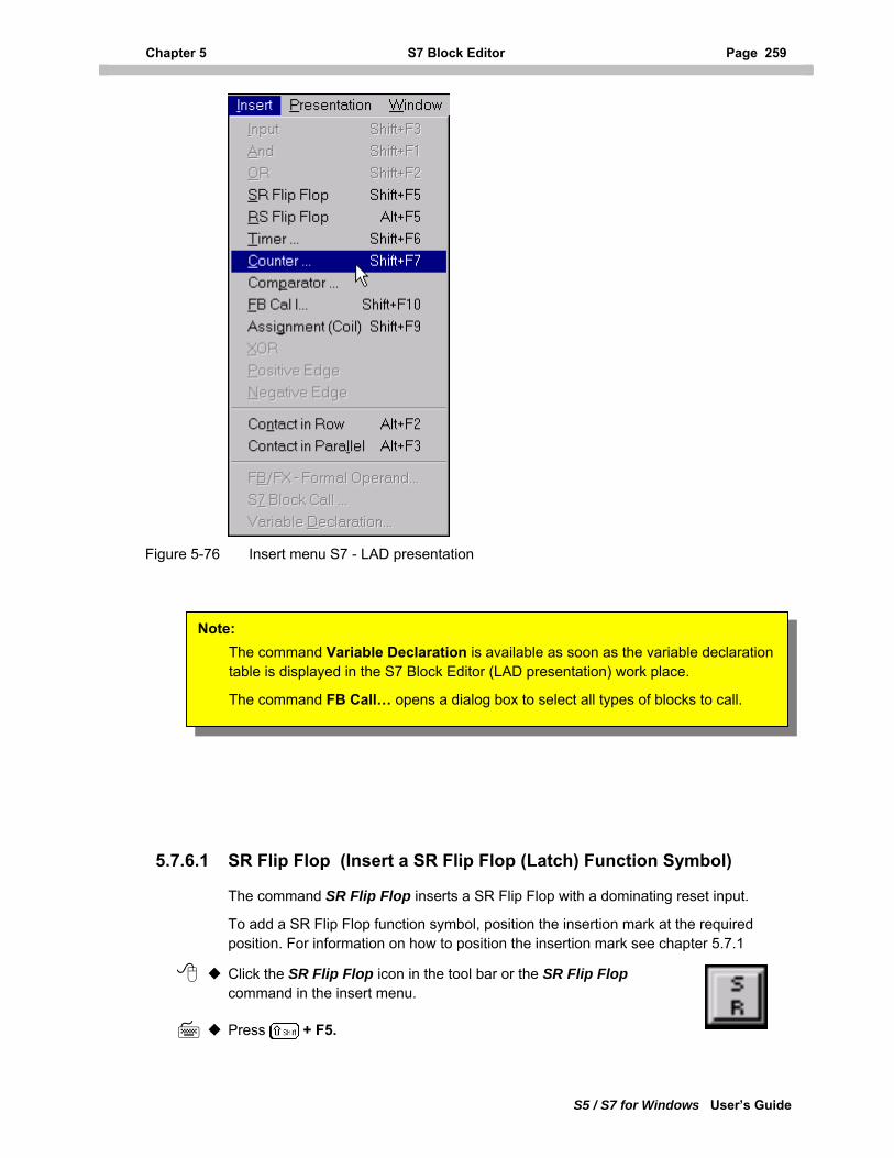
Chapter 5 S7 Block Editor Page 259
S5 / S7 for Windows User’s Guide
Figure 5-76 Insert menu S7 - LAD presentation
Note: The command Variable Declaration is available as soon as the variable declaration able is displayed in the S7 Block Editor (LAD presentation) work place. t
he command FB Call… opens a dialog box to select all types of blocks to call. T
5.7.6.1 SR Flip Flop (Insert a SR Flip Flop (Latch) Function Symbol)
The command SR Flip Flop inserts a SR Flip Flop with a dominating reset input.
To add a SR Flip Flop function symbol, position the insertion mark at the required position. For information on how to position the insertion mark see chapter 5.7.1
Click the SR Flip Flop icon in the tool bar or the SR Flip Flop command in the insert menu.
Press + F5.
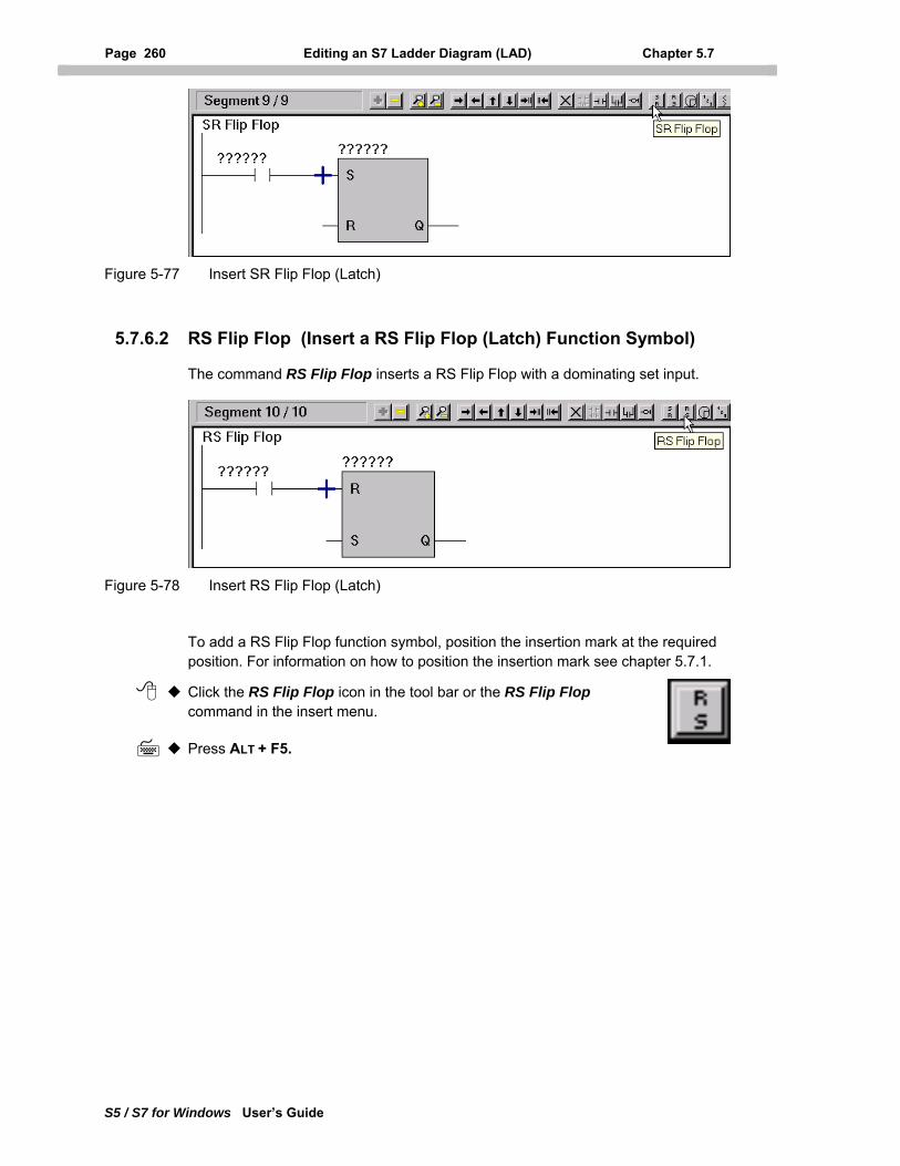
Page 260 Editing an S7 Ladder Diagram (LAD) Chapter 5.7
S5 / S7 for Windows User’s Guide
Figure 5-77 Insert SR Flip Flop (Latch)
5.7.6.2 RS Flip Flop (Insert a RS Flip Flop (Latch) Function Symbol)
The command RS Flip Flop inserts a RS Flip Flop with a dominating set input.
Figure 5-78 Insert RS Flip Flop (Latch)
To add a RS Flip Flop function symbol, position the insertion mark at the required position. For information on how to position the insertion mark see chapter 5.7.1.
Click the RS Flip Flop icon in the tool bar or the RS Flip Flop command in the insert menu.
Press ALT + F5.
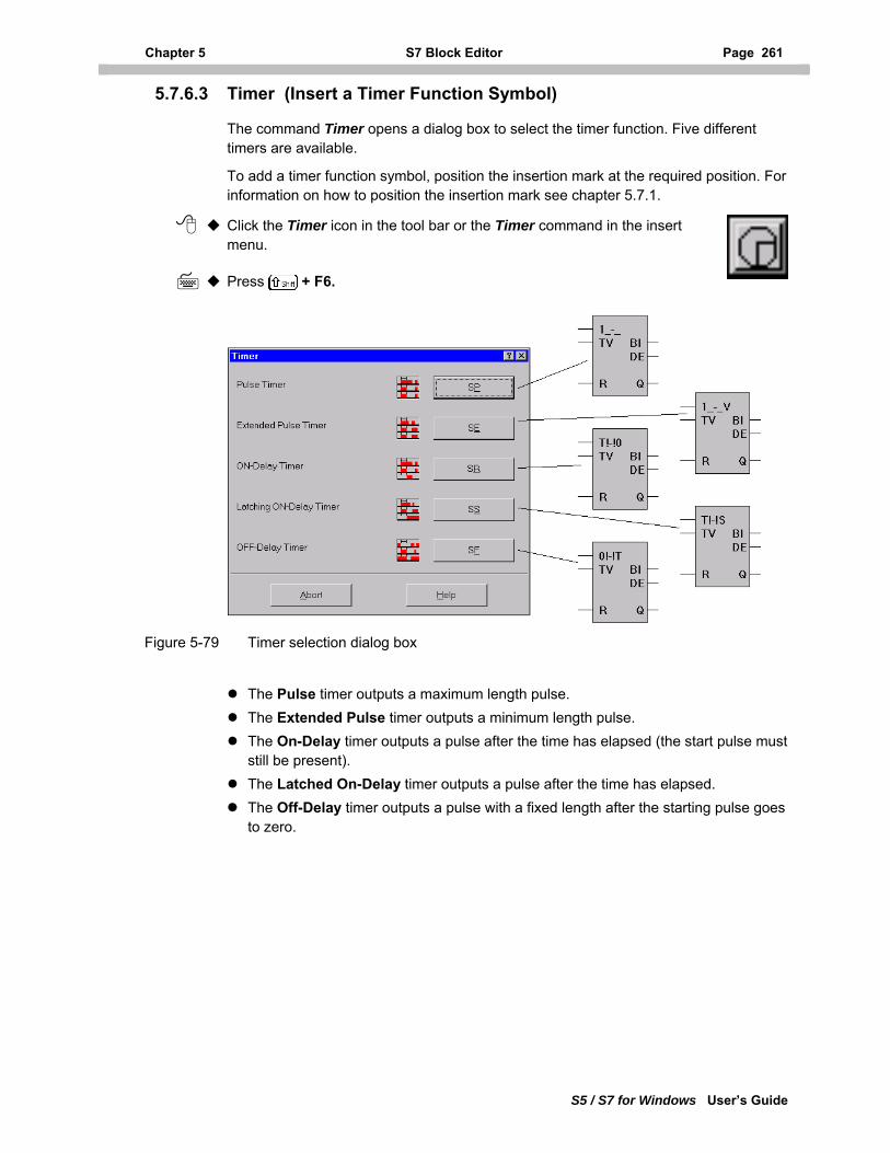
Chapter 5 S7 Block Editor Page 261
S5 / S7 for Windows User’s Guide
5.7.6.3 Timer (Insert a Timer Function Symbol)
The command Timer opens a dialog box to select the timer function. Five different timers are available.
To add a timer function symbol, position the insertion mark at the required position. For information on how to position the insertion mark see chapter 5.7.1.
Click the Timer icon in the tool bar or the Timer command in the insert menu.
Press + F6.
Figure 5-79 Timer selection dialog box
The Pulse timer outputs a maximum length pulse. The Extended Pulse timer outputs a minimum length pulse. The On-Delay timer outputs a pulse after the time has elapsed (the start pulse must
still be present). The Latched On-Delay timer outputs a pulse after the time has elapsed. The Off-Delay timer outputs a pulse with a fixed length after the starting pulse goes
to zero.
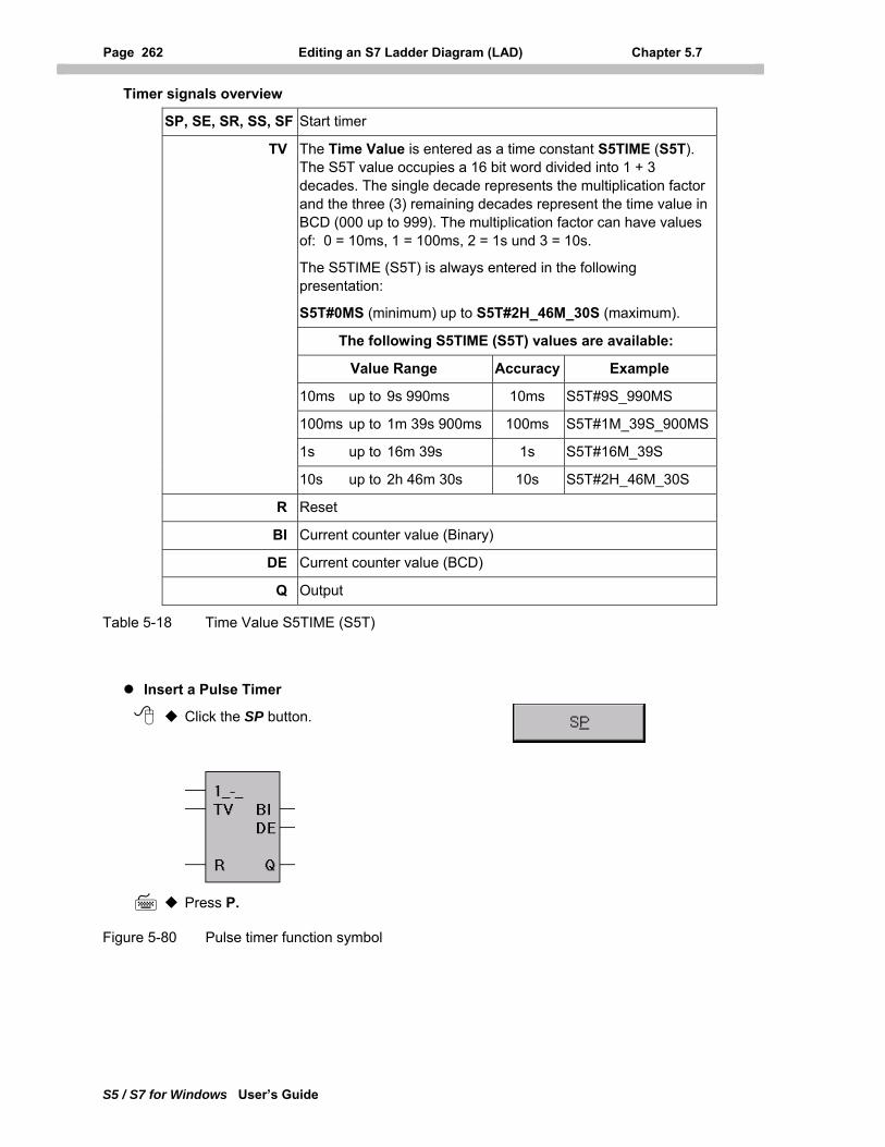
Page 262 Editing an S7 Ladder Diagram (LAD) Chapter 5.7
S5 / S7 for Windows User’s Guide
Timer signals overview
SP, SE, SR, SS, SF Start timer
TV The Time Value is entered as a time constant S5TIME (S5T). The S5T value occupies a 16 bit word divided into 1 + 3 decades. The single decade represents the multiplication factor and the three (3) remaining decades represent the time value in BCD (000 up to 999). The multiplication factor can have values of: 0 = 10ms, 1 = 100ms, 2 = 1s und 3 = 10s.
The S5TIME (S5T) is always entered in the following presentation:
S5T#0MS (minimum) up to S5T#2H_46M_30S (maximum).
The following S5TIME (S5T) values are available:
Value Range Accuracy Example
10ms up to 9s 990ms 10ms S5T#9S_990MS
100ms up to 1m 39s 900ms 100ms S5T#1M_39S_900MS
1s up to 16m 39s 1s S5T#16M_39S
10s up to 2h 46m 30s 10s S5T#2H_46M_30S
R Reset
BI Current counter value (Binary)
DE Current counter value (BCD)
Q Output
Table 5-18 Time Value S5TIME (S5T)
Insert a Pulse Timer
Click the SP button.
Press P.
Figure 5-80 Pulse timer function symbol
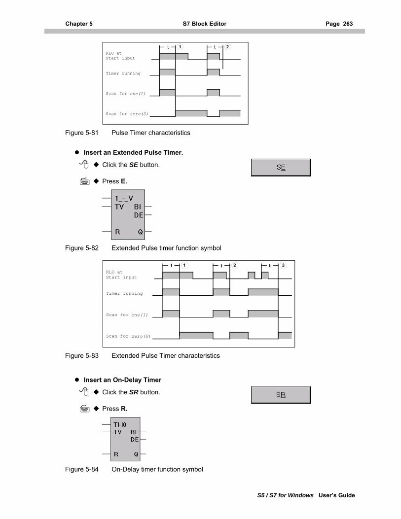
Chapter 5 S7 Block Editor Page 263
S5 / S7 for Windows User’s Guide
RLO atStart input
Timer running
Scan for one(1)
Scan for zero(0)
1 2t t
Figure 5-81 Pulse Timer characteristics
Insert an Extended Pulse Timer.
Click the SE button.
Press E.
Figure 5-82 Extended Pulse timer function symbol
RLO atStart input
Timer running
Scan for one(1)
Scan for zero(0)
t 1 2t t 3
Figure 5-83 Extended Pulse Timer characteristics
Insert an On-Delay Timer
Click the SR button.
Press R.
Figure 5-84 On-Delay timer function symbol
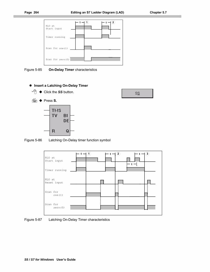
Page 264 Editing an S7 Ladder Diagram (LAD) Chapter 5.7
S5 / S7 for Windows User’s Guide
RLO atStart input
Timer running
Scan for one(1)
Scan for zero(0)
t 1 2t
Figure 5-85 On-Delay Timer characteristics
Insert a Latching On-Delay Timer
Click the SS button.
Press S.
Figure 5-86 Latching On-Delay timer function symbol
RLO atStart input
Timer running
RLO atReset input
Scan for one(1)
Scan for zero(0)
t 1 2t t 3
t
Figure 5-87 Latching On-Delay Timer characteristics
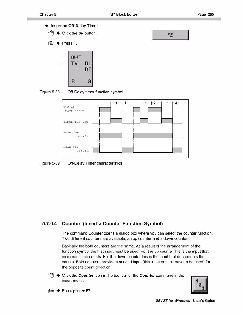
Chapter 5 S7 Block Editor Page 265
S5 / S7 for Windows User’s Guide
Insert an Off-Delay Timer
Click the SF button.
Press F.
Figure 5-88 Off-Delay timer function symbol
RLO atStart input
Timer running
Scan for one(1)
Scan for zero(0)
t 1 2t t 3
Figure 5-89 Off-Delay Timer characteristics
5.7.6.4 Counter (Insert a Counter Function Symbol)
The command Counter opens a dialog box where you can select the counter function. Two different counters are available, an up counter and a down counter.
Basically the both counters are the same. As a result of the arrangement of the function symbol the first input must be used. For the up counter this is the input that increments the counts. For the down counter this is the input that decrements the counts. Both counters provide a second input (this input doesn’t have to be used) for the opposite count direction.
Click the Counter icon in the tool bar or the Counter command in the insert menu.
Press + F7.
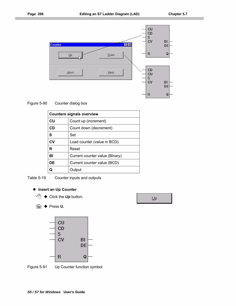
Page 266 Editing an S7 Ladder Diagram (LAD) Chapter 5.7
S5 / S7 for Windows User’s Guide
Figure 5-90 Counter dialog box
Counters signals overview
CU Count up (increment)
CD Count down (decrement)
S Set
CV Load counter (value in BCD)
R Reset
BI Current counter value (Binary)
DE Current counter value (BCD)
Q Output
Table 5-19 Counter inputs and outputs
Insert an Up Counter
Click the Up button.
Press U.
Figure 5-91 Up Counter function symbol
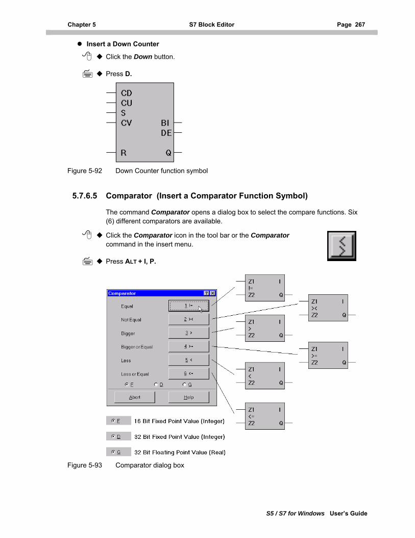
Chapter 5 S7 Block Editor Page 267
S5 / S7 for Windows User’s Guide
Insert a Down Counter
Click the Down button.
Press D.
Figure 5-92 Down Counter function symbol
5.7.6.5 Comparator (Insert a Comparator Function Symbol)
The command Comparator opens a dialog box to select the compare functions. Six (6) different comparators are available.
Click the Comparator icon in the tool bar or the Comparator command in the insert menu.
Press ALT + I, P.
Figure 5-93 Comparator dialog box
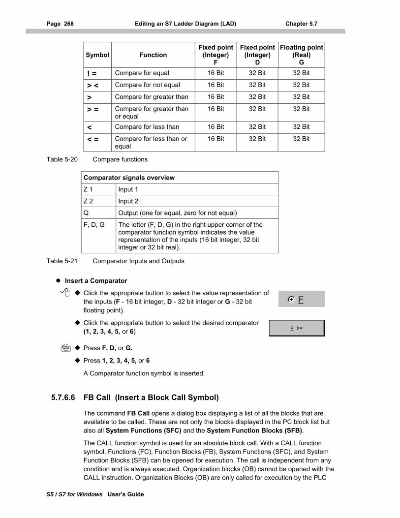
Page 268 Editing an S7 Ladder Diagram (LAD) Chapter 5.7
S5 / S7 for Windows User’s Guide
Symbol Function Fixed point
(Integer) F
Fixed point (Integer)
D
Floating point(Real)
G
! = Compare for equal 16 Bit 32 Bit 32 Bit
> < Compare for not equal 16 Bit 32 Bit 32 Bit
> Compare for greater than 16 Bit 32 Bit 32 Bit
> = Compare for greater than or equal
16 Bit 32 Bit 32 Bit
< Compare for less than 16 Bit 32 Bit 32 Bit
< = Compare for less than or equal
16 Bit 32 Bit 32 Bit
Table 5-20 Compare functions
Comparator signals overview
Z 1 Input 1
Z 2 Input 2
Q Output (one for equal, zero for not equal)
F, D, G The letter (F, D, G) in the right upper corner of the comparator function symbol indicates the value representation of the inputs (16 bit integer, 32 bit integer or 32 bit real).
Table 5-21 Comparator Inputs and Outputs
Insert a Comparator
Click the appropriate button to select the value representation of the inputs (F - 16 bit integer, D - 32 bit integer or G - 32 bit floating point).
Click the appropriate button to select the desired comparator (1, 2, 3, 4, 5, or 6)
Press F, D, or G.
Press 1, 2, 3, 4, 5, or 6
A Comparator function symbol is inserted.
5.7.6.6 FB Call (Insert a Block Call Symbol)
The command FB Call opens a dialog box displaying a list of all the blocks that are available to be called. These are not only the blocks displayed in the PC block list but also all System Functions (SFC) and the System Function Blocks (SFB).
The CALL function symbol is used for an absolute block call. With a CALL function symbol, Functions (FC), Function Blocks (FB), System Functions (SFC), and System Function Blocks (SFB) can be opened for execution. The call is independent from any condition and is always executed. Organization blocks (OB) cannot be opened with the CALL instruction. Organization Blocks (OB) are only called for execution by the PLC
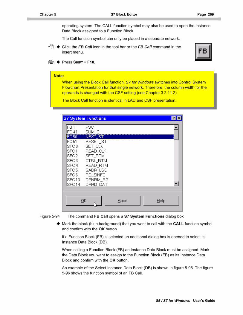
Chapter 5 S7 Block Editor Page 269
S5 / S7 for Windows User’s Guide
operating system. The CALL function symbol may also be used to open the Instance Data Block assigned to a Function Block.
The Call function symbol can only be placed in a separate network.
Click the FB Call icon in the tool bar or the FB Call command in the insert menu.
Press SHIFT + F10.
Note: When using the Block Call function, S7 for Windows switches into Control System Flowchart Presentation for that single network. Therefore, the column width for the operands is changed with the CSF setting (see Chapter 3.2.11.2).
The Block Call function is identical in LAD and CSF presentation.
Figure 5-94 The command FB Call opens a S7 System Functions dialog box
Mark the block (blue background) that you want to call with the CALL function symbol and confirm with the OK button.
If a Function Block (FB) is selected an additional dialog box is opened to select its Instance Data Block (DB).
When calling a Function Block (FB) an Instance Data Block must be assigned. Mark the Data Block you want to assign to the Function Block (FB) as its Instance Data Block and confirm with the OK button.
An example of the Select Instance Data Block (DB) is shown in figure 5-95. The figure 5-96 shows the function symbol of an FB Call.
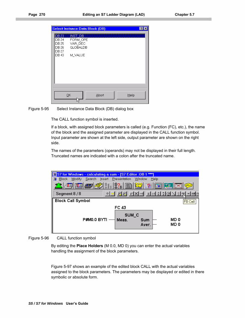
Page 270 Editing an S7 Ladder Diagram (LAD) Chapter 5.7
S5 / S7 for Windows User’s Guide
Figure 5-95 Select Instance Data Block (DB) dialog box
The CALL function symbol is inserted.
If a block, with assigned block parameters is called (e.g. Function (FC), etc.), the name of the block and the assigned parameter are displayed in the CALL function symbol. Input parameter are shown at the left side, output parameter are shown on the right side.
The names of the parameters (operands) may not be displayed in their full length. Truncated names are indicated with a colon after the truncated name.
Figure 5-96 CALL function symbol
By editing the Place Holders (M 0.0, MD 0) you can enter the actual variables handling the assignment of the block parameters.
Figure 5-97 shows an example of the edited block CALL with the actual variables assigned to the block parameters. The parameters may be displayed or edited in there symbolic or absolute form.
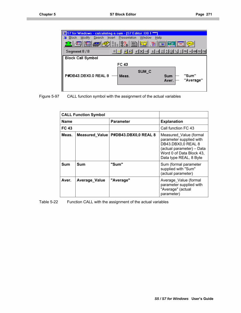
Chapter 5 S7 Block Editor Page 271
S5 / S7 for Windows User’s Guide
Figure 5-97 CALL function symbol with the assignment of the actual variables
CALL Function Symbol Name Parameter Explanation FC 43 Call function FC 43
Meas. Measured_Value P#DB43.DBX0,0 REAL 8 Measured_Value (formal parameter supplied with DB43.DBX0,0 REAL 8 (actual parameter) – Data Word 0 of Data Block 43, Data type REAL, 8 Byte
Sum Sum "Sum" Sum (formal parameter supplied with "Sum" (actual parameter)
Aver. Average_Value "Average" Average_Value (formal parameter supplied with "Average" (actual parameter)
Table 5-22 Function CALL with the assignment of the actual variables
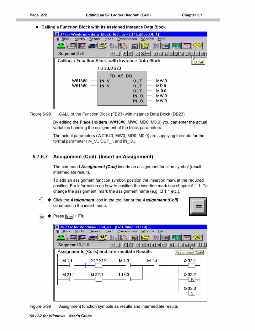
Page 272 Editing an S7 Ladder Diagram (LAD) Chapter 5.7
S5 / S7 for Windows User’s Guide
Calling a Function Block with its assigned Instance Data Block
Figure 5-98 CALL of the Function Block (FB23) with instance Data Block (DB23)
By editing the Place Holders (W#16#0, MW0, MD0, M0.0) you can enter the actual variables handling the assignment of the block parameters.
The actual parameters (W#16#0, MW0, MD0, M0.0) are supplying the data for the formal parameter (IN_V., OUT_., and IN_O.).
5.7.6.7 Assignment (Coil) (Insert an Assignment)
The command Assignment (Coil) inserts an assignment function symbol (result, intermediate result).
To add an assignment function symbol, position the insertion mark at the required position. For information on how to position the insertion mark see chapter 5.1.1. To change the assignment, mark the assignment name (e.g. Q 1.1 etc.).
Click the Assignment icon in the tool bar or the Assignment (Coil) command in the insert menu.
Press + F9.
Figure 5-99 Assignment function symbols as results and intermediate results
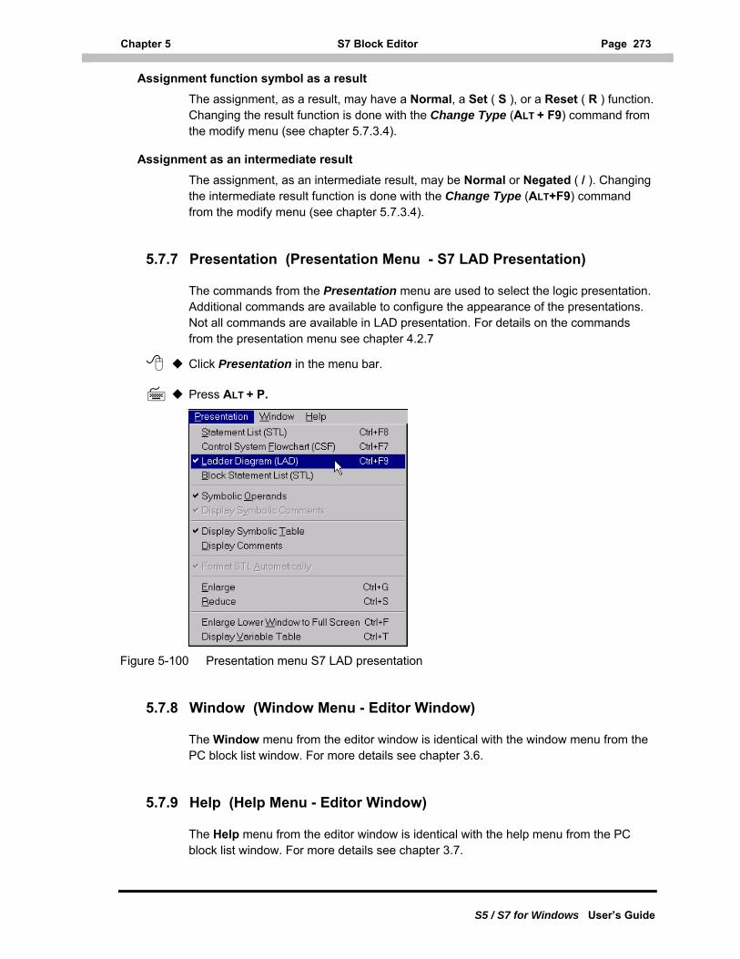
Chapter 5 S7 Block Editor Page 273
S5 / S7 for Windows User’s Guide
Assignment function symbol as a result The assignment, as a result, may have a Normal, a Set ( S ), or a Reset ( R ) function. Changing the result function is done with the Change Type (ALT + F9) command from the modify menu (see chapter 5.7.3.4).
Assignment as an intermediate result The assignment, as an intermediate result, may be Normal or Negated ( / ). Changing the intermediate result function is done with the Change Type (ALT+F9) command from the modify menu (see chapter 5.7.3.4).
5.7.7 Presentation (Presentation Menu - S7 LAD Presentation)
The commands from the Presentation menu are used to select the logic presentation. Additional commands are available to configure the appearance of the presentations. Not all commands are available in LAD presentation. For details on the commands from the presentation menu see chapter 4.2.7
Click Presentation in the menu bar.
Press ALT + P.
Figure 5-100 Presentation menu S7 LAD presentation
5.7.8 Window (Window Menu - Editor Window)
The Window menu from the editor window is identical with the window menu from the PC block list window. For more details see chapter 3.6.
5.7.9 Help (Help Menu - Editor Window)
The Help menu from the editor window is identical with the help menu from the PC block list window. For more details see chapter 3.7.
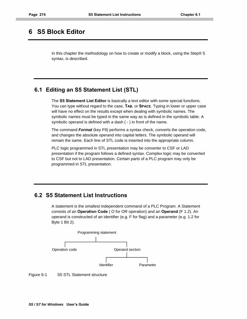
Page 274 S5 Statement List Instructions Chapter 6.1
S5 / S7 for Windows User’s Guide
6 S5 Block Editor
In this chapter the methodology on how to create or modify a block, using the Step® 5 syntax, is described.
6.1 Editing an S5 Statement List (STL)
The S5 Statement List Editor is basically a text editor with some special functions. You can type without regard to the case, TAB, or SPACE. Typing in lower or upper case will have no effect on the results except when dealing with symbolic names. The symbolic names must be typed in the same way as is defined in the symbolic table. A symbolic operand is defined with a dash ( - ) in front of the name.
The command Format (key F9) performs a syntax check, converts the operation code, and changes the absolute operand into capital letters. The symbolic operand will remain the same. Each line of STL code is inserted into the appropriate column.
PLC logic programmed in STL presentation may be converter to CSF or LAD presentation if the program follows a defined syntax. Complex logic may be converted to CSF but not to LAD presentation. Certain parts of a PLC program may only be programmed in STL presentation.
6.2 S5 Statement List Instructions
A statement is the smallest independent command of a PLC Program. A Statement consists of an Operation Code ( O for OR operation) and an Operand (F 1.2). An operand is constructed of an identifier (e.g. F for flag) and a parameter (e.g. 1.2 for Byte 1 Bit 2).
Programming statement
Operation code Operand section
Identifier Parameter
Figure 6-1 S5 STL Statement structure
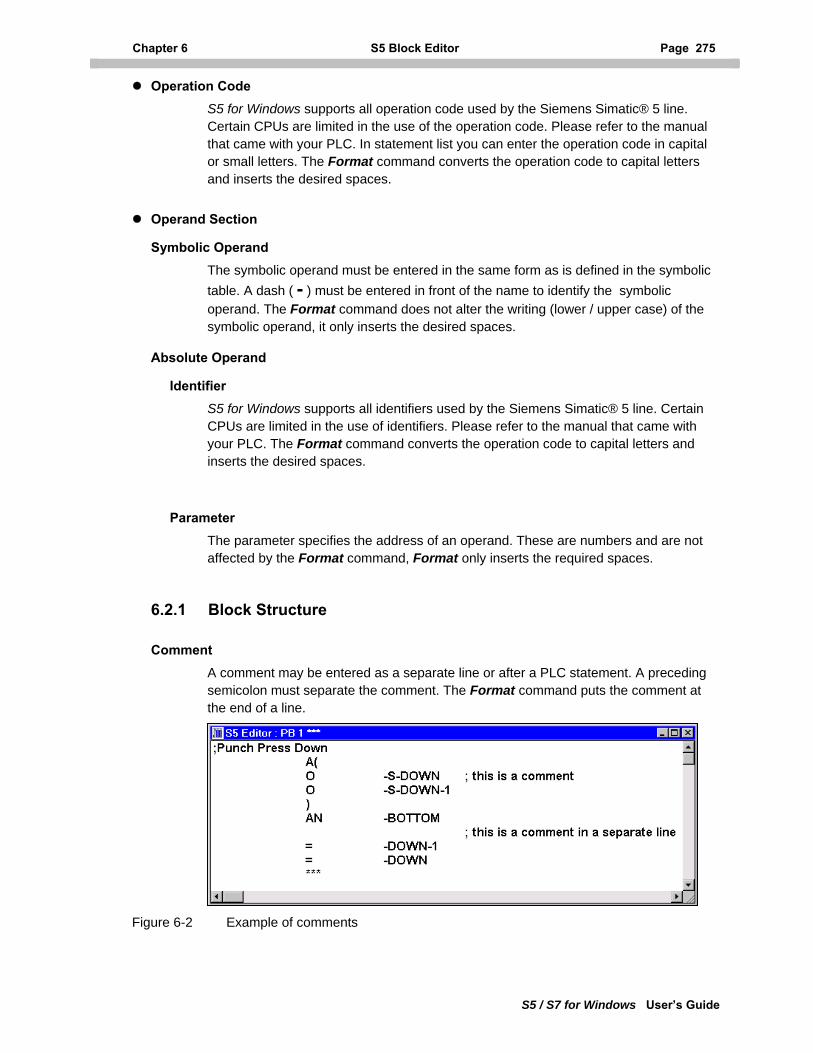
Chapter 6 S5 Block Editor Page 275
S5 / S7 for Windows User’s Guide
Operation Code
S5 for Windows supports all operation code used by the Siemens Simatic® 5 line. Certain CPUs are limited in the use of the operation code. Please refer to the manual that came with your PLC. In statement list you can enter the operation code in capital or small letters. The Format command converts the operation code to capital letters and inserts the desired spaces.
Operand Section
Symbolic Operand
The symbolic operand must be entered in the same form as is defined in the symbolic table. A dash ( - ) must be entered in front of the name to identify the symbolic operand. The Format command does not alter the writing (lower / upper case) of the symbolic operand, it only inserts the desired spaces.
Absolute Operand
Identifier S5 for Windows supports all identifiers used by the Siemens Simatic® 5 line. Certain CPUs are limited in the use of identifiers. Please refer to the manual that came with your PLC. The Format command converts the operation code to capital letters and inserts the desired spaces.
Parameter The parameter specifies the address of an operand. These are numbers and are not affected by the Format command, Format only inserts the required spaces.
6.2.1 Block Structure
Comment A comment may be entered as a separate line or after a PLC statement. A preceding semicolon must separate the comment. The Format command puts the comment at the end of a line.
Figure 6-2 Example of comments
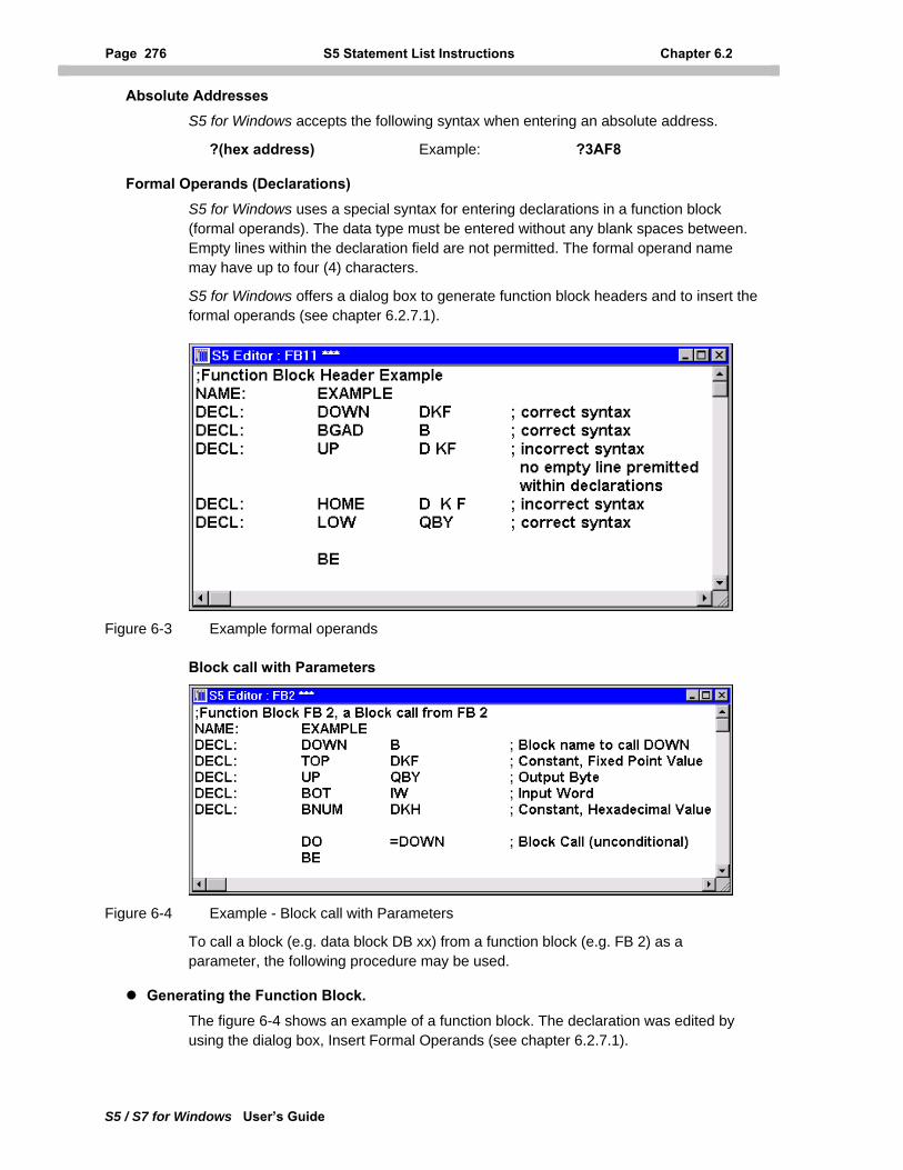
Page 276 S5 Statement List Instructions Chapter 6.2
S5 / S7 for Windows User’s Guide
Absolute Addresses
S5 for Windows accepts the following syntax when entering an absolute address.
?(hex address) Example: ?3AF8
Formal Operands (Declarations) S5 for Windows uses a special syntax for entering declarations in a function block (formal operands). The data type must be entered without any blank spaces between. Empty lines within the declaration field are not permitted. The formal operand name may have up to four (4) characters.
S5 for Windows offers a dialog box to generate function block headers and to insert the formal operands (see chapter 6.2.7.1).
Figure 6-3 Example formal operands
Block call with Parameters
Figure 6-4 Example - Block call with Parameters
To call a block (e.g. data block DB xx) from a function block (e.g. FB 2) as a parameter, the following procedure may be used.
Generating the Function Block. The figure 6-4 shows an example of a function block. The declaration was edited by using the dialog box, Insert Formal Operands (see chapter 6.2.7.1).
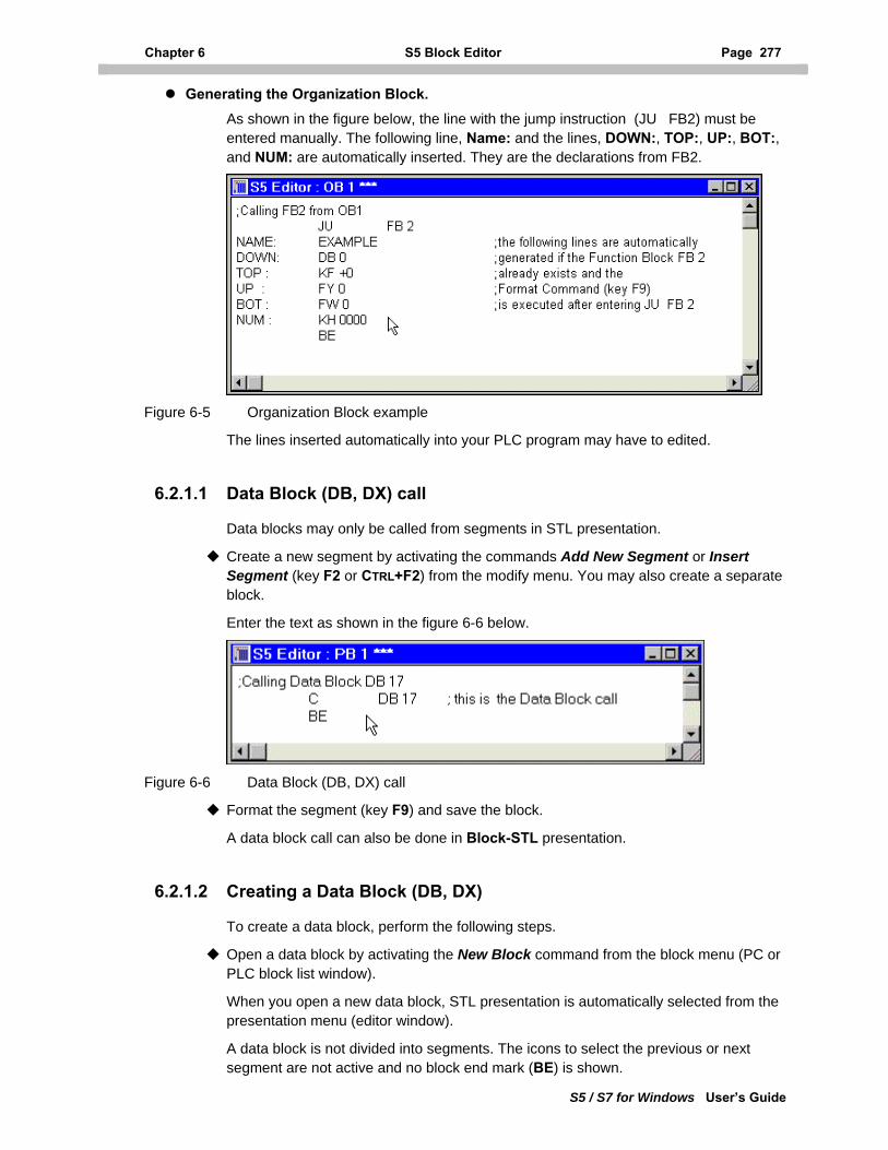
Chapter 6 S5 Block Editor Page 277
S5 / S7 for Windows User’s Guide
Generating the Organization Block. As shown in the figure below, the line with the jump instruction (JU FB2) must be entered manually. The following line, Name: and the lines, DOWN:, TOP:, UP:, BOT:, and NUM: are automatically inserted. They are the declarations from FB2.
Figure 6-5 Organization Block example
The lines inserted automatically into your PLC program may have to edited.
6.2.1.1 Data Block (DB, DX) call
Data blocks may only be called from segments in STL presentation.
Create a new segment by activating the commands Add New Segment or Insert Segment (key F2 or CTRL+F2) from the modify menu. You may also create a separate block.
Enter the text as shown in the figure 6-6 below.
Figure 6-6 Data Block (DB, DX) call
Format the segment (key F9) and save the block.
A data block call can also be done in Block-STL presentation.
6.2.1.2 Creating a Data Block (DB, DX)
To create a data block, perform the following steps.
Open a data block by activating the New Block command from the block menu (PC or PLC block list window).
When you open a new data block, STL presentation is automatically selected from the presentation menu (editor window).
A data block is not divided into segments. The icons to select the previous or next segment are not active and no block end mark (BE) is shown.
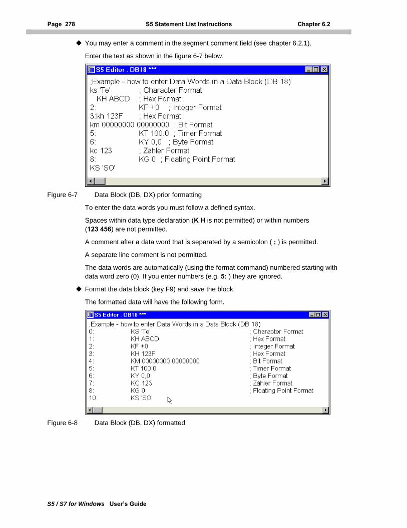
Page 278 S5 Statement List Instructions Chapter 6.2
S5 / S7 for Windows User’s Guide
You may enter a comment in the segment comment field (see chapter 6.2.1).
Enter the text as shown in the figure 6-7 below.
Figure 6-7 Data Block (DB, DX) prior formatting
To enter the data words you must follow a defined syntax.
Spaces within data type declaration (K H is not permitted) or within numbers (123 456) are not permitted.
A comment after a data word that is separated by a semicolon ( ; ) is permitted.
A separate line comment is not permitted.
The data words are automatically (using the format command) numbered starting with data word zero (0). If you enter numbers (e.g. 5: ) they are ignored.
Format the data block (key F9) and save the block.
The formatted data will have the following form.
Figure 6-8 Data Block (DB, DX) formatted
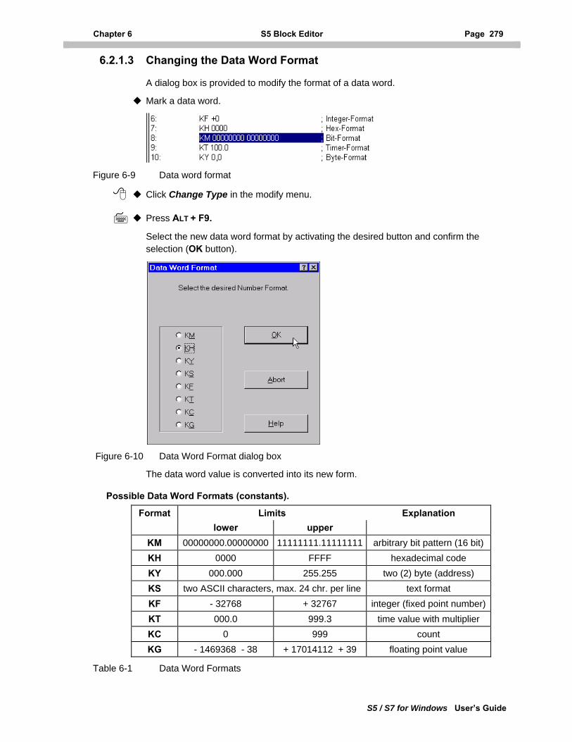
Chapter 6 S5 Block Editor Page 279
S5 / S7 for Windows User’s Guide
6.2.1.3 Changing the Data Word Format
A dialog box is provided to modify the format of a data word.
Mark a data word.
Figure 6-9 Data word format
Click Change Type in the modify menu.
Press ALT + F9.
Select the new data word format by activating the desired button and confirm the selection (OK button).
Figure 6-10 Data Word Format dialog box
The data word value is converted into its new form.
Possible Data Word Formats (constants).
Format Limits Explanation lower upper
KM 00000000.00000000 11111111.11111111 arbitrary bit pattern (16 bit) KH 0000 FFFF hexadecimal code KY 000.000 255.255 two (2) byte (address) KS two ASCII characters, max. 24 chr. per line text format KF - 32768 + 32767 integer (fixed point number)KT 000.0 999.3 time value with multiplier KC 0 999 count KG - 1469368 - 38 + 17014112 + 39 floating point value
Table 6-1 Data Word Formats
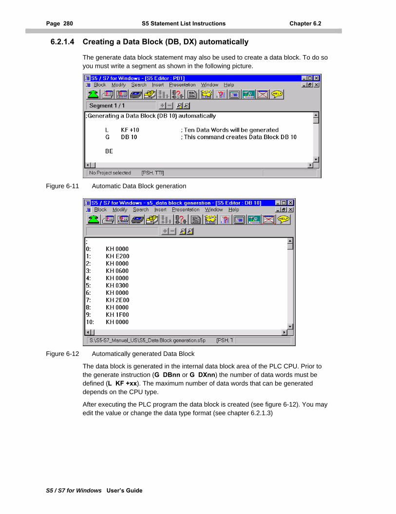
Page 280 S5 Statement List Instructions Chapter 6.2
S5 / S7 for Windows User’s Guide
6.2.1.4 Creating a Data Block (DB, DX) automatically
The generate data block statement may also be used to create a data block. To do so you must write a segment as shown in the following picture.
Figure 6-11 Automatic Data Block generation
Figure 6-12 Automatically generated Data Block
The data block is generated in the internal data block area of the PLC CPU. Prior to the generate instruction (G DBnn or G DXnn) the number of data words must be defined (L KF +xx). The maximum number of data words that can be generated depends on the CPU type.
After executing the PLC program the data block is created (see figure 6-12). You may edit the value or change the data type format (see chapter 6.2.1.3)
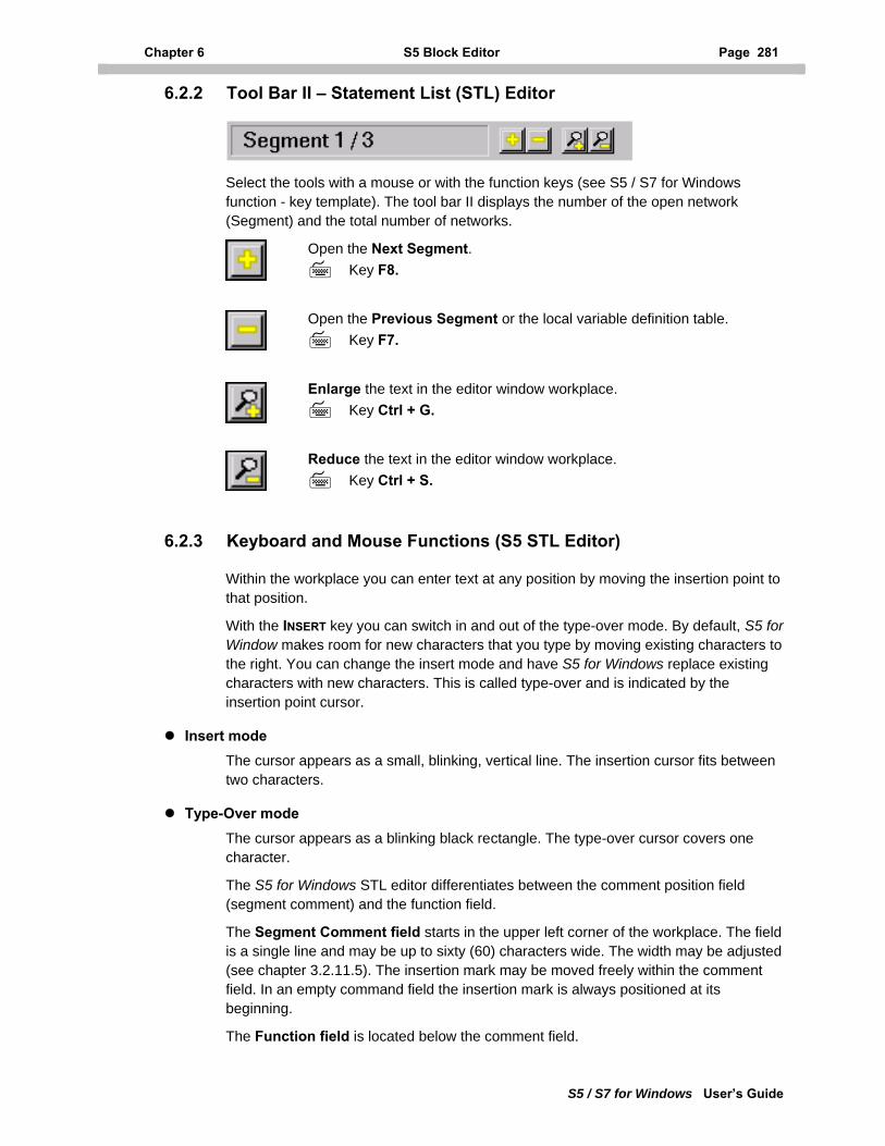
Chapter 6 S5 Block Editor Page 281
S5 / S7 for Windows User’s Guide
6.2.2 Tool Bar II – Statement List (STL) Editor
Select the tools with a mouse or with the function keys (see S5 / S7 for Windows function - key template). The tool bar II displays the number of the open network (Segment) and the total number of networks.
Open the Next Segment. Key F8.
Open the Previous Segment or the local variable definition table.
Key F7.
Enlarge the text in the editor window workplace.
Key Ctrl + G.
Reduce the text in the editor window workplace.
Key Ctrl + S.
6.2.3 Keyboard and Mouse Functions (S5 STL Editor)
Within the workplace you can enter text at any position by moving the insertion point to that position.
With the INSERT key you can switch in and out of the type-over mode. By default, S5 for Window makes room for new characters that you type by moving existing characters to the right. You can change the insert mode and have S5 for Windows replace existing characters with new characters. This is called type-over and is indicated by the insertion point cursor.
Insert mode
The cursor appears as a small, blinking, vertical line. The insertion cursor fits between two characters.
Type-Over mode
The cursor appears as a blinking black rectangle. The type-over cursor covers one character.
The S5 for Windows STL editor differentiates between the comment position field (segment comment) and the function field.
The Segment Comment field starts in the upper left corner of the workplace. The field is a single line and may be up to sixty (60) characters wide. The width may be adjusted (see chapter 3.2.11.5). The insertion mark may be moved freely within the comment field. In an empty command field the insertion mark is always positioned at its beginning.
The Function field is located below the comment field.
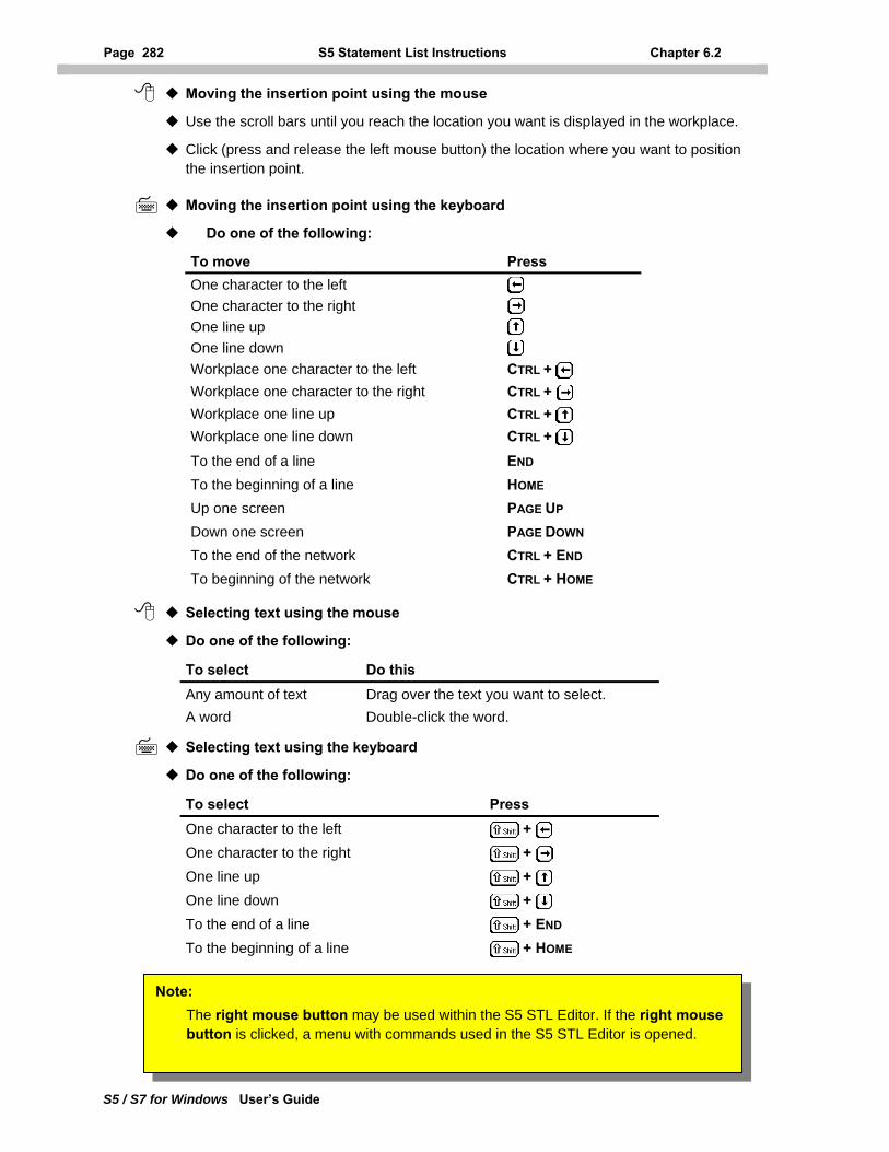
Page 282 S5 Statement List Instructions Chapter 6.2
S5 / S7 for Windows User’s Guide
Moving the insertion point using the mouse
Use the scroll bars until you reach the location you want is displayed in the workplace.
Click (press and release the left mouse button) the location where you want to position the insertion point.
Moving the insertion point using the keyboard
Do one of the following:
To move Press One character to the left One character to the right One line up One line down Workplace one character to the left CTRL + Workplace one character to the right CTRL + Workplace one line up CTRL + Workplace one line down CTRL +
To the end of a line END To the beginning of a line HOME Up one screen PAGE UP Down one screen PAGE DOWN To the end of the network CTRL + END To beginning of the network CTRL + HOME
Selecting text using the mouse
Do one of the following:
To select Do this Any amount of text Drag over the text you want to select. A word Double-click the word.
Selecting text using the keyboard
Do one of the following:
To select Press One character to the left + One character to the right + One line up + One line down + To the end of a line + END To the beginning of a line + HOME
Note: The right mouse button may be used within the S5 STL Editor. If the right mouse button is clicked, a menu with commands used in the S5 STL Editor is opened.
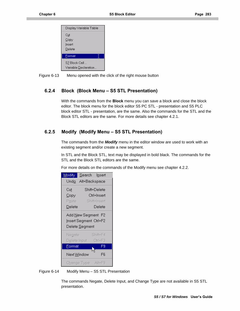
Chapter 6 S5 Block Editor Page 283
S5 / S7 for Windows User’s Guide
Figure 6-13 Menu opened with the click of the right mouse button
6.2.4 Block (Block Menu – S5 STL Presentation)
With the commands from the Block menu you can save a block and close the block editor. The block menu for the block editor S5 PC STL - presentation and S5 PLC block editor STL - presentation, are the same. Also the commands for the STL and the Block STL editors are the same. For more details see chapter 4.2.1.
6.2.5 Modify (Modify Menu – S5 STL Presentation)
The commands from the Modify menu in the editor window are used to work with an existing segment and/or create a new segment.
In STL and the Block STL, text may be displayed in bold black. The commands for the STL and the Block STL editors are the same.
For more details on the commands of the Modify menu see chapter 4.2.2.
Figure 6-14 Modify Menu – S5 STL Presentation
The commands Negate, Delete Input, and Change Type are not available in S5 STL presentation.
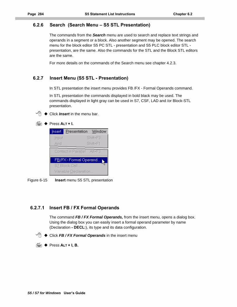
Page 284 S5 Statement List Instructions Chapter 6.2
S5 / S7 for Windows User’s Guide
6.2.6 Search (Search Menu – S5 STL Presentation)
The commands from the Search menu are used to search and replace text strings and operands in a segment or a block. Also another segment may be opened. The search menu for the block editor S5 PC STL - presentation and S5 PLC block editor STL - presentation, are the same. Also the commands for the STL and the Block STL editors are the same.
For more details on the commands of the Search menu see chapter 4.2.3.
6.2.7 Insert Menu (S5 STL - Presentation)
In STL presentation the insert menu provides FB /FX - Formal Operands command.
In STL presentation the commands displayed in bold black may be used. The commands displayed in light gray can be used in S7, CSF, LAD and /or Block-STL presentation.
Click Insert in the menu bar.
Press ALT + I.
Figure 6-15 Insert menu S5 STL presentation
6.2.7.1 Insert FB / FX Formal Operands
The command FB / FX Formal Operands, from the insert menu, opens a dialog box. Using the dialog box you can easily insert a formal operand parameter by name (Declaration - DECL:), its type and its data configuration.
Click FB / FX Formal Operands in the insert menu
Press ALT + I, B.
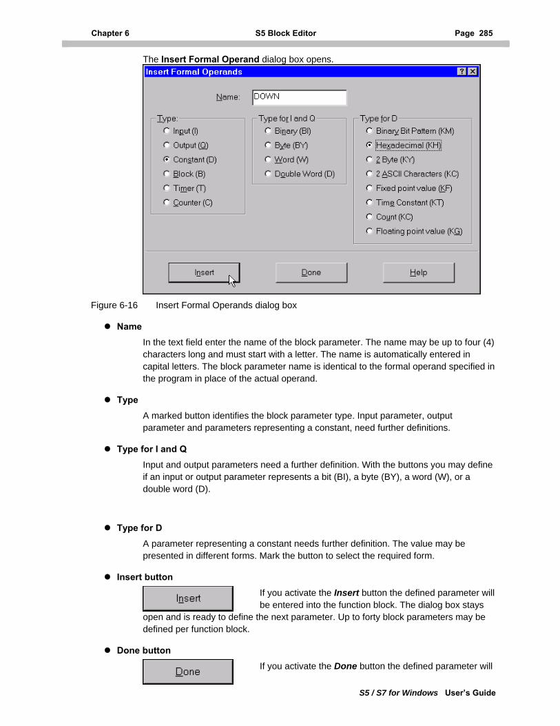
Chapter 6 S5 Block Editor Page 285
S5 / S7 for Windows User’s Guide
The Insert Formal Operand dialog box opens.
Figure 6-16 Insert Formal Operands dialog box
Name In the text field enter the name of the block parameter. The name may be up to four (4) characters long and must start with a letter. The name is automatically entered in capital letters. The block parameter name is identical to the formal operand specified in the program in place of the actual operand.
Type A marked button identifies the block parameter type. Input parameter, output parameter and parameters representing a constant, need further definitions.
Type for I and Q Input and output parameters need a further definition. With the buttons you may define if an input or output parameter represents a bit (BI), a byte (BY), a word (W), or a double word (D).
Type for D A parameter representing a constant needs further definition. The value may be presented in different forms. Mark the button to select the required form.
Insert button If you activate the Insert button the defined parameter will be entered into the function block. The dialog box stays
open and is ready to define the next parameter. Up to forty block parameters may be defined per function block.
Done button If you activate the Done button the defined parameter will
Page 286 Editing an S5 Control System Flowchart (CSF) Chapter 6.2
S5 / S7 for Windows User’s Guide
be entered into the function block and the dialog box will be closed.
Note: Prior to opening the dialog box Insert Formal Operand you must position the insertion mark in a separate line directly below the line defining the name.
6.2.8 Presentation (Presentation Menu - S5 STL Presentation)
The commands from the Presentation menu are used to select the logic presentation. Additional commands are available to configure the appearance of the presentations. All commands are available in STL presentation. For details on the commands of the presentation menu see chapter 4.2.5
6.2.9 Window (Window Menu - Editor Window)
The Window menu of the editor window is identical with the window menu of the PC block list window. For more details see chapter 3.5.
6.2.10 Help (Help Menu - Editor Window)
The Help menu of the editor window is identical with the help menu of the PC block list window. For more details see chapter 3.6.
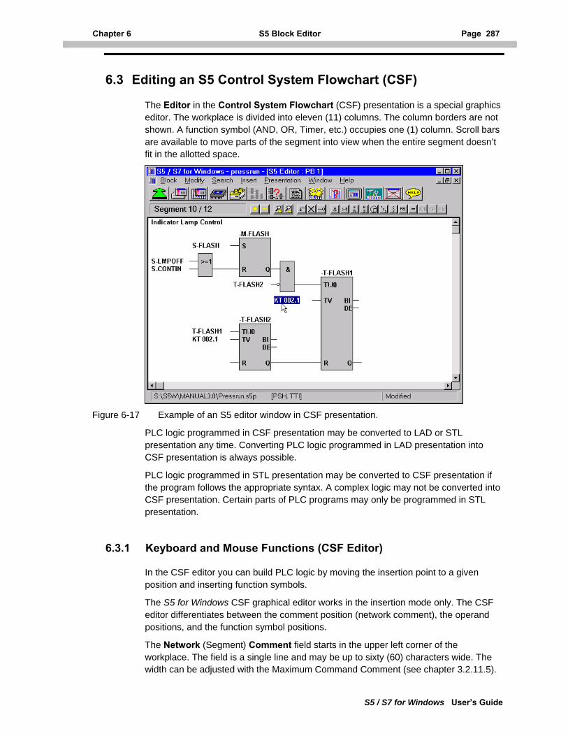
Chapter 6 S5 Block Editor Page 287
S5 / S7 for Windows User’s Guide
6.3 Editing an S5 Control System Flowchart (CSF)
The Editor in the Control System Flowchart (CSF) presentation is a special graphics editor. The workplace is divided into eleven (11) columns. The column borders are not shown. A function symbol (AND, OR, Timer, etc.) occupies one (1) column. Scroll bars are available to move parts of the segment into view when the entire segment doesn’t fit in the allotted space.
Figure 6-17 Example of an S5 editor window in CSF presentation.
PLC logic programmed in CSF presentation may be converted to LAD or STL presentation any time. Converting PLC logic programmed in LAD presentation into CSF presentation is always possible.
PLC logic programmed in STL presentation may be converted to CSF presentation if the program follows the appropriate syntax. A complex logic may not be converted into CSF presentation. Certain parts of PLC programs may only be programmed in STL presentation.
6.3.1 Keyboard and Mouse Functions (CSF Editor)
In the CSF editor you can build PLC logic by moving the insertion point to a given position and inserting function symbols.
The S5 for Windows CSF graphical editor works in the insertion mode only. The CSF editor differentiates between the comment position (network comment), the operand positions, and the function symbol positions.
The Network (Segment) Comment field starts in the upper left corner of the workplace. The field is a single line and may be up to sixty (60) characters wide. The width can be adjusted with the Maximum Command Comment (see chapter 3.2.11.5).
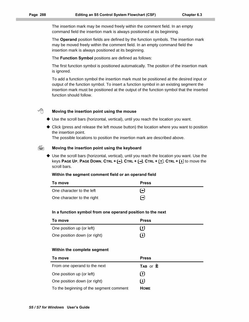
Page 288 Editing an S5 Control System Flowchart (CSF) Chapter 6.3
S5 / S7 for Windows User’s Guide
The insertion mark may be moved freely within the comment field. In an empty command field the insertion mark is always positioned at its beginning.
The Operand position fields are defined by the function symbols. The insertion mark may be moved freely within the comment field. In an empty command field the insertion mark is always positioned at its beginning.
The Function Symbol positions are defined as follows:
The first function symbol is positioned automatically. The position of the insertion mark is ignored.
To add a function symbol the insertion mark must be positioned at the desired input or output of the function symbol. To insert a function symbol in an existing segment the insertion mark must be positioned at the output of the function symbol that the inserted function should follow.
Moving the insertion point using the mouse
Use the scroll bars (horizontal, vertical), until you reach the location you want.
Click (press and release the left mouse button) the location where you want to position the insertion point. The possible locations to position the insertion mark are described above.
Moving the insertion point using the keyboard
Use the scroll bars (horizontal, vertical), until you reach the location you want. Use the keys PAGE UP, PAGE DOWN, CTRL + , CTRL + , CTRL + , CTRL + to move the scroll bars.
Within the segment comment field or an operand field
To move Press
One character to the left
One character to the right
In a function symbol from one operand position to the next
To move Press
One position up (or left)
One position down (or right)
Within the complete segment
To move Press
From one operand to the next TAB or È
One position up (or left)
One position down (or right) To the beginning of the segment comment HOME
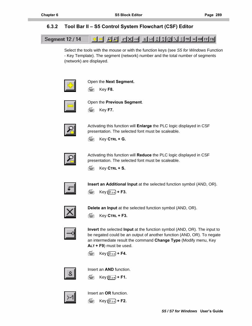
Chapter 6 S5 Block Editor Page 289
S5 / S7 for Windows User’s Guide
6.3.2 Tool Bar II – S5 Control System Flowchart (CSF) Editor
Select the tools with the mouse or with the function keys (see S5 for Windows Function - Key Template). The segment (network) number and the total number of segments (network) are displayed.
Open the Next Segment.
Key F8.
Open the Previous Segment.
Key F7.
Activating this function will Enlarge the PLC logic displayed in CSF presentation. The selected font must be scaleable.
Key CTRL + G.
Activating this function will Reduce the PLC logic displayed in CSF presentation. The selected font must be scaleable.
Key CTRL + S.
Insert an Additional Input at the selected function symbol (AND, OR).
Key + F3.
Delete an Input at the selected function symbol (AND, OR).
Key CTRL + F3.
Invert the selected Input at the function symbol (AND, OR). The input to be negated could be an output of another function (AND, OR). To negate an intermediate result the command Change Type (Modify menu, Key ALT + F9) must be used.
Key + F4.
Insert an AND function.
Key + F1.
Insert an OR function.
Key + F2.
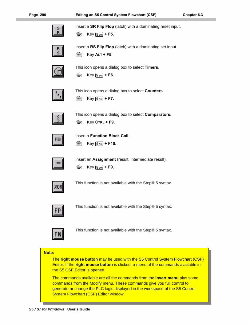
Page 290 Editing an S5 Control System Flowchart (CSF) Chapter 6.3
S5 / S7 for Windows User’s Guide
Insert a SR Flip Flop (latch) with a dominating reset input.
Key + F5.
Insert a RS Flip Flop (latch) with a dominating set input.
Key ALT + F5.
This icon opens a dialog box to select Timers.
Key + F6.
This icon opens a dialog box to select Counters.
Key + F7.
This icon opens a dialog box to select Comparators.
Key CTRL + F9.
Insert a Function Block Call.
Key + F10.
Insert an Assignment (result, intermediate result).
Key + F9.
This function is not available with the Step® 5 syntax.
This function is not available with the Step® 5 syntax.
This function is not available with the Step® 5 syntax.
Note: The right mouse button may be used with the S5 Control System Flowchart (CSF) Editor. If the right mouse button is clicked, a menu of the commands available in the S5 CSF Editor is opened.
The commands available are all the commands from the Insert menu plus some commands from the Modify menu. These commands give you full control to generate or change the PLC logic displayed in the workspace of the S5 Control System Flowchart (CSF) Editor window.
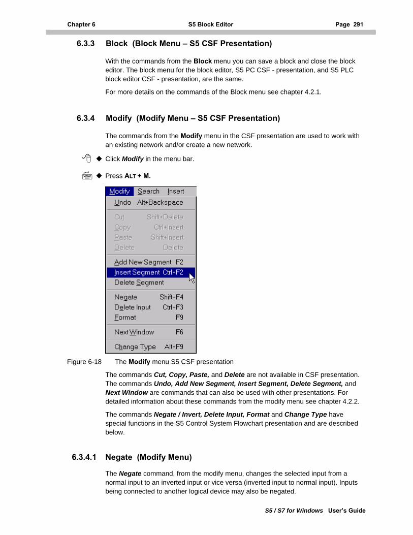
Chapter 6 S5 Block Editor Page 291
S5 / S7 for Windows User’s Guide
6.3.3 Block (Block Menu – S5 CSF Presentation)
With the commands from the Block menu you can save a block and close the block editor. The block menu for the block editor, S5 PC CSF - presentation, and S5 PLC block editor CSF - presentation, are the same.
For more details on the commands of the Block menu see chapter 4.2.1.
6.3.4 Modify (Modify Menu – S5 CSF Presentation)
The commands from the Modify menu in the CSF presentation are used to work with an existing network and/or create a new network.
Click Modify in the menu bar.
Press ALT + M.
Figure 6-18 The Modify menu S5 CSF presentation
The commands Cut, Copy, Paste, and Delete are not available in CSF presentation. The commands Undo, Add New Segment, Insert Segment, Delete Segment, and Next Window are commands that can also be used with other presentations. For detailed information about these commands from the modify menu see chapter 4.2.2.
The commands Negate / Invert, Delete Input, Format and Change Type have special functions in the S5 Control System Flowchart presentation and are described below.
6.3.4.1 Negate (Modify Menu)
The Negate command, from the modify menu, changes the selected input from a normal input to an inverted input or vice versa (inverted input to normal input). Inputs being connected to another logical device may also be negated.
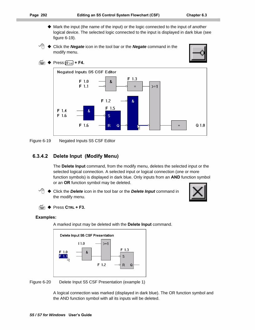
Page 292 Editing an S5 Control System Flowchart (CSF) Chapter 6.3
S5 / S7 for Windows User’s Guide
Mark the input (the name of the input) or the logic connected to the input of another logical device. The selected logic connected to the input is displayed in dark blue (see figure 6-19).
Click the Negate icon in the tool bar or the Negate command in the modify menu.
Press + F4.
Figure 6-19 Negated Inputs S5 CSF Editor
6.3.4.2 Delete Input (Modify Menu)
The Delete Input command, from the modify menu, deletes the selected input or the selected logical connection. A selected input or logical connection (one or more function symbols) is displayed in dark blue. Only inputs from an AND function symbol or an OR function symbol may be deleted.
Click the Delete icon in the tool bar or the Delete Input command in the modify menu.
Press CTRL + F3.
Examples: A marked input may be deleted with the Delete Input command.
Figure 6-20 Delete Input S5 CSF Presentation (example 1)
A logical connection was marked (displayed in dark blue). The OR function symbol and the AND function symbol with all its inputs will be deleted.
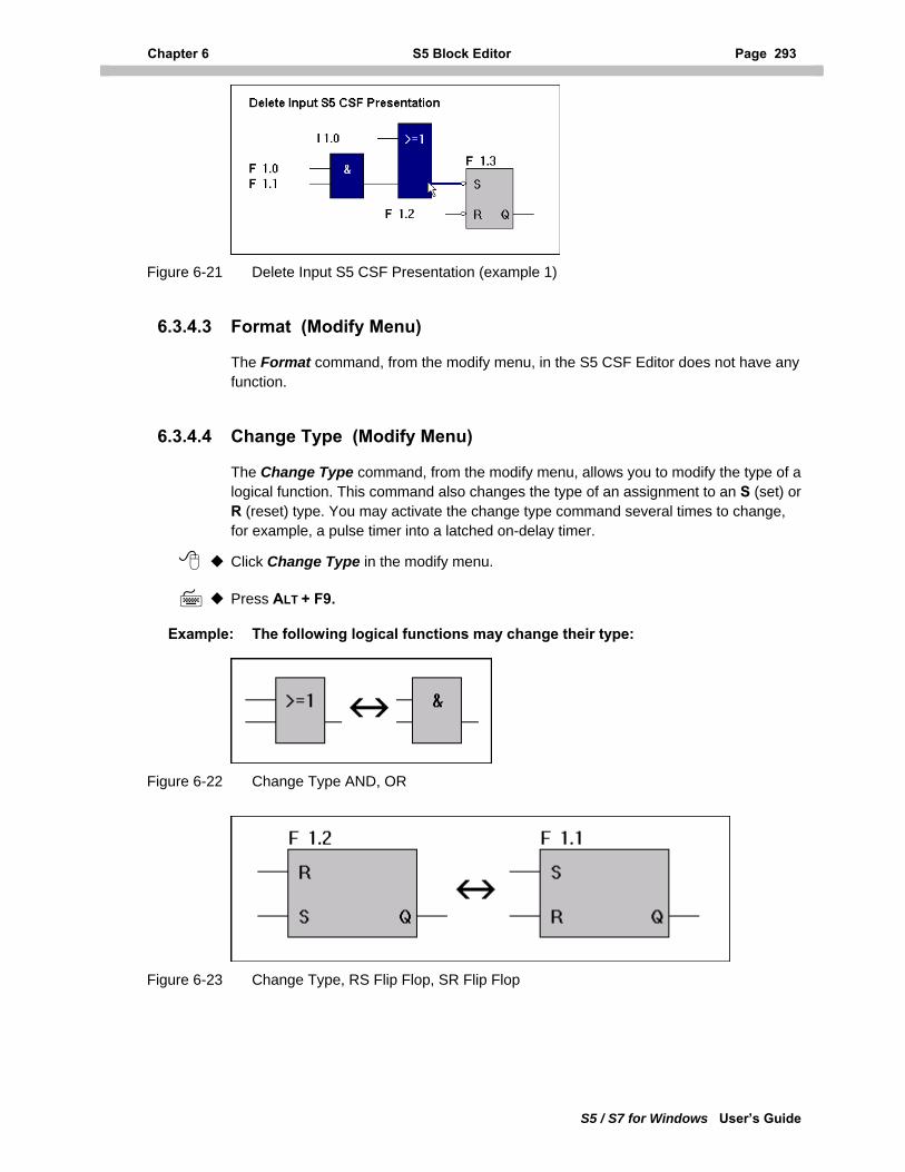
Chapter 6 S5 Block Editor Page 293
S5 / S7 for Windows User’s Guide
Figure 6-21 Delete Input S5 CSF Presentation (example 1)
6.3.4.3 Format (Modify Menu)
The Format command, from the modify menu, in the S5 CSF Editor does not have any function.
6.3.4.4 Change Type (Modify Menu)
The Change Type command, from the modify menu, allows you to modify the type of a logical function. This command also changes the type of an assignment to an S (set) or R (reset) type. You may activate the change type command several times to change, for example, a pulse timer into a latched on-delay timer.
Click Change Type in the modify menu.
Press ALT + F9.
Example: The following logical functions may change their type:
Figure 6-22 Change Type AND, OR
Figure 6-23 Change Type, RS Flip Flop, SR Flip Flop
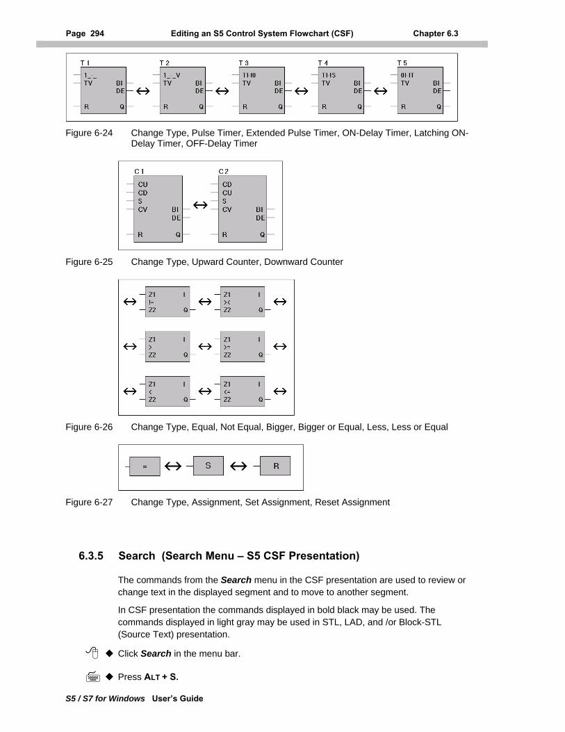
Page 294 Editing an S5 Control System Flowchart (CSF) Chapter 6.3
Figure 6-24 Change Type, Pulse Timer, Extended Pulse Timer, ON-Delay Timer, Latching ON-Delay Timer, OFF-Delay Timer
Figure 6-25 Change Type, Upward Counter, Downward Counter
Figure 6-26 Change Type, Equal, Not Equal, Bigger, Bigger or Equal, Less, Less or Equal
Figure 6-27 Change Type, Assignment, Set Assignment, Reset Assignment
6.3.5 Search (Search Menu – S5 CSF Presentation)
The commands from the Search menu in the CSF presentation are used to review or change text in the displayed segment and to move to another segment.
In CSF presentation the commands displayed in bold black may be used. The commands displayed in light gray may be used in STL, LAD, and /or Block-STL (Source Text) presentation.
Click Search in the menu bar.
Press ALT + S.
S5 / S7 for Windows User’s Guide
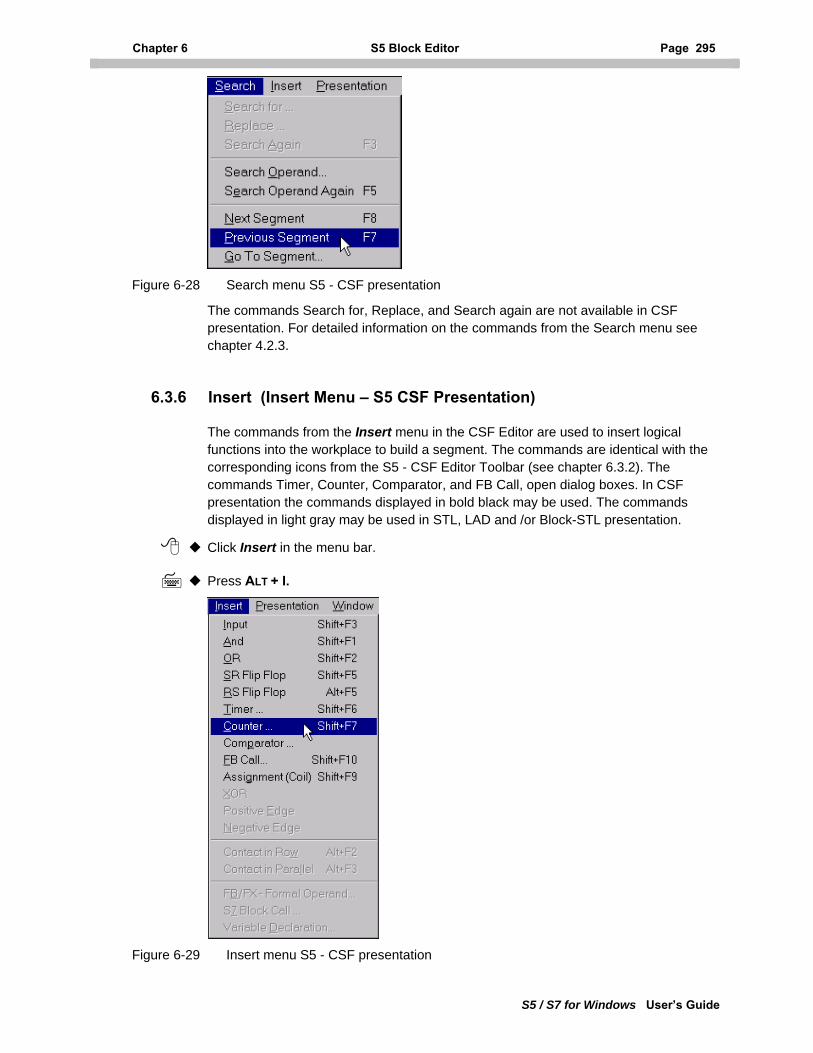
Chapter 6 S5 Block Editor Page 295
S5 / S7 for Windows User’s Guide
Figure 6-28 Search menu S5 - CSF presentation
The commands Search for, Replace, and Search again are not available in CSF presentation. For detailed information on the commands from the Search menu see chapter 4.2.3.
6.3.6 Insert (Insert Menu – S5 CSF Presentation)
The commands from the Insert menu in the CSF Editor are used to insert logical functions into the workplace to build a segment. The commands are identical with the corresponding icons from the S5 - CSF Editor Toolbar (see chapter 6.3.2). The commands Timer, Counter, Comparator, and FB Call, open dialog boxes. In CSF presentation the commands displayed in bold black may be used. The commands displayed in light gray may be used in STL, LAD and /or Block-STL presentation.
Click Insert in the menu bar.
Press ALT + I.
Figure 6-29 Insert menu S5 - CSF presentation
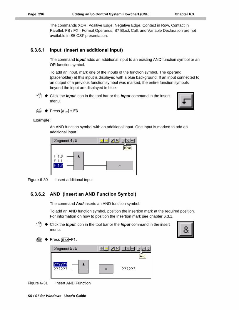
Page 296 Editing an S5 Control System Flowchart (CSF) Chapter 6.3
S5 / S7 for Windows User’s Guide
The commands XOR, Positive Edge, Negative Edge, Contact in Row, Contact in Parallel, FB / FX - Formal Operands, S7 Block Call, and Variable Declaration are not available in S5 CSF presentation.
6.3.6.1 Input (Insert an additional Input)
The command Input adds an additional input to an existing AND function symbol or an OR function symbol.
To add an input, mark one of the inputs of the function symbol. The operand (placeholder) at this input is displayed with a blue background. If an input connected to an output of a previous function symbol was marked, the entire function symbols beyond the input are displayed in blue.
Click the Input icon in the tool bar or the Input command in the insert menu.
Press + F3
Example: An AND function symbol with an additional input. One input is marked to add an additional input.
Figure 6-30 Insert additional input
6.3.6.2 AND (Insert an AND Function Symbol)
The command And inserts an AND function symbol.
To add an AND function symbol, position the insertion mark at the required position. For information on how to position the insertion mark see chapter 6.3.1.
Click the Input icon in the tool bar or the Input command in the insert menu.
Press +F1.
Figure 6-31 Insert AND Function
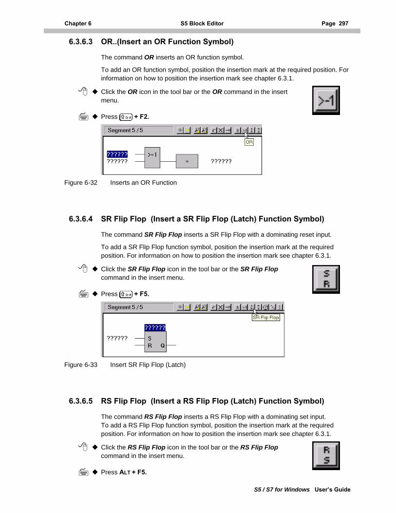
Chapter 6 S5 Block Editor Page 297
S5 / S7 for Windows User’s Guide
6.3.6.3 OR..(Insert an OR Function Symbol)
The command OR inserts an OR function symbol.
To add an OR function symbol, position the insertion mark at the required position. For information on how to position the insertion mark see chapter 6.3.1.
Click the OR icon in the tool bar or the OR command in the insert menu.
Press + F2.
Figure 6-32 Inserts an OR Function
6.3.6.4 SR Flip Flop (Insert a SR Flip Flop (Latch) Function Symbol)
The command SR Flip Flop inserts a SR Flip Flop with a dominating reset input.
To add a SR Flip Flop function symbol, position the insertion mark at the required position. For information on how to position the insertion mark see chapter 6.3.1.
Click the SR Flip Flop icon in the tool bar or the SR Flip Flop command in the insert menu.
Press + F5.
Figure 6-33 Insert SR Flip Flop (Latch)
6.3.6.5 RS Flip Flop (Insert a RS Flip Flop (Latch) Function Symbol)
The command RS Flip Flop inserts a RS Flip Flop with a dominating set input. To add a RS Flip Flop function symbol, position the insertion mark at the required position. For information on how to position the insertion mark see chapter 6.3.1.
Click the RS Flip Flop icon in the tool bar or the RS Flip Flop command in the insert menu.
Press ALT + F5.
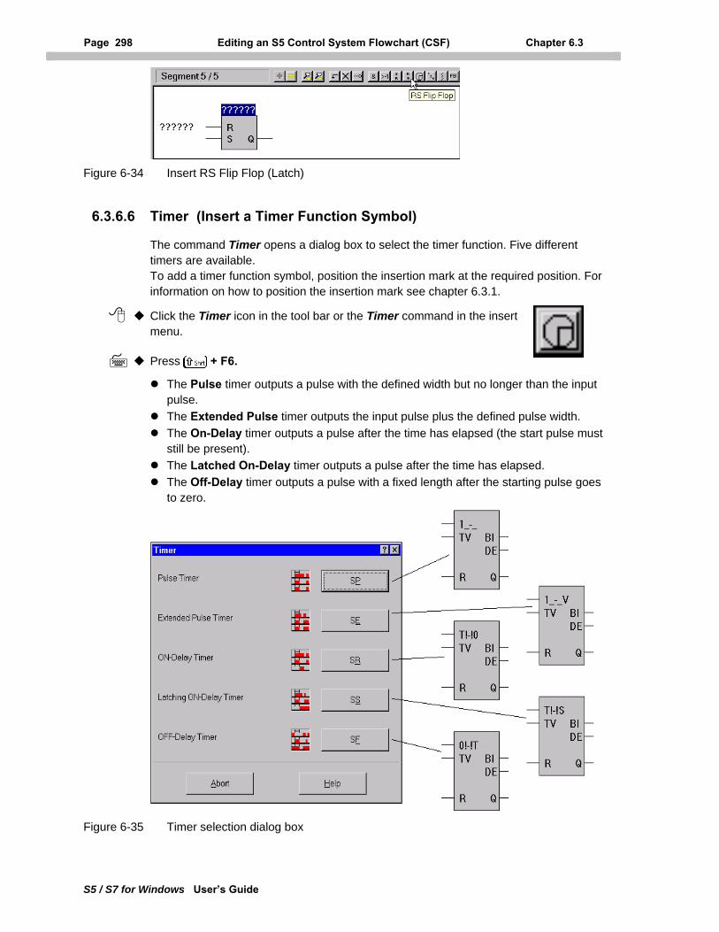
Page 298 Editing an S5 Control System Flowchart (CSF) Chapter 6.3
S5 / S7 for Windows User’s Guide
Figure 6-34 Insert RS Flip Flop (Latch)
6.3.6.6 Timer (Insert a Timer Function Symbol)
The command Timer opens a dialog box to select the timer function. Five different timers are available. To add a timer function symbol, position the insertion mark at the required position. For information on how to position the insertion mark see chapter 6.3.1.
Click the Timer icon in the tool bar or the Timer command in the insert menu.
Press + F6.
The Pulse timer outputs a pulse with the defined width but no longer than the input pulse.
The Extended Pulse timer outputs the input pulse plus the defined pulse width. The On-Delay timer outputs a pulse after the time has elapsed (the start pulse must
still be present). The Latched On-Delay timer outputs a pulse after the time has elapsed. The Off-Delay timer outputs a pulse with a fixed length after the starting pulse goes
to zero.
Figure 6-35 Timer selection dialog box
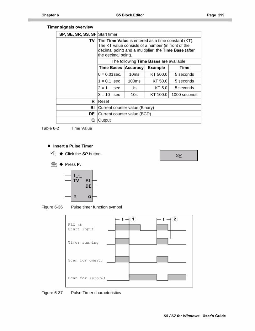
Chapter 6 S5 Block Editor Page 299
S5 / S7 for Windows User’s Guide
Timer signals overview
SP, SE, SR, SS, SF Start timer TV The Time Value is entered as a time constant (KT).
The KT value consists of a number (in front of the decimal point) and a multiplier, the Time Base (after the decimal point).
The following Time Bases are available: Time Bases Accuracy Example Time 0 = 0.01 sec. 10ms KT 500.0 5 seconds 1 = 0.1 sec 100ms KT 50.0 5 seconds 2 = 1 sec 1s KT 5.0 5 seconds
3 = 10 sec 10s KT 100.0 1000 seconds R Reset BI Current counter value (Binary)
DE Current counter value (BCD) Q Output
Table 6-2 Time Value
Insert a Pulse Timer
Click the SP button.
Press P.
Figure 6-36 Pulse timer function symbol
RLO atStart input
Timer running
Scan for one(1)
Scan for zero(0)
1 2t t
Figure 6-37 Pulse Timer characteristics
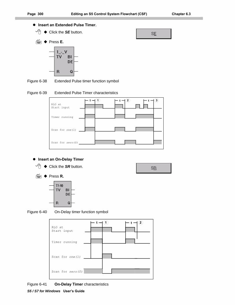
Page 300 Editing an S5 Control System Flowchart (CSF) Chapter 6.3
S5 / S7 for Windows User’s Guide
Insert an Extended Pulse Timer.
Click the SE button.
Press E.
Figure 6-38 Extended Pulse timer function symbol
Figure 6-39 Extended Pulse Timer characteristics
RLO atStart input
Timer running
Scan for one(1)
Scan for zero(0)
t 1 2t t 3
Insert an On-Delay Timer
Click the SR button.
Press R.
Figure 6-40 On-Delay timer function symbol
RLO atStart input
Timer running
Scan for one(1)
Scan for zero(0)
t 1 2t
Figure 6-41 On-Delay Timer characteristics
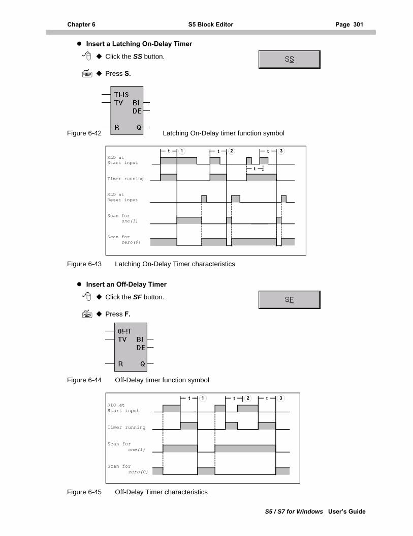
Chapter 6 S5 Block Editor Page 301
S5 / S7 for Windows User’s Guide
Insert a Latching On-Delay Timer
Click the SS button.
Press S.
Figure 6-42 Latching On-Delay timer function symbol
RLO atStart input
Timer running
RLO atReset input
Scan for one(1)
Scan for zero(0)
t 1 2t t 3
t
Figure 6-43 Latching On-Delay Timer characteristics
Insert an Off-Delay Timer
Click the SF button.
Press F.
Figure 6-44 Off-Delay timer function symbol
RLO atStart input
Timer running
Scan for one(1)
Scan for zero(0)
t 1 2t t 3
Figure 6-45 Off-Delay Timer characteristics
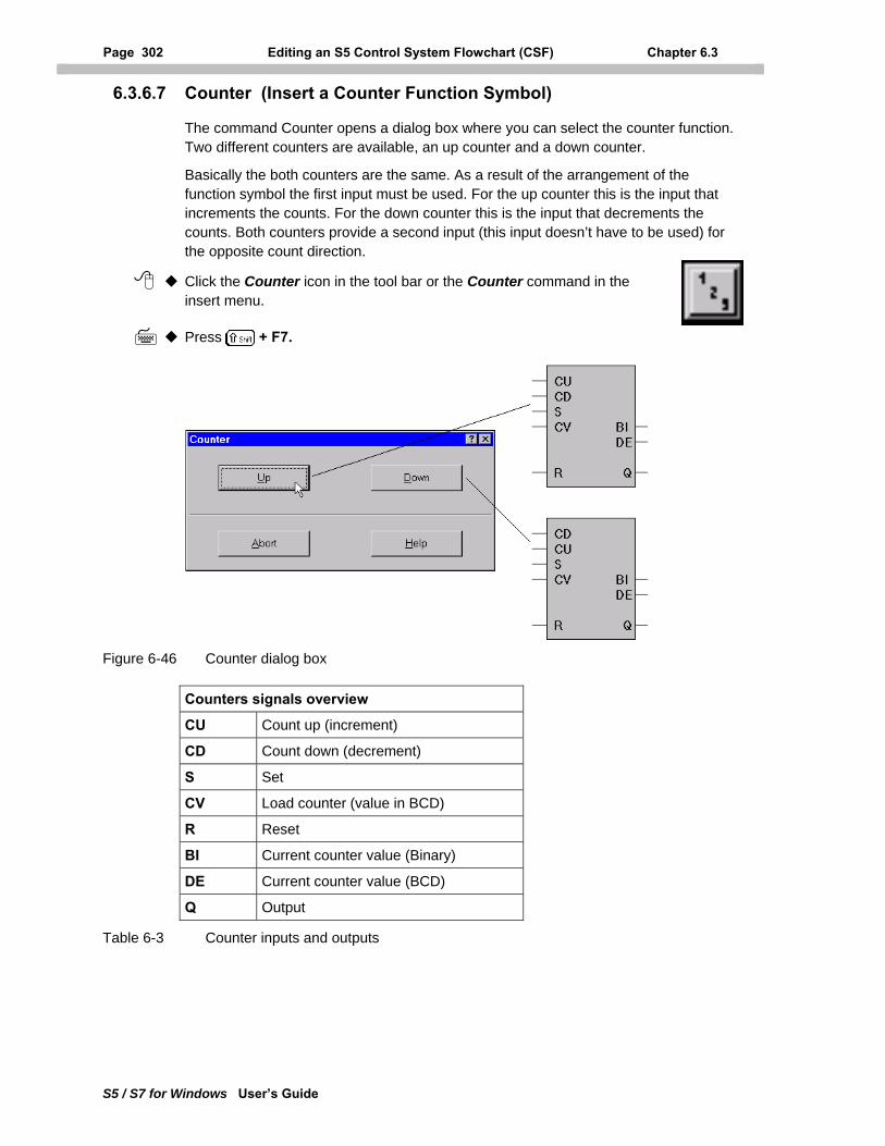
Page 302 Editing an S5 Control System Flowchart (CSF) Chapter 6.3
S5 / S7 for Windows User’s Guide
6.3.6.7 Counter (Insert a Counter Function Symbol)
The command Counter opens a dialog box where you can select the counter function. Two different counters are available, an up counter and a down counter.
Basically the both counters are the same. As a result of the arrangement of the function symbol the first input must be used. For the up counter this is the input that increments the counts. For the down counter this is the input that decrements the counts. Both counters provide a second input (this input doesn’t have to be used) for the opposite count direction.
Click the Counter icon in the tool bar or the Counter command in the insert menu.
Press + F7.
Figure 6-46 Counter dialog box
Counters signals overview
CU Count up (increment)
CD Count down (decrement)
S Set
CV Load counter (value in BCD)
R Reset
BI Current counter value (Binary)
DE Current counter value (BCD)
Q Output
Table 6-3 Counter inputs and outputs
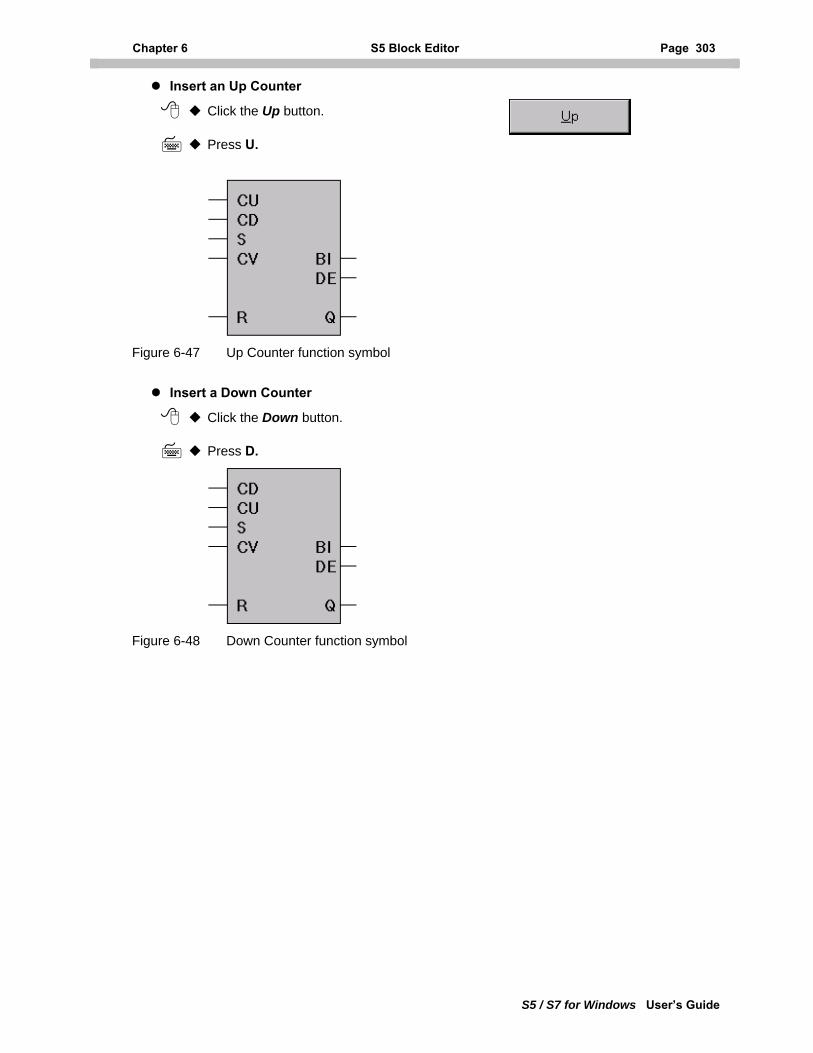
Chapter 6 S5 Block Editor Page 303
S5 / S7 for Windows User’s Guide
Insert an Up Counter
Click the Up button.
Press U.
Figure 6-47 Up Counter function symbol
Insert a Down Counter
Click the Down button.
Press D.
Figure 6-48 Down Counter function symbol
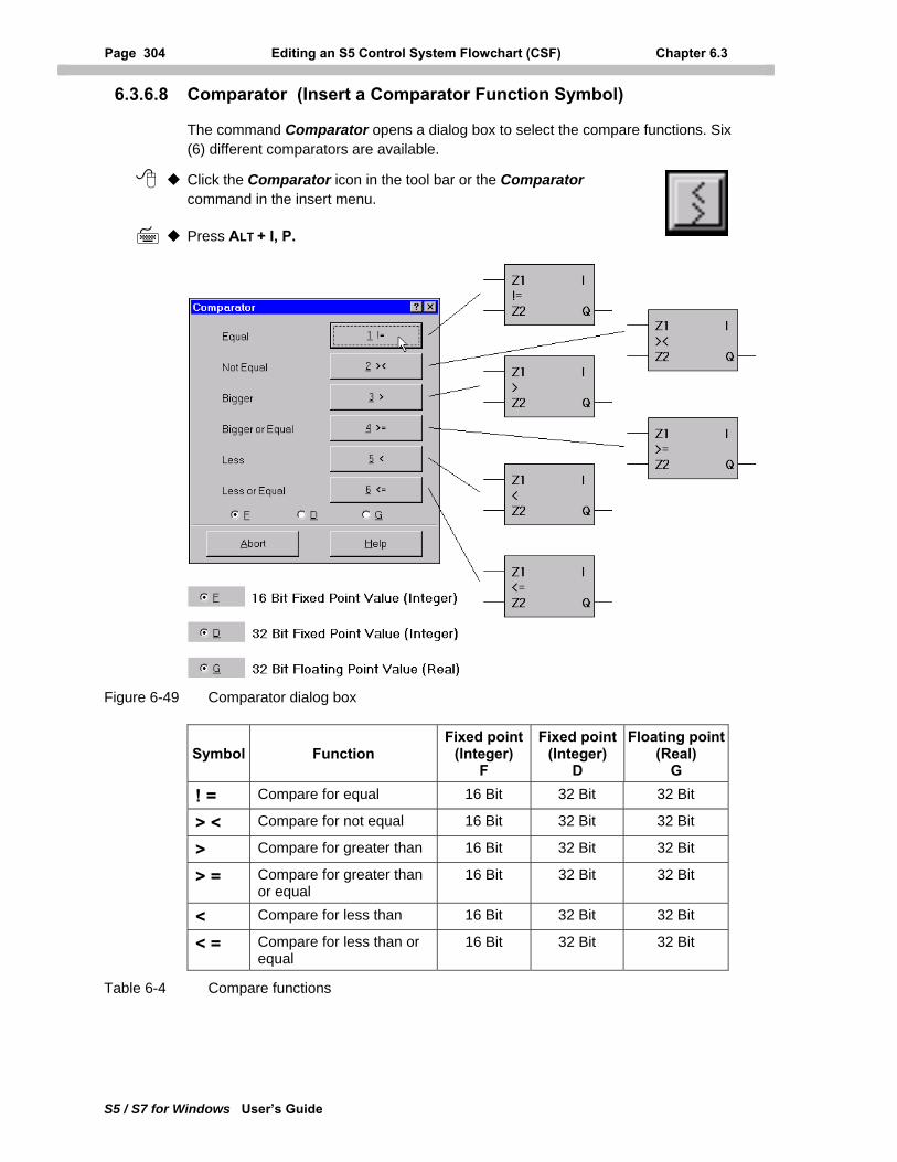
Page 304 Editing an S5 Control System Flowchart (CSF) Chapter 6.3
S5 / S7 for Windows User’s Guide
6.3.6.8 Comparator (Insert a Comparator Function Symbol)
The command Comparator opens a dialog box to select the compare functions. Six (6) different comparators are available.
Click the Comparator icon in the tool bar or the Comparator command in the insert menu.
Press ALT + I, P.
Figure 6-49 Comparator dialog box
Symbol Function Fixed point
(Integer) F
Fixed point (Integer)
D
Floating point(Real)
G
! = Compare for equal 16 Bit 32 Bit 32 Bit
> < Compare for not equal 16 Bit 32 Bit 32 Bit
> Compare for greater than 16 Bit 32 Bit 32 Bit
> = Compare for greater than or equal
16 Bit 32 Bit 32 Bit
< Compare for less than 16 Bit 32 Bit 32 Bit
< = Compare for less than or equal
16 Bit 32 Bit 32 Bit
Table 6-4 Compare functions
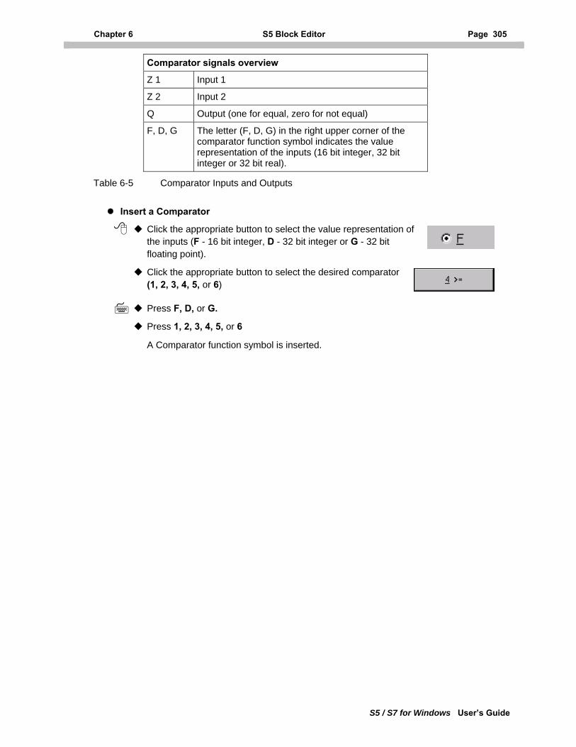
Chapter 6 S5 Block Editor Page 305
S5 / S7 for Windows User’s Guide
Comparator signals overview
Z 1 Input 1
Z 2 Input 2
Q Output (one for equal, zero for not equal)
F, D, G The letter (F, D, G) in the right upper corner of the comparator function symbol indicates the value representation of the inputs (16 bit integer, 32 bit integer or 32 bit real).
Table 6-5 Comparator Inputs and Outputs
Insert a Comparator
Click the appropriate button to select the value representation of the inputs (F - 16 bit integer, D - 32 bit integer or G - 32 bit floating point).
Click the appropriate button to select the desired comparator (1, 2, 3, 4, 5, or 6)
Press F, D, or G.
Press 1, 2, 3, 4, 5, or 6
A Comparator function symbol is inserted.
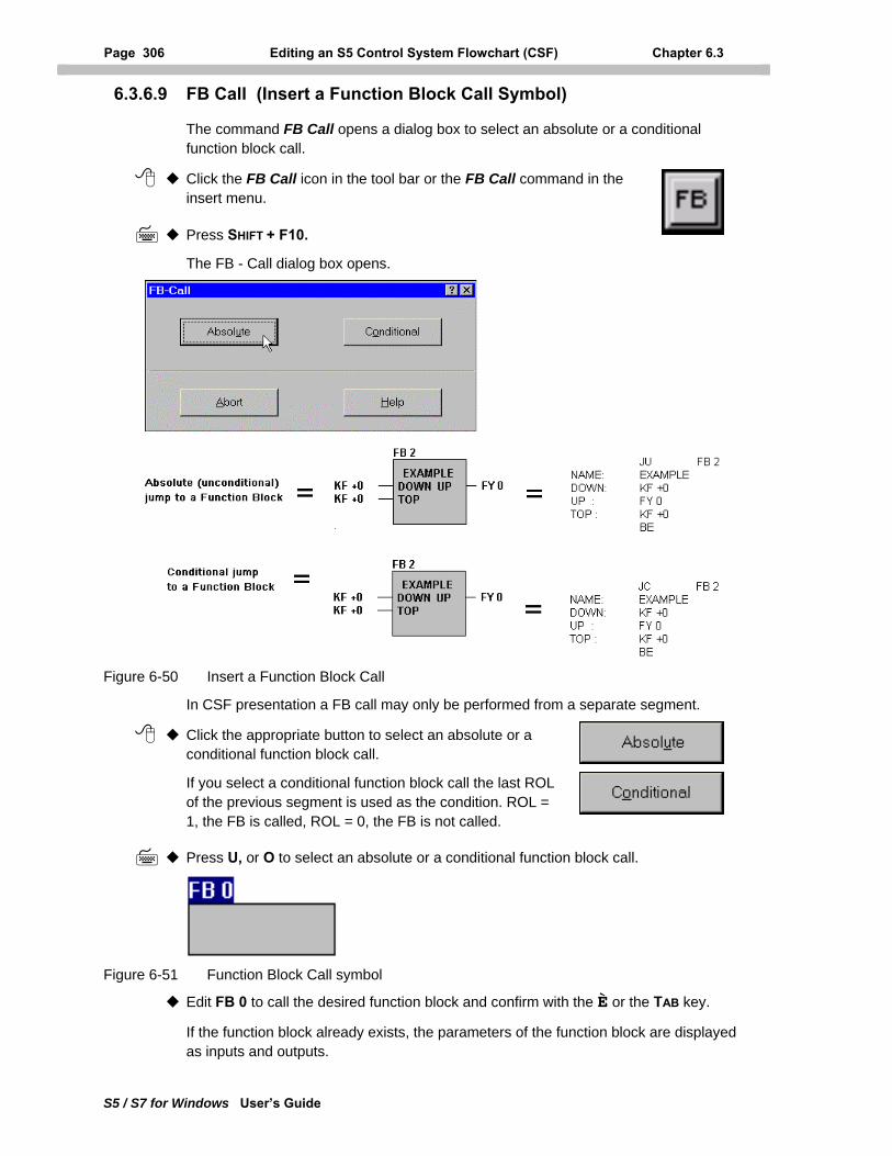
Page 306 Editing an S5 Control System Flowchart (CSF) Chapter 6.3
S5 / S7 for Windows User’s Guide
6.3.6.9 FB Call (Insert a Function Block Call Symbol)
The command FB Call opens a dialog box to select an absolute or a conditional function block call.
Click the FB Call icon in the tool bar or the FB Call command in the insert menu.
Press SHIFT + F10.
The FB - Call dialog box opens.
Figure 6-50 Insert a Function Block Call
In CSF presentation a FB call may only be performed from a separate segment.
Click the appropriate button to select an absolute or a conditional function block call.
If you select a conditional function block call the last ROL of the previous segment is used as the condition. ROL = 1, the FB is called, ROL = 0, the FB is not called.
Press U, or O to select an absolute or a conditional function block call.
Figure 6-51 Function Block Call symbol
Edit FB 0 to call the desired function block and confirm with the È or the TAB key.
If the function block already exists, the parameters of the function block are displayed as inputs and outputs.
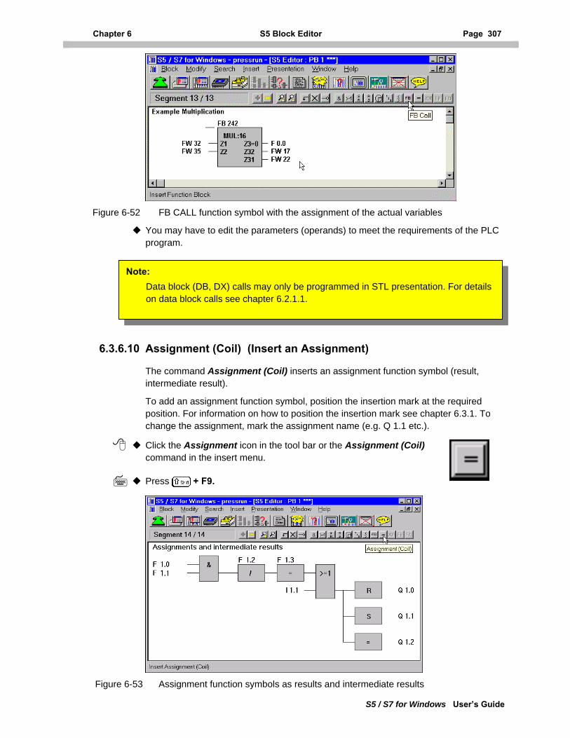
Chapter 6 S5 Block Editor Page 307
S5 / S7 for Windows User’s Guide
Figure 6-52 FB CALL function symbol with the assignment of the actual variables
You may have to edit the parameters (operands) to meet the requirements of the PLC program.
Note: Data block (DB, DX) calls may only be programmed in STL presentation. For details on data block calls see chapter 6.2.1.1.
6.3.6.10 Assignment (Coil) (Insert an Assignment)
The command Assignment (Coil) inserts an assignment function symbol (result, intermediate result).
To add an assignment function symbol, position the insertion mark at the required position. For information on how to position the insertion mark see chapter 6.3.1. To change the assignment, mark the assignment name (e.g. Q 1.1 etc.).
Click the Assignment icon in the tool bar or the Assignment (Coil) command in the insert menu.
Press + F9.
Figure 6-53 Assignment function symbols as results and intermediate results
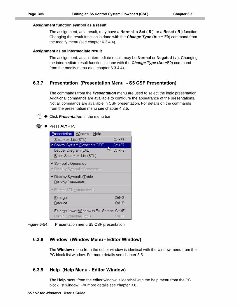
Page 308 Editing an S5 Control System Flowchart (CSF) Chapter 6.3
S5 / S7 for Windows User’s Guide
Assignment function symbol as a result The assignment, as a result, may have a Normal, a Set ( S ), or a Reset ( R ) function. Changing the result function is done with the Change Type (ALT + F9) command from the modify menu (see chapter 6.3.4.4).
Assignment as an intermediate result The assignment, as an intermediate result, may be Normal or Negated ( / ). Changing the intermediate result function is done with the Change Type (ALT+F9) command from the modify menu (see chapter 6.3.4.4).
6.3.7 Presentation (Presentation Menu - S5 CSF Presentation)
The commands from the Presentation menu are used to select the logic presentation. Additional commands are available to configure the appearance of the presentations. Not all commands are available in CSF presentation. For details on the commands from the presentation menu see chapter 4.2.5.
Click Presentation in the menu bar.
Press ALT + P.
Figure 6-54 Presentation menu S5 CSF presentation
6.3.8 Window (Window Menu - Editor Window)
The Window menu from the editor window is identical with the window menu from the PC block list window. For more details see chapter 3.5.
6.3.9 Help (Help Menu - Editor Window)
The Help menu from the editor window is identical with the help menu from the PC block list window. For more details see chapter 3.6.
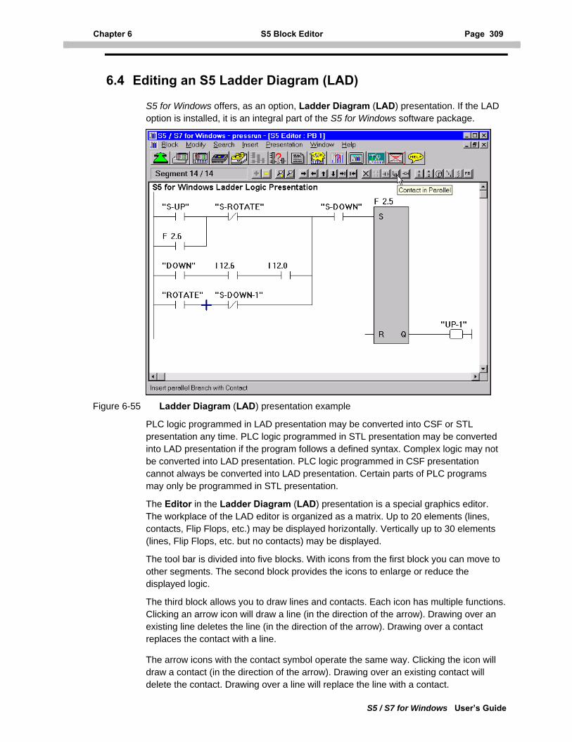
Chapter 6 S5 Block Editor Page 309
S5 / S7 for Windows User’s Guide
6.4 Editing an S5 Ladder Diagram (LAD)
S5 for Windows offers, as an option, Ladder Diagram (LAD) presentation. If the LAD option is installed, it is an integral part of the S5 for Windows software package.
Figure 6-55 Ladder Diagram (LAD) presentation example
PLC logic programmed in LAD presentation may be converted into CSF or STL presentation any time. PLC logic programmed in STL presentation may be converted into LAD presentation if the program follows a defined syntax. Complex logic may not be converted into LAD presentation. PLC logic programmed in CSF presentation cannot always be converted into LAD presentation. Certain parts of PLC programs may only be programmed in STL presentation.
The Editor in the Ladder Diagram (LAD) presentation is a special graphics editor. The workplace of the LAD editor is organized as a matrix. Up to 20 elements (lines, contacts, Flip Flops, etc.) may be displayed horizontally. Vertically up to 30 elements (lines, Flip Flops, etc. but no contacts) may be displayed.
The tool bar is divided into five blocks. With icons from the first block you can move to other segments. The second block provides the icons to enlarge or reduce the displayed logic.
The third block allows you to draw lines and contacts. Each icon has multiple functions. Clicking an arrow icon will draw a line (in the direction of the arrow). Drawing over an existing line deletes the line (in the direction of the arrow). Drawing over a contact replaces the contact with a line.
The arrow icons with the contact symbol operate the same way. Clicking the icon will draw a contact (in the direction of the arrow). Drawing over an existing contact will delete the contact. Drawing over a line will replace the line with a contact.
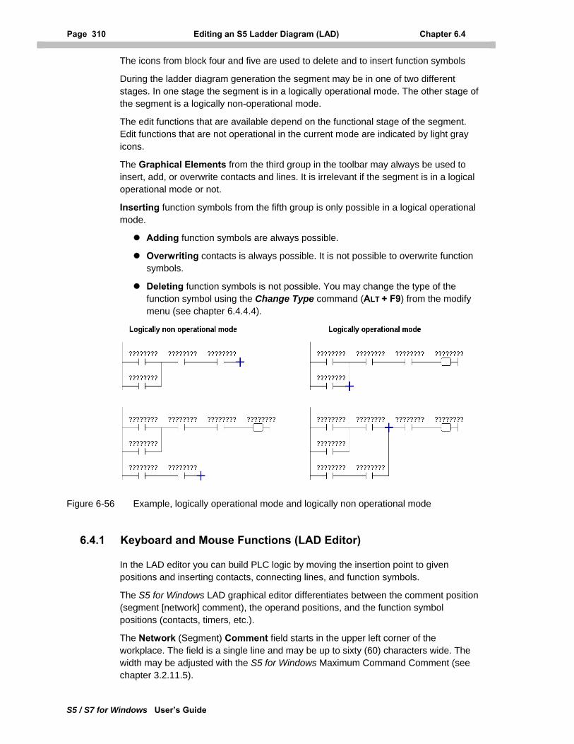
Page 310 Editing an S5 Ladder Diagram (LAD) Chapter 6.4
S5 / S7 for Windows User’s Guide
The icons from block four and five are used to delete and to insert function symbols
During the ladder diagram generation the segment may be in one of two different stages. In one stage the segment is in a logically operational mode. The other stage of the segment is a logically non-operational mode.
The edit functions that are available depend on the functional stage of the segment. Edit functions that are not operational in the current mode are indicated by light gray icons.
The Graphical Elements from the third group in the toolbar may always be used to insert, add, or overwrite contacts and lines. It is irrelevant if the segment is in a logical operational mode or not.
Inserting function symbols from the fifth group is only possible in a logical operational mode.
Adding function symbols are always possible.
Overwriting contacts is always possible. It is not possible to overwrite function symbols.
Deleting function symbols is not possible. You may change the type of the function symbol using the Change Type command (ALT + F9) from the modify menu (see chapter 6.4.4.4).
Figure 6-56 Example, logically operational mode and logically non operational mode
6.4.1 Keyboard and Mouse Functions (LAD Editor)
In the LAD editor you can build PLC logic by moving the insertion point to given positions and inserting contacts, connecting lines, and function symbols.
The S5 for Windows LAD graphical editor differentiates between the comment position (segment [network] comment), the operand positions, and the function symbol positions (contacts, timers, etc.).
The Network (Segment) Comment field starts in the upper left corner of the workplace. The field is a single line and may be up to sixty (60) characters wide. The width may be adjusted with the S5 for Windows Maximum Command Comment (see chapter 3.2.11.5).
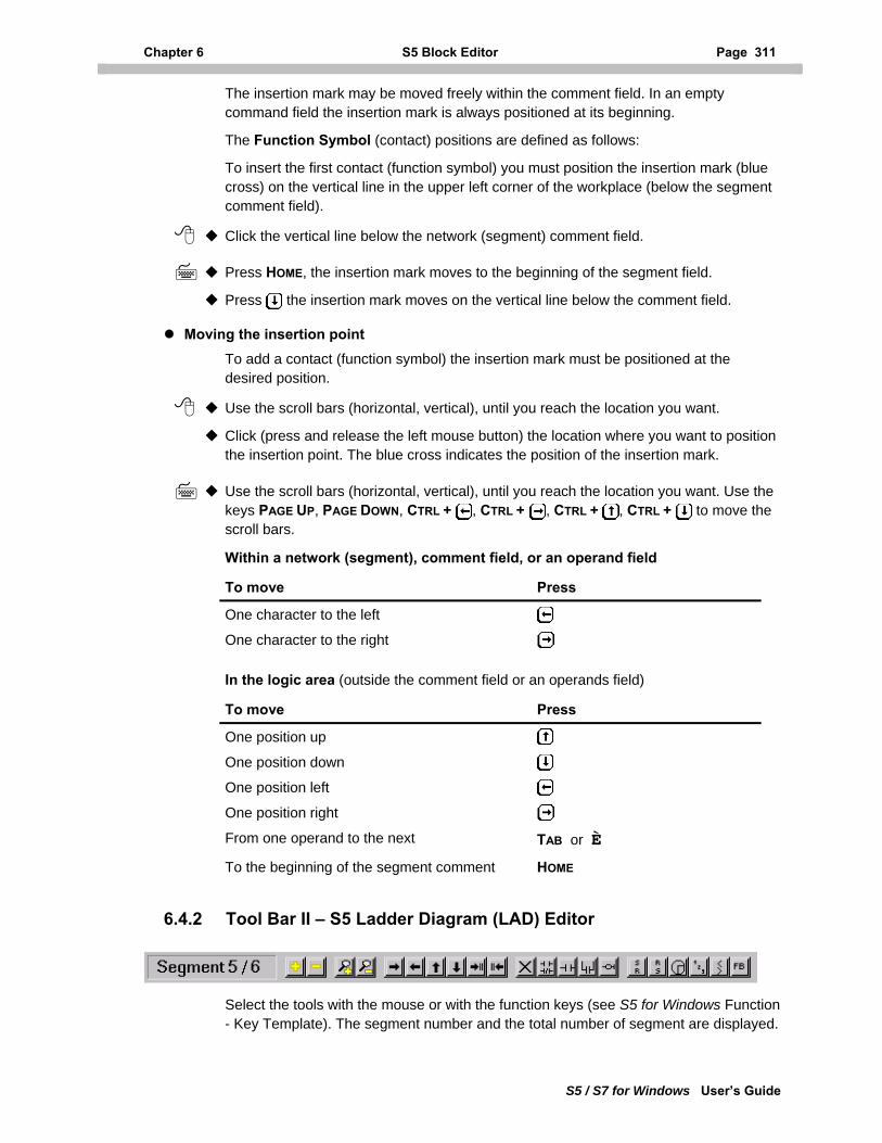
Chapter 6 S5 Block Editor Page 311
S5 / S7 for Windows User’s Guide
The insertion mark may be moved freely within the comment field. In an empty command field the insertion mark is always positioned at its beginning.
The Function Symbol (contact) positions are defined as follows:
To insert the first contact (function symbol) you must position the insertion mark (blue cross) on the vertical line in the upper left corner of the workplace (below the segment comment field).
Click the vertical line below the network (segment) comment field.
Press HOME, the insertion mark moves to the beginning of the segment field.
Press the insertion mark moves on the vertical line below the comment field.
Moving the insertion point To add a contact (function symbol) the insertion mark must be positioned at the desired position.
Use the scroll bars (horizontal, vertical), until you reach the location you want.
Click (press and release the left mouse button) the location where you want to position the insertion point. The blue cross indicates the position of the insertion mark.
Use the scroll bars (horizontal, vertical), until you reach the location you want. Use the keys PAGE UP, PAGE DOWN, CTRL + , CTRL + , CTRL + , CTRL + to move the scroll bars.
Within a network (segment), comment field, or an operand field
To move Press
One character to the left
One character to the right In the logic area (outside the comment field or an operands field)
To move Press
One position up
One position down
One position left
One position right From one operand to the next TAB or È To the beginning of the segment comment HOME
6.4.2 Tool Bar II – S5 Ladder Diagram (LAD) Editor
Select the tools with the mouse or with the function keys (see S5 for Windows Function - Key Template). The segment number and the total number of segment are displayed.
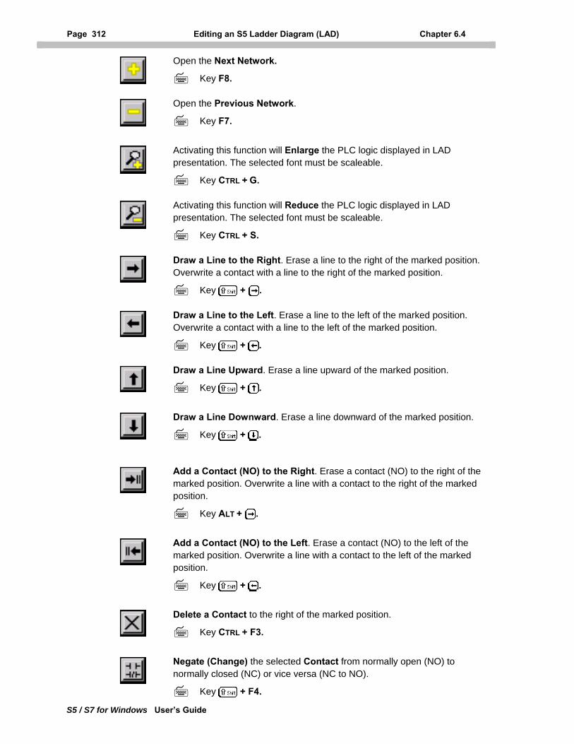
Page 312 Editing an S5 Ladder Diagram (LAD) Chapter 6.4
S5 / S7 for Windows User’s Guide
Open the Next Network.
Key F8.
Open the Previous Network.
Key F7.
Activating this function will Enlarge the PLC logic displayed in LAD presentation. The selected font must be scaleable.
Key CTRL + G.
Activating this function will Reduce the PLC logic displayed in LAD presentation. The selected font must be scaleable.
Key CTRL + S.
Draw a Line to the Right. Erase a line to the right of the marked position. Overwrite a contact with a line to the right of the marked position.
Key + .
Draw a Line to the Left. Erase a line to the left of the marked position. Overwrite a contact with a line to the left of the marked position.
Key + .
Draw a Line Upward. Erase a line upward of the marked position.
Key + .
Draw a Line Downward. Erase a line downward of the marked position.
Key + .
Add a Contact (NO) to the Right. Erase a contact (NO) to the right of the marked position. Overwrite a line with a contact to the right of the marked position.
Key ALT + .
Add a Contact (NO) to the Left. Erase a contact (NO) to the left of the marked position. Overwrite a line with a contact to the left of the marked position.
Key + .
Delete a Contact to the right of the marked position.
Key CTRL + F3.
Negate (Change) the selected Contact from normally open (NO) to normally closed (NC) or vice versa (NC to NO).
Key + F4.
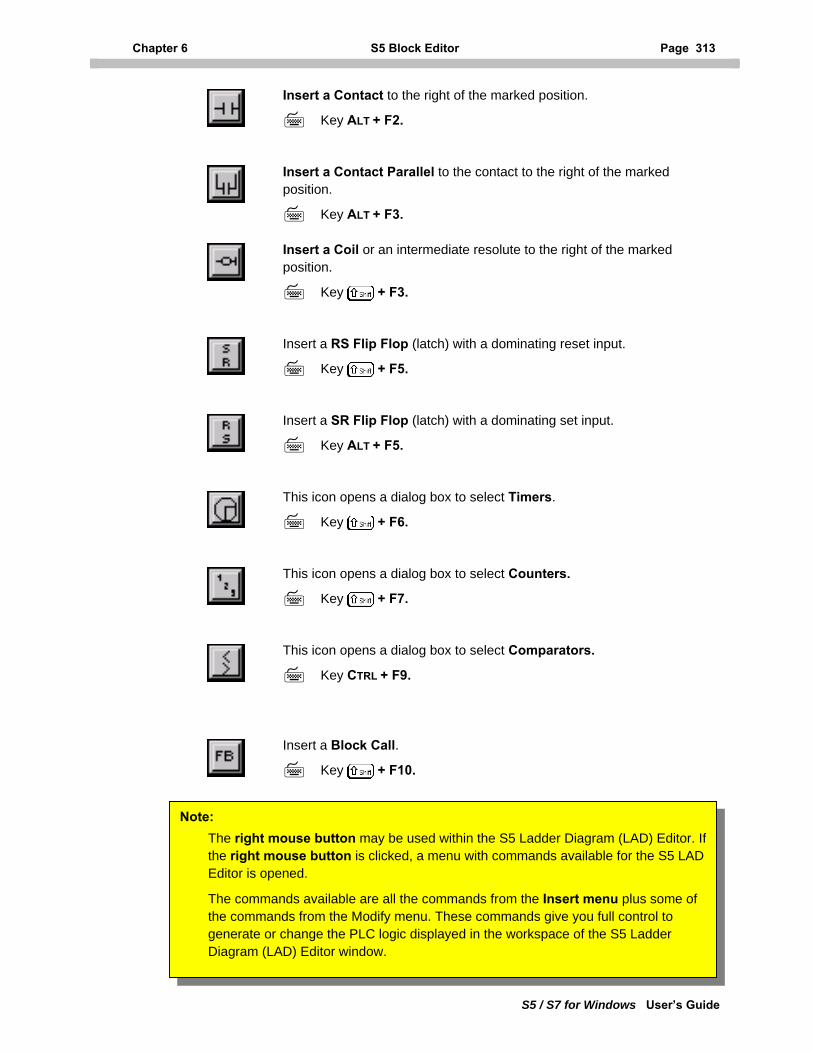
Chapter 6 S5 Block Editor Page 313
S5 / S7 for Windows User’s Guide
Insert a Contact to the right of the marked position.
Key ALT + F2.
Insert a Contact Parallel to the contact to the right of the marked position.
Key ALT + F3.
Insert a Coil or an intermediate resolute to the right of the marked position.
Key + F3.
Insert a RS Flip Flop (latch) with a dominating reset input.
Key + F5.
Insert a SR Flip Flop (latch) with a dominating set input.
Key ALT + F5.
This icon opens a dialog box to select Timers.
Key + F6.
This icon opens a dialog box to select Counters.
Key + F7.
This icon opens a dialog box to select Comparators.
Key CTRL + F9.
Insert a Block Call.
Key + F10.
Note: The right mouse button may be used within the S5 Ladder Diagram (LAD) Editor. Ifthe right mouse button is clicked, a menu with commands available for the S5 LAD Editor is opened.
The commands available are all the commands from the Insert menu plus some of the commands from the Modify menu. These commands give you full control to generate or change the PLC logic displayed in the workspace of the S5 Ladder Diagram (LAD) Editor window.
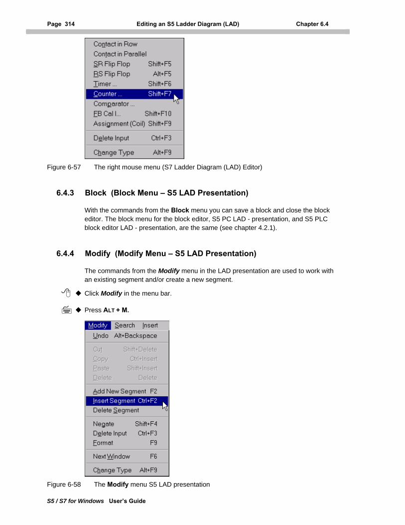
Page 314 Editing an S5 Ladder Diagram (LAD) Chapter 6.4
S5 / S7 for Windows User’s Guide
Figure 6-57 The right mouse menu (S7 Ladder Diagram (LAD) Editor)
6.4.3 Block (Block Menu – S5 LAD Presentation)
With the commands from the Block menu you can save a block and close the block editor. The block menu for the block editor, S5 PC LAD - presentation, and S5 PLC block editor LAD - presentation, are the same (see chapter 4.2.1).
6.4.4 Modify (Modify Menu – S5 LAD Presentation)
The commands from the Modify menu in the LAD presentation are used to work with an existing segment and/or create a new segment.
Click Modify in the menu bar.
Press ALT + M.
Figure 6-58 The Modify menu S5 LAD presentation
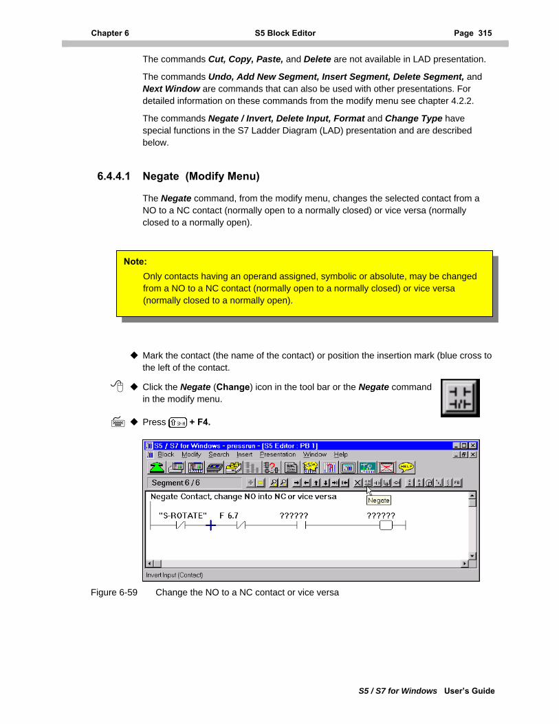
Chapter 6 S5 Block Editor Page 315
S5 / S7 for Windows User’s Guide
The commands Cut, Copy, Paste, and Delete are not available in LAD presentation.
The commands Undo, Add New Segment, Insert Segment, Delete Segment, and Next Window are commands that can also be used with other presentations. For detailed information on these commands from the modify menu see chapter 4.2.2.
The commands Negate / Invert, Delete Input, Format and Change Type have special functions in the S7 Ladder Diagram (LAD) presentation and are described below.
6.4.4.1 Negate (Modify Menu)
The Negate command, from the modify menu, changes the selected contact from a NO to a NC contact (normally open to a normally closed) or vice versa (normally closed to a normally open).
Mark the contact (the name of the contact) or position the insertion mark (blue cross to the left of the contact.
Click the Negate (Change) icon in the tool bar or the Negate command in the modify menu.
Press + F4.
Note: Only contacts having an operand assigned, symbolic or absolute, may be changed rom a NO to a NC contact (normally open to a normally closed) or vice versa normally closed to a normally open).
f(
Figure 6-59 Change the NO to a NC contact or vice versa
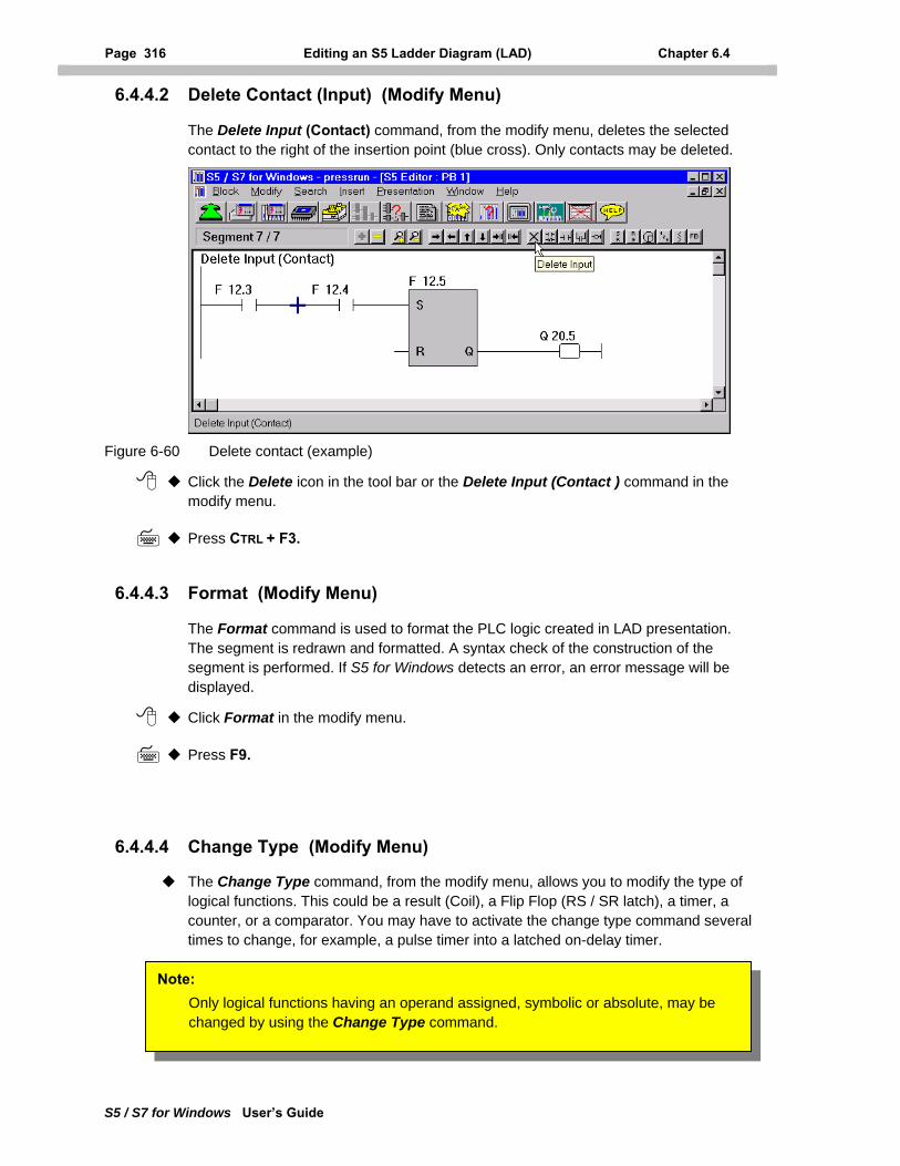
Page 316 Editing an S5 Ladder Diagram (LAD) Chapter 6.4
S5 / S7 for Windows User’s Guide
6.4.4.2 Delete Contact (Input) (Modify Menu)
The Delete Input (Contact) command, from the modify menu, deletes the selected contact to the right of the insertion point (blue cross). Only contacts may be deleted.
Figure 6-60 Delete contact (example)
Click the Delete icon in the tool bar or the Delete Input (Contact ) command in the modify menu.
Press CTRL + F3.
6.4.4.3 Format (Modify Menu)
The Format command is used to format the PLC logic created in LAD presentation. The segment is redrawn and formatted. A syntax check of the construction of the segment is performed. If S5 for Windows detects an error, an error message will be displayed.
Click Format in the modify menu.
Press F9.
6.4.4.4 Change Type (Modify Menu)
The Change Type command, from the modify menu, allows you to modify the type of logical functions. This could be a result (Coil), a Flip Flop (RS / SR latch), a timer, a counter, or a comparator. You may have to activate the change type command several times to change, for example, a pulse timer into a latched on-delay timer.
Note: Only logical functions having an operand assigned, symbolic or absolute, may be changed by using the Change Type command.
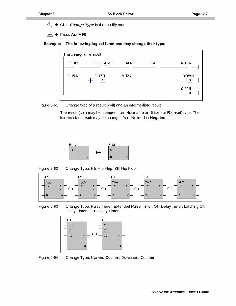
Chapter 6 S5 Block Editor Page 317
S5 / S7 for Windows User’s Guide
Click Change Type in the modify menu.
Press ALT + F9.
Example: The following logical functions may change their type:
Figure 6-61 Change type of a result (coil) and an intermediate result
The result (coil) may be changed from Normal to an S (set) or R (reset) type. The intermediate result may be changed from Normal to Negated.
Figure 6-62 Change Type, RS Flip Flop, SR Flip Flop
Figure 6-63 Change Type, Pulse Timer, Extended Pulse Timer, ON-Delay Timer, Latching ON-Delay Timer, OFF-Delay Timer
Figure 6-64 Change Type, Upward Counter, Downward Counter
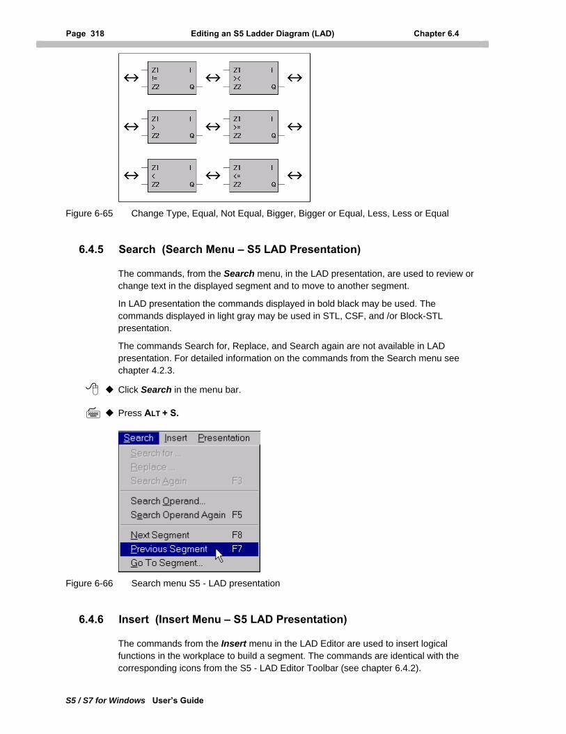
Page 318 Editing an S5 Ladder Diagram (LAD) Chapter 6.4
S5 / S7 for Windows User’s Guide
Figure 6-65 Change Type, Equal, Not Equal, Bigger, Bigger or Equal, Less, Less or Equal
6.4.5 Search (Search Menu – S5 LAD Presentation)
The commands, from the Search menu, in the LAD presentation, are used to review or change text in the displayed segment and to move to another segment.
In LAD presentation the commands displayed in bold black may be used. The commands displayed in light gray may be used in STL, CSF, and /or Block-STL presentation.
The commands Search for, Replace, and Search again are not available in LAD presentation. For detailed information on the commands from the Search menu see chapter 4.2.3.
Click Search in the menu bar.
Press ALT + S.
Figure 6-66 Search menu S5 - LAD presentation
6.4.6 Insert (Insert Menu – S5 LAD Presentation)
The commands from the Insert menu in the LAD Editor are used to insert logical functions in the workplace to build a segment. The commands are identical with the corresponding icons from the S5 - LAD Editor Toolbar (see chapter 6.4.2).
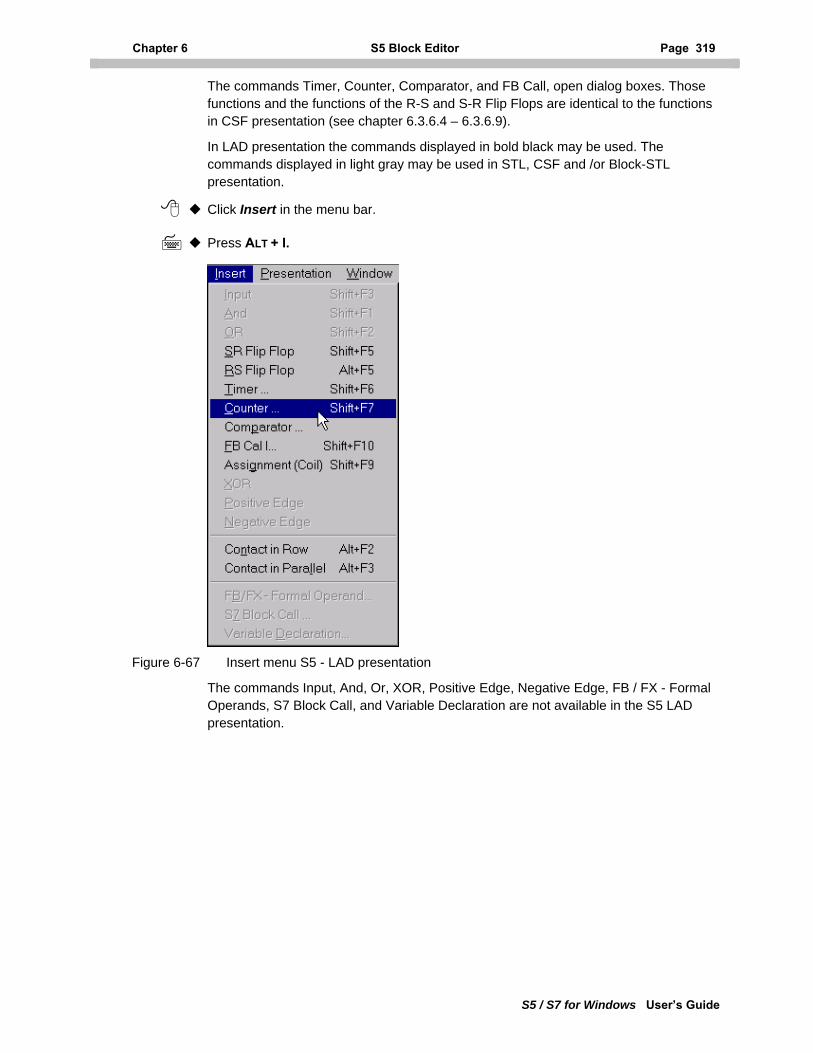
Chapter 6 S5 Block Editor Page 319
S5 / S7 for Windows User’s Guide
The commands Timer, Counter, Comparator, and FB Call, open dialog boxes. Those functions and the functions of the R-S and S-R Flip Flops are identical to the functions in CSF presentation (see chapter 6.3.6.4 – 6.3.6.9).
In LAD presentation the commands displayed in bold black may be used. The commands displayed in light gray may be used in STL, CSF and /or Block-STL presentation.
Click Insert in the menu bar.
Press ALT + I.
Figure 6-67 Insert menu S5 - LAD presentation
The commands Input, And, Or, XOR, Positive Edge, Negative Edge, FB / FX - Formal Operands, S7 Block Call, and Variable Declaration are not available in the S5 LAD presentation.
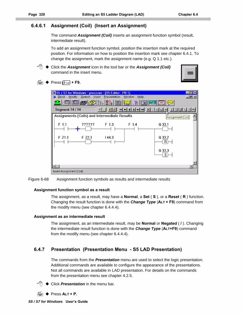
Page 320 Editing an S5 Ladder Diagram (LAD) Chapter 6.4
S5 / S7 for Windows User’s Guide
6.4.6.1 Assignment (Coil) (Insert an Assignment)
The command Assignment (Coil) inserts an assignment function symbol (result, intermediate result).
To add an assignment function symbol, position the insertion mark at the required position. For information on how to position the insertion mark see chapter 6.4.1. To change the assignment, mark the assignment name (e.g. Q 1.1 etc.).
Click the Assignment icon in the tool bar or the Assignment (Coil) command in the insert menu.
Press + F9.
Figure 6-68 Assignment function symbols as results and intermediate results
Assignment function symbol as a result The assignment, as a result, may have a Normal, a Set ( S ), or a Reset ( R ) function. Changing the result function is done with the Change Type (ALT + F9) command from the modify menu (see chapter 6.4.4.4).
Assignment as an intermediate result The assignment, as an intermediate result, may be Normal or Negated ( / ). Changing the intermediate result function is done with the Change Type (ALT+F9) command from the modify menu (see chapter 6.4.4.4).
6.4.7 Presentation (Presentation Menu - S5 LAD Presentation)
The commands from the Presentation menu are used to select the logic presentation. Additional commands are available to configure the appearance of the presentations. Not all commands are available in LAD presentation. For details on the commands from the presentation menu see chapter 4.2.5.
Click Presentation in the menu bar.
Press ALT + P.
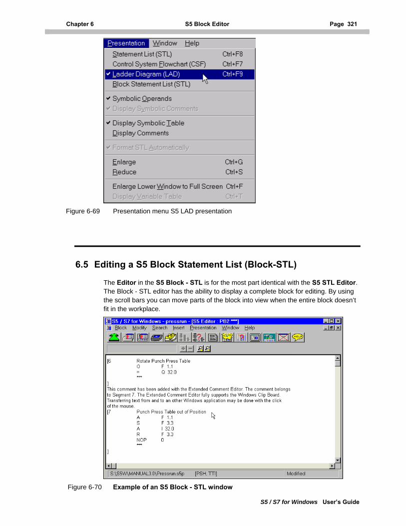
Chapter 6 S5 Block Editor Page 321
S5 / S7 for Windows User’s Guide
Figure 6-69 Presentation menu S5 LAD presentation
6.5 Editing a S5 Block Statement List (Block-STL)
The Editor in the S5 Block - STL is for the most part identical with the S5 STL Editor. The Block - STL editor has the ability to display a complete block for editing. By using the scroll bars you can move parts of the block into view when the entire block doesn’t fit in the workplace.
Figure 6-70 Example of an S5 Block - STL window
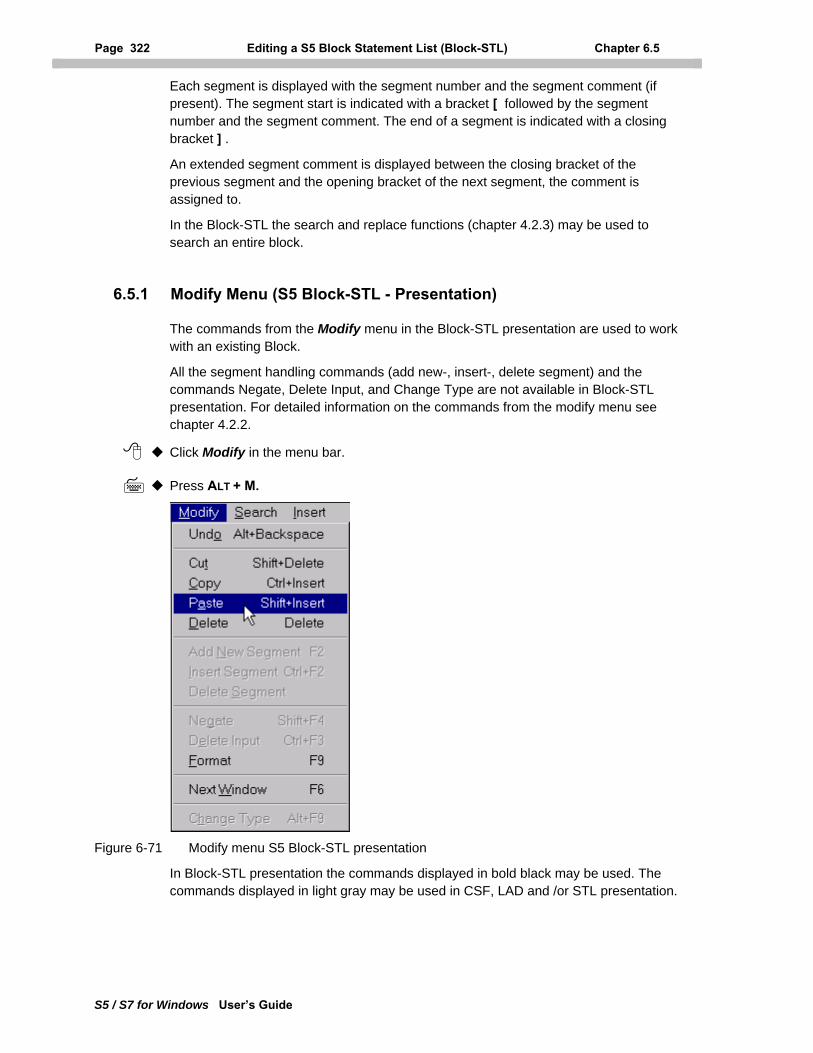
Page 322 Editing a S5 Block Statement List (Block-STL) Chapter 6.5
S5 / S7 for Windows User’s Guide
Each segment is displayed with the segment number and the segment comment (if present). The segment start is indicated with a bracket [ followed by the segment number and the segment comment. The end of a segment is indicated with a closing bracket ] .
An extended segment comment is displayed between the closing bracket of the previous segment and the opening bracket of the next segment, the comment is assigned to.
In the Block-STL the search and replace functions (chapter 4.2.3) may be used to search an entire block.
6.5.1 Modify Menu (S5 Block-STL - Presentation)
The commands from the Modify menu in the Block-STL presentation are used to work with an existing Block.
All the segment handling commands (add new-, insert-, delete segment) and the commands Negate, Delete Input, and Change Type are not available in Block-STL presentation. For detailed information on the commands from the modify menu see chapter 4.2.2.
Click Modify in the menu bar.
Press ALT + M.
Figure 6-71 Modify menu S5 Block-STL presentation
In Block-STL presentation the commands displayed in bold black may be used. The commands displayed in light gray may be used in CSF, LAD and /or STL presentation.
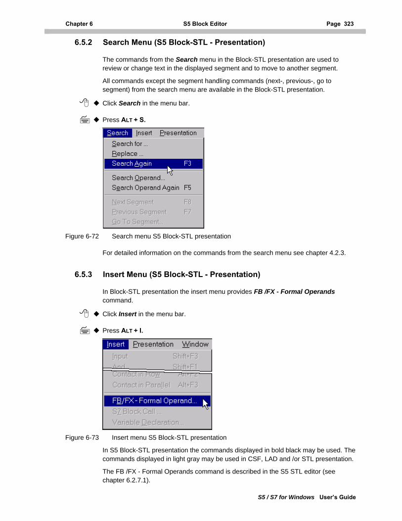
Chapter 6 S5 Block Editor Page 323
S5 / S7 for Windows User’s Guide
6.5.2 Search Menu (S5 Block-STL - Presentation)
The commands from the Search menu in the Block-STL presentation are used to review or change text in the displayed segment and to move to another segment.
All commands except the segment handling commands (next-, previous-, go to segment) from the search menu are available in the Block-STL presentation.
Click Search in the menu bar.
Press ALT + S.
Figure 6-72 Search menu S5 Block-STL presentation
For detailed information on the commands from the search menu see chapter 4.2.3.
6.5.3 Insert Menu (S5 Block-STL - Presentation)
In Block-STL presentation the insert menu provides FB /FX - Formal Operands command.
Click Insert in the menu bar.
Press ALT + I.
Figure 6-73 Insert menu S5 Block-STL presentation
In S5 Block-STL presentation the commands displayed in bold black may be used. The commands displayed in light gray may be used in CSF, LAD and /or STL presentation.
The FB /FX - Formal Operands command is described in the S5 STL editor (see chapter 6.2.7.1).
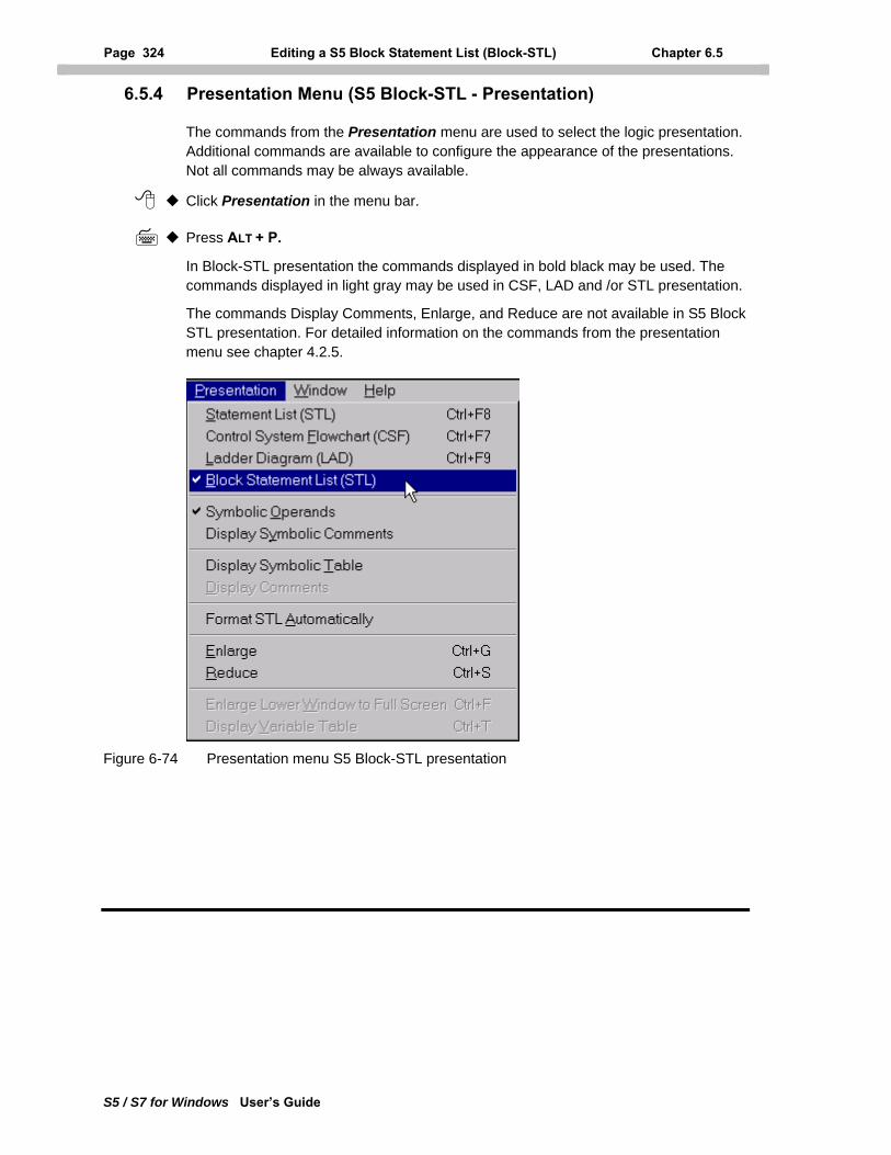
Page 324 Editing a S5 Block Statement List (Block-STL) Chapter 6.5
S5 / S7 for Windows User’s Guide
6.5.4 Presentation Menu (S5 Block-STL - Presentation)
The commands from the Presentation menu are used to select the logic presentation. Additional commands are available to configure the appearance of the presentations. Not all commands may be always available.
Click Presentation in the menu bar.
Press ALT + P.
In Block-STL presentation the commands displayed in bold black may be used. The commands displayed in light gray may be used in CSF, LAD and /or STL presentation.
The commands Display Comments, Enlarge, and Reduce are not available in S5 Block STL presentation. For detailed information on the commands from the presentation menu see chapter 4.2.5.
Figure 6-74 Presentation menu S5 Block-STL presentation
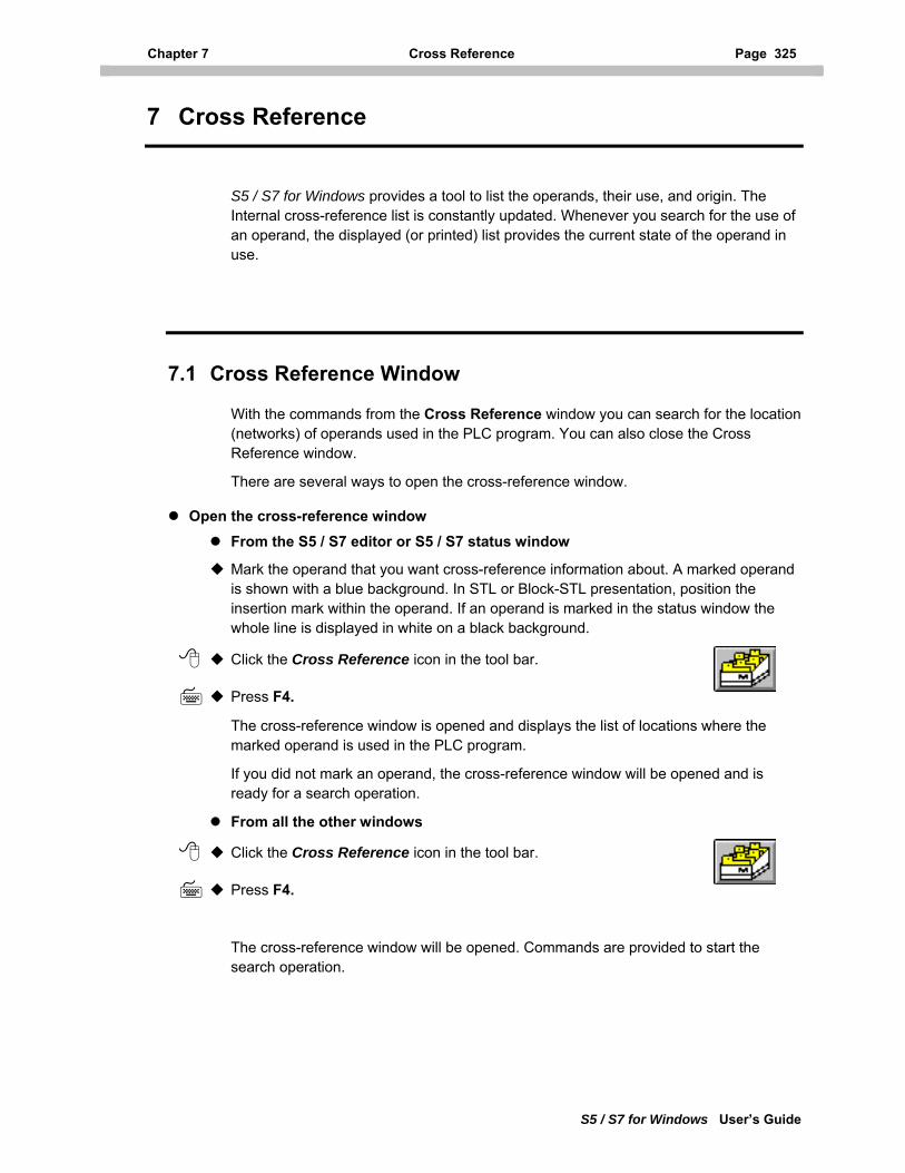
Chapter 7 Cross Reference Page 325
S5 / S7 for Windows User’s Guide
7 Cross Reference
S5 / S7 for Windows provides a tool to list the operands, their use, and origin. The Internal cross-reference list is constantly updated. Whenever you search for the use of an operand, the displayed (or printed) list provides the current state of the operand in use.
7.1 Cross Reference Window
With the commands from the Cross Reference window you can search for the location (networks) of operands used in the PLC program. You can also close the Cross Reference window.
There are several ways to open the cross-reference window.
Open the cross-reference window From the S5 / S7 editor or S5 / S7 status window
Mark the operand that you want cross-reference information about. A marked operand is shown with a blue background. In STL or Block-STL presentation, position the insertion mark within the operand. If an operand is marked in the status window the whole line is displayed in white on a black background.
Click the Cross Reference icon in the tool bar.
Press F4.
The cross-reference window is opened and displays the list of locations where the marked operand is used in the PLC program.
If you did not mark an operand, the cross-reference window will be opened and is ready for a search operation.
From all the other windows
Click the Cross Reference icon in the tool bar.
Press F4.
The cross-reference window will be opened. Commands are provided to start the search operation.
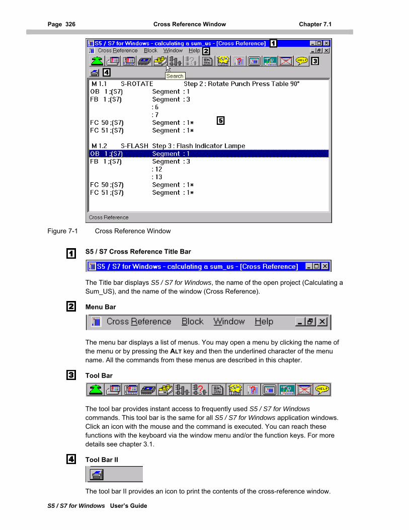
Page 326 Cross Reference Window Chapter 7.1
S5 / S7 for Windows User’s Guide
Figure 7-1 Cross Reference Window
S5 / S7 Cross Reference Title Bar
The Title bar displays S5 / S7 for Windows, the name of the open project (Calculating a Sum_US), and the name of the window (Cross Reference).
Menu Bar
The menu bar displays a list of menus. You may open a menu by clicking the name of the menu or by pressing the ALT key and then the underlined character of the menu name. All the commands from these menus are described in this chapter.
Tool Bar
The tool bar provides instant access to frequently used S5 / S7 for Windows commands. This tool bar is the same for all S5 / S7 for Windows application windows. Click an icon with the mouse and the command is executed. You can reach these functions with the keyboard via the window menu and/or the function keys. For more details see chapter 3.1.
Tool Bar II
The tool bar II provides an icon to print the contents of the cross-reference window.
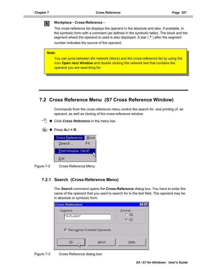
Chapter 7 Cross Reference Page 327
S5 / S7 for Windows User’s Guide
Workplace - Cross-Reference - The cross-reference list displays the operand in the absolute and also, if available, in the symbolic form with a comment (as defined in the symbolic table). The block and the segment where the operand is used is also displayed. A star ( * ) after the segment number indicates the source of the operand.
Note: You can jump between the network (block) and the cross-reference list by using the Icon Open next Window and double clicking the network line that contains the operand you are searching for.
7.2 Cross Reference Menu (S7 Cross Reference Window)
Commands from the cross-reference menu control the search for, and printing of, an operand, as well as closing of the cross-reference window.
Click Cross Reference in the menu bar.
Press ALT + R.
Figure 7-2 Cross-Reference Menu
7.2.1 Search (Cross-Reference Menu)
The Search command opens the Cross-Reference dialog box. You have to enter the name of the operand that you want to search for in the text field. The operand may be in absolute or symbolic form.
Figure 7-3 Cross Reference dialog box
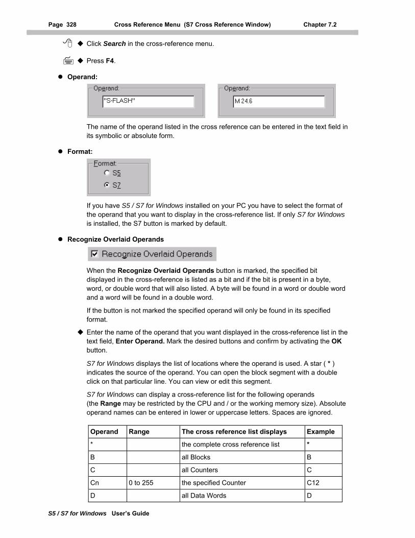
Page 328 Cross Reference Menu (S7 Cross Reference Window) Chapter 7.2
S5 / S7 for Windows User’s Guide
Click Search in the cross-reference menu.
Press F4.
Operand:
The name of the operand listed in the cross reference can be entered in the text field in its symbolic or absolute form.
Format:
If you have S5 / S7 for Windows installed on your PC you have to select the format of the operand that you want to display in the cross-reference list. If only S7 for Windows is installed, the S7 button is marked by default.
Recognize Overlaid Operands
When the Recognize Overlaid Operands button is marked, the specified bit displayed in the cross-reference is listed as a bit and if the bit is present in a byte, word, or double word that will also listed. A byte will be found in a word or double word and a word will be found in a double word.
If the button is not marked the specified operand will only be found in its specified format.
Enter the name of the operand that you want displayed in the cross-reference list in the text field, Enter Operand. Mark the desired buttons and confirm by activating the OK button.
S7 for Windows displays the list of locations where the operand is used. A star ( * ) indicates the source of the operand. You can open the block segment with a double click on that particular line. You can view or edit this segment.
S7 for Windows can display a cross-reference list for the following operands (the Range may be restricted by the CPU and / or the working memory size). Absolute operand names can be entered in lower or uppercase letters. Spaces are ignored.
Operand Range The cross reference list displays Example
* the complete cross reference list *
B all Blocks B
C all Counters C
Cn 0 to 255 the specified Counter C12
D all Data Words D
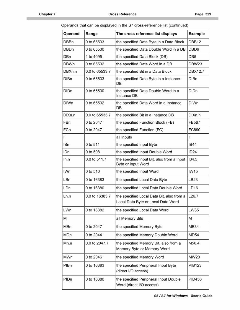
Chapter 7 Cross Reference Page 329
S5 / S7 for Windows User’s Guide
Operands that can be displayed in the S7 cross-reference list (continued)
Operand Range The cross reference list displays Example
DBBn 0 to 65533 the specified Data Byte in a Data Block DBB12
DBDn 0 to 65530 the specified Data Double Word in a DB DBD6
DBn 1 to 4095 the specified Data Block (DB) DB5
DBWn 0 to 65532 the specified Data Word in a DB DBW23
DBXn.n 0.0 to 65533.7 the specified Bit in a Data Block DBX12.7
DIBn 0 to 65533 the specified Data Byte in a Instance DB
DIBn
DIDn 0 to 65530 the specified Data Double Word in a Instance DB
DIDn
DIWn 0 to 65532 the specified Data Word in a Instance DB
DIWn
DIXn.n 0.0 to 65533.7 the specified Bit in a Instance DB DIXn.n
FBn 0 to 2047 the specified Function Block (FB) FB567
FCn 0 to 2047 the specified Function (FC) FC890
I all Inputs I
IBn 0 to 511 the specified Input Byte IB44
IDn 0 to 508 the specified Input Double Word ID24
In.n 0.0 to 511.7 the specified Input Bit, also from a Input Byte or Input Word
I34.5
IWn 0 to 510 the specified Input Word IW15
LBn 0 to 16383 the specified Local Data Byte LB23
LDn 0 to 16380 the specified Local Data Double Word LD16
Ln.n 0.0 to 16383.7 the specified Local Data Bit, also from a Local Data Byte or Local Data Word
L26.7
LWn 0 to 16382 the specified Local Data Word LW35
M all Memory Bits M
MBn 0 to 2047 the specified Memory Byte MB34
MDn 0 to 2044 the specified Memory Double Word MD54
Mn.n 0.0 to 2047.7 the specified Memory Bit, also from a Memory Byte or Memory Word
M56.4
MWn 0 to 2046 the specified Memory Word MW23
PIBn 0 to 16383 the specified Peripheral Input Byte (direct I/O access)
PIB123
PIDn 0 to 16380 the specified Peripheral Input Double Word (direct I/O access)
PID456
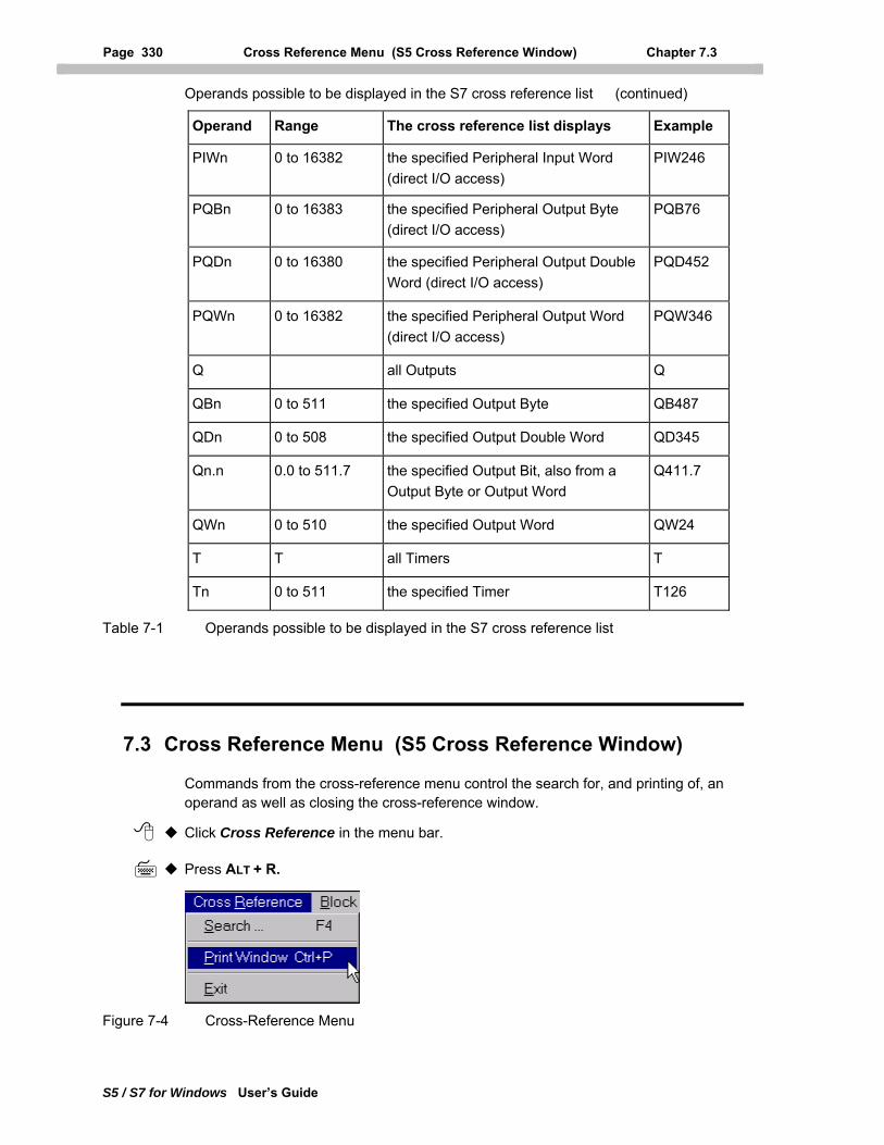
Page 330 Cross Reference Menu (S5 Cross Reference Window) Chapter 7.3
S5 / S7 for Windows User’s Guide
Operands possible to be displayed in the S7 cross reference list (continued)
Operand Range The cross reference list displays Example
PIWn 0 to 16382 the specified Peripheral Input Word (direct I/O access)
PIW246
PQBn 0 to 16383 the specified Peripheral Output Byte (direct I/O access)
PQB76
PQDn 0 to 16380 the specified Peripheral Output Double Word (direct I/O access)
PQD452
PQWn 0 to 16382 the specified Peripheral Output Word (direct I/O access)
PQW346
Q all Outputs Q
QBn 0 to 511 the specified Output Byte QB487
QDn 0 to 508 the specified Output Double Word QD345
Qn.n 0.0 to 511.7 the specified Output Bit, also from a Output Byte or Output Word
Q411.7
QWn 0 to 510 the specified Output Word QW24
T T all Timers T
Tn 0 to 511 the specified Timer T126
Table 7-1 Operands possible to be displayed in the S7 cross reference list
7.3 Cross Reference Menu (S5 Cross Reference Window)
Commands from the cross-reference menu control the search for, and printing of, an operand as well as closing the cross-reference window.
Click Cross Reference in the menu bar.
Press ALT + R.
Figure 7-4 Cross-Reference Menu
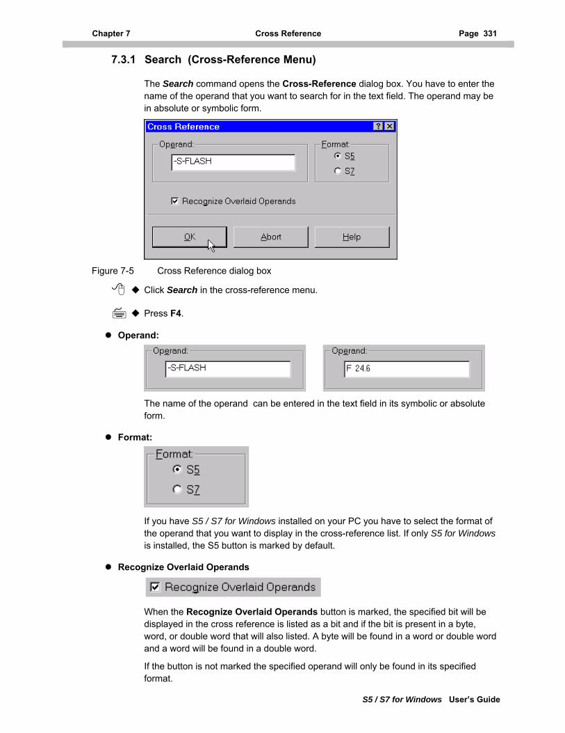
Chapter 7 Cross Reference Page 331
S5 / S7 for Windows User’s Guide
7.3.1 Search (Cross-Reference Menu)
The Search command opens the Cross-Reference dialog box. You have to enter the name of the operand that you want to search for in the text field. The operand may be in absolute or symbolic form.
Figure 7-5 Cross Reference dialog box
Click Search in the cross-reference menu.
Press F4.
Operand:
The name of the operand can be entered in the text field in its symbolic or absolute form.
Format:
If you have S5 / S7 for Windows installed on your PC you have to select the format of the operand that you want to display in the cross-reference list. If only S5 for Windows is installed, the S5 button is marked by default.
Recognize Overlaid Operands
When the Recognize Overlaid Operands button is marked, the specified bit will be displayed in the cross reference is listed as a bit and if the bit is present in a byte, word, or double word that will also listed. A byte will be found in a word or double word and a word will be found in a double word.
If the button is not marked the specified operand will only be found in its specified format.
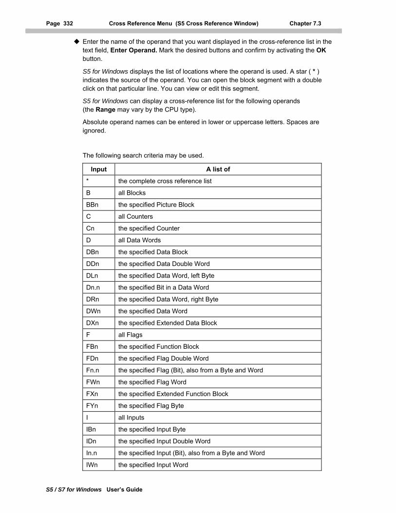
Page 332 Cross Reference Menu (S5 Cross Reference Window) Chapter 7.3
S5 / S7 for Windows User’s Guide
Enter the name of the operand that you want displayed in the cross-reference list in the text field, Enter Operand. Mark the desired buttons and confirm by activating the OK button.
S5 for Windows displays the list of locations where the operand is used. A star ( * ) indicates the source of the operand. You can open the block segment with a double click on that particular line. You can view or edit this segment.
S5 for Windows can display a cross-reference list for the following operands (the Range may vary by the CPU type).
Absolute operand names can be entered in lower or uppercase letters. Spaces are ignored.
The following search criteria may be used.
Input A list of
* the complete cross reference list
B all Blocks
BBn the specified Picture Block
C all Counters
Cn the specified Counter
D all Data Words
DBn the specified Data Block
DDn the specified Data Double Word
DLn the specified Data Word, left Byte
Dn.n the specified Bit in a Data Word
DRn the specified Data Word, right Byte
DWn the specified Data Word
DXn the specified Extended Data Block
F all Flags
FBn the specified Function Block
FDn the specified Flag Double Word
Fn.n the specified Flag (Bit), also from a Byte and Word
FWn the specified Flag Word
FXn the specified Extended Function Block
FYn the specified Flag Byte
I all Inputs
IBn the specified Input Byte
IDn the specified Input Double Word
In.n the specified Input (Bit), also from a Byte and Word
IWn the specified Input Word
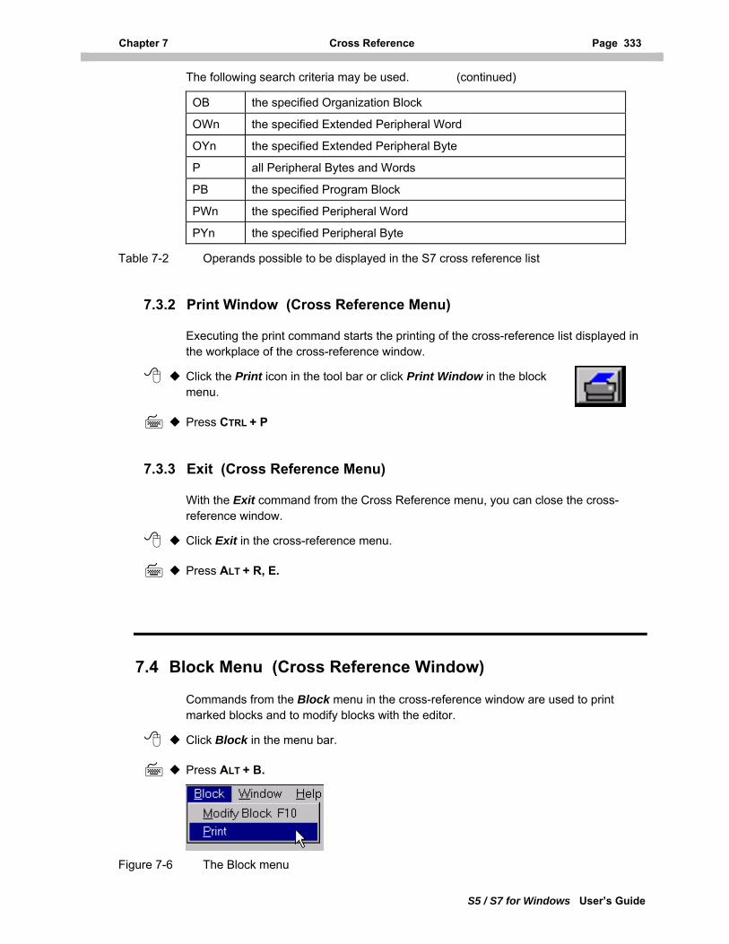
Chapter 7 Cross Reference Page 333
S5 / S7 for Windows User’s Guide
The following search criteria may be used. (continued)
OB the specified Organization Block
OWn the specified Extended Peripheral Word
OYn the specified Extended Peripheral Byte
P all Peripheral Bytes and Words
PB the specified Program Block
PWn the specified Peripheral Word
PYn the specified Peripheral Byte
Table 7-2 Operands possible to be displayed in the S7 cross reference list
7.3.2 Print Window (Cross Reference Menu)
Executing the print command starts the printing of the cross-reference list displayed in the workplace of the cross-reference window.
Click the Print icon in the tool bar or click Print Window in the block menu.
Press CTRL + P
7.3.3 Exit (Cross Reference Menu)
With the Exit command from the Cross Reference menu, you can close the cross-reference window.
Click Exit in the cross-reference menu.
Press ALT + R, E.
7.4 Block Menu (Cross Reference Window)
Commands from the Block menu in the cross-reference window are used to print marked blocks and to modify blocks with the editor.
Click Block in the menu bar.
Press ALT + B.
Figure 7-6 The Block menu
Page 334 Help (Help Menu - Cross Reference Window) Chapter 7.5
S5 / S7 for Windows User’s Guide
7.4.1 Modify Block (Block Menu)
This command opens the editor for the block network selected (marked in the cross-reference window workplace). If you did not select a block network (marked) in the cross-reference window workplace, the command is not active.
Click Modify Block in the cross-reference menu.
Press F10.
7.4.2 Print (Block Menu)
Executing the print command starts the printing of the selected block. One or more blocks may be marked in the cross-reference window workplace for printing.
Click Print in the block menu.
Press ALT + B, P
The marked blocks will be printed using the presets from the documentation layout dialog box (see chapter 3.2.13.1).
7.5 Window (Window Menu - Cross Reference Window)
The Window menu from the cross-reference window is identical with the window menu from the PC block list window. For more details see chapter 3.5.
7.6 Help (Help Menu - Cross Reference Window)
The Help menu from the cross-reference window is identical with the help menu from the PC block list window. For more details see chapter 3.6.
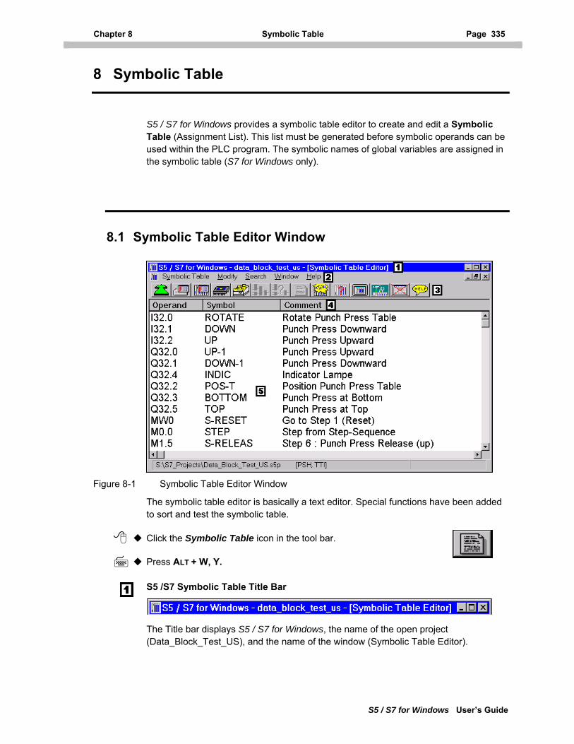
Chapter 8 Symbolic Table Page 335
S5 / S7 for Windows User’s Guide
8 Symbolic Table
S5 / S7 for Windows provides a symbolic table editor to create and edit a Symbolic Table (Assignment List). This list must be generated before symbolic operands can be used within the PLC program. The symbolic names of global variables are assigned in the symbolic table (S7 for Windows only).
8.1 Symbolic Table Editor Window
Figure 8-1 Symbolic Table Editor Window
The symbolic table editor is basically a text editor. Special functions have been added to sort and test the symbolic table.
Click the Symbolic Table icon in the tool bar.
Press ALT + W, Y.
S5 /S7 Symbolic Table Title Bar
The Title bar displays S5 / S7 for Windows, the name of the open project (Data_Block_Test_US), and the name of the window (Symbolic Table Editor).
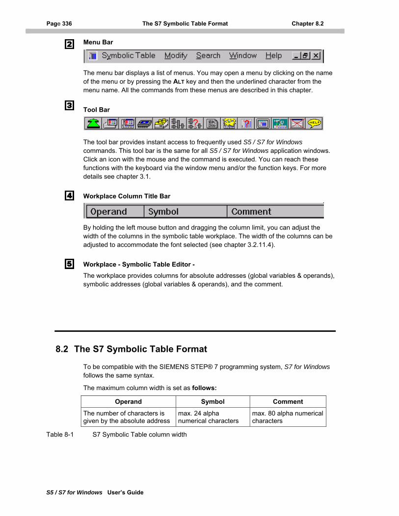
Page 336 The S7 Symbolic Table Format Chapter 8.2
S5 / S7 for Windows User’s Guide
Menu Bar
The menu bar displays a list of menus. You may open a menu by clicking on the name of the menu or by pressing the ALT key and then the underlined character from the menu name. All the commands from these menus are described in this chapter.
Tool Bar
The tool bar provides instant access to frequently used S5 / S7 for Windows commands. This tool bar is the same for all S5 / S7 for Windows application windows. Click an icon with the mouse and the command is executed. You can reach these functions with the keyboard via the window menu and/or the function keys. For more details see chapter 3.1.
Workplace Column Title Bar
By holding the left mouse button and dragging the column limit, you can adjust the width of the columns in the symbolic table workplace. The width of the columns can be adjusted to accommodate the font selected (see chapter 3.2.11.4).
Workplace - Symbolic Table Editor - The workplace provides columns for absolute addresses (global variables & operands), symbolic addresses (global variables & operands), and the comment.
8.2 The S7 Symbolic Table Format
To be compatible with the SIEMENS STEP® 7 programming system, S7 for Windows follows the same syntax.
The maximum column width is set as follows:
Operand Symbol Comment
The number of characters is given by the absolute address
max. 24 alpha numerical characters
max. 80 alpha numerical characters
Table 8-1 S7 Symbolic Table column width
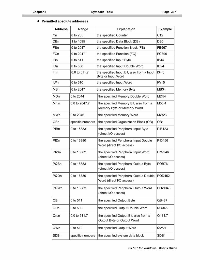
Chapter 8 Symbolic Table Page 337
S5 / S7 for Windows User’s Guide
Permitted absolute addresses
Address Range Explanation Example
Cn 0 to 255 the specified Counter C12
DBn 1 to 4095 the specified Data Block (DB) DB5
FBn 0 to 2047 the specified Function Block (FB) FB567
FCn 0 to 2047 the specified Function (FC) FC890
IBn 0 to 511 the specified Input Byte IB44
IDn 0 to 508 the specified Input Double Word ID24
In.n 0.0 to 511.7 the specified Input Bit, also from a Input Byte or Input Word
I34.5
IWn 0 to 510 the specified Input Word IW15
MBn 0 to 2047 the specified Memory Byte MB34
MDn 0 to 2044 the specified Memory Double Word MD54
Mn.n 0.0 to 2047.7 the specified Memory Bit, also from a Memory Byte or Memory Word
M56.4
MWn 0 to 2046 the specified Memory Word MW23
OBn specific numbers the specified Organization Block (OB) OB1
PIBn 0 to 16383 the specified Peripheral Input Byte (direct I/O access)
PIB123
PIDn 0 to 16380 the specified Peripheral Input Double Word (direct I/O access)
PID456
PIWn 0 to 16382 the specified Peripheral Input Word (direct I/O access)
PIW246
PQBn 0 to 16383 the specified Peripheral Output Byte (direct I/O access)
PQB76
PQDn 0 to 16380 the specified Peripheral Output Double Word (direct I/O access)
PQD452
PQWn 0 to 16382 the specified Peripheral Output Word (direct I/O access)
PQW346
QBn 0 to 511 the specified Output Byte QB487
QDn 0 to 508 the specified Output Double Word QD345
Qn.n 0.0 to 511.7 the specified Output Bit, also from a Output Byte or Output Word
Q411.7
QWn 0 to 510 the specified Output Word QW24
SDBn specific numbers the specified system data block SDB1
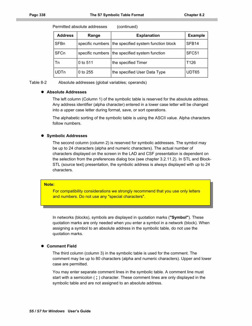
Page 338 The S7 Symbolic Table Format Chapter 8.2
S5 / S7 for Windows User’s Guide
Permitted absolute addresses (continued)
Address Range Explanation Example
SFBn specific numbers the specified system function block SFB14
SFCn specific numbers the specified system function SFC51
Tn 0 to 511 the specified Timer T126
UDTn 0 to 255 the specified User Data Type UDT65
Table 8-2 Absolute addresses (global variables; operands)
Absolute Addresses The left column (Column 1) of the symbolic table is reserved for the absolute address. Any address identifier (alpha character) entered in a lower case letter will be changed into a upper case letter during format, save, or sort operations.
The alphabetic sorting of the symbolic table is using the ASCII value. Alpha characters follow numbers.
Symbolic Addresses The second column (column 2) is reserved for symbolic addresses. The symbol may be up to 24 characters (alpha and numeric characters). The actual number of characters displayed on the screen in the LAD and CSF presentation is dependent on the selection from the preferences dialog box (see chapter 3.2.11.2). In STL and Block-STL (source text) presentation, the symbolic address is always displayed with up to 24 characters.
Note: For compatibility considerations we strongly recommend that you use only letters and numbers. Do not use any "special characters".
In networks (blocks), symbols are displayed in quotation marks ("Symbol"). These quotation marks are only needed when you enter a symbol in a network (block). When assigning a symbol to an absolute address in the symbolic table, do not use the quotation marks.
Comment Field
The third column (column 3) in the symbolic table is used for the comment. The comment may be up to 80 characters (alpha and numeric characters). Upper and lower case are permitted.
You may enter separate comment lines in the symbolic table. A comment line must start with a semicolon ( ; ) character. These comment lines are only displayed in the symbolic table and are not assigned to an absolute address.
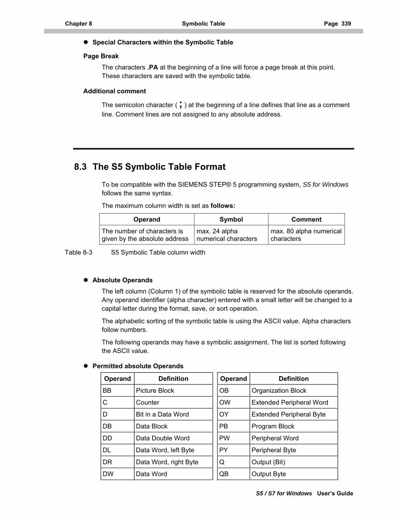
Chapter 8 Symbolic Table Page 339
S5 / S7 for Windows User’s Guide
Special Characters within the Symbolic Table
Page Break
The characters .PA at the beginning of a line will force a page break at this point. These characters are saved with the symbolic table.
Additional comment
The semicolon character ( ; ) at the beginning of a line defines that line as a comment line. Comment lines are not assigned to any absolute address.
8.3 The S5 Symbolic Table Format
To be compatible with the SIEMENS STEP® 5 programming system, S5 for Windows follows the same syntax.
The maximum column width is set as follows:
Operand Symbol Comment
The number of characters is given by the absolute address
max. 24 alpha numerical characters
max. 80 alpha numerical characters
Table 8-3 S5 Symbolic Table column width
Absolute Operands The left column (Column 1) of the symbolic table is reserved for the absolute operands. Any operand identifier (alpha character) entered with a small letter will be changed to a capital letter during the format, save, or sort operation.
The alphabetic sorting of the symbolic table is using the ASCII value. Alpha characters follow numbers.
The following operands may have a symbolic assignment. The list is sorted following the ASCII value.
Permitted absolute Operands
Operand Definition Operand Definition
BB Picture Block OB Organization Block
C Counter OW Extended Peripheral Word
D Bit in a Data Word OY Extended Peripheral Byte
DB Data Block PB Program Block
DD Data Double Word PW Peripheral Word
DL Data Word, left Byte PY Peripheral Byte
DR Data Word, right Byte Q Output (Bit)
DW Data Word QB Output Byte
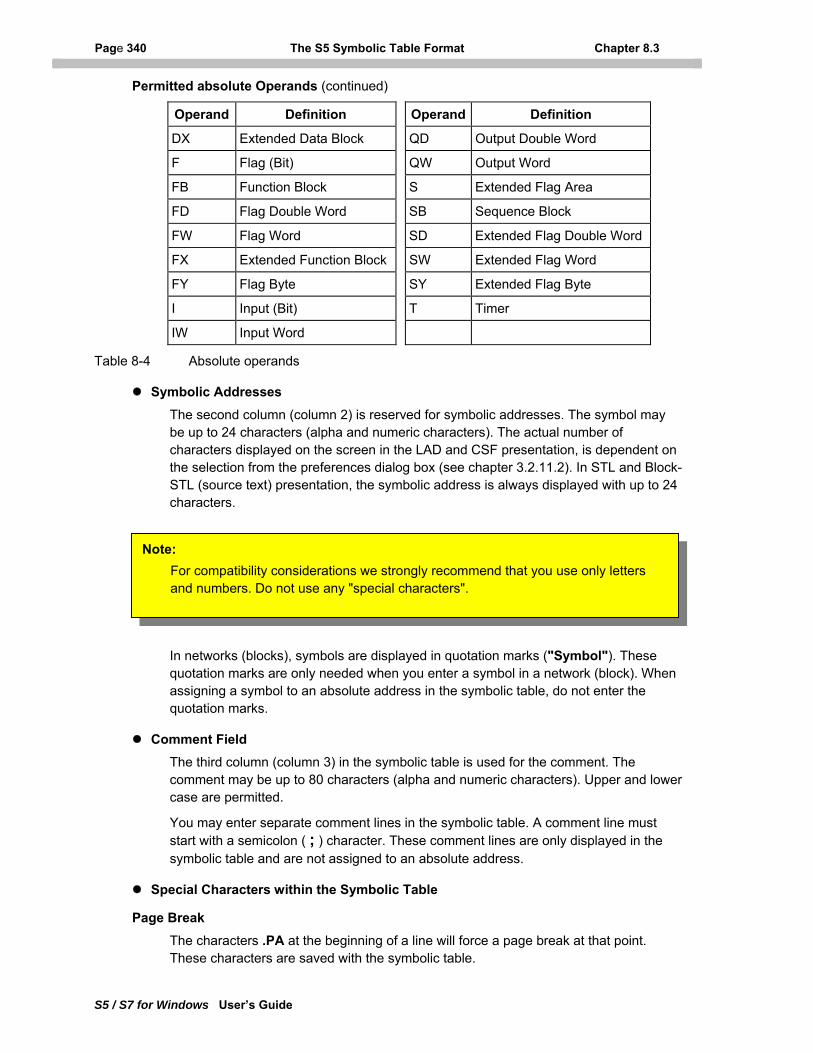
Page 340 The S5 Symbolic Table Format Chapter 8.3
S5 / S7 for Windows User’s Guide
Permitted absolute Operands (continued)
Operand Definition Operand Definition
DX Extended Data Block QD Output Double Word
F Flag (Bit) QW Output Word
FB Function Block S Extended Flag Area
FD Flag Double Word SB Sequence Block
FW Flag Word SD Extended Flag Double Word
FX Extended Function Block SW Extended Flag Word
FY Flag Byte SY Extended Flag Byte
I Input (Bit) T Timer
IW Input Word
Table 8-4 Absolute operands
Symbolic Addresses The second column (column 2) is reserved for symbolic addresses. The symbol may be up to 24 characters (alpha and numeric characters). The actual number of characters displayed on the screen in the LAD and CSF presentation, is dependent on the selection from the preferences dialog box (see chapter 3.2.11.2). In STL and Block-STL (source text) presentation, the symbolic address is always displayed with up to 24 characters.
Note: For compatibility considerations we strongly recommend that you use only letters and numbers. Do not use any "special characters".
In networks (blocks), symbols are displayed in quotation marks ("Symbol"). These quotation marks are only needed when you enter a symbol in a network (block). When assigning a symbol to an absolute address in the symbolic table, do not enter the quotation marks.
Comment Field
The third column (column 3) in the symbolic table is used for the comment. The comment may be up to 80 characters (alpha and numeric characters). Upper and lower case are permitted.
You may enter separate comment lines in the symbolic table. A comment line must start with a semicolon ( ; ) character. These comment lines are only displayed in the symbolic table and are not assigned to an absolute address.
Special Characters within the Symbolic Table
Page Break
The characters .PA at the beginning of a line will force a page break at that point. These characters are saved with the symbolic table.
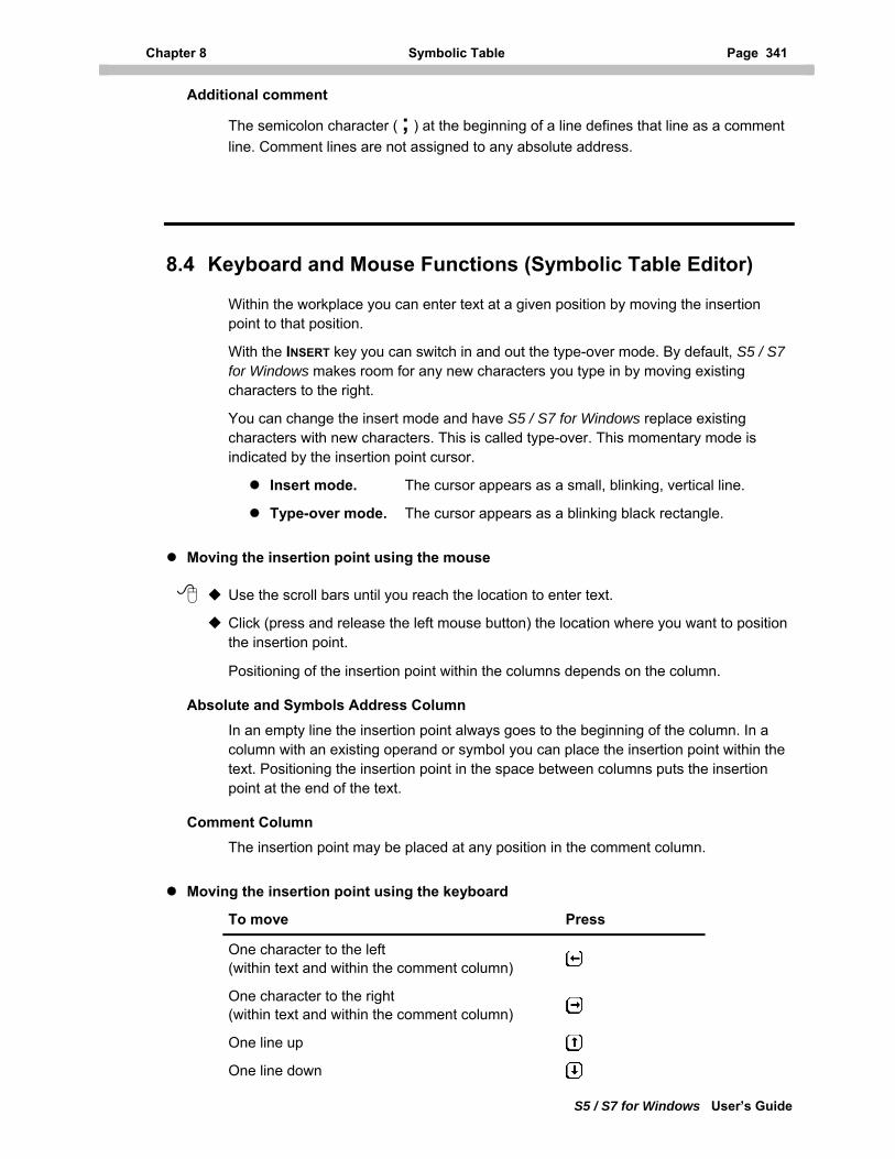
Chapter 8 Symbolic Table Page 341
S5 / S7 for Windows User’s Guide
Additional comment
The semicolon character ( ; ) at the beginning of a line defines that line as a comment line. Comment lines are not assigned to any absolute address.
8.4 Keyboard and Mouse Functions (Symbolic Table Editor)
Within the workplace you can enter text at a given position by moving the insertion point to that position.
With the INSERT key you can switch in and out the type-over mode. By default, S5 / S7 for Windows makes room for any new characters you type in by moving existing characters to the right.
You can change the insert mode and have S5 / S7 for Windows replace existing characters with new characters. This is called type-over. This momentary mode is indicated by the insertion point cursor.
Insert mode. The cursor appears as a small, blinking, vertical line.
Type-over mode. The cursor appears as a blinking black rectangle.
Moving the insertion point using the mouse
Use the scroll bars until you reach the location to enter text.
Click (press and release the left mouse button) the location where you want to position the insertion point.
Positioning of the insertion point within the columns depends on the column.
Absolute and Symbols Address Column In an empty line the insertion point always goes to the beginning of the column. In a column with an existing operand or symbol you can place the insertion point within the text. Positioning the insertion point in the space between columns puts the insertion point at the end of the text.
Comment Column The insertion point may be placed at any position in the comment column.
Moving the insertion point using the keyboard
To move Press
One character to the left (within text and within the comment column)
One character to the right (within text and within the comment column)
One line up
One line down

Page 342 Keyboard and Mouse Functions (Symbolic Table Editor) Chapter 8.4
S5 / S7 for Windows User’s Guide
Moving the insertion point using the keyboard (continued)
To move Press
One word to the left (within the comment column) CTRL +
One word to the right (within the comment column) CTRL +
To the end of a line END
To the beginning of a line HOME
Up one screen PAGE UP
Down one screen PAGE DOWN
To the end of the symbolic table CTRL + END
To beginning of the symbolic table CTRL + HOME
To the previous column (if the insertion point is currently in the space between columns)
To the next column (if the insertion point is currently in the space between columns)
To the next column (next Tab position within the comment column) TAB
To the beginning of a line (a new line is added) È
Table 8-5 Moving the insertion point using the keyboard (symbolic table)
Note: Always use the TAB key to move to the next column when you enter a new Absolute Address, a new Symbolic Address, or a Comment in an empty line.
Use È only after entering the comment to move to the next line to enter the next absolute address.
Selecting text using the mouse
Do one of the following
To select Do this
Any amount of text Drag over the text you want to select
A word (within column)
Double-click the word
Table 8-6 Selecting text using the mouse (symbolic table)
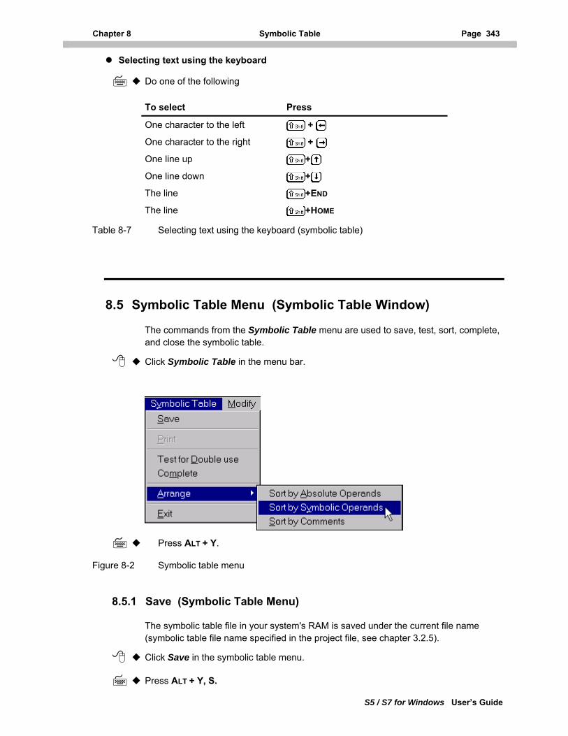
Chapter 8 Symbolic Table Page 343
S5 / S7 for Windows User’s Guide
Selecting text using the keyboard
Do one of the following
To select Press
One character to the left +
One character to the right +
One line up +
One line down +
The line +END
The line +HOME
Table 8-7 Selecting text using the keyboard (symbolic table)
8.5 Symbolic Table Menu (Symbolic Table Window)
The commands from the Symbolic Table menu are used to save, test, sort, complete, and close the symbolic table.
Click Symbolic Table in the menu bar.
Press ALT + Y.
Figure 8-2 Symbolic table menu
8.5.1 Save (Symbolic Table Menu)
The symbolic table file in your system's RAM is saved under the current file name (symbolic table file name specified in the project file, see chapter 3.2.5).
Click Save in the symbolic table menu.
Press ALT + Y, S.
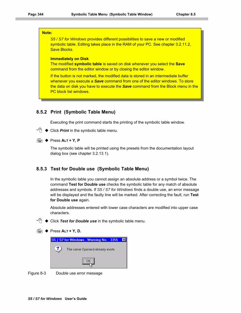
Page 344 Symbolic Table Menu (Symbolic Table Window) Chapter 8.5
S5 / S7 for Windows User’s Guide
Note: S5 / S7 for Windows provides different possibilities to save a new or modified symbolic table. Editing takes place in the RAM of your PC. See chapter 3.2.11.2, Save Blocks.
Immediately on Disk The modified symbolic table is saved on disk whenever you select the Save command from the editor window or by closing the editor window.
If the button is not marked, the modified data is stored in an intermediate buffer whenever you execute a Save command from one of the editor windows. To store the data on disk you have to execute the Save command from the Block menu in the PC block list windows.
8.5.2 Print (Symbolic Table Menu)
Executing the print command starts the printing of the symbolic table window.
Click Print in the symbolic table menu.
Press ALT + Y, P
The symbolic table will be printed using the presets from the documentation layout dialog box (see chapter 3.2.13.1).
8.5.3 Test for Double use (Symbolic Table Menu)
In the symbolic table you cannot assign an absolute address or a symbol twice. The command Test for Double use checks the symbolic table for any match of absolute addresses and symbols. If S5 / S7 for Windows finds a double use, an error message will be displayed and the faulty line will be marked. After correcting the fault, run Test for Double use again.
Absolute addresses entered with lower case characters are modified into upper case characters.
Click Test for Double use in the symbolic table menu.
Press ALT + Y, D.
Figure 8-3 Double use error message
Chapter 8 Symbolic Table Page 345
S5 / S7 for Windows User’s Guide
8.5.4 Complete (Symbolic Table Menu)
The Complete command, from the symbolic table menu, searches the PLC program for addresses not defined in the symbolic table. These addresses will be listed at the end of the symbolic table. The absolute address is used as the symbolic name. This is an easy way to create a symbolic table.
Click Complete in the symbolic table menu.
Press ALT + Y, M.
8.5.5 Arrange (Symbolic Table Menu)
S5 /S7 for Windows provides tools to arrange (sort) the symbolic table.
Note: Sorting may be done even if the Test for Double use has found absolute addresses and symbols have been used more than once. Absolute addresses entered without a symbol will get the same absolute address assigned as a symbolic name.
8.5.5.1 Sort by Absolute Operands
Use the Sort by Absolute Operands command to sort the symbolic table in the alphabetically ascending order of the absolute addresses. This sort is done using ASCII values (numbers are listed prior to alpha characters).
Click Arrange, Sort by Absolute Operands in the symbolic table menu.
Press ALT + Y, A, A.
8.5.5.2 Sort by Symbolic Operands
Use the Sort by Symbolic Operands command to sort the symbolic table by symbolic names in alphabetically ascending order. This sort is done using ASCII values (numbers are listed prior to alpha characters).
Click Arrange, Sort by Symbolic Operands in the symbolic table menu.
Press ALT + Y, A, Y.
8.5.5.3 Sort by Comments
Use the Sort by Comments command to sort the symbolic table by the comments in alphabetically ascending order. This sort is done using ASCII values (numbers are listed prior to alpha characters).
Click Arrange, Sort by Comments in the symbolic table menu.
Press ALT + Y, A, S.
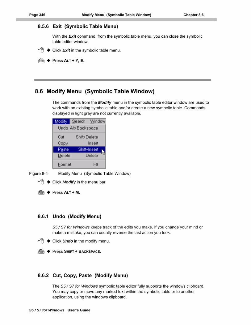
Page 346 Modify Menu (Symbolic Table Window) Chapter 8.6
S5 / S7 for Windows User’s Guide
8.5.6 Exit (Symbolic Table Menu)
With the Exit command, from the symbolic table menu, you can close the symbolic table editor window.
Click Exit in the symbolic table menu.
Press ALT + Y, E.
8.6 Modify Menu (Symbolic Table Window)
The commands from the Modify menu in the symbolic table editor window are used to work with an existing symbolic table and/or create a new symbolic table. Commands displayed in light gray are not currently available.
Figure 8-4 Modify Menu (Symbolic Table Window)
Click Modify in the menu bar.
Press ALT + M.
8.6.1 Undo (Modify Menu)
S5 / S7 for Windows keeps track of the edits you make. If you change your mind or make a mistake, you can usually reverse the last action you took.
Click Undo in the modify menu.
Press SHIFT + BACKSPACE.
8.6.2 Cut, Copy, Paste (Modify Menu)
The S5 / S7 for Windows symbolic table editor fully supports the windows clipboard. You may copy or move any marked text within the symbolic table or to another application, using the windows clipboard.
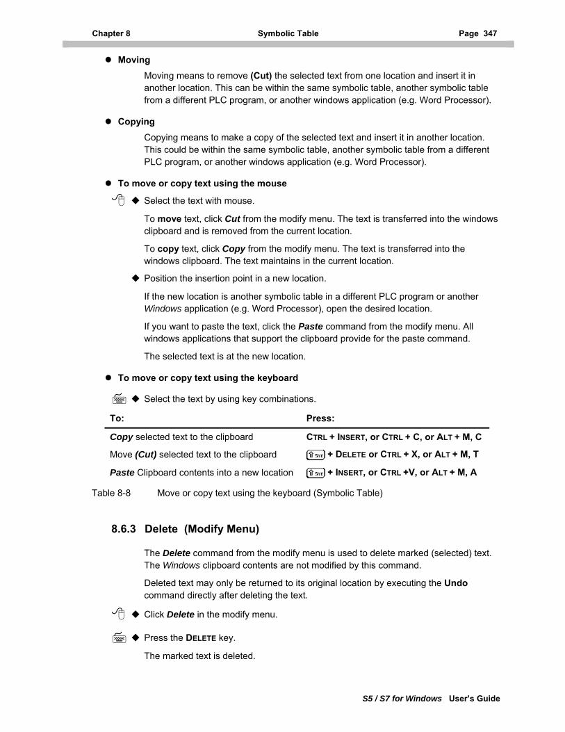
Chapter 8 Symbolic Table Page 347
S5 / S7 for Windows User’s Guide
Moving Moving means to remove (Cut) the selected text from one location and insert it in another location. This can be within the same symbolic table, another symbolic table from a different PLC program, or another windows application (e.g. Word Processor).
Copying Copying means to make a copy of the selected text and insert it in another location. This could be within the same symbolic table, another symbolic table from a different PLC program, or another windows application (e.g. Word Processor).
To move or copy text using the mouse
Select the text with mouse.
To move text, click Cut from the modify menu. The text is transferred into the windows clipboard and is removed from the current location.
To copy text, click Copy from the modify menu. The text is transferred into the windows clipboard. The text maintains in the current location.
Position the insertion point in a new location.
If the new location is another symbolic table in a different PLC program or another Windows application (e.g. Word Processor), open the desired location.
If you want to paste the text, click the Paste command from the modify menu. All windows applications that support the clipboard provide for the paste command.
The selected text is at the new location.
To move or copy text using the keyboard
Select the text by using key combinations.
To: Press:
Copy selected text to the clipboard CTRL + INSERT, or CTRL + C, or ALT + M, C
Move (Cut) selected text to the clipboard + DELETE or CTRL + X, or ALT + M, T
Paste Clipboard contents into a new location + INSERT, or CTRL +V, or ALT + M, A
Table 8-8 Move or copy text using the keyboard (Symbolic Table)
8.6.3 Delete (Modify Menu)
The Delete command from the modify menu is used to delete marked (selected) text. The Windows clipboard contents are not modified by this command.
Deleted text may only be returned to its original location by executing the Undo command directly after deleting the text.
Click Delete in the modify menu.
Press the DELETE key.
The marked text is deleted.
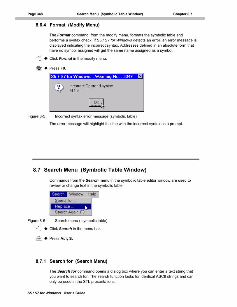
Page 348 Search Menu (Symbolic Table Window) Chapter 8.7
S5 / S7 for Windows User’s Guide
8.6.4 Format (Modify Menu)
The Format command, from the modify menu, formats the symbolic table and performs a syntax check. If S5 / S7 for Windows detects an error, an error message is displayed indicating the incorrect syntax. Addresses defined in an absolute form that have no symbol assigned will get the same name assigned as a symbol.
Click Format in the modify menu.
Press F9.
Figure 8-5 Incorrect syntax error message (symbolic table)
The error message will highlight the line with the incorrect syntax as a prompt.
8.7 Search Menu (Symbolic Table Window)
Commands from the Search menu in the symbolic table editor window are used to review or change text in the symbolic table.
Figure 8-6 Search menu ( symbolic table)
Click Search in the menu bar.
Press ALT, S.
8.7.1 Search for (Search Menu)
The Search for command opens a dialog box where you can enter a text string that you want to search for. The search function looks for identical ASCII strings and can only be used in the STL presentations.
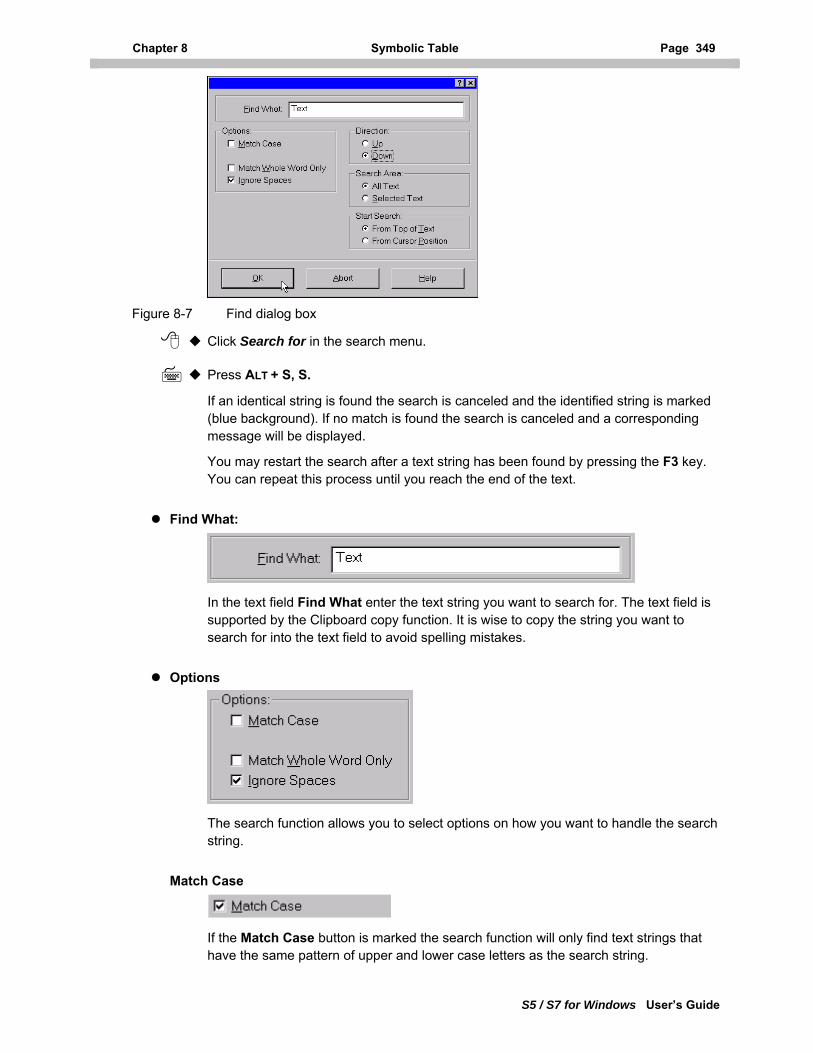
Chapter 8 Symbolic Table Page 349
S5 / S7 for Windows User’s Guide
Figure 8-7 Find dialog box
Click Search for in the search menu.
Press ALT + S, S.
If an identical string is found the search is canceled and the identified string is marked (blue background). If no match is found the search is canceled and a corresponding message will be displayed.
You may restart the search after a text string has been found by pressing the F3 key. You can repeat this process until you reach the end of the text.
Find What:
In the text field Find What enter the text string you want to search for. The text field is supported by the Clipboard copy function. It is wise to copy the string you want to search for into the text field to avoid spelling mistakes.
Options
The search function allows you to select options on how you want to handle the search string.
Match Case
If the Match Case button is marked the search function will only find text strings that have the same pattern of upper and lower case letters as the search string.
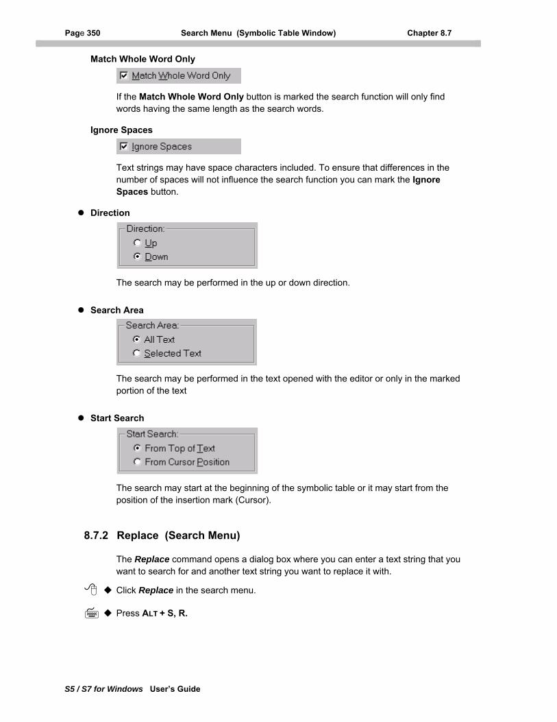
Page 350 Search Menu (Symbolic Table Window) Chapter 8.7
S5 / S7 for Windows User’s Guide
Match Whole Word Only
If the Match Whole Word Only button is marked the search function will only find words having the same length as the search words.
Ignore Spaces
Text strings may have space characters included. To ensure that differences in the number of spaces will not influence the search function you can mark the Ignore Spaces button.
Direction
The search may be performed in the up or down direction.
Search Area
The search may be performed in the text opened with the editor or only in the marked portion of the text
Start Search
The search may start at the beginning of the symbolic table or it may start from the position of the insertion mark (Cursor).
8.7.2 Replace (Search Menu)
The Replace command opens a dialog box where you can enter a text string that you want to search for and another text string you want to replace it with.
Click Replace in the search menu.
Press ALT + S, R.
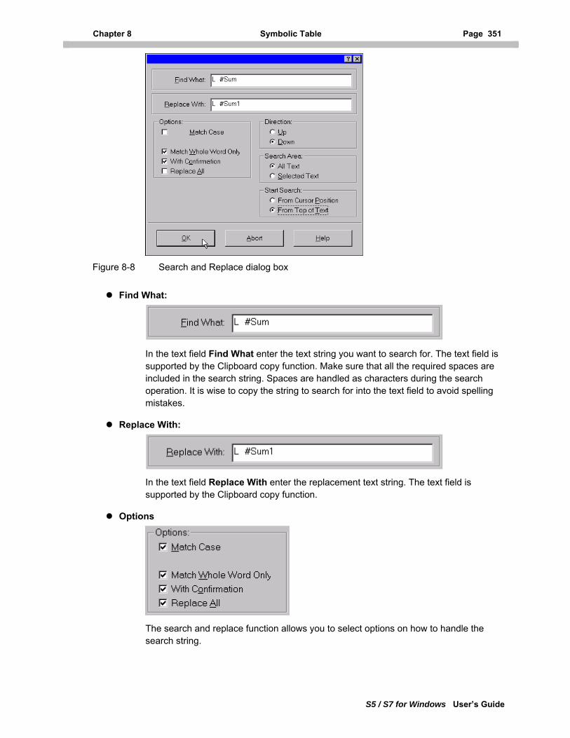
Chapter 8 Symbolic Table Page 351
S5 / S7 for Windows User’s Guide
Figure 8-8 Search and Replace dialog box
Find What:
In the text field Find What enter the text string you want to search for. The text field is supported by the Clipboard copy function. Make sure that all the required spaces are included in the search string. Spaces are handled as characters during the search operation. It is wise to copy the string to search for into the text field to avoid spelling mistakes.
Replace With:
In the text field Replace With enter the replacement text string. The text field is supported by the Clipboard copy function.
Options
The search and replace function allows you to select options on how to handle the search string.
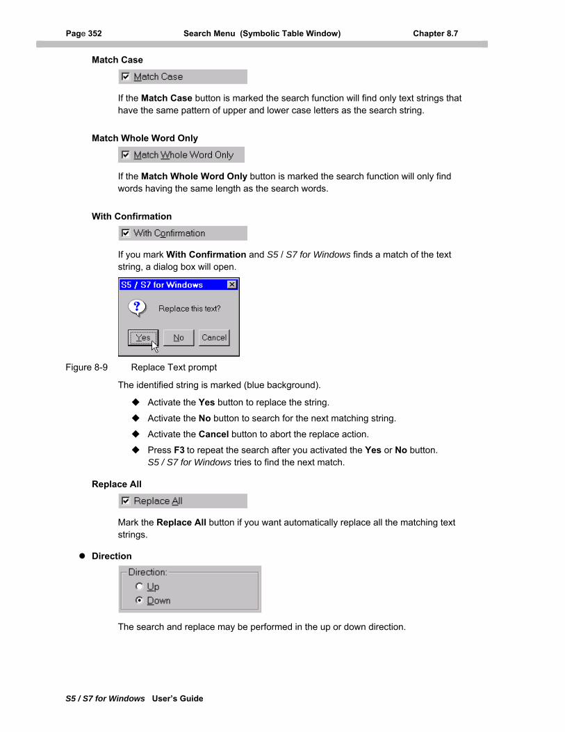
Page 352 Search Menu (Symbolic Table Window) Chapter 8.7
S5 / S7 for Windows User’s Guide
Match Case
If the Match Case button is marked the search function will find only text strings that have the same pattern of upper and lower case letters as the search string.
Match Whole Word Only
If the Match Whole Word Only button is marked the search function will only find words having the same length as the search words.
With Confirmation
If you mark With Confirmation and S5 / S7 for Windows finds a match of the text string, a dialog box will open.
Figure 8-9 Replace Text prompt
The identified string is marked (blue background).
Activate the Yes button to replace the string.
Activate the No button to search for the next matching string.
Activate the Cancel button to abort the replace action.
Press F3 to repeat the search after you activated the Yes or No button. S5 / S7 for Windows tries to find the next match.
Replace All
Mark the Replace All button if you want automatically replace all the matching text strings.
Direction
The search and replace may be performed in the up or down direction.
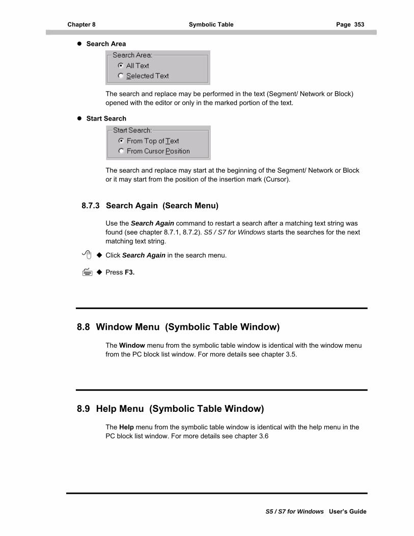
Chapter 8 Symbolic Table Page 353
S5 / S7 for Windows User’s Guide
Search Area
The search and replace may be performed in the text (Segment/ Network or Block) opened with the editor or only in the marked portion of the text.
Start Search
The search and replace may start at the beginning of the Segment/ Network or Block or it may start from the position of the insertion mark (Cursor).
8.7.3 Search Again (Search Menu)
Use the Search Again command to restart a search after a matching text string was found (see chapter 8.7.1, 8.7.2). S5 / S7 for Windows starts the searches for the next matching text string.
Click Search Again in the search menu.
Press F3.
8.8 Window Menu (Symbolic Table Window)
The Window menu from the symbolic table window is identical with the window menu from the PC block list window. For more details see chapter 3.5.
8.9 Help Menu (Symbolic Table Window)
The Help menu from the symbolic table window is identical with the help menu in the PC block list window. For more details see chapter 3.6
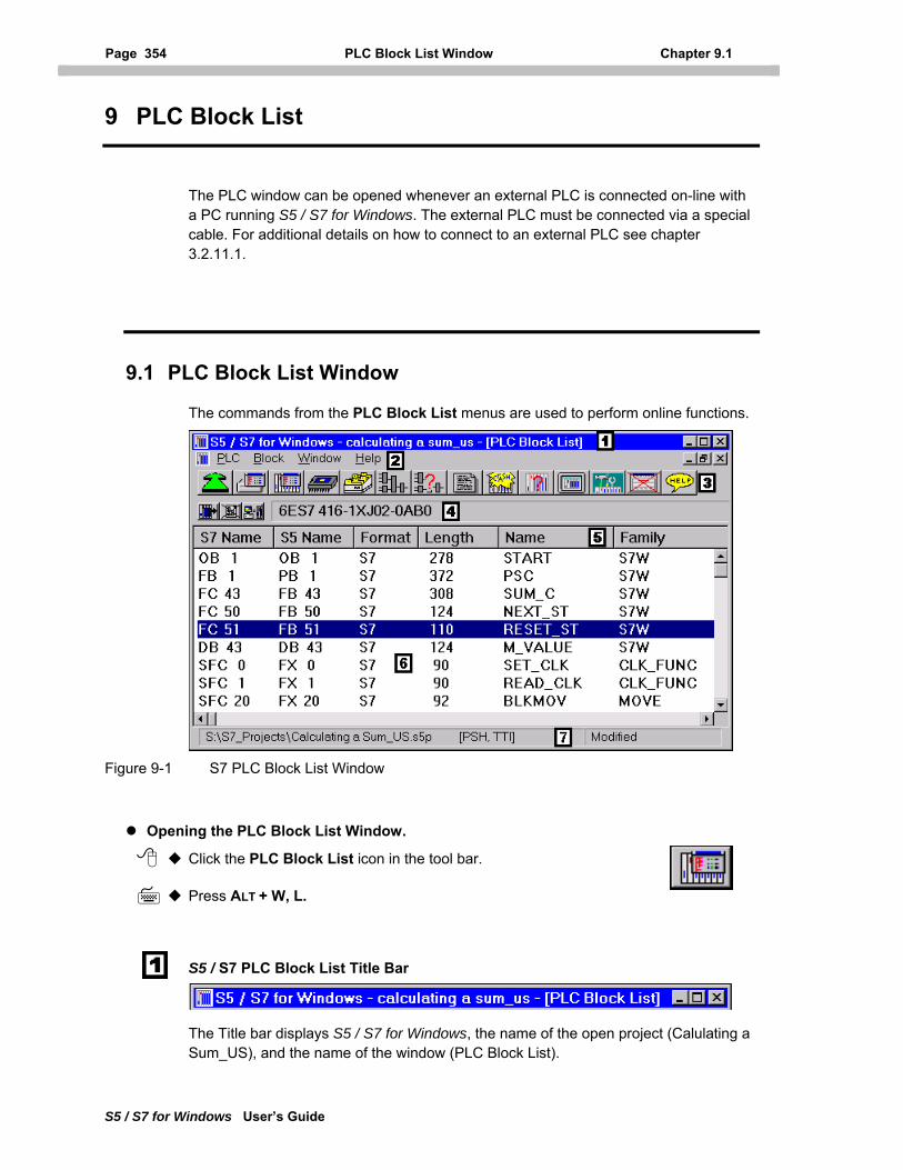
Page 354 PLC Block List Window Chapter 9.1
S5 / S7 for Windows User’s Guide
9 PLC Block List
The PLC window can be opened whenever an external PLC is connected on-line with a PC running S5 / S7 for Windows. The external PLC must be connected via a special cable. For additional details on how to connect to an external PLC see chapter 3.2.11.1.
9.1 PLC Block List Window
The commands from the PLC Block List menus are used to perform online functions.
Figure 9-1 S7 PLC Block List Window
Opening the PLC Block List Window.
Click the PLC Block List icon in the tool bar.
Press ALT + W, L.
S5 / S7 PLC Block List Title Bar
The Title bar displays S5 / S7 for Windows, the name of the open project (Calulating a Sum_US), and the name of the window (PLC Block List).
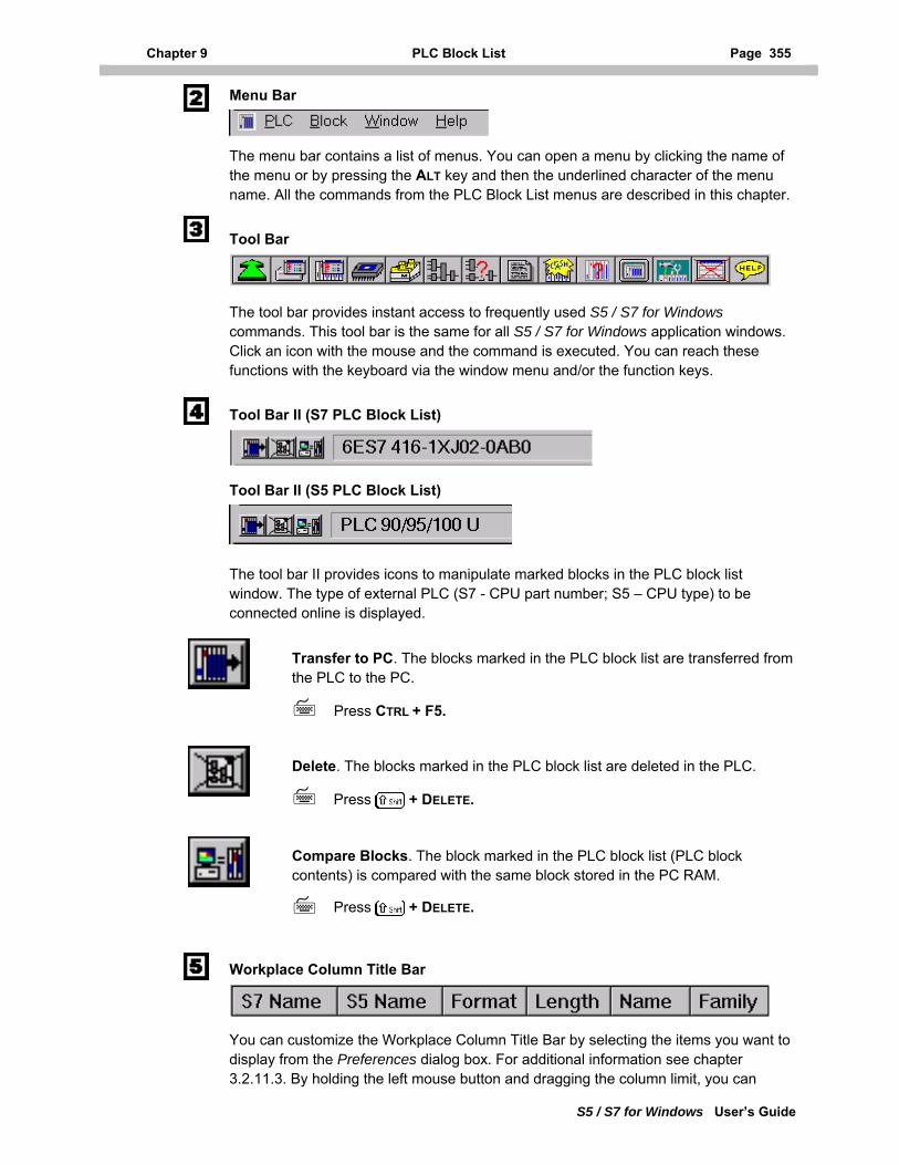
Chapter 9 PLC Block List Page 355
S5 / S7 for Windows User’s Guide
Menu Bar
The menu bar contains a list of menus. You can open a menu by clicking the name of the menu or by pressing the ALT key and then the underlined character of the menu name. All the commands from the PLC Block List menus are described in this chapter.
Tool Bar
The tool bar provides instant access to frequently used S5 / S7 for Windows commands. This tool bar is the same for all S5 / S7 for Windows application windows. Click an icon with the mouse and the command is executed. You can reach these functions with the keyboard via the window menu and/or the function keys.
Tool Bar II (S7 PLC Block List)
Tool Bar II (S5 PLC Block List)
The tool bar II provides icons to manipulate marked blocks in the PLC block list window. The type of external PLC (S7 - CPU part number; S5 – CPU type) to be connected online is displayed.
Transfer to PC. The blocks marked in the PLC block list are transferred from the PLC to the PC.
Press CTRL + F5.
Delete. The blocks marked in the PLC block list are deleted in the PLC.
Press + DELETE.
Compare Blocks. The block marked in the PLC block list (PLC block contents) is compared with the same block stored in the PC RAM.
Press + DELETE.
Workplace Column Title Bar
You can customize the Workplace Column Title Bar by selecting the items you want to
display from the Preferences dialog box. For additional information see chapter 3.2.11.3. By holding the left mouse button and dragging the column limit, you can
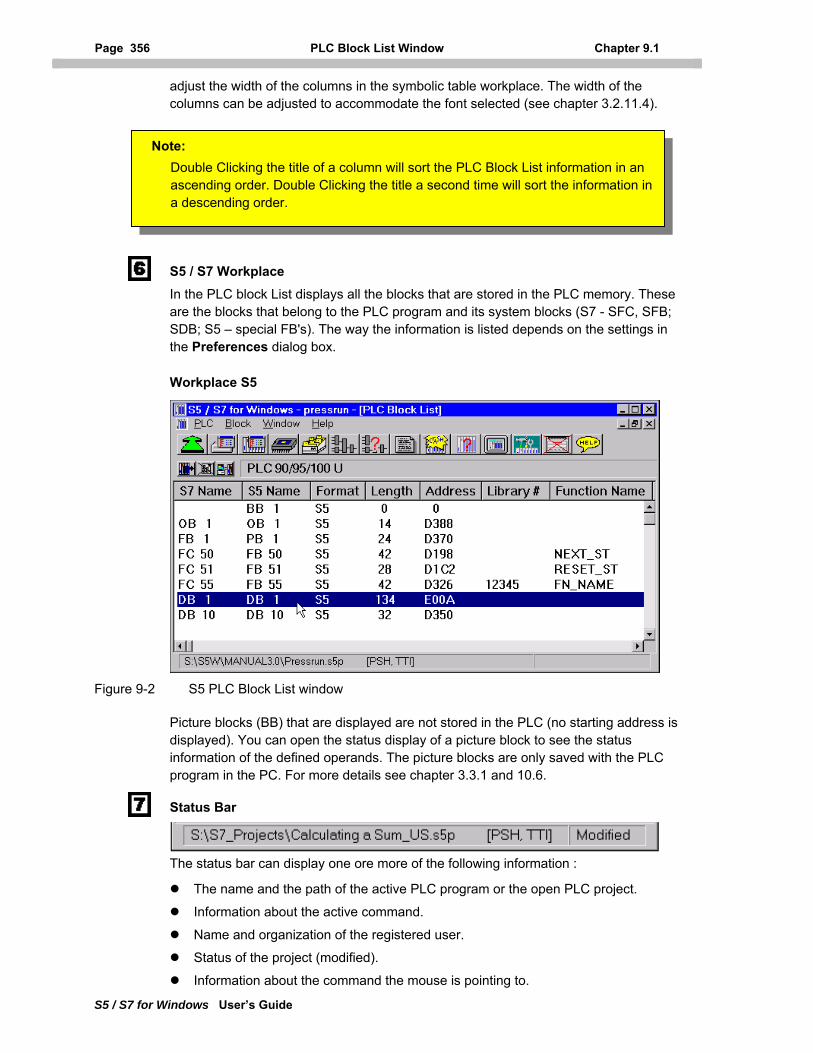
Page 356 PLC Block List Window Chapter 9.1
S5 / S7 for Windows User’s Guide
adjust the width of the columns in the symbolic table workplace. The width of the columns can be adjusted to accommodate the font selected (see chapter 3.2.11.4
).
displays all the blocks that are stored in the PLC memory. These
Workplace S5
Figure 9-2
Picture blocks (BB) that are displayed are not stored in the PLC (no starting address is
PLC
tatus Bar
ect.
user.
the mouse is pointing to.
S5 / S7 Workplace In the PLC block Listare the blocks that belong to the PLC program and its system blocks (S7 - SFC, SFB; SDB; S5 – special FB's). The way the information is listed depends on the settings in the Preferences dialog box.
No : ble Clicking the title of a column will sort the PLC Block List information in an
te
S5 PLC Block List window
displayed). You can open the status display of a picture block to see the status information of the defined operands. The picture blocks are only saved with the program in the PC. For more details see chapter 3.3.1 and 10.6.
S
Douascending order. Double Clicking the title a second time will sort the information ina descending order.
The status bar can display one ore more of the following information :
The name and the path of the active PLC program or the open PLC proj
Information about the active command.
Name and organization of the registered
Status of the project (modified).
Information about the command
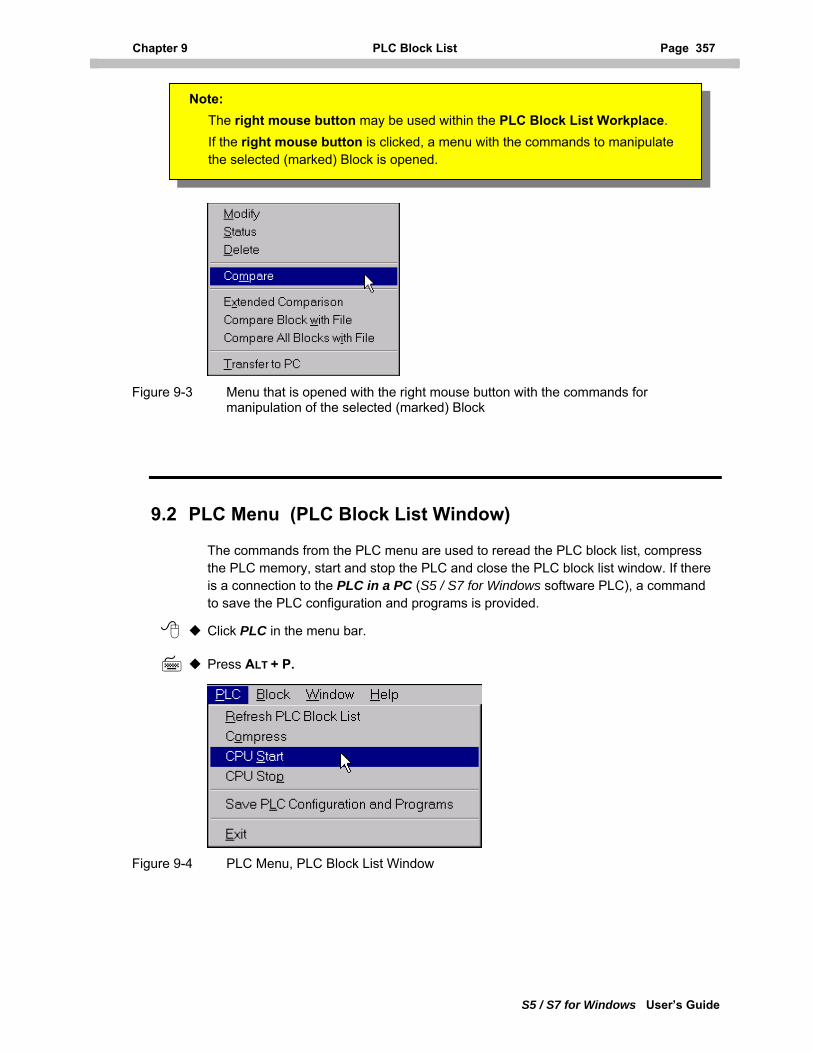
Chapter 9 PLC Block List Page 357
S5 / S7 for Windows User’s Guide
Figure 9-3 ght mouse button with the commands for
9.2 PLC Menu (PLC Block List Window)
Note: right mouse button may be used within the PLC Block List Workplace.
Menu that is opened with the rimanipulation of the selected (marked) Block
The commands from the PLC menu are used to reread the PLC block list, compress
Figure 9-4
the PLC memory, start and stop the PLC and close the PLC block list window. If thereis a connection to the PLC in a PC (S5 / S7 for Windows software PLC), a command to save the PLC configuration and programs is provided.
Click PLC in the menu bar.
Press ALT + P.
TheIf the right mouse button is clicked, a menu with the commands to manipulate the selected (marked) Block is opened.
PLC Menu, PLC Block List Window
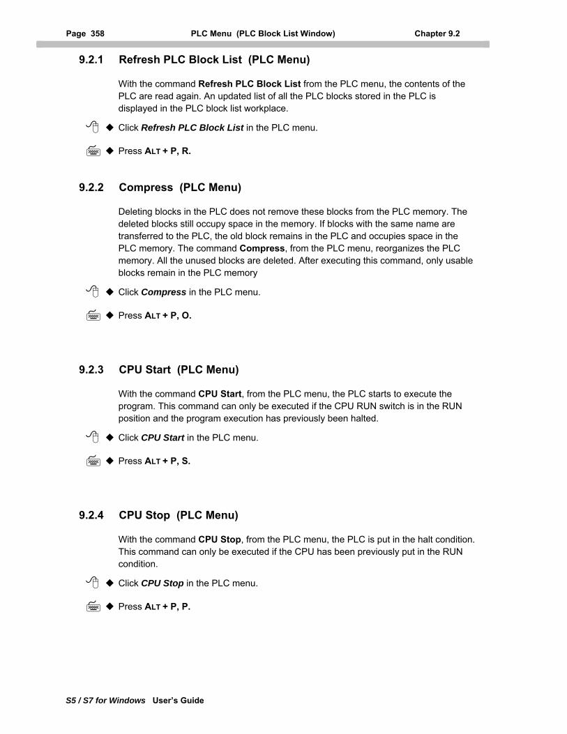
Page 358 PLC Menu (PLC Block List Window) Chapter 9.2
S5 / S7 for Windows User’s Guide
9.2.1 Refresh PLC Block List (PLC Menu)
With the command Refresh PLC Block List from the PLC menu, the contents of the PLC are read again. An updated list of all the PLC blocks stored in the PLC is displayed in the PLC block list workplace.
Click Refresh PLC Block List in the PLC menu.
Press ALT + P, R.
9.2.2 Compress (PLC Menu)
Deleting blocks in the PLC does not remove these blocks from the PLC memory. The deleted blocks still occupy space in the memory. If blocks with the same name are transferred to the PLC, the old block remains in the PLC and occupies space in the PLC memory. The command Compress, from the PLC menu, reorganizes the PLC memory. All the unused blocks are deleted. After executing this command, only usable blocks remain in the PLC memory
Click Compress in the PLC menu.
Press ALT + P, O.
9.2.3 CPU Start (PLC Menu)
With the command CPU Start, from the PLC menu, the PLC starts to execute the program. This command can only be executed if the CPU RUN switch is in the RUN position and the program execution has previously been halted.
Click CPU Start in the PLC menu.
Press ALT + P, S.
9.2.4 CPU Stop (PLC Menu)
With the command CPU Stop, from the PLC menu, the PLC is put in the halt condition. This command can only be executed if the CPU has been previously put in the RUN condition.
Click CPU Stop in the PLC menu.
Press ALT + P, P.
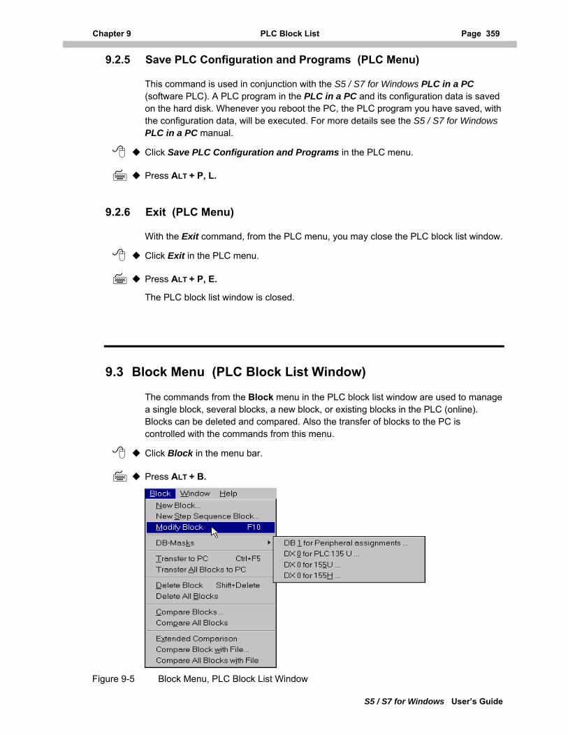
Chapter 9 PLC Block List Page 359
S5 / S7 for Windows User’s Guide
9.2.5 Save PLC Configuration and Programs (PLC Menu)
This command is used in conjunction with the S5 / S7 for Windows PLC in a PC (software PLC). A PLC program in the PLC in a PC and its configuration data is saved on the hard disk. Whenever you reboot the PC, the PLC program you have saved, with the configuration data, will be executed. For more details see the S5 / S7 for Windows PLC in a PC manual.
Click Save PLC Configuration and Programs in the PLC menu.
Press ALT + P, L.
9.2.6 Exit (PLC Menu)
With the Exit command, from the PLC menu, you may close the PLC block list window.
Click Exit in the PLC menu.
Press ALT + P, E.
The PLC block list window is closed.
9.3 Block Menu (PLC Block List Window)
The commands from the Block menu in the PLC block list window are used to manage a single block, several blocks, a new block, or existing blocks in the PLC (online). Blocks can be deleted and compared. Also the transfer of blocks to the PC is controlled with the commands from this menu.
Click Block in the menu bar.
Press ALT + B.
Figure 9-5 Block Menu, PLC Block List Window
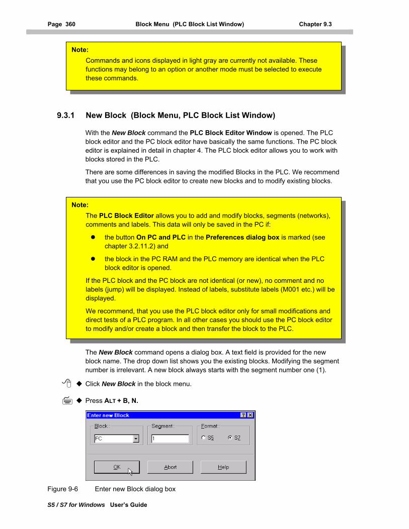
Page 360 Block Menu (PLC Block List Window) Chapter 9.3
S5 / S7 for Windows User’s Guide
Note: Commands and icons displayed in light gray are currently not available. These functions may belong to an option or another mode must be selected to execute these commands.
9.3.1 New Block (Block Menu, PLC Block List Window)
With the New Block command the PLC Block Editor Window is opened. The PLC block editor and the PC block editor have basically the same functions. The PC block editor is explained in detail in chapter 4. The PLC block editor allows you to work with blocks stored in the PLC.
There are some differences in saving the modified Blocks in the PLC. We recommend that you use the PC block editor to create new blocks and to modify existing blocks.
The New Block command opens a dialog box. A text field is provided for the new block name. The drop down list shows you the existing blocks. Modifying the segment number is irrelevant. A new block always starts with the segment number one (1).
Click New Block in the block menu.
Press ALT + B, N.
Note: The PLC Block Editor allows you to add and modify blocks, segments (networks), comments and labels. This data will only be saved in the PC if:
the button On PC and PLC in the Preferences dialog box is marked (see chapter 3.2.11.2) and
the block in the PC RAM and the PLC memory are identical when the PLC block editor is opened.
If the PLC block and the PC block are not identical (or new), no comment and no labels (jump) will be displayed. Instead of labels, substitute labels (M001 etc.) will be displayed.
We recommend, that you use the PLC block editor only for small modifications and direct tests of a PLC program. In all other cases you should use the PC block editor to modify and/or create a block and then transfer the block to the PLC.
Figure 9-6 Enter new Block dialog box
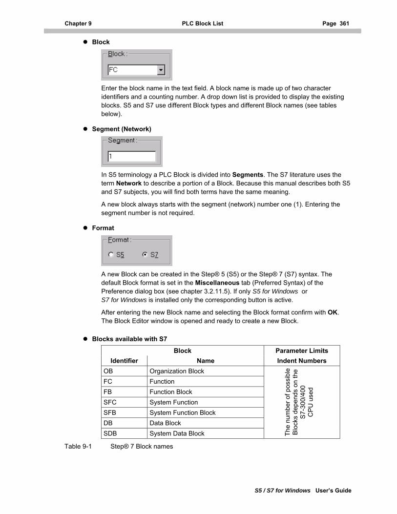
Chapter 9 PLC Block List Page 361
S5 / S7 for Windows User’s Guide
Block
Enter the block name in the text field. A block name is made up of two character identifiers and a counting number. A drop down list is provided to display the existing blocks. S5 and S7 use different Block types and different Block names (see tables below).
Segment (Network)
In S5 terminology a PLC Block is divided into Segments. The S7 literature uses the term Network to describe a portion of a Block. Because this manual describes both S5 and S7 subjects, you will find both terms have the same meaning.
A new block always starts with the segment (network) number one (1). Entering the segment number is not required.
Format
A new Block can be created in the Step® 5 (S5) or the Step® 7 (S7) syntax. The default Block format is set in the Miscellaneous tab (Preferred Syntax) of the Preference dialog box (see chapter 3.2.11.5). If only S5 for Windows or S7 for Windows is installed only the corresponding button is active.
After entering the new Block name and selecting the Block format confirm with OK. The Block Editor window is opened and ready to create a new Block.
Blocks available with S7
Block Parameter Limits Identifier Name Indent Numbers
OB Organization Block FC Function FB Function Block SFC System Function SFB System Function Block DB Data Block SDB System Data Block
The
num
ber o
f pos
sibl
e B
lock
s de
pend
s on
the
S
7-30
0/40
0
CP
U u
sed
Table 9-1 Step® 7 Block names
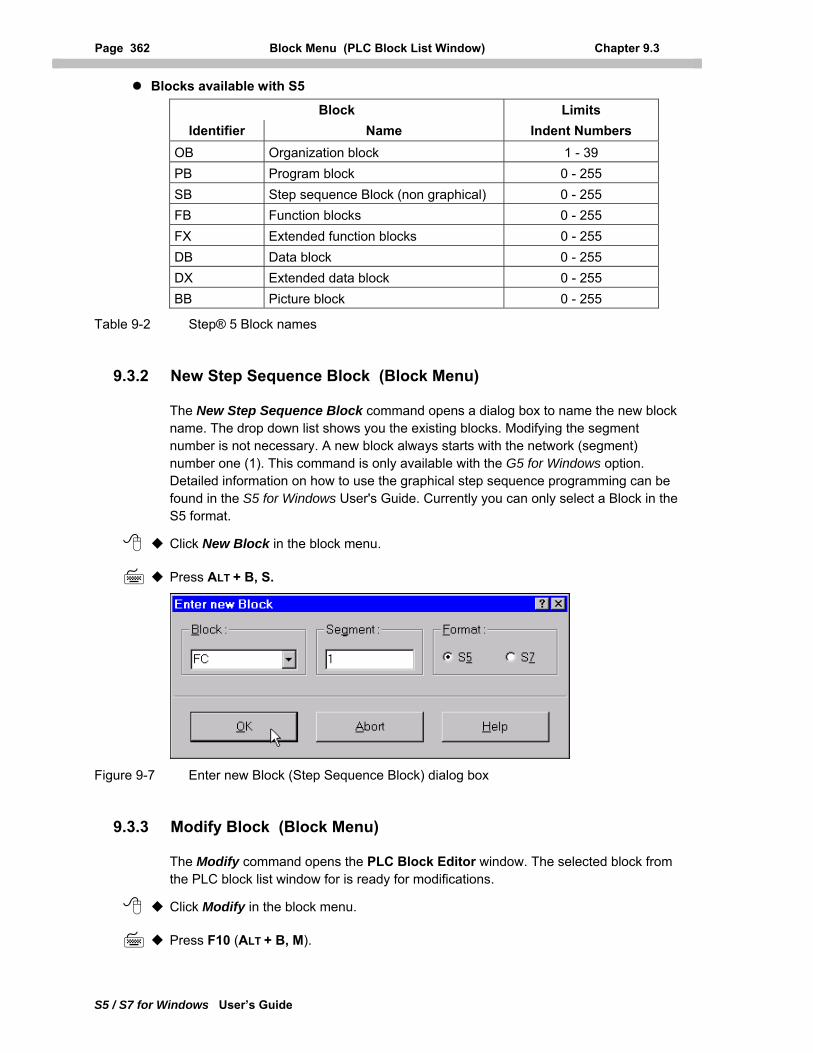
Page 362 Block Menu (PLC Block List Window) Chapter 9.3
S5 / S7 for Windows User’s Guide
Blocks available with S5
Block Limits Identifier Name Indent Numbers
OB Organization block 1 - 39 PB Program block 0 - 255 SB Step sequence Block (non graphical) 0 - 255 FB Function blocks 0 - 255 FX Extended function blocks 0 - 255 DB Data block 0 - 255 DX Extended data block 0 - 255 BB Picture block 0 - 255
Table 9-2 Step® 5 Block names
9.3.2 New Step Sequence Block (Block Menu)
The New Step Sequence Block command opens a dialog box to name the new block name. The drop down list shows you the existing blocks. Modifying the segment number is not necessary. A new block always starts with the network (segment) number one (1). This command is only available with the G5 for Windows option. Detailed information on how to use the graphical step sequence programming can be found in the S5 for Windows User's Guide. Currently you can only select a Block in the S5 format.
Click New Block in the block menu.
Press ALT + B, S.
Figure 9-7 Enter new Block (Step Sequence Block) dialog box
9.3.3 Modify Block (Block Menu)
The Modify command opens the PLC Block Editor window. The selected block from the PLC block list window for is ready for modifications.
Click Modify in the block menu.
Press F10 (ALT + B, M).
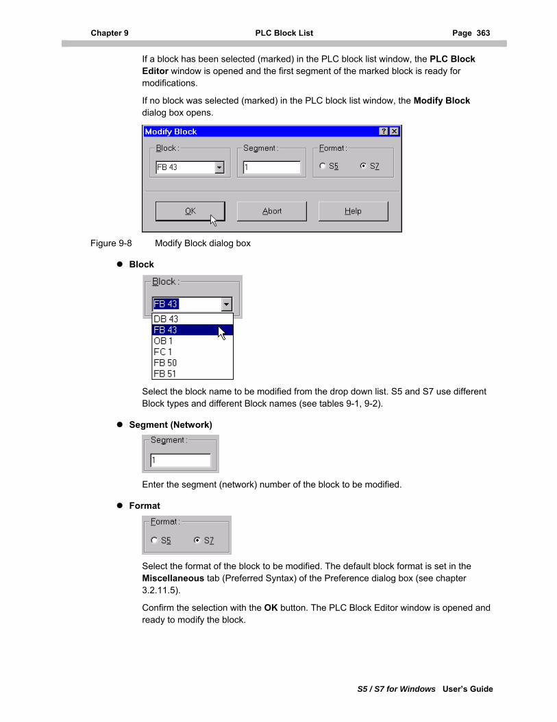
Chapter 9 PLC Block List Page 363
S5 / S7 for Windows User’s Guide
If a block has been selected (marked) in the PLC block list window, the PLC Block Editor window is opened and the first segment of the marked block is ready for modifications.
If no block was selected (marked) in the PLC block list window, the Modify Block dialog box opens.
Figure 9-8 Modify Block dialog box
Block
Select the block name to be modified from the drop down list. S5 and S7 use different Block types and different Block names (see tables 9-1, 9-2).
Segment (Network)
Enter the segment (network) number of the block to be modified.
Format
Select the format of the block to be modified. The default block format is set in the Miscellaneous tab (Preferred Syntax) of the Preference dialog box (see chapter 3.2.11.5).
Confirm the selection with the OK button. The PLC Block Editor window is opened and ready to modify the block.
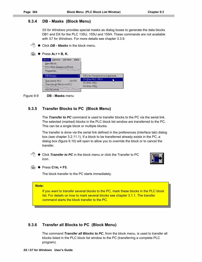
Page 364 Block Menu (PLC Block List Window) Chapter 9.3
S5 / S7 for Windows User’s Guide
9.3.4 DB - Masks (Block Menu)
S5 for Windows provides special masks as dialog boxes to generate the data blocks DB1 and DX for the PLC 135U, 155U and 155H. These commands are not available with S7 for Windows. For more details see chapter 3.3.9.
Click DB - Masks in the block menu.
Press ALT + B, K.
Figure 9-9 DB - Masks menu
9.3.5 Transfer Blocks to PC (Block Menu)
The Transfer to PC command is used to transfer blocks to the PC via the serial link. The selected (marked) blocks in the PLC block list window are transferred to the PC. This can be a single block or multiple blocks.
The transfer is done via the serial link defined in the preferences (interface tab) dialog box (see chapter 3.2.11.1). If a block to be transferred already exists in the PC, a dialog box (figure 9.10) will open to allow you to override the block or to cancel the transfer.
Click Transfer to PC in the block menu or click the Transfer to PC icon.
Press CTRL + F5.
The block transfer to the PC starts immediately.
Note: If you want to transfer several blocks to the PC, mark these blocks in the PLC block list. For details on how to mark several blocks see chapter 3.1.1. The transfer command starts the block transfer to the PC.
9.3.6 Transfer all Blocks to PC (Block Menu)
The command Transfer all Blocks to PC, from the block menu, is used to transfer all blocks listed in the PLC block list window to the PC (transferring a complete PLC program).
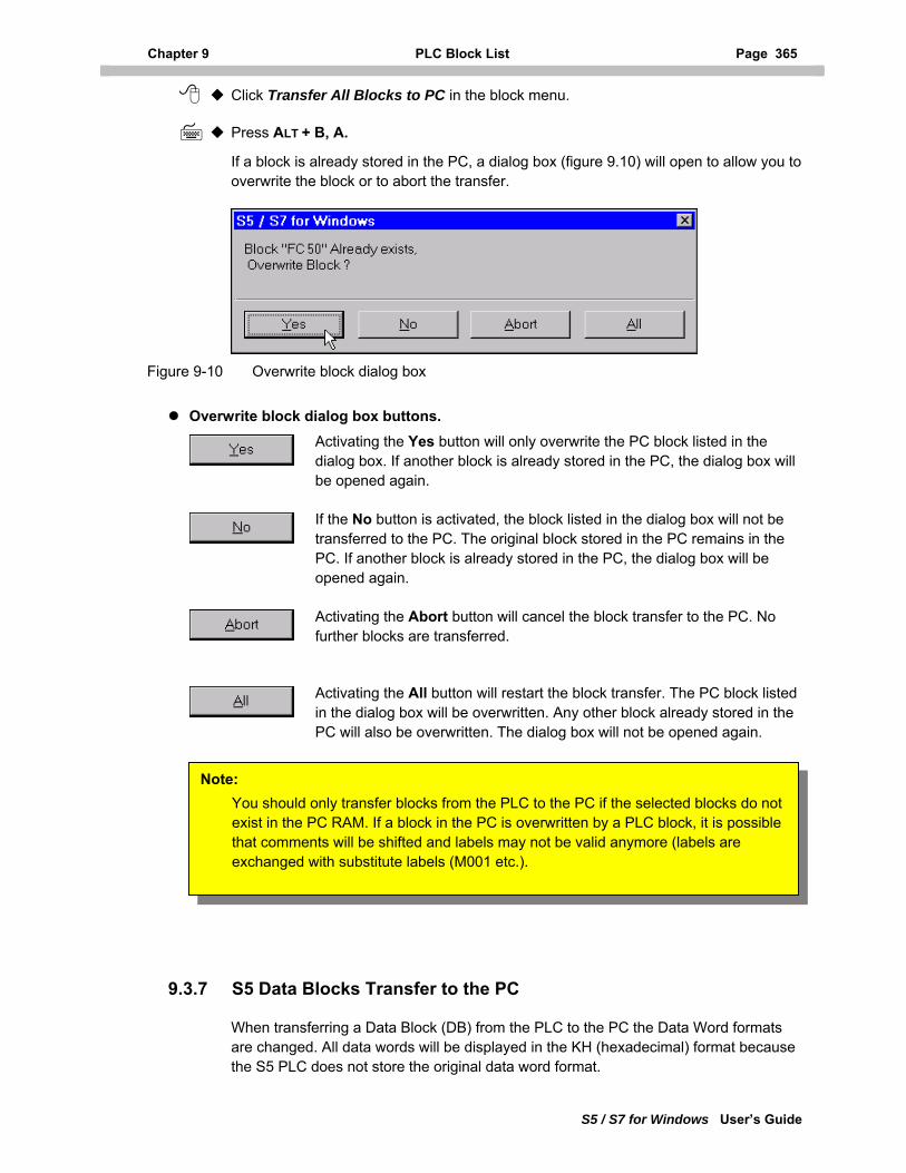
Chapter 9 PLC Block List Page 365
S5 / S7 for Windows User’s Guide
Click Transfer All Blocks to PC in the block menu.
Press ALT + B, A.
If a block is already stored in the PC, a dialog box (figure 9.10) will open to allow you to overwrite the block or to abort the transfer.
Figure 9-10 Overwrite block dialog box
Overwrite block dialog box buttons. Activating the Yes button will only overwrite the PC block listed in the dialog box. If another block is already stored in the PC, the dialog box will be opened again.
If the No button is activated, the block listed in the dialog box will not be transferred to the PC. The original block stored in the PC remains in the PC. If another block is already stored in the PC, the dialog box will be opened again.
Activating the Abort button will cancel the block transfer to the PC. No further blocks are transferred.
Activating the All button will restart the block transfer. The PC block listed in the dialog box will be overwritten. Any other block already stored in the PC will also be overwritten. The dialog box will not be opened again.
Note: You should only transfer blocks from the PLC to the PC if the selected blocks do not exist in the PC RAM. If a block in the PC is overwritten by a PLC block, it is possible that comments will be shifted and labels may not be valid anymore (labels are exchanged with substitute labels (M001 etc.).
9.3.7 S5 Data Blocks Transfer to the PC
When transferring a Data Block (DB) from the PLC to the PC the Data Word formats are changed. All data words will be displayed in the KH (hexadecimal) format because the S5 PLC does not store the original data word format.
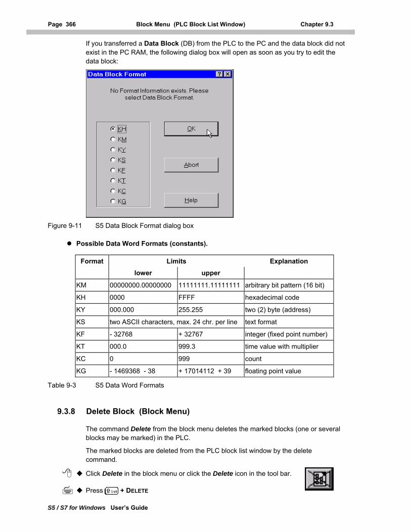
Page 366 Block Menu (PLC Block List Window) Chapter 9.3
S5 / S7 for Windows User’s Guide
If you transferred a Data Block (DB) from the PLC to the PC and the data block did not exist in the PC RAM, the following dialog box will open as soon as you try to edit the data block:
Figure 9-11 S5 Data Block Format dialog box
Possible Data Word Formats (constants).
Format Limits Explanation
lower upper
KM 00000000.00000000 11111111.11111111 arbitrary bit pattern (16 bit)
KH 0000 FFFF hexadecimal code
KY 000.000 255.255 two (2) byte (address)
KS two ASCII characters, max. 24 chr. per line text format
KF - 32768 + 32767 integer (fixed point number)
KT 000.0 999.3 time value with multiplier
KC 0 999 count
KG - 1469368 - 38 + 17014112 + 39 floating point value
Table 9-3 S5 Data Word Formats
9.3.8 Delete Block (Block Menu)
The command Delete from the block menu deletes the marked blocks (one or several blocks may be marked) in the PLC.
The marked blocks are deleted from the PLC block list window by the delete command.
Click Delete in the block menu or click the Delete icon in the tool bar.
Press + DELETE
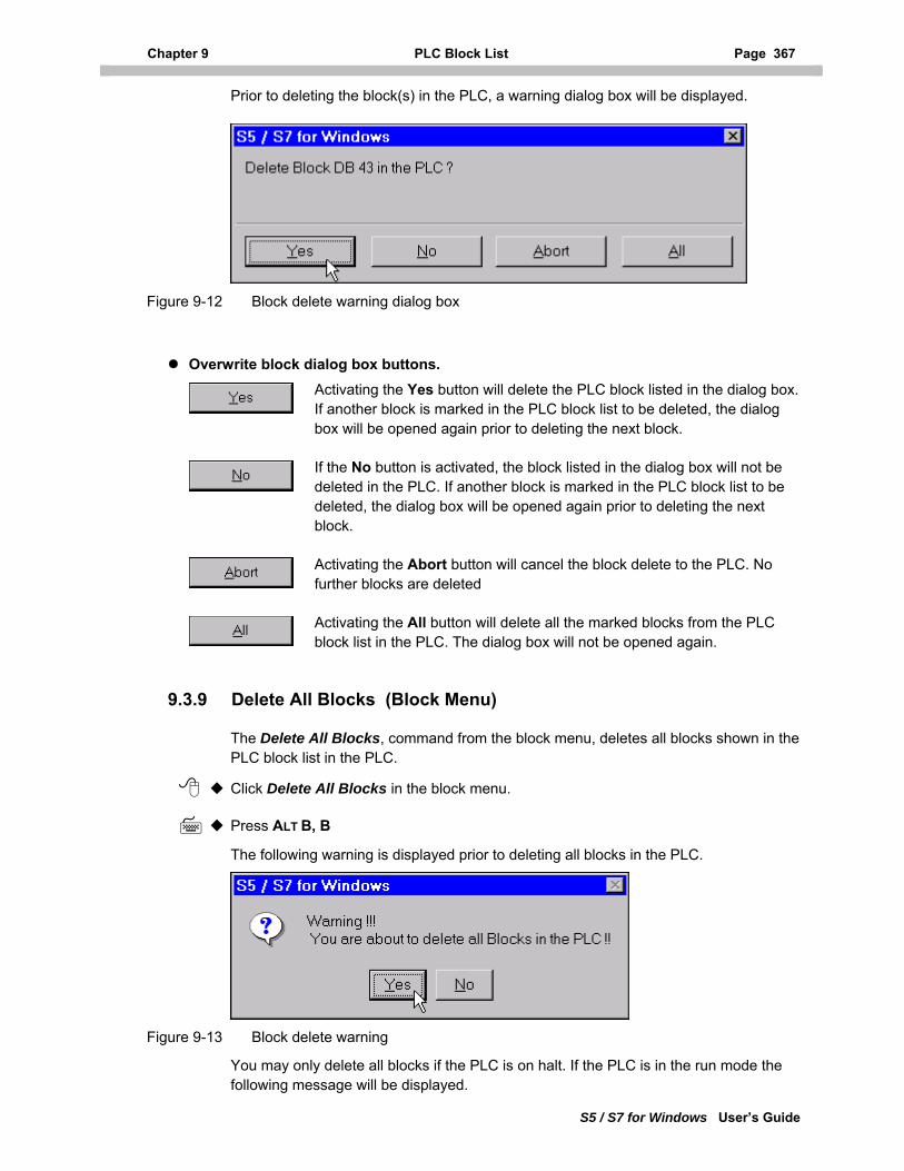
Chapter 9 PLC Block List Page 367
S5 / S7 for Windows User’s Guide
Prior to deleting the block(s) in the PLC, a warning dialog box will be displayed.
Figure 9-12 Block delete warning dialog box
Overwrite block dialog box buttons. Activating the Yes button will delete the PLC block listed in the dialog box. If another block is marked in the PLC block list to be deleted, the dialog box will be opened again prior to deleting the next block.
If the No button is activated, the block listed in the dialog box will not be deleted in the PLC. If another block is marked in the PLC block list to be deleted, the dialog box will be opened again prior to deleting the next block.
Activating the Abort button will cancel the block delete to the PLC. No further blocks are deleted
Activating the All button will delete all the marked blocks from the PLC block list in the PLC. The dialog box will not be opened again.
9.3.9 Delete All Blocks (Block Menu)
The Delete All Blocks, command from the block menu, deletes all blocks shown in the PLC block list in the PLC.
Click Delete All Blocks in the block menu.
Press ALT B, B
The following warning is displayed prior to deleting all blocks in the PLC.
Figure 9-13 Block delete warning
You may only delete all blocks if the PLC is on halt. If the PLC is in the run mode the following message will be displayed.
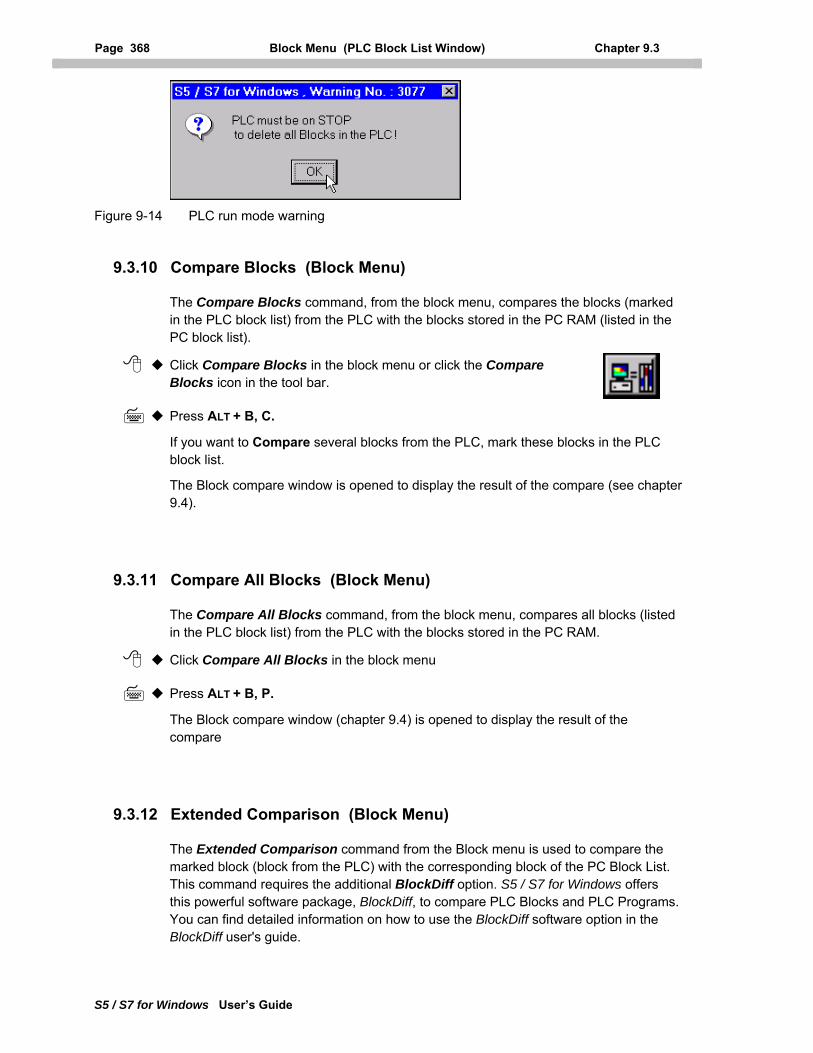
Page 368 Block Menu (PLC Block List Window) Chapter 9.3
S5 / S7 for Windows User’s Guide
Figure 9-14 PLC run mode warning
9.3.10 Compare Blocks (Block Menu)
The Compare Blocks command, from the block menu, compares the blocks (marked in the PLC block list) from the PLC with the blocks stored in the PC RAM (listed in the PC block list).
Click Compare Blocks in the block menu or click the Compare Blocks icon in the tool bar.
Press ALT + B, C.
If you want to Compare several blocks from the PLC, mark these blocks in the PLC block list.
The Block compare window is opened to display the result of the compare (see chapter 9.4).
9.3.11 Compare All Blocks (Block Menu)
The Compare All Blocks command, from the block menu, compares all blocks (listed in the PLC block list) from the PLC with the blocks stored in the PC RAM.
Click Compare All Blocks in the block menu
Press ALT + B, P.
The Block compare window (chapter 9.4) is opened to display the result of the compare
9.3.12 Extended Comparison (Block Menu)
The Extended Comparison command from the Block menu is used to compare the marked block (block from the PLC) with the corresponding block of the PC Block List. This command requires the additional BlockDiff option. S5 / S7 for Windows offers this powerful software package, BlockDiff, to compare PLC Blocks and PLC Programs. You can find detailed information on how to use the BlockDiff software option in the BlockDiff user's guide.
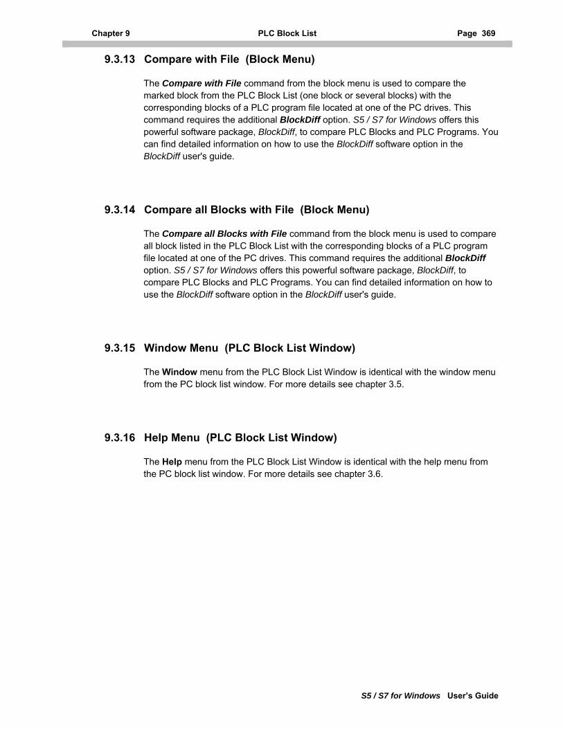
Chapter 9 PLC Block List Page 369
S5 / S7 for Windows User’s Guide
9.3.13 Compare with File (Block Menu)
The Compare with File command from the block menu is used to compare the marked block from the PLC Block List (one block or several blocks) with the corresponding blocks of a PLC program file located at one of the PC drives. This command requires the additional BlockDiff option. S5 / S7 for Windows offers this powerful software package, BlockDiff, to compare PLC Blocks and PLC Programs. You can find detailed information on how to use the BlockDiff software option in the BlockDiff user's guide.
9.3.14 Compare all Blocks with File (Block Menu)
The Compare all Blocks with File command from the block menu is used to compare all block listed in the PLC Block List with the corresponding blocks of a PLC program file located at one of the PC drives. This command requires the additional BlockDiff option. S5 / S7 for Windows offers this powerful software package, BlockDiff, to compare PLC Blocks and PLC Programs. You can find detailed information on how to use the BlockDiff software option in the BlockDiff user's guide.
9.3.15 Window Menu (PLC Block List Window)
The Window menu from the PLC Block List Window is identical with the window menu from the PC block list window. For more details see chapter 3.5.
9.3.16 Help Menu (PLC Block List Window)
The Help menu from the PLC Block List Window is identical with the help menu from the PC block list window. For more details see chapter 3.6.
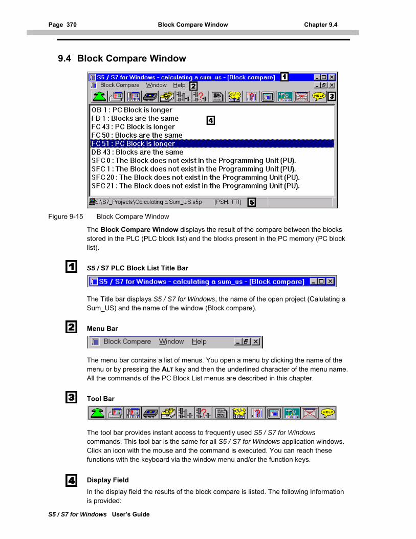
Page 370 Block Compare Window Chapter 9.4
S5 / S7 for Windows User’s Guide
9.4 Block Compare Window
Figure 9-15 Block Compare Window
The Block Compare Window displays the result of the compare between the blocks stored in the PLC (PLC block list) and the blocks present in the PC memory (PC block list).
S5 / S7 PLC Block List Title Bar
The Title bar displays S5 / S7 for Windows, the name of the open project (Calulating a Sum_US) and the name of the window (Block compare).
Menu Bar
The menu bar contains a list of menus. You open a menu by clicking the name of the menu or by pressing the ALT key and then the underlined character of the menu name. All the commands of the PC Block List menus are described in this chapter.
Tool Bar
The tool bar provides instant access to frequently used S5 / S7 for Windows commands. This tool bar is the same for all S5 / S7 for Windows application windows. Click an icon with the mouse and the command is executed. You can reach these functions with the keyboard via the window menu and/or the function keys.
Display Field In the display field the results of the block compare is listed. The following Information is provided:
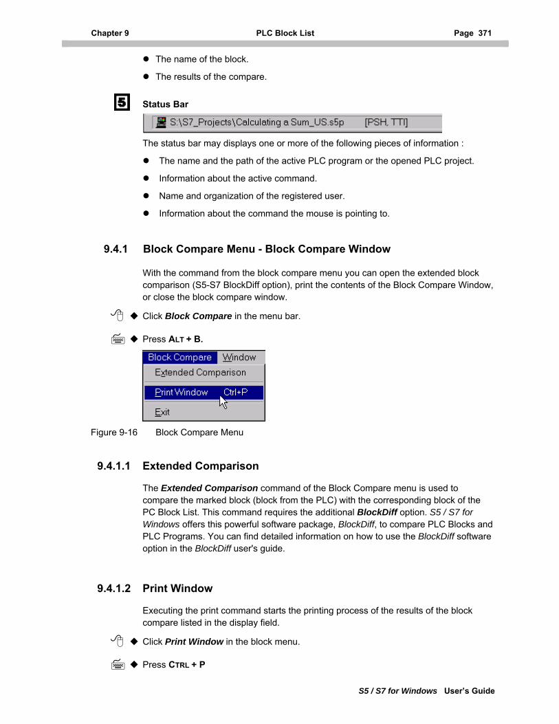
Chapter 9 PLC Block List Page 371
S5 / S7 for Windows User’s Guide
The name of the block.
The results of the compare.
Status Bar
The status bar may displays one or more of the following pieces of information :
The name and the path of the active PLC program or the opened PLC project.
Information about the active command.
Name and organization of the registered user.
Information about the command the mouse is pointing to.
9.4.1 Block Compare Menu - Block Compare Window
With the command from the block compare menu you can open the extended block comparison (S5-S7 BlockDiff option), print the contents of the Block Compare Window, or close the block compare window.
Click Block Compare in the menu bar.
Press ALT + B.
Figure 9-16 Block Compare Menu
9.4.1.1 Extended Comparison
The Extended Comparison command of the Block Compare menu is used to compare the marked block (block from the PLC) with the corresponding block of the PC Block List. This command requires the additional BlockDiff option. S5 / S7 for Windows offers this powerful software package, BlockDiff, to compare PLC Blocks and PLC Programs. You can find detailed information on how to use the BlockDiff software option in the BlockDiff user's guide.
9.4.1.2 Print Window
Executing the print command starts the printing process of the results of the block compare listed in the display field.
Click Print Window in the block menu.
Press CTRL + P
Page 372 Block Compare Window Chapter 9.4
S5 / S7 for Windows User’s Guide
9.4.1.3 Exit (Block Compare Window)
With the Exit command, from the Block Compare menu, you can close the Block Compare Window.
Click Exit in the Block Compare menu.
Press ALT + B, E.
9.4.2 Window Menu (Block Compare Window)
The Window menu from the block compare window is identical with the window menu from the PC block list window. For more details see chapter 3.5
9.4.3 Help Menu (Block Compare Window)
The Help menu from the block compare window is identical with the help menu from the PC block list window. For more details see chapter 3.6.
Chapter 10 PLC Status Page 373
S5 / S7 for Windows User’s Guide
10 PLC Status
Commands from the PLC Status menus are used to perform online functions. These functions are available with an external Hardware PLC, S5 / S7 for Windows PLC in a PC (Software PLC) and the S5 / S7 Simulation PLC.
10.1 PLC Status Window
External S7-300/400 Hardware PLC The PLC status window is called from the PLC block list window.
To open the PLC status window, the PLC must be connected via an MPI converter cable with the PC. The PLC must be powered up and a program must be present in the PLC.
Software PLC, the S7 for Windows, PLC in a PC, installed on an external PC The PLC status window is called from the PLC block list window.
To open the PLC status window, the PC executing the Software PLC must be connected via a null modem with the PC executing S7 for Windows. The PC must be powered up, the Software PLC must be running and a PLC program must be present. This could also be the S7 Simulation PLC.
Software PLC, the S7 for Windows, PLC in a PC, installed on the PC running S7 for Windows
The PLC status window is called from the PLC block list window.
To open the PLC status window the Software PLC must be running and a PLC program must be present in the Software PLC. No external connection is needed. This could also be the S7 Simulation PLC.
External S5 Hardware PLC The PLC status window is called from the PLC block list window.
To open the PLC status window the PLC must be connected via a current loop converter (see a appendix) with the PC. The PLC must be powered up and a program must be present in the PLC.
Software PLC, the S5 for Windows, PLC in a PC, installed on an external PC The PLC status window is called from the PLC block list window.
To open the PLC status window the PC executing the Software PLC must be connected via a null modem (see a appendix) with the PC executing S5 for Windows. The PC must be powered up, the Software PLC must be running, and a PLC program must be present .
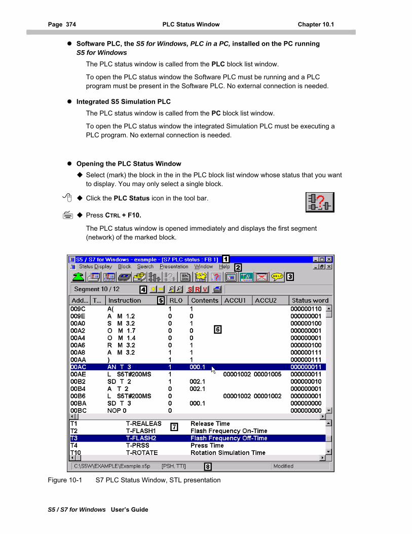
Page 374 PLC Status Window Chapter 10.1
S5 / S7 for Windows User’s Guide
Software PLC, the S5 for Windows, PLC in a PC, installed on the PC running S5 for Windows
The PLC status window is called from the PLC block list window.
To open the PLC status window the Software PLC must be running and a PLC program must be present in the Software PLC. No external connection is needed.
Integrated S5 Simulation PLC The PLC status window is called from the PC block list window.
To open the PLC status window the integrated Simulation PLC must be executing a PLC program. No external connection is needed.
Opening the PLC Status Window Select (mark) the block in the in the PLC block list window whose status that you want to display. You may only select a single block.
Click the PLC Status icon in the tool bar.
Press CTRL + F10.
The PLC status window is opened immediately and displays the first segment (network) of the marked block.
Figure 10-1 S7 PLC Status Window, STL presentation
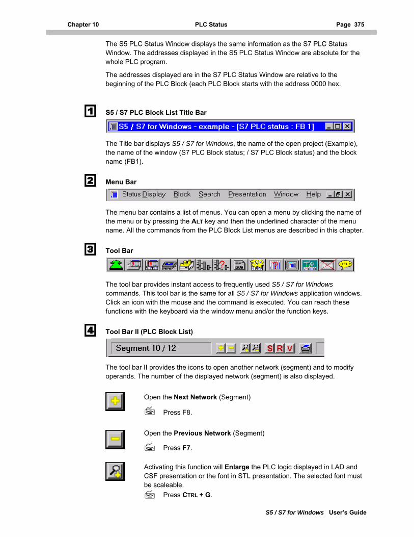
Chapter 10 PLC Status Page 375
S5 / S7 for Windows User’s Guide
The S5 PLC Status Window displays the same information as the S7 PLC Status Window. The addresses displayed in the S5 PLC Status Window are absolute for the whole PLC program.
The addresses displayed are in the S7 PLC Status Window are relative to the beginning of the PLC Block (each PLC Block starts with the address 0000 hex.
S5 / S7 PLC Block List Title Bar
The Title bar displays S5 / S7 for Windows, the name of the open project (Example), the name of the window (S7 PLC Block status; / S7 PLC Block status) and the block name (FB1).
Menu Bar
The menu bar contains a list of menus. You can open a menu by clicking the name of the menu or by pressing the ALT key and then the underlined character of the menu name. All the commands from the PLC Block List menus are described in this chapter.
Tool Bar
The tool bar provides instant access to frequently used S5 / S7 for Windows commands. This tool bar is the same for all S5 / S7 for Windows application windows. Click an icon with the mouse and the command is executed. You can reach these functions with the keyboard via the window menu and/or the function keys.
Tool Bar II (PLC Block List)
The tool bar II provides the icons to open another network (segment) and to modify operands. The number of the displayed network (segment) is also displayed.
Open the Next Network (Segment)
Press F8.
Open the Previous Network (Segment)
Press F7.
Activating this function will Enlarge the PLC logic displayed in LAD and CSF presentation or the font in STL presentation. The selected font must be scaleable.
Press CTRL + G.
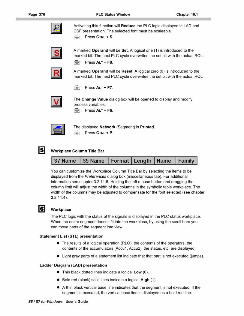
Page 376 PLC Status Window Chapter 10.1
S5 / S7 for Windows User’s Guide
Activating this function will Reduce the PLC logic displayed in LAD and CSF presentation. The selected font must be scaleable.
Press CTRL + S.
A marked Operand will be Set. A logical one (1) is introduced to the marked bit. The next PLC cycle overwrites the set bit with the actual ROL.
Press ALT + F8.
A marked Operand will be Reset. A logical zero (0) is introduced to the marked bit. The next PLC cycle overwrites the set bit with the actual ROL .
Press ALT + F7.
The Change Value dialog box will be opened to display and modify process variables.
Press ALT + F6.
The displayed Network (Segment) is Printed.
Press CTRL + P.
Workplace Column Title Bar
You can customize the Workplace Column Title Bar by selecting the items to be displayed from the Preferences dialog box (miscellaneous tab). For additional information see chapter 3.2.11.5. Holding the left mouse button and dragging the column limit will adjust the width of the columns in the symbolic table workplace. The width of the columns may be adjusted to compensate for the font selected (see chapter 3.2.11.4).
Workplace The PLC logic with the status of the signals is displayed in the PLC status workplace. When the entire segment doesn’t fit into the workplace, by using the scroll bars you can move parts of the segment into view.
Statement List (STL) presentation The results of a logical operation (RLO), the contents of the operators, the
contents of the accumulators (Accu1, Accu2), the status, etc. are displayed.
Light gray parts of a statement list indicate that that part is not executed (jumps).
Ladder Diagram (LAD) presentation Thin black dotted lines indicate a logical Low (0).
Bold red (black) solid lines indicate a logical High (1).
A thin black vertical base line indicates that the segment is not executed. If the segment is executed, the vertical base line is displayed as a bold red line.
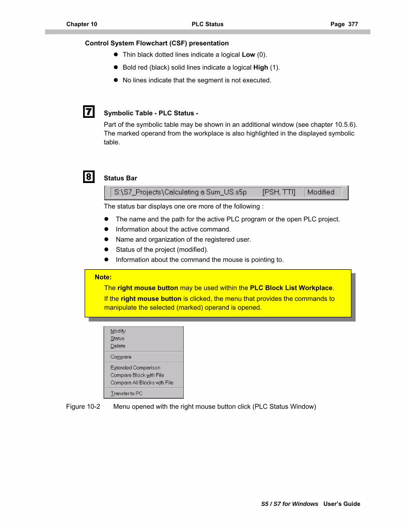
Chapter 10 PLC Status Page 377
S5 / S7 for Windows User’s Guide
Control System Flowchart (CSF) presentation Thin black dotted lines indicate a logical Low (0).
Bold red (black) solid lines indicate a logical High (1).
No lines indicate that the segment is not executed.
Symbolic Table - PLC Status - Part of the symbolic table may be shown in an additional window (see chapter 10.5.6). The marked operand from the workplace is also highlighted in the displayed symbolic table.
Status Bar
The status bar displays one ore more of the following :
The name and the path for the active PLC program or the open PLC project. Information about the active command. Name and organization of the registered user. Status of the project (modified). Information about the command the mouse is pointing to.
Note: The right mouse button may be used within the PLC Block List Workplace. If the right mouse button is clicked, the menu that provides the commands to manipulate the selected (marked) operand is opened.
Figure 10-2 Menu opened with the right mouse button click (PLC Status Window)
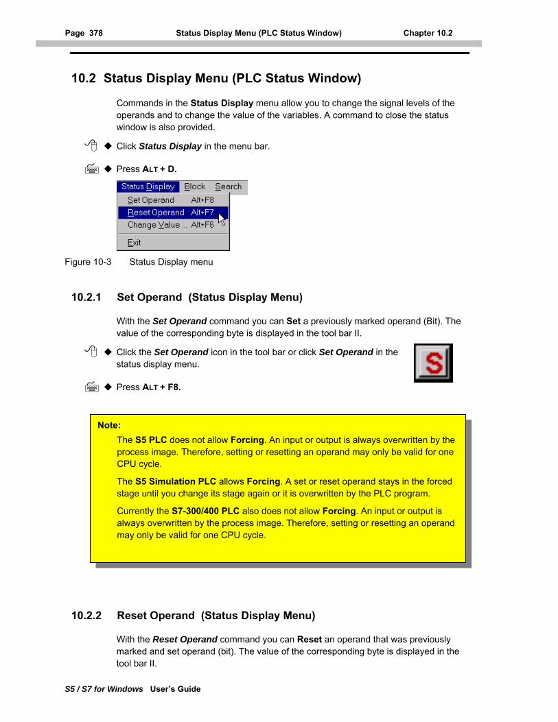
Page 378 Status Display Menu (PLC Status Window) Chapter 10.2
S5 / S7 for Windows User’s Guide
10.2 Status Display Menu (PLC Status Window)
Commands in the Status Display menu allow you to change the signal levels of the operands and to change the value of the variables. A command to close the status window is also provided.
Click Status Display in the menu bar.
Press ALT + D.
Figure 10-3 Status Display menu
10.2.1 Set Operand (Status Display Menu)
With the Set Operand command you can Set a previously marked operand (Bit). The value of the corresponding byte is displayed in the tool bar II.
Click the Set Operand icon in the tool bar or click Set Operand in the status display menu.
Press ALT + F8.
Note: The S5 PLC does not allow Forcing. An input or output is always overwritten by the process image. Therefore, setting or resetting an operand may only be valid for one CPU cycle.
The S5 Simulation PLC allows Forcing. A set or reset operand stays in the forced stage until you change its stage again or it is overwritten by the PLC program.
Currently the S7-300/400 PLC also does not allow Forcing. An input or output is always overwritten by the process image. Therefore, setting or resetting an operand may only be valid for one CPU cycle.
10.2.2 Reset Operand (Status Display Menu)
With the Reset Operand command you can Reset an operand that was previously marked and set operand (bit). The value of the corresponding byte is displayed in the tool bar II.
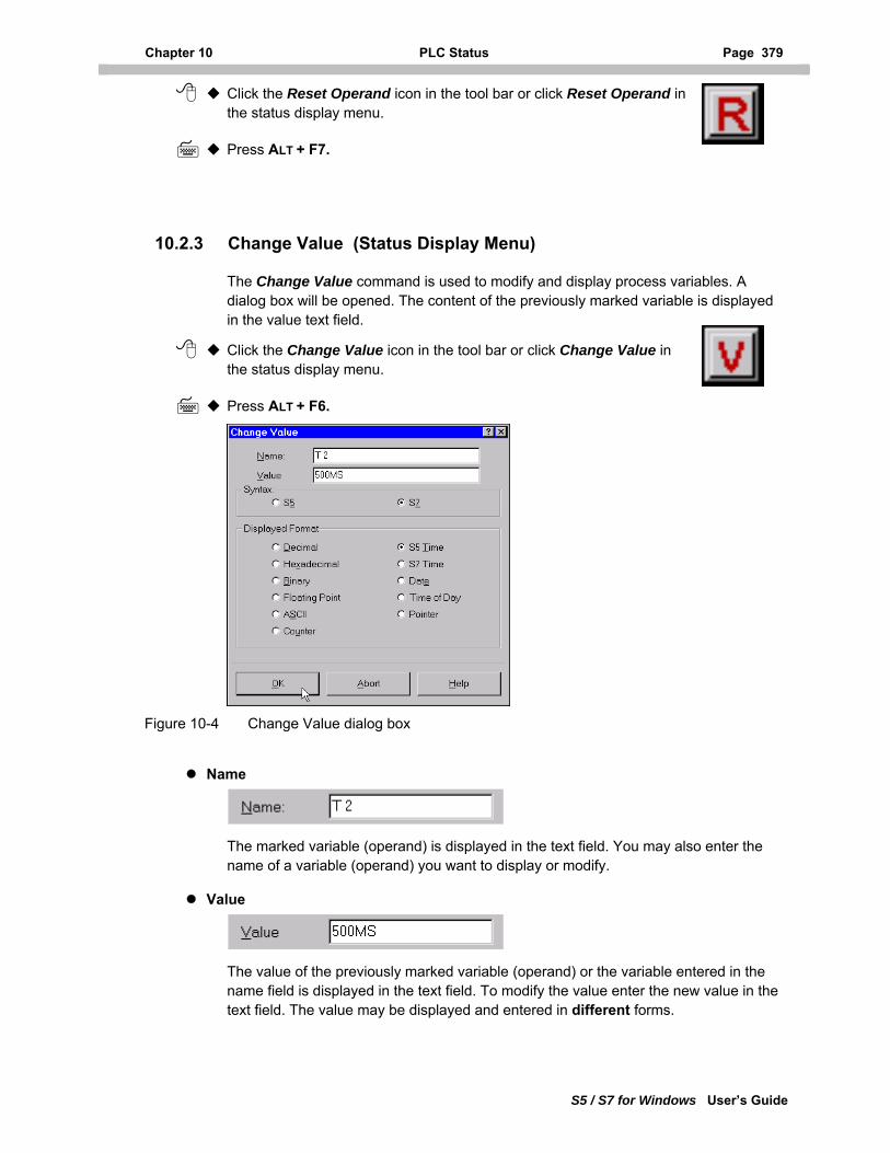
Chapter 10 PLC Status Page 379
S5 / S7 for Windows User’s Guide
Click the Reset Operand icon in the tool bar or click Reset Operand in the status display menu.
Press ALT + F7.
10.2.3 Change Value (Status Display Menu)
The Change Value command is used to modify and display process variables. A dialog box will be opened. The content of the previously marked variable is displayed in the value text field.
Click the Change Value icon in the tool bar or click Change Value in the status display menu.
Press ALT + F6.
Figure 10-4 Change Value dialog box
Name
The marked variable (operand) is displayed in the text field. You may also enter the name of a variable (operand) you want to display or modify.
Value
The value of the previously marked variable (operand) or the variable entered in the name field is displayed in the text field. To modify the value enter the new value in the text field. The value may be displayed and entered in different forms.
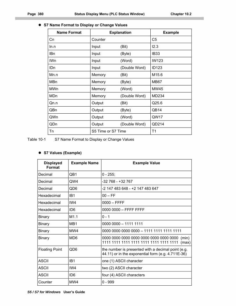
Page 380 Status Display Menu (PLC Status Window) Chapter 10.2
S5 / S7 for Windows User’s Guide
S7 Name Format to Display or Change Values
Name Format Explanation Example
Cn Counter C5
In.n Input (Bit) I2.3
IBn Input (Byte) IB33
IWn Input (Word) IW123
IDn Input (Double Word) ID123
Mn.n Memory (Bit) M15.6
MBn Memory (Byte) MB67
MWn Memory (Word) MW45
MDn Memory (Double Word) MD234
Qn.n Output (Bit) Q25.6
QBn Output (Byte) QB14
QWn Output (Word) QW17
QDn Output (Double Word) QD214
Tn S5 Time or S7 Time T1
Table 10-1 S7 Name Format to Display or Change Values
S7 Values (Example)
Displayed Format
Example Name Example Value
Decimal QB1 0 - 255;
Decimal QW4 -32 768 - +32 767
Decimal QD6 -2 147 483 648 - +2 147 483 647
Hexadecimal IB1 00 – FF
Hexadecimal IW4 0000 – FFFF
Hexadecimal ID6 0000 0000 – FFFF FFFF
Binary M1.1 0 - 1
Binary MB1 0000 0000 – 1111 1111
Binary MW4 0000 0000 0000 0000 – 1111 1111 1111 1111
Binary MD6 0000 0000 0000 0000 0000 0000 0000 0000 (min) 1111 1111 1111 1111 1111 1111 1111 1111 (max)
Floating Point QD6 the number is presented with a decimal point (e.g. 44.11) or in the exponential form (e.g. 4.711E-36)
ASCII IB1 one (1) ASCII character
ASCII IW4 two (2) ASCII character
ASCII ID6 four (4) ASCII characters
Counter MW4 0 - 999
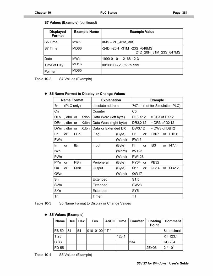
Chapter 10 PLC Status Page 381
S5 / S7 for Windows User’s Guide
S7 Values (Example) (continued)
Displayed Format
Example Name Example Value
S5 Time MW6 0MS – 2H_46M_30S
S7 Time MD66 -24D_-20H_-31M_-23S_-648MS 24D_20H_31M_23S_647MS
Date MW4 1990-01-01 - 2168-12-31
Time of Day MD16 00:00:00 - 23:59:59.999
Pointer MD65
Table 10-2 S7 Values (Example)
S5 Name Format to Display or Change Values
Name Format Explanation Example ?n (PLC only) absolute address ?4711 (not for Simulation PLC) Cn Counter C5 DLn , dbn or Xdbn Data Word (left byte) DL3,X12 = DL3 of DX12 DRn , dbn or Xdbn Data Word (right byte) DR3,X12 = DR3 of DX12 DWn , dbn or Xdbn Data or Extended DX DW3,12 = DW3 of DB12 Fn or FBn Flag (Byte) F5 or FB67 or F15.6 FWn (Word) FW45 In or IBn Input (Byte) I1 or IB3 or I47.1 IWn (Word) IW123 PWn (Word) PW128 PYn or PBn Peripheral (Byte) PY34 or PB32 Qn or QBn Output (Byte) Q11 or QB14 or Q32.2 QWn (Word) QW17 Sn Extended S1.5 SWn Extended SW23 SYn Extended SY5 Tn Timer T1
Table 10-3 S5 Name Format to Display or Change Values
S5 Values (Example)
Name Dec Hex Bin ASCII Time Counter Floating Point
Comment
FB 50 84 54 01010100 “ T “ 84 decimal T 25 123.1 KT 123.1 C 33 234 KC 234 FD 55 2E+06 2 * 106
Table 10-4 S5 Values (Example)
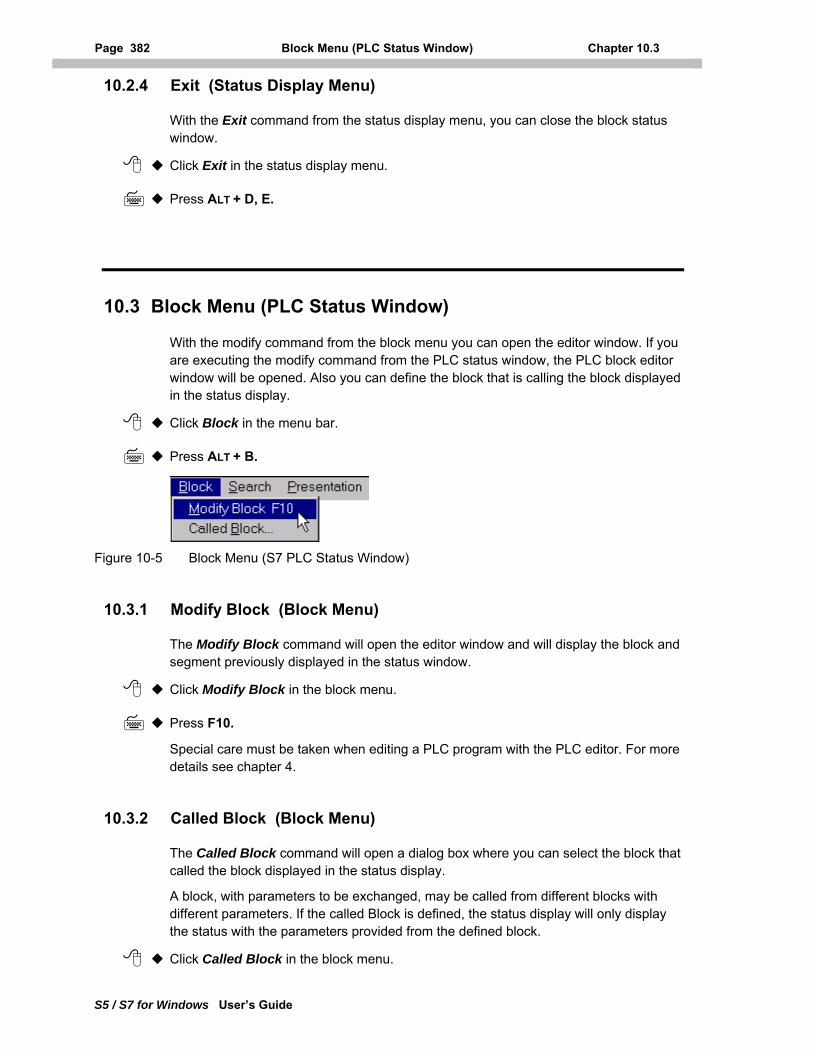
Page 382 Block Menu (PLC Status Window) Chapter 10.3
S5 / S7 for Windows User’s Guide
10.2.4 Exit (Status Display Menu)
With the Exit command from the status display menu, you can close the block status window.
Click Exit in the status display menu.
Press ALT + D, E.
10.3 Block Menu (PLC Status Window)
With the modify command from the block menu you can open the editor window. If you are executing the modify command from the PLC status window, the PLC block editor window will be opened. Also you can define the block that is calling the block displayed in the status display.
Click Block in the menu bar.
Press ALT + B.
Figure 10-5 Block Menu (S7 PLC Status Window)
10.3.1 Modify Block (Block Menu)
The Modify Block command will open the editor window and will display the block and segment previously displayed in the status window.
Click Modify Block in the block menu.
Press F10.
Special care must be taken when editing a PLC program with the PLC editor. For more details see chapter 4.
10.3.2 Called Block (Block Menu)
The Called Block command will open a dialog box where you can select the block that called the block displayed in the status display.
A block, with parameters to be exchanged, may be called from different blocks with different parameters. If the called Block is defined, the status display will only display the status with the parameters provided from the defined block.
Click Called Block in the block menu.
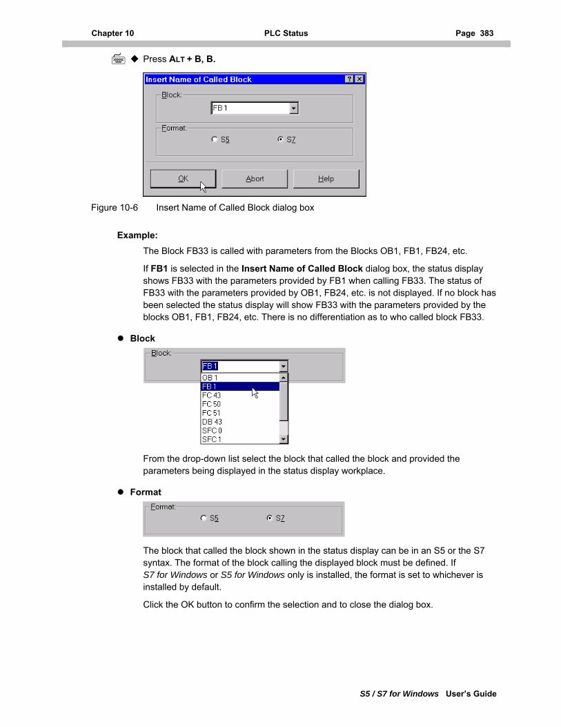
Chapter 10 PLC Status Page 383
S5 / S7 for Windows User’s Guide
Press ALT + B, B.
Figure 10-6 Insert Name of Called Block dialog box
Example: The Block FB33 is called with parameters from the Blocks OB1, FB1, FB24, etc.
If FB1 is selected in the Insert Name of Called Block dialog box, the status display shows FB33 with the parameters provided by FB1 when calling FB33. The status of FB33 with the parameters provided by OB1, FB24, etc. is not displayed. If no block has been selected the status display will show FB33 with the parameters provided by the blocks OB1, FB1, FB24, etc. There is no differentiation as to who called block FB33.
Block
From the drop-down list select the block that called the block and provided the parameters being displayed in the status display workplace.
Format
The block that called the block shown in the status display can be in an S5 or the S7 syntax. The format of the block calling the displayed block must be defined. If S7 for Windows or S5 for Windows only is installed, the format is set to whichever is installed by default.
Click the OK button to confirm the selection and to close the dialog box.
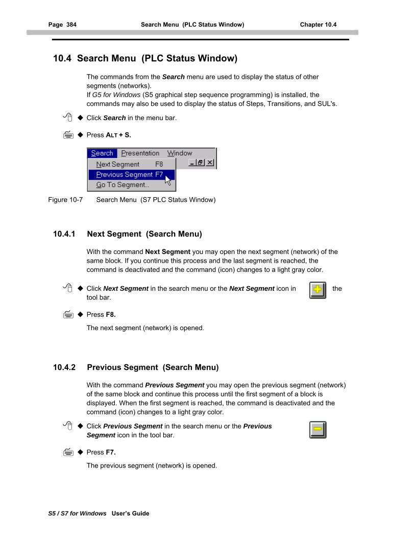
Page 384 Search Menu (PLC Status Window) Chapter 10.4
S5 / S7 for Windows User’s Guide
10.4 Search Menu (PLC Status Window)
The commands from the Search menu are used to display the status of other segments (networks). If G5 for Windows (S5 graphical step sequence programming) is installed, the commands may also be used to display the status of Steps, Transitions, and SUL's.
Click Search in the menu bar.
Press ALT + S.
Figure 10-7 Search Menu (S7 PLC Status Window)
10.4.1 Next Segment (Search Menu)
With the command Next Segment you may open the next segment (network) of the same block. If you continue this process and the last segment is reached, the command is deactivated and the command (icon) changes to a light gray color.
Click Next Segment in the search menu or the Next Segment icon in the tool bar.
Press F8.
The next segment (network) is opened.
10.4.2 Previous Segment (Search Menu)
With the command Previous Segment you may open the previous segment (network) of the same block and continue this process until the first segment of a block is displayed. When the first segment is reached, the command is deactivated and the command (icon) changes to a light gray color.
Click Previous Segment in the search menu or the Previous Segment icon in the tool bar.
Press F7.
The previous segment (network) is opened.
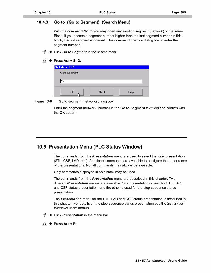
Chapter 10 PLC Status Page 385
S5 / S7 for Windows User’s Guide
10.4.3 Go to (Go to Segment) (Search Menu)
With the command Go to you may open any existing segment (network) of the same Block. If you choose a segment number higher than the last segment number in this block, the last segment is opened. This command opens a dialog box to enter the segment number.
Click Go to Segment in the search menu.
Press ALT + S, G.
Figure 10-8 Go to segment (network) dialog box
Enter the segment (network) number in the Go to Segment text field and confirm with the OK button.
10.5 Presentation Menu (PLC Status Window)
The commands from the Presentation menu are used to select the logic presentation (STL, CSF, LAD, etc.). Additional commands are available to configure the appearance of the presentations. Not all commands may always be available.
Only commands displayed in bold black may be used.
The commands from the Presentation menu are described in this chapter. Two different Presentation menus are available. One presentation is used for STL, LAD, and CSF status presentation, and the other is used for the step sequence status presentation.
The Presentation menu for the STL, LAD and CSF status presentation is described in this chapter. For details on the step sequence status presentation see the S5 / S7 for Windows users manual.
Click Presentation in the menu bar.
Press ALT + P.
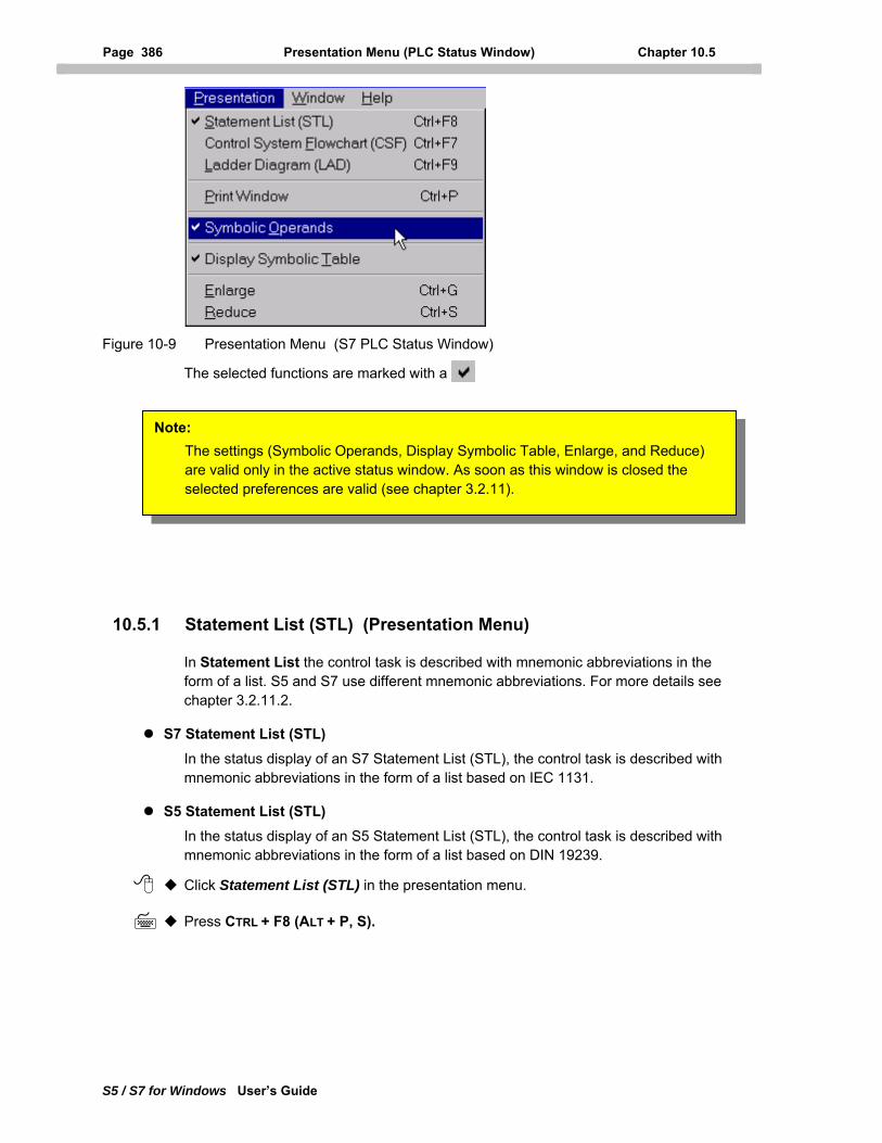
Page 386 Presentation Menu (PLC Status Window) Chapter 10.5
S5 / S7 for Windows User’s Guide
Figure 10-9 Presentation Menu (S7 PLC Status Window)
The selected functions are marked with a
Note: The settings (Symbolic Operands, Display Symbolic Table, Enlarge, and Reduce) are valid only in the active status window. As soon as this window is closed the selected preferences are valid (see chapter 3.2.11).
10.5.1 Statement List (STL) (Presentation Menu)
In Statement List the control task is described with mnemonic abbreviations in the form of a list. S5 and S7 use different mnemonic abbreviations. For more details see chapter 3.2.11.2.
S7 Statement List (STL) In the status display of an S7 Statement List (STL), the control task is described with mnemonic abbreviations in the form of a list based on IEC 1131.
S5 Statement List (STL) In the status display of an S5 Statement List (STL), the control task is described with mnemonic abbreviations in the form of a list based on DIN 19239.
Click Statement List (STL) in the presentation menu.
Press CTRL + F8 (ALT + P, S).
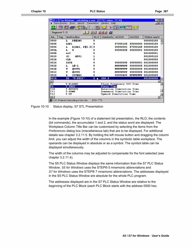
Chapter 10 PLC Status Page 387
S5 / S7 for Windows User’s Guide
Figure 10-10 Status display, S7 STL Presentation
In the example (Figure 10-10) of a statement list presentation, the RLO, the contents (bit commands), the accumulator 1 and 2, and the status word are displayed. The Workplace Column Title Bar can be customized by selecting the items from the Preferences dialog box (miscellaneous tab) that are to be displayed. For additional details see chapter 3.2.11.5. By holding the left mouse button and dragging the column limit, you can adjust the width of the columns in the symbolic table workplace. The operands can be displayed in absolute or as a symbol. The symbol table can be displayed simultaneously.
The width of the columns may be adjusted to compensate for the font selected (see chapter 3.2.11.4).
The S5 PLC Status Window displays the same information than the S7 PLC Status Window. S5 for Windows uses the STEP® 5 mnemonic abbreviations and S7 for Windows uses the STEP® 7 mnemonic abbreviations. The addresses displayed in the S5 PLC Status Window are absolute for the whole PLC program.
The addresses displayed are in the S7 PLC Status Window are relative to the beginning of the PLC Block (each PLC Block starts with the address 0000 hex.
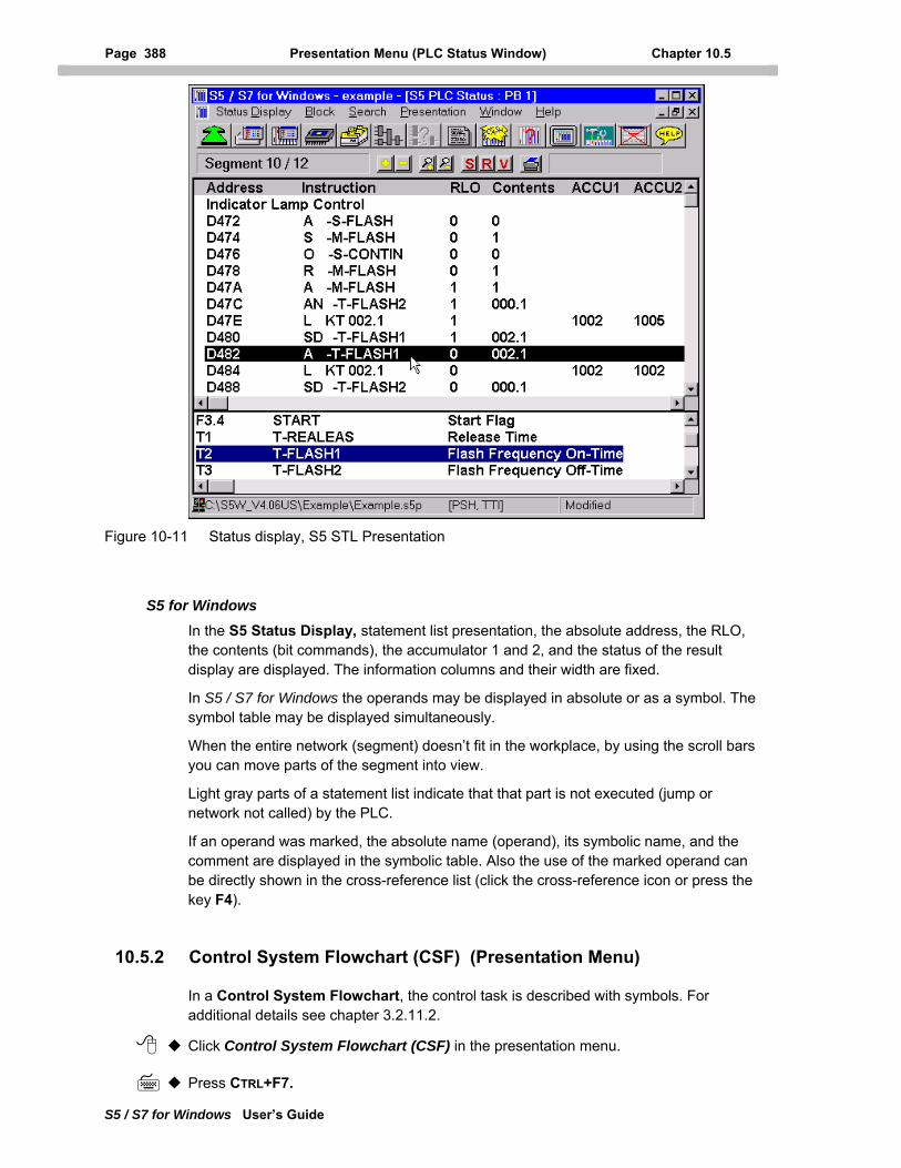
Page 388 Presentation Menu (PLC Status Window) Chapter 10.5
S5 / S7 for Windows User’s Guide
Figure 10-11 Status display, S5 STL Presentation
S5 for Windows In the S5 Status Display, statement list presentation, the absolute address, the RLO, the contents (bit commands), the accumulator 1 and 2, and the status of the result display are displayed. The information columns and their width are fixed.
In S5 / S7 for Windows the operands may be displayed in absolute or as a symbol. The symbol table may be displayed simultaneously.
When the entire network (segment) doesn’t fit in the workplace, by using the scroll bars you can move parts of the segment into view.
Light gray parts of a statement list indicate that that part is not executed (jump or network not called) by the PLC.
If an operand was marked, the absolute name (operand), its symbolic name, and the comment are displayed in the symbolic table. Also the use of the marked operand can be directly shown in the cross-reference list (click the cross-reference icon or press the key F4).
10.5.2 Control System Flowchart (CSF) (Presentation Menu)
In a Control System Flowchart, the control task is described with symbols. For additional details see chapter 3.2.11.2.
Click Control System Flowchart (CSF) in the presentation menu.
Press CTRL+F7.
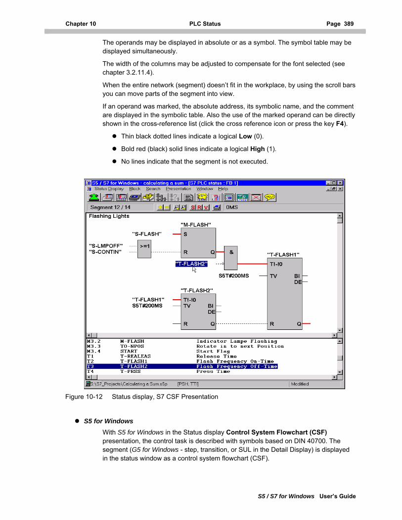
Chapter 10 PLC Status Page 389
S5 / S7 for Windows User’s Guide
The operands may be displayed in absolute or as a symbol. The symbol table may be displayed simultaneously.
The width of the columns may be adjusted to compensate for the font selected (see chapter 3.2.11.4).
When the entire network (segment) doesn’t fit in the workplace, by using the scroll bars you can move parts of the segment into view.
If an operand was marked, the absolute address, its symbolic name, and the comment are displayed in the symbolic table. Also the use of the marked operand can be directly shown in the cross-reference list (click the cross reference icon or press the key F4).
Thin black dotted lines indicate a logical Low (0).
Bold red (black) solid lines indicate a logical High (1).
No lines indicate that the segment is not executed.
Figure 10-12 Status display, S7 CSF Presentation
S5 for Windows With S5 for Windows in the Status display Control System Flowchart (CSF) presentation, the control task is described with symbols based on DIN 40700. The segment (G5 for Windows - step, transition, or SUL in the Detail Display) is displayed in the status window as a control system flowchart (CSF).
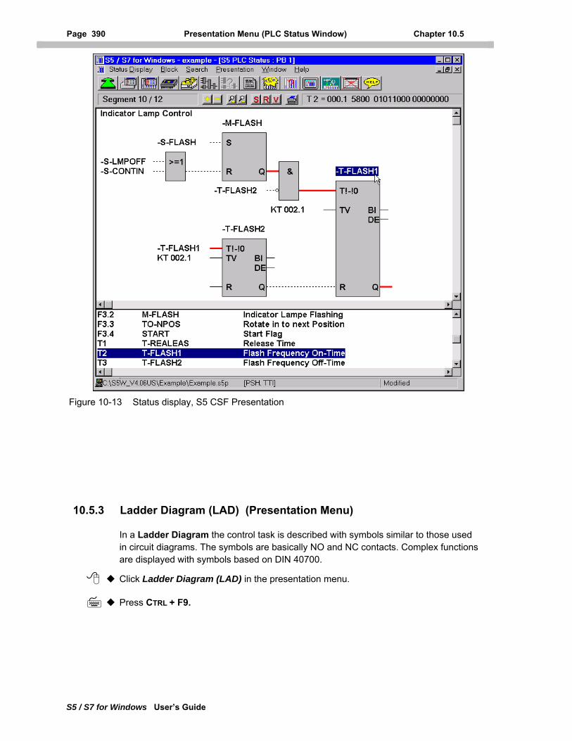
Page 390 Presentation Menu (PLC Status Window) Chapter 10.5
S5 / S7 for Windows User’s Guide
Figure 10-13 Status display, S5 CSF Presentation
10.5.3 Ladder Diagram (LAD) (Presentation Menu)
In a Ladder Diagram the control task is described with symbols similar to those used in circuit diagrams. The symbols are basically NO and NC contacts. Complex functions are displayed with symbols based on DIN 40700.
Click Ladder Diagram (LAD) in the presentation menu.
Press CTRL + F9.
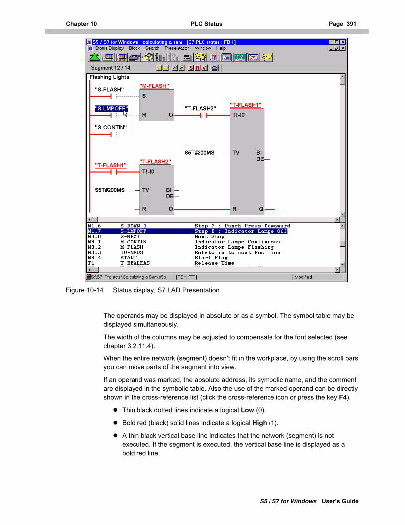
Chapter 10 PLC Status Page 391
S5 / S7 for Windows User’s Guide
Figure 10-14 Status display, S7 LAD Presentation
The operands may be displayed in absolute or as a symbol. The symbol table may be displayed simultaneously.
The width of the columns may be adjusted to compensate for the font selected (see chapter 3.2.11.4).
When the entire network (segment) doesn’t fit in the workplace, by using the scroll bars you can move parts of the segment into view.
If an operand was marked, the absolute address, its symbolic name, and the comment are displayed in the symbolic table. Also the use of the marked operand can be directly shown in the cross-reference list (click the cross-reference icon or press the key F4).
Thin black dotted lines indicate a logical Low (0).
Bold red (black) solid lines indicate a logical High (1).
A thin black vertical base line indicates that the network (segment) is not executed. If the segment is executed, the vertical base line is displayed as a bold red line.
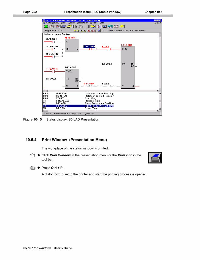
Page 392 Presentation Menu (PLC Status Window) Chapter 10.5
S5 / S7 for Windows User’s Guide
Figure 10-15 Status display, S5 LAD Presentation
10.5.4 Print Window (Presentation Menu)
The workplace of the status window is printed.
Click Print Window in the presentation menu or the Print icon in the tool bar.
Press Ctrl + P.
A dialog box to setup the printer and start the printing process is opened.
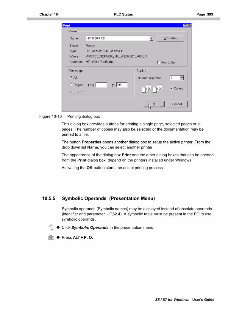
Chapter 10 PLC Status Page 393
S5 / S7 for Windows User’s Guide
Figure 10-16 Printing dialog box
This dialog box provides buttons for printing a single page, selected pages or all pages. The number of copies may also be selected or the documentation may be printed to a file.
The button Properties opens another dialog box to setup the active printer. From the drop down list Name, you can select another printer.
The appearance of the dialog box Print and the other dialog boxes that can be opened from the Print dialog box, depend on the printers installed under Windows.
Activating the OK button starts the actual printing process.
10.5.5 Symbolic Operands (Presentation Menu)
Symbolic operands (Symbolic names) may be displayed instead of absolute operands (identifier and parameter - Q32.4). A symbolic table must be present in the PC to use symbolic operands.
Click Symbolic Operands in the presentation menu.
Press ALT + P, O.
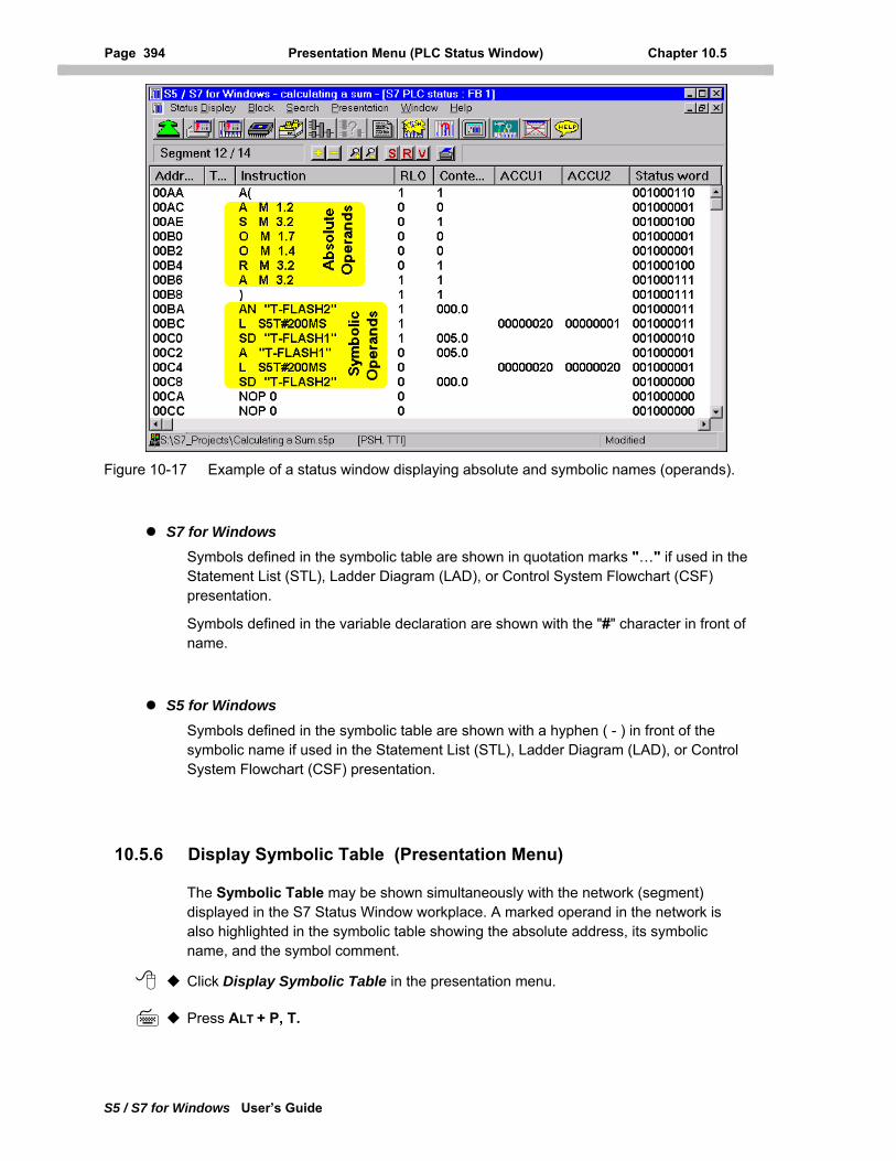
Page 394 Presentation Menu (PLC Status Window) Chapter 10.5
S5 / S7 for Windows User’s Guide
Figure 10-17 Example of a status window displaying absolute and symbolic names (operands).
S7 for Windows Symbols defined in the symbolic table are shown in quotation marks "…" if used in the Statement List (STL), Ladder Diagram (LAD), or Control System Flowchart (CSF) presentation.
Symbols defined in the variable declaration are shown with the "#" character in front of name.
S5 for Windows Symbols defined in the symbolic table are shown with a hyphen ( - ) in front of the symbolic name if used in the Statement List (STL), Ladder Diagram (LAD), or Control System Flowchart (CSF) presentation.
10.5.6 Display Symbolic Table (Presentation Menu)
The Symbolic Table may be shown simultaneously with the network (segment) displayed in the S7 Status Window workplace. A marked operand in the network is also highlighted in the symbolic table showing the absolute address, its symbolic name, and the symbol comment.
Click Display Symbolic Table in the presentation menu.
Press ALT + P, T.
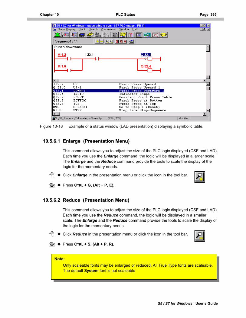
Chapter 10 PLC Status Page 395
S5 / S7 for Windows User’s Guide
Figure 10-18 Example of a status window (LAD presentation) displaying a symbolic table.
10.5.6.1 Enlarge (Presentation Menu)
This command allows you to adjust the size of the PLC logic displayed (CSF and LAD). Each time you use the Enlarge command, the logic will be displayed in a larger scale. The Enlarge and the Reduce command provide the tools to scale the display of the logic for the momentary needs.
Click Enlarge in the presentation menu or click the icon in the tool bar.
Press CTRL + G, (Alt + P, E).
10.5.6.2 Reduce (Presentation Menu)
This command allows you to adjust the size of the PLC logic displayed (CSF and LAD). Each time you use the Reduce command, the logic will be displayed in a smaller scale. The Enlarge and the Reduce command provide the tools to scale the display of the logic for the momentary needs.
Click Reduce in the presentation menu or click the icon in the tool bar.
Press CTRL + S, (Alt + P, R).
Note: Only scaleable fonts may be enlarged or reduced. All True Type fonts are scaleable. The default System font is not scaleable
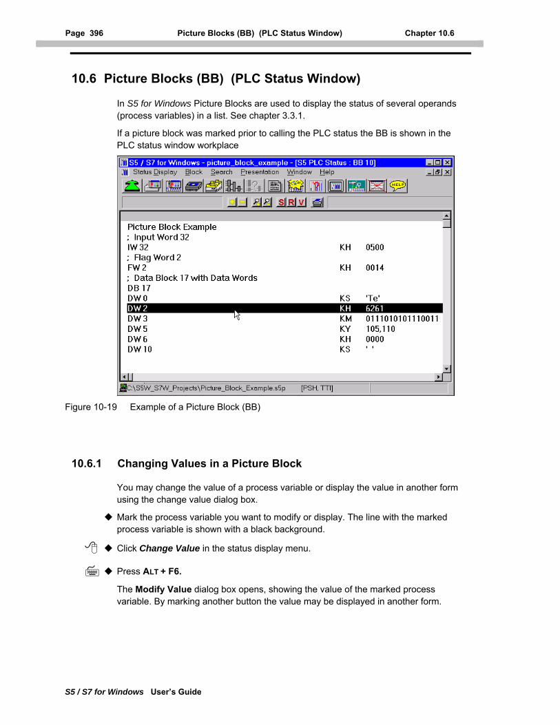
Page 396 Picture Blocks (BB) (PLC Status Window) Chapter 10.6
S5 / S7 for Windows User’s Guide
10.6 Picture Blocks (BB) (PLC Status Window)
In S5 for Windows Picture Blocks are used to display the status of several operands (process variables) in a list. See chapter 3.3.1.
If a picture block was marked prior to calling the PLC status the BB is shown in the PLC status window workplace
Figure 10-19 Example of a Picture Block (BB)
10.6.1 Changing Values in a Picture Block
You may change the value of a process variable or display the value in another form using the change value dialog box.
Mark the process variable you want to modify or display. The line with the marked process variable is shown with a black background.
Click Change Value in the status display menu.
Press ALT + F6.
The Modify Value dialog box opens, showing the value of the marked process variable. By marking another button the value may be displayed in another form.
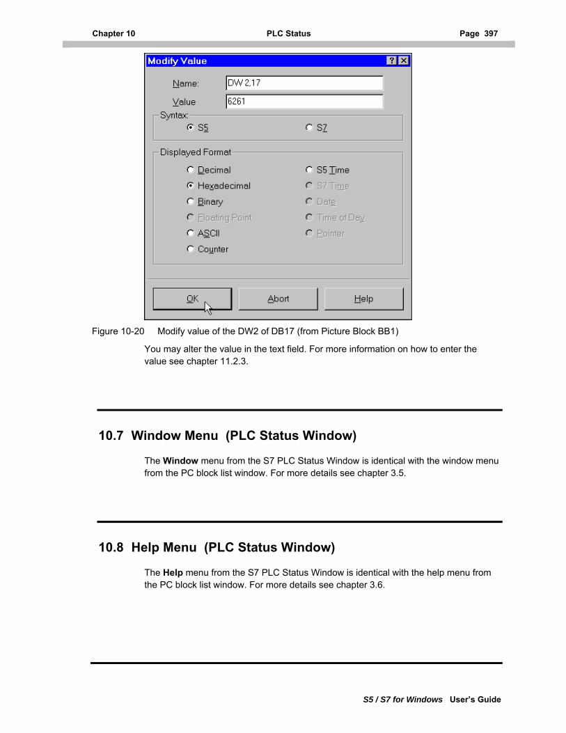
Chapter 10 PLC Status Page 397
S5 / S7 for Windows User’s Guide
Figure 10-20 Modify value of the DW2 of DB17 (from Picture Block BB1)
You may alter the value in the text field. For more information on how to enter the value see chapter 11.2.3.
10.7 Window Menu (PLC Status Window)
The Window menu from the S7 PLC Status Window is identical with the window menu from the PC block list window. For more details see chapter 3.5.
10.8 Help Menu (PLC Status Window)
The Help menu from the S7 PLC Status Window is identical with the help menu from the PC block list window. For more details see chapter 3.6.
Page 398 External PLC Status Window Chapter 11.1
S5 / S7 for Windows User’s Guide
11 External PLC Status
The commands from the external PLC status window are used to set and reset inputs, outputs, and memory bits, and to display and change values (Online functions).
These functions are available with an external Hardware PLC, our Software PLC, the PLC in a PC, the S7 Simulation PLC, and the S5 Extended Simulation PLC.
11.1 External PLC Status Window
S7 for Windows
External Hardware PLC To open the External PLC status window the PLC must be connected with the PC via an MPI converter cable. The PLC must be powered up and a program must be present in the PLC.
Software PLC, the PLC in a PC installed on an external PC To open the External PLC status window, the PC executing the Software PLC must be connected via a null modem with the PC executing S7 for Windows. The PC must be powered up, the Software PLC must be running and a PLC program must be present. This could also be the S7 Simulation PLC.
Software PLC, the PLC in a PC installed on the PC running S7 for Windows To open the External PLC status window, the Software PLC must be running and a PLC program must be present in the Software PLC. No external connection is needed. This could also be the S7 Simulation PLC.
S5 for Windows
External Hardware PLC To open the External PLC status window the PLC must be connected with the PC via a current loop converter cable. The PLC must be powered up and a program must be present in the PLC.
Software PLC, the PLC in a PC installed on an external PC To open the External PLC status window, the PC executing the Software PLC must be connected via a null modem with the PC executing S5 for Windows. The PC must be powered up, the Software PLC must be running and a PLC program must be present. This could also be the S5 Extended Simulation PLC.
Software PLC, the PLC in a PC installed on the PC running S5 for Windows To open the External PLC status window, the Software PLC must be running and a PLC program must be present in the Software PLC. No external connection is needed. This could also be the S5 Extended Simulation PLC.
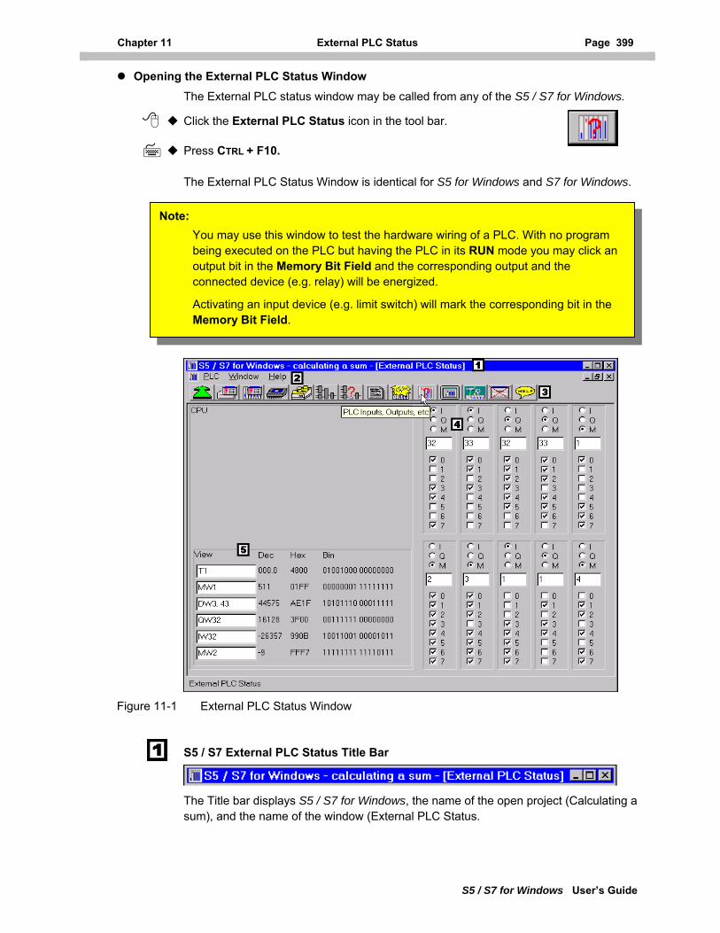
Chapter 11 External PLC Status Page 399
S5 / S7 for Windows User’s Guide
Opening the External PLC Status Window The External PLC status window may be called from any of the S5 / S7 for Windows.
Click the External PLC Status icon in the tool bar.
Press CTRL + F10.
The External PLC Status Window is identical for S5 for Windows and S7 for Windows.
Note: You may use this window to test the hardware wiring of a PLC. With no program being executed on the PLC but having the PLC in its RUN mode you may click an output bit in the Memory Bit Field and the corresponding output and the connected device (e.g. relay) will be energized.
Activating an input device (e.g. limit switch) will mark the corresponding bit in the Memory Bit Field.
Figure 11-1 External PLC Status Window
S5 / S7 External PLC Status Title Bar
The Title bar displays S5 / S7 for Windows, the name of the open project (Calculating a sum), and the name of the window (External PLC Status.
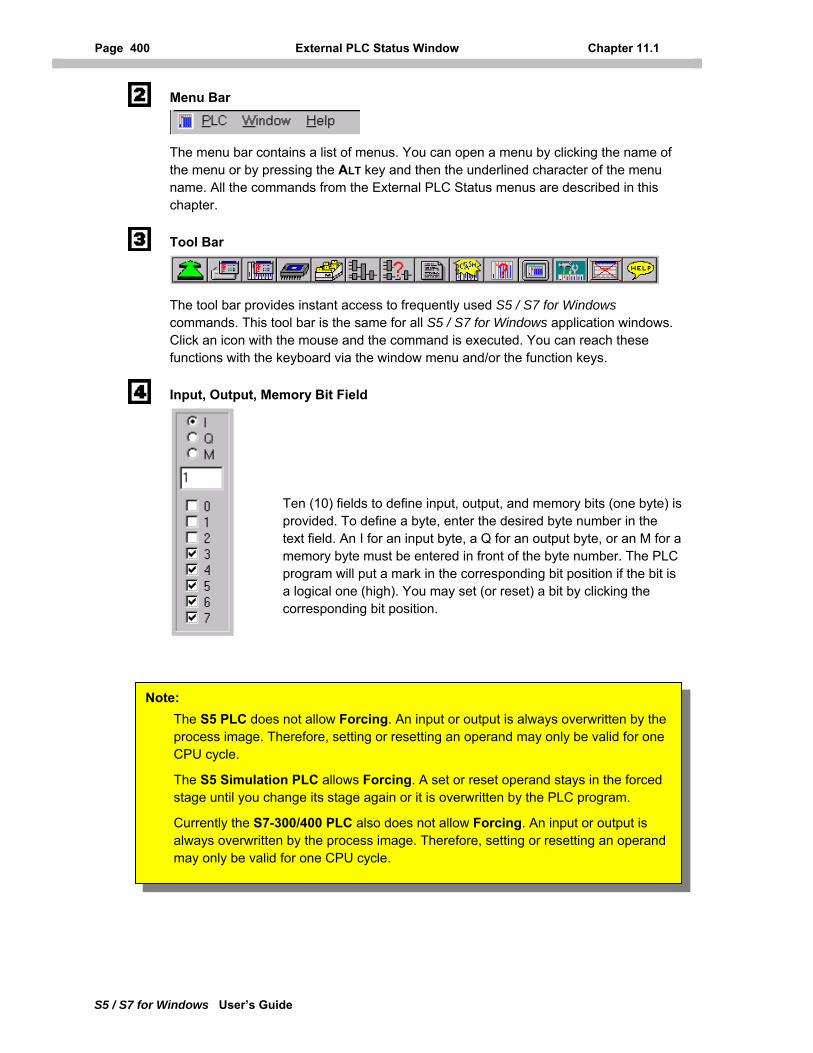
Page 400 External PLC Status Window Chapter 11.1
S5 / S7 for Windows User’s Guide
Menu Bar
The menu bar contains a list of menus. You can open a menu by clicking the name of the menu or by pressing the ALT key and then the underlined character of the menu name. All the commands from the External PLC Status menus are described in this chapter.
Tool Bar
The tool bar provides instant access to frequently used S5 / S7 for Windows commands. This tool bar is the same for all S5 / S7 for Windows application windows. Click an icon with the mouse and the command is executed. You can reach these functions with the keyboard via the window menu and/or the function keys.
Input, Output, Memory Bit Field
Ten (10) fields to define input, output, and memory bits (one byte) is provided. To define a byte, enter the desired byte number in the text field. An I for an input byte, a Q for an output byte, or an M for a memory byte must be entered in front of the byte number. The PLC program will put a mark in the corresponding bit position if the bit is a logical one (high). You may set (or reset) a bit by clicking the corresponding bit position.
Note: The S5 PLC does not allow Forcing. An input or output is always overwritten by the process image. Therefore, setting or resetting an operand may only be valid for one CPU cycle.
The S5 Simulation PLC allows Forcing. A set or reset operand stays in the forced stage until you change its stage again or it is overwritten by the PLC program.
Currently the S7-300/400 PLC also does not allow Forcing. An input or output is always overwritten by the process image. Therefore, setting or resetting an operand may only be valid for one CPU cycle.
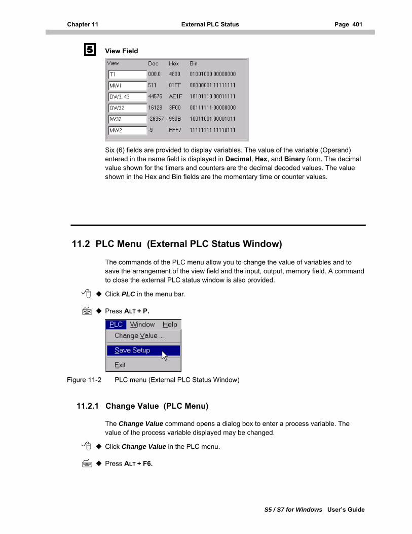
Chapter 11 External PLC Status Page 401
S5 / S7 for Windows User’s Guide
View Field
Six (6) fields are provided to display variables. The value of the variable (Operand) entered in the name field is displayed in Decimal, Hex, and Binary form. The decimal value shown for the timers and counters are the decimal decoded values. The value shown in the Hex and Bin fields are the momentary time or counter values.
11.2 PLC Menu (External PLC Status Window)
The commands of the PLC menu allow you to change the value of variables and to save the arrangement of the view field and the input, output, memory field. A command to close the external PLC status window is also provided.
Click PLC in the menu bar.
Press ALT + P.
Figure 11-2 PLC menu (External PLC Status Window)
11.2.1 Change Value (PLC Menu)
The Change Value command opens a dialog box to enter a process variable. The value of the process variable displayed may be changed.
Click Change Value in the PLC menu.
Press ALT + F6.
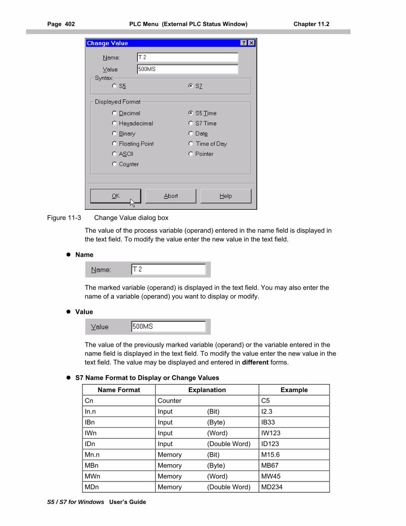
Page 402 PLC Menu (External PLC Status Window) Chapter 11.2
S5 / S7 for Windows User’s Guide
Figure 11-3 Change Value dialog box
The value of the process variable (operand) entered in the name field is displayed in the text field. To modify the value enter the new value in the text field.
Name
The marked variable (operand) is displayed in the text field. You may also enter the name of a variable (operand) you want to display or modify.
Value
The value of the previously marked variable (operand) or the variable entered in the name field is displayed in the text field. To modify the value enter the new value in the text field. The value may be displayed and entered in different forms.
S7 Name Format to Display or Change Values
Name Format Explanation Example Cn Counter C5 In.n Input (Bit) I2.3 IBn Input (Byte) IB33 IWn Input (Word) IW123 IDn Input (Double Word) ID123 Mn.n Memory (Bit) M15.6 MBn Memory (Byte) MB67 MWn Memory (Word) MW45 MDn Memory (Double Word) MD234
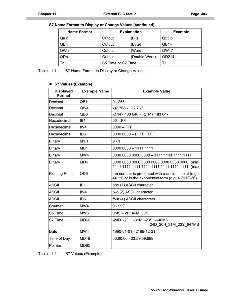
Chapter 11 External PLC Status Page 403
S5 / S7 for Windows User’s Guide
S7 Name Format to Display or Change Values (continued)
Name Format Explanation Example Qn.n Output (Bit) Q25.6 QBn Output (Byte) QB14 QWn Output (Word) QW17 QDn Output (Double Word) QD214 Tn S5 Time or S7 Time T1
Table 11-1 S7 Name Format to Display or Change Values
S7 Values (Example)
Displayed Format
Example Name Example Value
Decimal QB1 0 - 255; Decimal QW4 -32 768 - +32 767 Decimal QD6 -2 147 483 648 - +2 147 483 647 Hexadecimal IB1 00 – FF
Hexadecimal IW4 0000 – FFFF
Hexadecimal ID6 0000 0000 – FFFF FFFF
Binary M1.1 0 - 1
Binary MB1 0000 0000 – 1111 1111
Binary MW4 0000 0000 0000 0000 – 1111 1111 1111 1111
Binary MD6 0000 0000 0000 0000 0000 0000 0000 0000 (min)1111 1111 1111 1111 1111 1111 1111 1111 (max)
Floating Point QD6 the number is presented with a decimal point (e.g. 44.11) or in the exponential form (e.g. 4.711E-36)
ASCII IB1 one (1) ASCII character
ASCII IW4 two (2) ASCII character
ASCII ID6 four (4) ASCII characters
Counter MW4 0 - 999
S5 Time MW6 0MS – 2H_46M_30S
S7 Time MD66 -24D_-20H_-31M_-23S_-648MS 24D_20H_31M_23S_647MS
Date MW4 1990-01-01 - 2168-12-31
Time of Day MD16 00:00:00 - 23:59:59.999
Pointer MD65
Table 11-2 S7 Values (Example)
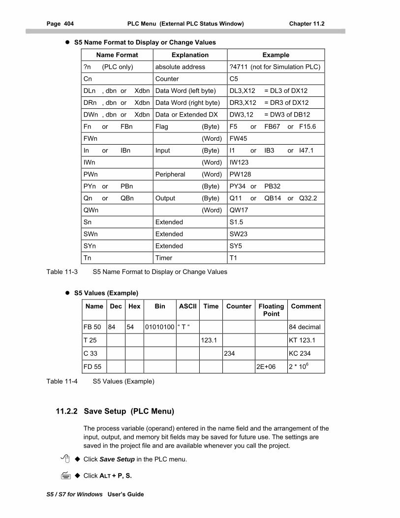
Page 404 PLC Menu (External PLC Status Window) Chapter 11.2
S5 / S7 for Windows User’s Guide
S5 Name Format to Display or Change Values
Name Format Explanation Example
?n (PLC only) absolute address ?4711 (not for Simulation PLC)
Cn Counter C5
DLn , dbn or Xdbn Data Word (left byte) DL3,X12 = DL3 of DX12
DRn , dbn or Xdbn Data Word (right byte) DR3,X12 = DR3 of DX12
DWn , dbn or Xdbn Data or Extended DX DW3,12 = DW3 of DB12
Fn or FBn Flag (Byte) F5 or FB67 or F15.6
FWn (Word) FW45
In or IBn Input (Byte) I1 or IB3 or I47.1
IWn (Word) IW123
PWn Peripheral (Word) PW128
PYn or PBn (Byte) PY34 or PB32
Qn or QBn Output (Byte) Q11 or QB14 or Q32.2
QWn (Word) QW17
Sn Extended S1.5
SWn Extended SW23
SYn Extended SY5
Tn Timer T1
Table 11-3 S5 Name Format to Display or Change Values
S5 Values (Example)
Name Dec Hex Bin ASCII Time Counter Floating Point
Comment
FB 50 84 54 01010100 “ T “ 84 decimal
T 25 123.1 KT 123.1
C 33 234 KC 234
FD 55 2E+06 2 * 106
Table 11-4 S5 Values (Example)
11.2.2 Save Setup (PLC Menu)
The process variable (operand) entered in the name field and the arrangement of the input, output, and memory bit fields may be saved for future use. The settings are saved in the project file and are available whenever you call the project.
Click Save Setup in the PLC menu.
Click ALT + P, S.
Chapter 11 External PLC Status Page 405
S5 / S7 for Windows User’s Guide
11.2.3 Exit (PLC Menu)
With the Exit command of the PLC menu, you can close the External PLC Status window.
Click Close.
Press ALT + P, E.
11.3 Window Menu (External PLC Status Window)
The Window menu of the external PLC status window is identical with the window menu from the PC block list window. For more details see chapter 3.5.
11.4 Help Menu (External PLC Status Window)
The Help menu of the external PLC status window is identical with the help menu from the PC block list window. For more details see chapter 3.6.
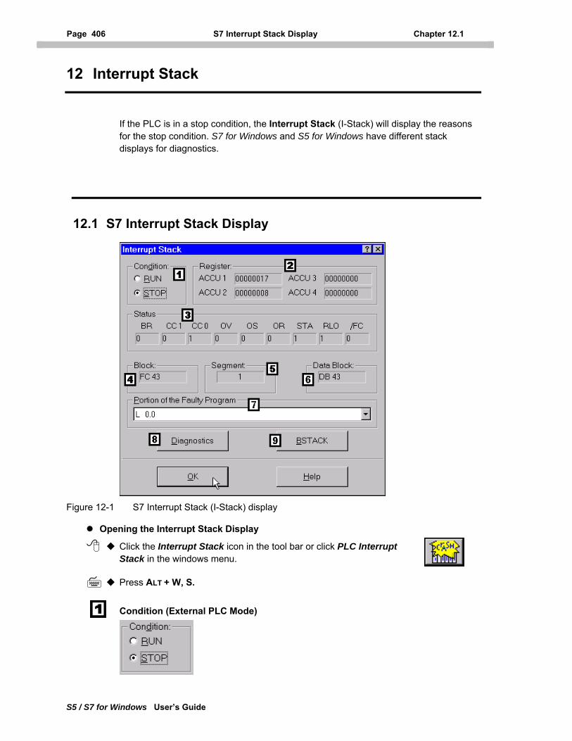
Page 406 S7 Interrupt Stack Display Chapter 12.1
S5 / S7 for Windows User’s Guide
12 Interrupt Stack
If the PLC is in a stop condition, the Interrupt Stack (I-Stack) will display the reasons for the stop condition. S7 for Windows and S5 for Windows have different stack displays for diagnostics.
12.1 S7 Interrupt Stack Display
Figure 12-1 S7 Interrupt Stack (I-Stack) display
Opening the Interrupt Stack Display
Click the Interrupt Stack icon in the tool bar or click PLC Interrupt Stack in the windows menu.
Press ALT + W, S.
Condition (External PLC Mode)
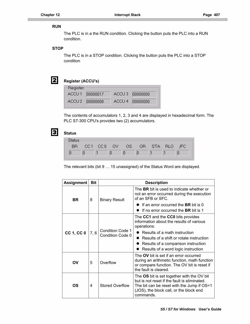
Chapter 12 Interrupt Stack Page 407
S5 / S7 for Windows User’s Guide
RUN
The PLC is in a the RUN condition. Clicking the button puts the PLC into a RUN condition.
STOP
The PLC is in a STOP condition. Clicking the button puts the PLC into a STOP condition
Register (ACCU's)
The contents of accumulators 1, 2, 3 and 4 are displayed in hexadecimal form. The PLC S7-300 CPU's provides two (2) accumulators.
Status
The relevant bits (bit 9 … 15 unassigned) of the Status Word are displayed.
Assignment Bit Description
BR 8 Binary Result
The BR bit is used to indicate whether or not an error occurred during the execution of an SFB or SFC. If an error occurred the BR bit is 0 If no error occurred the BR bit is 1
CC 1, CC 0 7, 6 Condition Code 1 Condition Code 0
The CC1 and the CC0 bits provides information about the results of various operations: Results of a math instruction Results of a shift or rotate instruction Results of a comparison instruction Results of a word logic instruction
OV 5 Overflow
The OV bit is set if an error occurred during an arithmetic function, math function or compare function. The OV bit is reset if the fault is cleared.
OS 4 Stored Overflow
The OS bit is set together with the OV bit but is not reset if the fault is eliminated. The bit can be reset with the Jump if OS=1 (JOS), the block call, or the block end commands.
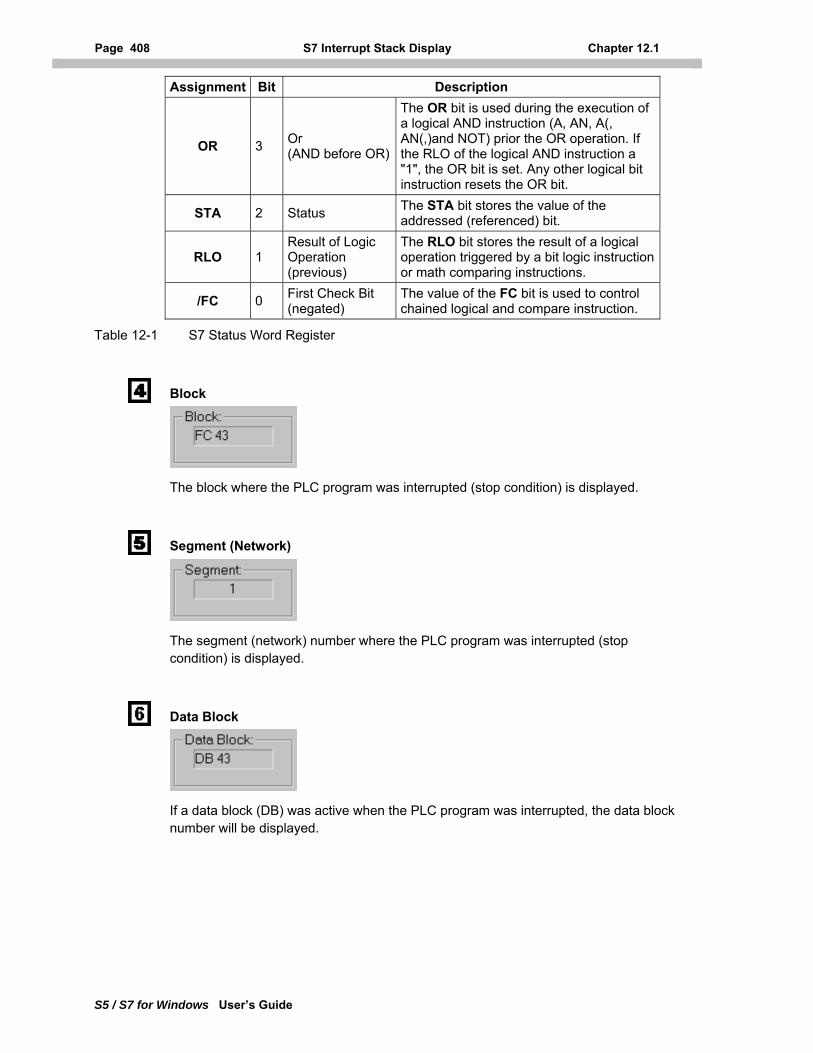
Page 408 S7 Interrupt Stack Display Chapter 12.1
S5 / S7 for Windows User’s Guide
Assignment Bit Description
OR 3 Or (AND before OR)
The OR bit is used during the execution of a logical AND instruction (A, AN, A(, AN(,)and NOT) prior the OR operation. If the RLO of the logical AND instruction a "1", the OR bit is set. Any other logical bit instruction resets the OR bit.
STA 2 Status The STA bit stores the value of the addressed (referenced) bit.
RLO 1 Result of Logic Operation (previous)
The RLO bit stores the result of a logical operation triggered by a bit logic instruction or math comparing instructions.
/FC 0 First Check Bit (negated)
The value of the FC bit is used to control chained logical and compare instruction.
Table 12-1 S7 Status Word Register
Block
The block where the PLC program was interrupted (stop condition) is displayed.
Segment (Network)
The segment (network) number where the PLC program was interrupted (stop condition) is displayed.
Data Block
If a data block (DB) was active when the PLC program was interrupted, the data block number will be displayed.
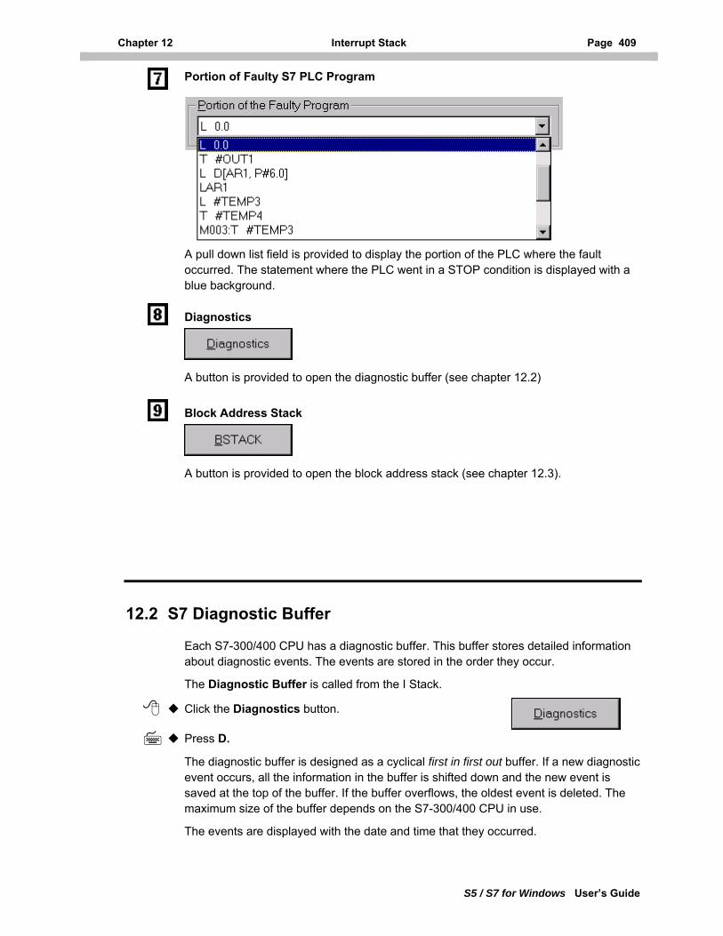
Chapter 12 Interrupt Stack Page 409
S5 / S7 for Windows User’s Guide
Portion of Faulty S7 PLC Program
A pull down list field is provided to display the portion of the PLC where the fault occurred. The statement where the PLC went in a STOP condition is displayed with a blue background.
Diagnostics
A button is provided to open the diagnostic buffer (see chapter 12.2)
Block Address Stack
A button is provided to open the block address stack (see chapter 12.3).
12.2 S7 Diagnostic Buffer
Each S7-300/400 CPU has a diagnostic buffer. This buffer stores detailed information about diagnostic events. The events are stored in the order they occur.
The Diagnostic Buffer is called from the I Stack.
Click the Diagnostics button.
Press D.
The diagnostic buffer is designed as a cyclical first in first out buffer. If a new diagnostic event occurs, all the information in the buffer is shifted down and the new event is saved at the top of the buffer. If the buffer overflows, the oldest event is deleted. The maximum size of the buffer depends on the S7-300/400 CPU in use.
The events are displayed with the date and time that they occurred.
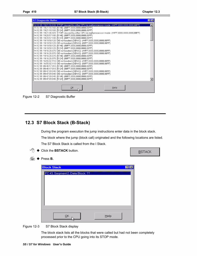
Page 410 S7 Block Stack (B-Stack) Chapter 12.3
S5 / S7 for Windows User’s Guide
Figure 12-2 S7 Diagnostic Buffer
12.3 S7 Block Stack (B-Stack)
During the program execution the jump instructions enter data in the block stack.
The block where the jump (block call) originated and the following locations are listed.
The S7 Block Stack is called from the I Stack.
Click the BSTACK button.
Press B.
Figure 12-3 S7 Block Stack display
The block stack lists all the blocks that were called but had not been completely processed prior to the CPU going into its STOP mode.
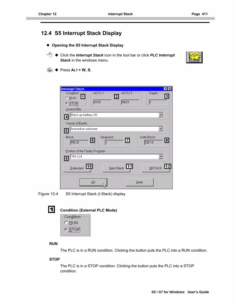
Chapter 12 Interrupt Stack Page 411
S5 / S7 for Windows User’s Guide
12.4 S5 Interrupt Stack Display
Opening the S5 Interrupt Stack Display
Click the Interrupt Stack icon in the tool bar or click PLC Interrupt Stack in the windows menu.
Press ALT + W, S.
Figure 12-4 S5 Interrupt Stack (I-Stack) display
Condition (External PLC Mode)
RUN
The PLC is in a RUN condition. Clicking the button puts the PLC into a RUN condition.
STOP
The PLC is in a STOP condition. Clicking the button puts the PLC into a STOP condition.
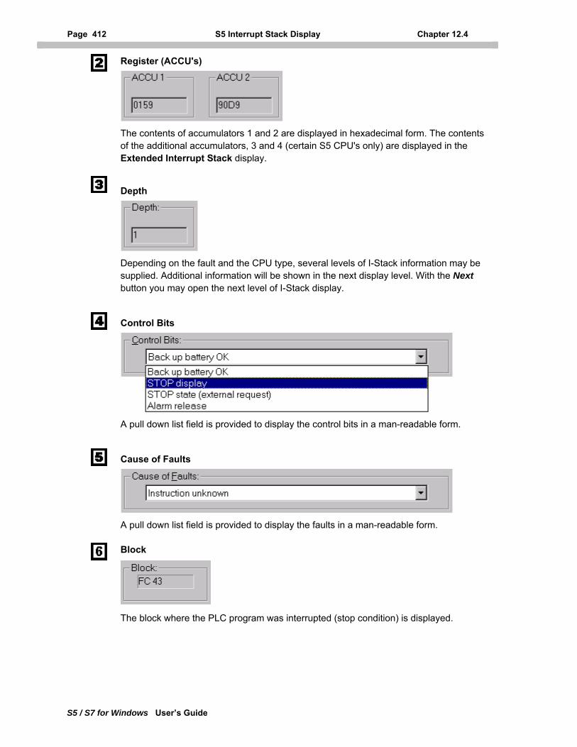
Page 412 S5 Interrupt Stack Display Chapter 12.4
S5 / S7 for Windows User’s Guide
Register (ACCU's)
The contents of accumulators 1 and 2 are displayed in hexadecimal form. The contents of the additional accumulators, 3 and 4 (certain S5 CPU's only) are displayed in the Extended Interrupt Stack display.
Depth
Depending on the fault and the CPU type, several levels of I-Stack information may be supplied. Additional information will be shown in the next display level. With the Next button you may open the next level of I-Stack display.
Control Bits
A pull down list field is provided to display the control bits in a man-readable form.
Cause of Faults
A pull down list field is provided to display the faults in a man-readable form.
Block
The block where the PLC program was interrupted (stop condition) is displayed.
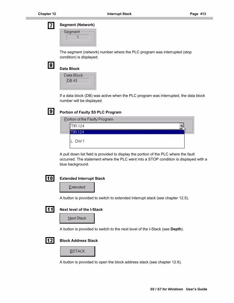
Chapter 12 Interrupt Stack Page 413
S5 / S7 for Windows User’s Guide
Segment (Network)
The segment (network) number where the PLC program was interrupted (stop condition) is displayed.
Data Block
If a data block (DB) was active when the PLC program was interrupted, the data block number will be displayed.
Portion of Faulty S5 PLC Program
A pull down list field is provided to display the portion of the PLC where the fault occurred. The statement where the PLC went into a STOP condition is displayed with a blue background.
Extended Interrupt Stack
A button is provided to switch to extended interrupt stack (see chapter 12.5).
Next level of the I-Stack
A button is provided to switch to the next level of the I-Stack (see Depth).
Block Address Stack
A button is provided to open the block address stack (see chapter 12.6).
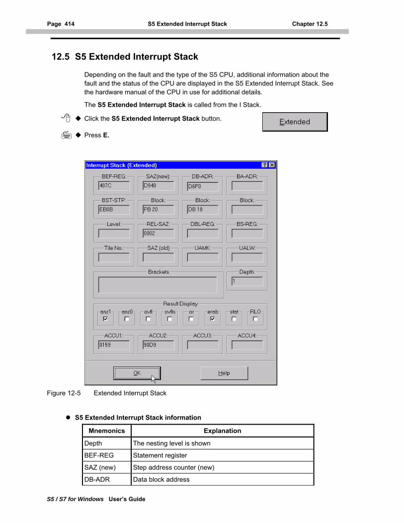
Page 414 S5 Extended Interrupt Stack Chapter 12.5
S5 / S7 for Windows User’s Guide
12.5 S5 Extended Interrupt Stack
Depending on the fault and the type of the S5 CPU, additional information about the fault and the status of the CPU are displayed in the S5 Extended Interrupt Stack. See the hardware manual of the CPU in use for additional details.
The S5 Extended Interrupt Stack is called from the I Stack.
Click the S5 Extended Interrupt Stack button.
Press E.
Figure 12-5 Extended Interrupt Stack
S5 Extended Interrupt Stack information
Mnemonics Explanation
Depth The nesting level is shown
BEF-REG Statement register
SAZ (new) Step address counter (new)
DB-ADR Data block address
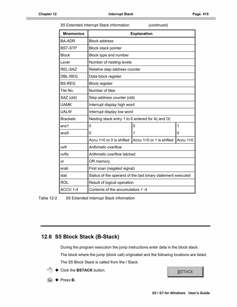
Chapter 12 Interrupt Stack Page 415
S5 / S7 for Windows User’s Guide
S5 Extended Interrupt Stack information (continued)
Mnemonics Explanation
BA-ADR Block address
BST-STP Block stack pointer
Block Block type and number
Level Number of nesting levels
REL-SAZ Relative step address counter
DBL-REG Data block register
BS-REG Block register
Tile No. Number of tiles
SAZ (old) Step address counter (old)
UAMK Interrupt display high word
UALW Interrupt display low word
Brackets Nesting stack entry 1 to 6 entered for A( and O(
anz1 0 0 1
anz0 0 1 0
Accu 1=0 or 0 is shifted Accu 1>0 or 1 is shifted Accu 1<0
ovfl Arithmetic overflow
ovfls Arithmetic overflow latched
or OR memory
erab First scan (negated signal)
stat Status of the operand of the last binary statement executed
ROL Result of logical operation
ACCU 1-4 Contents of the accumulators 1 -4
Table 12-2 S5 Extended Interrupt Stack information
12.6 S5 Block Stack (B-Stack)
During the program execution the jump instructions enter data in the block stack.
The block where the jump (block call) originated and the following locations are listed.
The S5 Block Stack is called from the I Stack.
Click the BSTACK button.
Press B.
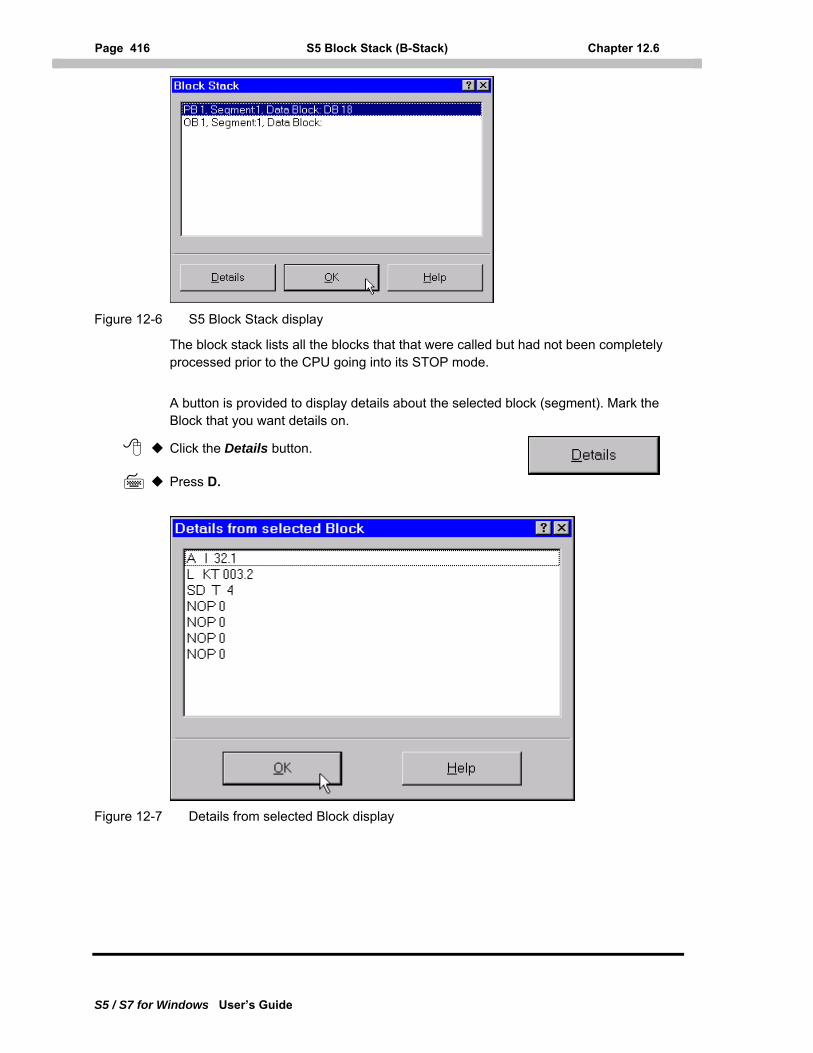
Page 416 S5 Block Stack (B-Stack) Chapter 12.6
S5 / S7 for Windows User’s Guide
Figure 12-6 S5 Block Stack display
The block stack lists all the blocks that that were called but had not been completely processed prior to the CPU going into its STOP mode.
A button is provided to display details about the selected block (segment). Mark the Block that you want details on.
Click the Details button.
Press D.
Figure 12-7 Details from selected Block display
Chapter 13 S7 Hardware Configuration Page 417
S5 / S7 for Windows User’s Guide
13 S7 Hardware Configuration
S7 for Windows provides an integrated program to configure and set the parameters and addresses of the S7-300/400 hardware CPU’s and modules.
With the S7 for Windows hardware configuration program it is possible to build a S7-300/400 PLC configuration off-line by using the integrated hardware catalog. It is also possible to read in a configuration of an existing S7-300/400 PLC (on-line).
The newly generated or existing PLC hardware configuration may be transferred to an S7-300/400 PLC via a serial link (MPI cable).
The configuration data is saved in the System Data Blocks and may be transferred to a PLC as part of the PLC program.
13.1 S7 Hardware Configuration Window
Opening the Configuration Window Open the PC Block List Window.
Click Open S7 Hardware Configuration in the Options menu (see chapter 3.4.13.
You may also double click an existing System Data Block, containing hardware configuration data, to open the S7 hardware configuration window. The workplace will display the current hardware configuration.
Press ALT + O, 7.
If a project has a hardware configuration file already assigned the command S7 Hardware Configuration opens this file and is ready for modifications (see chapter 3.2.5.2).
If no hardware configuration file is assigned to the project a new S7 hardware configuration file can be generated and assigned to the project.
The hardware configuration file is saved using the project name with the file name extension *.CF7.
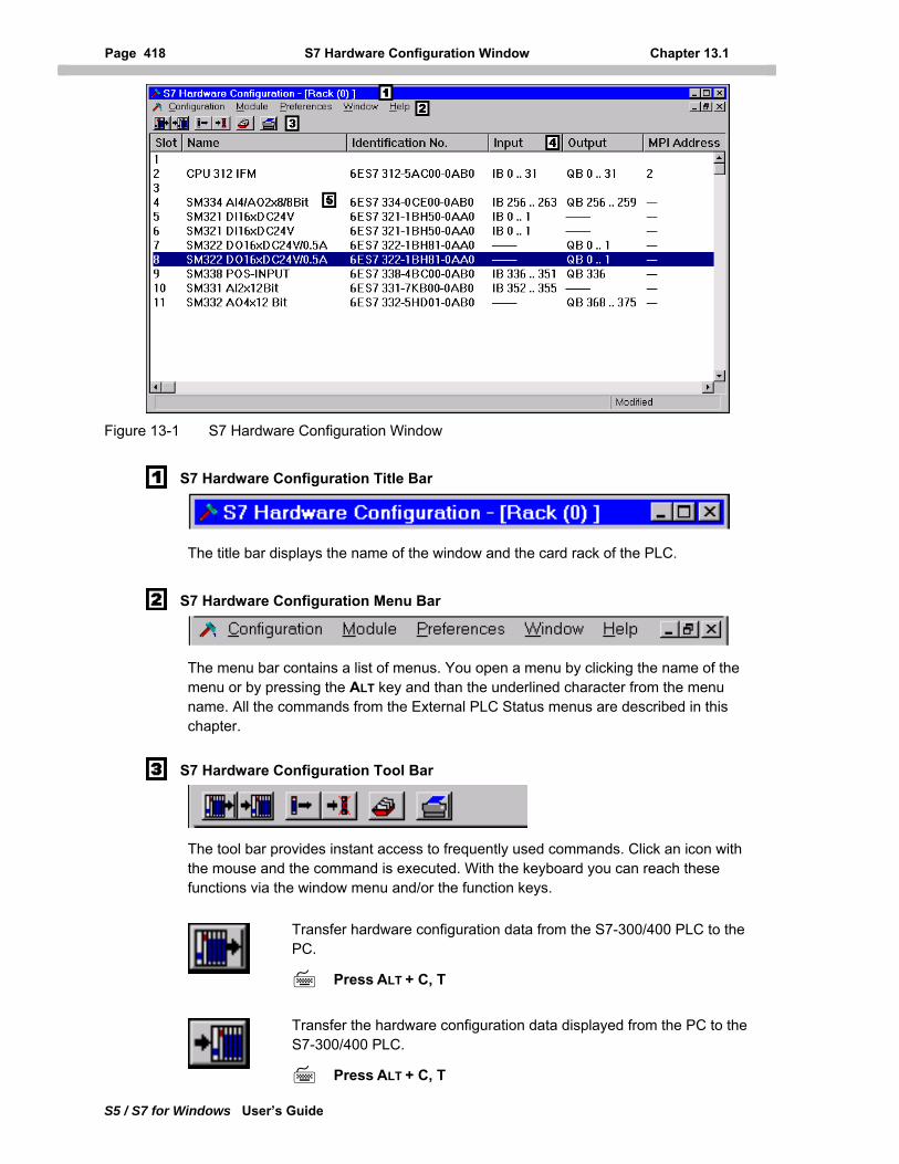
Page 418 S7 Hardware Configuration Window Chapter 13.1
S5 / S7 for Windows User’s Guide
Figure 13-1 S7 Hardware Configuration Window
S7 Hardware Configuration Title Bar
The title bar displays the name of the window and the card rack of the PLC.
S7 Hardware Configuration Menu Bar
The menu bar contains a list of menus. You open a menu by clicking the name of the menu or by pressing the ALT key and than the underlined character from the menu name. All the commands from the External PLC Status menus are described in this chapter.
S7 Hardware Configuration Tool Bar
The tool bar provides instant access to frequently used commands. Click an icon with the mouse and the command is executed. With the keyboard you can reach these functions via the window menu and/or the function keys.
Transfer hardware configuration data from the S7-300/400 PLC to the PC.
Press ALT + C, T
Transfer the hardware configuration data displayed from the PC to the S7-300/400 PLC.
Press ALT + C, T
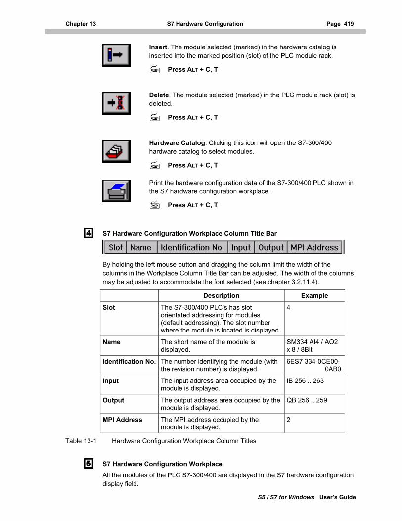
Chapter 13 S7 Hardware Configuration Page 419
S5 / S7 for Windows User’s Guide
Insert. The module selected (marked) in the hardware catalog is inserted into the marked position (slot) of the PLC module rack.
Press ALT + C, T
Delete. The module selected (marked) in the PLC module rack (slot) is deleted.
Press ALT + C, T
Hardware Catalog. Clicking this icon will open the S7-300/400 hardware catalog to select modules.
Press ALT + C, T
Print the hardware configuration data of the S7-300/400 PLC shown in the S7 hardware configuration workplace.
Press ALT + C, T
S7 Hardware Configuration Workplace Column Title Bar
By holding the left mouse button and dragging the column limit the width of the columns in the Workplace Column Title Bar can be adjusted. The width of the columns may be adjusted to accommodate the font selected (see chapter 3.2.11.4).
Description Example
Slot The S7-300/400 PLC’s has slot orientated addressing for modules (default addressing). The slot number where the module is located is displayed.
4
Name The short name of the module is displayed.
SM334 AI4 / AO2 x 8 / 8Bit
Identification No. The number identifying the module (with the revision number) is displayed.
6ES7 334-0CE00- 0AB0
Input The input address area occupied by the module is displayed.
IB 256 .. 263
Output The output address area occupied by the module is displayed.
QB 256 .. 259
MPI Address The MPI address occupied by the module is displayed.
2
Table 13-1 Hardware Configuration Workplace Column Titles
S7 Hardware Configuration Workplace All the modules of the PLC S7-300/400 are displayed in the S7 hardware configuration display field.
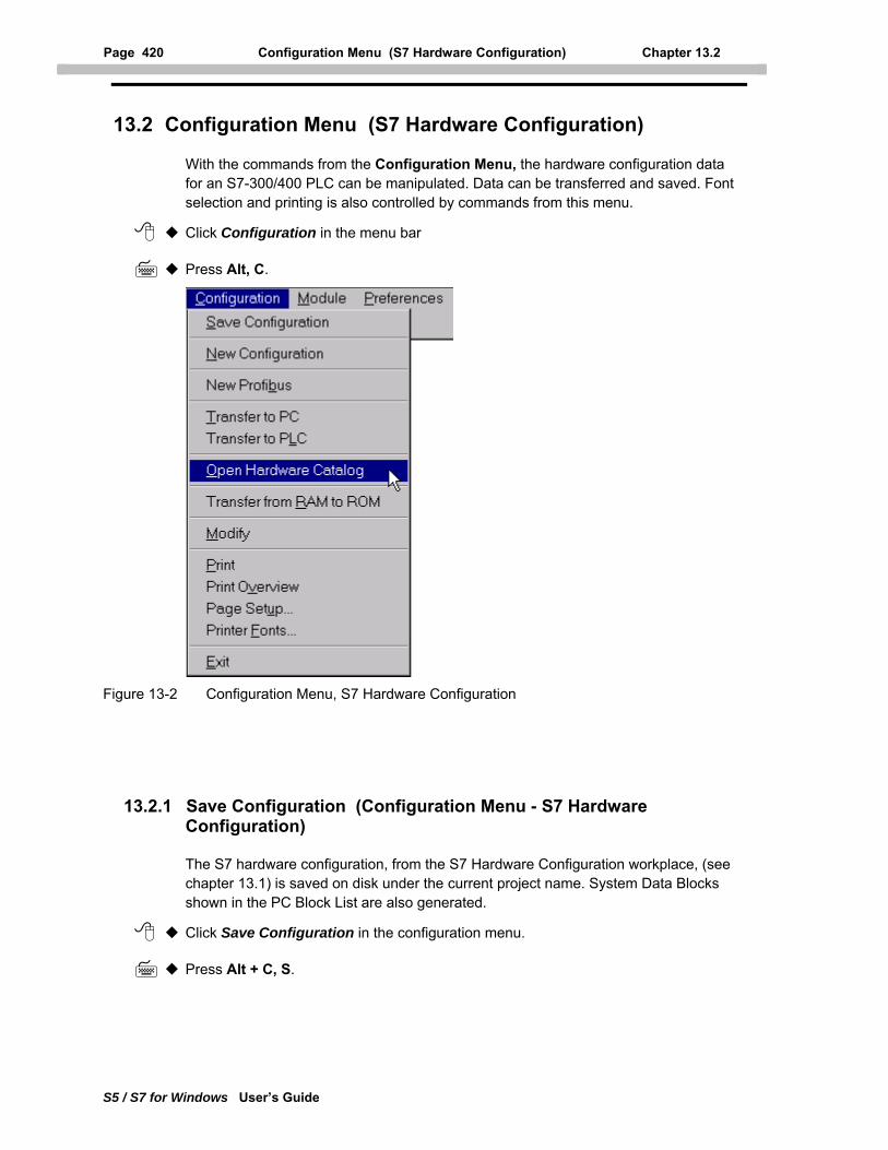
Page 420 Configuration Menu (S7 Hardware Configuration) Chapter 13.2
S5 / S7 for Windows User’s Guide
13.2 Configuration Menu (S7 Hardware Configuration)
With the commands from the Configuration Menu, the hardware configuration data for an S7-300/400 PLC can be manipulated. Data can be transferred and saved. Font selection and printing is also controlled by commands from this menu.
Click Configuration in the menu bar
Press Alt, C.
Figure 13-2 Configuration Menu, S7 Hardware Configuration
13.2.1 Save Configuration (Configuration Menu - S7 Hardware Configuration)
The S7 hardware configuration, from the S7 Hardware Configuration workplace, (see chapter 13.1) is saved on disk under the current project name. System Data Blocks shown in the PC Block List are also generated.
Click Save Configuration in the configuration menu.
Press Alt + C, S.
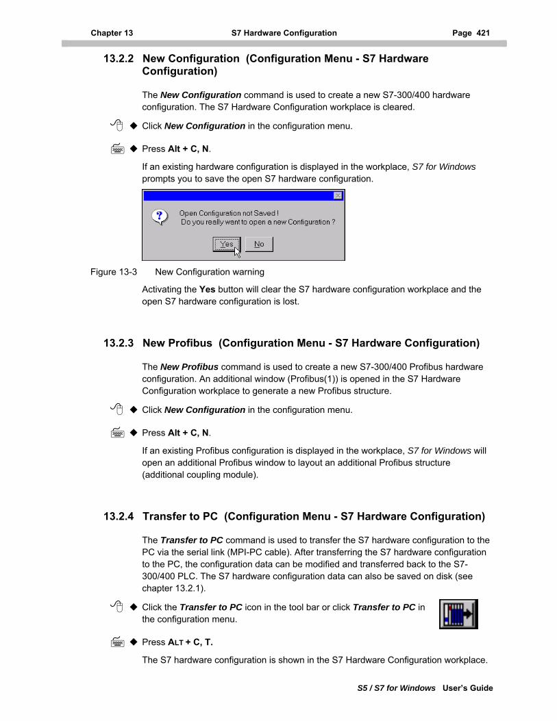
Chapter 13 S7 Hardware Configuration Page 421
S5 / S7 for Windows User’s Guide
13.2.2 New Configuration (Configuration Menu - S7 Hardware Configuration)
The New Configuration command is used to create a new S7-300/400 hardware configuration. The S7 Hardware Configuration workplace is cleared.
Click New Configuration in the configuration menu.
Press Alt + C, N.
If an existing hardware configuration is displayed in the workplace, S7 for Windows prompts you to save the open S7 hardware configuration.
Figure 13-3 New Configuration warning
Activating the Yes button will clear the S7 hardware configuration workplace and the open S7 hardware configuration is lost.
13.2.3 New Profibus (Configuration Menu - S7 Hardware Configuration)
The New Profibus command is used to create a new S7-300/400 Profibus hardware configuration. An additional window (Profibus(1)) is opened in the S7 Hardware Configuration workplace to generate a new Profibus structure.
Click New Configuration in the configuration menu.
Press Alt + C, N.
If an existing Profibus configuration is displayed in the workplace, S7 for Windows will open an additional Profibus window to layout an additional Profibus structure (additional coupling module).
13.2.4 Transfer to PC (Configuration Menu - S7 Hardware Configuration)
The Transfer to PC command is used to transfer the S7 hardware configuration to the PC via the serial link (MPI-PC cable). After transferring the S7 hardware configuration to the PC, the configuration data can be modified and transferred back to the S7-300/400 PLC. The S7 hardware configuration data can also be saved on disk (see chapter 13.2.1).
Click the Transfer to PC icon in the tool bar or click Transfer to PC in the configuration menu.
Press ALT + C, T.
The S7 hardware configuration is shown in the S7 Hardware Configuration workplace.
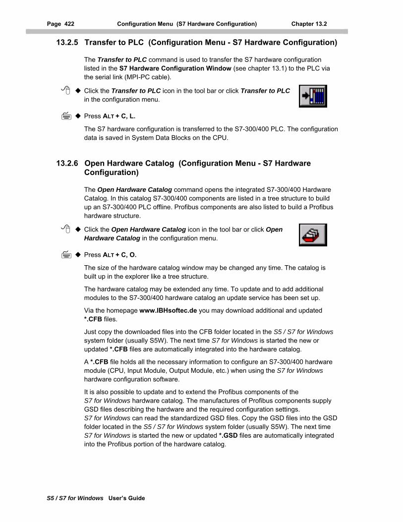
Page 422 Configuration Menu (S7 Hardware Configuration) Chapter 13.2
S5 / S7 for Windows User’s Guide
13.2.5 Transfer to PLC (Configuration Menu - S7 Hardware Configuration)
The Transfer to PLC command is used to transfer the S7 hardware configuration listed in the S7 Hardware Configuration Window (see chapter 13.1) to the PLC via the serial link (MPI-PC cable).
Click the Transfer to PLC icon in the tool bar or click Transfer to PLC in the configuration menu.
Press ALT + C, L.
The S7 hardware configuration is transferred to the S7-300/400 PLC. The configuration data is saved in System Data Blocks on the CPU.
13.2.6 Open Hardware Catalog (Configuration Menu - S7 Hardware Configuration)
The Open Hardware Catalog command opens the integrated S7-300/400 Hardware Catalog. In this catalog S7-300/400 components are listed in a tree structure to build up an S7-300/400 PLC offline. Profibus components are also listed to build a Profibus hardware structure.
Click the Open Hardware Catalog icon in the tool bar or click Open Hardware Catalog in the configuration menu.
Press ALT + C, O.
The size of the hardware catalog window may be changed any time. The catalog is built up in the explorer like a tree structure.
The hardware catalog may be extended any time. To update and to add additional modules to the S7-300/400 hardware catalog an update service has been set up.
Via the homepage www.IBHsoftec.de you may download additional and updated *.CFB files.
Just copy the downloaded files into the CFB folder located in the S5 / S7 for Windows system folder (usually S5W). The next time S7 for Windows is started the new or updated *.CFB files are automatically integrated into the hardware catalog.
A *.CFB file holds all the necessary information to configure an S7-300/400 hardware module (CPU, Input Module, Output Module, etc.) when using the S7 for Windows hardware configuration software.
It is also possible to update and to extend the Profibus components of the S7 for Windows hardware catalog. The manufactures of Profibus components supply GSD files describing the hardware and the required configuration settings. S7 for Windows can read the standardized GSD files. Copy the GSD files into the GSD folder located in the S5 / S7 for Windows system folder (usually S5W). The next time S7 for Windows is started the new or updated *.GSD files are automatically integrated into the Profibus portion of the hardware catalog.

Chapter 13 S7 Hardware Configuration Page 423
S5 / S7 for Windows User’s Guide
Figure 13-4 Hardware Catalog Window
13.2.7 Transfer from RAM to ROM (Configuration Menu - S7 Hardware Configuration)
Some CPU's (e.g. CPU 312) have the ability to transfer the contents of the PLC work memory (RAM = volatile memory) into non-volatile memory (ROM). The ROM area is physically made up of EEPROM modules.
Click Transfer from RAM to ROM in the configuration menu.
Press ALT + C, R.
To initiate the PLC program transfer from the RAM area into the non-volatile ROM area, the CPU key switch must be in the STOP position. If the Transfer from RAM to ROM command was initiated without having the key switch in the STOP position, a warning will be displayed and the command is aborted. Confirm the warning, place the key switch in the STOP position and repeat the Transfer from RAM to ROM command.
Figure 13-5 Transfer from RAM to ROM warning.
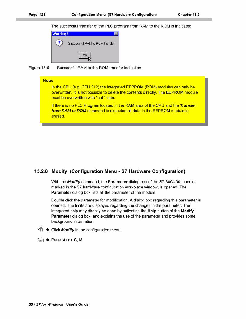
Page 424 Configuration Menu (S7 Hardware Configuration) Chapter 13.2
S5 / S7 for Windows User’s Guide
The successful transfer of the PLC program from RAM to the ROM is indicated.
Figure 13-6 Successful RAM to the ROM transfer indication
Note: In the CPU (e.g. CPU 312) the integrated EEPROM (ROM) modules can only be overwritten. It is not possible to delete the contents directly. The EEPROM module must be overwritten with "null" data.
If there is no PLC Program located in the RAM area of the CPU and the Transfer from RAM to ROM command is executed all data in the EEPROM module is erased.
13.2.8 Modify (Configuration Menu - S7 Hardware Configuration)
With the Modify command, the Parameter dialog box of the S7-300/400 module, marked in the S7 hardware configuration workplace window, is opened. The Parameter dialog box lists all the parameter of the module.
Double click the parameter for modification. A dialog box regarding this parameter is opened. The limits are displayed regarding the changes in the parameter. The integrated help may directly be open by activating the Help button of the Modify Parameter dialog box and explains the use of the parameter and provides some background information.
Click Modify in the configuration menu.
Press ALT + C, M.
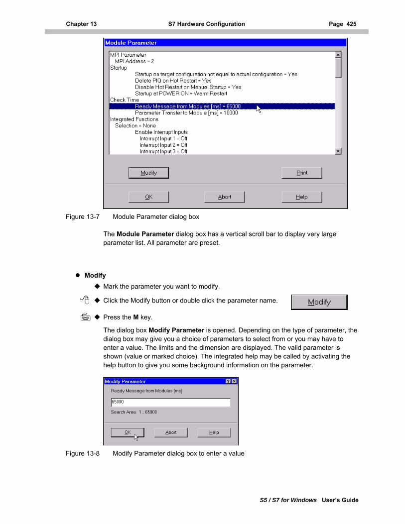
Chapter 13 S7 Hardware Configuration Page 425
S5 / S7 for Windows User’s Guide
Figure 13-7 Module Parameter dialog box
The Module Parameter dialog box has a vertical scroll bar to display very large parameter list. All parameter are preset.
Modify Mark the parameter you want to modify.
Click the Modify button or double click the parameter name.
Press the M key.
The dialog box Modify Parameter is opened. Depending on the type of parameter, the dialog box may give you a choice of parameters to select from or you may have to enter a value. The limits and the dimension are displayed. The valid parameter is shown (value or marked choice). The integrated help may be called by activating the help button to give you some background information on the parameter.
Figure 13-8 Modify Parameter dialog box to enter a value
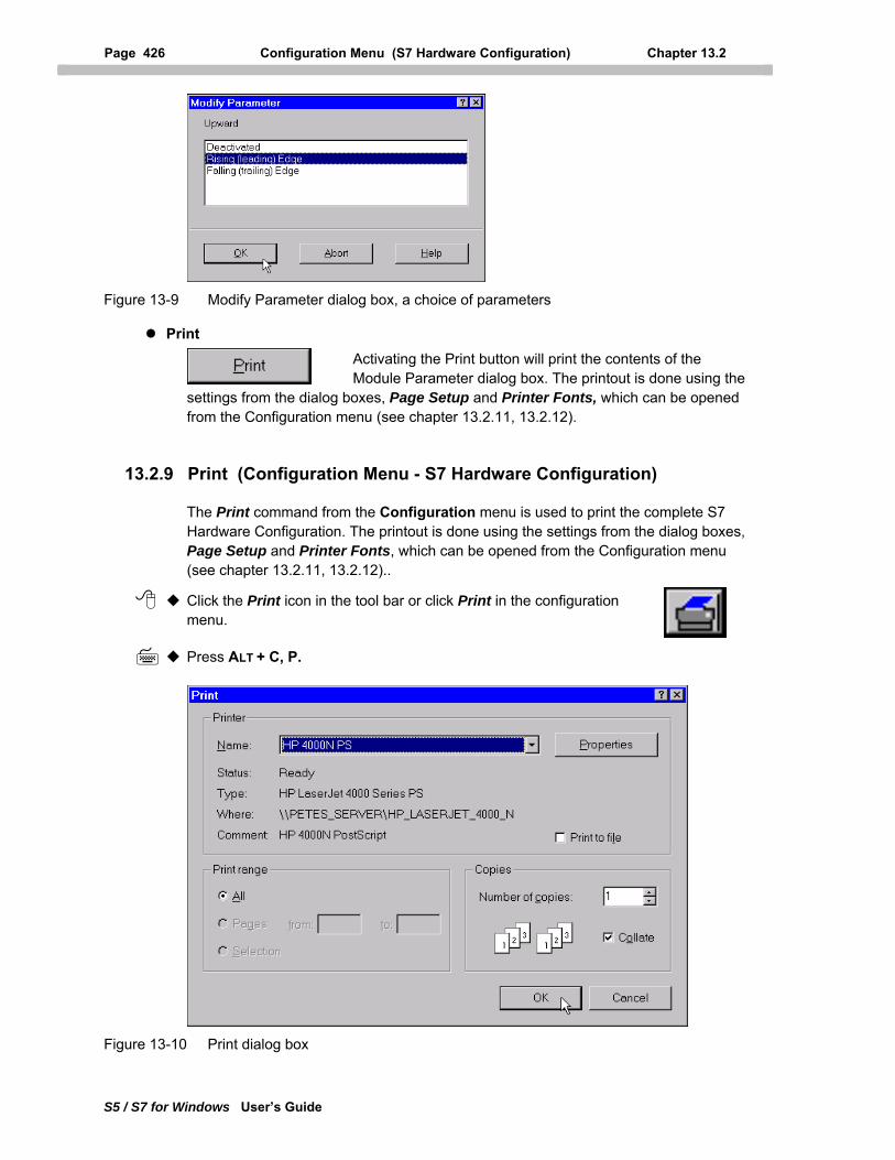
Page 426 Configuration Menu (S7 Hardware Configuration) Chapter 13.2
S5 / S7 for Windows User’s Guide
Figure 13-9 Modify Parameter dialog box, a choice of parameters
Print Activating the Print button will print the contents of the Module Parameter dialog box. The printout is done using the
settings from the dialog boxes, Page Setup and Printer Fonts, which can be opened from the Configuration menu (see chapter 13.2.11, 13.2.12).
13.2.9 Print (Configuration Menu - S7 Hardware Configuration)
The Print command from the Configuration menu is used to print the complete S7 Hardware Configuration. The printout is done using the settings from the dialog boxes, Page Setup and Printer Fonts, which can be opened from the Configuration menu (see chapter 13.2.11, 13.2.12)..
Click the Print icon in the tool bar or click Print in the configuration menu.
Press ALT + C, P.
Figure 13-10 Print dialog box
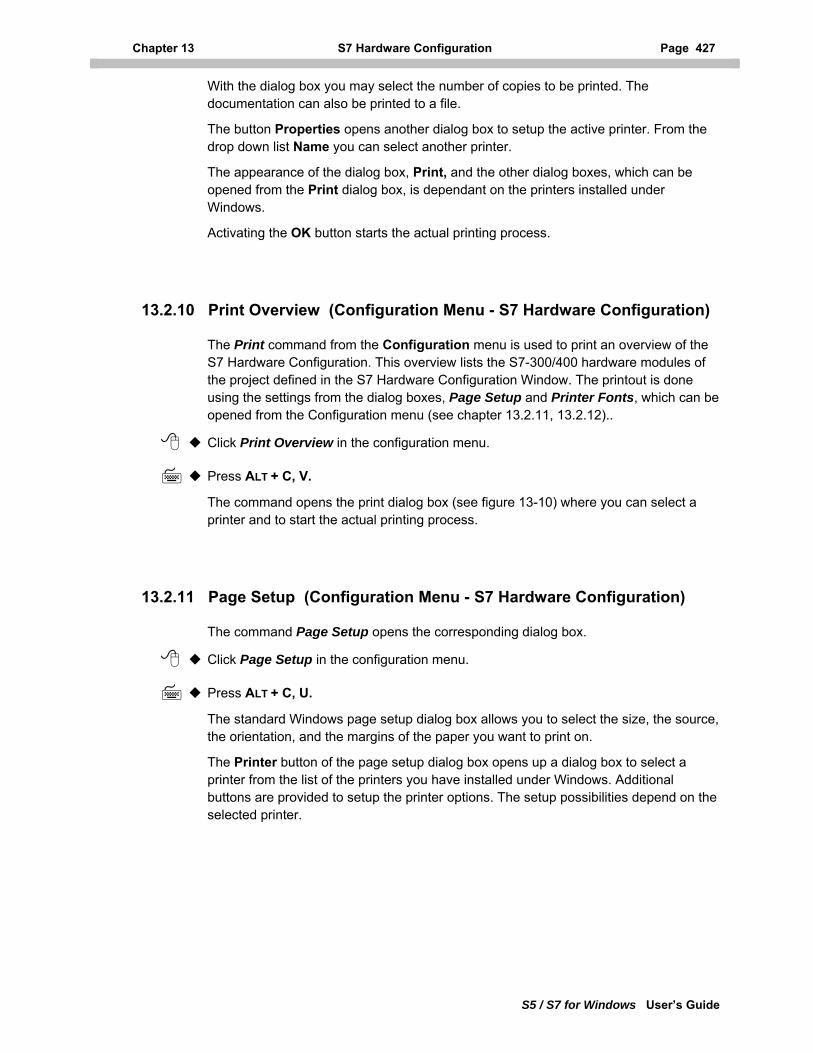
Chapter 13 S7 Hardware Configuration Page 427
S5 / S7 for Windows User’s Guide
With the dialog box you may select the number of copies to be printed. The documentation can also be printed to a file.
The button Properties opens another dialog box to setup the active printer. From the drop down list Name you can select another printer.
The appearance of the dialog box, Print, and the other dialog boxes, which can be opened from the Print dialog box, is dependant on the printers installed under Windows.
Activating the OK button starts the actual printing process.
13.2.10 Print Overview (Configuration Menu - S7 Hardware Configuration)
The Print command from the Configuration menu is used to print an overview of the S7 Hardware Configuration. This overview lists the S7-300/400 hardware modules of the project defined in the S7 Hardware Configuration Window. The printout is done using the settings from the dialog boxes, Page Setup and Printer Fonts, which can be opened from the Configuration menu (see chapter 13.2.11, 13.2.12)..
Click Print Overview in the configuration menu.
Press ALT + C, V.
The command opens the print dialog box (see figure 13-10) where you can select a printer and to start the actual printing process.
13.2.11 Page Setup (Configuration Menu - S7 Hardware Configuration)
The command Page Setup opens the corresponding dialog box.
Click Page Setup in the configuration menu.
Press ALT + C, U.
The standard Windows page setup dialog box allows you to select the size, the source, the orientation, and the margins of the paper you want to print on.
The Printer button of the page setup dialog box opens up a dialog box to select a printer from the list of the printers you have installed under Windows. Additional buttons are provided to setup the printer options. The setup possibilities depend on the selected printer.
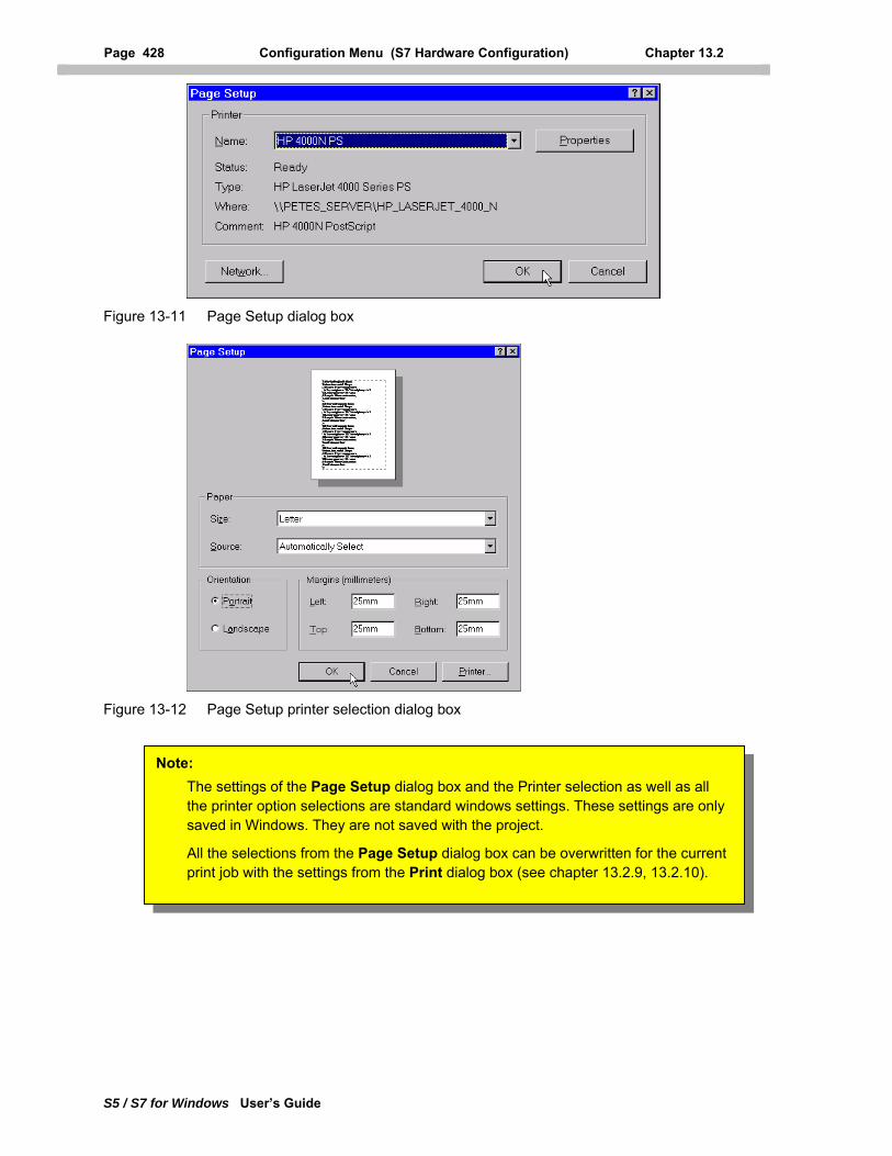
Page 428 Configuration Menu (S7 Hardware Configuration) Chapter 13.2
S5 / S7 for Windows User’s Guide
Figure 13-11 Page Setup dialog box
Figure 13-12 Page Setup printer selection dialog box
Note: The settings of the Page Setup dialog box and the Printer selection as well as all the printer option selections are standard windows settings. These settings are only saved in Windows. They are not saved with the project.
All the selections from the Page Setup dialog box can be overwritten for the current print job with the settings from the Print dialog box (see chapter 13.2.9, 13.2.10).
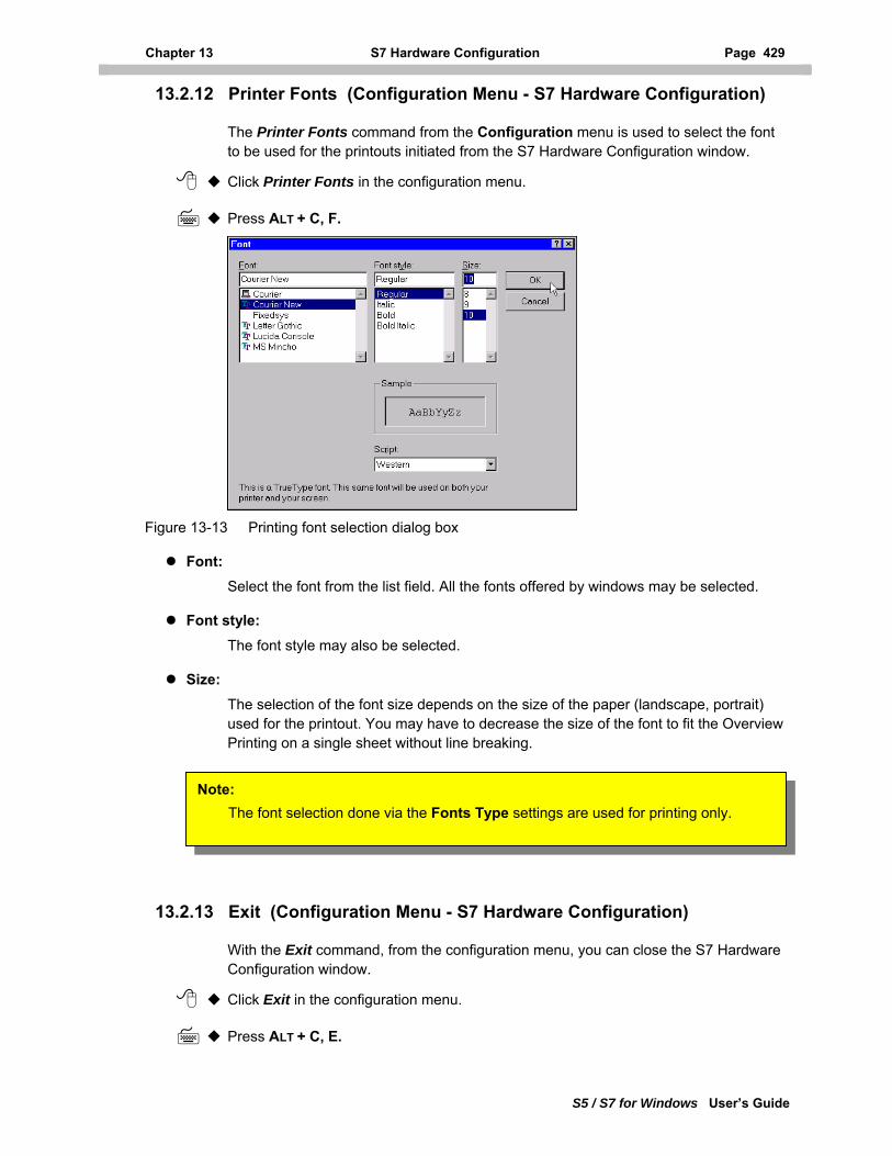
Chapter 13 S7 Hardware Configuration Page 429
S5 / S7 for Windows User’s Guide
13.2.12 Printer Fonts (Configuration Menu - S7 Hardware Configuration)
The Printer Fonts command from the Configuration menu is used to select the font to be used for the printouts initiated from the S7 Hardware Configuration window.
Click Printer Fonts in the configuration menu.
Press ALT + C, F.
Figure 13-13 Printing font selection dialog box
Font: Select the font from the list field. All the fonts offered by windows may be selected.
Font style: The font style may also be selected.
Size: The selection of the font size depends on the size of the paper (landscape, portrait) used for the printout. You may have to decrease the size of the font to fit the Overview Printing on a single sheet without line breaking.
Note: The font selection done via the Fonts Type settings are used for printing only.
13.2.13 Exit (Configuration Menu - S7 Hardware Configuration)
With the Exit command, from the configuration menu, you can close the S7 Hardware Configuration window.
Click Exit in the configuration menu.
Press ALT + C, E.
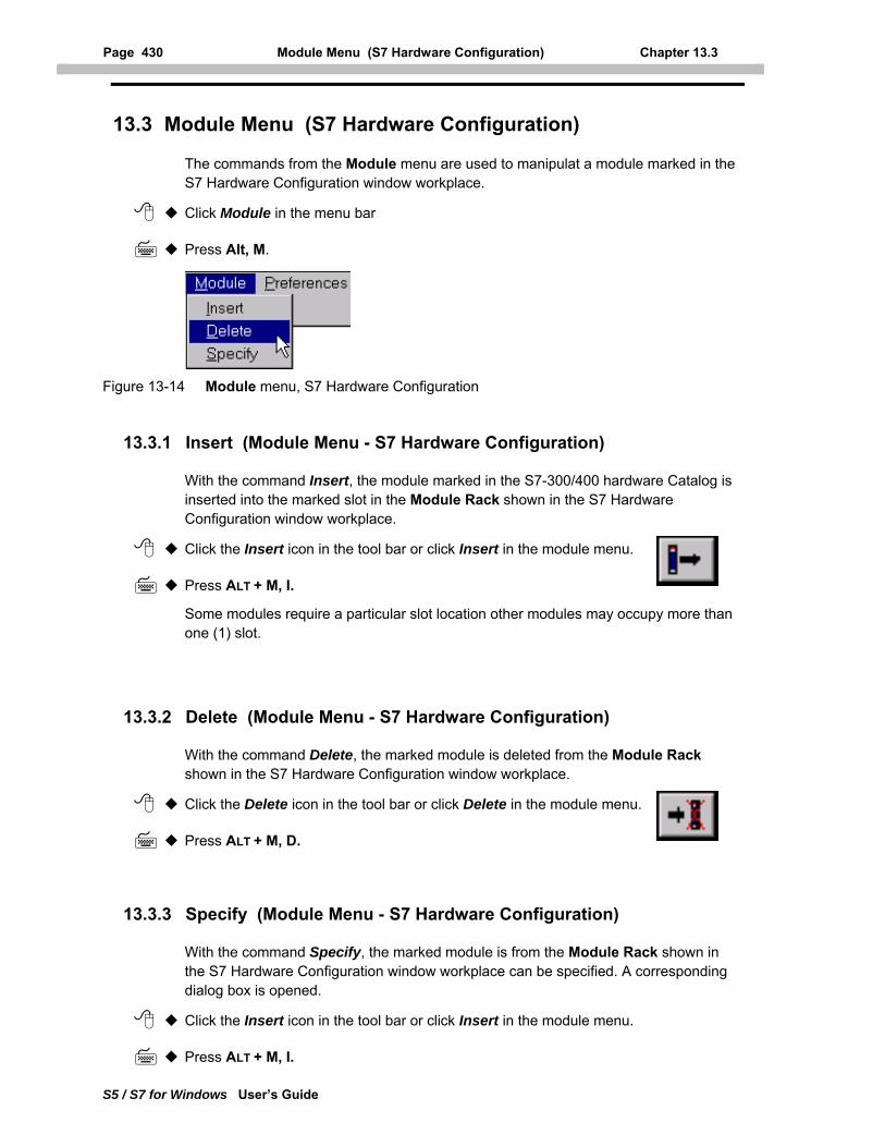
Page 430 Module Menu (S7 Hardware Configuration) Chapter 13.3
S5 / S7 for Windows User’s Guide
13.3 Module Menu (S7 Hardware Configuration)
The commands from the Module menu are used to manipulat a module marked in the S7 Hardware Configuration window workplace.
Click Module in the menu bar
Press Alt, M.
Figure 13-14 Module menu, S7 Hardware Configuration
13.3.1 Insert (Module Menu - S7 Hardware Configuration)
With the command Insert, the module marked in the S7-300/400 hardware Catalog is inserted into the marked slot in the Module Rack shown in the S7 Hardware Configuration window workplace.
Click the Insert icon in the tool bar or click Insert in the module menu.
Press ALT + M, I.
Some modules require a particular slot location other modules may occupy more than one (1) slot.
13.3.2 Delete (Module Menu - S7 Hardware Configuration)
With the command Delete, the marked module is deleted from the Module Rack shown in the S7 Hardware Configuration window workplace.
Click the Delete icon in the tool bar or click Delete in the module menu.
Press ALT + M, D.
13.3.3 Specify (Module Menu - S7 Hardware Configuration)
With the command Specify, the marked module is from the Module Rack shown in the S7 Hardware Configuration window workplace can be specified. A corresponding dialog box is opened.
Click the Insert icon in the tool bar or click Insert in the module menu.
Press ALT + M, I.
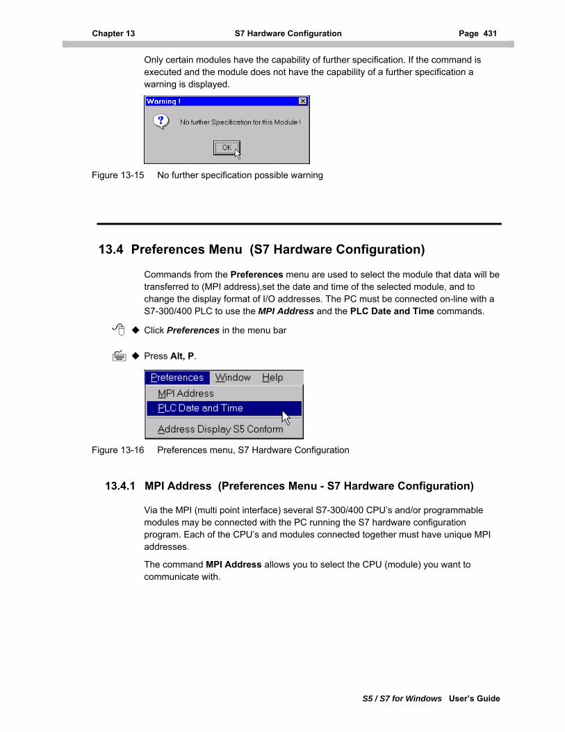
Chapter 13 S7 Hardware Configuration Page 431
S5 / S7 for Windows User’s Guide
Only certain modules have the capability of further specification. If the command is executed and the module does not have the capability of a further specification a warning is displayed.
Figure 13-15 No further specification possible warning
13.4 Preferences Menu (S7 Hardware Configuration)
Commands from the Preferences menu are used to select the module that data will be transferred to (MPI address),set the date and time of the selected module, and to change the display format of I/O addresses. The PC must be connected on-line with a S7-300/400 PLC to use the MPI Address and the PLC Date and Time commands.
Click Preferences in the menu bar
Press Alt, P.
Figure 13-16 Preferences menu, S7 Hardware Configuration
13.4.1 MPI Address (Preferences Menu - S7 Hardware Configuration)
Via the MPI (multi point interface) several S7-300/400 CPU’s and/or programmable modules may be connected with the PC running the S7 hardware configuration program. Each of the CPU’s and modules connected together must have unique MPI addresses.
The command MPI Address allows you to select the CPU (module) you want to communicate with.
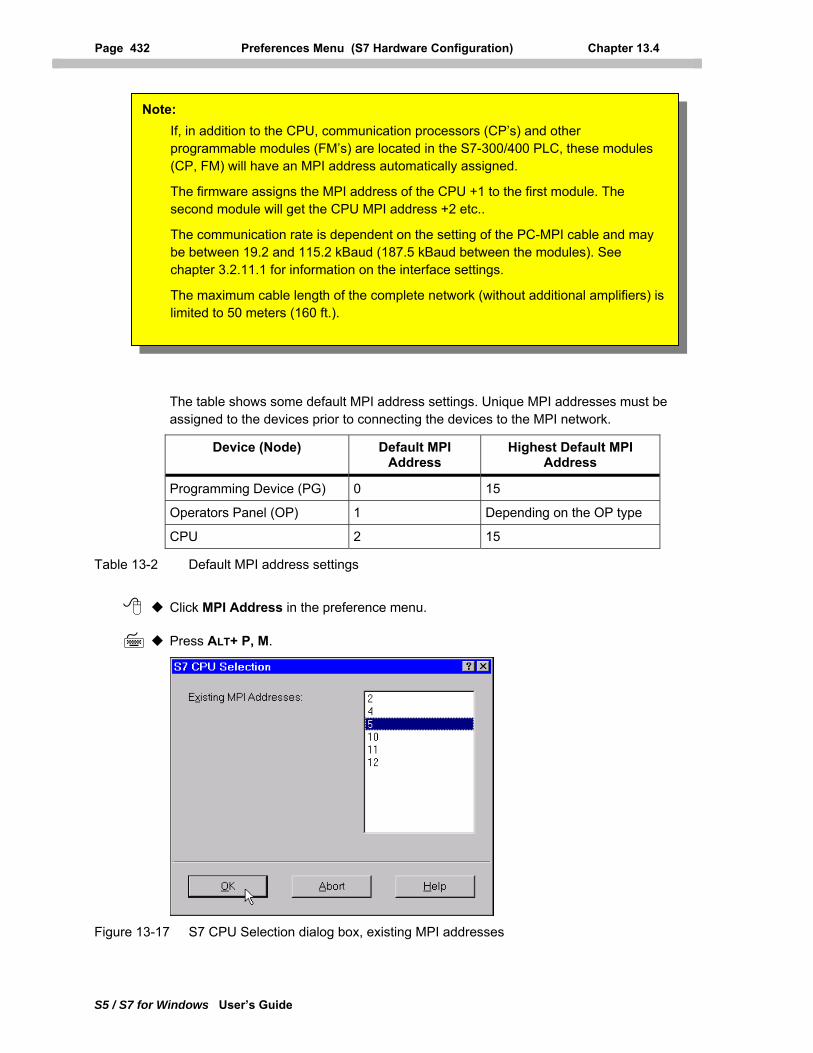
Page 432 Preferences Menu (S7 Hardware Configuration) Chapter 13.4
S5 / S7 for Windows User’s Guide
The table shows some default MPI address settings. Unique MPI addresses must be assigned to the devices prior to connecting the devices to the MPI network.
Note: If, in addition to the CPU, communication processors (CP’s) and other programmable modules (FM’s) are located in the S7-300/400 PLC, these modules (CP, FM) will have an MPI address automatically assigned.
The firmware assigns the MPI address of the CPU +1 to the first module. The second module will get the CPU MPI address +2 etc..
The communication rate is dependent on the setting of the PC-MPI cable and may be between 19.2 and 115.2 kBaud (187.5 kBaud between the modules). See chapter 3.2.11.1 for information on the interface settings.
The maximum cable length of the complete network (without additional amplifiers) is limited to 50 meters (160 ft.).
Device (Node) Default MPI Address
Highest Default MPI Address
Programming Device (PG) 0 15
Operators Panel (OP) 1 Depending on the OP type
CPU 2 15
Table 13-2 Default MPI address settings
Click MPI Address in the preference menu.
Press ALT+ P, M.
Figure 13-17 S7 CPU Selection dialog box, existing MPI addresses
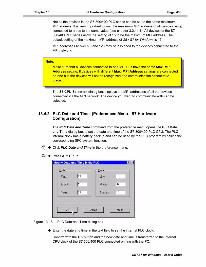
Chapter 13 S7 Hardware Configuration Page 433
S5 / S7 for Windows User’s Guide
Not all the devices in the S7-300/400 PLC series can be set to the same maximum MPI address. It is very important to limit the maximum MPI address of all devices being connected to a bus to the same value (see chapter 3.2.11.1). All devices of the S7-300/400 PLC series allow the setting of 15 to be the maximum MPI address. The default setting of the maximum MPI address of S5 / S7 for Windows is 15.
MPI addresses between 0 and 126 may be assigned to the devices connected to the MPI network.
Note: Make sure that all devices connected to one MPI Bus have the same Max. MPI Address setting. If devices with different Max. MPI Address settings are connected on one bus the devices will not be recognized and communication cannot take place.
The S7 CPU Selection dialog box displays the MPI addresses of all the devices connected via the MPI network. The device you want to communicate with can be selected.
13.4.2 PLC Date and Time (Preferences Menu - S7 Hardware Configuration)
The PLC Date and Time command from the preference menu opens the PLC Date and Time dialog box to set the date and time of the S7-300/400 PLC CPU. The PLC internal clock has a battery backup and can be used by the PLC program by calling the corresponding SFC system function.
Click PLC Date and Time in the preference menu.
Press ALT + P, P.
Figure 13-18 PLC Date and Time dialog box
Enter the date and time in the text field to set the internal PLC clock.
Confirm with the OK button and the new date and time is transferred to the internal CPU clock of the S7-300/400 PLC connected on-line with the PC.
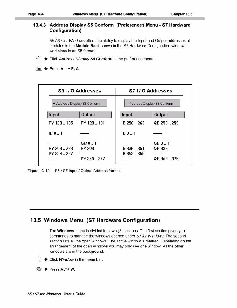
Page 434 Windows Menu (S7 Hardware Configuration) Chapter 13.5
S5 / S7 for Windows User’s Guide
13.4.3 Address Display S5 Conform (Preferences Menu - S7 Hardware Configuration)
S5 / S7 for Windows offers the ability to display the Input and Output addresses of modules in the Module Rack shown in the S7 Hardware Configuration window workplace in an S5 format.
Click Address Display S5 Conform in the preference menu.
Press ALT + P, A.
Figure 13-19 S5 / S7 Input / Output Address format
13.5 Windows Menu (S7 Hardware Configuration)
The Windows menu is divided into two (2) sections. The first section gives you commands to manage the windows opened under S7 for Windows. The second section lists all the open windows. The active window is marked. Depending on the arrangement of the open windows you may only see one window. All the other windows are in the background.
Click Window in the menu bar.
Press ALT+ W.
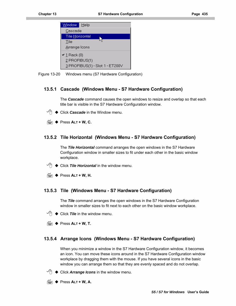
Chapter 13 S7 Hardware Configuration Page 435
S5 / S7 for Windows User’s Guide
Figure 13-20 Windows menu (S7 Hardware Configuration)
13.5.1 Cascade (Windows Menu - S7 Hardware Configuration)
The Cascade command causes the open windows to resize and overlap so that each title bar is visible in the S7 Hardware Configuration window.
Click Cascade in the Window menu.
Press ALT + W, C.
13.5.2 Tile Horizontal (Windows Menu - S7 Hardware Configuration)
The Tile Horizontal command arranges the open windows in the S7 Hardware Configuration window in smaller sizes to fit under each other in the basic window workplace.
Click Tile Horizontal in the window menu.
Press ALT + W, H.
13.5.3 Tile (Windows Menu - S7 Hardware Configuration)
The Tile command arranges the open windows in the S7 Hardware Configuration window in smaller sizes to fit next to each other on the basic window workplace.
Click Tile in the window menu.
Press ALT + W, T.
13.5.4 Arrange Icons (Windows Menu - S7 Hardware Configuration)
When you minimize a window in the S7 Hardware Configuration window, it becomes an icon. You can move these icons around in the S7 Hardware Configuration window workplace by dragging them with the mouse. If you have several icons in the basic window you can arrange them so that they are evenly spaced and do not overlap.
Click Arrange Icons in the window menu.
Press ALT + W, A.
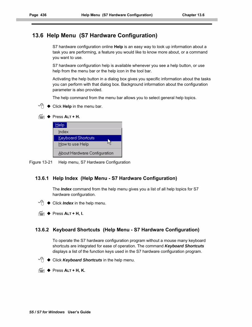
Page 436 Help Menu (S7 Hardware Configuration) Chapter 13.6
S5 / S7 for Windows User’s Guide
13.6 Help Menu (S7 Hardware Configuration)
S7 hardware configuration online Help is an easy way to look up information about a task you are performing, a feature you would like to know more about, or a command you want to use.
S7 hardware configuration help is available whenever you see a help button, or use help from the menu bar or the help icon in the tool bar.
Activating the help button in a dialog box gives you specific information about the tasks you can perform with that dialog box. Background information about the configuration parameter is also provided.
The help command from the menu bar allows you to select general help topics.
Click Help in the menu bar.
Press ALT + H.
Figure 13-21 Help menu, S7 Hardware Configuration
13.6.1 Help Index (Help Menu - S7 Hardware Configuration)
The Index command from the help menu gives you a list of all help topics for S7 hardware configuration.
Click Index in the help menu.
Press ALT + H, I.
13.6.2 Keyboard Shortcuts (Help Menu - S7 Hardware Configuration)
To operate the S7 hardware configuration program without a mouse many keyboard shortcuts are integrated for ease of operation. The command Keyboard Shortcuts displays a list of the function keys used in the S7 hardware configuration program.
Click Keyboard Shortcuts in the help menu.
Press ALT + H, K.
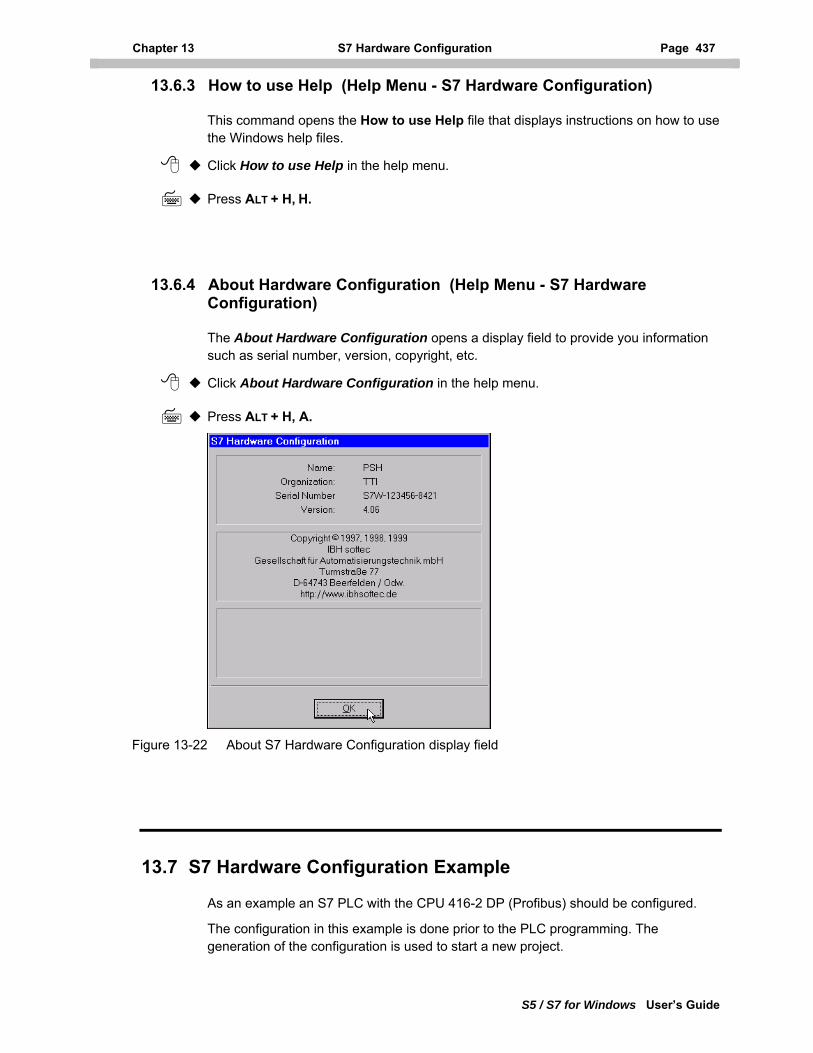
Chapter 13 S7 Hardware Configuration Page 437
S5 / S7 for Windows User’s Guide
13.6.3 How to use Help (Help Menu - S7 Hardware Configuration)
This command opens the How to use Help file that displays instructions on how to use the Windows help files.
Click How to use Help in the help menu.
Press ALT + H, H.
13.6.4 About Hardware Configuration (Help Menu - S7 Hardware Configuration)
The About Hardware Configuration opens a display field to provide you information such as serial number, version, copyright, etc.
Click About Hardware Configuration in the help menu.
Press ALT + H, A.
Figure 13-22 About S7 Hardware Configuration display field
13.7 S7 Hardware Configuration Example
As an example an S7 PLC with the CPU 416-2 DP (Profibus) should be configured.
The configuration in this example is done prior to the PLC programming. The generation of the configuration is used to start a new project.
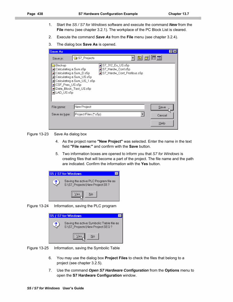
Page 438 S7 Hardware Configuration Example Chapter 13.7
S5 / S7 for Windows User’s Guide
1. Start the S5 / S7 for Windows software and execute the command New from the File menu (see chapter 3.2.1). The workplace of the PC Block List is cleared.
2. Execute the command Save As from the File menu (see chapter 3.2.4).
3. The dialog box Save As is opened.
Figure 13-23 Save As dialog box
4. As the project name "New Project" was selected. Enter the name in the text field "File name:" and confirm with the Save button.
5. Two information boxes are opened to inform you that S7 for Windows is creating files that will become a part of the project. The file name and the path are indicated. Confirm the information with the Yes button.
Figure 13-24 Information, saving the PLC program
Figure 13-25 Information, saving the Symbolic Table
6. You may use the dialog box Project Files to check the files that belong to a project (see chapter 3.2.5).
7. Use the command Open S7 Hardware Configuration from the Options menu to open the S7 Hardware Configuration window.
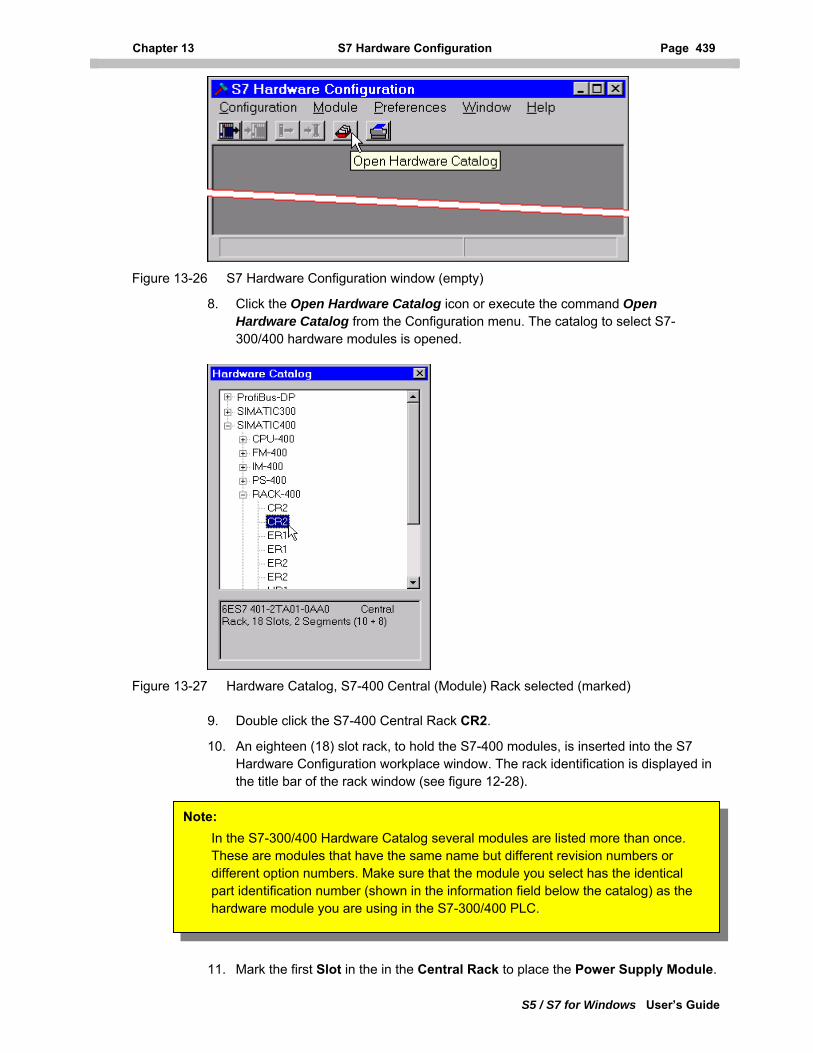
Chapter 13 S7 Hardware Configuration Page 439
S5 / S7 for Windows User’s Guide
Figure 13-26 S7 Hardware Configuration window (empty)
8. Click the Open Hardware Catalog icon or execute the command Open Hardware Catalog from the Configuration menu. The catalog to select S7-300/400 hardware modules is opened.
Figure 13-27 Hardware Catalog, S7-400 Central (Module) Rack selected (marked)
9. Double click the S7-400 Central Rack CR2.
10. An eighteen (18) slot rack, to hold the S7-400 modules, is inserted into the S7 Hardware Configuration workplace window. The rack identification is displayed in the title bar of the rack window (see figure 12-28).
Note: In the S7-300/400 Hardware Catalog several modules are listed more than once. These are modules that have the same name but different revision numbers or different option numbers. Make sure that the module you select has the identical part identification number (shown in the information field below the catalog) as the hardware module you are using in the S7-300/400 PLC.
11. Mark the first Slot in the in the Central Rack to place the Power Supply Module.
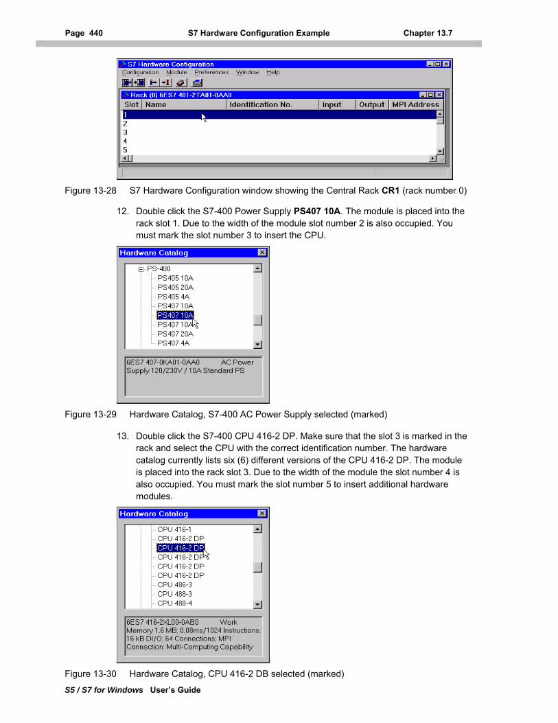
Page 440 S7 Hardware Configuration Example Chapter 13.7
S5 / S7 for Windows User’s Guide
Figure 13-28 S7 Hardware Configuration window showing the Central Rack CR1 (rack number 0)
12. Double click the S7-400 Power Supply PS407 10A. The module is placed into the rack slot 1. Due to the width of the module slot number 2 is also occupied. You must mark the slot number 3 to insert the CPU.
Figure 13-29 Hardware Catalog, S7-400 AC Power Supply selected (marked)
13. Double click the S7-400 CPU 416-2 DP. Make sure that the slot 3 is marked in the rack and select the CPU with the correct identification number. The hardware catalog currently lists six (6) different versions of the CPU 416-2 DP. The module is placed into the rack slot 3. Due to the width of the module the slot number 4 is also occupied. You must mark the slot number 5 to insert additional hardware modules.
Figure 13-30 Hardware Catalog, CPU 416-2 DB selected (marked)
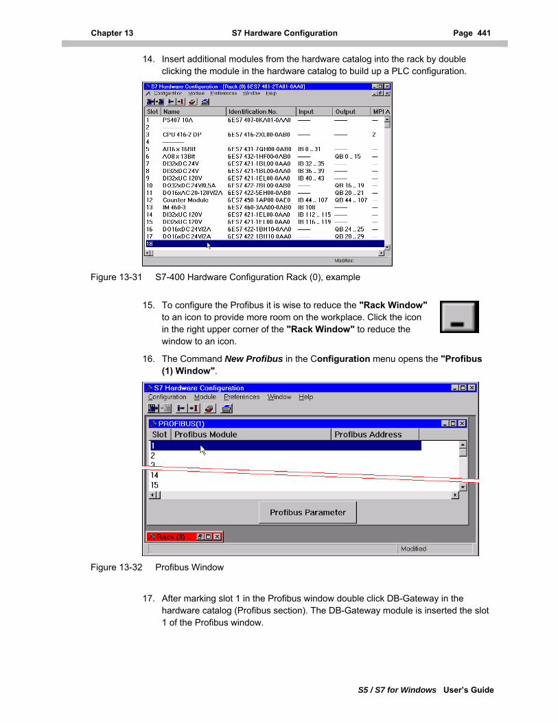
Chapter 13 S7 Hardware Configuration Page 441
S5 / S7 for Windows User’s Guide
14. Insert additional modules from the hardware catalog into the rack by double clicking the module in the hardware catalog to build up a PLC configuration.
Figure 13-31 S7-400 Hardware Configuration Rack (0), example
15. To configure the Profibus it is wise to reduce the "Rack Window"
to an icon to provide more room on the workplace. Click the icon in the right upper corner of the "Rack Window" to reduce the window to an icon.
16. The Command New Profibus in the Configuration menu opens the "Profibus (1) Window".
Figure 13-32 Profibus Window
17. After marking slot 1 in the Profibus window double click DB-Gateway in the hardware catalog (Profibus section). The DB-Gateway module is inserted the slot 1 of the Profibus window.
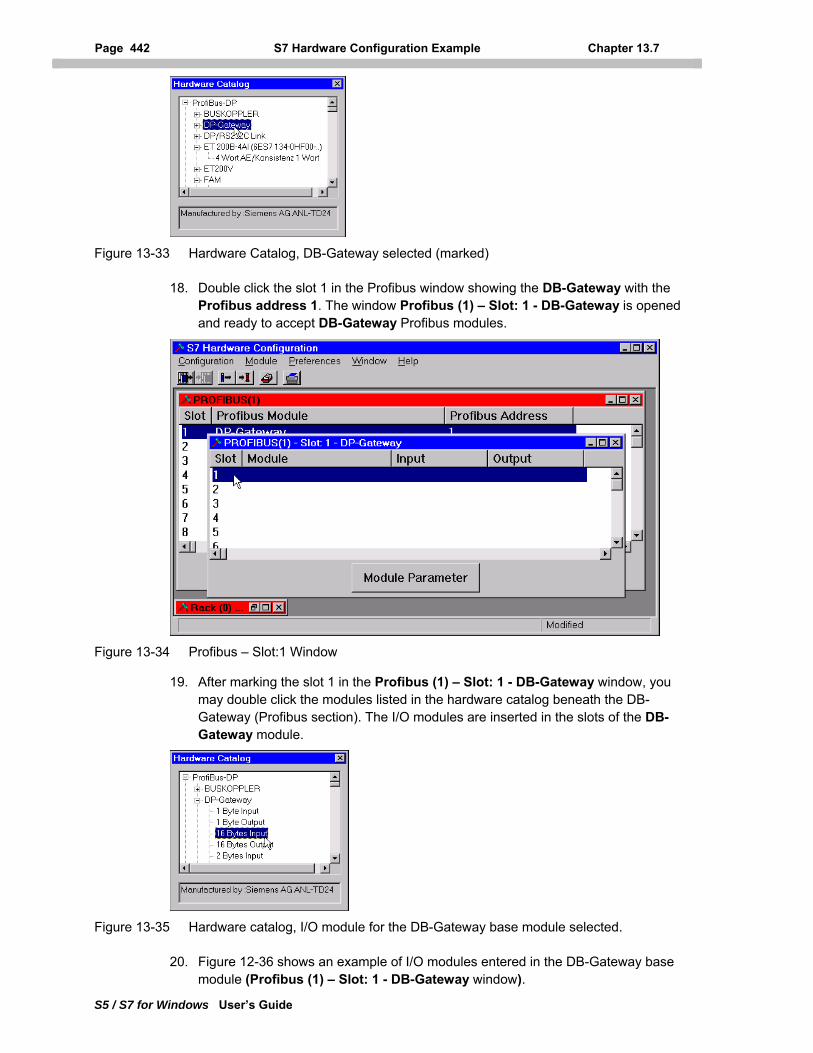
Page 442 S7 Hardware Configuration Example Chapter 13.7
S5 / S7 for Windows User’s Guide
Figure 13-33 Hardware Catalog, DB-Gateway selected (marked)
18. Double click the slot 1 in the Profibus window showing the DB-Gateway with the Profibus address 1. The window Profibus (1) – Slot: 1 - DB-Gateway is opened and ready to accept DB-Gateway Profibus modules.
Figure 13-34 Profibus – Slot:1 Window
19. After marking the slot 1 in the Profibus (1) – Slot: 1 - DB-Gateway window, you may double click the modules listed in the hardware catalog beneath the DB-Gateway (Profibus section). The I/O modules are inserted in the slots of the DB-Gateway module.
Figure 13-35 Hardware catalog, I/O module for the DB-Gateway base module selected.
20. Figure 12-36 shows an example of I/O modules entered in the DB-Gateway base module (Profibus (1) – Slot: 1 - DB-Gateway window).
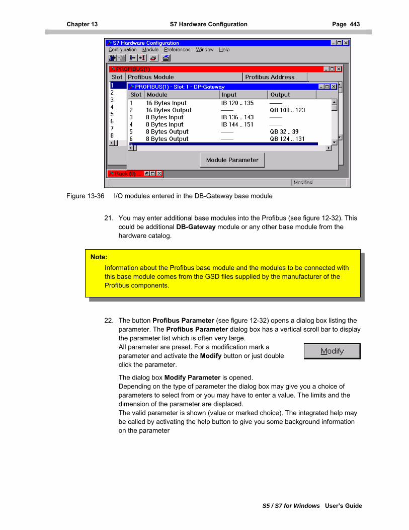
Chapter 13 S7 Hardware Configuration Page 443
S5 / S7 for Windows User’s Guide
Figure 13-36 I/O modules entered in the DB-Gateway base module
21. You may enter additional base modules into the Profibus (see figure 12-32). This could be additional DB-Gateway module or any other base module from the hardware catalog.
Note: Information about the Profibus base module and the modules to be connected with this base module comes from the GSD files supplied by the manufacturer of the Profibus components.
22. The button Profibus Parameter (see figure 12-32) opens a dialog box listing the
parameter. The Profibus Parameter dialog box has a vertical scroll bar to display the parameter list which is often very large. All parameter are preset. For a modification mark a parameter and activate the Modify button or just double click the parameter.
The dialog box Modify Parameter is opened. Depending on the type of parameter the dialog box may give you a choice of parameters to select from or you may have to enter a value. The limits and the dimension of the parameter are displaced. The valid parameter is shown (value or marked choice). The integrated help may be called by activating the help button to give you some background information on the parameter
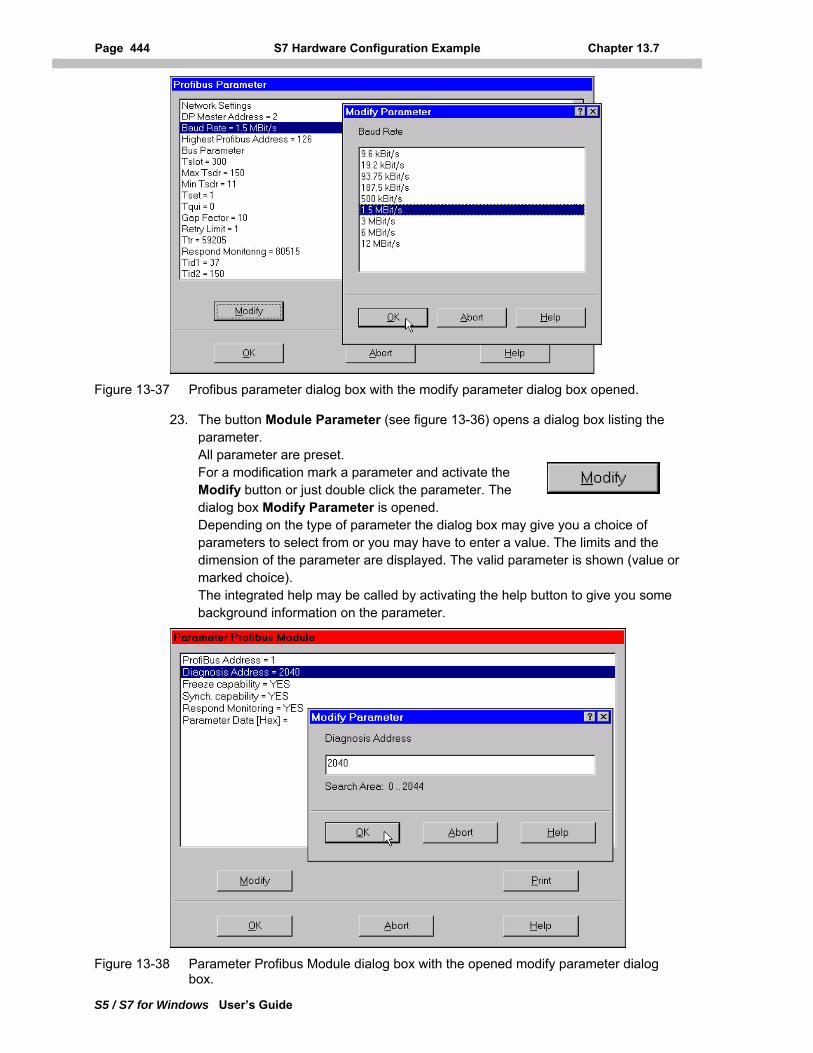
Page 444 S7 Hardware Configuration Example Chapter 13.7
S5 / S7 for Windows User’s Guide
Figure 13-37 Profibus parameter dialog box with the modify parameter dialog box opened.
23. The button Module Parameter (see figure 13-36) opens a dialog box listing the parameter. All parameter are preset. For a modification mark a parameter and activate the Modify button or just double click the parameter. The dialog box Modify Parameter is opened. Depending on the type of parameter the dialog box may give you a choice of parameters to select from or you may have to enter a value. The limits and the dimension of the parameter are displayed. The valid parameter is shown (value or marked choice). The integrated help may be called by activating the help button to give you some background information on the parameter.
Figure 13-38 Parameter Profibus Module dialog box with the opened modify parameter dialog box.
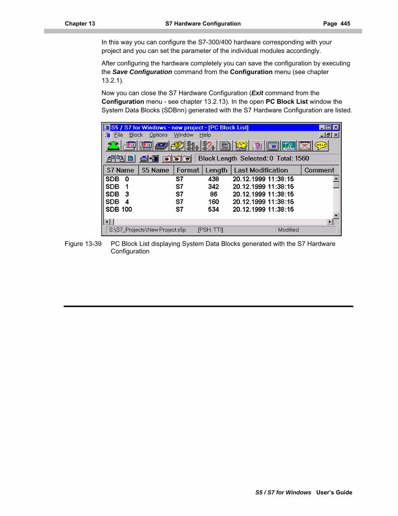
Chapter 13 S7 Hardware Configuration Page 445
S5 / S7 for Windows User’s Guide
In this way you can configure the S7-300/400 hardware corresponding with your project and you can set the parameter of the individual modules accordingly.
After configuring the hardware completely you can save the configuration by executing the Save Configuration command from the Configuration menu (see chapter 13.2.1).
Now you can close the S7 Hardware Configuration (Exit command from the Configuration menu - see chapter 13.2.13). In the open PC Block List window the System Data Blocks (SDBnn) generated with the S7 Hardware Configuration are listed.
Figure 13-39 PC Block List displaying System Data Blocks generated with the S7 Hardware Configuration
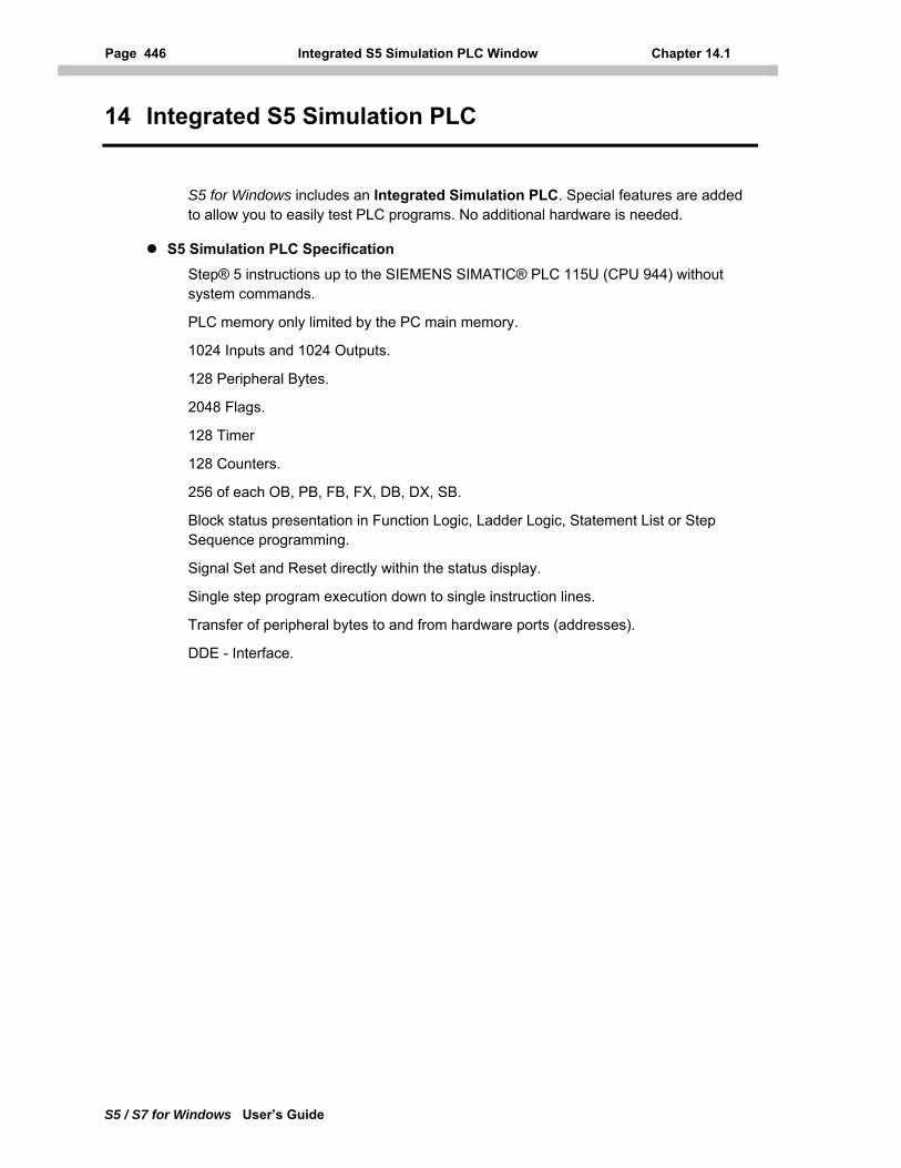
Page 446 Integrated S5 Simulation PLC Window Chapter 14.1
S5 / S7 for Windows User’s Guide
14 Integrated S5 Simulation PLC
S5 for Windows includes an Integrated Simulation PLC. Special features are added to allow you to easily test PLC programs. No additional hardware is needed.
S5 Simulation PLC Specification Step® 5 instructions up to the SIEMENS SIMATIC® PLC 115U (CPU 944) without system commands.
PLC memory only limited by the PC main memory.
1024 Inputs and 1024 Outputs.
128 Peripheral Bytes.
2048 Flags.
128 Timer
128 Counters.
256 of each OB, PB, FB, FX, DB, DX, SB.
Block status presentation in Function Logic, Ladder Logic, Statement List or Step Sequence programming.
Signal Set and Reset directly within the status display.
Single step program execution down to single instruction lines.
Transfer of peripheral bytes to and from hardware ports (addresses).
DDE - Interface.
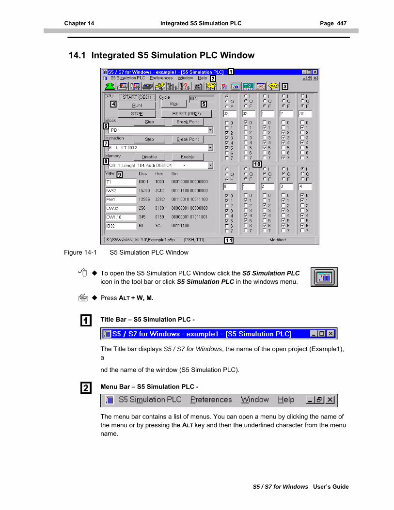
Chapter 14 Integrated S5 Simulation PLC Page 447
S5 / S7 for Windows User’s Guide
14.1 Integrated S5 Simulation PLC Window
Figure 14-1 S5 Simulation PLC Window
To open the S5 Simulation PLC Window click the S5 Simulation PLC icon in the tool bar or click S5 Simulation PLC in the windows menu.
Press ALT + W, M.
Title Bar – S5 Simulation PLC -
The Title bar displays S5 / S7 for Windows, the name of the open project (Example1), a
nd the name of the window (S5 Simulation PLC).
Menu Bar – S5 Simulation PLC -
The menu bar contains a list of menus. You can open a menu by clicking the name of the menu or by pressing the ALT key and then the underlined character from the menu name.
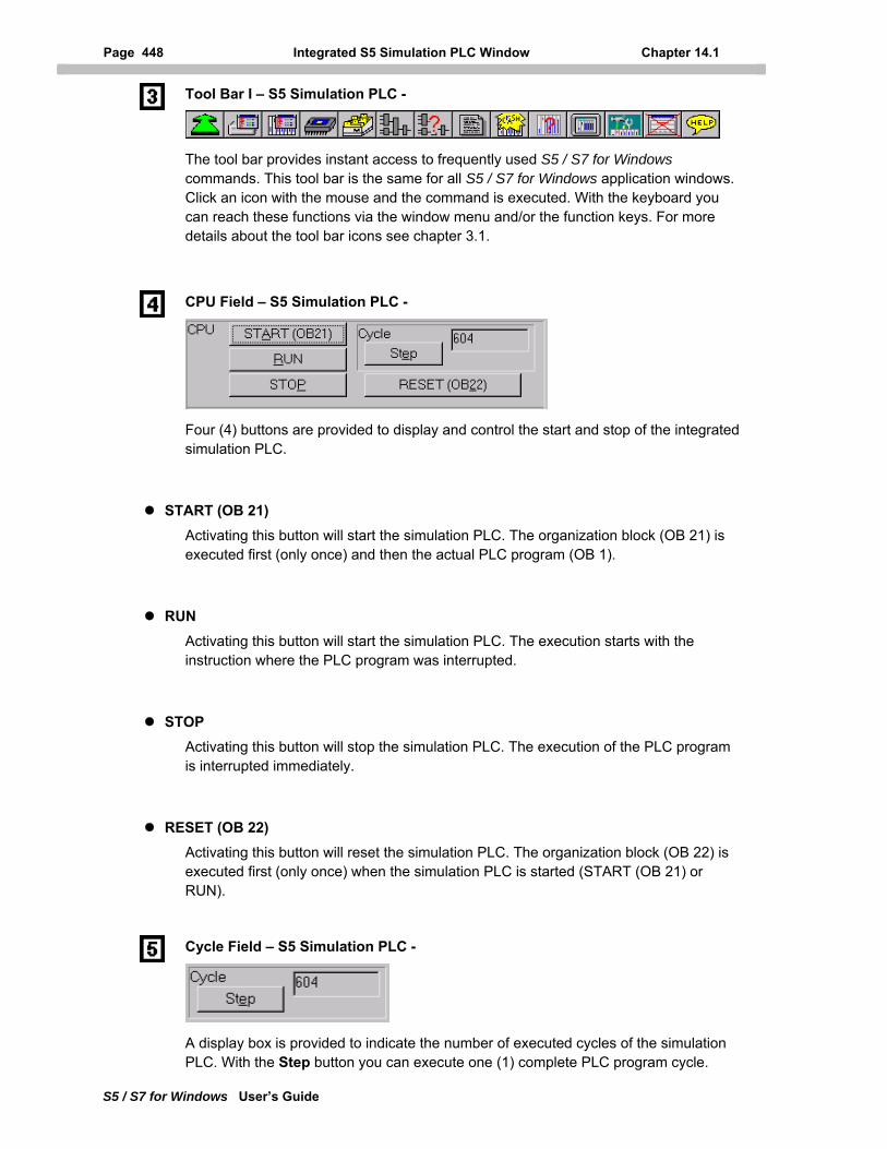
Page 448 Integrated S5 Simulation PLC Window Chapter 14.1
S5 / S7 for Windows User’s Guide
Tool Bar I – S5 Simulation PLC -
The tool bar provides instant access to frequently used S5 / S7 for Windows commands. This tool bar is the same for all S5 / S7 for Windows application windows. Click an icon with the mouse and the command is executed. With the keyboard you can reach these functions via the window menu and/or the function keys. For more details about the tool bar icons see chapter 3.1.
CPU Field – S5 Simulation PLC -
Four (4) buttons are provided to display and control the start and stop of the integrated simulation PLC.
START (OB 21) Activating this button will start the simulation PLC. The organization block (OB 21) is executed first (only once) and then the actual PLC program (OB 1).
RUN
Activating this button will start the simulation PLC. The execution starts with the instruction where the PLC program was interrupted.
STOP
Activating this button will stop the simulation PLC. The execution of the PLC program is interrupted immediately.
RESET (OB 22) Activating this button will reset the simulation PLC. The organization block (OB 22) is executed first (only once) when the simulation PLC is started (START (OB 21) or RUN).
Cycle Field – S5 Simulation PLC -
A display box is provided to indicate the number of executed cycles of the simulation PLC. With the Step button you can execute one (1) complete PLC program cycle.
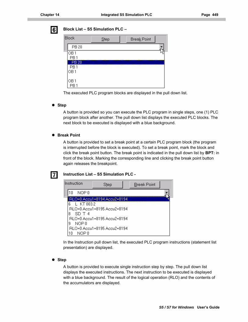
Chapter 14 Integrated S5 Simulation PLC Page 449
S5 / S7 for Windows User’s Guide
Block List – S5 Simulation PLC –
The executed PLC program blocks are displayed in the pull down list.
Step
A button is provided so you can execute the PLC program in single steps, one (1) PLC program block after another. The pull down list displays the executed PLC blocks. The next block to be executed is displayed with a blue background.
Break Point A button is provided to set a break point at a certain PLC program block (the program is interrupted before the block is executed). To set a break point, mark the block and click the break point button. The break point is indicated in the pull down list by BPT: in front of the block. Marking the corresponding line and clicking the break point button again releases the breakpoint.
Instruction List – S5 Simulation PLC -
In the Instruction pull down list, the executed PLC program instructions (statement list presentation) are displayed.
Step
A button is provided to execute single instruction step by step. The pull down list displays the executed instructions. The next instruction to be executed is displayed with a blue background. The result of the logical operation (RLO) and the contents of the accumulators are displayed.
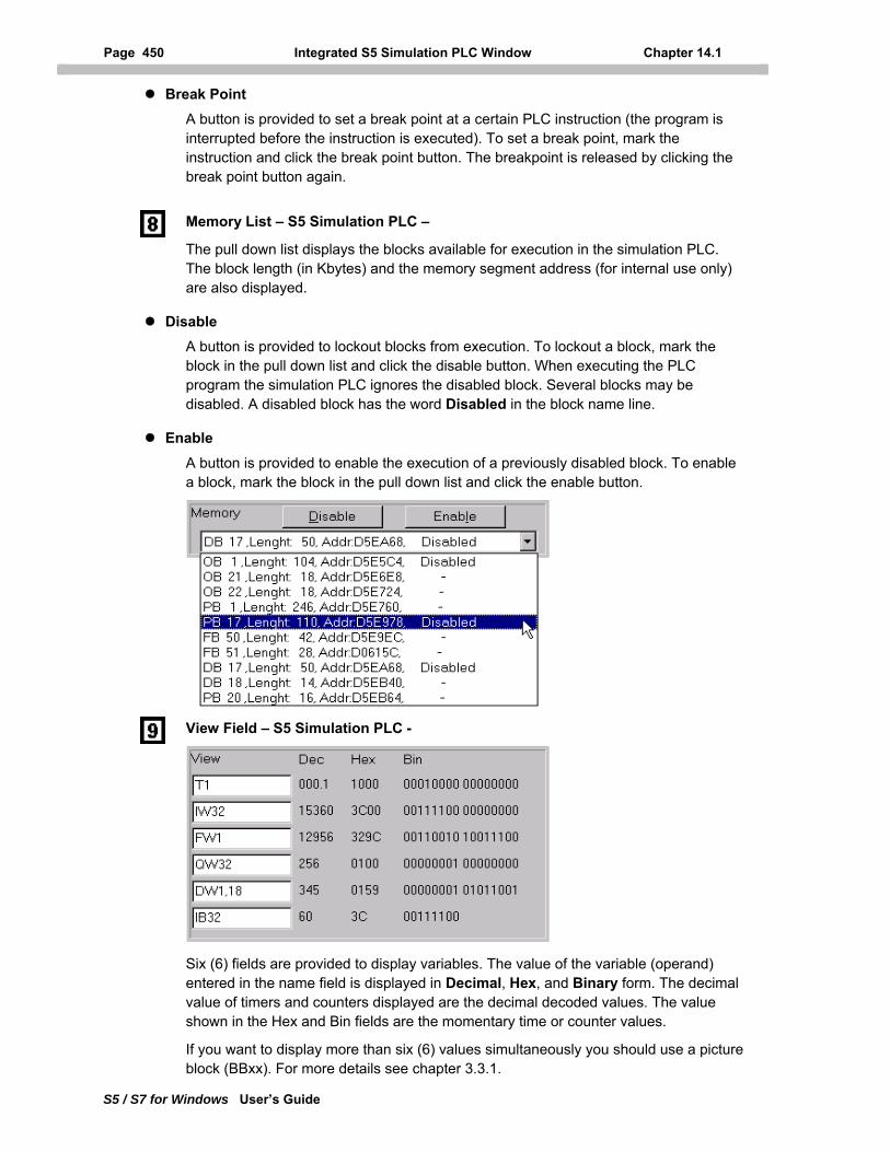
Page 450 Integrated S5 Simulation PLC Window Chapter 14.1
S5 / S7 for Windows User’s Guide
Break Point A button is provided to set a break point at a certain PLC instruction (the program is interrupted before the instruction is executed). To set a break point, mark the instruction and click the break point button. The breakpoint is released by clicking the break point button again.
Memory List – S5 Simulation PLC –
The pull down list displays the blocks available for execution in the simulation PLC. The block length (in Kbytes) and the memory segment address (for internal use only) are also displayed.
Disable
A button is provided to lockout blocks from execution. To lockout a block, mark the block in the pull down list and click the disable button. When executing the PLC program the simulation PLC ignores the disabled block. Several blocks may be disabled. A disabled block has the word Disabled in the block name line.
Enable
A button is provided to enable the execution of a previously disabled block. To enable a block, mark the block in the pull down list and click the enable button.
View Field – S5 Simulation PLC -
Six (6) fields are provided to display variables. The value of the variable (operand) entered in the name field is displayed in Decimal, Hex, and Binary form. The decimal value of timers and counters displayed are the decimal decoded values. The value shown in the Hex and Bin fields are the momentary time or counter values.
If you want to display more than six (6) values simultaneously you should use a picture block (BBxx). For more details see chapter 3.3.1.
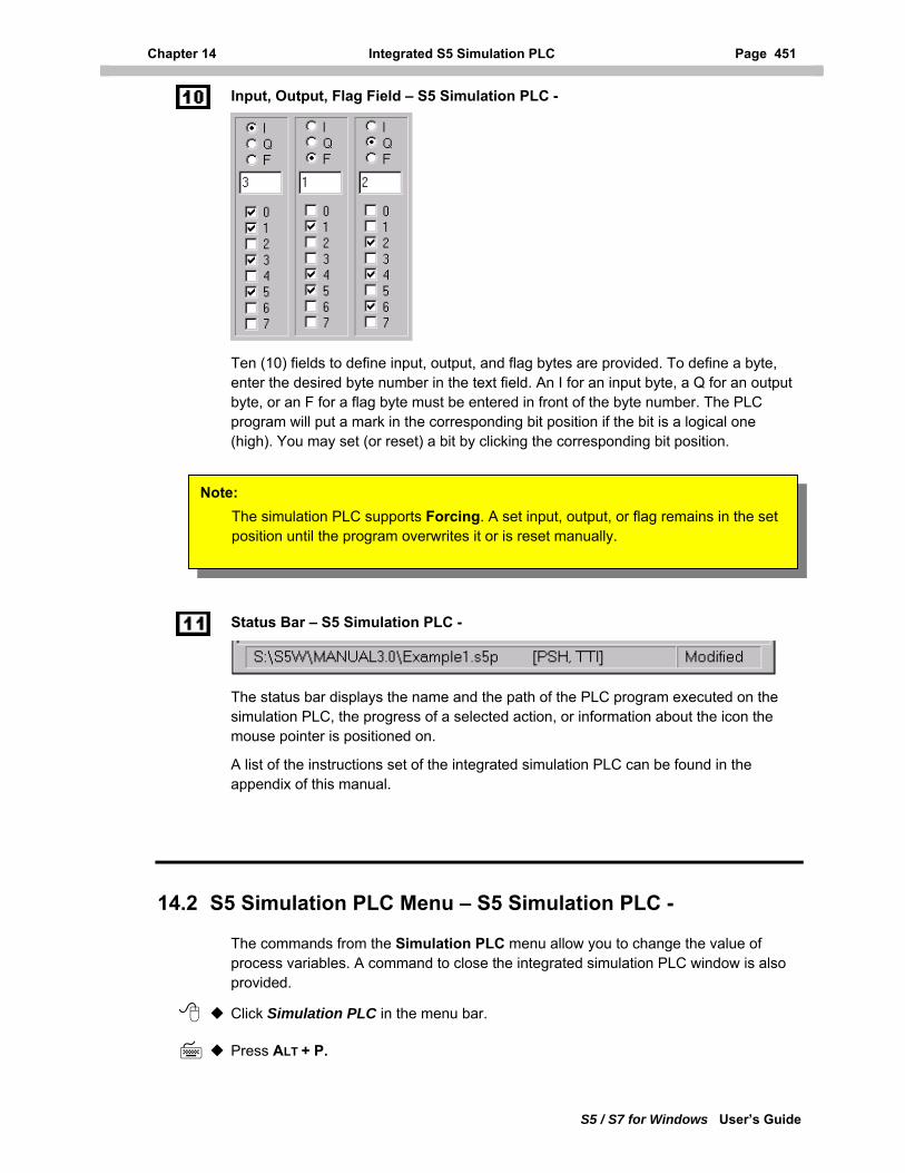
Chapter 14 Integrated S5 Simulation PLC Page 451
Input, Output, Flag Field – S5 Simulation PLC -
Ten (10) fields to define input, output, and flag bytes are provided. To define a byte, enter the desired byte number in the text field. An I for an input byte, a Q for an output byte, or an F for a flag byte must be entered in front of the byte number. The PLC program will put a mark in the corresponding bit position if the bit is a logical one (high). You may set (or reset) a bit by clicking the corresponding bit position.
Note: The simulation PLC supports Forcing. A set input, output, or flag remains in the set position until the program overwrites it or is reset manually.
Status Bar – S5 Simulation PLC -
The status bar displays the name and the path of the PLC program executed on the simulation PLC, the progress of a selected action, or information about the icon the mouse pointer is positioned on.
A list of the instructions set of the integrated simulation PLC can be found in the appendix of this manual.
14.2 S5 Simulation PLC Menu – S5 Simulation PLC -
The commands from the Simulation PLC menu allow you to change the value of process variables. A command to close the integrated simulation PLC window is also provided.
Click Simulation PLC in the menu bar.
Press ALT + P.
S5 / S7 for Windows User’s Guide
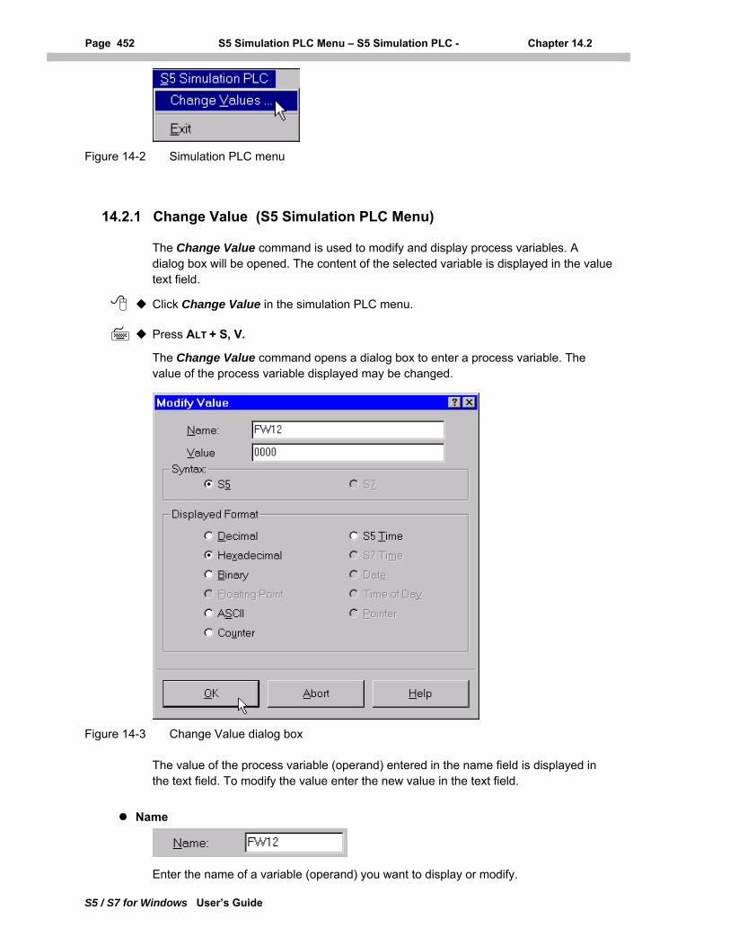
Page 452 S5 Simulation PLC Menu – S5 Simulation PLC - Chapter 14.2
S5 / S7 for Windows User’s Guide
Figure 14-2 Simulation PLC menu
14.2.1 Change Value (S5 Simulation PLC Menu)
The Change Value command is used to modify and display process variables. A dialog box will be opened. The content of the selected variable is displayed in the value text field.
Click Change Value in the simulation PLC menu.
Press ALT + S, V.
The Change Value command opens a dialog box to enter a process variable. The value of the process variable displayed may be changed.
Figure 14-3 Change Value dialog box
The value of the process variable (operand) entered in the name field is displayed in the text field. To modify the value enter the new value in the text field.
Name
Enter the name of a variable (operand) you want to display or modify.
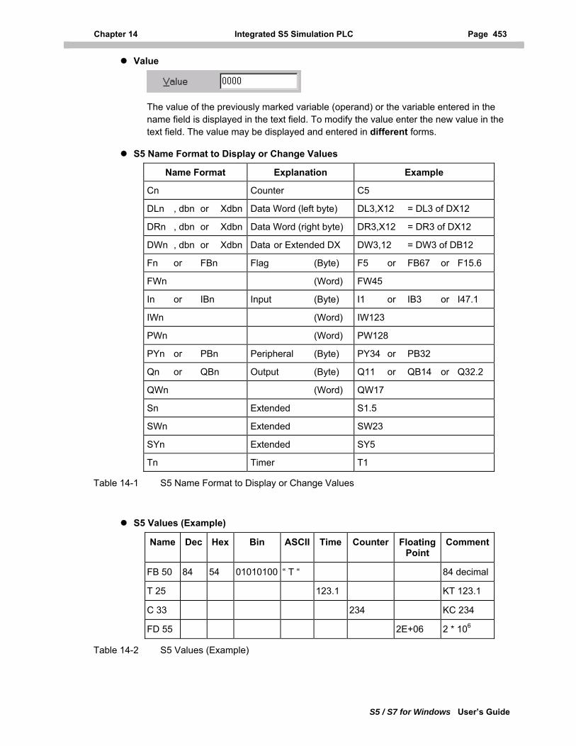
Chapter 14 Integrated S5 Simulation PLC Page 453
S5 / S7 for Windows User’s Guide
Value
The value of the previously marked variable (operand) or the variable entered in the name field is displayed in the text field. To modify the value enter the new value in the text field. The value may be displayed and entered in different forms.
S5 Name Format to Display or Change Values
Name Format Explanation Example
Cn Counter C5
DLn , dbn or Xdbn Data Word (left byte) DL3,X12 = DL3 of DX12
DRn , dbn or Xdbn Data Word (right byte) DR3,X12 = DR3 of DX12
DWn , dbn or Xdbn Data or Extended DX DW3,12 = DW3 of DB12
Fn or FBn Flag (Byte) F5 or FB67 or F15.6
FWn (Word) FW45
In or IBn Input (Byte) I1 or IB3 or I47.1
IWn (Word) IW123
PWn (Word) PW128
PYn or PBn Peripheral (Byte) PY34 or PB32
Qn or QBn Output (Byte) Q11 or QB14 or Q32.2
QWn (Word) QW17
Sn Extended S1.5
SWn Extended SW23
SYn Extended SY5
Tn Timer T1
Table 14-1 S5 Name Format to Display or Change Values
S5 Values (Example)
Name Dec Hex Bin ASCII Time Counter Floating Point
Comment
FB 50 84 54 01010100 “ T “ 84 decimal
T 25 123.1 KT 123.1
C 33 234 KC 234
FD 55 2E+06 2 * 106
Table 14-2 S5 Values (Example)
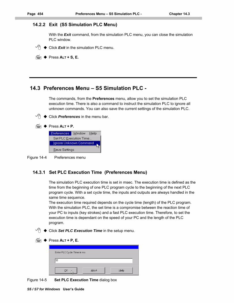
Page 454 Preferences Menu – S5 Simulation PLC - Chapter 14.3
S5 / S7 for Windows User’s Guide
14.2.2 Exit (S5 Simulation PLC Menu)
With the Exit command, from the simulation PLC menu, you can close the simulation PLC window.
Click Exit in the simulation PLC menu.
Press ALT + S, E.
14.3 Preferences Menu – S5 Simulation PLC -
The commands, from the Preferences menu, allow you to set the simulation PLC execution time. There is also a command to instruct the simulation PLC to ignore all unknown commands. You can also save the current settings of the simulation PLC.
Click Preferences in the menu bar.
Press ALT + P.
Figure 14-4 Preferences menu
14.3.1 Set PLC Execution Time (Preferences Menu)
The simulation PLC execution time is set in msec. The execution time is defined as the time from the beginning of one PLC program cycle to the beginning of the next PLC program cycle. With a set cycle time, the inputs and outputs are always handled in the same time sequence. The execution time required depends on the cycle time (length) of the PLC program. With the simulation PLC, the set time is a compromise between the reaction time of your PC to inputs (key strokes) and a fast PLC execution time. Therefore, to set the execution time is dependant on the speed of your PC and the length of the PLC program.
Click Set PLC Execution Time in the setup menu.
Press ALT + P, E.
Figure 14-5 Set PLC Execution Time dialog box
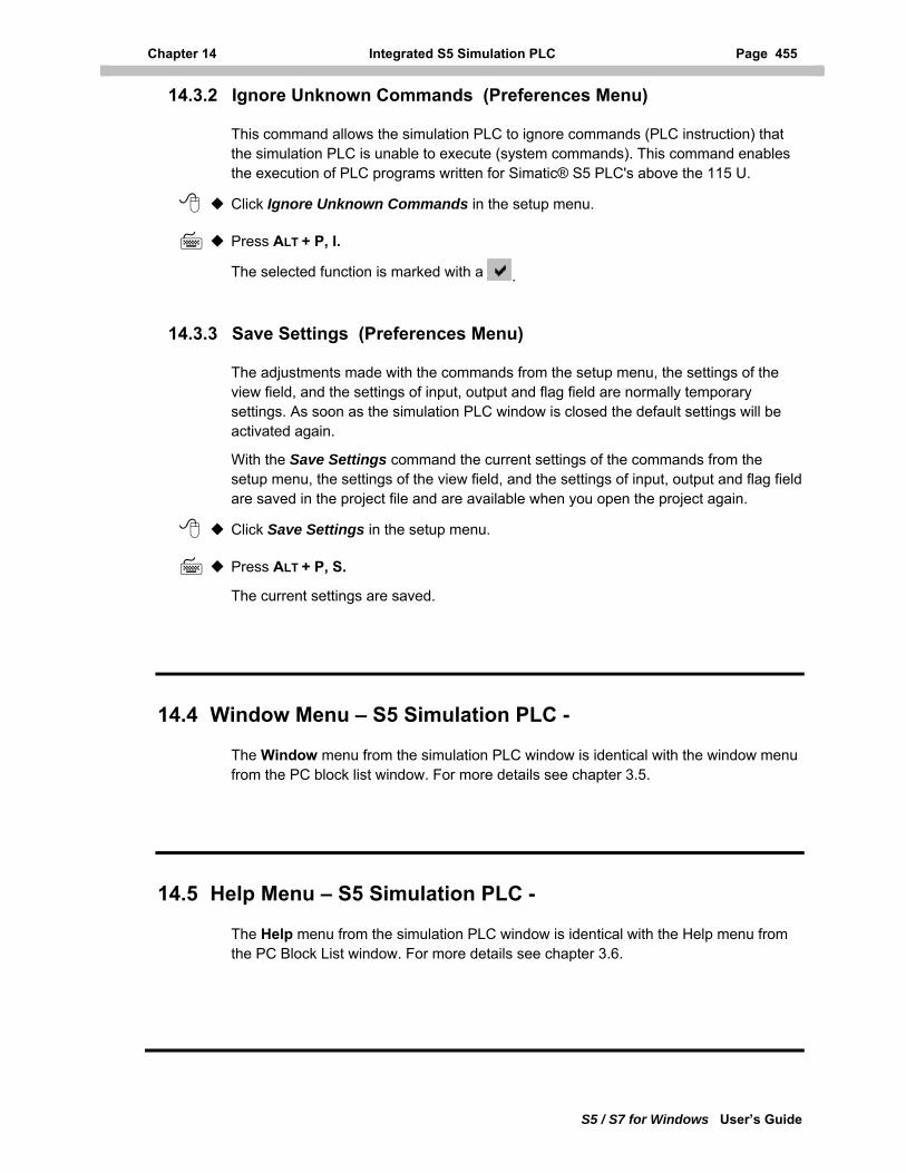
Chapter 14 Integrated S5 Simulation PLC Page 455
S5 / S7 for Windows User’s Guide
14.3.2 Ignore Unknown Commands (Preferences Menu)
This command allows the simulation PLC to ignore commands (PLC instruction) that the simulation PLC is unable to execute (system commands). This command enables the execution of PLC programs written for Simatic® S5 PLC's above the 115 U.
Click Ignore Unknown Commands in the setup menu.
Press ALT + P, I.
The selected function is marked with a .
14.3.3 Save Settings (Preferences Menu)
The adjustments made with the commands from the setup menu, the settings of the view field, and the settings of input, output and flag field are normally temporary settings. As soon as the simulation PLC window is closed the default settings will be activated again.
With the Save Settings command the current settings of the commands from the setup menu, the settings of the view field, and the settings of input, output and flag field are saved in the project file and are available when you open the project again.
Click Save Settings in the setup menu.
Press ALT + P, S.
The current settings are saved.
14.4 Window Menu – S5 Simulation PLC -
The Window menu from the simulation PLC window is identical with the window menu from the PC block list window. For more details see chapter 3.5.
14.5 Help Menu – S5 Simulation PLC -
The Help menu from the simulation PLC window is identical with the Help menu from the PC Block List window. For more details see chapter 3.6.
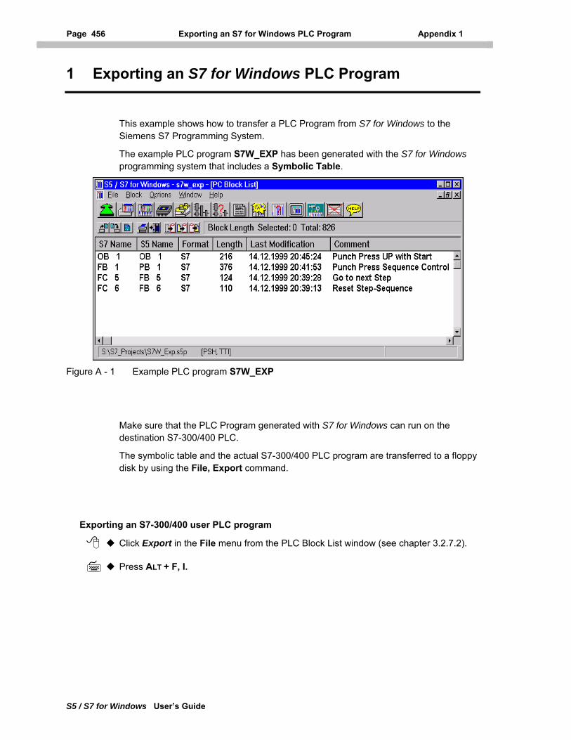
Page 456 Exporting an S7 for Windows PLC Program Appendix 1
S5 / S7 for Windows User’s Guide
1 Exporting an S7 for Windows PLC Program
This example shows how to transfer a PLC Program from S7 for Windows to the Siemens S7 Programming System.
The example PLC program S7W_EXP has been generated with the S7 for Windows programming system that includes a Symbolic Table.
Figure A - 1 Example PLC program S7W_EXP
Make sure that the PLC Program generated with S7 for Windows can run on the destination S7-300/400 PLC.
The symbolic table and the actual S7-300/400 PLC program are transferred to a floppy disk by using the File, Export command.
Exporting an S7-300/400 user PLC program
Click Export in the File menu from the PLC Block List window (see chapter 3.2.7.2).
Press ALT + F, I.
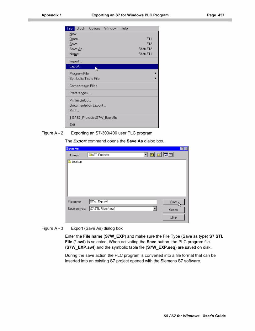
Appendix 1 Exporting an S7 for Windows PLC Program Page 457
S5 / S7 for Windows User’s Guide
Figure A - 2 Exporting an S7-300/400 user PLC program
The Export command opens the Save As dialog box.
Figure A - 3 Export (Save As) dialog box
Enter the File name (S7W_EXP) and make sure the File Type (Save as type) S7 STL File (*.awl) is selected. When activating the Save button, the PLC program file (S7W_EXP.awl) and the symbolic table file (S7W_EXP.seq) are saved on disk.
During the save action the PLC program is converted into a file format that can be inserted into an existing S7 project opened with the Siemens S7 software.
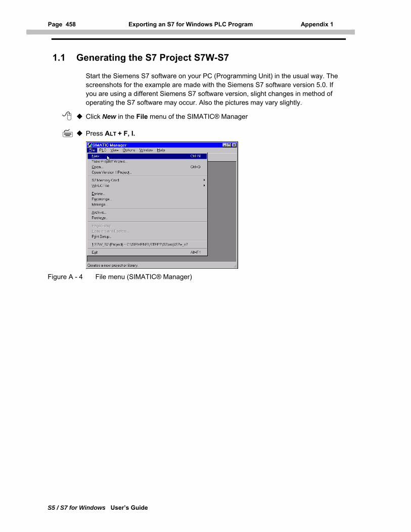
Page 458 Exporting an S7 for Windows PLC Program Appendix 1
S5 / S7 for Windows User’s Guide
1.1 Generating the S7 Project S7W-S7
Start the Siemens S7 software on your PC (Programming Unit) in the usual way. The screenshots for the example are made with the Siemens S7 software version 5.0. If you are using a different Siemens S7 software version, slight changes in method of operating the S7 software may occur. Also the pictures may vary slightly.
Click New in the File menu of the SIMATIC® Manager
Press ALT + F, I.
Figure A - 4 File menu (SIMATIC® Manager)
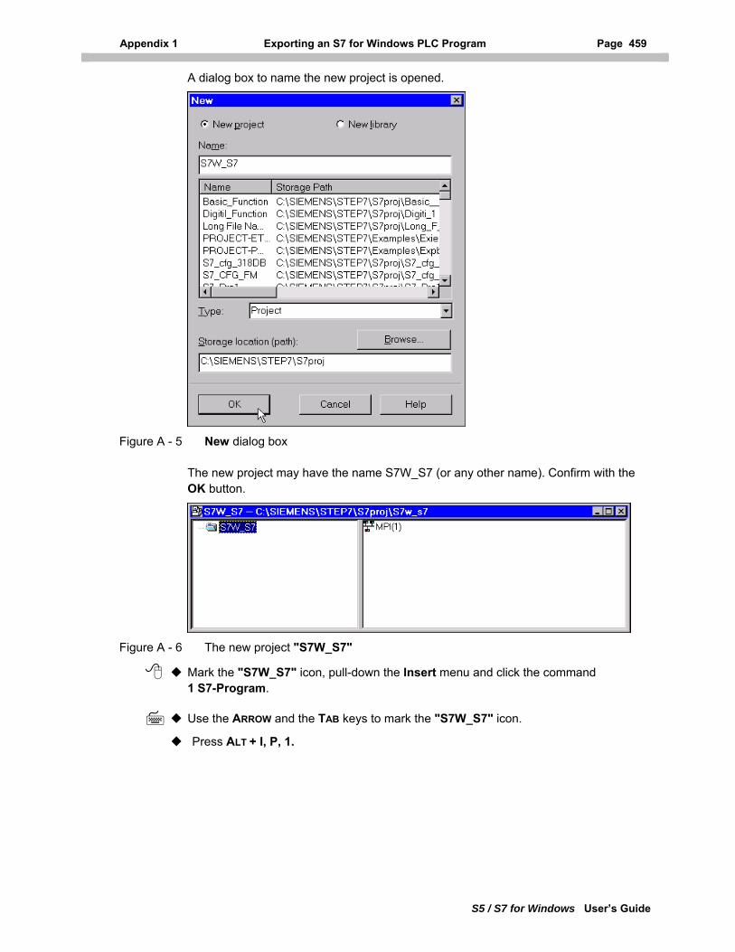
Appendix 1 Exporting an S7 for Windows PLC Program Page 459
S5 / S7 for Windows User’s Guide
A dialog box to name the new project is opened.
Figure A - 5 New dialog box
The new project may have the name S7W_S7 (or any other name). Confirm with the OK button.
Figure A - 6 The new project "S7W_S7"
Mark the "S7W_S7" icon, pull-down the Insert menu and click the command 1 S7-Program.
Use the ARROW and the TAB keys to mark the "S7W_S7" icon.
Press ALT + I, P, 1.
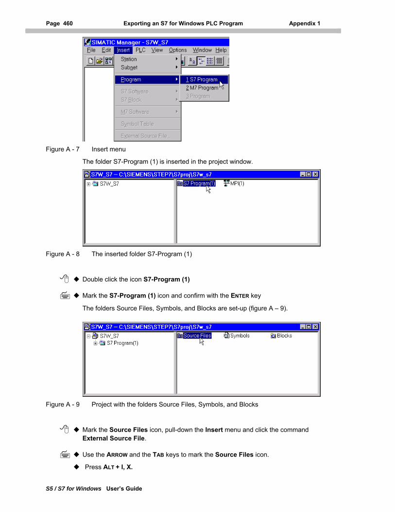
Page 460 Exporting an S7 for Windows PLC Program Appendix 1
S5 / S7 for Windows User’s Guide
Figure A - 7 Insert menu
The folder S7-Program (1) is inserted in the project window.
Figure A - 8 The inserted folder S7-Program (1)
Double click the icon S7-Program (1)
Mark the S7-Program (1) icon and confirm with the ENTER key
The folders Source Files, Symbols, and Blocks are set-up (figure A – 9).
Figure A - 9 Project with the folders Source Files, Symbols, and Blocks
Mark the Source Files icon, pull-down the Insert menu and click the command External Source File.
Use the ARROW and the TAB keys to mark the Source Files icon.
Press ALT + I, X.
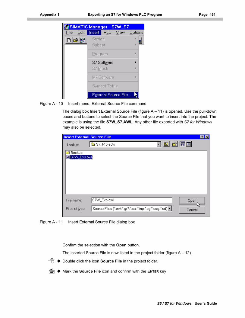
Appendix 1 Exporting an S7 for Windows PLC Program Page 461
S5 / S7 for Windows User’s Guide
Figure A - 10 Insert menu, External Source File command
The dialog box Insert External Source File (figure A – 11) is opened. Use the pull-down boxes and buttons to select the Source File that you want to insert into the project. The example is using the file S7W_S7.AWL. Any other file exported with S7 for Windows may also be selected.
Figure A - 11 Insert External Source File dialog box
Confirm the selection with the Open button.
The inserted Source File is now listed in the project folder (figure A – 12).
Double click the icon Source File in the project folder.
Mark the Source File icon and confirm with the ENTER key
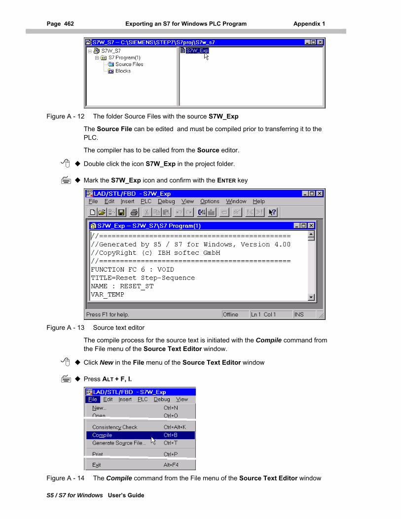
Page 462 Exporting an S7 for Windows PLC Program Appendix 1
S5 / S7 for Windows User’s Guide
Figure A - 12 The folder Source Files with the source S7W_Exp
The Source File can be edited and must be compiled prior to transferring it to the PLC.
The compiler has to be called from the Source editor.
Double click the icon S7W_Exp in the project folder.
Mark the S7W_Exp icon and confirm with the ENTER key
Figure A - 13 Source text editor
The compile process for the source text is initiated with the Compile command from the File menu of the Source Text Editor window.
Click New in the File menu of the Source Text Editor window
Press ALT + F, I.
Figure A - 14 The Compile command from the File menu of the Source Text Editor window
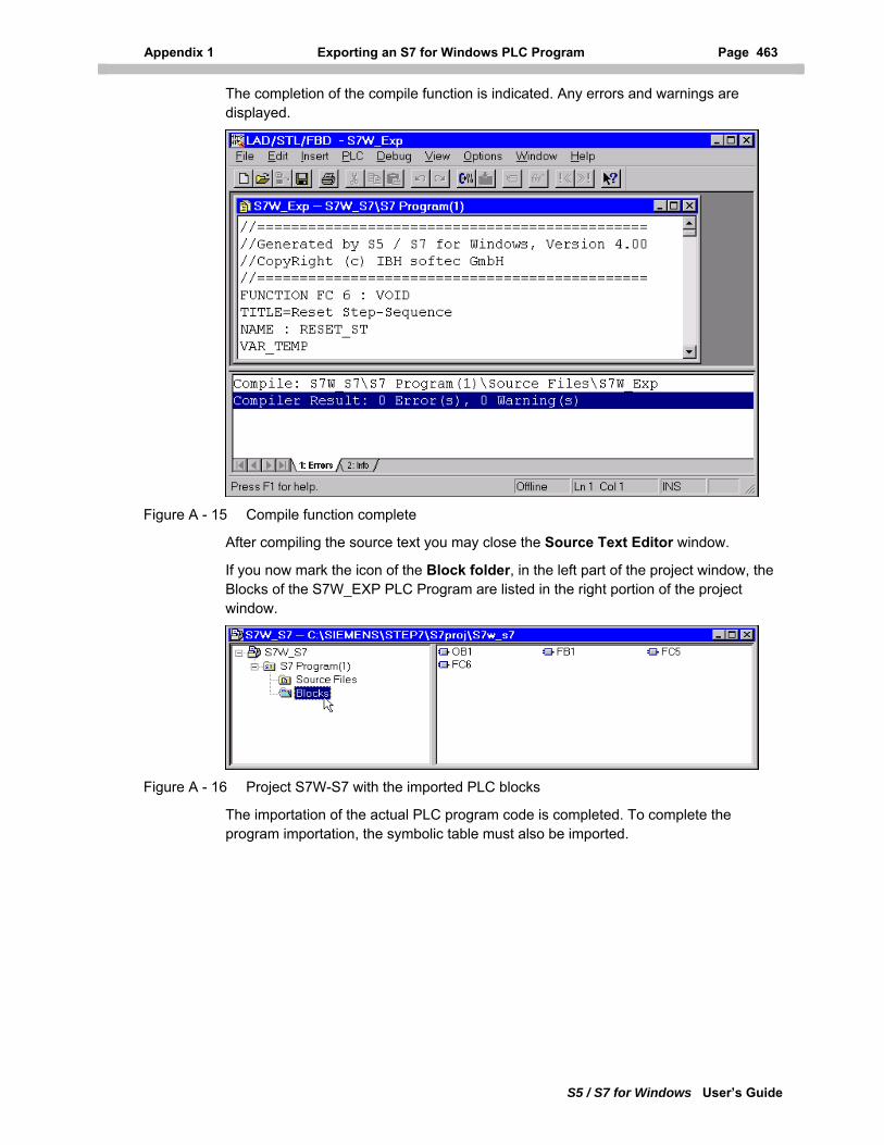
Appendix 1 Exporting an S7 for Windows PLC Program Page 463
S5 / S7 for Windows User’s Guide
The completion of the compile function is indicated. Any errors and warnings are displayed.
Figure A - 15 Compile function complete
After compiling the source text you may close the Source Text Editor window.
If you now mark the icon of the Block folder, in the left part of the project window, the Blocks of the S7W_EXP PLC Program are listed in the right portion of the project window.
Figure A - 16 Project S7W-S7 with the imported PLC blocks
The importation of the actual PLC program code is completed. To complete the program importation, the symbolic table must also be imported.
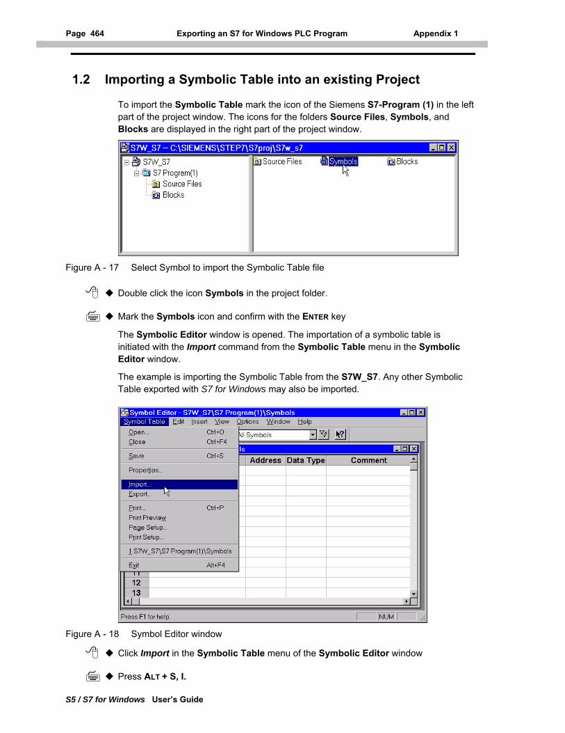
Page 464 Exporting an S7 for Windows PLC Program Appendix 1
S5 / S7 for Windows User’s Guide
1.2 Importing a Symbolic Table into an existing Project
To import the Symbolic Table mark the icon of the Siemens S7-Program (1) in the left part of the project window. The icons for the folders Source Files, Symbols, and Blocks are displayed in the right part of the project window.
Figure A - 17 Select Symbol to import the Symbolic Table file
Double click the icon Symbols in the project folder.
Mark the Symbols icon and confirm with the ENTER key
The Symbolic Editor window is opened. The importation of a symbolic table is initiated with the Import command from the Symbolic Table menu in the Symbolic Editor window.
The example is importing the Symbolic Table from the S7W_S7. Any other Symbolic Table exported with S7 for Windows may also be imported.
Figure A - 18 Symbol Editor window
Click Import in the Symbolic Table menu of the Symbolic Editor window
Press ALT + S, I.
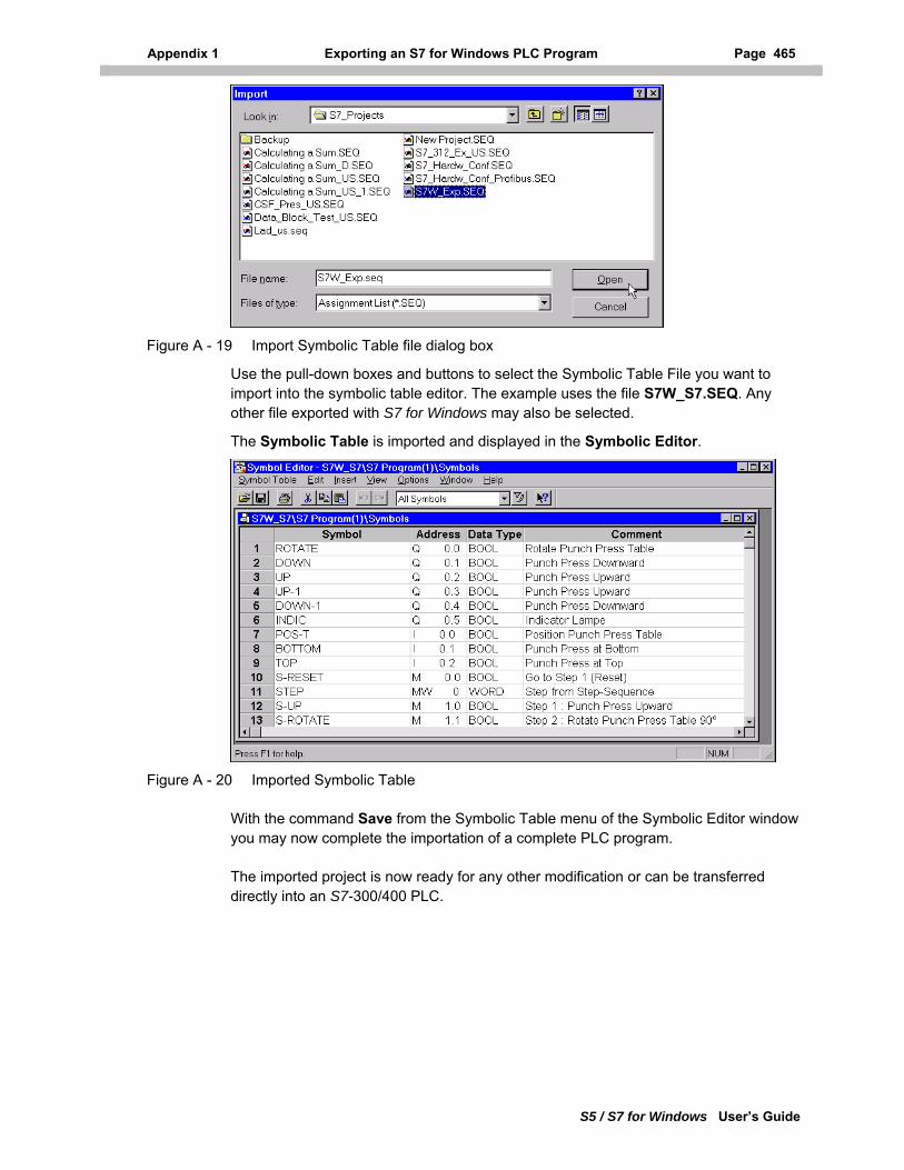
Appendix 1 Exporting an S7 for Windows PLC Program Page 465
S5 / S7 for Windows User’s Guide
Figure A - 19 Import Symbolic Table file dialog box
Use the pull-down boxes and buttons to select the Symbolic Table File you want to import into the symbolic table editor. The example uses the file S7W_S7.SEQ. Any other file exported with S7 for Windows may also be selected.
The Symbolic Table is imported and displayed in the Symbolic Editor.
Figure A - 20 Imported Symbolic Table
With the command Save from the Symbolic Table menu of the Symbolic Editor window you may now complete the importation of a complete PLC program.
The imported project is now ready for any other modification or can be transferred directly into an S7-300/400 PLC.
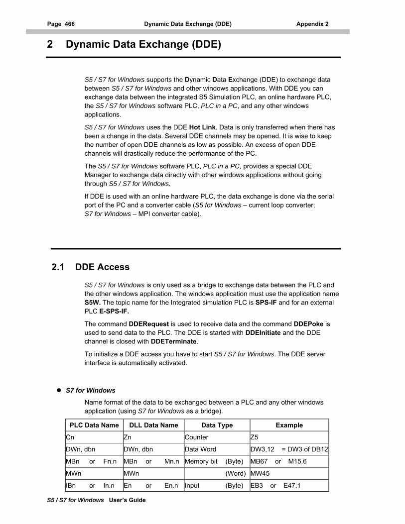
Page 466 Dynamic Data Exchange (DDE) Appendix 2
2 Dynamic Data Exchange (DDE)
S5 / S7 for Windows User’s Guide
S5 / S7 for Windows supports the Dynamic Data Exchange (DDE) to exchange data between S5 / S7 for Windows and other windows applications. With DDE you can exchange data between the integrated S5 Simulation PLC, an online hardware PLC, the S5 / S7 for Windows software PLC, PLC in a PC, and any other windows applications.
S5 / S7 for Windows uses the DDE Hot Link. Data is only transferred when there has been a change in the data. Several DDE channels may be opened. It is wise to keep the number of open DDE channels as low as possible. An excess of open DDE channels will drastically reduce the performance of the PC.
The S5 / S7 for Windows software PLC, PLC in a PC, provides a special DDE Manager to exchange data directly with other windows applications without going through S5 / S7 for Windows.
If DDE is used with an online hardware PLC, the data exchange is done via the serial port of the PC and a converter cable (S5 for Windows – current loop converter; S7 for Windows – MPI converter cable).
2.1 DDE Access
S5 / S7 for Windows is only used as a bridge to exchange data between the PLC and the other windows application. The windows application must use the application name S5W. The topic name for the Integrated simulation PLC is SPS-IF and for an external PLC E-SPS-IF.
The command DDERequest is used to receive data and the command DDEPoke is used to send data to the PLC. The DDE is started with DDEInitiate and the DDE channel is closed with DDETerminate.
To initialize a DDE access you have to start S5 / S7 for Windows. The DDE server interface is automatically activated.
S7 for Windows
Name format of the data to be exchanged between a PLC and any other windows application (using S7 for Windows as a bridge).
PLC Data Name DLL Data Name Data Type Example
Cn Zn Counter Z5
DWn, dbn DWn, dbn Data Word DW3,12 = DW3 of DB12
MBn or Fn.n MBn or Mn.n Memory bit (Byte) MB67 or M15.6
MWn MWn (Word) MW45
IBn or In.n En or En.n Input (Byte) EB3 or E47.1
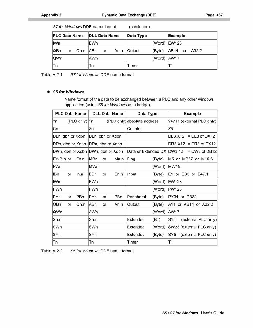
Appendix 2 Dynamic Data Exchange (DDE) Page 467
S5 / S7 for Windows User’s Guide
S7 for Windows DDE name format (continued)
PLC Data Name DLL Data Name Data Type Example
IWn EWn (Word) EW123
QBn or Qn.n ABn or An.n Output (Byte) AB14 or A32.2
QWn AWn (Word) AW17
Tn Tn Timer T1
Table A 2-1 S7 for Windows DDE name format
S5 for Windows
Name format of the data to be exchanged between a PLC and any other windows application (using S5 for Windows as a bridge).
PLC Data Name DLL Data Name Data Type Example
?n (PLC only) ?n (PLC only) absolute address ?4711 (external PLC only)
Cn Zn Counter Z5
DLn, dbn or Xdbn DLn, dbn or Xdbn DL3,X12 = DL3 of DX12
DRn, dbn or Xdbn DRn, dbn or Xdbn DR3,X12 = DR3 of DX12
DWn, dbn or Xdbn DWn, dbn or Xdbn Data or Extended DX DW3,12 = DW3 of DB12
FY(B)n or Fn.n MBn or Mn.n Flag (Byte) M5 or MB67 or M15.6
FWn MWn (Word) MW45
IBn or In.n EBn or En.n Input (Byte) E1 or EB3 or E47.1
IWn EWn (Word) EW123
PWn PWn (Word) PW128
PYn or PBn PYn or PBn Peripheral (Byte) PY34 or PB32
QBn or Qn.n ABn or An.n Output (Byte) A11 or AB14 or A32.2
QWn AWn (Word) AW17
Sn.n Sn.n Extended (Bit) S1.5 (external PLC only)
SWn SWn Extended (Word) SW23 (external PLC only)
SYn SYn Extended (Byte) SY5 (external PLC only)
Tn Tn Timer T1
Table A 2-2 S5 for Windows DDE name format
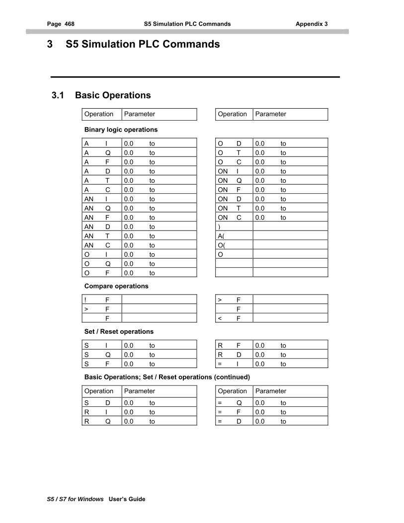
Page 468 S5 Simulation PLC Commands Appendix 3
3 S5 Simulation PLC Commands
S5 / S7 for Windows User’s Guide
3.1 Basic Operations
Operation Parameter Operation Parameter
Binary logic operations
A I 0.0 to O D 0.0 to A Q 0.0 to O T 0.0 to A F 0.0 to O C 0.0 to A D 0.0 to ON I 0.0 to A T 0.0 to ON Q 0.0 to A C 0.0 to ON F 0.0 to AN I 0.0 to ON D 0.0 to AN Q 0.0 to ON T 0.0 to AN F 0.0 to ON C 0.0 to AN D 0.0 to )AN T 0.0 to A(AN C 0.0 to O(O I 0.0 to OO Q 0.0 to O F 0.0 to
Compare operations
! F > F> F F F < F
Set / Reset operations
S I 0.0 to R F 0.0 to S Q 0.0 to R D 0.0 to S F 0.0 to = I 0.0 to
Basic Operations; Set / Reset operations (continued)
Operation Parameter Operation Parameter
S D 0.0 to = Q 0.0 to R I 0.0 to = F 0.0 to R Q 0.0 to = D 0.0 to
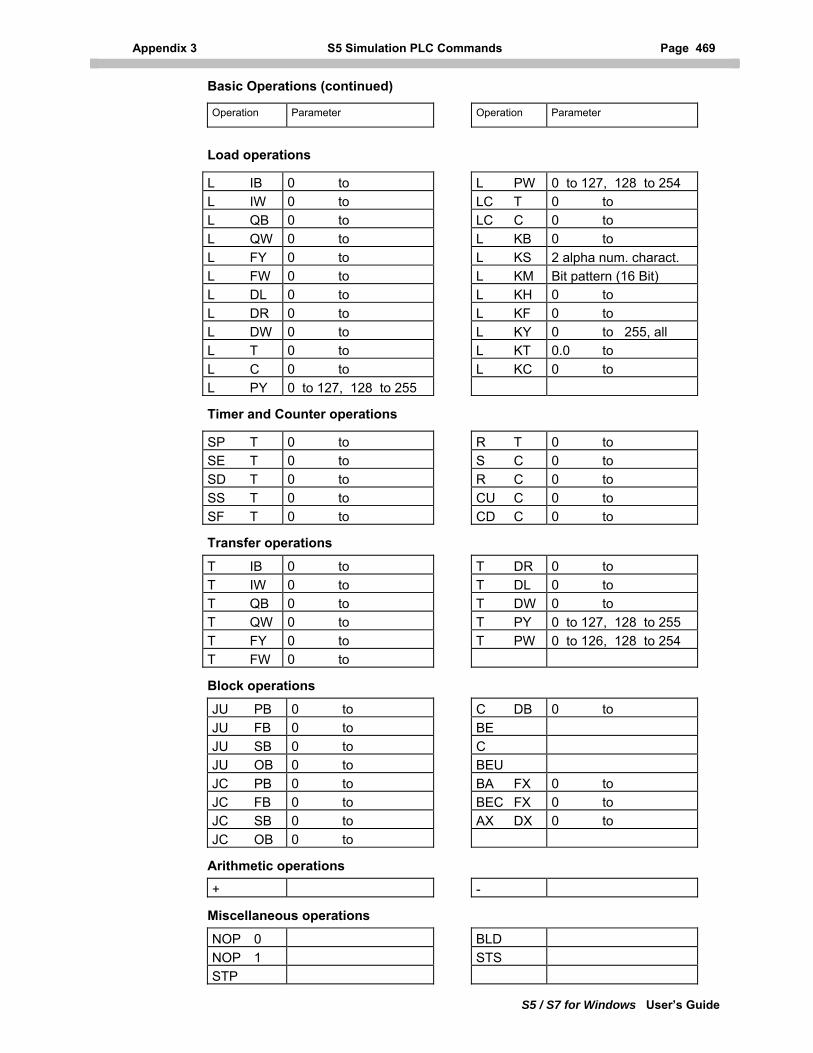
Appendix 3 S5 Simulation PLC Commands Page 469
S5 / S7 for Windows User’s Guide
Basic Operations (continued)
Operation Parameter Operation Parameter
Load operations
L IB 0 to L PW 0 to 127, 128 to 254L IW 0 to LC T 0 to L QB 0 to LC C 0 to L QW 0 to L KB 0 to L FY 0 to L KS 2 alpha num. charact.L FW 0 to L KM Bit pattern (16 Bit)L DL 0 to L KH 0 to L DR 0 to L KF 0 to L DW 0 to L KY 0 to 255, all L T 0 to L KT 0.0 to L C 0 to L KC 0 to L PY 0 to 127, 128 to 255
Timer and Counter operations
SP T 0 to R T 0 to SE T 0 to S C 0 to SD T 0 to R C 0 to SS T 0 to CU C 0 to SF T 0 to CD C 0 to
Transfer operations
T IB 0 to T DR 0 to T IW 0 to T DL 0 to T QB 0 to T DW 0 to T QW 0 to T PY 0 to 127, 128 to 255T FY 0 to T PW 0 to 126, 128 to 254T FW 0 to
Block operations
JU PB 0 to C DB 0 to JU FB 0 to BEJU SB 0 to CJU OB 0 to BEUJC PB 0 to BA FX 0 to JC FB 0 to BEC FX 0 to JC SB 0 to AX DX 0 to JC OB 0 to
Arithmetic operations
+ -
Miscellaneous operations
NOP 0 BLDNOP 1 STSSTP
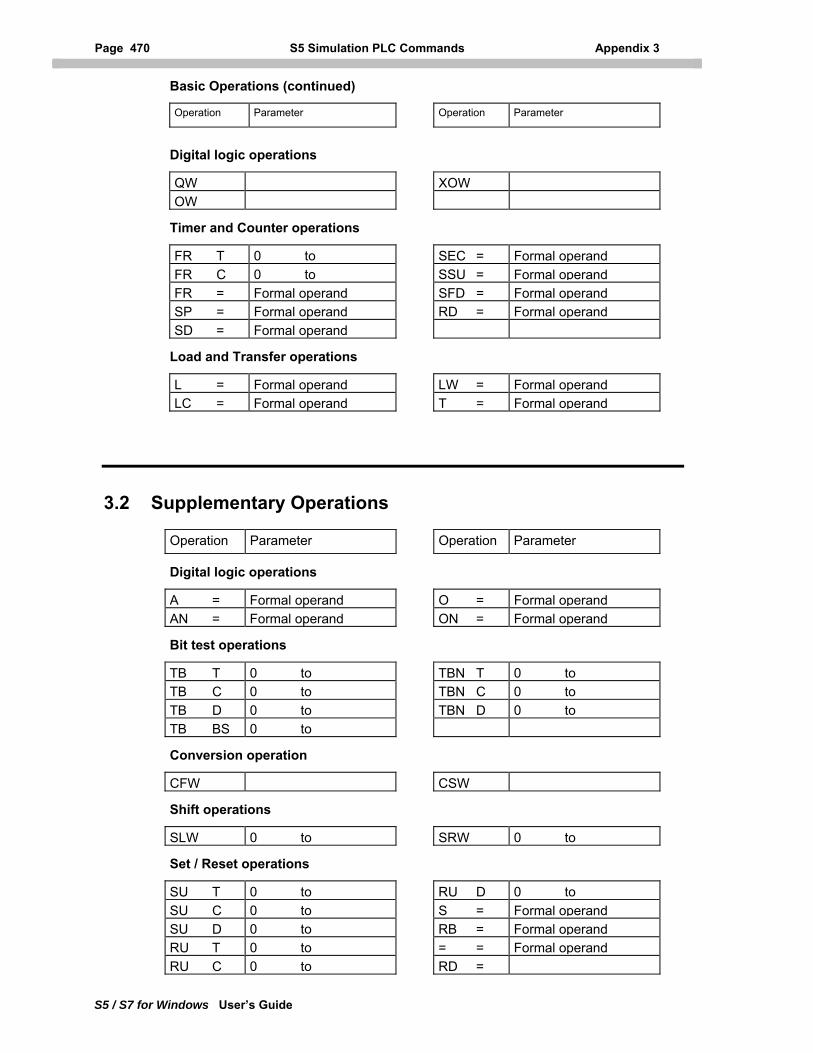
Page 470 S5 Simulation PLC Commands Appendix 3
S5 / S7 for Windows User’s Guide
Basic Operations (continued)
Operation Parameter Operation Parameter
Digital logic operations
QW XOWOW
Timer and Counter operations
FR T 0 to SEC = Formal operand FR C 0 to SSU = Formal operand FR = Formal operand SFD = Formal operand SP = Formal operand RD = Formal operand SD = Formal operand
Load and Transfer operations
L = Formal operand LW = Formal operand LC = Formal operand T = Formal operand
3.2 Supplementary Operations
Operation Parameter Operation Parameter
Digital logic operations
A = Formal operand O = Formal operand AN = Formal operand ON = Formal operand
Bit test operations
TB T 0 to TBN T 0 to TB C 0 to TBN C 0 to TB D 0 to TBN D 0 to TB BS 0 to
Conversion operation
CFW CSW
Shift operations
SLW 0 to SRW 0 to
Set / Reset operations
SU T 0 to RU D 0 to SU C 0 to S = Formal operand SU D 0 to RB = Formal operand RU T 0 to = = Formal operand RU C 0 to RD =
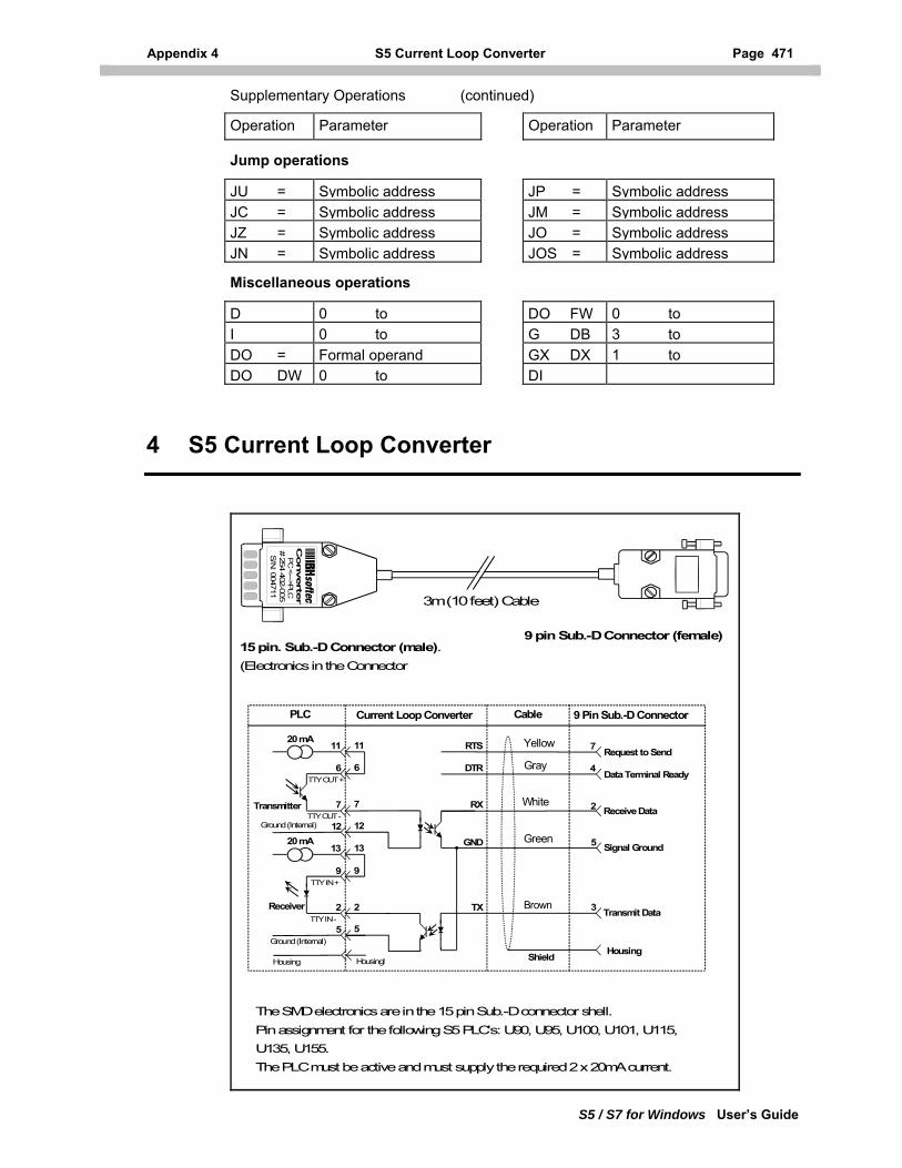
Appendix 4 S5 Current Loop Converter Page 471
S5 / S7 for Windows User’s Guide
Supplementary Operations (continued)
Operation Parameter Operation Parameter
Jump operations
JU = Symbolic address JP = Symbolic addressJC = Symbolic address JM = Symbolic addressJZ = Symbolic address JO = Symbolic addressJN = Symbolic address JOS = Symbolic address
Miscellaneous operations
D 0 to DO FW 0 to I 0 to G DB 3 to DO = Formal operand GX DX 1 to DO DW 0 to DI
4 S5 Current Loop Converter
15 pin. Sub.-D Connector (male).(Electronics in the Connector
9 pin Sub.-D Connector (female)
11
6
7
13
9
2
12
5
11
6
7
13
9
2
12
5
3
2
5
4Request to Send
Data Terminal Ready
Receive Data
Signal Ground
Transmit Data
RTS
DTR
RX
GND
TX
20 mA
20 mA
Transmitter
Receiver
TTY OUT +
TTY OUT -
TTY IN +
TTY IN -
Ground (Internal)
Shield Housing
PLC Current Loop Converter Cable 9 Pin Sub.-D Connector
Housing
The SMD electronics are in the 15 pin Sub.-D connector shell. Pin assignment for the following S5 PLC's: U90, U95, U100, U101, U115, U135, U155.The PLC must be active and must supply the required 2 x 20mA current.
Converte
r P
C <--->PLC
# 254 402-005S/N
: 004711
Ground (Internal)
Housingl
Brown
Green
White
Yellow 7
3m (10 feet) Cable
Gray
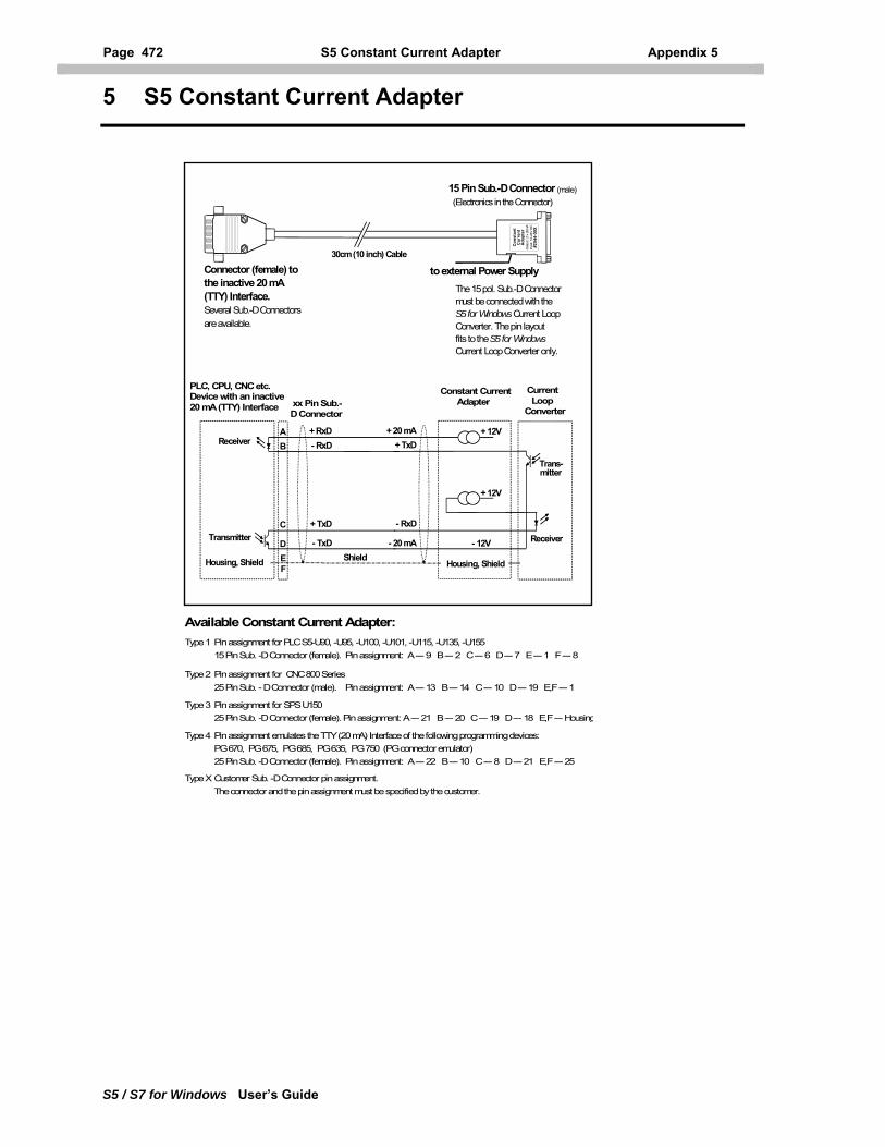
Page 472 S5 Constant Current Adapter Appendix 5
S5 / S7 for Windows User’s Guide
5 S5 Constant Current Adapter
15 Pin Sub.-D Connector (male)
to external Power Supply
(Electronics in the Connector)
Connector (female) tothe inactive 20 mA(TTY) Interface.Several Sub.-D Connectorsare available.
The 15 pol. Sub.-D Connectormust be connected with theS5 for Windows Current Loop Converter. The pin layout fits to the S5 for WindowsCurrent Loop Converter only.
xx Pin Sub.- D Connector
PLC, CPU, CNC etc.Device with an inactive20 mA (TTY) Interface
30cm (10 inch) Cable
Receiver+ RxD- RxD
+ TxD
- TxDTransmitter
Housing, Shield Shield
- RxD
- 20 mA
+ 20 mA+ TxD
+ 12V
- 12V
+ 12V
Con
stan
tC
urre
ntA
dapt
erO
utpu
t: 2
x 20
mA
Inpu
t: 12
-24V
DC
#254
4-00
XReceiver
Housing, Shield
Trans-mitter
Constant Current Adapter
Current LoopConverter
AB
C
DEF
Available Constant Current Adapter:Type 1 Pin assignment for PLC S5-U90, -U95, -U100, -U101, -U115, -U135, -U155 15 Pin Sub. -D Connector (female). Pin assignment: A --- 9 B --- 2 C --- 6 D --- 7 E --- 1 F --- 8
Type 2 Pin assignment for CNC 800 Series 25 Pin Sub. - D Connector (male). Pin assignment: A --- 13 B --- 14 C --- 10 D --- 19 E,F --- 1
Type 3 Pin assignment for SPS U150 25 Pin Sub. -D Connector (female). Pin assignment: A --- 21 B --- 20 C --- 19 D --- 18 E,F --- Housing
Type 4 Pin assignment emulates the TTY (20 mA) Interface of the following programming devices: PG 670, PG 675, PG 685, PG 635, PG 750 (PG connector emulator) 25 Pin Sub. -D Connector (female). Pin assignment: A --- 22 B --- 10 C --- 8 D --- 21 E,F --- 25
Type X Customer Sub. -D Connector pin assignment. The connector and the pin assignment must be specified by the customer.
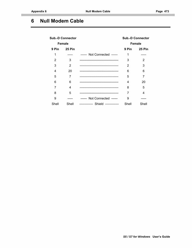
Appendix 6 Null Modem Cable Page 473
6 Null Modem Cable
S5 / S7 for Windows User’s Guide
Sub.-D Connector Sub.-D Connector
Female Female
9 Pin 25 Pin 9 Pin 25 Pin
1 ----- ------ Not Connected ------ 1 -----
2 3 ------------------------------------- 3 2
3 2 ------------------------------------- 2 3
4 20 ------------------------------------- 6 6
5 7 ------------------------------------- 5 7
6 6 ------------------------------------- 4 20
7 4 ------------------------------------- 8 5
8 5 ------------------------------------- 7 4
9 ----- ------ Not Connected ------ 9 -----
Shell Shell ------------- Shield ------------- Shell Shell
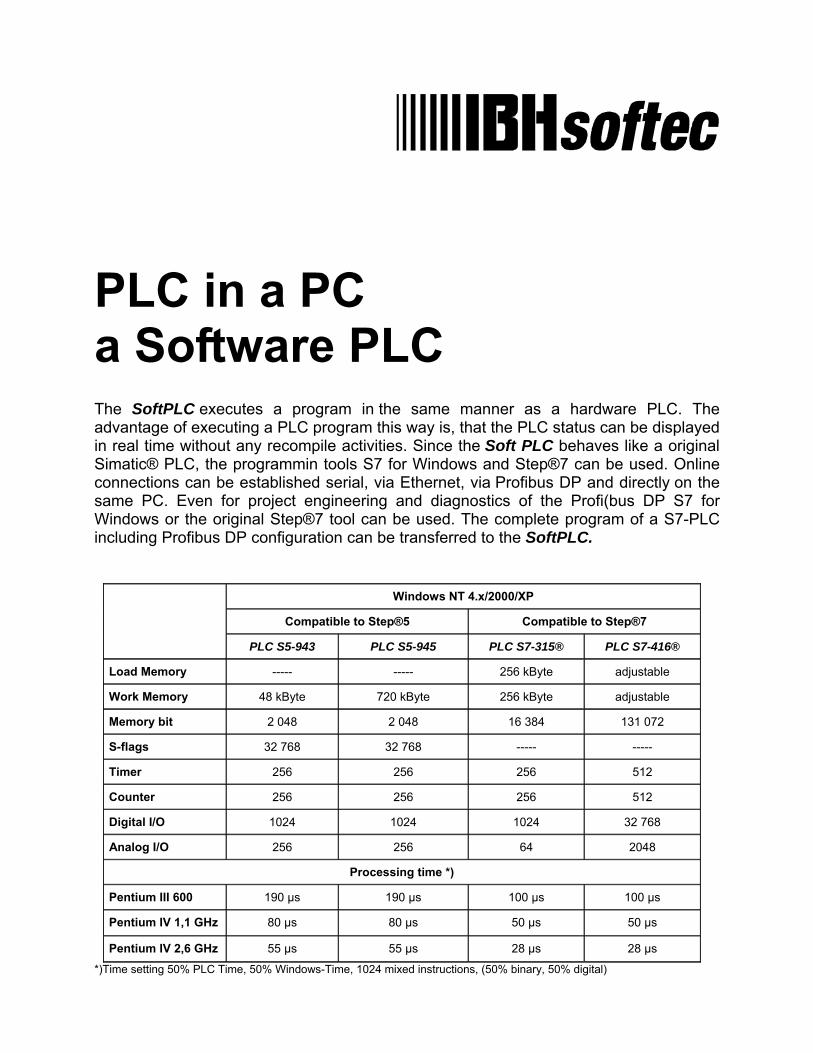
PLC in a PC a Software PLC The SoftPLC executes a program in the same manner as a hardware PLC. The advantage of executing a PLC program this way is, that the PLC status can be displayed in real time without any recompile activities. Since the Soft PLC behaves like a original Simatic® PLC, the programmin tools S7 for Windows and Step®7 can be used. Online connections can be established serial, via Ethernet, via Profibus DP and directly on the same PC. Even for project engineering and diagnostics of the Profi(bus DP S7 for Windows or the original Step®7 tool can be used. The complete program of a S7-PLC including Profibus DP configuration can be transferred to the SoftPLC.
Windows NT 4.x/2000/XP Compatible to Step®5 Compatible to Step®7
PLC S5-943 PLC S5-945 PLC S7-315® PLC S7-416®
Load Memory ----- ----- 256 kByte adjustable
Work Memory 48 kByte 720 kByte 256 kByte adjustable
Memory bit 2 048 2 048 16 384 131 072
S-flags 32 768 32 768 ----- -----
Timer 256 256 256 512
Counter 256 256 256 512
Digital I/O 1024 1024 1024 32 768
Analog I/O 256 256 64 2048
Processing time *)
Pentium III 600 190 µs 190 µs 100 µs 100 µs
Pentium IV 1,1 GHz 80 µs 80 µs 50 µs 50 µs
Pentium IV 2,6 GHz 55 µs 55 µs 28 µs 28 µs
*)Time setting 50% PLC Time, 50% Windows-Time, 1024 mixed instructions, (50% binary, 50% digital)


![S7-1200 Easy Book en [11 2009]](https://img.pdfslide.net/doc/110x75/634fe85a483af7f78c01e9ef/s7-1200-easy-book-en-11-2009.jpg)