Embed Size (px)
Citation preview
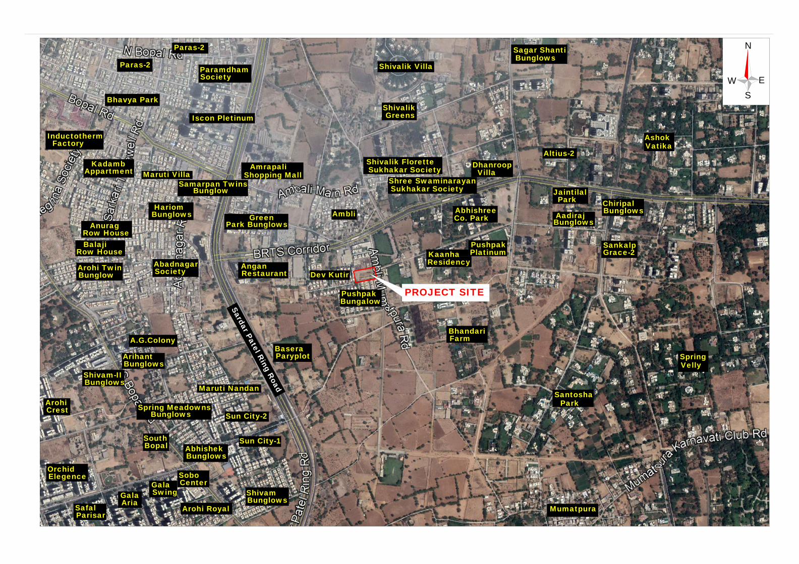
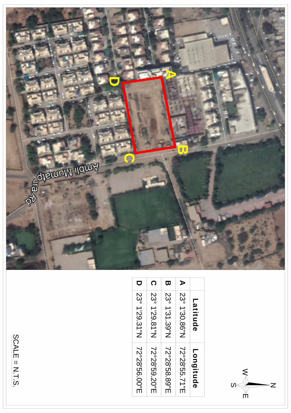
PROJECT SITE
S
a
r
k
h
e
j-
G
a
n
d
h
in
a
g
a
r
H
w
y
S
a
rd
a
r P
a
te
l R
in
g
R
o
a
d
KKKBBBMMM EEENNNGGGIIINNNEEEEEERRRIIINNNGGG RRREEESSSEEEAAARRRCCCHHH LLLAAABBBOOORRRAAATTTOOORRRYYY OVER 30 YEARS IN FIELD OF SOIL-CEMENT-CONCRETE TESTING
BUNGALOW NO.H-79, GOTA OGNAJ ROAD, TA.: DASKROI, AHMEDABAD 380060
PHONE: 02717 242373, 02717 241538, FAX: 02717 241538, e-mail: [email protected]
_______________________________________________________
JOB NO. 2408
GEOTECHNICAL INVESTIGATION REPORT
PROJECT : GEOTECHNICAL INVESTIGATION FOR
PROPOSED SITE @ AMBALI
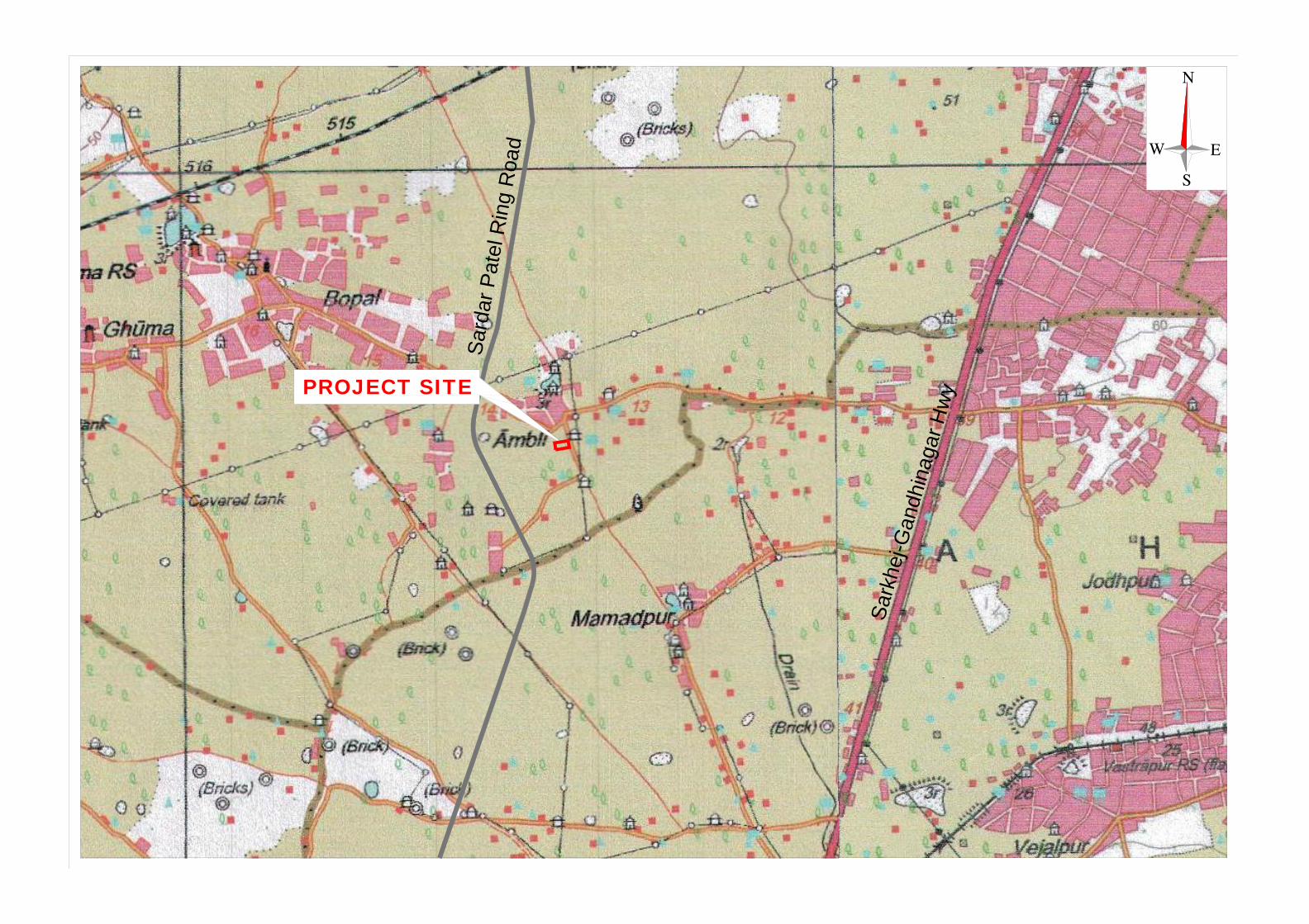
LOCATION : S.NO. 418/2, F.P. NO.129, T.P. NO.52
NEAR PUSHPAK BUNGALOW
VILLAGE AMBLI
TA.: DASKROI, DIST.: AHMEDABAD
CLIENTS : ARMAAN INFRASTRUCTURE
AHMEDABAD
REPORT ISSUE STATUS Sr. No. Report No. Date Issued Report Status
1 2408 6th October, 2018 Final Report
Page 1
KKKBBBMMM EEENNNGGGIIINNNEEEEEERRRIIINNNGGG RRREEESSSEEEAAARRRCCCHHH LLLAAABBBOOORRRAAATTTOOORRRYYY OVER 30 YEARS IN FIELD OF SOIL-CEMENT-CONCRETE TESTING
BUNGALOW NO.H-79, GOTA OGNAJ ROAD, TA.: DASKROI, AHMEDABAD 380060
PHONE: 02717 242373, 02717 241538, FAX: 02717 241538, e-mail: [email protected]
________________________________________________________Index
JOB NO. 2408
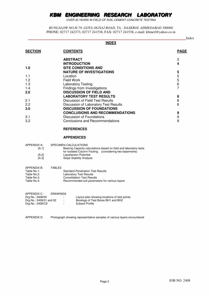
INDEX SECTION CONTENTS PAGE ABSTRACT 3 INTRODUCTION 4 1.0 SITE CONDITIONS AND NATURE OF INVESTIGATIONS 5 1.1 Location 5 1.2 Field Work 5 1.3 Laboratory Testing 6 1.4 Findings from Investigations 7 2.0 DISCUSSION OF FIELD AND LABORATORY TEST RESULTS 8 2.1 Discussion of Field Test Results 8 2.2 Discussion of Laboratory Test Results 8 3.0 DISCUSSION OF FOUNDATIONS
CONCLUSIONS AND RECOMMENDATIONS 9 3.1 Discussion of Foundations 9 3.2 Conclusions and Recommendations 9 REFERENCES
APPENDICES APPENDIX A: SPECIMEN CALCULATIONS
[A.1] Bearing Capacity calculations based on field and laboratory tests for Isolated Column Footing (considering two basements)
[A.2] Liquefaction Potential [A.3] Slope Stability Analysis
APPENDIX B: TABLES Table No.1: Standard Penetration Test Results Table No.2: Laboratory Test Results Table No.3: Consolidation Test Results Table No.4: Recommended soil parameters for various layers APPENDIX C: DRAWINGS Drg.No.: 2408/00 : Layout plan showing locations of test points Drg.No.: 2408/01 and 02 : Borelogs of Test Bores BH1 and BH2 Drg.No.: 2408/CS : Subsoil Profile
APPENDIX D: Photograph showing representative samples of various layers encountered
Page 2
KKKBBBMMM EEENNNGGGIIINNNEEEEEERRRIIINNNGGG RRREEESSSEEEAAARRRCCCHHH LLLAAABBBOOORRRAAATTTOOORRRYYY OVER 30 YEARS IN FIELD OF SOIL-CEMENT-CONCRETE TESTING
BUNGALOW NO.H-79, GOTA OGNAJ ROAD, TA.: DASKROI, AHMEDABAD 380060
PHONE: 02717 242373, 02717 241538, FAX: 02717 241538, e-mail: [email protected]
________________________________________________________ Abstract
JOB NO. 2408
ABSTRACT
In the following pages, is presented the Report with Analysis, prepared from the thorough study of Geotechnical investigation results. The detailed scope of work was decided in consultation with the representatives of clients and consultants. A complete geotechnical investigation work was undertaken to obtain the required subsurface informations to study and define the nature and behaviour of soil, under application of loads of proposed structures. Such informations were obtained through following steps:
• by making test bores, and collecting disturbed and undisturbed soil samples.
• by performing required in-situ tests.
• by testing the soil in laboratory to classify it and to determine the engineering properties of soil.
An analysis was made to derive the allowable bearing capacity, taking into consideration the settlements and the present soil conditions with the future possibilities. Based on such analysis of the soil properties, the conclusions are made regarding the nature, behaviour and characteristics of soil. Recommendations are also given, after a thorough and careful study of the present soil conditions, regarding the suitability of type of foundation, and regarding the precautions and protective measures to be taken, if found necessary.
Page 3
KKKBBBMMM EEENNNGGGIIINNNEEEEEERRRIIINNNGGG RRREEESSSEEEAAARRRCCCHHH LLLAAABBBOOORRRAAATTTOOORRRYYY OVER 30 YEARS IN FIELD OF SOIL-CEMENT-CONCRETE TESTING
BUNGALOW NO.H-79, GOTA OGNAJ ROAD, TA.: DASKROI, AHMEDABAD 380060
PHONE: 02717 242373, 02717 241538, FAX: 02717 241538, e-mail: [email protected]
________________________________________________________
JOB NO. 2408
GEOTECHNICAL INVESTIGATION REPORT
FOR PROPOSED SITE AT AMBLI, AHMEDABAD
INTRODUCTION:
We (KBM Engineering Research Laboratory, Ahmedabad) have carried out complete Geotechnical Investigation, covering field work and tests, laboratory tests and analysis to study and establish the subsoil characteristics of the proposed project site. The principal objective of the exploration work was to determine the soil profile, bearing capacities at various depths for type/design of foundations of structures. The entire field testing was carried out as per relevant IS codes and as per the instructions of the representatives of the clients. The samples collected from various test locations, were sealed, labelled and transported to our laboratory at Ahmedabad. The required laboratory tests were conducted as per relevant IS codes. This report has been prepared after careful study of the field and laboratory test results. The type and depth of foundations, are suggested.
Page 4
KKKBBBMMM EEENNNGGGIIINNNEEEEEERRRIIINNNGGG RRREEESSSEEEAAARRRCCCHHH LLLAAABBBOOORRRAAATTTOOORRRYYY OVER 30 YEARS IN FIELD OF SOIL-CEMENT-CONCRETE TESTING
BUNGALOW NO.H-79, GOTA OGNAJ ROAD, TA.: DASKROI, AHMEDABAD 380060
PHONE: 02717 242373, 02717 241538, FAX: 02717 241538, e-mail: [email protected]
________________________________________________________
JOB NO. 2408
SECTION I
SITE CONDITIONS AND NATURE OF INVESTIGATIONS
1.1 LOCATION: The site is located at S.No. 418/2, F.P. No.129, T.P. No.52, near Pushpak Bungalow, Village Ambli, Ta.: Daskroi, Dist.: Ahmedabad. 1.2 FIELD WORK:
1.2.1 BORING:
The exploratory test bores were drilled as per IS:1892 at the locations suggested by clients/consultants. The exploratory test bores of 100mm to 150mm diameter were drilled by mud-rotary drilling method using bentonite slurry in soil. The depth of test bores at the proposed locations were as mentioned below: TEST BORE
DEPTH DRILLED
REMARKS
BH1 and BH2
6M to 24M
The test bores were drilled from excavated pit level which was about 6M below road level.
1.2.2 SAMPLING:
1.2.2.1 Disturbed Samples:
Disturbed samples were collected during the boring at a depth 0 to 0.5M below existing G.L. Disturbed samples were also collected where, undisturbed samples were not recovered. The samples were packed in polyethylene bags, labeled and transported to our laboratory at Ahmedabad. 1.2.2.2 Split Spoon Samples:
Standard penetration tests were conducted as per IS:2131 at 1.5M interval or any change in stratum, whichever is earlier, and split spoon samples were collected. The SPT blow counts were noted for 150mm penetration of split spoon sampler. The blow counts were terminated when combined blow counts exceeded 50. The tests were conducted after cleaning the bottom of borehole and sampler centrally seated in position in borehole. The samples were packed in polyethylene bags, labeled and transported to our laboratory at Ahmedabad.
Page 5
KKKBBBMMM EEENNNGGGIIINNNEEEEEERRRIIINNNGGG RRREEESSSEEEAAARRRCCCHHH LLLAAABBBOOORRRAAATTTOOORRRYYY OVER 30 YEARS IN FIELD OF SOIL-CEMENT-CONCRETE TESTING
BUNGALOW NO.H-79, GOTA OGNAJ ROAD, TA.: DASKROI, AHMEDABAD 380060
PHONE: 02717 242373, 02717 241538, FAX: 02717 241538, e-mail: [email protected]
________________________________________________________
JOB NO. 2408
1.2.2.3 Undisturbed Samples:
Undisturbed soil samples were collected in 100mm diameter, 450mm long thin walled tubes having area ratio of about 15% as per IS:2132 at 1.5M interval or any change in stratum, whichever was earlier. Undisturbed samples were collected in strata consisting of cohesive soil/partly cohesive soil. Undisturbed samples were replaced by standard penetration test in cohesionless strata or where undisturbed samples cannot be collected in hard clay or partly cohesive soil. However to correlate the shear parameters/consolidation parameters with N-values few undisturbed were attempted up to 3M depth below existing G.L. in hard strata. Immediately on retrieval of sampling tube after collection of sample, both ends were sealed with freshly molten wax. The samples were sealed, labelled and transported to our laboratory at Ahmedabad for testing. 1.3 LABORATORY TESTING: Soil samples were collected, sealed and labeled at the site, and sent to our laboratory at Ahmedabad. The test results are given in Appendix B. 1.3.1 Field Density and Natural Water Content (IS:2132, IS:2720 P-2): The volume and weight of sample in UDS tube were determined for calculation of field density. Before emptying tube, wherever, shear tests were to be carried out, smaller sampling tube of 38mm diameter and about 76mm height were pushed into the sample in the direction of sampling on site. For consolidation tests, consolidation ring was pushed and extruded from UDS tube before emptying the same. Water content of the specimen was determined from representative sample taken from UDS tube by oven drying method. 1.3.2 Grain Size Analysis (IS:2720 P-4): The grain size analysis was carried out by wet sieving using sieves of sizes 19mm, 4.75mm, 2mm, 0.425mm and 0.075mm. 1.3.3 Atterberg’s Limit (IS:2720 P-5): Liquid limit test was carried out on fraction passing through 0.425mm sieve by mechanical method (Casangrande’s Apparatus). Plastic limit was also carried out on fraction passing 0.425mm sieve by rolling threads of 3mm diameter at a rate of 80-90 strokes/min till the thread crumbled.
Page 6
KKKBBBMMM EEENNNGGGIIINNNEEEEEERRRIIINNNGGG RRREEESSSEEEAAARRRCCCHHH LLLAAABBBOOORRRAAATTTOOORRRYYY OVER 30 YEARS IN FIELD OF SOIL-CEMENT-CONCRETE TESTING
BUNGALOW NO.H-79, GOTA OGNAJ ROAD, TA.: DASKROI, AHMEDABAD 380060
PHONE: 02717 242373, 02717 241538, FAX: 02717 241538, e-mail: [email protected]
________________________________________________________
JOB NO. 2408
1.3.4 Unconfined CompressiveTest (IS:2720 P-10): The samples extruded from UDS tube were tested in triaxial test apparatus for determination of unconfined compressive strength without application of cell pressure. 1.3.5 Triaxial Unconsolidated Undrained Test (IS:2720 P-11): The sample extruded from UDS tube were tested in triaxial test apparatus in unconsolidated undrained condition at field density and natural water content with cell pressures of 1kg/cm
2, 2kg/cm
2 and 3kg/cm
2 respectively. The shear strength parameters
(c-φ ) were obtained by plotting Mohr’s circle for peak values. 1.3.6 Direct Shear Test (IS:2720 P-13): The direct shear tests were conducted on remolded sample compacted in shear box at field density/natural water content obtained from undisturbed samples (obtained in cohesive soils and cohesionless soil comprising of fine sand/silts). For cohesionless soil comprising of coarse to medium sand, the soil was compacted at relative density based on N-value and natural water content directly into shear box. The tests were carried out for normal stress of 1kg/cm
2, 2kg/cm
2 and 3kg/cm
2 respectively. The tests on cohesive soils were
carried out in unconsolidated undrained condition while tests on cohesionless soils were
carried out in consolidated drained condition. The shear strength parameters (c-φ) were obtained by plotting graph for applied normal stress and maximum shear stress. The laboratory test results are given in Appendix B. 1.4 FINDINGS FROM INVESTIGATIONS: 1.4.1 SURFACE: The surface is uneven ground in general. 1.4.2 SUBSURFACE: The subsurface consists of the soil formations as shown in the respective borelogs. 1.4.3 GROUND WATER: The ground water table was not encountered within depth drilled. However, comparatively higher natural water content (with reduction in N-values) was observed at depth of about 13.5M below road level indicating possibility of localised seasonal water logging.
Page 7
KKKBBBMMM EEENNNGGGIIINNNEEEEEERRRIIINNNGGG RRREEESSSEEEAAARRRCCCHHH LLLAAABBBOOORRRAAATTTOOORRRYYY OVER 30 YEARS IN FIELD OF SOIL-CEMENT-CONCRETE TESTING
BUNGALOW NO.H-79, GOTA OGNAJ ROAD, TA.: DASKROI, AHMEDABAD 380060
PHONE: 02717 242373, 02717 241538, FAX: 02717 241538, e-mail: [email protected]
________________________________________________________
JOB NO. 2408
SECTION II
DISCUSSION ON FIELD AND LABORATORY TEST RESULTS
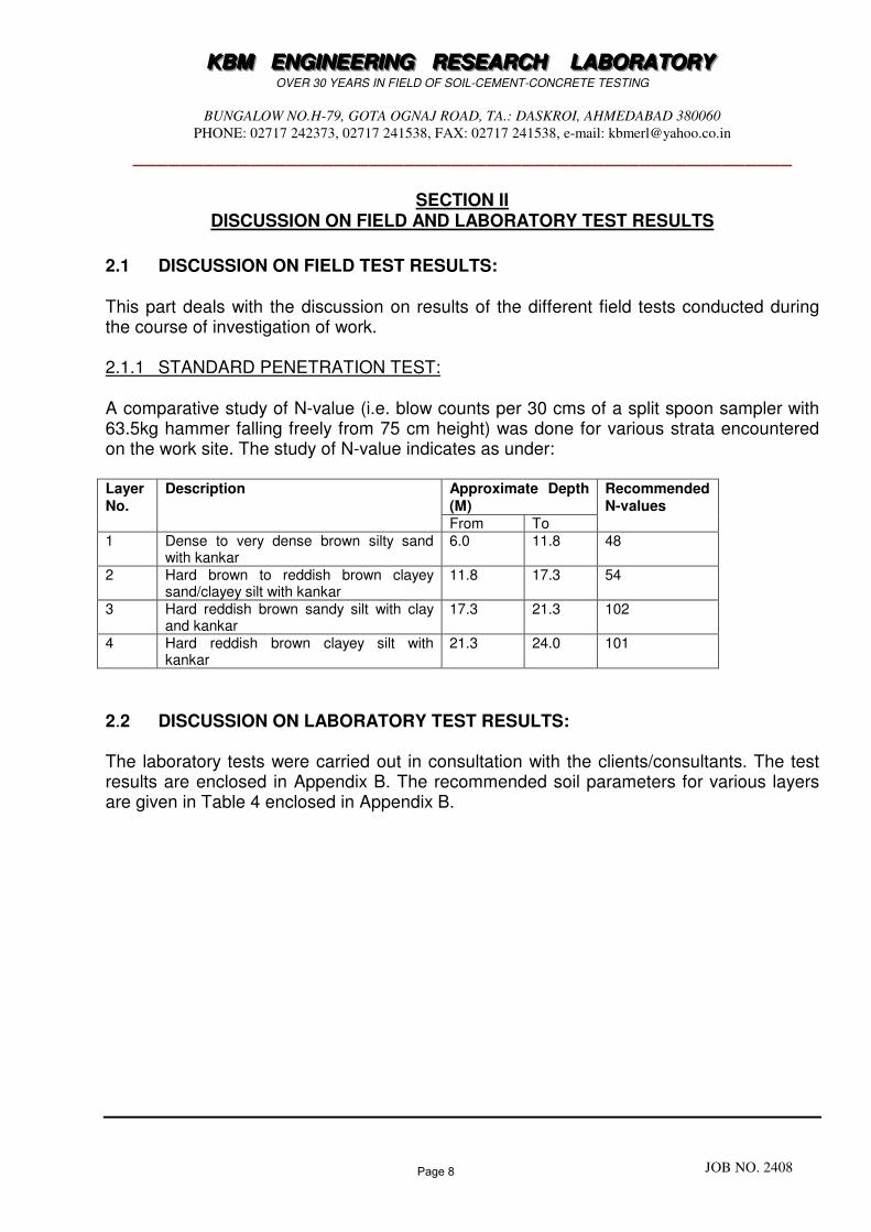
2.1 DISCUSSION ON FIELD TEST RESULTS: This part deals with the discussion on results of the different field tests conducted during the course of investigation of work. 2.1.1 STANDARD PENETRATION TEST:
A comparative study of N-value (i.e. blow counts per 30 cms of a split spoon sampler with 63.5kg hammer falling freely from 75 cm height) was done for various strata encountered on the work site. The study of N-value indicates as under: Layer No.
Description Approximate Depth (M)
Recommended N-values
From To 1 Dense to very dense brown silty sand
with kankar 6.0 11.8 48
2 Hard brown to reddish brown clayey sand/clayey silt with kankar
11.8 17.3 54
3 Hard reddish brown sandy silt with clay and kankar
17.3 21.3 102
4 Hard reddish brown clayey silt with kankar
21.3 24.0 101
2.2 DISCUSSION ON LABORATORY TEST RESULTS: The laboratory tests were carried out in consultation with the clients/consultants. The test results are enclosed in Appendix B. The recommended soil parameters for various layers are given in Table 4 enclosed in Appendix B.
Page 8
KKKBBBMMM EEENNNGGGIIINNNEEEEEERRRIIINNNGGG RRREEESSSEEEAAARRRCCCHHH LLLAAABBBOOORRRAAATTTOOORRRYYY OVER 30 YEARS IN FIELD OF SOIL-CEMENT-CONCRETE TESTING
BUNGALOW NO.H-79, GOTA OGNAJ ROAD, TA.: DASKROI, AHMEDABAD 380060
PHONE: 02717 242373, 02717 241538, FAX: 02717 241538, e-mail: [email protected]
________________________________________________________
JOB NO. 2408
SECTION III
DISCUSSION OF FOUNDATIONS
CONCLUSIONS AND RECOMMENDATIONS
3.1 DISCUSSION OF FOUNDATIONS :
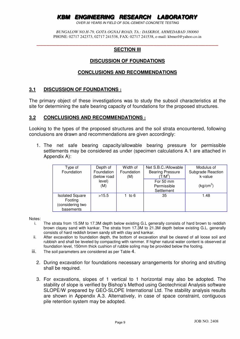
The primary object of these investigations was to study the subsoil characteristics at the site for determining the safe bearing capacity of foundations for the proposed structures. 3.2 CONCLUSIONS AND RECOMMENDATIONS : Looking to the types of the proposed structures and the soil strata encountered, following conclusions are drawn and recommendations are given accordingly:
1. The net safe bearing capacity/allowable bearing pressure for permissible settlements may be considered as under (specimen calculations A.1 are attached in Appendix A):
Type of Foundation
Depth of Foundation (below road
level) (M)
Width of Foundation
(M)
Net S.B.C./Allowable Bearing Pressure
(T/M2)
Modulus of Subgrade Reaction
k-value
(kg/cm3)
For 50 mm Permissible Settlement
Isolated Square Footing
(considering two basements
>15.5
1 to 6 35 1.48
Notes:
i. The strata from 15.5M to 17.3M depth below existing G.L generally consists of hard brown to reddish brown clayey sand with kankar. The strata from 17.3M to 21.3M depth below existing G.L. generally consists of hard reddish brown sandy silt with clay and kankar.
ii. After excavation to foundation depth, the bottom of excavation shall be cleared of all loose soil and rubbish and shall be leveled by compacting with rammer. If higher natural water content is observed at foundation level, 150mm thick cushion of rubble soling may be provided below the footing.
iii. The soil parameters are considered as per Table 4.
2. During excavation for foundations necessary arrangements for shoring and strutting shall be required.
3. For excavations, slopes of 1 vertical to 1 horizontal may also be adopted. The stability of slope is verified by Bishop’s Method using Geotechnical Analysis software SLOPE/W prepared by GEO-SLOPE International Ltd. The stability analysis results are shown in Appendix A.3. Alternatively, in case of space constraint, contiguous pile retention system may be adopted.
Page 9
KKKBBBMMM EEENNNGGGIIINNNEEEEEERRRIIINNNGGG RRREEESSSEEEAAARRRCCCHHH LLLAAABBBOOORRRAAATTTOOORRRYYY OVER 30 YEARS IN FIELD OF SOIL-CEMENT-CONCRETE TESTING
BUNGALOW NO.H-79, GOTA OGNAJ ROAD, TA.: DASKROI, AHMEDABAD 380060
PHONE: 02717 242373, 02717 241538, FAX: 02717 241538, e-mail: [email protected]
________________________________________________________
JOB NO. 2408
4. The strata below proposed foundation depth generally consists of fined grained soil
comprising of hard clayey silt/clayey sand with kankar and is not susceptible to liquefaction (ref. Appendix A.2).
5. If the soil strata encountered during actual excavations are found different from
strata mentioned in the Report, the matter should be reported to us for reconsideration.
REPORT PREPARED BY M. P. VORA (M.S., GEOTECHNICAL ENGINEERING)
Page 10
KKKBBBMMM EEENNNGGGIIINNNEEEEEERRRIIINNNGGG RRREEESSSEEEAAARRRCCCHHH LLLAAABBBOOORRRAAATTTOOORRRYYY OVER 30 YEARS IN FIELD OF SOIL-CEMENT-CONCRETE TESTING
BUNGALOW NO.H-79, GOTA OGNAJ ROAD, TA.: DASKROI, AHMEDABAD 380060
PHONE: 02717 242373, 02717 241538, FAX: 02717 241538, e-mail: [email protected]
________________________________________________________
JOB NO. 2408
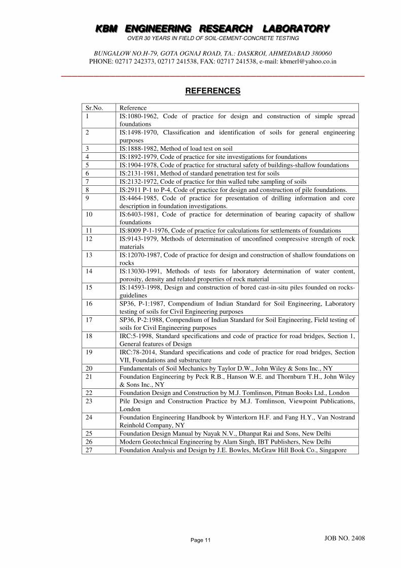
REFERENCES
Sr.No. Reference
1 IS:1080-1962, Code of practice for design and construction of simple spread
foundations
2 IS:1498-1970, Classification and identification of soils for general engineering
purposes
3 IS:1888-1982, Method of load test on soil
4 IS:1892-1979, Code of practice for site investigations for foundations
5 IS:1904-1978, Code of practice for structural safety of buildings-shallow foundations
6 IS:2131-1981, Method of standard penetration test for soils
7 IS:2132-1972, Code of practice for thin walled tube sampling of soils
8 IS:2911 P-1 to P-4, Code of practice for design and construction of pile foundations.
9 IS:4464-1985, Code of practice for presentation of drilling information and core
description in foundation investigations.
10 IS:6403-1981, Code of practice for determination of bearing capacity of shallow
foundations
11 IS:8009 P-1-1976, Code of practice for calculations for settlements of foundations
12 IS:9143-1979, Methods of determination of unconfined compressive strength of rock
materials
13 IS:12070-1987, Code of practice for design and construction of shallow foundations on
rocks
14 IS:13030-1991, Methods of tests for laboratory determination of water content,
porosity, density and related properties of rock material
15 IS:14593-1998, Design and construction of bored cast-in-situ piles founded on rocks-
guidelines
16 SP36, P-1:1987, Compendium of Indian Standard for Soil Engineering, Laboratory
testing of soils for Civil Engineering purposes
17 SP36, P-2:1988, Compendium of Indian Standard for Soil Engineering, Field testing of
soils for Civil Engineering purposes
18 IRC:5-1998, Standard specifications and code of practice for road bridges, Section 1,
General features of Design
19 IRC:78-2014, Standard specifications and code of practice for road bridges, Section
VII, Foundations and substructure
20 Fundamentals of Soil Mechanics by Taylor D.W., John Wiley & Sons Inc., NY
21 Foundation Engineering by Peck R.B., Hanson W.E. and Thornburn T.H., John Wiley
& Sons Inc., NY
22 Foundation Design and Construction by M.J. Tomlinson, Pitman Books Ltd., London
23 Pile Design and Construction Practice by M.J. Tomlinson, Viewpoint Publications,
London
24 Foundation Engineering Handbook by Winterkorn H.F. and Fang H.Y., Van Nostrand
Reinhold Company, NY
25 Foundation Design Manual by Nayak N.V., Dhanpat Rai and Sons, New Delhi
26 Modern Geotechnical Engineering by Alam Singh, IBT Publishers, New Delhi
27 Foundation Analysis and Design by J.E. Bowles, McGraw Hill Book Co., Singapore
Page 11
KKKBBBMMM EEENNNGGGIIINNNEEEEEERRRIIINNNGGG RRREEESSSEEEAAARRRCCCHHH LLLAAABBBOOORRRAAATTTOOORRRYYY OVER 30 YEARS IN FIELD OF SOIL-CEMENT-CONCRETE TESTING
BUNGALOW NO.H-79, GOTA OGNAJ ROAD, TA.: DASKROI, AHMEDABAD 380060
PHONE: 02717 242373, 02717 241538, FAX: 02717 241538, e-mail: [email protected]
________________________________________________________
JOB NO. 2408
APPENDIX A
(SPECIMEN CALCULATIONS)
Page 12
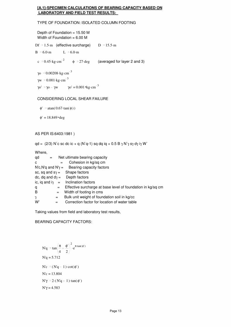
[A.1]-SPECIMEN CALCULATIONS OF BEARING CAPACITY BASED ON
LABORATORY AND FIELD TEST RESULTS:
TYPE OF FOUNDATION: ISOLATED COLUMN FOOTING
Depth of Foundation = 15.50 M
Width of Foundation = 6.00 M
Df .1.5 m (effective surcharge) D .15.5 m
B .6.0 m L .6.0 m
c ..0.45 kg cm2
φ .27 deg (averaged for layer 2 and 3)
γo ..0.00208 kg cm3
γw ..0.001 kg cm3
γo' γo γw =γo' 0.001 .kg cm3
CONSIDERING LOCAL SHEAR FAILURE
φ' atan( ).0.67 tan( )φ
=φ' 18.849 deg
AS PER IS:6403:1981 )
qd = (2/3) N`c sc dc ic + q (N`q-1) sq dq iq + 0.5 B γ N`γ sγ dγ iγ W`
Where,
qd = Net ultimate bearing capacity
c = Cohesion in kg/sq cm
N'c,N'q and N'γ = Bearing capacity factors
sc, sq and sγ = Shape factors
dc, dq and dγ = Depth factors
ic, iq and iγ = Inclination factors
q = Effective surcharge at base level of foundation in kg/sq cm
B = Width of footing in cms
γ = Bulk unit weight of foundation soil in kg/cc
W' = Correction factor for location of water table
Taking values from field and laboratory test results,
BEARING CAPACITY FACTORS:
N'q .tanπ
4
φ'
2
2
e.π tan( )φ'
=N'q 5.712
N'c .( )N'q 1 cot( )φ'
=N'c 13.804
N'γ ..2 ( )N'q 1 tan( )φ'
=N'γ 4.583
Page 13
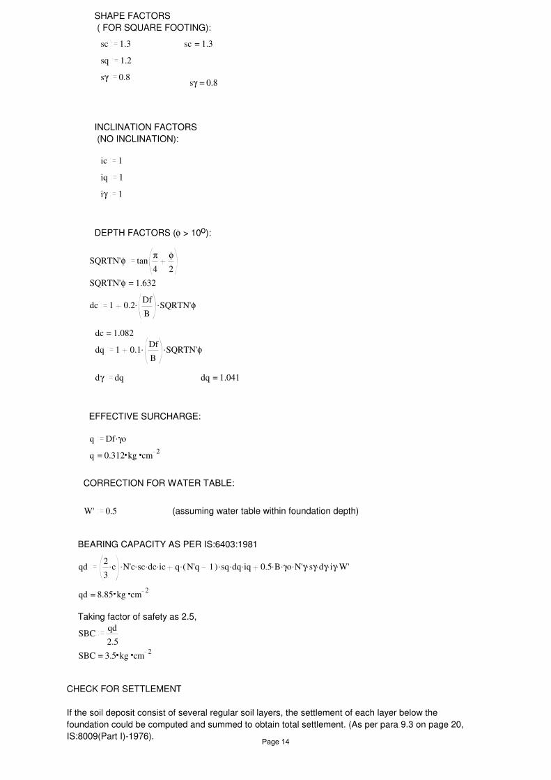
SHAPE FACTORS
( FOR SQUARE FOOTING):
sc 1.3 =sc 1.3
sq 1.2
sγ 0.8=sγ 0.8
INCLINATION FACTORS
(NO INCLINATION):
ic 1
iq 1
iγ 1
DEPTH FACTORS (φ > 10o):
SQRTN'φ tanπ
4
φ
2
=SQRTN'φ 1.632
dc 1 ..0.2Df
BSQRTN'φ
=dc 1.082
dq 1 ..0.1Df
BSQRTN'φ
dγ dq =dq 1.041
EFFECTIVE SURCHARGE:
q .Df γo
=q 0.312 kg cm2
CORRECTION FOR WATER TABLE:
W' 0.5 (assuming water table within foundation depth)
BEARING CAPACITY AS PER IS:6403:1981
qd .....2
3c N'c sc dc ic ....q ( )N'q 1 sq dq iq .......0.5 B γo N'γ sγ dγ iγ W'
=qd 8.85 kg cm2
Taking factor of safety as 2.5,
SBCqd
2.5
=SBC 3.5 kg cm2
CHECK FOR SETTLEMENT
If the soil deposit consist of several regular soil layers, the settlement of each layer below the
foundation could be computed and summed to obtain total settlement. (As per para 9.3 on page 20,
IS:8009(Part I)-1976).Page 14
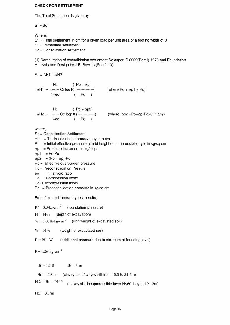
CHECK FOR SETTLEMENT
The Total Settlement is given by
Sf = Sc
Where,
Sf = Final settlement in cm for a given load per unit area of a footing width of B
Si = Immediate settlement
Sc = Consolidation settlement
(1) Computation of consolidation settlement Sc asper IS:8009(Part I)-1976 and Foundation
Analysis and Design by J.E. Bowles (Sec 2-10)
Sc = ∆H1 + ∆H2
Ht ( Po + ∆p)
∆H1 = ------- Cr log10 (--------------) (where Po + ∆p1 < Pc)
1+eo ( Po )
Ht ( Pc + ∆p2)
∆H2 = ------- Cc log10 (--------------) (where ∆p2 =Po+∆p-Pc>0, if any)
1+eo ( Pc )
where,
Sc = Consolidation Settlement
Ht = Thickness of compressive layer in cm
Po = Initial effective pressure at mid height of compressible layer in kg/sq cm
∆p = Pressure increment in kg/ sqcm
∆p1 = Pc-Po
∆p2 = (Po + ∆p)-Pc
Po = Effective overburden pressure
Pc = Preconsolidation Presure
eo = Initial void ratio
Cc = Compression index
Cr= Recompression index
Pc = Preconsolidation pressure in kg/sq cm
From field and laboratory test results,
Pf ..3.5 kg cm2
(foundation pressure)
H .14 m (depth of excavation)
γs ..0.0016 kg cm3
(unit weight of excavated soil)
W .H γs (weight of excavated soil)
P Pf W (additional pressure due to structure at founding level)
=P 1.26 .kg cm2
Ht .1.5 B =Ht 9 m
Ht1 .5.8 m (clayey sand/ clayey silt from 15.5 to 21.3m)
Ht2 Ht ( )Ht1(clayey silt, incopmressible layer N>60, beyond 21.3m)
=Ht2 3.2 m
Page 15
for Layer 2 and 3
γ1 ..0.00213 kg cm3
eo1 0.5Pc1 ..2.3 kg cm
2
Cc1 0.152E1 ..450 kg cm
2
Cr1 0.0176
µ1 0.5
for layer 2
E2 ..500 kg cm2
µ2 0.5
Taking weighted average
E.E1 Ht1 .E2 Ht2
Ht =E 467.778 .kg cm2
µ.µ1 Ht1 .µ2 Ht2
Ht =µ 0.5
γ1' γ1 γw=γ1' 0.001 .kg cm
3
Po .Df γo .Ht1
2γ1' (overburden pressure at centre of layer)
=Po 0.64 .kg cm2
L1L
2 =L1 3 m
B1B
2=B1 3 m
z1Ht1
2(at centre of layer of layer)
=z1 2.9 m
=L1
z11.034 =
B1
z11.034
IB1 0.175 (From fig.18, IS:8009 Part 1)
∆p ..4 P IB1
=∆p 0.882 .kg cm2
∆p1 Pc1 Po
=∆p1 1.66 .kg cm2
∆p2 ( )Po ∆p Pc1 =∆p2 0.778 .kg cm2
(<0)
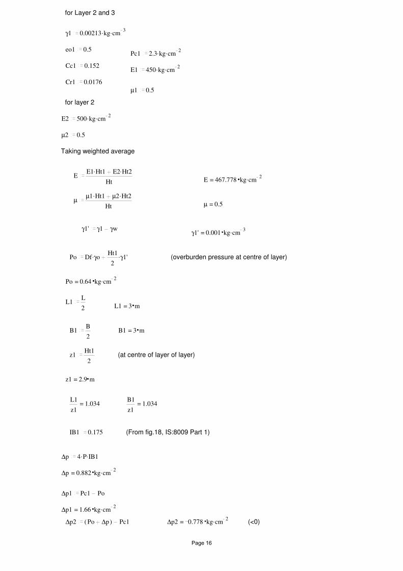
Page 16
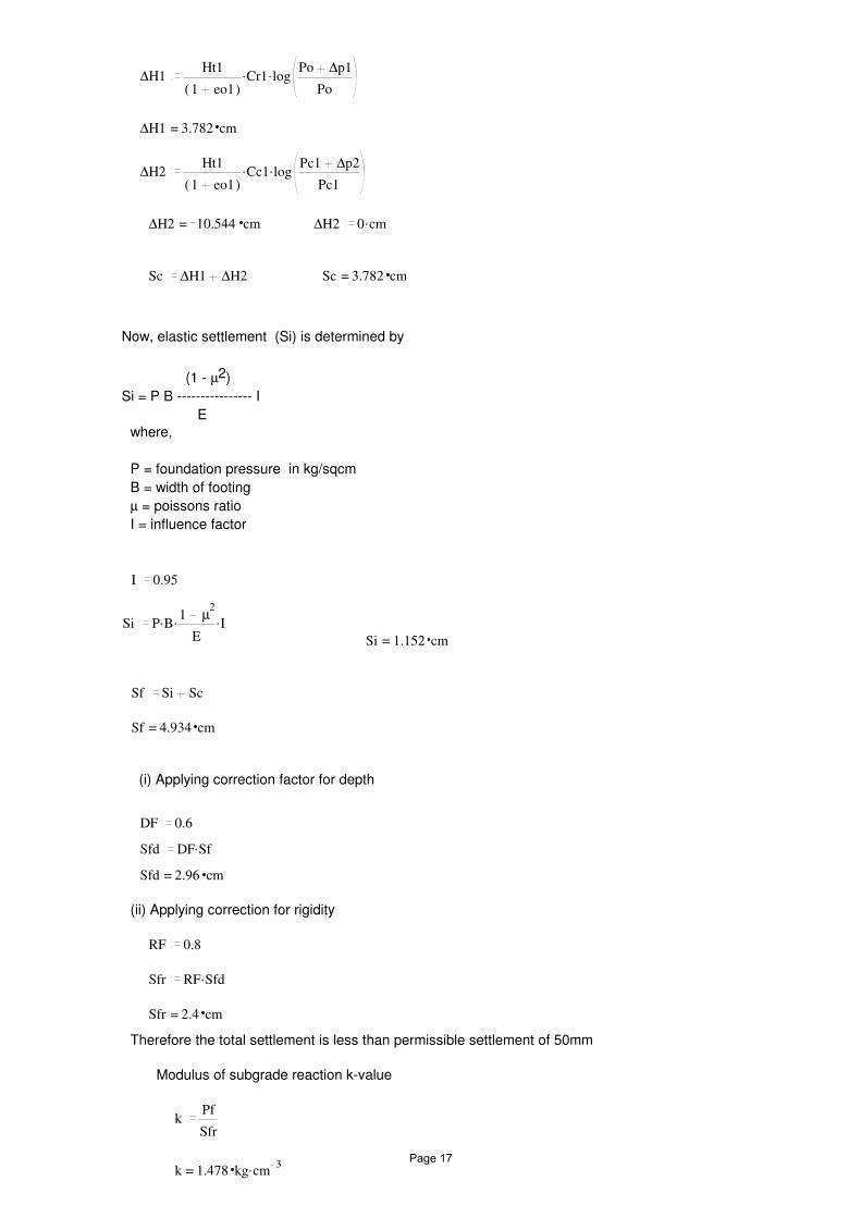
∆H1 ..Ht1
( )1 eo1Cr1 log
Po ∆p1
Po
=∆H1 3.782 cm
∆H2 ..Ht1
( )1 eo1Cc1 log
Pc1 ∆p2
Pc1
=∆H2 10.544 cm ∆H2 .0 cm
Sc ∆H1 ∆H2 =Sc 3.782 cm
Now, elastic settlement (Si) is determined by
(1 - µ2)
Si = P B ---------------- I
E
where,
P = foundation pressure in kg/sqcm
B = width of footing
µ = poissons ratio
I = influence factor
I 0.95
Si ...P B1 µ
2
EI
=Si 1.152 cm
Sf Si Sc
=Sf 4.934 cm
(i) Applying correction factor for depth
DF 0.6
Sfd .DF Sf
=Sfd 2.96 cm
(ii) Applying correction for rigidity
RF 0.8
Sfr .RF Sfd
=Sfr 2.4 cm
Therefore the total settlement is less than permissible settlement of 50mm
Modulus of subgrade reaction k-value
kPf
Sfr
=k 1.478 .kg cm3
Page 17
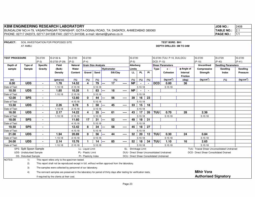
KBM ENGINEERING RESEARCH LABORATORY JOB NO.: 2408
BUNGALOW NO.H-79, VASANTNAGAR TOWNSHIP, GOTA-OGNAJ ROAD, TA: DASKROI, AHMEDABAD 380060 TABLE NO.: 2.1
PHONE: 02717 242373, 02717 241538 FAX: (02717) 241538, e-mail: [email protected] PAGE NO.: 1/1
PROJECT: SOIL INVESTIGATION FOR PROPOSED SITE TEST BORE: BH1
AT AMBLI DEPTH DRILLED: 6M TO 24M
TEST PROCEDURE IS:2720 IS:2132 & IS:2720 IS:2720 IS:2720 IS:2720 (TUU: P-10, DUU,DCU IS:2720 IS:2720 IS:2720
(P-3) IS:2720 (P-29) (P-2) (P-4) (P-5) DCD: P-13) (P-10) (P-40) (P-41)
Depth of Type of Specific Field Natural Grain Size Analysis Atterberg Shear Parameters Unconfined Swelling Parameters
sample Sample Gravity (Bulk) Water Hydrometer Limits Type c - φφφφ-Angle of Compressive Swelling Swelling
Density Content Gravel Sand Silt/Clay LL PL PI Cohesion Internal Strength Index Pressure
Friction
(m) (gms/cc) (%) (%) (%) (%) (%) (%) (%) (kg/cm2) (deg) (kg/cm
2) (%) (kg/cm
2)
8.00 UDS - 1.78 14.52 4 79 --- 17 ---- NP - - DCD 0.00 36
Date of Test: - 1.10.18 2.10.18 3.10.18 3.10.18 3.10.18
10.50 UDS - 1.85 10.28 1 83 --- 16 ---- NP - -
Date of Test: - 1.10.18 2.10.18 3.10.18 3.10.18
12.00 SPS - 12.60 0 44 --- 56 ---- 39 16 23
Date of Test: - 4.10.18 5.10.18 5.10.18
13.50 UDS - 2.26 9.78 5 50 --- 45 ---- 33 15 18
Date of Test: - 1.10.18 2.10.18 3.10.18 3.10.18
16.50 UDS - 2.17 14.22 4 35 --- 61 ---- 43 17 26 TUU 0.70 28 2.38
Date of Test: - 1.10.18 2.10.18 3.10.18 3.10.18 3.10.18 3.10.18
18.00 SPS - 11.60 17 31 --- 52 ---- 49 18 31
Date of Test: - 4.10.18 5.10.18 5.10.18
19.50 SPS - 12.42 8 34 --- 58 ---- 45 18 27
Date of Test: - 4.10.18 5.10.18 5.10.18
21.00 UDS - 1.94 20.89 0 56 --- 44 ---- 32 20 12 TUU 0.30 24 0.84
Date of Test: - 1.10.18 2.10.18 3.10.18 3.10.18 3.10.18 3.10.18
24.00 UDS - 2.14 15.76 1 14 --- 85 ---- 52 18 34 TUU 1.10 16 2.65
Date of Test: - 1.10.18 2.10.18 3.10.18 3.10.18 3.10.18 3.10.18
SPS- Split Spoon Sample LL- Liquid Limit SL- Shrinkage Limit TUU- Triaxial Shear Unconsolidated Undrained
UDS- Undisturbed Sample PL- Plastic Limit DUU- Direct Shear Unconsolidated Undrained DCD- Direct Shear Consolidated Drained
DS- Disturbed Sample PI- Plasticity Index DCU- Direct Shear Consolidated Undrained
NOTES: 1) This report refers only to the specimen tested.
2) This report shall not be reproduced except in full, without written approval from the laboratory.
3) The samples were collected by personnel of our laboratory.
4) The remnant samples are preserved in the laboratory for period of thirty days after testing for verification tests, Mihir Vora
if required by the clients at their cost. Authorised Signatory
Page 23
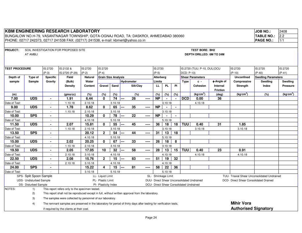
KBM ENGINEERING RESEARCH LABORATORY JOB NO.: 2408
BUNGALOW NO.H-79, VASANTNAGAR TOWNSHIP, GOTA-OGNAJ ROAD, TA: DASKROI, AHMEDABAD 380060 TABLE NO.: 2.2
PHONE: 02717 242373, 02717 241538 FAX: (02717) 241538, e-mail: [email protected] PAGE NO.: 1/1
PROJECT: SOIL INVESTIGATION FOR PROPOSED SITE TEST BORE: BH2
AT AMBLI DEPTH DRILLED: 6M TO 24M
TEST PROCEDURE IS:2720 IS:2132 & IS:2720 IS:2720 IS:2720 IS:2720 (TUU: P-10, DUU,DCU IS:2720 IS:2720 IS:2720
(P-3) IS:2720 (P-29) (P-2) (P-4) (P-5) DCD: P-13) (P-10) (P-40) (P-41)
Depth of Type of Specific Field Natural Grain Size Analysis Atterberg Shear Parameters Unconfined Swelling Parameters
sample Sample Gravity (Bulk) Water Hydrometer Limits Type c - φφφφ-Angle of Compressive Swelling Swelling
Density Content Gravel Sand Silt/Clay LL PL PI Cohesion Internal Strength Index Pressure
Friction
(m) (gms/cc) (%) (%) (%) (%) (%) (%) (%) (kg/cm2) (deg) (kg/cm
2) (%) (kg/cm
2)
7.00 UDS - 1.91 6.44 0 74 --- 26 ---- NP - - DCD 0.00 36
Date of Test: - 1.10.18 2.10.18 3.10.18 3.10.18 4.10.18
9.00 UDS - 1.78 8.62 0 65 --- 35 ---- NP - -
Date of Test: - 1.10.18 2.10.18 3.10.18 3.10.18
10.00 SPS - 10.29 0 78 --- 22 ---- NP - -
Date of Test: - 4.10.18 5.10.18 5.10.18
11.50 UDS - 2.07 15.81 0 55 --- 45 ---- 36 18 18 TUU 0.40 31 1.85
Date of Test: - 1.10.18 2.10.18 3.10.18 3.10.18 3.10.18 3.10.18
13.50 SPS - 20.12 2 54 --- 44 ---- 31 13 18
Date of Test: - 4.10.18 5.10.18 5.10.18
15.00 UDS - 2.02 20.25 0 67 --- 33 ---- 26 18 8
Date of Test: - 1.10.18 2.10.18 3.10.18 3.10.18
19.50 UDS - 2.05 17.05 10 32 --- 58 ---- 28 13 15 TUU 0.40 23 0.91
Date of Test: - 2.10.18 3.10.18 4.10.18 4.10.18 4.10.18 4.10.18
22.50 UDS - 2.08 15.76 2 15 --- 83 ---- 51 19 32
Date of Test: - 2.10.18 3.10.18 4.10.18 4.10.18
24.00 SPS - 15.22 4 15 --- 81 ---- 58 22 36
Date of Test: - 3.10.18 5.10.18 5.10.18
SPS- Split Spoon Sample LL- Liquid Limit SL- Shrinkage Limit TUU- Triaxial Shear Unconsolidated Undrained
UDS- Undisturbed Sample PL- Plastic Limit DUU- Direct Shear Unconsolidated Undrained DCD- Direct Shear Consolidated Drained
DS- Disturbed Sample PI- Plasticity Index DCU- Direct Shear Consolidated Undrained
NOTES: 1) This report refers only to the specimen tested.
2) This report shall not be reproduced except in full, without written approval from the laboratory.
3) The samples were collected by personnel of our laboratory.
4) The remnant samples are preserved in the laboratory for period of thirty days after testing for verification tests, Mihir Vora
if required by the clients at their cost. Authorised Signatory
Page 24
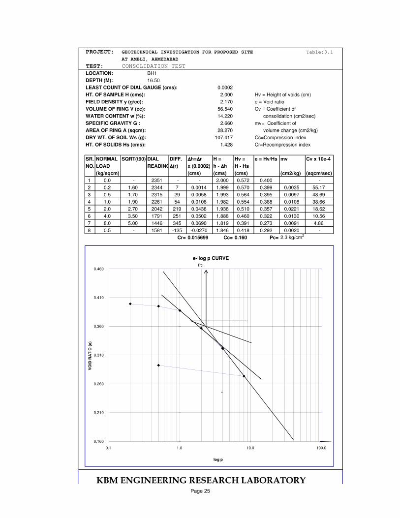
PROJECT: GEOTECHNICAL INVESTIGATION FOR PROPOSED SITE Table:3.1
AT AMBLI, AHMEDABAD
TEST: CONSOLIDATION TEST
LOCATION: BH1
DEPTH (M): 16.50
LEAST COUNT OF DIAL GAUGE (cms): 0.0002
HT. OF SAMPLE H (cms): 2.000 Hv = Height of voids (cm)
FIELD DENSITY y (g/cc): 2.170 e = Void ratio
VOLUME OF RING V (cc): 56.540 Cv = Coefficient of
WATER CONTENT w (%): 14.220 consolidation (cm2/sec)
SPECIFIC GRAVITY G : 2.660 mv= Coefficient of
AREA OF RING A (sqcm): 28.270 volume change (cm2/kg)
DRY WT. OF SOIL Ws (g): 107.417 Cc=Compression index
HT. OF SOLIDS Hs (cms): 1.428 Cr=Recompression index
SR. NORMAL SQRT(t90) DIAL DIFF. ∆∆∆∆h=∆∆∆∆r H = Hv = e = Hv/Hs mv Cv x 10e-4
NO. LOAD READING∆∆∆∆(r) x (0.0002) h - ∆∆∆∆h H - Hs
(kg/sqcm) (cms) (cms) (cms) (cm2/kg) (sqcm/sec)
1 0.0 - 2351 - - 2.000 0.572 0.400 -
2 0.2 1.60 2344 7 0.0014 1.999 0.570 0.399 0.0035 55.17
3 0.5 1.70 2315 29 0.0058 1.993 0.564 0.395 0.0097 48.69
4 1.0 1.90 2261 54 0.0108 1.982 0.554 0.388 0.0108 38.66
5 2.0 2.70 2042 219 0.0438 1.938 0.510 0.357 0.0221 18.62
6 4.0 3.50 1791 251 0.0502 1.888 0.460 0.322 0.0130 10.56
7 8.0 5.00 1446 345 0.0690 1.819 0.391 0.273 0.0091 4.86
8 0.5 - 1581 -135 -0.0270 1.846 0.418 0.292 0.0020 -
Cr= 0.015699 Cc= 0.160 Pc= 2.3 kg/cm2
KBM ENGINEERING RESEARCH LABORATORY
0.160
0.210
0.260
0.310
0.360
0.410
0.460
0.1 1.0 10.0 100.0
VO
ID R
AT
IO (
e)
log p
e- log p CURVE
Pc
Page 25
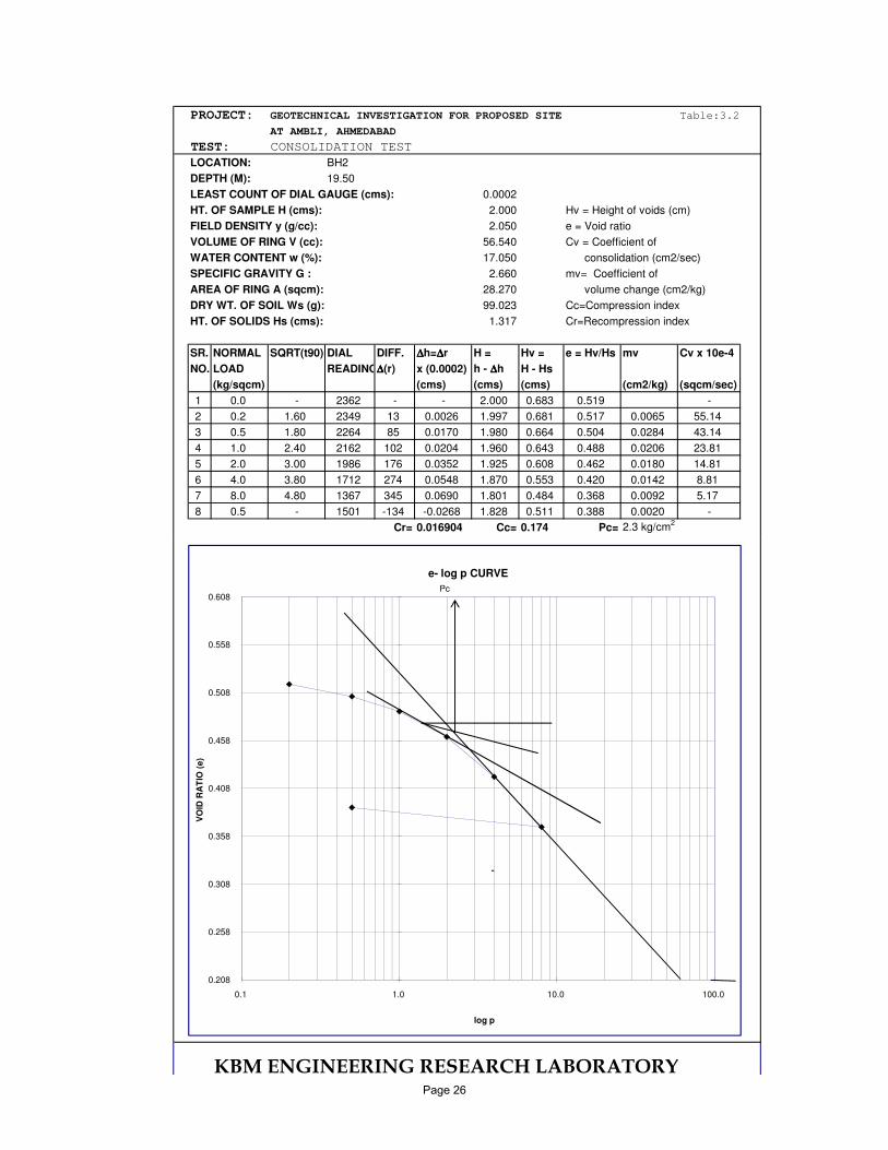
PROJECT: GEOTECHNICAL INVESTIGATION FOR PROPOSED SITE Table:3.2
AT AMBLI, AHMEDABAD
TEST: CONSOLIDATION TEST
LOCATION: BH2
DEPTH (M): 19.50
LEAST COUNT OF DIAL GAUGE (cms): 0.0002
HT. OF SAMPLE H (cms): 2.000 Hv = Height of voids (cm)
FIELD DENSITY y (g/cc): 2.050 e = Void ratio
VOLUME OF RING V (cc): 56.540 Cv = Coefficient of
WATER CONTENT w (%): 17.050 consolidation (cm2/sec)
SPECIFIC GRAVITY G : 2.660 mv= Coefficient of
AREA OF RING A (sqcm): 28.270 volume change (cm2/kg)
DRY WT. OF SOIL Ws (g): 99.023 Cc=Compression index
HT. OF SOLIDS Hs (cms): 1.317 Cr=Recompression index
SR. NORMAL SQRT(t90) DIAL DIFF. ∆∆∆∆h=∆∆∆∆r H = Hv = e = Hv/Hs mv Cv x 10e-4
NO. LOAD READING∆∆∆∆(r) x (0.0002) h - ∆∆∆∆h H - Hs
(kg/sqcm) (cms) (cms) (cms) (cm2/kg) (sqcm/sec)
1 0.0 - 2362 - - 2.000 0.683 0.519 -
2 0.2 1.60 2349 13 0.0026 1.997 0.681 0.517 0.0065 55.14
3 0.5 1.80 2264 85 0.0170 1.980 0.664 0.504 0.0284 43.14
4 1.0 2.40 2162 102 0.0204 1.960 0.643 0.488 0.0206 23.81
5 2.0 3.00 1986 176 0.0352 1.925 0.608 0.462 0.0180 14.81
6 4.0 3.80 1712 274 0.0548 1.870 0.553 0.420 0.0142 8.81
7 8.0 4.80 1367 345 0.0690 1.801 0.484 0.368 0.0092 5.17
8 0.5 - 1501 -134 -0.0268 1.828 0.511 0.388 0.0020 -
Cr= 0.016904 Cc= 0.174 Pc= 2.3 kg/cm2
KBM ENGINEERING RESEARCH LABORATORY
0.208
0.258
0.308
0.358
0.408
0.458
0.508
0.558
0.608
0.1 1.0 10.0 100.0
VO
ID R
AT
IO (
e)
log p
e- log p CURVE
Pc
Page 26
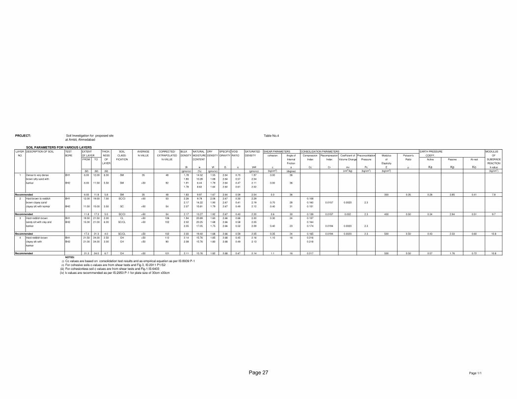
PROJECT: Soil Investigation for proposed site Table No.4
at Ambli, Ahmedabad
SOIL PARAMETERS FOR VARIOUS LAYERS
LAYER DESCRIPTION OF SOIL TEST EXTENT THICK- SOIL AVERAGE CORRECTED/ BULK NATURAL DRY SPECIFIC VOID SATURATED SHEAR PARAMETERS CONSOLIDATION PARAMETERS EARTH PRESSURE MODULUS
NO. BORE OF LAYER NESS CLASS- N-VALUE EXTRAPOLATED DENSITY MOISTURE DENSITY GRAVITY RATIO DENSITY cohesion Angle of Compression Recompression Coefficient of Preconsolidation Modulus Poisson's COEFF. OF
FROM TO OF FICATION N-VALUE CONTENT Internal Index Index Volume Change Pressure of Ratio Active Passive At-rest SUBGRADE
LAYER Friction Elasticity REACTION
γb w γd G e γsat c φ Cc Cr mv Pc E µ Ka Kp Ko k-value
(M) (M) (M) (gms/cc) (%) (gms/cc) (gms/cc) (kg/cm2) (degree) (cm
2/kg) (kg/cm
2) (kg/cm
2) (kg/cm
3)
1 Dense to very dense BH1 6.00 12.00 6.00 SM 35 48 1.78 14.52 1.55 2.64 0.70 1.97 0.00 36
brown silty sand with 1.85 10.28 1.68 2.64 0.57 2.04
kankar BH2 6.00 11.50 5.50 SM >50 92 1.91 6.44 1.79 2.64 0.47 2.11 0.00 36
1.78 8.62 1.64 2.64 0.61 2.021.78 8.62 1.64 2.64 0.61 2.02
Recommended 6.00 11.8 5.8 SM 35 48 1.83 9.97 1.67 2.64 0.59 2.04 0.0 36 300 0.35 0.26 3.85 0.41 7.8
2 Hard brown to reddish BH1 12.00 19.50 7.50 SC/CI >50 53 2.26 9.78 2.06 2.67 0.30 2.29 0.108
brown clayey sand/ 2.17 14.22 1.90 2.67 0.41 2.19 0.70 28 0.160 0.0157 0.0020 2.3
clayey silt with kankar BH2 11.50 15.00 3.50 SC >50 54 2.07 15.81 1.79 2.67 0.49 2.12 0.40 31 0.151
Recommended 11.8 17.3 5.5 SC/CI >50 54 2.17 13.27 1.92 2.67 0.40 2.20 0.6 30 0.139 0.0157 0.002 2.3 400 0.50 0.34 2.94 0.51 9.7
3 Hard reddish brown BH1 19.50 21.50 2.00 CL >50 106 1.94 20.89 1.60 2.66 0.66 2.00 0.30 24 0.157
sandy silt with clay and BH2 15.00 21.00 6.00 SC/CL >50 102 2.02 20.25 1.68 2.66 0.58 2.05 0.164
kankar 2.05 17.05 1.75 2.66 0.52 2.09 0.40 23 0.174 0.0194 0.0020 2.3
Recommended 17.3 21.3 4.0 SC/CL >50 102 2.00 19.40 1.68 2.66 0.59 2.05 0.35 24 0.165 0.0194 0.0020 2.3 500 0.50 0.43 2.33 0.60 10.8
4 Hard reddish brown BH1 21.50 24.00 2.50 CH >50 112 2.14 15.76 1.85 2.68 0.45 2.16 1.10 16 0.216
clayey silt with BH2 21.00 24.00 3.00 CH >50 90 2.08 15.76 1.80 2.68 0.49 2.13 0.218
kankar
Recommended 21.3 24.0 6.7 CH >50 101 2.11 15.76 1.82 2.68 0.47 2.14 1.1 16 0.217 500 0.50 0.57 1.76 0.72 10.8
NOTES:
(i) Cc values are based on consolidation test results and as empirical equation as per IS:8009 P-1
(ii) For cohesive soils c-values are from shear tests and Fig.3, IS:2911 P1/S2
(iii) For cohesionless soil φ-values are from shear tests and Fig.1 IS:6403
(iv) k-values are recommended as per IS:2950 P-1 for plate size of 30cm x30cm
Page 1/1Page 27
Sagar Shanti
PROJECT SITE
Dev Kutir
AmbliGreen Park Bunglows
Shree SwaminarayanSukhakar Society
Shivalik FloretteSukhakar Society
BhandariFarm
BaseraParyplot
AnganRestaurant
Shivalik Villa
DhanroopVilla
AshokVatika
AadirajBunglows
SpringVelly
AbhishekBunglows
Sun City-1
SoboCenterGala
SwingGalaAriaSafal
Parisar
OrchidElegence
ArohiCrest
SouthBopal
Spring MeadownsBunglows
Shivam-IIBunglows
Maruti Nandan
Sun City-2
A.G.Colony
ArihantBunglows
AbadnagarSociety
HariomBunglows
Maruti Villa
Mumatpura
Arohi TwinBunglow
BalajiRow House
AnuragRow House
InductothermFactory
KadambAppartment
Samarpan TwinsBunglow
Iscon Pletinum
AmrapaliShopping Mall
Bunglows
Altius-2
ShivalikGreens
JaintilalPark Chiripal
Bunglows
SankalpGrace-2
PushpakPlatinum
AbhishreeCo. Park
PushpakBungalow
KaanhaResidency
SantoshaPark
ShivamBunglows
Arohi Royal
Bhavya Park
ParamdhamSociety
Paras-2
Paras-2
N
WE
S
Sardar Patel Ring Road
ABCD
B
WE
S
SCALE = N
.T.S.
23° 1'30.86"N 72°28'55.71"E
23° 1'31.39"N 72°28'58.89"E
23° 1'29.81"N 72°28'59.20"E
23° 1'29.31"N 72°28'56.00"E
LatitudeLongitude N
ADC
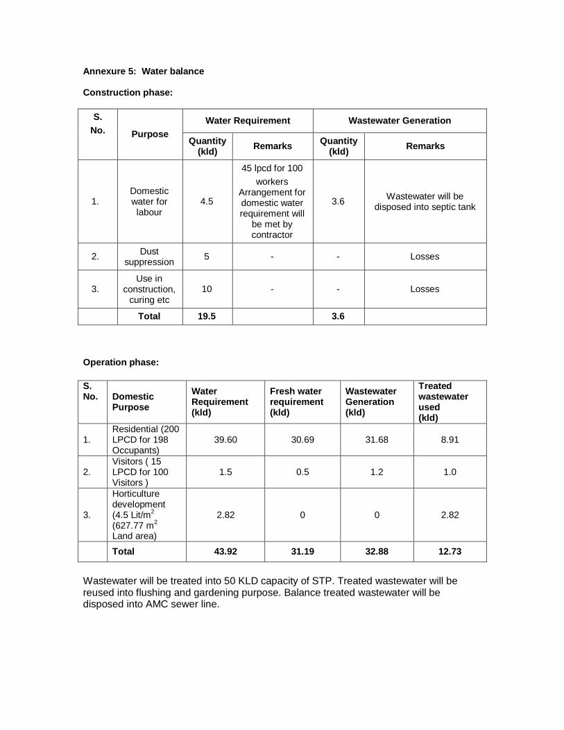
Annexure 5: Water balance Construction phase:
S. No. Purpose
Water Requirement Wastewater Generation
Quantity (kld) Remarks Quantity
(kld) Remarks
1. Domestic water for labour
4.5
45 lpcd for 100 workers
Arrangement for domestic water requirement will
be met by contractor
3.6 Wastewater will be disposed into septic tank
2. Dust suppression 5 - - Losses
3. Use in
construction, curing etc
10 - - Losses
Total 19.5 3.6 Operation phase: S. No. Domestic
Purpose Water Requirement (kld)
Fresh water requirement (kld)
Wastewater Generation (kld)
Treated wastewater used (kld)
1. Residential (200 LPCD for 198 Occupants)
39.60 30.69 31.68 8.91
2. Visitors ( 15 LPCD for 100 Visitors )
1.5 0.5 1.2 1.0
3.
Horticulture development (4.5 Lit/m2 (627.77 m2 Land area)
2.82 0 0 2.82
Total 43.92 31.19 32.88 12.73
Wastewater will be treated into 50 KLD capacity of STP. Treated wastewater will be reused into flushing and gardening purpose. Balance treated wastewater will be disposed into AMC sewer line.
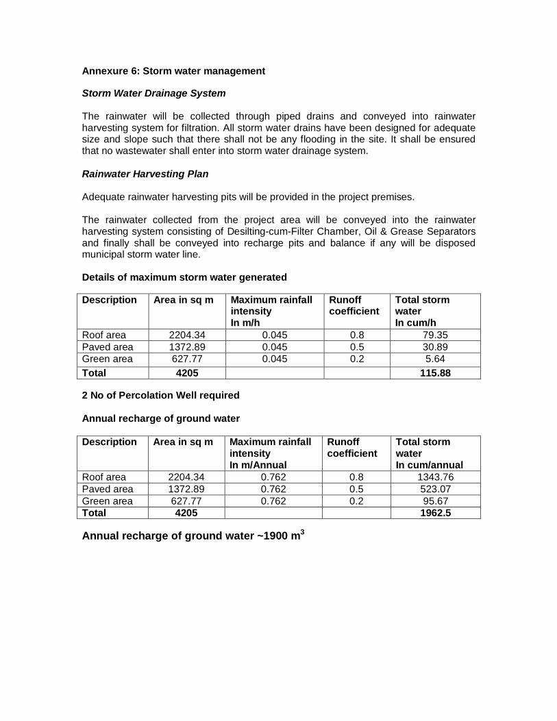
Annexure 6: Storm water management Storm Water Drainage System The rainwater will be collected through piped drains and conveyed into rainwater harvesting system for filtration. All storm water drains have been designed for adequate size and slope such that there shall not be any flooding in the site. It shall be ensured that no wastewater shall enter into storm water drainage system. Rainwater Harvesting Plan Adequate rainwater harvesting pits will be provided in the project premises. The rainwater collected from the project area will be conveyed into the rainwater harvesting system consisting of Desilting-cum-Filter Chamber, Oil & Grease Separators and finally shall be conveyed into recharge pits and balance if any will be disposed municipal storm water line. Details of maximum storm water generated Description Area in sq m Maximum rainfall
intensity In m/h
Runoff coefficient
Total storm water In cum/h
Roof area 2204.34 0.045 0.8 79.35 Paved area 1372.89 0.045 0.5 30.89 Green area 627.77 0.045 0.2 5.64 Total 4205 115.88 2 No of Percolation Well required Annual recharge of ground water Description Area in sq m Maximum rainfall
intensity In m/Annual
Runoff coefficient
Total storm water In cum/annual
Roof area 2204.34 0.762 0.8 1343.76 Paved area 1372.89 0.762 0.5 523.07 Green area 627.77 0.762 0.2 95.67 Total 4205 1962.5 Annual recharge of ground water ~1900 m3
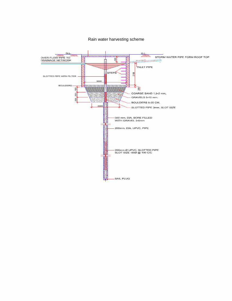
Rain water harvesting scheme

Annexure 7: Fire and Safety Proposed building height is 45m from ground level. All fire protection facilities will be designed as per the National Building Code
Residential Flats is in Group A, sub Group A-4 Fire Zone No.1 (clause 3.2.2.2)
Following component/item will be provided: Under the clauses (4.18.2, 6.1.2, 6.2.3, 6.3.2, 6.4.3, 6.5.2, 6.5.2.1, 6.5.2.2, 6.5.2.3, 6.5.2.4, 6.5.2.5, 6.6.2, 6.7.2, 6.8.2 and 6.9.2) following are minimum requirements for fire fighting installations.
Fire Extinguishers Hose Reel Wet Riser Yard Hydrant Automatic sprinkler system (Basement) Manually Operated Electric Fire Alarm System Terrace Tank -20,000 liter Underground Tank -1,00,000 liter Fire pump near underground static water storage tank with minimum pressure of
3.5 kg/cm2 at terrace level.
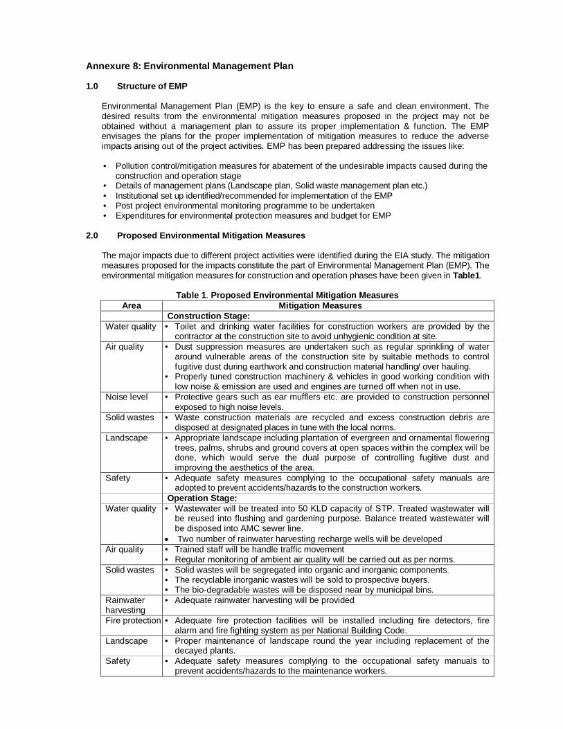
Annexure 8: Environmental Management Plan 1.0 Structure of EMP
Environmental Management Plan (EMP) is the key to ensure a safe and clean environment. The desired results from the environmental mitigation measures proposed in the project may not be obtained without a management plan to assure its proper implementation & function. The EMP envisages the plans for the proper implementation of mitigation measures to reduce the adverse impacts arising out of the project activities. EMP has been prepared addressing the issues like:
• Pollution control/mitigation measures for abatement of the undesirable impacts caused during the
construction and operation stage • Details of management plans (Landscape plan, Solid waste management plan etc.) • Institutional set up identified/recommended for implementation of the EMP • Post project environmental monitoring programme to be undertaken • Expenditures for environmental protection measures and budget for EMP
2.0 Proposed Environmental Mitigation Measures
The major impacts due to different project activities were identified during the EIA study. The mitigation measures proposed for the impacts constitute the part of Environmental Management Plan (EMP). The environmental mitigation measures for construction and operation phases have been given in Table1.
Table 1. Proposed Environmental Mitigation Measures
Area Mitigation Measures Construction Stage: Water quality • Toilet and drinking water facilities for construction workers are provided by the
contractor at the construction site to avoid unhygienic condition at site. Air quality • Dust suppression measures are undertaken such as regular sprinkling of water
around vulnerable areas of the construction site by suitable methods to control fugitive dust during earthwork and construction material handling/ over hauling.
• Properly tuned construction machinery & vehicles in good working condition with low noise & emission are used and engines are turned off when not in use.
Noise level • Protective gears such as ear mufflers etc. are provided to construction personnel exposed to high noise levels.
Solid wastes • Waste construction materials are recycled and excess construction debris are disposed at designated places in tune with the local norms.
Landscape • Appropriate landscape including plantation of evergreen and ornamental flowering trees, palms, shrubs and ground covers at open spaces within the complex will be done, which would serve the dual purpose of controlling fugitive dust and improving the aesthetics of the area.
Safety • Adequate safety measures complying to the occupational safety manuals are adopted to prevent accidents/hazards to the construction workers.
Operation Stage: Water quality • Wastewater will be treated into 50 KLD capacity of STP. Treated wastewater will
be reused into flushing and gardening purpose. Balance treated wastewater will be disposed into AMC sewer line.
Two number of rainwater harvesting recharge wells will be developed Air quality • Trained staff will be handle traffic movement
• Regular monitoring of ambient air quality will be carried out as per norms. Solid wastes • Solid wastes will be segregated into organic and inorganic components.
• The recyclable inorganic wastes will be sold to prospective buyers. • The bio-degradable wastes will be disposed near by municipal bins.
Rainwater harvesting
• Adequate rainwater harvesting will be provided
Fire protection • Adequate fire protection facilities will be installed including fire detectors, fire alarm and fire fighting system as per National Building Code.
Landscape • Proper maintenance of landscape round the year including replacement of the decayed plants.
Safety • Adequate safety measures complying to the occupational safety manuals to prevent accidents/hazards to the maintenance workers.
Others • The building will be provided with disabled-friendly design, timber-free construction, energy efficient lighting & ventilation, and control of indoor environment.
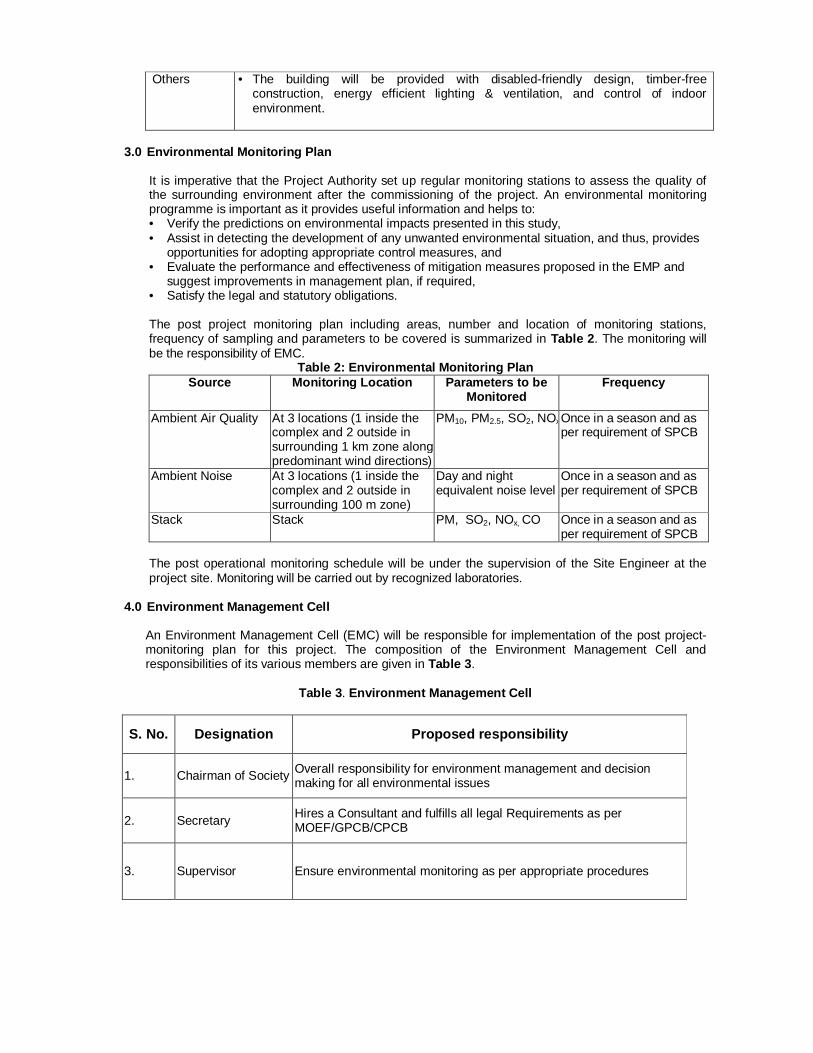
3.0 Environmental Monitoring Plan
It is imperative that the Project Authority set up regular monitoring stations to assess the quality of the surrounding environment after the commissioning of the project. An environmental monitoring programme is important as it provides useful information and helps to: • Verify the predictions on environmental impacts presented in this study, • Assist in detecting the development of any unwanted environmental situation, and thus, provides
opportunities for adopting appropriate control measures, and • Evaluate the performance and effectiveness of mitigation measures proposed in the EMP and
suggest improvements in management plan, if required, • Satisfy the legal and statutory obligations. The post project monitoring plan including areas, number and location of monitoring stations, frequency of sampling and parameters to be covered is summarized in Table 2. The monitoring will be the responsibility of EMC.
Table 2: Environmental Monitoring Plan Source Monitoring Location Parameters to be
Monitored Frequency
Ambient Air Quality At 3 locations (1 inside the complex and 2 outside in surrounding 1 km zone along predominant wind directions)
PM10, PM2.5, SO2, NOxOnce in a season and as per requirement of SPCB
Ambient Noise At 3 locations (1 inside the complex and 2 outside in surrounding 100 m zone)
Day and night equivalent noise level
Once in a season and as per requirement of SPCB
Stack Stack PM, SO2, NOx, CO Once in a season and as per requirement of SPCB
The post operational monitoring schedule will be under the supervision of the Site Engineer at the project site. Monitoring will be carried out by recognized laboratories.
4.0 Environment Management Cell An Environment Management Cell (EMC) will be responsible for implementation of the post project-monitoring plan for this project. The composition of the Environment Management Cell and responsibilities of its various members are given in Table 3.
Table 3. Environment Management Cell
S. No. Designation Proposed responsibility
1. Chairman of Society Overall responsibility for environment management and decision making for all environmental issues
2. Secretary Hires a Consultant and fulfills all legal Requirements as per MOEF/GPCB/CPCB
3. Supervisor Ensure environmental monitoring as per appropriate procedures
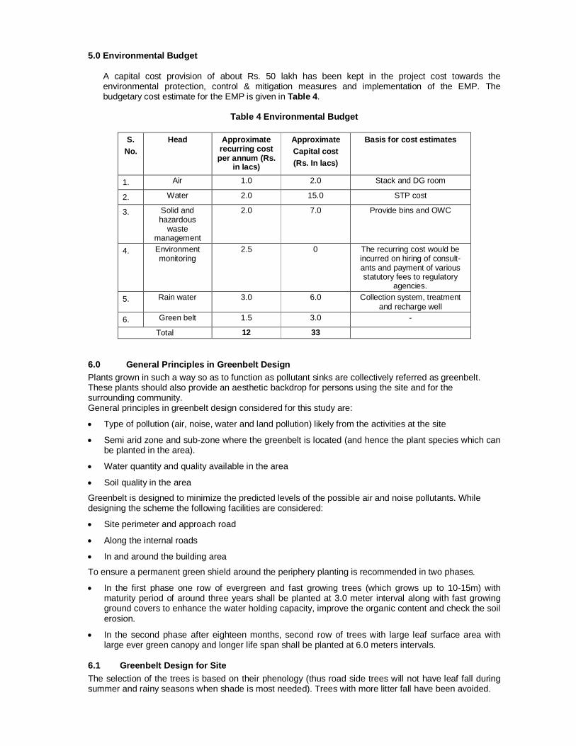
5.0 Environmental Budget
A capital cost provision of about Rs. 50 lakh has been kept in the project cost towards the environmental protection, control & mitigation measures and implementation of the EMP. The budgetary cost estimate for the EMP is given in Table 4.
Table 4 Environmental Budget
S.
No. Head Approximate
recurring cost per annum (Rs.
in lacs)
Approximate Capital cost (Rs. In lacs)
Basis for cost estimates
1. Air 1.0 2.0 Stack and DG room
2. Water 2.0 15.0 STP cost
3. Solid and hazardous
waste management
2.0 7.0 Provide bins and OWC
4. Environment monitoring
2.5 0 The recurring cost would be incurred on hiring of consult-ants and payment of various statutory fees to regulatory
agencies. 5. Rain water 3.0 6.0 Collection system, treatment
and recharge well 6. Green belt 1.5 3.0 -
Total 12 33
6.0 General Principles in Greenbelt Design Plants grown in such a way so as to function as pollutant sinks are collectively referred as greenbelt. These plants should also provide an aesthetic backdrop for persons using the site and for the surrounding community. General principles in greenbelt design considered for this study are:
Type of pollution (air, noise, water and land pollution) likely from the activities at the site
Semi arid zone and sub-zone where the greenbelt is located (and hence the plant species which can be planted in the area).
Water quantity and quality available in the area
Soil quality in the area
Greenbelt is designed to minimize the predicted levels of the possible air and noise pollutants. While designing the scheme the following facilities are considered:
Site perimeter and approach road
Along the internal roads
In and around the building area
To ensure a permanent green shield around the periphery planting is recommended in two phases.
In the first phase one row of evergreen and fast growing trees (which grows up to 10-15m) with maturity period of around three years shall be planted at 3.0 meter interval along with fast growing ground covers to enhance the water holding capacity, improve the organic content and check the soil erosion.
In the second phase after eighteen months, second row of trees with large leaf surface area with large ever green canopy and longer life span shall be planted at 6.0 meters intervals.
6.1 Greenbelt Design for Site The selection of the trees is based on their phenology (thus road side trees will not have leaf fall during summer and rainy seasons when shade is most needed). Trees with more litter fall have been avoided.
The selection criteria of the species are based on pollution mitigation capacity (including particulate matter), large leaf surface area to deep root system and less litter fall. Faster growing trees with lighter canopy will be planted alternatively with relatively slow growing trees with wider canopy. Trees of about 6.0 m heights will be planted at 4.5 m intervals, 2.5 m away from the road curbing as per CPCB guidelines. Trees will be planted along the outer periphery at centerline of road between the set back line and the boundary of the plots. Palms and shrubs will be planted along the roads and around recreational lawns.
6.2 Greenbelt Management It is presumed that the selected plants will be grown as per normal horticultural practice and the authorities responsible for the plantation will make adequate provisions for water and protection of the saplings. A budgetary cost estimate is also prepared for greenbelt development.
Water source Water tankers may also be used at the initial stages of development of the plant.
Irrigation method Water hydrants may be installed at 50 m intervals to irrigate area under shrubs and ground covers.
6.3 Improving Indoor Air Quality The indoor air quality can be improved by any of the following:
Ventilation
Include the use of natural, dilution, local exhaust, or increased ventilation efficiency. The most effective engineering control for prevention of indoor air quality problems is assuring an adequate supply of fresh outdoor air through natural or mechanical ventilation.
When possible, use local exhaust ventilation and enclosure to capture and remove contaminants generated by specific processes. Room air in which contaminants are generated should be discharged directly outdoors rather than recirculated.
Outside air intakes should not be located in close proximity to potential sources of contamination (automobile garages, building exhausts, and roadways).
Work Place Recommendations
Eliminate or control all known and potential sources of microbial contaminants by prompt cleanup and repair of all areas where water collection and leakage has occurred including floors, roofs, drain pans, humidifiers containing reservoirs of stagnant water, air washers etc.
Remove and discard porous organic materials that are contaminated (e.g., damp insulation in ventilation system, ceiling tiles, and carpets).
Clean and disinfect non-porous surfaces where microbial growth has occurred
Maintain indoor air relative humidity below 60%
Adjust intake of outdoor air to avoid contamination from nearby soil, vegetable debris unless air is adequately conditioned.
Isolate, if feasible, areas of renovation, painting, carpet laying, pesticide application, etc., from occupied areas that are not under construction.
Supply adequate ventilation during and after completion of work to assist in diluting the contaminant levels.
Eliminate or reduce contamination of the air supply with cigarette smoke by banning smoking or restricting smoking to designated areas which have their air discharged directly to the outdoor rather than recirculated.
6.4 Safety Aspects of the Project The following needs to be implemented:
Fall Protection
The Contractor is required to provide fall protection to employees who are working at heights equal to or greater than 1.8 m. fall protection can be in the form of perimeter protection such as guardrails and toe rails, personal protective equipment (PPE), a safety monitoring system, or a fall protection plan. Activities that require personal fall protection systems include steel erection bolting, riveting, fitting-up and plumbing-up, work over water and some deep excavation work.
On buildings or structures not adaptable to temporary floors, and where scaffolds are not used, safety nets will be installed and maintained whenever the potential fall distance exceeds two storey.
The PPE standard should cover occupational foot, head, hearing, and eye protection.
Foot Protection: If machines or operations present the potential for foot injury, the Contractor must provide foot protection, which is of safe design and construction for the work to be performed. Workers and visitors should not be allowed on a construction site without safety boots.
Head Protection: If head hazards remain after all steps have been taken to control them (safety nets for work at heights, proper housekeeping), the Contractor must provide employees with appropriate head protection.
Noise Protection: Workers should be wearing hearing protection devices (ear plugs, ear muffs, canal caps) that are in good condition whenever they are involved in noisy activities.
Eye Protection: When machines or operations present potential eye injury from physical or chemical elements, the Contractor must select, provide, maintain and required affected employees to use appropriate eye protection. Eye protection (safety glasses and goggles, face shields and welding helmets) must be adequate and reasonably comfortable.
To the greatest extent possible, working surfaces must be kept dry to prevent slips and falls and to reduce the chance of nuisance odors from pooled water.
All equipment and materials should be stored in designated storage areas that are labeled as such.
Ladders and Stairs
The Contractor is required to inspect and maintain all ladders and temporary/portable steps to ensure that they are in good working condition.
Portable ladders used for access to an upper landing surface must extend a minimum of 1.8 m above the landing surface, or where not practical, be provided with grab rails and be secured against movement while in use.
All ladders must be used only on stable and level surfaces unless secured to prevent accidental movement. Ladders must not be used on slippery surfaces unless secured or provided with slip-resistant feet to prevent accidental movement.
The Contractor should provide a ladder (or stairway) at all work points of access where there is a break in elevation of 0.5 m or more.
When there is only one point of access between levels, it must be kept clear to permit free passage by workers. If free passage becomes restricted, a second point of access must be provided and used. At all times, at least one point of access must be kept clear.
All required stairway and ladder fall protection systems must be provided and installed before employees begin work that requires them to use stairways or ladders.
Scaffolds
Access to Scaffolds - access to and between scaffold platforms more than 0.6 m above or below the point of access will be made by portable/attachable ladders or ramps.
Employees must never use makeshift devices, such as boxes and barrels, to increase the scaffold platform working level height.
Trenching and Excavation
The area around the trench/excavation would be kept clear of surface encumbrances.
Water should not be allowed to accumulate in the excavation.
Adjacent structures would be shored in accordance with the design documents to prevent collapse.
Guardrails or some other means of protecting people from falling into the trench/excavation would be present.
The trench or excavation would be shored or sloped to prevent cave-ins.
Electrical Safety
If work has to be done near an overhead power line, the line must be de-energized and grounded before work is started.
A licensed electrician would have completed all temporary wiring and electrical installations required for construction activities.
Fuses and circuit breakers would be used to protect motherboards, conductors and equipment.
Extension cords for equipment or as part of a temporary wiring system will not be damaged or compromised in any way and insulation must be of the highest grade.
Anytime electrical equipment is deactivated for repair, or circuits are shut off, the equipment will be locked out and tagged at the point where it can be energized.
Temporary lights may not be suspended by their cords.
The Contractor would provide the necessary safety equipment, supplies and monitoring equipment to their personnel.
Cranes A competent person has been designated to supervise activities that require the use of cranes. Cranes would not be operated near any power lines. All picks would be carefully planned to ensure that the crane adequately hoist the load. The hoisting signals would be posted on the exterior of the crane.
Occupational Noise Exposure
The Contractor should implement engineering controls to reduce noise levels.
The Contractor should provide hearing protection to employees that are exposed to noise levels above the permissible limit.
Welding and Cutting
The Contractor's employees would be trained in hot work procedures.
There should be adequate ventilation to reduce the build up of metal fume.
The hot work operators would use proper personal protective equipment (i.e., welding helmet, burning goggles, face shield, welding gloves, and apron).
There would be a fire extinguisher present at all welding and burning activities.
Extinguishers would also be placed at locations where slag and sparks may fall.
Oxygen and flammable gas bottles are separated by at least 7 m when not in use.
The Contractor would control the release of gases, vapors, fumes, dusts, and mists with engineering controls (e.g., adequate ventilation).
General Guidelines
Signs and symbols would be visible during any construction activity that presents a hazard. Upon completion of such activity, the postings must be removed immediately.
The Contractor would post specific DANGER signs when an immediate hazard exists and specific CAUTION signs when the potential for a hazard exists. EXIT, NOTICE and specific safety signs may also be posted in the work area.
Signage for traffic control, including directional signs, is applicable when the Contractor is disrupting traffic along a public way.
Danger signs are posted at all immediate hazards (i.e. Danger: Open Hole).
Caution signs are posted at all potential hazards (i.e. Caution: Construction Area, Caution: Buried Cable).
The floor that is being used as the erection floor must be solidly planked or decked over its entire surface except for access openings.
Every floor, working place and passageway would be kept free from protruding nails, splinters, holes or loose boards.
Combustible scrap and debris (wood, clearing/grubbing material) would be removed from the site daily or should be securely stored in covered containers.
The Contractor would have a spill prevention control and countermeasure plan that limits the risk of releases of oil or hazardous materials to the environment.


