Embed Size (px)
Citation preview
symmetryS S
Article
Schematic Diagrams Design of DisplacementSuppression Mechanism with OneDegree-of-Freedom in a Rope-GuidedHoisting System
Lu Yan 1,2, Guohua Cao 1,2,* , Naige Wang 1,2 and Weihong Peng 3
1 School of Mechatronic Engineering, China University of Mining and Technology, Xuzhou 221116, China;[email protected] (L.Y.); [email protected] (N.W.)
2 Jiangsu Key Laboratory of Mine Mechanical and Electrical Equipment, China University of Mining andTechnology, Xuzhou 221116, China
3 School of Mechanics and Civil Engineering, China University of Mining and Technology, Xuzhou 221116,China; [email protected]
* Correspondence: [email protected]
Received: 16 January 2020; Accepted: 19 February 2020; Published: 18 March 2020�����������������
Abstract: Since it is difficult for lateral stiffness of rope-guided rails to meet industry criteria indeep construction shaft, schematic diagrams of displacement suppression mechanisms (DSMs) aredesigned with a systematic approach demonstrated to reduce the lateral displacement of rope-guidedrails in this paper. DSMs are simplified as planar four-bar and six-bar topological graphs based ontopological theory. Each corresponding mechanical chain of these four-bar and six-bar mechanisms isdivided into a rack, mechanical parts, prismatic, and revolute joints. An extended adjacency matrix isdefined to represent the rack position, specific types of kinematic joints, and adjacency relationshipsbetween kinematic parts. Then, a symmetric vertex identification method is proposed with regard toplanar 1-DOF (one degree of freedom) four-bar and six-bar topological graphs to get the sequences ofprismatic joints for kinematic chains of DSMs. Finally, the alternative schematic diagrams of DSMsare obtained. The results show four-bar mechanisms with simple structure; few kinematical parts butless resident force are suitable for a mine shaft with small space and small swing. Six-bar mechanismswith two prismatic joints and three mechanical rack degree are applicable for wide shaft space indeep shaft, due to their stable structure and double resistant force. This development is helpful forDSM dimension synthesis design in future.
Keywords: rope-guided rail; displacement suppression mechanisms; vertex symmetry identification;schematic diagrams design
1. Introduction
With the increasing shortage of global resources and energy, many countries in the world aredeveloping and utilizing mineral resources deeper in the earth. The excavation depth of newly-builtmines in China has increased at an average speed of 10 m per year and mine hoisting in deep shaftrequires higher speed, heavier load, and more stability. Wire ropes are widely used for the guidanceof hosting conveyances in the process of shaft construction or in a mine hoisting system. Increasingdepth of mine shaft leads to more insufficient stiffness of guiding ropes, thereby causing the substantialswinging of hoisting conveyances and increasing insecurity. Researchers made many studies about thestiffness [1,2] of guiding ropes and the vibration [3,4] in a rope-guided mine hoisting system. Therefore,the lateral deflection of conveyance and guiding ropes catch more attention in rope-guided hoisting
Symmetry 2020, 12, 474; doi:10.3390/sym12030474 www.mdpi.com/journal/symmetry
Symmetry 2020, 12, 474 2 of 16
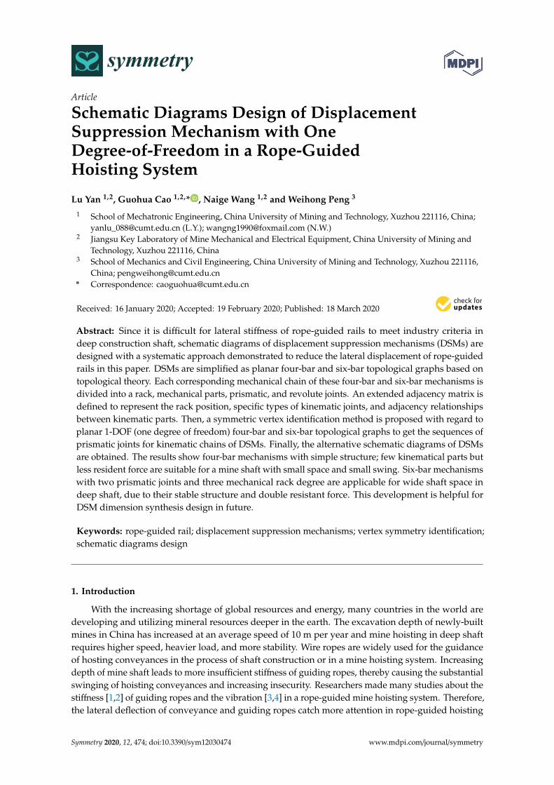
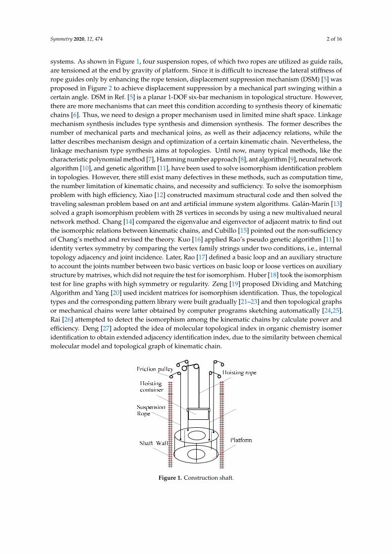
systems. As shown in Figure 1, four suspension ropes, of which two ropes are utilized as guide rails,are tensioned at the end by gravity of platform. Since it is difficult to increase the lateral stiffness ofrope guides only by enhancing the rope tension, displacement suppression mechanism (DSM) [5] wasproposed in Figure 2 to achieve displacement suppression by a mechanical part swinging within acertain angle. DSM in Ref. [5] is a planar 1-DOF six-bar mechanism in topological structure. However,there are more mechanisms that can meet this condition according to synthesis theory of kinematicchains [6]. Thus, we need to design a proper mechanism used in limited mine shaft space. Linkagemechanism synthesis includes type synthesis and dimension synthesis. The former describes thenumber of mechanical parts and mechanical joins, as well as their adjacency relations, while thelatter describes mechanism design and optimization of a certain kinematic chain. Nevertheless, thelinkage mechanism type synthesis aims at topologies. Until now, many typical methods, like thecharacteristic polynomial method [7], Hamming number approach [8], ant algorithm [9], neural networkalgorithm [10], and genetic algorithm [11], have been used to solve isomorphism identification problemin topologies. However, there still exist many defectives in these methods, such as computation time,the number limitation of kinematic chains, and necessity and sufficiency. To solve the isomorphismproblem with high efficiency, Xiao [12] constructed maximum structural code and then solved thetraveling salesman problem based on ant and artificial immune system algorithms. Galán-Marín [13]solved a graph isomorphism problem with 28 vertices in seconds by using a new multivalued neuralnetwork method. Chang [14] compared the eigenvalue and eigenvector of adjacent matrix to find outthe isomorphic relations between kinematic chains, and Cubillo [15] pointed out the non-sufficiencyof Chang’s method and revised the theory. Kuo [16] applied Rao’s pseudo genetic algorithm [11] toidentity vertex symmetry by comparing the vertex family strings under two conditions, i.e., internaltopology adjacency and joint incidence. Later, Rao [17] defined a basic loop and an auxiliary structureto account the joints number between two basic vertices on basic loop or loose vertices on auxiliarystructure by matrixes, which did not require the test for isomorphism. Huber [18] took the isomorphismtest for line graphs with high symmetry or regularity. Zeng [19] proposed Dividing and MatchingAlgorithm and Yang [20] used incident matrices for isomorphism identification. Thus, the topologicaltypes and the corresponding pattern library were built gradually [21–23] and then topological graphsor mechanical chains were latter obtained by computer programs sketching automatically [24,25].Rai [26] attempted to detect the isomorphism among the kinematic chains by calculate power andefficiency. Deng [27] adopted the idea of molecular topological index in organic chemistry isomeridentification to obtain extended adjacency identification index, due to the similarity between chemicalmolecular model and topological graph of kinematic chain.
Symmetry 2020, 12, x FOR PEER REVIEW 3 of 16
Hamming number isomorphism determination based on a link–link adjacency matrix. This matrix contains the topological structure information of the kinematic chain. In order to obtain the required schematic diagrams of DSM, a new method is proposed to identity the schematic diagram isomorphism based on the unique nature of each kinematic chain. According to the definition of adjacency matrix, extended adjacency matrix is defined in this paper, which describes the certain type of kinematic joints, adjacency relations between two kinematic parts, and two mechanical rack positions. Then, the isomorphism identification procedure for schematic diagrams of DSM are derived based on four-bar and six-bar mechanisms. Sequences of prismatic joints for DSMs based on canonical perimeter are determined, and the alternative schemes for DSMs are obtained. This provides a new method for type synthesis of schematic diagram and also offers alternative models for the design of DSM.
The remainder of this paper is organized as follows. In Section 2, possible topological graphs for DSMs is presented and corresponding types of kinematic joints are enumerated. In Section 3, connected relations of graphs are defined by two kinds of matrices to identify different topological graphs in Section 3.1 and corresponding schematic diagrams in Section 3.2, respectively. In addition, a symmetry discrimination method by two steps is proposed to identify whether any two vertices (or any two schematic diagrams) are symmetric in Section 3.3. In Section 4, detailed computational isomorphic discrimination steps are presented, and all the non-isomorphic vertexes, racks, as well as schematic diagrams of DSMs, are obtained by special types of sequence numbers. In Section 5, alternative schematic diagrams of DSM are screened and analyzed for further use in a rope-guided mine shaft. In Section 6, concluding remarks are presented.
Figure 1. Construction shaft.
Figure 2. Displacement suppression scheme with rope-guided rail.
Figure 1. Construction shaft.
Symmetry 2020, 12, 474 3 of 16
Symmetry 2020, 12, x FOR PEER REVIEW 3 of 16
Hamming number isomorphism determination based on a link–link adjacency matrix. This matrix contains the topological structure information of the kinematic chain. In order to obtain the required schematic diagrams of DSM, a new method is proposed to identity the schematic diagram isomorphism based on the unique nature of each kinematic chain. According to the definition of adjacency matrix, extended adjacency matrix is defined in this paper, which describes the certain type of kinematic joints, adjacency relations between two kinematic parts, and two mechanical rack positions. Then, the isomorphism identification procedure for schematic diagrams of DSM are derived based on four-bar and six-bar mechanisms. Sequences of prismatic joints for DSMs based on canonical perimeter are determined, and the alternative schemes for DSMs are obtained. This provides a new method for type synthesis of schematic diagram and also offers alternative models for the design of DSM.
The remainder of this paper is organized as follows. In Section 2, possible topological graphs for DSMs is presented and corresponding types of kinematic joints are enumerated. In Section 3, connected relations of graphs are defined by two kinds of matrices to identify different topological graphs in Section 3.1 and corresponding schematic diagrams in Section 3.2, respectively. In addition, a symmetry discrimination method by two steps is proposed to identify whether any two vertices (or any two schematic diagrams) are symmetric in Section 3.3. In Section 4, detailed computational isomorphic discrimination steps are presented, and all the non-isomorphic vertexes, racks, as well as schematic diagrams of DSMs, are obtained by special types of sequence numbers. In Section 5, alternative schematic diagrams of DSM are screened and analyzed for further use in a rope-guided mine shaft. In Section 6, concluding remarks are presented.
Figure 1. Construction shaft.
Figure 2. Displacement suppression scheme with rope-guided rail. Figure 2. Displacement suppression scheme with rope-guided rail.
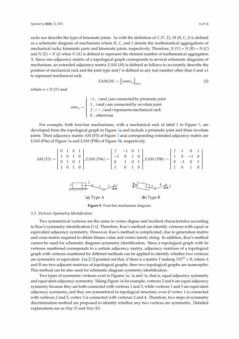
However, different from topological graph, the schematic diagram of mechanism includes differentjoint types and mechanism rack types. Since the generation from a topological graph or a kinematicchain to a schematic diagram does not make a one-to-one correspondence, due to symmetrical verticesand edges in topological graphs, i.e., several schematic diagrams may be obtained by one topologicalgraph or kinematic chain. Therefore, Rao [28] used values of 2 and 1 in the link–link adjacencymatrix to represent prismatic and revolute joints, respectively. Thus, schematic diagram isomorphismidentification is less defined and concerned. Eleashy [29] obtained all solutions of planar 8-bar kinematicchains with up to three prismatic pairs by a systematic method. Dharanipragada [30] thoroughlyconsidered the type difference between prismatic and revolute joints and studied the isomorphismfor 1-DOF six-bar and an eight-bar mechanism by splitting Hamming String. However, it is worthnoting that the existence of a mechanism rack may also lead to different schematic diagrams. Thus, itis necessary to identify the isomorphic schematic diagrams and obtain all these schematic diagrams ofDSM. Finally, these mechanisms can be designed according to their working condition requirements,which are:
(1) One of the mechanical parts of DSM is capable of swinging within a certain angle.(2) The mechanism can be locked at the limited position.(3) It is a 1-DOF planar structure in order to implement easily.
Vertex symmetry in schematic diagram is different from that in a topology graph due to thedistinct type among mechanical parts, such as rack and binary bar. Sun [31] proposed to improveHamming number isomorphism determination based on a link–link adjacency matrix. This matrixcontains the topological structure information of the kinematic chain. In order to obtain the requiredschematic diagrams of DSM, a new method is proposed to identity the schematic diagram isomorphismbased on the unique nature of each kinematic chain. According to the definition of adjacency matrix,extended adjacency matrix is defined in this paper, which describes the certain type of kinematicjoints, adjacency relations between two kinematic parts, and two mechanical rack positions. Then, theisomorphism identification procedure for schematic diagrams of DSM are derived based on four-barand six-bar mechanisms. Sequences of prismatic joints for DSMs based on canonical perimeter aredetermined, and the alternative schemes for DSMs are obtained. This provides a new method for typesynthesis of schematic diagram and also offers alternative models for the design of DSM.
The remainder of this paper is organized as follows. In Section 2, possible topological graphsfor DSMs is presented and corresponding types of kinematic joints are enumerated. In Section 3,connected relations of graphs are defined by two kinds of matrices to identify different topologicalgraphs in Section 3.1 and corresponding schematic diagrams in Section 3.2, respectively. In addition,a symmetry discrimination method by two steps is proposed to identify whether any two vertices(or any two schematic diagrams) are symmetric in Section 3.3. In Section 4, detailed computational
Symmetry 2020, 12, 474 4 of 16
isomorphic discrimination steps are presented, and all the non-isomorphic vertexes, racks, as wellas schematic diagrams of DSMs, are obtained by special types of sequence numbers. In Section 5,alternative schematic diagrams of DSM are screened and analyzed for further use in a rope-guidedmine shaft. In Section 6, concluding remarks are presented.
2. Topology Design for DSM
According to the three working condition requirements of DSM, the number of its kinematic jointsPh can be derived as
Ph =3(n− 1) − F
2(1)
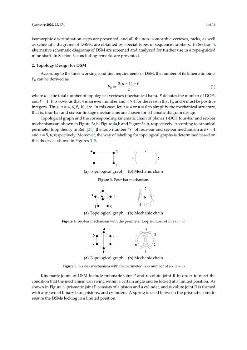
where n is the total number of topological vertexes (mechanical bars). F denotes the number of DOFsand F = 1. It is obvious that n is an even number and n ≥ 4 for the reason that Ph and n must be positiveintegers. Thus, n = 4, 6, 8, 10, etc. In this case, let n = 4 or n = 6 to simplify the mechanical structure,that is, four-bar and six-bar linkage mechanisms are chosen for schematic diagram design.
Topological graph and the corresponding kinematic chain of planar 1-DOF four-bar and six-barmechanisms are shown in Figure 3a,b, Figure 4a,b and Figure 5a,b, respectively. According to canonicalperimeter loop theory in Ref. [21], the loop number “r” of four-bar and six-bar mechanism are r = 4and r = 5, 6, respectively. Moreover, the way of labelling for topological graphs is determined based onthis theory as shown in Figures 3–5.
Symmetry 2020, 12, x FOR PEER REVIEW 4 of 16
2. Topology Design for DSM
According to the three working condition requirements of DSM, the number of its kinematic joints Ph can be derived as
3( 1)2
− −=hn FP (1)
where n is the total number of topological vertexes (mechanical bars). F denotes the number of DOFs and F = 1. It is obvious that n is an even number and n ≥ 4 for the reason that Ph and n must be positive integers. Thus, n = 4, 6, 8, 10, etc. In this case, let n = 4 or n = 6 to simplify the mechanical structure, that is, four-bar and six-bar linkage mechanisms are chosen for schematic diagram design.
Topological graph and the corresponding kinematic chain of planar 1-DOF four-bar and six-bar mechanisms are shown in Figures 3a,b, 4a,b and 5a,b, respectively. According to canonical perimeter loop theory in Ref. [21], the loop number “r” of four-bar and six-bar mechanism are r = 4 and r = 5, 6, respectively. Moreover, the way of labelling for topological graphs is determined based on this theory as shown in Figures 3–5.
(a) Topological graph (b) Mechanic chain
Figure 3. Four-bar mechanism.
(a) Topological graph (b) Mechanic chain
Figure 4. Six-bar mechanism with the perimeter loop number of five (r = 5)
(a) Topological graph (b) Mechanic chain
Figure 5. Six-bar mechanism with the perimeter loop number of six (r = 6)
Kinematic joints of DSM include prismatic joint P and revolute joint R in order to meet the condition that the mechanism can swing within a certain angle and be locked at a limited position. As shown in Figure 6, prismatic joint P consists of a piston and a cylinder, and revolute joint R is formed with any two of binary bars, pistons, and cylinders. A spring is used between the prismatic joint to ensure the DSMs locking in a limited position.
Figure 6. Kinematic joint types.
Figure 3. Four-bar mechanism.
Symmetry 2020, 12, x FOR PEER REVIEW 4 of 16
2. Topology Design for DSM
According to the three working condition requirements of DSM, the number of its kinematic joints Ph can be derived as
3( 1)2
− −=hn FP (1)
where n is the total number of topological vertexes (mechanical bars). F denotes the number of DOFs and F = 1. It is obvious that n is an even number and n ≥ 4 for the reason that Ph and n must be positive integers. Thus, n = 4, 6, 8, 10, etc. In this case, let n = 4 or n = 6 to simplify the mechanical structure, that is, four-bar and six-bar linkage mechanisms are chosen for schematic diagram design.
Topological graph and the corresponding kinematic chain of planar 1-DOF four-bar and six-bar mechanisms are shown in Figures 3a,b, 4a,b and 5a,b, respectively. According to canonical perimeter loop theory in Ref. [21], the loop number “r” of four-bar and six-bar mechanism are r = 4 and r = 5, 6, respectively. Moreover, the way of labelling for topological graphs is determined based on this theory as shown in Figures 3–5.
(a) Topological graph (b) Mechanic chain
Figure 3. Four-bar mechanism.
(a) Topological graph (b) Mechanic chain
Figure 4. Six-bar mechanism with the perimeter loop number of five (r = 5)
(a) Topological graph (b) Mechanic chain
Figure 5. Six-bar mechanism with the perimeter loop number of six (r = 6)
Kinematic joints of DSM include prismatic joint P and revolute joint R in order to meet the condition that the mechanism can swing within a certain angle and be locked at a limited position. As shown in Figure 6, prismatic joint P consists of a piston and a cylinder, and revolute joint R is formed with any two of binary bars, pistons, and cylinders. A spring is used between the prismatic joint to ensure the DSMs locking in a limited position.
Figure 6. Kinematic joint types.
Figure 4. Six-bar mechanism with the perimeter loop number of five (r = 5)
Symmetry 2020, 12, x FOR PEER REVIEW 4 of 16
2. Topology Design for DSM
According to the three working condition requirements of DSM, the number of its kinematic joints Ph can be derived as
3( 1)2
− −=hn FP (1)
where n is the total number of topological vertexes (mechanical bars). F denotes the number of DOFs and F = 1. It is obvious that n is an even number and n ≥ 4 for the reason that Ph and n must be positive integers. Thus, n = 4, 6, 8, 10, etc. In this case, let n = 4 or n = 6 to simplify the mechanical structure, that is, four-bar and six-bar linkage mechanisms are chosen for schematic diagram design.
Topological graph and the corresponding kinematic chain of planar 1-DOF four-bar and six-bar mechanisms are shown in Figures 3a,b, 4a,b and 5a,b, respectively. According to canonical perimeter loop theory in Ref. [21], the loop number “r” of four-bar and six-bar mechanism are r = 4 and r = 5, 6, respectively. Moreover, the way of labelling for topological graphs is determined based on this theory as shown in Figures 3–5.
(a) Topological graph (b) Mechanic chain
Figure 3. Four-bar mechanism.
(a) Topological graph (b) Mechanic chain
Figure 4. Six-bar mechanism with the perimeter loop number of five (r = 5)
(a) Topological graph (b) Mechanic chain
Figure 5. Six-bar mechanism with the perimeter loop number of six (r = 6)
Kinematic joints of DSM include prismatic joint P and revolute joint R in order to meet the condition that the mechanism can swing within a certain angle and be locked at a limited position. As shown in Figure 6, prismatic joint P consists of a piston and a cylinder, and revolute joint R is formed with any two of binary bars, pistons, and cylinders. A spring is used between the prismatic joint to ensure the DSMs locking in a limited position.
Figure 6. Kinematic joint types.
Figure 5. Six-bar mechanism with the perimeter loop number of six (r = 6)
Kinematic joints of DSM include prismatic joint P and revolute joint R in order to meet thecondition that the mechanism can swing within a certain angle and be locked at a limited position. Asshown in Figure 6, prismatic joint P consists of a piston and a cylinder, and revolute joint R is formedwith any two of binary bars, pistons, and cylinders. A spring is used between the prismatic joint toensure the DSMs locking in a limited position.
Symmetry 2020, 12, 474 5 of 16
Symmetry 2020, 12, x FOR PEER REVIEW 4 of 16
2. Topology Design for DSM
According to the three working condition requirements of DSM, the number of its kinematic joints Ph can be derived as
3( 1)2
− −=hn FP (1)
where n is the total number of topological vertexes (mechanical bars). F denotes the number of DOFs and F = 1. It is obvious that n is an even number and n ≥ 4 for the reason that Ph and n must be positive integers. Thus, n = 4, 6, 8, 10, etc. In this case, let n = 4 or n = 6 to simplify the mechanical structure, that is, four-bar and six-bar linkage mechanisms are chosen for schematic diagram design.
Topological graph and the corresponding kinematic chain of planar 1-DOF four-bar and six-bar mechanisms are shown in Figures 3a,b, 4a,b and 5a,b, respectively. According to canonical perimeter loop theory in Ref. [21], the loop number “r” of four-bar and six-bar mechanism are r = 4 and r = 5, 6, respectively. Moreover, the way of labelling for topological graphs is determined based on this theory as shown in Figures 3–5.
(a) Topological graph (b) Mechanic chain
Figure 3. Four-bar mechanism.
(a) Topological graph (b) Mechanic chain
Figure 4. Six-bar mechanism with the perimeter loop number of five (r = 5)
(a) Topological graph (b) Mechanic chain
Figure 5. Six-bar mechanism with the perimeter loop number of six (r = 6)
Kinematic joints of DSM include prismatic joint P and revolute joint R in order to meet the condition that the mechanism can swing within a certain angle and be locked at a limited position. As shown in Figure 6, prismatic joint P consists of a piston and a cylinder, and revolute joint R is formed with any two of binary bars, pistons, and cylinders. A spring is used between the prismatic joint to ensure the DSMs locking in a limited position.
Figure 6. Kinematic joint types. Figure 6. Kinematic joint types.
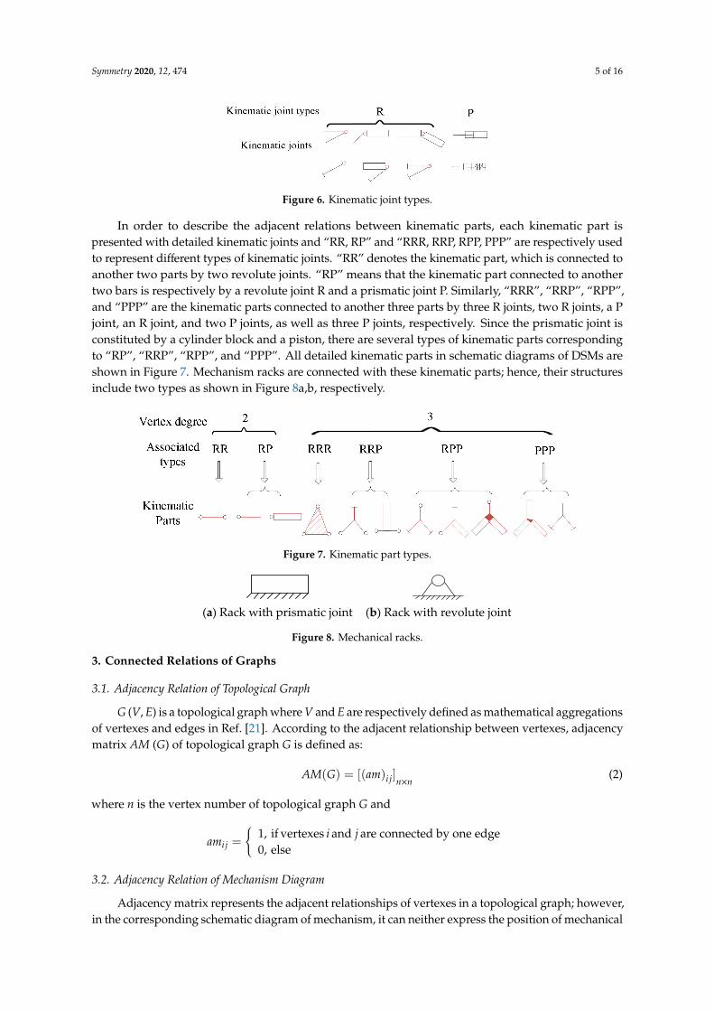
In order to describe the adjacent relations between kinematic parts, each kinematic part ispresented with detailed kinematic joints and “RR, RP” and “RRR, RRP, RPP, PPP” are respectively usedto represent different types of kinematic joints. “RR” denotes the kinematic part, which is connected toanother two parts by two revolute joints. “RP” means that the kinematic part connected to anothertwo bars is respectively by a revolute joint R and a prismatic joint P. Similarly, “RRR”, “RRP”, “RPP”,and “PPP” are the kinematic parts connected to another three parts by three R joints, two R joints, a Pjoint, an R joint, and two P joints, as well as three P joints, respectively. Since the prismatic joint isconstituted by a cylinder block and a piston, there are several types of kinematic parts correspondingto “RP”, “RRP”, “RPP”, and “PPP”. All detailed kinematic parts in schematic diagrams of DSMs areshown in Figure 7. Mechanism racks are connected with these kinematic parts; hence, their structuresinclude two types as shown in Figure 8a,b, respectively.
Symmetry 2020, 12, x FOR PEER REVIEW 5 of 16
In order to describe the adjacent relations between kinematic parts, each kinematic part is presented with detailed kinematic joints and “RR, RP” and “RRR, RRP, RPP, PPP” are respectively used to represent different types of kinematic joints. “RR” denotes the kinematic part, which is connected to another two parts by two revolute joints. “RP” means that the kinematic part connected to another two bars is respectively by a revolute joint R and a prismatic joint P. Similarly, “RRR”, “RRP”, “RPP”, and “PPP” are the kinematic parts connected to another three parts by three R joints, two R joints, a P joint, an R joint, and two P joints, as well as three P joints, respectively. Since the prismatic joint is constituted by a cylinder block and a piston, there are several types of kinematic parts corresponding to “RP”, “RRP”, “RPP”, and “PPP”. All detailed kinematic parts in schematic diagrams of DSMs are shown in Figure 7. Mechanism racks are connected with these kinematic parts; hence, their structures include two types as shown in Figure 8a,b, respectively.
Figure 7. Kinematic part types.
(a) Rack with prismatic joint (b) Rack with revolute joint
Figure 8. Mechanical racks.
3. Connected Relations of Graphs
3.1. Adjacency Relation of Topological Graph
G (V, E) is a topological graph where V and E are respectively defined as mathematical aggregations of vertexes and edges in Ref. [21]. According to the adjacent relationship between vertexes, adjacency matrix AM (G) of topological graph G is defined as:
( ) [( ) ] ×= ij n nAM G am (2)
where n is the vertex number of topological graph G and
1, if vertexes and are connected by one edge0, else
=
ij
i jam
3.2. Adjacency Relation of Mechanism Diagram
Adjacency matrix represents the adjacent relationships of vertexes in a topological graph; however, in the corresponding schematic diagram of mechanism, it can neither express the position of mechanical racks nor describe the type of kinematic joints. As with the definition of G (V, E), M (R, C, J) is defined as a schematic diagram of mechanism where R, C, and J denote the mathematical aggregations of mechanical racks, kinematic parts and kinematic joints, respectively. Therefore, N (V) = N (R) + N (C) and N (E) = N (J) when N (X) is defined to represent the element number of mathematical aggregation X. Since one adjacency matrix of a topological graph corresponds to several schematic diagrams of mechanism, an extended adjacency matrix EAM (M) is defined as follows to accurately describe the position of mechanical rack and the joint type and f is defined as any real number other than 0 and ±1 to represent mechanical rack:
Figure 7. Kinematic part types.
Symmetry 2020, 12, x FOR PEER REVIEW 5 of 16
In order to describe the adjacent relations between kinematic parts, each kinematic part is presented with detailed kinematic joints and “RR, RP” and “RRR, RRP, RPP, PPP” are respectively used to represent different types of kinematic joints. “RR” denotes the kinematic part, which is connected to another two parts by two revolute joints. “RP” means that the kinematic part connected to another two bars is respectively by a revolute joint R and a prismatic joint P. Similarly, “RRR”, “RRP”, “RPP”, and “PPP” are the kinematic parts connected to another three parts by three R joints, two R joints, a P joint, an R joint, and two P joints, as well as three P joints, respectively. Since the prismatic joint is constituted by a cylinder block and a piston, there are several types of kinematic parts corresponding to “RP”, “RRP”, “RPP”, and “PPP”. All detailed kinematic parts in schematic diagrams of DSMs are shown in Figure 7. Mechanism racks are connected with these kinematic parts; hence, their structures include two types as shown in Figure 8a,b, respectively.
Figure 7. Kinematic part types.
(a) Rack with prismatic joint (b) Rack with revolute joint
Figure 8. Mechanical racks.
3. Connected Relations of Graphs
3.1. Adjacency Relation of Topological Graph
G (V, E) is a topological graph where V and E are respectively defined as mathematical aggregations of vertexes and edges in Ref. [21]. According to the adjacent relationship between vertexes, adjacency matrix AM (G) of topological graph G is defined as:
( ) [( ) ] ×= ij n nAM G am (2)
where n is the vertex number of topological graph G and
1, if vertexes and are connected by one edge0, else
=
ij
i jam
3.2. Adjacency Relation of Mechanism Diagram
Adjacency matrix represents the adjacent relationships of vertexes in a topological graph; however, in the corresponding schematic diagram of mechanism, it can neither express the position of mechanical racks nor describe the type of kinematic joints. As with the definition of G (V, E), M (R, C, J) is defined as a schematic diagram of mechanism where R, C, and J denote the mathematical aggregations of mechanical racks, kinematic parts and kinematic joints, respectively. Therefore, N (V) = N (R) + N (C) and N (E) = N (J) when N (X) is defined to represent the element number of mathematical aggregation X. Since one adjacency matrix of a topological graph corresponds to several schematic diagrams of mechanism, an extended adjacency matrix EAM (M) is defined as follows to accurately describe the position of mechanical rack and the joint type and f is defined as any real number other than 0 and ±1 to represent mechanical rack:
Figure 8. Mechanical racks.
3. Connected Relations of Graphs
3.1. Adjacency Relation of Topological Graph
G (V, E) is a topological graph where V and E are respectively defined as mathematical aggregationsof vertexes and edges in Ref. [21]. According to the adjacent relationship between vertexes, adjacencymatrix AM (G) of topological graph G is defined as:
AM(G) = [(am)i j]n×n(2)
where n is the vertex number of topological graph G and
ami j =
{1, if vertexes i and j are connected by one edge0, else
3.2. Adjacency Relation of Mechanism Diagram
Adjacency matrix represents the adjacent relationships of vertexes in a topological graph; however,in the corresponding schematic diagram of mechanism, it can neither express the position of mechanical
Symmetry 2020, 12, 474 6 of 16
racks nor describe the type of kinematic joints. As with the definition of G (V, E), M (R, C, J) is definedas a schematic diagram of mechanism where R, C, and J denote the mathematical aggregations ofmechanical racks, kinematic parts and kinematic joints, respectively. Therefore, N (V) = N (R) + N (C)and N (E) = N (J) when N (X) is defined to represent the element number of mathematical aggregationX. Since one adjacency matrix of a topological graph corresponds to several schematic diagrams ofmechanism, an extended adjacency matrix EAM (M) is defined as follows to accurately describe theposition of mechanical rack and the joint type and f is defined as any real number other than 0 and ±1to represent mechanical rack:
EAM(M) =[(eam)i j
]n×n
(3)
where n = N (V) and
eami j =
−1 , i and j are connected by prismatic joint1 , i and j are connected by revolute jointf , i = j and i represents mechanical rack0 , otherwise
For example, both four-bar mechanisms, with a mechanical rack of label 1 in Figure 9, aredeveloped from the topological graph in Figure 3a and include a prismatic joint and three revolutejoints. Their adjacency matrix AM (F3) of Figure 3 and corresponding extended adjacency matrix areEAM (F9a) of Figure 9a and EAM (F9b) of Figure 9b, respectively.
AM (F3) =
0 1 0 11 0 1 00 1 0 11 0 1 0
, EAM (F9a) =
f −1 0 1−1 0 1 00 1 0 11 0 1 0
, EAM (F9b) =
f 1 0 11 0 −1 00 −1 0 11 0 1 0
Symmetry 2020, 12, x FOR PEER REVIEW 6 of 16
( )( )×
= ij n nEAM M eam (3)
where n = N (V) and
1 and are connected by prismatic joint1 and are connected by revolute joint
, = and represents mechanical rack0 , otherwise
,
,
−=
ij
i ji j
eamf i j i
For example, both four-bar mechanisms, with a mechanical rack of label 1 in Figure 9, are developed from the topological graph in Figure 3a and include a prismatic joint and three revolute joints. Their adjacency matrix AM (F3) of Figure 3 and corresponding extended adjacency matrix are EAM (F9a) of Figure 9a and EAM (F9b) of Figure 9b, respectively.
(a) Type A (b) Type B
Figure 9. Four-bar mechanism diagram.
( )
0 1 0 11 0 1 0
30 1 0 11 0 1 0
=
AM F ,
1 0 11 0 1 0
( 9a)0 1 0 11 0 1 0
− − =
f
EAM F ,
1 0 11 0 1 0
( 9b)0 1 0 11 0 1 0
− = −
f
EAM F
3.3. Vertexes Symmetry Identification
Two symmetrical vertexes are the same in vertex degree and incident characteristics according to Kuo’s symmetry identification [16]. Therefore, Kuo’s method can identify vertexes with equal or equivalent adjacency symmetry. However, Kuo’s method is complicated, due to generation matrix and cross matrix required to obtain fitness value and vertex family string. In addition, Kuo’s method cannot be used for schematic diagram symmetry identification. Since a topological graph with its vertexes numbered corresponds to a certain adjacency matrix, adjacency matrixes of a topological graph with vertexes numbered by different methods can be applied to identify whether two vertexes are symmetric or equivalent. Liu [32] pointed out that, if there is a matrix T making TATT = B, where A and B are two adjacent matrixes of topological graphs, then two topological graphs are isomorphic. This method can be also used for schematic diagram symmetry identification.
Two types of symmetric vertexes exist in Figures 3a, 4a and 5a, that is, equal adjacency symmetry and equivalent adjacency symmetry. Taking Figure 4a for example, vertexes 2 and 6 are equal adjacency symmetry because they are both connected with vertexes 1 and 3, while vertexes 1 and 3 are equivalent adjacency symmetry, and they are symmetrical in topological structure; even if vertex 1 is connected with vertexes 2 and 5, vertex 3 is connected with vertexes 2 and 4. Therefore, two steps of symmetry discrimination method are proposed to identify whether any two vertices are symmetric. Detailed explanations are as Step (I) and Step (II):
Step (I)—Equal adjacency symmetry: Two vertexes with equal adjacency symmetry exactly as vertexes 2 and 6 in Figure 4a have the same adjacent relationship with other vertexes, i.e., their adjacency matrixes are the same. Therefore, if two vertexes are equal adjacency symmetry, the corresponding row and column of a vertex in adjacent matrix are respectively equal to those of the other. Thus, transformation matrix TM (p, q) is defined as Equation (4) to identify whether two vertexes in a topological graph have equal adjacency symmetry, where p and q are the label number of two vertexes:
Figure 9. Four-bar mechanism diagram.
3.3. Vertexes Symmetry Identification
Two symmetrical vertexes are the same in vertex degree and incident characteristics accordingto Kuo’s symmetry identification [16]. Therefore, Kuo’s method can identify vertexes with equal orequivalent adjacency symmetry. However, Kuo’s method is complicated, due to generation matrixand cross matrix required to obtain fitness value and vertex family string. In addition, Kuo’s methodcannot be used for schematic diagram symmetry identification. Since a topological graph with itsvertexes numbered corresponds to a certain adjacency matrix, adjacency matrixes of a topologicalgraph with vertexes numbered by different methods can be applied to identify whether two vertexesare symmetric or equivalent. Liu [32] pointed out that, if there is a matrix T making TATT = B, where Aand B are two adjacent matrixes of topological graphs, then two topological graphs are isomorphic.This method can be also used for schematic diagram symmetry identification.
Two types of symmetric vertexes exist in Figures 3a, 4a and 5a, that is, equal adjacency symmetryand equivalent adjacency symmetry. Taking Figure 4a for example, vertexes 2 and 6 are equal adjacencysymmetry because they are both connected with vertexes 1 and 3, while vertexes 1 and 3 are equivalentadjacency symmetry, and they are symmetrical in topological structure; even if vertex 1 is connectedwith vertexes 2 and 5, vertex 3 is connected with vertexes 2 and 4. Therefore, two steps of symmetrydiscrimination method are proposed to identify whether any two vertices are symmetric. Detailedexplanations are as Step (I) and Step (II):
Symmetry 2020, 12, 474 7 of 16
Step (I)—Equal adjacency symmetry: Two vertexes with equal adjacency symmetry exactly asvertexes 2 and 6 in Figure 4a have the same adjacent relationship with other vertexes, i.e., their adjacencymatrixes are the same. Therefore, if two vertexes are equal adjacency symmetry, the correspondingrow and column of a vertex in adjacent matrix are respectively equal to those of the other. Thus,transformation matrix TM (p, q) is defined as Equation (4) to identify whether two vertexes in atopological graph have equal adjacency symmetry, where p and q are the label number of two vertexes:
TM(p, q) = [(tm)i j]n×n, p = 1, 2, . . . , n− 1 and p < q (4)
where
tmi j =
{1 , if (i = j and i , p, q) or (i = p, j = q ) or ( i = p, j = q)0 , else
In addition, the relationship between the new adjacency matrix AM (j) and the original adjacencymatrix AM (G) is derived as:
AM( j) = TM(p, q) ×AM(G) × TMT(p, q), j = (p− 1)n− p(p− 1)/2 + q− p (5)
where superscript T denotes a transpose of the matrix, and j represents the graph number in eachidentification step. If AM(j) = AM(G), vertexes p and q have equal adjacency symmetry. Takingtransformation matrixes TM (2, 6) and TM (1, 3), for example, their expressions are:
TM (2, 6) =
1 0 0 0 0 00 0 0 0 0 10 0 1 0 0 00 0 0 1 0 00 0 0 0 1 00 1 0 0 0 0
TM (1, 3) =
0 0 1 0 0 00 1 0 0 0 01 0 0 0 0 00 0 0 1 0 00 0 0 0 1 00 0 0 0 0 1
According to Equation (5) and Figure 4, AM (9) = TM (2, 6) × AM (F4) × TMT (2, 6), AM (2) = TM
(1, 3) × AM (F4) × TMT (1, 3):
AM(F4) =
0 1 0 0 1 11 0 1 0 0 00 1 0 1 0 10 0 1 0 1 01 0 0 1 0 01 0 1 0 0 0
AM(9) =
0 1 0 0 1 11 0 1 0 0 00 1 0 1 0 10 0 1 0 1 01 0 0 1 0 01 0 1 0 0 0
AM(2) =
0 1 0 1 0 11 0 1 0 0 00 1 0 0 1 11 0 0 0 1 00 0 1 1 0 01 0 1 0 0 0
Since AM(9) = AM(F4) and AM(2) , AM(F4), it can be concluded that vertexes 2 and 6 have equal
adjacency symmetry, while vertexes 1 and 3 are not. Therefore, this identification method is to detectwhether the vertexes connected with two objective vertexes are the same.
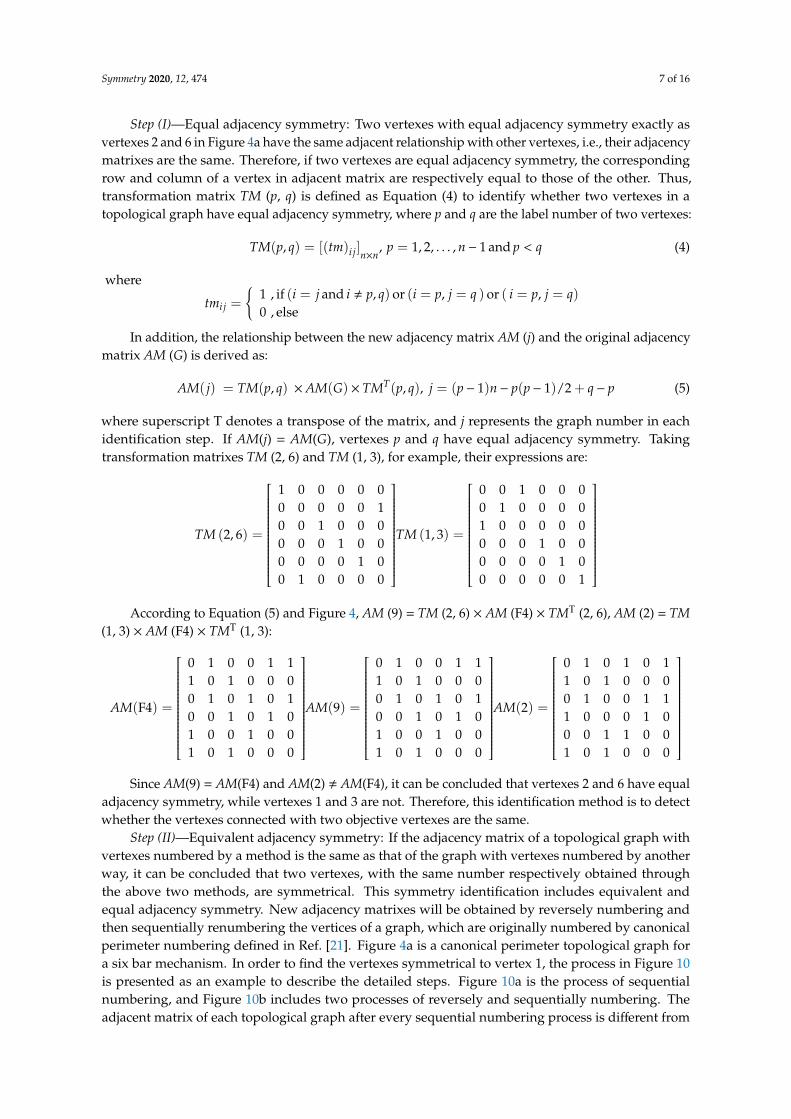
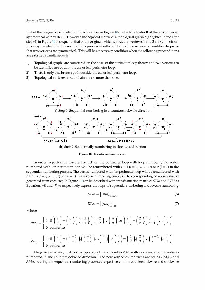
Step (II)—Equivalent adjacency symmetry: If the adjacency matrix of a topological graph withvertexes numbered by a method is the same as that of the graph with vertexes numbered by anotherway, it can be concluded that two vertexes, with the same number respectively obtained throughthe above two methods, are symmetrical. This symmetry identification includes equivalent andequal adjacency symmetry. New adjacency matrixes will be obtained by reversely numbering andthen sequentially renumbering the vertices of a graph, which are originally numbered by canonicalperimeter numbering defined in Ref. [21]. Figure 4a is a canonical perimeter topological graph fora six bar mechanism. In order to find the vertexes symmetrical to vertex 1, the process in Figure 10is presented as an example to describe the detailed steps. Figure 10a is the process of sequentialnumbering, and Figure 10b includes two processes of reversely and sequentially numbering. Theadjacent matrix of each topological graph after every sequential numbering process is different from
Symmetry 2020, 12, 474 8 of 16
that of the original one labeled with red number in Figure 10a, which indicates that there is no vertexsymmetrical with vertex 1. However, the adjacent matrix of a topological graph highlighted in red afterstep (4) in Figure 10b is equal to that of the original, which shows that vertexes 1 and 3 are symmetrical.It is easy to detect that the result of this process is sufficient but not the necessary condition to provethat two vertexes are symmetrical. This will be a necessary condition when the following preconditionsare satisfied simultaneously:
1) Topological graphs are numbered on the basis of the perimeter loop theory and two vertexes tobe identified are both in the canonical perimeter loop.
2) There is only one branch path outside the canonical perimeter loop.3) Topological vertexes in sub-chain are no more than one.
Symmetry 2020, 12, x FOR PEER REVIEW 8 of 16
2) There is only one branch path outside the canonical perimeter loop. 3) Topological vertexes in sub-chain are no more than one.
(a) Step 1: Sequential numbering in a counterclockwise direction
(b) Step 2: Sequentially numbering in clockwise direction
Figure 10. Transformation process.
In order to perform a traversal search on the perimeter loop with loop number r, the vertex numbered with i in perimeter loop will be renumbered with i − 1 (i = 2, 3, …, r) or r (i = 1) in the sequential numbering process. The vertex numbered with i in perimeter loop will be renumbered with r + 2 − i (i = 2, 3, …, r) or 1 (i = 1) in a reverse numbering process. The corresponding adjacency matrix generated from each step in Figure 10 can be described with transformation matrixes STM and RTM as Equations (6) and (7) to respectively express the steps of sequential numbering and reverse numbering:
( )×
=
ij n nSTM stm (6)
( )×
=
ij n nRTM rtm
(7)
where
1 1 2 2 31, if = , , ... or = , ...
1 1 2 1 20, otherwise
ij
i r r n i rrtm j j rr r n r
+ + = + + −
1 2 1 2 11, if = , ... or = , ... ,
1 2 2 3 10, otherwise
ij
i r r n i r rstm j jr r n r
+ + − = + +
The given adjacency matrix of a topological graph is set as AM0 with its corresponding vertexes numbered in the counterclockwise direction. The new adjacency matrixes are set as AMa(i) and AMb(i) during the sequential numbering processes respectively in the counterclockwise and clockwise direction. Thus, the initial matrix AMa(1) and AMb(1) satisfy AMa(1) = AMb(1) = AM0, thereby, AMa(i + 1) and AMb(i + 1) are derived as Equations (8) and (9), respectively:
( ) ( ) T1 , 1,2,..., 1+ = × × = −a aAM i STM AM i STM i r (8)
The new adjacency matrix after each step is derived as:
( ) ( )( )
T
T
, 11
, 2,3,...,
× × =+ = × × =
bb
b
RTM AM i RTM iAM i
STM AM i STM i r (9)
Figure 10. Transformation process.
In order to perform a traversal search on the perimeter loop with loop number r, the vertexnumbered with i in perimeter loop will be renumbered with i − 1 (i = 2, 3, . . . , r) or r (i = 1) in thesequential numbering process. The vertex numbered with i in perimeter loop will be renumbered withr + 2 − i (i = 2, 3, . . . , r) or 1 (i = 1) in a reverse numbering process. The corresponding adjacency matrixgenerated from each step in Figure 10 can be described with transformation matrixes STM and RTM asEquations (6) and (7) to respectively express the steps of sequential numbering and reverse numbering:
STM =[(stm)i j
]n×n
(6)
RTM =[(rtm)i j
]n×n
(7)
where
rtmi j =
1, if[(
ij
)=
(11
),(
r + 1r + 1
),(
r + 2r + 2
). . .
(nn
)]or
[(ij
)=
(2r
),(
3r− 1
). . .
(r2
)]0, otherwise
stmi j =
1, if[(
ij
)=
(r + 1r + 1
),(
r + 2r + 2
). . .
(nn
)]or
[(ij
)=
(12
),(
23
). . .
(r− 1r
),(
r1
)]0, otherwise
The given adjacency matrix of a topological graph is set as AM0 with its corresponding vertexesnumbered in the counterclockwise direction. The new adjacency matrixes are set as AMa(i) andAMb(i) during the sequential numbering processes respectively in the counterclockwise and clockwise
Symmetry 2020, 12, 474 9 of 16
direction. Thus, the initial matrix AMa(1) and AMb(1) satisfy AMa(1) = AMb(1) = AM0, thereby,AMa(i + 1) and AMb(i + 1) are derived as Equations (8) and (9), respectively:
AMa(i + 1) = STM×AMa(i) × STMT, i = 1, 2, . . . , r− 1 (8)
The new adjacency matrix after each step is derived as:
AMb(i + 1) ={
RTM×AMb(i) ×RTMT, i = 1STM×AMb(i) × STMT, i = 2, 3, . . . , r
(9)
We can obtain that AMb (5) = AMb (1) by computing each step in Figure 10 with Equations (8) and(9). The corresponding vertex numbers of AMb (5) are marked in red, which indicates that vertexes 1and 3 are equivalent adjacency symmetry.
Four-bar and six-bar linkage mechanisms both fulfill conditions 2 and 3 in their topologicalstructures. As for condition 1, the equivalent adjacency symmetry method can identify two vertexesboth in a canonical perimeter loop, while an equal adjacency symmetry method can identify twovertexes, respectively, in a sub-chain and canonical perimeter loop. Therefore, the two symmetryidentifications above are workable. In addition, this symmetry identification is not only effectivefor topological graphs that satisfy the above conditions, but also feasible to identity symmetry forschematic diagram of mechanisms due to less concern about the process from a topological graph ormechanical chain to sundry schematic diagrams.
4. Computational Identification
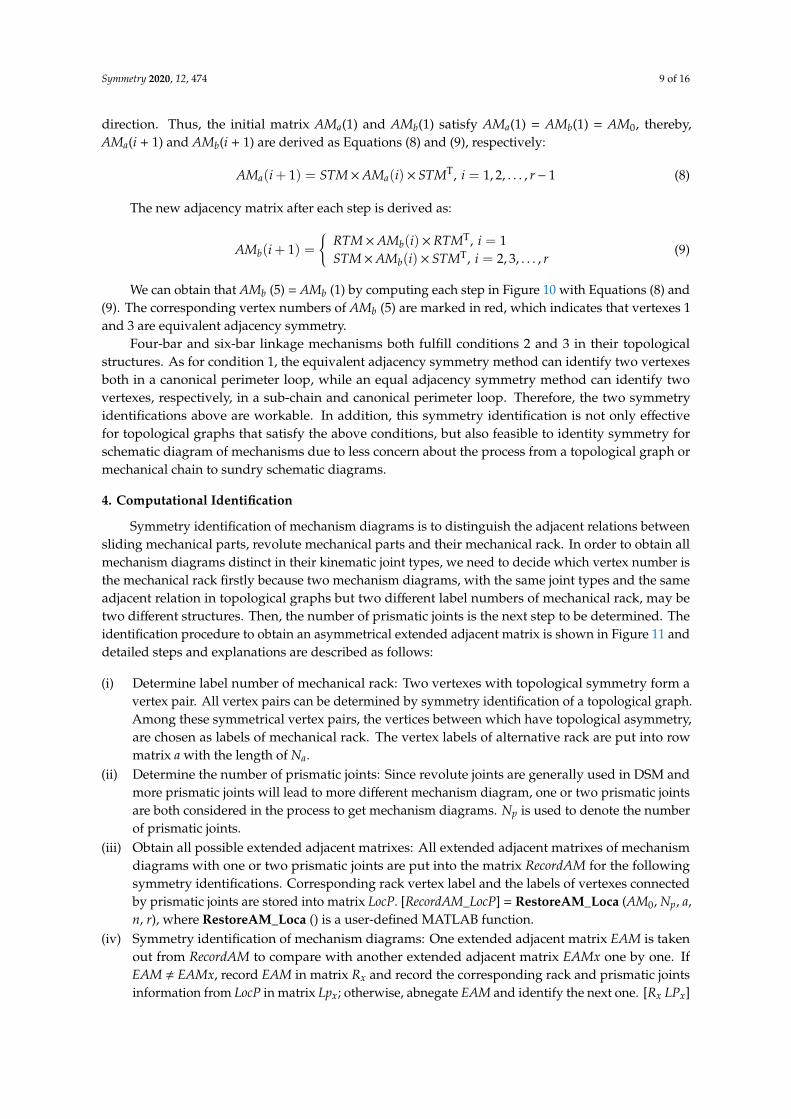
Symmetry identification of mechanism diagrams is to distinguish the adjacent relations betweensliding mechanical parts, revolute mechanical parts and their mechanical rack. In order to obtain allmechanism diagrams distinct in their kinematic joint types, we need to decide which vertex number isthe mechanical rack firstly because two mechanism diagrams, with the same joint types and the sameadjacent relation in topological graphs but two different label numbers of mechanical rack, may betwo different structures. Then, the number of prismatic joints is the next step to be determined. Theidentification procedure to obtain an asymmetrical extended adjacent matrix is shown in Figure 11 anddetailed steps and explanations are described as follows:
(i) Determine label number of mechanical rack: Two vertexes with topological symmetry form avertex pair. All vertex pairs can be determined by symmetry identification of a topological graph.Among these symmetrical vertex pairs, the vertices between which have topological asymmetry,are chosen as labels of mechanical rack. The vertex labels of alternative rack are put into rowmatrix a with the length of Na.
(ii) Determine the number of prismatic joints: Since revolute joints are generally used in DSM andmore prismatic joints will lead to more different mechanism diagram, one or two prismatic jointsare both considered in the process to get mechanism diagrams. Np is used to denote the numberof prismatic joints.
(iii) Obtain all possible extended adjacent matrixes: All extended adjacent matrixes of mechanismdiagrams with one or two prismatic joints are put into the matrix RecordAM for the followingsymmetry identifications. Corresponding rack vertex label and the labels of vertexes connectedby prismatic joints are stored into matrix LocP. [RecordAM_LocP] = RestoreAM_Loca (AM0, Np, a,n, r), where RestoreAM_Loca () is a user-defined MATLAB function.
(iv) Symmetry identification of mechanism diagrams: One extended adjacent matrix EAM is takenout from RecordAM to compare with another extended adjacent matrix EAMx one by one. IfEAM , EAMx, record EAM in matrix Rx and record the corresponding rack and prismatic jointsinformation from LocP in matrix Lpx; otherwise, abnegate EAM and identify the next one. [Rx LPx]
Symmetry 2020, 12, 474 10 of 16
= SymmetryIdentP (n, r, Np, a, RecordAM, LocP), where SymmetryIdentP () is a user-definedMATLAB function.
(v) Discard the mechanism diagrams with two consecutive prismatic joints in a six-bar mechanismexcept those both connected with mechanism rack: Two consecutive prismatic joints mean amechanical part is connected with other two parts both by prismatic joints, which leads to a morecomplex structure and more difficult diagram design relative to that in a four-bar mechanism.Since a mechanism rack is immovable, its position can be quickly determined according torequired movement. The number of alternative mechanisms is NPLx = length (LPx)/Np, wherelength () is a MATLAB function to obtain the matrix length. If the common vertex of twoconsecutive prismatic joints is not equal to rack label, a corresponding extended adjacent matrixfrom matrix Rx and a matrix of rack and prismatic joints information from Lpx will be recorded inmatrixes fR and fLP, respectively.
(vi) Abandon six-bar mechanism diagrams with all prismatic joints in four-bar sub-loops and themechanisms for which any prismatic joint exist in a sub-loop without a mechanism rack: Fromobjective topological graphs, a sub-loop of a six-bar topological graph is four vertexes and will besubstituted with four mechanical parts in a conversion process to the mechanism diagram. Asix-bar mechanism with all prismatic joints existing in a four-bar sub-loop is almost equivalentto four-bar mechanisms, due to the following movement of the other sub-chain. In addition, ifprismatic joints exist in this sub-loop without mechanism rack, there is little possibility to achievelocking in a limited position because the function is achieved by setting prismatic joints and amechanism rack in the same sub-loop. Therefore, the above conditions can be neglected.
Symmetry 2020, 12, x FOR PEER REVIEW 9 of 16
We can obtain that AMb (5) = AMb (1) by computing each step in Figure 10 with Equations (8) and (9). The corresponding vertex numbers of AMb (5) are marked in red, which indicates that vertexes 1 and 3 are equivalent adjacency symmetry.
Four-bar and six-bar linkage mechanisms both fulfill conditions 2 and 3 in their topological structures. As for condition 1, the equivalent adjacency symmetry method can identify two vertexes both in a canonical perimeter loop, while an equal adjacency symmetry method can identify two vertexes, respectively, in a sub-chain and canonical perimeter loop. Therefore, the two symmetry identifications above are workable. In addition, this symmetry identification is not only effective for topological graphs that satisfy the above conditions, but also feasible to identity symmetry for schematic diagram of mechanisms due to less concern about the process from a topological graph or mechanical chain to sundry schematic diagrams.
4. Computational Identification
Symmetry identification of mechanism diagrams is to distinguish the adjacent relations between sliding mechanical parts, revolute mechanical parts and their mechanical rack. In order to obtain all mechanism diagrams distinct in their kinematic joint types, we need to decide which vertex number is the mechanical rack firstly because two mechanism diagrams, with the same joint types and the same adjacent relation in topological graphs but two different label numbers of mechanical rack, may be two different structures. Then, the number of prismatic joints is the next step to be determined. The identification procedure to obtain an asymmetrical extended adjacent matrix is shown in Figure 11 and detailed steps and explanations are described as follows:
Figure 11. Identification procedure to obtain EAM.
Give perimetes: AM0, n, r and the number of prismatic joints: Np
Put alternative rack vertex number into row matrix a with length of Na
Extended adjacent matrixes recording:[RecordAM LocP] = RestoreAM_Loca (AM0, Np, a, n, r)
Symmetrical identification:[Rx LPx]=SymmetryIdentP(n, r, Np, a, RecordAM, LocP)
NPLx=length(LPx)/Np
Np=2?
Y
N
fLP=LPxfR=Rx
n=6?
i=1Y
N
Common vertex=rack label?
NRecord in fR and fLP
i=i+1Y
i=NPLx+1?
EndY
N
Figure 11. Identification procedure to obtain EAM.
Symmetry 2020, 12, 474 11 of 16
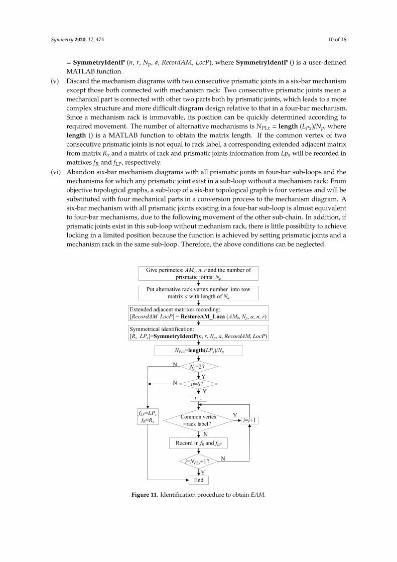
According to vertexes’ symmetry identification in Section 2, the computational identificationprocedures from step i to detect equal and equivalent symmetrical vertexes are demonstrated inFigure 12, where RG with dimension of n × n is defined to display the information about twosymmetrical vertexes and RG (p, q) represent the element in the pth row and the qth column of RG.Thus, RG (p, q) = 1 indicates that vertexes p and q have topological symmetry.Symmetry 2020, 12, x FOR PEER REVIEW 11 of 16
Figure 12. Symmetrical identification of vertexes.
RG1, RG2, and RG3 calculated from Figure 11 are used to describe the topological symmetry of vertexes in Figures 3–5, where
1 2 3
0 0 1 0 0 0 0 0 0 1 0 00 1 1 1 0 0 0 0 0 1 0 0 1 0 1 10 0 1 1 0 0 0 0 0 0 0 0 0 0 1 1
, ,0 0 0 1 0 0 0 0 1 0 0 0 0 0 0 00 0 0 0 0 0 0 0 0 0 0 0 0 0 0 1
0 0 0 0 0 0 0 0 0 0 0 0
R R R
= = =
(10)
A–B is used to describe that vertexes A and B have topological symmetry. It can be easily concluded that three symmetrical vertex pairs A–B, B–C, and A–C denote that A, B, and C are mutually symmetrical. Therefore, matrix R1 denotes that vertex pairs with topological symmetry are 1–2, 1–3, 1–4, 2–3, 2–4, 3–4, and vertexes 1, 2, 3, 4 have mutual symmetry. According to this principle, symmetrical vertex pairs and the determined rack positions can be derived as shown in Table 1.
Table 1. Topological symmetry vertex pairs and rack labels.
Topological Graph Four Bar Six Bar with r = 5 Six Bar with r = 6
Symmetric vertex pairs 1~2, 1~3, 1~4, 2~3, 2~4, 3~4 2~6, 1~3, 4~5 1~4, 2~3, 2~5, 2~6, 3~5, 3~6, 5~6
Mechanism rack label 1 1, 2, 4 1, 2
According to link adjacency and joint incidence theory and the method in Ref. [16], if two vertex family strings of all their corresponding cross matrixes are the same, two vertexes are proved to be isomorphic. {Fi}1−L denotes the family string of the ith vertex with L generation matrixes in a topological graph.
The vertex family strings of four-bar mechanism shown in Figure 3a are:
Figure 12. Symmetrical identification of vertexes.
RG1, RG2, and RG3 calculated from Figure 11 are used to describe the topological symmetry ofvertexes in Figures 3–5, where
R1 =
0 1 1 10 0 1 10 0 0 10 0 0 0
, R2 =
0 0 1 0 0 00 0 0 0 0 10 0 0 0 0 00 0 0 0 1 00 0 0 0 0 00 0 0 0 0 0
, R3 =
0 0 0 1 0 00 0 1 0 1 10 0 0 0 1 10 0 0 0 0 00 0 0 0 0 10 0 0 0 0 0
(10)
A–B is used to describe that vertexes A and B have topological symmetry. It can be easilyconcluded that three symmetrical vertex pairs A–B, B–C, and A–C denote that A, B, and C are mutuallysymmetrical. Therefore, matrix R1 denotes that vertex pairs with topological symmetry are 1–2, 1–3, 1–4,2–3, 2–4, 3–4, and vertexes 1, 2, 3, 4 have mutual symmetry. According to this principle, symmetricalvertex pairs and the determined rack positions can be derived as shown in Table 1.
Table 1. Topological symmetry vertex pairs and rack labels.
Topological Graph Four Bar Six Bar with r = 5 Six Bar with r = 6
Symmetric vertex pairs 1~2, 1~3, 1~4, 2~3, 2~4,3~4 2~6, 1~3, 4~5 1~4, 2~3, 2~5, 2~6, 3~5,
3~6, 5~6
Mechanism rack label 1 1, 2, 4 1, 2
Symmetry 2020, 12, 474 12 of 16
According to link adjacency and joint incidence theory and the method in Ref. [16], if two vertexfamily strings of all their corresponding cross matrixes are the same, two vertexes are proved tobe isomorphic. {Fi}1−L denotes the family string of the ith vertex with L generation matrixes in atopological graph.
The vertex family strings of four-bar mechanism shown in Figure 3a are:
{F1}1−2 = {F2}1−2 = {F3}1−2 = {F4}1−2 =
{8− 2(4)6− 3(2)
}Vertex family strings of six-bar mechanism with r = 5 shown in Figure 4a are:
{F1}1−2 = {F3}1−2 =
{20− (2), (3), 3(5)18− 3(3), (4), (5)
},
{F2}1−2 = {F6}1−2 =
{14− 2(2), 2(5)16− (2), 2(3), 2(4)
},
{F4}1−2 = {F5}1−2 =
{16− 2(2), (3), (4), (5)17− (2), 2(3), (4), (5)
}Vertex family strings of four-bar mechanism with r = 6 shown in Figure 5a are:
{F1}1−3 = {F4}1−3 =
14− 2(1), 2(5), (6)16− 2(2), 3(4)4− 4(1)
, {F2}1−3 = {F3}1−3 = {F5}1−3 = {F6}1−3 =
14− (1), (2), 2(4), (5)16− 2(2), 3(4)8− 2(1), 3(2)
The results calculated by the method in Ref. [16] show that four-bar mechanism family strings of
vertexes 1–4 are the same, which represents that vertexes 1–4 in Figure 3a are isomorphic or symmetric.Similarly, vertexes between 2 and 6, vertexes between 1 and 3, and vertexes between 4 and 5 in Figure 4aare symmetric, respectively. In Figure 5, Vertexes 1 and 3 are symmetric, and vertexes 2, 3, 5, 6 aremutually symmetric. These results are consistent with that in Table 1 and indicate the validity ofsymmetry identification of this paper.
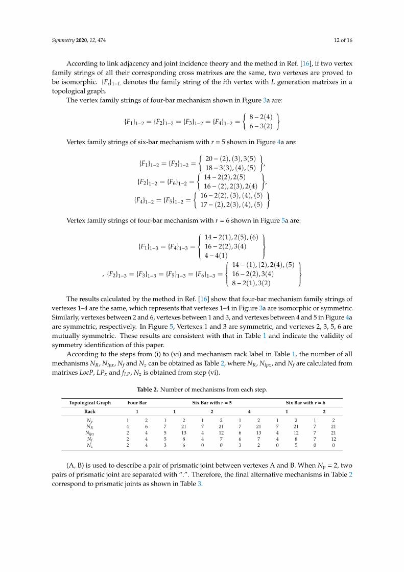
According to the steps from (i) to (vi) and mechanism rack label in Table 1, the number of allmechanisms NR, Nlpx, Nf and Nz can be obtained as Table 2, where NR, Nlpx, and Nf are calculated frommatrixes LocP, LPx and fLP, Nz is obtained from step (vi).
Table 2. Number of mechanisms from each step.
Topological Graph Four Bar Six Bar with r = 5 Six Bar with r = 6
Rack 1 1 2 4 1 2
Np 1 2 1 2 1 2 1 2 1 2 1 2NR 4 6 7 21 7 21 7 21 7 21 7 21Nlpx 2 4 5 13 4 12 6 13 4 12 7 21Nf 2 4 5 8 4 7 6 7 4 8 7 12Nz 2 4 3 6 0 0 3 2 0 5 0 0
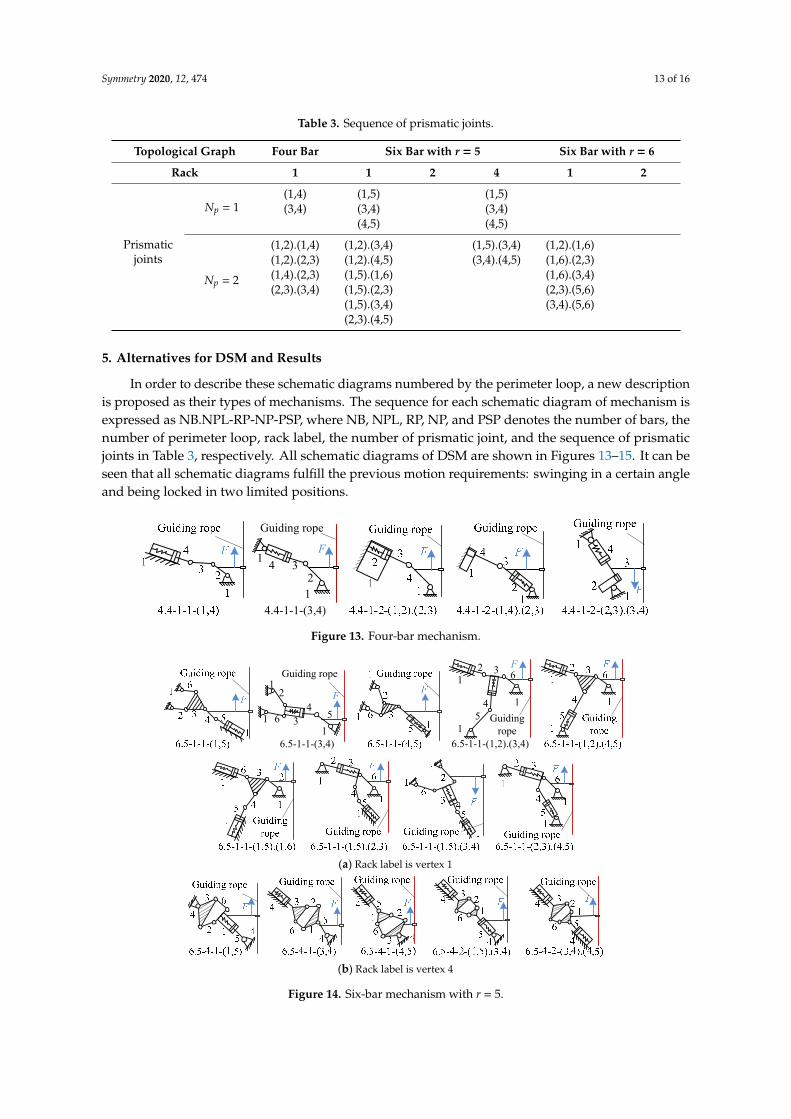
(A, B) is used to describe a pair of prismatic joint between vertexes A and B. When Np = 2, twopairs of prismatic joint are separated with “.”. Therefore, the final alternative mechanisms in Table 2correspond to prismatic joints as shown in Table 3.
Symmetry 2020, 12, 474 13 of 16
Table 3. Sequence of prismatic joints.
Topological Graph Four Bar Six Bar with r = 5 Six Bar with r = 6
Rack 1 1 2 4 1 2
Prismaticjoints
Np = 1(1,4) (1,5) (1,5)(3,4) (3,4) (3,4)
(4,5) (4,5)
Np = 2
(1,2).(1,4) (1,2).(3,4) (1,5).(3,4) (1,2).(1,6)(1,2).(2,3) (1,2).(4,5) (3,4).(4,5) (1,6).(2,3)(1,4).(2,3) (1,5).(1,6) (1,6).(3,4)(2,3).(3,4) (1,5).(2,3) (2,3).(5,6)
(1,5).(3,4) (3,4).(5,6)(2,3).(4,5)
5. Alternatives for DSM and Results
In order to describe these schematic diagrams numbered by the perimeter loop, a new descriptionis proposed as their types of mechanisms. The sequence for each schematic diagram of mechanism isexpressed as NB.NPL-RP-NP-PSP, where NB, NPL, RP, NP, and PSP denotes the number of bars, thenumber of perimeter loop, rack label, the number of prismatic joint, and the sequence of prismaticjoints in Table 3, respectively. All schematic diagrams of DSM are shown in Figures 13–15. It can beseen that all schematic diagrams fulfill the previous motion requirements: swinging in a certain angleand being locked in two limited positions.
Symmetry 2020, 12, x FOR PEER REVIEW 13 of 16
(2,3).(3,4) (1,5).(2,3) (2,3).(5,6) (1,5).(3,4) (3,4).(5,6) (2,3).(4,5)
5. Alternatives for DSM and Results
In order to describe these schematic diagrams numbered by the perimeter loop, a new description is proposed as their types of mechanisms. The sequence for each schematic diagram of mechanism is expressed as NB.NPL-RP-NP-PSP, where NB, NPL, RP, NP, and PSP denotes the number of bars, the number of perimeter loop, rack label, the number of prismatic joint, and the sequence of prismatic joints in Table 3, respectively. All schematic diagrams of DSM are shown in Figures 13–15. It can be seen that all schematic diagrams fulfill the previous motion requirements: swinging in a certain angle and being locked in two limited positions.
Analyzing from the kinematic structure in Figure 13, a four-bar mechanism can be divided into two categories, respectively with one P-joint and two P-joints. Four-bar mechanisms with one P-joint are simple in structure and easy to design, while those with two P-joints need more elaborate design for the direction and position of initiative force, especially the bar as mechanical rack with a P-joint. Moreover, a mechanical rack with a P-joint in Figure 13 may have problems of insufficient locking force in their limited position because one of the prismatic joints without a spring only provides sliding motion and its motion direction is limited.
Figure 13. Four-bar mechanism.
(a) Rack label is vertex 1
(b) Rack label is vertex 4
Figure 14. Six-bar mechanism with r = 5.
1 342
Guiding rope
4.4-1-1-(3,4)
F
1
1
1
14
3
2
6 5
Guiding rope
6.5-1-1-(3,4)
F
6.5-1-1-(1,2).(3,4)
2 3
4
1
Guiding rope
F
15
1
6
Figure 13. Four-bar mechanism.
Symmetry 2020, 12, x FOR PEER REVIEW 13 of 16
(2,3).(3,4) (1,5).(2,3) (2,3).(5,6) (1,5).(3,4) (3,4).(5,6) (2,3).(4,5)
5. Alternatives for DSM and Results
In order to describe these schematic diagrams numbered by the perimeter loop, a new description is proposed as their types of mechanisms. The sequence for each schematic diagram of mechanism is expressed as NB.NPL-RP-NP-PSP, where NB, NPL, RP, NP, and PSP denotes the number of bars, the number of perimeter loop, rack label, the number of prismatic joint, and the sequence of prismatic joints in Table 3, respectively. All schematic diagrams of DSM are shown in Figures 13–15. It can be seen that all schematic diagrams fulfill the previous motion requirements: swinging in a certain angle and being locked in two limited positions.
Analyzing from the kinematic structure in Figure 13, a four-bar mechanism can be divided into two categories, respectively with one P-joint and two P-joints. Four-bar mechanisms with one P-joint are simple in structure and easy to design, while those with two P-joints need more elaborate design for the direction and position of initiative force, especially the bar as mechanical rack with a P-joint. Moreover, a mechanical rack with a P-joint in Figure 13 may have problems of insufficient locking force in their limited position because one of the prismatic joints without a spring only provides sliding motion and its motion direction is limited.
Figure 13. Four-bar mechanism.
(a) Rack label is vertex 1
(b) Rack label is vertex 4
Figure 14. Six-bar mechanism with r = 5.
1 342
Guiding rope
4.4-1-1-(3,4)
F
1
1
1
14
3
2
6 5
Guiding rope
6.5-1-1-(3,4)
F
6.5-1-1-(1,2).(3,4)
2 3
4
1
Guiding rope
F
15
1
6
Figure 14. Six-bar mechanism with r = 5.
Symmetry 2020, 12, 474 14 of 16
Symmetry 2020, 12, x FOR PEER REVIEW 14 of 16
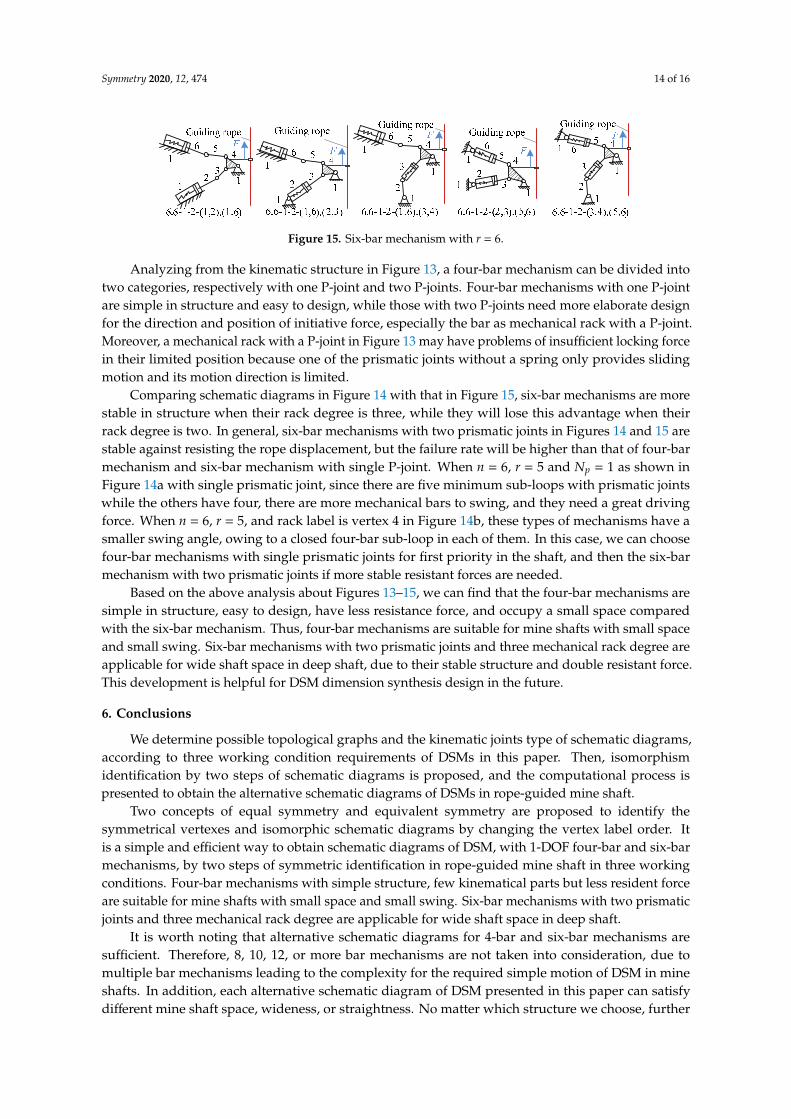
Figure 15. Six-bar mechanism with r = 6.
Comparing schematic diagrams in Figure 14 with that in Figure 15, six-bar mechanisms are more stable in structure when their rack degree is three, while they will lose this advantage when their rack degree is two. In general, six-bar mechanisms with two prismatic joints in Figures 14 and 15 are stable against resisting the rope displacement, but the failure rate will be higher than that of four-bar mechanism and six-bar mechanism with single P-joint. When n = 6, r = 5 and Np = 1 as shown in Figure 14a with single prismatic joint, since there are five minimum sub-loops with prismatic joints while the others have four, there are more mechanical bars to swing, and they need a great driving force. When n = 6, r = 5, and rack label is vertex 4 in Figure 14b, these types of mechanisms have a smaller swing angle, owing to a closed four-bar sub-loop in each of them. In this case, we can choose four-bar mechanisms with single prismatic joints for first priority in the shaft, and then the six-bar mechanism with two prismatic joints if more stable resistant forces are needed.
Based on the above analysis about Figures 13–15, we can find that the four-bar mechanisms are simple in structure, easy to design, have less resistance force, and occupy a small space compared with the six-bar mechanism. Thus, four-bar mechanisms are suitable for mine shafts with small space and small swing. Six-bar mechanisms with two prismatic joints and three mechanical rack degree are applicable for wide shaft space in deep shaft, due to their stable structure and double resistant force. This development is helpful for DSM dimension synthesis design in the future.
6. Conclusions
We determine possible topological graphs and the kinematic joints type of schematic diagrams, according to three working condition requirements of DSMs in this paper. Then, isomorphism identification by two steps of schematic diagrams is proposed, and the computational process is presented to obtain the alternative schematic diagrams of DSMs in rope-guided mine shaft.
Two concepts of equal symmetry and equivalent symmetry are proposed to identify the symmetrical vertexes and isomorphic schematic diagrams by changing the vertex label order. It is a simple and efficient way to obtain schematic diagrams of DSM, with 1-DOF four-bar and six-bar mechanisms, by two steps of symmetric identification in rope-guided mine shaft in three working conditions. Four-bar mechanisms with simple structure, few kinematical parts but less resident force are suitable for mine shafts with small space and small swing. Six-bar mechanisms with two prismatic joints and three mechanical rack degree are applicable for wide shaft space in deep shaft.
It is worth noting that alternative schematic diagrams for 4-bar and six-bar mechanisms are sufficient. Therefore, 8, 10, 12, or more bar mechanisms are not taken into consideration, due to multiple bar mechanisms leading to the complexity for the required simple motion of DSM in mine shafts. In addition, each alternative schematic diagram of DSM presented in this paper can satisfy different mine shaft space, wideness, or straightness. No matter which structure we choose, further dimension synthesis to each structure is still required to be solved. Thus, it is important for further choice and design of DSM in rope-guided mine shaft.
Author Contributions: L.Y. and G.C contributed equally to conceptualization and methodology of this paper. L.Y. and W. P.: references and literature collection and organization. L.Y. and N.W.: validation and main analysis, G.C; supervision, project administration and funding acquisition. All authors have read and agreed to publish this version of the paper.
Funding: This research received no external funding.
Figure 15. Six-bar mechanism with r = 6.
Analyzing from the kinematic structure in Figure 13, a four-bar mechanism can be divided intotwo categories, respectively with one P-joint and two P-joints. Four-bar mechanisms with one P-jointare simple in structure and easy to design, while those with two P-joints need more elaborate designfor the direction and position of initiative force, especially the bar as mechanical rack with a P-joint.Moreover, a mechanical rack with a P-joint in Figure 13 may have problems of insufficient locking forcein their limited position because one of the prismatic joints without a spring only provides slidingmotion and its motion direction is limited.
Comparing schematic diagrams in Figure 14 with that in Figure 15, six-bar mechanisms are morestable in structure when their rack degree is three, while they will lose this advantage when theirrack degree is two. In general, six-bar mechanisms with two prismatic joints in Figures 14 and 15 arestable against resisting the rope displacement, but the failure rate will be higher than that of four-barmechanism and six-bar mechanism with single P-joint. When n = 6, r = 5 and Np = 1 as shown inFigure 14a with single prismatic joint, since there are five minimum sub-loops with prismatic jointswhile the others have four, there are more mechanical bars to swing, and they need a great drivingforce. When n = 6, r = 5, and rack label is vertex 4 in Figure 14b, these types of mechanisms have asmaller swing angle, owing to a closed four-bar sub-loop in each of them. In this case, we can choosefour-bar mechanisms with single prismatic joints for first priority in the shaft, and then the six-barmechanism with two prismatic joints if more stable resistant forces are needed.
Based on the above analysis about Figures 13–15, we can find that the four-bar mechanisms aresimple in structure, easy to design, have less resistance force, and occupy a small space comparedwith the six-bar mechanism. Thus, four-bar mechanisms are suitable for mine shafts with small spaceand small swing. Six-bar mechanisms with two prismatic joints and three mechanical rack degree areapplicable for wide shaft space in deep shaft, due to their stable structure and double resistant force.This development is helpful for DSM dimension synthesis design in the future.
6. Conclusions
We determine possible topological graphs and the kinematic joints type of schematic diagrams,according to three working condition requirements of DSMs in this paper. Then, isomorphismidentification by two steps of schematic diagrams is proposed, and the computational process ispresented to obtain the alternative schematic diagrams of DSMs in rope-guided mine shaft.
Two concepts of equal symmetry and equivalent symmetry are proposed to identify thesymmetrical vertexes and isomorphic schematic diagrams by changing the vertex label order. Itis a simple and efficient way to obtain schematic diagrams of DSM, with 1-DOF four-bar and six-barmechanisms, by two steps of symmetric identification in rope-guided mine shaft in three workingconditions. Four-bar mechanisms with simple structure, few kinematical parts but less resident forceare suitable for mine shafts with small space and small swing. Six-bar mechanisms with two prismaticjoints and three mechanical rack degree are applicable for wide shaft space in deep shaft.
It is worth noting that alternative schematic diagrams for 4-bar and six-bar mechanisms aresufficient. Therefore, 8, 10, 12, or more bar mechanisms are not taken into consideration, due tomultiple bar mechanisms leading to the complexity for the required simple motion of DSM in mineshafts. In addition, each alternative schematic diagram of DSM presented in this paper can satisfydifferent mine shaft space, wideness, or straightness. No matter which structure we choose, further
Symmetry 2020, 12, 474 15 of 16
dimension synthesis to each structure is still required to be solved. Thus, it is important for furtherchoice and design of DSM in rope-guided mine shaft.
Author Contributions: L.Y. and G.C. contributed equally to conceptualization and methodology of this paper.L.Y. and W.P.: references and literature collection and organization. L.Y. and N.W.: validation and main analysis,G.C; supervision, project administration and funding acquisition. All authors have read and agreed to publishthis version of the paper.
Funding: This research received no external funding.
Acknowledgments: This work is supported by the Fundamental Research Funds for the Central Universities(2017XKQY038) and the Priority Academic Program Development of Jiangsu Higher Education Institutions(PAPD).
Conflicts of Interest: The authors declare no conflicts of interest.
References
1. Greenway, E.M. Lateral stiffness and deflection of vertical ropes with application to mine shaft hoisting.Aust. J. Mech. Eng. 2008, 5, 59–70. [CrossRef]
2. Yan, L.; Cao, G.; Wang, N.; Li, J. Lateral stiffness and deflection characteristics of guide cable withmulti-boundary constraints. Adv. Mech. Eng. 2017, 9. [CrossRef]
3. Cao, G.; Wang, J.; Zhu, Z. Coupled vibrations of rope-guided hoisting system with tension difference betweentwo guiding ropes. Proc. Inst. Mech. Eng. Part. C. J. Mech. Eng. Sci. 2018, 232, 231–244. [CrossRef]
4. Wang, J.; Pi, Y.; Hu, Y.; Gong, X. Modeling and dynamic behavior analysis of a coupled multi-cable doubledrum winding hoister with flexible guides. Mech. Mach. Theory 2017, 108, 191–208. [CrossRef]
5. Cao, G.; Wang, J.; Zhu, Z. Guide rail rope deflection inhibition mechanism and method for parallel soft cablesuspension system. US Invention Patent US09689257B2, 22 January 2014.
6. Yan, H.; Chiu, Y. On the number synthesis of kinematic chains. Mech. Mach. Theory 2015, 89, 128–144.[CrossRef]
7. Uicker, J.J.; Raicu, A. A Method for the Identification of and Recognition of Equivalence of Kinematic Chains.Mech. Mach. Theory 1975, 10, 375–383. [CrossRef]
8. Rao, A.C.; Varada, R.D. Application of the hamming number technique to detect isomorphism amongkinematic chains and inversion. Mech. Mach. Theory 1991, 26, 55–75. [CrossRef]
9. Yang, P.; Pei, Z.H.; Liao, N.B.; Yang, B. Isomorphism identification for epicyclic gear mechanism based onmapping property and ant algorithm. Eng. Comput. 2007, 23, 49–54. [CrossRef]
10. Kong, F.G.; Li, Q.; Zhang, W.J. An artificial neural network approach to mechanism kinematic chainisomorphism identification. Mech. Mach. Theory 1999, 34, 271–283. [CrossRef]
11. Rao, A.C. A Genetic Algorithm for Topological Characteristics of Kinematic Chains. J. Mech. Des. 2000, 122,228–231. [CrossRef]
12. Xiao, R.; Tao, Z.; Liu, Y. Isomorphism identification of kinematic chains using novel evolutionary approaches.Trans. ASME J. Comput. Inf. Sci. Eng. 2005, 5, 18–24. [CrossRef]
13. Galán-Marín, G.; López-Rodríguez, D.; Mérida-Casermeiro, E. A new multivalued neural network forisomorphism identification of kinematic chains. J. Comput. Inf. Sci. Eng. 2010, 10, 011009. [CrossRef]
14. Chang, Z.Y.; Zhang, C.; Yang, Y.H.; Wang, Y.X. A new method to mechanism kinematic chain isomorphismidentification. Mech. Mach. Theory 2002, 37, 411–417. [CrossRef]
15. Cubillo, J.P.; Wan, J.B. Comments on mechanism kinematic chain isomorphism identification using adjacentmatrices. Mech. Mach. Theory 2005, 40, 131–139. [CrossRef]
16. Kuo, C.H.; Shih, C.J. Computational identification of link adjacency and joint incidence in kinematic chainsand mechanisms. J. Mech. Des. 2008, 130, 084501. [CrossRef]
17. Rao, A.C.; Deshmukh Pratap, B. Computer aided structural synthesis of planar kinematic chains obviatingthe test for isomorphism. Mech. Mach. Theory 2001, 36, 489–506. [CrossRef]
18. Huber, M. Computational complexity of reconstruction and isomorphism testing for designs and line graphs.J. Comb. Theory Ser. A 2011, 118, 341–349. [CrossRef]
19. Zeng, K.; Fan, X.; Dong, M.; Yang, P. A fast algorithm for kinematic chain isomorphism identification basedon dividing and matching vertices. Mech. Mach. Theory 2014, 72, 25–38. [CrossRef]
Symmetry 2020, 12, 474 16 of 16
20. Yang, F.; Deng, Z.; Tao, J.; Li, L. A new method for isomorphism identification in topological graphs usingincident matrices. Mech. Mach. Theory 2012, 49, 298–307. [CrossRef]
21. Ding, H.F.; Huang, Z. The establishment of the canonical perimeter topological graph of kinematic chainsand isomorphism identification. J. Mech. Des. 2006, 129, 915–923. [CrossRef]
22. Ding, H.; Zhao, J.; Huang, Z. Unified structural synthesis of planar simple and multiple joint kinematicchains. Mech. Mach. Theory 2010, 45, 555–568. [CrossRef]
23. Ding, H.; Hou, F. Synthesis of the whole family of planar 1-DOF kinematic chains and creation of their atlasdatabase. Mech. Mach. Theory 2012, 47, 1–15. [CrossRef]
24. Wu, X.H.; Nie, S.H.; Li, N. An approach of original loop to automatic sketching of planar kinematic chains.Mech. Sci. Technol. Aerosp. Eng. 2009, 28, 546–552.
25. Nie, S.H.; Liu, H. Maximal Loop Method of Automatic Sketching of Planar Closed Kinematic Chains. J. Mech.Eng. 2009, 45, 30–37. [CrossRef]
26. Rai, R.K.; Punjabi, S. Kinematic chains isomorphism identification using link connectivity number andentropy neglecting tolerance and clearance. Mech. Mach. Theory 2018, 123, 40–65. [CrossRef]
27. Deng, T.; Xu, H.; Tang, P.; Liu, P.; Yan, L. A novel algorithm for the isomorphism detection of variouskinematic chains using topological index. Mech. Mach. Theory 2020, 146, 103740. [CrossRef]
28. Rao, A.C.; Nageswara Rao, C. Isomorphism among kinematic chains with Sliding Pairs. Indian J. Technol.1989, 27, 363–365.
29. Eleashy, H. A new atlas for 8-bar kinematic chains with up to 3 prismatic pairs using Joint Sorting Code.Mech. Mach. Theory 2018, 124, 118–132. [CrossRef]
30. Dharanipragada, V.; Chintada, M. Split hamming string as an isomorphism test for one degree-of-freedomplanar simple-jointed kinematic chains containing sliders. J. Mech. Des. 2016, 138, 082301–082308. [CrossRef]
31. Sun, W.; Kong, J.Y.; Wang, X.D.; Hou, Y. Description and isomorphism judgment of the kinematic chainwith multiple joints based on link-link adjacency matrix. J. Mech. Eng. 1–6. Available online: http://kns.cnki.net/kcms/detail/11.2187.TH.20191224.1509.176.html (accessed on 25 December 2019).
32. Liu, H.; Shi, S.Y.; Yang, P.; Yang, J. An improved genetic algorithm approach on mechanism kinematicstructure enumeration with intelligent manufacturing. J. Intell. Robot. Syst. 2018, 89, 343–350. [CrossRef]
© 2020 by the authors. Licensee MDPI, Basel, Switzerland. This article is an open accessarticle distributed under the terms and conditions of the Creative Commons Attribution(CC BY) license (http://creativecommons.org/licenses/by/4.0/).