Embed Size (px)
Citation preview

Scott Street Norman Park SPS SP025 Switchboard Maintenance Manual
Q-Pulse Id TMS740 Active 29/01/2014 Page 1 of 95

1
S ECTION
MAINTENANCE INSTRUCTIONS
TEST REPORTS
S ECTION 2
EQUIPMENT CATALOGUES
S ECTION
M.C.C. DRAWINGS
Scott Street Norman Park SPS SP025 Switchboard Maintenance Manual
Q-Pulse Id TMS740 Active 29/01/2014 Page 2 of 95

PREVENTATIVE MAINTENANCE INSTRUCTIONS
1. MAINS CONNECTIONS:
The mains must be checked annually to ensure:
- All bolted connections are tight, dust and corrosion free; - All fixings and cable supports etc. are positive.
2. MOTOR CONTROL CENTRE
The M.C.0 must be checked annually. Firstly, remove all access panels
and clean all accumulated dust out of the enclosure, and then check:
- All bolted connections;
- All incoming and, outgoing terminations;
- Operations of all C.F.S units, isolators, contactors, controls etc.
- All instruments and instrument connections;
- All labelling and schedules are in place and up to date;
- Main earth connections and continuity;
- Load Balance;
- All fixings are tight and in place;
- Paintwork for blemishes and for any signs of corrosion;
- All hinges, locks, keys, handles, etc. to ensure that they are secure and function properly;
- All gaskets create a good seal;
- Automatic operation of control circuits.
3. Cleaning of Equipment
The equipment should be cleaned with a soft, dry paint brush, feather duster or equivalent, according to the circumstances and if possible with a jet of clean, dry air taking care to avoid damage to the components.
If it should happen that a component such as a relay is not working properly owing to dirt on its moving parts, its immediate replacement by a spare is to be recommended. in the case of grommets, connectors, contactors, etc., cleaning of the contact area can be done in place, using a cloth moistened with a solvent such as benzine or trichorethylene plus a dab of vaseline. All due care should be taken to de-energize the circuits associated with the location being serviced.
Visual inspection
Visual inspection should be quite frequent. To verify the perfect functioning of the signalling system is to guarantee the immediate indication of any abnormal occurrence in the equipment or its components.
Scott Street Norman Park SPS SP025 Switchboard Maintenance Manual
Q-Pulse Id TMS740 Active 29/01/2014 Page 3 of 95

POWER ELECTRIC Switchboards rIDY
Manufacturers of. Engineered Switchboards for Mining, Industrial and Commercial Projects
FINAL CHECKING PROCEDURE FOR ALL SWITCHBOARDS
SWITCHBOARD TITLE: BRISBANE CITY.COUNCIL.SCOTT.STREZT
JOB NUMBER: 323
1. Check Switchboard has been built as per the approved drawing. (KA Rating, IP. Rating, Form of Segregation.)
2. Check all Control Functions.
3. Check all Connections.
4. Check all Clearance's.
5. Check hinges, locks, keys, handles etc, to ensure that they are secure and function properly.
6. Check operations of all CFS units, Circuit Breakers, Isolators, Contactors etc.
7. Check Main Earth connections and continuity.
8. Check that all neutrals are accessible.
9. Check that all labeling and schedules are in place.
10. Check general condition of Switchboard (Paintwork etc).
11. Check Switchboard has been cleaned out.
12. Meger Switchboard.
CIRCUIT RESULT 1000V MEGER
R-E 4570Agg- W-E i3i7Av.06. B-E /S-0 oza- R-W /Sio AW- R-B /570 Aza. W-B /Scow-.
/SD /' Z. NEUT-E
COMMENTS:
CHECKED BY:
Scott Street Norman Park SPS SP025 Switchboard Maintenance Manual
Q-Pulse Id TMS740 Active 29/01/2014 Page 4 of 95

a TERASAKI Ensuring Service, Maintaining Quality
Publication
G20A May 1993
Standard Series
Higeluft Level Series
moorjErotection Series
automatic Series
Tim Break Total Protection,Complete Control
1111.11111NMANIWAIIMI 1111RMIRAWAINIVAIVAI IIIIINERINNIMENEIVAIPMEM
ANIAMPINVANIAMPI AimiirrAwrAdommi A I I WA I I WAWA I I I
ANNVANIVPrd.PrINEP11% 4NIVAMPIMIANNIIIMP ANINMANOrni AIMPINEVAMM/4
IA ri= Amm IIMOON M111W4111111 r..-' 1111 ........ AWN
AMIN.
IINIMP2/1/1 .4111111111/41111111K
......11111,...111111
INFAKNICI (ern)
41111111/
:. - 0 '1 WWWMU: I I I "1.1.elb.11
W4 WIll&kC I I I ILNI I I I N114 I IN W37 a
itc.n ctm nent.
1111,11111
.10Ior MA WOK 41,11.,
Selection Guide PRODUCTS PTY LTD
Scott Street Norman Park SPS SP025 Switchboard Maintenance Manual
Q-Pulse Id TMS740 Active 29/01/2014 Page 5 of 95
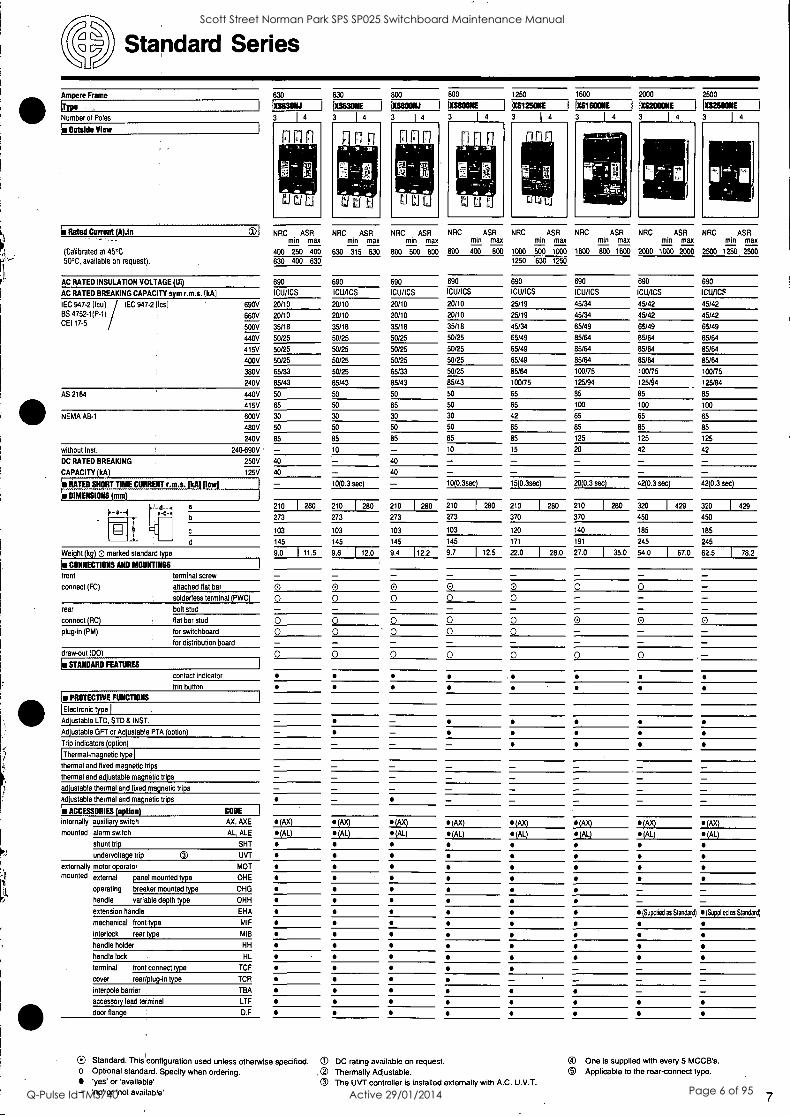
Standard Series
Ampere Frame
(Type
Number of Poles
Is Outside View
In Rated Current (A),In
(Calibrated at 45°C 50°C, available on request).
0)I
AC RATED INSULATION VOLTAGE (UI)
AC RATED BREAKING CAPACITY sym r.m.s. (kA)
IEC 947.2 (lcu) IEC 947.2 tics) BS 4752-1(Pt) CEI 17-5
690V
660V
500V
440V
415V
400V
380V
240V
AS 2164 440V
415V
NEMA AB-1 600V
480V
240V
without Inst. 240-690V
DC RATED BREAKING 250V
CAPACITY (kA) 125V
RATED SHORT TIME CURRENT r.m.s. (U] Dow]
DIMENSIONS (mm)
a
d
Weight (kg) 0 marked standard type
Is CONNECTIONS AND MOUNTINGS
front terminal screw
connect (FC) attached flat bar 0
630 630 800 800 1250 1600 2000
XSIMONJ IESMONE IXS80011J GUMOONE IXS125011E IXSTIMONE IXS200011E 1
3 l4 3 I4 3 I4 3 1 4 3 1 4 3 1 4 3 1 4
2500
XS2500NE
3 1
4
NRC ASR NRC ASR NRC ASR NRC ASR NRC ASR NRC ASR NRC ASR NRC ASR min max min max min max min max min max min max min max min max
400 250 400 630 315 630 800 500 BOO 800 400 BOO 1000 500 1000 1600 BOO 1600 2000 1000 2000 2500 1250 2500
630 400 630 1250 630 1250
690 690 690 690 690 690 690 690
ICU/ICS ICU/ICS ICU/ICS ICU/ICS ICU/ICS ICU/ICS ICU/ICS ICU/ICS
20/10 20/10 20/10 20/10 25/19
20/10 20/10 20/10 20/10 25/19
35/18 35/18 35/18 35/18 45/34
50/25 50/25 50/25 50/25 65/49
50/25 50/25 50/25 50/25 65/49
50/25 50/25 50/25 50/25 65/49
65/33 50/25 65/33 50/25 85/64
85/43 85/43 85/43 85/43 100/75
50 50 50 50 65
65 50 65 50 65
30 30 30 30 42
50 50 50 50 65
85 85 85 85 85
- 10 - 10 15
40 - 40 - - 40 - 40 - - - 10(0.3 sec) - 10(0.3sec) 15(0.3sec)
210 1 280 210 1 280 210 1 280 210 I 280 210 I 280
273 273 273 273 370
103 103 103 103 120
145 145 145 145 171
9.0 1 11.5 9.6 1 12.0 9.4 112.2 9.7 1 12.5 22.0
1 28.0
rear
connect (RC)
plug-in (PM)
solderless terminal (PWC) 0 bolt stud - flat bar stud 0 for switchboard 0 for distribution board
draw-out (DO) 0 STANDARD FEATURES
O 0 0 0 O 0 0 0
O 0 0 0 O . 0 0 0 - - - - O 0 0 0
contact indicator
trio button
Is PROTECTIVE FUNCTIONS
'Electronic type
Adjustable LTD, STD & INST.
Adjustable GFT or Adjustable PTA (option)
Trip indicators (option)
[Thermal-magnetic tydel thermal and fixed magnetic trips
thermal and adjustable magnetic trips
adjustable thermal and fixed magnetic trips
adjustable thermal and magnetic trips
ACCESSORIES (option) CODE
internally auxiliary switch AX, AXE (AX) (AX) (AX) (AX) (AX) mounted alarm switch AL, ALE (AL) (AL) (AL) (AL) (AL)
shunt trip SHT
undervoltage trip 0 UVT
externally motor operator MOT
45/34 45/42 45/42
45/34 45/42 45/42
65/49 65/49 65/49
85/64 85/64 85/64
85/64 85/64 85/64
85/64 85/64 85/64
100/75 100/75 100/75
125/94 12564 125/94
85 85 85
100 100 100
65 65 65
85 85 85
125 125 125
20 42 42
- - - - - 20(0.3 sec) 42(0.3 sec) 42 0.3 sec
210 I 280 320 I 429 320 429
370 450 450
140 185 185
191 245 245
27.0 I 35.0 54.0 I 67.0 62.5 78.2
0 0
0 0 0 - - - - 0 0
(AX) (AX) (AX)
(AL) (AL) (AL)
s mounted external panel mounted type ONE
operating breaker mounted type OHG - - handle variable depth type OHH - - extension handle EHA re (Supplied as Standard) (Supplied as Standard)
mechanical front type MIF
interlock rear type MIB .
handle holder HH
handle lock HL
terminal front connect type TCF - - - cover rear/plug-in type TCR _ - - - interpole barrier TBA - - accessory lead terminal LTF ii)
door flange D.F
® Standard. This l'configuration used unless otherwise specified. 0 DC rating available on request. O Optional standard. Specify when ordering. . (21 Thermally Adjustable.
'yes' or 'available' 0 The UVT controller is installed externally with A.G. U.V.T. - 'no' or 'not available'
0 One is supplied with every 5 MCCB's.
al Applicable to the rear-connect type.
7
Scott Street Norman Park SPS SP025 Switchboard Maintenance Manual
Q-Pulse Id TMS740 Active 29/01/2014 Page 6 of 95

High-fault Level Series
Ampere Frame
Number of Poles
ROSItaide VIew
(Calibrated at 45°C 50°C, available on request).
125 250
*asolut, 3 1 4
630 800 400 630/800 1250
flM80011Elinhi 0100SITXW 1XV630/800NEW 10;1251E 14
NRC ASR NRC ASR NRC ASR NRC ASR NRC ASR NRC ASR NRC ASR NRC ASR min max min max min max min max min max min max min max min max
20 12.5 20 160 100 160 250 125 250 630 315 630 800 400 800 250 125 250 630 315 630 400 200 400 32 20 32 250 160 250 400 200 400 400 200 400 800 400 800 800 400 800 50 32 50 1000 500 1000 63 40 63 1250 630 1250 100 63 100
125 80 125
AC RATED INSULATION VOLTAGE (U8 690
AC RATED BREAKING CAPACITY sym r.m.s. (kA) ICU/ICS
IEC 947-2 (lcu) IEC 947-2 (Ws) 690V 8/4
BS 5742-1(P-1) 660V 8/4 CEI 17-5 AS 3858 500V 25/13
440V 42/21
415V 50/25
400V 50/25
380V 50/25
1100V - AS 2184 440V 50
415V 50
NEMA AB-1 600V 25
480V 42
240V 85
without Inst. 240-690V - DC RATED BREAKING 250V 40
CAPACITY (kA) 125V 40
WRATEDSNONTOIMEnCUNNENT caLs. [1-717-7Al pct) - DIABIONS M m) L411
690 690 690 690
ICU/ICS ICU/ICS ICU/ICS ICU/ICS
15/7.5 20/10
15/7.5 20/10
25/13 42/21
42/21 65/33
50/25 65/33
50/25 65/33
50/25 65/33
- - 50 65
50 65
25 42
42 65
85 85
- 5
40 - 40 - - 5(0.3 sec)
F- -1 a
P-C-4
90 I 120 105 I 140 140 1 185
b 155 165 260
b
d
Weight (kg) 0 ma ked standard type
m.CONNECTIONS AND MOUNTINGS . . ' front
connect (FC)
rear
connect (RC)
plug-in (PM)
terminal screw
attached flat bar
solderless terminal (PWC)
bolt stud
flat bar stud
for switchboard
for distribution board
draw-out (DO)
m.STANDARD FEATURES
86 103 103
104 124 131
1.3 1 1.58 2.1 1 2.6 4.8 I 6.2
O 0 0 - 0(BAR) 0(BAR)
O 0 0 O - - - 0 0 O 0 0 O I . - - - 0 0
Electronic type I
Adjustable LTD, STD 8 INST. - - Adjustable GFT or Adjustable PTA (option) - - (PTA only)
tri indicators o tine - - - Thermal-magnetic type
thermal and fixed magnetic trips - thermal and adjustable magnetic trips
adjustable thermal and fixed magnetic trips - adjustable thermal and magnetic trips - - - w ACCESSORIES(opit ' . . W,.. COME -I
internally auxiliary switch AX, AXE (AXE) (AXE) (AX) mounted alarm switch AL, ALE (ALE) (ALE) (AL)
shunt trip SHT
undervoltage trip 0 UVT .
externally motor operator MOT mounted external panel mounted type OHE
1150
ICS
1150
ICS
1150
ICS
20/10 20/10
20/10 20/10
42/21 42/21
65/33 65/33
65/33 65/33
65/33 65/33
65/33 65/33
- - 12.5 12.5
65 65
65 65
42 42
65 65
85 85
10 10
- - - - 10(0.3 sec) 10(0.3 sec)
210 I 280 210 I 280 140 210 210
273 273 260 273 370
103 103 103 103 120
145 145 131 145 171
9.6 1 12.0 9.7 1 12.5 4.8 9.7 22
- - 0 0 0 0 0 0 0 0 0 - - - 0 0 0 0 0 - - 0 0
(PTA only)
- -
- - - -
(AX) (AX) (AX) (AX)
(AL) (AL) (AL) (AL)
operating breaker mounted type
handle variable depth type
extension handle
mechanical front type
interlock rear type
handle holder
handle lock
terminal front connect type
cover rear/plug-in type
interpole barrier
accessory lead terminal
door flange
OHG
OHH
EHA - - - MIF
MIB
HH
HL
TCF
TCR
TBA
LTF 0 0 D.F
Standard. This configuration used unless otherwise specified. 0 DC rating available on request.
O Optional standard. Specify when ordering. (2) Thermally Adjustable. yes' or 'available' 0 The UVT controller is installed externally with A.C. U.V.T.
8 - 'no' or Mot available'
Scott Street Norman Park SPS SP025 Switchboard Maintenance Manual
Q-Pulse Id TMS740 Active 29/01/2014 Page 7 of 95
I
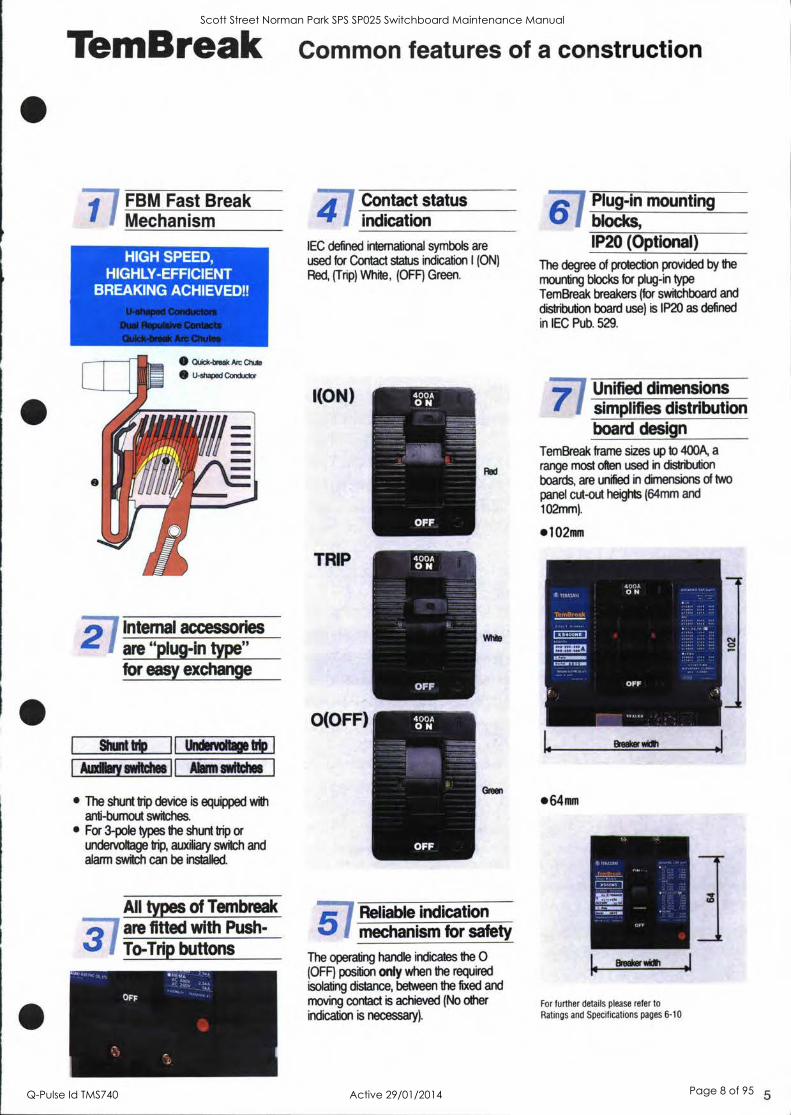
TemBreak Common features of a construction
1 FBM Fast Break Mechanism
HIGH SPEED, HIGHLY-EFFICIENT
BREAKING ACHIEVED!!
al Repulsive Con
Quick-break Arc
2 Internal accessories are "plug-in type" for easy exchange
Shunt trip
tundliary switches
Undenroltage trip
Alarm switches
The shunt trip device is equipped with anti-burnout switches. For 3-pole types the shunt trip or undervoltage trip, auxiliary switch and alarm switch can be installed.
All types of Tembreak
3 are fitted with Push- To-Trip buttons
Orp
IIMIL-77"-`-',1
-4.117Contact
status indication
IEC defined international symbols are
used for Contact status indication I (ON)
Red, (Trip) White, (OFF) Green.
I(ON)
TRIP
O(OFF)
51
Red
White
Green
Reliable indication mechanism for safety
The operating handle indicates the 0 (OFF) position only when the required
isolating distance, between the fixed and
moving contact is achieved (No other indication is necessary).
Plug-in mounting blocks, 11320 (Optional)
The degree of protection provided by the
mounting blocks for plug-in type
TemBreak breakers (for switchboard and distribution board use) is IP20 as defined
in !EC Pub. 529.
Unified dimensions simplifies distribution board design
TemBreak frame sizes up to 400A, a
range most often used in distribution
boards, are unified in dimensions of two
panel cut-out heights (64mm and
102mm).
102mm
1
I. Breaker win
64mm
Brodr IMdD j For further details please refer to
Ratings and Specifications pages 6-10
5
Scott Street Norman Park SPS SP025 Switchboard Maintenance Manual
Q-Pulse Id TMS740 Active 29/01/2014 Page 8 of 95
6
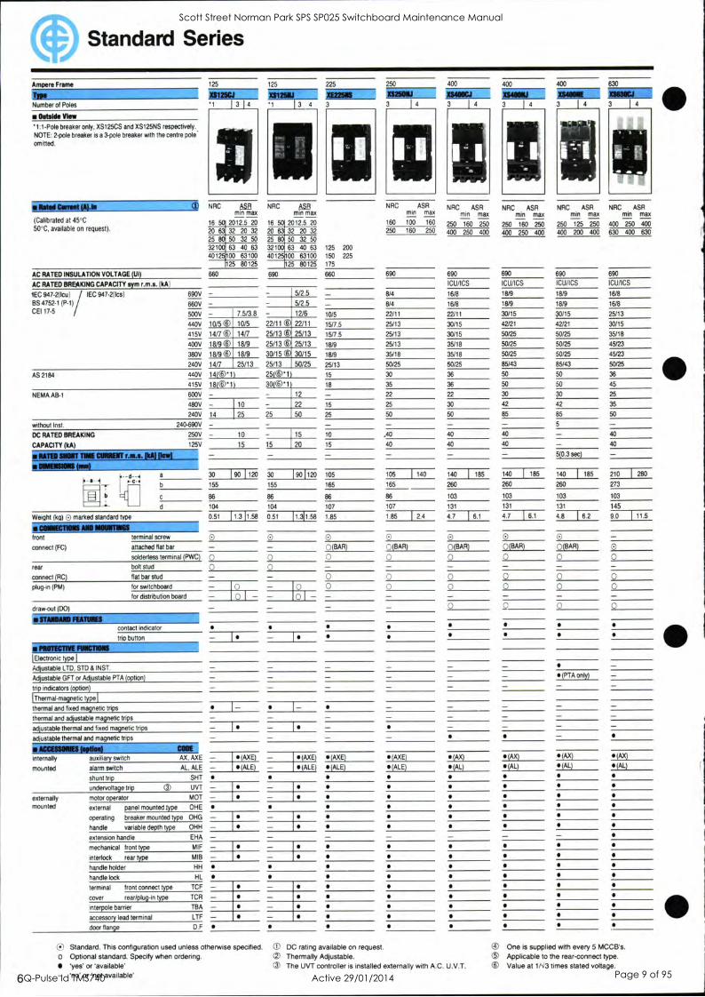
Standard Series
Ampere Frame
h Number of Poles
Outside View
1:1-Pole breaker only, XS125CS and XSI25NS respectively.. NOTE: 2-pole breaker is a 3-pole breaker with the centre pole
omitted.
(Calibrated at 45°C
50°C, available on request).
AC RATED INSULATION VOLTAGE (UI)
AC RATED BREAKING CAPACITY sym IkA)
1EC 947-211eu) IEC 947-21Ics)
BS 4752- 1(P -1)
CEI 17.5
AS 2184
NEMA AB-1
without Inst.
DC RATED BREAKING
CAPACITY (1a)
125 125 225 250 400 400 400
3
NRC
*MI Ili Amu_ NNE 1 1 3 4 3 3 1 4 3 1 4 3 1 4 3 1 4
AB NRC 11$13 min max min max
16 r 2012.5 20 16 r 2012.5 20
20 63 32 20 32 20 32 20 32
25 50 32 50 25 80 50 32 50
321 r r 63 40 63 32100 63 40 63 125 200
4012 00 63100 4012 00 63100 150 225
5 80125 25 83125 175
660 690 660
690V - 660V - 500V - 7.5/3.8
440V 10/50 10/5 22/11
415V 14/7 0 14/7 25/13
400V 18/9 10 18/9 25/13
380V 18/9 CD 18/9 30/15
240V 14/7 25/13 25/13
440V 14(0'1) 25(0'1 415V 18(©*1) 30(3'1 600V - 12
480V - 10 22 15
240V 14 25 25 50 25
240-690V - 10 - 15 10
125V 15 15 20 15
5/2.5
5/2.5
12/6
22/11
25/13
25/13
30/15
50/25
10/5
15/7.5
15/7.5
18/9
18/9
25/13
15
18
NATO SNORT ME CURRENT Lica. NA) gad IIIMEISIONS MEd
F- a- -1 P-C-1 a
b
d
Weight (kg) 0 marked standard type
front
connect (FC)
rear
connect (RC)
plug-in (PM)
draw-out (DO)
terminal screw
attached flat bar
solderless terminal (PWC)
bolt stud
flat bar stud
for switchboard
for distribution board
'Electronic type I
Adjustable LTD. STD & INST.
Adjustable GFT or Adjustable PTA (option)
trip indicators (option)
(Thermal- magnetic 1)9131
thermal and fixed magnetic trips
thermal and adjustable magnetic trips
adjustable thermal and fixed magnetic trips
adjustable thermal and magnetic trips
contact indicator
trio button
NRC ASR mm max
160 100 160
250 160 250
3
NRC ASR NRC ASR NRC ASR NRC ASR min max min max min max min max
250 160 250 250 160 250 250 125 250 400 250 400
400 250 400 400 250 400 400 200 400 630 400 630
690 690 690 690
ICU/ICS ICU/ICS ICU/ICS
8/4 16/8 18/9 18/9
8/4 16/8 18/9 18/9
22/11 22/11 30/15 30/15
25/13 30/15 42/21 42/21
25/13 30/15 50/25 50/25
25/13 35/18 50/25 50/25
35/18 35/18 50/25 50/25
50/25 50/25 85/43 85/43
30 36 50 50
35 36 50 50
22 22 30 30
25 30 42 42
50 50 155 85
- - - 5
,40 40 40 - 40 40 40
- - - 5(0.3 sec)
690
ICU/ICS
16/8
16/8
25/13
30/15
35/18
45123
45/23
50/25
36
45
25
35
50
40
40
30 1 90 1 120 30 190 1120 105 105 1 140 140 140 I 185 140 I 185 210 1 280
155 155 165 165 260 260 260 273
86 86 es 86 103 103 103 103
104 104 107 107 131 131 131 145
0.51 0.51 1.85 1.85 1 2.4 4.7 4.7 1 6.1 4.8 1 6.2 9.0 1 11.5 11.3 11.58 11.311.56
0 0
0 0(BAR) 0 0
0
0 0 0 0 - 0 (BADt 0(BAR) 0(BAR) 0(BAR) 0 3 0 0 0 0 - - - - - " ., 0 0 0 0
0 0 0
(PTA only)
I
I- 1-
internally
mounted
externally mounted
auxiliary switch
alarm switch AL. ALE - shunt trip SHT
undervoltage trip O UVT - motor operator MOT - external panel mounted type OHE
operating breaker mounted type OHG - handle variable depth type OHH
extension handle EHA - mechanical front type MIF - interlock rear type MIB - handle holder HH
handle lock HL
terminal front connect type TCF - cover rear/plug-in type TCR
interpole barrier TBA - accessory lead terminal LTF - door flange D.F
- Is - I (AXE) - (AXE) (AXE)
(ALE) - (ALE) (ALE)
(!-) Standard. This configuration used unless otherwise specified
O Optional standard. Specify when ordering. 'yes' or 'available' 'no' or 'not available'
(AXE)
(ALE)
0
(AX) (AX) (AX) 'AX)
(AL) (AL) (AL) (AL)
DC rating available on request. Thermally Adjustable.
® The UVT controller is installed externally with A.C. U.V.T.
® One is supplied with every 5 MCCB's. ® Applicable to the rear-connect type.
0 Value at 1/N13 times stated voltage.
Scott Street Norman Park SPS SP025 Switchboard Maintenance Manual
Q-Pulse Id TMS740 Active 29/01/2014 Page 9 of 95

Motor Protection Series Non-automatic Series
Ampere Frame
TO* Number of Poles
MAN VIM
RAINES Voltage for motor
Motor output and
rated current (Calibrated at 40°C or 45°C, please specify, 50°C
available on request.)
AC RATED INSULATION VOLTAGE (U0
AC RATED BREAKING CAPACITY sym (kA)
IEC 947-2(lculi IEC 947-2 [Ics]
AS2184
NEMA AB-1
without Inst.
DC RATED BREAKING
CAPACITY
50
TP.50
3
50
XM3OPS
3
40Q- 440V
(A) 0 1.6
2.5
4.0
6.3
8.0
10.0
16
25
40
50
-Sb,
(A)
0.8 1.25
1.4 2.0
2.6 3.6
4.2 5.0
7.4 8.0
10 12
660 660
690V
660V
500V
440V 50
415V 50/42
400V 50/42
380V 50/42
240V
440V 50
415V 50
600V
480V
240V
240-690V - 250V
125V
MATEO SNORT ME =MIT r.m.s. Pik Pew]
111111111111111MI
IF -a -dc -1 a
Weight (kg) 0 marked standard type
CONNECTIONS ANA INNEITIMS front terminal screw
connect (FC) attached flat bar
solderless terminal (PWC)
rear bolt stud
connect (RC) flat bar stud
plug-in (PM) for switchboard
for distribution board
draw-out (DO)
STANDARD FEATURES
contact indicator
trip button
over current trip type
50
50
50
50
90/105
130
90
109
1.5
78
147
90
109
1.7
0 0
0
0
PROTECTIVE FUNCTIONS
Thermal-magnetic type
adjustable thermal and fixed magnetic trips
adjustable thermal and magnetic trips
ACCESSIONS WNW CIE internally © auxiliary switch AX, AXE
mounted alarm switch AL, ALE
shunt trip SHT
undervoltage trip 0 UVT
externally ® motor operator MOT
mounted external panel mounted type OHE
operating breaker mounted type OHG
handle variable depth type OHH
mechanical front type MIF
interlock rear type NIB
handle holder HH
handle lock HL
terminal front connect type TCF 0 cover rear/plug-in type TCR 0 interpole barrier TBA 0 accessory lead terminal LTF 0
0
0
Adj Therm Fix mag Fixed
0 (AXE)
O (ALE)
O
0 0 0
0
Standard. This configuration used unless otherwise specified. O Optional standard. Specify when ordering.
'yes' or 'available' - 'no' or 'not available'
Number of Poles
NOTE: 2-pole breaker is a 3-pole breaker with the centre pole omitted
PSI 111111111[ Rated Current (A) 125
Rated Voltage (V) AC 690
DC 250
RATED SHORT CIRCUIT MAKING CAPACITY Peak/kA 3.5
RATED SHORT TIME CURRENT r.m.s./kA 1 sec, 2.5
DIMENSIONS (mm)
d -.1 PC4
a 60
b 155
86
Jr_ d 86
Wei ht k C) marked standard 0.78
front terminal screw
connected (FC) attached flat bar
solderless terminal (PWC)
rear bolt stud
connected (RC) flat bar stud
plug-in (PM) for switchboard
for distribution board
contact indication
tri button
internally
mounted
auxiliary switch
alarm switch
shunt trip
undervoltage trip
AX, AXE
AL, ALE
SHT
UVT
externally mounted motor operator MOT
external panel mounted type OHE
operating breaker mounted type OHG
handle variable depth type OHH
extension handle EHA
mechanical front type MIF
interlock rear type MID
handle holder HH
handle lock HL
terminal front-connect type TCF
COW reabconnect/plug-in type TCR
interpole barrier TBA
accessory lead terminal LTF
door flange D.F
IRCR4IP INEAKEN Max Switching Current AC
DC
Endurance No. of Ops. w/out Current
No. of Ops. with Current
O UVT controller is installed externally with AC UVT. CD Complies with IEC-292 - Overload Relay optional. CD Accessories mounted externally.
190 1 120
11.1 [1.4
0
0 0
0 o I -
(AXE)
(ALE)
XS25ONJ
750
313
7000
1000
O Accessory Chassis optional. (5) Indication by handle only. Si Contact NHP for details. 9
Scott Street Norman Park SPS SP025 Switchboard Maintenance Manual
Q-Pulse Id TMS740 Active 29/01/2014 Page 10 of 95

Non-automatic Series
3 4 Number of Poles
NOTE: 2-pole breaker is a 3-pole breaker
with the centre pole omitted.
1=111=11111111111=111111111111 Rated Current (A) 250
Rated Voltage (V) AC 690
DC 250
RATED SHORT CIRCUIT MAKING CAPACITY Peak/kA 6
RATED SHORT TIME CURRENT r.m../kA 1 sec. 4
DIMENSIONS (mm)
a-7.1 f a 1 140 : -C-1
165
b 86
d 107
Wei ht k. 0 marked standard pe 1.85 1 2.4
1111111 4 3 Mil1 !MI 3111111111 4 IMF "Mir 1111111. 3
400
690
250
9
5
630
690
250
15
9
800
690
250
15
9
1250
690
250
32
15
1600
690
250
45
20
2000
690
250
90
35
2600
690
250
90
35
140 210 210 1 280 210 1 280 210 1 280 320 429 320 1 429
260 273 273 370 370 450
103 103 103 120 140 185
131
1 185
145
1 280
145 171 191 285 245
4.7 1 6.1 9.0 1 11.5 9.4 112.2 20.4 1 26.4 24.9 1 32.9 51.8 1 64.8 60 1 75.7
front
connected (FC)
terminal screw 0 0 attached flat bar 0 (BAR) 0 (BAR) 0 0 solderless terminal (PWC) 0 0 0 0
rear
connected (RC)
bolt stud - - - - flat bar stud 0 0
plug-in (PM) for switchboard 0 0 for distribution board
drawout DO
contact indication
trig button
internally
mounted
auxiliary switch MC, AXE (AXE) (AX) (AX) (AX)
alarm switch AL, ALE (ALE) (AL) (AL) (AL)
shunt trip SHT
undervoltage trip UVT
externally mounted motor operator MOT .
external panel mounted type OHE
operating breaker mounted type 011G
handle variable depth type OHH
extension handle EHA
mechanical front type MIF
interlock rear type MIB
handle holder HH
handle lock HL
terminal front-connect type TCF
cover rear-connectlplug-in type TCR
interpole barrier TBA
accessory lead terminal LTF
door flan .e D.F
Max. Switching Current AC
DC
Endurance No. of Ops. wlout Current
No. of Ops. with Current
10
0 0 -
0 0
0 0 - -
0
(AX) (AX) (AX) (AX)
(AL) (AL) (AL) (AL)
ea
s ® ® (supplied as standard) )supplied as standard)
XS400NJ XS63ONJ XSBOONJ XS800NJ
1500 2400 3780 4800 7500 9600 12000 15000
625 1000 1575 2000 3125 4000 5000 6250
7000 4000 4000 2500 2500 2500 2500 2509
1000 1000 1000 500 500 500 500 500
Standard. This configuration used unless otherwise specified. - 'no' or 'not available'
O Optional standard. Specify when ordering. ® One is supplied with every 5 MCCB's.
'yes' or 'available'
® Applicable to the rear-connect type.
© Contact NHP for details.
Remote tripping is possible with switches without automatic tripping element and with approximately six times the rated current switching capacity, when equipped with shunt trip and
undervoltage trip. Auxiliary switches can also be used.
For details on specifications please refer to the appropriate breaker.
Scott Street Norman Park SPS SP025 Switchboard Maintenance Manual
Q-Pulse Id TMS740 Active 29/01/2014 Page 11 of 95

OCR Checker, Inspection and Maintenance
Element select switch
Power switch
OCR Checker TNS-1
Display (Digital)
aess Start switch
ELEMENT SELECT..,
Funicxtc* A
CURRE TOASAICI,
ELECTRIC CO., LTD..
- Power cord
- Connecting cable
Reset switch
Current adjust. switch
The TemBreak (Electronic) OCR Checker, Type TNS-1, is a portable easy-to-use instrument for field testing the trip functions. It checks the pick-up current and tripping time values of the LTD, STD, INST. and GFT functions.
Ratings and Specifications
Power Source
Power Consumption
100-11W, 220-24W AC Single Phase 50/60Hz
30 VA
Application LTD
STD
INST
GFT
Measurement of set current values Display
Range
Display
Measurement of tripping time values Range
function check (Set current and trip time values)
function check (Set current and trip time values)
function check (Set current value)
function check (set current and trip time values)
3-digit digital display
0-900mA
3-digit digital display
0.00-99.9 seconds
Outline dimensions
Weight
200mm (w) x 84mra(H)x 130mm (D)
2.7kg
Accessories Power cord 3-core with grounding pole 2.4m one pc
Connecting cable 2m one pc
NIFIIP ELECTRICAL ENGINEERING PRODUCTS PTY 00111P2
Melbourne: 43-67 River Street, Richmond, Vic. 3121.
P.O. Box 199, Richmond 3121. Telephone: (03) 429 2999 Facsimile: (03) 4291075. Telex: AA31644.
Sydney: 30-34 Day Street North, Silverwater, N.S.W. 2141.
P.O. Box 259, Ermington 2115. Telephone: (02) 748 3444
Facsimile: (02) 648 4353
Brisbane: 25 Turbo Drive, Coorparoo, Old. 4151.
P.O. Box 1127, Coorparoo DC, 4151. Telephone: (07) 891 6008
Facsimile: (07) 891 6139
Adelaide: 50 Croydon Road, Keswick, S.A. 5035.
Telephone: (08) 297 9055. Facsimile: (08) 371 0962
Newcastle: 57 Crescent Road, Waratah, N.S.W. 2298.
Telephone: (049) 60 2220. Facsimile: (049) 60 2203
Rockhampton: 208 Denison Street, Rockhampton, Old. 4700. Telephone: (079) 27 2277. Facsimile: (079) 22 2947
Townsville: 62 Leyland Street, Garbutt, Old. 4814. Telephone: (077) 79 0700. Facsimile: (077) 75 1457
Toowoomba: Cnr Carroll St. & Struan Crt, Toowoomba, Old. 4350.
Telephone: (076) 34 4799. Facsimile: (076) 33 1796
Perth: Trading as C.J. Young & Co
38-42 Railway Parade, Bayswater, W.A. 6053. Telephone: (09) 271 8666. Facsimile: (09) 272 3906
AGENTS:
Hobart: H.M. Bamford (Hobart), 199 Harrington Street, Hobart,
Tas. 7000. Telephone: (002) 34 9299. Facsimile: (002) 31 1693
Launceston: H.M. Bamford (Launceston), 59 Garfield Street,
Launceston, Tas. 7250. Telephone: (003) 44 8811. Facsimile: (003) 44 4069
Darwin: J.Blackwood & Son Ltd. (inc. Tesco Pearce),
Mataram Street, Winnellie N.T. 0820. Telephone: (089) 84 4255. Facsimile: (089) 84 3945. Telex: AA85454
Scott Street Norman Park SPS SP025 Switchboard Maintenance Manual
Q-Pulse Id TMS740 Active 29/01/2014 Page 12 of 95
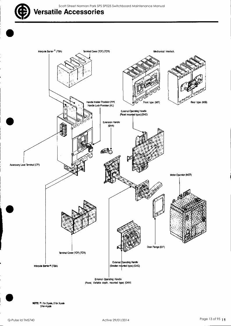
Versatile Accessories
Interpole Barrier * (IBA) Terminal Cover (TCF) (TCR)
Handle Holder Provision (HH)
Handle Lock Provision (HL)
Extension Handle
(EHA)
Mechanical Interlock.
External Operating Handle
(Panel monmtpd type) (OHE)
Accessory Lead Terminal (LTF)
Interpol° Barrier* (TBA)
Terminal Cover (TCF) (TCR)
NOTE: *1 for 2-pole, 2 for 3-pole
3 for 4-pole
External Operating Handle
(Panel, Variable depth, mounted type) (OHH)
Motor Operator (MOT)
11
Scott Street Norman Park SPS SP025 Switchboard Maintenance Manual
Q-Pulse Id TMS740 Active 29/01/2014 Page 13 of 95

PRICE LIST CATALOGUE
1803-P MAY 1989
sprecher+ schuh
PRICES INVALID This publication is for
technical reference only,
FOR CURRENT PRICES
PLEASE REFER TO THE
LATEST EDITION.
DT 3 Control and Indicating Units, 22 mm 0
Scott Street Norman Park SPS SP025 Switchboard Maintenance Manual
Q-Pulse Id TMS740 Active 29/01/2014 Page 14 of 95

DT 3 range: Better in design and operation
DT 3 brings together the technical solutions of Sprecher + Schuh engineers and the creativity of Italian designers.
Added value for your leading products Control and indicating units should and must be attractive. The control panel is what catches the eye in every installation. It should thus meet the highest aesthetic demands, and demonstrate externally what is hidden within: the high quality and reliability of your control system.
The creators of the DT 3 format: a design team at the famous I.DE.A studios in Turin.
III
Scott Street Norman Park SPS SP025 Switchboard Maintenance Manual
Q-Pulse Id TMS740 Active 29/01/2014 Page 15 of 95

A successful combination Flexible in planning of design and function and application Perfect design is at the same time functional and attractive. DT 3 control and indicating units demonstrate this in many ways: they are not only elegant, but also ergonomic. The two colour front sections not only enhance the appearance of every front panel, but also improve recognition by the user.
Advanced technology provides a much wider selection of units, and allows unrestricted combination of front and rear elements. The harmony between design and technology leads to ease of use and functional integrity even under difficult conditions such as damp, dust, slurry or operation with gloves.
Economy and security, through thoughtful application of technology Technology with better design brings economy. For example: problem free compatability with various inscription types. Design with better technology equals security, as in the design of the front rings to prevent unauthorised tampering, or the foolproof emergency stop pushbutton with two step reset «turn and pull».
Scott Street Norman Park SPS SP025 Switchboard Maintenance Manual
Q-Pulse Id TMS740 Active 29/01/2014 Page 16 of 95

The DT3 range: created for practicality
-..-;;+-t, '44,
s 3( c' X
For effortless and economical solution of all control and signalling problems DT3 is the choice. 4
Scott Street Norman Park SPS SP025 Switchboard Maintenance Manual
Q-Pulse Id TMS740 Active 29/01/2014 Page 17 of 95

Scott Street Norman Park SPS SP025 Switchboard Maintenance Manual
Q-Pulse Id TMS740 Active 29/01/2014 Page 18 of 95

The DT 3 range: modular, dependable, economical
Speed rom the start
A simple round hole without slots is enough!
From innovative modular construction to reliability of function, from time saving mounting to simple wiring: DT 3 is in every respect the best solution.
Compact vane y uired by the simply attached rear elements
The depth req
is in every case 50 mm whether contact block,
lamp or transformer.
6
Scott Street Norman Park SPS SP025 Switchboard Maintenance Manual
Q-Pulse Id TMS740 Active 29/01/2014 Page 19 of 95

Secure positioning Front insertion front elements are held securely in place.
Effortless mounting Mounting needs only one person, even when the front of the
panel is out of reach.
Modular flexibility The consistent modular construction allows additional
elements to be fitted in one of two levels to meet even the most
special requirements.
Reliable operation 'Reliability through and through: from the central
lamp test to the electronics compatible
H-bridge contacts.
7
Scott Street Norman Park SPS SP025 Switchboard Maintenance Manual
Q-Pulse Id TMS740 Active 29/01/2014 Page 20 of 95

The DT 3 range: systematic ordering
Three ordering systems to exactly match your specific require- ments. Savings already - of selection time.
Ordering system 1
simple system
Complete standards units Right at the beginning you will find a list of the most common complete units with the corresponding short form order numbers.
Ordering system 2 comprehensive system
Complete units to your requirements This system also needs only one order number per unit: To the type number you add details for round or rectangular front, colour, legend, contact and lamp elements. (The completed order numbers will be the same as for ordering system 1).
Ordering system 3 fully flexible system
Components for self assembly Diagrams give a clear overview of all individual components and the way which they fit together. The index number refers to the decription, variants and the order number.
Ilk Enclosures Complete or empty
Required arrangement: Copy and complete the order form on page 23.
fi Accessories, Elements for mounting, Legends, Technical information Comprehensive modular system of legends and accessories to suit even the most unusual needs.
8 18 03 Sprecher + Schuh
Scott Street Norman Park SPS SP025 Switchboard Maintenance Manual
Q-Pulse Id TMS740 Active 29/01/2014 Page 21 of 95

Page
Pushbuttons DT 3 Illuminated pushbuttons DTL 3 Rotary switches DS 3 Rotary switches with key DSS 3
Indicator lamps DL 3
Emergency stop pushbutton DN 3 Potentiometer dial DR 3
10 10 10 10
11
11
11
Pushbuttons DT 3 12 Latched pushbuttons DTV 3 12 Illuminated pushbuttons DTL 3 13 Latched illuminated pushbuttons DTLV 3 13 Mushroom pushbuttons DP 3 12 Latched mushroom pushbuttons DPV 3 12 Rotary switches DS 3 14 Illuminated rotary switches DSL 3 15 Rotary switches with key DSS 3 16 Indicator lamps DL 3 17
Indicator lamps DL 3 18 Pushbuttons DT 3 19 Illuminated pushbuttons DTL 3 19 Latched pushbuttons DTV 3 19 Latched illuminated pushbuttons DTLV 3 19 Mushroom pushbuttons DP 3 19 Latched mushroom pushbuttons DPV 3 19 Rotary switches DS 3 20 Illuminated rotary switches DSL 3 20 Rotary switches with key DSS 3 21
Enclosures, empty 22 Enclosures with emergency stop pushbutton 22 Front plates, empty 22
Enclosures, fully fitted 23 Front plates, fully fitted 23
Accessories: Bulbs, small components 24 Contact and lamp blocks 25 Legend plates 25
Legends: Standard legends 26/27 Symbols for text-free legends 28/29 Special legends 34
Technical information 30/31
Dimensions 32/33
Mounting instructions 35
18 03 9
o0
Sprecher + Schuh
o C)
Scott Street Norman Park SPS SP025 Switchboard Maintenance Manual
Q-Pulse Id TMS740 Active 29/01/2014 Page 22 of 95

Complete standard units
10 18 03
Design (for front mounting) Contact
Order Price No.
DT 3 pushbuttons with flush operator and contact blocks
green red
green (START) red (STOP)
DT 3 P-G-10 DT 3 P-R-01
10.80 10.80
DTL 3 illuminated pushbuttons with contact blocks and BA 9s bulb holder, max. 250 V (without bulb)')
for filament bulbs, max. 2 W or neon bulbs
green red
DT 3 P-G-166-10 DT 3 P-R-167-01
12.10 12.10
DTL 3 P-G-E-10 DTL 3 P-R-E-01
15.60 15.60
with series diode and resistor for operating voltage AC 220 V (use 130 V filament bulb, see page 24)
green red DTL 3 P-R-C-01 19.40
DSK 3 rotary switch with knob operator with contact blocks
A stay-put switching
O angle 90°
0-1 DSK 3 P-A-10
V
20.40
D stay-put switching
O angle 2x90°
1-0-II 1_1_11 DSK 3 P-D-10/10
DSS 3 rotary switch with key with contact blocks, all with same key - no. EG 0021
A stay-put switching angle 90°
0-1
key withdrawable in positions 0 and I
DSS 3 P-AF-10
D stay-put switching
O angle 2x90°
1-0-11 1_1_11 DSS 3 P-DT-10/10
key withdrawable in positions I, 0, II
Bulbs - see page 24.
Scott Street Norman Park SPS SP025 Switchboard Maintenance Manual
Q-Pulse Id TMS740 Active 29/01/2014 Page 23 of 95

Sprecher + Schuh
Design (for front mounting) Contact
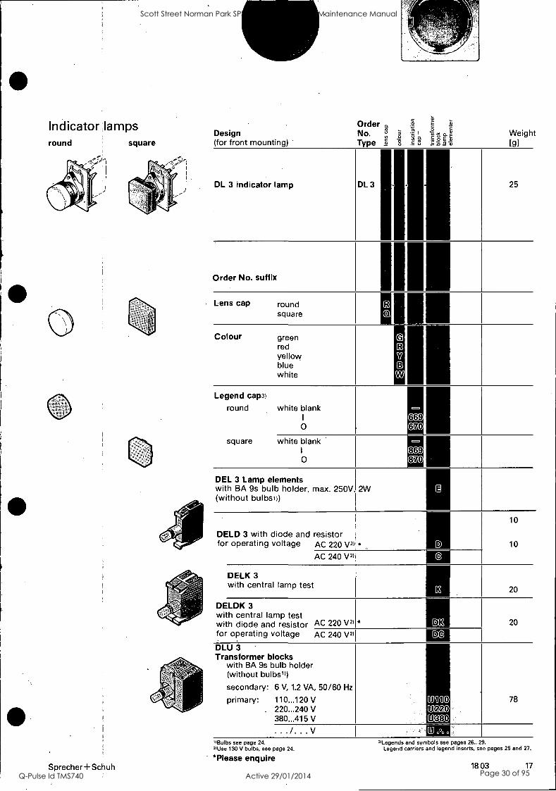
DL 3 indicator lamp with BA 9s bulb holder, max. 250 V (without bulblu
for filament bulb, max. 2.6 W or neon bulbs green red white (clear) yellow blue
with series diode and resistor for operating voltage AC 240 V (use 130 V filament bulb, see page 24)
green red white (clear) yellow blue
DN 3 emergency stop pushbutton 2'
colour red, complete with 1 N/C contact
reset by turning clockwise 0 30 mm 0 40 mm 0 50 mm
Order Price No.
DL 3R-G-E DL 3R-R-E DL 3R-W-E DL 3R-Y-E DL 3R-B-E
DL 3R-G-C DL 3R-R-C DL 3R-W-C DL 3R-Y-C DL 3R-B-C
DNS 3 emergency stop pushbutton colour red, complete with 1 N/C contact
release by key reset by turning clockwise 0 30 mm 0 40 mm 0 50 mm
2)
DR 3 potentiometer dial scale divisions 0...12, 360 legend size 2.5 mm (without potentiometer)
for potentiometers with 6 mm spindles spindle length 50 mm
1' Bulbs - see page 24. Legend rings - see page 24
DN 3-30-01 DN 3-40-01 DN 3-50-01
DNS 3-30-01 DNS 3-40-01 DNS 3-50-01
DR 3
11.75 11.75 11.75 11.75 11.75
17.90 17.90 17.90 17.90 17.90
26.20
18 03 11
Scott Street Norman Park SPS SP025 Switchboard Maintenance Manual
Q-Pulse Id TMS740 Active 29/01/2014 Page 24 of 95

DT 3
DTH 3
DTV 3
DTVH 3 -
DP 3
DPV 3
DPG 3
DPGV 3 -
Complete units to specification Pushbuttons round square
12 18 03
Design (for front mounting)
DT 3 pushbutton
DTH 3 raised pushbutton')
DTV 3 latched pushbutton
DTVH 3 raised latched pushbutton')
DP 3 mushroom pushbutton 42 mm 0
DPV 3 latched mush. pushbutton') 42 mm 0
DPG 3 mushroom pushbutton 68 mm 0
DPGV 3 latched mush. pushbutton') 68 mm 0 Order No. suffix
Front ring Raised
round PB PB Mush.
grey plastic P P P
black plastic N N N
metal L L L
metal extended M - metal sealed
square grey plastic black plastic
Raised Mush. Mush. Colour P8 PB 42 68
green G G G G
red R R R R
yellow Y Y Y - blue B - - with W - black N N
Inscription cap white blank
other text and symbols see START pages 26...29 STOP
black blank
DE 3 Contact blocks2)3) none 1 contact
block
2 contact blocks
3 contact blocks
1) Legend caps cannot be used.
3) For operation of Contact block in centre position Operating bridge DT3 -OB is required (see pages 24 and 35)
Order No. Type
0 0 0
101 369 370 166 167 106
Weight [g]
44
45
44
45
44
44
49
49
2
8 10 18 11
0.5
10
20
30
21Further contact blocks can be fitted at second level. Contact blocks for base mounting (separate mounting) see page 25. Legend carriers and legend inserts, see pages 25 and 27.
Sprecher +Schuh
Scott Street Norman Park SPS SP025 Switchboard Maintenance Manual
Q-Pulse Id TMS740 Active 29/01/2014 Page 25 of 95

Illuminated pushbuttons round square
0
Sprecher+Schuh
Design (for front mounting)
Order No. Typ
a
0 0
Weight [g]
DTL 3 illuminated pushbutton
DTLV 3 illuminated latched pushbutton
DTL 3 K K K J, J, 44
DTLV 3 I H li 44
Order No. suffix
Front ring rond grey plastic
black plastic metal metal extended metal sealed
P N L M F
2
8 10 18 11
square grey plastic black plastic
llP 6 12
Colour cap green red yellow blue white
R
Y B
W
.
Inscription cap white blank
other text I
and symbols 0 see pages START 26...29 STOP
101 369, 370 166 167
0.5
.
DEL 3 Lamp elementsi) with BA 9s bulb holder, max. 250V, (without bulbs) -
2W
10
with diode and resistor for operating voltage AC 220 V2) * 10
DELD 3 AC 240 V2)
DELK 3 with central lamp test
20
with central lamp test with diode and resistor for operating voltage AC 220 V2) * Dit 20
DELDK 3 AC 240 V2)
Contact blocks3) none 00
1 contact ----c- block _r_ O1
10 10
2 contact ----4- ---r" blocks ---r"
0 VI 20
20
DU 3 Transformer blocks secondary: 6 V, 1.2 VA, 50/60 Hz primary: 110...120 V
220...240 V 380...415 V
gil'il0 (!)%n
78
4380 (!) ,, , . . . /. . . V
')Bulbs see page 24. 2)Use 130 V bulbs. See page 24.
Legend carriers and legend inserts, see pages 25 and 27.
* Please enquire
3) Further contact blocks can be fitted to illuminated push- buttons at the second level if no transformer block is used. Contact and lamp blocks for base (sep.mounting)s. page 25.
18 03 13
Scott Street Norman Park SPS SP025 Switchboard Maintenance Manual
Q-Pulse Id TMS740 Active 29/01/2014 Page 26 of 95

Complete units to specification Rotary switches round
14 18 03
square Design for front mounting)
Order g <
No. IF;
Type n s
Weight [g]
DSH 3 rotary switch with long operator
DSK 3 rotary switch with short operator
DSH 3
,
ihdvvf
46
DSK 3 47
Order No. suffix
Front ring round grey plastic
black plastic metal
P lZI
11,
2
8 10
square grey plastic black plastic
6
12
Switch A
positions 0
stay-put .____I 0 -I switching angle 90°
B 0 1
17 momentary
0-1 switching angle 45°
D 0 stay-put
I____I____ii switching 1-0-11 angle 2X90°
E
I 0 II momentary
\s'f.1.> / switching 1-0-11 angle 2X45° g
G
I
<'
right stay-put switching
0 angle 90° left left momentary
___II switching 1-0-11 angle 45°
DE 3 Contact blocksi )2)
none 00/00
switch pos.
1 contact block
left 01 10
10
2 contact blocks
-
---3- --7-
----F-
Mal 90XXI
Meil®
20
3 contact blocks
--/- --y- -r--
...,_.
--4- --F-
a ,.,=
,c= '-'
I
inftgE D]
'1109i111
Mili]
30
"Further contact blocks can be fitted at level 2. Contact blocks for base (separate) mounting, see page 25.
2) For operation of Contact block in centre position Operating bridge DT3 -OB is required. (see pages 24 and 35).
Legend carriers and legend inserts, see pages 25 and 27.
Sprecher +Schuh
Scott Street Norman Park SPS SP025 Switchboard Maintenance Manual
Q-Pulse Id TMS740 Active 29/01/2014 Page 27 of 95

Illuminated rotary switches round square
Sprecher + Schuh
Design (for front mounting)
Order No. Type
5 y t cLE 2-6
2 `8 go go Weight [g]
DSHL 3 illuminated rotary switch with long operator
DSKL 3 illuminated rotary switch with short operator
DSHL 3
DSKL 3 pm Ii
0 1
46
47
Order No. suffix I
1
Front ring round grey plastic
metal 2
10
square grey plastic 1 11
( 3
Switch positions A ? stay-put
L _ i 0 -I sw. angle 90° CQ
B O 1 momentary 0 -I sw. angle 45°
D 0 stay-put i____1___JI 1-0-II sw. angle 2x90°
E ! 0 4 momentary 1-0-11 sw. angle 2x45°
G right stay-put sw. angle 90°
1 0 left momentary .:1 1_____111-0-11 sw. angle 45°
DEL 3 Lamp elements with BA 9s bulb holder, max. 250V, (without bulbsi))
2W E
with diode and resistor for operating voltage AC 220 V2) please enquire D
10
10
DELD 3 AC 240 V21 -
DELK 3 with central lamp test
133 ; 20
with central lamp test with diode and resistor for operating voltage AC 220 V21
1
please enquire 1
20
DELDK 3 AC 240 V21
DE 3 Contact blocks3) none
D@
CD
switch pos. 1 contact
block
left right -----v -, 09
90 10
2 contact blocks
----r- r_
---,---
----+- ----+- . .....,_
01M 410 9(10i] 1:113990
09890
20
Transformer blocks see page 13
78
',Bulbs see page 24. 2) Use 130 V bulbs, see page 24. 31 Further contact blocks can be fitted at the second level
if no transformer block is used
Legend carriers and inserts, see pages 25 and 27. Contact and lamp blocks for base (separate) mounting, see page 25.
18 03 15
Scott Street Norman Park SPS SP025 Switchboard Maintenance Manual
Q-Pulse Id TMS740 Active 29/01/2014 Page 28 of 95

Complete units to specification Key operated rotary switches
16 18 03
Design (for front mounting)
Order No. Type
-3
3 PI §.T°
Weight [g]
DSS 3 P rotary switch, grey, with key with two keys
DSS 3 P
1)
11 48
DSS 3 N rotary switch, black, with key with two keys
DSS 3 N - -
all with same key no. EG 0021 EG21
with various random key no's on request E E. .
with specified key no's on request E E. . I
Order No. suffix Switching and key removal positions A 0 stay-put
1.____I switching angle 90°
key removable at pos.: Kaba-Micro type 0 1707 D i AD
AF 0-1 1707-F
B 0 I momentary ty switching angle 45°
key removable at pos.: Kaba-Micro type 0 1707-D BD
D
key removable
0
0 stay-put sw. angle 2X90°
at pos.: Kaba-Micro type 1707-D DD
DZ
DF
DT
i
I and II 1707-Z
0 and II 1707-F
0 and I and II 1707-T
E I 0 II momentary ss)!Iy" sw. angle 2X45°
key removable at pos.: Kaba-Micro type 0 1707-D ED
G right stay-put switching angle 90°
I 0 left momentary l_____Ii switching angle 45°
key removable at pos.: Kaba-Micro type 0 1707-D GD
GF O and II 1707-F
Contact blocks') none j 00
switch pos.
1 contact block
left right
. j
01 10
10
2 contact blocks
--v -r- - ---v
----3-
--v j
j
01/01 10/01 10/10 01/10
20
3 contact blocks
-/- -- _,..--__ _..--- ...,_
----v ---v
__,-._
_,_ _,,_
---3- ---v _y_ _,--_ _,--_. _7_ ---c-
20/10 10/20 20/01 10/11 01120 01/11
30
Legend carriers and legend inserts, see pages 25 and 27.
1) For operation of Contact blocks in centre position Operating bridge DT3 -OB is required. (see pages 24 and 35). Sprecher+Schuh
Scott Street Norman Park SPS SP025 Switchboard Maintenance Manual
Q-Pulse Id TMS740 Active 29/01/2014 Page 29 of 95
Indicator', lamps round
Sprecher +Schuh
square Design (for front mounting) -
Order a .
c 9 E
No. = a 2 ° a
Type 2 8 .s E
-a
Weight [g]
DL 3 indicator lamp DL 3 25
Order No. suffix
Lens cap round square
Colour green red yellow blue white
173
SY
D Zig
Legend cap3)
round white blank I
0
= 669 OM
square white blank .
Io =
869 870
DEL 3 Lamp elements with BA 9s bulb holder, max. 250V, (without bulbsi))
2W g
DELD 3 with diode and resistor for operating voltage AC 220 V2) * D
10
10
AC 240 V2) @
DELK 3 with central lamp test
G3 20
DELDK 3 with central lamp test with diode and resistor AC 220 V2) * LE 20
for operating voltage AC 240 V2) CA
DLU 3 '
Transformer blocks with BA 9s bulb holder (without bulbs'))
secondary: 6 V, 1.2 VA, 50/60 Hz
primary: 110...120 V . 220...240 V
380...415 V
Pii90 Ma) U 380
78
. . . /. . . V U... "Bulbs see page 24. zUse 130 V bulbs, see page 24.
*Please enquire
"Legends and symbols see pages 26...29. Legend carriers and legend inserts, see pages 25 and 27.
18 03 17
Scott Street Norman Park SPS SP025 Switchboard Maintenance Manual
Q-Pulse Id TMS740 Active 29/01/2014 Page 30 of 95

Components for self assembly DL 3 indicator lights
L0021
Front elements with blank inscription cap and colour cap
-DL 3 R round LO011
green -G red -R yellow -Y blue -B white -W
-DL 3 Q square
green -G red -R yellow -Y blue -B white -W
D 3-BR fixing ring
for front elements
1 003
D 3-KE coupling plate
for attachment of lamp blocks
01Y4
18 18 03
DEL 3 lamp elements with BA 9s bulb holder, max. 250 V (without bulbs1))
for filament bulbs, max. 2.6 W or neon bulbs
L005
4.90
with central lamp test for filament bulbs, max. 2.6 W or neon bulbs
with diode and resistor for operating voltage
-D AC 220 V -C AC 240 V
Con
8.60
130 V filament bulbs, s. page 24
with central lamp test with diode and resistor for operating voltage D008
DK AC 220V DC AC 240V 11&03
130 V filament lamps, s. page 24
LIndex_Not
Price $
DUL 3 transfomer blocks with BA 9s bulb holder, max. 250 V (without bulbs1))
secondary: 6 V, 1.2 VA, 50/60 Hz
primary: 110...120 V 220...240 V 380...415 V
[0.09
29.00
Lolo
"Bulbs, see page 24.
Sprecher+ Schuh
Scott Street Norman Park SPS SP025 Switchboard Maintenance Manual
Q-Pulse Id TMS740 Active 29/01/2014 Page 31 of 95

DT...3 pushbuttons DT...L3 illuminated pushbuttons
Front elements
DT 3 momentary
DTV 3 latched
[008
[009
fliidercNO1 Price $
DEL 3- lamp elements with BA 9s bulb holder, max. 250 V (without bulbs2))
FIM61
Operators
D 37 colour caps
green -G red -R yellow -Y blue -B white -W
0
Lod
0.28
D3-H Raised button') L0.02
green -G red -R yellow -Y
Mushroom 42 mm 01) E003 DP 3 green -G reds -R yellow -Y black -B
LID
Mushroom 68 mm 01) DPG-3 green -G red -R
momentary with plastic front ring -P grey -N black
with metal front ring -L
OYI.
with square front ring -QP grey -QN black
a &
latched with plastic front ring -P grey .
-N black
TO-1
,q0
with metal front ring 0:174
-L
with square front ring -QP grey -QN black
[015
)
L004 D 3-BR fixing ring for front elements
c C D
Inscription cap
D3-101 white blank D3-106 black blank
Front rings
DT 3-MFR extended front ring metal
&
Ea-16
D 3-KE coupling plate for attachment of contact and lamp blocks
a) DE 3 contact blocks
-V- 10 01
Sprecher+ Schuh
OL
3.n 01.9
'1 kaID
for filament bulbs, max. 2 W or neon bulbs Eiffo" -E 4.90
with central lamp test for filament bulbs, max. 2 W or neon bulbs L021. -K
c
with diode and resistor for operating voltage -D AC 220 V -C AC 240 V
ro2
8.60
130 V filament bulbs, s. page 24
with central lamp test with diode and resistor for operating voltage -DK AC 220 V -DC AC 240 V
[023
CC
130 V filament lamps, s. page 24
DU 3- transformer blocks for addition to lamp blocks
secondary: 6 V, 1.2 VA, 50/60 Hz
primary: 110...120 V 220...240 V 380...415 V
L024
29.00
. . . /. . . V [625
',Not suitable for illuminated pushbuttons. ,,For bulbs see page 24.
3) For operation of Contact block in centre position Operating bridge DT3 -OB is required (see pages 24 and 35). 18 03 19
Scott Street Norman Park SPS SP025 Switchboard Maintenance Manual
Q-Pulse Id TMS740 Active 29/01/2014 Page 32 of 95

Components for self assembly DS 3 rotary switches DSL 3 illuminated rotary switches
0
serating elements
DSK 3- short operator 1270-0,
0 DSH 3- long operator
Round front elements DS 3P-with
plastic front ring
Switch positions: A ? grey
1 -- --' black
CoCT21
PrOA Eadl
a)
B grey 1 black
94CC)
D ° rey "black
iNCO O
E !,,,?,9 grey l/ black
WI)
G co iga grey , )
DS 3L- with metal front ring
Square front elements
DS 30- with plastic front ring
Switch positions: A o grey
black
B grey black
'QE2.03
D o grey black
CO
E 0 u grey
\<1>" black ilaa)
O G 0 grey
black a)
D 3-BR fixing ring
for front elements
006
MCI
D 3-KE coupling plate for attachment of contact and lamp blocks
B ?
D o
[_014]
atW
F6091
flndez No?
Price $
DEL 3- lamp elements with BA 9s bulb holder, max. 250 V (without bulbs1))
for filament bulbs, max. 2 W or neon bulbs -E
with central lamp test for filament bulbs, max. 2 W or neon bulbs -K
with diode and resistor for operating voltage -D AC 220 V -C AC 240 V
Dal
[OW2.
130 V filament bulbs, s. page 24
with central lamp test with diode and resistor for operating voltage
-DK AC 220 V -DC AC 240 V
golo,
ZCCI
130 V filament lamps, s. page 24
DU 3 transformer blocks for addition to lamp blocks
secondary: 6 V, 1.2 VA, 50/60 Hz
primary: 110...120 V 220...240 V 380...415 V E
I o n
G 1 0
20 18 03
DE 3 contact blocks
-10 -01
-OL
00 toirA
r2M. row
Mom azatir, 11For bulbs see page 24.
Sprecher +Schuh
Scott Street Norman Park SPS SP025 Switchboard Maintenance Manual
Q-Pulse Id TMS740 Active 29/01/2014 Page 33 of 95

DSS 3 rotary switch with key
Warning: During assembly ensure that the lock and front element are correctly positioned before fitting together.
For security reasons it is not possible to repeat this dperation.
Kaba-micro 1707 lock with 2 keys
all with same key, no. EG 17071)
switch positions:
A 0
[____I
key removal positions:
0 (1707D)
0 I (1707F)
0 B 0 (1707D)
D 0 (1707D)
0 II (1707F)
0 I II (1707Z)
0 I 11 (1707T)
I E
0 I I 0 (1707D)
GI 0
0 (1707D)
sq_____110 II (1707F)
[0011 DSS 3 front elements
34.00
31M)
34.00
3=0
switch positions: colour
A 0 grey [ black
1006]
[0021 D 3-BR fixing ring
0 I
B kr' grey 1/ black
for front elements
Ilndez Nod.
Price $
[003]
D 3-KE coupling plate
MI D 0 grey black
i________II
E grey ! black
31M) \fi>/ O
g)34a G grey I 0 black
v: II
1) Other key number available on request.
Sprecher + Schuh
for attachment of contact blocks
004
903
DE 3 contact blocks
-10 -01
-OL
005
Me, glFg,
006
9411E0
18 03 21
Scott Street Norman Park SPS SP025 Switchboard Maintenance Manual
Q-Pulse Id TMS740 Active 29/01/2014 Page 34 of 95

Enclosures Enclosures
Front plates
Enclosures with emergency stop pushbutton
Accessories
Legend plates
Dimensions
22 18 03
Design
Total control positions Order No.
Price $
grey plastic degree of protection IP 65 to IEC 529. Water jet protected to SEV 3047
empty with 22.5 mm 0 mounting holes, and 2 cable entries 21.5 mm 0, top with knock out, bottom with cable sleeve
aluminium grey painted degree,of protection IP 65 to IEC 529 water jet protected to SEV 3047
empty with 22.5 mm 0 mounting holes
1
2
3 5
1
2
3 5
empty without mounting 1
holes 2
3
5
anodised aluminium plate with tightfitting rubbergasketand 4 captive fixing screws
empty with 22.5 mm 0 mounting holes
1
2 3 4 5
yellow plastic complete with 1 N/C contact
reset by turning clockwise
release by key reset by turning clockwise
DYA 3-1A DYA 3-2A DYA 3-3A DYA 3-5A
DZA 3-1A DZA 3-2A DZA 3-3A DZA 3-5A
DZB 3-1A * DZB 3-2A * DZB 3-3A * DZB 3-5A *
DZE 1-1A * DZE 1-2A * DZE 1-3A * DZE 1-4A * DZE 1-5A *
DYA 3-NS-40-01
yellow aluminium complete with 1 N/C contact
reset by turning clockwise DZA 3-N-40-01
release oy Key reset by turning clockwise DZA 3-NS-40-01 -
cable glands PG 16 mm with fixing nut , plastic +P VM
brass +M *
blanking plug PG 16 mm plastic, with fixing nut +K MC)
blank, page 23 with legend, page 27
see page 33
*Please enquire Sprecher + Schuh
Scott Street Norman Park SPS SP025 Switchboard Maintenance Manual
Q-Pulse Id TMS740 Active 29/01/2014 Page 35 of 95

Fully equipped enclosurei Fully equipped front plates
Assembled in plastic or aluminium enclosure
Positions:
Assembled on anodized aluminium front plate
Positions:
D
C
B
A
Order sheet for copying
Order details for specially equipped enclosure or front plate
Customer:
Originator:
Date:
Design
Enclosure
To
C 0
O c
E
Price
Cable gland
plastic aluminium
plastic brass
Blanking plugs plastic
Front plate anodised alum.
Position Order No.
E
C
B
A
total
Ordering example Design
Plastic enclosure with 5 control positions.
Pos. E: Indicator lamp') DL 3-R-Y-582-E
Pos. D: Pushbutton DT 3 L-G-369-21
Pos. C: Pushbutton DT 3 L-R-370-11
Pos. B: Rotary switch with key DSS 3-AD-01
(page 17)
(page 12)
Design 0
0
0a
E
a. Pride
Enclosure
Cable gland
plastic aluminium
plastic brass
(page 12) Blanking plugs plastic
(page 16)
Pos. A: Round blanking plug 18.104.207-51 (page 24)
Front elements (see pages 12...17).
Contact and lamp blocks for base mounting (see page 25).
Please order legend plates separately (see pages 25 and 27).
Front plate
Position Order No.
E
C
B
A
1 5
O
1-11-771 >HD Fri 17F1
anodised alum. 71 17
DL 3 R-Y-582-E DT 3 L-G-369-21 DT 3 L-R-370-11 DSS 3-AD-01 18.104.207-51
total
"Lamp blocks E, D or C may be specified (see page 25).
Sprecher + Schuh 18 03 23
Scott Street Norman Park SPS SP025 Switchboard Maintenance Manual
Q-Pulse Id TMS740 Active 29/01/2014 Page 36 of 95

Accessories, small components
24 18 03
Design Order No.
Price
Miniature filament bulbs, clear (BA 9s)
voltage [V] max. rating [W]
6. 1.2 12 1.4 24 1.4 36 1.4 48 1.4 60 1.5
BA 9-6 BA 9-12 BA 9-24 '
BA 9-36 BA 9-48-02 BA 9-60-02
MO
130 2.6
for lamp blocks with diodes and resistors for operation from AC 220 V or 240 V
BA 9-130 an
Miniature neon bulbs (BA 9s)
110 V...127,V clear 220 V...240 V clear
BA 9N-110 BA 9N-240
gia)
Lamp extractor for BA 9s filament and neon lamps DT 3-LE KO)
Emergency stop ring yellow 0 90 mm without legend DN 3-B MD
with legend: EMERGENCY-STOP/ NOT-AUS/ARRET D'URGENCE DN 3-E Sza)
Blanking plug round square
DT 3R-BP DT 3Q -BP
Sa) aa)
Operating bridge for operating contacts in position 3
DT 3-0B (i).
Locking tab for securing front ring (use 2, 90° apart)
DT 3-LT .
Clii)
Replacement key Kaba-Micro 1700 DSS 3 6.00
Front rings for pushbuttons round plastic grey DT 3-PFR
plastic black DT 3-NFR 0.45 metal DT 3-LFR 4ic00
square - plastic grey DT 3Q -PFR 0.45
plastic black DT 30-NFR Oia,
Lens caps for indicator lamps round green
red yellow blue white
DT 3G-LC DT 3R-LC DT 3Y-LC DT 3B-LC DT 3W-LC
'100
square green red yellow blue white
DT 3Q -GLC DT 3Q -RLC DT 30-YLC DT 30-BLC DT 30-WLC
qa)
Legend caps11
round square
DT 3-LC DT 3Q -LC
Cg@ 0:0
Reset Rod for resetting overload relays DT 3-RR150 gia)
1) With legends or symbols, see page 26...29.
Scott Street Norman Park SPS SP025 Switchboard Maintenance Manual
Q-Pulse Id TMS740 Active 29/01/2014 Page 37 of 95

I)
Base mounting elements, legend plates
Sprecher +Schuh
Design Order No.
Price
DA 3 contact blocks for base mounting -10 ----- -E 10 ---= -01 ---.4-
DA 3-10 -DA 3-E10 DA 3-01
bia:)
Ma) MO
-OL ---..b- DA 3-L01 Ma) DAL 3 lamp elements for base mounting with BA 9s bulb holder, max. 250 V (without bulb1))
for filament bulbs max. 2 W for DTL max. 2.6 W for DL or neon bulb -E DAL 3-E lag)
with diode and resistor for operating voltage -D 'AC 220 V - -C AC 240 V
filament bulbs 130 V see page 24
DALD-C X4.00
Legend carriers black plastic for use with legend inserts
size 30X48 mm secured by front element
DT 3-30-LC 0.60
size 48X48 mm secured by front element
size 48X18 mm secured by double sided adhesive tape or by 2 screws
DT 3-48-LC
DT 3-18-LC
Shi:n
IC C)
Legend platesz * for legend carrier
size 30X48 mm aluminised plastic without legend (10 pieces)
DT 3-30-LP C:620
for legend carriers size 48X48 mm and 48X18 mm aluminised plastic without legend (10 pieces)
DT 3-48-LP Oa)
Legend platesz for enclosures size 19X19 mm aluminised plastic without legend (10 pieces)
DT 3-19-LP 0.60
"For bulbs, see page 24. zFor legend plates with legends see page 27.
18 03 25
Scott Street Norman Park SPS SP025 Switchboard Maintenance Manual
Q-Pulse Id TMS740 Active 29/01/2014 Page 38 of 95

Standard legends To DIN 30 640 E
German English.02)3) French
Inscription caps for pushbuttons white black characters
Price Order No. $
Special.Iegends page 34
Legend caps for indicator lamps
black round square white characters
Price Order No. $ Order No.
Price Order No.
Price
EIN ON
.
MARCHE
DT3-151 -168* -183
1.30 DT3-
-268e 1.30 DT3
- -556581e 1.30
DT3-751 -7686 -783
1.30
AUS -152 -552 -752 OFF -169* 1.30 -2690 1.30 -569* 1.30 -769* 1.30 ARRET -184 -584 -784
AUF -153 DT3-253 UP -170e 1.30 -2700 1.30 -570e 1.30 -770* 1.30 OUVRIR -185 -285/ AB -154 -254 DOWN -171e 1.30 -271e 1.30 -571e 1.30 -771e 1.30 Descendre -188
ZU -155 -255 CLOSE -172 -272 FERMER -186 -286
HEBEN -156 RAISE -173e 1.30 -2736 1.30 -5730 1.30 -773e 1.30 Monter -187
SENKEN -157 .
LOWER -174e 1.30 -274e 1.30 -5746 1.30 -7740 1.30 Descendre -188
RECHTS -158 RIGHT -175 DROITE -189
LINKS -159 LEFT -176 GAUCHE -190
VOR -160 -260 FORWARD -177. 1.30 -2770 1.30 -577* 1.30 -777e 1.30 AVANT -191 -291
ZURUECK -161 -261 REVERSE -178e 1.30 -278e 1.30 -578e 1.30 -7780 1.30
ARRIERE -192 -292
SCHNELL -162 -262 FAST -179 -279 RAPIDE -193 -293
LANGSAM -163 -263 SLOW -180 -280 LENT -194 -294
Einrichten -164 -264 SET-UP -181 -281 .
Reg ler -195 -295
Betrieb 165 -265 -565 -765 RUN -182 -282 -582. -782 En service -196 -296 f -596 -796
START -166 START -166* 1.30 -266* 1.30 -566e 1.30 -7660 1.30 MARCHE -183 -583
STOP -167 STOP -1679 1.30 -267e 1.30 -567e 1.30 -7670 1.30 ARRET -184 -584
HAND -197 -297 -597 -797 HAND -197 -297 -597 -797 MANUEL -199 -299 -599 -799
AUTO -198 -298 -598 -798 AUTO -198 -298 -598 -798 AUTO -198 -298 -598 -798
RESET -149 -249
26 18 03
1) NOTE: Stocked Labels - others on request 2) Lettering 4mm 3) Special legendsi$0.551per letter. Sprecher + Schuh
Scott Street Norman Park SPS SP025 Switchboard Maintenance Manual
Q-Pulse Id TMS740 Active 29/01/2014 Page 39 of 95
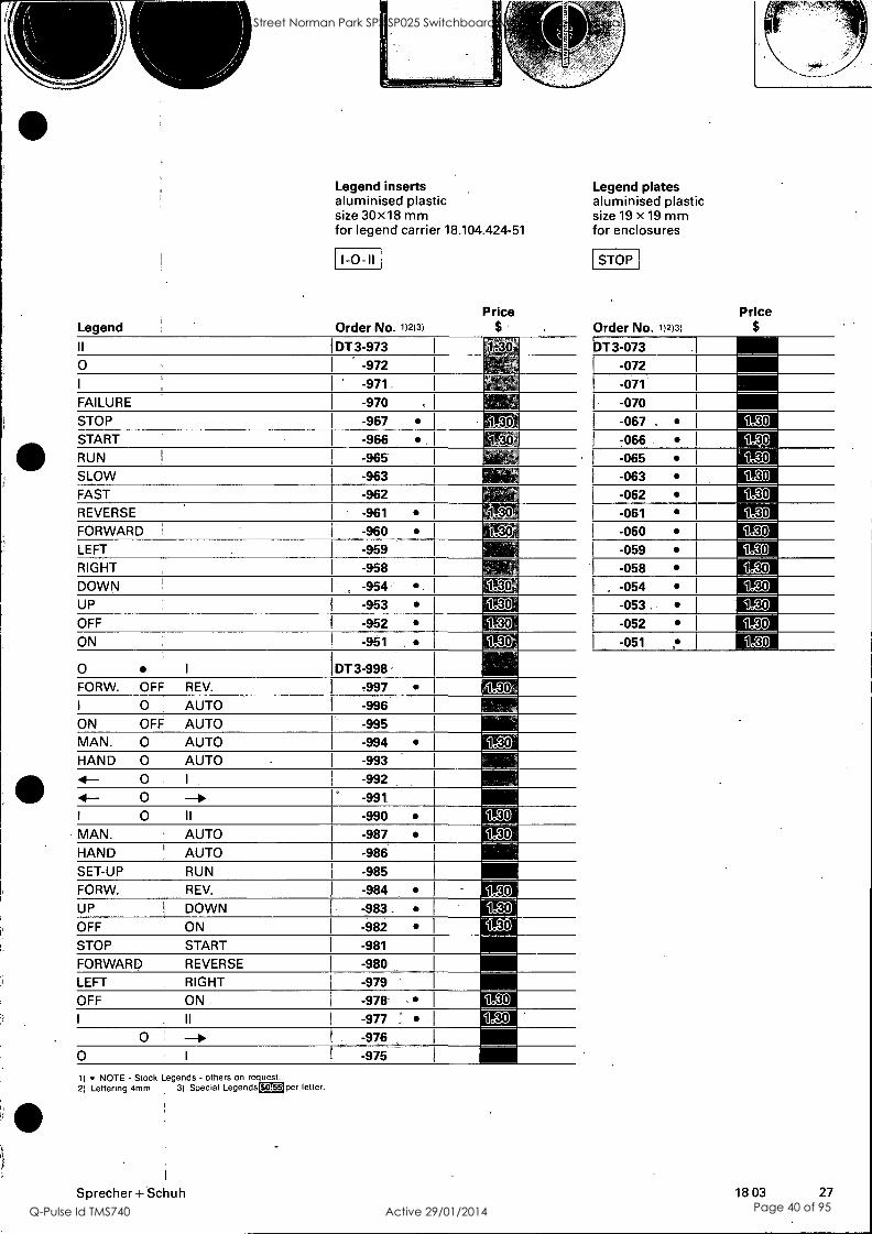
Legend
Legend inserts aluminised plastic size 30x18 mm for legend carrier 18.104.424-51
1-0-11
Order No. 1)2)3)
Price
Il DT 3-973 1.
O ' -972
I -971
FAILURE -970 .
STOP -967 130 START -966 1.301
RUN -965 1$
SLOW -963 FAST -962 REVERSE -961 1.30
FORWARD -960 1.30
LEFT -959
RIGHT -958
DOWN , -954 . IF30 UP -953 1.30
OFF -952 1.30
ON -951 1.30
O I DT 3-998 FORW. OFF REV. -997 tn I 0 AUTO -996
ON OFF AUTO -995 111111 MAN. 0 AUTO -994 1.30 HAND 0 AUTO -993
0 I -992 4- 4- 0 ° -991 -- I 0 II -990 MAN. AUTO -987
HAND H AUTO -986
SET-UP RUN -985
FORW. REV. -984 100 UP DOWN -983. 9.g:0
OFF ON -982 1f30
STOP START -981
FORWARD REVERSE -980
LEFT RIGHT -979
OFF ON -978' 1!30
I II -977 ° 1F30 '
0 -976 - O I -975
1) NOTE - Stock Legends - others on request. 2) Lettering 4mm 3) Special Legends DTI per letter.
Legend plates aluminised plastic size 19 X 19 mm for enclosures
STOP
Order No. 1)2)3)
Price $
DT 3-073
-072
-071
-070
-067. -066 1.30
-065 1.30
-063
-062 1.30
-061
-060 1.30
-059 130 -058 1.30
. -054 1.30
-053. 1.30
-052 1.30
-051 1.30
Sprecher + Schuh 18 03 27
Scott Street Norman Park SPS SP025 Switchboard Maintenance Manual
Q-Pulse Id TMS740 Active 29/01/2014 Page 40 of 95

Symbols for text free legends To DIN 30 600 Inscription caps 1) Legend caps 1)
To ISO R 369 for pushbuttons for indicator lamps white black characters
black white characters
round square
Order Order Order Order Symbols for motion No. No. No. No.
-> DIN direction of continuous ISO 1 linear motion
DT 3-351 DT 3-451 DT 3-651 DT 3-851
DIN linear motion in two -352 -452 -652 -852 4--, ISO 2 directions
-->1 DIN direction of limited ISO 4 linear motion
-353 -453 -653 -853
-71 DIN limited linear I' ISO 5 . movement and return -354 -454 -654 -854
.--m DIN 100 continuous clockwise ISO 7A rotation
-355 -455 -655 -855
es. DIN continuous ISO 7 B anti-clockwise rotation
-356 -456 -656 -856
NW 1r feed
ISO 16 -457 -657 -857
....". DIN rapid traverse ISO 26
° -458 -658 -858
DIN increase a value I ISO 28
-3591 -459 -659 -859
DIN decrease a value ISO 29
-360 -460 -660 -860
Equipment symbols electric motor dB
ISO 41 -461 -661 -861
A DIN pump ISO 48 (general symbol)
-462 -662 -862
Operational symbols 0, DIN - continuous regulation
1 ISO 61
-363 -663 -863
A DIN adjustable ' ISO 62 -364 -664 -864
414 DIN look or tighten ISO 63A
-365 -465
DIN unlock, unclamp 114 ISO 64A
-366 -466
-,(0)<- DIN brake on ISO 65
-367
+(0)-> DIN brake off ISO 66
-368 .
DIN automatic or semi- ISO 267 automatic cycle
-376 ° -676 -876
DIN hand-control --' ISO 35
-375 -675 -875
1 DIN on ISO 69
-369 -469 -669 -869
O DIN off ISO 70
-370 -670 -870
O DIN onoff ISO 71
-371
O DIN 168 on, whilst pushbutton ISO 72 depressed
-372
4, DIN 46 engaging 1r ISO 74
-373 V -473
4. DIN 45 disengaging -tr ISO 75
-374 -474 .
1) These Legend and Inscription caps are available on indent only.
28 18 03 Sprecher + Schuh
Scott Street Norman Park SPS SP025 Switchboard Maintenance Manual
Q-Pulse Id TMS740 Active 29/01/2014 Page 41 of 95

To DIN 30 600 Inscription caps 1) Legend caps 1)
To ISO R 369 for pushbuttons for indicator lamps
white black characters
black white characters
round square
Order Order Order Order Safety and miscellaneous symbols No. No. No. No. di DIN shear pin construction P ISO 91 DT 3-683 DT 3-883 t DIN 131 danger high voltage 1 ISO 92 -684 -884 I DIN 1 caution
ISO 93 . -685 -885 mi 1 DIN main switch ' ISO 94 -686 -886
DIN ; :r. ,,,. 986 ,setup DT 3-382 DT 3-482
oci DIN 155 audible signal ISO -687 -887
fT4 IDSION coolant 101 -388
A ISO
113029 light -389 .
4, DIN 25C-filling aperture L'I ISO 104 -390 -690 -890
4, DIN 258 full level 1""1 ISO 105 -391 -691 -891 6---c) DIN 257 drain '' ISO 106 -392 -692 -892
... p DIN 1751 lubricant ISO 107 493 -693 -893
.
1-4 DIN 263 blowing unit ISO 108 -494 -694 -894 - f DIN 264 suction unit - ISO 109 -495 -695 -895
II step 2
-377 -477
III step 3
-378 . -478
IV step 4 -379
V step 5 -380-
R reset
-381
1) These Legend and Inscription caps are available on inden only.
Sprecher + Schuh 18 03 29
Scott Street Norman Park SPS SP025 Switchboard Maintenance Manual
Q-Pulse Id TMS740 Active 29/01/2014 Page 42 of 95

Technical information
SEV CSA Switzerland Canada
DEMKO Denmark
NEMKO Norway
Electrical CEBEC inspectorate Belgium. Finland
' Germanischer Lloyd FRG
UL Listed USA
SEMKO Sweden
Standards IEC 204-1, 337; SEV 1005, 1093; VDE 0113, 0660 part 201; BS 4794; CEE 24; CSA 22.2, No. 0, No. 14; UL 508, 486 E
./=111k\
Approvals SEV, CSA, UL, CEBEC, Germ. Lloyd, DEMKO, NEMKO, SEMKO, Finland, Buro Veritas, USSR Reg. in preparation
Rated insulation voltage L. IEC 337, VDE 0110, insulation group C
CSA, UL 660 V V. 600 V
Test voltage phase- phase phase - earth
3 kV, 1s 4 kV, 1s
Life mechanical
DT/DP DS DTV/DPV DSS/DN/DNS millon operations 10 0.5 0.5 0.05
UL utilisation category heavy pilot duty light pilot duty
AC A 600 DC Q 600
Ambient temperature AC-1, AC-11 operation
storage, transport
- 25 °C... +60 °C (T85) (inside and outside the enclosure. For illuminated pushbuttons and switches max. external temperature 40 °C)
- 40 °C...+ 80 °C
Climatic resistance damp heat 40 °C/95% rel. humidity
humidity cycling 23 °C, 83%, 40 °C, 93%
56 days
20 cycles
Degree of protection to IEC 529, DIN 40050
Protection against accidental contact to
IP 65 except rotary switch with key and emergency stop pushbutton with key (DSS 3, DNS 3)
IP 54 DSS 3, DNS 3 IP 20 contact and lamp blocks
VDE 0106, part 100
Shock withstand to IEC 68-2-27 30 g
Mounting orientation as required
Example of central lamp test
L1
S 1 F- K1
Test pushbutton
K2 K3
X5
H1
X1
X2
30 18 03 Sprecher+ Schuh
Scott Street Norman Park SPS SP025 Switchboard Maintenance Manual
Q-Pulse Id TMS740 Active 29/01/2014 Page 43 of 95

1i
Contact blocks
Lamp elethents
10
01
3
1 4
Rated thermal current Ah open (ambient 40 °C) enclosed (ambient 60 °C)
10A 6A
Nominal operating voltage (J0 AC 660 V
Nominal operating current I. AC-1 10 A
AC-11 220 V 240 V 380 V 415 V 500 V 600 V 3A 3A 2.5A 2.2A 1.5A 0.75A
DC-11 DE 3 10/DE 3 01
DA 310/DA 301
24 V 48 V 110 V 220 V 440 V
2A 0.6 A 0.2 A 0.1 A 0.04 A
1 DE 3 LO1 /DA 3 LO1 1.3A 0.4A 0.13 A 0.065 A 0.026A
Short circuit withstand without welding 10 A slow
2 Back up fusing permissible rated current fast (D, gF)
slow (DT, gL) 16 A 10 A
Switching frequency
5 Electrical life Ie 0.1 A 1 A 2 A 3 A (AC-11) mill. ops. 10 3 1 0.5
OL Contact security
6000 ops/h
X1
X2
Clearance between oen contacts [loff A on DE 3 10 DE 3 01 DE 3L01 DA 3 10 DA 3 01
reliable for switching electronic circuits
DA 3-L01
2,2 5,7 1,3 5,7 3,3 5,7 2,5 5,7
I I :
6 p
0 1 2 3 4 5 6
mm
I I I I
0 1 2 3 4 5 6 0 1 2 3 4 5 6 0 1 2 3 4 5 6
mm mm mm
DA 3 E10
1,6 5,7
0 1 2 3 4 5 6
mm
Terminal markings to DIN EN 50013
Connections 0.75...2.5 mm2 18+12 AWG
Lamp elements indicator lamps
pushbuttons and illuminated switches
max. permissible 2.6 W
2W
Standard element with BA 9s bulb holder
for filament or neon bulbs max. 250 V (28 mm long, 10 mm 0)
Special elements with BA 9s bulb holder
® X2 with series diode and resistor L , for operating voltage
X5 for filament bulbs AC 220 V or 240 V 130 V (see page 24)
X2 with central lamp test for filarhent or neon bulbs max. 250 V (28 mm long, 10 mm 0)
X1 X2
with series diode and resistor with central lamp test for operating voltage for filament bulbs
AC 220 \for 240 V 130 V (see page 24)
with transformer for filament bulbs 6 V, max. 1.2 W
secondary: voltage 6 V load max. 1.2 VA, 50/60 Hz
primary: voltage 110...120 V, 220...240 V, 380...415 V
Sprecher +Schuh 18 03 31
Scott Street Norman Park SPS SP025 Switchboard Maintenance Manual
Q-Pulse Id TMS740 Active 29/01/2014 Page 44 of 95

Dimensions [mm] Pushbuttons DT 3 (Q), DTV 3 (Q)
Illuminated pushbuttons DTL 3 (Q), DTLV 3 (Q)
Pushbuttons with raised operator Pushbuttons with extended front ring DT 3, DTV 3 DTH 3 (Q), DTVH 3 (Q)
0 0
00
0
0
30
Illuminated pushbuttons with transformer DTL 3 (0), DTLV 3 (Q)
Mushroom pushbuttons DPG 3, DPGV 3 Mushroom pushbuttons DP 3, DPV 3 0 68 mm 0 42 mm
Rotary switch with long operator DSH 3 (Q), DSHL 3 (Q)
Indicator lights DL 3 (Q)
0
0
30
01'1
000
000
30
Illuminated pushbuttons with sealed front ring DT 3, DTV 3
Rotary switch with short operator Rotary switch with key DSS 3 DSK 3 (Q), DSKL 3 (Q)
Indicator lights with transformer DL 3 (0)
Indicator lights with central lamp test DL 3 (Q)
Emergency stop pushbutton with turn Emergency stop pushbutton with key Drilling detail and pull reset DN 3 reset DNS 3
O
O O
00
Potentiometer dial DR 3 spindle lenght 50 mm
O
32 18 03
Blanking plugs round and square
F- min. 30 min. 30 min 30
o 00-00F u-,
E
Legend plates
Sprecher + Schuh
Scott Street Norman Park SPS SP025 Switchboard Maintenance Manual
Q-Pulse Id TMS740 Active 29/01/2014 Page 45 of 95

Base mounting components Pushbuttons
Plastic enclosure DYA 3')
72
Aluminium enclosure DZA 3
Knock-Out Openings at Base
es '°
Earth (Ground) Terminal
Front plate DZE 1
Indicator lamps Bulbs for DL 3, DTL 3, DSL 3
Design Total control positions
A
:DYA 3-1 A 1 - 84 67 22.5 DYA 3-2 A 2 117 100 22.5 'DYA 3-3 A 3 150 133 22.5 ,DYA 3-5 A 5 215 198 22.5
')Knock out opening at top, cable sleeve at bottom.
Design Total control positions
A
DZA 3-1 A 1 99 62 56 22.5 DZA 3-2 A 2 137 100 94 22.5 DZA 3-3 A 3 174 137 131 22.5 ,DZA 3-5 A 5 249 212 206 22.5
Design Total control positions
A
',DZE 1-1 A 1 80 64 22.5 ,DZE 1-2 A 2 110 94 22.5 ,DZE 1-3 A 3 147 131 22.5 ,DZE 1-4 A 4 185 169 22.5 DZE 1-5 A 5 232 206 22.5
Sprecher+ Schuh 1803 33
Scott Street Norman Park SPS SP025 Switchboard Maintenance Manual
Q-Pulse Id TMS740 Active 29/01/2014 Page 46 of 95

Special legends
max. 16
34 18 03
Process hot stamping
Price
Details of requirements clear drawing scale 2:1 provided by customer
Special symbols and text for first order only, charge for stamp, which remains our property Pcano
set up (per text and order) Pdano
stamping charge per letter 0.55
Inscription caps for DT 3 pushbuttons
standard legends see page 26 ISO symbols see pages 27/28 legend area: 4x16 mm or 16 mm 0 legend height: 4mm line spacing: as drawing
Legend caps for DL 3 indicator lamps
round standard legends see page 26 legend area: 4x16 mm or 16 mm 0 legend height: 4mm line spacing: as drawing
square standard legends see page 26 ISO symbols see pages 27/28 legend area: 4x16 mm or 16x16 mm legend height: 4mm line spacing: as drawing. Legend inserts
for 30x48 mm legend carriers
standard legends: see page 27 legend area: 4x16 mm or 3x2 x6.4 mm legend height: 4mm
for enclosures
standard legends:see page 27 legend area: legend height: 3 mm
Sprecher + Schuh
Scott Street Norman Park SPS SP025 Switchboard Maintenance Manual
Q-Pulse Id TMS740 Active 29/01/2014 Page 47 of 95

Mounting instructions Single person mounting Front 1...4 Rear 5...7
1
Front element round or square, push, with the markings at the top, into the 22.5 mm hole in the mounting plate.
2 Locking tabs for securing the front section against unauthorised removal. From the rear insert 2 of these 90° apart into the front element.
3 Bridge for operating contacts at position 3 (centre position). Fit to front element from the rear. Recommended with contact blocks on second level. (2 bridges required). 4 Legend carrier for legend additional to that on front element. Insert tabs into slots in front element.
Permissible combinations of contact blocks .and lamp elements
pushbuttons DT 3, DTH 3, DTV 3, DTVH 3, DP 3, DPV 3, DPG 3, DPGV 3 -
rotary switches DSH 3, DSK 3, DSS 3
illuminated pushbuttons DTL 3, DTLV 3 illuminated rotary switches DSHL 3, DSKL 3
for filament bulbs 6...110 V
for filament bulbs with series diode 130 V, 2.6 W
5 Fixing ring engage bayonet with a slight twist to the right, and fix with 2 screws to prevent rotation.
6 Coupling plate with securing clip to snap onto front element. Not required for base mounting.
7 Contact blocks and lamp elements snap onto coupling plate, or the rear of an existing contact block (2 levels of contacts). For base mounting use elements with fixing feet (see page 23).
for filament bulbs with central lamp test 6...110 V
for filament bulbs with series diode and resistor and central lamp test 130 V, 2.6 W
Sprecher + Schuh
with transformer element
18 03 35
Scott Street Norman Park SPS SP025 Switchboard Maintenance Manual
Q-Pulse Id TMS740 Active 29/01/2014 Page 48 of 95

sprecher+ schuh Represented in Australia by
Electrical Engineering Products P/L
Melbourne 51-67 River Street Richmond VIC. 3121 Phone: (03) 429 2999 Telex: AA31644 Fax: (03) 429 1075
Sydney _30-34 Day Street
Silverwater NSW 2141 Phone: (02) 748 3444
Fax: (02) 648 4353
Brisbane 39 Commercial Road Fortitude Valley OLD. 4006 Phone: (07) 252 9517 Fax: (07) 2523415
Adelaide 29 Croydon Road Keswick SA 5035 Phone: (08) 297 9055 Fax: (08) 371 0962
Newcastle 57 Crescent Road Waratah NSW 2298 Phone: (049) 60 2220 Fax: (049) 60 2203
Agents Perth C.J. Young & Co. Pty. Ltd. 38-40 Railway Parade Bayswater WA 6053 Phone: (09) 271 8666
Fax: (09) 272 3906
Hobart H.M. Bamford (Hobart) 199 Harrington Street Hobart TAS. 7000 Phone: (002) 34 9299 Fax: (002) 31 1693
Launceston H.M. Bamford (Launceston) 59 Garfield Street Launceston TAS. 7250 Phone: (003) 44 8811
Fax: (003) 44 4069
Townsville Paterson Electrical Engineering Agencies 62 Leyland Street Garbutt QLD. 4814 .
Phone: (077) 79 0700 Fax: (077) 75 1457
Darwin J. Blackwood & Son Ltd. (Inc. Tesco Pearce) Mataram Street, Winnellie NT 5789 Phone:. (089) 84 4255 Telex: AA85454 Fax: (089) 84 3945
Technical changes reserved
1803/5.89/22M
-r
Scott Street Norman Park SPS SP025 Switchboard Maintenance Manual
Q-Pulse Id TMS740 Active 29/01/2014 Page 49 of 95

ID
I
r )
HAWKER
Crompton INSTRUMENTS
CURRENT TRANSFORMERS
SCCT Edition 1
Scott Street Norman Park SPS SP025 Switchboard Maintenance Manual
Q-Pulse Id TMS740 Active 29/01/2014 Page 50 of 95
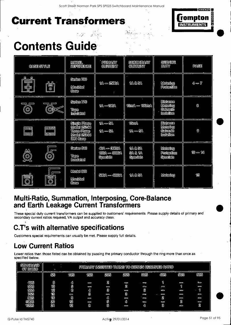
Current Transformers
Contents Guide
MEMO
EOMptOn INSTRUMENTS
CASE Si ILE MODEL REFERENCE
PRIMARY CURRENT
SE-0(3190' CURRENT
SERVICE BUM PAGE
1 i Series 780
Moulded Case
1A - 2500A 1A & 5A Metering Protection
4 -7 ci 0
CP 1
Series 770
Tape Insulated
-100A 10mA - 100mA Distance Metering Galvanic Galvanic Isolation
8
Single Phase Model 252.94 Three Phase Model 253-94 DIN ease
1A - 5A
1A - 5A
lOrrilA
1A - 5A
Distance Metering Galmariic Isolation
9 noon
04- - WI 0
Series 810
Tap_e Insulated
40A - 000A
100A - 3000A Specials
1A & 5A 5A & 1A
Specials
Metering Protection Specials
10 - 14
Model 809
Moulded C ase
500A - o o oA 1A & 5A Metering 15 I-) 0
o 0
Multi-Ratio, Summation, Interposing, Core-Balance and Earth Leakage Current Transformers These special duty current transformers can be supplied to customers' requirements. Please supply details of primary and secondary current ratios required, VA output and accuracy class.
C.T's with alternative specifications Customers special requirements can usually be met. Please supply full details.
Low Current Ratios Lower ratios than those listed can be obtained by passing the primary conductor through the ring more than once as specified below.
grANDARD Gaa0 PRIMARY INSEBIED TURNS TO OBTAIN RECUILIED RATIO
5/5 10/5 15/5 20/5 25/5 30/5 40/5 50/5 60/5
40/5 8 4 2 - - 1
50/5 10 5 - 2 1
60/5 12 6 4 3 2 1
75/5 15 - 5 - 3 80/5 16 8 4 2
100/5 20 10 5 4 2 1-20/5 24 12 8 6 4 3 2
2
Scott Street Norman Park SPS SP025 Switchboard Maintenance Manual
Q-Pulse Id TMS740 Active 29/01/2014 Page 51 of 95

Current Transformers
Measuring Duty Current Transfomers Accuracy selection
Class 0.2
Class 0.5
Class 1
Class 3
Available on request. Designed to individual customer requirements, energy metering, micro control systems. Transducers, pay integration meters, test equipment, control systems WattNAr/Phase Angle meters, recording meters, protection devices, instrument transducers Industrial ammeters, maximum demand indicators
VA Burden Guide
GB=
Crompton INSTRUMENTS
0.5 Short scale moving iron ammeters 0.75-1.5 240° scale moving iron ammeters 0.2-1 Rectified moving coil ammeters 1-1.25 WattNAr/Phase Angle meters 2-4 Recording ammeters 2-3.5 Maximum Demand Indicators 3-3.5 Combined MDI & MI 0.5-4 Paladin transducers 0.5-4 Protector modules 5-10 Electronic control systems
Protection Duty Current Transformers Protection duty current transformers are supplied to accuracy classes 5P or 10P. The figures 5 or 10 define the maximum composite errors in percentage permitted at the specified overload value. Letter `13' indicates a protection duty.
The rated accuracy limit factor (or overload multiple) is specified by a further figure added to the code. 5, 10 and 15 satisfy most applications and indicate overload values x5, x10 and x15. For more detailed information, see BS3938: 1973.
Rated outputs available in VA are 2.5, 5, 7.5, 10, 15. Correct selection requires reference to relay manu- facturers recommendations.
The secondary circuit must not be open-circuited when primary is energised since a dangerously high voltage can build up in certain conditions. Terminals are not insulated against physical contact.
Secondary Lead Burden
Limits of error to BS3938: 1973
Accuracy Class
Error at rated Primary Current
Phase displacement at rated Primary Current
Mins Radians
Composite error at rated accuracy limit Primary current
5P ±1% ±60 ±1.8 5%
10P ±3% - - 10%
The resistance of the secondary lead circuit can be significant and must be taken into account when the current transformer burden is chosen. Where the current transformer is mounted remotely a 1 amp secondary should be used.
VA Burden for 5A C.Ts.
25 A . 20
15 P 10 ,/ ,,, ,''2 a
5 AMR 6,,,,2 lomm2
5 10 15 20 25 30 Metres (CT to instrument)
3
VA Burden for 1A C.Ts.
t. 4 ....,
0.8
, roil 0.6
0.4 1r PE" /ill
,/ .
6rnt.,2
1 OrnM2 MIMI
/1" 1111
4(111112
0.2 A PW
5 10 15 20 25 30 Metres (CT to instrument)
Scott Street Norman Park SPS SP025 Switchboard Maintenance Manual
Q-Pulse Id TMS740 Active 29/01/2014 Page 52 of 95

780 Series umalm
(rompton INSTRUMENTS
The Crompton 780 Series offers current ratios, VA outputs and accuracy classes to suit the require- ments of modern electrical and electronic installations. The tough moulded cases are designed for apiSro- priate busbar or cable sizes and incorporate altern- ative foot or busbar fixing options. They comply with most international standards for ring current transformers. A major feature is the ease of installation with several base and busbar mounting arrangements.
Features * high impact, flame-retardant moulded cases
(classification UL94V-1)
* secondary currents for 1A or 5A * primary currents 1A to 2500A
* cable or busbar styles * simple busbar clamp or push-in fixing feet * alternative DIN rail mounting adaptor * single or twin screw terminals * alternative terminations with integral 600mm
leads * wire sealable terminal cover
Standards Compliance Designed to international standards, the 780 Series complies with the following specifications. BS3938: 1973 (1982), I EC 185: 1966.
Secondary Terminals All models can be supplied with single or double M4 screw shell clamp terminals eliminating the use of cable shoes or tags. When specified insulated flexible leads (600mm) can be provided in place of screw terminals.
Compton I
IYPI I 711,-_,Prd
14030,171 MO
Crompton TIFF
IIC too ISMI,1071
Performance System voltage Test voltage System frequency
Short circuit thermal current (Ith)
Rated dynamic current (Idyn)
Saturation co-efficient
Service temperature Insulation class BS2757 Enclosure code
= 660V max 3kV for 1m
= 50/60Hz (400Hz available on request)
= 60 x rated primary current for 1 second
2.55 x Ith <5 for plain ring <10 for wound primary
: - 20°C to 85°C : Class A (max 105°C) : IP40
Installation A set of push-in fixing feet or busbar clamp, as necessary, are supplied with each CT.
In-line primary busbar inserts and centre insert are available for some models.
A 35mm DIN rail mounting adaptor is available for all models except 788.
Models 781, 782, 783, 784, 785, 786 have two M5 screw fixings in the base.
68
38
Li 12
55
83
4
Scott Street Norman Park SPS SP025 Switchboard Maintenance Manual
Q-Pulse Id TMS740 Active 29/01/2014 Page 53 of 95

780 Series cumn
Crompton INSTRUMENTS
Terminal cover A wire sealable cover is available to insulate secondary terminals.
A ------Th B
...
n \ n
the
__-i
Fixing between 2 conductors A centre insert, designed for types 780 and 781 allows clamping between two bar or cable primary conductors.
D
, A
4 th , i as
Fixing Bolt F °
-
Type No.
DIMENSIONS mm A B C
Type No.
DIMENSIONS mm D E F
780
All other Types
56 31 14
71 38 14
780
781
36 8.2
46 14
M8x50
M12x75
DIN Rail Adaptor 70
Primary
M12 35LG.
Busbars
30
10 - 4 _ii L
1 r 75
For use with Models 781, 782, 783, 784, 785, 786.
x
0-600A
M12 x 35LG.
MIN NU IMMEM' 4 1.1
- 7-i: 17* - nig =i.:- 156
100 1
[En
q1 125
1.-IT r
NM NIS NM OM
78
I
illi 10
-1 0-800A
_AM_ -' II _
-i-: -- i1 Nil __ iiiri
100
ari , ,r____, ,
1 70 "-\---II-.0
---t
152 ,
18
I 180 - 40
For use use with Model 780.
or;111
55 1
m12x 35LG HU WM I i OW 1
OM 1 ill
L.,: - L A
111111 r / / me 10
0.1200A
iinn iiiii - -i- Iii.
100
el miss
152 8 180 ...
I
5
Scott Street Norman Park SPS SP025 Switchboard Maintenance Manual
Q-Pulse Id TMS740 Active 29/01/2014 Page 54 of 95

780 Series in=g
Eompton INSTRUMENTS
Accuracies comply with 853938: and IEC 185: All measurements in millimetres
Type 780 -943
6.5
Supplied with 2 fixing feet. Max cable 0 = 15mm. 1A secondaries are available for all ratings.
Type 781-943
Supplied with 4 fixing feet Max cable 0 = 23mm 1A secondaries are available for all ratings
Type 782-943
Supplied with 4 fixing feet Max cable 0 = 43mm 1A secondaries are available for all ratings except 1200A
Type 783 -944
Supplied with busbar clamp For busbar 30 x 10, 20 x 20mm and cable 0 25mm 1A secondaries are available for all ratings
CT Ratio
VA at Class 5 3 1
30/5 1.5 - - 40/5 2 1.5 - 50/5 2.8 2.5 - 60/5 3.5 3 - 75/5 5 4 - 80/5 5 4 -
100/5 - 5 2.5 120/5 - 5 2.5 125/5 - 5 2.5 150/5 - 5 2.5 200/5 - 6 3 250/5 - 7.5 4
CT Ratio
VA at Class 3 1
VA at Class 3 1 3
VA at Class 1 0.5
40/5 2.5 - - - - - 50/5 2.5 - - - - - - 60/5 2.5 - - - - - 75/5 2.5 - 5 2.5 - - - 80/5 2.5 - 5 2.5 - - -
100/5 5 - 7.5 5 - - - 120/5 5 - 7.5 5 - - - 125/5 5 - 7.5 5 - - - 150/5 5 - 7.5 5 15 10 5 200/5 5 - 7.5 5 15 10 7.5 250/5 5 2.5 7.5 5 20 15 10 300/5 5 2.5 7.5 5 20 15 10 400/5 5 2.5 10 5 30 15 15 500/5 5 2.5 10 5 30 15 15
CT Ratio
VA at Class 3 VA at Class 3 1 3
VA at Class 1 0.5
100/5 2.5 - - - - - 120/5 2.5 5 2.5 - 125/5 2.5 5 2.5 - - - 150/5 2.5 7.5 4.5 L.-- 5 or 3 200/5 2.5 7.5 5 10 6 2.5 250/5 5 7.5 5 10 7.5 5 30015 5 7.5 5 ib 7.5 5 400/5 5 7.5 5 15 7.5 5 500/5 - - - 10 7.5 5 600/5 - - - 12 10 7.5 750/5 - - - 15 10 10 800/5 - - - 15 10 10
1000/5 - - - 20 15 15 1200/5 - - - 20 15 15
CT Ratio
VA at Class 3 1
VA at Class 3 .1
VA at Class 3 1 0.5 .
75/5 2.5 - - - - - - 80/5 2.5 - - - - - -
100/5 2.5 - 5 2.5 - - - 120/5 2.5 - 5 5 - - - 125/5 2.5 - 5 5 - - - 150/5 2.5 - 5 5 10 7.5 2.5 200/5 5 - 7.5 5 15 10 5 250/5 5 2.5 10 7.5 20 15 10 300/5 5 2.5 15 10 20 15 10 .
400/5 5 2.5 15 10 20 15 10 500/5 - - - - 30 15 100
600/5 - - - - 30 15 15 750/5 - - - - 30 15 15 800/5 - - - 30 15 15
6
Scott Street Norman Park SPS SP025 Switchboard Maintenance Manual
Q-Pulse Id TMS740 Active 29/01/2014 Page 55 of 95

780 Series 11=3
Eompton INSTRUMENTS
Accuracies comply with 853938: and IEC 185:
Type 784-944
77 as
Supplied with busbar clamp For busbar 40 x 10, 30 x 20mm and cable 0 32mm: 1A secondaries are available for all ratings except 1200A
Type 785-946
Supplied with 4 fixing feet 1A secondaries are available for all ratings
Type 786-946
77 I. L.- 654 --j 60
Supplied with 4 fixing feet 1A secondaries are available for all ratings
Type 788-944
6,
Supplied with busbar clamp it
4 fixing feet are an optional extra For bUsbar 80 x 30, 64 x 35, 50 x 50mm and cable 063mm 1A secondaries are available for all ratings except 25004
CT Ratio
VA at Class 3 VA at Class 3 1 3
VA at Class 1 0.5
100/5 2.5 - - - - 120/5 2.5 5 2.5 - - 125/5 2.5 5 2.5 - - - 150/5 2.5 6 4.5 6 4.5 2.5 200/5 2.5 7.5 5 10 6 2.5 250/5 5 7.5 5 10 7.5 5 300/5 5 7.5 5 10 7.5 5 400/5 5 7.5 5 15 7.5 5 500/5 - - - 10 7.5 5 600/5 - - - 12 10 7.5 750/5 - - - 15 10 10 800/5 - - - 15 10 10
1000/5 - - - 20 15 15 1200/5 - - - 20 15 15
CT VA at Class VA at Class VA at Class Ratio 3 3 1 3 1 0.5
1/5 5 7.5 5 18 15 7.5 5/5 5 7.5 5 18 15 7.5
7.5/5 5 7.5 5 18 15 7.5 10/5 5 7.5 5 18 15 7.5 15/5 5 7.5 5 18 15 7.5 20/5 5 7.5 5 18 15 7.5 25/5 5 7.5 5 18 15 10 30/5 5 7.5 5 18 15 10 40/5 5 7.5 5 18 15 10 50/5 5 7.5 5 18 15 10 60/5 5 7.5 5 15 15 10 75/5 5 7.5 5 18 15 10 80/5 5 7.5 5 18 15 10
100/5 5 7.5 5 18 15 10 120/5 5 7.5 5 20 15 10 125/5 5 7.5 5 20 15 10 150/5 5 7.5 5 20 15 10 200/5 5 7.5 5 20 15 10 250/5 5 7.5 5 20 15 10
CT VA at Class VA at Class VA at Class Ratio 3 3 1 3 1 0.5
1/5 5 7.5 5 18 15 7.5 5/5 5 7.5 5 18 15 7.5
7.5/5 5 7.5 5 18 15 7.5 10/5 5 7.5 5 18 15 7.5 15/5 5 7.5 5 18 15 7.5 20/5 5 7.5 5 18 15 7.5 25/5 5 7.5 5 18 15 10 30/5 5 7.5 5 18 15 10 40/5 5 7.5 5 18 15 10 50/5 5 7.5 5 18 15 10
CT Ratio
VA at Class 3 1 0.5 3
VA at Class 1 0.5
10P10 VA
200/5 7.5 2.5 - 10 5 - - 250/5 10 5 - 15 10 5 - 300/5 15 10 5 20 15 10 - 400/5 15 .10 7.5 25 15 10 - 500/5 20 15 10 30 20 15 5
600/5 15 10 5 30 20 15 5
750/5 15 10 5 40 25 15 5
800/5 20 15 7.5 40 30 20 5
1000/5 25 20 10 50 40 30 5
1200/5 30 20 15 50 40 30 5 1500/5 30 20 15 50 40 30 5
1600/5 40 30 20 - - - 5
2000/5 50 40 30 - - - 5
2500/5 50 40 30 - - - -
7
Scott Street Norman Park SPS SP025 Switchboard Maintenance Manual
Q-Pulse Id TMS740 Active 29/01/2014 Page 56 of 95

770 Series Crompton INSTRUMENTS
Miniature CT's
Features * Slips over mains cables * Plain ring, cable tie or foot mounted * Size permits pcb mounting * Tough PVC moisture resistant coating * Secondary output lOrnA * Primary rating 1A - 100A * Multi-range version 10A - 100A
Applications * Distance measuring via light conductors * Galvanic isolation for control circuits * Converts mains current to electronic signal values * Operates electronic relays * Moving coil rectifier meters, recorders, digital readouts
Selection Table Intermediate primary current ratings available.
771-940 Ring Type
14-33-1m
Leads 150mm Flexible
Primary current
Dimension C
10A 15 15A 14 20A 14 25A 14 30A 14
773-940 Ring Type- multi-range
15
to- 45 -1.1
Primary Secondary VA current output output
10A 10mA 0.015
d/ 100A 100mA 0.15
Foot Mounting Option MODELS 771, 772 & 773.942 MODEL 771.94 (Wound Primary)
Performance MODELS 771, 772
Primary ratings Secondary outputs
VA output MODEL 773 MULTI-RANGE Primary current range Secondary output VA output ALL MODELS System frequencies Service temperature Insulation class BS2757 Operating voltage Test voltage Accuracy class at standard VA load
% rated Primary current
20-80% 81-120%
Alternative specifications to meet requirements can usually be accommodated.
: 1A - 100A 10mA standard
Other outputs available on request
: 0.03VA (3V at 10mA)
: 10A - 100A : 10mA -- 100mA : 0.015VA - 0.15VA
: 50-60Hz, 400Hz 0°C - 80°C
: class Y (Max. 90°C) 660V a.c. max. 2000V d.c.
% total error (phase displacement
and ratio error) : 1.5% max.
1.0% max.
customers' special
772-940 Ring Type
14
D
Leads 150mm Flexible
Primary current
Dimension A D
40A 25 43 50A 25 43 60A 25 43 75A 25 43
100A 24 44
771-945 Wound Primary Type 150mm Leads
Primary current
Secondary output
1
1.5 2 3 10mA 5 0.03VA 7.5 (3V)
Cable Tie (with or without self-adhesive mount) :
I
39
cable tie
M3 fixing hole 14- 39-+I
Code number becomes xxx - 948
8
Scott Street Norman Park SPS SP025 Switchboard Maintenance Manual
Q-Pulse Id TMS740 Active 29/01/2014 Page 57 of 95
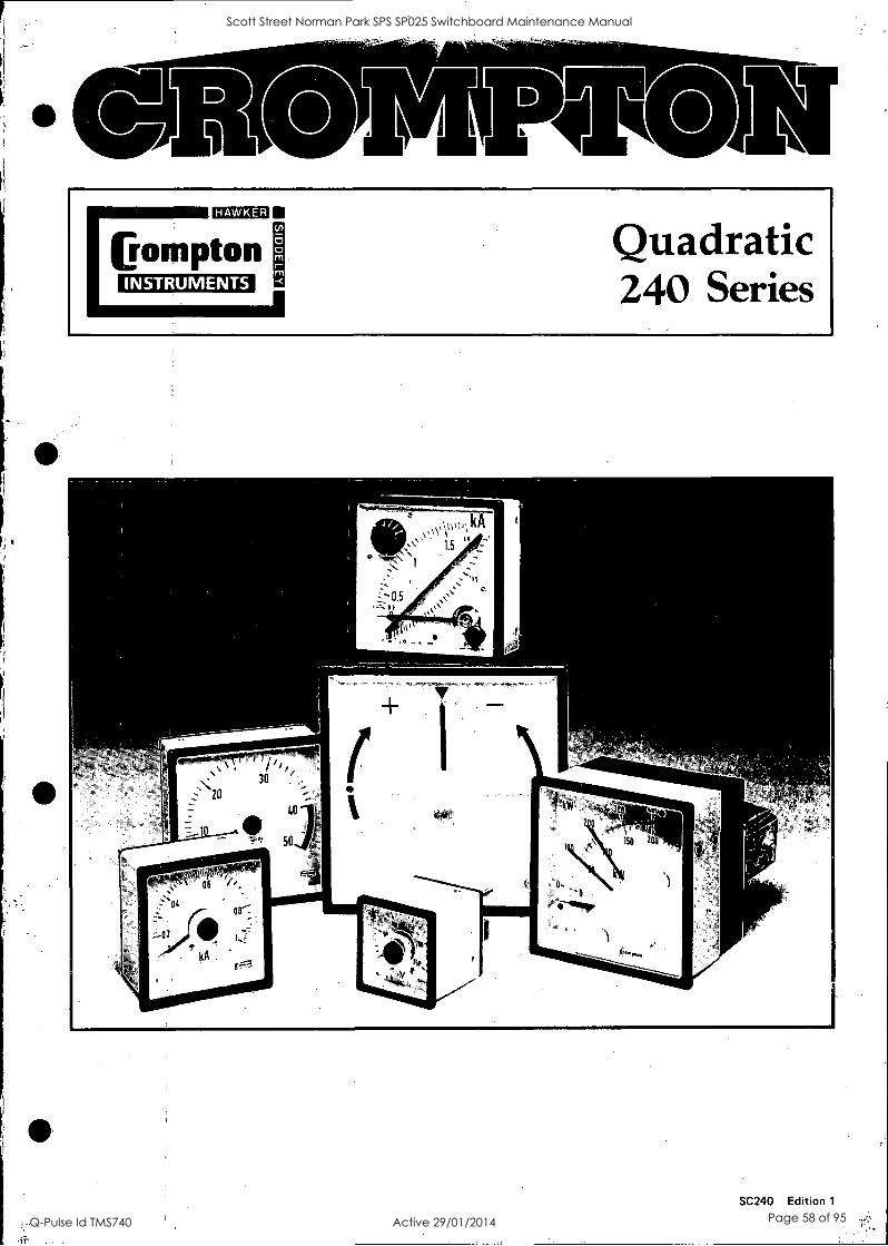
HAWKER
Eompton INSTRUMENTS
Quadratic 240 Series
4
/1/, 30 tli 20
40
50 ..""
kA ig
.4
SO 200
SC240 Edition 1
Scott Street Norman Park SPS SP025 Switchboard Maintenance Manual
Q-Pulse Id TMS740 Active 29/01/2014 Page 58 of 95

Quadratic 240 Series
Immmo.
Crompton INSTRUMENTS
Selection table 242 -243
C 244 246 242 243
G--)
244 246
Symbol Movement Page 48 X 48 72 X 72 96 X 96 144 X 144 48 X 48 72 X 72 96 X 96 144 X 144
C A V n A V
1=2 A p c A
Moving Iron Moving Coil Maximum Demand Indicators Moving Iron + MDI
4 - -
- -
- -
- - - -
n4) W VAR 0 0 Cost
COS?
n® Hz
Wattmeter Varmeter Phase Angle meter Power Factor meter. 360° scale Frequency meter - pointer'type
5
* * -
* * - - -
* * - *
* * - *
-
A. Hz V (fl
\
ID
Frequency meter-reed type Synchronising Voltmeter Synchroscope. 360° scale Phase Sequence Indicator
6
- - - -
- - -
.,
- - - -
- - -
- - - -
- - -
- -
- G1 A V
0 4) 00 rev/min Ile oc
Moving Coil Rectifier Position Indicator Speed Indicator Temperature Indicators
7 * *
* *
* *
* *
* *
* *
000M9 h Elapsed Time Meter Meter Relay
8 - - -
- -
- -
- -
- - n*
Current Transformers, Shunts, Transducers, 8
self contained . * with separate transducer
- not presently in range Connection diagrams Dimensions
9-1 1
12
Features * Shock-resistant taut band suspension
* Vibration-proof Hi-Q damping
* Suitable for tropical climates
* Customised options Er extras
* Complementary transducers, current transformers, shunts, tachogenerators
*90° and 240° scale
* Slide in dials for 90° volts amp frequency
Standards All instruments comply with the following specifications:
Case dimensions DIN43700 Benzels (slim) DIN43718
Scale markings DIN43802 Magnetic influence DIN43780
Performance Accuracy IEC 51 Overloads
Measuring ranges DIN43701 Safety requirements IEC414 Dial symbols IEC51
A tviIN v \\A"will 'l I
% 80 100
..... 0 , .. ...: 1
1 t , .,...-, --- 20 .--.-zo -
.-7- ziz ...-.---20 01"i = z_- -f- =- 100 --7-0 --0 0 -0 50
'' . x W
Enclosure IEC529
Optional compliance on request Lloyds Marine National Area Boards Spec ES141 - 26 + 50 + 8
2
Scott Street Norman Park SPS SP025 Switchboard Maintenance Manual
Q-Pulse Id TMS740 Active 29/01/2014 Page 59 of 95

Quadratic 240 Series
=ED
Crompton INSTRUMENTS
Hi - Q Taut Band Suspension
In the Crompton world-patented 'Hi-Q taut band suspension (see diagram) all the delicate parts of the traditional instru- ments are elm inated. There are no pivots, no jewel bearings, no hair-springs, no air damping vane. Instead, a tough metal ribbon suspends the moving element between front and rear tension springs.
Specially contoured pads are fitted toJhe ends of the spindle and the working gap at each end is filled with a high quality silicon fluid. The pads, together with the fluid reservoir, form a system which acts as resilient built-in shock absorbers. This provides both rotational and longitudinal damping as the moving element floats on oil with no bearing friction and is effec- tively cushioned against shock and vibration.
360° synchroscopes and power factor meters have robust pivot and jewel bearings.
All movements are self-shielded against external magnetic fields as defined in
BS89 IEC51 and DIN 43780.
Construction Models 242, 243 and 244 have cases, bez- els and terminal plates injection moulded in flame retardent engineering thermoplastic recognised by Underwriters Laboratory (UL)
Model 244 Meter Relay and all model 246 have pressed steel cases.
All instruments have glass windows, with zero adjusters where necessary. Non-reflecting glass or polycarbonate shatterproof windows are available.
Enclosure
The cases comply with enclosure code IP54 to IEC 529. They are suitable for use in tropical conditions.
Specification Performance Instruments comply with IEC51.
Accuracy Class 1.5 is standard. Frequency meters offer Class 0.5 or 0.2. Maximum demand indicators are Class 3. Synchroscopes and 360° power factor meters are Class 2.5 (2° electrical).
Overload withstand 1.2 times rated current or voltage for 2 hours. Ammeters 10 times rated current, voltmeters and frequency meters 2 times rated voltage for 5 seconds. Power instruments accept similar overloads.
Dielectric test 2kV a.c. for 1 minute.
Ambient Temperature Instruments have a working ambient range of - 20°C to 60°C (70°C Lloyds) with relative humidity up to 90%. They are calibrated for other temperatures within the working range can be specified. (Lloyds Shipping at 35°C)
Damping time 3 seconds is usual. More heavily
damped movements are available on request.
Illumination Internally illuminated dials are available for Models 243, 244 and 246, 240° moving coil. The replaceable rear mounted lamps are supplied for 6, 12 or 24V.
Mounting Clamps
Dials and Scales Standard dials are acrylic matt white with black printed scales and bar pointers.
They are scaled in accordance to DIN 43802. Interchangeable slide-in dials are used .on models 243 and 244 short scale moving iron and moving coil.
360° Instruments have platform dials.
Black dials with white or yellow scales and pointers are available.
General options include red supple- mentary pointers, red indexes (quadrant scales), red, green or blue lines, bands or segments, finely spaced divisions, multi- scales and special scales and captions to customers' requirements.
All 243 and 244 90° scale voltmeters, amme- ters and frequency meters have slide in dial, offering the benefit of low stock costs as only the basic instruments types need to be stocked together with ranges of dials. Other dials can be obtained rapidly from our local sales and serv- ice centres or agents.
Mounting Angle Standard instruments are calibrated for mounting on a vertical panel.
Special calibration for other mounting positions can be provided on request. Specify the angle of inclinations required in degrees, a° from the horizontal.
World Patents Crompton indicators incorporate features co- vered by one or more of the following patents:
GREAT BRITAIN: 1,124,667; 1,295,935; 1,212,245; 29,466/77 AUSTRALIA: 415, 321.
CANADA: 792,902; 846,338 GERMANY: 1,591,864; PI,591,864,6; P 2747965.8; G 7732975.0. U.S.A.: 3,439,273; 3,590,375; 845032
Models 242, 243 and 244 are provided with two corner fixing clamps and tensioning thumb screws.
Model 246 and Meter Relay model 244-30 have two side fixing spring clips.
3
Scott Street Norman Park SPS SP025 Switchboard Maintenance Manual
Q-Pulse Id TMS740 Active 29/01/2014 Page 60 of 95
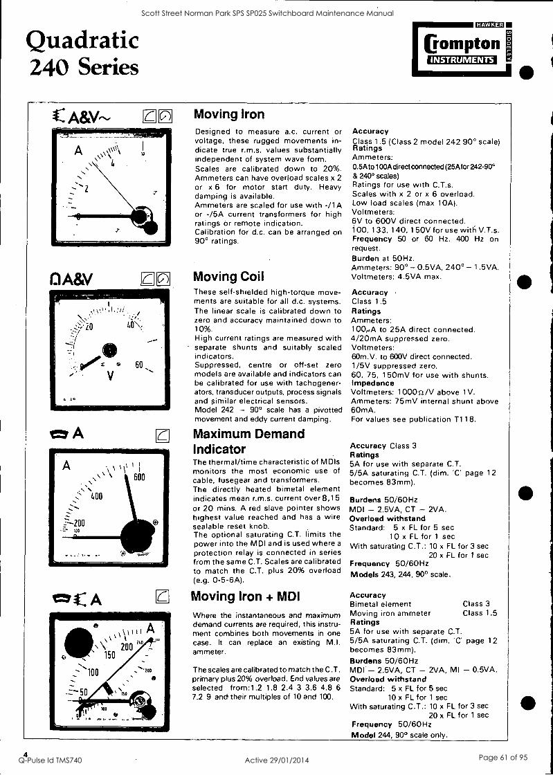
Quadratic 240 Series
ciumm
Crompton INSTRUMENTS
C ic)
ti
10
El A&V LI
ctr A
C A
Moving Iron Designed to measure a.c. current or voltage, these rugged movements in- dicate true r.m.s. values substantially independent of system wave form. Scales are calibrated down to 20%. Ammeters can have overload scales x 2
or x 6 for motor start duty. Heavy damping is available. Ammeters are scaled for use with -/1 A or -/5A current transformers for high ratings or remote indication. Calibration for d.c. can be arranged on 90° ratings.
Moving Coil These self-shielded high-torque move- ments are suitable for all d.c. systems. The linear scale is calibrated down to zero and accuracy maintained down to 10%. High current ratings are measured with separate shunts and suitably scaled indicators. Suppressed, centre or off-set zero models are available and indicators can be calibrated for use with tachogener- ators, transducer outputs, process signals and similar electrical sensors. Model 242 - 90° scale has a pivotted movement and eddy current damping.
Maximum Demand Indicator The thermal/time characteristic of MD's monitors the most economic use of cable, fusegear and transformers. The directly heated bimetal element indicates mean r.m.s. current over 8,15 or 20 mins. A red slave pointer shows highest value reached and has a wire sealable reset knob. The optional saturating C.T. limits the power into the MDI and is used where a
protection relay is connected in series from the same C.T. Scales are calibrated to match the C.T. plus 20% overload (e.g. 0-5-6A).
Moving Iron + MDI
Where the instantaneous and maximum demand currents are required, this instru- ment combines both movements in one case. It can replace an existing M.I. ammeter.
The scales are calibrated to match the C.T. primary plus 20% overload. End values are selected from:1.2 1.8 2.4 3 3.6 4.8 6
7.2 9 and their multiples of 10 and 100.
Accuracy Class 1.5 (Class 2 model 242 90° scale) Ratings Ammeters: 0.5A to100A direct connected (25A for 242-90° & 240° scales) Ratings for use with C.T.s. Scales with x 2 or x 6 overload. Low load scales (max 10A). Voltmeters: 6V to 600V direct connected. 100, 133, 140, 1 50V for use with V.T.s. Frequency 50 or 60 Hz. 400 Hz on request. Burden at 50Hz. Ammeters: 90° - 0.5VA, 240° - 1.5VA. Voltmeters: 4.5VA max.
Accuracy Class 1.5 Ratings Ammeters: 100,..A to 25A direct connected. 4/20mA suppressed zero. Voltmeters: 60m.V. to 600V direct connected. 1/5V suppressed zero. 60, 75, 1 50mV for use with shunts. Impedance Voltmeters: 1000n/V above 1V. Ammeters: 75mV internal shunt above 60mA. For values see publication T1 18.
Accuracy Class 3 Ratings 5A for use with separate C.T. 5/5A saturating C.T. (dim. 'C' page 12 becomes 83mm).
Burdens 50/60Hz MDI - 2.5VA, CT - 2VA. Overload withstand Standard: 5 x FL for 5 sec
10 x FL for 1 sec With saturating C.T.: 10 x FL for 3 sec
20 x FL for 1 sec Frequency 50/60Hz Models 243, 244, 90° scale.
Accuracy Bimetal element Class 3 Moving iron ammeter Class 1.5 Ratings 5A for use with separate C.T. 5/5A saturating C.T. (dim. 'C' page 12 becomes 83mm). Burdens 50/60Hz MDI - 2.5VA, CT - 2VA, MI - 0.5VA. Overload withstand Standard: 5 x FL for 5 sec
10 x FL for 1 sec With saturating C.T.: 10 x FL for 3 sec
20 x FL for 1 sec Frequency 50/60Hz Model 244, 90° scale only.
4
Scott Street Norman Park SPS SP025 Switchboard Maintenance Manual
Q-Pulse Id TMS740 Active 29/01/2014 Page 61 of 95

Quadratic 240 Series
111M1211[3
Crompton INSTRUMENTS
130W&VAR (1
occos
cos 3600
41:)Hz 1cl
Wattmeters / Varmeters Watt and Var meters are available in all models of the Quadratic range for the following a.c. systems:
single phase 3 phase balanced load, 3 or 4 wire 3 phase unbalanced load, 3 or 4 wire
The measuring system comprises a
moving coil indicator and power con- verting transducer. Scales are linear down to zero. Centre and off-set zero scales are available for reverse power and Import/Export in- dication.
Phase Angle Meter These meters indicate the phase dis- placement between current and voltage. Ideal value is unity power factor (cos
= 1.0 on the meter scale). Systems operating at lower values are using watt- less power.
single phase 3 phase 3 wire balanced load 3 phase 4 wire balanced load
The measuring system comprises a
moving coil indicator and phase angle transducer.
Power Factor Meter For 3 phase 3 or 4 wire unbalanced load systems. These meters are suitable for generators or supplies operating in parallel. The four quadrant 360° scale calibrated 0-1-0-1-0 cos q) indicates forward (export) and reverse (import) power flow for inductive and capacitive loads. The rotating iron vane movement has spring-loaded bearings and silicon fluid damping.
Frequency Meter Pointer type Pointer type frequency meters are the most accurate and easy to read instrument of their type. Resolutions of 0.1 Hz can be observed. The instrument comprises a moving coil indicator with a frequency transducer.
Accuracy Class 1..5 Ratings Current: 0.2A to 10A direct connected. 1A or 5A for C.T.s. Voltage: 100/125, 200/250, 380/450V, 100-110 for V.T. use. Frequency: 50Hz, 60Hz, 400Hz. Power Factor: UPF assumed (range 0.5/1/0.5) Burdens at 50Hz Current: 1VA each cct. Voltage: 4VA each cct. Models 244, 246 self-contained or with separate transducer. 242, 243 with separate transducer.
Accuracy Class 2.5 (2° electrical)
Ratings Current: 1 A or 5A for C.T.s. Voltage: 100/125, 200/250, 380/450V 100-110V for V.T. use. Frequency: 50Hz, 60Hz, 400Hz. Burdens at 50Hz. Current: 1 VA Voltage: 4VA Current range 2096 to 125%.
Models 244, self-contained or with separate transducer. 242, 24.3, 246 with separate transducer.
Accuracy Class 2.5 (2° electrical) Ratings Current: - /1A or - /5A for C.T.s. Voltage: 100/125, 200/250V, 380/450V 100-110V for V.T. use. Frequency: 50Hz, 60Hz, 400Hz. Burdens at 50Hz Current: 2VA per coil. Voltage: 4VA per coil.
(7.5VA above 250V) Models 244, 246.only.
Accuracy Class 0.2, Class 0.5 Ratings Voltage: 100-125, 200-250, 380 -440V. 100 - 110V for V.T. use. Frequency spans Class 0.5: 45/55, 55/65, 45/65,
360/440Hz. Class 0.2: 47/53, 57/63Hz. Burdens Voltage: 4VA max. Models 242, 243, 244, 246-90° scale self - contained.
244, 246 - 240° scale self-contained. 242, 243 - 240° scale with separate transducer.
5
Scott Street Norman Park SPS SP025 Switchboard Maintenance Manual
Q-Pulse Id TMS740 Active 29/01/2014 Page 62 of 95
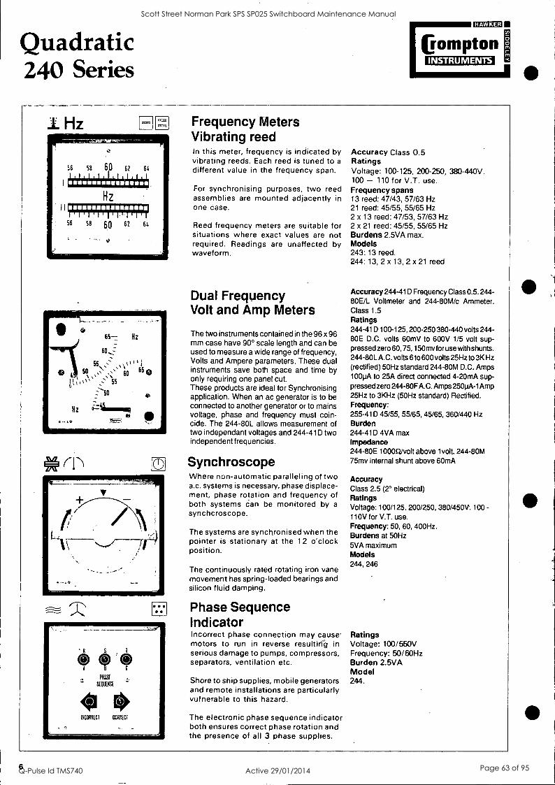
Quadratic 240 Series
CL171:111:1
Pompton INSTRUMENTS
1 Hz
1
i56 se th 60 62 64 ftti±erkitth Hz
11
?;FIF;IF4til;CER 56 58 60 62 66
'I /
Frequency Meters Vibrating reed In this meter, frequency is indicated by vibrating reeds. Each reed is tuned to a
different value in the frequency span.
For synchronising purposes, two reed assemblies are mounted adjacently in one case.
Reed frequency meters are suitable for situations where exact values are not required. Readings are unaffected by waveform.
Dual Frequency Volt and Amp Meters
The two instruments contained in the 96 x 96 mm case have 90° scale length and can be used to measure a wide range of frequency, Volts and Ampere parameters. These dual instruments save both space and time by only requiring one panel cut. These products are ideal for Synchronising application. When an ac generator is to be connected to another generator or to mains voltage, phase and frequency must coin- cide. The 244-80L allows measurement of two independant voltages and 244-41D two independent frequencies.
Synchroscope Where non-automatic paralleling of two a.c. systems is necessary, phase displace- ment, phase rotation and frequency of both systems can be monitored by a
synchcroscope.
The systems are synchronised when the pointer is stationary at the 12 o'clock position.
The continuously rated rotating iron vane movement has spring-loaded bearings and silicon fluid damping.
Phase Sequence Indicator Incorrect phase connection may cause' motors to run in reverse resultirig in serious damage to pumps, compressors, separators, ventilation etc.
Shore to ship supplies, mobile generators and remote installations are particularly vulnerable to this hazard.
The electronic phase sequence indicator both ensures correct phase rotation and the presence of all 3 phase supplies.
Accuracy Class 0.5 Ratings Voltage: 100-125, 200-250, 380-440V. 100 - 110 for V.T. use. Frequency spans 13 reed: 47/43, 57/63 Hz 21 reed: 45/55, 55/65 Hz 2 x 13 reed: 47/53, 57/63 Hz 2 x 21 reed: 45/55, 55/65 Hz Burdens 2.5VA max. Models 243:13 reed. 244: 13, 2 x 13, 2 x 21 reed
Accuracy 244-41D Frequency Class 0.5. 244- 80E/L Voltmeter and 244-80M/c Ammeter. Class 1.5 Ratings 244-41D 100-125, 200-250 380-440 volts 244- 80E D.C. volts 60mV to 600V 1/5 volt sup- pressed zero 60, 75, 150my for use with shunts. 244-80LA.C. volts 6 to 600 volts 25Hz to 3K Hz (rectified) 50Hz standard 244-80M D.C. Amps 100pA to 25A direct connected 4-20mA sup- pressed zero 244-80F A.C. Amps 250pA-1Amp 25Hz to 3KHz (50Hz standard) Rectified. Frequency: 255-41D 45/55, 55/65, 45/65, 360/440 Hz Burden 244-410 4VA max Impedance 244-80E 10000/volt above 1 volt. 244-80M 75mv internal shunt above 60mA
Accuracy Class 2.5 (2° electrical) Ratings Voltage: 100/125, 200/250, 380/450V. 100 - 110V for V.T. use. Frequency: 50, 60, 400Hz. Burdens at 50Hz 5VA maximum Models 244, 246
Ratings Voltage: 100/550V Frequency: 50/60Hz Burden 2.5VA Model 244.
6
Scott Street Norman Park SPS SP025 Switchboard Maintenance Manual
Q-Pulse Id TMS740 Active 29/01/2014 Page 63 of 95

Quadratic 240 Series
CUMEI
60MPtOn INSTRUMENTS
A&V--
00 rev/min
c5-. L
\ is/
*\400 .600
ZOO
1000
U/min
800
OCT
Moving Coil Rectifier For high frequency or linear full scale a.c. measurements. These instruments measure average values of sinusoidal waveforms and are scaled in r.m.s. values. The high quality silicon bridge rectifier gives a linear scale down to zero, except on low voltage where some compression occurs. For ratings 1A to 100A use a 10mA instru- ment with a 770 Series miniature CT.
Position Indicator The measuring system comprises a
moving coil indicator, stabilised power source transducer and remote potentio- meter or resistance thermometer sensor (supplied by customer).
The Position Indicator monitors trans- former tap position, hoist or valve posi- tion, etc. It employs a 3 wire system. 11- 18 positions can be provided using 40052 steps.
Speed Indicator These moving coil indicators can be calibrated for any d.c. or rectified a.c. tachogenerator or voltage/current signal source.
They can be scaled in any speed function where the relationship of output signal to speed is specified.
A suitable range of rectified 3 phase tachogenerators is available with foot or flange mounting options - see publication SW840.
Temperature Indicators These indicators read temperature values, usually remotely, with RTD or Thermocouple sensors supplied by customer.
RTD (resistance thermometer) indicators measure the change in resistance of the sensor. A 2 or 3 wire system may be used.
Thermocouple indicators accept stan- dard milliVolt input signals. Cold junction compensation is provided and high scale thermocouple break indication is in- corporated.
Accuracy Class 1.5 down to 10%. Ratings Ammeters: 250pA to 1 A direct connected. 1A for use with C.T.s. Voltmeters: 6V to 600V direct connected. Frequency 50/60Hz. Other single frequencies 25.3000Hz on request. Impedance see publication T118. Models 242, 243, 244, 246, 90° and 240° scales.
Accuracy Class 1.5 overall Auxiliary supply a.c. 50/60Hz, 45/55Hz: 100/125, 200/250V,
380/440V. : 50, 110, 220V, ±15% d.c.
Burden 2VA Models 244, 246 self-contained or with separate power source transducer. 242, 243 with separate Paladin power source transducer, see publication SW25OT
Accuracy Class 1.5 Models 242, 243, 244, 246 Tachogenerator speed ranges 0/30 to 0/45 rev/min 0/46 to 0/50 0/51 to 0/85 0/86 to 0/120 0/121 to 0/180 0/181 to 0/200 0/201 to 0/350 0/351 to 0/10000 Nominal output 1 mA
Accuracy Class 1.5-Indicator only RTD indicator -45RG. Suitable for 1052 Copper or 1000 Platinum sensors. Power in RTD 10014W approx. Thermocouple indicator -45TG. Suitable for standard thermocouple out- puts 10-50 mV full scale value. 50t max. cct resistance. Auxiliary supply -45RG 50, 110 or 220V a.c. 50/60Hz -45TG 110 or 220V a.c. 50/60Hz Burden -45RG 2VA, -45TG 3VA Models 244, 246 'self-contained. All models available with separate transducer. See SW250T.
7
Scott Street Norman Park SPS SP025 Switchboard Maintenance Manual
Q-Pulse Id TMS740 Active 29/01/2014 Page 64 of 95

Quadratic 240 Series
cualEg
Crompton INSTRUMENTS
9 9 9 9 9 9191
cti
Combining a highly accurate indicator with High and Low set-point relays, this robust unit is available in case sizes 96 x
96mm. The relays can operate alarm and control circuits when the monitored signal value moves outside the set-point limits indi- cated by adjustable red index pointers.
Models 244-301 G: 1 relay, 1 set-point for High, upscale energising. 244-307G: 1 relay, 1 set-point for Low, downscale energising. 244-302G: 2 relay, 2 set-points for High and Low energising. 244-30TG: 2 relay, 2 set-points for thermocouple operation; CJC and thermo- couple break protection are provided. 244-300G: 1 relay, 2 set-points for level control. Low energising, High de- energising.
Current Transformers Designed to IEC1 85, VDE 0414:70 and BS3938:73, and offering a full range of styles, ratings, outputs and accuracies to meet International Standards.
Ask for publications SW CT
Elapsed Time Meter These synchronous motor driven cyclo- meters register in increments of 0.01 h up to 99999.99 h after which they recom- mence from zero.
A running indicator is provided. Hand reset not available.
Production efficiency, cost estimating and service periods are typical uses.
Meter Relay * Monitors and controls any variable
parameter which can be converted into a d.c. or a.c. signal.
* Indicator, relays and power unit in one housing.
* Control function continues should indicator become damaged.
* Stable electronic switching circuit does not use lamps, photocells, indicators or capacitors.
* LED switching mode indication. * Isolated input signal. * Rugged shock and vibration resist-
ant design. * Optional time delay relay.
Accuracy Indicator: Class 1.5 Set-point: Class 1.5 Repeatability: 0.5% Differential: 1% of span Set-point adjustment: 98%of scale Minimum span: 2% between set-points.
Auxiliary supply a.c.: dual rating 100/125V and 200/250V,' 50/60Hz. d.c.: 12V or 24V Other voltages to special order. Burden: 3VA max.
Fixing Clips Side fixing spring clips are provided.
Transducers These a.c. power to d.c. signal converters provide a complete measuring system when used with suitably calibrated 1 mA moving coil indicators, close coupled or remote mounted.
Publication SW250IT details converting transducers for frequency, watts, vars. Current, voltage, position, temperature, resistance, etc are described in the SW250T series.
Ratings Voltage: 100/125, 200/250, 380/440V Frequency: 50Hz, 60Hz. Burden 2.5VA max. Models 242, 243, 244
Input signals Volts d.c.: 20mV to 500V (10k2/V) Volts a.c.: 6V to 500V (1000E2 /V)
50/60Hz. 25 - 3000Hz on request.
Current d.c.: 1 OuA to 1 5A (20mV drop). Current a.c.: 100mA to 1A (1V drop)
50/60 Hz. 25 - 3000Hz on request. -/1 A or -/5A C.T. operation (0.5VA).
Thermocouples: Standard outputs.
Motor start duty with 1A/10mA or 5A/ 10mA internal C.T. permitting 1.2 times overload continuously and 10 times for 10s.
Output relay Octal base plug-in relay Type: SPDT contacts, each set-point. Rating: 5A or 250V or 1000W non- inductive. Operating time: 250ms overall Optional time delay adjustable 1 - 1 Os
Relay contact position with input signal in zone indicated by meter pointer.
3
id:)0 2
7
90 % 8
Low Set Point /
Shunts
3 3
10 % 2 1 0 % 2
7
90%. 90( 08
- Meter Pointer
A comprehensive range of high quality shunts to meet IEC51, BS89, AS1042, DIN43703, DIN43780. DEF66-1 3, British PO CD746, USA MIL- S-61 B and most specialised designs can be complied with. Send for SW 820
8
Scott Street Norman Park SPS SP025 Switchboard Maintenance Manual
Q-Pulse Id TMS740 Active 29/01/2014 Page 65 of 95

Quadratic 240 Series
Symbols based on DIN43 807. Transformer terminal markings to BS3938/3941.
=mo (rompton
INSTRUMENTS
VOLTMETER d.c. - 89VG - 01VG - 10VG - 05VG
Direct connected (max. 600V)
VOLTMETER a.c. -02VG -07VG -03VG, -78VG -89WG, -01WG, - 10WG, - 05WG
Direct connected (max. 600V) Line/Line volts Line/Neutral volts
- 0 0 H 0 O
I
A
With voltage transformer Line volts.
i
I
I
_J L _J
AMMETER d.c. - 89AG -01AG - 10AG -05AG
Direct connected With shunt
AMMETER a.c. Moving iron - 02AG, -022G, -026G - 07AG, -072G, -076G - 03AG, -032G, -036G - 78G
Moving Coil Rectifier -01BG, -106G, -056G
MDI and MDI plus MI - 16AG, -168G - 16CG, - 16DG
A
N
Direct With current connected transformer r - -- 7 I-----1 1 0 0 I I I
I I I I
L _J L _I
32
Pt LOAD
FREQUENCY AND ELAPSED TIME METERS -41SG, -197G, - 19RG Double vibrating reed -41LG, -199G, -19SG -1 9TG -155G, -156GG
I. A
N 8
Direct With volt connected transtormer
I
I I
L _J
bin
No.1 Supply A B C
No.2 Supply A B C
Shown with V.T.
TRANSDUCER INDICATOR
- 89 -01 -10 - 05
AG VG 3G 4G
5G 6G 7G
E l
7 I
I
Separate 250 series + I transducer, See SW250IT
Er SW250T for Watts, L_ _I Vars, Frequency, Amps Volts, Phase angle, Resistance. Temperature, Position etc.
POSITION INDICATOR -45C1B -45PB
Aux
Indicator with' self-contained' power source.,
Customers Potentiometer. I
No.1 tap
supply N. L+
I 000 1
L _J
TEMPERATURE INDICATORS -45 TG
Aux. supply N- L+
Customers Thermocouole
Multiple RTD's may be used with additional RTD switch C
positions.
Customer's RTD
-45 RG Al. SOPPY
1- 0 C.)
Minimum Resistance Change 2 R Cu, 20 0 Pt.
All L, leads mus be within 0.02 ohms of the same resistance.
L, leads should not exceed 3 ohms each.
L, leads should not exceed 0.02 ohms each.
9
Scott Street Norman Park SPS SP025 Switchboard Maintenance Manual
Q-Pulse Id TMS740 Active 29/01/2014 Page 66 of 95

Quadratic 240 Series
WATTMETERS
assma
Crompton INSTRUMENTS
-210G & -215G Single Phase a.c.
r-- - 7
21 CG & 21 DG 3 Phase. 4-wire, balanced load
r________I
, I LI 1 4/d
I
,
-211G & -216G 3-phase, 3-wire, balanced load
1 1
L or 0 0
I
01 J I 0 0 0 : I
0 ,
I
_I
A
9 MUMS
SI S2
b
SI 52 r SI S1
LOAD
A B
B PI P2
B
LOAD IIII IMUMU
LOAD C
C
-213G & -218G 3-phase, 3-wire, unbalanced
I-
load
-1
-21EG & -21 FG
3- phase. 4-wire, unbalanced load with delta connected C.T s.
1- 1
-214G & -219G 3-phase, 4-wire, unbalanced load with star connected C.T.s
r -I
11/ 1
I
'Ti' OSO 0/10 0 I
t- --I 10000 001
I
J 10000000! J
b c 1117 lir MIIIIIIIIMM 0 c
11 -- MIDI
b rill. rimriwt_ MSI S21.11
um MMMIlima=---- =
Si s, In SI S2 111011111111= A
A 11
MInawzillir IN PI P2 LOAD pi LOAD
PI P2 - LOAD
PI P2
PI P2
Star connected C.T.s must be used Delta connected C.T.s. must be used
VAR METERS
Single phase VAR meters are available using a Paladin type 256 TXKW transducer and' transducer indicator.
See Publication SW2507
-310G & -315G 3-phase, 4-wire, balanced load
A
1 1
L 0 0 J re
LOAD
-310G & -315G 3-phase, 3-wire, balanced load
A
LOAD
31SG & -31LG 3phase. 3 wire, unbalanced load
PI
10
P1
LOAD
-31EG & -31 FG
3-phase, 4-wire, unbalanced load with delta connected C.T.s
P2
Delta connected C.T.s. must be used
LOAD
-314G & -319G 3-phase. 4-wire, unbalanced load with star connected C.T.s
PI P2
Star connected C.T.s must be used
:DAO
Scott Street Norman Park SPS SP025 Switchboard Maintenance Manual
Q-Pulse Id TMS740 Active 29/01/2014 Page 67 of 95

Quadratic 240 Series
PHASE ANGLE METER -42BG -425G Single Phase Spans 0.5/1/0.5 or 0.8/1/0.2
LIAO
PHASE ANGLE METER -42AG -427G 3-phase, 3-wire, or 4-wire, balanced load Span 0.5/1 /0.5 or 0.8/1 /0.2
a LOAD
SYNCHROSCOPE -145G -146G Single or 3-phase systems
son latalaVNG OUSIAAS
VT, ,l mowed
1 Al1 1111,
INSTRUMENTS
J
O °00 L0000
ABOVE 250V USE SEPERATE TRANSFORMER BOX 855-954C
Oes
360° POWER FACTOR METER - 1310 3-phase, 3 or 4-wire, balanced load 3 current and 1 voltage element span 0/1/0 ABOVE 250V USE TRANSFORMER BOX 855-95B
A
I mr-ei,=1"""
Ellam2M=-- PT
ALWAYS QUOTE LINE/LINE VOLTAGE
360° POWER FACTOR METER -136G 3-phase, 3 or 4-wire, unbalanced load' 3 current and 3 voltage elements .
span 0/1/0 ABOVE 250V USE SEPERATE BOX 855-95D
ALWAYS QUOTE LINE/LINE VOLTAGE
_s
360° POWER FACTOR METER .1360 (Alternative connection)
3-phase, 3-wire unbalanced load 2 current and 3 voltage elements span 0/1/0 ABOVE 250V USE SEPERATE BOX 855-95C C.T.s must be used.
1
1_1000 9,0000
an Pi
ALWAYS QUOTE LINE/LINE VOLTAGE
J
360° Power Factor Meter
300 POWER FACTOR METER Smolt.. oh 100-120V 6 200 OP FtItnos .
1.0 No -137
LOAD
360° Power Factor Meter
360 POWER FACTOR METER 3 Pne e 3 or A Mr. Delano d Load I Current 6 3 Voltage Ebro..
® Above 350v Transformer Box 11.1 1333-00
Alt. OuPt Lon/Ltne Vol.®
ALTERNATIVE V.T. CONNECTIONS
3-phase. 3 -wire 3-phase. 4-wire
METER RELAY -300G -3010 -302G -307G -39TG -3030 -304G
MEASURING INPUT
0 lOsec owe delaying relay
loptional)
I 2 3 5 7 a E900000000 I OW SET POIN
'DJ II 230V MIEN SF T POINT
12V 24V
AG/CILIARY SUPPl v
PHASE SEQUENCE INDICATOR ,12PG
LOAD
NOTES Where practical, all circuits should be earthed at one point. Voltaged circuits should be fused. C.T. circuits must not be open-circuited on load. Connection diagrams are shown with current and voltage transformers, which are subject to seperate order. Direct connected ratings are usually available for voltages up to 600V and currents up to 10A. Calculate watt scales as follows: single phase = V x A PF 3 phase = 3 x V phase x A x PF or =V 3 xVlinexAxPF round off upwards, allowing for overloads.
11
Scott Street Norman Park SPS SP025 Switchboard Maintenance Manual
Q-Pulse Id TMS740 Active 29/01/2014 Page 68 of 95

Quadratic 240 Series
Dimensions Case sizes to DIN43700. Narrow bezels to DIN43718.
Panel cut-out A
Max. panel thickness 10 mm.
A
Model 242 243 244 246
Bezel 'A' Panel cut-out 'B'
48 x 48 45 x 45
72 x 72 68 x 68
96 x 96 92 x 92
144 x 144 138 x 138
Scale length: 900 42 65 94 145 " " 240°C 72 112 150 230
Maximum overall depth 'C' 242 243 244 246
Ammeter and Voltmeter 75 78 78 95 Maximum Demand Indicator 78 78 95
Wattmeter, VArmeter - 90° * * 87 145 - 240° * * 145 145 Phase Angle, Power Factor Meter - 90° * * 65 - 240° * * 126 Frequency Meter - 90° * 78 78 95 - 240° * * 140 131 *M.C. Indicator with separate transducer 75 78 78 95
Reed Frequency Meter - 78 78 - Synchronising Voltmeter - - 78 - Synchroscope, 360°Power Factor Meter - - 140 131 Phase Sequence Indicator - - 78 - Position Indicator * * 140 131 Speed Indicator 75 78 78 95 Temperature Indicators - - 140 131
Elapsed Time Meter - 78 78 - Meter Relay - - 120 - Terminals: Voltage and current up to 30A --M5 screw clamps. Current above 30A - M8 studs with nuts. * Dimensions of external transducers for use with moving coil indicators are given in
publication SW250IT or SW250T.
cram eompton
INSTRUMENTS
Base cover available for 243 and 244 Slide - in dial instruments only.
Terminal Boot available for all Quadratic Instruments.
The information contained in this specification is correct at the time of publication, but the right is reserved to supply instruments differing in construction and appearance from those illustrated and described.
CROMPTON INSTRUMENTS (AUSTRALIA) PTY. LTD. HEAD OFFICE: N.S.W. Unit 20, Minto Industrial Park, 25-31 Airds Road, Minto, N.S.W. 2566 Ph: 02 603 2066 Fax: 02 603 9335
BRANCH OFFICES: S.A. 350 Torrens Road, Croydon Park, S.A. 5008 Ph: 08 347 1522 Fax: 08 347 3094 VIC. 3 Chesterville Road, Cheltenham, Vic. 3192 Ph: 03 584 8844 Fax: 03 584 1042 W.A. Suite 1, 929 Wellington Street, West Perth, W.A. 6005 Ph: 09 321 4387 Fax: 09 321 8901
QUEENSLAND AGENTS: Bartlett Marketing Co. Pty. Ltd., Underwood, Qld. 4119 Ph: 07 841 1586 Fax: 07 841 1676 Industrial & Marine Electrics, Cairns, Old. 4870 Ph: 070 35 2722 Fax: 070 35 2723 Marcon Agencies Pty. Ltd., Garbutt, Old. 4818 Ph: 077 25 4499 Fax: 077 25 4511
N.S.W. AGENTS: Excel! Control Pty. Ltd., Unanderra, N.S.W. 2526 Ph: 042 72 1922 Fax: 042 72 1833 Borg Electrical Wholesalers Pty. Ltd., Broadmeadow, N.S.W. 2292 Ph: 049 52'4366 Fax: 049 52 7490 TASMANIAN AGENTS: George Harvey Electric Pty. Ltd., Hobart, Tas. 7000 Ph: 002 34 2233 Fax: 002 31 1347 George Harvey Electric Pty. Ltd., Launceston, Tas. 7250 Ph: 003 31 6533 Fax: 003 34 1899
NORTHERN TERRITORY AGENT: I.S.A.S., Winnellie, N.T. 0820 Ph: 089 47 2313 Fax: 089 47 0149 SOUTH PACIFIC ISLANDS: Export Procurement Pty. Ltd., Northgate, Qld. Ph: 07 260 5499 Fax: 07 260 5546 NEW ZEALAND AGENT: Electrade Limited, Auckland. Ph: 09 525 1031 Fax: 09 525 1756
Scott Street Norman Park SPS SP025 Switchboard Maintenance Manual
Q-Pulse Id TMS740 Active 29/01/2014 Page 69 of 95

DIN Cased Current Transformers
Crompton INSTRUMENTS
MODEL 252 - 94 These current transformers comprise a board mounted Wound Primary C.T., generally as Model 771-945 described on page 8. They are housed in a tough flame retardant moulded case complying with DIN 43604. The cases are designed for DIN rail mounting and an adaptor can be supplied for screw fixing.
Styles available Model 252-94A : Single phase, one C.T. Model 252 -94B : Three phase, three C.T's.
Performance Primary ratings : 1A up to 7.5A Secondary outputs : 10mA standard
Other outputs available on request VA output : 0.03VA (3V at 10mA) System frequencies : 50-60Hz, 400Hz Service Temperature : 0°C-80°C Insulation class : BS2757 class Y (Max. 90°C) Operating voltage : 660V ac max. Test voltage : 2000V ac
Accuracy class at standard ,VA load % rated % total error Primary current (phase displacement and ratio error) 20-80% : 1.5% max. 81-120% : 1.0% max.
Alternative specifications to meet customers' special requirements can usually be accommodated.
Connections
PRIMARY
MODEL 252-948 ONLY
PRIM,ARY PRIMARY
P1 P2 PI P2 PI P2
!Dampen] SI S2 SI S2 SI S2 -.-
SECONDARY SECONDARY SECONDARY 2
MODEL 252-948 ONLY
Dimensions-measurements in mm.
O
112
ADAPTOR PLATE
RELEASE CLIP
55
HOBO FIT,
MODEL 253 94A The Crompton Model 253 offers galvanic isolation and current ratio matching for 1 amp and 5 amp mains current C.T., secondaries. The current transformers are manufactured to the same high standard and specification as the 780 Series. They are housed in a tough flame retardant moulded case complying with DIN 43604. Cases can be DIN rail mounted or fixed by two screws.
Performance Primary current :
Secondary current :
System voltage Test voltage System frequency :
ShOrt circuit thermal current (Ith) Rated dynamic
current (Idyn) :
Saturation co-efficient
Service temperature: Insulation BS2757 :
Enclosure code :
Accuracy class
1A or 5A 1A or 5A
Any primary or secondary current between 1A and 5A available
660V max. 3kV for 1m 50/60Hz (400Hz available on request) 60 x rated primary current for
1 second
2.55 x Ith <5 for plain ring <10 for wound primary 20 °C to 85°C Class A (max 105°C) IP40 1°/0 at 3VA, 5% at 7.5VA
Connections Dimensions- measurements in mm. Weight 0.3kg approx.
PRIMARY
PI P2
ligompton I
SI 52
SECONDARY
75
9
112.5 60
RELEASE CLIP 2 FIXING HOLE 'A' TO SUIT M4
2 FIXING HOLES '13' TO SUIT M5
VIEW ON BASE SHOWING PANEL MOUNTING HOLES
Scott Street Norman Park SPS SP025 Switchboard Maintenance Manual
Q-Pulse Id TMS740 Active 29/01/2014 Page 70 of 95

810 Series CLIZ1:120
Crompton INSTRUMENTS
The Crompton 810 Series provides a comprehensive range of Measuring and Protective duty ring current transformers for installation where traditional reliability, accuracy and quality are required.
Features * Plain ring, foot mounting or busbar fixings * Substantial tag terminals or flexible leads * Measuring Duty ranges up to 3000A * Protection Duty classes 5P10 and 10P10 * Special designs to customers requirements
Performance Designed to highest standards, 810 Series trans- formers Kaye accuracy classes, outputs and perform- ance to BS3938: 1973 and IEC185: 1966 for measuring and protective duties. Overload withstand: to BS3938-IEC185 Operating voltage: 660V ac. maximum Test voltage: 2500V a.c.
System frequency: 50/60Hz or 400Hz Service temperature: 40°C to + 70°C Insulation class: BS2757 class Y (Max. 90°C)
Style Selection Codes
Construction High grade silicon iron cores are carefully selected, then insulated and protected by a polypropylene covering on which the secondary winding is toroidally wound by precision machines. The P.V.A. coated copper wire is additionally protected by a layer of half- lapped plasticised P.V.C. tape. A second layer of self- bonding P.V.C. tape is applied and vulcanised to pro- vide a tough moisture-resistant coating. A substantial terminal block with tag terminals and M6 screws and nuts is standard but M4 screws or insul- ated flex leads (normally 600mm) can be supplied. Integral fixing feet are normally provided but a busbar mount clamp or a plain ring may be specified.
CODE 940 941 942 943 944* 946 Wound Primary
947*
STYLE i pos
W ip.
MOUNTING Plain ring Plain ring Foot Foot Busbar Foot Busbar
WINDING TERMINATION
Flexible Tag leads terminals
Flexible Tag leads terminals
Tag terminals
Tag terminals
Flexible leads
* Busbar mounted types 944 and 947 have bore diameter 'A' reduced by 6mm.
Class X Current Transformers In balanced earth fault protection systems, correct operation depends on the accuracy of the current transformers. Class 5P and 10P are suitable where the definite minimum time is greater than 0.2 seconds. For shorter operating times, transient conditions may require cur- rent transformers to have cross sectional areas many
times greater than those of steady state faults. Class X is required for this duty and the following information is required. °
(a) Turns ratio (b) Knee point voltage (c) Maximum excitation current (d) Secondary circuit resistance.
10
Scott Street Norman Park SPS SP025 Switchboard Maintenance Manual
Q-Pulse Id TMS740 Active 29/01/2014 Page 71 of 95

810 Series Selection Table
=MD
Crompton INSTRUMENTS
Current transformers can be manufactured to meet specific dimensional and accuracy requirements. (Code 811-94'). All enquiries should be directed to a local sales centre stating all current, accuracy and dimensional requirements.
P1 M6 Screws & nuts supplied.
Dimensions of Standard 5A C.T.'s given in mm.
1
1A C.T., dimensions may vary by up to 10%
Measuring Current Transformers Accuracies comply with BS3938 and IEC 185.
Model Type
Primary Current 3
VA at Class 1 0.5 A
Approx. 5 Amp Dimensions B C D E F
Weight Kgs
812 40A 2 - - 20 60 48 66 40 75 0.48 812 50A 2.5 - - 20 60 48 66 40 75 0.48 813 5 - - 30 102 65 108 61 105 2.2 812 60A 2.5 - - 20 60 48 66 40 75 0.48 813 5 - - 30 76 55 82 48 85 0.85 812 75A 5 - - 20 60 48 66 40 75 0.5 813 5 3 - 30 76 55 82 48 85 0.85 813 10 6 4 30 102 100 108 61 105 3.4 812 80A 5 - - 20 60 48 66 40 75 0.5 813 5 3 - 30 76 55 82 48 85 0.85 813 10 6 4 30 102 100 108 61 105 3.4
814 100A 5 - - 42 84 35 90 52 85 0.5 815 10 5 2.5 42 108 45 114 64 105 1.6 815 15 7.5 4 42 108 73 114 64 105 2.65 814 120A 5 2.5 - 42 84 35 90 52 85 0.55 815 10 5 2.5 42 108 35 114 64 105 1.15 815 15 7.5 4 42 108 73 114 64 105 2.65 814 150A 7.5 5 - 42 84 35 90 52 85 0.55 815 20 10 5 42 84 45 90 52 85 0.8 814 200A 10 5 - 42 84 35 90 52 85 , 0.6 815 15 10 5 42 84 35 90 52 85 0.8 815 30 20 10 42 108 45 114 64 105 1.65 814 250A 10 5 - 42 84 35 90 52 85 0.65 815 15 10 5 42 84 35 90 52 85 0.65 815 35 25 15 42 108 45 114 64 85 0.65 814 300A 10 5 - 42 84 35 90 52 85 0.7 815 15 10 5 42 84 35 90 52 85 0.7 815 35 25 15 42 84 45 90 52 85 0.85 814 400A 20 10 5 42 84 35 90 52 85 0.75 815 30 20 10 42 84 35 90 52 85 0.75
816 500A 20 15 5 74 112 30 118 66 105 0.65 817 30 20 15 74 112 52 118 66 105 1
816 600A 20 15 5 74 112 30 118 66 105 0.7 817 30 20 15 74 112 52 118 66 105 1
816 750A 20 15 5 74 112 30 118 66 105 0.7 817 30 20 15 74 112 30 118 66 105 0.7 816 800A 30 20 10 74 112 30 118 66 105 . 0.7 817 30 25 20 74 112 30 118 66 105 0.7
818 1000A 40 30 15 98 142 33 148 81 125 0.85 818 1200A 50 30 15 98 142 33 148 81 125 0.9 818 1500A 50 30 20 98 142 33 148 81 125 1.05 818 1600A 50 30 20 98 142 33 148 81 125 1.15 818 2000A 60 45 30 98 142 33 148 81 125 1.3
819 2500A 60 45 30 114 170 36 176 95 140 1.55 819 3000A 60 45 30 114 170 36 176 95 .140 1.7
11
Scott Street Norman Park SPS SP025 Switchboard Maintenance Manual
Q-Pulse Id TMS740 Active 29/01/2014 Page 72 of 95

Selection Table =MU
Eompton INSTRUMENTS
Dimensions of Standard 5A C.T.'s given in mm.
1A C.T., dimensions may vary by up to 10%
-1
Protective Current Transformers
25.4
St .S2
M6 Screws & nuts supplied.
Accuracies comply with BS3938 and IEC 185.
Model Type
Primary Current
VA Burden
Approx. 5 Amp Dimensions A B C D E F
Weight Kgs
Accuracy Class 5P10
100A 2.5 38 140 76 150 78 125 5.4
5 38 140 142 150 78 125 10.8
150A 2.5 38 140 54 150 78 125 3.6
5 38 140 98 150 78 125 7.2
81A 200A 2.5
5 38 38
140 140
54 76
150 150
78 78
125 125
3.6 5.4
250A 2.5 38 140 54 150 78 125 3.6
5 38 140 54 150 78 125 3.6
300A 2.5 38 140 32 150 78 125 1.8
5 38 140 54 150 78 125 3.6
400A 2.5 53 140 32 150 78 125 1.8
5 53 140 54 150 78 125 3.3
81B 500A 2.5
5 53 53
140 140
32 54
150 150
78 78
125 125
1.9 3.4
600A 2.5 53 140 32 150 78 125 2
5 53 140 54 150 78 125 3.5
800A 5 63 114 42 124 65 105 1.4
7.5 63 114 66 124 65 105 2 10 63 114 66 124 65 105 2
1000A 5 63 114 37 124 65 105 1.3
81C 7.5 63 114 42 124 65 105 1.5 10 63 114 66 124 65 105 2.1
1200A 5 63 114 37 124 65 105 1.4
7.5 63 114 42 124 65 105 1.6
10 63 114 66 124 65 105 2.2
1500A 5 73 132 35 142 74 125 1.5
7.5 73 132 35 142 74 125 1.5
81D 1600A
10 5
73 73
132 132
57 35
142 142
74 74
125 125
2.5 1.6
7.5 73 132 35 142 74 125 1.6
10 73 132 57 142 74 125 2.6
2000A 5 82 148 30 158 82 125 1.7
7.5 82 148 35 158 82 125 2
10 82 148 47 158 82 125 2.6 15 82 148 57 158 82 125 3.2
2500A 5 80 150 30 160 83 125 1.8
7.5 80 150 35 160 83 125 2.1 81E 10 80 150 35 160 83 125 2.1
15 80 150 47 160 83 125 2.8
3000A 5 78 152 30 162 84 125 2.1
7.5 78 152 35 162 84 125 2.5
10 78 152 35 162 84 125 2.5 15 78 152 47 162 84 125 3.2
12
Scott Street Norman Park SPS SP025 Switchboard Maintenance Manual
Q-Pulse Id TMS740 Active 29/01/2014 Page 73 of 95

810 Series 12121311;1
Eompton INSTRUMENTS
Selection Table continued
Accuracy Class 10P10
Model Type
Primary Current
VA Burden
Approx. 5 Amp Dimensions A BCD E F
Weight Kgs
100A 5 32 102 93 112 59 105 3.3 7.5 32 102 115 112 59 105 4.5
10 36 140 119 150 78 125 9.25 150A 5 32 102 61 112 59 105 2.1
7.5 32 102 93 112 59 105 3.35 10 36 140 75 150 78 125 5.6
200A 5 32 102 56 112 59 105 1.95 7.5 32 102 77 112 59 105 2.8
81F 10 15
32 36
102 140
93 97
112 150
59 78
105 125
3.4 7.5
250A 5 32 102 51 112 59 105 1.75 7.5 32 102 61 112 59 105 2.15
10 32 102 83 112 59 105 .3 15 36 140 75 150 78 125 5.7
300A 5 32 102 46 112 59 105 1.55 7.5 32 102 61 112 59 105 2.2
10 32 102 72 112 59 105 2.65 15 36 140 75 150 78 125 5.75
400A 5 47 100 56 110 58 105 1.45 7.5 47 100 83 110 58 105 2.25
10 47 100 93 110 58 105 2.55 15 51 140 75 150 78 125 5.15
500A 5 47 100 51 110 58 105 1.35
81G 7.5 47 100 83 110 58 105 2.3 10 47 100 88 110 58 105 2.5 15 51 140 75 150 78 125 5.15
600A 5 44 103 49 113 60 105 1.25 7.5 44 103 59 113 60 105 1.55
10 44 103 86 113 60 105 2.35 15 44 103 96 113 60 105 2.71
800A 5 58 115 44 125 66 105 1.2 7.5 58 115 66 125 66 105 1.95
10 58 115 66 125 66 105 1.95 15 58 115 93 125 66 105 2.9
1000A 5 58 115 39 125 66 105 1.1
81 FI 7.5
10 58 58
115 115
44 66
125 125
66 66
105 -105
1.3 2.1
15 58 115 76 125 66 105 2.45 1200A 5 58 115 39 125 66 105 1.2
7.5 58 115 44 125 66 105 1.4 10 58 115 66 125 66 105 2.2 15 58 115 66 125 66 105 2.2,
1500A 5 71 131 34 141 74 124 1.25 7.5 71 131 34 141 74 125 1.25
10 71 131 56 141 74 125 2.3
81J 1600A
15 5
71
68 131
134 56 37
141 144
74 75
125 125
2.3 1.3
7.5 68 134 37 144 75 125 1.3 10 68 134 59 144 75 125 2.35 15 68 134 59 144 75 125 235
13
Scott Street Norman Park SPS SP025 Switchboard Maintenance Manual
Q-Pulse Id TMS740 Active 29/01/2014 Page 74 of 95

810 Series acenno
Pompton INSTRUMENTS
Selection Table continued
Accuracy Class 10P10
Model Type
Primary Current
VA Burden
Approx. 5 Amp Dimensions A BCD E F
Weight Kgs
2000A 5 78 149 33 159 83 125 1.35 7.5 78 149 38 159 83 125 1.65
10 78 149 50 159 83 125 2.35 15 78 149 60 159 83 125 3
2500A 5 78 149 33 '159 83 125 1.5 7.5 78 149 38 159 83 125 1.85
10 78 149 38 159 83 125 1.85 81K
15 78 149 50 159 83 125 2.55 3000A 5 78 152 30 162 84 125 2.1
7.5 78 152 35 162 84 125 2.5 10 78 152 35 162 84 125 2.5 15 78 152 47 162 84 125 3.2
Protection C.T.'s 5A secondary is standard. Accuracies comply with BS3938 and IEC 185.
Accuracy Class 10P10
Model Type
Primary Current
VA Burden
Approx. Dimensions A B C
100 5 40 108 90 150 5 40 108 68 200 7.5 40 108 73 300 10 40 108 68
, 400 10 61 112 90 500 10 61 112 73
600 10 61 112 73 81L 800 15 81 145 60
1000 15 81 145 53 1200 15 81 145 45 1600 15 94 153 49 2000 15 117 163 66 2500 15 114 166 59 3000 . 15 114 166 59
Dimensions
25.4
S2
M6 Screws & nuts supplied.
Fixing feet or Busbar clamps available on request.
B
Protection CT's can also be supplied to meet specific requirements and requests should be made in the same manner as with the 811-94* Series.
14
Scott Street Norman Park SPS SP025 Switchboard Maintenance Manual
Q-Pulse Id TMS740 Active 29/01/2014 Page 75 of 95

Model 809
0
111212010
Crompton INSTRUMENTS
This moulded case metering Current Transformer offers a tough reliable but inexpensive design where higher currents are to be measured.
Features * Primary ratings 500A to 4000A * Secondary current 5A or 1A * For 100 x 10mm busbars, 108mm cable. * Square cases with foot or busbar mounting * Optional 600mm flexible lead terminations
Performance BS3938, IEC 185.
System voltage Dielectric test System frequency Service temperature Enclosure code Insulation class BS2757
Accuracies comply with
Dimensions
: 660V max. : 2.5kV for lm : 50, 60 or 400Hz : - 20°C to 85°C : IP40 : Class 'A' (Max. 105°C)
BS3938 and IEC 185
All dimensions in millimetres
BUSBAR MOUNTING
FOOT MOUNTING
I 59 j
MODEL MODEL 809.944 809-943
BUSBAR MOUNTING
FOOT MOUNTING
600mm LONG LEADS
Selection Table Primary Current
A 3
VA Output at Class
1 0.5
Weight Kg
500 15 10 5 1.5 600 15 10 5 1.5 750 20 15 10 1.5 800 20 15 10 1.5
1000 25 20 15 1.55 1200 25 20 15 1.6 1500 25 20 15 1.15 1600 25 20 15 1.15 2000 25 20 15 1.25 2500 25 20 15 1.25 3000 30 25 15 1.45 4000 30 25 20 1.55
2 OPEN SLOTS 5.5mm WIDE 124mm APART @
MODEL MODEL 809-947 809.942
0
30
15
Scott Street Norman Park SPS SP025 Switchboard Maintenance Manual
Q-Pulse Id TMS740 Active 29/01/2014 Page 76 of 95
HAWKER
fiompton INSTRUMENTS
Our policy is one of continuous development and although the information is correct at the time of publication, we reserve the right to supply products differing in construction or dimensions from those illustrated and described.
CROMPTON INSTRUMENTS (AUSTRALIA) PTY. LTD. HEAD OFFICE: N.S.W. Unit 20, Minto Industrial Park, 25.31 Airds Road, Minto, N.S.W. 2566 Ph: 02 603 2066 Fax: 02 603 9335
BRANCH OFFICES: S.A. 350 Torrens Road, Croydon Park, S.A. 5008 Ph: 08 347 1522 Fax: 08 347 3094 VIC. 3 Chesterville Road, Cheltenham, Vic. 3192 Ph: 03 584 8844 Fax: 03 584 1042 W.A. Suite 1, 929 Wellington Street, West Perth, W.A. 6005 Ph: 09 321 4387 Fax: 09 321 8901
QUEENSLAND AGENTS: Bartlett Marketing Co. Pty. Ltd., Underwood, Qld. 4119 Ph: 07 841 1586 Fax: 07 841 1676 Industrial & Marine Electrics, Cairns, Qld. 4870 Ph: 070 35 2722 Fax: 070 35 2723 Marcon Agencies Pty. Ltd., Garbutt, QId. 4818 Ph: 077 25 4499 Fax: 077 25 4511
N.S.W. AGENTS: Excell Control Pty. Ltd., Unanderra, N.S.W. 2526 Ph: 042 72 1922 Fax: 042 72 1833 Borg Electrical Wholesalers Pty. Ltd., Broadmeadow, N.S.W. 2292 Ph: 049 52 4366 Fax: 049 52 7490
TASMANIAN AGENTS: George Harvey Electric Pty. Ltd., Hobart, Tas. 7000 Ph: 002 34 2233 Fax: 002 31 1347 George Harvey Electric Pty. Ltd., Launceston, Tas. 7250 Ph: 003 31 6533 Fax: 003 34 1899
NORTHERN TERRITORY AGENT: .S.A.S., Winnellie, N.T. 0820 Ph: 089 47 2313 Fax: 089 47 0149
SOUTH PACIFIC ISLANDS: Export Procurement Pty. Ltd., Northgate, QId. Ph: 07 260 5499 Fax: 07 260 5546
NEW ZEALAND AGENT: Electrade Limited, Auckland. Ph: 09 525 1031 Fax: 09 525 1756
Scott Street Norman Park SPS SP025 Switchboard Maintenance Manual
Q-Pulse Id TMS740 Active 29/01/2014 Page 77 of 95

KR
AU
S & N
AIM
ER
B
LUE
LINE
SW
ITC
HG
EA
R
Sw
itch Types
CA
4, CA
10, CA
11, CA
20, CA
10B,
CA
11B, C
A20E
1
0
O
compact design w
ith the smallest escutcheon plate size of 30 x 30 m
m (1.181" x 1.181")
O
finger-proof acc. to VD
E 0106, part 100 and V
BG
4
open terminals w
hich are accessible from both sides
captive plus-minus screw
s and screwdriver guide
high switching capability
®
contacts with gold plating (sw
itch type CA
4)
DIM
EN
SIO
NS
nch
Panel m
ounting and base mounting
C m
ax.
L
Mount-
CA
10- CA
10B-
Mount-
CA
10- CA
10B-
CA
4 C
A10 - C
A20B
ing
CA
4 C
A20
CA
20B
ing C
A4
CA
20 C
A2013
E/E
FN
E')
A B
E
C
VE
30 48
64 1.18
1.89 2.52
36 48
1.42 1.89
4,5 4
4 .18
.16 .16
10,5 13,5
.41 .53
4,1 4,1
.16 .16
E/E
F/V
E
D1
-
E
D2
-
EF
D
2 -
VE
M
-
6 8,5
.24 .34
16 20
.63 .79
4 4
.16 .16
EF
N
1
2 2
.04 .08
.08
1) CA
4: Dim
ensions of the escutcheon plate, excepting V
E m
ounting
Single hole m
ounting 16 or 22 mm
and 22 or 30 mm
CA
4 F
S1
FS
2
0.5 - 5.5
FS
4
CA
10 - CA
20
1
- 6
29.5
1.16' 1.18"sq
FT
1 F
T2
I.93"sq
1.18"
0, th
4.8'0'2 p89,...goe" 0
)
'40
30.5 -05
1.201" g
Dim
ensions L and K
Type
CA
4
CA
10
CA
11
CA
20
CA
10B
CA
11B
CA
208
No. of stages/D
imensions L
1 2
3 4
5 6
7 8
9 10
11 12
K
30 38
46 54
62 70
78 86
94 1.18
1.50 1.81
2.13 2.44
2.76 3.07
3.39 3.70
31,7 41,2
50,7 60,2
69,7 79,2
88,7 98,2
107,7 117,2
126,7 136,2
1.25 1.62
2.0 2.37
2.74 3.12
3.49 3.87
4.24 4.61
4.99 5.36
34,9 47,6
60,3 73,0
85,7 98,4
111,1 123,8
136,5 149,2
161,9 174,6
1.37 1.87
2.37 2.87
3.37 3.87
4.37 4.87
5.37 5.87
6.37 6.87
35,9 48,6
61,3 74
86,7 99,4
112,1 124,8
137,5 150,2
162,9 175,6
1.41 1.91
2.41 2.91
3.41 3.91
4.41 4.91
5.41 5.91
6.41 6.91
37,9 47,4
56,9 66,4
75,9 85,4
94,9 104,4
113,9 123,4
132,9 138,4
1.49 1.87
2.24 2.61
2.99 3.36
3.74 4.11
4.48 4.86
5.23 5.45
41,1 53,8
66,5 79,2
91,9 104,6
117,3 130
142,7 155,4
168,1 180,8
1.62 2.12
2.62 3.12
3.62 4.12
4.62 5.12
5.62 6.12
6.62 7.12
42,1 54,8
67,5 80,2
92,9 105,6
118,3 131
143,7 156,4
169,1 181,8
1.66 2.16
2.66 3.16
3.66 4.16
4.66 5.16
5.66 6.16
6.66 7.16
28 1.1
43 1.69
43 1.69
45 1.77
56 2.2
56 2.2
56
2.2
australian solenoid
co. pty.
ltd. (R
egistered in N. S
. W.)
HE
AD
O
FF
ICE
379 LIV
ER
PO
OL R
OA
D
AS
HF
IELD
N
. S.
W. 2131
P. O
. BO
X
109
TE
LEP
HO
NE
: (02)797-7333 F
AX
: (02) 797-0092 T
ELE
X: A
SO
LSY
D A
A23029
CA
BLE
AD
DR
ES
S: A
US
TR
AS
OL S
YD
NE
Y
0 P
OA
A126 G
B
K
11.87
Scott Street Norman Park SPS SP025 Switchboard Maintenance Manual
Q-Pulse Id TMS740 Active 29/01/2014 Page 78 of 95

The
term
inal
s of
the
CA
ser
ies
cam
sw
itche
s ar
e ac
cess
ible
from
bot
h si
des.
Thi
s is
an
adva
ntag
e in
cas
es w
here
the
switc
h is
pre
wire
d fo
r in
stal
latio
n or
in c
ases
whe
re th
e te
rmin
al w
iring
can
not b
e do
ne in
the
se
quen
ce o
f th
e st
age.
The
com
pact
des
ign,
the
exc
elle
nt s
witc
hing
ca
pabi
litie
s un
der
AC
11,
A
C 3
an
d A
C 2
3 an
d th
e ob
viou
sly
unlim
ited
num
ber
of s
witc
h de
velo
pmen
ts a
re c
hara
cter
istic
for
the
CA
sw
itche
s.
CA
sw
itche
s of
thi
s se
ries
are
supp
lied
with
ope
n te
rmin
als
and
prot
ecte
d ag
ains
t ac
cide
ntal
fin
ger
cont
act
in
acco
rdan
ce
with
V
DE
010
6, s
ectio
n 10
0 (V
BG
4).
Cap
tive
plus
-min
us te
rmin
al s
crew
s an
d in
tegr
ated
scr
ewdr
iver
gui
des
faci
litat
e w
iring
.
The
C
A4
switc
hes
offe
r m
axim
um
spac
e sa
ving
be
nefit
s.
A C
A4
switc
h in
E
m
ount
ing
1 st
age
long
and
2 co
ntac
ts f
its i
nto
30 x
30
x 30
mm
cub
icle
. The
add
ition
al le
ngth
of
any
furt
her
stag
e is
8 m
m.
CA
4 co
ntac
ts a
re s
uppl
ied
stan
dard
with
gol
d pl
atin
g of
1 [t.
Sin
gle
hole
mou
ntin
g ac
cord
ing
to E
N 5
0007
with
pro
tect
ion
IP 6
5 is
su
itabl
e fo
r ei
ther
16
or 2
2 an
d 22
or
30 m
m d
iam
eter
hol
es a
nd i
s av
aila
ble
with
key
ope
rato
r, i
f re
quire
d.
Sw
itchi
ng a
ngle
of
CA
sw
itche
s m
ay b
e 30
°, 4
5°,
60°
or 9
0°.
Sw
itch
type
CA
4 is
ava
ilabl
e w
ith u
p to
18
cont
acts
. C
A 1
0, C
A 1
1 an
d C
A20
sw
itche
s ar
e av
aila
ble
with
up
to 2
4 co
ntac
ts.
A w
ide
rang
e of
opt
iona
l ext
ras
and
encl
osur
es is
ava
ilabl
e.
You
r or
der
shou
ld i
nclu
de th
e fo
llow
ing
data
:
1. S
witc
h ty
pe (
sele
ctio
n ac
cord
ing
to t
he f
ollo
win
g ta
bles
)
2. S
witc
hing
pro
gram
(ord
er a
pre
scrib
ed fo
rm fo
r sp
ecia
l pro
gram
s)
3. M
ount
ing
type
4. E
scut
cheo
n pl
ate
5. H
andl
e
6. O
ptio
nal
extr
as
SW
ITC
H T
YP
ES
C
A4
CA
10
CA
10B
C
A11
C
A11
B
CA
20
CA
20B
Nom
inal
vol
tage
IE
C/V
DE
/BS
V
50
0 66
0 66
0 66
0 U
L/C
SA
V
30
0 30
0 60
0 60
0 S
EV
V
380
660
660
660
CE
E 2
4 V
38
0 38
0 38
0 38
0
Mai
n sw
itch
char
acte
ristic
Is
olat
or c
ondi
tions
are
m
et u
p to
: V
25
0 38
0 38
0 38
0
The
rmal
cur
rent
Ith
IEC
/VD
E/B
S
A
10
20
20
32
UL/
CS
A
A
10
16
16
30
SE
V
max
. A
10
16
16
25
Nom
inal
cur
rent
le
AC
21
IEC
/VD
E/B
S
A
10
20
20
32
AC
1
SE
V
380
V
A
10
16
16
30
660
V
A
12
12
20
AC
11
IEC
/VD
E
220-
240
V
A
2,5
6 6
8 38
0-44
0 V
A
1,
5 4
4 5
UL/
CS
A
Pilo
t D
uty - C
onta
ct R
atin
g C
ode
A30
0 A
300
A60
0 A
600
Am
pere
Rat
ing
A
10
16
16
30
CE
E 2
4
Res
itive
/Mot
or lo
ad
A
10
10
16
A
2 7
7 10
Mot
or ra
ting
AC
2
IEC
/VD
E/B
S
3 ph
ase
220-
240
V
kW
2,5
4 4
5,5
3 po
le
380-
440
V
kW
4,5
7,5
7,5
11
500
V
kW
5,5
10
10
15
660
V
kW
10
10
13
AC
3
IEC
/VD
E/B
S
3 ph
ase
220-
240
V
kW
1,5
3 3
4 3
pole
38
0-44
0 V
kW
2,
2 5,
5 5,
5 7,
5 50
0 V
kW
3
5,5
5,5
7,5
660
V
kW
5,5
5,5
7,5
1 ph
ase
110
V
kW
0,3
0,6
0,6
1,5
2 po
le
220
V
kW
0,55
2,
2 2,
2 3
380-
440
V
kW
0,75
3
3 3,
7
AC
23
IEC
/VD
E/B
S
3 ph
ase
220-
240
V
kW
1,8
3,7
3,7
5,5
3 po
le
380-
440
V
kW
3 7,
5 7,
5 11
500
V
kW
3,7
7,5
7,5
11
600
V
kW
7,5
7,5
11
1 ph
ase
110
V
kW
0,37
0,
75
0,75
1,
5 2
pole
22
0-24
0 V
kW
0,
75
2,5
2,5
3 38
0-44
0 V
kW
1,
1 3,
7 3,
7 5,
5
UL/
CS
A
Sta
ndar
d m
otor
load
3
phas
e 12
0 V
H
P
1,5
1,5
2 3
pole
24
0 V
H
P
3 3
5 48
0-60
0 V
H
P
5 10
1 ph
ase
120
V
HP
0,
33
0,5
0,5
1
2 po
le
240
V
HP
0,
75
1 1
2 27
7 V
H
P
0,75
2
2 3
480-
600
V
HP
2
5
Max
. fu
se s
ize
(gL-
char
acte
ristic
) A
10
25
25
35
R
ated
con
ditio
nal s
hort
-circ
uit c
urre
nt
kA
3 5
5 10
Max
. pe
rmis
sibl
e w
ire g
age
mm
2 1,
5 2,
5 2,
5 4
stra
nded
wire
2
x A
WG
14
12
12
10
flexi
ble
(with
sle
eve)
2 x
m
m2
1,5
2,5
2,5
4 A
WG
14
12
12
10
ES
SE
NT
IAL
MO
UN
TIN
G
IP
for
Cod
e fr
ont
type
E
EF
40
65
CA
4 C
A10
C
A11
C
A20
C
A10
B
CA
11B
C
A20
B
Pan
el m
ount
ing
with
sha
ft se
al
ti
gz.
8
VE
40
CA
10
CA
11
CA
20
CA
10B
C
A11
B
CA
20B
Bas
e m
ount
ing
FS
1 65
FS
2 65
FS
4 65
CA
4
Sin
gle
hole
mou
ntin
g co
mbi
ned
with
16
and
22 m
m
with
out
escu
tche
on p
late
with
esc
utch
eon
plat
e 30
x 3
0 m
m
with
esc
utch
eon
plat
e 30
x 3
9 m
m
FT
1 65
FT
2 65
CA
10
CA
11
CA
20
Sin
gle
hole
mou
ntin
g co
mbi
ned
with
22
and
30 m
m
with
out e
scut
cheo
n pl
ate
with
esc
utch
eon
plat
e 49
x 4
9 m
m
Scott Street Norman Park SPS SP025 Switchboard Maintenance Manual
Q-Pulse Id TMS740 Active 29/01/2014 Page 79 of 95

FU
SE
LINK
/FU
SE
HO
LDE
R
S
LE
ION
TA
BLE
A
ND
MO
TO
R S
TA
RT
R
EC
OM
ME
ND
AT
ION
S
CU
P-IN
HR
C F
US
E LIN
KS
AN
D H
OLD
ER
S - 415V
.A.C
.
Fuse F
itting C
onnections
Available
Associated
Fuse Link
Kw
H
P
FLC
S
tandard Fuse
SC
20 .
H,P
,BW
N
S2-20A
.37
0.5 1
NS
4 .55
0.75 1.5
NS
6 .75
1 1.9
NS
10 1.1
1.5 2.5
NS
10 1.5
2 3.4
NS
16 2.2
3 4.8
NS
16 3
4 6.4
NS
20 S
C32
H,P
,BW
N
S2-32A
4
5.5 8.1
NS
25 5.5
7.5 11.6
NS
32
SC
63 H
,BW
N
S2-32
7.5 10
14.4 E
S40
ES
40-63 11
15 21.1
ES
50 15
20 28
ES
63
BO
LT-IN
HR
C F
US
E LIN
KS
AN
D H
OLD
ER
S - 415V
.A.C
. F
use Fitting
Connections A
vailable
Associated F
use Links
t"DIR
EC
T O
N LIN
E M
OT
OR
ST
AR
T R
EC
OM
ME
ND
AT
ION
S (415V
AC
J"
Kw
H
P
FLC
S
tandard F
use M
otor Fuse
RS
20 H
,P,P
H,B
W
NIT
2-20A
0.37 0.5
1 N
IT4
- 0.55
0.75 1.5
NIT
6 -
0.75 1
1.9 N
IT10
- 1.1
1.5 2.5
NIT
10 -
1.5 2
3.4 N
IT16
- 2.2
3 4.8
NIT
16 -
3 4
6.4 N
IT20
- N
1T20M
25 4
5.5 8.1
- N
IT20M
25 N
IT20M
32 5.5
7.5 11.6
- N
1T20M
32
RS
32 H
,P,P
H,B
W
TIA
2-32A
0.37 0.5
-
1 T
IA4
- 0.55
0.75 1.5
TIA
6 -
0.75 1
1.9 T
IA10
1.1 1.5
2.5 T
IA10
- 1.5
2 3.4
TIA
16 -
2.2 3
4.8 T
IA16
- 3
4 6.4
TIA
20 -
4 5.5
8.1 T
IA25
- 5.5
7.5 11.6
TIA
32 -
TIA
32M35
7.5 10
14.4 T
IA32M
35 T
IA32M
50 11
15 21.1
- T
IA32M
50 T
IA32M
63 15
20 28
- T
IA32M
63
RS
63 H
,P,P
H,B
W
TIA
2-32A
7.5 10
14.4 T
IS35
- T
IS35-63A
11
15 21.1
TIS
50 -
15 20
28 T
IS63
- 18.5
25 35
- T
IS63 M
80 T
IS63M
80 22
30 41
- T
IS63M
80 T
IS63M
100 30
40 55
- T
IS63M
100
RS
100 H
,P,P
H,B
W
TC
P80
22 30
41 T
CP
80 -
TC
P100
30 40
55 T
CP
100 -
TC
P100M
125 37
50 69
- T
CP
100M125
TC
P100M
160 45
60 83
- T
CP
100M160
TC
P100M
200 55
75 99
- T
CP
100M200
RS
200 H
,P,P
H
. T
BC
2-63A
37 50
69 T
F125
- T
C80-100A
45
60 83
TF
160 -
TF
125 -200A
55 75
99 T
F200
- T
F200M
250 75
100 136
- T
F200M
250 T
F200M
250 90
120 162
TF
200M250
RS
400 H
,P,P
H
TK
M250/315
110 150
200 T
M355
- 132
175 231
TM
355 -
TK
M355 /400
/400 150
160
200 215
263 281
TM
400 T
M400
-1-KM
355 -
TM
400M450
185 250
324 -
TM
400M450
200 270
350 -
TM
400M450
A F
ULL R
AN
GE
OF
HR
C F
US
E LIN
KS
AR
E A
VA
ILAB
LE F
RO
M 2 A
MP
TO
1600 AM
P
Refer publication IE
F401 for technical details.
Asta 20 certified and com
plying with A
S 2005 &
13588.
tp.0.1_ start based upon 7 x FLC
for 10 seconds *T
o accomm
odate the 'NS
' fuselink additional fuse carrier list No: S
CA
63 is required. This m
ust be specified at the time of ordering.
'RE
D SPO
T'
HR
C FU
SE H
OL
DE
RS
Dim
ensions
PA
NE
A
C
Type
Rating
Am
p A
B
C
D
P,P
H
ON
LY
E
F
P,P
H
ON
LY
G
D IA
p pH
O
NLY
H
K
Max
Cable
Size
RS
20 20
27 80
54 63
35 M
6 13,5
15 22,2
10mm
2
RS
32 32
32 103-
70 81
73 M
6 17,5
15 15,1
16mm
2
RS
63 63
35 110
75 84
78 M
8 17,5
15 15,9
50mm
2
RS
100 100
51 140
100 87
94 M
10 22,2
15 23
70mm
2
RS
200 200
70 216
136,5 95
171,5 M
12 25,4
22 22,2
120mm
2
RS
400 400
98,5 254
192 114
140 M
16 31,8
32 57,2
240mm
2
RS 20
A
_ _ _
- - - D
I: I
RS 32,63,100 &
200 R
S 400
t
DIM
FU
SE
HO
LDE
R T
YP
E
. 20 H
20 P
20 P
H
20 B
W
32 H
32 P
32 P
H
32 B
W
63 H
63 P
63 P
H
63 B
W
100 H
100
P
100 P
H
100 B
W
200 I-I
200 P
200 P
H
400 H
400 P
400 P
H
A
- 17.5
17.5 17.5
- 36,5
36,5 36,5
- 36,5
36,5 36,5
46,8 46,8
46,8 -
85,7 85,7
- 69,9
69,9
B
- 17,5
- 17,5
- 36,5
- 36,5
- 41,3
- 41,3
- 46,8
- 46,8
- 85.7
- -
69.9 -
C
- -
- -
6,4 6,4
6,4 6,4
6,4 6,4
6,4 6,4
11,1 11,1
11,1 11,1
19,1 19,1
19,1 27
27 27
D
- -
- -
3,2 3,2
3,2 3,2
3,2 3,2
3,2 3,2
9,5 9,5
9,5 9,5
28,6 28,6
28,6 -
- -
E
- 015
015 08
- 020
020 08
- 020
020 08
- 024
024 016
- 027
027 -
035 035
F
HO
LES
TO
SU
IT M
5 SC
RE
WS
H
OLE
S T
O S
UIT
M6 S
CR
EW
S.
(DIM
EN
SION
S IN M
ILL
IME
TR
ES)
Scott Street Norman Park SPS SP025 Switchboard Maintenance Manual
Q-Pulse Id TMS740 Active 29/01/2014 Page 80 of 95

-o
9
C.)
s, moan. cm
23<.i8g-?-30,g=22,2- P. 2 -Y a'
>3 ..i.
acm c 0'
cos E.6 2, .-. F,
. 2. EL
Na 8 0..g6. 5,02 (D
(..33 a" 2.2. s 31! egg j(3V7 -&-D
-22 ,3 z36012' `co'! 023 .
Ov SE 13_ gl - - a 3
,nt4 0
0.
0
CD
NAJ X X
131133
33 33.
2: §,-,,. a< ,8 .. 1".t).,a F. J1-, ":"-. r) grl Fa' 47.1 , : .0 ,a; 66 E i 2 I mg 0 !. . 3.,11 ill F1.1 Fju'zlF111.
SIVic97'14d7F:Ic°74: 'rniriti22, g°1'9,
io&LiF:.aiaglsg1(1)37 S filsIg4
E. 5
2:12-g° iiii"°:' F-4,. i I 'i ;::- EI g
1 0:8, ilg=F7,411
E'L.o,c1 §.1 l',-F,i,2 i .: <T8 g . . cr
co "" a; . ,T; A 9:4 0 .5 II -'
alp ?-C 5'111 *CCIP:: ! '''. C13 : ,3... : ;317' : 1 g.592
.' ' 7D '
.2-'11.G. 2-9. 0
.1;
a cobc.2-. ngii .. t _:: ...., 0,-. CD , a' a ,
CO '
. . . m -. 23., ; §: E;
ca r..". o. =
7 E:' 2 2- 'a ,i g x x -41.3
9 n . 2,
:4. in °r .7.-
! niT. '1''''`i- ca.. ' .-. 3 '7' 13(o g E a'. 0 6 33 0. 33 -0 x g 6''3 n.-7 1 I 'I' '4 i
096°
64
3 § 7. I', g g.E. a 0 6 2
3 3 3 ..< 0 0, a 8 1 0
E7
1.
(D ''' r''
c E' ,
0 g 0 E E CD a g: ii; g i _ 3 s . . .. .T,*
i f. i i ,iu ) I'D i i 1
lillililli isq ag i 11 a s3. y.; .=.00 g ii-g;rii
a :3.,21s5-D .-0i- o. vo. .83 po
`32311; 2,
5. 9002oj' P '2'.
PH.I.E' 0,.. . F. NP
©O a
3 6 " 9 g 6 7T.I. 2' 0 `4 a . . 0
o 2353 3N8TgQ3
2i 7 0230 C0 g 8 - 0 o. a 82- s
47
E. s
3 2.-
0
;; 3. 01
4 2323 m
N m
30 _
h'E'*??`'gi? 3 ..13a5E,;o
S 3. 3' if, mg:, ,,,.Eg. T 3' .:
,T;agg6.3 g 2226 gi 8s § 3m R a?" 59. V?? . ,6 . ° -.71.2 E., .7. I E 0 8
,-,D; ug . ., al v. ii- a, a ... ,z, a N, a 0
,0e, 2 . co
,i7 E' -2 z 3
V O
0
3
3 3
m V
T 0 D. P 0, "1
o ---=.2.9=--"-aa. a 2---s nome woo ... In C.3
Isx':13j i.i`i [ 23.1' il 1 1 a..3. 0.211 sii 1 1 II 2.71 I I C I gfigEf' r7g:6'.6.&LE:1.-.1.2,,.;8-8- g 8 .':';: g : 8 iT g 3 aL=. aLgg 2 2 gn's3.:11., c&-s, a g} : E ;t>irgir ?1:i ,,o," II !gh8 a! I i i
il g 6 . u.. no_tc . om '3.0' a F 3 3 2 o z c° ii J 6
0 . 2.
8 5
' 0. s, 3 0
0
E a 2 . .
in i 2 a 8
cD
0 §
41 8 24 ()..,7,
O o
3
cg:
O
a Ti 0 0 10
0. 3 E: - CD . 8 8 "
5 5
8
a
3
CD
...11 zta a a P. -.. <-2. r 1 fr. i vg , , , 0. i
.36 6. I. as 26 2 p.., g g 0.% 09.: a ,f. i. Fi g g. g. 1 : i 3 2 Es
7 1 : ig
c 001.4.3: 2: N. tt.
jal 3 -o - 12... 3
o: a s .7 (Ln., g .._
3 ii 1 ''- 3
O a C
. 0 v V . ; `4.
N 8
3 V CD V
V a
m
0
0:1
. gglia, t.,1, '1.'g'11 Sr, g
.F.rfillillilli:1 I agolcd }III i ,,I13(222f,h°2- cos Er,s. - .3§.T. g &Pr m2.23'4:1S"gg4z,..nn (4. 6csa§. .ct 45-25alO'coa.g[gigga, i ;-.81g,. o-g.a. Om !L' 1:::5 ,g
, ...13( m 5' a. ° co ,. "' m . !A'o. 9 tt.
0'., .5' ° 2''. ' ; 5-5500. 13 3' 3 2 a ./.,) . ^..' a. 2 , . _ccs), ,. a z 5. n . .4. . . . 3 F. -,7, pis.,. 2- R:. `4al.i'' g* 3 .. m 3, 2 0 5 A rk-3 Cr -. m g g. i .-' 2. = CO - _ 5, 2 . ...4 si . s- .4 5 g-a, ,22a0-g -.. s .
:''', a 14,-. 3 3
5: (4 .0.,' 0.1 7.. gS c!.t'ci 1.25811 I ab!"3.
3.43. : X 3 co 3 3 3. 7I. %
A g ' !...,
s a 0-' 1 t0 8 2 P E" r, 8 . = . . s '' ;.-. 0 P z 2 ' ?
a ilp'1a02 2 Et 3,9 3s grO 2.4 5 g .91 s2 ' ,E A. 3c gr'3. NI ' 11 .
iSTYaigi31ilVIA1nE k-
. 2 ,..n o 3 0 Ica
0'1 1:70 6
g ; ma.-;Fg g 2-.; =-2154g3:02.3 a. ..~. ',": ii, F. .3 =a 0
_ta 1 R., 0.<3 4a ..r 24 v g - z a 4 ng :;:, a °. g 3 ; .a .,-,.3 . *., %)
& 6.542 ,...,,, ... 5 o SL x x . 7" N co 01 01
33 33
3
9 3 3
O
° nil, i i r33° li r. 4 III: 1 1 1 I 17.11111:kit ...a.s,..,40..p. s.s.a.11,,,a, 1 Ean 2r31,72 ;Isla Ell 2-22gT s=t13: Z.2-431 ii- ;03 55 " aa 31 1 m2 g. . I* ; g- ma o3m. ''' gi,g = 3'3 Po 3.°`° ' v a KE To 5.':9 .9...a8-2. -,;,.5 nO5 w, ps.,,,. Pt is is
'SAD c?-. . - 1, Oa 0; ." X .X 1 t i ,,, 0. 0 ..........01 _.2,5 .- -_. .. ii -Pa goi,F4" ...=-I 3 1" 3 3 x (4 -o
z. ..-6 3 24 Z 3 3 co -o m ii °' co 3
cs, 0 , o-, . E3 ". o i ,c7 a s a ct 2 i g . cr, 3 6 . .,.- .
!T ET 3' at PI -' a 3 lai
03 ;. a CO Pr Ii g (4 3 a 3 a g. D.
m z a c 0 . fg3 V 3 s rc- -
3 2 3 P.'
. so! ; : II) ::: : ! CO 7 , a lij a: 3
0 0 A) 10
m. a CO
v 2 0 a c = TA-
v s'. .-: 1' 3 cA a; a a 2 !I' 1 s'3," 0
3
cor,
CD
a
o 8 -a'@
2.6. 5.
g g 2
3
co
V 5'
0$
3- '
3
3 a
a
a n g u ma p,
2' a E 121Ng.g2 .o_2.plir.g g n 0 sic 5- o_ = g-ag-c7;392.9.bgrl :%* ° F g" , 23. g < c.2 §. 443.65 5 a
s Rag g 0 2' to. ag I a ' 6 3 =
c aa 6
g 3 g
a z ri
3 3
Fj)cr,
.='""" " OHOT O. Q ^mots.,5-oo g 00 m2NN- g.n 22 p =1 a a, owzTE12: p.a. 3 '447 ".2. t":"C3a a at a a P. a a, 5 §.
O 31111.28.1-2`13 '..;..aca.ag,T.,1
115E2 i- -aa< 88d 'FL.' 3,0'1 00 s 5 z41 0. 0 a a
5' -0 2
a 3
8 3
NI
617 ill 1 i ..., 3
a 9? 8k3. 2 E i,- F,.3 E LI Tffig.1
go= P.2g,-.2.3 8-_ a. a , li tri 3 -.:- c° i R ,- 1; .g ,ge a 5,.= a° sa..5.3: 36 3F:- 2° 13 3 2 3 r-zto.;5N.0 v a,. 3'5' co 0 a a
a co co cr z . CM .0 M (0 a, . Ad g a a v . 5. a. g 3 g ca v . . g . . V
El . -. . s-
i 2 `1 i 3
O. . o.
3
a
Scott Street Norman Park SPS SP025 Switchboard Maintenance Manual
Q-Pulse Id TMS740 Active 29/01/2014 Page 81 of 95

0
7PU
4220
-2B
..0
7PU
4320
-2A
..0
7PU
4320
-2B
..0
7PU
4620
-2A
..0
0 0 0 0 0
7PU
4620
-26.
.0
0 0 0 0 0 0 0
O
a)
r I
A.
IL
142
16N
C 1
18N
O
126N
C 1
28N
0
ansp
rech
verz
oger
t L.
_ O
ND
ELA
Y
15C
25
C
b)
15C
)2
1C
' i
42
16N
C 1
18N
0 12
2NC
124N
O:
ansp
rech
verz
oger
t
C)
i I
A.
117(
12
7C
I
I42
Y18
N0
1428
NO
S
tern
/Ore
leck
S
TA
R/D
ELT
A._
d)
i I
A.
113.
15C
j2
5C
I A
2 16
NC
118
NO
11
-6N
C12
8NO
e) fl
rack
fallv
erzt
lger
t OFF DELAY
R
A.
I B
. 11
5c
I
! I
A2
25C
j
16N
C 1
18N
O
26N
C 1
28N
O:
j an
spre
ch-/
rack
fallv
er7O
gert
1-
;1
1.
I A
2
15C
25
C
16N
C
18N
O
26N
C 2
8NO
Wes
cher
Aus
g)
;I
25C
I A
2 -.
. 16
NC
118
NO
26
NC
128
NO
W
isch
er E
ln
MP
ULS
E
ON
h)
1 A
.1 B
. 15
C
1
1 42
-1
-'1
16=
0 26
NC
128
NO
j
Impu
lsto
rmun
g PULSE SHAPING
L
I A
. 11
5C
125C
16N
C11
8NO
26
NC
1213
NO
;i
Blin
ker
FLASHER
O
A.
/A2
15/1
8 15
/16
21/2
4 21
/22
stez
ezas
ar
rt
t
A.
/42
17/1
8
2728
1
1.-
1.-5
0 m
s
4.14
2 U
222=
2ZE
ZE
EZ
E22
.22
35 m
s Ir
B
. /A
2 ,F
177/
77,1
72A
15/1
8 15
/16
25/2
8
A.
/A2
B./A
2
15/1
8 15
/16
t
1111
1111
1111
11.1
1f
1.11
1
25/2
8 25
/26
A.
/42
B.
/A2
15/1
8 15
/16
25/2
8 25
/26
A. /4
2
15/1
8 15
/16
25/2
8 25
/26
A.
/42
FA
- >
35
ms
elo"
,151
1S1=
111.
r.1
, 111.
MI=
yl B
35
ms
1.-
8. /
42 C
1222
2E2Y
0Ze,
20
15/1
8 15
/16
25/2
8 25
/26
A. /
A2
15/1
8 15
116
t
L-1
--04
5,01
1111
1117
3250
1=11
1111
t
-I
25/2
8 25
/26
If
MS
CS
SIM
INR
=71
5, IN
ST
.
Tec
hnis
cheA
nder
unge
n vo
rbeh
alte
n.
Sub
ject
to c
hang
e w
ithou
t prio
r no
tice.
B
este
ll-N
r.:
GW
A 4
NE
B 9
63 0
520-
10c
Prin
ted
in th
e F
eder
al R
epub
lic o
f Ger
man
y A
G
0592
40.0
F
l. D
e- E
n- F
r- It
-Sp
-Sv
SIE
ME
NS
Ele
ktro
nisc
he Z
eitr
elai
s E
lect
roni
c T
ime
Rel
ays
Ele
ktro
nisk
a tid
rela
er
Rel
ais
tem
poris
e el
ectr
oniq
ue
Rel
es d
e tie
mpo
ele
ctro
nico
s R
ele
a te
mpo
ele
ttron
ico
7PU
40 2
0, 7
PU
41 2
0, 7
PU
42 2
0 7P
U43
20,
7P
U46
20
AC
250
V
VD
E 0
435
Bet
riebs
anle
itung
/Inst
ruct
ions
B
este
ll-N
r./O
rder
No.
: G
WA
4N
EB
963
052
0-10
c
Deu
tsch
I
Tec
hnis
che
Oat
en
7PU
4020
: F
unkt
ion
ansp
rech
verz
oger
t, 1
Zei
tber
eich
7P
U41
20:
F
unkt
ion
ansp
rech
verz
oger
t, 8
Zei
tber
eich
e O
ber
Dre
hsch
alte
r an
Fro
ntse
ite e
inst
ellb
ar
7PU
42 2
0: 0
Fun
ktio
n O
ber
Cod
iers
teck
er 0
und
8 Z
eitb
e-
reic
he O
ber
Dre
hsch
alte
r an
F
ront
seite
ei
n-
stel
lbar
. 7P
U43
20:
0
Fun
ktio
n O
ber
Cod
iers
teck
er 0
und
8 Z
eitb
e-
reic
he
Obe
r D
rehs
chal
ter
an
Fro
ntse
ite e
in-
stel
lbar
7P
U46
20:
0 F
unkt
ion
Obe
r C
odie
rste
cker
O u
nd 8
Zei
tbe-
re
iche
Obe
r D
rehs
chal
ter
an
Fro
ntse
ite
ein-
st
ellb
ar
Nen
nbet
riebs
stro
m I.
(AC
-11)
bei
220
V:
3 A
I.
(DC
-11)
bei
220
V:
0,1
A
Bet
atig
ungs
span
nung
sie
he T
ypsc
hild
K
urzs
chlu
8sic
heru
ngen
: m
ax. 6
A t
rag
Ein
stel
lgen
auig
keit:
-±
. 5%
Min
dest
eins
chal
tdau
er (b
ei F
unkt
ione
n m
it H
ilfss
pann
ung)
: 35
ms
Wie
derb
erei
tsch
afts
zeit
wah
rend
Zei
tabl
auf:
150
ms
nach
Zei
tabl
auf:
50 m
s W
iede
rhol
gena
uigk
eit:
± 1
%,
± 3
ms
(10
s B
erei
ch)
-± 0,
5%,
(100
s B
erei
ch)
± 0
,2%
, (m
in/h
Ber
eich
) P
ause
nzei
t: B
ei F
unkt
ione
n S
tern
/Dre
ieck
50
ms
Nen
niso
latio
nssp
annu
ng
nach
V
DE
01
10
Gru
ppe
C
bis
AC
250
V
Eng
lish
ti A
WA
RN
ING
H
AZ
AR
DO
US
VO
LTA
GE
C
AN
CA
US
E
ELE
CT
RIC
AL S
HO
CK
A
ND
BU
RN
S.
CR
EC
ON
NE
CT
PO
WE
R
BE
FOR
E P
RO
CE
ED
ING
W
ITN
AN
Y Y
AM
ON
TA
II
EC
OW
NE
WE
Tec
hnic
al d
ata
7PU
4020
: O
N-d
elay
fun
ctio
n, 1
tim
e ra
nge
7PU
41 2
0:
ON
-del
ay f
unct
ion,
8 tim
e ra
nges
, ad
just
able
on
fron
t pa
nel v
ia r
otar
y sw
itch
7PU
42 2
0: °F
unct
ion
sele
ctab
le v
ia c
odin
g pl
ug 0
and
8 tim
e ra
nges
adj
usta
ble
via
rota
ry s
witc
h on
fr
ont
pane
l 7P
U43
20:
OF
unct
ion
sele
ctab
le v
ia c
odin
g pl
ug (
;) a
nd 8
tim
e ra
nges
' adj
usta
ble
via
rota
ry s
witc
h on
fr
ont
pane
l 7P
U46
20:
°Fun
ctio
n se
lect
able
via
cod
ing
plug
0 an
d 8
time
rang
es a
djus
tabl
e vi
a ro
tary
sw
itch
on
fron
t pa
nel
Rat
ed o
pera
ting
curr
ent
I. (A
C-1
1) a
t 22
0 V
: 3
A
I. (D
C-1
1) a
t 22
0 V
: 0.
1 A
F
or o
pera
ting
volta
ge s
ee r
atin
g pl
ate
Fus
e ra
ting:
max
. 6
A ti
me-
lag
Set
ting
accu
racy
: ±
5%
Min
imum
ope
ratin
g tim
e (f
or f
unct
ions
req
uirin
g au
xilia
ry
volta
ge):
35
ms
Rec
over
y tim
e du
ring
oper
atio
n: 1
50 m
s af
ter
oper
atio
n:
50 m
s R
epea
t acc
urac
y: ±
1%
, ±
3 m
s( 1
0 s
rang
e)
0.5%
(1
00 s
ran
ge)
+ 0
.2%
(m
in/h
ran
ge)
Inte
rval
pau
se fp
r st
ar/d
elta
sta
rtin
g: 5
0 m
s R
ated
insu
latio
n vo
ltage
up
to 2
50 V
AC
to V
DE
011
0 G
roup
C
Sve
nska
Tek
nisk
a da
ta
7PU
4020
: T
illsl
agsf
ordr
ajd
funk
tlon,
1 tid
som
rade
7P
U41
20:
T
illsl
agsf
ordr
ojd
funk
tion,
8 tid
sorn
rade
n in
- st
allb
ara
pa f
ram
sida
n .
-
7PU
42 2
0: 0
Fun
ktio
n vi
a ko
dnin
gsko
ntak
t O 8
tid
SO
Mrt
- de
n in
stal
lbar
a m
ed v
alia
re p
a fr
arns
iden
, 7P
U43
20:
0 F
unkt
ion
via
kodn
ings
kont
akt
eb 8
tid
sern
ra.
den
inst
allb
ara
med
val
jore
Pt
fram
sida
n,
7PU
46 2
0: 0
Funk
tion
via
kodn
ings
kont
akt 9
9th
Blid
egm
ra
cien
ins
tallb
ara
pa f
ram
sida
n M
arkd
rifts
trom
IB (A
C-1
1) v
id 2
20 V
; 3A
I.
(DC
.11)
vid
220
V:
0,1
A
Man
over
apan
ning
: se
mar
ksky
lteo,
K
orts
lutn
ings
sakr
inga
r: m
ax.
6 A
trO
g In
stal
lnin
gspr
ecis
ign:
± 5
%
Min
sta
tills
lags
tid
(vid
fp
nktio
ner
riled
hj
alps
pann
ing)
7.
; 35
ms
Ate
rgan
gstid
und
er p
ang:
150
ms
efte
rtid
sutg
ang;
50
ms
Upp
repn
ings
prec
isio
n; ±
1%
, ±
(1
0 sp
it. is
mra
gle)
±
0,5
%,
(190
sek
. grp
rade
) '±
0,2
%,
Imjn
/h 9
1710
00
Pau
stid
: vi
d st
jarn
tria
ngel
funk
tion:
50
ms
Mar
kiso
latio
nssp
anni
n9 e
nl, V
DE
011
0 G
rtm
p C
tiJ
J 25
9 y,
i4C
Fra
ncai
s
Car
acte
ristiq
ues
tech
niqu
es
7PU
4020
: fo
nctio
n te
mpo
risat
ion
a ('a
ttrac
tion,
1
plag
e de
tem
poris
atio
n 7P
U41
20:
fo
nctio
n te
mpo
risat
ion
a ('a
ttrac
tion,
8 p
lage
s de
tem
poris
atio
n re
glab
les
par c
omm
utat
eur
rota
tif s
ur l
a fa
ce a
vant
7P
1142
20:
sele
ctio
n de
la
fo
nctio
n 0
par
cava
lier
de
coda
ge 0
8 pl
ages
de
tem
poris
atio
n M
ole-
bl
es p
ar c
omm
utat
eur r
otat
if su
r la
fac
e av
ant
7PU
4320
: se
lect
ion
de
la
fonc
tion
0 pa
r ca
valie
r de
co
dage
0
8 pl
ages
de
tem
poris
atio
n M
ole-
bl
es p
ar c
omm
utat
eur
rota
tif s
ur la
fac
e av
ant
7PU
46 2
0:
sele
ctio
n de
la
fo
nctio
n 0
par
cava
lier
de
coda
ge 0
$ pl
ages
de
tem
poris
atio
n re
gla.
bl
es p
ar c
omm
utat
eur
rota
tif s
ur l
a fa
ce a
vant
C
oura
nt n
omin
al d
'em
ploi
I,
(AC
-11)
en
220
V:
3 A
I.
(DC
-11)
en
220
V:
0,1
A
Ten
sion
de
com
man
do v
oir
plaq
ue s
igna
letiq
ue
Pro
tect
ion
cont
ra l
es
cour
ts-c
ircui
ts:
max
. 6
A
a fu
sion
te
mpo
rises
P
reci
sion
a r
egla
ge;
± 5
%
Dur
ee m
inim
ale
de f
erm
etur
e (p
our l
es f
onct
ions
nec
essi
- ta
nt u
ne t
ensi
on O
uxili
aire
): A
35
MS
D
urS
e de
rOar
mem
ent p
enda
nt la
tem
poris
atio
n: 1
50 m
s ap
res
la t
empo
risat
ion;
50
ms
Rep
etab
ilitO
; ± 1
%,
-± 3
ms
(pin
e 19
s)
0.5%
, (p
laga
100s
) 0,
2%,
( pl
age
min
/h)
.
Tem
ps d
e pa
ssag
e O
toile
ftria
ngte
: 50
ms
Ten
sion
no
min
ate
d'is
oler
nent
sal
on V
DE
01
10,
9rop
pe C
jusq
ua A
C 2
50 V
Esp
anol
Dat
os t
ecni
cos
-
7PU
4020
: F
unci
on "
Ret
arde
d° a
la c
onex
ion"
, 1 m
arge
n de
tie
mpo
7P
U41
20:
F
unci
on "
Ret
erda
do a
la
co
nexi
on",
8 m
erge
, ne
s de
tie
mpo
aju
stab
les
con
sele
ctor
gira
lp-
riO e
n el
fre
nte
7PU
42 2
0: 0
Fun
cion
aju
stab
le c
on c
onec
tor
codi
ficad
o y
8 m
arge
nes
de t
iem
po c
on s
elec
tor
gira
tprio
en
el fr
ente
7P
U43
20: 0
Fun
cion
aju
stab
le c
on c
onec
tor
codi
ficad
o 0
y 8
mar
gene
s de
tiem
po c
on s
elec
tor
gira
torio
en
el f
rent
e 7P
U46
20:
0
Fun
cion
aju
stab
le e
on c
onec
tor
codi
ficad
o 0
y 8
mar
gene
s de
tiem
po e
on s
elec
tor g
irato
rig
an e
l fre
nte
Inte
nsid
ad n
omin
al l
(AC
-11)
a 22
0 V
; 3
A
j,(D
c-11
) a
220
V:
0;1
A
Ten
siO
n de
ost
ives
iOn:
v,
la p
lace
de
ea ra
cter
istic
es
Fus
ible
s co
ntra
cor
toei
rcui
tos:
max
. 6
A le
nto
Pre
eisi
On
de a
just
e: I
8%
Dtir
eeiO
n m
inim
a de
co
eezi
On
(en
func
ipne
s gg
n te
nsio
n at
ncill
ar):
2:
35 M
O
Tem
po d
e re
arrn
ado
du re
nt?
la t
empo
rizat
ion:
150
Ins
de
spue
s de
la t
ern
pong
ee*)
; 50
it's
pr
ecis
ion
dere
petic
ion:
±.
1%,
± 3
ms
(Tar
get)
de
lc s
) ±
0,5
%,
ifflA
rgen
Oa
MS
/ 0,
2%,
( m
arge
n de
Mir*
"n
arT
IPP
de
paus
e: E
n fP
ngig
eS
treJ
le/tr
iang
uIP
5P
my
Ten
sion
nom
inal
de
aiS
iarn
jent
o se
gOn
VD
E P
IIP.p
rupe
C
hast
e A
C 2
5P V
Italia
no
Dat
i te
cnic
i 7P
U40
20:
eon
funz
ione
"r
itard
ato
ago
eggi
tazi
emp'
, 1
cam
eo t
emp]
7P
U41
eo
n,
funz
ione
"r
itard
ato
Pile
ec
eita
ziti.
ne,
$ ca
mpi
tem
pi r
egol
abift
sui
fron
tale
rne
diap
te
sele
ttore
rot
ante
71
.U42
20:
0
funz
ione
reg
olab
ile m
edle
y:4e
spi
na d
i god
iftgo
O
8
cam
pi
tem
pi
regp
loO
fti
put
trop
tete
m
edia
nte
sel
etto
re ro
ta*
7pt.4
3 20
: O
funz
ione
reg
gJa
bi la
med
ient
e sp
ina
di C
Odi
fiSe
O
8 ca
mpi
te
mpi
r0
99Ja
0iii
suJ
frP
ritet
e m
ad ia
nte
sel
otlo
ro r
otan
te
7PU
4029
: 0
Nnz
ipne
reg
olab
ile m
edia
MD
ePirW
di g
edifi
n O
ca
mpi
te
mpi
re
gola
tiili
suj
from
aje
r.ne
dian
te s
elef
tore
rot
ante
C
orre
nte
nOrn
inal
e d'
impi
ego
(AC
,1:1
) ge
n 22
.9v.
: 3A
1,
ID
C4:
1) O
n 22
0 V
; 0.
1 P
er te
nsio
ne c
rimpi
ng y
edi t
arpe
tta,
Fus
lbili
di
cone
, ci
rcui
tp.:
may
, 5.
A le
nd
Pre
eisi
One
di
regO
lelio
ne;
±
DP
F5t
a m
inim
a di
ins
PrZ
ione
(pe
r ft.
ing1
0.0i
she
00g
0§0.
§.0.
0 di
tens
ione
aus
iliar
ia):
g 3
5 m
s R
iprio
Pno
eon
it t
empo
irn
post
ato
non
enco
re d
geor
so;
150
me
deco
rsol
ltem
polm
post
ato
: 50
ms
Pre
siS
iene
dj
riPet
igitm
e;
1%, t
3 M
g fg
eniP
g di
10
§1
05%
05
(31P
S
300
i !g
amed
rni
n/P
rO
Pau
se p
er a
vvia
men
to s
telja
hria
ngol
o: 5
0 m
s T
ensi
ons
nom
inat
e di
iS
OP
MP
M0
lino
a 44
V.4
S
ec,
YP
E
0110
, 91
1.-I
PP
O
7PU
4320
- .B
r..;
7PU
4220
-.B
...
7PU
4120
-.B
...
713U
4020
,A,.,
© S
iem
ens
AG
05/
1992
Scott Street Norman Park SPS SP025 Switchboard Maintenance Manual
Q-Pulse Id TMS740 Active 29/01/2014 Page 82 of 95

f.:Tr-
L 25
---)-
CONTROL OF THREE APPLIANCES IN A CHARGING SITUATION RELAY PROGRAM FUNCTIONS SWITCH No SETTING 1 2
SENSITIVITY N 16 Ile 218
RELAY DIP SVATCH SETTINGS IMPORTANT RELAYS PROGRAMMED FOR LOW ALARM RELAY SET IN CHARGE 'Qum -CHARGING STANTIRY -DISCHARGING Ai ARM 1
-Instant acti.tIon 2 -201( ohms sensitivity 3
PUll ea ea NA CCU nil EIZI
STANDBY
1 2 3 4 5 6
ON OFF OFF OFF OTT ON
ALM I 2 3 4 5 6
CI Eta Lim EMI LW 021
MODE, HIGH ALARM RELAY SET IN DISCHARGE MODE USE 115 AND 118
FOR HIGH OR LOW ALARMS ALWAYS CONNECT TO HI INPUT TERMINAL
OFF OFF Concentrated Acids, 1k Q Minerals, Alkalines
Note Spero tom moody
orroavd al annacemary /
4 .. 5
6 OFF ON 4k Q Acids,Alkalines, Diluted brine,Sea water
I - 2
I 3 : 1
I - 5-
i . -
I i 6
! .., 9
I 10
NOTE: - DUTY STANDBY LOW
ON OFF Sullage,Sewage effluent 20k Q Town water
Connection shown as etymon slop for both pumps, however separate slops can be occornmcqated if required as shown dotted -
PUMP PUMP ALARM CONTROLS CONTROL CONTROL CHOSEN PUMP STOP
SET POINT(S)
CHOSEN DUTY PUMP 1 1 1 1 1 ON ON 80k n Low conductive liquids. " Purified water START SET POINT
PUMP
TERMINAL STRIP
RI 32 :232 i 62 h IF 3711E1311ellr2 1 4, % 3 1C..111 32 eg 32 3 4 5 DELAY ON ACTIVATION
1
I
=MI Illmla MN NMI NNW OFF OFF OFF Zero Seconds
MIP.14111111.111141 ISIMID11114111:1 itlil Ina 111411114 MI AAA,
mrvio Tan
OW OW OW 1.9 OFF OFF ON 2.5 Seconds CHOSEN STANDBY START SET POINT
CHOSEN LOW ALARM
OFF (4 2 3
11 - - - -6 11] ,,,,, 0, A
a
lag MOE
Marti toad Coaral INN
Model IITR-
NIA, .1413 son n ram ours el4
Mil MT t Dodd Loral 1
; 0, Combat Rio I
Model MTR -.
mut ACAVAID
1 ,,,e A
I .L.S.,
MAT
Ma
- 1111 MX Dodd Laval
Control Rio Modal IAIR-
OFF ON OFF 5 Seconds SET POINT
4 5 6
7
(.' ""'" mi
I
I'l STANDBY ONI
I mi. mi.. Mt
OFF ON ON
ON OFF OFF
ON OFF ON
ON ON OFF
10 Seconds
20 Seconds
40 Seconds
80 Seconds
MULTI TROD( PROBE MULTI MULTI SENSORED PROBE CORE CABLE
--240VAC I --240VAC ..240VAC 8
9
S] I
MI LOW ALARM pc I
11011.11111101111OCI 10/1121010111121 1011:1110131110121 o
DESIRED
-
ID SENSOR MULTI IROOE PROBE CONNECTED TO 3 WIT RELAYS SET IN CHARGING MODE RELAY 011/X CONNECTED FOR ACTIVATION AT SENSOR /4 DEACTIVRON AT it RELAY UMW CONNECTED FOR ACTIVATION AT SENSOR 18 DEACTIVATION AT r RELAY &OA CONNECTED FOR SINGLE POINT ACTIVATION AT /10
FIGURE-4 WARNING: Always
I SELECT
LEVELS
I
I
L_ . 32 EIM p 32
......- 32132 32 3.2 3.2 3i2 3.2 32 32 .
--f- ... .
1 ON ON ON 160 Seconds
- POWER SUPPLY
_ - ORE - il
ONE
1 6 MODE
SUPPLY SUPPLY OFF Discharge
ON Charge
separate probe cables from power wiring MTR DIMENSIONS IN mm.
ON-OFF CONTROL IN A CHARGING SITUATION SINGLE POINT OPERATION IN A CHARGING RELAY DIP
RELAYS PROGRAMMED FOR I
-Charging
SITUATION RELAY DIP SWITCH
RELAYS PROGRAMMED FOR 2 -Charging 3
r
M ON
SETTINGS SNITCH
DIM LA [.ai Etj Mal rim
SETTINGS
0 6.0 -Instant activation 4 -20k Ohm sensitivity 5
6
3 -Indian t activation 4 -20t Ohm sensitivity 5 6
Nato Separate «ottani) al tank aloofly ow...ray
CHOSEN PUMP STOP
i i i - 2
i - 5
- e
7
- a
9
1 10
Nato Soweto aarthha of CONTROLS tan Iowa). unnseesnoty
PUMP CONTROLS
. PROM min CORE CABLE
TERMINAL STRIP
Hatirgktigt ladc,,,tigliNidti 114.0
LOW ALARM
35.0 SET POINT
CHOSEN PUMP START SET POINT
2 3 4 5 6
,t4 151 Si 5t
IS] -.I
P4411:11D1111111 ow
MUT ALMAII
I i,,,,I,,
w' Ian int
1, 01.1.1,d1LIC:
A Mod mot- II
P44R1:11T1M111:1 ow '''
MD TM ii II
.., 11Platiali T - ..1W."%na Ws
II
SET POINT OIN T sciTITA.L
Mod. A UckAd Lend Contra Rao
Mali VTR-
II
\- I , ST.W-1 OCLAY A
on-nr e
19'All
AIIIIIImi I
50.0 MULTI TROOE MULTI SENSCRED PROBE
7 5 9
OFF S .PA4 I CH= MULTI TRODE SINGLE
SENSORED PROBE -
1=3 74.0 f5i
LSI 04 110 1111011011111111111.11 10 CIIINEMMIZI
I 11;71g# 60.0 0 1 .
SELECT SELECT DESIRED LEVELS
CG 2 IL: :)ICG r,. IC,G21 CG
-_7_. IC,G 4: --
._=. _..-=-. ii ___.=---
, - -
45.0 0
SUPPLY 0
SUPPLY
10 SENSOR MULTI MODE PROBE CONNECTED TO SINGLE MIR RELAY SET IN DISCHARGING MODE RELAY CONNECTED FOR ACTIVATION AT SENSOR /10 DEACTIVATED AT SENSOR 07
FIGURE-5
I SINGLE SENSOR PROBE CONNECTED TO SINGLE MTR RELAY IN CHARGING MODE ACTIVATION AND DEACTIVATION AT SAME POINT
FIGURE-6
PHONE 101 605-4011 FAX 07 808 -0011
FOR TITLE MTR - WIRINSi DIAGRAMS
ktill TRODE DESIGNED BY SAR TE REV. 'SCALE NO CHECKED P. TOWELL DATE APRIL 93 DRAWN BY S. SwARTZ DRAWING Aa-D563
designed & manuractured by SAR1EK Ply. Ltd. BRISBANE, AUS1RALIA
Scott Street Norman Park SPS SP025 Switchboard Maintenance Manual
Q-Pulse Id TMS740 Active 29/01/2014 Page 83 of 95

L CONTROL OF THREE APPLIANCES IN A DISCHARGING SITUATION <I.
-37)-1 I IMPORTANT
RELAY SNITCH
_
RELAY PROGRAM FUNCTIONS
SWITCH NQ
SETTING I 2
SENSITIVITY N 16 18 28
RELAYS PROGRAMMED FOR DIP SETTINGS HIGH ALARM RELAY SET IN -DISCHARGING max iTANDRY DISCHARGING MODE, LOW -CHARGNG ALARM -Instant activation 1
-20K ohms sensitivity 2 3
DUTY MI CM Ca Ea CB [Ili
STANDBY I
2 3 4 5 6
ON OFF
OFF OFF OFF OFF
ALARM
1
2 3 4 5 6
ON -,- Ler OFF Orr OFF ofr
ALARM RELAY SET IN CHARGE MODE USE vs AND /18 -
FOR HIGH OR LOW ALARMS ALWAYS CONNECT TO HI INPUT TERMINAL
OFF OFF Concentrated Acids,
1k Q Minerals, Alkalises
Note Sea:rote la . usually
! 1
2
. w 3 i
w 4
- 5
. 6 I
7. . I
a I . 9 I
w 10
Wrap of unnecessary
4 5 6
OFF ON
4
A L n Acids,AlkolineSi Diluted -t-K IL brine,Sea water
NOTE: - DUTY STANDBY ' HIGH
ON OFF 20k 0 Sullage,Sewoge effluent Town water CHOSEN HIGH ALARM
SET POINT Connection shown as common stop tor both pumps. however separate stops can b. accommodated II required as shown dotted -
PI-7118.4 PUMP MARLA CONTROLS CONTROL CONTROL
1 1 1 ON ON Low conductive liquids,
80k 0 Purified water
TERMNAL STRIP
Et-2 Et-2 t-: Ell CO CC.) [.4-2 CO CIO R2 C:+2 1R13 (421C*-21C1-2 3 4 5 DELAY ON ACTIVATION CHOSEN STANDBY PUMP
START SET POINT
CHOSEN Dun PUMP
OFF OFF OFF Zero Seconds fr4:114:1111D1114111:1 Kllall1111.111:1
1
I
KA IFZIIIIIIMID1 OV am.
Lewd 1
Rdo I
01, MN' ov MIN' OFF OFF ON 2.5 Seconds START SET POINT
,HICH ALARM c. (5) PA PA
NI TANDBY
2 3 4 5
KW MO
I 7512M
OLLAV Co.
MU MCC AS% KO Mt WS San
u,,s, I SIMLA OCLAV A
Da. e
2.W
tau tROX OFF ON OFF 5 Seconds
CHOSEN PUMP STOP SET POINT(S)
11
T sC
Liquid Cadre!
Medd MIR-
sea 220-0. MAY A DELAY 0 NV Pi
LIMA Led Centred Rdo
Model 1/111-2
Lladd Leal Gonad Role
model MTR- OFF ON ON 10 Seconds
MULTI TROOE PROBE MULTI MULTI SENSORED PROBE CORE CABLE
6 ON NI
ell DUTY ON ON OFF OFF
ON OFF ON
20 Seconds
40 Seconds
c. 240VAC 440VAC -240VAC e 9 0
($.1 El: ,..--,..,- - - Ellol -- -.1
I
ID 11:11DICIIINNI 101E110131111111 10 1111111M1111111.1
I SELECT
DESIRED LEVELS
10 SENSOR MULTI TRODE PROBE CONNECTED TO 3 MIR RELAYS SET IN DISCHARGING MODE
RELAY (Nu CONNECTED FOR ACTIVATION AT SENSOR sta DEACTIVATION AT /10
(CD) 421g2 CCU) Rt .42 (t2 8)1N CtIOINIR21E121g2 ON ON OFF 80 Seconds
_ .... ON ON ON 160 Seconds
-- PO - --- -- OWER LINE! SUPPLY
6 MODE SUPPLY SUPPLY OFF Discharge
RELAY simaiy CONNECTED FOR ACTIVATION AT SENSOR ir6 DEACTIVATION AT ro RELAY &am CONNECTED FOR SINGLE POINT ACTIVATION AT SENSOR gi
11CURE-I WARNING: Always separate
ON Charge
probe cables from power wiring SPECIFICATIONS SENSOR VOLTAGE. 12VAC NOMINAL
NUMBER OF OUTPUTS 2 SETS. I NO & 1 CHANGEOVER
CONTACT RA TING 5 AMP 250VAC RESISTIVE
CONTACT LIFE 105 OPERATIONS
SUPPLY VOLTAGE(4-1071) 240, 110, 240VAC. 50/60Hz 24, I 2VDC
POWER CONSUMPTION 3.4VA (MAX)
DIMENSIONS mm (inches) N74(2.76) X W45(1.77) X 0114(4.5)
TERMINAL SIZE mm (Inches) 2 X 2.5m0(0.64'INCH)
DISPLAY LEDS GREEN - POWER ON RED - ACTIVATION
MOUNTING ARRANGEMENT DIN RAIL OR 2X4rnm SCREWS (3/16.1
SENSITIVITY (OHMS) SELECTABLE VIA SWITCHES 1K, 4K. 20K, 80K
MODE SELECTABLE VIA SWITCHES CHARGE/DISCHARGE
-
DELAYS (SECS) SELECTABLE VIA SWITCHES 2.5, 5. 1,0. 20. 40,80, 160
WORKING TEMPERATURE C(F) MINUS 10* C (+14* F) _
PLUS 60* C (140' F)
ON-OFF CONTROL IN A DISCHARGING SITUATION . RELAY DIP SNITCH
1
RELAYS PROGRAMMED FOR 2 -Discharging 3
PA D.Wi OA C1111 In !12
SETTINGS
'
SINGLE POINT OPERATION FOR
RELAYS PROGRAMMED -Discharging
DISCHARGING RELAY DIP SNITCH
I FOR 2
3 4
5 6
WI Ku CD (:11 Cal Cal
SETTINGS
CHOSEN PUMP START
- - 2
I
5 i ; 6 I ; 7
w a
1 w a i
80
-Install activation 4 -20k Ohm sensitivity 5
6
Note
HIGH ALARM
=
-Instant at Ovation -20k Ohm sensitivity
Nate Soma. earabla of tank usually unnseeseary - pump
Upend. wage, of la. *Audis mInseessary CONTROLS CONTROLS
SET POINT
* PROBE man CORE CABLE
TERMINAL STRIP
(11;)1E:Olgicgla;)
MULTI TROD( SINGLE SENSORED PROBE
g 21Rtiadg
p II II
SET POINT
CHOSEN PUMP STOP
2 3 4 5 6
IS MT NI 1g] I',I g
P.1.114:1 Otta
lLel Pa ean
I Stle. A
6T111:1114 NW'
farts TRU
, 1.10.1id Level
Ki1P1111114111.11111 0
.TI O
II 7&0114
V. ma
KU TM
UqA Level
SET POINT I Ey}
DELAY II
Ventral Rd* I Medd dm-
Control Rots
goad MIR-
man moot MULTI SENSORED PROBE
7
a 9
g,` Di* 110911.11101DINIII.1
: t5i NT orr
11001;1110431112:1 IMMIMINIIIIIIIINNINIRM missomiIimmissas
igtinig9Mig TO I
1
SELECT DESIRED LEVELS
.8)1C4'01LIqD101[4t . ...-. i
111
1=98111masis
- .....- . .-X-4 - -.,...---. ...
=.- POWER !i.. SUPPLY
- POWER SUPPLY
10 SENSOR MULTI MODE PROBE CONNECTED TO SINGLE
MTR RELAY SET IN DISCHARGE MODE
RELAY CONNECTED FOR ACTIVATION AT SENSOR la DEACTIVATED AT SENSOR /10
FIGURE-2
I SINGLE SENSOR PROBE CONNECTED TO
SINGLE MIR RELAY SET IN DISCHARGING MODE
ACTIVATION AND DEACTIVATION AT SAME POINT
- FIGURE-3
PHONE (07) 609-4011 FAX (07 808-0011
FOR TITL
kiwi" Nom DESIGNED BY REV. S AL
CHECKED P. TOWELL DATE APRIL 93 DRAWN BY S. SWART DRAWING I 8565
designed & manufactured by SARFEK Pty. Ltd. BPTSBANE, AUSTRALIA
Scott Street Norman Park SPS SP025 Switchboard Maintenance Manual
Q-Pulse Id TMS740 Active 29/01/2014 Page 84 of 95

Phase Balance Relay The _Groin PtOnl. Protector Phaie::
4: provides continuous surveillance'Ofejipi*-6; 3. art' 4 wire system and protects against " Phase
Phase Reverie!' Sequence
* PhaSe Unbalance -
. -* System Under Voltage
The module de-energises a relaystiotild'enyorie-of the above faults occur. It is fitted Withariadjustable_ time delay to eliMinate premature. Operehori on short duration supply fluctuationa:-
A red LED indicates that the sUpplY, is within limits and that the output relay is energiSediKalthe relay will not energise if the supply is connected in the'_ wrong sequence.
.The "phase unbalance' feature!.`pretect* (WO. any size, from full-load tono-loidagairiSt.e.ZCeSsOya temperature rise due to unbalanCedSuP-PlieS,'-e.g: el 10% unbalanced supply can increasier,thetemper-, ature rise by 150%. In addition, this
`against the phantom voltage generated during a
single phasse failU re: when ,running,et
Principle of Operation The module comprises' mbnitorind'cieCtiiii.foryolt: age phase reversal phase', uhbalihde: Outputs from these circUiteare fed to-a comparator which
-changes state under fault conditidna.-
Os.
When the comparator switches,..the output relay will de-energise after a pre-setlirtie delay and:, red LED will also de-energise kr, SerieS.-,
The relay and LED Will automatically,energise when all the supply parameters, have returned to safe and acceptable limits. t-
Specification Type No:
Input System:
Voltage Ratings:
Burden: Voltage Withstand:
Set Points Unbalance: Time Delay:
Under Voltage: (Type 252-PSGW
Output Relay Type: Rating ac:
dc: Operations: Reset:
Weight:
252-PSFW. Phase loss and unbalance only 252-PSGW. Phase loss, unbalance and undervoltage.
3 phase, 3 or 4 wire, 50 or 60Hz (specify) 100-125V, 200-250V or 380-450V (nominal voltage to be specified when ordering) 3VA 1.2 times continuous 1.5 times for 10 x 10s To B.S. 6253
Adjustable 5% to 15% 200ms to 10s adjustable (not operative if voltage falls below 70% of nominal or set point or type 252-PSGW) Internally reset at 15%
only): nominal voltage (other values between - 10% and - 30% available on request)
DP changeover 240V, 5A non -inductive 24V, 5A resistive 2 x 10⁵ at above load Automatic Approx. 0.3kg
8
Scott Street Norman Park SPS SP025 Switchboard Maintenance Manual
Q-Pulse Id TMS740 Active 29/01/2014 Page 85 of 95

Basic U
nits, Coil A
.C. O
perated M
odules 2
4 6
7
Rating data
Max. three-phase m
otor rating 50-60 Hz
AC
-3 A
C-4
220 V
: 380 V
500 V
.660 V
220 V
230V
400V
690V
230V
240V
440V
1) 240V
kW
kW
kW
kW
kW
380V
500V
660V
400V
690V
440 V
kW
kW
1)
kW
Conventional
thermal cur-
rent Ith =
le R
esistive load A
C-1
Open/
enclosed A
Type
Actuating
voltage P
age 03/26
Price
Std.
coil
(. .)
each
Std.
pack
Basic units
20/16
20/16
35/30
35/30
55/44
55/44
90/80
90/80
DIL 00 M
(...)
DIL 00 A
M (...)
DIL 0 M
(...)
DIL 0 A
M (...)
DIL 1 M
(...)
DIL
1 AM
(...)
3 3 2 2 1
DIL C
ontactors 03/02
OIL
8 9
10 11
12 13
14 15
16
Type
Price
Std.
pack
each P
age
03/04
eCri
6f-e rte.jtr
03/08
DIL 2 M
(...)
DIL 2 A
M (...)
Auxiliary contact m
odules, conventional thermal current Ite =
16A
Side m
ounting M
= M
ake contact 1M
B
=
Break contact
-M
1M
-B
1B
1B
10 S D
IL M
01S D
IL M
11S D
IL M
5 5 5
Top m
ounting M
= M
ake contact -M
B
=
Break contact
1M
2M
-M
1M
2M
3M
4M
2B
1B
-B
4B
3B
2B
1B
-B
11 D
IL M
;"
22 DIL M
I Q
31 DIL M
5 5 5
2 M
(1 early make)
2 B
(1 late break) 22 D
DIL M
5
Pneum
atic timer m
odules, conventional thermal current Ith =
10A
On-delayed
1M
Off-delayed
1M
Mechanical latching m
odule
1B
1B
TP
E 11 D
IL
TP
D 11 D
IL
VD
IL(...)
1 1
') Do not reverse directly
11710
1.Et
21.22
7213
1344 2Int
14E4 24.3
21 \-14
22
-11134.12s1-2 (33231,434
14(22(32 1
113 133[43
r 1-14 (22
1;4144 -
4 (2Tt4)
r
\113
-14 (22(36 \ 40 14(22(3i '443
167
-E
4
'517
Si In
-E
66'56 66
SO
02 DIL
20 DIL
04 DIL
13 DIL
40 DIL
5p!, 5
2 i2
5 5
I53163
52 62
72 82
5 -\ -54(62 (72(132
153163173183
5 54t7-4\
Auxiliary contacts
for side mounting
can be combined w
ith auxiliary contacts for top m
ounting up to a m
aximum
of five contacts.
The com
bination of basic unit and auxiliary contact m
odule shown in
Colum
n 5 corresponds to E
N 50 012 and is to
be given preference; C
olumn 11 corres-
ponds to EN
50 005.
Sw
itching time ranges
of 0.2-30 s and 20-180 s
1 O
verload relay 04/02 2 A
mplifier m
odule 03/22
Enclosures
11tota1lv km8838011
03/29
Accessories
03/22
03/08 03/09
03/12
03/14
03/16
03/18
03/20
:3
03/06
03/06
&T
O
03/13
03/15
Scott Street Norman Park SPS SP025 Switchboard Maintenance Manual
Q-Pulse Id TMS740 Active 29/01/2014 Page 86 of 95

Z O
verload Relays
With single-phasing sensitivity to IE
C 947
2 3
4 5
6 7
8
Setting
For use
range w
ith
A
Suitable for the protection
of EE
x e motors
PT
B C
ertificate No.
ZE
: 3.53/38 0.793
Z 00:3.53/38 6.3288
Type
Price
Std.
pack.
each
Short-circuit protection
gL gL
aM
Type of co-ordination
'a' 'c'
'a'
Max.
A
Max.
A
Max.
A
0.1-0.16
0.16-0.24
0.24-0.4
0.4-0.6
0.6-1.0
1.0-1.6
1.6-2.4
2.4-4
4-6
6-9
0.1-0.16
0.16-0.24
0.24-0.4
0.4-0.6
0.6-1.0
1.0-1.6
1.6-2.4
2.4-4
4-6
6-10
10-16
16-24
DIL E
M')
SD
AIN
L EM
M
SE
') A distance of at least
5 mm
should be ensured betw
een overload relays w
hen mounted together
CIR
IN
DILO
OM
D
IL 00 AM
D
ILOM
D
ILOA
M
DIU
L 00 M/11(/1)
DIU
L 00 AM
/11(/1) S
DA
INL 00 A
M/11(/1)
SD
AIN
L 0 M( /1)
SD
AIN
L 0 AM
( /I)
2 4
6
CIN
EI
2 4
9795
\-- 98 96
9795
6 98 96
ZE
-0,16 3
25 0.5
ZE
-0,24 3
25 1
ZE
-0,4 3
25 2
ZE
-0,6 3
25 2
ZE
-1,0 3
25 4
ZE
-1,6 3
25 6
ZE
-2,4 3
25 6
ZE
-4 3
25 16
ZE
-6 3
25 20
ZE
-9 3
50 25
20
Z 00-0,16
3 25
0.5
Z 00-0,24
3 25
1
Z 00-0,4
3 25
2
Z 00-0,6
3 25
4
Z 00-1,0
25 4
Z 00-1,6
3 25
6
Z 00-2,4
25 10
Z 00-4
3 25
16
Z 00-6
3 25
20
Z 00-10
3 50
25 20
Z 00-16
3 63
35 35
Z 00-24
3 63
50 50
04/02
Z O
verload Relays
With single-phasing sensitivity to IE
C 947
2 4
5 6
7 8
Setting
For use
range w
ith S
uitable for the protection T
ype of E
Ex e m
otors P
TB
Certificate N
o. Z
1: 3.53/386.3397
Z 4:
3.53.35751/78 Z
3: in preparation
A 6-10
DIL
1 M
97 95
DIL
1 AM
10-16
DIL 2 M
2
4 D
IL 2 AM
6
98 96
16-24 S
DA
INL
1 M( /I)
SD
AIN
L 1 A
M( /I)
24-40 S
DA
INL 2 M
( /I) S
DA
INL 2 A
M( /I)
40-57
50-63
63-80 F
or separate 9795
mounting
- 1
2 4
6 98 96
45-60 D
IL 3 M
97 95
SD
AIN
L 3 M( /I)
EIN
60-75
2 6
98 96
50-70 D
IL 3-22 97 95
I
70-100 \ --
98 96
`41F
100-140
50-70 D
IL 4-22 D
IL 6-22 70-100
100-140
140-180
180-240
50-70 D
IL 8-22
70-100
100-140
140-180
180-240
Price
Std.
pack
each
Short-circuit protection
gL gL
aM
Type of co-ordination
'a' 'c'
'a'
Max.
A
[11
Max.
Max.
A
A
Z 1-10
Z 1-16
Z1 -24
Z 1-40
Z 1-57
Z 1-63
Z 3-60
Z 3-75
Z 4-70/K
3
Z 4-100/K
3
Z 4-140/K
3
Z 4-70
Z 4-100
Z 4-140
Z 4-180
Z 4-240
Z 4-70/K
8
Z 4-100/K
8
Z 4-140/K
8
Z 4-180/K
8
Z 4-240/K
8
2 50.
25 20
2 63
35 35
2 63
50 50
2 125
80 80
2 160
100 80
2 160
125 100
2 250
160 125
-
1 160
125 100
1 250
160 125
1 250
160 160
2400
1 400
200 250
2400
1 500
250 250
2400
1 250
160 160
2400
1
400 200
250 2400
1
500 250
250 2490
1
500 315
.315 2400
1 600
500 500
2400
1 250
160 160
2400
1 400
200 250
2400
1 500
250 250
2400
1 500
315 315
2400
600 500
500 2400
04/03
Scott Street Norman Park SPS SP025 Switchboard Maintenance Manual
Q-Pulse Id TMS740 Active 29/01/2014 Page 87 of 95

INH
P F
or motor sw
itching and general purpose loads.
40A
Fram
e RI
Rollcon and Plugcon fuse-sw
itches 63A
100A
')
125A
160A
Fram
e R2
Rollcon and Plugcon fuse-sw
itches F
rame R
3
160A
.
200A
250A
315A
400A
630A
800A
Standard fixed`
LKS
I-40 LK
SI-63
LKS
1-100 LK
SI -125
LKS
1 -160
DI
ai4r,
LKS
I-40-PI
LKS
1-63-DIN
LICS
1-63-PI
LKS
I -125-DIN
LKS
1- 125 -PI
LKS
1-160-PI
`Plug A
ti
SWIttiiilif-VtF4-17014111100;A*
for.IP20 cutztiiit (B
S:Itise`
ALL S
WIT
CH
ES
INC
LUD
E H
AN
DLE
AN
D S
HA
FT
AS
ST
AN
DA
RD
(FO
R O
PT
ION
S R
EF
ER
PA
GE
S 16 to 17)
ficited:iislplartionyaraVe--
Rated conventionaLther- m
al current
Rated enclosed therm
al current (tale) ,
(Ith
Rated o
-rtitiori
cckle-ft arid; typlcat1000V A
C A
C
motor iocidslo: AS
A7
1
1000V A
C
1000V A
C
63 Am
ps 80 A
mps
40 Am
ps 63 A
mps
15VA
C'i-
40A
22kW
63A
30kW
0009 AO
; AC
,22._2 40A
Max. breaking,capac
-650V. A
C:0.35 P
.FP
les in les 220V
DC
',. DC
23-,5
°Per,.
poles in .ieri- *-44CA
LD
Q',pc 234;
Capacitor
sw itching
415' AC
E
iVA
L171:4.-4
Rated
500V A
C- kA
RM
Sitg
shod'arcurt eurre ax..fU
te am
ps
NgC
t=1T
6Ifii0C-&
-Of.iiiK
CW
5"'5"ri 43i 7'7
Re9yirecfs1W
itChingitorciue
Nm
Weigh
Outline
hiin.) m
Icrricik) m
By
ajohg shaft arnm*-
.4t,Tr-n.77,-.n-
Enclistke.D
sur face mounted
7switchesA
f -646661,61-ig-ira'
'ir3`61
500A
40A
40A
22
100kA
40A
A2, A
3
15000
7.5
1.6
100
155'
165
225
385
LKS
1-40-SE
300
300
200
3003
63A
-
500A
63A
63A
34
100kA
63A
A3
00
15000
7.5
1.6
100
155
165
225
385
LKS
1-63-SE
300
300
200
3003
1000V A
C
100 Am
ps
100 Am
ps
1000V A
C
160 Am
ps
125 Am
ps
1000V A
C
160 Am
ps 160 A
mps
100A
55kW
125A
70KW
160A
90kW
100A
- 100A
-
160A
-
LKS
2-160 LK
S2-200
LKS
2-160-DIN
LKS
2-200-PI
LKS
2-250
LKS
2-250-DIN
LKS
2-250-PI
LKS
2-315 LK
S2-400
LKS
3-630 LK
S3-800
LKS
2-400-DIN
LK
S3-630-D
IN
LKS
2-315-PI
LKS
2-400-PI
LKS
3-630-P16)
L S
3-800-PI1
ALL S
WIT
CH
ES
INC
LUD
E
HA
ND
LE A
ND
SH
AF
T A
S S
TA
ND
AR
D (F
OR
OP
TIO
NS
RE
FE
R P
AG
ES
16 to 17)
1000V A
C
160 Am
ps
160 Am
ps
160A
90kW
160A
230kW
160A
-
1000V A
C
1000V A
C
200 Am
ps 400 A
mps
200 Am
ps 250 A
mps
200A
116kW
250A
145kW
200A
285kW
250A
355kW
200A
- 250A
-
1000V A
C
1000V A
C
400 Am
ps 400 A
mps
315 Am
ps 400 A
mps
315A
185kW
400A
235kW
250A
355kW
250A
355kW
315A
400A
-
1000A
100A
100A
1000A
125A
125A
2400A
160A
160A
2400A
160A
160A
2400A
200A
200A
2400A
250A
250A
2400A
315A
315A
2400A
400A
400A
54 67
86 86
108 134
170 215
100kA
100kA
50kA
100kA
100kA
100kA
100kA
100kA
100A
125A
160A
160A
200A
250A
400A
400A
A4 (m
ax 300)1) B
l, B2
Bl, B
2 B
l, B2
Bl, B
2 B
1 - B4
B1 - B
4 B
1 - B
4
00 00
1,2 1, 2
15000 15000
15000 12000
12000 12000
12000 12000
7.5 7.5
7.5 16
16 16
16 16
1.7 1.7
1.8 4.1---
4.2 4.5
4.6 4.7
116 116
127 146
146 160
160 160
155 184 -BS
155-DIN
184 240
240 240
240 240
165' 165
165 220
220 220
220 220
225 225
225 270
270 270
270 270
385 385
385 390
390 390
390 390
LKS
1-100-SE
LK
S1-125-S
E
LKS
1-160-SE
LK
S2-200-S
E
LKS
2-250-SE
LK
S2-315-S
E
LKS
2-400-SE
300 300
400 500
500 500
500
300 300
300 500
500 500.
500
200 200
200. 250
250 250
250
3003 3003
3018 3025
3025 3025
3025
Notes:
For sw
itchboard type flush mounting enclosures - refer page 20.
For 'clip-on' neutral links and sw
itched neutral blocks - refer page 15. ')
This fuse barrel diam
eter restriction will exclude som
e makes of
100 amps A
4 fuses. H
owever suitable fuses are
available from N
HP
. F
or DIN
type plug-in switches, please contact N
HP
.
Before applying this rating, check availability of suitable 1000V
AC
fuse links. R
efer page 17 for fuse types by manufacturer.
Enclosed sw
itches are B
.S. type as standard.
Many non standard enclosed sw
itches can be catered for - refer your nearest N
HP
branch or agent. T
his plug-in fuse-switch is not suitable for IP
20 cut-out. 800 am
ps in a ventilated enclosure or 720 amps totally enclosed.
2)
3)
4)
5)
6)
7)
8 R
ollcon
1000V A
C
800 Am
ps 630 A
mps
630A
370kW
315A
450kW
630A
-
4800A
630A
630A
340
100kA
630A
Cl
- 3
3000
30
14
270
345
250
265
529
LKS
3-630-SE
-
800
600
300
3057
1000V A
C
800 Am
ps
800A' / 720A
')
800A
485kW
315A
450kW
800A
-
4800A
800A
800A
430
100kA
800A
Cl -C
3 3
3000
30
14.5
270
345
250
265
529
LKS
3-800-SE
800
600 300
3057
Notes:
For sw
itchboard type flush mounting enclosures - refer page 20.
For 'clip-on' neutral links and sw
itched neutral blocks - refer page 15.
') T
his fuse barrel diameter restriction w
ill exclude some m
akes of 100 amps A
4 fuses. H
owever suitable fuses are
available from N
HP
.
7) F
or DIN
type plug -in switches, please contact N
HP
.
') B
efore applying this rating, check availability of suitable 1000V A
C fuse
links.
°) R
efer page 17 for fuse types by m
anufacturer. 5)
Enclosed sw
itches are B.S
. type as standard. M
any non standard enclosed switches can be catered for - refer your
nearest NH
P branch or agent.
This plug-in fuse-sw
itch is not suitable for IP20 cut-out.
800 amps in a ventilated enclosure or 720 am
ps totally enclosed. 6)
7)
Rollcon
9
Scott Street Norman Park SPS SP025 Switchboard Maintenance Manual
Q-Pulse Id TMS740 Active 29/01/2014 Page 88 of 95

Din -T SERIES 6kA
Ordering Details
The 6000 Series offers unparalleled choice of DIN rail mounted miniature circuit breakers. This high performance device uses all the latest developments and technology of circuit breaker protection and is capable of dealing with the most difficult problems. These include high short circuit currents and selectivity with a feeder, or back-up protection. The 6000 Series is designed and certified to many International and National Specifications, especially AS3111. Truly an International range of high performance miniature circuit breakers.
Mounting: Suitable for quick mounting (snap-on) symmetric DIN rail. Ratings: Rated voltages from 240/415 volts A.C. Rated currents from 2 amps to 40 amps. Available in 1 pole, 2 pole and 3 pole. The 6000 Series is of the highest protection and, as standard with the entire Din-T system, finger protected to IP20.
6 kA Interrupting Capacity to AS3111
RATED CURRENT
Part No.
6
Single pole
One protected
pole
Double pole
2 4
6
10 16 20 25 32 40
Din-T 6 102 Din-T 6 104 Din-T 6 106 Din-T 6 110 Din-T 6 116 Din-T 6 120 Din-T 6 125 Din-T 6 132 Din-T 6 140
Two protected
poles
Triple pole
2
4 6
10 16 20 25 32 40
Din-T 6 202 Din-T 6 204 Din-T 6 206 Din-T 6 210 Din-T 6 216 Din-T 6 220 Din-T 6 225 Din-T 6 232 Din-T 6 240
Three protected
poles
2
4 6
10 16 20 25 32 40
Din-T 6 302 Din-T 6 304 Din-T 6 306 Din-T 6 310 Din-T 6 316 Din-T 6 320 Din-T 6 325 Din-T 6 332 Din-T 6 340
Note 1 Din-T MCB's can be backed up by a 125 amp GEC Type-T or equivalent HRC fuse to 50kA fault level.
Scott Street Norman Park SPS SP025 Switchboard Maintenance Manual
Q-Pulse Id TMS740 Active 29/01/2014 Page 89 of 95
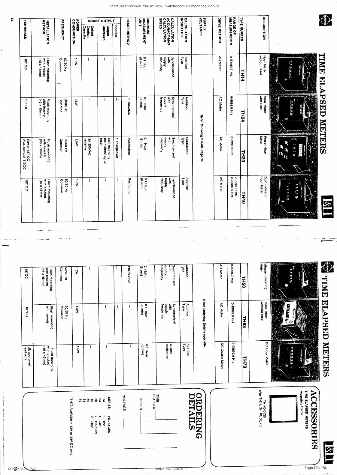
TIM
E E
LA
PSED
ME
TE
RS
. .
.
I
-
I
-11-1 44'
I I
.., _
....
- r
-
1 1
, 0
les; 5
. I D
ES
CR
IPT
ION
H
our Meter
without reset
Hour M
eter w
ith reset P
reset Hour
Meter
Dual Indicator
Hour M
eter
TY
PE
NU
MB
ER
T
H14
TH
24 T
H30
TH
40
RA
NG
E O
F
ME
AS
UR
EM
EN
TS
0-69999.9 H
rs 0-9999.9 H
rs 0-9999.9 H
rs 0-9999.9 H
rs 0-99999.9 H
rs
DR
IVE
ME
TH
OD
A
C M
otor A
C M
otor A
C M
otor A
C M
otor
SU
PP
LY
VO
LTA
GE
S
Refer O
rdering Details P
age 15
CA
LCU
LAT
ION
IN
DIC
AT
OR
A
ddition T
ype
Addition
Type
Subtraction
Type
Addition
Type
CA
LCU
LAT
ION
A
CC
UR
AC
Y/M
AX
C
ALC
ULA
TIO
N
SP
EE
D
Synchronised
with
supply frequency
Synchronised
with
supply frequency
Synchronised
with
supply frequency
Synchronised
with
supply frequency
MIN
IMU
M
ME
AS
UR
EM
EN
T
UN
IT
0.1 H
our (6 m
in)
0.1 Hour
(6 min)
0.1 H
our (6 m
in)
0.1 H
our (6 m
in)
RE
SE
T M
ET
HO
D
- P
ushbutton P
ushbutton P
ushbutton
n F
M
O
I z O
O
Contact
- 1
changeover -
Output
Operation
- -
Self recording
maintained up to
reset
-
Output
Contact
Capacity
- -
3A 250V
AC
resistive
-
PO
WE
R
CO
NS
UM
PT
ION
1.5W
1.5W
1.5W
1.5W
FR
EQ
UE
NC
Y
50/60 Hz
Com
mon
1
50/60 Hz
Com
mon
50/60 Hz
Com
mon
50/60 Hz
Com
mon
INS
TA
LLAT
ION
M
ET
HO
D
Flush m
ounting w
ith bracket (45 x 45m
m)
Flush m
ounting w
ith bracket (45
x 45mm
)
Flush m
ounting w
ith bracket
(50 x 50mm
)
Flush m
ounting w
ith bracket (45 x 45m
m)
TE
RM
INA
LS
187 QC
187 Q
C
Pow
er 187 QC
A
ux. contact 110QC
187 Q
C
14
In TIM
E E
LA
PSED
ME
TE
RS
)
M. H
01.0 PIZT
ER
....T revels. A
i __ _,
0 eat
Minute indicating
Meter
Hour M
eter w
ithout reset D
C H
our Meter
TH
50 T
H63
TH
70
0-9999.9 Min
0-99999.9 Hrs
0-99999.9 Hrs
AC
Motor
AC
Motor
DC
Quartz M
otor
Refer O
rdering Details opposite
Addition
Type
Addition
Type
Addition
Type
Synchronised
with
supply frequency
Synchronised
with
supply frequency
Quartz
oscillation
0.1 M
in
(6 sec)
0.1 Hour
(6 min)
0.1 Hour
(6 min)
Pushbutton
- -
- -
1.5W
1.5W.
1.5W
50/60 Hz
Com
mon
50/60 Hz
Com
mon
Flush m
ounting w
ith bracket (45
x 45mm
)
Flush m
ounting w
ith spring
Flush m
ounting w
ith bracket (45 x 45m
m)
187QC
187Q
C
UL approved
lead wire
TIM
E E
LAP
SE
D M
ET
ER
S
Mounting F
rame
OR
DE
RIN
G
DE
TA
ILS
TIM
E
ELA
PS
ED
SE
RIE
S
VO
LTA
GE
SE
RIE
S
VO
LTA
GE
S
14 3
12V
24 4
24V
30 7
115-120V
40 9
240V
50 63
'70
*TH
70 Available in
12V or 24V
DC
only.
15
Scott Street Norman Park SPS SP025 Switchboard Maintenance Manual
Q-Pulse Id TMS740 Active 29/01/2014 Page 90 of 95

Control units 022 mm Telemecanique
Black, double insulated bezel - ZA2-B
ZA2-BA .
ZA2-BA .8
ZA2-BL4
ZA2-BP .
ZA2-BC44
ZA2-BS54
ZA2-BS74
ZA2-BD9.2
Discount code IC4
Pushbutton operating heads, spring return - IP65 Description Colour
Flush Black Green Red Yellow Blue
Flush Green with transparent plunger for use with legend ZB2-BY1 Red
Flush Green Start with function symbol marked on plunger Red Stop
Projecting Black Green Red Yellow Blue
Projecting with function symbol Red Stop marked on plunger
Booted Black Green Red Yellow Blue
Mushroom head pushbuton Spring return Red o 30 mm
O 40 mm
Operating heads for emergency stop pushbuttons Latching Standard Red "Push pull" Padlockable Red
a 40 mm o 40 mm
Latching Red o 30 mm Turn to release o 40 mm
Latching Key release (Ronis key n 455)
Red o 30 mm o 40 mm
Reference Price
ZA2-BA2 6.60 ZA2-BA3 6.60 ZA2-BA4 6.60 ZA2-BA5 6.60 ZA2-BA6 6.60
ZA2-BA38 12.90
ZA2-BA48 12.90
ZA2-BA333 7.90
ZA2-BA434 7.90
ZA2-BL2 10.00 ZA2-BL3 10.00 ZA2-BL4 10.00 ZA2-BL5 10.00 ZA2-BL6 10.00
ZA2-BL434 10.00
ZA2-13P2 10.00 ZA2-BP3 10.00 ZA2-BP4 10.00 ZA2-BP5 10.00 ZA2-BP6 10.00
ZA2-BC44 11.30 ZA2-BC4 12.70
ZA2-BT4 22.00 ZA2-BT409 53.50
ZA2-BS44 26.10 ZA2-BS54 27.10
ZA2-BS74 48.30 ZA2-BS14 49.60
Potentiometer control knob (potentiometer not supplied) - IP65
Head only with collar for For potentiometer with 6 mm shaft ZA2-BD912 52.50 potentiometer with shaft For potentiometer with 6.35 mm shaft ZA2-BD922 52.50 length 43 to 47 mm Other versions: Key release mushroom head pushbuttons with other key numbers, please consult your Regional Sales office.
SCHNEIDER 6/8
Scott Street Norman Park SPS SP025 Switchboard Maintenance Manual
Q-Pulse Id TMS740 Active 29/01/2014 Page 91 of 95

Telemecanique Control & signalling units 022 mm
Black, double insulated bezel - ZA2-B
ZA2-BD
ZA2-BG
ZA2-BVO
ZA2-BW3
ZA2-BW14
6/9
Operating heads for selector switches - IP65 Description Reference Price
2 position Stay put ZA2-BD2 13.60 Spring return from right to left ZA2-BD4 15.60
3 position Stay put ZA2-BD3 13.60 Spring return to centre position ZA2-BD5 15.60 1 spring return from right to centre ZA2-BD8 15.60 1 spring return from left to centre ZA2-BD7 15.60
Key switch operating heads (Ronis key no. 455) - IP65 2 position Stay put
Key withdrawal in LH position ZA2-BG2 34.20
Stay put - Key withdrawal in LH and RH position
ZA2-BG4 34.20
Spring return from right to left Key withdrawal in LH position
ZA2-BG6 40.20
3 position Stay put Key withdrawal in centre position
ZA2-BG3 34.20
Stay put - Key withdrawal in LH and RH position
ZA2-BG5 34.20
Stay put Key withdrawal in LH position
ZA2-BG9 34.20
2 Spring return from centre position Key withdrawal in centre position
ZA2-BG7 40.20
1 Spring return from left to centre position Key withdrawal in RH position
ZA2-BG1 40.20
Pilot light heads (lens + bezel) - IP65 Description Colour Reference Price
For use with incandescent bulbs
Green ZA2-BV03 6.90 Red ZA2-BV04 6.90 Yellow ZA2-BV05 6.90 Blue ZA2-BV06 6.90 Clear ZA2-BV07 6.90
For use with neon bulbs or LED light sources
Green ZA2-BV033 10.50 Red ZA2-BV043 10.50 Yellow ZA2-BV053 10.50
Operating heads for illuminated pushbuttons - IP65 Description Colour Reference Price
$ Flush Green ZA2-BW33 13.70
Red ZA2-BW34 13.70 Yellow ZA2-BW35 13.70 Blue ZA2-BW36 13.70 Clear ZA2-BW37 13.70
Projecting Green ZA2-BW13 16.50 Red ZA2-BW14 16.50 Yellow ZA2-BW15 16.50
Other versions Key switches with other mechanical functions or other Ronis key numbers. Operating heads for illuminated 2 or 3 position selector swtiches. Pleage consult your Regional Sales Office
SCHNEIDER Discount code IC4
Scott Street Norman Park SPS SP025 Switchboard Maintenance Manual
Q-Pulse Id TMS740 Active 29/01/2014 Page 92 of 95

Control & signalling units 0 22 mm 0 Telemecanique
Black, double insulated bezel - ZA2-B
ZA2-BZ101
ZA2-BZ105
ZA2-BW06
ZA2-BW07
ZB2-BE1O
ZB2-BE10
Discount code IC4
Body assemblies with 1 contact block
Description Contact Scheme type
For pushbuttons and 2 position selector and key switches
13
N/O Standard
N/C 21
22
Standard "
Body assemblies with 2 contact blocks
13 23 For pushbuttons and 2 or 3 position selector
N/0+ N/O
I Standard
and key switches 14 24
11 21
N/C + Standard N/C
12 22
21 13
N/C + Standard N/O
2214
Illuminated pushbutton body/contact assemblies Supply Typical Supply Contact
scheme voltage
Direct bulb not supplied
Direct through resistor BA 9s, 130 V bulb supplied
110 V max N/O N/C N/C + N/O
220 V N/O 250 V N/C
N/C + N/O
Via integral 110 V/50 Hz N/O transformer X1 13 23 110120 V/60 Hz N/C
_ J. 1.2 VA, BA 9s, 6 V i i
N/C + N/O -) ---- bulb supplied
X2 14 24
220/240 V/50 Hz N/O N/C N/C + N/O
380/415 V/50 Hz N/O N/C N/C + N/O
Additional/replacement contact blocks
Description Contact Scheme type
For making up body N/O . Standard assemblies with 3, 4, 5 or maximum of 6 contact .4 For low power blocks or replacing switching
1st or 2nd contact N/C A Standard
.2 For low power switching
Reference Price
ZA2-BZ101 7.90
ZA2-BZ102 7.90
ZA2-BZ103 13.60
ZA2-8Z104 13.60
ZA2-BZ105 13.60
Reference Price
ZA2-BW061 19.60 ZA2-BW062 19.60 ZA2-BW065 24.90
ZA2-BW071 35.20 ZA2-BW072 35.20 ZA2-BW075 40.20
ZA2-BW031 51.00 ZA2-BW032 51.00 ZA2-BW035 56.00
ZA2-BW041 51.00 ZA2-BW042 51.00 ZA2-BW045 56.00
ZA2-BW051 51.00 ZA2-BW052 51.00 ZA2-BW055 56.00
Reference Price $
ZB2-BE101 6.70
ZB2-BE1016 36.90
ZB2-BE102 6.70
ZB2-BE1026 36.90
SCHNEIDER 6/10
Scott Street Norman Park SPS SP025 Switchboard Maintenance Manual
Q-Pulse Id TMS740 Active 29/01/2014 Page 93 of 95

Telemecanique
Signalling units 0 22 mm Black, double insulated bezel - ZA2-B
ZA2-BV6
ZA2-BV4
DL1-C
DL1-CJ10
ZB2-BY
ZB2-BP
ZBF-X13
6/11
Pilot light body/contact assemblies Supply Scheme Supply
voltage Reference Price
Direct X1 110 V max bulb not supplied
ZA2-BV6 8.20
X2
Direct through 220 V resistor 250 V
ZA2-BV7 16.50
BA 9s, 130 V X2
bulb supplied
Via integral X1 110 V/50 Hz transformer
(.3C 110-120 V/60 Hz
ZA2-BV3 39.20
1.2 VA X2
BA 9s, 6 V 220/240 V/50 Hz ZA2-BV4 39.20 bulb supplied
380/415 V/50 Hz ZA2-BV5 39.20
BA9-s Bulbs and L.E.D.s Description Voltage Colour Reference Price
S
Incandecent 6 Clear DL1-CB006 4.45 filament lamp 12 Clear DL1-CE012 4.45 (max. power 2.6W) 24 Clear DL1-CE024 4.45 48 Clear DL1-CE048 4.45
130 Clear DL1-CE130 4.45
LED Cluster lamp 12* Green DL1-CJ0063 16.50 (8 cluster) 12* Red DL1-CJ0064 16.50 12* Yellow DL1-CJ0065 16.50 24 Green DL1-CJ0243 16.50 24 Red DL1-CJ0244 16.50 24 Yellow DL1-CJ0245 16.50 For use with transformer pilot lightsfilluminated pushbuttons
Accessories Description Reference Price
S
Legend plates 30x40 mm (refer page 4/5) ZB2-BY 1.50
Add-on "push-push to release" mechanism for use with pushbuttons and illuminated pushbuttons
ZB2-BZ21 10.00
Boot, silicon rubber (for ZA2-BP) Black ZB2-BP012 5.40 Green ZB2-BP013 5.40 Red ZB2-BP014 5.40 Yellow ZB2-BP015 5.40 Blue ZB2-BP016 5.40
Tools
Bezel key for transparent pushbuttons ZB2-BZ8 5.00
Bulb extractor for use with BA 9s bulb XBF-X13 7.60
Socket key for tightening the operating head locking ring ZA2-BZ905 13.00
SCHNEIDER Discount code IC4
Scott Street Norman Park SPS SP025 Switchboard Maintenance Manual
Q-Pulse Id TMS740 Active 29/01/2014 Page 94 of 95

91 u
0110
aS - X
IdV
>13
0 91
uo!
ioeS
- XId
V)1
30
91 u
o!lo
eS - X
IdV
>13
0
9998
V0
Z d
H
9998
40
Z dH
99
g8V
0 1.
di
-' 06
98V
0 Z
d0V
06
98b0
Z
day
O
Z98
170
l da
y _
. .
. .
.
0682
10
ZZ
C7(
TvT
FN
§§
064E
10
(ZZ
x E
IAI)
>IS
O
068Z
1.0
(ZZ
x W
I) )
1S9
009L
C0
443V
01
.916
0 V
ay
099/
60
V a
y
0669
1.0
VI.
91S
0/
9 l Z
O
9'8
81S
0/
9L30
g8
els
09
6620
(O
(7)
Sd
0170
9 L 0
(06'
Z)
Sd
0(70
81.0
(O
c) S
d
0117
9 L
0 S
S
OV
491.
0 S
S
0936
20
(SZ
x 6
1A1)
S8
0936
20
(9Z
x D
v) s
e 01
.992
0 61
. H
A
01.9
9Z0
61.
HA
00
161.
0 Z
lA
0016
1.0
? 1A
960L
Z0
ZS
O
OLZ
LZO
Z
SO
(9
1 U
0408
S 9
8S) Z
ak.]
mai
os u
o 8A
1108
0 M
9JO
S U
O e
Alld
80
man
s uo
am
ide°
00
6060
(O
Z x
CIA
I)58
00
E06
0 (O
Z x
CM
S8
0069
60
(91.
x
CM
) S
EI
006V
ZO
Z
t. H
A
()G
RIN
9'
61.
HA
0/
99Z
0 8
HA
06
9660
01
. 10
03
8660
01
. 10
01
.966
0 01
. 10
09
1761
.0
V 1
0 08
061.
0 V
10
01.9
91.0
V
10
OV
46 L
O
6 10
01
061.
0 C
10
0099
1.0
C 1
0 O
C46
L 0
Z 1
0 09
06 1.
0 Z
10
0699
1.0
Z 1
C
01.L
61.0
(9
'0)
M1
01.L
61.0
(9
'0)
M1
01.
L 6Z
0 (0
'1.)
NU
_ L1
.061
.0
(gZ
) M
1 L1
.061
.0
(gZ
) M
1 Z
1.06
1.0
(gZ
) M
1 Z
1.06
1. 0
(g
'Z)
M1
Zsz
oco
(s.z
) M
l 81
.061
.0
' (g
L) M
1 (n
om
(9-0
Ml
88E
0E0
(9.0
Ml
91.0
01.0
(g
L) M
1 91
-061
.0
(9'1
.) M
.I.
snow
(g
.i.)
mi.
1611
.1.0
(S
'1.)
dV
1.
61.1
1.0
(9'1
.) dV
L9
6LZ
0 (g
l) dV
E
6/1.
1.0
(91)
dV
Z
6/1.
1.0
(TO
dV
Z
9612
0 (T
O d
V
86L1
.1.0
(9
1) d
V
9611
.1.0
(g
l) d
V
996/
20
(gl)
dV
96/L
1.0
(91)
dV
96
111.
0 (9
"1.)
dV
99
6LZ
0 (9
'1.)
dV
9190
20
(59)
1.1
IM3
91.9
030
(9'8
) L)
4M3
91.9
0Z0
(5'8
) I.
)1M
3
OLZ
91.0
6
125
OLZ
GLO
C
AS
S
mg
Lo
c IS
'S
01.9
190
Zea
l_
01.9
/90
ZE
ST
01
9/90
Z
ES
1 08
ZZ
1. 0
Z
eS1
OW
L 0
ZE
ST
08
ZZ
1.0
Z
ES
1 -O
N 1
e0
edic
l. 'O
N 'W
O
'ON
le0
edfu
(.1)
(D
0
WI
0 80
30
x3-V
d33S
V8
(!)
(9
©
®
VS
*ID
89
30
x3-V
A33
SV
8 (I
I;
(9
© 0
Wt a
8930
x3
-1/J
33S
V8
LZ66
1.0
LC9Z
1.0
L96L
Z0
ZZ
C61
.0
M31
.0
Z96
LZ0
8Z66
1. 0
86
821.
0 99
6LZ
0 9Z
661-
0
9682
1.0
996L
20
'ON
le3
'oN
le0
'oN
le3
Z I.
Z
1.
6
9-g0
V
-g0
4-9.
0 01
.-9'
0 '
9-9'
0 V
-9.0
Lutu
g ss
euvi
tyl
ww
9 ss
ault0
141
.
ww
g sw
um:4
1u
or
ov
5£
!22
i 3
0
"
.: te
.' I
' I
41,:-
-.
.J..,
v.4.
..t.,.
..---
,-
r-
-,"
, _:
4_
,-1.
4s
4
-v
,r-
--,
-___
_,
F;
LT
'
4-i-
--- ;Z
.!
V
.7-
L
-
r -i
t':41
v,,,.
.!t7
51-t
, !I
CT
- --
. T
- el
,.:
..,,,,
)
-....
..
-_
.1
VL
Z A
OSL
9*Z
MV
S
VL
V A
091.
N9
)ISI
S
_...-
4.
V9£
A09
1 V
NY
S uo
dchr
i
9].
uoH
oa'S
ea-
s *o
sseo
o lu
o!l!p
pe JO
d
91 N
O11
033 - X
UV
)130
91
uo!
joas
U
MO
US
aJe
sw
elsA
s 6U
NJE
W I
IV
96%
. B
uppe
w
9998
(70
1. dH
la
relq
uod
dns
()M
VO
1.
dC
1V
18A
00 w
eied
suea
11
10- p
Oi%
L3
(w1.
) .1
43A
0 3
M9.
108
o!ls
eId
law
! !!
A
oQol
leqt
ri S
ugue
m
0/91
.Z0
OV
091.
0 g8
els
(f
ac.z
) Sd
lloq
6nId
on
ld
0E3
r--4
1 1
I
enid
pal
Ja
ysem
M
eJO
S
Aem
z
E4=
==
(r
uc)
al=
==
dull
Sul
LIN
IAA
S
&id
clo
d -!
8
0119
60
M8J
OS
UO
3A
110.
80
(Pt
X S
ZIN
) S
e 18
1.1S
EM
MeJ
OS
0699
20
58 H
A
9A0e
IS
0086
60
01.1
0 A
em 0
1.
0094
20
10
Aem
0691
.30
610
Aem
5
0991
30
Z10
A
eM z
000 - -0
ffi
(91
uogo
es e
as)
i!un
0
SU
OR
O8U
U03
SS
0,11
0
9899
60
LI
S1
aPlw
eAio
d uo
!pue
d H
ews
0910
60
(s.o
) Ml
Jade
d pe
puoq
uis
a8
au!w
eleN
3
eu!w
elat
Ai
881.
61.0
(s
'0)
mi.
epw
eAlo
d 98
1.61
.0
(go)
Ml
0P1w
eAlo
d (w
w s
sew
lom
) up
land
9111
111E
101A
I
8609
1.0
(9'1
) dV
ep
!weA
lod
9609
1.0
(90
dV
appe
Alo
d (w
w s
seu>
pm)
+m
id p
u3
91.9
020
(9.8
) 1.
)1M
3 ::4
(w
w s
sauN
om) le
vers
pu3
O
LZS
LO
£1S
S
leak
le
uo!ld
o - (w
1.)
u!d
6upp
o1
01.9
190
Z6S
1 ( s
lo s
9161
) la
elS
08
ZZ
LO
ZC
S1
leal
S
C-3
13
N V
O
ecbr
u.
(u01
1BE
I Ie
uluu
al
ep!n
e si
enoi
ddv
aQ 0
xv,
a 80
33
x3 -V
d338
1/8
pals
!! aJ
e si
enoi
ddy
IIV
sien
oidd
y eu
iwel
eiN
ie
qwnu
an6
olei
eo
eu!w
elaw
aw
01,
N,
JO a
, )(
pis
ppe
'sle
u!w
iej
,N.x
3 P
ue 0
,x33
6up
apio
uaL
IM
appe
/god
ie
ueve
w b
uy:r
ot/1
R
ea 6
upep
iO
8591
.20
eID
IUJE
A10
d
9551
.30
'ON
le3
( w w
) te
uel 6
u!dd
uls
uoR
eins
ui
53 -Z
Z'O
(z
ww
) pe
puei
ls
S'3
-Za0
(z
ww
) mos
lo
lonp
uo0
eleC
I le
olug
oal
..tug
SZ
E
VO
Z A
009
149"
Z C
DIV
S su
cgoe
uuo3
dw
ei3
men
S
reu!
wie
i 01
41. to
doi
uo
man
s og
seld
E q
l!An
paw
l eq
Aew
av
adA
l SJa
n00
leU
d!IIP
IDe
103
.eiA
>p!
! el
qeyo
l!ms
ayl
6u!s
n pe
nelg
oe e
q ue
o su
ogoe
uuoo
elq
uyow
s le
tmun
al y
oee
to a
ilueo
ayl
u!
pan
g si
eq J
adw
rif ()
nano
pJep
uels
ou
!sn
pane
we
eq u
eo u
ogoe
uuoo
sew
°
(GaI
SS
EI)
.S
CO
OgN
13
of z
csi H
al A
lqw
esse
uo
palu
now
eq
of p
euE
lsap
ale
pue
gg
epiw
eAlo
d10
lepa
lew
6u!
prow
au!
wel
ew
Jam
e u!
erm
ene
ale
sedA
T le
u!w
iel
Isoo
j
'uop
euuo
o lo
ad
uoR
alq!
A e
slo
op M
8JO
S eq
uo 6
u!ua
lq61
1 01
4) p
ue 'u
olle
ieda
Jd
ou 1
4wA
e)io
A 0
141
oiu!
Ago
ailp
peu
esu!
s!
Jolo
npuo
o ei
eq a
u se
z!s
Jolo
npuo
o sn
o!Ju
n to
uop
euuo
o ay
l Jo)
peA
oldw
e al
e s>
poic
! O
naiq
l-pee
l to
sepa
S W
s al
l
)IV
s ad
Al.
sieu
wei
LiB
noA
til-p
eeA
Scott Street Norman Park SPS SP025 Switchboard Maintenance Manual
Q-Pulse Id TMS740 Active 29/01/2014 Page 95 of 95


![[Fairclough, Norman] Discourse and social change(BookSee.org)](https://img.pdfslide.net/doc/110x75/6361cc79c78c28495d0b9569/fairclough-norman-discourse-and-social-changebookseeorg.jpg)


