Embed Size (px)
Citation preview
Secure Semantic Web Data Management
Confidentiality, Integrity, and Compliant Availabilityin Open and Distributed Networks
Vom Promotionsausschuss des Fachbereichs 4: Informatik der UniversitatKoblenz-Landau zur Verleihung des akademischen Grades Doktor der
Naturwissenschaften (Dr. rer. nat.) genehmigte
Dissertation
vorgelegt von
Andreas Kasten
Vorsitzender des PromotionsausschussesProf. Dr. Ralf Lammel, Universitat Koblenz-Landau
Vorsitzender der PromotionskommissionProf. Dr. Steffen Staab, Universitat Koblenz-Landau
BerichterstatterProf. Dr. Rudiger Grimm, Universitat Koblenz-LandauProf. Dr. habil. Ansgar Scherp,
Universitat Kiel und Leibniz-Informationszentrum Wirtschaft
Datum der wissenschaftlichen Aussprache11.11.2016
Datum der Einreichung30.05.2016

Abstract
Confidentiality, integrity, and availability are often listed as the three major requirementsfor achieving data security and are collectively referred to as the C-I-A triad. Confiden-tiality of data restricts the data access to authorized parties only, integrity means thatthe data can only be modified by authorized parties, and availability states that the datamust always be accessible when requested. Although these requirements are relevant forany computer system, they are especially important in open and distributed networks.Such networks are able to store large amounts of data without having a single entity incontrol of ensuring the data’s security. The Semantic Web applies to these characteristicsas well as it aims at creating a global and decentralized network of machine-readabledata. Ensuring the confidentiality, integrity, and availability of this data is thereforealso important and must be achieved by corresponding security mechanisms. However,the current reference architecture of the Semantic Web does not define any particularsecurity mechanism yet which implements these requirements. Instead, it only containsa rather abstract representation of security.
This thesis fills this gap by introducing three different security mechanisms for each ofthe identified security requirements confidentiality, integrity, and availability of SemanticWeb data. The mechanisms are not restricted to the very basics of implementing eachof the requirements and provide additional features as well. Confidentiality is usuallyachieved with data encryption. This thesis not only provides an approach for encryptingSemantic Web data, it also allows to search in the resulting ciphertext data withoutdecrypting it first. Integrity of data is typically implemented with digital signatures.Instead of defining a single signature algorithm, this thesis defines a formal frameworkfor signing arbitrary Semantic Web graphs which can be configured with various algo-rithms to achieve different features. Availability is generally supported by redundantdata storage. This thesis expands the classical definition of availability to compliantavailability which means that data must only be available as long as the access requestcomplies with a set of predefined policies. This requirement is implemented with a mod-ular and extensible policy language for regulating information flow control. This thesispresents each of these three security mechanisms in detail, evaluates them against a setof requirements, and compares them with the state of the art and related work.
3

Zusammenfassung
Als wichtigste Anforderungen an Datensicherheit werden oft Vertraulichkeit, Integritatund Verfugbarkeit genannt. Vertraulichkeit von Daten bedeutet, dass nur berechtigteParteien auf sie zugreifen konnen. Datenintegritat erfordert, dass nur berechtigte Par-teien die Daten andern durfen. Verfugbarkeit von Daten bedeutet, dass auf die Datenjederzeit bei Bedarf zugegriffen werden kann. Obgleich die Umsetzung dieser Sicherheits-anforderungen fur jedes Computersystem relevant ist, gilt dies insbesondere bei offenenund verteilten Netzen. Solche Netze speichern große Mengen an Daten ohne eine zentraleInstanz, die den sicheren Zugriff und die sichere Verarbeitung der Daten steuert. DasSemantic Web teilt diese grundlegende Eigenschaft, da es das Erstellen eines globalenund dezentralen Netzes von maschinenlesbaren Daten anstrebt. Auch fur solche Datenmuss daher durch entsprechende Sicherheitsmaßnahmen die Vertraulichkeit, Integritatund Verfugbarkeit garantiert werden konnen. Obgleich die aktuelle Referenzarchitekturdes Semantic Webs durchaus das Umsetzen von Sicherheitsmaßnahmen vorsieht, defi-niert sie selbst noch keine konkreten Maßnahmen. Stattdessen enthalt sie lediglich einenabstrakten Baustein, dem solche Maßnahmen zugeordnet werden konnen.
Diese Arbeit stellt drei konkrete Sicherheitsmaßnahmen vor, welche sich in die Re-ferenzarchitektur des Semantic Webs einbetten lassen und die Anforderungen an dieVertraulichkeit, Integritat und Verfugbarkeit der Semantic-Web-Daten umsetzen. Dieeinzelnen Maßnahmen setzen die Anforderungen dabei nicht minimalistisch um, son-dern bieten zugleich noch weiterfuhrende Funktionen. Vertraulichkeit von Daten wirdublicherweise durch Datenverschlusselung umgesetzt. Diese Arbeit stellt einen Ansatzzum Verschlusseln von Semantic-Web-Daten vor, der zugleich auch ein Suchen auf denverschlusselten Daten ohne vorhergehende Entschlusselung erlaubt. Datenintegritat wirdmeist durch digitale Signaturen sichergestellt. Diese Arbeit definiert ein formales Rah-menwerk zum Signieren beliebiger Semantic-Web-Daten, welches mit verschiedenen Al-gorithmen flexibel konfiguriert werden kann. Verfugbarkeit wird oft durch eine red-undante Datenhaltung garantiert. In dieser Arbeit wird eine Erweiterung der klassi-schen Definition von Verfugbarkeit verwendet, die als konforme Verfugbarkeit bezeichnetwird. Konforme Verfugbarkeit bedeutet, dass Daten nur dann bei einem Zugriffsversuchverfugbar sein mussen, wenn der Zugriff konform ist zu einem vordefinierten Regelsatz.Diese Sicherheitsanforderung wird umgesetzt durch eine modulare und erweiterbare for-male Sprache zum Beschreiben von Regelsatzen zur Steuerung von Informationsflussen.Jede der drei Sicherheitsmaßnahmen wird in dieser Arbeit im Detail beschrieben, anhanddefinierter Anforderungen evaluiert und mit verwandten Arbeiten verglichen.
5

Acknowledgments
Although a PhD thesis should officially be the work of the one person writing the thesis,it is completely unrealistic to avoid any support of other people. Quite the contrary, notasking for any kind of help and trying to solve all problems alone even contradicts withthe basic principles of scientific work which involves communication and interaction withother researchers. As I do not want to offend anyone by not listing her or him on thispage, I will use a brute-force approach by simply listing all people who have helped me inthe past years with at least something related to this work. In order to avoid a large andconfusing list of names, all persons listed below are grouped according to their type ofassistance. First of all, I would like to thank my supervisors Ansgar Scherp and RudigerGrimm for their extensive support on this thesis and on any related scientific activities.This includes paying the conference fees and the trip to the respective locations aswell. I would also like to thank all former co-workers of the University of Koblenz forgiving various types of advice and for enduring my annoying personality. As most of thesoftware and some related artifacts mentioned in this thesis were developed by students ofthis university, I would like to thank them as well. In addition to the developed software,they also provided helpful suggestions for improving the different security mechanismspresented in this thesis. Finally, I have to thank all people who participated in the time-consuming and tedious proofreading process. The different categories of thankfulnessand their respective participants are listed below, sorted in alphabetical order by lastname. Multiple categories per person are possible.
SupervisorsRudiger Grimm and Ansgar Scherp
Former co-workersKatharina Braunlich, Nico Jahn, Helge Hundacker, Brigitte Jung, Marco Krause,Daniel Pahler, Daniela Simic-Draws, Stefan Stein, and Tim Wambach
University studentsAlexander Balke, Stefan Becker, Felix Gorbulski, Katharina Großer (neeNaujokat), Benjamin Huck, Michael Kornas, Dominik Mosen, Michael Ruster,Peter Schauß, Artur Schens, Erwin Schens, Arne Fritjof Schmeiser, JohannTissen, and Rainer Weißenfels
ProofreadersKatharina Braunlich, Nicole Kohler, Katharina Krause, Marco Krause, JohannesSiebel, Daniela Simic-Draws, and Tim Wambach
7

Contents
1. Secure Data Management in the Semantic Web 11.1. Research Questions . . . . . . . . . . . . . . . . . . . . . . . . . . . . . . . 3
1.2. Contributions . . . . . . . . . . . . . . . . . . . . . . . . . . . . . . . . . . 4
1.3. Methodology . . . . . . . . . . . . . . . . . . . . . . . . . . . . . . . . . . 5
2. Scenarios for Secure Semantic Web Data Management 112.1. Regulating Internet Communication . . . . . . . . . . . . . . . . . . . . . 11
2.1.1. Example Network Topology . . . . . . . . . . . . . . . . . . . . . . 12
2.1.2. Creating and Distributing Regulation Policies . . . . . . . . . . . . 14
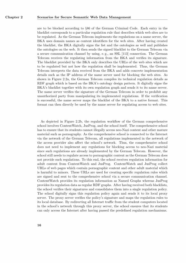
2.1.3. Privacy Compliant Logging of Internet Activities . . . . . . . . . . 17
2.1.4. Summary of the Scenario . . . . . . . . . . . . . . . . . . . . . . . 19
2.2. Securing Medical Data Records in Electronic Healthcare . . . . . . . . . . 19
2.2.1. Medical Data Records Used in Electronic Healthcare . . . . . . . . 20
2.2.2. Security Requirements for Medical Data Records . . . . . . . . . . 20
2.2.3. Example Medical Case . . . . . . . . . . . . . . . . . . . . . . . . . 21
2.2.4. Summary of the Scenario . . . . . . . . . . . . . . . . . . . . . . . 23
3. InFO: A Policy Language for Regulating Information Flow 253.1. State of the Art and Related Work . . . . . . . . . . . . . . . . . . . . . . 26
3.1.1. Access Control Languages . . . . . . . . . . . . . . . . . . . . . . . 26
3.1.2. Usage Control Languages . . . . . . . . . . . . . . . . . . . . . . . 27
3.1.3. Flow Control Languages . . . . . . . . . . . . . . . . . . . . . . . . 29
3.1.4. General Purpose Languages . . . . . . . . . . . . . . . . . . . . . . 29
3.1.5. Content Labeling Schemes . . . . . . . . . . . . . . . . . . . . . . . 30
3.2. Requirements for a Policy Language . . . . . . . . . . . . . . . . . . . . . 31
3.3. Design of the InFO policy language . . . . . . . . . . . . . . . . . . . . . . 34
3.3.1. Modeling Methodology and Reused Ontologies . . . . . . . . . . . 35
3.3.2. Overview of the pattern system . . . . . . . . . . . . . . . . . . . . 37
3.3.3. Flow Control Rule Pattern . . . . . . . . . . . . . . . . . . . . . . 40
3.3.4. Flow Control Policy Pattern . . . . . . . . . . . . . . . . . . . . . . 43
3.3.5. Flow Control Meta-Policy Pattern . . . . . . . . . . . . . . . . . . 44
3.3.6. Organizational Regulation and Legal Regulation Patterns . . . . . 47
3.3.7. Integration of Existing Legal Ontologies into InFO . . . . . . . . . 49
3.3.8. Integration of Existing Content Labeling Schemes into InFO . . . 50
3.3.9. Summary . . . . . . . . . . . . . . . . . . . . . . . . . . . . . . . . 50
i
Contents
3.4. Applications and Use Cases . . . . . . . . . . . . . . . . . . . . . . . . . . 50
3.4.1. Example Policies for Regulating Internet Communication . . . . . 50
3.4.2. Applying the Name Server Ontology . . . . . . . . . . . . . . . . . 53
3.4.3. Applying the Router Ontology . . . . . . . . . . . . . . . . . . . . 56
3.4.4. Applying the Application-Level Proxy Ontology . . . . . . . . . . 59
3.4.5. Example Policies for Securing the Exchange of Medical Data . . . 61
3.5. Prototypical Implementation of the InFO Pattern System . . . . . . . . . 63
3.5.1. Example Name Server Implementation . . . . . . . . . . . . . . . . 64
3.5.2. Example Router Implementation . . . . . . . . . . . . . . . . . . . 66
3.5.3. Example Proxy Server Implementation . . . . . . . . . . . . . . . . 67
3.6. Evaluation and Comparison with Existing Approaches . . . . . . . . . . . 68
3.6.1. Evaluating the Functional Requirements . . . . . . . . . . . . . . . 68
3.6.2. Evaluating the Non-Functional Requirements . . . . . . . . . . . . 74
3.6.3. Summary . . . . . . . . . . . . . . . . . . . . . . . . . . . . . . . . 76
3.7. Limitations and Possible Extensions . . . . . . . . . . . . . . . . . . . . . 76
3.7.1. Enforcing InFO Policies . . . . . . . . . . . . . . . . . . . . . . . . 76
3.7.2. Legal Background . . . . . . . . . . . . . . . . . . . . . . . . . . . 76
3.7.3. Consistency Between Different Layers . . . . . . . . . . . . . . . . 77
3.7.4. Supporting Child Protection Software . . . . . . . . . . . . . . . . 77
3.7.5. Integration into Software Defined Networking . . . . . . . . . . . . 78
3.8. Summary . . . . . . . . . . . . . . . . . . . . . . . . . . . . . . . . . . . . 78
4. Siggi: A Framework for Iterative Signing of Graph Data 814.1. State of the Art and Related Work . . . . . . . . . . . . . . . . . . . . . . 82
4.1.1. Graph Signing Functions . . . . . . . . . . . . . . . . . . . . . . . 82
4.1.2. Canonicalization Functions for Graphs . . . . . . . . . . . . . . . . 83
4.1.3. Serialization Functions for Graphs . . . . . . . . . . . . . . . . . . 85
4.1.4. Hash Functions for Graphs . . . . . . . . . . . . . . . . . . . . . . 85
4.1.5. Signature Functions . . . . . . . . . . . . . . . . . . . . . . . . . . 86
4.1.6. Assembly Function . . . . . . . . . . . . . . . . . . . . . . . . . . . 86
4.1.7. Alternative Approaches for Achieving Integrity of Graph Data . . 87
4.2. Requirements for a Graph Signing Framework . . . . . . . . . . . . . . . . 88
4.3. Formalization of the Graph Signing Framework Siggi . . . . . . . . . . . . 90
4.3.1. Definition of Graphs . . . . . . . . . . . . . . . . . . . . . . . . . . 91
4.3.2. Graph Signing Function σN . . . . . . . . . . . . . . . . . . . . . . 91
4.3.3. Canonicalization Function for Graphs κN . . . . . . . . . . . . . . 92
4.3.4. Serialization Function νN . . . . . . . . . . . . . . . . . . . . . . . 92
4.3.5. Hash Function for Graphs λN . . . . . . . . . . . . . . . . . . . . . 93
4.3.6. Combining Function for Graphs %N . . . . . . . . . . . . . . . . . 93
4.3.7. Signature Function ϕ . . . . . . . . . . . . . . . . . . . . . . . . . 93
4.3.8. Assembly Function αN . . . . . . . . . . . . . . . . . . . . . . . . . 94
4.3.9. Verification Function γN . . . . . . . . . . . . . . . . . . . . . . . . 94
4.3.10. Fulfillment of the Requirements . . . . . . . . . . . . . . . . . . . . 95
ii
Contents
4.4. Four Configurations of the Signing Framework . . . . . . . . . . . . . . . 964.4.1. Configuration A: Carroll . . . . . . . . . . . . . . . . . . . . . . . . 974.4.2. Configuration B: Tummarello et al. . . . . . . . . . . . . . . . . . . 984.4.3. Configuration C: Fisteus et al. . . . . . . . . . . . . . . . . . . . . 984.4.4. Configuration D: Sayers and Karp . . . . . . . . . . . . . . . . . . 99
4.5. Cryptanalysis of the Four Configurations . . . . . . . . . . . . . . . . . . . 994.5.1. Attack Model . . . . . . . . . . . . . . . . . . . . . . . . . . . . . . 994.5.2. Cryptanalysis of the Canonicalization Function κN . . . . . . . . . 1014.5.3. Cryptanalysis of the Serialization Function νN . . . . . . . . . . . 1014.5.4. Cryptanalysis of the Hash Function for Graphs λN . . . . . . . . . 1024.5.5. Cryptanalysis of the Combining Function for Graphs %N . . . . . . 1034.5.6. Cryptanalysis of the Signature Function ϕ . . . . . . . . . . . . . . 1034.5.7. Cryptanalysis of Configuration A . . . . . . . . . . . . . . . . . . . 1044.5.8. Cryptanalysis of Configuration B . . . . . . . . . . . . . . . . . . . 1054.5.9. Cryptanalysis of Configuration C . . . . . . . . . . . . . . . . . . . 1054.5.10. Cryptanalysis of Configuration D . . . . . . . . . . . . . . . . . . . 106
4.6. Performance of the Four Configurations . . . . . . . . . . . . . . . . . . . 1074.6.1. Runtime and Memory Usage of the Functions κN and λN . . . . . 1084.6.2. Accumulated Runtime of all Functions . . . . . . . . . . . . . . . . 1094.6.3. Influence of Blank Nodes . . . . . . . . . . . . . . . . . . . . . . . 1094.6.4. Summary . . . . . . . . . . . . . . . . . . . . . . . . . . . . . . . . 112
4.7. Applications and Use Cases . . . . . . . . . . . . . . . . . . . . . . . . . . 1134.7.1. Signing Policies for Regulating Internet Communication . . . . . . 1134.7.2. Signing an OWL Graph . . . . . . . . . . . . . . . . . . . . . . . . 1144.7.3. Iteratively Signing of Graphs . . . . . . . . . . . . . . . . . . . . . 1164.7.4. Signing a Named Graph . . . . . . . . . . . . . . . . . . . . . . . . 1184.7.5. Signing Multiple and Distributed Graphs . . . . . . . . . . . . . . 1194.7.6. Signing Medical Data . . . . . . . . . . . . . . . . . . . . . . . . . 120
4.8. Evaluation and Comparison with Existing Approaches . . . . . . . . . . . 1224.8.1. Evaluating the Functional Requirements . . . . . . . . . . . . . . . 1234.8.2. Evaluating the Non-Functional Requirements . . . . . . . . . . . . 1254.8.3. Summary . . . . . . . . . . . . . . . . . . . . . . . . . . . . . . . . 126
4.9. Limitations and Future Extensions . . . . . . . . . . . . . . . . . . . . . . 1264.9.1. Reasoning on Signed Graph Data . . . . . . . . . . . . . . . . . . . 1264.9.2. Security of the Graph Signing Framework . . . . . . . . . . . . . . 1274.9.3. Key Management . . . . . . . . . . . . . . . . . . . . . . . . . . . . 1274.9.4. Public Key Infrastructure and Trust Model . . . . . . . . . . . . . 1284.9.5. Secure Time Stamps . . . . . . . . . . . . . . . . . . . . . . . . . . 1294.9.6. Alternative Assembly Functions . . . . . . . . . . . . . . . . . . . . 129
4.10. Summary . . . . . . . . . . . . . . . . . . . . . . . . . . . . . . . . . . . . 130
5. T-Store: Searching in Encrypted Graph Data 1315.1. State of the Art and Related Work . . . . . . . . . . . . . . . . . . . . . . 132
5.1.1. Searching in Encrypted Relational Databases . . . . . . . . . . . . 133
iii
Contents
5.1.2. Searching in Encrypted XML Documents . . . . . . . . . . . . . . 1355.1.3. Searching in Encrypted Graph Structures . . . . . . . . . . . . . . 1365.1.4. SPARQL Query Language . . . . . . . . . . . . . . . . . . . . . . . 137
5.2. Requirements for Searching in Encrypted Graphs . . . . . . . . . . . . . . 1385.3. Basic Terminology and Solution Overview . . . . . . . . . . . . . . . . . . 141
5.3.1. Representing SPARQL Queries in T-Store . . . . . . . . . . . . . . 1415.3.2. Preparing and Applying Queries in T-Store . . . . . . . . . . . . . 143
5.4. Basic Formalization . . . . . . . . . . . . . . . . . . . . . . . . . . . . . . 1445.4.1. Plaintext Graphs and Plaintext Triples . . . . . . . . . . . . . . . 1445.4.2. Encrypted Graphs and Encrypted Triples . . . . . . . . . . . . . . 1455.4.3. Basic Keys . . . . . . . . . . . . . . . . . . . . . . . . . . . . . . . 1455.4.4. Query Keys, Query Patterns, and Authorization Keys . . . . . . . 1455.4.5. Index . . . . . . . . . . . . . . . . . . . . . . . . . . . . . . . . . . 1465.4.6. Query Functions . . . . . . . . . . . . . . . . . . . . . . . . . . . . 1465.4.7. Triple Keys . . . . . . . . . . . . . . . . . . . . . . . . . . . . . . . 1485.4.8. Query Algebras, Query Forms, and Queries . . . . . . . . . . . . . 148
5.5. Design of T-Store . . . . . . . . . . . . . . . . . . . . . . . . . . . . . . . . 1505.5.1. Encryption Phase . . . . . . . . . . . . . . . . . . . . . . . . . . . 1505.5.2. Indexing Phase . . . . . . . . . . . . . . . . . . . . . . . . . . . . . 1535.5.3. Authorization Phase . . . . . . . . . . . . . . . . . . . . . . . . . . 1575.5.4. Query Phase . . . . . . . . . . . . . . . . . . . . . . . . . . . . . . 1595.5.5. Applying Queries with Multiple Triple Keys . . . . . . . . . . . . . 161
5.6. Performance of T-Store . . . . . . . . . . . . . . . . . . . . . . . . . . . . 1645.6.1. Experimental Setup and Implementation Details . . . . . . . . . . 1645.6.2. Preparation Phase . . . . . . . . . . . . . . . . . . . . . . . . . . . 1665.6.3. Query Processing Phase . . . . . . . . . . . . . . . . . . . . . . . . 1685.6.4. Influence of the Array Size z . . . . . . . . . . . . . . . . . . . . . 170
5.7. Cryptanalysis of T-Store . . . . . . . . . . . . . . . . . . . . . . . . . . . . 1735.7.1. Achieving Confidentiality of RDF Graphs . . . . . . . . . . . . . . 1735.7.2. Attack Model . . . . . . . . . . . . . . . . . . . . . . . . . . . . . . 1765.7.3. Guessing Basic Keys . . . . . . . . . . . . . . . . . . . . . . . . . . 1785.7.4. Guessing Query Keys . . . . . . . . . . . . . . . . . . . . . . . . . 1785.7.5. Extracting Basic Keys . . . . . . . . . . . . . . . . . . . . . . . . . 1795.7.6. Computing Basic Keys . . . . . . . . . . . . . . . . . . . . . . . . . 1805.7.7. Reducing authorization keys . . . . . . . . . . . . . . . . . . . . . . 1825.7.8. Analyzing Ciphertext Frequency . . . . . . . . . . . . . . . . . . . 1825.7.9. Analyzing Ciphertext Size . . . . . . . . . . . . . . . . . . . . . . . 1835.7.10. Reasoning on Query Results . . . . . . . . . . . . . . . . . . . . . . 1845.7.11. Analyzing the graph’s characteristics . . . . . . . . . . . . . . . . . 185
5.8. Applications and Use Cases . . . . . . . . . . . . . . . . . . . . . . . . . . 1865.8.1. Searching in Encrypted Log Files . . . . . . . . . . . . . . . . . . . 1865.8.2. Splitting Query Authorizations . . . . . . . . . . . . . . . . . . . . 1875.8.3. Analyzing the Log Database . . . . . . . . . . . . . . . . . . . . . 1895.8.4. Searching on Encrypted Medical Data . . . . . . . . . . . . . . . . 193
iv
Contents
5.9. Evaluation and Comparison with Existing Approaches . . . . . . . . . . . 195
5.9.1. Encoding RDF Graphs . . . . . . . . . . . . . . . . . . . . . . . . . 195
5.9.2. Evaluating the Functional Requirements . . . . . . . . . . . . . . . 198
5.9.3. Evaluating the Non-Functional Requirements . . . . . . . . . . . . 205
5.9.4. Conducing Join Operations on Encrypted Data . . . . . . . . . . . 210
5.9.5. Summary . . . . . . . . . . . . . . . . . . . . . . . . . . . . . . . . 213
5.10. Limitations and Future Extensions . . . . . . . . . . . . . . . . . . . . . . 214
5.10.1. Replacing the Combining Function % . . . . . . . . . . . . . . . . . 214
5.10.2. Query Results with Blank Nodes . . . . . . . . . . . . . . . . . . . 214
5.10.3. Distributing Authorization Keys . . . . . . . . . . . . . . . . . . . 215
5.10.4. Refining Query Authorizations . . . . . . . . . . . . . . . . . . . . 215
5.10.5. Revoking Basic Keys and Ciphertexts . . . . . . . . . . . . . . . . 216
5.10.6. Additional Support for the SPARQL Algebra . . . . . . . . . . . . 216
5.11. Summary . . . . . . . . . . . . . . . . . . . . . . . . . . . . . . . . . . . . 217
6. Conclusion 2196.1. Implementing the Scenarios . . . . . . . . . . . . . . . . . . . . . . . . . . 219
6.2. Summary of the Main Contributions . . . . . . . . . . . . . . . . . . . . . 220
6.3. Outlook and Future Work . . . . . . . . . . . . . . . . . . . . . . . . . . . 221
A. Algorithms and Domain Ontologies of the InFO Policy Language 223A.1. Generic Algorithms for Resolving Conflicts . . . . . . . . . . . . . . . . . 223
A.2. Details of the Router Ontology . . . . . . . . . . . . . . . . . . . . . . . . 224
A.2.1. Flow Control Rules . . . . . . . . . . . . . . . . . . . . . . . . . . . 224
A.2.2. RulePriorityAlgorithms . . . . . . . . . . . . . . . . . . . . . . . . 226
A.3. Details of the Name Server Ontology . . . . . . . . . . . . . . . . . . . . . 227
A.3.1. Flow Control Rules . . . . . . . . . . . . . . . . . . . . . . . . . . . 227
A.3.2. RulePriorityAlgorithms . . . . . . . . . . . . . . . . . . . . . . . . 228
A.4. Details of the Application-Level Proxy Ontology . . . . . . . . . . . . . . 229
A.4.1. Flow Control Rules . . . . . . . . . . . . . . . . . . . . . . . . . . . 229
A.4.2. RulePriorityAlgorithms . . . . . . . . . . . . . . . . . . . . . . . . 231
B. Integrating External Vocabularies into the InFO Policy Language 235B.1. Integrating Legal Ontologies into InFO . . . . . . . . . . . . . . . . . . . . 235
B.1.1. Integrating the Core Legal Ontology . . . . . . . . . . . . . . . . . 235
B.1.2. Integrating the Legal Knowledge Interchange Format . . . . . . . . 239
B.2. Integrating Content Labeling Schemes into InFO . . . . . . . . . . . . . . 241
B.2.1. Integrating the RTA Label . . . . . . . . . . . . . . . . . . . . . . 241
B.2.2. Integrating age-de.xml . . . . . . . . . . . . . . . . . . . . . . . . . 242
B.2.3. Integrating PICS . . . . . . . . . . . . . . . . . . . . . . . . . . . . 243
C. Signature Ontology 245C.1. Signature Pattern . . . . . . . . . . . . . . . . . . . . . . . . . . . . . . . . 245
C.2. Graph Signing Method Pattern . . . . . . . . . . . . . . . . . . . . . . . . 246
v
Contents
C.3. Certificate Pattern . . . . . . . . . . . . . . . . . . . . . . . . . . . . . . . 247
D. Extended Log Format Ontology 249
Bibliography 251
Curriculum Vitae 279
vi
List of Figures
1.1. The Semantic Web layer cake . . . . . . . . . . . . . . . . . . . . . . . . . 21.2. The design science research process . . . . . . . . . . . . . . . . . . . . . . 6
2.1. Example network topology . . . . . . . . . . . . . . . . . . . . . . . . . . . 132.2. Distributing regulation policies . . . . . . . . . . . . . . . . . . . . . . . . 152.3. Example log database storing Internet activities . . . . . . . . . . . . . . . 172.4. Storing and querying encrypted log entries . . . . . . . . . . . . . . . . . . 182.5. Example medical case . . . . . . . . . . . . . . . . . . . . . . . . . . . . . 22
3.1. Different types of policy languages for information control . . . . . . . . . 263.2. Important classes and patterns of DOLCE+DnS Ultralite . . . . . . . . . 353.3. Topic pattern of the Ontopic ontology . . . . . . . . . . . . . . . . . . . . 363.4. Overview of the InFO pattern system . . . . . . . . . . . . . . . . . . . . 373.5. Basic structure of the Flow Control Rule Pattern . . . . . . . . . . . . . . 413.6. Flow Control Rule Pattern . . . . . . . . . . . . . . . . . . . . . . . . . . 413.7. Redirecting Flow Control Rule Pattern . . . . . . . . . . . . . . . . . . . . 423.8. Replacing Flow Control Rule Pattern . . . . . . . . . . . . . . . . . . . . . 423.9. Flow Control Policy Pattern . . . . . . . . . . . . . . . . . . . . . . . . . . 443.10. Flow Control Meta-Policy Pattern . . . . . . . . . . . . . . . . . . . . . . 453.11. Code of Conduct Pattern . . . . . . . . . . . . . . . . . . . . . . . . . . . 473.12. Flow Regulation Norm Pattern . . . . . . . . . . . . . . . . . . . . . . . . 483.13. Legislation Pattern . . . . . . . . . . . . . . . . . . . . . . . . . . . . . . . 493.14. Regulated example network . . . . . . . . . . . . . . . . . . . . . . . . . . 513.15. General definitions used for Name Server Ontology . . . . . . . . . . . . . 543.16. Example regulating using the Name Server Ontology . . . . . . . . . . . . 553.17. Representation of a web server and its IP addresses . . . . . . . . . . . . . 573.18. Example usage of the Router Ontology . . . . . . . . . . . . . . . . . . . . 583.19. Example usage of the Application-Level Proxy Ontology . . . . . . . . . . 603.20. Example medical network . . . . . . . . . . . . . . . . . . . . . . . . . . . 613.21. Regulating the transmission of medical data records . . . . . . . . . . . . 623.22. Architecture of the prototypical implementations . . . . . . . . . . . . . . 64
4.1. General process of signing graphs . . . . . . . . . . . . . . . . . . . . . . . 824.2. Runtime and required memory for signing graphs . . . . . . . . . . . . . . 1084.3. Overall runtime for signing graphs . . . . . . . . . . . . . . . . . . . . . . 1104.4. Signing graphs with blank nodes . . . . . . . . . . . . . . . . . . . . . . . 111
vii
List of Figures
4.5. Examples of signed graphs containing regulation policies . . . . . . . . . . 1134.6. Example signature graph . . . . . . . . . . . . . . . . . . . . . . . . . . . 1164.7. Examples of signed graphs containing medical data . . . . . . . . . . . . . 121
5.1. General process of searching in encrypted RDF graphs . . . . . . . . . . . 1325.2. Representing a SPARQL query in T-Store . . . . . . . . . . . . . . . . . . 1425.3. Overview of the computations for searching in encrypted graphs . . . . . 1445.4. Overview of searching in encrypted graphs . . . . . . . . . . . . . . . . . . 1505.5. Index tree for the ciphertext identifiers . . . . . . . . . . . . . . . . . . . . 1575.6. File size of encrypted graphs . . . . . . . . . . . . . . . . . . . . . . . . . 1665.7. Runtime of preparing different graphs . . . . . . . . . . . . . . . . . . . . 1675.8. Runtime of searching on different graphs . . . . . . . . . . . . . . . . . . . 1695.9. File size of index . . . . . . . . . . . . . . . . . . . . . . . . . . . . . . . . 1715.10. Runtime of searching on different indexed graphs . . . . . . . . . . . . . . 1725.11. Average runtime and standard deviation of searching on indexed graphs . 172
A.1. Content Modifying Rule Pattern . . . . . . . . . . . . . . . . . . . . . . . 231
B.1. Important classes of the Core Legal Ontology . . . . . . . . . . . . . . . . 236B.2. Code of Conduct Pattern of the Core Legal Ontology . . . . . . . . . . . . 236B.3. Flow Regulation Norm Pattern of the Core Legal Ontology . . . . . . . . 237B.3. Flow Regulation Norm Pattern of the Core Legal Ontology . . . . . . . . 238B.4. Legislation Pattern of the Core Legal Ontology . . . . . . . . . . . . . . . 238B.5. Different roles in LKIF . . . . . . . . . . . . . . . . . . . . . . . . . . . . . 239B.6. Code of Conduct Pattern of LKIF . . . . . . . . . . . . . . . . . . . . . . 240B.7. Flow Regulation Norm Pattern of LKIF . . . . . . . . . . . . . . . . . . . 240B.8. Legislation Pattern of LKIF . . . . . . . . . . . . . . . . . . . . . . . . . . 241B.9. RTAMapping ontology . . . . . . . . . . . . . . . . . . . . . . . . . . . . . 242B.10.Example usage of the RTAMapping ontology . . . . . . . . . . . . . . . . 242B.11.Age-Based Redirecting Flow Control Rule Pattern . . . . . . . . . . . . . 243B.12.PICSMapping ontology . . . . . . . . . . . . . . . . . . . . . . . . . . . . 244
C.1. Signature Pattern . . . . . . . . . . . . . . . . . . . . . . . . . . . . . . . . 246C.2. Graph Signing Method Pattern . . . . . . . . . . . . . . . . . . . . . . . . 246C.3. Certificate Pattern . . . . . . . . . . . . . . . . . . . . . . . . . . . . . . . 248
D.1. Extended Log Format Ontology . . . . . . . . . . . . . . . . . . . . . . . . 250
viii
List of Tables
1.1. Methodological overview . . . . . . . . . . . . . . . . . . . . . . . . . . . . 7
3.1. Functional requirements implemented by the InFO patterns . . . . . . . . 403.2. Comparison of InFO with the related work . . . . . . . . . . . . . . . . . 69
4.1. Complexity of the graph signing sub-functions . . . . . . . . . . . . . . . . 844.2. Implementation of the example configurations of Siggi . . . . . . . . . . . 964.3. Complexity of the example configurations of Siggi . . . . . . . . . . . . . . 974.4. Comparison of Siggi with the related work . . . . . . . . . . . . . . . . . . 123
5.1. Creating encryption keys . . . . . . . . . . . . . . . . . . . . . . . . . . . . 1515.2. Encrypting a single triple . . . . . . . . . . . . . . . . . . . . . . . . . . . 1525.3. Creating ciphertext identifiers . . . . . . . . . . . . . . . . . . . . . . . . . 1545.4. Grouping ciphertext identifiers . . . . . . . . . . . . . . . . . . . . . . . . 1545.5. Creating ciphertext arrays . . . . . . . . . . . . . . . . . . . . . . . . . . . 1555.6. Encrypting ciphertext arrays . . . . . . . . . . . . . . . . . . . . . . . . . 1565.7. Creating index keys . . . . . . . . . . . . . . . . . . . . . . . . . . . . . . 1565.8. Creating authorization keys . . . . . . . . . . . . . . . . . . . . . . . . . . 1585.9. Creating query keys . . . . . . . . . . . . . . . . . . . . . . . . . . . . . . 1605.10. Different queries for analyzing encrypted log data . . . . . . . . . . . . . . 1915.11. Creating different basic keys for each year . . . . . . . . . . . . . . . . . . 1945.12. Example database table storing an RDF graph . . . . . . . . . . . . . . . 1975.13. Comparison of T-Store with the related work . . . . . . . . . . . . . . . . 1995.14. Comparison of T-Store with the related work . . . . . . . . . . . . . . . . 2005.15. Approaches for supporting join operations . . . . . . . . . . . . . . . . . . 212
B.1. Age categories of the AgeDeXmlMapping mapping ontology . . . . . . . . 242
C.1. Identifiers used in the Signature Ontology . . . . . . . . . . . . . . . . . . 247
ix

List of Listings
3.1. Example blocking result of a name server. . . . . . . . . . . . . . . . . . . 653.2. Example blocking result of a router. . . . . . . . . . . . . . . . . . . . . . 673.3. Example blocking result of a proxy server. . . . . . . . . . . . . . . . . . . 68
4.1. Example of a signed OWL graph . . . . . . . . . . . . . . . . . . . . . . . 1144.2. Example of iteratively signed graphs . . . . . . . . . . . . . . . . . . . . . 1174.3. Example of a signed Named Graph . . . . . . . . . . . . . . . . . . . . . . 1184.4. Example of a signed RDF Graph . . . . . . . . . . . . . . . . . . . . . . . 1194.5. Example of multiple signed graphs . . . . . . . . . . . . . . . . . . . . . . 1204.6. Example of signed medical graphs . . . . . . . . . . . . . . . . . . . . . . 122
5.1. Example SPARQL query . . . . . . . . . . . . . . . . . . . . . . . . . . . . 1385.2. Example graph consisting of eight triples . . . . . . . . . . . . . . . . . . . 1535.3. Example of reasoned triples . . . . . . . . . . . . . . . . . . . . . . . . . . 1855.4. Example log file . . . . . . . . . . . . . . . . . . . . . . . . . . . . . . . . . 1875.5. Example query applied to encrypted graphs . . . . . . . . . . . . . . . . . 1905.6. First example query applied to encrypted graphs . . . . . . . . . . . . . . 1915.7. Second example query applied to encrypted graphs . . . . . . . . . . . . . 1925.8. Third example query applied to encrypted graphs . . . . . . . . . . . . . . 1925.9. Fourth example query applied to encrypted graphs . . . . . . . . . . . . . 1925.10. Fifth Example query applied to encrypted graphs . . . . . . . . . . . . . . 1935.11. Example RDF graph . . . . . . . . . . . . . . . . . . . . . . . . . . . . . . 1955.12. Example SPARQL query . . . . . . . . . . . . . . . . . . . . . . . . . . . . 1955.13. Example XML encodings . . . . . . . . . . . . . . . . . . . . . . . . . . . 1965.14. Example XPath query . . . . . . . . . . . . . . . . . . . . . . . . . . . . . 1975.15. Example SQL query . . . . . . . . . . . . . . . . . . . . . . . . . . . . . . 198
xi


List of Algorithms
5.1. Applying a query to a ciphertext graph . . . . . . . . . . . . . . . . . . . 1625.2. Applying a SELECT query to a ciphertext graph . . . . . . . . . . . . . . . 1635.3. Applying a CONSTRUCT query to a ciphertext graph . . . . . . . . . . . . . 1635.4. Applying an ASK query to a ciphertext graph . . . . . . . . . . . . . . . . 164
xiii

Chapter 1.
Secure Data Managementin the Semantic Web
The Data Management Association (DAMA) defines data management as the “devel-opment, execution, and supervision of plans, policies, programs, projects, processes,practices and procedures that control, protect, deliver, and enhance the value of dataand information assets” [207]. According to this definition, data management comprisesall steps of processing data including its initial creation, storage, and usage. In order toimplement these steps, DAMA defines a data management framework [207] consisting often basic components, each of which covers a different aspect of managing data. One ofthese components is data security management which aims at implementing the securityrequirements confidentiality and integrity of data as well as protection against unau-thorized data access [208]. Confidentiality of data means that only authorized partiesare aware of the data’s existence and are able to see its contents [37]. Integrity of datameans that any unauthorized modification of the data must be prohibited [37]. Protec-tion against unauthorized data access prevents a party from accessing the data in sucha way the party is not allowed to. Although general definitions of computer security [37]also focus on confidentiality and integrity, they do not include protection against un-wanted data access as one of the main security requirements. Instead, this requirementis often replaced by availability of data. Availability means that data must always beaccessible to any requesting party [28]. The three security requirements confidentiality,integrity, and availability of data are often collectively referred to as the C-I-A triad [28].
Although DAMA is mainly concerned with data management in closed environmentssuch as organizations [207], its basic principles of data management can also be trans-ferred to open and distributed networks [288] such as the Internet. The Semantic Webrelies on these characteristics of the Internet as its own design is inherently open anddecentralized as well. The aim of the Semantic Web is to create a global network ofmachine-readable data [35] by interlinking various distributed data sources [39]. Eachdata source provides a different type of data, including both publicly available data suchas media [187, 240], life science [30], and e-government [134] as well as sensitive privatedata like medical records [256, 106] and information about business processes [143]. Asthe application areas and the size of the Semantic Web are still increasing, securing andprotecting the data stored in the Semantic Web is also gaining more importance [185].
1
Chapter 1 Secure Data Management in the Semantic Web
Since the Semantic Web is essentially a large collection of data, DAMA’s security re-quirements for data management can be applied to it as well.
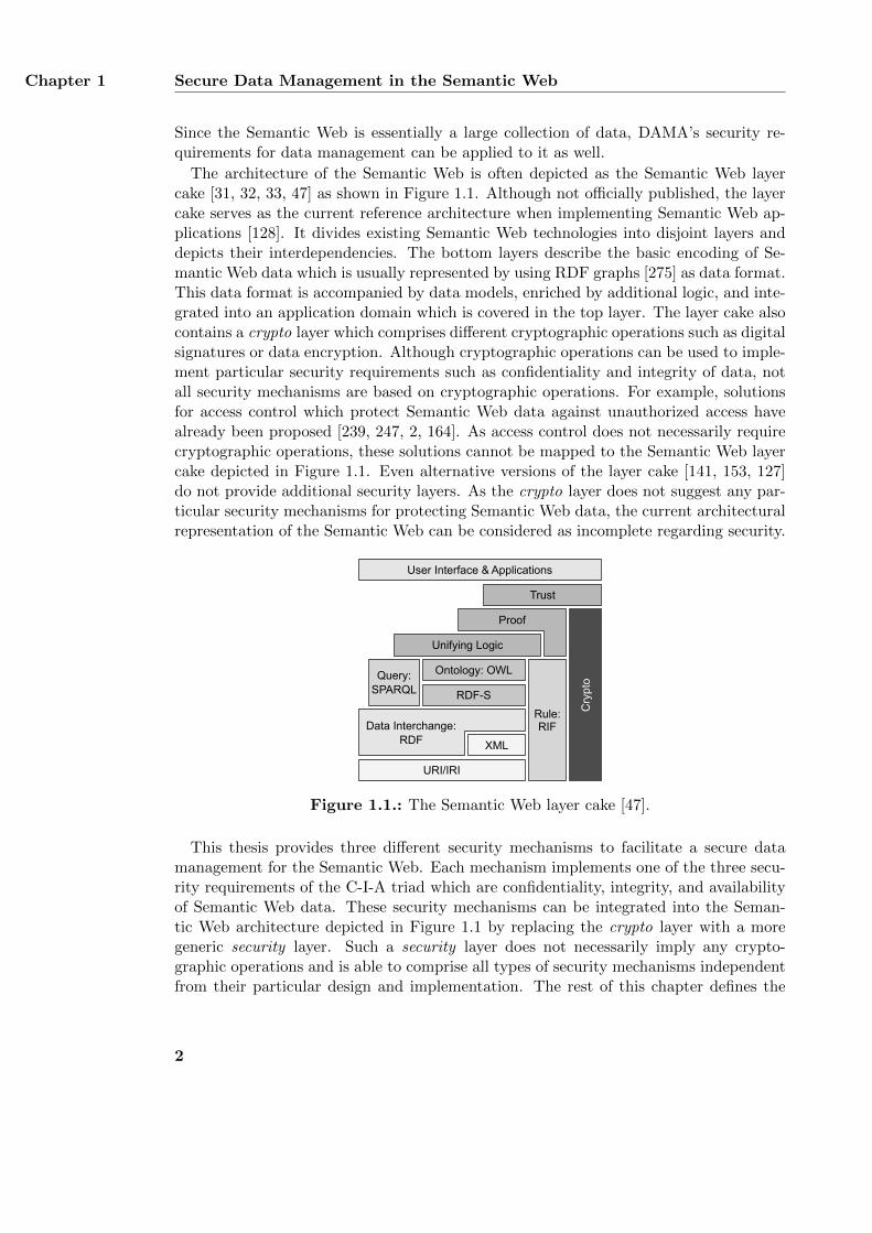
The architecture of the Semantic Web is often depicted as the Semantic Web layercake [31, 32, 33, 47] as shown in Figure 1.1. Although not officially published, the layercake serves as the current reference architecture when implementing Semantic Web ap-plications [128]. It divides existing Semantic Web technologies into disjoint layers anddepicts their interdependencies. The bottom layers describe the basic encoding of Se-mantic Web data which is usually represented by using RDF graphs [275] as data format.This data format is accompanied by data models, enriched by additional logic, and inte-grated into an application domain which is covered in the top layer. The layer cake alsocontains a crypto layer which comprises different cryptographic operations such as digitalsignatures or data encryption. Although cryptographic operations can be used to imple-ment particular security requirements such as confidentiality and integrity of data, notall security mechanisms are based on cryptographic operations. For example, solutionsfor access control which protect Semantic Web data against unauthorized access havealready been proposed [239, 247, 2, 164]. As access control does not necessarily requirecryptographic operations, these solutions cannot be mapped to the Semantic Web layercake depicted in Figure 1.1. Even alternative versions of the layer cake [141, 153, 127]do not provide additional security layers. As the crypto layer does not suggest any par-ticular security mechanisms for protecting Semantic Web data, the current architecturalrepresentation of the Semantic Web can be considered as incomplete regarding security.
User Interface & Applications
Trust
Proof
Cry
pto
Unifying Logic
Ontology: OWL
RDF-S
XML
URI/IRI
Rule:RIF
Query:SPARQL
Data Interchange:RDF
Figure 1.1.: The Semantic Web layer cake [47].
This thesis provides three different security mechanisms to facilitate a secure datamanagement for the Semantic Web. Each mechanism implements one of the three secu-rity requirements of the C-I-A triad which are confidentiality, integrity, and availabilityof Semantic Web data. These security mechanisms can be integrated into the Seman-tic Web architecture depicted in Figure 1.1 by replacing the crypto layer with a moregeneric security layer. Such a security layer does not necessarily imply any crypto-graphic operations and is able to comprise all types of security mechanisms independentfrom their particular design and implementation. The rest of this chapter defines the
2
Research Questions Section 1.1
research questions of this thesis, identifies its main contributions, and describes the usedmethodology.
1.1. Research Questions
This section defines the research questions which are answered in this thesis. Theseresearch questions derive from the motivation outlined in the previous section and fromthe three security requirements of the C-I-A triad. Each of the security requirementsconfidentiality, integrity, and availability is mapped to one research question. As in-tegrity of Semantic Web graph data is closely related to the data’s authenticity [37], thissecurity requirement is mapped to a fourth research question. Integrity requires thatonly authorized parties are able to modify the graph data and authenticity means thatthe data is retrieved from a verified source [28]. If the source of the data is not verified,it cannot be guaranteed that the graph data is only modified by authorized parties. Inthe following, the four research questions are explained in more detail.
RQ.1: How can confidentiality of Semantic Web data be ensured in open and dis-tributed networks so that only authorized parties are able to access parts ofthe data?Implementing confidentiality of a Semantic Web graph requires that the contentsof the graph are hidden from any unauthorized party. Even authorized parties arenot necessarily able to access all contents of the graph. Instead, their access maybe restricted to particular triples of the graph.
RQ.2: How can integrity of Semantic Web data be achieved in open and distributednetworks so that any unauthorized modification of the data is detected?Integrity of a Semantic Web graph requires that only authorized parties are ableto alter the graph’s contents. Any unauthorized modification destroys the graph’sintegrity and must therefore be detected. Please note that parties who are allowedto view the contents of a graph may still be prohibited from altering it.
RQ.3: How can authenticity of Semantic Web data be ensured in open and dis-tributed networks so that the data can be related to a verified source?Authenticity of a Semantic Web graph requires that the identity of the sourcewhich the graph is retrieved from can be verified. In providing a Semantic Webgraph, the party acting as the data source approves of the graph’s contents.
RQ.4: How can Semantic Web data be made available in open and distributed net-works to such parties whose access requests are compliant with predefined andtransparently communicated policies?Availability of data usually requires that the data is always accessible for autho-rized parties [28]. This thesis enhances this classical definition of availability tocompliant availability which states that graph data must only be accessible to au-thorized parties as long as the parties’ access complies with a set of predefinedconditions. Compliant availability corresponds to DAMA’s security requirement
3
Chapter 1 Secure Data Management in the Semantic Web
for protection of data against unauthorized access [208]. If the conditions are notmet, the graph data must not be available to the requesting party. In contrast toresearch question RQ.1, this research question aims at regulating the availabilityof complete graphs and not of individual triples.
1.2. Contributions
The main contributions of this thesis are three different security mechanisms which an-swer the four research questions from the previous section. The security mechanismsimplement the security requirements confidentiality, integrity, authenticity, and compli-ant availability of Semantic Web graph data. They can be integrated into the SemanticWeb layer cake as shown in Figure 1.1 by replacing the crypto layer with a more genericsecurity layer. In the following, the three contributions are described in more detail.
Confidentiality is implemented by T-Store, an approach for searching in encryptedSemantic Web graphs. Data encryption is a common security mechanism to achievethe data’s confidentiality [96]. Encrypting plaintext data results in ciphertext datawhich can only be decrypted by authorized parties with access to the correct decryptionkeys. Searching in encrypted data extends this basic encryption scheme by supportingqueries on the ciphertext. T-Store encrypts a plaintext graph in such a way that theresulting ciphertext graph can be directly used for processing queries without decryptingit first. A query corresponds to a decryption key which only decrypts those parts ofthe ciphertext graph that fulfill the query. T-Store supports arbitrary queries on theciphertext graph and is not restricted to a set of queries which are defined at encryptiontime. It distinguishes between a data owner who encrypts the plaintext graph and userswho are authorized by the data owner to perform queries on the ciphertext graph. Asunauthorized parties are not able to access any part of the plaintext graph, T-Storeanswers research question RQ.1. A preliminary version of T-Store was first publishedin [171].
Integrity and authenticity are implemented by Siggi, a formal framework for signingSemantic Web graph data. Digital signatures are a security mechanism for achievingboth integrity [267] and authenticity of the signed data [215]. Siggi formally defines ageneric signature pipeline for signing arbitrary graph data. The pipeline is independentfrom any particular algorithm and can be configured with various algorithms to providedifferent features such as minimum signature overhead or minimum runtime. It dividesthe signing process into separate functions, each of which implements a specific step ofthe process. These functions include a canonicalization function, a serialization function,a hash function, and a signature function. Siggi specifies the input and output of eachfunction. The functions are designed in such a way that the resulting signature isindependent from the encoding of the signed graph. The signature only covers the graph’ssemantics and not its syntactical representation. An additional assembly function isapplied at the end of the signing process. It stores all information about how a signaturewas created and how it can be verified by another party. A signature associates asigned graph with the signing party. Modifying the semantics of a graph after it was
4
Methodology Section 1.3
signed invalidates the signature and also destroys the graph’s integrity. Furthermore, themodification affects the graph’s authenticity as well as the signing party only signed theoriginal graph and has not approved of its modified version. Thus, Siggi answers researchquestion RQ.2 and RQ.3. Preliminary versions of Siggi were published in [168, 169, 173].
Finally, compliant availability is implemented by InFO, a policy language for regulat-ing information flow in open and distributed networks. Although availability is usuallyimplemented by providing redundant data storage systems [28], compliant availabilityrequires a different implementation. Compliant availability of data requires the data tobe accessible to any requesting party as long as the access complies with a predefinedpolicy. InFO is specifically designed to regulate communication flow in open networkssuch as the Internet. A policy is a set of rules which share the same purpose and allowor deny a particular communication. A communication is described by a sender andreceiver, the exchanged data, and the used communication channel. Policies define theconditions under which a party can access data stored at a server. Each policy containsall details for technically enforcing a regulation and can be implemented on various com-munication systems such as application-level proxy servers, name servers, and routers.InFO’s modular and extensible design also allows to support additional enforcing sys-tems as well. A policy is further enriched by a legal justification and an organizationalmotivation. As this background information can be transparently communicated to allinvolved parties, InFO fulfills research question RQ.4. A preliminary version of InFOwas first published in [172].
1.3. Methodology
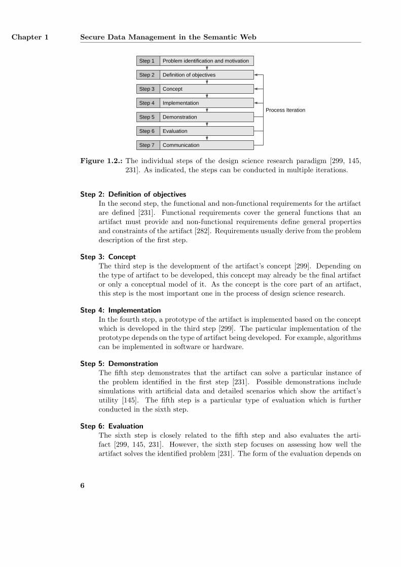
Design science research is a paradigm for developing computer-related artifacts in infor-mation systems research and computer science [299, 231, 22]. Possible artifacts includeabstract models, algorithms and processes, and software implementations [145]. T-Store,Siggi, and InFO comply with this definition and can therefore be considered as artifactsas well. The development process of all three artifacts is based on the design scienceresearch paradigm. Several different suggestions have been made to define the particularsteps involved in design science research [194, 299, 145, 231]. Although all suggestionsdefine the creation of an artifact and its evaluation as the two most important steps,additional steps have also been proposed. The particular steps for developing T-Store,Siggi, and InFO are based on Vaishnavi and Kuechler [299], Hevner et al. [145], andPeffers et al. [231]. These steps are depicted in Figure 1.2 and are further explainedin the following. The overall process of developing an artifact is iterative and uses theresults of one iteration to further improve the artifact in the next iteration.
Step 1: Problem identification and motivationDesign science research focuses on developing computer-related artifacts whichsolve a particular problem. The first step is therefore the identification of thisproblem [299, 145, 231]. It describes why this problem is important and motivatesthe development of possible solutions.
5
Chapter 1 Secure Data Management in the Semantic Web
Problem identification and motivation
Definition of objectives
Implementation
Demonstration
Evaluation
Communication
Step 1
Step 2
Step 4
Step 5
Step 6
Step 7
Process Iteration
ConceptStep 3
Figure 1.2.: The individual steps of the design science research paradigm [299, 145,231]. As indicated, the steps can be conducted in multiple iterations.
Step 2: Definition of objectivesIn the second step, the functional and non-functional requirements for the artifactare defined [231]. Functional requirements cover the general functions that anartifact must provide and non-functional requirements define general propertiesand constraints of the artifact [282]. Requirements usually derive from the problemdescription of the first step.
Step 3: ConceptThe third step is the development of the artifact’s concept [299]. Depending onthe type of artifact to be developed, this concept may already be the final artifactor only a conceptual model of it. As the concept is the core part of an artifact,this step is the most important one in the process of design science research.
Step 4: ImplementationIn the fourth step, a prototype of the artifact is implemented based on the conceptwhich is developed in the third step [299]. The particular implementation of theprototype depends on the type of artifact being developed. For example, algorithmscan be implemented in software or hardware.
Step 5: DemonstrationThe fifth step demonstrates that the artifact can solve a particular instance ofthe problem identified in the first step [231]. Possible demonstrations includesimulations with artificial data and detailed scenarios which show the artifact’sutility [145]. The fifth step is a particular type of evaluation which is furtherconducted in the sixth step.
Step 6: EvaluationThe sixth step is closely related to the fifth step and also evaluates the arti-fact [299, 145, 231]. However, the sixth step focuses on assessing how well theartifact solves the identified problem [231]. The form of the evaluation depends on
6
Methodology Section 1.3
the developed artifact and includes security analyses, performance measurements,or a comparison with the requirements identified in the second step [145].
Step 7: CommunicationIn the last step, the artifact and its importance is communicated to other re-searchers and professionals [145, 231]. This allows to receive feedback on theartifact in order to further improve it. Possible forms of communication includescientific publications and conference presentations.
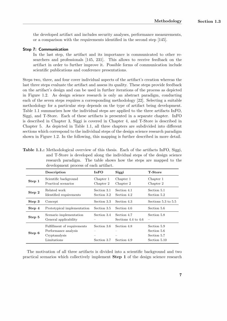
Steps two, three, and four cover individual aspects of the artifact’s creation whereas thelast three steps evaluate the artifact and assess its quality. These steps provide feedbackon the artifact’s design and can be used in further iterations of the process as depictedin Figure 1.2. As design science research is only an abstract paradigm, conductingeach of the seven steps requires a corresponding methodology [22]. Selecting a suitablemethodology for a particular step depends on the type of artifact being development.Table 1.1 summarizes how the individual steps are applied to the three artifacts InFO,Siggi, and T-Store. Each of these artifacts is presented in a separate chapter. InFOis described in Chapter 3, Siggi is covered in Chapter 4, and T-Store is described inChapter 5. As depicted in Table 1.1, all three chapters are subdivided into differentsections which correspond to the individual steps of the design science research paradigmshown in Figure 1.2. In the following, this mapping is further described in more detail.
Table 1.1.: Methodological overview of this thesis. Each of the artifacts InFO, Siggi,and T-Store is developed along the individual steps of the design scienceresearch paradigm. The table shows how the steps are mapped to thedevelopment process of each artifact.
Description InFO Siggi T-Store
Step 1Scientific background Chapter 1 Chapter 1 Chapter 1
Practical scenarios Chapter 2 Chapter 2 Chapter 2
Step 2Related work Section 3.1 Section 4.1 Section 5.1
Identified requirements Section 3.2 Section 4.2 Section 5.2
Step 3 Concept Section 3.3 Section 4.3 Sections 5.3 to 5.5
Step 4 Prototypical implementation Section 3.5 Section 4.6 Section 5.6
Step 5Scenario implementation Section 3.4 Section 4.7 Section 5.8
General applicability – Sections 4.4 to 4.6 –
Step 6
Fulfillment of requirements Section 3.6 Section 4.8 Section 5.9
Performance analysis – – Section 5.6
Cryptanalysis – – Section 5.7
Limitations Section 3.7 Section 4.9 Section 5.10
The motivation of all three artifacts is divided into a scientific background and twopractical scenarios which collectively implement Step 1 of the design science research
7
Chapter 1 Secure Data Management in the Semantic Web
paradigm. The scientific background is based on the four security requirements confiden-tiality, integrity, authenticity, and compliant availability as described at the beginning ofthis chapter. These requirements derive from the literature on computer security [37, 28].Their application to the Semantic Web is motivated by analyzing its architecture whichis represented by the Semantic Web layer cake depicted in Figure 1.1. Although thelayer cake contains a section which summarizes different security mechanisms, it doesnot define any particular mechanism yet. The practical scenarios are introduced in Chap-ter 2 and provide two comprehensive example use cases for applying the three artifactsT-Store, Siggi, and InFO to Semantic Web data. The scenarios necessitate the implemen-tation of the security requirements confidentiality, integrity, authenticity, and compliantavailability. The first scenario covers the regulation of information flow on the Internetand derives from analyzing the current practice of such regulations [321, 89]. The secondscenario discusses the secure management of medical data in electronic healthcare. Itresults from analyzing the literature on electronic healthcare [224, 136] as well as itslegal requirements [297, 90].
Step 2 is implemented by first identifying the general application domain of eachartifact and then extracting its functional and non-functional requirements from theidentified domain. In particular, the domain is comprised of the two scenarios definedin Chapter 2 and the related work of each artifact. The related work is summarizedin separate sections of the three chapters 3, 4, and 5. Each summarized approach isanalyzed regarding its individual features and design characteristics. The result of thisanalysis is used together with the general requirements of the two scenarios to define thespecific requirements for each artifact which are listed in Sections 3.2, 4.2, and 5.2.
The conceptual design resulting from Step 3 is created differently for each artifact.InFO is designed as a set of ontology design patterns [237, 121], which are describedin Section 3.3. The patterns extend the foundational ontology DOLCE+DnS Ultralite(DUL) [119] which defines several ontological concepts and axioms for various applica-tion domains [266]. By reusing and further specifying these concepts and axioms, thevocabulary of InFO can be related to the basic categories of human cognition [222] whichresults in a better linguistic foundation. Siggi provides a mathematical formalization ofa generic signing framework that is presented in Section 4.3. The formalization definesa signature pipeline consisting of several steps, which are implemented using differentalgorithms. The pipeline is based on the XML signature syntax and processing stan-dard [20] for signing and verifying XML documents. The framework is designed in sucha way that it is compatible with already existing algorithms that can be used in theindividual steps of the signature pipeline. T-Store is basically a collection of mathemat-ical algorithms and data structures. Its concept is described in three different sections.Section 5.3 summarizes the overall process of T-Store by outlining its general design andterminology, Section 5.4 provides a mathematical formalization of the terminology, andSection 5.5 applies the formalization to describe all steps of T-Store in more detail.
InFO, Siggi, and T-Store are essentially formal models and not particular softwareimplementations. As such, the implementation of these artifacts conducted in Step 4 isnot an integral part of this thesis and is mainly used for demonstrating their practicalapplicability and for supporting further evaluations. InFO is implemented on three
8
Methodology Section 1.3
prototypical systems which enforce particular regulation policies and are presented inSection 3.5. The feedback drawn from each implementation was used for improvingthe design of InFO’s ontological model. Siggi is implemented by mapping its formalspecification to source code. The implementation is described as part of Section 4.6which discusses the performance of four example configurations of the framework. T-Store is implemented similarly to Siggi by transforming its mathematical model intoa software application. The implementation is also used for evaluating the artifact’sperformance and is described as part of Section 5.6.
Step 5 demonstrates the applicability of an artifact and is a particular type of evalu-ation. The applicability and utility of all three artifacts are demonstrated by using themto implement the two scenarios of Chapter 2. InFO is used for creating example regula-tions which are enforced by the prototypical implementations described in Section 3.5.The policies and their enforcement show that InFO can in fact be used for regulating in-formation flow in open and distributed networks. Section 4.7 shows how Siggi is appliedto sign the example regulations and thereby demonstrates the general signing processof Semantic Web graphs. In addition, Section 4.4 shows four different example configu-rations of a particular signature pipeline. These configurations demonstrate that Siggiin fact supports different algorithms. The configurations are further analyzed with re-spect to their cryptographic security in Section 4.5 and their performance in Section 4.6.The applicability of T-Store is demonstrated by outlining two possible applications forsearching in encrypted data in Section 5.8. Both applications derive from the examplescenarios of Chapter 2 and extend the basic concept of T-Store with additional features.
The evaluation of an artifact as required in Step 6 depends on the type of the artifactand on the particular criteria to be assessed [145, 238]. All three artifacts are comparedwith their related work and analyzed regarding the fulfillment of their functional andnon-functional requirements defined in Step 2. This analysis is conducted manually inSections 3.6, 4.8, and 5.9 by considering the artifacts’ individual characteristics. In addi-tion, all artifacts are evaluated against their conceptual limitations in Sections 3.7, 4.9,and 5.10. T-Store provides a particular algorithm for searching in encrypted data whichis further evaluated with regard to its performance and cryptographic security in Sec-tions 5.6 and 5.7. The performance evaluation is based on an evaluation framework [40]which provides artificial graph data. It is conducted in several experiments in whichdifferent artificial graphs are encrypted and queried. In each experiment, the runtimeand memory usage are measured. The cryptanalysis is based on different attacks whichderive from the related work and state of the art. It is conducted by carefully analyzingthe mathematical design of T-Store. As neither InFO nor Siggi provide a particularalgorithm, they cannot be evaluated the same way. Although four example configura-tions of Siggi are analyzed regarding their cryptographic security and performance, theseanalyses do not apply to the whole framework. Instead, they only cover the particularconfigurations and are part of Step 5.
In order to receive feedback from other researchers on all three artifacts as required inStep 7, each artifact was published at scientific workshops and conferences as well as injournals. InFO was published in [172], Siggi was published in [168, 169, 170, 173], and T-Store was first published in [171]. All publications were peer-reviewed and the feedback
9
Chapter 1 Secure Data Management in the Semantic Web
from the reviewers was used for further improvement together with the discussions at theworkshops and conferences. In addition, InFO and Siggi were implemented by universitystudents who also provided helpful comments on the artifacts’ conceptual design.
10
Chapter 2.
Scenarios for Secure Semantic Web DataManagement
This section describes two different scenarios which demonstrate the need for secure se-mantic web data management in open and distributed networks. The scenarios consistof several parts which motivate the research questions RQ.1, RQ.2, RQ.3, and RQ.4defined in Section 1.1. They also serve as two example applications of the artifactsdeveloped in this thesis which are described in Chapters 3 to 5. The first scenario isgiven in Section 2.1 and focuses on regulating communication in open networks such asthe Internet. The scenario requires a policy language for modeling allowed and prohib-ited communication, a framework for signing regulation policies, and a mechanism forsecurely evaluating log data of Internet activities. The second scenario is described inSection 2.2 and covers the secure distribution of medical data between patients and med-ical institutions. The scenario requires a framework for signing medical data, a policylanguage for managing the secure distribution, and a mechanism for regulating access tothe patients’ personal data. At the end of each subsection, the scenario is summarizedand its relation to the research questions is demonstrated. The implementation of thetwo scenarios is demonstrated in Chapters 3 to 5 as part of the developed artifacts.
2.1. Regulating Internet Communication
The Internet is a global communication medium which interconnects several computernetworks located in different countries and managed by different authorities. The contentprovided on the Internet can generally be accessed by anyone from anywhere. However,each country connected to the Internet has its own national laws and wants to enforcethese laws on the Internet as well. For example, neo-Nazi material can legally be accessedin the USA but its access is regulated in Germany due to the country’s history [198,293]. Additionally, organizations and institutions want to enforce their own rules withintheir local computer network on top of existing national regulations. For example,companies may want to prohibit their employees from accessing any non-work-relatedInternet content which distracts them from their actual work [280, 186]. Schools areeven required by law to protect their students from accessing any content which is
11
Chapter 2 Scenarios for Secure Semantic Web Data Management
inappropriate for minors [151, 61]. Besides these examples, there are many other caseswhere such regulations are desired or even needed [89].
This section outlines a scenario for regulating Internet communication. The scenariocovers an example computer network, a workflow for creating and distributing regulationdetails, and a concept of privacy compliant logging of Internet activities. The examplenetwork consists of several communication nodes and smaller sub-networks which aremanaged by different authorities. These authorities regulate the communication flow inthe networks by applying a workflow for creating and distributing regulation policies.The policies are implemented by technical regulation systems which may also recordall Internet traffic. In order to support traffic analyses without interfering with theprivacy of the affected Internet users, the logging mechanism stores all recorded data inencrypted form and restricts decryption to authorized parties only.
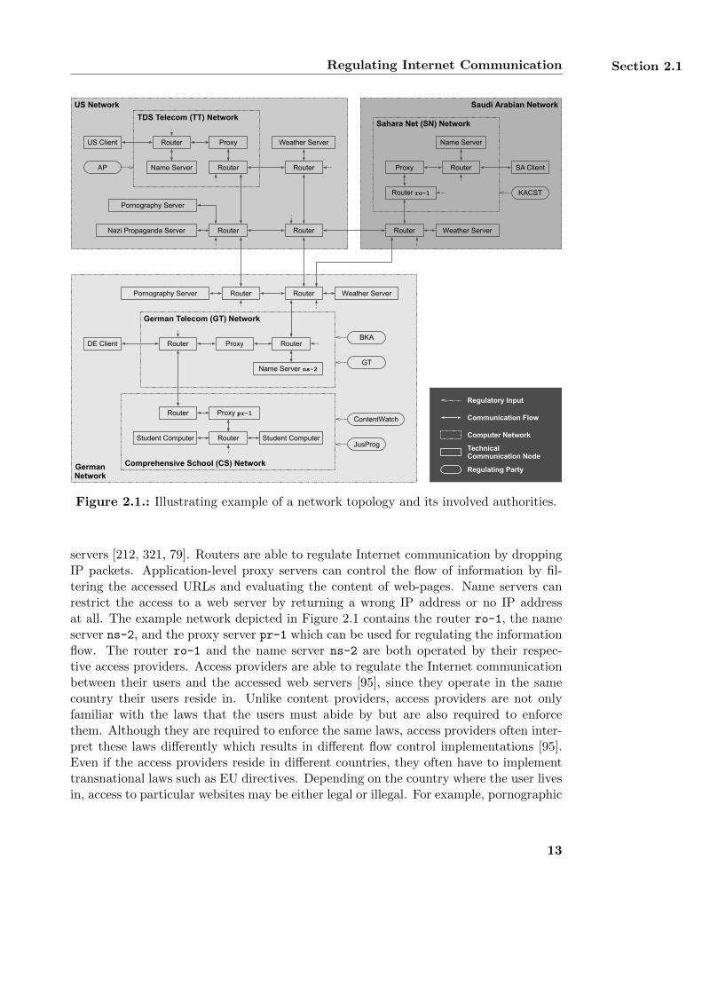
2.1.1. Example Network Topology
Computer networks consist of communication end nodes such as web servers and clientsystems as well as intermediary communication nodes like routers and application-levelproxy servers. An example computer network connecting various communication nodeslocated in the USA, Germany, and Saudi Arabia is depicted in Figure 2.1. Each ofthe three countries has its own national network which includes smaller subnetworkssuch as access provider networks or networks of organizations and institutions. Nationalnetworks and their subnetworks again contain several communication end nodes andintermediary nodes. The communication end nodes cover both end user computerssuch as the US client, the DE client, and the SA client as well as web servers suchas weather servers and pornography servers. End users and small institutions suchas schools do not access the Internet directly. Instead, they are customers of accessproviders and access the Internet through their respective access provider network intheir country. For example, the US client resides in the USA and uses the TDS Telecom1
as its access provider. The SA client is located in Saudi Arabia and is connected tothe Internet via the network of Sahara Net2. The DE client and the comprehensiveschool are located in Germany and use the German Telecom3 as their access provider.The network of the comprehensive school contains several student computers whichact as client systems. These computers only access the Internet after having passedthe intermediary communication nodes of the school’s network and the network of theGerman Telecom.
Each web server in the example network is operated by a content provider and canbe accessed by any user from any country. A content provider can in principle regulatethe access to its provided content at server side. However, content providers may notalways be capable of or even interested in denying access for particular users based onnational laws. Thus, regulations of information flow on the Internet are often imple-mented on intermediary nodes like routers, name servers, and application-level proxy
1http://www.tdstelecom.com, last accessed: 01/21/162http://www.sahara.com, last accessed: 01/21/163http://www.telekom.de, last accessed: 01/21/16
12
Regulating Internet Communication Section 2.1
GermanNetwork
US Network
German Telecom (GT) Network
DE Client
Pornography Server
Nazi Propaganda Server
TDS Telecom (TT) Network
US Client
AP
BKA
Saudi Arabian Network
Weather Server
Sahara Net (SN) Network
SA Client
Router Router
Router
Router
RouterName Server
Proxy
Router
Proxy
Name Server
Router
Router
Router Weather Server
Proxy
KACST
GT
Router
Pornography Server
Weather Server
Router
Comprehensive School (CS) Network
Router Student Computer
ContentWatch
Student ComputerStudent Computer
Router
Regulatory Input
Communication Flow
TechnicalCommunication Node
Regulating Party
Computer NetworkJusProg
Name Server ns-2
Router ro-1
Proxy pr-1
Figure 2.1.: Illustrating example of a network topology and its involved authorities.
servers [212, 321, 79]. Routers are able to regulate Internet communication by droppingIP packets. Application-level proxy servers can control the flow of information by fil-tering the accessed URLs and evaluating the content of web-pages. Name servers canrestrict the access to a web server by returning a wrong IP address or no IP addressat all. The example network depicted in Figure 2.1 contains the router ro-1, the nameserver ns-2, and the proxy server pr-1 which can be used for regulating the informationflow. The router ro-1 and the name server ns-2 are both operated by their respec-tive access providers. Access providers are able to regulate the Internet communicationbetween their users and the accessed web servers [95], since they operate in the samecountry their users reside in. Unlike content providers, access providers are not onlyfamiliar with the laws that the users must abide by but are also required to enforcethem. Although they are required to enforce the same laws, access providers often inter-pret these laws differently which results in different flow control implementations [95].Even if the access providers reside in different countries, they often have to implementtransnational laws such as EU directives. Depending on the country where the user livesin, access to particular websites may be either legal or illegal. For example, pornographic
13
Chapter 2 Scenarios for Secure Semantic Web Data Management
content may be legally accessible by German users and US users over a specific age4, butnot by Saudi Arabians according to §6 of the Saudi Arabian Anti-Cyber Crime Law [179].Access to neo-Nazi propaganda is legal in the USA and in Saudi Arabia but not in Ger-many according to §86 of the German Criminal Code [62]. Finally, weather informationprovided by a weather server can be accessed by users of all three countries. In order toreduce the number of possible errors when interpreting national laws or transnationaldirectives, this interpretation is sometimes made by third parties. The details of theinteraction between all parties involved in the regulation process are further describedin the next section.
2.1.2. Creating and Distributing Regulation Policies
As outlined above, information flow control can be enforced at three different types ofnetwork nodes [212, 321, 79], namely routers, application-level proxy servers, and nameservers. The example network depicted in Figure 2.1 provides different instances of theseenforcing communication nodes. Each type of node requires specific content identifierssuch as IP addresses, domain names, or URLs. The collection of such identifiers is of-ten based on interpreting national laws or transnational directives. This process differsfrom country to country and is implemented by access providers and/or by third partieswhich may even be authorized by the country’s government. In Saudi Arabia, all contentidentifiers are collected and managed centrally by the King Abdulaziz City for Science& Technology (KACST)5 [226]. The USA does not have such a central institution. In-stead, the identifiers of the regulated web content are collected and managed decentrallyby private parties such as Internet access providers [227]. In Germany, there is a hy-brid situation in which the Federal Criminal Police Office (Bundeskriminalamt; BKA)6
centrally collects content identifiers and delivers them to the access providers [64]. In ad-dition, several court decisions have required German access providers to manage contentidentifiers themselves in order to block access to particular web servers [95]. Apart fromthe national laws of a country, access providers can also define their own code of conductor guiding principles for information flow control. An example of such principles is thecode of conduct of the German Telecom [91]. It basically states that the internationallyoperating company abides by the national law of the physical location of its subsidiary.Another example of a code of conduct are the Principles on Freedom of Expression andPrivacy [129] issued by the Global Network Initiative (GNI). The GNI consists of largecompanies of the information and communications technology sector including GoogleInc., Microsoft Corporation, and Yahoo! Inc. It aims at providing more transparencyin Internet regulations. Furthermore, organizations and institutions such as the com-prehensive school located in Germany may also want to enforce their own rules andregulations. In the case of the comprehensive school, the underage students must beprevented from accessing mature content such as pornography according to §184 of theGerman Criminal Code [61]. Instead of creating the corresponding regulations itself,
4Please note that this excludes specific content like child abuse images.5http://www.kacst.edu.sa, last accessed: 01/21/166http://www.bka.de, last accessed: 01/21/16
14
Regulating Internet Communication Section 2.1
the comprehensive school entrusts third parties such as ContentWatch and JusProg tocompile such regulations. ContentWatch Inc.7 is a private company located in the USAwhich provides different solutions for regulating Internet communication within organi-zations and institutions. JusProg e. V.8 is a registered society in Germany that createsand distributes filter lists of websites which are considered to be harmful to minors. Byusing regulation policies from two different sources, the comprehensive school achievesa larger coverage of undesirable web content.
BKA
German Telecom
Name Server
(a) Regulating the network of theGerman Telecom
Comprehensive School
JusProg
Proxy Server
ContentWatch
XXX
XXX
(b) Regulating the network of thecomprehensive school
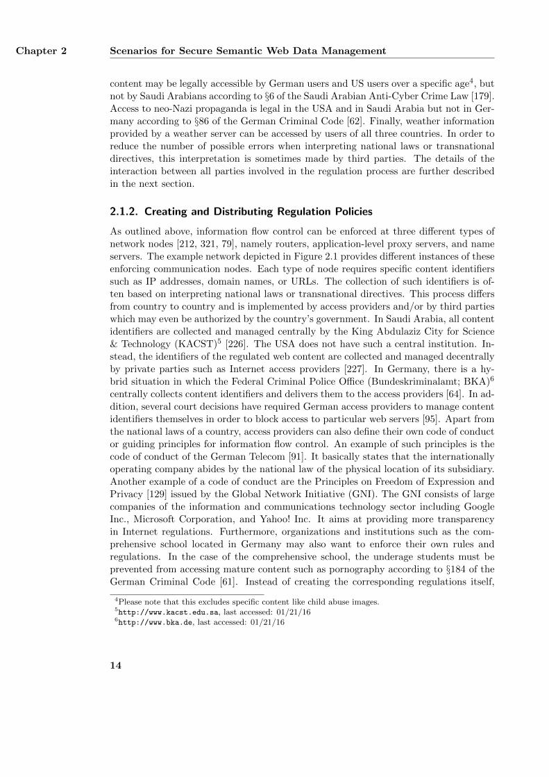
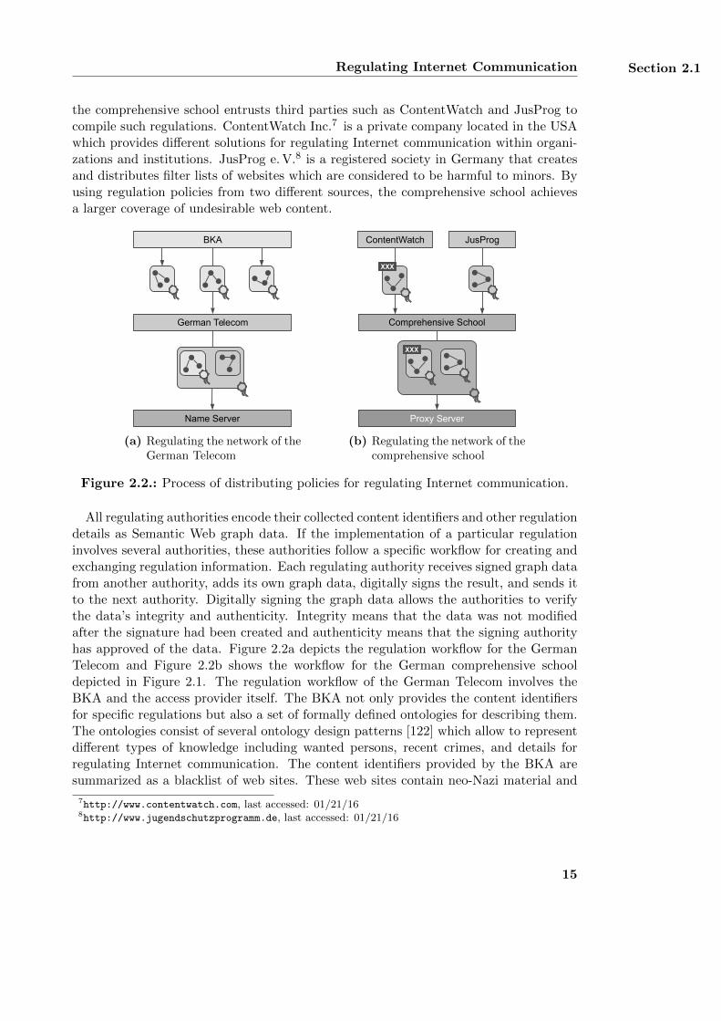
Figure 2.2.: Process of distributing policies for regulating Internet communication.
All regulating authorities encode their collected content identifiers and other regulationdetails as Semantic Web graph data. If the implementation of a particular regulationinvolves several authorities, these authorities follow a specific workflow for creating andexchanging regulation information. Each regulating authority receives signed graph datafrom another authority, adds its own graph data, digitally signs the result, and sends itto the next authority. Digitally signing the graph data allows the authorities to verifythe data’s integrity and authenticity. Integrity means that the data was not modifiedafter the signature had been created and authenticity means that the signing authorityhas approved of the data. Figure 2.2a depicts the regulation workflow for the GermanTelecom and Figure 2.2b shows the workflow for the German comprehensive schooldepicted in Figure 2.1. The regulation workflow of the German Telecom involves theBKA and the access provider itself. The BKA not only provides the content identifiersfor specific regulations but also a set of formally defined ontologies for describing them.The ontologies consist of several ontology design patterns [122] which allow to representdifferent types of knowledge including wanted persons, recent crimes, and details forregulating Internet communication. The content identifiers provided by the BKA aresummarized as a blacklist of web sites. These web sites contain neo-Nazi material and
7http://www.contentwatch.com, last accessed: 01/21/168http://www.jugendschutzprogramm.de, last accessed: 01/21/16
15
Chapter 2 Scenarios for Secure Semantic Web Data Management
are to be blocked according to §86 of the German Criminal Code. Each entry in theblacklist corresponds to a particular regulation rule that describes which web sites are tobe regulated. As the German Telecom implements the regulations on a name server, theBKA uses domain names as content identifiers for the web sites. After having createdthe blacklist, the BKA digitally signs the list and the ontologies as well and publishesthe ontologies on the web. It then sends the signed blacklist to the German Telecom viaa secure communication channel by using, e. g., an SSL [113] connection. The GermanTelecom receives the regulating information from the BKA and verifies its signature.The blacklist provided by the BKA only describes the URLs of the web sites which areto be regulated but not how the regulation shall be implemented. Thus, the GermanTelecom interprets the data received from the BKA and adds concrete implementationdetails such as the IP address of the name server used for blocking the web sites. Asshown in Figure 2.2a, the German Telecom compiles its technical regulation details asRDF graph which is based on the BKA’s ontology design pattern. It digitally signs theBKA’s blacklist together with its own regulation graph and sends it to its name server.The name server verifies the signature of the German Telecom in order to prohibit anyunauthorized party from manipulating its implemented regulations. If the verificationis successful, the name server maps the blacklist of the BKA to a native format. Thisformat can then directly be used by the name server for regulating access to web sites.
As depicted in Figure 2.2b, the regulation workflow of the German comprehensiveschool involves ContentWatch, JusProg, and the school itself. The comprehensive schoolhas to ensure that its students cannot illegally access neo-Nazi content and other maturematerial such as pornography. As the comprehensive school is connected to the Internetvia the network of the German Telecom, all regulations implemented in the network ofthe access provider also affect the school’s network. Thus, the comprehensive schooldoes not need to implement any regulations for blocking access to neo-Nazi materialsince such regulations are already implemented by the German Telecom. However, theschool still needs to regulate access to pornographic content as the German Telecom doesnot provide such regulations. To this end, the school receives regulation information foradult content from ContentWatch and JusProg. ContentWatch and JusProg collectURLs of web pages which contain pornographic content and other adult material whichis harmful to minors. These URLs are used for creating specific regulation rules whichare signed and sent to the comprehensive school via a secure communication channel.ContentWatch provides its regulation information as Named Graphs whereas JusProgprovides its regulation data as regular RDF graphs. After having received both blacklists,the school verifies their signatures and consolidates them into a single regulation policy.The school digitally signs this regulation policy again and sends it to its local proxyserver. The proxy server verifies the policy’s signature and maps the regulation rules toits local database. By redirecting all Internet traffic from the student computers locatedin the school’s network through this proxy server, the school ensures that its studentscan only access the Internet after having passed the predefined regulation mechanisms.
16
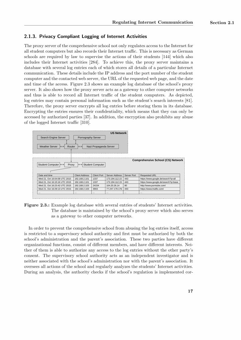
Regulating Internet Communication Section 2.1
2.1.3. Privacy Compliant Logging of Internet Activities
The proxy server of the comprehensive school not only regulates access to the Internet forall student computers but also records their Internet traffic. This is necessary as Germanschools are required by law to supervise the actions of their students [144] which alsoincludes their Internet activities [284]. To achieve this, the proxy server maintains adatabase with several log entries each of which stores all details of a particular Internetcommunication. These details include the IP address and the port number of the studentcomputer and the contacted web server, the URL of the requested web page, and the dateand time of the access. Figure 2.3 shows an example log database of the school’s proxyserver. It also shows how the proxy server acts as a gateway to other computer networksand thus is able to record all Internet traffic of the student computers. As depicted,log entries may contain personal information such as the student’s search interests [81].Therefore, the proxy server encrypts all log entries before storing them in its database.Encrypting the entries ensures their confidentiality, which means that they can only beaccessed by authorized parties [37]. In addition, the encryption also prohibits any abuseof the logged Internet traffic [310].
Comprehensive School (CS) Network
Student Computer Proxy
Client Address Client Port Server AddressDate and time Requested URL
Wed 21. Oct 16:04:08 UTC 2015 192.168.2.101 1337 173.194.112.15 443
Server Port
https://www.google.de/search?q=all
Wed 21. Oct 16:15:16 UTC 2015 192.168.2.101 1337 173.194.112.15 443 https://www.google.de/search?q=base
... ... ... ... ... ...
Wed 21. Oct 16:23:42 UTC 2015 192.168.2.103 24154 104.20.26.14 80 http://www.porntube.com/
US Network
Search Engine Server
Nazi Propaganda Server
Pornography Server
Weather Server
Student Computer
Router
Wed 21. Oct 16:29:13 UTC 2015 192.168.2.103 3903 77.247.179.176 443 https://www.tnaflix.com/
Figure 2.3.: Example log database with several entries of students’ Internet activities.The database is maintained by the school’s proxy server which also servesas a gateway to other computer networks.
In order to prevent the comprehensive school from abusing the log entries itself, accessis restricted to a supervisory school authority and first must be authorized by both theschool’s administration and the parent’s association. These two parties have differentorganizational functions, consist of different members, and have different interests. Nei-ther of them is able to authorize any access to the log entries without the other party’sconsent. The supervisory school authority acts as an independent investigator and isneither associated with the school’s administration nor with the parent’s association. Itoversees all actions of the school and regularly analyzes the students’ Internet activities.During an analysis, the authority checks if the school’s regulation is implemented cor-
17
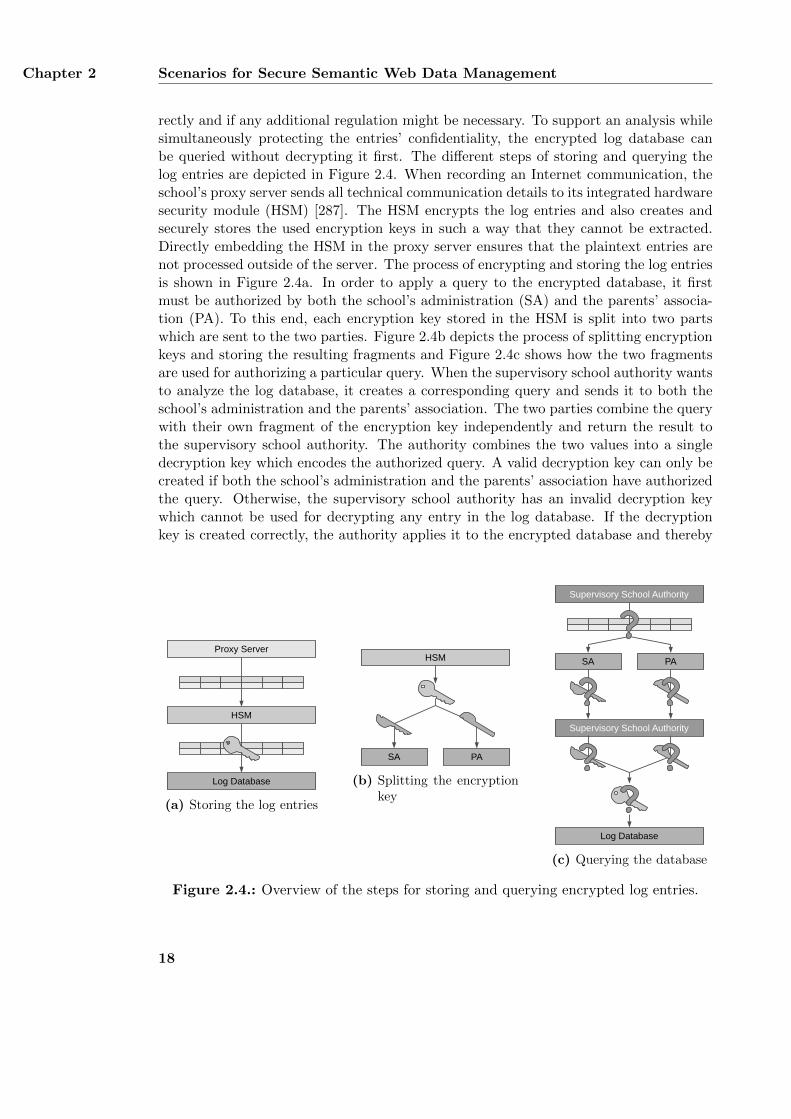
Chapter 2 Scenarios for Secure Semantic Web Data Management
rectly and if any additional regulation might be necessary. To support an analysis whilesimultaneously protecting the entries’ confidentiality, the encrypted log database canbe queried without decrypting it first. The different steps of storing and querying thelog entries are depicted in Figure 2.4. When recording an Internet communication, theschool’s proxy server sends all technical communication details to its integrated hardwaresecurity module (HSM) [287]. The HSM encrypts the log entries and also creates andsecurely stores the used encryption keys in such a way that they cannot be extracted.Directly embedding the HSM in the proxy server ensures that the plaintext entries arenot processed outside of the server. The process of encrypting and storing the log entriesis shown in Figure 2.4a. In order to apply a query to the encrypted database, it firstmust be authorized by both the school’s administration (SA) and the parents’ associa-tion (PA). To this end, each encryption key stored in the HSM is split into two partswhich are sent to the two parties. Figure 2.4b depicts the process of splitting encryptionkeys and storing the resulting fragments and Figure 2.4c shows how the two fragmentsare used for authorizing a particular query. When the supervisory school authority wantsto analyze the log database, it creates a corresponding query and sends it to both theschool’s administration and the parents’ association. The two parties combine the querywith their own fragment of the encryption key independently and return the result tothe supervisory school authority. The authority combines the two values into a singledecryption key which encodes the authorized query. A valid decryption key can only becreated if both the school’s administration and the parents’ association have authorizedthe query. Otherwise, the supervisory school authority has an invalid decryption keywhich cannot be used for decrypting any entry in the log database. If the decryptionkey is created correctly, the authority applies it to the encrypted database and thereby
Proxy Server
HSM
Log Database
(a) Storing the log entries
HSMHSM
PASA
(b) Splitting the encryptionkey
PASA
Supervisory School Authority
Log Database
Supervisory School Authority
(c) Querying the database
Figure 2.4.: Overview of the steps for storing and querying encrypted log entries.
18
Securing Medical Data Records in Electronic Healthcare Section 2.2
searches for all log entries which match the encoded query. Finally, the authority usesthe resulting entries for further analyzing the student’s Internet activities and checksthem for any inappropriate access.
2.1.4. Summary of the Scenario
The scenario for regulating Internet communication requires a policy language for de-scribing allowed and prohibited communication flow. This policy language must be ableto describe the communication flow in the example network described in Section 2.1.1.The policy language answers research question RQ.4 as it makes Internet content avail-able as long as it is compliant with a set of predefined rules. A particular policy iscreated by several authorities which communicate with each other. In order to provideintegrity and authenticity of their exchanged data, all data is signed before its trans-mission. The provided signature is permanently attached to the signed data and notrestricted to the existence of a secure communication channel. Creating a signaturerequires a corresponding signing framework which answers research questions RQ.2and RQ.3. Internet regulations are enforced by different communication nodes suchas routers, application-level proxy servers, and name servers. As an enforcing system’sregulations may be further analyzed by its operator or a third party, the system logs allof its activities. However, logging the Internet activities of regulated Internet users mayinvade their privacy. Thus, each enforcing system encrypts its log files and makes themonly partially available to authorized parties. This is achieved by providing a mechanismfor searching in encrypted data. The corresponding approach achieves confidentiality ofdata and thus answers research question RQ.1.
2.2. Securing Medical Data Records in Electronic Healthcare
E-health commonly refers to the application of electronic technologies in health careand aims at improving medical processes in various aspects [224]. A core part of e-health is the digitization of medical data records and their exchange between differentcare delivery organizations (CDOs) by using information and communication technologysuch as the Internet [105]. CDOs are medical institutions such as general practitioners,medical specialists, or hospitals. The use of electronic records in e-health aims at easingthe process of exchanging medical information between different CDOs and providingmore accurate data than paper-based records [177, 136]. In addition, electronic recordscan be processed automatically by software applications and can be used to supportmedical decisions and treatments [279, 220]. These main goals of e-health can be achievedby improving the interoperability between different CDOs and their patients. As e-health relies on electronic records, the aspired interoperability requires a standardizeddata format for exchanging such records [154]. This section presents a scenario whichfocuses on the secure exchange of electronic records based on a standardized format.The scenario distinguishes between different types of medical data records, defines thesecurity requirements for exchanging them between different parties, and provides anexample use case of the data exchange.
19
Chapter 2 Scenarios for Secure Semantic Web Data Management
2.2.1. Medical Data Records Used in Electronic Healthcare
Medical data records of a patient can generally be distinguished between electronicmedical records (EMR), electronic health records (EHR), and personal health records(PHR) [135, 125, 289]. An EMR is an electronic data record that stores the results of asingle medical test, examination, or operation which is conducted by a single CDO foran individual patient. This CDO not only creates the EMR but also manages all accessrequests to it [177]. An EHR is a collection of several EMRs of the same patient and maybe created by different CDOs [177]. EHRs support the aspired interoperability of e-healthas they are used for exchanging medical information between different CDOs. An EHRmay focus on a particular medical case and only covers EMRs which are relevant to thatcase.9 Both EMRs and EHRs are created, managed, and owned by CDOs while PHRsare managed and owned by the patients themselves. A PHR contains both subjectiveand objective medical information of an individual patient [289]. Subjective data iscreated by the patient directly and includes symptoms as well as their descriptions andassessments. Objective data covers measured values such as blood pressure or weightand is created by technical devices used by the patient. Each patient is associatedwith a single PHR which is stored in a personal storage device or in a cloud system.Medical information about the same patient may also be stored in several EHRs whichare scattered across different CDOs.
Depending on their actual use, EMRs, EHRs, and PHRs may store similar data andoverlap with each other. However, each type of record also contains some informationwhich is not part of other record types. Thus, combining all types of records results in acomprehensive collection of medical information about a single patient which can be usedby CDOs to conduct medical treatments [289]. An expedient integration of all recordsrequires that they share a common data format or that they are stored in different dataformats which can easily be mapped to each other [303]. Compatibility between allrecords is also necessary in order to achieve interoperability between different CDOs andtheir patients’ PHRs. Vizenor et al. [300] argue that Semantic Web ontologies are bestsuited as a common data format for different e-health records. Ontologies can be usedfor aligning different vocabularies and terminologies from different medical departments.Furthermore, they allow to reason on medical data which can be used to support medicaldecisions by relating a patient’s medical records to medical knowledge bases. Exampleontologies which are specifically designed for reasoning on medical data are presented in[279, 220, 246].
2.2.2. Security Requirements for Medical Data Records
Medical data records store sensitive information about a patient and must therefore beprotected against unauthorized access. The legal foundation for e-health applicationsin the USA is the Health Insurance Portability and Accountability Act (HIPAA) [297].HIPAA does not only motivate the use of interoperable e-health applications and data
9Please note that there are varying definitions of EMRs and EHRs in the literature [318]. In this thesis,the terms EMR and EHR are used as defined in this section.
20
Securing Medical Data Records in Electronic Healthcare Section 2.2
formats but also defines several requirements for achieving security and privacy of themedical data. The security requirements are further refined by the Security Standardsfor the Protection of Electronic Protected Health Information [90] and correspond toconfidentiality, integrity, and availability of the data. Confidentiality states that thepatient’s medical data must be protected from any unauthorized access. This require-ment is especially necessary since medical data contains highly sensitive information suchas a patient’s health status and diseases [312]. Integrity requires that the data is notmodified or destroyed by unauthorized parties. Since medical data is used for medicalexaminations and treatments, ensuring that the data is correct and accurate is essentialto ensure a patient’s safety [108]. Availability states that the data must be accessible toauthorized parties whenever needed. Supporting this requirement is also fundamentalto a health care system as incomplete or missing data may otherwise affect a patient’streatment [108, 136]. In Europe, the legal foundation for e-health applications is basedon several directives which focus on protecting any type of personal data. The Data Pro-tection Directive [100] requires that processing and transmitting personal data is onlyconducted if the data’s privacy and confidentiality can be guaranteed. The directive canbe equally applied to electronic processing and non-electronic processing. The Directiveon Privacy and Electronic Communications [101] complements the Data Protection Di-rective and is specifically designed for electronic processing and transmission of personaldata. The directive states that the basic security requirements confidentiality, integrity,and availability of the data must be implemented in computer systems which processthe data. As both directives can be applied to various types of personal data, they covermedical data records as well.
2.2.3. Example Medical Case
Marla manages her own PHR in order to keep track of her health. She uses the PHRto monitor various medical information including her weight, blood pressure, and pulse.Whenever she feels sick, she records her symptoms in the PHR to support a medicalprofessional’s diagnosis. She also uses her PHR to record any prescribed medicine andits recommended taking. In order to ensure the confidentiality of her health data, Marlaencrypts her PHR and stores it on a portable device. If she consults a CDO such asa doctor or hospital, she grants the medical personnel access to particular parts of herPHR to support her medical treatment. Marla provides all medical information in herPHR as Semantic Web graph data to achieve a better interoperability between her PHRand the EHRs and EMRs managed by CDOs. Figure 2.5 depicts the application of thisdata for a particular medical case.
When Marla senses a lump in her throat and suffers from swallowing difficulties,she consults her general practitioner (GP). The GP asks Marla to grant him access tothose parts of her PHR which he suspects to be related to her symptoms. After havinganalyzed the requested entries in the PHR, the GP relates the symptoms to a goiterand performs an ultrasonography to examine Marla’s thyroid. He records all resultsof the examination as graph data and digitally signs it to ensure the data’s integrityand authenticity. The resulting graph corresponds to an EMR and is stored on a local
21
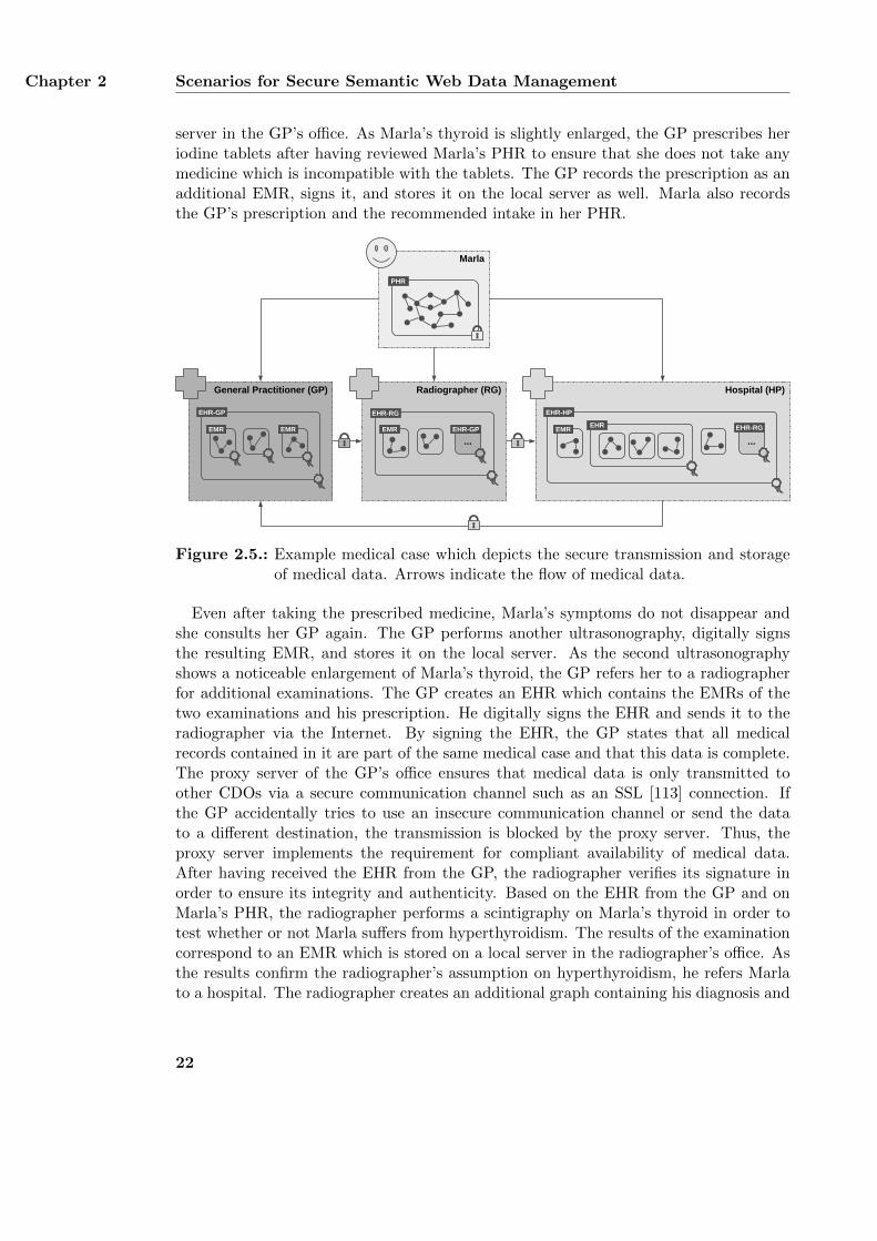
Chapter 2 Scenarios for Secure Semantic Web Data Management
server in the GP’s office. As Marla’s thyroid is slightly enlarged, the GP prescribes heriodine tablets after having reviewed Marla’s PHR to ensure that she does not take anymedicine which is incompatible with the tablets. The GP records the prescription as anadditional EMR, signs it, and stores it on the local server as well. Marla also recordsthe GP’s prescription and the recommended intake in her PHR.
Hospital (HP)
Marla
EMR
EHR-HP
Radiographer (RG)
EMR
EHR-RG
General Practitioner (GP)
EMR EMR
EHR-GP
PHR
...EHR-GP
...
EHR-RGEHR
Figure 2.5.: Example medical case which depicts the secure transmission and storageof medical data. Arrows indicate the flow of medical data.
Even after taking the prescribed medicine, Marla’s symptoms do not disappear andshe consults her GP again. The GP performs another ultrasonography, digitally signsthe resulting EMR, and stores it on the local server. As the second ultrasonographyshows a noticeable enlargement of Marla’s thyroid, the GP refers her to a radiographerfor additional examinations. The GP creates an EHR which contains the EMRs of thetwo examinations and his prescription. He digitally signs the EHR and sends it to theradiographer via the Internet. By signing the EHR, the GP states that all medicalrecords contained in it are part of the same medical case and that this data is complete.The proxy server of the GP’s office ensures that medical data is only transmitted toother CDOs via a secure communication channel such as an SSL [113] connection. Ifthe GP accidentally tries to use an insecure communication channel or send the datato a different destination, the transmission is blocked by the proxy server. Thus, theproxy server implements the requirement for compliant availability of medical data.After having received the EHR from the GP, the radiographer verifies its signature inorder to ensure its integrity and authenticity. Based on the EHR from the GP and onMarla’s PHR, the radiographer performs a scintigraphy on Marla’s thyroid in order totest whether or not Marla suffers from hyperthyroidism. The results of the examinationcorrespond to an EMR which is stored on a local server in the radiographer’s office. Asthe results confirm the radiographer’s assumption on hyperthyroidism, he refers Marlato a hospital. The radiographer creates an additional graph containing his diagnosis and
22
Securing Medical Data Records in Electronic Healthcare Section 2.2
signs it together with the EMR of the scintigraphy and the EHR received from the GP.In doing so, the radiographer states that his own examinations are based on the findingsof the GP. The signed graph corresponds to another EHR which is sent to the hospital.Similar to the GP’s office, the proxy server of the radiographer’s office ensures thatmedical data such as EHRs are only transmitted via a secure communication channel.
The hospital receives the EHR from the radiographer and verifies its signature. Afterhaving evaluated the findings from the radiographer and the GP as well as Marla’ssymptoms stored in her PHR, the hospital staff conducts a second scintigraphy on thepatient’s thyroid. Again, the results of this scintigraphy are provided as graph dataand stored as an EMR on the hospital’s server. Since the second scintigraphy providessimilar results as the first scintigraphy, the hospital staff initiates a thyroidectomy inorder to surgically remove parts of Marla’s thyroid. An operation generally consists ofseveral steps which must all be documented according to the guidelines of the WorldHealth Organization [313]. The steps include the preoperative note, operating roomrecords, and postoperative notes. Each of these steps is recorded as a separate graph.After having completed the operation, the graphs are collectively signed by the operationteam as an EHR. When discharging Marla from the hospital, the hospital staff compilesa discharge note and signs it along with the EMR of the performed scintigraphy and theEHR from the operation. As depicted in Figure 2.5, the hospital also includes the EHRfrom the radiographer in the new graph to state that the operation was conducted afterhaving reviewed the radiographer’s examination results. The resulting EHR is sent backto Marla’s GP for documentation reasons by using a secure communication channel.Again, the hospital’s proxy server ensures that medical records are only transmitted viasecure channels.
2.2.4. Summary of the Scenario
E-health aims at improving various aspects of medical processes such as the storage andthe transmission of medical data records. Medical records are created by different partiesincluding patients and care delivery organizations (CDOs). Patients who maintain theirown medical records encrypt the records in order to ensure their confidentiality. A CDOaccesses specific parts of the encrypted records by applying queries to them which areauthorized by the patients. Such a protection mechanism requires an approach for query-ing encrypted data which answers research question RQ.1. CDOs create medical datarecords after having examined the patients or having operated on them. A CDO signsthe medical records in order to ensure their integrity and authenticity. The organizationcan even sign medical data records from other CDOs which have already been signed.Such an iterative signing can be used to track the provenance of the medical recordsand document the data flow of the signed data. Signing medical data requires a signingframework which answers research questions RQ.2 and RQ.3. Exchanging the signedrecords between different CDOs must be done via a secure communication channel. Inaddition, transmitting the records to any other destination which is not a CDO mustbe prohibited. Describing such rules for sending content via open networks requires apolicy language for regulating information flow control. Such a policy language answers
23
Chapter 2 Scenarios for Secure Semantic Web Data Management
research question RQ.4 as it ensures that medical records are only available to partieswhich comply with the predefined rules.
24
Chapter 3.
InFO: A Policy Language for RegulatingInformation Flow
This chapter presents the Information Flow Ontology (InFO), a generic policy languagefor regulating information flow in open and distributed networks such as the Internet.Regulations expressed with the InFO policy language can be enforced by various com-munication nodes operating on different levels of the OSI reference model [159] such asthe Internet layer or the application layer. Example nodes which are natively supportedby InFO as enforcing systems are routers, application-level proxy servers, and nameservers. However, InFO’s generic language model can also be further refined to supportother types of communication nodes as well. An InFO policy consists of multiple ruleswhich share the same purpose. Each rule regulates one particular communication flowand provides several technical regulation details for implementing the regulation on anenforcing node. The purpose of a policy is expressed with human-readable backgroundinformation which is directly embedded into the policy. This allows an easy comparisonbetween different policies and to check whether or not a policy implements the correcthigh-level regulation. The provided background information covers a regulation’s le-gal foundation and its organizational motivation. The InFO policy language achievescompliant availability and thus answers research question RQ.4 by making informationavailable to authorized parties as long as they comply with the rules of the regulationpolicies. If a policy rule prohibits the access to any requested information, the partytrying to access the information is considered to be unauthorized. A prior version of theInFO policy language was published in [172]. This chapter is based on this publicationbut rephrases its contents and further enriches them with additional aspects.
The remainder of this chapter is organized as follows: The state of the art and relatedwork for regulating information processing is summarized in Section 3.1. Based on thissection and on the scenarios introduced in Chapter 2, Section 3.2 defines the functionaland non-functional requirements for the InFO policy language. The design of InFO isdescribed in Section 3.3. Section 3.4 demonstrates how the policy language is used forexpressing specific regulations which can be enforced by routers, application-level proxyservers, and name servers. These example regulations are implemented on prototypicalsystems which are presented in Section 3.5. Section 3.6 assesses the state of the art and
25
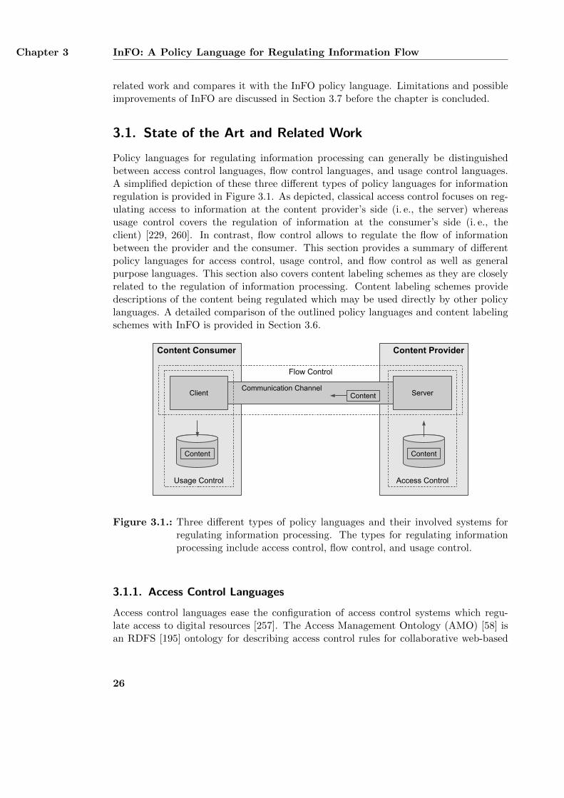
Chapter 3 InFO: A Policy Language for Regulating Information Flow
related work and compares it with the InFO policy language. Limitations and possibleimprovements of InFO are discussed in Section 3.7 before the chapter is concluded.
3.1. State of the Art and Related Work
Policy languages for regulating information processing can generally be distinguishedbetween access control languages, flow control languages, and usage control languages.A simplified depiction of these three different types of policy languages for informationregulation is provided in Figure 3.1. As depicted, classical access control focuses on reg-ulating access to information at the content provider’s side (i. e., the server) whereasusage control covers the regulation of information at the consumer’s side (i. e., theclient) [229, 260]. In contrast, flow control allows to regulate the flow of informationbetween the provider and the consumer. This section provides a summary of differentpolicy languages for access control, usage control, and flow control as well as generalpurpose languages. This section also covers content labeling schemes as they are closelyrelated to the regulation of information processing. Content labeling schemes providedescriptions of the content being regulated which may be used directly by other policylanguages. A detailed comparison of the outlined policy languages and content labelingschemes with InFO is provided in Section 3.6.
Content ProviderContent Consumer
Client ServerCommunication Channel
Content
Flow Control
Usage Control Access Control
ContentContent
Figure 3.1.: Three different types of policy languages and their involved systems forregulating information processing. The types for regulating informationprocessing include access control, flow control, and usage control.
3.1.1. Access Control Languages
Access control languages ease the configuration of access control systems which regu-late access to digital resources [257]. The Access Management Ontology (AMO) [58] isan RDFS [195] ontology for describing access control rules for collaborative web-based
26
State of the Art and Related Work Section 3.1
document systems such as wikis or content management systems. In order to ease thecreation of access rules and their integration into such systems, AMO’s design is verysimple and only allows to model permitted actions. Other types of rules such as pro-hibitions are not supported. Actions, which are not explicitly allowed by AMO, areconsidered to be forbidden. CommonPolicy [276] is an XML-based language for describ-ing access rules for personal data. Similar to AMO, the language model of CommonPolicy is rather lightweight and only allows to define permitted actions. Furthermore,Common Policy is designed to be used only in combination with additional application-level protocols such as FTP or HTTP. These protocols must cover the authentication ofthe requesting user and the transmission of the requested data. WebAccessControl1 isanother lightweight RDFS ontology for describing access control rules for web resources.It is designed for decentralized systems in which the web resources and the users can bemanaged by different parties. All users are identified by their WebID2 which serves asa globally unique identifier. User authentication is based on the WebID authenticationprotocol. Similar to AMO and CommonPolicy, WebAccessControl has a simple designwhich only supports permitted actions. The Enterprise Privacy Authorization Language(EPAL) [15] and the eXtensible Access Control Markup Language (XACML) [205] areXML-based access control languages which allow to create much more expressive policiesthan AMO, Common Policy, or WebAccessControl. Both languages are designed to beused within closed network environments such as intranets of large corporations. WhileEPAL merely focuses on regulating access to personal data, XACML does not have apredefined use case and can be used for regulating the access to arbitrary data. Specificuse cases are implemented by creating corresponding XACML profiles. A profile forregulating access to personal data is given in [206]. XACML is much more expressivethan EPAL and can replace it in many applications [12].
In summary, classical access control regulates access to data within a closed environ-ment [229, 260]. XACML and EPAL can be considered as classical access control systemssince they require a centrally controlled enforcing infrastructure. On the other hand,AMO, Common Policy, and WebAccessControl focus on regulating access to pieces ofinformation in a rather open environment such as the Internet. In all access control sys-tems, content providers regulate the access to their content. However, such regulationscannot be used for regulating the communication flow between an arbitrary server andarbitrary client in the Internet.
3.1.2. Usage Control Languages
Rights Expression Languages (REL) allow to define usage control policies for digitalobjects. RELs often define only an abstract policy model which is accompanied by anadditional Rights Data Dictionary (RDD). The REL defines a basic syntax shared by allpolicies while the RDD provides a vocabulary for creating specific policies. The PLUSLicense Data Format (LDF)3 provides a lightweight RDFS ontology for creating usage
1http://www.w3.org/wiki/WebAccessControl, last accessed: 01/21/162http://www.w3.org/wiki/WebID, last accessed: 01/21/163http://www.useplus.com, last accessed: 01/21/16
27
Chapter 3 InFO: A Policy Language for Regulating Information Flow
policies for digital images. The policies are primarily designed for human recipients andcannot directly be enforced by a technical system. Instead, the design of PLUS focuseson a technical support for communicating usage policies between all involved parties.ccREL [3] is a lightweight RDFS ontology primarily designed for describing CreativeCommons4 licenses. Such licenses describe actions that may, must, or must not be ap-plied to the digital good. In order to be easy to use, there are six predefined licenseswhich can be applied to arbitrary goods. Although ccREL can generally be extendedwith additional terms, using such terms may lead to licenses which do not correspondto Creative Commons licenses. The Linked Data Rights ontology (LDR) [253, 254] isa lightweight OWL [302] ontology which supports usage control licenses for linked dataresources. Although it defines a few terms itself, it is mainly designed to be extendedwith additional terms for particular use cases. The Metadata Encoding and Transmis-sion Standard (METS) [93] is a general language model for describing different types ofmetadata of digital resources. METS itself only defines a basic XML language struc-ture which must be extended with additional vocabularies in order annotate the digitalresource. METSRights5 is an example vocabulary which provides a very basic REL. Itonly allows to define which parties are allowed to perform which actions on a digitalresource. It does not provide any means for defining prohibitions. More complex us-age control languages are MPEG-21 REL [306] and the Open Digital Rights Language(ODRL) [156, 157]. MPEG-21 REL is the successor of XrML [308] and shares the samebasic architecture [307]. It is part of MPEG-21 [65] which is a language framework sim-ilar to METS for annotating digital resources with different types of metadata. BothMPEG-21 REL and ODRL can be used for the same applications and allow to cre-ate almost arbitrary usage control policies. MPEG-21 REL is an XML-based languagewhile ODRL provides an abstract language model which can be expressed with differentencodings. The current version of ODRL provides an OWL ontology [199] as well asencodings for XML [155] and JSON [221]. Although both MPEG-21 REL and ODRLdefine their own REL and RDD, using the default RDD is not mandatory when creatingspecific policies. Instead, the creation of user-defined RDDs are also possible. In ODRL,user-defined RDDs are called profiles. An example profile is RightsML [162] which isdesigned for managing usage rights in the news industry.
In summary, RELs allow to describe which users are permitted to perform whichactions on which digital resources. Contrary to flow control languages, these descriptionsare rather abstract and must be interpreted manually in order to enforce them on atechnical system. The more abstract a particular policy is, the more interpretations andimplementations of the same policy are possible. For example, ODRL’s RDD definesthe action anonymize as the process to “anonymize all or parts of the Asset” [157].Although an additional comment in the RDD further explains this as the process to“remove identifying particulars”, it still remains unclear what the identifying particularscover in detail. Thus, the anonymizing action cannot be directly enforced by a computersystem since the system does not have a precise understanding of what the identifying
4http://creativecommons.org, last accessed: 01/21/165http://www.loc.gov/standards/rights/METSRights.xsd, last accessed: 01/21/16
28
State of the Art and Related Work Section 3.1
particulars are. Instead, enforcing the action on a technical system requires manualinterpretation and therefore human interaction. However, since RELs usually do notprovide a precise human-readable description of their policies, different interpretationsof the same policy may be considered as valid.
3.1.3. Flow Control Languages
Flow control languages are primarily designed for managing a closed network environ-ment supervised by a single organization or institution. The languages aim at easing theconfiguration of the network by mapping high-level organizational security policies todifferent network systems such as routers and switches. The XML-based firewall meta-model proposed by Cuppens et al. [85], the UML-based DEN-ng [286], and the OWL-based Ontology-Based Policy Translator (OPoT) [21] provide languages for describingflow control regulations. While both the firewall metamodel and DEN-ng merely focuson low-level routers and do not directly support communication end points such as webservers, OPoT also covers different nodes of a communication path including the endsystems. The firewall model of Cuppens et al. only supports permitting rules. It doesnot provide any means for defining prohibited communication flows. Any communicationthat is not explicitly allowed is considered to be forbidden. OPoT uses a set of twelvepredefined basic policies each of which covers a particular use case. A basic policy canbe considered as a template for implementing a specific organizational security policy.In order to actually enforce such an organizational policy, a corresponding basic policyhas to be chosen and mapped to the current network environment. This mapping corre-sponds to filling in the basic policy with specific IP addresses and other implementationdetails.
In summary, flow control languages focus on regulating the flow of communicationwithin a closed network environment which is centrally administrated by a single entity.The existing languages are designed to allow a direct enforcement of their policies bynetwork nodes without requiring any further interpretation. This is achieved by preciselydescribing the actions that must be performed by the nodes including all necessaryparameters such as IP addresses, port numbers, and communication protocols.
3.1.4. General Purpose Languages
General purpose languages do not focus on one particular type of information regulationbut rather follow a more general approach in order to cover several scenarios such asaccess control or flow control. KAoS [298], Rei [166], and Ponder [88] are examples ofsuch languages. Since these languages support different types of control policies, theycannot be clearly categorized as access control, usage control, or flow control. KAoSis based on OWL and allows to create policies that describe which systems a user canaccess within a closed management environment such as an organization. An exampleof such a policy is granting a user access to a specific server. However, KAoS only allowsto regulate access to the server or its provided services and cannot further distinguishbetween the data hosted by them. More specifically, KAoS does not directly provide
29
Chapter 3 InFO: A Policy Language for Regulating Information Flow
any means for regulating the content hosted by a server. A KAoS policy can generallybe enforced by any application-level communication system including content providers,content consumers, and application-level proxy servers. Contrary to KAoS, both Reiand Ponder allow to define document-centric policies. This allows to create more pre-cise access control policies. Rei is based on OWL and merely considers reasoning aboutpolicies and is not designed for enforcing them [294]. Ponder uses its own low-levelobject-oriented language syntax which is not compatible with W3C standards such asXML or RDF. The language is able to define policies which can be enforced on the con-tent providers’ server, the end users’ clients, as well as on intermediary communicationnodes. However, due to its low-level descriptive language, Ponder is not able to coverdifferent levels of abstraction on the same regulation [294] such as organizational or legalbackground information.
In summary, the applicability of a general purpose language as well as the implemen-tation and enforcement of its policies heavily depends on the language’s design. WhileKAoS and Rei focus on a more abstract view of a policy, Ponder merely covers itstechnical implementation details.
3.1.5. Content Labeling Schemes
Content labeling schemes allow to annotate digital resources with additional metadatadescribing their topic. Although these schemes usually do not provide a policy languagefor regulating information processing, they are specifically designed to be used togetherwith such languages. The Restricted to Adults (RTA) label6 and age-de.xml [264] allowto annotate web resources with an age category. Both formats are used by child protec-tion software such as Net Nanny7 or the Jugendschutzprogramm8 for prohibiting minorsfrom accessing adult web content. The RTA label is a simple label for flagging adultcontent. It consists of a single string which represents the age category of all adults.The label is either directly included in a web page or part of the HTTP response thata client receives from the server when requesting the page. In contrast, the XML-basedage-de.xml supports arbitrary age categories which can be defined for single web pagesor whole web sites. Similar to the RTA label, age categories defined with age-de.xmlcan also be included directly in the affected web pages or into the HTTP responses thatcontain the web pages. The Platform for Internet Content Selection (PICS) [183] sup-ports more complex descriptions of web content than the RTA label or age-de.xml. Itdefines a proprietary format for annotating web content with arbitrary labels. A labelconsists of several ratings which contain a string and a numerical value. Labels can referto single web pages or complete web sites. PICSRules [103] provides a policy languagefor allowing or denying access to web pages based on PICS labels or the pages’s URLs.
In summary, content labeling schemes focus on the description of web content. Withthe exception of PICS, the discussed schemes do not provide a policy language for de-scribing how these annotations shall be used for regulating information processing. How-
6http://www.rtalabel.org, last accessed: 01/21/167https://www.netnanny.com/support/changelog/, last accessed: 01/21/168http://www.jugendschutzprogramm.de/faq6.php, last accessed: 01/21/16
30
Requirements for a Policy Language Section 3.2
ever, content labeling schemes can also be used together with other policy languages.The policy language InFO described in this chapter also supports the description of webcontent. Such descriptions can either be modeled by using the InFO vocabulary or byintegrating one of the existing content labeling schemes.
3.2. Requirements for a Policy Language
The policy language InFO defines several ontology design patterns [237, 121] for de-scribing policies for regulating information flow control on the Internet. These policiescover both a human-readable description of their actual meaning as well as the tech-nical implementation details for enforcing them on a particular communication node.A particular flow control policy models a specific use case and consists of several flowcontrol rules that implement this use case. Multiple use cases require several policies.Based on these general objectives, this section defines the specific requirements for InFOwhich are divided into functional requirements (RA.F.*) and non-functional require-ments (RA.N.*). Functional requirements describe the services and functions that asystem must provide [282]. In the case of the InFO policy language, these requirementsdefine the content of a particular flow control policy which must cover all details forregulating information flow control. Thus, the functional requirements for InFO focuson the language’s vocabulary. On the other hand, non-functional requirements definegeneral properties and constraints of a system [282]. While functional requirementsbasically focus on a particular aspect of the system, non-functional requirements areusually abstract and cover the system as a whole [282]. In the case of InFO, non-functional requirements define restrictions of the language’s design and implementation.Although there is no clear distinction between functional and non-functional require-ments [182, 282], separating both types of requirements can help to better identify thepurpose of a particular requirement. The specific requirements for the policy languageInFO derive from the scenario for regulating Internet communication presented in Sec-tion 2.1 and on the related work summarized in Section 3.1. InFO must support thefollowing functional requirements:
RA.F.1: Supporting different types of enforcing communication nodesThe policy language must be able to describe flow control policies which canbe enforced by different intermediate communication nodes on the Internet suchas routers (RA.F.1.1), name servers (RA.F.1.2), and application-level proxyservers (RA.F.1.3). As outlined in Section 2.1, different enforcing nodes are in factused in practice for regulating information processing on the Internet [212, 321, 79].Thus, these nodes must also be supported by the InFO policy language. The ex-ample computer network introduced in the scenario in Section 2.1.1 includes allthree types of enforcing nodes.
RA.F.2: Operationalizing the policiesThe interpretation of a particular control policy by a corresponding enforcing noderequires a detailed description of the communication flow that shall be regulated.
31
Chapter 3 InFO: A Policy Language for Regulating Information Flow
This description must contain all relevant parameters such as the IP addresses ofthe communicating parties, the URL of the web content, or the domain name of theweb server. The policy language InFO must be able to describe such parameters.Each of the enforcing nodes of the scenario requires their own parameters in orderto operate properly.
RA.F.3: Supporting different modalities of control rulesThe InFO policy language must be able to describe control rules that either al-low (RA.F.3.1) or deny (RA.F.3.2) a communication flow between two commu-nicating parties. Supporting both types of rule modalities allows a more flexiblecreation of regulations such as regulations based on whitelisting or blacklisting [19].Blacklisting allows every communication which is not explicitly forbidden whereaswhitelisting prohibits all communication which is not explicitly allowed. Prohibit-ing a particular communication flow can be implemented in different ways such asredirecting to a different communication party or preventing the establishment ofthe communication channel. InFO must also support such different implementa-tions.
RA.F.4: Resolving rule conflictsConflicts between two control rules occur when a particular flow of communicationis allowed by one rule and prohibited by another one. The contradicting rules mayappear in the same control policy (RA.F.4.1) or in different policies (RA.F.4.2).The policy language InFO must provide mechanisms for resolving both types ofrule conflicts. In the scenario, the regulations derive from different sources such asContentWatch and JusProg which may lead to conflicting rules.
RA.F.5: Identifying involved partiesThe policy language must provide information about the parties who are respon-sible for a particular policy. This includes the party who technically enforces thepolicy (enforcer) (RA.F.5.1), the party who provides the details for this enforce-ment (provider) (RA.F.5.2), and the party who legislates the enforcement (legis-lator) (RA.F.5.3). Distinguishing between all three parties can help in achievingmore transparency in the regulation’s implementation. In the scenario of Sec-tion 2.1, access providers such as the German Telecom act as regulation enforcers.Examples of regulation providers are the BKA and ContentWatch and examplesof regulation legislators are the German states and their federation [60].
RA.F.6: Identifying regulated contentRegulating access to web content may cause unwanted side-effects such as over-blocking or under-blocking [249]. Over-blocking affects the access to more contentthan is actually intended. Under-blocking covers only parts of the content to beregulated. In order to reduce such unwanted side-effects, InFO must allow toidentify the content or its hosting server as precisely as possible. Examples ofprecise identifiers are the IP address of the hosting web servers, the domain namesof the websites, and the URLs of the individual web pages.
32
Requirements for a Policy Language Section 3.2
RA.F.7: Classifying regulated contentAccess regulation is often based on the content’s topic such as online gambling,adult websites, or neo-Nazi propaganda. In order to provide a clear reason forwhy access to particular web content is regulated, the topic of the content mustbe identified. Thus, InFO must provide means for representing the classificationof content. In the scenario, the classification of the provided web content is givenby the label of its respective web server, e. g. each “Weather Server” providesinformation about the weather.
RA.F.8: Providing users’ access locationEach information flow control policy is ultimately based on a set of laws issued forand active in a specific country. Since an end user’s current location also definesthe laws she must abide by, InFO must relate a user to her corresponding location.The scenario presented in Section 2.1 distinguishes between end users of the threeexample countries USA, Germany, and Saudi Arabia.
RA.F.9: Providing background informationThe regulation represented by a flow control policy is authorized by a legal foun-dation and/or motivated by an organizational code of conduct. In order to en-rich a policy with human-readable explanations, InFO must be able to attachcorresponding background information to the policy in form of its legal justifica-tion (RA.F.9.2) and/or organizational motivation (RA.F.9.1). As outlined inthe scenario, §86 of the German Criminal Code [62] is an example of a legal justifi-cation which prohibits the distribution of neo-Nazi material. The code of conductof the German Telecom [91] is a statement to actually enforce this law as well asthe local laws of other countries in which the Internet access provider operates.
Besides these functional requirements, the InFO policy language must also fulfill thefollowing non-functional requirements:
RA.N.1: Complying with standardsThe policy language must provide a particular encoding for creating specific poli-cies. This encoding must be based on common standards such as XML or RDFS.Avoiding a proprietary syntax simplifies the process of interpreting and implement-ing particular regulation policies on an enforcing system. Furthermore, it eases thecreation and distribution of the policies for all involved parties. In the scenario,different parties such as the BKA and the German Telecom interact with eachother by exchanging regulation details. Using a common standard for encodingthese details improves the interoperability between the parties.
RA.N.2: Supporting a modular designThe InFO policy language must have a modular design in which each module im-plements a particular function of the language [266]. This allows a flexible use ofthe actually needed parts of the ontology. For example, requirement RA.F.1 statesthat the policy language must be able to support different systems as enforcing
33
Chapter 3 InFO: A Policy Language for Regulating Information Flow
nodes. Each type of enforcing nodes requires specific parameters and enforcementdetails, which may be irrelevant for other enforcing nodes. By designing a partic-ular module for routers, name servers, and proxy servers, a specific enforcing nodeonly needs to implement its respective regulation module. In the scenario, eachenforcing node only implements those regulation modules which it can technicallyenforce.
RA.N.3: Supporting an extensible designAlthough InFO must natively support three different types of enforcing nodes, thissupport can only cover a limited set of all possible attributes and functions that aspecific node may have. For example, the build-in support for routers as enforcingnodes does not guarantee a complete support for all functions of all possible routerslike Cisco’s 3945 Integrated Services Router9. An extensible design [266] allows tofurther enrich InFO with product-specific concepts. Furthermore, such a designcan also be used for defining new concepts of future regulation mechanisms.
The fulfillment of all functional and non-functional requirements by the InFO patternsystem and a comparison with the state of the art and related work is provided inSection 3.6.
3.3. Design of the InFO policy language
This section presents the pattern-based design of the InFO policy language. The de-sign is based on the state of the art and related work discussed in Section 3.1 as wellas on the requirements stated in Section 3.2. InFO is a set of several ontology designpatterns [237, 121] for describing flow control policies which regulate the exchange ofinformation on the Internet. Ontology design patterns are adapted from software engi-neering. They provide both a description of a specific, recurring modeling problem of aparticular modeling context and present a proven, generic solution to this problem [67].The provided solution consists of a description of the required components, their relation-ships and responsibilities, and the possible collaboration between these components [67].Similar to a software design pattern, an ontology design pattern is also independent of aparticular application domain [117] and can be used in a variety of different applicationcontexts. Each pattern of InFO implements a different aspect of controlling the flow ofinformation that distinguishes it from the other patterns. The patterns are not a collec-tion of independent ontology design patterns but are instead designed to be used togetherin order to create flow control policies. Thus, InFO corresponds to a so-called patternsystem [67]. The pattern system reuses and extends design patterns from the founda-tional ontology DOLCE+DnS Ultralite (DUL) [119] and the Ontopic core ontology10. Itis implemented using the Web Ontology Language (OWL) [302] and axiomatized usingDescription Logics [16]. This section first briefly describes these reused ontologies and
9http://www.cisco.com/c/en/us/products/routers/3945-integrated-services-router-isr/
index.html, last accessed: 01/21/1610http://ontologydesignpatterns.org/ont/dul/ontopic.owl, last accessed: 01/21/16
34
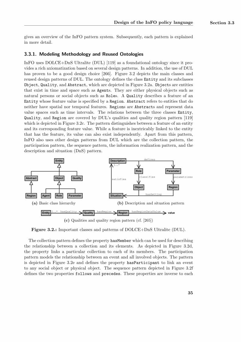
Design of the InFO policy language Section 3.3
gives an overview of the InFO pattern system. Subsequently, each pattern is explainedin more detail.
3.3.1. Modeling Methodology and Reused Ontologies
InFO uses DOLCE+DnS Ultralite (DUL) [119] as a foundational ontology since it pro-vides a rich axiomatization based on several design patterns. In addition, the use of DULhas proven to be a good design choice [266]. Figure 3.2 depicts the main classes andreused design patterns of DUL. The ontology defines the class Entity and its subclassesObject, Quality, and Abstract, which are depicted in Figure 3.2a. Objects are entitiesthat exist in time and space such as Agents. They are either physical objects such asnatural persons or social objects such as Roles. A Quality describes a feature of anEntity whose feature value is specified by a Region. Abstract refers to entities that doneither have spatial nor temporal features. Regions are Abstracts and represent datavalue spaces such as time intervals. The relations between the three classes Entity,Quality, and Region are covered by DUL’s qualities and quality region pattern [119]which is depicted in Figure 3.2c. The pattern distinguishes between a feature of an entityand its corresponding feature value. While a feature is inextricably linked to the entitythat has the feature, its value can also exist independently. Apart from this pattern,InFO also uses other design patterns from DUL which are the collection pattern, theparticipation pattern, the sequence pattern, the information realization pattern, and thedescription and situation (DnS) pattern.
Abstract
Entity
Object
AgentRegion
Quality
Role Parameter
(a) Basic class hierarchy
parametrizes
Role
classifies
Description
Situation
satisfies
1..*
Region
hasSetting
defines
Parameter
Object
(b) Description and situation pattern
RegionEntity QualityhasQuality hasRegion valuehasRegionDataValue1..*
(c) Qualities and quality region pattern (cf. [265])
Figure 3.2.: Important classes and patterns of DOLCE+DnS Ultralite (DUL).
The collection pattern defines the property hasMember which can be used for describingthe relationship between a collection and its elements. As depicted in Figure 3.2d,the property links a particular collection to each of its members. The participationpattern models the relationship between an event and all involved objects. The patternis depicted in Figure 3.2e and defines the property hasParticipant to link an eventto any social object or physical object. The sequence pattern depicted in Figure 3.2fdefines the two properties follows and precedes. These properties are inverse to each
35
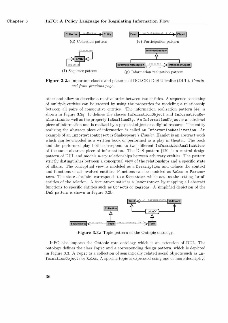
Chapter 3 InFO: A Policy Language for Regulating Information Flow
EntityCollection hasMember
(d) Collection pattern
ObjectEvent 1..*hasParticipant
(e) Participation pattern
Entity
precedes
follows
(f) Sequence pattern
realizes
InformationEntity
InformationRealization InformationObject1..* 1..*
(g) Information realization pattern
Figure 3.2.: Important classes and patterns of DOLCE+DnS Ultralite (DUL). Contin-ued from previous page.
other and allow to describe a relative order between two entities. A sequence consistingof multiple entities can be created by using the properties for modeling a relationshipbetween all pairs of consecutive entities. The information realization pattern [44] isshown in Figure 3.2g. It defines the classes InformationObject and InformationRe-
alization as well as the property isRealizedBy. An InformationObject is an abstractpiece of information and is realized by a physical object or a digital resource. The entityrealizing the abstract piece of information is called an InformationRealization. Anexample of an InformationObject is Shakespeare’s Hamlet. Hamlet is an abstract workwhich can be encoded as a written book or performed as a play in theater. The bookand the performed play both correspond to two different InformationRealizationsof the same abstract piece of information. The DnS pattern [120] is a central designpattern of DUL and models n-ary relationships between arbitrary entities. The patternstrictly distinguishes between a conceptual view of the relationships and a specific stateof affairs. The conceptual view is modeled as a Description and defines the contextand functions of all involved entities. Functions can be modeled as Roles or Parame-
ters. The state of affairs corresponds to a Situation which acts as the setting for allentities of the relation. A Situation satisfies a Description by mapping all abstractfunctions to specific entities such as Objects or Regions. A simplified depiction of theDnS pattern is shown in Figure 3.2b.
TopicSocialObject
Collection
TermisTopicOf isExpressedBy 1..*
Word Multiword2..*
unionOf
hasComponent
Figure 3.3.: Topic pattern of the Ontopic ontology.
InFO also imports the Ontopic core ontology which is an extension of DUL. Theontology defines the class Topic and a corresponding design pattern, which is depictedin Figure 3.3. A Topic is a collection of semantically related social objects such as In-
formationObjects or Roles. A specific topic is expressed using one or more descriptive
36
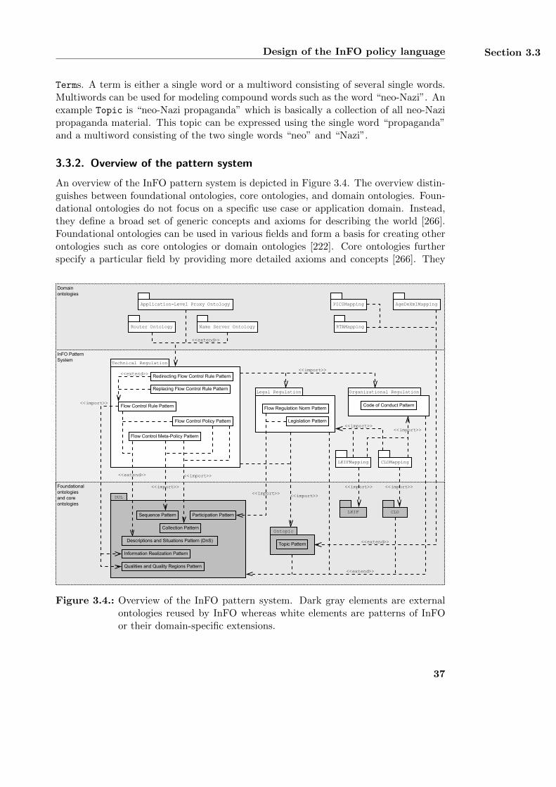
Design of the InFO policy language Section 3.3
Terms. A term is either a single word or a multiword consisting of several single words.Multiwords can be used for modeling compound words such as the word “neo-Nazi”. Anexample Topic is “neo-Nazi propaganda” which is basically a collection of all neo-Nazipropaganda material. This topic can be expressed using the single word “propaganda”and a multiword consisting of the two single words “neo” and “Nazi”.
3.3.2. Overview of the pattern system
An overview of the InFO pattern system is depicted in Figure 3.4. The overview distin-guishes between foundational ontologies, core ontologies, and domain ontologies. Foun-dational ontologies do not focus on a specific use case or application domain. Instead,they define a broad set of generic concepts and axioms for describing the world [266].Foundational ontologies can be used in various fields and form a basis for creating otherontologies such as core ontologies or domain ontologies [222]. Core ontologies furtherspecify a particular field by providing more detailed axioms and concepts [266]. They
Technical Regulation
Flow Control Policy Pattern
Flow Control Meta-Policy Pattern
Flow Control Rule Pattern
DUL
Qualities and Quality Regions Pattern
Information Realization Pattern
<<extend>>
<<import>>
<<extend>>
<<import>>
<<extend>>
Foundationalontologiesand coreontologies
Domainontologies
InFO PatternSystem
Redirecting Flow Control Rule Pattern
Replacing Flow Control Rule Pattern
<<import>>
Descriptions and Situations Pattern (DnS)
<<extend>>
Sequence Pattern
<<import>>
LKIF CLO
<<import>> <<import>>
<<import>><<import>>
Name Server OntologyRouter Ontology
Application-Level Proxy Ontology
<<import>>
RTAMapping
<<extend>>
AgeDeXmlMapping
Legal Regulation
Legislation Pattern
LKIFMapping CLOMapping
Organizational Regulation
Code of Conduct Pattern
Ontopic
Topic Pattern
Participation Pattern
Collection Pattern
Flow Regulation Norm Pattern
<<import>>
PICSMapping
Figure 3.4.: Overview of the InFO pattern system. Dark gray elements are externalontologies reused by InFO whereas white elements are patterns of InFOor their domain-specific extensions.
37
Chapter 3 InFO: A Policy Language for Regulating Information Flow
are usually built upon foundational ontologies and serve as the modeling basis for do-main ontologies [266]. Thus, core ontologies cover various domains within a particularfield [222]. Finally, domain ontologies focus on a particular domain within a specificfield [222]. They provide concepts and axioms which are only relevant to the particulardomain and are not used in other domains [102]. Domain ontologies can be based onfoundational ontologies and core ontologies [222].
The InFO pattern system represents a core ontology for modeling regulations of In-ternet communication. It is based on the foundational ontology DUL and on the coreontology Ontopic. Its patterns are subdivided into the Technical Regulation patterns,the Organizational Regulation patterns, and the Legal Regulation patterns. Each cate-gory of patterns implements a specific aspect of information flow control. The TechnicalRegulation patterns cover the description of all technical regulation details which areInFO’s main focus. The Organizational Regulation patterns and the Legal Regulationpatterns enrich the technical policies with human-readable descriptions. Domain specificextensions of the InFO pattern system are provided for routers, proxy servers, and nameservers as corresponding domain ontologies. As depicted in Figure 3.4, the InFO patternsystem also allows to integrate existing content labeling schemes such as PICS [183], theRTA label, or age-de.xml [264].
In detail, the Technical Regulation consists of five different patterns which are basedon DUL’s DnS pattern depicted in Figure 3.2b. Each pattern models a different flowcontrol aspect which defines the context of the involved entities. The DnS pattern isused since it allows entities such as computer systems to participate in a specific contextby fulfilling a specific function. Policies are basically descriptions of regulations and thusare modeled as subclasses of Description. Their implementation leads to a Situation
where each concept defined by the policy is fulfilled by a corresponding entity. TheFlow Control Rule Pattern describes a flow control rule which covers the technical reg-ulation details for a particular communication flow. The pattern describes whether ornot this flow of communication is to be allowed or denied and thus implements require-ments RA.F.3.1 and RA.F.3.2. The regulation details include an identifier (RA.F.6)and a classification (RA.F.7) of the content to be regulated as well as the location ofthe user accessing the content (RA.F.8). All technical regulation details are providedby an agent who acts as the rule data provider (RA.F.5.2). The Flow Control RulePattern is further extended by the Redirecting Flow Control Rule Pattern and the Re-placing Flow Control Rule Pattern, which allow the creation of more complex rules forprohibiting a communication flow. Several flow control rules sharing the same purposeare combined to form a flow control policy, which is provided by the Flow Control PolicyPattern. In order to further describe the rules’ purpose, a flow control policy is linkedto an organizational code of conduct and/or a legal foundation. Therefore, the FlowControl Policy Pattern imports the Organizational Regulation patterns and the LegalRegulation patterns. A flow control policy also covers the enforcing party (RA.F.5.1)and the enforcing system in form of routers (RA.F.1.1), proxy servers (RA.F.1.3), andname servers (RA.F.1.2) which implement the flow control. Possible conflicts betweenrules of one policy (RA.F.4.1) or multiple policies (RA.F.4.2) are resolved by using
38
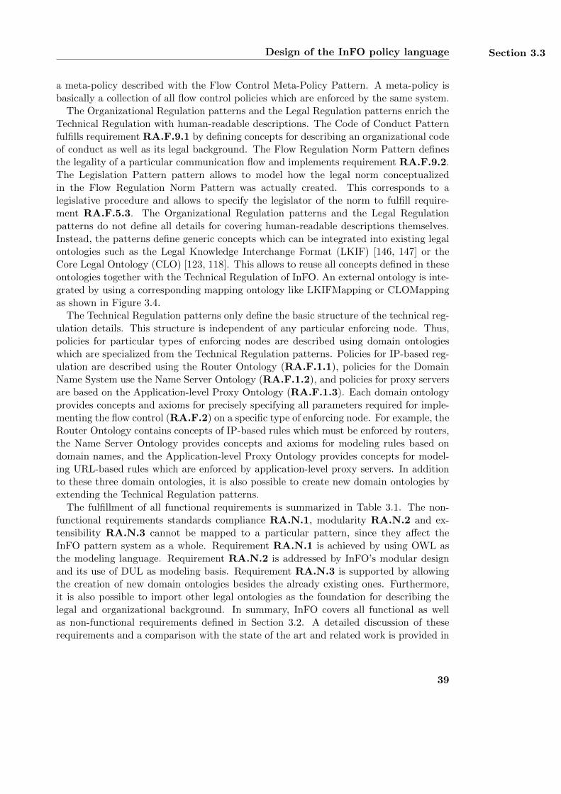
Design of the InFO policy language Section 3.3
a meta-policy described with the Flow Control Meta-Policy Pattern. A meta-policy isbasically a collection of all flow control policies which are enforced by the same system.
The Organizational Regulation patterns and the Legal Regulation patterns enrich theTechnical Regulation with human-readable descriptions. The Code of Conduct Patternfulfills requirement RA.F.9.1 by defining concepts for describing an organizational codeof conduct as well as its legal background. The Flow Regulation Norm Pattern definesthe legality of a particular communication flow and implements requirement RA.F.9.2.The Legislation Pattern pattern allows to model how the legal norm conceptualizedin the Flow Regulation Norm Pattern was actually created. This corresponds to alegislative procedure and allows to specify the legislator of the norm to fulfill require-ment RA.F.5.3. The Organizational Regulation patterns and the Legal Regulationpatterns do not define all details for covering human-readable descriptions themselves.Instead, the patterns define generic concepts which can be integrated into existing legalontologies such as the Legal Knowledge Interchange Format (LKIF) [146, 147] or theCore Legal Ontology (CLO) [123, 118]. This allows to reuse all concepts defined in theseontologies together with the Technical Regulation of InFO. An external ontology is inte-grated by using a corresponding mapping ontology like LKIFMapping or CLOMappingas shown in Figure 3.4.
The Technical Regulation patterns only define the basic structure of the technical reg-ulation details. This structure is independent of any particular enforcing node. Thus,policies for particular types of enforcing nodes are described using domain ontologieswhich are specialized from the Technical Regulation patterns. Policies for IP-based reg-ulation are described using the Router Ontology (RA.F.1.1), policies for the DomainName System use the Name Server Ontology (RA.F.1.2), and policies for proxy serversare based on the Application-level Proxy Ontology (RA.F.1.3). Each domain ontologyprovides concepts and axioms for precisely specifying all parameters required for imple-menting the flow control (RA.F.2) on a specific type of enforcing node. For example, theRouter Ontology contains concepts of IP-based rules which must be enforced by routers,the Name Server Ontology provides concepts and axioms for modeling rules based ondomain names, and the Application-level Proxy Ontology provides concepts for model-ing URL-based rules which are enforced by application-level proxy servers. In additionto these three domain ontologies, it is also possible to create new domain ontologies byextending the Technical Regulation patterns.
The fulfillment of all functional requirements is summarized in Table 3.1. The non-functional requirements standards compliance RA.N.1, modularity RA.N.2 and ex-tensibility RA.N.3 cannot be mapped to a particular pattern, since they affect theInFO pattern system as a whole. Requirement RA.N.1 is achieved by using OWL asthe modeling language. Requirement RA.N.2 is addressed by InFO’s modular designand its use of DUL as modeling basis. Requirement RA.N.3 is supported by allowingthe creation of new domain ontologies besides the already existing ones. Furthermore,it is also possible to import other legal ontologies as the foundation for describing thelegal and organizational background. In summary, InFO covers all functional as wellas non-functional requirements defined in Section 3.2. A detailed discussion of theserequirements and a comparison with the state of the art and related work is provided in
39
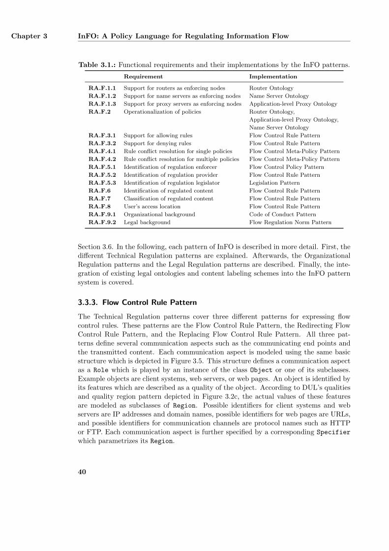
Chapter 3 InFO: A Policy Language for Regulating Information Flow
Table 3.1.: Functional requirements and their implementations by the InFO patterns.
Requirement Implementation
RA.F.1.1 Support for routers as enforcing nodes Router Ontology
RA.F.1.2 Support for name servers as enforcing nodes Name Server Ontology
RA.F.1.3 Support for proxy servers as enforcing nodes Application-level Proxy Ontology
RA.F.2 Operationalization of policies Router Ontology,
Application-level Proxy Ontology,
Name Server Ontology
RA.F.3.1 Support for allowing rules Flow Control Rule Pattern
RA.F.3.2 Support for denying rules Flow Control Rule Pattern
RA.F.4.1 Rule conflict resolution for single policies Flow Control Meta-Policy Pattern
RA.F.4.2 Rule conflict resolution for multiple policies Flow Control Meta-Policy Pattern
RA.F.5.1 Identification of regulation enforcer Flow Control Policy Pattern
RA.F.5.2 Identification of regulation provider Flow Control Rule Pattern
RA.F.5.3 Identification of regulation legislator Legislation Pattern
RA.F.6 Identification of regulated content Flow Control Rule Pattern
RA.F.7 Classification of regulated content Flow Control Rule Pattern
RA.F.8 User’s access location Flow Control Rule Pattern
RA.F.9.1 Organizational background Code of Conduct Pattern
RA.F.9.2 Legal background Flow Regulation Norm Pattern
Section 3.6. In the following, each pattern of InFO is described in more detail. First, thedifferent Technical Regulation patterns are explained. Afterwards, the OrganizationalRegulation patterns and the Legal Regulation patterns are described. Finally, the inte-gration of existing legal ontologies and content labeling schemes into the InFO patternsystem is covered.
3.3.3. Flow Control Rule Pattern
The Technical Regulation patterns cover three different patterns for expressing flowcontrol rules. These patterns are the Flow Control Rule Pattern, the Redirecting FlowControl Rule Pattern, and the Replacing Flow Control Rule Pattern. All three pat-terns define several communication aspects such as the communicating end points andthe transmitted content. Each communication aspect is modeled using the same basicstructure which is depicted in Figure 3.5. This structure defines a communication aspectas a Role which is played by an instance of the class Object or one of its subclasses.Example objects are client systems, web servers, or web pages. An object is identified byits features which are described as a quality of the object. According to DUL’s qualitiesand quality region pattern depicted in Figure 3.2c, the actual values of these featuresare modeled as subclasses of Region. Possible identifiers for client systems and webservers are IP addresses and domain names, possible identifiers for web pages are URLs,and possible identifiers for communication channels are protocol names such as HTTPor FTP. Each communication aspect is further specified by a corresponding Specifier
which parametrizes its Region.
40
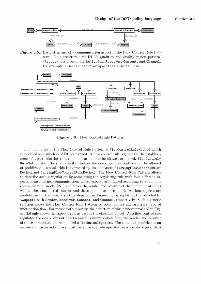
Design of the InFO policy language Section 3.3
classifies
1
specifies 1..*1
QualityhasQuality 1..* hasRegion 1..*
classifies
1..*
<Aspect>RoleRole
Object
<Aspect>Specifier Parameter
Region
Figure 3.5.: Basic structure of a communication aspect in the Flow Control Rule Pat-tern. This structure uses DUL’s qualities and quality region pattern.<Aspect> is a placeholder for Sender, Receiver, Content, and Channel.For example, a SenderSpecifier specifies a SenderRole.
FlowControlRuleMethod
InformationRealization
FlowControlRuleSituation
1
ContentRole
AllowingFlowControlRuleSituation
DenyingFlowControlRuleSituation
AllowingFlowControlRuleMethod
DenyingFlowControlRuleMethod
defines
1..*classifies
1
1..*Situation
Method
0..2
0..1
RegulatedTopic
classifies
1
RuleDataProvider
classifies
1
Role
SocialAgent
1
1
1
hasSetting
1
0..1
0..1
Description
hasTopic
1..*Topic TechnicalSystem
SenderRole
ChannelRole
1 1
Object
ReceiverRole
1
PhysicalAgent
InformationObject
realizes
1..*
classifies
classifies
classifiessatisfies
1..*
Figure 3.6.: Flow Control Rule Pattern.
The main class of the Flow Control Rule Pattern is FlowControlRuleMethod whichis modeled as a subclass of DUL’s Method. A flow control rule regulates if the establish-ment of a particular Internet communication is to be allowed or denied. FlowControl-
RuleMethod itself does not specify whether the described flow control shall be allowedor prohibited. Instead, this is expressed by its subclasses AllowingFlowControlRule-
Method and DenyingFlowControlRuleMethod. The Flow Control Rule Pattern allowsto describe such a regulation by associating the regulating rule with four different as-pects of an Internet communication. These aspects are defined according to Shannon’scommunication model [278] and cover the sender and receiver of the communication aswell as the transmitted content and the communication channel. All four aspects aremodeled using the basic structure depicted in Figure 3.5 by replacing the placeholder<Aspect> with Sender, Receiver, Content, and Channel, respectively. Such a genericsolution allows the Flow Control Rule Pattern to cover almost any arbitrary type ofinformation flow. For reasons of simplicity, the depiction of this pattern provided in Fig-ure 3.6 only shows the aspect’s role as well as the classified object. As a flow control ruleregulates the establishment of a technical communication flow, the sender and receiverof this communication are modeled as TechnicalSystems. The content is modeled as aninstance of InformationRealization since the rule operates on a specific digital data
41
Chapter 3 InFO: A Policy Language for Regulating Information Flow
file and not on an abstract piece of information. If a flow control rule does not specifyone of the four communication aspects, it will be evaluated for all possible aspects. Forexample, if a rule does not explicitly define a sender, it will be evaluated for all senders.
Besides the four communication aspects, the Flow Control Rule Pattern also definesthe provider of the rule as well as a regulated topic. RuleDataProvider represents theparty who creates a flow control rule by providing all information for technically enforc-ing it. This includes the identifiers of all communication aspects such as IP addresses,domain names, or URLs. Possible RuleDataProviders are given in the scenario in Sec-tion 2.1 and include the BKA and KACST. The regulated topic describes the contentwhose transmission is regulated by the rule. Example topics are neo-Nazi propagandaor pornography. The content’s topic is described using the topic pattern of the Ontopicontology depicted in Figure 3.3. For simplicity reasons, Figure 3.6 only shows the classTopic and not the complete topic pattern. Since a topic is independent from any spe-cific encoding and primarily associated with abstract piece of information, the Ontopicontology associates a topic with an InformationObject. In order to be able to associatea topic with an InformationRealization, the Flow Control Rule Pattern includes anInformationObject as an indirect link between the two classes. If additional descrip-tions of the content are desired, the InformationObject can be further described byusing additional content labeling schemes such as age-de.xml and their integration intothe InFO pattern system. The general process of such an integration is presented inSection 3.3.8 and the details are covered in Appendix B.2.
parametrizes
RedirectionTarget
classifies
1
RedirectingFlowControlRuleMethod
RedirectingFlowControlRuleSituation
satisfies
1
Region
defines
1
hasSetting
1..*
1
RedirectionSpecifierspecifies 11Role
DenyingFlowControlRuleMethod
DenyingFlowControlRuleSituation
Parameter
1..*
TechnicalSystem
1
Figure 3.7.: Redirecting Flow Control Rule Pattern.
parametrizes
ReplacementTarget
classifies
1
ReplacingFlowControlRuleMethod
ReplacingFlowControlRuleSituation
satisfies
1
Region
defines
1
hasSetting
1..*
1
ReplacementSpecifierspecifies 11Role
DenyingFlowControlRuleMethod
DenyingFlowControlRuleSituation
Parameter
1..*
InformationRealization
1
Figure 3.8.: Replacing Flow Control Rule Pattern.
42
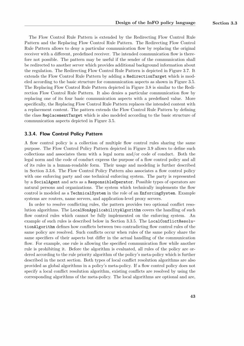
Design of the InFO policy language Section 3.3
The Flow Control Rule Pattern is extended by the Redirecting Flow Control RulePattern and the Replacing Flow Control Rule Pattern. The Redirecting Flow ControlRule Pattern allows to deny a particular communication flow by replacing the originalreceiver with a different, predefined receiver. The intended communication flow is there-fore not possible. The pattern may be useful if the sender of the communication shallbe redirected to another server which provides additional background information aboutthe regulation. The Redirecting Flow Control Rule Pattern is depicted in Figure 3.7. Itextends the Flow Control Rule Pattern by adding a RedirectionTarget which is mod-eled according to the basic structure for communication aspects as shown in Figure 3.5.The Replacing Flow Control Rule Pattern depicted in Figure 3.8 is similar to the Redi-rection Flow Control Rule Pattern. It also denies a particular communication flow byreplacing one of its four basic communication aspects with a predefined value. Morespecifically, the Replacing Flow Control Rule Pattern replaces the intended content witha replacement content. The pattern extends the Flow Control Rule Pattern by definingthe class ReplacementTarget which is also modeled according to the basic structure ofcommunication aspects depicted in Figure 3.5.
3.3.4. Flow Control Policy Pattern
A flow control policy is a collection of multiple flow control rules sharing the samepurpose. The Flow Control Policy Pattern depicted in Figure 3.9 allows to define suchcollections and associates them with a legal norm and/or code of conduct. Both thelegal norm and the code of conduct express the purpose of a flow control policy and allof its rules in a human-readable form. Their usage and modeling is further describedin Section 3.3.6. The Flow Control Policy Pattern also associates a flow control policywith one enforcing party and one technical enforcing system. The party is representedby a SocialAgent and acts as a ResponsibleOperator. Possible types of operators arenatural persons and organizations. The system which technically implements the flowcontrol is modeled as a TechnicalSystem in the role of an EnforcingSystem. Examplesystems are routers, name servers, and application-level proxy servers.
In order to resolve conflicting rules, the pattern provides two optional conflict reso-lution algorithms. The LocalNonApplicabilityAlgorithm covers the handling of suchflow control rules which cannot be fully implemented on the enforcing system. Anexample of such rules is described below in Section 3.3.5. The LocalConflictResolu-
tionAlgorithm defines how conflicts between two contradicting flow control rules of thesame policy are resolved. Such conflicts occur when rules of the same policy share thesame specifiers of their aspects but differ in the actual handling of the communicationflow. For example, one rule is allowing the specified communication flow while anotherrule is prohibiting it. Before the algorithm is evaluated, all rules of the policy are or-dered according to the rule priority algorithm of the policy’s meta-policy which is furtherdescribed in the next section. Both types of local conflict resolution algorithms are alsoprovided as global algorithms in a policy’s meta-policy. If a flow control policy does notspecify a local conflict resolution algorithm, existing conflicts are resolved by using thecorresponding algorithms of the meta-policy. The local algorithms are optional and are,
43
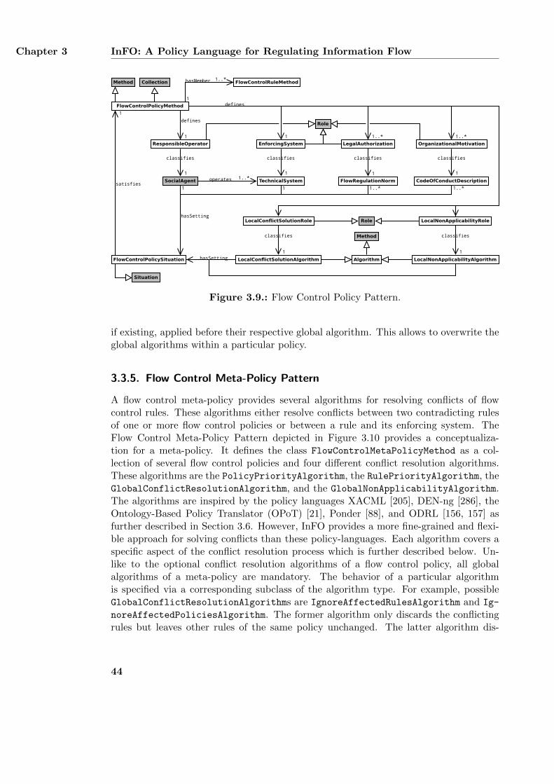
Chapter 3 InFO: A Policy Language for Regulating Information Flow
FlowControlPolicyMethod
FlowControlPolicySituation
satisfies
1
classifies
1
FlowRegulationNorm
classifies
1
CodeOfConductDescription
Method
Situation
LocalConflictSolutionAlgorithm
LocalConflictSolutionRole
OrganizationalMotivationLegalAuthorization
FlowControlRuleMethodhasMember
1
1..*
classifies
1
LocalNonApplicabilityAlgorithm
LocalNonApplicabilityRole
ResponsibleOperator EnforcingSystem
SocialAgent TechnicalSystem
classifies
1
classifies
1
classifies
1
Role
Algorithm
Method
1..*
defines
1
hasSetting
1 1 1..*
hasSetting
operates 1..*
1..*
defines
1
1..*
Role
Collection
Figure 3.9.: Flow Control Policy Pattern.
if existing, applied before their respective global algorithm. This allows to overwrite theglobal algorithms within a particular policy.
3.3.5. Flow Control Meta-Policy Pattern
A flow control meta-policy provides several algorithms for resolving conflicts of flowcontrol rules. These algorithms either resolve conflicts between two contradicting rulesof one or more flow control policies or between a rule and its enforcing system. TheFlow Control Meta-Policy Pattern depicted in Figure 3.10 provides a conceptualiza-tion for a meta-policy. It defines the class FlowControlMetaPolicyMethod as a col-lection of several flow control policies and four different conflict resolution algorithms.These algorithms are the PolicyPriorityAlgorithm, the RulePriorityAlgorithm, theGlobalConflictResolutionAlgorithm, and the GlobalNonApplicabilityAlgorithm.The algorithms are inspired by the policy languages XACML [205], DEN-ng [286], theOntology-Based Policy Translator (OPoT) [21], Ponder [88], and ODRL [156, 157] asfurther described in Section 3.6. However, InFO provides a more fine-grained and flexi-ble approach for solving conflicts than these policy-languages. Each algorithm covers aspecific aspect of the conflict resolution process which is further described below. Un-like to the optional conflict resolution algorithms of a flow control policy, all globalalgorithms of a meta-policy are mandatory. The behavior of a particular algorithmis specified via a corresponding subclass of the algorithm type. For example, possibleGlobalConflictResolutionAlgorithms are IgnoreAffectedRulesAlgorithm and Ig-
noreAffectedPoliciesAlgorithm. The former algorithm only discards the conflictingrules but leaves other rules of the same policy unchanged. The latter algorithm dis-
44
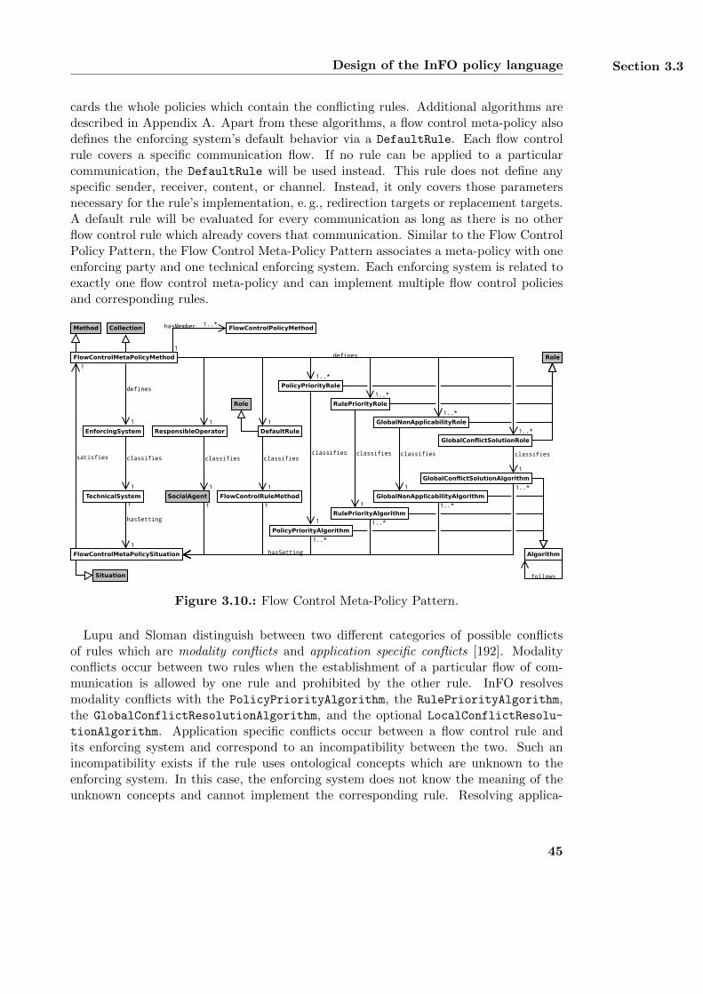
Design of the InFO policy language Section 3.3
cards the whole policies which contain the conflicting rules. Additional algorithms aredescribed in Appendix A. Apart from these algorithms, a flow control meta-policy alsodefines the enforcing system’s default behavior via a DefaultRule. Each flow controlrule covers a specific communication flow. If no rule can be applied to a particularcommunication, the DefaultRule will be used instead. This rule does not define anyspecific sender, receiver, content, or channel. Instead, it only covers those parametersnecessary for the rule’s implementation, e. g., redirection targets or replacement targets.A default rule will be evaluated for every communication as long as there is no otherflow control rule which already covers that communication. Similar to the Flow ControlPolicy Pattern, the Flow Control Meta-Policy Pattern associates a meta-policy with oneenforcing party and one technical enforcing system. Each enforcing system is related toexactly one flow control meta-policy and can implement multiple flow control policiesand corresponding rules.
GlobalConflictSolutionAlgorithm
GlobalConflictSolutionRole
FlowControlMetaPolicyMethod
FlowControlMetaPolicySituation
satisfies
1
classifies
1
classifies
1
classifies
1
classifies
1
Role
PolicyPriorityAlgorithm
PolicyPriorityRole
RulePriorityAlgorithm
RulePriorityRole
GlobalNonApplicabilityAlgorithm
GlobalNonApplicabilityRole
FlowControlPolicyMethod
hasSetting
1
1
defines
1
1..*
1..*
Method
Situation
Algorithm
follows
1..*
1..*
defines
1..*
1..*
hasSetting
1..*
1..*
hasMember
1
1..*
ResponsibleOperator
SocialAgent
classifies
1
11
11
Collection
FlowControlRuleMethod
DefaultRule
classifies
1
Role
EnforcingSystem
TechnicalSystem
classifies
1
Figure 3.10.: Flow Control Meta-Policy Pattern.
Lupu and Sloman distinguish between two different categories of possible conflictsof rules which are modality conflicts and application specific conflicts [192]. Modalityconflicts occur between two rules when the establishment of a particular flow of com-munication is allowed by one rule and prohibited by the other rule. InFO resolvesmodality conflicts with the PolicyPriorityAlgorithm, the RulePriorityAlgorithm,the GlobalConflictResolutionAlgorithm, and the optional LocalConflictResolu-tionAlgorithm. Application specific conflicts occur between a flow control rule andits enforcing system and correspond to an incompatibility between the two. Such anincompatibility exists if the rule uses ontological concepts which are unknown to theenforcing system. In this case, the enforcing system does not know the meaning of theunknown concepts and cannot implement the corresponding rule. Resolving applica-
45
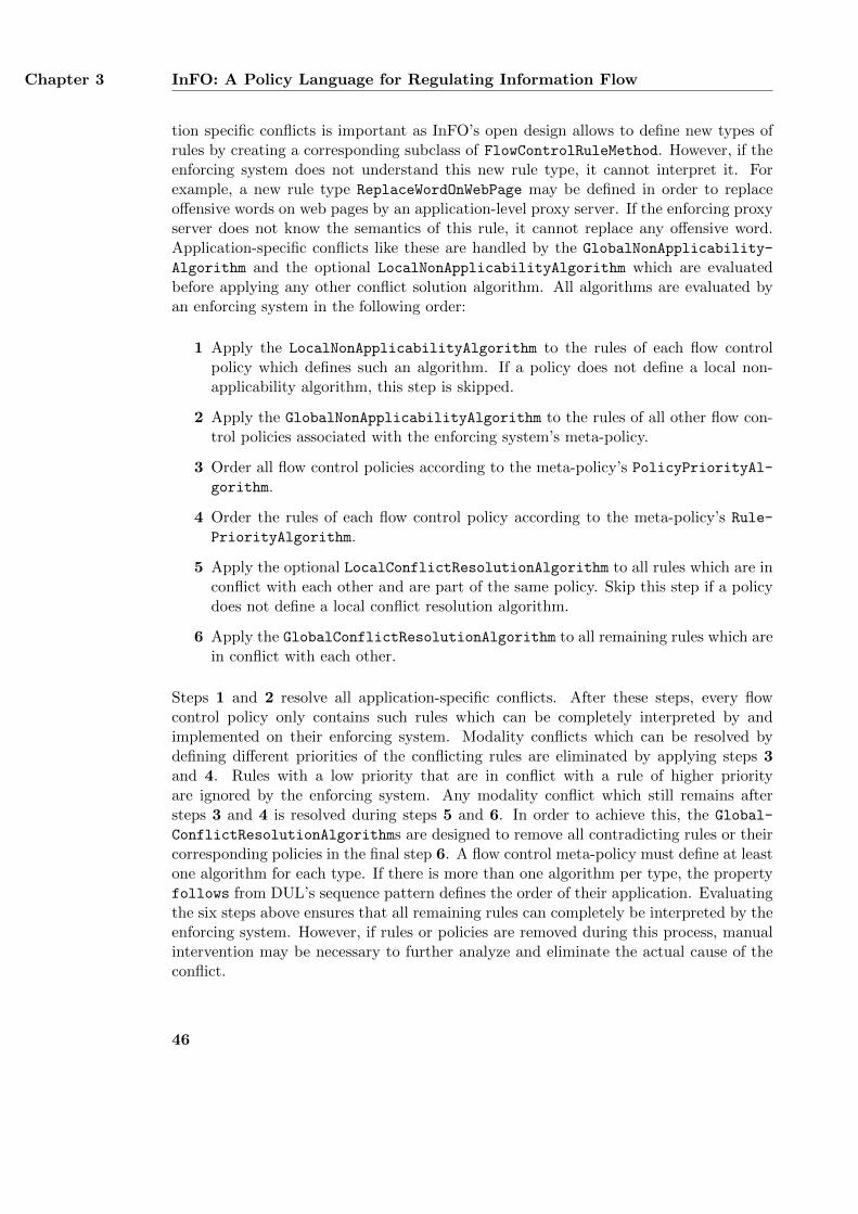
Chapter 3 InFO: A Policy Language for Regulating Information Flow
tion specific conflicts is important as InFO’s open design allows to define new types ofrules by creating a corresponding subclass of FlowControlRuleMethod. However, if theenforcing system does not understand this new rule type, it cannot interpret it. Forexample, a new rule type ReplaceWordOnWebPage may be defined in order to replaceoffensive words on web pages by an application-level proxy server. If the enforcing proxyserver does not know the semantics of this rule, it cannot replace any offensive word.Application-specific conflicts like these are handled by the GlobalNonApplicability-
Algorithm and the optional LocalNonApplicabilityAlgorithm which are evaluatedbefore applying any other conflict solution algorithm. All algorithms are evaluated byan enforcing system in the following order:
1 Apply the LocalNonApplicabilityAlgorithm to the rules of each flow controlpolicy which defines such an algorithm. If a policy does not define a local non-applicability algorithm, this step is skipped.
2 Apply the GlobalNonApplicabilityAlgorithm to the rules of all other flow con-trol policies associated with the enforcing system’s meta-policy.
3 Order all flow control policies according to the meta-policy’s PolicyPriorityAl-gorithm.
4 Order the rules of each flow control policy according to the meta-policy’s Rule-
PriorityAlgorithm.
5 Apply the optional LocalConflictResolutionAlgorithm to all rules which are inconflict with each other and are part of the same policy. Skip this step if a policydoes not define a local conflict resolution algorithm.
6 Apply the GlobalConflictResolutionAlgorithm to all remaining rules which arein conflict with each other.
Steps 1 and 2 resolve all application-specific conflicts. After these steps, every flowcontrol policy only contains such rules which can be completely interpreted by andimplemented on their enforcing system. Modality conflicts which can be resolved bydefining different priorities of the conflicting rules are eliminated by applying steps 3and 4. Rules with a low priority that are in conflict with a rule of higher priorityare ignored by the enforcing system. Any modality conflict which still remains aftersteps 3 and 4 is resolved during steps 5 and 6. In order to achieve this, the Global-
ConflictResolutionAlgorithms are designed to remove all contradicting rules or theircorresponding policies in the final step 6. A flow control meta-policy must define at leastone algorithm for each type. If there is more than one algorithm per type, the propertyfollows from DUL’s sequence pattern defines the order of their application. Evaluatingthe six steps above ensures that all remaining rules can completely be interpreted by theenforcing system. However, if rules or policies are removed during this process, manualintervention may be necessary to further analyze and eliminate the actual cause of theconflict.
46
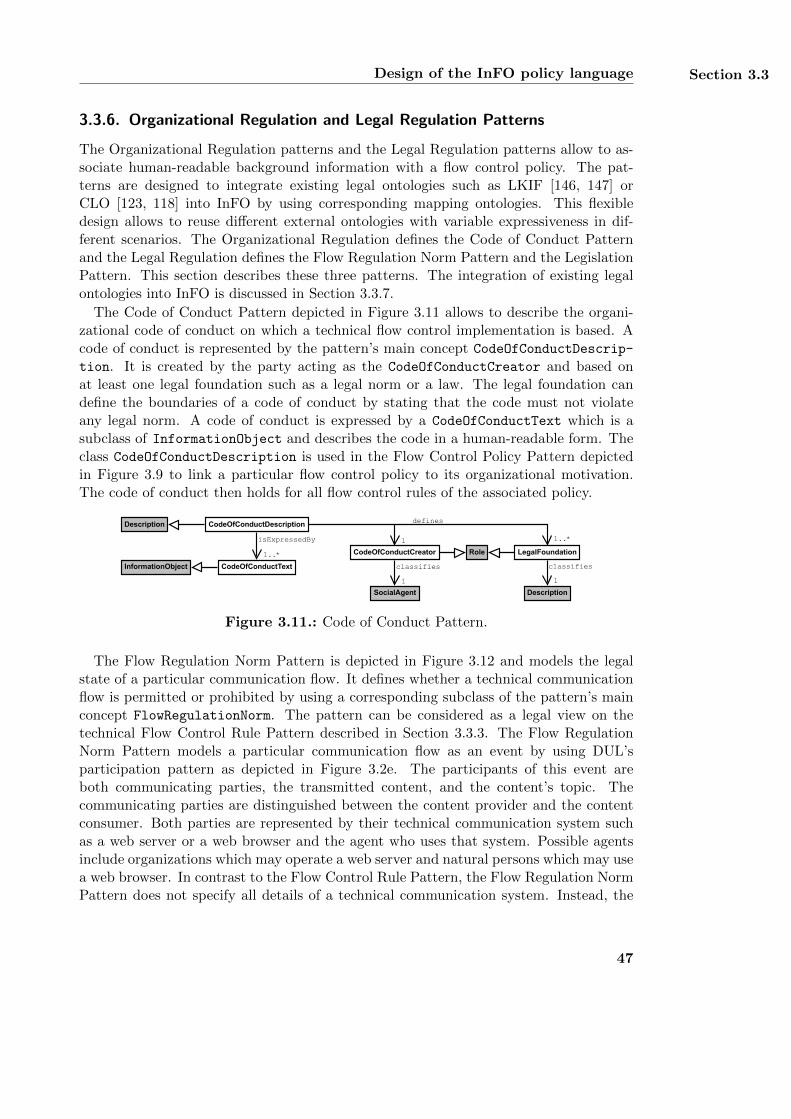
Design of the InFO policy language Section 3.3
3.3.6. Organizational Regulation and Legal Regulation Patterns
The Organizational Regulation patterns and the Legal Regulation patterns allow to as-sociate human-readable background information with a flow control policy. The pat-terns are designed to integrate existing legal ontologies such as LKIF [146, 147] orCLO [123, 118] into InFO by using corresponding mapping ontologies. This flexibledesign allows to reuse different external ontologies with variable expressiveness in dif-ferent scenarios. The Organizational Regulation defines the Code of Conduct Patternand the Legal Regulation defines the Flow Regulation Norm Pattern and the LegislationPattern. This section describes these three patterns. The integration of existing legalontologies into InFO is discussed in Section 3.3.7.
The Code of Conduct Pattern depicted in Figure 3.11 allows to describe the organi-zational code of conduct on which a technical flow control implementation is based. Acode of conduct is represented by the pattern’s main concept CodeOfConductDescrip-
tion. It is created by the party acting as the CodeOfConductCreator and based onat least one legal foundation such as a legal norm or a law. The legal foundation candefine the boundaries of a code of conduct by stating that the code must not violateany legal norm. A code of conduct is expressed by a CodeOfConductText which is asubclass of InformationObject and describes the code in a human-readable form. Theclass CodeOfConductDescription is used in the Flow Control Policy Pattern depictedin Figure 3.9 to link a particular flow control policy to its organizational motivation.The code of conduct then holds for all flow control rules of the associated policy.
CodeOfConductCreator Role LegalFoundation
CodeOfConductDescriptionDescription
SocialAgent
classifies
1
Description
classifies
1
1
defines
1..*
CodeOfConductText
isExpressedBy
1..*
InformationObject
Figure 3.11.: Code of Conduct Pattern.
The Flow Regulation Norm Pattern is depicted in Figure 3.12 and models the legalstate of a particular communication flow. It defines whether a technical communicationflow is permitted or prohibited by using a corresponding subclass of the pattern’s mainconcept FlowRegulationNorm. The pattern can be considered as a legal view on thetechnical Flow Control Rule Pattern described in Section 3.3.3. The Flow RegulationNorm Pattern models a particular communication flow as an event by using DUL’sparticipation pattern as depicted in Figure 3.2e. The participants of this event areboth communicating parties, the transmitted content, and the content’s topic. Thecommunicating parties are distinguished between the content provider and the contentconsumer. Both parties are represented by their technical communication system suchas a web server or a web browser and the agent who uses that system. Possible agentsinclude organizations which may operate a web server and natural persons which may usea web browser. In contrast to the Flow Control Rule Pattern, the Flow Regulation NormPattern does not specify all details of a technical communication system. Instead, the
47
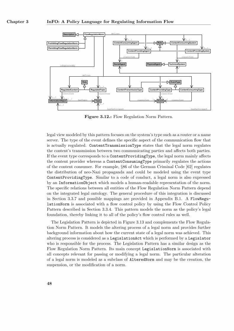
Chapter 3 InFO: A Policy Language for Regulating Information Flow
Description FlowRegulationNorm
PermittingFlowRegulationNorm
ProhibitingFlowRegulationNorm
RegulatedTopic
Topic
classifies
1
InformationObject
classifies
1hasTopic1..*
ContentTransmissionType
Eventclassifies 1
EventType
ContentProvidingType ContentConsumingType
classifies1
classifies
1
RegulatedContent
ContentConsumingAgent ContentConsumingSystem
ContentProvidingSystemContentProvidingAgent
SocialAgent TechnicalSystem
classifies
PhysicalAgent
classifies
defines
defines
1..*
Role
0..1
0..1
0..1
isExpressedBy
1..*
Role
1
hasParticipant
1..*1..*
2 2
hasParticipant
1
0..1
Figure 3.12.: Flow Regulation Norm Pattern.
legal view modeled by this pattern focuses on the system’s type such as a router or a nameserver. The type of the event defines the specific aspect of the communication flow thatis actually regulated. ContentTransmissionType states that the legal norm regulatesthe content’s transmission between two communicating parties and affects both parties.If the event type corresponds to a ContentProvidingType, the legal norm mainly affectsthe content provider whereas a ContentConsumingType primarily regulates the actionsof the content consumer. For example, §86 of the German Criminal Code [62] regulatesthe distribution of neo-Nazi propaganda and could be modeled using the event typeContentProvidingType. Similar to a code of conduct, a legal norm is also expressedby an InformationObject which models a human-readable representation of the norm.The specific relations between all entities of the Flow Regulation Norm Pattern dependon the integrated legal ontology. The general procedure of this integration is discussedin Section 3.3.7 and possible mappings are provided in Appendix B.1. A FlowRegu-
lationNorm is associated with a flow control policy by using the Flow Control PolicyPattern described in Section 3.3.4. This pattern models the norm as the policy’s legalfoundation, thereby linking it to all of the policy’s flow control rules as well.
The Legislation Pattern is depicted in Figure 3.13 and complements the Flow Regula-tion Norm Pattern. It models the altering process of a legal norm and provides furtherbackground information about how the current state of a legal norm was achieved. Thisaltering process is considered as a LegislationAct which is performed by a Legislator
who is responsible for the process. The Legislation Pattern has a similar design as theFlow Regulation Norm Pattern. Its main concept LegislationNorm is associated withall concepts relevant for passing or modifying a legal norm. The particular alterationof a legal norm is modeled as a subclass of AlteredNorm and may be the creation, thesuspension, or the modification of a norm.
48
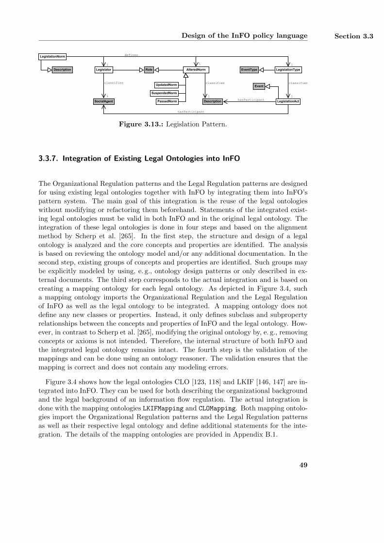
Design of the InFO policy language Section 3.3
Legislator
classifies
1
Role
SocialAgent
Description
LegislationNorm
LegislationTypeEventTypeAlteredNorm
Description
classifies
1
classifies
1
1
defines
1 1
Event
hasParticipant
hasParticipant
UpdatedNorm
SuspendedNorm
PassedNorm LegislationAct
Figure 3.13.: Legislation Pattern.
3.3.7. Integration of Existing Legal Ontologies into InFO
The Organizational Regulation patterns and the Legal Regulation patterns are designedfor using existing legal ontologies together with InFO by integrating them into InFO’spattern system. The main goal of this integration is the reuse of the legal ontologieswithout modifying or refactoring them beforehand. Statements of the integrated exist-ing legal ontologies must be valid in both InFO and in the original legal ontology. Theintegration of these legal ontologies is done in four steps and based on the alignmentmethod by Scherp et al. [265]. In the first step, the structure and design of a legalontology is analyzed and the core concepts and properties are identified. The analysisis based on reviewing the ontology model and/or any additional documentation. In thesecond step, existing groups of concepts and properties are identified. Such groups maybe explicitly modeled by using, e. g., ontology design patterns or only described in ex-ternal documents. The third step corresponds to the actual integration and is based oncreating a mapping ontology for each legal ontology. As depicted in Figure 3.4, sucha mapping ontology imports the Organizational Regulation and the Legal Regulationof InFO as well as the legal ontology to be integrated. A mapping ontology does notdefine any new classes or properties. Instead, it only defines subclass and subpropertyrelationships between the concepts and properties of InFO and the legal ontology. How-ever, in contrast to Scherp et al. [265], modifying the original ontology by, e. g., removingconcepts or axioms is not intended. Therefore, the internal structure of both InFO andthe integrated legal ontology remains intact. The fourth step is the validation of themappings and can be done using an ontology reasoner. The validation ensures that themapping is correct and does not contain any modeling errors.
Figure 3.4 shows how the legal ontologies CLO [123, 118] and LKIF [146, 147] are in-tegrated into InFO. They can be used for both describing the organizational backgroundand the legal background of an information flow regulation. The actual integration isdone with the mapping ontologies LKIFMapping and CLOMapping. Both mapping ontolo-gies import the Organizational Regulation patterns and the Legal Regulation patternsas well as their respective legal ontology and define additional statements for the inte-gration. The details of the mapping ontologies are provided in Appendix B.1.
49
Chapter 3 InFO: A Policy Language for Regulating Information Flow
3.3.8. Integration of Existing Content Labeling Schemes into InFO
The Flow Control Rule Pattern introduced in Section 3.3.3 uses the topic pattern ofthe Ontopic ontology for describing the topic of the transmitted content. Although thedescriptions created with this pattern are sufficient for many scenarios, it is also possi-ble to further describe the transmitted content by importing content labeling schemessuch as the RTA label, age-de.xml [264], or PICS [248] into InFO. These schemes aredesigned to be used by child protection software for prohibiting minors from accessingadult web content. Thus, integrating these schemes into InFO can achieve more com-patibility between the InFO pattern system and other implementations for regulatingaccess to web pages such as Net Nanny and the Jugendschutzprogramm. Figure 3.4shows how the RTA label, age-de.xml, and PICS are integrated into InFO. The integra-tion of the content labeling schemes is done in a similar way as the integration of thelegal ontologies described in the previous section. The mapping uses the correspondingmapping ontologies RTAMapping, AgeDeXmlMapping, and PICSMapping. The detailsof the three mapping ontologies are provided in Appendix B.2.
3.3.9. Summary
The pattern system InFO consists of several ontology design patterns which cover specificaspects for describing the regulation of information flow on the Internet. These aspectsare either of technical, of organizational, or of legal issue. The main focus of InFO is thetechnical regulation of Internet communication. The Organizational Regulation and theLegal Regulation are designed to be used together with existing legal ontologies.
3.4. Applications and Use Cases
This section demonstrates how the InFO policy language is applied for implementingthe scenarios provided in Section 2. The first scenario covers the regulation of Internetcommunication and is described in Sections 3.4.1 to 3.4.4. Afterwards, Section 3.4.5describes the second scenario for securing the access to medical data.
3.4.1. Example Policies for Regulating Internet Communication
Figure 3.14 depicts a subnetwork of the example network described in Section 2.1 in-cluding more technical details such as the addresses of the communication nodes and theURLs of the web content. These details are required for precisely defining a set of flowcontrol policies. The policies are created using three different domain ontologies thatextend InFO’s Technical Regulation patterns. These domain ontologies are the RouterOntology, the Name Server Ontology, and the Application-Level Proxy Ontology. Eachontology defines specific flow control rules which are designed to be implemented on theirrespective enforcement systems. For example, the Router Ontology defines the classesIPAddressBlockingRuleMethod and IPAddressRedirectingRuleMethod as subclasses
50
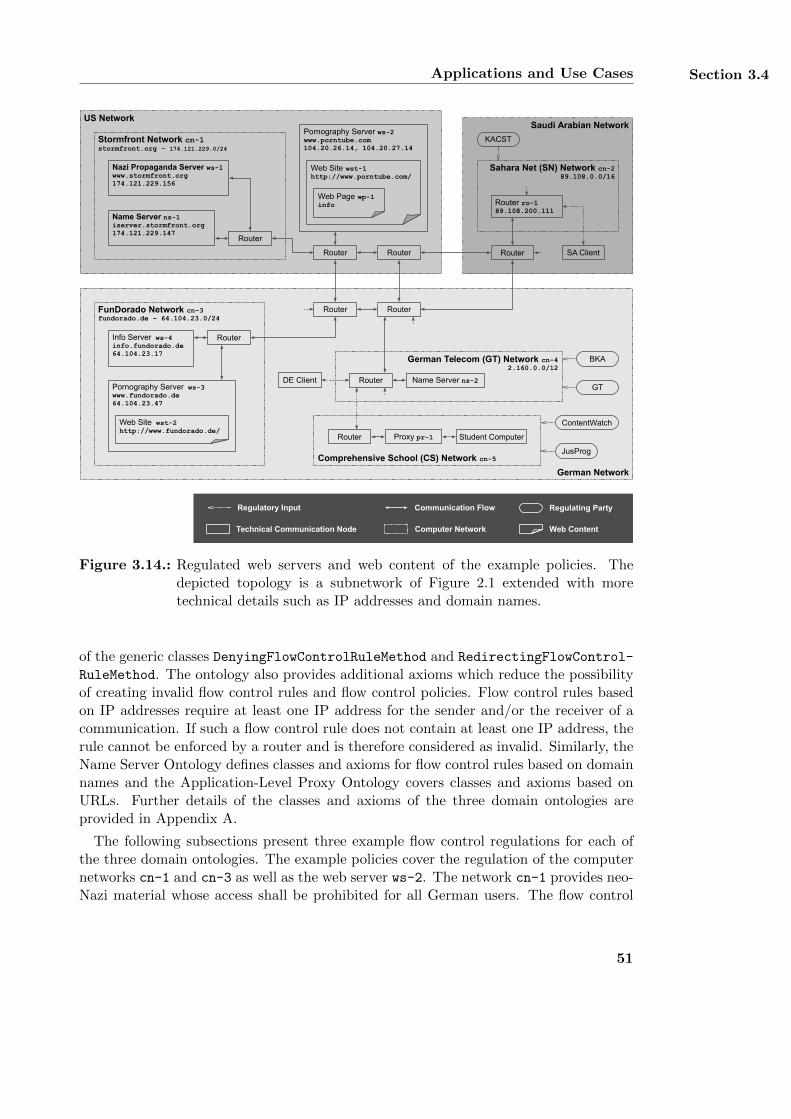
Applications and Use Cases Section 3.4
US Network
Stormfront Network cn-1stormfront.org - 174.121.229.0/24
Nazi Propaganda Server ws-1www.stormfront.org174.121.229.156
Name Server ns-1iserver.stormfront.org174.121.229.147
Router
Router
Router
German Network
German Telecom (GT) Network cn-42.160.0.0/12
DE Client
BKA
Router
Router Router
GTName Server ns-2
FunDorado Network cn-3fundorado.de – 64.104.23.0/24
Pornography Server ws-3www.fundorado.de64.104.23.47
Info Server ws-4info.fundorado.de64.104.23.17
Web Site wst-2http://www.fundorado.de/
Router
Pornography Server ws-2www.porntube.com104.20.26.14, 104.20.27.14
Web Site wst-1http://www.porntube.com/
Saudi Arabian Network
Sahara Net (SN) Network cn-289.108.0.0/16
Router ro-189.108.200.111
Router
Regulatory Input Communication Flow Regulating Party
Technical Communication Node Web Content
Comprehensive School (CS) Network cn-5
Student ComputerRouter Proxy pr-1
Computer Network
JusProg
ContentWatch
SA Client
KACST
Web Page wp-1info
Figure 3.14.: Regulated web servers and web content of the example policies. Thedepicted topology is a subnetwork of Figure 2.1 extended with moretechnical details such as IP addresses and domain names.
of the generic classes DenyingFlowControlRuleMethod and RedirectingFlowControl-
RuleMethod. The ontology also provides additional axioms which reduce the possibilityof creating invalid flow control rules and flow control policies. Flow control rules basedon IP addresses require at least one IP address for the sender and/or the receiver of acommunication. If such a flow control rule does not contain at least one IP address, therule cannot be enforced by a router and is therefore considered as invalid. Similarly, theName Server Ontology defines classes and axioms for flow control rules based on domainnames and the Application-Level Proxy Ontology covers classes and axioms based onURLs. Further details of the classes and axioms of the three domain ontologies areprovided in Appendix A.
The following subsections present three example flow control regulations for each ofthe three domain ontologies. The example policies cover the regulation of the computernetworks cn-1 and cn-3 as well as the web server ws-2. The network cn-1 provides neo-Nazi material whose access shall be prohibited for all German users. The flow control
51
Chapter 3 InFO: A Policy Language for Regulating Information Flow
rules implementing this access regulation are based on domain names and are enforcedby the name server ns-2 of the German Telecom. The network cn-3 located in Germanyand the web server ws-2 located in the USA provide pornographic web content. Accessto this content shall be prohibited for all users in Saudi Arabia and for all students ofthe German comprehensive school. In Saudi Arabia, the access regulations are based onIP addresses and enforced by the router ro-1 whereas the German comprehensive schoolregulates the access using its proxy server pr-1 which operates on URLs. For illustrationpurpose, each flow control regulation consists of two or three FlowControlRuleMethods,one FlowControlPolicyMethod that contains these rules, and one FlowControlMeta-
PolicyMethod. All rules of the same policy share the same regulated topic and sender.The sender of each rule and hence the requester of the regulated content is modeled asa whole computer network rather than a single computer.
In general, a communication between a content consumer and a content provider canbe regulated in two different ways. The first option is to regulate the content consumer’srequest before it is sent to the content provider. In this case, the server acting as thecontent provider does not receive any message from the client which acts as the contentconsumer. The second option is to regulate the content provider’s response after it hasprocessed the content consumer’s request. Implementing this option allows the serverto receive messages from the client but prohibits the transmission of messages in theopposite direction. InFO generally supports both types of regulation by defining thesender and receiver of a communication accordingly. Choosing a particular type ofregulation may depend on technical, on organizational and/or on legal factors and mustbe decided before creating particular regulation policies. For example, the first optionresults in a faster regulation as an enforcing system can immediately regulate a requestwithout having to wait for a corresponding response. This also reduces the amount oftransmitted data and may result in a faster Internet connection of the enforcing node.On the other hand, the legal foundation of a regulation may allow requesting particularcontent but not the transmission of the content itself. In this case, the second optionmight be used for implementing the regulation. In addition, there are also technicalconstraints when choosing between the two types of regulation. Although routers andproxy servers can regulate the flow of communication in both directions, name servers canonly regulate requests from a client system. This is due to the use of the domain namesystem when initiating an Internet communication [212]. If a client wants to contact aserver, it first maps the domain name of the server to its IP address. The IP addresses ofthe client and the server are then included in the messages which are exchanged betweenthe two systems. When sending a response, the server already has the IP address of theclient and does not need to contact a name server. Thus, prohibiting the communicationbetween two parties is only possible by implementing the regulation on the client’s nameserver. In the following, all example rules are designed in such a way that the initialrequest of a client system is regulated by the enforcing system.
For reasons of brevity, the following depictions of flow control rules, policies, andmeta-policies only show their most important aspects although the actual regulationis still complete. All three meta-policies define a global conflict resolution algorithmand a global non-applicability algorithm as these algorithms are mandatory for the
52
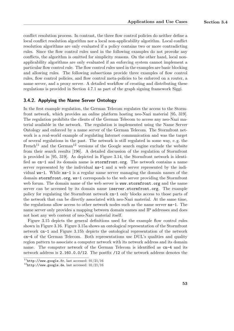
Applications and Use Cases Section 3.4
conflict resolution process. In contrast, the three flow control policies do neither define alocal conflict resolution algorithm nor a local non-applicability algorithm. Local conflictresolution algorithms are only evaluated if a policy contains two or more contradictingrules. Since the flow control rules used in the following examples do not provoke anyconflicts, the algorithm is omitted for simplicity reasons. On the other hand, local non-applicability algorithms are only evaluated if an enforcing system cannot implement aparticular flow control rule. The flow control rules used in the examples are basic blockingand allowing rules. The following subsections provide three examples of flow controlrules, flow control policies, and flow control meta-policies to be enforced on a router, aname server, and a proxy server. A detailed workflow of creating and distributing theseregulations is provided in Section 4.7.1 as part of the graph signing framework Siggi.
3.4.2. Applying the Name Server Ontology
In the first example regulation, the German Telecom regulates the access to the Storm-front network, which provides an online platform hosting neo-Nazi material [95, 319].The regulation prohibits the clients of the German Telecom to access any neo-Nazi ma-terial available in the network. The regulation is implemented using the Name ServerOntology and enforced by a name server of the German Telecom. The Stormfront net-work is a real-world example of regulating Internet communication and was the targetof several regulations in the past. The network is still regulated in some way, e. g. theFrench11 and the German12 versions of the Google search engine exclude the websitefrom their search results [196]. A detailed discussion of the regulation of Stormfrontis provided in [95, 319]. As depicted in Figure 3.14, the Stormfront network is identi-fied as cn-1 and its domain name is stormfront.org. The network contains a nameserver represented by the individual ns-1 and a web server represented by the indi-vidual ws-1. While ns-1 is a regular name server managing the domain names of thedomain stormfront.org, ws-1 corresponds to the web server providing the Stormfrontweb forum. The domain name of the web server is www.stormfront.org and the nameserver can be accessed by its domain name iserver.stormfront.org. The examplepolicy for regulating the Stormfront network cn-1 only blocks access to those parts ofthe network that can be directly associated with neo-Nazi material. At the same time,the regulations allow access to other network nodes such as the name server ns-1. Thename server only provides a mapping between domain names and IP addresses and doesnot host any web content of neo-Nazi material itself.
Figure 3.15 depicts the general definitions used for the example flow control rulesshown in Figure 3.16. Figure 3.15a shows an ontological representation of the Stormfrontnetwork cn-1 and Figure 3.15b depicts the ontological representation of the networkcn-4 of the German Telecom. Both representations use DUL’s qualities and qualityregion pattern to associate a computer network with its network address and its domainname. The computer network of the German Telecom is identified as cn-4 and itsnetwork address is 2.160.0.0/12. The postfix /12 of the network address denotes the
11http://www.google.fr, last accessed: 01/21/1612http://www.google.de, last accessed: 01/21/16
53
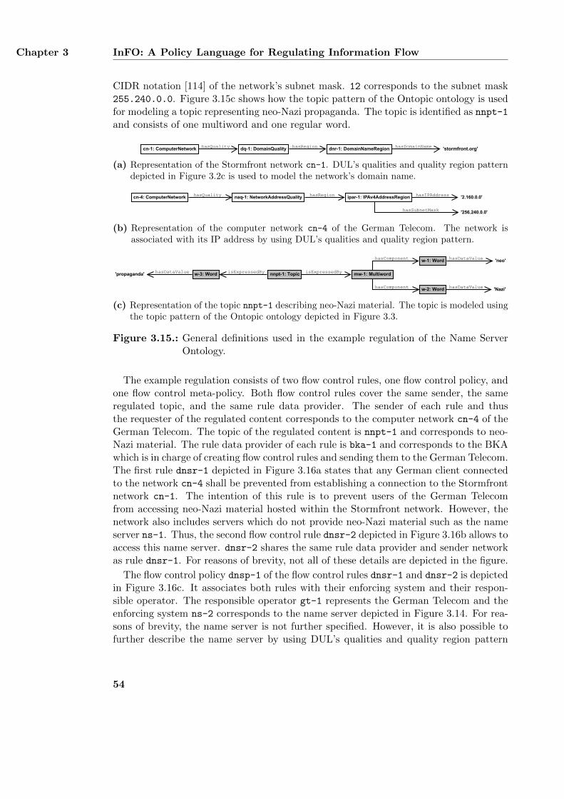
Chapter 3 InFO: A Policy Language for Regulating Information Flow
CIDR notation [114] of the network’s subnet mask. 12 corresponds to the subnet mask255.240.0.0. Figure 3.15c shows how the topic pattern of the Ontopic ontology is usedfor modeling a topic representing neo-Nazi propaganda. The topic is identified as nnpt-1and consists of one multiword and one regular word.
hasQuality hasRegion hasDomainNamedq-1: DomainQuality dnr-1: DomainNameRegion 'stormfront.org'cn-1: ComputerNetwork
(a) Representation of the Stormfront network cn-1. DUL’s qualities and quality region patterndepicted in Figure 3.2c is used to model the network’s domain name.
cn-4: ComputerNetwork naq-1: NetworkAddressQualityhasQuality hasRegion
'256.240.0.0'
'2.160.0.0'
'256.240.0.0'
'2.160.0.0'hasIPAddress
hasSubnetMask
ipar-1: IPAv4AddressRegion
(b) Representation of the computer network cn-4 of the German Telecom. The network isassociated with its IP address by using DUL’s qualities and quality region pattern.
nnpt-1: Topic
w-1: Word
w-2: Word
w-3: Word mw-1: MultiwordisExpressedByisExpressedBy
hasComponent
hasComponent
hasDataValue
'neo'
'Nazi'
'propaganda'
hasDataValue
hasDataValue
(c) Representation of the topic nnpt-1 describing neo-Nazi material. The topic is modeled usingthe topic pattern of the Ontopic ontology depicted in Figure 3.3.
Figure 3.15.: General definitions used in the example regulation of the Name ServerOntology.
The example regulation consists of two flow control rules, one flow control policy, andone flow control meta-policy. Both flow control rules cover the same sender, the sameregulated topic, and the same rule data provider. The sender of each rule and thusthe requester of the regulated content corresponds to the computer network cn-4 of theGerman Telecom. The topic of the regulated content is nnpt-1 and corresponds to neo-Nazi material. The rule data provider of each rule is bka-1 and corresponds to the BKAwhich is in charge of creating flow control rules and sending them to the German Telecom.The first rule dnsr-1 depicted in Figure 3.16a states that any German client connectedto the network cn-4 shall be prevented from establishing a connection to the Stormfrontnetwork cn-1. The intention of this rule is to prevent users of the German Telecomfrom accessing neo-Nazi material hosted within the Stormfront network. However, thenetwork also includes servers which do not provide neo-Nazi material such as the nameserver ns-1. Thus, the second flow control rule dnsr-2 depicted in Figure 3.16b allows toaccess this name server. dnsr-2 shares the same rule data provider and sender networkas rule dnsr-1. For reasons of brevity, not all of these details are depicted in the figure.
The flow control policy dnsp-1 of the flow control rules dnsr-1 and dnsr-2 is depictedin Figure 3.16c. It associates both rules with their enforcing system and their respon-sible operator. The responsible operator gt-1 represents the German Telecom and theenforcing system ns-2 corresponds to the name server depicted in Figure 3.14. For rea-sons of brevity, the name server is not further specified. However, it is also possible tofurther describe the name server by using DUL’s qualities and quality region pattern
54
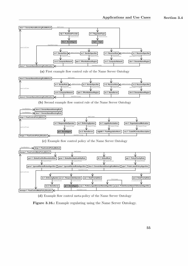
Applications and Use Cases Section 3.4
dnsrs-1: DomainNameBlockingRuleSituation
satisfies
dnsr-1: DomainNameBlockingRuleMethod
rr-1: ReceiverRole
cn-1: ComputerNetwork
classifies
rs-1: ReceiverSpecifier
dnr-1: DomainNameRegion
parametrizes
ss-1: SenderSpecifier
classifies
nnpt-1: Topic
rt-1: RegulatedTopic
classifies
bka-1: SocialAgent
classifies
rdp-1: RuleDataProvider
defines
hasSetting
sr-1: SenderRole
cn-4: ComputerNetwork
classifies
hasSetting
specifies specifies
ipar-1: IPAv4AddressRegion
(a) First example flow control rule of the Name Server Ontology
hasSetting dnsrs-2: DomainNameAllowingRuleSituation
satisfies
dnsr-2: DomainNameAllowingRuleMethod
rr-2: ReceiverRole
ns-1: NameServer
rs-2: ReceiverSpecifier
dnr-2: DomainNameRegion
defines
specifiesss-1: SenderSpecifier
classifies
sr-1: SenderRole
cn-4: ComputerNetwork
classifies
specifies
classifies parametrizes
ipar-1: IPAv4AddressRegion
(b) Second example flow control rule of the Name Server Ontology
dnsp-1: FlowControlPolicyMethod
dnsps-1: FlowControlPolicySituation
dnsr-2: DomainNameAllowingRule
satisfies
la-1: LegalAuthorization
defines
coc-1: CodeOfConductDescription
om-1: OrganizationalMotivation
dnsr-1: DomainNameBlockingRule
stgb86-1: FlowRegulationNorm
hasSetting
hasMember
hasMember
ro-1: ResponsibleOperator
classifies
gt-1: SocialAgent
es-1: EnforcingSystem
ns-2: NameServer
classifies classifies classifies
(c) Example flow control policy of the Name Server Ontology
dnsmp-1: FlowControlMetaPolicyMethod
dnsmps-1: FlowControlMetaPolicySituation
satisfies
dnsp-1: FlowControlPolicyMethod
dnsr-3: DomainNameAllowingRuleMethod
dr-1: DefaultRule
classifies
defines
hasSetting
hasSetting
ppa-1: PreferLatestPolicyAlgorithm
ppr-1: PolicyPriorityRole
classifies
follows
hasMember
rpa-2: PreferDomainNameToDomainAlgorithm
rpr-2: RulePriorityRolerpr-1: RulePriorityRole
rpa-1: PreferLongestDomainNameAlgorithm
ro-1: ResponsibleOperator
classifies
gt-1: SocialAgent
classifies classifies
gcra-1: IgnoreAffectedRulesAlgorithm
gcrr-1: GlobalConflictResolutionRole
classifies
gnaa-1: IgnoreAffectedRuleAlgorithm
gnar-1: GlobalNonApplicabilityRole
classifies
es-1: EnforcingSystem
classifies
ns-2: NameServer
(d) Example flow control meta-policy of the Name Server Ontology
Figure 3.16.: Example regulating using the Name Server Ontology.
55
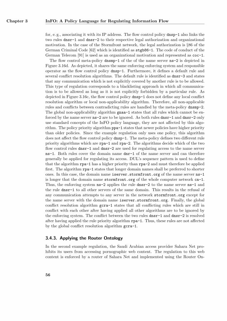
Chapter 3 InFO: A Policy Language for Regulating Information Flow
for, e. g., associating it with its IP address. The flow control policy dnsp-1 also links thetwo rules dnsr-1 and dnsr-2 to their respective legal authorization and organizationalmotivation. In the case of the Stormfront network, the legal authorization is §86 of theGerman Criminal Code [62] which is identified as stgb86-1. The code of conduct of theGerman Telecom [91] is used as an organizational motivation and represented as coc-1.
The flow control meta-policy dnsmp-1 of the of the name server ns-2 is depicted inFigure 3.16d. As depicted, it shares the same enforcing enforcing system and responsibleoperator as the flow control policy dnsp-1. Furthermore, it defines a default rule andseveral conflict resolution algorithms. The default rule is identified as dnsr-3 and statesthat any communication which is not explicitly covered by another rule is to be allowed.This type of regulation corresponds to a blacklisting approach in which all communica-tion is to be allowed as long as it is not explicitly forbidden by a particular rule. Asdepicted in Figure 3.16c, the flow control policy dnsp-1 does not define any local conflictresolution algorithm or local non-applicability algorithm. Therefore, all non-applicablerules and conflicts between contradicting rules are handled by the meta-policy dnsmp-2.The global non-applicability algorithm gnaa-1 states that all rules which cannot be en-forced by the name server ns-2 are to be ignored. As both rules dnsr-1 and dnsr-2 onlyuse standard concepts of the InFO policy language, they are not affected by this algo-rithm. The policy priority algorithm ppa-1 states that newer policies have higher prioritythan older policies. Since the example regulation only uses one policy, this algorithmdoes not affect the flow control policy dnsp-1. The meta-policy defines two different rulepriority algorithms which are rpa-1 and rpa-2. The algorithms decide which of the twoflow control rules dnsr-1 and dnsr-2 are used for regulating access to the name serverns-1. Both rules cover the domain name dnr-1 of the name server and can thereforegenerally be applied for regulating its access. DUL’s sequence pattern is used to definethat the algorithm rpa-1 has a higher priority than rpa-2 and must therefore be appliedfirst. The algorithm rpa-1 states that longer domain names shall be preferred to shorterones. In this case, the domain name iserver.stormfront.org of the name server ns-1is longer that the domain name stormfront.org of the whole computer network cn-1.Thus, the enforcing system ns-2 applies the rule dnsr-2 to the name server ns-1 andthe rule dnsr-1 to all other servers of the same domain. This results in the refusal ofany communication attempts to any server in the network stormfront.org except forthe name server with the domain name iserver.stormfront.org. Finally, the globalconflict resolution algorithm gcra-1 states that all conflicting rules which are still inconflict with each other after having applied all other algorithms are to be ignored bythe enforcing system. The conflict between the two rules dnsr-1 and dnsr-2 is resolvedafter having applied the rule priority algorithm rpa-1. Thus, these rules are not affectedby the global conflict resolution algorithm gcra-1.
3.4.3. Applying the Router Ontology
In the second example regulation, the Saudi Arabian access provider Sahara Net pro-hibits its users from accessing pornographic web content. The regulation to this webcontent is enforced by a router of Sahara Net and implemented using the Router On-
56
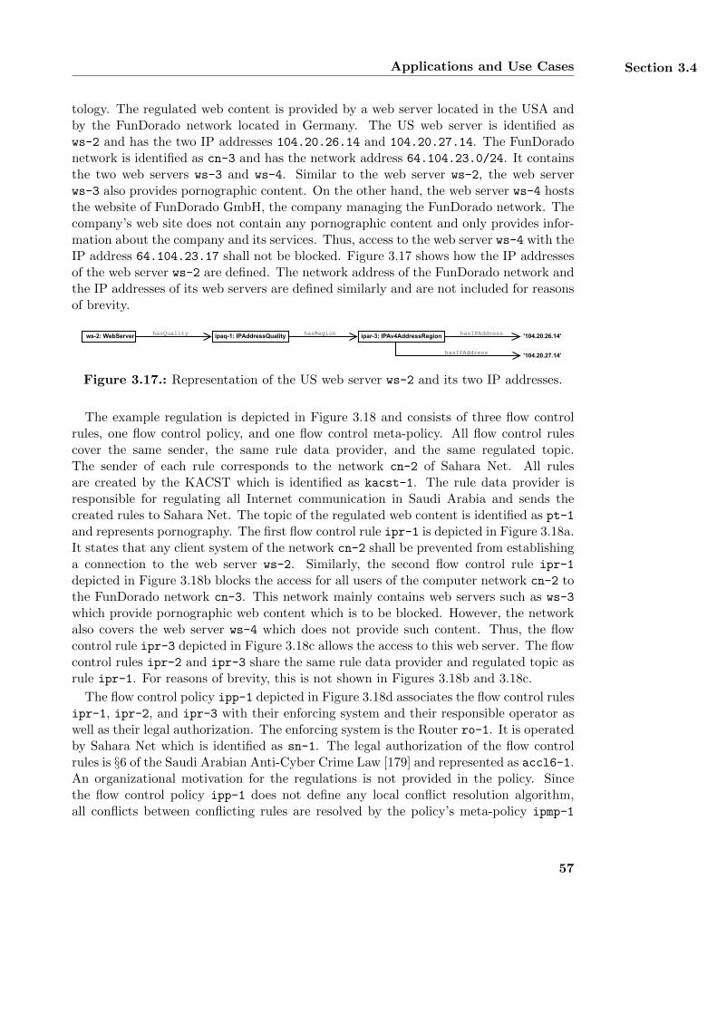
Applications and Use Cases Section 3.4
tology. The regulated web content is provided by a web server located in the USA andby the FunDorado network located in Germany. The US web server is identified asws-2 and has the two IP addresses 104.20.26.14 and 104.20.27.14. The FunDoradonetwork is identified as cn-3 and has the network address 64.104.23.0/24. It containsthe two web servers ws-3 and ws-4. Similar to the web server ws-2, the web serverws-3 also provides pornographic content. On the other hand, the web server ws-4 hoststhe website of FunDorado GmbH, the company managing the FunDorado network. Thecompany’s web site does not contain any pornographic content and only provides infor-mation about the company and its services. Thus, access to the web server ws-4 with theIP address 64.104.23.17 shall not be blocked. Figure 3.17 shows how the IP addressesof the web server ws-2 are defined. The network address of the FunDorado network andthe IP addresses of its web servers are defined similarly and are not included for reasonsof brevity.
ws-2: WebServer ipaq-1: IPAddressQualityhasQuality hasRegion
'104.20.27.14'
'104.20.26.14'hasIPAddress
hasIPAddress
ipar-3: IPAv4AddressRegion
Figure 3.17.: Representation of the US web server ws-2 and its two IP addresses.
The example regulation is depicted in Figure 3.18 and consists of three flow controlrules, one flow control policy, and one flow control meta-policy. All flow control rulescover the same sender, the same rule data provider, and the same regulated topic.The sender of each rule corresponds to the network cn-2 of Sahara Net. All rulesare created by the KACST which is identified as kacst-1. The rule data provider isresponsible for regulating all Internet communication in Saudi Arabia and sends thecreated rules to Sahara Net. The topic of the regulated web content is identified as pt-1and represents pornography. The first flow control rule ipr-1 is depicted in Figure 3.18a.It states that any client system of the network cn-2 shall be prevented from establishinga connection to the web server ws-2. Similarly, the second flow control rule ipr-1
depicted in Figure 3.18b blocks the access for all users of the computer network cn-2 tothe FunDorado network cn-3. This network mainly contains web servers such as ws-3
which provide pornographic web content which is to be blocked. However, the networkalso covers the web server ws-4 which does not provide such content. Thus, the flowcontrol rule ipr-3 depicted in Figure 3.18c allows the access to this web server. The flowcontrol rules ipr-2 and ipr-3 share the same rule data provider and regulated topic asrule ipr-1. For reasons of brevity, this is not shown in Figures 3.18b and 3.18c.
The flow control policy ipp-1 depicted in Figure 3.18d associates the flow control rulesipr-1, ipr-2, and ipr-3 with their enforcing system and their responsible operator aswell as their legal authorization. The enforcing system is the Router ro-1. It is operatedby Sahara Net which is identified as sn-1. The legal authorization of the flow controlrules is §6 of the Saudi Arabian Anti-Cyber Crime Law [179] and represented as accl6-1.An organizational motivation for the regulations is not provided in the policy. Sincethe flow control policy ipp-1 does not define any local conflict resolution algorithm,all conflicts between conflicting rules are resolved by the policy’s meta-policy ipmp-1
57
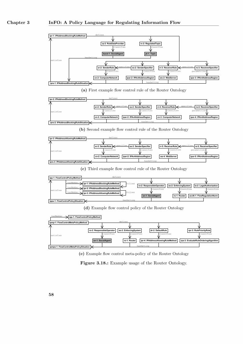
Chapter 3 InFO: A Policy Language for Regulating Information Flow
iprs-1: IPAddressBlockingRuleSituation
satisfies
ipr-1: IPAddressBlockingRuleMethod
rr-3: ReceiverRole
ws-2: WebServer
classifies
rs-3: ReceiverSpecifier
parametrizes
ss-2: SenderSpecifier
classifies
pt-1: Topic
rc-2: RegulatedTopic
classifies
kacst-1: SocialAgent
classifies
rp-2: RuleDataProvider
defines
hasSetting
sr-2: SenderRole
cn-2: ComputerNetwork
classifies
hasSetting
specifies specifies
ipar-2: IPAv4AddressRegion ipar-3: IPAv4AddressRegion
(a) First example flow control rule of the Router Ontology
iprs-2: IPAddressBlockingRuleSituation
satisfies
ipr-2: IPAddressBlockingRuleMethod
rr-4: ReceiverRole
cn-3: ComputerNetwork
classifies
rs-4: ReceiverSpecifier
parametrizes
ss-2: SenderSpecifier
classifies
sr-2: SenderRole
cn-2: ComputerNetwork
classifies
hasSetting
specifies specifies
defines
ipar-4: IPAv4AddressRegionipar-2: IPAv4AddressRegion
(b) Second example flow control rule of the Router Ontology
hasSettingiprs-3: IPAddressAllowingRuleSituation
satisfies
ipr-3: IPAddressAllowingRuleMethod
rr-5: ReceiverRole
ws-4: WebServer
classifies
rs-5: ReceiverSpecifier
defines
specifiesss-2: SenderSpecifier
classifies
sr-2: SenderRole
cn-2: ComputerNetwork
classifies
specifies
parametrizes
ipar-5: IPAv4AddressRegionipar-2: IPAv4AddressRegion
(c) Third example flow control rule of the Router Ontology
ipp-1: FlowControlPolicyMethod
ipps-1: FlowControlPolicySituation
ipr-3: IPAddressAllowingRuleMethod
satisfies
la-2: LegalAuthorizationipr-1: IPAddressBlockingRuleMethod
accl6-1: FlowRegulationNorm
classifies
followshasMember
hasMember
ro-2: ResponsibleOperator
classifies
sn-1: SocialAgent
es-2: EnforcingSystem
ro-1: Router
classifies
defines
hasSetting
ipr-2: IPAddressBlockingRuleMethodhasMember
follows
(d) Example flow control policy of the Router Ontology
ipmp-1: FlowControlMetaPolicyMethod
ipmps-1: FlowControlMetaPolicySituation
satisfies
ipp-1: FlowControlPolicyMethod
ipr-4: IPAddressAllowingRuleMethod
dr-2: DefaultRule
classifies
rpa-3: EvaluateRuleOrderingAlgorithm
rpr-3: RulePriorityRole
classifies
defines
hasSetting
hasMember
ro-2: ResponsibleOperator
classifies
sn-1: SocialAgent
es-2: EnforcingSystem
ro-1: Router
classifies
(e) Example flow control meta-policy of the Router Ontology
Figure 3.18.: Example usage of the Router Ontology.
58
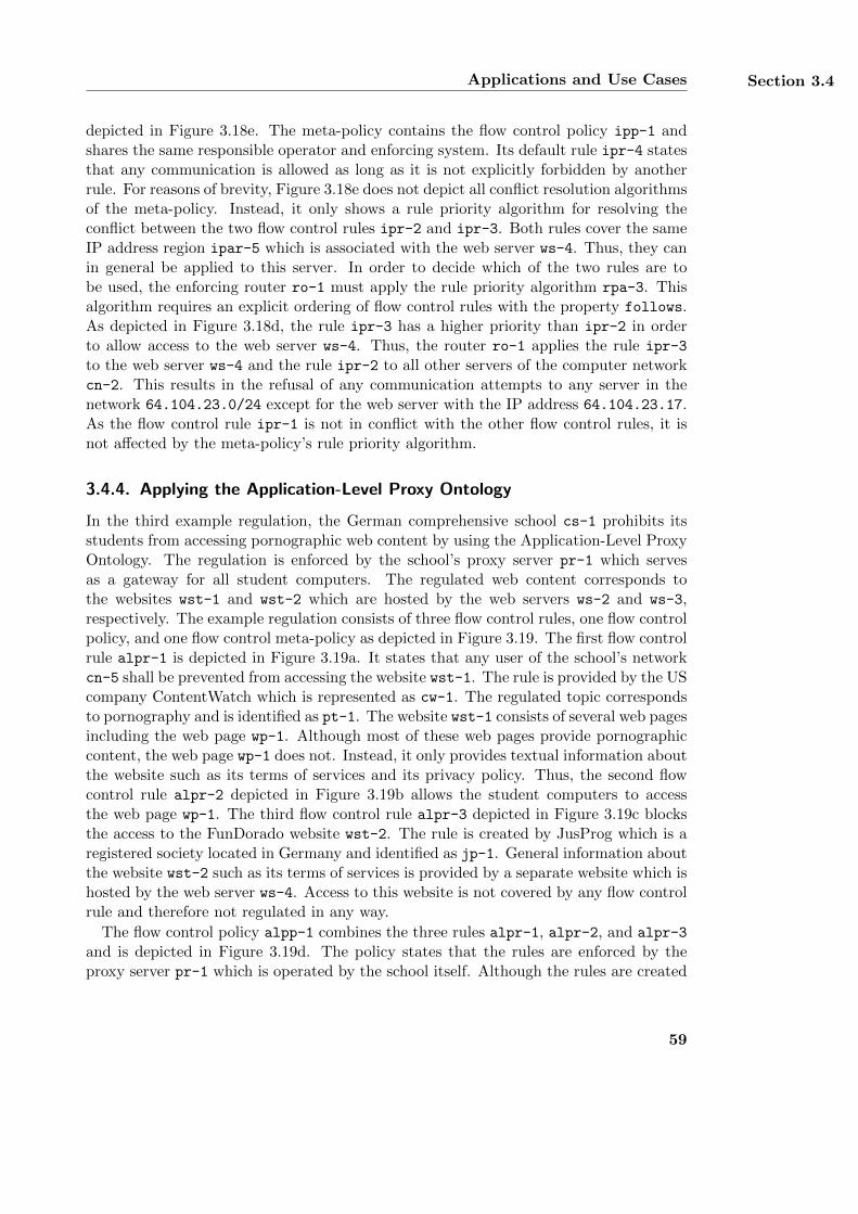
Applications and Use Cases Section 3.4
depicted in Figure 3.18e. The meta-policy contains the flow control policy ipp-1 andshares the same responsible operator and enforcing system. Its default rule ipr-4 statesthat any communication is allowed as long as it is not explicitly forbidden by anotherrule. For reasons of brevity, Figure 3.18e does not depict all conflict resolution algorithmsof the meta-policy. Instead, it only shows a rule priority algorithm for resolving theconflict between the two flow control rules ipr-2 and ipr-3. Both rules cover the sameIP address region ipar-5 which is associated with the web server ws-4. Thus, they canin general be applied to this server. In order to decide which of the two rules are tobe used, the enforcing router ro-1 must apply the rule priority algorithm rpa-3. Thisalgorithm requires an explicit ordering of flow control rules with the property follows.As depicted in Figure 3.18d, the rule ipr-3 has a higher priority than ipr-2 in orderto allow access to the web server ws-4. Thus, the router ro-1 applies the rule ipr-3
to the web server ws-4 and the rule ipr-2 to all other servers of the computer networkcn-2. This results in the refusal of any communication attempts to any server in thenetwork 64.104.23.0/24 except for the web server with the IP address 64.104.23.17.As the flow control rule ipr-1 is not in conflict with the other flow control rules, it isnot affected by the meta-policy’s rule priority algorithm.
3.4.4. Applying the Application-Level Proxy Ontology
In the third example regulation, the German comprehensive school cs-1 prohibits itsstudents from accessing pornographic web content by using the Application-Level ProxyOntology. The regulation is enforced by the school’s proxy server pr-1 which servesas a gateway for all student computers. The regulated web content corresponds tothe websites wst-1 and wst-2 which are hosted by the web servers ws-2 and ws-3,respectively. The example regulation consists of three flow control rules, one flow controlpolicy, and one flow control meta-policy as depicted in Figure 3.19. The first flow controlrule alpr-1 is depicted in Figure 3.19a. It states that any user of the school’s networkcn-5 shall be prevented from accessing the website wst-1. The rule is provided by the UScompany ContentWatch which is represented as cw-1. The regulated topic correspondsto pornography and is identified as pt-1. The website wst-1 consists of several web pagesincluding the web page wp-1. Although most of these web pages provide pornographiccontent, the web page wp-1 does not. Instead, it only provides textual information aboutthe website such as its terms of services and its privacy policy. Thus, the second flowcontrol rule alpr-2 depicted in Figure 3.19b allows the student computers to accessthe web page wp-1. The third flow control rule alpr-3 depicted in Figure 3.19c blocksthe access to the FunDorado website wst-2. The rule is created by JusProg which is aregistered society located in Germany and identified as jp-1. General information aboutthe website wst-2 such as its terms of services is provided by a separate website which ishosted by the web server ws-4. Access to this website is not covered by any flow controlrule and therefore not regulated in any way.
The flow control policy alpp-1 combines the three rules alpr-1, alpr-2, and alpr-3
and is depicted in Figure 3.19d. The policy states that the rules are enforced by theproxy server pr-1 which is operated by the school itself. Although the rules are created
59
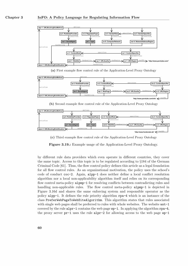
Chapter 3 InFO: A Policy Language for Regulating Information Flow
alprs-1: URLBlockingRuleSituation
satisfies
alpr-1: URLBlockingRuleMethod
cr-1: ContentRole
wst-1: WebSite
classifies
cs-1: ContentSpecifier
ur-1: URLRegion
parametrizes
pt-1: Topic
rc-2: RegulatedTopic
classifies
cw-1: SocialAgent
classifies
rp-3: RuleDataProvider
defines
hasSetting
hasSetting
specifies
ss-3: SenderSpecifier
nar-4: NetworkAddressRegion
classifies
sr-3: SenderRole
cn-5: ComputerNetwork
classifies
specifies
uq-1: URLQualityhasQuality hasRegion 'http://www.porntube.com/'hasURL
(a) First example flow control rule of the Application-Level Proxy Ontology
alprs-2: URLAllowingRuleSituation
satisfies
alpr-2: URLAllowingRuleMethod
cr-2: ContentRole
wp-1: WebPage
classifies
cts-2: ContentSpecifier
ur-2: URLRegion
classifies
rp-3: RuleDataProvider
classifies
defines
uq-2: URLQuality
'http://www.porntube.com/info'
hasQuality hasRegion
hasSetting
hasURL
specifies
cw-1: SocialAgent
(b) Second example flow control rule of the Application-Level Proxy Ontology
alprs-3: URLBlockingRuleSituation
satisfies
alpr-3: URLBlockingRuleMethod
cr-3: ContentRole
wst-2: WebSite
classifies
cts-3: ContentSpecifier
ur-3: URLRegion
classifies
rp-4: RuleDataProvider
classifies
defines
uq-3: URLQuality
'http://www.fundorado.de/'
hasQuality hasRegion
hasSetting
hasURL
specifies
jp-1: SocialAgent pt-1: Topic
rc-2: RegulatedTopic
classifies
(c) Third example flow control rule of the Application-Level Proxy Ontology
Figure 3.19.: Example usage of the Application-Level Proxy Ontology.
by different rule data providers which even operate in different countries, they coverthe same topic. Access to this topic is to be regulated according to §184 of the GermanCriminal Code [61]. Thus, the flow control policy defines this article as a legal foundationfor all flow control rules. As an organizational motivation, the policy uses the school’scode of conduct coc-2. Again, alpp-1 does neither define a local conflict resolutionalgorithm nor a local non-applicability algorithm itself and relies on its correspondingflow control meta-policy alpmp-1 for resolving conflicts between contradicting rules andhandling non-applicable rules. The flow control meta-policy alpmp-1 is depicted inFigure 3.16d and shares the same enforcing system and responsible operator as thepolicy alpp-1. It defines the rule priority algorithm rpa-4 which is an instance of theclass PreferWebPageToWebSiteAlgorithm. This algorithm states that rules associatedwith single web pages shall be preferred to rules with whole websites. The website wst-1covered by the rule alpr-1 contains the web page wp-1. In applying the algorithm rpa-4,the proxy server pr-1 uses the rule alpr-2 for allowing access to the web page wp-1
60
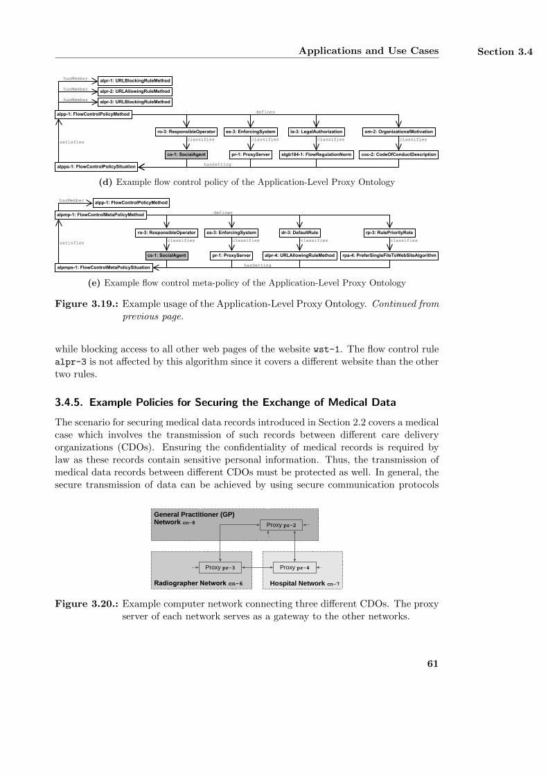
Applications and Use Cases Section 3.4
alpp-1: FlowControlPolicyMethod
alpps-1: FlowControlPolicySituation
alpr-2: URLAllowingRuleMethod
satisfies
la-3: LegalAuthorization
defines
coc-2: CodeOfConductDescription
om-2: OrganizationalMotivation
alpr-1: URLBlockingRuleMethod
classifies
stgb184-1: FlowRegulationNorm
classifies
hasSetting
hasMember
hasMember
ro-3: ResponsibleOperator
classifies
cs-1: SocialAgent
es-3: EnforcingSystem
pr-1: ProxyServer
classifies
alpr-3: URLBlockingRuleMethodhasMember
(d) Example flow control policy of the Application-Level Proxy Ontology
alpmp-1: FlowControlMetaPolicyMethod
alpmps-1: FlowControlMetaPolicySituation
satisfies
alpp-1: FlowControlPolicyMethod
alpr-4: URLAllowingRuleMethod
dr-3: DefaultRule
classifies
rpa-4: PreferSingleFileToWebSiteAlgorithm
rp-3: RulePriorityRole
classifies
defines
hasSetting
hasMember
ro-3: ResponsibleOperator
classifies
cs-1: SocialAgent
es-3: EnforcingSystem
pr-1: ProxyServer
classifies
(e) Example flow control meta-policy of the Application-Level Proxy Ontology
Figure 3.19.: Example usage of the Application-Level Proxy Ontology. Continued fromprevious page.
while blocking access to all other web pages of the website wst-1. The flow control rulealpr-3 is not affected by this algorithm since it covers a different website than the othertwo rules.
3.4.5. Example Policies for Securing the Exchange of Medical Data
The scenario for securing medical data records introduced in Section 2.2 covers a medicalcase which involves the transmission of such records between different care deliveryorganizations (CDOs). Ensuring the confidentiality of medical records is required bylaw as these records contain sensitive personal information. Thus, the transmission ofmedical data records between different CDOs must be protected as well. In general, thesecure transmission of data can be achieved by using secure communication protocols
Radiographer Network cn-6 Hospital Network cn-7
Proxy pr-4
General Practitioner (GP)Network cn-8 Proxy pr-2
Proxy pr-3
Figure 3.20.: Example computer network connecting three different CDOs. The proxyserver of each network serves as a gateway to the other networks.
61
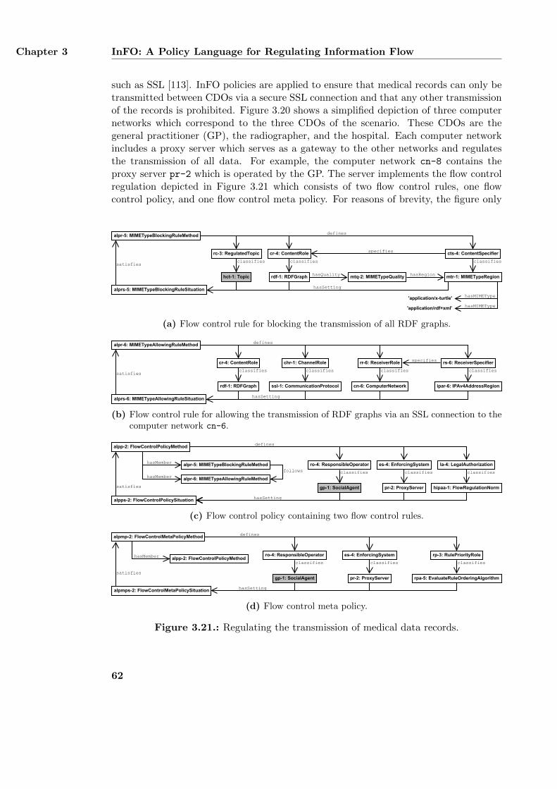
Chapter 3 InFO: A Policy Language for Regulating Information Flow
such as SSL [113]. InFO policies are applied to ensure that medical records can only betransmitted between CDOs via a secure SSL connection and that any other transmissionof the records is prohibited. Figure 3.20 shows a simplified depiction of three computernetworks which correspond to the three CDOs of the scenario. These CDOs are thegeneral practitioner (GP), the radiographer, and the hospital. Each computer networkincludes a proxy server which serves as a gateway to the other networks and regulatesthe transmission of all data. For example, the computer network cn-8 contains theproxy server pr-2 which is operated by the GP. The server implements the flow controlregulation depicted in Figure 3.21 which consists of two flow control rules, one flowcontrol policy, and one flow control meta policy. For reasons of brevity, the figure only
alprs-5: MIMETypeBlockingRuleSituation
satisfies
alpr-5: MIMETypeBlockingRuleMethod defines
hasSetting
hct-1: Topic
rc-3: RegulatedTopic
classifies
cr-4: ContentRole
rdf-1: RDFGraph
classifies
cts-4: ContentSpecifier
mtr-1: MIMETypeRegion
classifies
mtq-2: MIMETypeQuality
'application/rdf+xml'
hasQuality hasRegion
specifies
'application/x-turtle' hasMIMEType
hasMIMEType
(a) Flow control rule for blocking the transmission of all RDF graphs.
alprs-6: MIMETypeAllowingRuleSituation
satisfies
alpr-6: MIMETypeAllowingRuleMethod
chr-1: ChannelRole
ssl-1: CommunicationProtocol
classifies
rs-6: ReceiverSpecifier
ipar-6: IPAv4AddressRegion
classifies
defines
hasSetting
cr-4: ContentRole
rdf-1: RDFGraph
classifies
rr-6: ReceiverRole
cn-6: ComputerNetwork
classifies
specifies
(b) Flow control rule for allowing the transmission of RDF graphs via an SSL connection to thecomputer network cn-6.
alpp-2: FlowControlPolicyMethod
alpps-2: FlowControlPolicySituation
alpr-6: MIMETypeAllowingRuleMethod
satisfies
alpr-5: MIMETypeBlockingRuleMethodhasMember
hasMember
ro-4: ResponsibleOperator
classifies
gp-1: SocialAgent
es-4: EnforcingSystem
pr-2: ProxyServer
classifies
defines
hasSetting
follows la-4: LegalAuthorization
hipaa-1: FlowRegulationNorm
classifies
(c) Flow control policy containing two flow control rules.
alpmp-2: FlowControlMetaPolicyMethod
alpmps-2: FlowControlMetaPolicySituation
alpp-2: FlowControlPolicyMethod
rpa-5: EvaluateRuleOrderingAlgorithm
rp-3: RulePriorityRole
classifieshasMember ro-4: ResponsibleOperator
classifies
gp-1: SocialAgent
es-4: EnforcingSystem
pr-2: ProxyServer
classifies
defines
hasSetting
satisfies
(d) Flow control meta policy.
Figure 3.21.: Regulating the transmission of medical data records.
62
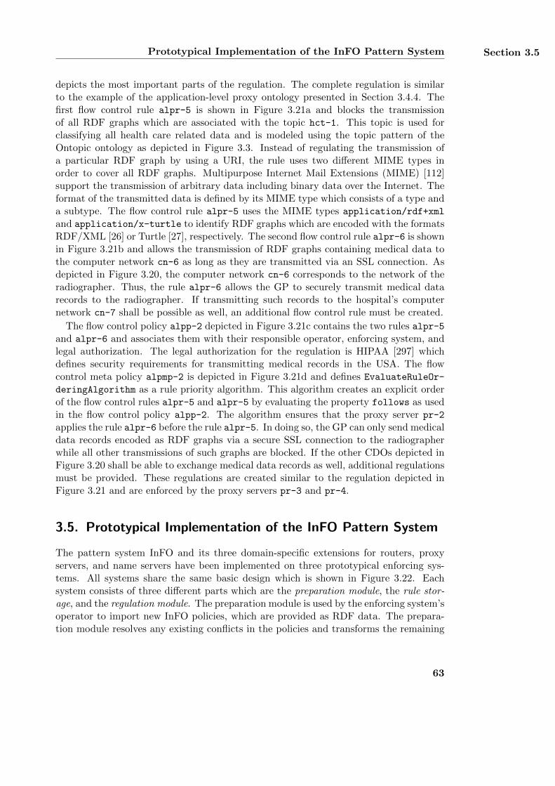
Prototypical Implementation of the InFO Pattern System Section 3.5
depicts the most important parts of the regulation. The complete regulation is similarto the example of the application-level proxy ontology presented in Section 3.4.4. Thefirst flow control rule alpr-5 is shown in Figure 3.21a and blocks the transmissionof all RDF graphs which are associated with the topic hct-1. This topic is used forclassifying all health care related data and is modeled using the topic pattern of theOntopic ontology as depicted in Figure 3.3. Instead of regulating the transmission ofa particular RDF graph by using a URI, the rule uses two different MIME types inorder to cover all RDF graphs. Multipurpose Internet Mail Extensions (MIME) [112]support the transmission of arbitrary data including binary data over the Internet. Theformat of the transmitted data is defined by its MIME type which consists of a type anda subtype. The flow control rule alpr-5 uses the MIME types application/rdf+xml
and application/x-turtle to identify RDF graphs which are encoded with the formatsRDF/XML [26] or Turtle [27], respectively. The second flow control rule alpr-6 is shownin Figure 3.21b and allows the transmission of RDF graphs containing medical data tothe computer network cn-6 as long as they are transmitted via an SSL connection. Asdepicted in Figure 3.20, the computer network cn-6 corresponds to the network of theradiographer. Thus, the rule alpr-6 allows the GP to securely transmit medical datarecords to the radiographer. If transmitting such records to the hospital’s computernetwork cn-7 shall be possible as well, an additional flow control rule must be created.
The flow control policy alpp-2 depicted in Figure 3.21c contains the two rules alpr-5and alpr-6 and associates them with their responsible operator, enforcing system, andlegal authorization. The legal authorization for the regulation is HIPAA [297] whichdefines security requirements for transmitting medical records in the USA. The flowcontrol meta policy alpmp-2 is depicted in Figure 3.21d and defines EvaluateRuleOr-
deringAlgorithm as a rule priority algorithm. This algorithm creates an explicit orderof the flow control rules alpr-5 and alpr-5 by evaluating the property follows as usedin the flow control policy alpp-2. The algorithm ensures that the proxy server pr-2
applies the rule alpr-6 before the rule alpr-5. In doing so, the GP can only send medicaldata records encoded as RDF graphs via a secure SSL connection to the radiographerwhile all other transmissions of such graphs are blocked. If the other CDOs depicted inFigure 3.20 shall be able to exchange medical data records as well, additional regulationsmust be provided. These regulations are created similar to the regulation depicted inFigure 3.21 and are enforced by the proxy servers pr-3 and pr-4.
3.5. Prototypical Implementation of the InFO Pattern System
The pattern system InFO and its three domain-specific extensions for routers, proxyservers, and name servers have been implemented on three prototypical enforcing sys-tems. All systems share the same basic design which is shown in Figure 3.22. Eachsystem consists of three different parts which are the preparation module, the rule stor-age, and the regulation module. The preparation module is used by the enforcing system’soperator to import new InFO policies, which are provided as RDF data. The prepara-tion module resolves any existing conflicts in the policies and transforms the remaining
63
Chapter 3 InFO: A Policy Language for Regulating Information Flow
Enforcing System
Policies RuleStorage
PreparationModule
RegulationModule
Figure 3.22.: Basic architecture of the prototypical implementations of the three en-forcing systems. The arrows indicate the direction of the flow of regula-tion data.
policy rules to a simpler data structure. This data structure is stored in the rule storageand can be directly interpreted by the enforcing system. The regulation module per-forms the actual regulation by applying the transformed rules of the rule storage. Themodule interacts with the users that are affected by the regulation. All three enforcingsystems are based on a common preparation module which is implemented in Java anduses the Jena triple store13. In contrast, the implementation details of the rule storageand the regulation module depend on the corresponding enforcing system. The followingsubsections describe the prototypical implementations of the three enforcing systems inmore detail.
3.5.1. Example Name Server Implementation
The Name Server Ontology has been implemented as a prototypical, modified nameserver. The preparation module of this name server transforms the InFO policies into aset of DNS resource records [202]. Resource records are the data format of the domainname system and store information about domain names and IP addresses. A resourcerecord contains a domain name, a type, and a value. The value of a resource recorddepends on the record’s type and can be, e. g., an IP address, an alternative domainname, or a textual description. Resource records are stored in zone files which arebasically collections of resource records of the same domain. In the prototypical nameserver, these zone files correspond to the server’s rule storage and are directly used bythe regulation module. The regulation module operates as a name server and answersIP address requests from users. Such requests contain a domain name and ask for thecorresponding IP address. If the domain name is not regulated, the regulation modulereturns the correct IP address. Otherwise, the result depends on the type of regulationand can contain a wrong IP address or no IP address at all. The implementation of theregulation module is based on the Java name server EagleDNS14 and described in moredetail in [204].
13http://jena.apache.org, last accessed: 01/21/1614http://www.unlogic.se/projects/eagledns, last accessed: 01/21/16
64
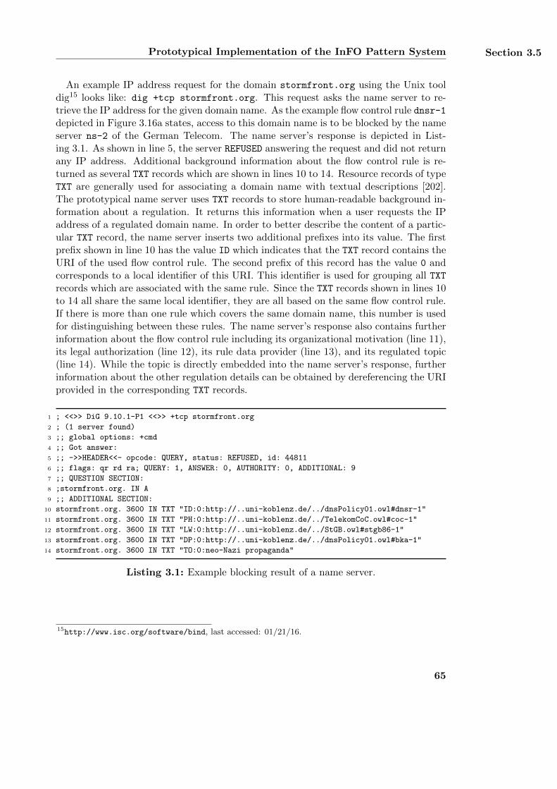
Prototypical Implementation of the InFO Pattern System Section 3.5
An example IP address request for the domain stormfront.org using the Unix tooldig15 looks like: dig +tcp stormfront.org. This request asks the name server to re-trieve the IP address for the given domain name. As the example flow control rule dnsr-1depicted in Figure 3.16a states, access to this domain name is to be blocked by the nameserver ns-2 of the German Telecom. The name server’s response is depicted in List-ing 3.1. As shown in line 5, the server REFUSED answering the request and did not returnany IP address. Additional background information about the flow control rule is re-turned as several TXT records which are shown in lines 10 to 14. Resource records of typeTXT are generally used for associating a domain name with textual descriptions [202].The prototypical name server uses TXT records to store human-readable background in-formation about a regulation. It returns this information when a user requests the IPaddress of a regulated domain name. In order to better describe the content of a partic-ular TXT record, the name server inserts two additional prefixes into its value. The firstprefix shown in line 10 has the value ID which indicates that the TXT record contains theURI of the used flow control rule. The second prefix of this record has the value 0 andcorresponds to a local identifier of this URI. This identifier is used for grouping all TXTrecords which are associated with the same rule. Since the TXT records shown in lines 10to 14 all share the same local identifier, they are all based on the same flow control rule.If there is more than one rule which covers the same domain name, this number is usedfor distinguishing between these rules. The name server’s response also contains furtherinformation about the flow control rule including its organizational motivation (line 11),its legal authorization (line 12), its rule data provider (line 13), and its regulated topic(line 14). While the topic is directly embedded into the name server’s response, furtherinformation about the other regulation details can be obtained by dereferencing the URIprovided in the corresponding TXT records.
1 ; <<>> DiG 9.10.1-P1 <<>> +tcp stormfront.org
2 ; (1 server found)
3 ;; global options: +cmd
4 ;; Got answer:
5 ;; ->>HEADER<<- opcode: QUERY, status: REFUSED, id: 44811
6 ;; flags: qr rd ra; QUERY: 1, ANSWER: 0, AUTHORITY: 0, ADDITIONAL: 9
7 ;; QUESTION SECTION:
8 ;stormfront.org. IN A
9 ;; ADDITIONAL SECTION:
10 stormfront.org. 3600 IN TXT "ID:0:http://..uni-koblenz.de/../dnsPolicy01.owl#dnsr-1"
11 stormfront.org. 3600 IN TXT "PH:0:http://..uni-koblenz.de/../TelekomCoC.owl#coc-1"
12 stormfront.org. 3600 IN TXT "LW:0:http://..uni-koblenz.de/../StGB.owl#stgb86-1"
13 stormfront.org. 3600 IN TXT "DP:0:http://..uni-koblenz.de/../dnsPolicy01.owl#bka-1"
14 stormfront.org. 3600 IN TXT "TO:0:neo-Nazi propaganda"
Listing 3.1: Example blocking result of a name server.
15http://www.isc.org/software/bind, last accessed: 01/21/16.
65
Chapter 3 InFO: A Policy Language for Regulating Information Flow
3.5.2. Example Router Implementation
The Router Ontology has been implemented as a set of routers, which are configuredvia a dedicated administration node. This node serves as the preparation module whichtransforms all InFO policies into a configuration script for the Linux firewall softwareiptables16. The administration node sends the configuration script to all connectedrouters via an encrypted SSL connection [113]. The iptables software runs on all routers.After having received the configuration script, each router applies the script in order toupdate the current configuration of its local iptables installation. The iptables softwareconsists of a packet filter and several tables which store the active firewall rules. Thetables correspond to the rule storage and the packet filter is directly used as the regulationmodule. Thus, an additional implementation of the regulation module is not required. Ifa user wants to access a prohibited IP address, she receives an Internet Control MessageProtocol (ICMP) [236] message that informs about the regulation. ICMP is specificallydesigned for exchanging information messages and error messages between IP-basedcommunication nodes. The ICMP message is encapsulated in an IP message and sendback to the original requester. The sender of this message is the router implementingthe flow control. All routers and their administration node are implemented in Java anddescribed in more detail in [311].
Listing 3.2 shows an ICMP message after a user with the IP address 89.108.23.155
has tried to access the server with the IP address 104.20.26.14. The message wascaptured with the packet analyzing software Wireshark17 and slightly modified for il-lustration. The user is connected to the Internet via the Saudi Arabian access providerSahara Net. The server is located in the USA and provides pornographic content. Ac-cording to the example flow control rule ipr-1 shown in Figure 3.18a, access to thisserver is to be blocked for all users of Sahara Net. As depicted in the example net-work in Figure 3.14, the users of Sahara Net communicate with the Internet throughthe gateway router ro-1 with the IP address 89.108.200.111. This router acts asthe enforcing system which implements the example regulation shown in Figure 3.18.Lines 1 to 5 of Listing 3.2 show the header of the IP packet which encapsulates theICMP message. Line 2 states that the sender of the ICMP message was the enforc-ing router and line 3 indicates that the receiver was the user of Sahara Net. Lines 6to 18 cover the actual ICMP message. The meaning of an ICMP message is generallydefined by its type and code. The type defines the category of the message and thecode further specifies the particular reason for sending the message. Line 7 states thatthe server with the IP address 104.20.26.14 was unreachable due to administrativefiltering as explained in line 8. The ICMP message also contains the header of the orig-inal request which is shown in lines 9 to 15. The request consists of the IP header andthe TCP header. As depicted in the example network in Figure 3.14, the IP address104.20.26.14 corresponds to the server hosting the website http://porntube.com/.The lines 12 and 15 further describe this server as a web server since such a server typi-cally uses the port number 80 and the transport layer protocol TCP. The data section
16http://www.netfilter.org/projects/iptables/, last accessed: 01/21/1617http://www.wireshark.org/, last accessed: 01/21/16
66
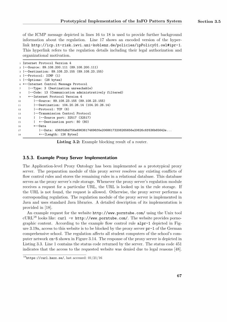
Prototypical Implementation of the InFO Pattern System Section 3.5
of the ICMP message depicted in lines 16 to 18 is used to provide further backgroundinformation about the regulation. Line 17 shows an encoded version of the hyper-link http://icp.it-risk.iwvi.uni-koblenz.de/policies/ipPolicy01.owl#ipr-1.This hyperlink refers to the regulation details including their legal authorization andorganizational motivation.
1 Internet Protocol Version 4
2 |--Source: 89.108.200.111 (89.108.200.111)
3 |--Destination: 89.108.23.155 (89.108.23.155)
4 |--Protocol: ICMP (1)
5 |--Options: (28 bytes)
6 +--Internet Control Message Protocol
7 |--Type: 3 (Destination unreachable)
8 |--Code: 13 (Communication administratively filtered)
9 +--Internet Protocol Version 4
10 |--Source: 89.108.23.155 (89.108.23.155)
11 |--Destination: 104.20.26.14 (104.20.26.14)
12 |--Protocol: TCP (6)
13 |--Transmission Control Protocol
14 | |--Source port: 32517 (32517)
15 | +--Destination port: 80 (80)
16 +--Data
17 |--Data: 436f6d6d756e69636174696f6e20686173206265656e20626c6f636b65642e...
18 +--[Length: 126 Bytes]
Listing 3.2: Example blocking result of a router.
3.5.3. Example Proxy Server Implementation
The Application-level Proxy Ontology has been implemented as a prototypical proxyserver. The preparation module of this proxy server resolves any existing conflicts offlow control rules and stores the remaining rules in a relational database. This databaseserves as the proxy server’s rule storage. Whenever the proxy server’s regulation modulereceives a request for a particular URL, the URL is looked up in the rule storage. Ifthe URL is not found, the request is allowed. Otherwise, the proxy server performs acorresponding regulation. The regulation module of the proxy server is implemented inJava and uses standard Java libraries. A detailed description of its implementation isprovided in [18].
An example request for the website http://www.porntube.com/ using the Unix toolcURL18 looks like: curl -v http://www.porntube.com/. The website provides porno-graphic content. According to the example flow control rule alpr-1 depicted in Fig-ure 3.19a, access to this website is to be blocked by the proxy server pr-1 of the Germancomprehensive school. The regulation affects all student computers of the school’s com-puter network cn-5 shown in Figure 3.14. The response of the proxy server is depicted inListing 3.3. Line 1 contains the status code returned by the server. The status code 451indicates that the access to the requested website was denied due to legal reasons [48].
18https://curl.haxx.se/, last accessed: 01/21/16
67
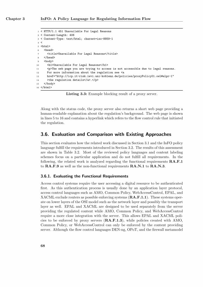
Chapter 3 InFO: A Policy Language for Regulating Information Flow
1 < HTTP/1.1 451 Unavailable For Legal Reasons
2 < Content-Length: 406
3 < Content-Type: text/html; charset=iso-8859-1
4 <
5 <html>
6 <head>
7 <title>Unavailable For Legal Reasons</title>
8 </head>
9 <body>
10 <h1>Unavailable For Legal Reasons</h1>
11 <p>The web page you are trying to access is not accessible due to legal reasons.
12 For more information about the regulation see <a
13 href="http://icp.it-risk.iwvi.uni-koblenz.de/policies/proxyPolicy01.owl#alpr-1"
14 >the regulation details</a>.</p>
15 </body>
16 </html>
Listing 3.3: Example blocking result of a proxy server.
Along with the status code, the proxy server also returns a short web page providing ahuman-readable explanation about the regulation’s background. The web page is shownin lines 5 to 16 and contains a hyperlink which refers to the flow control rule that initiatedthe regulation.
3.6. Evaluation and Comparison with Existing Approaches
This section evaluates how the related work discussed in Section 3.1 and the InFO policylanguage fulfill the requirements introduced in Section 3.2. The results of this assessmentare shown in Table 3.2. Most of the reviewed policy languages and content labelingschemes focus on a particular application and do not fulfill all requirements. In thefollowing, the related work is analyzed regarding the functional requirements RA.F.1to RA.F.9 as well as the non-functional requirements RA.N.1 to RA.N.3.
3.6.1. Evaluating the Functional Requirements
Access control systems require the user accessing a digital resource to be authenticatedfirst. As this authentication process is usually done by an application layer protocol,access control languages such as AMO, Common Policy, WebAccessControl, EPAL, andXACML exclude routers as possible enforcing systems (RA.F.1.1). These systems oper-ate on lower layers of the OSI model such as the network layer and possibly the transportlayer as well. EPAL and XACML are designed to be used separately from the serverproviding the regulated content while AMO, Common Policy, and WebAccessControlrequire a more close integration with the server. This allows EPAL and XACML poli-cies to be enforced by proxy servers (RA.F.1.3), while policies created with AMO,Common Policy, or WebAccessControl can only be enforced by the content providingserver. Although the flow control languages DEN-ng, OPoT, and the firewall metamodel
68
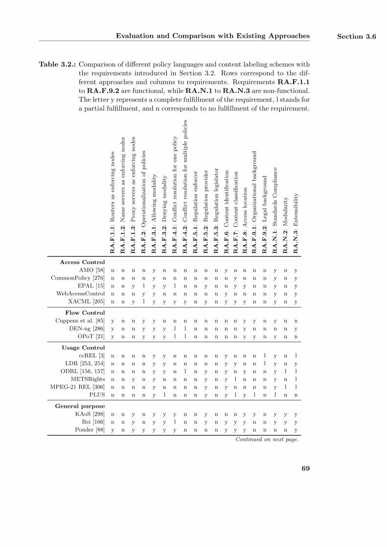
Evaluation and Comparison with Existing Approaches Section 3.6
Table 3.2.: Comparison of different policy languages and content labeling schemes withthe requirements introduced in Section 3.2. Rows correspond to the dif-ferent approaches and columns to requirements. Requirements RA.F.1.1to RA.F.9.2 are functional, while RA.N.1 to RA.N.3 are non-functional.The letter y represents a complete fulfillment of the requirement, l stands fora partial fulfillment, and n corresponds to no fulfillment of the requirement.
RA.F
.1.1
:R
oute
rsas
enfo
rcin
gnodes
RA.F
.1.2
:N
am
ese
rver
sas
enfo
rcin
gnodes
RA.F
.1.3
:P
roxy
serv
ers
as
enfo
rcin
gnodes
RA.F
.2:
Op
erati
onaliza
tion
of
polici
es
RA.F
.3.1
:A
llow
ing
modality
RA.F
.3.2
:D
enyin
gm
odality
RA.F
.4.1
:C
onflic
tre
solu
tion
for
one
policy
RA.F
.4.2
:C
onflic
tre
solu
tion
for
mult
iple
polici
es
RA.F
.5.1
:R
egula
tion
enfo
rcer
RA.F
.5.2
:R
egula
tion
pro
vid
er
RA.F
.5.3
:R
egula
tion
legis
lato
r
RA.F
.6:
Conte
nt
iden
tifica
tion
RA.F
.7:
Conte
nt
class
ifica
tion
RA.F
.8:
Acc
ess
loca
tion
RA.F
.9.1
:O
rganiz
ati
onal
back
gro
und
RA.F
.9.2
:L
egal
back
gro
und
RA.N
.1:
Sta
ndard
sC
om
pliance
RA.N
.2:
Modula
rity
RA.N
.3:
Exte
nsi
bilit
y
Access Control
AMO [58] n n n n y n n n n n n y n n n n y n y
CommonPolicy [276] n n n n y n n n n n n n y n n n y n y
EPAL [15] n n y l y y l n n y n n y y n n y n y
WebAccessControl n n n y y n n n n n n y n n n n y n y
XACML [205] n n y l y y y y n y n y y y n n y n y
Flow Control
Cuppens et al. [85] y n n y y n n n n n n n n y y n y n n
DEN-ng [286] y n n y y y l l n n n n n y n n n n y
OPoT [21] y n n y y y l l n n n n n y y n y n n
Usage Control
ccREL [3] n n n n y y n n n n n y n n n l y n l
LDR [253, 254] n n n n y y n n n n n y y n n l y n y
ODRL [156, 157] n n n n y y n l n y n y n y n n y l l
METSRights n n y n y n n n n y n y l n n n y n l
MPEG-21 REL [306] n n n n y n n n n y n y n n n n y l l
PLUS n n n n y l n n n y n y l y l n l n n
General purpose
KAoS [298] n n y n y y y n n y n n n y y n y y y
Rei [166] n n y n y y l n n y n y y y n n y y y
Ponder [88] y n y y y y y n n n n y y y n n n n y
Continued on next page.
69
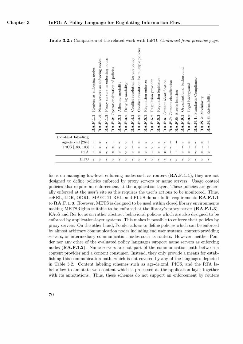
Chapter 3 InFO: A Policy Language for Regulating Information Flow
Table 3.2.: Comparison of the related work with InFO. Continued from previous page.
RA.F
.1.1
:R
oute
rsas
enfo
rcin
gnodes
RA.F
.1.2
:N
am
ese
rver
sas
enfo
rcin
gnodes
RA.F
.1.3
:P
roxy
serv
ers
as
enfo
rcin
gnodes
RA.F
.2:
Op
erati
onaliza
tion
of
polici
es
RA.F
.3.1
:A
llow
ing
modality
RA.F
.3.2
:D
enyin
gm
odality
RA.F
.4.1
:C
onflic
tre
solu
tion
for
one
policy
RA.F
.4.2
:C
onflic
tre
solu
tion
for
mult
iple
polici
es
RA.F
.5.1
:R
egula
tion
enfo
rcer
RA.F
.5.2
:R
egula
tion
pro
vid
er
RA.F
.5.3
:R
egula
tion
legis
lato
r
RA.F
.6:
Conte
nt
iden
tifica
tion
RA.F
.7:
Conte
nt
class
ifica
tion
RA.F
.8:
Acc
ess
loca
tion
RA.F
.9.1
:O
rganiz
ati
onal
back
gro
und
RA.F
.9.2
:L
egal
back
gro
und
RA.N
.1:
Sta
ndard
sC
om
pliance
RA.N
.2:
Modula
rity
RA.N
.3:
Exte
nsi
bilit
y
Content labeling
age-de.xml [264] n n y l y y l n n y n y l l n n y n l
PICS [183, 103] n n y n y y l n n y n y y n l l l l l
RTA n n y n n y n n n l n n l n n n y n n
InFO y y y y y y y y y y y y y y y y y y y
focus on managing low-level enforcing nodes such as routers (RA.F.1.1), they are notdesigned to define policies enforced by proxy servers or name servers. Usage controlpolicies also require an enforcement at the application layer. These policies are gener-ally enforced at the user’s site as this requires the user’s actions to be monitored. Thus,ccREL, LDR, ODRL, MPEG-21 REL, and PLUS do not fulfill requirements RA.F.1.1to RA.F.1.3. However, METS is designed to be used within closed library environmentsmaking METSRights suitable to be enforced at the library’s proxy server (RA.F.1.3).KAoS and Rei focus on rather abstract behavioral policies which are also designed to beenforced by application-layer systems. This makes it possible to enforce their policies byproxy servers. On the other hand, Ponder allows to define policies which can be enforcedby almost arbitrary communication nodes including end user systems, content-providingservers, or intermediary communication nodes such as routers. However, neither Pon-der nor any other of the evaluated policy languages support name servers as enforcingnodes (RA.F.1.2). Name servers are not part of the communication path between acontent provider and a content consumer. Instead, they only provide a means for estab-lishing this communication path, which is not covered by any of the languages depictedin Table 3.2. Content labeling schemes such as age-de.xml, PICS, and the RTA la-bel allow to annotate web content which is processed at the application layer togetherwith its annotations. Thus, these schemes do not support an enforcement by routers
70
Evaluation and Comparison with Existing Approaches Section 3.6
or name servers and do not fulfill requirements RA.F.1.1 and RA.F.1.2. As both theweb content and their annotations can be interpreted by proxy servers, content label-ing schemes fulfill requirement RA.F.1.3. InFO supports different enforcing systemsincluding routers, name servers, and proxy servers. Each enforcing system is supportedby a specific domain ontology such as the Router Ontology, the Name Server Ontology,and the Application-Level Proxy Ontology.
Many of the examined policy languages and content labeling schemes define rather ab-stract rules whose enforcement cannot be directly mapped onto the enforcing systems’capabilities. Instead, the enforcement requires additional parameters and a further in-terpretation of how to interpret the policy’s actual meaning. These parameters aresometimes not included in the policy directly (RA.F.2) and must therefore be addedthrough a different process. Although policies created with AMO or Common Policycontain a reference to those users who are allowed to access a specific piece of infor-mation, they do not define how the users shall be authenticated. EPAL and XACMLprovide such a description but do not explicitly define the rest of the enforcement pro-cedure. WebAccessControl requires user identification via the WebID authenticationprocess. Usage control only describes on an abstract level what a user may do with adigital resource. However, usage control languages do not define how the permitted orprohibited actions shall actually be regulated. For example, it is unclear how a permis-sion to print a text document is to be technically enforced. Thus, the evaluated usagecontrol policies do not fulfill requirement RA.F.2. Since the general purpose languagesRei and KAoS also define rather abstract policies and not their specific enforcement,they also do not fulfill requirement RA.F.2. However, Ponder’s low-level language canbe directly used for enforcing mechanisms. Although content labeling schemes are de-signed to block the access to web content based on their annotations, most schemes donot define how the blocking procedure shall actually be implemented. age-de.xml allowsto redirect all requests to another website instead of just blocking the access. However,it does not support a precise definition of how the redirection or the default blockingbehavior shall be technically implemented. On the other hand, flow control languagesare specifically designed for a direct enforcement of policies. Each created policy alreadycontains enough information to be enforced without requiring any additional interpre-tation or parameters. Similarly, InFO is also designed for enforcing particular policies.Support for a precise description of all enforcement parameters are provided by the do-main extensions of InFO such as the Router Ontology, the Name Server Ontology, andthe Application-Level Proxy Ontology.
All policy languages for access control, usage control, and flow control as well as allgeneral purpose languages shown in Table 3.2 support allowing rules and thus fulfillrequirement RA.F.3.1. Allowing rules are also supported by PICSRules. age-de.xmlsupports allowing rules by annotating web content with the all ages category. In contrast,the RTA label does not fulfill requirement RA.F.3.1 as it represents a single age categorywhich results in the blocking of the annotated content. In order to ease the creation ofspecific policies, some languages such as AMO, Common Policy, WebAccessControl, andthe firewall metamodel do not support denying rules (RA.F.3.2) and focus on allowingrules only. In doing so, these languages completely avoid potential conflicts between
71
Chapter 3 InFO: A Policy Language for Regulating Information Flow
two or more contradicting rules. Thus, they do not provide any means for resolvingsuch conflicts (requirements RA.F.4.1 and RA.F.4.2). Similarly, the RTA label onlyprovides a means for denying access and does not require any conflict resolution algorithmas well. PLUS only supports allowing rules and expresses denying rules as constraints onsuch a rule. Consequently, the support for denying rules is only limited and the languagedoes not support any conflict resolution mechanism. InFO allows to create both allowingand denying rules as well as specific types of denying rules. The different types of rulesare provided by the Flow Control Rule Pattern as well as the Redirecting Flow ControlRule Pattern and the Replacing Flow Control Rule Pattern described in Section 3.3.3.
The usage control policy languages ccREL and LDR assume that there is only onepolicy for each regulated good which is created by its owner. Thus, the languages do notprovide any means for resolving conflicts between contradicting rules. EPAL, Rei, andPICSRules only provide the order of rules as a mechanism for resolving conflicts betweenrules of the same policy (RA.F.4.1). Since all three languages support only one activepolicy, they do not provide any means for resolving conflicts between rules of differentpolicies (RA.F.4.2). Similarly, age-de.xml uses the order of the defined age categoriesfor a single web page to resolve any conflicts between contradicting categories. DEN-ngalso uses the order of rules for resolving conflicts between them. Additionally, policies canalso be ordered to resolve conflicts between rules of different policies. OPoT is only ableto detect conflicting rules of one or more policies and shows them to the policy’s creator.The actual conflict resolution must be performed manually by the creator of the policy.ODRL assumes that a single policy does not contain any conflicting rules. Since eachpolicy is created by a single party, the party must pay attention when creating the policy.On the other hand, resolving conflicts between rules of different policies is supportedby ODRL. This is done by either preferring the allowing or the denying rule of twocontradicting rules. However, the preferred rule modality is defined within each policy.Thus, ODRL’s conflict resolution algorithm only works if all affected policies prefer thesame modality. Otherwise, conflicts cannot be resolved [24]. XACML and Ponder allowto define specific conflict resolution algorithms which provide a much greater flexibilitythan a simple order of rules. These algorithms can be used for resolving conflicts betweenrules of one or more policies. KAoS also provides algorithms for resolving conflicts. SinceKAoS only supports one active policy, these algorithms can only be used for contradictingrules of one policy. The conflict resolution mechanisms of InFO are inspired by XACML.Similar to XACML and Ponder, InFO allows to resolve conflicts between contradictingrules of one or multiple policies based on predefined or user-defined algorithms. TheFlow Control Meta-Policy Pattern described in Section 3.3.5 is especially designed forexpressing such algorithms and thus for resolving conflicts as well. The pattern alsosplits the whole conflict resolution process of XACML and Ponder into four differentsteps and assigns a particular algorithm to each step. This achieves a greater flexibilityas some algorithms can be reused for different enforcing systems while others must bereplaced with more specific algorithms.
Most of the discussed policy languages do not distinguish between a policy’s creator(i. e. the provider) and its enforcer. Languages like EPAL, XACML, ODRL, METS-Rights, MPEG-21 REL, PLUS, KAoS, Rei, and PICSRules, which allow naming a pol-
72
Evaluation and Comparison with Existing Approaches Section 3.6
icy’s provider within the policy itself (RA.F.5.2), do not allow to name a separateenforcer (RA.F.5.1). Similarly, the content labeling scheme age-de.xml only supportsproviders of age categories. However, InFO explicitly requires such a distinction as out-lined in the scenario for regulating Internet communication of Section 2.1. Support for aregulation’s provider is given as the rule data provider defined in the Flow Control RulePattern and a means for defining the regulation’s enforcer is given in the Flow ControlPolicy Pattern described in Section 3.3.4.
Most of the reviewed policy languages are not able to link a policy to its legal back-ground (RA.F.9.2). Consequently, they do not allow to specify the legislator of thepolicy’s legal background (RA.F.5.3). Both ccREL and LDR allow policies to be linkedto their jurisdiction. This jurisdiction defines the circumstances under which a policy isvalid and may even add additional permissions or prohibitions. However, the jurisdictiononly refers to a country’s legislation and not to particular laws. Identifying the creatorsof this legislation is neither supported by ccREL nor by LDR. InFO supports both re-lating a flow control to its legal background and the definition of a legislator as well.The legal background is described by the Flow Regulation Norm Pattern introduced inSection 3.3.6 and the legislator is part of the Legislation Pattern. By linking technicalpolicies to their legal background, InFO allows a better comparison between differentpolicies of various enforcing systems.
The identification and classification of content (RA.F.6) is only supported by thosepolicy languages which are directly able to regulate the processing of particular infor-mation documents rather than whole systems or services only. Such languages includeaccess control and usage control languages as well as most general purpose languages.Both AMO and WebAccessControl require the explicit identification of the document tobe protected by using an URI (RA.F.6). Content classification is neither supported byAMO nor by WebAccessControl. On the other hand, both Common Policy and EPALonly support classes of documents (RA.F.7) but do not allow a more precise identifica-tion of the content. Data classification with Common Policy can be achieved by usingthe sphere constraint whereas EPAL provides data categories. XACML allows to reg-ulate access based on either the contents’ ID or its topic. Usage control languages aredesigned to control the consumption of digital resources. Thus, they all support a preciseidentification of the content to be controlled. METSRights also supports a simple clas-sification of the content according to its licensing status such as copyrighted or licensed.However, an actual content description is not supported. Similarly, PLUS and the RTAlabel only support the classification of adult content but do not provide more precisecontent descriptions. Flow control languages only focus on regulating communicationbetween complete systems and thus do not fulfill requirements RA.F.6 and RA.F.7.age-de.xml uses URIs to associate web content with its respective age category andthus fulfills requirement RA.F.6. However, the precise topic of the content cannot bedescribed. On the other hand, the RTA label is directly embedded into the labeledweb content and does not require any content identifier. PICS supports precise contentdescriptions by associating the content’s URI with arbitrary labels and thus fulfills re-quirements RA.F.6 and RA.F.7. Although InFO also focus on regulating flow control,
73
Chapter 3 InFO: A Policy Language for Regulating Information Flow
it considers the topic of the regulated content as well. The Flow Control Rule Patternassociates each particular flow regulation with such a topic.
The location of the user who wants to access a regulated resource can be implementedin different ways. EPAL, XACML, ODRL, KAoS, Rei, Ponder, and PLUS supportconstraints regarding the applicability of their rules. These constraints also cover lo-cation constraints which directly implement requirement RA.F.8. All evaluated flowcontrol languages are able to regulate network communication using IP addresses. Sincethese addresses can be mapped to a geographical location, the flow control languagesfulfill requirement RA.F.8 as well. age-de.xml fulfills requirement RA.F.8 by support-ing ISO 3166-1 alpha-2 country codes [161] such as DE for defining the user’s location.InFO also uses IP addresses to refer to a requesting user’s country and thus supportsrequirement RA.F.8.
Organizational background information corresponds to the enforcer’s motivation toimplement a specific policy. Although some of the analyzed policy languages providea purpose constraint, this property does not correspond to an actual explanation of apolicy’s meaning and function. Instead, it only restricts the applicability of allowingand denying rules to a specific use case. The firewall metamodel and OPoT are designedfor mapping high-level organizational security policies to their technical representation.Such a design also allows to link policies created with one of these languages to theircorresponding security policy. In doing so, the policies are enriched by a human-readabledescription and thus implement requirement RA.F.9.1. KAoS and PICSRules followa different approach by directly embedding human-readable descriptions into a createdpolicy using the properties hasDescription and description, respectively. As theseproperties are designed for annotating arbitrary strings, they can be used for describingboth organizational and legal background information. PLUS provides several attributesfor embedding human-readable conditions and restrictions into the policy. However,these attributes are not sufficient for describing the complete organizational backgroundof a particular policy as each of the attributes only covers a specific part of it. InFOallows to express a regulation enforcer’s code of conduct with the Code of ConductPattern described in Section 3.3.6.
3.6.2. Evaluating the Non-Functional Requirements
Most of the policy languages and content labeling schemes are based on standard formatssuch as XML, RDFS, or OWL and thus support requirement RA.N.1. DEN-ng usesUML for describing policies. Although UML is a well-known standard, it cannot bedirectly used for implementing policies. Instead, policies modeled as UML diagrams haveto be mapped to other formats which can natively be interpreted by an enforcing system.As DEN-ng does not provide such a mapping, it does not fulfill requirement RA.N.1.Although PLUS uses an RDFS ontology, many essential parts of a PLUS policy areencoded as structured string values. Since these string values have their own proprietaryformat, PLUS does not completely fulfill requirement RA.N.1. Ponder uses its ownproprietary format which is not compatible with other formats such as XML or OWL.Although PICS and PICSRules also use their own format, a suggestion for mapping
74
Evaluation and Comparison with Existing Approaches Section 3.6
PICS labels to a lightweight RDFS ontology is provided in [51]. However, the ontologydoes not cover PICSRules and only focuses on PICS labels. InFO is modeled as an OWLontology and thus fulfills requirement RA.N.1.
None of the evaluated access control languages has a modular design and thus do notfulfill requirement RA.N.2. Instead, their specification consists of a single documentwhich cannot be further partitioned into different sections. However, the main entitiesdefined by the languages can still be extended with additional terms such as new actionsor new roles (RA.N.3). The examined flow control languages solely focus on networkmanagement and already provide a sufficient vocabulary for expressing correspondingpolicies. Due to their restricted use case and their straightforward design, they donot provide a modular structure or a broad extensibility. However, based on its opendesign on UML, DEN-ng is still able to be extended with additional language elements.Based on their lightweight design, neither ccREL, LDR, nor PLUS have a modularstructure. Although both ccREL and LDR can be extended with additional terms,using such terms in a ccREL policy may result in a policy which no longer correspondsto a Creative Commons license. In contrast, PLUS cannot be extended with additionalterms. ODRL and MPEG-21 REL define an REL and a separate RDD. Since the defaultRDD is not mandatory and can be replaced with a user-defined one, the separationbetween the REL and the RDD can be considered as limited modularity. However,the REL of both languages itself is not modular. The extendability of both ODRLand MPEG-21 REL is limited to defining new vocabulary terms for their correspondingRDD such as new actions or constraints. Adding new entities to their REL’s modelis not possible. METSRights does not define separate specifications for an REL andan RDD and thus cannot be considered as modular. However, it is still possible toadd new terms to the language’s vocabulary. KAoS and Rei are based on OWL. Theconcepts of these languages are separated into different ontologies, each of which coversa specific aspect of them. For example, both languages define an ontology for describingactions and a separate ontology for policies. Since the languages are based on OWL,they also fulfill requirement RA.N.3 by supporting user-defined extensions. AlthoughPonder also supports the definition of new language entities such as new rule types, itsproprietary representation format does not permit a modular design (RA.N.2). Dueto their simple design, neither age-de.xml nor the RTA label have a modular design.However, age-de.xml can be extended with new XML elements. The PICS frameworkconsists of the PICS labeling scheme and PICSRules which are two separate formats.Since both formats can also be used separately from each other, PICS supports a limitedmodularity. The PICS labels can also be extended with arbitrary new labels, similarto the RDD of a rights expression language. However, PICSRules cannot be extendedwith new types of rules. InFO’s modular design consists of several ontology designpatterns (RA.N.2). Many of these patterns can be extended with new concepts suchas introducing new rule types as subclasses of FlowControlRuleMethod. Furthermore,InFO is specifically designed to be extended with domain-specific ontologies that coverconcepts relevant for particular use cases.
75
Chapter 3 InFO: A Policy Language for Regulating Information Flow
3.6.3. Summary
None of the evaluated policy languages and content labeling schemes can be used forregulating information flow control in open and distributed networks such as the Internet.However, InFO reuses some of their concepts such as meta-policies and different conflictresolution algorithms. InFO’s extendability is inspired by Ponder which allows to modelarbitrary types of communication flow. XACML’s flexible conflict resolution algorithmsare also adopted by InFO. Since InFO is a pattern system which covers a core ontology,ontological languages such as AMO, WebAccessControl, KAoS, and Rei may be alignedas domain specific extensions. Other domain specific extensions are also possible andcover the integration of content labeling schemes such as PICS or age-de.xml into InFO.Such extensions can be used to further describe the content of a regulated Internetcommunication.
3.7. Limitations and Possible Extensions
As demonstrated in the previous section, the InFO policy language fulfills all functionaland non-functional requirements defined in Section 3.2. However, InFO still has somelimitations when applying a particular policy to an enforcing system. This section firstdescribes these limitations and their causes. Afterwards, possible extensions to InFOare discussed which provide additional features.
3.7.1. Enforcing InFO Policies
InFO primarily focuses on providing a policy language for precisely describing how aregulation shall be technically implemented. However, the policy language itself does notto provide any means for ensuring that an enforcing system interprets and implementsa regulation correctly. It is also possible that the enforcing system’s behavior does notcomply with the intended meaning of a policy and thus implements a regulation whichdiffers from the provided flow regulation policies. In order to reduce the possibility ofsuch effects, each enforcing system should be tested according to its conformance to theInFO policy language. Such a conformance test should be conducted by an independentparty in order to reduce the chance of manipulating the test’s procedure and outcome.Systems which pass the test should be certified accordingly and the resulting certificateshould be provided to all parties involved in a regulation. Similarly, the responsibleoperator of the enforcing system should also be tested and certified in order to eliminateany organizational mistakes in the regulation’s implementation.
3.7.2. Legal Background
InFO provides a solution for a technical regulation of Internet communication without re-quiring any manual interaction. Although each policy is associated with its legal and/ororganizational background, this background is primarily used as the policy’s human-readable explanation. It is expressed using external ontologies such as LKIF [146, 147]
76
Limitations and Possible Extensions Section 3.7
or CLO [123, 118] which are integrated into InFO. However, even existing legal on-tologies may not be able to completely replace every human intervention. As Brownand Greenberg [55] have demonstrated, not all legal cases are formally decidable andrequire manual interaction instead. Thus, InFO considers the mapping from an organi-zational background and/or a legal background to a technical regulation to be a manualprocess as well. The process may supported by KORA (Konkretisierung rechtlicherAnforderungen; concretizing of legal requirements) [139], a methodology for derivingtechnical requirements from legal requirements.
In addition to this creation process, some legal regulations also contain exceptionsregarding the affected users. For example, the German Criminal Code contains severalnorms related to computer crimes including §202c [63]. §202c prohibits the creationand distribution of software tools which can be used for conducting computer crimes.However, §202c does not apply to security experts who use the software tools for assessingthe security of a computer system [277]. The treatment of such exceptions generallyrequires human intervention and is usually done by courts [277]. Thus, a completelyautomatic assessment of a particular situation is not always possible. Even a securityexpert may violate §202c if she uses software tools to deliberately sabotage a computersystem without having a proper authorization. Although InFO can easily be extendedwith additional roles representing the intervening parties, the actual interpretation ofthe exceptions would still require a manual intervention.
3.7.3. Consistency Between Different Layers
An InFO flow control policy associates several flow control rules with their organizationalmotivation and/or legal authorization. As described in the previous section, deriving aparticular flow control policy from an organizational code of conduct and/or legal normis considered to be a manual process. Similarly, ensuring that the technical regulationdetails comply with its organizational and legal background is a manual process as well.Although the Flow Regulation Norm Pattern described in Section 3.3.6 can be consideredas a legal view on the technical Flow Control Rule Pattern described in Section 3.3.3,InFO does not provide any means for checking the consistency between both patterns.Instead, the patterns can only be used as a basis for evaluating whether or not a technicalflow control policy complies with its organizational and legal background. The actualevaluation must be conducted via a manual process. However, this process may besupported by ontological reasoning on the InFO policies and by evaluating additionalrules such as RIF expressions [178].
3.7.4. Supporting Child Protection Software
Child protection software aims at prohibiting minors from accessing adult web content.Most software applications focus on regulating the Internet access of a local home envi-ronment and can be installed on local proxy servers, home routers, or client computers.Although some child protection software such as NetNanny19 and the Jugendschutzpro-
19see https://www.netnanny.com/support/changelog/, last accessed: 01/21/16
77
Chapter 3 InFO: A Policy Language for Regulating Information Flow
gramm20 evaluate third-party formats such as the RTA label or age-de.xml as well, theirregulation is mainly based on a proprietary rule syntax created via the software’s userinterface. Since child protection software focuses on a similar use case as the InFO policylanguage, it is possible to configure the software by using corresponding InFO policies.This would achieve a greater interoperability between different software products andalso between different installations of the same product. Regulation policies created withInFO could then be imported into any child protection software without having to re-configure any specific regulation. This could also be used for separating the developersof child protection software from the providers of regulation rules. A particular soft-ware installation could then be configured with regulation rules from different providers.Supporting the configuration of child protection software with InFO can be achieved byproviding corresponding domain ontologies.
3.7.5. Integration into Software Defined Networking
Software Defined Networking (SDN) [225] defines a generic architecture for flexible anddynamic management of closed networks which are centrally administrated by a singleorganization. SDN generally distinguishes between the controller plane and the dataplane. The controller plane is a central control node which manages and configures othernetwork nodes such as routers and switches. These network nodes correspond to the dataplane and carry out the actual packet forwarding. The configuration of these nodes isdone via a specific protocol. This protocol and the distinction between the controllerplane and the data plane are the main components of the SDN architecture. SinceSDN defines a generic architecture, a particular implementation of all three componentsis not provided. Instead, different protocols and even different routers and switchescan be used. The only requirement is that all three components of the architectureare compatible with each other. InFO can be a used as part of the SDN protocolfor exchanging regulation information between the controller plane and the data plane.However, as InFO does not provide such a protocol itself, designing and implementinga complete protocol for both the controller plane and the data plane would still benecessary. A first step towards this integration has been conducted by implementingpolicy-based regulation rules on routers which is described in Section 3.5.2 and furtherexplained in [311]. The implementation also uses a central administration node forconfiguring a set of routers with InFO regulations.
3.8. Summary
This chapter has presented InFO, a policy language for regulating information flow inopen and distributed networks such as the Internet. Regulations expressed with InFOcan be implemented on different types of enforcing systems such as routers, application-level proxy servers, and name servers. Additionally, other types of enforcing systemscan also be supported due to InFO’s modular and extensible design. Each regulation
20See http://www.jugendschutzprogramm.de/faq6.php, last accessed: 01/21/16
78
Summary Section 3.8
policy consists of several rules which contain precise technical details for implement-ing a particular regulation. Any conflicts between two or more rules are eliminated byInFO’s conflict resolution mechanism. The purpose of a policy is described by attachinghuman-readable background information such as a regulation’s legal foundation and theorganizational motivation. InFO achieves compliant availability and thus answers re-search question RQ.4 by restricting the availability of information to authorized partiesonly. Parties are considered to be authorized as long as they comply with the InFOregulations.
79

Chapter 4.
Siggi: A Framework for Iterative Signing ofGraph Data
This chapter presents Siggi, a generic framework for iterative signing of Semantic Webgraph data. Signing graph data is a security mechanism for achieving integrity andauthenticity of the data [28]. Thus, the graph signing framework Siggi answers theresearch questions RQ.2 and RQ.3. The framework is independent from any particularalgorithm or software implementation. It can be configured to achieve different featuressuch as minimum signature overhead or minimum runtime. The framework divides thesigning process into multiple steps, each of which can be implemented with differentalgorithms. Due to its generic design, the framework also serves as a guideline forcreating new algorithms. It provides various features such as signing Named Graphs,signing multiple graphs at once, and iterative signing of graph data. Iteratively signinggraph data is the process of signing already signed graph data again. This can beused for provenance tracking which documents the data flow of the signed data. Asignature created with the graph signing framework Siggi is independent of the graph’sencoding. The signature only covers the actual contents of the graph’s triples but nottheir syntactical representation. This allows it to change the order of the triples withina graph or rename the local identifiers of the graph’s blank nodes without invalidatingthe signature. Prior versions of the graph signing framework were published in [168, 169,170, 173]. This chapter is based on these publications but rephrases, consolidates, andextends them with additional aspects.
The remainder of this chapter is organized as follows: The state of the art and relatedwork for achieving integrity and authenticity of graph data is summarized in Section 4.1.Based on this section and on the scenarios introduced in Chapter 2, Section 4.2 definesthe functional and non-functional requirements for the graph signing framework Siggi.The formal specification of Siggi is provided in Section 4.3. Section 4.4 presents fourexample configurations of the signing framework. These configurations are further an-alyzed in Sections 4.5 and 4.6 which conduct a detailed cryptanalysis and performanceanalysis, respectively. Section 4.7 demonstrates how the graph signing framework is usedfor signing different types of graph data. Section 4.8 assesses the state of the art and re-lated work and compares it with the framework. Limitations and possible improvementsof Siggi are discussed in Section 4.9 before the chapter is concluded.
81
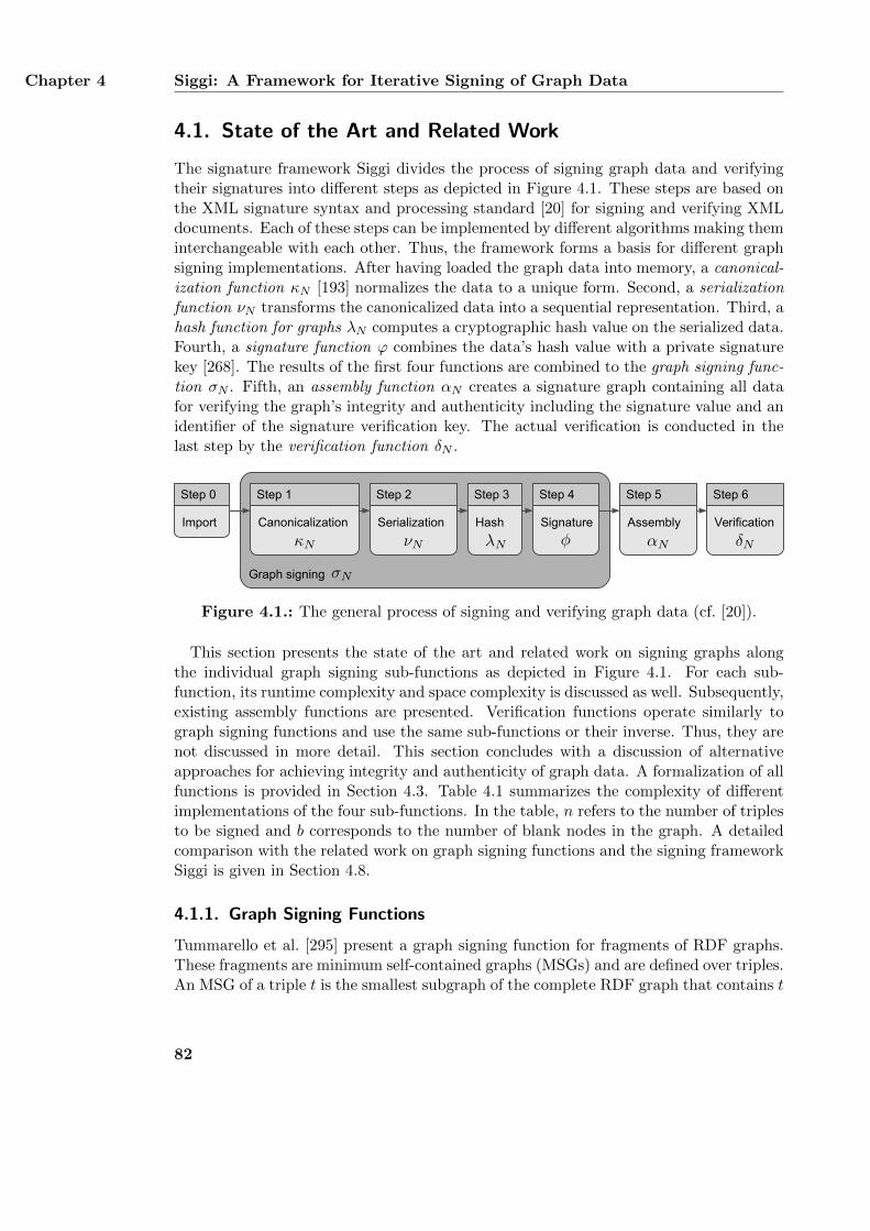
Chapter 4 Siggi: A Framework for Iterative Signing of Graph Data
4.1. State of the Art and Related Work
The signature framework Siggi divides the process of signing graph data and verifyingtheir signatures into different steps as depicted in Figure 4.1. These steps are based onthe XML signature syntax and processing standard [20] for signing and verifying XMLdocuments. Each of these steps can be implemented by different algorithms making theminterchangeable with each other. Thus, the framework forms a basis for different graphsigning implementations. After having loaded the graph data into memory, a canonical-ization function κN [193] normalizes the data to a unique form. Second, a serializationfunction νN transforms the canonicalized data into a sequential representation. Third, ahash function for graphs λN computes a cryptographic hash value on the serialized data.Fourth, a signature function ϕ combines the data’s hash value with a private signaturekey [268]. The results of the first four functions are combined to the graph signing func-tion σN . Fifth, an assembly function αN creates a signature graph containing all datafor verifying the graph’s integrity and authenticity including the signature value and anidentifier of the signature verification key. The actual verification is conducted in thelast step by the verification function δN .
Graph signing
Canonicalization
Step 1
Serialization
Step 2
Hash
Step 3
Assembly
Step 5
Verification
Step 6
Signature
Step 4
Import
Step 0
Figure 4.1.: The general process of signing and verifying graph data (cf. [20]).
This section presents the state of the art and related work on signing graphs alongthe individual graph signing sub-functions as depicted in Figure 4.1. For each sub-function, its runtime complexity and space complexity is discussed as well. Subsequently,existing assembly functions are presented. Verification functions operate similarly tograph signing functions and use the same sub-functions or their inverse. Thus, they arenot discussed in more detail. This section concludes with a discussion of alternativeapproaches for achieving integrity and authenticity of graph data. A formalization of allfunctions is provided in Section 4.3. Table 4.1 summarizes the complexity of differentimplementations of the four sub-functions. In the table, n refers to the number of triplesto be signed and b corresponds to the number of blank nodes in the graph. A detailedcomparison with the related work on graph signing functions and the signing frameworkSiggi is given in Section 4.8.
4.1.1. Graph Signing Functions
Tummarello et al. [295] present a graph signing function for fragments of RDF graphs.These fragments are minimum self-contained graphs (MSGs) and are defined over triples.An MSG of a triple t is the smallest subgraph of the complete RDF graph that contains t
82
State of the Art and Related Work Section 4.1
and the triples of all blank nodes associated directly or recursively with t. Triples withoutblank nodes are an MSG on their own. The graph signing function of Tummarello etal. is based on Carroll’s canonicalization function and hash function [72] described inSection 4.1.2. A signature is stored as six triples, which are linked to the signed MSG viaRDF statement reification [142] of one of the MSG’s triples. The approach of Tummarelloet al. only supports signing one MSG at a time. Signing a full graph with multiple MSGsrequires multiple signatures. Thus, the graph signing process depicted in Figure 4.1 hasto be applied to each MSG in the graph. This creates a large overhead of six signaturetriples per MSG. Furthermore, sining arbitrary sets of triples which do not correspondto complete MSGs is not supported by the approach.
Signing a graph can also be accomplished by signing a document containing a par-ticular serialization of the graph [262]. For example, a graph can be serialized using anXML-based format such as RDF/XML [26] or OWL/XML [210]. This results in an XMLdocument which can be signed using the XML signature standard [20]. If the graph isserialized using a plain text-based format such as the triple-based serialization formatsN-Triples [25] or Turtle [27], also standard text document signing approaches may beused [268]. However, these approaches inextricably link the signature with a concreteencoding of the graph [262]. Consequently, such a signature can only be verified as longas the very specific serialization of the graph contained in the document is provided.
4.1.2. Canonicalization Functions for Graphs
A canonicalization function κN deterministically normalizes a graph in such a way thatits syntactical representation does not affect its hash value and its signature. A canon-icalization function ensures that a graph’s signature only covers its semantics and notits syntax [193]. As depicted in Figure 4.1, a cryptographic hash function is used forcomputing a hash value of a serialized and canonicalized graph. Such a hash functionoperates on string values and outputs different hash values for different input strings.Blank node identifiers of a graph also influence the graph’s hash value and thus its signa-ture as well. These blank node identifiers can be consistently renamed within the wholegraph without modifying the graph’s semantics. This means that a particular blank nodeidentifier can be renamed to another identifier without destroying the graph’s meaningas long as this identifier is renamed in all its occurrences. However, renaming blanknode identifiers changes the graph’s syntactical representation and thus its hash valueand signature as well. A canonicalization function prohibits blank node renaming frominvalidating a graph’s signature. A formal specification for canonicalization functions isprovided in Section 4.3.3.
Hogan [148] canonicalizes an RDF graph by computing all its isomorphic graphs, sort-ing them, and selecting the first graph as canonical graph. A single isomorphic graph iscomputed by replacing all blank nodes in the graph with the same identifier, computingthe hash values of all triples in the graph, and computing the hash values of all blanknodes by using the hash values of the triples in which they occur. If several blank nodesshare the same hash value, one of the blank nodes is replaced by a new identifier andthe hash values are computed again. This process is repeated until the hash values of
83
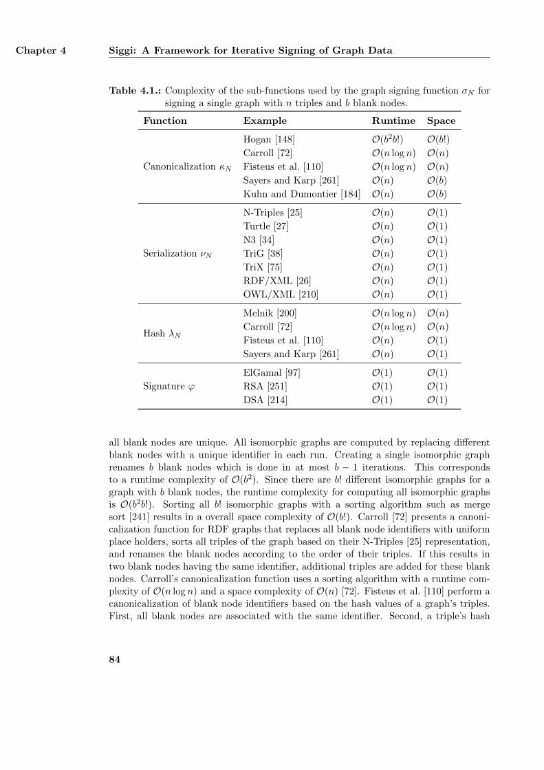
Chapter 4 Siggi: A Framework for Iterative Signing of Graph Data
Table 4.1.: Complexity of the sub-functions used by the graph signing function σN forsigning a single graph with n triples and b blank nodes.
Function Example Runtime Space
Canonicalization κN
Hogan [148] O(b2b!) O(b!)
Carroll [72] O(n log n) O(n)
Fisteus et al. [110] O(n log n) O(n)
Sayers and Karp [261] O(n) O(b)
Kuhn and Dumontier [184] O(n) O(b)
Serialization νN
N-Triples [25] O(n) O(1)
Turtle [27] O(n) O(1)
N3 [34] O(n) O(1)
TriG [38] O(n) O(1)
TriX [75] O(n) O(1)
RDF/XML [26] O(n) O(1)
OWL/XML [210] O(n) O(1)
Hash λN
Melnik [200] O(n log n) O(n)
Carroll [72] O(n log n) O(n)
Fisteus et al. [110] O(n) O(1)
Sayers and Karp [261] O(n) O(1)
Signature ϕ
ElGamal [97] O(1) O(1)
RSA [251] O(1) O(1)
DSA [214] O(1) O(1)
all blank nodes are unique. All isomorphic graphs are computed by replacing differentblank nodes with a unique identifier in each run. Creating a single isomorphic graphrenames b blank nodes which is done in at most b − 1 iterations. This correspondsto a runtime complexity of O(b2). Since there are b! different isomorphic graphs for agraph with b blank nodes, the runtime complexity for computing all isomorphic graphsis O(b2b!). Sorting all b! isomorphic graphs with a sorting algorithm such as mergesort [241] results in a overall space complexity of O(b!). Carroll [72] presents a canoni-calization function for RDF graphs that replaces all blank node identifiers with uniformplace holders, sorts all triples of the graph based on their N-Triples [25] representation,and renames the blank nodes according to the order of their triples. If this results intwo blank nodes having the same identifier, additional triples are added for these blanknodes. Carroll’s canonicalization function uses a sorting algorithm with a runtime com-plexity of O(n log n) and a space complexity of O(n) [72]. Fisteus et al. [110] perform acanonicalization of blank node identifiers based on the hash values of a graph’s triples.First, all blank nodes are associated with the same identifier. Second, a triple’s hash
84
State of the Art and Related Work Section 4.1
value is computed by multiplying the hash values of its subject, predicate, and objectwith corresponding constants and combining all results with XOR modulo a large prime.If two triples have the same hash value, new identifiers of the blank nodes are computedby combining the hash values of the triples in which they occur either directly or tran-sitively. This process is repeated until there are no collisions left. Colliding hash valuesare detected by sorting them. Using merge sort as sorting algorithm leads to a runtimecomplexity of O(n log n) and a space complexity of O(n). Sayers and Karp [261] pro-vide a canonicalization function for RDF graphs which stores the identifier of each blanknode in an additional triple. If the identifier is changed, the original one can be recreatedusing this triple. Since this does not require sorting the triples, the runtime complexityof the function is O(n). In order to detect already processed blank nodes, the functionmaintains a list of additional triples created so far. This list contains at most b entrieswith b being the total number of additional blank node triples. Thus, the space complex-ity of the function is O(b). Finally, Kuhn and Dumontier [184] canonicalize an onlineavailable RDF graph by transforming all its blank nodes to URIs. In order to prohibitname clashes with similar URIs stored in other graphs, all created URIs are prefixedwith the same string based on the graph’s designated web address. As this renamingprocess does not require sorting, it can be implemented with a runtime complexity ofO(n). To achieve a consistent renaming of blank nodes, the canonicalization functionrequires a list of already transformed blank nodes and their respective URIs. This listcontains at most b entries, resulting in a space complexity of O(b).
4.1.3. Serialization Functions for Graphs
A serialization function νN transforms an RDF graph into a sequential representationsuch as a set of bit strings. A formal definition of serialization functions is given inSection 4.3.4. The sequential representation is encoded in a specific format such as triple-based N-Triples [25] and Turtle [27] or XML-based RDF/XML [26] and OWL/XML [210].TriX [75] and TriG [38] are formats for expressing Named Graphs. While TriX is basedon XML, TriG has a triple-based syntax built upon Turtle. Notation3 (N3) [34] is an-other superset of Turtle for expressing RDF graphs as well as RDF rules. When signingRDF graphs, triple-based formats are often preferred to XML-based notations due totheir simpler structure. If a serialization function processes each triple in the graphindividually, it can be implemented with a runtime complexity of O(n) and a spacecomplexity of O(1). Some canonicalization functions such as [72] directly operate ona serialized graph. Such canonicalization functions also include a serialization functionand output a canonical serialization of the graph.
4.1.4. Hash Functions for Graphs
Applying a hash function for graphs λN is often based on computing the hash values ofthe graph’s triples and combining them into a single value. Computing a triple’s hashvalue can be done by using a basic hash function λ such as MD5 [250] or SHA-2 [218]. Aformalization of basic hash functions and hash functions for graphs functions is provided
85
Chapter 4 Siggi: A Framework for Iterative Signing of Graph Data
in Section 4.3.5. Melnik [200] uses a simple hash function for RDF graphs. A triple’shash value is computed by concatenating the hash value of its subject, predicate, andobject and hashing the result. The hash values of all triples are sorted, concatenated,and hashed again to form the hash value of the entire RDF graph. Using a sortingalgorithm like merge sort, the function’s runtime complexity is O(n log n) and its spacecomplexity is O(n). Carroll [72] uses a graph-hashing function which sorts all triples,concatenates the result, and hashes the resulting bit string using a basic hash functionsuch as SHA-2 [218]. As the function uses a sorting algorithm with a runtime complexityof O(n log n) and a space complexity of O(n), the runtime complexity and the spacecomplexity of the canonicalization function are the same. Fisteus et al. [110] suggesta hash function for N3 [34] datasets. The triples’ hash values are computed with thecanonicalization function of the same authors described in Section 4.1.2. The hash valueof a graph is computed by incrementally multiplying the hash values of its triples moduloa large prime. Since this operation is commutative, sorting the triples’ hash values isnot required. Thus, the runtime complexity of the hash function is O(n). Due to theincremental multiplication, the space complexity is O(1). Finally, Sayers and Karp [261]compute a hash value of an RDF graph similar to the approach of Fisteus et al. First,the triples are serialized as single bit string and then hashed. Second, the incrementalmultiplication is conducted. Thus, the runtime complexity of this approach is O(n) andthe space complexity is O(1).
4.1.5. Signature Functions
A signature function ϕ computes the actual graph signature by combining the graph’shash value with a secret signature key. Signature functions are formalized in Sec-tion 4.3.7. Examples of existing signature functions are DSA [214], RSA [251], andElGamal [97]. Since the graph’s hash value is independent from the number of triples,the signature is as well. Thus, the runtime complexity and the space complexity of allsignature functions are O(1).
4.1.6. Assembly Function
An assembly function αN creates a detailed description of how a graph’s signature canbe verified. This description may then be added to the signed graph data or be storedat a separate location. Section 4.3.8 provides a formal definition of assembly functions.Tummarello et al. [295] present a simple assembly function which adds additional triplesto each signed MSG containing the signature value and a URL to the public key usedfor verifying the signature value. Information about the graph signing function andits sub-functions is not provided. Once the URL to the signature verification key isbroken, i. e., the key is not available anymore at this URL, the signature can no longerbe verified. Even if a copy of the verification key is still available at a different location,the verifier has no proof that this copy is really a legitimate copy of the original publickey. Since the issuer and other identifying metadata of the signature verification key arenot provided by the triples of the assembly function, the verifier cannot check the true
86
State of the Art and Related Work Section 4.1
authenticity of the copied key. The assembly function described in the XML signaturestandard [20] provides an XML schema for covering all information about the signature’screation and verification. This includes the names of the used canonicalization function,the hash function, and the signature function used for computing the signature value.The XML schema also provides a unique identifier of the signature key issuer, the key’sserial number, and further information.
4.1.7. Alternative Approaches for Achieving Integrity of Graph Data
RDF graph data is usually stored at a data provider located in the web [39]. In order toaccess the graph data, a recipient has to first download it from such a provider. Thus,ensuring integrity of RDF graph data can also be accomplished by securing this down-load process. The Transport Layer Security (TLS) protocol [92] and its predecessor, theSecure Sockets Layer (SSL) protocol [113], can be used to create a secure communicationchannel between a recipient and a data provider. Such a secure communication channelcan be used for achieving both integrity and authenticity of the transmitted graph data.When the recipient downloads the graph from the data provider, the communicationchannel is digitally signed by the data provider. Any unauthorized modification of thedata during its transmission can be identified by the recipient. Furthermore, the dig-ital signature also associates the transmitted graph with the data provider, achievingauthenticity of the graph data. However, secure communication channels based on TLSor SSL only protect the transmitted data during the transmission process. They cannotbe used for permanently achieving integrity and authenticity of the data. Once a securecommunication channel is closed after the graph data has been transmitted, the recip-ient cannot verify the graph data again without retrieving it once more from the dataprovider. Additional verifications might be necessary if the data is stored on untrusteddevices such as cloud storage services or when it is transmitted further to other partieswhich need to verify the graph data themselves. Furthermore, secure communicationchannels require the data provider to be completely trusted. If the data provider isdifferent from the graph’s original creator, it may not be considered as completely trust-worthy. In this case, the data provider can modify the graph at any time and thereforeviolate the graph’s integrity. The recipient of the graph cannot notice such modificationsas the secure communication channel originates from the data provider and not fromthe graph’s creator.
Kuhn and Dumontier [184] present trusty URIs, an approach for achieving integrity ofRDF graphs without digitally signing them. A trusty URI is a web address of an RDFgraph which contains the graph’s cryptographic hash value. After having downloaded agraph, the recipient computes the graph’s hash value again and compares it with the hashvalue encoded into the trusty URI. If both hash values are identical, the graph’s integrityis confirmed. Publishing a graph on the web requires the data provider to first computethe graph’s hash value. In order to remove the influence of the graph’s blank nodeson the computed hash value, all blank nodes are transformed into preliminary URIs byusing the canonicalization function of the same authors described in Section 4.1.2. Inthis case, the prefix used for the preliminary URIs is the graph’s designated web address
87
Chapter 4 Siggi: A Framework for Iterative Signing of Graph Data
without its hash value. After having transformed the blank nodes, the graph’s hashvalue is computed by using the hash function of Carroll [72] as described in Section 4.1.4.Finally, the computed hash value is used for creating the trusty URI of the graph. Thesecurity of trusty URIs is based on the connection between a graph’s hash value andits web address. Any modifications of a graph can be identified as the hash value ofthe modified graph differs from the hash value encoded into the graph’s web address.However, trusty URIs are only capable of protecting the integrity of a graph if thegraph is downloaded from the web. After this process has been completed, verifyingthe graph’s integrity is no longer possible without having to download the graph again.Furthermore, trusty URIs do not create a connection between a data provider and theprovided graph data. Thus, trusty URIs are not able to protect a graph’s authenticityand are vulnerable to spoofing attacks in which an attacker masquerades as the dataowner. An attacker may fake a trusty URI for a self-created graph which contains theweb address of the data owner, thereby claiming that this data owner has published thegraph. The attacker then publishes the trusty URI on the web. If a recipient wants todownload the graph from the data owner, the attacker uses a spoofing attack such as IPspoofing [291] or ARP cache poisoning [1] to redirect and intercept the communication.The attacker then sends the self-created graph to the recipient, pretending that therecipient is actually communicating with the data provider. As trusty URIs do not useany mechanisms for achieving the graph’s authenticity, a recipient cannot verify theidentity of the respective communication partner and thus cannot distinguish betweenan attacker and a legitimate data owner. Such attacks can be prohibited by establishinga secure communication channel based on a protocol such as TLS or SSL. However, assuch connections also achieve integrity of the transmitted data, the use of trusty URIswould become obsolete in this case.
4.2. Requirements for a Graph Signing Framework
The graph signing framework Siggi formally defines a process for signing arbitrary graphdata. Due to the framework’s flexible design, each step in this process can be imple-mented by a different algorithm. Based on these general objectives, this section definesthe functional (RI.F.*) and non-functional (RI.N.*) requirements for the graph signingframework Siggi. As defined in Section 3.2, functional requirements define the servicesand functions that a system must provide [282]. On the other hand, non-functional re-quirements define the overall design of a system and describe how functional requirementsare implemented. The following requirements are based on the scenario for regulating In-ternet communication presented in Section 2.1 and on the related work for signing graphdata summarized in Section 4.1. The graph signing framework Siggi must support thefollowing functional requirements:
RI.F.1: Signing different types of graph dataThe graph signing framework must allow a party to sign different types of graphdata such as RDF(S) graphs (RI.F.1.1), OWL graphs (RI.F.1.2), and Named
88
Requirements for a Graph Signing Framework Section 4.2
Graphs (RI.F.1.3). This allows the framework to be used in heterogeneous envi-ronments such as Linked Open Data [39]. In the workflow for exchanging regulationpolicies introduced in the scenario in Section 2.1.2, the BKA provides OWL ontol-ogy design patterns, ContentWatch provides Named Graphs, and JusProg providesits regulation data as RDF graphs.
RI.F.2: Signing at different levels of granularityThe graph signing framework must support signing graph data at different levels ofgranularity including single triples (RI.F.2.1), arbitrary sets of triples (RI.F.2.2),MSGs (RI.F.2.3), and entire graphs (RI.F.2.4). This results in a most flexibleuse of the framework. In the scenario, the BKA signs ontology design patternsand the German Telecom signs its entire regulation graph.
RI.F.3: Signing T-box and A-box knowledgeThe graph signing framework must allow a party to sign both assertional (A-box)knowledge (RI.F.3.2) and terminological (T-box) knowledge (RI.F.3.1). A-boxknowledge corresponds to factual knowledge whereas T-box knowledge representsthe knowledge encoded in the ontological model, i. e., the schema knowledge [152].This enables the framework to be used for signing vocabularies issued by, e. g.,standardization bodies. In addition, parties publishing their own instance data us-ing those vocabularies can sign their assertional knowledge as well. In the scenario,the BKA signs both its ontologies and its technical regulation details.
RI.F.4: Signing graph data iterativelyThe graph signing framework must support signing graph data which is alreadysigned, i. e., iterative signing of graph data. An iterative signature may cover signedgraph data from a previous signing step as well as newly added graph data. Signingalready signed graph data again without adding any additional triples can be usedfor countersigning the data. Other applications of iterative signing are provenancetracking where each party receives signed data from a party, sings the data again,and sends the result to another party. This allows it to re-create the flow of thesigned data. In the scenario, the German Telecom receives signed graph data fromthe BKA and signs it again in order to track the provenance of the exchangedregulation details.
RI.F.5: Signing multiple and distributed graphsThe graph signing framework must allow a party to sign multiple graphs at thesame time which are distributed over different locations. In the scenario, the Ger-man comprehensive school retrieves two different graphs from the ContentWatchand JusProg and signs both graphs at once.
In addition to these functional requirements, the graph signing framework Siggi mustalso support the following non-functional requirements:
RI.N.1: Creating encoding-independent signaturesThe signatures created with the graph signing framework must not rely on a par-ticular encoding or serialization of the graph. It must be possible to modify the
89
Chapter 4 Siggi: A Framework for Iterative Signing of Graph Data
graph’s syntactical representation after having signed the graph without invalidat-ing the created signature. For example, it must be possible to transform a signedgraph stored as an RDF/XML document into an N-Triples file while still beingable to verify the graph’s signature. Changing the order of the triples of a signedgraph or renaming its blank node identifiers must also be possible without destroy-ing the graph’s signature. As these two modifications do not influence the graph’ssemantics, they are also considered to be plain syntactical modifications and aresubsumed by this requirement as well.
RI.N.2: Supporting flexible configurabilityThe graph signing framework must support different configurations for signinggraph data. A configuration implements each step of the general signing processdepicted in Figure 4.1 with a particular algorithm. Possible configurations of theframework must at least cover already existing approaches for signing graph dataas discussed in the related work in Section 4.1. Furthermore, the design of theframework should also support future configurations.
RI.N.3: Supporting a modular designThe graph signing framework must have a modular design which allows to combinedifferent sub-functions for signing graphs as one framework configuration. Theframework must support interchangeable implementations for each sub-functionand allow the creation of new configurations by using these sub-functions as build-ing blocks. For example, it must be possible to use the canonicalization functionof one author and combine it with a hash function for graphs from another author.
RI.N.4: Separating the signing process from software implementationsThe graph signing framework must not rely on a particular software implementa-tion or programming language. Instead, it must be possible to sign a graph with aparticular software implementation and verify the created signature with anotherimplementation.
Integrity and authenticity of graph data are not listed as specific requirements for thegraph signing framework Siggi. Instead, integrity and authenticity of graph data corre-spond to the research questions RQ.2 and RQ.3, respectively, which are answered bythe graph signing framework Siggi. The fulfillment of all functional and non-functionalrequirements by the the graph signing framework Siggi is summarized in Section 4.3.10and a comparison with the related work is given in Section 4.8.
4.3. Formalization of the Graph Signing Framework Siggi
Based on the state of the art and the related work discussed in Section 4.1 as well as onthe requirements defined in Section 4.2, this section provides a formal specification ofthe graph signing framework Siggi. This specification covers the input and output of allfunctions which are part of the graph signing process as depicted in Figure 4.1. The spec-ification can be used as a guideline to create new functions for each step in the process.
90
Formalization of the Graph Signing Framework Siggi Section 4.3
As the formal specification is independent from any particular software implementation,the created signatures can be verified using any available implementation.
4.3.1. Definition of Graphs
An RDF graph G is an unordered, finite set of RDF triples t. The set of all RDF triplesis defined as follows with the pairwise disjoint sets of resource URIs R, blank nodes B,and literals L1:
T := (R ∪B)×R× (R ∪B ∪ L) (4.1)
It is t = (s, p, o) with s ∈ R∪B being the subject of the triple, p ∈ R being the predicate,and o ∈ R ∪ B ∪ L being the object [13]. An OWL graph can be mapped to an RDFgraph [230]. Thus, in the following only RDF graphs are denoted while OWL graphsare included by mapping them to RDF graphs. The set of all possible RDF graphs isdefined as follows:
G := P(T) = P((R ∪B)×R× (R ∪B ∪ L)) (4.2)
A Named Graph extends the notion of RDF graphs and associates a unique name inform of a URI to a single RDF graph [73] or set of RDF graphs. This URI can bedescribed by further triples, which form the so-called annotation graph. Consequently,the original RDF graph is also called the content graph. A Named Graph NG ∈ GN isdefined as NG = (a,A, {C1, C2, . . . , Cl}) with a ∈ R∪ {ε} being the name of the graph,A ∈ G being the annotation graph, and Ci ∈ GN being content graphs with i = 1 . . . land l ∈ N. If a Named Graph does not explicitly specify an identifier, ε is used asits name. This corresponds to associating a blank node with the graph. In this case,the annotation graph A is empty, i. e., A = ∅. Any RDF graph G ∈ G can be definedas Named Graph C using the notation above as C = (ε, ∅, G). The set of all NamedGraphs GN is recursively defined as follows:
GN := (R×G× P(GN )) ∪ ({ε} × {∅} ×G) (4.3)
4.3.2. Graph Signing Function σN
The graph signing function σN consists of several sub-functions and creates a signaturevalue s of a set of Named Graphs. These sub-functions are the canonicalization func-tion κN , the serialization function νN , the hash function for graphs λN , the combiningfunction for graphs %N , and the signature function ϕ, which are formally defined be-low. The combining function for graphs %N allows the graph signing function to signmultiple graphs at once. The assembly function αN and the verification function γNare not part of the graph signing function σN and are applied afterwards. The graphsigning function σN requires a secret key ks ∈ Ks as input with Ks being the set ofall secret keys. Additionally, the function requires a set of m Named Graphs NG with
1Please note that this thesis uses the symbol R for representing resources and not real numbers. Theset of real numbers is not used at all in this work.
91
Chapter 4 Siggi: A Framework for Iterative Signing of Graph Data
NGi = (ai, Ai, {C1i , . . . , Cli}), i = 1, . . . ,m, and m ∈ N. The resulting signature value sis a bit string of length d′ ∈ N, i. e., s ∈ {0, 1}d′ . The graph signing function σN isdefined as follows:
σN : Ks × P(GN )→ {0, 1}d′ , σN (ks, {NG1, . . . , NGm}) := s (4.4)
s := ϕ(ks, %N (λN (νN (κN (NG1))), . . . , λN (νN (κN (NGm))))) (4.5)
The graph signing function σN first canonicalizes all Named Graphs using the canonical-ization function κN . Each canonicalized graph is then serialized using the serializationfunction νN and transformed into a bit string using the hash function for graphs λN .The combining function for graphs %N is applied to these bit strings in order to createa single bit string which can then be signed with the signature function ϕ.
4.3.3. Canonicalization Function for Graphs κN
The canonicalization function κ transforms a graph G ∈ G into its canonical form G ∈ Gwith G ⊂ G being the set of all canonical graphs. Example implementations of thefunction κ are discussed in Section 4.1.2. The function is defined as follows:
κ : G→ G, κ(G) := G (4.6)
For Named Graphs, the canonicalization function κN is recursively defined. It computesa canonical representation of a Named Graph NG = (a,A, {C1, . . . , Cl}) by comput-ing the canonical representations A and Ci of its annotation graph A and its contentgraphs Ci with i = 1, . . . , l and l ∈ N. The result is a canonical representation NG ∈ GN
with GN ⊂ GN being the set of all canonical Named Graphs. Using the function κ, thecanonicalization function κN is defined as follows:
κN : GN → GN , κN (NG) := NG (4.7)
NG :=
{(ε, ∅, κ(G)) if NG = (ε, ∅, G), G ∈ G(a, κ(A), {κN (C1), . . . , κN (Cl)}) if NG = (a,A, {C1, . . . , Cl})
(4.8)
4.3.4. Serialization Function νN
The serialization function ν transforms a graph G ∈ G into a set G of bit strings b ∈{0, 1}∗ with G ∈ P({0, 1}∗). A single bit string usually represents a triple in the graph G.The concrete characteristics of the bit strings in G depend on the used serializationformat. Example formats of the serialization function ν are discussed in Section 4.3.4.The serialization function ν is defined as follows:
ν : G→ P({0, 1}∗), ν(G) := G (4.9)
The serialization function ν can be extended to the serialization function νN for NamedGraphs NG ∈ GN . The result of the function νN is a set NG of o bit strings bi ∈ {0, 1}∗with NG = {b1, b2, . . . , bo}, i = 1, . . . , o, and o ∈ N. The particular value of o depends
92
Formalization of the Graph Signing Framework Siggi Section 4.3
on the used implementation of the serialization function νN and on the serialized NamedGraph NG. Using the function ν, the serialization function νN is recursively defined asfollows:
νN : GN → P({0, 1}∗), νN (NG) := NG (4.10)
NG :=
{ν(G) if NG = (ε, ∅, G), G ∈ G{a} ∪ ν(A) ∪ νN (C1) ∪ . . . ∪ νN (Cl) if NG = (a,A, {C1, . . . , Cl})
(4.11)
4.3.5. Hash Function for Graphs λN
The basic hash function λ computes a hash value h of an arbitrary bit string b ∈ {0, 1}∗.The resulting hash value h has a fixed length d ∈ N, i. e., h ∈ {0, 1}d. The function λ isdefined as follows:
λ : {0, 1}∗ → {0, 1}d, λ(b) := h (4.12)
The hash function for graphs λN computes a hash value hN ∈ {0, 1}d of a set of bitstrings b ∈ {0, 1}∗. It is built upon the basic hash function λ. The function λN directlyoperates on bit strings and can be used for computing hash values of graphs G ∈ G andhash values of Named Graps NG ∈ GN . Example implementations of the basic hashfunction λ and the hash function for graphs λN are presented in Section 4.3.5. The hashfunction for graphs λN is defined as follows:
λN : P({0, 1}∗)→ {0, 1}d, λN (NG) := hN (4.13)
4.3.6. Combining Function for Graphs %N
The combining function for graphs %N combines a set of hash values h ∈ {0, 1}d of equallength d ∈ N into a single hash value hM ∈ {0, 1}d. The function %N allows the graphsigning function σN to sign multiple graphs at once. Example combining functions ofgraphs %N are discussed in [261]. The combining function for graphs %N is defined asfollows:
%N : P({0, 1}d)→ {0, 1}d, %N ({h1, h2, . . .}) := hM (4.14)
4.3.7. Signature Function ϕ
A signature function ϕ computes the signature value of a set of graphs based on theset’s hash value hN ∈ {0, 1}d and a cryptographic key. The keyspace, i. e., the setof all asymmetric, cryptographic keys is defined as Ka = Kp × Ks with Kp as theset of public keys and Ks as the set of secret keys. For computing signatures, a secretkey ks ∈ Ks is used. Possible implementations for the signature function ϕ are presentedin Section 4.1.5. Using s ∈ {0, 1}d′ as identifier for the resulting bit string, the signaturefunction is defined as follows:
ϕ : Ks × {0, 1}d → {0, 1}d′, ϕ(ks, b) := s (4.15)
93
Chapter 4 Siggi: A Framework for Iterative Signing of Graph Data
4.3.8. Assembly Function αN
The assembly function αN is applied after the graph signing function σN . It creates asignature graph S ∈ G and includes it in a new Named Graph NGS ∈ GN . The contentand structure of S depend on the implementation of the assembly function αN . Thegraph S provides information about how to verify the signature of a set of a graphs.This includes all sub-functions of the graph signing function σN , the public key kp ofthe used secret key ks, the identifiers ai of the signed Named Graphs, and the signaturevalue s. A possible structure of a signature graph is shown in the examples in Section 4.7.Additional examples of an assembly function are presented in Section 4.1.6. The NamedGraph NGS contains the signature graph S as its annotation graph and the signedgraphs NGi with i = 1, . . . ,m and m ∈ N as its content graphs. In order to supportiterative signing of Named Graphs, the result of the assembly function αN is also aNamed Graph. The function is defined as follows:
αN : Kp × {0, 1}d′ × P(GN )→ GN , αN (kp, s, {NG1, . . . , NGm}) := NGS (4.16)
NGS := (aS , S, {NG1, . . . , NGm}) (4.17)
4.3.9. Verification Function γN
The verification of a signature is similar to its creation. A verification function γNrequires a canonicalization function κN , a serialization function νN , and a hash func-tion λN for graphs. It also requires a signature verification function δN as inverse of thesignature function ϕ. The function δN requires a bit string s ∈ {0, 1}d′ and a publickey kp ∈ Kp as input. It is defined as follows with b ∈ {0, 1}d being the resulting bitstring. If a secret key ks ∈ Ks is inverse to the public key kp, it holds δN (kp, ϕ(ks, b)) = bfor all b ∈ {0, 1}d.
δN : Kp × {0, 1}d′ → {0, 1}d, δN (kp, s) := b (4.18)
The verification function γN checks whether or not a given signature is a valid signatureof a set of Named Graphs. The function requires a public key kp and a signature value swhich can be taken from the signature graph S. Additionally, the function requires aset of signed Named Graphs {NG1, . . . , NGm} with m ∈ N. The key kp is the publiccounterpart of the secret key ks, which was used for creating the signature value s.The verification function γN combines the signature value s with the public key kpand computes the hash value h′ of the Named Graphs NGi with i = 1, . . . ,m. Thesignature is valid iff both computed values are equal. Using h′ = λN (νN (κN (NG1)) ∪. . . ∪ νN (κN (NGm))), the verification function γN is defined as follows:
γN : Kp × P(GN )× {0, 1}∗ → {TRUE,FALSE} (4.19)
γN (kp, {NG1, . . . , NGm}, s) :=
{TRUE if δN (kp, s) = h′
FALSE otherwise(4.20)
94
Formalization of the Graph Signing Framework Siggi Section 4.3
4.3.10. Fulfillment of the Requirements
This section outlines how the functional and non-functional requirements defined in Sec-tion 4.2 are fulfilled by the graph signing framework Siggi. A further discussion andcomparison with the related work is provided in Section 4.8. The requirement of signingdifferent types of graph data (RI.F.1) is supported via the definition of Named Graphsgiven in Equation 4.3. This definition allows to map RDF(S) graphs (RI.F.1.1) andOWL graphs (RI.F.1.2) to Named Graphs by using a representation like (ε, ∅, G). Inthis case, ε is used as the graph’s name, ∅ is used as the annotation graph, and G ∈ Gcorresponds to the original graph. Signing Named Graphs (RI.F.1.3) is directly sup-ported by the graph signing function σN as defined in Equation 4.4. Thus, this functioncan also be used to sign RDF(S) graphs and OWL graphs. The fulfillment of the require-ment of signing graph data at different levels of granularity (RI.F.2) depends on theparticular granularity level. Signing a complete graph (RI.F.2.4) is directly supportedby the graph signing function σN . Signing individual triples (RI.F.2.1), arbitrary setsof triples (RI.F.2.2), or MSGs (RI.F.2.3) is achieved by first creating a new graphwhich contains all triples to be signed. The resulting graph can then be transformedinto a Named Graph by applying Equation 4.3 and signed using the graph signing func-tion ϕ. T-box knowledge and A-box knowledge (RI.F.3) share the same syntacticalrepresentation which consists of a set of triples. A Named Graph can contain any typeof triples and does not distinguish between schema knowledge and factual knowledge.Thus, signing T-box knowledge (RI.F.3.1) and A-box knowledge (RI.F.3.2) is equallysupported by the graph signing function σN . The requirement of iterative signing ofgraph data (RI.F.4) is fulfilled by the design of the assembly function αN defined inEquation 4.16. The output of the function is a Named Graph which can be signed againusing the graph signing function σN . Signing multiple graphs at once (RI.F.5) is sup-ported by the combining function for graphs %N defined in Equation 4.14. The functioncombines the hash values of multiple graphs into a single hash value. Singing this hashvalue corresponds to signing these graphs at the same time. As the function does notdistinguish between local graphs and remote graphs, it equally supports both types ofgraphs.
The requirement of an encoding-independent signature (RI.N.1) is collectively ful-filled by the canonicalization function for graphs κN , the hash function for graphs λN ,and the design of the framework’s formal specification. The canonicalization functionfor graphs κN ensures that renaming a graph’s blank node identifiers does not invalidatethe graph’s signature. The hash function for graphs λN normalizes the order of thegraph’s triples in such a way that changing this order does not influence the signature.The framework’s formal specification does not rely on a particular encoding of the graphand interprets the graph as an abstract data structure which is processed as such. Asthe encoding format used by the assembly function αN is independent of the signingprocess, it can be changed without invalidating the graph’s signature. The requirementof different configurations of the graph signing framework (RI.N.2) is supported by thegeneric design of the framework’s formal specification. The specification only defines thebasic characteristics of the signing process and focuses on the input and output data of
95
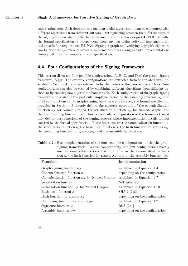
Chapter 4 Siggi: A Framework for Iterative Signing of Graph Data
each signing step. As it does not rely on a particular algorithm, it can be configured withdifferent algorithms from different authors. Distinguishing between the different steps ofthe signing process also fulfills the requirement of a modular design (RI.N.3). Finally,the formal specification is independent from any particular software implementationand thus fulfills requirement RI.N.4. Signing a graph and verifying a graph’s signaturecan be done using different software implementations as long as both implementationscomply with the framework’s formal specification.
4.4. Four Configurations of the Signing Framework
This section discusses four possible configurations A, B, C, and D of the graph signingframework Siggi. The example configurations are extracted from the related work de-scribed in Section 4.1 and are referred to by the names of their respective authors. Newconfigurations can also be created by combining different algorithms from different au-thors or by creating new algorithms from scratch. Each configuration of the graph signingframework must define the particular implementation of the assembly function αN andof all sub-functions of the graph signing function σN . However, the formal specificationprovided in Section 4.3 already defines the concrete operation of the canonicalizationfunction κN for Named Graphs, the serialization function νN for Named Graphs, andthe graph signing function σN . Thus, a particular configuration of the framework mustonly define those functions of the signing process whose implementation details are notcovered by the formal specification. These functions are the canonicalization function κ,the serialization function ν, the basic hash function λ, the hash function for graphs λN ,the combining function for graphs %N , and the assembly function αN .
Table 4.2.: Basic implementation of the four example configurations of the the graphsigning framework. To ease comparability, the four configurations mostlyuse the same sub-functions and only differ in the canonicalization func-tion κ, the hash function for graphs λN , and in the assembly function αN .
Function Implementation
Graph signing function σN as defined in Equation 4.4
Canonicalization function κ depending on the configuration
Canonicalization function κN for Named Graphs as defined in Equation 4.7
Serialization function ν N-Triples [25]
Serialization function νN for Named Graphs as defined in Equation 4.10
Basic hash function λ SHA-2 [218]
Hash function for graphs λN depending on the configuration
Combining function for graphs %N as defined in Equation 4.21
Signature function ϕ RSA [251]
Assembly function αN depending on the configuration
96
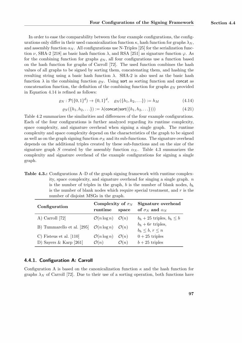
Four Configurations of the Signing Framework Section 4.4
In order to ease the comparability between the four example configurations, the config-urations only differ in their used canonicalization function κ, hash function for graphs λN ,and assembly function αN . All configurations use N-Triples [25] for the serialization func-tion ν, SHA-2 [218] as basic hash function λ, and RSA [251] as signature function ϕ. Asfor the combining function for graphs %N , all four configurations use a function basedon the hash function for graphs of Carroll [72]. The used function combines the hashvalues of all graphs to be signed by sorting them, concatenating them, and hashing theresulting string using a basic hash function λ. SHA-2 is also used as the basic hashfunction λ in the combining function %N . Using sort as sorting function and concat asconcatenation function, the definition of the combining function for graphs %N providedin Equation 4.14 is refined as follows:
%N : P({0, 1}d)→ {0, 1}d, %N ({h1, h2, . . .}) := hM (4.14)
%N ({h1, h2, . . .}) := λ(concat(sort({h1, h2, . . .}))) (4.21)
Table 4.2 summarizes the similarities and differences of the four example configurations.Each of the four configurations is further analyzed regarding its runtime complexity,space complexity, and signature overhead when signing a single graph. The runtimecomplexity and space complexity depend on the characteristics of the graph to be signedas well as on the graph signing function σN and its sub-functions. The signature overheaddepends on the additional triples created by these sub-functions and on the size of thesignature graph S created by the assembly function αN . Table 4.3 summarizes thecomplexity and signature overhead of the example configurations for signing a singlegraph.
Table 4.3.: Configurations A–D of the graph signing framework with runtime complex-ity, space complexity, and signature overhead for singing a single graph. nis the number of triples in the graph, b is the number of blank nodes, bhis the number of blank nodes which require special treatment, and r is thenumber of disjoint MSGs in the graph.
ConfigurationComplexity of σN Signature overhead
runtime space of σN and αN
A) Carroll [72] O(n log n) O(n) bh + 25 triples, bh ≤ b
B) Tummarello et al. [295] O(n log n) O(n)bh + 6r triples,
bh ≤ b, r ≤ nC) Fisteus et al. [110] O(n log n) O(n) 0 + 25 triples
D) Sayers & Karp [261] O(n) O(n) b+ 25 triples
4.4.1. Configuration A: Carroll
Configuration A is based on the canonicalization function κ and the hash function forgraphs λN of Carroll [72]. Due to their use of a sorting operation, both functions have
97

Chapter 4 Siggi: A Framework for Iterative Signing of Graph Data
a runtime complexity of O(n log n) and a space complexity of O(n) with n being thenumber of triples in the processed graph. The resulting graph signing function σNbuilt upon these functions shares the same complexity. The canonicalization function κhandles blank node identifiers by sorting all of a graph’s triples and creating additionaltriples for blank nodes sharing the same identifier. With b as the total number ofblank nodes in the graph and bh ≤ b as the number of blank nodes which requirean additional triple, the canonicalized graph contains bh more triples than the originalgraph. Configuration A uses an assembly function αN which creates a signature graph Sbased on the signature ontology provided in Appendix C. This signature graph contains25 triples which results in a total signature overhead consisting of bh + 25 triples.
4.4.2. Configuration B: Tummarello et al.
Configuration B corresponds to the approach by Tummarello et al. [295] and is basedon the canonicalization function κ and hash function for graphs λN of Carroll [72].Although both functions are also used in configuration A, configuration B only allowsto sign individual MSGs. Signing a complete graph with n triples and r disjoint MSGsrequires the graph to be split into its MSGs first. Splitting the graph can be done with aruntime complexity of O(n) and a space complexity of O(n) by using an implementationbased on bucket sort [83] where each MSG corresponds to one bucket. Each MSG isthen signed individually using Carroll’s functions. Signing a complete graph results ina runtime complexity of O (
∑ri=1 ni log ni) and a space complexity of O (
∑ri=1 ni) with
ni being the number of triples in MSG i. Since all MSGs are disjoint, it is∑r
i=1 ni = n.Thus, the total runtime complexity of configuration B’s graph signing function σN isO(n log n) and its space complexity is O(n). The assembly function αN of Tummarelloet al. stores a signature using six additional triples. Since each MSG of the graph issigned individually, the assembly function creates a separate set of signature triples foreach MSG. Thus, the overhead created by the assembly function αN for a graph withr MSGs is 6r triples. Combining these triples with the bh triples created by Carroll’scanonicalization function κ results in a total overhead of bh + 6r triples.
4.4.3. Configuration C: Fisteus et al.
Configuration C uses the canonicalization function κ and hash function for graphs λNof Fisteus et al. [110]. Combining these two functions results in a configuration withminimum signature overhead. Due to its use of a sorting algorithm, the canonicalizationfunction κ has a runtime complexity of O(n log n) and a space complexity of O(n) whencanonicalizing a graph with n triples. Since the hash function for graphs λN operatesincrementally on the triples of the graph and does not require sorting, its has a runtimecomplexity of O(n) and a space complexity of O(1). This results in a runtime complexityof the graph signing function σN of O(n log n) and a space complexity of O(n). As thefunctions of Fisteus et al. do not create any additional triples, the signature overhead isindependent of the signed graph and only depends on the signature graph S. Using the
98
Cryptanalysis of the Four Configurations Section 4.5
same assembly function αN as configuration A which creates a signature graph S with25 triples results in a total signature overhead of 25 triples.
4.4.4. Configuration D: Sayers and Karp
Configuration D is based on the canonicalization function κ and hash function forgraphs λN by Sayers and Karp [261]. Signing a graph with n triples and b blank nodesusing this configuration results in a minimum runtime complexity of O(n) of the graphsigning function σN . The canonicalization function κ creates an additional triple foreach blank node in the graph. In order to detect already handled blank nodes, thisfunction maintains a list of additional triples created so far. This list contains at mostb entries with b being the total number of additional triples. Blank nodes can only occuron subject and/or object position in a triple. Thus, each triple of a graph contains no,one, or two blank nodes. Assuming that each blank node is part of at least one triple,a graph can contain at most twice as many blank nodes as triples, i. e., b ≤ 2n. Thisresults in a space complexity of O(n) of the graph signing function σN . Using the sameassembly function as configuration A and C, the signature overhead of configuration Dconsists of b triples added by the canonicalization function κ and 25 triples created bythe assembly function αN .
4.5. Cryptanalysis of the Four Configurations
The cryptographic security of a particular configuration of the graph signing frameworkSiggi depends on the cryptographic security of the graph signing function σN and itsused sub-functions. A comprehensive cryptanalysis of a graph signing function σN musttherefore cover all algorithms used for implementing these sub-functions. This sectionfirst introduces an attack model which covers different attacks on signing graph data.This attack model is then used as a foundation for analyzing the cryptographic securityof the four example configurations A, B, C, and D presented in Section 4.4 for signing aset of Named Graphs. The analysis first covers the common security aspects of all fourexample configurations and then discusses the particular security of each configurationin more detail. As the four example configurations mainly differ in their used canoni-calization function κ and hash function for graphs λN , the specific cryptanalysis of eachconfiguration focuses on these two functions.
4.5.1. Attack Model
The graph signing framework Siggi implements the two security requirements authen-ticity and integrity of a set of Named Graphs. Authenticity means that the party whoclaims to have signed the set of graphs is actually the signature’s creator. Integritymeans that the signed graph data was not modified by an unauthorized party after thesignature had been created [28]. Modifications of the set of graphs are considered tobe unauthorized if they modify the semantics of at least one graph in the set. As re-quirement RI.N.1 implies, purely syntactical modifications of a graph such as consistent
99
Chapter 4 Siggi: A Framework for Iterative Signing of Graph Data
renaming of blank nodes or re-ordering the triples in the graph do not modify the graph’ssemantics. Thus, such modifications are not considered to be unauthorized and are evennecessary for canonicalizing and hashing a graph as defined in the formal specificationin Section 4.3. All unauthorized modifications are summarized as the following attackson a set of signed Named Graphs. These attacks also form the basis of the cryptanalysisprovided in this section.
AI.1: Removing triples from a signed graphAn attacker removes at least one triple from a graph in the set. The resultinggraph has fewer triples than the original graph. This violates the integrity of themodified graph and thus the integrity of the set of graphs as well.
AI.2: Inserting additional triples into a signed graphAn attacker inserts at least one new triple into a graph in the set. The resultinggraph has more triples than the original graph. Again, this violates the integrityof the modified graph and thus the integrity of the set of graphs as well. Insertingan already existing triple of a graph into the same graph again is not considered asan attack. As RDF graphs do not contain any duplicate triples, inserting alreadyexisting triples does not modify the graph’s semantics.
AI.3: Modifying existing triples in a signed graphAn attacker modifies at least one existing triple in a graph or replaces an existingtriple in the graph with a new triple which is not part of the graph. Possible modi-fications include the substitution of a subject URI with a different URI. Modifyingor replacing triples in a graph violate the graph’s integrity and thus the integrityof the set as well.
AI.4: Removing a signed graph from the setAn attacker removes at least one graph from the set of signed graphs. The resultingset of graphs has fewer graphs than the original set. Thus, this attack violates theintegrity of the set of graphs.
AI.5: Inserting a new graph into the setAn attacker inserts a new graph into the set of signed graphs. The resulting set ofgraphs has more graphs than the original set. Inserting an already existing graphinto the set a second time is not considered as an attack as the set can contain agraph at most once. Again, this attack violates the integrity of the set of graphs.
AI.6: Forging signatures of a set of graphsAn attacker creates a signature for a set of graphs of own choice without havingaccess to the secret signing key ks. The forged signature is considered as valid bythe verification function γN as the function uses the corresponding public key kp ofthe secret key ks for verification. In this attack, the real owner of the secret key kshas not approved of the signed set of graphs. However, the verification function γNcannot distinguish between a legitimate signature and a forged signature. Thus,this attack violates the authenticity of the set of graphs.
100
Cryptanalysis of the Four Configurations Section 4.5
Removing a triple from the graph (AI.1) and inserting the triple again (AI.2) intothe same graph at another position is not considered as an attack. This correspondsto simply re-ordering the graph’s triples which is not an unauthorized modification.Modifying a signed graph is not listed as a separate attack since it is already coveredby the attacks AI.1, AI.2 and AI.3. All attacks violate the authenticity of the set ofsigned graphs. Modifying a single graph in the set or changing the number of graphsresults in a new set of graphs which was not approved by the signing party. Thisdirectly contradicts with the authenticity of the set. Forging signatures of a set ofgraphs (AI.6) does not violate the integrity of this set as the attacker does not performany unauthorized modifications of already existing graph data. However, this attackstill violates the authenticity of the set of graphs.
4.5.2. Cryptanalysis of the Canonicalization Function κN
The canonicalization function κ deterministically renames the blank nodes of a graph.The cryptographic security of the canonicalization function κ determines the difficultyfor an attacker to forge a signature of a graph (AI.6). If the canonicalization function κworks correctly, semantically equivalent graphs are mapped to an identical canonicalform and semantically different graphs are mapped to different canonical forms. How-ever, if the canonicalization function κ does not work correctly, semantically identicalgraphs may be mapped to different canonical forms. Similarly, semantically differentgraphs may be mapped to the same canonical representation. As this would allow anattacker to replace a signed graph with another graph of identical canonical form (AI.6),the cryptographic security of the canonicalization function for graphs κ depends on thefunction’s stability and correctness. The canonicalization function for Named Graphs κNis built upon the function κ. Thus, the cryptographic security of the function κN de-pends solely on the function κ. The particular security of the canonicalization function κused in the four example configurations is further discussed for each of the four exampleconfigurations below.
4.5.3. Cryptanalysis of the Serialization Function νN
The serialization function ν transforms a canonical graph into a set of bit strings. Thecryptographic security of the serialization function ν determines the difficulty for anattacker to modify a triple of a signed graph without being noticed by the verificationfunction γN (AI.3). All four example configurations use N-Triples [25] as serializationformat. In this format, each bit string in the set corresponds to a syntactical represen-tation of a single triple in the graph. As the serialization function ν does not requireany cryptographic operations or secret information such as secret keys, its cryptographicsecurity is solely based on its stability. The output of the serialization function serves asthe input for the hash function for graphs λN . In order to create the same hash value forsemantically identical graphs, the output of the serialization function ν must be stable,i. e., the serialization function must output identical sets of bit strings for identical inputgraphs. Although N-Triples does not support any shortcuts such as compact URI repre-
101
Chapter 4 Siggi: A Framework for Iterative Signing of Graph Data
sentations, it still allows different syntactical notations for a single triple. For example,the type and amount of whitespace characters between the subject, predicate, and objectof a triple is not restricted in the N-Triples format. However, using different whitespacecharacters still affects the syntactical representation of a triple and therefore also theoutput of the hash function for graphs λN . In order to produce a stable serialization fora canonicalized graph, each triple must be transformed to a canonical serialization. Thisis achieved in all four example configurations by using a single space as delimiter betweenall three triple parts and removing all other whitespace characters. This results in a sta-ble serialization function ν which outputs identical sets of bit strings for identical inputgraphs, prohibiting an attacker from modifying any triple (AI.3) without being noticedby the verification function γN . As the serialization function for Named Graphs νN isbuilt upon the serialization function ν, its cryptographic security also depends on thisfunction and the used serialization format.
4.5.4. Cryptanalysis of the Hash Function for Graphs λN
The basic hash function λ is used by the hash function for graphs λN for computing thehash value of a graph. The specific effects of the basic hash function on the cryptographicsecurity of the graph signing function σN depend on its particular usage within the hashfunction for graphs λN . Basic hash functions λ used for signing graph data must beresistant against pre-image attacks, second pre-image attacks, and collision attacks [56].A basic hash function λ is resistant against pre-image attacks if it is difficult to findany input value that maps to a given hash value. Hash functions with this propertyare called one-way functions. A basic hash function λ is resistant against second pre-image attacks if it is difficult to find another input value with the same hash value as agiven input value. Finally, a basic hash function λ is resistant against collision attacksif it is difficult to find any two different input values with the same hash value. Allcollision resistant hash functions are also resistant against pre-image attacks and secondpre-image attacks [56].
All four example configurations use SHA-2 [218] as basic hash function λ as recom-mended by the National Institute for Standards and Technology (NIST) [217]. Comput-ing a hash value with SHA-2 is done incrementally in several rounds. Each round usesthe output of the previous round as input. The total number of rounds depends on thecryptographic strength of the resulting hash value. All four example configurations useSHA-2 with an output length of 224 bits which corresponds to a cryptographic strengthof 112 bit [217]. This particular variant of SHA-2 uses 64 rounds for computing the hashvalue. Although several attacks on SHA-2 have already been published [258, 158, 201],all of them only use a reduced version of the hash function in which not all 64 rounds arecovered. These attacks focus on collision resistance which also includes resistance againstpre-image attacks and second pre-image attacks [56]. As there is no attack on completeSHA-2 yet, this basic hash function λ can still be considered as collision resistant.
The hash function for graphs λN is built upon the basic hash function λ and outputsa hash value for each graph to be signed. The cryptographic security of this functiondetermines the difficulty for an attacker to remove triples from a signed graph (AI.1),
102
Cryptanalysis of the Four Configurations Section 4.5
insert new triples into a signed graph (AI.2), modify triples in a signed graph (AI.3),and forge a signature of a graph (AI.6). In order to prohibit such attacks, the hashfunction for graphs λN must create different hash values for semantically different graphs.Additionally, the function must create identical hash values for semantically identicalgraphs. The cryptographic security of the hash function for graphs λN depends on thesecurity of the used basic hash function λ and on how the function λ is particularly usedwithin the function λN . As the four example configurations use different hash functionfor graphs λN , the cryptographic security of these functions is further discussed for eachof the configurations below.
4.5.5. Cryptanalysis of the Combining Function for Graphs %N
The combining function for graphs %N combines the hash values of several graphs createdwith the hash function for graphs λN into a single hash value. The cryptographic securityof the combining function for graphs %N determines the difficulty for an attacker toremove a graph from the set of signed graphs (AI.4) or insert a new graph into thisset (AI.5) without being noticed by the verification function γN . All four exampleconfigurations use a combining function for graphs %N which operates similar as thehash function for graphs λN of Carroll [72]. As defined in Equation 4.14, the combiningfunction for graphs %N sorts the hash values of all graphs, concatenates them, and hashesthe resulting string using a basic hash function λ. Using a stable sorting algorithm suchas merge sort [241], the sorting function produces identical output values for identicalinput values. Similarly, the concatenation function also produces identical output valuesfor identical input values. As both functions do not influence the stability and security ofthe combining function for graphs %N , the cryptographic security of this function solelydepends on the used basic hash function λ. Using SHA-2 [218] as basic hash function, thecombining function for graphs %N can be considered as secure. Modifying the processedset of hash values by removing a hash value of a graph (AI.4) or inserting a hash valueof a new graph (AI.5) results in a different output of the function %N . Unauthorizedmodifications like these can therefore be identified by the verification function γN .
4.5.6. Cryptanalysis of the Signature Function ϕ
The signature function ϕ digitally signs the hash value created with the combining func-tion for graphs %N using the signing party’s secret key ks. The cryptographic security ofthe signature function ϕ determines the difficulty for an attacker to forge a signature fora set of graphs (AI.6). Signature functions ϕ can generally be used for digitally signingarbitrary messages. In the graph signing framework Siggi, these messages correspondto graph data. Signature functions ϕ must be resistant against key-only attacks andmessage attacks [130]. In both types of attacks, an attacker forges a valid signature fora message of own choice so that the resulting signature can be verified with the realsigning party’s public key kp. In a key-only attack, the attacker has only access to thispublic key kp whereas a message attack provides the attacker with several messages andtheir respective signature values. Message attacks can be further distinguished by the
103
Chapter 4 Siggi: A Framework for Iterative Signing of Graph Data
influence that the attacker has on the received messages [130]. The strongest messageattack is the adaptive chosen-message attack in which the attacker can requests a setof messages to be directly signed by the real signing party with the secret key ks. Theresulting pairs of messages and corresponding signatures can then be used by the at-tacker to create valid signatures for new messages of own choice. In order to prohibitan attacker from forging signatures (AI.6), a digital signature scheme must be resistantagainst adaptive chosen-message attacks as these are the strongest attacks which includeall other weaker attacks.
All four example configurations use RSA [251] as signature function ϕ as recommendedby NIST [217]. An RSA key pair consists of a secret key ks = 〈d,N〉 and a publickey kp = 〈e,N〉 with d being a secret value, e being its public counterpart, and N beingthe product of large primes p and q. The primes p and q are only known to the ownerof the secret key ks. The cryptographic security of an RSA signature is based on thefactorization problem for large numbers which is considered to be hard to solve [174].The larger the prime factors of a number are, the more difficult it is to find them. Anattacker who can factorize N can easily compute the value of d. Thus, the size of N andits prime factors p and q defines the cryptographic security of an RSA key pair. Thefour example configurations use a value of N with a length of 2048 bit as recommendedby NIST [217]. This corresponds to a cryptographic strength of 112 bit. Althoughfactorizations of 512 bit and 768 bit numbers N have already been implemented inreasonable time [77, 180], a factorization of a 2048 bit number has not been found yet.
However, factorizing N is not necessary in order to forge signatures for a message whenusing plain RSA which does not use any additional security operations. Plain RSA is notsecure against key-only attacks which allows an attacker to create a valid signature for amessage of own choice using only the public key 〈e,N〉 [175]. Furthermore, plain RSA isalso not secure against adaptive chosen-message attacks in which an attacker choses twodifferent messages to be signed by the signing party in order to create a valid signaturefor any other message. However, such attacks can be made more difficult for an attackerby signing a hash value of the message instead of signing the message directly [175]. Allfour example configurations use the combining function for graphs %N in order to createa combined hash value of all graphs to be signed. This hash value is used as input for thesignature function ϕ which makes the attacks described above much harder to implement.In summary, the signature function ϕ used in the four example configurations can beconsidered as secure and resistant against signature forging attacks (AI.6).
4.5.7. Cryptanalysis of Configuration A
Configuration A uses the canonicalization function κ and hash function for graphs λN ofCarroll [72]. The canonicalization function κ also includes a serialization function ν andoutputs a canonical serialization of a graph. The canonicalization function κ removes allblank node identifiers from the graph, sorts the resulting triples based on their canonicalN-Triples representation, and renames the blank nodes based on the order of the triples.If the order of the triples is not unique due to the removal of the blank node identifiers,additional triples are added for these blank nodes in order to create a unique triple
104
Cryptanalysis of the Four Configurations Section 4.5
order. This ensures that the canonicalization function κ of Carroll always produces astable output, prohibiting an attacker from finding two semantically different graphs withthe same canonical form (AI.6). As the canonicalization function κ does not performany further cryptographic operations, it does not affect the cryptographic security ofconfiguration A.
The hash function for graphs λN of Carroll sorts all bit strings of the canonicalizedand serialized graph, concatenates them, and computes a hash value of the resultingstring using a basic hash function λ. Hash values of several graphs are combined withthe combining function %N into a single value which is then signed using the signaturefunctions ϕ. Since the combining function for graphs %N also uses a basic hash func-tion λ, the cryptographic security of configuration A solely depends on the basic hashfunction λ and on the signature functions ϕ. If an attacker removes a triple from asigned graph (AI.1), its hash value changes which results in a different hash value of theset of graphs and an invalid signature as well. Similarly, adding new triples to a singlegraph (AI.2) or modifying existing triples (AI.3) changes the graph’s hash value andthus invalidates the signature of the set as well. In order to prohibit an attacker fromforging graph signatures (AI.6), configuration A uses SHA-2 as collision resistant basichash function λ and RSA as signature function ϕ which is resistant against adaptivechosen-message attacks.
4.5.8. Cryptanalysis of Configuration B
Configuration B only differs from configuration A by using an additional split functionwhich partitions a graph into disjoint MSGs. As the MSGs of a graph are well-defined,the split function operates deterministically and produces identical outputs for identi-cal inputs. Thus, the split function does not influence the cryptographic security ofconfiguration B. The canonicalization function κ and hash function for graphs λN ofconfiguration B are identical to configuration A. Thus, the cryptographic security ofconfiguration B also depends on the basic hash function λ and on the signature func-tions ϕ.
4.5.9. Cryptanalysis of Configuration C
Configuration C uses the canonicalization function κ and hash function for graphs λNof Fisteus et al. [110]. The canonicalization function κ uses hash values as blank nodeidentifiers. The hash values are based on the structure of the graph and are computedin several steps. First, the initial hash value of all blank nodes is set to a constantvalue. Second, the hash value of each triple is computed with a hash function λt. Thefunction combines the hash values of a triple’s subject, predicate, and object using XORmodulo a large prime p. Finally, the hash values of the blank nodes are computedagain using a hash function λb. The function combines the hash value of all triplesof a blank node using XOR modulo a large prime p. If this results in two or moreblank node identifiers being identical, the hash values of the blank nodes and triples arecomputed again. This process is repeated until there are either no collisions left or if the
105
Chapter 4 Siggi: A Framework for Iterative Signing of Graph Data
remaining collisions cannot be resolved. In the latter case, the graph contains disjointsubgraphs which are syntactically equivalent except for their blank node identifiers. Asthese subgraphs are also isomorphic, they cannot be semantically distinguished fromeach other. Thus, the semantics of the canonicalized graph is also not affected by thesesubgraphs. The stability of the canonicalization function therefore only depends on thetwo hash functions λt and λb. Both functions are based on XHash, which is proven tobe vulnerable to pre-image attacks and collision attacks [29]. This allows an attackerto create colliding hash values with the function λt and replace an existing triple withanother triple of identical hash value. In a similar attack on the hash function λb, anattacker can replace blank nodes in the graph with other blank nodes sharing the samehash value. Both attacks allow an attacker to modify a triple in a signed graph (AI.3)without being noticed by the verification function γN .
The hash function for graphs λN of Fisteus et al. also uses the hash function λt forcomputing the hash value of each triple in the graph. The function λN combines thesehash values by multiplying them modulo a large prime p. This operation is based onMuHash [29] which is considered to be collision resistant as long as the hash function λtis a one-way-function and the prime p is large enough. If both requirements are met, thecryptographic security of MuHash can be reduced to the discrete logarithm problem [29]which is considered to be hard to solve [197]. The hash function for graphs λN uses aprime p with a length of 1024 bit as recommended in the literature [285]. However, thehash function λt is not a one-way function as it is not resistant against pre-image attacks.Since the hash function for graphs λN is therefore vulnerable as well, it is possible to findtwo different input graphs with the same hash value. This allows an attacker to replacea graph in the set of signed graphs with another graph of identical hash value (AI.1,AI.2, AI.3).
In order to improve the cryptographic security of configuration C, the two hash func-tions λt and λb are modified as follows: The XOR operation used in the hash function λbis replaced with multiplication, resulting in a variant of MuHash. As prime p, the hashfunction λb also uses a value with a length of 1024 bit. The hash function λt is modi-fied so that it computes the hash value of a triple by concatenating all of its parts andhashing the resulting bit string using a basic hash function λ. As basic hash function λ,SHA-2 is used with an output length of 224 bit. These modifications improve the cryp-tographic security of the hash function for graphs λN and thus the overall security ofconfiguration C as well.
4.5.10. Cryptanalysis of Configuration D
Configuration D uses the canonicalization function κ and hash function for graphs λNof Sayers and Karp [261]. Instead of altering the blank node identifiers of a graph, thecanonicalization function κ stores the current identifier of each blank node in an addi-tional triple which is added to the original graph. The subject of such a triple correspondsto the blank node and the object is a literal containing the blank node’s current label.As the new triples are deterministically created, the canonicalization function κ outputsthe same canonical graph for identical input graphs and different canonical graphs for
106
Performance of the Four Configurations Section 4.6
different input graphs. The additional triples can be used to re-create the original graphby undoing any later modifications of the graph’s blank node identifiers. Thus, thecanonicalization function κ of Sayers and Karp prohibits an attacker from finding twosemantically different graphs with the same canonical form (AI.6).
The hash function for graphs λN of Sayers and Karp computes the hash value of eachserialized triple in the graph using a basic hash function λ and multiplies the resultinghash values modulo a large prime p. Similar to the hash function for graphs λN ofFisteus et al. [110], the hash function for graphs λN of Sayers and Karp is also based onMuHash [29]. Thus, the cryptographic security of hash function for graphs λN of Sayersand Karp is based on the collision resistance of the used basic hash function λ and thesize of the prime p. The hash function for graphs λN uses SHA-2 with an output length of224 bit as basic hash function λ and a prime p with a length of 1024 bit as recommendedin the literature [285]. As the used SHA-2 variant is collision resistant, an attacker cannotreplace an existing triple in the graph with another triple of identical hash value (AI.3)without being noticed by the verification function γN . Since the resulting hash functionfor graphs λN is collision resistant as well, an attacker cannot insert new triples intothe graph (AI.2) or remove existing triples from the graph (AI.1) without changingthe hash value of the graph. Configuration D prohibits an attacker from forging graphsignatures (AI.6) by using SHA-2 as collision resistant basic hash function λ and RSAas signature function ϕ which is resistant against adaptive chosen-message attacks.
4.6. Performance of the Four Configurations
This section assesses the performance of the four example configurations A, B, C, and Dintroduced in Section 4.4. Each configuration and its sub-functions are analyzed andthe experimental findings are compared with the theoretical analysis provided in Sec-tion 4.4. In the experiments, the runtime and required memory for singing a single graphand the number of additional triples created by the graph signing function σN and theassembly function αN were measured. As datasets, synthetic RDF graphs ranging from10,000 to 250,000 triples were used. The datasets were created with the Berlin SPARQLbenchmark (BSBM) [40] which provides a framework for comparing different RDF datastores. In order to measure the influence of blank nodes in the graph on the graph sign-ing function σN and the assembly function αN , different percentages of blank nodes wereintroduced into the BSBM graph with 250,000 triples. This was done by mapping 1%,5%, 10%, 25%, and 50% of the unique subject URIs [131] in the graph to correspondingblank node identifiers. The graph signing framework is implemented in Java using Open-JDK version 1.7. A detailed description of the implementation’s architecture is providedin [263]. The evaluation was conducted using a system with 100 GB memory and anIntel R© Xeon R© CPU with 2.00 GHz running Debian GNU/Linux version 7. In order toavoid interference with statistical outliers, each operation was performed ten times andthe mean value was calculated. Additionally, three warm-up phases were performed toreduce the influence of any initializations on the measured values.
107
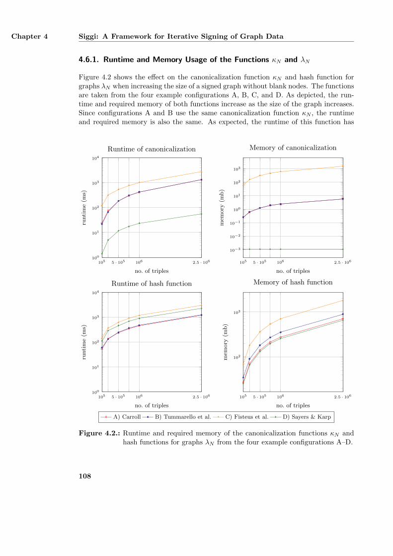
Chapter 4 Siggi: A Framework for Iterative Signing of Graph Data
4.6.1. Runtime and Memory Usage of the Functions κN and λN
Figure 4.2 shows the effect on the canonicalization function κN and hash function forgraphs λN when increasing the size of a signed graph without blank nodes. The functionsare taken from the four example configurations A, B, C, and D. As depicted, the run-time and required memory of both functions increase as the size of the graph increases.Since configurations A and B use the same canonicalization function κN , the runtimeand required memory is also the same. As expected, the runtime of this function has
105 5 · 105 106 2.5 · 106100
101
102
103
104
no. of triples
runti
me
(ms)
Runtime of canonicalization
105 5 · 105 106 2.5 · 106
10−3
10−2
10−1
100
101
102
103
no. of triples
mem
ory
(mb)
Memory of canonicalization
105 5 · 105 106 2.5 · 106100
101
102
103
104
no. of triples
runti
me
(ms)
Runtime of hash function
105 5 · 105 106 2.5 · 106
102
103
no. of triples
mem
ory
(mb)
Memory of hash function
A) Carroll B) Tummarello et al. C) Fisteus et al. D) Sayers & Karp
Figure 4.2.: Runtime and required memory of the canonicalization functions κN andhash functions for graphs λN from the four example configurations A–D.
108
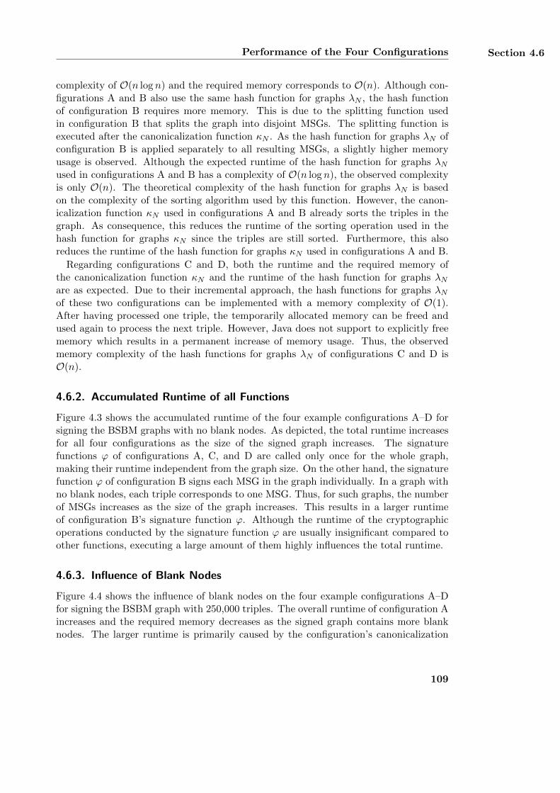
Performance of the Four Configurations Section 4.6
complexity of O(n log n) and the required memory corresponds to O(n). Although con-figurations A and B also use the same hash function for graphs λN , the hash functionof configuration B requires more memory. This is due to the splitting function usedin configuration B that splits the graph into disjoint MSGs. The splitting function isexecuted after the canonicalization function κN . As the hash function for graphs λN ofconfiguration B is applied separately to all resulting MSGs, a slightly higher memoryusage is observed. Although the expected runtime of the hash function for graphs λNused in configurations A and B has a complexity of O(n log n), the observed complexityis only O(n). The theoretical complexity of the hash function for graphs λN is basedon the complexity of the sorting algorithm used by this function. However, the canon-icalization function κN used in configurations A and B already sorts the triples in thegraph. As consequence, this reduces the runtime of the sorting operation used in thehash function for graphs κN since the triples are still sorted. Furthermore, this alsoreduces the runtime of the hash function for graphs κN used in configurations A and B.
Regarding configurations C and D, both the runtime and the required memory ofthe canonicalization function κN and the runtime of the hash function for graphs λNare as expected. Due to their incremental approach, the hash functions for graphs λNof these two configurations can be implemented with a memory complexity of O(1).After having processed one triple, the temporarily allocated memory can be freed andused again to process the next triple. However, Java does not support to explicitly freememory which results in a permanent increase of memory usage. Thus, the observedmemory complexity of the hash functions for graphs λN of configurations C and D isO(n).
4.6.2. Accumulated Runtime of all Functions
Figure 4.3 shows the accumulated runtime of the four example configurations A–D forsigning the BSBM graphs with no blank nodes. As depicted, the total runtime increasesfor all four configurations as the size of the signed graph increases. The signaturefunctions ϕ of configurations A, C, and D are called only once for the whole graph,making their runtime independent from the graph size. On the other hand, the signaturefunction ϕ of configuration B signs each MSG in the graph individually. In a graph withno blank nodes, each triple corresponds to one MSG. Thus, for such graphs, the numberof MSGs increases as the size of the graph increases. This results in a larger runtimeof configuration B’s signature function ϕ. Although the runtime of the cryptographicoperations conducted by the signature function ϕ are usually insignificant compared toother functions, executing a large amount of them highly influences the total runtime.
4.6.3. Influence of Blank Nodes
Figure 4.4 shows the influence of blank nodes on the four example configurations A–Dfor signing the BSBM graph with 250,000 triples. The overall runtime of configuration Aincreases and the required memory decreases as the signed graph contains more blanknodes. The larger runtime is primarily caused by the configuration’s canonicalization
109
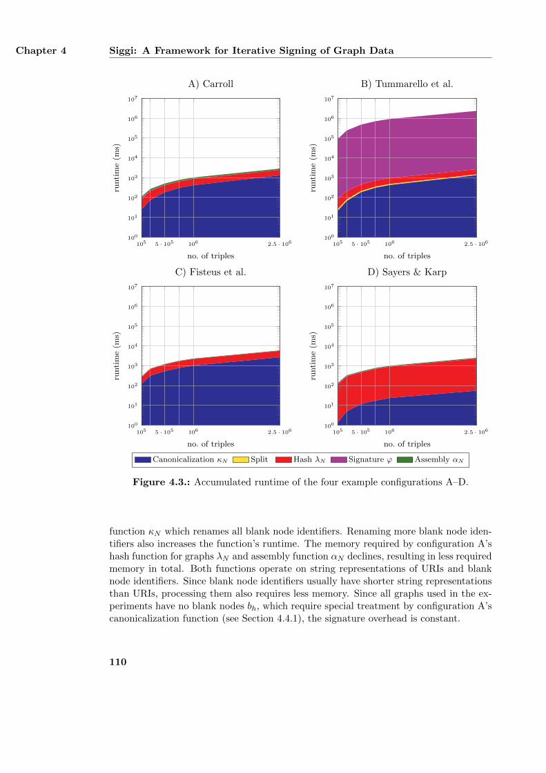
Chapter 4 Siggi: A Framework for Iterative Signing of Graph Data
105 5 · 105 106 2.5 · 106100
101
102
103
104
105
106
107
no. of triples
runti
me
(ms)
A) Carroll
105 5 · 105 106 2.5 · 106100
101
102
103
104
105
106
107
no. of triples
runti
me
(ms)
B) Tummarello et al.
105 5 · 105 106 2.5 · 106100
101
102
103
104
105
106
107
no. of triples
runti
me
(ms)
C) Fisteus et al.
105 5 · 105 106 2.5 · 106100
101
102
103
104
105
106
107
no. of triples
runti
me
(ms)
D) Sayers & Karp
Canonicalization κN Split Hash λN Signature ϕ Assembly αN
Figure 4.3.: Accumulated runtime of the four example configurations A–D.
function κN which renames all blank node identifiers. Renaming more blank node iden-tifiers also increases the function’s runtime. The memory required by configuration A’shash function for graphs λN and assembly function αN declines, resulting in less requiredmemory in total. Both functions operate on string representations of URIs and blanknode identifiers. Since blank node identifiers usually have shorter string representationsthan URIs, processing them also requires less memory. Since all graphs used in the ex-periments have no blank nodes bh, which require special treatment by configuration A’scanonicalization function (see Section 4.4.1), the signature overhead is constant.
110
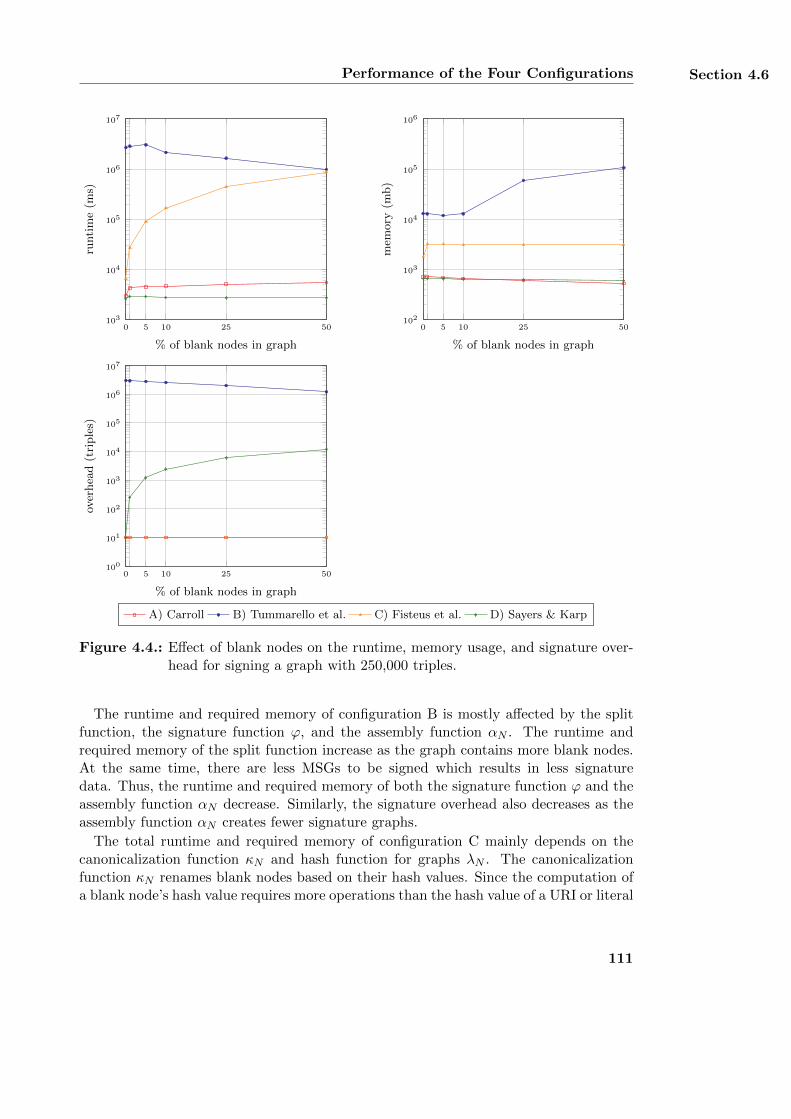
Performance of the Four Configurations Section 4.6
0 5 10 25 50103
104
105
106
107
% of blank nodes in graph
runti
me
(ms)
0 5 10 25 50102
103
104
105
106
% of blank nodes in graph
mem
ory
(mb)
0 5 10 25 50100
101
102
103
104
105
106
107
% of blank nodes in graph
over
hea
d(t
riple
s)
A) Carroll B) Tummarello et al. C) Fisteus et al. D) Sayers & Karp
Figure 4.4.: Effect of blank nodes on the runtime, memory usage, and signature over-head for signing a graph with 250,000 triples.
The runtime and required memory of configuration B is mostly affected by the splitfunction, the signature function ϕ, and the assembly function αN . The runtime andrequired memory of the split function increase as the graph contains more blank nodes.At the same time, there are less MSGs to be signed which results in less signaturedata. Thus, the runtime and required memory of both the signature function ϕ and theassembly function αN decrease. Similarly, the signature overhead also decreases as theassembly function αN creates fewer signature graphs.
The total runtime and required memory of configuration C mainly depends on thecanonicalization function κN and hash function for graphs λN . The canonicalizationfunction κN renames blank nodes based on their hash values. Since the computation ofa blank node’s hash value requires more operations than the hash value of a URI or literal
111
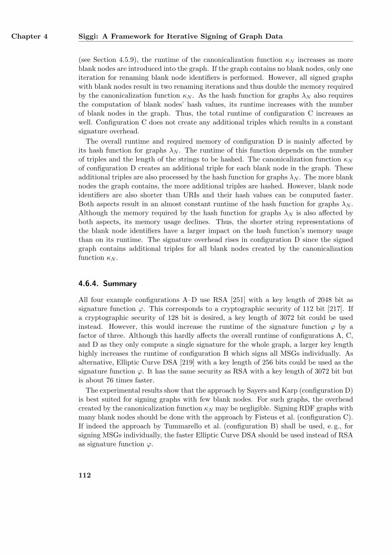
Chapter 4 Siggi: A Framework for Iterative Signing of Graph Data
(see Section 4.5.9), the runtime of the canonicalization function κN increases as moreblank nodes are introduced into the graph. If the graph contains no blank nodes, only oneiteration for renaming blank node identifiers is performed. However, all signed graphswith blank nodes result in two renaming iterations and thus double the memory requiredby the canonicalization function κN . As the hash function for graphs λN also requiresthe computation of blank nodes’ hash values, its runtime increases with the numberof blank nodes in the graph. Thus, the total runtime of configuration C increases aswell. Configuration C does not create any additional triples which results in a constantsignature overhead.
The overall runtime and required memory of configuration D is mainly affected byits hash function for graphs λN . The runtime of this function depends on the numberof triples and the length of the strings to be hashed. The canonicalization function κNof configuration D creates an additional triple for each blank node in the graph. Theseadditional triples are also processed by the hash function for graphs λN . The more blanknodes the graph contains, the more additional triples are hashed. However, blank nodeidentifiers are also shorter than URIs and their hash values can be computed faster.Both aspects result in an almost constant runtime of the hash function for graphs λN .Although the memory required by the hash function for graphs λN is also affected byboth aspects, its memory usage declines. Thus, the shorter string representations ofthe blank node identifiers have a larger impact on the hash function’s memory usagethan on its runtime. The signature overhead rises in configuration D since the signedgraph contains additional triples for all blank nodes created by the canonicalizationfunction κN .
4.6.4. Summary
All four example configurations A–D use RSA [251] with a key length of 2048 bit assignature function ϕ. This corresponds to a cryptographic security of 112 bit [217]. Ifa cryptographic security of 128 bit is desired, a key length of 3072 bit could be usedinstead. However, this would increase the runtime of the signature function ϕ by afactor of three. Although this hardly affects the overall runtime of configurations A, C,and D as they only compute a single signature for the whole graph, a larger key lengthhighly increases the runtime of configuration B which signs all MSGs individually. Asalternative, Elliptic Curve DSA [219] with a key length of 256 bits could be used as thesignature function ϕ. It has the same security as RSA with a key length of 3072 bit butis about 76 times faster.
The experimental results show that the approach by Sayers and Karp (configuration D)is best suited for signing graphs with few blank nodes. For such graphs, the overheadcreated by the canonicalization function κN may be negligible. Signing RDF graphs withmany blank nodes should be done with the approach by Fisteus et al. (configuration C).If indeed the approach by Tummarello et al. (configuration B) shall be used, e. g., forsigning MSGs individually, the faster Elliptic Curve DSA should be used instead of RSAas signature function ϕ.
112
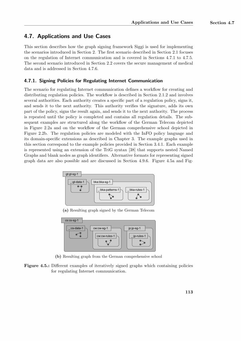
Applications and Use Cases Section 4.7
4.7. Applications and Use Cases
This section describes how the graph signing framework Siggi is used for implementingthe scenarios introduced in Section 2. The first scenario described in Section 2.1 focuseson the regulation of Internet communication and is covered in Sections 4.7.1 to 4.7.5.The second scenario introduced in Section 2.2 covers the secure management of medicaldata and is addressed in Section 4.7.6.
4.7.1. Signing Policies for Regulating Internet Communication
The scenario for regulating Internet communication defines a workflow for creating anddistributing regulation policies. The workflow is described in Section 2.1.2 and involvesseveral authorities. Each authority creates a specific part of a regulation policy, signs it,and sends it to the next authority. This authority verifies the signature, adds its ownpart of the policy, signs the result again, and sends it to the next authority. The processis repeated until the policy is completed and contains all regulation details. The sub-sequent examples are structured along the workflow of the German Telecom depictedin Figure 2.2a and on the workflow of the German comprehensive school depicted inFigure 2.2b. The regulation policies are modeled with the InFO policy language andits domain-specific extensions as described in Chapter 3. The example graphs used inthis section correspond to the example policies provided in Section 3.4.1. Each exampleis represented using an extension of the TriG syntax [38] that supports nested NamedGraphs and blank nodes as graph identifiers. Alternative formats for representing signedgraph data are also possible and are discussed in Section 4.9.6. Figure 4.5a and Fig-
_:bka-patterns-1
bka:bka-sg-1
gt:gt-sg-1
_:gt-data-1
_:bka-rules-1
(a) Resulting graph signed by the German Telecom
cw:cw-sg-1
cw:cw-rules-1
cs:cs-sg-1
_:cs-data-1 jp:jp-sg-1
_:jp-rules-1
(b) Resulting graph from the German comprehensive school
Figure 4.5.: Different examples of iteratively signed graphs which containing policiesfor regulating Internet communication.
113
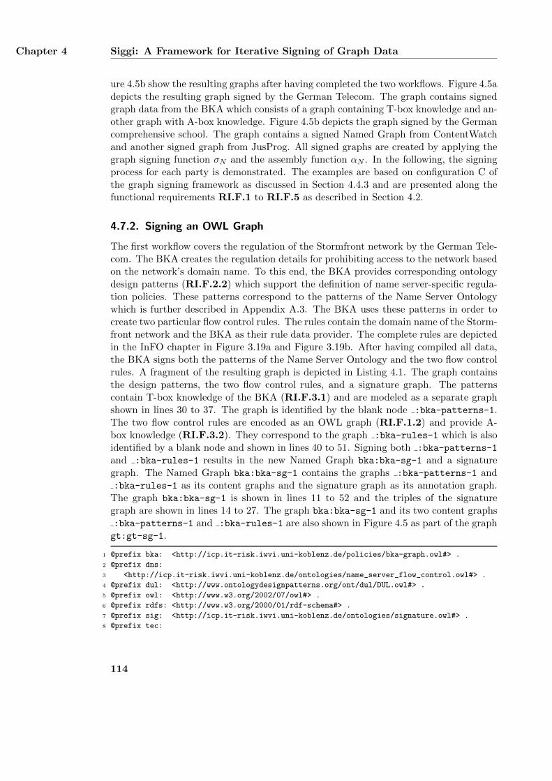
Chapter 4 Siggi: A Framework for Iterative Signing of Graph Data
ure 4.5b show the resulting graphs after having completed the two workflows. Figure 4.5adepicts the resulting graph signed by the German Telecom. The graph contains signedgraph data from the BKA which consists of a graph containing T-box knowledge and an-other graph with A-box knowledge. Figure 4.5b depicts the graph signed by the Germancomprehensive school. The graph contains a signed Named Graph from ContentWatchand another signed graph from JusProg. All signed graphs are created by applying thegraph signing function σN and the assembly function αN . In the following, the signingprocess for each party is demonstrated. The examples are based on configuration C ofthe graph signing framework as discussed in Section 4.4.3 and are presented along thefunctional requirements RI.F.1 to RI.F.5 as described in Section 4.2.
4.7.2. Signing an OWL Graph
The first workflow covers the regulation of the Stormfront network by the German Tele-com. The BKA creates the regulation details for prohibiting access to the network basedon the network’s domain name. To this end, the BKA provides corresponding ontologydesign patterns (RI.F.2.2) which support the definition of name server-specific regula-tion policies. These patterns correspond to the patterns of the Name Server Ontologywhich is further described in Appendix A.3. The BKA uses these patterns in order tocreate two particular flow control rules. The rules contain the domain name of the Storm-front network and the BKA as their rule data provider. The complete rules are depictedin the InFO chapter in Figure 3.19a and Figure 3.19b. After having compiled all data,the BKA signs both the patterns of the Name Server Ontology and the two flow controlrules. A fragment of the resulting graph is depicted in Listing 4.1. The graph containsthe design patterns, the two flow control rules, and a signature graph. The patternscontain T-box knowledge of the BKA (RI.F.3.1) and are modeled as a separate graphshown in lines 30 to 37. The graph is identified by the blank node :bka-patterns-1.The two flow control rules are encoded as an OWL graph (RI.F.1.2) and provide A-box knowledge (RI.F.3.2). They correspond to the graph :bka-rules-1 which is alsoidentified by a blank node and shown in lines 40 to 51. Signing both :bka-patterns-1
and :bka-rules-1 results in the new Named Graph bka:bka-sg-1 and a signaturegraph. The Named Graph bka:bka-sg-1 contains the graphs :bka-patterns-1 and:bka-rules-1 as its content graphs and the signature graph as its annotation graph.
The graph bka:bka-sg-1 is shown in lines 11 to 52 and the triples of the signaturegraph are shown in lines 14 to 27. The graph bka:bka-sg-1 and its two content graphs:bka-patterns-1 and :bka-rules-1 are also shown in Figure 4.5 as part of the graphgt:gt-sg-1.
1 @prefix bka: <http://icp.it-risk.iwvi.uni-koblenz.de/policies/bka-graph.owl#> .
2 @prefix dns:
3 <http://icp.it-risk.iwvi.uni-koblenz.de/ontologies/name_server_flow_control.owl#> .
4 @prefix dul: <http://www.ontologydesignpatterns.org/ont/dul/DUL.owl#> .
5 @prefix owl: <http://www.w3.org/2002/07/owl#> .
6 @prefix rdfs: <http://www.w3.org/2000/01/rdf-schema#> .
7 @prefix sig: <http://icp.it-risk.iwvi.uni-koblenz.de/ontologies/signature.owl#> .
8 @prefix tec:
114
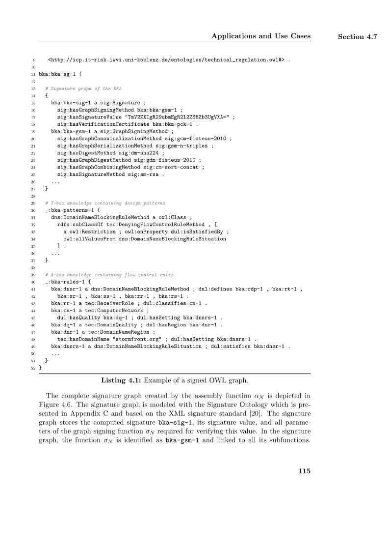
Applications and Use Cases Section 4.7
9 <http://icp.it-risk.iwvi.uni-koblenz.de/ontologies/technical_regulation.owl#> .
10
11 bka:bka-sg-1 {
12
13 # Signature graph of the BKA
14 {
15 bka:bka-sig-1 a sig:Signature ;
16 sig:hasGraphSigningMethod bka:bka-gsm-1 ;
17 sig:hasSignatureValue "TmV2ZXIgR29ubmEgR2l2ZSBZb3UgVXA=" ;
18 sig:hasVerificationCertificate bka:bka-pck-1 .
19 bka:bka-gsm-1 a sig:GraphSigningMethod ;
20 sig:hasGraphCanonicalizationMethod sig:gcm-fisteus-2010 ;
21 sig:hasGraphSerializationMethod sig:gsm-n-triples ;
22 sig:hasDigestMethod sig:dm-sha224 ;
23 sig:hasGraphDigestMethod sig:gdm-fisteus-2010 ;
24 sig:hasGraphCombiningMethod sig:cm-sort-concat ;
25 sig:hasSignatureMethod sig:sm-rsa .
26 ...
27 }
28
29 # T-box knowledge containing design patterns
30 _:bka-patterns-1 {
31 dns:DomainNameBlockingRuleMethod a owl:Class ;
32 rdfs:subClassOf tec:DenyingFlowControlRuleMethod , [
33 a owl:Restriction ; owl:onProperty dul:isSatisfiedBy ;
34 owl:allValuesFrom dns:DomainNameBlockingRuleSituation
35 ] .
36 ...
37 }
38
39 # A-box knowledge containing flow control rules
40 _:bka-rules-1 {
41 bka:dnsr-1 a dns:DomainNameBlockingRuleMethod ; dul:defines bka:rdp-1 , bka:rt-1 ,
42 bka:sr-1 , bka:ss-1 , bka:rr-1 , bka:rs-1 .
43 bka:rr-1 a tec:ReceiverRole ; dul:classifies cn-1 .
44 bka:cn-1 a tec:ComputerNetwork ;
45 dul:hasQuality bka:dq-1 ; dul:hasSetting bka:dnsrs-1 .
46 bka:dq-1 a tec:DomainQuality ; dul:hasRegion bka:dnr-1 .
47 bka:dnr-1 a tec:DomainNameRegion ;
48 tec:hasDomainName "stormfront.org" ; dul:hasSetting bka:dnsrs-1 .
49 bka:dnsrs-1 a dns:DomainNameBlockingRuleSituation ; dul:satisfies bka:dnsr-1 .
50 ...
51 }
52 }
Listing 4.1: Example of a signed OWL graph.
The complete signature graph created by the assembly function αN is depicted inFigure 4.6. The signature graph is modeled with the Signature Ontology which is pre-sented in Appendix C and based on the XML signature standard [20]. The signaturegraph stores the computed signature bka-sig-1, its signature value, and all parame-ters of the graph signing function σN required for verifying this value. In the signaturegraph, the function σN is identified as bka-gsm-1 and linked to all its subfunctions.
115
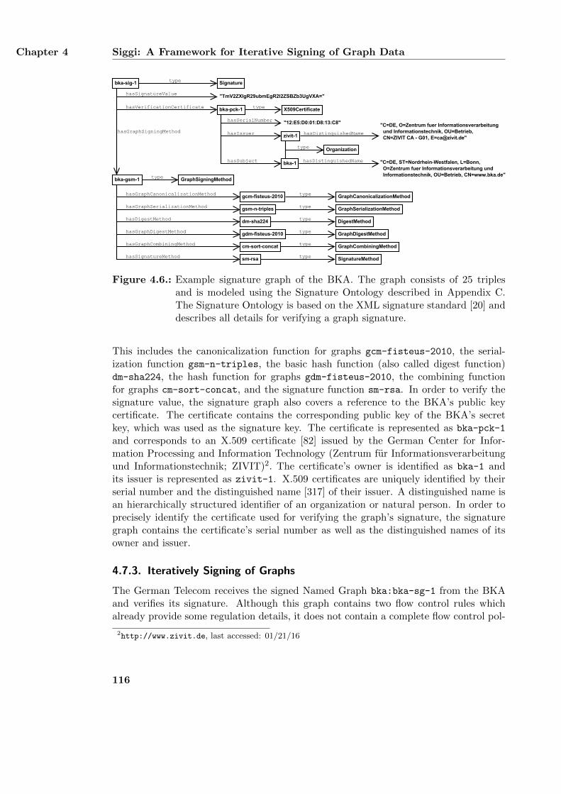
Chapter 4 Siggi: A Framework for Iterative Signing of Graph Data
bka-gsm-1
"TmV2ZXIgR29ubmEgR2l2ZSBZb3UgVXA="
hasGraphSigningMethod
hasSignatureValue
Signaturetype
GraphSigningMethodtype
gcm-fisteus-2010
dm-sha224
sm-rsa type
type
type
type
hasSignatureMethod
hasGraphSerializationMethod
hasDigestMethod
hasGraphCanonicalizationMethod GraphCanonicalizationMethod
DigestMethod
SignatureMethod
GraphSerializationMethodgsm-n-triples
gdm-fisteus-2010 type GraphDigestMethodhasGraphDigestMethod
bka-sig-1
bka-pck-1 X509Certificatetype
"12:E5:D0:01:D8:13:C8"hasSerialNumber "C=DE, O=Zentrum fuer Informationsverarbeitung
und Informationstechnik, OU=Betrieb, CN=ZIVIT CA - G01, [email protected]"
hasDistinguishedName
type
hasIssuer
hasVerificationCertificate
zivit-1
cm-sort-concat type GraphCombiningMethodhasGraphCombiningMethod
"C=DE, ST=Nordrhein-Westfalen, L=Bonn, O=Zentrum fuer Informationsverarbeitung und Informationstechnik, OU=Betrieb, CN=www.bka.de"
hasDistinguishedName bka-1
Organization
hasSubject
Figure 4.6.: Example signature graph of the BKA. The graph consists of 25 triplesand is modeled using the Signature Ontology described in Appendix C.The Signature Ontology is based on the XML signature standard [20] anddescribes all details for verifying a graph signature.
This includes the canonicalization function for graphs gcm-fisteus-2010, the serial-ization function gsm-n-triples, the basic hash function (also called digest function)dm-sha224, the hash function for graphs gdm-fisteus-2010, the combining functionfor graphs cm-sort-concat, and the signature function sm-rsa. In order to verify thesignature value, the signature graph also covers a reference to the BKA’s public keycertificate. The certificate contains the corresponding public key of the BKA’s secretkey, which was used as the signature key. The certificate is represented as bka-pck-1
and corresponds to an X.509 certificate [82] issued by the German Center for Infor-mation Processing and Information Technology (Zentrum fur Informationsverarbeitungund Informationstechnik; ZIVIT)2. The certificate’s owner is identified as bka-1 andits issuer is represented as zivit-1. X.509 certificates are uniquely identified by theirserial number and the distinguished name [317] of their issuer. A distinguished name isan hierarchically structured identifier of an organization or natural person. In order toprecisely identify the certificate used for verifying the graph’s signature, the signaturegraph contains the certificate’s serial number as well as the distinguished names of itsowner and issuer.
4.7.3. Iteratively Signing of Graphs
The German Telecom receives the signed Named Graph bka:bka-sg-1 from the BKAand verifies its signature. Although this graph contains two flow control rules whichalready provide some regulation details, it does not contain a complete flow control pol-
2http://www.zivit.de, last accessed: 01/21/16
116
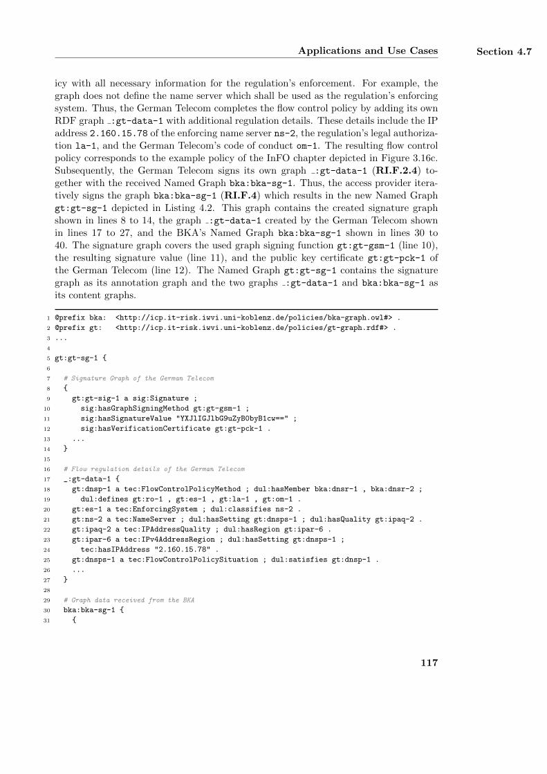
Applications and Use Cases Section 4.7
icy with all necessary information for the regulation’s enforcement. For example, thegraph does not define the name server which shall be used as the regulation’s enforcingsystem. Thus, the German Telecom completes the flow control policy by adding its ownRDF graph :gt-data-1 with additional regulation details. These details include the IPaddress 2.160.15.78 of the enforcing name server ns-2, the regulation’s legal authoriza-tion la-1, and the German Telecom’s code of conduct om-1. The resulting flow controlpolicy corresponds to the example policy of the InFO chapter depicted in Figure 3.16c.Subsequently, the German Telecom signs its own graph :gt-data-1 (RI.F.2.4) to-gether with the received Named Graph bka:bka-sg-1. Thus, the access provider itera-tively signs the graph bka:bka-sg-1 (RI.F.4) which results in the new Named Graphgt:gt-sg-1 depicted in Listing 4.2. This graph contains the created signature graphshown in lines 8 to 14, the graph :gt-data-1 created by the German Telecom shownin lines 17 to 27, and the BKA’s Named Graph bka:bka-sg-1 shown in lines 30 to40. The signature graph covers the used graph signing function gt:gt-gsm-1 (line 10),the resulting signature value (line 11), and the public key certificate gt:gt-pck-1 ofthe German Telecom (line 12). The Named Graph gt:gt-sg-1 contains the signaturegraph as its annotation graph and the two graphs :gt-data-1 and bka:bka-sg-1 asits content graphs.
1 @prefix bka: <http://icp.it-risk.iwvi.uni-koblenz.de/policies/bka-graph.owl#> .
2 @prefix gt: <http://icp.it-risk.iwvi.uni-koblenz.de/policies/gt-graph.rdf#> .
3 ...
4
5 gt:gt-sg-1 {
6
7 # Signature Graph of the German Telecom
8 {
9 gt:gt-sig-1 a sig:Signature ;
10 sig:hasGraphSigningMethod gt:gt-gsm-1 ;
11 sig:hasSignatureValue "YXJlIGJlbG9uZyB0byB1cw==" ;
12 sig:hasVerificationCertificate gt:gt-pck-1 .
13 ...
14 }
15
16 # Flow regulation details of the German Telecom
17 _:gt-data-1 {
18 gt:dnsp-1 a tec:FlowControlPolicyMethod ; dul:hasMember bka:dnsr-1 , bka:dnsr-2 ;
19 dul:defines gt:ro-1 , gt:es-1 , gt:la-1 , gt:om-1 .
20 gt:es-1 a tec:EnforcingSystem ; dul:classifies ns-2 .
21 gt:ns-2 a tec:NameServer ; dul:hasSetting gt:dnsps-1 ; dul:hasQuality gt:ipaq-2 .
22 gt:ipaq-2 a tec:IPAddressQuality ; dul:hasRegion gt:ipar-6 .
23 gt:ipar-6 a tec:IPv4AddressRegion ; dul:hasSetting gt:dnsps-1 ;
24 tec:hasIPAddress "2.160.15.78" .
25 gt:dnsps-1 a tec:FlowControlPolicySituation ; dul:satisfies gt:dnsp-1 .
26 ...
27 }
28
29 # Graph data received from the BKA
30 bka:bka-sg-1 {
31 {
117
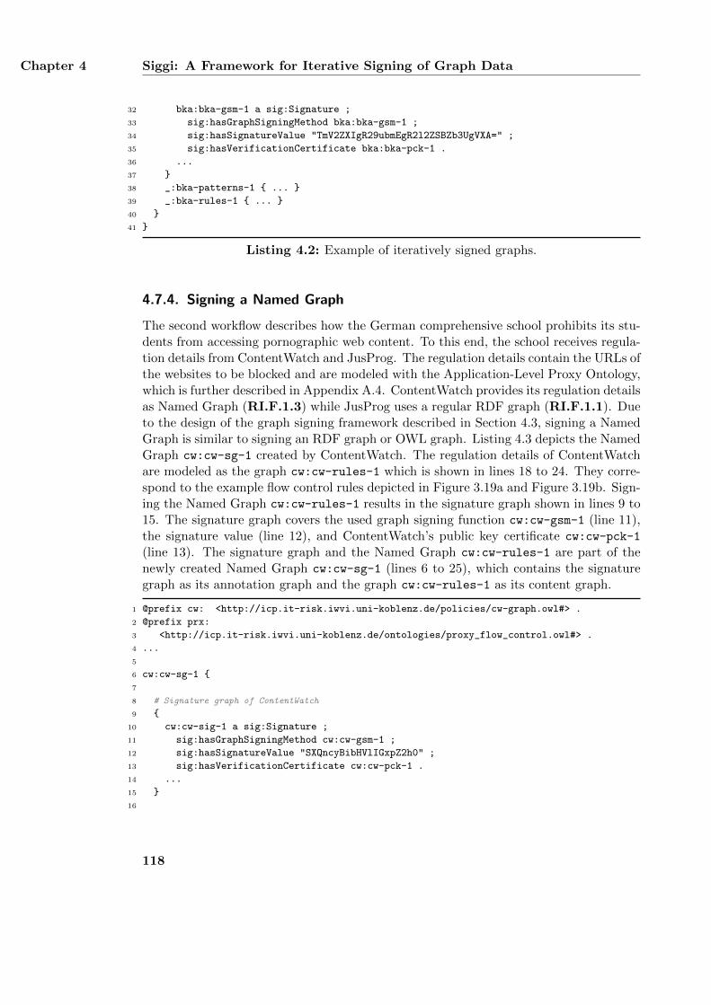
Chapter 4 Siggi: A Framework for Iterative Signing of Graph Data
32 bka:bka-gsm-1 a sig:Signature ;
33 sig:hasGraphSigningMethod bka:bka-gsm-1 ;
34 sig:hasSignatureValue "TmV2ZXIgR29ubmEgR2l2ZSBZb3UgVXA=" ;
35 sig:hasVerificationCertificate bka:bka-pck-1 .
36 ...
37 }
38 _:bka-patterns-1 { ... }
39 _:bka-rules-1 { ... }
40 }
41 }
Listing 4.2: Example of iteratively signed graphs.
4.7.4. Signing a Named Graph
The second workflow describes how the German comprehensive school prohibits its stu-dents from accessing pornographic web content. To this end, the school receives regula-tion details from ContentWatch and JusProg. The regulation details contain the URLs ofthe websites to be blocked and are modeled with the Application-Level Proxy Ontology,which is further described in Appendix A.4. ContentWatch provides its regulation detailsas Named Graph (RI.F.1.3) while JusProg uses a regular RDF graph (RI.F.1.1). Dueto the design of the graph signing framework described in Section 4.3, signing a NamedGraph is similar to signing an RDF graph or OWL graph. Listing 4.3 depicts the NamedGraph cw:cw-sg-1 created by ContentWatch. The regulation details of ContentWatchare modeled as the graph cw:cw-rules-1 which is shown in lines 18 to 24. They corre-spond to the example flow control rules depicted in Figure 3.19a and Figure 3.19b. Sign-ing the Named Graph cw:cw-rules-1 results in the signature graph shown in lines 9 to15. The signature graph covers the used graph signing function cw:cw-gsm-1 (line 11),the signature value (line 12), and ContentWatch’s public key certificate cw:cw-pck-1
(line 13). The signature graph and the Named Graph cw:cw-rules-1 are part of thenewly created Named Graph cw:cw-sg-1 (lines 6 to 25), which contains the signaturegraph as its annotation graph and the graph cw:cw-rules-1 as its content graph.
1 @prefix cw: <http://icp.it-risk.iwvi.uni-koblenz.de/policies/cw-graph.owl#> .
2 @prefix prx:
3 <http://icp.it-risk.iwvi.uni-koblenz.de/ontologies/proxy_flow_control.owl#> .
4 ...
5
6 cw:cw-sg-1 {
7
8 # Signature graph of ContentWatch
9 {
10 cw:cw-sig-1 a sig:Signature ;
11 sig:hasGraphSigningMethod cw:cw-gsm-1 ;
12 sig:hasSignatureValue "SXQncyBibHVlIGxpZ2h0" ;
13 sig:hasVerificationCertificate cw:cw-pck-1 .
14 ...
15 }
16
118
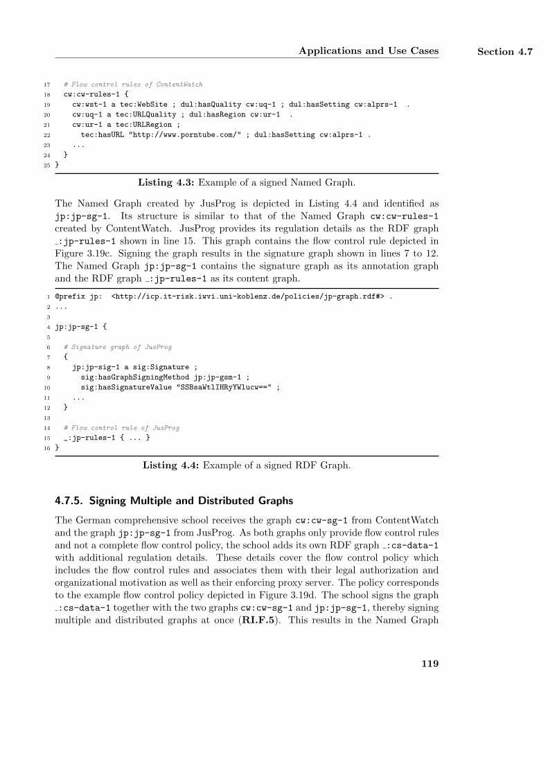
Applications and Use Cases Section 4.7
17 # Flow control rules of ContentWatch
18 cw:cw-rules-1 {
19 cw:wst-1 a tec:WebSite ; dul:hasQuality cw:uq-1 ; dul:hasSetting cw:alprs-1 .
20 cw:uq-1 a tec:URLQuality ; dul:hasRegion cw:ur-1 .
21 cw:ur-1 a tec:URLRegion ;
22 tec:hasURL "http://www.porntube.com/" ; dul:hasSetting cw:alprs-1 .
23 ...
24 }
25 }
Listing 4.3: Example of a signed Named Graph.
The Named Graph created by JusProg is depicted in Listing 4.4 and identified asjp:jp-sg-1. Its structure is similar to that of the Named Graph cw:cw-rules-1
created by ContentWatch. JusProg provides its regulation details as the RDF graph:jp-rules-1 shown in line 15. This graph contains the flow control rule depicted in
Figure 3.19c. Signing the graph results in the signature graph shown in lines 7 to 12.The Named Graph jp:jp-sg-1 contains the signature graph as its annotation graphand the RDF graph :jp-rules-1 as its content graph.
1 @prefix jp: <http://icp.it-risk.iwvi.uni-koblenz.de/policies/jp-graph.rdf#> .
2 ...
3
4 jp:jp-sg-1 {
5
6 # Signature graph of JusProg
7 {
8 jp:jp-sig-1 a sig:Signature ;
9 sig:hasGraphSigningMethod jp:jp-gsm-1 ;
10 sig:hasSignatureValue "SSBsaWtlIHRyYWlucw==" ;
11 ...
12 }
13
14 # Flow control rule of JusProg
15 _:jp-rules-1 { ... }
16 }
Listing 4.4: Example of a signed RDF Graph.
4.7.5. Signing Multiple and Distributed Graphs
The German comprehensive school receives the graph cw:cw-sg-1 from ContentWatchand the graph jp:jp-sg-1 from JusProg. As both graphs only provide flow control rulesand not a complete flow control policy, the school adds its own RDF graph :cs-data-1
with additional regulation details. These details cover the flow control policy whichincludes the flow control rules and associates them with their legal authorization andorganizational motivation as well as their enforcing proxy server. The policy correspondsto the example flow control policy depicted in Figure 3.19d. The school signs the graph:cs-data-1 together with the two graphs cw:cw-sg-1 and jp:jp-sg-1, thereby signing
multiple and distributed graphs at once (RI.F.5). This results in the Named Graph
119
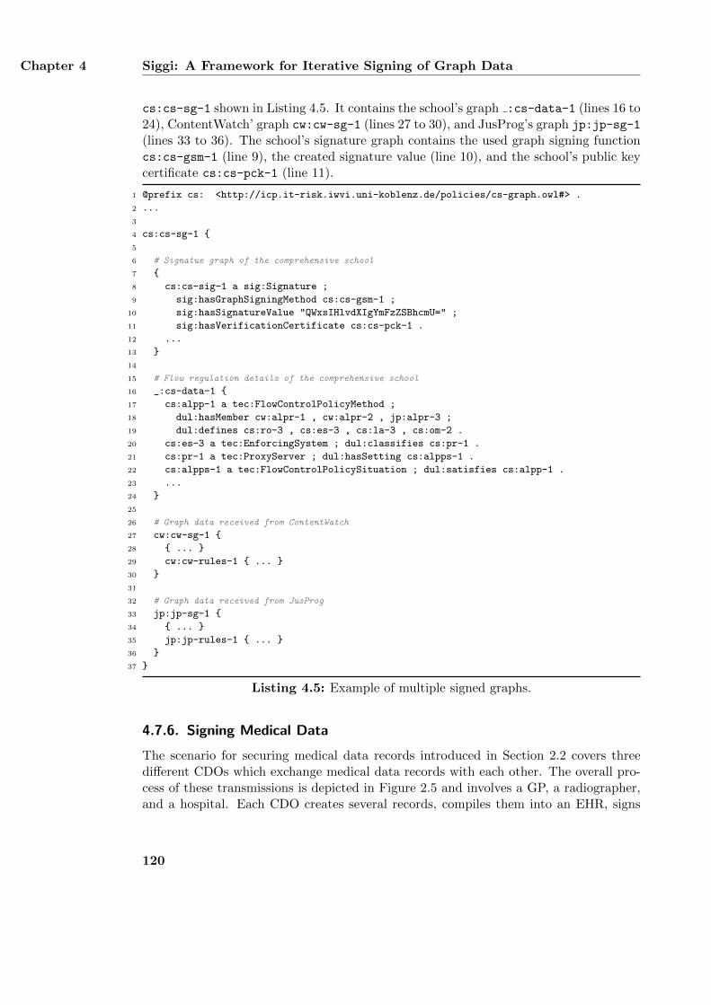
Chapter 4 Siggi: A Framework for Iterative Signing of Graph Data
cs:cs-sg-1 shown in Listing 4.5. It contains the school’s graph :cs-data-1 (lines 16 to24), ContentWatch’ graph cw:cw-sg-1 (lines 27 to 30), and JusProg’s graph jp:jp-sg-1
(lines 33 to 36). The school’s signature graph contains the used graph signing functioncs:cs-gsm-1 (line 9), the created signature value (line 10), and the school’s public keycertificate cs:cs-pck-1 (line 11).
1 @prefix cs: <http://icp.it-risk.iwvi.uni-koblenz.de/policies/cs-graph.owl#> .
2 ...
3
4 cs:cs-sg-1 {
5
6 # Signatue graph of the comprehensive school
7 {
8 cs:cs-sig-1 a sig:Signature ;
9 sig:hasGraphSigningMethod cs:cs-gsm-1 ;
10 sig:hasSignatureValue "QWxsIHlvdXIgYmFzZSBhcmU=" ;
11 sig:hasVerificationCertificate cs:cs-pck-1 .
12 ...
13 }
14
15 # Flow regulation details of the comprehensive school
16 _:cs-data-1 {
17 cs:alpp-1 a tec:FlowControlPolicyMethod ;
18 dul:hasMember cw:alpr-1 , cw:alpr-2 , jp:alpr-3 ;
19 dul:defines cs:ro-3 , cs:es-3 , cs:la-3 , cs:om-2 .
20 cs:es-3 a tec:EnforcingSystem ; dul:classifies cs:pr-1 .
21 cs:pr-1 a tec:ProxyServer ; dul:hasSetting cs:alpps-1 .
22 cs:alpps-1 a tec:FlowControlPolicySituation ; dul:satisfies cs:alpp-1 .
23 ...
24 }
25
26 # Graph data received from ContentWatch
27 cw:cw-sg-1 {
28 { ... }
29 cw:cw-rules-1 { ... }
30 }
31
32 # Graph data received from JusProg
33 jp:jp-sg-1 {
34 { ... }
35 jp:jp-rules-1 { ... }
36 }
37 }
Listing 4.5: Example of multiple signed graphs.
4.7.6. Signing Medical Data
The scenario for securing medical data records introduced in Section 2.2 covers threedifferent CDOs which exchange medical data records with each other. The overall pro-cess of these transmissions is depicted in Figure 2.5 and involves a GP, a radiographer,and a hospital. Each CDO creates several records, compiles them into an EHR, signs
120
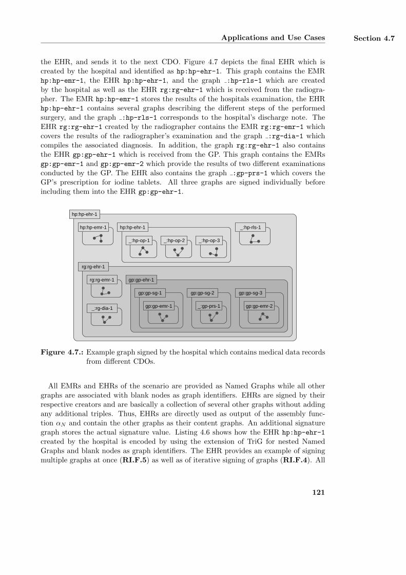
Applications and Use Cases Section 4.7
the EHR, and sends it to the next CDO. Figure 4.7 depicts the final EHR which iscreated by the hospital and identified as hp:hp-ehr-1. This graph contains the EMRhp:hp-emr-1, the EHR hp:hp-ehr-1, and the graph :hp-rls-1 which are createdby the hospital as well as the EHR rg:rg-ehr-1 which is received from the radiogra-pher. The EMR hp:hp-emr-1 stores the results of the hospitals examination, the EHRhp:hp-ehr-1 contains several graphs describing the different steps of the performedsurgery, and the graph :hp-rls-1 corresponds to the hospital’s discharge note. TheEHR rg:rg-ehr-1 created by the radiographer contains the EMR rg:rg-emr-1 whichcovers the results of the radiographer’s examination and the graph :rg-dia-1 whichcompiles the associated diagnosis. In addition, the graph rg:rg-ehr-1 also containsthe EHR gp:gp-ehr-1 which is received from the GP. This graph contains the EMRsgp:gp-emr-1 and gp:gp-emr-2 which provide the results of two different examinationsconducted by the GP. The EHR also contains the graph :gp-prs-1 which covers theGP’s prescription for iodine tablets. All three graphs are signed individually beforeincluding them into the EHR gp:gp-ehr-1.
rg:rg-ehr-1
gp:gp-ehr-1
_:gp-prs-1
gp:gp-sg-1
gp:gp-emr-1
gp:gp-sg-2 gp:gp-sg-3
gp:gp-emr-2_:rg-dia-1
rg:rg-emr-1
hp:hp-emr-1 hp:hp-ehr-1
_:hp-op-2_:hp-op-1 _:hp-op-3
_:hp-rls-1
hp:hp-ehr-1
Figure 4.7.: Example graph signed by the hospital which contains medical data recordsfrom different CDOs.
All EMRs and EHRs of the scenario are provided as Named Graphs while all othergraphs are associated with blank nodes as graph identifiers. EHRs are signed by theirrespective creators and are basically a collection of several other graphs without addingany additional triples. Thus, EHRs are directly used as output of the assembly func-tion αN and contain the other graphs as their content graphs. An additional signaturegraph stores the actual signature value. Listing 4.6 shows how the EHR hp:hp-ehr-1
created by the hospital is encoded by using the extension of TriG for nested NamedGraphs and blank nodes as graph identifiers. The EHR provides an example of signingmultiple graphs at once (RI.F.5) as well as of iterative signing of graphs (RI.F.4). All
121
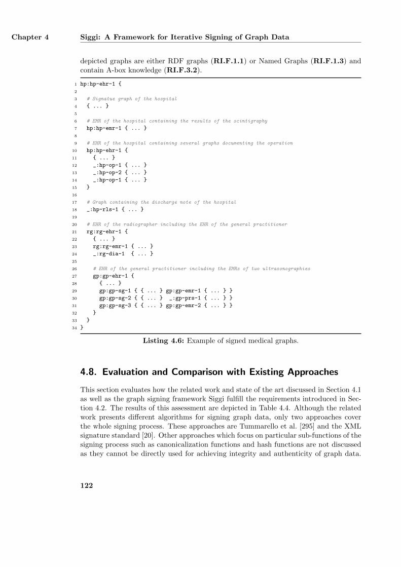
Chapter 4 Siggi: A Framework for Iterative Signing of Graph Data
depicted graphs are either RDF graphs (RI.F.1.1) or Named Graphs (RI.F.1.3) andcontain A-box knowledge (RI.F.3.2).
1 hp:hp-ehr-1 {
2
3 # Signatue graph of the hospital
4 { ... }
5
6 # EMR of the hospital containing the results of the scintigraphy
7 hp:hp-emr-1 { ... }
8
9 # EHR of the hospital containing several graphs documenting the operation
10 hp:hp-ehr-1 {
11 { ... }
12 _:hp-op-1 { ... }
13 _:hp-op-2 { ... }
14 _:hp-op-1 { ... }
15 }
16
17 # Graph containing the discharge note of the hospital
18 _:hp-rls-1 { ... }
19
20 # EHR of the radiographer including the EHR of the general practitioner
21 rg:rg-ehr-1 {
22 { ... }
23 rg:rg-emr-1 { ... }
24 _:rg-dia-1 { ... }
25
26 # EHR of the general practitioner including the EMRs of two ultrasonographies
27 gp:gp-ehr-1 {
28 { ... }
29 gp:gp-sg-1 { { ... } gp:gp-emr-1 { ... } }
30 gp:gp-sg-2 { { ... } _:gp-prs-1 { ... } }
31 gp:gp-sg-3 { { ... } gp:gp-emr-2 { ... } }
32 }
33 }
34 }
Listing 4.6: Example of signed medical graphs.
4.8. Evaluation and Comparison with Existing Approaches
This section evaluates how the related work and state of the art discussed in Section 4.1as well as the graph signing framework Siggi fulfill the requirements introduced in Sec-tion 4.2. The results of this assessment are depicted in Table 4.4. Although the relatedwork presents different algorithms for signing graph data, only two approaches coverthe whole signing process. These approaches are Tummarello et al. [295] and the XMLsignature standard [20]. Other approaches which focus on particular sub-functions of thesigning process such as canonicalization functions and hash functions are not discussedas they cannot be directly used for achieving integrity and authenticity of graph data.
122
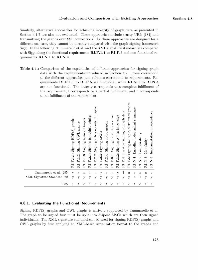
Evaluation and Comparison with Existing Approaches Section 4.8
Similarly, alternative approaches for achieving integrity of graph data as presented inSection 4.1.7 are also not evaluated. These approaches include trusty URIs [184] andtransmitting the graphs over SSL connections. As these approaches are designed for adifferent use case, they cannot be directly compared with the graph signing frameworkSiggi. In the following, Tummarello et al. and the XML signature standard are comparedwith Siggi along the functional requirements RI.F.1.1 to RI.F.5 and non-functional re-quirements RI.N.1 to RI.N.4.
Table 4.4.: Comparison of the capabilities of different approaches for signing graphdata with the requirements introduced in Section 4.2. Rows correspondto the different approaches and columns correspond to requirements. Re-quirements RI.F.1.1 to RI.F.5 are functional, while RI.N.1 to RI.N.4are non-functional. The letter y corresponds to a complete fulfillment ofthe requirement, l corresponds to a partial fulfillment, and n correspondsto no fulfillment of the requirement.
RI.
F.1
.1:
Sig
nin
gR
DF
(S)
grap
hs
RI.
F.1
.2:
Sig
nin
gO
WL
grap
hs
RI.
F.1
.3:
Sig
nin
gN
amed
Gra
ph
s
RI.
F.2
.1:
Sig
nin
gin
div
idu
altr
iple
s
RI.
F.2
.2:
Sig
nin
gar
bit
rary
sets
oftr
iple
s
RI.
F.2
.3:
Sig
nin
gM
SG
s
RI.
F.2
.4:
Sig
nin
gen
tire
grap
hs
RI.
F.3
.1:
Sig
nin
gT
-box
kn
owle
dge
RI.
F.3
.2:
Sig
nin
gA
-box
kn
owle
dge
RI.
F.4
:It
erat
ive
sign
ing
ofgr
aph
data
RI.
F.5
:S
ign
ing
mu
ltip
le,
dis
trib
ute
dgra
ph
s
RI.
N.1
:E
nco
din
g-in
dep
end
ent
sign
atu
re
RI.
N.2
:C
onfi
gura
bil
ity
RI.
N.3
:M
od
ula
rity
RI.
N.4
:Im
ple
men
tati
on
ind
epen
den
ce
Tummarello et al. [295] y y n l n y y y y l n y n n y
XML Signature Standard [20] y y y y y y y y y y y n l y y
Siggi y y y y y y y y y y y y y y y
4.8.1. Evaluating the Functional Requirements
Signing RDF(S) graphs and OWL graphs is natively supported by Tummarello et al.The graph to be signed first must be split into disjoint MSGs which are then signedindividually. The XML signature standard can be used for signing RDF(S) graphs andOWL graphs by first applying an XML-based serialization format to the graphs and
123
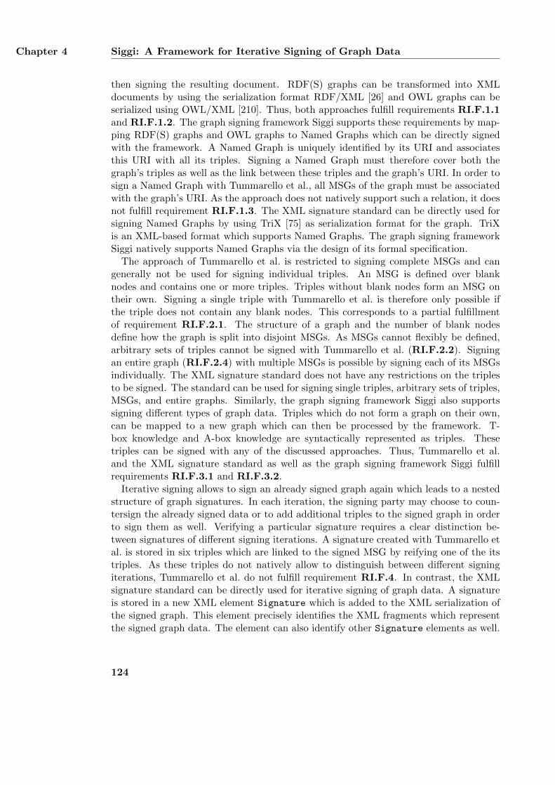
Chapter 4 Siggi: A Framework for Iterative Signing of Graph Data
then signing the resulting document. RDF(S) graphs can be transformed into XMLdocuments by using the serialization format RDF/XML [26] and OWL graphs can beserialized using OWL/XML [210]. Thus, both approaches fulfill requirements RI.F.1.1and RI.F.1.2. The graph signing framework Siggi supports these requirements by map-ping RDF(S) graphs and OWL graphs to Named Graphs which can be directly signedwith the framework. A Named Graph is uniquely identified by its URI and associatesthis URI with all its triples. Signing a Named Graph must therefore cover both thegraph’s triples as well as the link between these triples and the graph’s URI. In order tosign a Named Graph with Tummarello et al., all MSGs of the graph must be associatedwith the graph’s URI. As the approach does not natively support such a relation, it doesnot fulfill requirement RI.F.1.3. The XML signature standard can be directly used forsigning Named Graphs by using TriX [75] as serialization format for the graph. TriXis an XML-based format which supports Named Graphs. The graph signing frameworkSiggi natively supports Named Graphs via the design of its formal specification.
The approach of Tummarello et al. is restricted to signing complete MSGs and cangenerally not be used for signing individual triples. An MSG is defined over blanknodes and contains one or more triples. Triples without blank nodes form an MSG ontheir own. Signing a single triple with Tummarello et al. is therefore only possible ifthe triple does not contain any blank nodes. This corresponds to a partial fulfillmentof requirement RI.F.2.1. The structure of a graph and the number of blank nodesdefine how the graph is split into disjoint MSGs. As MSGs cannot flexibly be defined,arbitrary sets of triples cannot be signed with Tummarello et al. (RI.F.2.2). Signingan entire graph (RI.F.2.4) with multiple MSGs is possible by signing each of its MSGsindividually. The XML signature standard does not have any restrictions on the triplesto be signed. The standard can be used for signing single triples, arbitrary sets of triples,MSGs, and entire graphs. Similarly, the graph signing framework Siggi also supportssigning different types of graph data. Triples which do not form a graph on their own,can be mapped to a new graph which can then be processed by the framework. T-box knowledge and A-box knowledge are syntactically represented as triples. Thesetriples can be signed with any of the discussed approaches. Thus, Tummarello et al.and the XML signature standard as well as the graph signing framework Siggi fulfillrequirements RI.F.3.1 and RI.F.3.2.
Iterative signing allows to sign an already signed graph again which leads to a nestedstructure of graph signatures. In each iteration, the signing party may choose to coun-tersign the already signed data or to add additional triples to the signed graph in orderto sign them as well. Verifying a particular signature requires a clear distinction be-tween signatures of different signing iterations. A signature created with Tummarello etal. is stored in six triples which are linked to the signed MSG by reifying one of the itstriples. As these triples do not natively allow to distinguish between different signingiterations, Tummarello et al. do not fulfill requirement RI.F.4. In contrast, the XMLsignature standard can be directly used for iterative signing of graph data. A signatureis stored in a new XML element Signature which is added to the XML serialization ofthe signed graph. This element precisely identifies the XML fragments which representthe signed graph data. The element can also identify other Signature elements as well.
124
Evaluation and Comparison with Existing Approaches Section 4.8
This can be used for iteratively signing a graph together with additional triples. Thegraph signing framework Siggi supports iterative signing of graph data via the design ofits assembly function αN .
Tummarello et al. do not support signing multiple graphs at once (RI.F.5) as it focuseson signing individual MSGs only. Due to its design, the approach neither supportssigning all MSGs of a single graphs at once nor signing all MSGs of multiple graphsat the same time. On the other hand, the XML signature standard can be used forsigning multiple and distributed XML documents via the use of detached signatures.Such signatures allow to refer to the signed XML documents by their remote URI. EachXML document can contain one or more graphs, allowing the XML signature standardto sign multiple and distributed graphs as well. The graph signing framework Siggifulfills requirement RI.F.5 via the design of its combining function for graphs %N .
4.8.2. Evaluating the Non-Functional Requirements
Tummarello et al. and the graph signing framework Siggi do not rely on a particularserialization format of the graph data to be signed. Instead, they interpret the graph asan abstract data structure and thus fulfill requirement RI.N.1. In contrast, the XMLsignature standard requires an XML serialization of the graph. Although a graph canalso be signed by signing a particular XML serialization of it, the resulting signature isinextricably linked to the signed XML document. It is attached to the signed documentas a new Signature element which consists of plain XML data and does not contain anytriples. If the serialization of the graph is lost, e. g., by loading the graph into a triplestore, the signature can no longer be verified. Re-creating the particular serializationrequires the same blank node identifiers and the same order of triples as used in thesigned graph. Even if the serialization can be re-created, the Signature element maystill be lost as it does not contain any triples which can be processed as graph data.Thus, the contents of this element cannot be stored with the graph when loading itinto a triple store. In order to create a stable signature for a graph using the XMLsignature standard, a canonicalization function κN , a hash function for graphs λN , andan assembly function αN must be used as defined in the graph signing framework Siggi.The canonicalization function and the hash function ensure that renaming blank nodeidentifiers and re-ordering the triples does not invalidate the graph’s signature. Theassembly function ensures that the information for verifying the signature is provided asgraph data which can also be processed together with the signed graph. None of thesefunctions are natively supported by the XML signature standard and are only part ofthe graph signing framework Siggi. Thus, the XML signature standard does not fulfillrequirement RI.N.1.
The graph signing framework Siggi provides a generic signature pipeline without rely-ing on any particular algorithm. Instead, it can be configured with different algorithmsand thus fulfills requirement RI.N.2. As the signature pipeline of the framework also hasa modular design, it fulfills requirement RI.N.3 as well. Similarly, the XML signaturestandard also provides a generic signature pipeline which supports different algorithms.However, in contrast to Siggi, the XML signature standard only supports one particular
125
Chapter 4 Siggi: A Framework for Iterative Signing of Graph Data
assembly function αN which stores all details for verifying the signature in an XMLelement. Thus, the XML signature standard only partially fulfills requirement RI.N.2.As the signature pipeline of the XML signature standard has a modular design, the stan-dard fulfills requirement RI.N.3 as well. In contrast, Tummarello et al. define specificalgorithms for the signing process to be used. Thus, the approach neither fulfills require-ment RI.N.2 nor requirement RI.N.3. All three approaches focus on signing graph dataon a conceptual level. As they do not rely on any particular software implementation,they all fulfill requirement RI.N.4.
4.8.3. Summary
Tummarello et al. do not fulfill all functional and non-functional requirements definedin Section 4.2. As the graph signing framework Siggi provides a generic frameworkof the signing process, the approach of Tummarello et al. can be integrated into Siggiand corresponds to configuration B of the framework as described in Section 4.4.2. Incontrast, the XML signature standard fulfills almost all of these requirements exceptfor requirement RI.N.1 which corresponds to an encoding independent signature. TheXML signature standard only supports signing XML documents and cannot be directlyused for signing Semantic Web graphs. Even signing XML serializations of such graphsstill requires the steps defined in the signature pipeline of Siggi. However, the graphsigning framework Siggi reuses many of the concepts provided in the XML signaturestandard such as its modular signature pipeline which can be configured with variousalgorithms.
4.9. Limitations and Future Extensions
As demonstrated in the previous section, the graph signing framework Siggi fulfills allfunctional and non-functional requirements defined in Section 4.2. However, the frame-work only provides a formal specification of the signing process. In order to actuallyuse the framework for signing graph data, it must be implemented in software or hard-ware. Furthermore, this implementation may be part of a particular environment orapplication context which requires additional security considerations. This section firstdescribes the aspects that must be considered when using the graph signing frameworkSiggi in practice. Afterwards, possible extensions to the framework are discussed.
4.9.1. Reasoning on Signed Graph Data
Reasoning is the process of inferring additional data from existing data [11]. A SemanticWeb reasoner uses T-box knowledge in order to interpret the provided A-box knowledge.The interpretation results in additional triples which may be included in the originalA-box knowledge. Reasoning on signed data may invalidate the signature if it is nolonger possible to distinguish between the original data and the data created through thereasoning process. In order to prohibit a reasoner from invalidating a graph’s signature,it is necessary to store the inferred data separately from the original graph data. This
126
Limitations and Future Extensions Section 4.9
can be achieved by creating additional graphs for storing only the inferred triples. Triplestores such as Sesame [54] and Jena [74] provide mechanisms for implementing such adistinction. If it is also required to sign the inferred triples together with the originaltriples, iterative signing can be used. In this case, the graph which stores the inferredtriples is signed together with the already signed graph that contains the original triples.
4.9.2. Security of the Graph Signing Framework
The main goal of the graph signing framework Siggi is to provide integrity and authen-ticity of graph data. In order to achieve these main objectives, the framework must besecure. The security of the graph signing framework Siggi depends on several aspects, in-cluding the cryptographic security of the algorithms used for a particular configuration,the security of the software implementation, and the security of the environment in whichthe software implementation is applied. The cryptographic security of the algorithmsis discussed in Section 4.5. However, a cryptanalysis does not consider the context inwhich the algorithms are applied. Even though the used algorithms may be secure, it isstill possible for a software implementation of the framework to contain implementationerrors which may lead to security vulnerabilities. In order to assess the security of aparticular software implementation, product-oriented methods such as [80, 66] can beused. These methods provide a framework for assessing the security of various IT prod-ucts including software and hardware. A particular implementation of the graph signingframework may be part of a larger IT system. The security of such IT systems as wellas their environment also influences the security of the actual signing process. Thus, itis necessary to evaluate the security of these systems and their respective environmentto ensure that the framework’s main objectives are fulfilled. The security of the environ-ment can be evaluated by using holistic approaches such as [133, 59]. Important securityaspects of the environment such as trust models and key management are discussed inSections 4.9.4 and 4.9.3.
4.9.3. Key Management
The signature of a signed graph associates the graph with the owner of the secret signingkey. Key management defines different organizational tasks for protecting the signingkey as well as its corresponding public key from being compromised and misused byunauthorized parties. The tasks of key management include the generation of the keypair, its secure storage, its distribution, and its secure destruction [269, 217]. Thesetasks ensure that a secret signature key is only known to and used by its actual ownerand that the corresponding public signature verification key can be related to this owner.Creating a key pair and storing the private key in a secure environment ensures thatonly authorized parties have access to the private key. Destroying old keys is necessaryto prohibit a usage beyond their intended lifetime. Keys which are too old may not besecure anymore due to new attacks or greater computational power available to breakthe keys. Compromised keys must be revoked to prevent any further usage of them. Theparticular implementation of the individual key management tasks depends on the appli-
127
Chapter 4 Siggi: A Framework for Iterative Signing of Graph Data
cation and environment in which the graph signing framework Siggi is used. Professionalenvironments may have higher security requirements than private applications. Detailedguidelines for key management in professional environments are provided in [216, 217].
4.9.4. Public Key Infrastructure and Trust Model
Digitally signing graph data is a security mechanism for implementing authenticity ofthe signed data. The graph data is authentic if it is retrieved from an identified datasource and if the identity of this data source is proven to be correct [28]. In order toprove the identity of the signing party, authenticity of graph data requires a connectionbetween the secret signing key and its owner. Such a connection is created via a publickey certificate which contains both the public key of the secret signing key and anidentifier of its owner [4, 317]. Example identifiers are e-mail addresses or distinguishednames [317]. Public key certificates are managed by public key infrastructures (PKIs)which ensure that the mapping provided by a public key certificate is actually correct.The management of public key certificates includes the creation and distribution ofthe certificates as well as their revocation [5]. A PKI consists of several services whichinclude a certification authority (CA) and a registration authority (RA). The registrationauthority verifies the identity of a party and the party’s ownership of a key pair [232, 4].The verified mapping is then sent to the certification authority which issues the publickey certificate [269].
A PKI only provides an infrastructure for managing public keys. The organizationalprocesses for verifying the identities of certificate owners and issuing their certificatesdepend on the certificate authority. A trust model defines the conditions under which anentity trusts a public key certificate and its creation by a CA [6]. By signing a public keycertificate, a CA states that the party identified in the certificate is actually the owner ofthe certificate’s public key. Thus, the trustworthiness of a public key certificate dependson the trustworthiness of its issuing CA. Trust is basically a subjective assumption of aPKI user [6] that the CA behaves in such a way the user expects it to [290]. Differenttrust models provide different methods for managing trust between users and CAs ofa PKI. Two widely used trust models for public key certificates are PGP [320] andX.509 [82]. X.509 organizes all CAs as a hierarchy with a few trusted root CAs whichissue public key certificates for other CAs. These CAs may issue public key certificatesto other CAs as well or provide public key certificates to end users. In the X.509 model,the trust of the hierarchy depends on the trust of the root CAs which are usually pre-configured as trust-worthy in most operating systems. In contrast, PGP has no hierarchyand allows its participants to be end users and CAs at the same time, resulting in ainterconnected web of certificates. In the PGP model, trusting a CA is achieved byissuing a certificate directly or by manually selecting a trust-worthy certification path.Applying a particular trust model depends on the intended application. While X.509may be used in professional environments, PGP is mostly sufficient for private use. Anoverview of different trust models and their characteristics is provided in [232, 6].
128
Limitations and Future Extensions Section 4.9
4.9.5. Secure Time Stamps
The examples provided in Section 4.7 demonstrate how the graph signing frameworkSiggi can be applied for signing graph data. The examples also include a possible sig-nature graph providing the basic information about the signature verification process.However, the examples do not contain any additional data which may be relevant forthe context in which the signature is used. Such data may include a time stamp thatspecifies when the signature was created. This can be used for defining the topicality ofthe signature and the data. A time stamp may be provided by a secure time stampingservice which provides signed time stamp information [7]. If the time stamp is providedas graph data, it can be signed using the graph signing framework. The resulting graphcan then be signed together with the actual graph data using the framework’s iterativesigning feature.
4.9.6. Alternative Assembly Functions
The assembly function αN attaches a signature graph to a signed graph by embeddingboth graphs into a new Named Graph. In the examples of Section 4.7, the assemblyfunction encodes this Named Graph by using an extended version of TriG [40] which sup-ports nested Named Graphs and blank nodes as graph identifiers. However, the assemblyfunction can also be built upon alternative encodings which are directly compatible withexisting Semantic Web concepts such as RDF datasets [87]. An RDF dataset is similarto a Named Graph except that it does not support nested structures or blank nodes asgraph identifiers. Thus, RDF datasets can be expressed with the regular TriG syntax.In order to encode a Named Graph as an RDF dataset, its nested structure must bemapped to a flat structure and blank nodes as graph identifiers must be eliminated.Removing the nested structure can be achieved by storing all subgraphs in differentTriG documents so that the resulting documents contain only valid RDF datasets. Thenested structure of the original graphs can then be expressed by creating additionaltriples which explicitly describe the graphs’ nested structures. This can be done byusing a property such as hasSubGraph to relate a graph to its corresponding subgraphs.Blank nodes used as graph identifiers can be eliminated by replacing them with URIs.
Another alternative encoding of nested Named Graphs is the use of N-Quads [71].N-Quads is an extension of N-Triples which adds an optional additional context URIto each triple. The context URI corresponds to the URI of the graph containing thetriple and allows N-Quads to be used for encoding Named Graphs. Similar to TriG,N-Quads does not support nested graphs or blank nodes as graph identifiers. In orderto use N-Quads for encoding Named Graphs as defined in Equation 4.3, blank nodesfirst must be mapped to URIs and the nested structure must be transformed to a flatstructure. This can be achieved by storing all subgraphs in separate N-Quads documentsand introducing additional triples which describe the nested structure of the originalgraphs. As the graph signing framework Siggi does not rely on any particular assemblyfunction αN , both alternative encodings are already compatible with the framework.
129
Chapter 4 Siggi: A Framework for Iterative Signing of Graph Data
4.10. Summary
This chapter has presented the graph signing framework Siggi which supports iterativesigning of graph data. It allows to sign graphs at different levels of granularity, signingNamed Graphs, and signing multiple and distributed graphs at once. It is based ona formal specification which divides the signing process into different steps. Each stepcan be implemented with various algorithms, allowing the framework to be configuredfor achieving different features such as minimum signature overhead or minimum run-time. The framework processes a graph as abstract data structure and does not rely ona particular encoding. Thus, a signature created with the graph signing framework isindependent from the order of the triples in the graph, the local identifiers of the graph’sblank nodes, and the used serialization format. As signing a graph achieves integrityand authenticity of the graph, the graph signing framework Siggi answers research ques-tions RQ.2 and RQ.3.
130
Chapter 5.
T-Store:Searching in Encrypted Graph Data
This chapter presents T-Store, an approach for searching in encrypted RDF graphs.T-Store restricts access to particular triples of a plaintext graph to authorized parties,i. e., only authorized parties are able to apply queries to the corresponding ciphertextgraph. Unauthorized parties are not able to access any plaintext triples and even autho-rized parties can only retrieve triples which match a legitimate query. Thereby, T-Storeachieves confidentiality of the plaintext graph and answers research question RQ.1. Afundamental design principle of T-Store is the distinction between a data owner andseveral users. The data owner possesses the plaintext graph and manages its access. Tothis end, the data owner encrypts the plaintext graph and sends the resulting ciphertextgraph to the users. Users are authorized by the data owner to apply queries to theciphertext graph. The design of T-Store requires only little communication between thedata owner and the users which covers the distribution of the ciphertext graph and theexchange of query authorizations. Query processing is conducted offline by the userson their local systems and does not involve the data owner or any third party. T-Storesupports a restricted set of SPARQL [292] queries of type ASK, CONSTRUCT, and SELECT.The basic concept of T-Store was first published in [171]. This chapter extends this basicconcept with additional features, evaluates the performance of the extended approach,and conducts a detailed analysis of its cryptographic security.
The remainder of this chapter is organized as follows: The state of the art and re-lated work for searching in encrypted data is summarized in Section 5.1. Based on thissection and on the scenarios introduced in Chapter 2, the functional and non-functionalrequirements for T-Store are defined in Section 5.2. Section 5.3 provides a short overviewof the concept for searching in encrypted graphs including a basic formalization. Thebasic formalization is then used to describe the details of T-Store’s design in Section 5.5.The performance of T-Store is evaluated in Section 5.6 and Section 5.7 analyses itscryptographic security. Section 5.8 shows two different applications of the approach forsearching in encrypted graphs which are based on the scenarios of Chapter 2. Section 5.9discusses the state of the art and related work and compares it with T-Store. Limitationsand possible improvements of T-Store are discussed in Section 5.10 before the chapteris concluded.
131
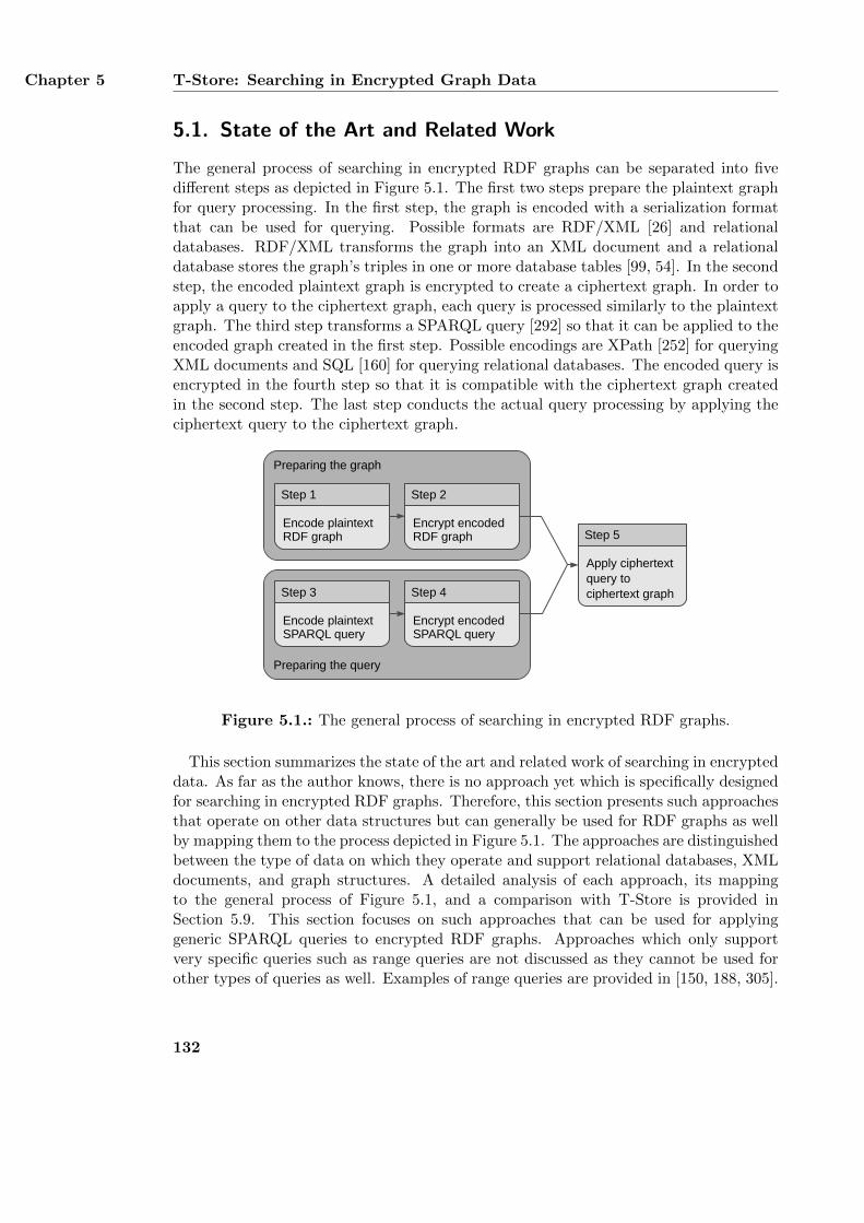
Chapter 5 T-Store: Searching in Encrypted Graph Data
5.1. State of the Art and Related Work
The general process of searching in encrypted RDF graphs can be separated into fivedifferent steps as depicted in Figure 5.1. The first two steps prepare the plaintext graphfor query processing. In the first step, the graph is encoded with a serialization formatthat can be used for querying. Possible formats are RDF/XML [26] and relationaldatabases. RDF/XML transforms the graph into an XML document and a relationaldatabase stores the graph’s triples in one or more database tables [99, 54]. In the secondstep, the encoded plaintext graph is encrypted to create a ciphertext graph. In order toapply a query to the ciphertext graph, each query is processed similarly to the plaintextgraph. The third step transforms a SPARQL query [292] so that it can be applied to theencoded graph created in the first step. Possible encodings are XPath [252] for queryingXML documents and SQL [160] for querying relational databases. The encoded query isencrypted in the fourth step so that it is compatible with the ciphertext graph createdin the second step. The last step conducts the actual query processing by applying theciphertext query to the ciphertext graph.
Preparing the graph
Encode plaintextRDF graph
Step 1
Encrypt encodedRDF graph
Step 2
Preparing the query
Encode plaintextSPARQL query
Step 3
Encrypt encodedSPARQL query
Step 4
Apply ciphertextquery tociphertext graph
Step 5
Figure 5.1.: The general process of searching in encrypted RDF graphs.
This section summarizes the state of the art and related work of searching in encrypteddata. As far as the author knows, there is no approach yet which is specifically designedfor searching in encrypted RDF graphs. Therefore, this section presents such approachesthat operate on other data structures but can generally be used for RDF graphs as wellby mapping them to the process depicted in Figure 5.1. The approaches are distinguishedbetween the type of data on which they operate and support relational databases, XMLdocuments, and graph structures. A detailed analysis of each approach, its mappingto the general process of Figure 5.1, and a comparison with T-Store is provided inSection 5.9. This section focuses on such approaches that can be used for applyinggeneric SPARQL queries to encrypted RDF graphs. Approaches which only supportvery specific queries such as range queries are not discussed as they cannot be used forother types of queries as well. Examples of range queries are provided in [150, 188, 305].
132
State of the Art and Related Work Section 5.1
Approaches which focus on document collections are also not discussed as they onlyretrieve complete documents and do not support searching within them. Examples ofsuch approaches are presented in [107, 68, 234].
5.1.1. Searching in Encrypted Relational Databases
A relational database stores data records in tables which consist of columns, rows, andcells. A row contains a particular data record, a column represents an attribute, anda cell stores a record’s value of a specific attribute. All approaches for searching inencrypted relational databases store the encrypted data records at an untrusted server.Depending on the approach, the records are encrypted row-wise or cell-wise. A row-wiseencryption maps the complete record to a single ciphertext and a cell-wise encryptionencrypts each attribute value separately. Many approaches focus on data outsourcingin which a user stores encrypted data at a potentially untrusted server managed by athird party [281]. The user is completely trusted and the server conducts most of thequery processing. Data outsourcing is often implemented with filtering and refining [296]which processes queries in two steps. The user initiates a query by transforming it intoa ciphertext query and sending it to the server. The server conducts a filtering step inwhich it applies the ciphertext query to the encrypted data. This leads to an encryptedsuperset of the actual query result which is sent back to the user. In a refining step,the user decrypts the preliminary query result and applies the plaintext query to theresulting plaintext data to retrieve the final query result.
Filtering and refining is used by Hacıgumus et al. [137] as well as Wang et al. [309].Both approaches allow to search for all ciphertext records which match a set of attributevalues. Hacıgumus et al. use row-wise encryption and index all ciphertext records basedon their attribute values with bucketization. Bucketization splits the value space of eachattribute into disjoint buckets. The server stores a mapping from a ciphertext recordto the buckets of its attributes and the user associates each plaintext value with theircorresponding buckets. In order to search for particular attribute values, the user mapsthe values to their respective bucket identifiers and sends them to the server. The serverreturns all ciphertext records for the specified buckets which are then further processedby the user in a refining step. Wang et al. use cell-wise encryption and associate eachciphertext with a hash value. The hash value is used as an index and stored togetherwith the ciphertext at the server. In order to search for all data records with particularattribute values, the user computes their hash values and sends them to the server whichreturns all matching ciphertext records. As the used hash function produces collisions,the received records form a superset of the actual query result which is further refinedby the user.
Exact query results without refining are returned by Z. Yang et al. [316], Elovici etal. [98], and Evdokimov and Gunther [104]. All three approaches use probabilistic, cell-wise encryption which maps identical plaintexts to different ciphertexts. Z. Yang et al.and Elovici et al. support queries that retrieve all ciphertext records with a particu-lar attribute value whereas Evdokimov and Gunther support keyword queries with anarbitrary keyword. Z. Yang et al. use trapdoors [42] to check if a particular cipher-
133
Chapter 5 T-Store: Searching in Encrypted Graph Data
text record matches a query. Each plaintext is mapped to a tuple of two ciphertextswhich are stored at the server. The first ciphertext encrypts the actual plaintext andthe second ciphertext encrypts the first ciphertext with the plaintext and the name ofits corresponding attribute. A user initiates a query by creating a trapdoor from thequeried value and the name of its attribute and sends it to the server. The server tries todecrypt the second ciphertext of each tuple with the trapdoor. If the result is identical tothe tuple’s first ciphertext, the corresponding ciphertext record is returned to the user.Evdokimov and Gunther propose a similar approach which is also based on trapdoorsbut supports keyword queries instead of attribute queries. Elovici et al. create an indextree for each column and store it together with the encrypted cell values at the server.A user applies an attribute query by iteratively traversing the index tree and sendingcorresponding messages to the server. In each iteration, the user receives an encryptedtree node, decrypts it, and requests the next node. This process is repeated until theuser has received all matching tree nodes which are then used to retrieve the desiredciphertext records.
Exact queries and multiple users are supported by CryptDB [235], Probabilistic Ran-domly Partitioned Encryption (Prob-RPE) [259], and Y. Yang et al. [315]. CryptDBsupports different types of queries, Y. Yang et al. support keyword queries, and Prob-RPE supports range queries and attribute queries for a single attribute. CryptDB en-crypts all cell values of a column individually with the same encryption key. Eachcolumn is encrypted as multiple layers which provide different security and functional-ity. Processing a query may require to permanently remove an encryption layer from aqueried column. A trusted proxy server authorizes querying users, maps their queries tociphertext queries, and sends them to the database server. The proxy server also storesall encryption keys and can remove encryption layers. The database server executesciphertext queries and sends the encrypted results to the proxy server which are thendecrypted and forwarded to the querying user. Prob-RPE divides all values of a columninto random buckets and probabilistically encrypts all values of a bucket individually.Identical plaintext values are mapped to different tuples consisting of a bucket identifierand a ciphertext. This mapping is stored at a trusted proxy server which authorizesall users, intercepts and transforms their queries, and stores all encryption keys. If aplaintext value is mapped to multiple tuples, the proxy server requests all tuples fromthe database server. Y. Yang et al. use a row-wise, probabilistic encryption. Each useris authenticated with a public key pair which is registered at the database server. Theserver associates ciphertext records with encrypted keywords. In order to apply a query,a user digitally signs the requested keyword with her private key and sends it to theserver. The server verifies the signature and thereby removes any user-specific partsfrom the keyword which is then used to retrieve all matching ciphertext records.
In summary, all presented approaches for searching in encrypted relational databasescan generally be used for searching in encrypted RDF graphs as well. This can beaccomplished by storing a graph in a single database table with three different columns.The columns represent the subject, predicate, and object of the graph’s triples. Thepresented approaches can then be directly applied to the resulting database.
134
State of the Art and Related Work Section 5.1
5.1.2. Searching in Encrypted XML Documents
XML documents [49] store data in a hierarchically organized tree of elements. Thetree has a single root element and can be divided into subtrees with their own root.Each element has a name and can optionally have attributes and data values. Theset of all possible element names and attribute names are restricted by the document’sschema [124]. A path is a sequence of connected elements in the tree, starting at theroot and ending at a particular element. Approaches for searching in encrypted XMLdocuments generally support path queries, element queries, and subtree queries. Pathqueries match a path against the XML tree and return the elements at the end ofthe path. Each element in the path may be further specified by its attribute values.Element queries retrieve individual elements with particular attribute values and datavalues. Subtree queries return individual subtrees based on the query parameters.
Approaches based on filtering and refining are Lin and Candan [191, 190], Jammala-madaka and Mehrotra [165], and Order Preserving Encryption with Splitting and Scal-ing (OPESS) [304]. Lin and Candan support path queries by traversing the XML tree.Each element is stored in multiple buckets, encrypted individually, and stored at theserver together with two indexes. The first index lists all ciphertexts for each bucketand the second index maps an element to its child elements and their buckets. A userinitiates a query by requesting all child elements of the root element and their buckets.The user randomly selects one bucket for each child element, retrieves all its ciphertexts,and selects the next element in the queried path. The process is repeated until theuser has retrieved all query results. Jammalamadaka and Mehrotra support elementqueries which retrieve elements based on their attribute values. The approach is similarto Hacıgumus et al. and splits all attribute values into disjoint buckets. Each elementis encrypted together with its attribute values and indexed with their bucket identi-fiers. Storage, index management, and query processing is identical to Hacıgumus et al.OPESS supports path queries based on the names and data values of the path’s elements.All subtrees of an XML tree are encrypted individually and indexed with structural andvalue-based information. The structural index maps all subtrees to their encrypted rootelement and the value index maps all encrypted data values to the subtrees in whichthey occur. The user prepares a query by encrypting its element names and data valuesand sends it to the server. The server uses its indexes to retrieve all matching subtreesand sends them to the user who conducts a refining step to extract the desired elements.
Exact query results without refining are provided by SemCrypt [274], Bouganim etal. [46], and two approaches of Brinkman et al., which are referred to as Brinkman 1 [52]and Brinkman 2 [53]. Bouganim et al. allow multiple users whereas the other approachesfocus on data outsourcing. Brinkman 1 supports subtree queries which retrieve allsubtrees with a particular element. The XML tree is encoded as hierarchically structuredpolynomial by mapping all element names to integers. The polynomial is randomly splitinto two parts which are stored at the user and the server, respectively. A user searchesfor an element by sending its integer representation to the server. Starting at the rootelement, the server iteratively computes the value of its polynomial and returns theresult. The user computes its own polynomial, combines it with the server’s value and
135
Chapter 5 T-Store: Searching in Encrypted Graph Data
compares it with a predefined value. If both values are equal, the queried element is partof the subtree whose polynomial was just calculated. Brinkman 2 supports path querieswhich are based on trapdoors and consist of element names, attribute values, and datavalues. Encryption and query processing is similar to Z. Yang et al. SemCrypt supportspath queries based on element names, attribute values, and data values. The user mapseach path in the XML tree to a unique identifier which is used in a structural index anda value index stored at the server. The structural index maps a path identifier to anencrypted data value and the value index associates a data value with all elements thathave the same data value. A user initiates a path query by transforming it into a sequenceof ciphertext queries for each step in the path. Each ciphertext query is sent to the serverand evaluated by applying the two indexes. Bouganim et al. support arbitrary queriesand require a secure processing unit for every user. The XML document is split intosubtrees which are encrypted with different encryption keys. An access policy is createdfor each user and associated with several encryption keys. An authorized user receivesthe encrypted document and her secure processing unit receives the access policy andthe encryption keys. The unit processes the user’s queries after having decided whethera query is allowed or prohibited by evaluating the access policy.
In summary, many approaches for searching in encrypted XML documents focus onqueries which evaluate the document’s structure such as path queries and subtree queries.These queries cannot be directly used for searching in encrypted RDF graphs. Althoughsuch a graph can easily be encoded as XML document, the actual contents of a tripleare either stored as attribute values or data values. Storing the contents of a triple aselement names is not possible as the set of possible element names is restricted by thedocument’s schema. However, element queries can be used for searching in RDF graphsas they can contain data values like a URIs and literals as query parameters.
5.1.3. Searching in Encrypted Graph Structures
A graph is an abstract data structure which can be used for storing different types ofdata such as text documents and RDF triples. A graph generally consists of nodeswhich are connected via edges and can be split into subgraphs by removing some of thenodes and edges. Depending on the type of graph, the graph may also have additionalcharacteristics. A labeled graph associates its nodes and/or edges with a name. In abipartite graph, the nodes are divided into two disjoint sets and the edges connect twonodes from each set. This section summarizes three different approaches for searching inencrypted graph data. All approaches store the encrypted graph and an encrypted indexat an untrusted server. The server processes queries from a single user by applying theindex to the ciphertext graph. Privacy-Preserving Graph Query (PPGQ) [69] supportssubgraph queries in encrypted graph collections which retrieve all graphs with a partic-ular subgraph. Each graph is indexed with a feature vector which lists all its subgraphs.The feature vector is encrypted and stored together with the encrypted graph at theserver. A user initiates a subgraph query by mapping it to a feature vector, encryptingit, and sending it to the server. The server combines the received feature vector with thefeature vector of each encrypted graph. If the result matches a predefined comparison
136
State of the Art and Related Work Section 5.1
value, the encrypted graph is sent to the user. Chase and Kamara [78] provide a genericindexing mechanism to support different queries on encrypted labeled graphs. The indexessentially maps one or two query parameters to an encrypted set of query results. Auser initiates a query by computing a query key from the query parameters and sendingit to the server. The server processes the query by applying the query key to the index.Chase and Kamara apply their index to support neighbor queries, subgraph queries, andqueries that retrieve all edges between two nodes. CryptGraph [314] supports subgraphqueries on bipartite graphs. A graph is represented by its adjacency matrix which isencrypted using probabilistic homomorphic encryption. Homomorphic encryption [111]allows arithmetic operations on ciphertexts without decrypting them first. A subgraphquery combines several atomic queries which ask whether or not two nodes are directlyconnected. An atomic query is a polynomial and is evaluated with the adjacency matrix.A user initiates a subgraph query by creating the polynomials for all atomic queries andsending them to the server. The server applies the polynomials to the adjacency matrixand sends the resulting value to the user who decrypts it to retrieve the actual queryresult.
In summary, some approaches for searching in encrypted graph structures focus onsubgraph queries and can only partially be used for searching in RDF graphs. Subgraphqueries basically correspond to SPARQL ASK queries and determine whether or not agraph contains a set of triples. However, SPARQL also supports SELECT queries whichare used more often in practice than ASK queries [203, 14, 233].
5.1.4. SPARQL Query Language
SPARQL [292] is a W3C-standardized query language for RDF graphs and is supportedby several RDF triple stores such as Sesame [54] and Jena [74]. The syntax and design ofSPARQL is inspired by SQL [160]. A SPARQL query consists of a query form and a queryalgebra and is applied to an RDF dataset. The query form defines the type of the queryand the format of the query result. Possible query types include SELECT, CONSTRUCT, andASK. A SELECT query returns a list of individual query results whereas a CONSTRUCT queryreturns a new graph created from these results. An ASK query determines whether ornot the query algebra matches against the queried dataset and returns a boolean value.The query algebra corresponds to the WHERE clause of a query. It defines the query’smatching conditions and consists of several triple patterns. A triple pattern is similarto a triple but may contain an unbound query variable at subject, predicate, and/orobject position. Considering that each position in a triple pattern can be either boundor unbound results in eight different variants of the same pattern. Triple patterns of aquery algebra are combined into graph patterns. The simplest form of a graph patternis a basic graph pattern which is a collection of an arbitrary number of triple patterns.More complex graph patterns such as unions of basic graph patterns or optional basicgraph patterns are also possible. Finally, an RDF dataset [87] is a collection of severalgraphs. It is similar to a Named Graph as defined in Section 4.3.1 except that it doesnot allow nested graphs and blank nodes as graph identifiers.
137
Chapter 5 T-Store: Searching in Encrypted Graph Data
A SPARQL query is evaluated by matching the query algebra against the queried RDFdataset. This process replaces the query variables in the algebra’s triple patterns withcorresponding URIs, blank nodes, or literals. A mapping from a single query variable toits corresponding value is referred to as a variable binding [292]. A solution mapping is aset of variable bindings and corresponds to a single solution of a triple pattern or a basicgraph pattern. It is created by matching a pattern against a graph and replacing allquery variables in the pattern with corresponding URIs, blank nodes, or literals. Severalsolution mappings are combined into a solution sequence which contains all solutions ofa triple pattern or a basic graph pattern. Solution sequences may either be returnedas the query result or only used during query processing. If the query algebra containsmultiple triple patterns sharing the same query variables, their solution sequences arecombined with a join operation. A join can only be conducted on two solution sequencesif they are compatible with each other. This is the case if their solution mappings shareidentical variable bindings, i. e., if their query variables are mapped to identical values.The result of a join on two solution sequences is a new solution sequence which containsthe combination of all compatible solution mappings.
An example SPARQL query of type SELECT is depicted in Listing 5.1. The queryreturns the name of all persons with the e-mail address [email protected]. Thenamespace foaf corresponds to the FOAF vocabulary [50] for describing social networks.The query contains a single basic graph pattern with two triple patterns. The solutionsequences of both triple patterns are joined using the variable bindings of the queryvariable ?person. Line 2 states that the bindings of the variable ?name are returned asthe query result while the bindings of ?person are only used during query processing.
1 PREFIX foaf: <http://xmlns.com/foaf/0.1/>
2 SELECT ?name
3 WHERE {
4 ?person foaf:name ?name .
5 ?person foaf:mbox "[email protected]" .
6 }
Listing 5.1: Example SPARQL query.
5.2. Requirements for Searching in Encrypted Graphs
T-Store allows to apply different types of SPARQL queries to encrypted RDF graphs.The queries are executed locally by authorized users without involving a server. Basedon these general objectives, this section defines the specific requirements for T-Store.The requirements are distinguished between functional (RC.F.*) requirements and non-functional (RC.N.*) requirements. As defined in Section 3.2, functional requirementsdefine the functions that a system must provide and non-functional requirements describehow functional requirements are implemented [282]. The following requirements arebased on the scenario for regulating Internet communication presented in Section 2.1and on the related work for searching in encrypted data summarized in Section 5.1.T-Store must fulfill the following functional requirements:
138
Requirements for Searching in Encrypted Graphs Section 5.2
RC.F.1: Applying SPARQL triple patternsT-Store must support queries which consist of a single SPARQL triple pattern withnone, one, two, or three query variables. Such queries are the most basic types ofqueries and are the foundation for creating more complex queries.
RC.F.2: Applying SPARQL basic graph patternsThe approach must support queries which consist of a single SPARQL basic graphpattern. A basic graph pattern contains an arbitrary number of triple patterns.If the triple patterns share the same query variables, executing the basic graphpattern requires the computation of a join operation. Thus, this requirement alsoimplies the support of join operations. In the scenario, the German comprehensiveschool applies queries to the encrypted log files of its proxy server.
RC.F.3: Supporting SPARQL query formsT-Store must support the three different SPARQL query forms SELECT, ASK, andCONSTRUCT. The query forms define the format of the query result. Supporting thethree different query forms is necessary as they are most frequently used in manySPARQL queries [14, 233].
RC.F.4: Supporting dynamic query authorizationsT-Store must support the authorization of particular queries after the plaintextgraph has been encrypted. This allows a more flexible query authorization thanpredefining all supported queries when encrypting the plaintext graph. In thescenario, an investigator is authorized to apply queries to the log file after it hasbeen encrypted by the proxy server.
RC.F.5: Separating the data owner from authorized usersThe approach must distinguish between a data owner who encrypts the plaintextgraph and users who can apply queries to the encrypted graph. The data owner canaccess the complete graph and possesses all encryption keys. In contrast, users areexplicitly authorized by the data owner to apply particular queries to the graph.In the scenario, the school’s administration (SA) and the parents’ association (PA)collectively authorize an investigator to apply particular queries.
RC.F.6: Supporting query templatesT-Store must support the authorization of specific queries and query templates.A query template represents a group of similar queries. It corresponds to anincomplete query which must be further refined by the querying user in orderto receive a complete query. Query templates reduce the communication overheadbetween the data owner who encrypts the plaintext graph and the users who querythe ciphertext graph. Thus, this requirement implies requirement RC.F.5.
In addition to these functional requirements, T-Store must also support the followingnon-functional requirements:
139
Chapter 5 T-Store: Searching in Encrypted Graph Data
RC.N.1: Processing queries offlineT-Store must not rely on a server which processes the queries, even if the server op-erates only on encrypted data. Instead, users must be able to process all authorizedqueries on their local systems after having received a corresponding query autho-rization and the ciphertext graph. In the following, this type of query processingis referred to as an offline approach. In the scenario, the authorized investigatorapplies the queries locally at her own computer system after having received a copyof the encrypted log files.
RC.N.2: Eliminating trusted systemsT-Store must not involve a trusted system which processes queries on behalf ofauthorized users and which can access the query results or parts of them. Instead,query results must only be accessible to the user who initiates a query. Examplesof trusted systems are secure processing units, which are located at the user side,and proxy servers, which act as an intermediary between an authorized user anda server.
RC.N.3: Providing exact query resultsConducting queries with T-Store must not reveal any triples of the plaintext graphwhich are not part of the final query result. Thus, authorized users must receiveexactly those triples of the plaintext graph which satisfy their queries. This re-quirement is necessary as otherwise an authorized user may receive more plaintexttriples than the authorization intends. In the scenario, the investigator must onlyreceive the graph data which is being investigated.
RC.N.4: Prohibiting data distinguishabilityT-Store must encrypt the plaintext graph in such a way that the resulting cipher-text graph does not reveal the amount of identical plaintext URIs, blank nodes, orliterals and their individual positions in the graph. More specifically, it must becomputationally hard to identify identical plaintext URIs, blank nodes, or literalsas such. This requirement is called data indistinguishability [167]. It is fulfilled ifthere is no algorithm which decides in polynomial time whether or not two cipher-texts represent the same plaintext value. Fulfilling this requirement is necessaryin order to prevent an attacker from analyzing the ciphertext graph and use it toinfer any information about the plaintext graph.
RC.N.5: Concealing graph characteristicsThe ciphertext graph created by T-Store must not reveal any characteristics ofthe corresponding plaintext graph. The characteristics of a graph can generallybe distinguished between local characteristics and global characteristics. Localcharacteristics cover individual plaintext triples and their respective parts. Suchcharacteristics include the string length of all URIs, blank nodes, and literals inthe graph (RC.N.5.1). Global characteristics depend on the whole graph and noton individual triples. Such characteristics include the density and the connectivityof the plaintext graph (RC.N.5.2) as well as the number of different plaintext
140
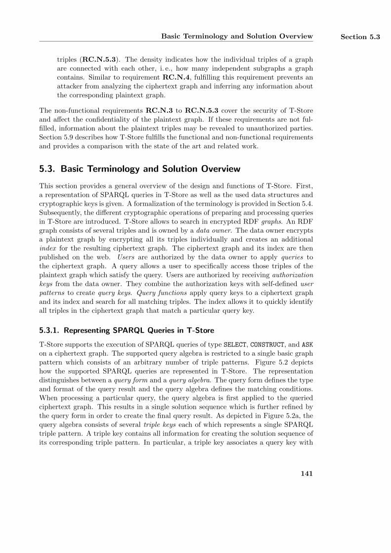
Basic Terminology and Solution Overview Section 5.3
triples (RC.N.5.3). The density indicates how the individual triples of a graphare connected with each other, i. e., how many independent subgraphs a graphcontains. Similar to requirement RC.N.4, fulfilling this requirement prevents anattacker from analyzing the ciphertext graph and inferring any information aboutthe corresponding plaintext graph.
The non-functional requirements RC.N.3 to RC.N.5.3 cover the security of T-Storeand affect the confidentiality of the plaintext graph. If these requirements are not ful-filled, information about the plaintext triples may be revealed to unauthorized parties.Section 5.9 describes how T-Store fulfills the functional and non-functional requirementsand provides a comparison with the state of the art and related work.
5.3. Basic Terminology and Solution Overview
This section provides a general overview of the design and functions of T-Store. First,a representation of SPARQL queries in T-Store as well as the used data structures andcryptographic keys is given. A formalization of the terminology is provided in Section 5.4.Subsequently, the different cryptographic operations of preparing and processing queriesin T-Store are introduced. T-Store allows to search in encrypted RDF graphs. An RDFgraph consists of several triples and is owned by a data owner. The data owner encryptsa plaintext graph by encrypting all its triples individually and creates an additionalindex for the resulting ciphertext graph. The ciphertext graph and its index are thenpublished on the web. Users are authorized by the data owner to apply queries tothe ciphertext graph. A query allows a user to specifically access those triples of theplaintext graph which satisfy the query. Users are authorized by receiving authorizationkeys from the data owner. They combine the authorization keys with self-defined userpatterns to create query keys. Query functions apply query keys to a ciphertext graphand its index and search for all matching triples. The index allows it to quickly identifyall triples in the ciphertext graph that match a particular query key.
5.3.1. Representing SPARQL Queries in T-Store
T-Store supports the execution of SPARQL queries of type SELECT, CONSTRUCT, and ASK
on a ciphertext graph. The supported query algebra is restricted to a single basic graphpattern which consists of an arbitrary number of triple patterns. Figure 5.2 depictshow the supported SPARQL queries are represented in T-Store. The representationdistinguishes between a query form and a query algebra. The query form defines the typeand format of the query result and the query algebra defines the matching conditions.When processing a particular query, the query algebra is first applied to the queriedciphertext graph. This results in a single solution sequence which is further refined bythe query form in order to create the final query result. As depicted in Figure 5.2a, thequery algebra consists of several triple keys each of which represents a single SPARQLtriple pattern. A triple key contains all information for creating the solution sequence ofits corresponding triple pattern. In particular, a triple key associates a query key with
141
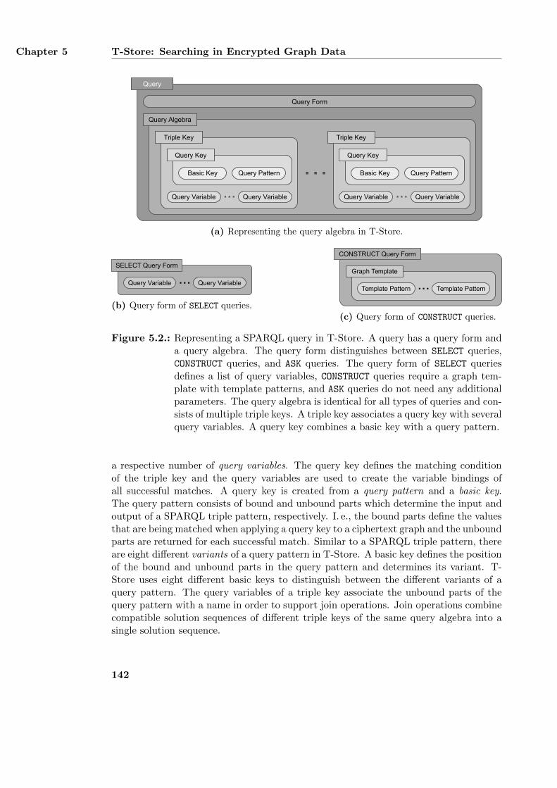
Chapter 5 T-Store: Searching in Encrypted Graph Data
…
Query
Triple Key
Query Key
Query PatternBasic Key
Query Algebra
Query Form
Query Key
Query PatternBasic Key
Triple Key
Query Variable Query Variable... Query Variable Query Variable...
(a) Representing the query algebra in T-Store.
SELECT Query Form
Query Variable Query Variable...
(b) Query form of SELECT queries.
Template Pattern Template Pattern...Graph Template
CONSTRUCT Query Form
(c) Query form of CONSTRUCT queries.
Figure 5.2.: Representing a SPARQL query in T-Store. A query has a query form anda query algebra. The query form distinguishes between SELECT queries,CONSTRUCT queries, and ASK queries. The query form of SELECT queriesdefines a list of query variables, CONSTRUCT queries require a graph tem-plate with template patterns, and ASK queries do not need any additionalparameters. The query algebra is identical for all types of queries and con-sists of multiple triple keys. A triple key associates a query key with severalquery variables. A query key combines a basic key with a query pattern.
a respective number of query variables. The query key defines the matching conditionof the triple key and the query variables are used to create the variable bindings ofall successful matches. A query key is created from a query pattern and a basic key.The query pattern consists of bound and unbound parts which determine the input andoutput of a SPARQL triple pattern, respectively. I. e., the bound parts define the valuesthat are being matched when applying a query key to a ciphertext graph and the unboundparts are returned for each successful match. Similar to a SPARQL triple pattern, thereare eight different variants of a query pattern in T-Store. A basic key defines the positionof the bound and unbound parts in the query pattern and determines its variant. T-Store uses eight different basic keys to distinguish between the different variants of aquery pattern. The query variables of a triple key associate the unbound parts of thequery pattern with a name in order to support join operations. Join operations combinecompatible solution sequences of different triple keys of the same query algebra into asingle solution sequence.
142
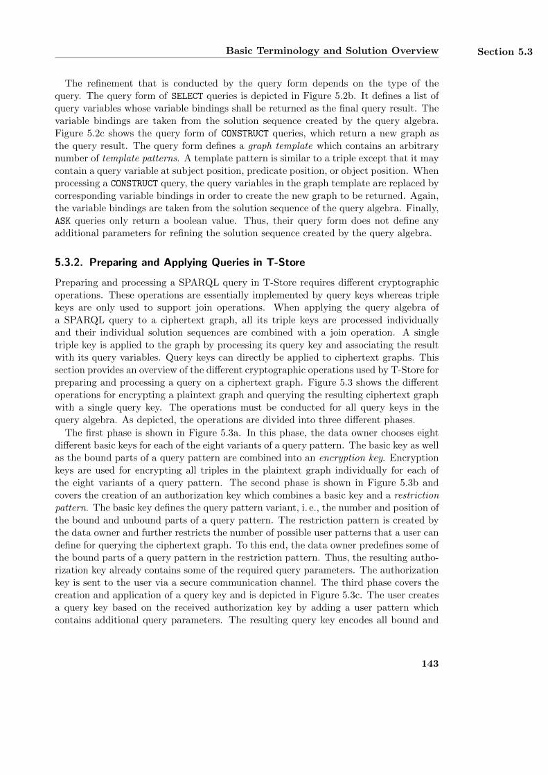
Basic Terminology and Solution Overview Section 5.3
The refinement that is conducted by the query form depends on the type of thequery. The query form of SELECT queries is depicted in Figure 5.2b. It defines a list ofquery variables whose variable bindings shall be returned as the final query result. Thevariable bindings are taken from the solution sequence created by the query algebra.Figure 5.2c shows the query form of CONSTRUCT queries, which return a new graph asthe query result. The query form defines a graph template which contains an arbitrarynumber of template patterns. A template pattern is similar to a triple except that it maycontain a query variable at subject position, predicate position, or object position. Whenprocessing a CONSTRUCT query, the query variables in the graph template are replaced bycorresponding variable bindings in order to create the new graph to be returned. Again,the variable bindings are taken from the solution sequence of the query algebra. Finally,ASK queries only return a boolean value. Thus, their query form does not define anyadditional parameters for refining the solution sequence created by the query algebra.
5.3.2. Preparing and Applying Queries in T-Store
Preparing and processing a SPARQL query in T-Store requires different cryptographicoperations. These operations are essentially implemented by query keys whereas triplekeys are only used to support join operations. When applying the query algebra ofa SPARQL query to a ciphertext graph, all its triple keys are processed individuallyand their individual solution sequences are combined with a join operation. A singletriple key is applied to the graph by processing its query key and associating the resultwith its query variables. Query keys can directly be applied to ciphertext graphs. Thissection provides an overview of the different cryptographic operations used by T-Store forpreparing and processing a query on a ciphertext graph. Figure 5.3 shows the differentoperations for encrypting a plaintext graph and querying the resulting ciphertext graphwith a single query key. The operations must be conducted for all query keys in thequery algebra. As depicted, the operations are divided into three different phases.
The first phase is shown in Figure 5.3a. In this phase, the data owner chooses eightdifferent basic keys for each of the eight variants of a query pattern. The basic key as wellas the bound parts of a query pattern are combined into an encryption key. Encryptionkeys are used for encrypting all triples in the plaintext graph individually for each ofthe eight variants of a query pattern. The second phase is shown in Figure 5.3b andcovers the creation of an authorization key which combines a basic key and a restrictionpattern. The basic key defines the query pattern variant, i. e., the number and position ofthe bound and unbound parts of a query pattern. The restriction pattern is created bythe data owner and further restricts the number of possible user patterns that a user candefine for querying the ciphertext graph. To this end, the data owner predefines some ofthe bound parts of a query pattern in the restriction pattern. Thus, the resulting autho-rization key already contains some of the required query parameters. The authorizationkey is sent to the user via a secure communication channel. The third phase covers thecreation and application of a query key and is depicted in Figure 5.3c. The user createsa query key based on the received authorization key by adding a user pattern whichcontains additional query parameters. The resulting query key encodes all bound and
143
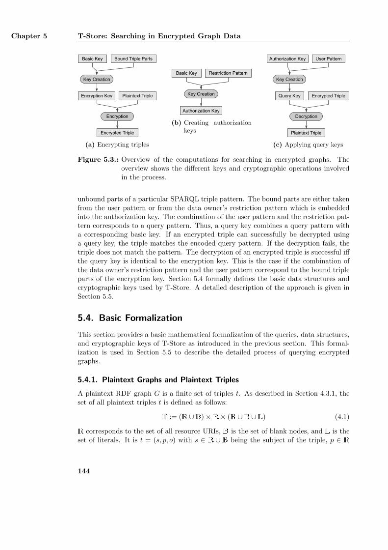
Chapter 5 T-Store: Searching in Encrypted Graph Data
Bound Triple PartsBasic Key
Encryption Key Plaintext Triple
Encrypted Triple
Key Creation
Encryption
(a) Encrypting triples
Restriction PatternBasic Key
Authorization Key
Key Creation
(b) Creating authorizationkeys
User PatternAuthorization Key
Query Key Encrypted Triple
Plaintext Triple
Decryption
Key Creation
(c) Applying query keys
Figure 5.3.: Overview of the computations for searching in encrypted graphs. Theoverview shows the different keys and cryptographic operations involvedin the process.
unbound parts of a particular SPARQL triple pattern. The bound parts are either takenfrom the user pattern or from the data owner’s restriction pattern which is embeddedinto the authorization key. The combination of the user pattern and the restriction pat-tern corresponds to a query pattern. Thus, a query key combines a query pattern witha corresponding basic key. If an encrypted triple can successfully be decrypted usinga query key, the triple matches the encoded query pattern. If the decryption fails, thetriple does not match the pattern. The decryption of an encrypted triple is successful iffthe query key is identical to the encryption key. This is the case if the combination ofthe data owner’s restriction pattern and the user pattern correspond to the bound tripleparts of the encryption key. Section 5.4 formally defines the basic data structures andcryptographic keys used by T-Store. A detailed description of the approach is given inSection 5.5.
5.4. Basic Formalization
This section provides a basic mathematical formalization of the queries, data structures,and cryptographic keys of T-Store as introduced in the previous section. This formal-ization is used in Section 5.5 to describe the detailed process of querying encryptedgraphs.
5.4.1. Plaintext Graphs and Plaintext Triples
A plaintext RDF graph G is a finite set of triples t. As described in Section 4.3.1, theset of all plaintext triples t is defined as follows:
T := (R ∪B)×R× (R ∪B ∪ L) (4.1)
R corresponds to the set of all resource URIs, B is the set of blank nodes, and L is theset of literals. It is t = (s, p, o) with s ∈ R ∪ B being the subject of the triple, p ∈ R
144
Basic Formalization Section 5.4
being the predicate, and o ∈ R∪B∪L being the object. A plaintext graph consisting ofm triples is defined as G = {t1, t2, . . . , tm} with m ∈ N. The set of all plaintext graphsis defined as follows:
G := P(T) = P((R ∪B)×R× (R ∪B ∪ L)) (4.2)
5.4.2. Encrypted Graphs and Encrypted Triples
Encrypting a plaintext triple t results in an encrypted triple c. An encrypted triple is atuple of eight bit strings. Each bit string is used for one of the eight variants of a querypattern. Thus, an encrypted triple c contains eight different ciphertexts of the sameplaintext triple t for each of the eight query pattern variants. The set of all possibleencrypted triples is defined as follows:
TC := {0, 1}∗ × {0, 1}∗ × . . .× {0, 1}∗︸ ︷︷ ︸8 times
(5.1)
It is c = (c---, c+--, c-+-, c--+, c++-, c+-+, c-++, c+++). The indices + and - state if the cor-responding part of the query pattern is bound or unbound. For example, the bit stringc-+- supports query patterns with a bound predicate that retrieve tuples of subjects andobjects for each matching triple. Encrypting a plaintext graph G results in an encryptedgraph GC = {c1, c2, . . . , cm}. The set of all encrypted graphs is defined as follows:
GC := P(TC) = P({0, 1}∗ × {0, 1}∗ × . . .× {0, 1}∗︸ ︷︷ ︸8 times
) (5.2)
5.4.3. Basic Keys
A basic key bk ∈ Kb is a bit string of length d ∈ N and is used for encrypting thetriples t of a plaintext graph G for a particular query pattern variant. The data ownerchoses eight different basic keys for each pattern variant which are identified as bk---,bk+--, bk-+-, bk--+, bk++-, bk+-+, bk-++, and bk+++. Each of these keys is used for creatinga particular bit string of the encrypted triples c. For example, the basic key bk-+- is usedfor creating the bit strings c-+-. The set of all basic keys is defined as Kb ⊂ {0, 1}d.
5.4.4. Query Keys, Query Patterns, and Authorization Keys
A query key qk ∈ Kq is a bit string of length d ∈ N which encodes the bound andunbound parts of a query pattern. It is applied to an encrypted graph and may containan unbound subject, predicate, and/or object. The type of a query key is defined byusing the symbols + and - which mark the bound and unbound parts, respectively. Forexample, a query key of type +++ encodes a bound subject, a bound predicate, and abound object. It can be used for SPARQL ASK queries and determines whether or notthe specified triple is part of the queried graph. Applying a query key returns a set of allmatching values. For example, applying a query key of type -++ returns a set of subject
145
Chapter 5 T-Store: Searching in Encrypted Graph Data
URIs and requires a bound predicate and a bound object. The set of all query keys isdefined as Kq ⊂ {0, 1}d.
As described in Section 5.3.1, a query key is created from a basic key and a querypattern. The basic key defines the type of the query key and the query pattern specifiesits bound and unbound parts. A query pattern consists of two different parts which area restriction pattern r and a user pattern u. A restriction pattern r ∈ Pq is defineda-priori by the data owner and narrows down the possible queries that a user can apply.A user pattern u ∈ Pq represents the query parameters specified by the user. The set ofall query patterns Pq is defined as follows:
Pq := (R ∪B ∪ {?})× (R ∪ {?})× (R ∪B ∪ L ∪ {?}) (5.3)
The symbol ? identifies the unbound parts of a query pattern and corresponds to avariable like ?x. A query key encodes a query pattern (s?, p?, o?) with s? ∈ (R∪B∪{?})as the queried subject, p? ∈ (R ∪ {?}) being the queried predicate, and o? ∈ (R ∪B ∪L ∪ {?}) as the queried object. An authorization key ak ∈ Ka is a bit string whichcorresponds to a partially specified query key. It already encodes a basic key bk anda data owner’s restriction pattern r. However, an authorization key does not encodea user pattern u. Thus, a complete query key is created from an authorization keyby combining it with a user pattern u. The set of all authorization keys is defined asKa ⊂ {0, 1}∗.
5.4.5. Index
An index I ∈ I is a mapping from a query key qk ∈ Kq to a set of encrypted triples c ∈TC . The index associates a query key with a set of all encrypted triples of a ciphertextgraph GC ∈ GC that match the query pattern which is encoded in the query key. Anindex is created by the data owner and applied by a user to speed up the queryingprocess. The set I of all indexes is defined as follows:
I := Kq −→ P(TC) (5.4)
5.4.6. Query Functions
A query function f applies a single query key qk ∈ Kq to an encrypted graph GC ∈ GC
and its corresponding index I ∈ I and returns a result set based on all matching triples tof the plaintext graph G ∈ G. A query function requires a query key qk, the encryptedgraph GC , and its index I as input. Each query function supports one particular type ofquery keys. Thus, there are eight different query functions which are identified as f---,f+--, f-+-, f--+, f++-, f+-+, f-++, and f+++. Again, the symbols + and - mark the boundand unbound parts of the supported query keys, respectively. A + at the first positionrequires a subject to be specified in the query key. At the second or the third position,the symbol + requires a predicate or an object to be specified, respectively. The resultof a query function f also depends on the symbols + and -. The result can be a setof triples, a set of tuples, a set of resources, a set of blank nodes, a set of literals, or a
146
Basic Formalization Section 5.4
boolean value. For example, the query function f+-- returns a set of tuples (p, o) withp ∈ R ∪B and o ∈ R ∪B ∪ L.
The bound and unbound parts of a query key qk are defined by its encoded querypattern. The query pattern consists of a user pattern u = (su, pu, ou) and a data owner’srestriction pattern r = (sr, pr, or) as depicted in Figure 5.3 and must comply with thetype of the query function. For example, the query function f-++ requires a bound pred-icate and a bound object, i. e., the function requires either pr 6= ? or pu 6= ? and eitheror 6= ? or ou 6= ?. The data owner may define a restriction pattern r = (?, rdf:type, ?)which specifies rdf:type as the predicate of the query pattern. This restriction patternallows a user to search for instances of a particular ontological class. However, the usermust still define a specific class in the user pattern u = (?, ?, ou) and cannot leave theobject position unbound. In this case, the object ou contains the URI of the class to bequeried. Furthermore, any particular value which is already specified in the restrictionpattern r cannot be specified in the user pattern u as well. For example, if the dataowner defines a restriction pattern r = (?, rdf:type, ?) for the query function f-++, theuser cannot define a user pattern u = (?, foaf:mbox, ?) and overwrite the data owner’srestriction on the predicate. Thus, a restriction pattern allows the data owner to restrictthe possible queries that a user can apply by specifying the corresponding parts in therestriction pattern r. The result of the query function f-++ is a list of all subjects sfor which the plaintext graph G contains a matching triple (s, p, o). Given a plaintextgraph G, its ciphertext graph GC , an index I, and a query key qk which encodes thequery pattern (s, p, o), the eight different query functions f are defined as follows:
f--- : Kq ×GC × I −→ P(T), f---(qk---, GC , I) := G (5.5)
f+-- : Kq ×GC × I −→ P(R× (R ∪B ∪ L)) (5.6)
f+--(qk+--, GC , I) := {(y, z) | y ∈ R, z ∈ (R ∪B ∪ L),∃(s, y, z) ∈ G}
f-+- : Kq ×GC × I −→ P((R ∪B)× (R ∪B ∪ L)) (5.7)
f-+-(qk-+-, GC , I) := {(x, z) | x ∈ (R ∪B), z ∈ (R ∪B ∪ L), ∃(x, p, z) ∈ G}
f--+ : Kq ×GC × I −→ P((R ∪B)×R) (5.8)
f--+(qk--+, GC , I) := {(x, y) | x ∈ (R ∪B), y ∈ R, ∃(x, y, o) ∈ G}
f++- : Kq ×GC × I −→ P(R ∪B ∪ L) (5.9)
f++-(qk++-, GC , I) := {z | z ∈ (R ∪B ∪ L), ∃(s, p, z) ∈ G}
f+-+ : Kq ×GC × I −→ P(R) (5.10)
f+-+(qk+-+, GC , I) := {y | y ∈ R,∃(s, y, o) ∈ G}
147
Chapter 5 T-Store: Searching in Encrypted Graph Data
f-++ : Kq ×GC × I −→ P(R ∪B) (5.11)
f-++(qk-++, GC , I) := {x | x ∈ (R ∪B), ∃(x, p, o) ∈ G}
f+++ : Kq ×GC × I −→ {TRUE,FALSE} (5.12)
f+++(qk+++, GC , I) :=
{TRUE if (s, p, o) ∈ GFALSE otherwise
The query function f--- returns the complete plaintext graph G if neither the restrictionpattern r = (sr, pr, or) nor the user pattern u = (su, pu, ou) specify any particular URIs,blank nodes, or literals. Thus, the function requires r = u = (?, ?, ?). On the otherhand, the query function f+-- requires either sr 6= ? or su 6= ?. The function searchesfor all triples (s, p, o) ∈ G with s = sr or s = su and returns a set of tuples (p, o).Similarly, the functions f-+- and f--+ return sets of tuples (s, o) or (s, p), respectively.The function f++- requires both a subject and a predicate to be encoded in the query key.For every matching triple (s, p, o) ∈ G, the object o is returned. The query functions f+-+and f-++ are similar and return a set of predicates or subjects, respectively. Finally, thefunction f+++ returns TRUE if a query key encoding the query pattern (s, p, o) matchesa triple in G, i. e., if (s, p, o) ∈ G. Otherwise, the function returns FALSE.
5.4.7. Triple Keys
A triple key tk ∈ Kt represents a SPARQL triple pattern and is used for supporting joinoperations. It contains a query key qk ∈ Kq and associates it with zero, one, two, orthree query variables. The specific number of query variables depends on the number ofunbound parts which are encoded in the query key. The type of a triple key correspondsto the type of its query key as defined in Section 5.4.4. It is denoted using the symbols +and - which mark the bound and unbound parts of the query key, respectively. Forexample, triple keys of type +-- contain query keys with two unbound parts. Such triplekeys require a query variable for the predicate and a query variable for the object. Incontrast, triple keys of type +++ do not require any query variables as their query keysonly contain bound triple parts. A triple key is applied to an encrypted graph GC ∈ GC
by processing its query key qk with a corresponding query function f and binding theindividual results to their respective query variables. The resulting variable bindingsform a solution sequence. Using V as the set of all possible query variables and Kq asthe set of all query keys as defined in Section 5.4.4, the set Kt of all triple keys is definedas follows:
Kt := Kq × (∅ ∪V ∪ (V ×V) ∪ (V ×V ×V)) (5.13)
The number of query variables in a triple key must be equal to the number of unboundparts that are encoded in its query key qk.
5.4.8. Query Algebras, Query Forms, and Queries
A query q ∈ Q consists of a query form and a query algebra QA ∈ A. The structureof the query form depends on the type of the query whereas the query algebra has the
148
Basic Formalization Section 5.5
same structure for all query types. The query algebra QA contains an arbitrary numberof triple keys tk ∈ Kt and corresponds to the WHERE clause of a SPARQL query. Theset of all query algebras is defined as A := P(Kt). A query algebra is applied to anencrypted graph GC by applying all its triple keys to the graph and combining theirindividual solution sequences with a join operation into a single solution sequence. Joinoperations are conducted by evaluating the variable bindings of the solution sequencesof all triple keys. The query form of a query defines how the solution sequence of thequery algebra shall be further refined. The query form of a SELECT query defines a listof query variables whose variable bindings shall be returned as the final query result.The set of all SELECT queries is defined as follows:
QSELECT := {(v1, . . . , vn) | vi ∈ V, i ∈ {1, . . . , n}, n ∈ N} ×A (5.14)
The query variables vi ∈ V of a query form must also be defined within the triple keysof the query algebra QA ∈ A. The query form of a CONSTRUCT query defines a graphtemplate which is used for creating a new RDF graph from the solution sequence ofthe query algebra. This RDF graph is then returned as the final query result. A graphtemplate contains an arbitrary number of template patterns tp ∈ Pt. A template patternis similar to a query pattern and also contains both bound and unbound triple parts.In a template pattern, bound parts are identified by resources R, blank nodes B, orliterals L whereas unbound parts are represented as query variables V. The set of alltemplate patterns is defined as follows:
Pt := (R ∪B ∪V)× (R ∪V)× (R ∪B ∪ L ∪V) (5.15)
A graph template is instantiated by replacing all query variables in the template patternswith corresponding values. The values are taken from the solution mappings of the queryalgebra’s solution sequence. The triples that result from all instantiations are combinedinto a single RDF graph which is returned as the final query result. Using the set Aof all query algebras and the set Pt of all template patterns, the set of all CONSTRUCTqueries is defined as follows:
QCONSTRUCT := P(Pt)×A (5.16)
All query variables of the graph template must also be defined in the triple keys tk ofthe query algebra QA ∈ A. Finally, ASK queries return a boolean value and only requirea query algebra with an arbitrary number of triple keys. The set of all ASK queries isdefined as follows:
QASK := A (5.17)
Based on these three different sets of queries, the set of all SPARQL queries is definedas follows:
Q := QSELECT ∪QCONSTRUCT ∪QASK (5.18)
149
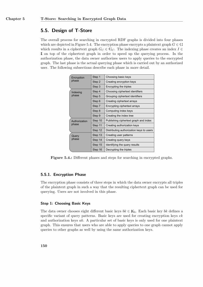
Chapter 5 T-Store: Searching in Encrypted Graph Data
5.5. Design of T-Store
The overall process for searching in encrypted RDF graphs is divided into four phaseswhich are depicted in Figure 5.4. The encryption phase encrypts a plaintext graphG ∈ Gwhich results in a ciphertext graph GC ∈ GC . The indexing phase creates an index I ∈I on top of the ciphertext graph in order to speed up the querying process. In theauthorization phase, the data owner authorizes users to apply queries to the encryptedgraph. The last phase is the actual querying phase which is carried out by an authorizeduser. The following subsections describe each phase in more detail.
Authorizationphase
Encryptionphase
Choosing basic keys
Creating encryption keys
Encrypting the triples
Indexingphase
Choosing ciphertext identifiers
Grouping ciphertext identifiers
Creating ciphertext arrays
Computing index keys
Creating the index tree
Encrypting ciphertext arrays
Creating authorization keys
Distributing authorization keys to usersStep 12
Step 10
Step 11
Step 9
Step 8
Step 7
Step 6
Step 5
Step 4
Step 3
Step 2
Step 1
Publishing ciphertext graph and index
Queryphase Creating query keys
Identifying the query results
Decrypting the triples
Step 13
Step 14
Step 15
Step 16
Creating user patterns
Figure 5.4.: Different phases and steps for searching in encrypted graphs.
5.5.1. Encryption Phase
The encryption phase consists of three steps in which the data owner encrypts all triplesof the plaintext graph in such a way that the resulting ciphertext graph can be used forquerying. Users are not involved in this phase.
Step 1: Choosing Basic Keys
The data owner chooses eight different basic keys bk ∈ Kb. Each basic key bk defines aspecific variant of query patterns. Basic keys are used for creating encryption keys ekand authorization keys ak. A particular set of basic keys is only used for one plaintextgraph. This ensures that users who are able to apply queries to one graph cannot applyqueries to other graphs as well by using the same authorization keys.
150
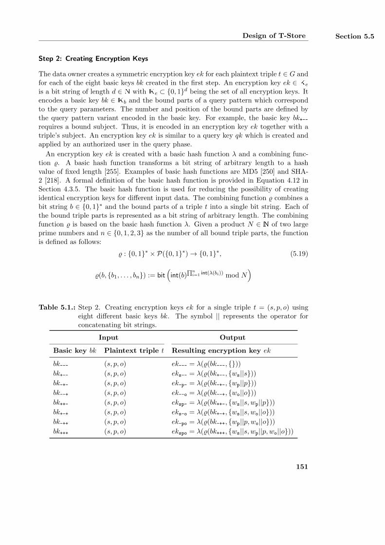
Design of T-Store Section 5.5
Step 2: Creating Encryption Keys
The data owner creates a symmetric encryption key ek for each plaintext triple t ∈ G andfor each of the eight basic keys bk created in the first step. An encryption key ek ∈ Ke
is a bit string of length d ∈ N with Ke ⊂ {0, 1}d being the set of all encryption keys. Itencodes a basic key bk ∈ Kb and the bound parts of a query pattern which correspondto the query parameters. The number and position of the bound parts are defined bythe query pattern variant encoded in the basic key. For example, the basic key bk+--requires a bound subject. Thus, it is encoded in an encryption key ek together with atriple’s subject. An encryption key ek is similar to a query key qk which is created andapplied by an authorized user in the query phase.
An encryption key ek is created with a basic hash function λ and a combining func-tion %. A basic hash function transforms a bit string of arbitrary length to a hashvalue of fixed length [255]. Examples of basic hash functions are MD5 [250] and SHA-2 [218]. A formal definition of the basic hash function is provided in Equation 4.12 inSection 4.3.5. The basic hash function is used for reducing the possibility of creatingidentical encryption keys for different input data. The combining function % combines abit string b ∈ {0, 1}∗ and the bound parts of a triple t into a single bit string. Each ofthe bound triple parts is represented as a bit string of arbitrary length. The combiningfunction % is based on the basic hash function λ. Given a product N ∈ N of two largeprime numbers and n ∈ {0, 1, 2, 3} as the number of all bound triple parts, the functionis defined as follows:
% : {0, 1}∗ × P({0, 1}∗)→ {0, 1}∗, (5.19)
%(b, {b1, . . . , bn}) := bit(int(b)
∏ni=1 int(λ(bi)) mod N
)
Table 5.1.: Step 2. Creating encryption keys ek for a single triple t = (s, p, o) usingeight different basic keys bk. The symbol || represents the operator forconcatenating bit strings.
Input Output
Basic key bk Plaintext triple t Resulting encryption key ek
bk--- (s, p, o) ek--- = λ(%(bk---, {}))bk+-- (s, p, o) eks-- = λ(%(bk+--, {ws||s}))bk-+- (s, p, o) ek-p- = λ(%(bk-+-, {wp||p}))bk--+ (s, p, o) ek--o = λ(%(bk--+, {wo||o}))bk++- (s, p, o) eksp- = λ(%(bk++-, {ws||s, wp||p}))bk+-+ (s, p, o) eks-o = λ(%(bk+-+, {ws||s, wo||o}))bk-++ (s, p, o) ek-po = λ(%(bk-++, {wp||p, wo||o}))bk+++ (s, p, o) ekspo = λ(%(bk+++, {ws||s, wp||p, wo||o}))
151
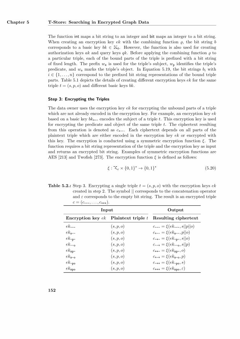
Chapter 5 T-Store: Searching in Encrypted Graph Data
The function int maps a bit string to an integer and bit maps an integer to a bit string.When creating an encryption key ek with the combining function %, the bit string bcorresponds to a basic key bk ∈ Kb. However, the function is also used for creatingauthorization keys ak and query keys qk. Before applying the combining function % toa particular triple, each of the bound parts of the triple is prefixed with a bit stringof fixed length. The prefix ws is used for the triple’s subject, wp identifies the triple’spredicate, and wo marks the triple’s object. In Equation 5.19, the bit strings bi withi ∈ {1, . . . , n} correspond to the prefixed bit string representations of the bound tripleparts. Table 5.1 depicts the details of creating different encryption keys ek for the sametriple t = (s, p, o) and different basic keys bk.
Step 3: Encrypting the Triples
The data owner uses the encryption key ek for encrypting the unbound parts of a triplewhich are not already encoded in the encryption key. For example, an encryption key ekbased on a basic key bk+-- encodes the subject of a triple t. This encryption key is usedfor encrypting the predicate and object of the same triple t. The ciphertext resultingfrom this operation is denoted as c+--. Each ciphertext depends on all parts of theplaintext triple which are either encoded in the encryption key ek or encrypted withthis key. The encryption is conducted using a symmetric encryption function ξ. Thefunction requires a bit string representation of the triple and the encryption key as inputand returns an encrypted bit string. Examples of symmetric encryption functions areAES [213] and Twofish [273]. The encryption function ξ is defined as follows:
ξ : Ke × {0, 1}∗ → {0, 1}∗ (5.20)
Table 5.2.: Step 3. Encrypting a single triple t = (s, p, o) with the encryption keys ekcreated in step 2. The symbol || corresponds to the concatenation operatorand ε corresponds to the empty bit string. The result is an encrypted triplec = (c---, . . . , c+++).
Input Output
Encryption key ek Plaintext triple t Resulting ciphertext
ek--- (s, p, o) c--- = ξ(ek---, s||p||o)eks-- (s, p, o) c+-- = ξ(eks--, p||o)ek-p- (s, p, o) c-+- = ξ(ek-p-, s||o)ek--o (s, p, o) c--+ = ξ(ek--o, s||p)eksp- (s, p, o) c++- = ξ(eksp-, o)
eks-o (s, p, o) c+-+ = ξ(eks-o, p)
ek-po (s, p, o) c-++ = ξ(ek-po, s)
ekspo (s, p, o) c+++ = ξ(ekspo, ε)
152
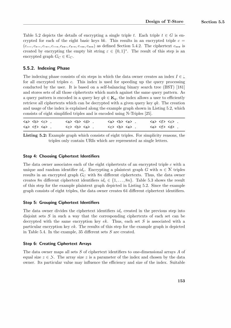
Design of T-Store Section 5.5
Table 5.2 depicts the details of encrypting a single triple t. Each triple t ∈ G is en-crypted for each of the eight basic keys bk. This results in an encrypted triple c =(c---, c+--, c-+-, c--+, c++-, c+-+, c-++, c+++) as defined Section 5.4.2. The ciphertext c+++ iscreated by encrypting the empty bit string ε ∈ {0, 1}∗. The result of this step is anencrypted graph GC ∈ GC .
5.5.2. Indexing Phase
The indexing phase consists of six steps in which the data owner creates an index I ∈ Ifor all encrypted triples c. This index is used for speeding up the query processingconducted by the user. It is based on a self-balancing binary search tree (BST) [181]and stores sets of all those ciphertexts which match against the same query pattern. Asa query pattern is encoded in a query key qk ∈ Kq, the index allows a user to efficientlyretrieve all ciphertexts which can be decrypted with a given query key qk. The creationand usage of the index is explained along the example graph shown in Listing 5.2, whichconsists of eight simplified triples and is encoded using N-Triples [25].
<a> <b> <c> . <a> <b> <d> . <a> <b> <e> . <a> <f> <c> .
<a> <f> <e> . <c> <b> <a> . <c> <b> <e> . <e> <f> <d> .
Listing 5.2: Example graph which consists of eight triples. For simplicity reasons, thetriples only contain URIs which are represented as single letters.
Step 4: Choosing Ciphertext Identifiers
The data owner associates each of the eight ciphertexts of an encrypted triple c with aunique and random identifier idc. Encrypting a plaintext graph G with n ∈ N triplesresults in an encrypted graph GC with 8n different ciphertexts. Thus, the data ownercreates 8n different ciphertext identifiers idc ∈ {1, . . . , 8n}. Table 5.3 shows the resultof this step for the example plaintext graph depicted in Listing 5.2. Since the examplegraph consists of eight triples, the data owner creates 64 different ciphertext identifiers.
Step 5: Grouping Ciphertext Identifiers
The data owner divides the ciphertext identifiers idc created in the previous step intodisjoint sets S in such a way that the corresponding ciphertexts of each set can bedecrypted with the same encryption key ek. Thus, each set S is associated with aparticular encryption key ek. The results of this step for the example graph is depictedin Table 5.4. In the example, 35 different sets S are created.
Step 6: Creating Ciphertext Arrays
The data owner maps all sets S of ciphertext identifiers to one-dimensional arrays A ofequal size z ∈ N. The array size z is a parameter of the index and chosen by the dataowner. Its particular value may influence the efficiency and size of the index. Suitable
153
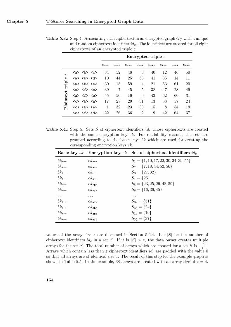
Chapter 5 T-Store: Searching in Encrypted Graph Data
Table 5.3.: Step 4. Associating each ciphertext in an encrypted graph GC with a uniqueand random ciphertext identifier idc. The identifiers are created for all eightciphertexts of an encrypted triple c.
Encrypted triple c
c--- c+-- c-+- c--+ c++- c+-+ c-++ c+++P
lain
text
trip
let <a> <b> <c> 34 52 48 3 40 12 46 50
<a> <b> <d> 10 44 25 53 41 35 14 11
<a> <b> <e> 30 18 59 4 21 63 61 20
<a> <f> <c> 39 7 45 5 38 47 28 49
<a> <f> <e> 55 56 16 6 43 62 60 31
<c> <b> <a> 17 27 29 51 13 58 57 24
<c> <b> <e> 1 32 23 33 15 8 54 19
<e> <f> <d> 22 26 36 2 9 42 64 37
Table 5.4.: Step 5. Sets S of ciphertext identifiers idc whose ciphertexts are createdwith the same encryption key ek. For readability reasons, the sets aregrouped according to the basic keys bk which are used for creating thecorresponding encryption keys ek.
Basic key bk Encryption key ek Set of ciphertext identifiers idc
bk--- ek--- S1 = {1, 10, 17, 22, 30, 34, 39, 55}bk+-- eka-- S2 = {7, 18, 44, 52, 56}bk+-- ekc-- S3 = {27, 32}bk+-- eke-- S4 = {26}bk-+- ek-b- S5 = {23, 25, 29, 48, 59}bk-+- ek-f- S6 = {16, 36, 45}. . . . . . . . .
bk+++ ekafe S32 = {31}bk+++ ekcba S33 = {24}bk+++ ekcbe S34 = {19}bk+++ ekefd S35 = {37}
values of the array size z are discussed in Section 5.6.4. Let |S| be the number ofciphertext identifiers idc in a set S. If it is |S| > z, the data owner creates multiple
arrays for the set S. The total number of arrays which are created for a set S is d |S|z e.Arrays which contain less than z ciphertext identifiers idc are padded with the value 0so that all arrays are of identical size z. The result of this step for the example graph isshown in Table 5.5. In the example, 38 arrays are created with an array size of z = 4.
154
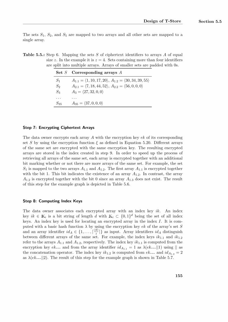
Design of T-Store Section 5.5
The sets S1, S2, and S5 are mapped to two arrays and all other sets are mapped to asingle array.
Table 5.5.: Step 6. Mapping the sets S of ciphertext identifiers to arrays A of equalsize z. In the example it is z = 4. Sets containing more than four identifiersare split into multiple arrays. Arrays of smaller sets are padded with 0s.
Set S Corresponding arrays A
S1 A1.1 = 〈1, 10, 17, 20〉, A1.2 = 〈30, 34, 39, 55〉S2 A2.1 = 〈7, 18, 44, 52〉, A2.2 = 〈56, 0, 0, 0〉S3 A3 = 〈27, 32, 0, 0〉. . . . . .
S35 A35 = 〈37, 0, 0, 0〉
Step 7: Encrypting Ciphertext Arrays
The data owner encrypts each array A with the encryption key ek of its correspondingset S by using the encryption function ξ as defined in Equation 5.20. Different arraysof the same set are encrypted with the same encryption key. The resulting encryptedarrays are stored in the index created in step 9. In order to speed up the process ofretrieving all arrays of the same set, each array is encrypted together with an additionalbit marking whether or not there are more arrays of the same set. For example, the setS1 is mapped to the two arrays A1.1 and A1.2. The first array A1.1 is encrypted togetherwith the bit 1. This bit indicates the existence of an array A1.2. In contrast, the arrayA1.2 is encrypted together with the bit 0 since an array A1.3 does not exist. The resultof this step for the example graph is depicted in Table 5.6.
Step 8: Computing Index Keys
The data owner associates each encrypted array with an index key ik. An indexkey ik ∈ Ki is a bit string of length d with Ki ⊂ {0, 1}d being the set of all indexkeys. An index key is used for locating an encrypted array in the index I. It is com-puted with a basic hash function λ by using the encryption key ek of the array’s set Sand an array identifier idA ∈ {1, . . . , d |S|z e} as input. Array identifiers idA distinguishbetween different arrays of the same set. For example, the index keys ik1.1 and ik1.2refer to the arrays A1.1 and A1.2, respectively. The index key ik1.1 is computed from theencryption key ek--- and from the array identifier idA1.1 = 1 as λ(ek---||1) using || asthe concatenation operator. The index key ik1.2 is computed from ek--- and idA1.2 = 2as λ(ek---||2). The result of this step for the example graph is shown in Table 5.7.
155
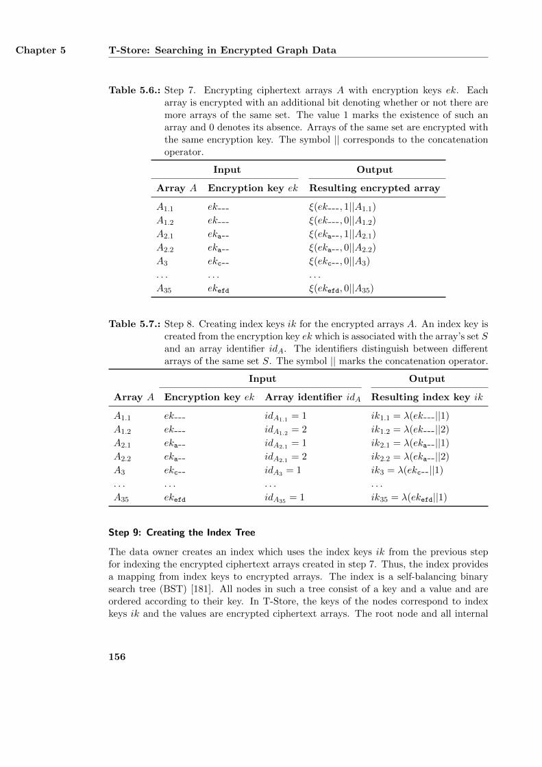
Chapter 5 T-Store: Searching in Encrypted Graph Data
Table 5.6.: Step 7. Encrypting ciphertext arrays A with encryption keys ek. Eacharray is encrypted with an additional bit denoting whether or not there aremore arrays of the same set. The value 1 marks the existence of such anarray and 0 denotes its absence. Arrays of the same set are encrypted withthe same encryption key. The symbol || corresponds to the concatenationoperator.
Input Output
Array A Encryption key ek Resulting encrypted array
A1.1 ek--- ξ(ek---, 1||A1.1)
A1.2 ek--- ξ(ek---, 0||A1.2)
A2.1 eka-- ξ(eka--, 1||A2.1)
A2.2 eka-- ξ(eka--, 0||A2.2)
A3 ekc-- ξ(ekc--, 0||A3)
. . . . . . . . .
A35 ekefd ξ(ekefd, 0||A35)
Table 5.7.: Step 8. Creating index keys ik for the encrypted arrays A. An index key iscreated from the encryption key ek which is associated with the array’s set Sand an array identifier idA. The identifiers distinguish between differentarrays of the same set S. The symbol || marks the concatenation operator.
Input Output
Array A Encryption key ek Array identifier idA Resulting index key ik
A1.1 ek--- idA1.1 = 1 ik1.1 = λ(ek---||1)
A1.2 ek--- idA1.2 = 2 ik1.2 = λ(ek---||2)
A2.1 eka-- idA2.1 = 1 ik2.1 = λ(eka--||1)
A2.2 eka-- idA2.1 = 2 ik2.2 = λ(eka--||2)
A3 ekc-- idA3 = 1 ik3 = λ(ekc--||1)
. . . . . . . . . . . .
A35 ekefd idA35 = 1 ik35 = λ(ekefd||1)
Step 9: Creating the Index Tree
The data owner creates an index which uses the index keys ik from the previous stepfor indexing the encrypted ciphertext arrays created in step 7. Thus, the index providesa mapping from index keys to encrypted arrays. The index is a self-balancing binarysearch tree (BST) [181]. All nodes in such a tree consist of a key and a value and areordered according to their key. In T-Store, the keys of the nodes correspond to indexkeys ik and the values are encrypted ciphertext arrays. The root node and all internal
156
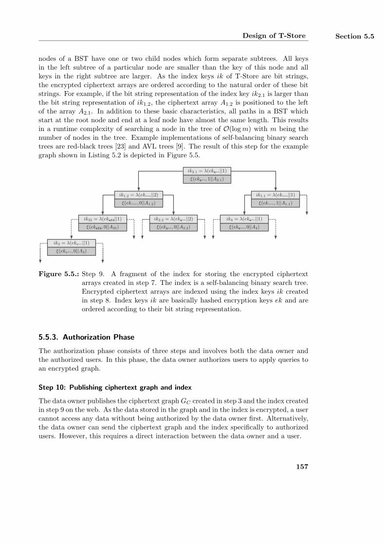
Design of T-Store Section 5.5
nodes of a BST have one or two child nodes which form separate subtrees. All keysin the left subtree of a particular node are smaller than the key of this node and allkeys in the right subtree are larger. As the index keys ik of T-Store are bit strings,the encrypted ciphertext arrays are ordered according to the natural order of these bitstrings. For example, if the bit string representation of the index key ik2.1 is larger thanthe bit string representation of ik1.2, the ciphertext array A1.2 is positioned to the leftof the array A2.1. In addition to these basic characteristics, all paths in a BST whichstart at the root node and end at a leaf node have almost the same length. This resultsin a runtime complexity of searching a node in the tree of O(logm) with m being thenumber of nodes in the tree. Example implementations of self-balancing binary searchtrees are red-black trees [23] and AVL trees [9]. The result of this step for the examplegraph shown in Listing 5.2 is depicted in Figure 5.5.
ik2.1 = λ(eka--||1)ξ(eka--, 1||A2.1)
ik1.2 = λ(ek---||2)ξ(ek---, 0||A1.2)
ik1.1 = λ(ek---||1)ξ(ek---, 1||A1.1)
ik35 = λ(ekefd||1)ξ(ekefd, 0||A35)
ik2.2 = λ(eka--||2)ξ(eka--, 0||A2.2)
ik4 = λ(eke--||1)ξ(eke--, 0||A4)
ik3 = λ(ekc--||1)ξ(ekc--, 0||A3)
Figure 5.5.: Step 9. A fragment of the index for storing the encrypted ciphertextarrays created in step 7. The index is a self-balancing binary search tree.Encrypted ciphertext arrays are indexed using the index keys ik createdin step 8. Index keys ik are basically hashed encryption keys ek and areordered according to their bit string representation.
5.5.3. Authorization Phase
The authorization phase consists of three steps and involves both the data owner andthe authorized users. In this phase, the data owner authorizes users to apply queries toan encrypted graph.
Step 10: Publishing ciphertext graph and index
The data owner publishes the ciphertext graphGC created in step 3 and the index createdin step 9 on the web. As the data stored in the graph and in the index is encrypted, a usercannot access any data without being authorized by the data owner first. Alternatively,the data owner can send the ciphertext graph and the index specifically to authorizedusers. However, this requires a direct interaction between the data owner and a user.
157
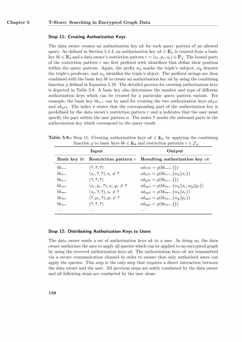
Chapter 5 T-Store: Searching in Encrypted Graph Data
Step 11: Creating Authorization Keys
The data owner creates an authorization key ak for each query pattern of an allowedquery. As defined in Section 5.4.4, an authorization key ak ∈ Ka is created from a basickey bk ∈ Kb and a data owner’s restriction pattern r = (sr, pr, or) ∈ Pq. The bound partsof the restriction pattern r are first prefixed with identifiers that define their positionwithin the query pattern. Again, the prefix ws marks the triple’s subject, wp denotesthe triple’s predicate, and wo identifies the triple’s object. The prefixed strings are thencombined with the basic key bk to create an authorization key ak by using the combiningfunction % defined in Equation 5.19. The detailed process for creating authorization keysis depicted in Table 5.8. A basic key also determines the number and type of differentauthorization keys which can be created for a particular query pattern variant. Forexample, the basic key bk+-- can be used for creating the two authorization keys akr??and aku??. The index r states that the corresponding part of the authorization key ispredefined by the data owner’s restriction pattern r and u indicates that the user mustspecify the part within the user pattern u. The index ? marks the unbound parts in theauthorization key which correspond to the query result.
Table 5.8.: Step 11: Creating authorization keys ak ∈ Ka by applying the combiningfunction % to basic keys bk ∈ Kb and restriction patterns r ∈ Pq.
Input Output
Basic key bk Restriction pattern r Resulting authorization key ak
bk--- (?, ?, ?) ak??? = %(bk---, {})bk+-- (sr, ?, ?), sr 6= ? akr?? = %(bk+--, {ws||sr})bk+-- (?, ?, ?) aku?? = %(bk+--, {})bk++- (sr, pr, ?), sr, pr 6= ? akrr? = %(bk++-, {ws||sr, wp||pr})bk++- (sr, ?, ?), sr 6= ? akru? = %(bk++-, {ws||sr})bk++- (?, pr, ?), pr 6= ? akur? = %(bk++-, {wp||pr})bk++- (?, ?, ?) akuu? = %(bk++-, {})· · · · · · · · ·
Step 12: Distributing Authorization Keys to Users
The data owner sends a set of authorization keys ak to a user. In doing so, the dataowner authorizes the user to apply all queries which can be applied to an encrypted graphby using the received authorization keys ak. The authorization keys ak are transmittedvia a secure communication channel in order to ensure that only authorized users canapply the queries. This step is the only step that requires a direct interaction betweenthe data owner and the user. All previous steps are solely conducted by the data ownerand all following steps are conducted by the user alone.
158
Design of T-Store Section 5.5
5.5.4. Query Phase
The query phase consists of four steps which are conducted by an authorized user. Inthis phase, an authorized user queries an encrypted graph GC by using the receivedauthorization keys ak. This section describes how a user can process a query consistingof a single triple key tk. The application of more complex queries consisting of multipletriple keys is discussed in Section 5.5.5. The user applies each triple key to the ciphertextgraph GC by processing its query key qk with a corresponding query function f .
Step 13: Choosing User Patterns
The user choses a user pattern u ∈ Pq which is compatible with the received authoriza-tion key ak ∈ Ka. As described in Section 5.4.4, an authorization key ak already encodesa data owner’s restriction pattern r ∈ Pq. The more parts the data owner specifies in therestriction pattern r, the fewer choices does the user have to formulate a user pattern u.For example, the query function f-++ requires a predicate and an object to be eitherspecified in r or in u. If the data owner defines r = (?, rdf:type, foaf:Person), a usercan only search for resources of rdf:type foaf:Person from the FOAF vocabulary [50].In this case, the user can only define a user pattern u = (?, ?, ?) which does not addany further query parameters to the restriction pattern r. However, if the data ownerdefines r = (?, rdf:type, ?), the user can specify different values for the object of theuser pattern. For example, the user may define u = (?, ?, foaf:Organization) to searchfor all resources of rdf:type foaf:Organization.
Step 14: Creating Query Keys
The user creates a query key qk ∈ Kq by combining an authorization key ak ∈ Ka witha compatible user pattern u ∈ Pq created in the previous step. A query key qk is similarto an encryption key ek ∈ Ke and thus created similarly as well. A query key encodesa query pattern and is used as input for a corresponding query function f . Table 5.9depicts the details of creating a query key qk from a received authorization key ak anda user pattern u. A query key is created by using the combining function % and thebasic hash function λ. The bound parts of the user pattern are first prefixed with theidentifiers ws, wp, and wo. These identifiers are used to determine the position of thebound parts of the user pattern. If a query key qk was created correctly, it encodes allbound parts of a query pattern and is identical to the encryption key ek which was usedfor encrypting the unbound parts. In this case, the query key can be directly used fordecrypting the unbound triple parts.
Step 15: Identifying the Query Results
The user applies the index I in order to identify all ciphertexts which match againsta particular query pattern. The index is accessed by index keys ik ∈ Ki which arecomputed from the query keys created in the previous step. For each query key qk,the user computes ik1 = λ(qk||1) and locates ik1 in the index. If the index does not
159
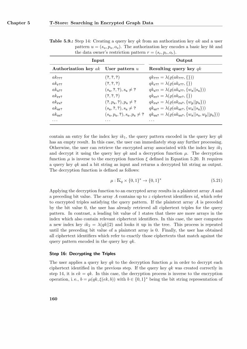
Chapter 5 T-Store: Searching in Encrypted Graph Data
Table 5.9.: Step 14: Creating a query key qk from an authorization key ak and a userpattern u = (su, pu, ou). The authorization key encodes a basic key bk andthe data owner’s restriction pattern r = (sr, pr, or).
Input Output
Authorization key ak User pattern u Resulting query key qk
ak??? (?, ?, ?) qk??? = λ(%(ak???, {}))akr?? (?, ?, ?) qkr?? = λ(%(akr??, {})aku?? (su, ?, ?), su 6= ? qku?? = λ(%(aku??, {ws||su}))akrr? (?, ?, ?) qkrr? = λ(%(akrr?, {})akru? (?, pu, ?), pu 6= ? qkru? = λ(%(akru?, {wp||pu}))akur? (su, ?, ?), su 6= ? qkur? = λ(%(akur?, {ws||su}))akuu? (su, pu, ?), su, pu 6= ? qkuu? = λ(%(akuu?, {ws||su, wp||pu}))· · · · · · · · ·
contain an entry for the index key ik1, the query pattern encoded in the query key qkhas an empty result. In this case, the user can immediately stop any further processing.Otherwise, the user can retrieve the encrypted array associated with the index key ik1and decrypt it using the query key qk and a decryption function µ. The decryptionfunction µ is inverse to the encryption function ξ defined in Equation 5.20. It requiresa query key qk and a bit string as input and returns a decrypted bit string as output.The decryption function is defined as follows:
µ : Kq × {0, 1}∗ → {0, 1}∗ (5.21)
Applying the decryption function to an encrypted array results in a plaintext array A anda preceding bit value. The array A contains up to z ciphertext identifiers idc which referto encrypted triples satisfying the query pattern. If the plaintext array A is precededby the bit value 0, the user has already retrieved all ciphertext triples for the querypattern. In contrast, a leading bit value of 1 states that there are more arrays in theindex which also contain relevant ciphertext identifiers. In this case, the user computesa new index key ik2 = λ(qk||2) and looks it up in the tree. This process is repeateduntil the preceding bit value of a plaintext array is 0. Finally, the user has obtainedall ciphertext identifiers which refer to exactly those ciphertexts that match against thequery pattern encoded in the query key qk.
Step 16: Decrypting the Triples
The user applies a query key qk to the decryption function µ in order to decrypt eachciphertext identified in the previous step. If the query key qk was created correctly instep 14, it is ek = qk. In this case, the decryption process is inverse to the encryptionoperation, i. e., b = µ(qk, ξ(ek, b)) with b ∈ {0, 1}∗ being the bit string representation of
160
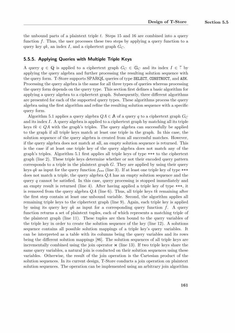
Design of T-Store Section 5.5
the unbound parts of a plaintext triple t. Steps 15 and 16 are combined into a queryfunction f . Thus, the user processes these two steps by applying a query function to aquery key qk, an index I, and a ciphertext graph GC .
5.5.5. Applying Queries with Multiple Triple Keys
A query q ∈ Q is applied to a ciphertext graph GC ∈ GC and its index I ∈ I byapplying the query algebra and further processing the resulting solution sequence withthe query form. T-Store supports SPARQL queries of type SELECT, CONSTRUCT, and ASK.Processing the query algebra is the same for all three types of queries whereas processingthe query form depends on the query type. This section first defines a basic algorithm forapplying a query algebra to a ciphertext graph. Subsequently, three different algorithmsare presented for each of the supported query types. These algorithms process the queryalgebra using the first algorithm and refine the resulting solution sequence with a specificquery form.
Algorithm 5.1 applies a query algebra QA ∈ A of a query q to a ciphertext graph GCand its index I. A query algebra is applied to a ciphertext graph by matching all its triplekeys tk ∈ QA with the graph’s triples. The query algebra can successfully be appliedto the graph if all triple keys match at least one triple in the graph. In this case, thesolution sequence of the query algebra is created from all successful matches. However,if the query algebra does not match at all, an empty solution sequence is returned. Thisis the case if at least one triple key of the query algebra does not match any of thegraph’s triples. Algorithm 5.1 first applies all triple keys of type +++ to the ciphertextgraph (line 2). These triple keys determine whether or not their encoded query patterncorresponds to a triple in the plaintext graph G. They are applied by using their querykeys qk as input for the query function f+++ (line 3). If at least one triple key of type +++does not match a triple, the query algebra QA has an empty solution sequence and thequery q cannot be satisfied. In this case, query processing is stopped immediately andan empty result is returned (line 4). After having applied a triple key of type +++, itis removed from the query algebra QA (line 6). Thus, all triple keys tk remaining afterthe first step contain at least one unbound variable. Second, the algorithm applies allremaining triple keys to the ciphertext graph (line 9). Again, each triple key is appliedby using its query key qk as input for a corresponding query function f . A queryfunction returns a set of plaintext tuples, each of which represents a matching triple ofthe plaintext graph (line 11). These tuples are then bound to the query variables ofthe triple key in order to create the solution sequence of the key (line 12). A solutionssequence contains all possible solution mappings of a triple key’s query variables. Itcan be interpreted as a table with its columns being the query variables and its rowsbeing the different solution mappings [86]. The solution sequences of all triple keys areincrementally combined using the join operator on (line 13). If two triple keys share thesame query variables, a natural join is conducted on their solution sequences using thesevariables. Otherwise, the result of the join operation is the Cartesian product of thesolution sequences. In its current design, T-Store conducts a join operation on plaintextsolution sequences. The operation can be implemented using an arbitrary join algorithm
161
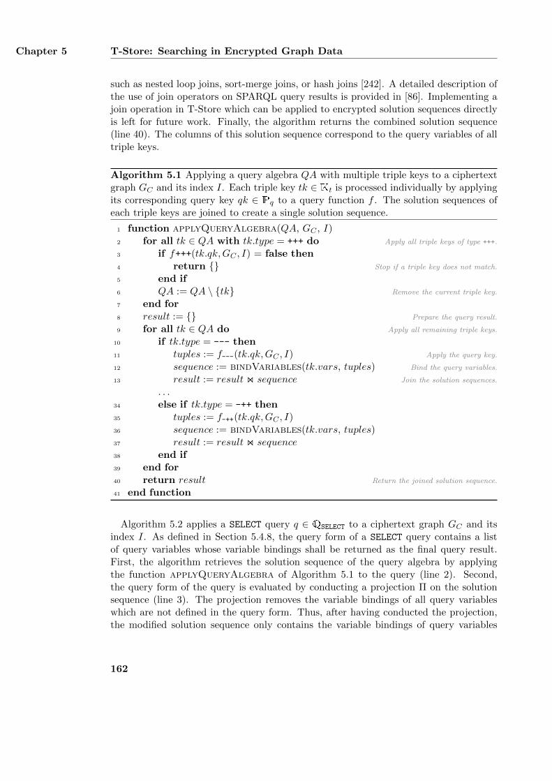
Chapter 5 T-Store: Searching in Encrypted Graph Data
such as nested loop joins, sort-merge joins, or hash joins [242]. A detailed description ofthe use of join operators on SPARQL query results is provided in [86]. Implementing ajoin operation in T-Store which can be applied to encrypted solution sequences directlyis left for future work. Finally, the algorithm returns the combined solution sequence(line 40). The columns of this solution sequence correspond to the query variables of alltriple keys.
Algorithm 5.1 Applying a query algebra QA with multiple triple keys to a ciphertextgraph GC and its index I. Each triple key tk ∈ Kt is processed individually by applyingits corresponding query key qk ∈ Pq to a query function f . The solution sequences ofeach triple keys are joined to create a single solution sequence.
1 function applyQueryAlgebra(QA, GC , I)2 for all tk ∈ QA with tk.type = +++ do Apply all triple keys of type +++.
3 if f+++(tk.qk,GC , I) = false then4 return {} Stop if a triple key does not match.
5 end if6 QA := QA \ {tk} Remove the current triple key.
7 end for8 result := {} Prepare the query result.
9 for all tk ∈ QA do Apply all remaining triple keys.
10 if tk.type = --- then11 tuples := f---(tk.qk,GC , I) Apply the query key.
12 sequence := bindVariables(tk.vars, tuples) Bind the query variables.
13 result := result on sequence Join the solution sequences.
. . .34 else if tk.type = -++ then35 tuples := f-++(tk.qk,GC , I)36 sequence := bindVariables(tk.vars, tuples)37 result := result on sequence38 end if39 end for40 return result Return the joined solution sequence.
41 end function
Algorithm 5.2 applies a SELECT query q ∈ QSELECT to a ciphertext graph GC and itsindex I. As defined in Section 5.4.8, the query form of a SELECT query contains a listof query variables whose variable bindings shall be returned as the final query result.First, the algorithm retrieves the solution sequence of the query algebra by applyingthe function applyQueryAlgebra of Algorithm 5.1 to the query (line 2). Second,the query form of the query is evaluated by conducting a projection Π on the solutionsequence (line 3). The projection removes the variable bindings of all query variableswhich are not defined in the query form. Thus, after having conducted the projection,the modified solution sequence only contains the variable bindings of query variables
162

Design of T-Store Section 5.5
which are also defined in the query form. Finally, the algorithm returns the modifiedsolution sequence as the final query result (line 4).
Algorithm 5.2 Applying a SELECT query q to a ciphertext graph GC and its index I.The result of the query is a list of variable bindings.
1 function applySelectQuery(q, GC , I)2 solutionSequence := applyQueryAlgebra(q.QA, GC , I)3 projectedSequence := Πv1,...,vn∈q.queryV ariables(solutionSequence)4 return projectedSequence5 end function
Algorithm 5.3 applies a CONSTRUCT query q ∈ QCONSTRUCT to a ciphertext graph GCand its index I. The query form of a CONSTRUCT query contains a graph template whichis used for creating a new graph resultGraph ∈ G based on the solution sequence ofthe query algebra. First, the algorithm processes the query algebra with the functionapplyQueryAlgebra of Algorithm 5.1 in order to retrieve an initial solution sequence(line 2). Second, an empty graph is created which serves as a basis for the new graph tobe created (line 3). Third, the graph template is instantiated with each solution mappingof the initial solution sequence (line 5). This is done by substituting all query variablesin the graph template with the variable bindings of a particular solution mapping. Eachinstantiation of the graph template corresponds to a new set of triples. Fourth, the setof triples is combined with the current result graph (line 6). Finally, the combined graphcreated from all instantiations of the graph template is returned as the final query result(line 8).
Algorithm 5.3 Applying a CONSTRUCT query q to a ciphertext graph GC and its index I.The result of the query is a newly created graph.
1 function applyConstructQuery(q, GC , I)2 solutionSequence := applyQueryAlgebra(q.QA, GC , I)3 resultGraph := {}4 for all mapping ∈ solutionSequence do5 tripleSet := substitute(q.graphTemplate, mapping)6 resultGraph := resultGraph ∪ tripleSet7 end for8 return resultGraph9 end function
Algorithm 5.4 applies an ASK query q ∈ QASK to an ciphertext graphGC and its index I.An ASK query determines whether or not the query algebra of a query matches againsta graph and returns a corresponding boolean value. The algorithm first applies thefunction applyQueryAlgebra of Algorithm 5.1 in order to retrieve an initial solutionsequence (line 2). If the solution sequence contains at least one solution mapping, thealgorithm returns TRUE and FALSE otherwise (line 3).
163
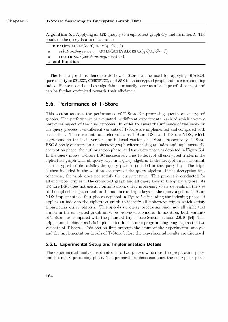
Chapter 5 T-Store: Searching in Encrypted Graph Data
Algorithm 5.4 Applying an ASK query q to a ciphertext graph GC and its index I. Theresult of the query is a boolean value.
1 function applyAskQuery(q, GC , I)2 solutionSequence := applyQueryAlgebra(q.QA, GC , I)3 return size(solutionSequence) > 04 end function
The four algorithms demonstrate how T-Store can be used for applying SPARQLqueries of type SELECT, CONSTRUCT, and ASK to an encrypted graph and its correspondingindex. Please note that these algorithms primarily serve as a basic proof-of-concept andcan be further optimized towards their efficiency.
5.6. Performance of T-Store
This section assesses the performance of T-Store for processing queries on encryptedgraphs. The performance is evaluated in different experiments, each of which covers aparticular aspect of the query process. In order to assess the influence of the index onthe query process, two different variants of T-Store are implemented and compared witheach other. These variants are referred to as T-Store BSC and T-Store NDX, whichcorrespond to the basic version and indexed version of T-Store, respectively. T-StoreBSC directly operates on a ciphertext graph without using an index and implements theencryption phase, the authorization phase, and the query phase as depicted in Figure 5.4.In the query phase, T-Store BSC successively tries to decrypt all encrypted triples in theciphertext graph with all query keys in a query algebra. If the decryption is successful,the decrypted triple satisfies the query pattern encoded in the query key. The tripleis then included in the solution sequence of the query algebra. If the decryption failsotherwise, the triple does not satisfy the query pattern. This process is conducted forall encrypted triples in the ciphertext graph and all query keys in the query algebra. AsT-Store BSC does not use any optimization, query processing solely depends on the sizeof the ciphertext graph and on the number of triple keys in the query algebra. T-StoreNDX implements all four phases depicted in Figure 5.4 including the indexing phase. Itapplies an index to the ciphertext graph to identify all ciphertext triples which satisfya particular query pattern. This speeds up query processing since not all ciphertexttriples in the encrypted graph must be processed anymore. In addition, both variantsof T-Store are compared with the plaintext triple store Sesame version 2.6.10 [54]. Thistriple store is chosen as it is implemented in the same programming language as the twovariants of T-Store. This section first presents the setup of the experimental analysisand the implementation details of T-Store before the experimental results are discussed.
5.6.1. Experimental Setup and Implementation Details
The experimental analysis is divided into two phases which are the preparation phaseand the query processing phase. The preparation phase combines the encryption phase
164
Performance of T-Store Section 5.6
and the indexing phase as depicted in Figure 5.4 and the query processing phase cor-responds to the query phase. In the preparation phase, different plaintext graphs aregenerated, encrypted, indexed, and loaded into memory. The runtime of encrypting agraph, creating its index, and loading the created files is measured. In addition, the sizeof the created files is measured as well. In the query processing phase, multiple querieswith different numbers of triple keys are applied to the ciphertext graphs. Again, theruntime of applying each query is measured. In order to avoid interference with statis-tical outliers, each operation is performed ten times and the mean value is calculated.
As experimental data, the Berlin SPARQL benchmark (BSBM) [40] is used whichis designed to assess the performance of different SPARQL implementations. BSBMprovides tools for generating synthetic RDF graphs and SPARQL queries which simulatea user browsing through the graphs. The tools are used to create five different RDFgraphs ranging from 10, 000 triples to 200, 000 triples. Each graph is serialized usingN-Triples [25] and stored in a separate file. Queries are taken from the explore scenarioof the BSBM framework which provides twelve different queries. The queries differ intheir number of SPARQL triple patterns and in the size of their solution sequence.Queries that use SPARQL features which are not yet supported by T-Store such asOPTIONAL and FILTER are modified by removing the unsupported parts. Queries usingUNION are split into separate queries and the runtime of these queries is summed up.The modified queries are available online at the website of this thesis which is referencedin the conclusion.
As described in Section 5.5.2, the array size z is a parameter of the index of T-StoreNDX. In order to measure the influence of the array size on the index, twelve indexeswith different values of z are created for the BSBM graph with 200,000 triples. For afair comparison between T-Store and Sesame, all files required for processing a queryare loaded into main memory before the actual query processing is conducted. Thisminimizes potential side effects from accessing the hard drive when applying a query. T-Store BSC only loads the ciphertext graph while T-Store NDX loads the ciphertext graphand its index. Sesame loads the plaintext graph using its MemoryStore which stores alltriples in main memory. When loading a graph, the MemoryStore automatically createsan index for the graph from scratch. The index provides a mapping from every subject,predicate, and object in the graph to a one-dimensional array of all triples in which theyoccur. All experiments were conducted on a system with 50 GB memory and an Intel R©
Xeon R© CPU with 3.00 GHz running Ubuntu GNU/Linux version 14.04.2.Both variants of T-Store are implemented in Java and use the Java Cryptography
Extension (JCE) for all cryptographic operations. JCE is an official Java API whichprovides different encryption algorithms and hash algorithms. As the encryption func-tion ξ, the Advanced Encryption Standard (AES) [213] with a key length of 256 bits isused. The algorithm and the used key length are proven of high security and are rec-ommended by the National Institute of Standards and Technology (NIST) [215]. AESis a block-based symmetric encryption scheme which operates on blocks of 16 bytes. Inorder to encrypt arbitrary plaintext data, the data is first split into blocks which arethen encrypted. If the data is not a multiple of the block size, it is padded before theencryption, which may slightly increase the size of the resulting ciphertext. As the basic
165
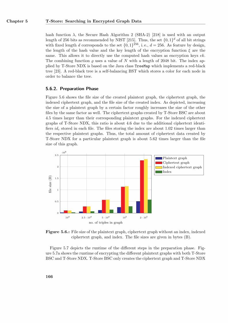
Chapter 5 T-Store: Searching in Encrypted Graph Data
hash function λ, the Secure Hash Algorithm 2 (SHA-2) [218] is used with an outputlength of 256 bits as recommended by NIST [215]. Thus, the set {0, 1}d of all bit stringswith fixed length d corresponds to the set {0, 1}256, i. e., d = 256. As feature by design,the length of the hash value and the key length of the encryption function ξ are thesame. This allows it to directly use the computed hash values as encryption keys ek.The combining function % uses a value of N with a length of 2048 bit. The index ap-plied by T-Store NDX is based on the Java class TreeMap which implements a red-blacktree [23]. A red-black tree is a self-balancing BST which stores a color for each node inorder to balance the tree.
5.6.2. Preparation Phase
Figure 5.6 shows the file size of the created plaintext graph, the ciphertext graph, theindexed ciphertext graph, and the file size of the created index. As depicted, increasingthe size of a plaintext graph by a certain factor roughly increases the size of the otherfiles by the same factor as well. The ciphertext graphs created by T-Store BSC are about4.5 times larger than their corresponding plaintext graphs. For the indexed ciphertextgraphs of T-Store NDX, this ratio is about 4.6 due to the additional ciphertext identi-fiers idc stored in each file. The files storing the index are about 1.02 times larger thanthe respective plaintext graphs. Thus, the total amount of ciphertext data created byT-Store NDX for a particular plaintext graph is about 5.62 times larger than the filesize of this graph.
104 2.5 · 104 5 · 104 105 2 · 1050
0.5
1
1.5
2
2.5·108
no. of triples in graph
file
size
(B)
Plaintext graph
Ciphertext graph
Indexed ciphertext graph
Index
Figure 5.6.: File size of the plaintext graph, ciphertext graph without an index, indexedciphertext graph, and index. The file sizes are given in bytes (B).
Figure 5.7 depicts the runtime of the different steps in the preparation phase. Fig-ure 5.7a shows the runtime of encrypting the different plaintext graphs with both T-StoreBSC and T-Store NDX. T-Store BSC only creates the ciphertext graph and T-Store NDX
166
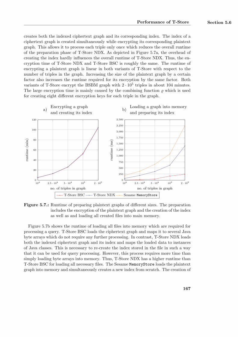
Performance of T-Store Section 5.6
creates both the indexed ciphertext graph and its corresponding index. The index of aciphertext graph is created simultaneously while encrypting its corresponding plaintextgraph. This allows it to process each triple only once which reduces the overall runtimeof the preparation phase of T-Store NDX. As depicted in Figure 5.7a, the overhead ofcreating the index hardly influences the overall runtime of T-Store NDX. Thus, the en-cryption time of T-Store NDX and T-Store BSC is roughly the same. The runtime ofencrypting a plaintext graph is linear in both variants of T-Store with respect to thenumber of triples in the graph. Increasing the size of the plaintext graph by a certainfactor also increases the runtime required for its encryption by the same factor. Bothvariants of T-Store encrypt the BSBM graph with 2 · 105 triples in about 104 minutes.The large encryption time is mainly caused by the combining function % which is usedfor creating eight different encryption keys for each triple in the graph.
104 2.5 · 104 5 · 104 105 2 · 1050
20
40
60
80
100
120
no. of triples in graph
runti
me
(min
)
a)Encrypting a graph
and creating its index
104 2.5 · 104 5 · 104 105 2 · 1050
250
500
750
1,000
1,250
1,500
1,750
2,000
2,250
2,500
no. of triples in graph
runti
me
(ms)
b)Loading a graph into memory
and preparing its index
T-Store BSC T-Store NDX Sesame MemoryStore
Figure 5.7.: Runtime of preparing plaintext graphs of different sizes. The preparationincludes the encryption of the plaintext graph and the creation of the indexas well as and loading all created files into main memory.
Figure 5.7b shows the runtime of loading all files into memory which are required forprocessing a query. T-Store BSC loads the ciphertext graph and maps it to several Javabyte arrays which do not require any further processing. In contrast, T-Store NDX loadsboth the indexed ciphertext graph and its index and maps the loaded data to instancesof Java classes. This is necessary to re-create the index stored in the file in such a waythat it can be used for query processing. However, this process requires more time thansimply loading byte arrays into memory. Thus, T-Store NDX has a higher runtime thanT-Store BSC for loading all necessary files. The Sesame MemoryStore loads the plaintextgraph into memory and simultaneously creates a new index from scratch. The creation of
167
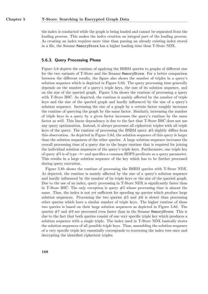
Chapter 5 T-Store: Searching in Encrypted Graph Data
the index is conducted while the graph is being loaded and cannot be separated from theloading process. This makes the index creation an integral part of the loading process.As creating an index requires more time than parsing an already existing index storedin a file, the Sesame MemoryStore has a higher loading time than T-Store NDX.
5.6.3. Query Processing Phase
Figure 5.8 depicts the runtime of applying the BSBM queries to graphs of different sizefor the two variants of T-Store and the Sesame MemoryStore. For a better comparisonbetween the different results, the figure also shows the number of triples in a query’ssolution sequence which is depicted in Figure 5.8d. The query processing time generallydepends on the number of a query’s triple keys, the size of its solution sequence, andon the size of the queried graph. Figure 5.8a shows the runtime of processing a querywith T-Store BSC. As depicted, the runtime is mainly affected by the number of triplekeys and the size of the queried graph and hardly influenced by the size of a query’ssolution sequence. Increasing the size of a graph by a certain factor roughly increasesthe runtime of querying the graph by the same factor. Similarly, increasing the numberof triple keys in a query by a given factor increases the query’s runtime by the samefactor as well. This linear dependency is due to the fact that T-Store BSC does not useany query optimization. Instead, it always processes all ciphertext triples with all triplekeys of the query. The runtime of processing the BSBM query #5 slightly differs fromthis observation. As depicted in Figure 5.8d, the solution sequence of this query is largerthan the solution sequences of the other queries. A large solution sequence increases theoverall processing time of a query due to the larger runtime that is required for joiningthe individual solution sequences of the query’s triple keys. Furthermore, one triple keyof query #5 is of type -+- and specifies a common RDFS predicate as a query parameter.This results in a large solution sequence of the key which has to be further processedduring query execution.
Figure 5.8b shows the runtime of processing the BSBM queries with T-Store NDX.As depicted, the runtime is mainly affected by the size of a query’s solution sequenceand hardly influenced by the number of its triple keys or the size of the queried graph.Due to the use of an index, query processing in T-Store NDX is significantly faster thanin T-Store BSC. The only exception is query #5 whose processing time is almost thesame. Thus, the index is not yet sufficient for speeding up queries which produce largesolution sequences. Processing the two queries #5 and #6 is slower than processingother queries which have a similar number of triple keys. The higher runtime of thesetwo queries is based on their large solution sequences as depicted in Figure 5.8d. Thequeries #7 and #9 are processed even faster than in the Sesame MemoryStore. This isdue to the fact that both queries consist of one very specific triple key which produces asolution sequence with a single triple. The index used in T-Store NDX basically storesthe solution sequences of all possible triple keys. Thus, assembling the solution sequenceof a very specific triple key essentially corresponds to traversing the index tree once anddecrypting the identified ciphertext triples.
168
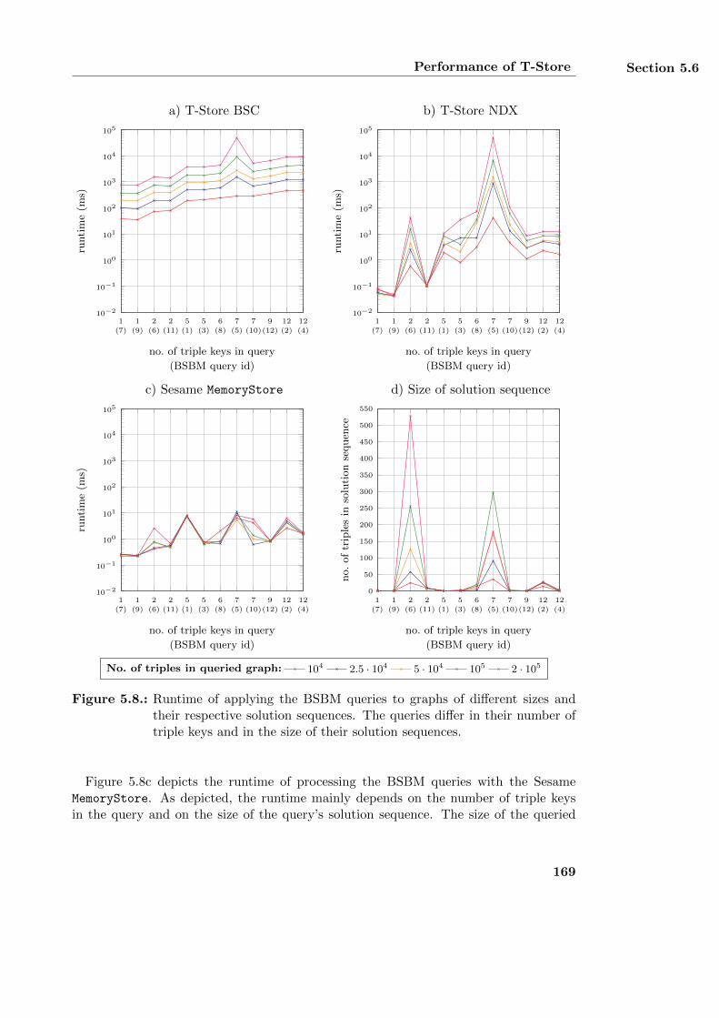
Performance of T-Store Section 5.6
1
(7)
1
(9)
2
(6)
2
(11)
5
(1)
5
(3)
6
(8)
7
(5)
7
(10)
9
(12)
12
(2)
12
(4)
10−2
10−1
100
101
102
103
104
105
no. of triple keys in query
(BSBM query id)
runti
me
(ms)
a) T-Store BSC
1
(7)
1
(9)
2
(6)
2
(11)
5
(1)
5
(3)
6
(8)
7
(5)
7
(10)
9
(12)
12
(2)
12
(4)
10−2
10−1
100
101
102
103
104
105
no. of triple keys in query
(BSBM query id)
runti
me
(ms)
b) T-Store NDX
1
(7)
1
(9)
2
(6)
2
(11)
5
(1)
5
(3)
6
(8)
7
(5)
7
(10)
9
(12)
12
(2)
12
(4)
10−2
10−1
100
101
102
103
104
105
no. of triple keys in query
(BSBM query id)
runti
me
(ms)
c) Sesame MemoryStore
1
(7)
1
(9)
2
(6)
2
(11)
5
(1)
5
(3)
6
(8)
7
(5)
7
(10)
9
(12)
12
(2)
12
(4)
0
50
100
150
200
250
300
350
400
450
500
550
no. of triple keys in query
(BSBM query id)
no.
of
trip
les
inso
luti
on
sequen
ce
d) Size of solution sequence
No. of triples in queried graph: 104 2.5 · 104 5 · 104 105 2 · 105
Figure 5.8.: Runtime of applying the BSBM queries to graphs of different sizes andtheir respective solution sequences. The queries differ in their number oftriple keys and in the size of their solution sequences.
Figure 5.8c depicts the runtime of processing the BSBM queries with the SesameMemoryStore. As depicted, the runtime mainly depends on the number of triple keysin the query and on the size of the query’s solution sequence. The size of the queried
169
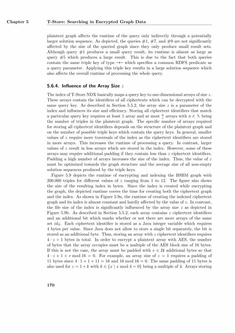
Chapter 5 T-Store: Searching in Encrypted Graph Data
plaintext graph affects the runtime of the query only indirectly through a potentiallylarger solution sequence. As depicted, the queries #1, #7, and #9 are not significantlyaffected by the size of the queried graph since they only produce small result sets.Although query #1 produces a small query result, its runtime is almost as large asquery #5 which produces a large result. This is due to the fact that both queriescontain the same triple key of type -+- which specifies a common RDFS predicate asa query parameter. Applying this triple key results in a large solution sequence whichalso affects the overall runtime of processing the whole query.
5.6.4. Influence of the Array Size z
The index of T-Store NDX basically maps a query key to one-dimensional arrays of size z.These arrays contain the identifiers of all ciphertexts which can be decrypted with thesame query key. As described in Section 5.5.2, the array size z is a parameter of theindex and influences its size and efficiency. Storing all ciphertext identifiers that matcha particular query key requires at least 1 array and at most n
z arrays with n ∈ N beingthe number of triples in the plaintext graph. The specific number of arrays requiredfor storing all ciphertext identifiers depends on the structure of the plaintext graph andon the number of possible triple keys which contain the query keys. In general, smallervalues of z require more traversals of the index as the ciphertext identifiers are storedin more arrays. This increases the runtime of processing a query. In contrast, largervalues of z result in less arrays which are stored in the index. However, some of thesearrays may require additional padding if they contain less than z ciphertext identifiers.Padding a high number of arrays increases the size of the index. Thus, the value of zmust be optimized towards the graph structure and the average size of all non-emptysolution sequences produced by the triple keys.
Figure 5.9 depicts the runtime of encrypting and indexing the BSBM graph with200.000 triples for different values of z ranging from 1 to 12. The figure also showsthe size of the resulting index in bytes. Since the index is created while encryptingthe graph, the depicted runtime covers the time for creating both the ciphertext graphand the index. As shown in Figure 5.9a, the runtime of creating the indexed ciphertextgraph and its index is almost constant and hardly affected by the value of z. In contrast,the file size of the index is significantly influenced by the array size z as depicted inFigure 5.9b. As described in Section 5.5.2, each array contains z ciphertext identifiersand an additional bit which marks whether or not there are more arrays of the sameset idS . Each ciphertext identifier is stored as a Java integer variable which requires4 bytes per value. Since Java does not allow to store a single bit separately, the bit isstored as an additional byte. Thus, storing an array with z ciphertext identifiers requires4 · z + 1 bytes in total. In order to encrypt a plaintext array with AES, the numberof bytes that the array occupies must be a multiple of the AES block size of 16 bytes.If this is not the case, the array must be padded with v ∈ N additional bytes so that4 · z + 1 + v mod 16 = 0. For example, an array size of z = 1 requires a padding of11 bytes since 4 · 1 + 1 + 11 = 16 and 16 mod 16 = 0. The same padding of 11 bytes isalso used for z = 1 + k with k ∈ {x | x mod 4 = 0} being a multiple of 4. Arrays storing
170
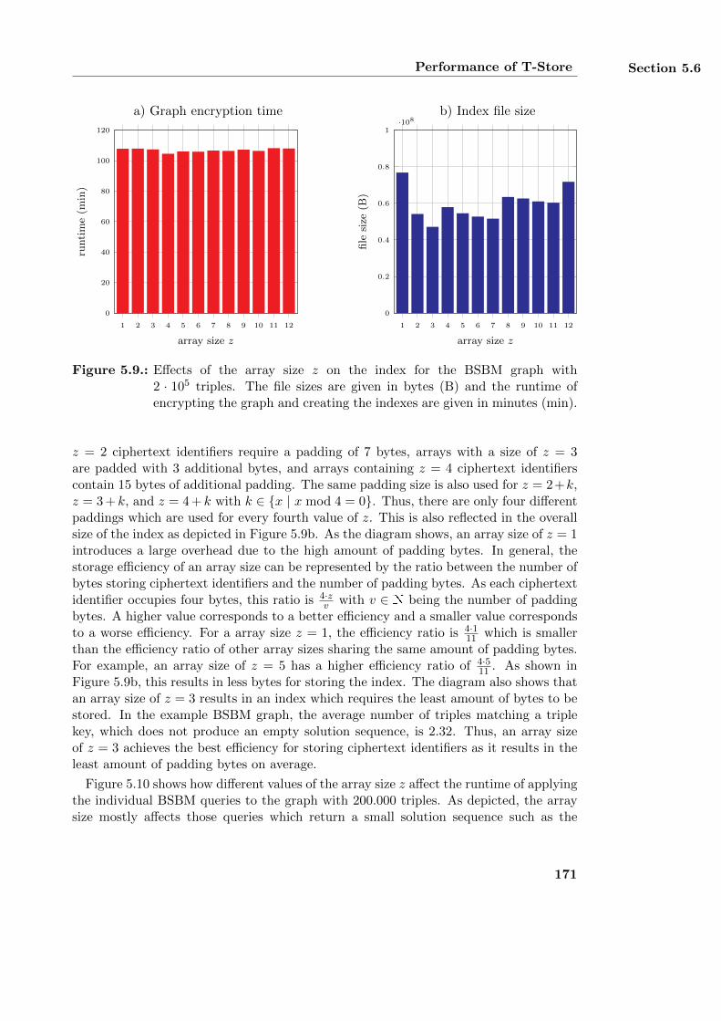
Performance of T-Store Section 5.6
1 2 3 4 5 6 7 8 9 10 11 12
0
20
40
60
80
100
120
array size z
runti
me
(min
)
a) Graph encryption time
1 2 3 4 5 6 7 8 9 10 11 12
0
0.2
0.4
0.6
0.8
1·108
array size z
file
size
(B)
b) Index file size
Figure 5.9.: Effects of the array size z on the index for the BSBM graph with2 · 105 triples. The file sizes are given in bytes (B) and the runtime ofencrypting the graph and creating the indexes are given in minutes (min).
z = 2 ciphertext identifiers require a padding of 7 bytes, arrays with a size of z = 3are padded with 3 additional bytes, and arrays containing z = 4 ciphertext identifierscontain 15 bytes of additional padding. The same padding size is also used for z = 2+k,z = 3 + k, and z = 4 + k with k ∈ {x | x mod 4 = 0}. Thus, there are only four differentpaddings which are used for every fourth value of z. This is also reflected in the overallsize of the index as depicted in Figure 5.9b. As the diagram shows, an array size of z = 1introduces a large overhead due to the high amount of padding bytes. In general, thestorage efficiency of an array size can be represented by the ratio between the number ofbytes storing ciphertext identifiers and the number of padding bytes. As each ciphertextidentifier occupies four bytes, this ratio is 4·z
v with v ∈ N being the number of paddingbytes. A higher value corresponds to a better efficiency and a smaller value correspondsto a worse efficiency. For a array size z = 1, the efficiency ratio is 4·1
11 which is smallerthan the efficiency ratio of other array sizes sharing the same amount of padding bytes.For example, an array size of z = 5 has a higher efficiency ratio of 4·5
11 . As shown inFigure 5.9b, this results in less bytes for storing the index. The diagram also shows thatan array size of z = 3 results in an index which requires the least amount of bytes to bestored. In the example BSBM graph, the average number of triples matching a triplekey, which does not produce an empty solution sequence, is 2.32. Thus, an array sizeof z = 3 achieves the best efficiency for storing ciphertext identifiers as it results in theleast amount of padding bytes on average.
Figure 5.10 shows how different values of the array size z affect the runtime of applyingthe individual BSBM queries to the graph with 200.000 triples. As depicted, the arraysize mostly affects those queries which return a small solution sequence such as the
171
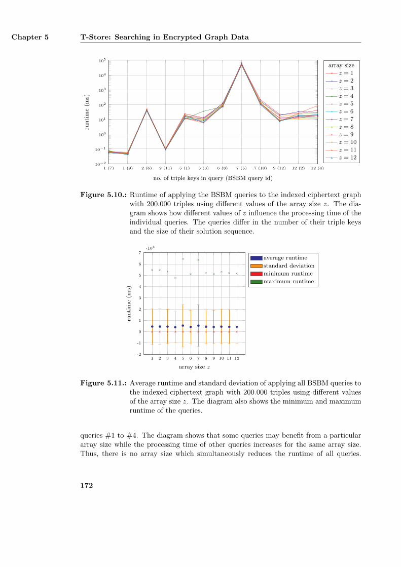
Chapter 5 T-Store: Searching in Encrypted Graph Data
1 (7) 1 (9) 2 (6) 2 (11) 5 (1) 5 (3) 6 (8) 7 (5) 7 (10) 9 (12) 12 (2) 12 (4)10−2
10−1
100
101
102
103
104
105
no. of triple keys in query (BSBM query id)
runti
me
(ms)
array size
z = 1
z = 2
z = 3
z = 4
z = 5
z = 6
z = 7
z = 8
z = 9
z = 10
z = 11
z = 12
Figure 5.10.: Runtime of applying the BSBM queries to the indexed ciphertext graphwith 200.000 triples using different values of the array size z. The dia-gram shows how different values of z influence the processing time of theindividual queries. The queries differ in the number of their triple keysand the size of their solution sequence.
1 2 3 4 5 6 7 8 9 10 11 12-2
-1
0
1
2
3
4
5
6
7·104
array size z
runti
me
(ms)
average runtime
standard deviation
minimum runtime
maximum runtime
Figure 5.11.: Average runtime and standard deviation of applying all BSBM queries tothe indexed ciphertext graph with 200.000 triples using different valuesof the array size z. The diagram also shows the minimum and maximumruntime of the queries.
queries #1 to #4. The diagram shows that some queries may benefit from a particulararray size while the processing time of other queries increases for the same array size.Thus, there is no array size which simultaneously reduces the runtime of all queries.
172
Cryptanalysis of T-Store Section 5.7
Figure 5.11 shows how different values of the array size z influence the average runtimeof all BSBM queries. The diagram depicts the minimum runtime, maximum runtime,average runtime, and standard deviation of processing all twelve queries for each ofthe different values of z. As depicted, an array size z = 4 results in the smallestaverage runtime of processing the queries as well as the smallest standard deviation.The maximum runtime and the minimum runtime of all queries are also smaller whenusing a value of z = 4 than for other values. Thus, it can be stated that this arraysize is best suited for minimizing the average runtime when querying the BSBM graphs.However, the optimal value of z may be different for other graphs as the optimal valuedepends on the graph’s structure.
5.7. Cryptanalysis of T-Store
T-Store implements confidentiality of RDF graphs by restricting access to the graph’striples to authorized users only. Accessing the triples is considered to be authorizedif a user has received a set of corresponding authorization keys from the data owner.Obtaining any other triples which are not explicitly permitted by the data owner is con-sidered to be unauthorized. This section describes how T-Store achieves confidentialityof RDF graphs. First, the cryptographic security of creating and applying authorizationkeys is analyzed. This analysis follows directly from the design of T-Store as covered inSection 5.5. Afterwards, an attack model is presented which introduces different attackson this design. Finally, this section analyzes how the attacks are prevented by T-Store.
5.7.1. Achieving Confidentiality of RDF Graphs
Figure 5.4 divides the overall process of T-Store into four different phases which includethe encryption phase, the authorization phase, and the query phase. In the encryptionphase, all triples t ∈ G of a plaintext graph G ∈ G are encrypted for all eight triplepattern variants to create the ciphertext graph GC ∈ GC . The encryption is conductedwith symmetric encryption keys ek ∈ Ke which encode all bound parts of a SPARQLtriple pattern. In the authorization phase, the data owner creates an authorizationkey ak ∈ Ka for each allowed triple pattern and sends it to a user. An authorization keyis a preliminary query key qk ∈ Kq and encodes a data owner’s restriction pattern r ∈ P.In the query phase, a user combines a received authorization key ak with a self-defineduser pattern u ∈ Pq to create a query key qk. A query key encodes a query patternwhich contains all bound parts of a SPARQL triple pattern. It is also a symmetric keyand created similarly to an encryption key. A query key qk is applied to a ciphertextgraph GC by decrypting all compatible ciphertext triples c ∈ GC . A ciphertext tripleis compatible with a query key if its corresponding plaintext triple t matches the querypattern encoded in the key. The result of this application is a set of all matching plaintexttriples. In order to ensure the confidentiality of a plaintext graph G, the set must notcontain any triple t ∈ G which does not match the query pattern. This implies thatdecrypting a ciphertext triple c with a query key qk must only be successful if qk encodesthe same query pattern as the encryption key ek which was used for creating the triple c.
173
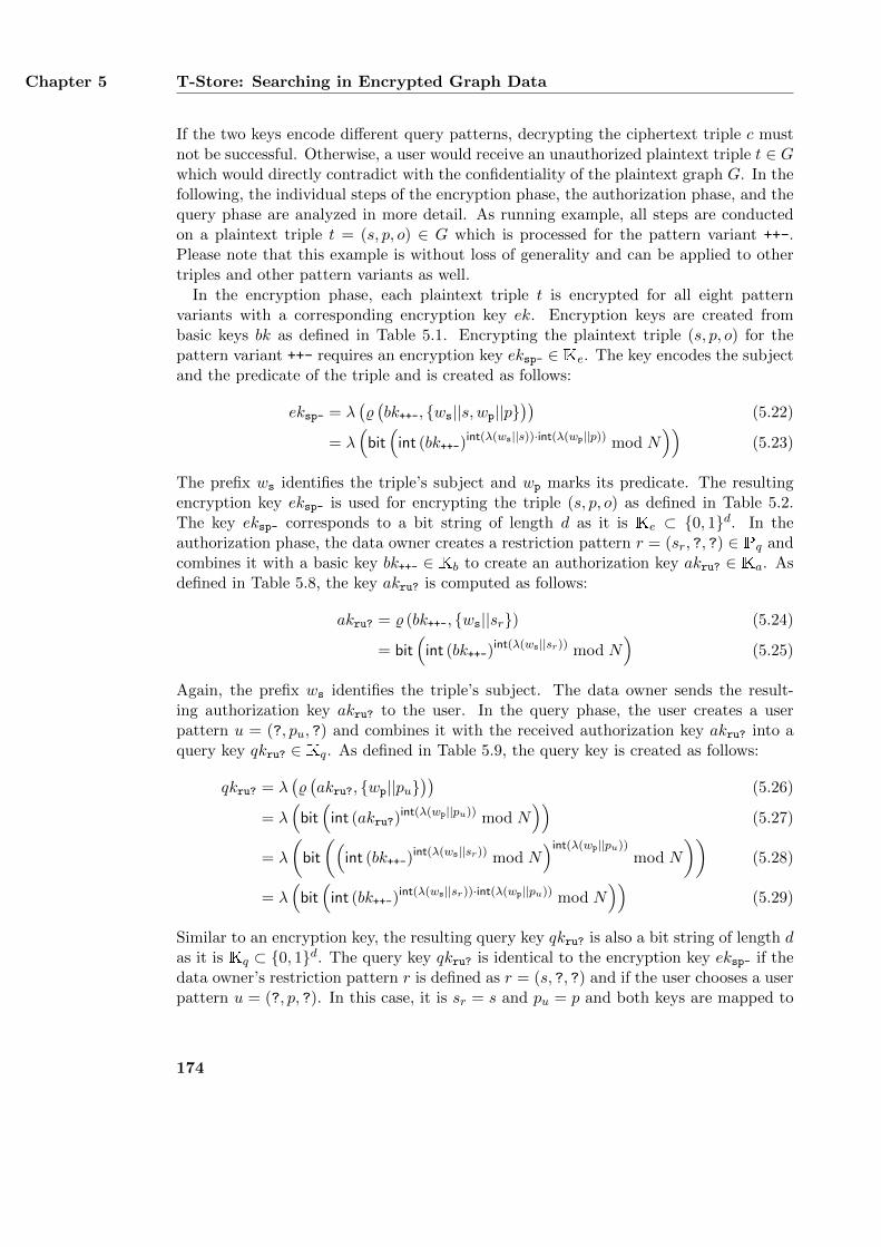
Chapter 5 T-Store: Searching in Encrypted Graph Data
If the two keys encode different query patterns, decrypting the ciphertext triple c mustnot be successful. Otherwise, a user would receive an unauthorized plaintext triple t ∈ Gwhich would directly contradict with the confidentiality of the plaintext graph G. In thefollowing, the individual steps of the encryption phase, the authorization phase, and thequery phase are analyzed in more detail. As running example, all steps are conductedon a plaintext triple t = (s, p, o) ∈ G which is processed for the pattern variant ++-.Please note that this example is without loss of generality and can be applied to othertriples and other pattern variants as well.
In the encryption phase, each plaintext triple t is encrypted for all eight patternvariants with a corresponding encryption key ek. Encryption keys are created frombasic keys bk as defined in Table 5.1. Encrypting the plaintext triple (s, p, o) for thepattern variant ++- requires an encryption key eksp- ∈ Ke. The key encodes the subjectand the predicate of the triple and is created as follows:
eksp- = λ(%(bk++-, {ws||s, wp||p}
))(5.22)
= λ(bit(int (bk++-)
int(λ(ws||s))·int(λ(wp||p)) mod N))
(5.23)
The prefix ws identifies the triple’s subject and wp marks its predicate. The resultingencryption key eksp- is used for encrypting the triple (s, p, o) as defined in Table 5.2.The key eksp- corresponds to a bit string of length d as it is Ke ⊂ {0, 1}d. In theauthorization phase, the data owner creates a restriction pattern r = (sr, ?, ?) ∈ Pq andcombines it with a basic key bk++- ∈ Kb to create an authorization key akru? ∈ Ka. Asdefined in Table 5.8, the key akru? is computed as follows:
akru? = % (bk++-, {ws||sr}) (5.24)
= bit(int (bk++-)
int(λ(ws||sr)) mod N)
(5.25)
Again, the prefix ws identifies the triple’s subject. The data owner sends the result-ing authorization key akru? to the user. In the query phase, the user creates a userpattern u = (?, pu, ?) and combines it with the received authorization key akru? into aquery key qkru? ∈ Kq. As defined in Table 5.9, the query key is created as follows:
qkru? = λ(%(akru?, {wp||pu}
))(5.26)
= λ(bit(int (akru?)
int(λ(wp||pu)) mod N))
(5.27)
= λ
(bit
((int (bk++-)
int(λ(ws||sr)) mod N)int(λ(wp||pu))
mod N
))(5.28)
= λ(bit(int (bk++-)
int(λ(ws||sr))·int(λ(wp||pu)) mod N))
(5.29)
Similar to an encryption key, the resulting query key qkru? is also a bit string of length das it is Kq ⊂ {0, 1}d. The query key qkru? is identical to the encryption key eksp- if thedata owner’s restriction pattern r is defined as r = (s, ?, ?) and if the user chooses a userpattern u = (?, p, ?). In this case, it is sr = s and pu = p and both keys are mapped to
174
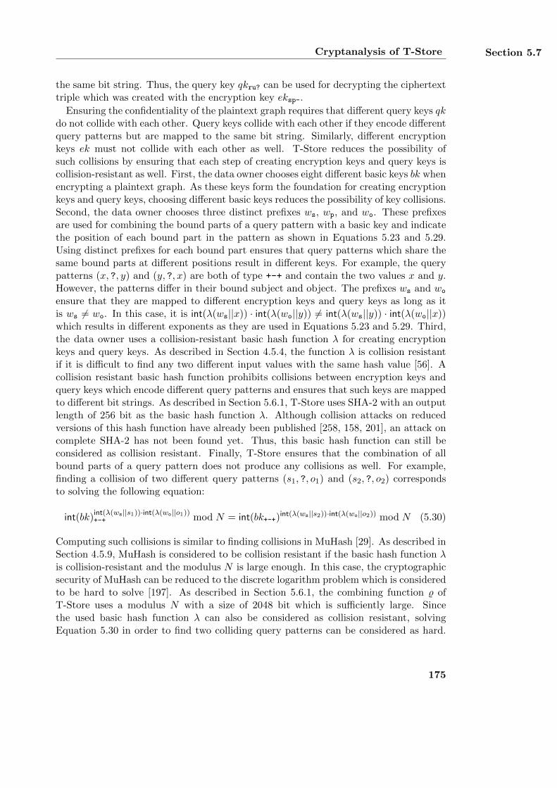
Cryptanalysis of T-Store Section 5.7
the same bit string. Thus, the query key qkru? can be used for decrypting the ciphertexttriple which was created with the encryption key eksp-.
Ensuring the confidentiality of the plaintext graph requires that different query keys qkdo not collide with each other. Query keys collide with each other if they encode differentquery patterns but are mapped to the same bit string. Similarly, different encryptionkeys ek must not collide with each other as well. T-Store reduces the possibility ofsuch collisions by ensuring that each step of creating encryption keys and query keys iscollision-resistant as well. First, the data owner chooses eight different basic keys bk whenencrypting a plaintext graph. As these keys form the foundation for creating encryptionkeys and query keys, choosing different basic keys reduces the possibility of key collisions.Second, the data owner chooses three distinct prefixes ws, wp, and wo. These prefixesare used for combining the bound parts of a query pattern with a basic key and indicatethe position of each bound part in the pattern as shown in Equations 5.23 and 5.29.Using distinct prefixes for each bound part ensures that query patterns which share thesame bound parts at different positions result in different keys. For example, the querypatterns (x, ?, y) and (y, ?, x) are both of type +-+ and contain the two values x and y.However, the patterns differ in their bound subject and object. The prefixes ws and wo
ensure that they are mapped to different encryption keys and query keys as long as itis ws 6= wo. In this case, it is int(λ(ws||x)) · int(λ(wo||y)) 6= int(λ(ws||y)) · int(λ(wo||x))which results in different exponents as they are used in Equations 5.23 and 5.29. Third,the data owner uses a collision-resistant basic hash function λ for creating encryptionkeys and query keys. As described in Section 4.5.4, the function λ is collision resistantif it is difficult to find any two different input values with the same hash value [56]. Acollision resistant basic hash function prohibits collisions between encryption keys andquery keys which encode different query patterns and ensures that such keys are mappedto different bit strings. As described in Section 5.6.1, T-Store uses SHA-2 with an outputlength of 256 bit as the basic hash function λ. Although collision attacks on reducedversions of this hash function have already been published [258, 158, 201], an attack oncomplete SHA-2 has not been found yet. Thus, this basic hash function can still beconsidered as collision resistant. Finally, T-Store ensures that the combination of allbound parts of a query pattern does not produce any collisions as well. For example,finding a collision of two different query patterns (s1, ?, o1) and (s2, ?, o2) correspondsto solving the following equation:
int(bk)int(λ(ws||s1))·int(λ(wo||o1))+-+ mod N = int(bk+-+)
int(λ(ws||s2))·int(λ(wo||o2)) mod N (5.30)
Computing such collisions is similar to finding collisions in MuHash [29]. As described inSection 4.5.9, MuHash is considered to be collision resistant if the basic hash function λis collision-resistant and the modulus N is large enough. In this case, the cryptographicsecurity of MuHash can be reduced to the discrete logarithm problem which is consideredto be hard to solve [197]. As described in Section 5.6.1, the combining function % ofT-Store uses a modulus N with a size of 2048 bit which is sufficiently large. Sincethe used basic hash function λ can also be considered as collision resistant, solvingEquation 5.30 in order to find two colliding query patterns can be considered as hard.
175
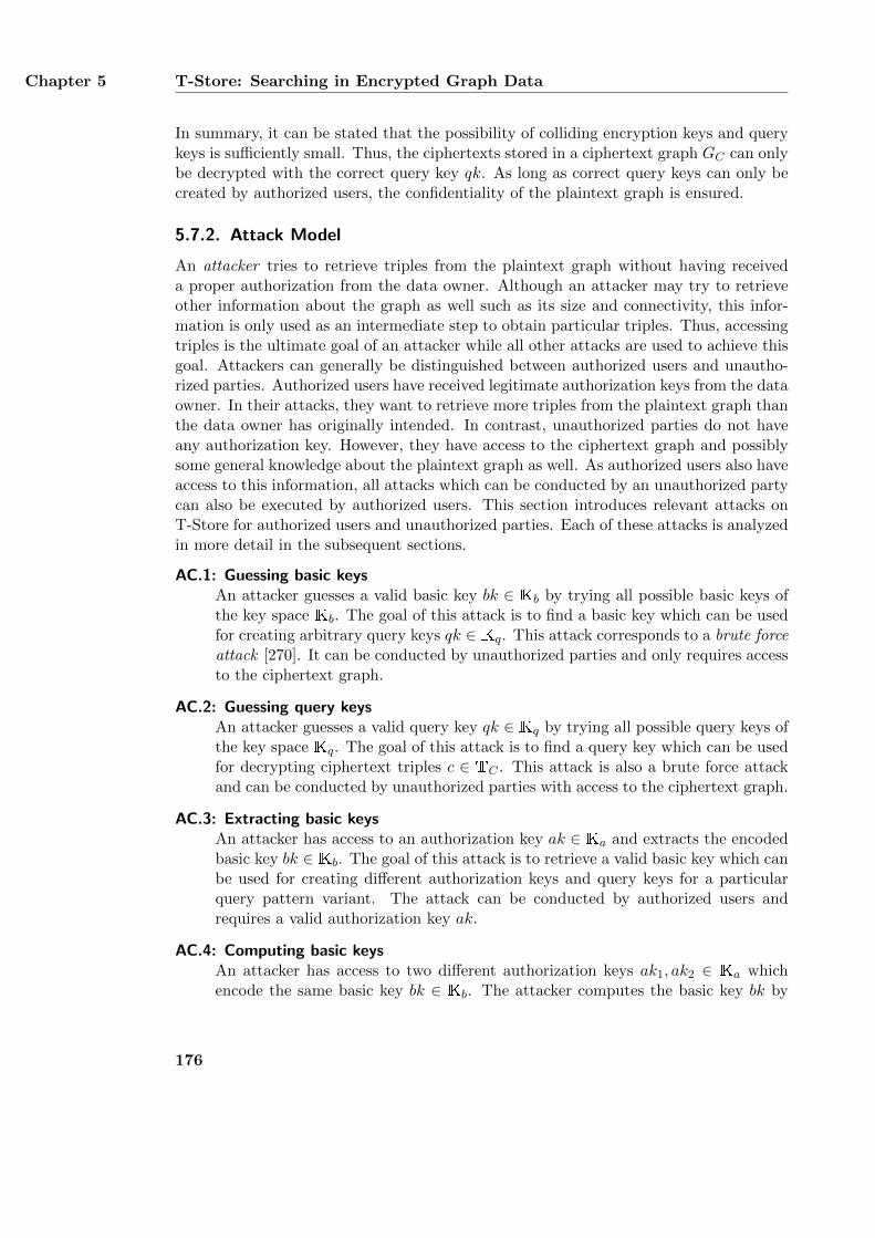
Chapter 5 T-Store: Searching in Encrypted Graph Data
In summary, it can be stated that the possibility of colliding encryption keys and querykeys is sufficiently small. Thus, the ciphertexts stored in a ciphertext graph GC can onlybe decrypted with the correct query key qk. As long as correct query keys can only becreated by authorized users, the confidentiality of the plaintext graph is ensured.
5.7.2. Attack Model
An attacker tries to retrieve triples from the plaintext graph without having receiveda proper authorization from the data owner. Although an attacker may try to retrieveother information about the graph as well such as its size and connectivity, this infor-mation is only used as an intermediate step to obtain particular triples. Thus, accessingtriples is the ultimate goal of an attacker while all other attacks are used to achieve thisgoal. Attackers can generally be distinguished between authorized users and unautho-rized parties. Authorized users have received legitimate authorization keys from the dataowner. In their attacks, they want to retrieve more triples from the plaintext graph thanthe data owner has originally intended. In contrast, unauthorized parties do not haveany authorization key. However, they have access to the ciphertext graph and possiblysome general knowledge about the plaintext graph as well. As authorized users also haveaccess to this information, all attacks which can be conducted by an unauthorized partycan also be executed by authorized users. This section introduces relevant attacks onT-Store for authorized users and unauthorized parties. Each of these attacks is analyzedin more detail in the subsequent sections.
AC.1: Guessing basic keysAn attacker guesses a valid basic key bk ∈ Kb by trying all possible basic keys ofthe key space Kb. The goal of this attack is to find a basic key which can be usedfor creating arbitrary query keys qk ∈ Kq. This attack corresponds to a brute forceattack [270]. It can be conducted by unauthorized parties and only requires accessto the ciphertext graph.
AC.2: Guessing query keysAn attacker guesses a valid query key qk ∈ Kq by trying all possible query keys ofthe key space Kq. The goal of this attack is to find a query key which can be usedfor decrypting ciphertext triples c ∈ TC . This attack is also a brute force attackand can be conducted by unauthorized parties with access to the ciphertext graph.
AC.3: Extracting basic keysAn attacker has access to an authorization key ak ∈ Ka and extracts the encodedbasic key bk ∈ Kb. The goal of this attack is to retrieve a valid basic key which canbe used for creating different authorization keys and query keys for a particularquery pattern variant. The attack can be conducted by authorized users andrequires a valid authorization key ak.
AC.4: Computing basic keysAn attacker has access to two different authorization keys ak1, ak2 ∈ Ka whichencode the same basic key bk ∈ Kb. The attacker computes the basic key bk by
176
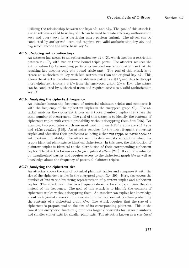
Cryptanalysis of T-Store Section 5.7
utilizing the relationship between the keys ak1 and ak2. The goal of this attack isalso to retrieve a valid basic key which can be used to create arbitrary authorizationkeys and query keys for a particular query pattern variant. The attack can beconducted by authorized users and requires two valid authorization key ak1 andak2 which encode the same basic key bk.
AC.5: Reducing authorization keysAn attacker has access to an authorization key ak ∈ Ka which encodes a restrictionpattern r ∈ Pq with two or three bound triple parts. The attacker reduces theauthorization key by removing parts of its encoded restriction pattern so that theresulting key encodes only one bound triple part. The goal of this attack is tocreate an authorization key with less restrictions than the original key ak. Thisallows the attacker to define more flexible user patterns u ∈ Pq and thus to decryptmore ciphertext triples c ∈ GC from the encrypted graph GC ∈ GC . The attackcan be conducted by authorized users and requires access to a valid authorizationkey ak.
AC.6: Analyzing the ciphertext frequencyAn attacker knows the frequency of potential plaintext triples and compares itwith the frequency of the ciphertext triples in the encrypted graph GC . The at-tacker matches the ciphertext triples with those plaintext triples that share thesame number of occurrences. The goal of this attack is to identify the contents ofciphertext triples with certain probability without decrypting them first [296]. Forexample, two predicates which are most used in many RDF graphs are rdf:type
and rdfs:seeAlso [149]. An attacker searches for the most frequent ciphertexttriples and identifies their predicates as being either rdf:type or rdfs:seeAlso
with certain probability. The attack requires deterministic encryption which en-crypts identical plaintexts to identical ciphertexts. In this case, the distribution ofplaintext triples is identical to the distribution of their corresponding ciphertexttriples. The attack is known as a frequency-based attack [296]. It can be conductedby unauthorized parties and requires access to the ciphertext graph GC as well asknowledge about the frequency of potential plaintext triples.
AC.7: Analyzing the ciphertext sizeAn attacker knows the size of potential plaintext triples and compares it with thesize of the ciphertext triples in the encrypted graph GC [296]. Here, size covers thenumber of bits in the bit string representation of plaintext triples and ciphertexttriples. The attack is similar to a frequency-based attack but compares the sizeinstead of the frequency. The goal of this attack is to identify the contents ofciphertext triples without decrypting them. An attacker can exploit her knowledgeabout widely-used classes and properties in order to guess with certain probabilitythe contents of a ciphertext graph GC . The attack requires that the size of aciphertext is proportional to the size of its corresponding plaintext. This is thecase if the encryption function ξ produces larger ciphertexts for larger plaintextsand smaller ciphertexts for smaller plaintexts. The attack is known as a size-based
177
Chapter 5 T-Store: Searching in Encrypted Graph Data
attack [296]. It can be conducted by unauthorized parties and requires access tothe ciphertext graph GC as well as knowledge about the size of potential plaintexttriples.
AC.8: Reasoning on query resultsAn attacker has access to a limited set of plaintext triples t ∈ G which may beretrieved by applying legitimate queries to the ciphertext graph GC . The attackerconducts reasoning on the plaintext triples in order to obtain additional triples fromthe plaintext graph G. The goal of this attack is to retrieve such triples t whichare not authorized by the data owner. The attack can be conducted by authorizedusers who have access to a valid authorization key ak to apply legitimate queriesto the ciphertext graph GC .
AC.9: Analyzing the graph’s characteristicsAn attacker analyzes a ciphertext graph GC in order to obtain structural infor-mation about the graph such as its size or connectivity. The attacker can exploitthis information to achieve different goals. The information can be used to de-cide whether or not two different ciphertext graphs encrypt the same plaintextgraph. In addition, the attacker can also compare the characteristics of a cipher-text graph GC with the characteristics of a given plaintext graph G in order todecide whether or not the graph GC is an encryption of the graph G. The at-tack can be conducted by unauthorized parties and requires access to a ciphertextgraph GC and possibly to a plaintext graph G as well.
The attacks AC.1 to AC.5 are cryptographic attacks on a ciphertext graph whereasthe attacks AC.6 to AC.8 exploit an attacker’s knowledge about plaintext triples. Incontrast, the attack AC.9 assesses the characteristics of a ciphertext graph as a wholeand does not necessarily reveal any triples of its corresponding plaintext graph.
5.7.3. Guessing Basic Keys (AC.1)
The data owner creates eight different basic keys bk ∈ Kb which are kept secret from allother parties. As described in Section 5.6.1, T-Store uses a key space of Kb = {0, 1}256which corresponds to 2256 possible basic keys. The probability of guessing a valid basickey is therefore 8
2256≈ 6.91 · 10−77. As this probability is sufficiently small, T-Store can
be considered as secure against brute force attacks AC.1 for guessing basic keys.
5.7.4. Guessing Query Keys (AC.2)
A query key qk ∈ Kq is created from a basic hash function λ and encodes a particularquery pattern. As described in Section 5.6.1, T-Store uses SHA-2 as the basic hashfunction with an output length of 256 bits. The set of all query keys Kq is thereforeKq = {0, 1}256 which corresponds to 2256 possible query keys. A query key is used forretrieving all plaintext triples from the ciphertext graph GC which satisfy the querypattern encoded in the key. Since each plaintext triple is encrypted for each of the eight
178
Cryptanalysis of T-Store Section 5.7
basic keys, encrypting a plaintext graph G with n ∈ N triples results in a ciphertextgraph GC with 8n ciphertexts. Each valid query key retrieves at least one and at mostn plaintext triples from the graph GC . Thus, the maximum number of possible querykeys per graph is 8n. This results in a probability of 8n
2256= n
2253for an attacker to
guess a valid query key. For a plaintext graph with n = 106 triples, this correspondsto 8·106
2256≈ 6.91 · 10−71 which is sufficiently small. In practice, this probability is usually
smaller since a particular query key can decrypt multiple ciphertexts in a graph. Thisalso results in less query keys for the graph. T-Store can therefore be considered assecure against brute force attacks AC.2 for guessing query keys.
5.7.5. Extracting Basic Keys (AC.3)
As defined in Section 5.5.3, an authorization key ak ∈ Ka is created from a basic key bk ∈Kb and a data owner’s restriction pattern r ∈ Pq by applying the combining function %as defined in Equation 5.19. In order to extract the basic key from an authorizationkey ak, an attacker must eliminate the restriction pattern from the key ak. Assumewithout loss of generality that an attacker has access to the authorization key akru?.The key is created from the basic key bk++- and the restriction pattern r = (sr, ?, ?) asfollows:
akru? = %(bk++-, {ws||sr}) (5.31)
= bit(int(bk++-)
int(λ(ws||sr)) mod N)
(5.32)
The function int transforms a bit string into an integer and bit transforms an integer intoa bit string. The modulus N ∈ N is a product of two large primes p, q ∈ N which areonly known to the data owner. Extracting the basic key bk++- from the authorizationkey akru? requires that the attacker is able to eliminate the exponent int(λ(ws||sr)) inEquation 5.32.
The combining function % is based on the RSA encryption algorithm [251] and sharesthe same security. The security of RSA is based on two mathematical problems whichare assumed to be hard to solve. These problems are the factorization of large integersand the RSA problem [174]. An attacker who wants to eliminate the restriction patternfrom an authorization key must solve one of these problems and thus has two differentoptions. For the authorization key akru?, the first option is to compute an x ∈ N whichsatisfies the following equation:
int(bk++-)int(λ(ws||sr))·x mod N = int(bk++-) mod N (5.33)
This is equivalent to computing an x ∈ N which is inverse to int(λ(ws||sr)) mod (p −1) · (q − 1) [57]. Thus, the attacker must compute x so that it satisfies the followingequation:
x · int(λ(ws||sr)) ≡ 1 mod (p− 1) · (q − 1) (5.34)
In order to solve this equation and to retrieve the value of x, the attacker must knowthe values of the two prime factors p and q. However, these values are only known to
179
Chapter 5 T-Store: Searching in Encrypted Graph Data
the data owner. Furthermore, factorizing the modulus N is assumed to be hard to solvefor large values of N [174]. The implementation of T-Store uses a value of N with a sizeof 2048 bit as recommended by NIST [217]. As an efficient way to factorize a modulusof this size has not been found yet, an attacker cannot compute the two primes p andq and apply Equation 5.34 in order to compute x. Consequently, the attacker can alsonot apply Equation 5.33 to extract the basic key bk from the authorization key ak.
The second option for the attacker to eliminate the restriction pattern from an au-thorization key is to compute a discrete root of an exponent. For the authorizationkey akru?, the attacker must solve the following equation:
int(λ(ws||sr))√int(akru?) mod N = int(λ(ws||sr))
√int(bk++-)int(λ(ws||sr)) mod N (5.35)
= int(bk++-) mod N (5.36)
Solving this equation corresponds to solving the RSA problem which is also assumedto be hard to solve [174]. In summary, eliminating a restriction pattern r from anauthorization key ak and extracting its basic key bk is hard as long as the factorizationproblem and the RSA problem are hard to solve as well. When using a value of N witha size of 2048 bit, T-Store can be considered as secure against attacks of type AC.3.
5.7.6. Computing Basic Keys (AC.4)
The combining function % creates authorization keys ak ∈ Ka from basic keys bk ∈ Kb
and restriction patterns r ∈ P. As described in the previous section, the function %is based on the RSA encryption algorithm [251]. RSA encrypts a plaintext messagewith a public exponent and a public modulus N . In the combining function %, theplaintext message corresponds to the basic key bk and the public exponent correspondsto the bound parts of the restriction pattern r. The ciphertext resulting from an RSAencryption corresponds to the authorization key ak. The modulus N is the same as inRSA and used for all authorization keys of a particular graph.
Although RSA is considered to be secure as long as the factorization problem and theRSA problem are hard to solve, it is still vulnerable to the common modulus attack [271].This attack exploits the relationship of two different RSA key pairs which share the samemodulus N and encrypt the same plaintext message. It allows an attacker to retrievethe plaintext message from the two ciphertexts by using only the public keys which wereused to create them. The common modulus attack can also be applied to the combiningfunction % as its design is similar to the RSA encryption algorithm. In order to conductthe attack on the combining function, an attacker must have access to two differentauthorization keys ak1, ak2 ∈ Ka which encode the same basic key bk. In addition, theattacker must know the corresponding restriction patterns r1, r2 ∈ P which are encodedinto the keys ak1 and ak2, respectively, as well as the modulus N . Assume withoutloss of generality that the two authorization keys ak1 and ak2 encode the restriction
180
Cryptanalysis of T-Store Section 5.7
patterns r1 = (s1, ?, ?) and r2 = (s2, ?, ?), respectively, and the basic key bk+--. Thekeys ak1 and ak2 are created with the combining function % as follows:
ak1 = %(bk+--, {ws||s1}) (5.37)
= bit(int(bk+--)
int(λ(ws||s1)) mod N)
(5.38)
ak2 = %(bk+--, {ws||s2}) (5.39)
= bit(int(bk+--)
int(λ(ws||s2)) mod N)
(5.40)
The attacker uses the bound parts s1 ∈ R ∪ B and s2 ∈ R ∪ B of the restrictionpatterns r1 and r2 to compute the greatest common divisor of the two the exponentsint(λ(ws||s1)) and int(λ(ws||s2)) as well as the coefficients of Bezout’s identity [36]. Thiscan be achieved by using the extended Euclidian algorithm [84]. I. e., the attacker appliesthis algorithm such that she receives the coefficients c1, c2 ∈ Z in the following equation:
c1 · int(λ(ws||s1)) + c2 · int(λ(ws||s2)) = gcd(int(λ(ws||s1)), int(λ(ws||s2))
)(5.41)
Since the values int(λ(ws||s1)) and int(λ(ws||s2)) are created with a basic hash function λ,they are similar to pseudo-random values. Thus, they are very likely to be co-prime,i. e., it is gcd
(int(λ(ws||s1)), int(λ(ws||s2))
)= 1 with high probability. The attacker can
exploit this relationship between the two coefficients c1 and c2 and use them to computethe basic key bk+-- from the authorization keys ak1 and ak2 as follows:
int(ak1)c1 · int(ak2)c2 mod N (5.42)
=(int(bk++-)
int(λ(ws||s1)) mod N)c1 · (int(bk++-)int(λ(ws||s2)) mod N
)c2mod N (5.43)
=(int(bk++-)
int(λ(ws||s1)))c1 · (int(bk++-)int(λ(ws||s2))
)c2mod N (5.44)
= int(bk++-)c1·int(λ(ws||s1)) · int(bk++-)c2·int(λ(ws||s2)) mod N (5.45)
= int(bk++-)c1·int(λ(ws||s1))+c2·int(λ(ws||s2)) mod N (5.46)
= int(bk++-) mod N (5.47)
These computations utilize the laws of exponentiation and the properties of multipli-cation in modular arithmetic. The attacker can apply the resulting basic key bk+-- tocreate arbitrary authorization keys of type ++- and use these keys to decrypt correspond-ing ciphertext triples. Implementations of RSA usually prevent the common modulusattack by ensuring that all created RSA key pairs use different moduli N . This pre-vents an attacker from exploiting any relationship between different key pairs and fromdecrypting the plaintext message. In T-Store, however, using a different modulus Nfor each authorization key ak is not possible. T-Store requires that all plaintext tripleswhich share the same bound parts for the same query type are encrypted with the sameencryption key ek ∈ Ke. This implies that the encryption key is created from the samebound parts and the same modulus N . Thus, T-Store is vulnerable to the attack AC.4which allows an attacker to compute the basic key from two authorization keys of the
181
Chapter 5 T-Store: Searching in Encrypted Graph Data
same query type. In order to successfully prevent the attack, the combining function %must be replaced by a secure function. Designing, implementing, and evaluating analternative combining function is left for future work.1
5.7.7. Reducing Authorization Keys (AC.5)
In general, an authorization key ak ∈ Ka may be reduced to a different authorization keywhich shares the same basic key bk ∈ Kb but has a less restrictive restriction pattern r ∈Pq. Assume without loss of generality that an attacker has access to the authorizationkey akrr? which encodes the basic key bk++- and the data owner’s restriction pattern r =(sr, pr, ?) ∈ Pq. This restriction pattern already specifies all bound parts of a querypattern of type ++-. Thus, an attacker can only define a user pattern u ∈ Pq asu = (?, ?, ?). In order to specify a bound subject or predicate herself, the attackerfirst must reduce the authorization key akrr? to the authorization key akru? or to thekey akur?. In the following, the process of reducing the key akrr? to the key akru? isdescribed in more detail. A reduction to the authorization key akur? is similar andomitted for reasons of brevity. The key akrr? is reduced to akru? as follows:
akrr? = %(bk++-, {ws||sr, wp||pr}) (5.48)
= bit(int(bk++-)
int(λ(ws||sr))·int(λ(wp||pr)) mod N)
(5.49)
= bit
((int(bk++-)
int(λ(ws||sr)))int(λ(wp||pr))
mod N
)(5.50)
= bit
((int(bk++-)
int(λ(ws||sr)) mod N)int(λ(wp||pr))
mod N
)(5.51)
= bit(int(akru?)
int(λ(wp||pr)) mod N)
(5.52)
Again, these computations are based on the laws of exponentiation and on the the prop-erties of multiplication in modular arithmetic. In order to extract the authorizationkey akru? from the key akrr?, the attacker must eliminate the exponent int(λ(ws||sr))from Equation 5.52. As described in Section 5.7.5, this would either require a factor-ization of the modulus N or the computation of a discrete root which are both hard tosolve [174]. Thus, the authorization key akrr? cannot be reduced to the less restrictiveauthorization keys akru? and akur? as long as these two problems are hard to solve. Inthis case, T-Store is able to prevent attacks of type AC.5.
5.7.8. Analyzing Ciphertext Frequency (AC.6)
Frequency-based attacks allow an attacker to infer the contents of ciphertext triples with-out decrypting them first. Conducting a frequency-based attack requires a deterministic
1This weakness of T-Store was discovered only recently with the help of a colleague of the author inFebruary, 2016. Due to time constraints, it was not possible to apply and evaluate a new combiningfunction before submitting this thesis.
182
Cryptanalysis of T-Store Section 5.7
encryption and knowledge about the distribution of potential plaintext triples. An at-tacker can acquire such knowledge by assessing the usage of widely-used properties andclasses such as rdf:type or foaf:Person [149]. Deterministic encryption maps identicalplaintexts to identical ciphertexts. In order to prohibit a frequency-based attack, it isnecessary to encrypt identical plaintext triples as different ciphertext triples.
As described in Section 5.5.1, a single plaintext triple t is encrypted as eight differentciphertexts which correspond to each of the eight query pattern variants. Each ciphertextdepends on a particular basic key bk ∈ Kb and on the complete plaintext triple. Itencodes the triple’s subject, predicate, and object as either bound or unbound. Thebound parts are combined with the basic key into an encryption key ek and the unboundparts are encrypted with the key ek by using the encryption function ξ. The data ownerchooses a different basic key for each of the eight query pattern variants. Thus, the eightciphertexts created from a single plaintext triple are distinguished from each other bytheir unique combination of bound parts, unbound parts, and basic keys. A plaintextgraph G is a set of plaintext triples t ∈ G which contains each triple at most once.Therefore, the corresponding ciphertext graphGC also contains each ciphertext triple c ∈GC at most once. In summary, all ciphertexts stored in the ciphertext graph GC areunique which prohibits frequency-based attacks AC.6.
5.7.9. Analyzing Ciphertext Size (AC.7)
Size-based attacks require that the size of a plaintext roughly corresponds to the size ofits respective ciphertext. Here, size refers to the length of the bit string representationof plaintexts and ciphertexts. In order to prevent size-based attacks in T-Store, allciphertexts of an encrypted graph GC must have the same size. This prohibits anattacker from distinguishing between different ciphertext triples c ∈ GC and relatingthem to their respective plaintext triples t ∈ G in the plaintext graph G.
In its current design, T-Store does not normalize the size of different ciphertexts andis therefore vulnerable to size-based attacks AC.7. However, these attacks can easily beeliminated by slightly modifying the encryption of the plaintext triples. In particular,all plaintext triples t must be transformed to the same size before encrypting them. Thiscan be done similarly to splitting the sets idS of ciphertext identifiers into arrays idA asdescribed in steps 6 and 7 of Section 5.5.2. A plaintext triple is first split into multiplefragments so that each fragment covers x bytes of data with x ∈ N. Fragments whichcontain less than x bytes are padded accordingly. Each resulting fragment is associatedwith a unique ciphertext identifier idc ∈ N. Fragments of the same plaintext are relatedto each other by prefixing them with the ciphertext identifier of the next fragment. Theprefixed fragments of the same plaintext are then encrypted separately with the sameencryption key ek. The details of this modification are as follows: Let y ∈ N be the sizeof each ciphertext to be stored in the encrypted graph GC . Each ciphertext encrypts5 bytes of meta data and x = y − 5 bytes of content data which stores a fragment ofthe actual plaintext triple. The meta data describes how the content bytes are to beinterpreted. The first byte of meta data states whether or not there are more ciphertexts
183
Chapter 5 T-Store: Searching in Encrypted Graph Data
storing additional fragments of the same plaintext triple2. The value 1 states that this isthe case and 0 indicates that this is not the case. The next 4 bytes of meta data store a32 bit integer. The meaning of this integer is determined by the value of the first byte. Ifthe first byte is 1, the integer contains the ciphertext identifier idc of another ciphertextwhich stores the next fragment of the plaintext triple. In this case, all remaining x bytesof ciphertext data contain encrypted plaintext data. In contrast, if the first byte of metadata is 0, the integer defines the amount of actual content bytes. If these content bytesare less than y − 5, they are padded with random bytes.
For example, the URI http://www.w3.org/1999/02/22-rdf-syntax-ns#type has alength of 47 bytes. In order to encrypt this URI for the query pattern type +-+ and theciphertext size y = 32, it is first split into two different bit strings. The first bit stringconsists of 32 − 5 = 27 bytes and the second bit string covers the remaining 20 bytes.Both bit strings are encrypted individually which results in two different ciphertexts. Letthe first ciphertext be identified as 3 and the ciphertext identifier of the second ciphertextbe 12. The ciphertexts c3 and c12 are computed as follows with the encryption function ξby using the encryption key ek+-+ ∈ Ke and || as the concatenation operator:
c3 := ξ(ek+-+,
5 bytes of meta data︷ ︸︸ ︷1 byte︷︸︸︷
1 ||4 bytes︷︸︸︷
12 ||x3=27 bytes of content︷ ︸︸ ︷
http://www.w3.org/1999/02/2) (5.53)
c12 := ξ(ek+-+, 0︸︷︷︸1 byte
|| 20︸︷︷︸4 bytes︸ ︷︷ ︸
5 bytes of meta data
|| 2-rdf-syntax-ns#type︸ ︷︷ ︸x12=20 bytes of content
.......︸ ︷︷ ︸7 bytes ofpadding
) (5.54)
Encrypting a single URI is necessary when encrypting a plaintext triple for the querypattern variant +-+. However, the described approach can also be used for encryptingplaintext triples for other query pattern variants. The presented modification of T-Storeensures that all ciphertexts stored in a ciphertext graph GC are of equal size. Thisprevents an attacker from conducting a size-based attack AC.7.
5.7.10. Reasoning on Query Results (AC.8)
An authorized user has access to a limited set of authorization keys and can use thesekeys to apply queries to the ciphertext graph GC . A corresponding query result con-sists different plaintext triples which contain A-box knowledge and/or T-box knowledge.A-box knowledge represents the factual data stored in the graph while T-box knowl-edge provides information about the ontology which was used for modeling the graph’striples [152]. More specifically, the T-box knowledge consists of URIs which identifyproperties and/or classes of the ontology. If the complete ontology of the plaintextgraph is not already provided, a malicious user can guess the ontology based on theseURIs. The user can then apply the ontology to reason about the A-box knowledge which
2Please note that a single bit would actually be sufficient for storing this information. However, T-Storeis implemented in Java which does not allow to store individual bits.
184
Cryptanalysis of T-Store Section 5.7
she received with her query results as well. The reasoning process may provide addi-tional triples from the plaintext graph which are not explicitly authorized by the dataowner.
For example, an authorized user receives the triple ex:Jay foaf:knows ex:Bob afterhaving applied a query to the ciphertext graph GC . This triple contains both A-boxknowledge and T-box knowledge. The A-box knowledge consists of the two URIs ex:Jayand ex:Bob and the T-box knowledge consists of the property foaf:knows. Based onthis property, the user can infer that the FOAF ontology [50] was used for modeling atleast one of the plaintext triples in the graph. The FOAF ontology defines several classesand properties for describing information about natural persons and their relationships.The user can apply these classes and properties to reason about the A-box knowledge ofthe query result. Using the property foaf:knows in a triple states that the subject andobject of this triple are both of type foaf:Person. Furthermore, the FOAF ontologydefines the class foaf:Person as being a subclass of foaf:Agent. By applying thisT-box knowledge, the user can infer the four triples depicted in Listing 5.3 in additionto the single triple received from the actual query result.
1 ex:Jay rdf:type foaf:Person . ex:Jay rdf:type foaf:Agent .
2 ex:Bob rdf:type foaf:Person . ex:Bob rdf:type foaf:Agent .
Listing 5.3: Example triples resulting from reasoning.
T-Store is vulnerable to reasoning attacks AC.8 as they are difficult to prevent in general.Preventing such attacks requires that the user does not have access to the used ontologyand cannot apply it for reasoning. However, this would contradict with the principles ofthe Semantic Web [35] which is designed to support reasoning on machine-readable data.If the data owner does not want to prevent a user from reasoning on the query results,she must accept that the user can retrieve more information about the plaintext graphthan the authorization keys allow. However, in many cases, the triples resulting fromreasoning may not reveal any secret data about the plaintext graph and can thereforebe considered as acceptable.
5.7.11. Analyzing the graph’s characteristics (AC.9)
The characteristics of a graph cover several aspects such as the graph’s size and con-nectivity as well as the number of all non-empty solution sequences, i. e., the numberof query patterns which match at least one triple. Analyzing a graph’s characteristicsallows an attacker to distinguish between different ciphertext graphs and to relate a ci-phertext graph to its corresponding plaintext graph. T-Store hides most characteristicswith a graph’s size being the only exception. As described in Section 5.5.1, encryptinga plaintext graph G with n ∈ N triples results in a ciphertext graph GC with 8n ci-phertexts. Thus, a ciphertext graph reveals the number of triples in its plaintext graph.Although the exact number can be concealed by inserting random bit strings as fakeciphertexts into the ciphertext graph and its index, the relative size of the plaintextgraph is still revealed. This allows an attacker to distinguish between small graphs andlarge graphs.
185
Chapter 5 T-Store: Searching in Encrypted Graph Data
As described in Section 5.7.8, T-Store ensures that each ciphertext in an encryptedgraph GC is unique. This prohibits an attacker from determining the contents of theplaintext triples t ∈ G by relating their frequency to the frequency of the ciphertexttriples c ∈ GC . It also prevents an attacker from discovering the number of uniqueURIs, blank nodes, and literals in the plaintext graph G and from determining howoften they occur at subject position, predicate position, or object position. This is nec-essary to determine the connectivity of the graph G which states how its triples areconnected with each other. The connectivity can be used, e. g., for identifying the num-ber of disjoint subgraphs or for distinguishing between loosely connected and stronglyconnected graphs. As an attacker cannot determine the frequency of individual tripleparts, she cannot assess a graph’s connectivity as well.
Neither a ciphertext graph GC nor its corresponding index I reveal the number ofquery patterns which match at least one plaintext triple. The graph GC is an unorderedset of ciphertexts and does not provide any grouping of similar ciphertexts which matchthe same query pattern. Thus, the ciphertext graph does not reveal any informationabout the structure of the plaintext graphG. Although the index I provides a grouping ofsimilar ciphertexts by using arrays of ciphertext identifiers as described in Section 5.5.2,these arrays are all of equal size and are scattered across the index. This prohibits anattacker from relating such arrays to each other which are associated with the samequery pattern. Consequently, the attacker cannot determine the number of differentciphertexts matching a particular query pattern as well. In addition, the ciphertexts forall eight query pattern variants are stored in a single index. This prevents an attackerfrom determining the number of valid query patterns for each variant. In summary,T-Store only reveals the size of a plaintext graph but does hide any other structuralinformation about it. Thus, the approach is only partially vulnerable to attacks AC.9.
5.8. Applications and Use Cases
This section describes how T-Store is used for implementing the scenarios introduced inChapter 2. The first scenario focuses on the regulation of Internet communication asdescribed in Section 2.1.3 and is covered in Sections 5.8.1 to 5.8.3. The second scenariois introduced in Section 2.2 and covers the secure management of medical data. Itsimplementation is addressed in Section 5.8.4.
5.8.1. Searching in Encrypted Log Files
The scenario for regulating Internet communication defines several computer networkswhich consist of communication end nodes such as client systems and intermediary nodeslike application-level proxy servers. One of the computer networks introduced in Sec-tion 2.1.1 is the network of the German comprehensive school. It consists of severalstudent computers which access the Internet via the school’s proxy server. The proxyserver acts as an enforcing system and implements the school’s regulation policies whichare further described in Section 3.4.4. In addition to this regulation, the server alsorecords all Internet activities of the student computers in a log database. Each log entry
186
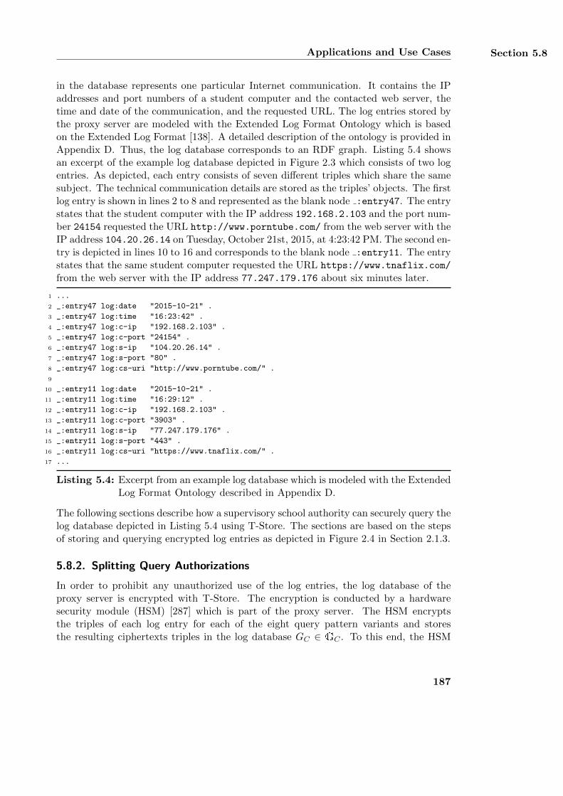
Applications and Use Cases Section 5.8
in the database represents one particular Internet communication. It contains the IPaddresses and port numbers of a student computer and the contacted web server, thetime and date of the communication, and the requested URL. The log entries stored bythe proxy server are modeled with the Extended Log Format Ontology which is basedon the Extended Log Format [138]. A detailed description of the ontology is provided inAppendix D. Thus, the log database corresponds to an RDF graph. Listing 5.4 showsan excerpt of the example log database depicted in Figure 2.3 which consists of two logentries. As depicted, each entry consists of seven different triples which share the samesubject. The technical communication details are stored as the triples’ objects. The firstlog entry is shown in lines 2 to 8 and represented as the blank node :entry47. The entrystates that the student computer with the IP address 192.168.2.103 and the port num-ber 24154 requested the URL http://www.porntube.com/ from the web server with theIP address 104.20.26.14 on Tuesday, October 21st, 2015, at 4:23:42 PM. The second en-try is depicted in lines 10 to 16 and corresponds to the blank node :entry11. The entrystates that the same student computer requested the URL https://www.tnaflix.com/
from the web server with the IP address 77.247.179.176 about six minutes later.
1 ...
2 _:entry47 log:date "2015-10-21" .
3 _:entry47 log:time "16:23:42" .
4 _:entry47 log:c-ip "192.168.2.103" .
5 _:entry47 log:c-port "24154" .
6 _:entry47 log:s-ip "104.20.26.14" .
7 _:entry47 log:s-port "80" .
8 _:entry47 log:cs-uri "http://www.porntube.com/" .
9
10 _:entry11 log:date "2015-10-21" .
11 _:entry11 log:time "16:29:12" .
12 _:entry11 log:c-ip "192.168.2.103" .
13 _:entry11 log:c-port "3903" .
14 _:entry11 log:s-ip "77.247.179.176" .
15 _:entry11 log:s-port "443" .
16 _:entry11 log:cs-uri "https://www.tnaflix.com/" .
17 ...
Listing 5.4: Excerpt from an example log database which is modeled with the ExtendedLog Format Ontology described in Appendix D.
The following sections describe how a supervisory school authority can securely query thelog database depicted in Listing 5.4 using T-Store. The sections are based on the stepsof storing and querying encrypted log entries as depicted in Figure 2.4 in Section 2.1.3.
5.8.2. Splitting Query Authorizations
In order to prohibit any unauthorized use of the log entries, the log database of theproxy server is encrypted with T-Store. The encryption is conducted by a hardwaresecurity module (HSM) [287] which is part of the proxy server. The HSM encryptsthe triples of each log entry for each of the eight query pattern variants and storesthe resulting ciphertexts triples in the log database GC ∈ GC . To this end, the HSM
187
Chapter 5 T-Store: Searching in Encrypted Graph Data
securely creates and stores eight different basic keys bk ∈ Kb. Queries on the encryptedlog database are collectively authorized by the school’s administration (SA) and theparent’s association (PA). Both parties only store a fragment of each basic key whichcannot be directly used to create authorizations keys ak ∈ Ka. Instead, the creationof a valid authorization key requires a separate authorization from both the school’sadministration and the parent’s association. The fragments of basic keys stored by theschool are defined as sa = (sa---, sa+--, . . . , sa+++) ∈ J and the fragments of the parent’sassociation are pa = (pa---, pa+--, . . . , pa+++) ∈ J with J being the set of all tuples of keyfragments. As a basic key bk is a bit string of length d ∈ N, each fragment of a basickey is a bit string of length d
2 ∈ N. The set J is therefore defined as follows:
J := {0, 1} d2 × {0, 1} d2 × . . .× {0, 1} d2︸ ︷︷ ︸8 times
(5.55)
The individual key fragments of the tuples sa and pa are chosen at random by theHSM when initializing the basic keys. Each basic key bk is then created by combiningits respective fragments from the tuples sa and pa. The fragments are combined bymultiplying their respective integer representations as follows:
bk--- = bit (int(sa---) · int(pa---)) (5.56)
bk+-- = bit (int(sa+--) · int(pa+--)) (5.57)
. . .
bk-++ = bit (int(sa-++) · int(pa-++)) (5.58)
bk+++ = bit (int(sa+++) · int(pa+++)) (5.59)
Again, the function int maps bit strings to integers and bit transforms integers to bitstrings. In order to apply a query to the encrypted log database, the supervisory schoolauthority sends its query to the school’s administration and the parent’s association.Both parties collectively act as the data owner and compute a partial authorizationkey for each query pattern in the query. The partial authorization keys are based ona restriction pattern r ∈ Pq and on the basic key fragments stored by each party.The restriction patterns contain bound parts of each query pattern and the basic keyfragments define the pattern variant. The computation of a partial authorization keyis similar to the computation of a regular authorization key ak ∈ Ka as described instep 11 in Section 5.5.3. For example, in order to authorize a query pattern of type -++
with a restriction pattern r = (?, pr, or), the school’s administration computes a partialauthorization key sa?rr by using its basic key fragment sa-++ as follows:
sa?rr = %(sa-++, {wp||pr, wo||or}) (5.60)
= bit(int(sa-++)
int(λ(wp||pr))·int(λ(wo||or)) mod N)
(5.61)
188
Applications and Use Cases Section 5.8
The function % corresponds to the combining function defined in Equation 5.19 and N isa product of two large primes. Similarly, the parent’s association computes its ownpartial authorization key pa?rr wit its basic key fragment pa-++ as follows:
pa?rr = %(pa-++, {wp||pr, wo||or}) (5.62)
= bit(int(pa-++)
int(λ(wp||pr))·int(λ(wo||or)) mod N)
(5.63)
As each of the two keys sa and pa only cover a part of a complete authorization key ak?rr,they cannot be directly applied to the encrypted log database GC . Both the school’sadministration and the parent’s association send their partial authorization keys sa?rrand pa?rr to the supervisory school authority via a secure communication channel. Theauthority then computes the complete authorization key ak?rr ∈ Ka by combining thetwo keys sa?rr and pa?rr as follows:
ak?rr = bit (int(sa?rr) · int(pa?rr) mod N) (5.64)
= bit((
int(sa-++)int(λ(wp||pr))·int(λ(wo||or)) mod N
)·(
int(pa-++)int(λ(wp||pr))·int(λ(wo||or)) mod N
)mod N
) (5.65)
= bit((
int(sa-++)int(λ(wp||pr))·int(λ(wo||or)) ·
int(pa-++)int(λ(wp||pr))·int(λ(wo||or))
)mod N
) (5.66)
= bit(
(int(sa-++) · int(pa-++))int(λ(wp||pr))·int(λ(wo||or)) mod N)
(5.67)
= bit(int(bk-++)
int(λ(wp||pr))·int(λ(wo||or)) mod N)
(5.68)
= %(bk-++, {wp||pr, wo||or}) (5.69)
These computations are based on the laws of exponentiation and on the properties ofmultiplication in modular arithmetic. The resulting authorization key ak?rr of Equa-tion 5.69 is identical to an authorization key which is created from the basic key bk++-and the restriction pattern r as described in Table 5.8. The supervisory school authorityuses the authorization key ak?rr to create a corresponding query key qk?rr ∈ Kq. Itthen applies this key to the encrypted log database GC in the query phase as describedin Section 5.5.4.
5.8.3. Analyzing the Log Database
According to §184 of the German Criminal Code [61], the comprehensive school mustprohibit its students from accessing pornographic Internet content. The school imple-ments this legal requirement by applying the regulation policy alpp-1 which is expressedwith the InFO policy language and further described in Section 3.4.4. The policy is tech-nically enforced by the school’s proxy server and contains two rules which prevent theschool’s students from accessing two web sites with pornographic content. The URLsof these web sites are http://www.porntube.com/ and http://www.fundorado.de/.
189
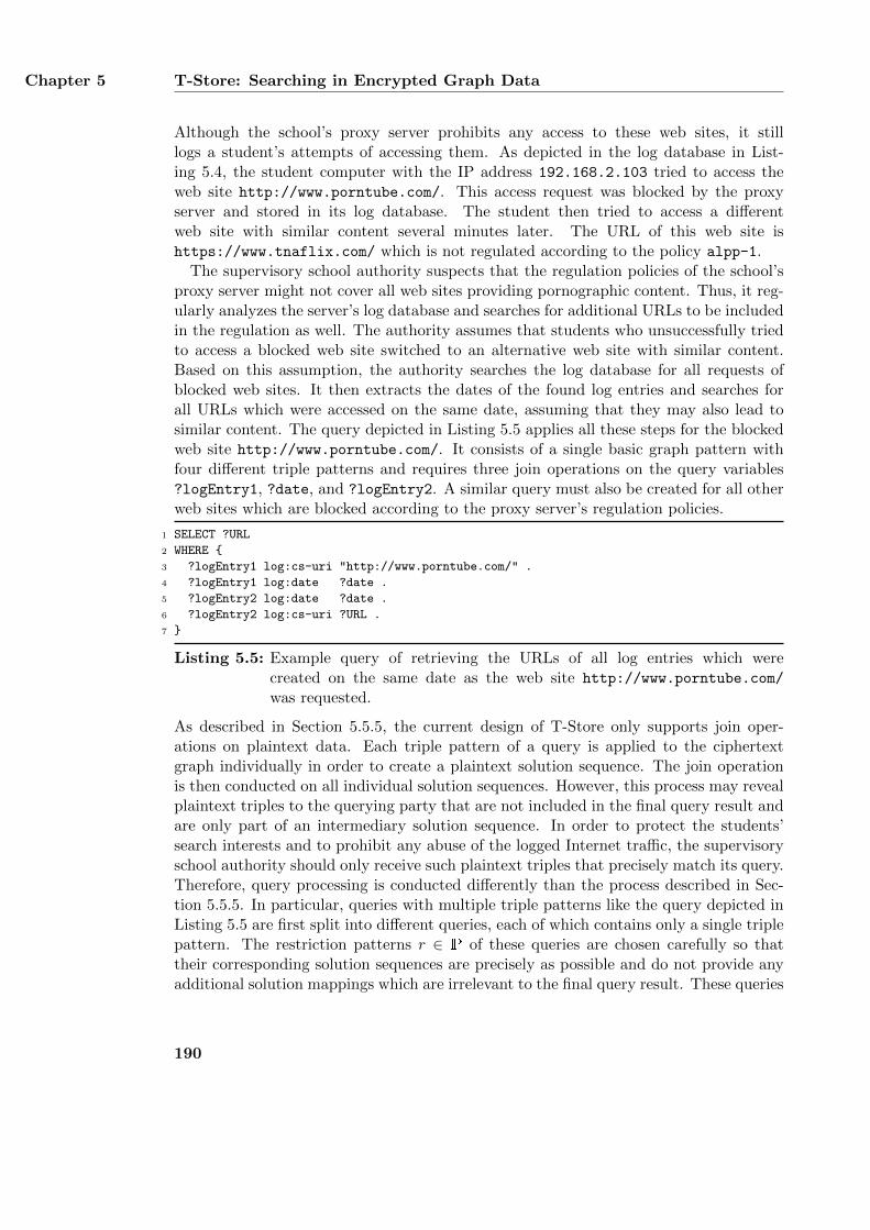
Chapter 5 T-Store: Searching in Encrypted Graph Data
Although the school’s proxy server prohibits any access to these web sites, it stilllogs a student’s attempts of accessing them. As depicted in the log database in List-ing 5.4, the student computer with the IP address 192.168.2.103 tried to access theweb site http://www.porntube.com/. This access request was blocked by the proxyserver and stored in its log database. The student then tried to access a differentweb site with similar content several minutes later. The URL of this web site ishttps://www.tnaflix.com/ which is not regulated according to the policy alpp-1.
The supervisory school authority suspects that the regulation policies of the school’sproxy server might not cover all web sites providing pornographic content. Thus, it reg-ularly analyzes the server’s log database and searches for additional URLs to be includedin the regulation as well. The authority assumes that students who unsuccessfully triedto access a blocked web site switched to an alternative web site with similar content.Based on this assumption, the authority searches the log database for all requests ofblocked web sites. It then extracts the dates of the found log entries and searches forall URLs which were accessed on the same date, assuming that they may also lead tosimilar content. The query depicted in Listing 5.5 applies all these steps for the blockedweb site http://www.porntube.com/. It consists of a single basic graph pattern withfour different triple patterns and requires three join operations on the query variables?logEntry1, ?date, and ?logEntry2. A similar query must also be created for all otherweb sites which are blocked according to the proxy server’s regulation policies.
1 SELECT ?URL
2 WHERE {
3 ?logEntry1 log:cs-uri "http://www.porntube.com/" .
4 ?logEntry1 log:date ?date .
5 ?logEntry2 log:date ?date .
6 ?logEntry2 log:cs-uri ?URL .
7 }
Listing 5.5: Example query of retrieving the URLs of all log entries which werecreated on the same date as the web site http://www.porntube.com/
was requested.
As described in Section 5.5.5, the current design of T-Store only supports join oper-ations on plaintext data. Each triple pattern of a query is applied to the ciphertextgraph individually in order to create a plaintext solution sequence. The join operationis then conducted on all individual solution sequences. However, this process may revealplaintext triples to the querying party that are not included in the final query result andare only part of an intermediary solution sequence. In order to protect the students’search interests and to prohibit any abuse of the logged Internet traffic, the supervisoryschool authority should only receive such plaintext triples that precisely match its query.Therefore, query processing is conducted differently than the process described in Sec-tion 5.5.5. In particular, queries with multiple triple patterns like the query depicted inListing 5.5 are first split into different queries, each of which contains only a single triplepattern. The restriction patterns r ∈ P of these queries are chosen carefully so thattheir corresponding solution sequences are precisely as possible and do not provide anyadditional solution mappings which are irrelevant to the final query result. These queries
190
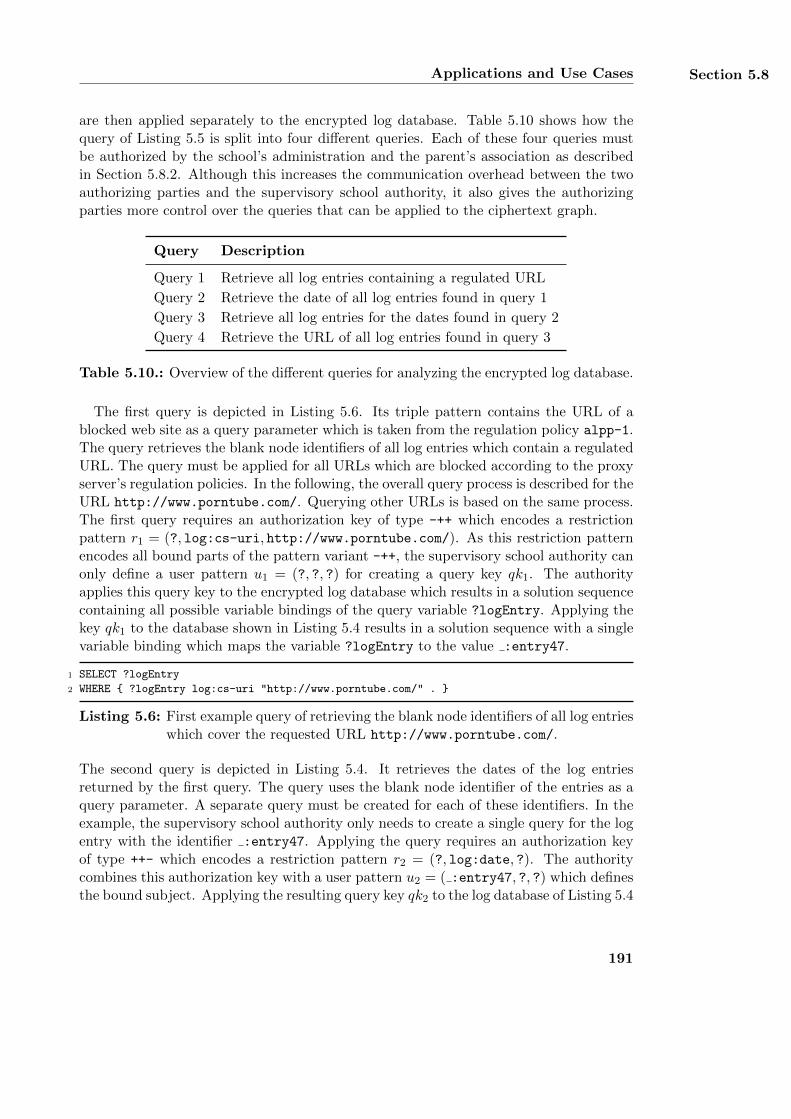
Applications and Use Cases Section 5.8
are then applied separately to the encrypted log database. Table 5.10 shows how thequery of Listing 5.5 is split into four different queries. Each of these four queries mustbe authorized by the school’s administration and the parent’s association as describedin Section 5.8.2. Although this increases the communication overhead between the twoauthorizing parties and the supervisory school authority, it also gives the authorizingparties more control over the queries that can be applied to the ciphertext graph.
Query Description
Query 1 Retrieve all log entries containing a regulated URL
Query 2 Retrieve the date of all log entries found in query 1
Query 3 Retrieve all log entries for the dates found in query 2
Query 4 Retrieve the URL of all log entries found in query 3
Table 5.10.: Overview of the different queries for analyzing the encrypted log database.
The first query is depicted in Listing 5.6. Its triple pattern contains the URL of ablocked web site as a query parameter which is taken from the regulation policy alpp-1.The query retrieves the blank node identifiers of all log entries which contain a regulatedURL. The query must be applied for all URLs which are blocked according to the proxyserver’s regulation policies. In the following, the overall query process is described for theURL http://www.porntube.com/. Querying other URLs is based on the same process.The first query requires an authorization key of type -++ which encodes a restrictionpattern r1 = (?, log:cs-uri, http://www.porntube.com/). As this restriction patternencodes all bound parts of the pattern variant -++, the supervisory school authority canonly define a user pattern u1 = (?, ?, ?) for creating a query key qk1. The authorityapplies this query key to the encrypted log database which results in a solution sequencecontaining all possible variable bindings of the query variable ?logEntry. Applying thekey qk1 to the database shown in Listing 5.4 results in a solution sequence with a singlevariable binding which maps the variable ?logEntry to the value :entry47.
1 SELECT ?logEntry
2 WHERE { ?logEntry log:cs-uri "http://www.porntube.com/" . }
Listing 5.6: First example query of retrieving the blank node identifiers of all log entrieswhich cover the requested URL http://www.porntube.com/.
The second query is depicted in Listing 5.4. It retrieves the dates of the log entriesreturned by the first query. The query uses the blank node identifier of the entries as aquery parameter. A separate query must be created for each of these identifiers. In theexample, the supervisory school authority only needs to create a single query for the logentry with the identifier :entry47. Applying the query requires an authorization keyof type ++- which encodes a restriction pattern r2 = (?, log:date, ?). The authoritycombines this authorization key with a user pattern u2 = ( :entry47, ?, ?) which definesthe bound subject. Applying the resulting query key qk2 to the log database of Listing 5.4
191
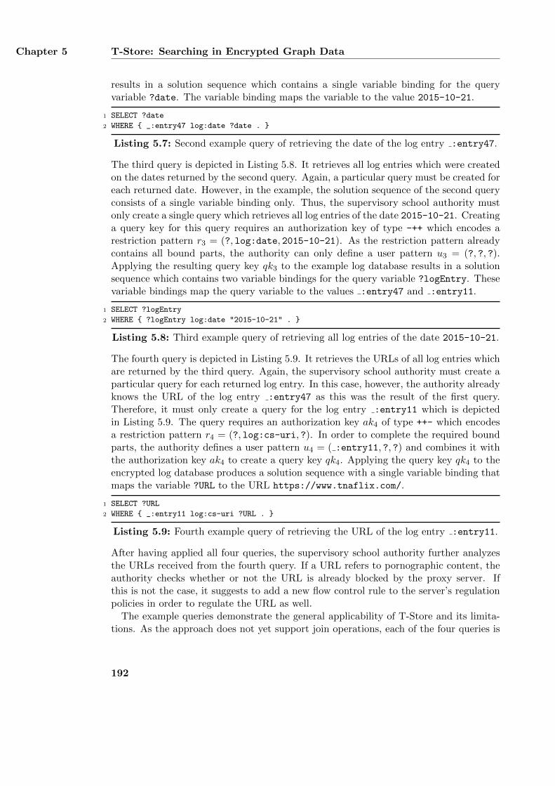
Chapter 5 T-Store: Searching in Encrypted Graph Data
results in a solution sequence which contains a single variable binding for the queryvariable ?date. The variable binding maps the variable to the value 2015-10-21.
1 SELECT ?date
2 WHERE { _:entry47 log:date ?date . }
Listing 5.7: Second example query of retrieving the date of the log entry :entry47.
The third query is depicted in Listing 5.8. It retrieves all log entries which were createdon the dates returned by the second query. Again, a particular query must be created foreach returned date. However, in the example, the solution sequence of the second queryconsists of a single variable binding only. Thus, the supervisory school authority mustonly create a single query which retrieves all log entries of the date 2015-10-21. Creatinga query key for this query requires an authorization key of type -++ which encodes arestriction pattern r3 = (?, log:date, 2015-10-21). As the restriction pattern alreadycontains all bound parts, the authority can only define a user pattern u3 = (?, ?, ?).Applying the resulting query key qk3 to the example log database results in a solutionsequence which contains two variable bindings for the query variable ?logEntry. Thesevariable bindings map the query variable to the values :entry47 and :entry11.
1 SELECT ?logEntry
2 WHERE { ?logEntry log:date "2015-10-21" . }
Listing 5.8: Third example query of retrieving all log entries of the date 2015-10-21.
The fourth query is depicted in Listing 5.9. It retrieves the URLs of all log entries whichare returned by the third query. Again, the supervisory school authority must create aparticular query for each returned log entry. In this case, however, the authority alreadyknows the URL of the log entry :entry47 as this was the result of the first query.Therefore, it must only create a query for the log entry :entry11 which is depictedin Listing 5.9. The query requires an authorization key ak4 of type ++- which encodesa restriction pattern r4 = (?, log:cs-uri, ?). In order to complete the required boundparts, the authority defines a user pattern u4 = ( :entry11, ?, ?) and combines it withthe authorization key ak4 to create a query key qk4. Applying the query key qk4 to theencrypted log database produces a solution sequence with a single variable binding thatmaps the variable ?URL to the URL https://www.tnaflix.com/.
1 SELECT ?URL
2 WHERE { _:entry11 log:cs-uri ?URL . }
Listing 5.9: Fourth example query of retrieving the URL of the log entry :entry11.
After having applied all four queries, the supervisory school authority further analyzesthe URLs received from the fourth query. If a URL refers to pornographic content, theauthority checks whether or not the URL is already blocked by the proxy server. Ifthis is not the case, it suggests to add a new flow control rule to the server’s regulationpolicies in order to regulate the URL as well.
The example queries demonstrate the general applicability of T-Store and its limita-tions. As the approach does not yet support join operations, each of the four queries is
192
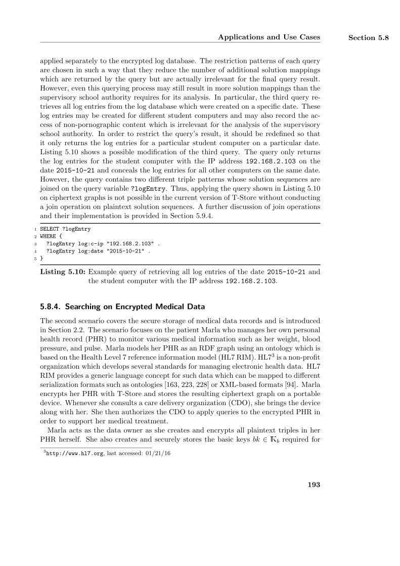
Applications and Use Cases Section 5.8
applied separately to the encrypted log database. The restriction patterns of each queryare chosen in such a way that they reduce the number of additional solution mappingswhich are returned by the query but are actually irrelevant for the final query result.However, even this querying process may still result in more solution mappings than thesupervisory school authority requires for its analysis. In particular, the third query re-trieves all log entries from the log database which were created on a specific date. Theselog entries may be created for different student computers and may also record the ac-cess of non-pornographic content which is irrelevant for the analysis of the supervisoryschool authority. In order to restrict the query’s result, it should be redefined so thatit only returns the log entries for a particular student computer on a particular date.Listing 5.10 shows a possible modification of the third query. The query only returnsthe log entries for the student computer with the IP address 192.168.2.103 on thedate 2015-10-21 and conceals the log entries for all other computers on the same date.However, the query contains two different triple patterns whose solution sequences arejoined on the query variable ?logEntry. Thus, applying the query shown in Listing 5.10on ciphertext graphs is not possible in the current version of T-Store without conductinga join operation on plaintext solution sequences. A further discussion of join operationsand their implementation is provided in Section 5.9.4.
1 SELECT ?logEntry
2 WHERE {
3 ?logEntry log:c-ip "192.168.2.103" .
4 ?logEntry log:date "2015-10-21" .
5 }
Listing 5.10: Example query of retrieving all log entries of the date 2015-10-21 andthe student computer with the IP address 192.168.2.103.
5.8.4. Searching on Encrypted Medical Data
The second scenario covers the secure storage of medical data records and is introducedin Section 2.2. The scenario focuses on the patient Marla who manages her own personalhealth record (PHR) to monitor various medical information such as her weight, bloodpressure, and pulse. Marla models her PHR as an RDF graph using an ontology which isbased on the Health Level 7 reference information model (HL7 RIM). HL73 is a non-profitorganization which develops several standards for managing electronic health data. HL7RIM provides a generic language concept for such data which can be mapped to differentserialization formats such as ontologies [163, 223, 228] or XML-based formats [94]. Marlaencrypts her PHR with T-Store and stores the resulting ciphertext graph on a portabledevice. Whenever she consults a care delivery organization (CDO), she brings the devicealong with her. She then authorizes the CDO to apply queries to the encrypted PHR inorder to support her medical treatment.
Marla acts as the data owner as she creates and encrypts all plaintext triples in herPHR herself. She also creates and securely stores the basic keys bk ∈ Kb required for
3http://www.hl7.org, last accessed: 01/21/16
193
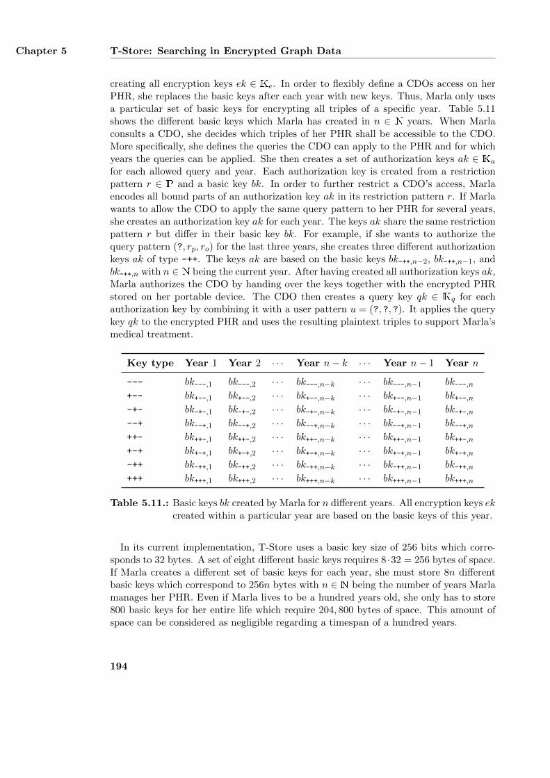
Chapter 5 T-Store: Searching in Encrypted Graph Data
creating all encryption keys ek ∈ Ke. In order to flexibly define a CDOs access on herPHR, she replaces the basic keys after each year with new keys. Thus, Marla only usesa particular set of basic keys for encrypting all triples of a specific year. Table 5.11shows the different basic keys which Marla has created in n ∈ N years. When Marlaconsults a CDO, she decides which triples of her PHR shall be accessible to the CDO.More specifically, she defines the queries the CDO can apply to the PHR and for whichyears the queries can be applied. She then creates a set of authorization keys ak ∈ Ka
for each allowed query and year. Each authorization key is created from a restrictionpattern r ∈ P and a basic key bk. In order to further restrict a CDO’s access, Marlaencodes all bound parts of an authorization key ak in its restriction pattern r. If Marlawants to allow the CDO to apply the same query pattern to her PHR for several years,she creates an authorization key ak for each year. The keys ak share the same restrictionpattern r but differ in their basic key bk. For example, if she wants to authorize thequery pattern (?, rp, ro) for the last three years, she creates three different authorizationkeys ak of type -++. The keys ak are based on the basic keys bk-++,n−2, bk-++,n−1, andbk-++,n with n ∈ N being the current year. After having created all authorization keys ak,Marla authorizes the CDO by handing over the keys together with the encrypted PHRstored on her portable device. The CDO then creates a query key qk ∈ Kq for eachauthorization key by combining it with a user pattern u = (?, ?, ?). It applies the querykey qk to the encrypted PHR and uses the resulting plaintext triples to support Marla’smedical treatment.
Key type Year 1 Year 2 · · · Year n− k · · · Year n− 1 Year n
--- bk---,1 bk---,2 · · · bk---,n−k · · · bk---,n−1 bk---,n+-- bk+--,1 bk+--,2 · · · bk+--,n−k · · · bk+--,n−1 bk+--,n-+- bk-+-,1 bk-+-,2 · · · bk-+-,n−k · · · bk-+-,n−1 bk-+-,n--+ bk--+,1 bk--+,2 · · · bk--+,n−k · · · bk--+,n−1 bk--+,n++- bk++-,1 bk++-,2 · · · bk++-,n−k · · · bk++-,n−1 bk++-,n+-+ bk+-+,1 bk+-+,2 · · · bk+-+,n−k · · · bk+-+,n−1 bk+-+,n-++ bk-++,1 bk-++,2 · · · bk-++,n−k · · · bk-++,n−1 bk-++,n+++ bk+++,1 bk+++,2 · · · bk+++,n−k · · · bk+++,n−1 bk+++,n
Table 5.11.: Basic keys bk created by Marla for n different years. All encryption keys ekcreated within a particular year are based on the basic keys of this year.
In its current implementation, T-Store uses a basic key size of 256 bits which corre-sponds to 32 bytes. A set of eight different basic keys requires 8 ·32 = 256 bytes of space.If Marla creates a different set of basic keys for each year, she must store 8n differentbasic keys which correspond to 256n bytes with n ∈ N being the number of years Marlamanages her PHR. Even if Marla lives to be a hundred years old, she only has to store800 basic keys for her entire life which require 204, 800 bytes of space. This amount ofspace can be considered as negligible regarding a timespan of a hundred years.
194
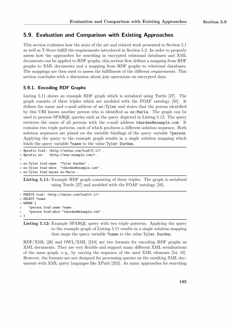
Evaluation and Comparison with Existing Approaches Section 5.9
5.9. Evaluation and Comparison with Existing Approaches
This section evaluates how the state of the art and related work presented in Section 5.1as well as T-Store fulfill the requirements introduced in Section 5.2. In order to properlyassess how the approaches for searching in encrypted relational databases and XMLdocuments can be applied to RDF graphs, this section first defines a mapping from RDFgraphs to XML documents and a mapping from RDF graphs to relational databases.The mappings are then used to assess the fulfillment of the different requirements. Thissection concludes with a discussion about join operations on encrypted data.
5.9.1. Encoding RDF Graphs
Listing 5.11 shows an example RDF graph which is serialized using Turtle [27]. Thegraph consists of three triples which are modeled with the FOAF ontology [50]. Itdefines the name and e-mail address of ex:Tyler and states that the person identifiedby this URI knows another person who is identified as ex:Marla. The graph can beused to process SPARQL queries such as the query depicted in Listing 5.12. The queryretrieves the name of all persons with the e-mail address [email protected]. Itcontains two triple patterns, each of which produces a different solution sequence. Bothsolution sequences are joined on the variable bindings of the query variable ?person.Applying the query to the example graph results in a single solution mapping whichbinds the query variable ?name to the value Tyler Durden.
1 @prefix foaf: <http://xmlns.com/foaf/0.1/> .
2 @prefix ex: <http://www.example.com/> .
3
4 ex:Tyler foaf:name "Tyler Durden" .
5 ex:Tyler foaf:mbox "[email protected]" .
6 ex:Tyler foaf:knows ex:Marla .
Listing 5.11: Example RDF graph consisting of three triples. The graph is serializedusing Turtle [27] and modeled with the FOAF ontology [50].
1 PREFIX foaf: <http://xmlns.com/foaf/0.1/>
2 SELECT ?name
3 WHERE {
4 ?person foaf:name ?name .
5 ?person foaf:mbox "[email protected]" .
6 }
Listing 5.12: Example SPARQL query with two triple patterns. Applying the queryto the example graph of Listing 5.11 results in a single solution mappingthat maps the query variable ?name to the value Tyler Durden.
RDF/XML [26] and OWL/XML [210] are two formats for encoding RDF graphs asXML documents. They are very flexible and support many different XML serializationsof the same graph, e. g., by varying the sequence of the used XML elements [54, 10].However, the formats are not designed for processing queries on the resulting XML doc-uments with XML query languages like XPath [252]. As many approaches for searching
195
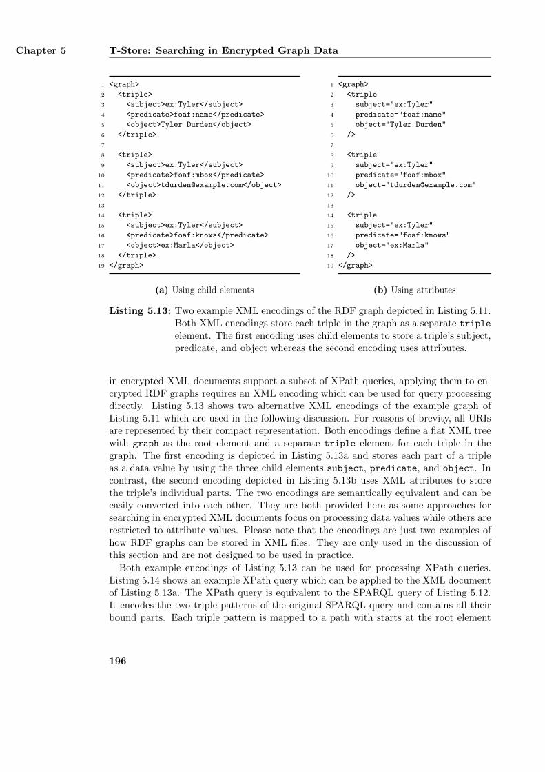
Chapter 5 T-Store: Searching in Encrypted Graph Data
1 <graph>
2 <triple>
3 <subject>ex:Tyler</subject>
4 <predicate>foaf:name</predicate>
5 <object>Tyler Durden</object>
6 </triple>
7
8 <triple>
9 <subject>ex:Tyler</subject>
10 <predicate>foaf:mbox</predicate>
11 <object>[email protected]</object>
12 </triple>
13
14 <triple>
15 <subject>ex:Tyler</subject>
16 <predicate>foaf:knows</predicate>
17 <object>ex:Marla</object>
18 </triple>
19 </graph>
(a) Using child elements
1 <graph>
2 <triple
3 subject="ex:Tyler"
4 predicate="foaf:name"
5 object="Tyler Durden"
6 />
7
8 <triple
9 subject="ex:Tyler"
10 predicate="foaf:mbox"
11 object="[email protected]"
12 />
13
14 <triple
15 subject="ex:Tyler"
16 predicate="foaf:knows"
17 object="ex:Marla"
18 />
19 </graph>
(b) Using attributes
Listing 5.13: Two example XML encodings of the RDF graph depicted in Listing 5.11.Both XML encodings store each triple in the graph as a separate triple
element. The first encoding uses child elements to store a triple’s subject,predicate, and object whereas the second encoding uses attributes.
in encrypted XML documents support a subset of XPath queries, applying them to en-crypted RDF graphs requires an XML encoding which can be used for query processingdirectly. Listing 5.13 shows two alternative XML encodings of the example graph ofListing 5.11 which are used in the following discussion. For reasons of brevity, all URIsare represented by their compact representation. Both encodings define a flat XML treewith graph as the root element and a separate triple element for each triple in thegraph. The first encoding is depicted in Listing 5.13a and stores each part of a tripleas a data value by using the three child elements subject, predicate, and object. Incontrast, the second encoding depicted in Listing 5.13b uses XML attributes to storethe triple’s individual parts. The two encodings are semantically equivalent and can beeasily converted into each other. They are both provided here as some approaches forsearching in encrypted XML documents focus on processing data values while others arerestricted to attribute values. Please note that the encodings are just two examples ofhow RDF graphs can be stored in XML files. They are only used in the discussion ofthis section and are not designed to be used in practice.
Both example encodings of Listing 5.13 can be used for processing XPath queries.Listing 5.14 shows an example XPath query which can be applied to the XML documentof Listing 5.13a. The XPath query is equivalent to the SPARQL query of Listing 5.12.It encodes the two triple patterns of the original SPARQL query and contains all theirbound parts. Each triple pattern is mapped to a path with starts at the root element
196
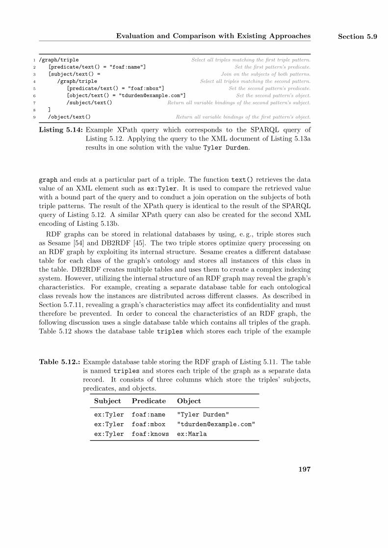
Evaluation and Comparison with Existing Approaches Section 5.9
1 /graph/triple Select all triples matching the first triple pattern.
2 [predicate/text() = "foaf:name"] Set the first pattern’s predicate.
3 [subject/text() = Join on the subjects of both patterns.
4 /graph/triple Select all triples matching the second pattern.
5 [predicate/text() = "foaf:mbox"] Set the second pattern’s predicate.
6 [object/text() = "[email protected]"] Set the second pattern’s object.
7 /subject/text() Return all variable bindings of the second pattern’s subject.
8 ]
9 /object/text() Return all variable bindings of the first pattern’s object.
Listing 5.14: Example XPath query which corresponds to the SPARQL query ofListing 5.12. Applying the query to the XML document of Listing 5.13aresults in one solution with the value Tyler Durden.
graph and ends at a particular part of a triple. The function text() retrieves the datavalue of an XML element such as ex:Tyler. It is used to compare the retrieved valuewith a bound part of the query and to conduct a join operation on the subjects of bothtriple patterns. The result of the XPath query is identical to the result of the SPARQLquery of Listing 5.12. A similar XPath query can also be created for the second XMLencoding of Listing 5.13b.
RDF graphs can be stored in relational databases by using, e. g., triple stores suchas Sesame [54] and DB2RDF [45]. The two triple stores optimize query processing onan RDF graph by exploiting its internal structure. Sesame creates a different databasetable for each class of the graph’s ontology and stores all instances of this class inthe table. DB2RDF creates multiple tables and uses them to create a complex indexingsystem. However, utilizing the internal structure of an RDF graph may reveal the graph’scharacteristics. For example, creating a separate database table for each ontologicalclass reveals how the instances are distributed across different classes. As described inSection 5.7.11, revealing a graph’s characteristics may affect its confidentiality and musttherefore be prevented. In order to conceal the characteristics of an RDF graph, thefollowing discussion uses a single database table which contains all triples of the graph.Table 5.12 shows the database table triples which stores each triple of the example
Table 5.12.: Example database table storing the RDF graph of Listing 5.11. The tableis named triples and stores each triple of the graph as a separate datarecord. It consists of three columns which store the triples’ subjects,predicates, and objects.
Subject Predicate Object
ex:Tyler foaf:name "Tyler Durden"
ex:Tyler foaf:mbox "[email protected]"
ex:Tyler foaf:knows ex:Marla
197
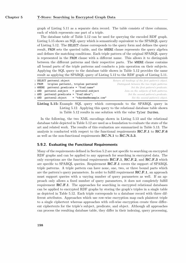
Chapter 5 T-Store: Searching in Encrypted Graph Data
graph of Listing 5.11 as a separate data record. The table consists of three columns,each of which represents one part of a triple.
The database table of Table 5.12 can be used for querying the encoded RDF graph.Listing 5.15 shows an SQL query which is semantically equivalent to the SPARQL queryof Listing 5.12. The SELECT clause corresponds to the query form and defines the queryresult, FROM sets the queried table, and the WHERE clause represents the query algebraand defines the matching conditions. Each triple pattern of the original SPARQL queryis represented in the FROM clause with a different name. This allows it to distinguishbetween the different patterns and their respective parts. The WHERE clause containsall bound parts of the triple patterns and conducts a join operation on their subjects.Applying the SQL query to the database table shown in Table 5.12 provides the sameresult as applying the SPARQL query of Listing 5.12 to the RDF graph of Listing 5.11.
1 SELECT pattern1.object Return all bindings of the first pattern’s object.
2 FROM triples pattern1, triples pattern2 Distinguish between the two triple patterns.
3 WHERE pattern1.predicate = "foaf:name" Set the first pattern’s predicate.
4 AND pattern1.subject = pattern2.subject Join on the subjects of both patterns.
5 AND pattern2.predicate = "foaf:mbox"; Set the second pattern’s predicate.
6 AND pattern2.object = "[email protected]" Set the second pattern’s object.
Listing 5.15: Example SQL query which corresponds to the SPARQL query inListing 5.12. Applying this query to the relational database table shownin Table 5.12 results in one solution with the value Tyler Durden.
In the following, the two XML encodings shown in Listing 5.13 and the relationaldatabase table depicted in Table 5.12 are used as a foundation to evaluate the state of theart and related work. The results of this evaluation are summarized in Table 5.13. Theanalysis is conducted with respect to the functional requirements RC.F.1 to RC.F.6as well as the non-functional requirements RC.N.1 to RC.N.5.3.
5.9.2. Evaluating the Functional Requirements
Many of the requirements defined in Section 5.2 are not specific to searching on encryptedRDF graphs and can be applied to any approach for searching in encrypted data. Theonly exceptions are the functional requirements RC.F.1, RC.F.2, and RC.F.3 whichare specific to SPARQL queries. Requirement RC.F.1 covers the support of SPARQLtriple patterns. A triple pattern can have none, one, two, or three bound parts whichare the pattern’s query parameters. In order to fulfill requirement RC.F.1, an approachmust support queries with a varying number of query parameters as well. If an ap-proach only allows a fixed number of query parameters, it does not completely fulfillrequirement RC.F.1. The approaches for searching in encrypted relational databasescan be applied to encrypted RDF graphs by storing the graph’s triples in a single tableas depicted in Table 5.12. Each triple corresponds to a database record with three dif-ferent attributes. Approaches which use row-wise encryption map each plaintext tripleto a single ciphertext whereas approaches with cell-wise encryption create three differ-ent ciphertexts for the triple’s subject, predicate, and object. Although all approachescan process the resulting database table, they differ in their indexing, query processing,
198
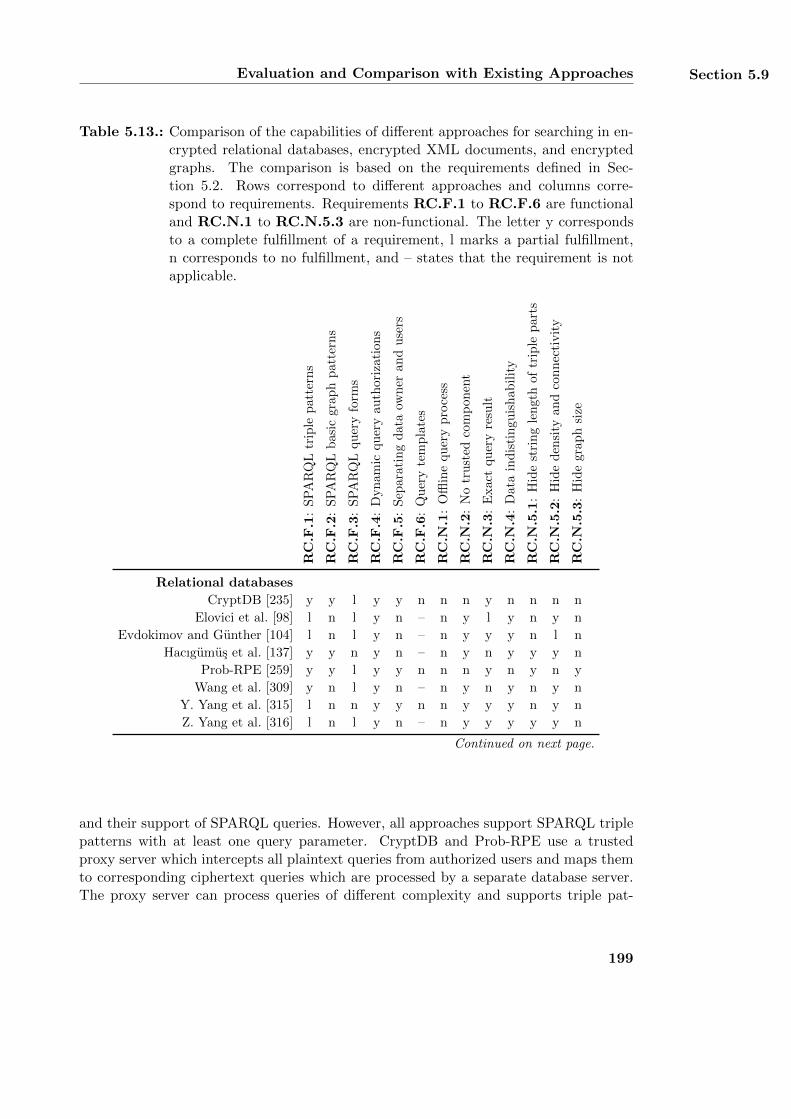
Evaluation and Comparison with Existing Approaches Section 5.9
Table 5.13.: Comparison of the capabilities of different approaches for searching in en-crypted relational databases, encrypted XML documents, and encryptedgraphs. The comparison is based on the requirements defined in Sec-tion 5.2. Rows correspond to different approaches and columns corre-spond to requirements. Requirements RC.F.1 to RC.F.6 are functionaland RC.N.1 to RC.N.5.3 are non-functional. The letter y correspondsto a complete fulfillment of a requirement, l marks a partial fulfillment,n corresponds to no fulfillment, and – states that the requirement is notapplicable.
RC
.F.1
:S
PA
RQ
Ltr
iple
pat
tern
s
RC
.F.2
:S
PA
RQ
Lb
asi
cgr
ap
hp
att
ern
s
RC
.F.3
:S
PA
RQ
Lquer
yfo
rms
RC
.F.4
:D
yn
amic
qu
ery
au
thori
zati
ons
RC
.F.5
:S
epar
atin
gd
ata
own
eran
du
sers
RC
.F.6
:Q
uer
yte
mp
late
s
RC
.N.1
:O
fflin
equ
ery
pro
cess
RC
.N.2
:N
otr
ust
edco
mp
onen
t
RC
.N.3
:E
xac
tqu
ery
resu
lt
RC
.N.4
:D
ata
ind
isti
ngu
ish
abil
ity
RC
.N.5
.1:
Hid
est
rin
gle
ngth
of
trip
lep
art
s
RC
.N.5
.2:
Hid
ed
ensi
tyan
dco
nnec
tivit
y
RC
.N.5
.3:
Hid
egra
ph
size
Relational databases
CryptDB [235] y y l y y n n n y n n n n
Elovici et al. [98] l n l y n – n y l y n y n
Evdokimov and Gunther [104] l n l y n – n y y y n l n
Hacıgumus et al. [137] y y n y n – n y n y y y n
Prob-RPE [259] y y l y y n n n y n y n y
Wang et al. [309] y n l y n – n y n y n y n
Y. Yang et al. [315] l n n y y n n y y y n y n
Z. Yang et al. [316] l n l y n – n y y y y y n
Continued on next page.
and their support of SPARQL queries. However, all approaches support SPARQL triplepatterns with at least one query parameter. CryptDB and Prob-RPE use a trustedproxy server which intercepts all plaintext queries from authorized users and maps themto corresponding ciphertext queries which are processed by a separate database server.The proxy server can process queries of different complexity and supports triple pat-
199
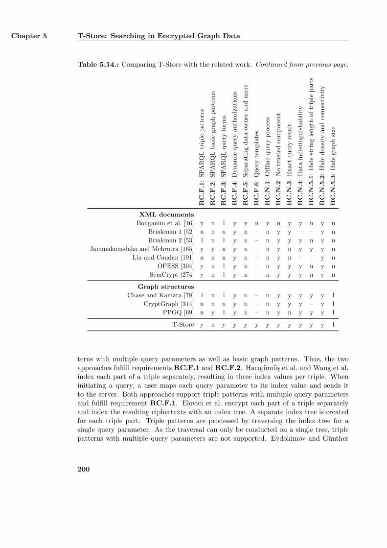
Chapter 5 T-Store: Searching in Encrypted Graph Data
Table 5.14.: Comparing T-Store with the related work. Continued from previous page.
RC
.F.1
:S
PA
RQ
Ltr
iple
pat
tern
s
RC
.F.2
:S
PA
RQ
Lb
asic
grap
hp
atte
rns
RC
.F.3
:S
PA
RQ
Lquer
yfo
rms
RC
.F.4
:D
yn
am
icqu
ery
au
thor
izati
on
s
RC
.F.5
:S
epara
tin
gd
ata
own
erand
use
rs
RC
.F.6
:Q
uer
yte
mp
late
s
RC
.N.1
:O
fflin
equ
ery
pro
cess
RC
.N.2
:N
otr
ust
edco
mp
on
ent
RC
.N.3
:E
xac
tqu
ery
resu
lt
RC
.N.4
:D
ata
ind
isti
ngu
ish
ab
ilit
y
RC
.N.5
.1:
Hid
est
rin
gle
ngth
of
trip
lep
art
s
RC
.N.5
.2:
Hid
ed
ensi
tyan
dco
nnec
tivit
y
RC
.N.5
.3:
Hid
egra
ph
size
XML documents
Bouganim et al. [46] y n l y y n y n y y n y n
Brinkman 1 [52] n n n y n – n y y – – y n
Brinkman 2 [53] l n l y n – n y y y n y n
Jammalamadaka and Mehrotra [165] y y n y n – n y n y y y n
Lin and Candan [191] n n n y n – n y n – – y n
OPESS [304] y n l y n – n y y y n y n
SemCrypt [274] y n l y n – n y y y n y n
Graph structures
Chase and Kamara [78] l n l y n – n y y y y y l
CryptGraph [314] n n n y n – n y y y – y l
PPGQ [69] n y l y n – n y n y y y l
T-Store y n y y y y y y y y y y l
terns with multiple query parameters as well as basic graph patterns. Thus, the twoapproaches fulfill requirements RC.F.1 and RC.F.2. Hacıgumus et al. and Wang et al.index each part of a triple separately, resulting in three index values per triple. Wheninitiating a query, a user maps each query parameter to its index value and sends itto the server. Both approaches support triple patterns with multiple query parametersand fulfill requirement RC.F.1. Elovici et al. encrypt each part of a triple separatelyand index the resulting ciphertexts with an index tree. A separate index tree is createdfor each triple part. Triple patterns are processed by traversing the index tree for asingle query parameter. As the traversal can only be conducted on a single tree, triplepatterns with multiple query parameters are not supported. Evdokimov and Gunther
200
Evaluation and Comparison with Existing Approaches Section 5.9
as well as Z. Yang et al. map each triple to three different ciphertext tuples. Triplepatterns correspond to trapdoors [42] which encode a single query parameter and areprocessed at the server by comparing them with all ciphertext tuples. As the approachesdo not support triple patterns with multiple query parameters, they only partially fulfillrequirement RC.F.1. Y. Yang et al. encrypt a triple as a single ciphertext and indexit with three different index values based on its subject, predicate, and object. A usercreates a triple pattern by signing a single query parameter with her private key andsends it to the server. As the used signature scheme does not support signing multiplequery parameters at once, the approach only partially fulfills requirement RC.F.1. Theapproaches for searching in encrypted XML documents support different types of querieswhich assess different parts of the document such as its element names, data values, andattribute values. In order to apply an approach to RDF graphs, it must support arbi-trary URIs, blank nodes, and literals as query parameters. Such an approach can beused for searching in encrypted RDF graphs by using one of the encodings provided inListing 5.13. In contrast, approaches which only allow element queries cannot be usedfor SPARQL queries. The number of possible element names in an XML document isrestricted by the document’s schema [124]. This prohibits element names from storingarbitrary URIs, blank nodes, or literals and makes it impossible to use them as queryparameters. Brinkman 1 as well as Lin and Candan are restricted to element queries andcannot be used for SPARQL queries. Thus, they do not fulfill requirements RC.F.1,RC.F.2, and RC.F.3. Bouganim et al., Jammalamadaka and Mehrotra, OPESS, andSemCrypt support triple patterns with multiple query parameters and fulfill require-ment RC.F.1. Bouganim et al. use a secure processing unit at the user side whichprocesses all queries on the encrypted XML document. This unit is also capable ofprocessing triple patterns with multiple query parameters and can operate on both en-codings of Listing 5.13. Each plaintext triple is mapped to three different ciphertextswhich correspond to the triple’s subject, predicate, and object. Jammalamadaka andMehrotra are essentially the same as Hacıgumus et al. and fulfill the same requirements.The approach requires the XML encoding of Listing 5.13b. It encrypts each triple ele-ment as single ciphertext and associates it with three index values for the triple’s subject,predicate, and object. Query processing is identical to Hacıgumus et al. OPESS sup-ports path queries based on element names and data values. As the approach does notoperate on attribute values, it requires the XML encoding of Listing 5.13a. Each triplein the resulting XML document is encrypted as three different ciphertexts and indexedbased on its individual parts. A triple pattern corresponds to a path and is processed byencrypting its query parameters and sending it to the server. SemCrypt supports pathqueries based on element names, attribute values, and data values and can be used withboth encodings of Listing 5.13. Again, each plaintext triple is mapped to three differentciphertexts. SemCrypt processes queries by exchanging messages between the user andthe server. Although each message only covers a single query parameter, multiple pa-rameters are possible by exchanging several messages which are further processed by theuser. Brinkman 2 uses trapdoors and is similar to Z. Yang et al. Thus, the approach onlypartially fulfills requirement RC.F.1. As supported queries may contain attribute valuesand data values, the approach supports both encodings of Listing 5.13. The graph-based
201
Chapter 5 T-Store: Searching in Encrypted Graph Data
approaches Chase and Kamara, CryptGraph, and PPGQ focus on abstract graphs andare not specifically designed to support RDF graphs. Chase and Kamara support querieswhich retrieve all edges between two nodes. These queries can be used for triple patternsof type +-+ which retrieve all predicates between a subject and and object. Although theapproach defines a flexible index structure which can generally be used to support othertypes of triple patterns as well, the authors themselves only provide a small set of querytypes. Thus, the approach only partially fulfills requirement RC.F.1. Although Crypt-Graph operates on labeled graphs, it does not support labeled edges. However, RDFgraphs have labeled nodes and labeled edges, which correspond to the triples’ predicates.Thus, CryptGraph cannot be used for searching in encrypted RDF graphs and does notfulfill requirements RC.F.1, RC.F.2, and RC.F.3. PPGQ is restricted to subgraphqueries and cannot be used for applying a single triple pattern to an RDF graph. Thus,the approach does not fulfill requirement RC.F.1. T-Store natively supports all eighttypes of triple patterns by encrypting each triple in the plaintext graph separately foreach of the pattern types.
Requirement RC.F.2 covers SPARQL basic graph patterns which consist of severaltriple patterns. If the triple patterns share identical query variables, their solution se-quences are combined via a join operation on the variables. Thus, an approach whichfulfills requirement RC.F.2 must support join operations as well. Conducting a joinoperation requires the identification of compatible solution sequences, i. e., solution se-quences which share identical variable bindings. Hacıgumus et al. divide the values of allthree triple parts into disjoint buckets which are used for processing queries and join op-erations. When processing a basic graph pattern, the server first computes the solutionsequence of each triple pattern. It then combines all solution sequences by conductinga join operation on all compatible variable bindings. Variable bindings are compati-ble with each other if they map the same query variable to the same bucket identifier.CryptDB uses deterministic encryption to support join operations. Deterministic en-cryption maps identical plaintext values to identical ciphertext values. A join operationcan then be directly applied to the ciphertext values. Although Prob-RPE uses proba-bilistic encryption, it associates each ciphertext with an additional join identifier. Joinidentifiers are bit strings which are identical for equal plaintext values. They allow aserver to detect compatible ciphertexts and to conducts join operations on them. Noneof the other approaches for searching in relational database support join operations.Instead, they require the user to split a basic graph pattern into multiple SQL queries,each of which consists of a single triple pattern. The server processes each triple pat-tern individually and returns a corresponding solution sequence. Subsequently, the userdecrypts all received solution sequences and conducts a join operation on the resultingplaintext. Jammalamadaka and Mehrotra are similar to Hacıgumus et al. and supportjoin operations using bucket identifiers. In contrast, none of the other approaches whichoperate on XML documents can detect compatible variable bindings and do not fulfillrequirement RC.F.2. Chase and Kamara are restricted to queries which consist of asingle triple pattern only. Join operations cannot be conducted on the ciphertext graphand must be conducted by the user via combining several solution sequences. Thus,the approach does not fulfill requirement RC.F.2. PPGQ supports subgraph queries
202
Evaluation and Comparison with Existing Approaches Section 5.9
which can be used for implementing basic graph patterns on RDF graphs. A basic graphpattern is encoded as a single subgraph query and does not require any join operation.PPGQ therefore fulfills requirement RC.F.2. Similar to Chase and Kamara, the currentdesign of T-Store does not support join operations and requires the user to conduct suchoperations on all received solution sequences. A detailed discussion on join operationsis provided in Section 5.9.4.
Requirement RC.F.3 states that SELECT, CONSTRUCT, and ASK queries must be equallysupported. As described in Section 5.1.4, SELECT queries and CONSTRUCT queries operateon variable bindings whereas ASK queries return a boolean value. In order to fulfillrequirement RC.F.3, an approach must support two different types of queries. Queriesof the first type are used in SELECT queries and CONSTRUCT queries and process the threeparts of all matching ciphertext triples individually in order to create the necessaryvariable bindings. An approach which cannot process an encrypted triple’s subject,predicate, or object separately and only operates on complete ciphertext triples neithersupports SELECT queries nor CONSTRUCT queries. Queries of the second type supportASK queries and match a set of query conditions against the queried data. The resultingboolean value indicates whether or not the query conditions have at least one matchin the encrypted data. The value does not reveal any additional information aboutthe plaintext data [140]. An approach which does not provide boolean query resultsor reveals more information about the plaintext data does not support ASK queries.None of the approaches which operate on relational databases support ASK queries asthey are not able to return boolean query results. However, most of them use cell-wiseencryption and encrypt each part of a triple individually. This can be used for returningindividual variable bindings as query results which is necessary to support SELECT queriesand CONSTRUCT queries. Thus, approaches using cell-wise encryption partially fulfillrequirement RC.F.3. In contrast, Hacıgumus et al. and Y. Yang et al. apply row-wise encryption and always return complete ciphertext triples. As they cannot createindividual variable bindings as query results, they do not fulfill requirement RC.F.3.Many of the approaches which operate on XML documents can retrieve individual tripleparts as query results and thus support SELECT queries and CONSTRUCT queries. However,none of them can be used for ASK queries. Bouganim et al. and Brinkman 2 encrypt eachpart of a triple separately and support individual variable bindings. Similarly, OPESSand SemCrypt map each plaintext triple to three different XML paths which correspondto the triple’s subject, predicate, and object. The different paths can be processedindependently and support individual variable bindings. PPGQ is restricted to subgraphqueries which can be used for implementing ASK queries on encrypted RDF graphs. Asthe approach does not provide any mechanism for implementing variable bindings, it onlypartially fulfills requirement RC.F.3. In contrast, Chase and Kamara are not designedfor subgraph queries and are restricted to SELECT queries and CONSTRUCT queries whichcontain triple patterns of type +-+. Thus, they partially fulfill requirement RC.F.3 aswell. In its current design, T-Store is only able to retrieve individual variable bindingsand natively supports SELECT queries and CONSTRUCT queries. Although Algorithm 5.4describes a method for processing ASK queries, it requires the computation of all variablebindings to determine the boolean query results. This contradicts with the specification
203
Chapter 5 T-Store: Searching in Encrypted Graph Data
of ASK queries since they do not reveal any additional information about the queriedgraph. However, T-Store can easily be extended to support ASK queries as well. Theextension requires eight additional basic keys for each of the eight triple pattern variants.These basic keys are independent from the basic keys that are used for SELECT queries andCONSTRUCT queries. They are used for creating encryption keys as defined in Table 5.1.Each created encryption key encrypts only a single value which indicates that the querypattern encoded in the key has at least one match in the ciphertext graph. The valuedoes not provide any additional information about the graph and thus corresponds to theboolean query result of an ASK query. The ciphertexts resulting from such an encryptioncan be processed in the same way as the ciphertexts of SELECT queries and CONSTRUCT
queries. They can also be stored in the same ciphertext graph and be indexed in itscorresponding index. With this extension, T-Store is able to support ASK queries as welland fulfills requirement RC.F.3.
None of the discussed approaches is limited to a predefined set of queries. Instead,each approach allows the queries to be formulated after the plaintext graph has beenencrypted. Thus, all approaches including T-Store fulfill requirement RC.F.4. Require-ment RC.F.5 demands that an approach must distinguish between a data owner whoencrypts the plaintext graph and users who apply queries to the ciphertext graph. Thedata owner creates and permanently stores all encryption keys and a user can only accessthose keys which are explicitly authorized by the data owner. This requirement impliesthat an approach is not restricted to a single party which stores all cryptographic keysand can exclusively access the plaintext triples. If an approach even supports multi-ple users with different query authorizations, it implicitly fulfills requirement RC.F.5.Supporting multiple users necessitates a distinction between the users and the dataowner who authorizes them. Most of the discussed approaches focus on data outsourc-ing [281] and consider the data owner to be identical to a single user. As this user iscompletely trusted and stores all cryptographic keys, the approaches do not fulfill re-quirement RC.F.5. The only exceptions are CryptDB, Prob-RPE, Y. Yang et al., andBouganim et al. which support multiple users. CryptDB and Prob-RPE authorize eachuser by a trusted proxy server and Y. Yang et al. authenticate a user with a publickey pair. Bouganim et al. require a trusted computing device at each user’s side whichauthorizes and conducts all queries. T-Store distinguishes between the data owner andusers and fulfills requirement RC.F.5. A data owner creates and permanently stores allbasic keys which are used for creating particular query authorizations.
Requirement RC.F.6 covers query templates which represent groups of similar queryauthorizations. Instead of authorizing each query individually, a query template com-bines similar queries into a single authorization. As query templates imply a distinc-tion between data owners and users, the fulfillment of requirement RC.F.6 necessitatesthe fulfillment of requirement RC.F.5 as well. All approaches which support multipleusers require an explicit authorization for each query. As they do not support querytemplates which combine similar queries, they do not fulfill requirement RC.F.6. Incontrast, T-Store provides query templates via authorization keys. An authorizationkey is an incomplete query key which can be transformed into different query keys byan authorized user. Thus, T-Store fulfills requirement RC.F.6.
204
Evaluation and Comparison with Existing Approaches Section 5.9
5.9.3. Evaluating the Non-Functional Requirements
Many of the discussed approaches require a server to conduct most of the query pro-cessing and do not fulfill requirement RC.N.1. The only exception is Bouganim et al.which use a secure processing unit for each user. The unit processes all queries withoutinvolving any online system. T-Store also allows a user to process all queries offlineand fulfills requirement RC.N.1 as well. Requirement RC.N.2 states that an approachmust not involve a trusted system when applying queries to ciphertext graphs. A sys-tem is considered to be trusted if it has access to plaintext triples but is not their finalrecipient. Examples of trusted systems are proxy servers which apply queries on behalfof authorized users. Most approaches only involve an authorized user and an untrustedserver when processing a query. The server solely operates on ciphertext triples andcannot access any plaintext triples. The user is not a trusted system as she is the fi-nal recipient of the query results. Thus, these approaches fulfill requirement RC.N.2.In contrast, CryptDB, Prob-RPE, and Bouganim et al. require a trusted system forprocessing queries. CryptDB and Prob-RPE use a proxy server which acts as an inter-mediary between an authorized user and the database server and conducts the actualquery processing. It is also able to access all plaintext triples returned by the databaseserver. Bouganim et al. use a secure processing unit at the user’s side. Similar to aproxy server, the unit intercepts all queries from the user, applies them to the ciphertextgraph, and returns the resulting plaintext triples. As the user neither controls the proxyserver nor the secure processing unit, she must trust that these systems do not abuseany received plaintext triples. Thus, CryptDB, Prob-RPE, and Bouganim et al. do notfulfill requirement RC.N.2. In contrast, T-Store does not use a trusted system and onlyinvolves the user who applies queries directly to a ciphertext graph.
An approach fulfills requirement RC.N.3 if processing a query only reveals the match-ing triples while all other triples remain inaccessible to the querying user. CryptDB,Prob-RPE, and Bouganim et al. use a trusted system for query processing which con-ducts any necessary refining steps itself and returns the final solution sequence to theuser. Thus, the three approaches fulfill requirement RC.N.3. Elovici et al. processa triple pattern by traversing an index tree. During the traversal, the user receivesseveral tree nodes which point to ciphertext triples stored at the server. After havingidentified all matching triples, the user retrieves them in a second step. Although anhonest user will only request matching ciphertext triples, the approach does not preventa dishonest user from retrieving other triples as well. Thus, the approach only partiallyfulfills requirement RC.N.3. Evdokimov and Gunther, Z. Yang et al., and Brinkman 2encode triple patterns as trapdoors. Due to their design, trapdoors can only be appliedto ciphertext triples which match the encoded triple pattern. Otherwise, the decryp-tion fails and the corresponding plaintext triple remains inaccessible. Consequently, thethree approaches return an exact solution sequence. Hacıgumus et al. as well as Jam-malamadaka and Mehrotra index ciphertext triples with the bucket identifiers of theirindividual parts. A user initiates a query by mapping its parameters to correspondingbucket identifiers and requesting all matching ciphertext triples from the server. As dif-ferent plaintext values are mapped to the same bucket identifiers, the server may return
205
Chapter 5 T-Store: Searching in Encrypted Graph Data
false positives which require an additional refining step. Wang et al. index each part of aciphertext triple with a hash value using a non-collision-resistant hash function. Again,query processing requires a refining step which contradicts with requirement RC.N.3.Y. Yang et al. associate each ciphertext triple with three index values based on its sub-ject, predicate, and object. As this allows the server to return exact query results, theapproach fulfills requirement RC.N.3. Brinkman 1 applies a subtree query to an XMLdocument by computing several polynomials. The user compares each polynomial witha predefined value. A query result is found if both values are equal. Otherwise, nothingis revealed about the plaintext data. Thus, the approach fulfills requirement RC.N.3.Lin and Candan apply path queries to XML documents by traversing the documenttree. In order to conceal her actual query, the user retrieves multiple ciphertexts in eachtraversal step. She decrypts all ciphertexts, re-encrypts them with a new encryption key,and sends them to the server. As the user receives more plaintext data than necessaryfor answering her query, the approach does not fulfill requirement RC.N.3. OPESSgenerally supports path queries which retrieve complete subtrees of an XML document.As a received subtree forms a superset of the actual query result, an additional refiningstep is necessary. However, applying OPESS to an RDF graph is based on the encodingof Listing 5.13a. Each triple is then encrypted individually which supports exact queryresults. SemCrypt returns exact results for queries with a single query parameter. Mul-tiple query parameters require a separate solution sequence for each parameter whichmust be combined afterwards. As this may remove incompatible solution mappings,SemCrypt only partially fulfills requirement RC.N.3. Chase and Kamara essentiallymap all possible combinations of query parameters to a corresponding solution sequenceand return exact query results. CryptGraph processes subgraph queries by using homo-morphic encryption [111] and does not reveal any intermediate query results. Instead,it only returns an encrypted value which states whether or not the subgraph is part ofthe queried graph. PPGQ supports subgraph queries in encrypted graph collections andindexes each graph with a feature vector describing its subgraphs. To reduce the sizeof the feature vector, similar subgraphs are mapped to the same feature. As this mayresult in false positives, the user must conduct an additional refining step. In contrast,T-Store returns exact query results since a query key can only decrypt those ciphertexttriples which match the query pattern encoded in the key.
Requirement RC.N.4 states that it must be computationally hard to detect identicalURIs, blank nodes, or literals in the ciphertext graph. This implies that neither theciphertext graph nor its index can be used for relating identical plaintext values toeach other. CryptDB and Prob-RPE support join operations by identifying compatibleciphertext triples. CryptDB achieves this with deterministic encryption and Prob-RPEuses join identifiers. Both solutions allow it to detect identical plaintext values whichdirectly contradicts with requirement RC.N.4. Elovici et al., Evdokimov and Gunther,and Z. Yang et al. use probabilistic encryption and map each plaintext value to a differentciphertext. The resulting ciphertext triples prohibit the detection of identical plaintextURIs, blank nodes, or literals. Elovici et al. use an index which is also probabilisticallyencrypted and hides the frequency of the indexed values. In contrast, Evdokimov andGunther as well as Z. Yang et al. do not use an index at all. Thus, all three approaches
206
Evaluation and Comparison with Existing Approaches Section 5.9
fulfill requirement RC.N.4. Hacıgumus et al. and Y. Yang et al. use row-wise encryptionwhich combines all three parts of a plaintext triple into a single ciphertext and concealsthe distribution of individual plaintext values. In addition, Hacıgumus et al. index eachciphertext triple with bucketization which maps different plaintext values to the samebucket identifier. Again, this hides the frequency of individual triple parts. Y. Yang etal. index a ciphertext triple with three index values created from the triple’s subject,predicate, and object. If different triples share the same parts, a counter is added to theindex value to ensure that all values are unique. Wang et al. apply cell-wise encryptionand index each ciphertext using a hash function which is not collision-resistant. Asthe encryption can be conducted probabilistically, neither the ciphertexts nor the indexvalues reveal the exact distribution of the plaintext values. Most of the approacheswhich operate on XML documents fulfill requirement RC.N.4. The only exceptions areBrinkman 1 as well as Lin and Candan which are restricted to element queries. As theydo not operate on individual URIs, blank nodes, or literals, requirement RC.N.4 cannotbe applied to them. Bouganim et al. and Brinkman 2 apply probabilistic encryption anduse an index which only operates on structural information. Thus, the index does notreveal any similarities between the ciphertext triples. OPESS probabilistically encryptseach XML element and transforms its index in such a way that the frequency of allindexed values is almost identical. Thus, the index cannot be used for determining theexact distribution of identical plaintext values. SemCrypt maps each path in an XMLdocument to a unique identifier and stores this mapping at the user’s side. The index isprobabilistically encrypted and conceals identical plaintext URIs, blank nodes, or literals.All approaches for searching in encrypted graphs fulfill requirement RC.N.4. Chase andKamara support triple patterns of type +-+ by mapping tuples of subjects and objectsto an encrypted list of predicates. Although the approach reveals the number of differentsubjects and objects in the graph, it does not reveal how often they occur in differentplaintext triples. As this information is only provided by the encrypted predicates, theapproach hides the frequency of individual URIs, blank nodes, and literals. CryptGraphrepresents a graph by its encrypted adjacency matrix. Similar to Chase and Kamara,CryptGraph reveals the number of different subjects and objects in the plaintext graphbut hides all information about how they are connected. Thus, it neither reveals thenumber of different predicates between a subject and an object nor how often a particularvalue occurs at subject or object position. PPGQ encrypts a graph as a single ciphertextand thereby hides the individual URIs, blank nodes, and literals in the graph. Asdescribed in Section 5.7.8, T-Store encrypts a plaintext graph in such a way that allresulting ciphertexts are unique. This prevents the identification of identical plaintextURIs, blank nodes, or literals in the ciphertext triples.
Requirement RC.N.5.1 demands that an approach hides the string length of indi-vidual URIs, blank nodes, and literals in the graph. Hacıgumus et al. use row-wiseencryption which hides the individual string length of each triple part. Prob-RPE sup-ports different encryption schemes and allows it to transform all plaintext values tothe same length before encrypting them. Z. Yang et al. apply cell-wise encryption af-ter having padded each part of a triple to the same length. The resulting ciphertextsall share the same string length and do not reveal the length of the plaintext values.
207
Chapter 5 T-Store: Searching in Encrypted Graph Data
Y. Yang et al. use row-wise encryption but associate each ciphertext triple with threeindex values. Different index values are created for the same plaintext value by usingan additional counter. As this counter only slightly modifies the string length of theindex value, the approach partially fulfill requirement RC.N.5.1. All other approacheswhich operate on relational databases use cell-wise encryption without any padding andmap plaintext triples to ciphertext triples with roughly the same string length. Apartfrom Jammalamadaka and Mehrotra, none of the approaches for searching in encryptedXML documents fulfill requirement RC.N.5.1. Similar to Hacıgumus et al. Jammala-madaka and Mehrotra encrypt each plaintext triple as a single ciphertext. Bouganimet al., OPESS, and SemCrypt encrypt each path in the XML document individuallywithout using any padding. As a path also contains the data value of an element, thestring length of a ciphertext reveals the size of its plaintext. Brinkman 2 encrypts eachelement together with its data value. Again, the approach does not use any paddingand reveals the size of the encrypted plaintext values. As Brinkman 1 and Lin andCandan are restricted to element queries, requirement RC.N.5.1 cannot be applied tothem. Chase and Kamara use padding to transform all graph labels to the same sizebefore encrypting them and fulfill requirement RC.N.5.1. As CryptGraph does notsupport labeled graphs, it cannot be evaluated for this requirement. PPGQ encrypts agraph as a single ciphertext and thereby hides the string length of all URIs, blank nodes,and literals in the graph. T-Store fulfills requirement RC.N.5.1 by using the extensiondescribed in Section 5.7.9.
Requirement RC.N.5.2 states that an approach must conceal the density and con-nectivity of a graph. The two characteristics can be used to distinguish between differentciphertext graphs or to relate a ciphertext graph to its corresponding plaintext graph.CryptDB uses deterministic encryption which allows it to analyze the frequency of allciphertexts and to compute the density and connectivity of the plaintext graph. Simi-larly, Prob-RPE uses join identifiers which also allow such an analysis. Thus, the twoapproaches do not fulfill requirement RC.N.5.2. In contrast, all other approaches whichoperate on relational databases fulfill this requirement. Elovici et al. use probabilistic en-cryption for the plaintext triples and their index values. Thus, the resulting ciphertextscannot be related to each other. Evdokimov and Gunther as well as Z. Yang et al. alsouse probabilistic encryption and do not use any index which can be used for analyzingthe ciphertext graph. The row-wise encryption applied by Hacıgumus et al. prohibits ananalysis of a graph’s density and connectivity by using its ciphertext graph. Althoughthe approach uses bucketization which associates different ciphertext triples with eachother, the buckets do not provide precise information about a graph’s internal structure.As different plaintext values are mapped to the same bucket, it is impossible to distin-guish between ciphertexts triples which share the same plaintext values and ciphertexttriples with different plaintext values. Wang et al. apply probabilistic encryption anduse an index with colliding index values which does not reveal any information about thegraph’s characteristics. Y. Yang et al. uses row-wise encryption and create index valuesusing a counter which is unknown to the database server. Thus, the counter cannotbe used for analyzing the graph’s internal structure. All approaches for searching inencrypted XML documents hide a graph’s density and connectivity and fulfill require-
208
Evaluation and Comparison with Existing Approaches Section 5.9
ment RC.N.5.2. Bouganim et al. and Brinkman 2 use probabilistic encryption andapply a structural index which does not provide any information about a graph’s plain-text values. Brinkman 1 as well as Lin and Candan only support path queries based onelement names and do not process URIs, blank nodes, or literals, which is necessary toanalyze a graph’s density and connectivity. Jammalamadaka and Mehrotra are similarto Hacıgumus et al. OPESS uses probabilistic encryption and normalizes its index insuch a way that it does not reveal the distribution of the encrypted URIs, blank nodes, orliterals. SemCrypt uses probabilistic encryption for the plaintext triples and the index.All approaches for searching in encrypted graphs fulfill requirement RC.N.5.2 as theydo not provide complete information about a graph’s structure. Chase and Kamara mappairs of subjects and objects to lists of all connecting predicates. These lists are paddedto the same length before encrypting them. Predicates which occur in many triples aretherefore indistinguishable from predicates which are only rarely used. CryptGraph rep-resent a graph by its encrypted adjacency matrix which hides all connections betweentwo nodes in the graph and prevents any analysis of the graph’s structure. PPGQ en-crypts a graph as a single ciphertext and thereby hides its internal structure. The featurevector used for indexing a graph maps different subgraphs to the same feature and doesnot reveal the density and connectivity of the graph. As described in Section 5.7.11,T-Store also hides these characteristics of a graph.
Requirement RC.N.5.3 demands that a ciphertext graph does not reveal the numberof different triples in the plaintext graph. Most of the approaches for searching in rela-tional databases do not fulfill this requirement. Approaches using row-wise encryptionmap a plaintext triple to a single ciphertext triple. Thus, the number of triples in theciphertext graph is identical to the number of triples in the plaintext graph. Approachesapplying cell-wise encryption create three ciphertexts for each plaintext triple. Again,the number of ciphertexts reveals the number of plaintext triples. The only exception isProb-RPE which maps a single plaintext triple to a varying number of ciphertext triplesand thereby hides the size of the plaintext graph. All approaches which operate on XMLdocuments reveal the number of plaintext triples in the ciphertext graph. Most of themcreate the same number of ciphertexts for each plaintext triple. Thus, the number ofall ciphertexts in the ciphertext graph is a multiple of all plaintext triples. Brinkman 1maps a plaintext graph to a hierarchically organized polynomial. However, the structureof this polynomial is essentially the same as the structure of the original XML documentand reveals the number of all XML elements. The approaches for searching in encryptedgraphs partially fulfill requirement RC.N.5.3. Chase and Kamara as well as Crypt-Graph index a graph by using its subjects and objects. Thus, the two approaches revealthe number of different URIs, blank nodes, and literals at subject and object position.However, they still hide the number of different predicates in the graph. PPGQ encryptseach graph as a single ciphertext and hides the exact number of plaintext triples. As theapproach does not normalize the size of a graph, it maps larger plaintext graphs to largerciphertext graphs and smaller plaintext graphs to smaller ciphertext graphs. This canbe used for guessing the number of triples of a ciphertext graph. As described in Sec-tion 5.7.11, T-Store reveals the exact number of plaintext triples in the ciphertext graph.The section also suggests to insert random bit strings as fake ciphertexts into the cipher-
209
Chapter 5 T-Store: Searching in Encrypted Graph Data
text graph and its index. Although this minor modification hides the exact number oftriples in the plaintext graph, it still does not eliminate the possibility of distinguishingbetween large graphs and small graphs. Thus, T-Store fulfills requirement RC.N.5.3only partially even after implementing this modification.
5.9.4. Conducing Join Operations on Encrypted Data
As implied by requirement RC.F.2, processing a SPARQL query requires a join opera-tion if two or more triple patterns share the same query variables. A join operation isthen conducted on the solution sequences of the triple patterns by combining all compat-ible solution mappings. Solution mappings are compatible if they map the same queryvariables to the same values. As described in the previous sections, only some approachesfor searching in encrypted data support join operations to be conducted on ciphertextdata directly and fulfill requirement RC.F.2. In contrast, other approaches require ajoin operation on plaintext data. Even approaches that do support join operations onciphertext data achieve this by not fulfilling other requirements instead. This sectionserves three different purposes. First, it outlines the general circumstances and diffi-culties of conducting join operations on ciphertext data. Second, it describes how andto what extent different approaches for searching in encrypted data solve these issues.Finally, it presents a theoretical approach for conducing join operations on ciphertextdata which provides confidentiality of a plaintext graph at the expense of efficiency.
Conducting join operations requires two different steps which are the combinationof the solution sequences to be joined and the identification of all compatible solutionmappings [243]. These two steps can be processed in arbitrary order or even executedsimultaneously. They apply to join operations in general and are necessary for processingboth plaintext data and ciphertext data. In order to speed up the joining process, manyjoin algorithms which operate on plaintext data use an index to distinguish betweencompatible and incompatible solution mappings. This allows a join processor to quicklydetect identical plaintext values and to reduce the number of solution mappings to beevaluated. When conducting a join on ciphertext data, using such an index would allowthe join processor to distinguish between ciphertext triples that share the same URIs,blank nodes, and literals and ciphertext triples that are completely different from eachother. However, this directly contradicts with requirement RC.N.4 which states thatit must be computationally hard to detect identical plaintext values in the ciphertextgraph. Thus, using a join index for ciphertext triples would affect the confidentialityof the plaintext graph. On the other hand, fulfilling requirement RC.N.4 implies thateach occurrence of the same plaintext value is mapped to a different ciphertext value.If an index is provided, it must conceal identical plaintext values as well. Although thisprevents frequency-based attacks AC.6 as described in Section 5.7.8, it also prohibitsan efficient execution of join operations on ciphertext triples.
The approaches which support join operations on ciphertext data solve this generalcontradiction at the expense of the fulfillment of other requirements. Apart from theapproaches for searching in encrypted data that support join operations, there are alsoother approaches which focus solely on joins without providing a complete querying en-
210
Evaluation and Comparison with Existing Approaches Section 5.9
vironment. Such approaches include Li and Chen [189], Carbunar and Sion [70], andFurukawa and Isshiki [115]. Li and Chen use a trusted hardware module to conduct joinoperations on two or more solution sequences. The module requires an encrypted crossproduct of all sequences as input. It successively decrypts all entries of the cross prod-uct to detect and remove incompatible solution mappings. The remaining compatiblemappings are returned as the join result. Carbunar and Sion use Bloom filters [41] todetect potentially compatible solution mappings. A Bloom filter is a bit string whichrepresents a set of elements by mapping each element to a bit string and combining allbit strings with binary OR. The resulting bit string allows to quickly determine if anelement is possibly part of the set or definitely not in the set. As the design of a Bloomfilter produces false positives, using them for joining produces incompatible solutionmappings which must be removed in an additional refining step conducted by the user.Furukawa and Isshiki require a join identifier to detect compatible solution mappings.
Current approaches that allow join operations to be conducted on ciphertext data canbe divided into four different categories as shown in Table 5.15. Approaches which onlysupport plaintext joins such as T-Store are not listed in the table as they do not fulfillrequirement RC.F.2. Such approaches require a user to split a query into differentsub-queries, process them separately, and join their plaintext solution sequences. Thisallows the user to access plaintext triples which are not part of the final query resultand are removed during the joining process. Thus, approaches which do not fulfill re-quirement RC.F.2 cannot ensure the confidentiality of all triples in the graph. Eachof the four categories depicted in Table 5.15 has its own drawbacks and does not fulfillone of the requirements RC.N.2, RC.N.3, and RC.N.4. If an approach fulfills onerequirement, it achieves this at the expense of another requirement. Approaches whichuse deterministic encryption or join identifiers do not require a trusted system for queryprocessing or conducting join operations and fulfill requirement RC.N.2. They oper-ate on individual ciphertext triples and return them as the final query result withoutneeding an additional refining step (RC.N.3). However, the frequency of determinis-tically encrypted ciphertext triples and join identifiers is identical to the frequency ofthe plaintext values. This supports frequency-based attacks AC.6 and contradicts withrequirement RC.N.4. Approaches based on filtering and refining prevent these attacksand fulfill requirement RC.N.4. Instead of operating on individual triples, they combineseveral ciphertext triples into sets. If at least one triple of a set fulfills a query, all triplesof the same set are returned as a preliminary query result. False positives are removedby the user in a refining step. However, the confidentiality of the removed triples is nolonger protected. A querying user has access to these triples although they are not partof the final query result as implied by requirement RC.N.3. Approaches which requirea trusted hardware module for processing joins ensure the confidentiality of all triples.Such a module can operate on probabilistic encryption (RC.N.4) and return exact queryresults (RC.N.3). However, the module must be protected against attacks from thirdparties [116] so that its cryptographic keys and processing memory is not accessible toanyone. Otherwise, the confidentiality of the processed triples cannot be guaranteed. Ascompletely protecting a trusted hardware module is generally difficult [17], using such amodule is not recommended (RC.N.2).
211
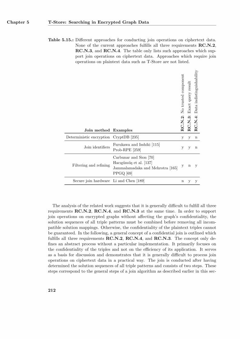
Chapter 5 T-Store: Searching in Encrypted Graph Data
Table 5.15.: Different approaches for conducting join operations on ciphertext data.None of the current approaches fulfills all three requirements RC.N.2,RC.N.3, and RC.N.4. The table only lists such approaches which sup-port join operations on ciphertext data. Approaches which require joinoperations on plaintext data such as T-Store are not listed.
Join method Examples RC
.N.2
:N
otr
ust
edco
mp
on
ent
RC
.N.3
:E
xact
qu
ery
resu
lt
RC
.N.4
:D
ata
ind
isti
ngu
ish
ab
ilit
y
Deterministic encryption CryptDB [235] y y n
Join identifiersFurukawa and Isshiki [115]
y y nProb-RPE [259]
Filtering and refining
Carbunar and Sion [70]
y n yHacıgumus et al. [137]
Jammalamadaka and Mehrotra [165]
PPGQ [69]
Secure join hardware Li and Chen [189] n y y
The analysis of the related work suggests that it is generally difficult to fulfill all threerequirements RC.N.2, RC.N.4, and RC.N.3 at the same time. In order to supportjoin operations on encrypted graphs without affecting the graph’s confidentiality, thesolution sequences of all triple patterns must be combined before removing all incom-patible solution mappings. Otherwise, the confidentiality of the plaintext triples cannotbe guaranteed. In the following, a general concept of a confidential join is outlined whichfulfills all three requirements RC.N.2, RC.N.4, and RC.N.3. The concept only de-fines an abstract process without a particular implementation. It primarily focuses onthe confidentiality of the triples and not on the efficiency of its application. It servesas a basis for discussion and demonstrates that it is generally difficult to process joinoperations on ciphertext data in a practical way. The join is conducted after havingdetermined the solution sequences of all triple patterns and consists of two steps. Thesesteps correspond to the general steps of a join algorithm as described earlier in this sec-
212
Evaluation and Comparison with Existing Approaches Section 5.10
tion. In order to protect the confidentiality of the plaintext triples, all solution sequencesare still encrypted. In the first step, a complete cross product of all solution sequencesis computed. This step does not distinguish between compatible and incompatible so-lution mappings and may produce many mappings which are not included in the finaljoin result. The result of this first step is also encrypted and does not reveal any infor-mation about the plaintext triples. In the second step, a decryption key is applied toeach combined solution mapping. The decryption must only be successful if the solutionmapping is a valid join result, i. e., if it contains compatible plaintext triples. Otherwise,the decryption must fail and must not reveal any information about the processed map-ping. The second step identifies all compatible solution mappings and creates the finaljoin result. In order to protect the plaintext graph’s confidentiality, it is necessary toprocess all solution mappings from the first step. Any optimization which only processesa subset of the solution mappings would directly contradict with requirement RC.N.3.
Although the outlined join process is generally possible, it is highly inefficient. If aquery with m ∈ N triple patterns is applied to a graph with n ∈ N triples, the runtimecomplexity of processing the query is O(nm) as each triple pattern may return n triplesat most. In worst case, nm decryption operations have to be conducted in order toretrieve the final join result. Although most SPARQL queries used in practice containless than four triple patterns [203, 14], applying a query with three triples patterns toa graph with 100, 000 triples still requires 1015 decryption operations. Even if a singledecryption operation required only 1 nanosecond to compute, processing 1015 decryptionoperations would still take about 11.5 days. Thus, a join operation based on the sketchedconcept is not practical unless the decryption itself is very efficient. However, finding asuitable encryption algorithm which is efficient even for larger graphs is very unlikely.On the other hand, any optimization of the concept would violate the confidentiality ofthe plaintext graph. In conclusion, it is currently almost impossible to provide a joinalgorithm which is both efficient and confidential at the same time.
5.9.5. Summary
Most approaches for searching in encrypted relational databases, encrypted XML docu-ments, and encrypted graphs can also be used for searching in encrypted RDF graphs.However, none of them fulfills all functional and non-functional requirements defined inSection 5.2. T-Store fulfills most of these requirements with RC.F.2 being the onlyexception. Fulfilling requirement RC.F.2 necessitates the ability to conduct join opera-tions on ciphertext graphs. As discussed in Section 5.9.4, some approaches support joinoperations at the expense of fulfilling other requirements. The section has also describedthe general difficulty of providing a join algorithm that can be applied to a ciphertextgraph directly and is still efficient enough to be used in practice. Therefore, developinga suitable compromise between efficiency and confidentiality is left for future work.
213
Chapter 5 T-Store: Searching in Encrypted Graph Data
5.10. Limitations and Future Extensions
As described in the previous section, T-Store fulfills most of the functional and non-functional requirements defined in Section 5.2. In addition to the identified drawbacks,T-Store has other limitations as well when querying encrypted RDF graphs. This sectionfirst outlines these limitations and describes their effect on the query process. After-wards, possible extensions of T-Store are discussed which may be added in the future.
5.10.1. Replacing the Combining Function %
As described in Section 5.7.6, T-Store is vulnerable to attack AC.4 and allows an at-tacker to compute a basic key from two authorization keys of the same query type. Theattack exploits the relationship of the two authorization keys and their construction viathe combining function %. In order to prevent the attack, the combining function mustbe replaced by a secure alternative. The alternative combining function must share thesame features as the current function which is defined in Equation 5.19. In particular,the alternative combining function must satisfy the following conditions:
%(b, {}) = b, ∀b ∈ {0, 1}∗ (5.70)
%(b, {b1, b2}) = %(%(b, {b1}), {b2}), ∀b, b1, b2 ∈ {0, 1}∗ (5.71)
%(%(b, {b1}), {b2}) = %(%(b, {b2}), {b1}), ∀b, b1, b2 ∈ {0, 1}∗ (5.72)
These conditions cover the arithmetic capabilities of the combining function which areused by T-Store to create authorization keys ak from basic keys bk and to create querykeys qk from authorization keys. As long as a function fulfills these conditions, it canbe used with T-Store without changing anything else of the approach. In addition, thecombining function must also prevent the attacks AC.3, AC.4, and AC.5 as describedin Section 5.7. This can be achieved by choosing a combining function % which makesit difficult for an attacker to determine b when given b1 and b2 with %(b, {b1}) = b2 andb, b1, b2 ∈ {0, 1}∗. Finding a suitable combining function which prevents the attacks andfulfills the three conditions of Equations 5.70 to 5.72 is left for future work.
5.10.2. Query Results with Blank Nodes
An RDF graph represents blank nodes as blank node identifiers. The scope of theseidentifiers is restricted to a particular graph, i. e., the same identifier can be used inother graphs as well and refers to another blank node. Applying a SPARQL query to aplaintext RDF graph may produce a query result with blank node identifiers. In this case,the scope of the identifiers is restricted to the query result and the identifiers in the queryresult are independent from the blank node identifiers in the queried graph [140]. T-Store also supports blank node identifiers in query results. However, these identifiers areidentical to the blank node identifiers in the queried graph and refer to the same blanknodes. This may reveal more information about the plaintext graph and its internalstructure than the data owner has indented. It allows an authorized user to relatedifferent query results to each other by analyzing their common blank node identifiers.
214
Limitations and Future Extensions Section 5.10
Such a relation is not necessary possible when applying a SPARQL query to a plaintextgraph.
5.10.3. Distributing Authorization Keys
Users are allowed to apply queries to ciphertext graphs by receiving authorization keysfrom the data owner. The secure distribution of authorization keys is therefore crucialto ensure the confidentiality of a plaintext graph. Distributing the keys requires a securecommunication channel between an authorized user and the data owner which ensuresthat the transmitted keys cannot be intercepted by any party. In addition, the dataowner should verify the identity of a user before sending an authorization key. A publickey certificate can be used for both creating the secure communication channel and forverifying the user’s identity. It provides a mapping from a public key to its owner andis managed by a public key infrastructure (PKI). Further information about PKIs isprovided in Section 4.9.4. For example, the data owner could apply a user’s public keycertificate to send an authorization key via an encrypted e-mail. Possible standards fore-mail encryption are S/MIME [245] and PGP [320]. Transmitting an authorization keyin an encrypted e-mail by using a verified public key certificate ensures that only thelegitimate owner of the certificate can access the key.
Even a secure communication channel cannot prevent a user from forwarding autho-rization keys to other parties. Forwarding such keys circumvents the data owner’s queryauthorizations and affects the confidentiality of the plaintext graph. T-Store does notprohibit the re-distribution of authorization keys as they are not bound to individualusers. Instead, an authorization key which encodes a specific restriction pattern is iden-tical for all users. If several users have access to the same key and the key is sent toanother party, the data owner cannot identify the malicious user. In order to detect theuser, the data owner could create a different ciphertext graph with different basic keysfor each authorized user. Although this does not prevent a user from both forwardingauthorization keys together with the ciphertext graph, the data owner is at least able todetermine the malicious user. However, using different keys for each user increases thenumber of keys that the data owner must manage.
5.10.4. Refining Query Authorizations
Query authorization in T-Store is currently restricted to distributing individual autho-rization keys to users. An authorization key defines the basic matching conditions of asingle SPARQL triple pattern. However, as described in Section 5.1.4, SPARQL queriesare more complex and do not only consist of a single triple pattern. Instead, they have aquery algebra with an arbitrary number of triple patterns and a query form that definesthe format of the query result. Consequently, when authorizing a user to apply queriesto a ciphertext graph, the data owner should be able to precisely define the completeSPARQL query that is being authorized. In particular, the data owner should be ableto specify all triple keys of a query algebra as well as a corresponding query form in sucha way that all triple keys and the query form can only be used in combination with each
215
Chapter 5 T-Store: Searching in Encrypted Graph Data
other. I. e., it must not be possible for a user to extract a triple key from one authorizedquery and include it in another query or to replace the query form of an authorizedquery with an alternative query form.
In order to support more precise query authorizations, the authorization mechanismof T-Store must be further improved. This includes the implementation and enforcementof join operations as described in Section 5.9.4 as well as the enforcement of query forms.Enforcing join operations prevents an authorized user from applying an individual triplekey to a ciphertext graph without applying the other triple keys of the query as well. Thisprohibits the user from receiving any temporary query results. Enforcing a query formensures that the query result does not provide any more information about the plaintexttriples than the data owner has originally intended. For example, the query form ofa SELECT query may only return the variable bindings of a single query variable andhide the bindings of all other variables that are defined in the triple keys. In summary,enforcing join operations and query forms ensures that a user can only apply a query toa ciphertext graph if this exact query has been authorized by the data owner.
5.10.5. Revoking Basic Keys and Ciphertexts
The data owner uses eight different basic keys for creating a ciphertext graph which iseither published on the web or sent to all authorized users. If a basic key is compromised,it should be revoked since the confidentiality of the plaintext graph can no longer beguaranteed. In addition, the ciphertext graph should be revoked as well since the dataowner can no longer manage the parties who apply queries to it. However, T-Store doesnot support the revocation of basic keys or ciphertext graphs. Once a ciphertext graphhas been made available, it can no longer be revoked. Since basic keys are bound to aparticular ciphertext graph, they cannot be revoked as well or replaced with new keys. Ingeneral, any offline approach for searching in encrypted data suffers from this drawbackas it does not use a central system which regulates all access to the ciphertext data. Incontrast, online approaches such as CryptDB [235], Prob-RPE [259], and Y. Yang etal. [315] support the revocation of query authorizations but require a central server forstoring the data. To circumvent the problem of key revocation, both the data owner andall authorized users must ensure that their key material is safe and cannot be accessedby any unauthorized party.
5.10.6. Additional Support for the SPARQL Algebra
The current design of T-Store only supports a small fragment of the SPARQL alge-bra [140] and is limited to matching triple patterns against a ciphertext graph. However,SPARQL also provides additional features such as filters, solution sequence modifiers,and aggregates. A filter applies a boolean expression to each solution mapping of asolution sequence and removes all mappings which do not match the expression. Filtersallow, e. g., value comparisons, type checking, and regular expressions. They can be in-tegrated into T-Store by using functional encryption [43] which supports the applicationof arbitrary functions to ciphertext data. Solution sequence modifiers are evaluated on
216
Summary Section 5.11
all solution mappings of a solution sequence and affect the whole sequence. An examplemodifier is ORDER BY which sorts all solution mappings in ascending or descending order.Applying this modifier requires order-preserving encryption which ensures that the orderof the ciphertexts is the same as the order of their corresponding plaintexts. To sup-port ORDER BY, T-Store can be combined with approaches which use order-preservingencryption such as [304, 137]. Aggregates apply aggregation functions to all solutionmappings of a solution sequence. Example aggregates are SUM, which adds up numericalliterals, and AVG, which computes the mean value of such literals. Both aggregates canbe supported by integrating approaches for homomorphic encryption [111] into T-Store.Example approaches which support aggregates on ciphertext data include [76, 126].
5.11. Summary
This chapter has presented T-Store, an approach for applying SPARQL queries to en-crypted RDF graphs. A plaintext graph is encrypted by a data owner who authorizesdifferent users to apply queries to the resulting ciphertext graph. T-Store supports querytemplates which represent sets of similar queries sharing the same query parameters. In-stead of authorizing each query individually, the data owner can use a query templateand allow a user to define the remaining query parameters herself. T-Store limits thecommunication between the data owner and an authorized user to a minimum and allowsthe user to conduct the query processing offline on her local system. Query processing issolely based on conducting cryptographic operations on the ciphertext graph and doesnot need a trusted computing device at the user’s side. Query results are exact anddo not require any post-processing conducted by the user. Apart from an authorizeduser, all other parties are prohibited from accessing any plaintext triples of the queriedgraph. Thus, T-Store provides confidentiality of the graph and answers research ques-tion RQ.1. Although the approach fulfills most of its requirements, it still has somedrawbacks which may affect a graph’s confidentiality. Eliminating these drawbacks andenhancing T-Store with additional features is left for future work.
217

Chapter 6.
Conclusion
This thesis has presented three different security mechanisms for achieving secure Seman-tic Web data management. The mechanisms implement the four security requirementsconfidentiality, integrity, authenticity, and compliant availability of Semantic Web graphdata. The first security mechanism is InFO, a policy language for regulating infor-mation flow in open and distributed networks. A policy defines the conditions underwhich Semantic Web data is accessible and contains all details for technically enforc-ing them. InFO implements compliant availability of Semantic Web data and answersresearch question RQ.4. The second security mechanism is Siggi, a formal frameworkfor digitally signing arbitrary Semantic Web graphs. A graph’s signature is invalidatedif the graph is modified by an unauthorized party. This affects the graph’s integrityand authenticity since its original creator has not approved of the modifications. Thus,Siggi implements integrity and authenticity of Semantic Web data and answers researchquestions RQ.2 and RQ.3. The third security mechanism is T-Store, an approach forsearching in encrypted Semantic Web data. Only authorized parties are able to accessparticular triples of a plaintext graph by applying queries to its corresponding ciphertextgraph. At the same time, all other triples remain inaccessible. Thus, T-Store implementsconfidentiality of Semantic Web graphs and answers research question RQ.1. The restof this chapter describes how the three security mechanisms are used for implementingthe scenarios presented in Chapter 2, summarizes their main contributions, and outlinespossible future work.
6.1. Implementing the Scenarios
The scenario for regulating Internet communication defined in Section 2.1 involves differ-ent authorities which create regulation policies and distribute them between each other.The policies are created with InFO and describe allowed and prohibited communicationflow. In order to ensure the integrity and authenticity of a policy when transmitting it toanother authority, each policy is signed by its creator using the graph signing frameworkSiggi. InFO policies are enforced by different communication systems which maintain alog database of all regulated transmissions. The log database is encrypted with T-Storein order to protect the log entries’ confidentiality and to ensure that only authorizedparties can retrieve particular entries. The scenario for securing medical data records in
219
Chapter 6 Conclusion
electronic healthcare is covered in Section 2.2 and focuses on a patient who manages herown medical records. These records are encrypted with T-Store in order to ensure theirconfidentiality. Only medical professionals can access specific records after being autho-rized by the patient. In addition to the patient’s medical records, medical professionalscreate medical records as well which are transmitted between different medical institu-tions. Before transmitting a medical record, it is signed with Siggi in order to ensurethe record’s integrity and authenticity and prevent it from any unauthorized modifica-tions. InFO is used to ensure that the signed records are only sent to other medicalinstitutions via an encrypted communication channel. At the same time, InFO blocksany other transmission of medical records.
6.2. Summary of the Main Contributions
InFO, Siggi, and T-Store achieve confidentiality, integrity, authenticity, and compliantavailability of Semantic Web data in open and distributed networks such as the Internet.Such networks are not regulated by a single authority which defines specific restrictionson the network’s components and usage. Instead, they have a heterogeneous environmentwith different computer systems and data formats. InFO is designed for creating policieswhich are implemented in networks without a central regulatory authority. In contrast toother policy language, InFO policies can be enforced by various communication systemssuch as application-level proxy severs, name servers, and routers. This allows it toapply InFO policies directly to the Internet without requiring any specific regulationsystems. InFO’s modular and extensible design allows it to support additional enforcingsystems as well. An InFO policy is enriched by human-readable background informationwhich covers the policy’s organizational motivation and its legal justification. In orderto precisely describe such information, InFO allows to integrate different legal ontologieswhich provide a rich vocabulary for various legal scenarios. Although some other policylanguages also allow organizational background information to be included into a policyas well, their support for legal information is very limited. InFO supports a conflictresolution mechanism for resolving conflicts of contradicting rules within one or morepolicies. This is especially important in open and distributed networks in which policiesare created by different authorities with different intentions.
Siggi defines a generic signature pipeline which can be configured with various algo-rithms to achieve different features. The generic design of the pipeline also supportsthe creation of new algorithms by adopting the framework’s formal specification. Theflexible configurability of Siggi allows it to be used in heterogeneous environments wherethere is no standard set of algorithms that are used by all authorities. Instead, each au-thority may use its own configuration of the framework. Siggi supports iterative signingof graph data by signing already signed data again. This can be used for provenancetracking in which each party receives a signed graph, signs it again, and sends it to thenext party. A signature created with Siggi only covers a signed graph’s semantics andnot its syntax. Therefore, the signature does not rely on a particular serialization of thegraph and is still valid after re-encoding the graph with a different serialization format.
220
Outlook and Future Work Section 6.3
For this reason, the signature is permanently attached to the signed data and does notrely on a secure communication channel. The signature value can be accompanied withadditional metadata which further describes its creation such the date and time thegraph was signed or the name of the signing party.
T-Store distinguishes between a data owner who encrypts a plaintext graph and au-thorized users who perform queries on the resulting ciphertext graph. The approachrequires only little communication between the data owner and a user. Instead of au-thorizing each query individually, similar queries can be combined into query templates.A query template is an incomplete query which must be further specified by an autho-rized user with additional query parameters before applying it to the ciphertext graph.Query processing is conducted offline by the user without involving any online systemor a trusted system located at the user’s side.
The main contributions of this thesis are available online at https://github.com/
akasten/. InFO is provided as a set of OWL ontologies which also include the threedomain ontologies for application-level proxy severs, name servers, and routers. In addi-tion, the mapping ontologies of the legal ontologies and the content classification schemes,which are further described in Appendix B, are available as well. Siggi is available asthe source code of its prototypical Java implementation which covers both the genericsigning framework and the four example configurations discussed in Section 4.4. Fur-thermore, the signature ontology which is used by the assembly function of Siggi andfurther described in Appendix C is also provided. T-Store is available as the source codeof its two prototypical Java implementations which cover the two variants T-Store BSCand T-Store NDX. In addition, the SPARQL queries used for evaluating the two variantsas described in Section 5.6.1 as well as the extended log format ontology, which is usedin the scenario of T-Store and further described in Appendix D, are also available.
6.3. Outlook and Future Work
All three security mechanisms have been prototypically implemented, applied to twoexample scenarios, and evaluated against their respective requirements. However, allthree mechanisms can still be improved and further analyzed. InFO can be evaluatedby simulating a large computer network with several different communication end nodessuch as web servers and client systems as well as intermediary communication nodeslike routers and application-level proxy servers. The intermediary nodes can be usedas enforcing systems to implement different regulation policies. Such a simulation canassess the scalability of InFO policies and its enforcing systems in a larger network.In addition, it can provide general insights into large scaled network regulations andpossible side-effects. Siggi can be used as a basis to provide various applications forsecuring integrity and authenticity of Semantic Web graphs. An example applicationis provenance tracking of signed graph data which allows it to trace the graph’s pathalong different authorities. Furthermore, Siggi can be used for applications which aim atproviding trust between different interacting parties. Finally, the framework can also beintegrated into ontology editors to provide permanent signatures for the created graph
221
Chapter 6 Conclusion
data. Similar to Siggi, T-Store can also be used as a foundation to provide differentapplications for securing Semantic Web data. Example applications are outlined in thisthesis and cover an encrypted log database and a confidential storage for medical records.In addition, T-Store’s prototypical implementation can be further extended to create ageneric triple store which supports arbitrary SPARQL queries on encrypted graphs andrestricts access to particular triples to authorized users only.
222
Appendix A.
Algorithms and Domain Ontologies of theInFO Policy Language
This appendix provides additional details on the InFO policy language which is describedin Chapter 3. In particular, it describes different algorithms for resolving conflicts be-tween two or more flow control rules. These algorithms are generic and can be usedwithin different application domains. Thus, they are part of InFO’s Technical Regula-tion patterns. Apart from these algorithms, this appendix also provides further detailson the three domain-specific extensions for implementing InFO policies on routers, nameservers, and proxy servers. These details cover specific flow control rules as well as ad-ditional algorithms for resolving conflicts.
A.1. Generic Algorithms for Resolving Conflicts
The Technical Regulation of InFO defines six different types of algorithms for resolvingconflicts between flow control rules of one or more flow control policies. The conflicts aredistinguished between modality conflicts and application specific conflicts [192]. Modal-ity conflicts exist between two flow control rules if one rule allows a particular communi-cation flow and the other rule prohibits it. In contrast, application specific conflicts existbetween an enforcing system and any flow control rule which cannot be completely inter-preted by this enforcing system. The algorithms of the Technical Regulation are used inthe Flow Control Policy Pattern described in Section 3.3.4 and in the Flow Control Meta-Policy Pattern described in Section 3.3.5. They are part of a flow control policy or a flowcontrol meta-policy. The different types of algorithms are represented by the classes Lo-calNonApplicabilityAlgorithm, LocalConflictResolutionAlgorithm, GlobalNon-ApplicabilityAlgorithm, GlobalConflictResolutionAlgorithm, RulePriorityAl-gorithm, and PolicyPriorityAlgorithm. Particular algorithms are modeled as sub-classes of these generic classes. In order to better distinguish between the different al-gorithms and to avoid name clashes, each type of algorithm is associated with a uniquenamespace. All algorithms are evaluated by the enforcing system which implementsthe flow control regulation. The detailed process of resolving conflicts is described inSection 3.3.5.
223
Appendix A Algorithms and Domain Ontologies of the InFO Policy Language
A LocalNonApplicabilityAlgorithm solves application-specific conflicts within asingle flow control policy. The Technical Regulation of InFO defines the class Discard-NonApplicableRuleAlgorithm as a particular instance of such an algorithm. The algo-rithm removes all flow control rules from the policy which cannot be interpreted by thepolicy’s enforcing system. Other algorithms for resolving application-specific conflicts ofa single policy are not provided. However, it is also possible to add new algorithms dueto InFO’s open design. GlobalNonApplicabilityAlgorithms solve application-specificconflicts of one or more flow control policies. Particular instances are DiscardNonAp-
plicableRuleAlgorithm and DiscardNonApplicablePolicyAlgorithm. The first al-gorithm has the same semantics as its local counterpart1 and removes all conflicting ruleswhile leaving all other rules intact. On the other hand, the second algorithm removesall policies which contain at least one conflicting rule.
LocalConflictResolutionAlgorithms resolve modality conflicts between contradict-ing flow control rules of the same policy. InFO’s Technical Regulation provides the classDiscardConflictingRulesAlgorithm as an example of such algorithms. The algo-rithm resolves modality conflicts by removing all affected rules from a policy. Similarly,algorithms of type GlobalConflictResolutionAlgorithm resolve modality conflicts be-tween contradicting flow control rules of the one or more policies. Specific algorithmsare DiscardAffectedRulesAlgorithm and DiscardAffectedPoliciesAlgorithm. Thefirst algorithm removes all conflicting rules and leaves all other rules intact while thesecond algorithm removes all policies which contain at least one conflicting rule.
PolicyPriorityAlgorithms define the order of evaluating different flow control poli-cies by the same enforcing system. PreferLatestPolicyAlgorithm states that newerpolicies must be preferred to older policies and PreferOldestPolicyAlgorithm prefersolder policies instead of newer policies. The algorithm EvaluatePolicyOrderingAlgo-
rithm requires an explicit order between policies with the properties follows and/orprecedes and states that this order shall be evaluated. Similarly, RulePriorityAlgo-rithms define the order of evaluating the rules of a particular policy. EvaluateRuleOr-deringAlgorithm requires an explicit order between the rules and evaluates this order.
A.2. Details of the Router Ontology
The Router Ontology is a domain-specific extension of the InFO policy language forrouters. It provides several concepts and axioms for describing flow control policieswhich shall be enforced by these network nodes. The concepts cover router-specific flowcontrol rules and rule priority algorithms. New patterns are not defined in the ontology.
A.2.1. Flow Control Rules
The Router Ontology refines the generic allowing flow control rule and the denying flowcontrol rule of the Flow Control Rule Pattern and the redirecting flow control rule of
1Please note that both algorithms share the same local name but have different URIs. Therefore, theirfully qualified name is unique and name clashes are prevented.
224
Details of the Router Ontology Section A.2
the Redirecting Flow Control Rule Pattern with router-specific concepts. Each of therefined rules requires a router as its enforcing system and may also require additionalparameters. An allowing flow control rule explicitly allows a sender to communicate witha receiver. Further refinements of the generic class AllowingFlowControlRuleMethod
define how the sender and receiver shall be identified. The Router Ontology defines thefollowing allowing flow control rules:
IPAddressAllowingRuleMethod
This rule explicitly permits a communication between a sender and a receiver basedon the IP addresses of the two systems. The rule requires at least one IP address.
PortNumberAllowingRuleMethod
This rule explicitly permits a communication between a sender and a receiver basedon the port numbers they use for establishing their communication channel. Aseach of the two communication systems choses their own port number, the portnumber is directly associated with each system and not with the communicationchannel. The rule requires at least one port number.
SocketAddressAllowingRuleMethod
This rule explicitly permits a communication between a sender and a receiver basedon their sockets of the communication channel. A socket address consists of an IPaddress and a port number. The rule requires at least one IP address and one portnumber which form the socket address.
TransportLayerProtocolAllowingRuleMethod
The rule explicitly permits a communication between a sender and a receiver basedon the transport layer protocol of their communication channel. Example transportlayer protocols are TCP and UDP. The rule requires at least one transport layerprotocol to be specified.
A denying flow control rule prevents a sender from communicating with a receiver.Further refinements of the generic class DenyingFlowControlRuleMethod define howthe sender and receiver shall be identified. The Router Ontology defines the followingdenying flow control rules:
IPAddressBlockingRuleMethod
This rule prohibits a communication between a sender and a receiver based ontheir IP addresses. The rule requires at least one IP address.
PortNumberBlockingRuleMethod
This rule prohibits a communication between a sender and a receiver based onthe port numbers they use for establishing their communication channel. The rulerequires at least one port number to be specified.
SocketAddressBlockingRuleMethod
This rule prohibits a communication between a sender and a receiver based onthe socket addresses which they use for establishing their communication channel.
225
Appendix A Algorithms and Domain Ontologies of the InFO Policy Language
The rule requires at least one IP address and one port number which form a socketaddress.
TransportLayerProtocolBlockingRuleMethod
This rule prohibits a communication between a sender and a receiver based on thetransport layer protocol of their communication channel. The rule requires at leastone transport layer protocol.
A redirecting flow control rule prevents a sender from communicating with a receiver byredirecting it to a different receiver. Further refinements of the generic class Redirect-ingFlowControlRuleMethod define the parts of the original receiver’s address that shallbe replaced with other address information. The Router Ontology defines the followingredirecting flow control rules:
IPAddressRedirectingRuleMethod
This rule prohibits a communication between a sender and a receiver by redirectingthe sender to a different receiver with another IP address. The rule requires atleast one IP address as the redirection target.
PortNumberRedirectingRuleMethod
This rule prohibits a communication between a sender and a receiver by redirectingthe sender to a different receiver with another port number. The IP address of theoriginal receiver may stay the same. The rule requires at least one port number asthe redirection target.
SocketAddressRedirectingRuleMethod
This rule prohibits a communication between a sender and a receiver by redirectingthe sender to a different receiver with another IP address and another port number.The rule requires at least one IP address and one port number which form thesocket address of the redirection target.
A.2.2. RulePriorityAlgorithms
The Router Ontology defines two additional rule priority algorithms which can be usedtogether with the generic algorithms described in Appendix A.1. Other types of algo-rithms are not provided by the Router Ontology. The provided algorithms are Prefer-
ShortestSubnetMaskAlgorithm and PreferLongestSubnetMaskAlgorithm which areboth modeled as subclasses of RulePriorityAlgorithm. The two algorithms operateon network addresses and thus only affect flow control rules which regulate the access tocomputer networks. Single network systems such as clients and servers are not affected.The first algorithm sorts all flow control rules in ascending order according to the subnetmask of the regulated network’s IP address. The first element in the resulting order hasthe shortest subnet mask. The shorter the subnet mask of a computer network is, themore nodes the network contains. Thus, the algorithm prefers flow control rules whichcover larger computer networks to such rules which regulate access to smaller networks.The second algorithm is inverse to the first algorithm. It also sorts all flow control rules
226
Details of the Name Server Ontology Section A.3
in descending order according to the subnet mask of the regulated network. However,the algorithm prefers longer subnet masks and thus smaller networks.
A.3. Details of the Name Server Ontology
The Name Server Ontology is a domain-specific extension of the InFO policy language forname servers. It provides several concepts and axioms for describing flow control policieswhich shall be enforced by such systems. The concepts cover name server-specific flowcontrol rules and rule priority algorithms. New patterns are not defined in the ontology.The flow control rules and algorithms of the Name Server Ontology operate on domainsand domain names. A domain is a hierarchically organized tree in the domain namesystem and consists of several domain names. Each domain name corresponds to anindividual nodes in the tree. Domains are associated with computer networks whileindividual domain names represent single computer systems. A domain is identified bya domain name which corresponds to the root node of the tree.
A.3.1. Flow Control Rules
The Name Server Ontology refines the generic allowing flow control rule and the denyingflow control rule of the Flow Control Rule Pattern and the redirecting flow controlrule of the Redirecting Flow Control Rule Pattern with name server-specific concepts.Each of the refined rules requires a name server as its enforcing system and may alsorequire additional parameters. An allowing flow control rule explicitly allows a sender tocommunicate with a receiver. Further refinements of the generic class AllowingFlow-
ControlRuleMethod define how the sender and receiver shall be identified. The NameServer Ontology defines the following allowing flow control rules:
DomainAllowingRuleMethod
This rule explicitly permits a communication between a sender and a receiverbased on their domains. The rule requires at least one domain name which is thedomain’s root node.
DomainNameAllowingRuleMethod
This rule explicitly permits a communication between a sender and a receiver basedon their domain names. The rule requires at least one domain name.
A denying flow control rule prevents a sender from communicating with a receiver.Further refinements of the generic class DenyingFlowControlRuleMethod define how thesender and receiver shall be identified. The Name Server Ontology defines the followingdenying flow control rules:
DomainBlockingRuleMethod
This rule prohibits a communication between a sender and a receiver based ontheir domains. The rule requires at least one domain name which corresponds tothe domain’s root node.
227
Appendix A Algorithms and Domain Ontologies of the InFO Policy Language
DomainNameBlockingRuleMethod
This rule prohibits a communication between a sender and a receiver based ontheir domain names. The rule requires at least one domain name.
A redirecting flow control rule prevents a sender from communicating with a receiver byredirecting to a different receiver. Further refinements of the generic class Redirect-
ingFlowControlRuleMethod define the parts of the original receiver’s domain or domainname that shall be replaced with other address information. The Name Server Ontologydefines the following redirecting flow control rules:
DomainRedirectingRuleMethod
This rule prohibits a communication between a sender and a receiver by redirectingthe sender to a different domain. The original receiver is identified by its domainwhich is represented by the domain name of its root node. Apart from this domainname, the rule also requires another domain name which identifies the domain usedas the redirection target.
DomainNameRedirectingRuleMethod
This rule prohibits a communication between a sender and a receiver by redirectingthe sender to a different domain name. The original receiver is identified by itsdomain name. Apart from this domain name, the rule also requires another domainname which is used as the redirection target.
A.3.2. RulePriorityAlgorithms
The Name Server Ontology extends the set of generic rule priority algorithms describedin Appendix A.1 with four additional algorithms. Other types of algorithms are notprovided. The ontology provides the following rule priority algorithms:
PreferDomainNameToDomainAlgorithm
This algorithm states that flow control rules regulating domains names shall bepreferred to such rules which cover whole domains. Thus, the algorithms prefersrules which regulate the access to single computer systems to such rules whichcover whole networks.
PreferDomainToDomainNameAlgorithm
This algorithm states that flow control rules regulating whole domains shall bepreferred to such rules which cover single domain names. Thus, the algorithmprefers rules which regulate the access to computer networks. Using this algorithmis not recommended as it may lead to overblocking by discarding more precise flowcontrol rules. It is mainly included in the Name Server Ontology for reasons ofcompleteness.
PreferLongestDomainNameAlgorithm
This algorithm sorts all flow control rules which are based on domain names indescending order according to the length of their domain name. Thus, the first
228
Details of the Application-Level Proxy Ontology Section A.4
rule of the resulting order has the longest domain name. The length of a domainname is measured by the number of labels it contains. A label corresponds to thestring between two dots in a domain name. The algorithm basically prefers moreprecise rules which affect less computer systems.
PreferShortestDomainNameAlgorithm
This algorithm sorts all flow control rules which are based on domain names inascending order according to the length of their domain name. Thus, the first ruleof the resulting order has the shortest domain name. This algorithm essentiallyprefers more imprecise rules which affect more computer systems. Using this al-gorithm is not recommended as it may lead to overblocking. It is included in theName Server Ontology for reasons of completeness.
A.4. Details of the Application-Level Proxy Ontology
The Application-Level Proxy Ontology is a domain-specific extension of the InFO policylanguage for proxy servers. It provides several concepts and axioms for describing flowcontrol policies which shall be enforced by these servers. The concepts cover proxyserver-specific flow control rules and rule priority algorithms. The ontology also definesa new pattern for describing denying flow control rules which modify the original content.
A.4.1. Flow Control Rules
The Application-Level Proxy Ontology refines the generic allowing flow control ruleand the denying flow control rule of the Flow Control Rule Pattern and the replacingflow control rule of the Replacing Flow Control Rule Pattern with proxy server-specificconcepts. Each of the refined rules requires a proxy server as its enforcing system andmay also require additional parameters. Furthermore, the ontology also introduces theContent Modifying Rule Pattern as a specialization of the Flow Control Rule Pattern.An allowing flow control rule explicitly allows a sender to communicate with a receiverby transmitting content via a channel. Further refinements of the generic class Allow-
ingFlowControlRuleMethod define how the transmitted content shall be identified. TheApplication-Level Proxy Ontology defines the following allowing flow control rules:
URLAllowingRuleMethod
This rule explicitly permits the transmission of content that is identified by itsURL. The rule requires at least one URL.
HashValueAllowingRuleMethod
This rule explicitly permits the transmission of content that is identified by itshash value. The rule may be used for regulating access to content independentfrom its URL. Even if the same content is provided at different URLs, its hashvalue remains the same. Thus, this rule is more robust than rules based on URLs.The rule requires at least one hash value.
229
Appendix A Algorithms and Domain Ontologies of the InFO Policy Language
FileExtensionAllowingRuleMethod
This rule explicitly permits the transmission of content based on its file extension.Example file extensions are .jpg for JPEG images and .mp3 for MP3 audio files.The rule requires at least one file extension.
MIMETypeAllowingRuleMethod
This rule explicitly permits the transmission of content based on its MIME type.A MIME type [112] consists of a type and a subtype and can be used for describingthe format of a file. Example MIME types are image/jpeg for JPEG images andaudio/mp3 for MP3 audio files. The rule requires at least one MIME type.
A denying flow control rule prohibits the transmission of content between a sender and areceiver. Further refinements of the generic class DenyingFlowControlRuleMethod de-fine how transmitted content shall be identified. The Application-Level Proxy Ontologydefines the following denying flow control rules:
URLBlockingRuleMethod
This rule prohibits the transmission of content that is identified by its URL. Therule requires at least one URL.
Hash value blocking RuleMethod
This rule prohibits the transmission of content that is identified by its hash value.The rule requires at least one hash value.
FileExtensionBlockingRuleMethod
This rule prohibits the transmission of content based on its file extension. Therule requires at least one file extension.
MIMETypeBlockingRuleMethod
This rule prohibits the transmission of content based on its MIME type. The rulerequires at least one MIME type.
A replacing flow control rule prohibits the transmission of content between a senderand a receiver by exchanging the original content with other content. The Application-Level Proxy Ontology defines the class FileReplacingRuleMethod as a subclass of thegeneric class ReplacingFlowControlRuleMethod. The rule prohibits the transmissionof the original content by replacing the file to be transmitted with a different, predefinedfile. This file is fixed and must exist before the rule is applied. The rule may be used forreplacing certain images with another image providing an explanation for the reasons ofthe image blocking. Other rules for replacing the transmitted content are not providedby the Application-Level Proxy Ontology. However, the ontology also defines a pat-tern for modifying the original content to be transmitted. This pattern is the ContentModifying Rule Pattern which is depicted in Figure A.1. The pattern allows to deny aparticular communication flow by modifying the original content with a specified modifi-cation algorithm. In contrast to the FileReplacingRuleMethod, a content modificationrule does not use a predefined file as the replacement target. Instead, it requires the
230
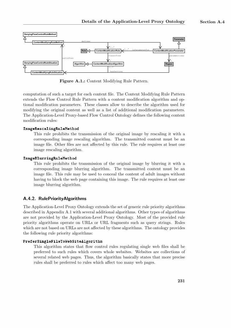
Details of the Application-Level Proxy Ontology Section A.4
parametrizes
1
ContentModificationRole
classifies
1
ContentModifyingRuleMethod
ContentModifyingRuleSituation
satisfies
1
Region
defines
1..*
hasSetting
ContentModificationParameterisParameterFor1..*Role
DenyingFlowControlRuleMethod
DenyingFlowControlRuleSituation
Parameter
1..*
ContentModificationAlgorithmAlgorithm
Figure A.1.: Content Modifying Rule Pattern.
computation of such a target for each content file. The Content Modifying Rule Patternextends the Flow Control Rule Pattern with a content modification algorithm and op-tional modification parameters. These classes allow to describe the algorithm used formodifying the original content as well as a list of additional modification parameters.The Application-Level Proxy-based Flow Control Ontology defines the following contentmodification rules:
ImageRescalingRuleMethod
This rule prohibits the transmission of the original image by rescaling it with acorresponding image rescaling algorithm. The transmitted content must be animage file. Other files are not affected by this rule. The rule requires at least oneimage rescaling algorithm.
ImageBlurringRuleMethod
This rule prohibits the transmission of the original image by blurring it with acorresponding image blurring algorithm. The transmitted content must be animage file. This rule may be used to conceal the content of adult images withouthaving to block the web page containing this image. The rule requires at least oneimage blurring algorithm.
A.4.2. RulePriorityAlgorithms
The Application-Level Proxy Ontology extends the set of generic rule priority algorithmsdescribed in Appendix A.1 with several additional algorithms. Other types of algorithmsare not provided by the Application-Level Proxy Ontology. Most of the provided rulepriority algorithms operate on URLs or URL fragments such as query strings. Ruleswhich are not based on URLs are not affected by these algorithms. The ontology providesthe following rule priority algorithms:
PreferSingleFileToWebSiteAlgorithm
This algorithm states that flow control rules regulating single web files shall bepreferred to such rules which covers whole websites. Websites are collections ofseveral related web pages. Thus, the algorithm basically states that more preciserules shall be preferred to rules which affect too many web pages.
231
Appendix A Algorithms and Domain Ontologies of the InFO Policy Language
PreferWebSiteToSingleFileAlgorithm
This algorithm states that flow control rules regulating whole websites shall bepreferred to such rules which only covers single web files. This algorithm essentiallyprefers more imprecise rules which affect more web pages. Using this algorithmis not recommended as it may lead to overblocking. It is mainly included in theApplication-Level Proxy Ontology for reasons of completeness.
PreferLongestDomainNameAlgorithm
This algorithm sorts the flow control rules in descending order according to thelength of their URL’s domain name. Thus, the first rule of the resulting orderhas the longest domain name. The length of a domain name corresponds to thenumber of labels it contains. The algorithm basically prefers more precise ruleswhich affect less web pages. The algorithm is semantically equivalent with thealgorithm of the Name Server Ontology of the same name.
PreferShortestDomainNameAlgorithm
This algorithm sorts the flow control rules in ascending order according to thelength of their URL’s domain name. Thus, the first rule of the resulting orderhas the shortest domain name. This algorithm essentially prefers more impreciserules which affect more web pages. Using this algorithm is not recommended as itmay lead to overblocking. It is included in the Application-Level Proxy Ontologyfor reasons of completeness. The algorithm is semantically equivalent with thealgorithm of the Name Server Ontology of the same name.
PreferLongestPathAlgorithm
This algorithm sorts the flow control rules in descending order according to thelength of their URL’s local path. Thus, the first rule of the resulting order has thelongest path. The length of a path corresponds to the number of directory sectionsit contains. The algorithm basically prefers more precise rules which affect less webpages.
PreferShortestPathAlgorithm
This algorithm sorts the flow control rules in ascending order according to thelength of their URL’s local path. Thus, the first rule of the resulting order hasthe shortest path. The algorithm essentially prefers more imprecise rules whichaffect more web pages. Using this algorithm is not recommended as it may lead tooverblocking. It is included in the Application-Level Proxy Ontology for reasonsof completeness.
PreferLongestQueryStringAlgorithm
This algorithm sorts the flow control rules in descending order according to thelength of their URL’s query string. Thus, the first rule of the resulting order hasthe longest query string. The length of a query string corresponds to the number ofquery parameters. The algorithm basically prefers more precise rules which affectless web content.
232
Details of the Application-Level Proxy Ontology Section A.4
PreferShortestQueryStringAlgorithm
This algorithm sorts the flow control rules in ascending order according to thelength of their URL’s query string. Thus, the first rule of the resulting order hasthe shortest query string. The algorithm essentially prefers more imprecise ruleswhich affect less web content. Using this algorithm is not recommended as it maylead to overblocking. It is included in the Application-Level Proxy Ontology forreasons of completeness.
233

Appendix B.
Integrating External Vocabulariesinto the InFO Policy Language
This appendix describes how legal ontologies and content labeling schemes are integratedinto the InFO policy language which is introduced in Chapter 3. InFO policies focus onthe technical implementation details for regulating information flow and associate themwith human-readable background information. This information can be further enrichedby integrating external legal ontologies and content labeling schemes into InFO whichsupport more elaborate descriptions. In particular, legal ontologies provide a vocabu-lary for annotating a flow control policy with its organizational motivation and legaljustification whereas content labeling schemes further describe the regulated content.
B.1. Integrating Legal Ontologies into InFO
This section describes how legal ontologies can be integrated into the InFO patternsystem. The discussed legal ontologies are the Core Legal Ontology (CLO) [123, 118]and the Legal Knowledge Interchange Format (LKIF) [146, 147]. The ontologies areintegrated by extending the patterns of the Legal Regulation and the OrganizationalRegulation of InFO as introduced in Section 3.3.6. These patterns are the Code ofConduct Pattern, the Flow Regulation Norm Pattern, and the Legislation Pattern. Theintegration of CLO and LKIF is implemented by using the mapping ontologies CLOMap-ping and LKIFMapping, respectively, as depicted in Figure 3.4. Each mapping ontologyimports the InFO patterns and the legal ontology to be integrated. It defines subclassand subproperty relationships between the concepts and properties of InFO and thelegal ontology. Where necessary, the mapping ontology also defines additional classesand properties as well as new ontology design patterns. The integration is conductedaccording to the general process described in Section 3.3.7.
B.1.1. Integrating the Core Legal Ontology
The Core Legal Ontology (CLO) [123, 118] is a legal core ontology which provides variousclasses, properties, and design patterns for modeling different legal aspects such as legaldocuments or legal norms. It is based on DOLCE+DnS Ultralite (DUL) [119] and
235
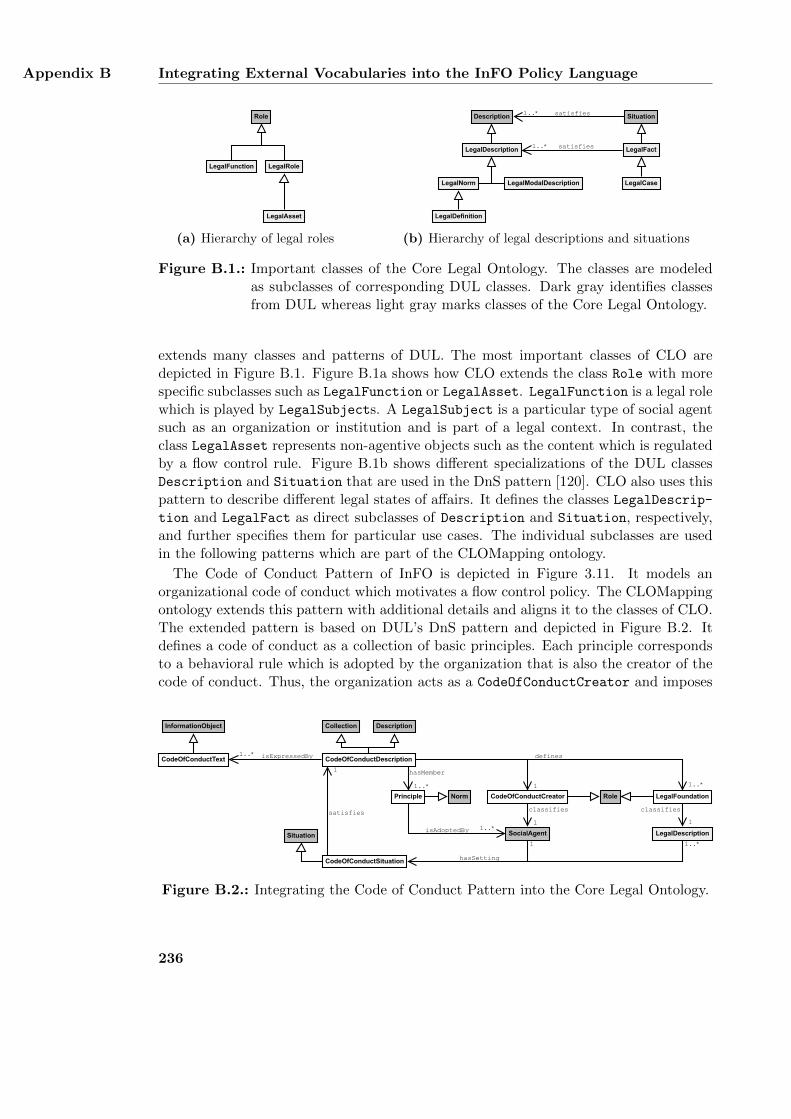
Appendix B Integrating External Vocabularies into the InFO Policy Language
LegalRoleLegalFunction
LegalAsset
Role
(a) Hierarchy of legal roles
LegalNorm
LegalFact
LegalCase
Situation
LegalModalDescription
LegalDescription
Description satisfies
satisfies
LegalDefinition
1..*
1..*
(b) Hierarchy of legal descriptions and situations
Figure B.1.: Important classes of the Core Legal Ontology. The classes are modeledas subclasses of corresponding DUL classes. Dark gray identifies classesfrom DUL whereas light gray marks classes of the Core Legal Ontology.
extends many classes and patterns of DUL. The most important classes of CLO aredepicted in Figure B.1. Figure B.1a shows how CLO extends the class Role with morespecific subclasses such as LegalFunction or LegalAsset. LegalFunction is a legal rolewhich is played by LegalSubjects. A LegalSubject is a particular type of social agentsuch as an organization or institution and is part of a legal context. In contrast, theclass LegalAsset represents non-agentive objects such as the content which is regulatedby a flow control rule. Figure B.1b shows different specializations of the DUL classesDescription and Situation that are used in the DnS pattern [120]. CLO also uses thispattern to describe different legal states of affairs. It defines the classes LegalDescrip-tion and LegalFact as direct subclasses of Description and Situation, respectively,and further specifies them for particular use cases. The individual subclasses are usedin the following patterns which are part of the CLOMapping ontology.
The Code of Conduct Pattern of InFO is depicted in Figure 3.11. It models anorganizational code of conduct which motivates a flow control policy. The CLOMappingontology extends this pattern with additional details and aligns it to the classes of CLO.The extended pattern is based on DUL’s DnS pattern and depicted in Figure B.2. Itdefines a code of conduct as a collection of basic principles. Each principle correspondsto a behavioral rule which is adopted by the organization that is also the creator of thecode of conduct. Thus, the organization acts as a CodeOfConductCreator and imposes
CodeOfConductText
Description
isExpressedBy1..*
Role
classifies
1
1
Collection
SocialAgent
CodeOfConductDescription
CodeOfConductCreator LegalFoundationPrinciple
hasMember
1..*
Norm
isAdoptedBy 1..*
defines
1..*
LegalDescription
classifies
CodeOfConductSituation
Situation1 1..*
satisfies
1
InformationObject
hasSetting
1
Figure B.2.: Integrating the Code of Conduct Pattern into the Core Legal Ontology.
236
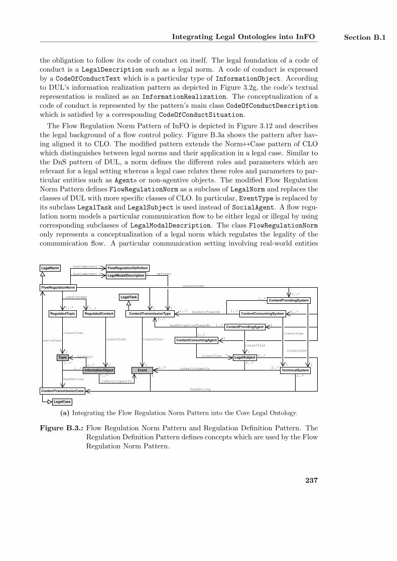
Integrating Legal Ontologies into InFO Section B.1
the obligation to follow its code of conduct on itself. The legal foundation of a code ofconduct is a LegalDescription such as a legal norm. A code of conduct is expressedby a CodeOfConductText which is a particular type of InformationObject. Accordingto DUL’s information realization pattern as depicted in Figure 3.2g, the code’s textualrepresentation is realized as an InformationRealization. The conceptualization of acode of conduct is represented by the pattern’s main class CodeOfConductDescriptionwhich is satisfied by a corresponding CodeOfConductSituation.
The Flow Regulation Norm Pattern of InFO is depicted in Figure 3.12 and describesthe legal background of a flow control policy. Figure B.3a shows the pattern after hav-ing aligned it to CLO. The modified pattern extends the Norm↔Case pattern of CLOwhich distinguishes between legal norms and their application in a legal case. Similar tothe DnS pattern of DUL, a norm defines the different roles and parameters which arerelevant for a legal setting whereas a legal case relates these roles and parameters to par-ticular entities such as Agents or non-agentive objects. The modified Flow RegulationNorm Pattern defines FlowRegulationNorm as a subclass of LegalNorm and replaces theclasses of DUL with more specific classes of CLO. In particular, EventType is replaced byits subclass LegalTask and LegalSubject is used instead of SocialAgent. A flow regu-lation norm models a particular communication flow to be either legal or illegal by usingcorresponding subclasses of LegalModalDescription. The class FlowRegulationNorm
only represents a conceptualization of a legal norm which regulates the legality of thecommunication flow. A particular communication setting involving real-world entities
ContentTransmissionCase
Topic
RegulatedTopic
classifies
1
usesConcept
1..*
satisfies
hasSetting
1..*
LegalNorm
hasTopic
1..*
classifies
1
1..*
1..*
classifies 1
1
1..*
classifies
1
1
1
isParticipantIn
InformationObject
RegulatedContent ContentTransmissionType
hasComponent
FlowRegulationNorm
LegalCase
1
2..*
Event
ContentProvidingSystem
hasSetting
hasDutyTowards 1..*1..*
hasObligationTowards
1..*
1..*
ContentConsumingAgent
ContentProvidingAgent
ContentConsumingSystem
2..*
isParticipantIn 2..*1..*TechnicalSystem
FlowRegulationDefinition
definesLegalModalDescription
LegalTask
LegalSubject
usesConcept
1..*
1
hasComponent 1
1
1
1..*
1..*
2..*
1
1..*
classifies
1
classifies
1
classifies
(a) Integrating the Flow Regulation Norm Pattern into the Core Legal Ontology.
Figure B.3.: Flow Regulation Norm Pattern and Regulation Definition Pattern. TheRegulation Definition Pattern defines concepts which are used by the FlowRegulation Norm Pattern.
237
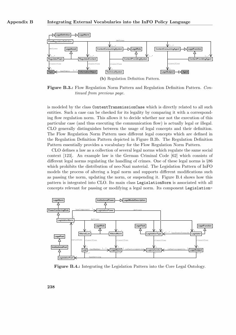
Appendix B Integrating External Vocabularies into the InFO Policy Language
LegalNorm
FlowRegulationDefinition
LegalDefinition
RegulatedTopic
LegalAsset LegalRole LegalFunction
Topic InformationObject
RegulatedContent
LegalSubject Agent
ContentProvidingSystem
ContentConsumingSystem
TechnicalSystem
ContentProvidingAgent
ContentConsumingAgentdefines
1..*
classifies
1hasTopic 1..*
1..*
classifies
1
1..*
classifies
1
1..*
defines
1..*
classifies
1
1..*
(b) Regulation Definition Pattern.
Figure B.3.: Flow Regulation Norm Pattern and Regulation Definition Pattern. Con-tinued from previous page.
is modeled by the class ContentTransmissionCase which is directly related to all suchentities. Such a case can be checked for its legality by comparing it with a correspond-ing flow regulation norm. This allows it to decide whether nor not the execution of thisparticular case (and thus executing the communication flow) is actually legal or illegal.CLO generally distinguishes between the usage of legal concepts and their definition.The Flow Regulation Norm Pattern uses different legal concepts which are defined inthe Regulation Definition Pattern depicted in Figure B.3b. The Regulation DefinitionPattern essentially provides a vocabulary for the Flow Regulation Norm Pattern.
CLO defines a law as a collection of several legal norms which regulate the same socialcontext [123]. An example law is the German Criminal Code [62] which consists ofdifferent legal norms regulating the handling of crimes. One of these legal norms is §86which prohibits the distribution of neo-Nazi material. The Legislation Pattern of InFOmodels the process of altering a legal norm and supports different modifications suchas passing the norm, updating the norm, or suspending it. Figure B.4 shows how thispattern is integrated into CLO. Its main class LegislationNorm is associated with allconcepts relevant for passing or modifying a legal norm. Its component Legislation-
LegislationFact
Law
AlteredLaw
classifies
1
defines
satisfies
1
hasSetting
PowerConferringRule
hasMember 1..*
classifies
1
1..*
1..*
Legislator
LegalSubject
classifies
1
1
1..*
classifies
1
1
1
hasPowerTowards1..*
isParticipantIn 1LegalNorm
AlteredNorm LegislationType
LegislationPowerhasComponent
1
1
LegislationNorm
LegislationAct
InstitutionalFact
defines
1
InstitutionalPower
LegalRole LegalTask LegalFunction
LegalNorm
LegalFact
LegalModalDescription
isParticipantIn1
1..*
1..*
Figure B.4.: Integrating the Legislation Pattern into the Core Legal Ontology.
238
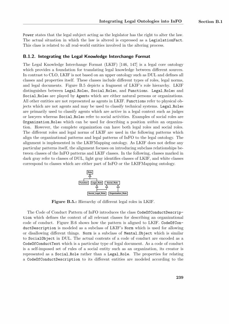
Integrating Legal Ontologies into InFO Section B.1
Power states that the legal subject acting as the legislator has the right to alter the law.The actual situation in which the law is altered is expressed as a LegislationFact.This class is related to all real-world entities involved in the altering process.
B.1.2. Integrating the Legal Knowledge Interchange Format
The Legal Knowledge Interchange Format (LKIF) [146, 147] is a legal core ontologywhich provides a foundation for translating legal knowledge between different sources.In contrast to CLO, LKIF is not based on an upper ontology such as DUL and defines allclasses and properties itself. These classes include different types of roles, legal norms,and legal documents. Figure B.5 depicts a fragment of LKIF’s role hierarchy. LKIFdistinguishes between Legal Roles, Social Roles, and Functions. Legal Roles andSocial Roles are played by Agents which are either natural persons or organizations.All other entities are not represented as agents in LKIF. Functions refer to physical ob-jects which are not agents and may be used to classify technical systems. Legal Rolesare primarily used to classify agents which are active in a legal context such as judgesor lawyers whereas Social Roles refer to social activities. Examples of social roles areOrganization Roles which can be used for describing a position within an organiza-tion. However, the complete organization can have both legal roles and social roles.The different roles and legal norms of LKIF are used in the following patterns whichalign the organizational patterns and legal patterns of InFO to the legal ontology. Thealignment is implemented in the LKIFMapping ontology. As LKIF does not define anyparticular patterns itself, the alignment focuses on introducing subclass relationships be-tween classes of the InFO patterns and LKIF classes. In the following, classes marked indark gray refer to classes of DUL, light gray identifies classes of LKIF, and white classescorrespond to classes which are either part of InFO or the LKIFMapping ontology.
Legal_RoleFunction
Social_Legal_Role
Role
Social_Role
Organisation_Role
Figure B.5.: Hierarchy of different legal roles in LKIF.
The Code of Conduct Pattern of InFO introduces the class CodeOfConductDescrip-
tion which defines the context of all relevant classes for describing an organizationalcode of conduct. Figure B.6 shows how the pattern is aligned to LKIF. CodeOfCon-ductDescription is modeled as a subclass of LKIF’s Norm which is used for allowingor disallowing different things. Norm is a subclass of Mental Object which is similarto SocialObject in DUL. The actual contents of a code of conduct are encoded as aCodeOfConductText which is a particular type of legal document. As a code of conductis a self-imposed set of rules of a social entity such as an organization, its creator isrepresented as a Social Role rather than a Legal Role. The properties for relatinga CodeOfConductDescription to its different entities are modeled according to the
239
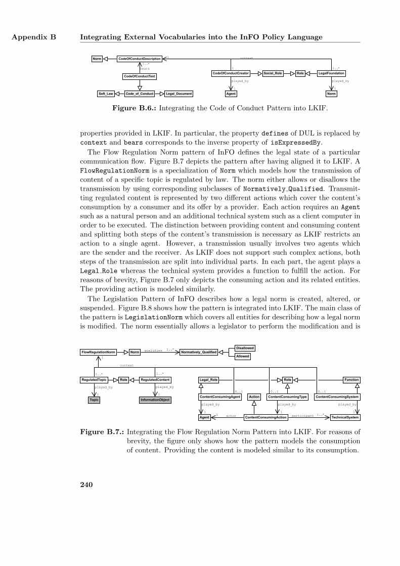
Appendix B Integrating External Vocabularies into the InFO Policy Language
CodeOfConductCreator LegalFoundation
CodeOfConductDescriptionNorm
Agent
played_by
1
Norm
played_by
1
1
1
context
1..*
Code_of_Conduct
bears
1..*
RoleSocial_Role
Soft_Law Legal_Document
CodeOfConductText
Figure B.6.: Integrating the Code of Conduct Pattern into LKIF.
properties provided in LKIF. In particular, the property defines of DUL is replaced bycontext and bears corresponds to the inverse property of isExpressedBy.
The Flow Regulation Norm pattern of InFO defines the legal state of a particularcommunication flow. Figure B.7 depicts the pattern after having aligned it to LKIF. AFlowRegulationNorm is a specialization of Norm which models how the transmission ofcontent of a specific topic is regulated by law. The norm either allows or disallows thetransmission by using corresponding subclasses of Normatively Qualified. Transmit-ting regulated content is represented by two different actions which cover the content’sconsumption by a consumer and its offer by a provider. Each action requires an Agent
such as a natural person and an additional technical system such as a client computer inorder to be executed. The distinction between providing content and consuming contentand splitting both steps of the content’s transmission is necessary as LKIF restricts anaction to a single agent. However, a transmission usually involves two agents whichare the sender and the receiver. As LKIF does not support such complex actions, bothsteps of the transmission are split into individual parts. In each part, the agent plays aLegal Role whereas the technical system provides a function to fulfill the action. Forreasons of brevity, Figure B.7 only depicts the consuming action and its related entities.The providing action is modeled similarly.
The Legislation Pattern of InFO describes how a legal norm is created, altered, orsuspended. Figure B.8 shows how the pattern is integrated into LKIF. The main class ofthe pattern is LegislationNorm which covers all entities for describing how a legal normis modified. The norm essentially allows a legislator to perform the modification and is
FlowRegulationNorm Norm Normatively_Qualifiedqualifies 1..*
Allowed
Disallowed
Role RegulatedContent
Topic
played_by
1
InformationObject
played_by
1
RegulatedTopic
ContentConsumingType
Role
ContentConsumingSystem
played_by
TechnicalSystem
ContentConsumingAgent
played_by
1
Agent ContentConsumingAction
Function
played_by
1actor1 participant 1..*
Legal_Role
1
1..*
context
1..*
Action
0..1 0..1 0..1
1
Figure B.7.: Integrating the Flow Regulation Norm Pattern into LKIF. For reasons ofbrevity, the figure only shows how the pattern models the consumptionof content. Providing the content is modeled similar to its consumption.
240
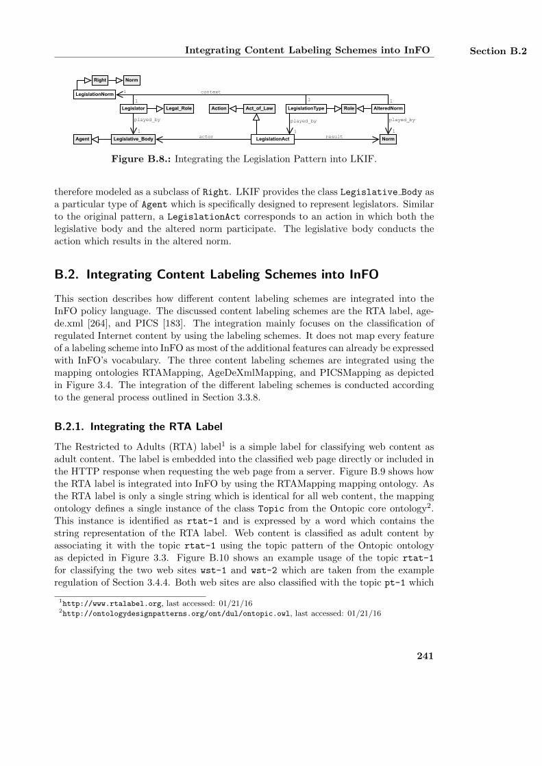
Integrating Content Labeling Schemes into InFO Section B.2
Legislator
played_by
1
Role
Legislative_Body
Right
LegislationNorm
LegislationType AlteredNorm
Norm
played_by
1
played_by
1
1
1 1
context
1
actor resultLegislationAct
Act_of_LawAction
Agent
Legal_Role
Norm
Figure B.8.: Integrating the Legislation Pattern into LKIF.
therefore modeled as a subclass of Right. LKIF provides the class Legislative Body asa particular type of Agent which is specifically designed to represent legislators. Similarto the original pattern, a LegislationAct corresponds to an action in which both thelegislative body and the altered norm participate. The legislative body conducts theaction which results in the altered norm.
B.2. Integrating Content Labeling Schemes into InFO
This section describes how different content labeling schemes are integrated into theInFO policy language. The discussed content labeling schemes are the RTA label, age-de.xml [264], and PICS [183]. The integration mainly focuses on the classification ofregulated Internet content by using the labeling schemes. It does not map every featureof a labeling scheme into InFO as most of the additional features can already be expressedwith InFO’s vocabulary. The three content labeling schemes are integrated using themapping ontologies RTAMapping, AgeDeXmlMapping, and PICSMapping as depictedin Figure 3.4. The integration of the different labeling schemes is conducted accordingto the general process outlined in Section 3.3.8.
B.2.1. Integrating the RTA Label
The Restricted to Adults (RTA) label1 is a simple label for classifying web content asadult content. The label is embedded into the classified web page directly or included inthe HTTP response when requesting the web page from a server. Figure B.9 shows howthe RTA label is integrated into InFO by using the RTAMapping mapping ontology. Asthe RTA label is only a single string which is identical for all web content, the mappingontology defines a single instance of the class Topic from the Ontopic core ontology2.This instance is identified as rtat-1 and is expressed by a word which contains thestring representation of the RTA label. Web content is classified as adult content byassociating it with the topic rtat-1 using the topic pattern of the Ontopic ontologyas depicted in Figure 3.3. Figure B.10 shows an example usage of the topic rtat-1
for classifying the two web sites wst-1 and wst-2 which are taken from the exampleregulation of Section 3.4.4. Both web sites are also classified with the topic pt-1 which
1http://www.rtalabel.org, last accessed: 01/21/162http://ontologydesignpatterns.org/ont/dul/ontopic.owl, last accessed: 01/21/16
241
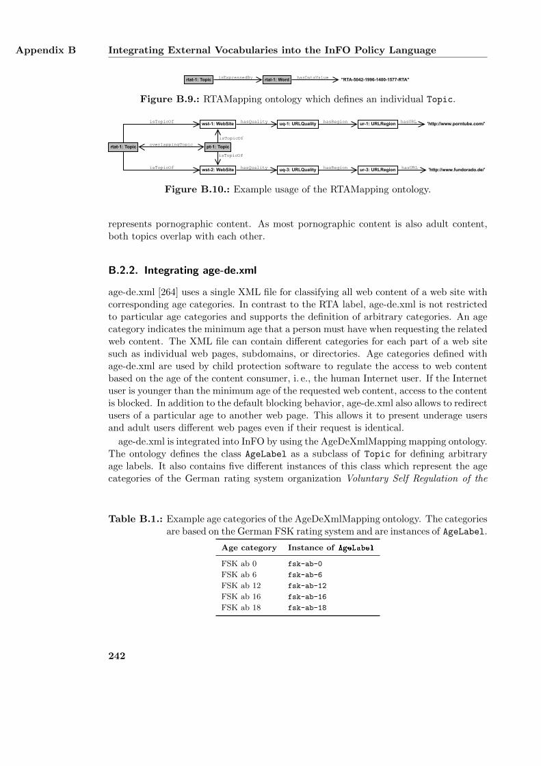
Appendix B Integrating External Vocabularies into the InFO Policy Language
rtat-1: Topic isExpressedBy rtal-1: Word "RTA-5042-1996-1400-1577-RTA"hasDataValue
Figure B.9.: RTAMapping ontology which defines an individual Topic.
wst-1: WebSite ur-1: URLRegionuq-1: URLQualityhasQuality hasRegion 'http://www.porntube.com/'hasURL
pt-1: Topic
wst-2: WebSite ur-3: URLRegionuq-3: URLQuality 'http://www.fundorado.de/'hasQuality hasRegion hasURL
rtat-1: Topic
isTopicOf
isTopicOf
isTopicOf
isTopicOf
overlappingTopic
Figure B.10.: Example usage of the RTAMapping ontology.
represents pornographic content. As most pornographic content is also adult content,both topics overlap with each other.
B.2.2. Integrating age-de.xml
age-de.xml [264] uses a single XML file for classifying all web content of a web site withcorresponding age categories. In contrast to the RTA label, age-de.xml is not restrictedto particular age categories and supports the definition of arbitrary categories. An agecategory indicates the minimum age that a person must have when requesting the relatedweb content. The XML file can contain different categories for each part of a web sitesuch as individual web pages, subdomains, or directories. Age categories defined withage-de.xml are used by child protection software to regulate the access to web contentbased on the age of the content consumer, i. e., the human Internet user. If the Internetuser is younger than the minimum age of the requested web content, access to the contentis blocked. In addition to the default blocking behavior, age-de.xml also allows to redirectusers of a particular age to another web page. This allows it to present underage usersand adult users different web pages even if their request is identical.
age-de.xml is integrated into InFO by using the AgeDeXmlMapping mapping ontology.The ontology defines the class AgeLabel as a subclass of Topic for defining arbitraryage labels. It also contains five different instances of this class which represent the agecategories of the German rating system organization Voluntary Self Regulation of the
Table B.1.: Example age categories of the AgeDeXmlMapping ontology. The categoriesare based on the German FSK rating system and are instances of AgeLabel.
Age category Instance of AgeLabel
FSK ab 0 fsk-ab-0
FSK ab 6 fsk-ab-6
FSK ab 12 fsk-ab-12
FSK ab 16 fsk-ab-16
FSK ab 18 fsk-ab-18
242
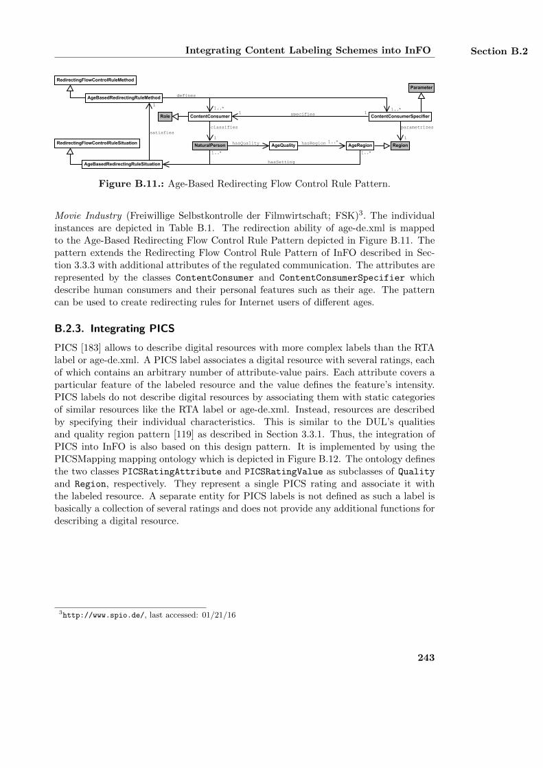
Integrating Content Labeling Schemes into InFO Section B.2
parametrizes
1
ContentConsumer
classifies
1
AgeBasedRedirectingRuleMethod
AgeBasedRedirectingRuleSituation
satisfies
1
Region
defines
1..*
1..*
1..*
ContentConsumerSpecifierspecifies 11Role
RedirectingFlowControlRuleMethod
RedirectingFlowControlRuleSituation
Parameter
1..*
NaturalPerson AgeQuality AgeRegionhasRegion 1..*hasQuality
hasSetting
Figure B.11.: Age-Based Redirecting Flow Control Rule Pattern.
Movie Industry (Freiwillige Selbstkontrolle der Filmwirtschaft; FSK)3. The individualinstances are depicted in Table B.1. The redirection ability of age-de.xml is mappedto the Age-Based Redirecting Flow Control Rule Pattern depicted in Figure B.11. Thepattern extends the Redirecting Flow Control Rule Pattern of InFO described in Sec-tion 3.3.3 with additional attributes of the regulated communication. The attributes arerepresented by the classes ContentConsumer and ContentConsumerSpecifier whichdescribe human consumers and their personal features such as their age. The patterncan be used to create redirecting rules for Internet users of different ages.
B.2.3. Integrating PICS
PICS [183] allows to describe digital resources with more complex labels than the RTAlabel or age-de.xml. A PICS label associates a digital resource with several ratings, eachof which contains an arbitrary number of attribute-value pairs. Each attribute covers aparticular feature of the labeled resource and the value defines the feature’s intensity.PICS labels do not describe digital resources by associating them with static categoriesof similar resources like the RTA label or age-de.xml. Instead, resources are describedby specifying their individual characteristics. This is similar to the DUL’s qualitiesand quality region pattern [119] as described in Section 3.3.1. Thus, the integration ofPICS into InFO is also based on this design pattern. It is implemented by using thePICSMapping mapping ontology which is depicted in Figure B.12. The ontology definesthe two classes PICSRatingAttribute and PICSRatingValue as subclasses of Quality
and Region, respectively. They represent a single PICS rating and associate it withthe labeled resource. A separate entity for PICS labels is not defined as such a label isbasically a collection of several ratings and does not provide any additional functions fordescribing a digital resource.
3http://www.spio.de/, last accessed: 01/21/16
243
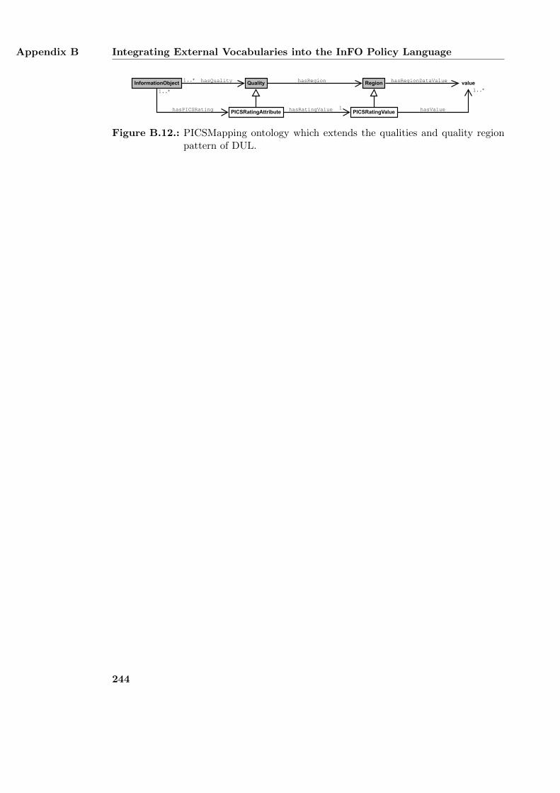
Appendix B Integrating External Vocabularies into the InFO Policy Language
RegionInformationObject QualityhasQuality hasRegion valuehasRegionDataValue
PICSRatingAttribute PICSRatingValuehasRatingValue 1 hasValue
1..*
hasPICSRating
1..*
1..*
Figure B.12.: PICSMapping ontology which extends the qualities and quality regionpattern of DUL.
244
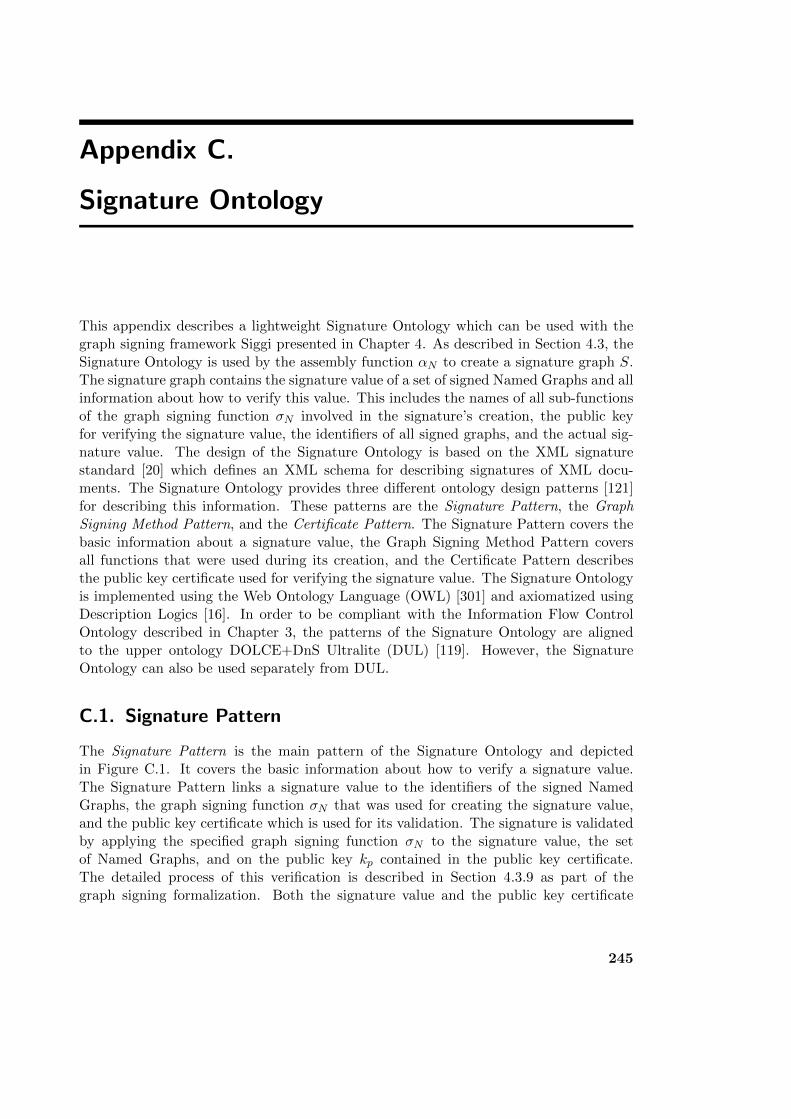
Appendix C.
Signature Ontology
This appendix describes a lightweight Signature Ontology which can be used with thegraph signing framework Siggi presented in Chapter 4. As described in Section 4.3, theSignature Ontology is used by the assembly function αN to create a signature graph S.The signature graph contains the signature value of a set of signed Named Graphs and allinformation about how to verify this value. This includes the names of all sub-functionsof the graph signing function σN involved in the signature’s creation, the public keyfor verifying the signature value, the identifiers of all signed graphs, and the actual sig-nature value. The design of the Signature Ontology is based on the XML signaturestandard [20] which defines an XML schema for describing signatures of XML docu-ments. The Signature Ontology provides three different ontology design patterns [121]for describing this information. These patterns are the Signature Pattern, the GraphSigning Method Pattern, and the Certificate Pattern. The Signature Pattern covers thebasic information about a signature value, the Graph Signing Method Pattern coversall functions that were used during its creation, and the Certificate Pattern describesthe public key certificate used for verifying the signature value. The Signature Ontologyis implemented using the Web Ontology Language (OWL) [301] and axiomatized usingDescription Logics [16]. In order to be compliant with the Information Flow ControlOntology described in Chapter 3, the patterns of the Signature Ontology are alignedto the upper ontology DOLCE+DnS Ultralite (DUL) [119]. However, the SignatureOntology can also be used separately from DUL.
C.1. Signature Pattern
The Signature Pattern is the main pattern of the Signature Ontology and depictedin Figure C.1. It covers the basic information about how to verify a signature value.The Signature Pattern links a signature value to the identifiers of the signed NamedGraphs, the graph signing function σN that was used for creating the signature value,and the public key certificate which is used for its validation. The signature is validatedby applying the specified graph signing function σN to the signature value, the setof Named Graphs, and on the public key kp contained in the public key certificate.The detailed process of this verification is described in Section 4.3.9 as part of thegraph signing formalization. Both the signature value and the public key certificate
245
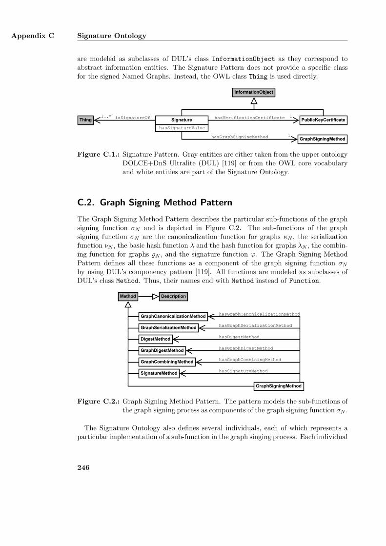
Appendix C Signature Ontology
are modeled as subclasses of DUL’s class InformationObject as they correspond toabstract information entities. The Signature Pattern does not provide a specific classfor the signed Named Graphs. Instead, the OWL class Thing is used directly.
PublicKeyCertificate
InformationObject
Signature
hasSignatureValue
GraphSigningMethod
hasVerificationCertificate 1
hasGraphSigningMethod 1
Thing isSignatureOf1..*
Figure C.1.: Signature Pattern. Gray entities are either taken from the upper ontologyDOLCE+DnS Ultralite (DUL) [119] or from the OWL core vocabularyand white entities are part of the Signature Ontology.
C.2. Graph Signing Method Pattern
The Graph Signing Method Pattern describes the particular sub-functions of the graphsigning function σN and is depicted in Figure C.2. The sub-functions of the graphsigning function σN are the canonicalization function for graphs κN , the serializationfunction νN , the basic hash function λ and the hash function for graphs λN , the combin-ing function for graphs %N , and the signature function ϕ. The Graph Signing MethodPattern defines all these functions as a component of the graph signing function σNby using DUL’s componency pattern [119]. All functions are modeled as subclasses ofDUL’s class Method. Thus, their names end with Method instead of Function.
Method
SignatureMethod
GraphCanonicalizationMethod
DigestMethod
GraphSerializationMethod
Description
GraphDigestMethod
GraphCombiningMethod
hasSignatureMethod
hasDigestMethod
hasGraphSerializationMethod
hasGraphCanonicalizationMethod
hasGraphDigestMethod
hasGraphCombiningMethod
GraphSigningMethod
Figure C.2.: Graph Signing Method Pattern. The pattern models the sub-functions ofthe graph signing process as components of the graph signing function σN .
The Signature Ontology also defines several individuals, each of which represents aparticular implementation of a sub-function in the graph singing process. Each individual
246
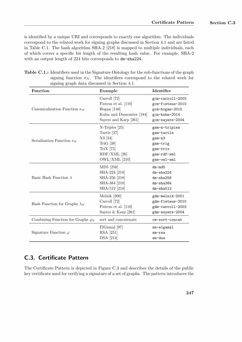
Certificate Pattern Section C.3
is identified by a unique URI and corresponds to exactly one algorithm. The individualscorrespond to the related work for signing graphs discussed in Section 4.1 and are listedin Table C.1. The hash algorithm SHA-2 [218] is mapped to multiple individuals, eachof which covers a specific bit length of the resulting hash value. For example, SHA-2with an output length of 224 bits corresponds to dm-sha224.
Table C.1.: Identifiers used in the Signature Ontology for the sub-functions of the graphsigning function σN . The identifiers correspond to the related work forsigning graph data discussed in Section 4.1.
Function Example Identifier
Canonicalization Function κN
Carroll [72] gcm-carroll-2003
Fisteus et al. [110] gcm-fisteus-2010
Hogan [148] gcm-hogan-2015
Kuhn and Dumontier [184] gcm-kuhn-2014
Sayers and Karp [261] gcm-sayers-2004
Serialization Function νN
N-Triples [25] gsm-n-triples
Turtle [27] gsm-turtle
N3 [34] gsm-n3
TriG [38] gsm-trig
TriX [75] gsm-trix
RDF/XML [26] gsm-rdf-xml
OWL/XML [210] gsm-owl-xml
Basic Hash Function λ
MD5 [250] dm-md5
SHA-224 [218] dm-sha224
SHA-256 [218] dm-sha256
SHA-384 [218] dm-sha384
SHA-512 [218] dm-sha512
Hash Function for Graphs λN
Melnik [200] gdm-melnik-2001
Carroll [72] gdm-fisteus-2010
Fisteus et al. [110] gdm-carroll-2003
Sayers & Karp [261] gdm-sayers-2004
Combining Function for Graphs %N sort and concatenate cm-sort-concat
Signature Function ϕ
ElGamal [97] sm-elgamal
RSA [251] sm-rsa
DSA [214] sm-dsa
C.3. Certificate Pattern
The Certificate Pattern is depicted in Figure C.3 and describes the details of the publickey certificate used for verifying a signature of a set of graphs. The pattern introduces the
247
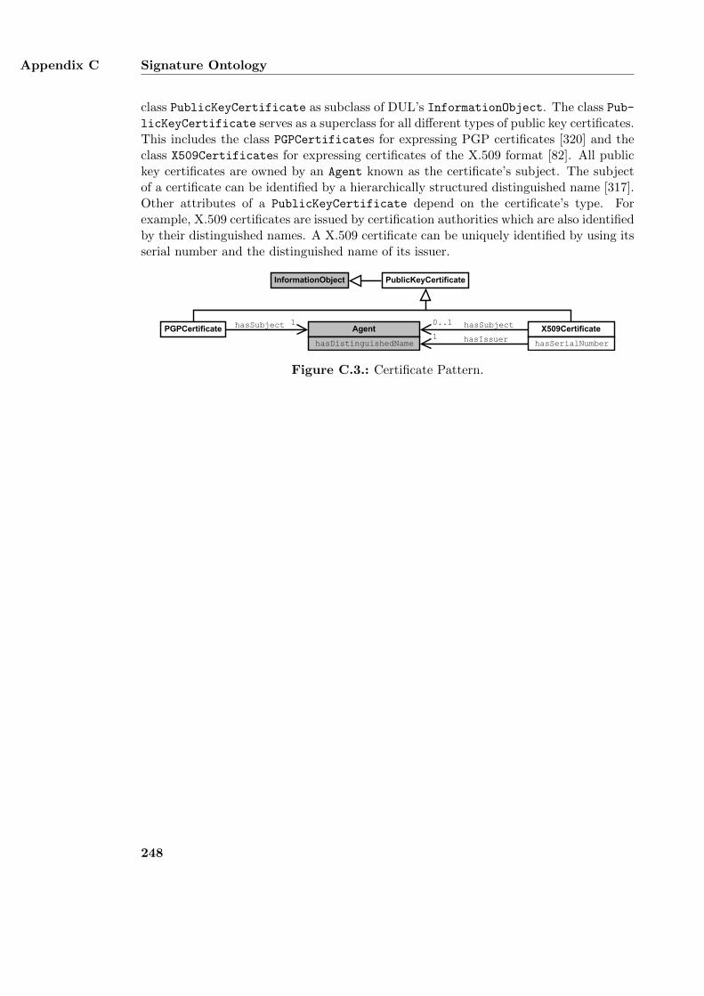
Appendix C Signature Ontology
class PublicKeyCertificate as subclass of DUL’s InformationObject. The class Pub-licKeyCertificate serves as a superclass for all different types of public key certificates.This includes the class PGPCertificates for expressing PGP certificates [320] and theclass X509Certificates for expressing certificates of the X.509 format [82]. All publickey certificates are owned by an Agent known as the certificate’s subject. The subjectof a certificate can be identified by a hierarchically structured distinguished name [317].Other attributes of a PublicKeyCertificate depend on the certificate’s type. Forexample, X.509 certificates are issued by certification authorities which are also identifiedby their distinguished names. A X.509 certificate can be uniquely identified by using itsserial number and the distinguished name of its issuer.
X509Certificate
hasSerialNumberhasIssuer1PGPCertificate
PublicKeyCertificate
Agent
hasDistinguishedName
InformationObject
hasSubject0..1hasSubject 1
Figure C.3.: Certificate Pattern.
248
Appendix D.
Extended Log Format Ontology
This appendix describes a lightweight OWL ontology of the Extended Log Format [138].The format is designed for monitoring HTTP communication between two differentcomputer systems such as client computers, proxy servers, and web servers. It candescribe all technical communication details of a single HTTP transmission. The formathas an open design which can be extended with additional fields in order to furtherdescribe a recorded transmission. It can be used by web servers to monitor incomingclient requests or applied by proxy servers to log all HTTP communication betweenseveral client computers and their contacted servers. A recorded HTTP transmission isrepresented by a log entry which describes the transmission’s technical communicationdetails. A log entry consists of several fields, each of which covers a particular detail suchas the IP address of the client computer or the requested URL. Several log entries arecombined into log files which are usually stored at the system that conducts the logging.Example web servers which support the Extended Log Format include the Microsoft webserver IIS1 and Oracle WebLogic [211].
The Extended Log Format Ontology provides an OWL ontology of the Extended LogFormat by mapping each of the format’s fields to ontological classes and properties. Theontology is used in the example application of T-Store, an approach for searching inencrypted RDF graphs which is covered in Chapter 5. The details of this applicationare described in Section 5.8. The ontology has a lightweight design which is primarilybased on data properties. This allows the ontology to be used for creating simple logfiles without an unnecessary overhead. The ontology defines the three classes Log-
File, LogEntry, and SummaryEntry as well as several data properties for specifyingtheir attributes. The names of the data properties derive from the specification ofthe Extended Log Format [138]. Figure D.1 depicts the relations between all threeclasses and their most important data properties. In addition to the depicted classesand properties, the ontology can also be extended with additional properties. The classLogFile represents a log file which consists of several log entries. A log file can befurther described by subproperties of logFileProperty. Examples of such propertiesare logFileDate and logFileSoftware. logFileSoftware describes the software whichwas used for creating the log file and logFileDate specifies the date and time when the
1See https://msdn.microsoft.com/en-us/library/ms525807\%28v=vs.90\%29.aspx, last accessed:01/21/16
249
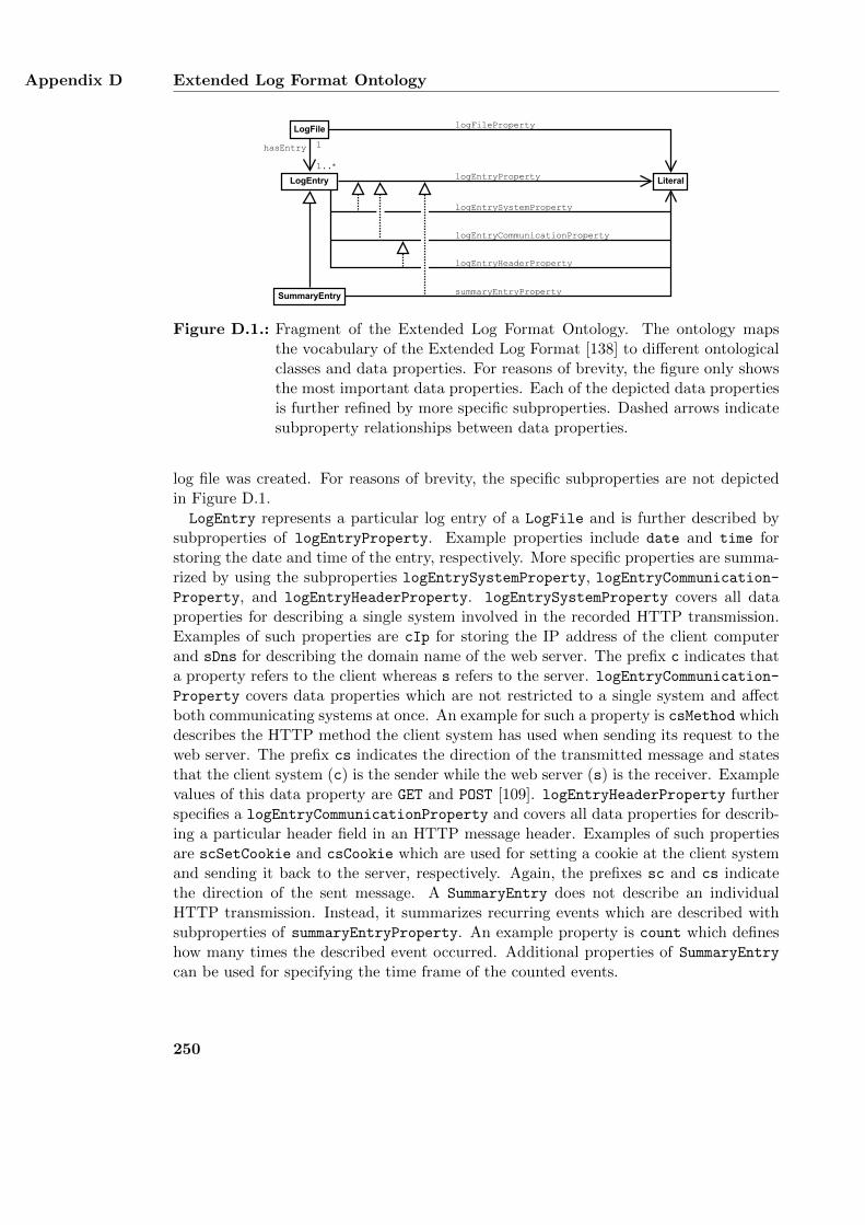
Appendix D Extended Log Format Ontology
LogEntry
LogFile
SummaryEntry
hasEntry
Literal
logFileProperty
summaryEntryProperty
logEntryProperty
logEntrySystemProperty
logEntryHeaderProperty
logEntryCommunicationProperty
1
1..*
Figure D.1.: Fragment of the Extended Log Format Ontology. The ontology mapsthe vocabulary of the Extended Log Format [138] to different ontologicalclasses and data properties. For reasons of brevity, the figure only showsthe most important data properties. Each of the depicted data propertiesis further refined by more specific subproperties. Dashed arrows indicatesubproperty relationships between data properties.
log file was created. For reasons of brevity, the specific subproperties are not depictedin Figure D.1.LogEntry represents a particular log entry of a LogFile and is further described by
subproperties of logEntryProperty. Example properties include date and time forstoring the date and time of the entry, respectively. More specific properties are summa-rized by using the subproperties logEntrySystemProperty, logEntryCommunication-Property, and logEntryHeaderProperty. logEntrySystemProperty covers all dataproperties for describing a single system involved in the recorded HTTP transmission.Examples of such properties are cIp for storing the IP address of the client computerand sDns for describing the domain name of the web server. The prefix c indicates thata property refers to the client whereas s refers to the server. logEntryCommunication-Property covers data properties which are not restricted to a single system and affectboth communicating systems at once. An example for such a property is csMethod whichdescribes the HTTP method the client system has used when sending its request to theweb server. The prefix cs indicates the direction of the transmitted message and statesthat the client system (c) is the sender while the web server (s) is the receiver. Examplevalues of this data property are GET and POST [109]. logEntryHeaderProperty furtherspecifies a logEntryCommunicationProperty and covers all data properties for describ-ing a particular header field in an HTTP message header. Examples of such propertiesare scSetCookie and csCookie which are used for setting a cookie at the client systemand sending it back to the server, respectively. Again, the prefixes sc and cs indicatethe direction of the sent message. A SummaryEntry does not describe an individualHTTP transmission. Instead, it summarizes recurring events which are described withsubproperties of summaryEntryProperty. An example property is count which defineshow many times the described event occurred. Additional properties of SummaryEntry
can be used for specifying the time frame of the counted events. [132]
250
Bibliography
[1] Cristina L. Abad and Rafael I. Bonilla. An analysis on the schemes for detectingand preventing ARP cache poisoning attacks. In 27th International Conference onDistributed Computing Systems Workshops (ICDCSW ’07), pages 60–60, 2007.
[2] Fabian Abel, Juri Luca De Coi, Nicola Henze, Arne Wolf Koesling, Daniel Krause,and Daniel Olmedilla. Enabling advanced and context-dependent access control inRDF stores. In Karl Aberer, Key-Sun Choi, Natasha Noy, Dean Allemang, Kyung-Il Lee, Lyndon Nixon, Jennifer Golbeck, Peter Mika, Diana Maynard, RiichiroMizoguchi, Guus Schreiber, and Philippe Cudre-Mauroux, editors, The SemanticWeb, volume 4825 of Lecture Notes in Computer Science, pages 1–14. Springer,Berlin Heidelberg, 2007.
[3] Hal Abelson, Ben Adida, Mike Linksvayer, and Nathan Yergler. ccREL: TheCreative Commons rights expression language. W3C member submission, Cre-ative Commons, 2008. http://www.w3.org/Submission/ccREL/ (last accessed:01/21/16).
[4] Carlisle Adams and Steve Lloyd. Understanding PKI: Concepts, Standards, andDeployment Considerations, chapter 6: Certificates and Certification, pages 69–87.In [8], 2nd edition, 2003.
[5] Carlisle Adams and Steve Lloyd. Understanding PKI: Concepts, Standards, andDeployment Considerations, chapter 3: The Concept of an Infrastructure, pages21–36. In [8], 2nd edition, 2003.
[6] Carlisle Adams and Steve Lloyd. Understanding PKI: Concepts, Standards, andDeployment Considerations, chapter 9: Trust Models, pages 131–149. In [8], 2ndedition, 2003.
[7] Carlisle Adams and Steve Lloyd. Understanding PKI: Concepts, Standards, andDeployment Considerations, chapter 5: PKI-Enabled Services, pages 49–67. In [8],2nd edition, 2003.
[8] Carlisle Adams and Steve Lloyd. Understanding PKI: Concepts, Standards, andDeployment Considerations. Addison-Wesley, 2nd edition, 2003.
[9] Georgy Adelson-Velsky and Evgenii Mikhailovich Landis. An algorithm for the or-ganization of information. Proceedings of the USSR Academy of Sciences, 146:263–266, 1962.
251
Bibliography
[10] Waseem Akhtar, Jacek Kopecky, Thomas Krennwallner, and Axel Polleres. XS-PARQL: Traveling between the XML and RDF Worlds – and avoiding the XSLTpilgrimage. In Sean Bechhofer, Manfred Hauswirth, Jorg Hoffmann, and ManolisKoubarakis, editors, The Semantic Web: Research and Applications, volume 5021of Lecture Notes in Computer Science, pages 432–447. Springer, Berlin Heidelberg,2008.
[11] Dean Allemang and James Hendler. Semantic Web for the Working Ontologist,chapter 10: Counting and Sets in OWL, pages 213–245. Morgan Kaufmann, 2011.
[12] Anne Anderson. A comparison of two privacy policy languages: EPAL andXACML. Technical report, Sun Microsystems Laboratories, Mountain View, CA,USA, 2005.
[13] Marcelo Arenas, Claudio Gutierrez, and Jorge Perez. Foundations of RDFdatabases. In Sergio Tessaris, Enrico Franconi, Thomas Eiter, Claudio Gutierrez,Siegfried Handschuh, Marie-Christine Rousset, and Renate A. Schmidt, editors,Reasoning Web. Semantic Technologies for Information Systems, volume 5689 ofLecture Notes in Computer Science, pages 158–204. Springer, Berlin Heidelberg,2009.
[14] Mario Arias, Javier D. Fernandez, Miguel A. Martınez-Prieto, and Pablo de laFuente. An empirical study of real-world SPARQL queries. In Proceedings of theWorkshop on Usage Analysis and the Web of Data (USEWOD’11), 2011.
[15] Paul Ashley, Satoshi Hada, Gunter Karjoth, Calvin Powers, and MatthiasSchunter. Enterprise privacy authorization language (EPAL 1.2). W3C mem-ber submission, World Wide Web Consortium (W3C), 2003. http://www.w3.
org/Submission/2003/SUBM-EPAL-20031110/ (last accessed: 01/21/16).
[16] Franz Baader, Diego Calvanese, Deborah L. McGuinness, Daniele Nardi, and Pe-ter F. Patel-Schneider, editors. The description logic handbook: theory, imple-mentation, and applications. Cambridge University Press, New York, NY, USA,2003.
[17] Shane Balfe, Eimear Gallery, Chris J. Mitchell, and Kenneth G. Paterson. Chal-lenges for trusted computing. IEEE Security & Privacy, 6(6):60–66, 2008.
[18] Alexander Balke, Felix Gorbulski, Artur Schens, and Erwin Schens. φ. Projekt-praktikumsausarbeitung, Universitat Koblenz-Landau, 2014.
[19] Jack M. Balkin, Beth Simone Noveck, and Kermit Roosevelt. Filtering the In-ternet: A best practices model. In Jens Waltermann and Marcel Machill, editors,Protecting Our Children on the Internet: Towards a New Culture of Responsibility.Bertelsmann Foundation Publishers, 2000.
252
Bibliography
[20] Mark Bartel, John Boyer, Barb Fox, Brian LaMacchia, and Ed Simon. XML signa-ture syntax and processing. W3C recommendation, World Wide Web Consortium(W3C), 2008. http://www.w3.org/TR/xmldsig-core/ (last accessed: 01/21/16).
[21] Cataldo Basile, Antonio Lioy, Salvatore Scozzi, and Marco Vallini. Ontology-based policy translation. Computational Intelligence in Security for InformationSystems, 63:117–126, 2009.
[22] Richard Baskerville. What design science is not. European Journal of InformationSystems, 17(5):441–443, 2008.
[23] Rudolf Bayer. Symmetric binary B-trees: Data structure and maintenance algo-rithms. Acta Informatica, 1(4):290–306, 1972.
[24] Stefan Becker, Benjamin Huck, Katharina Naujokat, Arne Fritjof Schmeiser, andAndreas Kasten. ODRL 2.0 revisited. In 11th International Workshop for Tech-nical, Economical, and Legal Aspects of Business Models for Virtual Goods, 2013.
[25] Dave Beckett. N-Triples. W3C RDF core WG internal working draft, WorldWide Web Consortium (W3C), 2001. http://www.w3.org/2001/sw/RDFCore/
ntriples/ (last accessed: 01/21/16).
[26] Dave Beckett. RDF/XML syntax specification. W3C recommenda-tion, World Wide Web Consortium (W3C), 2004. http://www.w3.org/TR/
rdf-syntax-grammar/ (last accessed: 01/21/16).
[27] David Beckett and Tim Berners-Lee. Turtle. W3C team submission, World WideWeb Consortium (W3C), 2011. http://www.w3.org/TeamSubmission/turtle/
(last accessed: 01/21/16).
[28] Mark Bedner and Tobias Ackermann. Schutzziele der IT-Sicherheit. Datenschutzund Datensicherheit (DuD), 34(5):323–328, 2010.
[29] Mihir Bellare and Daniele Micciancio. A new paradigm for collision-free hashing:Incrementality at reduced cost. In Walter Fumy, editor, Advances in Cryptology(EUROCRYPT’97), volume 1233 of Lecture Notes in Computer Science, pages163–192, Berlin Heidelberg, 1997. Springer.
[30] Francois Belleau, Marc-Alexandre Nolin, Nicole Tourigny, Philippe Rigault, andJean Morissette. Bio2RDF: Towards a mashup to build bioinformatics knowledgesystems. Journal of biomedical informatics, 41(5):706–716, 2008.
[31] Tim Berners-Lee. Semantic Web. Presentation at XML2000, 2000. http://www.
w3.org/2000/Talks/1206-xml2k-tbl/ (last accessed: 01/21/16).
[32] Tim Berners-Lee. WWW past & future. Presentation at the Royal Society, 2003.http://www.w3.org/2003/Talks/0922-rsoc-tbl/ (last accessed: 01/21/16).
253
Bibliography
[33] Tim Berners-Lee. Artificial intelligence and the Semantic Web. Keynote at theAAAI2006, 2006. https://www.w3.org/2006/Talks/0718-aaai-tbl/Overview.html (last accessed: 01/21/16).
[34] Tim Berners-Lee and Dan Connolly. Notation3 (N3): A readable RDF syntax.W3C team submission, World Wide Web Consortium (W3C), 2011. http://www.w3.org/TeamSubmission/n3/ (last accessed: 01/21/16).
[35] Tim Berners-Lee, James Hendler, and Ora Lassila. The Semantic Web. Scientificamerican, 284(5):28–37, 2001.
[36] Etienne Bezout. Theorie generale des equations algebriques. Ph.-D. Pierres, 1779.
[37] Matt Bishop. Introduction to computer security, chapter 1: An Overview of Com-puter Security, pages 1–25. Addison Wesley, 2006.
[38] Christian Bizer and Richard Cyganiak. RDF 1.1 TriG. W3C recommendation,World Wide Web Consortium (W3C), 2014. http://www.w3.org/TR/trig/ (lastaccessed: 01/21/16).
[39] Christian Bizer, Tom Heath, and Tim Berners-Lee. Linked data – the story sofar. International Journal on Semantic Web and Information Systems, 5(3):1–22,2009.
[40] Christian Bizer and Andreas Schultz. The Berlin SPARQL benchmark. Interna-tional Journal on Semantic Web and Information Systems, 5(2):1–24, 2009.
[41] Burton H. Bloom. Space/time trade-offs in hash coding with allowable errors.Communications of the ACM (CACM), 13(7):422–426, 1970.
[42] Dan Boneh, Giovanni Di Crescenzo, Rafail Ostrovsky, and Giuseppe Persiano.Public key encryption with keyword search. In Christian Cachin and Jan L. Ca-menisch, editors, Advances in Cryptology (EUROCRYPT’04), volume 3027 of Lec-ture Notes in Computer Science, pages 506–522. Springer, Berlin Heidelberg, 2004.
[43] Dan Boneh, Amit Sahai, and Brent Waters. Functional encryption: Definitionsand challenges. In Yuval Ishai, editor, Theory of Cryptography, volume 6597 ofLecture Notes in Computer Science, pages 253–273. Springer, Berlin Heidelberg,2011.
[44] Stefano Borgo and Claudio Masolo. Foundational choices in DOLCE. In Staaband Studer [283], chapter 17, pages 361–381.
[45] Mihaela A. Bornea, Julian Dolby, Anastasios Kementsietsidis, Kavitha Srinivas,Patrick Dantressangle, Octavian Udrea, and Bishwaranjan Bhattacharjee. Buildingan efficient RDF store over a relational database. In Proceedings of the 2013 ACMSIGMOD International Conference on Management of Data (SIGMOD’13), pages121–132, New York, NY, USA, 2013. ACM.
254
Bibliography
[46] Luc Bouganim, Francois Dang Ngoc, and Philippe Pucheral. Client-based accesscontrol management for XML documents. In Proceedings of the Thirtieth Interna-tional Conference on Very Large Data Bases (VLDB ’04), volume 30, pages 84–95.VLDB Endowment, 2004.
[47] Steve Bratt. Semantic Web, and other technologies to watch. Presentation atthe INCOSE International Workshop, 2007. http://www.w3.org/2007/Talks/
0130-sb-W3CTechSemWeb/ (last accessed: 01/21/16).
[48] Tim Bray. An HTTP status code to report legal obstacles. Internet-draft,Network Working Group, 2015. Work in progress. https://tools.ietf.org/
html/draft-ietf-httpbis-legally-restricted-status-04 (last accessed:01/21/16).
[49] Tim Bray, Jean Paoli, C. M. Sperberg-McQueen, Eve Maler, Francois Yergeau,and John Cowan. Extensible markup language (XML) 1.1 (second edition). W3Crecommendation, World Wide Web Consortium (W3C), 2006. http://www.w3.
org/TR/xml11 (last accessed: 01/21/16).
[50] Dan Brickley and Libby Miller. FOAF vocabulary specification 0.99, 2014. http://xmlns.com/foaf/spec/ (last accessed: 01/21/16).
[51] Dan Brickley and Ralph R. Swick. PICS rating vocabularies in XML/RDF. W3Cnote, World Wide Web Consortium (W3C), 2000. http://www.w3.org/2000/02/rdf-pics/ (last accessed: 01/21/16).
[52] Richard Brinkman, Jeroen Doumen, and Willem Jonker. Using secret sharingfor searching in encrypted data. In Willem Jonker and Milan Petkovic, editors,Secure Data Management, volume 3178 of Lecture Notes in Computer Science,pages 18–27, Berlin Heidelberg, 2004. Springer.
[53] Richard Brinkman, Ling Feng, Jeroen Doumen, Pieter H. Hartel, and WillemJonker. Efficient tree search in encrypted data. In Proceedings of the 2nd Interna-tional Workshop on Security In Information Systems (WOSIS’04), pages 126–135.Taylor & Francis, 2004.
[54] Jeen Broekstra, Arjohn Kampman, and Frank van Harmelen. Sesame: A genericarchitecture for storing and querying RDF and RDF schema. In Ian Horrocks andJames Hendler, editors, Proceedings of 1st International Semantic Web Confer-ence (ISWC’02), volume 2342 of Lecture Notes in Computer Science, pages 54–68.Springer, Berlin Heidelberg, 2002.
[55] Mark R. Brown and Andrew C. Greenberg. On formally undecidable propositionsof law: Legal indeterminacy and the implications of metamathematics. HastingsLaw Journal, 43:1439, 1992.
[56] Johannes Buchmann. Einfuhrung in die Kryptographie, chapter 12. Kryptografis-che Hashfunktionen, pages 191–202. Springer, 2008.
255
Bibliography
[57] Johannes Buchmann. Einfuhrung in die Kryptographie, chapter 9.3: Das RSA-Verfahren, pages 137–148. Springer, 4th edition, 2008.
[58] Michel Buffa and Catherine Faron-Zucker. Ontology-based access rights man-agement. In Advances in Knowledge Discovery and Management, volume 398 ofStudies in Computational Intelligence, pages 49–61. Springer, Berlin Heidelberg,2012.
[59] Bundesamt fur Sicherheit in der Informationstechnik (BSI), editor. IT-Grundschutz-Kataloge: Standardwerk zur Informationssicherheit. BundesanzeigerVerlag, 2014.
[60] Bundesrepublik Deutschland. Die Gesetzgebung des Bundes. In Grundgesetz furdie Bundesrepublik Deutschland, chapter VII. Bundesrepublik Deutschland, 1949.http://www.gesetze-im-internet.de/gg/ (last accessed: 01/21/16).
[61] Bundesrepublik Deutschland. §184 StGB: Verbreitung pornographischerSchriften, 1975. www.gesetze-im-internet.de/stgb/__184.html (last accessed:01/21/16).
[62] Bundesrepublik Deutschland. §86 StGB: Verbreiten von Propagandamitteln ver-fassungswidriger Organisationen, 1975. http://www.gesetze-im-internet.de/
stgb/__86.html (last accessed: 01/21/16).
[63] Bundesrepublik Deutschland. § 202c Vorbereiten des Ausspahens und Abfangensvon Daten, 2007. http://www.gesetze-im-internet.de/stgb/__202c.html
(last accessed: 01/21/16).
[64] Bundesrepublik Deutschland. Gesetz zur Bekampfung der Kinderpornogra-phie in Kommunikationsnetzen. Bundesgesetzblatt, (6):78–80, 2010.http://www2.bgbl.de/Xaver/start.xav?startbk=Bundesanzeiger_BGBl&
start=//*[@attr_id=%27bgbl110s0078.pdf%27] (last accessed: 01/21/16).
[65] Ian Burnett, Rik van de Walle, Keith Hill, Jan Bormans, and Fernando Pereira.MPEG-21: Goals and achievements. IEEE MultiMedia, 10(4):60–70, 2003.
[66] Julian Busch. A Brief Guide to CCC: China Compulsory Certification. Create-Space Independent Publishing Platform, 2013.
[67] Frank Buschmann, Regine Meunier, Hans Rohnert, Peter Sommerlad, and MichaelStal. Pattern-Oriented Software Architecture, Volume 1: A System of Patterns,chapter 1: Patterns, pages 1–24. Wiley, 1996.
[68] Jianneng Cao, Fang-Yu Rao, Mehmet Kuzu, Elisa Bertino, and Murat Kantar-cioglu. Efficient tree pattern queries on encrypted XML documents. In Proceed-ings of the Joint EDBT/ICDT 2013 Workshops (EDBT ’13), pages 111–120, NewYork, NY, USA, 2013. ACM.
256
Bibliography
[69] Ning Cao, Zhenyu Yang, Cong Wang, Kui Ren, and Wenjing Lou. Privacy-preserving query over encrypted graph-structured data in cloud computing. InICDCS’11, pages 393–402. IEEE, 2011.
[70] Bogdan Carbunar and Radu Sion. Joining privately on outsourced data. In SecureData Management, pages 70–86. Springer, 2010.
[71] Gavin Carothers. RDF 1.1 N-Quads. W3C recommendation, World WideWeb Consortium (W3C), 2014. http://www.w3.org/TR/n-quads/ (last accessed:01/21/16).
[72] Jeremy J. Carroll. Signing RDF graphs. In Dieter Fensel, Katia Sycara, and JohnMylopoulos, editors, Proceedings of 2nd International Semantic Web Conference(ISWC’03), volume 2870, pages 369–384, Berlin Heidelberg, 2003. Springer.
[73] Jeremy J. Carroll, Christian Bizer, Pat Hayes, and Patrick Stickler. Named graphs,provenance and trust. In Proceedings of the 14th International Conference onWorld Wide Web (WWW’05), WWW ’05, pages 613–622, New York, NY, USA,2005. ACM.
[74] Jeremy J. Carroll, Ian Dickinson, Chris Dollin, Dave Reynolds, Andy Seaborne,and Kevin Wilkinson. Jena: Implementing the Semantic Web recommendations.In Proceedings of the 13th International World Wide Web Conference on AlternateTrack Papers & Posters (WWW Alt. ’04), pages 74–83, New York, NY, USA, 2004.ACM.
[75] Jeremy J. Carroll and Patrick Stickler. RDF triples in XML. Technical ReportHPL-2003-268, HP Laboratories, 2004.
[76] Claude Castelluccia, Einar Mykletun, and Gene Tsudik. Efficient aggregation ofencrypted data in wireless sensor networks. In The Second Annual InternationalConference on Mobile and Ubiquitous Systems: Networking and Services (Mobi-Quitous’05), pages 109–117, 2005.
[77] Stefania Cavallar, Bruce Dodson, Arjen K. K. Lenstra, Walter Lioen, Peter L.Montgomery, Brian Murphy, Herman te Riele, Karen Aardal, Jeff Gilchrist, GerardGuillerm, Paul Leyland, Joel Marchand, Francois Morain, Alec Muffett, Chris andCraig Putnam, and Paul Zimmermann. Factorization of a 512-bit RSA modulus.In Bart Preneel, editor, Advances in Cryptology (EUROCRYPT’00), volume 1807of Lecture Notes in Computer Science, pages 1–18. Springer, Berlin Heidelberg,2000.
[78] Melissa Chase and Seny Kamara. Structured encryption and controlled disclosure.In ASIACRYPT’10, pages 577–594. Springer, 2010.
[79] Richard Clayton, Steven J. Murdoch, and Robert N. M. Watson. Ignoring thegreat firewall of China. In George Danezis and Philippe Golle, editors, Privacy
257
Bibliography
Enhancing Technologies (PET’06), number 4258 in LNCS, pages 20–35. Springer,2006.
[80] Common Criteria. Common Criteria for information technology security evaluation– part 1: Introduction and general model. CCMB-2012-09-001, 2012.
[81] Alissa Cooper. A survey of query log privacy-enhancing techniques from a policyperspective. ACM Transactions on the Web (TWEB), 2(4):19:1–19:27, 2008.
[82] David Cooper, Stefan Santesson, Stephen Farrell, Sharon Boeyen, Russell Housley,and Tim Polk. Internet X.509 public key infrastructure. Request for Comments5280, Network Working Group, 2008. https://tools.ietf.org/html/rfc5280
(last accessed: 01/21/16).
[83] Thomas H. Cormen, Charles E. Leiserson, Ronald L. Rivest, and Clifford Stein.Introduction to Algorithms, chapter 8.4: Bucket sort, pages 174–177. The MITPress, 2nd edition, 2001.
[84] Thomas H. Cormen, Charles E. Leiserson, Ronald L. Rivest, and Clifford Stein.Introduction to Algorithms, chapter 31.2: Greatest common divisor, pages 933–938.The MIT, 3rd edition, 2009.
[85] Frederic Cuppens, Nora Cuppens-Boulahia, Thierry Sans, and Alexandre Miege.A formal approach to specify and deploy a network security policy. Formal Aspectsin Security and Trust, 173:203–218, 2005.
[86] Richard Cyganiak. A relational algebra for SPARQL. Technical Report HPL-2005-170, HP Laboratories, 2005.
[87] Richard Cyganiak, David Wood, and Markus Lanthaler. RDF 1.1 concepts andabstract syntax. W3C recommendation, World Wide Web Consortium (W3C),2014. http://www.w3.org/TR/rdf11-concepts/ (last accessed: 01/21/16).
[88] Nicodemos Damianou, Naranker Dulay, Emil Lupu, and Morris Sloman. ThePonder policy specification language. In Morris Sloman, Emil C. Lupu, and JorgeLobo, editors, Proceedings of the Workshop on Policies for Distributed Systemsand Networks (POLICY ’01), volume 1995 of Lecture Notes in Computer Science,pages 18–38, Berlin Heidelberg, 2001. Springer.
[89] Ronald Deibert, John Palfrey, Rafal Rohozinski, and Jonathan Zittrain, editors.Access Controlled: The Shaping of Power, Rights, and Rule in Cyberspace. TheMIT Press, 2010.
[90] Department of Health and Human Services. Health insurance re-form: Security standards; final rule. Federal Register, 68(34):8334–8381,2003. http://www.hhs.gov/sites/default/files/ocr/privacy/hipaa/
administrative/securityrule/securityrulepdf.pdf (last accessed:01/21/16).
258

Bibliography
[91] Deutsche Telekom AG. Our code of conduct: The way we work. Booklet, 2012.http://www.telekom.com/code-of-conduct-en (last accessed: 01/21/16).
[92] Tim Dierks and Eric Rescorla. The transport layer security (TLS) protocol ver-sion 1.2. Request for Comments 5246, Network Working Group, 2008. http:
//tools.ietf.org/html/rfc5246 (last accessed: 01/21/16).
[93] Digital Library Federation. Metadata encoding and transmission standard:Primer and reference manual. Technical report, Digital Library Federation, 2010.http://www.loc.gov/standards/mets/METSPrimerRevised.pdf (last accessed:01/21/16).
[94] Robert H. Dolin, Liora Alschuler, Sandy Boyer, Calvin Beebe, Fred M. Behlen,Paul V. Biron, and Amnon Shabo Shvo. HL7 clinical document architecture,release 2. Journal of the American Medical Informatics Association, 13(1):30–39,2006.
[95] Maximillian Dornseif. Government mandated blocking of foreign web content.In Jan von Knop, Wilhelm Haverkamp, and Eike Jessen, editors, Security, E-Learning, E-Services: Proceedings of the 17. DFN-Arbeitstagung uber Kommu-nikationsnetze, Lecture Notes in Informatics, pages 617–648, Dusseldorf, 2004.
[96] Claudia Eckert. IT-Sicherheit: Konzepte – Verfahren – Protokolle, chapter 1.2:Schutzziele, pages 6–14. Oldenbourg Verlag, 2009.
[97] Taher ElGamal. A public key cryptosystem and a signature scheme based on dis-crete logarithms. In George Robert Blakley and David Chaum, editors, Advancesin Cryptology, volume 196 of Lecture Notes in Computer Science, pages 10–18.Springer, Berlin Heidelberg, 1985.
[98] Yuval Elovici, Ronen Waisenberg, Erez Shmueli, and Ehud Gudes. A structurepreserving database encryption scheme. In Willem Jonker and Milan Petkovic,editors, Secure Data Management, volume 3178 of Lecture Notes in ComputerScience, pages 28–40. Springer, Berlin Heidelberg, 2004.
[99] Orri Erling and Ivan Mikhailov. Virtuoso: RDF support in a native RDBMS. InRoberto de Virgilio, Fausto Giunchiglia, and Letizia Tanca, editors, Semantic WebInformation Management, pages 501–519. Springer, 2010.
[100] European Parliament and Council. Directive on the protection of individualswith regard to the processing of personal data and on the free movement ofsuch data. Official Journal of the European Union, L 281(23/11/1995):31–50,1995. http://eur-lex.europa.eu/legal-content/EN/TXT/HTML/?uri=CELEX:
31995L0046 (last accessed: 01/21/16).
[101] European Parliament and Council. Directive on the protection of individu-als with regard to the processing of personal data and on the free movement
259
Bibliography
of such data. Official Journal of the European Union, L 201(2002/07/31):37–47, 2002. http://eur-lex.europa.eu/LexUriServ/LexUriServ.do?uri=CELEX:32002L0058:EN:HTML (last accessed: 01/21/16).
[102] Jerome Euzenat and Pavel Shvaiko. Ontology Matching, chapter 4: Classificationof Ontology Matching Techniques, pages 73–84. Springer, 2013.
[103] Christopher Evans, Clive D. W. Feather, Alex Hopmann, Martin Presler-Marshall,and Paul Resnick. PICSRules 1.1. W3C recommendation, World Wide Web Con-sortium (W3C), 1997. http://www.w3.org/TR/REC-PICSRules/ (last accessed:01/21/16).
[104] Sergei Evdokimov and Oliver Gunther. Encryption techniques for secure databaseoutsourcing. In Joachim Biskup and Javier Lopez, editors, Computer Security(ESORICS’07), volume 4734 of Lecture Notes in Computer Science, pages 327–342. Springer, Berlin Heidelberg, 2007.
[105] Gunther Eysenbach. What is e-health? Journal of Medical Internet Research,3(2), 2001.
[106] Goran Falkman, Marie Gustafsson, Mats Jontell, and Olof Torgersson. SOMWeb:A Semantic Web-based system for supporting collaboration of distributed medicalcommunities of practice. Journal of medical Internet research, 10(3), 2008.
[107] Ling Feng and Willem Jonker. Efficient processing of secured XML metadata. InRobert Meersman and Zahir Tari, editors, On The Move to Meaningful InternetSystems 2003: OTM 2003 Workshops, volume 2889 of Lecture Notes in ComputerScience, pages 704–717, Berlin Heidelberg, 2003. Springer.
[108] Jose Luis Fernandez-Aleman, Inmaculada Carrion Se nor, Pedro Angel Oliver Lo-zoya, and Ambrosio Toval. Security and privacy in electronic health records: Asystematic literature review. Journal of Biomedical Informatics, 46:541–562, 2013.
[109] Roy T. Fielding, James Gettys, Jeffrey C. Mogul, Henrik Frystyk Nielsen, LarryMasinter, Paul J. Leach, and Tim Berners-Lee. Hypertext transfer protocol –HTTP/1.1. Request for Comments 2616, Network Working Group, 1999. http:
//tools.ietf.org/html/rfc2616 (last accessed: 01/21/16).
[110] Jesus Arias Fisteus, Norberto Fernandez Garcıa, Luis Sanchez Fernandez, andCarlos Delgado Kloos. Hashing and canonicalizing Notation3 graphs. Journal ofComputer and System Sciences, 76(7):663–685, 2010.
[111] Caroline Fontaine and Fabien Galand. A survey of homomorphic encryption fornonspecialists. EURASIP Journal on Information Security, 2007:15:1–15:15, Jan-uary 2007.
[112] Ned Freed and Nathaniel S. Borenstein. Multipurpose Internet mail extensions(MIME) part one: Format of internet message bodies. Request for Comments
260
Bibliography
2045, Network Working Group, 1996. https://tools.ietf.org/html/rfc2045
(last accessed: 01/21/16).
[113] Alan O. Freier, Philip Karlton, and Paul C. Kocher. The secure sockets layer(SSL) protocol version 3.0. Request for Comments 6101, Internet EngineeringTask Force (IETF), 2011. https://tools.ietf.org/html/rfc6101 (last ac-cessed: 01/21/16).
[114] Vince Fuller, Tony Li, Jessica Yu, and Kannan Varadhan. Classless inter-domainrouting (CIDR): an address assignment and aggregation strategy. Request forComments 1519, Network Working Group, 1993. http://tools.ietf.org/html/rfc1519 (last accessed: 01/21/16).
[115] Jun Furukawa and Toshiyuki Isshiki. Controlled joining on encrypted relationaldatabase. In Pairing 2012, pages 46–64. Springer, 2013.
[116] Eimear Gallery and Chris J. Mitchell. Trusted computing: Security and applica-tions. Cryptologia, 33(3):217–245, 2009.
[117] Erich Gamma, Richard Helm, Ralph Johnson, and John Vlissides. Design patterns:elements of reusable object-oriented software, chapter 1: Introduction, pages 1–31.Addison-Wesley, 1995.
[118] Aldo Gangemi. Design patterns for legal ontology construction. In PompeuCasanovas, Maria Angela Biasiotti, Enrico Francesconi, and Maria Teresa Sagri,editors, Proceedings of the 2nd Workshop on Legal Ontologies and Artificial In-telligence Techniques (LOAIT’07), volume 321, pages 65–85. CEUR WorkshopProceedings, 2007.
[119] Aldo Gangemi, Nicola Guarino, Claudio Masolo, Alessandro Oltramari, and LucSchneider. Sweetening ontologies with DOLCE. In Proceedings of the 13th In-ternational Conference on Knowledge Engineering and Knowledge Management.Ontologies and the Semantic Web, pages 223–233. Springer, 2002.
[120] Aldo Gangemi and Peter Mika. Understanding the Semantic Web through de-scriptions and situations. In On The Move to Meaningful Internet Systems 2003:CoopIS, DOA, and ODBASE, pages 689–706. Springer, 11 2003.
[121] Aldo Gangemi and Valentina Presutti. Ontology design patterns. In Steffen Staaband Rudi Studer, editors, Handbook on Ontologies, International Handbooks onInformation Systems, pages 221–243. Springer, Berlin Heidelberg, 2009.
[122] Aldo Gangemi and Valentina Presutti. Ontology design patterns. In Staab andStuder [283], chapter 11, pages 221–243.
[123] Aldo Gangemi, Maria-Teresa Sagri, and Daniela Tiscornia. A constructive frame-work for legal ontologies. In V. Richard Benjamins, Pompeu Casanovas, JoostBreuker, and Aldo Gangemi, editors, Law and the Semantic Web, volume 3369,pages 97–124. Springer, 2005.
261
Bibliography
[124] Shudi (Sandy) Gao, C. M. Sperberg-McQueen, and Henry S. Thompson. W3CXML schema definition language (XSD) 1.1 part 1: Structures. W3C recom-mendation, World Wide Web Consortium (W3C), 2012. http://www.w3.org/TR/xmlschema11-1/ (last accessed: 01/21/16).
[125] Dave Garets and Mike Davis. Electronic medical records vs. electronic healthrecords: Yes, there is a difference. White paper, HIMSS Analytics, LLC, 2006.
[126] Craig Gentry. Computing arbitrary functions of encrypted data. Communicationsof the ACM (CACM), 53(3):97–105, 2010.
[127] Aurona J. Gerber, Andries Barnard, and Alta J. van der Merwe. Towards a Seman-tic Web layered architecture. In International Conference on Software Engineering,2007.
[128] Aurona J. Gerber, Alta J. van der Merwe, and Andries Barnard. A functional Se-mantic Web architecture. In Sean Bechhofer, Manfred Hauswirth, Jorg Hoffmann,and Manolis Koubarakis, editors, The Semantic Web: Research and Applications,volume 5021 of Lecture Notes in Computer Science, pages 273–287. Springer, BerlinHeidelberg, 2008.
[129] Global Network Initiative. Principles on freedom of expression andprivacy. Technical report, Global Network Initiative, 2011. http:
//www.globalnetworkinitiative.org/principles/index.php (last accessed:01/21/16).
[130] Shafi Goldwasser, Silvio Micali, and Ronald L. Rivest. A digital signature schemesecure against adaptive chosen-message attacks. SIAM Journal on Computing,17(2):281–308, 1988.
[131] Thomas Gottron, Malte Knauf, and Ansgar Scherp. Analysis of schema structuresin the linked open data graph based on unique subject URIs, pay-level domains,and vocabulary usage. Distributed and Parallel Databases, pages 1–39, 2014.
[132] Jacob Grimm and Wilhelm Grimm, editors. Deutsche Sagen, volume 1. NicolaischeBuchhandlung, Berlin, 1816.
[133] Rudiger Grimm, Daniela Simic-Draws, Katharina Braunlich, Andreas Kas-ten, and Anastasia Meletiadou. Referenzmodell fur ein Vorgehen bei der IT-Sicherheitsanalyse. Informatik-Spektrum, pages 1–19, 2014.
[134] Alessio Gugliotta, Liliana Cabral, John Domingue, Vito Roberto, Mary Rowlatt,and Rob Davies. A Semantic Web service-based architecture for the interoper-ability of e-Government services. Web Information Systems Modeling Workshop(WISM’05), pages 21–30, 2005.
[135] Tracy D. Gunter and Nicolas P. Terry. The emergence of national electronic healthrecord architectures in the United States and Australia. Journal of Medical Inter-net Research, 7(1), 2005.
262
Bibliography
[136] Sebastian Haas, Sven Wohlgemuth, Isao Echizen, Noboru Sonehara, and GunterMuller. Aspects of privacy for electronic health records. International journal ofmedical informatics, 80(2):e26–e31, 2011.
[137] Hakan Hacigumus, Bala Iyer, Chen Li, and Sharad Mehrotra. Executing SQL overencrypted data in the database-service-provider model. In Proceedings of the 2002ACM SIGMOD international conference on Management of data (SIGMOD’02),pages 216–227, New York, NY, USA, 2002. ACM.
[138] Phillip M. Hallam-Baker and Brian Behlendorf. Extended Log File Format. W3CWorking Draft WD-logfile-960323, World Wide Web Consortium (W3C), 1996.http://www.w3.org/TR/WD-logfile.html (last accessed: 01/21/16).
[139] Volker Hammer, Ulrich Pordesch, and Alexander Roßnagel. KORA – eineMethode zur Konkretisierung rechtlicher Anforderungen zu technischen Gestal-tungsvorschlagen fur Informations-und Kommunikationssysteme. Infotech/I+ G,5, 1993.
[140] Steve Harris and Andy Seaborne. SPARQL 1.1 query language. W3C recom-mendation, World Wide Web Consortium (W3C), 2013. http://www.w3.org/TR/2013/REC-sparql11-query-20130321/ (last accessed: 01/21/16).
[141] Andreas Harth, Maciej Janik, and Steffen Staab. Semantic Web architecture.In John Domingue, Dieter Fensel, and James A. Hendler, editors, Handbook ofSemantic Web Technologies, pages 43–75. Springer, Berlin Heidelberg, 2011.
[142] Patrick J. Hayes and Peter F. Patel-Schneider. RDF 1.1 semantics. W3C recom-mendation, World Wide Web Consortium (W3C), 2014. http://www.w3.org/TR/rdf11-mt/ (last accessed: 01/21/16).
[143] Martin Hepp, Frank Leymann, John Domingue, Alexander Wahler, and DieterFensel. Semantic business process management: A vision towards using SemanticWeb services for business process management. In International Conference one-Business Engineering (ICEBE’05), pages 535–540. IEEE, 2005.
[144] Hessisches Kultusministerium. Verordnung uber die Aufsicht uber Schulerinnenund Schuler (Aufsichtsverordnung – AufsVO) vom 11. Dezember 2013. In Amtsblattdes Hessischen Kultusministeriums. A. Bernecker Verlag GmbH, 2013.
[145] Alan R. Hevner, Salvatore T. March, Jinsoo Park, and Sudha Ram. Design sciencein information systems research. MIS quarterly, 28(1):75–105, 2004.
[146] Rinke Hoekstra, Joost Breuker, Marcello di Bello, and Alexander Boer. The LKIFcore ontology of basic legal concepts. In Pompeu Casanovas, Maria Angela Bia-siotti, Enrico Francesconi, and Maria Teresa Sagri, editors, Proceedings of the 2ndWorkshop on Legal Ontologies and Artificial Intelligence Techniques (LOAIT’07),volume 321, pages 43–63. CEUR Workshop Proceedings, 2007.
263
Bibliography
[147] Rinke Hoekstra, Joost Breuker, Marcello di Bello, and Alexander Boer. LKIF core:Principled ontology development for the legal domain. Law, Ontologies and theSemantic Web: Channelling the Legal Information Flood, 188:21, 2009.
[148] Aidan Hogan. Skolemising blank nodes while preserving isomorphism. In Proceed-ings of the 24th International Conference on World Wide Web (WWW’15), pages430–440. International World Wide Web Conferences Steering Committee, 2015.
[149] Aidan Hogan, Jurgen Umbrich, Andreas Harth, Richard Cyganiak, Axel Polleres,and Stefan Decker. An empirical survey of linked data conformance. Web Seman-tics: Science, Services and Agents on the World Wide Web, 14:14–44, 2012.
[150] Bijit Hore, Sharad Mehrotra, and Gene Tsudik. A privacy-preserving index forrange queries. In Proceedings of the Thirtieth International Conference on VeryLarge Data Bases (VLDB ’04), volume 30, pages 720–731. VLDB Endowment,2004.
[151] Adam Horowitz. The constitutionality of the children’s internet protection act.St. Thomas Law Review, 13(1):425–444, 2000.
[152] Ian Horrocks. Ontologies and the Semantic Web. Communications of the ACM(CACM), 51(22):58–67, 2008.
[153] Ian Horrocks, Bijan Parsia, Peter Patel-Schneider, and James Hendler. SemanticWeb architecture: Stack or two towers? In Francois Fages and Sylvain Soliman,editors, Principles and practice of Semantic Web reasoning, volume 3703 of LectureNotes in Computer Science, pages 37–41. Springer, Berlin Heidelberg, 2005.
[154] Evelyn Johanna Sophia Hovenga. Importance of achieving semantic interoper-ability for national health information systems. Texto & Contexto - Enfermagem,17(1):158 –167, 2008.
[155] Renato Iannella. ODRL version 2.1 XML encoding. Specification, W3C ODRLCommunity Group, 2015. https://www.w3.org/community/odrl/xml/2.1/ (lastaccessed: 01/21/16).
[156] Renato Iannella, Susanne Guth, Daniel Pahler, and Andreas Kasten. ODRLversion 2.1 core model. Specification, W3C ODRL Community Group, 2015.https://www.w3.org/community/odrl/model/2.1/ (last accessed: 01/21/16).
[157] Renato Iannella, Michael Steidl, and Susanne Guth-Orlowski. ODRL version 2.1common vocabulary. Specification, W3C ODRL Community Group, 2015. https://www.w3.org/community/odrl/vocab/2.1/ (last accessed: 01/21/16).
[158] Sebastiaan Indesteege, Florian Mendel, Bart Preneel, and Christian Rechberger.Collisions and other non-random properties for step-reduced SHA-256. InRoberto Maria Avanzi, Liam Keliher, and Francesco Sica, editors, Selected Ar-eas in Cryptography, volume 5381 of Lecture Notes in Computer Science, pages276–293. Springer, Berlin Heidelberg, 2009.
264
Bibliography
[159] International Organization for Standardization (ISO). Information technology –open systems interconnection – basic reference model: The basic model. ISO/IECStandard 7498-1:1994, 1994.
[160] International Organization for Standardization (ISO). Information technology –database languages – SQL – part 1: Framework (SQL/framework). ISO/IECStandard 9075-1:2011, 2011.
[161] International Organization for Standardization (ISO). Codes for the representationof names of countries and their subdivisions – part 1: Country codes. ISO Standard3166-1:2013, 2013.
[162] International Press Telecommunications Council (IPTC). RightsML: Specificationof a profile and vocabulary for the communication of usage rights in ODRL 2.0.IPTC Standards, 2013. http://www.iptc.org/std/RightsML/1.1/RightsML_1.1EP2-spec_1.pdf (last accessed: 01/21/16).
[163] Ashraf Mohammed Iqbal. An OWL-DL ontology for the HL7 reference informationmodel. In Bessam Abdulrazak, Sylvain Giroux, Bruno Bouchard, Helene Pigot,and Mounir Mokhtari, editors, Toward Useful Services for Elderly and People withDisabilities, volume 6719 of Lecture Notes in Computer Science, pages 168–175.Springer, Berlin Heidelberg, 2011.
[164] Amit Jain and Csilla Farkas. Secure resource description framework: an accesscontrol model. In Proceedings of the eleventh ACM symposium on Access controlmodels and technologies (SACMAT ’06), pages 121–129, New York, NY, USA,2006. ACM.
[165] Ravi Chandra Jammalamadaka and Sharad Mehrotra. Querying encrypted XMLdocuments. In 10th International Database Engineering and Applications Sympo-sium (IDEAS ’06), pages 129–136. IEEE, 2006.
[166] Lalana Kagal, Tim Finin, and Anupam Joshi. A policy language for a pervasivecomputing environment. In Proceedings of the 4th International Workshop onPolicies for Distributed Systems and Networks (POLICY’03), pages 63–74. IEEE,2003.
[167] Murat Kantarcıoglu and Chris Clifton. Security issues in querying encrypted data.In Data and Applications Security XIX, pages 325–337. Springer, 2005.
[168] Andreas Kasten and Ansgar Scherp. Iterative signing of RDF(S) graphs, NamedGraphs, and OWL graphs: Formalization and application. Arbeitsberichte ausdem Fachbereich Informatik 03/2013, Universitat Koblenz-Landau, 2013.
[169] Andreas Kasten and Ansgar Scherp. Towards a configurable framework for itera-tive signing of distributed graph data. In Proceedings of the Workshop on Society,Privacy and the Semantic Web – Policy and Technology (PrivOn’13), volume 1121,Sydney, 2013. CEUR Workshop Proceedings.
265
Bibliography
[170] Andreas Kasten and Ansgar Scherp. Towards a framework for iteratively signinggraph data. In Proceedings of the seventh international conference on Knowledgecapture (K-CAP’13), pages 141–142. ACM, 2013.
[171] Andreas Kasten and Ansgar Scherp. Towards search on encrypted graph data. InProceedings of the Workshop on Society, Privacy and the Semantic Web – Pol-icy and Technology (PrivOn’13), volume 1121, Sydney, 2013. CEUR WorkshopProceedings.
[172] Andreas Kasten and Ansgar Scherp. Ontology-based information flow control ofnetwork-level Internet communication. International Journal of Semantic Com-puting, 9(1):1–45, 2015.
[173] Andreas Kasten, Ansgar Scherp, and Peter Schauß. A framework for iterativesigning of graph data on the web. In Valentina Presutti, Claudia d’Amato, FabienGandon, Mathieu d’Aquin, Steffen Staab, and Anna Tordai, editors, The Seman-tic Web: Trends and Challenges (ESWC’14), volume 8465 of Lecture Notes inComputer Science. Springer International Publishing, 2014.
[174] Jonathan Katz and Yehuda Lindell. Introduction to Modern Cryptography, chapter7.2: Primes, Factoring, and RSA, pages 261–274. In [176], 2008.
[175] Jonathan Katz and Yehuda Lindell. Introduction to Modern Cryptography, chapter12.3: RSA Signatures, pages 426–429. In [176], 2008.
[176] Jonathan Katz and Yehuda Lindell. Introduction to Modern Cryptography. Chap-man & Hall/CRC, Boca Raton, London, New York, 2008.
[177] Patrick Kierkegaard. Electronic health record: Wiring europe’s healthcare. Com-puter Law & Security Review, 27(5):503–515, 2011.
[178] Michael Kifer and Harold Boley. RIF overview (second edition). W3C workinggroup note, World Wide Web Consortium (W3C), 2013. http://www.w3.org/TR/rif-overview/ (last accessed: 01/21/16).
[179] Kingdom of Saudi Arabia. Anti-Cyber Crime Law, 2007. http:
//www.citc.gov.sa/English/RulesandSystems/CITCSyste/Documents/LA_
004_%20E_%20Anti-Cyber%20Crime%20Law.pdf (last accessed: 01/21/16).
[180] Thorsten Kleinjung, Kazumaro Aoki, Jens Franke, Arjen K. Lenstra, EmmanuelThome, Joppe W. Bos, Pierrick Gaudry, Alexander Kruppa, Peter L. Montgomery,Dag Arne Osvik, Herman te Riele, Andrey Timofeev, and Paul Zimmermann. Fac-torization of a 768-bit RSA modulus. In Tal Rabin, editor, Advances in Cryptology(CRYPTO’10), volume 6223 of Lecture Notes in Computer Science, pages 333–350.Springer, Berlin Heidelberg, 2010.
[181] Donald Knuth. The Art of Computer Programming, Volume 3: Sorting and Search-ing, volume 3 of The Art of Computer Programming, chapter 6.2.3: Balanced Trees,pages 458–481. Addison-Wesley, 2nd edition, 1998.
266
Bibliography
[182] Gerald Kotonya and Ian Sommerville. Requirements Engineering: Processes andTechniques, chapter 8: Non-Functional Requirements, pages 187–213. Wiley, 2003.
[183] Tim Krauskopf, Jim Miller, Paul Resnick, and Win Treese. PICS label distributionlabel syntax and communication protocols. W3C Recommendation, World WideWeb Consortium (W3C), 1996. http://www.w3.org/TR/REC-PICS-labels (lastaccessed: 01/21/16).
[184] Tobias Kuhn and Michel Dumontier. Trusty URIs: Verifiable, immutable, and per-manent digital artifacts for linked data. In Valentina Presutti, Claudia d’Amato,Fabien Gandon, Mathieu d’Aquin, Steffen Staab, and Anna Tordai, editors, TheSemantic Web: Trends and Challenges (ESWC’14), volume 8465 of Lecture Notesin Computer Science, pages 395–410. Springer International Publishing, BerlinHeidelberg, 2014.
[185] Jin Kyu Lee, Shambhu J. Upadhyaya, H. Raghav Rao, and Raj Sharman. Secureknowledge management and the Semantic Web. Communications of the ACM(CACM), 48(12):48–54, 2005.
[186] Han Li, Jie Zhang, and Rathindra Sarathy. Understanding compliance with In-ternet use policy from the perspective of rational choice theory. Decision SupportSystems, 48(4):635–645, 2010.
[187] Jun Li, Youdong Ding, Yunyu Shi, and Jianfei Zhang. Building a large annotationontology for movie video retrieval. Journal of Digital Content Technology and itsApplications, 4(5):74–81, 2010.
[188] Jun Li and Edward R. Omiecinski. Efficiency and security trade-off in supportingrange queries on encrypted databases. In Sushil Jajodia and Duminda Wijesekera,editors, Data and Applications Security XIX, volume 3654 of Lecture Notes inComputer Science, pages 69–83. Springer, Berlin Heidelberg, 2005.
[189] Yaping Li and Minghua Chen. Privacy preserving joins. In 24th InternationalConference on Data Engineering (ICDE’08), pages 1352–1354. IEEE, 2008.
[190] Ping Lin and K. Selcuk Candan. Hiding traversal of tree structured data from un-trusted data stores. In Proceedings of the 2nd International Workshop on SecurityIn Information Systems (WOSIS’04), pages 314–323, 2004.
[191] Ping Lin and K. Selcuk Candan. Secure and privacy preserving outsourcing oftree structured data. In Willem Jonker and Milan Petkovic, editors, Secure DataManagement, volume 3178 of Lecture Notes in Computer Science, pages 1–17.Springer, Berlin Heidelberg, 2004.
[192] Emil C. Lupu and Morris Sloman. Conflicts in policy-based distributed systemsmanagement. IEEE Transactions on Software Engineering, 25(6):852–869, 1999.
267
Bibliography
[193] Clifford Lynch. Canonicalization: A fundamental tool to facilitate preservationand management of digital information. D-Lib Magazine, 5(9), 1999. http://
www.dlib.org/dlib/september99/09lynch.html (last accessed: 01/21/16).
[194] Salvatore T. March and Gerald F. Smith. Design and natural science research oninformation technology. Decision support systems, 15(4):251–266, 1995.
[195] Brian McBride. RDF schema 1.1. W3C recommendation, World Wide WebConsortium (W3C), 2014. http://www.w3.org/TR/rdf-schema/ (last accessed:01/21/16).
[196] Declan McCullagh. Google excluding controversial sites. Online news article, 2002.http://news.cnet.com/2100-1023-963132.html (last accessed: 01/21/16).
[197] Kevin S. McCurley. The discrete logarithm problem. In Proceedings of Symposiain Applied Mathematics, volume 42, pages 49–74. American Mathematical Society,1990.
[198] John F. McGuire. When speech is heard around the world: Internet contentregluation in the United States and Germany. New York University Law Review,74:750–792, 1999.
[199] Mo McRoberts and Vıctor Rodrıguez-Doncel. ODRL version 2.1 ontology. Spec-ification, W3C ODRL Community Group, 2015. http://www.w3.org/ns/odrl/
2/ODRL21 (last accessed: 01/21/16).
[200] Sergey Melnik. RDF API draft, 2001. http://infolab.stanford.edu/~melnik/rdf/ (last accessed: 01/21/16).
[201] Florian Mendel, Tomislav Nad, and Martin Schlaffer. Improving local collisions:New attacks on reduced SHA-256. In Thomas Johansson and Phong Q. Nguyen,editors, Advances in Cryptology (EUROCRYPT’13), volume 7881 of Lecture Notesin Computer Science, pages 262–278. Springer, Berlin Heidelberg, 2013.
[202] Paul Mockapetris. Domain names – implementation and specification. Request forComments 1035, Network Working Group, 1987. http://tools.ietf.org/html/rfc1035 (last accessed: 01/21/16).
[203] Knud Moller, Michael Hausenblas, Richard Cyganiak, and Siegfried Handschuh.Learning from linked open data usage: Patterns & metrics. In Web Science Con-ference 2010, 2010.
[204] Dominik Mosen. Erweiterung eines Nameservers zur policy-basierten Internetreg-ulierung. Bachelorarbeit, Universitat Koblenz-Landau, 2012.
[205] Tim Moses. eXtensible Access Control Markup Language (XACML) version2.0. OASIS standard, OASIS, 2005. http://docs.oasis-open.org/xacml/2.
0/access_control-xacml-2.0-core-spec-os.pdf (last accessed: 01/21/16).
268
Bibliography
[206] Tim Moses. Privacy policy profile of XACML v2.0. OASIS standard, OASIS,2005. http://docs.oasis-open.org/xacml/2.0/PRIVACY-PROFILE/access_
control-xacml-2.0-privacy_profile-spec-os.pdf (last accessed: 01/21/16).
[207] Mark Mosley, Michael H. Brackett, Susan Earley, and Deborah Henderson. TheDAMA Guide to the Data Management Body of Knowledge (DAMA-DMBOKGuide), chapter 1: Introduction, pages 1–16. In [209], 2010.
[208] Mark Mosley, Michael H. Brackett, Susan Earley, and Deborah Henderson. TheDAMA Guide to the Data Management Body of Knowledge (DAMA-DMBOKGuide), chapter 7: Data Security Management, pages 151–169. In [209], 2010.
[209] Mark Mosley, Michael H. Brackett, Susan Earley, and Deborah Henderson. TheDAMA Guide to the Data Management Body of Knowledge (DAMA-DMBOKGuide). DAMA International, 2010.
[210] Boris Motik, Bijan Parsia, and Peter F. Patel-Schneider. OWL 2 web ontologylanguage XML serialization. W3C recommendation, World Wide Web Consortium(W3C), 2009. http://www.w3.org/TR/owl2-xml-serialization/ (last accessed:01/21/16).
[211] Jon Mountjoy and Avinash Chugh. WebLogic: The Definitive Guide, chapter 3.3:HTTP Access Logs, pages 72–74. O’Reilly Media, 2004.
[212] Steven J. Murdoch and Ross Anderson. Tools and technology of Internet filtering.In Ronald Deibert, John Palfrey, Rafal Rohozinski, and Jonathan Zittrain, editors,Access Denied: The Practice and Policy of Global Internet Filtering, chapter 3,pages 57–72. The MIT Press, 2008.
[213] National Institute of Standards and Technology (NIST). Advanced encryp-tion standard. Federal Information Processing Standards Publication 197, 2001.http://csrc.nist.gov/publications/fips/fips197/fips-197.pdf (last ac-cessed: 01/21/16).
[214] National Institute of Standards and Technology (NIST). Digital signature stan-dard (DSS). Federal Information Processing Standards Publication 186-3, 2009.http://csrc.nist.gov/publications/fips/fips186-3/fips_186-3.pdf (lastaccessed: 01/21/16).
[215] National Institute of Standards and Technology (NIST). Transitions: Recom-mendation for transitioning the use of cryptographic algorithms and key lengths.Special Publication 800-131A, 2011. http://csrc.nist.gov/publications/
nistpubs/800-131A/sp800-131A.pdf (last accessed: 01/21/16).
[216] National Institute of Standards and Technology (NIST). Recommendation forcryptographic key generation. Special Publication 800-133, 2012. http://dx.
doi.org/10.6028/NIST.SP.800-133 (last accessed: 01/21/16).
269
Bibliography
[217] National Institute of Standards and Technology (NIST). Recommendation for keymanagement pt. 1. Special Publication 800-57, 2012. http://csrc.nist.gov/
publications/nistpubs/800-57/sp800-57_part1_rev3_general.pdf (last ac-cessed: 01/21/16).
[218] National Institute of Standards and Technology (NIST). Secure hash stan-dard. Federal Information Processing Standards Publication 180-4, 2012.http://csrc.nist.gov/publications/fips/fips180-4/fips-180-4.pdf (lastaccessed: 01/21/16).
[219] National Institute of Standards and Technology (NIST). Digital signaturestandard (DSS). Federal Information Processing Standards Publication 186-4,2013. http://nvlpubs.nist.gov/nistpubs/FIPS/NIST.FIPS.186-4.pdf (lastaccessed: 01/21/16).
[220] Eric K. Neumann and Dennis Quan. BioDash: a Semantic Web dashboard fordrug development. Pacific Symposium on Biocomputing, pages 176–187, 2006.
[221] Jonas Oberg, Stuart Myles, and Lu Ai. ODRL version 2.1 JSON encoding. Specifi-cation, W3C ODRL Community Group, 2015. https://www.w3.org/community/odrl/json/2.1/ (last accessed: 01/21/16).
[222] Daniel Oberle. Semantic Management of Middleware, chapter 3: Ontologies, pages33–53. Semantic Web and Beyond: Computing for Human Experience. SpringerUS, 2006.
[223] Frank Oemig and Bernd Blobel. An ontology architecture for HL7 v3: Pitfallsand outcomes. In Olaf Dossel and Wolfgang C. Schlegel, editors, World Congresson Medical Physics and Biomedical Engineering, September 7 - 12, 2009, Munich,Germany, volume 25/12 of IFMBE Proceedings, pages 408–410. Springer, 2009.
[224] Hans Oh, Carlos Rizo, Murray Enkin, and Alejandro Jadad. What is eHealth: Asystematic review of published definitions. World Hospitals and Health Services,41(1):32–40, 2005.
[225] Open Networking Foundation. SDN architecture. Technical ReportSDN ARCH 1.0 06062014, Open Networking Foundation, 2014. https:
//www.opennetworking.org/images/stories/downloads/sdn-resources/
technical-reports/TR_SDN_ARCH_1.0_06062014.pdf (last accessed: 01/21/16).
[226] OpenNet Initiative. Internet filtering in Saudi Arabia. Research report, OpenNetInitiative, 2009. http://opennet.net/research/profiles/saudi-arabia (lastaccessed: 01/21/16).
[227] OpenNet Initiative. Access Controlled: The Shaping of Power, Rights, and Rulein Cyberspace, pages 369–387. In Deibert et al. [89], 2010.
270
Bibliography
[228] Bhavna Orgun and Joseph Vu. HL7 ontology and mobile agents for interoper-ability in heterogeneous medical information systems. Computers in Biology andMedicine, 36(7–8):817–836, 2006. Special Issue on Medical Ontologies.
[229] Jaehong Park and Ravi Sandhu. Towards usage control models: Beyond traditionalaccess control. In Proceedings of the seventh ACM symposium on Access controlmodels and technologies (SACMAT ’02), pages 57–64, New York, NY, USA, 2002.ACM.
[230] Peter F. Patel-Schneider and Boris Motik. OWL 2 web ontology language mappingto RDF graphs. W3C recommendation, World Wide Web Consortium (W3C),2012. http://www.w3.org/TR/owl2-mapping-to-rdf/ (last accessed: 01/21/16).
[231] Ken Peffers, Tuure Tuunanen, Marcus A. Rothenberger, and Samir Chatterjee. Adesign science research methodology for information systems research. Journal ofmanagement information systems, 24(3):45–77, 2007.
[232] Radia Perlman. An overview of PKI trust models. Network, IEEE, 13(6):38–43,1999.
[233] Francois Picalausa and Stijn Vansummeren. What are real SPARQL queries like?In Proceedings of the International Workshop on Semantic Web Information Man-agement (SWIM’11), pages 7:1–7:6, New York, NY, USA, 2011. ACM.
[234] Hoi Ting Poon and Ali Miri. Computation and search over encrypted XML docu-ments. In IEEE International Congress on Big Data (BigData Congress’15), pages631–634, 2015.
[235] Raluca Ada Popa, Catherine Redfield, Nickolai Zeldovich, and Hari Balakrishnan.CryptDB: Protecting confidentiality with encrypted query processing. In Pro-ceedings of the Twenty-Third ACM Symposium on Operating Systems Principles(SOSP ’11), pages 85–100, New York, NY, USA, 2011. ACM.
[236] Jon Postel. Internet control message protocol. Request for Comments 792,Network Working Group, 1981. http://tools.ietf.org/html/rfc792 (last ac-cessed: 01/21/16).
[237] Valentina Presutti and Aldo Gangemi. Content ontology design patterns as prac-tical building blocks for web ontologies. In Proceedings of the 27th InternationalConference on Conceptual Modeling. Springer, 2008.
[238] Jan Pries-Heje, Richard Baskerville, and John R. Venable. Strategies for design sci-ence research evaluation. Proceedings of the European Conference on InformationSystems (ECIS’08), pages 1–12, 2008.
[239] Jyothsna Rachapalli, Vaibhav Khadilkar, Murat Kantarcioglu, and Bhavani M.Thuraisingham. Towards fine grained RDF access control. In 19th ACM Sympo-sium on Access Control Models and Technologies (SACMAT ’14), pages 165–176,New York, NY, USA, 2014. ACM.
271
Bibliography
[240] Yves Raimond, Samer A. Abdallah, Mark B. Sandler, and Frederick Giasson. Themusic ontology. In 8th International Conference on Music Information Retrieval(ISMIR’07), pages 417–422, 2007.
[241] Raghu Ramakrishnan and Johannes Gehrke. Database Management Systems,chapter 13.3: External Merge Sort, pages 424–430. In [244], 3rd edition, 2003.
[242] Raghu Ramakrishnan and Johannes Gehrke. Database Management Systems,chapter 14.4: The Join Operation, pages 452–468. In [244], 3rd edition, 2003.
[243] Raghu Ramakrishnan and Johannes Gehrke. Database Management Systems,chapter 4.2.4: Joins, pages 107–109. In [244], 3rd edition, 2003.
[244] Raghu Ramakrishnan and Johannes Gehrke. Database Management Systems.McGraw-Hill Higher Education, 3rd edition, 2003.
[245] Blake Ramsdell and Sean Turner. Secure/multipurpose Internet mail extensions(S/MIME) version 3.2 message specification. Request for Comments 5751, InternetEngineering Task Force (IETF), 2010. http://tools.ietf.org/html/rfc5751
(last accessed: 01/21/16).
[246] Alan L. Rector, R. Qamar, and T. Marley. Binding ontologies & coding systemsto electronic health records and messages. In Biomedical Ontology in Action (KR-MED 2006), 2006.
[247] Pavan Reddivari, Tim Finin, and Anupam Joshi. Policy-based access control foran RDF store. In Proceedings of the Policy Management for the Web workshop(PM4W’05), volume 120, pages 78–83, 2005.
[248] Paul Resnick and James Miller. PICS: Internet access controls without censorship.Communications of the ACM (CACM), 39(10):87–93, 1996.
[249] Paul J. Resnick, Derek L. Hansen, and Caroline R. Richardson. Calculating errorrates for filtering software. Commununications of the ACM, 47(9):67–71, 2004.
[250] Ronald Rivest. The MD5 message-digest algorithm. Request for Comments 1321,Network Working Group, 1992. https://tools.ietf.org/html/rfc1321 (lastaccessed: 01/21/16).
[251] Ronald L. Rivest, Adi Shamir, and Leonard Adleman. A method for obtainingdigital signatures and public-key cryptosystems. Commununications of the ACM,21(2):120–126, 1978.
[252] Jonathan Robie and Michael Dyck. XML path language (XPath) 3.1. W3C Rec-ommendation, World Wide Web Consortium (W3C), 2014. http://www.w3.org/TR/xpath-31/ (last accessed: 01/21/16).
272
Bibliography
[253] Vıctor Rodrıguez-Doncel, Mari Carmen Suarez-Figueroa, Asuncion Gomez-Perez,and Marıa Poveda-Villalon. License linked data resources pattern. In Proceedingsof the 4th International Workshop on Ontology Patterns (WOP’13), volume 1188.CEUR Workshop Proceedings, 2013.
[254] Vıctor Rodrıguez-Doncel, Mari Carmen Suarez-Figueroa, Asuncion Gomez-Perez,and Marıa Poveda-Villalon. Licensing patterns for linked data. In Proceedings ofthe 4th International Workshop on Ontology Patterns (WOP’13), volume 1188.CEUR Workshop Proceedings, 2013.
[255] Phillip Rogaway and Thomas Shrimpton. Cryptographic hash-function basics:Definitions, implications, and separations for preimage resistance, second-preimageresistance, and collision resistance. In Bimal Roy and Willi Meier, editors, FastSoftware Encryption, volume 3017 of Lecture Notes in Computer Science, pages371–388. Springer, Berlin Heidelberg, 2004.
[256] Daniel L. Rubin, Pattanasak Mongkolwat, Vladimir Kleper, Kaustubh Supekar,and David S. Channin. Medical imaging on the Semantic Web: Annotation andimage markup. In AAAI Spring Symposium: Semantic Scientific Knowledge Inte-gration, pages 93–98, 2008.
[257] Pierangela Samarati and Sabrina Capitani de Vimercati. Access control: Poli-cies, models, and mechanisms. In Riccardo Focardi and Roberto Gorrieri, editors,Foundations of Security Analysis and Design, volume 2171 of Lecture Notes inComputer Science, pages 137–196. Springer, Berlin Heidelberg, 2001.
[258] Somitra Kumar Sanadhya and Palash Sarkar. New collision attacks against up to24-step SHA-2. In Dipanwita Roy Chowdhury, Vincent Rijmen, and Abhijit Das,editors, Progress in Cryptology (INDOCRYPT’08), volume 5365 of Lecture Notesin Computer Science, pages 91–103. Springer, Berlin Heidelberg, 2008.
[259] Tahmineh Sanamrad, Lucas Braun, Donald Kossmann, and RamarathnamVenkatesan. Randomly partitioned encryption for cloud databases. In Vijay Atluriand Gunther Pernul, editors, Data and Applications Security and Privacy XXVIII,volume 8566 of Lecture Notes in Computer Science, pages 307–323. Springer, BerlinHeidelberg, 2014.
[260] Ravi Sandhu and Jaehong Park. Usage control: A vision for next generation accesscontrol. Computer Network Security, 2776:17–31, 2003.
[261] Craig Sayers and Alan H. Karp. Computing the digest of an RDF graph. TechnicalReport HPL-2003-235, HP Laboratories, 2004.
[262] Craig Sayers and Alan H. Karp. RDF graph digest techniques and potential ap-plications. Technical Report HPL-2004-95, HP Laboratories, 2004.
[263] Peter Schauß. Digitales Signieren von RDF-Graphen. Bachelorarbeit, UniversitatKoblenz-Landau, 2013.
273
Bibliography
[264] Stefan Schellenberg. label format for age classification in telemedia/ websites – age-de.xml. Technical paper, Online Management Kon-tor, 2010. http://www.online-management-kontor.de/images/downloads/
age-de-xml-label_definition_v3.0g_english1.pdf (last accessed: 01/21/16).
[265] Ansgar Scherp, Daniel Eißing, and Carsten Saathoff. A method for integratingmultimedia metadata standards and metadata formats with the multimedia meta-data ontology. International Journal of Semantic Computing, 6(1):25–49, 2012.
[266] Ansgar Scherp, Carsten Saathoff, Thomas Franz, and Steffen Staab. Designingcore ontologies. Applied Ontology, 6(3):177–221, 2011.
[267] Bruce Schneier. Applied Cryptography, chapter 2.6: Digital Signatures, pages 34–41. In [272], 1996.
[268] Bruce Schneier. Applied Cryptography, chapter 2: Protocol Building Blocks, pages21–46. In [272], 1996.
[269] Bruce Schneier. Applied Cryptography, chapter 8: Key Management, pages 169–187. In [272], 1996.
[270] Bruce Schneier. Applied Cryptography, chapter 1.1: Terminology, pages 1–9. In[272], 1996.
[271] Bruce Schneier. Applied Cryptography, chapter 19.3: RSA, pages 466–474. In [272],1996.
[272] Bruce Schneier. Applied Cryptography. John Wiley & Sons, 1996.
[273] Bruce Schneier, John Kelsey, Doug Whiting, David Wagner, Chris Hall, and NielsFerguson. The Twofish Encryption Algorithm: A 128-bit Block Cipher. John Wiley& Sons, Inc., New York, NY, USA, 1999.
[274] Michael Schrefl, Katharina Grun, and Jurgen Dorn. SemCrypt – ensuring pri-vacy of electronic documents through semantic-based encrypted query processing.In 21st International Conference on Data Engineering Workshops (ICDEW’05),pages 1191–1200. IEEE, 2005.
[275] Guus Schreiber and Yves Raimond. RDF 1.1 primer. W3C working groupnote, World Wide Web Consortium (W3C), 2014. http://www.w3.org/TR/2014/NOTE-rdf11-primer-20140624/ (last accessed: 01/21/16).
[276] Henning Schulzrinne, Hannes Tschofenig, John B. Morris, Jr., Jorge R. Cuellar,James Polk, and Jonathan Rosenberg. Common Policy: A document format forexpressing privacy preferences. Request for Comments 4745, Network WorkingGroup, 2007. http://tools.ietf.org/html/rfc4745 (last accessed: 01/21/16).
[277] Mark M. Seeger. Three years hacker paragraph. Datenschutz und Datensicherheit,34(7):476–478, 2010.
274
Bibliography
[278] Claude E. Shannon. A mathematical theory of communication. The Bell SystemTechnical Journal, 27:379–423, 1948.
[279] A. Sheth, S. Agrawal, J. Lathem, N. Oldham, H. Wingate, P. Yadav, and K. Gal-lagher. Active semantic electronic medical records. In Jorge Cardoso, MartinHepp, and Miltiadis D. Lytras, editors, The Semantic Web, volume 6 of SemanticWeb And Beyond Computing for Human Experience, pages 123–140. Springer US,2008.
[280] Keng Siau, Fiona Fui-Hoon Nah, and Limei Teng. Acceptable Internet use policy.Communications of the ACM (CACM), 45(1):75–79, 2002.
[281] Radu Sion. Towards secure data outsourcing. In Michael Gertz and Sushil Jajodia,editors, Handbook of Database Security, pages 137–161. Springer US, 2008.
[282] Ian Sommerville. Software Engineering, chapter Software Requirements, pages97–120. Addison Wesley, 6th edition, 2001.
[283] Steffen Staab and Rudi Studer, editors. Handbook on Ontologies. Springer, 2009.
[284] Standige Konferenz der Kultusminister der Lander in der Bundesrepublik Deutsch-land. Neue Medien und Schule. Beschluss der Kultusministerkonferenz vom22.02.2001, Sekretariat der standigen Konferenz der Kultusminister der Landerin der Bundesrepublik Deutschland, 2001.
[285] Paul T. Stanton, Benjamin McKeown, Randal Burns, and Giuseppe Ateniese. Fast-AD: An authenticated directory for billions of objects. ACM SIGOPS, 44(1):45–49,2010.
[286] John Strassner, Jose Neuman de Souza, Sven van der Meer, Steven Davy, KearaBarrett, Dave Raymer, and Srini Samudrala. The design of a new policy model tosupport ontology-driven reasoning for autonomic networking. Journal of Networkand Systems Management, 17(1–2):5–32, 2009.
[287] Laurent Sustek. Hardware security module. In Henk C. A. van Tilborg, editor,Encyclopedia of Cryptography and Security, pages 254–256. Springer US, 2005.
[288] Andrew Tanenbaum and Maarten van Steen. Distributed systems. Pearson PrenticeHall, 2007.
[289] Paul C. Tang, Joan S. Ash, David W. Bates, J. Marc Overhage, and Daniel Z.Sands. Personal health records: definitions, benefits, and strategies for overcomingbarriers to adoption. Journal of the American Medical Informatics Association,13(2):121–126, 2006.
[290] Telecommunication Standardization Sector of ITU. Information technology – opensystems interconnection – the directory: Public-key and attribute certificate frame-works. ITU-T Recommendation X.509, International Telecommunication Union(ITU), 2000.
275
Bibliography
[291] Steven J. Templeton and Karl E. Levitt. Detecting spoofed packets. In Proceedingson the DARPA Information Survivability Conference and Exposition, volume 1,pages 164–175, 2003.
[292] The W3C SPARQL Working Group. SPARQL 1.1 overview. W3C recommen-dation, World Wide Web Consortium (W3C), 2013. http://www.w3.org/TR/
sparql11-overview/ (last accessed: 01/21/16).
[293] Yulia A. Timofeeva. Hate speech online: Restricted or protected? Comparison ofregulations in the United States and Germany. Journal of Transnational Law &Policy, 12:253–286, 2002.
[294] Gianluca Tonti, Jeffrey M. Bradshaw, Renia Jeffers, Rebecca Montanari, NiranjanSuri, and Andrzej Uszok. Semantic Web languages for policy representation andreasoning: A comparison of KAoS, Rei, and Ponder. In Dieter Fensel, KatiaSycara, and John Mylopoulos, editors, Proceedings of 2nd International SemanticWeb Conference (ISWC’03), volume 2870 of Lecture Notes in Computer Science,pages 419–437. Springer, Berlin Heidelberg, 2003.
[295] Giovanni Tummarello, Christian Morbidoni, Paolo Puliti, and Francesco Piazza.Signing individual fragments of an RDF graph. In Special Interest Tracks andPosters of the 14th International Conference on World Wide Web (WWW’05),pages 1020–1021, New York, NY, USA, 2005. ACM.
[296] Ozan Unay and Taflan I. Gundem. A survey on querying encrypted XML docu-ments for databases as a service. SIGMOD Record, 37(1):12–20, 2008.
[297] United States Congress. Health insurance portability and accountabil-ity act of 1996 (HIPAA). Public Law 104-191, 110 Statutes atLarge 1936, 1996. http://www.gpo.gov/fdsys/pkg/PLAW-104publ191/html/
PLAW-104publ191.htm (last accessed: 01/21/16).
[298] A. Uszok, J. Bradshaw, R. Jeffers, N. Suri, P. Hayes, M. Breedy, L. Bunch,M. Johnson, S. Kulkarni, and J. Lott. KAoS policy and domain services: Towarda description-logic approach to policy representation, deconfliction, and enforce-ment. In IEEE 4th International Workshop on Policies for Distributed Systemsand Networks (POLICY’03), pages 93–96, 2003.
[299] Vijay Vaishnavi and William Kuechler. Design science re-search in information systems, 2004. http://desrist.org/
design-research-in-information-systems/ (last accessed: 01/21/16).
[300] L. Vizenor, B. Smith, and W. Ceusters. Foundation for the electronic healthrecord: An ontological analysis of the HL7’s reference information model, 2004.
[301] W3C OWL Working Group. OWL 2 Web Ontology Language document overview.W3C recommendation, World Wide Web Consortium (W3C), 2009. http://www.w3.org/TR/owl2-overview/ (last accessed: 01/21/16).
276
Bibliography
[302] W3C OWL Working Group. OWL 2 Web Ontology Language document overview(second edition). W3C recommendation, World Wide Web Consortium (W3C),2012. http://www.w3.org/TR/owl2-overview/ (last accessed: 01/21/16).
[303] Jan Walker, Eric Pan, Douglas Johnston, Julia Adler-Milstein, David W. Bates,and Blackford Middleton. The value of health care information exchange andinteroperability. Health Affairs, 24:W5.10–W5.18, 2005.
[304] Hui Wang and Laks V. S. Lakshmanan. Efficient secure query evaluation overencrypted XML databases. In Proceedings of the 32nd International Conferenceon Very Large Data Bases (VLDB’06), pages 127–138. VLDB Endowment, 2006.
[305] Peng Wang and Chinya V. Ravishankar. Secure and efficient range queries onoutsourced databases using Rp-trees. In IEEE 29th International Conference onData Engineering (ICDE’13), pages 314–325. IEEE, 2013.
[306] Xin Wang. MPEG-21 rights expression language: Enabling interoperable digitalrights management. IEEE Multimedia, 11(4):84–87, 2004.
[307] Xin Wang, Thomas De Martini, Barney Wragg, M. Paramasivam, and Chris Bar-las. The MPEG-21 rights expression language and rights data dictionary. IEEETransactions on Multimedia, 7(3):408–417, 2005.
[308] Xin Wang, Guillermo Lao, Thomas DeMartini, Hari Reddy, Mai Nguyen, andEdgar Valenzuela. XrML – eXtensible rights Markup Language. In Proceedingsof the 2002 ACM workshop on XML security (XMLSEC ’02), pages 71–79, NewYork, NY, USA, 2002. ACM.
[309] Zheng-Fei Wang, Jing Dai, Wei Wang, and Bai-Le Shi. Fast query over encryptedcharacter data in database. In Jun Zhang, Ji-Huan He, and Yuxi Fu, editors, Com-putational and Information Science, volume 3314 of Lecture Notes in ComputerScience, pages 1027–1033. Springer, Berlin Heidelberg, 2005.
[310] Brent R. Waters, Dirk Balfanz, Glenn Durfee, and D. K. Smetters. Buildingan encrypted and searchable audit log. In 11th Annual Network and DistributedSecurity Symposium (NDSS ’04), 2004.
[311] Rainer Weißenfels. Policy-basierte Internetregulierung durch Router. Diplomar-beit, Universitat Koblenz-Landau, 2014.
[312] Khin Than Win. A review of security of electronic health records. Health Infor-mation Management Journal, 34(1):13–18, 2005.
[313] World Health Organization (WHO). Clinical procedures safety. Best practicesafety protocol, WHO, 2012.
[314] Pengtao Xie and Eric P. Xing. CryptGraph: Privacy preserving graph analyticson encrypted graph. CoRR, abs/1409.5021, 2014.
277
Bibliography
[315] Yanjiang Yang, Feng Bao, Xuhua Ding, and Robert H. Deng. Multiuser privatequeries over encrypted databases. International Journal of Applied Cryptography,1(4):309–319, 2009.
[316] Zhiqiang Yang, Sheng Zhong, and Rebecca N. Wright. Privacy-preserving querieson encrypted data. In Dieter Gollmann, Jan Meier, and Andrei Sabelfeld, editors,Computer Security (ESORICS’06), volume 4189 of Lecture Notes in ComputerScience, pages 479–495. Springer, Berlin Heidelberg, 2006.
[317] Kurt D. Zeilenga. Lightweight directory access protocol. Request for Comments4514, Internet Engineering Task Force (IETF), 2006. https://tools.ietf.org/html/rfc4514 (last accessed: 01/21/16).
[318] Rui Zhang and Ling Liu. Security models and requirements for healthcare appli-cation clouds. In 3rd International Conference on Cloud Computing (CLOUD’10),pages 268–275. IEEE, 2010.
[319] Yilu Zhou, Edna Reid, Jialun Qin, Hsinchun Chen, and Guanpi Lai. US domesticextremist groups on the web: Link and content analysis. IEEE Intelligent Systems,20(5):44–51, 2005.
[320] Philip R. Zimmermann. The official PGP user’s guide. The MIT Press, 1995.
[321] Jonathan Zittrain and Benjamin Edelman. Empirical analysis of Internet filteringin China. Research Publication 2003-02, The Berkman Center for Internet &Society, 2003.
278

Curriculum Vitae
Personal Details
Name Andreas Kasten
Date of Birth 12/05/1983
Place of Birth Marburg
Nationality German
Contact Information
Phone +49 261 390 549 06
E-Mail [email protected]
Street Johannesstraße 24
City 56070 Koblenz
Education
08/90–07/94 Grundschule Dreihausen, Dreihausen
08/94–06/00 Gesamtschule Ebsdorfergrund, Heskem
08/00–06/03 Gymnasium Philippinum, Marburg
06/2003 Higher Education Entrance Qualification
Higher Education
10/03–03/09 Academic studies in Computational VisualisticsUnversity of Koblenz-Landau, Koblenz
05/09–11/16 Ph. D. studies in Computer ScienceUnversity of Koblenz-Landau, Koblenz
279

Curriculum Vitae
Professional Occupation
05/06–08/06 Student assistant at the Institute of Software EngineeringUnversity of Koblenz-Landau, Koblenz
09/06–01/07 Student assistant at the Institute of Computer ScienceUnversity of Koblenz-Landau, Koblenz
11/07–02/08 Student assistant at the Department of Aesthetics and Art HistoryUnversity of Koblenz-Landau, Koblenz
05/09–09/15 Research assistant at the Institute of Information Systems ResearchUnversity of Koblenz-Landau, Koblenz
since 10/2015 Software engineer at the Hauptabteilung BetriebsorganisationDebeka-Gruppe, Koblenz
280


