Embed Size (px)
Citation preview

SEG AUTOADAPT
GRUNDFOS INSTRUCTIONS
Installation and operating instructions

Declaration of ConformityWe, Grundfos, declare under our sole responsibility that the products SEG AUTOADAPT, to which this declaration relates, are in conformity with these Council directives on the approximation of the laws of the EC member states:– Machinery Directive (2006/42/EC).
Standards used: EN 809: 1998 and EN 60204-1: 2006.– Low Voltage Directive (2006/95/EC).
Standards used: EN 60335-1: 2002 and EN 60335-2-41: 2003. Applicable when the rated power is lower than 2.2 kW.
– EMC Directive (2004/108/EC).Standards used: EN 61000-3-2: 2006, EN 61000-3-3: 1995, EN 55014-1: 2006 and EN 55014-2: 1997.
– Construction Products Directive (89/106/EEC).Standards used: EN 12050-1: 2001 and EN 12050-2: 2000.
– ATEX Directive (94/9/EC).Standards used: EN 60079-0: 2006, EN 60079-1: 2007, EN 13463-1: 2009, EN 13463-5: 2003 and EN 13463-6: 2005.Applies only to products intended for use in potentially explosive environments, Ex II 2G, equipped with the separate ATEX approval plate and EC-type examination certificate. Further information, see below.
KonformitätserklärungWir, Grundfos, erklären in alleiniger Verantwortung, dass die Produkte SEG AUTOADAPT, auf die sich diese Erklärung bezieht, mit den folgenden Richtlinien des Rates zur Angleichung der Rechtsvorschriften der EU-Mitgliedsstaaten übereinstimmen:– Maschinenrichtlinie (2006/42/EG).
Normen, die verwendet wurden: EN 809: 1998 und EN 60204-1: 2006.
– Niederspannungsrichtlinie (2006/95/EG).Normen, die verwendet wurden: EN 60335-1: 2002 und EN 60335-2-41: 2003. Nur anwendbar für Nennleistungen kleiner 2,2 kW.
– EMV-Richtlinie (2004/108/EG).Normen, die verwendet wurden: EN 61000-3-2: 2006, EN 61000-3-3: 1995, EN 55014-1: 2006 und EN 55014-2: 1997.
– Bauprodukterichtlinie (89/106/EWG).Normen, die verwendet wurden: EN 12050-1: 2001 und EN 12050-2: 2000.
– ATEX-Richtlinie (94/9/EG).Normen, die verwendet wurden: EN 60079-0: 2006, EN 60079-1: 2007, EN 13463-1: 2009, EN 13463-5: 2003 und EN 13463-6: 2005.Gilt nur für Produkte, die für den Gebrauch in potentiell explosiver Umgebung nach Ex II 2G bestimmt und mit einem separaten ATEX-Typenschild und einem EG-Prüfzeugnis ausgestattet sind. Weitere Informationen, siehe unten.
Déclaration de ConformitéNous, Grundfos, déclarons sous notre seule responsabilité, que les produits SEG AUTOADAPT, auxquels se réfère cette déclaration, sont conformes aux Directives du Conseil concernant le rapprochement des législations des Etats membres CE relatives aux normes énoncées ci-dessous :– Directive Machines (2006/42/CE).
Normes utilisées : EN 809 : 1998 et EN 60204-1 : 2006.– Directive Basse Tension (2006/95/CE).
Normes utilisées : EN 60335-1 : 2002 et EN 60335-2-41 : 2003. Applicable lorsque la puissance nominale est inférieure à 2,2 kW.
– Directive Compatibilité Electromagnétique CEM (2004/108/CE).Normes utilisées : EN 61000-3-2 : 2006, EN 61000-3-3 : 1995, EN 55014-1 : 2006 et EN 55014-2 : 1997.
– Directive sur les Produits de Construction (89/106/CEE)Normes utilisées : EN 12050-1 : 2001 et EN 12050-2 : 2000.
– Directive ATEX (94/9/CE).Normes utilisées : EN 60079-0 : 2006, EN 60079-1 : 2007, EN 13463-1 : 2009, EN 13463-5 : 2003 et EN 13463-6 : 2005. S'applique uniquement aux produits utilisés dans des environnements potentiellement explosifs, Ex II 2G, équipés d'une plaque séparée avec norme ATEX et d'un certificat d'examination type CE. Pour plus d'informations, voir ci-après.
Dichiarazione di ConformitàGrundfos dichiara sotto la sua esclusiva responsabilità che i prodotti SEG AUTOADAPT, ai quali si riferisce questa dichiarazione, sono conformi alle seguenti direttive del Consiglio riguardanti il riavvicinamento delle legislazioni degli Stati membri CE:– Direttiva Macchine (2006/42/CE).
Norme applicate: EN 809: 1998 e EN 60204-1: 2006.– Direttiva Bassa Tensione (2006/95/CE).
Norme applicate: EN 60335-1: 2002 e EN 60335-2-41: 2003. Applicabile quando la corrente nominale è inferiore a 2,2 kW.
– Direttiva EMC (2004/108/CE).Norme applicate: EN 61000-3-2: 2006, EN 61000-3-3: 1995, EN 55014-1: 2006 e EN 55014-2: 1997.
– Direttiva Prodotti da Costruzione (89/106/CEE)Norme applicate: EN 12050-1: 2001 e EN 12050-2: 2000.
– Direttiva ATEX (94/9/CE).Norme applicate: EN 60079-0: 2006, EN 60079-1: 2007, EN 13463-1: 2009, EN 13463-5: 2003 e EN 13463-6: 2005.Si riferisce solo ai prodotti per uso in ambienti potenzialmente esplosivi Ex II 2G, con targa di approvazone ATEX a parte e certificato tipo CE. Per ulteriori informazioni, vedere oltre.
Declaración de ConformidadNosotros, Grundfos, declaramos bajo nuestra entera responsabilidad que los productos SEG AUTOADAPT, a los cuales se refiere esta declaración, están conformes con las Directivas del Consejo en la aproximación de las leyes de las Estados Miembros del EM:– Directiva de Maquinaria (2006/42/CE).
Normas aplicadas: EN 809: 1998 y EN 60204-1: 2006.– Directiva de Baja Tensión (2006/95/CE).
Normas aplicadas: EN 60335-1: 2002 y EN 60335-2-41: 2003. Aplicable cuando el índice de potencia es inferior a 2,2 kW.
– Directiva EMC (2004/108/CE).Normas aplicadas: EN 61000-3-2: 2006, EN 61000-3-3: 1995, EN 55014-1: 2006 y EN 55014-2: 1997.
– Directiva de Productos de Construcción (89/106/CEE).Normas aplicadas: EN 12050-1: 2001 y EN 12050-2: 2000.
– Directiva ATEX (94/9/CE).Normas aplicadas: EN 60079-0: 2006, EN 60079-1: 2007, EN 13463-1: 2009, EN 13463-5: 2003 y EN 13463-6: 2005.Se aplica sólo a productos concebidos para su utilización en entornos potencialmente explosivos, Ex II 2G, equipados con una placa independiente de homologación ATEX y certificado de prueba tipo CE. Para información adicional, ver más abajo.
Declaração de ConformidadeA Grundfos declara sob sua única responsabilidade que os produtos SEG AUTOADAPT, aos quais diz respeito esta declaração, estão em conformidade com as seguintes Directivas do Conselho sobre a aproximação das legislações dos Estados Membros da CE:– Directiva Máquinas (2006/42/CE).
Normas utilizadas: EN 809: 1998 e EN 60204-1: 2006.– Directiva Baixa Tensão (2006/95/CE).
Normas utilizadas: EN 60335-1: 2002 e EN 60335-2-41: 2003. Aplicável quando a potência nominal é inferior a 2,2 kW.
– Directiva EMC (compatibilidade electromagnética) (2004/108/CE).Normas utilizadas: EN 61000-3-2: 2006, EN 61000-3-3: 1995, EN 55014-1: 2006 e EN 55014-2: 1997.
– Directiva Produtos Construção (89/106/CEE).Normas utilizadas: EN 12050-1: 2001 e EN 12050-2: 2000.
– Directiva ATEX (94/9/CE).Normas utilizadas: EN 60079-0: 2006, EN 60079-1: 2007, EN 13463-1: 2009, EN 13463-5: 2003 e EN 13463-6: 2005.Aplica-se apenas a produtos cuja utilização é em ambientes potencialmente explosivos, Ex II 2G, equipados com uma chapa de aprovação ATEX e certificado tipo CE. Para mais informações consulte abaixo.
Certificate number
KEMA 09ATEX0146X
Notified body: KEMA Quality B.V. No 0344, Utrechtseweg 310, 6812 AR Arnhem, Netherlands.Manufacturer: GRUNDFOS Management A/S, Poul Due Jensens Vej 7, DK-8850 Bjerringbro, Denmark.
2
Δήλωση ΣυμμόρφωσηςΕμείς, η Grundfos, δηλώνουμε με αποκλειστικά δική μας ευθύνη ότι τα προϊόντα SEG AUTOADAPT στα οποία αναφέρεται η παρούσα δήλωση, συμμορφώνονται με τις εξής Οδηγίες του Συμβουλίου περί προσέγγισης των νομοθεσιών των κρατών μελών της ΕΕ:– Οδηγία για μηχανήματα (2006/42/EC).
Πρότυπα που χρησιμοποιήθηκαν: EN 809: 1998 και EN 60204-1: 2006.
– Οδηγία χαμηλής τάσης (2006/95/EC).Πρότυπα που χρησιμοποιήθηκαν: EN 60335-1: 2002 και EN 60335-2-41: 2003. Ισχύει για ονομαστική ισχύ μικρότερη από 2,2 kW.
– Οδηγία Ηλεκτρομαγνητικής Συμβατότητας (EMC) (2004/108/EC).Πρότυπα που χρησιμοποιήθηκαν: EN 61000-3-2: 2006, EN 61000-3-3: 1995, EN 55014-1: 2006 και EN 55014-2: 1997.
– Οδηγία Παραγωγής Προϊόντων (89/106/EEC).Πρότυπα που χρησιμοποιήθηκαν: EN 12050-1: 2001 και EN 12050-2: 2000.
– Οδηγία ATEX (94/9/EC).Πρότυπα που χρησιμοποιήθηκαν: EN 60079-0: 2006, EN 60079-1: 2007, EN 13463-1: 2009, EN 13463-5: 2003 και EN 13463-6: 2005.Ισχύει μόνο για προϊόντα που απευθύνονται για χρήση σε δυνητικά εκρηκτικά περιβάλλοντα, Ex II 2G, εφοδιασμένα με τη χωριστή πινακίδα έγκρισης ATEX και πιστοποιητικό εξέτασης τύπου EC. Για περισσότερες πληροφορίες, βλέπε κατωτέρω.
OvereenkomstigheidsverklaringWij, Grundfos, verklaren geheel onder eigen verantwoordelijkheid dat de producten SEG AUTOADAPT waarop deze verklaring betrekking heeft, in overeenstemming zijn met de Richtlijnen van de Raad in zake de onderlinge aanpassing van de wetgeving van de EG Lidstaten betreffende:– Machine Richtlijn (2006/42/EC).
Gebruikte normen: EN 809: 1998 en EN 60204-1: 2006.– Laagspannings Richtlijn (2006/95/EC).
Gebruikte normen: EN 60335-1: 2002 en EN 60335-2-41: 2003. Van toepassing wanneer het opgenomen vermogen lager is dan 2,2 kW.
– EMC Richtlijn (2004/108/EC).Gebruikte normen: EN 61000-3-2: 2006, EN 61000-3-3: 1995, EN 55014-1: 2006 en EN 55014-2: 1997.
– Bouwproducten Richtlijn (89/106/EEC).Gebruikte normen: EN 12050-1: 2001 en EN 12050-2: 2000.
– ATEX Richtlijn (94/9/EC).Gebruikte normen: EN 60079-0: 2006, EN 60079-1: 2007, EN 13463-1: 2009, EN 13463-5: 2003 en EN 13463-6: 2005. Is alleen van toepassing op pompen welke gebruikt worden in een explosie gevaarlijke omgeving, Ex II 2G, met een afzonderlijke ATEX-goedkeurings plaatje en EG-type onderzoekscertificaat. Voor verdere informatie, zie onderstaand.
Försäkran om överensstämmelseVi, Grundfos, försäkrar under ansvar att produkterna SEG AUTOADAPT, som omfattas av denna försäkran, är i överensstämmelse med rådets direktiv om inbördes närmande till EU-medlemsstaternas lagstiftning, avseende:– Maskindirektivet (2006/42/EG).
Tillämpade standarder: EN 809: 1998 och EN 60204-1: 2006.– Lågspänningsdirektivet (2006/95/EG).
Tillämpade standarder: EN 60335-1: 2002 och EN 60335-2-41: 2003. Kan användas när märkeffekten är lägre än 2,2 kW.
– EMC-direktivet (2004/108/EG).Tillämpade standarder: EN 61000-3-2: 2006, EN 61000-3-3: 1995, EN 55014-1: 2006 och EN 55014-2: 1997.
– Byggproduktdirektivet (89/106/EEG).Tillämpade standarder: EN 12050-1: 2001 och EN 12050-2: 2000.
– ATEX-direktivet (94/9/EG).Tillämpade standarder: EN 60079-0: 2006, EN 60079-1: 2007, EN 13463-1: 2009, EN 13463-5: 2003 och EN 13463-6: 2005. Gäller endast produkter avsedda att användas i exposionsfarlig miljö, Ex II 2G, utrustade med separat ATEX-godkännandeskylt och EG-typkontrollintyg. För ytterligare information, se nedan.
VaatimustenmukaisuusvakuutusMe, Grundfos, vakuutamme omalla vastuullamme, että tuotteet SEG AUTOADAPT, joita tämä vakuutus koskee, ovat EY:n jäsenvaltioiden lainsäädännön yhdenmukaistamiseen tähtäävien Euroopan neuvoston direktiivien vaatimusten mukaisia seuraavasti:– Konedirektiivi (2006/42/EY).
Sovellettavat standardit: EN 809: 1998 ja EN 60204-1: 2006.– Pienjännitedirektiivi (2006/95/EY).
Sovellettavat standardit: EN 60335-1: 2002 ja EN 60335-2-41: 2003. Koskee alle 2,2 kW nimellistehoa.
– EMC-direktiivi (2004/108/EY).Sovellettavat standardit: EN 61000-3-2: 2006, EN 61000-3-3: 1995, EN 55014-1: 2006 ja EN 55014-2: 1997.
– Rakennustuotedirektiivi (89/106/ETY).Sovellettavat standardit: EN 12050-1: 2001 ja EN 12050-2: 2000.
– ATEX-direktiivi (94/9/EY).Sovellettavat standardit: EN 60079-0: 2006, EN 60079-1: 2007, EN 13463-1: 2009, EN 13463-5: 2003 ja EN 13463-6: 2005.Koskee vain tuotteita, jotka on tarkoitettu käytettäviksi mahdollisesti räjähdysvaarallisissa ympäristöissä, Ex II 2G, varustettuina erillisellä ATEX-hyväksyntäkilvellä ja EY-tyyppitarkastustodistuksella. Katso lisätietoja jäljempänä.
OverensstemmelseserklæringVi, Grundfos, erklærer under ansvar at produkterne SEG AUTOADAPT som denne erklæring omhandler, er i overensstemmelse med disse af Rådets direktiver om indbyrdes tilnærmelse til EF-medlemsstaternes lovgivning:– Maskindirektivet (2006/42/EF).
Anvendte standarder: EN 809: 1998 og EN 60204-1: 2006.– Lavspændingsdirektivet (2006/95/EF).
Anvendte standarder: EN 60335-1: 2002 og EN 60335-2-41: 2003. Gælder når mærkeeffekten er lavere end 2,2 kW.
– EMC-direktivet (2004/108/EF).Anvendte standarder: EN 61000-3-2: 2006, EN 61000-3-3: 1995, EN 55014-1: 2006 og EN 55014-2: 1997.
– Byggevaredirektivet (89/106/EØF).Anvendte standarder: EN 12050-1: 2001 og EN 12050-2: 2000.
– ATEX-direktivet (94/9/EF).Anvendte standarder: EN 60079-0: 2006, EN 60079-1: 2007, EN 13463-1: 2009, EN 13463-5: 2003 og EN 13463-6: 2005.Gælder kun produkter til eksplosionsfarlige omgivelser, Ex II 2G, med et separat ATEX-godkendelsesskilt og EF-typeprøvnings-certifikat. Yderligere oplysninger, se nedenfor.
Deklaracja zgodnościMy, Grundfos, oświadczamy z pełną odpowiedzialnością, że nasze wyroby SEG AUTOADAPT, których deklaracja niniejsza dotyczy, są zgodne z następującymi wytycznymi Rady d/s ujednolicenia przepisów prawnych krajów członkowskich WE:– Dyrektywa Maszynowa (2006/42/WE).
Zastosowane normy: EN 809: 1998 oraz EN 60204-1: 2006.– Dyrektywa Niskonapięciowa (LVD) (2006/95/WE).
Zastosowane normy: EN 60335-1: 2002 oraz EN 60335-2-41: 2003. Mają zastosowanie w przypadku, gdy moc znamionowa jest mniejsza niż 2,2 kW.
– Dyrektywa EMC (2004/108/WE).Zastosowane normy: EN 61000-3-2: 2006, EN 61000-3-3: 1995, EN 55014-1: 2006 oraz EN 55014-2: 1997.
– Dyrektywa Wyrobów Budowlanych (89/106/WE).Zastosowane normy: EN 12050-1: 2001 oraz EN 12050-2: 2000.
– Dyrektywa ATEX (94/9/WE).Zastosowane normy: EN 60079-0: 2006, EN 60079-1: 2007, EN 13463-1: 2009, EN 13463-5: 2003 oraz EN 13463-6: 2005.Dotyczy tylko produktów przeznaczonych do pracy w środowisku potencjalnie zagrożonym wybuchem, Ex II 2G, wyposażonych w odzielną tabliczkę znamionową ATEX i certyfikat typu EG (examination certyficate). Więcej informacji na ten temat, patrz poniżej.
Certificate number
KEMA 09ATEX0146X
Notified body: KEMA Quality B.V. No 0344, Utrechtseweg 310, 6812 AR Arnhem, Netherlands.Manufacturer: GRUNDFOS Management A/S, Poul Due Jensens Vej 7, DK-8850 Bjerringbro, Denmark.
3

Декларация о соответствииМы, компания Grundfos, со всей ответственностью заявляем, что изделия SEG AUTOADAPT, к которым относится настоящая декларация, соответствуют следующим Директивам Совета Евросоюза об унификации законодательных предписаний стран-членов ЕС:– Механические устройства (2006/42/ЕС).
Применявшиеся стандарты: EN 809: 1998 и EN 60204-1: 2006.– Низковольтное оборудование (2006/95/EC).
Применявшиеся стандарты: EN 60335-1: 2002 и EN 60335-2-41: 2003. Применимо, если номинальная мощность меньше 2,2 кВт.
– Электромагнитная совместимость (2004/108/EC).Применявшиеся стандарты: EN 61000-3-2: 2006, EN 61000-3-3: 1995, EN 55014-1: 2006 и EN 55014-2: 1997.
– Директива на строительные материалы и конструкции (89/106/ЕЭС).Применявшиеся стандарты: EN 12050-1: 2001 и EN 12050-2: 2000.
– Директива ATEX (94/9/EC).Применявшиеся стандарты: EN 60079-0: 2006, EN 60079-1: 2007, EN 13463-1: 2009, EN 13463-5: 2003 и EN 13463-6: 2005.Действительно только для изделий, разрешённых для использования в потенциально взрывоопасных условиях, Ex II 2G, с маркировкой ATEX на фирменной табличке и Сертификатом (свидетельством) типовой проверки ЕС. Подробная информация представлена ниже.
Megfelelőségi nyilatkozatMi, a Grundfos, egyedüli felelősséggel kijelentjük, hogy a SEG AUTOADAPT termékek, amelyekre jelen nyilatkozik vonatkozik, megfelelnek az Európai Unió tagállamainak jogi irányelveit összehangoló tanács alábbi előírásainak:– Gépek (2006/42/EK).
Alkalmazott szabványok: EN 809: 1998 és EN 60204-1: 2006.– Kisfeszültségű Direktíva (2006/95/EK).
Alkalmazott szabványok: EN 60335-1: 2002 és EN 60335-2-41: 2003. 2,2 kW alatti névleges teljesítmény alatt érvényes.
– EMC Direktíva (2004/108/EK).Alkalmazott szabványok: EN 61000-3-2: 2006, EN 61000-3-3: 1995, EN 55014-1: 2006 és EN 55014-2: 1997.
– Építőipari Termék Direktíva (89/106/EGK).Alkalmazott szabványok: EN 12050-1: 2001 és EN 12050-2: 2000.
– ATEX Direktíva (94/9/EK).Alkalmazott szabványok: EN 60079-0: 2006, EN 60079-1: 2007, EN 13463-1: 2009, EN 13463-5: 2003 és EN 13463-6: 2005.Azon szivattyú típusokra vonatkozik, melyek potencionálisan robbanásveszélyes környezetben telepíthetok, Ex II 2G, és el vannak látva egy további ATEX jelzésu adattáblával, valamint rendelkeznek EK típusú vizsgálati bizonylattal is. További információkat lásd alul.
Izjava o skladnostiV Grundfosu s polno odgovornostjo izjavljamo, da so naši izdelki SEG AUTOADAPT, na katere se ta izjava nanaša, v skladu z naslednjimi direktivami Sveta o približevanju zakonodaje za izenačevanje pravnih predpisov držav članic ES:– Direktiva o strojih (2006/42/ES).
Uporabljeni normi: EN 809: 1998 in EN 60204-1: 2006.– Direktiva o nizki napetosti (2006/95/ES).
Uporabljeni normi: EN 60335-1: 2002 in EN 60335-2-41: 2003. Primerno, kadar je nominalna moč nižja od 2,2 kW.
– Direktiva o elektromagnetni združljivosti (EMC) (2004/108/ES).Uporabljeni normi: EN 61000-3-2: 2006, EN 61000-3-3: 1995, EN 55014-1: 2006 in EN 55014-2: 1997.
– Direktiva konstruiranja proizvoda (89/106/EGS).Uporabljeni normi: EN 12050-1: 2001 in EN 12050-2: 2000.
– ATEX direktiva (94/9/ES).Uporabljeni normi: EN 60079-0: 2006, EN 60079-1: 2007, EN 13463-1: 2009, EN 13463-5: 2003 in EN 13463-6: 2005.Velja samo za proizvode namenjene uporabi v potencialno eksplozivnih okoljih, Ex II 2G, opremljene z dodatno tipsko ploščico z ATEX odobritvijo in certifikatom EG o skladnosti tipa. Za več informacij glejte spodaj.
Izjava o usklađenostiMi, Grundfos, izjavljujemo pod vlastitom odgovornošću da je proizvod SEG AUTOADAPT, na koji se ova izjava odnosi, u skladu s direktivama ovog Vijeća o usklađivanju zakona država članica EU:– Direktiva za strojeve (2006/42/EZ).
Korištene norme: EN 809: 1998 i EN 60204-1: 2006.– Direktiva za niski napon (2006/95/EZ).
Korištene norme: EN 60335-1: 2002 i EN 60335-2-41: 2003. Primjenjuje se kada je nazivna snaga niža od 2,2 kW.
– Direktiva za elektromagnetsku kompatibilnost (2004/108/EZ).Korištene norme: EN 61000-3-2: 2006, EN 61000-3-3: 1995, EN 55014-1: 2006 i EN 55014-2: 1997.
– Uredba o konstrukciji proizvoda (89/106/EEZ).Korištene norme: EN 12050-1: 2001 i EN 12050-2: 2000.
– ATEX uredba (94/9/EZ).Korištene norme: EN 60079-0: 2006, EN 60079-1: 2007, EN 13463-1: 2009, EN 13463-5: 2003 i EN 13463-6: 2005. Odnosi se samo na proizvode namijenjene uporabi u potencijalno eksplozivnom okružju, Ex II 2G, opremljene s dodatnom ATEX pločicom i certifikatom EZ o ispitivanju. Više informacija potražite niže u tekstu.
Deklaracija o konformitetuMi, Grundfos, izjavljujemo pod vlastitom odgovornošću da je proizvod SEG AUTOADAPT, na koji se ova izjava odnosi, u skladu sa direktivama Saveta za usklađivanje zakona država članica EU:– Direktiva za mašine (2006/42/EC).
Korišćeni standardi: EN 809: 1998 i EN 60204-1: 2006.– Direktiva niskog napona (2006/95/EC).
Korišćeni standardi: EN 60335-1: 2002 i EN 60335-2-41: 2003. Primenljivo kada je nominalna snaga niža od 2,2 kW.
– EMC direktiva (2004/108/EC).Korišćeni standardi: EN 61000-3-2: 2006, EN 61000-3-3: 1995, EN 55014-1: 2006 i EN 55014-2: 1997.
– Direktiva o konstrukciji proizvoda (89/106/EEC).Korišćeni standardi: EN 12050-1: 2001 i EN 12050-2: 2000.
– ATEX direktiva (94/9/EC).Korišćeni standardi: EN 60079-0: 2006, EN 60079-1: 2007, EN 13463-1: 2009, EN 13463-5: 2003 i EN 13463-6: 2005.Primenjuje se samo na proizvode namenjene upotrebi u potencijalno eksplozivnim okolinama, Ex II 2G, opremljene sa dodatnom ATEX pločicom i EC-tip ispitnim sertifikatom. Više informacija potražite u tekstu dole.
Declaraţie de ConformitateNoi, Grundfos, declarăm pe propria răspundere că produsele SEG AUTOADAPT, la care se referă această declaraţie, sunt în conformitate cu aceste Directive de Consiliu asupra armonizării legilor Statelor Membre CE:– Directiva Utilaje (2006/42/CE).
Standarde utilizate: EN 809: 1998 şi EN 60204-1: 2006.– Directiva Tensiune Joasă (2006/95/CE).
Standarde utilizate: EN 60335-1: 2002 şi EN 60335-2-41: 2003. Aplicabil când puterea înregistrată este mai mică decât 2,2 kW.
– Directiva EMC (2004/108/CE).Standarde utilizate: EN 61000-3-2: 2006, EN 61000-3-3: 1995, EN 55014-1: 2006 şi EN 55014-2: 1997.
– Directiva referitoare la produsele pentru construcţii (89/106/CEE).Standarde utilizate: EN 12050-1: 2001 şi EN 12050-2: 2000.
– Directiva ATEX (94/9/EC).Standarde utilizate: EN 60079-0: 2006, EN 60079-1: 2007, EN 13463-1: 2009, EN 13463-5: 2003 şi EN 13463-6: 2005.Se aplica doar produselor care se pot folosi în medii cu potential explozibil, Ex II 2G, si sunt contin placuta separata de certificare ATEX si certificat de examinare de tip CE. Mai multe informaţii, vezi mai jos.
Certificate number
KEMA 09ATEX0146X
Notified body: KEMA Quality B.V. No 0344, Utrechtseweg 310, 6812 AR Arnhem, Netherlands.Manufacturer: GRUNDFOS Management A/S, Poul Due Jensens Vej 7, DK-8850 Bjerringbro, Denmark.
4

Декларация за съответствиеНие, фирма Grundfos, заявяваме с пълна отговорност, че продуктите SEG AUTOADAPT, за които се отнася настоящата декларация, отговарят на следните указания на Съвета за уеднаквяване на правните разпоредби на държавите членки на ЕС:– Директива за машините (2006/42/EC).
Приложени стандарти: EN 809: 1998 и EN 60204-1: 2006.– Директива за нисковолтови системи (2006/95/EC).
Приложени стандарти: EN 60335-1: 2002 и EN 60335-2-41: 2003. Приложим за помпи с номинална мощност по-нсика от 2,2 kW.
– Директива за електромагнитна съвместимост (2004/108/EC).Приложени стандарти: EN 61000-3-2: 2006, EN 61000-3-3: 1995, EN 55014-1: 2006 и EN 55014-2: 1997.
– Директива за строителни продукти (89/106/EEC).Приложени стандарти: EN 12050-1: 2001 и EN 12050-2: 2000.
– ATEX директива (94/9/EC).Приложени стандарти: EN 60079-0: 2006, EN 60079-1: 2007, EN 13463-1: 2009, EN 13463-5: 2003 и EN 13463-6: 2005.Приложими само за продукти, предназначени за използване в потенциално взривоопасни среди, клас Ex II 2G, доставени с ATEX сертификат и ЕО Сертификат за изпитание. Сертификат за изпитание.
Prohlášení o shoděMy firma Grundfos prohlašujeme na svou plnou odpovědnost, že výrobky SEG AUTOADAPT, na něž se toto prohlášení vztahuje, jsou v souladu s ustanoveními směrnice Rady pro sblížení právních předpisů členských států Evropského společenství v oblastech:– Směrnice pro strojní zařízení (2006/42/ES).
Použité normy: EN 809: 1998 a EN 60204-1: 2006.– Směrnice pro nízkonapět’ové aplikace (2006/95/ES).
Použité normy: EN 60335-1: 2002 a EN 60335-2-41: 2003. Je možno použít, pokud jmenovitý výkon je menší než 2,2 kW.
– Směrnice pro elektromagnetickou kompatibilitu (EMC) (2004/108/ES).Použité normy: EN 61000-3-2: 2006, EN 61000-3-3: 1995, EN 55014-1: 2006 a EN 55014-2: 1997.
– Směrnice o konstrukci výrobků (89/106/ES).Použité normy: EN 12050-1: 2001 a EN 12050-2: 2000.
– Směrnice pro ATEX (94/9/ES).Použité normy: EN 60079-0: 2006, EN 60079-1: 2007, EN 13463-1: 2009, EN 13463-5: 2003 a EN 13463-6: 2005.Platí pouze pro výrobky určené pro použití v potencionálně výbušném prostředí, Ex II 2G, opatřené samostatným typovým štítkem s označením ATEX a certifikátem o zkoušce typu ES. Další informace jsou uvedeny níže.
Prehlásenie o konformiteMy firma Grundfos prehlasujeme na svoju plnú zodpovednost’, že výrobky SEG AUTOADAPT, na ktoré sa toto prehlásenie vzt’ahuje, sú v súlade s ustanovením smernice Rady pre zblíženie právnych predpisov členských štátov Európskeho spoločenstva v oblastiach:– Smernica pre strojové zariadenie (2006/42/EC).
Použité normy: EN 809: 1998 a EN 60204-1: 2006.– Smernica pre nízkonapät’ové aplikácie (2006/95/EC).
Použité normy: EN 60335-1: 2002 a EN 60335-2-41: 2003. Je možné použit’, pokiaľ je menovitý výkon menší než 2,2 kW.
– Smernica pre elektromagnetickú kompatibilitu (2004/108/EC).Použité normy: EN 61000-3-2: 2006, EN 61000-3-3: 1995, EN 55014-1: 2006 a EN 55014-2: 1997.
– Smernica o konštrukcií výrobkov (89/106/EEC).Použité normy: EN 12050-1: 2001 a EN 12050-2: 2000.
– Smernica pre ATEX (94/9/EC).Použité normy: EN 60079-0: 2006, EN 60079-1: 2007, EN 13463-1: 2009, EN 13463-5: 2003 a EN 13463-6: 2005. Platí iba pre výrobky určené pre použitie v potenciálne výbušnom prostredí, Ex II 2G, vybavené samostatným typovým štítkom s označením ATEX a certifikátom o skúške typu EC. Ďalšie informácie sú uvedené nižšie.
Uygunluk BildirgesiGrundfos olarak bu beyannameye konu olan SEG AUTOADAPT ürünlerinin, AB Üyesi Ülkelerin kanunlarını birbirine yaklaştırma üzerine Konsey Direktifleriyle uyumlu olduğunun yalnızca bizim sorumluluğumuz altında olduğunu beyan ederiz:– Makineler Yönetmeliği (2006/42/EC).
Kullanılan standartlar: EN 809: 1998 ve EN 60204-1: 2006.– Düşük Voltaj Yönetmeliği (2006/95/EC).
Kullanılan standartlar: EN 60335-1: 2002 ve EN 60335-2-41: 2003. Nominal güç 2,2 kW'tan daha düşük olduğunda uygulanabilir.
– EMC Diretifi (2004/108/EC).Kullanılan standartlar: EN 61000-3-2: 2006, EN 61000-3-3: 1995, EN 55014-1: 2006 ve EN 55014-2: 1997.
– Yapı Ürünleri Yönergesi (89/106/EEC).Kullanılan standartlar: EN 12050-1: 2001 ve EN 12050-2: 2000.
– ATEX Yönergesi (94/9/EC).Kullanılan standartlar: EN 60079-0: 2006, EN 60079-1: 2007, EN 13463-1: 2009, EN 13463-5: 2003 ve EN 13463-6: 2005.Potansiyel patlayıcı ortamlarda kullanılan, Örn. Ex II 2G, uzere parcalı olarak ATEX onay etiketi ve EC tip muayene sertifikası verilebilmektedir. Ayrıntılı bilgi için, bkz. aşağıda.
VastavusdeklaratsioonMeie, Grundfos, deklareerime enda ainuvastutusel, et tooted SEG AUTOADAPT, mille kohta käesolev juhend käib, on vastavuses EÜ Nõukogu direktiividega EMÜ liikmesriikide seaduste ühitamise kohta, mis käsitlevad:– Masinate ohutus (2006/42/EC).
Kasutatud standardid: EN 809: 1998 ja EN 60204-1: 2006.– Madalpinge direktiiv (2006/95/EC).
Kasutatud standardid: EN 60335-1: 2002 ja EN 60335-2-41: 2003. Kehtib, kui nominaalvõimsus on alla 2,2 kW.
– Elektromagnetiline ühilduvus (EMC direktiiv) (2004/108/EC).Kasutatud standardid: EN 61000-3-2: 2006, EN 61000-3-3: 1995, EN 55014-1: 2006 ja EN 55014-2: 1997.
– Ehitustoodete direktiiv (89/106/EEC).Kasutatud standardid: EN 12050-1: 2001 ja EN 12050-2: 2000.
– ATEX direktiiv (94/9/EC).Kasutatud standardid: EN 60079-0: 2006, EN 60079-1: 2007, EN 13463-1: 2009, EN 13463-5: 2003 ja EN 13463-6: 2005.Kehtib ainult toodetele, mis on mõeldud kasutamiseks potentsiaalselt plahvatusohtlikus keskkonnas, Ex II 2G, varustatud eraldi ATEX tunnustuse andmesildiga ja EC-tüüpi kontrollsertifikaadiga. Täiendav info, vaata alla.
Atitikties deklaracijaMes, Grundfos, su visa atsakomybe pareiškiame, kad gaminiai SEG AUTOADAPT, kuriems skirta ši deklaracija, atitinka šias Tarybos Direktyvas dėl Europos Ekonominės Bendrijos šalių narių įstatymų suderinimo:– Mašinų direktyva (2006/42/EB).
Taikomi standartai: EN 809: 1998 ir EN 60204-1: 2006.– Žemų įtampų direktyva (2006/95/EB).
Taikomi standartai: EN 60335-1: 2002 ir EN 60335-2-41: 2003. Galioja, kai nominali galia yra mažesnė kaip 2,2 kW.
– EMS direktyva (2004/108/EB).Taikomi standartai: EN 61000-3-2: 2006, EN 61000-3-3: 1995, EN 55014-1: 2006 ir EN 55014-2: 1997.
– Statybos produktų direktyva (89/106/EEB).Taikomi standartai: EN 12050-1: 2001 ir EN 12050-2: 2000.
– ATEX direktyva (94/9/EB).Taikomi standartai: EN 60079-0: 2006, EN 60079-1: 2007, EN 13463-1: 2009, EN 13463-5: 2003 ir EN 13463-6: 2005.Galioja tik produktams, skirtiems naudoti potencialiai sprogioje aplinkoje, Ex II 2G, ir turintiems atskirą ATEX atitikties lentelę ir EB tipo patikrinimo sertifikatą. Daugiau informacijos pateikiama žemiau.
Certificate number
KEMA 09ATEX0146X
Notified body: KEMA Quality B.V. No 0344, Utrechtseweg 310, 6812 AR Arnhem, Netherlands.Manufacturer: GRUNDFOS Management A/S, Poul Due Jensens Vej 7, DK-8850 Bjerringbro, Denmark.
5

Paziņojums par atbilstību prasībāmSabiedrība GRUNDFOS ar pilnu atbildību dara zināmu, ka produkti SEG AUTOADAPT, uz kuriem attiecas šis paziņojums, atbilst šādām Padomes direktīvām par tuvināšanos EK dalībvalstu likumdošanas normām:– Mašīnbūves direktīva (2006/42/EK).
Piemērotie standarti: EN 809: 1998 un EN 60204-1: 2006.– Zema sprieguma direktīva (2006/95/EK).
Piemērotie standarti: EN 60335-1: 2002 un EN 60335-2-41: 2003. Piemērojams, kad nominālā jauda ir mazāka par 2,2 kW.
– Elektromagnētiskās saderības direktīva (2004/108/EK).Piemērotie standarti: EN 61000-3-2: 2006, EN 61000-3-3: 1995, EN 55014-1: 2006 un EN 55014-2: 1997.
– Būvmateriālu direktīva (89/106/EEK).Piemērotie standarti: EN 12050-1: 2001 un EN 12050-2: 2000.
– ATEX direktīva (94/9/EK).Piemērotie standarti: EN 60079-0: 2006, EN 60079-1: 2007, EN 13463-1: 2009, EN 13463-5: 2003 un EN 13463-6: 2005. Attiecas tikai uz tādiem izstrādājumiem, kas ir paredzēti lietošanai potenciāli sprādzienbīstamās vidēs, Ex II 2G, ir aprīkoti ar atsevišķu ATEX apstiprinājuma plāksnīti un EK pārbaudes sertifikātu. Papildus informāciju skatīt zemāk.
Bjerringbro, 1st September 2009
Jan StrandgaardTechnical Director
Certificate number
KEMA 09ATEX0146X
Notified body: KEMA Quality B.V. No 0344, Utrechtseweg 310, 6812 AR Arnhem, Netherlands.Manufacturer: GRUNDFOS Management A/S, Poul Due Jensens Vej 7, DK-8850 Bjerringbro, Denmark.
6

SEG AUTOADAPT
Installation and operating instructions 8
Montage- und Betriebsanleitung 30
Notice d'installation et de fonctionnement 53
Istruzioni di installazione e funzionamento 75
Instrucciones de instalación y funcionamiento 97
Instruções de instalação e funcionamento 119
Οδηγίες εγκατάστασης και λειτουργίας 141
Installatie- en bedieningsinstructies 163
Monterings- och driftsinstruktion 185
Asennus- ja käyttöohjeet 207
Monterings- og driftsinstruktion 229
Instrukcja montażu i eksploatacji 251
Руководство по монтажу и эксплуатации 274
Szerelési és üzemeltetési utasítás 299
Navodila za montažo in obratovanje 322
Montažne i pogonske upute 344
Uputstvo za instalaciju i rad 366
Instrucţiuni de instalare şi utilizare 389
Упътване за монтаж и експлоатация 411
Montážní a provozní návod 434
Návod na montáž a prevádzku 457
Montaj ve kullanım kılavuzu 480
Paigaldus- ja kasutusjuhend 504
Įrengimo ir naudojimo instrukcija 526
Uzstādīšanas un ekspluatācijas instrukcija 548
7

Original installation and operating instructions.
CONTENTSPage
1. Symbols used in this document 82. General description 92.1 Applications 103. Operating conditions 103.1 Installation depth 103.2 Operating pressure 103.3 Operation 103.4 pH value 103.5 Liquid temperature 103.6 Density of pumped liquid 104. Approvals 114.1 Approval standards 114.2 Explanation to Ex approval 115. Identification 125.1 Nameplate 125.2 Type key 136. Safety 147. Transportation and storage 148. Installation 158.1 Installation on auto coupling 158.2 Free-standing submerged installation 169. Electrical connection 179.1 CIU unit (communication interface) 179.2 Electrical connection – single-phase
pumps 179.3 Electrical connection – three-phase
pumps 189.4 Alarm relay/communication connection 1810. Configuration 1810.1 Default settings 1810.2 Pump alternation 1810.3 Start level set 1910.4 Thermal switches 1911. Start-up 2011.1 Before start-up 2011.2 Operating modes 2011.3 Direction of rotation 2111.4 Resetting the pump 2112. Maintenance and service 2112.1 Recommended cleaning intervals
for sensors in standard pumps 2212.2 Required cleaning intervals for
sensors in explosion-proof pumps 2212.3 Inspection intervals 2212.4 Replacing the grinder system 2312.5 Cleaning the pump housing 2312.6 Cleaning the sensors 2412.7 Checking/replacing the shaft seal 2412.8 Oil change 2512.9 Service kits 2612.10 Built-in protection 2712.11 Contaminated pumps 2713. Fault finding chart 2813.1 Megging 28
14. Technical data 2914.1 Supply voltage 2914.2 Enclosure class 2914.3 Ex protection 2914.4 Insulation class 2914.5 Pump curves 2914.6 Sound pressure level 2915. Disposal 29
1. Symbols used in this document
WarningPrior to installation, read these installation and operating instructions. Installation and operation must comply with local regulations and accepted codes of good practice.
WarningIf these safety instructions are not observed, it may result in personal injury!
WarningIf these instructions are not observed, it may lead to electric shock with consequent risk of serious personal injury or death.
WarningThese instructions must be observed for explosion-proof pumps. It is advisable also to follow these instructions for standard pumps.
CautionIf these safety instructions are not observed, it may result in malfunction or damage to the equipment!
Note Notes or instructions that make the job easier and ensure safe operation.
8

2. General description The electronic Grundfos SEG pumps incorporate a controller and motor-protective functions. They only need to be connected to the mains supply.The controller offers the following benefits:• Built-in level and dry-running sensors.• Built-in motor protection.• Pump alternation.
If several pumps are installed in the same tank, the control logic incorporated in the pump will ensure that the load is distributed evenly among the pumps over time.
• Alarm relay output.The pump incorporates an alarm relay output. NC and NO are available and can be used as required, for example for acoustic or visual alarms.
• Anti-seizing system.The anti-seizing system starts the pump at programmed intervals to prevent the impeller from seizing up.
• Random start delay.This function ensures an even mains load when several pumps are started at the same time after an unintentional power cut.
The SEG pumps are designed with a grinder system which grinds solids into small pieces so that they can be led away through pipes of a relatively small diameter.SEG pumps are used in pressurised systems, e.g. in hilly areas, and for similar applications.
Fig. 1 SEG pump
Warning
Special conditions for safe use of SEG explosion-proof pumps:• Bolts used for replacement must be
class A2-70 or better according to EN/ISO 3506-1.
• The thermal switch in the stator windings with a nominal switch temperature of 150 °C shall guarantee the disconnection of the supply; the resetting of the supply shall be manually.
TM04
447
7 15
09
Pos. Description
1 Cable plug
2 Electronic unit
3 Discharge flange DN 40/DN 50
4 Discharge port
5 Lifting bracket
6 Stator housing
7 Level sensor
8 Oil screw
9 Clamp
10 Dry-running sensors
11 Pump foot
12 Pump housing
9

2.1 ApplicationsSEG pumps are designed for pumping • domestic wastewater with discharge from toilets • sewage from restaurants, hotels, camping sites,
etc.The compact design makes the pumps suitable for both temporary and permanent installation. The pumps can be installed on an auto-coupling system or stand freely on the bottom of the tank.
2.1.1 Potentially explosive environmentsUse explosion-proof pumps for applications in potentially explosive environments.
3. Operating conditionsThe pumps are designed for intermittent operation (S3). When completely submerged, the pumps can also operate continuously (S1). See section 11.2 Operating modes.
3.1 Installation depth Maximum 10 metres below liquid level.
3.2 Operating pressureMaximum 6 bar.
3.3 OperationMaximum number of starts per hour, see WebCAPS on www.grundfos.com.
3.4 pH valuePumps in permanent installations can be used for pumping liquids with a pH value between 4 and 10.
3.5 Liquid temperature0 °C to +40 °C. For short periods (maximum 10 minutes) a temperature of up to +60 °C is allowed (standard versions only).
3.6 Density of pumped liquidMaximum 1000 kg/m3.In the case of higher values, see WebCAPS on www.grundfos.com, or contact Grundfos.
WarningThe explosion protection classification of the pump is CE II 2 G, Ex bcd IIB T4 Gb.The classification of the installation site must in each individual case be approved by the local fire-fighting authorities.
WarningThe pumps must under no circumstances pump combustible liquids.
WarningExplosion-proof pumps must never pump liquids with a temperature higher than 40 °C.
10
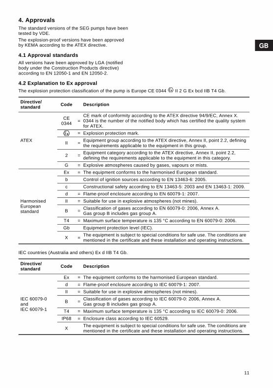
4. ApprovalsThe standard versions of the SEG pumps have been tested by VDE. The explosion-proof versions have been approved by KEMA according to the ATEX directive.
4.1 Approval standardsAll versions have been approved by LGA (notified body under the Construction Products directive) according to EN 12050-1 and EN 12050-2.
4.2 Explanation to Ex approvalThe explosion protection classification of the pump is Europe CE 0344 II 2 G Ex bcd IIB T4 Gb.
IEC countries (Australia and others) Ex d IIB T4 Gb.
Directive/standard Code Description
ATEX
CE 0344 =
CE mark of conformity according to the ATEX directive 94/9/EC, Annex X. 0344 is the number of the notified body which has certified the quality system for ATEX.
= Explosion protection mark.
II = Equipment group according to the ATEX directive, Annex II, point 2.2, defining the requirements applicable to the equipment in this group.
2 = Equipment category according to the ATEX directive, Annex II, point 2.2, defining the requirements applicable to the equipment in this category.
G = Explosive atmospheres caused by gases, vapours or mists.
Harmonised European standard
Ex = The equipment conforms to the harmonised European standard.b Control of ignition sources according to EN 13463-6: 2005.c Constructional safety according to EN 13463-5: 2003 and EN 13463-1: 2009.d = Flame-proof enclosure according to EN 60079-1: 2007.II = Suitable for use in explosive atmospheres (not mines).
B = Classification of gases according to EN 60079-0: 2006, Annex A.Gas group B includes gas group A.
T4 = Maximum surface temperature is 135 °C according to EN 60079-0: 2006.Gb Equipment protection level (IEC).
X = The equipment is subject to special conditions for safe use. The conditions are mentioned in the certificate and these installation and operating instructions.
Directive/ standard Code Description
IEC 60079-0 and IEC 60079-1
Ex = The equipment conforms to the harmonised European standard.d = Flame-proof enclosure according to IEC 60079-1: 2007.II = Suitable for use in explosive atmospheres (not mines).
B = Classification of gases according to IEC 60079-0: 2006, Annex A.Gas group B includes gas group A.
T4 = Maximum surface temperature is 135 °C according to IEC 60079-0: 2006.IP68 = Enclosure class according to IEC 60529.
X The equipment is subject to special conditions for safe use. The conditions are mentioned in the certificate and these installation and operating instructions.
11

5. Identification
5.1 NameplateThe nameplate states the operating data and approvals applying to the pump. The nameplate is fixed to the side of the stator housing opposite the electronic unit. The additional nameplate supplied with the pump can be fixed close to the tank.
Fig. 2 Nameplate
TM04
445
9 13
09
Àß56
Made in Tatabánya, Hungary
Type:
9677
0195
Model:
P.c. Auto Adapt
IP68
Hmax: m Qmax:
P1: kW
l/s
m
kW
A
P2:
Weight: Tmax: °C
Insul.class:
kg
n: Cos φmin -1
opr.:: μF Hz
~
123456789
1011121314
15
16
171819202122
2324
Pos. Description Pos. Description Pos. Description
1 Version 10 Number of phases 19 Maximum liquid temperature
2 Type designation 11 Rated input power 20 Output power
3 Product number 12 Rated speed 21 Power factor
4 Ex mark 13 Rated voltage 22 Rated current
5 ATEX certificate 14 Weight (without cable) 23 Operating capacitor
6 IEC Ex mark 15 Pump approval 24 Frequency
7 IEC Ex certificate 16 Enclosure class 25 Insulation class
8 Production code 17 Maximum installation depth 26 Country of origin
9 Maximum head 18 Maximum flow
12

5.2 Type key
Example SEG.40.11.E.Ex.2.1.502 SE G .40 .11 .E .Ex .2 .1 .5 02
Type rangeGrundfos sewage pumps
Impeller typeG = Grinder system in the pump inlet
MaterialStandard, cast iron
Maximum spherical impeller clearance [mm]Not relevant for SEG pumps
Pump dischargeNominal diameter of pump discharge port [mm]
Output power, P2P2 = Code from type designation/10 kW
Equipment in pumpE = Electronic version
Installation typeBlank = Submerged without cooling jacket
Pump versionBlank = Standard version of submersible wastewater pumpsEx = The pump is designed according to the ATEX standard stated or
Australian standard, AS 2430.1.
Number of poles2 poles, n = 3000 min-1, 50 Hz
Number of phases1 = Single-phase motorBlank = Three-phase motor
Mains frequency5 = 50 Hz
Voltage and starting method02 = 230 V, direct-on-line starting0B = 400-415 V, direct-on-line starting
GenerationBlank = 1st generationA = 2nd generationB = 3rd generation, etc.The pumps belonging to the individual generations differ in design, but are similar in terms of power rating.
Material in pumpBlank = Standard material in pump
13

6. Safety
For safety reasons, all work in tanks must be supervised by a person outside the pump tank.
Tanks for submersible wastewater pumps contain wastewater with toxic and/or disease-causing substances. Therefore, all persons involved must wear appropriate personal protective equipment and clothing and all work on and near the pump must be carried out under strict observance of the hygiene regulations in force.
7. Transportation and storageThe pump may be transported and stored in a vertical or horizontal position. Make sure that the pump cannot roll or fall over. Check that the protective cap for the level sensor has not been damaged during transportation. See fig. 1 (pos. 7). If the protective cap is defective, contact your nearest Grundfos company.All lifting equipment must be rated for the purpose and checked for damage before any attempts to lift the pump. The lifting equipment rating must under no circumstances be exceeded. The pump weight is stated on the pump nameplate.
The polyurethane-embedded plug prevents water from penetrating into the motor via the motor cable.For long periods of storage, the pump must be protected against moisture and heat. After a long period of storage, the pump should be inspected before it is put into operation. Make sure that the impeller can rotate freely. Pay special attention to the shaft seal, cable entry and sensors.
WarningThe use of this product requires experience with and knowledge of the product.Persons with reduced physical, sensory or mental capabilities must not use this product, unless they are under supervision or have been instructed in the use of the product by a person responsible for their safety.Children must not use or play with this product.
WarningPump installation in tanks must be carried out by specially trained persons.Work in or near wastewater collecting tanks must be carried out according to local regulations.
WarningIt must be possible to lock the mains switch in position 0. Type and requirements as specified in EN 60204-1, 5.3.2.
WarningPersons must not enter the installation area when the atmosphere is explosive.
NoteIt is advisable to carry out all maintenance and service work when the pump is placed outside the tank.
WarningMake sure that the lifting bracket is tightened before attempting to lift the pump. Tighten if necessary. Carelessness during lifting or transportation may cause injury to personnel or damage to the pump.
WarningAlways lift the pump by its lifting bracket or by means of a fork-lift truck if the pump is fixed to a pallet. Never lift the pump by means of the motor cable or the hose/pipe.
14

8. Installation
The additional nameplate supplied with the pump can be fixed close to the tank.All safety regulations must be observed at the installation site, for instance the use of blowers for fresh-air supply to the tank.Prior to installation, check the oil level in the oil chamber. See section 12. Maintenance and service. The pumps are suitable for different installation types which are described in sections 8.1 and 8.2.All pump housings have a cast DN 40, PN 10 discharge flange which can also be connected to a DN 50, PN 10 flange.
8.1 Installation on auto coupling Pumps for permanent installation can be mounted on a stationary auto-coupling guide rail system or a "hookup" auto-coupling system. Both auto-coupling systems facilitate maintenance and service as the pump can easily be lifted out of the tank.
Auto-coupling guide rail system, see fig. A on page 570.Proceed as follows:1. Drill mounting holes for the guide rail bracket on
the inside of the tank, and fasten the guide rail bracket provisionally with two screws.
2. Place the auto-coupling base unit on the bottom of the tank. Use a plumb line to establish the correct positioning. Fasten the auto coupling with heavy-duty expansion bolts. If the bottom of the tank is uneven, the auto-coupling base unit must be supported so that it is level when being fastened.
3. Assemble the discharge line in accordance with the generally accepted procedures and without exposing the line to distortion or tension.
4. Insert the guide rails in the auto-coupling base unit, and adjust the length of the rails accurately to the guide rail bracket.
5. Unscrew the provisionally fastened guide rail bracket, fit it on top of the guide rails, and finally fasten it firmly to the tank wall.
6. Clean out debris from the tank before lowering the pump into the tank.
7. Fit the guide claw to the discharge port of the pump. Then slide the guide claw down the guide rails, and lower the pump into the tank by means of a chain secured to the pump lifting bracket. When the pump reaches the auto-coupling base unit, the pump will automatically connect tightly.
WarningBefore beginning the installation, switch off the power supply, and lock the mains switch in position 0.Any external voltage connected to the pump must be switched off before working on the pump.
WarningBefore installation and the first start-up of the pump, check the cable for visible defects to avoid short-circuits.
Caution Before beginning the installation, make sure the tank floor is even.
WarningDo not put your hands or any tool into the pump suction or discharge port after the pump has been connected to the power supply, unless the pump has been switched off by removing the fuses or switching off the mains switch. It must be ensured that the power supply cannot be accidentally switched on.
WarningOnly use the lifting bracket for lifting the pump. Do not use it to hold the pump when in operation.
NoteWe recommend always to use Grundfos accessories to avoid malfunction due to incorrect installation.
Note
The pumps are designed for intermittent operation. When completely submerged in the pumped liquid, the pumps can also operate continuously. See section 11.2 Operating modes.
WarningBefore beginning installation procedures, make sure that the atmosphere in the tank is not potentially explosive.
Caution
Make sure that the pipework is installed without the use of undue force. No loads from the pipework weight must be carried by the pump. We recommend the use of loose flanges to ease the installation and to avoid pipe tension at flanges and bolts.
Caution
Do not use elastic elements or bellows in the pipework. Never use these elements as a means to align the pipework.
NoteThe guide rails must not have any axial play as this would cause noise during pump operation.
15

8. Hang up the end of the chain on a suitable hook at the top of the tank and in such a way that the chain cannot come into contact with the pump housing.
9. Adjust the length of the motor cable by coiling it up on a relief fitting to ensure that the cable is not damaged during operation. Fasten the relief fitting to a suitable hook at the top of the tank. Make sure that the cables are not sharply bent or pinched.
10. Connect the motor cable and the monitoring cable, if any.
Hookup auto-coupling system, see fig. B on page 571.Proceed as follows:1. Fit the crossbar in the tank. 2. Fit the adapted piece of pipe for the movable part
of the hookup auto coupling to the pump discharge port.
3. Fasten a shackle and a chain to the movable part of the hookup auto coupling.
4. Clean out debris from the tank before lowering the pump.
5. Lower the pump into the tank by means of the chain secured to the pump lifting bracket.
6. Hang up the end of the chain on a suitable hook at the top of the tank and in such a way that the chain cannot come into contact with the pump housing.
7. Adjust the length of the motor cable by coiling it up on a relief fitting to ensure that the cable is not damaged during operation. Fasten the relief fitting to a suitable hook at the top of the tank. Make sure that the cables are not sharply bent or pinched.
8. Connect the motor cable and the monitoring cable, if any.
8.2 Free-standing submerged installation Pumps for free-standing submerged installation can stand freely on the bottom of the tank or similar location. See fig. C on page 572.The pump must be mounted on separate feet (accessory). In order to facilitate service on the pump, fit a flexible union or coupling to the discharge line for easy separation.If a hose is used, make sure that the hose does not buckle and that the inside diameter of the hose matches that of the discharge port. If a rigid pipe is used, the union or coupling, non-return valve and isolating valve should be fitted in the order mentioned, when viewed from the pump. If the pump is installed in muddy conditions or on uneven ground, it is recommended to support the pump on bricks or a similar support. Proceed as follows:1. Fit a 90 ° elbow to the pump discharge port,
and connect the discharge pipe or hose.2. Lower the pump into the liquid by means of a
chain secured to the lifting bracket of the pump. It is recommended to place the pump on a plane, solid foundation. Make sure that the pump is hanging from the chain and not the cable.
3. Hang up the end of the chain on a suitable hook at the top of the tank and in such a way that the chain cannot come into contact with the pump housing.
4. Adjust the length of the motor cable by coiling it up on a relief fitting to ensure that the cable is not damaged during operation. Fasten the relief fitting to a suitable hook. Make sure that the cables are not sharply bent or pinched.
5. Connect the motor cable and the monitoring cable, if any.
Note
If several pumps are installed in the same tank, the pumps must be installed at the same level in order to allow optimum pump alternation.
16

9. Electrical connection
The electrical connection should be carried out in accordance with local regulations.
The supply voltage and frequency are marked on the pump nameplate. For voltage tolerance, see section 14.1 Supply voltage. Make sure that the motor is suitable for the power supply available at the installation site.All pumps are supplied with 10 metres of cable and a free cable end.
9.1 CIU unit (communication interface)The Grundfos CIU unit (CIU = Communication Interface Unit) is used as a communication interface between an SEG pump and a main network.The CIU unit is optional. See separate installation and operating instructions supplied with the unit.
9.2 Electrical connection – single-phase pumps
The pump has a patented start function which eliminates the need of a starting capacitor. The operating capacitor is incorporated in the pump.
Fig. 3 Wiring diagram for single-phase pumps
Caution The pump must not be used with a frequency converter.
WarningThe pump must be connected to an electrical panel in accordance with local regulations. The electrical panel typically includes fuses, main switch and earth leakage circuit breaker with a contact separation according to EN 60204-1, 5.3.2.It must be possible to lock the mains switch in position 0. Type and requirements as specified in EN 60204-1, 5.3.2.The pump incorporates a motor-protective circuit breaker and all control logic.
WarningIf the pump has an Ex mark on the nameplate, make sure that the pump is connected in accordance with the instructions given in this booklet.
WarningThe explosion protection classification of the pump is CE II 2 G, Ex bcd IIB T4 Gb. See section 4.2.The classification of the installation site must in each individual case be approved by the local authorities. The CIU unit, if used, (see section 9.1) must not be installed in potentially explosive environments.
WarningOn explosion-proof pumps, make sure that an external earth conductor is connected to the external earth terminal on the pump using a conductor with a secure cable clamp. Clean the surface for external earth connection, and fit the cable clamp.The cross section of the earth conductor must be at least 4 mm2, e.g. type H07 V2-K (PVT 90 °) yellow/green.Make sure that the earth connection is protected from corrosion.
WarningBefore installation and the first start-up of the pump, check the cable for visible defects to avoid short-circuits.
WarningThe pump must not run dry.
CautionA possible replacement of the cable must be carried out by Grundfos or an authorised service workshop.
TM04
429
7 12
09
2 A 230 VAC2 A 230 VAC
17

9.3 Electrical connection – three-phase pumps
The pump motor is designed so that the phase sequence in the electrical panel is clockwise (can be determined with a phase sequence detector). The pump does not start unless the phase sequence is correct. If the dry-running sensors are covered by liquid, and the pump does not start, the cause may be a wrong phase sequence. Interchange L1 and L2.
Fig. 4 Wiring diagram for three-phase pumps
9.4 Alarm relay/communication connectionThe pump incorporates an alarm relay output. NC and NO are available and can be used as required, for example for acoustic or visual alarms.Alternatively, the wires 4 and 6 can be used for external communication via a CIU unit (communication interface).
See example of wiring diagram in the documentation supplied with the CIU unit.
10. Configuration
10.1 Default settingsThe pump is supplied from the factory with the following default settings.
If one or more of the above parameters are to be changed, use the optional CIU unit together with an R100 remote control.The CIU unit can be connected temporarily for configuration.For further information, see installation and operating instructions for the CIU unit.
Fig. 5 Start and stop levels
10.2 Pump alternationIf several pumps (up to four) are installed in the same tank, the control logic incorporated in the pump will ensure that the load is distributed evenly among the pumps over time.Alternation is carried out according to a patented method based on measurement of the liquid level in the tank.
TM04
429
8 12
09
Note
If a CIU unit is connected, the relay must not be used. The CIU unit incorporates a relay which takes over the alarm function.
2 A 230 VAC
Parameter 0.9 - 1.5 kW 2.6 kW 3.1 - 4.0
kW
Start delay (random) Off – –
Start level 25 cm – –
High-level alarm + 10 cm – –
Anti-seizing:
Interval 3 days – –
Duration 2 sec. – –
TM04
447
8 15
09
Note The barometric pressure may affect the alternating sequence.
Alarm
Start
Stop
18

10.3 Start level setThe pump start level may be affected by the barometric pressure. In the case of long intervals between start and stop, the start level may differ from the set level. See examples below.
Example 1: Constant barometric pressureThe pump will start when the liquid level in the tank has reached the set start level. Then the pump will run until the liquid level reaches the stop level. When it stops, the pump will calibrate itself in relation to the actual barometric pressure. See fig. 6.
Fig. 6 Example 1: Constant barometric pressure
Example 2: Rising barometric pressureIf the barometric pressure rises after the pump has stopped, the pump will register this rise as a rise in liquid level. The result may be that the pump starts before the set start level is reached. See fig. 7.
Fig. 7 Example 2: Rising barometric pressure
Example 3: Falling barometric pressureIf the barometric pressure falls after the pump has stopped, the pump will register this fall as a fall in liquid level. The result may be that the pump starts after the set start level was reached. See fig. 8.Therefore, the distance between the pump stop level and the inlet to the tank should be at least 50 cm. See fig. 5.
Fig. 8 Example 3: Falling barometric pressure
10.4 Thermal switchesAll pumps have two sets of thermal switches incorporated in the stator windings.
TM04
433
7 12
09TM
04 4
338
1209
Barometric pressure
Pum
p ru
nnin
g
Pum
p ru
nnin
g
Pum
p ru
nnin
g
Start level set
Stop level
Barometric pressure
Pum
p ru
nnin
g
Pum
p ru
nnin
g
Pum
p ru
nnin
g
Start level set
Stop levelTM
04 4
339
1209
WarningThe pump incorporates dry-running protection based on two dry-running sensors placed on either side of the electronic unit. If a dry-running sensor detects water shortage, the pump will stop immediately and cannot restart until the sensors are fully submerged again.The sensors must be cleaned at regular intervals, depending on the deposits of sludge on the sensors in the tank.
Note
When a thermal switch is activated, the pump will stop immediately and will not restart until the motor windings have cooled sufficiently.If the pump does not restart automatically, the pump must be reset and restarted manually. See section 11.4 Resetting the pump.If the pump has to be restarted manually repeatedly, contact Grundfos or an authorised service workshop.
Barometric pressure
Pum
p ru
nnin
g
Pum
p ru
nnin
g
Pum
p ru
nnin
g
Start level set
Stop level
19

11. Start-up
After one week of operation after replacement of the the shaft seal, the condition of the oil in the oil chamber should be checked. See section 12. Maintenance and service for procedure.
11.1 Before start-upProceed as follows:1. Remove the fuses. Check that the impeller can
rotate freely. Turn the grinder head by hand.2. Check the condition of the oil in the oil chamber.
See also section 12.8 Oil change.3. Check that the level sensor is clean, and that the
protective cap is intact. 4. Check that the dry-running sensors are clean.5. Open the isolating valves, if fitted.6. Lower the pump into the liquid, and insert the
fuses.7. Check that the system has been filled with liquid
and vented. The pump is self-venting.8. Switch on the power supply to the pump.When powered, the pump will start and pump down to the dry-running level. This function can be used to check the pump.
11.2 Operating modesThe pumps are designed for intermittent operation (S3). When completely submerged, the pumps can also operate continuously (S1).• S3, intermittent operation:
The electronics of the pump will in due time stop the pump automatically. The operating mode S3 means that within 10 minutes the pump must run for 4 minutes and be stopped for 6 minutes. See fig. 9. In this operating mode, the pump is partly submerged in the pumped liquid, i.e. the liquid level reaches at minimum the middle of the motor.
Fig. 9 S3 operation
• S1, continuous operation:In this operating mode, the pump can operate continuously without having to be stopped for cooling. See fig. 10. Being completely submerged, the pump is sufficiently cooled by the surrounding liquid.
Fig. 10 S1 operation
WarningBefore starting work on the pump, make sure that the fuses have been removed or the mains switch has been switched off. It must be ensured that the power supply cannot be accidentally switched on.Make sure that all protective equipment has been connected correctly.The pump must not run dry.
WarningOpening the clamp when the pump is started can lead to personal injury or death.
WarningThe pump must not be started if a potentially explosive atmosphere is present in the tank.
Caution
In case of abnormal noise or vibrations from the pump or other pump or supply failure, stop the pump immediately. Do not attempt to restart the pump until the cause of the fault has been found and the fault corrected.
NoteIf the dry-running sensors are not covered by liquid, the pump cannot start.
TM04
452
7 15
09TM
04 4
528
1509
Operation
Stop
6 min.4 min.
10 min.
P
t
P
t
20

11.3 Direction of rotationAll single-phase pumps are factory-wired for the correct direction of rotation. The electronics incorporated in three-phase pumps ensures that the pump does not start with a wrong phase sequence, and consequently wrong direction of rotation.If the pump does not run, and the liquid level is above the dry-running sensors, interchange L1 and L2.
Fig. 11 Jerk direction
11.4 Resetting the pumpTo reset the pump, switch off the power supply to the pump for 1 minute, and switch it on again.
12. Maintenance and service
Before carrying out maintenance and service, it must be ensured that the pump has been thoroughly flushed with clean water. Rinse the pump parts in water after dismantling.
Note
The pump rotates clockwise when viewed from above. When started, the pump will jerk in the opposite direction of the direction of rotation.
TM04
447
9 15
09
WarningBefore starting work on the pump, make sure that the fuses have been removed or the mains switch has been switched off. It must be ensured that the power supply cannot be accidentally switched on.All rotating parts must have stopped moving.
WarningExcept for service on the hydraulic part, all other service work must be carried out by Grundfos or an authorised service workshop approved for servicing Ex products.
WarningWhen slackening the screws of the oil chamber, note that pressure may have built up in the chamber. Do not remove the screws until the pressure has been fully relieved.
Note
The cleaning intervals in section 12.1 are stated as guidelines and should be matched to the specific tank.For explosion-proof pumps, the cleaning intervals in section 12.2 must be observed.
NoteDuring long periods of inactivity, it is recommended to check the function of the pump.
21

12.1 Recommended cleaning intervals for sensors in standard pumps
For cleaning of sensors, see section 12.6.
12.2 Required cleaning intervals for sensors in explosion-proof pumps
For cleaning of sensors, see section 12.6.
12.3 Inspection intervals
Pumps running normal operation should be inspected every 3000 operating hours or at least once a year. If the dry-solid content of the pumped liquid is very high or sandy, check the pump at shorter intervals.Check the following points: • Power consumption
See pump nameplate.• Oil level and oil condition
When the pump is new or after replacement of the shaft seal, check the oil level after one week of operation.If the oil contains more than 20 % water, the shaft seal may be defective. The oil should be changed every 3000 operating hours or at least once a year.Use Shell Ondina 917 oil or similar type.See sections 12.8 Oil change and 12.9 Service kits.
• For cleaning of sensors, see section 12.6.
The table states how much oil the pumps must have in the oil chamber:
• Cable entryMake sure that the cable entry is watertight and that the cables are not sharply bent and/or pinched. See section 12.9 Service kits.
• Pump partsCheck the impeller, pump housing, etc. for possible wear. Replace defective parts.See section 12.9 Service kits.
• Ball bearingsCheck the shaft for noisy or heavy operation (turn the shaft by hand). Replace defective ball bearings.A general overhaul of the pump is usually required in case of defective ball bearings or poor motor function. This work must be carried out by Grundfos or an authorised service workshop.
• Grinder system/partsIn case of frequent choke-ups, check the grinder system for visible wear. When worn, the edges of the grinding parts are round and worn. Compare with a new grinder system.
Wastewater containing
grease
Wastewater containing dry solid matter or
fibres
Wastewater without
grease, dry solid matter or
fibres
3 months 6 months 12 months
Wastewater containing
grease
Wastewater containing dry solid matter or
fibres
Wastewater without
grease, dry solid matter or
fibres
3 months 6 months 6 months
WarningExcept for service on the hydraulic part, all other service work must be carried out by Grundfos or an authorised service workshop approved for servicing Ex products.
Note Used oil must be disposed of in accordance with local regulations.
Pump type Quantity of oil in oil chamber [l]
SEG up to 1.5 kW 0.17
SEG 2.2 to 4.0 kW 0.42
22

12.4 Replacing the grinder system
For position numbers, see page 588.Removing the grinder system:1. Slacken the screw (pos. 188a) in one of the pump
feet.2. Loosen the grinder ring (pos. 44), and open the
bayonet socket by knocking the grinder ring clockwise.
Fig. 12 Removal of grinder ring
3. Remove the grinder ring (pos. 44).4. Remove the screw from the shaft end. 5. Remove the grinder head (pos. 45).For adjustment of impeller clearance, see fig. 13.a) Gently tighten the nut (pos. 68) (spanner size 24)
until the impeller (pos. 49) cannot rotate any more.
b) Slacken the nut by 1/4 turn.
Fig. 13 Adjustment of impeller clearance
Fitting the grinder system:1. When fitting the grinder head (pos. 45), the
projections on the back of the grinder head must engage with the holes in the impeller (pos. 49).
2. Tighten the screw (pos. 188a) for the grinder head to 20 Nm.
3. Engage the bayonet socket for the grinder ring (pos. 44).
4. Knock the bayonet socket counter-clockwise until the grinder ring (pos. 44) is fastened.
5. Tighten the screw (pos. 188a).6. Turn the grinder head to make sure that it is fitted
correctly, i.e. it turns freely.
12.5 Cleaning the pump housingFor position numbers, see page 588.To clean the pump housing, proceed as follows:
Dismantling1. Loosen and remove the clamp (pos. 92) holding
the pump housing and motor together.2. Lift the motor part out of the pump housing
(pos. 50). The impeller and grinder head are removed together with the motor part.
3. Clean the pump housing and the impeller.
Assembly1. Place the motor part with impeller and grinder
head in the pump housing.2. Fit and tighten the clamp.See also section 12.7 Checking/replacing the shaft seal.
WarningBefore starting work on the pump, make sure that the fuses have been removed or the mains switch has been switched off. It must be ensured that the power supply cannot be accidentally switched on.All rotating parts must have stopped moving.
TM04
448
0 15
09
TM04
448
1 15
09
23

12.6 Cleaning the sensors
Fig. 14 Position of level and dry-running sensors
Proceed as follows:See fig. 14. 1. Level sensor (pos. 7):
Flush the sensor with clean water.Dry-running sensors (pos. 10): Flush the dry-running sensors with clean water and clean using a soft brush.
2. Switch on the power supply to the pump. 3. Check that the pump starts and pumps down to
the dry-running level.
12.7 Checking/replacing the shaft sealTo make sure that the shaft seal is intact, the oil should be checked.If the oil contains more than 20 % water, the shaft seal may be defective and must be replaced. If the shaft seal is nevertheless used, the motor will be damaged.If the oil is clean, it can be reused. See also section 12. Maintenance and service.For position numbers, see page 588.
To check the shaft seal, proceed as follows:1. Remove the grinder ring (pos. 44).
See section 12.4 Replacing the grinder system.2. Remove the screw (pos. 188a) from the shaft
end.3. Loosen and remove the clamp (pos. 92) holding
the pump housing and motor together.4. Lift the motor part out of the pump housing
(pos. 50). The impeller and grinder head are removed together with the motor part.
5. Remove the grinder head (pos. 45).6. Remove the impeller (pos. 49) from the shaft.7. Drain the oil from the oil chamber.
See section 12.8 Oil change.
The shaft seal is a complete unit for all pumps.8. Remove the screws (pos. 188a) securing the
shaft seal (pos. 105).9. Lift the shaft seal (pos. 105) out of the oil
chamber according to the lever principle using the two dismounting holes in the shaft seal carrier (pos. 58) and two screwdrivers.
10. Check the condition of the shaft where the secondary seal of the shaft seal touches the shaft. The bush (pos. 103) fitted to the shaft must be intact. If it is worn and must be replaced, the pump must be checked by Grundfos or an authorised service workshop.
If the shaft is intact, proceed as follows: 1. Check/clean the oil chamber. 2. Lubricate the faces in contact with the shaft seal
with oil (pos. 105a) (O-rings and shaft).3. Insert the new shaft seal (pos. 105) using the
plastic bush included in the kit.4. Tighten the screws (pos. 188a) securing the shaft
seal to 16 Nm.5. Fit the impeller. Make sure that the key (pos. 9a)
is fitted correctly.6. Fit the pump housing (pos. 50).7. Fit and tighten the clamp (pos. 92).8. Fill the oil chamber with oil. See section 12.8 Oil
change.For adjustment of impeller clearance, see section 12.4 Replacing the grinder system.
TM04
455
9 16
09
CautionTo avoid damaging the sensors, do not use other cleaning aid than those mentioned above.
NoteIf the dry-running sensors are not covered by liquid, the pump cannot start.
Note Used oil must be disposed of in accordance with local regulations.
WarningWhen slackening the screws of the oil chamber, note that pressure may have built up in the chamber. Do not remove the screws until the pressure has been fully relieved.
24

12.8 Oil changeEvery 3000 operating hours or at least once a year, change the oil in the oil chamber as described below.If the shaft seal has been changed, the oil must be changed as well. See section 12.7 Checking/replacing the shaft seal.Draining of oil:
1. Slacken and remove both oil screws to allow all the oil to drain from the chamber.
2. Check the oil for water and impurities. If the shaft seal has been removed, the oil will give a good indication of the condition of the shaft seal.
Oil filling, pump lying down:See fig. 15. 1. Place the pump in such a position that it is lying
on the stator housing and the discharge flange and that the oil screws are pointing upwards.
2. Fill oil into the oil chamber through the upper hole until it starts running out of the lower hole. The oil level is now correct.For oil quantity, see section 12.3 Inspection intervals.
3. Fit both oil screws using the packing material included in the kit.See section 12.9 Service kits.
Oil filling, pump in upright position:1. Place the pump on a plane, horizontal surface.2. Fill oil into the oil chamber through one of the
holes until it starts running out of the other hole.For oil quantity, see section 12.3 Inspection intervals.
3. Fit both oil screws using the packing material included in the kit.See section 12.9 Service kits.
Fig. 15 Oil filling holes
WarningWhen slackening the screws of the oil chamber, note that pressure may have built up in the chamber. Do not remove the screws until the pressure has been fully relieved.
Note Used oil must be disposed of in accordance with local regulations.
TM04
448
2 15
09
Oil level
Oil filling
25

12.9 Service kits
The service kits in the table below are available for all pumps.The kits can be ordered as required.
WarningBefore starting work on the pump, make sure that the fuses have been removed or the mains switch has been switched off. It must be ensured that the power supply cannot be accidentally switched on.All rotating parts must have stopped moving.
Service kit Contents Pump type Material Product number
Shaft seal kit Shaft seal complete
SEG.40.09 - 15BQQP 96076122
BQQV 96645160
SEG.40.26 - 40 BQQP 96076123
BQQV 96645275
O-ring kit O-rings and gaskets for oil screws
SEG.40.09 - 15NBR 96076124
FKM 96646061
SEG.40.26 - 40NBR 96076125
FKM 96646062
Grinder system Grinder head, grinder ring, shaft screw and locking screw All types 96076121
Impeller Impeller complete with adjusting nut, shaft screw and key
SEG.40.09 96076115
SEG.40.12 96076116
SEG.40.15 96076117
SEG.40.26 96076118
SEG.40.31 96076119
SEG.40.40 96076120
Oil
1 litre of oil, type Shell Ondina 917.See section 12. Maintenance and service for required quantity in oil chamber.
All types 96076171
Lifting bracket Lifting bracket and screw0.9 - 1.5 kW 96984147
2.6 - 4.0 kW 96984148
Power plug Plug for power supply and O-rings for cover All types 96984144
Protective cap for level sensor
Protective cap and O-rings for cover and sensor All types 96898081
Level sensor Level sensor, protective cap and O-rings for cover and sensor
Standard pumps 96898082
Ex pumps 96984130
Dry-running sensor
Dry-running sensor and O-rings for cover and sensor
Standard pumps 96898083
Ex pumps 96984131
Electronic unitSingle-phase
Cover with electronics and O-rings for cover
Single-phase pumps 96898085
Single-phase Ex pumps 96984145
Electronic unitThree-phase
Cover with electronics and O-rings for cover
Three-phase pumps 96898086
Three-phase Ex pumps 96984146
Pt1000 sensor Pt1000 sensor and bracket All types 96984143
26

12.10 Built-in protectionThe motor incorporates an electronic unit which protects the motor in various situations.In case of overload, the built-in overload protection will stop the pump for 5 minutes. After that period, the pump is ready to restart if the start conditions are fulfilled.To reset the pump, switch off the power supply for 1 minute. The motor is protected in case of:• Dry running.• Voltage surges (up to 6000 V) in areas with high
lightning intensity. External lightning protection is required.
• Overvoltage.• Undervoltage.• Overload. • Overtemperature.
12.11 Contaminated pumps
If Grundfos is requested to service the pump, Grundfos must be contacted with details about the pumped liquid, etc. before the pump is returned for service. Otherwise Grundfos can refuse to accept the pump for service.Possible costs of returning the pump are paid by the customer.However, any application for service (no matter to whom it may be made) must include details about the pumped liquid if the pump has been used for liquids which are injurious to health or toxic.Before a pump is returned, it must be cleaned in the best possible way.
Operating capacitor
Operating capacitor, Pt1000 sensor, bracket and O-rings for cover
All single-phase pumps 96984142
Caution A possible replacement of the cable must be carried out by Grundfos or an authorised service workshop.
Service kit Contents Pump type Material Product number
WarningIf a pump has been used for a liquid which is injurious to health or toxic, the pump will be classified as contaminated.
27

13. Fault finding chart
13.1 MeggingMegging of SEG pumps is not allowed, as the built-in electronics may be damaged.
WarningBefore attempting to diagnose any fault, make sure that the fuses have been removed or the mains switch has been switched off. It must be ensured that the power supply cannot be accidentally switched on. All rotating parts must have stopped moving.
WarningAll regulations applying to pumps installed in potentially explosive environments must be observed.It must be ensured that no work is carried out in potentially explosive atmosphere.
Fault Cause Remedy
1. The pump does not run. a) The dry-running sensors are not covered by liquid.
After power-on: Allow the liquid level to rise until the dry-running sensors are covered with liquid.
b) Three-phase pumps only:The pump is connected to the power supply with a wrong phase sequence.
Interchange L1 and L2.
c) Fuses in electric installation blown.
Replace blown fuses. If the new ones blow too, check the electric installation and the submersible drop cable.
d) Supply failure; short-circuit; fault in cable or motor winding.
Have the cable and motor checked and repaired by a qualified electrician.
e) Fault in motor electronics. Have the motor checked and repaired by a Grundfos service engineer.
f) Deposits on level or dry-running sensors.
Clean the sensor(s).
2. The pump operates, but the motor stops after a short while.
a) Impeller blocked by impurities. Increased current consumption in all three phases.
Clean the impeller.
b) Increased current consumption due to large voltage drop.
Check that the supply voltage is within the range.
c) Too high liquid temperature. Reduce the liquid temperature.
d) Too high liquid viscosity. Dilute the liquid.
3. The pump operates at below-standard performance and power consumption.
a) Discharge pipe partly blocked by impurities.
Clean the discharge port.
b) Valves in the discharge pipe partly closed or blocked.
Check and clean or replace the valves, if necessary.
4. The pump operates, but delivers no liquid.
a) Discharge valve closed or blocked.
Check the discharge valve, and possibly open and/or clean it.
b) Non-return valve blocked. Clean the non-return valve.
Vent the pump.c) Air in pump.
5. The pump is choked up. a) Grinder system is worn. Replace the grinder system.
28

14. Technical data
14.1 Supply voltage• 1 x 230 V – 10 %/+ 6 %, 50 Hz.• 3 x 400 V – 10 %/+ 10 %, 50 Hz.
14.2 Enclosure classIP68. According to IEC 60529.
14.3 Ex protectionCE II 2 G, Ex bcd IIB T4 Gb according to EN 60079-0: 2006 and Ex d IIB T4 Gb according to IEC 60079-0: 2006.
14.4 Insulation classF (155 °C).
14.5 Pump curvesPump curves are available via internet www.grundfos.com.The curves are to be considered as a guide. They must not be used as guarantee curves.Test curves for the supplied pump are available on request.
14.6 Sound pressure levelThe sound pressure level of the pumps is lower than the limiting values stated in the EC Council Directive 98/37/EC relating to machinery.
15. DisposalThis product or parts of it must be disposed of in an environmentally sound way:1. Use the public or private waste collection service.2. If this is not possible, contact the nearest
Grundfos company or service workshop.
Subject to alterations.
29

Fig. A One-pump installation on auto-coupling
TM04
448
3 15
09
570

Fig. B One-pump installation on hookup auto-couplingTM
04 5
648
3709
571

Fig. C Free-standing Installation
TM04
448
5 15
09
Power[kW] A B C D E F G H I J K M N U O S T V X Y
0.9, 1.2and 1.5 456 100 271 71 255 154 216 99 388 214 140 134 100 536
min. 600
116 500 68 397 495
2.6 527 100 271 60 292 173 256 119 423 215 166 134 100 619 115 582 80 433 531
3.1 and4.0 567 100 271 60 292 173 256 119 423 214 166 134 100 657 115 622 79 433 531
572

Pos.Description Beschreibung Description Descrizione
6a Pin Stift Broche Perno
7a Rivet Niet Rivet Rivetto
9a Key Passfeder Clavette Chiavetta
37a O-ring O-Ring Joint torique O-ring
44 Grinder ring Schneidring Anneau broyeur Anello trituratore
45 Grinder head Schneidkopf Tête de broyeur Trituratore
48 Stator Stator Stator Statore
48a Terminal board Klemmbrett Bornier Morsettiera
49 Impeller Laufrad Roue Girante
50 Pump housing Pumpengehäuse Corps de pompe Corpo pompa
55 Stator housing Statorgehäuse Logement de stator Cassa statore
58 Shaft seal carrier Gleitringdichtungs-träger
Support de garniture mécanique
Supporto tenuta meccanica
66 Locking ring Sicherungsring Anneau de serrage Anello di arresto
68 Adjusting nut Justiermutter Ecrou de réglage Dado di regolazione
76 Nameplate Leistungsschild Plaque signalétique Targhetta di identificazione
90a Electronic unit Elektronikeinheit Unité électronique Unità elettronica
90b O-ring O-Ring Joint torique O-ring
92 Clamp Spannband Collier de serrage Fascetta
102 O-ring O-Ring Joint torique O-ring
103 Bush Buchse Douille Bussola
104 Seal ring Dichtungsring Anneau d’étanchéité Anello di tenuta
105105a Shaft seal Gleitringdichtung Garniture mécanique Tenuta meccanica
107 O-rings O-Ringe Joints toriques O-ring
112a Locking ring Sicherungsring Anneau de serrage Anello di arresto
153 Bearing Lager Roulement Cuscinetto
154 Bearing Lager Roulement Cuscinetto
155 Oil chamber Ölsperrkammer Chambre à huile Camera dell’olio
158 Corrugated spring Gewellte Feder Ressort ondulé Molla ondulata
159 O-ring O-Ring Joint torique O-ring
161 Operating capacitor* Betriebskondensator* Condensateur* Condensatore di marcia*
161b Nut Mutter Ecrou Dado
161c Bracket Halter Support Staffa
161d Washer Unterlegscheibe Rondelle Rondella
161e Washer Unterlegscheibe Rondelle Rondella
161f Screw Schraube Vis Vite
172 Rotor/shaft Rotor/Welle Rotor/arbre Gruppo rotore/albero
173 Screw Schraube Vis Vite
173a Washer Unterlegscheibe Rondelle Rondella
174 Earth screw Erdungsschraube Vis terre Vite di messa a terra
573

* Single-phase pumps only.
** Standard pumps have only one dry-running sensor.
174a Washer Unterlegscheibe Rondelle Rondella
176 Inner plug part Kabelanschluß, innerer Teil
Partie intérieure de la fiche
Parte interna del connettore
181 Outer plug part Kabelanschluß,äußerer Teil
Partie extérieure de la fiche
Parte esterna del connettore
188a Screw Schraube Vis Vite
190 Lifting bracket Tragbügel Poignée de levage Maniglia
193 Oil screw Ölschraube Bouchon d’huile Tappo dell’olio
193a Oil Öl Huile Olio
194 Gasket Dichtung Joint d’étanchéité Guarnizione
198 O-ring O-Ring Joint torique O-ring
285 Dry-running sensor** Trockenlaufsensor** Capteur de marche à sec**
Sensore di marcia a secco**
285a O-ring O-Ring Joint torique O-ring
285b Set screw Einstellschraube Jeu de vis Vite di fermo
287 Level sensor Niveausensor Capteur de niveau Sensore di livello
287a Protection cap Schutzkappe Bouchon de protection Tappo di protezione
287b O-ring O-Ring Joint torique O-ring
287c Set screw Einstellschraube Jeu de vis Vite di fermo
288 Pt1000 sensor Pt1000-Sensor Capteur Pt1000 Sensore Pt1000
Pos.Description Beschreibung Description Descrizione
574

Pos.Descripción Descrição Περιγραφή
Omschrijving
6a Pasador Pino Πείρος Paspen
7a Remache Rebite Πριτσίνι Klinknagel
9a Chaveta Chaveta Κλειδί Spie
37a Junta tórica O-ring Δακτύλιος-Ο O-ring
44 Anillo de corte Anilha da trituradora Δακτύλιος άλεσης Snijring
45 Cabezal de corte Cabeça da trituradora Κεφαλή άλεσης Snijkop
48 Estator Estator Στάτης Stator
48a Caja de conexiones Caixa terminal Κλέμες σύνδεσης Aansluitblok
49 Impulsor Impulsor Πτερωτή Waaier
50 Cuerpo de bomba Voluta da bomba Περίβλημα αντλίας Pomphuis
55 Alojamiento de estator Carcaça do estator Περίβλημα στάτη Motorhuis
58 Soporte de cierre Suporte do empanque Φορέας στυπιοθλίπτη άξονα Dichtingsplaat
66 Anillo de cierre Anilha de fixação Ασφαλιστικός δακτύλιος Borgring
68 Tuerca de ajuste Porca de ajuste Ρυθμιστικό περικόχλιο Afstelmoer
76 Placa de identificación Placa de característi-cas Πινακίδα Typeplaat
90a Unidad electrónica Unidade electrónica Ηλεκτρονική μονάδα Elektronische unit
90b Junta tórica O-ring Δακτύλιος-Ο O-ring
92 Abrazadera Gancho Σφιγκτήρας Span ring
102 Junta tórica O-ring Δακτύλιος-Ο O-ring
103 Casquillo Anilha Αντιτριβικός δακτύλιος Bus
104 Anillo de cierre Anilha de empanque Στεγανοποιητικός δακτύλιος Oliekeerring
105105a Cierre Empanque Στυπιοθλίπτης άξονα As afdichting
107 Juntas tóricas O-rings Δακτύλιοι-Ο O-ringen
112a Anillo de cierre Anilha de fixação Ασφαλιστικός δακτύλιος Borgring
153 Cojinete Rolamento Έδρανο Kogellager
154 Cojinete Rolamento Έδρανο Kogellager
155 Cámara de aceite Compartimento do óleo Θάλαμος λαδιού Oliekamer
158 Muelle ondulado Mola Αυλακωτό ελατήριο Drukring
159 Juntas tóricas O-rings Δακτύλιοι-Ο O-ring
161 Condensador operativo*
Condensador de funcionamento* Πυκνωτής λειτουργίας* Bedrijfscondensator*
161b Tuerca Porca Παξιμάδι Moer
161c Soporte Suporte Βραχίονας στήριξης Beugel
161d Arandela Anilha Ροδέλα Ring
161e Arandela Anilha Ροδέλα Ring
161f Tornillo Parafuso Βίδα Schroef
172 Rotor/eje Rotor/veio Ρότορας/άξονας Rotor/as
173 Tornillo Parafuso Βίδα Schroef
575

* Single-phase pumps only.
** Standard pumps have only one dry-running sensor.
173a Arandela Anilha Ροδέλα Ring
174 Tornillo de tierra Parafuso de terra Βίδα γείωσης Aardschroef
174a Arandela Anilha Ροδέλα Ring
176 Parte de clavija interior Parte interna do bujão Εσωτερικό τμήμα φις Kabelconnector inwendig
181 Parte de clavija exterior Parte externa do bujão Εξωτερικό τμήμα φις Kabelconnector uitwendig
188a Tornillo Parafuso Βίδα Inbusbout
190 Asa Suporte de elevação Χειρολαβή Ophangbeugel
193 Tornillo de aceite Parafuso do óleo Βίδα λαδιού Inbusbout
193a Aceite Óleo Λάδι Olie
194 Junta Junta Τσιμούχα Pakkingring
198 Junta tórica O-ring Δακτύλιος-Ο O-ring
285 Sensor de marcha en seco**
Sensor de funciona-mento em seco**
Αισθητήρας ξηρής λειτουργίας** Droogloopsensor**
285a Junta tórica O-ring Δακτύλιος-Ο O-ring
285b Tornillo ajuste Conjunto de parafusos Βίδα ρύθμισης Stelbout
287 Sensor de nivel Sensor de nível Αισθητήρας στάθμης Niveausensor
287a Tapón de protección Tampa de protecção Προστατευτικό καπάκι Beschermkap
287b Junta tórica O-ring Δακτύλιος-Ο O-ring
287c Tornillo ajuste Conjunto de parafusos Βίδα ρύθμισης Stelbout
288 Sensor Pt1000 Sensor Pt1000 Αισθητήρας Pt1000 Pt1000 sensor
Pos.Descripción Descrição Περιγραφή
Omschrijving
576

Pos.Beskrivning
Kuvaus Beskrivelse Opis
6a Stift Tappi Stift Kołek
7a Nit Niitti Nitte Nit
9a Kil Kiila Feder Klin
37a O-ring O-rengas O-ring Pierścień O-ring
44 Skärring Repijärengas Snittering Pierścień tnący
45 Skärhuvud Repijä Snittehoved Głowica tnąca
48 Stator Staattori Stator Stator
48a Kopplingsplint Kytkentälevy Klembræt Listwa przyłączeniowa
49 Pumphjul Juoksupyörä Løber Wirnik
50 Pumphus Pumppupesä Pumpehus Korpus pompy
55 Statorhus Staattoripesä Statorhus Obudowa statora
58 Axeltätningshållare Akselitiivistekannatin Akseltætningsholder Mocowanie uszczelnienia wału
66 Låsring Lukkorengas Låsering Pierścień mocujący
68 Justermutter Säätömutteri Justermøtrik Nakrętkadopasowująca
76 Typskylt Arvokilpi Typeskilt Tabliczka znamionowa
90a Elektronikenhet Elektroniikkayksikkö Elektronikenhed Skrzynka z układami elektronicznymi
90b O-ring O-rengas O-ring Pierścień O-ring
92 Spännband Kiinnityspanta Spændebånd Zacisk
102 O-ring O-rengas O-ring Pierścień O-ring
103 Bussning Holkki Bøsning Tulejka
104 Simmerring Tiivisterengas Simmerring Pierścień uszczelniający
105105a Axeltätning Akselitiiviste Akseltætning Uszczelnienie wału
107 O-ringar O-renkaat O-ringe Pierścień O-ring
112a Låsring Lukkorengas Låsering Pierścień mocujący
153 Lager Laakeri Leje Łożysko
154 Lager Laakeri Leje Łożysko
155 Oljekammare Öljytila Oliekammer Komorze olejowej
158 Fjäder Aaltojousi Bølgefjeder Sprężyna falista
159 O-ring O-rengas O-ring Pierścień O-ring
161 Driftskondensator* Käyntikondensaattori* Driftskondensator* Kondensator roboczy*
161b Mutter Mutteri Møtrik Nakrętka
161c Konsol Sanka Beslag Uchwyt
161d Bricka Aluslevy Skive Podkładka
161e Bricka Aluslevy Skive Podkładka
161f Skruv Ruuvi Skrue Śruba
172 Rotor/axel Roottori/akseli Rotor/aksel Rotor/wał
173 Skruv Ruuvi Skrue Śruba
173a Bricka Aluslevy Skive Podkładka
577

* Single-phase pumps only.
** Standard pumps have only one dry-running sensor.
174 Jordskruv Maadoitusruuvi Jordskrue Zacisk uziemiający
174a Bricka Aluslevy Skive Podkładka
176 Kontakt, inre del Sisäpuolinen tulppaosa Indvendig stikdel Część zewn. wtyczki
181 Kontakt, yttre del Ulkopuolinen tulppaosa Udvendig stikdel Część wewn. wtyczki
188a Skruv Ruuvi Skrue Śruba
190 Lyftbygel Nostosanka Løftebøjle Uchwyt
193 Oljeskruv Öljytulppa Olieskrue Śruba olejowa
193a Olja Öljy Olie Olej
194 Packning Tiiviste Pakning Uszczelka
198 O-ring O-rengas O-ring Pierścień O-ring
285 Torrkörningsgivare** Kuivakäyntianturi** Tørløbssensor** Czujnik suchobiegu**
285a O-ring O-rengas O-ring Pierścień O-ring
285b Justerskruv Asetusruuvi Pinolskrue Zestaw śrub
287 Nivågivare Pinta-anturi Niveausensor Czujnik poziomu
287a Skyddskåpa Suojakansi Beskyttelseshætte Osłona ochronna
287b O-ring O-rengas O-ring Pierścień O-ring
287c Justerskruv Asetusruuvi Pinolskrue Zestaw śrub
288 Pt1000-givare Pt1000-anturi Pt1000-sensor Czujnik Pt1000
Pos.Beskrivning
Kuvaus Beskrivelse Opis
578

Pos.Наименование Megnevezés Opis
6a Штифт Csap Zatič
7a Заклепка Szegecs Zakovica
9a Шпонка Rögzítőék Ključ
37a Уплотнительное кольцо круглого сечения O-gyűrűk O-obroči
44 Кольцо режущего механизма Őrlőgyűrű Drobilni obroč
45 Головка режущего механизма Őrlőfej Drobilna glava
48 Статор Állórész Stator
48a Выходной щит Kapcsoló tábla Priključna letvica
49 Рабочее колесо Járókerék Tekalno kolo
50 Корпус насоса Szivattyúház Ohišje črpalke
55 Корпус статора Állórészház Ohišje statorja
58 Корпус уплотнения вала Tengelytömítés-keret Nosilec tesnila osi
66 Стопорная шайба Rögzítőgyűrű Zaklepni obroček
68 Регулировочная гайка Beállítóanya Prilagoditvena matica
76Фирменная табличка с номинальными техническими данными
Adattábla Tipska ploščica
90a Электронный блок Elektromos egység Elektronska enota
90b Уплотнительное кольцо круглого сечения O-gyűrűk O-obroči
92 Стяжная скоба Bilincs Sponka
102 Уплотнительное кольцо круглого сечения O-gyűrű O-obroč
103 Втулка Tömítőgyűrű Podloga ležaja
104 Уплотнительное кольцо Tömítőgyűrű Tesnilni obroč
105105a Уплотнение вала Tengelytömítés Tesnilo osi
107 Уплотнительное кольцо круглого сечения O-gyűrűk O-obroči
112a Стопорная шайба Rögzítőgyűrű Zaklepni obroček
153 Подшипник Csapágy Ležaj
154 Подшипник Csapágy Ležaj
155 Масляной камере Olajkamra Oljni komori
158 Упорное нажимное кольцо Hullámrugó Vzmet
159 Уплотнительное кольцо круглого сечения O-gyűrűk O-obroči
161 Рабочий конденсатор* Üzemi kondenzátor* Delovni kondenzator*
161b Гайка Anya Matica
161c Кронштейн Bilincs Nosilec
161d Шайба Alátét Tesnilni obroč
161e Шайба Alátét Tesnilni obroč
161f Винт Csavar Vijak
172 Ротор/вал Forgórész/tengely Rotor/os
579

* Single-phase pumps only.
** Standard pumps have only one dry-running sensor.
173 Винт Csavar Vijak
173a Шайба Alátét Tesnilni obroč
174 Винт заземления Földelő csavar Ozemljitveni vijak
174a Шайба Alátét Tesnilni obroč
176 Внутренние детали электросоединителя Belső kábelbevezetés Notranji vtični del
181 Наружные детали электросоединителя Külső kábelbevezetés Zunanji vtični del
188a Винт Csavar Vijak
190 Ручка Emelőfül Ročaj
193 Резьбовая пробка Olajtöltőnyílás zárócsavarja Oljni vijak
193a Масло Olaj Olje
194 Прокладка Tömítés Tesnilni obroč
198 Уплотнительное кольцо круглого сечения O-gyűrű O-obroč
285 Датчик сухого хода** Szárazonfutás szenzor** Senzor zaščite proti suhemu teku**
285a Уплотнительное кольцо круглого сечения O-gyűrű O-obroč
285b Установочный винт Beállítócsavar Nastavitveni vijak
287 Датчик контроля уровня Szinttávadó Senzor nivoja
287a Защитная крышка Védősapka Zaščitna kapica
287b Уплотнительное кольцо круглого сечения O-gyűrű O-obroč
287c Установочный винт Beállítócsavar Nastavitveni vijak
288 Датчик Pt1000 Pt1000 érzékelő Senzor Pt1000
Pos.Наименование Megnevezés Opis
580

Pos.Opis Naziv Instalaţie fixă Описание
6a nožica Klin Pin Щифт
7a zarezani čavao Zakovica Nit Нит
9a opruga Klin Cheie Фиксатор
37a O-prsten O-prsten Inel tip O О-пръстени
44 prsten za rezanje Prsten seckalice Inel tocător Пръстен
45 glava za rezanje Glava seckalice Cap tocător Режеща глава
48 stator Stator Stator Статор
48a priključna letvica Priključna letva Înveliş stator Клеморед
49 rotor Propeler Rotor Работно колело
50 kućište crpke Kućište pumpe Carcasă pompa Помпен корпус
55 kućište statora Stator kućišta Carcasă stator Корпус на статора
58držač brtve Nosač zaptivanja
osovine EtanşareНосач на уплътнението при вала
66 sigurnosni prsten Prsten pričvršćivanja Inel închidere Фиксиращ пръстен
68 matica za justiranje Matica za podešavanje Cap reglaj Регулираща гайка
76 natpisna pločica Pločica za obeležavanje Etichetă Табела
90a elektronička jedinica Električna jedinica Unitate electronică Електронен блок
90b O-prsten O-prsten Inel tip O О-пръстени
92 zatezna traka Obujmica spajanja Şurub Скоба
102 O-prsten O-prsten Inel tip O О-пръстени
103 brtvenica Čaura Bucşă Втулка
104 brtveni prsten Zaptivni prsten Inel etanşare Уплътняващ пръстен
105105a brtva vratila Zaptivka osovine Etanşare Уплътнение при вала
107 O-prsten O-prsten Inel tip O О-пръстени
112a sigurnosni prsten Prsten pričvršćivanja Inel închidere Фиксиращ пръстен
153 ležaj Kuglični ležaj Rulment Лагер
154 ležaj Kuglični ležaj Rulment Лагер
155 komora za ulje Uljnoj komori Camera de ulei Маслото в камерата
158 valovita opruga Sigurnosni prste Arc canelat Гофрирана пружина
159 O-prsten O-prsten Inel tip O О-пръстени
161 radni kondenzator* Radni kondezator* Condensator* Работен кондензатор*
161b matica Navrtka Piuliţă Гайка
161c nosač Držač Consolă Скоба
161d podložna pločica Prsten podloške Spălător Шайба
161e podložna pločica Prsten podloške Spălător Шайба
161f vijak Zavrtanj Filet Винт
172 rotor/vratilo Rotor/osovina Rotor/ax Ротор/вал
173 vijak Zavrtanj Filet Винт
173a podložna pločica Prsten podloške Spălător Шайба
581

* Single-phase pumps only.
** Standard pumps have only one dry-running sensor.
174 vijak za uzemljenje Zavrtanj uzemljenja Şurub de legare la pământ Винт за заземяване
174a podložna pločica Prsten podloške Spălător Шайба
176 kabel. priključak, nutarnji dio
Unutrašnji deo konektora Cablu conector intrare Вътрешна част на
щепсела
181 kabel. priključak, vanjski dio Spoljni deo konektora Cablu conector ieşire Външна част на
щепсела
188a vijak Zavrtanj Filet Винт
190 transportni stremen Ručica Mâner Ръкохватка
193 vijak za ulje Zavrtanj za ulje Şurub ulei Винт при камерата за масло
193a ulje Ulje Ulei Масло
194 brtva Podloška Spălător Гарнитура
198 O-prsten O-prsten Inel tip O О-пръстен
285 senzor rada na suho** Senzor rada na suvo** Senzor pentru mers în gol**
Сензор за "суха" работа**
285a O-prsten O-prsten Inel tip O О-пръстен
285b set vijaka Set zavrtanja Şurub de reglare Фиксиращ винт
287 senzor razine Senzor nivoa Senzor de nivel Сензор за ниво
287a zaštitna kapa Zaštitna kapa Capac de protecţie Защитна капачка
287b O-prsten O-prsten Inel tip O О-пръстен
287c set vijaka Set zavrtanja Şurub de reglare Фиксиращ винт
288 Pt1000 senzor Pt1000 senzor Senzor Pt1000 Pt1000 сензор
Pos.Opis Naziv Instalaţie fixă Описание
582

Pos.Popis Popis Tanım
6a Kolík Kolík Pim
7a Nýt Nýt Perçin
9a Pero Pero Anahtar
37a O-kroužek O-krúžok O-ring
44 Řezací kolo Rezacie koleso Parçalayıcı halka
45 Hlava mělnicího zařízení Hlava rezacieho zariadenia Parçalayıcı başlık
48 Stator Stator Stator
48a Svorkovnice Svorkovnica Klemens bağlantısı
49 Oběžné kolo Obežné koleso Çark
50 Těleso čerpadla Teleso čerpadla Pompa gövdesi
55 Těleso statoru Teleso statora Stator muhafazası
58 Unašeč ucpávky Unášač upchávky Salmastra taşıyıcı
66 Pojistný kroužek Poistný krúžok Kilitleme halkası
68 Stavěcí matice Stavacie matice Ayar somunu
76 Typový štítek Typový štítok Bilgi etiketi
90a Elektronická jednotka Elektronická jednotka Elektronik ünite
90b O-kroužek O-krúžok O-ring
92 Fixační objímka Fixačná objímka Kelepçe
102 O-kroužek O-krúžok O-ring
103 Pouzdro Púzdro Burç
104 Těsnicí kroužek Tesniaci krúžok Sızdırmazlık halkası
105105a Hřídelová ucpávka Hriadeľová upchávka Salmastra
107 O-kroužky O-krúžky O-ringler
112a Pojistný kroužek Poistný krúžok Kilitleme halkası
153 Ložisko Ložisko Rulman
154 Ložisko Ložisko Rulman
155 Olejové komoře Olejovej komore Yağ miktarı
158 Tlačná pružina Tlačná pružina Oluklu yay
159 O-kroužek O-krúžok O-ring
161 Provozní kondenzátor* Prevádzkový kondenzátor* Çalıştırma kondansatörü*
161b Matice Matica Somun
161c Držák Konzola Eleman
161d Podložka Podložka Pul
161e Podložka Podložka Pul
161f Šroub Skrutka Vida
172 Rotor/hřídel Rotor/hriadeľ Rotor/mil
173 Šroub Skrutka Vida
173a Podložka Podložka Pul
174 Zemnicí šroub Uzemňovacia skrutka Toprak civatası
174a Podložka Podložka Pul
583

* Single-phase pumps only.
** Standard pumps have only one dry-running sensor.
176 Vnitřní část kabelové průchodky Vnútorná čast’ káblovej priechodky İç fiş kısmı
181 Vnější část kabelové průchodk Vonkajšia čast’ káblovej priechodky Dış fiş kısmı
188a Šroub Skrutka Vida
190 Zvedací rukojet’ Dvíhacia rukovät’ Kaldırma kolu
193 Olejová zátka Olejová zátka Yağ vidası
193a Olej Olej Yağ
194 Těsnicí kroužek Tesniaci krúžok Conta
198 O-kroužek O-krúžok O-ring
285 Snímač provozu nasucho** Snímač prevádzky nasucho** Kuru çalıştırma sensörü**
285a O-kroužek O-krúžok O-ring
285b Stavěcí šroub Regulačná skrutka Ayar vidası
287 Hladinový snímač Hladinový snímač Seviye sensörü
287a Ochranná čepička Ochranné viečko Koruma başlığı
287b O-kroužek O-krúžok O-ring
287c Stavěcí šroub Regulačná skrutka Ayar vidası
288 Snímač Pt1000 Snímač Pt1000 Pt1000 sensörü
Pos.Popis Popis Tanım
584

Pos.Seletus Aprašymas Apraksts
6a Tihvt Vielokaištis Tapa
7a Neet Kniedė Kniede
9a Kiil Kaištis Atslēga
37a O-ring O žiedas Apaļa šķērsgriezuma blīvgredzens
44 Purusti plaat Smulkintuvo žiedas Griezējgredzens
45 Purusti pea Smulkintuvo galvutė Griezējgalva
48 Staator Statorius Stators
48a Klemmliist Kontaktų plokštė Spaiļu plate
49 Tööratas Darbaratis Darbrats
50 Pumbapesa Siurblio korpusas Sūkņa korpuss
55 Staatori korpus Statoriaus korpusas Statora korpuss
58 Võllitihendi alusplaat Veleno sandariklio lizdas Vārpstas blīvējuma turētājs
66 Lukustusrõngas Fiksavimo žiedas Sprostgredzens
68 Seademutter Reguliavimo veržlė Regulēšanas uzgrieznis
76 Andmeplaat Vardinė plokštelė Pases datu plāksnīte
90a Elektroonikaplokk Elektronikos blokas Elektroniskā ierīce
90b O-ring O žiedas Apaļa šķērsgriezuma blīvgredzens
92 Klamber Apkaba Apskava
102 O-ring O žiedas Apaļa šķērsgriezuma blīvgredzens
103 Puks Įvorė Ieliktnis
104 Tihend Sandarinimo žiedas Blīvējošais gredzens
105105a Võllitihend Veleno sandariklis Vārpstas blīvējums
107 O-ringid O žiedai Apaļa šķērsgriezuma blīvgredzeni
112a Lukustusrõngas Fiksavimo žiedas Sprostgredzens
153 Laager Guolis Gultnis
154 Laager Guolis Gultnis
155 Õlikamber Alyvos kamera Eļļas kamera
158 Vedruseib Rifliuota spyruoklė Viļņotā atspere
159 O-ring O žiedas Apaļa šķērsgriezuma blīvgredzens
161 Töökondensaator* Darbinis kondensatorius* Darba kondensators*
161b Mutter Veržlė Uzgrieznis
161c Kronstein Rankena Skava
161d Seib Poveržlė Paplāksne
161e Seib Poveržlė Paplāksne
161f Polt Varžtas Skrūve
172 Rootor/võll Rotorius/velenas Rotors/vārpsta
173 Polt Varžtas Skrūve
585
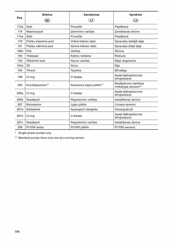
* Single-phase pumps only.
** Standard pumps have only one dry-running sensor.
173a Seib Poveržlė Paplāksne
174 Maanduspolt Įžeminimo varžtas Zemēšanas skrūve
174a Seib Poveržlė Paplāksne
176 Pistiku sisemine pool Vidinė kištuko dalis Spraudņa iekšējā daļa
181 Pistiku välimine pool Išorinė kištuko dalis Spraudņa ārējā daļa
188a Polt Varžtas Skrūve
190 Tõsteaas Kėlimo rankena Rokturis
193 Õlikambri kork Alyvos varžtas Eļļas aizgrieznis
193a Õli Alyva Eļļa
194 Tihend Tarpiklis Blīvslēgs
198 O-ring O žiedas Apaļa šķērsgriezuma blīvgredzens
285 Kuivkäiguandur** Sausosios eigos jutiklis** Bezšķidruma darbības indikācijas sensors**
285a O-ring O žiedas Apaļa šķērsgriezuma blīvgredzens
285b Seadepolt Reguliavimo varžtas Iestatīšanas skrūve
287 Nivooandur Lygio jutiklis Līmeņa sensors
287a Kaitsekork Apsauginis dangtelis Aizsargvāciņš
287b O-ring O žiedas Apaļa šķērsgriezuma blīvgredzens
287c Seadepolt Reguliavimo varžtas Iestatīšanas skrūve
288 Pt1000 andur Pt1000 jutiklis Pt1000 sensors
Pos.Seletus Aprašymas Apraksts
586

587

Fig. D SEG, 0.9 - 1.5 kWTM
04 4
486
1909
588

Fig. E SEG, 2.6 - 4 kW
TM04
5062
210
9
589

590

ArgentinaBombas GRUNDFOS de Argentina S.A.Ruta Panamericana km. 37.500 Lote 34A1619 - GarinPcia. de Buenos AiresPhone: +54-3327 414 444Telefax: +54-3327 411 111
AustraliaGRUNDFOS Pumps Pty. Ltd. P.O. Box 2040 Regency Park South Australia 5942 Phone: +61-8-8461-4611 Telefax: +61-8-8340 0155
AustriaGRUNDFOS Pumpen Vertrieb Ges.m.b.H.Grundfosstraße 2 A-5082 Grödig/Salzburg Tel.: +43-6246-883-0 Telefax: +43-6246-883-30
BelgiumN.V. GRUNDFOS Bellux S.A. Boomsesteenweg 81-83 B-2630 Aartselaar Tél.: +32-3-870 7300 Télécopie: +32-3-870 7301
BelorussiaПредставительство ГРУНДФОС в Минске220123, Минск,ул. В. Хоружей, 22, оф. 1105 Тел.: +(37517) 233 97 65, Факс: +(37517) 233 97 69E-mail: [email protected]
Bosnia/HerzegovinaGRUNDFOS SarajevoTrg Heroja 16,BiH-71000 SarajevoPhone: +387 33 713 290Telefax: +387 33 659 079e-mail: [email protected]
BrazilMark GRUNDFOS Ltda.Av. Humberto de Alencar Castelo Branco, 630CEP 09850 - 300São Bernardo do Campo - SPPhone: +55-11 4393 5533Telefax: +55-11 4343 5015
BulgariaGRUNDFOS Pumpen VertriebRepresentative Office - BulgariaBulgaria, 1421 SofiaLozenetz District105-107 Arsenalski blvd. Phone: +359 2963 3820, 2963 5653Telefax: +359 2963 1305
CanadaGRUNDFOS Canada Inc. 2941 Brighton Road Oakville, Ontario L6H 6C9 Phone: +1-905 829 9533 Telefax: +1-905 829 9512
ChinaGRUNDFOS Pumps (Shanghai) Co. Ltd.51 Floor, Raffles CityNo. 268 Xi Zang Road. (M)Shanghai 200001PRCPhone: +86-021-612 252 22Telefax: +86-021-612 253 33
CroatiaGRUNDFOS CROATIA d.o.o.Cebini 37, BuzinHR-10010 ZagrebPhone: +385 1 6595 400 Telefax: +385 1 6595 499www.grundfos.hr
Czech RepublicGRUNDFOS s.r.o.Čajkovského 21779 00 OlomoucPhone: +420-585-716 111Telefax: +420-585-716 299
DenmarkGRUNDFOS DK A/S Martin Bachs Vej 3 DK-8850 Bjerringbro Tlf.: +45-87 50 50 50 Telefax: +45-87 50 51 51 E-mail: [email protected]/DK
EstoniaGRUNDFOS Pumps Eesti OÜPeterburi tee 92G11415 TallinnTel: + 372 606 1690Fax: + 372 606 1691
FinlandOY GRUNDFOS Pumput AB Mestarintie 11 FIN-01730 Vantaa Phone: +358-3066 5650 Telefax: +358-3066 56550
FrancePompes GRUNDFOS Distribution S.A. Parc d’Activités de Chesnes 57, rue de Malacombe F-38290 St. Quentin Fallavier (Lyon) Tél.: +33-4 74 82 15 15 Télécopie: +33-4 74 94 10 51
GermanyGRUNDFOS GMBHSchlüterstr. 3340699 ErkrathTel.: +49-(0) 211 929 69-0 Telefax: +49-(0) 211 929 69-3799e-mail: [email protected] in Deutschland:e-mail: [email protected]
GreeceGRUNDFOS Hellas A.E.B.E. 20th km. Athinon-Markopoulou Av. P.O. Box 71 GR-19002 Peania Phone: +0030-210-66 83 400 Telefax: +0030-210-66 46 273
Hong KongGRUNDFOS Pumps (Hong Kong) Ltd. Unit 1, Ground floor Siu Wai Industrial Centre 29-33 Wing Hong Street & 68 King Lam Street, Cheung Sha Wan Kowloon Phone: +852-27861706 / 27861741 Telefax: +852-27858664
HungaryGRUNDFOS Hungária Kft.Park u. 8H-2045 Törökbálint, Phone: +36-23 511 110Telefax: +36-23 511 111
IndiaGRUNDFOS Pumps India Private Limited118 Old Mahabalipuram RoadThoraipakkamChennai 600 096Phone: +91-44 2496 6800
IndonesiaPT GRUNDFOS Pompa Jl. Rawa Sumur III, Blok III / CC-1 Kawasan Industri, Pulogadung Jakarta 13930 Phone: +62-21-460 6909 Telefax: +62-21-460 6910 / 460 6901
IrelandGRUNDFOS (Ireland) Ltd. Unit A, Merrywell Business ParkBallymount Road LowerDublin 12 Phone: +353-1-4089 800 Telefax: +353-1-4089 830
ItalyGRUNDFOS Pompe Italia S.r.l. Via Gran Sasso 4I-20060 Truccazzano (Milano)Tel.: +39-02-95838112 Telefax: +39-02-95309290 / 95838461
JapanGRUNDFOS Pumps K.K.Gotanda Metalion Bldg., 5F, 5-21-15, Higashi-gotandaShiagawa-ku, Tokyo141-0022 JapanPhone: +81 35 448 1391Telefax: +81 35 448 9619
KoreaGRUNDFOS Pumps Korea Ltd.6th Floor, Aju Building 679-5Yeoksam-dong, Kangnam-ku, 135-916Seoul, KoreaPhone: +82-2-5317 600Telefax: +82-2-5633 725
LatviaSIA GRUNDFOS Pumps Latvia Deglava biznesa centrsAugusta Deglava ielā 60, LV-1035, Rīga,Tālr.: + 371 714 9640, 7 149 641Fakss: + 371 914 9646
LithuaniaGRUNDFOS Pumps UABSmolensko g. 6LT-03201 VilniusTel: + 370 52 395 430Fax: + 370 52 395 431
MalaysiaGRUNDFOS Pumps Sdn. Bhd.7 Jalan Peguam U1/25Glenmarie Industrial Park40150 Shah AlamSelangor Phone: +60-3-5569 2922Telefax: +60-3-5569 2866
MéxicoBombas GRUNDFOS de México S.A. de C.V. Boulevard TLC No. 15Parque Industrial Stiva AeropuertoApodaca, N.L. 66600Phone: +52-81-8144 4000 Telefax: +52-81-8144 4010
NetherlandsGRUNDFOS NetherlandsVeluwezoom 351326 AE AlmerePostbus 220151302 CA ALMERE Tel.: +31-88-478 6336 Telefax: +31-88-478 6332e-mail: [email protected]
New ZealandGRUNDFOS Pumps NZ Ltd.17 Beatrice Tinsley CrescentNorth Harbour Industrial EstateAlbany, AucklandPhone: +64-9-415 3240Telefax: +64-9-415 3250
NorwayGRUNDFOS Pumper A/S Strømsveien 344 Postboks 235, Leirdal N-1011 Oslo Tlf.: +47-22 90 47 00 Telefax: +47-22 32 21 50
PolandGRUNDFOS Pompy Sp. z o.o.ul. Klonowa 23Baranowo k. PoznaniaPL-62-081 PrzeźmierowoTel: (+48-61) 650 13 00Fax: (+48-61) 650 13 50
PortugalBombas GRUNDFOS Portugal, S.A. Rua Calvet de Magalhães, 241Apartado 1079P-2770-153 Paço de ArcosTel.: +351-21-440 76 00Telefax: +351-21-440 76 90
RomâniaGRUNDFOS Pompe România SRLBd. Biruintei, nr 103 Pantelimon county IlfovPhone: +40 21 200 4100Telefax: +40 21 200 4101E-mail: [email protected]
RussiaООО ГрундфосРоссия, 109544 Москва, ул. Школьная 39Тел. (+7) 495 737 30 00, 564 88 00Факс (+7) 495 737 75 36, 564 88 11E-mail [email protected]
Serbia GRUNDFOS Predstavništvo BeogradDr. Milutina Ivkovića 2a/29YU-11000 Beograd Phone: +381 11 26 47 877 / 11 26 47 496Telefax: +381 11 26 48 340
SingaporeGRUNDFOS (Singapore) Pte. Ltd. 24 Tuas West Road Jurong Town Singapore 638381 Phone: +65-6865 1222 Telefax: +65-6861 8402
SloveniaGRUNDFOS PUMPEN VERTRIEB Ges.m.b.H.,Podružnica LjubljanaŠlandrova 8b, SI-1231 Ljubljana-ČrnučePhone: +386 1 568 0610Telefax: +386 1 568 0619E-mail: [email protected]
SpainBombas GRUNDFOS España S.A. Camino de la Fuentecilla, s/n E-28110 Algete (Madrid) Tel.: +34-91-848 8800 Telefax: +34-91-628 0465
SwedenGRUNDFOS AB Box 333 (Lunnagårdsgatan 6) 431 24 Mölndal Tel.: +46(0)771-32 23 00 Telefax: +46(0)31-331 94 60
SwitzerlandGRUNDFOS Pumpen AG Bruggacherstrasse 10 CH-8117 Fällanden/ZH Tel.: +41-1-806 8111 Telefax: +41-1-806 8115
TaiwanGRUNDFOS Pumps (Taiwan) Ltd. 7 Floor, 219 Min-Chuan Road Taichung, Taiwan, R.O.C. Phone: +886-4-2305 0868Telefax: +886-4-2305 0878
ThailandGRUNDFOS (Thailand) Ltd. 92 Chaloem Phrakiat Rama 9 Road,Dokmai, Pravej, Bangkok 10250Phone: +66-2-725 8999Telefax: +66-2-725 8998
TurkeyGRUNDFOS POMPA San. ve Tic. Ltd. Sti.Gebze Organize Sanayi Bölgesi Ihsan dede Caddesi,2. yol 200. Sokak No. 20441490 Gebze/ KocaeliPhone: +90 - 262-679 7979Telefax: +90 - 262-679 7905E-mail: [email protected]
UkraineТОВ ГРУНДФОС УКРАЇНА 01010 Київ, Вул. Московська 8б, Тел.:(+38 044) 390 40 50 Фах.: (+38 044) 390 40 59E-mail: [email protected]
United Arab EmiratesGRUNDFOS Gulf DistributionP.O. Box 16768Jebel Ali Free ZoneDubaiPhone: +971-4- 8815 166Telefax: +971-4-8815 136
United KingdomGRUNDFOS Pumps Ltd. Grovebury Road Leighton Buzzard/Beds. LU7 8TL Phone: +44-1525-850000 Telefax: +44-1525-850011
U.S.A.GRUNDFOS Pumps Corporation 17100 West 118th TerraceOlathe, Kansas 66061Phone: +1-913-227-3400 Telefax: +1-913-227-3500
UsbekistanПредставительство ГРУНДФОС в Ташкенте700000 Ташкент ул.Усмана Носира 1-й тупик 5Телефон: (3712) 55-68-15Факс: (3712) 53-36-35
Addresses revised 15.06.2009

www.grundfos.com
Being responsible is our foundationThinking ahead makes it possible
Innovation is the essence
The name Grundfos, the Grundfos logo, and the payoff Be–Think–Innovate are registrated trademarks owned by Grundfos Management A/S or Grundfos A/S, Denmark. All rights reserved worldwide.
97525813 0111
Repl. 97525813 0909
ECM: 1070331


