Embed Size (px)
Citation preview

SENIOR DESIGN
GROUP 13
OSCAR CEDENO
CESAR ROMERO
CAMILO ROMERO
E-SKATE
2
Table of Contents
1.0 EXECUTIVE SUMMARY .................................................................................1
2.0 DEFINITION ....................................................................................................2
2.1 MOTIVATION ...............................................................................................2
2.2 GOALS AND OBJECTIVES .........................................................................3
2.3 SPECIFICATIONS .......................................................................................3
2.3.1 BLOCK DIAGRAM ................................................................................4
3.0 RESEARCH ....................................................................................................5
3.1 MICROCONTROLLERS ..............................................................................5
3.1.1 Microchip PIC Family .............................................................................7
3.1.2 Freescale MC9S8QG8 ..........................................................................9
3.1.3 Arduino Boards ......................................................................................9
3.1.4 Arduino Fio ..........................................................................................10
3.1.5 Arduino BT ..........................................................................................10
3.1.6 Arduino UNO ......................................................................................11
3.1.7 Motor Controller ...................................................................................13
3.1.8 LM4570 ...............................................................................................13
3.1.9 ATmega 328 .......................................................................................14
3.1.10 Speed controller H-Bridge ................................................................15
3.2 LIQUID CRYSTAL DISPLAY .....................................................................16
3.2.1 Monochrome LCD‘s .............................................................................16
3.2.2 Previous Monochrome LCD Project.....................................................16
3.2.3 Color LCD‘s .........................................................................................17
3.2.4 Previous Graphical LCD Project ..........................................................17
3.2.5 LCD Configuration ...............................................................................18
3.2.6 Integration ............................................................................................19
3.2.7 Graphics Controller ..............................................................................19
3.2.8 Direct ...................................................................................................20
3.2.9 LCD interface with Microcontroller .......................................................20
3.2.10 Parallel ...............................................................................................21
3.2.11 Serial .................................................................................................21
3.2.12 RGB Interface ....................................................................................21
3.2.13 Method Chosen .................................................................................22
3.3 GLOBAL POSITION SYSTEM ...................................................................23
3.3.1 EM-406A ..............................................................................................24
3
3.3.2 EM-408 ............................................................................................... 24
3.3.3 Etek EB-85A ....................................................................................... 25
3.3.4 Copernicus GPS module..................................................................... 26
3.3.5 NMEA 0183 Protocol .......................................................................... 27
3.4 POWER SYSTEM ..................................................................................... 29
3.4.1 Electric Motor ...................................................................................... 29
3.4.2 Direct Current Motors .......................................................................... 30
3.4.3 Type Of DC Motors ............................................................................. 32
3.4.4 Batteries .............................................................................................. 34
3.4.5 Lithium Ion Battery .............................................................................. 35
3.4.6 Lead-acid Batteries ............................................................................. 37
3.5 WIRELESS ADAPTORS ........................................................................... 39
3.5.1 Zigbee ................................................................................................. 41
3.5.2 Bluetooth ............................................................................................. 43
3.5.3 WiFi ..................................................................................................... 44
3.5.4 Wireless USB ...................................................................................... 47
3.5.5 IR Wireless.......................................................................................... 48
3.5.6 Transmitter and Receiver .................................................................... 48
3.5.7 FS-GT2 ............................................................................................... 49
3.6 SENSORS ................................................................................................ 50
3.6.1 Accelerometer ..................................................................................... 50
3.6.2 2-Axis Dimension Engineering DE-ACCM2G2 .................................... 50
3.6.3 Freescale MMA7361L Accelerometer ................................................. 51
3.6.4 Relay ................................................................................................... 52
3.6.5 Electro Mechanical Relay.................................................................... 53
3.6.6 Reed Relay ......................................................................................... 53
3.6.7 RW-SS-112D Relay ............................................................................ 54
3.6.8 Field Effect Transistor Relay ............................................................... 54
3.6.9 Solid State Relay ................................................................................ 54
3.7 BUILDING MATERIALS ............................................................................ 55
3.8 DRIVE TRAIN ............................................................................................ 56
3.8.1 Deck or Board ..................................................................................... 56
3.8.2 Wheels ................................................................................................ 56
3.8.3 Bearing................................................................................................ 56
3.8.4 Trucks ................................................................................................. 57
3.8.5 Risers .................................................................................................. 57
3.8.6 Hardware ............................................................................................ 58
4
3.9 PROGRAMMING ......................................................................................58
3.9.1 Assembly .............................................................................................59
3.9.2 C Language .........................................................................................59
3.9.3 Arduino Language ...............................................................................60
3.10 PRINTED CIRCUIT BOARD ...................................................................60
3.10.1 PCB 123 ............................................................................................61
3.10.2 Express PCB .....................................................................................62
4.0 DESIGN ........................................................................................................62
4.1 CONTROLLERS ........................................................................................62
4.1.1 Motor Controller ...................................................................................63
4.1.2 Data Microcontroller .............................................................................64
4.2 LCD DISPLAY ............................................................................................66
4.3 POWER SYSTEM ......................................................................................67
4.3.1 Motor MY6812A ...................................................................................67
4.3.2 Battery RT 1250...................................................................................68
4.3.3 Charger Leadman KY-05036S-12 .......................................................69
4.4 WIRELESS ADAPTORS ............................................................................70
4.5 SENSORS .................................................................................................72
4.5.1 Velocity Sensor ....................................................................................72
4.5.2 Accelerometer......................................................................................72
4.6 DRIVE TRAIN.............................................................................................73
4.7 GLOBAL POSITION SYSTEM ...................................................................75
4.8 SOFTWARE DESIGN ................................................................................77
4.9 PCB DESIGN .............................................................................................78
5.0 DESIGN SUMMARY .....................................................................................79
6.0 PROTOTYPING ............................................................................................82
6.1 STATEBOARD ...........................................................................................82
6.2 MOTOR CONTROLLER PROTOTYPING .................................................82
7.0 BULDING STRATEGY ..................................................................................84
7.1 Building Meetings .......................................................................................84
7.2 Materials ....................................................................................................85
7.3 Errors and Failures .....................................................................................85
7.4 Presentation of the E-Skate .......................................................................86
5
8.0 TESTING PROCEDURE .............................................................................. 86
8.1 HARDWARE ............................................................................................. 87
8.1.1 Motor Controller Testing...................................................................... 87
8.1.2 Wireless Module Testing ..................................................................... 87
8.1.3 PCB Testing ........................................................................................ 87
8.1.4 Power System Testing ........................................................................ 88
8.1.5 GPS Testing ........................................................................................ 88
8.1.6 Drive Train Testing .............................................................................. 88
8.1.7 Sensor Testing .................................................................................... 88
8.1.8 LCD Testing ........................................................................................ 89
8.2 SOFTWARE .............................................................................................. 89
9.0 ADMINISTRATIVE CONTENT ..................................................................... 89
9.1 MILESTONE DISCUSSION ...................................................................... 89
9.2 BUDGET AND MANAGEMENT ............................................................... 90
9.2.1 Responsibility Chart ............................................................................ 90
9.2.2 Expected Budget ................................................................................. 91
10.0 APPENDICES ............................................................................................... I
10.1 Figures .................................................................................................... I
10.2 Tables .................................................................................................... II
10.3 Charts and Graphs ................................................................................. II
11.0 WORK CITED .............................................................................................. IV
12.0 PERMISSIONS ........................................................................................... VII
6
1.0 EXECUTIVE SUMMARY
Imagine a student walking at University of Central Florida (UCF), it is the first day of class and really been on time and make the first impression is the most important thing in anyone mind. Moreover, try to check were all the classes are and understand the university map is a pain. Without thinking, time is running out just trying to find the building. By the time he or she gets to the classroom it has already pass some minutes; class started and the student is rushing and sweating. Finally he or she finds the first impression went out the window. Now class is over from the Engineering Building and the next class which is in 15 minutes is at the Communication Building, the student rush again and it would make another first impression go out to the communication classroom window. Now we ask ourselves, how can we make this student be on time and not a mess? Of course by time pass the student would get to know better the university, and get on time and in a better presentation, but what about the first day. Yes, he can get to memorize the map during his vacation time. Yes, he can speed walk, but would this make him look crazy. Yes he can get a bicycle, which includes get a chain, a lock, and a place to park it, and can get him sweet also. Yes, a skateboard is the best idea, but he have to make sure don‘t get a workout by getting before class, people usually ovoid stinky and sweet people. Yes, a scooter is a great idea cause; it does not need mechanical force from the user to transport. The down side is that it needs a chain, a lock, and a place to parking as the bicycle. There are not many choices, but what about the E-Skate. And now we ask ourselves. What is an E-Skate? Well, it is a skateboard, but it is electronic. Which means no working out to get to class and end up stinking; moreover, it is easy to carry to the classroom and even recharger it to make sure to get to the next period on time. It is unique and do not see much of it around the campus. Finally, this all the first impression is about the introduction of our project about the E-Skate. The E-Skate is more than just an electric skateboard controlled by a control remote. It is a skateboard that has been implied speed control, Global Position System (GPS) capabilities to read us the distance and speed it has travel. Moreover, it has sensor to find the speed it is traveling. And finally it was a motor powerful enough to carry a person with great speed. The E-Skate is composed by a microcontroller that would accumulated data and control the motor signal receive by the transmitter. This microcontroller would export the data to a Liquid Crystal Display (LCD) attach in the front deck of the skateboard. Moreover this microcontroller would accumulate data from the GPS and Sensor, which mean our microcontroller would be the main brain of the E-Skate system. For this we are going to research a lot about microcontroller and find the best suitable for the E-Skate that would make all this process a reality. An anything that has brain it need member to move and the E-Skate the wheel by itself would not make it. Getting the right motor that would be powerful enough to move a human being, is
7
critical as well. In this paper we are going to research about what kind of motor do we need to use. If we have a motor, we need a battery good enough to provide enough current per hour to power the motor and well as the printed circuit board (PCB), without blowing anything off. So the power system of the E-Skate is going to be researched to find the appropriated motor and battery. For the PCB to not get burn we need relay connect to it so it if too much current is flowing, it would shut down. So relays would be another part to research and get to know. There is going to be a LCD which would show data that is getting from the GPS and Sensors. So understanding LCD is another part of the E-Skate. GPS capabilities are very import to research because this would import data to the microcontroller which would connect to the LCD. Sensor that would describe battery life and speed of the E-Skate would be seen in detail later on in a chapter. Because we are using a microcontroller we need to programmed and this would be talk as well in later chapters. To send signal from a controller remote to the microcontroller, we need to research about the wireless receiver and transmitter. Also the understanding how a skateboard works, would be talk during this E-Skate project. And, what kinds of material are going to be enlisted for a better and broad understanding of the E-Skate. This would be all in the research chapter of this paper. Finally, we would take in consideration all the research made, and choose part that would make the E-Skate to function. So from Here we are going to design and schematic our E-Skate. After the all been chosen, we are going to integrated them and run a function of test. We will make a build strategy to get all this part together and test. We are going to play around with microcontrollers, motors, batteries, to make a prototype that would be very close to the E-Skate. We would test the hardware and Software to make sure at time of presenting the E-Skate, it would work perfectly. Consequently, we are going to provide administrative contents of how the work was divided within the team members, the cost of the making of the E-Skate, and the milestone we use to make the research and the design together. Now that we have a basic understanding of the project and the part we are going to cover is now to be more detail in it. Later on in this project paper, it would be shows in detail are the components talked in this executive summary.
2.0 DEFINITION
2.1 MOTIVATION
Traveling around the university could be stressful and tiring for many students. In order to get to class, students must cross long distances inside campus in a short period of time. Some students use bicycles or skateboards to get to class on time. Using bicycles is a very good idea, but the only problem is that they are too big to bring them inside the class or it takes more time to lock them outside. In the other hand skateboard are very portable but you have to be paddling with your foot constantly.
8
In addition, we noticed that universities are rally big, parking spaces are hard to find, and sometimes students have classes in really far areas and they have some limitless time to get to class. For example, at the University of Central Florida, sometimes students have to go from the farthest engineering building to the other side where the communications building is located. This can cause exhaustion, and might influence in the class performance and therefore have some consequences in your grade.
Our group though about and innovative design that will resolve the issues of students in means of transportation inside the university. The electric skateboard will be an intelligent hi-tech product made with high quality components. It will be easy to use indoors or outdoors. The most important thing is that you will be able to control the speed and direction of where you want to go and it could be easily stopped.
An Electric powered skateboard will resolve the issues of transporting students from one point to another in minimum time and to be able to bring them to class because of its portability. We decided to call this innovative concept the E-SKATE, or in other words the Electronic Skateboard.
2.2 GOALS AND OBJECTIVES
Electronic power skate board will be a unique skate able to perform certain define tasks. The main goal that this skate will accomplish is to be able to run without paddling using a wireless control that may be attach to the wrist like a watch.
Another goal we want to achieve is to program the E-Skate with a wireless control remote. For this process to be done it need to have a sensor which will react different according to the impulse it receives from the control. For example, stop, accelerated, decelerate, miles count, and localizer will be the many of in pulses sent be the control with the E- skate would sense and perform.
Moreover, E- skate would be very portable, the only extra weight it would have is the controls which are going to be sent to be acquired according to our schematic to weigh less. A GPS system to localize the position of the E-Skate, it case it was stolen and borrow without permission. More over a wired control in cause the wireless control may not give the right impulses to be done.
Finally, E-Skate may be a long skate board; therefore, we may going to need a battery that would last a good amount of time according to the person using mainly in campus. We will do research to determined which controls and battery may bring the best outcome, goals, objectives done.
2.3 SPECIFICATIONS / REQUIREMENTS
In this section we are going to set and enlist the specification and requirements that the E-Skate most past all the time. By not acquiring these specs, the E-
9
Skate is not reliable for the function it would make in the presentation if the requirement are set to be follow, in any case, the requirements are broken, the E-skate is not responsible for an overall functionality.
1. E-SKATE will require a minimum budget of $500 to build. 2. Less than 20 pounds of weight. 3. Transport up to 200 pounds of weight. 4. 36 X 11 in long skateboard to be used. 5. Skate only to be used in dry pavement. 6. Rechargeable battery life of 3 hours. 7. Maximum distance per charge of 10 miles. 8. Wireless Speed control with range of 25 feet. 9. Easily accessible wireless controller wristband. 10. Able to record velocity from 0 up to 15 miles per hour. 11. Acquire GPS location using latitude and longitude coordinates in clear
weather conditions. 12. E-SKATE will be used for cruising only, which means no tricks or jumps.
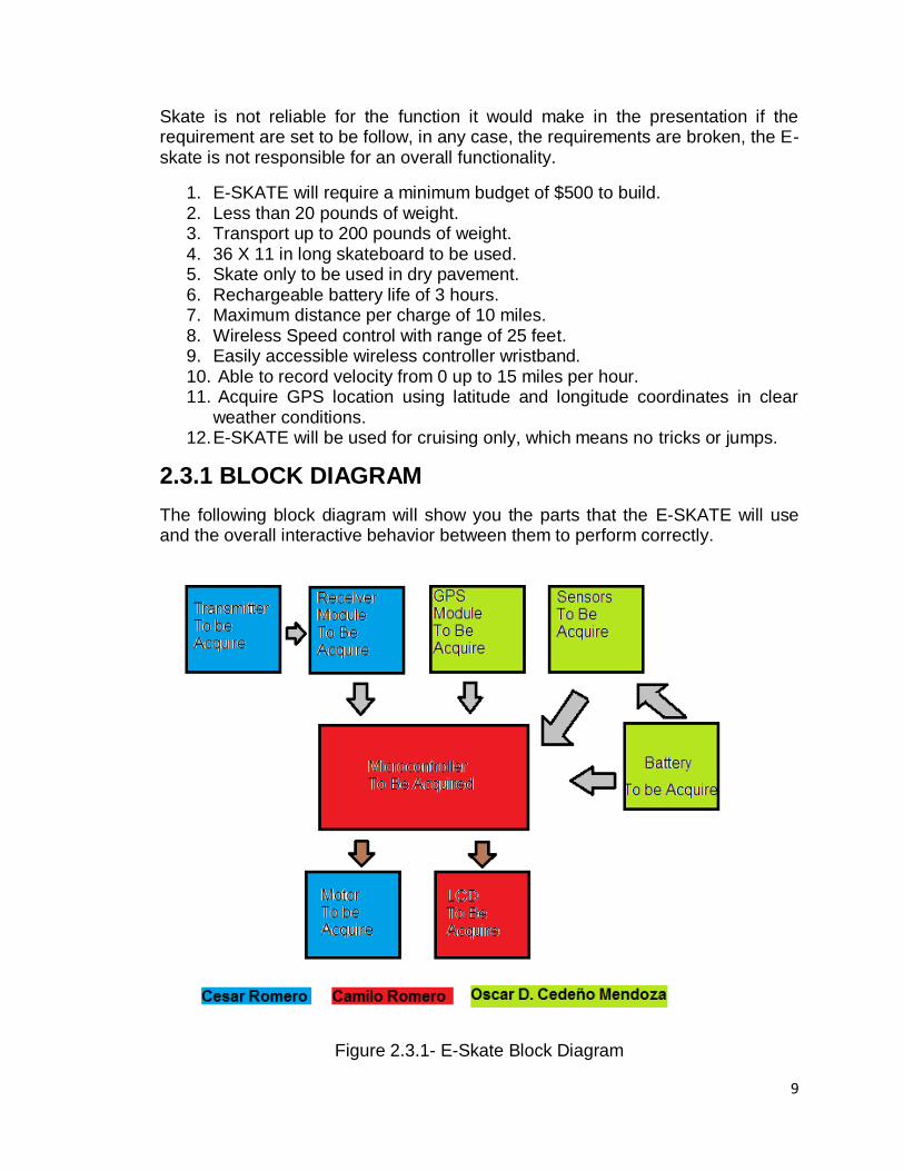
2.3.1 BLOCK DIAGRAM
The following block diagram will show you the parts that the E-SKATE will use and the overall interactive behavior between them to perform correctly.
Figure 2.3.1- E-Skate Block Diagram
10
As the Figure 2.3.1 shown above, the Transmitter with is going to be design would send a signal to the receiver module that would be acquired and design. This receiver would be connected to the main controller. Also the GPS module would be programmable to give data to the microcontroller as well. The microcontroller is going to be connected to the motor and it would be attach to the wheel by a plastic grid belt that would make it to acquire some motion. Also as well, the microcontroller is going to be connected in a output to the LCD screen that would shown the data collected by the GPS module. Moreover, it also be thought to add a sensor to it would also recollect data of battery life and speed. The sensor data would be sent to the microcontroller, and the LCD would show this. The sensor would be acquired and design to be part of the main PCB. Finally the power supply would be a rechargeable battery that would power up the PCB and the motor for it to work. Also, the research of each main part is going to be dived as is shown in the block diagram. As well as what components are going to be acquired specifically is going to be chosen the member responsible in their parts. The design to make it put all together would be part of the entire team member for a complete work project design.
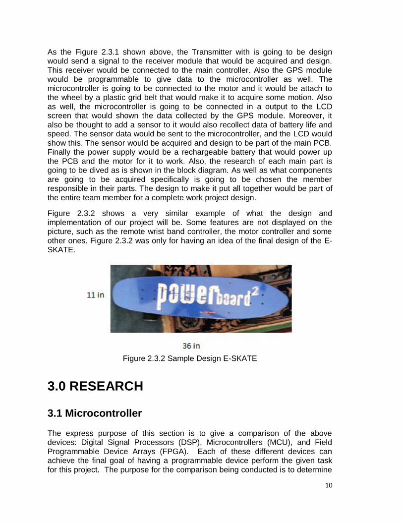
Figure 2.3.2 shows a very similar example of what the design and implementation of our project will be. Some features are not displayed on the picture, such as the remote wrist band controller, the motor controller and some other ones. Figure 2.3.2 was only for having an idea of the final design of the E-SKATE.
Figure 2.3.2 Sample Design E-SKATE
3.0 RESEARCH
3.1 Microcontroller The express purpose of this section is to give a comparison of the above devices: Digital Signal Processors (DSP), Microcontrollers (MCU), and Field Programmable Device Arrays (FPGA). Each of these different devices can achieve the final goal of having a programmable device perform the given task for this project. The purpose for the comparison being conducted is to determine
11
which device will not only perform the objective, but also perform it the most effectively and costs the least for this project.
A Field Programmable Gate Array is defined as a semiconductor device which contains programmable interconnects and programmable logic components. ―The programmable logic components can be programmed to duplicate the functionality of basic logic gates such as AND, OR, XOR, NOT or more complex combinational functions such as decoders or simple math functions. In most FPGAs, memory elements included are either simple flip-flops or more complete blocks of memories. An FPGA can be compared to a one-chip programmable breadboard in that the FPGA has a hierarchy of programmable interconnects that allow its logic blocks to be interconnected as needed by the system designer. There are some drawbacks to using FPGAs: they are generally slower than their application-specific integrated circuit counterparts (ASIC), cannot handle as complex a design as an ASIC, and draw more power. On the other hand, the advantages of using an FPGA are that they require a shorter time to market (being that they can be used for general purpose applications), they are able to be re-programmed in the field in an attempt to fix a bug, and they have lower non-recurring engineering costs associated.
A microcontroller is defined as a computer that is on a chip. The purpose of this device is to control electronic devices. ―It is a type of microprocessor emphasizing self-sufficiency and cost-effectiveness, in contrast to a general-purpose microprocessor (the kind used in a PC)‖. The difference between the microprocessor versus microcontroller is that the microcontroller contains all of the memory and interface required to perform applications whereas the microprocessor requires additional chips and devices to perform the same tasks the microcontroller. The general features for most microcontrollers include the following: a central processing unit, Input/Output (I/O) Ports, random access memory (RAM), peripherals, ROM, EPROM, EEPROM, Flash Memory, and clock generators. ―A typical home in a developed country is likely to have only one or two general-purpose microprocessors but somewhere between one and two dozen microcontrollers. A typical mid-range vehicle has as many as 50 or more microcontrollers‖. Previously, most microcontrollers were only programmed to be able to read assembly language, making coding more difficult for the designer. Now microcontrollers mostly use C Programming Language, and are able to be debugged by debugging circuitry which is accessed by the In-Circuit emulator. This enables the programmer to debug the software of an embedded system with a debugger. Some microcontrollers even have begun to include high-level programming language interpreters, making it even easier for the user to control the different aspects of the microcontroller.
Known as a specialized microprocessor designed for the specific purpose of digital signal processing, the Digital Signal Processor can process signals digitally, generally in real time. Like a microcontroller, a DSP has separate program memory and data memory, it also has special instructions for Single Instruction, Multiple Data (SIMD) operations, it has the ability to act as a direct
12
memory access device if it is in a host environment, and is able to take in data from an Analog-to-Digital Converter (ADC) and be pass data that is finally output by converting it back to an analog state using a Digital-to-Analog Converter (DAC). Due to its processing speed, generally a DSP has a good calculation-performance/price ratio.
The data microcontroller will control data from the sensors and calculate the output data for the LCD. Data to be calculated by the data microcontroller includes velocity, average velocity, distance, total distance traveled, and battery state of charge. Sensor inputs necessary to the microcontroller include a velocity sensor, and the state of charge input. Outputs planned for the E-Skate include output to the LCD, and an output to the data storage which can be either USB or an SD Card. In order to accommodate this, there has to be enough pins on the microcontroller to be able to support these inputs and outputs. Also consideration in choosing a microcontroller is its ability to be used on a breadboard. This will make testing of the microcontroller easier, with a final that can be the same microcontroller in a different package for better integration. Many microcontroller out in the market have the ability to drive a monochrome LCD, so memory capacity for this is not taken into consideration. Consideration for choosing a microcontroller is choosing a microcontroller that can be programmed in a higher level language preferably C or C++. Other considerations for choosing a microcontroller are the availability of support, and price. Many microcontrollers for this level of are priced under $10.00. The goal is to find a reliable and efficient microcontroller with a low price level to keep replacement cost down.
3.1.1 Microchip PIC Family
A very popular line of microcontrollers is the PIC family from Microchip Technology. Many hobbyists use this line of microcontroller for different projects, with many using this family of microcontrollers for the projects similar to ours. If this type of microcontroller was to be chosen for our group we would choose the PIC16F57. The reason for considering this microcontroller is the high use of this microcontroller which makes troubleshooting any issues, fairly easy. This microcontroller comes with 20 I/O pins which in case of the both the data and the motor microcontroller is more than enough. This microcontroller comes with many different packaging types which the group would acquire a DIP type microcontroller for bread boarding and testing, and then get the same microcontroller but surface-mountable, which would allow the group to use the same program. Programming on this type of microcontrollers can be done with the MPLAB Integrated Development Environment software. With this development software the group can program the microcontroller with the C-Language.
13
PIC 16F57 Specification:
Clock Speed – 20 MHz clock speed
On-Chip Flash program memory 2048 x 12-Bit
General Purpose Register (SRAM) 72 x 8-Bit
Operating Current: 170 μA @ 2V, 4 MHz
20 I/O Pins with 28-pin DIP
Operating Voltage: 2.0V to 5.5V
Temperature Range: -40°C to 85°C
Has over 40 year retention period
Power-On-Reset
Watchdog Timer
Selectable Oscillator between RC, crystal, High Speed Crystal, and Low frequency Crystal
These are the some of the basic specification for the PIC 16F57 microcontroller. The price of this microcontroller is from digikey.com is $2.48. Looking at this microcontroller we then considered another Microchip controller afterwards that seems to provide a better alternative to the PIC 16F57. This microcontroller is the PIC 18F2525. This microcontroller provides a much better feature set for the E-Skate than the PIC 16F57. This microcontroller also has the same number of pins, but less I/O pins at 20. In the case of the E-Skate, this would not be a problem as the E-Skate does not require as many inputs to be controlled. The microcontroller does have the advantage of having analog-to-digital converters integrated eliminating the need to include them in the design if the E-Skate was to be used with the PIC 16F57. This chip does have a higher price on digikey.com of $6.86, but considering the increase in the amount of processing throughput, this microcontroller is well worth the price increase over the PIC 16F57.
PIC 18F2525 Specification:
Has Power Management features which include Idle Mode
Watchdog Timer
Four Crystal modes, up to 40 MHz
Two External Clock modes, up to 40 MHz
Master Synchronous Serial Port (MSSP) module
Supporting 3-Wire SPI (all 4 modes) and I2C
Master and Slave modes
Enhanced Addressable USART module: RS-485, RS-232 and LIN/J2602
10-Bit, up to 13-Channel Analog-to-Digital (A/D)
100,000 Erase/Write Cycle Enhanced Flash Program Memory
1,000,000 Erase/Write Cycle Data EEPROM Memory
Flash/Data EEPROM Retention: 100 Years
Wide Operating Voltage Range: 2.0V to 5.5V
14
Programming for this board is simple as there are development boards that can make programming these microcontrollers easy. This microcontroller actually has an extended instruction set that makes programming in the C-Language easier than other PIC 18 and PIC 16 models. The biggest issue with this microcontroller is the price of the development board, which is about $165 from digikey.com. For this reason the group believes this microcontroller is not the way to go.
3.1.2 Freescale MC9S8QG8
Another option for a microcontroller is using a Freescale MC9S8QG8. This microcontroller is a cheap alternative to the other microcontrollers as it has a $.91 price on digikey.com. The microcontroller uses 16 pins with 11 I/O lines. This microcontroller has the advantage on the Microchip controllers that it is cheaper than the others. The real issue with this microcontroller as with the other microcontrollers is its lack of a cheap development board that can be easily accessible. The development board most used by this microcontroller is the Freescale DEMO9S08QG8E development kit which cost about $50.00 on the digikey.com website. This microcontroller is MC9S8QG8 Specifications:
• 20-MHz HCS08 CPU (central processor unit) • FLASH read/program/erase over full operating voltage and temperature • MC9S08QG8 — 8 Kbytes FLASH, 512 bytes RAM • XOSC — Low-power oscillator module with software selectable crystal or
ceramic resonator range and supports external clock source input up to 20 MHz
• Watchdog computer operating properly (COP) reset • ADC — 8-channel, 10-bit analog-to-digital converter with automatic
compare function, asynchronous clock source and temperature sensor • SPI — Serial peripheral interface module • I2C — Inter-integrated circuit bus module • 12 general-purpose input/output (I/O) pins, one input-only pin and one
output-only pin; outputs 10 mA each, 60 mA max for package Even though this microcontroller offers the cheapest price to replace, and has all the capabilities of the other microcontrollers, there is more troubleshooting information about the other microcontrollers. Other microcontrollers that will be looked at are the ATmega328 with the Arduino boards.
3.1.3 Arduino Boards Arduino boards are used as a popular prototyping platform for small scale projects as it is easy to learn and can the designer of the project easier to understand the project. There are many Arudino boards that each has its own application or niche. The standard Arduino board is the Arduino Uno, while
15
considering the E-Skate has wireless capabilities there are the Arduino Fio and the Arduino Bluetooth. After doing much research on microcontrollers it was found that in order to build a successful project at first, without many problems is by using an Arduino board.
3.1.4 Arduino Fio
The Arduino Fio is a prototyping and development board for the ATmega328P microcontroller and is designed to be used as a wireless capable board. The use of this board helps with the wireless adaptor which the group chose to be the XBee Pro. The microcontroller that comes with the Fio runs at 8 MHz, and has 32KB of flash memory. All Arduino platforms can be programmed in the Arduino language which is similar to C and C++. This makes the programming of the microcontroller simpler. This microcontroller does not come in DIP format, which the group was trying to achieve as the microcontroller can tested and bread boarded this way. Testing of the microcontroller would have to be done through the board, which makes designing the PCB layout for the final design harder. As with many ATmega328 microcontrollers, the Fio comes with 8 analog inputs and 14 I/O pins. The Arduino Fio comes with a USB adaptor that connects to the computer, and as such supports serial communication protocols I2C and SPI.
Arduino Fio with ATmega328P Specifications:
Microcontroller ATmega328P running at a clock speed of 8 MHz
Operating Voltage 3.35 -12 V
14 I/O Pins
8 ADC Input Pins
32 KB Flash Memory
2KB SRAM
1KB EEPROM The Arduino Fio which is the development board and the ATmega microcontroller cost $25 from sparkfun.com. On top of that, the Arduino Fio requires the use of shield which is an adaptor that in the case of the Fio already comes with the XBee Wi-Fi unit. This is more economical than the other processors in terms of price and as Arduino boards are largely used for college projects, has a wide availability of support.
3.1.5 Arduino BT
The Arduino BT (Bluetooth) is similar to the Arduino Fio in which it‘s a prototyping board for use with an ATmega microcontroller. In the case of this board the microcontroller is the ATmega 168. The BT also comes with a Bluegiga WT11 module which allows for serial communication through Bluetooth. The BT has the
16
capacity of a baud rate of 115200 bits per second. Just as with the Fio the BT can be programmed through the use of the Arduino language.
Microcontroller ATmega168 with a clock speed of 16 MHz
Operating Voltage of 1.2 -5.5 V
14 I/O pins
6 ADC Input pins
16 KB of Flash Memory
1 KB of SRAM
512 Bytes of EEPROM This microcontroller when compared to the Fio has but requires less standby power which can help in the case of the E-Skate where the user likely won‘t be accessing the Bluetooth of the skateboard. This board compared to the others is prohibitively expensive at a price of $150 from website sparkfun.com
3.1.6 Arduino UNO
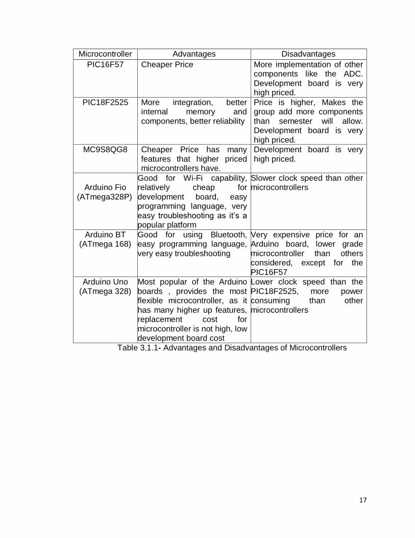
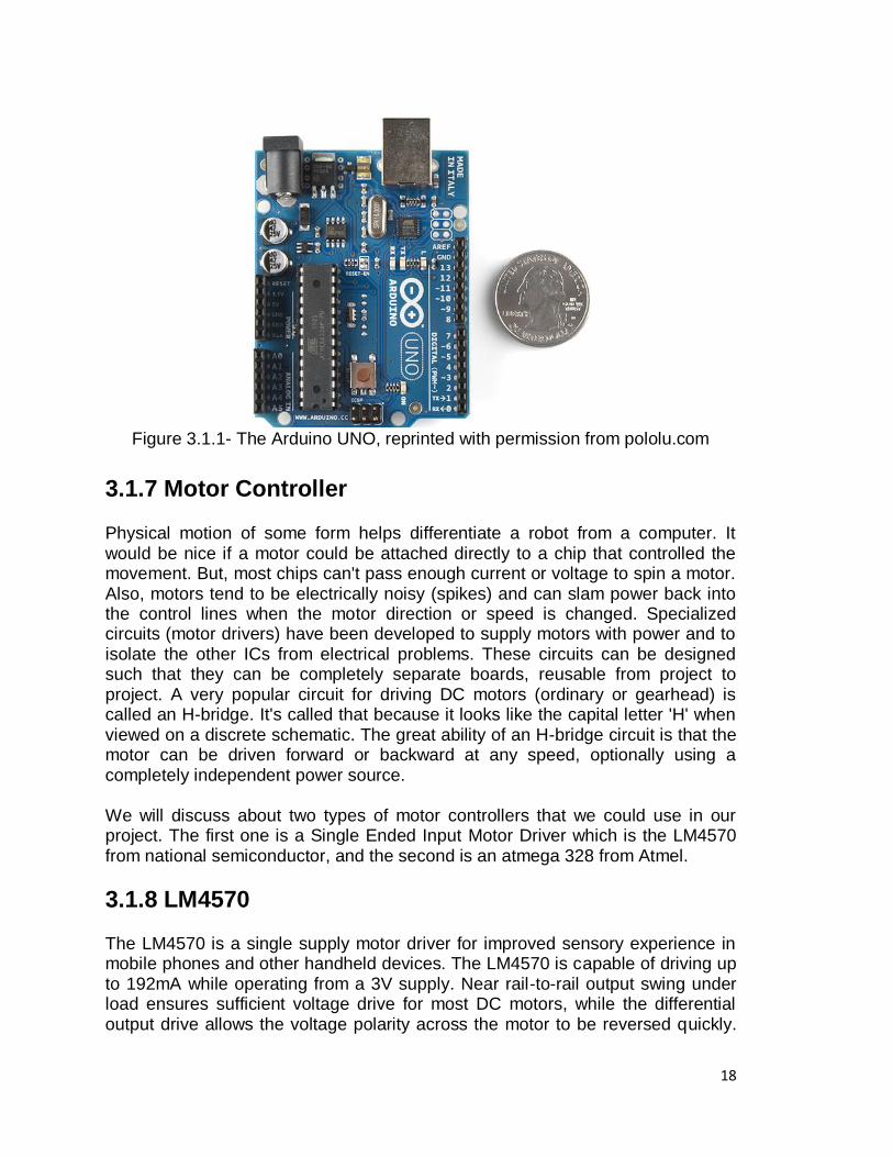
A very popular microcontroller used is the ATMEL ATmega328 for similar types of applications. This microcontroller was chosen as it is used in the Arduino Uno board. This provides a good base as there is a good amount of information on how to use Arduino boards. This will help in the testing phase of the E-Skate. The ATmega328 uses a low power AVR 8-bit processor with a 16 MHz clock cycle. Programming can be done through the Arduino software and it is similar to the C and C++ programming languages. There were other microcontroller similar to this one, and we chose this one as it has the biggest types of memory. It has 32KB of Flash memory for storing a program, 1KB of EEPROM to store non-volatile data, and 2KB of RAM. This microcontroller also features 6 channels of 10-Bit Analog-to-Digital Converter (ADC) and 23 programmable I/O lines. The microcontroller comes with the Arudino board, which comes with the programming language software. The Arduino Uno board makes the data microcontroller easy for prototyping and testing, by providing a platform for the group to be access the microcontroller pins easily. The Arduino Uno board comes with an USB adaptor, which means the board has I2C and SPI serial communications protocols. Table 3.1.1 shows the advantages and disadvantages of microcontrollersand figure 3.1.1 shows the arduino UNO. Arduino Uno with ATmega 328 Specifications:
Microcontroller ATmega328 with a clock speed of 16 MHz
Operating Voltage of 7 -12 V
14 I/O pins
6 ADC Input pins
32 KB of Flash Memory
2 KB of SRAM, 1 KB of EEPROM
17
Microcontroller Advantages Disadvantages
PIC16F57 Cheaper Price More implementation of other components like the ADC. Development board is very high priced.
PIC18F2525 More integration, better internal memory and components, better reliability
Price is higher, Makes the group add more components than semester will allow. Development board is very high priced.
MC9S8QG8 Cheaper Price has many features that higher priced microcontrollers have.
Development board is very high priced.
Arduino Fio
(ATmega328P)
Good for Wi-Fi capability, relatively cheap for development board, easy programming language, very easy troubleshooting as it‘s a popular platform
Slower clock speed than other microcontrollers
Arduino BT (ATmega 168)
Good for using Bluetooth, easy programming language, very easy troubleshooting
Very expensive price for an Arduino board, lower grade microcontroller than others considered, except for the PIC16F57
Arduino Uno (ATmega 328)
Most popular of the Arduino boards , provides the most flexible microcontroller, as it has many higher up features, replacement cost for microcontroller is not high, low development board cost
Lower clock speed than the PIC18F2525, more power consuming than other microcontrollers
Table 3.1.1- Advantages and Disadvantages of Microcontrollers
18
Figure 3.1.1- The Arduino UNO, reprinted with permission from pololu.com
3.1.7 Motor Controller
Physical motion of some form helps differentiate a robot from a computer. It would be nice if a motor could be attached directly to a chip that controlled the movement. But, most chips can't pass enough current or voltage to spin a motor. Also, motors tend to be electrically noisy (spikes) and can slam power back into the control lines when the motor direction or speed is changed. Specialized circuits (motor drivers) have been developed to supply motors with power and to isolate the other ICs from electrical problems. These circuits can be designed such that they can be completely separate boards, reusable from project to project. A very popular circuit for driving DC motors (ordinary or gearhead) is called an H-bridge. It's called that because it looks like the capital letter 'H' when viewed on a discrete schematic. The great ability of an H-bridge circuit is that the motor can be driven forward or backward at any speed, optionally using a completely independent power source. We will discuss about two types of motor controllers that we could use in our project. The first one is a Single Ended Input Motor Driver which is the LM4570 from national semiconductor, and the second is an atmega 328 from Atmel.
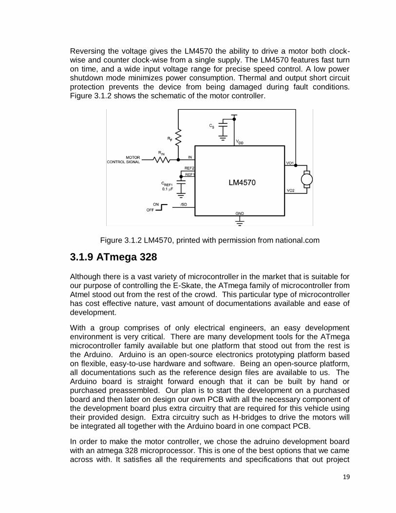
3.1.8 LM4570 The LM4570 is a single supply motor driver for improved sensory experience in mobile phones and other handheld devices. The LM4570 is capable of driving up to 192mA while operating from a 3V supply. Near rail-to-rail output swing under load ensures sufficient voltage drive for most DC motors, while the differential output drive allows the voltage polarity across the motor to be reversed quickly.
19
Reversing the voltage gives the LM4570 the ability to drive a motor both clock-wise and counter clock-wise from a single supply. The LM4570 features fast turn on time, and a wide input voltage range for precise speed control. A low power shutdown mode minimizes power consumption. Thermal and output short circuit protection prevents the device from being damaged during fault conditions. Figure 3.1.2 shows the schematic of the motor controller.
Figure 3.1.2 LM4570, printed with permission from national.com
3.1.9 ATmega 328 Although there is a vast variety of microcontroller in the market that is suitable for our purpose of controlling the E-Skate, the ATmega family of microcontroller from Atmel stood out from the rest of the crowd. This particular type of microcontroller has cost effective nature, vast amount of documentations available and ease of development.
With a group comprises of only electrical engineers, an easy development environment is very critical. There are many development tools for the ATmega microcontroller family available but one platform that stood out from the rest is the Arduino. Arduino is an open-source electronics prototyping platform based on flexible, easy-to-use hardware and software. Being an open-source platform, all documentations such as the reference design files are available to us. The Arduino board is straight forward enough that it can be built by hand or purchased preassembled. Our plan is to start the development on a purchased board and then later on design our own PCB with all the necessary component of the development board plus extra circuitry that are required for this vehicle using their provided design. Extra circuitry such as H-bridges to drive the motors will be integrated all together with the Arduino board in one compact PCB.
In order to make the motor controller, we chose the adruino development board with an atmega 328 microprocessor. This is one of the best options that we came across with. It satisfies all the requirements and specifications that out project
20
needs. The processor will be programmed in the computer using software similar to C++, this is really helpful because many of us have experience with C. The specifications and parameters of the microprocessor and why we chose it are explained in the first part of the research section. The atmega 328 will be used to control the motors and will function as the main controller as well.
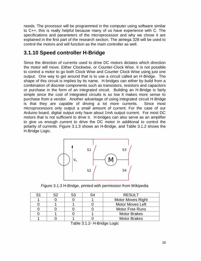
3.1.10 Speed controller H-Bridge Since the direction of currents used to drive DC motors dictates which direction the motor will move. Either Clockwise, or Counter-Clock Wise. It is not possible to control a motor to go both Clock Wise and Counter Clock Wise using just one output. One way to get around that is to use a circuit called an H-Bridge. The shape of this circuit is implies by its name. H-bridges can either by build from a combination of discrete components such as transistors, resistors and capacitors or purchase in the form of an integrated circuit. Building an H-Bridge is fairly simple since the cost of integrated circuits is so low it makes more sense to purchase from a vendor. Another advantage of using integrated circuit H-Bridge is that they are capable of driving a lot more currents. Since most microprocessors only output a small amount of current. For the case of our Arduino board, digital output only have about 1mA output current. For most DC motors that is not sufficient to drive it. H-bridges can also serve as an amplifier to give us enough current to drive the DC motor in additional to control the polarity of currents. Figure 3.1.3 shows an H-Bridge, and Table 3.1.2 shows the H-Bridge Logic.
Figure 3.1.3 H-Bridge, printed with permission from Wikipedia
S1 S2 S3 S4 RESULT
1 0 0 1 Motor Moves Right
0 1 1 0 Motor Moves Left
0 0 0 0 Motor Free Runs
0 1 0 1 Motor Brakes
1 0 1 0 Motor Brakes
Table 3.1.2- H-Bridge Logic
21
3.2 LIQUID CRYSTAL DISPLAY The E-Skate will have a liquid crystal display (LCD) screen to show information about the skateboard to the rider. Necessary information will include vital starts about the skateboard as well as some other information about the skateboard to let the rider know certain conditions. The group has to decide what type of LCD to use and how to connect the LCD to the skateboard, and how it will be integrated. The group must also decide how to use a microcontroller to control the data displayed to the LCD. Common methods for connecting the LCD to microcontrollers will be discussed as well as different technologies between LCDs to use on the skateboard.
3.2.1 Monochrome LCD’s
The group will consider using monochrome LCD‘s for the skateboard. This type of technology is the cheapest as the ―pixels‖ used on the LCD are bigger than in other technology. Also data transmission is simple with this type of technology and connections are maintained to a minimum. Monochrome LCD‘s work by using a small amount of data sent from the microcontroller to the LCD to display information. There are different types of monochromes screens that can be used and as well the configuration used for these types of screens. Some of the options considered are the use of a character LCD and the use of a numerical LCD. Character LCD‘s has more flexibility for use in this type of application but it also uses more data. A numerical LCD only shows numbers and thus uses less data, but in the case of the E-Skate, that data cannot be labeled through the LCD. Table 3.2.1 shows the advantages and disadvantages of monochrome LCDs.
3.2.2 Previous Monochrome LCD Project A previous project that used monochrome LCD‘s was a digital voltmeter. A microcontroller sample an input voltage, then an internal program interprets the data, which then it proceed to display it on the LCD screen. The LCD used on this project was the HD44870 LCD, which is a character LCD. This project was designed for the data to immediately display data to the screen without the user interfering. The microcontroller used is the 16F877A microchip microcontroller which has an analog port. The code from the microcontroller then determines which port of the microcontroller will be used for the LCD and sends data from there to the LCD. Programming for the microcontroller was done with the computer language C, which uses libraries to make the programming easier for the user. The libraries are put on a header file, which includes the header file for the microcontroller and includes all the ports and pins used by the microcontroller. It also includes functions and variables that determine where to when to send the data to the port. The user then determines what character they want to send, and they write the code that calls the function that prints to the port. The character LCD has inputs which include a power input, contrast voltage, enable and the data pins. The project had the LCD power input to a five volts
22
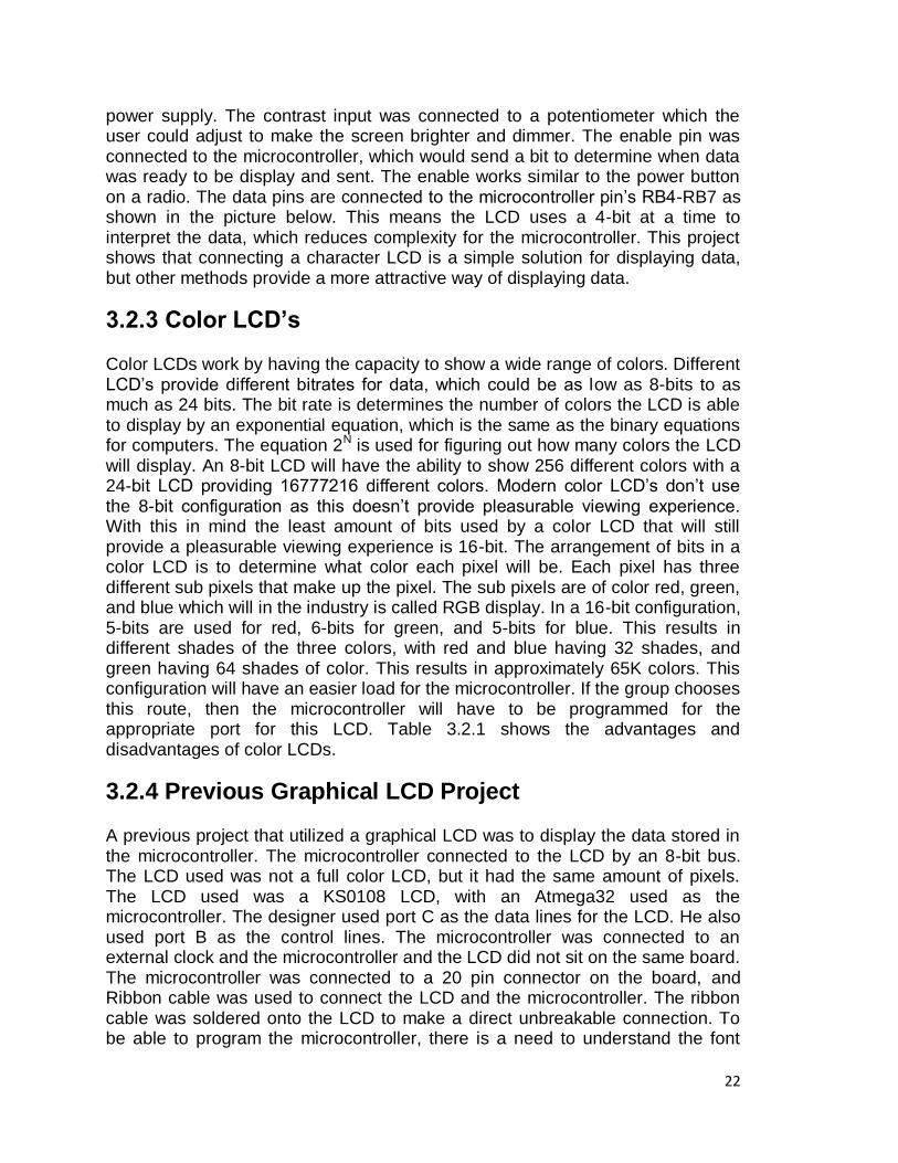
power supply. The contrast input was connected to a potentiometer which the user could adjust to make the screen brighter and dimmer. The enable pin was connected to the microcontroller, which would send a bit to determine when data was ready to be display and sent. The enable works similar to the power button on a radio. The data pins are connected to the microcontroller pin‘s RB4-RB7 as shown in the picture below. This means the LCD uses a 4-bit at a time to interpret the data, which reduces complexity for the microcontroller. This project shows that connecting a character LCD is a simple solution for displaying data, but other methods provide a more attractive way of displaying data.
3.2.3 Color LCD’s Color LCDs work by having the capacity to show a wide range of colors. Different LCD‘s provide different bitrates for data, which could be as low as 8-bits to as much as 24 bits. The bit rate is determines the number of colors the LCD is able to display by an exponential equation, which is the same as the binary equations for computers. The equation 2N is used for figuring out how many colors the LCD will display. An 8-bit LCD will have the ability to show 256 different colors with a 24-bit LCD providing 16777216 different colors. Modern color LCD‘s don‘t use the 8-bit configuration as this doesn‘t provide pleasurable viewing experience. With this in mind the least amount of bits used by a color LCD that will still provide a pleasurable viewing experience is 16-bit. The arrangement of bits in a color LCD is to determine what color each pixel will be. Each pixel has three different sub pixels that make up the pixel. The sub pixels are of color red, green, and blue which will in the industry is called RGB display. In a 16-bit configuration, 5-bits are used for red, 6-bits for green, and 5-bits for blue. This results in different shades of the three colors, with red and blue having 32 shades, and green having 64 shades of color. This results in approximately 65K colors. This configuration will have an easier load for the microcontroller. If the group chooses this route, then the microcontroller will have to be programmed for the appropriate port for this LCD. Table 3.2.1 shows the advantages and disadvantages of color LCDs.
3.2.4 Previous Graphical LCD Project A previous project that utilized a graphical LCD was to display the data stored in the microcontroller. The microcontroller connected to the LCD by an 8-bit bus. The LCD used was not a full color LCD, but it had the same amount of pixels. The LCD used was a KS0108 LCD, with an Atmega32 used as the microcontroller. The designer used port C as the data lines for the LCD. He also used port B as the control lines. The microcontroller was connected to an external clock and the microcontroller and the LCD did not sit on the same board. The microcontroller was connected to a 20 pin connector on the board, and Ribbon cable was used to connect the LCD and the microcontroller. The ribbon cable was soldered onto the LCD to make a direct unbreakable connection. To be able to program the microcontroller, there is a need to understand the font
23
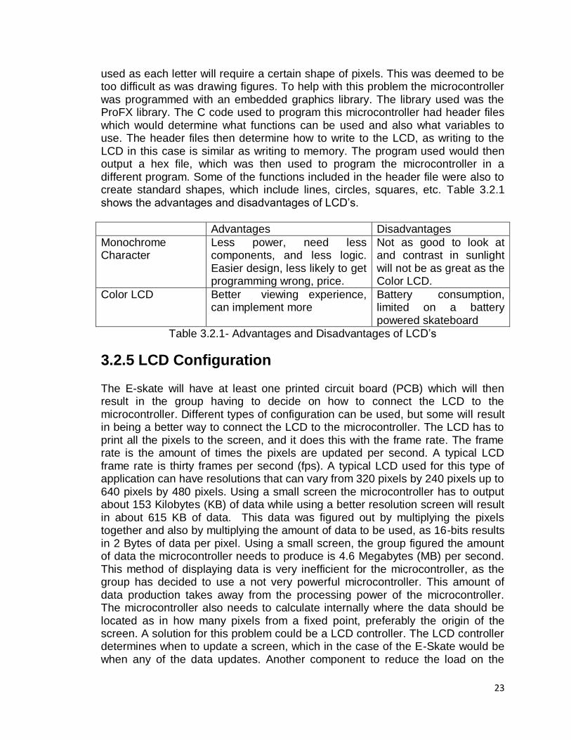
used as each letter will require a certain shape of pixels. This was deemed to be too difficult as was drawing figures. To help with this problem the microcontroller was programmed with an embedded graphics library. The library used was the ProFX library. The C code used to program this microcontroller had header files which would determine what functions can be used and also what variables to use. The header files then determine how to write to the LCD, as writing to the LCD in this case is similar as writing to memory. The program used would then output a hex file, which was then used to program the microcontroller in a different program. Some of the functions included in the header file were also to create standard shapes, which include lines, circles, squares, etc. Table 3.2.1 shows the advantages and disadvantages of LCD‘s.
Advantages Disadvantages
Monochrome Character
Less power, need less components, and less logic. Easier design, less likely to get programming wrong, price.
Not as good to look at and contrast in sunlight will not be as great as the Color LCD.
Color LCD Better viewing experience, can implement more
Battery consumption, limited on a battery powered skateboard
Table 3.2.1- Advantages and Disadvantages of LCD‘s
3.2.5 LCD Configuration The E-skate will have at least one printed circuit board (PCB) which will then result in the group having to decide on how to connect the LCD to the microcontroller. Different types of configuration can be used, but some will result in being a better way to connect the LCD to the microcontroller. The LCD has to print all the pixels to the screen, and it does this with the frame rate. The frame rate is the amount of times the pixels are updated per second. A typical LCD frame rate is thirty frames per second (fps). A typical LCD used for this type of application can have resolutions that can vary from 320 pixels by 240 pixels up to 640 pixels by 480 pixels. Using a small screen the microcontroller has to output about 153 Kilobytes (KB) of data while using a better resolution screen will result in about 615 KB of data. This data was figured out by multiplying the pixels together and also by multiplying the amount of data to be used, as 16-bits results in 2 Bytes of data per pixel. Using a small screen, the group figured the amount of data the microcontroller needs to produce is 4.6 Megabytes (MB) per second. This method of displaying data is very inefficient for the microcontroller, as the group has decided to use a not very powerful microcontroller. This amount of data production takes away from the processing power of the microcontroller. The microcontroller also needs to calculate internally where the data should be located as in how many pixels from a fixed point, preferably the origin of the screen. A solution for this problem could be a LCD controller. The LCD controller determines when to update a screen, which in the case of the E-Skate would be when any of the data updates. Another component to reduce the load on the
24
microcontroller is the frame buffer. The frame buffer stores the image to be displayed, and updates only the changes. Then it sends the data to the LCD. The frame buffer can be any type of memory that the LCD controller can use to store an image. There are many ways to connect the LCD Controller, frame buffer, LCD and the microcontroller. The following three methods which are integration, graphics controller and direct connect are the most useful and simple way to connecting these components.
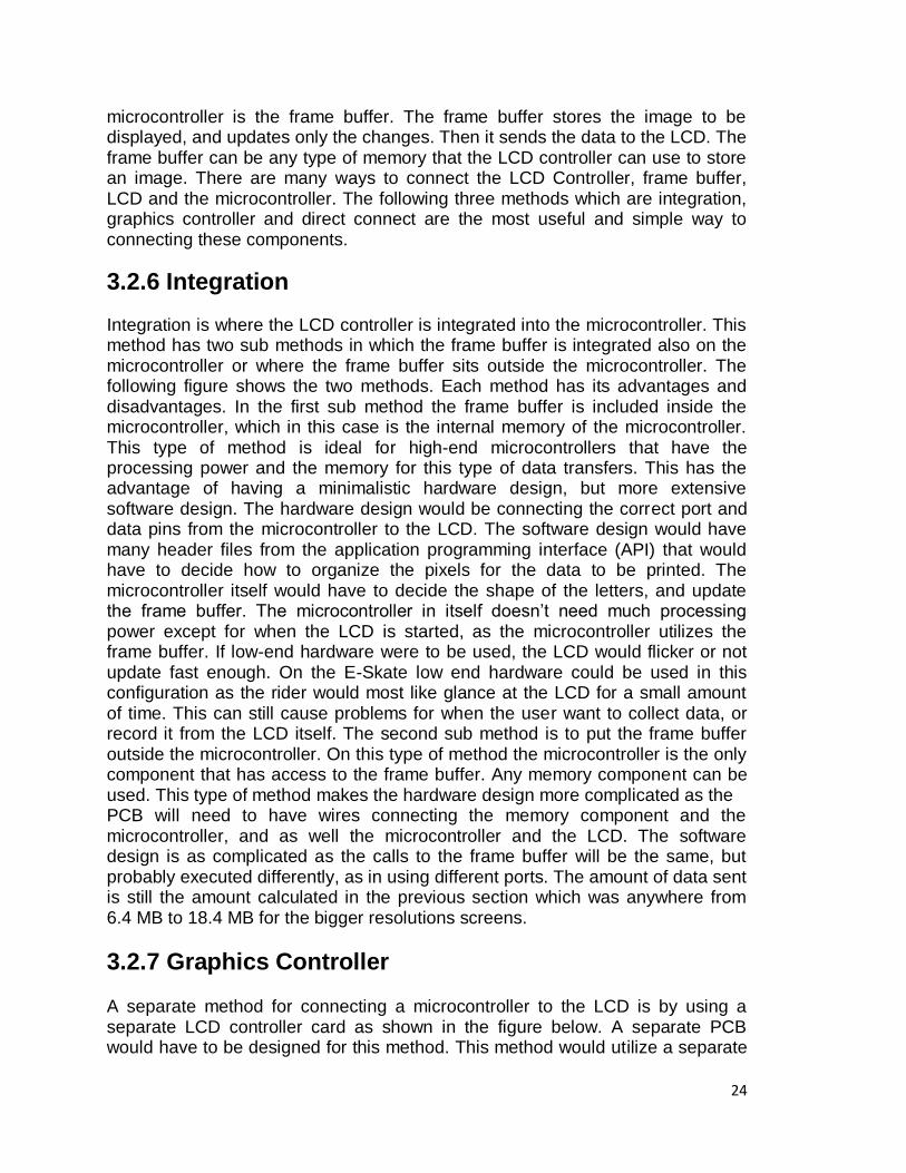
3.2.6 Integration
Integration is where the LCD controller is integrated into the microcontroller. This method has two sub methods in which the frame buffer is integrated also on the microcontroller or where the frame buffer sits outside the microcontroller. The following figure shows the two methods. Each method has its advantages and disadvantages. In the first sub method the frame buffer is included inside the microcontroller, which in this case is the internal memory of the microcontroller. This type of method is ideal for high-end microcontrollers that have the processing power and the memory for this type of data transfers. This has the advantage of having a minimalistic hardware design, but more extensive software design. The hardware design would be connecting the correct port and data pins from the microcontroller to the LCD. The software design would have many header files from the application programming interface (API) that would have to decide how to organize the pixels for the data to be printed. The microcontroller itself would have to decide the shape of the letters, and update the frame buffer. The microcontroller in itself doesn‘t need much processing power except for when the LCD is started, as the microcontroller utilizes the frame buffer. If low-end hardware were to be used, the LCD would flicker or not update fast enough. On the E-Skate low end hardware could be used in this configuration as the rider would most like glance at the LCD for a small amount of time. This can still cause problems for when the user want to collect data, or record it from the LCD itself. The second sub method is to put the frame buffer outside the microcontroller. On this type of method the microcontroller is the only component that has access to the frame buffer. Any memory component can be used. This type of method makes the hardware design more complicated as the PCB will need to have wires connecting the memory component and the microcontroller, and as well the microcontroller and the LCD. The software design is as complicated as the calls to the frame buffer will be the same, but probably executed differently, as in using different ports. The amount of data sent is still the amount calculated in the previous section which was anywhere from 6.4 MB to 18.4 MB for the bigger resolutions screens.
3.2.7 Graphics Controller A separate method for connecting a microcontroller to the LCD is by using a separate LCD controller card as shown in the figure below. A separate PCB would have to be designed for this method. This method would utilize a separate
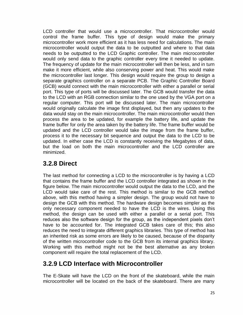
25
LCD controller that would use a microcontroller. That microcontroller would control the frame buffer. This type of design would make the primary microcontroller work more efficient as it has less need for calculations. The main microcontroller would output the data to be outputted and where to that data needs to be outputted to the LCD Graphic controller. The main microcontroller would only send data to the graphic controller every time it needed to update. The frequency of update for the main microcontroller will then be less, and in turn make it more efficient, while also conserving power and heat. This would make the microcontroller last longer. This design would require the group to design a separate graphics controller on a separate PCB. The Graphic Controller Board (GCB) would connect with the main microcontroller with either a parallel or serial port. This type of ports will be discussed later. The GCB would transfer the data to the LCD with an RGB connection similar to the one used by the VGA port on a regular computer. This port will be discussed later. The main microcontroller would originally calculate the image first displayed, but then any updates to the data would stay on the main microcontroller. The main microcontroller would then process the area to be updated, for example the battery life, and update the frame buffer for only the area taken by the battery life. The frame buffer would be updated and the LCD controller would take the image from the frame buffer, process it to the necessary bit sequence and output the data to the LCD to be updated. In either case the LCD is constantly receiving the Megabytes of data, but the load on both the main microcontroller and the LCD controller are minimized.
3.2.8 Direct The last method for connecting a LCD to the microcontroller is by having a LCD that contains the frame buffer and the LCD controller integrated as shown in the figure below. The main microcontroller would output the data to the LCD, and the LCD would take care of the rest. This method is similar to the GCB method above, with this method having a simpler design. The group would not have to design the GCB with this method. The hardware design becomes simpler as the only necessary component needed to have the LCD is the wires. Using this method, the design can be used with either a parallel or a serial port. This reduces also the software design for the group, as the independent pixels don‘t have to be accounted for. The integrated GCB takes care of this; this also reduces the need to integrate different graphics libraries. This type of method has an inherited risk as some errors are likely to be caused, because of the disparity of the written microcontroller code to the GCB from its internal graphics library. Working with this method might not be the best alternative as any broken component will require the total replacement of the LCD.
3.2.9 LCD Interface with Microcontroller The E-Skate will have the LCD on the front of the skateboard, while the main microcontroller will be located on the back of the skateboard. There are many
26
ways to connect the microcontroller to the GCB or to the LCD. The methods that the group will consider are by serial connection, parallel connection and by the RGB interface. These connections have their advantages and disadvantages which will be explored.
3.2.10 Parallel Since the LCD is not connected directly to the microcontroller‘s PCB, there is a need to connect it through an interface. The first method of connecting the LCD to the microcontroller discussed is the use of a parallel interface. The parallel interface transfers data in parallel at the same time. The parallel interface has many data pins on the parallel cable and is defined by the IEEE standard 1284. There are inherited advantages and disadvantages to using a parallel connection. An advantage to transferring data through a parallel connection includes having a better feed and faster speed to transfer the data to the LCD.A disadvantage include the inherit design of a parallel connection. A parallel wire has many wires for the data pins, with each wire creating its own noise, which interferes with the data and with the other wires. This can result in damaged data to the LCD, which would make the parallel connection unreliable. As the skateboard moves, this risk increases and the parallel wires will pick up external noise. Another disadvantage of a parallel connection is the limited use of length on the wire. As the parallel cable gets longer, there is signal degradation which if this cable is used and noise is not accounted for, will further damage data. If the group decides to use a parallel connection, it would be used for connecting the microcontroller to the GCB.
3.2.11 Serial Another method for connecting a LCD to the microcontroller is with a serial connection. A serial connection transfers data at one-bit at a time, as well as the control bits. The use of serial is widely used throughout the industry as serial connectors provide many benefits. When comparing serial to parallel connections, it was found that serial connections are faster than parallel. In theory the parallel data wire would be faster, as there is more pins to transfer data, but because of the amount of noise created, there is a need to slow down data transfers. The clock on the serial connection would be faster as there would be more data to transmit. There are many different ways to implement a serial connection with the most widespread being the Universal Serial Bus (USB) which will be used on another component. Another popular type of connection is the IEEE standard RS 232. This method is popular for LCD data transfer. On the PCB there are many ways to implement serial communications with different standards. These are SPI, I2C, UNI/O, RS232 and 1-Wire.
3.2.12 RGB Interface
27
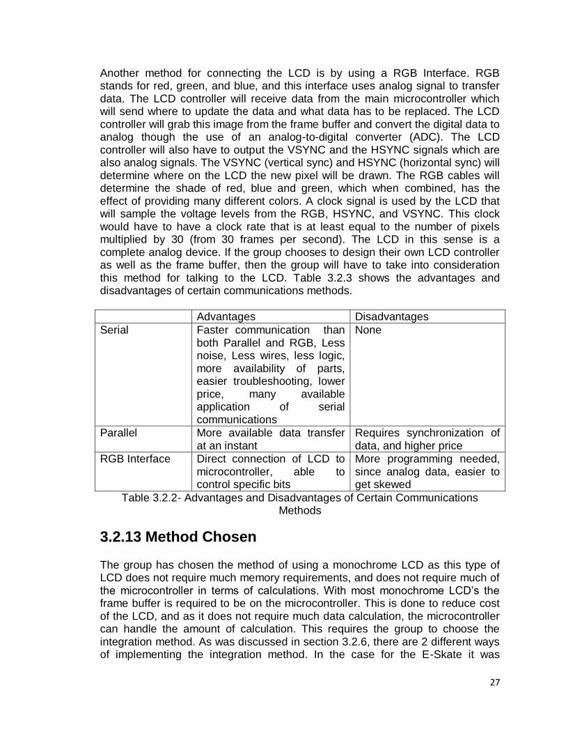
Another method for connecting the LCD is by using a RGB Interface. RGB stands for red, green, and blue, and this interface uses analog signal to transfer data. The LCD controller will receive data from the main microcontroller which will send where to update the data and what data has to be replaced. The LCD controller will grab this image from the frame buffer and convert the digital data to analog though the use of an analog-to-digital converter (ADC). The LCD controller will also have to output the VSYNC and the HSYNC signals which are also analog signals. The VSYNC (vertical sync) and HSYNC (horizontal sync) will determine where on the LCD the new pixel will be drawn. The RGB cables will determine the shade of red, blue and green, which when combined, has the effect of providing many different colors. A clock signal is used by the LCD that will sample the voltage levels from the RGB, HSYNC, and VSYNC. This clock would have to have a clock rate that is at least equal to the number of pixels multiplied by 30 (from 30 frames per second). The LCD in this sense is a complete analog device. If the group chooses to design their own LCD controller as well as the frame buffer, then the group will have to take into consideration this method for talking to the LCD. Table 3.2.3 shows the advantages and disadvantages of certain communications methods.
Advantages Disadvantages
Serial Faster communication than both Parallel and RGB, Less noise, Less wires, less logic, more availability of parts, easier troubleshooting, lower price, many available application of serial communications
None
Parallel More available data transfer at an instant
Requires synchronization of data, and higher price
RGB Interface Direct connection of LCD to microcontroller, able to control specific bits
More programming needed, since analog data, easier to get skewed
Table 3.2.2- Advantages and Disadvantages of Certain Communications Methods
3.2.13 Method Chosen The group has chosen the method of using a monochrome LCD as this type of LCD does not require much memory requirements, and does not require much of the microcontroller in terms of calculations. With most monochrome LCD‘s the frame buffer is required to be on the microcontroller. This is done to reduce cost of the LCD, and as it does not require much data calculation, the microcontroller can handle the amount of calculation. This requires the group to choose the integration method. As was discussed in section 3.2.6, there are 2 different ways of implementing the integration method. In the case for the E-Skate it was
28
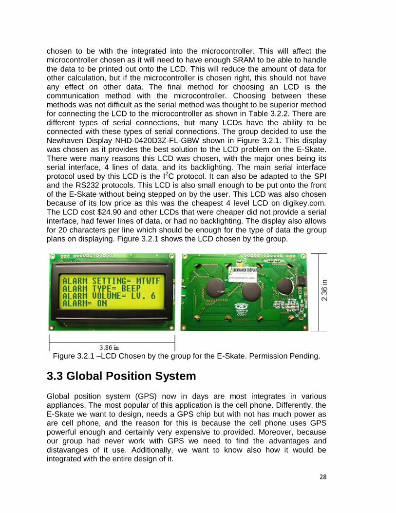
chosen to be with the integrated into the microcontroller. This will affect the microcontroller chosen as it will need to have enough SRAM to be able to handle the data to be printed out onto the LCD. This will reduce the amount of data for other calculation, but if the microcontroller is chosen right, this should not have any effect on other data. The final method for choosing an LCD is the communication method with the microcontroller. Choosing between these methods was not difficult as the serial method was thought to be superior method for connecting the LCD to the microcontroller as shown in Table 3.2.2. There are different types of serial connections, but many LCDs have the ability to be connected with these types of serial connections. The group decided to use the Newhaven Display NHD-0420D3Z-FL-GBW shown in Figure 3.2.1. This display was chosen as it provides the best solution to the LCD problem on the E-Skate. There were many reasons this LCD was chosen, with the major ones being its serial interface, 4 lines of data, and its backlighting. The main serial interface protocol used by this LCD is the I2C protocol. It can also be adapted to the SPI and the RS232 protocols. This LCD is also small enough to be put onto the front of the E-Skate without being stepped on by the user. This LCD was also chosen because of its low price as this was the cheapest 4 level LCD on digikey.com. The LCD cost $24.90 and other LCDs that were cheaper did not provide a serial interface, had fewer lines of data, or had no backlighting. The display also allows for 20 characters per line which should be enough for the type of data the group plans on displaying. Figure 3.2.1 shows the LCD chosen by the group.
Figure 3.2.1 –LCD Chosen by the group for the E-Skate. Permission Pending.
3.3 Global Position System
Global position system (GPS) now in days are most integrates in various appliances. The most popular of this application is the cell phone. Differently, the E-Skate we want to design, needs a GPS chip but with not has much power as are cell phone, and the reason for this is because the cell phone uses GPS powerful enough and certainly very expensive to provided. Moreover, because our group had never work with GPS we need to find the advantages and distavanges of it use. Additionally, we want to know also how it would be integrated with the entire design of it.
29
According to Michael Simpson, He talks about GPS in his paper about interfacing with GPS module or Receiver. He talks about how GPS system would not help to much in a project if resolution of less than 25 feet. Also if the project is an indoor project would not be beneficial to use a GPS interface, but if a project is and outdoor, it would help greatly. This article also focuses in EM-406A, EM-408, Etek, and Coprenicus modules. Therefore for our E-Skate is an outdoor project which will be great to interface with a GPS. E-Skate only downer is that it would be use in campus only which will make the buildings be an interference with the GPS signal. Also what is great of these modules is that it can be used with a desktop PC, Laptop, Pocket PC, or a microcontroller. And according to the article it all support NMEA 0183 protocol.
3.3.1 EM-406A EM-406A is manufactured by USglobalsat. The em-406 is a module that has an optional development board available. This board is perfect to interface with the computer and pocket computer, which makes the EM-406A a perfect starting research for GPS. Some features that the EM406A have, according to the research article, are:
20 channel receiver
built-in antenna, high sensitivity: -159dBm
30‘ positional Accuracy/ 25‘ with WAAS
supports WAAS in default mode
Hot Start: 8 seconds
Warm Start: 38 seconds
Cold Start: 42 seconds
70mA power consumption
4.5 – 6.5 volt operation
Outputs NMEA 0183 and SiRF binary protocols
Small foot print: 30mm x 30mm x 10.5mm
Buit-in LED status indicator
6-pin interface cable included According to the features above we can conclude that it is a excellent GPS to start with just because there is small consumption of power. It can have a fast start and a slow one. It supports two protocols, the antenna is already provided as a LED status. This GPS make a good start. For the E-Skate still we need to considerate the other GPS to make a accurately assumption. For this GPS module it would suit great to our E-Skate if we need to know where it is form our computer also.
3.3.2 EM-408
30
The EM-408 module is also manufactured by USGlobalSat. As difference with the EM-406A It does not have its own evaluation board. Now let‘s see the feature this module offers and how differently it is from it brother module EM-406A.
EM-408 Features:
20 Channel Receiver
Built in antenna
High sensitivity: -159dBm
30‘ positional Accuracy/ 25‘ with WAAS
Support WAAS in default mode
Hot start: 8 seconds
Warm Star: 38 seconds
Cold Start: 42 seconds
75mA power consumption
3.3 volts operation
Output NMEA 0183 and SiRF binary protocols
30 gram weight
Built in LED status indicator
5-pins interface cable
External MMCX antenna connector
The only differences that the EM-408 has form his sibling is the 5-pins interface, the external MMCX antenna connector, it also need less voltage to operated, but it consumes a little more power that the EM-406A. Also because it does not come with a development board, there is a need to mount headers, even if it we are going to connected to a microcontroller.
3.3.3 Etek EB-85A
According to Michael Simpson, Author of Interface to GPS Module or Receiver, the Etek EB-85A is the most accurate GPS that he had tested. It supports up 32 parallel channels with WAAS enable. The disadvantage is that WAAS is not enable default. So we would need to send commands to the module in order to enable this feature. Additionally, when the module is turn off, it loses these setting, and we need to send the WAAS command again to set it up when it is power on again.
Features of the Etek EB-85A:
· 32 Channel Receiver · Built-in antenna · High sensitivity: -158dBm · 1-5 Hz update rate · Selectable baud rate from 4800 to 115200bps · 9.8‘ Positional Accuracy / 8.2‘ with WAAS
31
· Hot Start : 1 seconds · Warm Start : 33 seconds · Cold Start : 36 seconds · 55mA power consumption to acquire and 30mA for tracking · 3.3 – 5 volt operation · Outputs NMEA 0183 · Small foot print: 30mm x 30mm x 8.6mm · 8-pin interface cable included · Free Mini GPS utility available
As the EM-408 it does not have a development board available but it can be made too. The great thing about this module is that the features speak for themselves. First, it has 32 channels. The more channels a GPS module has the better. Second, it has 1 to 5 Hz update rate with the other two modules did not offer. Consequently, has a hot start of 1 second, faster than the 8 second the EM brother features. To turn on has almost the same rate as the EM 408 it has an 8 pin interface, and mini GPS utility is available. So far the Etek look and features better qualities. For this features, the E-Skate would be great, the only down part would be that we have to set, each time it is on, the WAAS command to be default.
3.3.4 Copernicus GPS module
Finally, we are going to talk about the Copernicus module which has an evaluation board, and it also can be plug to a standard breadboard. Also it will be needed to keep in mind that it needs a 3.3 volt interface.
Copernicus Features:
12 Channel Receiver
External Antenna Connector
High sensitivity: -152dBm
NMEA 0813, TSIP, and TAIP protocols supported
Cold Start : 39 seconds
28.5mA power consumption
Small foot print : 30mm x 30mm x 8.6mm
Free GPS utility available
It is notice that the Copernicus module does not support WAAS and it is also rumored that the near future. Also it is notice that it has only 12 channels which make it a little lower than the EM brother and the lesser than Etek module. It does support more protocols but we are focus on the NMEA 0813 protocol only because it is the most use in all the modules. There were not as much features for the Copernicus GPS module as the other one.
Finally of all this GPS modules or receivers the best that can be use is the Etek EB-85A. It has more channels available. It pricing is around 99.99 dollars. It also may be call now SANAV FV-M8 now that the San Jose Technology own ETEK.
32
Following is a picture of the Etek EB-85A look. If we compared prices with the EM-406A pricing is only 59.95 dollars, while the EM-408 is 64.95. The Copernicus is only 44.95 dollars. Therefore, if we go from performance and pricing, the EM 406A, which is very close to the EM 408, is the best choice for E-Skate to be use.
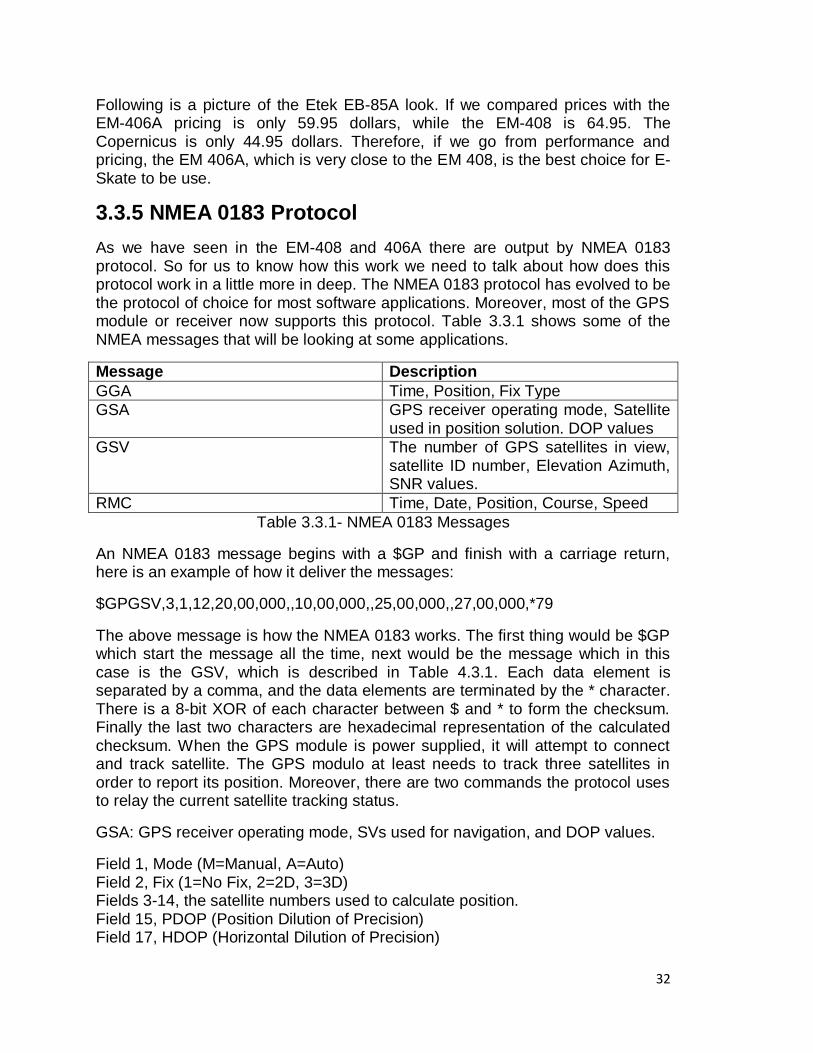
3.3.5 NMEA 0183 Protocol
As we have seen in the EM-408 and 406A there are output by NMEA 0183 protocol. So for us to know how this work we need to talk about how does this protocol work in a little more in deep. The NMEA 0183 protocol has evolved to be the protocol of choice for most software applications. Moreover, most of the GPS module or receiver now supports this protocol. Table 3.3.1 shows some of the NMEA messages that will be looking at some applications.
Message Description
GGA Time, Position, Fix Type
GSA GPS receiver operating mode, Satellite used in position solution. DOP values
GSV The number of GPS satellites in view, satellite ID number, Elevation Azimuth, SNR values.
RMC Time, Date, Position, Course, Speed
Table 3.3.1- NMEA 0183 Messages
An NMEA 0183 message begins with a $GP and finish with a carriage return, here is an example of how it deliver the messages:
$GPGSV,3,1,12,20,00,000,,10,00,000,,25,00,000,,27,00,000,*79
The above message is how the NMEA 0183 works. The first thing would be $GP which start the message all the time, next would be the message which in this case is the GSV, which is described in Table 4.3.1. Each data element is separated by a comma, and the data elements are terminated by the * character. There is a 8-bit XOR of each character between $ and * to form the checksum. Finally the last two characters are hexadecimal representation of the calculated checksum. When the GPS module is power supplied, it will attempt to connect and track satellite. The GPS modulo at least needs to track three satellites in order to report its position. Moreover, there are two commands the protocol uses to relay the current satellite tracking status.
GSA: GPS receiver operating mode, SVs used for navigation, and DOP values.
Field 1, Mode (M=Manual, A=Auto) Field 2, Fix (1=No Fix, 2=2D, 3=3D) Fields 3-14, the satellite numbers used to calculate position. Field 15, PDOP (Position Dilution of Precision) Field 17, HDOP (Horizontal Dilution of Precision)
33
Field 18, VDOP (Vertical Dilution of Precision) The field that is the most important in is Field 2 (Fix). This field values would tell what kind of satellite tracking we obtain. If it is 1, then not enough satellites can be tracked to get a signal. if it is 2, then the module is 2D mode. This means that only X and Y position are going to be reported. Moreover, if it is 3 then the module is in 3D mode, and it will report position of X, Y and Z axis. GSV: Detailed Satellite data Field 1, Number of Messages (1-3) Field 2, Current Message Number (1-3) Field 3, Satellites in View Field 4-7, Satellite Number (1-32), Elevation (0-90), Azimuth (0-359), SNR (0-99) Fields 8-11, Satellite Number (1-32), Elevation (0-90), Azimuth (0-359), SNR (0-99) Fields 12-15, Satellite Number (1-32), Elevation (0-90), Azimuth (0-359), SNR (0-99) Fields 16-19, Satellite Number (1-32), Elevation (0-90), Azimuth (0-359), SNR (0-99) The GSV message will report the number of satellites in view and the actual signal value of any of those satellites that is able to track. The third field tells the number of satellites in view. Then, 4 fields for each satellites in view report the satellite number, Elevation, Azimuth and SRN. GGA: Global Positioning System Fixed Data Field 1, UTC Time in the format of hhmmss.sss Field 2, Latitude in the format of ddmm.mmmm Fields 3, N/S Indicator (N=North, S=South) Field 4, Longitude in the format of dddmm.mmmm Field 5, E/W Indicator (E=East, W=West) Field 6, Position Fix Indicator (0=No Fix, 1=SPS Fix, 2=DGPS Fix) Field 7, Satellites Used (0-12) Field 8, Horizontal Dilution of Precision Field 9, MSL Altitude Field 10, MSL Units (M=Meters) Field 11, Geoid Separation Field 12, Geoid Units (M=Meters) Field 13, Age of Diff Correction in seconds Field 14, Diff Reference RMC: Recommended Minimum Specific GNSS Data Field 1, UTC Time in the format of hhmmss.sss
34
Field 2, Status (A=Valid Data, B=Invalid Data) Field 3, Latitude in the format of ddmm.mmmm Fields 4, N/S Indicator (N=North, S=South) Field 5, Longitude in the format of dddmm.mmmm Field 6, E/W Indicator (E=East, W=West) Field 7, Speed over ground in knots Field 8, Course over ground in degrees Field 9, Date in the format of ddmmyy Field 10, Magnetic Variation in degrees Field 11, Mode (A=Autonomous, D=DGPS, E=DR) Both GGA and RMC field will inform latitude and longitude, but the GGA command will report the altitude and fix type. Otherwise, the RMC command will report the course and speed. So it‗s clear the we need to call both of these commands to gain all the information. This protocol is very informative of what we need to shown in the E-Skate. So therefore this protocol would certainly be use for our GPS module. And one of the biggest reason is because it shows the position and speed and how many fix satellites are encounter.
3.4 POWER SYSTEM
For the E-Skate as our power system we are going to use electric skateboard motors and batteries. There are various electric skateboard motors, some of what are more powerful as another. For our E-Skate we are going to research the difference between all this motor and choose the one most appropriate with our desires. For example money and speed are going to be the key for this decision. So for this part of our E-Skate project we are going to research various electric motors and talk about the qualities these possess. Moreover, as we see the different time of motors we are going to see the types of batteries we need to use for the E-Skate. As the motor we need to consider speed and money as our key for decision, for the batteries would be the power, money, and motors voltage need. Consequently, we are going to talk about the motors first and end up with the batteries later on.
3.4.1 Electric Motor
In order to understand which electric motor better suits our project for an electric skateboard, we need to understand the principles of an electric motor. Electric motors convert electric energy into mechanical energy; this is the basically understanding of how electric motors work. For E-Skate we are going to use the energy from the battery to generate or ignited an electric field that will make the rotor to rotate and it would be attached to one side of the weal in the skateboard, and this is going to make the E-Skate to gain some velocity and move. This is the basic and more simplify use of the electric motor in or E-Skate. Moreover, there
35
are two main electric motors that we can use the direct current (DC) motor and the Alternating Current (AC) motor. Because we are using a battery as main power supply we need to use a Direct Current motor.
3.4.2 Direct Current Motors
DC motors are good for our project of the E-Skate because the speed-torque relationship can be varied to almost any useful form. DC motors are often applied where they momentarily deliver three or more times their rated torque. In emergency situations they can supply over five times rated torque without stalling (power supply permitting). Another great characteristic of using is the dynamic braking or generative braking. Therefore, for our E-Skate if the user felts from the board, it would have a quick stop without having to run to catch the E-Skate down the road. DC motors delivers a speed which can be controlled nicely down; moreover, followed by acceleration in the opposite direction without power circuit switching. Additionally, because our E-Skate is going to be controlled by a control remote, DC motors respond quickly to changes in control signals due to the high speed ratio torque. Wound-field dc motors are usually classified by shunt-wound, series-wound, and compound-wound. In addition to these, permanent-magnet and brushless dc motors are also available, normally as fractional-horsepower dc motors. Dc motors may be further classified for intermittent or continuous duty. Continuous-duty dc motors can run without an off period. There are two ways to adjust the speed of a wound-field dc motor. Combinations of the two are sometimes used to adjust the speed of a dc motor. Shunt field control in one of the control. The dc motor‘s material is ramp on a reel at constant linear speed and strip tension, no matter the diameter of the reel. The control is obtain by weakening the shunt field current of the motor to increase speed and the reduce torque for the given armature current. The rating for a dc motor is determined by the heating; therefore, the maximum permitted armature current is closely constant over the speed range. Moreover, at rated current, the motor‘s output force varies inversely with speed. Consequently, the DC motor has constant horsepower capability over its speed of range. If we overexcited the field, we can obtain speeds greater than the regular speed. It is just momentary because it causes over excitation, and it would overheat the dc motor. In addition, magnetic field saturation in the dc motor permits only a small reduction in speed for a substantial increase in field voltage. The maximum standard speed range by the field control is 3:1 in a DC motor. There are some special motor with greater speed ranges, but other control method is used for parts of the range. The second control of speed is the Armature voltage DC motor control. The shunt field current is maintained constant form a separate source while the voltage applied to the armature is varied. Dc motors have a speed that is proportional to the counter electric magnetic field. Consequently, this is the same to the applied voltage minus the armature circuit current resistant drop. The torque stay constant no matter of the dc motor speed, for the magnetic flux is constant too, and the dc motor has a constant torque capability over the range of speed. Horsepower varies directly with speed. In deep, as the speed of a self ventilated
36
motor is lowered, it loses ventilation and cannot be loaded as much armature current without over passing the rated temperature rise.
As we discuss at the beginning of this section choosing a dc motor and associated equipment for E-Skate requires consideration of several factors. The motor is the fundamental reason why the skate is going to move therefore is very important to choose a motor powerful enough and easy to control to make this project of the E skate a success. Moreover, by having the right motor, we can find the right battery and our project would be half done. This section is all about research and to make an accurate choosing we need to find what factors of dc motor will make the best for our suited project. One of the factors we need to consider is the Speed range. If a field control is to be uses in the E-Skate project, and a large speed range is required, then the base speed most be lower and the size of the motor quite large. If speed range is much over 3:1, armature voltage control, we should consider for at least part of the range. Wide dynamic range of speed can be obtained with armature voltage control. Otherwise, below a 65% of base speed, the motor should be derated or used for only short periods. For the E-Skate project, the skate is not going to be in use for long period however we need a small motor with not a large speed rated so most likely we are going to be using as or control for the speed range would be the armature voltage control. Applications that required constant speed at all torque should use a shunt wound motor. If speed change with load has to minimize, a dc motor regulator, must be used. When the motor speed must decrease as the load increases, compound or series wound dc motors most be used. Otherwise, a dc motor power supply with a drooping volt-ampere curve could be used with a shunt-wound motor. For the E-Skate the using a power supply with a drooping volt-ampere curve is going to be used more often to reduce the speed. With bring us back to a shunt wound dc motor to be required in our project. Reversing, this Operation affects power supply and control, and it affects the motor‘s brush adjustment if the dc motor cannot be stopped for a switching before reverse operation. Therefore, compound and stabilizing motor winding should not be used, and a armature-voltage control system should supply power to the motor. Once again in our project the skateboard is not going to do reverse but it would stop. Therefore the reversing application doesn‘t have to be provided in this project. But, if there were to use this reversing application, the armature voltage control would be need it and may be used to acquire this reversing mode for the E-Skate. Duty cycle, direct current motors are sometimes used on drives that runs continuously at one speed and load. Motor size needed may determined by the peak torque requirement or heating. Our E-Skate would not be needed the worry about the duty cycle because it won‘t be running at the same speed all the time, the load would most likely change over time or over person, and at the motor sized most likely have to be small enough to be attack in a skate board with making it to heavy to carry. The Peak torque that a motor delivers is limited by the load at which damaging commutation starts. DC motor brushes and communtators damage depends on sparking severity and duration. Consequently, the dc motor‘s peak torque depends on the duration and frequency of occurrence of the
37
overload. DC motor peak torque is often limited by the maximum current that the power supply can deliver. DC motor can commutate greater loads at low speed without damage. The E-Skate peak torque has to be calculated by the Power supply which in this case is a battery. More from here is just putting the battery with a Dc motor and experience the maximum speed and minimum speed it makes with different loads. Heating, Dc motors temperature is a function of ventilation and electoral/mechanical losses in the machine. Some motors have looses such as core, shunt field, and brush friction, which are independent of the load, but vary speed and excitation. The best method to find a given dc motors‘ operating temperature is to use a thermal capability curves from the manufacturer. If the curves are not found, the dc motor temperature can be estimated by the power-loss method. This method requires a total loss versus load curves or an efficiency curve. For each portion of the duty cycle, power loss is obtained and multiplied by the duration of that portion of the cycle.
3.4.3 Type of DC Motors
Now that we have research a little about how dc motor work, and what kind of control we need to maximize speed. We are going to see different types of Dc motor that would work best with or E-Skate project: Brushless DC motors despites their superior qualities, brushless motors still run second to brush types in motion control applications. Brushless systems are most likely preferred, but where their benefits outweigh their expensive prices. In addition, they cost less than brush types in some applications when energy, maintenance, and downtime cost are included. Because brushless system are becoming popular in the market, the price of this systems are decreasing in price and competitors in are arising. Moreover, it is becoming easier to use brushless type and therefore it is a good option for our E-Skate project. Conventional brushless motors come in different variety of configurations. The most widely used look much like brush type motors. Brushless motors have a wound stator that surrounds a permanent magnet rotor, an inverse arrangement form that for brush motors. Consequently, stator winding are commutated electronically rather through a conventional commutator and brushes. Brushless motors generally contain a three phase winding, although some operate four phase. Brushless motor powering small fans and other constant speed equipment are often two phase. For our motor to be use we most likely are going to use a three phase winding in order to maintain a continuous voltage control. Power for brushless motors generally is a trapezoidal ac wave for, but some of the motors operate with sine waves. Trapezoidal- powered motors develop about ten percent more torque than those on sine wave power. But, sinusoidal powered motors exhibit less torque ripple and operate smother at low speed. Thus, sinusoidal power motors are often used for machining, grinding, coating, and other operations calling for fine surface finishes. Brushless motors are more efficient and need less maintenance because they have no commutator. Moreover, it can operate at higher speeds than conventional dc motors. Also brushless dc motors are high efficiency and
38
small sizes with make it perfect to by use in small portable instruments. Therefore, it makes a good decision for our E-Skate project.
The cost of both brush-type and brushless motors likely will rise because of increasing costs for iron, steel, copper, aluminum, and magnets. The increases will be partly offset by use of neodymium-iron-boron magnets. The magnets are often more powerful than samarium-cobalt magnets and promise to be much less expensive. Amplifies for brushless motors are more complex than brush types. Generally, brushless motors are calling for two additional solid-state power switches. These switches account for most of the cost between the two types. Luckily, switch cost are continue to drop because of the increased use of MOSFET and insulated gate type switches. Linear dc motors, like a rotation dc motor generates mechanical force by the interaction of current in conductor and magnetic flux provided by permanent rare earth magnets. It is constructed of a stator assembly and a slider. The stator assembly serves as the body and contains one or more sets of magnets, commutations components, a bearing surface, and its body completes the magnetic flux path between the magnets. The brush types sliders carrier two sets of brushes. One set picks up the power from a pair of copper rail, and the other one set transfers power into the conductors located under the slider through commutator segments. Two of the three oases are energized at any one time. The brushless slider contains an additional set of magnets which activate Hall Effect sensors and solid state switches to commutate the motor windings. A dc linear motor positioning system is extremely stiff, fast, and efficient. It is capable of precision accuracy and does not deteriorate with wear. It can drive loads directly, obtaining the need for gears and lead screws. Linear dc Motors are not going to be useful for the E-Skate therefore, just explaining how it works would be good enough for the research in this paper. Moreover, linear dc motors most likely are used in different types or transportation applications.
Coreless Dc motors is a specialized form of brush or brushless dc motor. These motors have a rotor that is constructed without any iron core. The rotor takes a form of a winding filled cylinder, or a structure comprising only the magnet wire and the bonding material. The rotor fit inside the stator magnets. A magnetically soft stationary cylinder inside the rotor provides a return path for the stator magnetic flux. Another arrangement has the rotor winding basket surrounding the stator magnets. In this design, the rotor fits inside a magnetically soft cylinder that can serve as the housing for the motor, and provides a return path for the flux. The great think of using this type of motor is that because the rotor is much lighter in weight than common rotor made from cooper windings on steel laminations, the rotor can accelerate much faster. Especially if the winding use aluminum rather than copper, this acceleration can be achieve quickly. The down part about using these kinds of motors is because there is no metal mass in the rotor to act as a heat sink, even the smallest coreless motors must often be cooled by forced air distribution. This kind of motor are uses in more of computer application because of the many fan to be uses to cool off the heat and the need
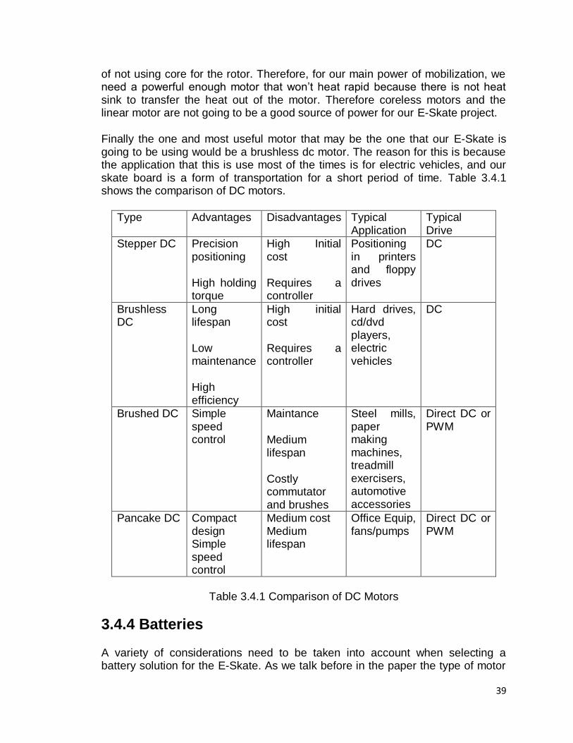
39
of not using core for the rotor. Therefore, for our main power of mobilization, we need a powerful enough motor that won‘t heat rapid because there is not heat sink to transfer the heat out of the motor. Therefore coreless motors and the linear motor are not going to be a good source of power for our E-Skate project.
Finally the one and most useful motor that may be the one that our E-Skate is going to be using would be a brushless dc motor. The reason for this is because the application that this is use most of the times is for electric vehicles, and our skate board is a form of transportation for a short period of time. Table 3.4.1 shows the comparison of DC motors.
Type Advantages Disadvantages Typical Application
Typical Drive
Stepper DC Precision positioning
High holding torque
High Initial cost
Requires a controller
Positioning in printers and floppy drives
DC
Brushless DC
Long lifespan
Low maintenance
High efficiency
High initial cost
Requires a controller
Hard drives, cd/dvd players, electric vehicles
DC
Brushed DC Simple speed control
Maintance
Medium lifespan
Costly commutator and brushes
Steel mills, paper making machines, treadmill exercisers, automotive accessories
Direct DC or PWM
Pancake DC Compact design Simple speed control
Medium cost Medium lifespan
Office Equip, fans/pumps
Direct DC or PWM
Table 3.4.1 Comparison of DC Motors
3.4.4 Batteries
A variety of considerations need to be taken into account when selecting a battery solution for the E-Skate. As we talk before in the paper the type of motor
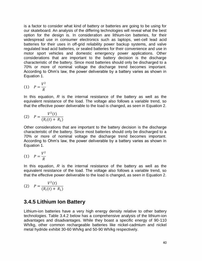
40
is a factor to consider what kind of battery or batteries are going to be using for our skateboard. An analysis of the differing technologies will reveal what the best option for the design is. In consideration are lithium-ion batteries, for their widespread use in consumer electronics such as laptops, wet-cell lead acid batteries for their uses in off-grid reliability power backup systems, and valve regulated lead acid batteries, or sealed batteries for their convenience and use in motor sport vehicles and domestic emergency power applications. Other considerations that are important to the battery decision is the discharge characteristic of the battery. Since most batteries should only be discharged to a 70% or more of nominal voltage the discharge trend becomes important. According to Ohm‘s law, the power deliverable by a battery varies as shown in Equation 1.
In this equation, R is the internal resistance of the battery as well as the equivalent resistance of the load. The voltage also follows a variable trend, so that the effective power deliverable to the load is changed, as seen in Equation 2.
Other considerations that are important to the battery decision is the discharge characteristic of the battery. Since most batteries should only be discharged to a 70% or more of nominal voltage the discharge trend becomes important. According to Ohm‘s law, the power deliverable by a battery varies as shown in Equation 1.
In this equation, R is the internal resistance of the battery as well as the equivalent resistance of the load. The voltage also follows a variable trend, so that the effective power deliverable to the load is changed, as seen in Equation 2.
3.4.5 Lithium Ion Battery
Lithium-ion batteries have a very high energy density relative to other battery technologies. Table 3.4.2 below has a comprehensive analysis of the lithium-ion advantages and disadvantages. While they boast a specific energy of 90-110 Wh/kg, other common rechargeable batteries like nickel-cadmium and nickel metal hydride exhibit 30-60 Wh/kg and 50-90 Wh/kg respectively.
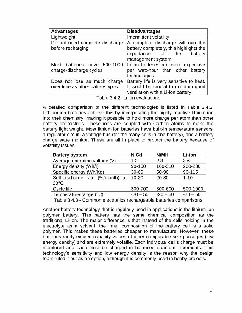
41
Advantages Disadvantages
Lightweight Intermittent volatility
Do not need complete discharge before recharging
A complete discharge will ruin the battery completely, this highlights the importance of the battery management system
Most batteries have 500-1000 charge-discharge cycles
Li-ion batteries are more expensive per watt-hour than other battery technologies
Does not lose as much charge over time as other battery types
Battery life is very sensitive to heat. It would be crucial to maintain good ventilation with a Li-ion battery
Table 3.4.2- Li-ion evaluations
A detailed comparison of the different technologies is listed in Table 3.4.3. Lithium ion batteries achieve this by incorporating the highly reactive lithium ion into their chemistry, making it possible to hold more charge per atom than other battery chemistries. These ions are coupled with Carbon atoms to make the battery light weight. Most lithium ion batteries have built-in temperature sensors, a regulator circuit, a voltage bus (for the many cells in one battery), and a battery charge state monitor. These are all in place to protect the battery because of volatility issues.
Battery system NiCd NiMH Li-ion
Average operating voltage (V) 1.2 2.3 3.6
Energy density (Wh/I) 90-150 160-310 200-280
Specific energy (Wh/Kg) 30-60 50-90 90-115
Self-discharge rate (%/month) at 20°C
10-20 20-30 1-10
Cycle life 300-700 300-600 500-1000
Temperature range (°C) -20 – 50 -20 – 50 -20 – 50
Table 3.4.3 - Common electronics rechargeable batteries comparisons
Another battery technology that is regularly used in applications is the lithium-ion polymer battery. This battery has the same chemical composition as the traditional Li-ion. The major difference is that instead of the cells holding in the electrolyte as a solvent, the inner composition of the battery cell is a solid polymer. This makes these batteries cheaper to manufacture. However, these batteries rarely exceed capacity values of other comparable size packages (low energy density) and are extremely volatile. Each individual cell‘s charge must be monitored and each must be charged in balanced quantum increments. This technology‘s sensitivity and low energy density is the reason why the design team ruled it out as an option, although it is commonly used in hobby projects.
42
3.4.6 Lead-acid Batteries
There are two kinds of lead-acid batteries. The first kind is a cranking or starting battery and it is used primarily in motor vehicles for delivering high amperage levels for short periods of time at the vehicle‘s start. Physically, this battery contains a higher density of thin lead plates that assist it in performing this function. The second kind is a deep-cycle lead acid battery. The deep cycle variety has thicker plates, which allow it to withstand the physical demands of a charge-discharge cycle. This type of battery is used in marine and electric vehicle applications.
Each kind of lead acid-battery has three categories. Wet cell lead acid batteries have lead plates impregnated with a sulfuric acid electrolyte solution. This solution is typically 65% water. As the battery discharges, the sulfuric acid in the solution bonds to the lead plates. As it recharges, the sulfuric acid bonds are pried apart and the acid returns to the solution. This process decomposes the plates and causes a sediment buildup in the battery. Over time, this buildup will cause the various cells to short together, killing the battery. This type of lead acid battery has been around since 1859, and is still very popular. It is also the least expensive of the lead acid technologies.
The second kind of lead acid technology is the gel cell. This type of battery would be ideal for the E-Skate because it requires little to no maintenance. Since the E-Skate is a system that is marketed for young adults, and considering the safety concerns intrinsic with all batteries, this is a very attractive feature of this technology. The gel cell is a VRLA (valve regulated lead acid) and the solution found in wet cells is mixed with a silica content that makes the solution a gel, and thus immobile. This keeps the battery from spilling issues that are more common to the wet cells. This also allows the battery to be used in varying positions, although they should not be charged in any but the upright position. Because of the gel interior, this type of battery is more resistant to vibration-heavy applications. The trade off is that this battery is more sensitive to overcharge situations, and has a lower charging voltage than most lead acid batteries.
The third subcategory is the AGM (Absorbent Glass Mat). Depending on the orientation and geometry of the cells internal to the battery, it can be a traditional AGM or a ―spiral wound.‖ The electrolyte in this type of battery is held by a mat of glass fibers. Because of these mats, the lead plates are relieved of the duty of holding up their own weight. This gives more flexibility in the design and application of this battery. The mats and plate proximities also reduce the internal resistance of the battery. Good for deep-cycle applications, these batteries can be discharged and recharged quickly and feature the highest energy density of the lead acid batteries. The AGMs are also the most expensive.
Another consideration is whether the battery is a deep-cycle battery or a starter battery. Starter batteries are common and are used in vehicles. Deep cycle batteries are used in backup power systems and in RVs and boats as power
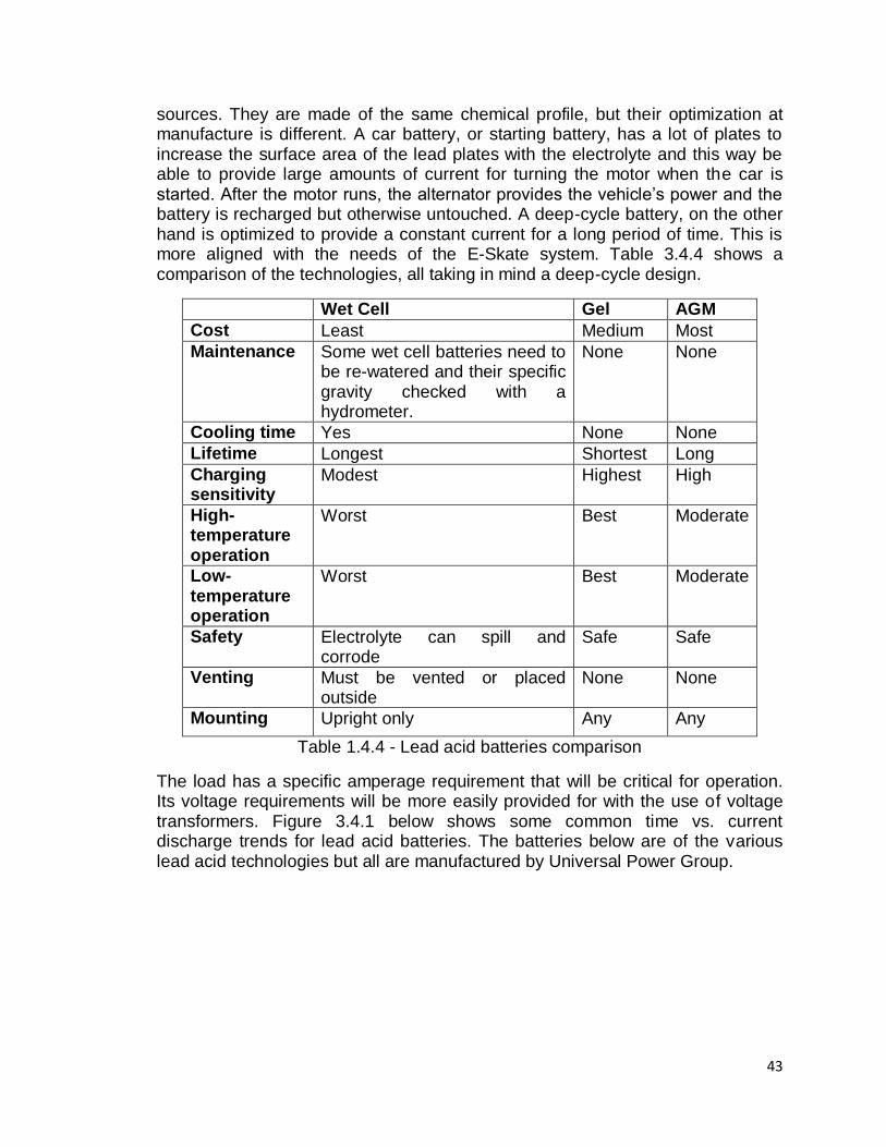
43
sources. They are made of the same chemical profile, but their optimization at manufacture is different. A car battery, or starting battery, has a lot of plates to increase the surface area of the lead plates with the electrolyte and this way be able to provide large amounts of current for turning the motor when the car is started. After the motor runs, the alternator provides the vehicle‘s power and the battery is recharged but otherwise untouched. A deep-cycle battery, on the other hand is optimized to provide a constant current for a long period of time. This is more aligned with the needs of the E-Skate system. Table 3.4.4 shows a comparison of the technologies, all taking in mind a deep-cycle design.
Wet Cell Gel AGM
Cost Least Medium Most
Maintenance Some wet cell batteries need to be re-watered and their specific gravity checked with a hydrometer.
None None
Cooling time Yes None None
Lifetime Longest Shortest Long
Charging sensitivity
Modest Highest High
High-temperature operation
Worst Best Moderate
Low-temperature operation
Worst Best Moderate
Safety Electrolyte can spill and corrode
Safe Safe
Venting Must be vented or placed outside
None None
Mounting Upright only Any Any
Table 1.4.4 - Lead acid batteries comparison
The load has a specific amperage requirement that will be critical for operation. Its voltage requirements will be more easily provided for with the use of voltage transformers. Figure 3.4.1 below shows some common time vs. current discharge trends for lead acid batteries. The batteries below are of the various lead acid technologies but all are manufactured by Universal Power Group.
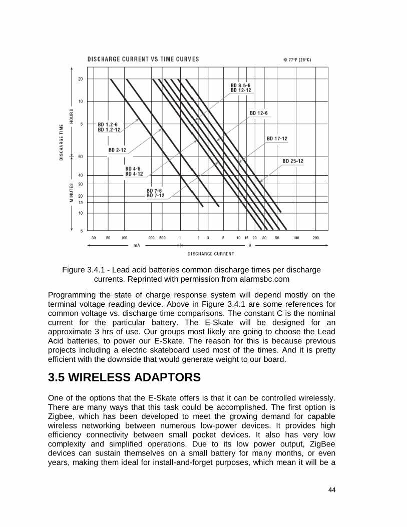
44
Figure 3.4.1 - Lead acid batteries common discharge times per discharge currents. Reprinted with permission from alarmsbc.com
Programming the state of charge response system will depend mostly on the terminal voltage reading device. Above in Figure 3.4.1 are some references for common voltage vs. discharge time comparisons. The constant C is the nominal current for the particular battery. The E-Skate will be designed for an approximate 3 hrs of use. Our groups most likely are going to choose the Lead Acid batteries, to power our E-Skate. The reason for this is because previous projects including a electric skateboard used most of the times. And it is pretty efficient with the downside that would generate weight to our board.
3.5 WIRELESS ADAPTORS One of the options that the E-Skate offers is that it can be controlled wirelessly. There are many ways that this task could be accomplished. The first option is Zigbee, which has been developed to meet the growing demand for capable wireless networking between numerous low-power devices. It provides high efficiency connectivity between small pocket devices. It also has very low complexity and simplified operations. Due to its low power output, ZigBee devices can sustain themselves on a small battery for many months, or even years, making them ideal for install-and-forget purposes, which mean it will be a
45
good option for maintaining battery life of our electric skateboard. The specified maximum range of ZigBee devices is 250 feet, which is further than Bluetooth. The second wireless option is Bluetooth. During research it was found that Bluetooth solution is considerably more expensive than ZigBee. . Even though the actual development of these two solutions have really come down to very close race, it is assumed that because of Bluetooth's wide use in the cell phone industry among other industries such as the gaming console industry that it has had its cost raised significantly. Bluetooth range is about 100 m, which will be a considerable range in our project specifications. Also, the data transfer rate of Bluetooth can go up to 1 Mbits/sec, which can transfer more data than we even need. As with the Zigbee solution there are different selections of decibel ranges that can be used providing different levels of range capabilities. One of the great things about both Zigbee and Bluetooth is they tend to have easy interface capabilities with a standard computer. We came to the point in which we had to introduce Wi-Fi in our research. Wi-Fi plays a very important role in our work and school. Before we can determine if Wi-Fi is the way to go, we must first analyze the capabilities of Wi-Fi and see if it will meet the requirements of our project. The range of typical Wi-Fi configurations meets our requirement, but Wi-Fi is far more complex than ZigBee or Bluetooth. It consumes more power than the other devices mentioned before. The Data transmit Range was around 2Mbit/sec and it will be capable of transmit video and other kinds of data. Today‘s Wi-Fi can go up to 11 & 54 Mbits/s, which is far too much that we need to use. We will not require that much power for our project. Wi-Fi range is about 50 feet; however this range can be amply boosted with the use of an external antenna and go up to 100m. Also, we considered the use of a Wireless USB, which has a short range and high bandwidth communication. The disadvantage is that we would have to use a board which would have an USB port so we could connect its wireless adapter so that it could be used for our project. This adapter is capable of sending 480 Mbit/s at distances up to 3 meters and 110 Mbit/s at up to 10 meters. It was designed to operate in the 3.1 to 10.6 GHz frequency. This is mostly used for video gaming consoles, which its motherboard has embedded the USB hub in which the adapter could be inserted. The last type of wireless communication that we found was the IR Wireless technology. This infrared technology is used for short and medium range control. The bad thing about this is that the path from where the receiver to the transmitter must be without any obstacles so it could work perfectly. In real life we know that is not the case, so this technology will not work in our project. But it could be used in some other projects like a remote control for a television, but having in mind that it will not function when an object is between the adapters. Moreover, we will talk about the parts that we researched and what we found about them, their similarities and contrasts.
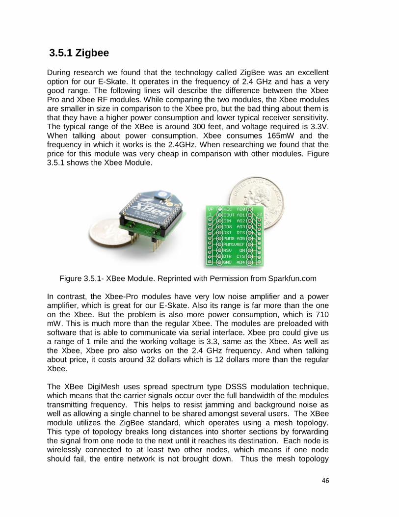
46
3.5.1 Zigbee During research we found that the technology called ZigBee was an excellent option for our E-Skate. It operates in the frequency of 2.4 GHz and has a very good range. The following lines will describe the difference between the Xbee Pro and Xbee RF modules. While comparing the two modules, the Xbee modules are smaller in size in comparison to the Xbee pro, but the bad thing about them is that they have a higher power consumption and lower typical receiver sensitivity. The typical range of the XBee is around 300 feet, and voltage required is 3.3V. When talking about power consumption, Xbee consumes 165mW and the frequency in which it works is the 2.4GHz. When researching we found that the price for this module was very cheap in comparison with other modules. Figure 3.5.1 shows the Xbee Module.
Figure 3.5.1- XBee Module. Reprinted with Permission from Sparkfun.com
In contrast, the Xbee-Pro modules have very low noise amplifier and a power amplifier, which is great for our E-Skate. Also its range is far more than the one on the Xbee. But the problem is also more power consumption, which is 710 mW. This is much more than the regular Xbee. The modules are preloaded with software that is able to communicate via serial interface. Xbee pro could give us a range of 1 mile and the working voltage is 3.3, same as the Xbee. As well as the Xbee, Xbee pro also works on the 2.4 GHz frequency. And when talking about price, it costs around 32 dollars which is 12 dollars more than the regular Xbee. The XBee DigiMesh uses spread spectrum type DSSS modulation technique, which means that the carrier signals occur over the full bandwidth of the modules transmitting frequency. This helps to resist jamming and background noise as well as allowing a single channel to be shared amongst several users. The XBee module utilizes the ZigBee standard, which operates using a mesh topology. This type of topology breaks long distances into shorter sections by forwarding the signal from one node to the next until it reaches its destination. Each node is wirelessly connected to at least two other nodes, which means if one node should fail, the entire network is not brought down. Thus the mesh topology
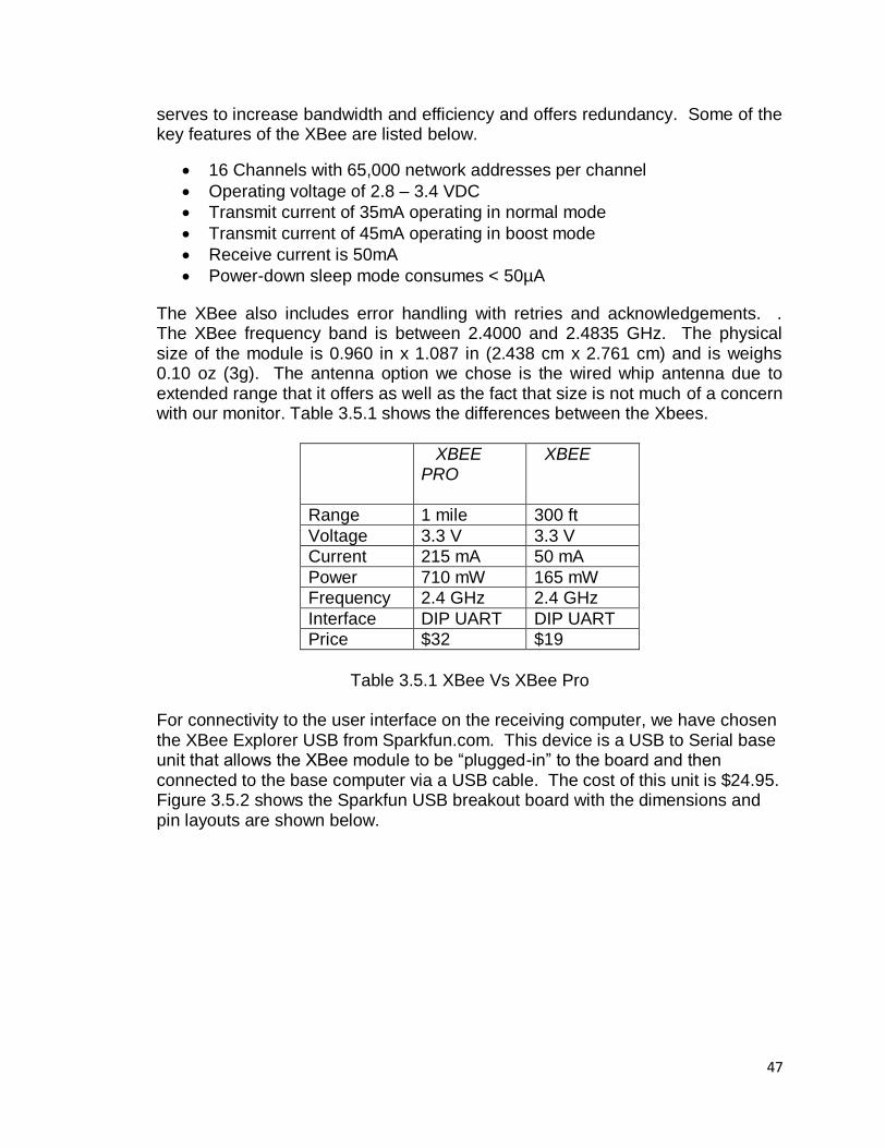
47
serves to increase bandwidth and efficiency and offers redundancy. Some of the key features of the XBee are listed below.
16 Channels with 65,000 network addresses per channel
Operating voltage of 2.8 – 3.4 VDC
Transmit current of 35mA operating in normal mode
Transmit current of 45mA operating in boost mode
Receive current is 50mA
Power-down sleep mode consumes < 50µA
The XBee also includes error handling with retries and acknowledgements. . The XBee frequency band is between 2.4000 and 2.4835 GHz. The physical size of the module is 0.960 in x 1.087 in (2.438 cm x 2.761 cm) and is weighs 0.10 oz (3g). The antenna option we chose is the wired whip antenna due to extended range that it offers as well as the fact that size is not much of a concern with our monitor. Table 3.5.1 shows the differences between the Xbees.
XBEE PRO
XBEE
Range 1 mile 300 ft
Voltage 3.3 V 3.3 V
Current 215 mA 50 mA
Power 710 mW 165 mW
Frequency 2.4 GHz 2.4 GHz
Interface DIP UART DIP UART
Price $32 $19
Table 3.5.1 XBee Vs XBee Pro For connectivity to the user interface on the receiving computer, we have chosen the XBee Explorer USB from Sparkfun.com. This device is a USB to Serial base unit that allows the XBee module to be ―plugged-in‖ to the board and then connected to the base computer via a USB cable. The cost of this unit is $24.95. Figure 3.5.2 shows the Sparkfun USB breakout board with the dimensions and pin layouts are shown below.
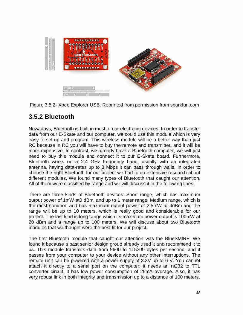
48
Figure 3.5.2- Xbee Explorer USB. Reprinted from permission from sparkfun.com
3.5.2 Bluetooth Nowadays, Bluetooth is built in most of our electronic devices. In order to transfer data from our E-Skate and our computer, we could use this module which is very easy to set up and program. This wireless module will be a better way than just RC because in RC you will have to buy the remote and transmitter, and it will be more expensive. In contrast, we already have a Bluetooth computer, we will just need to buy this module and connect it to our E-Skate board. Furthermore, Bluetooth works on a 2.4 GHz frequency band, usually with an integrated antenna, having data-rates up to 3 Mbps it can pass through walls. In order to choose the right Bluetooth for our project we had to do extensive research about different modules. We found many types of Bluetooth that caught our attention. All of them were classified by range and we will discuss it in the following lines. There are three kinds of Bluetooth devices: Short range, which has maximum output power of 1mW at0 dBm, and up to 1 meter range. Medium range, which is the most common and has maximum output power of 2.5mW at 4dBm and the range will be up to 10 meters, which is really good and considerable for our project. The last kind is long range which its maximum power output is 100mW at 20 dBm and a range up to 100 meters. We will discuss about two Bluetooth modules that we thought were the best fit for our project. The first Bluetooth module that caught our attention was the BlueSMIRF. We found it because a past senior design group already used it and recommend it to us. This module transmits data from 9600 to 115200 bytes per second, and it passes from your computer to your device without any other interruptions. The remote unit can be powered with a power supply of 3.3V up to 6 V. You cannot attach it directly to a serial port on the computer; it needs an rs232 to TTL converter circuit. It has low power consumption of 25mA average. Also, it has very robust link in both integrity and transmission up to a distance of 100 meters.
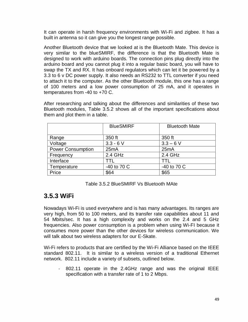
49
It can operate in harsh frequency environments with Wi-Fi and zigbee. It has a built in antenna so it can give you the longest range possible.
Another Bluetooth device that we looked at is the Bluetooth Mate. This device is very similar to the blueSMIRF, the difference is that the Bluetooth Mate is designed to work with arduino boards. The connection pins plug directly into the arduino board and you cannot plug it into a regular basic board, you will have to swap the TX and RX. It has onboard regulators which can let it be powered by a 3.3 to 6 v DC power supply. It also needs an RS232 to TTL converter if you need to attach it to the computer. As the other Bluetooth module, this one has a range of 100 meters and a low power consumption of 25 mA, and it operates in temperatures from -40 to +70 C.
After researching and talking about the differences and similarities of these two Bluetooth modules, Table 3.5.2 shows all of the important specifications about them and plot them in a table.
BlueSMIRF Bluetooth Mate
Range 350 ft 350 ft
Voltage 3.3 - 6 V 3.3 – 6 V
Power Consumption 25mA 25mA
Frequency 2.4 GHz 2.4 GHz
Interface TTL TTL
Temperature -40 to 70 C -40 to 70 C
Price $64 $65
Table 3.5.2 BlueSMIRF Vs Bluetooth MAte
3.5.3 WiFi Nowadays Wi-Fi is used everywhere and is has many advantages. Its ranges are very high, from 50 to 100 meters, and its transfer rate capabilities about 11 and 54 Mbits/sec. It has a high complexity and works on the 2.4 and 5 GHz frequencies. Also power consumption is a problem when using Wi-FI because it consumes more power than the other devices for wireless communication. We will talk about two wireless adapters for our E-Skate. Wi-Fi refers to products that are certified by the Wi-Fi Alliance based on the IEEE standard 802.11. It is similar to a wireless version of a traditional Ethernet network. 802.11 include a variety of subsets, outlined below.
- 802.11 operate in the 2.4GHz range and was the original IEEE specification with a transfer rate of 1 to 2 Mbps.
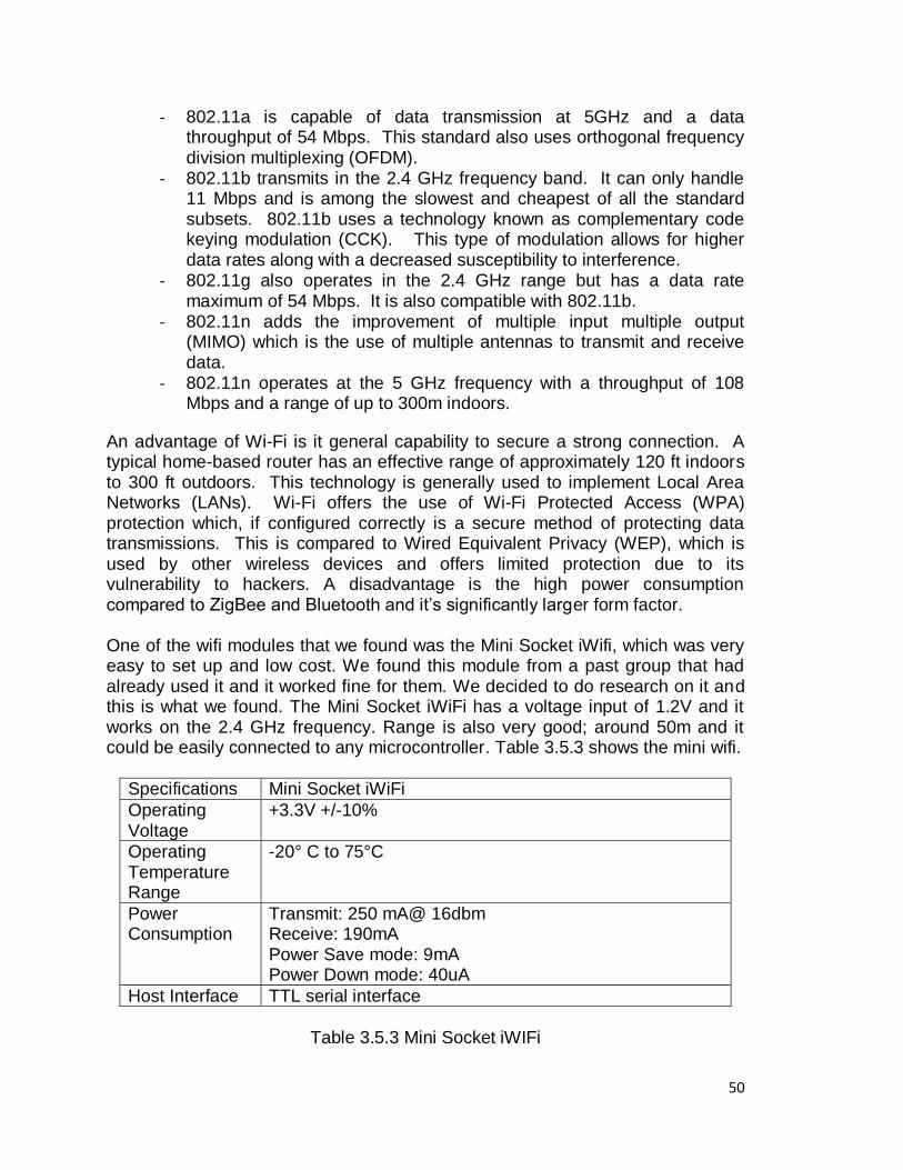
50
- 802.11a is capable of data transmission at 5GHz and a data throughput of 54 Mbps. This standard also uses orthogonal frequency division multiplexing (OFDM).
- 802.11b transmits in the 2.4 GHz frequency band. It can only handle 11 Mbps and is among the slowest and cheapest of all the standard subsets. 802.11b uses a technology known as complementary code keying modulation (CCK). This type of modulation allows for higher data rates along with a decreased susceptibility to interference.
- 802.11g also operates in the 2.4 GHz range but has a data rate maximum of 54 Mbps. It is also compatible with 802.11b.
- 802.11n adds the improvement of multiple input multiple output (MIMO) which is the use of multiple antennas to transmit and receive data.
- 802.11n operates at the 5 GHz frequency with a throughput of 108 Mbps and a range of up to 300m indoors.
An advantage of Wi-Fi is it general capability to secure a strong connection. A typical home-based router has an effective range of approximately 120 ft indoors to 300 ft outdoors. This technology is generally used to implement Local Area Networks (LANs). Wi-Fi offers the use of Wi-Fi Protected Access (WPA) protection which, if configured correctly is a secure method of protecting data transmissions. This is compared to Wired Equivalent Privacy (WEP), which is used by other wireless devices and offers limited protection due to its vulnerability to hackers. A disadvantage is the high power consumption compared to ZigBee and Bluetooth and it‘s significantly larger form factor. One of the wifi modules that we found was the Mini Socket iWifi, which was very easy to set up and low cost. We found this module from a past group that had already used it and it worked fine for them. We decided to do research on it and this is what we found. The Mini Socket iWiFi has a voltage input of 1.2V and it works on the 2.4 GHz frequency. Range is also very good; around 50m and it could be easily connected to any microcontroller. Table 3.5.3 shows the mini wifi.
Specifications Mini Socket iWiFi
Operating Voltage
+3.3V +/-10%
Operating Temperature Range
-20° C to 75°C
Power Consumption
Transmit: 250 mA@ 16dbm Receive: 190mA Power Save mode: 9mA Power Down mode: 40uA
Host Interface TTL serial interface
Table 3.5.3 Mini Socket iWIFi
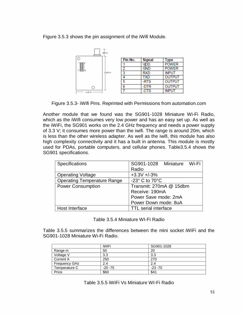
51
Figure 3.5.3 shows the pin assignment of the iWifi Module.
Figure 3.5.3- iWifi Pins. Reprinted with Permissions from automation.com Another module that we found was the SG901-1028 Miniature Wi-Fi Radio, which as the iWifi consumes very low power and has an easy set up. As well as the iWiFi, the SG901 works on the 2.4 GHz frequency and needs a power supply of 3.3 V; it consumes more power than the iwifi. The range is around 20m, which is less than the other wireless adapter. As well as the iwifi, this module has also high complexity connectivity and it has a built in antenna. This module is mostly used for PDAs, portable computers, and cellular phones. Table3.5.4 shows the SG901 specifications.
Specifications SG901-1028 Miniature Wi-Fi Radio
Operating Voltage +3.3V +/-3%
Operating Temperature Range -23° C to 70°C
Power Consumption Transmit: 270mA @ 15dbm Receive: 190mA Power Save mode: 2mA Power Down mode: 8uA
Host Interface TTL serial interface
Table 3.5.4 Miniature WI-Fi Radio
Table 3.5.5 summarizes the differences between the mini socket iWiFi and the SG901-1028 Miniature Wi-Fi Radio.
iWiFi SG901-1028
Range m 50 20
Voltage V 3.3 3.3
Current A 250 270
Frequency GHz 2.4 2.4
Temperature C -20 -75 -23 -70
Price $60 $41
Table 3.5.5 iWiFi Vs Miniature WI-Fi Radio
52
Bluetooth vs. Wi-Fi Nowadays Wi-Fi is used everywhere and is has many advantages. Its ranges are very high, from 50 to 100 meters, and its transfer rate capabilities about 11 and 54 Mbits/sec. It has a high complexity and works on the 2.4 and 5 GHz frequencies. Also power consumption is a problem when using Wi-FI because it consumes more power than the other devices for wireless communication. Now that we have covered some modules we can ask the following question. What are the differences between WiFi and Bluetooth? Well, some of the most important differences will depend on the use of them. For example, in our case, we are building an electric skate board, we will not need as much complexity as the wifi, Bluetooth will do fine, but we will need the range of wifi because it give us far more range than regular Bluetooth. So going back to the question, wifi has faster speeds and greater range than Bluetooth. Also, Bluetooth has a weaker radio signal; in consequence, the battery life of Bluetooth will be greater than wifi. Wifi has a much stronger signal than Bluetooth. Overall, Bluetooth has low bandwidth of 800 kbps; it has low power consumption and works at a frequency of 2.4 GHz. In contrast Wi-Fi has a high bandwidth of 11 Mbps; it is a far more complex device which requires configuration of hardware and software. Its range is about 100 meters and it also works on the 2.4 GHz frequency. The bad thing about it is that security is not as good as Bluetooth. But we will be using it just to transfer command data to our skateboard so it can be controlled wirelessly.
3.5.4 Wireless USB This kind of technology is a short range and high bandwidth communication. It is capable of transmitting data of 62.5 Kbits/s for up to a range of 10 meters. Also it works on the 2.4 GHz frequency and it‘s a low complexity and low power device. In order to use this wireless USB adapter in our project, we need to connect it to an USB port on the board. We can accomplish this by using a TTL to USB adaptor in our board. The only disadvantage is that only the adaptor costs around 25 dollars and the Wireless USB around 40 to 50 dollars and of course you need a computer with wireless adaptor embedded to it.
Having talked about different technologies, now we can get to the following question. What is the difference between Wireless USB and Wi-Fi? These technologies have different intended purposes. Wi-Fi is intended to replace Ethernet cable, providing wireless internet access, whereas Wireless USB is intended to remove the cables from USB peripherals. Wi-Fi uses the crowded signals of 2.4 GHz and the 5 GHz, whereas Wireless USB uses UWB, which uses a very broad signal from 3.1 to 10.6 GHz.
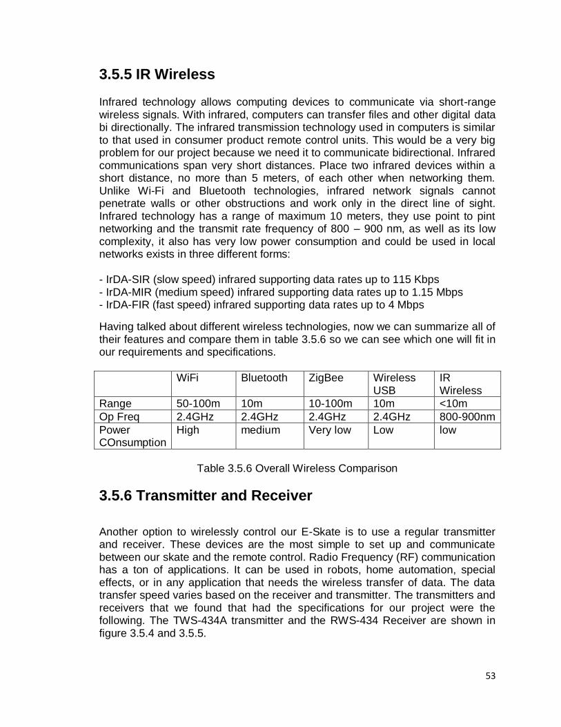
53
3.5.5 IR Wireless Infrared technology allows computing devices to communicate via short-range wireless signals. With infrared, computers can transfer files and other digital data bi directionally. The infrared transmission technology used in computers is similar to that used in consumer product remote control units. This would be a very big problem for our project because we need it to communicate bidirectional. Infrared communications span very short distances. Place two infrared devices within a short distance, no more than 5 meters, of each other when networking them. Unlike Wi-Fi and Bluetooth technologies, infrared network signals cannot penetrate walls or other obstructions and work only in the direct line of sight. Infrared technology has a range of maximum 10 meters, they use point to pint networking and the transmit rate frequency of 800 – 900 nm, as well as its low complexity, it also has very low power consumption and could be used in local networks exists in three different forms: - IrDA-SIR (slow speed) infrared supporting data rates up to 115 Kbps - IrDA-MIR (medium speed) infrared supporting data rates up to 1.15 Mbps - IrDA-FIR (fast speed) infrared supporting data rates up to 4 Mbps
Having talked about different wireless technologies, now we can summarize all of their features and compare them in table 3.5.6 so we can see which one will fit in our requirements and specifications.
WiFi Bluetooth ZigBee Wireless USB
IR Wireless
Range 50-100m 10m 10-100m 10m <10m
Op Freq 2.4GHz 2.4GHz 2.4GHz 2.4GHz 800-900nm
Power COnsumption
High medium Very low Low low
Table 3.5.6 Overall Wireless Comparison
3.5.6 Transmitter and Receiver
Another option to wirelessly control our E-Skate is to use a regular transmitter and receiver. These devices are the most simple to set up and communicate between our skate and the remote control. Radio Frequency (RF) communication has a ton of applications. It can be used in robots, home automation, special effects, or in any application that needs the wireless transfer of data. The data transfer speed varies based on the receiver and transmitter. The transmitters and receivers that we found that had the specifications for our project were the following. The TWS-434A transmitter and the RWS-434 Receiver are shown in figure 3.5.4 and 3.5.5.
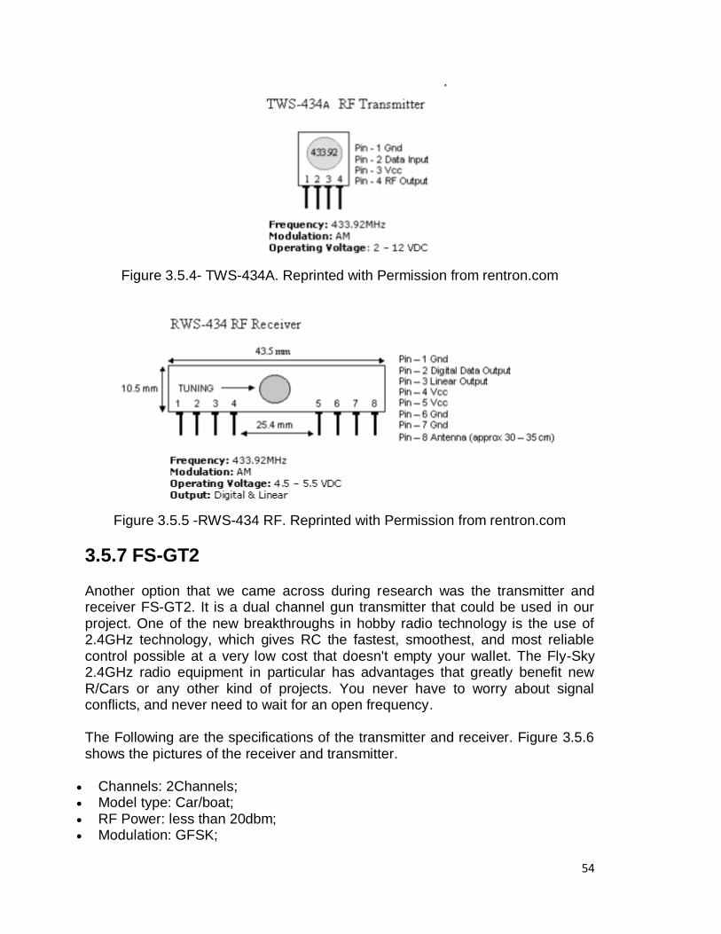
54
Figure 3.5.4- TWS-434A. Reprinted with Permission from rentron.com
Figure 3.5.5 -RWS-434 RF. Reprinted with Permission from rentron.com
3.5.7 FS-GT2 Another option that we came across during research was the transmitter and receiver FS-GT2. It is a dual channel gun transmitter that could be used in our project. One of the new breakthroughs in hobby radio technology is the use of 2.4GHz technology, which gives RC the fastest, smoothest, and most reliable control possible at a very low cost that doesn't empty your wallet. The Fly-Sky 2.4GHz radio equipment in particular has advantages that greatly benefit new R/Cars or any other kind of projects. You never have to worry about signal conflicts, and never need to wait for an open frequency.
The Following are the specifications of the transmitter and receiver. Figure 3.5.6 shows the pictures of the receiver and transmitter.
Channels: 2Channels; Model type: Car/boat; RF Power: less than 20dbm; Modulation: GFSK;
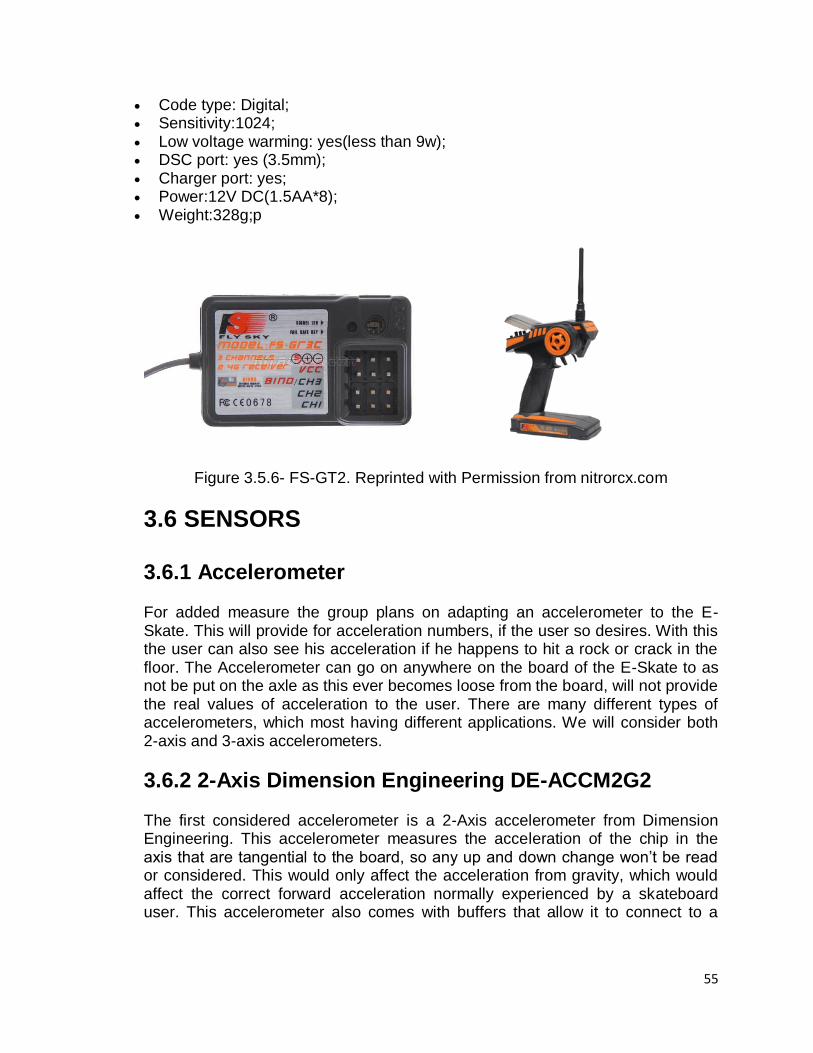
55
Code type: Digital; Sensitivity:1024; Low voltage warming: yes(less than 9w); DSC port: yes (3.5mm); Charger port: yes; Power:12V DC(1.5AA*8); Weight:328g;p
Figure 3.5.6- FS-GT2. Reprinted with Permission from nitrorcx.com
3.6 SENSORS 3.6.1 Accelerometer For added measure the group plans on adapting an accelerometer to the E-Skate. This will provide for acceleration numbers, if the user so desires. With this the user can also see his acceleration if he happens to hit a rock or crack in the floor. The Accelerometer can go on anywhere on the board of the E-Skate to as not be put on the axle as this ever becomes loose from the board, will not provide the real values of acceleration to the user. There are many different types of accelerometers, which most having different applications. We will consider both 2-axis and 3-axis accelerometers.
3.6.2 2-Axis Dimension Engineering DE-ACCM2G2 The first considered accelerometer is a 2-Axis accelerometer from Dimension Engineering. This accelerometer measures the acceleration of the chip in the axis that are tangential to the board, so any up and down change won‘t be read or considered. This would only affect the acceleration from gravity, which would affect the correct forward acceleration normally experienced by a skateboard user. This accelerometer also comes with buffers that allow it to connect to a
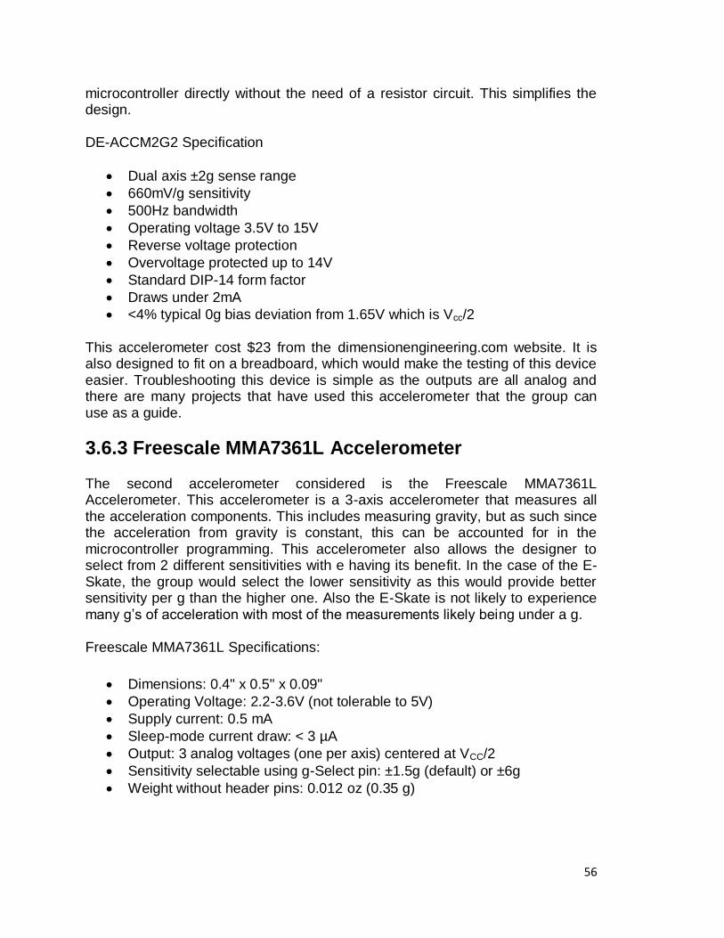
56
microcontroller directly without the need of a resistor circuit. This simplifies the design. DE-ACCM2G2 Specification
Dual axis ±2g sense range
660mV/g sensitivity
500Hz bandwidth
Operating voltage 3.5V to 15V
Reverse voltage protection
Overvoltage protected up to 14V
Standard DIP-14 form factor
Draws under 2mA
<4% typical 0g bias deviation from 1.65V which is Vcc/2
This accelerometer cost $23 from the dimensionengineering.com website. It is also designed to fit on a breadboard, which would make the testing of this device easier. Troubleshooting this device is simple as the outputs are all analog and there are many projects that have used this accelerometer that the group can use as a guide.
3.6.3 Freescale MMA7361L Accelerometer
The second accelerometer considered is the Freescale MMA7361L Accelerometer. This accelerometer is a 3-axis accelerometer that measures all the acceleration components. This includes measuring gravity, but as such since the acceleration from gravity is constant, this can be accounted for in the microcontroller programming. This accelerometer also allows the designer to select from 2 different sensitivities with e having its benefit. In the case of the E-Skate, the group would select the lower sensitivity as this would provide better sensitivity per g than the higher one. Also the E-Skate is not likely to experience many g‘s of acceleration with most of the measurements likely being under a g.
Freescale MMA7361L Specifications:
Dimensions: 0.4" x 0.5" x 0.09"
Operating Voltage: 2.2-3.6V (not tolerable to 5V)
Supply current: 0.5 mA
Sleep-mode current draw: < 3 µA
Output: 3 analog voltages (one per axis) centered at VCC/2
Sensitivity selectable using g-Select pin: ±1.5g (default) or ±6g
Weight without header pins: 0.012 oz (0.35 g)
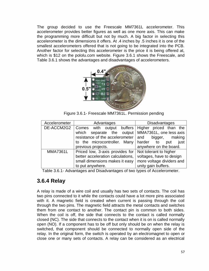
57
The group decided to use the Freescale MM7361L accelerometer. This accelerometer provides better figures as well as one more axis. This can make the programming more difficult but not by much. A big factor in selecting this accelerometer is the dimensions it offers. At .4 inches by .5 inches it is one of the smallest accelerometers offered that is not going to be integrated into the PCB. Another factor for selecting this accelerometer is the price it is being offered at, which is $12 on the pololu.com website. Figure 3.6.1 shows the Freescale, and Table 3.6.1 shows the advantages and disadvantages of accelerometers.
Figure 3.6.1- Freescale MM7361L. Permission pending
Accelerometer Advantages Disadvantages
DE-ACCM2G2 Comes with output buffers which separate the output resistance of the accelerometer to the microcontroller. Many previous projects.
Higher priced than the MMA7361L, one less axis and bigger, making harder to put just anywhere on the board.
MMA7361L Priced low, 3-axis provides for better acceleration calculations, small dimensions makes it easy to put anywhere.
Not tolerant to higher voltages, have to design more voltage dividers and unity gain buffers.
Table 3.6.1- Advantages and Disadvantages of two types of Accelerometer.
3.6.4 Relay A relay is made of a wire coil and usually has two sets of contacts. The coil has two pins connected to it while the contacts could have a lot more pins associated with it. A magnetic field is created when current is passing through the coil through the two pins. The magnetic field attracts the metal contacts and switches them from one contact to another. The contact pin is common to both sides. When the coil is off, the side that connects to the contact is called normally closed (NC). The side that connects to the contact when it is on is called normally open (NO). If a component has to be off but only should be on when the relay is switched, that component should be connected to normally open side of the relay. In the original form, the switch is operated by an electromagnet to open or close one or many sets of contacts. A relay can be considered as an electrical
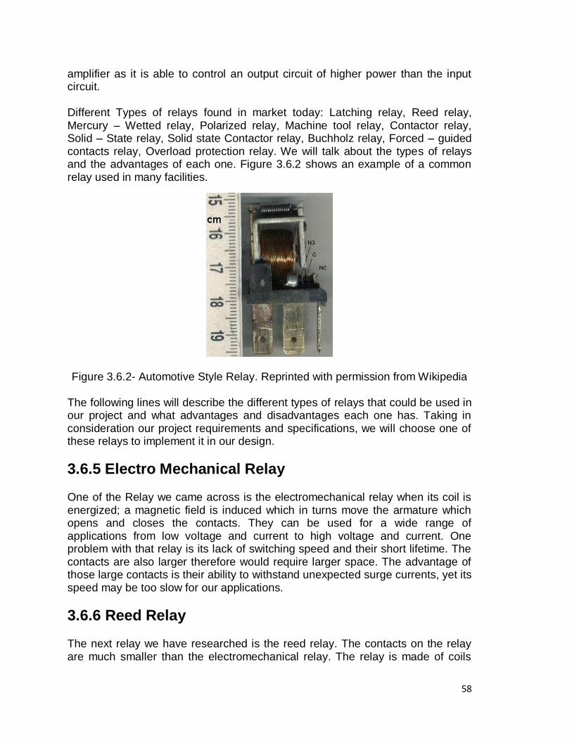
58
amplifier as it is able to control an output circuit of higher power than the input circuit. Different Types of relays found in market today: Latching relay, Reed relay, Mercury – Wetted relay, Polarized relay, Machine tool relay, Contactor relay, Solid – State relay, Solid state Contactor relay, Buchholz relay, Forced – guided contacts relay, Overload protection relay. We will talk about the types of relays and the advantages of each one. Figure 3.6.2 shows an example of a common relay used in many facilities.
Figure 3.6.2- Automotive Style Relay. Reprinted with permission from Wikipedia The following lines will describe the different types of relays that could be used in our project and what advantages and disadvantages each one has. Taking in consideration our project requirements and specifications, we will choose one of these relays to implement it in our design.
3.6.5 Electro Mechanical Relay One of the Relay we came across is the electromechanical relay when its coil is energized; a magnetic field is induced which in turns move the armature which opens and closes the contacts. They can be used for a wide range of applications from low voltage and current to high voltage and current. One problem with that relay is its lack of switching speed and their short lifetime. The contacts are also larger therefore would require larger space. The advantage of those large contacts is their ability to withstand unexpected surge currents, yet its speed may be too slow for our applications.
3.6.6 Reed Relay The next relay we have researched is the reed relay. The contacts on the relay are much smaller than the electromechanical relay. The relay is made of coils
59
wrapped around reed switches composing of two overlapped blades sealed within a glass capsule which is filled of an inert gas. When the coil is energized, the switches come together in a way where their contacts complete a path through the relay. A reed relay is much smaller than the electromechanical type, Because of its size it can switch much faster approximately ten times faster and it lasts longer. Because of its size the disadvantage is damage from arcing. When the switch is closed there is a chance that an arc can jump and burn the contacts rendering the relay inoperable. Their thermal electromagnetic force may cause noise which will in turn cause errors in measurements.
3.6.7 RW-SS-112D Relay We found different types of relay we could use to switch the appliance on and off. One last specific relay seen in figure 4.2.11o is RW-SS-112D manufactured by an Australian company named Goodsky. Depending on what type of circuit you want to switch on and off, you can use the RW-SS-112D or RW-SS-124D. These relays can switch a maximum of 5 A at 240 VAC, a maximum of 10A at 120 VAC and a maximum of 10A at 24 VDC. The RW-SS-112D relay is practical because of its size. Its measurement 19.5mm x 15.4mm x 15.4mm makes it very attractive for our project. Also it has complete protective construction against dust and soldering flux, this component is very popular for applications like Domestic appliances, office machines, audio equipment, coffee-Pots, Control units and so forth. When used for electrical purpose, this relay can switch a device on and off a maximum of 30 operations per minute. However when used mechanically, it can operate a maximum of 300 operations per minute.
3.6.8 Field Effect Transistor Relay The next relay is the FET Relay short for field effect transistor; it uses several CMOS transistors to do its switching, no mechanical component. The difference between the SSR and the FET is the control circuit drives the gates of the transistors instead of using LED to do the switching. So the time it took the LED between power on and power off is not an issue here therefore allows the FET to switch much faster than the SSR. They come also in very small sizes convenient for our project. A disadvantage is that it lacks a physical isolation barrier again that‘s not an issue we will use for low voltage signals. One such relay that we found is the CMOS8RF ideal for RF applications like the Bluetooth we are designing also applicable for handsets and GPS systems.
3.6.9 Solid State Relay
A solid state relay also called SSR for short name is a semiconductor device that can be utilized instead of a mechanical relay to switch power to a load in different applications. SSR are pure electronic, usually made of a low current control side with a high current load side. The low current control side would be the coil of an electromechanical relay and the high current load would be contact of a
60
conventional relay. Solid state relay usually have electrical isolation to some thousands of volts between the control and load sides. Since there is isolation, the load side of the SSR is powered by the switched line. In order for that relay to operate, a line voltage and a load should be present. The SSR has optical coupling to a photodiode array that ties driver circuitry which provides an interface to devices at the output. Semiconductor relays are not very complex as we can see from the diagram and they are not made from rare components. However they are still very expensive and although its simplicity could drive the idea of building your own circuit, it is not considered the safest way to switch circuit.
3.7 BUILDING MATERIAL For the E-Skate there should be a list of materials. These material are gone to be the basics for our projects design. The following list are going to be used for the construction of the E-Skate:
1. Long skateboard: 36in by 11in 2. Lead acid DC motor MY6812A: 12volts, 100Watts 3. Drive belt 4 inches of diameter 4. Plastic case for the battery and the PCB 5. 12 volts Relays 6. Transmitter and Receiver 7. GPS Module 8. Resistor, Capacitances, inductors, diodes, transistors 9. 12volts and 5 volts power regulator 10. Wheels 11. Skateboard axel 12. LCD Screen 13. Charger: KY05036S-12 14. PCB 15. Electrical tape 16. Wires 17. Microcontroller 18. Volts 19. Switches 20. LEDs 21. Development board 22. Computer to program in C.
As it was say above the list, these materials are going to be useful to construct and make our E-Skate a reality. Because none of the group members have a lot of experience with the building of a project like this, the list of materials would change by deleting some components or adding some materials.
61
3.8 DRIVE TRAIN
For the E-Skate to work, we need to find how a skateboard is made, and how can be modified to acquire more speed, or longer rides. Also, there are various part that would make the drive train of the skate board to obtainable. The next subsections of this section are going to be the part we need to make this drive train successful.
3.8.1 Deck or Board
The two kinds of skateboards are regular for sport like the X games, which is a tournament of skating board; and the long skateboards for a long ride and is use a speed in downhill usually; it simulates the feeling of surfing because the rider can make sharp turn like in surfing. Now that we know the two king of skateboard people use usually the most, what kind of skateboard is appropriated to build the E-Skate? One of the thinks that we think of it first is having enough space to put the electronic parts together, but enough space to make it look professional too. Another factor to look at it is if the electric skateboard is going to be use to make tricks. If we want to cruise around on and don‘t plan on doing tricks, then the bigger and wider board is always better. So we most likely interested in long skateboard as is shown Figure 2.3.1. Longboard skateboard is bigger than regular skates; moreover, it is easy to control and turn. Therefore it makes a great board to work with. Now that the deck of the skateboard is decided, which is the longboard, the next part is to look at the wheels.
3.8.2 Wheels
The wheels of a skateboard do much more that just move the board along, they are design to be slightly flexible, but resistant to use in order to last longer and acquired a great speed. Skateboards Wheel come in different colors, sizes and degrees of harness. The two stats that are very important to look at is the Diameter, and the Durometer. The diameter, which is going to show how tall the wheel is most of the time, is measure by millimeters, in the skateboard world. The durometer is the harness of the wheels. Most of the wheels of skateboard are A-scales; basically, the higher the number, the harder the wheel of the skateboard. For street skateboarding wheel, which make a lot of air tricks, is usually a-95, while for softer wheels can be all the way down town to a 70 or lower. Usually longboard used a-85 or lower. Larger skateboard wheels roll a lot faster. For the E-Skate we want speed to get in class on time, so we most likely want a big diameter of 64-75mm and soft durometer of 78-85a. Other wheels that longboard skateboard uses are dirt wheels with knobs, but these aren‘t for skateboards. Also our E-Skate wheels are to be a little custom made to add a grinder in the direction where the staft of the motor would be. This would be attack to the motor with a drive belt, which would make the skate board to gain speed from the motor and not from the rider.

62
3.8.3 Bearings
Bearing are like the suspensions of the skateboard. When a trick is involve, and it is landed on a hard surface as the pediment, the bearing are the reason the wheel do not fall off of the skateboard. It as a shock absorber, which means it absorbers the brute force on the fall to the wheel and truck to deliver a nice and smooth land. Bearing are inside little metal rings that fit inside the skateboard wheel. There‘s only one way to rate bearing and it does not work well with skateboards and the reason for this is because originally developed to rate the bearings in machines. The rating is called ABEC and goes from 1 to 9, but only odd numbers. The ABEC only rates the precision of the bearing. It is odd how the most precise the bearing the weaker they usually are. The ideal ABEC rating for a skateboard is 3 or 5 because it is a little precise and a little durable. For the E-Skate we mostly will be using the bearing 3 and 5 or even 7 because there is not much trick we will be doing in it. So durability would not be to important because we are not forcing the bearing to a break point.
3.8.4 Trucks
When we are riding a sake board and it is able to turn by the used of our own weight and body movements, the trucks are responsible for this to happen. Trucks are the part that allows steering. And it is attached to both board and wheels. It‘s the hinge forces the skateboard to turn to the right and to the left if the rider leans to the right or left. The control mode can be changed by the rider. If the truck is tighten, it would make it sturdier, but hard to turn, otherwise, if it is loosen, the skateboard will turn easier and faster, but it will be harder to control. Truck width need to match the deck. Most of the time the, truck should be within ¼‘ of the size of the deck. Inside of the truck are the bushings, a small part that looks like a rubber donut. The bushing cushions the truck when it turns. And this is the part that can be tighten or loosen. Also the bushing are make form tight, medium, and soft. The tight brushings are usually a perfect choice for street skateboarding, and they would break in over time making it softer. The medium are usually prefer for any kind of skateboarding. And the soft brushings are the hardest to control and sometimes prefer for longboarding. The heights of the truck are important to. And it also can vary. Low trucks are more for tricks and flips because it would offer stability, but they required smaller wheels. High trucks allow using larger wheels, which help when skateboarding at higher speed or long distance. So because we are going to use a longboard, it is recommended high trucks. Once again the E-Skate is going to be use for cruising most and all the time.
3.8.5 Risers
The risers are not as important as the other parts of this section. But it does help to release stress from the truck. This would help the deck or board from cracking. More importantly, risers help keep the wheels from biting into the board on a hard turn. Most risers are about 1/8 inches high. If the board has extra large wheels,
63
then it would need higher risers. Otherwise if the wheels are small the need of riders is obsolete. For our E-skate this would be a recommended need, but not sure of using.
3.8.6 Hardware
Even though, the hardware is compose by nuts and screws, in the skater world they have different colors and design. the most common are the basic nuts and screws. But these parts are very important to make the skateboard to be tied up everything together. So even though, it sound like a small part the screws and nuts are very important in the relation of a skateboard. And for our E-Skate the even in the electronics part the screws and nuts are very important to adhere in the skateboard.
3.9 PROGRAMMING Programming the microcontrollers is necessary for it to do what the group needs it to do. In the data microcontroller most of the programming will deal with different analog voltages being converted into usable data and manipulated to print out to the LCD. On the motor controller, the programming will be done by reading an input that comes from the wireless receiver, and outputting a PWM signal that can be used to turn the motor. Most of the microcontrollers are programmed through their own language, similar to the Assembly language. There are development kits for all the microcontrollers, which can make programming easier with the C Language. On the Arduino boards, the programming is done through the Arduino language which is similar to the C Language and the C++ Language. Aside from the vast majority of hardware resources required to implement the project functional requirements it is imperative that a suitable programming architecture be chosen in order to execute the desired functionalities defined by the project scope. Not only must the programming environment enable the implementation of the desired functionalities, it must also limit on the amount of code for which solutions already exist. As thus, this section delves into programming languages, code libraries, and other resources that will enable the designers to extract the necessary implementation from the available hardware. Prior to writing the program that will control the device, it is important to have the ability to transfer the program itself to the controller that will act as the mind of the device. As such, a programmer will enable the team to implement the desired functionality for the available hardware. The first device to be discussed is the Pocket AVR Programmer which is intended for the Atmega AVR family of micro controller. The device features a USB connection to a computer with the ability to power the target microcontroller when connected. The installation process of a *.hex file (the machine code that the controller reads) to the microcontroller through the programmer is a simple process using the command prompt on a
64
windows machine, and only needs the extra software called WinAVR to be installed. The advantage of using an Atmel, specifically the AVR family, microprocessor comes in the form of an external library called WebbotLib. The library contains a great deal useful prewritten functionality including from analog to digital conversions, IO pin interfacing and initializations. The library is written in the C programming language, which covers the minimum knowledge of the team. The implementation of the library is based on three different functions. The first function, void appInitHardware( void), is called only once in the execution process, and as its name implies it provides the ability for the programmer to initialize the hardware components that the particular controller will be using.
3.9.1 Assembly
Programming the microcontrollers can be done by the microcontroller‘s native language. Programming though assembly was done previously by all group members in a class required for Senior Design, which is Embedded Systems. With this in mind basic program commands are easy to decipher and it would be easy to follow if one group member were to troubleshoot another group member‘s code. Programming through Assembly would require more time, as each line of code in the C-language would require anywhere from 3 to 10 lines of code in assembly. If programming is to be done through Assembly it would probably be done to the motor controller, as the only function of the motor controller is managing the signal output to the motor, after it receives the signal at one of its ports. It would seem that programming will be too time consuming for programming the data microcontroller. This is because the data microcontroller will need to run the LCD and control the data sent to the LCD and also make many calculation. This method does not seem to be very practical for when a lot of data needs to be processed.
3.9.2 C Language
The C language is a very popular language for programming microcontrollers. C Language was done previously by most group members in the intro to C class, but as this is an intro class, it is not as fresh as Assembly. Programming with the C Language depends on the development kit that comes with the microcontroller, but most all of them have the option to program the microcontroller with C. Programming with C would also require less time, as recurring code is done with loops. The data microcontroller would definitely require to be programmed in C or some other higher-level programming language. There is also programming examples on the datasheets of the microcontroller in the C Language that can help the group to troubleshoot any errors in code. Programming in C is also made easier with the header files that come with the development kits, where many pins of the microcontrollers are defined, which reduces the need for the group members to declare these. A similar language to C is the C++ Language

65
which is an object-oriented language. This is not required much in the microcontroller as the use of objects is more used in other higher level projects. C++ can still be used but it is not necessary.
3.9.3 Arduino Language The Arduino Language is the language used by the microcontrollers made by Arduino which the ones considered for this project is the Arduino Fio, Arduino BT and the Arduino Uno. The Arduino language is a mixture of the C Language and the C++ Language which can make troubleshooting easy as the syntax is similar. The Arduino Language also comes with many libraries that help with different components of the board. Libraries included are for controlling the internal EEPROM, LCD, serial communications, as well as controlling the motor. Extended libraries allow for connecting to XBee, PWM, and for connecting different LCD and LEDs. As this has the most support and the microcontroller chosen with the development board is already chosen, this is the way to go in terms of programming the microcontrollers. Table 3.9.1 shows the advantages and disadvantages of programming.
Language Advantages Disadvantages
Assembly Easy to read, brute force way to implement the code makes it reliable, all group members know Assembly.
Code needs to be longer than in the other languages, no real support for LCD.
C and C++ Higher level language, lot of support, faster to write than Assembly.
No direct control for LCD, group members need to re-learn their knowledge of the C Language.
Arduino Higher level language, lot of support and lots of libraries for different hardware components. Similar to C so doesn‘t require group members to learn anything much different than in C.
None.
Table 3.9.1 Advantages and Disadvantages of Programming Languages
3.10 PCB
The following section discusses the advantage of using a printed circuit board instead of a punchboard. In order to connect all the components that out E-Skate are going to utilize, we need the help of a printed circuit board. The PCB is used to electrically connect electrical components such as resistors, capacitor and inductors using conductive pathways integrated on the board. There are two PCB options we can use in our project. The first option is by buying a punchboard and adding the electrical components using a soldering pump. The second option is

66
by using the services of a company that builds printed circuit board. These two options are very important because both have advantages and disadvantages that we will cover next. One disadvantage of using a punchboard instead of a PCB is that the size will be bigger because we will use regular electrical components. On the other hand, by using a company that builds our PCB is a more expensive. Also, it is difficult because we need to learn how to use a program to design the schematic and the connection layers of the circuit so that the company can build the PCB. We will need to take some time to learn how to use this software and design our PCB correctly because if we made a mistake, we cannot solve the problem and we will need to redesign the circuit and order a new PCB again. Also, an advantage of using a PCB instead of a punchboard is that the size will be smaller because we will use surface mount electrical components that are use nowadays. Furthermore, another advantage of using a company to build our PCB is that the final product will look very professional. In addition, getting a PCB from a company is what it is currently being use in the industry, so we will beneficiate by learning all the process that takes in order to design and construct a PCB. Finally, once we receive the PCB, we need to mount and solder the surface mount components manually. In the present day, there are different companies that build custom PCB. Next, we will compare some companies and present the some advantages and disadvantages from each company. For compact footprint and a more professional appeal, we plan to combine most of our circuitry onto one single PCB. The process of printing out a custom circuit board is fairly easy to understand. First comes the software. A circuit design will be completed using a PCB design software and then send to a manufacturer to print out the PCB using their industrial grade equipment. The cost associated with printing a circuit board depends on the size of the circuit board and the number of layers. For our purpose, a 2 layer PCB is sufficient. 2 layers PCB tend to be fairly cheap compared to higher number of layers. Since most manufacturers encourage people to use their custom PCB software, the software to design such circuits tends to be free of cost. We will discuss about two PCB Designers. Finally, one important characteristic that we have on mind in order to help us decide is that we will use more than one board in our skate. The first option of using a punchboard is the easiest and cheapest solution we can use for our E-Skate. Also, and advantage by using a punchboard is that we can arrange the components any way we want and if we connect a component wrong it can be easily rearrange by using a de-soldering pump.
3.10.1 PCB123
We came across PCB design software called PCB123 from Sunstone Circuits. They provide an easy to use design software as shown below and the ordering
67
can be done directly through the software so users can keep track of how much their PCB will cost as they design them.
PCB123 offered a $100 credit at their store for our PCB needs. Through the ―Sunstone Circuits Partners in Education Sponsorship Program‖, one of our group members were successfully secure a $100 sponsorship. We contacted Sunstone Circuit to introduce ourselves and inform them of our Senior Design project via email and they were interested in sponsoring us. In return we will mention their brand on our website and keep them in mind for our PCB needs in the future.
3.10.2 Express PCB
This manufactures have several advantages we can beneficiate. First, ExpressPCB has a current promotion that consists of 3 mini boards of 2.5 X 3.8 inches for the total price of $51 plus shipping. This is an ideal promotion we can use for the different PCBs we have on mind for the different system we plan to use in our project. In addition, the manufacturer provides free CAD software to design the PCB. There are two different types of software this company provides. The first software is for drawing the circuit schematic and it is called EspressSCH. The second software is for laying out the PCB and it is called ExpressPCB. Both of this software are free and can be installed in Microsoft XP, Vista, and Windows 7. Both programs are easy to use because of its familiar user interface. The way the programs work is that first the user draws the schematic of the circuit in EXpreessPCB by placing all the components and wiring the pins on the same page. After that, the user can link the schematic to ExpressSCH to select the number of layer of the circuit and make the final connections the circuit. Finally, this manufacturer is a good candidate we can use in our project because it offers fast shipping and most 2 layer boards are shipped the next business day.
4.0 DESIGN
4.1 CONTROLLERS
The two microcontrollers will have many connections to the different components. The pin connections for the ATmega328 TQFP package that‘s going to be used in the E-Skate are shown in Figure 4.1.1. Since there are going to be two different microcontrollers the two microcontrollers will be setup differently, with some of the basic components being the same. The main idea of the E-Skate is to have the two microcontrollers not talk to each other, as one microcontroller is only going to be controlling the amount of power being sent to the wheel, while the other microcontroller will record data about what the E-Skate experiences. We plan to connect both microcontrollers
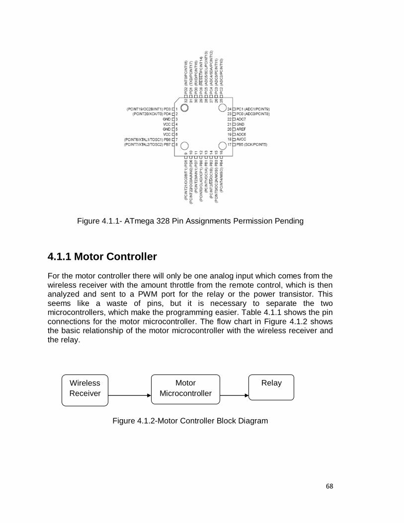
68
Figure 4.1.1- ATmega 328 Pin Assignments Permission Pending
4.1.1 Motor Controller
For the motor controller there will only be one analog input which comes from the wireless receiver with the amount throttle from the remote control, which is then analyzed and sent to a PWM port for the relay or the power transistor. This seems like a waste of pins, but it is necessary to separate the two microcontrollers, which make the programming easier. Table 4.1.1 shows the pin connections for the motor microcontroller. The flow chart in Figure 4.1.2 shows the basic relationship of the motor microcontroller with the wireless receiver and the relay.
Figure 4.1.2-Motor Controller Block Diagram
Motor
Microcontroller
Wireless
Receiver
Relay
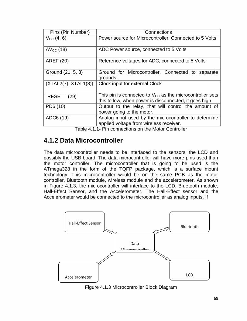
69
Data
Microcontroller
LCD
Hall-Effect Sensor
Accelerometer
Bluetooth
Pins (Pin Number) Connections
VCC (4, 6) Power source for Microcontroller, Connected to 5 Volts
AVCC (18) ADC Power source, connected to 5 Volts
AREF (20) Reference voltages for ADC, connected to 5 Volts
Ground (21, 5, 3) Ground for Microcontroller, Connected to separate grounds.
(XTAL2(7), XTAL1(8)) Clock input for external Clock
RESET (29) This pin is connected to VCC as the microcontroller sets this to low, when power is disconnected, it goes high
PD6 (10) Output to the relay, that will control the amount of power going to the motor.
ADC6 (19) Analog input used by the microcontroller to determine applied voltage from wireless receiver.
Table 4.1.1- Pin connections on the Motor Controller
4.1.2 Data Microcontroller
The data microcontroller needs to be interfaced to the sensors, the LCD and possibly the USB board. The data microcontroller will have more pins used than the motor controller. The microcontroller that is going to be used is the ATmega328 in the form of the TQFP package, which is a surface mount technology. This microcontroller would be on the same PCB as the motor controller, Bluetooth module, wireless module and the accelerometer. As shown in Figure 4.1.3, the microcontroller will interface to the LCD, Bluetooth module, Hall-Effect Sensor, and the Accelerometer. The Hall-Effect sensor and the Accelerometer would be connected to the microcontroller as analog inputs. If
Figure 4.1.3 Microcontroller Block Diagram
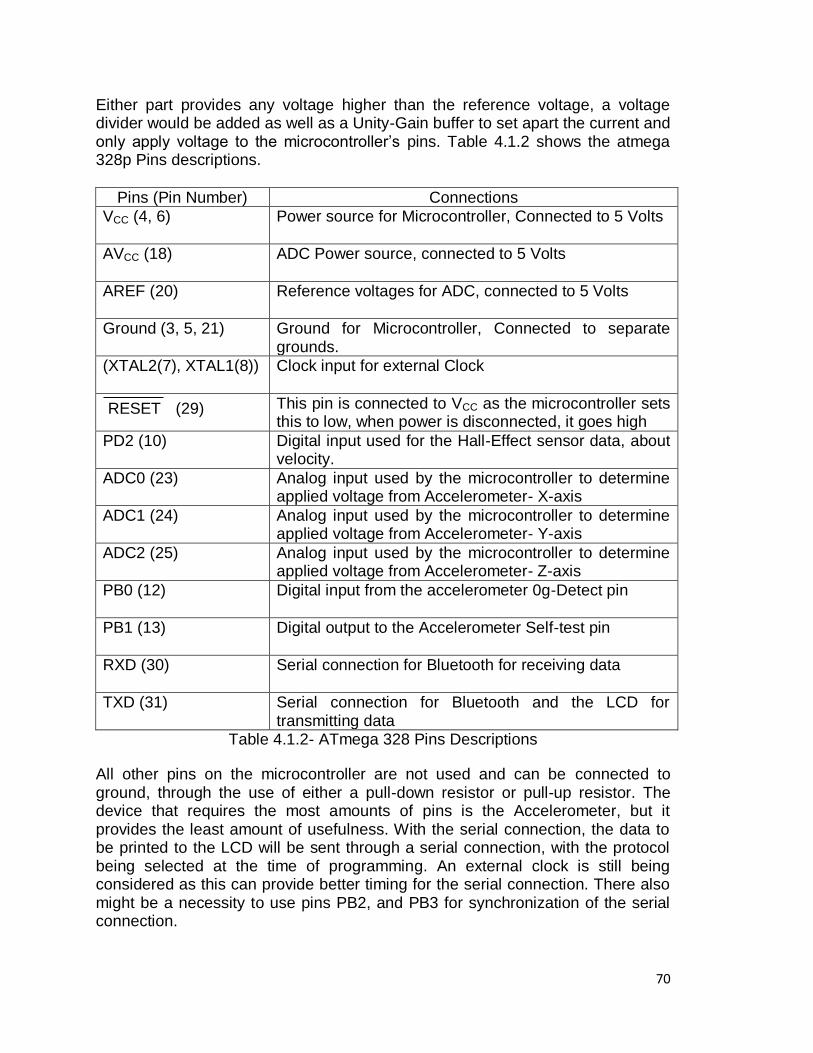
70
Either part provides any voltage higher than the reference voltage, a voltage divider would be added as well as a Unity-Gain buffer to set apart the current and only apply voltage to the microcontroller‘s pins. Table 4.1.2 shows the atmega 328p Pins descriptions.
Pins (Pin Number) Connections
VCC (4, 6) Power source for Microcontroller, Connected to 5 Volts
AVCC (18) ADC Power source, connected to 5 Volts
AREF (20) Reference voltages for ADC, connected to 5 Volts
Ground (3, 5, 21) Ground for Microcontroller, Connected to separate grounds.
(XTAL2(7), XTAL1(8)) Clock input for external Clock
RESET (29) This pin is connected to VCC as the microcontroller sets this to low, when power is disconnected, it goes high
PD2 (10) Digital input used for the Hall-Effect sensor data, about velocity.
ADC0 (23) Analog input used by the microcontroller to determine applied voltage from Accelerometer- X-axis
ADC1 (24) Analog input used by the microcontroller to determine applied voltage from Accelerometer- Y-axis
ADC2 (25) Analog input used by the microcontroller to determine applied voltage from Accelerometer- Z-axis
PB0 (12) Digital input from the accelerometer 0g-Detect pin
PB1 (13) Digital output to the Accelerometer Self-test pin
RXD (30) Serial connection for Bluetooth for receiving data
TXD (31) Serial connection for Bluetooth and the LCD for transmitting data
Table 4.1.2- ATmega 328 Pins Descriptions
All other pins on the microcontroller are not used and can be connected to ground, through the use of either a pull-down resistor or pull-up resistor. The device that requires the most amounts of pins is the Accelerometer, but it provides the least amount of usefulness. With the serial connection, the data to be printed to the LCD will be sent through a serial connection, with the protocol being selected at the time of programming. An external clock is still being considered as this can provide better timing for the serial connection. There also might be a necessity to use pins PB2, and PB3 for synchronization of the serial connection.
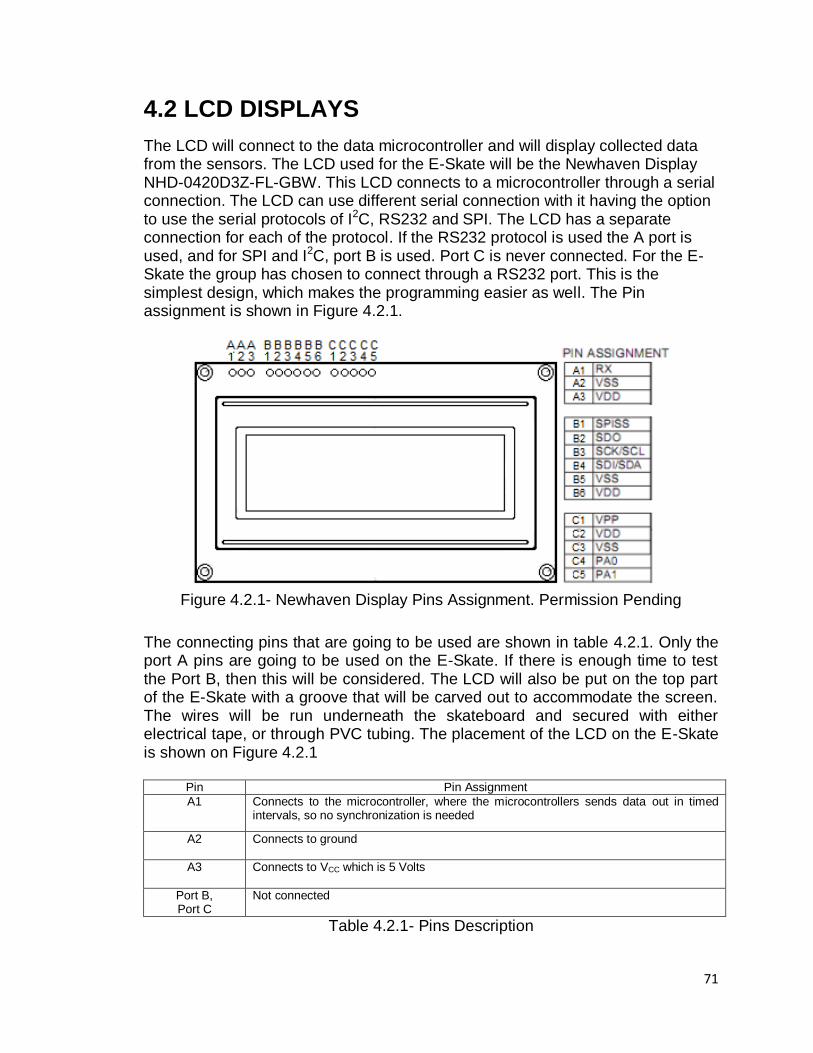
71
4.2 LCD DISPLAYS
The LCD will connect to the data microcontroller and will display collected data from the sensors. The LCD used for the E-Skate will be the Newhaven Display NHD-0420D3Z-FL-GBW. This LCD connects to a microcontroller through a serial connection. The LCD can use different serial connection with it having the option to use the serial protocols of I2C, RS232 and SPI. The LCD has a separate connection for each of the protocol. If the RS232 protocol is used the A port is used, and for SPI and I2C, port B is used. Port C is never connected. For the E-Skate the group has chosen to connect through a RS232 port. This is the simplest design, which makes the programming easier as well. The Pin assignment is shown in Figure 4.2.1.
Figure 4.2.1- Newhaven Display Pins Assignment. Permission Pending
The connecting pins that are going to be used are shown in table 4.2.1. Only the port A pins are going to be used on the E-Skate. If there is enough time to test the Port B, then this will be considered. The LCD will also be put on the top part of the E-Skate with a groove that will be carved out to accommodate the screen. The wires will be run underneath the skateboard and secured with either electrical tape, or through PVC tubing. The placement of the LCD on the E-Skate is shown on Figure 4.2.1
Pin Pin Assignment
A1 Connects to the microcontroller, where the microcontrollers sends data out in timed intervals, so no synchronization is needed
A2
Connects to ground
A3
Connects to VCC which is 5 Volts
Port B, Port C
Not connected
Table 4.2.1- Pins Description
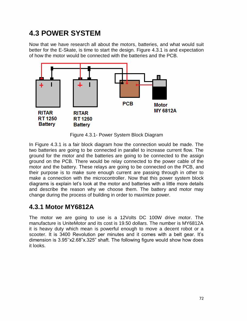
72
4.3 POWER SYSTEM
Now that we have research all about the motors, batteries, and what would suit better for the E-Skate, is time to start the design. Figure 4.3.1 is and expectation of how the motor would be connected with the batteries and the PCB.
Figure 4.3.1- Power System Block Diagram
In Figure 4.3.1 is a fair block diagram how the connection would be made. The two batteries are going to be connected in parallel to increase current flow. The ground for the motor and the batteries are going to be connected to the assign ground on the PCB. There would be relay connected to the power cable of the motor and the battery. These relays are going to be connected on the PCB, and their purpose is to make sure enough current are passing through in other to make a connection with the microcontroller. Now that this power system block diagrams is explain let‘s look at the motor and batteries with a little more details and describe the reason why we choose them. The battery and motor may change during the process of building in order to maximize power.
4.3.1 Motor MY6812A
The motor we are going to use is a 12Volts DC 100W drive motor. The manufacture is UniteMotor and its cost is 19.50 dollars. The number is MY6812A it is heavy duty which mean is powerful enough to move a decent robot or a scooter. It is 3400 Revolution per minutes and it comes with a belt gear. It‘s dimension is 3.95‘‘x2.68‖x.325‖ shaft. The following figure would show how does it looks.
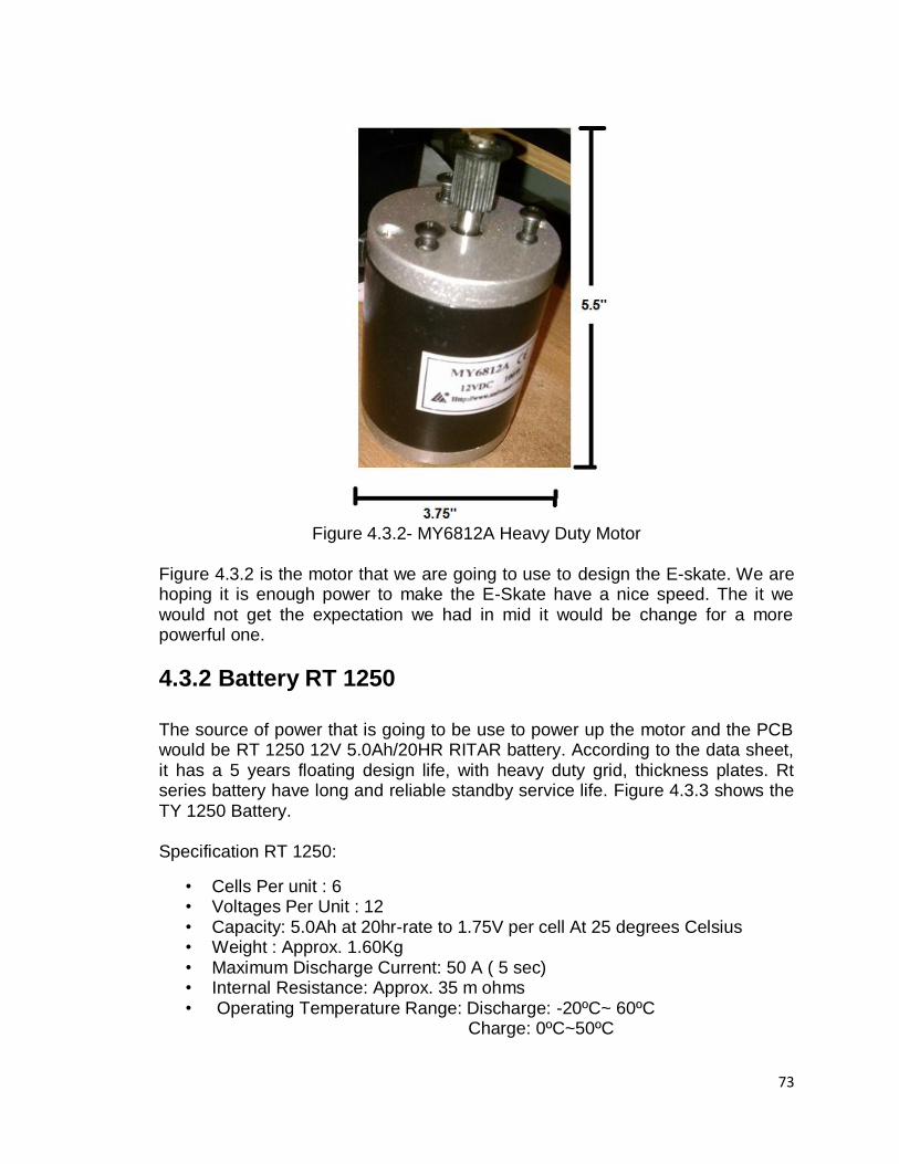
73
Figure 4.3.2- MY6812A Heavy Duty Motor
Figure 4.3.2 is the motor that we are going to use to design the E-skate. We are hoping it is enough power to make the E-Skate have a nice speed. The it we would not get the expectation we had in mid it would be change for a more powerful one.
4.3.2 Battery RT 1250 The source of power that is going to be use to power up the motor and the PCB would be RT 1250 12V 5.0Ah/20HR RITAR battery. According to the data sheet, it has a 5 years floating design life, with heavy duty grid, thickness plates. Rt series battery have long and reliable standby service life. Figure 4.3.3 shows the TY 1250 Battery. Specification RT 1250:
• Cells Per unit : 6 • Voltages Per Unit : 12 • Capacity: 5.0Ah at 20hr-rate to 1.75V per cell At 25 degrees Celsius • Weight : Approx. 1.60Kg • Maximum Discharge Current: 50 A ( 5 sec) • Internal Resistance: Approx. 35 m ohms • Operating Temperature Range: Discharge: -20ºC~ 60ºC
Charge: 0ºC~50ºC
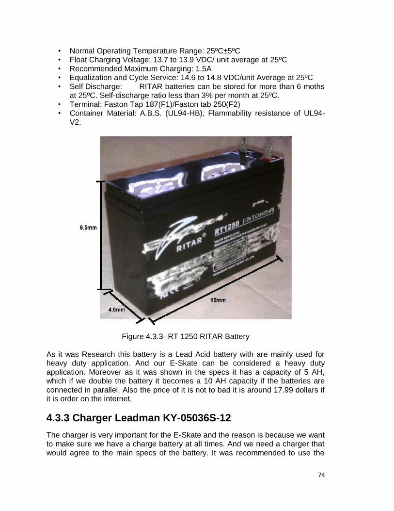
74
• Normal Operating Temperature Range: 25ºC±5ºC • Float Charging Voltage: 13.7 to 13.9 VDC/ unit average at 25ºC • Recommended Maximum Charging: 1.5A • Equalization and Cycle Service: 14.6 to 14.8 VDC/unit Average at 25ºC • Self Discharge: RITAR batteries can be stored for more than 6 moths
at 25ºC. Self-discharge ratio less than 3% per month at 25ºC. • Terminal: Faston Tap 187(F1)/Faston tab 250(F2) • Container Material: A.B.S. (UL94-HB), Flammability resistance of UL94-
V2.
Figure 4.3.3- RT 1250 RITAR Battery
As it was Research this battery is a Lead Acid battery with are mainly used for heavy duty application. And our E-Skate can be considered a heavy duty application. Moreover as it was shown in the specs it has a capacity of 5 AH, which if we double the battery it becomes a 10 AH capacity if the batteries are connected in parallel. Also the price of it is not to bad it is around 17.99 dollars if it is order on the internet,
4.3.3 Charger Leadman KY-05036S-12
The charger is very important for the E-Skate and the reason is because we want to make sure we have a charge battery at all times. And we need a charger that would agree to the main specs of the battery. It was recommended to use the
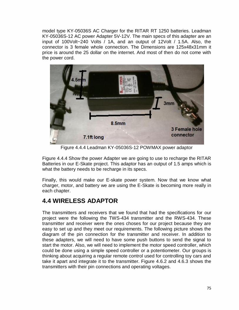
75
model type KY-05036S AC Charger for the RITAR RT 1250 batteries. Leadman KY-05036S-12 AC power Adapter 5V-12V. The main specs of this adapter are an input of 100Volt~240 Volts / 1A, and an output of 12Volt / 1.5A. Also, the connector is 3 female whole connection. The Dimensions are 125x48x31mm it price is around the 25 dollar on the internet. And most of then do not come with the power cord.
Figure 4.4.4 Leadman KY-05036S-12 POWMAX power adaptor
Figure 4.4.4 Show the power Adapter we are going to use to recharge the RITAR Batteries in our E-Skate project. This adaptor has an output of 1.5 amps which is what the battery needs to be recharge in its specs. Finally, this would make our E-skate power system. Now that we know what charger, motor, and battery we are using the E-Skate is becoming more really in each chapter.
4.4 WIRELESS ADAPTOR The transmitters and receivers that we found that had the specifications for our project were the following the TWS-434 transmitter and the RWS-434. These transmitter and receiver were the ones choses for our project because they are easy to set up and they meet our requirements. The following picture shows the diagram of the pin connection for the transmitter and receiver. In addition to these adapters, we will need to have some push buttons to send the signal to start the motor. Also, we will need to implement the motor speed controller, which could be done using a simple speed controller or a potentiometer. Our groups is thinking about acquiring a regular remote control used for controlling toy cars and take it apart and integrate it to the transmitter. Figure 4.6.2 and 4.6.3 shows the transmitters with their pin connections and operating voltages.
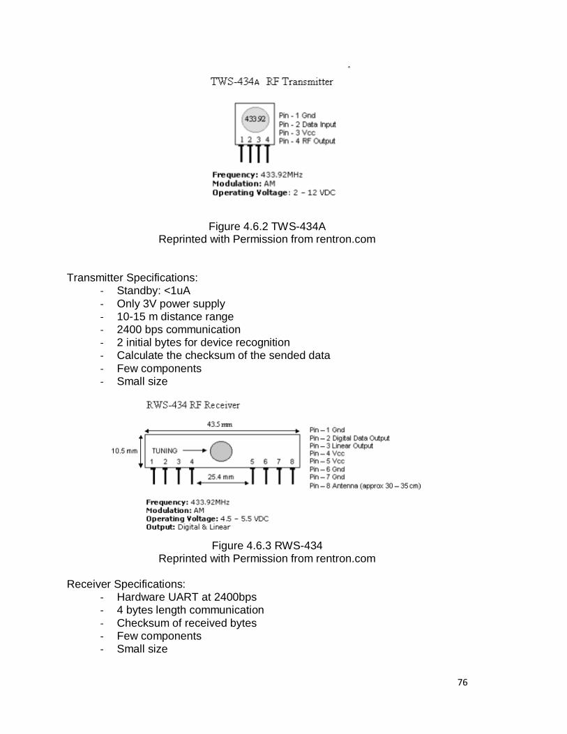
76
Figure 4.6.2 TWS-434A Reprinted with Permission from rentron.com
Transmitter Specifications:
- Standby: <1uA
- Only 3V power supply - 10-15 m distance range - 2400 bps communication - 2 initial bytes for device recognition - Calculate the checksum of the sended data
- Few components - Small size
Figure 4.6.3 RWS-434
Reprinted with Permission from rentron.com Receiver Specifications:
- Hardware UART at 2400bps - 4 bytes length communication
- Checksum of received bytes - Few components - Small size
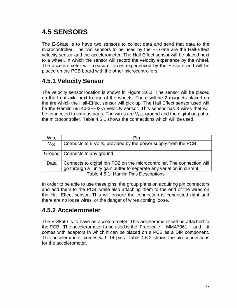
77
4.5 SENSORS
The E-Skate is to have two sensors to collect data and send that data to the microcontroller. The two sensors to be used by the E-Skate are the Hall-Effect velocity sensor and the accelerometer. The Hall Effect sensor will be placed next to a wheel, in which the sensor will record the velocity experience by the wheel. The accelerometer will measure forces experienced by the E-skate and will be placed on the PCB board with the other microcontrollers.
4.5.1 Velocity Sensor
The velocity sensor location is shown in Figure 3.6.1. The sensor will be placed on the front axle next to one of the wheels. There will be 2 magnets placed on the tire which the Hall-Effect sensor will pick up. The Hall Effect sensor used will be the Hamlin 55140-3H-02-A velocity sensor. This sensor has 3 wires that will be connected to various parts. The wires are VCC, ground and the digital output to the microcontroller. Table 4.5.1 shows the connections which will be used.
Wire Pin
VCC Connects to 5 Volts, provided by the power supply from the PCB
Ground Connects to any ground
Data Connects to digital pin PD2 on the microcontroller. The connection will go through a unity gain buffer to separate any variation in current.
Table 4.5.1- Hamlin Pins Descriptions
In order to be able to use these pins, the group plans on acquiring pin connectors and add them to the PCB, while also attaching them to the end of the wires on the Hall Effect sensor. This will ensure the connection is connected right and there are no loose wires, or the danger of wires coming loose.
4.5.2 Accelerometer
The E-Skate is to have an accelerometer. This accelerometer will be attached to the PCB. The accelerometer to be used is the Freescale MMA7361 and it comes with adaptors in which it can be placed on a PCB as a DIP component. This accelerometer comes with 14 pins. Table 4.6.2 shows the pin connections for the accelerometer.
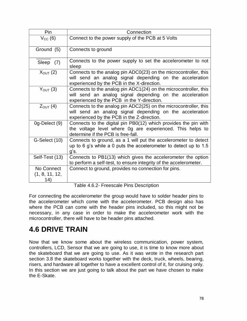
78
Pin Connection
VCC (6) Connect to the power supply of the PCB at 5 Volts
Ground (5) Connects to ground
Sleep (7) Connects to the power supply to set the accelerometer to not sleep
XOUT (2) Connects to the analog pin ADC0(23) on the microcontroller, this will send an analog signal depending on the acceleration experienced by the PCB in the X-direction.
YOUT (3) Connects to the analog pin ADC1(24) on the microcontroller, this will send an analog signal depending on the acceleration experienced by the PCB in the Y-direction.
ZOUT (4) Connects to the analog pin ADC2(25) on the microcontroller, this will send an analog signal depending on the acceleration experienced by the PCB in the Z-direction.
0g-Delect (9) Connects to the digital pin PB0(12) which provides the pin with the voltage level where 0g are experienced. This helps to determine if the PCB is free-fall.
G-Select (10) Connects to ground, as a 1 will put the accelerometer to detect up to 6 g‘s while a 0 puts the accelerometer to detect up to 1.5 g‘s.
Self-Test (13) Connects to PB1(13) which gives the accelerometer the option to perform a self-test, to ensure integrity of the accelerometer.
No Connect (1, 8, 11, 12,
14)
Connect to ground, provides no connection for pins.
Table 4.6.2- Freescale Pins Description
For connecting the accelerometer the group would have to solder header pins to the accelerometer which come with the accelerometer. PCB design also has where the PCB can come with the header pins included, so this might not be necessary, in any case in order to make the accelerometer work with the microcontroller, there will have to be header pins attached.
4.6 DRIVE TRAIN Now that we know some about the wireless communication, power system, controllers, LCD, Sensor that we are going to use, it is time to know more about the skateboard that we are going to use. As it was wrote in the research part section 3.8 the skateboard works together with the deck, truck, wheels, bearing, risers, and hardware all together to have a excellent control of it, for cruising only. In this section we are just going to talk about the part we have chosen to make the E-Skate.
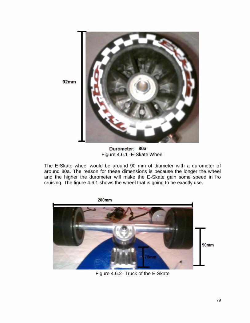
79
Figure 4.6.1 -E-Skate Wheel
The E-Skate wheel would be around 90 mm of diameter with a durometer of around 80a. The reason for these dimensions is because the longer the wheel and the higher the durometer will make the E-Skate gain some speed in fro cruising. The figure 4.6.1 shows the wheel that is going to be exactly use.
Figure 4.6.2- Truck of the E-Skate
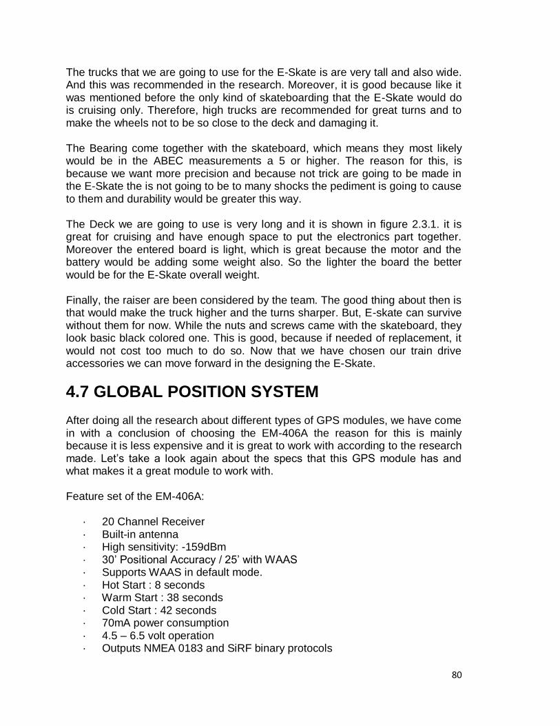
80
The trucks that we are going to use for the E-Skate is are very tall and also wide. And this was recommended in the research. Moreover, it is good because like it was mentioned before the only kind of skateboarding that the E-Skate would do is cruising only. Therefore, high trucks are recommended for great turns and to make the wheels not to be so close to the deck and damaging it. The Bearing come together with the skateboard, which means they most likely would be in the ABEC measurements a 5 or higher. The reason for this, is because we want more precision and because not trick are going to be made in the E-Skate the is not going to be to many shocks the pediment is going to cause to them and durability would be greater this way. The Deck we are going to use is very long and it is shown in figure 2.3.1. it is great for cruising and have enough space to put the electronics part together. Moreover the entered board is light, which is great because the motor and the battery would be adding some weight also. So the lighter the board the better would be for the E-Skate overall weight. Finally, the raiser are been considered by the team. The good thing about then is that would make the truck higher and the turns sharper. But, E-skate can survive without them for now. While the nuts and screws came with the skateboard, they look basic black colored one. This is good, because if needed of replacement, it would not cost too much to do so. Now that we have chosen our train drive accessories we can move forward in the designing the E-Skate.
4.7 GLOBAL POSITION SYSTEM After doing all the research about different types of GPS modules, we have come in with a conclusion of choosing the EM-406A the reason for this is mainly because it is less expensive and it is great to work with according to the research made. Let‘s take a look again about the specs that this GPS module has and what makes it a great module to work with. Feature set of the EM-406A:
· 20 Channel Receiver · Built-in antenna · High sensitivity: -159dBm · 30‘ Positional Accuracy / 25‘ with WAAS · Supports WAAS in default mode. · Hot Start : 8 seconds · Warm Start : 38 seconds · Cold Start : 42 seconds · 70mA power consumption · 4.5 – 6.5 volt operation · Outputs NMEA 0183 and SiRF binary protocols
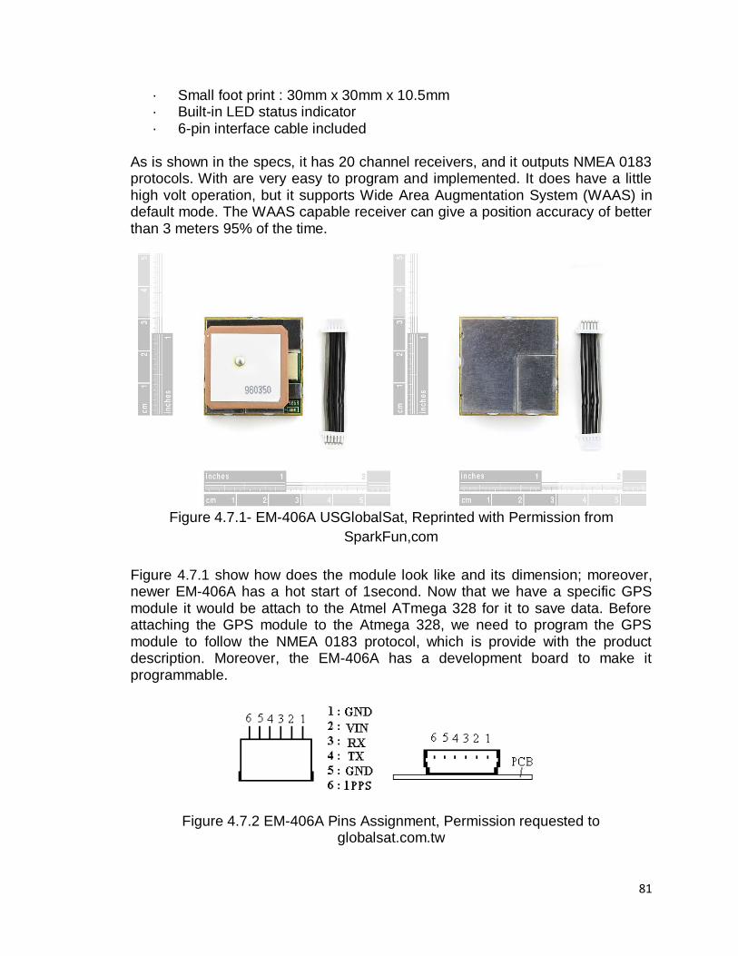
81
· Small foot print : 30mm x 30mm x 10.5mm · Built-in LED status indicator · 6-pin interface cable included
As is shown in the specs, it has 20 channel receivers, and it outputs NMEA 0183 protocols. With are very easy to program and implemented. It does have a little high volt operation, but it supports Wide Area Augmentation System (WAAS) in default mode. The WAAS capable receiver can give a position accuracy of better than 3 meters 95% of the time.
Figure 4.7.1- EM-406A USGlobalSat, Reprinted with Permission from
SparkFun,com
Figure 4.7.1 show how does the module look like and its dimension; moreover, newer EM-406A has a hot start of 1second. Now that we have a specific GPS module it would be attach to the Atmel ATmega 328 for it to save data. Before attaching the GPS module to the Atmega 328, we need to program the GPS module to follow the NMEA 0183 protocol, which is provide with the product description. Moreover, the EM-406A has a development board to make it programmable.
Figure 4.7.2 EM-406A Pins Assignment, Permission requested to globalsat.com.tw
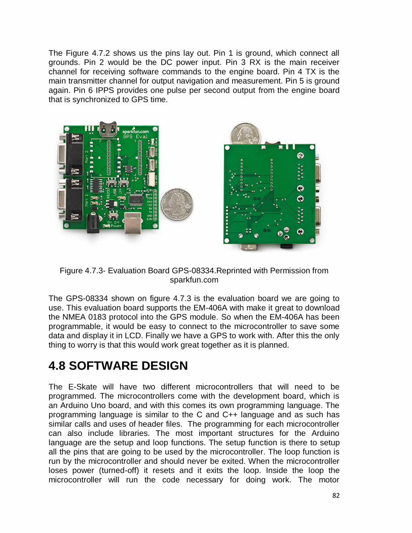
82
The Figure 4.7.2 shows us the pins lay out. Pin 1 is ground, which connect all grounds. Pin 2 would be the DC power input. Pin 3 RX is the main receiver channel for receiving software commands to the engine board. Pin 4 TX is the main transmitter channel for output navigation and measurement. Pin 5 is ground again. Pin 6 IPPS provides one pulse per second output from the engine board that is synchronized to GPS time.
Figure 4.7.3- Evaluation Board GPS-08334.Reprinted with Permission from sparkfun.com
The GPS-08334 shown on figure 4.7.3 is the evaluation board we are going to use. This evaluation board supports the EM-406A with make it great to download the NMEA 0183 protocol into the GPS module. So when the EM-406A has been programmable, it would be easy to connect to the microcontroller to save some data and display it in LCD. Finally we have a GPS to work with. After this the only thing to worry is that this would work great together as it is planned.
4.8 SOFTWARE DESIGN
The E-Skate will have two different microcontrollers that will need to be programmed. The microcontrollers come with the development board, which is an Arduino Uno board, and with this comes its own programming language. The programming language is similar to the C and C++ language and as such has similar calls and uses of header files. The programming for each microcontroller can also include libraries. The most important structures for the Arduino language are the setup and loop functions. The setup function is there to setup all the pins that are going to be used by the microcontroller. The loop function is run by the microcontroller and should never be exited. When the microcontroller loses power (turned-off) it resets and it exits the loop. Inside the loop the microcontroller will run the code necessary for doing work. The motor
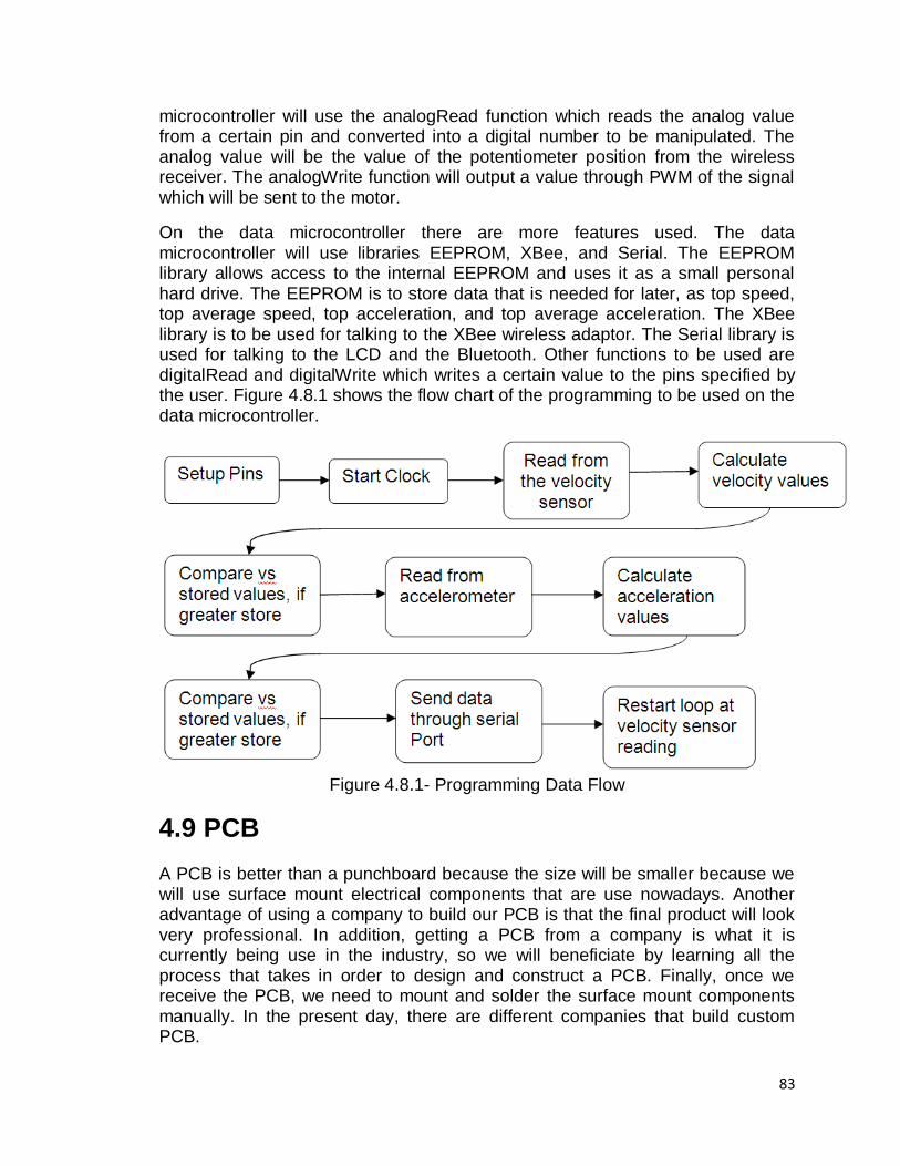
83
microcontroller will use the analogRead function which reads the analog value from a certain pin and converted into a digital number to be manipulated. The analog value will be the value of the potentiometer position from the wireless receiver. The analogWrite function will output a value through PWM of the signal which will be sent to the motor.
On the data microcontroller there are more features used. The data microcontroller will use libraries EEPROM, XBee, and Serial. The EEPROM library allows access to the internal EEPROM and uses it as a small personal hard drive. The EEPROM is to store data that is needed for later, as top speed, top average speed, top acceleration, and top average acceleration. The XBee library is to be used for talking to the XBee wireless adaptor. The Serial library is used for talking to the LCD and the Bluetooth. Other functions to be used are digitalRead and digitalWrite which writes a certain value to the pins specified by the user. Figure 4.8.1 shows the flow chart of the programming to be used on the data microcontroller.
Figure 4.8.1- Programming Data Flow
4.9 PCB A PCB is better than a punchboard because the size will be smaller because we will use surface mount electrical components that are use nowadays. Another advantage of using a company to build our PCB is that the final product will look very professional. In addition, getting a PCB from a company is what it is currently being use in the industry, so we will beneficiate by learning all the process that takes in order to design and construct a PCB. Finally, once we receive the PCB, we need to mount and solder the surface mount components manually. In the present day, there are different companies that build custom PCB.
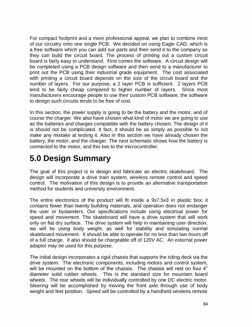
84
For compact footprint and a more professional appeal, we plan to combine most of our circuitry onto one single PCB. We decided on using Eagle CAD, which is a free software which you can add our parts and then send it to the company so they can build the circuit board. The process of printing out a custom circuit board is fairly easy to understand. First comes the software. A circuit design will be completed using a PCB design software and then send to a manufacturer to print out the PCB using their industrial grade equipment. The cost associated with printing a circuit board depends on the size of the circuit board and the number of layers. For our purpose, a 2 layer PCB is sufficient. 2 layers PCB tend to be fairly cheap compared to higher number of layers. Since most manufacturers encourage people to use their custom PCB software, the software to design such circuits tends to be free of cost. In this section, the power supply is going to be the battery and the motor, and of course the charger. We also have chosen what kind of motor we are going to use as the batteries and charges compatible with the battery chosen. The design of it is should not be complicated. It fact, it should be as simply as possible to not make any mistake at testing it. Also in this section we have already chosen the battery, the motor, and the charger. The next schematic shows how the battery is connected to the motor, and this two to the microcontroller.
5.0 Design Summary The goal of this project is to design and fabricate an electric skateboard. The design will incorporate a drive train system, wireless remote control and speed control. The motivation of this design is to provide an alternative transportation method for students and university environment. The entire electronics of the product will fit inside a 9x7.5x3 in plastic box; it contains fewer than twenty building materials, and operation does not endanger the user or bystanders. Our specifications include using electrical power for speed and movement. The skateboard will have a drive system that will work only on flat dry surface. The drive system will help in maintaining user direction; we will be using body weight, as well for stability and simulating normal skateboard movement. It should be able to operate for no less than two hours off of a full charge. It also should be chargeable off of 120V AC. An external power adaptor may be used for this purpose. The initial design incorporates a rigid chassis that supports the riding deck via the drive system. The electronic components, including motors and control system, will be mounted on the bottom of the chassis. The chassis will rest on four 4‖ diameter solid rubber wheels. This is the standard size for mountain board wheels. The rear wheels will be individually controlled by one DC electric motor. Steering will be accomplished by moving the front axle through use of body weight and feet position. Speed will be controlled by a handheld wireless remote
85
control. Running speed is adjustable during operation. The Deck dimension can be seen in figure 2.3.1, also has it was shown in figure 4.6.1 and 4.6.2 this would be the wheels and truck to be used consequently. The microcontroller chosen is the Atmel ATmega328 with the Arduino board. This microcontroller was chosen as it has enough processing capacity for controlling data on the E-Skate. There will be two microcontrollers, one for the motor and the other for data. The one from controlling the motor will only do that, and will not talk to the other one. The other microcontroller is the data microcontroller and its task is collecting data and printing it to the screen. This is done to ensure the microcontrollers are not being overworked. There will be two sensors on the microcontroller. One sensor is for collecting the velocity data and the other for collecting the acceleration figures. The velocity sensor was chosen as other sensors were considered, but this sensor provided for the best adaptation physically to the E-Skate. The velocity sensor chosen was the Hamlin 55140-3H-02-A. The acceleration sensor was chosen because of its price and its size. It has the ability to be put anywhere on the E-Skate or on a PCB. The Accelerometer chosen is the Freescale MMA7361L. With the velocity sensor, only velocity needs to be collected. From this overall average velocity, top velocity, motor rpm, distance, and total distance travelled can be calculated. With the acceleration sensor, average acceleration, top acceleration, and forces acted on the E-Skate can be calculated. The sensors is what makes the E-Skate better than other skateboards out there, as different data points can be displayed.
We found different types of relay we could use to switch the appliance on and off. The relay that we chose was the RW-SS-112D. These relays can switch a maximum of 5 A at 240 VAC, a maximum of 10A at 120 VAC and a maximum of 10A at 24 VDC. The RW-SS-112D relay is practical because of its size. Its measurement 19.5mm x 15.4mm x 15.4mm makes it very attractive for our project. Also it has complete protective construction against dust and soldering flux. When used for electrical purpose, this relay can switch a device on and off a maximum of 30 operations per minute. This relay will be very practical because if anything goes wrong in the connections, it will protect the motor and electrical components from getting damaged.
In order to control the E-Skate we will need to connect a remote control transmitter and receiver into the microcontroller atimega328. The wireless remote control that we will use is the TWS-434A and the RWS-434. This module is really good for our design because it satisfies our requirements and specifications. The transmitter has one data input and one RF output, and the receiver has two data outputs, which is exactly what we need in order to communicate to the microcontroller so we can transfer speed information in order to control the desire speed.
86
The LCD will display the data collected by the sensors and manipulated by the E-Skate. The LCD chosen is the Newhaven NHD‐0420D3Z‐FL‐GB. This screen was chosen because of its simplify to connecting to the microcontroller. This screen was also chosen as the size is perfect for the front of the E-Skate and as well as the price of $27.00. The LCD has 4 lines of characters which the group will decide later what data will print on what line. The LCD will need to have a groove marked out in the front of the E-Skate to mount it. The LCD will be controlled by the LCD microcontroller. The programming of the microcontrollers will be done by the Arduino boards own language called Arduino. This language is a mixture of C and C++ which makes the syntax easy to understand for the group members. The data microcontroller will be programmed to read the sensors and to print out to a serial port where the LCD will be connected. The motor microcontroller will be programmed to only read where the position of the throttle is, and will output a signal to the motor. The microcontrollers will also have an external clock which will require the software to account for this when doing data calculations as velocity is per unit time. The Power System to by use in the E-Skate design would be the motor MY6812A Heavy Duty, two batteries RITAR RT 1250, and a power adapter from Leadman powmax model KY-05036S-12 3 Whole Female connector. The MY6812A is a 12 Volts 100 watt heavy duty motor. It has enough power to move a scooter; therefore, it is an excellent choice for our E-Skate design. The Two RITAR batteries are going to be connected in parallel to provide more current flow. Each battery has an output of 12 volts and a 5 Amp hours. It is also rechargeable and need a minimum input of 1.5 amps to be recharge. It was a great battery life and need to be constant recharge after use to maintain battery life longer. The purpose of the charger is to power up the battery. The charger that is going to be used is manufacture by Leadman model KY-05036S-12 Powmax. It has an input of 100 ~240 Volts per 1 amp and an output of 12Volts / 1.5 Amps. Because it dissipated 1.5 amps it is a great used for the battery. The block diagram of how does the motor is going to be attach to the battery and the PCB is shown in Figure 4.3.1. The Global Position System (GPS) module to be use is going to be the EM 406A from GlobalSat, this EM follow the protocol NMEA 0183, and also offers the development board by SparkFun. This GPS would be programmed by the development board to load data to the Atmel ATmega 328. And it would be shown in the LCD display inform of the deck. Figure 4.7.1 and 4.7.2 shows the GPS module dimensions and the Pins layout consequently. The EM 406A is not as expensive as the other GPS module research in this paper. And that why is the main reason for choosing it. Moreover, it has an excellent reviews and easy to implement.
87
6.0 PROTOTYPING 6.1 SKATEBOARD The only prototyping we have at this moment is the electronics skateboard shown in figure 2.3.1. This Skate board is a long board and high truck and big wheels. This is great because the E-Skate is just only for cruising skateboarding only. For now this is the only prototyping we have. And later on in for senior design 2 we will have more prototypes. This would help to incorporated everything together to find a great prototyping for the design of the E-Skate. This section would be extended more information would be available later on.
6.2 MOTOR CONTROLLER PROTOTYPING In order to test the ATmega controller, we used a tutorial from societyofrobots.com in order to learn more about how a motor controller works. We decided at first to order a ATmega8 just to test a servo motor. We bought materials such as: breadboard, pin connectors, resistors, capacitors, LEDs, wires, battery, voltage regulator and the deep socket ATmega chip. In order to get all the parts together we needed to have a soldering machine. We bought one of these machines at our local RadioShack store. Also, In order to program our microprocessor in the computer we needed to hook it up to a RS232 to USB converter. Also in order to program it, we needed to have WinAVR, which is free software simple to use and setup. The following lines will describe the construction process of the motor controller prototype. First of all we decided to take a look to the website society of robots to come with a motor controller prototype example, we chose one example that had a design and parts, we did not have that much experience so we decided to learn by constructing that motor controller. We needed to get many parts such as resistors, capacitors and many other parts. Figure 6.2.1 A & B shows some of the parts that we had to acquire to make this work.
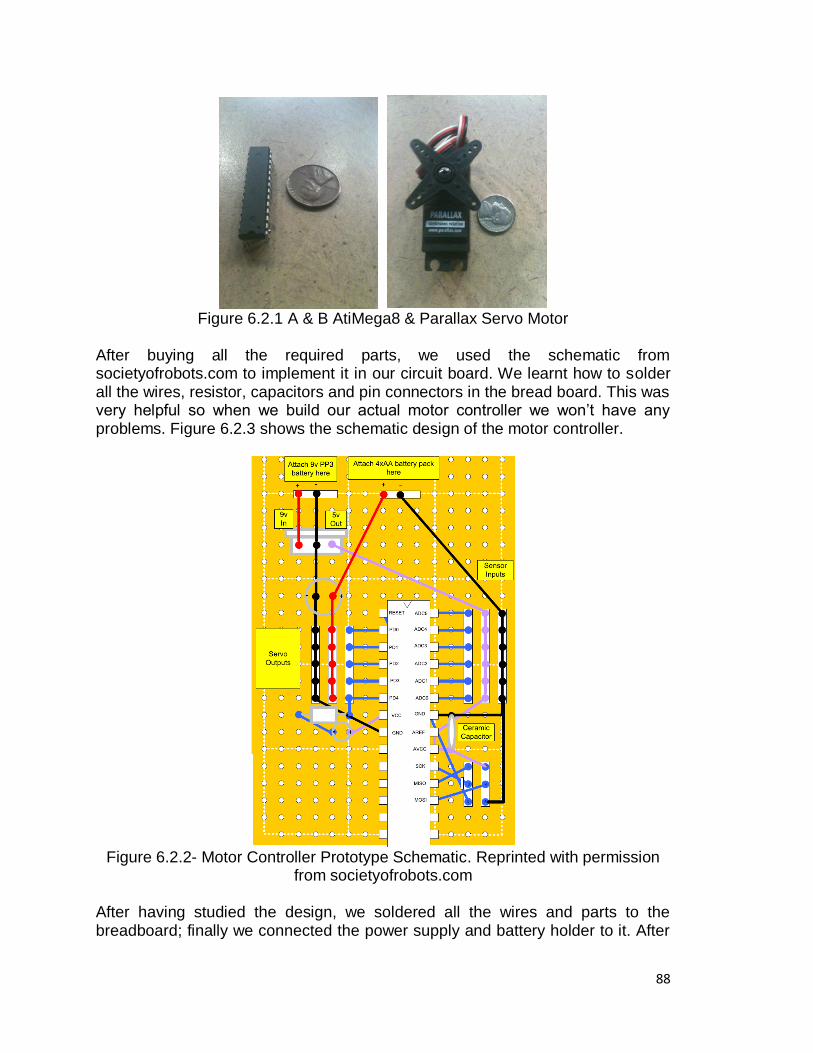
88
Figure 6.2.1 A & B AtiMega8 & Parallax Servo Motor
After buying all the required parts, we used the schematic from societyofrobots.com to implement it in our circuit board. We learnt how to solder all the wires, resistor, capacitors and pin connectors in the bread board. This was very helpful so when we build our actual motor controller we won‘t have any problems. Figure 6.2.3 shows the schematic design of the motor controller.
Figure 6.2.2- Motor Controller Prototype Schematic. Reprinted with permission
from societyofrobots.com After having studied the design, we soldered all the wires and parts to the breadboard; finally we connected the power supply and battery holder to it. After
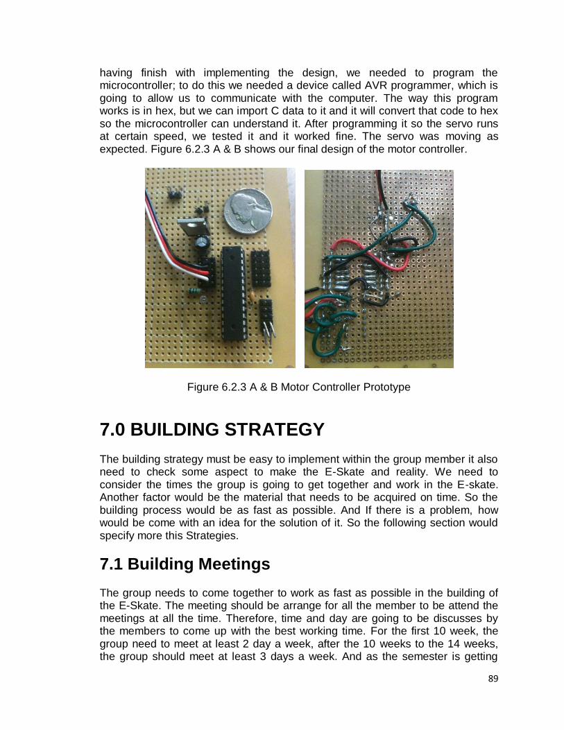
89
having finish with implementing the design, we needed to program the microcontroller; to do this we needed a device called AVR programmer, which is going to allow us to communicate with the computer. The way this program works is in hex, but we can import C data to it and it will convert that code to hex so the microcontroller can understand it. After programming it so the servo runs at certain speed, we tested it and it worked fine. The servo was moving as expected. Figure 6.2.3 A & B shows our final design of the motor controller.
Figure 6.2.3 A & B Motor Controller Prototype
7.0 BUILDING STRATEGY
The building strategy must be easy to implement within the group member it also need to check some aspect to make the E-Skate and reality. We need to consider the times the group is going to get together and work in the E-skate. Another factor would be the material that needs to be acquired on time. So the building process would be as fast as possible. And If there is a problem, how would be come with an idea for the solution of it. So the following section would specify more this Strategies.
7.1 Building Meetings
The group needs to come together to work as fast as possible in the building of the E-Skate. The meeting should be arrange for all the member to be attend the meetings at all the time. Therefore, time and day are going to be discusses by the members to come up with the best working time. For the first 10 week, the group need to meet at least 2 day a week, after the 10 weeks to the 14 weeks, the group should meet at least 3 days a week. And as the semester is getting
90
close to a deadline, the members should meet in day to day basics to make sure all the parts and implementations are working perfectly. Also, before the presentation, the group should come together for a presentation discussion, to make the best presentation suitable for the E-Skate. If any member would not be able to attend a meeting because a reasonable excuse, the entire group should reschedule another day in that week period. If any member cannot make it a week for a reasonable excuse, He or she is responsible for the updates of the week and the rest of the group should meet as usual. The same condition applies if the period is 2 weeks. This would be the terms and conditions that all the member must agree in order to create an excellent meeting schedule.
7.2 Materials Materials are very important to make the E-Skate possible. For this section we are going to talk about how the material should be acquired, implemented, and tested. Before the Second Senior Design course start, the material and parts described in the Design chapter of this paper should be already acquired. If this is able to meet, the group members should work with them and tested them as soon as possible. If a material is not to be acquired during the period stated, it should be acquired within the first two weeks of the semester. So, it can be tested and implemented as fast as possible. Moreover, if a materials or parts are to be added to the design during the building period, it should be recorded in the paper and acquired within the added week, to be tested and implemented. In order to test the parts, we need a station of work with all the applications and tools needed to make sure the part works accordingly to the supplier. If a material does not pass the test, it should be sent back to the supplier or be acquired during the week of it failure. After each part is tested and acquired. It need to be implemented with the other part in other to test the overall E-Skate performance. If this conditions and terms are to be follow correctly, the E-Skate should be working before the deadline in time to work in the presentation discussion. This section is an agreement for the group, and all the member should agree with it in order to work with the E-Skate.
7.3 Errors and Failures It is very normal to have errors or failures during the building period, but in order to make sure to be ready for them is having a strategy if they do happen. If any Errors and Failures Occurred within the first 10 weeks of meeting, it should not change the meet time and day because it is part of the building. If during this error or failure a part is to be damage. It need to be acquired as soon as possible and tested. Before using it again, the error should be find and noted so it would not happen again. If the same error occurs and it was documented and the part is to get damage the member responsible for the same error must acquired the part as soon as possible. Each Error made or failure should be documented to avoid same error and for prove of working period. The programmer should read

91
and make sure to explain the member the code in details so no error would be made. If an error in programming occurs. The member should come together as a team to find the problem in the code. If the programmer uses the same damage code again and it damages a part, he or she must acquire the part as soon as possible. In order to avoid repeated failures the code should be fixed and change as soon are the error is encounter. Errors are normal in a design, but if error continues during the 10 week and the 14 week team should come together and change the days of meeting in day to day basics. If there are errors and can‘t find a solution the member are responsible to research about it and fixed them. Consequently, if error continues in a part, it should be removed from the project paper and all changes must be documented including specifications and requirement. All members should agree to this section part and if they do not agree with it the E-Skate would not be a reality.
7.4 Presentation of the E-Skate Presenting the final project to the committee is very important because it will depend in the success of the project. In this section we are going to see the requirement and conditions to be prepare for the presentation period. If the E-Skate work perfectly, during the 10 week and 14 week, the team should come and meet to make sure to work in the project presentation. The presentation would hold the web sited the power point presentation, and E-Skate outer Design. The Web sited should be design by the person responsible with the programming on the E-Skate. He or she should make sure all the documents from the first semester to the last are on the page. The power point should be made to select the most important part of the design. The power point should be added to anyone in the group. The design of the E-Skate should be made to come across the name of it, and the institution it was made for. If the work do muck presentation with them before the final presentation, it would make the presentation 100% better. So practicing the parts to by each member would be schedule in last week of the semester. If E-Skate is not done during the 14 Weeks, a new schedule should be made to fit presentation meetings, finally this requirement need to be agreed by the entire members to make sure excellence runs in the overall affect of the E-Skate.
8.0 TESTING PROCEDURE This section of the document explains all the testing procedure our group has developed in order to test the functionality of every single system that forms The E-Skate. Each individual part of our project must be tested to ensure its proper function before being combined with the rest. This testing ensures that we find any error or defect in the product as well as in our calculations or programming before we put everything together. The following tests will be conducted on our equipment throughout the project construction.
92
8.1 HARDWARE To test the hardware to make sure it works as predicted, we need to test deferent parts of it. Then, when the individual parts are tested, we are testing the overall E-Skate performances. In the hardware we need to test the motor controller, wireless module, the PCB module. We are also going to test the Motor and the battery life.
8.1.1 Motor Controller Testing In order for us to ensure proper functioning of the motor controller we will be testing the remote control mode as well as the autonomous mode. For both test, it is assumed that the motors and the receiver are connected to the motor controller and power is supplied to them. Also the transmitter is connected to a control device, which will allow us to check if the controller is doing what it is supposed to do.
8.1.2 Wireless Module Testing
In order to test the wireless module we will have to first connect it to our board. Then we will have to program the microcontroller so it can transmit and receive data. We could test it by range and data sent. One of the most important functions of a programming language is to be able to provide the ability to manage memory and the objects that are stored in those memory locations. If we send data through the transmitter, the receiver will let the microprocessor know the data, and it will process it and make the motor move. We will also test the range of the transmitter by taking it to a distance of 10 to 15 meters to see if the signal loses range. If anything goes wrong we can test it again and make some implementations in the design.
8.1.3 PCB Testing This test is to determine if all the electrical components that our E-Skate uses are properly connected and functioning in the way they are supposed to. To do this test everything needs to be mounted and soldered to the printed circuit board including the battery. After that, we will manually check all the connections by using a multi-meter device in the voltage and current function. Next, if find out that a components is not properly connected we will try to solve it. The only way we can solve a problem in a PCB is by removing the component and reverting the polarity. Once we reconnected the device back, we will recheck the connection and if the problem is not solved, we will need to retest our schematic and connection layer design to find out the problem. Finally, if we determine that the problem was that
93
we missed a connection if the schematic design, we will need to fix it and reorder a new PCB. On the other hand, if all the electrical components were properly connected to the PCB we will proceed to the following test. The last test we will conduct with the PCB is to recheck if the PCB is properly functioning once we install it in the bottom of the chassis.
8.1.4 Power System Testing In order to test the power system, we first need to test the charger with the battery; this would be possible with a voltmeter. So after seeing that the battery is charging over time, he can conclude that the battery works right. After this we would measure how much does actually the battery discharge over time. Not that the battery is tested as well as the charger. We measure if the motor works. For this we make a straight connection from the battery and the motor. We may get a switch in other so see how much the motor runs can when battery runs out of juice. If the motor works it mean it is working perfectly and the test of the power system would be done.
8.1.5 GPS Testing For the GPS system as soon as we download the program and we power up the GPS we can check if the for the LED indicator for GPS fix or no fix. If the LED is off, the receiver switch is off. If the LED is on, there is not fixed satellite or is searching for signal. If the LED is flashing there is a position fixed. If the there is a fixed position the GPS is working perfectly and the text would be done. To check if it is sending data to the microcontroller, the LCD should be connected all together. If the software design is tested and working accurately, then the GPS should be sending the data to the microcontroller and it should be sending to the LCD.
8.1.6 Drive Train Testing To test the drive train is just to cruise the skateboard with the wheel, truck and deck are built in together. If the cruising is a fast and easy to control, is working correctly. It should also have nice sharps turns. Also another way to test the drive train is to upload some weight on the deck and try to cruise. The maximum weight we want to achieve the board to take it 200lb. if by testing the skate board with this weight and be able to have a nice smooth cruise, the test is successful and we are done with the testing of the drive train. Moreover, by checking this we would know the skateboard would take the weight of the overall E-Skate system.
8.1.7 Sensor Testing
Testing the sensors is a simple process. Connecting the output of the velocity sensor to a multimeter should show the output as a DC signal of 5V as the output

94
is digital. This should change every time a magnet passes thought the Hall-Effect sensor. The output determines if it‘s a zero or one. Testing the accelerometer goes thought the same process. For the accelerometer, it has to be connected to a power supply of 5 Volts, and connect the multimeter to the output of each axis. The accelerometer should create a voltage on the pin, at half the level of Vcc which is the 0 g level. Any force experienced by the accelerometer should either increase or decrease the voltage.
8.1.8 LCD Testing The LCD needs to be tested for integrity of the pixels. To test the LCD the simplest Hello World program would be written to ensure the LCD prints to the screen. The LCD needs to be connected to the microcontroller through the same process as if it weren‘t on the testing phase. The LCD is also to have a transparent cover over it, to protect it from the environment. Testing this we would test the cover first to make sure there is integrity and then tested with the LCD on the skateboard. Testing would be riding it, getting it wet, and leaving it out in the sun for a whole day. The LCD should work after that and so should the connections.
8.2 SOFTWARE
In order to test the software, we will need to place the microcontroller into the adruino board. First, we will need to test the 8mz 3.3v version of arduino board to determine whether it is fast enough to run the current program code. The 16 MHz version of the arduino can run the program code at 1 kHz speed. I expected the 8Hz arduino will run the program code at 500 Hz. Second, we will try to send the sample data from PC to arduino and we will have to write a simple protocol that allowed PC to read in one number of data from file, and then see if it reads it. After this is done, we will have to make a simple program to test the atmel microcontroller to see if it is processing data and sending it. If we succeed in this, we will have a working microcontroller that will be the brain of our project. To test the GPS program is to see if there is going to be data shown in the computer. If the data shows that there are some fix satellites then the system should be working great. This protocol would be the NMEA 0183 protocol. So the only way to get the protocol work is by coping the code the wrong way on the computer to program the GPS module.
9.0 ADMINISTRATIVE CONTENT
9.1 MILESTONE DISCUSSION
This section shows the plan our group has established up as a reference in order to keep track with all the responsibilities we have to accomplish during these months. This is an approximate milestone we will follow to build, test and

95
document our project. Because we are in our first semester of the documentation, we are worry about more the whiting phase. It also has been dived the project responsibilities around the group.
Chart 9.1.1 Milestones
9.2 BUDGET AND MANAGEMENT
9.2.1 Responsibility Chart
The following chart shows an approximation of how the amount of work and responsibilities will be divided within the group members.
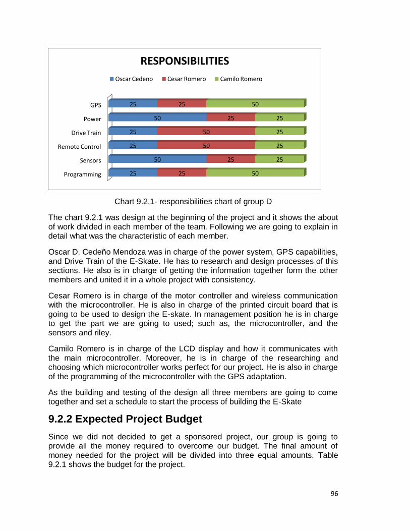
96
Chart 9.2.1- responsibilities chart of group D
The chart 9.2.1 was design at the beginning of the project and it shows the about of work divided in each member of the team. Following we are going to explain in detail what was the characteristic of each member.
Oscar D. Cedeño Mendoza was in charge of the power system, GPS capabilities, and Drive Train of the E-Skate. He has to research and design processes of this sections. He also is in charge of getting the information together form the other members and united it in a whole project with consistency.
Cesar Romero is in charge of the motor controller and wireless communication with the microcontroller. He is also in charge of the printed circuit board that is going to be used to design the E-skate. In management position he is in charge to get the part we are going to used; such as, the microcontroller, and the sensors and riley.
Camilo Romero is in charge of the LCD display and how it communicates with the main microcontroller. Moreover, he is in charge of the researching and choosing which microcontroller works perfect for our project. He is also in charge of the programming of the microcontroller with the GPS adaptation.
As the building and testing of the design all three members are going to come together and set a schedule to start the process of building the E-Skate
9.2.2 Expected Project Budget
Since we did not decided to get a sponsored project, our group is going to provide all the money required to overcome our budget. The final amount of money needed for the project will be divided into three equal amounts. Table 9.2.1 shows the budget for the project.
Programming
Sensors
Remote Control
Drive Train
Power
GPS
25
50
25
25
50
25
25
25
50
50
25
25
50
25
25
25
25
50
RESPONSIBILITIES
Oscar Cedeno Cesar Romero Camilo Romero
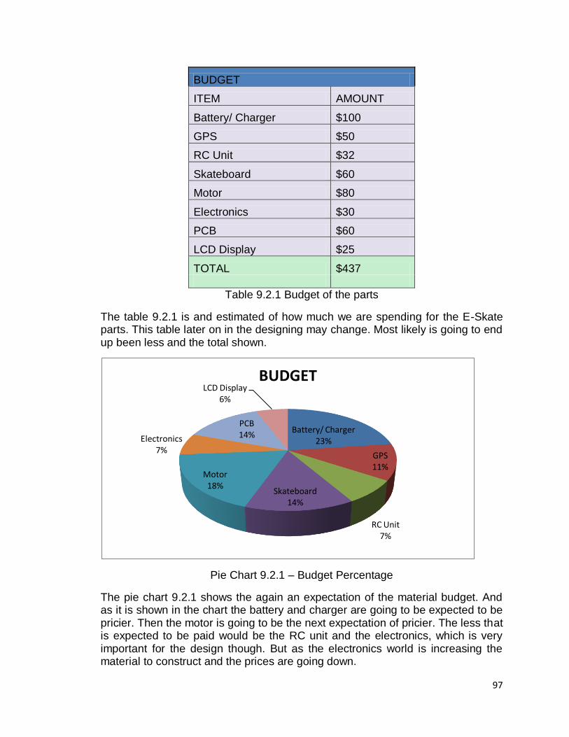
97
BUDGET
ITEM AMOUNT
Battery/ Charger $100
GPS $50
RC Unit $32
Skateboard $60
Motor $80
Electronics $30
PCB $60
LCD Display $25
TOTAL $437
Table 9.2.1 Budget of the parts
The table 9.2.1 is and estimated of how much we are spending for the E-Skate parts. This table later on in the designing may change. Most likely is going to end up been less and the total shown.
Pie Chart 9.2.1 – Budget Percentage
The pie chart 9.2.1 shows the again an expectation of the material budget. And as it is shown in the chart the battery and charger are going to be expected to be pricier. Then the motor is going to be the next expectation of pricier. The less that is expected to be paid would be the RC unit and the electronics, which is very important for the design though. But as the electronics world is increasing the material to construct and the prices are going down.
Battery/ Charger 23%
GPS 11%
RC Unit 7%
Skateboard 14%
Motor 18%
Electronics 7%
PCB 14%
LCD Display 6%
BUDGET
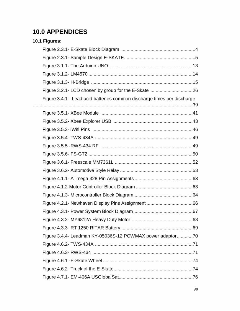
98
10.0 APPENDICES
10.1 Figures:
Figure 2.3.1- E-Skate Block Diagram ........................................................4
Figure 2.3.1- Sample Design E-SKATE ......................................................5
Figure 3.1.1- The Arduino UNO ................................................................13
Figure 3.1.2- LM4570 ...............................................................................14
Figure 3.1.3- H-Bridge .............................................................................15
Figure 3.2.1- LCD chosen by group for the E-Skate ................................26
Figure 3.4.1 - Lead acid batteries common discharge times per discharge
.........................................................................................................................39
Figure 3.5.1- XBee Module ......................................................................41
Figure 3.5.2- Xbee Explorer USB ............................................................43
Figure 3.5.3- iWifi Pins ............................................................................46
Figure 3.5.4- TWS-434A ..........................................................................49
Figure 3.5.5 -RWS-434 RF ......................................................................49
Figure 3.5.6- FS-GT2 ...............................................................................50
Figure 3.6.1- Freescale MM7361L ...........................................................52
Figure 3.6.2- Automotive Style Relay .......................................................53
Figure 4.1.1- ATmega 328 Pin Assignments ............................................63
Figure 4.1.2-Motor Controller Block Diagram ...........................................63
Figure 4.1.3- Microcontroller Block Diagram.............................................64
Figure 4.2.1- Newhaven Display Pins Assignment ...................................66
Figure 4.3.1- Power System Block Diagram .............................................67
Figure 4.3.2- MY6812A Heavy Duty Motor ..............................................68
Figure 4.3.3- RT 1250 RITAR Battery ......................................................69
Figure 3.4.4- Leadman KY-05036S-12 POWMAX power adaptor ............70
Figure 4.6.2- TWS-434A ..........................................................................71
Figure 4.6.3- RWS-434 ............................................................................71
Figure 4.6.1 -E-Skate Wheel ....................................................................74
Figure 4.6.2- Truck of the E-Skate ............................................................74
Figure 4.7.1- EM-406A USGlobalSat ........................................................76
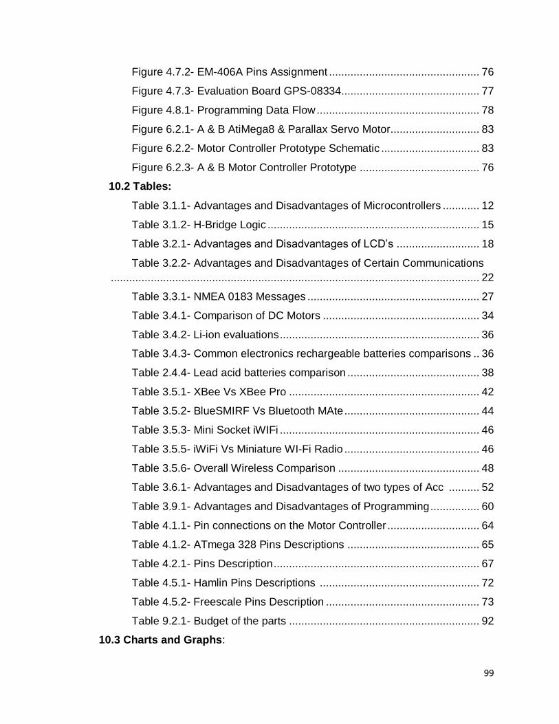
99
Figure 4.7.2- EM-406A Pins Assignment ................................................. 76
Figure 4.7.3- Evaluation Board GPS-08334 ............................................. 77
Figure 4.8.1- Programming Data Flow ..................................................... 78
Figure 6.2.1- A & B AtiMega8 & Parallax Servo Motor............................. 83
Figure 6.2.2- Motor Controller Prototype Schematic ................................ 83
Figure 6.2.3- A & B Motor Controller Prototype ....................................... 76
10.2 Tables:
Table 3.1.1- Advantages and Disadvantages of Microcontrollers ............ 12
Table 3.1.2- H-Bridge Logic ..................................................................... 15
Table 3.2.1- Advantages and Disadvantages of LCD‘s ........................... 18
Table 3.2.2- Advantages and Disadvantages of Certain Communications
........................................................................................................................ 22
Table 3.3.1- NMEA 0183 Messages ........................................................ 27
Table 3.4.1- Comparison of DC Motors ................................................... 34
Table 3.4.2- Li-ion evaluations ................................................................. 36
Table 3.4.3- Common electronics rechargeable batteries comparisons .. 36
Table 2.4.4- Lead acid batteries comparison ........................................... 38
Table 3.5.1- XBee Vs XBee Pro .............................................................. 42
Table 3.5.2- BlueSMIRF Vs Bluetooth MAte ............................................ 44
Table 3.5.3- Mini Socket iWIFi ................................................................. 46
Table 3.5.5- iWiFi Vs Miniature WI-Fi Radio ............................................ 46
Table 3.5.6- Overall Wireless Comparison .............................................. 48
Table 3.6.1- Advantages and Disadvantages of two types of Acc .......... 52
Table 3.9.1- Advantages and Disadvantages of Programming ................ 60
Table 4.1.1- Pin connections on the Motor Controller .............................. 64
Table 4.1.2- ATmega 328 Pins Descriptions ........................................... 65
Table 4.2.1- Pins Description ................................................................... 67
Table 4.5.1- Hamlin Pins Descriptions .................................................... 72
Table 4.5.2- Freescale Pins Description .................................................. 73
Table 9.2.1- Budget of the parts .............................................................. 92
10.3 Charts and Graphs:
100
Chart 9.1.1- Milestones ............................................................................90
Chart 9.2.1- responsibilities chart of group D............................................91
Pie Chart 9.2.1 – Budget Percentage .......................................................92
101
11.0 WORK CITED
Atmega328 datasheet: <http://www.atmel.com/dyn/resources/prod_documents/doc8271.pdf> Atmel AVR. Wikipedia. The Wikimedia Foundation. Web, March 31, 2009.
<http://en.wikipedia.org/wiki/Atmel_AVR>
"Battery Tutorial | BatteryStuff.com." Motorcycle Batteries, ATV, Car, Marine, and
Solar BatteryProducts | BatteryStuff.com. Web.
<http://www.batterystuff.com/tutorial_battery.html>.
Brain, Marshall. "HowStuffWorks "How Lithium-ion Batteries Work"" Howstuffworks "Electronics" Web. <http://electronics.howstuffworks.com/lithium-ion-battery.htm>.
―DC Motors‖ Electric Motors
<http://www.electricmotors.machinedesign.com/guiEdits/Content/bdeee3/bdeee3_1.aspx>.
―Electric motor‖ 04/22/2011 – Wikipedia.com
<http://en.wikipedia.org/wiki/Electric_motor>. Feare, Tom. "Wet-cell or maintenance-free battery? - 4/1/2001 – Modern
Materials Handling." Modern Materials Handling - Productivity solutions for
distribution, warehousing, manufacturing. Web.
<http://www.mmh.com/article/CA68733.html>.
"H-bridge." Wikipedia. June 2010. Web. Jun 25, 2010. <http://en.wikipedia.org/wiki/H-bridge>.
"HowStuffWorks "What is the difference between a normal lead-acid car battery
an"" Howstuffworks "Auto" Web.
<http://auto.howstuffworks.com/question219.htm>.
―Ritar RT1250 Sealed Lead Acid Battery‖ Battery Universe
< http://www.batteryuniverse.com/Sealed-Lead-
Acid/Ritar/RT1250/VRLA1250_Ritar_RT1250_Sealed-Lead-Acid-Battery>.
Universal Power Group. Sealed lead-acid Battery: Model #UB12350 (AGM)
UPG#D5722. Universal Power Group. Print.
102
WebbotLib. 06/24/2010. <http://webbot.org.uk/iPoint/ipoint>. Code Composer Studio IDE. Texas Instruments. Web, Jun 24, 2010. <http://focus.ti.com/dsp/docs/dspsupportatn.tsp?familyId=44§ionId=3&tabId=415&toolTypeId=30>. Brain, Marshall. ―How Microcontrollers Work‖. HowStuffWorks.com. Web, April, 01, 2000 <http://www.howstuffworks.com/microcontroller.htm> Aurel Wireless Modules. Aurelwireless.co, Web March 24, 2009 <http://www.aurelwireless.com/rf-wireless-modules/data-transceivers.asp> ―Relay‖, Wikipedia, Web, April, 03, 2009. <http://en.wikipedia.org/wiki/Relay> Rob, Arnold, ―Building an RF control system‖. rentron.co, Web May 12, 2006. <http://www.rentron.com/ruf-bot.htm> Williams, Eric, ―Implementing RF modules‖. narobo, progress in Engineering, Web October, 19, 2004. < http://narobo.com/articles/rfmodules.html> Arduino. Arduino, n.d. Web. 16 Apr 2011. <arduino.cc>.
"Asse mbly Language. " n . pag . W eb. 19 Apr 2011.
<h t tp : / /en . wi k i ped ia .o rg / wi k i /Asse mbly_ language>.
At me l Datasheet fo r AT mega328 . 20 10 . Atmel Corpora t io n . 16
Apr .
2011<ht tp : / / www.a t me l .co m/dyn / resources /p rod_docu ment
s /doc 8271.pd f>
"C (Progra mming Lan guage) . " n . pa g . W eb. 19 Apr 2011.
<h t tp : / /en . wi k i ped ia .o rg / wi k i /C_(progra mming_ language)> .
Cur t i s , Ke i th . No te s f rom the Lab . N .p . , n .d . W eb. 24 Mar 2011.
<h t tp : / /b l og .no tes f ro mthe lab .co m/>.
DE Da tasheet f o r ACCM2G2. 2008 . Dimens ion Eng ineer ing . 11
Apr . 2011 .
<h t tp : / / www.d i mens ioneng ineer i ng .co m/da ta sheets / DE -
ACCM2G2 .pd f>
F reesca le Datasheet fo r MC9S08 QG . Rev 5 . 20 09 . Freesca le
Sem icondu cto rs . 16 Apr . 201 1
103
<h t tp : / / www. f reesca le .co m/ f i l es / mi c rocon t ro l l e rs /doc /da ta
_shee t /MC9S08Q G8.pd f >
F reesca le Datasheet fo r MMA7361L. Rev 0 . 2008 . Freesca le
Sem icondu cto rs . 17 Apr . 2011
<h t tp : / / www.p o lo l u .co m/ f i l e /down loa d /MMA7361L.pd f? f i l e_
i d=0J 378>
Gupta , Av inash . Ext reme E lec t ron ics . N .p . , n .d . W eb. 26 Mar
2011. <h t tp : / / www.e x t re mee lec t ron i cs .co . i n /> .
"Ha l l Ef fec t Sen sor . " n . pag . W eb. 17 Apr 2011.
<h t tp : / /en . wi k i ped ia .o rg / wi k i /Ha l l _e f fec t_sensor >
Ha ml i n Datasheet fo r 55140 -3H-02- A. 2009. Haml in . 17 Apr .
2011
<
h t tp : / / www.ha ml i n .co m/specsheet s / 55140%20IssueAE.pd f >
Ma in , John . Best -M ic rocon t ro l le r -Pr o jec ts . John Ma in , n .d .
W eb. 25
Mar 2011. Microch ip Datasheet fo r 1 6FX5X. 20 07.
Micro ch ip Techn o log ie s Inc . 16 Apr . 2011
<h t tp : / / ww1. mi croch ip .co m/do wn loa ds/en /dev i cedoc/41213
d.pd f>
Mi c roch ip Datasheet fo r 18 F2525. 2 008 . M icroch ip
Techno log ies Inc .
6 Apr . 2011
<h t tp : / / ww1. mi croch ip .co m/do wn loa ds/en /Dev i ceDo c/3962
6e.pd f>
Ne whaven Di sp lay Datasheet fo r NHD ‐0420H1Z ‐FL ‐GBW ‐3V3.
2008 . Newhaven D isp lay In t e rna t iona l . 12 Apr . 2011
<h t tp : / / www.n e whavend i sp lay .co m/specs /NHD -0420H1Z-
FL- GBW -3V3.pd f >
"Reed Swi tch . " n . pag . W eb. 13 Apr 2011.
<h t tp : / /en . wi k i ped ia .o rg / wi k i /Reed_ swi tch>.

104
"Rota ry Encoder . " n . p ag . W eb. 17 Apr 2011.
<h t tp : / /en . wi k i ped ia .o rg / wi k i /Ro ta ry_encoder>.
12.0 PERMISSIONS

105
Good Morning, My name is Cesar Romero and I am an Electrical Engineer student attending the University of Central Florida. I will like to request permission to use pictures, tables, and

106
information from you website. I plan to use this information for my Senior Design class. My group and I know that if you approve our request to use your information, we need to include proper citation of the source. We will include a brief section in our Senior Design document stating that we received your permission to use information from your company. Thank you for your help in advance, CESAR ROMERO
Hello Cesar, I checked with our Marketing and Communications Department, and you may use the images for your project. Here is their response and request for credit: Hello, yes, you can use the images located at www.sparkfun.com Please give credit to Juan Pena who is the SparkFun’s photographer and include SparkFun’s name in the credit too. Thank you for asking and keep up the good work! Best, Lara Wikipedia.com Permissions
Relay
H-Bridge
nitrorcx.com
Hello Cesar,
It would be fine for you to use material from the protocol
specification and implementation guides if you cite the

107
source appropriately. Information that relates to a member
company's products should reference that company and it
would make sense to contact them as well. I can provide
contact information
if you plan to do that.
Would you like to share your paper and project with the
Nitrorcx community when you have completed it?
Regards,
Lenore
Lenore Tracey
Executive Director
Nitrorcx
+1 508-435-7170 ph
+1 508-435-7172 fax
-----Original Message-----
From: [email protected]
[mailto:[email protected]]
Sent: Sunday, April 19, 2009 7:09 PM
Subject: Permission to use your website information and
figures in College Paper]
To whom it may concern,
My name is Cesar Romero and I am an Electrical Engineer
student attending the University of Central Florida. I will
like to request permission to use pictures, tables, and
information from you website. I plan to use this
information for my Senior Design class. My group and I know
that if you approve our request to use your information, we
need to include proper citation of the source. We will
include a brief section in our Senior Design document
stating that we received your permission to use information
from your company.
Thank you for your help in advance,
CESAR ROMERO
National.com Permission
Copyright All articles and website content © 1998 - 2009 Tim Surtell.

108
Article text, figures, circuit schematics and design aids on this website may be printed and copied for individual and educational use. No part of this website may be reproduced in any way commercially without the prior permission of the publisher. If you wish to link to this website, please go to www.national.com
http://www.national.com/analog/site_terms Rentron.com permission Copying and distribution
Permission is granted to distribute, publish or otherwise present verbatim copies of the entire Source Data of the Work, in any medium, provided that full copyright notice and disclaimer of warranty, where applicable, is conspicuously published on all copies, and a copy of this License is distributed along with the Work. Permission is granted to distribute, publish or otherwise present copies of the Object Form of the Work, in any medium, under the terms for distribution of Source Data above and also provided that one of the following additional conditions are met: (a) The Source Data is included in the same distribution, distributed under the terms of this License; or (b) A written offer is included with the distribution, valid for at least three years or for as long as the distribution is in print (whichever is longer), with a publicly-accessible address (such as a URL on the Internet) where, for a charge not greater than transportation and media costs, anyone may receive a copy of the Source Data of the Work distributed according to the section above; or (c) A third party's written offer for obtaining the Source Data at no cost, as described in paragraph (b) above, is included with the distribution. This option is valid only if you are a non-commercial party, and only if you received the Object Form of the Work along with such an offer. You may copy and distribute the Work either gratis or for a fee, and if desired, you may offer warranty protection for the Work. The aggregation of the Work with other works which are not based on the Work -- such as but not limited to inclusion in a publication, broadcast, compilation, or other media -- does not bring the other works in the scope of the License; nor does such aggregation void the terms of the License for the Work.
automation.com Waiting for Permission


