Embed Size (px)
Citation preview

Electrical Engineering Department California Polytechnic State University
Senior Project Electrical Engineering
Contactless Charging Adapter
05/15/2017
Written by: Kevin Nguyen Joseph Pacheco Emmett Stetz
Advised by:
Professor Richard Murray

TABLE OF CONTENTS
Section Page
I. List of Tables and Figures……………………………………………………………..2
II. Abstract.........................................................................................................................3
III. Introduction.................................................................................................................4
IV. Requirements and Specifications.................................................................................6
V. Research and Design.....................................................................................................7
VI. Construction..............................................................................................................15
VII. Testing......................................................................................................................17
VIII. Conclusions and Recommendations.......................................................................20
IX. Bibliography..............................................................................................................20
Appendices
A. Senior Project Analysis...............................................................................................21
B. Parts List, and Cost…………………………………………………………………..24
C. Time Schedule Allocation............................................................................................25
D. Hardware Layout/Configuration…………………………………………………......26
E. Senior Project Expo Poster…………………………………………………………...27
1
LIST OF TABLES AND FIGURES
Table Page 1. Main Chips on Market Wireless Power Transmitter.................................................................7 2. Main Chips on Market Wireless Power Receiver…………………………………….............8 3. Results of Horizontal Positioning Test with Receiver Coil 1.1..............................................17 4. Results of Horizontal Positioning Test with Receiver Coil 1.2……………………………..18 5. Bill of Materials……………………………………………………………………………..23 6. Coil Dimensions…………………………………………………………………………….25 7. Capacitors…………………………………………………………………………………...25 Figures 1: Image of Inductive Power Transfer………………………………………………....…..……4 2: Wireless Power Receivers Market Trend……………………………………..……………...5 3: Coil and Circuitry of Market Wireless Charger - Transmitter……………………………….7 4: Coil and Circuitry of Market Wireless Charger - Receiver………...……….....…...……......8 5: Voltage Measured Across Primary Coil When Powered With No Secondary…….....……..9 6: Voltage Across Primary Coil When Powered With Secondary and No Smartphone…...…...9 7: Voltage Across Primary Coil When Powered With Secondary and Smartphone………….10 8: Voltage Measured Across Secondary Coil When Powered Without Smartphone…….……11 9: Voltage Measured Across Secondary Coil When Powered With Smartphone……...……...11 10: Initial Transmitter Design………………………...……………………………………….12 11: P9038-R Evaluation Board………………………………………………………………..13 12: Initial Wiring System………………………...…………………………………………....15 13: Improved Wiring System…………………...……………………………………………..16 14: Relay Coil Testing Setup…………………………………………………………………..16 15: Model for Horizontal Alignment Test…………………………………………………….17 16: Relay Coil and Transmitter Coil Voltages out-of-phase…………………………………...19 17: Relay Coil and Transmitter Coil Voltages in-phase………………………………………..19 18: Gantt Chart for Winter Quarter…………………………………………………………….24 19: Gantt Chart for Spring Quarter…………………………………………………………….24
2
Abstract: Currently, most cell phones utilize wired adapters to charge, which cause a minor hassle when
one frequently needs to unplug and replug their device whenever they pick it up to use while it is
charging. The charging adapter is a pad that phones can be placed on to wirelessly charge the
device. The charging adapter consists of two components: the wireless charging platform to
supply and transmit the power, and the wireless charging receiver for phones that do not already
have an internal receiver included, specifically targeting newer generation iPhones that utilize a
lightning port (i.e. iPhone 5, 6, 6s, 7, 7s). The wireless charging receiver connects to the
smartphone through the charging port and rests between the back of the phone and its casing.
The entire system fully charges the device to 100% battery capacity within three hours and
automatically shuts off upon completion. A unique feature of the charger is that it operates
regardless of the orientation of the phone on the pad (an LED indicator notifies the user that the
device is charging). The size of the entire charging assembly does not exceed that of a small
textbook, allowing ease of transportation and use on a table or surface with limited space.
Additionally, the incorporation of an ellipsed surface at the top of the 3D-printed base centers the
phone while charging and biases it towards the middle where optimum power transfer is
achieved.
Reverse engineering was done on market examples and designs were made to create a charging
platform to supply power. Then a development kit was used to test methods of improving the
performance
3

Introduction: The modern age is one of technological advancements and electronic dependency, particularly as
it pertains to personal communication. From 2011 to 2015, the percent of adult Americans that
possess smartphones has risen from 35% to 64% and that number is increasing [1]. These
devices serve as one of the main sources of connection to the world of online information and
various forms of interpersonal communication. People use their phones to text friends and
colleagues, view business and personal emails, check social media posts and updates, and
participate in many other forms of digital communication that helps them better connect to the
world. Generation of electricity is an important factor in keeping these everyday habits running
like clockwork. Smartphones have various charging methods such as wired wall outlet adapters,
wired solar powered charging adapters, and very few with wireless charging stations. One
technology that has become more popular in recent years, utilizes the principle of inductive
power transfer using inductive coupling shown in Figure 1 below. As electrical power is
converted from AC to DC and is applied to the primary coil, the transceiver, the coil inductively
and wirelessly transfers that power to a secondary coil, the receiver. The induced voltage across
the coil is then adjusted to the voltage range that a smartphone charges at to power the device.
Figure 1: Image of Inductive Power Transfer
Figure 2 below shows the expected trend for consumer purchases of wireless charging adapters
up to 2020 according to IHS technology. By the end of 2016, the number of devices with
wireless charging capabilities will exceed 200 million units a year and is expected to keep
4

increasing [2]. This also represents a 40% increase in wireless power receivers purchased
between 2015 and 2016.
Figure 2: Wireless Power Receivers Market Trend
The interest in this technology has only increased as a means of eliminating the need for wires in
places like your home or in the office. With a charging pad to power your smartphone you can
simply place it down on your desk, not having to worry about it running out of power when your
boss sends you that important text that needs to be handled immediately. After a hard day’s
work, you can also place it down on your nightstand and wake up the next morning to a fully
charged phone without the hassle of looking for that phone charging cable or finding an outlet in
the dark the night before. It also allows you to check for notifications on your phone quickly
without unplugging it from the charger; you can pick your phone up off the charger, check
something, and then drop it back down without having to unplug it or re-plug it. The design of
this wireless charging adapter utilizes an innovative and user friendly way to power a
smartphone through inductive power transfer via inductive coupling.
5

Requirements and Specifications: Examples of available wireless chargers on the market were purchased and both examined and
experimented with to better understand how wireless power transfer is done. Additionally,
specifications from the transmitting unit and receiving unit were needed, so analysis of both
components were necessary. A full analysis of this research and specification recording can be
found in the EE 461 Development Update Report. This led to the goal of designing a system to
take a 5.0VDC , 1.0A input from a USB and convert it into a 12.0Vpp, AC 190 kHz signal to run
through the primary coil to transfer the power wirelessly.
While looking into designs using amplifiers and oscillators, Professor Taufik was sought for
advice. He suggested using a rectifier and an isolated DC-DC converter to drop the wall outlet
as the input instead of using an amplifier with the USB as the input. Heeding his advice, a three
step design using a rectifier, a flyback converter, and either a colpitts or pierce oscillator was
decided upon. However, during the design review meeting, other professors expressed concerns
with the safety of the design and the focus of the project.
Afterwards, Professor Murray suggested using a development kit, and focusing on improvement
and optimization. The future goal then became to use the development kit as the transmitter and
improve the performance by replacing the secondary coil with our own and introducing relay
coils.
6

Research and Design: As a starting point, two examples of contactless charging adapters that were currently out on the market were purchased, specifically for the purpose of reverse-engineering. For that reason, one “Danforce Qi Wireless Charger” and one “Fantasy Wireless Charger: The Enterprise” were ordered, but when both items arrived, it was discovered that they used identical designs, so one was used for reverse-engineering and testing, and the other was kept as a back-up.
The transmitter component of the “Danforce Qi Wireless Charger” consists of one board approximately 3 inches by 2 inches, with the primary coil on one side and the remaining electronics and control circuitry on the other side. Inspecting the chips on the board revealed the following:
Table 1: Main Chips on Market Wireless Power Transmitter
Quantity Part Number Part Type
1 LM324 Low Power Quad Op-Amp
1 WSP4953A P-Ch Mosfet
1 WSP9925A N-Ch Mosfet
1 STM8003F3 Micro-Controller
Figure 3: Coil and Circuitry of Market Wireless Charger - Transmitter
The receiving unit/component of the wireless charger consisted of the secondary coil and some circuitry for controls and conversion. The wire gauge used for the secondary coil was clearly of
7

a higher value than that used for the primary coil, likely to make the device thinner so it would better fit within a smartphone case. Upon inspection, the following chips were identified:
Table 2: Main Chips on Market Wireless Power Receiver
Quantity Part Number Part Type
1 A19T P-Channel Mosfet
1 BQ51013B Wireless Receiver Compliant Power Supply
Figure 4: Coil and Circuitry of Market Wireless Charger - Receiver
Figure 4 shows the electronics of the receiver unit and the coil that power is transferred through. Experiments were then done to measure the voltage, current, and frequency through both the transmitter and the receiver. First voltage measurements were taken by connecting the probes of an oscilloscope to both sides of the primary coil while the transmitter was receiving power from the USB input but the secondary was not held in position to receive the transmitted power.
8
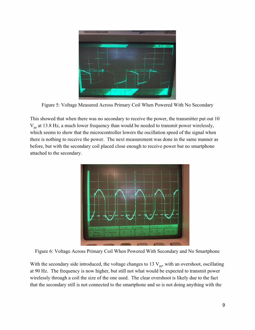
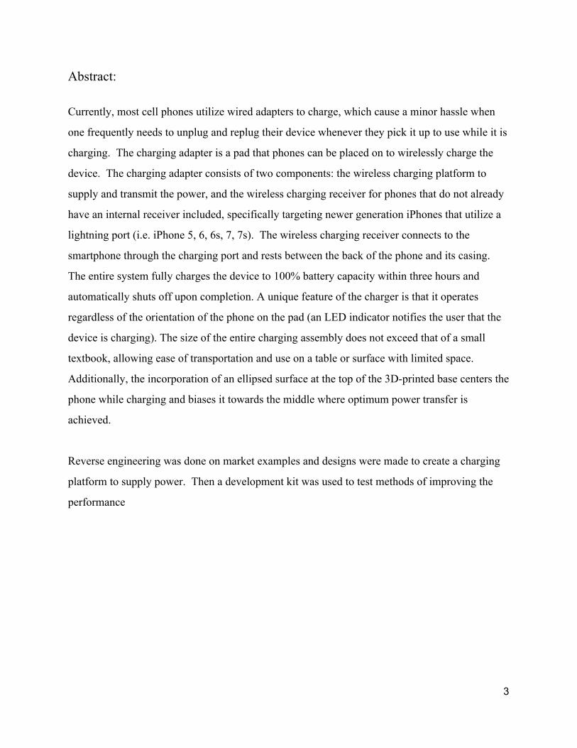
Figure 5: Voltage Measured Across Primary Coil When Powered With No Secondary
This showed that when there was no secondary to receive the power, the transmitter put out 10 Vpp at 13.8 Hz, a much lower frequency than would be needed to transmit power wirelessly, which seems to show that the microcontroller lowers the oscillation speed of the signal when there is nothing to receive the power. The next measurement was done in the same manner as before, but with the secondary coil placed close enough to receive power but no smartphone attached to the secondary.
Figure 6: Voltage Across Primary Coil When Powered With Secondary and No Smartphone
With the secondary side introduced, the voltage changes to 13 Vpp, with an overshoot, oscillating at 90 Hz. The frequency is now higher, but still not what would be expected to transmit power wirelessly through a coil the size of the one used. The clear overshoot is likely due to the fact that the secondary still is not connected to the smartphone and so is not doing anything with the
9

received power. The next measurement was done in the same manner as before, but the smartphone is now connected to the secondary and charging.
Figure 7: Voltage Across Primary Coil When Powered With Secondary and Smartphone
Now, with the secondary connected and charging the smartphone, the voltage was 12.8 Vpp at 190.8 kHz. So now both the frequency and the voltage are corrected, with the frequency at a high enough speed to properly transmit through the coil, and the voltage waveform appearing as a cleaner square wave.
With three voltage measurements for the primary coil in different situations, measurements for the secondary coil were done. This was accomplished by opening the foil pouch containing the circuitry and attaching the oscilloscope to both sides of the primary coil. The first measurement was for the secondary receiving power from the primary but without the smartphone attached.
10
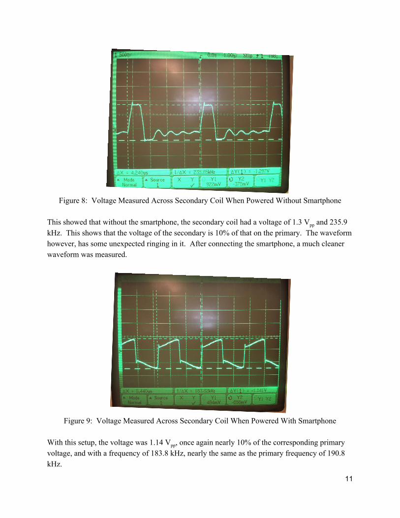
Figure 8: Voltage Measured Across Secondary Coil When Powered Without Smartphone
This showed that without the smartphone, the secondary coil had a voltage of 1.3 Vpp and 235.9 kHz. This shows that the voltage of the secondary is 10% of that on the primary. The waveform however, has some unexpected ringing in it. After connecting the smartphone, a much cleaner waveform was measured.
Figure 9: Voltage Measured Across Secondary Coil When Powered With Smartphone
With this setup, the voltage was 1.14 Vpp, once again nearly 10% of the corresponding primary voltage, and with a frequency of 183.8 kHz, nearly the same as the primary frequency of 190.8 kHz.
11

Next, current measurements were taken by unsoldering one side of each coil on the primary and secondary, and using an ammeter in series to complete each side of the circuit. With this setup, an AC current of 0.30 A was measured in the primary coil, and an AC current of 0.337 A on the secondary side. This was done when the secondary was receiving power from the primary and also connected to a smartphone. Since the currents are nearly the same on both coils, and the voltage on the secondary coil is only 10% of that on the primary, it seems that the wireless power transfer has an efficiency of only 10%. Regardless, the tradeoff for ease-of-use versus efficiency is something we have considered since the beginning of our project, and we believe having the ability to wirelessly transfer power to charge the smartphone is our primary objective.
These preliminary experiments were used to get a deeper understanding of how wireless power transfer worked. Detailed system specifications from both the transmitter unit and receiver unit that allow for wireless power transfer to the smartphone (iPhone 6s) were now known. With these specifications, designs for a transmitting unit were made with the advice of Professor Murray and Professor Taufik. The initial plan was to create a rectifier that would convert the 120VAC to 170VDC which would then go through a DC-to-DC converter with an isolated topology, specifically a flyback converter, to convert the 170VDC to approximately 6.5VDC. The last component needed in order to achieve the 190 kHz frequency was an oscillator that would create a 12.5VAC signal @ 190 kHz across our primary coils. A Pierce oscillator was decided on due to the fact that stray capacitance had less of an affect on the Pierce oscillator than the Colpitts oscillator.
Figure 10: Initial Transmitter Design
Another approach considered was to simply use a single converter that would directly take 120VAC from the wall outlet and convert it to 4.42VrmsAC @ 190 kHz at 0.5 amps. Professor Taufik recommended against this approach because creating a Cyclo-converter is too challenging given the amount of time available to complete the senior project. After coming up with these designs, Professor Murray advised the use of a development kit to serve as the primary, so the team would not spend too much time assembling and testing the primary-side electronics, and not have enough time for the coils and power transmission
12

Figure 11: P9038-R Evaluation Board
The P9038-R evaluation kit made by Integrated Device Technology includes a 5.0 Watt, Qi-certified wireless power transmitter and receiver . This allows for fast prototyping and design 1
integration, which would serve well for testing and optimizing other parts of the system, such as the receiver unit. The kit consists of a reference board and an associated layout module that enables direct instantiation on to a system board. Also, an advantage of using this evaluation kit is the the fully tested bill of materials that takes the guesswork out of component selection as well as safety. The kit only requires a 4.5V - 6.9VDC input which is much safer than our initial 120VAC plan.
The kit introduces some features not thought about when designing the early system. For example, the Q6 mosfet in series with the micro-USB connector limits inrush current and provides over-voltage protection over 12V. Additionally, the coil has a non-conductive encapsulation which is beneficial to the design. The kit can utilize a 1.0 amp input, but for maximum power transfer, a 2.0 amp input is recommended and will be used in the design specifications. By using the 9038 evaluation kit, the group could then focus on ways to improve the performance of the wireless power transmission, such as increasing the transmission distance or allowing for greater offset from the center of the charging platform. The simplest way to improve the performance of the system’s wireless power transfer is by increasing the size of the secondary coil, since the max distance for power transfer is proportional to the diameter of the coil. Multiple coils were made using a range of wire gauges 16, 22, 26, and 30 AWG for the receiver unit, with maximizing the diameter of the coil the priority, at least as much as could be achieved while still being small enough to fit inside the phone case. The number of turns for the secondary coils ranged from 10 to 20 turns, with later testing used to find the best coil.
1IDT P9038 Datasheet. San Jose: Integrated Device Technology, 22 Sept. 2015. PDF. 13

Another method of improving the kit’s wireless power transfer is the introduction of relay coils. 2
By placing a third or fourth magnetic coil between the primary and secondary coils, the strength of the magnetic field can be increased and wireless power transfer can be done at longer ranges. A few relays were created by physically winding magnetic wire into flat spiral coils with varying diameters and gauges. These relays will be coupled with a series capacitance to achieve resonance at the frequency the primary and secondary coils from the kit are transferring power, 200 kHz. 3
The following equations were used to find the necessary capacitance to achieve resonance at 200 kHz:
(H) L = 16D +28N (w+p)o
N (D −N (w+p))2o
2
×106
39.37 N (w )Di = Do − 2 + p Nπ(D )l = 2
1o + Di
)C = ( 12πf√L
2 Chabalko, Matthew J., Jordan Besnoff, and David S. Ricketts. "Magnetic Field Enhancement in Wireless Power With Metamaterials and Magnetic Resonant Couplers." IEEE ANTENNAS AND WIRELESS PROPAGATION LETTERS 15 (2016): 452-55. IEEE. Web. 25 Feb. 2017. 3 Waters, Benjamin H., Brody J. Mahoney, Gunbok Lee, and Joshua R. Smith. "Optimal Coil Size Ratios for Wireless Power Transfer Applications." Circuits and System, 2014 IEEE International Symposium on (2014): 2045-048. IEEE. Web. 25 Feb. 2017.
14

Construction and Assembly: An outwardly spiraling design for the coils was used rather than a vertical spiral, since it was decided it was better to save vertical space rather than horizontal space. Additionally, the 16 and 30 AWG wire gauges were quickly eliminated as possible sizes to use to make the coils, with the 16 AWG wire being too rigid to spiral and the 30 AWG being too delicate. Initial coils were made by using two pieces of cardboard cut to form a cross shape, with a cutout section to wind the wire in, while gluing the wire together after every turn. This method was inaccurate though, as it was difficult to get the diameter and circular shape right.
Figure 12: Initial Wiring System
A better system was developed where a circular object of the desired diameter was placed on a flat surface, such as a piece of paper or cardboard, and the wire was slowly wrapped around the object, with the wire being glued to the surface and itself. This system led to coils that were rounder, more tightly wound, and of more accurate diameters.
15

Figure 13: Improved Wiring System
As some of the coils were to be used in a relay, the coils had to be matched with capacitors of the correct value to achieve resonance at 200 kHz. The setup shown in figure 14 was used when testing relay coils.
Figure 14: Relay Coil Testing Setup
16

Testing: Experiment 1: Horizontal Alignment of Smartphone on the Charging Platform
Figure 15: Model for Horizontal Alignment Test
Figure 15 above shows a basic model for the horizontal positioning experiment. The rectangular phone is positioned in the center of the charging base and moved a certain distance to a point shown. The phone is then placed back in the center of the base and moved again to the other three points for four directional measurement distances. The results of these measurements give an outline for how much of the charging pads surface area can be used to successfully transfer power to the receiver unit, which can be found in Table 3 below.
Table 3: Results of Horizontal Positioning Test with Receiver Coil 1.1
Letter Description Distance [mm]
A Distance from the left side of the charging pad to the center 23
B Distance from the top of the charging pad to the center 9
C Distance from the right side of the charging pad to the center 23
D Distance from the bottom of the charging pad to the center 38
Table 3 shows the results from the horizontal positioning test conducted without a relay coil, between the transmitter chassis and receiver coil 1.1. This receiver coil is made from a 22 gauge wire wound with 16 turns in a rounded rectangular shape. The values are measured from the end of the phone case to the edge of the transmitter platform. The distances recorded shows how far the receiver coil could move horizontally across the platform before signal loss occurred and the phone stopped charging
17

Table 4: Results of Horizontal Positioning Test with Receiver Coil 1.2
Letter Description Distance [mm]
A Distance from the left side of the charging pad to the center 19
B Distance from the top of the charging pad to the center 15
C Distance from the right side of the charging pad to the center 19
D Distance from the bottom of the charging pad to the center 38
Table 4 shows the measurement results of the horizontal positioning experiment with coil 1.2 connected to the receiver circuitry. This coil uses the same number of turns and wire gauge as coil 1.1. Coil 1.2 is more circular than the rectangular coil 1.1 allowing for greater charging distance when moving the phone left to right on the charging pad. The new receiver coil is improved by having less coil separation, which allows for better power transfer, and a rounder shape, which allows more surface area to be utilized in charging the phone on the platform. Experiment 2: Vertical Distance of the SmartPhone Relative to Charging Platform In this experiment, we measured the maximum vertical distance that the smartphone could be lifted off of the transmitter platform before the signal was lost and the receiver stopped charging the phone. When coil 1.1 was attached to the receiving unit that is connected to the smartphone, we found that the distance from the top of the charging pad to the bottom of the phone case was 9mm. Coil 1.2 then replaced the coil on the receiver unit and the distance measured from the phone case to the charging platform increased to 15 mm. The new coil’s tighter winding turns allows for a better voltage induced on the coil so the receiver circuitry can receive the signal at a distance further away. The difference between the two receiver coils resulted in a gain of 6mm from the platform to the phone. Experiment 3: Vertical Distance Improvements Through Utilization of Relay Coil Relay coil tests faced some difficulties initially, as the first relay coil was made using the initial wiring system, using a 16 AWG wire with 10 turns. Because of the poor choice in wire and the inefficient method used, the inductance of the wire was dramatically different from the predicted value from the previous calculations, and did not achieve resonance at 200 kHz with the available capacitors.
18

Later improvements in the wiring technique allowed for the creation of a better relay coil, and a single capacitor of the correct value was placed in series with it to create resonance. When the relay unit was tested alongside the primary and secondary coils however, no improvement was noticed and the capacitor in the relay unit quickly heated up and the system had to be shut off. The voltage the relay unit was receiving was too high for the capacitor, and so three larger capacitors were placed in series to form an equivalent capacitance, but with the voltage shared between them to reduce the power dissipated in each capacitor. This fixed the overheating issue, but the relay unit still had no effect on the power transfer. After assembling the relay unit, with the polarized capacitors in a different orientation, the system began to work. To confirm this, we probed the voltage across the relay coil and the transmitter coil which can be shown in Figure 16 and Figure 17 below.
Figure 16: Relay Coil and Transmitter coil Voltages out-of-phase
Figure 17: Relay Coil and Transmitter Coil Voltages in-phase
Figure 16 shows the initial test using the relay coil in an orientation that didn’t allow power transfer to the receiving unit. When the coil was turned over, the voltage of the relay coil was in phase with that of the transmission side, and as a result, the receiving unit was able to receive the signal from the relay coil and begin charging the smartphone, as shown in Figure 17. With the
19

improved relay coil properly working, the maximum distance between the primary and secondary coils was now 20mm, a 5mm improvement from just using Coil 1.2 as the secondary receiving coil. Using a third coil between the primary and secondary coils of our system, extended the vertical range of power transfer from the charging platform to the smartphone receiver. However, there was no measurable change to the possible horizontal alignment of the receiver unit as the relay coil was positioned directly over the primary coil and below the secondary coil.
Conclusions and Recommendations Improvements were made upon the vertical distance and horizontal alignment for the wireless power transfer, through the use of improved secondary coils and the addition of a relay coil there are still further improvements that could be made by future student projects. While designs were made for the primary-side electronics, due to time constraints none of the designs could be implemented and the development kit had to be used instead. A future team could focus more exclusively on the primary-side electronics, and go about testing ways to improve power transfer by changing the frequency created by the oscillator. Additional Relays could also possibly be implemented to test how far the magnetic field could be extended. Future teams could also figure out how to use relays in a desktop wireless charging platform so that consumers could benefit from the improvements those create. A commercially focused team could attempt to improve the distance enough that the primary side could be mounted to the underside of a desk and the phone placed above the desk within an area of about 0.5 ft2 and charge, as consumers might appreciate the cleaner appearance that would create on their desks. Bibliography Smith, Aaron. “U.S. Smartphone Use in 2015.” Pew Research Center, 1 April 2015, http://www.pewinternet.org/2015/04/01/us-smartphone-use-in-2015/ Green, David. “Wireless Power Up 40 Percent in 2016, But Could it have been more?” IHS Inc, 11 October 2016, https://technology.ihs.com/584460/wireless-power-up-40-percent-in-2016 IDT P9038 Datasheet. San Jose: Integrated Device Technology, 22 Sept. 2015. PDF. Chabalko, Matthew J., Jordan Besnoff, and David S. Ricketts. "Magnetic Field Enhancement in Wireless Power With Metamaterials and Magnetic Resonant Couplers." IEEE ANTENNAS AND WIRELESS PROPAGATION LETTERS 15 (2016): 452-55. IEEE. Web. 25 Feb. 2017. Waters, Benjamin H., Brody J. Mahoney, Gunbok Lee, and Joshua R. Smith. "Optimal Coil Size Ratios for Wireless Power Transfer Applications." Circuits and System, 2014 IEEE International Symposium on (2014): 2045-048. IEEE. Web. 25 Feb. 2017.
20

Appendices A. Senior Project Analysis
Project Title: Contactless Charging Adapter Student Names: Kevin Nguyen, Joseph Pacheco, Emmett Stetz Advisor’s Name: Richard Murray
1. Summary of Functional Requirements The contactless charging adapter for smartphones is a device that allows the user to charge their smartphone’s battery without using a wire connecting the smartphone to the charger.
2. Primary Constraints The significant challenge associated with this project is to find a way to balance development and testing of the primary side electronics and the coil system itself. As the coils used need to be tested and modified to improve power, too much time cannot be spent on the electronics that lead to the primary side coil. For this reason, working examples may be needed for the purposes of testing the power transfer.
3. Economic
The development of this device would create jobs in design engineering, manufacturing, sales, and distribution. Since this device is made from electrical components it would impact the sales of the distributors of those products as well as companies harvesting the raw materials that go into making those products. The costs of this project occurred after design of the primary side electronics, when the group moved to studying the power transfer system, as magnetic wire and capacitors of different sizes had to be purchased as well as a development kit to use as the primary side electronics for testing purposes.
4. If Manufactured on a Commercial Basis Estimated number of devices sold per year: Approximately 1000 Estimated manufacturing cost for each device: Approximately $25
Estimated purchase price for each device: $45
Estimated profit per year: 1000*(45-25)=$20,000
Estimated cost for user to operate device: $0.01/hour
21

5. Environmental This project’s environmental impact is due to its reliance on electrical equipment that must be manufactured and the damage done to the environment in the process of harvesting the raw materials to make the components.
6. Manufacturability
There are no major challenges associated with manufacturing this device.
7. Sustainability The first point of failure for this device will likely be the receiving unit that is hidden inside the smartphone’s case, as it must be small and thin in order to fit and so will be less protected. A possible upgrade to improve the lifespan of this component would be a sturdier pouch for the receiving unit.
8. Ethical
There are some ethical implications in the development of this project, namely ensuring that the device with not harm its users nor damage the smartphones they charge with this device. Tests should be done to see if the device causes damage to the smartphone’s battery storage and operation as well as any data corruption resulting from magnetic interference.
9. Health and Safety A health and safety concern associated with this project is ensuring that the device is safe for humans to be around, without risking the device exploding or damaging them through the magnetic field used to wirelessly transmit power. Since voltage is induced in a third relay coil between the transmitter and receiver coils, the copper that makes up the coils generates heat.
10.Social and Political
The most social impact of this device would be on office workers and college students, as both groups would appreciate a reduction in the amount of wires they use at their desks. Bars and coffee shops could also install them in tables to allow customers to easily charge their devices while drinking. In order for these to be feasible, improvements must be made to wireless power transfer technology, like those studied in this project.
22

11.Development During the lifecycle of this project, in order to properly design the systems used in the wireless charging adapter, the group members had to independently study DC-to-DC converters, oscillators, and resonant inductive coupling. The members also had to learn methods to wire magnetic coils of proper shape and size efficiently.
12.Next Steps
While improvements were made upon the vertical distance and horizontal alignment for the wireless power transfer, there are still further improvements that can be made by future senior project teams. Future teams can improve upon our use of relays by implementing more of them to extend the range even further, or find a method of using relays in a consumer model. A commercially focused team could attempt to improve the distance enough that the primary side could be mounted to the underside of a desk and the phone place above the desk within an area of about 0.5 ft2 and charge, as consumers would likely appreciate the cleaner appearance that would create on their desks. That would require that the team build a much wider coil than the one used by this group, as the distance of the power transfer is related to the diameter of the coil. A future team could also focus more exclusively on the primary-side electronics, they could design it to include an oscillator that they could easily adjust to alter the frequency to see what frequency works best. They would also need to create different sized relays to pair with the tested frequencies. If future groups instead want to improve the speed that devices charge at instead of the horizontal or vertical distance available, they could instead modify the primary-side electronics to increase the amperage of the the AC signal sent through the coil. Future teams could also integrate our wireless charger into a device besides a phone, if they wished their senior project to be a wireless device.
23

B. Parts List and Costs Table 5: Bill of Materials
Name Cost Per Unit Quantity Total Cost
Danforce Qi Wireless Charger 24.99 1 24.99
Fantasy Wireless Charger: The Enterprise 11.88 1 11.88
0.10 μF Capacitors 0.10 10 1.00
1 μF Capacitors 0.26 5 1.30
0.15 μF Capacitors 0.31 5 1.55
Magnet Wire Set (22, 26, 30 Gauge) 6.29 2 12.58
Eval Kit For P9038 40.00 2 80.00
133.30
24

C. Schedule - Time Estimates
25

D. Hardware Configuration
Table 6: Coil Dimensions
Name Inner Diameter (mm) Outer Diameter (mm) Wire Gauge Turns
Primary Coil 20 40 18 20
Relay Coil 1.1 34 70 16 10
Relay Coil 1.2 25 57 22 23
Secondary Coil 1.1 25 55 22 16
Secondary Coil 1.2 25 55 22 16
Table 7: Capacitors
Quantity Description Capacitance Percentage Voltage
3 Aluminium Capacitors Radial 0.1 μF 20% 50 V
26

E. Senior Project Expo Poster
27


