Embed Size (px)
Citation preview
SERCOSI/O Unit
RECO02.2Configuration
DOK-CONTRL-RECO02.2***-PR01-EN-P
mannesmannRexroth
engineering
IndramatRexroth
7=78)1
About this Document RECO02.2 Input/Output Unit
DOK-CONTRL-RECO02.2***-PR01-EN-P
SERCOS I/O Unit RECO02.2
Configuration
DOK-CONTRL-RECO02.2***-PR01-EN-P
• DOK-MTC200-TECHN*UNTERL-04M1-EN-P
• DOK-MTC200-TEC*DOC*4V3-04M1-EN-P
• Drawing number: 120-0400-B311-01
This document is used
• for describing the hardware functions at the RECO02.2 unit
• connecting and installing the RECO02.2 unit
• providing the Specifications of the RECO02.2 unit
Documentation identification ofprevious releases
Releasedate
Comment
DOK-CONTRL-RECO02.2***-PR01-EN-P 02.99 First issue
INDRAMAT GmbH, 1999
Copying this document and giving it to others and the use orcommunication of the contents thereof without express authority areforbidden. Offenders are liable for the payment of damages. All rights arereserved in the event of the grant of a patent or the registration if a utilitymodel or design. (DIN 34-1)
All rights are reserved with respect to the content of this documentationand the availability of the product.
INDRAMAT GmbH • Bgm.-Dr.-Nebel-Str. 2 • D-97816 Lohr a. Main
Phone 09352/40-0 • Tx 689421 • Fax 09352/40-4885
Dept. ECS (RW)
This document is printed on paper bleached without chlorine.
Title
Type of document
Document code
Internal file reference
Purpose of the document
Configuration control
Copyright
Validity
Published by
Note
RECO02.2 Input/Output Unit Contents I
DOK-CONTRL-RECO02.2***-PR01-EN-P
Contents
1 Brief Description and Installation of the RECO02.2 Unit 1-11.1 Brief Description................................................................................................................................... 1-1
1.2 Overview .............................................................................................................................................. 1-1
1.3 Installation Instructions......................................................................................................................... 1-1
Installing the racks ........................................................................................................................ 1-1
Rack arrangement......................................................................................................................... 1-2
Installing the modules ................................................................................................................... 1-2
1.4 Mounting dimensions of the RECO02.2 Unit ....................................................................................... 1-3
Mounting dimensions of the RMB02.2-04 rack ............................................................................. 1-4
1.5 Slot addresses of the individual I/O racks............................................................................................ 1-5
2 Specifications 2-12.1 General ................................................................................................................................................ 2-1
Power supply................................................................................................................................. 2-1
EMC .............................................................................................................................................. 2-1
2.2 Addressing ........................................................................................................................................... 2-2
General Information About Addressing ......................................................................................... 2-2
Module addressing of the INDRAMAT SPS.................................................................................. 2-2
Address selection for input modules ............................................................................................. 2-3
Address selection for output modules ........................................................................................... 2-4
3 SERCOS Coupling Unit RMK02.2-LWL-SER 3-13.1 Brief Description................................................................................................................................... 3-1
3.2 Dimensions .......................................................................................................................................... 3-1
3.3 SERCOS Interface............................................................................................................................... 3-2
Setting the device address............................................................................................................ 3-2
Communication ............................................................................................................................. 3-2
Cyclic data transfer via SERCOS.................................................................................................. 3-3
3.4 Power Supply....................................................................................................................................... 3-3
3.5 Status Display and Fault Diagnosis ..................................................................................................... 3-4
Operating state display.................................................................................................................. 3-4
Error display .................................................................................................................................. 3-4
4 RME02.2-16-DC024 Input Module 4-14.1 Brief Description................................................................................................................................... 4-1
4.2 Dimensions .......................................................................................................................................... 4-1
4.3 Pin assignments................................................................................................................................... 4-2
II Contents RECO02.2 Input/Output Unit
DOK-CONTRL-RECO02.2***-PR01-EN-P
5 RME02.2-32-DC024 Input Module 5-15.1 Brief Description................................................................................................................................... 5-1
5.2 Dimensions .......................................................................................................................................... 5-1
5.3 Pin assignments................................................................................................................................... 5-2
6 RME02.2-16-AC115 Input Module 6-16.1 Brief Description................................................................................................................................... 6-1
6.2 Dimensions .......................................................................................................................................... 6-1
6.3 Pin assignments................................................................................................................................... 6-2
7 RMA02.2-16-DC024-200 output module 7-17.1 Brief Description................................................................................................................................... 7-1
7.2 Dimensions .......................................................................................................................................... 7-1
7.3 Pin assignments................................................................................................................................... 7-2
8 RMA02.2-32-DC024-050 Output Module 8-18.1 Brief Description................................................................................................................................... 8-1
8.2 Dimensions .......................................................................................................................................... 8-1
8.3 Pin assignments................................................................................................................................... 8-2
9 RMA02.2-16-AC230-200 Output Module 9-19.1 Brief Description................................................................................................................................... 9-1
9.2 Dimensions .......................................................................................................................................... 9-1
9.3 Pin assignments................................................................................................................................... 9-2
10 RMA02.2-16-RE230-200 Output Module 10-110.1 Brief Description............................................................................................................................... 10-1
10.2 Dimensions ...................................................................................................................................... 10-1
10.3 Load rating curve of the outputs ...................................................................................................... 10-2
10.4 Pin Assignments .............................................................................................................................. 10-2
11 SERCOS Analog Module RMC02.2-2E-1A 11-111.1 General ............................................................................................................................................ 11-1
11.2 Dimensions ...................................................................................................................................... 11-2
11.3 Analog Value Inputs X1 and X2 ....................................................................................................... 11-3
11.4 Entering the Analog Values.............................................................................................................. 11-3
11.5 Current Measurement ...................................................................................................................... 11-4
11.6 Analog Value Output X3................................................................................................................... 11-4
11.7 Programming the Input Measuring Ranges ..................................................................................... 11-5
11.8 Structure of the Module Registers ................................................................................................... 11-5
11.9 Diagnosis Indicators......................................................................................................................... 11-5
11.10 Connector Pin Assignments........................................................................................................... 11-6
11.11 Typical Applications ....................................................................................................................... 11-6
±10V voltage output .................................................................................................................... 11-6
±10V voltage measurement (Rin > 1MΩ) .................................................................................... 11-7
0 - 20mA current output .............................................................................................................. 11-7
RECO02.2 Input/Output Unit Contents III
DOK-CONTRL-RECO02.2***-PR01-EN-P
0 - 20mA current measurement .................................................................................................. 11-8
Temperature measurement using Pt 100 element ..................................................................... 11-8
12 RECO02.2 Configuration Limits 12-112.1 General ............................................................................................................................................ 12-1
12.2 Configuration-Related Current Consumption of the Bus Coupler Unit................................................... 12-1
13 Accessories 13-113.1 Additional Annotation ....................................................................................................................... 13-1
14 Figures 14-1

IV Contents RECO02.2 Input/Output Unit
DOK-CONTRL-RECO02.2***-PR01-EN-P
RECO02.2 Input/Output Unit Brief Description and Installation of the RECO02.2 Unit 1-1
DOK-CONTRL-RECO02.2***-PR01-EN-P
1 Brief Description and Installation of the RECO02.2Unit
1.1 Brief Description
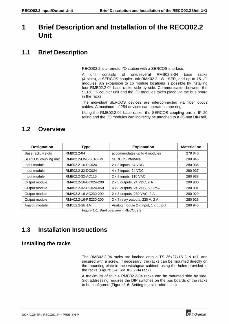
RECO02.2 is a remote I/O station with a SERCOS interface.
A unit consists of one/several RMB02.2-04 base racks(4 slots), a SERCOS coupler unit RMK02.2-LWL-SER, and up to 15 I/Omodules. An expansion to 16 module locations is possible by installingfour RMB02.2-04 base racks side by side. Communication between theSERCOS coupler unit and the I/O modules takes place via the bus boardin the racks.
The individual SERCOS devices are interconnected via fiber opticscables. A maximum of 254 devices can operate in one ring.
Using the RMB02.2-04 base racks, the SERCOS coupling unit in IP 20rating and the I/O modules can indirectly be attached to a 35-mm DIN rail.
1.2 Overview
Designation Type Explanation Material no.:
Base rack, 4 slots RMB02.2-04 accommodates up to 4 modules 278 846
SERCOS coupling unit RMK02.2-LWL-SER-FW SERCOS interface 280 946
Input module RME02.2-16-DC024 2 x 8 inputs, 24 VDC 280 936
Input module RME02.2-32-DC024 4 x 8 inputs, 24 VDC 280 937
Input module RME02.2-32-AC115 2 x 8 inputs, 115 VAC 280 938
Output module RMA02.2-16-DC024-200 2 x 8 outputs, 24 VDC, 2 A 280 930
Output module RMA02.2-32-DC024-050 4 x 8 outputs, 24 VDC, 500 mA 280 931
Output module RMA02.2-16-AC230-200 2 x 8 outputs, 230 VAC, 2 A 280 929
Output module RMA02.2-16-RE230-200 2 x 8 relay outputs, 230 V, 2 A 280 928
Analog module RMC02.2-2E-1A Analog module 2 x input, 1 x output 280 945Figure 1-1: Brief overview - RECO02.2
1.3 Installation Instructions
Installing the racks
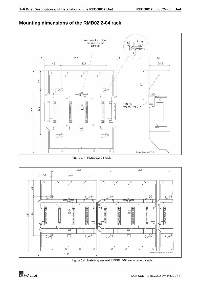
The RMB02.2-04 racks are latched onto a TS 35x27x15 DIN rail, andsecured with a screw. If necessary, the racks can be mounted directly onthe mounting plate in the switchgear cabinet, using the holes provided inthe racks (Figure 1-4: RMB02.2-04 rack).
A maximum of four 4 RMB02.2-04 racks can be mounted side by side.Slot addressing requires the DIP switches on the bus boards of the racksto be configured (Figure 1-6: Setting the slot addresses).
1-2 Brief Description and Installation of the RECO02.2 Unit RECO02.2 Input/Output Unit
DOK-CONTRL-RECO02.2***-PR01-EN-P
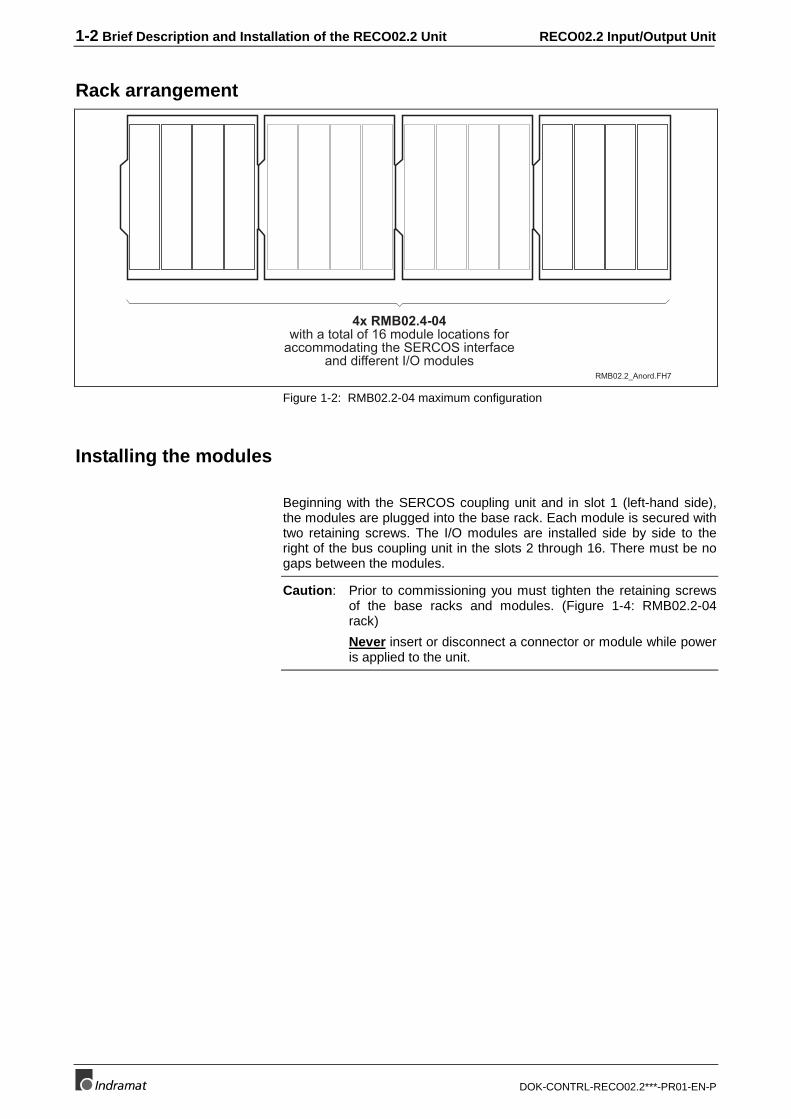
Rack arrangement
4x RMB02.4-04with a total of 16 module locations for
accommodating the SERCOS interfaceand different I/O modules
RMB02.2_Anord.FH7
Figure 1-2: RMB02.2-04 maximum configuration
Installing the modules
Beginning with the SERCOS coupling unit and in slot 1 (left-hand side),the modules are plugged into the base rack. Each module is secured withtwo retaining screws. The I/O modules are installed side by side to theright of the bus coupling unit in the slots 2 through 16. There must be nogaps between the modules.
Caution: Prior to commissioning you must tighten the retaining screwsof the base racks and modules. (Figure 1-4: RMB02.2-04rack)
Never insert or disconnect a connector or module while poweris applied to the unit.
RECO02.2 Input/Output Unit Brief Description and Installation of the RECO02.2 Unit 1-3
DOK-CONTRL-RECO02.2***-PR01-EN-P
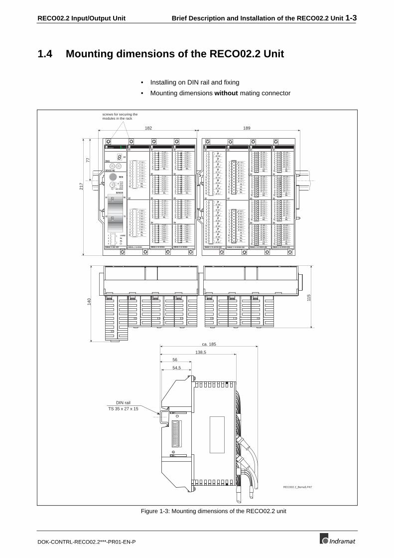
1.4 Mounting dimensions of the RECO02.2 Unit
• Installing on DIN rail and fixing
• Mounting dimensions without mating connector14
0 115
54,5
56
138,5
ca. 185
DIN railTS 35 x 27 x 15
217
77
182 189
screws for securing themodules in the rack
0 5
1
6
2
7
3
8
4
9
0 5
1
6
2
7
3
8
4
9
1
23
4
RMK02.2-LWL-SER
RX
TX
X1
X2
DEVICE-NO
MON
DIAG
SERCOS
LWL ERROR
+24VDC
0VL
0VL
< 15 m15 - 30 m
> 30 mGLAS
RECO
1
2
3
4
H18
RMA02.2-16-AC230-200
1
2
3
4
5
6
7
8
9
10
11
12
13
14
15
16
1
2
3
4
5
6
7
8
9
10
11
12
13
14
15
16
X1
Q*.1.0
Q*.1.1
Q*.1.2
Q*.1.3
Q*.1.4
Q*.1.5
Q*.1.6
Q*.1.7
X2
Q*.0.0
Q*.0.1
Q*.0.2
Q*.0.3
Q*.0.4
Q*.0.5
Q*.0.6
Q*.0.7
RME02.2-32-DC024
X1
X2
X3
X4
123456789
0VL
123456789
0VL
0VL
123456789
123456789
I*.3.0
0VL
I*.3.1I*.3.2I*.3.3I*.3.4I*.3.5I*.3.6I*.3.7
I*.2.0I*.2.1I*.2.2I*.2.3I*.2.4I*.2.5I*.2.6I*.2.7
I*.1.0I*.1.1I*.1.2I*.1.3I*.1.4I*.1.5I*.1.6I*.1.7
I*.0.0I*.0.1I*.0.2I*.0.3I*.0.4I*.0.5I*.0.6I*.0.7
RMA02.2-16-DC024-200
1
2
3
4
5
6
7
8
9
10
11
12
1
2
3
4
5
6
7
8
9
10
11
12
X2
Q*.0.0
Q*.0.1
Q*.0.2
Q*.0.3
Q*.0.4
Q*.0.5
Q*.0.6
Q*.0.7
0VL
0VL
+UL
+UL
X1
Q*.1.0
Q*.1.1
Q*.1.2
Q*.1.3
Q*.1.4
Q*.1.5
Q*.1.6
Q*.1.7
0VL
0VL
+UL
+UL
Q*.1.0Q*.1.1Q*.1.2Q*.1.3Q*.1.4Q*.1.5Q*.1.6Q*.1.7
X1
X2
X3
X4
123456789
123456789
10
10
RMA02.2-32-DC024-050
123456789
10
Q*.0.0
0VL
123456789
10+UL
Q*.0.1Q*.0.2Q*.0.3Q*.0.4Q*.0.5Q*.0.6Q*.0.7
0VL
+UL
Q*.2.0Q*.2.1Q*.2.2Q*.2.3Q*.2.4Q*.2.5Q*.2.6Q*.2.7
0VL
+UL
Q*.3.0Q*.3.1Q*.3.2Q*.3.3Q*.3.4Q*.3.5Q*.3.6Q*.3.7
0VL
+UL
RME02.2-16-DC024
X2
X1
I*.1.01
2
3
4
5
6
7
8
9 0VL
10 0VL
I*.0.01
2
3
4
5
6
7
8
9 0VL
10 0VL
I*.1.1
I*.1.2
I*.1.3
I*.1.4
I*.1.5
I*.1.6
I*.1.7
I*.0.1
I*.0.2
I*.0.3
I*.0.4
I*.0.5
I*.0.6
I*.0.7
RME02.2-32-DC024
X1
X2
X3
X4
123456789
0VL
123456789
0VL
0VL
123456789
123456789
I*.3.0
0VL
I*.3.1I*.3.2I*.3.3I*.3.4I*.3.5I*.3.6I*.3.7
I*.2.0I*.2.1I*.2.2I*.2.3I*.2.4I*.2.5I*.2.6I*.2.7
I*.1.0I*.1.1I*.1.2I*.1.3I*.1.4I*.1.5I*.1.6I*.1.7
I*.0.0I*.0.1I*.0.2I*.0.3I*.0.4I*.0.5I*.0.6I*.0.7
Q*.1.0Q*.1.1Q*.1.2Q*.1.3Q*.1.4Q*.1.5Q*.1.6Q*.1.7
X1
X2
X3
X4
123456789
123456789
10
10
RMA02.2-32-DC024-050
123456789
10
Q*.0.0
0VL
123456789
10+UL
Q*.0.1Q*.0.2Q*.0.3Q*.0.4Q*.0.5Q*.0.6Q*.0.7
0VL
+UL
Q*.2.0Q*.2.1Q*.2.2Q*.2.3Q*.2.4Q*.2.5Q*.2.6Q*.2.7
0VL
+UL
Q*.3.0Q*.3.1Q*.3.2Q*.3.3Q*.3.4Q*.3.5Q*.3.6Q*.3.7
0VL
+UL
RECO02.2_Bemaß.FH7
Figure 1-3: Mounting dimensions of the RECO02.2 unit
1-4 Brief Description and Installation of the RECO02.2 Unit RECO02.2 Input/Output Unit
DOK-CONTRL-RECO02.2***-PR01-EN-P
Mounting dimensions of the RMB02.2-04 rack
RMB02.2-04_Maß.FH7
S1
182
42 121
217
120
47
77
DIN railTS 35 x 27 x15
54,5
562 7
9
12
4,5
2,25
setscrew for lockingthe rack on the
DIN rail
Figure 1-4: RMB02.2-04 rack
42
182
121
182
4712
0
217
182
RMB02.2-04+02-04_Maß.FH7
S1 S1
Figure 1-5: Installing several RMB02.2-04 racks side by side
RECO02.2 Input/Output Unit Brief Description and Installation of the RECO02.2 Unit 1-5
DOK-CONTRL-RECO02.2***-PR01-EN-P
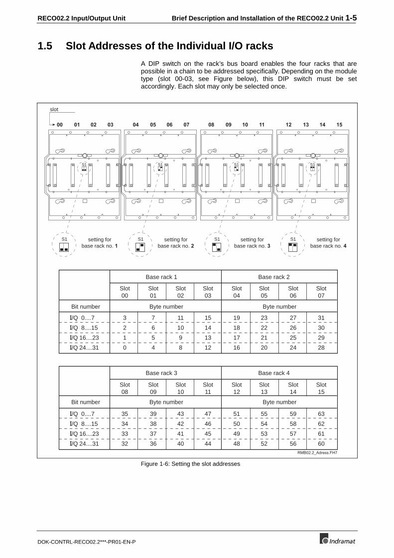
1.5 Slot Addresses of the Individual I/O racks
A DIP switch on the rack’s bus board enables the four racks that arepossible in a chain to be addressed specifically. Depending on the moduletype (slot 00-03, see Figure below), this DIP switch must be setaccordingly. Each slot may only be selected once.
S1S1 S1S1
RMB02.2_Adress.FH7
slot
setting forbase rack no. 1
setting forbase rack no. 2
setting forbase rack no. 4
setting forbase rack no. 3
S1 S1 S1 S1
00 01 02 03 04 05 06 07 08 09 10 11 12 13 14 15
Slot00
Slot01
Slot02
Slot03
Slot04
Slot05
Slot06
Slot07
I/Q 0....7
I/Q 8....15
I/Q 16....23
I/Q 24....31
Base rack 1 Base rack 2
3
2
1
0
7
6
5
4
11
10
9
8
15
14
13
12
19
18
17
16
23
22
21
20
27
26
25
24
31
30
29
28
Slot08
Slot09
Slot10
Slot11
Slot12
Slot13
Slot14
Slot15
Bit number
I/Q 0....7
I/Q 8....15
I/Q 16....23
I/Q 24....31
Base rack 3 Base rack 4
35
34
33
32
39
38
37
36
43
42
41
40
47
46
45
44
51
50
49
48
55
54
53
52
59
58
57
56
63
62
61
60
Bit number
Byte number Byte number
Byte number Byte number
Figure 1-6: Setting the slot addresses
1-6 Brief Description and Installation of the RECO02.2 Unit RECO02.2 Input/Output Unit
DOK-CONTRL-RECO02.2***-PR01-EN-P
RECO02.2 Input/Output Unit Specifications 2-1
DOK-CONTRL-RECO02.2***-PR01-EN-P
2 Specifications
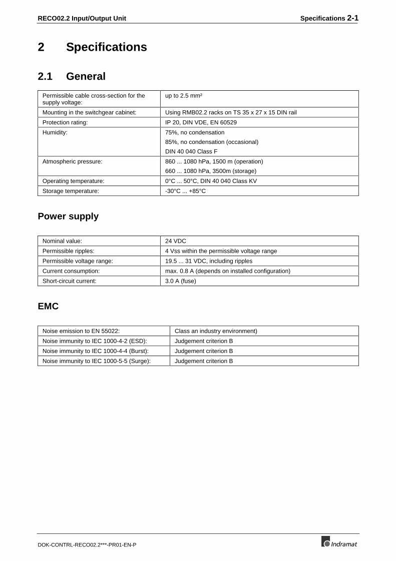
2.1 General
Permissible cable cross-section for thesupply voltage:
up to 2.5 mm²
Mounting in the switchgear cabinet: Using RMB02.2 racks on TS 35 x 27 x 15 DIN rail
Protection rating: IP 20, DIN VDE, EN 60529
Humidity: 75%, no condensation
85%, no condensation (occasional)
DIN 40 040 Class F
Atmospheric pressure: 860 ... 1080 hPa, 1500 m (operation)
660 ... 1080 hPa, 3500m (storage)
Operating temperature: 0°C ... 50°C, DIN 40 040 Class KV
Storage temperature: -30°C ... +85°C
Power supply
Nominal value: 24 VDC
Permissible ripples: 4 Vss within the permissible voltage range
Permissible voltage range: 19.5 ... 31 VDC, including ripples
Current consumption: max. 0.8 A (depends on installed configuration)
Short-circuit current: 3.0 A (fuse)
EMC
Noise emission to EN 55022: Class an industry environment)
Noise immunity to IEC 1000-4-2 (ESD): Judgement criterion B
Noise immunity to IEC 1000-4-4 (Burst): Judgement criterion B
Noise immunity to IEC 1000-5-5 (Surge): Judgement criterion B
2-2 Specifications RECO02.2 Input/Output Unit
DOK-CONTRL-RECO02.2***-PR01-EN-P
2.2 Addressing
General information about addressing
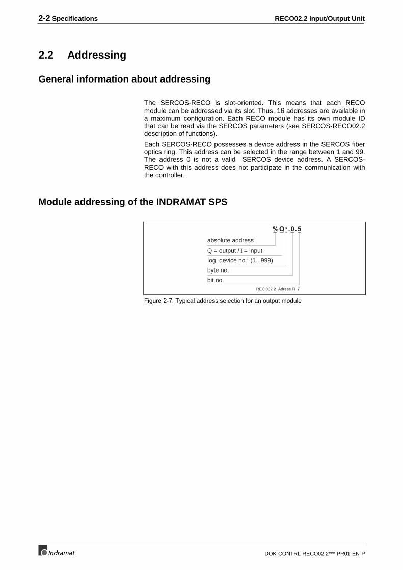
The SERCOS-RECO is slot-oriented. This means that each RECOmodule can be addressed via its slot. Thus, 16 addresses are available ina maximum configuration. Each RECO module has its own module IDthat can be read via the SERCOS parameters (see SERCOS-RECO02.2description of functions).
Each SERCOS-RECO possesses a device address in the SERCOS fiberoptics ring. This address can be selected in the range between 1 and 99.The address 0 is not a valid SERCOS device address. A SERCOS-RECO with this address does not participate in the communication withthe controller.
Module addressing of the INDRAMAT SPS
Iog. device no.: (1...999)
byte no.
bit no.
%Q*.0.5
Q = output / I = input
absolute address
RECO02.2_Adress.FH7
Figure 2-7: Typical address selection for an output module
RECO02.2 Input/Output Unit Specifications 2-3
DOK-CONTRL-RECO02.2***-PR01-EN-P
Address selection for input modules
Long
wor
dac
cess
%ID
*.0
031
Byt
e ac
cess
Wor
d
Bit
acce
ss
Byt
e ac
cess
Wor
d ac
cess
Bit
acce
ssX1
X2
X1
X2
X3
X4
%I*3.0.....
%I*3.7
%I*2.0.....
%I*2.7
%I*1.0.....
%I*1.7
%I*0.0.....
%I*0.7
%I*0.0.....
%I*0.7
%I*1.0.....
%I*1.7
%IW
*.0
%IW
*.2
00
1515
%IB
*.3
%IB
*.2
%IB
*.1
%IB
*.0
00
00
77
77
%IW
*.0
015
%IB
*.0
07
%IB
*.1
07
RECO02.2_Eingangsadress.FH716-bit module 32-bit module
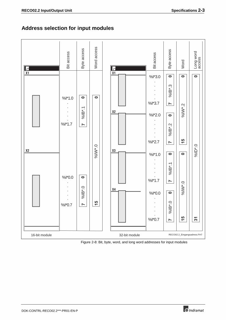
Figure 2-8: Bit, byte, word, and long word addresses for input modules
2-4 Specifications RECO02.2 Input/Output Unit
DOK-CONTRL-RECO02.2***-PR01-EN-P
Address selection for output modules
Long
wor
dac
cess
%Q
D*.
00
31
Byt
e ac
cess
Wor
d
Bit
acce
ss
Byt
e ac
cess
Wor
d ac
cess
Bit
acce
ssX1
X2
X1
X2
X3
X4
%Q*3.0.....
%Q*3.7
%Q*2.0.....
%Q*2.7
%Q*1.0.....
%Q*1.7
%Q*0.0.....
%Q*0.7
%Q*0.0.....
%Q*0.7
%Q*1.0.....
%Q*1.7
%Q
W*.
0%
QW
*.2
00
1515
%Q
B*.
3%
QB
*.2
%Q
B*.
1%
QB
*.0
00
00
77
77
%Q
W*.
00
15
%Q
B*.
00
7%
QB
*.1
07
RECO02.2_Ausgangsadress.FH716-bit module 32-bit module
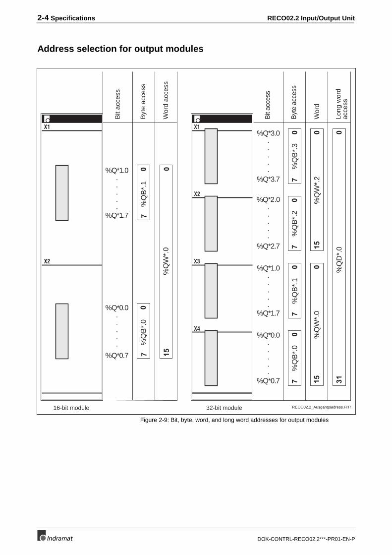
Figure 2-9: Bit, byte, word, and long word addresses for output modules
RECO02.2 Input/Output Unit SERCOS Coupling Unit RMK02.2-LWL-SER 3-1
DOK-CONTRL-RECO02.2***-PR01-EN-P
3 SERCOS Coupling Unit RMK02.2-LWL-SER
3.1 Brief Description
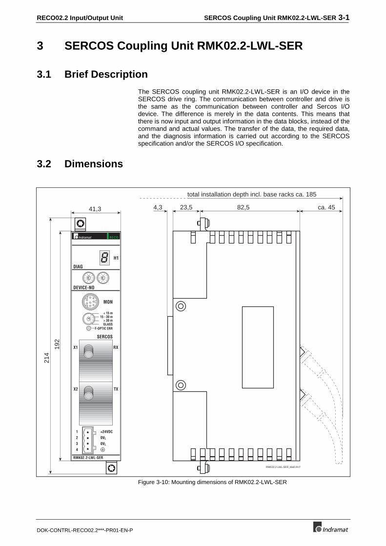
The SERCOS coupling unit RMK02.2-LWL-SER is an I/O device in theSERCOS drive ring. The communication between controller and drive isthe same as the communication between controller and Sercos I/Odevice. The difference is merely in the data contents. This means thatthere is now input and output information in the data blocks, instead of thecommand and actual values. The transfer of the data, the required data,and the diagnosis information is carried out according to the SERCOSspecification and/or the SERCOS I/O specification.
3.2 Dimensions
41,3
192
214
82,54,3 ca. 4523,5
total installation depth incl. base racks ca. 185
RMK02.2-LWL-SER_Maß.FH7
RECO
RMK02.2-LWL-SER
RX
TX
X1
X2
DEVICE-NO
MON
DIAG
SERCOS
+24VDC
0VL
0VL
< 15 m15 - 30 m
> 30 m
1
2
3
4
H18
0 5
1
6
2
7
3
8
4
9
0 5
1
6
2
7
3
8
4
9
1
23
4
F-OPTIC ERRGLASS
Figure 3-10: Mounting dimensions of RMK02.2-LWL-SER
3-2 SERCOS Coupling Unit RMK02.2-LWL-SER RECO02.2 Input/Output Unit
DOK-CONTRL-RECO02.2***-PR01-EN-P
3.3 SERCOS Interface
Setting the device address
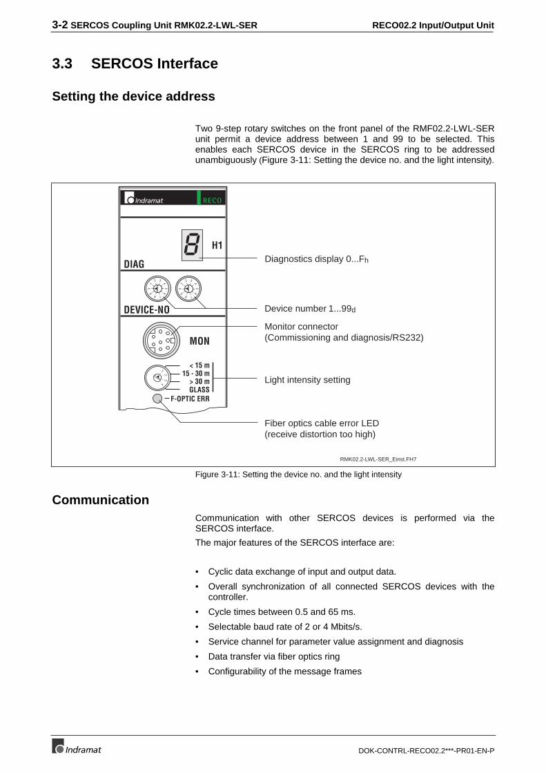
Two 9-step rotary switches on the front panel of the RMF02.2-LWL-SERunit permit a device address between 1 and 99 to be selected. Thisenables each SERCOS device in the SERCOS ring to be addressedunambiguously (Figure 3-11: Setting the device no. and the light intensity).
RECO
DEVICE-NO
MON
DIAG
< 15 m15 - 30 m
> 30 m
H18
0 5
1
6
2
7
3
8
4
9
0 5
1
6
2
7
3
8
4
9
1
23
4
F-OPTIC ERRGLASS
Diagnostics display 0...Fh
Device number 1...99d
Monitor connector(Commissioning and diagnosis/RS232)
Fiber optics cable error LED(receive distortion too high)
Light intensity setting
RMK02.2-LWL-SER_Einst.FH7
Figure 3-11: Setting the device no. and the light intensity
CommunicationCommunication with other SERCOS devices is performed via theSERCOS interface.
The major features of the SERCOS interface are:
• Cyclic data exchange of input and output data.
• Overall synchronization of all connected SERCOS devices with thecontroller.
• Cycle times between 0.5 and 65 ms.
• Selectable baud rate of 2 or 4 Mbits/s.
• Service channel for parameter value assignment and diagnosis
• Data transfer via fiber optics ring
• Configurability of the message frames
RECO02.2 Input/Output Unit SERCOS Coupling Unit RMK02.2-LWL-SER 3-3
DOK-CONTRL-RECO02.2***-PR01-EN-P
Here, the functionality of the interface will only be discussed briefly.Please refer to the SERCOS interface specification and the SERCOSinterface I/O functions for more detailed information.
Cyclic data transfer via SERCOS
To synchronize the SERCOS device on the ring, the mastersynchronization frame (MST) is transmitted at the beginning of eachSERCOS cycle. The sole information content of this frame is thecommunication phase that is specified by the master.
Once per SERCOS cycle time, a master data frame (MDT) is transmittedfrom the controller to each SERCOS device. It contains the master controlword, segments of the service channel, and a configurable data block.The data block usually contains the output information the controllerwants to send to the SERCOS device for controlling the respective mode.The contents of this data block can be configured through the messageframe selection.
The master data message frame is received by all SERCOS devices inthe ring at the same time.
Likewise, once per SERCOS cycle time, a drive message frame (AT) istransmitted from each SERCOS device to the controller. It contains thedrive status word, segments of the service channel, and a configurabledata block. The data block usually contains the input information thecontroller requires for controlling the respective mode of the SERCOSdevice.
3.4 Power Supply
RMK02.2-LWL-SER
+24VDC
0VL
0VL
1
2
3
4
0VL
2
3
4
0VL
1
F 3,0 A
+24V ± 20%current consumption: < 2,5 A+UL
F1
0VL 0VL
RMK02.2-LWL-SER_Vers.FH7
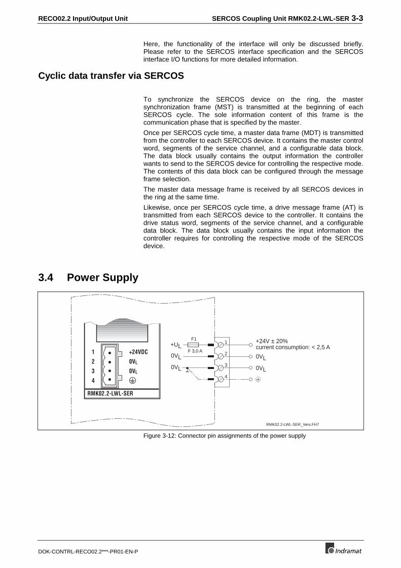
Figure 3-12: Connector pin assignments of the power supply
3-4 SERCOS Coupling Unit RMK02.2-LWL-SER RECO02.2 Input/Output Unit
DOK-CONTRL-RECO02.2***-PR01-EN-P
3.5 Status Display and Fault Diagnosis
Operating state display
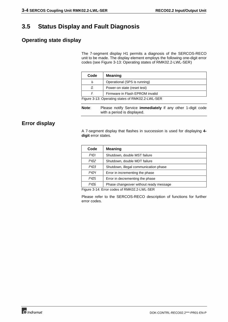
The 7-segment display H1 permits a diagnosis of the SERCOS-RECOunit to be made. The display element employs the following one-digit errorcodes (see Figure 3-13: Operating states of RMK02.2-LWL-SER)
Code Meaning
E Operational (SPS is running)
Power-on state (reset test)
) Firmware in Flash EPROM invalid
Figure 3-13: Operating states of RMK02.2-LWL-SER
Note: Please notify Service immediately if any other 1-digit codewith a period is displayed.
Error displayA 7-segment display that flashes in succession is used for displaying 4-digit error states.
Code Meaning
) Shutdown, double MST failure
) Shutdown, double MDT failure
) Shutdown, illegal communication phase
) Error in incrementing the phase
) Error in decrementing the phase
) Phase changeover without ready message
Figure 3-14: Error codes of RMK02.2-LWL-SER
Please refer to the SERCOS-RECO description of functions for furthererror codes.
RECO02.2 Input/Output Unit RME02.2-16-DC024 Input Module 4-1
DOK-CONTRL-RECO02.2***-PR01-EN-P
4 RME02.2-16-DC024 Input Module
4.1 Brief Description
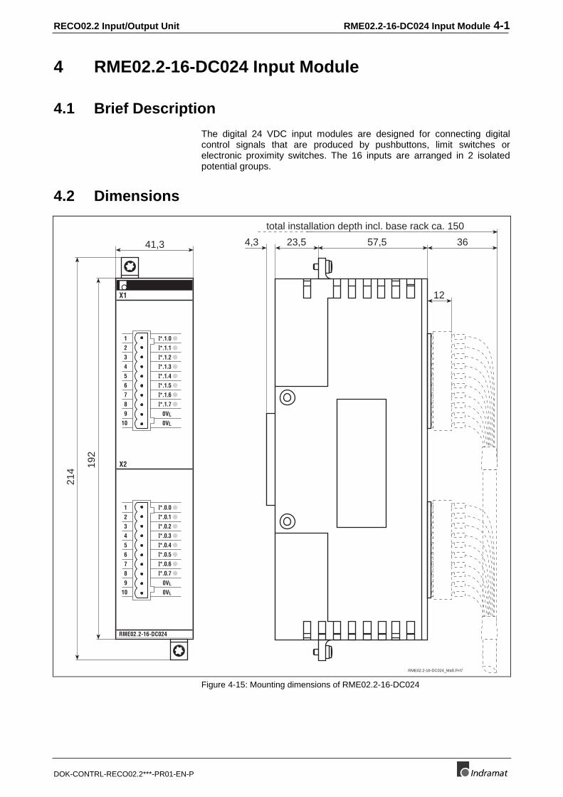
The digital 24 VDC input modules are designed for connecting digitalcontrol signals that are produced by pushbuttons, limit switches orelectronic proximity switches. The 16 inputs are arranged in 2 isolatedpotential groups.
4.2 Dimensions
41,3
192
214
57,54,3
12
3623,5
total installation depth incl. base rack ca. 150
RME02.2-16-DC024
X2
X1
I*.1.01
2
3
4
5
6
7
8
9 0VL
10 0VL
I*.0.01
2
3
4
5
6
7
8
9 0VL
10 0VL
I*.1.1
I*.1.2
I*.1.3
I*.1.4
I*.1.5
I*.1.6
I*.1.7
I*.0.1
I*.0.2
I*.0.3
I*.0.4
I*.0.5
I*.0.6
I*.0.7
RME02.2-16-DC024_Maß.FH7
Figure 4-15: Mounting dimensions of RME02.2-16-DC024
4-2 RME02.2-16-DC024 Input Module RECO02.2 Input/Output Unit
DOK-CONTRL-RECO02.2***-PR01-EN-P
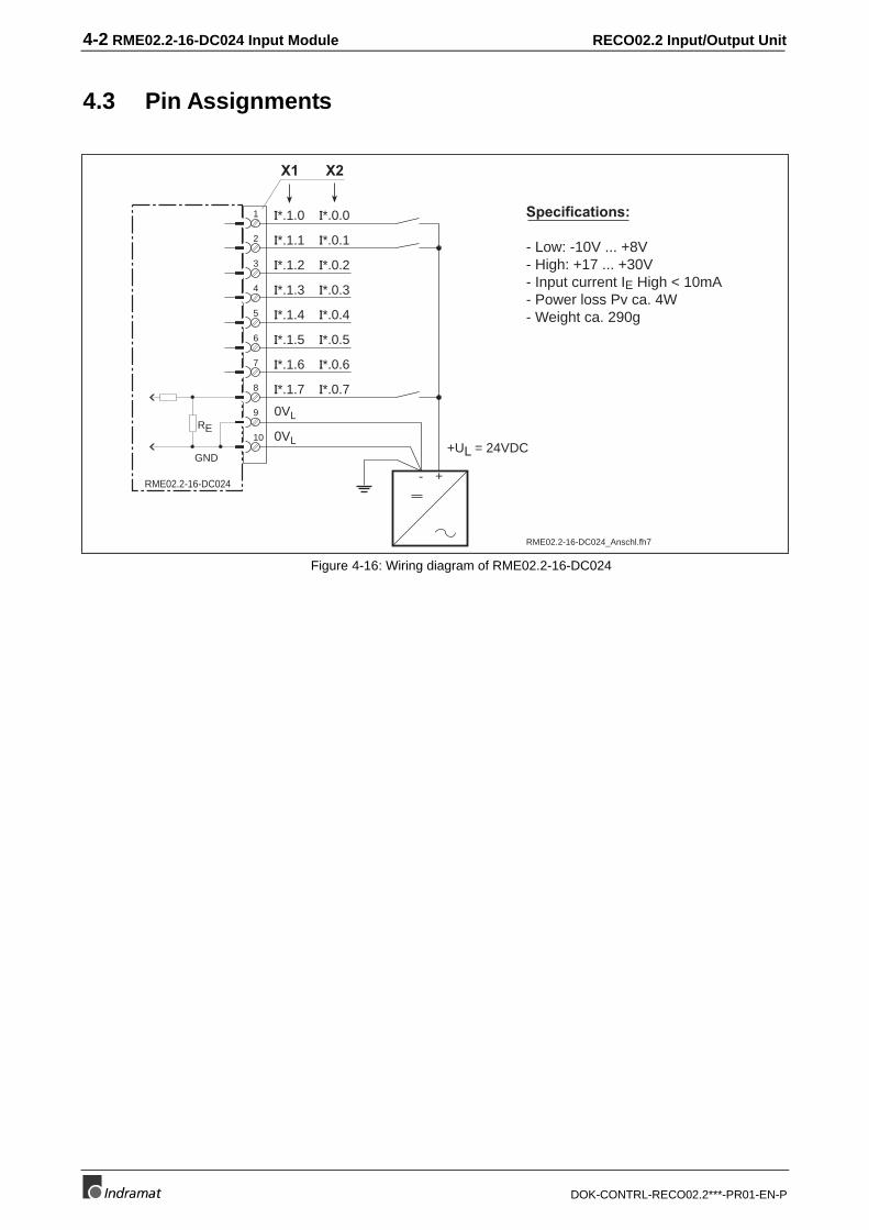
4.3 Pin Assignments
Specifications:
- Low: -10V ... +8V- High: +17 ... +30V- Input current IE High < 10mA- Power loss Pv ca. 4W- Weight ca. 290g
1
2
3
4
5
6
7
8
9
10
RME02.2-16-DC024
0VL
0VL
GND
RE
- +
+UL = 24VDC
I*.0.0
I*.0.1
I*.0.2
I*.0.3
I*.0.4
I*.0.5
I*.0.6
I*.0.7
I*.1.1
I*.1.2
I*.1.3
I*.1.4
I*.1.5
I*.1.6
I*.1.7
I*.1.0
RME02.2-16-DC024_Anschl.fh7
X1 X2
Figure 4-16: Wiring diagram of RME02.2-16-DC024
RECO02.2 Input/Output Unit RME02.2-32-DC024 Input Module 5-1
DOK-CONTRL-RECO02.2***-PR01-EN-P
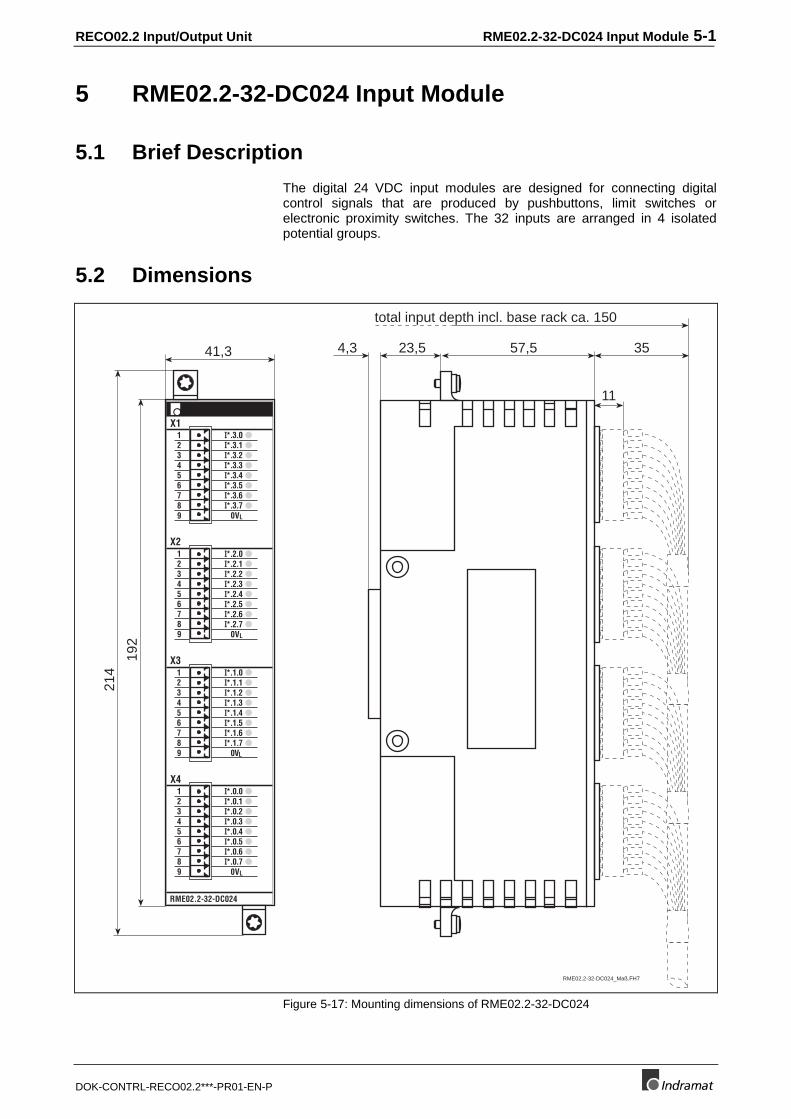
5 RME02.2-32-DC024 Input Module
5.1 Brief Description
The digital 24 VDC input modules are designed for connecting digitalcontrol signals that are produced by pushbuttons, limit switches orelectronic proximity switches. The 32 inputs are arranged in 4 isolatedpotential groups.
5.2 Dimensions
41,3
192
214
57,54,3
11
3523,5
total input depth incl. base rack ca. 150
RME02.2-32-DC024
X1
X2
X3
X4
123456789
0VL
123456789
0VL
0VL
123456789
123456789
I*.3.0
0VL
I*.3.1I*.3.2I*.3.3I*.3.4I*.3.5I*.3.6I*.3.7
I*.2.0I*.2.1I*.2.2I*.2.3I*.2.4I*.2.5I*.2.6I*.2.7
I*.1.0I*.1.1I*.1.2I*.1.3I*.1.4I*.1.5I*.1.6I*.1.7
I*.0.0I*.0.1I*.0.2I*.0.3I*.0.4I*.0.5I*.0.6I*.0.7
RME02.2-32-DC024_Maß.FH7
Figure 5-17: Mounting dimensions of RME02.2-32-DC024
5-2 RME02.2-32-DC024 Input Module RECO02.2 Input/Output Unit
DOK-CONTRL-RECO02.2***-PR01-EN-P
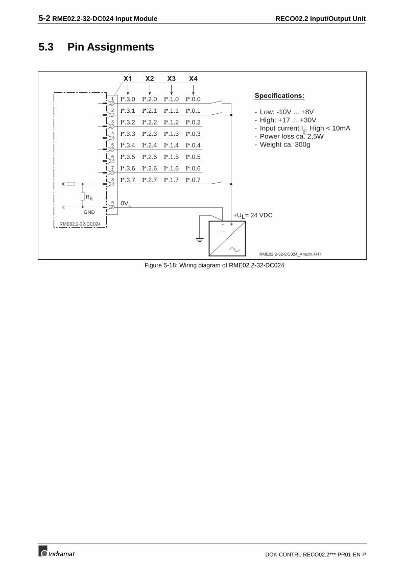
5.3 Pin Assignments
1
2
3
4
5
6
7
8
9
RME02.2-32-DC024
X1
0VL
X2 X3 X4
Specifications:
- Low: -10V ... +8V- High: +17 ... +30V- Input current IE High < 10mA- Power loss ca. 2,5W- Weight ca. 300g
GND
RE
+-
+UL= 24 VDC
I*.0.0
I*.0.1
I*.0.2
I*.0.3
I*.0.4
I*.0.5
I*.0.6
I*.0.7
I*.1.1
I*.1.2
I*.1.3
I*.1.4
I*.1.5
I*.1.6
I*.1.7
I*.1.0I*.2.0
I*.2.1
I*.2.2
I*.2.3
I*.2.4
I*.2.5
I*.2.6
I*.2.7
I*.3.1
I*.3.2
I*.3.3
I*.3.4
I*.3.5
I*.3.6
I*.3.7
I*.3.0
RME02.2-32-DC024_Anschl.FH7
Figure 5-18: Wiring diagram of RME02.2-32-DC024
RECO02.2 Input/Output Unit RME02.2-16-AC115 Input Module 6-1
DOK-CONTRL-RECO02.2***-PR01-EN-P
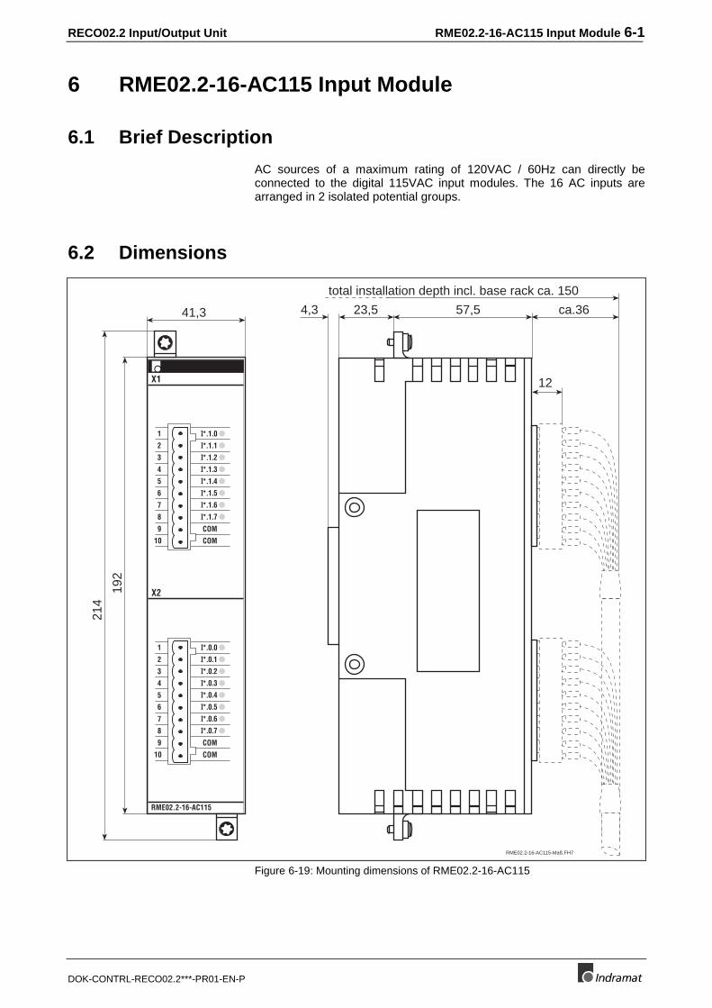
6 RME02.2-16-AC115 Input Module
6.1 Brief Description
AC sources of a maximum rating of 120VAC / 60Hz can directly beconnected to the digital 115VAC input modules. The 16 AC inputs arearranged in 2 isolated potential groups.
6.2 Dimensions
41,3
192
214
57,54,3
12
23,5 ca.36
total installation depth incl. base rack ca. 150
RME02.2-16-AC115
1
2
3
4
5
6
7
8
9 COM
COM10
X2
X1
1
2
3
4
5
6
7
8
9 COM
COM10
I*.1.0
I*.0.0
I*.1.1
I*.1.2
I*.1.3
I*.1.4
I*.1.5
I*.1.6
I*.1.7
I*.0.1
I*.0.2
I*.0.3
I*.0.4
I*.0.5
I*.0.6
I*.0.7
RME02.2-16-AC115-Maß.FH7
Figure 6-19: Mounting dimensions of RME02.2-16-AC115
6-2 RME02.2-16-AC115 Input Module RECO02.2 Input/Output Unit
DOK-CONTRL-RECO02.2***-PR01-EN-P
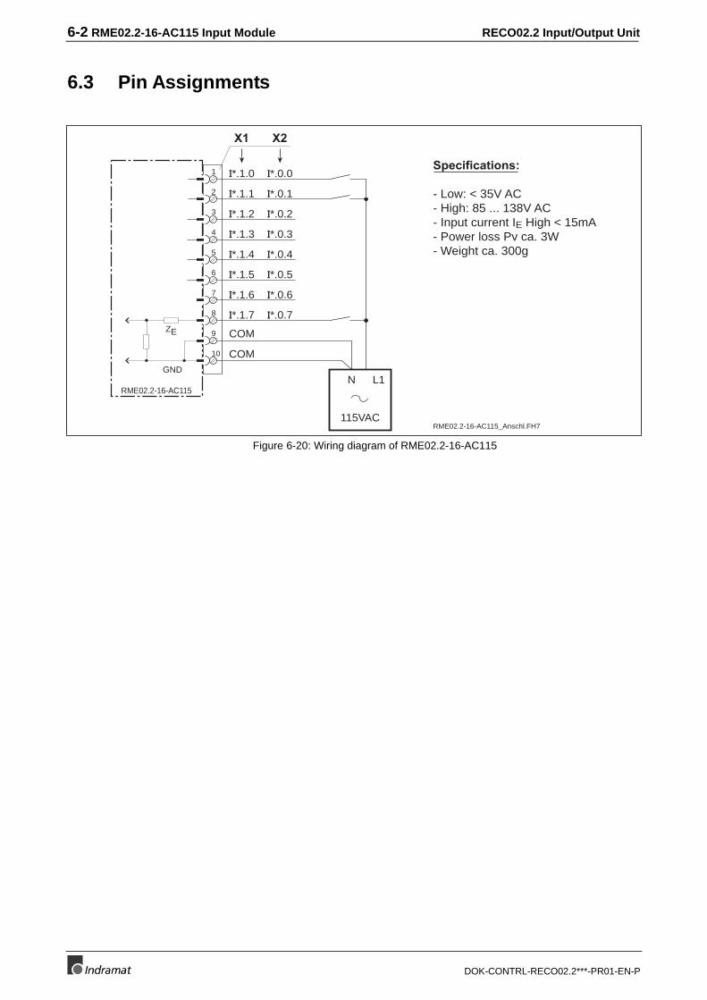
6.3 Pin Assignments
1
2
3
4
5
6
7
8
9
10
RME02.2-16-AC115
COM
COM
GND
ZE
I*.0.0
I*.0.1
I*.0.2
I*.0.3
I*.0.4
I*.0.5
I*.0.6
I*.0.7
I*.1.1
I*.1.2
I*.1.3
I*.1.4
I*.1.5
I*.1.6
I*.1.7
I*.1.0Specifications:
- Low: < 35V AC- High: 85 ... 138V AC- Input current IE High < 15mA- Power loss Pv ca. 3W- Weight ca. 300g
115VAC
N L1
RME02.2-16-AC115_Anschl.FH7
X1 X2
Figure 6-20: Wiring diagram of RME02.2-16-AC115
RECO02.2 Input/Output Unit RMA02.2-16-DC024-200 output module 7-1
DOK-CONTRL-RECO02.2***-PR01-EN-P
7 RMA02.2-16-DC024-200 output module
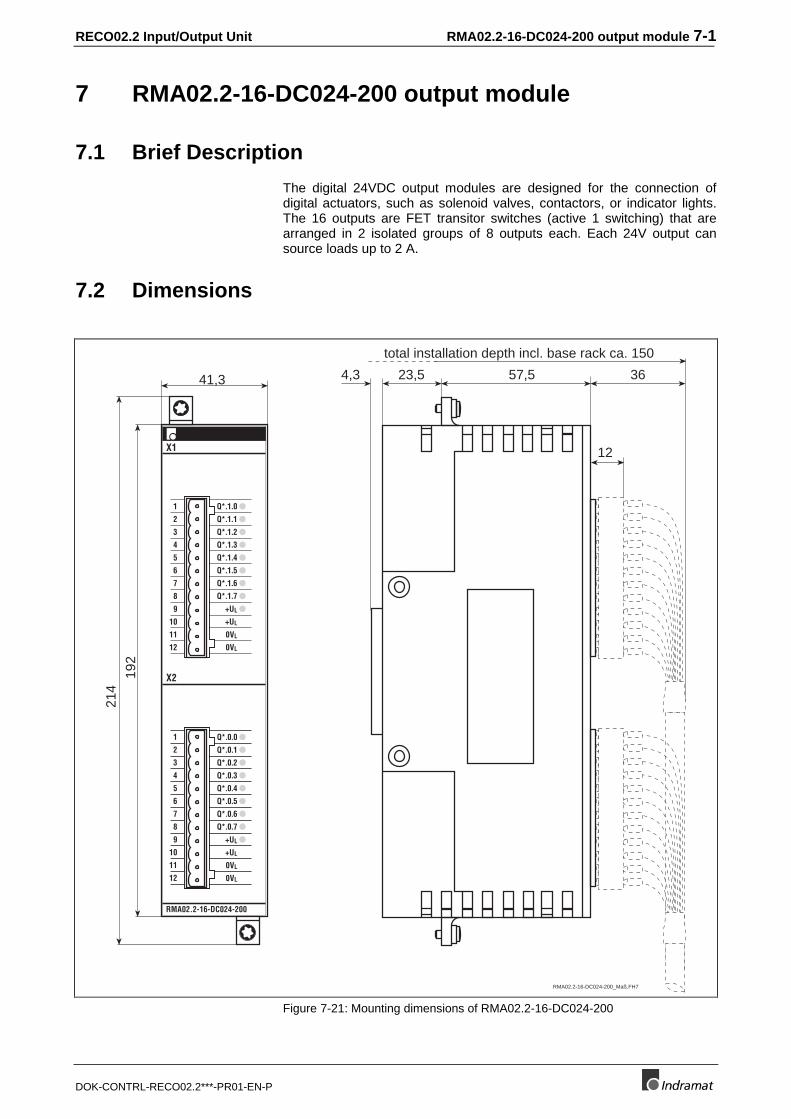
7.1 Brief Description
The digital 24VDC output modules are designed for the connection ofdigital actuators, such as solenoid valves, contactors, or indicator lights.The 16 outputs are FET transitor switches (active 1 switching) that arearranged in 2 isolated groups of 8 outputs each. Each 24V output cansource loads up to 2 A.
7.2 Dimensions
41,3
192
214
57,54,3
12
3623,5
total installation depth incl. base rack ca. 150
RMA02.2-16-DC024-200
1
2
3
4
5
6
7
8
9
10
11
12
1
2
3
4
5
6
7
8
9
10
11
12
X2
Q*.0.0
Q*.0.1
Q*.0.2
Q*.0.3
Q*.0.4
Q*.0.5
Q*.0.6
Q*.0.7
0VL
0VL
+UL
+UL
X1
Q*.1.0
Q*.1.1
Q*.1.2
Q*.1.3
Q*.1.4
Q*.1.5
Q*.1.6
Q*.1.7
0VL
0VL
+UL
+UL
RMA02.2-16-DC024-200_Maß.FH7
Figure 7-21: Mounting dimensions of RMA02.2-16-DC024-200
7-2 RMA02.2-16-DC024-200 output module RECO02.2 Input/Output Unit
DOK-CONTRL-RECO02.2***-PR01-EN-P
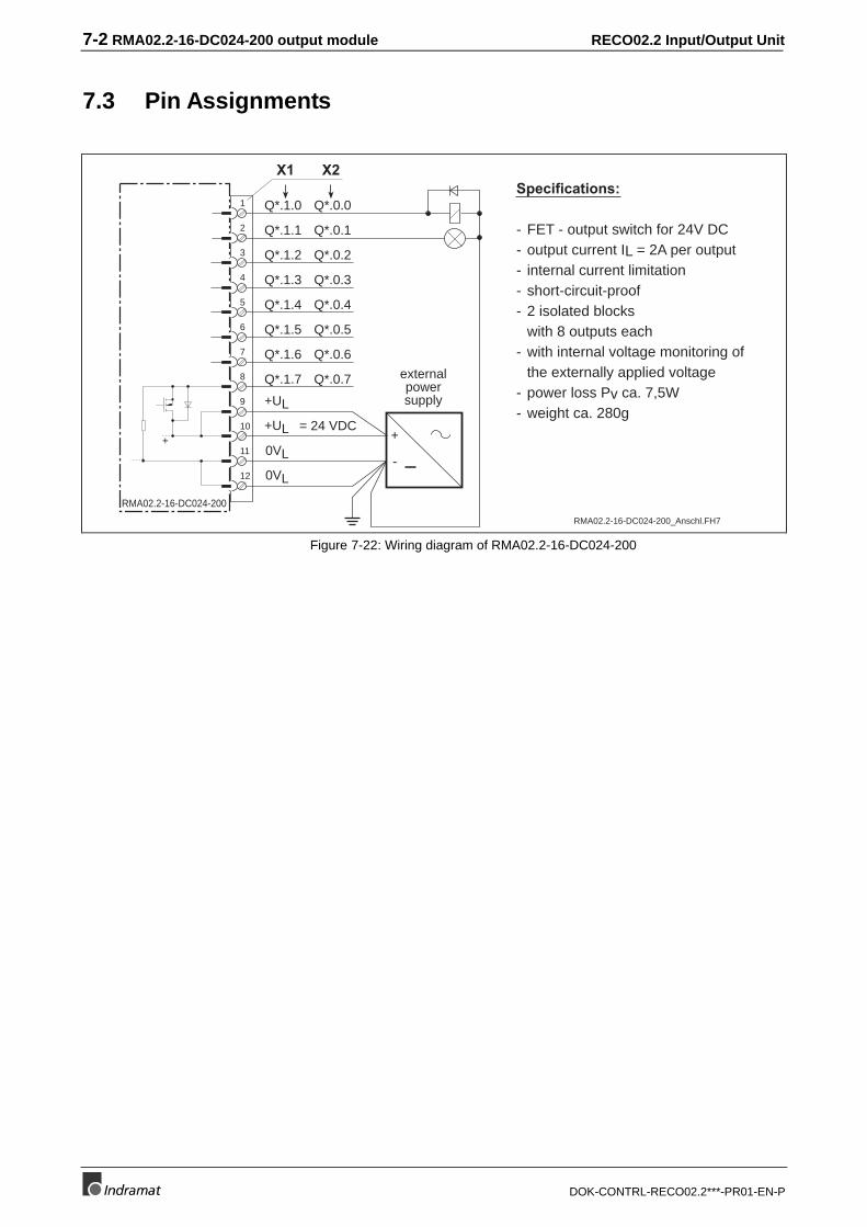
7.3 Pin Assignments
Specifications:
- FET - output switch for 24V DC- output current IL = 2A per output- internal current limitation- short-circuit-proof- 2 isolated blocks
with 8 outputs each- with internal voltage monitoring of
the externally applied voltage- power loss Pv ca. 7,5W- weight ca. 280g
1
2
3
4
5
6
7
8
11
12
RMA02.2-16-DC024-200
+UL
0VL
9
10 +UL
0VL
+ +
-
= 24 VDC
externalpowersupply
Q*.0.0
Q*.0.1
Q*.0.2
Q*.0.3
Q*.0.4
Q*.0.5
Q*.0.6
Q*.0.7
Q*.1.0
Q*.1.1
Q*.1.2
Q*.1.3
Q*.1.4
Q*.1.5
Q*.1.6
Q*.1.7
RMA02.2-16-DC024-200_Anschl.FH7
X1 X2
Figure 7-22: Wiring diagram of RMA02.2-16-DC024-200
RECO02.2 Input/Output Unit RMA02.2-32-DC024-050 Output Module 8-1
DOK-CONTRL-RECO02.2***-PR01-EN-P
8 RMA02.2-32-DC024-050 Output Module
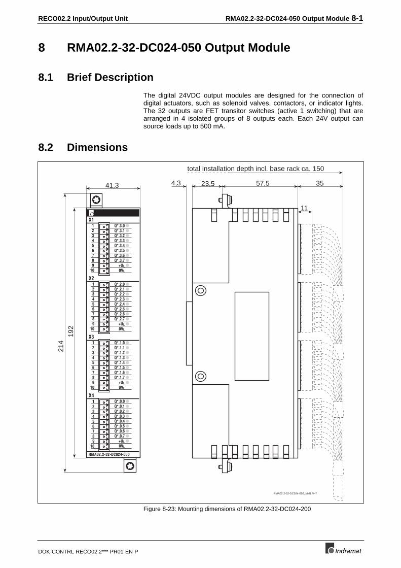
8.1 Brief Description
The digital 24VDC output modules are designed for the connection ofdigital actuators, such as solenoid valves, contactors, or indicator lights.The 32 outputs are FET transitor switches (active 1 switching) that arearranged in 4 isolated groups of 8 outputs each. Each 24V output cansource loads up to 500 mA.
8.2 Dimensions
41,3
192
214
23,5 57,54,3
11
35
total installation depth incl. base rack ca. 150
Q*.1.0Q*.1.1Q*.1.2Q*.1.3Q*.1.4Q*.1.5Q*.1.6Q*.1.7
X1
X2
X3
X4
123456789
123456789
10
10
RMA02.2-32-DC024-050
123456789
10
Q*.0.0
0VL
123456789
10+UL
Q*.0.1Q*.0.2Q*.0.3Q*.0.4Q*.0.5Q*.0.6Q*.0.7
0VL
+UL
Q*.2.0Q*.2.1Q*.2.2Q*.2.3Q*.2.4Q*.2.5Q*.2.6Q*.2.7
0VL
+UL
Q*.3.0Q*.3.1Q*.3.2Q*.3.3Q*.3.4Q*.3.5Q*.3.6Q*.3.7
0VL
+UL
RMA02.2-32-DC024-050_Maß.FH7
Figure 8-23: Mounting dimensions of RMA02.2-32-DC024-200
8-2 RMA02.2-32-DC024-050 Output Module RECO02.2 Input/Output Unit
DOK-CONTRL-RECO02.2***-PR01-EN-P
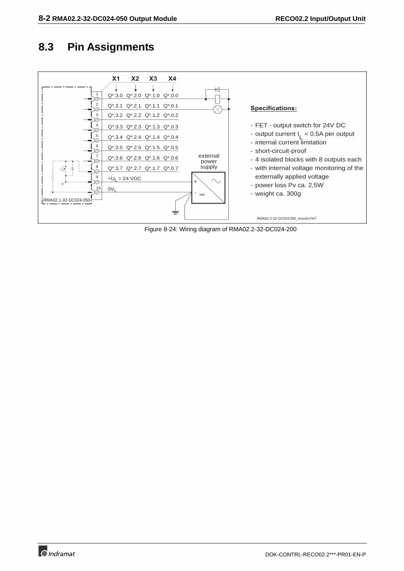
8.3 Pin Assignments
Specifications:
- FET - output switch for 24V DC- output current IL = 0.5A per output- internal current limitation- short-circuit-proof- 4 isolated blocks with 8 outputs each- with internal voltage monitoring of the
externally applied voltage- power loss Pv ca. 2,5W- weight ca. 300g
X1
RMA02.1-32-DC024-050
X2 X3 X4
1
2
3
4
5
6
7
8
9
10+ +
-
Q*.3.0 Q*.2.0 Q*.1.0 Q*.0.0
Q*.3.1 Q*.2.1 Q*.1.1 Q*.0.1
Q*.3.2 Q*.2.2 Q*.1.2 Q*.0.2
Q*.3.3 Q*.2.3 Q*.1.3 Q*.0.3
Q*.3.4 Q*.2.4 Q*.1.4 Q*.0.4
Q*.3.5 Q*.2.5 Q*.1.5 Q*.0.5
Q*.3.6 Q*.2.6 Q*.1.6 Q*.0.6
Q*.3.7 Q*.2.7 Q*.1.7 Q*.0.7
+UL = 24 VDC
0VL
externalpowersupply
RMA02.2-32-DC024-050_Anschl.FH7
Figure 8-24: Wiring diagram of RMA02.2-32-DC024-200
RECO02.2 Input/Output Unit RMA02.2-16-AC230-200 Output Module 9-1
DOK-CONTRL-RECO02.2***-PR01-EN-P
9 RMA02.2-16-AC230-200 Output Module
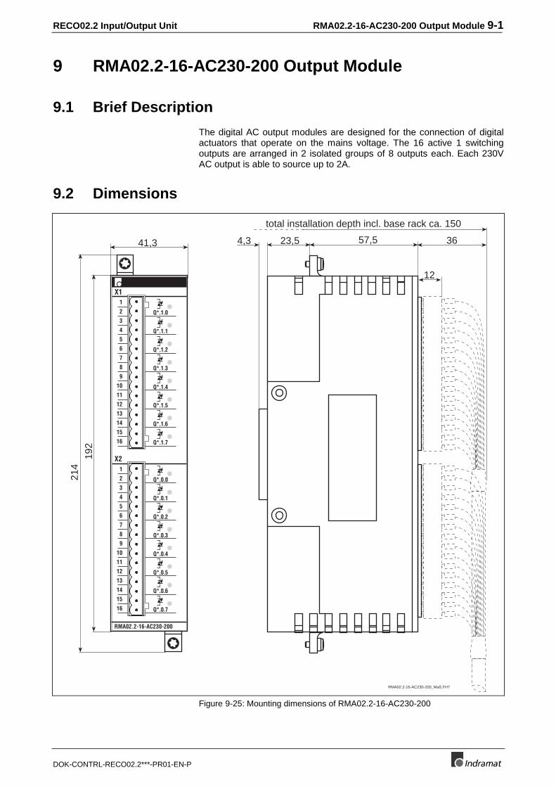
9.1 Brief Description
The digital AC output modules are designed for the connection of digitalactuators that operate on the mains voltage. The 16 active 1 switchingoutputs are arranged in 2 isolated groups of 8 outputs each. Each 230VAC output is able to source up to 2A.
9.2 Dimensions
41,3
192
214
57,54,3
12
3623,5
total installation depth incl. base rack ca. 150
RMA02.2-16-AC230-200
1
2
3
4
5
6
7
8
9
10
11
12
13
14
15
16
1
2
3
4
5
6
7
8
9
10
11
12
13
14
15
16
X1
Q*.1.0
Q*.1.1
Q*.1.2
Q*.1.3
Q*.1.4
Q*.1.5
Q*.1.6
Q*.1.7
X2
Q*.0.0
Q*.0.1
Q*.0.2
Q*.0.3
Q*.0.4
Q*.0.5
Q*.0.6
Q*.0.7
RMA02.2-16-AC230-200_Maß.FH7
Figure 9-25: Mounting dimensions of RMA02.2-16-AC230-200
9-2 RMA02.2-16-AC230-200 Output Module RECO02.2 Input/Output Unit
DOK-CONTRL-RECO02.2***-PR01-EN-P
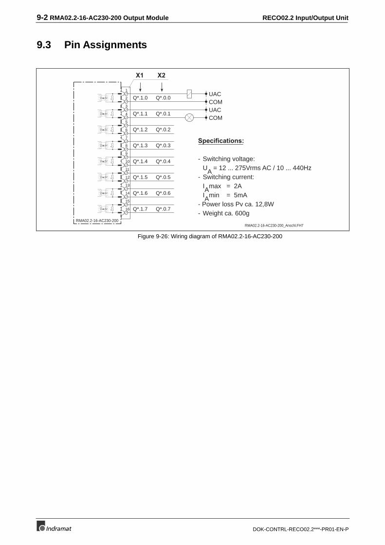
9.3 Pin Assignments
Specifications:
- Switching voltage:UA = 12 ... 275Vrms AC / 10 ... 440Hz
- Switching current:IAmax = 2AIAmin = 5mA
- Power loss Pv ca. 12,8W- Weight ca. 600g
1
RMA02.2-16-AC230-200
UACQ*.1.02
3
4
5
6
7
8
9
10
11
12
13
14
15
16
COMUACCOM
Q*.1.1
Q*.1.2
Q*.1.3
Q*.1.4
Q*.1.5
Q*.1.6
Q*.1.7
Q*.0.0
Q*.0.1
Q*.0.2
Q*.0.3
Q*.0.4
Q*.0.5
Q*.0.6
Q*.0.7
RMA02.2-16-AC230-200_Anschl.FH7
X1 X2
UU
UU
UU
UU
Figure 9-26: Wiring diagram of RMA02.2-16-AC230-200
RECO02.2 Input/Output Unit RMA02.2-16-RE230-200 Output Module 10-1
DOK-CONTRL-RECO02.2***-PR01-EN-P
10 RMA02.2-16-RE230-200 Output Module
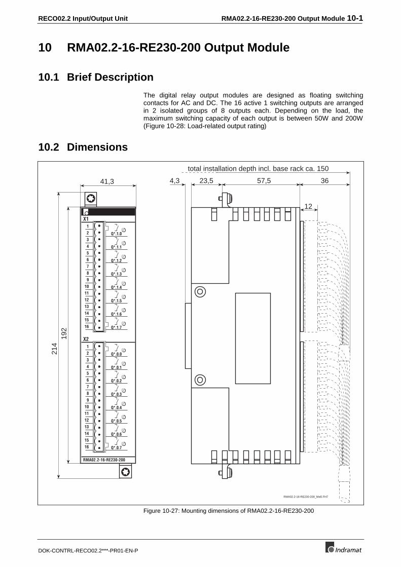
10.1 Brief Description
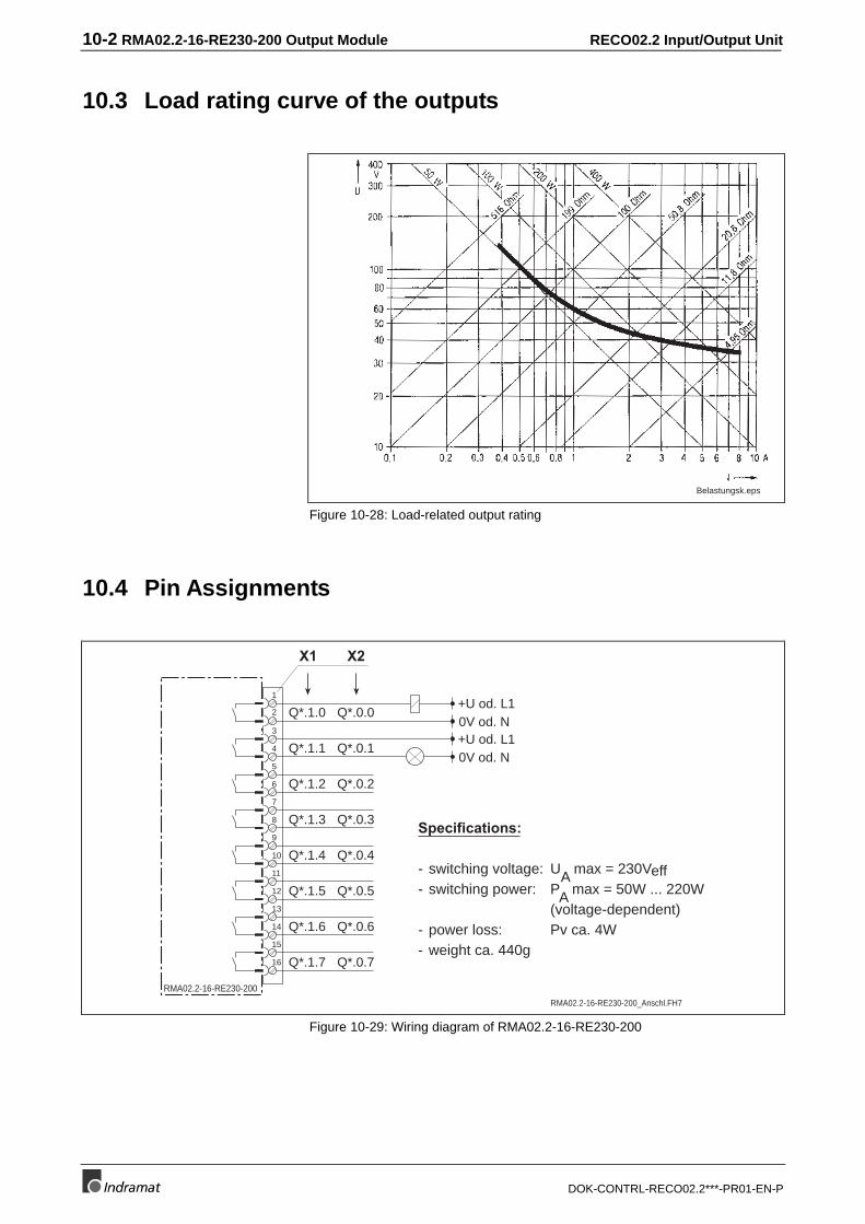
The digital relay output modules are designed as floating switchingcontacts for AC and DC. The 16 active 1 switching outputs are arrangedin 2 isolated groups of 8 outputs each. Depending on the load, themaximum switching capacity of each output is between 50W and 200W(Figure 10-28: Load-related output rating)
10.2 Dimensions
41,3
192
214
57,54,3
12
3623,5
total installation depth incl. base rack ca. 150
RMA02.2-16-RE230-200
1
2
3
4
5
6
7
8
9
10
11
12
13
14
15
16
1
2
3
4
5
6
7
8
9
10
11
12
13
14
15
16
X1
X2
Q*.1.0
Q*.1.1
Q*.1.2
Q*.1.3
Q*.1.4
Q*.1.5
Q*.1.6
Q*.1.7
Q*.0.0
Q*.0.1
Q*.0.2
Q*.0.3
Q*.0.4
Q*.0.5
Q*.0.6
Q*.0.7
RMA02.2-16-RE230-200_Maß.FH7
Figure 10-27: Mounting dimensions of RMA02.2-16-RE230-200
10-2 RMA02.2-16-RE230-200 Output Module RECO02.2 Input/Output Unit
DOK-CONTRL-RECO02.2***-PR01-EN-P
10.3 Load rating curve of the outputs
Belastungsk.eps
Figure 10-28: Load-related output rating
10.4 Pin Assignments
1
RMA02.2-16-RE230-200
+U od. L10V od. N
2
3
4
5
6
7
8
9
10
11
12
13
14
15
16
+U od. L10V od. N
Specifications:
- switching voltage: UA max = 230Veff- switching power: PA max = 50W ... 220W
(voltage-dependent)- power loss: Pv ca. 4W- weight ca. 440g
Q*.1.0
Q*.1.1
Q*.1.2
Q*.1.3
Q*.1.4
Q*.1.5
Q*.1.6
Q*.1.7
Q*.0.0
Q*.0.1
Q*.0.2
Q*.0.3
Q*.0.4
Q*.0.5
Q*.0.6
Q*.0.7
RMA02.2-16-RE230-200_Anschl.FH7
X1 X2
Figure 10-29: Wiring diagram of RMA02.2-16-RE230-200
RECO02.2 Input/Output Unit SERCOS Analog Module RMC02.2-2E-1A 11-1
DOK-CONTRL-RECO02.2***-PR01-EN-P
11 SERCOS Analog Module RMC02.2-2E-1A
11.1 General
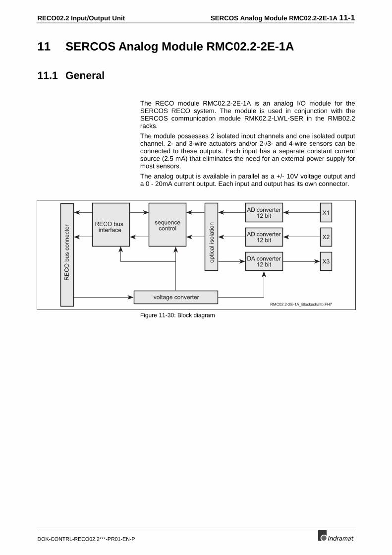
The RECO module RMC02.2-2E-1A is an analog I/O module for theSERCOS RECO system. The module is used in conjunction with theSERCOS communication module RMK02.2-LWL-SER in the RMB02.2racks.
The module possesses 2 isolated input channels and one isolated outputchannel. 2- and 3-wire actuators and/or 2-/3- and 4-wire sensors can beconnected to these outputs. Each input has a separate constant currentsource (2.5 mA) that eliminates the need for an external power supply formost sensors.
The analog output is available in parallel as a +/- 10V voltage output anda 0 - 20mA current output. Each input and output has its own connector.
RE
CO
bus
con
nect
or
RECO businterface
sequencecontrol
optic
al is
olat
ion
AD converter12 bit
DA converter12 bit
X1
X2
X3
AD converter12 bit
RMC02.2-2E-1A_Blockschaltb.FH7
voltage converter
Figure 11-30: Block diagram
11-2 SERCOS Analog Module RMC02.2-2E-1A RECO02.2 Input/Output Unit
DOK-CONTRL-RECO02.2***-PR01-EN-P
11.2 Dimensions
41,3
192
214
23,5 57,54,3
12
total installation depth incl. base rack ca. 150
ca.36
RMC02.2-2E-1A_Maß.FH7
X1IA CONST
RMC02.2-2E-1A
1
2
3
4
5
6
7
8
UANALOG
IINU IINUI +UI -GND A
GND A
X21
2
3
4
5
6
7
8
GND A
GND A
X3IO 0-20mA1
2
3
4
5
UO ±10V
GND A
GND A
ANALOG-INPUT 1
ANALOG-INPUT 2
ANALOG-OUTPUT 1
IA CONST
IINU IINUIN +UIN -
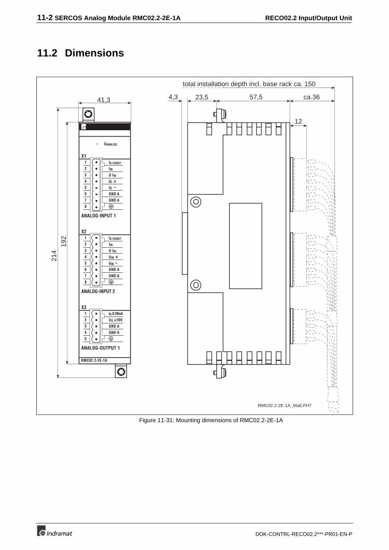
Figure 11-31: Mounting dimensions of RMC02.2-2E-1A
RECO02.2 Input/Output Unit SERCOS Analog Module RMC02.2-2E-1A 11-3
DOK-CONTRL-RECO02.2***-PR01-EN-P
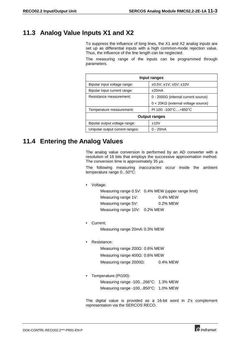
11.3 Analog Value Inputs X1 and X2
To suppress the influence of long lines, the X1 and X2 analog inputs areset up as differential inputs with a high common-mode rejection value.Thus, the influence of the line length can be neglected.
The measuring range of the inputs can be programmed throughparameters.
Input ranges
Bipolar input voltage range: ±0,5V; ±1V; ±5V; ±10V
Bipolar input current range: ±20mA
Resistance measurement: 0 - 2000Ω (internal current source)
0 < 20KΩ (external voltage source)
Temperature measurement: Pt 100: -100°C....+850°C
Output ranges
Bipolar output voltage range: ±10V
Unipolar output current ranges: 0 - 20mA
11.4 Entering the Analog Values
The analog value conversion is performed by an AD converter with aresolution of 16 bits that employs the successive approximation method.The conversion time is approximately 35 µs.
The following measuring inaccuracies occur inside the ambienttemperature range 0...50°C:
• Voltage:
Measuring range 0.5V: 0.4% MEW (upper range limit)
Measuring range 1V: 0.4% MEW
Measuring range 5V: 0.2% MEW
Measuring range 10V: 0.2% MEW
• Current:
Measuring range 20mA: 0.3% MEW
• Resistance:
Measuring range 200Ω: 0.6% MEW
Measuring range 400Ω: 0.6% MEW
Measuring range 2000Ω: 0.4% MEW
• Temperature (Pt100):
Measuring range -100...266°C: 1.3% MEW
Measuring range -100...850°C: 1.0% MEW
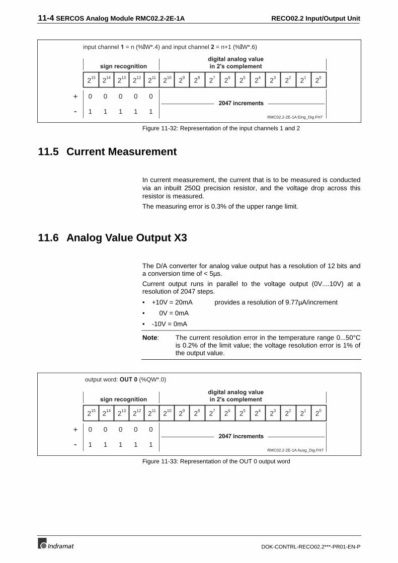
The digital value is provided as a 16-bit word in 2's complementrepresentation via the SERCOS RECO.
11-4 SERCOS Analog Module RMC02.2-2E-1A RECO02.2 Input/Output Unit
DOK-CONTRL-RECO02.2***-PR01-EN-P
RMC02.2-2E-1A Eing_Dig.FH7
215 214 213 212 211 210 29 28 27 26 25 23 22 21 2024
input channel 1 = n (%IW*.4) and input channel 2 = n+1 (%IW*.6)
sign recognitiondigital analog valuein 2's complement
2047 increments0 0 0 0 0
1 1 1 1 1-
+
Figure 11-32: Representation of the input channels 1 and 2
11.5 Current Measurement
In current measurement, the current that is to be measured is conductedvia an inbuilt 250Ω precision resistor, and the voltage drop across thisresistor is measured.
The measuring error is 0.3% of the upper range limit.
11.6 Analog Value Output X3
The D/A converter for analog value output has a resolution of 12 bits anda conversion time of < 5µs.
Current output runs in parallel to the voltage output (0V....10V) at aresolution of 2047 steps.
• +10V = 20mA provides a resolution of 9.77µA/increment
• 0V = 0mA
• -10V = 0mA
Note: The current resolution error in the temperature range 0...50°Cis 0.2% of the limit value; the voltage resolution error is 1% ofthe output value.
RMC02.2-2E-1A Ausg_Dig.FH7
215 214 213 212 211 210 29 28 27 26 25 23 22 21 2024
output word: OUT 0 (%QW*.0)
sign recognitiondigital analog valuein 2's complement
2047 increments0 0 0 0 0
1 1 1 1 1-
+
Figure 11-33: Representation of the OUT 0 output word
RECO02.2 Input/Output Unit SERCOS Analog Module RMC02.2-2E-1A 11-5
DOK-CONTRL-RECO02.2***-PR01-EN-P
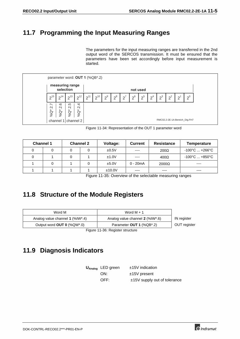
11.7 Programming the Input Measuring Ranges
The parameters for the input measuring ranges are transferred in the 2ndoutput word of the SERCOS transmission. It must be ensured that theparameters have been set accordingly before input measurement isstarted.
RMC02.2-2E-1A Bereich_Dig.FH7
215 214 213 212 211 210 29 28 27 26 25 23 22 21 2024
parameter word: OUT 1 (%QB*.2)
measuring rangeselection not used
channel 1 channel 2
%Q
*.2.
7
%Q
*.2.
6
%Q
*.2.
5
%Q
*.2.
4
Figure 11-34: Representation of the OUT 1 parameter word
Channel 1 Channel 2 Voltage: Current Resistance Temperature
0 0 0 0 ±0.5V ---- 200Ω -100°C ... +266°C
0 1 0 1 ±1.0V ---- 400Ω -100°C ... +850°C
1 0 1 0 ±5.0V 0 - 20mA 2000Ω ----
1 1 1 1 ±10.0V ---- ---- ----
Figure 11-35: Overview of the selectable measuring ranges
11.8 Structure of the Module Registers
Word M Word M + 1
Analog value channel 1 (%IW*.4) Analog value channel 2 (%IW*.6) IN register
Output word OUT 0 (%QW*.0) Parameter OUT 1 (%QB*.2) OUT register
Figure 11-36: Register structure
11.9 Diagnosis Indicators
UAnalog LED green ±15V indication
ON: ±15V present
OFF: ±15V supply out of tolerance
11-6 SERCOS Analog Module RMC02.2-2E-1A RECO02.2 Input/Output Unit
DOK-CONTRL-RECO02.2***-PR01-EN-P
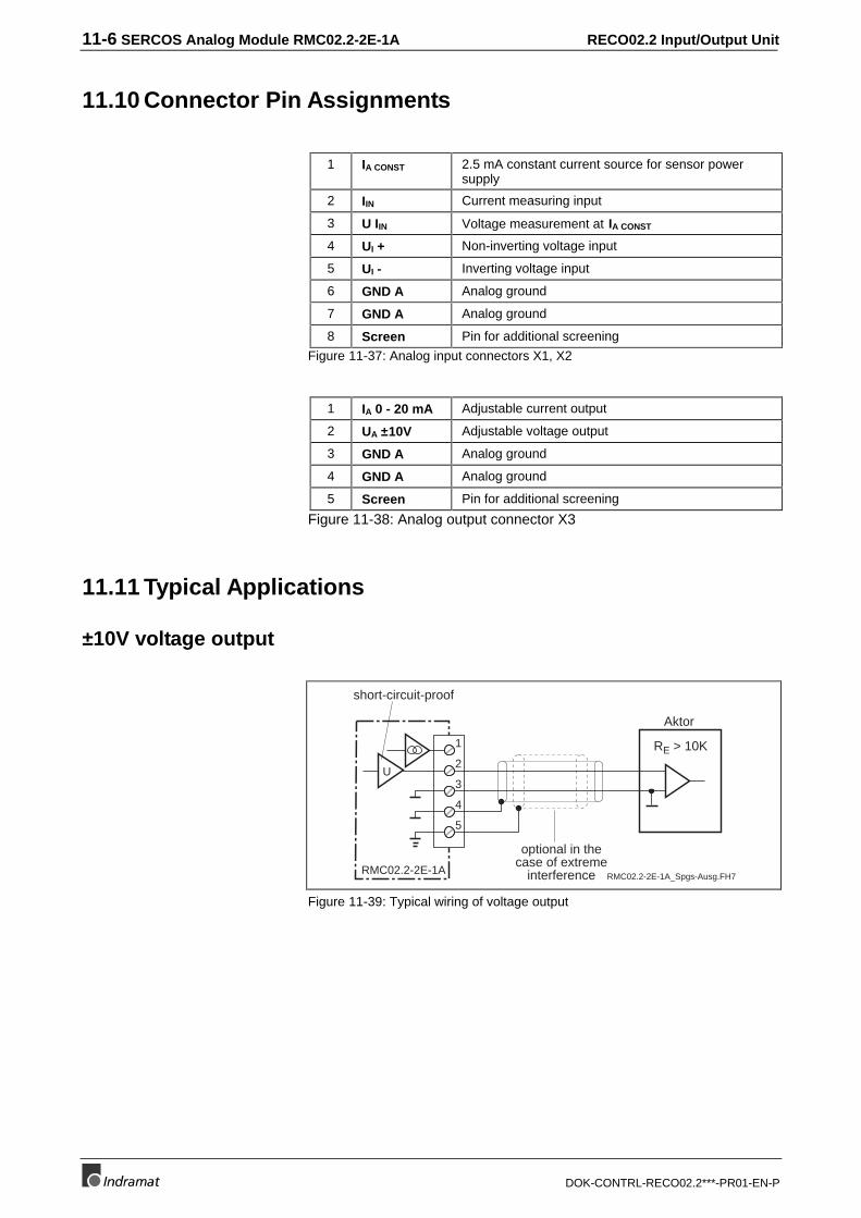
11.10 Connector Pin Assignments
1 IA CONST 2.5 mA constant current source for sensor powersupply
2 IIN Current measuring input
3 U IIN Voltage measurement at IA CONST
4 UI + Non-inverting voltage input
5 UI - Inverting voltage input
6 GND A Analog ground
7 GND A Analog ground
8 Screen Pin for additional screening
Figure 11-37: Analog input connectors X1, X2
1 IA 0 - 20 mA Adjustable current output
2 UA ±10V Adjustable voltage output
3 GND A Analog ground
4 GND A Analog ground
5 Screen Pin for additional screening
Figure 11-38: Analog output connector X3
11.11 Typical Applications
±10V voltage output
RMC02.2-2E-1A_Spgs-Ausg.FH7
Aktor
RE > 10K1
2
3
4
5
U
RMC02.2-2E-1A
optional in thecase of extreme
interference
short-circuit-proof
Figure 11-39: Typical wiring of voltage output
RECO02.2 Input/Output Unit SERCOS Analog Module RMC02.2-2E-1A 11-7
DOK-CONTRL-RECO02.2***-PR01-EN-P
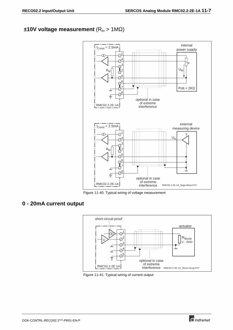
±10V voltage measurement (Rin > 1MΩ)
RMC02.2-2E-1A_Spgs-Mess.FH7
Poti < 2KΩ
1
4
3
2
5
RMC02.2-2E-1A
optional in caseof extreme
interference
IConst = 2.5mA
6
7
8
RMUM
internalpower supply
1
4
3
2
5
RMC02.2-2E-1A
IConst = 2.5mA
6
7
8
RM
externalmeasuring device
UA
optional in caseof extreme
interference
Figure 11-40: Typical wiring of voltage measurement
0 - 20mA current output
RMC02.2-2E-1A_Strom-Ausg.FH7
actuator
RBürde0 - 250Ω
1
2
3
4
5
U
RMC02.2-2E-1A
optional in caseof extreme
interference
short-circuit-proof
Figure 11-41: Typical wiring of current output
11-8 SERCOS Analog Module RMC02.2-2E-1A RECO02.2 Input/Output Unit
DOK-CONTRL-RECO02.2***-PR01-EN-P
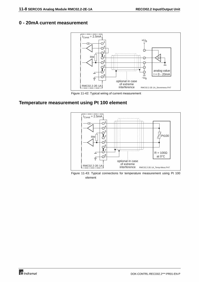
0 - 20mA current measurement
RMC02.2-2E-1A_Strommess.FH7
analog valueI = 0 - 20mA
1
4
3
2
5
RMC02.2-2E-1A
optional in caseof extreme
interference
IConst = 2.5mA
6
7
8
RM
+UB
-UB
Figure 11-42: Typical wiring of current measurement
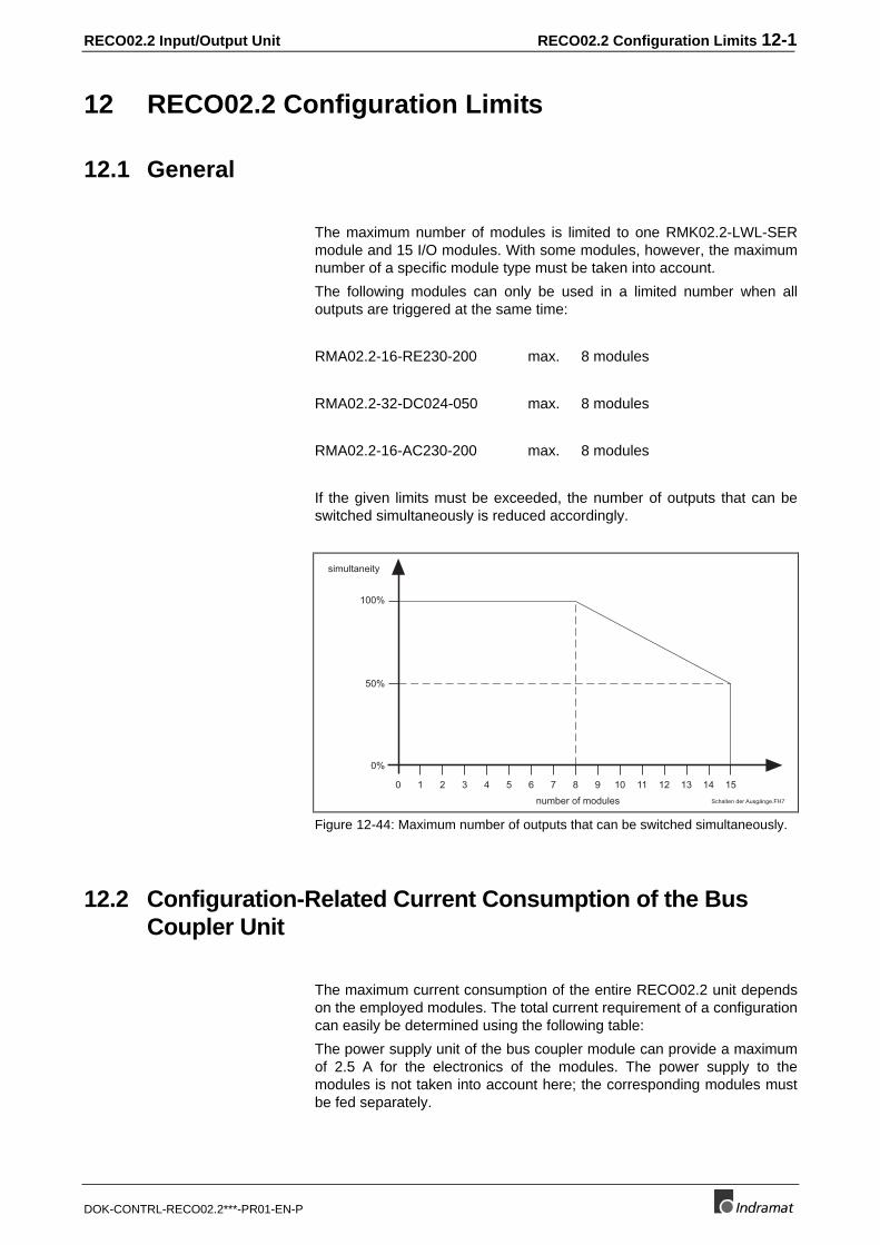
Temperature measurement using Pt 100 element
RMC02.2-2E-1A_Temp-Mess.FH7
R = 100Ωat 0°C
1
4
3
2
5
RMC02.2-2E-1A
optional in caseof extreme
interference
IConst = 2.5mA
6
7
8
RM Pt100
Figure 11-43: Typical connections for temperature measurement using Pt 100element
RECO02.2 Input/Output Unit RECO02.2 Configuration Limits 12-1
DOK-CONTRL-RECO02.2***-PR01-EN-P
12 RECO02.2 Configuration Limits
12.1 General
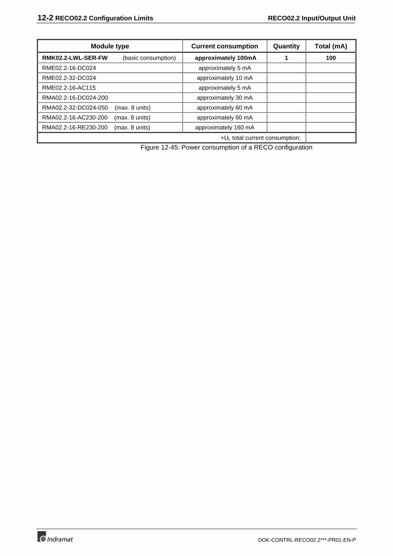
The maximum number of modules is limited to one RMK02.2-LWL-SERmodule and 15 I/O modules. With some modules, however, the maximumnumber of a specific module type must be taken into account.
The following modules can only be used in a limited number when alloutputs are triggered at the same time:
RMA02.2-16-RE230-200 max. 8 modules
RMA02.2-32-DC024-050 max. 8 modules
RMA02.2-16-AC230-200 max. 8 modules
If the given limits must be exceeded, the number of outputs that can beswitched simultaneously is reduced accordingly.
Schalten der Ausgänge.FH7
100%
50%
0%
10 2 3 4 5 6 7 8 9 10 11 12 13 14 15
simultaneity
number of modules
Figure 12-44: Maximum number of outputs that can be switched simultaneously.
12.2 Configuration-Related Current Consumption of the BusCoupler Unit
The maximum current consumption of the entire RECO02.2 unit dependson the employed modules. The total current requirement of a configurationcan easily be determined using the following table:
The power supply unit of the bus coupler module can provide a maximumof 2.5 A for the electronics of the modules. The power supply to themodules is not taken into account here; the corresponding modules mustbe fed separately.
12-2 RECO02.2 Configuration Limits RECO02.2 Input/Output Unit
DOK-CONTRL-RECO02.2***-PR01-EN-P
Module type Current consumption Quantity Total (mA)
RMK02.2-LWL-SER-FW (basic consumption) approximately 100mA 1 100
RME02.2-16-DC024 approximately 5 mA
RME02.2-32-DC024 approximately 10 mA
RME02.2-16-AC115 approximately 5 mA
RMA02.2-16-DC024-200 approximately 30 mA
RMA02.2-32-DC024-050 (max. 8 units) approximately 60 mA
RMA02.2-16-AC230-200 (max. 8 units) approximately 60 mA
RMA02.2-16-RE230-200 (max. 8 units) approximately 160 mA
+UL total current consumption:
Figure 12-45: Power consumption of a RECO configuration

RECO02.2 Input/Output Unit Accessories 13-1
DOK-CONTRL-RECO02.2***-PR01-EN-P
13 Accessories
13.1 Additional Annotation
A transparent carrier sheet that is glued to a side of the module can beused to provide the individual RECO I/O modules with additionalannotations. This foil can be glued to the left-hand or to the right-handside of the module housing. The carrier sheets are provided with anadhesive surface. The sheet is intended to accommodate the prepunchedstickers that come in quantities of six on an A4 foil.
The moisture-insensitive stickers can be printed on in a standard laserprinter. A word processing program is available that makes annotationeasier. This program is a Word 7.0 template for Windows NT that permits1 through 6 modules per sticker to be labelled. It can be selected whetherit is a 16-bit, or 32-bit, an input or an output module, and whether thesticker shall be glued to the right-hand or to the left-hand side of themodule.
Designation Type Material no.
Carrier sheet RECO annotation film 281 697
Annotation film RECO annotation film DIN A4 white 281 696
Annotation software SWD-CONTRL-REC-BESCH-MS-C1,44-WIN*NT 281 691Figure 13-46: Annotation accessories
13-2 Accessories RECO02.2 Input/Output Unit
DOK-CONTRL-RECO02.2***-PR01-EN-P
RECO02.2 Input/Output Unit Figures 14-1
DOK-CONTRL-RECO02.2***-PR01-EN-P
14 Figures
Figure 1-1: Brief overview - RECO02.2 1-1Figure 1-2: RMB02.2-04 maximum configuration 1-2Figure 1-3: Mounting dimensions of the RECO02.2 unit 1-3Figure 1-4: RMB02.2-04 rack 1-4Figure 1-5: Installing several RMB02.2-04 racks side by side 1-4Figure 1-6: Setting the slot addresses 1-5Figure 2-7: Typical address selection for an output module 2-2Figure 2-8: Bit, byte, word, and long word addresses for
input modules 2-3Figure 2-9: Bit, byte, word, and long word addresses for
output modules 2-4Figure 3-10: Mounting dimensions of RMK02.2-LWL-SER 3-1Figure 3-11: Setting the device no. and the light intensity 3-2Figure 3-12: Connector pin assignments of the power supply 3-3Figure 3-13: Operating states of RMK02.2-LWL-SER 3-4Figure 3-14: Error codes of RMK02.2-LWL-SER 3-4Figure 4-15: Mounting dimensions of RME02.2-16-DC024 4-1Figure 4-16: Wiring diagram of RME02.2-16-DC024 4-2Figure 5-17: Mounting dimensions of RME02.2-32-DC024 5-1Figure 5-18: Wiring diagram of RME02.2-32-DC024 5-2Figure 6-19: Mounting dimensions of RME02.2-16-AC115 6-1Figure 6-20: Wiring diagram of RME02.2-16-AC115 6-2Figure 7-21: Mounting dimensions of RMA02.2-16-DC024-200 7-1Figure 7-22: Wiring diagram of RMA02.2-16-DC024-200 7-2Figure 8-23: Mounting dimensions of RMA02.2-32-DC024-200 8-1Figure 8-24: Wiring diagram of RMA02.2-32-DC024-200 8-2Figure 9-25: Mounting dimensions of RMA02.2-16-AC230-200 9-1Figure 9-26: Wiring diagram of RMA02.2-16-AC230-200 9-2Figure 10-27: Mounting dimensions of RMA02.2-16-RE230-200 10-1Figure 10-28: Load-related output rating 10-2Figure 10-29: Wiring diagram of RMA02.2-16-RE230-200 10-2Figure 11-30: Block diagram 11-1Figure 11-31: Mounting dimensions of RMC02.2-2E-1A 11-2Figure 11-32: Representation of the input channels 1 and 2 11-4Figure 11-33: Representation of the OUT 0 output word 11-4Figure 11-34: Representation of the OUT 1 parameter word 11-5Figure 11-35: Overview of the selectable measuring ranges 11-5Figure 11-36: Register structure 11-5Figure 11-37: Analog input connectors X1, X2 11-6Figure 11-38: Analog output connector X3 11-6Figure 11-39: Typical wiring of voltage output 11-6Figure 11-40: Typical wiring of voltage measurement 11-7Figure 11-41: Typical wiring of current output 11-7Figure 11-42: Typical wiring of current measurement 11-8Figure 11-43: Typical connections for temperature measurement
using Pt 100 element 11-8Figure 12-44: Maximum number of outputs that can be
switched simultaneously. 12-1Figure 12-45: Power consumption of a RECO configuration 12-2Figure 13-46: Annotation accessories 13-1

14-2 Figures RECO02.2 Input/Output Unit
DOK-CONTRL-RECO02.2***-PR01-EN-P
RECO02.2 Input/Output Unit Service Agencies
DOK-CONTRL-RECO02.2***-PR01-EN-P
Sales & Service Facilities
Germany from abroad: don’t dial (0) after country code!
Vertriebsgebiet Mitte Germany Centre V/S Service
INDRAMAT GmbHBgm.-Dr.-Nebel-Str. 2D - 97816 Lohr am Main
Phone: +49 (0)9352/40-0Fax: +49 (0)9352/40-4885
Vertriebsgebiet Ost Germany East V/S Service
INDRAMAT GmbHBeckerstraße 31D - 09120 Chemnitz
Phone: +49 (0)371/35 55-0Fax: +49 (0)371/35 55-333
Vertriebsgebiet West Germany West V/S Service
INDRAMAT GmbHHarkortstraße 25D - 40849 Ratingen
Phone: +49 (0)2102/43 18-0Fax: +49 (0)2102/41 315
Vertriebsgebiet Nord Germany North V/S Service
INDRAMAT GmbHKieler Straße 212D - 22525 Hamburg
Phone: +49 (0)40/85 31 57-0Fax: +49 (0)40/85 31 57-15
Vertriebsgebiet Süd Germany South V/S Service
INDRAMAT GmbHRidlerstraße 75D-80339 München
Phone: +49 (0)89/540138-30Fax: +49 (0)89/540138-10
Gebiet Südwest Germany South-West V/S Service
INDRAMAT GmbHBöblinger Straße 25D-71229 Leonberg
Phone: +49 (0)7152/9 72-6Fax: +49 (0)7152/9 72-727
INDRAMAT Service-Hotline
INDRAMAT GmbHPhone: +49 (0)172/660 04 06
or
Phone: +49 (0)171/333 88 26
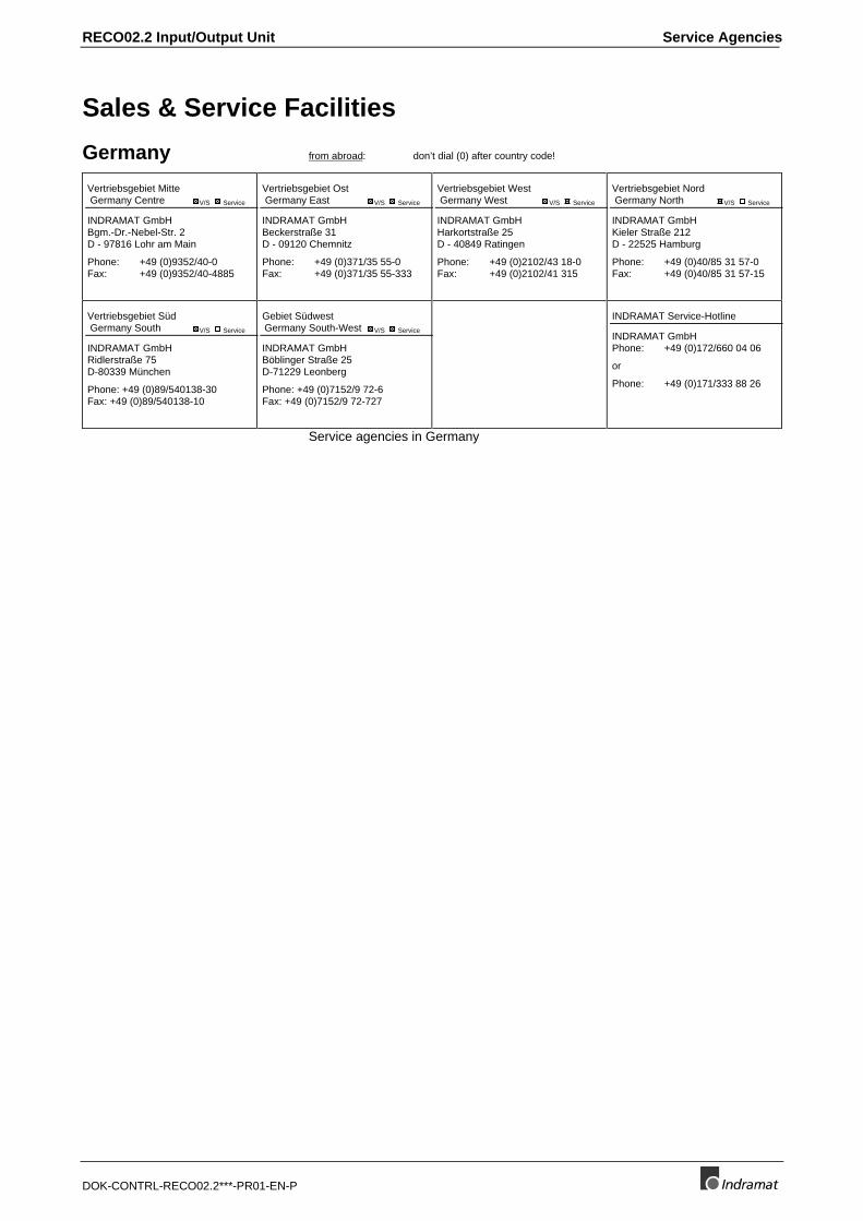
Service agencies in Germany
Service Agencies RECO02.2 Input/Output Unit
DOK-CONTRL-RECO02.2***-PR01-EN-P
Europe from abroad: don’t dial (0) after country code, dial 0 after country code!
Austria V/S Service
Mannesmann Rexroth Ges.m.b.H.Geschäftsbereich INDRAMATHägelingasse 3A - 1140 Wien
Phone: +43 (0)1/9852540-400Fax: +43 (0)1/9852540-93
Austria V/S Service
Mannesmann Rexroth G.m.b.H.Geschäftsbereich INDRAMATIndustriepark 18A - 4061 Pasching
Phone: +43 (0)7221/605-0Fax: +43 (0)7221/605-21
Belgium V/S Service
Mannesmann Rexroth N.V.-S.A.Geschäftsbereich INDRAMATIndustrielaan 8B-1740 Ternat
Phone: +32 (0)2/5823180Fax: +32 (0)2/5824310
Denmark V/S Service
BEC ASZinkvej 6DK-8900 Randers
Phone: +45 (0)87/11 90 60Fax: +45 (0)87/11 90 61
United Kingdom V/S Service
Mannesmann Rexroth Ltd.INDRAMAT Division4 Esland Place, Love LaneGB - Cirencester, Glos GL7 1YG
Phone: +44 (0)1285/658671Fax: +44 (0)1285/654991
Finland V/S Service
Rexroth Mecman OYAnsatie 6SF-017 40 Vantaa
Phone: +358 (0)9/84 91 11Fax: +358 (0)9/84 91 13 60
France V/S Service
Mannesmann Rexroth S.A.Division INDRAMATParc des Barbanniers4, Place du VillageF-92632 Gennevilliers Cedex
Phone: +33 (0)141 47 54 30Fax: +33 (0)147 94 69 41Hotline: +33 (0)6 08 33 43 28
France V/S Service
Mannesmann Rexroth S.A.Division INDRAMAT270, Avenue de LardenneF - 31100 Toulouse
Phone: +33 (0)5 61 49 95 19Fax: +33 (0)5 61 31 00 41
France V/S Service
Mannesmann Rexroth S.A.Division INDRAMAT91, Bd. Irène Joliot-CurieF - 69634 Vénissieux - Cedex
Phone: +33 (0)4 78 78 53 65Fax: +33 (0)4 78 78 52 53
Italy V/S Service
Mannesmann Rexroth S.p.A.Divisione INDRAMATVia G. Di Vittoria, 1I - 20063 Cernusco S/N.MI
Phone: +39 02/92 36 52 70Fax: +39 02/92 36 55 12
Italy V/S Service
Mannesmann Rexroth S.p.A.Divisione INDRAMATVia Borgomanero, 11I - 10145 Torino
Phone: +39 011/7 71 22 30Fax: +39 011/7 71 01 90
Italy V/S Service
Mannesmann Rexroth S.p.A.Divisione INDRAMATVia del Progresso, 16 (Zona Ind.)I - 35020 Padova
Phone: +39 049/8 70 13 70Fax: +39 049/8 70 13 77
Italy V/S Service
Mannesmann Rexroth S.p.A.Divisione INDRAMATVia de Nicola, 12I - 80053 Castellamare di Stabbia NA
Phone: +39 081/8 72 30 37Fax: +39 081/8 72 30 18
Italy V/S Service
Mannesmann Rexroth S.p.A.Divisione INDRAMATViale Oriani, 38/AI - 40137 Bologna
Phone: +39 051/34 14 14Fax: +39 051/34 14 22
Netherlands V/S Service
Hydraudyne Hydrauliek B.V.Kruisbroeksestraat 1P.O. Box 32NL - 5281 RV Boxtel
Phone: +31 (0)411/65 19 51Fax: +31 (0)411/65 14 83e-mail: [email protected]
Netherlands V/S Service
Hydrocare B.V.Kruisbroeksestraat 1P.O. Box 32NL - 5281 RV Boxtel
Phone: +31 (0)411/65 19 51Fax: +31 (0)411/67 78 14
Poland V/S Service
Mannesmann Rexroth Sp.zo.o.Biuro Poznanul. Dabrowskiego 81/85PL – 60-529 Poznan
Phone: +48 061/847 67 99Fax: +48 061/847 64 02
Spain V/S Service
Mannesmann Rexroth S.A.Divisiòn INDRAMATCentro Industrial SantigaObradors s/nE-08130 Santa Perpetua de MogodaBarcelona
Phone: +34 937 47 94 00Fax: +34 937 47 94 01
Spain V/S Service
Goimendi S.A.División IndramatJolastokieta (Herrera)Apartado 11 37E - 20017 San Sebastian
Phone: +34 9 43/40 01 63Fax: +34 9 43/39 17 99
Sweden V/S Service
Rexroth Mecman Svenska ABINDRAMAT DivisionVaruvägen 7S - 125 81 Stockholm
Phone: +46 (0)8/727 92 00Fax: +46 (0)8/64 73 277
Switzerland - East V/S Service
Mannesmann Rexroth AGGeschäftsbereich INDRAMATGewerbestraße 3CH-8500 Frauenfeld
Phone: +41 (0)52/720 21 00Fax: +41 (0)52/720 21 11
Switzerland - West V/S Service
Mannesmann Rexroth SADépartement INDRAMATChemin de l`Ecole 6CH-1036 Sullens
Phone: +41 (0)21/731 43 77Fax: +41 (0)21/731 46 78
Russia V/S Service
Tschudnenko E.B.Arsenia 22RUS - 153000 IvanovoRußland
Phone: +7 093/223 96 33oder/or +7 093/223 95 48Fax: +7 093/223 46 01
Slowenia V/S Service
INDRAMAT elektromotorji d.o.o.Otoki 21SLO - 64 228 Zelezniki
Phone: +386 64/61 73 32Fax: +386 64/64 71 50
Turkey V/S Service
Mannesmann Rexroth Hidropar A..S.Fevzi Cakmak Cad No. 3TR - 34630 Sefaköy Istanbul
Phone: +90 212/541 60 70Fax: +90 212/599 34 07
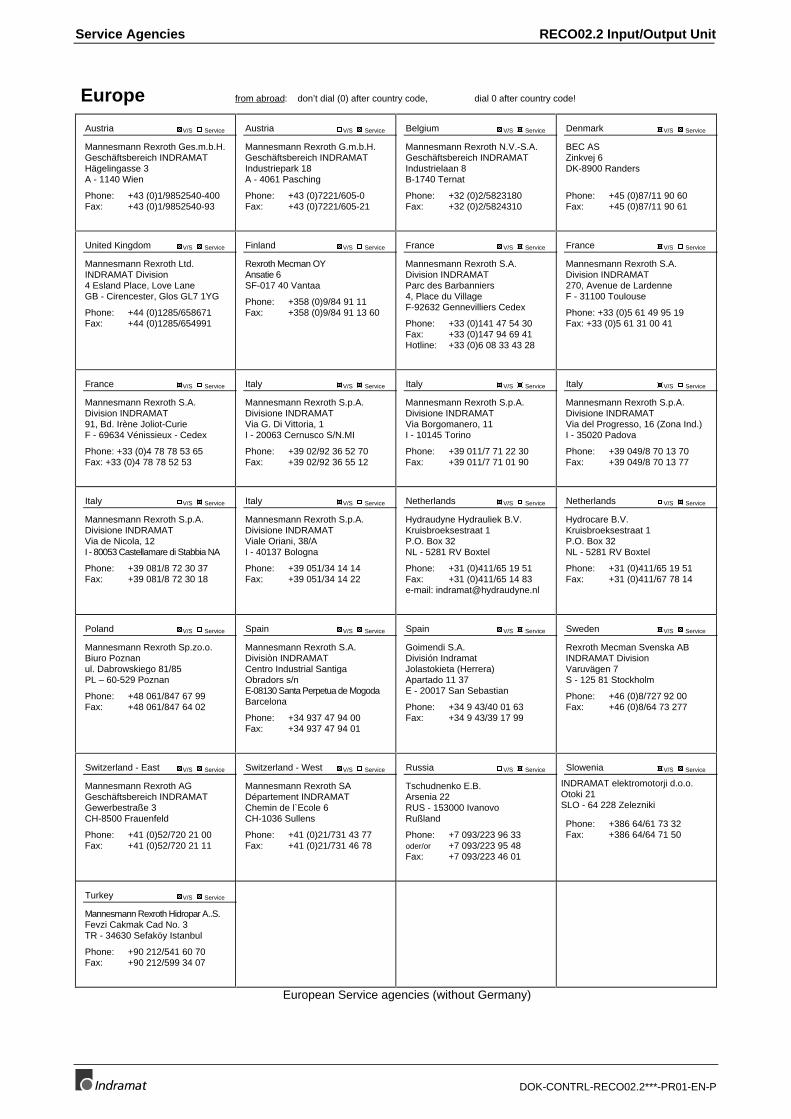
European Service agencies (without Germany)
RECO02.2 Input/Output Unit Service Agencies
DOK-CONTRL-RECO02.2***-PR01-EN-P
Outside Europe from abroad: don’t dial (0) after country code!
Argentina V/S Service
Mannesmann Rexroth S.A.I.C.Division INDRAMATAcassusso 48 41/7RA - 1605 Munro (Buenos Aires)
Phone: +54 (0)1/756 01 40+54 (0)1/756 01 36
Argentina V/S Service
NAKASEAsesoramiento TecnicoCalle 49, No. 5764-66RA - 1653 Villa BalesterProvincia de Buenos Aires
Phone: +54 (0) 1/768 36 43Fax: +54 (0) 1/768 24 13e-mail: Fehler! Textmarke nichtdefiniert.net
Australia V/S Service
AIMS - Australian IndustrialMachinery Services Pty. Ltd.Unit 3/45 Horne STCampbellfield 3061AUS - Melbourne, VIC
Phone: +61 (0)3/93 59 02 28Fax: +61 (0)3/93 59 02 86
Brazil V/S Service
Mannesmann RexrothAutomação Ltda.Divisão INDRAMATRua Georg Rexroth, 609Vila Padre AnchietaBR - 09951-270 Diadema-SP[ Caixa Postal 377 ][ BR-09901-970 Diadema-SP ]
Phone: +55 (0)11/745 90 60+55 (0)11/745 90 70
Fax: +55 (0)11/745 90 50
Brazil V/S Service
Mannesmann RexrothAutomação Ltda.Divisão INDRAMATRua Umberto Pinheiro Vieira, 100Distrito IndustrialBR - 09220-390 Joinville - SC[ Caixa Postal 1273 ]
Tel./Fax: +55 (0)47/473 55 833Mobil: +55 (0)47 974 6645e-mail: [email protected]
Canada V/S Service
Basic Technologies CorporationBurlington Division3426 Mainway DriveBurlington, OntarioCanada L7M 1A8
Phone: +1 905/335 55 11Fax: +1 905/335-41 84
China V/S Service
Mannesmann Rexroth (China) Ldt.Shanghai Office - Room 206Shanghai Internat. Trade Centre2200 Yanan Xi LuPRC - Shanghai 200335
Phone: +86 21/62 75 53 33Fax: +86 21/62 75 56 66
China V/S Service
Mannesmann Rexroth (China) Ldt.Shanghai Parts & Service Center199 Wu Cao Road, Hua CaoMinhang DistrictPRC - Shanghai 201 103
Phone: +86 21/62 20 00 58Fax: +86 21/62 20 00 68
China V/S Service
Mannesmann Rexroth (China) Ldt.15/F China World Trade Center1, Jianguomenwai AvenuePRC - Beijing 100004
Phone: +86 10/65 05 03 80Fax: +86 10/65 05 03 79
China V/S Service
Mannesmann Rexroth (China) Ldt.A-5F., 123 Lian Shan StreetSha He Kou DistrictPRC - Dalian 116 023
Phone: +86 411/46 78 930Fax: +86 411/46 78 932
Hong Kong V/S Service
Rexroth (China) Ldt.19 Cheung Shun Street1st Floor, Cheung Sha Wan,Kowloon, Hong Kong
Phone: +852 22 62 51 00Fax: +852 27 41 33 44
India V/S Service
Mannesmann Rexroth (India) Ltd.INDRAMAT DivisionPlot. 96, Phase IIIPeenya Industrial AreaIND - Bangalore - 560058
Phone: +91 (0)80/8 39 21 01Fax: +91 (0)80/8 39 43 45
India V/S Service
Mannesmann Rexroth (India) Ltd.INDRAMAT DivisionPlot. A-58, TTC Industrial AreaThane Turbhe Midc RoadMahape VillageIND - Navi Mumbai - 400 701
Phone: +91 (0)22/7 61 46 22Fax: +91 (0)22/7 68 15 31
Indonesia V/S Service
PT. Rexroth WijayakusumaJl. Raya Bekasi Km 21PulogadungRI - Jakarta Timur 13920
Phone: +62 21/4 61 04 87+62 21/4 61 04 88
Fax: +62 21/4 60 01 52
Japan V/S Service
Rexroth Automation Co., Ltd.INDRAMAT Division1F, I.R. BuildingNakamachidai 4-26-44Tsuzuki-ku, YOKOHAMA224-0041 Japan
Phone: +81 459/42-72 10Fax: +81 459/42-03 41
Japan V/S Service
Rexroth Automation Co., Ltd.INDRAMAT DivisionYutakagaoka 1810Meito-ku, NAGOYA465-0035 Japan
Phone: +81 (0)52/777 88 41+81 (0)52/777 88 53+81 (0)52/777 88 79
Fax: +81 (0)52/777 89 01
Mexico V/S Service
Rexroth Mexico S.A. de C.V.Calle Neptuno 72Unidad Ind. VallejoMEX - 07700 Mexico, D.F.
Phone: +52 5 754 17 11+52 5 754 36 84+52 5 754 12 60
Fax: +52 5 754 50 73+52 5 752 59 43
Korea V/S Service
Mannesmann Rexroth-Seki Co Ltd.1500-12 Da-Dae-DongROK - Saha-Ku, Pusan, 604-050
Phone: +82 (0)51/2 60 06 18Fax: +82 (0)51/2 60 06 19
Korea V/S Service
Seo Chang Corporation Ltd.Room 903, Jeail Building44-35 Yeouido-DongYeoungdeungpo-KuC.P.O.Box 97 56ROK - Seoul
Phone: +82 (0)2/7 80 82 08+82 (0)2/7 80 82 09
Fax: +82 (0)2/7 84 54 08
South Africa V/S Service
HYTEC Automation (Pty) Ltd.28 Banfield Road,Industria NorthRSA - Maraisburg 1700
Phone: +27 (0)11/673 20 80Fax: +27 (0)11/673 72 69
Taiwan V/S Service
Rexroth Uchida Co., Ltd.No.1, Tsu Chiang StreetTu Cheng Ind. EstateTaipei Hsien, Taiwan, R.O.C.
Phone: +886 2/2 68 13 47Fax: +886 2/2 68 53 88
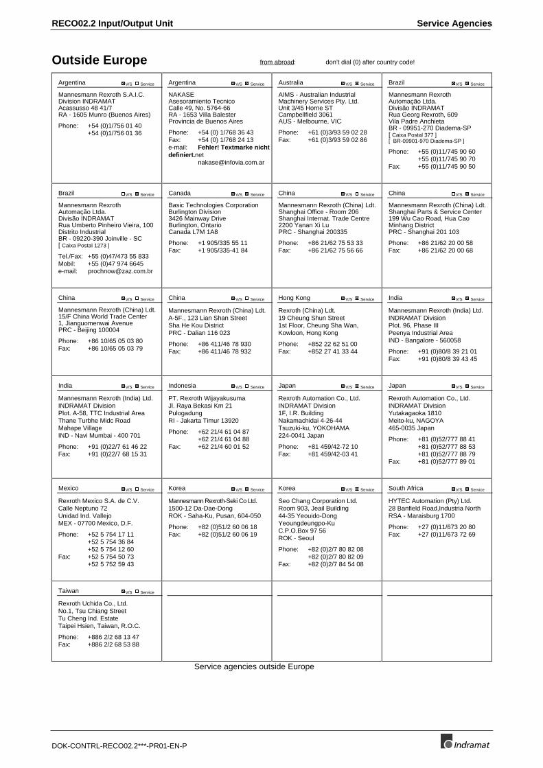
Service agencies outside Europe
Service Agencies RECO02.2 Input/Output Unit
DOK-CONTRL-RECO02.2***-PR01-EN-P
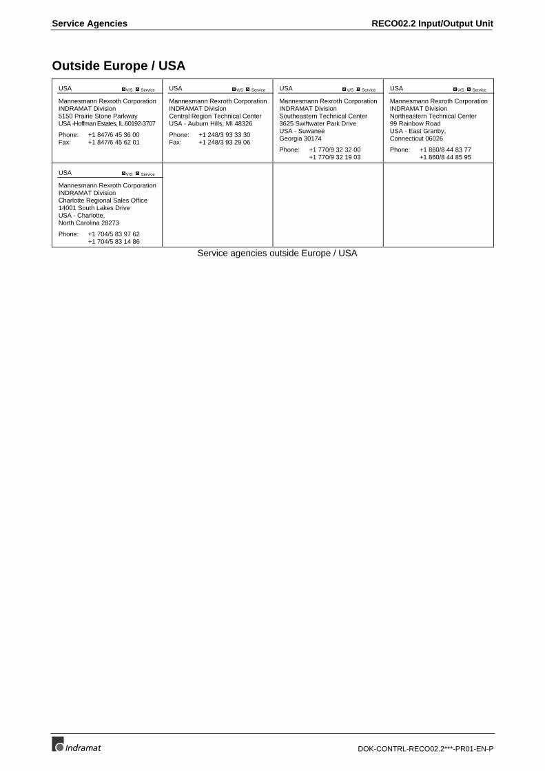
Outside Europe / USA
USA V/S Service
Mannesmann Rexroth CorporationINDRAMAT Division5150 Prairie Stone ParkwayUSA -Hoffman Estates, IL 60192-3707
Phone: +1 847/6 45 36 00Fax: +1 847/6 45 62 01
USA V/S Service
Mannesmann Rexroth CorporationINDRAMAT DivisionCentral Region Technical CenterUSA - Auburn Hills, MI 48326
Phone: +1 248/3 93 33 30Fax: +1 248/3 93 29 06
USA V/S Service
Mannesmann Rexroth CorporationINDRAMAT DivisionSoutheastern Technical Center3625 Swiftwater Park DriveUSA - SuwaneeGeorgia 30174
Phone: +1 770/9 32 32 00+1 770/9 32 19 03
USA V/S Service
Mannesmann Rexroth CorporationINDRAMAT DivisionNortheastern Technical Center99 Rainbow RoadUSA - East Granby,Connecticut 06026
Phone: +1 860/8 44 83 77+1 860/8 44 85 95
USA V/S Service
Mannesmann Rexroth CorporationINDRAMAT DivisionCharlotte Regional Sales Office14001 South Lakes DriveUSA - Charlotte,North Carolina 28273
Phone: +1 704/5 83 97 62+1 704/5 83 14 86
Service agencies outside Europe / USA
RECO02.2 Input/Output Unit Service Agencies
DOK-CONTRL-RECO02.2***-PR01-EN-P
Notes

283915
IndramatRexroth
Prin
ted
in G
erm
any