Embed Size (px)
Citation preview
IEEE TRANSACTIONS ON VEHICULAR TECHNOLOGY, VOL. 63, NO. 5, JUNE 2014 2183
Serial Amplify-and-Forward Relay TransmissionSystems in Nakagami-m Fading Channels
With a Poisson Interference FieldValentine A. Aalo, Senior Member, IEEE, Kostas P. Peppas, Member, IEEE, George P. Efthymoglou, Member, IEEE,
Mohammed M. Alwakeel, and Sami S. Alwakeel, Member, IEEE
Abstract—In this paper, the end-to-end performance of a wire-less relay transmission system that employs amplify-and-forward(AF) relays and operates in an interference-limited Nakagami-mfading environment is studied. The wireless links from one relaynode to another experience Nakagami-m fading, and the num-ber of interferers per hop is Poisson distributed. The aggregateinterference at each relay node is modeled as a shot-noise processwhose distribution follows an α-stable process. For the consideredsystem, analytical expressions for the moments of the end-to-endsignal-to-interference ratio (SIR), the end-to-end outage probabil-ity (OP), the average bit-error probability (ABEP), and the aver-age channel capacity are obtained. General asymptotic expressionsfor the end-to-end ABEP are also derived. The results provideuseful insights regarding the factors affecting the performance ofthe considered system. Monte Carlo simulation results are furtherprovided to demonstrate the validity of the proposed mathematicalanalysis.
Index Terms—Amplify-and-forward (AF), average bit-errorprobability (ABEP), channel capacity, cochannel interference,Fox’s H-function, Meijer’s G-function, multihop relaying, Poissoninterference field.
I. INTRODUCTION
MULTIHOP relaying has recently received considerableattention in the literature because of its potential to
provide more efficient and broader coverage in microwave andbent-pipe satellites links, as well as cellular, modern ad hoc,wireless local area, and hybrid wireless networks [1]. There-fore, multihop relaying, which is designed for extended cover-
Manuscript received November 13, 2012; revised July 5, 2013 andOctober 12, 2013; accepted October 17, 2013. Date of publicationNovember 14, 2013; date of current version June 12, 2014. This work wassupported by the Sensor Networks and Cellular Systems Research Centerof the University of Tabuk. The review of this paper was coordinated byProf. J. Y. Chouinard.
V. A. Aalo is with the Department of Computer and Electrical Engineeringand Computer Science, Florida Atlantic University, Boca Raton, FL 33431USA , and also with SNCS Research Center, University of Tabuk, Saudi Arabia(e-mail: [email protected]).
K. P. Peppas is with the Institute of Informatics and Telecommunications,National Centre for Scientific Research “Demokritos,” 15310 Athens, Greece(e-mail: [email protected]).
G. P. Efthymoglou is with the Department of Digital Systems, University ofPiraeus, 18534 Piraeus, Greece (e-mail: [email protected]).
M. M. Alwakeel is with the Sensor Networks and Cellular Systems ResearchCenter, University of Tabuk, Tabuk 71491, Saudi Arabia (e-mail: [email protected]).
S. S. Alwakeel is with the Department of Computer Engineering, King SaudUniversity, Riyadh 11543, Saudi Arabia, and also with the Sensor Networksand Cellular Systems Research Center, University of Tabuk, Tabuk 71491,Saudi Arabia (e-mail: [email protected]).
Digital Object Identifier 10.1109/TVT.2013.2291039
age and throughput enhancement, has been adopted in severalwireless standards [2]–[4]. In a multihop relaying system,intermediate idle nodes that are closer to the transmitter than thedestination operate as relays between the source node and thedestination node when the direct link between the source nodeand the destination node is deeply faded or highly shadowed.
Various protocols have been proposed to achieve the benefitsof multihop transmission. One of them is the so-called amplify-and-forward (AF) protocol, in which the received signal issimply amplified and forwarded to the receiver without per-forming any decoding [5]. The performance of multihop AFrelaying systems in series has been addressed in many pastworks based on the assumption that the system performanceis limited by Gaussian [6], [7] or generic noise [8]. On the otherhand, practical relaying systems generally employ frequencyreuse, which results in cochannel interference. The impact ofcochannel interference on the performance of AF relay systemsin a fading environment has been studied in many recent works,assuming a fixed number of interfering signals that are Rayleighor Nakagami-m distributed at each relay node and at the desti-nation node. (See [9]–[18] and references therein for examples.)
However, in a practical wireless environment, the numberof interfering signals at each relay may be a random variableas well. Moreover, in many wireless networks, the interfer-ing signals also experience attenuation due to path loss andshadowing, whereas their location and activity around thereceiving node may vary randomly [19]. Specifically, in theemerging heterogeneous cellular systems, the positions of manyinfrastructure elements are unknown a priori, and the presenceof unplanned network deployments should be considered bysystem designers. Moreover, due to the random spatial positionsof the interferers, it is more insightful to provide performancemetrics that are averaged over fast fading and spatial positionof each interferer.
Inspired by the seminal work in [20], in the emerging hetero-geneous cellular systems, a promising approach to model inter-ference is to treat the locations of some network elements (e.g.,cognitive radios and femto base stations) as points distributedaccording to the spatial Poisson point process (PPP). This modeloffers analytical flexibility and can provide insightful informa-tion on the effect of critical statistical–physical parameters on thesystem performance. For these reasons, network interferencemodeling based on PPP spatial models has attracted the interestof many researchers. Specifically, in [21] and [22], PPPs have
0018-9545 © 2013 IEEE. Personal use is permitted, but republication/redistribution requires IEEE permission.See http://www.ieee.org/publications_standards/publications/rights/index.html for more information.
2184 IEEE TRANSACTIONS ON VEHICULAR TECHNOLOGY, VOL. 63, NO. 5, JUNE 2014
been used to model cochannel interference from macrocellularbase stations. Cross-tier interference from femtocells was dis-cussed in [23] and [24], whereas in [25], cochannel interferencein ad hoc networks was investigated. Cochannel interference asa generic source of interference was addressed in [26] and [27].In [28], a unified framework for interference characterizationsand analysis in the unlicensed frequency bands was presented,assuming that interferers can have any power spectral densityand are distributed according to a Poisson process in spaceand frequency domains. The performance of diversity receiversin a Rayleigh fading environment and network interferencefrom a Poisson field of interference sources was addressed in[29]. In [30], a simplified interference model for heterogeneousnetworks to analyze downlink performance in a fixed size cellin a Poisson field of interferers was proposed. In [31], theperformance of multiantenna systems in a Poisson field ofinterferers was addressed.
To the best of our knowledge, although the PPP interfer-ence model has been used extensively in a variety of wirelessnetworks to account for the randomness in the number, thelocation, and the activity of the interferers, this model hasrarely been applied to the relay and destination nodes of amultihop relay network. Two recent examples include [32]and [33]. Specifically, in [32], analytical expressions for theoutage probability (OP) and average bit-error rate of dual-hop AF relaying, using the best relay in a 2-D Poisson fieldof relays, were derived. In [33], the random access transportcapacity of multihop AF relaying in a Poisson interference fieldwas addressed. In this paper, we analyze the performance ofmultihop AF systems in the presence of a Poisson distributedinterference field, in which the relay is assumed to possess per-fect channel state information. The interference model adoptedin this paper is based on the assumption that the number ofinterferers is a Poisson distributed random variable, whereasthe terminals are randomly distributed over the network areaand undergo Nakagami-m fading. Moreover, the wireless linksbetween relay nodes are assumed to be subject to Nakagami-mfading as well. It is also noted that the interference model underconsideration takes into account the randomness in the numberand location of the interferers and the effect of path loss for theinterfering signals. The main contributions of this paper are asfollows.
• Using the theory of Fox’s H-functions and Mellin–Barnesintegrals, a novel closed-form expression for the probabil-ity density function (pdf) of the aggregate interference isfirst derived. This result is afterward used to obtain closed-form expressions for important statistics of the signal-to-interference ratio (SIR) of each hop, i.e., the pdf, thecumulative distribution function (cdf) of the SIR, and themoment-generating function (MGF) of the inverse SIR.
• Exact analytical expressions for the uth moment of theend-to-end SIR are derived.
• Exact analytical expressions and closed-form lowerbounds for the OP are derived. These bounds become tightat high values of SIR.
• Exact analytical expressions and tight lower bounds for theaverage bit-error probability (ABEP) of digital modulationschemes and exact analytical expressions for the average
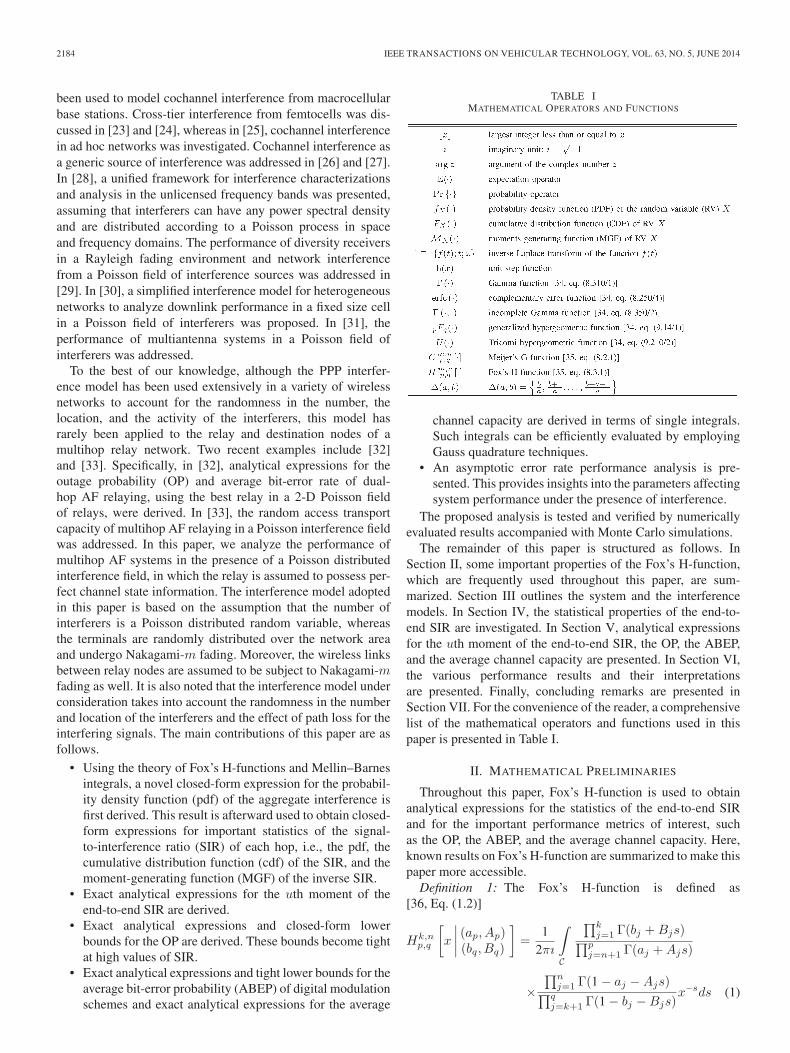
TABLE IMATHEMATICAL OPERATORS AND FUNCTIONS
channel capacity are derived in terms of single integrals.Such integrals can be efficiently evaluated by employingGauss quadrature techniques.
• An asymptotic error rate performance analysis is pre-sented. This provides insights into the parameters affectingsystem performance under the presence of interference.
The proposed analysis is tested and verified by numericallyevaluated results accompanied with Monte Carlo simulations.
The remainder of this paper is structured as follows. InSection II, some important properties of the Fox’s H-function,which are frequently used throughout this paper, are sum-marized. Section III outlines the system and the interferencemodels. In Section IV, the statistical properties of the end-to-end SIR are investigated. In Section V, analytical expressionsfor the uth moment of the end-to-end SIR, the OP, the ABEP,and the average channel capacity are presented. In Section VI,the various performance results and their interpretationsare presented. Finally, concluding remarks are presented inSection VII. For the convenience of the reader, a comprehensivelist of the mathematical operators and functions used in thispaper is presented in Table I.
II. MATHEMATICAL PRELIMINARIES
Throughout this paper, Fox’s H-function is used to obtainanalytical expressions for the statistics of the end-to-end SIRand for the important performance metrics of interest, suchas the OP, the ABEP, and the average channel capacity. Here,known results on Fox’s H-function are summarized to make thispaper more accessible.
Definition 1: The Fox’s H-function is defined as[36, Eq. (1.2)]
Hk,np,q
[x
∣∣∣∣ (ap, Ap)(bq, Bq)
]=
12πı
∫C
∏kj=1 Γ(bj +Bjs)∏p
j=n+1 Γ(aj +Ajs)
×∏n
j=1 Γ(1 − aj −Ajs)∏qj=k+1 Γ(1 − bj −Bjs)
x−sds (1)
AALO et al.: SERIAL AF RELAY TRANSMISSION SYSTEMS IN NAKAGAMI-m FADING CHANNELS 2185
where C is a suitable contour separating the poles of Γ(bj +Bjs) from the poles of Γ(1 − aj −Ajs).
Note that, for Aj = Bj = 1, the Fox’s H-Function reducesto the more familiar Meijer’s G-function [35, Eq. (8.2.1)]. Thefollowing identities presented serve as a direct consequence ofthe definition of the H-function by the application of certainproperties of gamma functions.
Property 1: There holds the formula [36, Eq. (1.58)]
Hk,np,q
[x
∣∣∣∣ (ap, Ap)(bq, Bq)
]= Hn,k
q,p
[1x
∣∣∣∣ (1 − bq, Bq)(1 − ap, Ap)
]. (2)
Property 2: The following reduction formulas are valid[36, Eqs. (1.56, 1.57)]:
Hk,np,q
[x
∣∣∣∣ (a1, A1), . . . , (ap, Ap)(b1, B1), . . . , (bq−1, Bq−1), (a1, A1)
]
= Hk,n−1p−1,q−1
[x
∣∣∣∣ (a2, A2), . . . , (ap, Ap)(b1, B1), . . . , (bq−1, Bq−1)
](3)
provided that n ≥ 1 and q > k and
Hk,np,q
[x
∣∣∣∣ (a1, A1), . . . , (ap−1, Ap−1), (b1, B1)(b1, B1), . . . , (bq, Bq)
]
= Hk−1,np−1,q−1
[x
∣∣∣∣ (a1, A1), . . . , (ap−1, Ap−1)(b2, B2), . . . , (bq, Bq)
](4)
provided that k ≥ 1 and p > n.The rth-order derivative of Fox’s H-function can be obtained
using the following property.Property 3: Identity (5), shown at the bottom of the page,
holds [36, Eq. (1.83)], where h > 0.Throughout this paper, integral transforms of Fox’s
H-function are used to derive the main results. The Mellin andLaplace transforms of the Fox’s H-function are of particularinterest. An important property of the H-function states thatthe Mellin transform of the product of two Fox’s H-functionsis also a Fox’s H-function, as summarized in the followingtheorem.
Theorem 1: The following integral identity is valid[36, p. 60], [35, Eq. (2.25.1.1)]:
∞∫0
xα−1Hs,tu,v
[σx
∣∣∣∣ (cu, Cu)(dv, Dv)
]Hk,n
p,q
[ωxr
∣∣∣∣ (ap, Ap)(bq, Bq)
]dx
= σ−αHk+t,n+sp+v,q+u
[ω
σr
∣∣∣∣ (ap+v, Ap+v)
(bq+u, Bq+u)
](6)
where α, σ, and ω are complex numbers; r > 0; and
(ap+v, Ap+v) = {(an, An), (1 − dv − αDv, rDv)
(an+1, An+1), . . . , (ap, Ap)}
(bq+u, Bq+u) = {(bk, Bk), (1 − cu − αCu, rCu)
(bk+1, Bk+1), . . . , (bq, Bq)}
provided that the following conditions are satisfied:
a∗Δ=
n∑j=1
Aj −p∑
j=n+1
Aj +
k∑j=1
Bj −q∑
j=k+1
Bj > 0
b∗Δ=
t∑j=1
Cj −u∑
j=t+1
Cj +
s∑j=1
Dj −v∑
j=s+1
Dj > 0
r > 0| arg σ| < b∗π/2 | argω| < a∗π/2
�{α}+ r min1≤j≤k
�{bj/Bj}+ min1≤h≤s
�{dh/Dh} > 0
�{α}+ r max1≤j≤n
�{(aj − 1)/Aj}
+ max1≤h≤t
�{(ch − 1)/Ch} < 0.
Proof: See [36, p. 60]. �Another interesting property of the Fox’s H-function states
that its inverse Laplace transform is also a Fox’s H-function.Specifically, the following theorem holds [36, Eq. (2.21)].
Theorem 2: The following inverse Laplace transform pair isvalid:
L−1
{t−ρHk,n
p,q
[atσ∣∣∣∣ (ap, Ap)(bq, Bq)
]; t;x
}
= xρ−1Hk,np+1,q
[ax−σ
∣∣∣∣ (ap, Ap), (ρ, σ)(bq, Bq)
](7)
provided that �{s}>0, σ>0, �{ρ}+σmax1≤i≤n [(1/Ai)−(�{ai}/Ai)]>0, and | arg a| < π(a∗ − σ), where a∗ is definedin Theorem I.
Proof: See [36, p. 51]. �Finally, power series expansion of the Fox’s H-function,
which are useful in deriving asymptotic results for importantperformance metrics of interest, are discussed. Specifically, thefollowing theorem holds [37, Eq. (3.4)].
Theorem 3: Let us assume that the poles of Γ(1 − aj −Ajs), j = 1, . . . , n, and Γ(bj +Bjs), j = 1, . . . , k do not
r∏i=1
(xd
dx− ci
){xsHk,n
p,q
[zxh
∣∣∣∣ (a1, A1), . . . , (ap, Ap)(b1, B1), . . . , (bq, Bq)
]}= xs
×Hk,n+rp+r,q+r
[zxh
∣∣∣∣ (c1 − s, h), . . . , (cr − s, h), (a1, A1), . . . , (ap, Ap)(b1, B1), . . . , (bq, Bq), (c1 − s+ 1, h), . . . , (cr − s+ 1, h)
](5)
2186 IEEE TRANSACTIONS ON VEHICULAR TECHNOLOGY, VOL. 63, NO. 5, JUNE 2014
coincide. Then, for∑q
j=1 Bj −∑p
j=1 Aj > 0, x �= 0, or for∑qj=1 Bj −
∑pj=1 Aj = 0, 0 < |x| <
∏pi=1 A
−Aii
∏qj=1 B
Bj
j ,the H-function has the following power series expansion:
Hk,np,q
[x
∣∣∣∣ (ap, Ap)(bq, Bq)
]=
k∑j=1
∞∑�=0
h∗j�x
bj+�
Bj (8)
where the constants h∗j� are given by [37, Eq. (3.3)]
h∗j� =
(−1)�
�!Bj
∏ki=1,i �=j Γ
(bi − [bj + �]Bi
Bj
)∏p
i=n+1 Γ(ai − [bj + �]Ai
Bj
)
×∏n
i=1 Γ(
1 − ai + [bj + �]Ai
Bj
)∏q
i=k+1 Γ(
1 − bi + [bj + �]Bi
Bj
) . (9)
Proof: See [37]. �Finally, as far as the computational implementation of the
Fox’s H-function is concerned, it is noted that the Fox’sH-function is still not available in standard mathematical soft-ware packages such as Mathematica and Maple. Nevertheless,in two recent works, numerically efficient methods to evaluatethis function have been developed using Matlab [38, Table 2]and Mathematica [39, Appendix A]. Both methods are basedon the definition of the Fox’s H-function, which is given by (1).
III. SYSTEM AND INTERFERENCE MODELS
A. System Model
An N -hop wireless network is considered, which consists ofsource terminal S, several AF relay nodes Rn
1 and destinationterminal D. The distance between the source and destinationnodes is assumed to be too long for a reliable direct communi-cation link to be established, given the power constraints andchannel fading effects. Therefore, N − 1 relay terminals areemployed via which the source and destination terminals cancommunicate. Each relay node and the destination terminal areinterrupted by a random number of cochannel interferers in aNakagami-m fading environment.
It is also assumed that the number of interfering signals at thenth relay terminal or at the destination is a Poisson distributeddiscrete random variable [12], [28], [40] and belongs to the PPPKn. The received signal at the nth relay node is given by
yn =√
PRn−1d−vn/2n anxn−1
+√
PI,n
∑i∈Kn
r−vn/2i,n ξi,nxi,n + wn (10)
where PRn−1is the transmit power of the (n− 1)th node; dn is
the distance between nodes Rn−1 and Rn; an is the Nakagami-m distributed fading amplitude for the direct channel betweenthe said nodes; ξi,n is the Nakagami-m distributed fadingamplitude for the channel from the ith interfering transmitter to
1Throughout this analysis and without loss of generality, index n = 1, 2,. . . , N − 1.
the nth relay node, respectively; xn−1 is the signal transmittedfrom the (n− 1)th node; and xi,n are the interfering signals tothe nth node. Moreover, ri,n is the random distance from theith interferers location to the nth relay, and vn is the path-lossexponent in the environment surrounding the nth relay termi-nal with 2 ≤ vn ≤ 5. All the interfering signals are assumedtransmitted with the same power PI,n [25], [41] but experiencemutually independent path loss and Nakagami-m fading.
The path-loss model used in this paper is unbounded andunrealistic in practice as the received power is infinite atdn = 0 or ri,n = 0 [42]; thus, it may cause the moments of theaggregate interference to become infinite. However, this modelis commonly used in the literature as it leads to more tractablemathematical formulation (see, e.g., [20], [25], [28], [40], etc.).In practice, a small exclusion region may be placed aroundthe nth relay, from within which interfering transmissions areprohibited [43].
The average power of the desired signal on the link betweenrelays Rn−1 and Rn is given by Ωs,n = PRn−1
dn−vn , whereas
the average power of the signal from the ith interferer torelay node n is given by Ωi,n = PI,nr
−vni,n . Throughout this
analysis, an interference-limited system is considered, in whichthe effect of additive white Gaussian noise (AWGN) on systemperformance can usually be neglected. For an AF transmissionscheme, the nth relay amplifies its received signal by gain Gn.
One choice for the relay gain is proposed in [6] to be Gn =√PRn
/(PRn−1a2n), which corresponds to the ideal gain at the
nth AF relay that inverts the channel gain in the nth link.Such a relay serves as a benchmark for all practical relayingsystems employing the AF protocol [6]. Then, the end-to-end instantaneous received SIR is related to the (normalizedby N ) harmonic mean of the individual per-hop SIRs [6], [13],[14], i.e.,
γeq =
[N∑
n=1
1γn
]−1
(11)
where
γn =a2nZn
(12)
is the instantaneous SIR of the nth hop for interference-limitedrelay systems. In (12), Zn =
∑i∈Kn
ξ2i,nr−vni,n κn is the total
instantaneous interference power at the nth relay, where κn isa lognormal random variable that represents the effect of shad-owing. Note that the expression for the SIR in (12) accountsnot only for multipath fading but for the effect of location-dependent path loss as well, where it is assumed that the numberof interferers i is a Poisson distributed random variable thatbelongs to PPP Kn.
B. Distribution of the Aggregate Interference
Throughout this analysis, it is assumed that the PPPs at eachrelay and the destination node are independent homogeneouspoint processes. Therefore, an independent interference modelis adopted [31], in which the relay and destination nodes haveno interferers in common. The statistical characteristics of the
AALO et al.: SERIAL AF RELAY TRANSMISSION SYSTEMS IN NAKAGAMI-m FADING CHANNELS 2187
aggregate interference power at the nth relay node depend onthe statistics of the individual signals, the randomness of whichdepends on such system characteristics as propagation effects,location of interferers, mobility patterns, and user activity. Un-der the assumption that the interfering signals sum incoherently,the aggregate interference can be modeled as a shot-noiseprocess, whose distribution, under certain conditions, followsan α-stable process [40], [44], [45]. In that case, under anappropriate choice of the system parameters, the characteristicfunction of the aggregate interference in a wireless networkcan be specified as in [40, Eq. (4)]. It is typically assumedthat interference arises only from transmitters located withina circular disk of radius R (vulnerability circle), and theircorresponding number is a Poisson distributed random variablethat belongs to a homogeneous PPP [40], [45].
Assuming that R → ∞, the MGF of the aggregate interfer-ence power at the nth relay node is given by [28], [40]
MZn(t) = exp
[− πλn
Γ(mI,n + bn)
Γ(mI,n)
Γ(1 − bn)
mbnI,n
×(E{ξ2i,n}E{κn}t
)bn ] (13)
where the parameter bn = (2/vn) is related to the path-loss co-efficient characterizing the propagation environment surround-ing the nth relay node. Note that parameter bn plays the roleof the characteristic exponent of the α-stable random variableZn. Parameter bn, which is in the range of 0 < bn ≤ 1 (sincevn ≥ 2), is a measure of the impulsiveness of the interference.A smaller value of bn indicates a more impulsive interferencephenomenon. In addition, since in (13) the amplitudes ξi,nare Nakagami-m distributed random variables with parametersmI,n and PI,n, ξ2i,n follows a gamma distribution with a pdfgiven by
fξ2i,n
(x) =
(mI,n
PI,n
)mI,n xmI,n−1
Γ(mI,n)exp
(−mI,nx
PI,n
). (14)
Thus, it follows that E{ξ2i,n} = PI,n, ∀i2.Finally, as it was pointed out in [40], the resulting distri-
bution of the aggregate interference is so far not available inclosed form, except in some special cases. For example, inan environment with path-loss exponent vn = 4, the aggregateinterference can be shown to follow the inverse Gaussian distri-bution [44]. The pdf for other values of vn can be determinedfrom numerical evaluation of the inverse Laplace transformof (13), as in [46]. Moreover, infinite series representationfor the pdf of the aggregate interference for arbitrary valuesof vn are available in [44] and references therein. However,these expressions are not convenient for system performanceevaluation purposes. Using the theory of Fox’s H-functions,a closed-form expression for the pdf of Zn, which is validfor arbitrary values of vn, will be presented. Specifically, thefollowing result holds.
2It is noted that, since the interferers at the nth relay are identically dis-tributed, subscript i in ξ2i,n can be ignored.
Proposition 1: The pdf of Zn can be expressed in closedform as
fZn(z) = z−1H0,1
1,1
[Anz
bn
∣∣∣∣ (1, 1)(1, bn)
](15)
where
An =Γ(mI,n)m
bnI,n
πλnΓ(mI,n + bn)Γ(1 − bn)(E{ξ2i,n}E{κn}
)bn .(16)
Proof: The proof follows by expressing the exponentialfunction in (13) in terms of the H-function, i.e., exp(−t) =H 1,0
0,1 [t|−
(0,1) ] [35, Eq. (8.4.3.1)], and employing the inverseLaplace transform pair given in (2) and (7). �
IV. STATISTICS OF THE END-TO-END
SIGNAL-TO-INTERFERENCE RATIO
Here, the statistical properties of end-to-end SIR γeq are stud-ied, assuming independent but not necessarily identical fadingamong the different hops of the considered multihop relayingsystem. The independence assumption is justified by the factthat, even for the case of an interferer located somewherebetween two relay nodes, the received signals at the two relayswill be independently faded due to the spatial separation of therelays and the temporal separation of the received desired signalby each relay. The spatial separation of the two relay nodeswill result in two totally different propagation paths, i.e., withdifferent fading amplitudes, arriving at the two receiving relaynodes. The different distances between the interferer locationand the two relays will also result in different average receivedpower at each relay node. Moreover, because of the time-slotted transmission scheme of the relay network, the receivingtime instants will differ between the relay nodes so that theinterfering signal will have different fading at different timeinstances (even if the two relays were colocated). For thesereasons, correlated interfering signals between two relays arenot to be expected. To derive the statistical properties of γeq, thestatistics of the individual SIR per hop γn are required. Thus, inthe following analysis, the pdf, and the cdf of γn and the MGFof 1/γn will be derived in closed form. Based on these formulasand under the assumption of independently distributed γn, theMGF of 1/γeq can be readily evaluated as
M1/γeq(t) =
N∏n=1
Mγ−1n
(t). (17)
A. Cumulative Distribution Function of γn
The following result holds.Proposition 2: The cdf of γn is given by
Fγn(γ)=1− 1
Γ(ms,n)H2,0
1,2
[Bnγ
bn
∣∣∣∣ (1, bn)(0, 1), (ms,n, bn)
](18)
where
Bn = πλnΓ(mI,n + bn)
Γ(mI,n)Γ(1 − bn)
(ms,nE{κn}ΛnmI,n
)bn
(19)
2188 IEEE TRANSACTIONS ON VEHICULAR TECHNOLOGY, VOL. 63, NO. 5, JUNE 2014
and Λn = Ωs,n/PI,n is the average SIR without taking intoaccount the path-loss effect for the interference power.
Proof: The cdf of γn can be expressed as
Fγn(γ) = Pr
[a2n < γZn
]= EZn
{Fa2
n(γz|Zn = z)
}. (20)
The instantaneous desired signal at the nth relay, under theassumption of a Nakagami-m fading environment, follows agamma distribution with a pdf given by
fa2n(x) =
(ms,n
Ωs,n
)ms,n xms,n−1
Γ(ms,n)exp
(−ms,nx
Ωs,n
)(21)
where parameter ms,n ≥ 1/2 indicates the severity of the fad-ing on the desired link between relay nodes Rn−1 and Rn.Using the relationship between the incomplete gamma andthe Tricomi hypergeometric functions, i.e., U(1; 1 + a; z) =z−a exp(z)Γ(a, z) [35, Eqs (7.11.4.2), (7.11.4.4)] along withthe integral representation of the Tricomi hypergeometric func-tion [34, 9.211/4], the cdf of a2n can be expressed as
Fa2n(γ) = 1 − Γ(ms,n,ms,nγ/Ωs,n)
Γ(ms,n)
= 1−(ms,nγ
Ωs,n
)ms,n e−ms,nγ
Ωs,n
Γ(ms,n)U
(1;ms,n+1;
ms,nγ
Ωs,n
)
= 1 −(ms,nγ
Ωs,n
)ms,n e−ms,nγ
Ωs,n
Γ(ms,n)
×∞∫0
(1 + y)ms,n−1e−ms,nγ
Ωs,nydy. (22)
By substituting (22) in (20), one obtains
Fγn(γ) = 1 − 1
Γ(ms,n)
∞∫0
(1 + y)−1
×EZn
{(ms,nγZn
Ωs,n(1 + y)
)ms,n
e−ms,nZnγ(1+y)
Ωs,n
}dy. (23)
Let us define cΔ= (ms,nγ(1 + y))/Ωs,n. Using Proposition 1
and expressing the exponential in terms of the H-function, theexpectation with respect to Zn can be expressed as
EZn
{(ms,nγZn
Ωs,n(1 + y)
)ms,n
e−ms,nZnγ(1+y)
Ωs,n
}= cms,n
×∞∫0
zms,n−1H1,00,1
[cz
∣∣∣∣ −(0, 1)
]H0,1
1,1
[Anz
bn
∣∣∣∣ (1, 1)(1, bn)
]dz.
(24)
Using (6) and (2), and after performing some straightforwardalgebraic manipulations, this expectation can be deduced as
EZn
{(ms,nγZn
Ωs,n(1 + y)
)ms,n
e−ms,nZnγ(1+y)
Ωs,n
}
= H2,01,2
[Bnγ
bn(1 + y)bn∣∣∣∣ (0, bn)(ms,n, bn), (0, 1)
]. (25)
Consequently, Fγn(γ) can be expressed as
Fγn(γ)
=1− 1Γ(ms,n)
∞∫0
11+y
×H2,01,2
[Bnγ
bn(1+y)bn∣∣∣∣ (0, bn)(ms,n, bn), (0, 1)
]dy
=1− 1Γ(ms,n)
∞∫1
H2,01,2
[Bnγ
bnwbn
∣∣∣∣ (0, bn)(ms,n, bn), (0, 1)
]dw
w
=1− 1Γ(ms,n)
∞∫0
h(w−1)
×H2,01,2
[Bnγ
bnwbn
∣∣∣∣ (0, bn)(ms,n, bn), (0, 1)
]dw
w. (26)
Using the identity w−1h(w − 1) = H 0,11,1 [w|
(0,1)(−1,1)
] [35, Eq.(8.4.2.2)] and applying (6) and (4), Fγn
(γ) can be derived as
Fγn(γ)=1− 1
Γ(ms,n)
∞∫0
H0,11,1
[w
∣∣∣∣ (0, 1)(−1, 1)
]
×H2,01,2
[Bnγ
bnwbn
∣∣∣∣ (0, bn)(ms,n, bn), (0, 1)
]dw
=1− 1Γ(ms,n)
H3,02,3
[Bnγ
bn
∣∣∣∣ (1, bn), (0, bn)(0, bn), (0, 1), (ms,n, bn)
]
=1− 1Γ(ms,n)
H2,01,2
[Bnγ
bn
∣∣∣∣ (1, bn)(0, 1), (ms,n, bn)
](27)
and this concludes the proof. �Finally, assuming rational values of the path-loss coefficient,
i.e., bn = 2/vn = pn/qn, where pn and qn are arbitrary positiveintegers, it is shown in Appendix A that Fγ(γ) can be expressedin terms of the Meijer’s G-function as (A-4).3
B. Probability Density Function of γn
The following result holds.Proposition 3: The pdf of γn is given by
fγn(γ)=
γ−1
Γ(ms,n)H2,0
1,2
[Bnγ
bn
∣∣∣∣ (0, bn)(0, 1), (ms,n, bn)
]. (28)
3It is noted that the computational efficiency in evaluating the Meijer’sG-function depends on the values of pn and qn, i.e., on the length of itsupper and lower lists of parameters. For realistic values of bn, the resultingvalues of pn and qn may be quite large. In such cases, the computation of theFox’s H-function using both aforementioned methods is more efficient than thecomputation of the Meijer’s G-function using standard software packages.
AALO et al.: SERIAL AF RELAY TRANSMISSION SYSTEMS IN NAKAGAMI-m FADING CHANNELS 2189
Proof: Using (5) and (1), the pdf of γn can be obtained as
fγn(γ)=
d
dγ
{1− 1
Γ(ms,n)H2,0
1,2
[Bnγ
bn
∣∣∣∣ (1, bn)(0, 1), (ms,n, bn)
]}
=−γ−1
Γ(ms,n)H2,1
2,3
[Bnγ
bn
∣∣∣∣ (0, bn), (1, bn)(0, 1), (ms,n, bn), (1, bn)
]
=−γ−1
Γ(ms,n)× 1
2πı
∫C
Γ(s)Γ(ms,n+bns)Γ(1−bns)
Γ(−bns)Γ(1+bns)
× (Bnγbn)−sds. (29)
Using the identities Γ(1 − bns) = −bnsΓ(−bns) and Γ(1 +bns) = bnsΓ(bns) along with the definition of the H-function,(29) can be written as
fγn(γ) =
γ−1
Γ(ms,n)
× 12πı
∫C
Γ(s)Γ(ms,n + bns)
Γ(bns)(Bnγ
bn)−sds
=γ−1
Γ(ms,n)H2,0
1,2
[Bnγ
bn
∣∣∣∣ (0, bn)(0, 1), (ms,n, bn)
](30)
and this concludes the proof. �
C. Moments Generating Function of 1/γeq
To evaluate the MGF of 1/γeq, the MGF of 1/γn is required.Specifically, the following result holds.
Proposition 4: The MGF of 1/γn is given by
Mγ−1n
(t)=1
Γ(ms,n)H2,0
0,2
[Bnt
bn
∣∣∣∣ −(0, 1), (ms,n, bn)
]. (31)
Proof: Using the definition of the MGF along with (28),Mγ−1
n(t) can be expressed as
Mγ−1n
(t) =1
Γ(ms,n)
∞∫0
γ−1 exp(−t/γ)
×H2,01,2
[Bnγ
bn
∣∣∣∣ (0, bn)(0, 1), (ms,n, bn)
]dγ. (32)
By expressing the exponential in terms of the Fox’s H-function,namely, exp(−t/γ) = H 0,1
1,0 [γ/t|(1,1)− ] [35, Eq. (8.4.3.2)], and
using (6) along with (4), Mγ−1n
(t) is deduced as
Mγ−1n
(t)=1
Γ(ms,n)H3,0
1,3
[Bnγ
bn
∣∣∣∣ (0, bn)(0, bn), (0, 1), (ms,n, bn)
]
=1
Γ(ms,n)H2,0
0,2
[Bnt
bn
∣∣∣∣ −(0, 1), (ms,n, bn)
](33)
and this concludes the proof. �Assuming rational values of bn, it is shown in Appendix B
that Mγ−1n
(t) can be obtained in terms of the Meijer’sG-function as (B-3).
V. PERFORMANCE ANALYSIS
Here, using the previously derived formulas for the end-to-end SIR statistics, important performance metrics of theconsidered system are presented, namely, the moments ofthe end-to-end SIR, the OP, the ABEP of digital modulationschemes, and the average channel capacity.
A. Moments of the End-to-End SIR
The uth moment of the end-to-end SIR γeq can be evaluatedusing [47, Theorem 4] as
E{γueq
}= − 1
u!
∞∫0
tuN∑
n=1
[∂
∂tMγ−1
n(t)
] N∏k=1k �=n
Mγ−1k
(t)dt.
(34)
As it is evident, to evaluate E{γueq}, the partial derivative of
Mγ−1n
(t) needs to be evaluated. The following results hold.Proposition 5: For arbitrary values of bn, the partial deriva-
tive of Mγ−1n
(t) can be deduced in closed form as
∂
∂tMγ−1
n(t) = − 1
Γ(ms,n)t
×H3,01,3
(Bnt
bn
∣∣∣∣ (0, bn)(1, bn), (0, 1), (ms,n, bn)
). (35)
Proof: Using the Mellin–Barnes representation of theFox’s H-function, one obtains
∂
∂tMγ−1
n(t)
=1
Γ(ms,n)
∂
∂t
{H2,0
0,2
(Bnt
bn
∣∣∣∣ −(0, 1), (ms,n, bn)
)}
=1
2πıΓ(ms,n)
∫C
Γ(s)Γ(ms,n + bns)∂
∂t
{(Bnt
bn)−s}ds
= − 12πıΓ(ms,n)t
∫C
Γ(s)Γ(ms,n + bns)Γ(1 + bns)
Γ(bns)
× (Bntbn)−sds
= − 1Γ(ms,n)t
H3,01,3
(Bnt
bn
∣∣∣∣ (0, bn)(1, bn), (0, 1), (ms,n, bn)
)(36)
and this concludes the proof. �Corollary 1: For rational values of bn, the partial derivative
of Mγ−1n
(t) is obtained as
∂
∂tMγ−1
n(t) = − p
ms,nn
tΓ(ms,n)
√pnqn
(2π)pn+qn−2Gpn+qn,0
0,pn+qn
×[(
Bn
qn
)qn ( t
pn
)pn∣∣∣∣ −Δ(pn,ms,n),Δ(qn, 1)
]. (37)
Proof: The proof follows by using (B-3) along with[35, Eq. (8.2.2.40)]. �
For the special case of a dual-hop system, i.e., when N = 2,a closed-form expression for the uth moment can be deduced.Specifically, the following result holds.
2190 IEEE TRANSACTIONS ON VEHICULAR TECHNOLOGY, VOL. 63, NO. 5, JUNE 2014
Proposition 6: For dual-hop systems and arbitrary valuesof bn, the uth moment of γeq can be deduced in closedform as
E{γueq
}=
B−ub11∏2
n=1 [Γ(ms,n)bn] Γ(u)
×H2,22,2
⎡⎣B 1
b11
B1b22
∣∣∣∣∣∣(
1, 1b2
), (1 −ms,2, 1)(
ub1, 1b1
), (ms,1 + u, 1)
⎤⎦ . (38)
Proof: Under the assumption that γn are independentrandom variables, the uth moment of γeq can be expressed as[48]
E〈γu〉 = 1Γ(u)
∞∫0
tu−1Mγ−11
(t)Mγ−12
(t)dt. (39)
To simplify the evaluation of (39), Mγ−1n
(t) is first expressedin the following form:
Mγ−1n
(t) =1
bnΓ(ms,n)H2,0
0,2
[B
1bnn t
∣∣∣∣ −(0, 1
bn
), (ms,n, 1)
].
(40)
This result follows trivially by using the definition of the Fox’sH-function in (31) and performing the change of variable sbn =ω. By substituting (40) to (39) and using (6) along with (2), (38)is readily obtained, and this concludes the proof. �
B. Outage Probability
OP is an important performance measure that is commonlyused to characterize a wireless communication system. It isdefined as the probability that the end-to-end output SIR γeqfalls below a specified threshold γth. Using [49, Eq. (7)], theend-to-end OP can be expressed as
Pout(γth) = Pr(γeq ≤ γth) = Pr
(1γeq
≥ 1γth
)
= 1 − L−1
{M 1γeq
(t)
t; t;x
}∣∣∣∣∣x= 1
γth
. (41)
A numerically efficient method to evaluate Pout(γth) is ob-tained as [50], [51]
Pout(γth) ≈ 1 − 2−QeA2
Q∑q=0
(Q
q
) P+Q∑p=0
(−1)pβp
�
⎧⎨⎩
M 1γeq
((A+ı2pπ)γth
2
)A+ ı2pπ
⎫⎬⎭ (42)
where
βp =
{1, if p = 02, if p = 1, . . . , P +Q.
(43)
In (42), A is an arbitrary parameter that controls the approxima-tion error, and P +Q is the total number of evaluation points.
Similar to [14], γeq can be upper bounded as
γeq ≤ γA = min(γ1, γ2, . . . , γN ). (44)
For the considered multihop system, the use of upper bound γAleads to lower bounds for the OP at the destination terminal. Notethat (44) corresponds to a decode-and-forward relaying systemwith cochannel interference [13]. The cdf of γA is given by
FγA(γ) = 1 −
N∏n=1
[1 − Fγn(γ)] (45)
which can be expressed in closed form as
FγA(γ)=1−
N∏n=1
1(Γ(ms,n))
H2,01,2
[Bnγ
bn
∣∣∣∣ (1, bn)(0, 1), (ms,n, bn)
](46)
Consequently, the OP of the considered system can be lowerbounded based on (46) or (A-4) as
Pout(γth) ≥ FγA(γth). (47)
C. Average Bit-Error Probability
Here, the ABEP of the considered relay network PE ,employing M -ary square quadrature amplitude modulation(QAM) with Gray encoding, is evaluated. Using [52], PE canbe expressed as
PE =1√
M log2(√M)
×log2(
√M)∑
h=1
(1−2−h)√M−1∑
i=0
(−1)�i2h−1/
√M�
×(
2h−1 −⌊i2h−1
√M
+12
⌋)Eγeq
{erfc(
√ciγeq)
}(48)
where
ci =3(2i+ 1)2
2(M − 1). (49)
To evaluate PE , the complementary error function is first ex-pressed in terms of the incomplete Gamma function, namely,erfc(
√ciγeq) = (1/
√π)Γ((1/2), ciγeq) [34, Eq. (8.359/3)].
Then, using [53, Eqs. (6) and (14)],4 the expectation in (48)can be expressed as
Eγeq
{erfc(
√ciγeq)
}= − 1√
π
∞∫0
G2,01,3
[cit
∣∣∣∣ 112 , 0, 0
]
×N∑
n=1
{∂
∂tMγ−1
n(t)
} N∏k=1k �=n
Mγ−1k
(t)dt. (50)
4Using [34, Eq. (9.303)], the auxiliary function G 2,01,3
[x| 1ε,0,0
] canbe expressed in terms of the more familiar hypergeometric functions asG 2,0
1,3[z| 1
ε,0,0] = Γ(ε)− (zε/ε2Γ(ε))1F2(ε; 1 + ε, 1 + ε;−z). This expres-
sion is more convenient for ABEP evaluation when Matlab is used.
AALO et al.: SERIAL AF RELAY TRANSMISSION SYSTEMS IN NAKAGAMI-m FADING CHANNELS 2191
The integral in (50) can be accurately approximated byemploying a Gauss–Chebyshev quadrature (GCQ) techniqueas [54]
Eγeq
{erfc(
√ciγeq)
}≈ 1√
π
J∑j=1
wjG2,01,3
[citj
∣∣∣∣ 112 , 0, 0
]
×N∑
n=1
{∂
∂tMγ−1
n(tj)
} N∏k=1k �=n
Mγ−1k
(tj) (51)
where J is the number of integration points, tj are the abscissas,and wj the corresponding weights. In [55, Eqs. (22) and (23)],tj and wj are defined, respectively, as
tj = tan
[π
4cos
(2j − 1
2Jπ
)+
π
4
](52a)
wj =π2 sin
(2j−12J π
)4J cos2
[π4 cos
(2j−12J π
)+ π
4
] . (52b)
Tight lower bounds for Eγeq{erfc(
√ciγeq)} can be obtained
using the cdf-based approach as follows:
Eγeq
{erfc(
√ciγeq)
}≥ 2√
π
∞∫0
exp(−w2)FγA
(w2
ci
)dw.
(53)
The integral in (53), can be accurately evaluated via the one-sided Gauss–Hermite quadrature rule, i.e.,
∞∫0
e−y2
f(y)dy ≈L∑
�=1
u�f(y�) (54)
where weights u� and abscissas y� are real numbers given in[56, Tab. II] for different values of the number of integrationpoints L.
D. Asymptotic Average Bit-Error Probability
To provide more insights regarding the factors affecting theperformance of the considered multihop system, the asymp-totic cdf of γeq at high SIRs is obtained, using the approachpresented in [57] and [58]. In particular, it was shown in [57]that the asymptotic performance of a multihop relaying systemdepends on the behavior of fγn
(γ) at γ = 0+. Using the lowerbound in (44), Fγeq
(γ) can be approximated at high SIRs
as Fγeq(γ) �
∑Nn=1 Fγn
(γ)5; hence, the pdf of γeq can be
approximated as fγeq(γ) �
∑Nn=1 fγn
(γ). These expressionsimply that the asymptotic performance is dominated by thestatistical properties of the SIR of the weakest hop.
5Assume that fγn (γ) accepts a Taylor series expansion at γ → 0+ as
fγn (γ)γ→0+
≈ wnγun+o(γun ), where wn and un are appropriate constants.
The corresponding cdf of γn can be approximated as Fγn (γ)γ→0+
≈ (wn/(un + 1))γun+1 + o(γun+1). For high SIR values, Fγeq (γ) ≥ FγA (γ).By expanding (45), FγA (γ) can be obtained using the well-known inclusion-
exclusion principle as FγA (γ) =∑N
n=1Fγn (γ)−
∑1≤i<j≤N
Fγi (γ)
Fγj (γ) + · · ·+ (−1)N−1∏N
n=1Fγn (γ). It can be observed that, at high
SIR regime, the resulting sums of products tend to zero faster than the term∑N
n=1Fγn (γ); therefore, Fγeq (γ) �
∑N
n=1Fγn (γ).
Using (28) and (8) and keeping the first two terms in theseries expansion of fγn
(γ), one obtains
fγn(γ) ≈ B
ms,nbn
n
Γ(ms,n)Γ(−ms,n)bnΓ
(−ms,n
bn
)γms,n−1
+(ms,n + 1)γms,n
Γ(ms,n)Γ(−ms,n)bnB
1+ms,nbn
n Γ
(−1 +ms,n
bn
)
− BnΓ(ms,n − bn)
Γ(ms,n)Γ(−bn)γbn−1. (55)
Using (55) and observing that the term γms,n tends to zero fasterthan the term γms,n−1, fγn
(γ) can be further expressed as
fγn(γ) ≈
⎧⎪⎨⎪⎩
− BnΓ(ms,n−bn)Γ(ms,n)Γ(−bn)
γbn−1, if ms,n > bn
Bms,nbn
n Γ(−ms,nbn
)Γ(ms,n)Γ(−ms,n)bn
γms,n−1, if ms,n < bn.
(56)
From (56), it is evident that the diversity order of the consideredsystem is determined either by ms,n or by bn and is equal tomin(ms,n, bn)
6. It can be observed that, since 2 ≤ vn ≤ 5, bnvaries from 1 to 2/5; therefore, the condition ms,n < bn impliesthat the desired signal is subjected to more severe fading con-ditions than Rayleigh (ms,n = 1). Consequently, only in thiscase that the diversity order is determined by ms,n; otherwise,i.e., when ms,n > 1, the diversity order is determined by bn anddecreases as vn increases (bn decreases).
Using (56), the corresponding asymptotic value forEγeq
{erfc(√ciγeq)} and, henceforth, PE can be obtained with
the help of [35, Eq. (8.4.16/2)] as in
Eγeq
{erfc(
√ciγeq)
}
≈
⎧⎪⎪⎪⎪⎪⎨⎪⎪⎪⎪⎪⎩
− 1√π
∑Nn=1
BnΓ(ms,n−bn)bnΓ(−bn)Γ(ms,n)
×c−bni Γ
(12 + bn
), if ms,n > bn
1√π
∑Nn=1
Γ(−ms,nbn
)Bms,nbn
n
bnms,nΓ(ms,n)Γ(−ms,n)
×c−ms,n
i Γ(12 +ms,n
), if ms,n < bn
. (57)
E. Average Channel Capacity
The average channel capacity of an N -hop system is obtainedas [60, Eq. (10)]
Cavg =W
N log(2)
∞∫0
1t(1 − exp(−t))Mγ−1
eq(t)dt (58)
where W is the bandwidth. By employing a J-point GCQtechnique, Cavg can be approximated as
Cavg =W
N log(2)
J∑j=0
wj
tj(1 − exp(−tj))
N∏n=1
Mγ−1n
(tj)
(59)
where weights wj and abscissas tj are given in (52).
6By reexpressing (56) as fγn (γ) ≈ aγt for γ → 0+, where a and t aresuitable parameters, and employing [59, Proposition 1], it becomes evident thatthe diversity order of the considered system is equal to t+ 1.
2192 IEEE TRANSACTIONS ON VEHICULAR TECHNOLOGY, VOL. 63, NO. 5, JUNE 2014
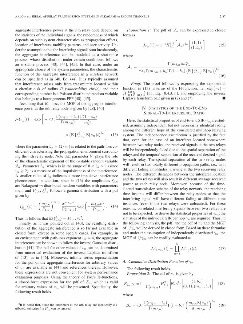
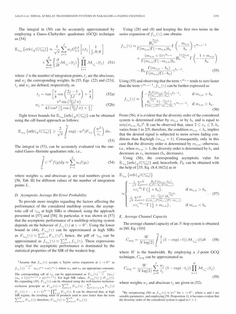
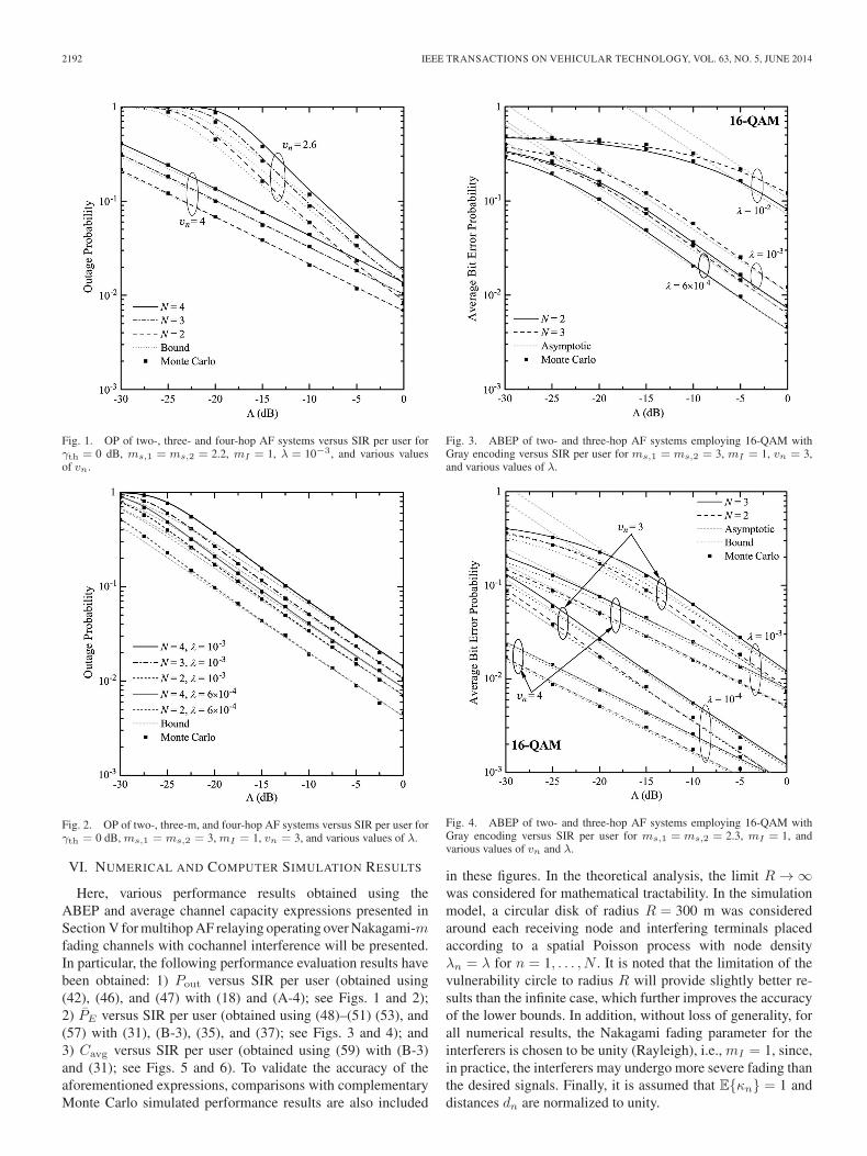
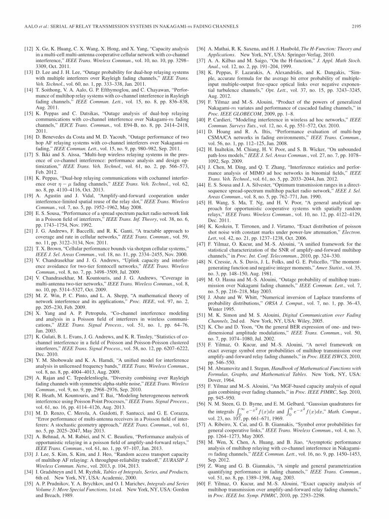
Fig. 1. OP of two-, three- and four-hop AF systems versus SIR per user forγth = 0 dB, ms,1 = ms,2 = 2.2, mI = 1, λ = 10−3, and various valuesof vn.
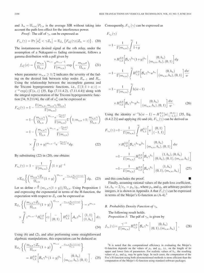
Fig. 2. OP of two-, three-m, and four-hop AF systems versus SIR per user forγth = 0 dB, ms,1 = ms,2 = 3, mI = 1, vn = 3, and various values of λ.
VI. NUMERICAL AND COMPUTER SIMULATION RESULTS
Here, various performance results obtained using theABEP and average channel capacity expressions presented inSection V for multihop AF relaying operating over Nakagami-mfading channels with cochannel interference will be presented.In particular, the following performance evaluation results havebeen obtained: 1) Pout versus SIR per user (obtained using(42), (46), and (47) with (18) and (A-4); see Figs. 1 and 2);2) PE versus SIR per user (obtained using (48)–(51) (53), and(57) with (31), (B-3), (35), and (37); see Figs. 3 and 4); and3) Cavg versus SIR per user (obtained using (59) with (B-3)and (31); see Figs. 5 and 6). To validate the accuracy of theaforementioned expressions, comparisons with complementaryMonte Carlo simulated performance results are also included
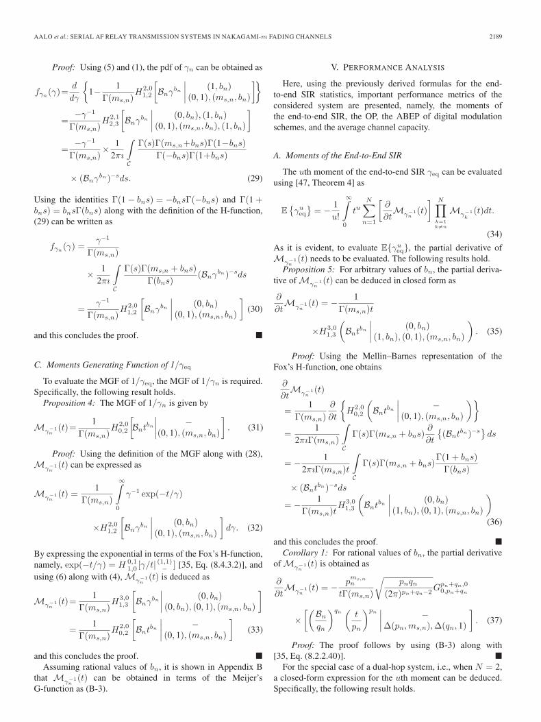
Fig. 3. ABEP of two- and three-hop AF systems employing 16-QAM withGray encoding versus SIR per user for ms,1 = ms,2 = 3, mI = 1, vn = 3,and various values of λ.
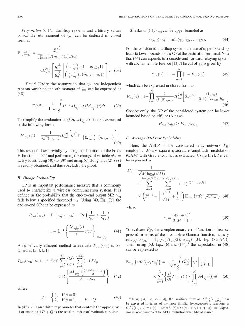
Fig. 4. ABEP of two- and three-hop AF systems employing 16-QAM withGray encoding versus SIR per user for ms,1 = ms,2 = 2.3, mI = 1, andvarious values of vn and λ.
in these figures. In the theoretical analysis, the limit R → ∞was considered for mathematical tractability. In the simulationmodel, a circular disk of radius R = 300 m was consideredaround each receiving node and interfering terminals placedaccording to a spatial Poisson process with node densityλn = λ for n = 1, . . . , N . It is noted that the limitation of thevulnerability circle to radius R will provide slightly better re-sults than the infinite case, which further improves the accuracyof the lower bounds. In addition, without loss of generality, forall numerical results, the Nakagami fading parameter for theinterferers is chosen to be unity (Rayleigh), i.e., mI = 1, since,in practice, the interferers may undergo more severe fading thanthe desired signals. Finally, it is assumed that E{κn} = 1 anddistances dn are normalized to unity.
AALO et al.: SERIAL AF RELAY TRANSMISSION SYSTEMS IN NAKAGAMI-m FADING CHANNELS 2193
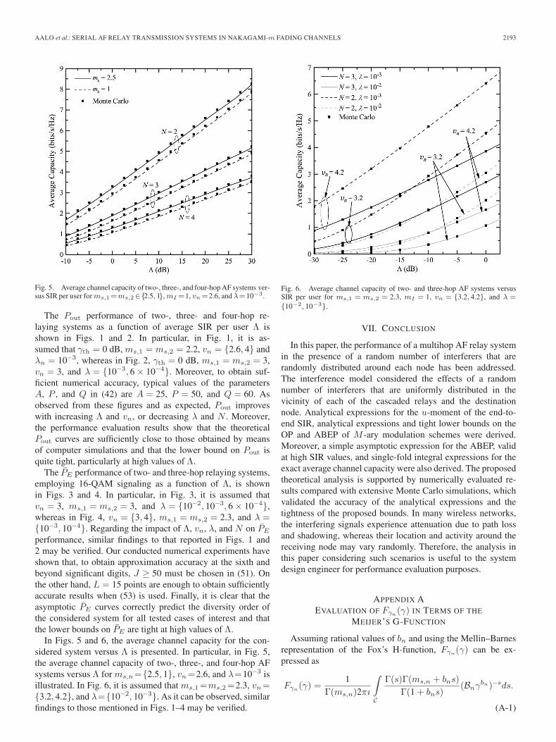
Fig. 5. Average channel capacity of two-, three-, and four-hop AF systems ver-sus SIR per user forms,1=ms,2∈{2.5, 1}, mI =1, vn=2.6, and λ=10−3.
The Pout performance of two-, three- and four-hop re-laying systems as a function of average SIR per user Λ isshown in Figs. 1 and 2. In particular, in Fig. 1, it is as-sumed that γth = 0 dB, ms,1 = ms,2 = 2.2, vn = {2.6, 4} andλn = 10−3, whereas in Fig. 2, γth = 0 dB, ms,1 = ms,2 = 3,vn = 3, and λ = {10−3, 6 × 10⁻⁴}. Moreover, to obtain suf-ficient numerical accuracy, typical values of the parametersA, P , and Q in (42) are A = 25, P = 50, and Q = 60. Asobserved from these figures and as expected, Pout improveswith increasing Λ and vn, or decreasing λ and N . Moreover,the performance evaluation results show that the theoreticalPout curves are sufficiently close to those obtained by meansof computer simulations and that the lower bound on Pout isquite tight, particularly at high values of Λ.
The PE performance of two- and three-hop relaying systems,employing 16-QAM signaling as a function of Λ, is shownin Figs. 3 and 4. In particular, in Fig. 3, it is assumed thatvn = 3, ms,1 = ms,2 = 3, and λ = {10−2, 10−3, 6 × 10⁻⁴},whereas in Fig. 4, vn = {3, 4}, ms,1 = ms,2 = 2.3, and λ ={10−3, 10−4}. Regarding the impact of Λ, vn, λ, and N on PE
performance, similar findings to that reported in Figs. 1 and2 may be verified. Our conducted numerical experiments haveshown that, to obtain approximation accuracy at the sixth andbeyond significant digits, J ≥ 50 must be chosen in (51). Onthe other hand, L = 15 points are enough to obtain sufficientlyaccurate results when (53) is used. Finally, it is clear that theasymptotic PE curves correctly predict the diversity order ofthe considered system for all tested cases of interest and thatthe lower bounds on PE are tight at high values of Λ.
In Figs. 5 and 6, the average channel capacity for the con-sidered system versus Λ is presented. In particular, in Fig. 5,the average channel capacity of two-, three-, and four-hop AFsystems versus Λ for ms,n={2.5, 1}, vn=2.6, and λ=10−3 isillustrated. In Fig. 6, it is assumed that ms,1=ms,2=2.3, vn={3.2, 4.2}, and λ={10−2, 10−3}. As it can be observed, similarfindings to those mentioned in Figs. 1–4 may be verified.
Fig. 6. Average channel capacity of two- and three-hop AF systems versusSIR per user for ms,1 = ms,2 = 2.3, mI = 1, vn = {3.2, 4.2}, and λ =
{10−2, 10−3}.
VII. CONCLUSION
In this paper, the performance of a multihop AF relay systemin the presence of a random number of interferers that arerandomly distributed around each node has been addressed.The interference model considered the effects of a randomnumber of interferers that are uniformly distributed in thevicinity of each of the cascaded relays and the destinationnode. Analytical expressions for the u-moment of the end-to-end SIR, analytical expressions and tight lower bounds on theOP and ABEP of M -ary modulation schemes were derived.Moreover, a simple asymptotic expression for the ABEP, validat high SIR values, and single-fold integral expressions for theexact average channel capacity were also derived. The proposedtheoretical analysis is supported by numerically evaluated re-sults compared with extensive Monte Carlo simulations, whichvalidated the accuracy of the analytical expressions and thetightness of the proposed bounds. In many wireless networks,the interfering signals experience attenuation due to path lossand shadowing, whereas their location and activity around thereceiving node may vary randomly. Therefore, the analysis inthis paper considering such scenarios is useful to the systemdesign engineer for performance evaluation purposes.
APPENDIX AEVALUATION OF Fγn
(γ) IN TERMS OF THE
MEIJER’S G-FUNCTION
Assuming rational values of bn and using the Mellin–Barnesrepresentation of the Fox’s H-function, Fγn
(γ) can be ex-pressed as
Fγn(γ) =
1Γ(ms,n)2πı
∫C
Γ(s)Γ(ms,n + bns)
Γ(1 + bns)(Bnγ
bn)−sds.
(A-1)
2194 IEEE TRANSACTIONS ON VEHICULAR TECHNOLOGY, VOL. 63, NO. 5, JUNE 2014
Assuming that bn = pn/qn, (A-1) can be written as
Fγn(γ) =
(2πı)−1
Γ(ms,n)
∫C
Γ(s)Γ(ms,n + pns
qn
)(Bnγ
pnqn
)−s
Γ(
1 + pnsqn
) ds
s=qnu=
qnΓ(ms,n)2πı
×∫C1
Γ(qnu)Γ(pn
[ms,n
pn+ u])
Γ(pn
[1pn
+ u])
× B−qnun γ−pnudu. (A-2)
By applying the Gauss multiplication formula for the gammafunction [34, Eq. (8.335)]
Γ(nx) = (2π)12 (1−n)n(nx−
12 )
n−1∏k=0
Γ
(x+
k
n
). (A-3)
Fγn(γ) can be finally expressed in terms of the Meijer’s
G-function as
Fγn(γ)=
pms,n−1n
Γ(ms,n)
√qn
(2π)qn−1
× 12πı
∫C1
qn−1∏k=0
Γ(u+ k
qn
) pn−1∏�=0
Γ(u+
ms,n+�qn
)pn−1∏j=0
Γ(u+ 1+j
qn
)
×[(
Bn
qn
)qn
γpn
]−u
du
=pms,n−1n
Γ(ms,n)
√qn
(2π)qn−1
×Gpn+qn,0pn,pn+qn
[(Bn
qn
)qn
γpn
∣∣∣∣ Δ(pn, 1)Δ(pn,ms,n),Δ(qn, 0)
].
(A-4)
APPENDIX BEVALUATION OF M−1
γn(t) IN TERMS OF THE
MEIJER’S G-FUNCTION
Assuming rational values of bn and using the Mellin–Barnesrepresentation of the Fox’s H-function, Mγn
−1(t) can be ex-pressed as
Mγ−1n
(t) =(2πı)−1
Γ(ms,n)
∫C
Γ(s)Γ(ms,n + bns)(Bntbn)−sds.
(B-1)
Assuming that bn = pn/qn, (B-1) can be written as
Mγ−1n
(t) =(2πı)−1
Γ(ms,n)
∫C
Γ(s)Γ
(ms,n +
pns
qn
)
×(Bnt
pnqn
)−s
ds
s=qnu=
qnΓ(ms,n)2πı
∫C1
Γ(qnu)Γ
(pn
[ms,n
pn+ u
])
× B−qnun t−pnudu. (B-2)
By applying the Gauss multiplication formula for the gammafunction, M−1
γn(t) can be finally expressed in terms of the
Meijer’s G-function as
Mγ−1n
(t)
= pms,n−1n
√pnqn
(2π)pn+qn−2
1Γ(ms,n)2πı
×∫C1
qn−1∏k=0
Γ
(u+
k
qn
) pn−1∏�=0
Γ
(u+
ms,n + �
qn
)
×[(
Bn
qn
)qn ( t
pn
)pn]−u
du
=pms,n−1n
Γ(ms,n)
√pnqn
(2π)pn+qn−2
×Gpn+qn,00,pn+qn
[(Bn
qn
)qn ( t
pn
)pn∣∣∣∣ −Δ(pn,ms,n),Δ(qn, 0)
].
(B-3)
ACKNOWLEDGMENT
The authors would like to thank the anonymous reviewersand the associate editor for their help in improving the presen-tation of this paper.
REFERENCES
[1] R. Pabst, B. Walke, D. Schultz, P. Herhold, H. Yanikomeroglu,S. Mukherjee, H. Viswanathan, M. Lott, W. Zirwas, M. Dohler,H. Aghvami, D. Falconer, and G. Fettweis, “Relay-based deploymentconcepts for wireless and mobile broadband radio,” IEEE Commun. Mag.,vol. 42, no. 9, pp. 80–89, Sep. 2004.
[2] B. Can, M. Portalski, H. Lebreton, S. Frattasi, and H. A. Suraweera,“Implementation issues for OFDM-based multihop cellular networks,”IEEE Commun. Mag., vol. 45, no. 9, pp. 74–81, Sep. 2007.
[3] V. Genc, S. Murphy, Y. Yu, and J. Murphy, “IEEE 802.16j relay-based wireless access networks: An overview,” IEEE Wireless Commun.,vol. 15, no. 5, pp. 56–63, Oct. 2008.
[4] S. W. Peters and R. W. Heath, “The future of WiMax: Multihop relayingwith IEEE 802.16j,” IEEE Commun. Mag., vol. 47, no. 1, pp. 104–111,Jan. 2009.
[5] T. Issariyakul and V. Krishnamurthy, “Amplify-and-forward cooperativediversity wireless networks: Model, analysis, and monotonicity proper-ties,” IEEE/ACM Trans. Netw., vol. 17, no. 1, pp. 225–238, Feb. 2009.
[6] M. O. Hasna and M.-S. Alouini, “End-to-end performance of transmissionsystems with relays over Rayleigh fading channels,” IEEE Trans. WirelessCommun., vol. 2, no. 6, pp. 1126–1131, Nov. 2003.
[7] G. Farfhadi and N. Beaulieu, “On the ergodic capacity of multi-hopwireless relaying systems,” IEEE Trans. Wireless Commun., vol. 8, no. 5,pp. 2286–2291, May 2009.
[8] A. Nasri, R. Schober, and I. F. Blake, “Performance and optimization ofamplify-and-forward cooperative diversity systems in generic noise andinterference,” IEEE Trans. Wireless Commun., vol. 10, no. 4, pp. 1132–1143, Apr. 2011.
[9] Q. Yang and K. S. Kwak, “Outage probability of cooperative relayingwith dissimilar Nakagami-m interferers in Nakagami-m fading,” IETCommun., vol. 3, no. 7, pp. 1179–1185, Jul. 2009.
[10] J. B. Si, Z. Li, and Z. Liu, “Outage probability of opportunistic relaying inRayleigh fading channels with multiple interferers,” IEEE Signal Process.Lett., vol. 17, no. 5, pp. 445–448, May 2010.
[11] H. A. Suraweera, H. K. Garg, and A. Nallanathan, “Performance analysisof two hop amplify-and-forward systems with interference at the relay,”IEEE Commun. Lett., vol. 14, no. 8, pp. 692–694, Aug. 2010.
AALO et al.: SERIAL AF RELAY TRANSMISSION SYSTEMS IN NAKAGAMI-m FADING CHANNELS 2195
[12] X. Ge, K. Huang, C. X. Wang, X. Hong, and X. Yang, “Capacity analysisin a multi-cell multi-antenna cooperative cellular network with co-channelinterference,” IEEE Trans. Wireless Commun., vol. 10, no. 10, pp. 3298–3309, Oct. 2011.
[13] D. Lee and J. H. Lee, “Outage probability for dual-hop relaying systemswith multiple interferers over Rayleigh fading channels,” IEEE Trans.Veh. Technol., vol. 60, no. 1, pp. 333–338, Jan. 2011.
[14] T. Soithong, V. A. Aalo, G. P. Efthymoglou, and C. Chayawan, “Perfor-mance of multihop relay systems with co-channel interference in Rayleighfading channels,” IEEE Commun. Lett., vol. 15, no. 8, pp. 836–838,Aug. 2011.
[15] K. Peppas and C. Datsikas, “Outage analysis of dual-hop relayingcommunications with co-channel interference over Nakagami-m fadingchannels,” IEICE Trans. Commun., vol. E94-B, no. 8, pp. 2414–2418,2011.
[16] D. Benevedes da Costa and M. D. Yacoub, “Outage performance of twohop AF relaying systems with co-channel interferers over Nakagami-mfading,” IEEE Commun. Lett., vol. 15, no. 9, pp. 980–982, Sep. 2011.
[17] S. Ikki and S. Aïssa, “Multi-hop wireless relaying systems in the pres-ence of co-channel interference: performance analysis and design op-timization,” IEEE Trans. Veh. Technol., vol. 61, no. 2, pp. 566–573,Feb. 2012.
[18] K. Peppas, “Dual-hop relaying communications with cochannel interfer-ence over η − μ fading channels,” IEEE Trans. Veh. Technol., vol. 62,no. 8, pp. 4110–4116, Oct. 2013.
[19] A. Agustin and J. Vidal, “Amplify-and-forward cooperation underinterference-limited spatial reuse of the relay slot,” IEEE Trans. WirelessCommun., vol. 7, no. 5, pp. 1952–1962, May 2008.
[20] E. S. Sousa, “Performance of a spread spectrum packet radio network linkin a Poisson field of interferers,” IEEE Trans. Inf. Theory, vol. 38, no. 6,pp. 1743–1754, Nov. 1992.
[21] J. G. Andrews, F. Baccelli, and R. K. Ganti, “A tractable approach tocoverage and rate in cellular networks,” IEEE Trans. Commun., vol. 59,no. 11, pp. 3122–3134, Nov. 2011.
[22] T. X. Brown, “Cellular performance bounds via shotgun cellular systems,”IEEE J. Sel. Areas Commun., vol. 18, no. 11, pp. 2334–2455, Nov. 2000.
[23] V. Chandrasekhar and J. G. Andrews, “Uplink capacity and interfer-ence avoidance for two-tier femtocell networks,” IEEE Trans. WirelessCommun., vol. 8, no. 7, pp. 3498–3509, Jul. 2009.
[24] V. Chandrasekhar, M. Kountouris, and J. G. Andrews, “Coverage inmulti-antenna two-tier networks,” IEEE Trans. Wireless Commun., vol. 8,no. 10, pp. 5314–5327, Oct. 2009.
[25] M. Z. Win, P. C. Pinto, and L. A. Shepp, “A mathematical theory ofnetwork interference and its applications,” Proc. IEEE, vol. 97, no. 2,pp. 205–230, Feb. 2009.
[26] X. Yang and A. P. Petropulu, “Co-channel interference modelingand analysis in a Poisson field of interferers in wireless communi-cations,” IEEE Trans. Signal Process., vol. 51, no. 1, pp. 64–76,Jan. 2003.
[27] K. Gulati, B. L. Evans, J. G. Andrews, and K. R. Tinsley, “Statistics of co-channel interference in a field of Poisson and Poisson-Poisson clusteredinterferers,” IEEE Trans. Signal Process., vol. 58, no. 12, pp. 6207–6222,Dec. 2010.
[28] Y. M. Shobowale and K. A. Hamdi, “A unified model for interferenceanalysis in unlicensed frequency bands,” IEEE Trans. Wireless Commun.,vol. 8, no. 8, pp. 4004–4013, Aug. 2009.
[29] A. Rajan and C. Tepedelenlioglu, “Diversity combining over Rayleighfading channels with symmetric alpha-stable noise,” IEEE Trans. WirelessCommun., vol. 9, no. 9, pp. 2968–2976, Sep. 2010.
[30] R. Heath, M. Kountouris, and T. Bai, “Modeling heterogeneous networkinterference using Poisson Point Processes,” IEEE Trans. Signal Process.,vol. 61, no. 16, pp. 4114–4126, Aug. 2013.
[31] M. D. Renzo, C. Merola, A. Guidotti, F. Santucci, and G. E. Corazza,“Error performance of multi-antenna receivers in a Poisson field of inter-ferers: A stochastic geometry approach,” IEEE Trans. Commun., vol. 61,no. 5, pp. 2025–2047, May 2013.
[32] A. Behnad, A. M. Rabiei, and N. C. Beaulieu, “Performance analysis ofopportunistic relaying in a poisson field of amplify-and-forward relays,”IEEE Trans. Commun., vol. 61, no. 1, pp. 97–107, Jan. 2013.
[33] J. Lee, S. Kim, S. Kim, and J. Heo, “Random access transport capacityof multihop AF relaying: A throughput-reliability tradeoff,” EURASIP J.Wireless Commun. Netw., vol. 2013, p. 104, 2013.
[34] I. Gradshteyn and I. M. Ryzhik, Tables of Integrals, Series, and Products,6th ed. New York, NY, USA: Academic, 2000.
[35] A. P. Prudnikov, Y. A. Brychkov, and O. I. Marichev, Integrals and SeriesVolume 3: More Special Functions, 1st ed. New York, NY, USA: Gordonand Breach, 1989.
[36] A. Mathai, R. K. Saxena, and H. J. Haubold, The H-Function: Theory andApplications. New York, NY, USA: Springer-Verlag, 2010.
[37] A. A. Kilbas and M. Saigo, “On the H-function,” J. Appl. Math Stoch.Anal., vol. 12, no. 2, pp. 191–204, 1999.
[38] K. Peppas, F. Lazarakis, A. Alexandridis, and K. Dangakis, “Sim-ple, accurate formula for the average bit error probability of multiple-input multiple-output free-space optical links over negative exponen-tial turbulence channels,” Opt. Lett., vol. 37, no. 15, pp. 3243–3245,Aug. 2012.
[39] F. Yilmaz and M.-S. Alouini, “Product of the powers of generalizedNakagami-m variates and performance of cascaded fading channels,” inProc. IEEE GLOBECOM, 2009, pp. 1–8.
[40] P. Cardieri, “Modeling interference in wireless ad hoc networks,” IEEECommun. Surveys Tuts., vol. 12, no. 4, pp. 551–572, Oct. 2010.
[41] D. Hoang and R. A. Iltis, “Performance evaluation of multi-hopCSMA/CA networks in fading environments,” IEEE Trans. Commun.,vol. 56, no. 1, pp. 112–125, Jan. 2008.
[42] H. Inaltekin, M. Chiang, H. V. Poor, and S. B. Wicker, “On unboundedpath-loss models,” IEEE J. Sel. Areas Commun., vol. 27, no. 7, pp. 1078–1092, Sep. 2009.
[43] J. Chen, M. Ding, and Q. T. Zhang, “Interference statistics and perfor-mance analysis of MIMO ad hoc networks in binomial fields,” IEEETrans. Veh. Technol., vol. 61, no. 5, pp. 2033–2044, Jun. 2012.
[44] E. S. Sousa and J. A. Silvester, “Optimum transmission ranges in a direct-sequence spread-spectrum multihop packet radio network,” IEEE J. Sel.Areas Commun., vol. 8, no. 5, pp. 762–771, Jun. 1990.
[45] H. Wang, S. Ma, T. Ng, and H. V. Poor, “A general analytical ap-proach for opportunistic cooperative systems with spatially randomrelays,” IEEE Trans. Wireless Commun., vol. 10, no. 12, pp. 4122–4129,Dec. 2011.
[46] K. Koskein, T. Tirronen, and J. Virtamo, “Exact distribution of poissonshot noise with constant marks under power-law attenuation,” Electron.Lett, vol. 42, no. 21, pp. 1237–1238, Oct. 2006.
[47] F. Yilmaz, O. Kucur, and M.-S. Alouini, “A unified framework for thestatistical characterization of the SNR of amplify-and-forward multihopchannels,” in Proc. Int. Conf. Telecommun., 2010, pp. 324–330.
[48] N. Cressie, A. S. Davis, J. L. Folks, and G. E. Policello, “The moment-generating function and negative integer moments,” Amer. Statist., vol. 35,no. 3, pp. 148–150, Aug. 1981.
[49] M. O. Hasna and M.-S. Alouini, “Outage probability of multihop trans-mission over Nakagami fading channels,” IEEE Commun. Lett., vol. 7,no. 5, pp. 216–218, May 2003.
[50] J. Abate and W. Whitt, “Numerical inversion of Laplace transforms ofprobability distributions,” ORSA J. Comput., vol. 7, no. 1, pp. 36–43,Winter 1995.
[51] M. K. Simon and M. S. Alouini, Digital Communication over FadingChannels, 2nd ed. New York, NY, USA: Wiley, 2005.
[52] K. Cho and D. Yoon, “On the general BER expression of one- and two-dimensional amplitude modulations,” IEEE Trans. Commun., vol. 50,no. 7, pp. 1074–1080, Jul. 2002.
[53] F. Yilmaz, O. Kucur, and M.-S. Alouini, “A novel framework onexact average symbol error probabilities of multihop transmission overamplify-and-forward relay fading channels,” in Proc. IEEE ISWCS, 2010,pp. 546–550.
[54] M. Abramovitz and I. Stegun, Handbook of Mathematical Functions withFormulas, Graphs, and Mathematical Tables. New York, NY, USA:Dover, 1964.
[55] F. Yilmaz and M.-S. Alouini, “An MGF-based capacity analysis of equalgain combining over fading channels,” in Proc. IEEE PIMRC, Sep. 2010,pp. 945–950.
[56] N. M. Steen, G. D. Byrne, and E. M. Gelbard, “Gaussian quadratures for
the integrals∫∞0
e−x2f(x)dx and
∫ b
0e−x2
f(x)dx,” Math. Comput.,vol. 23, no. 107, pp. 661–671, 1969.
[57] A. Ribeiro, X. Cai, and G. B. Giannakis, “Symbol error probabilities forgeneral cooperative links,” IEEE Trans. Wireless Commun., vol. 4, no. 3,pp. 1264–1273, May 2005.
[58] M. Wen, X. Chen, A. Huang, and B. Jiao, “Asymptotic performanceanalysis of multihop relaying with co-channel interference in Nakagami-m fading channels,” IEEE Commun. Lett., vol. 16, no. 9, pp. 1450–1453,Sep. 2012.
[59] Z. Wang and G. B. Giannakis, “A simple and general parametrizationquantifying performance in fading channels,” IEEE Trans. Commun.,vol. 51, no. 8, pp. 1389–1398, Aug. 2003.
[60] F. Yilmaz, O. Kucur, and M.-S. Alouini, “Exact capacity analysis ofmultihop transmission over amplify-and-forward relay fading channels,”in Proc. IEEE Int. Symp. PIMRC, 2010, pp. 2293–2298.

2196 IEEE TRANSACTIONS ON VEHICULAR TECHNOLOGY, VOL. 63, NO. 5, JUNE 2014
Valentine A. Aalo (S’89–M’92–SM’05) was bornin Nigeria on March 23, 1959. He received theB.S., M.S., and Ph.D. degrees from Southern IllinoisUniversity, Carbondale, IL, USA, in 1984, 1986, and1991, respectively, all in electrical engineering.
In the summer of 1994 and 1995, he was a Fac-ulty Research Associate with the Satellite Commu-nications and Networking Group, Rome Laboratory,Griffiss Air Force Base, Rome, NY, USA. Since1991, he has been with Florida Atlantic University,Boca Raton, FL, USA, where he is currently a Pro-
fessor with the Department of Computer and Electrical Engineering and Com-puter Science. His current research interests include wireless communications,channel modeling, diversity techniques, cooperative relay networks, wirelesssensor networks, and radar signal processing.
Dr. Aalo is a member of Tau Beta Pi and several IEEE societies. He servedas an Associate Editor for the IEEE TRANSACTIONS ON COMMUNICATIONS
from 2000 to 2011.
Kostas P. Peppas (M’11) was born in Athens,Greece, in 1975. He received the Diploma in electri-cal and computer engineering and the Ph.D. degree inwireless communications from the National Techni-cal University of Athens, Greece, in 1997 and 2004,respectively.
From 2004 to 2007, he was with the Departmentof Computer Science and Technology, University ofPeloponnese, Tripoli, Greece. Since 2008, he hasbeen a Researcher with the Institute of Informaticsand Telecommunications, National Centre for Sci-
entific Research “Demokritos,” Athens. He is the author of more than 50journal and conference papers. His current research interests include digitalcommunications over fading channels, multiple-input–multiple-output systems,wireless and personal communication networks, and system-level analysis anddesign.
George P. Efthymoglou (S’94–M’98) was born inAthens, Greece, on April 22, 1968. He received theB.S. degree in physics from the University of Athensin 1991 and the M.S. and Ph.D. degrees in electricalengineering from Florida Atlantic University, BocaRaton, FL, USA, in 1993 and 1997, respectively.
From 1997 to 2002, he was with Cadence DesignSystems, where he was engaged in the modeling,simulation, and performance evaluation of third-generation wireless systems. Since 2002, he has beenwith the Department of Digital Systems, University
of Piraeus, Piraeus, Greece, where he is currently an Associate Professor. Hisresearch interests include digital communication systems, with emphasis onthe performance evaluation of wireless systems in the presence of fading andinterference.
Mohammed M. Alwakeel was born in Tabuk,Saudi Arabia, in 1970. He received the B.S. degree incomputer engineering and the M.S. degree in electri-cal engineering from King Saud University, Riyadh,Saudi Arabia, in 1993 and 1998, respectively, and thePh.D. degree in electrical engineering from FloridaAtlantic University, Boca Raton, FL, USA, in 2005.
From 1994 to 1998, he was a Communications Net-work Manager with The National Information Center,Saudi Arabia. From 1999 to 2001, he was with KingAbdulaziz University, Jeddah, Saudi Arabia. From
2009 to 2010, he was an Assistant Professor and the Dean of the Collegeof Computers and Information Technology, Tabuk University, where he iscurrently the Vice-Rector for Development and Quality. His current researchinterests include teletraffic analysis, mobile satellite communications, sensornetworks, and cellular systems.
Sami S. Alwakeel (M’13) received the B.Sc. degree(with honors) from King Saud University, Riyadh,Saudi Arabia, and the M.Sc. and Ph.D. degrees fromStanford University, Stanford, CA, USA.
He is currently a Professor with the Departmentof Computer Engineering, College of Computer andInformation Sciences (CCIS), King Saud University(KSU), where he is a founding member and hadserved as the Dean from 2003 to 2009. He is alsoa Visiting Scholar with the College of Engineering,Florida Atlantic University, Boca Raton, FL, USA.
He is also one of the founding members of the Smart Electronic Company atKSU and of the Cellular System Research Center, Tabuk University, Tabuk,Saudi Arabia. He is the author of several college and high school textbooks andof articles on networking, computers, and the information technology societyin scientific journals and conferences and in technical and culture magazines.He has worked as a consultant to many Saudi private sector companies andgovernment agencies and contributed to the development and establishment ofmany computer colleges and departments in the Kingdom of Saudi Arabia.
Dr. Alwakeel is one of the founder members of the Saudi Computers Society.


