Embed Size (px)
Citation preview

Indoor Unit
!""#!
Outdoor Unit <High Wall, Heat Pump Type> <Heat Pump Type>RAS-10PKVPG-ERAS-13PKVPG-ERAS-16PKVPG-ERAS-10PKVPG-NZRAS-13PKVPG-NZRAS-16PKVPG-NZ
R32
May, 2018
RAS-10PAVPG-ERAS-13PAVPG-ERAS-16PAVPG-ERAS-10PAVPG-NZRAS-13PAVPG-NZRAS-16PAVPG-NZ
'
/U "
'" ! ---
li'@®[M]OOO& eo o
7
:::,.."'- i
FILE NO. SVM-18049

CONTENTS
1. SAFETY PRECAUTIONS .......................................................................... 3
2. SPECIFICATIONS ..................................................................................... 6
3. REFRIGERANT R32 ................................................................................ 11
4. CONSTRUCTION VIEWS ........................................................................ 19
5. WIRING DIAGRAM .................................................................................. 21
6. SPECIFICATIONS OF ELECTRICAL PARTS ......................................... 22
7. REFRIGERANT CYCLE DIAGRAM ........................................................ 23
8. CONTROL BLOCK DIAGRAM ................................................................ 27
9. OPERATION DESCRIPTION................................................................... 29
10. INSTALLATION PROCEDURE ................................................................ 68
11. HOW TO DIAGNOSE THE TROUBLE ...................................................... 85
12. HOW TO REPLACE THE MAIN PARTS.................................................. 111
13. EXPLODED VIEWS AND PARTS LIST .................................................. 128
FILE NO. SVM-18049
- 2 -
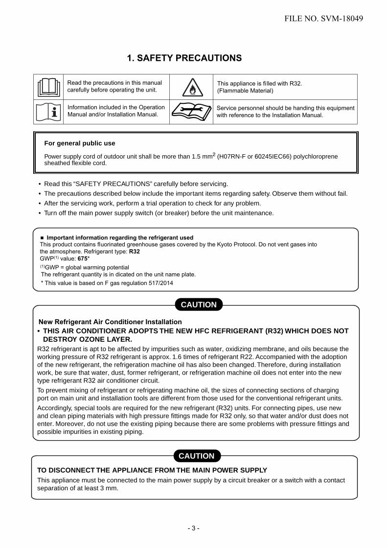
For general public use
Power supply cord of outdoor unit shall be more than 1.5 mm2 (H07RN-F or 60245IEC66) polychloroprene sheathed flexible cord.
• Read this “SAFETY PRECAUTIONS” carefully before servicing.
• The precautions described below include the important items regarding safety. Observe them without fail.
• After the servicing work, perform a trial operation to check for any problem.
• Turn off the main power supply switch (or breaker) before the unit maintenance.
1. SAFETY PRECAUTIONS
• THIS AIR CONDITIONER ADOPTS THE NEW HFC REFRIGERANT (R32) WHICH DOES NOTDESTROY OZONE LAYER.
R32 refrigerant is apt to be affected by impurities such as water, oxidizing membrane, and oils because the working pressure of R32 refrigerant is approx. 1.6 times of refrigerant R22. Accompanied with the adoption of the new refrigerant, the refrigeration machine oil has also been changed. Therefore, during installation work, be sure that water, dust, former refrigerant, or refrigeration machine oil does not enter into the new type refrigerant R32 air conditioner circuit.
To prevent mixing of refrigerant or refrigerating machine oil, the sizes of connecting sections of charging port on main unit and installation tools are different from those used for the conventional refrigerant units.
Accordingly, special tools are required for the new refrigerant (R32) units. For connecting pipes, use new and clean piping materials with high pressure fittings made for R32 only, so that water and/or dust does not enter. Moreover, do not use the existing piping because there are some problems with pressure fittings and possible impurities in existing piping.
CAUTION
TO DISCONNECT THE APPLIANCE FROM THE MAIN POWER SUPPLYThis appliance must be connected to the main power supply by a circuit breaker or a switch with a contact separation of at least 3 mm.
Important information regarding the refrigerant usedThis product contains fl uorinated greenhouse gases covered by the Kyoto Protocol. Do not vent gases intothe atmosphere. Refrigerant type: R32GWP(1) value: 675*(1)GWP = global warming potentialThe refrigerant quantity is in dicated on the unit name plate.* This value is based on F gas regulation 517/2014CAUTION
CAUTION
New Refrigerant Air Conditioner Installation
Read the precautions in this manual carefully before operating the unit.
This appliance is fi lled with R32.(Flammable Material)
Information included in the Operation Manual and/or Installation Manual.
Service personnel should be handing this equipment with reference to the Installation Manual.
FILE NO. SVM-18049
- 3 -

• ASK AN AUTHORIZED DEALER OR QUALIFIED INSTALLATION PROFESSIONAL TO IN-STALL/MAINTAIN THE AIR CONDITIONER.INAPPROPRIATE SERVICING MAY RESULT IN WATER LEAKAGE, ELECTRIC SHOCK OR FIRE.
• TURN OFF MAIN POWER SUPPLY BEFORE ATTEMPTING ANY ELECTRICAL WORK. MAKE SUREALL POWER SWITCHES ARE OFF. FAILURE TO DO SO MAY CAUSE ELECTRIC SHOCK.
DANGER: HIGH VOLTAGEThe high voltage circuit is incorporated.
Be careful to do the check service, as the electric shock may be caused in case of touching partson the P.C. board by hand.
• CORRECTLY CONNECT THE CONNECTING CABLE. IF THE CONNECTING CABLE IS INCOR-RECTLY CONNECTED, ELECTRIC PARTS MAY BE DAMAGED.
• CHECK THAT THE EARTH WIRE IS NOT BROKEN OR DISCONNECTED BEFORE SERVICE ANDINSTALLATION. FAILURE TO DO SO MAY CAUSE ELECTRIC SHOCK.
DANGER
• DO NOT INSTALL NEAR CONCENTRATIONS OF COMBUSTIBLE GAS OR GAS VAPORS. FAILURETO FOLLOW THIS INSTRUCTION CAN RESULT IN FIRE OR EXPLOSION.
• TO PREVENT THE INDOOR UNIT FROM OVERHEATING AND CAUSING A FIRE HAZARD, PLACETHE UNIT WELL AWAY (MORE THAN 2 M) FROM HEAT SOURCES SUCH AS RADIATORS, HEATREGISTORS, FURNACE, STOVES, ETC.
• WHEN MOVING THE AIR-CONDITIONER FOR INSTALLATION IN ANOTHER PLACE, BE VERY CARE-FUL NOT TO ALLOW THE SPECIFIED REFRIGERANT (R410A) TO BECOME MIXED WITH ANYOTHER GASEOUS BODY INTO THE REFRIGERATION CIRCUIT. IF AIR OR ANY OTHER GAS ISMIXED IN THE REFRIGERANT, THE GAS PRESSURE IN THE REFRIGERATION CIRCUIT WILLBECOME ABNORMALLY HIGH AND IT MAY RESULT IN THE PIPE BURSTING AND POSSIBLE PER-SONNEL INJURIES.
• IN THE EVENT THAT THE REFRIGERANT GAS LEAKS OUT OF THE PIPE DURING THE SERVICEWORK AND THE INSTALLATION WORK, IMMEDIATELY LET FRESH AIR INTO THE ROOM. IF THEREFRIGERANT GAS IS HEATED, SUCH AS BY FIRE, GENERATION OF POISONOUS GAS MAYRESULT.
WARNING
• Never modify this unit by removing any of the safety guards or bypass any of the safety interlockswitches.
• Do not install in a place which cannot bear the weight of the unit. Personal injury and propertydamage can result if the unit falls.
• After the installation work, confirm that refrigerant gas does not leak.If refrigerant gas leaks into the room and flows near a fire source, such as a cooking range, noxious gasmay generate.
• The electrical work must be performed by a qualified electrician in accordance with the InstallationManual. Make sure the air conditioner uses an exclusive circuit.An insufficient circuit capacity or inappropriate installation may cause fire.
• When wiring, use the specified cables and connect the terminals securely to prevent externalforces applied to the cable from affecting the terminals.
• Be sure to provide grounding.Do not connect ground wires to gas pipes, water pipes, lightning rods or ground wires for telephone cables.
• Conform to the regulations of the local electric company when wiring the power supply.Inappropriate grounding may cause electric shock.
• Manufacturer pay no responsibility to any damage, caused by heating cable, being outside of unit.
FILE NO. SVM-18049
- 4 -
•
•
•
Do not pierce or burn as the appliance is pressurized. Do not expose the appliance to heat, fl ame, sparks, or other sources or ignition. Else, it may explode and cause injury or death.For R32 model, use pipes, fl are nut and tools which is specifi ed for R32 refrigerant. Using of existing (R22) piping, fl are nut and tools may cause abnormally high pressure in the refrigerant cycle (piping), and possibly result in explosion and injury.Thickness of copper pipes used R32 must be more than 0.8mm. Never use copper pipes thinner than 0.8mm. Do not perform flare connection inside a building or dwelling or room, when joining the heat exchanger of indoor unit with interconnection piping. Refrigerant connection inside a building or dwelling or room must be made by brazing or welding. Joint connection of indoor unit by flaring method can only be made at outdoor or at outside of building or dwelling or room. Flare connection may cause gas leak and flammable atmosphere. After completion of installation or service, confirm there is no leakage of refrigerant gas. It may generate toxic gas when the refrigerant contacts with fire.
•
•
• Appliance and pipe-work shall be installed, operated and stored in a room with a floor area large than Amin m2
How to get Amin m2 : Amin = (M / (2.5 x 0.22759 x h0))2
M is the refrigerant charge amount in appliance in kg. h0 is the installation height of the appliance in m : 0.6 mfor floor standing/1.8m for wall mounted/1.0 m for window mounted/2.2 m for ceiling mounted.
• Comply with national gas regulations.
CAUTION• Exposure of unit to water or other moisture before installation may result in an electrical short.
Do not store in a wet basement or expose to rain or water.
• Do not install in a place that can increase the vibration of the unit. Do not install in a place that can amplifythe noise level of the unit or where noise or discharged air might disturb neighbors.
• To avoid personal injury, be careful when handling parts with sharp edges.
• Perform the specified installation work to guard against an earthquake.If the air conditioner is not installed appropriately, accidents may occur due to the falling unit.
For Reference:If a heating operation would be continuously performed for a long time under the condition that the outdoor temperature is 0°C or lower, drainage of defrosted water may be difficult due to freezing of the bottom plate, resulting in a trouble of the cabinet or fan.
It is recommended to procure an antifreeze heater locally for a safe installation of the air conditioner.
For details, contact the dealer.
FILE NO. SVM-18049
- 5 -

2. SPECIFICATIONS2-1. Specifications
Unit model IndoorOutdoor
Cooling capacity (kW)Cooling capacity range (kW)Heating capacity (kW)Heating capacity range (kW)Power supplyElectric Indoor Operation mode Cooling Heatingcharacteristic Running current (A) 0.24-0.22 0.28-0.26
Power consumption (W) 25 30Power factor (%) 47 48
Outdoor Operation mode Cooling HeatingRunning current (A) 2.31-2.13 3.12-2.86Power consumption (W) 425 570Power factor (%) 83 83Starting curent (A) 2.55-2.35 3.40-3.12
COP (Cooling/Heating)Operating noiseIndoor High (Cooling/Heating) (dB-A)
Medium (Cooling/Heating) (dB-A)Low (Cooling/Heating) (dB-A)
Outdoor (Cooling/Heating) (dB-A)Indoor unit Unit model
Dimension Height (mm)Width (mm)Depth (mm)
Net weight (kg)Fan motor output (W)Air flow rate (Cooling/Heating) (m3/min)
Outdoor unit Unit modelDimension Height (mm)
Width (mm)Depth (mm)
Net weight (kg)Compressor Motor output (W)
TypeModel
Fan motor output (W)Air flow rate (Cooling/Heating) (m3/min)
Piping Typeconnection Indoor unit Liquid side (mm)
Gas side (mm)Outdoor unit Liquid side (mm)
Gas side (mm)Maximum length (m)Maximum chargeless length (m)Maximum height difference (m)
Refrigerant Name of refrigerantWeight (kg)
Wiring Power supplyconnection InterconnectionUsable temperature range Indoor (Cooling/Heating) (°C)
Outdoor (Cooling/Heating) (°C)
* The specifications may be subject to change without notice for purpose of improvement.
1Ph, 220-240V, 50Hz
Twin rotary type with DC-inverter variable speed control
3 Wires: includes earth (Outdoor)4 Wires: includes earth
1.00
5.56/5.3343/4433/3324/2446/47
∅9.52∅6.35
2515
R32
11.4-12.1
Flare connection
4336-36
∅6.35∅9.52
750
21-32/0-28-15-46/-15-24
2938512701430
10
RAS-10PKVPG-E,-NZ
RAS-10PAVPG-E,-NZ
KTN110D42UFZ
63080030038
RAS-10PKVPG-E,-NZRAS-10PAVPG-E,-NZ
2.500.80-3.50
3.200.70-5.80
FILE NO. SVM-18049
- 6 -

Unit model IndoorOutdoor
Cooling capacity (kW)Cooling capacity range (kW)Heating capacity (kW)Heating capacity range (kW)Power supplyElectric Indoor Operation mode Cooling Heating Cooling Heatingcharacteristic Running current (A) 0.24-0.22 0.28-0.26 0.24-0.22 0.28-0.26
Power consumption (W) 25 30 25 30Power factor (%) 47 48 47 48
Outdoor Operation mode Cooling Heating Cooling HeatingRunning current (A) 3.43-3.15 3.73-3.39 5.05-4.64 6.16-5.63Power consumption (W) 725 770 1055 1340Power factor (%) 94 96 95 99Starting curent (A) 3.67-3.37 4.01-3.65 5.29-4.86 6.44-5.89
COP (Cooling/Heating)Operating noiseIndoor High (Cooling/Heating) (dB-A)
Medium (Cooling/Heating) (dB-A)Low (Cooling/Heating) (dB-A)
Outdoor (Cooling/Heating) (dB-A)Indoor unit Unit model
Dimension Height (mm)Width (mm)Depth (mm)
Net weight (kg)Fan motor output (W)Air flow rate (Cooling/Heating) (m3/min)
Outdoor unit Unit modelDimension Height (mm)
Width (mm)Depth (mm)
Net weight (kg)Compressor Motor output (W)
TypeModel
Fan motor output (W)Air flow rate (Cooling/Heating) (m3/min)
Piping Typeconnection Indoor unit Liquid side (mm)
Gas side (mm)Outdoor unit Liquid side (mm)
Gas side (mm)Maximum length (m)Maximum chargeless length (m)Maximum height difference (m)
Refrigerant Name of refrigerantWeight (kg)
Wiring Power supplyconnection InterconnectionUsable temperature range Indoor (Cooling/Heating) (°C)
Outdoor (Cooling/Heating) (°C)
* The specifications may be subject to change without notice for purpose of improvement.
-15-46/-15-24
1Ph, 220-240V, 50Hz
Twin rotary type with DC-inverter variable speed control
3 Wires: includes earth (Outdoor)4 Wires: includes earth
10R321.00
21-32/0-28
∅6.35∅12.70∅6.35∅12.70
2515
1050
KTN150D42UFZ43
36/36Flare connection
12.2-12.4RAS-16PAVPG-E,-NZ
63080030038
RAS-16PkVPG-E,-NZ2938512701430
4.17/4.0145/4635/3526/2649/50
RAS-16PKVPG-E,-NZRAS-16PAVPG-E,-NZ
4.500.90-5.105.50
0.80-6.80
1.00
4.67/5.0044/4534/3425/2448/50
∅9.52∅6.35
2515
R32
11.9-12.1
Flare connection
4336/36
∅6.35∅9.52
1050
21-32/0-28-15-46/-15-24
2938512701430
10
RAS-13PkVPG-E,-NZ
RAS-13PAVPG-E,-NZ
KTN150D42UFZ
63080030038
RAS-13PKVPG-E,-NZRAS-13PAVPG-E,-NZ
3.500.90-4.104.00
0.80-6.30
FILE NO. SVM-18049
- 7 -

2-2. Operation Characteristic CurveRAS-10PKVPG-E/RAS-10PAVPG-ERAS-10PKVPG-NZ/RAS-10PAVPG-NZ
FILE NO. SVM-18049
- 8 -
<Cooling> <Heating>
2-3. Capacity Variation ratio According to Temperature
<Cooling> <Heating>
0
1
2
3
4
5
6
7
8
0 10 02 30 04 05 06 07 08 90 100
Cur
rent
(A
)
Compressor Speed (RPS)
0
1
2
3
4
5
6
7
8
0 01 02 30 40 05 06 07 08 90 100
Cur
rent
(A
)
Compressor Speed (RPS)
ConditionsIndoor : DB 27oC/WB 19oCOutdoor : DB 35oC/WB 24oCIndoor Air Flow : HighPipe Length : 5mVoltage : 230V
ConditionsIndoor : DB 20oC/WB 15oCOutdoor : DB 7oC/WB 6oCIndoor Air Flow : HighPipe Length : 5mVoltage : 230V
0
10
20
30
40
50
60
70
80
90
100
110
120
-15 -10 -5 0 5 10
Hea
ting
capa
city
(%
)
Outside Temperature ( ºC)
Capacityratio:100%=4.10kW
ConditionsIndoor:DB20oC/WB15oCOutdoor:DB7oC/WB6oCIndoorAirFlow:HighPipeLength:5mVoltage:230V
50
60
70
80
90
100
32 33 34 35 36 37 38 39 40 41 42 43 44 45 46
Coo
ling
capa
city
(%
)
Outside Temperature ( oC)
Capacityratio:100%=2.50kW
ConditionsIndoor:DB27oC/WB19oCOutdoor:DB35oC/WB24oCIndoorAirFlow:HighPipeLength:5mVoltage:230V

2-4. Operation Characteristic CurveRAS-13PKVPG-E/RAS-13PAVPG-E
RAS-13PKVPG-NZ/RAS-13PAVPG-NZ
FILE NO. SVM-18049
- 9 -
<Cooling> <Heating>
2-5. Capacity Variation ratio According to Temperature
<Cooling> <Heating>
0
1
2
3
4
5
6
7
8
9
0 10 02 0430 05 06 07 08 90 100
Cur
rent
(A
)
Compressor Speed (RPS)
0
1
2
3
4
5
6
7
8
9
0 01 02 0430 05 60 07 08 90 100
Cur
rent
(A
)
Compressor Speed (RPS)
ConditionsIndoor : DB 27oC/WB 19oCOutdoor : DB 35oC/WB 24oCIndoor Air Flow : HighPipe Length : 5mVoltage : 230V
ConditionsIndoor : DB 20oC/WB 15oCOutdoor : DB 7oC/WB 6oCIndoor Air Flow : HighPipe Length : 5mVoltage : 230V
50
55
60
65
70
75
80
85
90
95
100
105
32 33 34 35 36 37 38 39 40 41 42 43 44 45 46
Coo
ling
capa
city
(%
)
Outside Temperature ( oC)
Capacityratio:100%=3.50kW
ConditionsIndoor:DB27oC/WB19oCOutdoor:DB35oC/WB24oCIndoorAirFlow:HighPipeLength:5mVoltage:230V
0
20
40
60
80
100
120
-15 -10 5 10
Hea
ting
capa
city
(%
)
-5 0
Outside Temperature ( ºC)
Capacityratio:100%=4.50kW
ConditionsIndoor:DB20oC/WB15oCOutdoor:DB7oC/WB6oCIndoorAirFlow:HighPipeLength:5mVoltage:230V

2-6. Operation Characteristic CurveRAS-16PKVPG-E/RAS-16PAVPG-ERAS-16PKVPG-NZ/RAS-16PAVPG-NZ
FILE NO. SVM-18049
- 10 -
<Cooling> <Heating>
2-7. Capacity Variation ratio According to Temperature.
<Cooling> <Heating>
0
1
2
3
4
5
6
7
8
9
10
0 01 20 30 40 05 06 70 08 90 100 110
Cur
rent
(A
)
Compressor Speed (RPS)
0
1
2
3
4
5
6
7
8
9
10
0 01 20 30 04 05 06 07 08 90 100 110
Cur
rent
(A
)
Compressor Speed (RPS)
ConditionsIndoor : DB 27oC/WB 19oCOutdoor : DB 35oC/WB 24oCIndoor Air Flow : HighPipe Length : 5mVoltage : 230V
ConditionsIndoor : DB 20oC/WB 15oCOutdoor : DB 7oC/WB 6oCIndoor Air Flow : HighPipe Length : 5mVoltage : 230V
50
55
60
65
70
75
80
85
90
95
100
105
32 33 34 35 36 37 38 39 40 41 42 43 44 45 46
Coo
ling
capa
city
(%
)
Outside Temperature ( oC)
Capacityratio:100%=4.50kW
ConditionsIndoor:DB27oC/WB19oCOutdoor:DB35oC/WB24oCIndoorAirFlow:HighPipeLength:5mVoltage:230V
0
20
40
60
80
100
120
-15 -10 -5 0 5 10
Hea
ting
capa
city
(%
)
Outside Temperature ( ºC)
Capacityratio:100%=5.50kW
ConditionsIndoor:DB20oC/WB15oCOutdoor:DB7oC/WB6oCIndoorAirFlow:HighPipeLength:5mVoltage:230V

3. REFRIGERANT R32This air conditioner adopts the new refrigerant HFC (R32) which does not damage the ozone layer.
The next section describes the precautions for air conditioner using the new refrigerant. Conforming to contents of the next section together with the general cautions included in this manual, perform the correct and safe work.
3-1. Safety During Installation/Servicing
The basic installation servicing work procedures are the same as conventional R410A models. As R32’s pressure is about 1.6 times higher than that of R22, improper installation/servicing may cause a serious trouble. By using tools and materi-als exclusive for R32, it is necessary to carry out installation/servicing safely while taking the following precautions into consideration.
1. Never use refrigerant other than R32 in an airconditioner which is designed to operate with R32.If other refrigerant than R32 is mixed, pressure inthe refrigeration cycle becomes abnormally high,and it may cause personal injury, etc. by a rupture.
2. Confirm the used refrigerant name, and use toolsand materials exclusive for the refrigerant.The refrigerant name R32 is indicated on the visibleplace of the outdoor unit of the air conditioner usingR32 as refrigerant. To prevent mischarging, thediameter of the service port differs from that of R22.R32 and other HFCs are heavier than air, andtherefore they are inclined to settle near the floorsurface.If the gas fills up the room or the bottom part of aroom, it may also cause oxygen deficiency and mayreach its combustion concentration.In order to prevent oxygen deficiency and R32combustion, keep the room well-ventilated for ahealthy work environment.In particular, using HFCs in a basement room orconfined area creates a higher risk; be sure tofurnish the room with local exhaust ventilation.If a refrigerant leak is confirmed in a room aninadequately ventilated location, do not use a flameuntil the area has been ventilated appropriately andthe work environment has been improved.The same applies in case of brazing, ensureappropriate ventilation to prevent oxygen deficiencyand R32 combustion.Check that there are no dangerous or combustibleitems nearby, and ensure a fire extinguisher is closeat hand.Keep a sufficient distance away from causes of fire(ignition sources) such as gas-burning equipmentand electric heaters in places where installation,repairs, or similar work on air-conditioningequipment is performed.
3. If a refrigeration gas leakage occurs duringinstallation/servicing, be sure to ventilate fully.If the refrigerant gas comes into contact with fire, apoisonous gas may occur.
4. When installing or removing an air conditioner, donot allow air moisture dust or oil to remain in therefrigeration cycle. Otherwise, pressure inthe refrigeration cycle may become abnormally highso that a rupture or personal injury may be caused.
5. After completion of installation work, check to makesure that there is no refrigeration gas leakage.If the refrigerant gas leaks into the room, cominginto contact with fire in the fan-driven heater, spaceheater, etc., a poisonous gas may occur
6. When an air conditioning system charged with alarge volume of refrigerant is installed in a smallroom, it is necessary to exercise care so that, evenwhen refrigerant leaks, its concentration does notexceed the marginal level.If the refrigerant gas leakage occurs and itsconcentration exceeds the marginal level, anoxygen starvation accident may result.
7. Be sure to carry out installation or removalaccording to the installation manual.Improper installation may cause refrigerationtrouble, water leakage, electric shock, fire, etc.
8. Unauthorized modifications to the air conditionermay be dangerous. If a breakdown occurs pleasecall a qualified air conditioner technician orelectrician.Improper repair's may result in water leakage,electric shock and fire, etc.
3-2. Refrigerant Piping Installation3-2-1. Piping Materials and Joints UsedFor the refrigerant piping installation, copper pipes and joints are mainly used. Copper pipes and joints suitable for the refrigerant must be chosen and installed. Furthermore, it is necessary to use clean copper pipes and joints whose interior surfaces are less affected by contaminants.
1. Copper Pipes
It is necessary to use seamless copper pipes whichare made of either copper or copper alloy and it isdesirable that the amount of residual oil is less than40 mg/10 m. Do not use copper pipes having acollapsed, deformed or discolored portion(especially on the interior surface).
Otherwise, the expansion valve or capillary tubemay become blocked with contaminants.
As an air conditioner using R32 incurs pres-surehigher than when using R22, it is necessary tochoose adequate materials.
Thicknesses of copper pipes used with R32 are asshown in Table 3-2-1. Never use copper pipesthinner than 0.8 mm even when it is available onthe market.
FILE NO. SVM-18049
- 11 -

Table 3-2-1 Thicknesses of annealed copper pipes
Nominal diameter
1/4
3/8
1/2
5/8
Outer diameter (mm)
6.35
9.52
12.70
15.88
Thickness (mm)
R32 R22
0.80 0.80
0.80 0.80
0.80 0.80
1.00 1.00
2. JointsFor copper pipes, flare joints or socket joints are used. Prior to use, be sure to remove all contaminants.a) Flare Joints
Flare joints used to connect the copper pipes cannot be used for pipings whose outer diameter exceeds20 mm. In such a case, socket joints can be used.Sizes of flare pipe ends, flare joint ends and flare nuts are as shown in Tables 3-2-3 to 3-2-6 below.
b) Socket JointsSocket joints are such that they are brazed for connections, and used mainly for thick pipings whosediameter is larger than 20 mm.Thicknesses of socket joints are as shown in Table 3-2-2.
Table 3-2-2 Minimum thicknesses of socket joints
Nominal diameter
1/4
3/8
1/2
5/8
Reference outer diameter ofcopper pipe jointed (mm)
6.35
9.52
12.70
15.88
Minimum joint thickness(mm)
0.50
0.60
0.70
0.80
3-2-2. Processing of Piping MaterialsWhen performing the refrigerant piping installation, care should be taken to ensure that water or dust does notenter the pipe interior, that no other oil than lubricating oils used in the installed air-water heat pump is used,and that refrigerant does not leak. When using lubricating oils in the piping processing, use such lubricating oilswhose water content has been removed. When stored, be sure to seal the container with an airtight cap or anyother cover.
1. Flare processing procedures and precautionsa) Cutting the Pipe
By means of a pipe cutter, slowly cut the pipe so that it is not deformed.b) Removing Burrs and Chips
If the flared section has chips or burrs, refrigerant leakage may occur.Carefully remove all burrs and clean the cut surface before installation.
c) Insertion of Flare Nut
FILE NO. SVM-18049
- 12 -

AØD
d) Flare ProcessingMake certain that a clamp bar and copperpipe have been cleaned.By means of the clamp bar, perform the flareprocessing correctly.Use either a flare tool for R32 or conven-tional flare tool.Flare processing dimensions differ accordingto the type of flare tool. When using a con-ventional flare tool, be sure to secure “dimen-sion A” by using a gauge for size adjustment. Fig. 3-2-1 Flare processing dimensions
Table 3-2-3 Dimensions related to flare processing for R32
Nominaldiameter
1/4
3/8
1/2
5/8
Outerdiameter
(mm)
6.35
9.52
12.70
15.88
Thickness(mm)
0.8
0.8
0.8
1.0
A (mm)
Flare tool for R32 clutch type
0 to 0.5
0 to 0.5
0 to 0.5
0 to 0.5
Conventional flare tool
Clutch type Wing nut type
1.0 to 1.5 1.5 to 2.0
1.0 to 1.5 1.5 to 2.0
1.0 to 1.5 2.0 to 2.5
1.0 to 1.5 2.0 to 2.5
Table 3-2-4 Dimensions related to flare processing for R22
Nominaldiameter
1/4
3/8
1/2
5/8
Outerdiameter
(mm)
6.35
9.52
12.70
15.88
Thickness(mm)
0.8
0.8
0.8
1.0
A (mm)
Flare tool for R22clutch type
0 to 0.5
0 to 0.5
0 to 0.5
0 to 0.5
Conventional flare tool
Clutch type Wing nut type
0.5 to 1.0 1.0 to 1.5
0.5 to 1.0 1.0 to 1.5
0.5 to 1.0 1.5 to 2.0
0.5 to 1.0 1.5 to 2.0
Table 3-2-5 Flare and flare nut dimensions for R32
Nominaldiameter
1/4
3/8
1/2
5/8
Outer diameter(mm)
6.35
9.52
12.70
15.88
Thickness(mm)
0.8
0.8
0.8
1.0
Dimension (mm)
A B C D
9.1 9.2 6.5 13
13.2 13.5 9.7 20
16.6 16.0 12.9 23
19.7 19.0 16.0 25
Flare nut width(mm)
17
22
26
29
FILE NO. SVM-18049
- 13 -

43° to 45°
45° to 46°
B A C D
Table 3-2-6 Flare and flare nut dimensions for R22
Nominaldiameter
1/4
3/8
1/2
5/8
3/4
Outer diameter(mm)
6.35
9.52
12.70
15.88
19.05
Thickness(mm)
0.8
0.8
0.8
1.0
1.0
Dimension (mm)
A B C D
9.0 9.2 6.5 13
13.0 13.5 9.7 20
16.2 16.0 12.9 20
19.7 19.0 16.0 23
23.3 24.0 19.2 34
Flare nut width(mm)
17
22
24
27
36
Fig. 3-2-2 Relations between flare nut and flare seal surface
2. Flare Connecting Procedures and Precautionsa) Make sure that the flare and union portions do not have any scar or dust, etc.b) Correctly align the processed flare surface with the union axis.c) Tighten the flare with designated torque by means of a torque wrench. The tightening torque for R32 is
the same as that for conventional R22. Incidentally, when the torque is weak, the gas leakage may occur.When it is strong, the flare nut may crack and may be made non-removable. When choosing the tighten-ing torque, comply with values designated by manufacturers. Table 3-2-7 shows reference values.
NOTE :When applying oil to the flare surface, be sure to use oil designated by the manufacturer.If any other oil is used, the lubricating oils may deteriorate and cause the compressor to burn out.
Table 3-2-7 Tightening torque of flare for R32 [Reference values]
Nominaldiameter
1/4
3/8
1/2
5/8
Outer diameter(mm)
6.35
9.52
12.70
15.88
Tightening torqueN•m (kgf•cm)
14 to 18 (140 to 180)
33 to 42 (330 to 420)
50 to 62 (500 to 620)
63 to 77 (630 to 770)
Tightening torque of torquewrenches available on the market
N•m (kgf•cm)
16 (160), 18 (180)
42 (420)
55 (550)
65 (650)
FILE NO. SVM-18049
- 14 -

Tools exclusive for R410A (The following tools for R32 are required.)
Tools whose specifications are changed for R410A and their interchangeability
No.
1
2
3
4
5
6
7
8
9
10
Used tool
Flare tool
Copper pipe gauge foradjusting projectionmargin
Torque wrench(For Ø12.7)
Gauge manifold
Charge hose
Vacuum pump adapter
Electronic balance forrefrigerant charging
Refrigerant cylinder
Leakage detector
Charging cylinder
Usage
Pipe flaring
Flaring byconventional flare tool
Connection of flare nut
Evacuating, refrigerantcharge, run check, etc.
Vacuum evacuating
Refrigerant charge
Refrigerant charge
Gas leakage check
Refrigerant charge
R32air-water heat pump installation
Existence ofnew equipmentfor R32
Yes
Yes
Yes
Yes
Yes
Yes
Yes
Yes
(Note 2)
Whether conven-tional equipmentcan be used
*(Note 1)
*(Note 1)
×
××××××
Conventional air-waterheat pump installation
Whether new equipmentcan be used withconventional refrigerant
*(Note 1)
×
×
×
×(Note 1) When flaring is carried out for R32 using the conventional flare tools, adjustment of projection
margin is necessary. For this adjustment, a copper pipe gauge, etc. are necessary.(Note 2) Charging cylinder for R32 is being currently developed.
General tools (Conventional tools can be used.)
In addition to the above exclusive tools, the following equipments which serve also for R22 are necessaryas the general tools.
1. Vacuum pumpUse vacuum pump by attachingvacuum pump adapter.
2. Torque wrench (For Ø6.35, Ø9.52)3. Pipe cutter
4. Reamer5. Pipe bender6. Level vial7. Screwdriver (+, –)8. Spanner or Monkey wrench
9. Hole core drill (Ø65)10. Hexagon wrench
(Opposite side 4mm)11. Tape measure12. Metal saw
Also prepare the following equipments for other installation method and run check.1. Clamp meter2. Thermometer
3. Insulation resistance tester4. Electroscope
3-3. Tools
3-3-1. Required Tools
The service port diameter of packed valve of the outdoor unit in the air-water heat pump using R32 is changed to prevent mixing of other refrigerant. To reinforce the pressure-resisting strength, flare processing dimensions and opposite side dimension of flare nut (For Ø12.7 copper pipe) of the refrigerant piping are lengthened.
The used refrigerating oil is changed, and mixing of oil may cause a trouble such as generation of sludge, clogging of capillary, etc. Accordingly, the tools to be used are classified into the following three types.
1. Tools exclusive for R32 (Those which cannot be used for conventional refrigerant (R22))
2. Tools exclusive for R32, but can be also used for conventional refrigerant (R22)
3. Tools commonly used for R32 and for conventional refrigerant (R22)
The table below shows the tools exclusive for R32 and their interchangeability.
FILE NO. SVM-18049
- 15 -

Connect the charge hose to packed valve service port at the outdoor unit’s gas side.
Recover the refrigerant, and check no refrigerant remains in the equipment.
(For refrigerant charging, see the figure below.)
Connect the charge hose to the vacuum pump adapter.
Open fully both packed valves at liquid and gas sides.
Place the handle of the gauge manifold Low in the fully opened position, and turn on the vacuum pump’s power switch. Then, evacuating the refrigerant in the cycle.
When the compound gauge’s pointer has indicated –0.1 Mpa (–76 cmHg), place the handle Low in thefully closed position, and turn off the vacuum pump’spower switch.
Keep the status as it is for 1 to 2 minutes, and ensure that the compound gauge’s pointer does not return.
Set the refrigerant cylinder to the electronic balance, connect the connecting hose to the cylinder and the connecting port of the electronic balance, and charge liquid refrigerant.
(Indoor unit) (Outdoor unit)
Opened
Opened
Refrigerant cylinder (with siphon)
Check valve
Open/close valve for charging
Electronic balance for refrigerant charging
Opened
Closed
Service port
3-4. Recharging of RefrigerantWhen it is necessary to recharge refrigerant, charge the specified amount of new refrigerant according to thefollowing steps.
1. Never charge refrigerant exceeding the specified amount.2. If the specified amount of refrigerant cannot be charged, charge refrigerant bit by bit in COOL mode.3. Do not carry out additional charging.
When additional charging is carried out if refrigerant leaks, the refrigerant composition changes in therefrigeration cycle, that is characteristics of the air conditioner changes, refrigerant exceeding thespecified amount is charged, and working pressure in the refrigeration cycle becomes abnormally highpressure, and may cause a rupture or personal injury.
Fig. 3-4-1 Configuration of refrigerant charging
FILE NO. SVM-18049
- 16 -
Gauge manifold
[ Cylinder with siphon ] [ Cylinder without siphon ]
OUTDOOR unitGauge manifold
OUTDOOR unit
Refrigerantcylinder
Electronic balance
Refrigerantcylinder
Electronic balance
Siphon
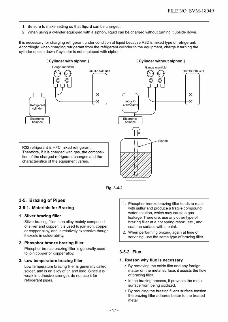
1. Be sure to make setting so that liquid can be charged.2. When using a cylinder equipped with a siphon, liquid can be charged without turning it upside down.
It is necessary for charging refrigerant under condition of liquid because R32 is mixed type of refrigerant. Accordingly, when charging refrigerant from the refrigerant cylinder to the equipment, charge it turning the cylinder upside down if cylinder is not equipped with siphon.
R32 refrigerant is HFC mixed refrigerant. Therefore, if it is charged with gas, the composi-tion of the charged refrigerant changes and the characteristics of the equipment varies.
3-5. Brazing of Pipes3-5-1. Materials for Brazing
1. Silver brazing fillerSilver brazing filler is an alloy mainly composedof silver and copper. It is used to join iron, copperor copper alloy, and is relatively expensive thoughit excels in solderability.
2. Phosphor bronze brazing fillerPhosphor bronze brazing filler is generally usedto join copper or copper alloy.
3. Low temperature brazing fillerLow temperature brazing filler is generally calledsolder, and is an alloy of tin and lead. Since it isweak in adhesive strength, do not use it forrefrigerant pipes.
1. Phosphor bronze brazing filler tends to reactwith sulfur and produce a fragile compoundwater solution, which may cause a gasleakage. Therefore, use any other type ofbrazing filler at a hot spring resort, etc., andcoat the surface with a paint.
2. When performing brazing again at time ofservicing, use the same type of brazing filler.
3-5-2. Flux
1. Reason why flux is necessary• By removing the oxide film and any foreign
matter on the metal surface, it assists the flowof brazing filler.
• In the brazing process, it prevents the metalsurface from being oxidized.
• By reducing the brazing filler’s surface tension,the brazing filler adheres better to the treatedmetal.
Fig. 3-4-2
FILE NO. SVM-18049
- 17 -

Nitrogen gascylinder
Pipe
Flow meterM
Stop valve
From Nitrogen cylinder
Nitrogen gas
Rubber plug
2. Characteristics required for flux• Activated temperature of flux coincides with the
brazing temperature.• Due to a wide effective temperature range, flux
is hard to carbonize.• It is easy to remove slag after brazing.• The corrosive action to the treated metal and
brazing filler is minimum.• It excels in coating performance and is harm-
less to the human body.As the flux works in a complicated manner asdescribed above, it is necessary to select anadequate type of flux according to the type andshape of treated metal, type of brazing filler andbrazing method, etc.
3. Types of flux• Noncorrosive flux
Generally, it is a compound of borax and boricacid.It is effective in case where the brazing tem-perature is higher than 800°C.
• Activated fluxMost of fluxes generally used for silver brazingare this type.It features an increased oxide film removingcapability due to the addition of compoundssuch as potassium fluoride, potassium chlorideand sodium fluoride to the borax-boric acidcompound.
4. Piping materials for brazing and usedbrazing filler/flux
1. Do not enter flux into the refrigeration cycle.2. When chlorine contained in the flux remains
within the pipe, the lubricating oil deteriorates.Therefore, use a flux which does not containchlorine.
3. When adding water to the flux, use waterwhich does not contain chlorine (e.g. distilledwater or ion-exchange water).
4. Remove the flux after brazing.
3-5-3. BrazingAs brazing work requires sophisticated techniques,experiences based upon a theoretical knowledge, itmust be performed by a person qualified.In order to prevent the oxide film from occurring inthe pipe interior during brazing, it is effective toproceed with brazing while letting dry Nitrogen gas(N2) flow.
Never use gas other than Nitrogen gas.
1. Brazing method to prevent oxidation1) Attach a reducing valve and a flow-meter to
the Nitrogen gas cylinder.2) Use a copper pipe to direct the piping mate-
rial, and attach a flow-meter to the cylinder.3) Apply a seal onto the clearance between the
piping material and inserted copper pipe forNitrogen in order to prevent backflow of theNitrogen gas.
4) When the Nitrogen gas is flowing, be sure tokeep the piping end open.
5) Adjust the flow rate of Nitrogen gas so that itis lower than 0.05 m3/Hr or 0.02 MPa(0.2kgf/cm2) by means of the reducing valve.
6) After performing the steps above, keep theNitrogen gas flowing until the pipe cools downto a certain extent (temperature at whichpipes are touchable with hands).
7) Remove the flux completely after brazing.
Fig. 3-5-1 Prevention of oxidation during brazing
Piping material
Copper - Copper
Copper - Iron
Iron - Iron
Used brazing filler
Phosphor copper
Silver
Silver
Used flux
Do not use
Paste flux
Vapor flux
FILE NO. SVM-18049
- 18 -

4. CONSTRUCTION VIEWS
4-1. Indoor Unit
590 225 225
137 104
45
293
4
6
69 174
35
156 156 102 174 65
198
4
6
Outline of indoor unit
HangerHanger
Installation plate outlineCenter line
Hanger
Minimum distanceto wall
Minimum distanceto wall
Minimum distanceto wall 52mm or more
190mm or more
225mm or more
Remote controller holder
57
Wiress remote controller 20
193
1
49
17.5 63
851
270
62
646626
64
Front panel
6262
84.5646452
Knock out systemKnock out system
312
114.3 109 150 150 150 150 141.5
Drain hose(0.6m) Hanger Hanger
Connecting pipe(0.41m) Flare 6.35mm
Connecting pipe(0.37m)(For 10, 13k : Flare 9.52mm)(For 16k : Flare 12.7mm)
le " " " " "
-"
,-,iii' llr--1 n
" ' ' '
_..,
TI'@@[MJ O [ID& © 0 o
rr IU
D M
• •
293
Heat exchanger Plasma ion charger(Air purier)
Air lter
FILE NO. SVM-18049
- 19 -

318
69100 600
440
99
FAN-GUARD
View Z
137
92
54
Service port
Gas side(Flare 9.52)
Liquid side(Flare 6.35)
Electrical part
36
50
R156 hole11x14 hole
330
316
B detail drawing (Front leg)
316
330
R155036
R5.5
6 hole
600
A detail drawing (Back leg)
(Unit : mm)
2 - R5-5 x 17L Ushape
2 - ∅11 x 14 Long holes (For ∅8- ∅10 anchor bolt)
Installation dimension
Air outlel 100 or more
100 or more
600 or more
600 or more
Air intlel
600
320
(For ∅8 - ∅10 anchor bolt)
351 330
COVER-PV
ViewZ
299
630
(Flare 12.70)
RAS-10PAVPG-E,-NZRAS-13PAVPG-E,-NZ
RAS-16PAVPG-E,-NZ
4-2. Outdoor Unit
A 12529 108
25 Drain outlet B2- 11x14 Hole
(For 8- 10 anchor bolt)
330 10
6
29
FILE NO. SVM-18049
- 20 -

5. WIRING DIAGRAM
FILE NO. SVM-18049
- 21 -

6. SPECIFICATIONS OF ELECTRICAL PARTS
6-1. Indoor Unit
6-2. Outdoor Unit
No.
1 Reactor L = 19mH, 10A
2 Outdoor fan motor DC140V, 43W
3 Suction temp. sensor (TS sensor) 10kΩ (25°C)
4 Discharge temp. sensor (TD sensor) 62kΩ (20°C)
5 Outside air temp. sensor (TO sensor) 10kΩ (25°C)
6 Heat exchanger temp. sensor (TE sensor) 10kΩ (25°C)
7 Terminal block (5P) 20A, AC250V
9 Coil for PMV DC12V
10 Coil for 4-way valve
CAM-MD12TCTH-5
STF-H01AJ
Compressor 3-phases 6-poles 885W
(Inverter attached)
(Inverter attached)
(Inverter attached)
8
(Inverter attached)
KTN110D42UFZ
Parts name Model name Rating
CH-69-Z-T
ICF-140-43-4R
ICF-340U30-6
JX0-5B
KTN150D42UFZ 3-phases 6-poles 1185W
RAS-10PAVPG-E,-NZ
RAS-13PAVPG-E,-NZRAS-16PAVPG-E,-NZ
AC Type
DC340, 30W
No.
Fan motor (for indoor)
2 Room temp. sensor (TA-sensor) 10kΩ at 25°C
3 Heat exchanger temp. sensor (TC-sensor) 10kΩ at 25°C
4
Louver motor
Output (Rated) 1W, 16 poles, DC12V
( - )
( - )
MP24Z4N
Parts name
1
Specif icat ionsType
5
Heat exchanger temp. sensor (TCJ-sensor) 10kΩ at 25°C( - )
FILE NO. SVM-18049
- 22 -

7. REFRIGERANT CYCLE DIAGRAM
7-1. Refrigerant Cycle Diagram
NOTE :• The maximum pipe length of this air conditioner is 25 m. When the pipe length exceeds 15m, the additional
Max. : 25m
Deoxidized copper pipe Outer dia. : 9.52mm
Thickness : 0.8mm
NOTE : Gas leak check positionRefrigerant flow (Cooling)Refrigerant flow (Heating)
INDOOR UNIT T1
TO
Temp. measurement
Indoor heatexchanger
Cross flow fan
Deoxidized copper pipe Outer dia. : 6.35mm Thickness : 0.8mm
Sectional shapeof heat insulator
Allo
wab
le h
eigh
tdi
ffere
nce
: 10m
Allo
wab
le p
ipe
leng
th
P Pressure measurementGauge attaching portVacuum pump connecting port
Strainer
Pulse Modulatingvalve at liquid side
Ø1.0 x 80
Ø1.0 x 80
TD
4-way valve
Compressor KTN110D42UFZ
TS
T2
Outdoor heat exchanger Split capillary
Temp. measurement
Propeller fan Refrigerant amount : 1.00kg
OUTDOOR UNIT
Muffler
Muffler
TE
TC
TA
Min. : 2mChargeless : 15mCharge : 20g/m(16 to 25m)
charging of refrigerant, 20g per 1m for the part of pipe exceeded 15m is required. (Max. 200g)
Dryer
Tcj
RAS-10PKVPG-E / RAS-10PAVPG-ERAS-10PKVPG-NZ / RAS-10PAVPG-NZ
FILE NO. SVM-18049
- 23 -
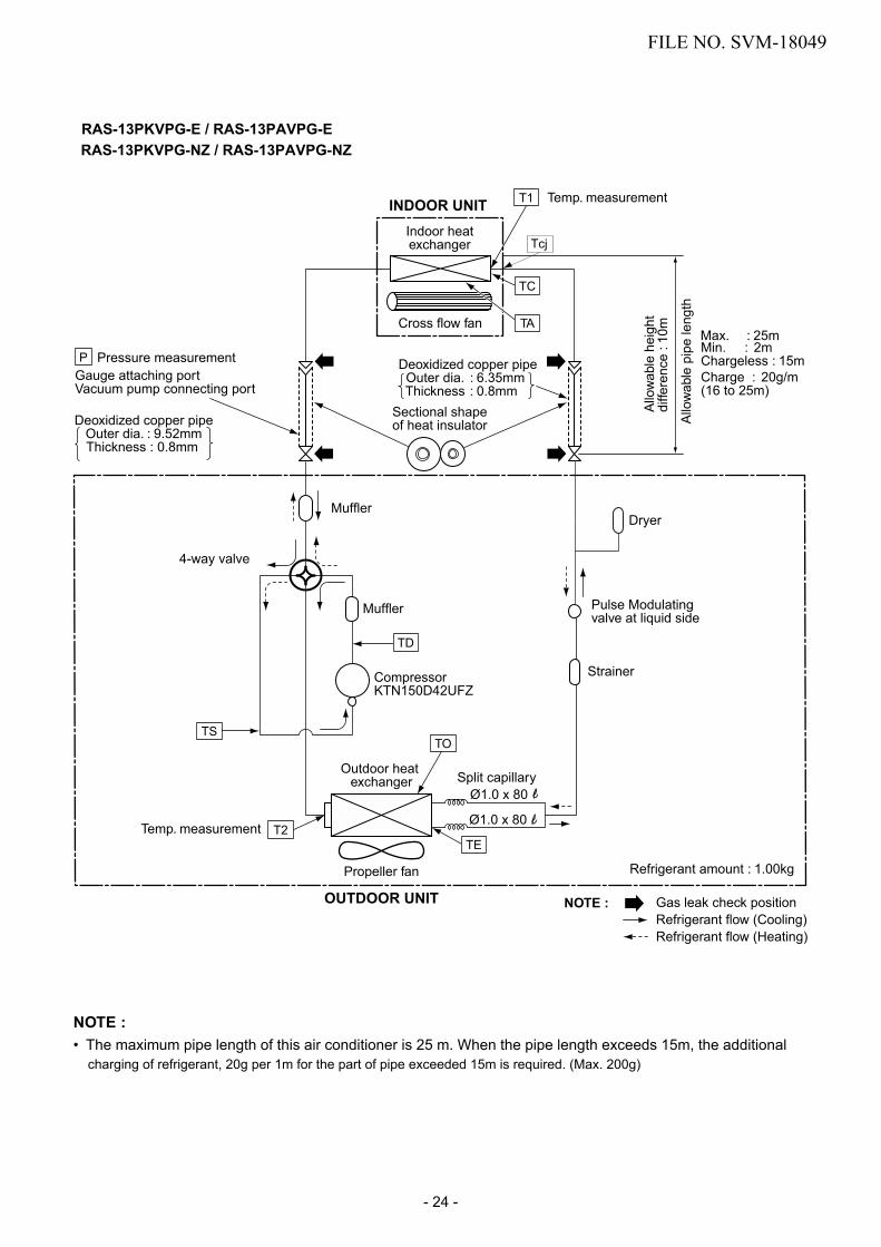
NOTE :• The maximum pipe length of this air conditioner is 25 m. When the pipe length exceeds 15m, the additional
Max. : 25m
Deoxidized copper pipe Outer dia. : 9.52mm
Thickness : 0.8mm
NOTE : Gas leak check positionRefrigerant flow (Cooling)Refrigerant flow (Heating)
INDOOR UNIT T1
TO
Temp. measurement
Indoor heatexchanger
Cross flow fan
Deoxidized copper pipe Outer dia. : 6.35mm Thickness : 0.8mm
Sectional shapeof heat insulator
Allo
wab
le h
eigh
tdi
ffere
nce
: 10m
Allo
wab
le p
ipe
leng
th
P Pressure measurementGauge attaching portVacuum pump connecting port
Strainer
Pulse Modulatingvalve at liquid side
Ø1.0 x 80
Ø1.0 x 80
TD
4-way valve
Compressor KTN150D42UFZ
TS
T2
Outdoor heat exchanger Split capillary
Temp. measurement
Propeller fan Refrigerant amount : 1.00kg
OUTDOOR UNIT
Muffler
Muffler
TE
TC
TA
Min. : 2mChargeless : 15mCharge : 20g/m(16 to 25m)
charging of refrigerant, 20g per 1m for the part of pipe exceeded 15m is required. (Max. 200g)
Dryer
Tcj
RAS-13PKVPG-E / RAS-13PAVPG-ERAS-13PKVPG-NZ / RAS-13PAVPG-NZ
FILE NO. SVM-18049
- 24 -

NOTE :• The maximum pipe length of this air conditioner is 25 m. When the pipe length exceeds 15m, the additional
Max. : 25m
Deoxidized copper pipe
NOTE : Gas leak check positionRefrigerant flow (Cooling)Refrigerant flow (Heating)
INDOOR UNIT T1
TO
Temp. measurement
Indoor heatexchanger
Cross flow fan
Deoxidized copper pipe Outer dia. : 6.35mm Thickness : 0.8mm
Sectional shapeof heat insulator
Allo
wab
le h
eigh
tdi
ffere
nce
: 10m
Allo
wab
le p
ipe
leng
th
P Pressure measurementGauge attaching portVacuum pump connecting port
Pulse Modulatingvalve at liquid side
Ø1.0 x 80
Ø1.0 x 80
TD
4-way valve
Compressor KTN150D42UFZ
TS
T2
Outdoor heat exchanger Split capillary
Temp. measurement
Propeller fan Refrigerant amount : 1.00kg
OUTDOOR UNIT
Muffler
Muffler
TE
TC
TA
Min. : 2mChargeless : 15mCharge : 20g/m(16 to 25m)
Outer dia. : 12.7mm Thickness : 0.8mm
charging of refrigerant, 20g per 1m for the part of pipe exceeded 15m is required. (Max. 200g)
Tcj
Strainer
Dryer
RAS-16PKVPG-E / RAS-16PAVPG-ERAS-16PKVPG-NZ / RAS-16PAVPG-NZ
FILE NO. SVM-18049
- 25 -

FILE NO. SVM-18049
- 26 -
7-2. Operation Data
<Cooling>Heat exchanger pipe
temp.Indoor fan
modeOutdoor fan
mode
Indoor Outdoor T1 (°C) T2 (°C)
10PKVPG-E10PKVPG-NZ
1.1 to 1.2 14 to 16 39 to 41 High High 27 5.0
13PKVPG-E13PKVPG-NZ
1.1 to 1.2 14 to 16 39 to 41 High High 27 5.0
16PKVPG-E16PKVPG-NZ
0.9 to 1.1 12 to 14 41 to 43 High High 37 5.0
<Heating>Heat exchanger pipe
temp.Indoor fan
modeOutdoor fan
mode
Indoor Outdoor T1 (°C) T2 (°C)
10PKVPG-E10PKVPG-NZ
2.1 to 2.3 33 to 35 3 to 4 High High 36 5.0
13PKVPG-E13PKVPG-NZ
2.1 to 2.3 33 to 35 3 to 4 High High 36 5.0
16PKVPG-E16PKVPG-NZ
2.4 to 2.6 36 to 38 2 to 3 High High 42 5.0
Tempeature condition(°C) Model name
RAS-
Standard pressureP (MPa)
Compressor revolution
(rps)
27/- 7/6
Connecting piping
(m)
27/19 35/-
Connecting piping
(m)
Compressor revolution
(rps)
Tempeature condition(°C) Model name
RAS-
Standard pressureP (MPa)
NOTES :Measure surface temperature of heat exchanger pipe around center of heat exchanger path U bent.(Thermistor thermometer)

8. CONTROL BLOCK DIAGRAM8-1. Indoor Unit
M.C.U. Indoor Unit Control Unit
Power SupplySerial Signal Communication
(Operation Command and Information)
Serial Signal Transmitter/Receiver
Micro SwitchConverter(AC --> DC)
Noise Filter
Indoor
Air purifier unit
LouverMotor
Louver MotorDrive Control
Indoor FanMotor Control
Initializing Circuit
Clock FrequencyOscillator Circuit
Power SupplyCircuit
Heat Exchanger Sensor (TC)
Room Temperature Sensor (TA)
Infrared Rays Signal Receiverand Indication
Functions
· Cold draft preventing Function
· 3-minute Delay at Restart for Compressor
· Fan Motor Starting Control
· Processing(Temperature Processing)
· Timer / Weekly Timer
· Serial Signal Communication
· Clean Function
· Power Selection & Silent CDU
· Fireplace & 8°C
IndoorFan Motor
Heat Exchanger Sensor (TCJ)
Infrared Rays, 36.7kHzRemote Controller
Thermo. Setting
Fan Speed Selection
ON TIMER Setting
OFF TIMER Setting
Louver AUTO Swing
Louver Direction Setting
Operation Mode SelectionAUTO, COOL, DRY, HEAT
REMOTE CONTROLLER
ECO
Hi-POWER
POWER-SEL & Silent CDU
WEEKLY ON / OFF
Operation ( )
COMFORT SLEEP
PURE
Air Flow
Fireplace & 8°C
FILE NO. SVM-18049
- 27 -

8-2. Outdoor Unit (Inverter Assembly)
220–
240
V ~
50H
z
MIC
RO
-CO
MPU
TER
BLO
CK
DIA
GR
AM
Driv
er c
ircui
tof
P.M
.V.
Hea
t exc
hang
erte
mp.
sens
or
Suc
tion
tem
p.
sens
or
Out
door
air
tem
p. s
enso
r
Dis
char
ge
tem
p. s
enso
r
Indo
or u
nit
send
/rece
ive
circ
uit
Rel
ayci
rcui
t
Noi
seFi
lter
Con
verte
r(A
C →
DC
)
Clo
ck
frequ
ency
10
MH
z
Hig
h Po
wer
fa
ctor
Cor
rect
ion
circ
uit
Inpu
t cur
rent
sens
or
P.M
.V.
: Pul
se M
otor
Val
veM
.C.U
. : M
icro
Con
trol U
nit
For I
ND
OO
R U
NIT
4-w
ayva
lve
P.M
.V.
Inve
rter
(DC
→ A
C)
Gat
e dr
ive
circ
uit
Gat
e dr
ive
circ
uit
Inve
rter
(DC
→ A
C)
Out
door
Fan
mot
or
Com
pres
sor
WP-
030
(PC
B)
OU
TDO
OR
UN
IT
Cur
rent
de
tect
Cur
rent
de
tect
M.C
.U
PW
M s
ynth
esis
func
tion
In
put c
urre
nt re
leas
e co
ntro
l
IGB
T ov
er-c
urre
nt d
etec
t con
trol
O
utdo
or fa
n co
ntro
l
Hig
h po
wer
fact
or c
orre
ctio
n co
ntro
l
Inve
rter o
utpu
t fre
quen
cy c
ontro
l
A/D
con
verte
r fun
ctio
n
P.M
.V. c
ontro
l
Dis
char
ge te
mp.
con
trol
4-
way
val
ve c
ontro
l
Sig
nal c
omm
unic
atio
n to
indo
or u
nit
Hig
h Pr
essu
reS
witc
h
Heater
Cord
Heater
Control
Circuit
FILE NO. SVM-18049
- 28 -
9. OPERATION DESCRIPTION
9-1. Outline of Air Conditioner ControlThis air conditioner is a capacity-variable type airconditioner. Its system can control the speed ofcompressor motor according to load. The drive circuitfor the indoor motor is mounted in the indoor unit. The drive circuits for outdoor motor and compressorare mounted in the outdoor unit.
The entire air conditioner is mainly controlled by theindoor unit controller. The indoor unit controller drives the indoor fan motor based upon commandsent from the remote controller. Moreover, it alsodetermines required speed of compressor motor andthen transfers the operation command to the outdoor unit controller.
• Detection of inverter input current and currentrelease operation
• Over-current detection and prevention operation toIGBT module (Compressor stop function)
• Compressor and outdoor fan stop function whenserial signal is off (when the serial signal does notreach the board assembly of outdoor control bytrouble of the signal system)
• Transferring of operation information (Serialsignal) from outdoor unit controller to indoor unitcontroller
• Detection of outdoor temperature and operationrevolution control
• Defrost control in heating operation (Temp.measurement by outdoor heat exchanger andcontrol for 4-way valve and outdoor fan)
3. Contents of operation command signal(Serial signal) from indoor unit controller tooutdoor unit controllerThe following three types of signals are sent fromthe indoor unit controller.• Operation mode set on the remote controller• Compressor revolution command signal defined
by indoor temperature and set temperature(Correction along with variation of room tempera-ture and correction of indoor heat exchangertemperature are added.)
• Temperature of indoor heat exchanger• For these signals ([Operation mode] and [Com-
pressor revolution] indoor heat exchanger tem-perature), the outdoor unit controller monitors theinput current to the inverter, and performs thefollowed operation within the range that currentdoes not exceed the allowable value.
4. Contents of operation command signal(Serial signal) from outdoor unit controllerto indoor unit controllerThe following signals are sent from the outdoor unitcontroller.• The current operation mode• The current compressor revolution• Outdoor temperature• Existence of protective circuit operation
For transferring of these signals, the indoor unitcontroller monitors the contents of signals, andjudges existence of trouble occurrence. Contentsof judgment are described below.• Whether distinction of the current operation
status meets to the operation command signal• Whether protective circuit operates
When no signal is received from the outdoorunit controller, it is assumed as a trouble.
The outdoor unit controller erceives operation command from the indoor unit and controls revolutionspeed of the compressor motor.The outdoor unit controller controls speed of compressor motor be controlling output voltage of theinverter and switching timing of supply power (currenttransfer timing), so that compressor motor operatesaccording to the operation command. And then, theoutdoor unit controller transfers the operating statusback to the indoor unit controller.
As the compressor adopts four-pole brushlessDC motor, the frequency of the supply powerfrom inverter to compressor is two-times cyclesof the actual number of revolution.
1. Role of indoor unit controllerThe indoor unit controller judges the operationcommands from the remote controller and assumesthe following functions.• Judgment of suction air temperature of the indoor
heat exchanger by using the indoor temp. sensor.(TA sensor)
• Judgment of the indoor heat exchanger tempera-ture by using heat exchanger sensor (TC sensor)(Prevent-freezing control, etc.)
• Louver motor control• Indoor fan motor operation control• LED (Light Emitting Diode) display control• Transferring of operation command signal (Serial
signal) to the outdoor unit• Reception of information of operation status
(Serial signal including outside temp. data) fromthe outdoor unit and judgment/display of error
2. Role of outdoor unit controllerReceiving the operation command signal (Serialsignal) from the indoor unit controller, the outdoorunit performs compressor operation control asfollowed to judgment of serial signal from indoorside.
FILE NO. SVM-18049
- 29 -

9-2. Operation Description
1. Basic operation ........................................................................................................... 311. Operation control ................................................................................................... 312. Cooling/Heating operation ..................................................................................... 323. AUTO operation ..................................................................................................... 324. DRY operation ........................................................................................................ 32
2. Indoor fan motor control ............................................................................................. 333. Outdoor fan motor control ........................................................................................... 364. Capacity control .......................................................................................................... 375. Current release control ............................................................................................... 376. Release protective control by temperature of indoor heat exchanger ........................ 387. Defrost control (Only in heating operation) ................................................................ 398. Louver control ............................................................................................................. 41
1) Louver position ....................................................................................................... 412) Wind direction adjustment ..................................................................................... 433) Swing ..................................................................................................................... 43
9. ECO operation ............................................................................................................ 4410. Temporary operation ................................................................................................... 4511. Plasma ionizer purifier control [Detection of abnormality] ......................................... 4512. Discharge temperature control ................................................................................... 4613. High pressure control ................................................................................................. 4714.
Self-Cleaning function ................................................................................................ 4815.Remote-A or B selection ............................................................................................ 50
21.
16.QUIET mode ............................................................................................................. 5017.COMFORT SLEEP mode ............ ............................................................................. 5018.Short Timer ................................... ............................................................................. 5119.
20. Hi-POWER Mode ..................... ................................................................................. 51
23.
POWER Selection Mode .................................................................................... 52
28.Cord Heater Control ............................................................................................ 5427.
Outdoor Quiet Control ........................................................................................ 53
Pulse Modulating valve (P.M.V.) control ...................................................................... 47
FCU Display lamp brighness control ..................................................................... 55
22. Silent Operation ............................................................................................... 52
24. Operation mode selectable .............................................................................. 5325. Fireplace Operation .......................................................................................... 5426. 8 degree heating / Frost protective Operation .................................................. 54
9-3. Auto Restart Function ..9-3-1. How to Set the A uto Restart Function ....................................................................... 56
9-3-2. How to Cancel the Au to Restar t Function ................................................................. 57
9-3-3. Power Failure During Timer Operation .................................................................... 57
9-4. Remote Controller and Its Fuctions9-4-1. Parts Name of Remote Contr oller .............................................................................. 58
9-4-2. Operation of remote control ....................................................................................... 58
9-4-3. Name and Functions of Indications on Remote Contr oller ......................................... 67
FILE NO. SVM-18049
- 30 -

Item
1. Basicoperation
Operation flow and applicable data, etc.
1. Operation control
Description
Receiving the user’s operation condition setup, the operation statuses of indoor/outdoor units arecontrolled.1) The operation conditions are selected by the remote controller as shown in the below.2) A signal is sent by ON button of the remote controller.3) The signal is received by a sensor of the indoor unit and processed by the indoor controllers as
shown in the below. The power relay is tumed ON and power supply to the outdoor unit.4) The indoor controller controls the indoor fan motor and louver motor.5) The indoor controller sends the operation command to the outdoor controller, and sends/receives
the control status with a serial signal.6) The outdoor controller controls the operation as shown in the below, and also controls the
compres-sor, outdoor fan motor, 4-way valve and pulse Modulating valve are controlled
Remote controller
Control contents of remote controller• ON/OFF (Air conditioner/Air purifier)• Operation select (COOL/HEAT/AUTO/DRY)• Temperature setup• Air direction• Swing• Air volume select (AUTO/QUIET/LOW/LOW+/MED/MED+/HIGH)
• ECO• ON timer setup• OFF timer setup• Hi-POWER
Selection of operation conditions
ON/OFF
• COMFORT SLEEP
• QUIET• PRESET• ONE-TOUCH• POWER-SELECTION
~
Indoor unit control
Operation command
Power relay
signal Serial transmission
signalSerial Inverter
Transmission
Signal receiving
Outdoor unit
Indoor unit control• Command signal generating function for
indoor unit operation• Calculation function (temperature
calculation)• 3 minute delay function for compressor
reactivation• Activation compensation function for indoor
fan• Cold draft preventive function• Timer function• Indoor heat exchanger release control
Outdoor unit control• Inverter output frequency
control• Waveform composite function• Calculation function
(temperature calculation)• AD conversion function• Quick heating function• Compressor reactivation delay
function• Current release function• GTr overload protective function• Defrost operation function• Outdoor temperature estimation
• Indoor fan motor
• Louver motor
Compressor•
• Outdoor fan motor
•
• Four-way valve
Pulse modulating valve
Indoor unit
• A/B Selection function
• Contront air flow (wide angle/Right wide/Left wide/spot front/spot right/spot lift)
• Fireplace• Silent operation
FILE NO. SVM-18049
- 31 -

Operation ON Setup of remote controller
Indoor fan motor control / Louver control / Operation HzControl (Requierment)Indoor unit control
Sending of operation command signal
Outdoor unit control [ ]Compressor revolution control / Outdoor fan motor control /
4-way valve control In cooling operation: ON In heating operation:
OFF
Pulse Modulating valve control
Item
1. Basicoperation
Operation flow and applicable data, etc.
2. Cooling/Heating operation
Description
The operations are performed in the following parts by controls according to cooling/heating conditions.
1) Receiving the operation ON signal of the remote controller, the cooling or heating operation signalstarts being transferred form the indoor controller to the outdoor unit.
2) At the indoor unit side, the indoor fan is operated according to the contents of “2. Indoor fanmotor control” and the louver according to the contents of “9. Louver control”, respectively.
3) The outdoor unit controls the outdoor fan motor, compressor, pulse Modulating valve and4-way valve according to the operation signal sent from the indoor unit.
3. AUTO operationSelection of operation modeAs shown in the following figure, the operation starts byselecting automatically the status of room temperature(Ta) when starting AUTO operation.
*1. When reselecting the operation mode, the fanspeed is controlled by the previous operation mode.
4. DRY operationDRY operation is performed according to the differencebetween room temperature and the setup temperature asshown below.
In DRY operation, fan speed is controlled in order toprevent lowering of the room temperature and to avoid airflow from blowing directly to persons.
1) Detects the room temperature (Ta) whenthe DRY operation started.
2) Starts operation under conditions in theleft figure according to the temperaturedifference between the room tempera-ture and the setup temperature (Tsc).Setup temperature (Tsc)= Set temperature on remote controller (Ts) + (0.0 to 1.0)
3) When the room temperature is lower1°C or less than the setup temperature,turn off the compressor.
1) Detects the room temperature (Ta) whenthe operation started.
2) Selects an operation mode from Ta inthe left figure.
3) Fan operation continues until anoperation mode is selected.
4) When AUTO operation has startedwithin 2 hours after heating operationstopped and if the room temperature is20°C or more, the fan operation isperformed with ”Super Ultra LOW” modefor 3 minutes.Then, select an operation mode.
5) If the status of compressor-OFFcontinues for 15 minutes the roomtemperature after selecting an operationmode (COOL/HEAT), reselect anoperation mode.
Ts + 1
Ts – 1
TaCooling operation
Monitoring (Fan)
Heating operation
Tsc
+0.5
+1.0
[˚C]Ta
Fan speed
L– (W5)
(W5+W3) / 2
SUL (W3)
Operation Hz control (Include limit control)
FILE NO. SVM-18049
- 32 -

Item
2. Indoor fanmotor control
Operation flow and applicable data, etc.
<In cooling operation>(This operation controls the fan speed at indoor unit side.)The indoor fan (cross flow fan) is operated by the phase-control induction motor. The fan rotates in 5 stages inMANUAL mode, and in 5 stages in AUTO mode, respec-tively. (Table 1)
Description
* SymbolsUH : Ultra HighH : HighM+ : Medium+M : MediumL+ : Low+L : LowL- : Low–UL : Ultra LowSUL : Super Ultra Low
* The values of fan speed and air flowvolume indicate on the table aremeasured when the louver is inclineddownward. Fan speed and air flowvolume broadly vary with position
(Fig. 1)
(Fig. 2)
+2.5
Ta[°C]
+2.0
+1.5
+1.0
+0.5
Tsc
a
b
c
d
e
M+(WC)
*3
*4
*5
L(W7)
Air volume AUTO
LL+MM+H
W7(L + M) / 2
WA(M + H) / 2
WD
Indication Fan speed
Fan speed setup
COOL ON
AUTO
MANUAL
*3 : Fan speed = (M + –L) x 3/4 + L
*4 : Fan speed = (M + –L) x 2/4 + L
*5 : Fan speed = (M + –L) x 1/4 + L
(Linear approximation from M+ and L)
(Table 1) Indoor fan air flow rate
Quiet W5
of louver.
1) When setting the fan speed to L,L+, M, M+,H or Quiet on theremote controller, the operation isperformed with the constantspeed shown in Fig. 1.
2) When setting the fan speed toAUTO on the remote controller,revolution of the fan motor iscontrolled to the fan speed levelshown in Fig. 2 and Table 1according to the setup tempera-ture, room temperature, and heatexchanger temperature.
RAS-10PKVPG-E,-NZ
Cooling Heating
Cool Heat PAP Dry Fan speed Air flow rate Fan speed Air flow rate
(rpm) (m3/h) (rpm) (m3/h)WF UH UH/H 1120 700 1160 750WE UH H 1120 700 1140 730WD H M+ UH 1100 690 990 610WC M+ M+ H 980 590 950 570WB M M+ 930 550 840 470WA /L+MM M 780 420 840 470W9 L+ 750 400 750 400W8 L+ L L+ 710 370 660 320W7 L L- L 640 300 650 310W6 L- L 620 290 640 300W5 UL UL L- L- 540 220 560 240W4 UL 520 200 550 230W3 SUL UL SUL/SL- 500 190 500 190W2 SUL SL 480 170 480 170W1 SL- 440 140 440 140
Fan speedlevel
Mode
FILE NO. SVM-18049
- 33 -

Item
2. Indoor fanmotor control
Operation flow and applicable data, etc. Description
(Table 2) Indoor fan air flow rate
RAS-13PKVPG-E,-NZ
Cooling Heating
Cool Heat PAP Dry Fan speed Air flow rate Fan speed Air flow rate
(rpm) (m3/h) (rpm) (m3/h)WF UH UH/H 1140 730 1160 750WE UH H 1120 700 1140 730WD H M+ UH 1120 700 990 610WC M+ M+ H 980 590 950 570WB M M+ 930 550 840 470WA /L+MM M 780 420 840 470W9 L+ 750 400 750 400W8 L+ L L+ 710 370 660 320W7 L L- L 640 300 650 310W6 L- L 620 290 640 300W5 UL UL L- L- 540 220 560 240W4 UL 520 200 550 230W3 SUL UL SUL/SL- 500 190 500 190W2 SUL SL 480 170 480 170W1 SL- 440 140 440 140
Fan speedlevel
Mode
RAS-16PKVPG-E,-NZ
Cooling Heating
Cool Heat PAP Dry Fan speed Air flow rate Fan speed Air flow rate
(rpm) (m3/h) (rpm) (m3/h)WF UH UH/H 1160 750 1160 750WE UH H 1160 750 1160 750WD H M+ UH 1150 740 1010 630WC M+ M+ H 1000 620 950 570WB M M+ 950 570 860 490WA /L+MM M 800 440 850 480W9 L+ 800 440 770 410W8 L+ L L+ 730 380 680 330W7 L L- L 660 320 680 330W6 L- L 650 310 650 310W5 UL UL L- L- 560 240 580 250W4 UL 540 220 550 230W3 SUL UL SUL/SL- 520 200 520 200W2 SUL SL 500 190 500 190W1 SL- 440 140 440 140
Fan speedlevel
Mode
(Table 3) Indoor fan air flow rate
FILE NO. SVM-18049
- 34 -

Item
2. Indoor fanmotor control
Operation flow and applicable data, etc.
<In heating operation>
Description
1) When setting the fan speed to L,L+, M, M+, H or Quiet on the remotecontroller, the operation is per-formed with the constant speedshown in Fig. 3 and Table 1.
2) When setting the fan speed toAUTO on the remote controller,revolution of the fan motor iscontrolled to the fan speed levelshown in Fig. 5 according to the settemperature and room temperature.
3) Min air flow rate is controlled bytemperature of the indoor heatexchanger (Tc) as shown in Fig. 4.
4) Cold draft prevention, the fanspeed is controlled by temperatureof the indoor heat exchanger (Tc)as shown in Fig. 6.
In starting In stability
Until 12 minutes passed after operation start When 12 to 25 minutes passed after operation start and room temperature is 3°C or lower than set temperature.
• When 12 to 25 minutes passed after operation startand room temperature is higher than (set temperature–3°C)
FAN AUTO
• When 25 minutes or more passed after operation startFAN Manual • Room temperature < Set temperature –4°C • Room temperature ≥ Set temperature –3.5°C
••
(Fig. 3)
(Fig. 4)Cold draft preventive control
(Fig. 6)
Fan speedAUTO
Basic fan control
* No limitation while fan speed MANUAL mode is in stability.* A: When Tsc ≥ 24, A is 24, and when Tsc < 24, A is Tsc
Tsc: Set value
TSCTA [°C]
b
–0.5 c
–1.0 d
–1.5 e
–2.0 f
–2.5 g
–5.0
–5.5
L+ (W9)
*1
*2
*3
M+(WD)
H (WE)
Line-approximateH and SUL with Tc.
SUL (W2)
Stop
45Tc
3344 32
33 2132 20
*A+4 *A+4
*A-4 *A-8
Fan speed MANUAL in starting Fan speed AUTO in starting and stability
LL+MM+H
W8(L + M) / 2
WB(M + H) / 2
WE
Indication Fan speed
Fan speed setup
HEAT ON
AUTO
YES
NO
MANUAL
TC ≥ 42°C
W
Min air flow rate control
Tc5150
4241
M+ (WC)
* Fan speed =(TC – (41+a)) / (51 − 41) x (M+ −L ) + L
No limit*
*1: Fan speed = (M + -L+) x 1 5 + L+*2: Fan speed = (M + -L+) x 2 5 + L+*3: Fan speed = (M + -L+) x 3 5 + L+
(Calculated with linear approximation from M+ and L+)
5) In order to prevent Cold draft whencompressor step during heatingoperation. Then louver will move toupper position and fan speed willreduce or off.
Quiet 5
*4
4: Fan speed = (M + -L+) x 4 5 + L+*
(Fig. 5)
[[In starting and in stability]
FILE NO. SVM-18049
- 35 -

Item
3. Outdoor fanmotor control
Operation flow and applicable data, etc.
The blowing air volume at the outdoor unit side is controlled.Receiving the operation command from the controller ofindoor unit, the controller of outdoor unit controls fan speed.* For the fan motor, a DC motor with non-stage variable
speed system is used. However, it is limited to 8 stages forreasons of controlling.
Description
1) The operation command sentfrom the remote controller isprocessed by the indoor unitcontroller and transferred to thecontroller of the outdoor unit.
2) When strong wind blows atoutdoor side, the operation of airconditioner continues with thefan motor stopped.
3) Whether the fan is locked or notis detected, and the operation ofair conditioner stops and analarm is displayed if the fan islocked.
4) According to each operationmode, by the conditions ofoutdoor temperature (To) andcompressor revolution, the speedof the outdoor fan shown in thetable is selected.
Air conditioner ON(Remote controller)
YES
YES
NO
NO
Indoor unit controller
Fan motor ON
3) Fan lock
4) Motor operates as shown in the table below.
1) Outdoor unitoperation command(Outdoor fan control)
Air conditionerOFF
Alarmdisplay
2) Fan speed ≥ 400.
(by strong wind)when the motor OFF.
Fan motor OFF continues(Use wind for heat
exchanging)
Outdoor fan speed (rpm)
In Cooling Operation
Compressor Speeds (rps)
Hz < 21.0 21.0 Hz <46.2 46.2 HzFan Speed Ranges Min Max Min Max Min Max
To 38C f6 fB f8 fE fA fE
To 28C f5 fA f7 fE f9 fE
To 15C f3 f7 f5 f9 f7 fB
To 5.5C f2 f5 f4 f7 f6 f9
To 0C f1 f3 f3 f5 f4 f7
To < 0C f1 f2 f2 f4 f3 f5
When To is abnormal OFF fB OFF fE f1 fE
In Heating Operation
Compressor Speeds (rps)
Hz < 21.0 21.0 Hz <46.2 46.2 HzTo 10C f7 f8 f9
To < 10C f9 fB fE
To < 5C fE fE fE
To < ‐3C fE fE fE
When To is abnormal fF fF fFTo
To
Comp. Hz Comp. Hz
Tap RAS‐10PAVPG‐E,‐NZ RAS‐13PAVPG‐E,‐NZ RAS‐16PAVPG‐E,‐NZ
f1 580 580 580
f2 580 580 580
f3 620 620 620
f4 620 620 620
f5 620 620 620
f6 630 630 630
f7 640 640 640
f8 640 640 640
Tap RAS‐10PAVPG‐E,‐NZ RAS‐13PAVPG‐E,‐NZ RAS‐16PAVPG‐E,‐NZ
f9 650 650 650
fA 650 650 650
fB 680 680 680
fC 700 700 700
fD 700 700 700
fE 700 700 700
fF 750 750 750
FILE NO. SVM-18049
- 36 -

Item
4. Capacitycontrol
Operation flow and applicable data, etc.
The cooling or heating capacity depending on the load isadjusted.According to difference between the setup value of tempera-ture and the room temperature, the capacity is adjusted bythe compressor revolution.
Description
1) The difference between settemperature on remote controller(Ts) and room temperature (Ta)is calculated.
2) According to the temperaturedifference, the correction value ofHz signal which determines thecompressor speed is set up.
3) The rotating position and speedof the motor are detected by theelectromotive force occurred onthe motor winding with operationof the compressor.
4) According to the differenceresulted from comparison of thecorrection value of Hz signal withthe present operation Hz, theinverter output and the commuta-tion timing are varied.
5) Change the compressor motorspeed by outputting power to thecompressor.* The contents of control
operation are same in coolingoperation and heatingoperation
This function prevents troubles on the electronic parts of thecompressor driving inverter.This function also controls drive circuit of the compressorspeed so that electric power of the compressor drive circuitdoes not exceed the specified value.
5. Current releasecontrol
Outdoor temp. To
Setup of current release point
Current decrease
Outdoor unit inverter maincircuit control current
High
Low
Reduce compressor speedOperating current ≤Setup value
Capacity control continues.
1) The input current of the outdoorunit is detected in the invertersection of the outdoor unit.
2) According to the detectedoutdoor temperature, thespecifice value of the current isselected.
3) Whether the current valueexceeds the specifice value ornot is judged.
4) If the current value exceeds thespecified value, this functionreduces the compressor speedand controls speed up to theclosest one commanded from theindoor unit within the rangewhich does not exceed thespecified value.
Set temp. (Ts) Room temp. (Ta)
Correction value of Hz signal
Detection of electromotive forceof compressor motor winding
Inverter output changeCommutation timing change
Change of compressor speed
Remote controller Indoor unit
Ts −Ta
Correction value of Hz signal- Operating Hz
Detection of motor speed (Operation Hz)and rotor position
Mode Outdoor temperature: To (°C) Current Release Value (A)
RAS-13PAVPG-E,-NZ RAS-16PAVPG-E,-NZ
To > 45 6.5 6.5
Cooling 45 > To > 40 6.8 6.8
To < 40 4.6 4.8
To > 16 10.0 10.0
Heating 16 > To > 11 9.8 10.0
To < 11 9.6 10.0
RAS-10PAVPG-E,-NZ
4.6
6.0
4.1
10.0
9.2
8.4
FILE NO. SVM-18049
- 37 -

Item
6. Release protectivecontrol by tempera-ture of indoor heatexchanger
Operation flow and applicable data, etc.
<In cooling/dry operation>(Prevent-freezing control for indoor heat exchanger)In cooling/dry operation, the sensor of indoor heatexchanger detects evaporation temperature andcontrols the compressor speed so that temperature ofthe heat exchanger does not exceed the specifiedvalue.
Description
1) When temperature of the indoorheat exchanger drops below 5°C,the compressor speed isreduced. (P zone)
2) When temperature of the indoorheat exchanger rises in therange from 6°C to under 7°C, thecompressor speed is kept.(Q zone)
3) When temperature of the indoorheat exchanger rises to 7°C orhigher, the capacity controloperation returns to the usualcontrol in cooling operation.(R zone)
1) When temperature of the indoorheat exchanger rises in therange from 52°C to 55°C, thecompressor speed is kept.(Q zone)When temperature of the indoorheat exchanger drops in therange from 48°C to under 55°C,the compressor speed is kept.(Q zone)
2) When temperature of the indoorheat exchanger rises to 55°C orhigher, the compressor speed isreduced. (P zone)
3) When temperature of the indoorheat exchanger does not rise to52°C, or when it drops below to48°C, the capacity controloperation returns to the usualcontrol in heating operation.(R zone)
<In heating operation>(Prevent-overpressure control for refrigerating cycle)In heating operation, the sensor of indoor heat ex-changer detects condensation temperature and controlsthe compressor speed so that temperature of the heatexchanger does not exceed the specified value.
7°C
6°C
5°C
R
Q
P
55°C
52°C
48°C
P
Q
R
Usual cooling capacity control
Reduction of compressor speedIndo
or h
eat e
xcha
nger
tem
pera
ture
When the value is in Q zone, the compressor speed is kept.
Reduction of compressor speed
Usual heating capacity controlIndo
or h
eat e
xcha
nger
tem
pera
ture
When the value is in Q zone, the compressor speed is kept.
FILE NO. SVM-18049
- 38 -

Item Operation flow and applicable data, etc. Description
7. Defrost control(Only in heatingoperation)
(This function removes frost adhered to the outdoor heat exchanger.)
The temperature sensor of the outdoor heat ex-changer (TE sensor) judges the frosting status of the outdoor heat exchanger and the defrost operation is performed with 4-way valve reverse defrost system.
The necessity of defrost operation is detected by the outdoor heat exchanger temperature (TE) and outdoor air temperature (TO). The conditions to detect the necessity of defrost operation differ in A, B, C or D zone each. And starting of defrost operation of each zone are explain on Table-1.
<Returning from defrost operation>1) Stop operation of the compressor for
approx. 50 seconds.
2) Invert (OFF) 4-way valve approx. 40seconds after stop of the compressor.
3) The outdoor fan starts rotating at thesame time when the compressor starts.
<Defrost operation>• Defrost operation in A to C zones
1) Stop operation of the compressor for20 seconds.
2) Invert (ON) 4-way valve 10 secondsafter stop of the compressor.
3) The outdoor fan stops at the same timewhen the compressor stops.
4) When temperature of the indoor heatexchanger becomes 38°C or lower,stop the indoor fan.
<Finish of defrost operation>• Returning conditions from defrost
operation to heating operation
1) Temperature of outdoor heat exchangerrises to +8°C or higher.
2) Temperature of outdoor heat exchanger iskept at +5°C or higher for 80 seconds.
3) Defrost operation continues for15 minutes.
Start of heating operation
*
* The minimum TE value and TO value between 10 and 15 minutes after heating operation hasstarted are stored in memory as TE0 and TO0, respectively.
Table 1
Defrost zone In normal TO In abnormal TO ***A zone TO> -10 °C & (TE0-TE)-(TO0-TO)≥3°C & SH-SH0≤2 TE0-TE≥3°C & SH-SH0≤2
B zone TO> -10 °C & (TE0-TE)-(TO0-TO)≥2°C & SH-SH0≤2 TE0-TE≥2°C & SH-SH0≤2
C zone To> -10 °C & TE≤ -25°C & SH-SH0≤2
D zone TO > -10 °C & Accumulate heating operation time > e minute & TE < 0 °C
*** If TO sensor is abnormal, TO value is fixed at +10°
C. Table 2
Heating operation Model
(time)
RAS-10PKVPG-ERAS-10PKVPG-NZ
RAS-13PKVPG-ERAS-13PKVPG-NZ
RAS-16PKVPG-ERAS-16PKVPG-NZ
a 73 37 37
b 35 35 35
c 31 31 31d 70
D zone
A zone
B zone
C zone
TE (°C) 0 10 15 c b a d
‐7 °C
‐0°C
‐3 °C
‐25 °C
FILE NO. SVM-18049
- 39 -

Item Operation flow and applicable data, etc. Description
• On demand defrostIn certain extreme condition, one can manuallydefrost at any time by pressing button on theremote controller.
<On demand defrost setting>In AUTO or Heat mode, pass SET button and hold for 5 seconds. When this function activate, DF will be shown on display.
7. Defrost control(Only in heatingoperation)
• Strong defrostUpgrade defrost ability when normal defrost abilityis not enough by increase defrosting finishedoperation.
<Finish of defrost operation for strong defrost>
• Do cut the jumper J803 on CDU PCB
Returning conditions from defrostoperation to heating operation
1)Temperature of outdoor heat exchangerrises to +13°C or higher.
2)Temperature of outdoor heat exchanger iskept at +10°C or higher for 80 seconds.
3)Defrost operation continues for20 minutes.
•
SET
WP-030
T101 C08
C07
IC81
J805
J804
J803
FILE NO. SVM-18049
- 40 -

Item
8. Louver control1) Louver
position
Operation flow and applicable data, etc.
This function controls the air direction of the indoor unit.
Description
• The position is automatically controlled according to the operation
• The set louver position is stored in memory by the microcomputer,
The angle of the louver is indicated as the louver closes fully is 0°.
mode (COOL/HEAT).
and the louver returns to the stored position when the next operationis performed. (Cooling/Heating memory position)
1) Louver position in cooling operation
Manual and automatic operation HI-POWER operation
Initial setting is directs downward (20mm) Default setting is directs downward (45mm)
Wide air direction
Wide position is directs downward (20mm)
Wide-angle Right wide Left wide
Left side lover setting is left facing (75mm)
Right side lover setting is right facing (75mm)
Left side lover setting is front facing (55mm)
Right side lover setting is right facing (75mm)
Left side lover setting is left facing (75mm)
Right side lover setting is front facing (55mm)
Spot air direction
Wide position is directs downward (73mm)
Spot front Spot right Spot left
Left side lover setting is left facing (55mm)
Right side lover setting is right facing (55mm)
Left side lover setting is front facing (35mm)
Right side lover setting is right facing (75mm)
Left side lover setting is left facing (75mm)
Right side lover setting is front facing (35mm)
FILE NO. SVM-18049
- 41 -

Item
8. Louver control
Operation flow and applicable data, etc. Description
2) Louver position in heating operation
Manual and automatic operation HI-POWER operation
Initial setting is directs downward (73mm) Default setting is directs downward (45mm)
Wide air direction
Wide position is directs downward (73mm)
Wide-angle Right wide Left wide
Left side lover setting is left facing (75mm)
Right side lover setting is right facing (75mm)
Left side lover setting is front facing (55mm)
Right side lover setting is right facing (75mm)
Left side lover setting is left facing (75mm)
Right side lover setting is front facing (55mm)
Spot air direction
Wide position is directs downward (73mm)
Spot front Spot right Spot left
Left side lover setting is left facing (55mm)
Right side lover setting is right facing (55mm)
Left side lover setting is front facing (35mm)
Right side lover setting is right facing (75mm)
Left side lover setting is left facing (75mm)
Right side lover setting is front facing (35mm)
FILE NO. SVM-18049
- 42 -

Item
8. Louver control
Operation flow and applicable data, etc. Description
2) Wind direction adjustment
• The Up-Down louverposition can bearbitrarily set up bypressing [FIX ] button.
• Swing operation is perfor in range 35° with the Fixed position asthe center.
• If the swing range exceeded either upper or lower limit position,swing operation is perfomed in range 35° from the limit.
3) Swing •
Fixed Position before start swing
Upper Limit Position.
Lower Limit Position
30o
5o
Swing range 35o
SwingWhen pressing[SWING] button during operation, the louver starts swinging.
Upper Limit Position.
Lower Limit Position.
Fixed Position before start swing.
17.5o
17.5o
Swing range 35o
Horizotal blowing Inclined blowing
Inclined blowing Blowing downward
Front blowing Left blowing
Right blowing Front blowing
• The Left-Right louverposition can bearbitrarily set up bypressing [FIX ] button.
• Up-Down and Left-Rightlouver are same setting.
FILE NO. SVM-18049
- 43 -

Item
9. ECOoperation
Operation flow and applicable data, etc.
When pressing [ECO] button on the remote controller, a Economic operation is performed. <Cooling operation>This function operates the air conditioner with the differencebetween the set and the room temperature as shown in thefollowing figure.
Description
1) The control target temperatureincrease 0.5ºC per hour up to 2ºCstarting from the set temperaturewhen ECONO has been received.
2) The indoor fan speed is dependon presetting and can changeevery speed after setting ECOoperation.
<Cooling operation>
3) The compressor speed iscontrolled as shown in the leftfigure.
Hz 13PKVPG-E,-NZ 16PKVPG-E,-NZ
a (Heating min Hz) 10 10
c (HEATING Quiet) 21 30
Cool min (Hz)
DRY max (Hz)
* 12 (DRY max - COOL min) /6 x 5 + COOL min* 11 (DRY max - COOL min) /6 x 4 + COOL min* 10 (DRY max - COOL min) /6 x 3 + COOL min
* 9 (DRY max - COOL min) /6 x 2 + COOL min* 8 (DRY max - COOL min) /6 x 1 + COOL min
°C
durin
g th
e E
CO
ope
ratio
n.
3.53.02.5
1.51.0
TSC
-1.0
-2.0
5.5
1H 2H
11 10
7 6
5 4 3
2
1
OFF
Dry Max *12 *11
*9*8
*10
6.06.5
3H 4H
5.04.54.0
2.0
0.5
-0.5
12
9 8
Time
Zone FrequencyFAN
MinHz
The
indo
or fa
n sp
eed
is n
ot c
ontro
lled
and
can
be s
elec
ted
< Heating Operation >
ECO Start 30 minutes Time
0.0Compressor stop
°C
1.0
2.0
3.0
4.0
7.0
8.0
11.0
5.0
6.0
12.0
9.0
10.0
A Zone
B Zone
C Zone
A Zone
B Zone
C Zone
<Heating operation>1) The difference of room temperature
and set temperature are separatedin to A zone, B zone and C zone.Three zone will changed again 30minutes after ECO operation start.
2) The compressor speed iscontrolled as shown on the table.
3) The indoor fan speed is notcontrolled and can be selectedduring the ECO operation.
(Roo
m te
mp.
– S
et te
mp.
)R
oom
tem
p. -
Set t
emp.
10PKVPG-E,-NZ
10
22
Tap 13PKVPG-E,-NZ 16PKVPG-E,-NZ
10 10
26 35
10PKVPG-E,-NZ
10
17
FILE NO. SVM-18049
- 44 -
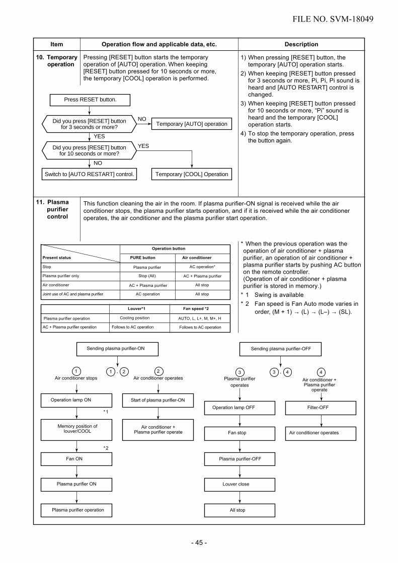
Item
10. Temporaryoperation
Operation flow and applicable data, etc.
Pressing [RESET] button starts the temporary operation of [AUTO] operation. When keeping [RESET] button pressed for 10 seconds or more, the temporary [COOL] operation is performed.
Description
11. Plasmapurifiercontrol
This function cleaning the air in the room. If plasma purifier-ON signal is received while the air conditioner stops, the plasma purifier starts operation, and if it is received while the air conditioner operates, the air conditioner and the plasma purifier start operation.
* When the previous operation was theoperation of air conditioner + plasmapurifier, an operation of air conditioner +plasma purifier starts by pushing AC buttonon the remote controller.(Operation of air conditioner + plasmapurifier is stored in memory.)
* 1 Swing is available* 2 Fan speed is Fan Auto mode varies in
order, (M + 1) → (L) → (L–) → (SL).
Sending plasma purifier-ON
Operation lamp ON
Fan ON
Plasma purifier ON
Plasma purifier operation
Start of plasma purifier-ONOperation lamp OFF Filter-OFF
Memory position of louver/COOL
Air conditioner + Plasma purifier operate Fan stop
Plasma purifier-OFF
Louver close
All stop
Air conditioner operates
Sending plasma purifier-OFF
1 , 2 3 4, 42Air conditioner operates
1Air conditioner stops
operatesAir conditioner + Plasma purifier
operate
*1
*2
Present status
Stop
Plasma purifier only
Air conditioner
Joint use of AC and plasma purifier
Operation button
PURE button Air conditioner
Plasma purifier AC operation*
Stop (All) AC + Plasma purifier
AC + Plasma purifier All stop
AC operation All stop
Plasma purifier operation
AC + Plasma purifier operation
Louver*1
Cooling position
Follows to AC operation
Fan speed *2
AUTO, L, L+, M, M+, H
Follows to AC operation
3Plasma purifier
Press RESET button.
Did you press [RESET] buttonfor 3 seconds or more?
Did you press [RESET] buttonfor 10 seconds or more?
Switch to [AUTO RESTART] control.
YES
NO
NO
YES
Temporary [AUTO] operation
Temporary [COOL] Operation
1) When pressing [RESET] button, thetemporary [AUTO] operation starts.
2) When keeping [RESET] button pressedfor 3 seconds or more, Pi, Pi, Pi sound isheard and [AUTO RESTART] control ischanged.
3)
4)
When keeping [RESET] button pressedfor 10 seconds or more, “Pi” sound isheard and the temporary [COOL]operation starts.To stop the temporary operation, pressthe button again.
FILE NO. SVM-18049
- 45 -

Item Operation flow and applicable data, etc. Description
1. PurposeThe air purifying control function is to alertthe user to trouble in the plasma purifieroperation.
2. DescriptionTrouble is determined to have occurred(indicated by the plasma purifier lampindicator) in the following two cases.1) When the panel switch has been set to
OFF by the opening of the air inletgrille, etc.
2) When an abnormal discharge causedby a symptom such as the build-up ofdirt has been detected while the airpurifier is ON* Trouble case are deemed to have
occurred when the action concernedcontinues for more than one second.
3. OperationThe sequence that plasma ionizer purifierlamp indicator is turned on are describedin the left flowchart.
1) A trouble detected within 1 minuteafter activation of the air isimmedi-ately judged as an errorand the plasma ionizer purifierlamp indicator goes on.
2) In case that 1 minute passed afteractivation of the plasma ionizerpurifier, it is turned off while thePURE indicator keeps ON. After 10minutes passed, restart the plasmaionizer purifier and an error is judgedagain.
12. Discharge temperature control
* When the breaker is turned [ON] (In restart timeafter power failure) or RESET button is pressedthe air purifier is not turned on until the integratedoperation time of the indoor fan exceeds 1 hourafter operation start (It is nor the Plasma ionizerpurifier operation time).It is the safety measures considering an incom-plete drain when electric dust collector has beencleaned with water.
1. PurposeThis function detects error on therefrigerating cycle or error on the com-pressor, and performs protective control.
2. OperationControl of the compressor speedThe speed control is performed asdescribed in the left table based uponthe discharge temperature.
11. Plasma ionizer purifier control [Detection of abnormality]
Plasma purifier lamp brink
Plasma purifier operation
Plasma purifier power ON
Error input
Plasma purifier power ON 1 minute or less
Plasma purifier power OFF
Reset
Plasma purifier power OFF
Error input 5 times
Plasma purifier power ON after 10
minutes from the error input.
Plasma purifier power OFF
Plasma purifier lamp
NO
NO
NO
Reset by RESET button or by the stop direction from the remote controller.
Td value
117°C
115°C
106°C
103°C
96°C
Control operation
Judges as an error and stops the compressor.
Reduce the compressor speed.
Reduce slowly compressor speed.
Keeps the compressor speed.
If the operation is performed with lower speed than onecommanded by the serial signal, speed is slowly raisedup to the commanded speed.
Operates with speed commanded by the serial signal.
FILE NO. SVM-18049
- 46 -

Item Operation flow and applicable data, etc. Description
Control operation
55°C 49°C
Cooling(TE)
Heating(TC)
63°C
63°C
61°C
59°C
62°C
57°C
55°C
53°C
13. High pressure control
14. PulseModulatingvalve (P.M.V.)
This function controls throttle amount of therefrigerant in the refrigerating cycle.According to operating status of the air conditioner,this function also controls the open degree of valvewith an expansion valve with pulse Modulation.
1) When starting the operation, move thevalve once until it fits to the stopper.(Initialize)* In this time, “Click” sound may be
heard.2) Adjust the open degree of valve by super
heat amount. (SH control)3) If the discharge temperature was exces-
sively up, adjust the open degree of valveso that it is in the range of set tempera-ture. (Discharge temp. control)
* SH (Super Heat amount) =Ts (Temperature of suction pipe of the compressor) –Tc or Te (Heat exchanger temperature at evaporation side)
* PMV: Pulse Modulating Valve
Starting up
Initialize
Move toinitial position
PMV open degree control
SH control Td, high pressure release control
Turn OFF byremote controller
Compressor Stop by"Room Temperature
Compressor ON
Defrostingoperation
Control"
Move to "StopPosition" (Setup
from factory)
Move to "DefrostPosition" (Setup
from factory)
control
4) When defrost operation is performed, theopen degree of valve is adjusted accord-ing to each setup conditions duringpreparation for defrost and during defrostoperation (4-way valve is inversed.).
5) When operation is OFF by the remotecontroller or when compressor is OFF byroom temperature control, the opendegree of valve is adjusted to the stopposition.
1. PurposeThis function detects error on therefrigerating cycle or error on the com-pressor, and performs protective control.
2. Operation- TE or TC sensor control- Control of the compressor speed Thespeed control is performed as described inthe left table.- High pressure switch control compressorare shut down when discharge pressure(Pd) reaches or exceeds 3.85 MPa- The compressor restart prevention timer(3 min) is set, and the control terminated.
FILE NO. SVM-18049
- 47 -

Item
15. Self-Cleaning
Operation flow and applicable data, etc.
1. PurposeThe Self-Cleaning operation is to minimize thegrowth of mold, bacteria etc. by runningthe fan and drying so as to keep theinside of the air conditioner clean.
Self-Cleaning operationWhen the cooling or dry operation shutsdown, the unit automatically starts the Self-Cleaning operation which is then performedfor the specified period based on durationof the operation which was performedprior to the shutdown, after which theSelf-Cleaning operation stops.(The Self-Cleaning operation is notperformed after a heating operation.)
2. Operation1) When the stop signal from the remote
controller or timer-off function is received,only the timer indicator light.
2) The period of the Self-Cleaning operationis determined by the duration of theoperation performed prior to thereception of the stop code.
3) After the Self-Cleaning operation hasbeen performed for the specified period,the unit stops operating.
Unit now performing cooling or dry operation
Press “STOP” button
Only timer indicator lights, and Self Cleaning operation starts
Time set now elapses
Operation stops
function
• During Self-Cleaning operations: The louver opensslightly. The indoor fan operates continuously ata speed of 500 rpm.
Cooling: Auto (cooling) Dry
Heating: Auto (heating)
Auto (fan only)
Shutdown
Operation time
Up to 10 minutes No Self-Cleaning operationperformed (0 minutes)
10 minutes 30 mins.or longer
No Self-Cleaning operation performed
• To stop an ongoing Self-Cleaning operation at any timePress the start/stop button on the remote controller twice during the Self-Cleaningoperation. (After pressing the button for the first time, press it for the
Self-Cleaning operation times
second time without delay (within 10 minutes).)
Description
Self-Cleaning operation time
FILE NO. SVM-18049
- 48 -

Item
15. Self-Cleaningfunction
Operation flow and applicable data, etc.
15-1-1. Self-Cleaning diagram
Description
Operation display ON OFF OFF
FCU fan ON ON
OFFrpm is depend on presetting. (500RPM)
FCU louver OPEN OPEN (12.7º) CLOSE
Timer displayON or OFF
ONON or OFF
depend on presetting of timer function. depend on presetting of timer function.
CompressorON or OFF
OFF OFFdepend on presetting per room temperature.
CDU fan ON or OFFOFF OFFdepend on presetting per room temperature.
Cool mode or dry modeoperation more than 10 mins.
Self-Cleaning modeoperate 30 mins.
Automatically turn-off.
Operation time
Turn off by remote controller ortimer-off function.
How to set/cancel Self-Cleaning functionTo set/cancel the Self-Cleaning function, proceed asfollows:
15-1-2. Self-Cleaning function release
ON
Operation LEDSelf-cleaning
flash 1 Hz
•
functionTimer LED
Flash 1 HzOFF flash 1 Hz
not flash
ON
OFF
ONOFF
• Setting diagnosis code "06" on remote controlle(See detail of setting diagnosis code in 15-1-1)
Take the remote controller to direction of LEDdisplay on air conditioner, press button up( ) at ON of the remote controller(Fig. 15-1-2) 1 time to send the code "07"(within 3 sec. after press [RESET] buton), thenair conditioner will shutdown automatically. Also,LED display will show flash follow the ablebelow.
• Turn on air conditioner again by remote controllerto confirm setting.
• Turn on the power supply to air conditioner,after that press [RESET] button on air conditioner1 time to turn on the air conditioner (The LEDdisplay will show in operation LED) (Fig. 7-9-1)
•
Note) Table above will show current status of Self-Cleaning function
Set or Cancel Self-Cleaning function by pushthe RESET button on air conditioner.When setting is changed, the sound warning willalarm "Beep". The setting is changed followingbelow.
Fig. 15-1-1
Fig. 15-1-2
Temporary switch
FILE NO. SVM-18049
- 49 -
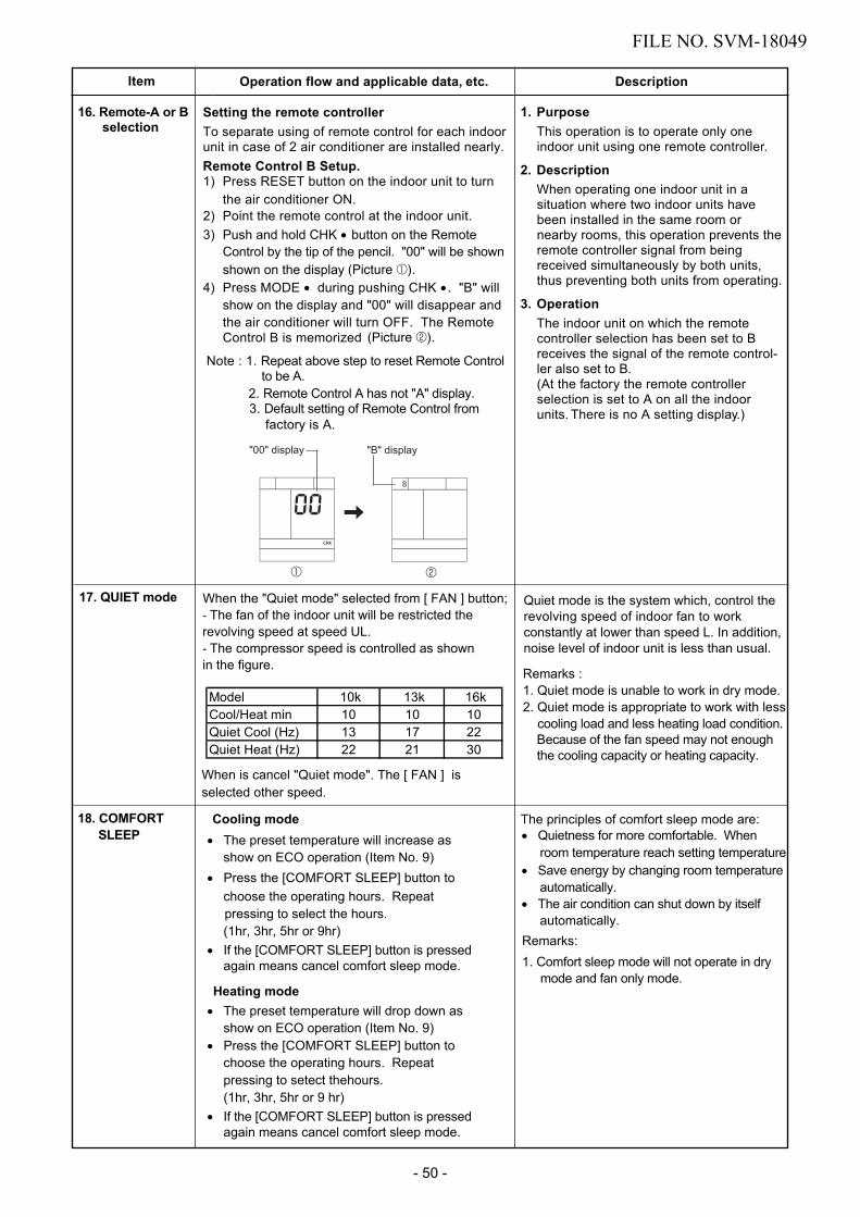
Item
17. QUIET mode
Operation flow and applicable data, etc. Description
Remarks : 1. Quiet mode is unable to work in dry mode.2. Quiet mode is appropriate to work with less
Quiet mode is the system which, control therevolving speed of indoor fan to work constantly at lower than speed L. In addition, noise level of indoor unit is less than usual.
When the "Quiet mode" selected from [ FAN ] button;- The fan of the indoor unit will be restricted therevolving speed at speed UL.- The compressor speed is controlled as shownin the figure.
18. COMFORT The principles of comfort sleep mode are: • Quietness for more comfortable. When
• Save energy by changing room temperature
• The air condition can shut down by itself
Remarks: 1. Comfort sleep mode will not operate in dry
automatically.
mode and fan only mode.
automatically.
room temperature reach setting temperature
Cooling mode• The preset temperature will increase as
show on ECO operation (Item No. 9)• Press the [COMFORT SLEEP] button to
choose the operating hours. Repeat pressing to select the hours.
• If the [COMFORT SLEEP] button is pressedagain means cancel comfort sleep mode.
Heating mode• The preset temperature will drop down as
show on ECO operation (Item No. 9)
choose the operating hours. Repeat• Press the [COMFORT SLEEP] button to
pressing to setect thehours.
• If the [COMFORT SLEEP] button is pressedagain means cancel comfort sleep mode.
(1hr, 3hr, 5hr or 9hr)
(1hr, 3hr, 5hr or 9 hr)
cooling load and less heating load condition.Because of the fan speed may not enoughthe cooling capacity or heating capacity.
SLEEP
16. Remote-A or Bselection
1. PurposeThis operation is to operate only oneindoor unit using one remote controller.
2. DescriptionWhen operating one indoor unit in asituation where two indoor units havebeen installed in the same room ornearby rooms, this operation prevents theremote controller signal from beingreceived simultaneously by both units,thus preventing both units from operating.
3. OperationThe indoor unit on which the remotecontroller selection has been set to Breceives the signal of the remote control-ler also set to B.(At the factory the remote controllerselection is set to A on all the indoorunits. There is no A setting display.)
Setting the remote controllerTo separate using of remote control for each indoor unit in case of 2 air conditioner are installed nearly.Remote Control B Setup.
Control B is memorized
Note : 1. Repeat above step to reset Remote Controlto be A.
2. Remote Control A has not "A" display.3. Default setting of Remote Control from
factory is A.
"00" display "B" display
Model 10k 16kCool/Heat min 10 10Quiet Cool (Hz) 13 22Quiet Heat (Hz) 22 30
When is cancel "Quiet mode". The [ FAN ] is selected other speed.
13k101721
FILE NO. SVM-18049
- 50 -
1) Press RESET button on the indoor unit to turn the air conditioner ON.
2) Point the remote control at the indoor unit.3) Push and hold CHK • button on the Remote
Control by the tip of the pencil. "00" will be shown shown on the display (Picture 1).
4) Press MODE • during pushing CHK • . "B" will show on the display and "00" will disappear and the air conditioner will turn OFF. The Remote
(Picture 2).
1 2
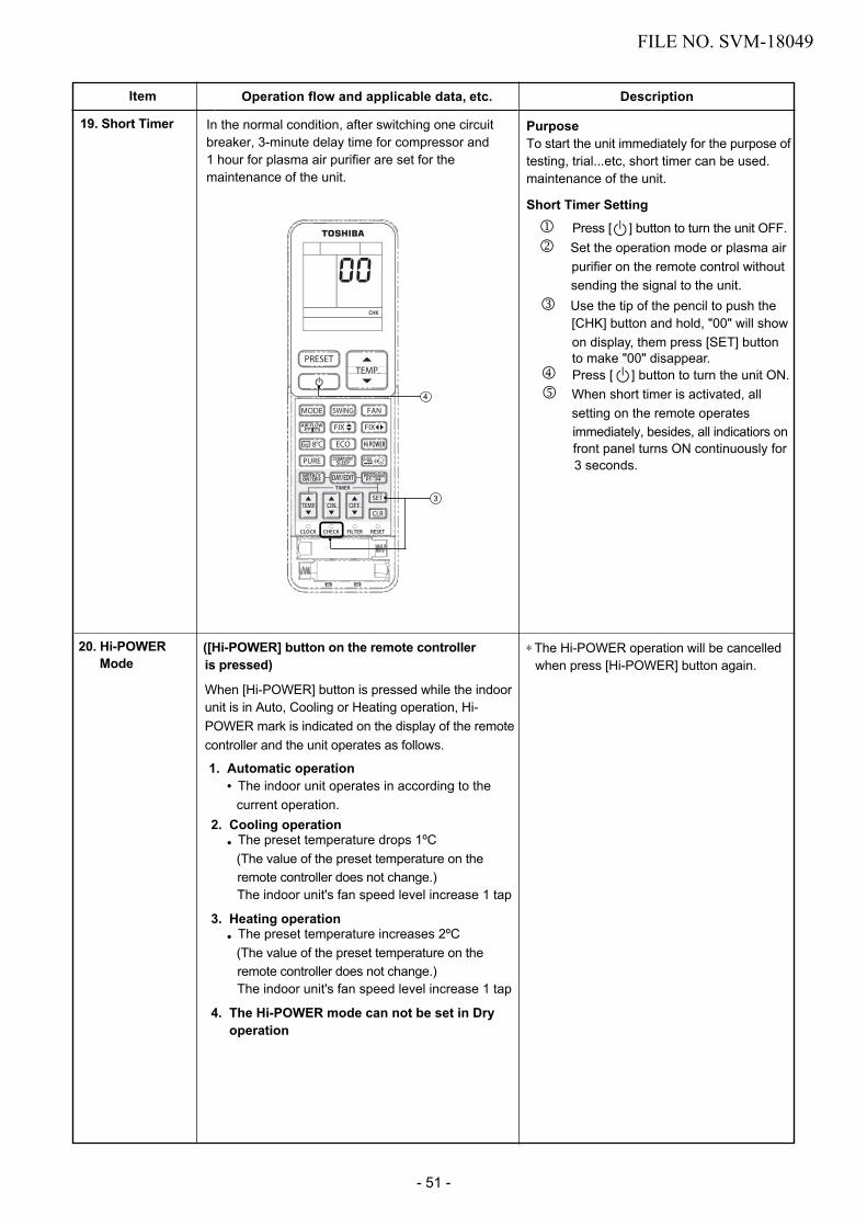
Item Operation flow and applicable data, etc. Description
20. Hi-POWER ([Hi-POWER] button on the remote controller is pressed)
When [Hi-POWER] button is pressed while the indoorunit is in Auto, Cooling or Heating operation, Hi-
Mode
POWER mark is indicated on the display of the remotecontroller and the unit operates as follows.
1. Automatic operation• The indoor unit operates in according to the
current operation.2. Cooling operation
remote controller does not change.)The indoor unit's fan speed level increase 1 tap
• The preset temperature drops 1ºC(The value of the preset temperature on the
3. Heating operation
remote controller does not change.)The indoor unit's fan speed level increase 1 tap
• The preset temperature increases 2ºC(The value of the preset temperature on the
4. The Hi-POWER mode can not be set in Dryoperation
∗ The Hi-POWER operation will be cancelledwhen press [Hi-POWER] button again.
19. Short Timer In the normal condition, after switching one circuitbreaker, 3-minute delay time for compressor and1 hour for plasma air purifier are set for the maintenance of the unit.
PurposeTo start the unit immediately for the purpose oftesting, trial...etc, short timer can be used.maintenance of the unit.
Short Timer Setting
purifier on the remote control without
[CHK] button and hold, "00" will show on display, them press [SET] button to make "00" disappear.
1 Press [ ] button to turn the unit OFF.2 Set the operation mode or plasma air
sending the signal to the unit.3 Use the tip of the pencil to push the
4 Press [ ] button to turn the unit ON.5 When short timer is activated, all setting on the remote operates
immediately, besides, all indicatiors on front panel turns ON continuously for 3 seconds.
4
3
FILE NO. SVM-18049
- 51 -

Item Operation flow and applicable data,etc Description
21. POWER
ModeSelection
([POWER-SEL] button on the remote controlleris pressed) The function is used when its circuit
breaker is shared with other electricalappliances. It limits the maximumcurrent/ power consumption to 100%,75% or 50%.The lower the percentage, the higherthe saving and also the longer thecompressor lifetime.
When the level is selected, Power-SELlevel flashes on LCD display for 3seconds. In case of 75% and 50%level, number "75" or "50" also flashesfor 2 seconds.
Note : Due to the reason that POWERSELECT FUNCTION limits themaximum current, inadequate capacity may occur.
− Power Selection 50% is 50% of rate maximum
− Power Selection 75% is 75% of maximumcurrent.
current.
22. SilentOperation
2. Description
1. Purpose
POWER-SELECTION AND SILENT OPERATION
Silent button on remote controller is pressed. Silent 1: Cooling/heating capacity is limited maximum for 70% of rated. Only compressor speed is limited. Silent 2: CDU sound level is limited for lowest CDU sound level. Compressor and CDU fan speed are limited.
This function is used when the user need to keep silent at outdoor side. It is limit maximum compressor speed and CDU fan speed. Sound level can be implemented by 2 silent level. Sound level: Rated level > Silent 1 > Silent 2 Note: Due to Silent operation reason, In adequate cooling/heating capacity may occur.
Silent Operation description
[100%] [75%] [50%]
SILENT#2 SILENT#1
Model Silent Cooling Heating
Operation Compressor CDU Compressor CDU
frequency Fan Speed frequency Fan Speed
(rps) (rpm) (rps) (rpm)
Silent 1 22.2 Normal 33.6 NormalRAS‐10PAVPG‐E
RAS‐10PAVPG‐NZ Silent 2 13.8 600 22.8 600
Silent 1 26.4 Normal 31.2 NormalRAS‐13PAVPG‐E
RAS‐13PAVPG‐NZ Silent 2 16.8 600 21.0 600
Silent 1 35.4 Normal 46.2 NormalRAS‐16PAVPG‐E
RAS‐16PAVPG‐NZ Silent 2 22.2 600 30.6 600
FILE NO. SVM-18049
- 52 -
POWER-SELECTION AND SILENT OPERATION
[100%] [75%] [50%]
SILENT#2 SILENT#1

Item Operation flow and applicable data,etc Description
23. Outdoor
controlQuiet
<With Quiet control/Non-select method> 1. PurposeFor the users who concern about noiseof the outdoor unit, this control controlsthe max. revolutions of the compressorto reduce the noise.
2. DescriptionTo reduce noise, [RESET] button of theindoor unit is kept pushed for 20seconds.The number of revolution for the indoorfan motor and the seup temp value arekept as they are.
3. OperationAs shown in the table, the maximumrevolution number of indoor unitcompressor can be reduced.As the maximum number of revolutionof the compressor is restricted, the rise-
up performance at the start time is weakened.
Select "Control" or "No control" by keeping [RESET] button pushed for 20 seconds.("No control" at shipment from the factory.)
Exchanging from "No control" to "Control" :Beep sound is heard (Pi, Pi, Pi, Pi, Pi) andthe operation LED 5Hz flashes for 5 seconds.Exchanging from "Control" to "No control" :Beep sound is heard.(Operation LED does not flash.)
<Maximum number of revolution of compressor at normal time and Quiet control time>
RAS-10PAVPG-E,-NZ RAS-13PAVPG-E,-NZ
Quiet controlled (rps)
COOL 52 41 45 41−5°C ~ 87 66 74 57
HEAT −10 ~ −5°C ~ 87 66 74 57
−10°C ~ 87 66 74 57
Outside temp.(TO)
Normal time (rps)
Normal time (rps)
Quiet controlled (rps)
24. Operationmodesetectable
2.
1. PurposeChoosing the operating system asappropriate in real condition
OperationFactory default setting prefer"Heat pump" system. Through it isable to cooling only system heatingonly system or return to factorydefault.
Operating system setting
••
• Do cut J804 for cooling only systempDo cut J805 for heating only systempDo cut both of J804 and J805 for returnto factory default.
WP-030
T101 C08
C07
IC81
J805
J804
J803
RAS-16PAVPG-E,-NZ
Quiet controlled (rps)
60 55
82 7282 72
82 72
Normal time (rps)
FILE NO. SVM-18049
- 53 -

Item Operation flow and applicable data,etc Description
25. FireplaceOperation
Fireplace button on remote controller is pressed. Fireplace 1: Cancel cold draft prevention control and fan speed depend on user require base on basic control. Fireplace 2: Cold draft prevention control is active with super low fan speed (640 rpm).
Keep air circulation during other heat source applied. Note: With Fireplace operation on heating mode indoor unit always runs and cold air breezing might be occurred.
Fireplace Operation
26. 8C heating /Frost protectiveoperation
8C Button on remote controller is pressed. Set temperature is performed for 5C to 13C and no cold draft prevention control.
Intended for cold latitudes and performs objective heating operation.
8C heating operation
8°C
Normaloperation
8°C
Normaloperation
Fireplace#1 Fireplace#2
Fireplace#1 Fireplace#2
FILE NO. SVM-18049
- 54 -

Item Operation flow and applicable data,etc Description
27. FCU Display lamp brightness controlPurposeIt is necessary to decrease the display lamp brightness or turn it off.
1.
While operating (Auto, Cool, Heat or Dry), press and hold 5 seconds.
Press Rise
or
Decrease
to adjust brightness which can be set at 4 levels or to turn it off.
LAMP BRIGHTNESS ADJUSTMENT
Rremote control LCD Operation display Brightness
Lamp illuminates an operation with full brightness.
100%
Lamp illuminates an operation with 50% brightness.
50%
Lamp illuminates an operation with 50% brightness and the operation mode lamp is turned off.
50%
All lamps are turned off.
All turned off
• In the examples of and , the lamp illuminates for 5 seconds before going off.
FILE NO. SVM-18049
- 55 -
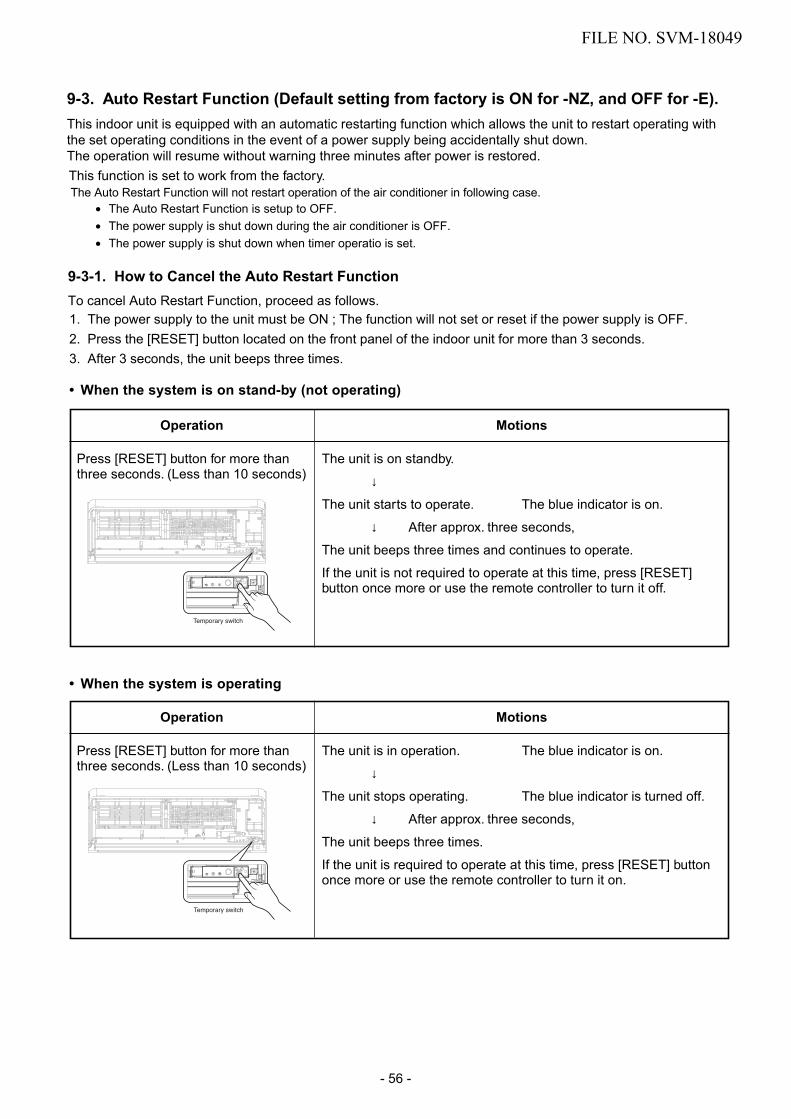
Operation
Press [RESET] button for more thanthree seconds. (Less than 10 seconds)
Motions
The unit is on standby.
↓
The unit starts to operate. The blue indicator is on.
↓ After approx. three seconds,
The unit beeps three times and continues to operate.
If the unit is not required to operate at this time, press [RESET]button once more or use the remote controller to turn it off.
Operation
Press [RESET] button for more thanthree seconds. (Less than 10 seconds)
Motions
The unit is in operation. The blue indicator is on.
↓
The unit stops operating. The blue indicator is turned off.
↓ After approx. three seconds,
The unit beeps three times.
If the unit is required to operate at this time, press [RESET] buttononce more or use the remote controller to turn it on.
1. The power supply to the unit must be ON ; The function will not set or reset if the power supply is OFF.2. Press the [RESET] button located on the front panel of the indoor unit for more than 3 seconds.3. After 3 seconds, the unit beeps three times.
• When the system is on stand-by (not operating)
• When the system is operating
9-3. Auto Restart Function (Default setting from factory is ON for -NZ, and OFF for -E).This indoor unit is equipped with an automatic restarting function which allows the unit to restart operating with the set operating conditions in the event of a power supply being accidentally shut down.The operation will resume without warning three minutes after power is restored.This function is set to work from the factory. The Auto Restart Function will not restart operation of the air conditioner in following case.
• The Auto Restart Function is setup to OFF.• The power supply is shut down during the air conditioner is OFF.• The power supply is shut down when timer operatio is set.
9-3-1. How to Cancel the Auto Restart FunctionTo cancel Auto Restart Function, proceed as follows.
Temporary switch
Temporary switch
FILE NO. SVM-18049
- 56 -

9-3-3. Power Failure During Timer Operation
Operation
Press [RESET] button for more thanthree seconds. (Less than 10 seconds)
Motions
The unit is on standby.
↓
The unit starts to operate. The blue indicator is on.
↓ After approx. three seconds,
The unit beeps three timesand continues to operate.
The blue indicator flashes for 5 seconds.
If the unit is not required to operate at this time, press [RESET]button once more or use the remote controller to turn it off.
Operation
Press [RESET] button for more thanthree seconds. (Less than 10 seconds)
Motions
The unit is in operation. The blue indicator is on.
↓
The unit stops operating. The blue indicator is turned off.
↓ After approx. three seconds,
The unit beeps three times. The blue indicator flashes for 5 seconds.
If the unit is required to operate at this time, press [RESET] buttononce more or use the remote controller to turn it on.
9-3-2. How to Set the Auto Restart FunctionTo set Auto Restart Function, proceed as follows:1. The power supply to the unit must be ON ; The function will not set or reset if the power supply is OFF.2. Press the [RESET] button located on the front panel of the indoor unit for more than 3 seconds.3. After 3 seconds, the unit beeps three times and the indicator blinks for 5 seconds.
• When the unit is standby (Not operating)
• When the unit is in operation
• If Timer operation is set and the power supply shut down accidentally, the previous Timer settingwill be cancelled.
• Weekly-timer operation will be not affected by power supply failure, if the remote controller islocated on the position which it can send the command signal to the indoor unit. It is because the remotecontroller will send signal when real clock reach to program setting.
Temporary switch
Temporary switch
FILE NO. SVM-18049
- 57 -

9-4. Remote control9-
1
4
67
9
1112
1415
1918
2322
32
5
8
10
13
1617
2021
1
4
3
2
8
14
27
22
1721
2625
1211
5
24
25
262728
9-4-2. Operation of remote control
1. Weekly timer operation4 programs for each day in the week can be set in WEEKLY TIMER. The following items can be set in WEEKLY TIMER operation.a. Operation time (ON timer for Start and OFF timer for Stop operation)b. Operation mode (COOL, DRY, HEAT, FAN ONLY)c. Temperature setting.d. Fan speed setting.e. Special operation (8°C, ECO, Hi-POWER, Silent)
4-1. Remote control and its functions
)
Infrared signal emitterMemory and preset button (PRESET) Start/Stop buttonTemperature up/down button (TEMP.) Mode select button (MODE)Swing louver button (SWING)Fan speed button (FAN)Wide air flow, spot air flow (AIR FLOW)Set louver button for vertical direction (FIX ) Set louver button for Horizontal divection (FIX ) 8 degree celcius operation and fireplace function button ( Economy button (ECO)High power button (Hi-POWER)Plasma ionizer purifier button (PURE) Comfort sleep button (COMFORT SLEEP) Power selection and Silent operation button( ) On timer button (ON)Off timer button (OFF)Setup button (SET)Clear button (CLR)Clock setup button (CLOCK)Check button (CHECK)Filter reset button (FILTER)Reset button (RESET)Weekly ON/OFF button ( )Day button ( )Temp for weekly timer button (TEMP )ProgrProgram P1-P4 button ( - )
7
9
15
6
10
16
13
28
18
19
20
24
23
FILE NO. SVM-18049
- 58 -

How to set WEEKLY TIMER
1 Press to enter WEEKLY TIMER setting.
Blink
2 Press to select desired day in sequence.The sequence of day symbol appears on the LCD
SU MO TU WE TH FR SA
WEEKLY SUMOTUWETHFRSA
(All day)
3Press to select the program number.
• The program 1 is ready for setting while is pressed PG-1 appears on the LCD.
• Press to change the program number in the sequence program 1 to program 4.
PG-1PG- 2PG- 3
4PG-
4 Press or to select the desired time.
• The time can be set between 0:00 and 23:50 in 10 minute intervals.
• Press and hold the button to change setting time for 1 hr.
• Only one of ON or OFF timer can be set on each program.
ON timer display OFF timer display*
* OFF timer is used to stop the air conditioner only. The display does not show Operation mode, Temperature, Fan speed and others.
FILE NO. SVM-18049
- 59 -

5Press to select desired operation.
6 Press or to select desired temperature.
• The temperature can be set between 17°C and 30°C.
7 Press to select the desired fan speed.
8Add operations, if required.
• Press to use 8°C operation.
• Press to use ECO operation
• Press to use Hi-POWER operation.
9Adding or editing the program.The program can be set to perform on all the required days until is pressed to
confi rm the setting !.
If adding or editing a program is required, please repeat steps 2 - 8 before setting confi rmation.
!After adding or editing, press to confi rm the setting*.
Weekly timer running
Next program
Timer ON or OFF
Next operation time
Operating Temperature and Fan speed
Display after pressing SET button
Operating Mode
*Point remote control at air conditioner receiving module then, press SET button until you hear the “PiPi” sound. This means the setting operation has been completed.As the air conditioner is receiving the signal, you will hear separate “Pi” sounds corresponding to the number of days in the selected setting.An incomplete setting is indicated if the TIMER lamp is blinking. Press twice.
Notes
1. Place the remote control where the indoor unit can receive the signal. This will increase the accuracy of the timing between the remote control and the air conditioning unit.
2. The ON/OFF timer can be set during the WEEKLY TIMER operation. In this situation, the air conditioner will fi rst follow the normal timer until it is complete; then, it will return to the WEEKLY TIMER function.
3. During WEEKLY TIMER operation, all of operation such as MODE, TEMP, FAN, Hi-POWER, ECO and etc., can be adjusted but when the clock reaches the program setting, the operation will return to the set items in the program.
4. When the remote control is sending a signal to the air conditioner, avoid interference from objects that can block the signal.
• Press to use SILENT operation.
FILE NO. SVM-18049
- 60 -

Page 23 , follow steps 1 - 3
Edit Weekly timer program
To edit the program after confi rming the weekly timer setting on below.
1 Press .
• The day of the week and the program number of the current day will be displayed.
2 Press to select the day of the week and press
to select program number to be confi rmed.
• Resetting the operation.
3Press to exit confi rming mode.
Deactivating WEEKLY TIMER operation
Press while “WEEKLY” is displayed on the LCD.
• The “WEEKLY” indicator will disappear from the LCD. However, the program will remain in the remote control.
•• again, LCD shows the next The TIMER lamp goes off.
To reactivate the WEEKLY TIMER operation again, pressprogram. The program, after reactivation, is related to the clock time.
FILE NO. SVM-18049
- 61 -

To delete programs
The individual program
1 Press .
• The day of the week and the program number is displayed.
• Select the day to delete the program.
2 Press to select the program number to be deleted.
3Press .
• ON or OFF timer will be cleared and the LCD will blink.
4Press
• Press
to delete the program.
while the LCD is blinking. The program has now been deleted.
All programs
1 Press .
• The day of the week and the program number will be displayed.
2Press and hold for 3 seconds.
• All programs will be deleted and LCD displays current operation.
Notes
Make sure the remote control receiving module on the air conditioner receives the signal from the remote control.
FILE NO. SVM-18049
- 62 -

2. AUTOMATIC OPERATIONTo automatically select cooling, heating, or fan only operation.
1.
2.
PressPress
PressPress
: Select
: Select the desired temperature
3. PressPress : Select AUTO, LOW , LOW+ , MED , MED+ , HIGH or Quiet
button to change Fireplace1, Fireplace2 and 8°C operation3. 8°C OPERATION
1.1.1. PPress
2.2. PrePress to adjust setting temperature from 5°C to 13°C
Note1 : 8°C will operate in Heating mode only. should be charge modeto Heating mode before use.
FIREPLACE and 8°C operation.
Normaloperation
8°C
5. DRY OPERATION (COOLING ONLY)For dehumidification, a moderate cooling performance is controlled automatically.
1.1.. PrePress
2. Pre ss
: Select Dry
: Set the desired temperature.
4. COOLING / HEATING / FAN ONLY OPERATION1. PressPress
2. PressPress
: Select Cool , Heat , or Fan only
: Set the desired temperature
3. or QuietCooling: Min. 17°C, Heating : Max, 30°C, Fan Only: No temperature indicationPressPress : Select AUTO, LOW , LOW+ , MED , MED+ HIGH
Note : QUIET is ultra low fan speed for quiet operation.
: Start and stop the operationPressPress
6. PLASMA IONIZER PURIFIER OPERATIONDuring air conditioner operation
Press PURE to start and plasma ionizer purifier operation.The plasma air purifier and plasma ionizer purifier can be activated or deactivated duringair conditioner is stopped and the plama ionizer purifier starts in conjunction with plasmaplasma ionizer purifier operation.
7. Hi-POWER OPERATIONTo automatically control room temperature and airflow for faster cooling or heatingoperation (except in DRY and FAN ONLY mode)
Note2 : With Fireplace operation on heating mode indoor unit always runs and cold air breezing might be occurred.
Fireplace#1 Fireplace#2
FILE NO. SVM-18049
- 63 -

8. ECO OPERATIONTo automatically control room to save energy (except in DRY and FAN ONLY mode)
Press : Start and stop the operation.
Note: Cooling operation; the set temperature will increase automatically 1 degree/hour for 2 hours (maximum 2 degrees increase). For heating operation theset temperature will decrease.
9. AIR VOLUME, AIR DIRECTION AND SWING LOUVERS• Changing the air volume, press FAN button
• Changing the air direction, press FIX button
• Movement of vertical air direction louvers
When changing the air to the vertical direction, release the left side at the desired position.
( PiPi at the lower and upper limit).
When changing the air to the horizontal position, release the right side at the desired position.
( PiPi sounds at the center position).
• Changing the air direction, press FIX button
• Every time...Pi Pi PiPi
Horizontal (Left-Right)
Swing
Vertical (Up-Down)
Swing
Up-DownLeft-Right
SwingSwing
off
Swing direction changes.
Cooling operation (Default setting)
Heating operation (Default setting)
Louver for air fl ow direction up and down
Louver for air fl ow direction up and down
The shows the range of air fl ow direction operation.
The range of swing operation.
FILE NO. SVM-18049
- 64 -

10. COMFORT AIR FLOW• Wide air flow : Air flows around the room.• Spot air flow : Air flow is concentrated at one point.
11. TIMER OPERATION
Setting the ON Timer Setting the OFF Timer
1 Press for enter ON timer setting Press for enter OFF timer setting
2 Press for select desired ON timer.
Press for select desired OFF timer.
3 Press for set timer. Press for set timer.
4 Press for cancel timer. Press for cancel timer.
Note: · Keep the remote control in accessible transmission to the indoor unit
otherwise, the time lag of up to 15 minutes will occur.· The setting will be saved for the next same operation
12. PRESET OPERATIONSet your preferred operation for future use. The setting will be memorized by theunit for future operation (except air flow direction).
1. Select your preferred operation.2. Press and hold for 3 seconds to memorize the setting. The P mark
displays.3. Press : Operate the preset operation.
While operating (Auto, Cool, Heat, Dry and these modes with PURE), Select
• Every time...When pressed, the air fl ow direction changes.
Spot left
Cancel Air Flow
Spot right Spot center
Wide leftWide center
Wide right
FILE NO. SVM-18049
- 65 -
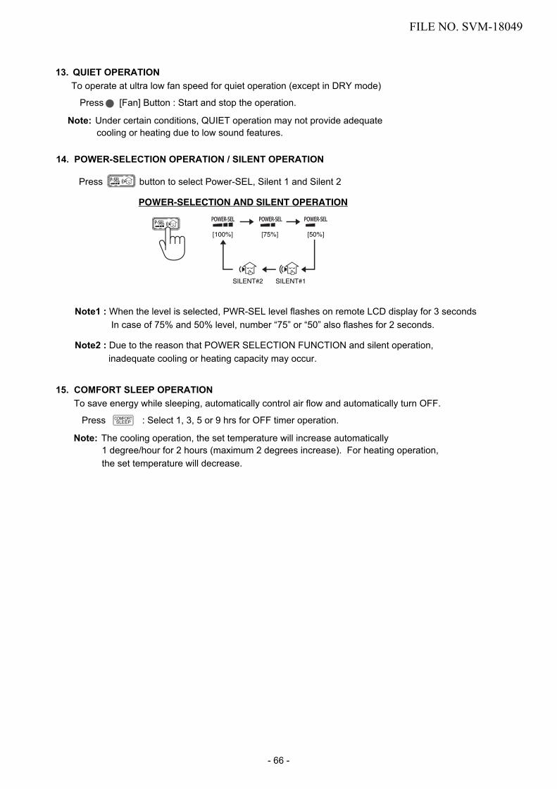
14. POWER-SELECTION OPERATION / SILENT OPERATION
13. QUIET OPERATIONTo operate at ultra low fan speed for quiet operation (except in DRY mode)
Press [Fan] Button : Start and stop the operation.
Note: Under certain conditions, QUIET operation may not provide adequatecooling or heating due to low sound features.
POWER-SELECTION AND SILENT OPERATION
[100%]
SILENT#2 SILENT#1
[75%] [50%]
15. COMFORT SLEEP OPERATIONTo save energy while sleeping, automatically control air flow and automatically turn OFF.
Press : Select 1, 3, 5 or 9 hrs for OFF timer operation.
Note: The cooling operation, the set temperature will increase automatically1 degree/hour for 2 hours (maximum 2 degrees increase). For heating operation,the set temperature will decrease.
Note1 : When the level is selected, PWR-SEL level flashes on remote LCD display for 3 secondsIn case of 75% and 50% level, number “75” or “50” also flashes for 2 seconds.
Note2 : Due to the reason that POWER SELECTION FUNCTION and silent operation, inadequate cooling or heating capacity may occur.
Press button to select Power-SEL, Silent 1 and Silent 2
FILE NO. SVM-18049
- 66 -

7 11
614
5
9-4-3. Name and Functions of Indications on Remote Controller[Display]All indications, except for the clock time indicator, are displayed by pressing the button.
1 Transmission markThis transmission mark indicates when theremote controller transmits signals to the indoorunit.
2 Mode indicatorIndicates the current operation mode.(AUTO : Automatic control, A : Auto changeovercontrol, : Cool, : Dry, : Heat)
3 Temperature indicatorIndicates the temperature setting.(17°C to 30°C)
4 Plasma indicatorShows that the electrical plasma purifying operation is in progress.
5 FAN speed indicatorIndicates the selected fan speed.AUTO or five fan speed levels(LOW , LOW+ , MED , MED+ ,HIGH ) can be shown.Indicates AUTO when the operating mode iseither AUTO or : Dry.
6 TIMER and weekly timer indicatorThe time setting for timer operation and weekly timer function is indicated.The current time is always indicated exceptduring TIMER operation.
7 Hi-POWER indicatorIndicates when the Hi-POWER operation starts.Press the Hi-POWER button to start and press itagain to stop the operation.
8 (PRESET) indicatorFlashes for 3 seconds when the PRESET button ispressed during operation.The mark is shown when holding down thebutton for more than 3 seconds while the mark isflashing.Press another button to turn off the mark.
9 POWER-SEL
10 A, B change indicator remote controllerWhen the remote controller switching function isset, “B” appears in the remote controller display.(When the remote controller setting is “A”, there isno indication at this position.)
11 Comfort sleepIndicates when comfort sleep is activaled.Press comfort sleep button to select function.
12 QuietIndicates when quiet is activated.Press Fan button to start and press it again to selectother fan speed for operation.
13 Comfort Air flow
14 ECO indicator
Indicates Air flow direction
Indicates the selected POWER-SEL level. ( 100%, 75%, 50%)
Indicates when the ECO is in activated.Press the ECO button to start and press it againto stop operation.
101
12 3 42 9 8
13
15 Silent operationIndicates the selected Silent 1 and Silent 2.
16 Fireplace operationIndicates the selected Fireplace 1 and Fireplace 2.
1516
Spot left Spot right Spot center
Wide leftWide center
Wide right
FILE NO. SVM-18049
- 67 -

10. INSTALLATION PROCEDURE
10-1. Installation Diagram of Indoor and Outdoor Units
Before installing the wireless remote controller
• Loading Batteries1. Remove the battery cover.2. Insert 2 new batteries (AAA type)
following the (+) and (- ) positions. 3 Batteries
2 Wireless remote controller
2
3
6
4
For the rear left and left piping
Wall
Make sure to run the drain hose sloped downward.
Do not allow the drain hose to get slack.
Cut the piping hole sloped slightly.
Insert the cushion between the indoor unit and wall, and tilt the indoor unit for better operation.
The auxiliary piping can be connected to the left, rear left, rear right, right, bottom right or bottom left.
Right
Rear right
Bottomright
Rearleft Bottom left
Left
Insulate the refrigerant pipes separately with insulation, not together.
6 mm thick heat resistingpolyethylene foam
1
Batteries
Remote control holder
Vinyl tapeApply after carryingout a drainage test.
Wireless remote control
Saddle
Extension drain hose(Not available, providedby installer)
Shield pipe
Bush body
Flat headwood screw
(Attach to the front panel.)
Air fi lter
HookInstallationplate
Hook
52 m
m o
r mor
e
190 mm or more
225 mm or more
100 mm or more
600
mm
or m
ore
100 mm or more
600 mm or more
600 mm or more
Refrigerant pipingmust be protected from physical damage.Install a plastic cover or equivalent.
The fl are connection should be installed outdoors.
FILE NO. SVM-18049
- 68 -

Fig. 10-2-1
•••
Secure the outdoor unit with fixing bolts and nuts if the unit is likely to be exposed to a strong wind.Use ∅ 8 mm or ∅ 10 mm anchor bolts and nuts.If it is necessary to drain the defrost water, attach drain nipple 7 and cap waterproof 8 to thebottom plate of the outdoor unit before installing it.
10-2. Installation
10-2-1. Optional installation parts
Fixing bolt arrangement of outdoor unit
125 mm108 mm29 mm
330
mm
600 mm99 mm
106
mm
121
mm
Ø25 mm
Air outlet
Air inlet
Drain outlet
PartCode
A
B
C
Parts name
Pipe insulating material(polyethylene foam, 6 mm thick)
Putty, PVC tapes
Q'ty
Oneeach
1
Oneeach
Refrigerant pipingLiquid side : ∅6.35 mmGas side : ∅9.52 mm (10k, 13k)
: ∅12.7 mm (16k)
FILE NO. SVM-18049
- 69 -

PartNo.
1
2
3
Part name (Q’ty)
Installation plate* x 1
Wireless remote control* x 1
Battery x 2
Part name (Q’ty)
Remote control holder* x 1
PartNo.
4
5
6
PartNo.
7
8
Part name (Q’ty)
Mounting screw** ∅4 x 25 s x 6
Flat head wood screw∅ 3.1 x 16 s x 2
Drain nipple*** x 1(for heating model only)
10-2-2. Accessory and installation parts
* The part may differ from that shown.** The number of parts may differ by model. *** The part is packed with the outdoor unit.
Cap waterproof*** x 2 (for some models only)
Air filtersClean every 2 weeks.1. Open the air inlet grille.2. Remove the filters if they are on the air filter.3. Vacuum or wash and then dry them.4. Reinstall the filters and close the air inlet grille.
Owner's Manual
Installation Manual
B Label x 1 (for Multi model)
FILE NO. SVM-18049
- 70 -

10-2-3. Installation/Servicing Tools
Changes in the product and componentsIn the case of an air conditioner using R410A, in order to prevent any other refrigerant from being chargedaccidentally, the service port diameter of the outdoor unit control valve (3 way valve) has been changed.(1/2 UNF 20 threads per inch)• In order to increase the pressure resisting strength of the refrigerant piping flare processing diameter and size
of opposite side of flare nuts has been changed. (for copper pipes with nominal dimensions 1/2 and 5/8)
New tools for R410A
New tools for R410A
Gauge manifold
Charge hose
Electronic balancefor refrigerant charging
Torque wrench(nominal diam. 1/2, 5/8)
Flare tool (clutch type)
Gauge for projectionadjustment
Vacuum pump adapter
Gas leakage detector
Applicable to R22 model
×
×
×
— —
×
Changes
As pressure is high, it is impossible to measure by means ofconventional gauge. In order to prevent any other refrigerant frombeing charged, each port diameter has been changed.
In order to increase pressure resisting strength, hose materialsand port size have been changed (to 1/2 UNF 20 threads per inch).When purchasing a charge hose, be sure to confirm the port size.
As pressure is high and gasification speed is fast, it is difficult toread the indicated value by means of charging cylinder, as airbubbles occur.
The size of opposite sides of flare nuts have been increased.Incidentally,a common wrench is used for nominal diameters 1/4 and 3/8.
By increasing the clamp bar’s receiving hole, strength of spring inthe tool has been improved.
Used when flare is made by using conventional flare tool.
Connected to conventional vacuum pump. It is necessary to usean adapter to prevent vacuum pump oil from flowing back to thecharge hose. The charge hose connecting part has two ports-onefor conventional refrigerant (7/16 UNF 20 threads per inch) andone for R410A. If the vacuum pump oil (mineral) mixes with R410Aa sludge may occur and damage the equipment.
Exclusive for HFC refrigerant.
• Incidentally, the “refrigerant cylinder” comes with the refrigerant designation (R410A) and protector coating in theU. S’s ARI specified rose color (ARI color code: PMS 507).
• Also, the “charge port and packing for refrigerant cylinder” require 1/2 UNF 20 threads per inch corresponding tothe charge hose’s port size.
FILE NO. SVM-18049
- 71 -

10-3. Indoor Unit10-3-1. Installation Place• A place which provides the spaces around the
indoor unit as shown in the diagram.• A place where there are no obstacle near the air
inlet and outlet.• A place which allows easy installation of the piping
to the outdoor unit.• A place which allows the front panel to be opened.• The indoor unit shall be installed at least 2.5 m
height. Also, it must be avoided to put anything onthe top of the indoor unit.
CAUTION• Direct sunlight on the indoor unit wireless
receiver should be avoided.• The microprocessor in the indoor unit should
not be too close to RF noise sources.(For details, see the owner's manual.)
Remote control• A place where here are no obstacles such as a
curtain that may block the signal from the indoor unit• Do not install the remote control in a place exposed
to direct sunlight or close to a heating source suchas a stove.
• Keep the remote control at least 1 m apart fromthe nearest TV set or stereo equipment.(This is necessary to prevent image disturbances ornoise interference.)
• The location of the remote control should bedetermined as shown below.
10-3-2. Cutting a Hole and MountingInstallation Plate
Cutting a holeWhen installing the refrigerant pipes from the rear.
1. After determining the pipe hole position on theinstallation plate ( ) drill the pipe hole (Ø65mm) at a slight downward slant to the outdoorside.
NOTE :• When drilling into a wall that contains a metal lath,
wire lath or metal plate, be sure to use a pipe holebrim ring sold separately.
Mounting the installation plate
Fig. 10-3-3
Fig. 10-3-2
Fig. 10-3-1
The center of the pipe hole is above the arrow.
35
Ø65
45º 45º
75º
(Side view) (Top view)
Indoor unit
Reception range
Remote control
Remotecontrol
Receptionrange
Indo
or u
nit
5
Anchor bolt holes
Hook
HookHook
Pipe hole Pipe holeInstallationplate
Mounting screwWeightIndoor unitThread
5240
190
104
225
137
1
FILE NO. SVM-18049
- 72 -

When the installation plate is directlymounted on the wall
1. Securely fit the installation plate onto the wall byscrewing it in the upper and lower parts to hookup he indoor unit.
2. To mount the installation plate on a concrete wallwith anchor bolts, use the anchor bolt holes asillustrated in the below figure.
3. Install the installation plate horizontally in the wall.
CAUTIONWhen installing the installation plate with a mounting screw, do not use the anchor bolt holes.Otherwise the unit may fall down and result inpersonal injury and property damage.
Fig. 10-3-4
Fig. 10-3-5
CAUTIONFailure to firmly install the unit may result inpersonal injury and/or property damage if theunit falls.
• In case of block, brick, concrete or similar typewalls, make 5 mm dia. holes in the wall.
• Insert clip anchors for appropriate mounting screws .
NOTE :• Secure four corners and lower parts of the
installation plate with 4 to 6 mounting screws toinstall it.
Anchor bolt
Projection 15mm or less
5 mm dia. hole
Clip anchor(local parts)
5 Mounting screw Ø4 × 25l
Installation plate(Keep horizontal direction.)
10-3-3. Piping and Drain Hose Installation
Piping and drain hose forming• Since condensation results in machine trouble,
make sure to insulate both the connecting pipesseparately.(Use polyethylene foam as insulating material.)
Fig. 10-3-7
1. Die-cutting bush body slitFor Bottom rightCut out the slit on bottom right side of bush bodyfor bottom right connection with a pair of nippers.For Left or RightTake off Cap and cut out the slit on left or rightside of bush body for the left or right connectionwith a pair of nippers.
2. Changing drain hoseFor leftward connection's piping, it is necessaryto change the drain hose and dain cap.
Fig. 10-3-8
•
•
Rear right
Rear left
Bottom left
Left
Bottom right
Right
Die
-cut
ting
bush
bod
y sl
it
Take
off
cap
and
cut b
ush
body
slit
Cha
ngin
gdr
ain
hose
Pip
ing
prep
arat
ion
Cha
ngin
gdr
ain
hose
How to remove the drain hose
Heat insulator
Drain hose
• The drain hose can be removed by removing thescrew securing the drain hose and then pulling outthe drain hose.
•
•
When removing the drain hose, be careful of anysharp edges of steel plate. The edges can injuries.To install the drain hose, insert the drain hose firmlyuntil the connection part contacs with heat insulator,and then secure it with original screw.
FILE NO. SVM-18049
- 73 -

Fig. 10-3-9
How to fix the drain cap1. Insert hexagonal wrench (4 mm) in a center head.
Fig. 10-3-10
Fig. 10-3-11
Fig. 10-3-12
• Take off the cap by hand and cut of the slit.After scribing slits of the bush body with a knife ora making-off, cut them with a pair of nippers or anequivalent tool.
CAUTIONFirmly insert the drain hose and drain cap; otherwise, water may leak.
In case of right or left piping
•
• Arter scribing slits of the bush body with a knife ora making-off pin, cut them with a pair of nippersor an equivalent tool.
In case of bottom right or bottom left piping
Fig. 10-3-13
Left-hand connection with pipingBend the connecting pipe so that it is laid within43 mm above the wall surface.If the connecting pipe is laid exceeding 43 mm above the wall surface, the indoor unit may unstably be set on the wall.When bending the connecting pipe, make sure touse a spring bender so as not crush the pipe.
Refer to the table below for the bendingradius of each connection pipe.
Outer diameter
∅ 6.35 mm
∅ 9.52 mm
∅ 12.7 mm
Bending radius
30 mm
40 mm
50 mm
Bend the connecting pipe within a radius of 30 mm.To connect the pipe after installation of the unit(figure)
Clip the drain cap by needle-nose pliers and pull out.
How to remove the drain cap
2) Firmly insert the drain cap.
Do not apply lubricating oil(refrigerant machine oil) when inserting the drain cap. Application causes deterioration and drainleakage of the plug.
Insert a hexagon wrench (4 mm).
No gap
Slit
SlitCap
FILE NO. SVM-18049
- 74 -

Fig. 10-3-14
NOTE :If the pipe is incorrectly, the indoor unit may unstably be set on the wall.After passing the connecting pipe through the pipe hole, connect the connecting pipes to the auxiliary pipes and wrap the facing tape around them.
Bend the connecting pipe within a radius of 30 mm.To connect the pipe after installation of the unit (figure)Reference position of Liquid side and Gas side's piping on Installation Plate.
10-3-4. Indoor Unit Fixing
• For detaching the indoor unitfrom the installation plate, pullthe indoor unit toward youwhile pushing its bottom up atthe specified parts.
1.Pass the pipe through the hole in the wall and hookthe indoor unit on the installation plate at the upperhook.
2. Swing the indoor unit to right and left to confirm thatit is firmly hooked up on the installation plate.
3. While pressing the indoor unit onto the wall, hook itat the lower part on the installation plate. Pull theindoor unit toward you to confirm that it is firmlyhooked up on the installation plate.
10-3-5. In case of Indoor unit is fixed toInstallation plate with screws1.
Push
Installation plateHook
Remove 2 screw caps with flat screwdriver.Fix them with ∅4 x10~14L, 2 screws which are prepared at the site.Cover screw caps as previous process.
CAUTION
• Bind the auxiliary pipes (two) and connecting cablewith facing tape tightly. In case of leftward pipingand rear-leftward piping, bind the auxiliary pipes(two) only with facing tape.
Carefully arrange pipes so that any pipe does not stick out of the rear plate of the indoor unit. Carefully connect the auxiliary pipes and connecting pipes to oneanother and cut off the insulating tape wound on the connecting pipe to avoid double-taping at the joint; moreover, seal the joint with the vinyl tape, etc.
• Since dewing results in a machine trouble, makesure to insulate both connecting pipes. (Usepolyethylene foam as insulating material.)When bending a pipe, carefully do it, not to crush it.•
Indoor unit
Auxiliary pipes Connecting
cable
Installation plate
•
•
Fig. 10-3-15
2.
3.
Fig. 10-3-16
326 mm
283 mm
43 m
m
80°
(To the forefront of flare)
Outward form of indoor unit
R 30 mm (Use polisin (polyethylene)core or the like for bending pipe.)
Use the handle of screwdriver, etc.
Gas side
Liquid side
1
Hook here.
Installation plate
Hook
Screw cap Flat screwdriver
<How to remove> <How to fi x>
Push Push
Do not perfor flare connection inside a building ordwelling or room, when joining the heat exchangerof indoor unit with interconnection piping. Refrigerantconnection inside a building or dwelling or roommust be made by brazing or welding. Jointconnection of indoor unit by flaring method can onlybe made at outdoor or at outside of building ordwelling or room. Flare connection may cause gasleak and flammable atmosphere.
WARNING :
FILE NO. SVM-18049
- 75 -

10-3-6. Drainage1. Run the drain hose sloped downwards.
NOTE :• The hole should be made a slight downward slant
on the outdoor side.
Fig. 10-3-17
2. Put water in the drain pan and make sure that thewater is drained out of doors.
3. When connecting extension drain hose, insulatethe connecting part of extension drain hose withshield pipe.
Fig. 10-3-18
CAUTIONArrange the drain pipe for proper drainage fromthe unit. Improper drainage can result in dew-dropping.
This air conditioner has the structure designedto drain water collected from dew, which formson the back of the indoor unit, to the drain pan.Therefore, do not store the power cord and otherparts at a height above the drain guide.
50 mmor more
Do not rise the drain hose. Do not form the drain hose into the wavy shape.
Do not put the drain hose end into water.
Do not put the drain hose end in the drainage ditch.
Shield pipe
Extension drain hoseDrain hose Inside the room
Fig. 10-3-19
Wall
Drainguide
Space for pipes
FILE NO. SVM-18049
- 76 -

10-4. Outdoor Unit
10-4-1. Installation place• A place which provides the spaces around the outdoor unit as shown in
the diagram•
•
A place which can bear the weight of the outdoor unit and does not allowan increase in noise level and vibrationA place where the operation noise and discharged air do not disturb yourneighbors
•
• A place which is not exposed to a strong wind• A place free of a leakage of combustible gases• A place which does not block a passage• When the outdoor unit is to be installed in an elevated position, be sure
to secure its feet.The allowable length of the connecting pipe.
• A place where the drain water does not raise any problems
CAUTIONWhen the outdoor unit is installed ina place where the drain water might cause any problems, Seal the water leakage point tightly using a silicone adhesive or caulking compound.
• Do not use the supplied drain nipple for draining water.Drain the water from all the drain holes directly.To protect the outdoor unit from snow accumulation,install a holding frame, and attach a snow protectionhood and plate.
Do not use a double-stacked design.
Snow protection plate
Snow protection hood
At least50 cm
Snow accumulation line
Holding frame
Front
Anchorbolts
Install at least 50 cmabove the snowaccumulation line.
Fig. 10-4-1
•
•
10-4-2. Precautions about Installation in Regions with Snowfall and Cold Temperatures
CAUTION1. Install the outdoor unit without anything blocking
the air discharging.2.
3.
When the outdoor unit is installed in a placeexposed always exposed to strong wind like acoast or on a high storey of a building, securethe normal fan operation using a duct or a windshield.In particularly windy areas, install the unit suchas to avoid admission of wind.
4. Installation in the following places may result introuble.Do not install the unit in such places.• A place full of machine oil.• A saline-place such as the coast.• A place full of sulfide gas.• A place where high-frequency waves are likely
to be generated as from audio equipment,welders, and medical equipment.
Fig. 10-4-2
• The allowable height of outdoor unit installation site.
Models RAS-10PAVPG-ERAS-10PAVPG-NZ
RAS-13PAVPG-ERAS-13PAVPG-NZ
RAS-16PAVPG-ERAS-16PAVPG-NZ
Chargeless Up to 15 m Up to 15 m Up to 15 mMaximum length 20 m 20 m 20 mAdditional refrigerant charging
16 - 25 m(20g / 1m)
16 - 25 m(20g / 1m)
16 - 25 m(20g / 1m)
Models RAS-10,13,16PAVPG-E,-NZ
Maximum height 10 m
Strong wind
Precautions for adding refrigerant• Use a scale having a precision with at least 10 g
per index line when adding the refrigerant.Do not use a bathroom scale or similar instrument.
• Use liquid refrigerant when refilling the refrigerant.Since the refrigerant is in liquid form, it can fillquickly.Therefore, perform the filling operation carefullyand insert the refrigerant gradually.
FILE NO. SVM-18049
- 77 -

Base plate
Drain nipple
Water-proof rubber caps (supplied with the outdoor unit)
10-4-3. Draining the Water• Holes are provided on the base plate of the
outdoor unit to ensure that the defrost waterproduced during heating operations is drained offefficiently.If a centralized drain is required when installing theunit on a balcony or wall, follow the steps below todrain off the water.
1. Proceed with water-proofing by installing thewater-proof rubber caps in the 2 elongated holeson the base plate of the outdoor unit. [How toinstall the waterproof rubber caps]1) Place four fingers into each cap, and insert
the caps into the water drain holes by pushingthem into place from the underside of thebase plate.
2) Press down on the outer circumferences ofthe caps to ensure that they have beeninserted tightly.(Water leaks may result if the caps have notbeen inserted properly, if their outer circumfer-ences lift up or the caps catch on or wedgeagainst something.)
Fig. 10-4-3
2. Install the drain nipple and a commerciallyavailable drain hose (with 16 mm inside diam-eter), and drain off the water.(For the position where the drain nipple isinstalled, refer to the installation diagram of theindoor and outdoor units.)• Check that the outdoor unit is horizontal, and
route the drain hose at a downward slopedangle while ensuring that it is connected tautly.
Do not use ordinary garden hose, but one canflatten and prevent water from draining.
Fig. 10-4-4
Commercially availabledrain hose
Base plate Drain nipple
10-4-4. Refrigerant piping connection
<Flaring>
1. Cut the pipe with a pipe cutter.
Fig. 10-4-5
2. Insert a flare nut into the pipe, and flare the pipe.• Projection margin in flaring : A (Unit : mm)
Fig. 10-4-6
90° RoughnessObliquity
A
Die Pipe
Warp
CAUTION• Do not scratch the inner surface of the flared part
when removing burrs.• Flare processing under the condition of scratches
on the inner surface of fl are processing part willcause refrigerant gas leak.
ial (wing nut type)
Ridgid (Clutch type)
Imper
Outer dia.of copper pipe R32 tool used Conventional tool
usedØ6.35 0 to 0.5 1.0 to 1.5Ø9.52 0 to 0.5 1.0 to 1.5Ø12.70 0 to 0.5 1.0 to 1.5
Pipes thickness 0.8 mm or more
Outer dia. of copper pipe R32Ø6.35 1.5 to 2.0Ø9.52 1.5 to 2.0
Ø12.70 2.0 to 2.5Pipes thickness 0.8 mm or more
FILE NO. SVM-18049
- 78 -

<Tightening connection>
Align the centers of the connecting pipes and tighten. Thenthe flare nut as far as possible with your fingers
tighten the nut with a spanner and torque wrench asshown in the figure.
Flare nutHalf union
Externallythreaded side
Internallythreaded side
Use a wrench to secure. Use a torque wrench to tighten.
Fig. 10-4-7
CAUTIONDo not apply excess torque. Otherwise, the nut may crack depending on the conditions.
•
Tightening torque of flare pipe connectionsThe operating pressure of R32 is higher than that of R22 (Approx. 1.6 times).It is therefore necessary to firmly tighten the flare pipe connecting sections (which connect the indoor and outdoor units) up to the specified tightening torque. Incorrect connections may cause not only a gas leakage, but also damage to the refrigerant cycle.
(Unit : N•m)
Outer dia. of copper pipe
Ø6.35 mm
Ø9.52 mm
Ø12.70 mm
Tightening torque
14 to 18 (1.4 to 1.8 kgf•m)
33 to 42 (3.3 to 4.2 kgf•m)
50 to 62 (5.0 to 6.2 kgf•m)
Flare at indoor unit side
Flare atoutdoor unit side
AIR PURGEacuate the air in the connecting pipes and in theEv
indoor unit using a vrefriger
acuum pump. Do not use theant in the outdoor unit. For details, see the
manual of the vacuum pump.
<Using a vacuum pump>
Be sure to use a vacuum pump with counter-flow prevention function so that inside oil of the pump does not flow backward into pipes of the air conditioner when the pump stops. (If oil inside of the vacuum pump enters into the air conditioner, which use R32, refrigeration cycle trouble may result.)1. Connect the charge hose from the manif e toold valv
the service port of the gas side packed valve.2. Connect the charge hose to the port of the vacuum
pump.3. Open fully the low pressure side handle of the
gauge manifold valve.4. Operate the vacuum pump to start evacuating.
Perform evacuating for about 15 minutes if thepiping length is 20 meters. (15 minutes for20 meters) (assuming a pump capacity of 27 litersper minute. Then confirm that the compoundpressure gauge reading is -101 kP a (76 cmHg).
5.
6.
Close the low pressure side valve handle of gaugemanifold.Open fully the valve stem of the packed valves(both side of Gas and Liquid).
7. Remove the charging hose from the service port.8. Securely tighten the caps on the packed valves.
Packed valve at liquid side
Packed valve at gas sideService port (Valve core (Setting pin))
Vacuumpump
Vacuum pump adapter forcounter-fl ow prevention
Charge hose
Handle Hi(Keep full closed)
Manifold valve
Pressure gaugeCompound pressure gauge
Handle Lo
Charge hose
Connecting pipe
–101 kPa(–76 cmHg)
Fig. 10-4-9
After the piping has been connected to the indoor unit, you can perform the air purge together at once.
Fig. 10-4-8
FILE NO. SVM-18049
- 79 -

<Packed valve handling precautions>
Fig. 10-4-10
• Open the valve stem all the way out, but do not tryto open it beyond the stopper.
Cap Torque
Pipe size of Packed Valve Size of Hexagon wrench12.70 mm and smallers A = 4 mm
15.88 mm A = 5 mm
• Securely tighten the valve cap with torque in thefollowing table
Cap Size (H)
Valve Rod Cap
Service Port Cap
H17 - H19
H22 - H30
H14
H17
14~18 N.m(1.4 to 1.8 kgf·m)
33~42 N.m(3.3 to 4.2 kgf·m)
8~12 N.m(0.8 to 1.2 kgf·m)
14~18 N.m(1.4 to 1.8 kgf·m)
A
H
Hexagon wrenchis required.
Service Port Cap
Valve Rod Cap
CAUTION• KEEP IMPORTANT 6 POINTS FOR PIPING WORK1) Take away dust and moisture (inside of the
connecting pipes).2) Tighten the connections (between pipes and
unit).3) Evacuate the air in the connecting pipes using a
VACUUM PUMP.4) Check gas leak (connected points).5) Be sure to fully open the packed valves before
operation.6) Reusable mechanical connectors and flared
joints are not allowed indoors. When mechanicalconnectors are reused indoors, sealing partsshall be renewed. When flared joints are reusedindoors, the flare part shall be refabricated.
FILE NO. SVM-18049
- 80 -

Wiring of the cable can be carried out without removing the main panel.1. Remove the front panel.
Pull and lift up front panel until it stops, move arms on left and right side to outward direction then pull toward you to remove front panel. Beware front panel fall down that may cause of injure or part damage.
2. Remove the terminal cover and cord clamp.3. Insert the cable (according to the local cords) into the pipe hole on the
wall.4. Take out the cable protrudes about 20 cm from the front.5. Insert the cable fully into the terminal block and secure it tightly with
screws.6. Tightening torque : 1.2 N·m (0.12 kgf·m)7. Secure the cable with the cord clamp.8. Fix the terminal cover and attach front panel to the indoor unit.
1. Remove the valve cover from the outdoor unit.2. Connect the cable to the terminals as identifi ed with their respective
matched numbers on the terminal block of indoor and outdoor unit.3. When connecting the cable to the outdoor unit terminals, make a loop as
shown in the installation diagram of indoor and outdoor unit to prevent water coming in the outdoor unit.
4. Insulate the unused cords (conductors) from any water coming in the outdoor unit. Proceed them so that they do not touch any electrical or metal parts.
10-5-1. Wiring Connection
Indoor unit
Carry out attaching in the reverse order to removal.Keep front panel horizontally and put both arms into guides.Make sure both arms are inserted completely.If the gap between main panel and front panel isn’t even, remove and attach again.
How to attach the front panel
Valve cover
Terminals block
10-5. Electrical works
The power supply can be selected to connect to indoor unit or outdoor unit. Choose proper way and connect the power supply and connecting cable by follow the instruction as following.
• Check local electrical cords and also any specifi c wiring instructions or
Outdoor unit
• Be sure to refer to the wiring system diagram labeled inside the main panel.
limitations.
CAUTION
Fig. 10-5-1
Fig. 10-5-2
Fig. 10-5-3
Fig. 10-5-4
Model
50Hz, 220 – 240 V Single phasePower source
Maximum running current
Circuit breaker rating
8.50A 10.00A
10.50A 12.50A
Power supply cable
Connecting cableH07RN-F or 60245 IEC66 (1.5 mm2 or more)
RAS-10PKVPG-E,-NZ RAS-13PKVPG-E,-NZ
Front panel
Main panel
Front panel
10.00A
13.50A
RAS-16PKVPG-E,-NZ
Arm
Arm
Cable
about 20 cm
Terminals block
Main panel
Terminal cover
Guide
Arm
FILE NO. SVM-18049
- 81 -

10-5-2. Power Supply and Connecting Cable Connection
Power Supply Input at Indoor Unit Terminal Block (Recommend)
N
L
Screw
Cord clamp
Earth line100 mm
10 mm
10 mm90 mm
Power supply cableStripping length of the power supply cable
3
Connecting cable
Stripping length of the connecting cable
Plastic wire guide
Earth line
Connecting cable cord
Power supply cord
Earth line
Connecting cable
about 20 cm
Power supply terminal block (L, N, ˙)
Connecting terminal block (1, 2, 3, ˙)
50 mm
45 mm
10 mm
Terminal block
Connecting cable
10
10
3040
1 2 3
Earth line
Connecting cable
Indoor Unit Outdoor Unit
Power Supply Input at Outdoor Unit Terminal Block (Optional)
Indoor Unit Outdoor Unit
3
NL
Earth lineConnecting cable50 mm
45 mm
90 mm
10 mm
10 mm
10 mm
Stripping length of the connecting cable
about 20 cm
Connecting cable connect to terminal block (3, ˙)
Connecting cable connect to terminal block (L, N)
Connecting cable
10
10 10
10
30304040
L N1 2 3
Connecting cable Power cord
Earth line Earth line
Terminal block
Power cordConnecting cable
FILE NO. SVM-18049
- 82 -

1. The power supply must be same as the rated of air conditioner.2. Prepare the power source for exclusive use with air conditioner.3. Circuit breaker must be used for the power supply line of this air conditioner.4. Be sure to comply power supply and connecting cable for size and wiring method.5. Every wire must be connected f rmly.6. Perform wiring works so as to allow a general wiring capacity.7. Wrong wiring connection may cause some electrical part burn out.8. Incorrect or incomplete wiring is carried out, it will cause an ignition or smoke.9. This product can be connected to main power supply.
Connection to fixed wiring : A switch which disconnects all poles and has a contact separation at least 3mm must beincorporated in the fixed wiring.
CAUTION
10-5-3. Power Supply input Wiring Diagram
Power supply input at Outdoor unit Terminal Block (Optional)
IndoorTerminalBlock
OutdoorTerminalBlock
Power supply input
CHASSIS
CHASSIS
EARTH
EARTH
Power supply input at Indoor unit Terminal Block (Recommend)
IndoorTerminalBlock
OutdoorTerminalBlock
Power supply input
FILE NO. SVM-18049
- 83 -

• Check the flare nut connections for the gas leak witha gas leak detector or soap water.
Fig. 10-6-1
F ig. 10-6-2
10-6-3. Test operationTo switch the TEST RUN (COOL) mode, press Temporary switch for 10 sec.(The unit will make a short Pi sound.)
Fig. 10-6-3
10-6-4. Auto restartThis product is designed so that, after a power failure, it can restart automatically in the same operating mode as before the power failure.
The product was shipped with Auto Restart function in the on position. Turn ti off as required.
<How to cancel the Auto Restart>
• Press and hold the Temporary switch on the indoorunit for 3 seconds to cancel the operation (3 "Pi"sounds but OPERATION lamp does not blink).In case the ON timer or OFF timer is set, AUTORESTART OPERATION does not activate.
• Press and hold the Temporary switch on theindoor unit for 3 seconds to set the operation (3"Pi" sounds and OPERATION lamp blinks 5 times/sec for 5 seconds.)
Note :
2. Remote Control A has not “A” display.3. Default setting of Remote Control from
factory is A.
1. Repeat previous step to reset RemoteControl to be A.
Information
10-6-2. Remote Control A-B Selection
10-6. Others10-6-1. Gas leak test
Check places forthe indoor unit.
Check places forthe outdoor unit.
<How to set the Auto Restart>
Temporary switch
FILE NO. SVM-18049
- 84 -
1 2
When two indoor units are installed in the same roomor adjacent two rooms, if operating a unit, two unitsmay receive the remote control signal simultaneouslyand operate. In this case, the operation can bepreserved by setting either one remote control to Bsetting. (Both are set to A setting in factory shipment.)
The remote control signal is not received when thesettings of indoor unit and remote control are different.
There is no relation between A setting/B setting andA room/B room when connecting the piping andcables.
To separate using of remote control for each indoor unit in case of 2 air conditioner are installed near.Remote Control B Setup. 1. Press RESET button on the indoor unit to turn the air
conditioner ON.2. Point the remote control at the indoor unit. 3. Push and hold button on the Remote Control by
the tip of the pencil. “00” will be shown on the display (Picture 1).
4. Press during pushing . “B” will show on the display and “00” will disappear and the air
conditioner will turn OFF. The Remote Control Bis memorized (Picture 2).

11. HOW TO DIAGNOSE THE TROUBLE
The pulse motor circuits are mounted to both indoor and outdoor units.Therefore, diagnose troubles according to the trouble diagnosis procedure as described below.(Refer to the check points in servicing written on the wiring diagrams attached to the indoor/outdoor units.)
Table 11-1
Precautions when handling the new inverter
CAUTION: HIGH VOLTAGENThe high voltage circuit is incorporated.Be careful to do the check service, as the electric shock may be caused in case of touching parts on theP.C. board by hand.
The new inverter will be incorporated starting with this unit.
The control circuitry has an uninsulated construction.
Fig. 11-1
No.
1
2
3
4
5
6
7
8
9
10
Troubleshooting Procedure
First Confirmation
Primary Judgment
Judgment by Flashing LED of Indoor Unit
Self-Diagnosis by Remote Controller (Check Code)
Judgment of Trouble by Every Symptom
Check Code 18 and 1E
Troubleshooting
How to Diagnose Trouble in Outdoor Unit
How to Check Simply the Main Parts
How to Simply Judge Whether Outdoor Fan Motor is Good or Bad
FET × 6
Compressor
Fan motorShared potential
Driver
Amplifier
SPM
ComparatorMCU
Driver
FILE NO. SVM-18049
- 85 -

CAUTIONA high voltage (equivalent to the supply voltage) is also energized to ground through thesensors, PMV and other low-voltage circuits. The sensor leads and other wires are coveredwith insulated tubes for protection. Nevertheless, care must be taken to ensure that thesewires are not pinched.
Take sufficient care to avoid directly touching any of the circuit parts without first turning offthe power.
At times such as when the circuit board is to be replaced, place the circuit board assembly ina vertical position.Laying the board flat on an electrically conductive object (such as the top panel of the air conditioner'soutdoor unit) while a charge is still retained by the electrolytic capacitors of the inverter's main circuit maycause short-circuiting between the electrolytic capacitors and secondary circuit components and result indamage to the components.
Do NOT lay the circuit board assembly flat.
Precautions when inspecting the control section of the outdoor unitNOTE :A large-capacity electrolytic capacitor is used in the outdoor unit controller (inverter). Therefore, if the powersupply is turned off, charge (charging voltage DC280 to 380V) remains and discharging takes a lot of time.After turning off the power source, if touching the charging section before discharging, an electrical shock maybe caused. Discharge the electrolytic capacitor completely by using soldering iron, etc.
< Discharging method >1. Remove the inverter cover (plating) by opening four mounting claws.2. As shown below, connect the discharge resistance (approx. 100Ω40W) or plug of the soldering iron to
voltage between + – terminals of the C10 (“CAUTION HIGH VOLTAGE” is indicated.) electrolytic capacitor(760µF/400V) on P.C. board, and then perform discharging.
Fig. 11-2
Fig. 11-3
Inverter coverP. C. board (Soldered surface)
FILE NO. SVM-18049
- 86 -

11-1. First Confirmation11-1-1. Confirmation of Power SupplyConfirm that the power breaker operates (ON) normally.
11-1-2. Confirmation of Power VoltageConfirm that power voltage is AC 220–230–240 ± 10%.If power voltage is not in this range, the unit may not operate normally.
11-1-3. Operation Which is not a Trouble (Program Operation)For controlling the air conditioner, the program operations are built in the microcomputer as described in thefollowing table.If a claim is made for running operation, check whether or not it meets to the contents in the following table.When it does, we inform you that it is not trouble of equipment, but it is indispensable for controlling and main-taining of air conditioner.
Table 11-1-1
No.
1
2
3
4
5
Operation of air conditioner
When power breaker is turned “ON”, theoperation indicator (white) of the indoorunit flashes.
Compressor may not operate even if theroom temperature is within range ofcompressor-ON.
In Dry and ECO mode, FAN (air flow)display does not change even though FAN(air flow select) button is operated.
In AUTO mode, the operation mode ischanged.
Description
The OPERATION lamp of the indoor unit flashes whenpower source is turned on. If [ ] button isoperated once, flashing stops.(Flashes also in power failure)
The compressor does not operate while compressorrestart delay timer (3-minutes timer) operates.The same phenomenon is found after power source hasbeen turned on because 3-minutes timer operates.
The air flow indication is fixed to [AUTO].
The compressor motor speed may decrease by high-temp. release control (Release protective operation bytemp.-up of the indoor heat exchanger) or currentrelease control.
After selecting Cool or Heat mode, select an operationmode again if the compressor keeps stop status for 15minutes.
In HEAT mode, the compressor motorspeed does not increase up to the maxi-mum speed or decreases before thetemperature arrives at the set temperature.
FILE NO. SVM-18049
- 87 -

11-2. Primary Judgment
To diagnose the troubles, use the following methods.
1) Judgment by flashing LED of indoor unit
2) Self-diagnosis by service check remote controller
3) Judgment of trouble by every symptom
Firstly use the method 1) for diagnosis. Then, use the method 2) or 3) to diagnose the details of troubles.
11-3. Judgment by Flashing LED of Indoor Unit
While the indoor unit monitors the operation status of the air conditioner, if the protective circuit operates, thecontents of self-diagnosis are displayed with block on the indoor unit indication section.
Table 11-3-1
NOTES :1. The contents of items B and C and a part of item E are displayed when air conditioner operates.
2. When item B and C, and item B and a part of item E occur concurrently, priority is given to the block of item B.
3. The check codes can be confirmed on the remote controller for servicing.
OPERATIONFlashing display (1 Hz)
OPERATION TIMERFlashing display (5 Hz)
OPERATION Flashing display (5 Hz)
OPERATION TIMER (White) Flashing display (5 Hz)
OPERATION Flashing display (5 Hz) Protective circuit operation for indoor P.C. board
Protective circuit operation for connecting cable and serial signal system
Protective circuit operation for outdoor P.C. board
Protective circuit operation for others(including compressor)
Power failure (when power is ON)Indoor indication
lamp flashes.
Which lamp does flash?
Item
A
B
C
D
E
Checkcode Block display Description for self-diagnosis
F
Release status displayOPERATION TIMERNormal Normal
Flash 1 Hz NoneFlash 2 Hz2 timesevery 1 sec.
None
None Flash 1 Hz TC release
TD releaseCurrent release
Nothing
FILE NO. SVM-18049
- 88 -

11-4. S elf-Diagnos is by R emote C ontroller (C hec k C ode)
11-4-1. How to Us e R emote C ontroller in S ervic e Mode
1 P res s [C HE C K ] button with a tip of penc il to s et the remote c ontroller to the s ervic e mode.
2 P res s [ON / OF F ] buttonIf there is no fault with a code, the indoor unit will beep once (Beep) and the display of the remote controller will change as follows :
•••
• The TIMER indicator of the indoor unit fashes continuously.(5 times per 1 sec.)Check the unit with all 52 check codes ( to )as shown in Table-11-4-1.
•
If there is a fault, the indoor unit will beep for 10 seconds (Beep, Beep, Beep...). Note the check code on the display of the remote controller.
3 P res s [C HE C K ] then [C L R ] button. A fter s ervic e finis h for c lear s ervic e c ode in memory.
4 P res s [ ] button to releas e the s ervic e mode.
Alphanumeric characters are used for the check codes.
F ig. 11-4-1 is 6.is 5. is A. is C.
is B. is D.
1. If the lamps are indicated as shown B to E in Table 11-4-1, execute the self-diagnosis by the remote controller.2. When the remote controller is set to the service mode, the indoor controller diagnoses the operation condition
and indicates the in formation of the self-diagnosis on the display of the remote controller with the check codes.If a fault is detected, all lamps on the indoor unit will flash at 5Hz and it will beep for 10 seconds(Beep, Beep, Beep ... ). The timer lamp usually flashes (5Hz) during self-diagnosis.
• “ ” is indicated on the display of the remotecontroller.
• Press [ON / OFF ] button to change the checkcode backward.
• 2-digits alphanumeric will be indicated on the display.• All indicators on the indoor unit will flash.
(5 times per 1 sec.)
• "7F" is indicated on the display of the remotecontrol.
• The display of the remote controller returns to asit was before service mode was engaged.
FILE NO. SVM-18049
- 89 -

11-4-2 Caution at Servicing
1. After using the service mode of remote controller finished, press the [ ] button to reset the remote controller tonormal function.
2. After finished the diagnosis by the remote controller, turn OFF power supply and turn its ON again to reset the airconditioner to normal operation. However, the check codes are not deleted from memory of the microcomputer.
3. After servicing finished, press [CLR] button of remote controller under service mode status to send code "7F" to theindoor unit. The check code stored in memory is cleared.
Table 11-4-1
Block distinction Operation of diagnosis function
Check code
BlockCheck code
Cause of operationAir
conditioner status
Display flashing error
Indoor P.C. TA sensor ; The room Operation Flashes when 1. Check the sensor TA and connection.
board. temperature sensor is continues. error is detected. 2. In case of the sensor and its
short-Circuit or disconnection. connection is normal, check the
P.C. board.
TC sensor ; The heat Operation Flashes when 1. Check the sensor TC and connection.
exchanger temperature continues. error is detected. 2. In case of the sensor and its
sensor of the indoor unit connection is normal, check the
is out of place, disconnection, P.C. board.
short-circuit or migration.
Fan motor of the indoor unit All OFF Flashes when 1. Check the fan motor and connection.
is failure, lock-rotor, short- error is detected. 2. In case of the motor and its
circuit, disconnection, etc. connection is normal, check the
Or its circuit on P.C. board P.C. board.
has problem.
Other trouble on the indoor Depend on Depend on Replace P.C. board.
P.C. board. cause of cause of
failure. failure.
Action and Judgment
FILE NO. SVM-18049
- 90 -
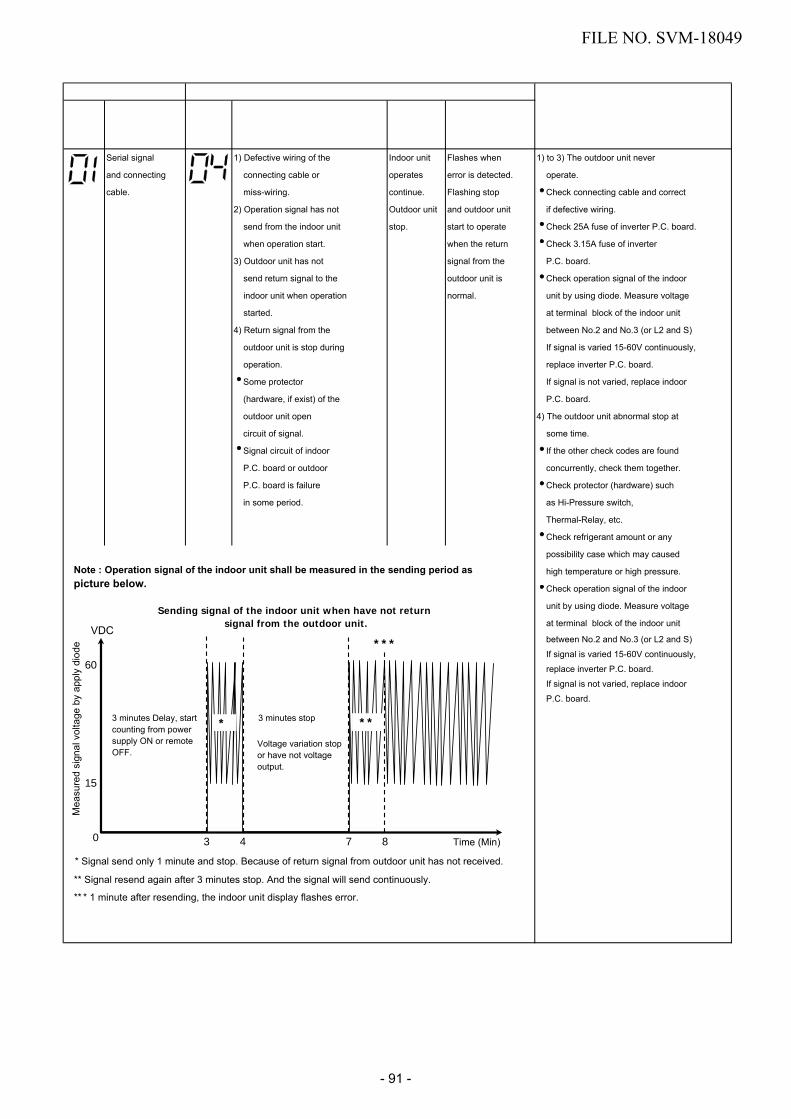
Block distinction Operation of diagnosis function
Check code
BlockCheck code
Cause of operationAir
conditioner status
Display flashing error
Serial signal 1) Defective wiring of the Indoor unit Flashes when 1) to 3) The outdoor unit never
and connecting connecting cable or operates error is detected. operate.
cable. miss-wiring. continue. Flashing stop Check connecting cable and correct
2) Operation signal has not Outdoor unit and outdoor unit if defective wiring.
send from the indoor unit stop. start to operate Check 25A fuse of inverter P.C. board.
when operation start. when the return Check 3.15A fuse of inverter
3) Outdoor unit has not signal from the P.C. board.
send return signal to the outdoor unit is Check operation signal of the indoor
indoor unit when operation normal. unit by using diode. Measure voltage
started. at terminal block of the indoor unit
4) Return signal from the between No.2 and No.3 (or L2 and S)
outdoor unit is stop during If signal is varied 15-60V continuously,
operation. replace inverter P.C. board.
Some protector If signal is not varied, replace indoor
(hardware, if exist) of the P.C. board.
outdoor unit open 4) The outdoor unit abnormal stop at
circuit of signal. some time.
Signal circuit of indoor If the other check codes are found
P.C. board or outdoor concurrently, check them together.
P.C. board is failure Check protector (hardware) such
in some period. as Hi-Pressure switch,
Thermal-Relay, etc.
Check refrigerant amount or any
possibility case which may caused
high temperature or high pressure.
Check operation signal of the indoor
unit by using diode. Measure voltage
at terminal block of the indoor unit
between No.2 and No.3 (or L2 and S)
If signal is varied 15-60V continuously,
replace inverter P.C. board.
If signal is not varied, replace indoor
P.C. board.
Action and Judgment
* Signal send only 1 minute and stop. Because of return signal from outdoor unit has not received.
** Signal resend again after 3 minutes stop. And the signal will send continuously.
** * 1 minute after resending, the indoor unit display flashes error.
VDC
Time (Min)0 3 4 7 8
15
60
Mea
sure
d si
gnal
vol
tage
by
appl
y di
ode
3 minutes Delay, start counting from power supply ON or remote OFF.
3 minutes stop* **
***
Sending signal of the indoor unit when have not return signal from the outdoor unit.
Voltage variation stop or have not voltage output.
Note : Operation signal of the indoor unit shall be measured in the sending period as picture below.
FILE NO. SVM-18049
- 91 -

Block distinction Operation of diagnosis function
Check code
BlockCheck code
Cause of operationAir
conditioner status
Display flashing error
Outdoor P.C. Current on inverter circuit All OFF Flashes after 1. Remove connecting lead wire of the
board is over limit in short time. error is detected compressor, and operate again.
Inverter P.C. board is 8 times*. 2. If outdoor fan does not operate or
failure, IGBT shortage, etc. operate but stop after some period,
Compressor current is replace the inverter P.C. board.
higher than limitation, 3. If outdoor fan operates normally,
lock rotor, etc. measure 3-Phase output of inverter
P.C. board (150-270VAC) at the
connecting lead wire of compressor.
4. If 3-Phase output is abnormal, replace
inverter P.C.Board.
5. If 3-Phase output is normal, replace
compressor. (lock rotor, etc.)
Compressor position-detect All OFF Flashes after 1. Remove connecting lead wire of the
circuit error or short-circuit error is detected compressor, and operate again.
between winding of 8 times*. 2. If outdoor fan does not operate or
compressor. operation but stop after some period,
replace the inverter P.C. board.
3. If outdoor fan operates normally,
measure resistance of compressor
winding. If circuit is shortage, replace
the compressor.
Current-detect circuit of All OFF Flashes after Even if trying to operate again, all
inverter P.C. board error. error is detected operations stop, replace inverter
4 times*. P.C. board.
All OFF Flashes after
error is detected
4 times*.
1. Check sensors, TE, TS connection. In
case of sensors and it’s connection is
normal, check the inverter P.C. board
2. Check 4way valve operation/position.
In case TE, TS detected temperature
relationship are different from normal
operation, “18” might be detected.
TE or TS sensor; abnormal.
Out of place, disconnection,
shortage, or misconnection
(TE sensor is connected to TS
connector, TS sensor is
connected to TE sensor
connector)
TE sensor; Outdoor heat
exchanger temperature sensor
TS sensor; Suction pipe
temperature sensor
TD sensor ; Discharge pipe All OFF Flashes after 1. Check sensors TD and connection.
temperature sensor is error is detected 2. In case of the sensor and its
disconnection or shortage. 4 times*. connection is normal, check the
inverter P.C. board.
Outdoor fan failure or its All OFF Flashes after 1. Check the motor, measure winding
drive-circuit on the inverter error is detected resistance, shortage or lock rotor.
P.C. board failure. 8 times*. 2. Check the inverter P.C. board.
TO sensor ; The outdoor Operation Record error 1. Check sensors TO and connection.
temperature sensor is continues. after detected 2. In case of the sensor and its
disconnection or shortage.4 times*.
connection is normal, check theBut does not
inverter P.C. board.flash display.
Action and Judgment
FILE NO. SVM-18049
- 92 -

Block distinction Operation of diagnosis function
Check code
BlockCheck code
Cause of operationAir
conditioner status
Display flashing error
Compressor drive output error. All OFF Flashes after
(Relation of voltage, current error is detected
and frequency is abnormal) 8 times*.
Overloading operation of
compressor caused by
over-charge refrigerant,
P.M.V. failure, etc.
Compressor failure (High
current).
1. Check installation conditions such as
packed valve opening, refrigerant
amount and power supply (rate +10%,
both of operation and non operation
condition).
2. (In case of P.M.V. exists)
Check P.M.V. by measure the
resistance of the coil and confirm its
operation (sound of initial
operation, etc.)
3. Observe any possibility cause which
may affect operation load of
compressor.
4. Operate again. If compressor operation
is failure when 20 seconds passed
(count time from operation starting of
compressor), replace compressor.
* 4 or 8 times ; When first error is detected, error is count as 1 time, then once operation is stop and re-started.
After re-starting operation within 6 minutes, if same error is detected, error count is add (count become 2 times)
When error count comes 4, 8, 11 or 18 times, record error to check code. But after re-starting operation, if no
error is detected and air conditioner can operate more than 6 minutes, error count is cleared.
The others Return signal of the outdoor Indoor unit Flashes when
(including unit has been sent when operates error is detected.
compressor) operation start. But after continue. Flashing stop
that, signal is stop some time. Outdoor unit and outdoor unit
Instantaneous power stop. start to operate
failure. when the return
Some protector signal from the
(hardware) of the outdoor unit is
outdoor unit open normal.
circuit of signal.
Signal circuit of indoor
P.C. board or outdoor
P.C. board is failure
in some period.
1. Check power supply (Rate + 10%)
2. If the air conditioner repeat operates and
stop with interval of approx. 10 to 40
minutes.
(In case of these exist)
Check protector (hardware) such as
Hi-Pressure switch, Thermal-Relay, etc.
Check refrigerant amount, packed valve
opening and any possibility cause which
may affect high temperature or high
pressure.
3. Check operation signal of the indoor unit
by using diode. Measure voltage at
terminal block of the indoor unit
between No.2 and No.3 (or L2 and S) If
signal is varied 15-60V continuously,
replace inverter P.C. board.
If signal is not varied, replace indoor
P.C. board.
Action and Judgment
Outdoor P.C.
board
FILE NO. SVM-18049
- 93 -

Block distinction Operation of diagnosis function
Check code
BlockCheck code
Cause of operationAir
conditioner status
Display flashing error
Compressor does not rotate. All OFF Flashes after 1. Remove connecting lead wire of the
Because of missed wiring, error is detected compressor, and operate again.
missed phase or shortage. 8 times*. 2. If outdoor fan does not operate or
operation but stop after some period,
replace the inverter P.C. board.
3. If outdoor fan operates normally,
measure 3-Phase output of inverter
P.C. board (150-270VAC) at the
connecting lead wire of compressor.
4. If 3-Phase output is abnormal, replace
inverter P.C.Board.
5. If 3-Phase output is normal, measure
resistance of compressor winding.
6. If winding is shortage, replace the
compressor.
Discharge temperature All OFF Flashes after
exceeded 117oC. error is detected
4 times*.
1. Check sensors TD.
2. Check refrigerant amount.
3. (In case of P.M.V. exists)
Check P.M.V. by measure the
resistance of the coil and confirm its
operation (sound of initial operation, etc.)
4. Observe any possibility cause which
may affect high temperature of
compressor.
Compressor is high current All OFF Flashes after
though operation Hz is error is detected
decreased to minimum limit. 8 times*.
Installation problem.
Instantaneous power
failure.
Refrigeration cycle
problem.
Compressor break down.
1. Check installation conditions such as
packed valve opening, refrigerant
amount and power supply (rate +10%,
both of operation and non operation
condition).
2. (In case of P.M.V. exists)
Check P.M.V. by measure the
resistance of the coil and confirm its
operation (sound of initial operation, etc.)
3. Observe any possibility cause which
may affect high current of compressor.
4. If 1, 2 and 3 are normal, replace
compressor.
Action and Judgment
Compressor failure (High
current).operation, etc.)
The others
(including
compressor)
FILE NO. SVM-18049
- 94 -

Block distinction Operation of diagnosis function
Check code
BlockCheck code
Cause of operationAir
conditioner status
Display flashing error
Action and Judgment
Indoor unit Flashes when 1.. Check power supply (Rate +10%)operates error is detected 2.continue.
Flashing stop
Return signal of the outdoor
unit has been sent when
operation start. But after
that, signal is stop some time.Outdoor unit
and outdoor unitstop.
start to operatewhen the returnsignal from theoutdoor unit isnormal.
. If the air conditioner repeat operat
and stop with interval of approx. 10 to 40 minutes.
(In case of these exist)Check protector (hardware) such as Hi-Pressure switch, Thermal-Relay,
etc.
Check refrigerant amount, packed valve opening and any possibility cause which may affect high temperature or high pressure.
3. Check operation signal of the indoorunit by using diode. Measure voltage
at terminal block of the indoor unit
between No.2 and No.3 (or L2 and S)If signal is varied 15-60V continuously,
replace inverter P.C. board.
If signal is not varied, replace indoorP.C. board.
4. Check and clean heat exchanger areaIndoor and Outdoor unit.
Instantaneous power
failure.
Some protector
(hardware) of the
outdoor unit open circuit
of signal.
Signal circuit of indoor
P.C. board or outdoor
P.C. board is failure in
some period.
TE, TC high tmperature
TE for cooling operation
TC for heating operation.
11 times*.
* 4, 8 or 11 times ; When first error is detected, error is count as 1 time, then once operation is stop and re-started.
After re-starting operation within 6 minutes, if same error is detected, error count is add (count become 2
times) When error count comes 4, 8, 11 or 18 times, record error to check code. But after re-starting operation,
if no error is detected and air conditioner can operate more than 6 minutes, error count is cleared.
The others
(including
compressor)
(TE only exists in the Heat Pump system)
FILE NO. SVM-18049
- 95 -
5. Check sensors, TE, TS connection. In case of sensors and it’s connection is normal, check the inverter P.C. board.
6. Check 4way valve operation/position. In case TE, TS detected temperature relationship are different from normal operation, “18” might be detected.
TE or TS sensor; abnormal. Out of place, disconnection, shortage, or misconnection (TE sensor is connected to TS connector, TS sensor is connected to TE sensor connector)
TE sensor; Outdoor heat exchanger temperature sensorTS sensor; Suction pipe temperature sensor

11-5. Judgement of Trouble by Every Symptom11-5-1. Indoor unit (Including remote controller)(1) Indoor unit is not operated.
(2) Operation is not turned on though Indoor P.C. board is replaced<Confirmation procedure>
NO
Turn off power supply once, and 5 second later, turn it on again.
Is OPERATION indicator flashing?
Is it possible to turn on A/C by pushing
[ ] button on remote controller?
Is voltage DC15V pin 4(+)and pin 3(GND)
onCN301?
Does transmission mark on remote controller flash normally,and is its signal
transmitted properly?
Does fan motor connector
between CN301 1 – 3 short-circuit?
Item by symptoms
Operation
Check Item
Considerable principle cause
Measures
Remote controller is defective.
Refer to (5) “Troubleshooting for remote controller”.Unit operates normally.
Replace main P.C. board
Replace fan motor.
Is fuse (F01) of indoor control
board blown?
Microcomputer is defective.
NO NO
NO NO
NO
YES
YES
YES YES
YES YES
Point remote to digitalcamera. Can see infrared
ray at sending LED
when push [ ] button?
Replace remote control
Does connectionbetween PC Board
and reciver PCB
Reconnect housing
on camera monitor
YES
YES
are connect properly?
YES
NO NO
To item of “Indoor unit is not operated”.
Turn on power supply.
Does OPERATION indicator flash? Is wired correctly to white andblack lead wires of terminal block?
NO
NO
YES
Correct wiring
FILE NO. SVM-18049
- 96 -

(3) Only the indoor motor fan does not operate
<Primary check>1. Is it possible to detect the power supply voltage (AC220–240V) between and on the terminal block?2. Does the indoor fan motor operate in cooling operation?
(In heating operation, the indoor fan motor does not operate for approximately 10 minutes after it is turnedon, to prevent a cold air from blowing in.)
L
Start to operate
A
indoor unit in cooling operation at airflow
B
level “LOW”.
Turn off indoor unit and remove connector from motor.Then start to operate indoor unit with remote controller.
Turn off indoor unit and remove connector from motor.Then push [ ] button
on remote controller to stop flashing lamp on indoor unit.
Change airflow level to “HIGH”.
Start to operate the indoor unit in except
heating operation.At this time, is it possible to detect DC 1V or more between 5 + and 3 –
of motor connector (CN301)?(Check this condition
within 15 seconds after starting unit.)
Start to operate the indoor unit in except
heating operation.At this time, is it possible to
detect DC 1V or more between 5 + and 3 – of motor
connector (CN301)?
Is it possible to detect DC 310–340V between
1 + and 3 – of motor connector (CN301).
(Motor connection condition)Is it possible to detect DC 15V between 4 + and 3 – of
motor connector (CN301).
Is it possible to detect DC 15V between 4 +
and 3 – of motor connector (CN301).
Does indoor fan operate?
Peplace main P.C. board.
YES
YES
YES
YES
YES
YES
NO
NO
NO
NO
NO
NO
Turn off powersupply once, andturn it on again.
Is it possible to detect DC 1V or more between
5 + and 3 – of motor connector (CN301).
Does fan motor continue to operate? Peplace indoor
fan motor.YES
YES
NO
NO
Does check operation LED flash?
Does check connecting cable or power supply
cord complely?interconnection cableand terminal block
NO NO
YES
Does check 5V at display unit?
Replacedisplay unit
Does check 5V at main P.C board?
Reconnecting the
NO
NO
YES
YES YES
N
FILE NO. SVM-18049
- 97 -

Turn off indoor unit and rotate cross-flow fan by hand when the
unit is on standby.At this time, is it possible to
detect DC 1V or more between 5 + and 3 –
of motor connector (CN301).
Is it possible to change airflow level
to “HIGH”?
Is it possible to rotate cross-flow fan by
hand properly?
Fan motor operates normally.
Replace bearingof cross-flow fan.
YES
YES
YES
NO
NO
NO
Does check cross-flow fan bearing normal
condition?
Replace indoorfan motor.
Peplace main P.C. board.
Does check displayon remote show high?
Change the new PCboard. Does fan speed
change?
Replace remote
Replace motor
NO
NO
NO
YES
YES
YES
A
B
FILE NO. SVM-18049
- 98 -

Indoor fan starts rotating when power supply is turned on.
(Check output DC voltage of fan motor on P.C. board.)
Measure voltage between 3 (GND : BLACK) and 5 (V line : YELLOW) of motor connector (CN301)
while indoor fan motor is rotating.
DC 1.0V or more
P.C. board is defective.
6 (Blue)5 (Yellow)4 (White)3 (Black)2 –1 (Red)
Motor is defective.
Under DC 1.0V
CN301
Yellow
Black
P.C. board
DC
Replace P.C. board. Replace motor.
3.2.1. Remove the grille.3.2.2. Remove the cover terminal by release one screw.3.2.3. Remove right panel and remove E-box coner.
1. Turn on breaker.2. After Fan motor operate, off A/C by remote controller.3. Turn off breaker for a while, then turn it ON.
3.1. If fan motor not operate, it means an unit in Auto-restart operation. (see more detail in P. 45-46)3.2. If Fan motor still operate, follow the below.
NOTE :• Do not disconnect the connector while the fan motor is rotating.• Use a thin test rod.
3.2.4. Check DC voltage with CN301 connector while the fan motor is rotating.
(4) Indoor fan motor automatically starts to rotate by turning on power supply
<Cause>The IC is built in the indoor fan motor. Therefore the P.C. board is also mounted to inside of the motor.If the P.C. board is soldered imperfectly or the IC is defective, the fan motor may automatically rotate by turning on power supply.
<Inspection procedure>
FILE NO. SVM-18049
- 99 -

(5) Troubleshooting for remote controller
<Primary check>Check that A or B selected on the main unit is matched with A or B selected on the remote controller.
Push the [ ] button.
Does the transmissionindicator blink?
YES
YES
YESYES
YES
YES
YES
Is there directsunlight on the
receptor of the airconditioner?
Avoid directsunlight.
Is there anythyristor
fluorescent lightnearly?
Keep the airconditioner away
from thyristorfluorescent light.
NO
NO
NO NO
NO
NO
NO
NO
Is operation possiblewhen setting the
temporary switch of theair conditioner main unit
to “TEST RUN” or“TEMPORARY AUTO”?
Can any signal tonebe heard in a transistorradio when transmitting
within 5 cm distancefrom the radio?
P.C. board is failure.
ReplaceP.C. board
Is operationpossible when the
transmitter is movednearer to the infraredsignal receiver of the
air conditioner?
Battery life
Replace thebatteries
Dose thetransmission
indicator light?
Is there anybeep and
operation?
Normal
Remote controlis failure.
Replace remotecontrol.
Push the [ ]button
YES
There is no beep from the indoor unitThe OPERATION lamp of the air conditioner main unit does not light
Press RESET buttonon remote controlwith tip of pencil
FILE NO. SVM-18049
- 100 -

Refer to the chart in 11-6.
Gas leakP.M.V. is defective.Miswiring of connecting wires of indoor/outdoor unitsClogging of pipe and coming-off of TC sensor
Gas circulation amount is down.
Measure gas pressure.
Gas shortageGas leakPipe clogging
Thermo. operation of compressor
Red
Blue
Terminal block
S5277G
Tester2
1
3
Terminal block at indoor side
S5277G or equivalent (Diode with rated voltage of 400V or more is acceptable.)
To item of Outdoor unit does not operate.
11-5-2. Wiring Failure (Interconnecting and Serial Signal Wire)
(1) Outdoor unit does not operate1) Is the voltage between and of the indoor terminal block varied?
Confirm that transmission from indoor unit to outdoor unit is correctly performed based upon the follow-ing diagram.
NOTE:• Measurement should be performed 2 minutes and 30 seconds after starting of the operation.• Be sure to prepare a diode for judgment.
Normal time : Voltage swings between DC15 and 60V. ................... Inverter Assembly check (11-8-1.)Abnormal time : Voltage does not vary.
(2) Outdoor unit stops in a little while after operation started<Check procedure> Select phenomena described below.
1) The outdoor unit stops 10 to 20 minutes after operation started, and 10 minutes or more are required torestart the unit.
2) If the unit stops once, it does not operate until the power will be turned on again.
3) The outdoor unit stops 10 minutes to 1 hour after operation started, and an alarm is displayed.(Discharge temp. error check code 03, 1E Sensor temp. error check code 02, 1C)
FILE NO. SVM-18049
- 101 -

11-6. Check Code 1C (Miswiring in indoor/outdoor units) and 1E
<Check procedure>
NO
NO
NO
NO
YES
YES
YES
YES
YES
Gas leakage, disconnection of TS/TC sensors (Check code 02, 1C)
Discharge temp. error, gas leakage(Check code 03, 1E)
1C 1E
Gas amount check and valve clogging check
Remove TC sensor connector from the P.C. board in indoor unit.(Remove connector from the P.C. board.)Operate the air conditioner in COOL mode by TEMP button (“Beep” sound is heard if keeping pushed for 10 seconds.).The operation enters temporary operation mode which fixes opening degree of compressor speed.
Valve drive check
Check the operating pressure from service port, and add gas if pressure is low.
Is connector of coil connected to inverter?
Is coil of the pulse motor valve (P.M.V.) correctly set?
Check condensation at outlet of P.M.V.If there is condensation at outlet (1/4 inch=Ø6.35mm valve side),
the valve is clogged. (If there is no P.M.V. --> Skip this step)
Are temp. sensors of indoor/outdoor units correctly set to the holder?NOTE :The temperature sensors include indoor heat exchanger sensor (TC), outdoor heat exchanger temp. sensor (TE), outdoor suction temp. sensor (TS) and outdoor sensor (TO).
Set it correctly.
Set it correctly.
Set it correctly.
Replace coil valve.
Replace valve.
Add gas.
Is positioning sound of valve (sound hitting to stopper) heardfrom valve when the air conditioner starts the operation after turning off power
of the air conditioner once?
NO Does this modelhave P.M.V. or not?
YES
* TE : (For Heating model)TS : (For P.M.V. used model).
NO
FILE NO. SVM-18049
- 102 -

11-7. How to Diagnose Trouble in Outdoor Unit
YES
Turn ON the unitby remote controller and wait for 3 min.
Check componentparts of control board
assembly by visual.(damage, burn,.. Etc.)
Check Power Supply(Voltage Rate ±10%)
Replace fuse.
NO
YES
YES
YES
Turn OFF powersupply.
Check 25Afuse (F01)
failure?
Remove connector of compressor.
Replace control board.
Check terminalVoltage of electrolytic
capacitor are in(Voltage Rate
Turn ON powerSupply.
NO
±10%) x 1.414?
Replace control board.
NO
(Cooling : 17°C)
A
• Connect dischargeresistance (approx. 100Ωı,40W) or soldering iron(plug) between +, –terminalsof the electrolytic capacitor(760µF)of C08 (with printed CAUTIONHIGH VOLTAGE) on P.C.board.
FILE NO. SVM-18049
- 103 -

YES
Does outdoor fanoperate normally?
Replace control board.
YES
YES
Compressoris normal
Check voltage of thecompressor connector
(AC150V-270V)?
Turn ON powersupply.
NO
Turn OFF powersupply.
Replace outdoor fan motor.
NO
Replace compressor.
Replace control board.
Replace compressor.
YES
Does compresseroperate normally?
Remove connector CN31 ofoutdoor fan motor.
Check winding resistance byohmmeter are correct?
Check rotor locking by rotate with hand. Can it rotate?
Turn OFF powersupply.
Check compressorwinding resistance
correct?
is in rate.
A
NO
NO
YES
NO
FILE NO. SVM-18049
- 104 -

Prim
ary
chec
kO
pera
tion
chec
k
Turn off the power breaker once, and turn on again after 10 seconds.
Does the OPERATION indicator flash?
Turn off the power breaker and remove CN401 (Micro switch connector). Short-circuit between and pin of CN401 at PC side, and turn on the power breaker after 10 seconds.
1) Check operation while short-circuiting CN401 of the main P.C. board.2) Perform air purifying operation by the remote controller.
• In this time, check that the remote controller is in status which is shortened by time onthe reactivation preventive timer and all display indicators go on for approx. 3 secondswhen a signal is received. If time on the reactivation preventive timer is not shortened, the high-voltage is not applied to electrode of the air purifier for approx. 1 hour.
• While the air purifier operates, check that the fan speed [AUTO] is not displayed. (Because the power ON/OFF is controlled on the program)
3) Be sure not to touch the electric dust collector.
Is there conduction of micro-switch connector under OFF status of the micro-switch
(Front panel opened)?
Is there conduction of micro-switch connector under ON status of the micro-switch
(Front panel closed)?
Does the indoor fan rotate?
Does the PURE indicator (white)go on?
Short Timer and then check,Is DC12V applied between (DC12V)
(GND) of CN1 of the high-voltage generator?
Is DC12V applied between (+) and (–)
of CN402 of the main P.C. board ?
Micro-switch is stuck
Micro-switch malfunction
To item “Power supply is not turned on”
Replace the main P.C. board.
Replace micro-switch.
Are the electric dust collector ?
(Electrode check)Dry the electric dust collector.
Is output of the collector approx. -2.7 kV to -3.4 kV?
Are the electric dust collector?
Is an abnormal sound (cracking noise) heard
from the electrode?
Referring to the right figure, check the high-output voltage of the air filter unit.(NOTE) Use an exclusive high voltage tester; otherwise the tester may be broken.
No trouble
Check High Voltage output Short to GND?
Replace the high-voltage generator.
To item “Only indoor fan does not operate”
YES
YES
NO
YES
YES
YES
YES
YES
NO NO
NO
NO
NO
YES
YES
YES
YES
NO
NOYES
NO
NO
( )
Refer to items, cleaning and check for the electric dust collector
• Conduction c heck of micr o-switc h
Tester
ON
• How to check output of the air purifier<Caution on High Voltage!!>
NO
1 1 2
1 2
Push the switch ˇ ON Release the switch ˇ OFF
Be sure not to come to contact to the gray part
2
Is DC-5V to DC-10V applied between
(Negative voltage) and (GND)
of CN402 of the main P.C. board?
42
FILE NO. SVM-18049
- 105 -

(2) Inspection procedures1) When a P.C. board is judged to be defective,
check for disconnection, burning, or discolora-tion of the copper foil pattern or this P.C. board.
2) The P.C. board consists of the following 3 partsa. Main P.C. board part:
DC power supply circuit (5 V, 12 V, 15V)Indoor fan motor control circuit, CPU andperipheral circuits, buzzer, and Driving circuitof louver.
b. Indication unit circuitc. Infrared ray receiving circuit
11-9. How to Check Simply the Main Parts11-9-1. How to check the P.C. board (Indoor unit)
(1) Operating precautions1) When removing the front panel or the P.C.
board, be sure to shut off the power supplybreaker.
2) When removing the P.C. board, hold the edgeof the P.C. board and do not apply force to theparts.
3) When connecting or disconnecting the connec-tors on the P.C. board, hold the whole housing.Do not pull at the lead wire.
11-9-2. How to shorten time for start the compressor.1. Turn on remote.2. Setting requirment operation.3. Push off remote.
This setting helps to shortern a compressor waiting period when operate cool, heat or dry mode.A compressor suddenly starts one order of Remote controller is received.
4. Press [SET] button while pressing [CHECK] buttonwith a tip of a pencil.
5. Then press [ ] button to transmit the signal to theindoor unit.
5
4
FILE NO. SVM-18049
- 106 -

11-9-2. P .C . Board Layout
100
30
40
50
60
70
80
90
20
100
0 10 20 30 40 50
Res
ista
nce
valu
e (k
)
Temperature (°C)
TD : Discharge temp. sensorTA : Room temp. sensorTC and TCJ : Heat exchanger temp. sensor TO : Outdoor temp. sensorTE : Outdoor heat exchanger temp. sensor TS : Suction temp. sensor
TA,TC,TCJ,TO,TE,TS
TD
[1] Sensor characteristic table
GND
+5V
+12V+15V
FILE NO. SVM-18049
- 107 -

11-9-3. Indoor Unit (Other Parts)
11-9-4. Outdoor Unit
No.
1
Part name
Room temp. (TA) sensorHeat exchanger (TC,TCJ)
Checking procedure
Disconnect the connector and measure the resistance value with tester.(Normal temp.)
No.
1
Part name Checking procedure
Measure the resistance value of winding by using the tester.
Red
White Black
Measure the resistance value of winding by using the tester.Resistance value1725 ± 172.5Ω
at 20°C
Measure the resistance value of winding by using the tester.
COM
4Y
W
BL
1
6 RO3
PositionGray - White
Gray - OrangeRed- YellowRed- Blue
Resistance value46 ± 4Ω46 ± 4Ω46 ± 4Ω46 ± 4Ω
TemperatureSensor
TA, TC, TCJ (kΩ)
10°C 20°C 25°C 30°C 40°C
20.7 12.6 10.0 7.9 4.5
54321White
YellowYellowYellowYellow 5
4321
Refer to 11-5-1. (5).
Measure the resistance value of each winding coil by using the tester.(Under normal temp. 25°C)
Position1 to 21 to 31 to 41 to 5
Resistance value
200 ± 14Ω
Refer to 11-5-1. (3) and (4).
at 20°C
Disconnect the connector, and measure resistance value with the tester.(Normal temperature)
Outdoor temperature sensor(TO), discharge temperaturesensor (TD), suctiontemperature sensor (TS),outdoor heat exchangertemperature sensor (TE)
TemperatureSensor
TD (kΩ )TO,TS,TE (kΩ )
10°C 20°C 25°C 30°C 40°C 50°C
100 64 50 41 27 1820.7 12.6 10.0 7.9 4.5 —
2
3
Remote controller
Louver motorMP24Z4N
4 Indoor fan motor
Measure the resistance value of each winding by using the tester.
Position
Red - White White - BlackBlack - Red
at 20ºC
1.82Ω
2
3
4
5
4-way valve coil(Model : STF-H01AJ1872A1)
Pulse motor valve coil(Model : CAM-MD12TCTH-5)
sensor
CompressorModel : KTN110D42UFZ (for RAS-10PAVPG-E,-NZ)Model : KTN150D42UFZ(for RAS-13,16PAVPG-E,-NZ)
KTN110D42UFZ KTN150D42UFZ
Red
White Black
Position
Red - WhiteWhite - BlackBlack - Red
Outdoor fan motor(Model : ICF-140-43-4R)
Resistance value
at 20ºC
at 25°C
21 ± 1.05Ω
2
FILE NO. SVM-18049
- 108 -

11-9-5. Checking Method for Each Part
No.
1
Part name
Electrolytic capacitor(For boost, smoothing)
Checking procedure
1. Turn OFF the power supply breaker.2. Discharge all two capacitors completely.3. Check that safety valve at the bottom of capacitor is not broken.4. Check that vessel is not swollen or exploded.5. Check that electrolytic liquid does not blow off.6. Check that the normal charging characteristics are shown in continuity test by
the tester.
Case that product is goodPointer swings once, and returnsslowly. When performing testonce again under anotherpolarity, the pointer should return.
C07, C08 → 760µF/400V
Resistance value in good product
∞
Tester rod
+ –~ 2
~ 3
~ 2
~ 3– 4
~ ~ ~+ –~
1
1 2 3(DB01,DB02)
4
4
23 + 1
+
–10 to 20 Ω when the multimeter probeis reversed
2 Diode block 1. Turn OFF the power supply breaker.2. Completely discharge the two electrolytic capacitors.3. Remove the diode block from the PCB (which is soldered in place).4. Use a multimeter with a pointer to test the continuity, and check that the
diode block has the proper rectification characteristics.
Hea
t sin
k si
de
C08
C07
WP-030 Soldered surface
FILE NO. SVM-18049
- 109 -

11-10. How to Simply Judge Whether Outdoor Fan Motor is Good or Bad
1. Symptom• Outdoor fan motor does not rotate.• Outdoor fan motor stops within several tens seconds though it started rotating.• Outdoor fan motor rotates or does not rotate according to the position where the fan stopped, etc.Remote controller check code “02 : Outdoor block, 1A : Outdoor fan drive system error”
2. CauseThe following causes are considered when the outdoor fan motor does not normally rotate.1) Mechanical lock of the outdoor fan motor2) Winding failure of the outdoor fan motor3) Position-detect circuit failure inside of the outdoor fan motor4) Motor drive circuit failure of the outdoor P.C. board
3. How to simply judge whether outdoor fan motor is good or bad
NOTE :However, GND circuit error inside of the motor may be accepted in some cases when the above check isperformed.When the fan motor does not become normal even if P.C. board is replaced, replace the outdoor fan motor.
If the resistance value between 1 (Red lead) – 2 (White lead)2 (White lead) – 3 (Black lead)3 (Black lead) – 1 (Red lead)
of the connector(CN31 : Motor winding)
is 21 ± 1.05Ω
Turn OFF the breaker.
Fan motor is normal.
Does the fan rotate without trouble when rotating it with hands?
Disconnect two connectors (CN31) of the outdoor fan motor from the outdoor P.C. board.
(Outdoor P.C. board error)
Fan motor error
YES
YES
NO
NO
CN31
FILE NO. SVM-18049
- 110 -

12. HOW TO REPLACE THE MAIN PARTS
WARNING• Since high voltages pass through the electrical parts, turn off the power without fail before proceeding with
the repairs.Electric shocks may occur if the power plug is not disconnected.
• After the repairs have been completed (after the front panel and cabinet have been installed), perform atest run, and check for smoking, unusual sounds and other abnormalities.If this check is omitted, a fire and/or electric shocks may occur.Before proceeding with the test run, install the front panel and cabinet.
• Ensure that the following steps are taken when doing repairs on the refrigerating cycle.1. Do not allow any naked flames in the surrounding area.
If a gas stove or other appliance is being used, extinguish the flames before proceeding.If the flames are not extinguished, they may ignite any oil mixed with the refrigerant gas.
2. Do not use welding equipment in an airtight room.Carbon monoxide poisoning may result if the room is not properly ventilated.
3. Do not bring welding equipment near flammable objects.Flames from the equipment may cause the flammable objects to catch fire.
• If keeping the power on is absolutely unavoidable while doing a job such as inspecting the cir-cuitry, wear rubber gloves to avoid contact with the live parts.Electric shocks may be received if the live parts are touched.High-voltage circuits are contained inside this unit.Proceed very carefully when conducting checks since directly touching the parts on the control circuitboard may result in electric shocks.
12-1. Indoor Unit
Front panel 1)) Stop operation of the air conditionerand turn off its main power supply.
2)) Open the air inlet grill, push the armtoward the outside, and remove the grill.
3)) Remove the left and the right air filters.
4) Remove the fixing screws (5 pcs.)5) Open LOUVER-HR as the picture
then pull down and pull outwardPANEL-FR (R) and PANEL-FR(L).as picture
No. Part name Work procedure Remarks
1
5 Screws
FILE NO. SVM-18049
- 111 -

BUSH-BODY(R) 1) Push the bottom of part and slide to theright side.
BUSH-BODY(L) 1) Push the bottom of part and slide to theleft side.
<Point to note during re-assemble
Front panel>
- Please make sure that the claw of Front- panel insert below edge of ASM-FRAME.- Hooks in left and right side must beinstall to lock position
Electric partsbox assembly.
1) Stop operation of the air conditioner andturn off its main power supply.2) Open the air inlet grill, push the arm towardthe outside, and remove the grille.3) Remove the fixing screw atPANEL-FR(R) 3pcs, at PLATE-DECO 3 pcsfollowing picture then pull out PANEL-FR (R)and PLATE-DECO.4) Remove a fixing screw and Cover- connector assembly, then remove Power- supply cord after already remove fixing- screws(2pcs.) at cord-clamp.5) Remove the fixing screw that securethe cover electric box, then removecover electric box toward right side.6) Remove the screws of Earth-lead that
fixing at the electronic box.
No. Part name Work procedure Remarks
The claw of Front panel mustbe lower ASM-FRAME
Hook must be installto lock position
2
3
4
BUSH-BODY(L) BUSH-BODY(R)
Earth screwFixing screw
Cover electric box
Right sideLeft side
3 Screws
Fixing screw 3 Screws
FILE NO. SVM-18049
- 112 -

7) Disconnect the connector ofElectric partsbox assembly. fan-motor, louver-motor and high voltage
generator and cord Wi-Fi connector.
8) Pull out TCJ sensor from sensor holderof the evaporator.Pull out TC sensor from sensor holderof the evaporator.Remove TA sensor form sensor holder.
9) Remove fixing screw that holdelectronic part, then remove
electronic parts.
<How to assemble the electric parts box>
1) Lock the top of electric box with hook ofFrame-up and secure it by fixing screwwith Back-body. After that connectthe connector of High-voltage-generator,Fan-motor and Louver-motor.
2) Insert TA/TC/TCJ sensor into holder- sensor.
Fix the grounding-lead with fixing screw.
No. Part name Work procedure Remarks
TCJ sensor
TC sensor
TA sensor
5
Fixing screw
High voltagegenerator connector
Wi-Fi cord connector
Wi-Fi cord connector
Fan motor
Louver motorconnector
FILE NO. SVM-18049
- 113 -

Frame 1) Follow to the procedure -2) Remove the fixing screws at COVER-WIFI1 Pcs. than take off wifi-cord out from hooklock.
3) Remove the Fixing screws at ASM-FRAME(5 Pcs).
4) Remove screw of earth lead on plate earth.
5) Take off 5 hooks from rear side thenremove Frame assembly.6) Remove a fixing screw of ground leadthen remove Earth assembly.
<How to assemble the Frame>
1) Press the top of Frame with 5 hooks ofBack-body
2) Fix Frame by 5 fixing screws.
Horizontal louver 1) Remove shaft of the horizontal louverfrom the back body. (First remove thecenter shaft, and then remove theother shafts.)
No. Part name Work procedure Remarks
2 Screws
5 hooks from rear
Earth screw.
5
6
4
Earthscrew
1
3 Screws
1 Screw
FILE NO. SVM-18049
- 114 -

1) Follow to the procedure in the item2) Remove 3 screws and remove the ion-
Plasma-ioncharger, Highvolt generator charger assembly from the frame.
3) Remove the Plasma-ion charger from the Highvolt generator assembly.
4) Remove cover of HV generator by unlock4 claws.
5) Remove the board of HV generetor.
<Points to note during re-installation>
- Lay the wires straight, such that they passthrough the earth wire in a U-shape.
- Lay the wires such that the high voltage powersupply line passes in a U-shape.
No. Part name Work procedure Remarks
7 5
Plasma-ion
4 Claws
U-shape groove
Ground lead
3 Screws
FILE NO. SVM-18049
- 115 -
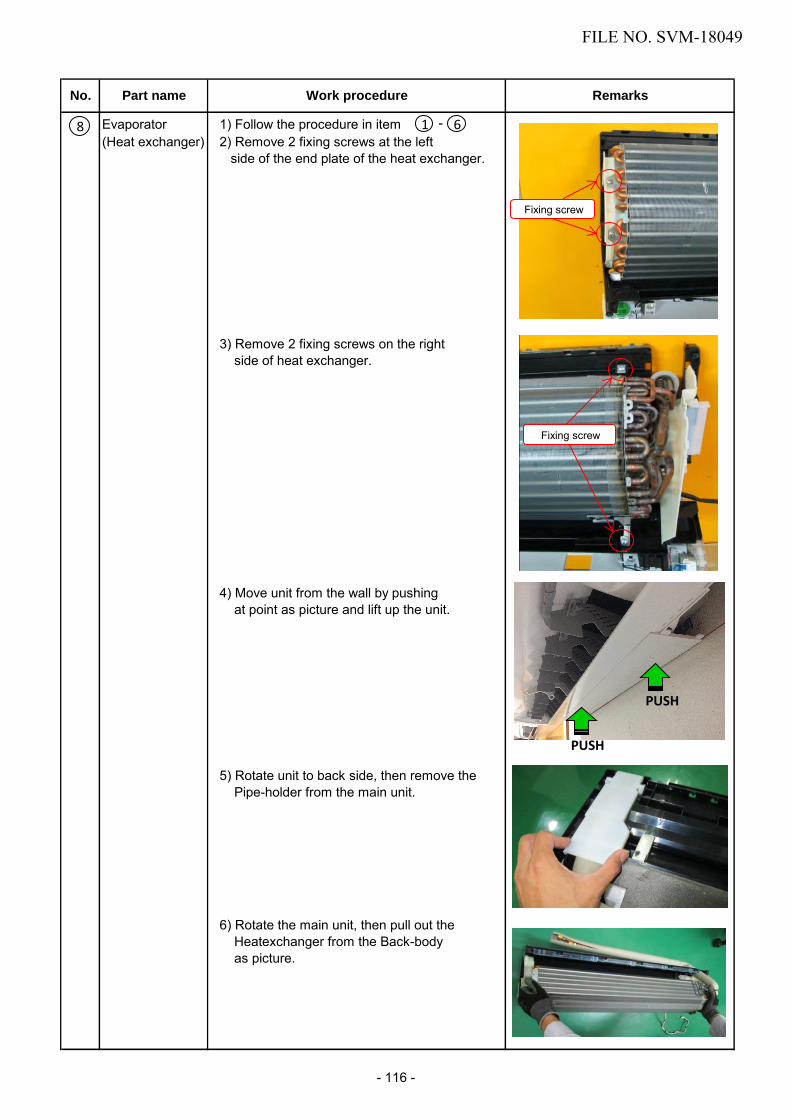
Evaporator 1) Follow the procedure in item -(Heat exchanger) 2) Remove 2 fixing screws at the left
side of the end plate of the heat exchanger.
3) Remove 2 fixing screws on the rightside of heat exchanger.
4) Move unit from the wall by pushingat point as picture and lift up the unit.
5) Rotate unit to back side, then remove thePipe-holder from the main unit.
6) Rotate the main unit, then pull out theHeatexchanger from the Back-bodyas picture.
No. Part name Work procedure Remarks
PUSH
PUSH
8 1 6
Fixing screw
Fixing screw
FILE NO. SVM-18049
- 116 -

Fan motor 1) Follow the procedure - and2) Remove 3 fixing screws, then remove
Cover motor assembly.
3) Loosen the set screws of the transversefan from the vent.
4) Remove 2 screws from the Motor- band (right)5) Pull the motor band(right) and the Fan-
Motor outward.
<Point to note during re-installation>
For the position of the fan motor, please installsuch that the fan motor connector matchesthe position and enters the space of the ribsof the motor band(right).
No. Part name Work procedure Remarks
9
Set screw
Screws
Motor band(right) Motor connector
1 6 8
Fixing screw
FILE NO. SVM-18049
- 117 -

Bearing 1) Follow to the procedure in the item and -
2) Remove 2 fixing screws from theBase bearing assembly, then removeBase bearing assembly from the main unit.
<Caution at assembling>
- If the bearing is out from the housing,push it into the specified position and thenincorperate it in the main body.
No. Part name Work procedure Remarks
10
Bearing Bearing base
Base bearing assembly 6 8 9
Fixing screw
Fixing screw
- 1
FILE NO. SVM-18049
- 118 -

Cross flow fan <Caution at reassemblying>
1) To incorporate the Fan-motor incorporatethe Motor into the position in the followingfigure, and then install the Fan-motor
- Install the cross flow fan so that the rightend of the 1st joint from the right of theCross flow fan is set keeping 5.0mmfrom closed wall of the main unit.
- Holding the set screw, install thecross flow fan so that flat area on shaft ofthe fan motor comes to the mounting holeof the set screw.
- Perform positioning of the fan motor asfollow:
- When assembling the fan motor, the fanmotor must be installed in such a way thatthe fan motor leads will be taken out ispositioned at the bottom front.
- After assembling the two hooking claws ofthe motor band(right) into the main body,position the fan motor, insert it, and thensecure the motor band(right) using the twofixing screws.
No. Part name Work procedure Remarks
11Fan motor Dshaft
Double point setscrew
5 mm.
FILE NO. SVM-18049
- 119 -

12-3. Outdoor Unit
No.
Part name
Commonprocedure
Procedure
1. Detachment
NOTEWear gloves for this job.Otherwise, you may injure yourhands on the parts, etc.
1) Stop operation of the air conditioner,and turn off the main switch of thebreaker for air conditioner.
2) Remove the valve cover.(ST2TØ4 × 10L 2 pcs.)• After removing screw, remove the
valve cover pulling it downward.3) Remove cord clamp (ST2TØ4 × 14L
3 pcs.), and then remove connectingcable.
4) Remove the upper cabinet.(ST1TØ4 × 10L 5 pcs.)• After removing screws, remove the
upper cabinet pulling it upward.
2. Attachment1) Attach the water-proof cover.
NOTEThe water-proof cover must beattached without fail in order toprevent rain water, etc. from enteringinside the indoor unit.
2) Attach the upper cabinet.(ST2TØ4 × 10L 5 pcs.)
3) Perform cabling of connecting cable,and attach the cord clamp.• Fix the cord clamp by tightening the
screws (ST2T∅ 4 x 14L 3 pcs.),fitting 2 concave parts of the cordclamp to each connecting cables.
4) Attach the valve cover.(ST2T∅4 x 10L 3 pcs.)• Insert the upper part into the squarehole of the side cabinet, set hookclaws of the valve cover to squareholes (at three positions) of the mainunit, and attach it pushing upward,
Remarks
How to mount the water-proof cover
These 2 bending parts shall beput inside of a unit by bendingthese 2 ports.
This part shall be put onthe side cabinet.
Fit the corner of the waterproof cover to the corner of the front cabinet.
This line shall be pavallel to the front cabinet
This part shall cover the gap between the inverter box and the front cabinet.
FILE NO. SVM-18049
- 120 -

No.
Part name
Front cabinet
Procedure
1. Detachment1) Perform step 1 in .2) Remove the fixing screws (ST2TØ4 × 10L
2 pcs.) used to secure the front cabinetand inverter cover, the screws (ST2TØ4× 10L 4 pcs.) used to secure the frontcabinet at the bottom, and the fixingscrews (ST2TØ4 × 10L 2 pcs.) used tosecure the motor base.• The front cabinet is fitted into the side
cabinet (left) at the front left side so pullup the top of the front cabinet to removeit.
2. Attachment1) Insert the claw on the front left side into
the side cabinet (left).2) Hook the bottom part of the front right side
onto the concave section of the bottomplate. Insert the claw of the side cabinet(right) into the square hole in the frontcabinet.
3) Return the screws that were removedabove to their original positions and attachthem.
Remarks
Front cabinet
ClawSquare hole
Concave section
FILE NO. SVM-18049
- 121 -

No.
Part name
Inverterassembly
Procedure Remarks
1) Perform work of item 1 in .2) Remove screw (ST2TØ4 × 10L 2 pcs.) of the
upper part of the front cabinet.• If removing the inverter cover in this
condition, P.C. board can be checked.• If there is no space above the unit, perform
work of 1 in .
Be careful to check the inverter becausehigh-voltage circuit is incorporated in it.
3) Perform discharging by connecting ,polarity by discharging resistance (approx.100Ω40W) or plug of soldering iron to ,terminals a of the C10 (printed “CAUTIONHIGH VOLTAGE” is attached.) electrolyticcapacitor (760µF) on P.C. board.
Be careful to discharge the capacitorbecause the electrolytic capacitorcannot naturally discharge and voltageremains according to trouble type insome cases.
NOTEThis capacitor is one with mass capacity.Therefore, it is dangerous that a largespark generates if short-circuitingbetween ,
RequirementAs each connector has a lock mecha-nism, avoid to remove the connector byholding the lead wire, but by holding theconnector.
The connector is onewith lock, so removeit while pushing thepart indicated by anarrow.
Be sure to remove the connector byholding the connector, not by pullingthe lead wire.
4)
5)
6) Remove various lead wires from the holderat upper part of the inverter box.
7) Pull the inverter box upward.8) Disconnect connectors of various lead wires.
Inverter cover
P.C. board(Soldered surface)
Remove screw (ST2T∅4 x 10L 4pcs.) fixing the terminal part of inverter box to the main body.
Remove the front cabinet by performing step 1 in 2 , and remove the fixing screws(ST2T∅4 x 10L) for securing the main body and inverter box.
A screw P.C. board(Sodered surface)(ST2T 4 x 10L
FILE NO. SVM-18049
- 122 -

CN
52
C
N7
3
CN63 CN61 CN64 CN62
No. Part name
Control boardassembly
Procedure
1. Disconnect the leads and connectors connected tothe other parts from the control board assembly.1) Leads
• 3 leads (black, white, orange) connected toterminal block.
• Lead connected to compressor :Disconnect the connector (3P).
• Lead connected to reactor :Disconnect the two connectors (2P).
2) ConnectorsCN31 : Outdoor fan motor (3P: white)*(* : See Note)CN72 : 4-way valve (2P: yellow)*CN61 : TE sensor (2P: white)*CN73 : PMV (6P: white)CN64 : TS sensor (3P: white)*CN62 :TD sensor (3P: white)*CN63 : TO sensor (2P: white)CN52 : High Pressure Switch (2P : white)
NOTE
These connectors have a disconnect preventionmechanism: as such, the lock on their housingmust be released before they are disconnected.
2. Remove the control board assembly from thespacer. (Remove the heat sink and control boardassembly while keeping them screwed together.)
3. Remove the two fixing screws used to secure theheat sink and control board assembly.
4. Mount the new control board assembly.
NOTE
When mounting the new control board assembly, ensure that the P.C. board is inserted properly into the spacer support.
Remarks
CN31,CN72,CN61,CN73,CN64, CN62,CN63 and CN52 are connectors with locking mechanisms: as such, to disconnect them, they must be pressed in the direction of the arrow while pulling them out.
4
P.C. board baseP.C. board
FILE NO. SVM-18049
- 123 -

No.
Part name
Side cabinet
Procedure
1. Side cabinet (right)1) Perform step 1 in and all the steps
in .2) Remove the fixing screw (ST2TØ4 × 10L
3 pcs.)used for securing the side cabinetto the bottom plate and valve fixing panel.
2. Side cabinet (left)1) Perform step 1 in .2) Remove the fixing screw (ST2TØ4 × 10L
1 pc.) used to secure the side cabinet(left) onto the heat exchanger.
3) Remove the fixing screw (ST2TØ4 × 10L2 pcs.) used for securing the side cabinetto the bottom plate and heat exchanger.
Remarks
Detail A Detail B Detail C
1) Perform work of item 1 of and .2) Remove the flange nut fixing the fan motor
and the propeller.• Flange nut is loosened by turning clock-
wise. (To tighten the flange nut, turncounterclockwise.)
3) Remove the propeller fan.4) Disconnect the connector for fan motor
from the inverter.5) Remove the fixing screws (4 pcs.) holding
by hands so that the fan motor does notfall.* Precautions when assembling the fan
motorTighten the flange nut using a tighteningtorque of 4.9 N•m.
Fan motor
Hook the claw onto the bottom plate
A
Propeller fan
Fan motor
Flange nut
The bac k body section hooked onto the bottom plate here.
B
C
FILE NO. SVM-18049
- 124 -

No.
Part name
Compressor
Procedure
1) Perform work of item 1 of and , , , .
2) Extract refrigerant gas.3) Remove the partition board.
(ST2TØ4 × 10L 4 pcs.)4) Remove the sound-insulation material.5) Remove terminal cover of the compressor,
and disconnect lead wire of the compressorfrom the terminal.
6) Remove pipe connected to the compressorwith a burner.• Take care to keep the 4-way valve away
from naked flames. (Otherwise, it maymalfunction.)
7) Remove the fixing screw of the bottom plateand heat exchanger. (ST2TØ4 × 10L 1 pc.)
8) Remove the fixing screw of the bottom plateand valve fixing plate.(ST2TØ4 × 10L 2 pcs.)
9) Pull upward the refrigeration cycle.10) Remove NUT (3 pcs.) fixing the compres-sor to the bottom plate.
Remarks
Reactor 1) Perform work of item 1 of , and .2) Remove screws fixing the reactors.
(ST2TØ4 × 10L 2 pcs.)
PartitionCompressor
Valve fixing
board
plate
Reactor
Screw
FILE NO. SVM-18049
- 125 -

No.
Part name
Electronicexpansion valvecoil
Procedure Remarks
Hooking clawMinus screwdriver
Fan guard 1. Detachment1) Perform work of item 1 of .2) Remove the front cabinet, and put it down
so that fan guard side directs downward.
Perform work on a corrugated cardboard,cloth, etc. to prevent flaw to the product.
3) Remove the hooking claws by pushing minusscrewdriver according to the arrow mark inthe right figure, and remove the fan guard.
2. Attachment1) Insert claws of the fan guard in the holes
of the front cabinet. Push the hookingclaws (9 positions) by hands and fix theclaws.
Check that all the hooking claws are fixedto the specified positions.
1. Detachment1) Perform step 1 in , all the steps in
and 1 in .2) Remove the coil by pull it upward.
2. Attachment1) Insert a valve coil to value body by push
it downward. And confirm to fix it surely.
FILE NO. SVM-18049
- 126 -

No.
11
Part name Procedure Remarks
TE sensor (outdoor heat exchanging temperature sensor)• Attachment
Install the sensor onto the straight pipe part of the condenseroutput pipe.
CAUTIONDuring the installation work (and on its completion), take care not to damage the coverings ofthe sensor leads on the edges of the metal plates or other parts. It is dangerous for thesecoverings to be damaged since damage may cause electric shocks and/or a fire.
CAUTIONAfter replacing the parts, check whether the positions where the sensors were installed are theproper positions as instructed. The product will not be controlled properly and trouble will resultif the sensors have not been installed in their proper positions.
TS sensor (Suction pipe temperature sensor)• Attachment
Install the senser onto the straight pipe part of the suctionpipe. Be careful for the lead direction of the sensor.
TD sensor (Discharge pipe temperature sensor)• Attachment
With its leads pointed upward, install the sensor onto thevertical straight pipe part of the discharge pipe.
TO sensor (Outside air temperature sensor)• Attachment
Insert the outdoor air temperature sensor into the holder, andinstall the holder onto the heat exchanger.
12
13
14
Detail ATS sensor
Sensor lead
Straight part
Detail C
Straight part
Sensor lead
TO sensorholder
Detail DTO sensor
10
Detail BTD sensor
Detail BDetail A
Detail C
Detail D
FILE NO. SVM-18049
- 127 -

13. EXPLODED VIEWS AND PARTS LIST
13-1. Indoor Unit
Location Part Location Part
No. No. No. No.
201 43T00731
257 43T03411
202 43T00732225 43T11331
203 43005871231 43049799
204 43T09545233 43T62352
207 43T02306234 43T83305
208 43T02307235 43T66376
209 43T04351238 4306A194
210 43020380241 43T70314
211 43022466242 43T63355
212 43022472243 43080658
213 43022473244 43T21421
214 43022475246 43T80345
217 4302C106247 43T80347
218 43T2D301248 43T80342
219 43T09503249 43T08428
220 43T09504250 43T08429
221 43T2D302252 43082298
222 4302D021254 43T44623
223 43039404
ASM-PANEL(R)-S ASM-PANEL(L)-S ASM-PANEL(AOLT) ASM-AINL-SASM-BUSH-BODY(R) ASM-BUSH-BODY(L) ASM-BODY-BUSH(DN) ASM-FAN-CF(CE110) ASM-BEAR-MOLD BASE-BEARING LOUVER-HR(FR) LOUVER-HR(BK) MOTOR-LOUVER ASM-SUB-GEAR(LV)-S ASM-LOUVER-VT ASM-LOUVER-VT ASM-GEAR(LV) ASM-ARM(L)BAND-MOTORASM-COV-MOTOR
254 43T44624
PIPE-SHIELDHOLDER-PIPEASM-COVER-CONN HOLDER, REMOTE CONTROL WIRELESS REMOCO CORD-MOTOR(LV)HOSE-DRAINASM-EARTHHOLD-IONFAN MOTORASM-ION-SASM-SUP-HP-SFILTER-AIRASM-FRAME-SASM-COVER-WIFIPLATE-INSTASM-CYCLE-REF(10k,13k) ASM-CYCLE-REF(16k)ASM-BODY-BACK
Description Description
4
224 43039406

13-2. Indoor Unit (E-Parts Assy)
Location Part Location Part
No. No. No. No.
401 43T50324 406 43T6W352402 43T50320
PC BOARD (RAS-10PKVPG-NZ)PC BOARD (RAS-13PKVPG-NZ)PC BOARD (RAS-16PKVPG-NZ)403 43T50355
407 43T60378404 43T62340408 43T60417405 43T6V469409 43T60416
TERMINALTERMINALTERMINAL406 43T6W349
410 43T60077 FUSE, TEMPERATURE, 73C
SENSOR; HEAT EXCHANGER SENSOR HEAT EXCHANGER TEMPERATURE SENSOR CORD-CLAMPPC BOARD ASSY:WRS-LED PC BOARD (RAS-10PKVPG-E)PC BOARD (RAS-13PKVPG-E)PC BOARD (RAS-16PKVPG-E)
Description Description
406 43T6W350406 43T6W351
406 43T6W353406 43T6W354
406409
410
- 129 -

13-3. Outdoor Unit
63 HOLDER SENSOR(TE)64 HOLDER SENSOR(TD)65 HOLDER SENSOR(TS)
35
23
42
43
44
45
4
5
20
62
2152
2
22
7
3051
25
18
60
61
46
6
24
3
36, 40
37, 41
9
Location Part Location PartNo. No. No. No.1 43T42345 40 43T465022 43T00560 41 43T465033 43T007194 43T00561 41 43T465075 43T007186 43T00448 42 43T463477 43T39341 43 43T633298 43T04376 44 43T463759 43T39374 45 43T63337
20 43T19371 46 43T6336921 43T20331 51 43T5830922 43T19350 52 43T2137523 43T79305 60 43T9700124 43T00691 61 43T4933525 43T63319 OL 43T47001
VALVE ; PACKED 6.35 DIAVALVE; PACKED 9.52 DIA(RAS-10,13PAVPG-E,-NZ)VALVE; PACKED 12.7 DIA(RAS-16PAVPG-E,-NZ)BODY PMVCOIL PMV 4 WAY VALVE 4 WAY VALVE COIL ASSEMBLYSWITCH, PRESSUREREACTORFAN MOTORNUTRUBBER CUSHION NUT FLANGE
30 43T43583 63 43T6331835 43T41542 64 43T6331735 43T41527 65 43T63316
HOLDER SENSORHOLDER,SENSOR HOLDER,SENSOR
70 43T9133636 43T47403 71 43T9133837 43T47404 72 43T91337
73 43T91301
CARTON-BOXFIBERBOARD UNDER ASSEMBLYCUSHION PACKING UPPERPE SHEET
37 43T47405
BASE PLATE ASSEMBLYLEFT CABINET RIGHT SIDE CABINET ASSEMBLYUPPER CABINET FRONT CABINET FIXING PLATE VALVEMOTOR BASE CONNECTION PLATEPARTITION ASSEMBLYMOTOR BASEFAN GUARDPROPELLER FANHANDLEDRAIN NIPPLEPACKED VALVE COVER ASSEMBLYHOLDER,SENSORCONDENSER ASSEMBLYCOMP-ASSY(RAS-10PAVPG-E,-NZ)COMPRESSOR(RAS-13,16PAVPG-E,-NZ)BONNET, 6.35 DIABONNET, 9.52 DIA(RAS-10,13PAVPG-E,-NZ)BONNET, 12.7 DIA(RAS-16PAVPG-E,-NZ)
Description Description
- 130 -

13-4. P.C. Board Layout
709
704
701
702
703
TO Sensor (Ø6)
TE Sensor (Ø6)
TS Sensor (Ø6)
TD Sensor (Ø4)
708
707
706
705
Location Part Location PartNo. No. No. No.701 43T62351 705 43T50369702 43T6W367 706 43T50336702 43T6W368 707 43T50370702 43T6W369 708 43T50371703 43T60392 709 43T62313
TEMPERATURE SENSOR TEMPERATURE SENSOR TEMPERATURE SENSOR TEMPERATURE SENSOR PC PLATE BASE
704 43T60326
HEATSINKPC BOARD(RAS-10PAVPG-E,-NZ)PC BOARD(RAS-13PAVPG-E,-NZ)PC BOARD(RAS-16PAVPG-E,-NZ)TERMINAL-5PFUSE
Description Description
FILE NO. SVM-18049
- 131 -

144/9 MOO 5, BANGKADI INDUSTRIAL PARK, TIVANON ROAD, TAMBOL BANGKADI,AMPHUR MUANG, PATHUMTHANI 12000, THAILAND.


