Embed Size (px)
Citation preview
P/NO :
CHASSIS :
MODEL :
CAUTIONBEFORE SERVICING THE CHASSIS, READ THE SAFETY PRECAUTIONS IN THIS MANUAL.
SERVICE MANUAL
Copyright © 2017 LG Electronics Inc. All rights reserved. Only training and service purposes.
CONFIDENTIAL
Any reproduction, duplication, distribution (including by way of email, facsimile or other electronic means), publication, modification, copying or transmission of this Service Manual is STRICTLY PROHIBITED unless you have obtained the prior written consent of the LG Electronics entity from which you received this Service Manual. The material covered by this prohibition includes, without limitation, any text, graphics or logos in this Service Manual.
P/NO : MFL70041016 (1712-REV01)
LED MONITORSERVICE MANUAL
LM61A
38UC99 38UC99-WF38CB99 38CB99-WF

- 2 - Copyright © LG Electronics Inc. All rights reserved.Only training and service purposes.
CONTENTS .............................................................................................. 2
SAFETY PRECAUTIONS ........................................................................ 3
SPECIFICATION ....................................................................................... 4
TROUBLE SHOOTING GUIDE ................................................................ 7
BLOCK DIAGRAM ................................................................................... 8
EXPLODED VIEW .................................................................................... 9
DISASSEMBLY ...................................................................................... 10
DOWNLOAD ............................................................................ APPENDIX
CONTENTS

- 3 - Copyright © LG Electronics Inc. All rights reserved.Only training and service purposes.
Many electrical and mechanical parts in this chassis have special safety-related characteristics. These parts are identified by in the Exploded View.It is essential that these special safety parts should be replaced with the same components as recommended in this manual to prevent Shock, Fire, or other Hazards. Do not modify the original design without permission of manufacturer.
General Guidance
An isolation Transformer should always be used during the servicing of a receiver whose chassis is not isolated from the AC power line. Use a transformer of adequate power rating as this protects the technician from accidents resulting in personal injury from electrical shocks.
It will also protect the receiver and it's components from being damaged by accidental shorts of the circuitry that may be inadvertently introduced during the service operation.
If any fuse (or Fusible Resistor) in this TV receiver is blown, replace it with the specified.
When replacing a high wattage resistor (Oxide Metal Film Resistor, over 1 W), keep the resistor 10 mm away from PCB.
Keep wires away from high voltage or high temperature parts.
Before returning the receiver to the customer,
always perform an AC leakage current check on the exposed metallic parts of the cabinet, such as antennas, terminals, etc., to be sure the set is safe to operate without damage of electrical shock.
Leakage Current Cold Check(Antenna Cold Check)With the instrument AC plug removed from AC source, connect an electrical jumper across the two AC plug prongs. Place the AC switch in the on position, connect one lead of ohm-meter to the AC plug prongs tied together and touch other ohm-meter lead in turn to each exposed metallic parts such as antenna terminals, phone jacks, etc. If the exposed metallic part has a return path to the chassis, the measured resistance should be between 1 MΩ and 5.2 MΩ. When the exposed metal has no return path to the chassis the reading must be infinite.An other abnormality exists that must be corrected before the receiver is returned to the customer.
Leakage Current Hot Check (See below Figure) Plug the AC cord directly into the AC outlet.
Do not use a line Isolation Transformer during this check. Connect 1.5 K / 10 watt resistor in parallel with a 0.15 uF capacitor between a known good earth ground (Water Pipe, Conduit, etc.) and the exposed metallic parts.Measure the AC voltage across the resistor using AC voltmeter with 1000 ohms/volt or more sensitivity.Reverse plug the AC cord into the AC outlet and repeat AC voltage measurements for each exposed metallic part. Any voltage measured must not exceed 0.75 volt RMS which is corresponds to 0.5 mA.In case any measurement is out of the limits specified, there is possibility of shock hazard and the set must be checked and repaired before it is returned to the customer.
Leakage Current Hot Check circuit
IMPORTANT SAFETY NOTICE
To Instrument'sexposed METALLIC PARTS
Good Earth Groundsuch as WATER PIPE,CONDUIT etc.
AC Volt-meter
SAFETY PRECAUTIONS

- 4 - Copyright © LG Electronics Inc. All rights reserved.Only training and service purposes.
SPECIFICATIONNOTE : Specifications and others are subject to change without notice for improvement.
1. General SpecificationItem Content Remark
1 Customer BRAND
2 User Model Name 38UC99/ 38CB99
3 Sale region World Wide
4 Feature 38” Wide Curved LCD MONITOR(WQHD)
5 Chassis Name LM61A
6 General Scope External SW &Adj. 5-way joystick switch
Function PBP, Picture Mode Ratio, Gamma Calibration, SES, Six Color, 10W speaker x 2, Type-C, DisplayPort, HDMI x 2, USB hub(USB3.0 x 2), On Screen Control
7 Power Code Length : 1.55±0.05M, Shape : Wall-out Color : White, Weight : 0.17kg
Refer to Suffix standard and power cord table
Input HDMI1/2 IN HDMI 1 and HDMI 2
DP IN Display Port
USB Type-C Type-C
USB UP N/A
USB 1/2 USB downstream(only with Host PC) Quick Charge(USB 1/2)
H/P Audio L/R
8 Cable USB Type-C Length : 1.0±0.05 M Shape : Detachable Type Color: White Pin : 24P Weight : 0.48kg±10%,
Displayport Length : 1.5±0.05 M Shape : Detachable Type Color : WhiteWeight : 0.10kg±10%
HDMI Length : 1.5±0.05 MShape : Detachable Type Color : White Weight : 0.09kg±10%,
9 Power Input: AC100~240V 50~60Hz, 2.5A Max Output: DC 19V 9.48A, 180W Adapter Color : White, Weight : 0.9kg±10%, without vinyl bag

- 5 - Copyright © LG Electronics Inc. All rights reserved.Only training and service purposes.
2. Signal Timing (Resolution)2.1. Signal (Video & Sync)
2.2. H/V TimingNo. Section Pol. Dot Clock
[MHz]Frequen-
cy[kHz]/[Hz]
Total Cycle
(E)
Dis-play(A)
FrontPorch(B)
Sync.(D)
BackPorch(F)
Resolution
1 H(Pixels) - 25.175 31.469 800 640 16 96 48 640 x 480
V(Lines) - 59.94 525 480 10 2 33
2 H(Pixels) + 40 37.879 1056 800 40 128 88 800 x 600
V(Lines) + 60.317 628 600 1 4 23
3 H(Pixels) - 65 48.363 1344 1024 24 136 160 1024 x 768
V(Lines) - 60 806 768 3 6 29
4 H(Pixels) + 79.99 54.347 1472 1152 32 96 192 1152 x 864
V(Lines) + 60.05 905 864 1 3 37
5 H(Pixels) + 74.25 45 1650 1280 110 40 220 1280x720
V(Lines) + 60 750 720 5 5 20
6 H(Pixels) + 108 63.981 1688 1280 48 112 248 1280x1024
V(Lines) + 60.02 1066 1024 1 3 38
7 H(Pixels) + 108 60 1800 1600 24 80 96 1600 x 900
V(Lines) + 60 1000 900 1 3 96
8 H(Pixels) - 146.25 65.29 2240 1680 104 176 280 1680x1050
V(Lines) + 59.954 1089 1050 3 6 30
9 H(Pixels) + 148.5 67.5 2200 1920 88 44 148 1920x1080
V(Lines) - 60 1125 1080 4 5 36
10 H(Pixels) + 174.5 83.894 2080 1920 48 32 80 1920x1080
V(Lines) - 74.973 1119 1080 3 5 31
11 H(Pixels) + 319.75 88.82 3600 3440 48 32 80 3440x1440
V(Lines) - 59.97 1481 1440 3 10 28
12 H(Pixels) + 429.8 110.77 3880 3440 144 96 200 3440x1440
V(Lines) - 75.05 1476 1440 8 4 24
13 H(Pixels) + 208 50.39 4128 3840 48 32 208 3840x1600
V(Lines) - 29.99 1680 1600 7 10 63
14 H(Pixels) + 422 102.23 4128 3840 48 32 208 3840x1600
V(Lines) - 59.99 1704 1600 7 10 87
15 H(Pixels) + 531.25 128.69 4128 3840 48 32 80 3840x1600
V(Lines) - 75 1716 1600 7 10 99
- 6 - Copyright © LG Electronics Inc. All rights reserved.Only training and service purposes.
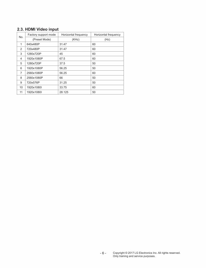
No.Factory support mode Horizontal frequency Horizontal frequency
(Preset Mode) (KHz) (Hz)
1 640x480P 31.47 60
2 720x480P 31.47 60
3 1280x720P 45 60
4 1920x1080P 67.5 60
5 1280x720P 37.5 50
6 1920x1080P 56.25 50
7 2560x1080P 56.25 60
8 2560x1080P 66 50
9 720x576P 31.25 50
10 1920x1080I 33.75 60
11 1920x1080I 28.125 50
2.3. HDMI Video input

- 7 - Copyright © LG Electronics Inc. All rights reserved.Only training and service purposes.
TROUBLESHOOTING GUIDE1) MAIN IC : Process display/audio signal/control signal Location no. : IC200
2) DC-DC Converter : Convert from 19V to proper voltage according to IC spec Location No. : IC402, IC403, IC404, IC600, IC601, IC901, IC902, IC903, IC904
3) Serial flash memory for Monitor : firmware saving Location No. : IC202 4) LED driver IC : Supporting proper voltage and current according to BLU spec Location No. : IC600, IC601
5) Headphone AMP : Amplify audio signal from Main IC and then provide amplifying signal to H/P interface Location No. : IC503
6) USB-C PD Controller : Set the signal from USB-C input and communicate with Source Device. Location No. : IC801
7) Mux IC : Separate DP and USB signal of USB-C input, controlled by PD controller. Location No. : IC800
8) USB Hub IC : function of HUB to the PC, should be connect to the PC with USB-C/C or USB-C/A cable. Location No. : IC701

- 8 - Copyright © LG Electronics Inc. All rights reserved.Only training and service purposes.
BLOCK DIAGRAM
MST
9U16
Q1
SPI
WQ
HD+
Pane
l (38
40 X
160
0)
HD
MI 1
DPRX, AUXN
, H
PD
HD
MI 2
TS3D
V64
2(S
witch
)
Key1
, Key2
DD
R2
SDRA
M(1
28M
B)
LED
Dri
ver IC
MP33
78E
Flas
hM
emory
(8M
)
TM
DS // DDC /
/ H
PD
Joys
tick
(Contr
ol K
ey)
DP
Syst
emEE
PRO
M
(32K
B)
I2C
TS3D
V64
2(S
witch
)
USB
Typ
e-C
EDID
EE
PRO
M (내장
)
HP O
ut
L/R O
ut
HP A
MP
USB
Typ
e A
USB
Typ
e A
USB
To U
ART
(TU
SB34
10)
EEPRO
M(3
2KB)
MU
XDP S
ignal
PD
Contr
oller
Contr
ol
DP, USB 3
.0
USB
HU
BUSB 3
.0
USB 2
.0
I2C
UART
I2C
CC통신
, USB 2
.0
WLE
D_E
NABLE
WLE
D_A
DIM
Flas
hM
emory
(8M
) SPI
( H
DM
I 2.0
)
E-D
P
DC-D
C
D+/ D-
VBUS=5V
Billb
oar
d(T
USB
3410
)
EEPRO
M(2
56KB) I2
C
D+/ D-
USB
Typ
e A
/ USB
2.0
only
/Ser
vice
onl
y
NTP
7515
NTP
7515
IS2
Switch
Front
I2S
I2S
BT A
udio
Module
(MCS K
ore
a)
SPEA
KER
SPEA
KER
LED
Dri
ver IC
MP33
78E

Copyright © LG Electronics Inc. All rights reserved.Only training and service purposes.
- -
EXPLODED VIEW
900
910
911
830
300
200
100
540
560
121
200T
510
120
400
LV1
720
700
Many electrical and mechanical parts in this chassis have special safety-related characteristics. These parts are identified by in the EXPLODED VIEW. It is essential that these special safety parts should be replaced with the same components as recommended in this manual to prevent Shock, Fire, or other Hazards. Do not modify the original design without permission of manufacturer.
IMPORTANT SAFETY NOTICE

- 10 - Copyright © LG Electronics Inc. All rights reserved.Only training and service purposes.
DISASSEMBLY1. Preparation1.1. Preparation tool (jig)
1.2. Preparation tool (Curved PAD)
2. Stand Assembly Separation1) Lay the set by the Curved PAD in Box
2) Disassemble the Stand after pull the button to down
3) Disassemble the Thumb Screw (2ea)
4) Remove the Screw (4ea). Detach SVC USB Cap.
5) Disassemble the Back Cover (By using JIG)
SVC USB Cap

- 11 - Copyright © LG Electronics Inc. All rights reserved.Only training and service purposes.
6) Disconnect LED Cable , Control Assemble (Latch Type) , Bluetooth PCB cable, FFC cable, Speaker
7) Disconnect Control Assemble, BT PCB (Latch Type)
8) Remove the screw. (4EA)
9) Remove the screw. (18EA)

DOWNLOAD
Copyright ⓒ 2017 LG Electronics Inc. All rights reserved. Only training and service purposes.
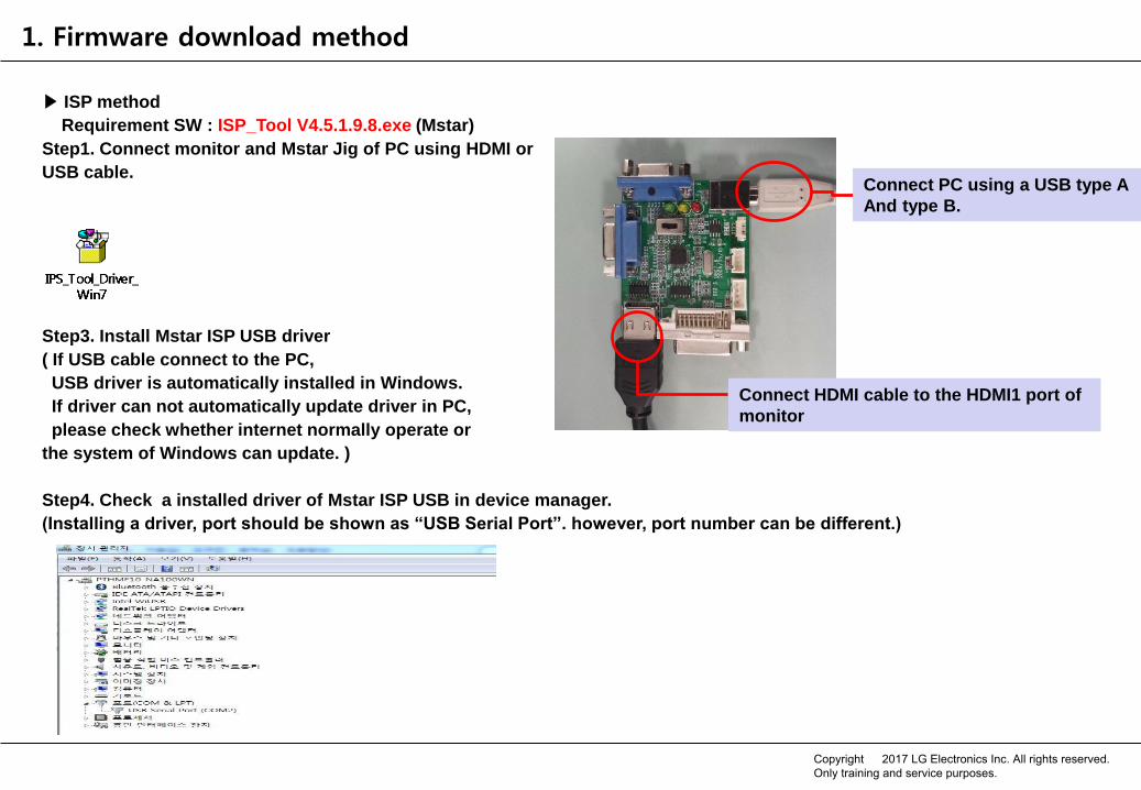
1. Firmware download method
▶ ISP method
Requirement SW : ISP_Tool V4.5.1.9.8.exe (Mstar)
Step1. Connect monitor and Mstar Jig of PC using HDMI or
USB cable.
Step3. Install Mstar ISP USB driver
( If USB cable connect to the PC,
USB driver is automatically installed in Windows.
If driver can not automatically update driver in PC,
please check whether internet normally operate or
the system of Windows can update. )
Step4. Check a installed driver of Mstar ISP USB in device manager.
(Installing a driver, port should be shown as “USB Serial Port”. however, port number can be different.)
Connect PC using a USB type A
And type B.
Connect HDMI cable to the HDMI1 port of
monitor
Copyright ⓒ 2017 LG Electronics Inc. All rights reserved. Only training and service purposes.

Step5. After extracting ISP Tool V4.5.1.9.8.zip then execute ISP_Tool V4.5.1.9.8.exe
Step6. Please click “Connect” button after connecting HDMI cable to HDMI1 port of monitor.
If monitor can communicate normally ISP, the following pop-up should be shown as “Device Type is MX25L8005”.
1. Firmware download method
Copyright ⓒ 2017 LG Electronics Inc. All rights reserved. Only training and service purposes.

Step6. After clicking “Read” button, the selected SW
file should be opened to be updated FW.
1. Firmware download method
Step7. Make sure match the checksum
Please ensure that it matches the checksum(E3AD) between
file name(E3AD).
EX :
UC99_MST9U11Q1_MSTAR_V2.07_E3AD_rev2728_160720.bin
Copyright ⓒ 2017 LG Electronics Inc. All rights reserved. Only training and service purposes.

Step8. Move “Auto”, then Click “Run” button
1) Click “Auto” button
2) Verify setting option
( The “File Area” of erase device should be selected in order to maintain system
and factory calibration data. )
3) Click “Run” button
1. Firmware download method
3
1
2
Copyright ⓒ 2017 LG Electronics Inc. All rights reserved. Only training and service purposes.

2. How to update the monitor FW using USB memory storage.
[Advance Preparation] 1. Please prepare an USB memory stick. (Except for the external HDD disk) [Note] The file system must use the following format. (NTFS, FAT, FAT32) 3. Please make a new folder like as LG_MNT of USB memory stick. (Ex. E:\LG_MNT) 4. Please copy monitor FW(UC99_MST9U11Q1_MSTAR_V3.XX_XXXX_revXXXX_16XXXX.bin) to the folder of LG_MNT. [Note] The downloading feature does not work properly when using the download file from the company security. 4. Please remove the plastic, which is marked as ‘DO NOT USE’ on the monitor’s rear.
5. Please insert the USB memory stick to the USB 2.0 port.
Title Monitor F/W update feature supports through a SVC USB port. For Oversea( √ )
Product MNT Product Name
Monitor Model Name
38UC99 Troubleshooting () Operation (√ ) Installation ( )
Copyright ⓒ 2017 LG Electronics Inc. All rights reserved. Only training and service purposes.

2. How to update the monitor FW using USB memory storage.
Title Monitor F/W update feature supports through a SVC USB port. For Oversea( √ )
Product MNT Product Name
Monitor Model Name
38UC99 Troubleshooting () Operation (√ ) Installation ( )
[Description] - Customer Condition 1. If the FW of USB must include a higher version more than version of current monitor, the updating feature will be normally worked. 3. User can choice whether or not performing a updating feature by the selection of user. - Factory Condition (Aging On) 1. After searching the highest version in LG_MNT folder of USB, the updating feature has been automatically performed regardless of the current version of monitor. [Common] When the updating feature is completed, monitor will turn off/on automatically after 3 seconds.
Copyright ⓒ 2017 LG Electronics Inc. All rights reserved. Only training and service purposes.

2. How to update the monitor FW using USB memory storage.
Title Monitor F/W update feature supports through a SVC USB port. For Oversea( √ )
Product MNT Product Name
Monitor Model Name
38UC99 Troubleshooting () Operation (√ ) Installation ( )
[Troubleshooting] Q. The power turns off suddenly during updating FW in the status of progress bar, monitor does not work. The power cable should be removed and reconnected after inserting an USB memory stick including FW in the determined folder. [Note] After searching the highest version in LG_MNT folder of USB, the recovering feature has been automatically performed After 40 seconds, the monitor will be normally recovered by itself. Q. The power turns off suddenly during updating PD FW under 50% status of progress bar, how can I do? After turning on the power, the updating will be progress again from the beginning percentage.
Copyright ⓒ 2017 LG Electronics Inc. All rights reserved. Only training and service purposes.


