Embed Size (px)
Citation preview
International Electrical Engineering Journal (IEEJ)
Vol. 1 (2011) No. 1, pp. 523-528
ISSN 2078-2365
523
Abstract— This paper presents a shunt active filter based on
three-phase three-level (NPC) inverter using two artificial
neural network controllers. Shunt active filter is the best
solution to eliminate harmonics drawn from nonlinear load
especially for low power system, the most inverter used is the
two-level voltage source inverter. Multilevel inverters are being
investigated and recently used for active filter topologies. Today
Three-level inverter becomes a good alternative for most
inverter applications, such as machine drives and power factor
compensators. The advantages of multilevel inverters is that
they can reduce the harmonic content generated by the active
filter and can reduce the voltage or current ratings of the
semiconductors. Two ANN’s are proposed in this paper, the first
one is used to replace the PWM logic controller while the second
regulate the dc voltage link of the shunt active filter. The results
simulations of global system control and power circuits are
obtained using Matlab-Simulink and SimPowerSystem Toolbox.
Index Terms— ANN controllers, Harmonic compensation,
Shunt active filter, Three-level (NPC) inverter.
I. INTRODUCTION
A large part of total electrical energy, produced in the
world, supplies different types of non-linear loads. The loads
such as variable frequency drives and electronic ballasts draw
current, which does not resemble the grid sinusoidal voltage.
This load is said to be non-linear and typically is composed of
odd order currents, which are expressed as multiples of the
fundamental frequency. The harmonic current cannot
contribute to active power and need to be eliminated to
enhance the power quality [1]. Active Power Filter (APF) is
the popular solution used to eliminate the undesired current
components by injection of compensation currents in
opposition to them [2].The most power converter used in APF
is the two-level voltage source inverter [3]-[4]-[5], due to
power handling capabilities of power semiconductors, these
inverter are limited for low power applications. Three-level
inverters have been successfully employed. The advantages
Corresponding Author Chennai Salim is with the Department of
Electrical Engineering, Nuclear Research Center of Birine, Algeria;
(e-mail: chenaisalimov@ yahoo.fr).
Benchouia M-T is with the L.G.E.B., Department of Electrical
Engineering, Biskra University Algeria. (e-mail: [email protected]).
of the three-level voltage source inverter have been applied
typically in medium and high power applications in the last
years [6]-[7].
The controller is the main part of the active power filter
operation and has been a subject of many researches in recent
years [8]-[9]. Multilevel pulse-width modulated (PWM)
techniques have been proposed for high power or
medium-voltage applications such as reactive power
compensation and AC motor drives. The advantages of
multilevel techniques are low voltage stress of power
semiconductors, lower current or voltage harmonics, and less
electromagnetic interference. To ameliorate the APF
Performances there’s a great tendency to use intelligent
control techniques, particularly neural network controllers.
The first studies have shown that ANNs are reliable in
improvement of power electronic systems control [10]-[11].
Some research work are elaborated using ANNs based a
two-level VSI in the last years.
In this paper we present, the application of neural network to
control shunt active filter based on three-level neutral point
clamped (NPC) inverter associated with a second ANN to
regulate the DC voltage link. The performances of the
complete structure including control and power circuit are
evaluated through computer simulations for steady-state
conditions using Matlab-Simulink program.
II. SHUNT ACTIVE FILTER
The basic compensation principle of a shunt active power
filter is shown in Fig.1. It is controlled to draw/supply a
compensating current from/to the utility. So that it cancels
current harmonics on AC side, and makes the source current
in phase with the different waveforms. The current drawn
from the power system at the coupling point of the shunt APF
will result sinusoidal [12]-[13].
Shunt Active Filter based on three–level (NPC)
Inverter using Current and DC Voltage Artificial
Neural Network Controllers
Chennai Salim, Benchouia M.T, Goléa A, and S.E. Zouzou
Chennai et al. Shunt Active Filter based on three–level (NPC) Inverter using Current and DC Voltage Artificial Neural
Network Controllers
524 | P a g e
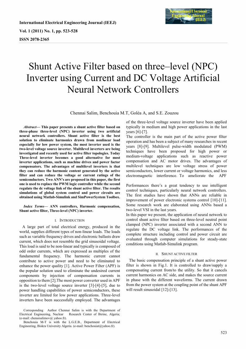
Fig.1 Three-level (NPC) shunt active filter
II.1THREE-LEVEL INVERTER
Multilevel inverters are being investigated and recently used
for active filter topologies. Three-level inverters are becoming
very popular today for most inverter applications, such as
machine drives and power factor compensators. The advantage
of multilevel converters is that they can reduce the harmonic
content generated by the active filter because they can produce
more levels of voltage than conventional converters (more than
two levels). Another advantage is that they can reduce the
voltage or current ratings of the semiconductors and the
switching frequency requirements [14].
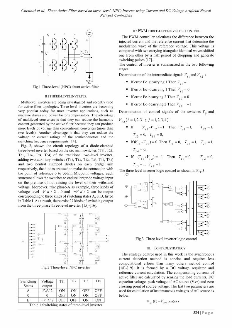
Fig. 2, shown the circuit topology of a diode-clamped
three-level inverter based on the six main switches (T11, T21,
T31, T14, T24, T34) of the traditional two-level inverter,
adding two auxiliary switches (T12, T13, T22, T23, T32, T33)
and two neutral clamped diodes on each bridge arm
respectively, the diodes are used to make the connection with
the point of reference 0 to obtain Midpoint voltages. Such
structure allows the switches to endure larger dc voltage input
on the premise of not raising the level of their withstand
voltage. Moreover, take phase-A as example, three kinds of
voltage level V d / 2 , 0 and −V d / 2 can be output
corresponding to three kinds of switching states A, 0, B, listed
in Table I. As a result, there exist 27 kinds of switching output
from the three-phase three-level inverter [15]-[16].
Fig.2 Three-level NPC inverter
Switching
States
Voltage
output
T11 T12 T13 T14
A V d / 2 ON ON OFF OFF
0 0 OFF ON ON OFF
B −V d / 2 OFF OFF ON ON
Table 1 Switching states of three-level inverter
II.2 PWM THREE-LEVEL INVERTER CONTROL
The PWM controller calculates the difference between the
injected current and the reference current that determine the
modulation wave of the reference voltage. This voltage is
compared with two carrying triangular identical waves shifted
one from other by a half period of chopping and generate
switching pulses [17].
The control of inverter is summarized in the two following
stages:
Determination of the intermediate signals 1i
V and 2i
V :
If error Ec carrying 1 Then 1
1i
V
If error Ec carrying 1 Then 1
0i
V
If error Ec carrying 2 Then 2
0i
V
If error Ec carrying 2 Then 2
1i
V
Determination of control signals of the switches ij
T and
2iV ( 1, 2,3i ; 1, 2,3, 4j ):
If 1 2
( ) 1i i
V V Then 1
1,i
T 2
1,i
T
30,
iT
40,
iT
If1 2
( ) 0i i
V V Then 1
0,i
T 2
1,i
T 3
1,i
T
40,
iT
If 1 2
( ) 1i i
V V Then 1
0,i
T 2
0,i
T
31,
iT
41,
iT
The three level inverter logic control as shown in Fig.3.
Fig.3. Three level inverter logic control
III. CONTROL STRATEGY
The strategy control used in this work is the synchronous
current detection method is concise and requires less
computational efforts than many others method control
[18]-[19]. It is formed by a DC voltage regulator and
reference current calculation. The compensating currents of
active filter are calculated by sensing the load currents, DC
capacitor voltage, peak voltage of AC source (Vsm) and zero
crossing point of source voltage. The last two parameters are
used for calculation of instantaneous voltages of AC source as
below:
. sin( )( ) tsmsav t V
International Electrical Engineering Journal (IEEJ)
Vol. 1 (2011) No. 1, pp. 523-528
ISSN 2078-2365
525
. sin(2
( ) )3
tsmsbv t V
(1)
. sin(4
( ) )3
tsmsav t V
In order to compensating the current harmonics, the
average active power of AC source must be equal with Lav
P ,
with considering the unity power factor of AC source side
currents the average active power of AC source can be
calculated as bellow :
*
.3
2 sms LavsmpP V I P (2)
From this equation, the first component of AC side current
can be calculated as bellow:
* 2
3Lav
smp sm
P
VI (3)
The second component of AC source current (*
smdI ) is
obtained from DC capacitor voltage regulator. The desired
peak current of AC source can be calculated as bellow:
* * *
sm smp smdI I I (4)
The AC source currents must be sinusoidal and in phase
with source voltages, theses currents can be calculated with
multiplying peak source current to a unity sinusoidal signal,
these unity signals can be obtained from equation (5):
( ) /sa smuai t v V
( ) /sb smubi t v V (5)
( ) /sc smuci t v V
The desired source side currents can be obtained from
equation (6):
* *
.( )sa sm ua
ii t I
* *
.( )sb sm ub
ii t I (6)
* *
.( )sc sm uc
ii t I
Finally, the reference currents of AF can be obtained from (7):
* *
ca sa Lai i i
* *
cb sb Lbi i i (7)
* *
cc sc Lci i i
The control strategy principle for the shunt active filter
based on three-level inverter is given by Fig.4.
Fig.4 Control strategy principle
IV. DCVOLTAGE REGULATOR
To compensate the inverter losses and maintain the constant
dc-link voltage dc
U , a proportional integral controller is used
to obtain the current*
smdI . The regulation loop consists of the
comparison of the measured voltage 1 2dc dc
U U with the
reference voltage *
dcU [20],[21]:
*
. .dcp dc ismdK U K U dtI (8)
V. ARTIFICIAL NEURAL NETWORK CONTROLLERS
V.1 ANN CURRENT CONTROLLER
Artificial Neural Networks have provided an alternative
modeling approach for power system applications. The
MLPN is one of the most popular topologies in use today.
This network consists of a set of input neurons, output
neurons and one or more hidden layers of intermediate
neurons. Data flows into the network through the input layer,
passes through the hidden layers and finally flows out of the
network through the output layer. The network thus has a
simple interpretation as a form of input-output model, with
network weights as free parameters. The use and training of
MLPNs is well understood.
The objective of the training is to modify weight matrices W
and V such that the ANN function approximates the plant
function and the error e between the desired function output y
and the ANN output ˆy is minimal. The training cycle has two
distinct paths:
Forward propagation: It is the passing of inputs through the
neural network structure to its output.
Error back-propagation: It is the passing of the output error
to the input in order to estimate the individual contribution of
each weight in the network to the final output error. The
weights are then modified so as to reduce the output error
[22].
The proposed ANN current controller for the three-level
inverter shunt active filter is shown in Fig.5. The input pattern
of the current controller network is the error values
Chennai et al. Shunt Active Filter based on three–level (NPC) Inverter using Current and DC Voltage Artificial Neural
Network Controllers
526 | P a g e
( , , )ca cccbE E E between the measured filter currents
( , , )fa fb fci i i and the compensating reference currents
* * *( , , )
fa fb fci i i whereas the outputs values are the switching
states , ,,1 2 3 4i i i i
T T T T for every phase. The hidden layer
contains 50 neurons with a sigmoid activation function,
whereas the output layer contains six neurons with a linear
activation function. The network is trained using
Levenberg-Marquardt back propagation algorithm, about
10000 training examples obtained by simulation.
Fig.5 ANN current controller
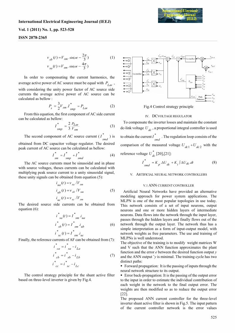
V.2 ANN DC VOLTAGE CONTROLLER
The dc voltage neural network controller used is presented in Fig.6 (a). Its role is to maintain
constant voltage around a desired value Udc-ref = 800V. The input pattern of the network is the error
values EUdc between the measured dc voltage Udc-mes and its reference value Udc-ref. The
architecture adopted for this network is three layer perceptron; the hidden layer contains eight neuron
with tansig activation function, whereas the output layer contains one neuron with linear activation
function.
The network is trained with back propagation Levenberg-Marquardt algorithm using 30,000 examples
of learning (off-line) obtained by simulation-based on PI control loop, Fig.6 (b). The training criterion
considered is the mean square error of ANN outputs. The performance is 0.000251523 after 100
epochs.
(a) (b)
Figure.6 ANN dc voltage controller
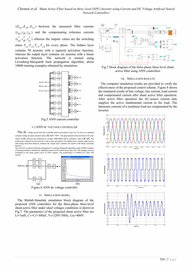
VI. SIMULATION MODEL
The Matlab-Simulink simulation block diagram of the
proposed ANN controllers for the three-phase three-level
shunt active filter under ideal voltages conditions is shown in
Fig.7. The parameters of the proposed shunt active filter are
Lf=3mH, C1=C2=300uF, Vs=220V/50Hz, Udc=800V.
Fig.7 block diagram of the three-phase three-level shunt
active filter using ANN controllers
VII. SIMULATION RESULTS
The computer simulation results are provided to verify the
effectiveness of the proposed control scheme. Figure 8 shows
the simulated results of line voltage, line current, load current
and compensated current after shunt active filter operation.
After active filter operation the AC-source current only
supplies the active fundamental current to the load. The
harmonic currents of a nonlinear load are compensated by the
inverter.
0 0.01 0.02 0.03 0.04 0.05 0.06 0.07 0.08 0.09 0.1-400
-300
-200
-100
0
100
200
300
400
Time (s)
Vol
tage
sou
rce
(V)
0 0.05 0.1 0.15 0.2 0.25 0.3-15
-10
-5
0
5
10
15
Time (s)
Load
cur
rent
IL(A
)
0 0.05 0.1 0.15 0.2 0.25 0.3-25
-20
-15
-10
-5
0
5
10
15
20
25
Time (s)
Cur
rent
sou
rce
isa
(A)
International Electrical Engineering Journal (IEEJ)
Vol. 1 (2011) No. 1, pp. 523-528
ISSN 2078-2365
527
0 0.05 0.1 0.15 0.2 0.25 0.3-15
-10
-5
0
5
10
15
Time (s)
Com
pens
atio
n cu
rren
t (A
)
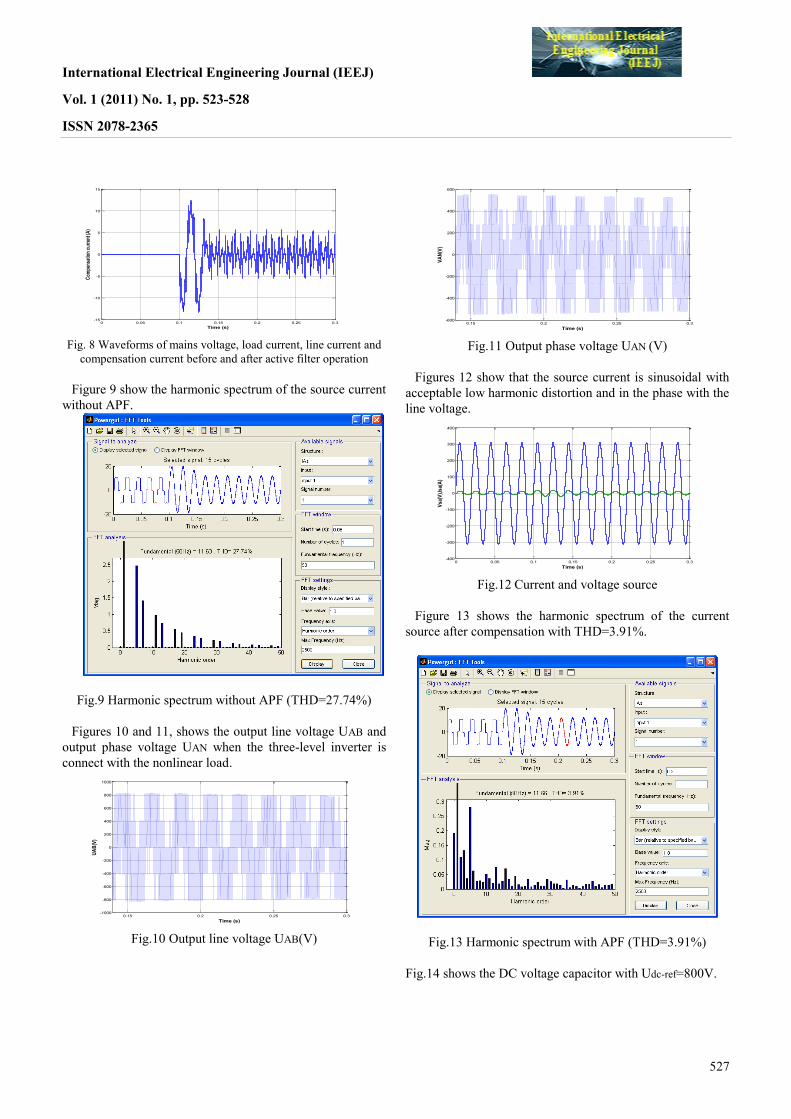
Fig. 8 Waveforms of mains voltage, load current, line current and
compensation current before and after active filter operation
Figure 9 show the harmonic spectrum of the source current
without APF.
Fig.9 Harmonic spectrum without APF (THD=27.74%)
Figures 10 and 11, shows the output line voltage UAB and
output phase voltage UAN when the three-level inverter is
connect with the nonlinear load.
0.15 0.2 0.25 0.3-1000
-800
-600
-400
-200
0
200
400
600
800
1000
Time (s)
UA
B(V
)
Fig.10 Output line voltage UAB(V)
0.15 0.2 0.25 0.3-600
-400
-200
0
200
400
600
Time (s)
VA
N(V
)
Fig.11 Output phase voltage UAN (V)
Figures 12 show that the source current is sinusoidal with
acceptable low harmonic distortion and in the phase with the
line voltage.
0 0.05 0.1 0.15 0.2 0.25 0.3-400
-300
-200
-100
0
100
200
300
400
Time (s)
Vsa
(V),I
sa(A
)
Fig.12 Current and voltage source
Figure 13 shows the harmonic spectrum of the current
source after compensation with THD=3.91%.
Fig.13 Harmonic spectrum with APF (THD=3.91%)
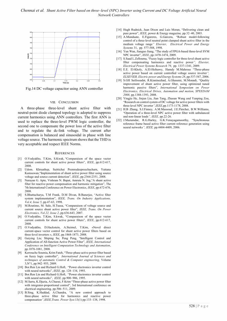
Fig.14 shows the DC voltage capacitor with Udc-ref=800V.
Chennai et al. Shunt Active Filter based on three–level (NPC) Inverter using Current and DC Voltage Artificial Neural
Network Controllers
528 | P a g e
0 0.05 0.1 0.15 0.2 0.25 0.3640
660
680
700
720
740
760
780
800
820
Time (s)
Ud
c(V
)
Fig.14 DC voltage capacitor using ANN controller
VIII. CONCLUSION
A three-phase three-level shunt active filter with
neutral-point diode clamped topology is adopted to suppress
current harmonics using ANN controllers. The first ANN is
used to replace the three-level PWM logic controller, the
second one to compensate the power loss of the active filter
and to regulate the dc-link voltage. The current after
compensation is balanced and sinusoidal in phase with line
voltage source. The harmonic spectrum shows that the THD is
very acceptable and respect IEEE Norms.
REFERENCES
[1] O.Vodyakho, T.Kim, S.Kwak, “Comparaison of the space vector
current controls for shunt active power filters”, IEEE, pp.612-617,
2008.
[2] Udom. Khruathep, Suittichai Premrudeepreechacharn, Yuttana
Kumsuwan,“Implementation of shunt active power filter using source
voltage and source current detection”, IEEE, pp.2364-2351, 2008.
[3] Narayan G. Apte, Vishram N. Bapat, Amruta N. Jog,“A shunt active
filter for reactive power compensation and harmonic mitigation”, The
7th International Conference on Power Electronics, IEEE, pp.672-676,
2008.
[4] S.Bhattacharya, T.M Frank, D.M Divan, B.Banerjee, “Active filter
system implementation”, IEEE, Trans. On Industry Applications,
Vol.4, Issue 5, pp.47-63, 1998.
[5] M.Routimo, M. Salo, H.Tuusa, “Comparaison of voltage source and
current source shunt active power filter”, IEEE, Trans. On Power
Electronics, Vol.22, Issue 2, pp.636-643, 2007.
[6] O.Vodyakho, T.Kim, S.kwak, “Comparaison of the space vector
current controls for shunt active power filters”, IEEE, pp.612-617,
2008.
[7] O.Vodyakho, D.Hackstein, A.Steimel, T.Kim, «Novel direct
current-space vector control for shunt active power filters based on
three-level inverters », IEEE, pp.1868-1873, 2008.
[8] Guiying Liu; Shiping Su; Peng Peng, “Intelligent Control and
Application of All-function Active Power Filter”, IEEE, International
Conference on Intelligent Computation Technology and Automation,
pp.1078-1081, 2008.
[9] Kerrouche Soumia, Krim Fateh, “Three-phase active power filter based
on fuzzy logic controller”, International Journal of Sciences and
techniques of automatic Control & Computer engineering, Volume
3,N°1, pp.942–955, 2009.
[10] Bor.Ren Lin and Richard G.Hoft, “Power electronics inverter control
with neural networks”, IEEE, pp. 128–134, 1993.
[11] Bor.Ren Lin and Richard G.Hoft, “Power electronics inverter control
with neural networks”, IEEE, pp.900–906, 1995.
[12] M.Sarra, K.Djazia, A.Chaoui, F.Krim “Three-phase active power filter
with integrator-proportional control”, 3rd International conference on
electrical engineering, pp.506–511, 2009.
[13] B.Sing, K.Haddad, A.Chandra, “A new control approach to
three-phase active filter for harmonics and reactive power
compensation”,IEEE,Trans. Power Syst.13(1) pp.133–138, 1998.
[14] Hugh Rudnick, Juan Dixon and Luis Moran, “Delivering clean and
pure power”, IEEE, power & Energy magazine, pp.32–40, 2003.
[15] A.Munduate, E.Figureres, G.Garcera, “Robust model-following
control of a three-level neutral point clamped shunt active filter in the
medium voltage range” Elsevier, Electrical Power and Energy
Systems 31, pp. 577-588, 1998.
[16] Yun Wan, Jianguo Jiang, “The study of FPGA-based three-level SVM
NPC inverter”, IEEE, pp.1470-1474, 2009.
[17] S.Saad L.Zellouma, “Fuzzy logic controller for three-level shunt active
filter compensating harmonics and reactive power”, Elsevier,
Electrical Power Systems Research 79, pp. 1337-1341, 2009.
[18] E.E. El-Kholy, A.El-Hefnawy, Hamdy M.Mahrous “Three-phase
active power based on current controlled voltage source inverter”,
ELSEVIER, Electric power and Energy Systems 28, pp.537-547, 2006.
[19] S.GH Seifossadat, R.Kianinezhad, A.Ghasemi, M.Monadi, “Quality
improvement of shunt active power filter, using optimized tuned
harmonic passive filters”, International Symposium on Power
Electronics, Electrical Drives, Automation and motion, SPEEDAM
2008, pp.1388-1393, 2008.
[20] Yingjie He, Jinjun Liu, Jian Tang, Zhaoan Wang and Yunping Zou,
“Research on control system of DC voltage for active power filters with
three-level NPC inverter”,IEEE,pp.1173-1178, 2008.
[21] H.B Zhang, S.J.Finney, A.M.Massoud, J.E.Fletcher, B.W.Williams,
“Operation of a three-level NPC active power filter with unbalanced
and non-linear loads”, IEEE, pp.22-26.
[22] J.Mazumdar, R.G.Harley, G.K.Venayagamoorthy, “Synchronous
reference frame based active filter current reference generation using
neural networks”, IEEE, pp.4404-4409, 2006.


