Embed Size (px)
Citation preview
Sampling of Aggregates 301-1 Alaska Test Methods Manual October 2004
SAMPLING OF AGGREGATES (See Addendum for AKDOT&PF Guidelines) FOP FOR AASHTO T 2 Scope This procedure covers sampling of fine and coarse aggregates (FA and CA) in accordance with AASHTO T 2. Sampling from conveyor belts, transport units, roadways, and stockpiles is covered. The specifications for some materials may require the contractor to provide a mechanical sampling system at crushers, screening operations, and mixing plants. This system is normally a permanently attached device that allows a sample container to pass perpendicularly through the entire stream of material or diverts the entire stream of material into the container. The sample container is normally larger at the bottom than the top (triangular shaped), with the slotted opening in the top based on the size of aggregate being sampled. Operation may be hydraulic, pneumatic, or manual, and shall allow the sample container to pass through the stream at least twice, once in each direction, without overfilling. With manually operated systems, a consistent operating speed is difficult to maintain and may result in variably sized, non-representative samples. For this reason, some agency specifications require that the sampling device be automatic or semi-automatic. Apparatus
• Shovels, scoops, sampling tubes of acceptable dimensions. • Custom built sampling devices suitable for varied sampling scenarios, and sampling containers.
Procedure - General Sampling is as important as testing, and the technician shall use every precaution to obtain samples that will show the true nature and condition of the materials the sample represents. 1. Wherever samples are taken, obtain at least three approximately equal increments, except that a
single pass or cycle (a pass through the aggregate stream and back) with a sampling device may be sufficient.
2. Mix the increments thoroughly to form a field sample that meets or exceeds the minimum mass
recommended in Table 1. Note 2: Based upon the tests required, the sample size may be four times that shown in Table 1 of the FOP for AASHTO T 27/T 11, if that mass is more appropriate. As a general rule the field sample size should be such that, when split twice will provide a testing sample of proper size.
Alaska Test Methods Manual 301-2 Sampling of Aggregates October 2004
TABLE 1 Sample Sizes
Nominal Maximum
Size* mm (in.) Minimum Mass
kg (lb)
2.36 (No. 8) 10 (25) 4.75 (No. 4) 10 (25) 9.5 (3/8) 10 (25) 12.5 (1/2) 15 (35) 19.0 (3/4) 25 (55) 25.0 (1) 50 (110) 37.5 (1 1/2) 75 (165) 50 (2) 100 (220) 63 (2 1/2) 125 (275) 75 (3) 150 (330) 90 (3 1/2) 175 (385)
* One sieve larger than the first sieve to retain more than 10 percent of the material using an agency specified set of sieves based on cumulative percent retained. Where large gaps in specification sieves exist, intermediate sieve(s) may be inserted to determine nominal maximum size.
Procedure – Specific Situations In all situations, determine the time or location for sampling in a random manner. A. Conveyor Belts
Method A (From the Belt): Stop the belt. Set the sampling device in place on the belt, avoiding intrusion by adjacent material. Scoop off the sample, including all fines. Method B (From the Belt Discharge): Pass a sampling device through the full stream of the material as it runs off the end of the conveyor belt. The sampling device may be manually, semi-automatic or automatically powered. The sample container shall pass through the stream at least twice, once in each direction, without overfilling while maintaining a constant speed during the sampling process.
B. Transport Units
Divide the unit into four quadrants. Dig down approximately 0.3 m (1 ft) in each quadrant and obtain material. Combine to form a single sample.
C. Roadways Obtain three increments of approximately equal size and combine. Take the full depth of the material to be sampled, being careful to exclude underlying material.
Note 3: If from a berm or windrow the entire cross-section must be sampled after the last mixing pass and prior to spreading and compacting. This may yield extra large samples and may not be the preferred sampling location. Do not sample from the beginning or the end of a berm or windrow.
Sampling of Aggregates 301-3 Alaska Test Methods Manual October 2004
D. Stockpiles Note 4: Sampling at stockpiles should be avoided whenever possible due to problems involved in obtaining a representative gradation of material 1. Create, with a loader if one is available, vertical faces in the top, middle, and bottom third of the
stockpile. When no equipment is available a shovel may be used to create vertical faces. 2. Prevent sloughing by shoving a flat board in against the vertical face. Sample from the
horizontal surface at the intersection of the horizontal and vertical faces. Take at least one increment from each of the top, middle, and bottom thirds of the pile – and combine.
3. When sampling sand, remove the outer layer that may have become segregated. Using a sampling tube, obtain material from five random locations on the pile and mix thoroughly to form one sample.
Alaska Test Methods Manual 301-4 Sampling of Aggregates October 2004
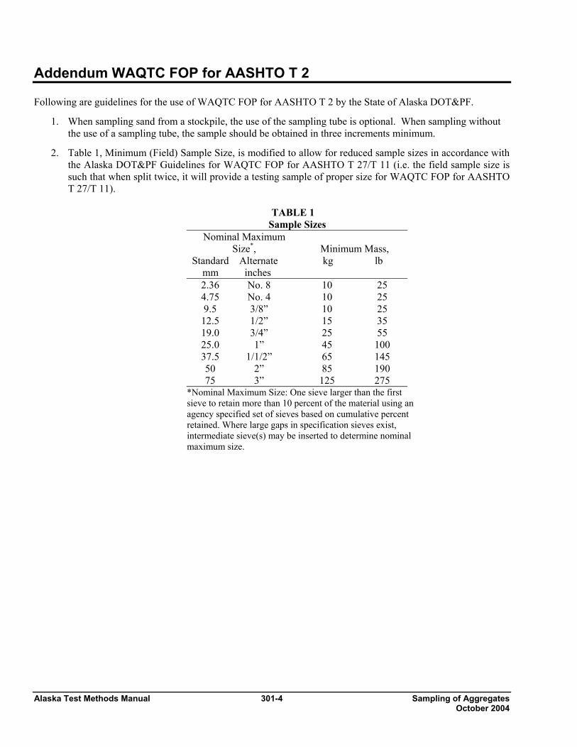
Addendum WAQTC FOP for AASHTO T 2 Following are guidelines for the use of WAQTC FOP for AASHTO T 2 by the State of Alaska DOT&PF.
1. When sampling sand from a stockpile, the use of the sampling tube is optional. When sampling without the use of a sampling tube, the sample should be obtained in three increments minimum.
2. Table 1, Minimum (Field) Sample Size, is modified to allow for reduced sample sizes in accordance with the Alaska DOT&PF Guidelines for WAQTC FOP for AASHTO T 27/T 11 (i.e. the field sample size is such that when split twice, it will provide a testing sample of proper size for WAQTC FOP for AASHTO T 27/T 11).
TABLE 1
Sample Sizes Nominal Maximum
Size*, Standard Alternate mm inches
Minimum Mass, kg lb
2.36 No. 8 10 25 4.75 No. 4 10 25 9.5 3/8” 10 25
12.5 1/2” 15 35 19.0 3/4” 25 55 25.0 1” 45 100 37.5 1/1/2” 65 145 50 2” 85 190 75 3” 125 275
*Nominal Maximum Size: One sieve larger than the first sieve to retain more than 10 percent of the material using an agency specified set of sieves based on cumulative percent retained. Where large gaps in specification sieves exist, intermediate sieve(s) may be inserted to determine nominal maximum size.
Reducing Samples of Aggregate 303-1 Alaska Test Methods Manual To Testing Size October 2004
REDUCING SAMPLES OF AGGREGATES TO TESTING SIZE FOP FOR AASHTO T 248 Scope This procedure covers the reduction of samples to the appropriate size for testing in accordance with AASHTO T 248. Techniques are used that minimize variations in characteristics between test samples and field samples. This procedure applies to fine aggregate (FA), coarse aggregate (CA), and mixes of the two, and may also be used on soils. Samples of fine aggregates that are drier than the saturated surface dry (SSD) condition shall be reduced by a mechanical splitter according to Method A. Samples of FA that are wetter than SSD shall be reduced by Method B, or the entire sample may be dried to the SSD condition, using temperatures that do not exceed those specified for any of the tests contemplated, and then reduced to test sample size using Method A. Samples of CA or mixtures of FA and CA may be reduced by either method. As a quick determination, if the fine aggregate will retain its shape when molded with the hand it is wetter that SSD. Apparatus Method A – Mechanical Splitter Sample splitter shall have an even number of equal width chutes, but not fewer than 8 for coarse aggregate or 12 for FA, which discharge alternately to each side of the splitter. The minimum width of individual chutes shall be approximately 50 percent larger than the largest particles in the sample to be split. For dry fine aggregate where the total sample passes the 9.5 mm (3/8 in.) sieve, the maximum chute width shall be 19 mm (3/4 in.). The splitter shall be equipped with two receptacles to hold the two halves of the sample following splitting. It shall also be equipped with a hopper or straightedge pan that has a width equal to or slightly less than the overall width of the assembly of chutes, by which the sample may be fed at a controlled rate to the chutes. The splitter and accessory equipment shall be so designed that the sample will flow smoothly without restriction or loss of material. Method B – Quartering
• Straightedge scoop, shovel, or trowel • Broom or brush • Canvas or plastic sheet, approximately 2 m by 3m (6 by 9 ft)
Sample Preparation If the FA sample is wetter than the SSD condition and Method A – Mechanical Splitter is to be used, dry the material using temperatures not exceeding those specified for any of the tests contemplated for the sample. Note 1: It may be undesirable to split some FA / CA mixtures that are over SSD condition using Method A.
Alaska Test Methods Manual 303-2 Reducing Samples of Aggregate To Testing Size October 2004
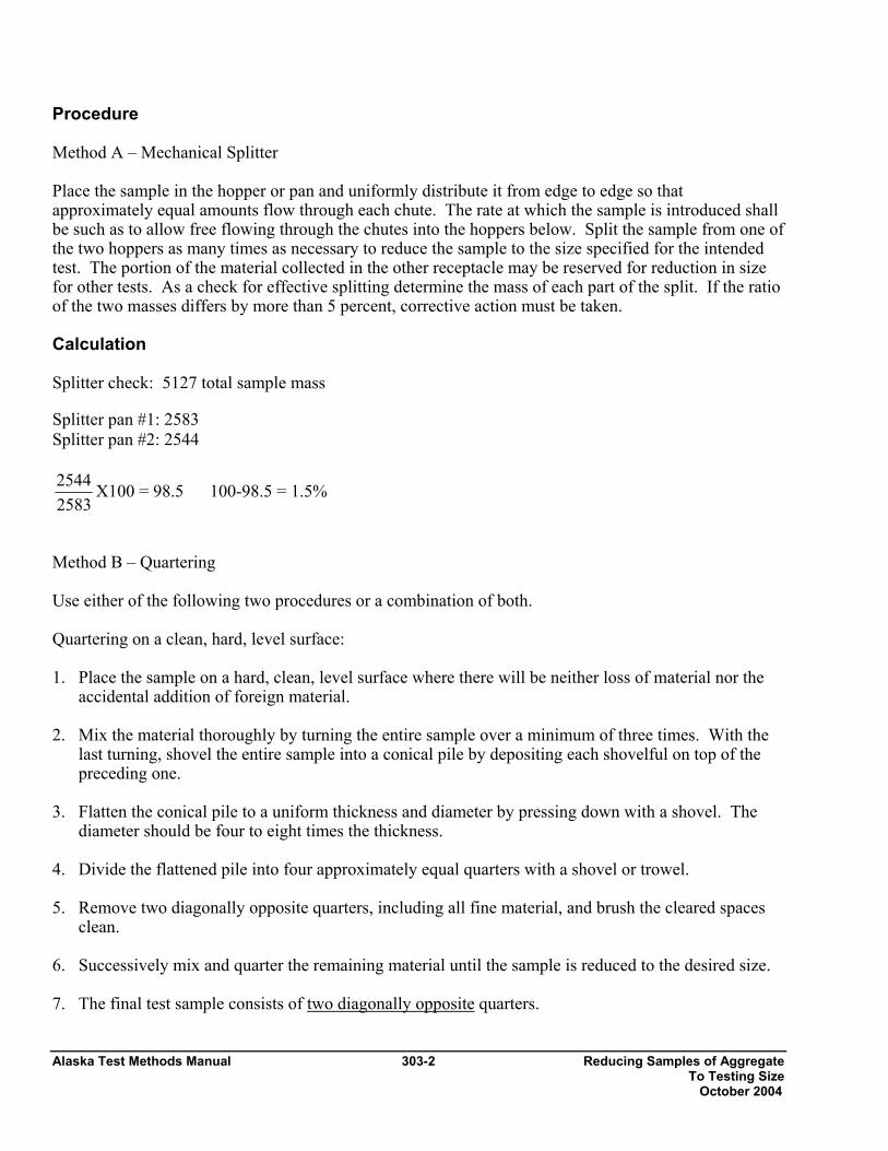
Procedure Method A – Mechanical Splitter Place the sample in the hopper or pan and uniformly distribute it from edge to edge so that approximately equal amounts flow through each chute. The rate at which the sample is introduced shall be such as to allow free flowing through the chutes into the hoppers below. Split the sample from one of the two hoppers as many times as necessary to reduce the sample to the size specified for the intended test. The portion of the material collected in the other receptacle may be reserved for reduction in size for other tests. As a check for effective splitting determine the mass of each part of the split. If the ratio of the two masses differs by more than 5 percent, corrective action must be taken. Calculation Splitter check: 5127 total sample mass Splitter pan #1: 2583 Splitter pan #2: 2544
25832544 X100 = 98.5 100-98.5 = 1.5%
Method B – Quartering Use either of the following two procedures or a combination of both. Quartering on a clean, hard, level surface: 1. Place the sample on a hard, clean, level surface where there will be neither loss of material nor the
accidental addition of foreign material. 2. Mix the material thoroughly by turning the entire sample over a minimum of three times. With the
last turning, shovel the entire sample into a conical pile by depositing each shovelful on top of the preceding one.
3. Flatten the conical pile to a uniform thickness and diameter by pressing down with a shovel. The
diameter should be four to eight times the thickness. 4. Divide the flattened pile into four approximately equal quarters with a shovel or trowel. 5. Remove two diagonally opposite quarters, including all fine material, and brush the cleared spaces
clean. 6. Successively mix and quarter the remaining material until the sample is reduced to the desired size. 7. The final test sample consists of two diagonally opposite quarters.
Reducing Samples of Aggregate 303-3 Alaska Test Methods Manual To Testing Size October 2004
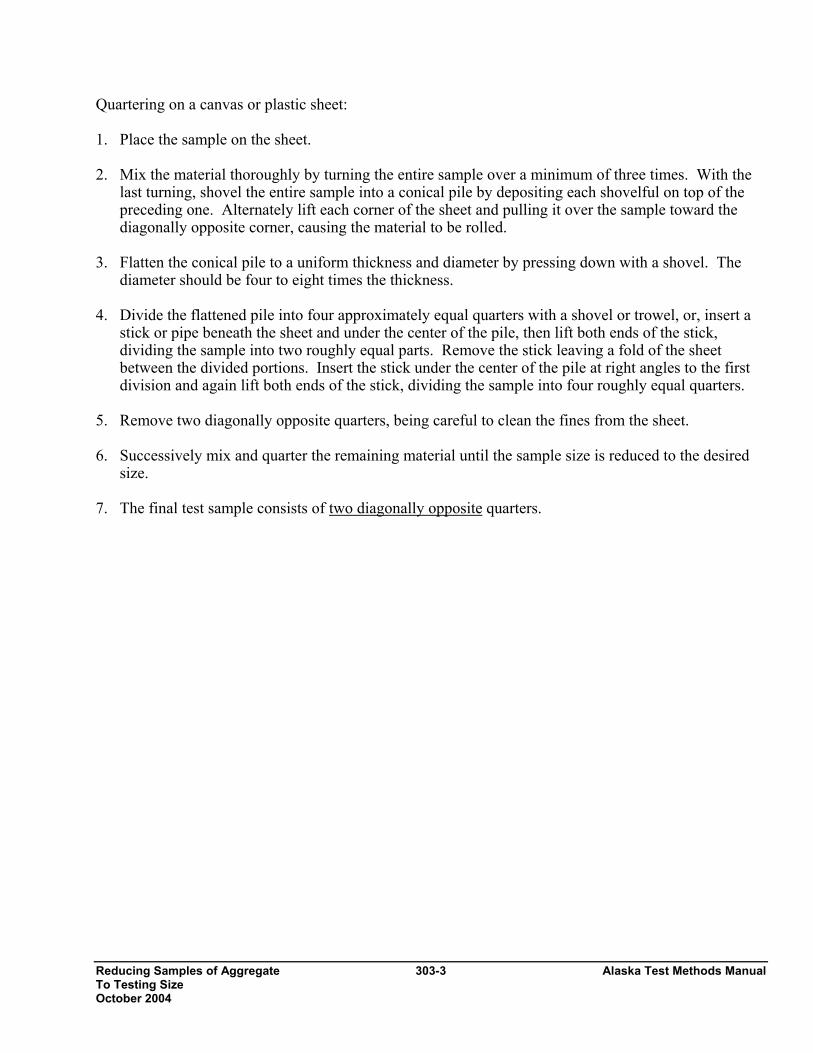
Quartering on a canvas or plastic sheet: 1. Place the sample on the sheet. 2. Mix the material thoroughly by turning the entire sample over a minimum of three times. With the
last turning, shovel the entire sample into a conical pile by depositing each shovelful on top of the preceding one. Alternately lift each corner of the sheet and pulling it over the sample toward the diagonally opposite corner, causing the material to be rolled.
3. Flatten the conical pile to a uniform thickness and diameter by pressing down with a shovel. The
diameter should be four to eight times the thickness. 4. Divide the flattened pile into four approximately equal quarters with a shovel or trowel, or, insert a
stick or pipe beneath the sheet and under the center of the pile, then lift both ends of the stick, dividing the sample into two roughly equal parts. Remove the stick leaving a fold of the sheet between the divided portions. Insert the stick under the center of the pile at right angles to the first division and again lift both ends of the stick, dividing the sample into four roughly equal quarters.
5. Remove two diagonally opposite quarters, being careful to clean the fines from the sheet. 6. Successively mix and quarter the remaining material until the sample size is reduced to the desired
size. 7. The final test sample consists of two diagonally opposite quarters.

Alaska Test Methods Manual 303-4 Reducing Samples of Aggregate To Testing Size October 2004
Sieve Analysis of 304-1 Alaska Test Methods Manual Fine and Coarse Aggregates October 2004
SIEVE ANALYSIS OF FINE AND COARSE AGGREGATES FOP FOR AASHTO T 27 (See Addendum for AKDOT&PF Guidelines) MATERIALS FINER THAN 75 µm (No. 200) SIEVE IN MINERAL AGGREGATE BY WASHING (See Addendum for AKDOT&PF Guidelines) FOP FOR AASHTO T 11 Scope Sieve analyses determine the gradation or distribution of aggregate particles within a given sample in order to determine compliance with design and production standards. Accurate determination of material smaller than 75 µm (No. 200) cannot be made with AASHTO T 27 alone. If quantifying this material is required, it is recommended that AASHTO T 27 be used in conjunction with AASHTO T 11. Following the procedure in AASHTO T 11, the sample is washed through a 75 µm (No. 200) sieve. The amount of material passing this sieve is determined by comparing dry sample masses before and after the washing process. This procedure covers sieve analysis in accordance with AASHTO T 27 and materials finer than 75 µm (No. 200) in accordance with AASHTO T 11 performed in conjunction with AASHTO T 27. The procedure includes three method choices, A, B and C. Apparatus
• Balance or scale: Capacity sufficient for the masses shown in Table 1, accurate to 0.1 percent of the sample mass or readable to 0.1 g. Meeting the requirements of AASHTO M 231.
• Sieves – Meeting the requirements of AASHTO M 92. • Mechanical sieve shaker – Meeting the requirements of AASHTO T 27. • Suitable drying equipment (see FOP for AASHTO T 255). • Containers and utensils: A pan or vessel of a size sufficient to contain the sample covered with
water and to permit vigorous agitation without loss of any part of the sample or water. Sample Preparation Obtain samples in accordance with the FOP for AASHTO T 2 and reduce to the size shown in Table 1 in accordance with the FOP for AASHTO T 248. These sample sizes are standard for aggregate testing but, due to equipment restraints, samples may need to be partitioned into several “subsamples.” For example, a gradation that requires 100 kg (220 lbs) of material would not fit into a large tray shaker in one batch. Some agencies permit reduced sample sizes if it is proven that doing so is not detrimental to the test results. Some agencies require larger sample sizes. Check agency guidelines for required or permitted test sample sizes.
TABLE 1
Sample Sizes for Aggregate Gradation Test
Alaska Test Methods Manual 304-2 Sieve Analysis of Fine and Coarse Aggregates October 2004
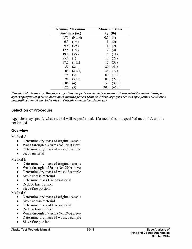
Nominal Maximum
Size* mm (in.) Minimum Mass
kg (lb) 4.75 (No. 4) 0.5 (1)
6.3 (1/4) 1 (2) 9.5 (3/8) 1 (2)
12.5 (1/2) 2 (4) 19.0 (3/4) 5 (11) 25.0 (1) 10 (22) 37.5 (1 1/2) 15 (33)
50 (2) 20 (44) 63 (2 1/2) 35 (77) 75 (3) 60 (130) 90 (3 1/2) 100 (220)
100 (4) 150 (330) 125 (5) 300 (660)
*Nominal Maximum size: One sieve larger than the first sieve to retain more than 10 percent of the material using an agency specified set of sieves based on cumulative percent retained. Where large gaps between specification sieves exist, intermediate sieve(s) may be inserted to determine nominal maximum size.
Selection of Procedure Agencies may specify what method will be performed. If a method is not specified method A will be performed.
Overview Method A
• Determine dry mass of original sample • Wash through a 75µm (No. 200) sieve • Determine dry mass of washed sample • Sieve material
Method B • Determine dry mass of original sample • Wash through a 75µm (No. 200) sieve • Determine dry mass of washed sample • Sieve coarse material • Determine mass fine of material • Reduce fine portion • Sieve fine portion
Method C • Determine dry mass of original sample • Sieve coarse material • Determine mass of fine material • Reduce fine portion • Wash through a 75µm (No. 200) sieve • Determine dry mass of washed sample • Sieve fine portion
Sieve Analysis of 304-3 Alaska Test Methods Manual Fine and Coarse Aggregates October 2004
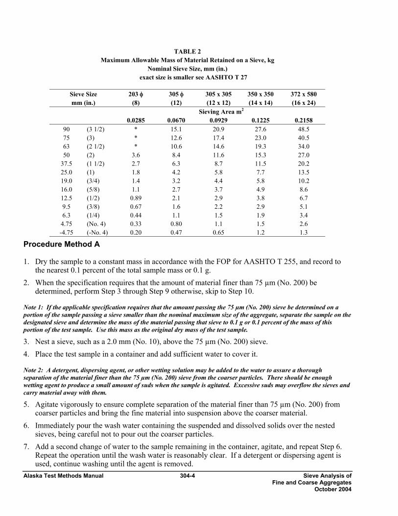
Sample Sieving In all procedures it is required to shake the sample over nested sieves. Sieves are selected to furnish information required by specification. The sieves are nested in order of decreasing size from the top to the bottom and the sample, or a portion of the sample, is placed on the top sieve. Additional sieves may be necessary to provide other information, such as fineness modulus, or to keep from overloading the specified sieves. The sample may also be sieved in increments. Sieves are shaken in a mechanical shaker for 10 approximately minutes, or the minimum time determined to provide complete separation for the sieve shaker being used. The minimum time requirement should be evaluated for each shaker at least annually, by the following method: Continue shaking for a sufficient period and in such a manner that, after completion, not more than 0.5 percent by mass of the total sample passes any sieve during one minute of continuous hand sieving. Provide a snug-fitting pan and cover, and hold in a slightly inclined position in one hand. Strike the side of the sieve sharply and with an upward motion against the heel of the other hand at the rate of about 150 times per minute, turning the sieve about one sixth of a revolution at intervals of about 25 strokes. In determining sufficiency of sieving for sizes larger than 4.75 mm (No. 4), limit the material on the sieve to a single layer of particles. For sieves with openings smaller than 4.75 mm (No. 4), the mass retained on any sieve shall not exceed 7 kg/m2 (4g/in2) of sieving surface. For sieves with openings 4.75 mm (No. 4) and larger, the mass, in kg shall not exceed the product of 2.5 x (sieve opening in mm) x (effective sieving area). See Table 2.
Alaska Test Methods Manual 304-4 Sieve Analysis of Fine and Coarse Aggregates October 2004
TABLE 2 Maximum Allowable Mass of Material Retained on a Sieve, kg
Nominal Sieve Size, mm (in.) exact size is smaller see AASHTO T 27
Procedure Method A 1. Dry the sample to a constant mass in accordance with the FOP for AASHTO T 255, and record to
the nearest 0.1 percent of the total sample mass or 0.1 g. 2. When the specification requires that the amount of material finer than 75 µm (No. 200) be
determined, perform Step 3 through Step 9 otherwise, skip to Step 10.
Note 1: If the applicable specification requires that the amount passing the 75 µm (No. 200) sieve be determined on a portion of the sample passing a sieve smaller than the nominal maximum size of the aggregate, separate the sample on the designated sieve and determine the mass of the material passing that sieve to 0.1 g or 0.1 percent of the mass of this portion of the test sample. Use this mass as the original dry mass of the test sample.
3. Nest a sieve, such as a 2.0 mm (No. 10), above the 75 µm (No. 200) sieve. 4. Place the test sample in a container and add sufficient water to cover it.
Note 2: A detergent, dispersing agent, or other wetting solution may be added to the water to assure a thorough separation of the material finer than the 75 µm (No. 200) sieve from the coarser particles. There should be enough wetting agent to produce a small amount of suds when the sample is agitated. Excessive suds may overflow the sieves and carry material away with them.
5. Agitate vigorously to ensure complete separation of the material finer than 75 µm (No. 200) from coarser particles and bring the fine material into suspension above the coarser material.
6. Immediately pour the wash water containing the suspended and dissolved solids over the nested sieves, being careful not to pour out the coarser particles.
7. Add a second change of water to the sample remaining in the container, agitate, and repeat Step 6. Repeat the operation until the wash water is reasonably clear. If a detergent or dispersing agent is used, continue washing until the agent is removed.
Sieve Size mm (in.)
203 φ (8)
305 φ (12)
305 x 305 (12 x 12)
350 x 350 (14 x 14)
372 x 580 (16 x 24)
Sieving Area m2 0.0285 0.0670 0.0929 0.1225 0.2158
90 (3 1/2) * 15.1 20.9 27.6 48.5 75 (3) * 12.6 17.4 23.0 40.5 63 (2 1/2) * 10.6 14.6 19.3 34.0 50 (2) 3.6 8.4 11.6 15.3 27.0
37.5 (1 1/2) 2.7 6.3 8.7 11.5 20.2 25.0 (1) 1.8 4.2 5.8 7.7 13.5 19.0 (3/4) 1.4 3.2 4.4 5.8 10.2 16.0 (5/8) 1.1 2.7 3.7 4.9 8.6 12.5 (1/2) 0.89 2.1 2.9 3.8 6.7 9.5 (3/8) 0.67 1.6 2.2 2.9 5.1 6.3 (1/4) 0.44 1.1 1.5 1.9 3.4
4.75 (No. 4) 0.33 0.80 1.1 1.5 2.6 -4.75 (-No. 4) 0.20 0.47 0.65 1.2 1.3
Sieve Analysis of 304-5 Alaska Test Methods Manual Fine and Coarse Aggregates October 2004
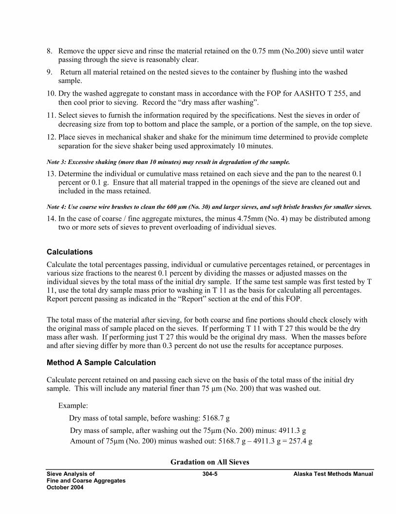
8. Remove the upper sieve and rinse the material retained on the 0.75 mm (No.200) sieve until water passing through the sieve is reasonably clear.
9. Return all material retained on the nested sieves to the container by flushing into the washed sample.
10. Dry the washed aggregate to constant mass in accordance with the FOP for AASHTO T 255, and then cool prior to sieving. Record the “dry mass after washing”.
11. Select sieves to furnish the information required by the specifications. Nest the sieves in order of decreasing size from top to bottom and place the sample, or a portion of the sample, on the top sieve.
12. Place sieves in mechanical shaker and shake for the minimum time determined to provide complete separation for the sieve shaker being used approximately 10 minutes.
Note 3: Excessive shaking (more than 10 minutes) may result in degradation of the sample.
13. Determine the individual or cumulative mass retained on each sieve and the pan to the nearest 0.1 percent or 0.1 g. Ensure that all material trapped in the openings of the sieve are cleaned out and included in the mass retained.
Note 4: Use coarse wire brushes to clean the 600 µm (No. 30) and larger sieves, and soft bristle brushes for smaller sieves.
14. In the case of coarse / fine aggregate mixtures, the minus 4.75mm (No. 4) may be distributed among two or more sets of sieves to prevent overloading of individual sieves.
Calculations Calculate the total percentages passing, individual or cumulative percentages retained, or percentages in various size fractions to the nearest 0.1 percent by dividing the masses or adjusted masses on the individual sieves by the total mass of the initial dry sample. If the same test sample was first tested by T 11, use the total dry sample mass prior to washing in T 11 as the basis for calculating all percentages. Report percent passing as indicated in the “Report” section at the end of this FOP. The total mass of the material after sieving, for both coarse and fine portions should check closely with the original mass of sample placed on the sieves. If performing T 11 with T 27 this would be the dry mass after wash. If performing just T 27 this would be the original dry mass. When the masses before and after sieving differ by more than 0.3 percent do not use the results for acceptance purposes. Method A Sample Calculation Calculate percent retained on and passing each sieve on the basis of the total mass of the initial dry sample. This will include any material finer than 75 µm (No. 200) that was washed out.
Example:
Dry mass of total sample, before washing: 5168.7 g Dry mass of sample, after washing out the 75µm (No. 200) minus: 4911.3 g Amount of 75µm (No. 200) minus washed out: 5168.7 g – 4911.3 g = 257.4 g
Gradation on All Sieves
Alaska Test Methods Manual 304-6 Sieve Analysis of Fine and Coarse Aggregates October 2004
Sieve Size mm (in.)
Mass Retained
g
Percent
Retained
Cumulative
Mass Retained
g
Cum.
Percent Retained
Calc’d Percent Passing
ReportedPercent Passing*
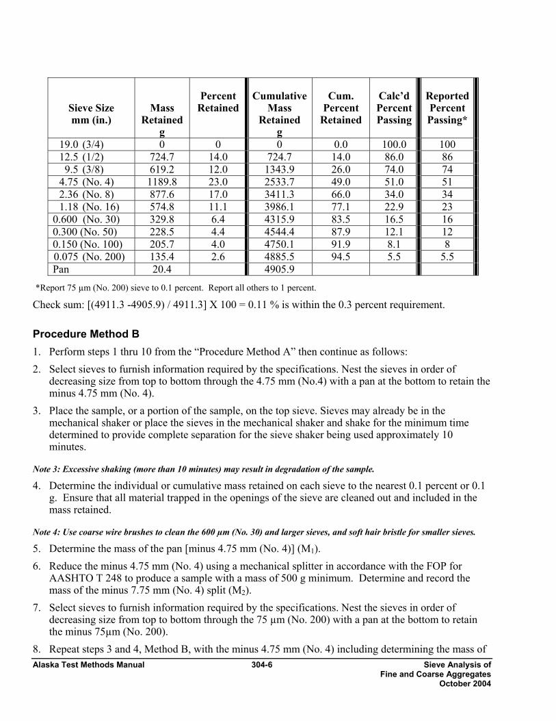
19.0 (3/4) 0 0 0 0.0 100.0 100 12.5 (1/2) 724.7 14.0 724.7 14.0 86.0 86 9.5 (3/8) 619.2 12.0 1343.9 26.0 74.0 74 4.75 (No. 4) 1189.8 23.0 2533.7 49.0 51.0 51 2.36 (No. 8) 877.6 17.0 3411.3 66.0 34.0 34 1.18 (No. 16) 574.8 11.1 3986.1 77.1 22.9 23 0.600 (No. 30) 329.8 6.4 4315.9 83.5 16.5 16 0.300 (No. 50) 228.5 4.4 4544.4 87.9 12.1 12 0.150 (No. 100) 205.7 4.0 4750.1 91.9 8.1 8 0.075 (No. 200) 135.4 2.6 4885.5 94.5 5.5 5.5 Pan 20.4 4905.9
*Report 75 µm (No. 200) sieve to 0.1 percent. Report all others to 1 percent.
Check sum: [(4911.3 -4905.9) / 4911.3] X 100 = 0.11 % is within the 0.3 percent requirement. Procedure Method B 1. Perform steps 1 thru 10 from the “Procedure Method A” then continue as follows: 2. Select sieves to furnish information required by the specifications. Nest the sieves in order of
decreasing size from top to bottom through the 4.75 mm (No.4) with a pan at the bottom to retain the minus 4.75 mm (No. 4).
3. Place the sample, or a portion of the sample, on the top sieve. Sieves may already be in the mechanical shaker or place the sieves in the mechanical shaker and shake for the minimum time determined to provide complete separation for the sieve shaker being used approximately 10 minutes.
Note 3: Excessive shaking (more than 10 minutes) may result in degradation of the sample.
4. Determine the individual or cumulative mass retained on each sieve to the nearest 0.1 percent or 0.1 g. Ensure that all material trapped in the openings of the sieve are cleaned out and included in the mass retained.
Note 4: Use coarse wire brushes to clean the 600 µm (No. 30) and larger sieves, and soft hair bristle for smaller sieves.
5. Determine the mass of the pan [minus 4.75 mm (No. 4)] (M1). 6. Reduce the minus 4.75 mm (No. 4) using a mechanical splitter in accordance with the FOP for
AASHTO T 248 to produce a sample with a mass of 500 g minimum. Determine and record the mass of the minus 7.75 mm (No. 4) split (M2).
7. Select sieves to furnish information required by the specifications. Nest the sieves in order of decreasing size from top to bottom through the 75 µm (No. 200) with a pan at the bottom to retain the minus 75µm (No. 200).
8. Repeat steps 3 and 4, Method B, with the minus 4.75 mm (No. 4) including determining the mass of
Sieve Analysis of 304-7 Alaska Test Methods Manual Fine and Coarse Aggregates October 2004
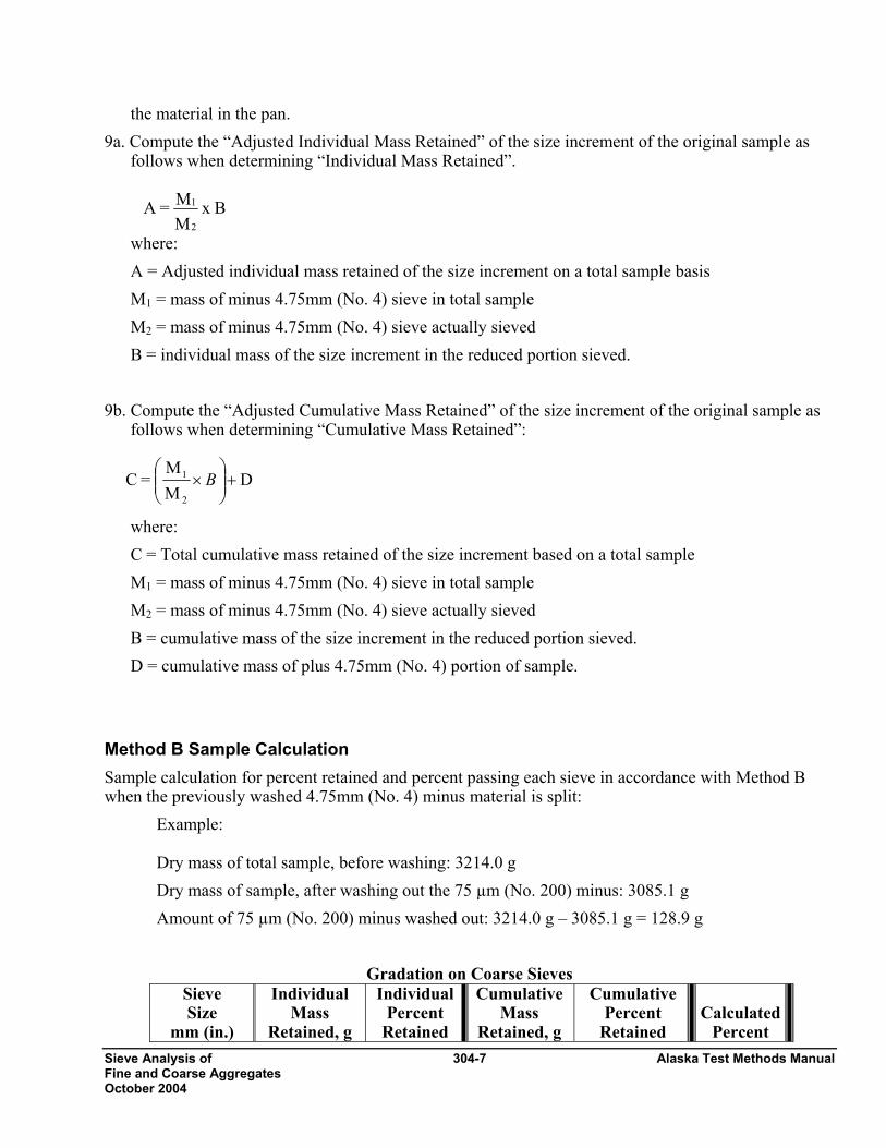
the material in the pan. 9a. Compute the “Adjusted Individual Mass Retained” of the size increment of the original sample as
follows when determining “Individual Mass Retained”.
where: A = Adjusted individual mass retained of the size increment on a total sample basis M1 = mass of minus 4.75mm (No. 4) sieve in total sample M2 = mass of minus 4.75mm (No. 4) sieve actually sieved B = individual mass of the size increment in the reduced portion sieved.
9b. Compute the “Adjusted Cumulative Mass Retained” of the size increment of the original sample as follows when determining “Cumulative Mass Retained”:
where: C = Total cumulative mass retained of the size increment based on a total sample M1 = mass of minus 4.75mm (No. 4) sieve in total sample M2 = mass of minus 4.75mm (No. 4) sieve actually sieved B = cumulative mass of the size increment in the reduced portion sieved. D = cumulative mass of plus 4.75mm (No. 4) portion of sample.
Method B Sample Calculation Sample calculation for percent retained and percent passing each sieve in accordance with Method B when the previously washed 4.75mm (No. 4) minus material is split:
Example: Dry mass of total sample, before washing: 3214.0 g Dry mass of sample, after washing out the 75 µm (No. 200) minus: 3085.1 g Amount of 75 µm (No. 200) minus washed out: 3214.0 g – 3085.1 g = 128.9 g
Gradation on Coarse Sieves Sieve Size
mm (in.)
Individual Mass
Retained, g
IndividualPercent
Retained
Cumulative Mass
Retained, g
Cumulative Percent
Retained
Calculated
Percent
B x MM =A
2
1
DMM
= C2
1 +⎟⎟⎠
⎞⎜⎜⎝
⎛× B
Alaska Test Methods Manual 304-8 Sieve Analysis of Fine and Coarse Aggregates October 2004
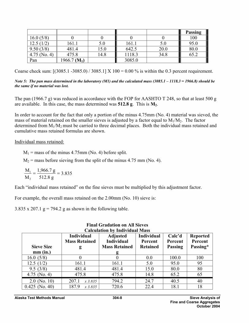
Passing 16.0 (5/8) 0 0 0 0 100 12.5 (1/2) 161.1 5.0 161.1 5.0 95.0 9.50 (3/8) 481.4 15.0 642.5 20.0 80.0 4.75 (No. 4) 475.8 14.8 1118.3 34.8 65.2 Pan 1966.7 (M1) 3085.0
Coarse check sum: [(3085.1 -3085.0) / 3085.1] X 100 = 0.00 % is within the 0.3 percent requirement.
Note 5: The pan mass determined in the laboratory (M1) and the calculated mass (3085.1 – 1118.3 = 1966.8) should be the same if no material was lost.
The pan (1966.7 g) was reduced in accordance with the FOP for AASHTO T 248, so that at least 500 g are available. In this case, the mass determined was 512.8 g. This is M2.
In order to account for the fact that only a portion of the minus 4.75mm (No. 4) material was sieved, the mass of material retained on the smaller sieves is adjusted by a factor equal to M1/M2. The factor determined from M1/M2 must be carried to three decimal places. Both the individual mass retained and cumulative mass retained formulas are shown.
Individual mass retained:
M1 = mass of the minus 4.75mm (No. 4) before split. M2 = mass before sieving from the split of the minus 4.75 mm (No. 4).
Each “individual mass retained” on the fine sieves must be multiplied by this adjustment factor. For example, the overall mass retained on the 2.00mm (No. 10) sieve is: 3.835 x 207.1 g = 794.2 g as shown in the following table.
Final Gradation on All Sieves Calculation by Individual Mass
Sieve Size mm (in.)
Individual Mass Retained
g
Adjusted Individual
Mass Retained g
Individual Percent
Retained
Calc’d Percent Passing
Reported Percent Passing*
16.0 (5/8) 0 0 0.0 100.0 100 12.5 (1/2) 161.1 161.1 5.0 95.0 95 9.5 (3/8) 481.4 481.4 15.0 80.0 80 4.75 (No. 4) 475.8 475.8 14.8 65.2 65 2.0 (No. 10) 207.1 x 3.835 794.2 24.7 40.5 40 0.425 (No. 40) 187.9 x 3.835 720.6 22.4 18.1 18
3.835
g 512.8 g 1,966.7
M M
2 1 = =
Sieve Analysis of 304-9 Alaska Test Methods Manual Fine and Coarse Aggregates October 2004
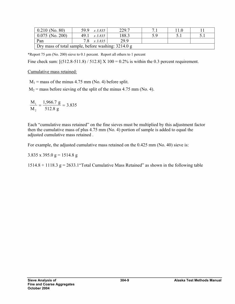
0.210 (No. 80) 59.9 x 3.835 229.7 7.1 11.0 11 0.075 (No. 200) 49.1 x 3.835 188.3 5.9 5.1 5.1 Pan 7.8 x 3.835 29.9 Dry mass of total sample, before washing: 3214.0 g
*Report 75 µm (No. 200) sieve to 0.1 percent. Report all others to 1 percent
Fine check sum: [(512.8-511.8) / 512.8] X 100 = 0.2% is within the 0.3 percent requirement. Cumulative mass retained: M1 = mass of the minus 4.75 mm (No. 4) before split.
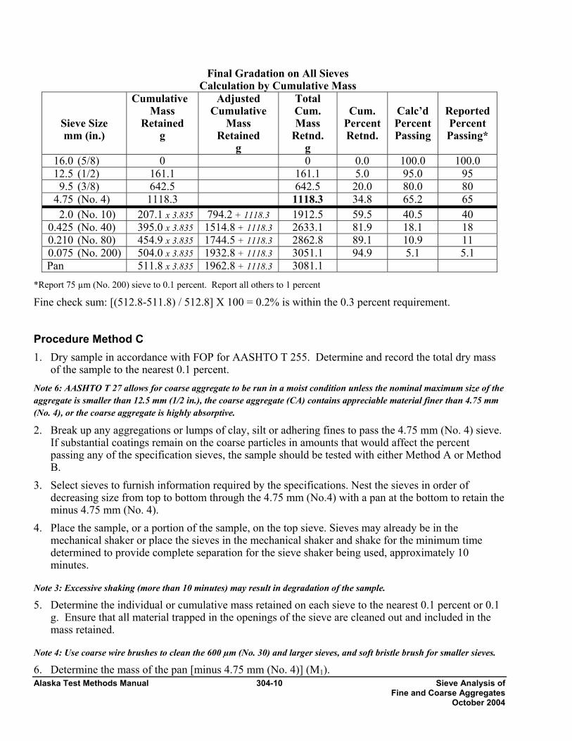
M2 = mass before sieving of the split of the minus 4.75 mm (No. 4). Each “cumulative mass retained” on the fine sieves must be multiplied by this adjustment factor then the cumulative mass of plus 4.75 mm (No. 4) portion of sample is added to equal the adjusted cumulative mass retained . For example, the adjusted cumulative mass retained on the 0.425 mm (No. 40) sieve is: 3.835 x 395.0 g = 1514.8 g 1514.8 + 1118.3 g = 2633.1“Total Cumulative Mass Retained” as shown in the following table
3.835g512.8g1,966.7
MM
2
1 ==
Alaska Test Methods Manual 304-10 Sieve Analysis of Fine and Coarse Aggregates October 2004
Final Gradation on All Sieves Calculation by Cumulative Mass
Sieve Size mm (in.)
Cumulative Mass
Retained g
Adjusted Cumulative
Mass Retained
g
Total Cum. Mass
Retnd. g
Cum.
Percent Retnd.
Calc’d Percent Passing
Reported Percent Passing*
16.0 (5/8) 0 0 0.0 100.0 100.0 12.5 (1/2) 161.1 161.1 5.0 95.0 95 9.5 (3/8) 642.5 642.5 20.0 80.0 80 4.75 (No. 4) 1118.3 1118.3 34.8 65.2 65 2.0 (No. 10) 207.1 x 3.835 794.2 + 1118.3 1912.5 59.5 40.5 40 0.425 (No. 40) 395.0 x 3.835 1514.8 + 1118.3 2633.1 81.9 18.1 18 0.210 (No. 80) 454.9 x 3.835 1744.5 + 1118.3 2862.8 89.1 10.9 11 0.075 (No. 200) 504.0 x 3.835 1932.8 + 1118.3 3051.1 94.9 5.1 5.1 Pan 511.8 x 3.835 1962.8 + 1118.3 3081.1
*Report 75 µm (No. 200) sieve to 0.1 percent. Report all others to 1 percent
Fine check sum: [(512.8-511.8) / 512.8] X 100 = 0.2% is within the 0.3 percent requirement. Procedure Method C 1. Dry sample in accordance with FOP for AASHTO T 255. Determine and record the total dry mass
of the sample to the nearest 0.1 percent. Note 6: AASHTO T 27 allows for coarse aggregate to be run in a moist condition unless the nominal maximum size of the aggregate is smaller than 12.5 mm (1/2 in.), the coarse aggregate (CA) contains appreciable material finer than 4.75 mm (No. 4), or the coarse aggregate is highly absorptive. 2. Break up any aggregations or lumps of clay, silt or adhering fines to pass the 4.75 mm (No. 4) sieve.
If substantial coatings remain on the coarse particles in amounts that would affect the percent passing any of the specification sieves, the sample should be tested with either Method A or Method B.
3. Select sieves to furnish information required by the specifications. Nest the sieves in order of decreasing size from top to bottom through the 4.75 mm (No.4) with a pan at the bottom to retain the minus 4.75 mm (No. 4).
4. Place the sample, or a portion of the sample, on the top sieve. Sieves may already be in the mechanical shaker or place the sieves in the mechanical shaker and shake for the minimum time determined to provide complete separation for the sieve shaker being used, approximately 10 minutes.
Note 3: Excessive shaking (more than 10 minutes) may result in degradation of the sample.
5. Determine the individual or cumulative mass retained on each sieve to the nearest 0.1 percent or 0.1 g. Ensure that all material trapped in the openings of the sieve are cleaned out and included in the mass retained.
Note 4: Use coarse wire brushes to clean the 600 µm (No. 30) and larger sieves, and soft bristle brush for smaller sieves.
6. Determine the mass of the pan [minus 4.75 mm (No. 4)] (M1).
Sieve Analysis of 304-11 Alaska Test Methods Manual Fine and Coarse Aggregates October 2004
7. Reduce the minus 4.75mm (No. 4) using a mechanical splitter in accordance with the FOP for AASHTO T 248 to produce a sample with a mass of 500 g minimum.
8. Determine and record the mass of the minus 4.75mm (No. 4) split (M3). 9. Perform steps 3 thru 10 of Method A (Wash) on the minus 4.75mm (No. 4) split. 10. Select sieves to furnish information required by the specifications. Nest the sieves in order of
decreasing size from top to bottom through the 75µm (No. 200) with a pan at the bottom to retain the minus 75 µm (No. 200).
11. Repeat steps 4 and 5, Method C, with the minus 4.75mm (No. 4) including determining the mass of the pan.
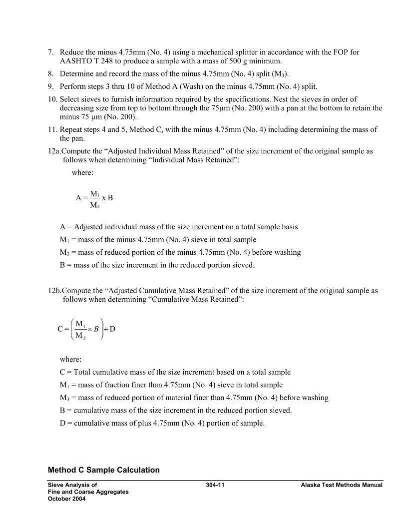
12a.Compute the “Adjusted Individual Mass Retained” of the size increment of the original sample as follows when determining “Individual Mass Retained”:
where:
A = Adjusted individual mass of the size increment on a total sample basis M1 = mass of the minus 4.75mm (No. 4) sieve in total sample M3 = mass of reduced portion of the minus 4.75mm (No. 4) before washing B = mass of the size increment in the reduced portion sieved.
12b.Compute the “Adjusted Cumulative Mass Retained” of the size increment of the original sample as
follows when determining “Cumulative Mass Retained”:
where: C = Total cumulative mass of the size increment based on a total sample M1 = mass of fraction finer than 4.75mm (No. 4) sieve in total sample M3 = mass of reduced portion of material finer than 4.75mm (No. 4) before washing B = cumulative mass of the size increment in the reduced portion sieved. D = cumulative mass of plus 4.75mm (No. 4) portion of sample.
Method C Sample Calculation
DMM
= C3
1 +⎟⎟⎠
⎞⎜⎜⎝
⎛× B
B x MM =A
3
1
Alaska Test Methods Manual 304-12 Sieve Analysis of Fine and Coarse Aggregates October 2004
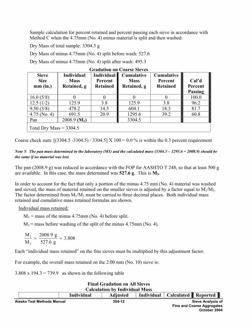
Sample calculation for percent retained and percent passing each sieve in accordance with Method C when the 4.75mm (No. 4) minus material is split and then washed: Dry Mass of total sample: 3304.5 g Dry Mass of minus 4.75mm (No. 4) split before wash: 527.6 Dry Mass of minus 4.75mm (No. 4) split after wash: 495.3
Gradation on Coarse Sieves Sieve Size
mm (in.)
Individual Mass
Retained, g
IndividualPercent
Retained
Cumulative Mass
Retained, g
Cumulative Percent
Retained
Cal’d
Percent Passing
16.0 (5/8) 0 0 0 0 100.0 12.5 (1/2) 125.9 3.8 125.9 3.8 96.2 9.50 (3/8) 478.2 14.5 604.1 18.3 81.7 4.75 (No. 4) 691.5 20.9 1295.6 39.2 60.8 Pan 2008.9 (M1) 3304.5 Total Dry Mass = 3304.5
Coarse check sum: [(3304.5 -3304.5) / 3304.5] X 100 = 0.0 % is within the 0.3 percent requirement Note 5: The pan mass determined in the laboratory (M1) and the calculated mass (3304.5 – 1295.6 = 2008.9) should be the same if no material was lost.
The pan (2008.9 g) was reduced in accordance with the FOP for AASHTO T 248, so that at least 500 g are available. In this case, the mass determined was 527.6 g. This is M3.
In order to account for the fact that only a portion of the minus 4.75 mm (No. 4) material was washed and sieved, the mass of material retained on the smaller sieves is adjusted by a factor equal to M1/M3. The factor determined from M1/M3 must be carried to three decimal places. Both individual mass retained and cumulative mass retained formulas are shown.
Individual mass retained: M1 = mass of the minus 4.75mm (No. 4) before split. M3 = mass before washing of the split of the minus 4.75mm (No. 4).
Each “individual mass retained” on the fine sieves must be multiplied by this adjustment factor. For example, the overall mass retained on the 2.00 mm (No. 10) sieve is: 3.808 x 194.3 = 739.9 as shown in the following table
Final Gradation on All Sieves Calculation by Individual Mass
Individual Adjusted Individual Calculated Reported
3.808g527.6g2008.9
MM
3
1 ==
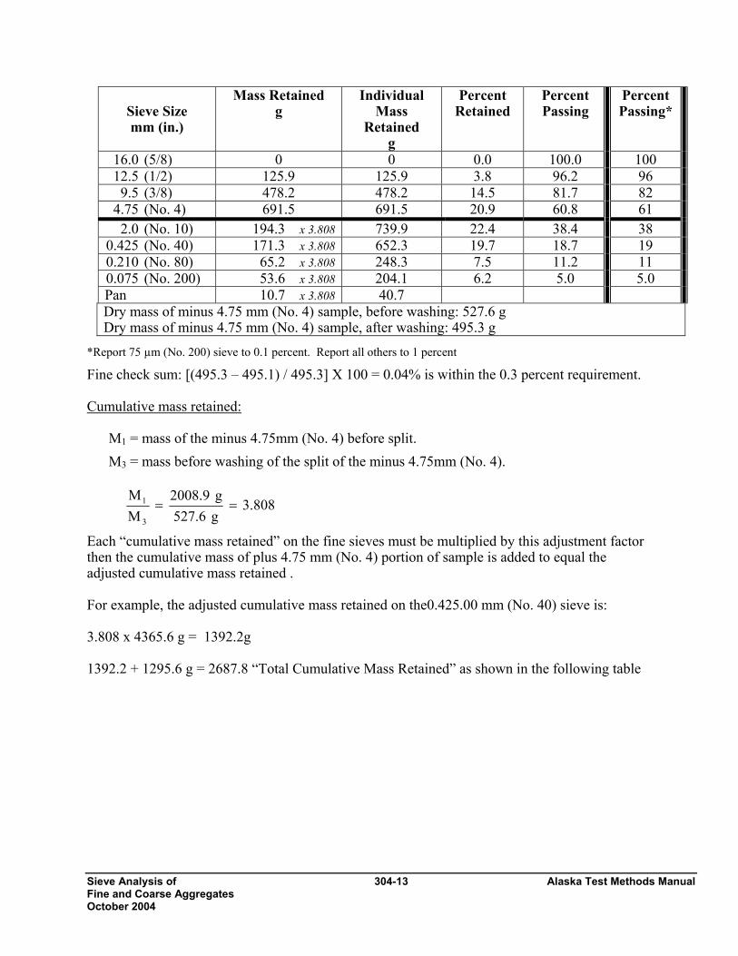
Sieve Analysis of 304-13 Alaska Test Methods Manual Fine and Coarse Aggregates October 2004
Sieve Size mm (in.)
Mass Retained g
Individual Mass
Retained g
Percent Retained
Percent Passing
Percent Passing*
16.0 (5/8) 0 0 0.0 100.0 100 12.5 (1/2) 125.9 125.9 3.8 96.2 96 9.5 (3/8) 478.2 478.2 14.5 81.7 82 4.75 (No. 4) 691.5 691.5 20.9 60.8 61 2.0 (No. 10) 194.3 x 3.808 739.9 22.4 38.4 38 0.425 (No. 40) 171.3 x 3.808 652.3 19.7 18.7 19 0.210 (No. 80) 65.2 x 3.808 248.3 7.5 11.2 11 0.075 (No. 200) 53.6 x 3.808 204.1 6.2 5.0 5.0 Pan 10.7 x 3.808 40.7 Dry mass of minus 4.75 mm (No. 4) sample, before washing: 527.6 g Dry mass of minus 4.75 mm (No. 4) sample, after washing: 495.3 g
*Report 75 µm (No. 200) sieve to 0.1 percent. Report all others to 1 percent Fine check sum: [(495.3 – 495.1) / 495.3] X 100 = 0.04% is within the 0.3 percent requirement. Cumulative mass retained:
M1 = mass of the minus 4.75mm (No. 4) before split. M3 = mass before washing of the split of the minus 4.75mm (No. 4).
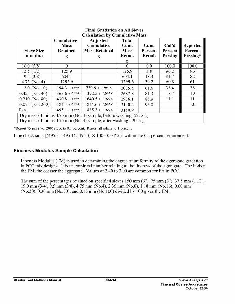
Each “cumulative mass retained” on the fine sieves must be multiplied by this adjustment factor then the cumulative mass of plus 4.75 mm (No. 4) portion of sample is added to equal the adjusted cumulative mass retained . For example, the adjusted cumulative mass retained on the0.425.00 mm (No. 40) sieve is: 3.808 x 4365.6 g = 1392.2g 1392.2 + 1295.6 g = 2687.8 “Total Cumulative Mass Retained” as shown in the following table
3.808g527.6g2008.9
MM
3
1 ==
Alaska Test Methods Manual 304-14 Sieve Analysis of Fine and Coarse Aggregates October 2004
Final Gradation on All Sieves Calculation by Cumulative Mass
Sieve Size mm (in.)
Cumulative Mass
Retained g
Adjusted Cumulative
Mass Retained g
Total Cum. Mass
Retnd. g
Cum.
Percent Retnd.
Cal’d
Percent Passing
ReportedPercent Passing*
16.0 (5/8) 0 0 0.0 100.0 100.0 12.5 (1/2) 125.9 125.9 3.8 96.2 96 9.5 (3/8) 604.1 604.1 18.3 81.7 82 4.75 (No. 4) 1295.6 1295.6 39.2 60.8 61 2.0 (No. 10) 194.3 x 3.808 739.9 + 1295.6 2035.5 61.6 38.4 38 0.425 (No. 40) 365.6 x 3.808 1392.2 + 1295.6 2687.8 81.3 18.7 19 0.210 (No. 80) 430.8 x 3.808 1640.5 + 1295.6 2936.1 88.9 11.1 11 0.075 (No. 200) 484.4 x 3.808 1844.6 + 1295.6 3140.2 95.0 5.0 Pan 495.1 x 3.808 1885.3 + 1295.6 3180.9 Dry mass of minus 4.75 mm (No. 4) sample, before washing: 527.6 g Dry mass of minus 4.75 mm (No. 4) sample, after washing: 495.3 g
*Report 75 µm (No. 200) sieve to 0.1 percent. Report all others to 1 percent
Fine check sum: [(495.3 – 495.1) / 495.3] X 100= 0.04% is within the 0.3 percent requirement. Fineness Modulus Sample Calculation
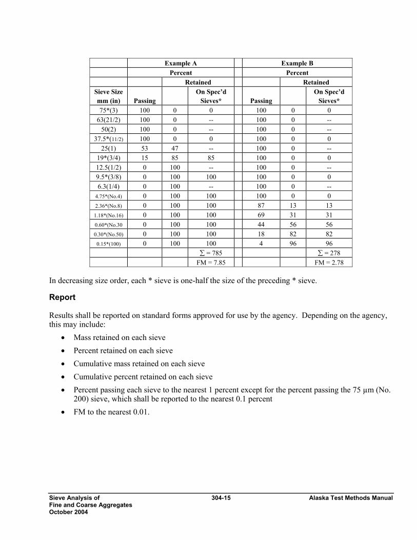
Fineness Modulus (FM) is used in determining the degree of uniformity of the aggregate gradation in PCC mix designs. It is an empirical number relating to the fineness of the aggregate. The higher the FM, the coarser the aggregate. Values of 2.40 to 3.00 are common for FA in PCC. The sum of the percentages retained on specified sieves 150 mm (6”), 75 mm (3”), 37.5 mm (11/2), 19.0 mm (3/4), 9.5 mm (3/8), 4.75 mm (No.4), 2.36 mm (No.8), 1.18 mm (No.16), 0.60 mm (No.30), 0.30 mm (No.50), and 0.15 mm (No.100) divided by 100 gives the FM.
Sieve Analysis of 304-15 Alaska Test Methods Manual Fine and Coarse Aggregates October 2004
Example A Example B Percent Percent Retained Retained
Sieve Size mm (in)
Passing
On Spec’d Sieves*
Passing
On Spec’d Sieves*
75*(3) 100 0 0 100 0 0 63(21/2) 100 0 -- 100 0 --
50(2) 100 0 -- 100 0 -- 37.5*(11/2) 100 0 0 100 0 0
25(1) 53 47 -- 100 0 -- 19*(3/4) 15 85 85 100 0 0 12.5(1/2) 0 100 -- 100 0 -- 9.5*(3/8) 0 100 100 100 0 0 6.3(1/4) 0 100 -- 100 0 --
4.75*(No.4) 0 100 100 100 0 0 2.36*(No.8) 0 100 100 87 13 13 1.18*(No.16) 0 100 100 69 31 31 0.60*(No.30 0 100 100 44 56 56 0.30*(No.50) 0 100 100 18 82 82 0.15*(100) 0 100 100 4 96 96
∑ = 785 ∑ = 278 FM = 7.85 FM = 2.78
In decreasing size order, each * sieve is one-half the size of the preceding * sieve. Report Results shall be reported on standard forms approved for use by the agency. Depending on the agency, this may include:
• Mass retained on each sieve • Percent retained on each sieve • Cumulative mass retained on each sieve • Cumulative percent retained on each sieve • Percent passing each sieve to the nearest 1 percent except for the percent passing the 75 µm (No.
200) sieve, which shall be reported to the nearest 0.1 percent • FM to the nearest 0.01.
Alaska Test Methods Manual 304-16 Sieve Analysis of Fine and Coarse Aggregates October 2004
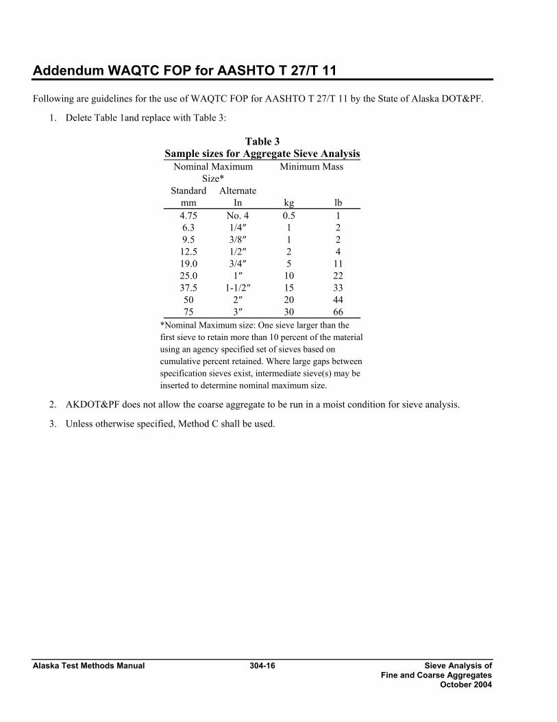
Addendum WAQTC FOP for AASHTO T 27/T 11 Following are guidelines for the use of WAQTC FOP for AASHTO T 27/T 11 by the State of Alaska DOT&PF.
1. Delete Table 1and replace with Table 3:
Table 3 Sample sizes for Aggregate Sieve Analysis
Nominal Maximum Size*
Minimum Mass
Standard Alternate mm In kg lb 4.75 No. 4 0.5 1 6.3 1/4″ 1 2 9.5 3/8″ 1 2
12.5 1/2″ 2 4 19.0 3/4″ 5 11 25.0 1″ 10 22 37.5 1-1/2″ 15 33 50 2″ 20 44 75 3″ 30 66
*Nominal Maximum size: One sieve larger than the first sieve to retain more than 10 percent of the material using an agency specified set of sieves based on cumulative percent retained. Where large gaps between specification sieves exist, intermediate sieve(s) may be inserted to determine nominal maximum size.
2. AKDOT&PF does not allow the coarse aggregate to be run in a moist condition for sieve analysis.
3. Unless otherwise specified, Method C shall be used.
Determining the Percentage of 305-1 Alaska Test Methods Manual Fracture in Coarse Aggregate October 2004
DETERMINING THE PERCENTAGE OF FRACTURE IN COARSE AGGREGATE FOP FOR AASHTO TP 61 Scope This procedure covers the determination of the percentage, by mass, of a coarse aggregate (CA) sample that consists of fractured particles meeting specified requirements in accordance with AASHTO TP 61. In this procedure, a sample of aggregate is screened on the sieve separating CA and fine aggregate (FA). This sieve will be identified in the agency’s specifications, but might be the 4.75 mm (No. 4) sieve. CA particles are visually evaluated to determine conformance to the specified fracture. The percentage of conforming particles, by mass, is calculated for comparison to the specifications. Apparatus • Balance or scale: Capacity sufficient for the principle sample mass, accurate to 0.1 percent of the
sample mass or readable to 0.1 g. Meets the requirements of AASHTO M231 • Sieves, meeting requirements of AASHTO M 92. • Splitter, meeting the requirements of FOP for AASHTO T 248. Terminology 1. Fractured Face – An angular, rough, or broken surface of an aggregate particle created by crushing
or by other means. A face is considered a “Fractured Face” whenever one-half or more of the projected area, when viewed normal to that face, is fractured with sharp and well defined edges. This excludes small nicks.
2. Fractured particle – A particle of aggregate having at least the minimum number of fractured faces
specified. (This is usually one or two.) Sampling and Sample Preparation 1. Sample and reduce the aggregate in accordance with the FOP’s for AASHTO T 2 and T 248. 2. When the specifications list only a total fracture percentage, the sample shall be prepared in
accordance with Method 1. When the specifications require that the fracture be counted and reported on each sieve, the sample shall be prepared in accordance with Method 2.
3. Method 1 - Combined Fracture Determination
a. Dry the sample sufficiently to obtain a clean separation of FA and CA material in the sieving operation.
Alaska Test Methods Manual 305-2 Determining the Percentage of Fracture in Coarse Aggregate October 2004
b. Sieve the sample in accordance with AASHTO T 27/ T 11 over the 4.75 mm (No. 4) sieve, or the appropriate sieve listed in the agency’s specifications for this material.
Note 1: Where necessary wash the sample over the sieve or sieves designated for the determination of fractured particles to remove any remaining fine material, and dry to a constant mass in accordance with AASHTO T 255.
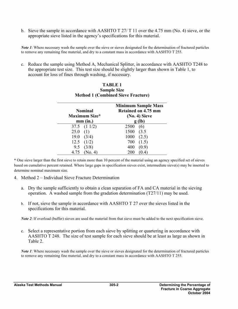
c. Reduce the sample using Method A, Mechanical Splitter, in accordance with AASHTO T248 to
the appropriate test size. This test size should be slightly larger than shown in Table 1, to account for loss of fines through washing, if necessary.
TABLE 1
Sample Size Method 1 (Combined Sieve Fracture)
Nominal Maximum Size*
mm (in.)
Minimum Sample Mass Retained on 4.75 mm
(No. 4) Sieve g (lb)
37.5 (1 1/2) 2500 (6) 25.0 (1) 1500 (3.5 19.0 (3/4) 1000 (2.5) 12.5 (1/2) 700 (1.5) 9.5 (3/8) 400 (0.9)
4.75 (No. 4) 200 (0.4) * One sieve larger than the first sieve to retain more than 10 percent of the material using an agency specified set of sieves based on cumulative percent retained. Where large gaps in specification sieves exist, intermediate sieve(s) may be inserted to determine nominal maximum size. 4. Method 2 – Individual Sieve Fracture Determination
a. Dry the sample sufficiently to obtain a clean separation of FA and CA material in the sieving operation. A washed sample from the gradation determination (T27/11) may be used.
b. If not, sieve the sample in accordance with AASHTO T 27 over the sieves listed in the
specifications for this material. Note 2: If overload (buffer) sieves are used the material from that sieve must be added to the next specification sieve.
c. Select a representative portion from each sieve by splitting or quartering in accordance with
AASHTO T 248. The size of test sample for each sieve should be at least as large as shown in Table 2.
Note 1: Where necessary wash the sample over the sieve or sieves designated for the determination of fractured particles to remove any remaining fine material, and dry to a constant mass in accordance with AASHTO T 255.
Determining the Percentage of 305-3 Alaska Test Methods Manual Fracture in Coarse Aggregate October 2004
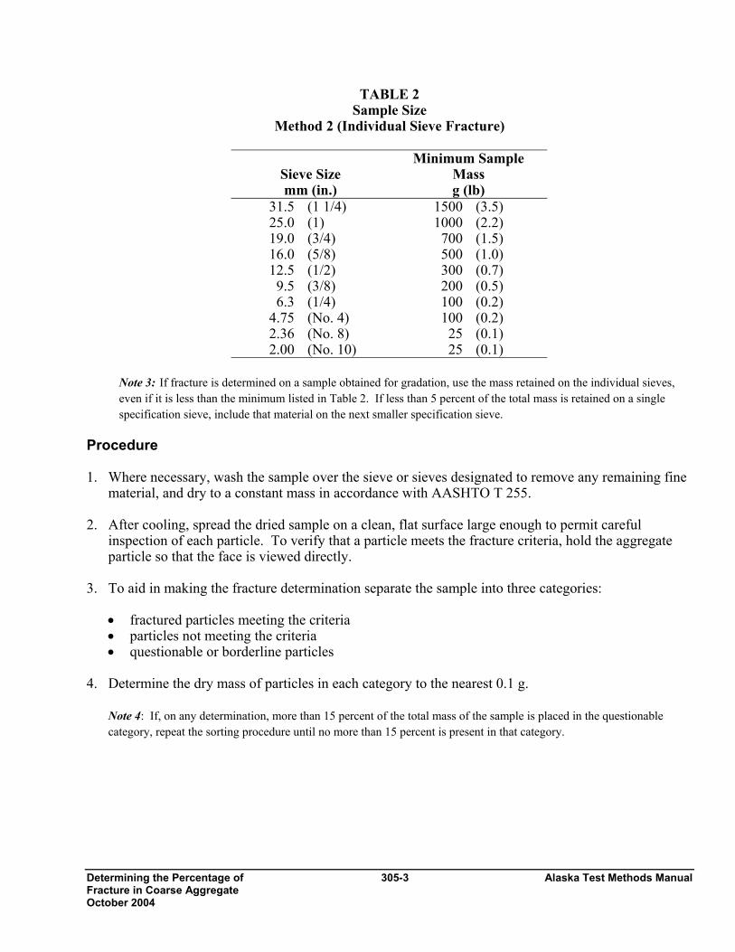
TABLE 2 Sample Size
Method 2 (Individual Sieve Fracture)
Sieve Size mm (in.)
Minimum Sample Mass g (lb)
31.5 (1 1/4) 1500 (3.5) 25.0 (1) 1000 (2.2) 19.0 (3/4) 700 (1.5) 16.0 (5/8) 500 (1.0) 12.5 (1/2) 300 (0.7) 9.5 (3/8) 200 (0.5) 6.3 (1/4) 100 (0.2)
4.75 (No. 4) 100 (0.2) 2.36 (No. 8) 25 (0.1) 2.00 (No. 10) 25 (0.1)
Note 3: If fracture is determined on a sample obtained for gradation, use the mass retained on the individual sieves, even if it is less than the minimum listed in Table 2. If less than 5 percent of the total mass is retained on a single specification sieve, include that material on the next smaller specification sieve.
Procedure 1. Where necessary, wash the sample over the sieve or sieves designated to remove any remaining fine
material, and dry to a constant mass in accordance with AASHTO T 255. 2. After cooling, spread the dried sample on a clean, flat surface large enough to permit careful
inspection of each particle. To verify that a particle meets the fracture criteria, hold the aggregate particle so that the face is viewed directly.
3. To aid in making the fracture determination separate the sample into three categories:
• fractured particles meeting the criteria • particles not meeting the criteria • questionable or borderline particles
4. Determine the dry mass of particles in each category to the nearest 0.1 g.
Note 4: If, on any determination, more than 15 percent of the total mass of the sample is placed in the questionable category, repeat the sorting procedure until no more than 15 percent is present in that category.
Alaska Test Methods Manual 305-4 Determining the Percentage of Fracture in Coarse Aggregate October 2004
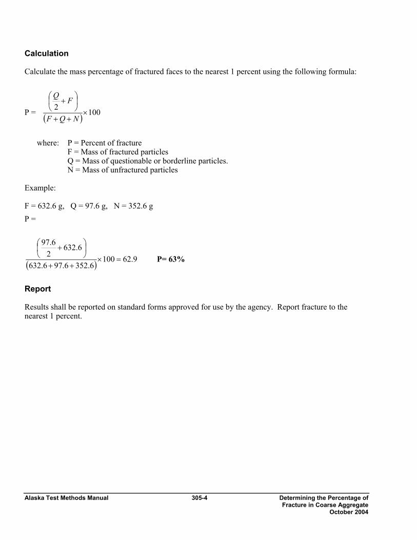
Calculation Calculate the mass percentage of fractured faces to the nearest 1 percent using the following formula:
P = ( ) 1002×
++
⎟⎠⎞
⎜⎝⎛ +
NQF
FQ
where: P = Percent of fracture F = Mass of fractured particles Q = Mass of questionable or borderline particles. N = Mass of unfractured particles Example: F = 632.6 g, Q = 97.6 g, N = 352.6 g P =
( ) 9.621006.3526.976.632
6.6322
6.97
=×++
⎟⎠⎞
⎜⎝⎛ +
P= 63%
Report Results shall be reported on standard forms approved for use by the agency. Report fracture to the nearest 1 percent.
Determining the Percentage 306 - 1 Alaska Test Methods Manual of Flat and/or Elongated … Revised 3/15/05
Determining the Percentage of Flat and Elongated Particles in Coarse Aggregate ATM 306 1. Scope
This procedure covers the determination of the percentages of flat (thin) particles, elongated particles or flat (thin) and elongated particles in coarse aggregates.
2. Apparatus
The apparatus used shall consist of any suitable equipment, by means of which aggregate particles may be tested for compliance, at the dimensional ratios desired, with the definitions given below. Types of acceptable apparatus are:
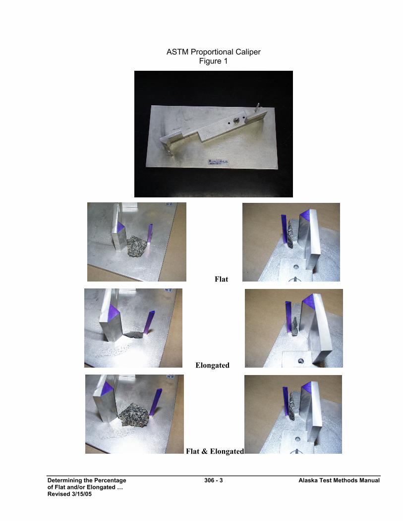
• ASTM Proportional Caliper Device meeting the requirements of ASTM D 4791. Illustrated in Figure 1.
• Balance or scale: Capacity sufficient for the principle sample mass, readable 0.1 percent or 0.1 g and meeting the requirements of AASHTO M 231.
Note: For this test, this would require a scale with a capacity of at least 1200 g and readable to 0.1 g, or better.
• Sieves, meeting the requirements of AASHTO M 92.
3. Definitions
1. Length ⎯ maximum dimension of the particle.
2. Thickness ⎯ maximum dimension perpindicular to the length and width.
3. Flat ("Thin") & Elongated Particle ⎯ a particle having a ratio of length to thickness greater than that specified.
4. Sampling and Sample Preparation
1. Sample the aggregate in accordance with the WAQTC FOP for AASHTO T 2.
2. Dry the sample to constant mass in accordance with WAQTC FOP for AASHTO T 255/T 265. Separate the sample in accordance with WAQTC FOP for AASHTO T 27/T 11 or use the gradation sample from that procedure or WAQTC FOP for AASHTO T 30, separating the coarse aggregate into the size fractions shown in Table 1.
3. Reduce the sample in accordance with WAQTC FOP for AASHTO T 248 Method A, to the appropriate test size as shown in Table 1 or use the material from WAQTC FOPs for AASHTO T 27/T 11 or AASHTO T 30. The test sample size should be slightly larger than shown in Table 1, to account for loss of fines through washing, if necessary. If the test is performed on a sample obtained for gradation, use the mass retained on the individual sieves, even if it is below the minimums listed in Table 1.
Alaska Test Methods Manual 306 - 2 Determining the Percentage of Flat and/or Elongated … Revised 3/15/05
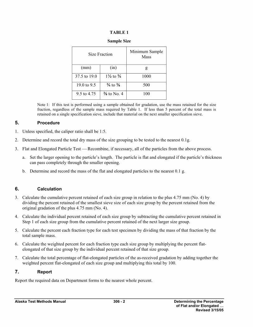
TABLE 1
Sample Size
Size Fraction Minimum Sample Mass
(mm) (in) g
37.5 to 19.0 1½ to ¾ 1000
19.0 to 9.5 ¾ to ⅜ 500
9.5 to 4.75 ⅜ to No. 4 100
Note 1: If this test is performed using a sample obtained for gradation, use the mass retained for the size fraction, regardless of the sample mass required by Table 1. If less than 5 percent of the total mass is retained on a single specification sieve, include that material on the next smaller specification sieve.
5. Procedure
1. Unless specified, the caliper ratio shall be 1:5.
2. Determine and record the total dry mass of the size grouping to be tested to the nearest 0.1g.
3. Flat and Elongated Particle Test ⎯ Recombine, if necessary, all of the particles from the above process.
a. Set the larger opening to the particle’s length. The particle is flat and elongated if the particle’s thickness can pass completely through the smaller opening.
b. Determine and record the mass of the flat and elongated particles to the nearest 0.1 g.
6. Calculation
3. Calculate the cumulative percent retained of each size group in relation to the plus 4.75 mm (No. 4) by dividing the percent retained of the smallest sieve size of each size group by the percent retained from the original gradation of the plus 4.75 mm (No. 4).
4. Calculate the individual percent retained of each size group by subtracting the cumulative percent retained in Step 1 of each size group from the cumulative percent retained of the next larger size group.
5. Calculate the percent each fraction type for each test specimen by dividing the mass of that fraction by the total sample mass.
6. Calculate the weighted percent for each fraction type each size group by multiplying the percent flat-elongated of that size group by the individual percent retained of that size group.
7. Calculate the total percentage of flat-elongated particles of the as-received gradation by adding together the weighted percent flat-elongated of each size group and multiplying this total by 100.
7. Report
Report the required data on Department forms to the nearest whole percent.
Determining the Percentage 306 - 3 Alaska Test Methods Manual of Flat and/or Elongated … Revised 3/15/05
ASTM Proportional Caliper Figure 1
Flat
Elongated
Flat & Elongated

Alaska Test Methods Manual 306 - 4 Determining the Percentage of Flat and/or Elongated … Revised 3/15/05
This page intentionally left blank.
Plastic Fines in Graded 307-1 Alaska Test Methods Manual Aggregates and Soils… October 2003
PLASTIC FINES IN GRADED AGGREGATES AND SOILS BY THE USE OF THE SAND EQUIVALENT TEST WAQTC FOP FOR AASHTO T 176 Scope This procedure covers the determination of plastic fines in accordance with AASHTO T 176. It serves as a rapid test to show the relative proportion of fine dust or clay-like materials in fine aggregates (FA) and soils. Apparatus See AASHTO T 176 for a detailed listing of sand equivalent apparatus. Note that the siphon tube and blow tube may be glass or stainless steel as well as copper. • Graduated plastic cylinder. • Rubber stopper. • Irrigator tube. • Weighted foot assembly: There are two models of the weighted foot assembly. The older model has
a guide cap that fits over the upper end of the graduated cylinder and centers the rod in the cylinder. It is read using a slot in the centering screws. The newer model has a sand reading indicator 254 mm (10 in.) above this point and is preferred for testing clay-like materials.
• Siphon assembly: The siphon assembly will be fitted to a 4-L (1 gal) bottle of working calcium chloride solution placed on a shelf 915 ±25 mm (36 ±1 in.) above the work surface.
• Weighted foot assembly having a mass of 1000 ± 5 g. • Measuring can having a capacity of 85 ±5 ml (3 oz.). • Funnel with a wide-mouth for transferring sample into graduated cylinder. • Quartering cloth – 600 mm (2 ft) square nonabsorbent cloth, such as plastic or oil cloth. • Mechanical splitter – see FOP for AASHTO T 248. • Strike off bar – A straight edge or spatula. • Clock or watch reading in minutes and seconds. • Manually operated sand equivalent shaker capable of producing an oscillating motion at a rate of
100 complete cycles in 45 ±5 seconds, with a hand assisted half stroke length of 127 ±5 mm (5 ±2 in.). It may be held stable by hand during the shaking operation. It is recommended that this shaker be fastened securely to a firm and level mount, by bolts or clamps, if a large number of determinations are to be made.
• Mechanical shaker – See AASHTO T 176 for equipment and procedure. • Oven capable of maintaining a temperature of 110 ±5°C (230 ±9°F). • Thermometer – Calibrated liquid-in-glass or electronic digital type designed for total immersion and
accurate to 0.1°C (0.2°F).
Alaska Test Methods Manual 307-2 Plastic Fines in Graded Aggregates and Soils… October 2003
Materials • Stock calcium chloride solution: Obtain commercially prepared calcium chloride stock solution
meeting AASHTO requirements. • Working calcium chloride solution: Dilute one 3 oz measuring can (85 ±5 mL) of stock calcium
chloride solution to 3.8 L (1 gal) with distilled or demineralized water. (The graduated cylinder filled to 111.8 mm [4.4 in.] contains 88 mL.)
Note 1: Mix the working solution thoroughly. Add 85ml (3oz) of stock solution to a clean, empty 3.8L (1qt) jug, add approximately one 1L (1qt) and agitate vigorously for 2 or 3 minutes. Add the remainder of the water in approximately 1L (1qt) increments repeating the agitation process.
Note 2: Tap water may be used if it is proven not to be detrimental to the test and if it is allowed by the agency.
Note 3: The shelf life of the working solution is approximately 30 days. Working solutions more than 30 days old shall be discarded.
Control The temperature of the working solution should be maintained at 22 ±3°C (72 ±5°F) during the performance of the test. If field conditions preclude the maintenance of the temperature range, reference samples should be submitted to the Central/Regional Laboratory, as required by the agency, where proper temperature control is possible. Samples that meet the minimum sand equivalent requirement at a working solution temperature outside of the temperature range need not be subject to reference testing. Sample Preparation 1. Obtain the sample in accordance with FOP for AASHTO T 2 and reduce in accordance with FOP
for AASHTO T 248. 2. Prepare sand equivalent test samples from the material passing the 4.75 mm (No. 4) sieve. If the
material is in clods, break it up and rescreen it over a 4.75 mm (No. 4) sieve. All fines shall be cleaned from particles retained on the 4.75 mm (No. 4) sieve and included with the material passing that sieve.
3. Split or quarter 1000 to 1500 g of material from the portion passing the 4.75 mm (No. 4) sieve. Use extreme care to obtain a truly representative portion of the original sample.
Note 4: Experiments show that, as the amount of material being reduced by splitting or quartering is decreased, the accuracy of providing representative portions is reduced. It is imperative that the sample be split or quartered carefully. When it appears necessary, dampen the material before splitting or quartering to avoid segregation or loss of fines.
Note 5: All tests including Reference Tests will be performed utilizing Alternative Method No. 2 as described in AASHTO T 176 unless specifications call for oven dry samples.
Plastic Fines in Graded 307-3 Alaska Test Methods Manual Aggregates and Soils… October 2003
4. The sample must have the proper moisture content to achieve reliable results. This condition is determined by tightly squeezing a small portion of the thoroughly mixed sample in the palm of the hand. If the cast that is formed permits careful handling without breaking, the correct moisture content has been obtained. If the material is too dry, the cast will crumble and it will be necessary to add water and remix and retest until the material forms a cast.
Note 6: Clean sands having little 75 µm(No.200) such as sand for Portland Cement Concrete (PCC) may not form a cast.
If the material shows any free water, it is too wet to test and must be drained and air dried, and mixed frequently to ensure uniformity. This drying process should continue until squeezing provides the required cast. If the moisture content is altered to provide the required cast, the altered sample should be placed in a pan, covered with a lid or with a damp cloth that does not touch the material, and allowed to stand for a minimum of 15 minutes. Samples that have been sieved without being air dried and still retain enough natural moisture are exempted from this requirement.
5. Place the sample on the quartering cloth and mix by alternately lifting each corner of the cloth and
pulling it over the sample toward the diagonally opposite corner, being careful to keep the top of the cloth parallel to the bottom, thus causing the material to be rolled. When the material appears homogeneous, finish the mixing with the sample in a pile near the center of the cloth.
6. Fill the measuring can by pushing it through the base of the pile while exerting pressure with the
hand against the pile on the side opposite the measuring can. As the can is moved through the pile, hold enough pressure with the hand to cause the material to fill the tin to overflowing. Press firmly with the palm of the hand, compacting the material and placing the maximum amount in the can. Strike off the can level full with the straight edge or spatula.
7. When required, repeat steps (5) and (6) to obtain additional samples. Procedure 1. Start the siphon by forcing air into the top of the solution bottle through the tube while the pinch
clamp is open.
2. Siphon 101.6 ±2.5 mm (4 ±0.1 in.) of working calcium chloride solution into the plastic cylinder. Pour the prepared test sample from the measuring can into the plastic cylinder using the funnel to avoid spilling. Tap the bottom of the cylinder sharply on the heel of the hand several times to release air bubbles and to promote thorough wetting of the sample.
3. Allow the wetted sample to stand undisturbed for 10 ±1 minutes. At the end of the 10-minute period, stopper the cylinder and loosen the material from the bottom by simultaneously partially inverting and shaking the cylinder.
4. After loosening the material from the bottom of the cylinder, shake the cylinder and contents by any
one of the following methods: a. Mechanical Method – Place the stoppered cylinder in the mechanical shaker, set the timer, and
allow the machine to shake the cylinder and contents for 45 ±1 seconds. Note 7: The next two methods – manually-operated shaker method and hand method – require that the
operator meet certain qualifications. See AASHTO T 176 for a full description.
Alaska Test Methods Manual 307-4 Plastic Fines in Graded Aggregates and Soils… October 2003
b. Manually-operated Shaker Method – Secure the stoppered cylinder in the three spring clamps
on the carriage of the manually-operated sand equivalent shaker and set the stroke counter to zero. Stand directly in front of the shaker and force the pointer to the stroke limit marker painted on the backboard by applying an abrupt horizontal thrust to the upper portion of the right hand spring strap. Remove the hand from the strap and allow the spring action of the straps to move the carriage and cylinder in the opposite direction without assistance or hindrance. Apply enough force to the right hand spring steel strap during the thrust portion of each stroke to move the pointer to the stroke limit marker by pushing against the strap with the ends of the fingers to maintain a smooth oscillating motion. The center of the stroke limit marker is positioned to provide the proper stroke length and its width provides the maximum allowable limits of variation. Proper shaking action is accomplished when the tip of the pointer reverses direction within the marker limits. Proper shaking action can best be maintained by using only the forearm and wrist action to propel the shaker. Continue shaking for 100 strokes.
c. Hand Method – Hold the cylinder in a horizontal position and shake it vigorously in a horizontal
linear motion from end to end. Shake the cylinder 90 cycles in approximately 30 seconds using a throw of 229 mm ±25 mm (9 ±1 in.). A cycle is defined as a complete back and forth motion. To properly shake the cylinder at this speed, it will be necessary for the operator to shake with the forearms only, relaxing the body and shoulders.
5. Set the cylinder upright on the work table and remove the stopper.
6. Insert the irrigator tube in the cylinder and rinse material from the cylinder walls as the irrigator is lowered. Force the irrigator through the material to the bottom of the cylinder by applying a gentle stabbing and twisting action while the working solution flows from the irrigator tip. Work the irrigator tube to the bottom of the cylinder as quickly as possible, since it becomes more difficult to do this as the washing proceeds. This flushes the fine material into suspension above the coarser sand particles. Continue to apply a stabbing and twisting action while flushing the fines upward until the cylinder is filled to the 381 mm (15 in.) mark. Then raise the irrigator slowly without shutting off the flow so that the liquid level is maintained at about 381 mm (15 in.) while the irrigator is being withdrawn. Regulate the flow just before the irrigator is entirely withdrawn and adjust the final level to 381 mm (15 in.).
Note 8: Occasionally the holes in the tip of the irrigator tube may become clogged by a particle of sand. If the obstruction cannot be freed by any other method, use a pin or other sharp object to force it out, using extreme care not to enlarge the size of the opening. Also, keep the tip sharp as an aid to penetrating the sample.
7. Allow the cylinder and contents to stand undisturbed for 20 minutes ±15 seconds. Start timing immediately after withdrawing the irrigator tube.
Note 9: Any vibration or movement of the cylinder during this time will interfere with the normal settling rate of the suspended clay and will cause an erroneous result.
8. Clay and Sand Readings a. At the end of the 20-minute sedimentation period, read and record the level of the top of the clay
suspension. This is referred to as the clay reading.
Plastic Fines in Graded 307-5 Alaska Test Methods Manual Aggregates and Soils… October 2003
Note 10: If no clear line of demarcation has formed at the end of the 20-minute sedimentation period, allow the sample to stand undisturbed until a clay reading can be obtained, then immediately read and record the level of the top of the clay suspension and the total sedimentation time. If the total sedimentation time exceeds 30 minutes, rerun the test using three individual samples of the same material. Read and record the clay column height of the sample requiring the shortest sedimentation period only. Once a sedimentation time has been established, subsequent tests will be run using that time. The time will be recorded along with the test results on all reports.
b. After the clay reading has been taken, place the weighted foot assembly over the cylinder and gently lower the assembly until it comes to rest on the sand. Do not allow the indicator to hit the mouth of the cylinder as the assembly is being lowered. Subtract 254 mm (10 in.) from the level indicated by the extreme top edge of the indicator and record this value as the sand reading.
c. If clay or sand readings fall between 2.5 mm (0.1 in.) graduations, record the level of the higher graduation as the reading. For example, a clay reading of 7.95 would be recorded as 8.0, a sand reading of 3.22 would be recorded as 3.3.
d. If two Sand Equivalent (SE) samples are run on the same material and the second varies by more than ±4 points, based on the first cylinder reading, additional tests shall be run.
e. If three or more Sand Equivalent (SE) samples are run on the same material, average the readings. If an individual reading varies by more than ±4 points, based on the average cylinder reading, additional tests shall be run.
Calculations 1. Calculate the SE to the nearest 0.1 using the following formula: SE =
For Example: Sand Reading = 3.3 and Clay Reading = 8.0
SE =
Note 11: This example reflects the use of equipment made with English units. At this time, equipment made with metric units is not available.
341.or41.251008.03.3
=×
100ReadingClayReadingSand
×
Alaska Test Methods Manual 307-6 Plastic Fines in Graded Aggregates and Soils… October 2003
2. Report the SE as the next higher whole number. In the example above, the 41.3 would be reported as 42. An SE of 41.0 would be reported as 41.
3. In determining the average of the two samples, raise each calculated SE value to the next higher
whole number before averaging. For example, calculated values of 41.3 and 42.8 would be reported as 42 and 43, respectively. Then average the two values:
If the average value is not a whole number, raise it to the next higher whole number – in this case: 43.
Report
Results shall be reported on standard forms approved for use by the agency.
Report results to the whole number.
42.52
4342=
+
Specific Gravity and Absorption of 308-1 Alaska Test Methods Manual Coarse Aggregate October 2003
SPECIFIC GRAVITY AND ABSORPTION OF COARSE AGGREGATE WAQTC FOP FOR AASHTO T 85 Scope This procedure covers the determination of specific gravity and absorption of coarse aggregate in accordance with AASHTO T 85. Specific gravity may be expressed as bulk specific gravity (Gsb), bulk specific gravity, saturated surface dry (Gsb SSD), or apparent specific gravity (Gsa). Gsb and absorption are based on aggregate after 15 hours soaking in water. This procedure is not intended to be used with lightweight aggregates. Terminology Absorption – the increase in the mass of aggregate due to water being absorbed into the pores of the material, but not including water adhering to the outside surface of the particles, expressed as a percentage of the dry mass. The aggregate is considered “dry” when it has been maintained at a temperature of 110 ±5°C (230 ±9°F) for sufficient time to remove all uncombined water. Specific Gravity – the ratio of the mass, in air, of a volume of a material to the mass of the same volume of gas-free distilled water at a stated temperature. Apparent Specific Gravity – the ratio of the mass, in air, of a volume of the impermeable portion of aggregate to the mass of an equal volume of gas-free distilled water at a stated temperature. Bulk Specific Gravity – the ratio of the mass, in air, of a volume of aggregate (including the permeable and impermeable voids in the particles, but not including the voids between particles) to the mass of an equal volume of gas-free distilled water at a stated temperature. Bulk Specific Gravity (SSD) – the ratio of the mass, in air, of a volume of aggregate, including the mass of water within the voids filled to the extent achieved by submerging in water for approximately 15 hours (but not including the voids between particles), to the mass of an equal volume of gas-free distilled water at a stated temperature. Apparatus
• Balance or scale with a capacity of 5 kg, sensitive to 1 g. Meeting the requirements of AASHTO M 231.
• Sample container, wire basket of 3.35 mm (No. 6) or smaller mesh, with a capacity of 4 to 7 L (1 to 2 gal) to contain aggregate with a nominal maximum size of 37.5 mm (1 1/2 in.) or smaller; larger basket for larger aggregates.
• Water tank, watertight and large enough to completely immerse aggregate and basket, equipped with an overflow valve to keep water level constant.
• Suspension apparatus: wire used to suspend apparatus shall be of smallest practical diameter. • Sieves, 4.75 mm (No. 4), or other sizes as needed, conforming to AASHTO M 92.
Sample Preparation 1. Obtain the sample in accordance with the FOP for AASHTO T 2 (see Note 1).
Alaska Test Methods Manual 308-2 Specific Gravity and Absorption of Coarse Aggregate October 2003
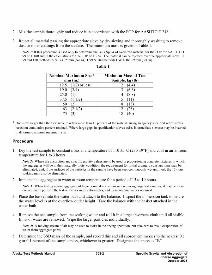
2. Mix the sample thoroughly and reduce it in accordance with the FOP for AASHTO T 248. 3. Reject all material passing the appropriate sieve by dry sieving and thoroughly washing to remove
dust or other coatings from the surface. The minimum mass is given in Table 1. Note 1: If this procedure is used only to determine the Bulk Sp Gr of oversized material for the FOP for AASHTO T 99 or T 180 and in the calculations for the FOP of T 224. The material can be rejected over the appropriate sieve; T 99 and 180 methods A & B 4.75 mm (No.4), T 99 & 180 methods C & D the 19 mm (3/4 in).
Table 1
Nominal Maximum Size* mm (in.)
Minimum Mass of Test Sample, kg (lb)
12.5 (1/2) or less 2 (4.4) 19.0 (3/4) 3 (6.6) 25.0 (1) 4 (8.8) 37.5 (1 1/2) 5 (11)
50 (2) 8 (18) 63 (2 1/2) 12 (26) 75 (3) 18 (40)
* One sieve larger than the first sieve to retain more than 10 percent of the material using an agency specified set of sieves
based on cumulative percent retained. Where large gaps in specification sieves exist, intermediate sieve(s) may be inserted to determine nominal maximum size.
Procedure 1. Dry the test sample to constant mass at a temperature of 110 ±5°C (230 ±9°F) and cool in air at room
temperature for 1 to 3 hours. Note 2: Where the absorption and specific gravity values are to be used in proportioning concrete mixtures in which the aggregates will be in their naturally moist condition, the requirement for initial drying to constant mass may be eliminated, and, if the surfaces of the particles in the sample have been kept continuously wet until test, the 15-hour soaking may also be eliminated.
2. Immerse the aggregate in water at room temperature for a period of 15 to 19 hours. Note 3: When testing coarse aggregate of large nominal maximum size requiring large test samples, it may be more convenient to perform the test on two or more subsamples, and then combine values obtained.
3. Place the basket into the water bath and attach to the balance. Inspect the immersion tank to insure the water level is at the overflow outlet height. Tare the balance with the basket attached in the water bath.
4. Remove the test sample from the soaking water and roll it in a large absorbent cloth until all visible
films of water are removed. Wipe the larger particles individually. Note 4: A moving stream of air may be used to assist in the drying operation, but take care to avoid evaporation of water from aggregate pores.
5. Determine the SSD mass of the sample, and record this and all subsequent masses to the nearest 0.1 g or 0.1 percent of the sample mass, whichever is greater. Designate this mass as “B”.
Specific Gravity and Absorption of 308-3 Alaska Test Methods Manual Coarse Aggregate October 2003
6. Re-inspect the immersion tank to insure the water level is at the overflow outlet height and tare the balance. Immediately place the SSD test sample in the sample container and weigh it in water maintained at 23.0 ±1.7°C (73.4 ±3°F). Shake the container to release entrapped air before recording the weight. Designate this submerged weight as “C”.
Note 5: The container should be immersed to a depth sufficient to cover it and the test sample during mass determination. Wire suspending the container should be of the smallest practical size to minimize any possible effects of a variable immersed length.
7. Dry the test sample to constant mass at a temperature of 110 ±5°C (230 ±9°F) and cool in air at room temperature for 1 to 3 hours. Designate this mass as “A”.
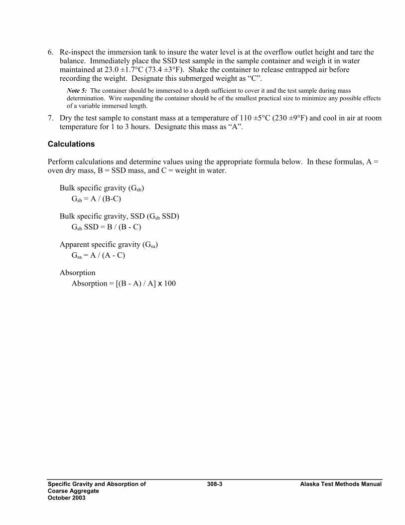
Calculations Perform calculations and determine values using the appropriate formula below. In these formulas, A = oven dry mass, B = SSD mass, and C = weight in water.
Bulk specific gravity (Gsb) Gsb = A / (B-C)
Bulk specific gravity, SSD (Gsb SSD)
Gsb SSD = B / (B - C)
Apparent specific gravity (Gsa) Gsa = A / (A - C)
Absorption
Absorption = [(B - A) / A] x 100
Alaska Test Methods Manual 308-4 Specific Gravity and Absorption of Coarse Aggregate October 2003
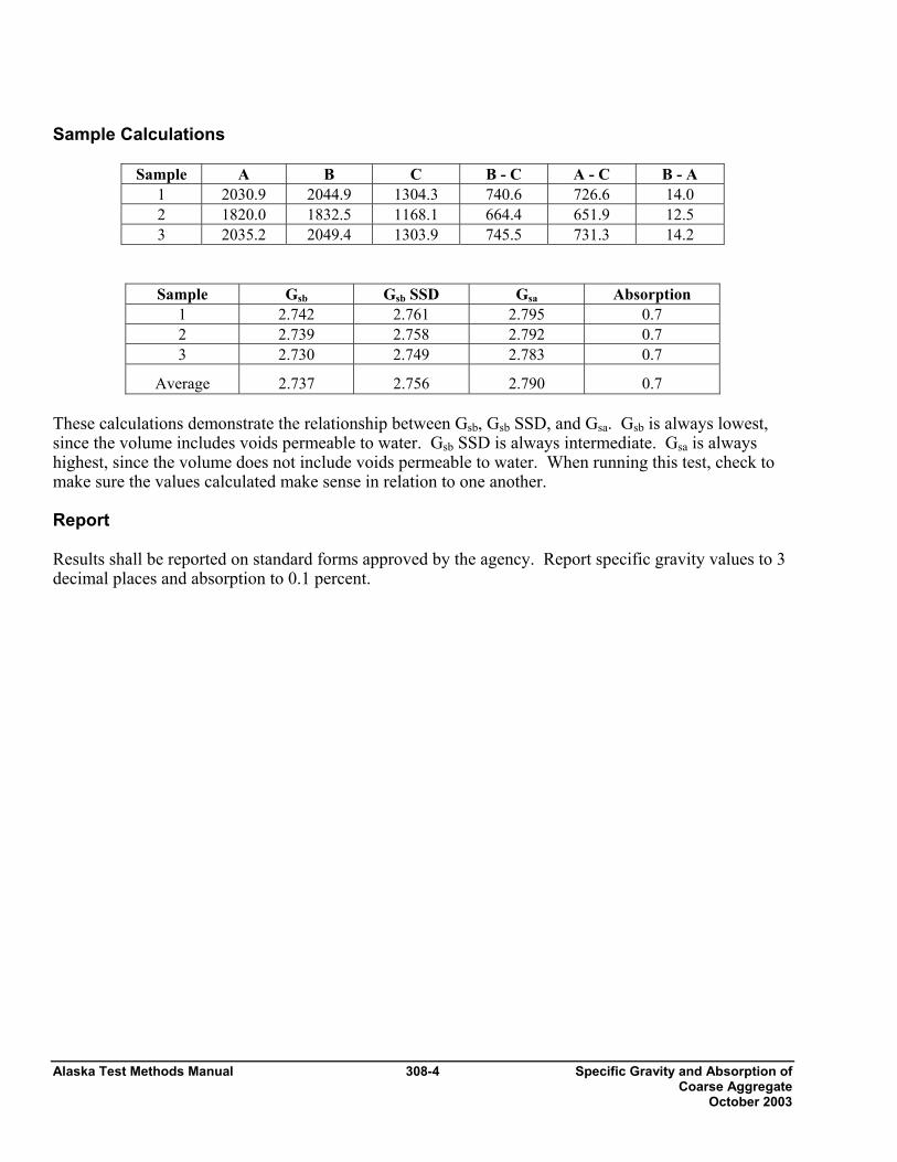
Sample Calculations
Sample A B C B - C A - C B - A 1 2030.9 2044.9 1304.3 740.6 726.6 14.0 2 1820.0 1832.5 1168.1 664.4 651.9 12.5 3 2035.2 2049.4 1303.9 745.5 731.3 14.2
Sample Gsb Gsb SSD Gsa Absorption 1 2.742 2.761 2.795 0.7 2 2.739 2.758 2.792 0.7 3 2.730 2.749 2.783 0.7
Average 2.737 2.756 2.790 0.7 These calculations demonstrate the relationship between Gsb, Gsb SSD, and Gsa. Gsb is always lowest, since the volume includes voids permeable to water. Gsb SSD is always intermediate. Gsa is always highest, since the volume does not include voids permeable to water. When running this test, check to make sure the values calculated make sense in relation to one another. Report Results shall be reported on standard forms approved by the agency. Report specific gravity values to 3 decimal places and absorption to 0.1 percent.
Nordic Abrasion 312 - 1 Alaska Test Methods Manual Revised 12/31/03
Nordic Abrasion Value of Coarse Aggregate ATM 312 1. Scope
This method describes the test procedure for the simulation of the abrasive action of traffic on coarse aggregates used in a surface layer to determine the ability of the aggregate to resist wear by abrasion from studded tires.
The test shall be performed on aggregates with a size fraction of 11.2 to 16.0 mm (7/16" to 5/8")
Note 1: Variations from this size range will not give consistent results.
The test is applicable to crushed and uncrushed natural and artificial aggregates.
This test method involves potentially hazardous materials, operations and equipment. This method does not purport to address all of the safety problems associated with it use.
2. Principle
A sample of a single-sized aggregate group, 11.2 to 16.0 mm (7/16" to 5/8"), is rotated together with steel balls and water in a steel drum. Three ribs, which are mounted on the interior of the drum, add to the abrading action of the aggregate particles and the steel balls. The contents roll within the drum with an abrading action. After the specified number of revolutions, the contents are removed from the drum and the aggregate portion is sieved on a 2.00 mm (No. 10) sieve to measure the wear as a percentage loss.
3. Apparatus
• Testing machine conforming to the design shown in Figure 1.
• The cylinder shall have an inside diameter of 206.5 ± 2 mm and an inside length of 335 ± 1 mm. Three ribs, each with a length of 333 ± 1 mm, shall be equally spaced around the internal circumference of the cylinder. The test drum shall be water-tight and made of a seamless steel tube conforming to according to grade TS 5 of ISO 2604-2, of outside diameter 219.1 and wall thickness of 6.3 mm. The cylinder shall rotate centrically with the axis in a horizontal position at a rate of 90 ± 3 rpm. A revolution counter shall automatically stop the rotation after 5400 revolutions.
• The three ribs shall be removable and made from spring steel as specified in ISO 683-14 and designed in accordance with figure 1. The ribs, prior to their use in the test, shall be preground in the drum for 25 h using a hard aggregate, together with the normal proportions of steel balls and water.
• During the test the ribs will wear and their action will change. Each rib shall be replaced, when its loss in original mass exceeds 15 g.
• Ball bearings, 14.99-15.05 mm diameter, of a hardness between 62 and 65 HRC, as specified in ISO
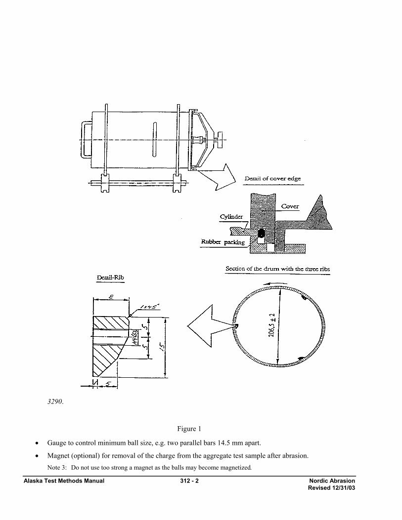
Alaska Test Methods Manual 312 - 2 Nordic Abrasion Revised 12/31/03
3290.
Figure 1
• Gauge to control minimum ball size, e.g. two parallel bars 14.5 mm apart.
• Magnet (optional) for removal of the charge from the aggregate test sample after abrasion. Note 3: Do not use too strong a magnet as the balls may become magnetized.
Nordic Abrasion 312 - 3 Alaska Test Methods Manual Revised 12/31/03
• Oven capable of maintaining a uniform temperature of 110 ± 5 °C (230 ± 9°F).
• Balance or scale: Capacity sufficient for the principle sample mass, readable to 0.1 percent or 0.1 g, of the total sample mass and meeting the requirements of AASHTO M 231.
• Sieves of the following sizes: 2.00 mm, 11.2 mm, and 16.0 mm (No. 10, 7/16" and 5/8").
• Bucket.
• Washing device.
4. Sampling
Obtain the sample in accordance with WAQTC FOP for AASHTO T 2.
5. Preparation Of Test Sample
Unprocessed Aggregate
1. Separate the sample on the 19 mm (3/4") sieve by hand or mechanical shaker, sieving the material for 5 minutes. Discard the minus 19 mm (3/4") material unless required for other testing.
2. Crush the plus 19 mm (3/4") aggregate, or a representative portion obtained in accordance with WAQTC FOP for AASHTO T 248, to pass the 19 mm (3/4") sieve.
3. Separate the material into the required test size, using 16 mm (5/8") sieve and 11.2 mm (7/16") sieves, in accordance with WAQTC FOP for AASHTO T 27/T 11. Discard all particles retained on the 16 mm (5/8") sieve and all the particles passing the 11.2 mm (7/16") sieve, unless required for other testing.
4. Proceed to Step 2 below.
Processed (already crushed) Aggregate
1. Separate the material into the required test size, using 16 mm (5/8") and 11.2 mm (7/16") sieves, in accordance with WAQTC FOP for AASHTO T 27/T 11. Discard all particles retained on the 5/8" (16 mm) sieve and all the particles passing the 11.2 mm (7/16") sieve, unless required for other testing.
2. Reduce the sample to test size (minimum of 3500 g) in accordance with WAQTC FOP for AASHTO T 248.
3. Wash the sample and dry to a constant mass in accordance with WAQTC FOP for AASHTO T 255/T 265.
4 Determine the apparent specific gravity of the sample, or a portion thereof, in accordance with WAQTC FOP for AASHTO T 85.
5. Determine the test sample mass by:
100066.2
×= ii
Pm
Where mi = mass of the test sample
pi = apparent specific gravity of test sample.
6. Batch 3 test specimens at the calculated weight ± 5 g.
6. Procedure
1. Place the ball charge (7000 ± 10 g) and the test sample in the drum and add (2000 ± 10) ml. of water.
2. Rotate the drum at a speed of 90 ± 3 rpm for 5400 ± 10 revolutions.
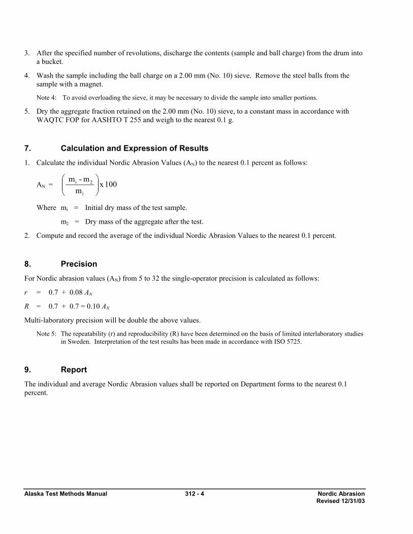
Alaska Test Methods Manual 312 - 4 Nordic Abrasion Revised 12/31/03
3. After the specified number of revolutions, discharge the contents (sample and ball charge) from the drum into a bucket.
4. Wash the sample including the ball charge on a 2.00 mm (No. 10) sieve. Remove the steel balls from the sample with a magnet.
Note 4: To avoid overloading the sieve, it may be necessary to divide the sample into smaller portions.
5. Dry the aggregate fraction retained on the 2.00 mm (No. 10) sieve, to a constant mass in accordance with WAQTC FOP for AASHTO T 255 and weigh to the nearest 0.1 g.
7. Calculation and Expression of Results
1. Calculate the individual Nordic Abrasion Values (AN) to the nearest 0.1 percent as follows:
AN = 100 x m
m -m
i
2i⎟⎟⎠
⎞⎜⎜⎝
⎛
Where mi = Initial dry mass of the test sample.
m2 = Dry mass of the aggregate after the test.
2. Compute and record the average of the individual Nordic Abrasion Values to the nearest 0.1 percent.
8. Precision
For Nordic abrasion values (AN) from 5 to 32 the single-operator precision is calculated as follows:
r = 0.7 + 0.08 AN
R = 0.7 + 0.7 = 0.10 AN
Multi-laboratory precision will be double the above values.
Note 5: The repeatability (r) and reproducibility (R) have been determined on the basis of limited interlaboratory studies in Sweden. Interpretation of the test results has been made in accordance with ISO 5725.
9. Report
The individual and average Nordic Abrasion values shall be reported on Department forms to the nearest 0.1 percent.
Degradation Values of Aggregate 313-1 Alaska Test Methods Manual Revised 3/15/05
Degradation Value of Aggregates ATM 313 1. Scope This test method describes the procedure for determining the durability of an aggregate. The durability of an aggregate as measured by the Degradation Value indicates the relative resistance of an aggregate to produce detrimental clay-like fines when subjected to a prescribed abrasion process in the presence of distilled or demineralized water.
2. Apparatus
• Jaw crusher with 150 mm (6") capacity.
• Sieves of the following sizes: 12.5 mm (½"), 6.3 mm (¼"), 2.00 mm (No. 10) and 75 µm (No. 200). Sieves shall conform to AASHTO M 92.
• Balance or scale: Capacity sufficient for the principle sample mass, readable to 0.1 percent or 0.1 g of the total sample mass and meeting the requirements of AASHTO M 231.
• 200 mm (8") sieve shaker with 45 mm (1¾") throw on cam at 285 ± 10 oscillations per minute.
• General Laboratory Interval Timer to control On-Off operation of sieve shaker. Timer will have a minimum 20 minute range accurate to ± 5 seconds.
• Plastic canister 190 mm (7 ½") in diameter and 150 mm (6") high, having a flat bottom.
• Distilled or demineralized water maintained at 22 ±3ºC (72 ± 5°F).
• Sample Washing Apparatus, consisting of a ring stand and ring capable of mounting a 230 mm mouth funnel with a 2.00 mm (No. 10) and 75 µm (No. 200) sieve setting on top of the funnel and a graduated cylinder calibrated at 500 ml with a rubber stopper.
• Graduated cylinder or pipette with 10 ml capacity graduated in 1 ml increments.
• Stock Sand Equivalent Solution prepared in accordance with WAQTC FOP for AASHTO T 176, using distilled water only. This solution should be stored in dark or opaque containers and protected from direct sunlight and heat. Solutions that have turned cloudy or formed precipitates will be discarded.
• Standard Sand Equivalent Cylinder with rubber stopper as described in WAQTC FOP for AASHTO T 176.
• Timer or Stopwatch, preferably with an alarm to indicate end of timed interval.
• Miscellaneous equipment including 500 ml wash bottle with a fine spray nozzle, pans, scoops, etc.
3. Degradation Test Area The degradation test area must be free of vibration and direct sunlight, and maintained at a temperature of 22 ±3ºC (72 ± 5°F).
4. Sample Preparation 1. Unprocessed Aggregate
a. Separate the aggregate on the 12.5 mm (½") sieve by hand or by mechanical shaker, sieving the material for 5 minutes. Discard the minus 12.5 mm (½") material unless required for other testing.
Alaska Test Methods Manual 313-2 Degradation Values of Aggregate Revised 3/15/05
b. Crush the plus 12.5 mm (½") aggregate, or a representative portion obtained in accordance with WAQTC FOP for AASHTO T 248, to pass the 12.5 mm (½") sieve.
c. Proceed to Step 4 below.
2. Processed (already crushed) Aggregate
a. Separate the material by hand sieving or by mechanical shaker, sieving the material for 5 minutes, into 2 size groups: minus 12.5 mm (½") to plus 6.3 mm (¼") and minus 6.3 mm (¼") to plus 2.00 mm (No. 10).
b. Reduce each size grouping to a representative sample in accordance with WAQTC FOP for AASHTO T 248, Method A, such that there will be a minimum of 500 grams after washing.
c. Wash each size grouping over a 2.00 mm (No. 10) sieve and dry to a constant mass in accordance with WAQTC FOP for AASHTO T 255/T 265.
d. Weigh out a 500 ±1 g portion of each size grouping.
5. Procedure 1. Combine both sample portions in the plastic canister, add 200 ml of distilled or demineralized water and
cover tightly. Do not allow the sample to soak more than 5 minutes before testing.
2. Place the canister in the degradation sieve shaker and run for 20 minutes ±5 seconds. Do not allow the sample to set for more than 5 minutes after agitation is completed.
3. Remove the canister and wash the material through nested 2.00 mm (No. 10) and 75 µm (No. 200) sieves. Continue washing until the wash water is clear and has reached the 500-ml mark on the graduated cylinder.
4. In instances where highly degradable materials are encountered and the sample cannot be washed clean with 500-ml. of water:
a. Continue washing using water sparingly, until the wash water is clear. If a change in receiver cylinders is required, be very careful not to lose any of the wash water.
b. To achieve the required 500 ml. volume, allow the wash water to settle until clear, then siphon or pipette off the excess water, being careful not to remove any of the settled material.
c. Use of a centrifuge to settle the material is allowed but extreme care must be taken to preclude any loss of material in transferring from the cylinders to the centrifuge bottles and then back to a single cylinder. The solution must be brought to a volume of 500 ml before proceeding to Step 5. Removal of extra water by oven-dried evaporation is not allowed.
5. Place the Sand Equivalent Cylinder upright in a vibration free area out of direct sunlight. Measure and pour 7 ml of the Stock Sand Equivalent Solution into the cylinder.
6. Bring all of the solids in the 500 ml of wash water into suspension by capping the graduated cylinder with the palm of the hand or a rubber stopper, then turning the graduated cylinder upside down and right side up 10 times or until material is in suspension, allowing the bubble to traverse from one end to the other and back again, as rapidly as possible (approximately 35 seconds).
7. Immediately pour the solution into the Sand Equivalent Cylinder, fill to the 15 mark, and plug with a rubber stopper.
8. Mix the contents of the Sand Equivalent Cylinder by turning the cylinder upside down and right side up allowing the bubble to traverse from one end to the other and back again. This is one cycle. Repeat this cycle 20 times as rapidly as possible (approximately 35 seconds).
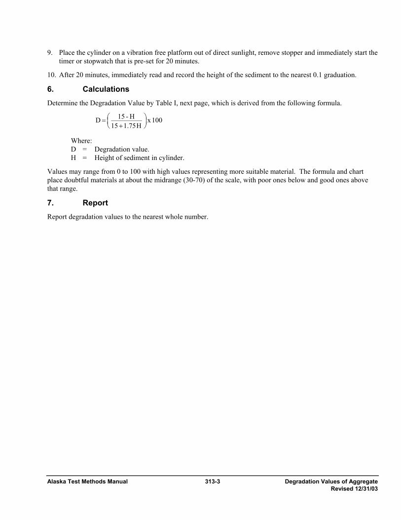
Alaska Test Methods Manual 313-3 Degradation Values of Aggregate Revised 12/31/03
9. Place the cylinder on a vibration free platform out of direct sunlight, remove stopper and immediately start the timer or stopwatch that is pre-set for 20 minutes.
10. After 20 minutes, immediately read and record the height of the sediment to the nearest 0.1 graduation.
6. Calculations Determine the Degradation Value by Table I, next page, which is derived from the following formula.
100 x H75.115
H - 15 D ⎟⎠⎞
⎜⎝⎛
+=
Where: D = Degradation value.
H = Height of sediment in cylinder.
Values may range from 0 to 100 with high values representing more suitable material. The formula and chart place doubtful materials at about the midrange (30-70) of the scale, with poor ones below and good ones above that range.
7. Report Report degradation values to the nearest whole number.
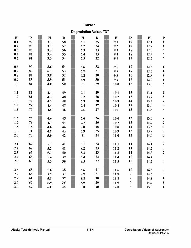
Alaska Test Methods Manual 313-4 Degradation Values of Aggregate Revised 3/15/05
Table 1
Degradation Value, "D" H D H D H D H D H D 0.1 98 3.1 58 6.1 35 9.1 19 12.1 8 0.2 96 3.2 57 6.2 34 9.2 19 12.2 8 0.3 95 3.3 56 6.3 33 9.3 18 12.3 7 0.4 93 3.4 55 6.4 33 9.4 18 12.4 7 0.5 91 3.5 54 6.5 32 9.5 17 12.5 7
0.6 90 3.6 54 6.6 32 9.6 17 12.6 6 0.7 88 6.7 53 6.7 31 9.7 17 12.7 6 0.8 87 3.8 52 6.8 30 9.8 16 12.8 6 0.9 85 3.9 51 6.9 30 9.9 16 12.9 6 1.0 84 4.0 50 7 29 10.0 15 13.0 5
1.1 82 4.1 49 7.1 29 10.1 15 13.1 5 1.2 81 4.2 48 7.2 28 10.2 15 13.2 5 1.3 79 4.3 48 7.3 28 10.3 14 13.3 4 1.4 78 4.4 47 7.4 27 10.4 14 13.4 4 1.5 77 4.5 46 7.5 27 10.5 13 13.5 4
1.6 75 4.6 45 7.6 26 10.6 13 13.6 4 1.7 74 4.7 44 7.7 26 10.7 13 13.7 3 1.8 73 4.8 44 7.8 25 10.8 12 13.8 3 1.9 71 4.9 43 7.9 25 10.9 12 13.9 3 2.0 70 5.0 42 8 24 11.0 12 14.0 3
2.1 69 5.1 41 8.1 24 11.1 11 14.1 2 2.2 68 5.2 41 8.2 23 11.2 11 14.2 2 2.3 67 5.3 40 8.3 23 11.3 11 14.3 2 2.4 66 5.4 39 8.4 22 11.4 10 14.4 1 2.5 65 5.5 39 8.5 22 11.5 10 14.5 1
2.6 63 5.6 38 8.6 21 11.6 10 14.6 1 2.7 62 5.7 37 8.7 21 11.7 9 14.7 1 2.8 61 5.8 37 8.8 20 11.8 9 14.8 0 2.9 60 5.9 36 8.9 20 11.9 9 14.9 0 3.0 59 6.0 35 9.0 20 12.0 8 15.0 0
Expansive Breakdown of 314-1 Alaska Test Methods Manual Stone on Soaking… Revised 12/31/03
Expansive Breakdown of Stone on Soaking in Ethylene Glycol ATM 314 1. Scope
This method covers a procedure for subjecting samples of stone to immersion in ethylene glycol and observation of the effects of such immersion in accordance with CRD-D 148-69.
2. Principle of Method
Ethylene glycol is one of the materials that reacts with swelling clays of the montmorillonite group to form an organo-clay complex having a larger basal spacing than that of the clay mineral itself. Hence a sample of stone containing swelling clay of the montmorillonite group will be expected to undergo expansive breakdown upon soaking in ethylene glycol, if the amount, distribution, state of expansion, and ability to take up glycol is such as to cause such breakdown to occur. If such breakdown does occur, it may be expected that similar breakdown may occur if similar rock samples are exposed, for longer times, to wetting and drying or freezing and thawing in a water soaked condition in service. 3. Reagent
Ethylene Glycol – The regent used in this method shall be ethylene glycol meeting the requirements of ASTM D 2693.
4. Apparatus
• Jaw crusher with 150 mm (6") capacity. • Sieves of the following sizes: 75 mm (3") and 19.0 mm (¾") and conforming to AASHTO M 92. • Balance or scale: Capacity sufficient for the principle sample mass, readable to 0.1 percent or 0.1 g of the
total sample mass and meeting the requirements of AASHTO M 231. • Container shall be of suitable plastic, non-reactive with the reagent and of sufficient size to hold the test
sample and sufficient reagent to cover all particles of the sample to a depth of not less that 10 mm (1/2") capped with a tight-fitting cover.
5. Sampling and Sample Preparation
1. Obtain representative samples of the stone in accordance with WAQTC FOP for AASHTO T 2.
2. Crush the rock to pass a 75 mm (3") sieve.
3. Separate the material into the required test size, using 75 mm (3") and 19 mm (¾") sieves, in accordance with WAQTC FOP for AASHTO T 27/T 11. Discard all particles retained on the 75 mm (3") sieve and all particles passing the 19 mm (¾") sieve, unless required for other testing.
4. Reduce the sample to a test size of 5 ± 2 kg (11 ± 1 lb) in accordance with WAQTC FOP for AASHTO T 248, Method A.
5. When a sample of the stipulated mass and particle size has been prepared, it shall be washed to remove dust, loosely adherent coatings, and chips. After being washed, dry to a constant mass in accordance with WAQTC FOP for AASHTO T 255/T 265 except that constant mass shall be regarded as having been attained when the loss in weight between successive weighing at intervals of not less than 4 hours does not exceed 0.1 percent. Determine the number of particles and the mass before immersion to the nearest 0.1 percent of the total sample mass.
Alaska Test Methods Manual 314-2 Expansive Breakdown of Stone on Soaking… Revised 12/31/03
6. Procedure
1. The sample shall be placed in the container and immersed in the reagent so that all particles are covered to a depth of at least 12.5 mm (½").
2. At intervals not to exceed 3 days, examine the sample and note significant changes. The normal duration of the test shall be 15 days.
Note 3: Further information of value may be obtained in certain cases by continuing the treatment beyond 15 days: in other cases expansive breakdown may have been too extensive at earlier periods that no information of value will be obtained by continuing the treatment for the full 15 days.
3. When the exposure has been terminated, the sample shall be thoroughly washed and sieved by hand over a 19 mm (¾") sieve to remove the reagent from the surfaces of the particles and to remove fragments that will pass a 19 mm (¾") sieve. The material remaining on the sieve shall be dried to constant weight as described in Step 4 of the Sampling and Sample Preparation, and the total mass after immersion determined to the nearest 0.1 percent of the total sample mass.
7. Calculations
Calculate the total percent loss by:
100 x M
M -
B
A
⎟⎟⎠
⎞⎜⎜⎝
⎛ BM
where: MB = Mass before immersion, and
MA = Mass after immersion. 8. Report
Report the percent loss to the nearest 1 percent on department forms.