Embed Size (px)
Citation preview
NOTE: Since the revision of NFPA 1971 slipped from the 1996 Annual Meeting revision cycle, the ROP is reprinted here on pages 280 through 362.
Report of the Committee on
Fire and Emergency Services Protective Clothing and Equipment
Technical Correlating Committee
Richard M. Duff)', Chair In t'l Assn. of Fire Fighters, DC Rep. Int'l Assn. of Fire Fighters
Thomas Augherton, Safety Equipment Inst., VA Joseph A. Bigler, Mine Safety Appliances Co., PA
Rep. Compressed Gas Assn. Dennis W. Browner, Scott Aviation, NC Rep. Industrial Safety Equipment Assn.
Robert H. Chiostergi, Southern Mills Inc., (,A Loui Clem, Alpine Center fi)r Rescue Studies, CO
Rep. Nat'l Assn. for Search and Rescue Paul H. Crawford, Southern Area Fire Equipment Research, CA
Rep. Southern Area Fire Equipment Research Robert A. Freese, (;Iobe Mfg., Co., NH William L, Grilliot, Morning Pride Mfg., Co., OH
Rel,. Fire and Emergency Mfrs. and.Services Assn., Inc. Tod L. Jilg, Hoechst (kelanese Gorp., NC James S. Johnson, Ltwrence Livermore Nat'l Labs, CA Cy Long, TX (;ommission on Fire Protection, TX David G. Matthews, I.IK Fire Brigades Assn., England
Rep. lnt'l Standards Organization Jim Minx, Oklahoma State Firefighters Assn., O K Ted Pumam, 1 ISDA Forest Service, MT Jeffrey o . Stall, Int'l Personnel Protection, Inc., TX Frank P. Taylor, Lion Apparel Inc., OH Bruce H. Varuer, City of Carrollu)n Fire Dept., TX Rep. Int'[ Fire Service Training Assn.
John Watt, (~difi:~rnia Dept. of Foresu 7, GA Harry Wirier, I I.S. Navy, MA Thomas L. Wollan, I Inderwriters Laboratories Inc., NC
Alternates
Mark B. Chambers, TX Commission on Fire Protection, TX (Ah. to C. D)ng)
Robert Dahl, The duPont Co., DE (Alt. to T. L. Jilg)
Ann Marie Williams, Springs Industries, SC (Alc to R~ H. Chiostergi)
Nonvoting
Don R. Forrest, I hfited Firefighters of LA City, CA Bryan C. Heirston, Oklahoma State Dept. of Labor, OK Richard Mangan, USDA Forest Service, MT Kirk H. Owen, Plant Fire Dept., TX Rep. NFPA Fire Service Section
Christopher B. Preu, Louisville Division of Fire, KY Alexander W. Santora, New York City Fire Dept., NY
Committee Scope: This Committee shall have primary responsibility for docmnents on the design, performance, testing, and certification of protective clothing and protective equipment mamffactured for fire and emergency services organizations and personnel to protect against exposures encountered during emergency incident operations. This (~mmittee shall also have the primary responsibility fi:~r documents on the selection, care, mid maintenance of such protective clothing and protective equipment by fire and emergency services organizations and personnel.
/
Technical Committee on
Fire Service Protective Clothing and Equipment
Kirk H. Owen, Chair Piano Fire Dept., TX
Rep. NFPA Fire Service Section
Wayde B. Miller, Secreta~ Mine S;d'ety Appliances Co., PA
(Nonw~ting)
Peter V. Ackerman, South Plainfield, NJ Rep. Nat'l Volunteer Fire Council
Donald Aldridge, Lion Apparel Inc., OH Curtis Berger, Menlo Park Fire Protection District; CA
Rep. Northern Area Fire Equipment Research Organization Joseph A. Bigler, Mine Safi~ty Appliances Co., PA
Rep. Gornpressed Gas Assn. Donna P. Brehm, Virginia Beach Fire Dept., VA Dennis W. Browner, Scott Aviation, NC
Rep. Industrial Safety Equipment Assn. Rand-Scott Coggan, Redmond, WA
Rep. !nt'l Assn. of Fire Chiefs Christopher E. Coombs, Cairns & Brother, Inc., NJ Paul H. Crawford, Southern Area Fire Eqnipment Research
Rep. Southern Area Fire Equipment Research Patricia A. Freeman, Globe Mfg., Co., NH Glen E. Gardner, U.S. Occupational Safety & Health Admin., DC Daniel Gohike, W. L. Gore & Assoc., MD JonathanJ. Greenawait, Kitsap County Fire District #2, WA William L. Grilliot, Morning Pride Mfg., (_~. Inc., OH Bryan C. Heirston, Oklahoma State Dept. of Labor, OK James R. Lawson, U.S. Nat'l Inst. of Stancktr&s and Technology, MD Cy Long, TX Commission on Fire Protection, TX Robert T. McCarthy, I I.S. Fire Administration, MD Robert W'dliam O'Gorman, Inchqape/ETL Testing Laboratories Inc., NY Christopher B. Preu, Louisville Division of Fire, KY Ray Reed, Dall~ Fire Dept., TX Alexander W. Santora, New York City Fire Dept., NY Brian A. Stoneback, 1LS. Air Force Fire Protection, FL Jeffrey o . Stull, Int'l Personnel Protection, Inc., TX Bruce H. Varner, City of Carrollton Fire Dept., TX James H. Veghte, Biotherm, Inc., OH Thomas L. Wollan, l lnderwriters Laboratories Inc., NC
Alternates
Roger L. Barker, N. (Larolina State University, NC (Ait. to P. A. Freeman)
Mary I. Grilliot, Morning Pride Mfg., Co., OH (Alt. to W. L. Grilliot)
Thomas A. Hillenbrand, Underwriters I~tboratories Inc., IL (Alt. to T. L. Wollan)
Dominick A. Martucci, United States Testing Co., Inc, NJ (Vot. Alt. to USTC Rep.)
Joanne E. Slattery, U.S. DepL of Labor OSHA, DC (Alt. to G. E. Gardner)
Richard L. Stein, Survivair, CA (Air. to D. W. Browner)
Jerry Swinford, Texas Commission on Fire Protection, TX (Alt. to C. Long)
Frank P. Taylor, Lion Apparel Inc., OH (Alt. to D. Aldridge)
Robert Vettori, U.S. Nat'l Inst. of Standards and Technology, MD (Ait. toJ. R. Lawson)
Staff Liaison: Bruce W. Teele
This list rqn'esents the m+w~bership at the time the Committee was ballot,~ on the text of this edition. Sirwe that time, changes in the membership may have occurred.
Committee Scope: This committee sh,'dl have primary responsibility for documents on the design, construction and performance criteria for protective clothing and equipment for the fire service including chemical protective clothing and aircraft rescue and fire fighting protective clothing.
280
This Report was prepared by the Technical Commit tee on Fire Service Protective Clothing and Equipment and proposes for adoption a complete revision to NFPA 1971-1991, Standard on Protective Clothing for Structural Fire Fighting, which consists of a combination of complete revisions and redesignation which incorporates NFPA 1972-1992, Standard on Helmets for Structural Fire Fighting, 1973-1993, Standard on Gloves for Structural Fire Fighting, and 1974-1992, Standard on Protective Footwear for Structural Fire Fighting. These documents are published in Volume 9 of the 1995 National Fire Codes and in separate pamphlet fi)rm.
This Report has been submitted to letter ballot of the Technical Commit tee on Fire Service Protective Clothing and Equipment , which consists of 29 w~ting members; of whom 19 w)ted affirmatively, 7 negatively (Mr. Browner, Ms. Freeman, Messrs. Grilliot ()'(;~)rman, Stoneback, Stull, and Wollan) 2 abstained (Messrs. Gardner and Mc(~u-thy), ,and 1 ballot was not returned (Mr. Gohlke.)
Mr. Browner wgted negatively stating: "We c:mnot objectively determine compliance to paragraph 3-1.3.5.
This paragraph requires user understanding which would then place compliance in the opinion of the individualreading the label. What a specific user, reading this label, will or will not understand is impossible to determine."
Ms. Freeman voted negatively stating: "As a reputable mantffacturer, we cannot support this document
with the inclusion of section 3-1.3.5 and with the current Appendix item A-3-1.1.
NFPA 1971 is a performance document, designed to protect fire fighters to the very best of our abilities. The above paragraphs offer no protection to the fire fighter, but do make the liability to the ulanufacturer completely nntenable.
In section 3-1.3.5: There is no way that a manufacturer can insure that the user underst'ands that conformance to the instructions will mitigate the risk and consequence. Further, it is impossible to guarantee that conformance to instructions will actually mitigate risk and consequence.
In Appendix section A-3-1.1: All manufacturers recognize that the purpose of the label is to protect the user and that it does not and will not absolve them of any liability. However, the proposed text does not protect the user not make him or her safe rather, in our litigious society, it is simply an open invitation to plaintiffs attorneys."
Mr. Grilliot w)ted negatively stating: "During the Technical Committee Meeting in San Francisco, I
believed that the Technical Committee had voted to delete ALL specific w:u[ting'requirenlents and only require that "a warning label" be attached to the product. We had problems with that decision, but the Conmlittee seemed to have formed a consensus. I had planned to w)te for the ROP so the document would not be delayed, and address any of our remaining warning concerns through the public comment process.
However, my review of the 1971 ROP reveals all specific warning requirements were N()T deleted (only the warning label language was) and that creates, I believe, literally an "industry stopping" crisis.
1. Specifically, paragraph 3-1.3.5 (and corresponding paragraphs for nnn-garment items) requires:
"The garment manufacturer shall integrato applicable warnings identifying 7isks a~ut consequences into the user information where appropriate, such that the user understands that conformance to the instructions will mitigate the risk and consequence."
There are obvious problems that make this requirement absolutely impossible to meet fi)r even the most diligent manufacturer:
(a) How c:m the manufacturer be held accountable fi)r insuring "tht~ usel__..£ u n d e r s t a n d s " ? g u l l (-an l e a d a h o r s e to w a t e r , h i l t you c a n ' t always make him drink.
(b) How could the manul~mtnrer identify all (that is how 11.S. strict liability law defines "where approp'date') potential risks?
(c) How many potential consequences are there for even one risk? (d) Given the above, how could a third party test lab certify a
manufacturer met this requirement? But these obvious problems are not the only problems with the
re tenton of paragraph 3-1.3.5 (and similar paragraphs fi)r non- garment products); its reterltion is a true Catch 22 situation for the fire service.
The easiest way to explain is through the use of an ex~nple. Let's suppose in spite of his most diligent efforts, a manufacturer fails to anticipate a risk. For instance, let's suppose a firefigbter is injured in a freak manner such as a plane of glass falls three stories onto him, causing severe injury. It is inarguable that falling glass was a risk, since the injury HAS occurred. Since the manufacturer failed to warn of a risk, his garment did not meet NFPA 1971 (because of the requireinents of paragraph 3-1.3.5 that risks must be warned oil.
Failure to meet the requirements of a national standard is DE- FACTO proof of product defect in most US legal jurisdictions.
If we can't, anticipate all risks, ...if paragraph 3-1.3.5 requires we must do so to meet the national standard, ...and if US Law makes us de-facto oroduct defective when we don ' t meet the national stand,arE HOW COULD ANY RATIONAL FIRM CONTINUE TO MANUFACTURE FOR THE FIRE SERVICE?
2. Also, we found another surprise that somehow just appeared (nut discussed in Tech Committee), in paragraph A-3-1.1. Among other things it says:
"Thefirst premise in providing adequate warnings is to understand that NO warning will remove or dilute a manufacturer's" obligation to adequatel~ warn, nor protect the manufacturer from liability. The're are many experts " _ _ , and far eoer~ there Jan be a differing "opinion on warning adequa~. The r~arr~ings are not, the'refute, inter~ded to remove liability." Review the Appendix handed out in San Francisco, this was not
part of the document at the close of that meeting. Where did this come from? Who is writing this stan&urd? This wording almost invites litigation, since it states some expert
will find any label inadequate and the manufacturer is liable. Then A-3-1.3.5 goes on to provide an incredibly demanding
lanndry list of requirements for the label (to which manufacturers will be held accountable) without providing guidance on how to accomplish same:
- label must be "unavoidably obvious" so the user "cannot avoid noticing iF - label should be "clear and q e catching" and ~ concise" - label should "establish the risk or hazard, establish the consequences of
exposure, establish safety pr~autions needed to mitigate or remove the CO~lSequ~es, - etc. It is impossible lbr even the most diligent mantffacturer to meet all
these requirements ( v.¢2£~ user must notice the label, establish al.._[l risks, consequences and safety precautions, etc.).
3. Legal ()pinion Granted just as the deletion of warning label language helps shield
the NFPA organization legally, these paragraphs (3-1.3.5 and A-3- 1.1) offer for want of a better term "the remaining shield". In other words, NFPA has avoided legal exposure as to the adequacy of warning label language by now not requiring specific language. But, in our counsel's position, NFPA had a remaining minimal legal exposure where a firefighter was hurt because his new NFPA garment did not have a warning that was previously required by the Standard (before NFPA's decision to'delete specific warning language) and which warning (if present) would have prevented his injury. Paragraph 3-1.3.5 allows, again in our counsel's opinion, NFPA the "shield" of being able to say,
"Wait, NFPA is not liable even though we deleted that specific warning requirement since paragraph 3-1.3.5 requires the manufacturer to warn of risks. If he didn't warn of a risk, his product does not meet the Standard and we are not involved."
But, in our op.inion, . . . . the shield atgminst a minimal risk to NFPA comes at a ternble pnce: the paralysis of the American Fire Manufacturing Community. Will this situation make firms with all their assets safely beyond our national boundaries (and thus less awtilable to the courts in the case of DE-FACTO judgements arising out of unanticipated risks) the only firms logically able to product f ) r the fire service. Would this service the interests of the fire service?
In Smnmary- The retention of paragraph 3-1.3.5 (and similar paragraphs for
other products), the inclusion of A-3-1.1, combined with the deletion of specific warning label language issuch a terrible disservice to the fire service, that I feel the only morally right voted on this issue is a negative vote. While I regret this may delay the document six months (of others vote negatively); I believe that is a small price to pay for correcting such a critical mistake. I am unconffortable leaving the correction to the public comment period since this particular issue is one that seems to have a life of its own; originally, the issue of requiring manufacturers to warn of all risks was inserted into ALL open documents WITHOUT COMMITTEE DISCI~SSION before the Austin meeting. The change in position was attributed to the rope task group but the rope task group and the fuU Technical Committee voted to delete the wording, presumably, because they understood the impossible (~tch 22 the requirement imposed on fire service manufacturers, but it is now back. Similarly, we brought the issue up in San Francisco and understood "that all specific warning requirements were to be deleted", that would (at least, in my opinion) have included deleting specific warning requirements of 3-1.3.a and preventing insertion of A-3-1.1, but it did not.
If we let this document go into public comment, and there are similar misunderstandings as these which lets the requirement st~md (perhaps even after a vote to the contrary) - - w e will have an issued docnment that precludes rational firms from making product for the fire servicel!
281
l can umterstand w~ting yes on a document with small problents that we are relatively su're can be addressed during public comment. But this is :m industry stopping issue that stubbornly resists being fixed. Why do we even vote on the ROP, if proper wisdom is "to fix problems (no matter how big) in public comment". Isn't that really a cop-out, a diminishing by one step of the NFPA review process ? And what is the big deal if this seriously flawed document is delayed six months - - ourJuly meeting is basically open. We ,are starting to talk like "delaying the document", is an evil on a level with the Holocaust. WE ARE SUPPOSED TO VOTE AGAINST A SERIOUSLY FLAWED
DOCUMENT - - Are yov proud of this document? Our real responsibility is m vote our true feelings on the document, not to vote fl)r re~tsons of expediency!!"
Mr. O'Gorman w)ted negatively staring: "Warning labels" as well members of the Technical Gonu-nittee
should recall, were discussed in great detail during the San Francisco meetings. Ks an actively participating member of the committee and having taken part in the discussions that took place regarding this issue, I can not f ind either in my notes or the previous documents where section A-3.1.1 or any other sections of the NFPA documents being combined ever referred to the manufacturer 's liability.
Section 3-1.3.5 requires the th i rdpar ty to certify that the user underst,'mds that conformance to the instructions will mitigate their risk ;md consequences. Having reviewed this carefully, I believe that the only way to accomplish this would be to certify a mandatory training procedure established as a p a r t o f each garment sale. This quickly becomes a training issue andtakes us away from the issue of performance."
Mr. Stoneback w)ted negatively stating: "It was agreed that all specific warning label requirements be
deleted. They still exist and some were even placed in the appendix. Let's relook in July."
Mr. Stull voted negatively stating: "I have reviewed the negative ballots presented in the letter
circulating the original results on the ROP and primarily agree with the comments on requirements relative to warmng labels. Manufacturer concerns about liability have arisen due to significant changes in the proposed standard. The new requirementsplace the fire service protective clothing industry in jeopardy and wi l l ultimately compromises the safety of fire fighters. The industry needs direction f rom the NFPA Technical Committee with its broad expertise to provide a consensus basis for the minimum performance, design, and documentat ion of protective products. This responsibility has ,and shonld continue to be extended to w , ~ i n g label design and language in a way that supports both manufacturer and end user. I~ss of confidence by either group in this process undermines the value of the NFPA standards within the fire protection industry.
Warning labels need to convey specific language to the end user in a concise manner. A task group established to develop this specific language had developed what I deemed a reasonable first draft. However, I feel that the interjection of NFPA philosophy on this matter has ,altered the normal process of standards development and has resulted in untenable language which may be difficult to correct during the public comment process. The standard already represents an achievement of consolidation and incorporation of new des ign/per formance areas which I believe are extremely vahmble to fire protection industry. Those involved in this process should be commended; however, I believe that the new Technical Gommittee on Smmtnral Fire Fighter Protective Clothing will be hard pressed to deal with the magnitude of issues likely presented during public comment . Given the issue o f warning labels, it seems
appropriate to clear this matter first, perhaps with the ,assistance of the new Technical Correlating C~)mmittee on Fire and Emergency Service Protective Clothing and EquipmenL"
Mr. Wollan voted negatively stating: "1. Paragraph 3-1.2.3, Section 3-1.2 is titled "Product Label
Requirements" however . . . . . ?,-1 2 3 states "The su plementary warning label shall have at least the fi)llowing text... '. ~hPe specific wording is then given fi)r this label.
(a) Is this a warning label or a ~ label? (b) If it is a warning label, I recall a motion made and passed at
the San F~mcisco meeting that in effect deleted all required specific warning label wording. Warning label(s) were to be required- periodI
(c) If this is a ~ label, remove the word ~warning" from both paragraphs 3-1 .'2.3 and 4-1.2.2.
2. Paragrapns 3-1.1.1, 3-2.1.1, $-3.1.1,3-4.1.1, and 3-5.1.1. Are ~ labels required to be ~printed at least in English"
similar to the requirement in paragraph 3-1.2.8 for Product Labels? l believe this needs to be included as a requirement.
3. There is some conflict between the definition of Product Label (states it ~can contain the label o f the certification organization") and paragraph 2-1.4 which states "the certification organization's mark shall be attached to thej3roduct label'.
4. Paragraphs 3-1.3.5, 3-2.3..% 3-3.3.5, 3-4.3.5, and 3-5.3.5. These paragraphs (all the same wording) require the certifying
laboratory to determine and certify whether the manufactnrer has "integrated applicable warnings identifying risks and consequences into the user information where appropriate such that the user understands that conformance to the instructions will mitigate the risk of consequence".
Key words here are: * applicable warnings : where appropriate
such that the user understands It is impossible for the certifying lab to determine conformance to
these requirements without specified and defined levels of acceptability for each.
5. Accessories Concept" I believe the new reqturements for accessories not "degrading the
designed protection or performance of the e lement below the requirements of this standard" is a good GOJI.f,¢.~. However, I believe clarification is needed regarding:
(a) the definition of accessories. (b) Paragraph "2-3.8. Does each accessory need to be certified as
stated? (c) Paragraph 4-8.1, the "function" of the e lement or its
componen t parts needs to be defined so that compliance can be determined.
(d) See also paragraph 1-1.5. 6. Paragraph 6-49.7.3. The term ~head opening" needs to be
specifically defined in order to make an evaluation.
Mr. Gardner abstained stating: "Although I concur with the Committee 's actions, it is the policy of
my agency to be a non-voting member."
Mr. McCarthy abstained stating: ~USFA reviewing policy on Committee voting."
This Report has also been submitted to letter ballot o f the Technical Correlating Committee on lrtre and Emergency Services Protective Clothing and Equipment, which consists of 21 voting members] o f whom 18 voted affirmatively and 3 ballots were not re turned (Messrs. Bigler, Clem, and Matthews).
282
N F P A 1 9 7 1 -- A 9 6 ROP
PART I
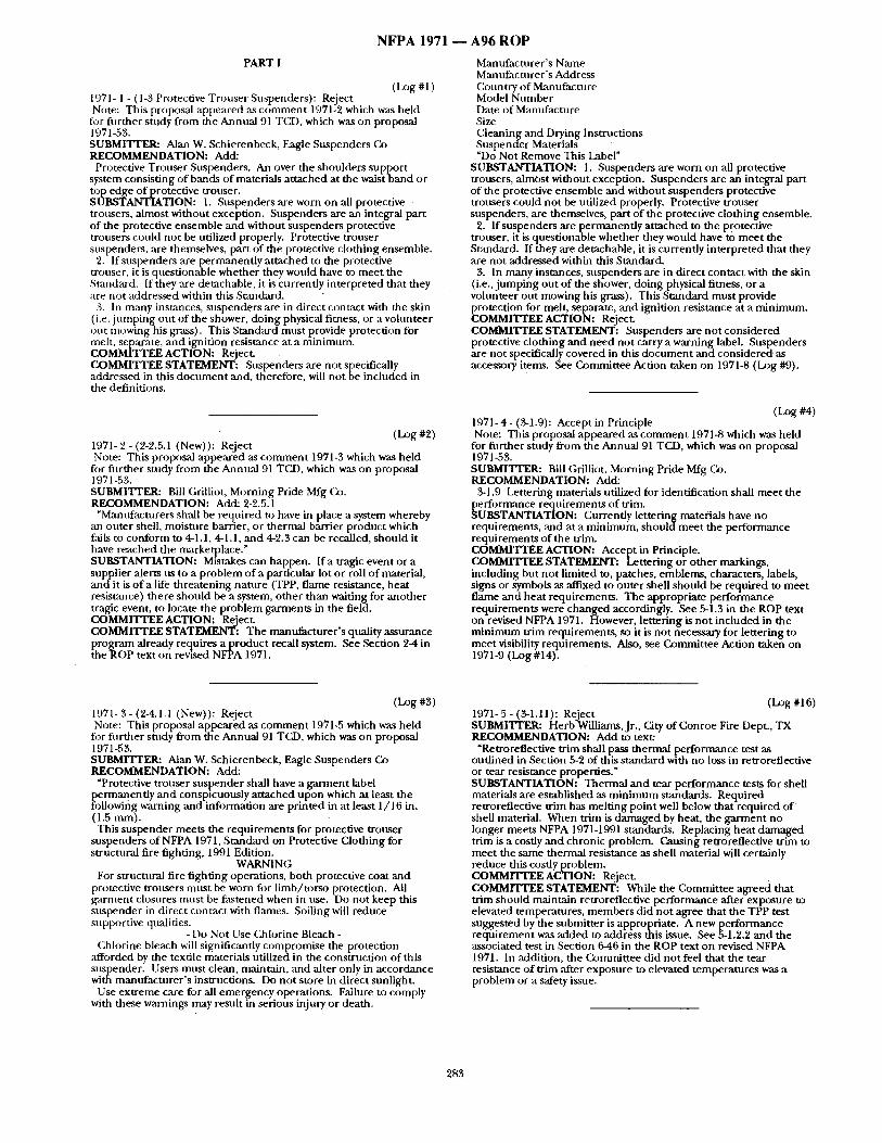
( L o g # l ) 1971- 1 - ( 1-3 Protective Trouser Suspenders): Reject Note: This proposal appeared as c o m m e n t 1971-2 which was held
for fur ther study from the Annual 91 TCD, which was on proposal 1971-53. SUBMI'I*rER: Alan W. Schierenbeck, Eagle Suspenders Co RECOMMENDATION: Add:
Protective Trouser Suspenders. An over the shoulders suppor t system consisting o f bands of materials a t tached at the waist band or top edge of protective trouser. SUBSTANTIATION: 1. Suspenders are worn on all protective trousers, almost without exception. Suspenders are an integral part of the protective ensemble and without suspenders protective trousers could not be utilized properly. Protective trouser suspenders, are themselves, part of the protective clothing ensemble.
2. If suspenders are pe rmanendy a t tached to the protective trouser, it is questionable whether they would have to meet the Standmd. If they are detachable, it is currently interpreted that they are not addressed within this St~mdard.
3. In many inst~mces, suspenders are in direct contact with the skin (i.e. j u m p i n g out of the shower, do ing physical fitness, or a vohmteer out mowing his grass). This Stan&ard mus t provide protection for melt, separate, and ignition resistance at a min imum. COMMITTEE ACTION: Reject. COMMITTEE STATEMENT: Suspenders are not specifically addressed in this d o c u m e n t and, therefore, will no t be included in the definitions.
(Log #2) 1971- 2 - (2-2.5.1 (New)): Reject Note: This proposed appeared ,as c o m m e n t 1971-3 which was held
for fi lrther study from the Annual 91 TCD, which was on proposal 1971-53. SUBMITrER: Bill Grilliot, Morning Pride Mfg Co. RECOMMENDATION: Add: 2-2.5.1
"Manufacturers shall be required to have in place a system whereby an outer shell, moisture barrier, or thermal barrier product which fails to conform to 4-1.1, 4-1.1, and 4-2.3 can be recalled, should it have reached the marketplace." SUBSTANTIATION: Mistakes can happen. I r a tragic event or a supplier alerts us to a p rob lem of a particular lot or roll o f material, a n d i t is o f a life threa tening na ture (TPP, f lame resistance, hea t resistance) there should be a system, o ther than waiting for ano the r tragic event, to locate the problem garments in the field. COMMITTEE ACTION: Reject. COMMITTEE STATEMENT: The manufac ture r ' s quality assurance Pthrogram already requires a product recall system. See ,Section 2 4 in
e ROP text on revised NFPA 1971.
Manuf~rcturer's Name Manufacturer ' s Address Country o f Manufacture Model N u m b e r Date of Manufacture Size Cleaning and Drying Instructions Suspender Materials "Do Not Remove This Label"
SUBSTANTIATION: 1. Suspenders are worn on all protective trousers, a lmost without exception. Suspenders are an integral part of the protective ensemble and without suspenders protective trousers could not be utilized properly. Protective trouser suspenders, are themselves, part of the protective clothing ensemble.
2. If suspenders are permanent ly a t tached to the protective trouser, it is questionable whether they would have to meet the Standard. If they are detachable, it is currendy interpreted that they are not addressed within this Standard.
3. In many instances, suspenders are in direct contact with the skin (i.e., j u m p i n g out o f the shower, doing physical fitness, or a vohmteer out mowing his grass). This Standard mus t provide protection for melt, separate, and ignition resistance at a min imum. COMMITTEE ACTION: Reject. COMMITTEE STATEMENT: Suspenders are not considered protective clothing and need not carry a warning label. Suspenders are not specifically covered in this d o c u m e n t and considered: as accessory items. See Commit tee Action taken on 1971-8 (D)g #9).
(Log #4) 1971- 4 - (3.1.9): Accept in Principle Note: This proposal appeared as c o m m e n t 1971-8 which was held
for fi lrther study f rom the Annual 91 TCD, which was on proposal 1971-53. SUBMITTER: Bill Grilliot, Morning Pride Mfg Co. RECOMMENDATION: Add:
3-1.9 Lettering materials utilized for identification shall mee t the
~ erformance requi rements of trim. UBSTANTIATION: Currently lettering materials have no
requirements , and at a min imum, s h o u l d m e e t the per formance requi rements of the trim. COMMITTEE ACTION: Accept in Principle. COMMITTEE STATEMENT: Letter ing or o ther markings, including but no t limited to, patches, emblems, characters, labels, signs or symbols as ,affixed to outer shell should be required to meet f lame and hea t requirements . The appropriate per formance requi rements were changed accordingly. See 5-1.3 in the ROP text on revised NFPA 1971. However, let tering is no t included in the r m m m u m trim requirements , so it is no t necessary for lettering to mee t visibility requirements . Also, see Commit tee Action taken on 1971-9 (Log #14).
(Log #3) 1971- 3 - (2-4.1.I (New)): Reject Note: This proposal appeared as comment 1971-5 which was held for further study from the Annual 91 TCD, which was on proposal 1971-53. SUBMITI'ER: Alan W. Schierenbeck, Eagle Suspenders (2) RECOMMENDATION: Add: "Protective trouser suspender shall have a garment label
permanently and conspicuously attached upon which at least the following warning and information are printed in at least 1/16 in. ( 1.5 ram). This suspender meets the requi rements for protective trouser
suspenders of NFPA 1971, Standard on Protective Clothing for structural fire fighting, 1991 Edition.
WARNING For structural fire f ighting operations, both protective coat and
protective trousers mus t be worn fi)r l imb/ torso protection. All ga rmen t closures mus t be f ,~tened when in use. Do not keep this suspender in direct contact with flames. Soiling will reduce supportive qualities.
-Do Not Use Chlorine Bleach- Chh)rine bleach will significantly compromise the protection
:tfforded by the textile materials utilized in the construct ion of this suspender. Users mus t clean, maintain, and alter only in accordance with manufac ture r ' s instructions. Do not store in direct sunlight.
Use ext reme care for ,all emergency operations. Failure to comply with these warnings may result in serious injury or death.
(Log #16) 1971-5 - (3-1.11): Reject SUBMITrER: Herb Williams, Jr., City of Conroe Fire Dept., TX RECOMMENDATION: Add to text:
~Retroreflective tr im shall pass thermal performance test as out l ined in Section 5-2 of this s tandard with no loss in retroreflective or tear resistance properties." SUBSTANTIATION: Thermal and tear per formance tests for shell materials are established as m i n i m u m standards. Required retroreflective trim has mel t ing poin t well below that required o f shell material. When tr im is damaged by heat, the ga rmen t no longer meets NFPA 1971-1991 standards. Replacing heat damaged trim is a costly and chronic problem. Causing retroreflective trim to meet the same thermal resistance as shell material will certainly reduce this cosdy problem. COMMITTEE ACTION: Reject. COMMITTEE STATEMENT: While the Commit tee agreed that trim should maintain retroreflective per formance after exposure to elevated temperatures, members did no t agree that the TPP test suggested by the submit ter is appropriate. A new per formance requ i rement was added to address this issue. See 5-1.2.2 and the associated test in Section 6-46 in the ROP text on revised NFPA 1971. In addition, the Commit tee did no t feel that the tear resistance o f tr im ,after exposure to elevated temperatures was a problem or a safety issue.
283
N F P A 1971 - -
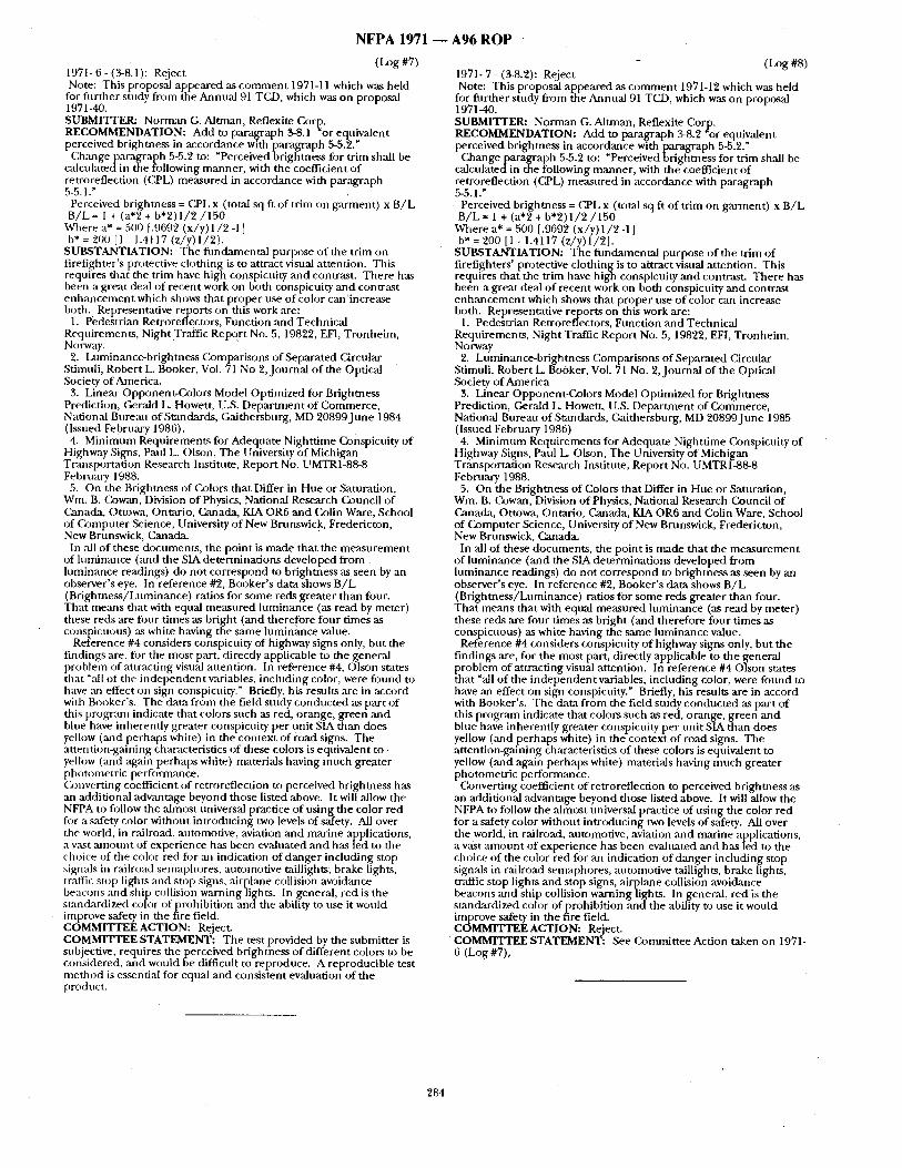
1971- 6- (3-8.1): Reject (IJ~g#7) Note: This proposal appeared as comment 1971-11 which was held
for further study from the Annual 91 TCD, which was on proposal 1971-40. SUBMITTER: Norman G. Altman, Reflexite Corl~. RECOMMENDATION: Add to paragraph 3-8.1 or equivalent perceived brightness in accordance with paragraph 5-5.2."
C, hangeparagraph 5-5.2 to: ~Perceived brightness for trim shall be calcu[atedin the following manner , with the coefficient o f retroreflection (CPL) measured in accordance with paragraph 5-5.1 ."
Perceived brightness = CPL x (total sq ft of trim on garment) x B / L B/L = 1 + (a*2 + b*2) 1 / 2 / 1 5 0
Where a* = 500 [.9692 (x/y) 1/2 -1 ] b* = 200 [1 - 1.4117 (z/y) 1/2].
SUBSTANTIATION: The funcklmental pt, rpose of the trim on firefighter's protective clothing is to attract visual attention. This requires that the trim have high conspicuity and contrast. There has been a great deal o f recent work on both conspicuity and contrast enhancement which shows that proper use of color can 'increase both. Representative r e p o t s on this work are:
1. Pedestrian Retroreflectors, Function and Technical Reqvirements, Nigh t .Tr ,~c Report No. 5, 19822, EFI, Tronheim, Norway.
2. Luminance-brightness (:2mlparisons of Separated Circular Stimuli, Robert L. Booker, Vol. 71 No 2,Journal o f the Optical Society of America.
3. Linear Opponent-Colors Model Optimized for Brightness Prediction, Gerald L. Howett, U.S. Depar tment of Commerce, National Bureau of Standards, Gaithersburg, MD 20899June 1984 (Issued February 1986). 4. Minimum Requirements for Adequate Nighttime Conspicuity of
Highway Signs, Paul L. Olsou, The University of Michigan Transportation Research Institute, Report No. UMTR1-88-8 February 1988.
5. On the Brightness of Colors that Differ in Hue or Saturation, Win. B. Cowan, Division of Physics, National Research Council of Canada, Ottowa, Ontario, Canada, KIA OR6 and Colin Ware, School of (~)mputer Science, University of New Brunswick, Fredericton, New Brunswick, Canada.
In all of these documents, the point is made that the measurement of luminance (and the SIA determinations developed from hmfinance readings) do not correspond to brightness asseen by an observer's eye. In reference #2, Booker's data shows B /L (Brightness/Luminance) ratios for some reds greater than four. That means that with equal measured luminance (as read by meter) these reds are flour times as bright (and therefore four times as conspicuous) as white having the same luminance value.
Reference #4 considers conspicuity of highway signs only, but the findings are, for the most part, directly applicable to the general problem of attracting visual attention. In reference #4, Olson states that "all of the independent variables, including color, were fiaund to have ,an effect on sign conspicuity." Briefly, his results ,are in accord with Booker's. The data from the field study conducted as part of dais program indicate that colors such as red, orange, green mad blue have inherently greater conspicuity per trait SIA than does yellow (and perhaps white) in the context of road signs. The at tent ion~aining characteristics of these colors is equivalent to- yelhaw (and again perhaps white) materials having much greater photometric performance. (kmverting coefficient of retroreflection to perceived brightness has an additional advantage beyond those listed above. It will allow the NFPA to follow the almost universal practice of using the color red fiat a safety color without introducing two levels of safety. All over the world, in railroad, antomotive, aviation and marine applications, a wL~t mnount of experience has been evaluated and has led to the choice of the color red fi)r ml indication of danger including stop signals in railroad semaphores, automotive taillights; brake lights, traffic stop lights and stop signs, airplane collision avoidance beacons and ship collision warning lights. In general, red is the stancLardized color ofprohibi t ion and the ability to use it world improve safety in the fire field. COMMITTEE ACTION: Reject. COMMITTEE STATEMENT: The test provided by the submitter is subjective, requires the perceived brightness of different colors to be considered, and would be difficult to reproduce. A reproducible test method is essential for equal and consistent evaluation of the product.
A 9 6 R O P
- (Log #8) 1971- 7 - (3-8.2): Reject Note: This proposal appeared as comment 1971-12 which was held
for further study from the Annual 91 TCD, which was on proposal 1971-40. SUBMITTER: Norman G. Altman, Reflexite Cor~p. RECOMMENDATION: Add to paragraph 3-8.2 or equivalent perceived brightness in accordance with paragraph 5-5.2."
Changeparagraph 5-5.2 to: "Perceived brightness for trim shall be calculatedin the following manner, with the coefficient o f retroreflection (CPL) measured in accordance with paragraph 5-5.1."
Perceived brightness = Ca~L x (total sq ft of trim on g a ~ e n t ) x B /L B / L = 1 + (a*2 + b ' 2 ) 1 / 2 / 1 5 0
Where a* = 500 [.9692 ( x / y ) l / 2 -1 ] b* = 200 [1 - 1.4117 (z/y) 1/21.
SUBSTANTIATION: The fundamental purpose of the trim of flrefighters' protective clothingis to attract visual attention. This requires that the trim have high conspicuity and contrast. There has been a great deal of recent work on both conspicuity and contrast enhancement which shows that proper use o f color can increase both. Representative reports on this work are:
1. Pedestrian Retroreflectors, Function and Technical Requirements, Night Traffic Report No. 5, 19822, EFI, Tronheim, Norway
2. Luminance-brightness Comparisons of Separated Circular Stimuli, Robert L. Booker, Vol. 71 No. 2,Journal of the Optical Society of America
3. Linear Opponent-Colors Model Optimized for Brightness Prediction, Gerald L. Howett, U.S. Depar tment of Commerce, National Bureau of Standards, Gaithersburg, MD 20899June 1985 (Issued February 1986) 4. Minimum Requirements for Adequate Nighttime Conspicuityof
Highway Signs, Paul L. Olson, The University of Michigan Transportation Research Institute, Report No. UMTR1-88-8 February 1988.
5. On the Brightness of Colors that Differ in Hue or Saturation, Wm. B. ())wan, Division of Physics, National Research Council of Canada, Ottowa, Ontario, Canada, KIA OR6 and Colin Ware, School of Computer Science, University of New Brunswick, Fredericton, New Brunswick, Canada.
In all o f these documents, the point is made that the measurement of luminance (and the SIA determinations developed from luminance readings) do not correspond to brightness as seen by an observer's eye. In reference #2, Booker's data shows B /L (Brightness/LuminanCe) ratios for some reds greater than four. That means that with equal measured luminance (as read by meter) these reds are four times as bright (and therefore four times as conspicuous) as white having the same luminance value.
Reference #4 considers conspicuity of highway signs only, but the findings are, fl~r the most part, directly applicable to the general problem of attracting visual attention. In reference # 4 0 l s o n states that "all of the independent variables, including color, were found to have an effect on sign conspicuity." Briefly, his results are in accord with Booker's. The data from the field study conducted as part of this program indicate that colors such as red, orange, green and blue have inherently greater conspicuity per unit SIA than does yellow (and perhaps white) in the context o f road signs. The attention-gaining characteristics of these colors is equivalent to yellow (and again perhaps white) materials having much greater photometric performance.
Converting coefficient of retroreflection to perceived brightness as' an additional advantage beyond those listed above. It will allow the NFPA to follow die almost universal practice of using the color red for a safety color without introducing two levels of safety. All over the world, in railroad, automotive, aviation and marine applications, a vast amount of experience has been evaluated and has led to the choice of the color red for an indication of danger including stop signals in railroad semaphores, automotive taillights, brake lights, t r , ~ c stop lights and stop signs, airplane collision avoidance beacons and ship collision waruing lights. In general, red is the standardized color ofprohibi t ion and the ability to use it would improve safety in the fire field. COMMITTEE ACTION: Reject. COMMITTEE STATEMENT: See Committee Action taken on 1971- 6 (Log #7),
284
N F P A 1 9 7 1 m A 9 6 R O P
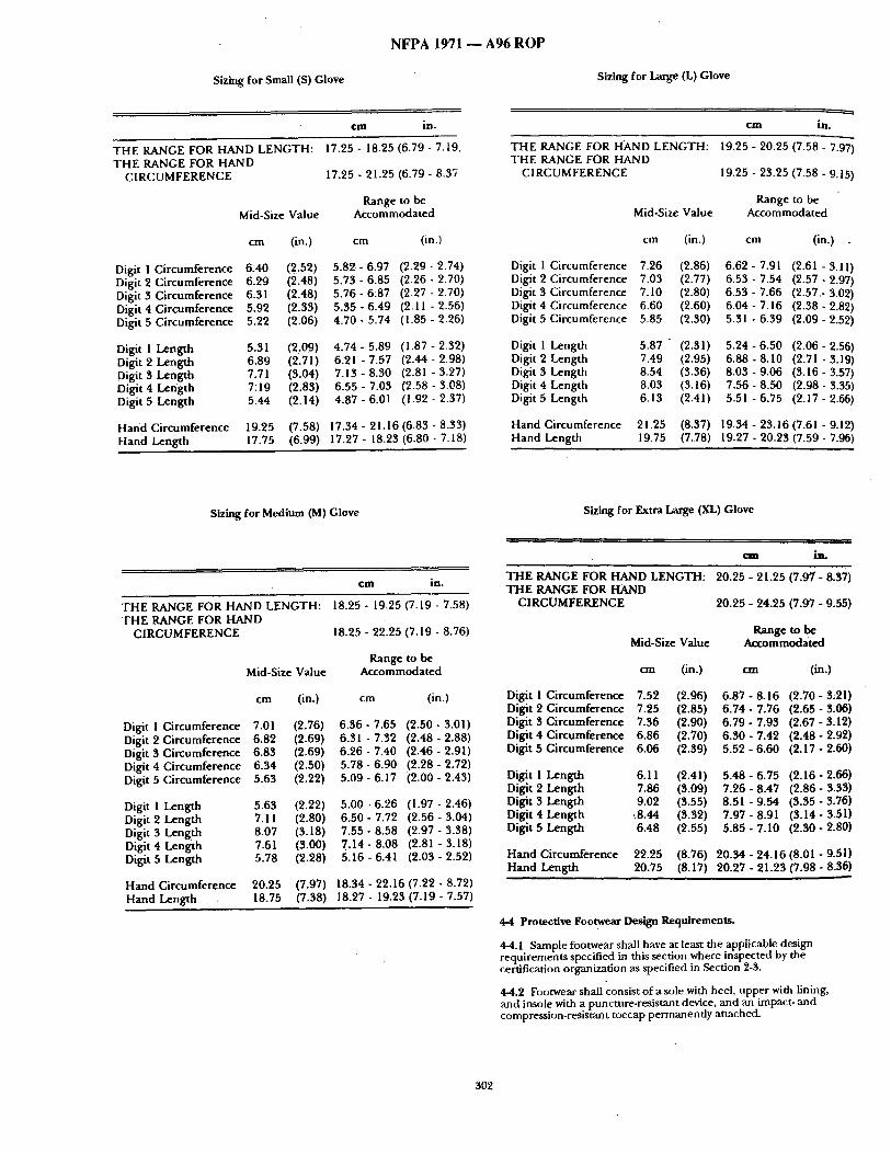
Sizing for Small (S) Glove Sizing for Large (L) Glove
c m in.
T H E RANGE FOR HAND L E NGT H: T H E RANGE FOR HAND
C I R C U M F E R E N C E
Mid-Size Value
cm (in.)
Digit 1 C i r cumfe rence 6.40 (2.52) Dig i t2 C i r cumfe rence 6.29 (2.48) Digit 3 C i r cumfe rence 6.31 (2.48) Digit 4 C i r cumfe rence 5.92 (2.33) Digit 5 C i rcumference 5.22 (2.06)
Digit 1 Leng th 5.31 (2.09) Digit 2 Leng t h 6.89 (2.71) Digit 3 Leng th 7.71 (3.04) Digit 4 Leng th 7:19 (2.83) Digit 5 Leng th 5.44 (2.14)
H a n d C i rcumfe rence 19.25 (7.58) [-land Leng th 17.75 (6.99)
17.25 - 18.25 (6.79 - 7.19,
17.25 - 21.25 (6.79 - 8.37
Range to be Accommoda ted
cm (in.)
5.82 - 6.97 (2.29 - 2.74) 5.73 - 6.85 (2.26 - 2.70) 5.76 - 6:87 (2.27 - 2.70) 5 . 3 5 - 6 . 4 9 (2.11 -2 .56) 4.70 - 5.74 (1.85 - 2.26)
4.74 - 5.89 (1.87 - 2.32) 6.21 - 7.57 (2.44 - 2.98) 7.13 - 8.30 (2.81 - 3.27) 6.55 - 7.03 (2.58 - 3.08) 4.87 - 6.01 (! .92 - 2.37)
17.34 - 21.16 (6.83 - 8.33) 17.27 - 18.23 (6.80 - 7.18)
,
c m in.
T H E RANGE FOR HAND LENGTH: T H E RANGE FOR HAND
CIRCUMFERENCE
Mid-Size Value
19.25 - 20.25 (7.58 - 7.97)
19.25 - 23.25 (7.58 - 9.15)
Range to be Accommoda ted
cm (in.) cm (in.)
Digit 1 Ci rcumference 7.26 (2.86) 6.62 - 7.91 (2.61"- 3.11) Digit 2 Ci rcumference 7.03 (2.77) 6.53 - 7.54 (2.57 - 2.97) Digit 3 Ci rcumference 7.10 (2.80) 6.53 - 7.66 (2.57,- 3.02) Digit 4 Ci rcumference 6.60 (2.60) 6.04 - 7.16 (2.38 - 2.82) Digit 5 Ci rcumference 5.85 (2.30) 5.31 - 6.39 (2.09 - 2.52)
Digit I Length 5.87 (2.31) 5.24 - 6.50 (2.06 - 2.56) Digit 2 Length 7,49 (2.95) 6.88 - 8.10 (2.71 - 3.19) Digit 3 Length 8.54 (3.36) 8.03 - 9,06 (3.16 - 3.57) Digit 4 Length 8.03 (3.16) 7.56 - 8.50 (2.98 - 3.35) Digit 5 Length 6.13 (2.41) 5.51 - 6,75 (2.17 - 2.66)
Hand Ci rcumference 21,25 (8.37) 19.34 - 23.16 (7.61 - 9.12) H a n d Leng th 19,75 (7.78) 19.27 - 20.23 (7.59 - 7.96)
Sizing for Medium (M) Glove Sizing for Extra Large (XL) Glove
c m in .
T H E RANGE FOR HAND LENGTH: T H E RANGE FOR HAND
C I R C U M F E R E N C E
18.25 - 19.25 (7.19 - 7.58)
18.25 - 22.25 (7.19 - 8.76)
Range to be Mid-Size Value Accommoda ted
cm (in.) cm (in.)
Digit 1 Ci rcumference 7.01 (2.76) 6.36 - 7.65 (2.50 - 3.01) Digit 2 C i rcumference 6.82 (2,69) 6.31 - 7.32 (2.48 - 2.88) Digit 3 C i rcumference 6.83 (2.69) 6.26 - 7.40 (2.46 - 2.91) Digit 4 C i rcumference 6.34 (2,50) 5.78 - 6.90 (2.28 - 2.72) Digit 5 C i rcumference 5.63 (2,22) 5.09 - 6.17 (2.00 - 2.43)
Digit I Leng th 5.63 (2,22) 5.00 - 6.26 (1.97 - 2.46) Digit 2 Leng th 7,11 (2,80) 6.50 - 7.72 (2.56 - 3.04) Digit 3 Leng th 8.07 (3,18) 7.55 - 8.58 (2.97 - 3.38) Digit 4 Leng th 7.61 (3,00) 7.14 - 8.08 (2.81 - 3.18) Digit 5 Leng th 5.78 (2,28) 5.16 - 6.41 (2.03 - 2.52)
H a n d Ci rcumference 20.25 (7,97) 18.34 - 22.16 (7.22 - 8.72) H a n d Leng th 18.75 (7.38) 18.27 - 19.23 ( 7 . 1 9 , 7 . 5 7 )
c m in .
T H E RANGE FOR H A N D LENGTH: T H E RANGE FOR HAND
C I R C U M F E R E N C E
2 0 . 2 5 - 2 1 . 2 5 ( 7 . 9 7 - 8 .37)
2 0 . 2 5 - 2 4 . 2 5 (7 ,97 - 9 .55)
Range to be Mid-Size Value Acco m m o d a t ed
cm (in.) c m (in.)
Digit 1 C i rcumference 7.52 (2.96) 6.87 - 8.16 (2.70 - 3;21) Digit 2 C i rcumference 7.25 (2.85) 6.74 - 7.76 (2.65 - 3.06) Digit 3 C i rcumference 7.36 (2.90) 6.79 - 7.93 (2.67 - 3.12) Digit 4 C i rcumference 6.86 (2.70) 6.30 - 7.42 (2.48 - 2.92) Digit 5 Ci rcumference 6.06 (2.39) 5.52 - 6.60 (2.17 - 2.60)
Digit 1 Leng th 6.11 (2.41) 5.48 - 6.75 (2.16 - 2.66) Digit 2 Leng th 7.86 (3.09) 7.26 - 8.47 (2.86 - 3.33) Digit 3 Leng th 9.02 (3.55) 8.51 - 9.54 (3.35 - 3.76) Digit 4 Leng th ~8.44 (3.32) 7.97 - 8.91 (3.14 - 3.51) Digit 5 Leng th 6.48 (2.55) 5.85 - 7.10 (2.30 - 2.80)
H a n d Ci rcumference 22.25 (8.76) 20.34 - 24.16 (8.01 - 9.51) H a n d Leng th 20.75 (8.17) 20.27 - 21.23 (7.98 - 8.36)
4-4 Protective Footwear Design Requirements .
4-4.1 Sample footwear shall have at least the applicable design requi rements specified in this section where inspected by the certification organization as specified in Section 2-3.
4-4.2 Footwear shall consist o f a sole with heel, upper with lining, and insole with a puncture-resistant device, and an impact- and compression-resistant toecap permanent ly attached.
302
NFPA 1971
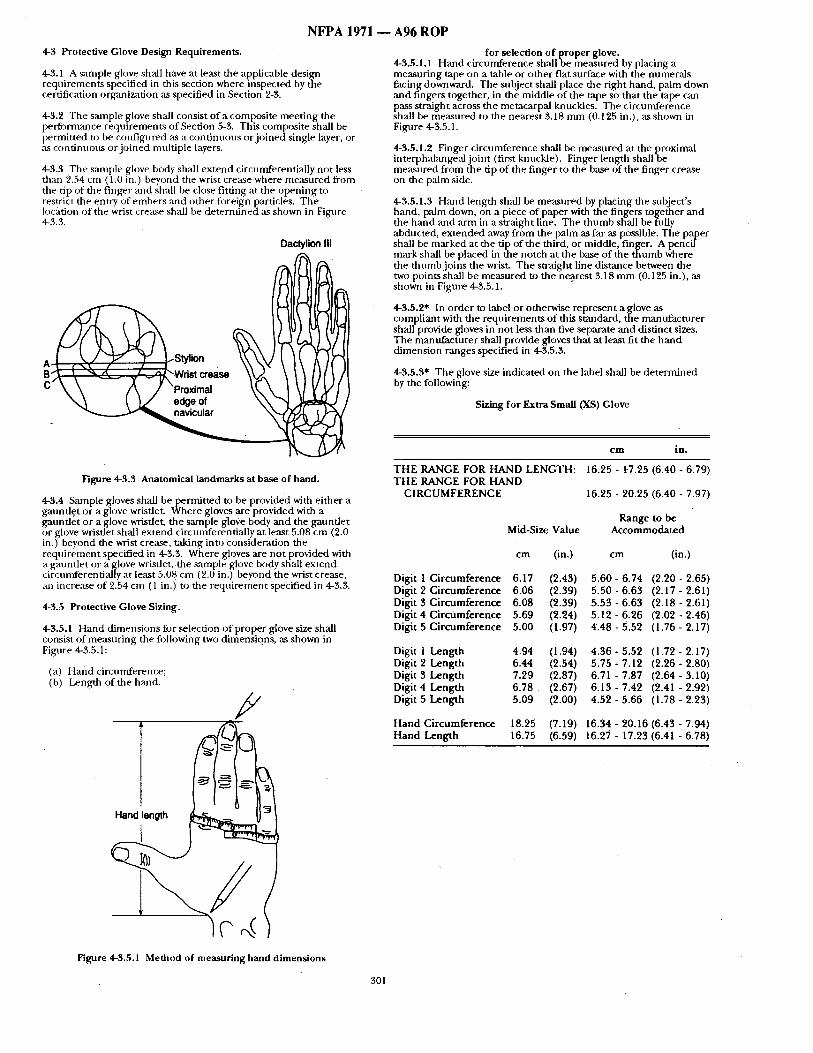
4-3 Protective Glove Design Requirements .
4-3.1 A .sample glove sh~ l have at least the applicable design requi rements specified in this section where inspected by the certification organization as specified in Section 2-3.
4-3.2 The sample glove shall consist of a composi te meet ing the performance requi rements of Section 5-3. This composite shall be permit ted to be cotffigured ~ a cont inuous or j o ined single layer, or as cont inuous or jo ined multiple layers.
4-3.3 The sample glove body shall ex tend circunfferentially not less than 2.54 cm (1.0 in.) beyond the wrist crease where measured from the tip o f t h e finger and shall be close fitting at the open ing to restrict the entry of embers and o ther foreign particles. The location of the wrist crease shall be deternf ined as shown in Figure 4~3.3.
Dactylion III
A ~ Styli°n B~~c::~,~Wristcrease ~ ~ /I [) C X \ /'\ / "Proximal \ \ , \ ] \[ ~'
~ ~. ~ edge of \ \ ' ~
Figure 4-3.3 Anatomica l l a n d m a r k s at base of hand.
4-3.4 Sample gloves shall be permi t ted to be provided with ei ther a gannflet or a glove wristlet. Where gloves are provided with a gmmfle t or a glove wristlet, the sample glove body and the gaunt le t or glove wristlet shall ex tend circnmferentially at least 5.08 cm (2.0 in.) beyond the wrist crease, taking into consideration the requi rement specified in 4-3.3. Where gloves are not provided with a gaunt le t or a glove wrisdet, the sample glove body shall ex tend circunfferentially at least 5.08 cm (2.0 in.) beyond the wrist crease, an increase of 2.54 cm ( 1 in.) to the requ i rement specified in 4-3.3.
4-3.5 Protective Glove Sizing.
4-3.5.1 Hand d imensions for selection of proper glove size shall consist of measur ing the following two dimensions, as shown in Fignre 4-3.5.1:
(a) Hand circumference; (b) Length of the hand.
Hand length
A96 ROP
for se lect ion o f p r o p e r glove. 4-3.5.1.1 H a n d ci rcumference sha l lbe measured by placing a measur ing tape on a table or o ther flat surface with the numerals facing downward. The subject shall place the right hand, palm down and fingers together, in the middle o f the tape so that the tape can pass straight across the metacarpal knuckles. The c i rcumference shall be measured to the nearest 3.18 m m (0.125 in.), as shown in Figure 4-3.5.1.
4-3.5.1.2 Finger c i rcumference shall be measured at the proximal interphal, 'mge~ jo in t (first knuckle). Finger length sha l lbe measured from the tip of the f inger to the base of the finger crease on the palm side.
4-3.5.1.3 H;md length shall be measured by placing the subject 's hand, palm down, on a piece of paper with the fingers together and the hand and arm in a straight line. The t h u m b shall be fully abducted, ex tended away f rom the palm as far as possible. The paper shall be marked at the tip of the third, or middle, finger. A p e n c i l mark shall be placed in the notch at the base o f the t h u m b where the t h u m b joins the wrist. The straight line distance between the two points shall be measured to the nearest 3.18 m m (0.125 in.), as shown in Figure 4-3.5.1.
4-3.5.2* In order to label or otherwise represent a glove as compliant with the requi rements o f this standard, the mantffacturer shall provide gloves in not less than five separate and distinct sizes. The manufac ture r shall provide gloves that at least fit the h a n d d imens ion ranges specified in 4-3.5.3.
4-3.5.3* The glove size indicated on the label shall be de te rmined by the following:
Sizing for Extra Small (XS) Glove
c m in.
T H E RANGE FOR HAND LENGTH: 16.25 - 1-7.25 (6.40 - 6.79) T H E RANGE FOR HAND
C I R C U M F E R E N C E 16.25 - 20.25 (6.40 - 7.97)
Range to be Mid-Size Va lue A c c o m m o d a t e d
c m (in.) c m (in.)
Digit 1 C i r c u m f e r e n c e 6 .17 (2.43) 5 .60 - 6 .74 (2.20 - 2 .65) Digit 2 C i r c u m f e r e n c e 6 .06 (2.39) 5 .50 - 6 .63 (2.17 - 2 .61) Digit 3 C i r c u m f e r e n c e 6 .08 (2.39) 5 .53 - 6 .63 (2.18 - 2 .61) Digit 4 C i r c U m f e r e n c e 5 .69 (2.24) 5 .12 - 6 .26 (2.02 - 2 .46) Digit 5 C i r c u m f e r e n c e 5 .00 (1 .97) 4:48 - 5 .52 ( 1 . 7 6 - 2.17)
Digit 1 Leng th 4.94 (1.94) 4.36 - 5.52 (1.72 - 2.17) Digit 2 Leng th 6.44 (2.54) 5.75 - 7.12 (2.26 - 2.80) Digit 3 Leng th 7.29 (2.87) 6.71 - 7:87 (2.64 - 3.10) Digit 4 Leng th 6.78 (2.67) 6.13 - 7.42 (2.41 - 2.92) Digit 5 L e n g t h 5 .09 (2.00) 4 .52 - 5 .66 (1.78 - 2.23)
H a n d C i r cumfe rence 18.25 (7.19) 16.34 - 20.16 (6.43 - 7.94) H a n d Leng th 16.75 (6.59) 16.27 ' 17.23 (6.41 - 6.78)
Figure 4-3.5.1 Method of measur ing hand d imensions
301
N F P A 1971 - - A 9 6 R O P
Front View
Back View Option One
Back View Option Two
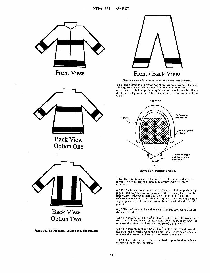
Figure 4-1.14.5 Minimum required coat trim patterns.
Front / Back View Figure 4-1.15.3 Minimum required trouser trim patterns.
4-2.4 The helmet shall provide peripher,-d vision clearance of at least 120 degrees to each side of the mid-sagit~d plmle when seated according to its helmet positioning index on the reference headform illustrated in Figure 6-1.5.1. The test setup shall be as shown in Figure 4-2.4.
TOp view
Reference Helmet headform
ii" vision
Too
Figure 4-2.4 Peripheral vision.
4-2.5 The retention system shall include a chin strap and a nape device. The chin strap shall have a minimum width of 1.0 cm (0.75 in.).
4-2.8* The helmet, when seated according to its helmet positioning index, shall provide coverage parallel to the coronal plane from the helmet front edge to not less thml 10.7 mm (4.2 in.) below the reference plane and not less than 45 degrees to each side of the mid- sagitml plane from the intersection of the mid-sagittal and coronal planes.
4-2.7 The helmet shall have fluorescent and retroreflective trim on the shell exterior.
4-2.7.1 A minimum of 26 cm 2 (4.0 in. 2) of the retroreflective area of the trim shall be visible when the helmet is viewed from any angle at or above the reference plane at a distance of 2.44 m (8.0 ft).
4-2.7.2 A minimum of 26 cm 2 (4.0 in. 2) of the fluorescent area of the trim shall be visible when the helmet is viewed from any angle at or above the reference plane at a distance of 2.44 m (8.0 ft).
4-2.7.3 The entire surface of the trim shall be permitted to be both fluorescent and retroreflecfive.
300
N F P A 1971 - - A96 R O P
3 Holm
iii I
I
o | ,
i I
I I D
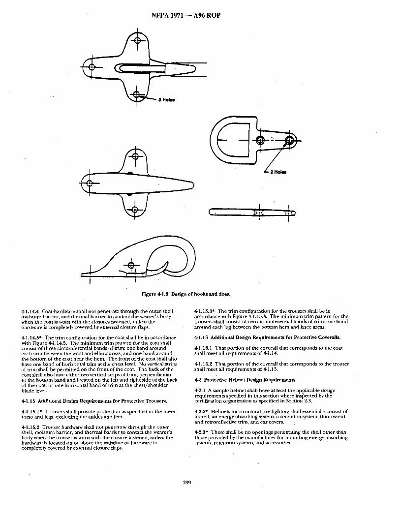
Figure 4-1.9 Design of hooks and dees.
4-1.14.4 Goathardware shall not penetrate th rough rite outer shell, moisture barrier, and thermal barrier to contact the wearer 's body when the coat is worn with the closures fastened, unless the hardware is completely covered by external closure flaps.
4-1.14.5" The txim configalration for the coat shall be in accordance with Figure 4-1,14.5. The m i n i m u m trim pattern for the coat shall consist of three circt,mferential bands o f trim: one band a ro tmd each arm between the wrist and elbow areas, and one band a round the bot tom of the coat near the hem. The front o f the coat shall also have one band of horizontal t r im at the chest level. No vertical strips of trim shall be permit ted on the front of the coat. The back of the coat shall also have either two vertical strips of trim, perpendicular to the bottoln band and located on the left and r ight side o f the back of the coat, or one horizontal band of trim at the ches t / shou lde r blade level.
4-!.15 Additional Design Requi rements for Protective Trousers .
* ( 4-1.15.1 Tr ~users shall provide protection as specified to the lower torso and legs, excluding the ankles and feet.
4-1.15.2 Trouser hardware Shall no t penetra te through the outer shell, moisture barrier, and thermal barrier to contact the w o r e r ' s body when the trouser is worn with the closure fastened, unless the hardware is located on or above the waistline or hardware is completely covered by external closure flaps.
4-1.15.3" The tr im configuration for the trousers shall be in accordance with Figure 4-1.15.3. The m i n i m u m trim pattern for the trousers shall consist of two circumferential bands of ~im: one band a round each leg between the bot tom h e m and knee areas.
4-1.16 Additional Design Requirements for Protective Coveralls.
4-1.16.1 Tha t portion of the coverall that corresponds to the coat shall mee t all requirements of 4-1.14.
4-1.16.2 Tha t portion of the coverall that corresponds to the tronser shall mee t all requirements of 4-1.15.
4-2 Protective Helmet Design Requirements.
4-2.1 A sample he lmet shall have at least the applicable design requi rements specified in this section where inspected by the certification organization as specified in Section 2-3.
4-2.2* Helmets for structural fire f ight ing shall essentially consist of a shell, an energy absorbing system, a retention system, f luorescent and retroreflective trim, and ear covers.
4-2.3* There shall be no openings peneu 'a t ing the shell o ther than those provided by the manufac ture r for m o u n t i n g energy absorbing systems, retention systems, and accessories.
299
N F P A 1971 - - A 9 6 R O P
3-5.3 User Information.
3-5.3.1 The hood manufacturer shall provide user information including, but not limited to, warnings, information, and instructions with each hood.
3-5.3.2 The hood manufactnrer shall attach the required user information, or packaging containing the user information, to the hood in such a manner that it is nut possible to use the hood without being aware of the infi)rmation.
3-5.3.3 The required user information, or packaging containing the user information, shall be attached to the hood so that a deliberate actitm is necessary to remove it. The hood manufacturer shall provide notice that the user information is to be removed ONLY by the end user.
3-5.3.4* The hood manufacturer shall provide at least the following instructions and information with each hood:
(a) Pre-use infi)rmaticm: • Safety considerations. • Limitations of use. • Hood marking recommendations and restrictions. • A statement that most performance properties of the hood
cannot be tested by the user in the field. • WarTanty information.
(b) Preparation for use: • Sizing/adjusunent. • Recommended storage practices.
(c) Inspection: • Inspection frequency and details.
(d) Don/Doff: • Donning and doffing procedures. • Sizing and adjustment procedures. • Interface issnes.
(e) Use: • Proper use consistent with NFPA 1500, Standard on Fire
Departrrurrtt Occupational Safety and Health Program.
(f) M~dntenance and Cleaning: • CJeaning instructions and precautions with a statement
advising{lsers not to use hoods that are not thoroughly cleaned and dried.
• M~dntenance criteria and methods of repair where a.[)plicable.
• t~econtmnination procedures fi)r both chemical and biological contamination.
(g) Retirement and disposal: • Retirement and disposal criteria and considerations.
3-5.3.5 The hood mannfacturer shall integrate applicable warnings identifying risks ~md consequences into the user information where appropriate, such that the user understands that conform;mce to the
• instructions will mitigate the risk and consequence.
Chapter 4 Design Requirements
4-1" Protective Garment Design Requirements.
4-1.1 A sample garment shall have at least the applicable design requirements specified in this section where inspected by the certification organization as specified in Section 2-3.
4-1.2" Garments shall consist of a composite of an outer shell, moisture barrier, and thermal barrier. This composite shall be permitted to be configured as a single layer or multiple layers.
4-1.2.1 The moisture barrier, or the thermal barrier or a portion of the thermal barrier, of a garment element shall be permitted to be configt,red as a protective uniform apparel unit or units. Where comfigured in this manner, the assembled garment element of the
otective ensemble shall meet the requirements specified in 2-1.1. e protective uniform apparel unit(s) shall also meet ,all applicable
requl'rements specified in NFPA 1075, Starulard on Station~Work /nifinms for Fire Fighters.
4-1.2.2 Where moisture barriers or thermal barriers are configured as permitted in 4-1.2.1, the garment manufacturer shall identify the protective uniform apparel unit(s) that comprise the garment element and that need to be worn together in order for the garment element to be compliant with the requirements of this su-mdard. Each such protective uniform apparel unit and the garment element itseff shall have labels that meet the requirements of 3-1 •2.2 and 3-1.2.3. These warning labels shall be in addition to any other warning label or product label requirements that apply to the protective uniform apparel units or that apply to the garment element.
4-1.3" Garment~ shall have a means of securing the moisture barrier ,and thermal barrier to the outer shell.
4-1.4 Moisture barriers ,and thermal barriers, or materials meeting the performance requirements of these components, shall extend, as a minimum, to the neckline seam of the coat and to the waistline seam of the trouser. They also shall extend to within 2.54 cm ( 1.0 in.) of the outer shell at the sleeve end and to within 7.62 cm (3 in.) of the bottom of gamnents. Moisture barriers and thermal barriers, or materials meeting the performance requirements of these coml~ments, shall be configured in a manner to provide overlap at all closures.
4-1.5 All garments shall have closure systems. Such closure systems, induding the coat front and trouser flies, shall be consmmted in a manner that provides continuous moisture and thermal protection. Such closure systems shall be secured with positive locking fasteners including, but not limited to, hooks and dees or zippers. Nonpositive fasteners. , such. as snaps or hook ,and pile tape, shall not be used as positive locking fasteners but shall be permitted to be utilized as supplementary garment closure devices.
4-1.6 Snaps shall meet the requirements of MS 27980E, Fastener, Snap.
4-1.7" Fastener tape shall meet the requirements of MIL-F-21840G, Fastt.n~ Tapes, Hook and Pile, Synthetic, excluding Class 2.
4-1.8 Zippers shall meet the requirements of FED-V-F-106F, Fasteners, Interlockin~ Slide.
4-1.9 Hooks and dees shall be nonferrous and shall conform to the design of Figure 4-1.9.
4-1.10 All garment hardware finish shall be free of rough spots, burrs, or sharp edges.
4-1.11" Cargo pockets, where provided, shall have a means to drain water and shall have a means of fastening in the closed position.
4-1.12* Garments shall have fluorescent and retroreflective trim permanently attached to the outer shell of garments to meet visibility requirements. Trim shall be not less than 5.08 cm (2.0 in.) wide and shall have both retroreflective and fluorescent surfaces. The retroreflective surface oft.rim shall be not less than 1.6 cm (0.625 in.) wide. Fluorescent and retroreflective areas of trim shall appear to be continuous for the length of the trim, with gaps between areas of retroreflectivity of not more than 3.18 mm (0.125 in.). Trim used to meet the minimum tr imoat tern refluirements shall have a minimum fluorescent surface J 1 2 . 9 cm 2/l inear cm (2.0 in.2/linear in.) ofu'im.
4-1.13 Trim affixed to garments that exceeds the requirements specified in 4-1.14.5 and 4-1.15.3 shall be jaermitted to be obscured by components including, but not limitect to, pockets, storm flaps, and reinforcing patches as long as the minimum trim pattern specified in 4-1.14.5 and 4-1.15.3 is not obscured.
4-1.14 Additional Design Requirements for Protective Coats.
4-1.14.1 Coats shall provide protection as specified to the upper torso, neck, arms, and wrists, excluding the hands and head.
4-1.14.2" Each coat sleeve shall have a protective wristlet permanently attached to the coat sleeve that meets the requirements specified in Section 4-6 and Section 5-6.
4-1.14.3 Coats shall have a composite collar at least 10.2 cm (4.0 in.) in height at any point and shall have a closure system. The collar and closure system shall consist of an outer shell, moisture barrier, and thermal barrier that meet ,all applicable performance requirements as specified in Section 5-1.
298
N F P A 1971 - - A 9 6 R O P
34.2.5* The certification organization's label, symbol, or identifying inark shall be a t tached to the product label or shall be part of the product label.
34.2.6 All worded port ions of the required product label shall be printed at least in English.
:4-4.2.7 Symbols and o ther pictorial graphic representat ions shall be permit ted to be used to supp lemen t worded s tatements on the product labels. Such graphic representat ions shall be consistent with the worded s tatements and shall be readily unders tood and clearly comnmnica te the in tended message.
34.2.8 The following s ta tement shall be pr in ted legibly on the product label. All letters shall be at least 2.5 m m (0.10 in.) high.
"THIS BOOT MEETS THE FOOTWEAR REQUIREMENTS OF NFPA 1971, STANDARD ON PROTECTIVE ENSEMBLE FOR STRUCTURAL FIRE FIGHTIN(;, 1996 EDITION."
34.2 .9 The following information shall also be pr inted legibly on the p roduc t label. All letters shall be at least 1.6 m m (0.063 in.) high:
(a) Certification organization label, symbol, or identifying mark; (b) M~mufacturer n,'une, identification, or designation; (c) Manufacntrer address; (d) Country of manufacture; (e) Manufacturer footwear identification~lot~serial number ; (f) Month ,and year of manufac ture (not coded) ; (g) Model name, number , or design; (h) Footwear size and width; (i) Cle,-ming precautions.
3-4.3 User Information.
34.3.1 The footwear manufac turer shall provide user information including, bu t not limited to, warnings, information, and instructions with each pair of boots.
34.3.2 The tbotwear manufac ture r shall attach the required user infi)rmation, or packaging conta in ing the user information, to the boot pair in such a m, 'moer that it is no t possible to use the boots without being aware of the information.
34.3.3 The required user information, or packaging containing the user information, shall be a t tached to the boot pair so that a deliberate action is necessary to remove it. The footwear ntanufacturer shall provide notice that the user information is to be removed ONLY by the e n d user.
34.3.4* The footwear manufac ture r shall provide at least the fi~llowiog instructions and information with each boot pair:
(a)* Pre-use information: * S,'tfety considerations. • Limitations of use. • Boot marking recommenda t ions and restrictions. • A s ta tement that mos t per formance properties of the boots
cannot be tested by the user in the field. • Warranty information.
(I)) Preparation fi)r rise: • S iz ing/adjus tmen L • R e c o m m e n d e d storage practices.
(c) Inspection: • Inspection frequency and details.
(d) Don/Doff : • Donn ing and doffing procedures. • Sizing and adjus tment procedures. • Interface issues.
(e) Use: • Proper use consistent with NFPA 1500, Standard on Fire
Department Occupational Safety. and Health Program.
(f) Maintenance and Cleaning: • ( ; leaning instructions and precautions with a s ta tement
advising users not to use boots that are not thoroughly cle,'m e d and dried.
• Maintenance criteria and me thods of repair where applicable.
• Decontaminat ion procedures fiJr both chemical and biologicM contaminat ion.
(g) Reti remen t and disposal: * Ret i rement and disposal criteria and considerations.
34.3 .5 The fi)otwear manufac ture r shall integrate applicable warnings identifying risks and consequences into the user information where appropriate, such that the user unders tands that conformance to the iristrfictions will mitigate the risk and consequence.
34.3.6 The footwear manufac tu re r shall warn the user that con t inued water resistance does not necessarily indicate cont inued viral or chemical resistance.
3-4.3.7* Manufacturers shall be required to establish and provide, upon request, a size conversion chart for each model or style of protective footwear based on toe length, arch length, and foot width as measured on the Brannock Scientific Foot Measur ing Device.
3-5 Protective Hood Interface Component.
3-5.1" Warning Label Requirements.
3-5.1.I Each hood interface c o m p o n e n t of the protective ensemble shall have warning labels permanent ly a t tached to each hood.
3-5.2 Product Label Requirements .
3-5.2.1 Each hood interface c o m p o n e n t o f the protective ensemble shall have a product label or labels pe rmanendy and conspicuously at tached to each hood. At least one product label shall be conspicuously located on or inside each hood when the hood is properly assembled with all componen t s in place.
3-5.2.2 Multi~)le label pieces shall be permit ted in order to carry all the s ta tements and information required to be on the product label; however, all label pieces compris ing the entire product label shall be located adjacent to each other.
3-5.2.3 The warning label specified in 3-5.1.1 shall be permit ted to be placed on the product label with the o ther s ta tements and information required for the product label, provided that the format is as specified in 3-5.2.4.
3-5.2.4 Where the warning label specified in 3-5.1.1 is located on the same label piece with the product label, the warning label portion shall be placed in the uppermos t position o f the product label and shall be separated f rom the remainder o f the p roduc t label s ta tements and information by sufficient space to prevent them f rom visually blending together.
3-5.2.5* The certification organization's label, symbol, or identifying mark shall be a t tached to the product label or shall be part o f the product label.
3-5.2.6 All worded port ions of the required produc t label shall be pr inted at least in English.
3-5.2.7 Symbols and other pictorial graphic representat ions shall be permit ted to be used to supp lemen t worded s tatements on the product labels. Such graphic representat ions shall be consistent with the worded s tatements ~md shall be readily unders tood and clearly communica te the in tended message.
3-5.2.8 The following s ta tement shall be pr in ted legibly on the product label. All letters shall be at least 2.5 m m (0.10 in.) high.
"THIS H O O D MEETS THE H O O D INTERFACE REQUIREMENTS OF NFPA 1971, STANDARD ON PROTECTIVE ENSEMBLE FOR STRUCTURAL FIRE FIGHTING, 1996 EDITION."
3-5.2.9 The following information shall also be pr in ted legibly on the product label. All letters shall be at least 1.6 m m (0.065 in.) high:
(a) Certification organization label, symbol, or identifying mark; (b) Manufacturer name, identification, or designation; (c) Manufacturer address; (d) Country of manufacture; (e) Manufacturer hood ident i f icat ion/ lot /ser ial number ; (0 Month and year of mannfac tore (not coded); (g) Model name, number , or design; (h) Size; (i) Garment material(s); (j) Cleaning precautions.
297
N F P A 1971 1 A 9 6 R O P
3-3.1.1 Each glove e lement of the protective ensemble shall have warning labels permanent ly a t tached to each glove.
9,-3.'2 Product Label Requirements .
3-3.2.1" Each gh:we e lement of the protective ensemble shall have a pt-~duct lal)el or labels perm,'mently and conspicuously at tached to each glove. At least one product label shall be conspicuously located on or inside each glove e lement when the glove is properly asseinbled with all componen t s in place.
3-3.2.2 Multiple label pieces shall be permit ted in order to carry all the s tatements and information required to be on the product label; however, all label pieces compris ing the entire product label shall be located adjacent to each other.
3-~.2.3 The warning label specified in 3-3.1.1 shall be permit ted to be placed on the product label with the other s ta tements and information required for the product label, provided that the format is as specified in 3-3.2.4..
3-3.2.4 Where the warning label specified in 3-3.1.1 is located on the same label piece with the product label, the warning label portion shall be placed in the uppermos t position of the product label and shall I)e separated f rom the remainder of the product label s ta tements and infi)rmatioi~ by sufit]cient space to prevent them from visually blending together.
3-3.2.5* The certification organization's label, symbol, o r identifying mark shall be a t tached to the product label or shall be part of the product label.
3-3.2.6 All worded port ions of the required product label shall be printed at least in English.
3-3.2.7 Symbols and o ther pictorial graphic representat ions shall be permit ted to be used to supp lemen t worded s tatements on the product labels. Such graphic representat ions shall be consistent with the worded s tatements and shall be readily unders tood and clearly comnmnica te the in tended me~age .
3-3.2.8 The fi)llowing s ta tement sball be pr inted legibly on the l:)r~Muct hi)el. All letters shall be at least 2.5 m m (0.10 in.) high.
"THIS GLOVE MEETS THE GLOVE REQUIREMENTS OF NFPA 1971, STANDARD ON PROTECTIVE ENSEMBLE FOR STRUCTURAL FIRE FIGHTING, 1996 EDITION."
3-3.2.9 The following inlormation shall also be pr in ted legibly on the product label. All lettm~ shall be at least 1.6 m m (0.063 in.) high:
(a) Certification organization label, symbol, or identifying mark; (b) Mam~acturer name, identification, or designation; (c) Manufactnrer address; ((1) Country of manufacture; (e) Mannfacturer glove identif icat ion/lot /serial number ; (f) Month and year of nlmmfactnre (not coded); (g) Model name, number , or design; (h) Glove size or size range; (i) CJeaning t)recautions.
3-3.3 User Information.
3-3.3.1 The glove manufac turer shall provide user information including, bu t not limited to, warnings, infi)rmation, and instructions with each pair of gloves.
3-3.3.2 The glove manlffactnrer shall attach the required user infl)rmation, or packaging conta in ing the user information, to the glove pair in such a m a n n e r that it is no t possible to use the gloves without being aware of the information.
3-3.3.3 The required user information, or packaging containing the user infi:wmation, shall be at tached to the giove pair so that a deliberate action is necessary to remove it. The glove manufac turer shall provide notice that the user information shall be removed ONLY by the end user.
"l-3.3.4' The glove manufac ture r shall provide at least the following instructions mid information with each glove:
(a) Pre-use information: • Sa.fety considerations. * Limitations of use. • Glove marking recommenda t ions and restrictions. • A s ta tement that most performance properties of the glove
cannot be tested by the user in the field. • A s ta tement regarding potential problems with the user
practice of "double gloving." • Warranty information.
(b) Preparation for use: • Sizing/adjustment . • Recommended storage practices.
(c) Inspection: • Inspection frequency and details.
(d) Don/Doff : • Donning ,and doffing procedures. • Sizing and adjus tment procedures. • Interface issues.
(e) Use: • Proper use consistent with NFPA 1500, Standard onFire
Department Occupational Safe~ and Health Program.
(f)* Maintenance and Cleaning: • C, leaning instructions a n d p r e c a u t i o n s with a s t a t e m e n t
advising users not to use gloves that are no t thoroughly cleaned and dried.
• Maintenance criteria and methods of repair where applicable.
• Decontaminat ion procedures for both chemical and biological contaminat ion.
* Instructions for f requency and m e t h o d of user testing for water resistance.
(g) Ret i rement and disposal: • Ret i rement and disposal criteria and considerations.
3-3.3.5 The glove manufac turer shall integrate applicable warnings identifying risks and consequences into the user information where appropriate, such that the user unders tands that conformance to the instructions will mitigate the risk and consequence.
3-3.3.6 The glove manufac turer shall notify the user that con t inued water resistance does not necessarily indicate cont inued viral or chemical resistance.
3-3.3.7 The manufactorer shall make available to prospective purchasers and the purchaser a chart illustrating the h an d d imension ranges specified in 4-3.5.3.
3-4 Protective Footwear.
34.1" Warning Label Requirements.
3-4.1.1 Each boot e lement of the protective ensemble shall have warning labels permanent ly at tached to each boot haft pair.
3-4.9 Product Label Requirements .
3-4.2.1" Each footwear e lement of the protective ensemble shall have a product label or labels permanent ly and conspicuously at tached to each boot haft pair. At least one product label shall be conspicuously located on or inside each boot when the boot is properly assembled with all componen t s in place.
3-4.2.2 Multiple label pieces shall be permit ted in order to carry all the s ta tements and information required to be on the product label; however, all label pieces compris ing the entire product label shall be located adjacent to each other.
3-4.2.3 The warning label specified in 3-4.1.1 shall be permit ted to be placed on the product label with the other s tatements and information required for the product label, provided that the fi)rmat is as specified in 3-4.2.4.
3-4.2.4 Where the warning label specified in 3-4.1.1 is located on the same label piece with the p roduc t label, the warning label portion shall be placed in the uppermos t position of the product label and shall be separated f rom the remainder of the product label s ta tements and information by sufficient space to prevent them from visually blending together.
"296
N F P A 1971 - - A 9 6 R O P
(d) Don/Doff : • Donn ing and doffing procedures. • Sizing and ad jus tment procedures. • Interface issues.
(e) I Ise: • Proper use consistent with NFPA 1500, Standard on Fire
Departme'nt Occupational Safety arut Health Program.
(f)* Maintenance and Cleaninl~: • Cleaning instructions a n a precaut ions with a s ta tement
advising users no t to use garments that are no t thoroughly c leaned and dried.
• Inspection details. • Maintenance criteria ,and methods of repair where
applicable. • Decontaminat ion procedures for both chemical and
biological contaminat ion.
(g) Ret i rement and disposal: • Ret i rement and disposal criteria and considerations.
3-1.3.5 The g~trment manutac tnre r shall integrate applicable warnings identifying risks a nd consequences into the user infi~rmation where appropriate, such that the user unders tmlds that conformmlce to the instrnctions will mitigate the risk and conseqtlence.
3-1.3.6 The ga rmen t manufac ture r shall inform the user that cont inued water resistance does not necessarily indicate cont inued viral or chemical resistance.
3-1.3.7" Upon request, the ga rmen t manufac ture r shall provide the purchaser or the authority having jurisdiction with the test results of the s tored energy test specified in Section 6-48.
3-2 Protective Helmets.
3-2.1" Warning Label Requirements.
3-2.1.1 Each helmet e l ement of the protective ensemble shall have a warning label permanent ly a t tached to each helmet.
3-2.2 Product Label Requirements.
3-2.2.1" Each hehne t e l ement of the protective ensemble shall have a product label or labels permanent ly and conspicuously at tached to each helmet. At least one product label shah be conspicuously located on or inside each he lmet e l ement when the he lmet is properly assembled with all componen t s in place.
3-2.2.2 Multiple label pieces shall be permit ted in o rder to carry all the s ta tements ,and information required to be on the product label; however, all label pieces compris ing the entire product label shall be located adjacent to each Other.
3-2.2.3 The warning label specified in 3-2.1.1 shall be permit ted to be placed on the product label with the o ther s ta tements and information required for the p roduc t label, provided that the fi)rmat is :rs specified in .3-2.2.4.
'1-2.2.4 Where the wmafing label specified in 3-2.1.i is located on the same label piece with the product label, the warning label portion shall be placed in the uppe rmos t position o f the product label and shall be separated f rom the remainder o f the product label s ta tements and information by sufficient space to prevent them from visually b lending together.
3-2.2.5* The certification organization's label, symbol, or identifying mark shall be a t tached to the product label or shall be part o f the product label.
3-2.2.6 All worded portions o f the required product label shall be pr inted at least in English,
3-2.2.7 Symbols and other pictoriai graphic representat ions shall be permit ted to be used to supp lemen t worded s tatements on the prothtct label(s). Such graphic representat ions shall be consistent with the worded s ta tements and shall be readily unders tood and clearly communica te the in tended message.
,3-2.2.8 The following s ta tement shall be pr inted legibly on the product label. All letters shall be at least 2.5 m m (0.10 in.) high.
"THIS HELMET MEETS THE HELMET REQUIREMENTS OF NFPA 1971, STANDARD ON PROTECTIVE ENSEMBLE FOR STRU(.WURAL FIRE FIGHTING, 1996 EDITION."
3-2.2.9 Tile following information sh~dl also be pr inted legibly on the product label. All letters shall be at least 1.6 m m (0.063 in.) high:
(a) C, ertification organization label, symbol, or identifying mark; (b) Manufacturer name, identification, or designation; (c) Manufacturer address; (d) Country of manufac tu re; (e) Manufacturer he lmet ident i f icat ion/ lot /ser ial number ; (f) Month ,and year of manufac tnre (not coded);
Model name, number , or design; I~I He lmet size or size range; (i) Cleaning precautions.
3-2.3 User Information.
3-2.3.1 The helmet manufac tu re r shall provide user information including, but not l imited to, warnings, information, and instructions with each helmet.
3-2.3.2 The he lmet manufac ture r shall attach the required user information, or packaging conta in ing the user information, to the he lmet in such a m a n n e r that it is no t possible to use the he lmet wi[thout being aware o f the information.
3-2.:3 3 The required user information, or packaging containing, the user reformation, shall be a t tached to the he lmet so that a dehberate action is necessary to remove it. The he lmet manu£acmrer shall provide notice tha t the user information is to be removed ONLY by i.he end user.
3-2.3.4* The he lmet manufac ture r shall provide at least the following instructions and information with each helmet:
(a)* Pre-use information: • Safety considerations. • Limitations of use. • Helmet marking recommenda t ions and restrictions. • A s ta tement that most per formance properties of the he lmet
canno t be tested by the user in the field. • Warranty information.
(b) Preparation fi)r use: • Sizing/adjustment . • R e c o m m e n d e d storage practices.
(c)* Inspection: • Inspection frequency and details.
(d) Don/Doff : • Donn ing and doffing procedures. • Sizing and ad jus tment procedures. • Interface issues.
(e) Use: • Proper use consistent with NFPA 1500, Standard onFire
Department Occupational Safety_ and Health Program.
(f)* Maintenance and Cleaning: • Cleaning instructions anct precant ionswith a s t a t e m e n t
advising users not to use helmets that are not thoroughly c leaned and dried.
• Maintenance criteria ,and methods of repair where applicable.
• Decontaminat ion procedures for both chenfical and biological contaminat ion.
(g) Ret i rement and disposal: • Re t i rement and disposal criteria and considerations.
3-2.3.5 The helmet manufac ture r shall integrate applicable warlfings identifying risks and consequences into the user infi~rmation where appropriate, such that the user unders tands that conformance to the instructions will mitigate the risk and consequence.
3-3 Protective Gloves.
3-3.1" Warning Label Requirements.
295
NFPA 1971
2-4 Manufacturer's Quality Assurance Program.
2-4.1 The manufac turer shall provide and maintain a quality assurance program that includes a d o c u m e n t e d inspection and product recall system. The manufac turer shall have an inspection system to sni)stantiate conformance to this stancktrd.
2-4.2 The manufac turer shall m:dntain written inspection ~md testing instructions. The instructions shall prescribe inspection and test of materials, work in process, and completed articles. Criteria for ao eptance and rejection of materials, processes, and final product shall be part of the instructions.
2-4.3 Tbe manu lacmre r shall m~dntain records of all pass/fail tests. P:Lss/fail records shall indicate the disposition of a failed material or prodnct-
2-4.4 The manutl tcturer 's inspection system shall provide for procedures that ensure the latest applicable drawings, specifications, and instructions are used for fabrication, inspection, and testing.
2-4.5 Tile manufac turer shall, as p.-wt of the quality assurance • :wogram, maintain a calibration program of all ins t ruments used to ensure proper control )f testang. The cahbranon program shall dl }CIIII/el|t tile date of calibration and perforn]ance verification.
2-4.6 The nlannlitcturer shall m:dnr~dn a system tot identifying the appropriate inspection sKtttts of c o m p o n e n t materials, work in process, and f inished goods.
2-4.7 The n~unffacturer shall establish and maintain a system for controlling noncoi f fonning material, including procedures for the identification, segregation, and disposition of rejected material. All nonconfornf ing materials or products shall be identified to prevent their use, shipment , and intermingl ing with conforming materials or pr~ducts. ,~
2-4.8 The manufac turer ' s quality asstu~mce program shall be audited by the third-party certification organization to de termine that the progr~tm is sufticient to ensure cont inued product compliance with this standard.
Chapter 3 Labeling and Information
3-1 Protective Garments.
3-1.1 * Warning,. Label Requirements,
3-1.1. I Each ga rmen t e lement of the protective ensemble shall have a w ~ n i n g lal)el permanent ly a t tached to each garment .
3-1.2 Product Label Requirements .
3-1.2.1" Each ga rmen t e l ement of the protective ensemble shall have a product label or labels permanent ly and conspicuously at tached to each garment . At least one product label shall be conspicuously located inside each ga rmen t e lement when tile ga rmen t is properly assembled with all layers and components in p lace
3-1.2.2 Where the garment ' s outer shell, thernml barrier, or moisture harrier layers can he separated f rom each other, each sepm'aMe layer shall have a suppmmenta ry label permanent ly at iached to tile inside of the layer in a conspicuous location so that tile notice can be seen by the user when d o n n i n g that layer.
3-1.2.3 The supplementary label shall have at least tile folh)wing text printed on the supplementary label:
NOTICE!
• THIS GARMENT HAS MULTIPLE LAYERS THAT CAN BE SEPARATE[).
DO NOT WEAR THIS LAYER ALONE!
• YOI l MI/ST/LSSEMBLE ALL SEPARABLE LAYERS TO GETHER AS FOLLOWS:
(Items shall be listed by type and identification.)
3-1.2.4 Multiple label pieces shall be permit ted in order to carry all s ta tements and information required to be on the product label; however, all label pieces compris ing the entire product label shall be located adjacent to each other.
A96 ROP
3-1.2.5 The warning label specified in 3-1.1.1 shall be permit ted to be placed on the product label with the o ther s ta tements and information required for the product label, provided that the format is ,as specified in 3-2.1.6.
3-1.2.6 Where the warning label specified in 3-1.1.1 is located on the same label piece with the product label, the warning label portion shall be placed in the uppermos t position o f the product label and shall be separated f rom the remainder of the product label s ta tements and itfformafion by stffficient space to prevent them from visually blending together.
3-1.2.7" The certification organization's label, symbol, or identifying n~ark shall be a t tached to the product label or shall be part of the product label.
3-1.2.8 All worded port ions o f the required product label shall be printed at least in English.
3-1.2.9 Symbols and o ther pictorial graphic representat ions shall be permit ted to be used to supp lemen t worded statements on the p.roduct label(s). Such graphic representations, shall be consistent wtth the worded statements and shall be readily unders tood and clearly commtmicate the in tended message.
3-1.2.10 The following s ta tement shall be pr inted legibly on the product label. All letters shall be at least 2.5 m m (0.10 in.) high.
"THIS ( T w e o f ~ a r m e n t element_ e.g.. COAT. TROUSER. or C~OVERALL. shall be stated here.] MEETS THE GARMENT REQUIREMENTS OF NFPA 1971, STANDARD ON PROTECTIVE ENSEMBLE FOR STRUCTURAL FIRE FIGHTING, 1996 EDITION."
3-1.2.11 The following information shall also be pr inted legibly on the product label. All letters shall be at least 1.6 m m (0.063 in.) high:
(a) Certification organization label, symbol, or identifying mark; (b) Manufacturer name, idendfication, or designation; (c) Mamffacturer address; (d) Con ntry of man ufactnre; (el Manufacturer ga rmen t identif icat ion/lot /serial number ; (f) Month and year of manufac ture (not coded); (g) Model name, number , or design; (10 Size; (i) Garment material(s); (j) Gleaning precautions.
3-1.3 User Information.
3-1.3.1 The ga rmen t manlffacturer shall provide user information including, but not l imited to, warnings, information, and instructions with each ga rmen t element.
3-1.3.2 The ga rmen t manufac turer shall attach the required user information, or packaging conta in ing the user information, to the garrnent in such a m a n n e r that it is not possible to use the ga rmen t without being aware of the information.
3-1.3.3 The required user information, or packaging cont~dning the user information, shall be a t tached to the gmnnent so that a deliberate action is necessary to remove it. The ga rm en t manlffacturer shall provide notice that the user information is to be removed ONLY by the end nser.
3-1.3.4 The ga rmen t mantffacturer shall provide at least the following instructions and information with each garment:
(a) Pre-nse information: • S,'ffety considerations. • Limitations of use. • Garment marking recommenda t ions and resl~ictions. • A s ta tement that most performance properties of the
ga rmen t cannot be tested by the user in the field. • Warranty intormation.
(b) Preparation fi~r use: • Sizing/adjustment . • Recommended storage practices.
(c) Inspection: * Inspection frequency and details.
294
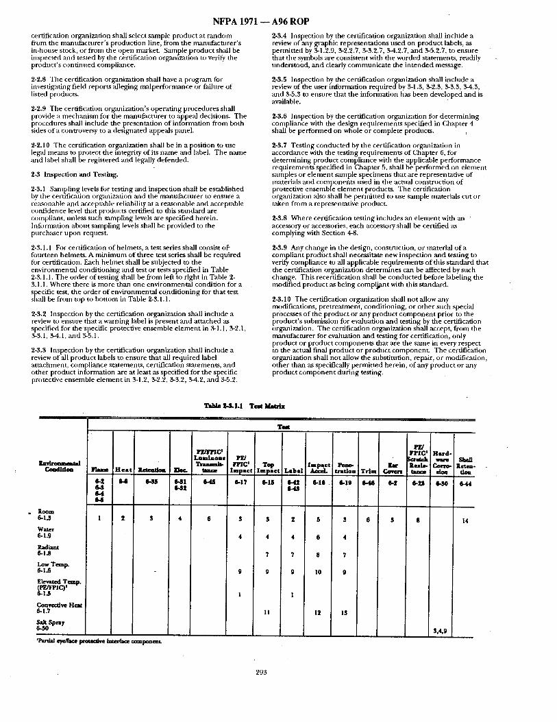
N F P A 1971 - - A 9 6 R O P
certification org:mization shall select sample product at random from the manufacturer 's production line, from the mantffacturer's in-hottse stock, or from the open market. Sample product shall be inspected and tested by the certification orgmHzation to verify the product 's contimted compliance.
2-'L8 The certification organization shall have a program for investigating field reports alleging malperfornmnce or f,'dlnre of listed products.
'~-2.9 The certification organization's operating procedures shall provide a mechanism for the manufacturer to appeal decisions. The procedures shall include the presentation of information from both sides of a controversy to a designated appeals panel.
2-2.10 The certification organization shall be in aposi t ion to use legal means to protect the integrity of its name andlabel . The name ,and label shall be registered and legally defended.
2-3 Inspection and Testing.
2-3.1 Sampling levels for testing and inspection shall be established by the certification org~mization and the manufacturer to enstire a re:Lsonable and acceptable reliability at a reasonable and acceptable confidence level that products certified to this sumdard are compliant, unless such sampling levels are specified herein. Infi:)rmation about sampling levels sh~dl be provided to the purchaser upon request.
2-3.1.1 For certification of helmets, a test series shall consist o f fi3urteen helmets. A minimum of three test series shall be required fi)r certification. Each helmet shall be subjected to the environmental condit ioning and test or tests specified in Table 2-3.1.1. The order of testing shall be from left to right in Table 2- 3.1.1. Where there is more than one environmental condition for a specific test, the order of environmental conditioning for that test shall be from top to bottom in Table 2-3.1.1.
2-3.2 Inspection by the certification organization shall include a review to ensure that a w~u-ning label is present and attached as specified for the specific protective ensemble e lement in %1.1, %2.1, %3.1, %4.1, and %5.1.
2-3.3 Inspection by the certification organization shall include a review of all product labels to ensure that all required label attachment, compliance statements, certification statements, and other product information are at least as specified for the specific protective ensemble e lement in 3-1.2, 3-2.2, 3-3.2, 3-4.2, and 3-5.2.
2-3.4 Inspection by the certification organization shall include a review of any graphic representations used on product labels, as permitted by 3-1.2.9, 3-2.2.7, %3.2.7, 3-4.2.7, and 3-5.2.7, to ensure that the symbols are consistent with the worded statements, readily understood, and clearly communicate the in tended message.
2-3.5 Inspection by the certification organization shall include a review of the user information required by 3-1.3, 3-2.3, 3-3.3, 3-4.3, and 3-5.3 to ensure that the information has been developed and is available.
2-3.6 Inspection by the certification organization fi)r determining compliance with the design requirements specified in Chapter 4 shall be performed on whole or complete products.
2-3.7 Testing conducted by the certification organization in accordance with the testing requirements of (3aapter 6, for determining product compliance with the applicable performance requirements specified in Chapter 5, shall be performed on element samples or e lement sample specimens that ,are representative of materials and components used in the actual construction of protective ensemble e lement products. The certification organization also shall be permitted to use sample materials cut or taken from a representative product.
2-3.8 Where certification testing includes an e lement with an accessory or accessories, each accessory shall be certified as complying with Section 4-8.
2-3.9 Any change in the design, constnlction, or material o f a compliant product shall necessitate new inspection and testing to verify compliance to all applicable requirements of this standard that the certification organization determines can be affected by such change. This recertification shall be conducted before labeling the modified product as being complj~mt with this standard.
2-3.10 The certification organization shall not allow any modifications, pretreatment, conditioning, or other such special processes of the product or any product componen t prior to the product 's submission for evaluation and testing by the certification organization. The certification organization shall accept, from the manufacturer for evaluation ,and testing for certification, only product or product components that ace the same in every respect to the actual final product or product component . The certification organization shall not allow the substitution, repair, or modification, other than as specifically permit ted herein, of any product or any product componen t during testing.
Tsb/e ~ q . l . l T e a t ~
Test
I*E/FIqO Luminous
Envirmsmmtal Trusmlt- Coadldoa Flmm H e a t i t~eadoa ~ tmsce
6.Z 6.@ 6.SS 6.,ql 6.SZ
6-4 64
Room 6-1.3 I 2, $
Water 6-1.9
Radiant 6-1.8
Low Temp. 6-1.6
Elevated Temp.
6-1.7
~ Spra7
'P 'a~ e ~ protecdve ~ componeslt.
4 6
PE/ FFIC t
Impact 1 2 ~ e t
6-17 6-15
S S 2
4 4 4
7 7
9 9 9
1 1
I1
l e t Pesm- Label tratloa Trim Covzz~
6.16 6.19 6.46 6-2 6.4.q
5 S 6
6 4
8 7
I0 9
12 13
PZ/ rPIC t Hard-
Scratch wu~ Shell Reslo- Corro- Retch, t a k e sioa tiou
6.Lq 6.30 e-44
S 8 14
$,4,9
293
N F P A 1971 ~ A 9 6 R O P
Should. Tiffs terut, ;ts used in the appendices, indicates a rec Qmmendat i tm or th'tt which is advised but not required.
Specimen. The item that undergoes testing. In re)me c:tses, the specimen is also the sample.
Structural Fire Fighting. The activities of rescue, fire suppression, and property conservation in buildings, enclosed structures, aircraft interiors, vehicles, vessels, or like properties that are inw)lved in a fire or enlergency situation.
Structural Fire
Structural Fire
Structural Fire
Structural Fire
Structural Fire
Structural Fire
Structural Fire
Structural Fire Ensemble.
Structural Fire
Fighting Coat. See (k)at.
Fighting Coverall. See ())verall.
Fighting
Fighting
Fighting
Fighting
Fighting
Fighting
Ensemble. See Protective Ensemble.
Footwear. See Footwear.
Garment(s) . See Garment .
Glove. ScXe Gloves.
Helmet. See Hehnet .
Protective Clothing. See Protective
Fighting Trousers . See Trousers.
Suspension. A he lmet te rm for the energy a t tenuat ing system made up of the headband m~d crown strap.
Sweatband. A hehne t term for that part of a headband, ei ther integral or at tached, that comes in contact with the wearer 's forehead.
Textile Fabric, A ptanm" structure consisting of yarns or fibers.
Thermal Barrier. Tbe portion of protective ensemble elexnent con nposites that is designed to provide thermM protection.
Toecap. A re inforcement to the toe area of fi)otwear designed to protect the toes f rom impact :uld compression.
Top. A helmet term fi~r the intersection between the mid-sagittal plane and the Bitragion-Coronal Arc ex tended to the he lmet snrfztce.
Top Line. The top edge of the protective footwear that includes the tongue, gusset, quarter, collar, and sh,'fft.
Trim. Retroreflective and f luorescent material a t tached to the outem~ost surface of the protective ensemble e lement for visibility enhancemen t . Retrorefiective materials enhance nightt ime visibility, and f luorescent materials enbance daytime visibility.
Trouser. A protective garment . An e lement of the protective ensemble that is designed to provide m i n i m u m protection to the lower torso and legs, excluding tfie ankles and feet.
Upper. Tha t part of the protective footwear, as shown in Fignre 1-3, including, but not limited to the toe vamp, quarter, sh,'fft collar :rod throat: [:)tit not including the sole with heel, puncture-resistant device, and insole.
Upper Torso. The area of body above the waist ,and extending to the shoulder, including the arms and wrists but excluding the hands.
Warning Label. A label or marking affixed to each compliant e lement of a protective ensemble by the mannfacmre r that contains important hazard warnings and s~ffety instructions. The warning label can be a separate label or can be part of the product label. ( .gee aLso Pwduct Led*el.)
Wear Surface. A tOotwe:u" term for the botn)m of the sole, including the heel.
Wildland Fire Fighting. The activities of fire suppression and property conservation in vegetation that is not within structnres but that is inw)lved in a fire situation.
Winter Liner. A ga rment term tbr an optional c o m p o n e n t layer designed to provide added insulation against cold.
Wristlet. An interface c o m p o n e n t e l ement of the protective ensemble that is the circular, dose-fit t ing extension o f the coat sleeve, usually made of knitted material, designed to provide limited protection to the protective coat /glove interface ,area. ( See also Gauntlet, Glove Wristlet, and Interface Components.)
1-4 Units.
1-4.1 In this standard, valnes for m e a s u r e m e n t are followed by an equivalent in parentheses, bnt only the first stated value shall be regarded ,as the reqnirement . Equivalent values in parentheses shall not be considered as the reqt, irement, as these values might be approximate.
Chapter 2 Certification
2-1 General.
2-1.1 All individual e lements of the protective ensemble that are labeled ~Ls being compliant with this s tandard shall meet or exceed all applicable requirements specified in this s tandard and shall be certified.
2-1.2 All certification shall be per formed by an approved certification organization that meets at least the requirements specified in Section 2-2.
2-1.$ All individual compliant e lements of the protective ensemble shall be labeled and listed. All individual compliant e lements of the protective ensemble shall also have a warning label an d a product label. The warning label and the product label shall mee t the applicable requi rements for the specific e lement specified in 3-1.1, 3-2.1, 3-3.1, 34.1, and 3-5.1.
2-1.4" The certification organization's label, symbol, or identifying mark shall be a t tached m the product label or shall be part o f the product label.
2-2 Certification Organization.
2-2.1" The certification organization shall no t be owned or controlled by mantffacturers or vendors of the product being certified. The certification organization shall be primarily engaged in certification work and shall no t have a monetary interest in the product ' s ultimate profitability.
2-2.2 The certification organization shall refuse to certify products to this s tandard that do not comply with all applicable requi rements of this standard.
2-2.3* The contractual provisions between the certification organization and the manufac tnrer shall specify that certification is cont ingent on compliance with all applicable requirements of this standard. There shall be no conditional, temporary, or partial certifications. Manufactnrers shall no t be authorized to use any label or reference to the certification organization on products that :ire not manufac tured in compliance with all applicable requirements of this st~mdard.
2-2.4* The certification organization shall have laboratory facilities and eqn ipmen t available for conduct ing proper tests, a program for calibration of all ins t ruments shall be in place and operating, and procedures shall be in use to ensure proper control of all testing. Good practice shall be followed regarding the use of laboratory manuals, form data sheets, documen ted calibration and calibration routines, performance verification, proficiency testing, and staff qualification and training programs.
2-2.5 The certification organization shall require the manufac turer to establish and maintain a program of production inspection and testing that at least meets the requirements specified in Section 2-4. The certification organization shall audi t the manufac turer ' s quality assurance progran~ to ensure that the quality assurance program provides cont inued product compliance with this stan&ard.
2-2.6 The certification organization and the manufac ture r shall evaluate any changes affecting the form, fit, or fnnct ion o f the certified product to de termine the product ' s cont inued compliance to this standttrd.
2-2.7* The certification organization shall have a follow-up inspection progran~ of the manufact t l r ing facilities of the certified product, with at least two random and u n a n n o u n c e d visits per 12- month period. As part of the follow-up inspection program, the
292
NFPA 1971
Ladder Shank. Reinforcement to the shank ,area of footwear designed to provide additional support to the instep when standing on a ladder rung.
Liquid Borne Pathogen. An infectious bacteria or virus carried in human, animal, or clinical body fluids, organs, or tissues.
Listed.* Equipment or materials included in a list published by an organization acceptable to the authority having jurisdiction and concerned with product evaluation that maintains periodic inspection of production of listed equipment or materials and whose listing states either that the equipment or material meets appropriate standards or ha sbeen tested and found suitable for use in a specified manner.
Lower Torso. The area of body below the waist including the legs but excluding the ankles and feet.
Major A Seams. See Seams.
Major B Seams. See Seams.
Manufacturer. The entity that assumes the liability and provides the warranty fi)r the compliant product.
Melt. A response to heat by a material resulting in evidence o f flowing or dripping.
Mid-Sagittal Plane. A he lmet term for the plane, perpendicular to the basic and coronal planes, that bisects the head symmetrically.
Minor Seams. See Seams.
Model Weight. The basic weight of the helmet plus accessories for the specific model identified.
Moisture Barrier. The portion of the composite designed to prevent the transfer of liquids.
Nape Device. A device located below the Bitragion Inion Arc used to ,aid in helmet retention.
Outer Shell. The outermost layer of the composite with the exception of trim, hardware, reinforcing material, and wrisdet material.
Partial Eye/Pace Protective Interface Component. An interface componen t intended to help shield a portion of the wearer's face in addition to the eyes; not in tended to provide primary eye protection.
Product. The compliant protective ensemble or the compliant elements of the protective ensemble.
Product Label. A label or marking affixed to each compliant e lement of a protective ensemble by the mannfacturer. Such labels contain compliance statements, certification statements, general infi~rmation, care, maintenance, or similar data. The warning label can be part o f the product label ( see also WtwningLabel.) The" prodt,ct label is not the certification organization's label, symbol, or identifying mark; however, the certification organization's label, symbol, or identifying mark can be attached to or be part o f the product label. ( See a/so Labdtd.)
Protective Clothing: See Protective Ensemble.
Protective Coat. See (',oat.
Protective Coverall. See (:overall.
Protective Ensemble. Multiple elements of clothing and equipment designed to provide a degree of protection for fire fighters from adverse exposures to the inherent risks of structural fire fighting operations and certain other emergency operations. The elements of the protective ensemble are coats, trousers, coveralls, helmets, gloves, footwear, and interface components.
Protective Footwear. See Footwear.
Protective GarmenL See Garment.
Protective Glove. See Gloves.
Protective Helmet. See Helmet.
Protective Hood. ,See Hood.
A96 ROP
Protective Trouser. See Trouser.
Protective Uniform.* A unit of textile apparel configured as a shirt, pant, or coverall and designed to be both the thermal barrier or a portion of the thermal b:ulier of a garment e lement of the protective ensemble, and an apparel unit(s) of a station/work uniform.
Protective Wristlet. See Wristlet.
Proximity Fire Fighting. Specialized fire fighting operations that can include the activities o f rescue, fire suppression, and property conservation at incidents involving fires producing very high levels of condnctive, convective, and radiant heat such as aircraft fires, bulk flammable gas fires, and bulk flammable liquid fires. Specialized thermal protection from exposure m high levels of radiant heat, as well as thermal protection from conductive and convective heat, is necessary for persons involved in such operations due to the scope of these operations and the close digtance to the fire at which these operations are conducted, although direct entry into flame is NOT made. These operations usually are exter ior operations but might be combined with interior operations. Proximity fire fighting i sno t structural fire fighting but might be combined with structural fire fighting operations. Proximity fire fighting also is not entry fire fighting. (See also Approach Fire Fighting, Entr~ Fire Fighting arm Structural Fire Fighting.)
Puncture-Resistant Device. A reinforcement to the bottom of protective footwear located between the sole with heel and the resole that is designed to provide puncture resistance.
Radiological Agents. Radiation associated with X-rays, alpha, beta, and gamma emissions from radioactive isotopes, or other irmtedals in excess of normal background radiation levels.
Reference Plane. A headform term for the plane that is 60 mm :1:1 nun (2.36 in. i-0.04 in.) above and parallel to the basic plane.
Retention System. The complete assembly by which the helmet is retained in position on the head.
Retroreflection. The reflection of light in which the reflected rays are preferentially re turned in the direction close to the opposite of the direction o f the incident rays, with this property being mairrtained over wide variations of the direction of the incident rays.
Retroreflective Markings. A material that reflects and returns a relatively high proport ion of light in a direction close to the direction from which it came.
Sample. Protective ensemble elements taken from a manuf~ ture r ' s current production lot. ( See a/so Spedracn.)
Seam. Any permanent a t tachment of two or more materials in a line formed by joining the separate material pieces.
Seam Assembly. The su'ucmre obtained when fabrics are jo ined by means of a seam.
Seams.
MajorA Seams. Outermost layer seam assemblies where rupture could reduce the protection of the garment by exposing the inner layers such as the moisture barrier, the thermal barrier, the wearer's station/work uniform, other clothing, or skin.
MajorB Seams. Moisture barrier or thermal barrier seam ,assemblies where rtlpmre could reduce the protection of the garment by exposing the next layer of the garment, the wearer's station/work uniform, other clothing, or skin.
Minor Seams. Seam assemblies that are not classified as Major A or Major B seams.
Separate. A material response evidenced by splitting or delaminating.
Shall. Indicates a mandatory requirement.
Shank. Reinforcement to the area of protective footwear designed to provide additional support to the instep.
Shell. The outermost layer of the protective ensemble e lement composite. ( See also Outer Shedl.)
291
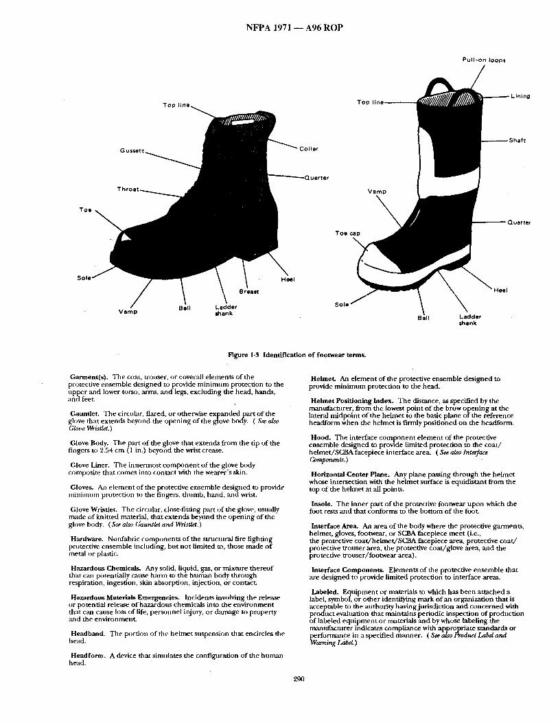
N F P A 1971 ~ A 9 6 R O P
Pull-on loops
Toe
:)liar
Quarter
T o p
T o e ,
uarter
Sole
Vamp shank Sole
Ball LaPPer shank
Figure 1-3 Identification of footwear terms.
Garment(s). The coat, trouser, or coverall elements of the protective ensemble designed to provide minimum protection to the upper ,and lower torso, arms, ,and legs, excluding the head, hands, and feet.
Gauntlet. The circular, flared, or otherwise expanded part o f the glove that extends beyond the opening of the glove body. ( See also Glove Wristlet.)
Glove Body. The part o f the glove that extends from the tip of the K fingers to 2.~4 cm ( 1 in.) beyond the wrist crease.
Glove Liner. The innermost componen t of the glove body composite that comes into contact with the wearer 's skin.
Gloves. An element of the protective ensemble designed to provide minimmn protection to the fingers, thumb, hand, and wrist.
Glove Wristlet. The circular, close-fitting part of the glove, usually made of knitted material, that extends beyond the opening of the ghwe body. (See, also (Jauntier and Wristlet.)
Hardware. Nonfabric components of the structural fire fighting protective ensemble iluzluding, but not limited to, those made of metal or plastic.
Hazardous Chemicals. Any solid, liquid, gas, o rmix ture thereof that can potentially cause harm to the human body through respiration, ingestion, skin absorption, injection, or contact.
Hazardous Materials Emergencies. Incidents involving the release or potential release of hazardous chemicals into the environment that can cause loss of life, personnel injury, or damage to property and the environment.
Headband. The portion of the helmet suspension that encircles the head.
Headform. A device that simulates the configuration of the human head.
Helmet. An e lement of the protective ensemble designed to provide minimum protection to the head.
Helmet Positioning Index. The distance, as specified by the manufacturer, from the lowest point o f the brow opening at the lateral midpoint of the helmet to the basic plane of the reference headform when the helmet is firmly positioned on the headform.
Hood. The interface comp?nen t e lement of the protective ensemble designed to provtde limited protection to the coa t / helmet/SCBAfacepiece interface area. ( See also Interface Components.)
Horizontal Center Plane. Any plane passing through the helmet whose intersection with the helmet surface is equidistant from the top of the helmet at all points.
Insole. The inner part of the protective footwear upon which the foot rests and that conforms to the bottom of the foot.
Interface Area. An area of the body where the protective gm'ments, helmet, gloves, footwear, or SC_,BA facepiece meet (i,e., the protective coatd'helmet/SCBA facepiece area, protective coa t / protective trouser area, the protective coat/glove area, and the protective trouser/footwear area).
Interface Components. Elements of the protective ensemble that are designed to provide limited protection to interface areas.
Labeled. Equipment or materials to which has been attached a label, symbol, or other identifying mark of an organization that is acceptable to the authority having jurisdiction and concerned with product evaluation that maintains periodic inspection of production of labeled equipment or materials and by whose labeling the mantffacturer indicates compliance with appropriate standards or performance in a specified manner. ( See also Product Label and Warning Label. )
290
NFPA 1971 requirements of this standard. Such accessories include, but are not limited to, utility belts, harnesses, back packs, tools, tool packs, radios, radio packs, suspenders, lights, goggles, and heat sensing devices.
Approach Fire Fighting. Limited, specialized exterior fire fighting operations :it incidents inw)lving fires producing very high levels of conductive convective zmd radiant heat, such as bulk flammable gas and bulk flammable liquid fires. Specialized therm~d protection from exposure to high levels of radiant heat is necessary for the persons inwMved in such operations due to the lintited scope of these operations :rod the greater distance from the fire at which these operations are condncted. Approach fire fighting is not entry, proximity, or structural fire fighting. ( See also Entry Fire Fighting, t~oximi~. Fire Fightin~ and Structural Fire Fighting.)
Approved.* Acceptable to the anthority having jurisdiction.
Arch. The bottom curve of the foot, from the heel to the ball.
Authority Having Jurisdiction.* The organization, office, or individual responsible for approving equipment, an installation, or a procedure.
Barrier Material. A single-layer fabric or a laminated/coated. multilayer material that is considered as a single-layer fabric that limits trans£er from the face of the layer to the other side.
Basic Plane. A behnet term for the plane through the centers o f the external ear openings and the lower edges of the eye sockets.
Basic Weight. The weight of the helmet, including all components specified in 4-2.1.
Biological Agents. Biological materials that could be capable of causing a disease or long-term damage to the human body.
Bitragion Coronal Arc.* A helmet term for the arc between the right and left tragion as measured over the top of the head in a plane perpendicular to the mid-sagittal plane.
Bitragion lnion Arc.* A helmet term for the arc between tragion as measured over the inion. For test purposes, the Bitragion Inion Arc is identified ms Datum Plane 10 in Figures 6-15.4.1 (a) through (c).
Body Fluids. Fluids prodl,ced by the body induding, but not limited to, blood, semen, mucus, feces, urine, vaginal secretions, breast milk, amniotic fluid, cerebrospinal fluid, synovial fluid, and pericardial fluid.
Brim. A part of the shell of the helmet extending around the entire circumference of the helmeL
Brim Line. A horizontal plane intersecting the lowest point o f the brim opening at the lateral midpoint of the helmet.
Cargo Pockets. Pockets located on the protective garment exterior.
Certification/Certified. A system whereby a certification organization determines that a manufacturer has demonstrated tile ability to produce a product that complies with the requirements of this standard, mtthorizes the mamffactnrer to use a label on listed products that comply with the requirements of this standard, and establishes a follow-up program conducted by the certification organization ,ms a check on the methods the manufacturer uses n) determine compliance with tile requirements of this standard.
Certification Organization. An independent , third-party organization that determines product compliance with the requirements of this standard with a labeling/listing/follow-np program.
Char. The formation of a britde residue when material is exposed to thermal energy.
Chin Strap. An adjustable strap, fitting under the chin, to help secure the hehnet to the head.
Coat. A protective garment; an e lement of the protective ensemble designed to provide minimum protection to tipper torso and arms, excluding the hands ,'rod head.
Collar Lining. That part of collar fabric composite that is next to the skin when the collar is closed in the raised position.
A96 ROP Compliance/Compliant. Meeting or exceeding ,all applicable
requirements of this stan&a.rd.
Component. Any material, part, or subassembly used in the construction of the protective ensemble or any e lement of the protective ensemble. (Se~alsolnt~rfaceComponents.)
Composite. The layer or combination of layers of the protective ensemble or any e lement of the protective ensemble that provides the required protection.
Coronal Plane. A helmet term for the plane, perpendicular to the basic and mid-sagittal planes, that passes through the centers o f the external ear openings.
Coverall. A protective garment; an e lement of the protective ensemble confignred ,as a single-piece garment and designed to provide minimum protection to the torso, arms, and legs, excluding the head, hands, and feet.
Crown. The portion of the helmet that covers the head above the reference plane.
Crown Straps. A helmet term for the part of the suspension that passes over the head.
Dielectric Test Plane. A plane that runs from the intersection of the test line and mid-sagittal plane in the front o f the headform diagonally through t hehead fo rm to the intersection of the reference plane and mid-sagittal plane in the rear of the headform.
Drip. To run or fall in drops or blobs.
Ear Covers. An integral p,a~ of the helmet designed to provide limited protection for tile ears in the coat /he lmet /SCBA facepiece interface area.
Elements. The parts or items that comprise the protective ensemble. The protective ensemble elements are coats, trousers, coveralls, helmets, gloves, footwear, and interface components.
Energy Absorbing System. A material, suspension system, or o)nlbination thereof incorporated into the design of the helmet to attenuate impact energy.
Ensemble. See Protective Ensemble.
Entry Fire Fighting. Extraordinari~. specialized fire fighting operations that can include the ,activities of rescue, fire suppression, and property conservation at incidents involving fires producing very high levels o f conductive, convective, and radiant heat; such as aircraft fires, bulk flammable gas fires, and bulk flammable liquid fires. Highly specialized thermal protection from exposure to extreme levels o f conductive, convective, and radiant heat is necessary for persons involved in st,ch extraordinarily specialized operations due to the scope of these operations ,and because direct ent" U into flame~ is made. Usually these operations are exterior operations. Entry fire fighting is not structural fire fighting. ( See also Approach Fire Fighting, Proximi~ Fire Fighting, and Structural Fire Fiffhting. )
Eye/Face Positioning Index. The distance, as specified by tile manufacturer, from the top lateral midpoint o f the partial eye/face protective interface component to the B plane of the Aldeson 50 percent adult rmde headform where the partial eye/face protective interface component is positioned on the headform.
Flame Resistance. The property of a material whereby the application of a flaming or nonflaming source of ignition and the subsequent removal o f the ignition source results in the termination of combustion. Flanm resistance can be an inherent property o f t h e
• material, or it can be imparted by specific treatment.
Fluorescence. A process bywhich radiant flux of certain wavelengths is absorbed and remdiated nonthermally in other, usually longer, wavelengths.
Follow-up Program. The sampling, inspection, tests, or other measures conducted by the certification organization on a periodic basis to determine the cont inued compliance of products listed that are being produced by the n~mtffacturer to the requirements of this standard.
Footwear. An e lement of the protective ensemble designed to provide minimum protection to the foot, ankle, and lower leg.
289
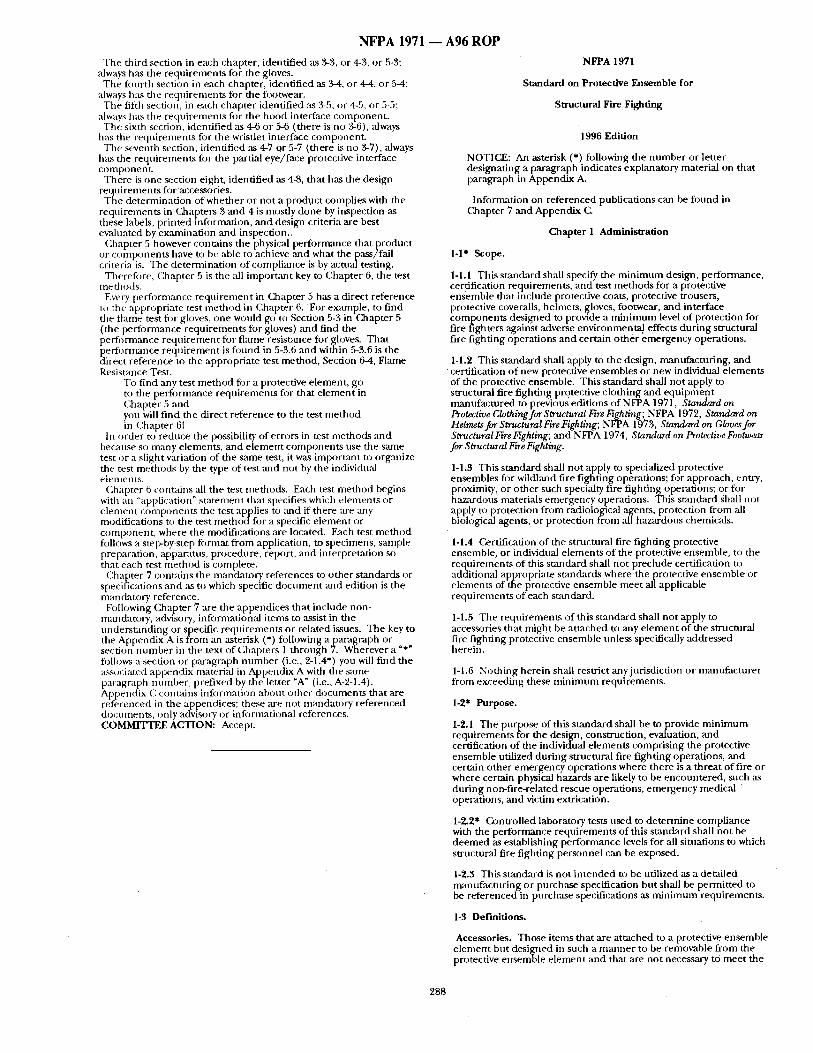
N F P A 1971 ~ A96 R O P
The third section in each chapter, identified ,as 3-3, or 4-3, or 5-3; always has the requi rements for the gloves.
The four th section ira each chapter, identified as 2,-4, or 4-4, or 5-4; always has the requirements for the footwear.
The filth section, in each chapter identified as 3-5, or 4-5, or 5-5; always has the reqt , i rements fi)r the hood interface component -
The sixth section, identified as 4-6 or 5-6 ( there is no 3-6), ~ways has the requirements for the wristlet interface component .
The seventh section, identified as 4-7 or 5-7 (there is no 3-7), always has the requirements fi)r the partial eye/face protective interface componenL
There is one section eight, identified as 4-8, tha t has the design requi rements for accessories.
Ttle determinat ion of whether or not a prodt.mt complies with the requirements in Chapters 3 and 4 is mostly done by inspection as these labels, pr inted itfformation, and design criteria are best evaluated by examinat ion ,and inspection..
Cha~,p ter ,5 however contains the physical, performance that preroduct. or componen t s have to be able to achieve and what the pass/lall criteria is. The determinat ion of compliance is by actual testing.
Therefore, (hhapter 5 is the all important key to Chapter 6, the test m e t i l O ds .
Every performance requ i rement in Chapter 5 has a direct reference to the appropriate test me thod in Chapter 6. F o r example, to find the flame test fi)r gloves, one would go to Section 5-3 in Chapter 5 (the performance requi rements for gloves) and find ate performance requ i rement for flame resistance for gloves. Tha t
er formance requ i rement is found in 54 .6 and within 5-5.6 is the direct reference to the appropriate test method, Section 6-4, Flame Resistance Test.
To find any test me t hod for a protective element , go to the pe r fonnance requi rements for that e lement in Chapter 5 and you will f ind the direct reference to the test me thod in Chapter 6!
In order to reduce the possibility of errors in test me thods and because so many elements, and e lement componen t s use the same test or a slight variation of the same test, it was impor tant to organize the test methods by the type of test ,and not by the individu:d e i e l n e t r Lq,
Chapter 6 cont:dns MI the test methods. Each test nmthod begins with an "application" stateinent that specifies which e lements or e lement componen ts the test applies to ,and if there :we :my modifications to the test me thod for a specific e lement or component , where the modifications are located. Each test me thod fi)llows a step-by-step format f rom application, to specimens, sample preparation, apparatus, procedure, report, and interpretation so that each test me t hod is complete.
Chapter 7 contains the mandatory references to o ther s tandards or specifications and as to which specific documen t ,and edition is the mandatory reference.
Following Chapter 7 are the appendices that include non- mandatory, advisory, informational items to assist in the unders tanding or specific requirements or related issues. The key to the Appendix A is f rom an asterisk (*) following a p a r a g r a p h or section n u m b e r in the text of (2hapters 1 through 7. Wherever a "*" follows a section or paragraph n u m b e r (i.e., 2-1.4") you will find the ass~ciated appendix mamrial in Appendix A with the s:une paragraph number , prefixed by the letter "A" (i.e., A-2-1.4). Appendix C cont~d ns information about o ther documents that are referenced ira the appendices; these are not manckm)ry referenced docnments , only advisol T or informational references. COMMITTEE ACTION: Accept.
NFPA 1971
Standard on Protective Ensemble for
Structural Fire Fighting
1996 Edition
NOTICE: An asterisk (*) following the n u m b e r or letter designating a paragraph indicates explanatory material on that paragraph in Appendix A.
Information on referenced publications can be found in C~apter 7 and Appendix C.
Chapter 1 Administration
1-1" Scope.
1-1.1 This s tandard shall specify the m i n i m u m design, performance, certification reqnirements , and test methods for a protective ensemble that include protective coats, protective trousers, protective coveralls, helmets, gloves, footwear, and interface componen ts designed to provide a m i n i m u m level of protection for fire fighters against adverse environmenta l effects dur ing structural fire fighting operations and certain o ther emergency operations.
1-1.2 This s tandard shall apply to the design, manufacturing, and cert i f icat ion o f new protective ensembles or new individual e lements of the protective ensemble. This s tandard shall no t apply to structural fire f ighting protective clothing and equ ipmen t rnanufacmred to previous editions of NFPA 1971, Standard on Protective Clothing for Structural Fire Fighting; NFPA 1972, Standard on Helmets for StructuraI Fire Fighting; NFPA 1973, Standard on Gloves for Structural Fire Fighting; ,and NFPA 1974, Standard on Protective Footwear for Structural Fire Fighting.
1-1.3 This s tandard shall no t apply to specialized protective ensembles for wildiand fire f ighting operations; for approach, entry, proximity, or o ther such specialty fire fighting operations; or for hazardous materials emergency operations. This s tandard shall no t apply to protection f rom radiological agents, protection from all biological agents, or protection from all hazardous chemicals.
1-1.4 Certification o f the structural fire f ighting protective ensemble, or individual e lements of the protective ensemble, to the requirements of this s tandard shall not preclude certification to additional appropriate standards where the protective ensemble or e lements of the protective ensemble meet al lapplicable requirements of each standard.
1-1.5 The requirements of this s tandard shall no t apply to accessories that might be at tached to any e lement of the structural fire f ighting protective ensemhle unless specifically addressed herein.
1-1.6 Nothing herein shall restrict any jurisdiction or manufac turer from exceeding these m i n i m u m requirements .
1-2" Purpose.
1-2.1 The purpose of this s tandard shall be to .provide m i n i m u m requirements for the design, construction, evaluation, and certification of the individual e lements compris ing the protective ensemble utilized dur ing structural fire f ight ing operations, and certain other emergency operations where there is a threat of fire or where certain physical hazards are likely to be encountered, such as dur ing non-fire-related rescue operations, emergency medical ' operations, and victim extrication.
1-2.2" Controlled laboratory tests used to de te rmine compliance with the performance requirements of this s tandard shall no t be deemed as establishing per formance levels for all situations to which structural fire fighting personnel can be exposed.
1-2.3 This s tandard is no t in tended to be utilized as a detailed manufac tur ing or purchase specification but shall be permit ted to be referenced in purchase specifications as m i n i m u m requirements .
1-3 Definitions.
Accessories. Those items that are at tached to a protective ensemble e lement but designed in such a m a n n e r to be removable f rom the protective ensemble e lement and that are not necessary to meet the
288
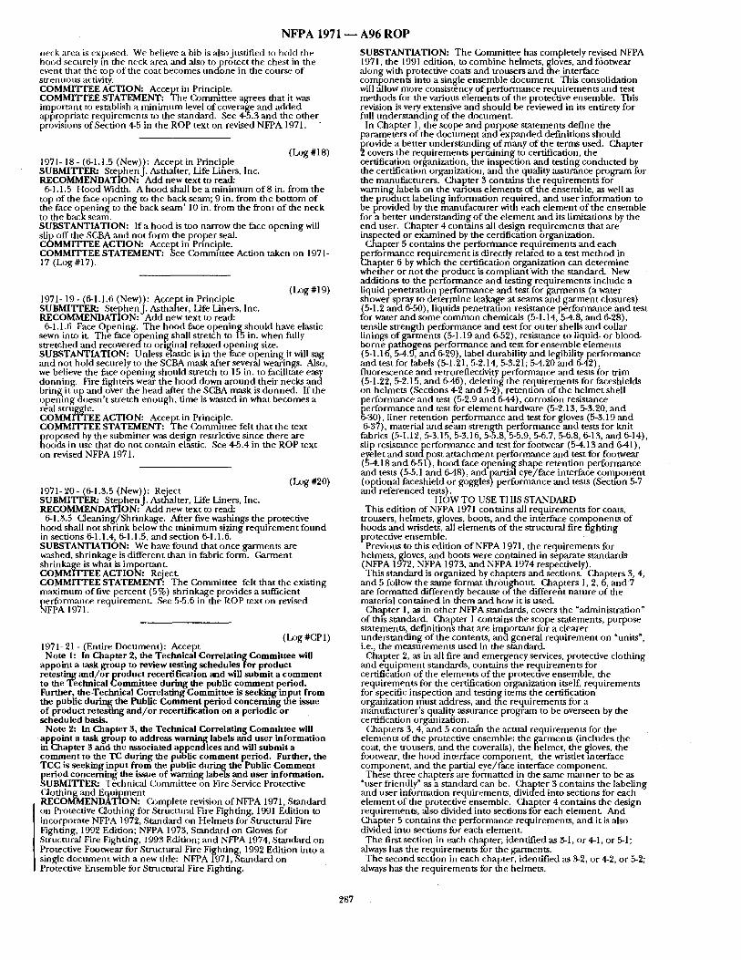
N F P A 1971 ~ A 9 6 R O P
neck area is exposed. We believe a bib is also justif ied to hold the hood securely in the neck area and also to protect the chest in the event that the t.op o f the coat becomes unc[one in the course o f s t renuous activity. COMMITTEE ACTION: Accept in Principle. COMMITTEE STATEMENT: The Cz)mm]ttee agrees that it was important to establish a m i n i m u m level of coverage and added app" ropriate requi rements to the standard. See 4-5.3 and the o ther provisions of Section 4-5 in the ROP text on revised NFPA 1971. "
(Log #18) 1971- 18- (6-1.1.5 (New)): Accept in Principle SUBMITTER: StephenJ . Asthalter, Life Liners, Inc. RECOMMENDATION: Add new text to read:
6-1.1.5 Hood Width. A hood shall be a m i n i m u m of 8 in. f rom the top of the face open ing to the back seam; 9 in. f rom the bot tom of the face open ing to t he back seam' 10 in. f rom the front of the neck to the back seam. SUBSTANTIATION: I r a hood is too narrow the face open ing will slip off the SCBA and not fo rm the proper seal. COMMITTEE ACTION: Accept in Prfncij31e. COMMITTEE STATEMENT: See Corrmuttee Action taken on 1971- 17 (Log #17).
(Log #19) 1971- 19- (6-1.1.6 (New)): Accept in Principle SUBMITI'EI~ StephenJ . Asthalter, Life Liners, Inc. RECOMMENDATION: Add new text to read:
6-1.1.6 Face Opening. The hood face o p e n i n g s h o u l d have elastic sewn into iL The face open ing shall stretch to [5 in. when fully s t re tched and recovered to original relaxed open ing size. SUBSTANTIATION: Unless elastic is in the face open ing it will sag and no t hold securely to the SCBA mask after severfd wearings. Also, we believe the face open ing should stretch to 15 in. to facilitate easy donning. Fire fighters wear the hood down a round their necks and bring it ul~ and over the head after the SCBA mask is donned. If the open ing ctoesn't stretch enough , t ime is wasted in what becomes a real struggle. COMMITTEE ACTION: Accept in Principle. COMMITTEE STATEMENT: The Commit tee felt that the text
~ roposed by the submit ter was design restrictive since there are oods in use that do not contain elas- tic. See 4-5.4 in the ROP text
on revised NFPA 1971.
(Log #20) 1971-20- (6-1.3.5 (New)): Reiect SUBMITTER: StephenJ . Asthalter, Life Liners, Inc. RECOMMENDATION: Add new text to read:
6-1.3.5 Cleaning/Shr inkage . After five washings the protective hood shall not shr ink below the m i n i m u m sizing r equ i r emen t f ound in sections 6-1.1.4, 6-1.1.5, and section 6-1.1.0. SUBSTANTIATION: We have found that once garments are washed, shr inkage is different than in fabric form. Garment shrinkage is what is important . COMMITTEE ACTION: Reject. COMMITTEE STATEMENT: T he Commit tee felt that the existing m a x i m u m of five percen t (5%) shr inkage provides a sufficient performmlce requirement . See 5-5.6 in the ROP text on revised NFPA 1971. -
( Log #CP 1 ) 1971- 21 - (Entire Document) : Accept
Note 1: In Chapter 2, the Technical Correlating Committee will appoint a task group to review testing schedules for product retesting a n d / o r p r o d u c t recertificatlon and will submit a comment to the Technical Committee during the public comment period. Further, the Technical Correlating Committee is seeking-input from the public during the Public Comment period concemirig the issue of product retesting and /or recertification on a periodic or scheduled basis.
Note 2: In Chapter 3, the Technical Correlating Committee will appoint a task group to address warning labels and user information in Chapter 3 and the associated appendices and will submit a comment to the TC during the public comment period. Further, the TCC is seeking input from the public during the Public Comment period concerning the issue of h, a m i n g labels and user information. SUBMITTER: Technical Conunit tee on Fire Service Protective Clothing and Equipment RECOMMENDATION: O)mple te revision of NFPA 1971, Standard on Protective Clothing for Structural Fire Fighting, 1991 Edition to incorporate NFPA 1972, Standard on Helmets for Structural Fire Fighting, 1992 Edition; NFPA 1973, Standard on Gloves for Structural Fire Fighting, 1993 Edition; and NFPA 1974, Standard on Protective Footwear for Structural Fire Fighting, 1992 Edition into a single d o c u m e n t with a new title: NFPA 1971, Standard on Protective Ensemble for Structural Fire Fighting.
SUBSTANTIATION: The Ck~mmittee has completely revised NFPA 1971, the 1991 edition, to combine helmets, gloves, and footwear ,along with protective coats and trousers and the interface componen ts into a single ensemble documenL This consolidation will allow more consistency of per formance requirements and test methods for the various e lements of the protective ensemble. This revision is very extensive and shou ld be reviewed in its entirety for full under s t and ing of the document .
In Chapter 1, the scope and purpose s tatements define the parameters of the d o c u m e n t and expanded definitions should
~ rovide a better unders tand ing o f many of the terms used. Chapter covers the requirements pertaining to certification, the
certification organization, the inspection and testing conduc ted by the certification organization, a n d t h e quality assurance program for the manufacturers . Chapter 3 contains the requi.rements for warning labels on the various e lements of the ensemble, as well as the product labeling information required, and user information to be provided by the fnanufacturer with each e lement o f the ensemble for a better unders tand ing o f the e lement and its limitations by the end user. Chapter 4 contains all design requirements that are inspected or e~,amined by the cert if icationbrganizafion.
Chapter 5 contains the performance requi rements and each performance requ i rement is directly related to a test me thod in Chapter 6 by which the certification organization can de te rmine whe/aher or no t the product is compl iant With the standard. New addit ions to the per formance a n d ~esting requi rements include a liquid penetra t ion per formance and test for garments (a water shower spray to de te rmine leakage at seams and ga rmen t closures) (5-1.2 and 6-50), liquids penetra t ion resistance per formance ~tnd test for water and some c o m m o n chemicals (5-1.14,5-4.8, and 6-28), tensile s t rength per formance and test for outer shells and collar linings of gaimaents (5-1.19 and 6-52), resistance to liquid- or blood- borne pathogens performance and test for ensemble e lements (5-1.1if, 5-4.9, and-6-29), label durability and legibility performance and test for labels (5-1.21, 5-2.14, 5-3.21; 5-4.20 and 6-42), f luorescence and retroreflectivity performance ,and tests fi)r t r im (5-1.22, 5-2.15, and 6-46), deletinl~ the requirements for faceshields on helmets (Sections 4-2 and 5-2), retention of the he lmet shell per formance and test (5-2.9 and 6-44), corrosion resistance performance and test for e l ement hardware (5-2.13, 5-3.20, and 6-30), liner retention performance and test for gloves (5-3.19 and 6-37), material and seam strength performance and tests for knit
fabrics (5-1.12, 5-3.15, 5-3.16, 5~.8, 5-5.9, 5-6.7, 5-6.8, 6-13, and 6-14), slip res i s tanceper formance ,and test for footwear (5-4.13 and 6-41), eyelet and s t u d p o s t a t t achment performance and test for footwear (5-4.18 and 6-51), hood face open ing shape retention per formance and tests (5-5.1 and 6-48), and partial eye/face interface c o m p o n e n t (optional faceshield or goggles) per formance and tests (secffon 5-7 and referenced tests).
HOW TO USE THIS STANDARD This edition of NFPA 1971 contains all requi rements for coats,
trousers, helmets, gloves, boots, and the interface componen t s of hoods and wristlets, all e lements of the structural fire f ighting protective ensemble.
Previous to this edition o f NFPA 1971, the requi rements for helmets, gloves, and boots were conta ined in separate s tandards (NFPA 19"72, NFPA 1973, and NFPA 1974 respectively). This s tandard is organized by chapters and sections. Chapters 3, 4,
and 5 follow the same format thr6ughout . Chapters 1, 2, 6, and 7 are format ted differendy because o f the differefit na ture o f the material conta ined in them and how it is used.
Chapter 1, as in o ther NFPA standards, covers the "administration" of this standard. Chapter 1 contains the scope statements, purpose statements, definit ions that are impor tan t for a clearer - - - unders tand ing of the contents, and general r equ i rement on "units", i.e., the measu remen t s used in the standard.
Chapter 2, as in all fire and emergency services, protective clothing and equ ipmen t standards, conta ins the requirements for certifidadon of the e lements of the protective ensemble, the requi rements for the certification organization itself, requirements for sp.ecific, inspection and test_in i tems the. certification organlzataon must address, and ~ e req turements for a mant- ffactnrer's quality assurance program to be overseen by the certification organization.
Chapters 3, 4, ,and 5 contai'n the actual requi rements for the e lemrnts of the protective ensemble: the garments (includes the coat, the trousers, and the coveralls), the helmet, the gloves, the footwear, the hood interface component , the wristlet interface component , and tim partial eye/ face interface component .
These three chapter's ,are format ted in the same m a n n e r to be as "user friendly" ,as a s tandard can be. C&apter 3 contains the labeling and user information requirements , divided into sections for each e lement o f the protective ensemble. Chapter 4 contains the design requirements , also divided into sections fo-r each element . And Chapter 5 contains the performance requirements , and it is also divided into sections for each element .
The first section in each chapter; identified as 3-1, or 4-1, or 5-1; always has the requirements for the garments.
The second section in each chapter, identified as 3-2, or 4-2, or 5-2; always has the requirements for the helmets.
287
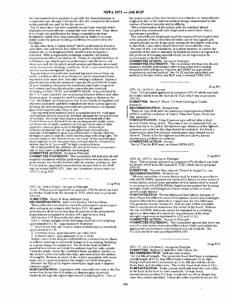
NFPA 1971
the only material then available to provide the desired increase in conspicnity even though it was known that the conspicuity decreased as the material was used by the fire service.
For 10 years there has been available an alternate material which maintains its retmreflective conspict,ity even when wet. Thus, there is no longer any justification for us ing a material to increase firefighters' safety when that material loses its ability to increase safety unde r the precise working condit ions encoun te red by the firefighter.
In any o ther field, a "s~ffety device ~ which per formed its f imction only when new and which then failed to per form this funct ion after normM rise, in its des ignated field, would not be accepted or tolerated. With a dependable substitute available, the falling equ ipmen t would not be used at all. Th ink of a parallel sitnation of a climbers ' rope which meet its per formance specifications only when new and dry but which would weaken mad dissolve when used under normal wet climbing conditions. Such a rope would never be used lay any knowledgeable climber.
Exposed bead retroreflective material has been barred from use under condit ions where its per formance can be moni tored when ex :~osed to rain, mist. dew, and other wetting conditions. Exposed g ass bead retroreflective material is specifically prohibited because ot poor rainfall performance by numerous nationally recognized and actively nsed specifications for retroreflective materials including L%300c, FP-85, and AP~SHTO M-248. It is prohibited by the ILS. Coast Guard for use on personal flotation devices and other flotation gear. It canno t be used for traffic signs or devices in the U.K. All of these prohibit ions are due to tile resnlts of impartial and objective laboratory and field evaluations by these various agencies showing the deteriorat ing retroreflective performance of exposed glass bead material when dirty or wet.
The exposed bead material which is unsatisfactory fiar road signs and highway devices cannot be d e e m e d adeqnate for the protection af humans . It is ironic that exposed glass bead material i f i the l lnited States is prohibi ted from use on inexpensive t r ~ c cones and froni nse o n trash containers in Europe but is used on trim a~l., lie i t ) turn )ut g,e-tr worn lay firefignhters. It should be unders tood that the nse of exposed glass bead retrorefiective material on firefighters' gear is permit ted due to the fact that the firefighter cannot easily see when his trina stops reflecting light. He cannot easily see the deterioration, over time, of the exposed glass bead rrmterial on his own gear when wet ,and thns he cont inues to believe that lie is "protected" by high conspicnity trim.
All of thisjustif iec)the addition o f a wet per formance acceptance test tan tr im used can firefighters' t n m o u t gear. COMMITTEE ACTION: Accept in Principle. COMMITTEE STATEMENT: The Commit tee felt that trim should maintain m i n i m u m visibility performance when wet and that a wet performance test should simulate adverse weather conditions. See 5-1.22 and the associated test me thod in Section 6-46 in the ROP text on revised NFPA 1971. Also, see £2Jmmittee Action taken on 1971-11 (Log #10).
(Log #12) 1971- 14 - (4-8.4 (New)): Accept in Principle Note: This proposM appea redas c o m m e n t 1971-36 which was held
fiar fi lrther study from the Annual 91 TCD, which w,~ on proposal 1971-53. SUBMITrER: Henry A. Ross, Reflexite Gorp RECOMMENDATION: Add a new Section 4-8.4 as follows:
"Retroreflective trim shall be tested fo rpho tome t r i c performance ,after soiling in accordance with Section 5-15. Measured performance shall not be less than 80 percent of the photometr ic requirements conta ined in Section 4-8.1 and Section 4-8.2.
Add Section 5-15 Retroreflective After Soiling. 5-6.5.1 Obtain sarnples o f the following materials each weighing
apfaroximately0.1 lb. (approximately45 g r a ~ ) : 1. Hard wood with cane car more surfaces shellacked or varnished,
approximately O. 1 lb. 2. I l rethane fomn. approximately one cubic inch. 3. Polyester fabric, approximately 12 in. x 12 in.. Subject each of the samples individually to a bunsen burner f lame
to achieve charr ing or structural change such as melting, bubbling or a gross change in consistency. Put all of the heat modif ied material in a mortar and crush the mixture together with a pestle. Using the pestle, smear the combined flame modif ied mixtnre on the surface of the retroreflective trim, and work it into the surface thoroughly. Remove as much of the residue as possible with warm water and a 1 percen t solution (by weight) of a mild detergent.
Measnre the SIA at 0.2 degree observation angle and 4 degrees ent rance angle." SUBSTANTIATION: Experience with retroreflective tr im in the fire service has shown that it is subject to deterioration by several methods through the rigors exper ienced in f ighting fires. One of
286
A96 ROP
the major causes of this deteriorat ion is a reduction in retroreflective brightness due to the material surfaces being con tamina ted by the residne of burned material and its effluvia.
This contaminat ion o f the surface with the resul tant almost complete loss of retroreflective br ightness is much more than a main tenance problem.
The retroreflective brightness (,and the expected level of safety that is the purpose o f the retroreflective trim) can be lost rapidly and catastrophically on the f i reground, leaving the fire fighter with what is effectively a zero safety benefit f rom the retroreflective trim.
Because of this, it is mandatory, as a safety measnre, to ensure the capability of the trim to maintain its brightness when it is exposed to the products of burn ing material which can be expected to be encoun te red in the fire field. COMMITTEE ACTION: Accept in Principle. COMMITTEE STATEMENT: The Conumttee felt that trim should maintain visibility performance ,after being subjected to soiling associated with emergency response and added an appropriate requ i rement and test method. See 5-1.22 and the associated test me thod in Section 646 in the ROP text on revised NFPA 1971.
(Log #6) 197l- 15 - (4-9.5.1): Accept Note: This p)roposal appeared ,as c o m m e n t 1971-27 which was held
fiar fnr ther study from the Annual 91 TCD, which was on proposal 1971-53. SUBMITrER: Harry P. Winer, US Navy Clothing & Texdle Research RECOMMENDATION: Revised text:
"Fastener tape shall mee t the m i n i m u m requirements o f MIL-F- 21840 G with the exclusion of Class 2, Fasteners Tapes, Hook and Pile, synthetic." SUBSTANTIATION: Class 2 fastener tape will fail after a short period o f t ime being cycled. This class is no t r e c o m m e n d e d for an item that has ua be cycled. All fasteners tape closures on fire fighters garments are cycled so this class should be excluded. Yes this is a main tenance issue but a known main tenance issue should not be allowed. Think of the fire fighters and lets no t allow a known m a l n t e n a n c e p r o b l e m to continue. COMMITTEEACTION: Accept.
See 4-1.7 in the ROP text on revised NFPA 1971.
(Log #15) 1971- 16 - (5-7.1): Accept in Principle Note: This proposal appeared as c o m m e n t 1971-29 which was held
for fi lrther stndy from the Annual 91 TCD, which was on proposal 1971-53. SUBMITFER: Vincent Diaz, Adantic Thread & Snpply Co., Inc. RECOMMENDATION: Revised text:
"All seam assemblies of woven fabrics shall be tested in accordance with A,STM D1683, s tandard test me thod for failure in sewn seams of woven fabrics; and all seam assemblies of knit fabrics shall be tested in accordance with ASTM D3940, Sumdard test m e t h o d for burst ing strength (load) and elongation of sewn seams of knit car woven stretch textile fabrics." SUBSTANTIATION: Woven fabrics and knit fabrics, because of their inherently different ratios of elongation (woven-low/knit-high) require different test methods to compensa te for this difference. The protective hoods, Section 6-I, that are part o f this ensemble, have a manufac tured seam down the center of the hood. Without the use of D3940, this seam cannot be evaluated by a certifying agency to de termine if it meets the requirements of the seam strength requirements stipulated in 4-1.2 and 4-1.2.1. COMMITTEE ACTION: Accept in Principle. COMMITTEE STATEMENT: The Commit tee agreed that there was a need to test certain seam assemblies in knit fabrics and added the appropriate perfiarmance requi rements and test methods. See 5-1.12 in the ROP text on revised NFPA 1971.
(tz~g #17) 1971- 17 - (6-1.1.4 (New)): Accept in Principle SUBMITrER: StephenJ . Asthalter, Life Liners, Inc. RECOMMENDATION: Add new text to read:
6-1.1.4 Hood Length. The protective hood shall have a m i n i m u m overall length of 21 in. that will include a m i n i m u m 15 in. t ight fitting head area and a m i n i m u m o f a 6 in. bib that will lay on the front, back, and shonlder area. The entire hood shall meet 6-1.3.1. SUBSTANTIATION: Today a hood need only mee t the coat collar at the back of the heat to meet standards. Certain hood mantffacturers produce 9 1/2 in. hoods with no bib at all and they meet this cur ren t standard. Unless the collar is perfecdy secnre the
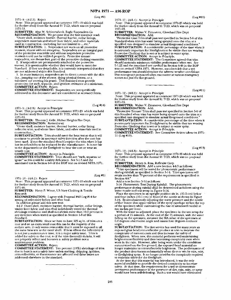
N F P A 1971 - -
1971- 8 - (4-2.3): Reject (~3g #9) Note: This proposal appeared as c o m m e n t 1971-18 which was held
fi~r fiwther study from the Anntlal 91 TCD, which was on proposal 1971-53. SUBMITTER: Alan W. Schierenbeck, Eagle Suspenders CO RECOMMENDATION: W e p r o p o s e that the first sentence read:
"Outer shell, moisture barrier, thermal barrier, collar linings, suspenders materials and winter liner fabric, and o ther materials used in construct ion - including but not l imited to ....etc." SUBSTANTIATION: 1. Suspenders are worn on all protective trousers, almost without exception. Suspenders are an integral part of the protective ensemble and without suspenders protective trousers could not be utilized properly. Protective trouser suspenders, are themselves, part of the protective clothing ensemble.
2. If suspenders are permanent ly a t tached to the proteciive trouser, it is quest ionable whether they would have to mee t the Sumdard. If they are detachable, it is currently interpreted that they are not addressed within this Standard.
3. In many instmlces, suspenders are in direct contact with the skin ( i .e . , jumping out o f the shower, doing physical fitness, or a volunteer out mowing his grass). This Standard must provide protection for melt, separate, and ignition resist~mce at a min imum. COMMITTEE ACTION: Reject. COMMITTEE STATEMENT: Suspenders are not specifically addressed in this d o c u m e n t and are considered as accessory items.
( LOg #14) 1971- 9 - (4z2.3): Accept in Principle Note: This proposal appeared as c o m m e n t 1971-23 which was held
for fi~rther study from the Annual 91 TCD, which was on proposal 1971-53. SUBMITTER: ThorruasJ. Grile, Huber Heights Fire Dept. RECOMMENDATION: Revised text:
"Outer shell, moisture bacrier, thermal barrier, collar lining, reflective trim, and winter liner fabric, and o ther materials used in construction.. ." SUBSTANTIATION: Trim should meet the hea t test so that it will cont inue to provide its necessary safety funct ion after the coat has been used. If no t the s tandard should require the tr im when it has lost its reflexibilty to be replaced by the manufacturer . It is no t fair to the depa r tmen t or the firefighter to bear the cost or wear an n n s~d~e COat. COMMITTEE ACTION: Accept in Principle. COMMITTEE STATEMENT: Trim should no t "melt, separate or ignite ~ as this could be a safety deficiency. See 5-1.5 and the associated test in Section 6-6 o f the ROP text on revised NFPA 1971.
(Log #5) 1971- 10- (4-8.1): Reject Note: This proposal appeared as c o m m e n t 1971-10 which was held
for fi, r ther study f rom the Annual 91 TCD, which was on proposal 1971-40. SUBMITTER: Harry P. Winer, US Navy Clothing & Textile Research RECOMMENDATION: I agree with Proposal #40 Log #14 for testing of reflectivity before and after heat.
In addition please add this new text: 4-2.2 Outer shell, moisture barrier, thermal barrier, collar linings,
winter liner fabric and trim shall individually tested for thermal shrinkage resistance and shall no t shr ink more than 10.0 percent in ,any direction when tested as specified in Section 5-3 of this Standard. SUBSTANTIATION: Since we have to have 325 sq in. of trim on a coat and on an extra small coat this can be the majority of the surface area, it only seems reasonable that it must be exposed to all the same heat test as the outer shell, ff hea t effects the reflectivity it is not just a mainten:mce issue, it is a n~tjor safety issue. Trim is added fi)r safety to tim coat, st) if the trim thermally shrinks, it will not properly reflect and becomes a safety problem not a main tenance problem. COMMITTEE ACTION: Reject. COMMITTEE STATEMENT: Ten percent (10%) shr inkage of trim due to heat is no t a safety issue unless melting, dripping, ignition, retr0reflectivity, or f luorescence are affected and these issues are addressed elsewhere in the standard.
A 9 6 R O P
(Log #I 0) 1971-11 - (4-8.1): Accept in Principle Note: This proposal appeared as c o m m e n t 1971-25 which was held
for fiwther study from the Annual 91 TCD, which was on proposal 1971-53. SUBMITTER: Walter V. Zimmerer , Cleveland Fire Dept RECOMMENDATION: Add.
"Protective Coat Tr im shall pass test specified in Section 5-6 o f this Standard when tr im has water being sprayed onto the trim at a specified rate designed to simulate actual f i reground conditions," SUBSTANTIATION: A considerable percentage o f the time when it is extremely impor tan t for Firefighters to be visible they are wearing Protective Clothing that is wet or is subject to water spray. COMMITTEE ACTION: Accept in Principle, COMMITTEE STATEMENT: The Commit tee agreed that trim should maintain m i n i m u m visibility per formance when wet. See 5-1.22 and the associated test me thod in Section 6-46 in the ROP text on revised NFPA 1971. However, members felt that a wet per formance test should simulate the adverse weather condit ions that emergency personnel often encoun te r at various emergency scenes no t jus t the fire ground.
(Log #11) 1971-12- (4-8.2): Accept in Principle Note: This proposal appeared as cormnent 1971-26 which was held
for fi lr ther study f rom the Annual 91 TCD, which was on proposal 1971-53. SUBMITTER: Walter V. Zimmerer , Cleveland Fire Dept RECOMMENDATION: Add.
"Protective Trouser Trim shall pass test specified in Section 5-6 of this Standard when trim has water being sprayed onto the trim at a specified rate designed to simulate actual f i reground conditions." SUBSTANTIATION: A considerable percentage of the time when it is extremely impor tan t for Firefighters to be visible they are wearing Protective Clothing that is wet or is subject to water spray. COMMITTEE ACTION: Accept in Principle. COMMITTEE STATEMENT: See Commit tee Action taken on 1971- 11 (Log #10).
(Log #13) 1971- 13- (4-8.3): Accept in Principle Note: This proposal appeared as c o m m e n t 197t-35 which was he ld
for fur ther study f rom the Annual 91 TCD, which was on proposal 1971-53. SUBMITI'ER: Henry A. Ross, Reflexite Corp RECOMMENDATION: Add a new Section 4-8.3 as follows:
"Trim specimens will be tested for photometr ic per formance dur ing rainfall, as specified in Section 5-14. Tr im specimens will retain no less than 70 percent of the requi rements as specified in Section 4-8."
Add a new Section 5-14 as follows: 5-14 Photometr ic Test Dur ing Rainfall. The photometr ic
performance dur ing rainfall shall be de te rmined as follows us ing th e water nozzle and test setup in Figure 5-14.
Place the specimen in an upr ight position six in. (15.2 cm) below and four inches (I0.1 cm) in front of the nozzle as shown in Figure 5.14. By simultaneously adjust ing the water pressure and the nozzle orifice insure that upper surface o f the spray envelope strikes the top of the specimen while mainta ining the rate of s imulated rainfall at two inches per hour .
With the water so adjusted, place the specimen in the test setup for Pleriod of 15 minutes . At the end of the 15 minutes, with the water
ing on the specimen, measure the SIA value o f the spec imen at 0.2 degrees observation angle and minus four degrees ent rance angle. SUBSTANTIATION: The fire service has used for many years an exposed glass bead retroreflective product as trim to increase the conspicuity o f tu rnou t coats and thus increase the safety of firefighters. When new, this material performs well-maintaining bright retroreflectivity and thus increasing conspicuity even when worn in the rain. However, after being worn u n d e r the condit ions encoun te red on the fire ground, the exposed bead material no longer nmintains its retroreflectivity brightness. The perfoi 'mance of the product deteriorates substantially when dirty or wet by rain, mist, or firefighting spray. It no longer provides the conspicuity required to maintain safety for the fireafighter.
At the t ime that this material was introduced, it was the only material available to provide the desired conspicuity to increase safety. At that time, the r equ i r emen t for a test to demonst ra te p e r m a n e n t per formance in the presence o f dirt, rain, mist, or spray would have been serf-defeating. Such a test would have el iminated
285
NFPA 1971
4-4.3 Footwem" height shall be a m i n i n n n n of 20.32 cm (8.0 in.). The height shall be de te rmined by measur ing inside the boot f rom the center of the heel back at tile insole level tip to the top line at tile center back. Removable insole inserts shall be removed prior to [ t l e ~ l s / I v e t D e l l t .
4-4.4 The 10orwear heel breast shall no t be less than 1.27 cm (0.5 in.) nor more than 2.54 cm ( 1.0 in.). The heel breasting :ingle shall not be less titan 90 degrees nor more than 135 degrees. The sides and rear of the heel shall not he flared or tapered, and the edges shall not be less than, or extend more than, 1.27 cm (0.5 in.) laterally f rom the tipper at any point. -
4-4.5 The puncture-resistant device shall cover the m a x i m u m area of the insole.
44 .6 Metal parts shall not penetrate f rom the outside into the lining or insole at any point.
4-4.7 No metal parts, including but no t l imited m nails or screws, shall be present or utilized in the construction or a t t achment of the sole with heel to the punctnre-resistmlt device, insole, or tipper.
4-4.8 Protective Footwear Sizing.
4-4.8.1 Protective footwear shall be available in ,all o f the folh)wing sizes:
Men's: 5-13, including half sizes and a m i n i m u m of two widths;
Women 's : 5-10, including half sizes and a m i n i m u m of two widths.
4-4.8.2 Full and haffsizes shall be accomplished by individual lasts or forms to provide proper fit.
4-5 Protective Hood Interface Component Design Requirements.
4-5~i A sample hood shall have at least the applicable design requirements specified in this section where inspected by the certification org~mization as specified in Section 2-3.
4-5.2 The hood sh:dl be des igned to cover and provide the limited protection, as specified within this section, to the head, face, and neck areas that do not receive primary protection flora the he lmet or the SCBA facepiece.
4-5.3 Specimens of hoods shall be measured to de te rmine the areas of coverage. The hood shall be d o n n e d properly in the position in which it is in tended to be worn on a s ize7 1 / 4 headform, as
' specified in Figure 6-16.4. In this position, the hood shall provide a m i n i m u m coverage on each side measured downward f rom the reference plane at the coronal plane of 23 cm (9.06 in.), shall provide a m i n i m u m coverage in the back measured downward from the reference plane at the rear mid-sagittal plane of 33 cm (13.0 in.), and shall provide a m i n i m u m coverage in the f ront measured downward f rom the reference plane at the front mid-sagittal plane, excluding the face opening, of 29.5 cm (11.60 in.).
4-5.4 The hood shall be des igned with a face opening. Other them where the hood face open ing is designed to interface with a specific SCBA facepiece or where the hood face open ing is designed to be adjustable, the hood face open ing shall measure 14.25 cm, +0.0/- 2.54 cm (5.6 in., +0.0/-1.0 in.) in any direction when the hood is laid out in a relaxed condition on a flat surface, smoo thed out, and with the face open ing up.
4-5.4.1 Where the hood face open ing is des igned to interface with a specific SCBA facepiece, the hood face open ing shall overlap the outer edge o f the specific SCBA facepiece-to-face seal per imeter by not less than 1.3 cm (0.5 in.).
4-5.4.2 Where the hood face open ing is provided with manual adjustment , the hood face open ing sha l lbe adjttstable to achieve a face open ing of 14.25 cm (5.6 in.).
4-6 Protective Wristlets Interface Component Design Requirements.
4-6.1 A sample wristlet shall have at least the applicable design requirements specified in this section where inspected by the certification organization ms specified in Section 2-3.
4-6.2 The wristlet shall be des igned to cover and provide limited protection to the wrist areas.
A96 ROP
4-6.3 The wristlet shall be permanent ly at tached to the protective coat sleeve.
4-7 Partial Eye/Face Protective Interface Componen t Design Requirements .
4-7,1 The partial eye/face protective device shall provide coverage of at least, 90 degrees when memsured from each side of the mid- sagitml plane and 50 m m above the basic plane when measured at
• the intersection of the inid-sagittal ,and basic planes when positioned in accord;race with mean vf-defined eye/face posit ioning index.
4-8 Accessory Des'Lgn Requirements .
4-8.1 Any accessories at tached to any e lement o f the protective ensemble shall no t interfere with the funct ion of the e lement or with the funct ion of any of the e lement ' s c o m p o n e n t parts.
4-8.2 Any'accessories at tached to any e lement o f the protective ensemble shall no t degrade the des igned protection or performance of the e lement beh)w the requirements of this standard.
Chapter 5 Performance Requirements
5-1 Protective Garment Performance Requirements.
5-1.1 Specimens o f ga rmen t composite consist ing of outer shell, moisture barrier, and thermal barrier shall be tested for overall liquid penetrat ion resistance as specified in Section 6-10, "Thermal Protective Performance (TPP) Test," and shall have an average thermal protective performance (TPP) of not less than 35.0.
5-1.2 Specimen ga rmen t composite shall be tested for overall liquid
~ enetrat ion resistance as specified in Section 6-49, "Liquid enetrat ion Test," and shall allow no liquid penetration.
5-1.3 Specimens o f ga rmen t outer shells, moisture barriers, thermal barriers, collar linings, winter liners where provided, trim, lettering, and o ther materials used in ga rmen t construction including, but no t limited to, padding, reinforcement, interfacing, binding, hanger loops, emblems, and patches shall he individually tes tedfor resistance to f lame as specified in Section 6-2, ~Flame Resistance Test One," and shall no t have a char length o f more than 10.16 cm (4.0 in.) average, shall no t have ,an afterflame of more than 2.0 seconds average, ,and shall not mel t or drip.
5-1.3.1 Where warning or product labels are not placed on the exterior o f the garment , where zippers and seam sealing materials are not placed on the exterior of the g a r m e n t and also are not placed where they will directly contact the wearer 's body, an d where elastic and hook and pile fasteners are no t placed where they will directly contact the wearer 's body, these items shall be excluded f rom the testing specified in 5-1.3.
5-1.4 Specimens o f ga rmen t outer shells, moisture barriers, thermal barriers, winter liners where provided, and collar linings shall be individually tested for resistance to heat as specified in Section 6-6, "Heat and Thermal Shrinkage Resistance Test," and shall no t shrink more than 10.0 percent in any direction.
5-1.5 Specimens o f ga rmen t outer shells, moisture barriers, thermal barriers, collar linings, winter liners where provided, trim, lettering, and o ther materials used in ga rmen t construction - - including, bu t not l imited to, padding, re inforcement , warning labels, product labels, interfacing, binding, hanger loops, emblems or patches; bu t excluding elastic and hook and pile fasteners where these i tems are
~ laced so that they will not directly contact the wearer's body - - shall e individually tested for resistance to hea t as specified in Section 6-
6, "Heat and Thermal Shrinkage Resistance Test," and shall no t melt, separate, or ignite.
5-1.6 Specimens of ga rmen t moisture barrier seams shall be individually tested for resistance to heat as specified in Section 6-6, *Heat and Thermal Shrinkage Resistance Test," and shall no t drip or ignite.
5-1.7 Specimens o f ga rmen t outer shells and collar linings shall be individually tested for resistance to heat as specified in Section 6-6, ~Heat and Thermal Shrinkage Resistance Test," and shall no t char.
5-1.8 Specimens o f all g a rmen t hardware, excluding hook an d pile fasteners, where placed so that they will no t directly contact the wearer 's body, shall be individually tested for resistance to heat as specified in Section 6-6, *Heat and Thermal Shrinkage Resistance Test," and shall no t ignite and shall remain functional.
303
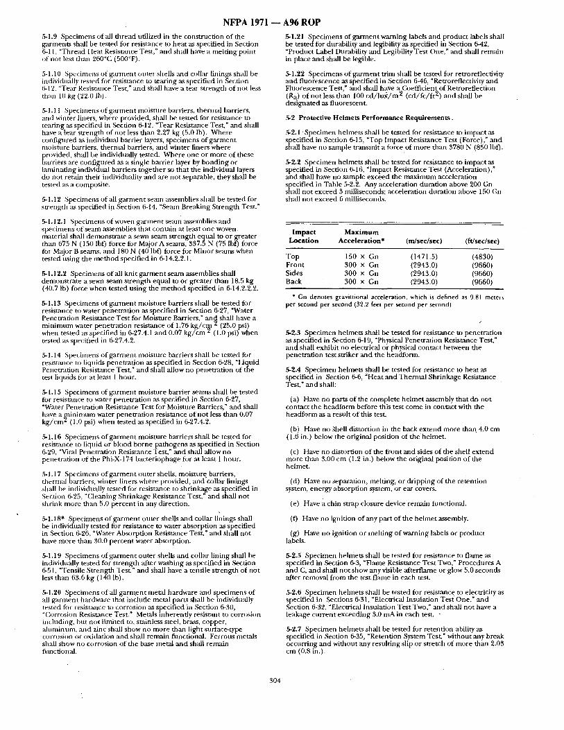
NFPA 1971
5-1.9 Specimens o f all thread utilized in the construction of the garments sh~dl be tested for resistance to heat as specified in Section 6-11, "Thread Heat Resistzmce Test," and shall have a melt ing point of not less than 260°C (500°F).
5-1.10 Specimens of ga rmen t ot,ter shells and collar linings shall be individually tested for resistaz~ce to tearing as specified in Section 6-12, "Tear Resistance Test," and shall have a tear strength o f not less than 10 kg (22.0 Ib).
5-1.11 Specimens o f ga rmen t moisture barriers, thermal barriers, and winter liners, where provided, shall be tested for resistance to tearing as specified in Section 6-12, "Tear Resistance Test," and shall have a [ear strength of not less than 2.27 kg (5.0 lb). Where configured as individual barrier layers, specimens of ga rmen t moisture barriers, thermal barriers, and winter liners where provided, shall be individually tested. Where one or more of these barriers are configured as a single barrier layer by bond ing or lanfinating individual barriers together so that the individual layers do not retain their individuality and are not separable, they shall be tested as a composite.
5-1.12 Specimens of all ga rmen t seam assemblies shall be tested for su 'ength as specified i n Section 6-t4, "Semn Breaking Strength Test."
5-1.12.1 Specimens of woven ga rmen t ~ a m assemblies and specimens o f seam assemblies that contzfin at least one woven material shall demonst ra te a sewn seam strength equal to or greater than 675 N (150 lbf) force for Major A semns, 337.5 N (75 lbf) force for MajOr B seams, and 180 N (40 lbf) force for Minor seams when tested using the m e t h o d specified in 6-14.2.2.1.
5-1.12.2 Specimens of all knit g a r m e n t seam assemblies shall demonst ra te a sewn seam strength equal to or greater than 18.5 kg (40.7 Ib) force when tested using the m e t h o d specified in 6-14.2.2.2.
5-1.13 Specimens o f ga rmen t moisture barriers shall be tested for resisumce to water penetrat ion as specified in Section 6-27, "Water Penetration Resistance Test for Moisture Barriers," an~ shall have a m i n i m u m water penetrat ion resistance o f 1.76 k g / c ~ (25.0 psi) when tested as specified in 6-27.4.1 ,and 0.07 k g / c m 2 (1.0 psi) when tested as specified in 6-27.4.2.
5-1.14 Specimens of ga rmen t moisture barriers shall be tested fi~r resistance to liquids penetrat ion as specified in Section 6-28, "Liquid Penetration Resistance Test," and shall allow no penetrat ion of the test liquids for at least l hour .
5-1.15 Specimens of ga rmen t moisture barrier seams shall be tested for resistance to water penetrat ion as specified in Section 6-27, "Water Penetration Resistance Test for Moisture Barriers," and shall have a [qfinimum water penetrat ion resistance o f not less than 0.07 k g / c m ~ (1.0 psi) when tested as specified in 6-27.4.2.
5-1.16 Specimens of ga rmen t moisture barriers shall be tested for resistance to liquid or blood borne pathogens ,as specified in Section 6-29, "Vi~d Penetrat ion Resistance Test," mad shall allow no penetrat ion of the Phi-X-174 bacteriophage for at least 1 hour .
5-1.17 Specimens o f ga rmen t outer shells, moisture barriers, thermal barriers, winter liners where provided, :rod collar linings shall be individually tested fi)r resist~mce to shr inkage as specified in Section 6-25, "Cleaning Shrinkage Resistance Test," and shall not shrink more than 5.0 percent in any direction.
5-1.18" Specimens of ga rmen t outer shells and collar linings shall be individnally tested fi~r resistance to water absorption as specified in Section 6-26, "Water Absorption Resistance Test," and shall no t have more than 30.0 percent water absorption.
5-1.19 Specimens of g a ~ e n t outer shells ~md collar lining shall be individually tested for s t rength after washing as specified in Section 6-51, "Tensile Strength Test," and shall have a tensile s t rength of not less than 63.6 kg (140 lb).
5-1.20 S ~ecimens of all g a rmen t metal hardware and specimens of all ~ m n e n t hardware that include metal parts shall be individu:d y tested for resistance to corrosion ,as specified in Section 6-30, "Corrosion Resishance Test." Metals inherent ly resistant to corrosion including, but not l imited to, stainless steel, brass, copper, Muminum, and zinc shall show no more than light surface-type corrosion or oxidation and shall remain functional. Ferrous metals shall show no corrosion of the base metal and shall remain fnnction:d.
A96 ROP
5-1.21 ,Specimens of ga rmen t warning labels and product labels shall be tested for durability and legibility as specified in Section 6-42, "Product Label Durability and Legibility Test One," and shall remain in place and shall be legible.
5-1.22 Specimens o f ga rmen t trim shall be tested fi)r retrorefiectivity and f luorescence as specified in Section 6-46, "Retroreflectivity and Fluorescence Test," and shall have a O~efficient of Retroreflection (Ra) o f not less than 100 c d / l u x / m 2 ( cd / f c / f t 2) and shall be designated as fluorescent.
5-2 Protective Helmets Performance Requirements.
5-2.1 • Specimen helmets shall be tested for resisumce to impact as specified in Section 6-15, "Top Impact Resistance Test (Force)," an d shall have no sample t ransmit a force of more than 3780 N (850 lbf).
5-2.2 Specimen helmets shall be tested for resistance to impact as specified in Section 6-16, "Impact Resistance Test (Acceleration)," and shall have no sample exceed the n m x i m u m acceleration specified in Table 5-2.2. Any acceleration durat ion above 200 Gn shall no t exceed 3 milliseconds; acceleration durat ion above 150 Gn shall not exceed 6 milliseconds.
Impact Maximum Location Acceleration* (m/sec/sec) (ft/sec/sec)
T o p 150 x Gn (1471.5) (4830) Front 300 x Gn (2943.0) (9660) Sides 3 0 0 × Gn (2943.0) (9660) Back 300 x Gn (2943.0) (9660)
* Gn denotes gravinional acceleration, which is defined as 9.81 meters per second per second (32.2 feet per second per second)
t
5-2.3 Specimen helmets shall be tested for resistance to penetrat ion ( e s as specified in ,Section 6-19, "Physical Penetrat ion Resistance T t,"
and shall exhibit no electrical or physical contact between the penetrat ion test striker and the headforrn.
5-2.4 Specimen helmets shall be tested for resistance to heat as specified in Section 6-6, "Heat and Thermal Shrinkage Resistance Test," and shall:
(a) Have no parts of the complete he lmet assembly that do not contact the headform before this test come in contact with the headform as a result of this test.
(b) Have no ~hell distortion in the back ex tend more than. 4.0 cm (1.6 in.) below the original position of the helmet.
(c) Have no distortion of the f ront and sides o f the shell ex tend more than 3.00 cm (1.2 in.) below the original position of the helmet.
(d) Have no separation, melting, or dr ipping of the retention system, energy absorption system, or ear covers.
(e) Have a chin strap closure device remain fimctional.
(f) Have no ignition of any part of the he lmet assembly.
(g) Have no ignition or melt ing o f warning labels or product labels.
5-2.5 ,Specimen helmets shall be tested for resistance to flame as specified in Section 6-3, "Flame Resistance Test Two," Procedures A and C, and shall no t show any visible afterflame or glow 5.0 seconds after removal f rom the test f lame in each test.
5-2.6 Specimen helmets shall be tested for resistance to electricity as specified in Sections 6-31, "Electrical Insulation Test One," and Section 6-32, "Electrical Insulation Test Two," and shall not have a leakage cu r r en t exceeding 3.0 mA in each test. -
5-2.7 Specimen helmets shall be tested for retention ability as specified in Section 6-35, "Retention System Test," without any break occurring and without any result ing slip or stretch of more than 2.03 cm (0.8 in.).
304
N F P A 1971 I
5-2.8 Specimen he lmet snspension systems shall be tested for retention ability as specif iedin Section 6-36, "Snspension System Retention Test," and shall no t separate f rom the he lmet shell.
.5-2.9 Specimen helmets shall be tested for shell retention ability as specified in Section 6-44, "Shell Retention Test," and shall not have the he lmet shell separate front the he lmet suspension and retention systems.
5-2.10 Specimens 0fal l inateri,als utilized in the construction of hehne t ear covers shall be individually tested for resistance to flame ~s specified in Section 6-2, "Flame Resist.ance Test One," and shall not have a char length greater than 10.2 cm (4.0 in.), shall no t show any visible :ffterflame 2.0 seconds after removal f rom the test flame, and shall not mel t or drip.
5-2.11 Specimens of all materials utilized in the construction of helmet ear covers shall be individually tested for resistance to hea t as specified in Section 6-6, "Heat and Thermal Shrinkage Resistance Test," and shall not shrink more than 10.0 percent in any direction, and shall not melt, separate, or ignite.
5-2.12 Specimens of all thread utilized in the construction o f the helmet ear covers shall be tested for resistance to heat as specified in Section 6-11. "Thread Heat Resistance Test," and shall have a melt ing point of not less than 260°(: (500°F).
\ ~2.13 Specimens of all helmet metal hardware and specimens of,all hehne t hardware that include metal parts shall be individually tested for resistance to corrosion as specified in Section 6-30, "Corrosion Resistance Test." Metals inherently resistmlt to corrosion including, hu t not limited to, stai~fless steel, brass, copper, ,aluminum, and zinc shall show no more than light snrface-type corrosion or oxidation and shall remain fimctional. Ferrous metals shall show no corrosion of the base metal and shall rem,--d n fimctional.
5-2.14 Specimens of he lmet warning labels and product labels shall be tested for durability ,and legibility as specified in Section 6-43, "Product Label Dnrability and Legibility Test Two," and shall remain in place and shall be legible.
5-2.15 Specimens of he lmet tr im shall be tested for retroreflectivity and f luorescence ,as specified in Section 646, "Retrorefiectivity and Fluorescence Test," and shall have a (~)efficient of Retroreflection (Ra) of not less than 100 c d / l n x / m 2 ( cd / fc / f t 2) and shall be designated as fluorescent.
5-3 Protective Glove Performance Requirements.
5-3. I Specimens of the glove body composite shall be tested for thermal insulation as specified ih Section 6-10, "Thermal Protective Performance (TPP) Test," and shall have an average thermal protective performance rating (TPP) not less than 35.0.
5-3.2 Where gauntlets or glove wristlets are provided, specimens of the glove gaunt le t or glove wristlet composite shall be tested for thermal insulation as specified in Section 6-10, "Thermal Protective Performance (TPP) Test," and shall have an average TPP rating of not less than 20.0.
5-3.3 Specimen gloves shall be tested for resistance to heat as specified in Section 6-6, "Heat and Thermal Shrinkage Resistance Test," and shall not melt, separate, or ignite, shall no t shr ink more than 5.0 percent in length or width, shall be donnable , and shall be flexiMe.
5-3.4 Specimens of the innermost separable layer of the glove body composite that is des igned to come into contact with the wearer's skin shall be individually tested fi)r resistance to heat as specified in Section 6-6, "Heat ,and Thermal Shrinkage Resistance Test," and shall not melt, separate, or ignite.
5-3.5 Specimens of the glove body composite shall be tested for the rmal insu la t ion as specified in Section 6-7, "Conductive Heat Resistance Test One," and shall have a second-degree burn t ime of not less than 10.0 seconds and shall have a pain t ime of not less than 6.0 seconds.
5-3.6 Specimens of the glove body composite shall be tested fi~r resistance to flame as specified in Section 6-4, "Flame Resist:race Test Three," and shall not have a char length of more than 10.2 cm (4.0 in.) average and shall no t have an afterfiarne of more than 2.0 seconds average ,after removal of the test flame. The composite shall not mel t or drip, and the consumed materials shall not exceed 5.0 percent o f the sample spec imen ' s original weight.
A 9 6 R O P
5-3.7 Where gauntlets or glove wristlets are provided, specimens of the glove gaunt le t or glove wristlet composite shall be tested for resistance to flame as specified in Section 6-2, "Flame Resistance Test One," and shall not have a char length o f more than 10.2 cm (4.0 in.) average, shall no t have ,an afterflame of more than 2.0 seconds average :ffter removal of the test flame, and shall .not mel t or drip.
.5-3.8 Specimens of all thread utilized in the construction of the gloves shall be tested for resistance to heat ,as specified in Section 6- 11, "Thread Heat Resistance Test," ,and shall have a melt ing point o f not less than 260°C (500°F).
5-3.9* Specimens of the glove body composite and seams shall .be tested for resistance to liquid or blood borne pa thogens as specified in Section 6-29, "Viral Penetrat ion Resistance Test," and shall allow no penetrat ion o f the Phi-X-174 bacteriophage for at least 1 hour.
5-3.10" Specimen gloves shall be tested for resistance to liquids enetrat ion as s[,)ecified in Section 6-28, "Liquid Penetration esistance Test, and shall allow no penetrat ion of the test liquids
for at least 1 hour .
5-3.11 Specimens of the glove body composite shall be tested for resistance to cut as specified in Section 6-22, "Cut Resistance Test," and shall no t cut completely through the composite u n d e r an average applied load of 8.2 kg (18.0 lb).
5-3.12 Specimens of the glove gan ntlet or glove wristlet composite, if different f rom the glove body composite, shall be tested for resistance to cut as specified in Sectiofi 6-22, ~Cut Resistance Test," ,and shall not cut completely through the composite und e r an average applied load of 8.2 kg (18.0 Ib).
5-3.13 Specimens of the glove body composite shall be tested for resistance to puncture as specified in Section 6-20, "Puncture Resistance Test One," and shall not be punc tured unde r an average applied force o f 6.0 kg (13.2 lb).
5-3.14" Specimen gloves shall be tested for dexterity as specified in Section 6-38, "Dexterity Test," and shall have the dexterity t ime not exceed 140 percent o f bare hand control time.
5-3.15 Specimens of knit glove wristlet material(s) shall be tested for ntaterial s trength as specified in Section 6-13, "Burst Strength Test," and shall have a burst s trength of not less than 23 kg (50.6 Ib).
5-3.16 Specimens of knit glove wristlet seams shall be tested for seam strength as specified in Section 6-14, "Seam Breaking Strength Test," and shall have a burst s t rength of not less than 18.5 kg (40.7 lb).
5-3.17 Specimen gloves shall be tested for grip as specified in Section 6-39, "Grip Test," and shall have a weight-pulling capacity not less than 80 percent of the bare hand control value.
5-3.18" Specimen gloves shall be tested for resistance to leakage ,as specified in Section 6-33, "Overall Liquid Integrity Test One," and shall show no leakage.
5-3.19" Specimen gloves shall be tested for ease of d o n n i n g a s specified in Section 6-37, "Liner Retention Test," and sha l lhave the final d o n n i n g time not exceed the baseline d o n n i n g time plus 20.0 seconds.
5-3.20 Specimens of all glove metal hardware and specimens of all glove hardware that include metal parts shall be individually tested for resistance to corrosion as specified in Section 6-30, "Corrosion Resist,'mce TesL" Metals inherent ly resistant to corrosion including, but not limited to, stainless steel, brass, copper, a luminum, an d zinc shall show no more than light surface-type corrosion or oxidation and shall remain flmctional. Ferrous metals shall show no corrosion of the base metal ,and shall remain t ract ional .
5-3.21 Specimens of glove warning labels and product labels shall be tested fi)r durability and legibility as specified in Section 6-42, "Product Label Durability and Legibility Test One," and shall rem~dn in place and shall be legible.
54 Protective Footwear Performance Requirements.
5-4.1 Specimen footwear shall be tested for resistance to heat as SlPeeCified in Section 6-6, "Heat and Thermal Shrinkage Resistance
st," and shall not have any part o f the footwear melt, separate, or ignite; and shall have all componen t s remain functional.
305
NFPA 1971
5-4.2 Specimen footwear shall be tested for thermal insulation as specified in Section 6-9, "Radiant Heat Resistance Test," and the tempera ture of the uppe r lining surface in contact with the skin shall not exceed 44.0°(:i (111.0°F).
5-4.3 Specimen footwear shall be tested for thermal insulation as specified in Section 6-7, "Conductive Heat Resistance Test One," and the tempera ture of the tipper l ining surface in contact with skin shall have a second-degree bairn t ime of not less than 10.0 seconds and shall have a pain time of not less than 6.0 seconds.
54 .4 Specimen fi3otwear shall be tested for thermal insulation ,as specified in Section 6-8, "(kmductive Heat Resistance Test Two," and the temperature of the insole stirface in contact with the foot shall not exceed 44.0°C (111.0°F).
,5-4.5 Specimen fi)otwear, with componen t s in place, shall be tested fi)r resistance to fl,'une as specified in Section 6-5, "Flame Resistance Test Four," and shall no t have an afterflame of more than 2.0
~seconds, shall no t mel t or drip, and shall no t exhibit any burn- through.
5-4.6 Specimens o f all thread utilized in the construct ion o f the footwear shall be tested for resistance to hea t as specified in Section 6-1 i, "Thread Heat Resistance Test," and shall have a mel t ing point of not less than 260°C (500F).
5-4.7 Specimen footwear shall be tested for resisumce to water as specified in Section 6-34, "Overall Liquid Integrity Test Two," and shall show no water penetrat ion.
.5-4.8 Specimen footwear t ipper rmateriai, tipper semns, vamp seams, and sole seams shall be tested for resis~mce to liquids penetrat ion as specified in Section 6-28, "Liquid Penetrat ion Resistance Test, ~ and shall allow no penetrat ion of the test liquids for at least l hour.
5-4.9 Specimens of the fi)otwear upper material, upper semns, vamp seams, and sole sean~s shall be tes tedfor resistance to liquid or blood borne pathogens as specified in Section 6-29, "Viral Penetrat ion Resistmace Test," and shall allow no penetra t ion o f the Phi-X-174 bacteriophage fi)r at least 1 hour.
5-4.10 ,Specimen footwear shall be tested for resistance to punc ture as specified in Section 6-20; "Puncture Resistance Test One," and sh:dl no t puncture the fi:~otwear upper unde r an average applied fi:mze of 6 kg (13.2 Ib).
.5-4.11 Specimen fi)otwear shall be tested fi:w resist;race to puncture as specified in Section 6-21, "Puncture Resist2mce Test Two," and shall not allow puncture through the sole ,area and the heel area at a fi:wce load of less than 1211.6 N (272 Ibm).
,5-4.12 Specimen fi)otwear shall be tested fi)r resistance to cu t as specified in Section 6-22, "Cut Resistance Test," and shall no t allow any cut through the footwear t ipper l ining at any point unde r an average applied load of8 .2 kg (18.0 lb).
5-4.13" Specimen footwear shall be tested for resistance to slipping ms specified in Section 6-41, "Slip Resistance Test:" T he soles shall have a static coefficient o f 0.75 or greater in a dry condition, and they shall have a static coefficient o f 0.50 or greater in a wet condition.
5-4.14 Specimen fi~otwear shall be tested fi~r resistance to ab~tsion as specified in Section 6-24, "Abrasion Resistance Test," and the sole with heel sh:dl have an abrasion index of not less than 100.
5-4.15" Specimen fi~otwear shall be tested for resistance to electricity as specified in Section 6-32, "Electrical Insulation Test Two," and shall have no leakage in excess o f 3.0 mA,
5-4.16 Specimens of fi~otwear toes shall be tested for resistance to impact and compression as specified in Section 6-18,' "Impact and £~mpress ion Tests," and shall have ,an impact r equ i rement of 101.7J (75 ft-lb), and shall have a compression requ i rement of 11,121 N (2500 lbf) with a m i n i m u m c l e : ~ n c e of at least 1.27 cm (0.5 in.).
5-4.17 Specimens o f footwear ladder shanks shall be tested for resistance to bend ing as specified in Section 6-40, "Ladder Shank Bend Resistance Test," and shall no t deflect more than 6.35 m m (0.25 in.).
,r~4.18 Specimens of footwear s tud posts and eyelets shall be tested for a t tachment strength as specified in Section 6-50, "At tachment for Eyelets :rod Stud Post T e s t : mid shall have a m i n i m u m de t achmen t sneng th o f 30 kfff (66 Ib f ) .
306
A96 ROP 5-4.19 Specimens of all footwear metal hardware and specimens of all footwear hardware that include metal parts including, but not l imited to, toecap, ladder shank, puncture-resistant device, and comp.onents shall be individually tested for resistance to corrosion as specified in Section 6-30, "Corrosion Resistance Test." Metals inherently resistant to corrosion including, bu t not l imited to, stainless steel, brass, copper, a luminum, and zinc shall show no more than light surface-type corrosion or oxidation. Ferrous metals shall show no corrosion of the base nmtal. All componen ts shall remain t rac t ional .
5-4.20 Specimens o f fi~otwear warning labels and product labels shall be tested for durability and legibility as specified in Section 6-42, "Product Label Durability and Legibility Test One," and shall remain in place and shall be legible to the una ided eye.
5-5 Protective Hood Interface Component Performance Requirements.
5-5.1 Specimens of hood face ol~enings , that are not manually adjustable or that are not des igned for interface with a specific SCBA facepiece, shall be tested for shape retent ion as specif iedin ,Section 6-47, "Hood Open ing Size Retention Test," and shall retain at least 80 percent o f the original face open ing size but shall no t exceed 14.25 cm (5.6 in.).
5-5.1.1 Where hood face openings are des igned to interface with a specific SC, BA facepiece, specimens o f such hood face Openings shall be tested for shape retention as specified in Section 6-47, ~Hood Open ing Size Retention Test," and shall overlap the outer edge o f the specific SCBA facepiece-to-face seal per imeter by not less than 1.3 cm (0.5 in.).
5-5.1.2 Where hood face openings are des igned to be manually adjustable, spec imens of such hood face openings shall meet the design requ i rement specified in 4-5.2.2.
5-5.2 Specimen hoods shall be tested for thermal insulation as specified in ,Section 6-10, "Thermal Protective Performance (TPP) Test," and shall have a thermal protective per formance (TPP) of not less than 20.0.
5-5.3 Specimens of hood material(s), including warning labels and product labels but excluding hook and pile fasteners and elastic when not placed in direct contact with the body, shall be individually tested for resistance to flame as specified in Section 6-2, "Flame Resistance Test One," and shall no t have a char length o f more than 10.2 cm (4.0 in.) average, shall no t have ,an afterflame of more than 2.0 seconds average, and shall no t melt or drip. Warn ing labels an d product labels not meet ing the specimen size requi rements for the procedure specified in 6-2.1 shall be sewn to a suppor t fabric o f the required size.
5-5.4 Specimens of hood material(s), including warning labels an d product labels but excluding hook and pile fasteners and elastic when these items are p lacedwhere they will no t directly contact the wearer 's body, shall be individually tested for resistance to heat as
in Section 6-6, "Heat and Thermal Shrinkage Resistance st," and shall not shr ink more than 10.0 percen t in any direction:
5-5.5 Specimens o f hood material(s), including warning labels an d product labels but excluding hook and pile fasteners and elastic when these items are placed where they will no t directly contact the wearer 's body, shall be individually tested for resistance to heat as specified in Section 6-6, "Heat mad Thermal Shrinkage Resistance Test," and shall not melt, separate, or ignite.
5-5.6 Specimens of hood material (s), including warning labels and product labels but excluding hook and pile fasteners and elastic when these items are placed where they will no t directly contact the wearer 's body, shall be individually tested for resistance to shrinkage as specified in Section 6-25, "Cleaning Shrinkage Resistance Test," and shall no t shr ink more than 5.0 percent in any direction.
5-5.7 Specimens o f all thread utilized in the construct ion o f hoods shall be tested fi)r resistance to hea t as specified in Section 6-11, "Thread Heat Resistance Test," and shall have a mel t ing poin t of no t less than 260°C (500°F).
5-5.8 Specimens of knit hood material(s) shall be tested for material s t rength as specified in Section 6-13, "Burst Strength Test," an d shall have a. burst s t rength of not less than 23 kg (50.6 lb).
5-5.9 Specimens of knit hood seams shall be tested for seam strength as specified in Section 6-14, "Seam Breaking Strength TesL" and shall have a burst s trength of no t less than 18.5 kg (40.7 lb).
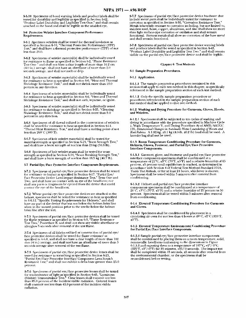
NFPA 1 9 7 1 -
5-5.10 Specimens o f hood warning labels and product labels shall be tested for durability and legibility ,as specified in Section 6-42, "Product Label Durability and Legibility Test One," and shall remain at tached to the hood and shall be legible to the una ided eye.
Protective Wristlet Interface Component Performance Requirements.
5-6.1 Specimen wristlets shall be tested for thermal insulation as SFPeeCified in Section 6-10, "Thermal Protective Performance (TPP)
st," and shall have a thermal protective performance (TPP) of not less than 20.0.
~6.2 Specimens of wristlet n'uaterial (s) shall be individually tested tar resistance to flame as specified in Section 6-2, "Flame Resist:race Test One," and shall not have a char length of more than 10.2 cm (4.(i) in.) average, shall no t have an af tername of more than 2.0 seconds average, and shall no t melt or drip.
,5-6.3 Specimens of wristlet unaterial(s) shall be individually tested for resistance to heat as specified in Section 6-6, "Heat and Thermal Shrinkage Resist:race Test," and shall no t shrink more than 10.0 percent in any direction.
5-6.4 Specimens of wristlet material(s) shall be individually tested for resistance to heat ,as specified in Section 6-6, "Heat and Thermal Shrinkage Resistance Test," aJid shall no t melt, separate, or ignite.
5-6.5 Specimens of wristlet material (s) shall be individually tested for resistance to shrinkage ,as specified in Section 6-25, "Cleaning Shrinkage Resistance Test," and shall no t shrink more than 5.0 percent in any direction.
5-6.6 Specimens of all thread utilized in the construction of wristlets shall be tested for resistance to heat as specified in Section 6-11, "Thread Heat Resistance Test," and shall have a melt ing point of not less than 260°(11 (500°F).
5-6.7 Specimens of knit wristlet material(s) shall be tested for material s trength as specified in Section 6-13, "Burst Strength Test," and shall have a burst s trength of no t less than 23 kg (50.6 Ib).
5-6.8 Specimens of knit wristlet seams shall be tested for se,'un s t rength as specified in Section 6-14, ~Seam Breaking Strength Test," and shall have a burst s trength of no t less than 18.5 kg (40.7 lb).
5-7 Partial Eye/Face Protective Interface Components Requirements.
5-7.1 Specimens of partial eye/face protective devices shall be tested for resistance to impact as specified in Section 6-17, "Partial Eye/ Face Protective Device Lens Impact Resistance Test," Tests One and Two, and shall have no contact with an eye of the headform: nor shall :my [)arts or f ragments be ejected from the device that could contact the eye of the headform.
5-7.2 Where partial eye/face promctive devices are at tached to the helmet, specimens shall be tested for resistance to heat as specified in 6-6.12, "Specific Test ing Requirements for Helmets," andsha l l have no part of the device that was not below the he lmet brim line when in the stowed position prior to the test be below the he lmet brim line after the test.
5-7.3 Specimens of partial eye/~tce protective devices shall be tested for flame resistance as specified in Section 6-3, ~Flame Resistance Test Two," Procedure B, and shall no t show any visible afterflame or ,afterglow 5 seconds ,after removal of the test flame.
5-7.4 Specimens of all fabrics utilized incons t ruc t ion of partial eye/ face protective devices shall be tested fi)r f lame resistance as specified in (L6.8, and shall not have a char length of more than 102 m m (4 in.) average, and shall no t have an ~ter f lmne of more thmt 5 seconds average ,after removal of the test flame.
5-7.5 Specimens of partial eye/face protective device lenses shall be tested tor resistance to scratching as specified in Section 6-23, "Partial Eye/Face Protective Interface C o m p o n e n t Lens Scratch Resistance Test," and shall not exhibit a delta haze greater than 25.0 percent.
5-7.6 Specimens of partial eye/face protective lenses shall be tested for t ransmit tance of l ight as specified in Section 6-45, "Luminous (Visible) Transmit tance Test. Clear lenses shall tr, 'msmit not less than 85.0 percent of the inciclent visible radiation. Colored lenses shall t ransmit no t less than 43.0 percent of the incident visible radiation.
A96 ROP
5-7.7 Specimens of partial eye/face protective device hardware that include metal parts shall be individually tested for resistance to corrosion as specified in Section 6-30, "Corrosion Resistance Test." Metals inherently resistant to corrosion incltlding, but not limited to, stainless steel, brass, copper, a luminum, and zinc shall show no more than light surface-type corrosion or oxidation mad shall remain functional. Ferrous metals shall show no corrosion of the base metal and shall remain fimctional.
5-7.8 Specimens of partial eye/face protective device warning labels and product labels shall be tested as specified in Section 6-43, ~Product Label Durability and Legibility Test Two," mad shall remain visible on the partial eye/face protective device mad shall be legible.
Chapter 6 Test Methods
6-1 Sample Preparation Procedures.
6-1.1 Application.
6-1.1.1 The sample preparation procedures contained in this section shall apply to each test me thod in this chapter, as specifically referenced in the santple preparation section of each test method.
6-1.1.2 Only the specific sample preparation procedure or procedt,res referenced in the sample preparation section of each test m e t h o d shall Se applied to that test method.
6-1.2 Washing and Drying Procedure for Garments, Gloves, Hoods, and Wrisdets.
6-1.2.1 Specimens shall be subjected to ten cycles of washing and drying in accordance with the procedure specified in Machine Cycle 1, Wash Tempera ture V, and Drying Procedure Ai of ANSI/AATCC 135, Dimensional Changes in Automatic Home Laundering of Woven arm Knit Fabrics. A 1.82-kg, ±0.1 kg (4.0-1b, i-0.2 lb) load shall be used. A laundry bag shall no t be used.
6-1.3 Room Temperature Conditioning Procedure for Garments, Helmets, Gloves, Footwear, and Partial Eye/Face Protective Interface Components.
6-1.3.1 Garment , glove, and footwear and partial eye/face protective interface componen ts specimens shall be condi t ioned at a temperature of 21°C, +3°C (70°F, +5°F) and a relative humidity of 65 percent, +5 percent until equil ibrium is reached, ,as de te rmined in accordance with Section 4 of Federal Test Method Standard 191A, Textile Test Methods, or for at least 24 honrs, whichever is shorter. Specimens shall be tested within 5 minutes after removal f rom conditioning.
6-1.3.2 Helmet and partial eye/face protective interface components specimens shall be condi t ioned at a tempera ture of 21°C, +3°C (70°F, ±5°F) and a relative humidi ty of 25 percent to 50 percent. Specimens shall be tested within 5 minutes after removal f rom conditioning.
6-1.4 Elevated Temperature Conditioning Procedure for Garments and Gloves.
6-1.4.1 Specimens shall be condi t ioned by p lacement in a circulating air oven for not less than 4 hours at 49°C, +20(; (120°F, ±5°F).
6-1.5 ElevatedTemperature Environmental Conditioning Procedure for Partial Eye/Face Interface Components.
6-1.5.1 Sample partial eye/face protective interface componen ts shall be condi t ioned by placing t hem on a room temperature, solid, nonmetal l ic headform conforming to file d imensions in Figure 6-1.5.1 and exposing them to a temperaul re of 107°C, +2°/-0%1 (225°F, +3°/-0°F) for 20 minutes, +15/-0 seconds. The impact test shall be comple ted within 15 seconds, ±5 seconds after removal from the environmental chamber , or the specimens shall be recondi t ioned befi)re testing.
307
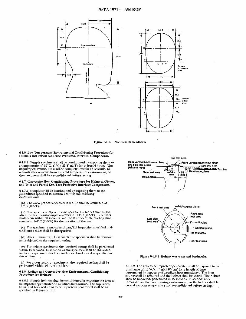
N F P A 1 9 7 1 - - A 9 6 ROP
~3,0
~ t oo.o ---,-,-¢~
ZW.V
8a$i¢ Diane
250.0 63.5
8 " - ~ " " C o . t o ~ t
- Itokb~ic
t98.
Figure 6.1.5.1 Nonmetallic headform.
6-1.6 Low Temperature Environmental Conditioning Procedure for Helmets and Partial Eye/Face Protective Interface Components.
6-1,6.1 Smnple specimens sh:dl be condi t ioned by exposing them to a temperature of-32°C, ±1 °C (-25°F, ±2°F) for at least 4 hours. The impact /penetrat ion test shall be completed within 15 seconds, ~5 seconds after removal from the cold.temperature environment, or the specimens shall be recondi t ioned before testing.
6-1.7 Convective Heat Conditioning Procedure for Helmets, Gloves, and Trim and Partial Eye/Face Protective Interface Components.
6-1.7.1 Samples shall be condit ioned by exposing them to the procedures specified in Section 6-6, with the following modifications:
(a) The oven preheat specified in 6-6.4:3 shall be stabilized at 141 °C (285°F).
(b) The specimen exposure time specified in 6-6.5.4 shall begin when the test thermocouple recovers to 141°C (285°F). Recovery shall occur within 30 seconds, and the thermocouple reading shall. remain at 141°C (285°F) for the duration of the test.
(c) The specimen removal and pass/fail inspection specified in 6- 6.5.5 and 6-6.5.6 shall be disregarded.
(d) Alter 10 minutes, ±15 seconds, the specimen shall be removed and subjected to the required testing.
(e) For helmet specimens, the required testing shall be performed within 15 seconds, ~5 seconds, or the specimen shall be discarded and a new specimen shall be condi t ioned and tested ,as specified in this section.
(D For gloves azld trim specimens, the required testing shall be performed within 24 hours, +1 hour.
6.1.8 Radiant and Convective Heat Environmental Conditioning Procedure for Helmets.
6.1.8.1 S:unple helmets shall be condit ioned by exposing the area to be impacted~penetrated to a radiant heat source. The top, sides, front, and back test areas to be impacted/penet ra ted shal /be as specified in Figure 6-1.8.1.
Top test area
Rear vertical transverse plane ~ ~ : ' ~ F r o n t vertical transverse plane sloe test areas :t<~:,=,=,:;,:~. ~ .~.~ - ~Fmnt test area
(len and right) ~g[?f~'~':" i -~\~(t i~,)~,,o r ~ , ~ p , ~ Test line Rear lest area ~--64~ 1 ~--64-,~ ?*-Reference plane
mm I ! mm I . . . . .
\V T M
lest a r e a ~ ~ ~ - 3 0 mm Radius
..... ~I ....... k ' " [ ' ~ ) ...... tt~ . . . . . Coronal plano
~ Rear test area
Figure 6-1.8.1 Helmet test areas and l~ndmarks.
6-1.8.2 The area to be impacted/penet ra ted shall be exposed to an irradiance of 1.0 W / c m z, £-0.1 W / c m z for a length of time determined by exposure of a radiant heat transducer. The heat source shall be rdmoved and the helmet shall be tested. The helmet shall be impacted /pene t ra ted in 15 seconds, ±5 seconds after removal from the conditioning environment, or the helmet shall be cooled to room temperature and recondit ioned before testing.
308
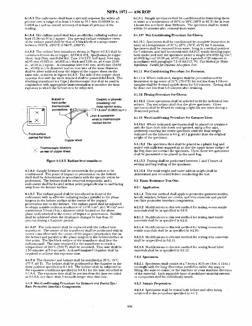
NFPA 1971
6-1.8.3 The radiometer shall have a spectral response flat within ±3 percent over a range of at least 1.0 m m to 10.1 m m (0.00004 in. to 0.0004 in.) and an overall accuracy of at least 25 percent of the reading.
6-1.8.4 The radiant panel shall have an effective radiating surface at leiLst 15.24 cm (6 in.) square. The spectral radiant emit tance curve of the radiant panel shall be that of a blackbody at a tempera ture between 1000°K, ±200°K (1340°F, ±360°F).
6-1.8.5 Tile radiant heat t ransducer shown in Figure 6-1.8.5 shall be constructed from shee t copper, ASTM B 152, Specification for Copper SheeLs', St@ Plate, and RoUedBar, Type 110 ETP, half hard, 0.64 ram, ±0.05 m m (0.025 in., ±0.002 in.) thick and 5.08 cm, i-0.4 m m (2,00 in.. -20.02 in.) square. A constantan wire 0.81 mm, e0.05 m m (0.032 in., ~k002 in.) in dimneter ,'and aJl iron wire of the same diameter shall be silver soldered near the edges of the copper sheet on the same side, as shown in Figure 6-1.8.5. The side of the copper shee t opposite that with the wires a t tached shall be painted flat black. The resulting t ransducer is a TypeJ thermocouple that shall be used in conjunction with appropriate ins t rumentat ion to moni tor the heat exposure to which the he lmet is to be subjected.
painted flat black
Brazed or Ceramic or phenolic hard solder (insulating) rod thermocouple cross section area<_ connections ~ "/1.6 mm z (0.0625 sq in.)
:t:£ tg,7 op, e
Copper sheet
• , T h e r m o c o u p l e l o c a t i o n s
, ' : , o n rear of copper sheet
Figure 6-1.8.5 Radiant heat transducer.
6-1.8.6 Smnple helmets shall be m o n n t e d in the position to be condit ioned. The point of impact or penetrat ion on the he lmet shell shall be de te rmined in accordance with the specific test to be performed. The he lmet shall be removed temporarily, and a radiometer shall be located at that point perpendicular to and fac ing away from the he lmet surface.
6-1.8.7 Tile radiant panel shall be introduced in front of the radiometer with its effective radiating surface parallel to the plane tangent to the hehne t surface at the center of the impac t / penetrat ion site on the helmet. The radiant panel shall be adjusted
Z 2 to obtain a stable uni form irradiance of 1.0 W / c m , :i.4).1 W / c m over a m i n i m u m 7.5-cm (3-in.) diameter circle located on the above phme and centered at the center o f impact or penetration. Stability shall be achieved when the irradiance changes by less than 10 percent dur ing a 3-minute period.
6-1.8.8" Tile radiometer shall be replaced with the radiant heat transducer. The center of the t ransducer shall be posit ioned with its center coincident with tile center of tile impact /pene t ra t ion site on tile hehne t and parallel to the plane tangent to the he lmet surface at that point. The flat black surface of the t ransducer shall face the radiant panel. The time required for the t ransducer to reach a tempera ture of 260°C (500°F) shall be recorded. Tha t t ime shall be 2.50 minutes, ±15.0 seconds, A closed insulated chamber shall be required to achieve this exposure time.
6-1.8.9 The chanlber ,and he lmet shall be stabilized at 25°(2, +5°C (77°F, ±9°F). The he lmet shall be posit ioned in the chamber in the same position specified in 6-1.8.6. The he lmet shall be subjected m the exposure condit ions specified in 6-1.8.1 for the time recorded in 6-1.8.8. The exposure time shall be not less than the t ime recorded in 6-1.8.8, nor more than 5 seconds longer than that time.
6-1.9 Wet Condit ioning Procedure for Helmets and Partial Eye/ Face Protective Interface Components.
A96 ROP
6-1.9.1 Sample specimens shall be condi t ioned by immers ing them in water at a tempera ture of 20°C to 28°C (68°F to 82°F) for at least 4 hours but not more than 24 hours. The specimen shall be tested within 10 minutes after removal f rom water.
6-1.10" Wet Conditioning Procedure for Gloves.
6-1.10.1 Specimens shall be condi t ioned by complete immersion in water at a tempera ture of 21°C, +3°C (70°F, -+.5°F) for 2 minutes. Specimens shall be removed from water, hung in a vertical position for 5 minutes, and laid horizontal with AATCC textile blotting paper both under and over the specimen unde r a weight of 0.0020 k g / c m 2, ±0.0002 k g / c m * (0.50 psi, ±0.05 psi) for a period o f 20 minutes in accordance with paragraph 7.2 of AATCC~70, Test Method fee Water Repellency: TumbleJar Dynamic Absm.ption Test.
6-1.11 Wet Conditioning Procedure for Footwear.
6-1.11.1 Where indicated, slunples shall be precondi t ioned by immersion in tap water of 21°C (70.0°F) for not less than 1.0 hour . Samples shall be dra ined upside down for 5.0 minutes. Testing shall be done not less than 5.0 minutes ,after draining.
6-1.12 Flexing Procedure for Gloves.
6-1.12.1 (;love specimens shall be selected to fit the individual test subject. The test subject shall don the glove specimen. (;love specimens shall be flexed by making a t ight fist ten times dur ing a 30-second period.
6-1.13 Wet Conditioning Procedure for Garment Liner.
6-1.13.1 Where indicated, specimens shall be placed on a balance with the face cloth side down and sprayed, us ing a fine mist, uniformly covering the entire specimen until the final weight indicated on the balance is 6.0 g, e0.1 g greater than the original weight of the specimen.
6-1.13.2 The specimen then shall be placed in a plastic bag and sealed with stffficient t rapped air so that the upper inner surface of the bag does not contact the specimen. Up to three wet specimens shall be permit ted to be placed in the same bag.
6-1.13.3 Test ing shall be per formed between 1 and 2 hours of wetting a n d bag sealing of the specimen.
6-1.13.4 The total weight and water add-on weight shall be de te rmined and recorded before conduc t ing the test.
6-2 Flame Resistance Test One.
6-2.1 Application.
6-2.1.1 This test me thod shall apply to protective ga rmen t textiles, hoods, wristlets, he lmet ear covers, and trim materials and partial eye/face protective interface components .
6-2.1.2 Modifications to this test me thod for testing woven textile materials shall be its specified in 6-2.8.
6-2.1.3 Modifications to this test me thod for testing knit textile materials shall be as specified in 6-2.9.
6-2.1.4 Modifications to this test me thod fi~r testing nonwoven textile materials shall be as specified in 6-2.10.
6-2.1.5 Modifications to this test me thod for testing tr im materials shall be its specified in 6-2.11.
6-2.1.6 Modifications to this test me thod for testing hood label materials shall be as specified in 6-2.12.
6-2.2 Specimens.
6-2.2.1 Specimens shall consist o f a 7.6-cm x 30.5-cm (3-in. x 12-in.) rectangle with the long dimension parallel to ei ther the warp or filling; the wale or coarse; or the machine or cross mach ine direction of the material. Each separable layer of multilayer material systems or composites shall be individually tested.
6-2.3 Sample Preparation.
6-2.3.1 Specimens shall be tested both before ,and afte[ being subjected to the procedure specified in 6-1.2.
309
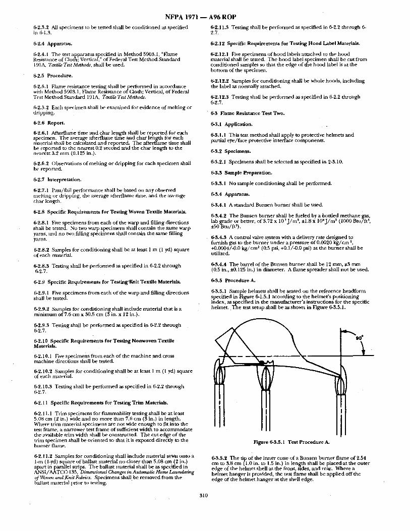
NFPA 1971
6-2.3.2 All specimens to be tested shall be condit ioned as specified in 6-1.3.
A96 ROP
6-2.11.3 Testing shall be performed as specified in 6-2.2 through 6- 2.7.
6-2.4 Apparatus.
6-2.4.1 The test apparatus specified in Method 5903.1, "Flame Resistance of Cloth; Vertical," o f Federal Test Method Standard 191A, Textile Test Methods, shall be used.
6-2.5 Procedure.
6-2.5.1 Fl,'une resistance testing shall b e p e r f o r m e d in accordance with Method 5903.1, Flame Resist,'mce of Cloth; Vertical, o f Federal Test Method Smncktrd 19 I A, Textile Test Methods.
6-2.5.2 Each specimen shall be examined ibr evidence of melting or dripping.
6-2.6 Report.
6-2.6.1 Afterflame time and char length shall be repor ted for each specimen. The average afterflame time and char lehgth for each material shall be calculated and reported. The afterflame time shall be reported to the nearest 0.2 second and the char length to the nearest 3.2 mm (0.125 in.).
6-2.6.2 Observations of melting or dripping for each specimen shall be reported.
6-2.7 Interpretation.
6-2.7.1 Pass/fail performance shall be based on any observed melting or dripping, the average ~ffterflame time. and the average char length.
6-2.8 Specific Requirements for Testing Woven Textile Materials.
6-2.8.1 Five specimens from each of the warp and filling directions shall be tested. No two warp specimens shall contain the same warp yarns, ,and no two filling specimens shall contain the same filling yarns.
6-2.8.2 Samples for condit ioningshall be at least 1 m (1 yd) square of each material.
6-2.8.3 Testing shall be performed as specified in 6-2.2 through 6-2.7.
6-2.9 Specific Requirements for Testing'Knit Textile Materials.
6-2.9.1 Five specimens from each of the warp and filling directions shall be tested.
6-2.9.2 &unples for conditioning shall include material that is a minimum of 7.6 cm x 30.5 cm (3 in. x 12 in.).
6-2.9.3 Testing shall be performed as specified in 6-2.2 through 6-2.7.
6-2.10 Specific Requirements for Test~ag Nonwoven Textile Materials.
6-2.10.1 Five specimens from each of the machine and cross machine directions shall be tested.
6-2.10.2 Samples for conditioning shall be at least 1 m (1 yd) square of each material.
6-2.10.3 Testing shall be performed as specified in 6-~2.2 through 6-2.7.
6-2.11 Specific Requirements for Testing Trim Materials.
6-2.11.1 Trim specimens for flammability testing shall be at least 5.08 cm (2 in.) wide ,and no more than 7.6 cm (3 in.) in length. Where trim material specimens are not wide enough to fit into the test frame, a narrower test frame o f suiticient width to accommodate the available trim width shall be constrncted. The cut edge of the trim specimen shall be or iented so that it is exposed directly to the burner flame.
6-2.11.2 Samples for conditioning shall include material sewn onto a 1-m (1-yd) square of ballast material no closer than 5.08 cm (2 in.) apart in parallel strips. The ballast material shall be as specified in ANSI/AATCC. 135, Diraer~ional Changes in Automatic Home Laundering of Wover~ and Knit Fabricz. Specimens shall be removed from the ballast material prior to testing.
6-2.12 Specific Requirements for Testing Hood Label Materials.
6-2.12.1 Five specimens of hood labels attached to the hood material shall be tested. The hood label specimen shall be cut from condit ioned samples so that the edge of the hood label is at the bottom of the specimen.
6-2.12.2 Samples for conditioning shall be whole hoods, including the label as normally attached.
6-2.12.3 Testing shall be performed as specified in 6-2.2 through 6-2.7.
• 6-3 Flame Resistance Test Two.
6-3.1 Application.
6-3.1.1 This test method shall apply to protective helmets and partial eye/face protective interface components.
6-3.2 Specimens.
6-3.2.1 Specimens shall be selected as specified in 2-3.10.
6-3.3 Sample Preparation.
6-3.3.1 No sample conditioning shall be performed.
6-3.4 Apparatus.
6-3.4.1 A standard Bunsen burner shall be used.
6-3.4.2 The Bunsen burner shall be fueled by a bottled methane gas, lab grade or better, o f 3.72 x 10⁷ j / m 3, ±1.8 x lOeJ /m 3 (1000 BtuTft 3, • .50 Btu/ft3).
6-3.4.3 A control valve system with a delivery rate designed to furnish gas to the burner under a pressure of 0.0020 kg /cm ~, +0.0004/-0.0 kg /cm ~ (0.5 psi, +0.t/-0.0 psi) at the burner shall be utilized.
6-3.4.4 The barrel of the Bunsen burner shall be 12 mm, +3 mm (0.5 in., x'-0.125 in.) in diameter. A flame spreader shall no t be used.
6-3.5 Procedure A.
6-3.5.1 Sample helmets shall be seated on the reference headform specified in Fignre 6-1.5.1 according to the helmet 's positioning index, ,as specified in the manufacturer 's instructions for the specific he lmet . .The test setup shall be as shown in Figure 6-3.5.1.
, III l i Figure 6-3.5.1 Test Procedure A.
6-3.5.2 The tip o f the inner cone of a Bunsen burner flame of 2.54 cm to 3.8 cm (1.0 in. to 1.5 in.) in length shall be placed at the outer edge of the helmet shell at the front, sides, and rear. Where a helmet hanger is provided, the test flame shall be applied of f the edge of t h e h e l m e t hanger at the shell edge.
310
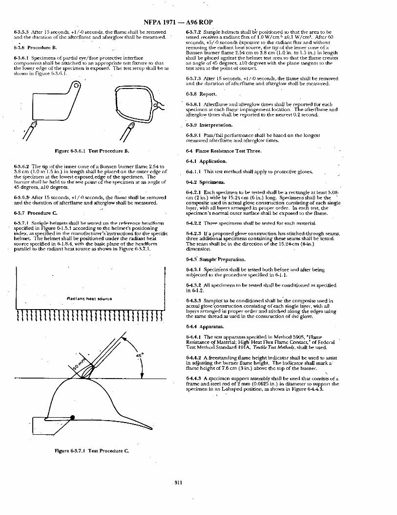
N F P A 1 9 7 1 -
6-3.5.3 After 15 seconds, +1/-0 seconds, the f lame shall be removed and the duration of the afterflame ,and afterglow shall be measured.
6-3.6 Procedure B. ;
6-3.6.1 Specimens of partial eye / f ace protective interface Components shall be a t tached to mt appropriate test fixture so that the lower edge o f the specimen is exposed. The test setup shall be as shown in Figure 6-3.6.1.
// Figure 6-3.6.1 Test Procedure B.
6-3.6.2 The tip of the inner cone of a Bunsen burner flame 2.54 to 3.8 cm (1.0 to 1.5 in.) in length shall be placed on the outer edge o f the specimen at the lowest exposed, edge of the specimen. The burner shall be he ld to the test point o f the spec imen at an ,angle of 45 degrees, +10 degrees.
6-3.6.3' After 15 seconds, +1/-0 seconds, the f lame shall be removed and the durat ion of afterf lame and afterglow shall be measured.
6-3.7 Procedure C.
6-3.7.1 Saffaple helmets shall be seated on the reference headform specified in Figure 6-1.5.1 according to the he lmet ' s posit ioning ifidex, as specified in the mantffacturer 's ' instruct ions for the specific helmet. The he lme t shall be posi t ioned unde r the radiant heat source specified in 6-1.8.4, with the basic plane o f the headform parallel to the radiant heat source as shown in Figure 6-3.7.1.
Radian t heat sdurce
t l t l t l t l t l l l l I l t t l I t l l I l t t l I I I t l
• 1
L
Figure 6-3.'/.1 Test Procedure {2.
A 9 6 R O P
6-3.7.2 Sara'pie he lme t s shall b~ posi t ioned so that the area to he tested receives a radiant flux of 1.0 W / c m ~' ~0.1 W / c m 2. After 60 seconds, +5/-0 seconds exposnre to the radiant flnx and without removing the radiant heat source, the t ip of file inner cone of a Bunsen burner flame 2.54 cm to 3.8 cm (1.0 in. to 1.5 in.) in length shall be placed against the he lmet test area so that the f lame creates an ,angle of 45 degrees, +10 degrees with the plane t angen t to the test area at the point of contact+
6-3.7.3 After 15 seconds, +1/-0 seconds, the f l~ne shall be removed • and the duration of afterflame and afterglow shall be measured.
6-3.8 Report.
6-3.8.1 Aftertlame and ~+terglow t imes shall be reported for each specimen at each flame imp ingemen t location. The afterflame and afterglow times shall be reported to the neares t 0.2 second.
6-3.9 Interpretation.
6-3.9.1 P~s / fa i l per formance shall be based on the longest measured afterflame and ,afterglow times.
6-4 Flame ResLstance Test Three.
6-4.1 Application.
6-.4.1.1 This test m e t h o d s h a l l apply to protective gloves. f
6-4.2 Specimens.
6-4.2.1 Each specimen to be tested shall be a rectangle at least 5.08~ cm (2 in.) wide by 15.24 cm (6 in.) long. Specimens shall be the " composite used in actual glove construct ion consist ing o f each single layer, with all layers a r ranged in proper order. In each test, the spec imen ' s normal outer surface shall be exposed to the flame.
6-4.2.2 Three specimens shall be tested for each material.
6-4.2.3 I f a proposed glove construct ion has s t i tched-through se,'m~s, three additional specimens conta in ing these se,'uns shall be tested. The seam shall be in the direction of the 15.24-cm (6-in.) d imension.
6-4.3' Sample' Preparation.
64.3.1 Specinfens'shall be tested both before and after being subjected to the procedure specified in 6-1.1.
6-4.3.2 All spec imens to be tested sh~ l be condi t ioned as specified in 6-1.2.
64.3.3 Samples to be condi t ioned shall be ' the composi te used in actual glove'construction consisting o f each single layer, with all layers arrang~ed ifi proper, order and stitched, a long the edges us ing the same thread as used m the cunstructaon of the glove.
6-4.4 Apparatus.
6-4.4.1 The test apparatus specified in Method 5905, "Flame Resistance of Material; High Heat Flux Flame Contact," of Federal Test Method Standard 191A, Textile Test Method4, shall be used.
64.4.2 A fi 'eestanding f lame he igh t indicator shall be used to assist in adjust ing the burner f lame height. The indicator shall mark a flame he igh t of 7.6 cm (3 in.) above the top of dae burner. \
64 .4 .3 A specimen suppor t assembly shall be used that consists of a f rame and steel rod o f 2 m m (0.0625 in.) in d iameter to suppor t the specimen in an L-shaped position, as shown in Figure 6-4.4.3.
311
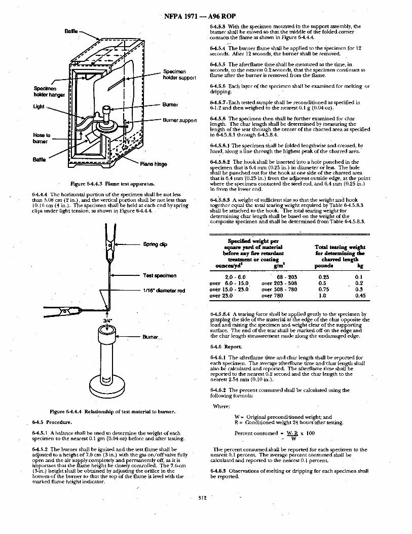
Figure 6-4.4.3 Flame test apparatu~
~ Specimen /~....- ~ f ~ 4 - "" holder suppor,
',11 i ; :11 I !
Light :11 ] 1. ~ __ ------ Burner
I..Ioso to tl l ? . ~ ' ~ ~ _, e bu :1 [] 1% ~ql r / f l . ~" ) ," met ;I ~ . / l l , I "_;PY~ ' ~
Baffle / ~ ~ m ~ J ~ " " ' -" Piano hinge
3/4"
64.4.4 The horizontal portion o f the specimen shall be not less than 5.08 cm (2 in.), and the vertical port ion shall be no t less than 10.1fi cm (4 in.). The spec imen shall be he ld at each e n d by spr ing clips t inder light tension, as shown in Figure 6-4.4.4.
" NFPA 1 9 7 1 -
Sp~ng c ~
Test specimen
1/16" ¢iameter rod
Bumot
Figure 64.4.4 Relationship o f test material to burner .
6*4.5 Procedure.
64.5,1 A balance shall be used to de termine the weight of each specimen to the neares t 0.1 g m (0.04 oz) before and after testing.
64.5.2 The burner shall be ignited and the test f lame shall be adjusted to a he igh t o f 7.6 cm (3 in.) with the gas on /o f fva lve fully open and the air supply completely and p e r m a n e n d y off, as it is impor tant that the f lame height be closely controlled. The 7.6-cm (3-in.) he igh t shall be obta ined by adjust ing the orifice in the bot tom of the burner so tha t the top of the f lame is !evel with the marked fl:mle he ight indicator.
/
312
A96 ROP 6-4.5.3 With the specimen m o u n t e d in the suppor t assembly, the burner shall be moved so tha t the middle o f the folded corner contacts the f lame as shown in Figure 64.4.4.
6-4.5.4 The burner f lame shall be applied to the spec imen for 12 seconds. After 12 seconds, the burner shall be removed.
6-4.5.5 The afterl]ame t ime shall be measured as the time, i n seconds, to the neares t 0.2 seconds, that the spec imen cont inues to f lame after the burner is removed f rom the flame.
64.5.6 Each layer of the specimen shall be examined for mel t ing or dri pping.
64.5.7 .Each tested sample shall be recondi t ioned as specified in 6-1,2 and then weighed to the neares t 0.1 g (0.04 oz).
6-4.5.8 The spec imen then shall be fur ther examined for char length. The char length shall be de t e rmined by measur ing the length of the tear th rough the center of the char red area as specified in 64.5.8.1 th rough 6-4.5.8.4.
6-4.5.8.1 The specimen shall be folded lengthwise and creased, by hand, a long a line th rough the highest peak of the charred area.
64.5.8.2 The hook shall be inserted into a hole p u n c h e d in the specimen that is 6.4 m m (0.25 in.) in d iameter or less. The hole shall be p u n c h e d ou t for the hook at one side of the char red area that is 6.4 m m ~(0.25 in.) f rom the adjacent outside edge, at the poin t where the specimen contacted the steel rod. and 6.4 m m (0.25 in.) in f rom the lower end.
64.)$.8.3 A weight of sufficient size so tha t the weight and hook together equal the total tearing weight required by Table 64.5.8.$ shall be a t tached to the hook. The total tearing weight for de te rmin ing char length shall be based on the weight o f the composite specimen and shall be de te rmined f rom Table 64.5.8.$.
square yard of material Total tearing weight before any ~ retardant for determining the
treatment or coating charred length otmcem/yd t ,~m 2 pounds kg
2.0 - 6.0 68 - 203 0.25 0.1 over 6.0 - 15.0 over 203 - 508 0.5 0.2 over 15.0 - 23.0 over 508 - 780 0.75 0.3 over 23.0" over 780 1.0 0.45
64.5.8.4 A tearing force shall be applied gendy to the specimen by grasping the side of the material at the edge o f the char opposite the 10acfand raising the specimen and weight clear o f the suppor t ing surface. The end of the tear shall be marked off on the edge and the char length m e a s u r e m e n t made along the u n d a m a g e d edge.
64 .6 Report.
6-4.6.1 The afterflame time and char length shall be repor ted for e ~ h specimen. The average "afterfi~sne time and ' cha r length shall also be calculated and reported. The afterflame t ime shall be repor ted to the nearest 0.2 second and the char length to the nearest 2.54 m m (0.10 in.).
64.6.2 The percent consumed shall be calculated us ing the following formula:
Where:
W = Original precondi t ioned weight; and R = Condi t ioned weight 24 hours after testing.
Percent consumed = ~ x 100 - W
The percent consumed shall be reported for each specimen to the neares t 0.1 percent . The average percent consumed shall be calculated and r epo r t ed to the nearest 0.1 p e r c e n t • •
6-4.6.3 Observations of mel t ing or dr ipping for each specimen shall be reported.
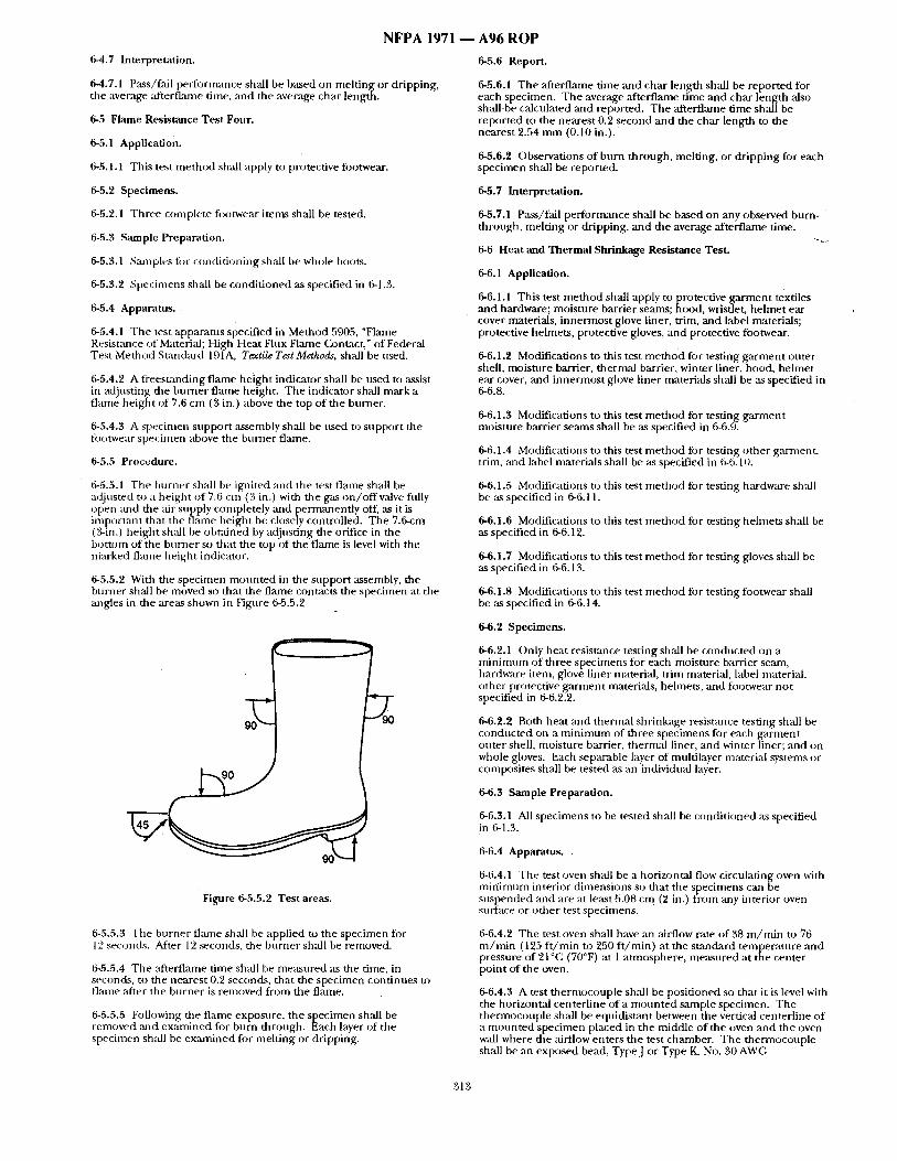
NFPA 1971 6-4.7 Interpretation.
6-4.7.1 P;tss/fail performance shall be based on mel t ingor dripping, the average :ffterflame time, and the average char length.
6-5 Flame Resistance Test Four.
6-5.1 Application.
6-5.1.1 This test method shall apply to protective footwear.
6-5.2 Specimens.
6-5.2.1 Three complete fi~otwear items shall be tested.
6-5..'4 Sample Preparation.
6-5.3.1 Samples for conditioning sball be whole boots.
6-5.3.2 Specimens shall be conditioned as specified in 6-1.3.
6-5.4 Apparatus.
6-5.4.1 The test apparatus specified in Method 5905, "Flame Resistance of Material; High Heat Flux Flame Conutct," of Federal Test Method Standard 191A, Textile Test Methods, shall be used.
6-5.4.2 A t'reesumding flame height indicator shall be used to assist in adjusting the burner flame height. The indicator shall mark a flame height of 7.6 cm (3 in.) above the top of the burner.
6-5.4.3 A specimen support assembly shall be used to support the t0otwear specimen above the burner flame.
6-5.5 Procedure.
6-5.5.1 The bmner shall be ignited and the test flame shall be a~justed to a height of 7.6 cm (3 in.) with the gas on / o f f valve fidly open ,and the air supply completely ,and permanently off, as it is important that the flame height be closely controlled. The 7.6-cm (3-in.) height shall be obt:dned by adjusting the orifice in the l)ottom of the burner so that the top of the flame is level with the marked fl~une height indicator.
6-5.5.2 With the specimen mounted in the support assembly, the burner shall be moved so that the flame contacts the specimen at the angles in the areas shown in Figure 6-5.5.2
F i b r e 6-5.5.2 Test areas.
6-5.5.3 The burner flan~e shall be applied to the specimen for 12 secon~Ls. Alter 12 ~conds, the burner shall be removed.
6-5.5.4 The afterfiame time shall be measured :is the time, in seconds, to the nearest 0.2 seconds, that the specimen continues t~) flame ,after the burner is removed from the flame.
6-5.5.5 Following the flame exposure, the specimen shall be removed ,and examined for burn-through. Each layer of the specimen shall be ex:mfined fi)r melting or dripping.
A96 ROP
6-5.6 Report.
6-5.6.1 The afterflame time and char length shall be reported for earh specimen. The average afterflame time and char length also shall-be calculated and reported. The afterflame time shall be reported to the nearest 0.2 second and the char length to the nearest 2.54 mm (0.10 in.).
6-5.6.2 Observations of bum through, melting, or dripping for each specimen shall be reported.
6-5.7 Interpretation.
6-5.7.1 Pass/fall performance shall be based on any observed burn- through, melting or dripping, and the average afterflame time.
6-6 Heat and Thermal Shrinkage Resist~lce Test.
6-6.1 Application.
6-6.1.1 This test method shall apply to protective garment textiles and hardware; moisture barrier seams; hood, wristlet, helmet ear cover materials, innermost glove liner, trim, and label materials; protective helmets, protective gloves, and protective footwear.
6-6.1.2 Modifications to this test method for testing garment outer shell, moisture barrier, thermal barrier, winter liner, hood, helmet ear cover, and innermost glove liner materials shall be as specified in 6-6.8.
6-6.1.3 Modifications to this test method for testing garment moisture barrier seams shall be as specified in 6-6.9.
6-6.1.4 Modifications to this test method fi~r testing other garment, trim, and label materials shall be as specified in 6-6.10.
6-6.1.5 Modifications to this test method for testing hardware shall be :~s specified in 6-6.11.
6-6.1.6 Modifications to this test method for testing helmets shall be as specified in 6-6.12.
6-6.1.7 Modifications to this test method for testing gloves shall be as specified in 6-6.13.
6-6.1.8 Modifications to this test method for testing footwear shall be as specified in 6-6.14.
6-6.2 Specimens.
6-6,2.1 Only heat resistance testing shall be conducted on a minimum of three specimens for each moisture barrier seam, hardware item, glove liner material, trim material, label material, other protective garment materials, helmets, and footwear not specified in 6-6.2.2.
6-6.2.2 Both heat and thermal shrinkage resistance testing shall be conducted on a minimum of three specimens for each garment outer shell, moisture barrier, thermal liner, and winter liner; and on whole gloves. Each separable layer of multilayer material systems or composites shall be tested as an individn:d layer.
6-6.3 Sample Preparation.
6-6.3.1 All specimens to be tested shall be conditioned ,as specified in 6-1.3.
6-6.4 Apparatus.
6-6.4.1 The test oven shall be a horizontal flow circulating oven with mirfimum interior dimensions so that the specimens can be suspended and are at least 5.08 c m (2 in.) from any interior oven surface or other test specimens.
6-6.4.2 The test oven shall have an airflow rate of 38 m/ra in to 76 m/ra in (125 f t /min to 250 f t /min) at the standard tempe~tture and pressure of 21 °C (70°F) at 1 atmosphere, measured at the center point of the oven.
6-6.4.3 A test thermocouple shall be positioned so that it is level with the horizontal centerline of a mounted sample specimen. The thermocouple shall be equidistant between the vertical centerline of a mounted specimen placed in the middle of the oven and the oven wall where the airflow enters the test chamber. The thermocouple shall be an exposed bead, TypeJ or Type K, No. 30 AWG
313
NFPA 1 9 7 1 - thermocouple. The test oven shall be hea ted and the test thermocouple stabilized at 260°G, +6°/-0°C, (500°F, +I 0°/-0°F) for a period of not less than 30 minutes.
6-6.5 Procedure.
6-6.5.1 Specimen marking and measurements shall be conduc ted in accordance with the procedure specified in ANSI/AATCC 135, Dimensional Changes in Automatic. Home Laundering of Woven and Knit Fabrics.
6-6.5.2 The specimen shall be suspended by metal hooks at the top and centered in the oven so tha t the entire specimen is no t less than 5.08 cm (2 in.) f rom any oven surface or o ther specimen, and air is parallel to the plane o f the material.
6-6.5.3 The oven door shall no t remain open more than 15 seconds. The air circulation shall be shu t off while the door is open and tu rned on when the door is closed. The total oven recovery time after the door is closed shall not exceed 30 seconds.
6-6.5.4 The specimen, m o u n t e d as specified, shall be exposed in the test oven for 5minu tes , +0.15/-0.0 minutes . The test exposure t ime shall begin when the test the rmocouple recovers to a tempera ture o f 260°(2, +6°/-0°C, (500°F, +10°/-0°F).
6-6.5.5 Immediately after the specified exposure, the specimen shall be removed and examined for evidence of ignition, melting, dripping, or separation.
6-6.5.6 After the specified exposure, the spec imen also shall be measured to de termine pass/fail . Knit fabric shall be pulled to its original d imensions and shall be allowed to relax for 1 minute prior to m e a s u r e m e n t to de te rmine pass/fall.
6-6.6 Report.
6-6.6.1 Observations of ignition, melting, dripping, or separation shall be re.ported for each specimen.
6-6.6.2 The percent change in the width and length d imens ions of each specimen shall be calculated. Results shall be reported as the average of all three spec imens in each dimension.
6-6.7 Interpretation.
6-6.7.1 Any evidence of ignition, melting, dripping, or separation on any specimen shall constitt, te falling performance.
6-6.7.2 The average percen t change in both d imens ions shall be used to de te rmine pass/fail performance. Failure in any one d imension consti tutes failure for the entire sample.
6-6.8 Specific Requirements for Test ing Garment Ou te r Shell, Moisture Barrier, Thermal Liner, Winter Liner Materials; Hood, Helmet Ear Cover, and Glove Liner Materials.
6-6.8.1 Samples fi)r condi t ioning shall be at least I m (1 yd) square of each rruaterial.
6-6.8.2 Each specimen shall be 38.1 cm x $8.1 cm, ±13 m m (15 in. x 15 in., i-0.5 in.) and shall be cut f rom the fabric to be utilized in the construction of the clothing item.
6-6.8.3 Specimens shall be tested both before and after being subjected to the procedure specified in 6-1.2.
6-6.8.4 Test ing shall be per formed as specified in 6-6.2 th rough 6-6.7.
6-6.8.5 For t)rotective ga rmen t outer shell and collar lining materials, any evidence o f charr ing on any specimen of outer shell fabric shall also constitute failing performance in addition to 6-6.7.1.
6-6.9 Specific Requirements for Test ing Moisture Barrier Seams.
6-6.9.1 &mlples for condi t ioning shall be a m i n i m u m of I l inear m (1 linear yd) with a m i n i m u m of 15.24 cm (6 in.) o f material on either side of the seam.
6-6.9.2 Moisture barrier seam spec imens shall consist of two 7.62-cm x 15.24-cm (3-in. x 6-in.) pieces o f moisture barrier fabric utilized in the ga rmen t and sewn together with the same thread, stitch type, and seam type as used in the moisture barrier, with seam sealing material applied.
A96 ROP 6-6.9.3 Specimens shall be tested both before ,and after being subjected to the procedure specified in 6-1.2.
6-6.9.4 For moisture barrier seam seal materials, observations shall be limited to seam material ignition and dripping.
6-6.9.5 Test ing shall be per formed as specified in 6-6.2 through 6-6.7. Thermal shr inkage shall no t be measured.
6-6.10 Specific Requirements for Testing Other Garment, Trim, and Label Materials.
6-6.10.1 Samples for condi t ionin~ shall include material sewn onto a 1-m (1-yd) square o f ballast material no closer than 5.08 cm (2 in.) apart in parallel strips. The ballast material shall be as specified in ANSI/AATCC 135, Dimensional Changes in Automatic Home Laundering of Woven and Knit Fabrirs. Specimens shall be removed f rom the ballast material prior to testing.
6-6.10.2 ,Specimen length shall be 15.24 cm (6 in.), o ther than for textiles utilized in the c lothing item in lengths less than 15.24 cm (6 in.), where length shall be the same as utilized in the clothing item. Specimen width shall be 15.24 cm (6 in.), o ther than for textiles utilized in the c lothing item in widths less than 15.24 cm (6 in.), where widths shall be the same as utilized in the c lothing item.
6-6.10.3 Specimens shall be tested both before and after being subjected to the procedure specified in 6-1.2.
6-6.10.4 Test ing shall be per formed as specified in 6-6.2 th rough 6-6.7. Thermal shr inkage shall no t be measured.
6-6.11 Specific Requi rements for Tes t ing Hardware.
6-6.11.1 A m i n i m u m of three complete hardware i tems shall be tested.
6-6.11.2 Observations of hardware condit ion following hea t exposure shall be l imited to ignition.
6-6.11.$ Hardware shall be evaluated for functionality within 10 minutes following removal f rom the oven.
6-6.11.4 Test ing shall be pe r fo rmed as specified in 6-6.2 through 6-6.7. Thermal shrinkage shall no t be measured.
6-6.12 Specific Testing Requirements for Helmets.
6-6.12.1 Samples for condi t ioning shall include complete helmets.
6-6.12.2 He lmet spec imens shall include accessories.
6-6.12.3 Specimens shall be selected as specified in 2-3.1.1.
6-6.12.4 Sample helmets with ear covers deployed and faceshield in the stowed position shall be m o u n t e d in accordance with the he lmet posit ioning index on a solid wood headform conforming to the d imensions in Figure 6-1.5.1. The headform with he lme t a t tached shall be placed in the center o f the test oven with the centerl ine o f the f ront of the he lmet facing the airflow.
6-6.12.5 The m i n i m u m interior d imensions o f the test oven shall be 61 cm x 61 cm x 61 cm (24 in. x 24 in. x 24 in.).
6-6.12.6 The test the rmocouple shall be posit ioned so that it is level with the horizontal centerl ine of a m o u n t e d test helmet . The the rmocouple shall be equidistant between the vertical centerl ine o f a m o u n t e d test he lmet placed in the middle o f the oven and the oven wall where the airflow enters the test chamber .
6-6.12.7 Following removal f rom the oven, the he lme t shall be allowed to cool at room tempera ture for not less than 2 minutes. The shell distortion shall then be measu red at the front, back, and sides at eight points radially separated by 45 degrees relative to their original position. The he lmet shall be examined to ascertain any effects of the heat exposure.
6-6.12.8 Test ing shall be per formed as specified in 6-6.2 through 6-6.7. Thermal shr inkage shall no t be measured.
6-6.13 Specific Requirements for Test ing Gloves.
6-6.13.1 Samples for condi t ioning shall be whole gloves.
314
N F P A 1971 - - A 9 6 R O P
6-6.13.2 Condi t ioning shall be pe r fo rmed as specified in 6-1.2.
6-6.13.3 Specimens shall include complete gloves with labels.
6-6.13.4 The m i n i m u m interior d imens ions o f the test oven shall be 61 c m x 61 cm x 61 cm (24 in. x 24 in. x 24 in.).
6-6.13.5 The glove body shall be filled with dry vermiculite, the opening of the glove shall be c lamped together, and the specimen shall be suspended by the clan~p in the oven so that the entire glove is not less thml 5.08 Cl][] (2 in.) f rom rely oven surface or o ther specimen and :tirflow is parallel to the plane of the material.
6-6.13.6 "The glove specimen dimensions also shall be measured to determine pass/fail. The length measu remen t of the glove specimen shall be f rom the tip of the middle finger to the end of the glove body on the palm side. The width m e a s u r e m e n t of the glove specimen shall be the width m e a s u r e m e n t on the palm side 2.54 cm ( 1 in.) below the base o f the fingers.
6-6.13.7 The percent change in the width and length d imensions of each specimen shall be calculated. Results shall be reported as the average of ,all three specimens in each dimension.
6-6.13.8 Specimens shall be d o n n e d and ' f lexed as specified in 6-1.12 before and:d ' ter the heat exposure.
6-6.13.9 Testing shall be per formed as specified in 6-6.2 through 6-6.7.
6-6.14 Specific Testing Requirements- for Footwear.
6-6.14.1 Samples for condi t ioning shall be whole boots.
6-6.14.2 The footwear spec imen for testing shall be size 9.
6-6.14.3 Footwear specimens shall include sole, heel, and upper. Footwear specimens shall be filled with dry vermiculite. Any closures shall be fastened.
6-6.14.4 The test thermocouple shall be posi t ioned so that it is level with the horizonual centerl ine of a footwear test specimen. The thermocouple shall be equidistant between the vertical centerl ine o f a footwear test specimen placed in the middle of the oven ~md the oven wail where the airflow enters the test chamber .
6-6.14.5 The m i n i m u m interior d imensions of the test oven shall be 61 c m x 61 c m x 61 cm (24 in. x 24 in. x 24 in.).
6-6.14.6 The protective tbotwear test specimen shall be placed in the center of the test oven with the centerl ine of the front o f the specimen facing the airflow.
6-6.14.7 Following removal f rom the oven, the specimen shall be allowed to cool at room tempera ture for not less than 5 minutes, +15/4) seconds.
6-6.14.8 Testing shall be per formed as specified in 6-6.2 through 6-6.7. Thermal shr inkage shall no t be measured.
6-6.14.9 Each tested specimen shall be recondi t ioned ,as specified in 6-1.2 :rod then re-examined inside and outside for separation and fimctionality.
6-7 Conductive Heat Resistance Test One.
6-7.1 Application.
6-7.1.1 This test m e t h o d shall apply to protective gloves ,and footwear upper material.
6-7.1.2 Modifications for this test m e t h o d for testing gloves shall be as specified in 6-7.7.
6-7,1.3 Modifications for this test me t hod for testing footwear shall be as specified in 6-7.8.
6-7.2 Specimens.
6-7.2.1 A total of three specimens shall be tested.
6-7.3 Sample Preparation.
6-7.3.1 Specimens shall be condi t ioned ,as specified in 6-1.2.
6-7.3.2 Samples for condi t ioning shall be whole gloves an d boots.
6-7.4 Procedure.
6-7.4.1 Sample specimens shall be tested in accordance with/LSTM F 1060, Standard Test Method for Thermal Protective Performance of Materials for Protective Clothing for Hot Surface Contact.
6-7.4.2 Sample spec imens shall be tested using ,an exposure tempera ture o f 280°C (536°F). The pressure applied dur ing the test sha l lbe 0.0020 k g / c m 2, ±0.0002 k g / c m z (0.5 psi, :t-0.05 psi).
6-7.4.3 The dine in seconds to pain and to second-degree burn, blister, as predicted by the Stoll H u m a n Tissue Burn Tolerance Criteria, shall be recorded.
6-7.5 Report.
6-7.5.1 The t ime to pain and time to second-degree burn for each specimen shall be reported. The average t ime to pain and time to second-degree burn shall be calculated and reported. If the t ime to pain or t ime to second-degree burn is greater than 30 seconds, the t ime to pain or t ime to second-degree burn shall be reported as "> 30 sec."
6-7.6 Interpretation.
6-7.6.1 Pass or fail de terminat ions shall be based on the average t ime to pain and time to second-degree burn o f all specimens tested.
6-7.6.2 I;f an individual result f rom any test set varies more than +8 percent f rom the average result, the results f rom the test set shall be discarded and ano the r set of specimens shall be tested.
6-7.7 Specific Requirement for Testing Gloves.
6-7.7.1 Specimens shall representative of glove body composite construction at the palm of the hand and at the palm side o f the fingers.
6-7.7.2 Specimens shall be stitched a round the per imeter using the same thread used in glove construction.
6-7.7.3 Glove specimens shall be tested before and after being subjected to the procedure specified in 6-1.2.
6-7.7.4 Specimens shall ,also be tested "Mter wet condi t ioning as specified in 6-1.10.
6-7.7.5 Test ing shall be per formed as specified in 6-6.2 th rough 6-6.7.
6-7.8 Specific RequirementS for Testing Footwear Upper Materials.
6-7.8.1 Footwear specimens shall include the th innest port ions of the footwear upper.
6-7.8.2 Testing shall be per formed as specified in 6-6.2 through 6- 6.7.
6-8 Conductive Heat Resistance Test Two.
6-8.1 Application.
6-8.1.1 This test me thod shall apply to the protective footwear sole.
6-8.2 Specimens.
6-8.2.1 A m i n i m u m of three complete footwear items shall be tested.
6-8.3 Sample Preparation.
6-8.3.1 Samples for condi t ioning shall be whole footwear.
6-8.3.2 Specimens shall be precondi t ioned as specified in 6-1.3.
6-8.4 Apparatus.
6-8.4.1 The apparatus shall consist of an iron plate measur ing 2.54 c m x 15.24 cm x 46 cm (1 in, x 6 in. x 18 in.) a n d a n oven capable of heat ing the plate to a tempera ture of 500°C (932°F), a TypeJ or Type K thermocouple , and a meter to read the thermocouple temperature .
• 6-8.5 Procedure.
315
N F P A 1971 - - A 9 6 R O P
6-8.5.1 The thermocouple shall be affLxed to the insole surface o f the specimen next to the foot, directly above the ball of the foot. The thermocouple shall be taped to the surface with electrical tape to hold it onto the insole surface.
6-8.5.2 The plate shall be heated to a tempera ture of 500°C, ±I0°C (932°F, ±18°F) and shall maintain this tempera ture t h roughou t the test period.
6-8.5.3 The specinlen shall be p laced on the plate in the upr igh t position for 30.0 seconds. A 4.55-kg (10-1b) weight shall then be placed on top o f the footwear toe.
6-8.5.4 The thermocouple tempera ture shall be recorded at 30.0 secon~ts. +2/-0 sect~nds :ffter die specimen is placed on the heated metal plate.
6-8.6 Report.
6-8.6.1 The tempera ture at 30.0 seconds of exposure shall be reported for each specimen. The average tempera ture at 30.0 seconds o f exposure figr all spec imens shall also he calculated and reported.
6-8.7 Interpretation.
6-8.7.1 The average tempera ture at 30.0 seconds of exposure for all specimens shall be used to de te rmine pass/fail performance.
6-9 Radiant Heat Resistance Test.
6-9. i Application.
6-9.1 .I This test me thod shall apply to protective footwear.
6-9.2 Specimens.
6-9.2.1 A m i n i m u m of three complete footwear i tems shall be tested.
6-9.3 Sample Preparation.
6-9.3.1 Samples for condi t ioning shall he complete footwear.
6-9.3.2 Specimens shall be condi t ioned in accordance with 6-1.3 and 6-1.11.
6-9.4 Apparatus.
6-9.4.1 The apparatus shall consist of the following:
(a) A radiometer with a spectral response fiat to within +3.0 percent o f not less than 1.10 m m to 10.0 m m with an accuracy of ±5.0 percent;
(b) A radiant panel with an effective radiating surface of not less than 15.94 cm x 15.24 cm (6 in. x 6 in.) and an emit tance approximat ing that of a blackbody of 1000°K, +200°K (1340°F, ±360°F);
(c) A the rmoconple with meter;
(d) A test chamber that prevents interference f rom air movement .
6-9.5 Procedure.
6-9.5.1 Tests shall be done on the toe, vamp, quarter, g u ~ e t if present, and shaft. If different types Or thicknesses of materials are utilized fi)r o ther areas of die upper , these areas shall also be tested.
6-9.5.2 The radiant panel shall be placed in f ront of the radiometer, parallel to the plume tin, gen t to the radiometer. The radiant panel shall be adjusted to obtain a stable, un i form irradiance of 1.0 W / cm2,+0.01/-0.0 W / c m 2 over a m i n i m u m 7.6-cm (3.0-in.) diameter circle located on die above plmle and centered at the center of test are`a Calibration shall be achieved when the irradiance changes by less than 10 percent d u r i n g a 3.0-minute period.
6-9.5.3 The thermocouple shall be affixed to the inside surface of the l ining next to the foot, in the center of the test area. The radiometer shall be replaced with the protective footwear with the test area or iented parallel to the plane tangent u) the heat source, at the same distance from the heat source. The area sh,'dl be exposed fi~r 1.0 minute., +5/-0 seconds.
6-9.5.4 The thermoconple tempera ture shall be recorded at 1.0 minute , +5/-0 seconds of exposure.
6-9.6 Report.
6-9.6.1 The tempera ture at 1.0 minu te of exposure shall be repor ted for each specimen. The average tempera ture at 1.0 minute of exposure for all specimens shall also be calculated and reported.
6-9.7 Interpretation.
6-9.7.1 The average tempera ture at 1.0 minute of exposnre for all specimens tested shall be used to de termine pass / fa i lper formance .
6-10" Thermal Protective Performance (TPP) Test.
6-10.1 Application.
6-10.1.1 This test m e t h o d shall apply to protective g a ~ e n t composites, hoods, wristlets, and gloves.
6-10.1.2 Modifications to this test m e t h o d for testing ga rmen t composites shall be as specified in 6-10.8.
6-10.1.3 Modifications to this test m e t h o d for testing hoods shall be as specified in 6-10.9.
6-10.1.4 Modifications to this test m e t h o d for testing wristlets shall be as specified in 6-10.10.
6-10.1.5 Modifications to this test m e t h o d for testing gloves shall be ,as specified in 6-10.11.
6-10.2 Speciinens.
6-10.2.1 Thermal protective per formance testing shall be conducted on three specimens. Specimens shall measure 15.24 cm x 15.24 cm, +6.4 nun (6 in. x 6 in., i-0.25 in.) and shall consist of all layers representative of the clothing i tem to be tested.
6-10.3 Sample Preparation.
6-10.3.1 Specimens shall be tested after precondi t ioning as specified in 6-1.4 and then condi t ioned as specified in 6-1.3.
6-10.3.2 Specimens shall also be tested after subjected to the procedure in 6-1.2 and then condi t ioned as specified in 6-1.3.
6-10.4 Apparatus.
6-10.4.1 The test apparatus shall consist o f a specimen holder assembly, specimen holder assembly support , thermal flux source, protective shutter, sensor assembly, andrecorde r . The apparatus shall also have a gas supply, gas rotometer, burners, and sensor.
6-10.4.1.1 The specimen holder assembly shall consist of upper an d lower m o u n t i n g plates. The spec imen holder mainta ining plates shall be 20.32 c m x 20.32 cm, :1:1.6 ram, x 6.4 ram, ~-0.8 m m (8 in. x 8 in., i-0.063 in. x 0.95 in., :t0.0313 in.). The lower specimen moun t ing plate shall have centered a hole with d imens ions of 10.16 cm x 10.16 cm, +1.6 m m (4 in. x 4 in., ~-0.063 in.). The upper
eCimen m o u n t i n g plate shall have centered a hole with ensions of 13.02 c m x 13.02 cm, ;t:1.6 m m (5.13 in. x 5.13 in.,
±0.063 in.). The lower specimen moun t ing plate shall have a 2.54-cm, +1.6 m m high, x 3.2-mm, ~:0.8 m m thick (1.0-in., ±0.063 in. high, x 0.13-in., :t-0.0313 in. thick) s tee lpos t welded to each corner 6.4 ram, +1.6 nm/ (0 .25 in., +0.063 in.) f rom each side and perpendicular to the plane of the plate. The upper sample moun t ing plate shall have a cor responding hole in each corner so that the upper specimen moun t ing plate fits over the lower specimen m o u n t i n g plate. "
6-10.4.1.2 The specimen holder assembly suppor t shall consist of a steel f rame tha t rigidly holds and positions in a reproducible m a n n e r the specimen holder assembly and specimen relative to the thermal flux. The specimen holder ,assembly suppor t shall be securely c lamped at the edges so that specimen shrinkage is prevented. The sensor assembly shall consist of 13.34 c m x 13.34 cm x 1.27 cm (5.25 in. x 5.25 in. x 0.5 in.) heat-resistant block that fits without b inding into the hole of the upper specimen moun t ing plate and shall be uniformly weighted so that the complete sensor ,assembly, including the copper calorimeter, weighs 1000 g, :t:10 g (2.2 lb, -1-0.022 lb).
316
NFPA 1971
6-10.4.1.3 The thermal flux source sh,'dl consist of a convective therntal flux source and a radiant thernml flux source. The convective thermal flux source shall consist of two Meeker or Fisher burners affixed beneath the specimen holder assembly opening, mid subtended at a nominal 45-degree angle from the verficalso that the drones converge at a point immediately beneath the specimen. The radiant thermal flux source shall consist of nine quartz infrared tuhes :fffixed beneath and centered between theburners .
6-10.4.1.4 A protective shutter shall be placed between the thermal fltLx source and the specimen. The protective shutter shall be capable of completely dissipatingthe thermal load from the thermal flux source fi)r the time periodsbefore and after specimen exposure. The protective shutter shall be controlled by means of an automatic tinter with a resolution of not less than 0.10 second.
6-10.4.1.5 The sensor assembly shall be fitted into the opening in the top plate of the specimen holder and shall be in contact with the surt~lce of the therntal barrier normally facing the wearer.
6-10.4.1.6 The recorder shall be any strip chart recorder with fill- scale deflection of at least 150°C (300°F) or 10 mV and sufficient sensitivity and ~ale divisions to read exposure time to 14).10 second.
6.10.4.1.7 The g,~ supply shall be liquid propane or natural gas with appropriate reducer ,and valving arrangements to control the gas supply pressure at 8 psig ±2 psig.
6-10.4.1.8 The gas rotometer shall be any gas rotometer with a range to provide flow equivalent to 2 lpm (0.07 ft 3/rain) of air at standard conditions.
6-10.4.1.9 The burners shall be Meker or Fisher burners with a 38-ram (1.5-in.) diameter top and with ,an orifice size of 1.2 mm (0.05 in.) for propane and 2.4 mm (0.09 in.) for natural gas.
6-10.4.1.10 The sensor shall be a copper calorimeter mounted in an insulating block.
6-10.5 Procedure.
6.10.5.1 Calibration.
6-10.5.1.1 Specimens shall be exposed to a thermal flux of 2.0 cal/ cm~/sec, ±0.1 cal/cm2/sec as measured with the copper calorimeter. The copper calorimeter shall be the only heat sensor used in setting the total 2.0 cal/cm2/sec exposure condition. The total heat flux shall be c:dculated directly and only from the voltage output of the thernlocouples, using the measured temperature rise of the testing copper calorimeter, the area and mass of the calorimeter, :rod the heat capacity of the copper to calibrate the heat fux. Other heat sensing devices shall not be used to reference or adjust the toted heat flux read by the copper calorimeter.
6-10.5.1.2 The total heat flux and the 50 percent/50 percent, +5 percent radiant/convective balance of the energy sources shall be set in accordance with the procedures in 6-10.5.1.3 to 6-10.5.1.6. The level of the radiant heat flux shall be deterntined using a contmerci~d radiometer and the level of the total heat flux shall be determined by using a calibration copper calorimeter designated and used only to set the total exposure level.
6-10.5.1.3 The radiant thermal flux source of nine quartz infrared robes alone shall be set to an incoming radiant heat flux of 0.25 cal/ cmZ/sec, ±0.1 cal/cm2/sec using a commercial radiometer meeting the specifications of 6-10.5.2. The radiometer window shah be positioned at the geometric center of the sample holder and at the same" plane as a test specimen. The radiometer shall be mounted in a holder of the same overall size, shape, and material as the one used fi)r the copper calorimeter to ensure similar heat and flame [~.atterns across the faces of the radiometer and calorimeters. The radiant quartz tubes shall be turned on ~ld operated fl)r 10 minutes prior to meas.nring the radiant heat flux.
6-10.5.1.4 The total radiant thermal flux shall be set at 1.0 cal/cm 2/ sec, ~) cal/cmZ/,~c by nsing a commercial radiometer specified in 6-10.5.2 to measure the radiant heat flux from both the nine quartz tubes and the two Meker or Fisher burners by adjusting only the w)ltage supplies to the nixie quartz robes.
6-10.5.1.5 The total heat flux shall be set at 2.0 cal /cm Z/sec, ±0 cal/ z c m / s e c using the calibration copper calorimeter, as specified in 6-
10.5.2, by adjusting only the gas supply to the Meker or Fisher burners. Without a mounted specimen, the calibration copper calorimeter shal be placed on top of the specimen holder with the
A96 ROP
blackened copper c:dorimeter facing down, and then it shall be exposed directly to the flame of the burner The response of the calorimeter sh,'dl be recorded for at least 10 seconds. The lowest temperature point on the curve where the response is linear shall be chosen, and the increase in sensor temperature during 10 seconds of heating shall be determined. T h e initial reading shall be subtracted from this 10-second reading to obtain the increase. The response shall be 148°C, +3.7°C (267°F, +6.7°F) (equivalent to 7.86 mV, :t-0.20 mV for an iron-constantan thermocouple), for an exposure heat flux of 8.3 W/cm z, i-0.2 W / c m z (2.0 cal/cmZ/sec, x,-0.05 cal/cm2/sec).
6-10.5.1.6 Procedures in 6-10.5.1.4and 6-10.5.1.5 shall be repeated until both the radiant thermal heat flux and the total heat flux are within + 0.1 cal/cm2/sec of the levels specified.
6-10.5.2 Commercia l Radiometer Specification.
6-10.5.2.1 The radiometer sh~dl be a Gardon-type radiation transducer with a diameter of 25.4 nun (1.0 in.) and having a smooth body design with flange, and shall be gas purged and water cooled. A sapphire window with a 60-degree view angle that has a spectrum tr~,msmission of 85 percent nomimd, from 0.15 micron to 5.0 microns, shall be used. The heat flux operating r,-mge shall be from 0 to 5 Btu/ftz/sec. The output signal shall be 10 mV, ±1.5 mV full range. The response time shall be no more than 290 m/sec and shall have a maximum nonlinearity of±2 percent.
6-10.5.3 Procedure.
6-10.5.3.1 After the total thermal heat flux has been set at 2.0 cal/ 2 c m / s e c , ~q).l cal /cm /sec using the calibration procedure in 6-
10.5.1.2 through 6-10.5.1.6, the testing copper calorimeter shall be used to measure the total heat flux. Prior to testing, the testing copper calorimeter shall be used to measure the total heat fltLx by placing the calorimeter on top of the specimen holder with the blackened copper calorimeter facing down, and then it shall be exposed directly to the total heat source. The response of the calorimeter sh~l be recorded for at least 10 seconds. The lowest temperature point on the curve where the response is linear shall be chosen, and the increase in sensor temperature during 10 seconds of heating shall be determined. The initial reading shall be subtracted from this 10-second reading to obtain the increase. The response shall be 148°C, ±3.7°C (267°F, ±6.7°F) (equivalent to 7.86 mV, -20.20 mV for an iron-constantan thermocouple), for an exposure heat flux of 8.3 W/cm ~, ±0.2 W/cm 2 (2.0 cal/cm~/sec, i-0.05 cal/cm~/sec).
6-10.5.3.2 If the measurement from the testing copper calorimeter is within ±0.1 cal/cm~/sec, then testing shall be done. ff the measurement from the testing copper c~orimeter does not agree within ~0.1 cal/cmZ/sec of the measurement of the calibration calorimeter, the testing copper calorimeter shall be repaired, reconditioned, or replacedto achieve agreement.
6-10.5.3.3 Specimens shall be mounted by placing th6 surface of the material to be used as the outside of rite garnaent face down on the mounting plate. The subsequent layers shall be placed on top in the order as assembled in the garment, with the surface to be worn toward the skin facing up. With the protective shutter engaged, the specimens then shall be placed on rite specimen holder.
6-10.5.3.4 The testing copper calorimeter shall be placed directly on the specimen in contact with the surface to be worn toward the skin.
6-10.5.3.5 The protective shutter shall be removed and the chart movement on the recorder shall be started. The start of the exposure shall be indicated. The exposure shall be continued until the sensor response exceeds the second-degree burn criterion that is equal to a sensor temperattlre rise of 35°C to 40°C (60°F to 70°F), or 1.7 mV to 2.0 inV. The protective shutter shall be engaged, the recorder shall be stopped, the calorimeter shall be removed and cooled, and the specimen holder and exposed specimen then shall be removed.
6-10.5.3.6 After each exposure, the calorimeter shall be cooled to less than 38°C (100°F), or 1.0 mV, before the next heat flux determination. The sensor shall be cooled after exposure with a jet of air or by contact with a cold surface. The sensor shall be reheated to approximate body temperature by contact with the palm of hand just prior to positioning over the test specimen. The sensor shall, not be adjusted. The zero setting of the recorder shall not be adjusted.
6-10.5.3.7 The sensor face shall be wiped immediately after each run, while hot, to remove any decomposition products that condense and could be a source of error. If a deposit collects and appears to be thicker than a thin layer of paint, or is irregular, the
317
NFPA 1971
sensor surface shall be recondit ioned. The cooled sensor shall be cleaned carefidly with acetone or pe t ro leum solvent, making certain there is no ignition source nearby.
6-10.5.3.8 If copper is showing on the testing copper calorimeter, the surface sha l lbe comple te lyrepa in ted with a f.h-in layer of flat black s p ~ y paint. At l e ~ t one calibration run shall be perf i ) rmed comp:wing the testing copper calorimeter With the calibration copper calorimeter. I f the testing calorimeter is in er ror by more than ~0.1 cal /cmZ/sec, all electrical connect ions and points where thermocouples are secured to the testing calorimeter shall be checked. Two more calibration runs shall be conducted. The testing copper calorimeter shall be compared with the calibration grade copper calorimeter and the average error shall be calculated. If the average error o f the testing calor imeter is more than !0.1 ca l / cm~/sec, then the testing calorir/ieter shall be repaired and recalibrated using the procedure specified 6-10.5.4 or the testing calorimeter shall-be replaced. -
6-10.5.4 Copper Calorimeter Calibration Procedures.
6-10.5.4.1" Calibration of the copper calorimeter shall be based on the following equation:
=incident heat flux ( W / c m z)
where:
=4 .184(MC/KAE) / (dT/d t ) .
(a) The value 4.184 shall be the conversion factor f o r W = 1.0 ca l / s e e .
(b) d T / d t shall be the rate o f tempera ture rise for the calorimeter.
(c) The physical cons tant for the calorimeter shall be (MC/KAE).
(d) M shall be the f inished mass (g) of the calorimeter, which includes the copper disk and flat black paint mass on the sensing surfiace minu s the thermocoup!e mass as described above.
(e) C shall be the hea t capacity o f pure copper, 0.0927 ca l /g /C .
(0 K shall be the thermocouple conversion constant, 0.135 cal / cm*/C/sec, for Type J i ron-constantan thermocouple at the TPP test temperamye.
(g) A shall be the surface area, 12.49 cm z, of the calorimeter 's front surface, which is exposed to the test hea t flux.
(h) E shall be the emissivity or absorptivity o f the black paint used on the calorimeter 's f ront surface, usually a value no t less than 0.95.
A96 ROP
8-10.5.4.2 For the copper disk calorimeter used in the TPP test, the p u n c h e d out and drilled copper slug mass shall be between 17.5 g and 18.0 g to mee t the tempera ture r ise/10-second rate r e q u i r e m e n t
6-10.5.4.3 The physical constant shall be calctllated based on the procedures discussed in 6-10.5.4.1 throu~[h 6-10.5.4.2. The testing copper calorimeter shall be calibrated us ing the procedure def ined in 6-10.5 The repaired calorimeter 's per formance shall be checked by substi tuting it with the calibration calorimeter. After proving equivalence, the test calorimeter shall be permit ted to bdrep laced back into service. - -
6-10.5.4.5 Copper Calorimeter Repair Procedures. The copper disk shall be removed carefifllyfrom its suppor t board. All the rmocouple to disk connect ions shall be checked to ensure the connect ions are securely made. Repair any loose connections. The thermoc0uple data transfer wire shall be removed while leaving the short therrnocouple wires ex tending f rom the sensor s back side. The sensing surface shall be smothed, cleaned, and repainted with a quality flat black paint having a known emissivity, with a value of no less than 0.95. After the paint has thoroughly dried, the finished calorimeter shall be weighted and its total-mass shall be recorded to an accuracy of 0.01g. The total mass shall include the copper disk mass with the shor t thermocoul~le wires a t tached and t he fnass of flat black paint applied to the calorimeter 's surface. The calorimeter 's f inished mass shall be de t e rmined blz subtract ing the sensor 's the rmocouple mass f rom the sensor s total mass. By measur ing the sensor 's therrnocouple wire lengths f rom their ends down to tile calorimeter 's back surface. The total wire mass shall be calctflated based on the n u m b e r of wires and their lengths, and this value shall be subtracted f rom the total mass o f the calorimeter assembly to obtain the f inished mass. After the f inished mass is determined, the data transfer wire shall be reconnec ted securely and the sensor shall be reposi t ioned in its suppor t board.
6-10.5.5 Preparation of Human Tissue Burn Tolerance.
6-10.5.5.1 Tolerance Over lay. The thermal end point shall be de t e rmined by plotting energy versus t ime to cause a second-degree burn in h u m a n tissne as shown in Table 6-10.5.5.1. The calorimeter equivalent f rom Table 6-10.5.5.1 that corresponds to the recorder scale shall be plotted on recorder char t paper. Column 6 (T°F) , c o h m m 7 (T°( : ) , or c o h m m 8 (mV) shall be on the vertical axis, and the cor responding exposure t ime ( cohmm 1 ) shall be on the horizontal ,axis. Chart units based on the recorder full-scale deflection and the chart-plotting speed for a graph directly comparable to the recorder sensor trace shall be used if the pen deflection is f rom left to right and the paper moves down t h 6 p l o t f rom r ight to left with the origin at lower right. If the recorde? trace differs, the graph shall be adjusted accordingly. An exact t ransparent duplicate shall be made for the overlay The overlay shall be compared with the original to ensure change in the overlay s i z e .
Table 6-10.5.5.1 Human TissueA--Tolerance to Second-Degree Burn
Time Exposure Heat Flux Total Heat Calorimeter B Equivalent
(sec) ca l /cmZ/sec W / c m z ca l /emZ/sec W / c m z AT (°F) AT (°C) (AmV) 1 1.2 5.0 1.20 5.0 16.0 8.9 0.46 2 0.73 3.1 1.46 6.1 19.5 10.8 0.57 3 0.55 2.3 1.65 6.9 22.0 12.2 0.63 4 0.45 1.9 1.80 7.5 24.0 13.3 0.69 5 0.38 1.6 1.90 8.0 25.3 14.1 0.72 6 0.34 1.4" 2.04 8.5 27.2 15.1 0.78 7 0.30 1.3 2.10 8.8 28.0 15.5 0.80 8 0.274 1.15 2.19 9.2 29.2 16.2 0.83 9 0.252 1.06 2.27 9.5 30.2 16.8 0.86
10 0.233 0.98 2.33 9.8 31.1 17.5 0.89 11 0.219 0.92 2.41 10.1 32.1 17.8 0.92 12 0.205 0.86 2.46 10.3 32.8 18.2 0.94 15 0.194 0.81 2.52 10.6 53.6 18.7 0.97 14 0.184 0.77 2.58 10.8 34.3 19.1 0.99 15 0.177 0.74 2.66 11.1 35.4 19.7 1.02 16 0.168 0.70 2.69 11.3 35.8 19.8 1.03 17 0.160 0.67 2.72 11.4 36.3 20.2 1.04 18 0.154 0.64 2.77 11.6 37.0 20.6 1.06 19 0.148 0.62 2.81 11.8 37.5 20.8 1.08 20 0.145 0.60 2.86 12.0 38.1 21.2 1.10 25 0.122 0.51 5.05 12.8 40.7 22.6 1.17 30 0.107 0.45 3.21 13.4 42.8 23.8 1.23
A Stoll, A. M. and M. A. C~tianta, ~Method and Rating System for Evaluation o f Thermal Protection," Aarospac.aMeztic'iru~, Vol. 40, 1968, ~p. 1232-38.
Iron-constantan thermocouple .
318
N I ~ A ' | ~ 7 1 - - ~ I O P
~-lo.e , ~ . .
~qo.~a Tb~ test ~ , , ~ ~ ~ ~ damage p~oduced by exposure and the anmunt of exposureenetgy that . would cause a secon°ree burn from the heat through the test specimen.
6-10.~.~ The exposed specimen shall be removed carefully from, the holder and shall be e.aa~ned ~ r the effect ot'ihe elq~oSure. ] he effect of the exposure sEall be described by one of the following terms:
(a) Break open:
(b) Melting;,
(c) Dripping;
(d) (~arring;
(e) Embrittlcment;
(f) Shrinkage;
(g) Ignition.
6-10.6.3 The exposure energy shall be recorded to the 0.1 cal/cma/ SeC.
6-10.6.4 The time to the thermal end point shall be determined graphicallyfrom the recorde~ chart, of ~ ~mbrrespome and th~ criterion overlay p~pared in 6-103: The overlaylh~lt be pmitioned on the recorder chart, matching the zero ofth e overlay with the exposure start in 6-10.5.3.5. The horizontal axis (time) shall be placed in line with the initial trace of the pen. The overlay square shall be retained with the recorder chart. The expo6ure time shall be read to the nearest 0.1 second from Ote~erlaychartwhen tl~ sensor response curve and the tissue burn toler~mce ctwves crots.
6-10.6.5 The thermal protective perfonmmce=rath~g (TI~) shall be deterrmned. The exposure energy to the thermal end point shall be the TPP rating (W)'cm I or cal/cmt/sec) and shall be calcUlaled~ as foUow~
TPP rating = F x T
where:
F = exposure heat flux [cat/cml/sec (W/cm z) ]
T = exposure time (sec). I
reported. Thgavefage TPPrating~&alt be Lmloa~a i~ t r epo r t ed . If the TPP rating is greater than 60, then the TPP ratinfshall tm reported as ">60."
6-10.7 ~ ~
6-10;7.1 Pass or fail detenaLqafions shall be based 0n "the avlmSe reported TPP rating of all specimens tested~.
6-10.7.2 if an i miividtml t, esuit from any test set varies more ~ percent from" the average,rest~ the t e m ~ fi~m the te t t le t shall be discard~ and another se tofspeamemshal l be timed.
6-10.8 S p ~ i l k lla~lUkemente for T ~ s ~ g ~unmmm.
6-10.8.1 Specimens shall consist of outer lh~ll, m o b ~ r e b i ~ e r , and thermal barrier. Winter liners shall not be induded in the test composite. CoBar b i n g ~lbrk ~ be pefiniez, d robe included in the protective garment collar fabric composite specimen. Specimens shall not include ~ , " . . . . .
6-10.8.2 Samples for conditioning shall be at least 1 m (1 yd) .square of each material.
6-10.8.$ Testingshaitbe pedbrmedlasjq~ified in 6.i0.2 t ~ r ~ . 6-10.7.
6.10.9 Specific Requirements for Testing Protec#~ Hood~
6-10,9.1 Specimens, Sllall conslst'of ma~'riai~'m~ the polQon of the protective hood thlt.cowe~ the neck and facial area. S~-- imen, shall not include sean~
6-I0,9,1 ~ p l ~ r f o r e o n ~ i ~ sl~dl i n e ~ l e hood mx~rial that amlnlnmm 0f17.8 cm 0"~.) squa~. "
~itJ~ Te, eng ~ be ~ ~ ~ . ~ ~I0.2 ~ruu~ 6-I0.7.
~10,1o spume ~ior ~oe~w~eeL 6.10.t0a ~ shall comist ofmaterias fr0m the poreon-of the~l:nX~ecUi~i,e Wlq~let thZ COVei's the wrist area. Sl~c|mens shall not include seams.
6.10.I0.2 Samples for conditJoninl; shall include wristlet material that is a minimum of II .4 cm (4.5 ~.) . .
6-10.10.8 .Testing shall be performed as specified in 6.10.2 through 6.10.7;
6.1.o.l I ~pecL~ Requirements for T e m ~ ~rotective Clove Body Composites imd Caumtlem.
~10.! l . l Specimen. ~ con~t of the composite used in the ~ actual glO~ consiruc~n, with d!e:layers " ~ 'ange in !~oper oroer. Specimen, shall not irick~le semns Ohere multiple layers are involved.
6.10~iI.Z Y~amples for conditioningshall include glove materiai that is a mFM~rmm of 17~8 cm (7'in.) squmfe c o n s i ~ f ~t~te composite used in.lhe actilal glove ~ , wi4h the ~ in _ proper older and stitched u ~ g the m~ne thread reed in the comu~ctinn of the glove.
'6.1t.11.$ Testh~g I~l l .be performed m ~ e c i f e d in 0-10.2 through --~10.7:
6-11 ~ Threld llm~ Reslla~ee Test.
6-11.1 Applka~on. "
6-11.1.1 'Th~ test shelf ~ to thread used in projective garments, hoods, ~ ~dmet ear cover~ glove~ and footwear. . -
6-11.1
6 . ILl . ! Each'type of thread used in the ~ l i o n of protective
made.
6.n.s s m ~ ~ a ~ .
6-11.3.1 Specimens shall, be co~d ieon~ at specified in 6.1.2.
6.11 ~ ~lamples for condlSonlng shall be 15.Z~.rn (6.in.) lengths of thread.
6.n.4 ern~d~_
6.HA.! ~ . ; s h a U be tested for meieng temperature ia ~ ~ whh Ab'TM E.'i~4, $1am&mdTat MmboCKforMW~g and
6-11.5 Report.
6-ll.SA The meleng tempen~mforeaeh ~ te~-d shatl be- reported. :The ~ivm~-me~Iting t e # n p e ~ s~taltbe calc.ula6edand reported.
r~n.0 l a ~
6-1i.~t ~ o~ f l t ~ ' ~ m m c e t t u m be deterraned u~ng the average melclng ~ for each thread %ype.
6-12 Tmw Reskum~ Tern.
6-17,.1 Apldkal i~.
6-I~,~1.1 Th~te~shal l apply ~ woven ffmtertai~sedtn protective ga~,' h o~di,' a~ d vnE~dlet. • " "
6-1~ Speclmen~
"6-HL2.1 Five ~:~-cimen, in linch of the ~arp a n d ' ~ l t n g ~ m shall be tested from each sample unit. Specimens sha]l be 7.62-cm x 15.24-cQ~ (3-in. x 6.in.) rectangles, The long dimension shall be
sl0
NFPA 1971 parallel to the warp for warp tests and parallel to the filling for filling tests. No two specimens for warp tests shall contain the same warp yarns, nor shall any two specimens for filling tests contain the same filling yarns. The specimen shall be taken no closer to the salvage than one-tenth o f the width of the clothing.
6-12.2.2 An isosceles trapezoid havin~ an altitude of 7.62 cm (3 in.) and bases of 2.54 cm (1 in.) and 10.16 cm (4 in.) in length, respectively, shall be marked on each specimen with the aid of a template. A cut 9.5 nun (0.375 in.) in length shall then be made in the center of a line perpendicular to the 2.54-cm (1-in.) edge.
6-12.3 Sample Preparation.
6-12.3.1 Specimens shall be condi t ioned as specified in 6-1.3.
6.12.3.2 Samples fi)r conditioning shall be 1 m (1 yd) square of material.
6-12.4 Apparatus.
6-12,4.1 Apparatus shall consist of a straining mechanism, two clanlps for holding specimens, and load and elongation recording mech:misms, wherein the specimen is held between two clamps and strained by a uniform movement o f thepul l ing clamp. The test machine shall be operated at a rate o f 30.48 cm/min (12 in./mirl).
6-12.4.2 The straining mechanism shall be of such capacity that the maximum load necessary to break the specimen shall be not greater than 85 percent or less than 15 percent o f the mantffacturer 's rated capacity.
6-12.4.3 The clamps shall have two jaws on each clamp. The design of the clamps shall be such that one gripping surface or jaw shall be permi t ted to be an integral part of the rigid frame of the clamp or shall be fastened to allow a slight vertical movement, while the o ther dgripping surface or jaw shall be completely movable. The
imensions of the immovable jaw o f each clamp parallel to the application of the load shall measure 2.54'cm (1 in.), and the dimension o f the jaw perpendicular to this direction shall measure 7.62 cm (3 in.) or m o r e . T h e face of the movable jaw of each clamp shall ineasure 2.54 cm x 7.62 cm (1 in. x 3 in.). Each jaw face shall have a flat, smooth gripping surface. All edges that might cause a cutting action shall be rounded to a radius o f not more than 0.4 mm (0.016 in.). In cases where a cloth tends to slip while being tested, the jaws shall be faced with rubber or other material to prevent slippage. The distance between the jaws shall be 2..54 cm (1 in.) at the start o f the test.
6-12.4.4 The recorder shall consist of a calibrated dial, scale, or chart used to indicate applied load and elongation. Error shall not exceed 2 percent for loads up to and including 22.7 kg (50 Ib) and 1 percent ' for loads over 22.7 kg (50 Ib) at any reading within its loading range. All machine attachments for determining maximum loads shall be disengaged during the test.
6-12.5 Procedure.
6-12.5.1 The specimen shall he clamped along the nonparallel sides of the trapezoids so that these sides lie along the lower edge of the upper clamp and the upper edge of the lower clamp, with the cut halfway between the clamps. The short trapezoid base shall be held taut, mad the long trapezoid base shall lie in the folds.
6-1,2.5.2 The strain mechanism shall be started, and the force necessary to tear the cloth shall be observed by means of the recording device.
6-12.5.3 If a specimen slips between the jaws, breaks in or at the edges of the jaws, or if for any reason attributable to faulty technique an individual measurement falls markedly below the average test results for the sample unit such result shall be discarded and another specimen shall be tested.
6-12.6 Report.
6-12.6.1 The tear strength of an individual specimen shall be the average of the five highest peak loads of resistance registered. The tear strength of each specimen shall be reported to the nearest 45.4 g (0.1 lb). An average tear strength shall becalculated for warp and filling directions.
t
6-12.7 Interpretation,
A96 ROP
6-12.7.1 Pass/fail performance shall be based on the average tear strength in the warp and filling directions. Failure in any one direction constitutes f,-filure for the material.
6-13 Burst Strength Test.
6-13.1 Application.
6-13.1.1 This test shall apply to knit materials used in protective garments, hoods, and wristlet. '
6-13.2 Specimens.
6.13.2.1 A total o f t e n specimens shall be tested.
6-13.3 Sample Preparation.
6-13.3.1 Specimens shall be condit ioned as specified in 6.1.2.
6-13.3.2 Samples for condit ioning shall be 1 m (1 yd) square of material.
6.13.4 Procedure.
6-13.4.1 Speclmens shall be tested as specified in ASTM D 3787, Test Method for Hydraulic Bursting Strength of Knitted C, oods and Nonwoven Fabrics--Ball Burst Testing Method.
6-13.5 Report.
6-13.5.1 The burst strength of each specimen shall be reported. The average burst strength of all specimens shall be calculated and reported.
6-13.6 Interpretation.
6-13.6.1 The average burst strength shall be used to determine pass/fail performance.
6-14 Seam Breaking Strength Test.
6-14.1 Application.
6-14.1.1 This test shall apply to seams used in protective garments and hoods.
6.14.2 Specimens.
6.14.2.1 A minimum of fn, e seam specimens representative of the garmentshal l be tested for each seam type.
6-14.2.2 The five seam specimens shall be straight seams. Seam specimens shall be pernnt ted to be cut from the finished garment or shall be permit ted to be prepared by joining two pieces of the garment fabric.
6.14.2.2.1 Where two pieces of woven garment fabric are joined, the woven fabric seam specimen shall b e p r e p a r e d as specified in 8.2.1.2 of ASTM D 1683, Standard Test Method foi Failure in Sewn Seams of Woven Fabrics, and shall use the same thread, seam type, and stitch type as used in the finished garment.
6.14. 2.2.2 Where two pieces of knit garment fabric are joined, the knit fabric seam specimen shall be prepared as specified in 7.2.2 o f ASTM D 3940, Standard Test for Bursting Strength (Load) and Elongation of Sewn Seams of Knit or Woven Stretch Textile Fabrics , using the same thread, seam type, and stitch type as used in the finished garment.
6.14.3 Sample Preparation.
6-14.3.1 Specimens shall be condit ioned as specified in 6-1.2.
6.14.3.2 Samples for conditioning shall be 1 m (1 yd) square o f material.
6.14.4 Procedure.
6.14.4.1 All woven seam assemblies shall be tested in accordance with ASTM D 1683, Standard Test Method for Failure in Sewn Seams of Woven Fabrics. The test machine shall be operated at a rate of 12 in . / min (304.8 m m / m i n ) . . -
6.14.4.2 All knit seam assemblies shall be tested in accordance with ASTM D 3940, Standa~ Test Mc~hod for Bursting Strength (Load) and Elongation of Se~,u of Knit and Stretch Woven Textiles.
320
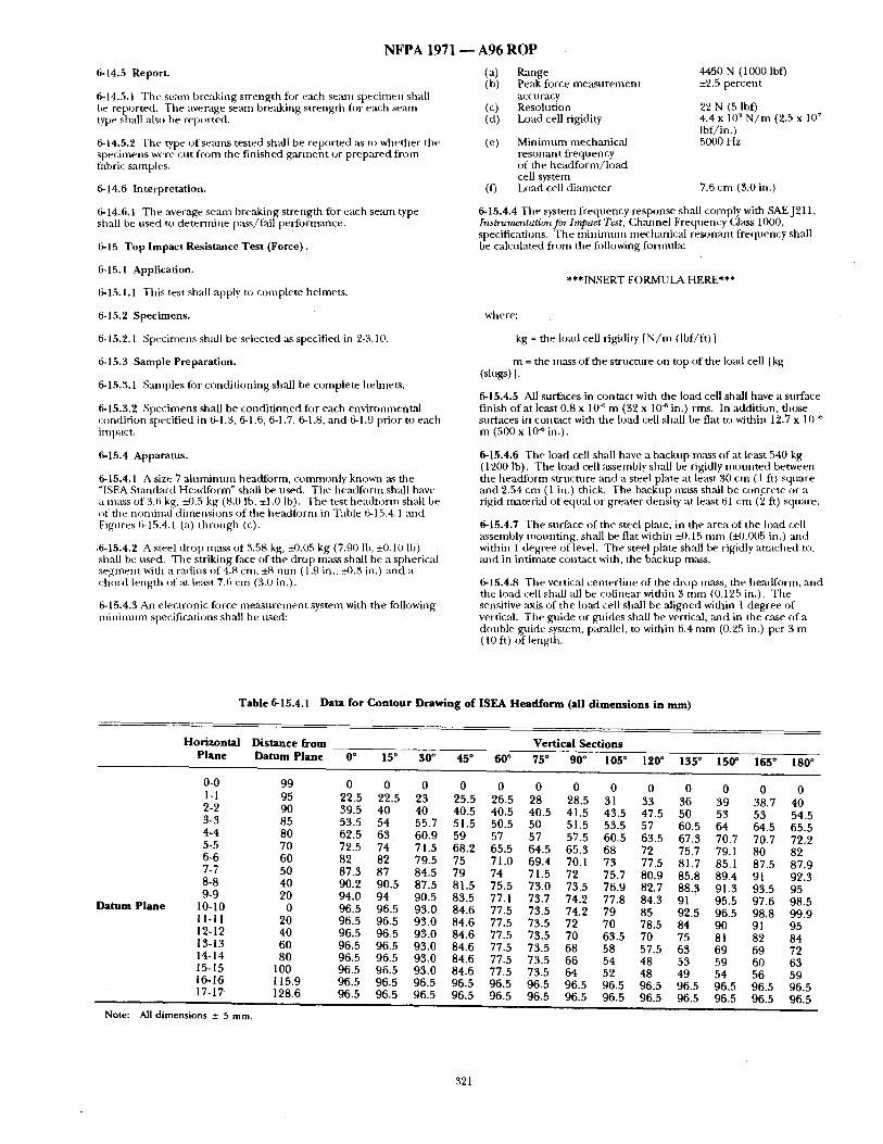
N F P A 1971 - - A96 R O P
6-14.5 Report. (a) (h)
6-14.5.1 The seam breaking strength fl)r each seam specimen shall be reported. The average semn breaking strength tor each seam (c) type shall also be reported. (d)
6-14.5.2 The type of seams tested shall be repor ted as to whether the (e) specimens were cut f rom the f inished ga rmen t or prepared f rom fabric samples.
6-14.6 Interpretation. (I)
6-14.6,1 The average seam breaking strength for each seam type shall be used to de termine pass/fail perfbrmance.
6-15 T o p I m p a c t Res i s tance T e s t (Force) :
6-15.1 Appl icat ion .
6-15.1.1 This test shall apply to complete helmets.
6-15.2 S p e c i m e n s .
6-15.2.1 Specimens sh:dl be selected :Ls specified in 2-3.10.
6-15.3 Sample Preparat ion .
6-15.3.1 Samples tier condi t ioning shall be complete hehnets .
6-15.3.2 Specimens shall be condi t ioned for each environmental condit ion specified in 6-1.3, 6-1.6, 6-1.7, 6-1.8, and 6-1.9 prior to each impact.
6-15.4 Apparatus.
6-15.4.1 A size 7 a l u m i n u m headform, commonly known as the "ISEA Standm'd Headform" sh:dl be used. The headform shall have a mass of 3.6 kg, i-0.5 kg (8.0 lb, ±1.0 Ib). The test headtbrm shall be of the nondnal d imensions of the headform in Table 6-15.4.1 and Figures 6-15.4.1 (a) th rough (c).
,6-15.4.2 A steel drop m~L~S of 3.58 kg, ~).05 kg (7.90 lh, ±0.10 Ib) shall be used. The striking face of the drop mass shall be a spherical segment with a radius of 4.8 cm, ±8 m m ( 1.9 in., ±0.3 in.) and a chord length of at le~L~t 7.6 cm (3.0 in.).
6-15.4.3 An electronic tbrce me~surement system with the following n d n i m u m specifications shall be used:
Range 4450 N (1000 Ibf) Peak force measu remen t ±2.5 percent accu racy Resolution 22 N (5 Ibf) Load cell rigidity 4.4 x 10⁹ N / m (2.5 x 10 ~
Ibf/in.) Min imum mechanical 5000 Hz resonant f requency of the head fo rm/ load cell system La)ad cell diameter 7.6 cm (3.0 in.)
6-15.4.4 The system frequency response shall comply with SAEJ211, Instrurm'ntation for Impact Test, Ch,'mnel Frequency Class 1000, specifications. Tile minimt tm mechanical resonant f requency shall be calculated from the tbllowing formula:
***INSERT FORMULA HERE***
where:
kg = the load cell rigidity [ N / m (Ibf/ft) ]
m = the mass of the structure on top of the load cell [kg (slugs) 1.
6-15.4.5 All surfaces in contact with the load cell shall have a surface finish of at least 0.8 x 10⁴ m (32 x 104 in.) rms. In addition, those surfaces in contact with the load cell shall be flat to within 12.7 x 10 ~ m (500 x 104 in.).
6-15.4.6 The load cell shall have a backup mass of at least 540 kg (1200 lb). The load cell assembly shall be rigidly m o u n t e d between tile headform structure and a steel plate at least 30 cm ( 1 ft) square and 2.54 cm (1 in.) thick. The backup mass shall be concrete or a rigid material of equ:d or greater density at least 61 cm (2 ft) square.
6-15.4.7 The surface of the steel plate, in the ,area o f the load cell assembly mount ing , sh',dl be flat within ±0.15 m m (i-0.005 in.) and within 1 degree of level. Tile steel plate shall be rigidly at tached to, al/d in int imate contact with, the backup mass.
6-15.4.8 The vertic:d centerl ine of the drop mass, the headform, and the load cell shall all be colinear within 3 m m (0.125 in.), The sensitive axis of the load cell shall be al igned within l degree of vertical. The guide or guides shall be vertic:d, ,and in the case of a double guide system, parallel, u) within 6.4 m m (0.25 in.) per 3 m ( 10 ft) of length.
T a b l e 6-15.4. I Data f o r C o n t o u r D r a w i n g o f I S E A H e a d f o r m (al l d i m e n s i o n s in ram)
H o r i z o n t a l D i s t a n c e f r o m V e r t i c a l S e c t i o n s
P l a n e D a t u m P l a n e 0 ° 15° 3 0 ° 45 ° 6 0 ° 75" 90* 105 ° 120 ° 135 ° 150 ° 165 ° 180 °
D a t u m P l a n e
0-0 99 0 0 0 0 0 0 0 0 0 0 0 0 0 1-I 95 22.5 22.5 23 25.5 26.5 28 28.5 31 33 36 39 38.7 40 2-2 90 39.5 40 40 40.5 40.5 40.5 41.5 43.5 47.5 50 53 53 54.5 3-3 85 53.5 54 55.7 51.5 50.5 50 51.5 53.5 57 60.5 64 64.5 65.5 4-4 80 62.5 63 . 60.9 59 57 57 57.5 60.5 63.5 67.3 70.7 70.7 72,2 5-5 70 72.5 74 71.5 68.2 65.5 64.5 65.3 68 72 75.7 79.1 80 82 6-6 60 82 82 79.5 75 71.0 69.4 70.1 73 77.5 81.7 85.1 87.5 87.9 7-7 50 87.3 87 84.5 79 74 71.5 72 75.7 80.9 85.8 89.4 91 92.3 8-8 40 90.2 90.5 87.5 81.5 75.5 73.0 73.5 76.9 82.7 88.3 91.3 93.5 95 9-9 20 94.0 94 90.5 83.5 77.1 73.7 74.2 77.8 84.3 91 95.5 97.6 98.5
10-10 0 96.5 96.5 93.0 84.6 77.5 73.5 74.2 79 85 92.5 96.5 98.8 99.9 11-11 20 96.5 96.5 93.0 84.6 77.5 73.5 72 70 78.5 84 90 91 95 12-12 40 96.5 96.5 93.0 84.6 77.5 73.5 70 63.5 70 75 81 82 84 13-13 60 96.5 96.5 93.0 84.6 77.5 73.5 68 58 57.5 63 69 69 72 14-14 80 96.5 96.5 93.0 84.6 77.5 73.5 66 54 48 53 59 60 63 15-15 100 96.5 96.5 93.0 84.6 77.5 73.5 64 52 48 49 54 56 59 16-16 115.9 96.5 96.5 96.5 96.5 96.5 96.5 96.5 96.5 96.5 96.5 96,5 96.5 96.5 17-17- 128.6 96.5 96.5 96.5 96.5 96.5 96.5 96.5 96.5 96.5 96.5 96.5 96.5 96.5
Note: All dimensions _+ 5 mm.
321
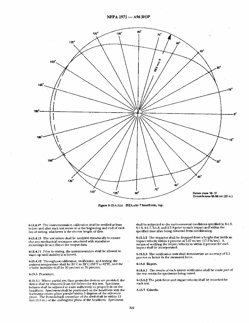
N F P A 1971 ~ A96 R O P
120 ° 105 o 90° 75 °
45*
120" [ I 75*
i
Figure 6-15.4.1(a) [SEA size 7 headform, top.
60*
Datum plane 10-10 Circumference 55.88 cm (22 in.I
6-15.4.9" The instrnmentation calibration shall be verified at least before and after each test series or at the beginning and end of each day of testing, whichever is the shorter length of time.
6-15.4.10 The test system shall be analyzed dynamically to ensure that ,any mechanical resonance ,associated with transducer mountings do not distort the output data.
6-15,4,11 Prior to testing, the instrumentat ion shall be allowed to warm up until stability is achieved,
6-15.4.12 Throughout calibration, veriiqcadon, and testing, the ambient temperature shall be 20°C to 28°C (68°F to 82°F), ,and the relative humidity shall be 50 percent to 70 percent.
6-15.5 Procedure.
6-15.5.1 Where partial eye/face protective devices are provided, the device shall be removed from the helmet for this test. Specimen helmets shall be adjusted to a size sufficiently to properly fit on the headfi~rm. Specimens shall be posit ioned on the headform with the horizonud center plane parallel within 5 degrees of the reference plane. The front<o-back centerl ine of the shell shall be within 13 mm (0.5 in.) o f the mid-sagi~al plane of the headform. Specimens
shall be subjected to the environmental conditions specified in 6-1.3, 6-1.6, 6-1.7, 6-1.8, and 6-1,9 prior to each impact and within the specified time after being removed from conditioning.
6-15.5.2 The impactor shall be d ropped from a height that yields an impact velocity within 2 percent of 5.47 m/sec (17.9 ft/sec). A means of verifying the impact velocity to within 2 percent for each impact shall be incorporate&
6-15.5.3 The verification tests shall demonstrate an accuracy of 2.5 percent or better in the measured force.
6-15.6 Report.
6-15.6.1 The results o f each system verification shall be made part of the test results for specimens being tested.
6-15.6.2 The peak force and impact velocity shall be recorded for each test.
6.15.7 Criteria,
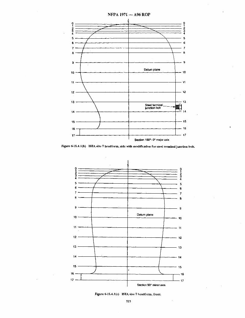
6 " 7/ 8
10
11
12
13
14
15
17
Figure 6-15.4.1 (b)
\ \
Datum plane
Steel t e r m i n a l junction bolt
Section 180 °- 0 ° major axis
N F P A 1971 - - A 9 6 R O P
10
11
12
13
14
15
16
17
ISEA size 7 headform, side with modification for steel terminal junction bolt.
5
6
7
8
1 0 ~
1 1 ~
12
13
14"
15
16
17
f f f //
t
0
2 3
\ 4
\ 6-
,,,,..,
Datum plane
7
- - 8
9
10
11
12
13
14
Section 90 ° minor axis
15
16
17
Figure 6-15.4.1(e) ISEA size 7 headform, front.
323
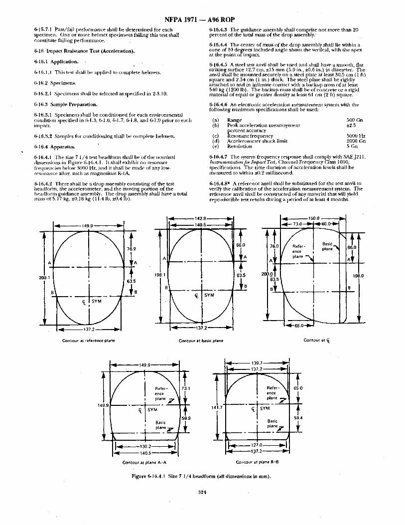
NFPA 1971 6-15.7.1 Pass/fail per formance shall be de t e rmined for each specimen. One or more he lmet specimens failing this test, shall constitute failing performance.
6-16 Impact Resistance Tes t (Acceleration).
6-16.1 Application.
6-16.1.1 This test shall be applied to complete helmets.
6-18.2 Specimens.
6-16.2.1 Specimens shall be selected as specified in 2-3.10.
6-16.3 Sample Preparation.
6-16.3.1 Specimens shall be condi t ioned for each environmenta l condition specified in 6-1.3, 6-1.6, 6-1.7, 6-1.8, and 6-1.9 prior to each intpact~
6-16.3.2 Samples fi)r cond idon ing shall be complete helmets.
6-16.4 Apparatus,
6-16.4.1 The size 7 1 /4 test headfi)rm shall be o f the nominal d imensions in Figure 6-16.4.1. It shall exhibit no reson~mt frequencies below 3000 Hz, and it shall be made of any low- resonance alloy, such as magnes inm K-IA.
6-16.4.2 There shall be a drop assembly consist ing of the test hea(-fform, the accelerometer, and the moving portion of the headfi)rm guidance assembly. The drop assembly shall have a total m a ~ of 5.17 kg, +0.18 kg (1 L4 lb, ~-0.4 lb).
A96 ROP
6-16.4.3 The gnidance assembly shall comprise not more than 20 percent o f the total mass o f the drop assembly.
6-16.4.4 The center of mass o f the drop ,assembly shall lie within a cone o f 10 degrees included angle about the vertical, with the apex at the point o f impact.
6-16.4.5 A steel test anvil shall be used ,and shall have a smooth, flat striking surface 12.7 cm, +15 m m (5.0 in., ~0.6 in.) in diameter. The anvil shall be m o u n t e d securely on a steel plate at least 30.5 cm (1 ft) square ,and 2.54 cm (i in.) thick. The steel plate shall be rigidly atutched to and in intimate contact with a backup mass of at least 540 kg (1200 l b). The backup mass shall be of concrete or a rigid material of equal or greater density at least 61 cm (2 ft) square.
6-16.4.6 An electronic acceleration measu remen t system with the following m i n i m u m specifications shall be used:
(a) Range 500 Gn (b) Peak ,acceleration m e a s u r e m e n t ±2.5
percent accuracy (c) Resonant f requency 5000 Hz (d) Accelerometer shock limit 2000 Gn (e) Resolution 5 Gn
6-16.4.7 The system frequency response shall comply with SAEJ211, Instrumcntation for Impact Test, Channel Frequency (2lass 1000, specifications. The time du~tt ion o f acceleration levels shall be measured to within i-0.~ millisecond.
6-16.4.8" A reference ~mvil shall be substi tuted for the test anvil to verify the calibration of the acceleration m e a s u r e m e n t system. The reference anvil shall be cons tn ic ted o f any material that will yield reproducible test results dur ing a period o f at least 4 months .
149.9
200.1 • i
71 63.5
l 137 2 "-
Contour at reference plane
_ L
13~ .2 ~= Contour at basic plane Contour at
149.9
Basic
, ~ t plane ~'
130.2 I ~ . 140.5' w
Contour at plane A-A
1!.7"
; I
139.7 ~ 1
137.2 ~i i
c~ s ~ - I Basic
. - j
13 7 .2
Contour at plane B-B
Figure 6-16.4.1 Size 7 I/4 headform (all dimensions in mm).
65.0
59.4
324
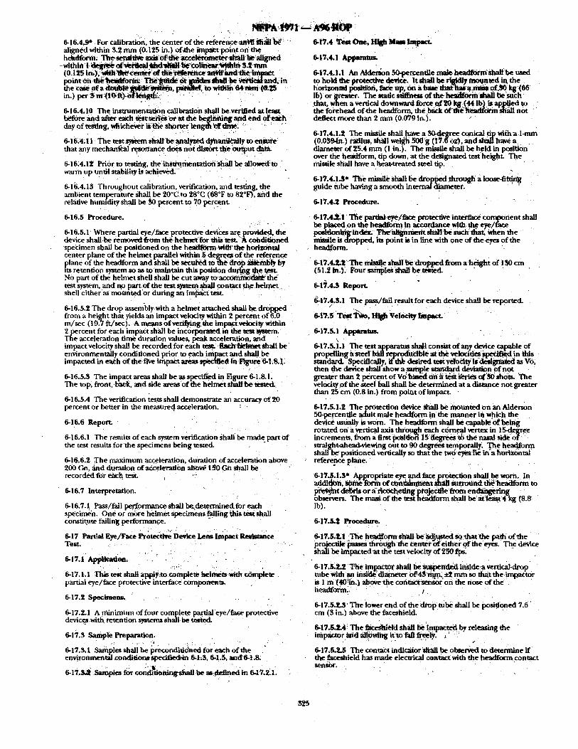
6-16.4.9" For calibration, the center of the reference an~! 1~!i~t1~ ~ aligned within 5.2 nun (0.125 in,) of~he impa~t poim on the hehdfiorm~ Th9 Semtti~e axiS0f di6 a c c ~ ~ h r a l l be aligned -within t ~ ~ ' ~ ~ ~ b¢~maear ~mnS.2.mm _
( O. i ~5 |m),. ~ ~(i~, ~enlg~r, .e~ th~ ~r~)~ace ~ t t W i m d ~ t h e . ~ t .
the c, se 0f a d ~ n ~ ~ , paralk4, t o ~ i O i m e 4 ~ m i ( ~ , ~ 5 in.) per S m~|O;~):o)i~gth' . " ' " :
6-16.4.10 The insummentation calibration sh~l be verified at least ~ d a/te~ ~a~h ~e~ ~ e ~ or at the be#nntng and end ofea~h
_day of testing, whicbever is th'e shorter length i~ff dine ~ ' "
6-16,4;11 The test S/stem shaft be analyzed dyhand~ly to e n S t ~ that any mechanfeal resonance does not dist6rt the output data.
0-16;4.12 Prior to testing, the:instrt~rnentatioti'shal] be a l l tm~ to warm up u n ~ stability is acMeved.'
0-16.4.13 Throughout calibration verification, and testing, the amhient tempe.rature sha U be 20°(: to 28°C (68°F to 82°1~, and the relative hunmdity shall be ~0 percent to 70 percent.
6-16.5 Procedure.
0-16.5.1 Where partial eye/face protective devi~:es are provided, the device shallbe removed from the helmet-for this ~ A conditioned specimen shall be positioned on the headfOemWith' the horizontal center plane of the helmet parallel within 5~ degrt~, of the refet, ence plane of the headform and shall be secui~d to ~ dr@ ~ b l y by its retention system so as to maintain this position during ~ f ten. NO part of the helmet shell shall be cut away t o ' a c c ~ the- test system, and no part.of the test system ~hall contact the.helmet shell either as mounted'or during an im[~ct test.
6-16.5.2 The drop assembly with a helmet attached shall ~ dr6pped from a height that yields an impact velocity within 2 percent of 6,0 m/sec (t9..7-. ft /sec), ,A nmans ofvel~F/ing, the tmpap:t velocity within 2 percent for each impact shall he incorporated in the'test ~stem. The acceleration time duration values, peak acceleration, and impact velocity shall be recorded for each test. ~tr~h h~qtvtet shall be environmentally conditioned prior to each impact and shall be impacted in each of the fl~e impact areas specified in,Figure 6-1.8.]L
6-16.5.3 The impact areas shall beas speci6ed in Figure 6-1.8. !. The top, front, b~tck, and side areas of the helmet shall be tested.
6-16.5.4 The verification tests shall demonswaw an accuracy of 20 percent or better in the measureql acceleration.
0-16.6 Report.
6-16.6.1 The results of each system verfl]cation shalibe madepart of the test results for the specimens being tested.
6-16.6.2 The maximum acceleration, duration of acceleration above 200 Gn, ~ad d~uratlon of acceleration ~ 150 Gn shall be recorded for e~cb test. ""
6-16.7 Interpretation.
6-16.7.1 Pass/fail pefform~ce shall be~de~rminedfor each specimen. One or more helmet specimens fal'lingthis test shaU constitute failing performance.
6-17 P ~ ~y~/ra~ P r o t ~ D~ce Lens Impact Re~mce Test . • •
6-,7a , ,~ ,~t io , , ,
6-17. !.1 This test shall ap~iy.to complete h~lmets with c6mplete partial eye/face protective interface components.
6-17,2 Specimens.
6-17.2.1 A minimum of four complete partial eye/fa~e protective devic _~ with retention systems shall be
6-17.3 Sample Preparation.
6-17.3.1 ,Samples shall be preconditio~aed for each of the " en~onmental conditions specified~ 6,L~, 0,1.5, and'6-1.8.
6-]7,s~ s ~ p ~ for c o g ~ n ~ a be a s , . ~ e d in 6-~7.ZL
6-tv.4 T . o . , ~ bh,= ~1~,~.
6-t7~4.1 &plmrams.
6-17.4.1.1 An A~derson 50-pementile real e headformshallbe used to hold the protective device, It shall be r i ~ . y mmlnted inthe . ho~um~ ~ , ~ e up, on abaae mat ha, a t o m of~0 gg (06 Ib) or g~-ater, the staticsiiffness ofthe~'dmU he'such ' that, when a vertical downward force of ~0 kg (44 I b} is applied to the forehead ofthe headform, the b ~ k 6 fd i i~d~c~f in shall not deflect more than 2 nun (0.079 in.).
6-17.4.1.2 The missile shall have a 30,degree conical tip with a l-ram (0.0594n.) radius, shMIwei~h 500 g (17.[oz), andShal] have a diameeer of 25.4 mm (1 in.). The missile shall be held in posi~km over the headform, tip down, at the designated test height. The missile shall have a i~at-treated steel tip.
6-17.4.1 ~* The missile shall be dropped through a loose-fitt~, g gnide tube having a smooth internal "dL~neter.
6-17.4.2 Procedure.
6-17.4.2.1 The partial eye/fare protective interface component shall be placed on the headform in accordance with th~ eye/fare pos|tlontciglild~. ?['h~alignme~ shallbe such: that~ When the missile is dropped, its point is in line with one of theeyes of the headform.
6-17,4,2;Z ~ The missile shall be ~ from a height of lS0 cm (51.2 in.)i Four samples Shallbetested.
6-17.4 .3 Report.
6-17.4.&I The pass/fall result for each device shall be reported. /
6-17.5.1 Apparatus.
6-17.5.1.1 The test apparatm shah consist of any device c.~p~_ le of propefliaga steel l~g 'rep .rpdiaclble at the velocities ~ e d in this standard` Specmc~.y, .'th~ des~.~ t ~ ~ iia/sltn-a~ed as Vo, then the device shall show a pamp~ standard deviation ot not • greater than 2 per.~nt o f V O b a s ~ 0 n a ~ t ~ d e ~ s of~0sh6ts. The velocity Df the steel ball shall be determined at a distance not greater than 25 cm (0.8 in.) from point of impact.
6-17.5.1.2 The protection device Shall be mounted on an Alderson 50-percentile adult male headform "in the manner in which the devic6 usually is worn. The headform shall be capableof being rotated on a verticalaxis through each c6rneal vertex in 15.degree increments, from a first poM~O/i 15 ~ ~ the nasal side o~ straight-ahead-viewing out to 90 degrees temporally', The head-Corm shall-be positioned vertically so that the two d~es lie in~ah~rlZontal reference plane. .
6-17~.1.$* App/opria_te ~ and fare protection shall be wnm. In addition, ~ a ~ fve/a of ctmednment shall surround ~i~ head~rm to pr~-~n~ t debris or ~ ricOCheting ptoj¢c.u3e from e n ~ r i n g observers. The masg of the test hea/dform shall be at l/~ast 4 kg (8.8 ib).
6-17.5 .2 Procedure.
6-17.5.~1 The hea~forrn shall.be ~djteRed so. that the path of the projectile ~ through the center bf either o f ~ e eyes, The d~-~ice shall be impacted~t the test velocity of2~0 fps~
6-17.5.2.2 The in) _p~xo~ shatt be ~penddd ins ide a vertical-drop tube ~dth ,~ insid6diam~er 0f~4$~n,, ~ ~, mm so that t h e i m ~ t o r is 1 m (40in.~ ~ the cont~tsensor on the nose of the headform.
6-17.5.2.3 The lower end of the drop robe shall be positioned 7.6 cm (3 in.) above the faceshield.
6-17.5.~.4 The fl/ces~etd shall be!Impacted by releasing the imp-actor ~mdaliOWit~g !tto fall freely. ,
/
6-17.5.:L5 The contact indicator shall be observed to determine if the faceshield has made electrical contact with the headfot'm contact seynsor.
325
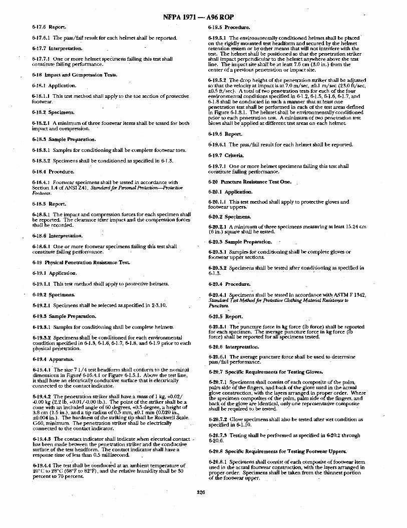
NFPA 1971 - - A96 R O P
6-17.6 Report.
6-17.fi. 1 The pass/~ail resuh for each helmet shall be reported.
6-17.7 Interpretation.
6-17.7.1 One or more helmet specimens failing this test shall constitute failing performance.
6-18 Impac t and Compression Tests.
6-18. ! Application.
6-18.1.1 This test method shall apply to the toe section of protective fcu~twear.
6-18.2 Specimens.
6-18.2.1 A minimum of three footwear items shall be tested for both impact and compression.
6-18.3 Sample Preparation.
6-18.3.1 Samples for conditioning shall be complete footwear toes.
6-18.3.2 Specimens shall be~onditioned as specified in 6-1.3.
6-18.4 Procedure.
6-18.4.1 Footwear specimens shall be tested in accordance with ,Section 1.4 of ANSI Z41, Standard for Personal Protection,--Protective FootoJear.
6-18.5 Report.
6-18.5.1 The impact and compression forces for each specimen shall be reported. The clearance after impact and the compression forces shall be recorded.
6-18.6 Interpretation.
6-18.6.i One or more footwear specimens failing this test shall constitute failing performance.
6-19 Physical Penetration Resistance Test.
6-19.1 Application.
6-19.1.1 This test method shall apply to protective helmets.
6-19.2 Specimens.
6-19.2.1 Specimens shall be selected as specified in 2-3.10.
6-19.3 Sample Preparation.
6-19.3.1 Samples for conditioning shall be complete helmets.
6-19.3.2 Specimens shall be conditioned for each environmental condition specified in 6-1.3, 6-1.6, 6-I .7, 6-1.8, and 6-I .9 prior to each physical penetration.
6-19.4 Apparatus.
6-19.4.1 The size 7 1/4 test headform shall conform to the nominal dimensions in Figurd 6-16.4.1 or Fil~rure 6-1.5,1. Above the test line, it shall have ,an electrically conducuve surface that is electrically connected ro the contact indicator.
6-19.4.2 The penetration striker shall have a mass of I kg, +0.02/ -0.00 kg (2.2 Ib, +0;01/-0.00 lb.). The point of the striker shall be a cone with an included angle of 60 degrees, +0.5 degree, a height of 3.8 cm (1.5 in.), and a tip radius of 0.5 ram, £-0.1 mm (0.020 in., -20.004 in.). The hardness of the striking tip shall be Rockwell Scale. G-f0, minimum. The penewation striker shall be electrically connected to the contact indicator.
6-19.4.3 The contact indicator shall indicate ~ e n electrical contact . has been made between the penetration striker and the conductive surface of the test headform. The contact indicator shall have a response time of less than 0.5 millisecond.
6-19.4.4 The test shall be conducted at an ambient temperature of 20°C to 28°C (68°F to 82°F), and the relative humidity shall be 30 percent to 70 percent.
6-19.5 Procedure.
6-19.5.1 The environmentally conditioned helmet shall be placed ~ on the rigidly mounted test headform and secured by the helmet retention system or by other means that will not interfere with the test. The helmet shall be positioned so that the penetratibrt striker shall impact perpendicular to the helmet anywhere above the test line. The impact site shall be at least 7.6 cm (3.0 in.) from the center of a previous penetration or impact site.
6-19.5.2 The drop height of the penetration striker shall be adjusted so that the velocity a t impact is at 7,0 m/see, ~0.1 m/sec (25.0 ft/sec, • 0.5 ft/sec). A total of two penetration tests for each of the four environmental conditions specified in 6-1.2, 6-1.5, 6-1.6, 6-] .7, and 6-1.8 shall be conducted in such a manner that at least one penetration test shall be performed in each of the test areas defined
Figure 6-1.8.1. The helmet shall be environmentally conditioned
~ rior to each penetration test. A minimum of two penetration test lows shall be applied at different test areas on each helmet.
6-19.6 Report.
6-19.6.1 The pass/fail result for each helmet shall be reported.
6-19.7 Criteria.
6-19.7.1 One or more helmet specimens failing this test shall constitute failing performance.
6-20 Puncture R~istance Test One.
6-20.1 Application.
6-20.1.1 This test method shall apply to protective gloves and footwear uppers.
6-20.2 Specimens.
6-20.2.1 A minimum of three specimens measuring at least 15.24 cm (fi in.) square shall be tested.
6-20.3 Sample Preparation.
6-20.3.1 Samples for conditioning shall be complete gloves or footwear upper sections.
6-20.3.2 Specimens shall be tested after conditioning as specified in 6-1.3.
6-20.4 Procedure.
6-20.4.1 Specimens shall be tested in accordance with ASTM F 1342, Standard Test Method for Protective Clothing Materlal Resistance to Punctur~
6-20.5 Report.
6-20.5.1 The puncture force in kg force (Ib force) shall he reported for each specimen. The average puncture force in kg force (ib force) shall be reported for all-specimens tested.
6-20.6 Interpretation.
6-20.6.1 T h e average puncture force shall be used to determine pass/fail performance.
6-20.7 Specific Requirements for Tesiing Gloves.
6-20.7.1 Specimens shall consist of each composite of the palm, palm side of the fingers, and back of the glove used in the actual glove construction, with the layers arranged in proper order. Where the specimen composites of the palm, palm side of the fingers, and back of the glove are identical, only one representative composite shall be required to be tested.
6-20.7.2 Glove specimens shMl also be tested after wet condition as specified in 6-1.10.
6-20.7.3 Testing shall be performed as specified in 6-20.2 through 6-20.fi.
6-20.8 Specific Requirements for Testing Footwear Uppers.
6-20.8.1 ,Specimens shall consist of each composite of footwear item used in the actual footwear constrnction, with the layers arranged in oP[Oper-order. Specimens shall be taken from the thinnest portion
the footwear upper.
326
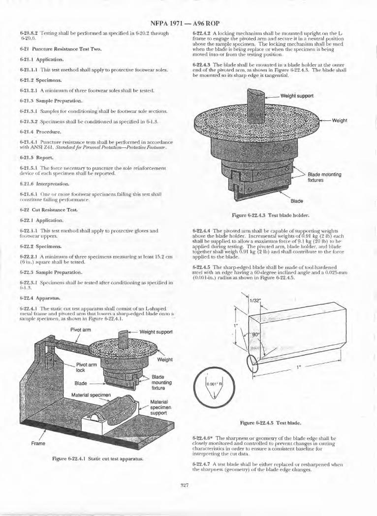
N F P A 1971 ~ A 9 6 R O P
6-20.8.2 Testing shall be per formed as specified in 6-20.2 through 6-20.6.
6-21 Puncture Resistance Test Two.
6-21.1 Application.
6-21.1.1 This test me thod shall apply to protective footwear soles.
6-21.2 Specimens.
6-21.2.1 A m i n i m u m of three footwear soles shall be tested.
6-21.3 Sample Preparation.
6-21.3.1 Samples tot condi t ioning shall be tbotwear sole sections.
6-21.3,2 Specimens shall be condi t ioned as specified in 6-1.3.
6-21.4 Procedure.
6-21.4.1 Ptmcture resist~mce tests shall be per formed in accordance with ANSI Z 41, Standard for Personal Protectiorv--Protective Footwear.
6-21.5 Report.
6-21.5.1 The fi)rce necessary to punctnre the sole re inforcement device of each specimen shall be reported.
6.21,6 Interpretation.
6-21.6.1 One or more footwear specimens failing this test sh;dl constitute failing performance.
6-22 Cut Resistance Test.
6-22.1 Application.
6-22.1.1 This test me thod shall apply to protective gloves and footwear uppers.
6-22.2 Specimens.
6-22.2.1 A m i n i m u m of three spec imens measur ing at least 15.2 cm (6 in.) square shall be tested.
6-22.3 Sample Preparation.
6-22.3.1 Specimens shall be tested after condi t ioning as specified in 6-1.3.
6-22,4 Apparatus.
6-22.4.1 The static cut test apparatns shall consist of an L-shaped meud frame and pivoted arm that lowers a sharp-edged blade onto a sample specimen, as shown in FigaJre 6-22.4.1. -"
6-22.4.2 A locking mechan i sm shall be m o u n t e d upr ight on the L- frame to engage the pivoted arm and secure it in a neuW, d position above the sample specimen. The locking mechan i sm shall be used when the blade is being replace or when the specimen is being moved into or f rom the testing position.
6-22.4.3 The blade shall be m o u n t e d in a blade holder at the outer end of the pivoted arm, as shown in Figure 6-22.4.3. The blade shall be moun ted so its sharp edge is tangential.
Blade
Figure 6-22.4.3 Tes t blade holder,
6-22.4.4 The pivoted arm shall be capable of suppor t ing weights above the blade holder. Incremental weights o f 0.91 kg (2 lb) each shall be supplied to allow a m a x i m u m force o f 9.1 kg (20 lb) to be applied dur ing testing. The pivoted ann , blade holder, ,an& blade together shall weigh 0.91 kg (2 lb) a n d shall contr ibute to tile force app_lied to the blade.
6-22.4.5 The sharp-edged blade shall be made of tool-hardened steel with ,an edge having a 60-degree inclined angle ,and a 0.025-ram (0.001-in.) radius as shown in Figure 6-22.4.5.
1 / 3 2 " , " '
1" J !: ' ;
Figure 6-22.4.5 Tes t blade.
Figure 6-22.4.1 Static cut test apparatus.
6-22.4.6* The sharpness or geometry of the blade edge shall be closely moni to red and controlled to prevent changes in cutt ing characteristics in order to ensure a consistent baseline for interpret ing the cut dater,
6-22.4.7 A test blade shall be either replaced or r e sha rpened when the sharpness (geometry) o f the blade edge ch~mges.
327
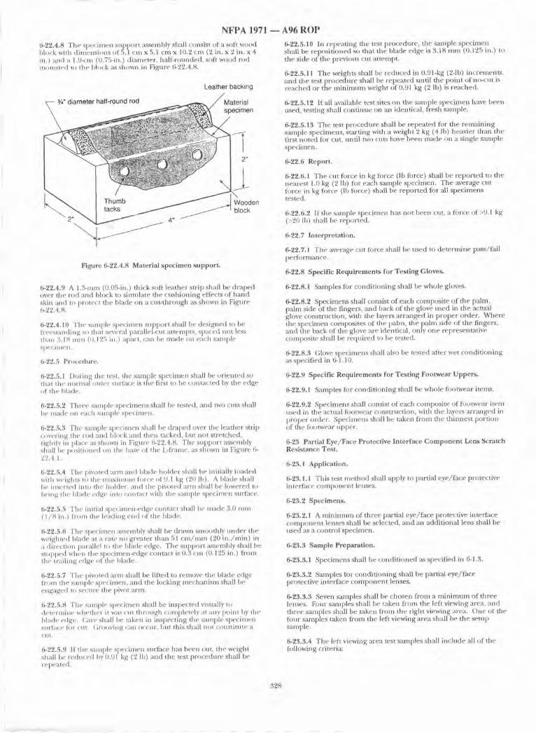
NFPA 1971
6-22.4,8 The specimen suppor t ,'~ssembly shall consist of a soft wood block with d imens ions of 5.1 cm x 5.1 c m x 10.2 cm (2 in. x 2 in. x 4 in.) and a 1.9-cm (0.75-in.) diameter, haft-rounded, soft wood rod moun ted to the block ,as shown in Figure 6-22.4.8.
Leather backing
¥," diameter half-round rod ~ / M a t e r i a l
I h,;mh ooden 2 4 '
Figure 6-22.4.8 Material specimen support.
6-22.4.9 A 1.3-ram (0.05-in.) thick soft leather sn ip shall be draped over the m d ,and block to simulate the cush ioning effects of hand skin and to protect the blade on a cut- through as shown in Figure 6-22.4.8.
6-22.4.10 The sample specimen suppor t shall be designed to be freestanding so that several parallel-cut at tempts, spaced not less than 3.18 nnn (0.125 in.) apart, can be made on each sample specinlen.
6-22.5 Procedure.
6-22.5.1 During the test, the sample specimen shall be or iented so that the normal outer surface is the first to be contacted by the edge of the blade.
6-22.5.2 Thl 'ee sample specimens shall be tested, ,and two ctms shall be made on each smnple specimen.
6-22.5.3 The sanlple specimen shall be draped over the leather strip covering the rod and hlock and then tacked, but not stretched, tightly in place as shown in Figure 6-22.4.8. The suppor t ,assembly shall be positioned on the base of the L-fiame, as shown in Figure 6- 22.4.1.
6-22.5.4 The pivoted arm and blade holder shall be initially loaded with weights to the m : ~ i m u m force of 9.1 kg (20 lb). A blade shall be inserted into the holder, and the pivoted alan shall be lowered to bring the hl:tde edge into contact with the sample specimen surface.
6-22.5.5 The initial specimen-edge contact shall he made 3.0 m m (1/8 in.) f rom the leading end of the blade.
6-22.5.6 The specimen assembly shall be drawn smoothly unde r the weighted blade at a rate no greater than 51 c m / m i n (20 in . /min ) in a direction parallel to the blade edge. The suppor t assembly shall be stopped when the specimen~edge contact is 0.3 cm {0.125 in.) from the trailing edge of the blade.
6-22.5.7 The pivoted arm shall be lifted to remove the blade edge from the sanlple specimen, and the locking mechan i sm shall be engaged to secure the pivot arm.
6-22.5.8 The sample specimen shall be inspected visually to determine whether it w ~ cut through completely at any point by the blade edge. (2u-e shall be taken in inspecting the sample specimen stn'face for [ : t i t . (7;roovil/g Call OCEUF, but this shall not constitttte a cnt.
6-22.5.9 l f t h e sample specimen surface has been cut, the weight shall be reduced by 0.91 kg (2 lb) ,'rod the test procedure shall be re peated.
A96 ROP 6-22.5.10 In repeat ing the test procedure, the sample specimen shall be reposit ioned so th,at the blade edge is $.18 nun (0.125 in.) to the side of the previous cut attempt~
6-22.5.11 The weights shall be reduced in 0.91-kg (2-1b) increments. and the test procednre shall be repeated until the poin t of no-cut is reached or the m i n i m u m weight of 0.91 kg (2 lb) is reached,
6-22.5.12 If all av~dlahle test sites on the sample spec imen have been used, testing shall cont inue on an identical, fresh smnple.
6-22.5.13 The test procedure shall be repeated for the remain ing sample specimens, start ing with a weight 2 kg (4 lb) heavier than the first no ted for cut, until two cuts have been made on a single sample specimen.
6-22.6 Report.
6-22.6.1 The cut force in kg force (lb force) shall be reported to the nearest 1.0 kg (2 Ib) for each sample specimen. The average cut force in kg force (Ib force) shall be reported for all specimens tested.
6-22.6.2 If the sample specimen h ~ not been cut, a force of>9.1 kg (>20 lb) shall be reported.
6-22.7 Interpretation.
6-22.7.1 The average cut force shall be used to de termine pass/fall perforrmance.
6-22.8 Specific Requirements for Testing Gloves.
6-22.8.1 Samples for condi t ioning shall be whole gloves.
6-22.8.2 Specimens shall consist o f each composite o f the palm, palm side of the fingers, and back of the glove used in the actual glove consmmtion , with the layers a r ranged in proper order. Where the specimen composites of the palm, the pa lm side of the fingers, a n d the back of the glove are identical, only one representative composite shall be required to be tested.
6-22.8.3 Glove specimens shall also be tested after wet condi t ioning ,~s specified in 6-1.10.
6-22.9 Specific Requirements for Testing Footwear Uppers.
6-22.9,1 Samples for condi t ioning shall be whole footwear items.
6-22.9.2 Specimens shall consist of each composite of footwear item used in the actual footwear construction, with the layers a r ranged in proper order. Speciinens shall be taken f rom the th innes t portion of the fi)otwear upper.
6-23 Partial Eye/Face Protective Interface Component Lens Scratch Resistance Test.
6-23.1 Application.
6-23.1.1 This test me thod shall apply to partial eye/ face protective in terrace c o m p o n e n t lenses,
6-23.2 Specimens.
6-23.2.1 A m i n i m u m of three partial eye/face protective inter-Pace c o m p o n e n t lenses shall be selected, and an additional lens shall be used as a control specimen.
6-23.3 Sample Preparation.
6-23.3.1 Specimens shall be condit ioned ,as specified in 6-1.3.
6-23.3.2 Samples for condi t ioning shall be partial eye/ face protective interface c o m p o n e n t lenses.
6-23.3.3 Seven samples shall be chosen from a m i n i m u m of three lenses. Four samples shall be taken from the left viewing area, and three samples shall be taken from the right viewing area. One of the fi)nr samples taken d-ore the left viewing area shall be the setup sample.
6-23.3.4 The left viewing area test samples shall include all of the fi)llowing criteria:
328
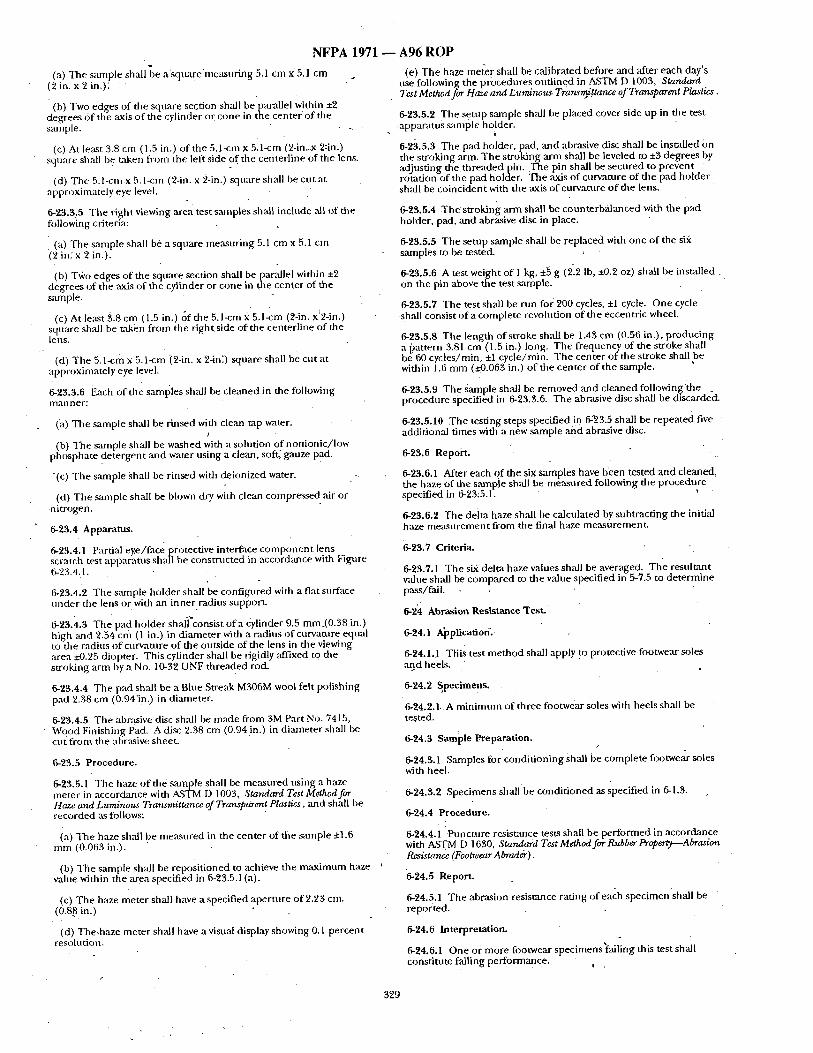
NFPA 1971
(a) The sample shall ~e a'square measur ing 5.1 cm x 5.1 cm (2 in. x 2 in.): "
ib) Two edges of the square section shall be parallel within ±2 degrees 6 f t h e ,axis o f the cylinder or cone in me center 'of the sample.
(c) At least 3.8 cm (1.5 in.i of the 5.1-cm x 5,l-cm (2-in.x 2:in.) sqt are shal be taken from the left side of the centerline of the lens.
(d) The 5. l-cm x 5. l-cm (2-in. x 2-in,) square shall be cut at approximately eye level.
6-23.3.5 Tile right viewing area test samples shall include ,all of the following criteria:
(a) The sample shall be a square measuring 5.1 c m x 5.1 cm (2 in: x 2 in.).
(b) T~'o edges of the square section shall be parallel within ±2 degrees of the ,axis of the cylinder or cone in the center of the sample.
(c) At least $.8 cm (1.5 in.) ¢~f the 5.l-cm X 5.1-cm (2-in. x~2-in.) square shall be taken from the r ights de o f t h e centerline of die lens.
(d) The 5.1-cm x 5.1-cm (2-in. x 2-in:) square shall be cut at approximately eye level.
6-23.3.6 Each of the samples shall be cleaned in the following ri~nl net:
(}t) The sample shall be rinsed with clean tap water. t
(b) The sample shall be washed with a solution of nonionic/ low phosphate detergent and water using a clean, soft; gauze pad.
-(c) The sample Shall be rinsed with deionized water.
(d) The sample shall be blown dry with clean compressed air or ni trogen.
6-23.4 Apparatus.
6-23.4.1 Partial eye/face protective interface componen t lens scratch test apparatus shall be consmmted in accordance with Figure 6-23.4.1.
6-23.4.2 The siunple holder shall be configalred with a flat surface under the lens or with an inner radius support.
6-23.4.3 The pad holder shali'consist o f a cylinder 9.5 ram_(0,38 in.) high ;rod 2.54 cm (1 in.) in diameter with a radius of curvature equal to the radit s o f cl rvamre of the outside of the lens in the viewing area -20.25 diopter. This cylinder shall be rigidly affixed to the stroking ann by a No, 1%32 UNF threaded rod.
6-23.4.4 The pad shall be a Blue Streak M306M wool felt polishing pad 2,38 cm (0.94in.) in diameter.
6-23.4.5 The ab~s'ive disc shall be made from 3M Part No. 7415, Wood Finishing Pad. A disc 2.38 cm (0.94 in.) in diameter shall be cu{ from the abrasive sheet•
6-23.5 Procedure.
6-23.5.1 The haze of the smnple shidl be measured using a haze meter in accordance with ASTM D 1003, ,Standard Test Method for Haze and Luminous Transmittance of Transflaren! Plastics, and shall be recorded as follows:
(a) The haze shall be measured in the center of the sample ±1.6 mm (0.063 in.).
(b) The sample shall be repositi0ned to achieve the maximum haze value within the area specified in 6-23.5.1 (a).
(c) The haze meter shall have a specified aperture of 2~23 cm. (0.88 in.)
(d) The.haze meter shall have a visual display showing 0.1 percent resoltltion.
A96 ROP (e) The haze memr shall be calibrated before ,and ,after each day's
use following the procedures outl ined in ASTM D 1003, Standard Test Method for Haze and Luminous, Transmittance of Transparent Plastics.
6-23.5.2 The setu p smnple shall be placed cover side up in the test apparatus saniple holder.
6-23.5.3 Tile pad holder, pad, and abrasive disc shall be installed on the stroking arm. The stroking arm shall be leveled to +3 degrees by adjusting the th readedpin . The pin shall be secured to prevent rotation of the pad holder. The axis of curvature of the pad holder shall be coincident with the axis o f curvature of the lens.
6-25.5.4 T h e stroking arm shall be counterbalanced with the pad holder, pad, and abrasive disc in place.
6-23.5.5 The setup sample shall be replaced with one of the six samples to be tested.
6-23.5.6 A test weight of 1 kg, +5 g (2~2 Ib, ±0.2 oz) shall be installed on the pin above the test sample,
6-23.5.7 The test shall be run for 200 cycles, +1 cycle. One cycle shall consist o f a complete revolution of the eccentric whee l
6-23:5.8 The length of stroke shall be 1.43 cm (0.56 in.), producing a pattern 3.81 cm (1.5 in.) long. T h e frequency of the stroke shall be' 60 cycles/min, ±1 cycle/rain. The center of the stroke shall be within 1.6 mm (~-0.063 in.) o f the center of the sample.
6-23.5.9 The Sample shall be removed ,and cleaned following the _ procedure specified in 6-23.3.6. The abrasive disc shall be discarded.
6-23.5.10 The testing steps specified in. 6-'23.5 shall be repeated five additional times with a new sample and abrasive disc.
6-23.6 Report.
6-23.6.1 After each of the six samples have been tested and cleaned, the haze of the sample shall be measured following the procedure specified in 6-23:5.1.
6-23.6.2 The delta haze shall be calculated by subtracting the initial haze measurement from the final haze measurement~
6-23.7 Criteria.
6-23.7.1 The sir delta haze values shall be averaged. The resultant value shall be compared to the value specified in 5-7.5 to determine pass/fail.
6-24 Abrasion Resistanc e TesL
6-24.1 Application::
6-24.1A Ttiis test method shall apply to protective footwear soles aBd heels,
6-24.2 Specimens.
6-24.2.1, A minimum of three footwear soles with heels shall be tested.
6-24.3 Sample P.reparation. t
6-24.3.1 Samples for condit ioningshall be complete footwe~r soles with heel.
6-24.3.2 Specimens shall be condit ioned as specified in 6-1.3.
6-24.4 Procedure.
6-24.4.1 Puncture resistance tests shall be performed in accordance with ASTM D 1630, Standard Test Method for Rubber Property--Abrasion R~istanc, e (Footwear A brad&) .
"6-24.5 Report.
6-24.5.1 The abrasion resistance rating of each specimenshal l be reported.
6-24.6 Interpretation.
6-24.6.1 One o? more footwear specimens'failing this test shall constitute failing performance. . ,
329
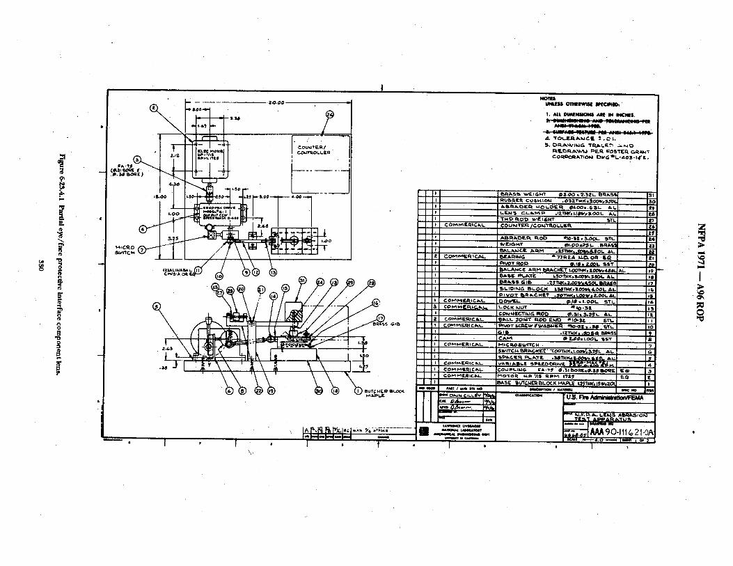
0
P.,
0
" 0 0
; O~,'llVl F_R.I C , ~ L P o y O T I~1~ ~ C
t - O C K IdUT
% COMMEI~ . IC / I , I - l~lk~t,. $OIi,,IT l i O O F..klt~ '~lO-~?.
C A )~1 ¢~ ~O0,1.OOt. $$T C O M M E . R ~ C . ~ . ~ 1 C I I tO.~vrTC t4 . -
c o ~ r ~ * c J , L. v A m P , h i . . " s p r ~ o O ~ v £ . I ,~"~ '~ '1. '~°,~-~, M I "
T , I • r" i W'-- ;
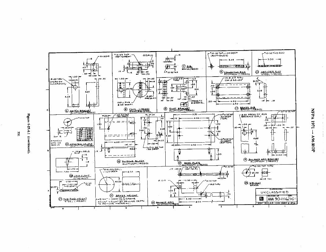
o =
,,,,,
1 , 0 0
Cw~ic Ro S
~
/ * - 2X ~.~.19
• ~3 : --
~,?-5
, 3~ . $ 0
.lz .25
"°°V- -?,
-I~ ~,,.oo .~ ~ ~ ~
I j__..~.,z
_.L;o~L---T ....._..I •
i ~.,o;~t,:~;,;? o.o
\ r---'" ~_L --~ ~- ~_~, &R~.%S 0 ~ D)
l
. ~ Z ' T ' ~ 0 RO~
-~.F-', J,~ ~"" -Ill i,,.-.:ro ° ~-~.,~i~.
! ~ :_ _-_ _ -_- _~-
/t.LUP'~l~l~.ll'~ (.; ~ w " * O ) ~,R~I~.%S ( I I~EQ O ) )
'~ ~ l ~ ' l I :'-'IF \ .~ro I.H 1 I tl
" =: " ~,~ I t t l/ ,..oo , ~ , , .oo_ .,v~
_ i o~ . ~ . oo
L - Z 3 8
I
I
L ' I
I
~ 2 . 0 0
I ~ I
~ - - ~ : - ~ . - - . ~ , ~ I " - . J , 0 L
o ~.~ - ~ .,o : : ; : o o
~ : ! ~ - - ~ ~ - _ ~ , ~ _ ~ o t .- .oo--~ ' ' [ "
A~.OM~UM~I RrLO0)
~ # 0 " 3 2 T~,O ~ u
~ - - ~ . ,~ L.- @ ~
B ~ A S ~
SEAL! ~ Z . O ~ p . * , 1 Z o+'& 2 I :
Z
I
A
N F P A 1971 - - A 9 6 R O P
6-25 Cleaning Shrinkage Resistahce Test.
6-25.1 Application.
6-25.1.1 This test method shall apply to the protective garment outer shell, moisture barrier, thermal barrier, and winter liner; and the hood, wristlet, and glove materials.
6-25.1.2 Modifications to this test method for testing woven textile materials shall be as specified in 6-25.7.
6-25.1.'~ Modifications to this test method for testing knit and stretch woven materials shall be as specified in 6-25.8.
6-25.2 Specimens.
6-25.2.1 Cleaning shrinkage resistance testing shall be conducted on three specimens of each material, and each separable layer of a composite material shall be tested separately.
6-25.3 Sample Preparation.
6-25.3.1 Specimens to be tested shall be condi t ioned as specified in 6-1.3.
6-25.4 Procedure.
6-25.4.1 Specimens sh~dl be tested using five cycles of Machine (~cle 1, Wash Temperature V, and Drying Procedure Ai of ANSI/AATCC 135, Dinwnsional Changes in Automatic Home Laundering of Woven and Knit Fabrz~s.
6-25.4.2 A 1.8-kg, i-O.l kg (4.0-1b, i0.2 lb) load shall be used. A laundry bag shall not be used.
6-25.4.3 Specimen marking and measurements shall be conducted in accordance with the procedure specified in ANSI/AATCC' 135, Dirr~siorugl Changes in Automatic Home Laundering of Woven and Knit Fa&rics.
6-25,4.4 IGfit fabric specimens shall be measured for cleaning shrinkage in ,accordance with AATCC 160, Diraensional Restoration of Knitted and Woven Fabrics After Laundering.
6-25.5 Report.
6-25.5.1 The. percent change, in the width :rod length dimensions• of each specimen shall be calculated. Results shall be reported as the average of all three specimens in each dimension.
6-25.6 Interpretation.
6-25.6.1 The average percent change in both dimensions shall be used to determine pass/fail performance. Failure of either dimension shall constitute failure for the entire s~unple.
6-25.7 Specific Requirements for Testing Woven Textile Materials.
6-25.7.1 Each specimen shall he 38.1 cm x 38.1 cm, +1.3 cm (15 in. x 15 in., i-0.5 in.) and shall be cut from the fabric to be utilized in the construction of the clothing item.
6-25.7.2 Samples fi)r conditioning shall be at least 1 m (1 yd) square of each material.
6-25.7.3 Testing shall be performed ,as specified in 6-25.2 through 6-25.6.
6-25.8 Specific Requirements for Testing Knit and Stretch Woven Textile Materials.
6-25.8.1 Other than for wristlets, the dimensions of each specimen shall be 38.1 x 38.1 cm, +1.3 cm (15 x 15 in., i-0.5 in.) and shall be cut t¥om the fabric to be utilized in the construction of the clothing item.
6-25.8.2 The dimensions of wristlet specimens shall be 11.5 x 11.5 ram, +1.3 cm (4.5 x 4.5 in,, ~'-0.5 in.) and shall be cut from the wristlet fabric to be utilized in the construction of the clothing item.
6-25.8.3 Samples fi~r conditioning shall include material that is at le:cst 5.08 cm (2 in.) larger in each of the two required specimen dimensions.
6-25.8.4 Testing shall be perfi~rmed ,as specified in 6-25.2 through 6-25.6.
6-26 Water Absorption Resistance Test.
6-26.1 Application.
6-26.1.1 This test method shall apply to the protective garment outer shell and collar lining materials.
6-26.2 Specimens.
6-26.2.1 Three specimens of outer shell material and collar l ining material measuring at least 20.3 c m x 20.3 cm (8 in. x 8 in.) shal lbe tested separately for water absorption.
6-26.3 Sample Preparation.
6-26.3.1. ,Samples for conditioning shall be at least l m (1 yd) sqnare of each material.
6-26,3.2 Specimens shall be tested ,'ffter being subjected to the procedure specified in 6-1.2.
6-26,4 Procedure.
6-26.4.1 Specimens shall be tested in accorckmce with Method 5504, "Water Resistance of (~a ted Cloth; Spray Absorption Method," of Federal Test Method Sumcktrd 191A, Textile Test Methods. The normal outer surface shall be exposed to the water spray.
6-26.4.2 For collar lining materials, the exposure surface shall be the surface of the fabric that is next to the skin when the collar is closed in the raised position.
6-26.5 Report.
6-26.5.1 The percent water absorbed for each specimen shall be reported. The average percent water absorption shall be calculated ,and reported.
6-26.6 Interpretation.
6-26.6.1 The average percent water absorption shall be used for determining pass/fail performance.
6-27 Water Penetration Test for Moisture Barriers.
6-27.1 Application.
6-27.1.1 This test method shall apply to moisture barrier materials and scants.
6-27.1.2 Modifications to this test fi~r testing moisture barrier materials shall be as specified in 6-27.8.
6-27.2 Specimens.
6-27.2.1 A minimum of five specimens of moisture barrier material shall be tested.
6-27.2.2 Semn specimens shall be cut so that the seam divides the specimen into two equal halves.
6-27.3 Sample Preparation.
6-27.3.1 Specimens shall be tested both before and ,after being subjected to the procedure specified in 6-1.1.
6-27.3.2 Specimens to be tested shall be condit ioned as specified in 6-1.2.
6-27.4 Procedures.
6-27.4.1 Procedure A.
6-27.4.1.1 Specimens shall be tested at 1.76 kg /cm ~ (25 psi) in accordance with Method 5512, "Water Resistance of Coated (~loth; High Range, Hydrostatic Pressure Method," of Federal Test Method Standard 191A, Textile Test Methods.
6-27.4.2 Procedure B.
6-27.4.2.1 'Specimens shall be tested at 0.07 kg/cm 2 (1 psi) for 5 minutes in accor&mce with Method 5516, ~VVater Resistance of (~iloth; Water Permeability; Hydrostatic Pressure Method," of Federal Test Method Standard 191A, Textile Test Methods.
332
N F P A 1971 - - A 9 6 R O P
6-27.5 Report.
6-27.5.1 The p,xss/fail results fi)r each specimen shall be reported.
6-27.6 Interpretation.
6-27.6.1 The appearance of any water shall constitute failure.
6-27.6.2 One or more test failures of any specimen against ,any liquid shall constitute failure of the material.
6-27.7 Specific Requirements for TestingMoisture Barrier Materials.
6-27.7.1 Samples for conditioning shall be at least 1 m (1 yd) square.
6-27.7.2 Specimens sh,'dl be tested as specified in 6-27.4.1, "Procednre A."
6-27.8 Specific Requirements for Testing Moisture Barrier Seams,
6-27.8.1 Sam )les for conditioning shall be at least 15.2 cm x 1 m (6 in. x 1 yd), with the semn bisecting the sample in the ongitudinal direction.
6-27.8.2 Specimens shall be tested as specified in 6-27.4.2, "Procedure B."
6-28 Liquid Penetration Resistance Test.
6-28.1 Application.
6-28.1.1 This test shall apply to protective garment moisture harriers, protective gloves, and protective footwear.
6-28.1.2 Modifications to this test method for testing protective garment moisture barriers shall be as specified in 6-28.7.
6-28.1.3 Modifications to this test method fi)r testing protective gloves shall be as specified in 6-28.8.
6-28.1.4 Modifications to this test method for testing protective footwear shall be as specified in 6-28.9.
6-28.2 Specimens.
6-28.2.1 A minimum of three specimens shall be tested. Specimens shall consist of three 7.6-cm (3-in.) squares fi)r each material type.
6-28.3 Sample Preparation.
6-28.3.1 Specimens shall be tested ,after being subjected to the procedure specified in 6-1.2.
6-28.3.2 Specimens to be tested shall be condit ioned ,as specified in 6-1.3.
6-28.4 Procedure.
6-28.4.1 Liquid penetration resistance testing shall be conducted in accorcLance with ASTM F 903, Standard Test Method for Re~istance of Protective Clothing Materials to Penetration by Liquids, using exposure Procedure C.
6-28.4.2* Each of the fl)llowing liquids sh:dl be tested separately against each sample specimen;
(a) Aqueous film-fi:wming fi)am (AFFF), 3 percent concentrate; (h) Battery acid (37 percent w/w sulfltric acid); (c) Fire-resistant hydraulic fluid, phosphate ester base; (d) Hexane; (e) Swimming pool chlorinating chemical cont,'fining at least 65
percent free chlorine (saturated solution).
6-28.4.3 The normal outer surface of the material shall be exposed to the liquid as oriented in the clothing item.
6-28.5 Report.
6-28.5.1 The pass/fb, il result for each specimen shall be reported.
6-28.6 Interpretation.
6-28.6.1 One or more test failures of any specimen against any liquid shall constitute ffdlure of the material.
6-28.7 Specific Requirements for Testing Moisture Barrier Materials.
6-28.7.1 Samples for conditioning shall be a least 1 m (1 yd) square.
6-28.7.2 Specimens shall consist of the moisture barrier or that material in tended to act as the moisture barrier in the garment material composite.
6-28.7.3 Testing shall be performed as specified in 6-28.2 through 6-28.7.
6-28.8 Specific Requirements for Testing Glove Materials,
6-28.8.1 Three specimens each shall be taken from the sample gloves at the palm, back, and seam areas.
6-28.8.2 Samples for conditioning shall be whole gloves.
6-28.8.3 Testing shall be per ibrmed as specified in 6-28.2 through 6-28.7.
6-28.9 Specific Requirements for Testing Footwear Materials.
6-28.9.1 Samples for condifioningshall be whole footwear.
6-28.9.2 Three specimens each shall be ~ken from the upper, the upper to sole seam, ,and any upper seam areas.
6-28.9.3 Testing shall be performed as described in 6-28.2 through 6-28.7.
6-29 Viral Penetration Resistance Test.
6-29.1 Application.
6-29.1.1 This test shall apply to protective garment moisture barriers, protective gloves, and protective footwear.
6-29.1.2 Modifications to this test method for testing mois~nre barriers shall be as specified in 6-29.7.
fi-29.2 Specimens.
6-29.2.1 A ~ninimum of three specimens shall be tested. Specimens shall consist of three 7.6-cm (3-in.) squares for each material type,
6-29.3 Sample Preparation.
6-29.$.1 Specimens shall be tested after being subjected to the procedure specified in 6-1.2.
6-29.$.2 Specimens to be tested shall be condit ioned as specified in 6-1.3.
6-29.4 Procedure.
6-29.4.1 Liquid penetration resistance testing shall be conducted in accordance with ASTM ES 22, Emergency Standard Test Method for Resistance of Proteaive Clothing Materials to Penetration t 0 Blood-Borne Pathogens Using Viral Penaration as a Test System.
6-29.5 Report.
6-29.5.1 The pass/fail result for each specimen shall be reported.
6-29.6 Interpretation.
6-29.6.1 A failu re of any specimen against any chemical constitutes failure of the material.
6-29.7 Specific Requirements for Testing Moisture Barrier Materials.
6-29.7.1 Specimens shall consist of the moisture barrier or that material in tended to act as the moisture barrier.
6-29.7.2 Samples for conditioning shall be at least I m (1 yd) square.
6-29.7.3 Testing shall be as described in 6-29.2 through 6-29.6.
6-29.8 Specific Requirements for Testing Glove Materials.
6-29.8.1 Three specimens each shall be taken from sample gloves at the palm, back, and seam areas.
333
NFPA 1971 6-29.8.2 Samples for condit ioningshall be whole gloves.
6-29.8.3 Testing shall be as described in 6-29.2 through 6-29.6.
6-29.9 Specific Requirements for Testing Footwear Materials.
6-29.9.1 Three specimens each shall be taken from the upper, the upper to sole seam, and any upper seam areas.
6-29.9.2 Smnples for conditioning shall be whole footwear.
6-29.9.3 Testing shall be as described in 6-29.2 through 6-29.6.
6-30 Corrosion Resistance Test.
6-30.1 Application.
6-30.1.1 This test method shall apply to hardware items on protective garments, helmets, gloves, footwear, and partial eye/face protective devices.
6-30.1.2 Modifications to this test for testing garment and glove hardware shall be .as specified in 6-30.7.
6-30-1.3 Modifications to this test for testin~ helmet and partial eye/ face protective devices shall be as specified In 6-30.8.
6-30.1.4 Modifications to this test for testing footwear shall be as specified in 6-30.9.
6-30.2 Specimens.
6-30.2.1 A total of three specimens of each hardware type shall be tested.
6-30.3 Sample Preparation.
6-30.3.1 Samples for condit ioning shall be whole hardware items.
6-30.3.2 Specimens shall he condit ioned as specified in 6-1.3.
6-30.4 Procedure.
6-30.4.1 Specimens shall be tested in accordance with ASTM B 117, Standard Method of Salt Spr~ (Fog) Testing. Hardware items shall be exposed to a 5 percent, ±1 percent saline solution for a period of 48 hours.
6-30.4.2 Specimens shall then be stored in an environment of 22°C, ±3C ~' (72°F, ±5°F) with 50 percent, ~ , percent relative humidity for a period of 48 hours.
6-30.4.3 lnmmdiately following the storage specified in 6-30.4.2 and prior to examinad~)n, specimens shall be rinsed nnder warm, r tmning tap water and dried with compressed ,air.
6-30.4.4 Specimens shall then be examined visually with the tmaided eye to determine the presence of corrosion.
6-30.4.5 The fimctionality of each specimen shall be evaluated.
6-30.5 Report.
6-30.5.1 The presence of corrosion and the funcdonality for each specimen shall be reported.
6-30.6 Interpretation.
6-30.6.1 One or more hardware specimens fidling this test shall constitute failing pecformmlce for the hardware type.
6-30.7 Specific Requirements for Testing Garment and Glove Hardware.
6-30.7.1 Samples for conditioning shall be whole hardware items.
6-30.7.2 A toh'd of three specimens of each hardware type shall be tested.
6-30.8 Specific Requirements for Testing Helmets and Partial Eye/ Face Protective Devices.
6-30.8.1 Star/pies for condit ioningshall be whole helmets and partial eye/face protective devices.
A96 ROP
6-30.8.2 A total of three different helmets or partial eye/face protective devices shall be tested.
6-30.9 Specific Requirements for Testing Footwear.
6-30.9.1 Samples for conditioning shall be whole hardware items.
6-30.9.2 A total of three specimens of each hardware type shall be tested.
6-30.9.3 Functionality of the hardware shall not be evaluated.
6-31 Electrical Insulation Test One.
6-31.1 Application.
6-31.1.1 This test method shall apply to protective helmets.
6-31.2 Specimens.
6-31.2.1 Specimens shall be selected as specified in 2-3.10.
6-31.3 Sample Preparation.
6-31.3.1 Specimens shall be condit ioned as specified in 6-1.3.
6-31.3.2 Samples for conditioning shall be complete helmets.
6-31.4 Apparatus.
6-31.4.1 The following equipment shall be provided for Procedure A:
(a) A source of 60-Hz alternating current variable from 0 to 2200 volts true rms;
(b) Wiring and terminals for application o f voltage across the crown of the test specimen:,
(c) A voltmeter to measure the applied voltage within 2 percent;
(d) A milliampmeter to measure the leakage current to within 2 percent;
(e) A vessel, containing fresh tap water, of sufficient size to submerge an inverted helmet shell to within 1.3 cm, ±6 mm (0.5 in., iO.25 in.) of the reference plane;
(f) A frame for snspending the test specimen in water.
6-31.4.2 The fbUowing equipment shall be provided for Procedure B:
(a) A source of 60-Hz alternating current variable from 0 to 2200 w~lts trne rms;
(b) Wiring and terminals for application of voltage across the crown o f the test specimen;
(c) Avoltmeter to measure the applied voltage within 2 percent;
(d) A milliampmeter to measure the leakage current to within 2 percent;
(e) A ves~el, containing fresh tap water, of sufficient size to submerge an inverted helmet shell to within 1.3 cm, 3=6 mm (0.5 in., i-0.25 in.) of the reference plane;
(f) An aluminum ISEA size 7 headform modified in accordance with Table 6-15.4.1 and Figures 6-15.4.1 (a) through (c).
6-31.5 Procedures.
6-31.5:1 Procedure A.
6-31.5.1.1 Where helmets have a vertical adjustment to the suspension system, the vertical adjustment shall be set to raise the helmet to the highest position, with maximum crown clearance, prior to establishing the helmet positioning index.
6-31.5.1.2 Procedure B.
The helmet shall be inverted and positioned in accordance with the inverted helmet posi t ioningindex while maintaining all vertical adjustments set at their highest position. The inverted helmet shall
334
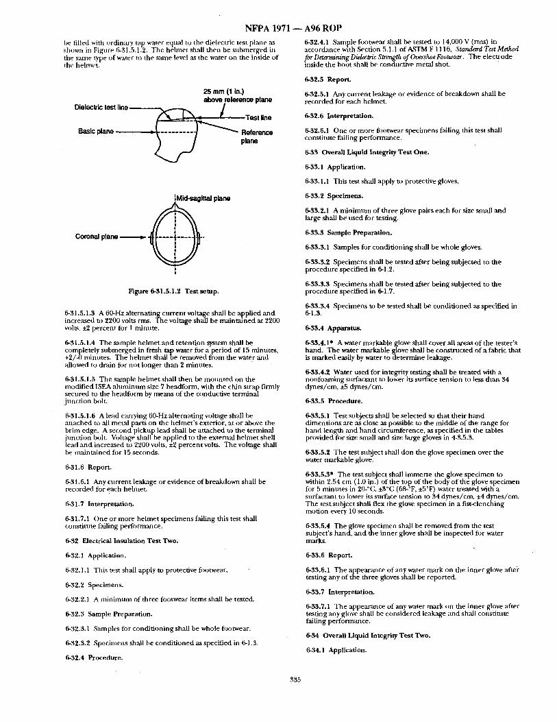
NFPA 1971
he filled with ordinary tap water equal to the dielectric test plane as shown in Figure 6-31.5.1.2. The helmet shall then be submerged in the same type of water to the same level as the water on the inside of the helmet.
25 mm (I in.) above reference plane
Dielectric test line ~ : Test line
Basic plane : ~ - - - - - - - - - ] [ ~ Reference plane
IMld-saglttal plane
Coronal plane ~ . ( I - - - i - o - l l I .
I
Figure 6-31.5.1.2 Test setup.
6-31.5.1.3 A 60-Hz alternating current voltage shall be applied ,and increased to 2200 volts rms. The voltage shall be maintained at 2200 volts, +2 percent for 1 minute.
6-31.5.1.4 The sample helmet and retention system shall be completely submerged in fresh tap water for a period of 15 minutes, +2/-0 minutes. The helmet shall be removed from the water and allowed to drain for not longer than 2 minutes.
6-31.5.1.5 The sample helmet shall then be mounted on the modified ISEA ,aluminum size 7 headform, with the chin strap firmly secured to the headform by means of the conductive terminal junction boh.
6-31.5.1.6 A lead carrying 60-Hz alternating voltage shall be attached to ,all metal parts on the helmet 's exterior, at or above the brim edge. A second pickup lead shall be attached t~ the terminal junction bolt. Vohage shall be applied to the external helmet shell lead ,and increased to 2200 volts, ±2 percent volts. The voltage shall be maintained fi)r 15 seconds.
6-31.6 Report.
6-31.6.1 Any current leakage or evidence of breakdown shall be recorded for each helmet.
6-31.7 Interpretation.
6-31.7.1 One or more helmet specimens falling this test shall constitute failing performance.
6-32 Electrical Insulation Test Two.
6-32.1 Application.
6-32.1.1 This test shall apply to protective fo~ytwear.
6-32.2 Specimens.
6-32.2.1 A minimum of three footwear items shall be tested.
6-32.3 Sample Preparation.
6-32.3.1 Samples for conditioning shall be whole fi~otwear.
6-32.3.2 Specimens shall be condit ioned as specified in 6-1.3.
6-32.4 Procedure.
A96 ROP
6-32.4.1 Sample footwear shall be tested to 14,000 V (rms) in accordance with ,Section 5.1.1 of A.STM F 1116, Standard Test Method for Determining Dielectric Strength of Overshoe Footwear. The electrode inside the boot shall be condncfive metal shot.
6-32.5 Report.
6-32.5.1 Any current leakage or evidence of breakdown shall be recorded for each helmet.
6-32.6 Interpretation.
6-32.6.1 One or more footwear specimens failing this test shall constitute failing performance.
6-33 Overall Liquid Integrity Test One.
6-33.1 Application.
6-33.1.1 This test shall apply to protective gloves.
6-33.2 Specimens.
6-33.2.1 A minimnm of three glove pairs each for size small and large shall be used for testing.
6-33.3 Sample Preparation.
6-33.3.1 Samples for conditioning shall be whole gloves.
6-33.3.2 Specimens shall be tested after being subjected to the procedure specified in 6-1.2.
6-33.3.3 Specimens shall be tested after being subjected to the procedure specified in 6-1.7.
6-33.3.4 Specimens to be tested shall be condit ioned as specified in 6-1.3.
6-33.4 Apparatus.
6-33,4.1" A water markable glove shall cover all areas of the tester's hand. The water markable glove shall be constructed of a fabric that is marked easily by water to determine leakage.
6-33.4.2 Water used for integrity testing shall be treated with a nonfoaming surfactant to lower its surface tension to less than 54 dynes/cm, ±5 dynes/cm.
6-33.5 Procedure.
6-33.5.1 Test subjects shall be selected so that their hand dimensions are ,as close as possible to the middle of the range for hand length mad hand circumference, as specified in the tables provided for size small and size large gloves in 4-3.5.5.
6-33.5.2 The test subject shall don the glove specimen over the water markable glove.
6-33.5.3* The test subject shall immerse the glove specimen to within 2.54 cm (1.0 in.) of the top of the body of the glove specimen for 5 minutes in 20-°C, ±3°C (68-°F, ±5°F) water treated with a surfactant to lower its surface tension to 34 dynes/cm. ±4 dynes/cm. The test subject shall flex the glove specimen in a fist-clenching motion every 10 seconds.
6-33.5.4 The glove specimen shall be removed from the test subject's hand, and the inner glove shall be inspected for water marks.
6-33.6 Report.
6-33.6.1 The appearance of any water mark on the inner glove aftei" testing any of the three gloves shall be reported.
6-33.7 Interpretation.
6-33.7.1 The appearance of any water mark on the inner glove ,after testing any glove shall be considered lea~age and shall constitute failing performance.
6-34 Overall Liquid Integrity Test Two.
6-34.1 Application.
335
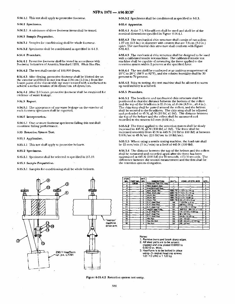
NFPA 1971 ~ A96 R O P
6-34.1.1 This test shall apply to protective footwear.
6-34.2 Specimens.
6-34.2.1 A m i n i m u m of three footwear i tems shall be tested.
6-34.3 Sample Preparation.
6-34.3.1 S,'unples fi~r condi t ioning shall be whole footwear.
6-34.3.2 Specimens shall be condi t ioned as specified in 6-1.3.
6-34.4 Procedure.
6-34.4.1 Protective footwear shall be tested in accordance with Footwear Industries o f America Standard 1209, Wh0/e SlweFlex.
6-34.4.2 The test shall consist of 100,000 flexes.
6-34.4.3 After flexing, protective fi)otwear shall be blotted dry on the exterior and filled to no t less than 2.54 cm (1.0 in.) f rom the lowest point o f the throat with mp water treated with a surfactant to achieve a surface tension of 34 dynes /cm, ±4 dynes /cm.
6-34,4.4 After 2.0 hours, protective fi~otwear shall be examined fiJr evidence of water leakage.
6-34.5 Report.
6-34,5.1 The appea~mce o f a n y w a t e r leakage 0n the exterior of each fi~otwear specimen shall be reported.
6-34.6 Interpretat ion.
6-34.6.1 One or more fiJotwear specimens failing this test shall constitt,te failing performance.
6-35 Retention System Test.
6-35.1 Application.
6-35.1.1 This test shall apply to protective helmets.
6-35.2 Specimens.
6-35.2.1 Specimens shall be selected as specified in 2-3.10.
6-35.3 Sample Preparation.
6-35.3.2 Specimens shall be condi t ioned ,as specified in 6-1.3.
6-35.4 Apparatus.
6-35.4.1 A size 7 1 /4 headform shall be used ,and shall be of the nominal d imens ions specified in Figure 6-16.4.1.
6-35.4.2 The mechanical chin smlc tu re shall consist of two rollers 1.27 cm (0.5 in.) in diameter with centers that ,are 7.6 cm (3.0 in.) apart. The mechanical chin structure shall confi)rm with Fignre 6-35.4.2.
6-35.4.3 The mechanical chin s tructure shall be designed to be used with a calibrated tensile test machine. The calibrated tensile test machine shall be capable o f measur ing the force applied to the retention system within 2 percent at the specified force.
6-35.4.4 The test shall be conduc ted at an ambien t tempera ture o f 20°C to 28°C (68°F to 82°F), and the relative humidi ty shall be 30 percent to 70 percent.
6-35.4.5 Prior to testing, the test machine shall be allowed to warm up until stability is achieved.
6-35.5 Procedure.
6-35.5.1 The headfi)rm and 'mechanica l chin s tructure shall be posit ioned so that the distance between the bot tom of the rollers and the top of the headform is 21.0 cm, +1.0 cm (8.3 in., ~0.4 in.). The chin strap shall be passed a round the rollers, and the he lmet shall be secured to the headform. The chin strap shall be adjusted and preloaded to 45 N, ±.5 N (10 lbf, +1 lbf). The distance between the top of the he lmet and the rollers shall be measured and recorded to the nearest 0.5 m m (0.02 in.).
6-35.5.2 The force applied to the retention system shall be slowly increased to 445 N, ±5 N (100 lbf, ±1 lbf). The force shall be increased smoothly f rom 45 N to 445 N (10 Ibfto 100 lbf) at between 9.0 N/ see to 45 N/ sec (2. 0 lbf/sec to 10 lbf/sec).
6-35.5.3 Where us ing a tensile testing machine, the load rate shall be 25 m m / m i n (1 in . /min ) to a limit of445 N (100 lbf).
6-35.5.4 The distance between the top of the he lmet and the rollers shall be measured and recorded ,again after the force has been mainta ined at 445 N (100 Ibf) for 60 seconds, +15/-0 seconds. The difference between the second m e a s u r e m e n t and the first shall be the retention system elongation.
6-35.3.1 San~ples tbr condi t ioning shall be whole helmets.
1 - - Z90.1 Headform ! r~. ~ I
r - "'~ / / - r e f . prt. L7791 ; •
. . . . .
ITEM $HT. NO. PART NO, NO, OE*~CRIPTION MAT'L . VENO. OR STR. SIZE QTY.
1 L8539 1 ~etention Test Fint. A ~ . I 2 2 ) Main Support A u y . 1 3 2 Knurind Knob At~f. -- 2 4 2 Ree l A lum. Bar 6061 -T6 1 1 / 2 x 3 x 14L~, | 5 2 Rect. A l u m Ear 6061 .T6 1 1/2 • 3 • t4 L~. 1 6 2 Alum. Bl¢ ~ 0 e l - ~ 2 • .2 • 7 I/'2 L~. 1 7 2 Alum, Bet" 8(~1-T6 2 x 2 x t 2 . 9 6 L V. I 8 2 Alum. Fl=t 6061 -T6 314 x 4 1/2 x 5 LO. 1 9 2 C.F. $ m l Rod 511. I 1/4 DiE. x 4 L~I. 1
10 2 C.F . Steel Rod Sth 3/8 Oia. • 22 Lf . 1 11 2 C.F . Steel Fiat Stl. 1 x 1 l l 4 x I 1/2L~L 1 12 2 HOllOw S t i l l Tube $fl. ,500 O.D..384 I.D. x I 1/2 2 13 2 C.F . $Uml FMt StL 1 1 4 x 3 1 1 4 x 3 3 / 4 L ! . 2
14 2 C.F. StSe[ Flint Sfi. 39 x 3/4 Thk, 2 15 2 C.F. StSel ROd StL 3 / 4 ~ x 10 1/2 L~. 2 16 2 Hex Nut Stl. 314 - 10 Un¢, 2 17 I Rex Hd. Bolt Stf. 3/8 - 24 Unf. x 2 1,~ L~I. 3 18 1 Hex Nu! Stl, , 3/8 " 24 Unf, 3
Notes: 1. Remove burrs and break sharp edges. 2. All steel parts are to be solvent
cleaned and zinc plated 0.0003 to 0 .0010 in. thick.
3, Headform is to be bolted in place using-3-socket head cap screws 1/2--13 UNC x 1 1/2 Lg.
Figure 6-35.4.2 Retention system test setup.
336
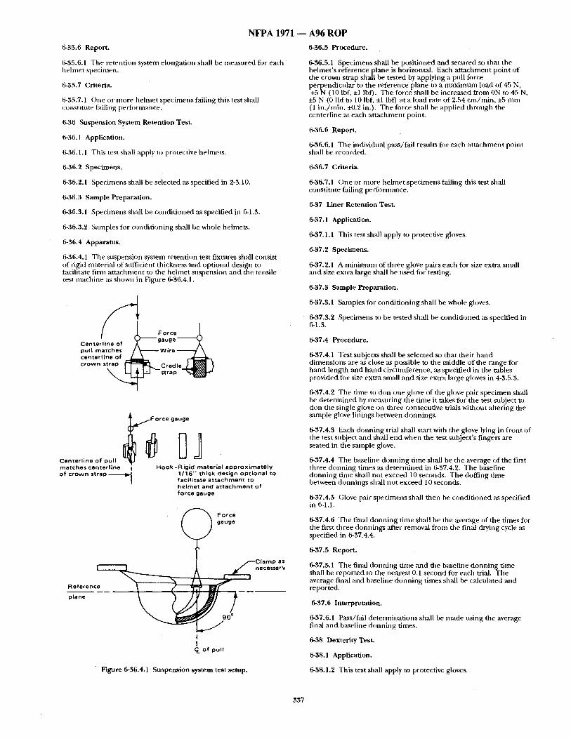
N F P A 1971
6-35.6 Report.
6-35.6.1 The retention system elongation shall be measured fi)r each helmet specimen.
6-35.7 Criteria.
6-35.7.1 One or more helmet specimens failing this test shall constitute failing performance.
6-36 Suspension System Retention Test.
6-36.1 Application.
6-36.1.1 Tiffs test shall apply to protective helmets.
6-'~6.2 Specimens.
6-t~6.2.1 Specimens shall be selected as specified in 2-3.10.
6-36.3 Sample Preparation.
6-36.3.1 Specimens shall be condit ioned as specified in 6-1.3.
6-36.3.2 Samples fi)r conditioning shzdl be whole helmets.
6-36.4 Apparatus.
6-36.4.1 The suspension system retention test fixtures sh~dl consist of rigid material of sufficient thickness and optional design to facilitate firm at tachment to the helmet suspension ,and the tensile test mactfine ,as shown in Figure 6-36.4.1.
F o r c e l Centerlioe of ) ~ - " gauge ~ pull matches ~ - ~ Wire centertine of crown strap ~- T - l ~ C r a d l e _ ~ _ ~ / ~ j .~
LI~ strap " ~ g / B "-
Centerline of pull matches centerlioe of crown strap
/ F o r c e gauge
Hook-Rigid material approximately 1/16" thick design optional to facilitate attachment to helmet and attachment of force gauge
(
~ - - - - R e f e r e n C ~ p l a n e
Force j ) gauge
- -Clamp as necessarv
C L of pull
Figure 6-36.4.1 Suspension system test .setup.
A 9 6 R O P
6-36.5 Procedure.
6-36.5.1 Specimens shall be positioned ,and secured so that the helmet 's reference plane is horizontal. Each at tachment point o f the crown strap shall be tested by applying a pull force
e endicular to the reference plane to a maximum load of 45 N, I~rPN (10 Ibf, +1 lbf). The force shall be increased from ON to 45 N. ~ , N (0 Ibfto 10 Ibf, +l Ibf) at a load ~tte of 2.54 cm/min , +5 mm (1 in . /min, i-0.2 in.). The force shall be applied through the centerline at each at tachment point.
6-36.6 Report.
6-36.6.1 The individual pass/fail results for each at tachment point sh~dl be recorded.
6-36.7 Criteria.
6-36.7.1 One or more helmet specimens failing this test shall constiulte failing performance.
6-37 Liner Retention Test.
6-37. ! Application.
6-37.1.1 This test shall apply to protective gloves.
6-37.2 Specimens.
6-37.2.1 A minimum of three glove pairs each for size extra small and size extra large shall be used for testing.
6-37.3 Sample Preparation.
6-37.3.1 Samples for conditioning shall be whole gloves.
6-37.5.2 Specimens to be tested shall be condit ioned as specified in 6-1.3,
t 6-37.4 Procedure.
6-37.4.1 Test subjects shall be selected so that their hand dimensions are as close as possible to the middle of the range for hand length and hand circunfference, as specified in the tables provided for size extra small and size extra large gloves in 4-3.5.3.
6-37.4.2 The time to don one glove of the glove pair specimen shall be determined by measuring the time it takes fi)r the test subject to don the single glove on fl~ree consecutive trials without altering the sample glove linings between donnings.
6-$7.4.3 Each donning trial shall start with the glove lying in front of the test subject and shall end when the test subject's fingers are seated in the smnple glove.
6-37.4,4 The baseline donning time shall be the average of the first three donning times as determined in 6-37.4.2. The baseline donning time shall not exceed 10 seconds. The doffing time between donnings shall not exceed 10 seconds.
6-37.4.5 Glove [)air specimens shall then be condit ioned as specified in 6-1.1.
6-37.4.6 The final donning time shall be the average of the times for the first three donnings after removal from the final drying cycle as specified in 6-37.4.4.
6-37.5 Report.
6-37.5.1 The final donning time and the baseline donning time shall be reported to the nearest 0.1 second for each trial. The average final and baseline ch)nning times shall be calculated and reported.
6-37.6 Interpretation,
6-37.6.1 Pass/fall determinations shall be made using the average final and baseline donning times.
6-38 Dexterity Test.
6-38.1 Application.
6-38.1.2 This test shall apply to protective gloves.
337
• 6-38.2 Specimens.
6-38.2.1 A minimum of three glove pairs each for each glove size shall be used for testing.
6-38.2;2 Each sample glove pair shall be tested ,aS a complete set o f gloves in new, as distributed, condition.
6-3&2.3 San~ple glove pairs shall not receive special softening treatments prior to tests.
6-38.2.4 Sample glove pairs shall be tested for each material and construction combination.
6-38.3 Sample Preparation.
6-38.3.1 &unples fi~r condit ioningshall be whole glove pairs.
6-38.3.2 Specimens shall be precondi t ioned as specified in 6-1.2.
6-38.3.3 Specimens shall be tested ,after being condit ioned for wet conditions as specified in 6-1.10.
6-38.4 Procedure.
6-38.4.1 i')exterity shall be evalnated using Manual 8018-1 ] 1, Bennett Hand-ToolDexteri~. Test.
6-38.4.2 Test subjects shall be selected so that their hand dimensions are as close ,as possible to the middle of the range for hand length and hand circumference, as specified in the tables provided fi:~r size small and size large gloves in 4-3.5.5.
6-38.4.3 Each test subject used to perform the test shall practice until tile baseline times of that test subject's last three repetitions varies no more than 6 percenL
6-38.4.4 Each test subject shall test a minimum of three pairs of sample gloves. A minimum of six dexterity tests using gloves shall be conducted, with at least three dexterity tests pe r formedns ing small size gloves and three dexterity tests using large size gloves.
6-38.4.5 Dexterity test times using gloves shall be compared with baseline dexterity test times for specific test subjects. The percentage of dexterity test times with gloves to baseline dexterity test times shall be calculated as follows:
Dexterity test dme (with ~lovcs) x 100 = Percent of bare - handed control Dexterity test time (baseline
6-38.5 Report.
6-38.5.1 The percent o f bare-handed control shMI be reported for each s:mlple glove pair and test subject tested.
6-38.6 Interpretation.
6-38.6. I One or more sample glove pairs failing this test shall constitute failing performance.
6-39 Grip Test.
6-39.1 Application.
6-39.1.1 This test method shail apply to protective gloves.
6-39.2 Specimens.
6-39.2.1 A minimtml of three glove pairs each for size extra small and size extra large shall be used for testing.
6-39.2.2 Each sample glove pair shall be tested as a complete set o f gloves in new. as distributed, condition.
6-39.2.3 Samffle glove pairs shall not receive special softening treatments prior to tests.
6-39.2.4 Sample glove pairs shall be tested for each material and monstrnction combination.
6-39.3 Sample Preparation.
6-:$9.3.1 Samples for conditioning shall be whole gloves.
N F P A 1 9 7 1 - - A96 ROP
6-39.3.2 Specimen glove pairs shall be precondi t ioned as specified in 6-1.2.
6-39.3.3 Specimen glove pairs shall be tested after being condit ioned for dry conditions ,as specified in 6-1.3.
6-39.3.4 Specimen glove pairs shall be tested after being condit ioned for wet Conditions as specified in 6-1.10.
6-39.4 Apparatus.
6-39.4.1 (;rip testing shall be evaluated with the use o f a 9,5-cm (0.375-in.) diameter, three-strand, prestretched polyester rope attached to a calibrated force measuring device:
6-39.5 Procedure.
639.5.1 Test subjects shall be selected so that their hand dimensions are as close as possible to the middle of the range for hand length and hand circumference as specified in the tables provided for size srruall ,and size large gloves in 4-3.5.3.
6-39.5.2 Each test snbject shall make three successive attempts to lift ,as much weight using the halyard as possible, using both hands and keeping both feet firllfly planted on the ground. The average weight hoisted over the three trials shall be the bare-handed weight lift capability.
6-39.5.3 Dry-conditioned sample gloves shall be tested on a dry rope and then on a wet rope.
6-39.5,4 Wet-conditioned sample gloves shall be tested on a dry rope :rod then on awet rope.
6-39.5.5 Each test subject shall test a minimum of three pairs of sample gloves. Test subjects shall at tempt one trial with each pair of gloves for a minimum of six grip tests for each set o f conditions, with at least three grip tests with size small gloves and three grip tests with size large gloves.
6-39.5.6 Weight-pulling capacity with gloves shall be compared with bare-handed, weight lift ca p ability. The. percentage, ofwei.. ~ht pullin g capacity with gloves to bare-handed weight lift capabdity shall be calculated as follows:
Weight pulling capacity(with gloves) x 100 = Percent of bare - handed control Bare ~ handed weight lift capability
6-39.6 Report.
6-39.6.1 The percent o f bare-handed control shall be reported for each sample glove pair, condition, and test subject testect.
6-39.7 Interpretation.
6-39.7,1 One or more sample glove pairs failing this test shall constitute failing performance.
6-40 Ladder Shank Bend Resistance Test.
6-40.1 Application.
6-40.1.1 This test shall apply to protective footwear.
6-40.2 Specimens.
6-40.2.1 A minimum of three footwear ladder shanks shall be tested.
6-40.3 Sample Preparation.
6-40.3.1 Samples for condltioning shall be whole footwear.
6-40.3.2 Ladder shanks shall be condi t ioned as specified in 6-1.3.
6-40.4 Apparatus.
6-40.4.1 The apparatus shall consist o f a tensile testing machine, such as an lnstron or equivalent, that challenges a specimen with a simulated ladder rung. A 3.25-cm diameter x 5.08-cm long (1.25-in. diameter x 2.0-in. long) noncompressible probe shall be mounted on the movable arm: T h e specimen support assembly shall consist of two 5.08 cm x 2.54 c m x 2.54 cm (2.Oin. x 1.0 in. x 1.0 in.) noncompressible blocks placed 5.08 cm (2.0 in.) apart as shown in Fignre 6-40.4.1.
338
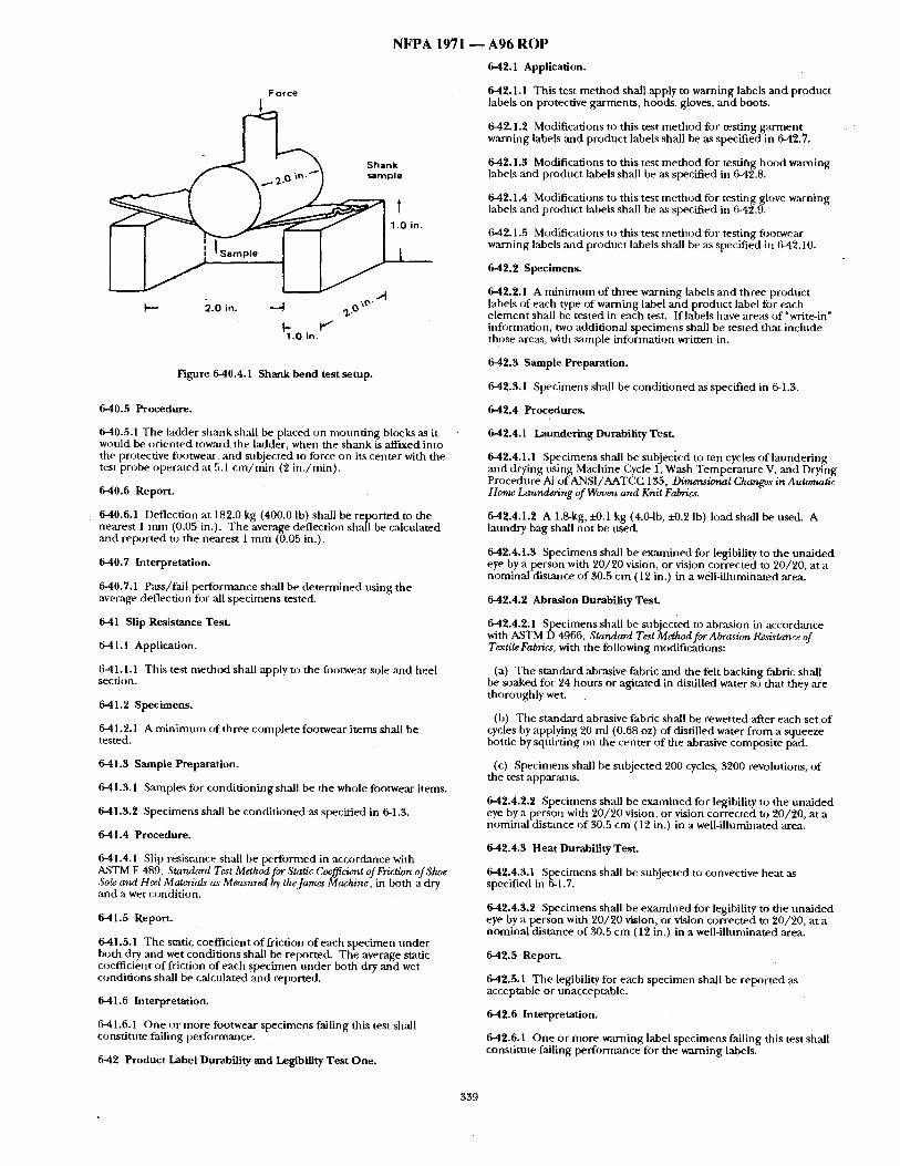
NFPA 1971
Force
1
Shank sample
% M
[-'- 2.0 in. ---,4 ,70 \°"
1.0 in.
Figure 6-40.4.1 S h a n k b e n d test setup.
6-40.5 Procedure.
6-40.5.1 The ladder shrink shall be placed on moun t ing blocks as it would be or iented toward the ladder, when the shank is aff'txed into the protective footwear, and subjected to force on its center with the test probe operated at 5.1 c m / m i n (2 in . /min ) .
6-40.6 Report.
6-40.6.1 Deflection at 182.0 kg (400.0 Ib) shall be repor ted to the nearest 1 m m (0.05 in.). T he average deflection shall be calculated and reported to the nearest 1 m m (0.05 in.).
6-40.7 Interpretation.
6-40.7.1 Pass/fail per formance shall be de t e rmined us ing the average deflection for ,all specimens tested.
6-41 Slip Resistance Test.
6-41.1 Application.
6-41.1.1 This test me thod shall apply to the footwear sole :md heel section.
641.2 Specimens.
6-41.2.1 A m i n i m u m of three complete footwear i tems shall be tested.
6-41.3 Sample Preparation.
6-41.3.1 Sm~aples for condi t ioning shall be the whole footwear items.
6-41.3.2 Specimens shall be condi t ioned as specified in 6-1.3.
6-41.4 Procedure.
641.4.1 Slip resistance shall be per formed in accordance with ASTM F 489. Standard Test Method for Static Coefficient of Friction of Shoe Sole am1 Heel Materials" as Measured I 0 theJamcs Machine, in both a dry and a wet condith)n.
6-41.5 Report.
6-41.5.1 The static coefficient o f friction of each specimen unde r both dry ,and wet condit ions shall be reported. The average static coefficient of friction of each spec imen unde r both dry and wet condit ions shall be calculated and reported.
6-41.6 Interpretation.
6-41.6.1 One or more footwear specimens failing this test shall constitute falling performance.
6-42 Product Label Durability mad Legibility Test One.
A96 ROP
6-42.1 Application.
6-42.1.1 This test me thod shall apply to warning labels and product labels on protective garments , hoods, gloves, and boots.
6-49.1.2 Modifications to this test m e t h o d for testing ga rmen t warning labels and product labels shall be as specified in 6-42.7.
6-42.1.3 Modifications to this test me thod for tesdlhg hood warning labels and product labels shall be as specified in 642.8.
6-42.1.4 Modifications to this test m e t h o d for testing glove warning labels and product labels shall be as specified in 6-42.9.
6-42.1.5 Modifications to this test me thod fi~r testing footwear warning labels and product labels shall be as specified in 6-42.10.
6-42.2 Specimens.
6-42.2.1 A m i n i m u m of three warning labels mid three product labels of each type of warning label and product label for each e lement shall be tested in each test. If labels have areas of "write-in" infi)rmadon, two additional specimens shall be tested tha t include thgse are:~s, with sample information written in.
6-42.3 Sample Preparation.
6-42.3.1 Specimens shall be condi t ioned as specified in 6-1.3.
6-42.4 Procedures.
6-42.4.1 Launder ing Durability Test.
6-42.4.1.1 Specimens shall be subje0:ed to ten cycles of launder ing and drying us ing Machine Cycle 1, Wash Tempera tu re V, and Drying Procedure Ai of ANSI/AATCC 135, Dimensional Changes in Automatic Home Laundering of Woven and Knit Fabrics.
6-42.4.1.2 A 1.8-kg, i-0.1 kg (4.0-1b, i4).2 lb) load shall be nsed. A lanndry bag shall no t be used.
6-42.4.1.3 Specimens shall be examined for legibility to the una ided eye by a person with 20/20 vision, or vision corrected to 20/20, at a nominal distance o f 30.5 cm (12 in.) in a well-illuminated area.
6-42.4.2 Abrasion Durability Test.
6-42.4.2.1 Specimens shall be subjected to abrasion in accordance with A,STM D 4966, Standard Test Method for Abrasion Resistance of TextileFabnc, L with the following modifications:
(a) The s tandard abrasive fabric and rite felt backing fabric shall be soaked for 24 hours or agitated in distilled water so that they ,are thoroughly wet.
(b) The s tandard abrasive fabric shall be rewetted after each set o f cycles by applying 20 ml (0.68 oz) of distilled water f rom a squeeze bottle by squi rdng on the center of the abrasive composite pad.
(c) Specimens shall be subjected 200 cycles, 3200 revolutions, of the test apparatus.
6-42.4.2,2 Specimens shall be examined for legibility to the una ided eye by a person with 20/20 vision, or vision corrected to 20/20, at a nominal distance of 30.5 cm ( 12 in.) in a well-illuminated area.
6-42.4.3 Heat Durability Te.sL
6-42.4.3.1 Specimens shall be subjected to convective heat ,as specified in 6-1.7.
6-42.4.3.2 Specimens shall be examined for legibility to the una ided eye by a person with 20/20 vision, or vision corrected to 20/20, at a nominal distance of $0.5 cm (12 in.) in a well-Uluminated area.
6-42.5 Report.
6-42.5.1 The legibility for each specimen shall be reported as acceptable or unacceptable.
6-42.6 Interpretation.
6-42.6.1 One or more w , ~ i n g label specimens failing this test shall constitnte falling per formance for the warning labels.
339
N F P A 1971 ~ A96 R O P
6-42.6.2 One or more product label specimens failing this test shall constitute failing performance for the product labels.
6-42.7 Specific Requirements for Testing Garment Labels.
6-42.7.1 For testing warning label and product label legibility after laundering, specimens shall include warning labels and product labels sewn onto a 1-m (1-yd) square ballast material no closer than 5.1 cm (2 in.) apart in parallel strips. The ballast material shall be as specified in ANSI/AATCC 135, Dimensional Changes in Automatic Horm; Lauml,ving of Woven and Knit Faln~cs.
6-42.7.2 For testing warning label and product label legibility "after abrasion, specimens shall be individual warning labels and individual product labels.
6-42,7.3 For testing warning label and product label legibility after convective heat exposure, specimens shall inch,de individual warning labels and individual product labels, each sewn onto a separate 38-cm, ±1.3 mm (15-in., ±0.5 in.) square of material that meets the outer shell requirements of this standard.
6-42.7.4 Sample conditioning shall be the same conditioning as specified for the respective tests.
6-42.7.5 Specimens shall be tested separately for legibility ,after laundering, abrasion, and heat durability tests as specified in 6- 42.4.1, 6-42.4.2, and 6-42.4.3 respectively.
6-42.8 Specific Requirements for Testing Hood Labels..,,
642.8.1 For testing warning label aJld product label legibility after laundering, specimens shall inchtde complete hoods with the warning labels and the product labels attached.
642.8.2 For testing warning label and product label legibility ,after abras on, specimens shall be individual warning labels :rod individual product labels.
642.8.3 For testing warning label and product label legibility after convective heat exposure, specimens shall include individual warning labels and individual product labels, each sewn onto a separate 38-cm, ±1.3 mm (15-in., ±0.5 in.) square of hood nmterial that meets the hood material requirements of this standard.
642.8.4 SaJnple conditioning shall be the stone conditioning as specified for the respective tests.
6-42.8.5 Specimens shall be tested separately fi)r legibility after Immdering, abrasion, :rod heat durability tests as specified in 6- 42.4.1, 6-42.4.2, and 6-42.4.3, respectively.
6-42.9 Specific Requirements for Testing Glove Labels.
6-42.9.1 For testing warning label and product label legibility after lanndering and convective heat exposure, specimens shall include complete gloves with warning labels and product labels attached.
642.9.2 For testing warning label and product label legibility after abrasion, specinlens shall be individual warning labels mid individiml product labels,
6-42.9.3 Sanlple conditioning shall be the sanle conditioning as specified fl)r the respective tests.
642.9.4 Specimens sh:dl be tested separately for legibility after laundering, abr~Lsion, and heat durability tests :is specified in 6- 42.4.1, 6-42.4.2, and 6-42.4.3, respectively.
642.10 Specific Requirements for Testing Footwear Labels.
6-42.10.1 For testing warning label and product label legibility after convective heat exposure, specimens shall include complete fl~otwear with warning labels and product labels attached.
642.10.2 For testing warning label and product label legibility after abrasion, specimens shall be individual warning labels ,and individtml product labels.
642.10.3 Sample conditioning shall be the same conditioning as specified for the respective tests.
6-42.10.4 Specimens shall be tested separately for legibility after abr:tsion and heat durability tests as specified in 6-42.4.2 and 6- 42.4.3, respectively.
6-43 Product Label Durability mad Legibility Test Two.
6-43.1 Application.
6-43.1.1 This test method shall apply to helmet warning labels and product labels.
6-43.2 Specimens.
6-43.2.1 Specimens shMl be selected as specified in 2-3.10.
6-43.3 Sample Preparation.
6-43.3.1 Samples for conditioning shall be whole helmets with the warning labels and product labels attached.
6-43,3.2 Specimens shall be conditioned as specified in 6-1.3, 6-1.6, 6-1.7, 6-1,8, and 6-1.9.
~-43.4 Procedure.
6-43.4.1 Label specimens shall be examined for legibility by a person with 20/20 vision, or vision corrected to 20/20, at a nominal distance of 30.5 cm (12 in.) in a well-illuminated area.
6-43.5 Report.
6-43.5.1 The legibilityfi)r each warning label specimen andprodnct label specimen shall be reported as acceptable or unacceptable.
6-43.6 Interpretation.
6-43.6.1 One or more warning label specimens failing this test shall constitnte failing performance for warning labels.
6-43.6.2 One or more product label specimens failing this test shall constitute failing performance for product labels.
6-44 Shell Retention Test.
6-44.1 Application.
6-44.1.1 This test shall apply to protective helmets.
6-44.2 Specimens.
6-44.2.1 Specimens sh:dl be selected as specified in 2-3,10.
6-44.3 Sample Preparation.
6-44.3.1 Samples fi3r conditioning shall be whole helments.
6-44.3.2 Specimens shall be conditioned as specified in 6-1.3.
6-44.4 Apparatus.
6-44.4.1 The shell retention test fLxtures shall consist of rigid material of sufficient thickness and optional design to facilitate firm attachment of the helmet shell ,and the chin strap tensile testing machine.
6-44.5 Procedure.
6-44.5.1 The specimen shall be tested by applying a pull force to the chin strap perpendicular to the reference plane to a maximum load of 36.5 kg (80 lb) within 30 seconds. The maximum load shall be maintained fi)r 1 minute, +5/-0 seconds.
6-44.6 Report.
6-44.6.1 The pass/fail results shall be recorded.
6-44.7 Interpretation.
6-44.7.1 Any one specimen failing the test shall constitute fall ing performance for the item being tested.
6-45 Luminous (Visible) Transmittance Test.
6-45.1 Application.
8-45.1.1 This te~t method shall apply to partial eye/face protective in terrace component lenses.
6-45.2 Specimens.
340
N F P A 1971 ~ A 9 6 R O P
645.2.1 Specimens shall be selected as specified in 2-3,1.1. (d) Photoreceptor angular aper ture and source aper ture = 0.1
645.3 Sample Preparation.
6-45.3.1 Samples for condi t ioning shall be complete partial eye/face protective interface cofnponents.
6-45.3.2 Specimens shall be condi t ioned as specified in 2-3.1.1.
6-45.4 Apparatus.
6-45.4.1 The sumdard source of radiant energy used in the measu remen t o f luminous transmittmace of filter lenses shall be a projection-type lantp No. "1"-8, or o ther high-powered, gas-filled, tungsten-fi lantent incandescent lantp, operated at the color tempera ture cor responding to Commission In t ema thmale de l'Eclairage (CIE), Source A.
645.5 Procedure.
6-45.5.1" Ltnninous t ransmit tance shall be de te rmined by one of the fi~llowing means:
(a) By mez~suring the spectral t ransmit tance and calculating the lumimms transmit tance through the use of published data on the spectral radi:mt energy of CIE, Source A, ~md the relative h lminous efficiency ogthe average eye; or
(b) By using a Gardner pivotal sphere haze meter and the s tandards of luminous t ransmit tance mainta ined by the National Bureau of Standards.
6-45.6 Report.
6-45.6,1 The percent o f light transmission shall be repor ted fi~r each specimen. The average light transmission of all specimens tested shall be calculated and reported.
6-45.7 Criteria.
6-45.7.1 Pass/fail perform:race sh~dl be based on the average light transnfission mensu red.
6-46 Retrorefiectivity and Fluorescence Test.
6-46.1 Application.
6-46.1.1 This test me t hod shall apply to tr im materials used on protective garments ,and helmets.
6-46.1.2 Trim materials shall be tested for each procedure specified in 6-46.4.
6-46.2 Specimens.
6-46.2.1 A m i n i m u m of three tr im test specimens shMl be tested.
6-46.2.2 Each trim test specimen shall consist of a 30.5-cm x 30.5-cm (12-in. x 12-in.) composite made up of multiple strips of the finished trim product. Where retroreflective ,and nonretroreflective surface ;tre~s are combined to form a trim. the complete f n i s h e d product consisting of the retroreflective m~d nonretroreflective portions shall be used to form the composite test specimen.
646.3 Sample Preparation.
6-46.3.1 Samples for condi t ioning shall include 30.5-cm (12-in.) long sections o f trim.
6-46.3.2 Specimens shall he condit ioned as specified in 6-1.3.
6-46.4 Procedures.
6-46.4.1 Memsairement of Coefficient of Retroreflection.
6-46.4.1.1 The coefficient of retroreflection (R ~) shall be measured in accordmace with A,STM E 809, Standard Pract~ceforMeaz'uring Photometric Ctuzmct~,~stics of Retr~rreflectors, using the following modifications:
(a) Test distance = 15.2 m (50 it);
(b) Observation angle = 0.2 degree;
(c) Entrance angle = 4.0 degree;
degree;
(e) Projector exit aper ture shall be a circle with a d iameter of 2.54 cm (1 in.);
(f) Retroreflector reference angle = 90 degrees; and
(g) Datum mark shall be placed ,as specified by the tr im manufaculrer .
6-46.4.1.2 The coefficient o f retroreflection ( R ) shall be calculated by the tbllowing equation:
R = R1/A r
where:
R 1 is the coefficient of Iuminous intensity measured as specified in 6-46.4.1.1; and
A represents only the retroreflective surface area of the tr im test spec imen ' s surface area. Ar shall be calculated by subtract ing the nonretroreflective surface area f rom the test spec imen ' s total surface area.
6-46.4.2 Evaluation of Fluorescence.
6-46.4.2.1 Tr im fluorescence shall be de te rmined by examining the material unde r a black light at a distance of 30.5 cm (12 in.) for a period of 30 seconds.
6-46.4.2.2 Specimens that exhibit f luorescence shall be designated as fluorescent, Specimens that do not exhibit f luorescence shall be designated as nonfluorescent .
6-46.4.3 Rainfall Test.
6-46.4.3.1 Specimens o f t r im shall be tested for retroreflectivity when wet as specified in Annex A, "Method of Measuring Wet Retroreflective Performance," of EN 471, High Visibilit~ Warning Clothing, at a rate o f 10.9 c m / h r (4,3 in . /hr ) .
6-46.4.3.2 The coefficient of retroreflectivity (R) sha l l be measured as specified in 6-46.4.1 while the rainfall test is in progress,
6-46.4;4 Soiling Test.
6-46.4.4.1 Specimens of tr im shall be tested for retroreflectivity ,after soiling as specified in "Test Method," Section 4.13, of I MO A16/Res. 658, Use and Fitting o~ Retro-Reflective Materials on Life Saving Appliances.
6-46.4.4.2 Soiled samples shall be c leaned in accordance with the manufac turer ' s specifications.
6-46.4.5 Convective Heat ExposaJre Test.
6-46.4.5.1 Specimens of trim shall be tested for retroreflectivity ,after convective heat exposure as specified in 6-1.7.
6-46.4.5.2 The coefficient of retroreflection "(R) shall be measured ,as specified in 6-46.4.1.
6-46.4.5.3 The f luorescence shall be evaluated ,as specified in 6-46.4.2.
6-46.5 Report.
6-46.5.1 The coefficient of retroreflection ( R ) shall be reported fi3r each spec imen. The aver,~e R of all specime~ns shall be calculated and reported separately for each of the test procedures specified in 6-46.4.1,646.4.3, 6-46.4.4, and 6-46.4.5.
6-46.5.2 The number of f luorescent and nonf lnorescent specimens shall be reported separately for each of the test procedures specified in 6-46.4.2, 6-46.4.3, 6-46.4.4, and 6-46.4.5.
6-46.6 Interpretation.
6-46.6.1 For trim retroreflectivity, pass/fail per formance shall be de te rmined using the average coefficient of retroreflection (R ~) of all specimens tested in 646.4.1, 6-46.4.3, 6-46.4.4, and 646.4.5.
6-46.6.2 For tr im fluorescence, any nonf luorescent specimens in may test procedure shall constitute failing performance.
341
NFPA 1971 647 Hood Opening Size Retention Test.
6-47.1 Application.
6-47.1.1 This test shall apply to the face openings or S(33A facepiece interface openings of protective hoods.
647.1.2 Protective hoods witta ei ther elastic face openings or manually adjustable face openings shall be tested by the procedure specified in "6-47.4.
647.1.3 Protective hoods designed for interface with aSCBA facepiece(s) shall be tested by the procedure specified in 647.5.
6-47.2 Specimens.
647.2.1 A m i n i m u m of three whole hoods shall be tested.
647.3 Sample Preparation.
6-47.3.1 Samples for condi t ioning shall be whole hoods.
647.3.2 Specimens shall be condi t ioned as specified in 6-1.2.
6-47.4 Procedure for Elastic or Manually Adjusted Face Openings .
647.4.1 The hood shall be laid on a flat snrface with the face opening facing up.
647.4.2 The hood thce open ing shall be measured at a m i n i m u m of eight separate locations a round the entire per imeter of the face opening. The locations of m e a s u r e m e n t shall be marked on the hood.
647.4.3 The hood shall be posi t ioned on ' the size 7 1 / 4 headform specified in Figure 6-16.4.1 so that the hood is a round the neck ,area of the headform with the neck and head area of the headform
rot ruding through the face open ing o f the hood. The hood shall en be d o n n e d and doffed for 50 cycles, pa s s ing the hood face
open ing up and over the headform to cover t h e h e a d , forehead, sides of face, chin, and neck each t ime and then passing the hood back down over the headform to the start ing area a round the neck. Hoods with manually adjustable face openings shall have the face open ing adjusted dur ing each cycle, once after d o n n i n g a n d again before doffing.
647.4.4 Following the 50 cycles, the hood shall be removed from the beadfi:~rm and the hood shall be allowed to relax for 1 minute .
647.4.5 The hood shall be laid on a flat snrface with the face open ing facing up.
6-47.4.6 The open ing d imensions shall then be measured at the san~e locations marked a round the entire per imeter o f the face open ing specified in 647.4.2.
647.4.7 The perceni: difference o f the hood face open ing dimensions before and after d o n n i n g shall be determined.
647.5 Procedure for SCBA Facepiece Interface Openings .
647.5.1 The SCBA facepiece, that the hood is designed to interface with, shall be properly mounted , according to the SCBA manufac turer ' s instructions, on the size 7 1 /4 h e a d f o n n specified in Figure 6-16.4.1.
6-47.5.2 The hood shall then be d o n n e d on the headform, placing it over the SCBA facepiece.
647.5.3 The contact surface o f the hood face open ing with the SC'BA facepiece shall be measu red at a m i n i m u m of eight separate locations a round the entire per imeter o f the face open ing contact are,x The locations o f m e a s u r e m e n t shall be marked on the hood.
647.5.4 With the SCBA facepiece in place, the hood shall then be posit ioned so that the hood is a round the neck area of the headform with the neck and head area o f the headform pro t ruding th rough the face open ing of the hood. T he hood shall then be d o n n e d and doffed for 50 cycles, passing the hood face open ing up and over the headform to cover the head and to contact the SCBA facepiece a round the entire per imeter of the face open ing contact area each time, and then passing the hood back down over the headform to the starting area a round the neck. Where such hoods are des igned to be m:mually adjustable a round the hood face open ing /SCBA facepiece interface ,area, the manual ad jus tment shall be made dur ing each cycle, once ,after d o n n i n g and again before doffing.
A96 ROP 6-47.5.5 Following the 50 cycles, the hood shall he removed f rom the headform, and the hood shall be allowed to relax for 1 minute.
6-47,5.6 The hood shall then be d o n n e d on the headtorm, placing it over the SCBA facepiece.
6-47,5.7 The contact surface of the hood face open ing with the SCBA facepiece shall be measured at the same locations marked a round the entire per imeter of the face open ing contact area specified in 6-47.5.3.
6-47.5.8 The percent difference o f the hood face open ing d imensions before and after d o n n i n g shall be determined.
6-47.6 Report.
6-47.6.1 The percent difference o f the hood face open ing d imensions shall be repor ted for each specimen. The average difference of the hood face open ing dimensions shall be calculated and reported.
6-47.7 Interpretation.
6-47.7.1 Pass/fail per formance shall be based on the average difference of the hood face open ing dimensions.
6-48 Stored Energy Test.
6-48.1 Application.
6-48.1.1 This test shall apply to protective garments .
6-48.2 Specimens.
g48.2.1 Testing shall be conduc ted on a m i n i m u m of three specimens, each measur ing 15.24 c m x 15.24 cm, +6.4 m m (6 in. x 6 in., ±0.25 in.) and shall consist of all layers representative o f the actual c lothing i tem to be tested.
6-48.3 Sample Preparation.
648.3.1 Specimens shall be condi t ioned as specified in 6-1.3.
648.3.2 Liner spec imens that are designated to be tested ~wet" shall be precondi t ioned ,as specified in 6-1.3 and then wet with water and condi t ioned as specified in 6-1.13.
648.3.3 Samples for condi t ioning shall be at least I m (1 yd) square of each fabric to be tested.
648.4 Apparatus.
6-48.4.1 The test apparau~s shall consist o f a specimen holder, spec imen holder support , cover plate, spacer, sensor assembly, radiant flttx source, and recorder. The apparatus shall mee t the specifications specified in 6-10.4 with modifications as specified in 6- 48.4.1.1 th rough 6-48.4.1.7:
6-48.4.1.1 The specimen holder shall consist o f a plate 20,32 c m x 20.32 cm, ±1.6 m m x 6.4 mm, ±0.8 m m (8 in. x 8 in., ~q3.063 in. x 0.25 in., ±0.031 in.) with a centered hole 10.16 c m x 10.16 cm, ±1.6 m m (4 in. x 4 in., x--0.063 in.).
6-48.4.1.2 The spec imen holder suppor t shall consist o f a s p a c e r constructed o f a r idged heat-resistant insulating material with outside d imensions o f 12.7 c m x 12.7 c m x 3.81 cm, ±1.6 ram (5 in. x 5 in. x 1.5 in., ~0.063 in.) and with a centered hole o f 10.16 c m x 10.16 cm, ±i .6 m m (4 in. x 4in. , ±0.063 in.).
648.4.1.3 The cover plate shall consist of a r idged ho t - res i s tan t insulating material 12.7 cm x 12.7 c m x 1.27 cm, ±1.6 m m (5 in. x 5 in. x 0.5 in., x~0.063 in.).
648.4,1.4 T h e s p a c e r shall be constructed o f a l u m i n u m with outside d imensions of 12.7 cm x 12.7 cm x 6.35 mm, ±1.6 m m (5 in. x 5 in. x 0.25 in., +0.063 in.) and with a centered hole of 10.16 c m x 10.16 cm, ±1.6 m m (4 in. x 4 in. £-0.063 in.).
6-48.4.1.5 The sensor assembly shall consist of a 6.35 c m x 6.35 c m x 1.27 cm, ±1.6 nun (2.5 in. x 2.5 in. x 0.5 in., :K).063 in.) heat-resistant block and shall be uniformly weighted so that the complete sensor assembly, including copper calorimeter, weighs 1417.5 g, ±11 g, (3.125 lb, i0.025 Ib). The sensor assembly shall be identical to the one specified in A~STM F 1060, Standard Test Method for Tt~craal Protective Performance of Materials for Protective Clotta'ng for Hot Surface Contact..
342
NFPA 1971
6-48.4.1.6 The radiant thermal flux source shall consist of n ine quartz T-3 infrared tubes affixed beneath and centered in a box constn~cted of a heat-resistant material and having a water-cooled top. The quartz tubes shall be m o u n t e d in a horizontal plmle with the tubes parallel a nd the centers located 3.'3 cm, +1.6 m m (1.25 in., ±0.063 in.) below the surface o f the top with 1.27 cm, m0.8 ham (0.5 in., ~).031 in.) between centerlines.
6-48.4.1.7 The recorder shall have a rill-scale deflection of at least 110°C (200°F), or 7 mV, and shall have sufficient sensitivity and scale divisions to be able to read sensor response to ±I°C (2°F), or i4).05 inV. A chart speed sh~dl be set at 5 m m / s e c (0.2 in. /sec) or slower.
6-48.5 Procedure.
6-48.5.1 The radiant flux source shall be set to 0.135 ca l / cm 2/sec, • 0.005 ca i /cm2/sec , using the copper calorimeter and the steps specified in 6-48.5.1.1 th rough 6-48.5.1.5.
6-48.5.1.1 Specimens shall be exposed to a thermal flux of 0.135 cal/cmZ/sec, ±0.005 ca l /cm2/sec , as mfa su red with the copper calorimeter. The copper calorimeter sh,'dl be the only heat sensor used in setting the exposure condition. The total hea t flux shall be calculated direcdy from the tempera ture response of the copper calorimeter m~d calorimeter constants. Other heat-sensing devices shall no t be used to reference or adjust the heat flux read by the copper calorimeter. This exposure of0.135 ca l / cm z/sec, ±0.005 ca l /cm2/sec shall be de t e rmined directly and only f rom the voltage OtLtput of the thermocouples , us ing the measured tempera ture rise of the copper calorimeter, the area and mass o f the calorimeter, and the hea t capacity of copper to calibrate the incoming heat flux.
6-48.5.1.2 The specimen holder suppor t shall be cen tered on the open ing in the radiant energy source, the calorimeter shall be exposed to the hea t source, the response of the sensor shall be recorded for at least 10 seconds, and the initial portion o f the curve with line,xr, straight-line response shall be identified.
6-48.5.1.3" The response t ime for this straight-line portion of the curve shall be ex tended for at least 10 seconds, and sensor readings shall be taken at 0 and 10 seconds. The 0 reading shall be subtracted from the 10-second reading to obtain the increase. The response sh:dl be 10'~C, -i-0.4 ° C (18.4°17, ±0.7°F).
6-48.5.1.4 After each exposure, the sensor shall be cooled to less than 38°C (100°F), or 1.0 mV, before the next hea t flux determinat ion.
6-48.5.1.5 The radiant heat flux source shall be preheated, and readings shall be taken until three readings fall within the specified lintits.
6-48.5.2 The test spec imen ,assembly shall consist of the specimen holder, the protective clothing composite with all layers a r ranged in proper order, the spacer, and the cover plate.
6-48.5.2.1 The outer shell fabric of the protective clothing composite shall be centered on the specimen holder with the outer surface facing down and in contact with the holder.
6-48.5.2.'2 The outer shell of the protective clothing composite specimen shall be placed fiat but shall no t be placed unde r tension or stretched. All four sides of the outer shell o f the protective clothing composi te specimen shall be secured to the holder with cont inuous strips of heavy-duty duck tape.
6-48.5.2.3 The o ther layers of the protective clothing composite specimen shall be laid over the outer shell fabric in the order and orientation used in the complete assembly.
6-48.5.2.4 The spacer shall be centered on the inner surface of the specimen, and the cover shall be placed on top to form a "san dwich."
6-48.5.3 The protective clothing composite specimen shall be centered on tl~e specimen holder st,pport, and the specimen shall be preheated with a heat flux of 0.135 ca l / cm ~/sec, i-0.005 ca l / cm~/ sec for 5 minutes.
6-48.5.4 Just prior to the end of the prehea t time, the recorder shall be started.
6-48.5.5 At the end of the prehea t time, the cover plate shall be t~lickly removed and replaced with the sensor assembly. Removal of
e cover plate and p lacement o f the sensor assembly shall be accomplished in less than 3 seconds.
A96 ROP
6-48.5.6* The sensor response shall be recorded until a clear indication of the performance is indicated by the recorder wace. If the sensor response does no t indicate a second-degree burn, the exposure sha l lbe cont inued ,and the sensor response shaU be recorded for 5 minutes.
6-48.5.7 The time to pain sensat ion and the t ime to second-degree burn shall be de te rmined using the tissue response curves. These curves shall be prepared using the me thod in Section 10.5 of ASTM F 1060, Standard Test Method for Thermal Protective Performance of Materials for Protective Clothing for Hot Surface Contact.
6-48.5.7.1 The zero point of the tissue response curves shall be posit ioned at the first deviation of the sensor response trace and shall be in line with the straight-line portion of the Wace prior to the deviation.
6-48.5.7.2 The t ime at which the sensor response curve an d the tissue response cnrve o f pain sensation cross shall be the time to pain.
6-48.5.7.3 The time at which the sensor response curve and the tissue response curve of second-degree burn cross shall be the t ime to b u l l
6-48.5.7.4 The time to second-degree b u m minus the time to pain shall be def ined as the alarm time.
6-48.6 Report.
6-48.6.1 Each layer o f the spec imen shall be identified a n d reported+ The identification o f each specimen layer shall include its trade name, composition, b lend ratio if applicable, basis weight, an d thickness.
6-48.fi.'+ The overall basis weight and overall thickness o f the composite spec imen shall be measured to the neares t 100 g / m ~ (0.1 oz /yd 2) and to the nearest 0.01 m m (0.001 in.), respectively.
6-48.6.3 The weight o f the water added to the specimen outer shell, when tested wet, shall be measured and r epor t ed to the nearest 0.01 g (0.04 oz).
8-48.6.4 The weight of the water remain ing in the specimen following the conclusion o f the test shall be measured and repor ted to rite nearest 0.01g (0.04 oz).
6-48.6.5 The time to pain, the t ime to second-degree burn, and the alarm time, which is def ined as the difference between the time to second-degree burn ,and the t ime to pain, shall be reported to the nearest 0.1 second for each specimen. The average t ime to pain, t ime to second degree burn, and alarm time shall be calculated and repor ted to the nearest 0.1 second for all specimens tested.
6-48.7 Interpretation.
6-48.7.1 Pass or fidl determinat ions shall be based on the average reported thne to second-degree burn and the alarm t ime of "all specimens tested.
6-48.7.2 If an individual result f rom any test set varies more than +8 percent f rom the average result, the results f rom the test set shall be discarded and ano the r set of specimens shall be tested.
6-48,8 Specific Requi rements for Test ing Garments .
6-48.8.1 Specimens shall consist of the outer shell, moisture barrier, ,and thermal barrier. Winter liners shall not be included in the test composite. Specimens shall no t include seams.
6-48.8.2 Samples for condi t ioning shall be at least 1 m (1 yd) square of each material.
6-48.8.3 Test ing shall be per formed as described in 6-48.4 through 6-48.7.
6-49 Liquid Penetration Test.
6-49.1 Application.
6-49.1.1 This test me thod shall apply to protective garments.
6-49.1.2 Modifications to this test me thod for testing protective coats shall be as specified in 6-49.8.
343
N F P A 1971 - - A 9 6 R O P
6-49.1.3 Modifications to this test m e t h o d fbr testing protective trousers shall be as specified in 6-49.9.
6-49.1.4 Modifications to this test m e t h o d for testing protective coat and trouser sets or protective coveralls shall be as specified in 6-49.i0.
6-49.2 Specimens.
6-49.2.1 A nf in imum of three spec imens shall be tested. Specimens shall consist o f individual coatS, trousers, coveralls, or sets of coats and trousers. Each e lement shall have in place all layers that are required fi~r the e l ement to be compliant.
6-49.2.2 Tile size of the e lements compris ing the specimens shall be chosen to conform with the d imens ions o f the mannequ i n for proper fit of the specimen on the mannequ i n in accordance with the mamtfacmrer ' s sizing system. The size of the e lements compris ing the specimen shall be the same size as the mannequ i n in terms of chest circumference, waist circunfference, and inseam height.
649.3 Sample Preparation.
6-49.3.1 Specimens to be tested shall be condi t ioned ,~s specified'in 6-1.2.
6-49-3.2 Samples to be condi t ioned shall be complete garments .
6-49.4 Apparatus.
6-49.4.1" The apparatus and supplies for testing shall be those specified in ASTM F 1359, Standard Practice for Evaluating the Liquid- Tight Integri~. of Cherm'cal P~otective Clothing, with the following modifications:
(a) The surface tension of the water used in testing shall be 32 dynes /cm, +2 dynes /cm.
(b) The m a n n e q u i n used in testing shall have straight a rms and legs, with the arms posit ioned at the m a n n e q u i n ' s side.
(c) Water shall be sprayed at a rate o f 4.0 L/ra in , i-0.1 L/nf in (34 oz /min , +3.4 oz /mi n ) .
6-49.5 Procedure.
6-49.5.1" Liquid penetrat ion testing of garments shall be conducted in accord:race with ASTM F 1359, Standard Practice for Evaluating the Liquid-Tifl~t Integri~. of Chemical Protective Clothing, with the following modifications:
(a) No provision fi~r partial garments shall be permitted.
(b) Blocking of the specimen shall be as specified in (L49.8, 6-19.9, an d 6-49.10, as appropriate, tbr the type of specimen being tested.
(c) The me thod used for moun t i ng of the mannequ i n in the spray c lmmber sh:dl not interfere with the water spray.
(d) Tile normal outer surface of tile material shall be exposed tile liquid as or iented in tile c lothing item.
(e) Fluorescent or visible dyes shall not be used in the water for spraying the suited mmmequ i n .
• (t) The suited maJmeqnin shall be exposed to the liquid spray fi~r a total of 20 minutes , 5 minutes in each of tile fl)ur mannequ in orientations.
(g) At the end of the liquid spray exposure period, excess liquid sh:dl be removed from the surface o f the specimen.
(h) The specimen shall be inspected within 10 minutes of the end of the liquid spray exposure period for evidence of liquid penetration.
6-49.6 Report.
6-49.6.1" A diagram shall be p repared for each test that identifies tile locations of any liquid leakage as detected on the liquid- absorptive ga rmen t ~md the interior o f the garment .
6-49.7 Interpretation.
6-49.7.1 Any evidence o f liquid on the liquid-absorptive garment , as de te rmined by visual, tactile, or absorbent toweling, shall constitute failure o f the specimen.
6-49.7.2* Any evidence of liquid on the interior o f the moisture barrier, as deternf ined by visual, tactile, or absorbent toweling, shall constitute failure of the specimen.
6-49.7.3 Any evidence of liquid on the innermos t liner, as de te rmined by visual, tactile, or absorbent toweling, shall constitute failnre o f the specimen, o ther than liquid within 2.54 cm (1 in.) of the head opening, the sleeve cliff opening, and the trouser waist, or within 10.2 cm (4 in.) o f the h e m at the coat bot tom or leg cuff opening.
6-49.8 Specific Requirements for Testing Coats.
6-49.8.1 The liquid-absorptive ga rmen t shall only cover the upper torso and arms of the m a n n e q u i n f rom the middle o f the mannequ in neck, down to the m a n n e q u i n waisdine, and down to the m a n n e q u i n wrist crease. ~
6-49.8.2 The coat slaall be d o n n e d on the m a n n e q u i n in accordance with the manufacnt re r ' s instructions for proper wearing.
6-49.8.'~ The coat collar shall be placed in the "up ~ position on the mannequ in . The head o f the mannequ in shall be se,'ded off with a plastic bag. The plastic bag shall ex tend over the collar by a distance of not greater than 2.54 cm (1 in) and shall be taped down using duct tape or similar waterproof tape. The collar neck seam shall no t be covered.
6-49.8.4 The test shall be conduc ted with the m a n n e q u i n hands removed. The coat sleeve h e m shall be taped smoothly to a can, or an object of sinfilar cylindrical, rigid shape, o f the same nominal diameter as the sleeve opening. The can or cylindrical object shall be fitted over the wristlet ,and unde r the coat sleeve hem. The tape shall be duct tape or similar waterproof tape
6-49.8.5 The coat shall be tested in conjunct ion with the protective trousers specified by the mantffacturer, even where the trousers are not being specifically evaluated by this test.
6-49.9 Specific Requirements for Testing Trousers~
6-49.9.1 The liquid-absorptive ga rmen t shall only cover the lower torso and legs of the mannequ in f rom the mannequ in waistline down to the mannequ in ankles.
6-49.9.2 The trousers shall be d o n n e d on the mannequ in in accordance with the mantffacturer 's instructions for proper wearing.
6-49.9.3 Trousers shall be tested in conjunct ion with the protective coat specified by the mantffacmrer, even where the coat is not being specifically evaluated by this test.
6-49.9.4 Absorbent toweling, or similar material, shall be placed tmdernea th the mannequ in in order to prevent water splashing up inside the trouser leg.
6-49.10 Specific Requirements for Test ing Coveralls and for Test ing Sets of Coats and Trousers.
6-49.10.1 The liquid-absorptive ga rmen t shall only cover the torso, arms, and legs of tile mannequ in f rom the middle of the mannequ in neck, down to the m m m e q u i n wrist crease, and down to the mannequ in ,ankles.
6-49.10.2 The coverall or set of coat and trousers shall be d o n n e d on the manneqn in in accor "dance with the manufac tnrer ' s instructions for proper wearing.
6-49.10.3 The coat collar shall be placed in the "up" position on the mannequ in . The head o f the m a n n e q u i n shall be sealed off with a plastic bag. The plastic bag shall ex tend over the collar by a distance of not greater than 2.54 cm (1 in.) and shall be taped down using duct rope or similar waterproof tape. The collar neck seam shall not be covered.
6-49.10.4 The test shall be conducted with the mannequ in hands removed. The coat sleeve hem shall be taped smoothly to a can, or an object of similar cylindrical, rigid shape, o f the same nominal diameter as the sleeve opening. The can or cylindrical object shall be fitted over the wristlet and trader the coat sleeve hem. The tape shall be duc t tape or similar waterproof tape.
344
N F P A 1971 ~ A 9 6 R O P
6-49.10.5 Absorbent roweling or similar material shall be placed unde rnea th the ma nnequ i n in order to prevent water splashing up inside the trouser leg.
6-50 Attachment Test for Eyelets and Stud Post.
6-50.1 Application.
6-50.1.1 This test m e t hod shall apply to protective fi)otwear eyelets and s tud posts.
6-50.2 Specimens.
6-50.2.1 Specimens shall total two eyelets and two stnd posts on three separate footwear items.
6-50.2.2 Specimens shall be removed f rom the footwear and shall be 2.54 c m x 5.08 cm (1.0 in. x 2.0 in.).
6-50.3 Sample Preparation.
6-50.3.1 Samples for condit ioning shall be whole footwear.
6-50,3.2 'Fhe eyelets or stud post specimens shall be condi t ioned as specified in 6-1.3.
6-50.4 Apparatus.
6-50.4.1 A tensile testing machine shall be used with a traverse rate of 5.1 c m / m i n (2 in . /min ) , Clamps measur ing 2,5 cm x 3.8 cm ( I in. x 1.5 in.) shall have gr ipping surfaces that are parallel, fiat, and capable of preventing slippage of the specimen dur ing the tes t
6-50.5 Procedure.
6-50.5.1 The stud post or eyelet puller shall be inserted or at tached to the upper position of the tensile machine. The traverse rate shall be mt at 5 c m / m i n (2.0 in . /min) . The test eyelet or stud post shall be at tached using the appropriate puller fixture. The eyelet stay shall be clm~aped, but c lamping the metal portion o f the eyelets or s tud hook in the lower clamps shall not be pernfitted, The distance between the clmnps and s tud hooks or eyelets shall be 1.6 m m to 3.2
• m m (0.063 in. m 0.125 in.). The test shall then be st'u-ted.
6-50.6 Report.
6-50.6.1 The force will reach a peak, decline slightly, and then increase to complete failure; however, the value at which the force first declines shall be recorded and reported as the initi:d falhtre point, as dais is the separation point o f the material a round the eyelet or s tud post. The average force shall be calculated and reported.
6-50.7 Interpretation.
6-50.7.1 The average force sh~dl be used to de termine pass/fail.
6-51 Tensile Strength Test.
6-51.1 Application.
6-51.1.1 This test shall apply to woven materials used in protective garments.
6-51.2 Specimens.
6-51.2.1 Five specimens in each of the warp andf i l l ing directions shall be tested from each sample unit.
6-51.3 Sample Preparation.
6-51.3.1 Specimens shall be condi t ioned as specified in 6-1.2.1.
6-51.32 Samples for condi t ioning shall be 1 m (1 yd) square of n~terial.
6-51.4 Procedure.
6-51.4.1 Specimens shall be tested for tensile strength in accordance with A,STM D 5034, StarMard Method for Breaking Force and Elongation of Textile Fabrics (Grab Test).
6-51.5 Report.
6-51.5.1 The brealdng force of each spec imen shall be reported, and an average tensile s t rength shall be calculated for the warp and filling directions.
6-51.6 Interpreation.
6-51,6.1 Pass/fail per formance shall be based on the average breaking strength in the warp and fill directions. Failure in any one direction consistutes failure for the material.
Chapter 7 Referenced Publications
7-1 The fo l lowingdoeuments or port ions thereof are referenced within this s tandard and shall be considered part of the requirements of this document . The edition indicated for each reference is the cur rent edition as of the date of the NFPA issuance of this document .
7-1.1 NFPA Publications. National Fire Protection Association, 1 Batterymarch Park, P.O. Box 9101, Quincy, MA 02269-9101.
NFPA 1500, Standard on Fire Department Occupational Safety and Health Program, 1992 edition.
NFPA 1972, Standard on Helnwts for Structural Fire Fighting, 1992 edition.
NFPA 1973, Standard on Gloves for Struotural Fire Fighting , 1993 edidon.
NFPA 1974, Standard on Protective Footwear for Structural Fire Fighting, 1992 edition.
NFPA 1975, Standard on Station~Work Uniforms for Fire Fighters, 1994 edition.
7-1.2 Other Publications.
7-1.2.1 AATCC Publication. American Association of Textile Chemists and Colorists, P.O. Box 12215, Research Triangle Park, NC 27709.
AATCC 70, Test Method for Water Repellency: TumbleJar Dymzmie Absorption Test, 1988.
7-1.2.9 ANSI Publications. American National Standards Institute, 1450 Broadway, NewYork, NY 10018.
ANSI Z41, Standard for Personal P~vtection---Protective Footwear, 1991.
ANSI Z87.1, Occupational and Educational Eye arm Face Protection, 1989.
ANSI/AATCC 135, Dimer~ional Changes in Automatic Home Laurulering of Wove'n and Knit Fabrics, 1989.
7-1.2.3 ASTM Publications. American Society for Test ing and Materials, 1916 Race Street, Philadelphia, PA 19103.
ASTM B 117, Standard Method of Salt Spray (Fog) Testing, 1985.
/LSTM B 159, Specification for Copper Sheet, Strip Plate, and Rolled Bar , 1986.
A,STM D 1003, Standard Test Method for Haze and Luminous Transmittance of Transparent Plastics, 1988.
A~STM D 1630, Standard Test Method for Rubber Property--Abrasion Resistance (Footwear Abrader), 1994.
ASTM D 1683, Star~ard Test Method for Failure in Sewn .Seams of Woven Fabrics, 1990.
/LSTM D 3787, Standard Test Method for Hydraulic Bursting Strength of Knitted Goods and Nonwoven Fabric.~--BaU Burst Testing Method, 1989.
ASTM D 3940 Standard Test Method for Bursting Strength (Load) and Elongation of Sewn Seams of Knit or Woven Stretch Textile Fabries , 1983.
ASTM D 4108 Standard Test Method for Thermal Protective Performance of Materials for Clothing by Open-Flame Method, 1978.
ASTM D 4966 Stan&trd Test Method for Abrasion Resistance of Textile Fabr/cs, 1989.
345
NFPA 1971 A,STM E 794, Standard Test Method for Melting and Crystallization
Temperatures by Thermal Analysis, 1989.
ASTM E 809, Sta~wIard Practice for" Measuring Photornetric Characteristics of Retrar~flectars, 1994.
A, S TM E 810, Standard Test Method far Coefficient of Retroreflection of Retroreflective Stweting, 1981.
ASTM E 1247, Standard Test Method for Identif~ing Fluorescence in Object-Color Spec, imens ~ Spectrophotometo. , 1992.
ASTM E,S 92, Emergent. Starutard Test Method for Resistanc~ of Protective Clothing Materials to Penetration by Blood-Borne Pathogens Using Viral Perwtration as a Test System, 1992.
ASTM F 489, Standard Test Method for Static Coefficient of Friction of Shoe Sole and Heal Materials as Measured by theJarnes Machine, 1977.
ASTM F 903, Standard Test Method for ~ t a n c e of Protective Clothing Mat~,wials to Perwtration by Liquids, 1990.
P~STM F 1060, Standard Test Method for Thermal Protective Performance of Matt~rials far Protective Clothing for Hot Surfae~ Contact, 1987.
ASTM F 1116, Sta~utard Test Method for Determining Dielectric Strength of Overshoe Footwear, 1988.
ASTM F 1342, Standard Test Method for Protective Clothing Material Resistance to Puncture, 1991.
ASTM F 1359, StarMard Praetice for Evaluating the Liquid-Tight IntegTi~ of (Themical Protective Clothing, 1991.
7-1.2.4 CSA Publication. (~anadian Standards Association, 178 Rexdale Boulevard, Toronto Mgw 1R3, (kanada.
CSA Standard Z 195-M, Standard for Protective Footwear, Occupational Health and SafeO, 1984.
7-1.2.5 Commission Internationale de I'Eclairage.
7-1.2.6 EN Publication.
EN 471, High Visibili~ Wa~ning Clothing,
7-1.2.7 FIA Publications. Footwear Industries o f America, 1420 K Sweet, NW, Suite 600, Washington, DC 20005.
FIA Standard 301, NBSAbrasion.
FIA Stan&trd 1209, Whole ShoeFlex.
7-1.2.8 GSA Publications. General Services Administration, Specifications Activity, Printed Materials Supply Division, Building 197, Naval Weapons Plant, Washington, DC 20407.
Federal Specification FED-V-F-IO6F, Fasteners, Int~¢locJcing, Slido, June 23, 1987.
Federal Test Method Standard 191A, Textile Test Methods, July 20, 1978.
7-1.2.9 IMO Publication.
IMO AI 6/Res. 658, Use and Fitting of Retro-Reflective Materials on Life Saving Appliances, .
7-1.2.10 NBS Publications. National Bureau of Standards.
7-1.2.11 Psychological Corporation Publication. Psychological (~)rporation, 555 Academic Court, San Antonio, TX 78204.
Manual 8018-111, Bennett Hand-ToolDexterity Test, 198 I.
7-1.2.12 SAE Publication. Society of Automotive Engineers, 400 Commonwealth Drive. Warrendale, PA 15096,
SAEJ211, Instrumentation for Impact Test, 1988.
A96 ROP 7-1.2.13 U. S. Naval Publications. Naval Publications and Forms Center, 5801 Tabor Avenue, Philadelphia, PA 19120.
M1L-F-21840G, Fastener Tapes, Hook and Pile, Synthetic, December 16, 1987.
MS 27980E, Fastener, Snap, November 30, 1984.
7-1.2.14 Stoll, A. M. and M. A, Chianta, "Method and Rating System for Evaluation of Thermal Protection," Aerospace Medicine, Vol. 40, 1968, pp. 1232-38.
Appendix A Explanatory Material
This Appendix is not part of the requirements of this NFPA document but is included for informational purposes only.
A-I-1 Organizations responsible for specialized fimctions including , but not limited to, wildland fire fighting, proximity and other , specialized fire fighting, emergency medical service, special operations, and hazardous materials response should nse appropriate protective clothing and protective equipment specifically designed for those activities.
A-I-2 This standard is not designed to be utilized as a purchase s p ecification, . It is prepared., as far as .PraCticable. ,.with regard to required performance, avoiding restnctaon of destgn wherever possible. Purchasers should specify departmental requirements for such items as color, markings, closures, pockets, and trim patterns. Tests specified-in this standard should not be deemed as defining or establishing performance levels for protection from all structural fire fighting environments.
A-1-2.2 The testing requirements in Chapter 6 of this standard are not in tended to establish the limitations of the working environment for fire fighting but are intended to establish material performance. Users should be advised that when a continual increase of heat is felt through the protective ensemble, the protective ensemble might be nearing its m:udmum capability and injury could be imminent.
Users should be advised that if unusual conditions prevail, or if there are signs of abuse or mutilation of the protective ensemble or any e lement or componen t thereof, or if modifications or replacements are made or accessories are added without authorization of the protective ensemble e lement manufacturer, the margin of protection might be reduced.
Users should be advised that the protective properties in new structural fire fighting protective ensemble elements, as required by this standard, can diminish as the product is worn and ages.
A-I-3 Approved. The National Fire Protection Association does not approve, inspect, or certify any installations, procedures, equipment, or materials; nor does it approve or evaluate testing laboratories. In determining the acceptability of installations, procedures, equipment, or materials, the attthority having jurisdiction may base acceptance on compliance with NFPA or other appropriate standards. In the absence of such standards, said authority may require evidence of proper installation, procedt,re, or use. The authority having jurisdiction may also refer to the listings or labeling practices of an organization concerned with product evaluations that is in a position to determine compliance with appropriate standards for the current production o f listed items.
A-1-3 Authority Having Jurisdiction. The phrase "authority having jurisdiction" is used in NFPA documents in a broad manner, since jurisdictions and approval agencies vary, as do their responsibilities. Wherepubl ic safety is primary, the authority having jurisdiction may be a federal, state, local, or other regional depar tment or individual such as a fire chief; fire marshal; chief o f af i re prevention bureau, labor deparmaent, or health department; building official; electrical inspector; or others having statutory authority. For insurance purposes, an insurance inspection department , rating bureau, or other insurance comp,-my representative may be the authority having jurisdiction. In many circumstances, the property owner or his or her designated agent assumes the role of the authority having jurisdiction; at government installations, the commanding officer or deparmaental official may be the authority having jurisdiction.
346
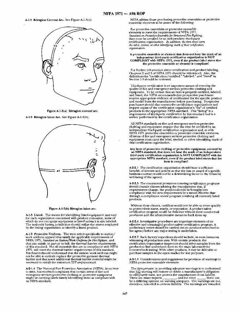
N F P A 1971 ~ A96 R O P
A-l-3 Bitragi'on Coronal Arc. See Figure A-1-3(a).
Figure A-l-3(a) Bitragion coronal arc.
A-l-3 Bitragion Inion Arc. See Figure A-1-3(b).
Figure A-1-3(b) Bitragion inion arc.
A-l-3 Listed. The means for identifying listed equipment may vary for each organization concerned with product evaluation, some of which do not recognize equipment as listed unless it is also labeled. The authority having jurisdiction should utilize the system employed by the listing organization to identify a listed product.
A-I-3 Protective Uniform. The term refers specifically to station/ work uniform apparel that satisfy the applicable requirements of NFPA 1975, Standard on Station~Work Uniforms for Fire Fighters, and that also satisfy, in part or in full, the thermal barrier requirements of this s~ndard. Not ,all materials that are in compliance with NFPA 1975, will meet the thermal barrier requirements of this standard. Purchasers should understand that the station/work uniform might not be able to entirely replace the protective garment thermal barrier and that some additional thermal barrier material might be necessary to safisfy the minimum TPP requirements.
A-2-1.4 The National Fire Protection Association (NFPA), from time to time, has received complaints that certain items of fire and emergency services protective clothing or protective equipment might be carrying labels falsely identifying them as compliant with an NFPA standard.
NFPA advises those purchasing protective ensembles or protective ensemble elements to be aware of the following:
For protective ensembles or protective ensemble elements to meet the requirements of NFPA 1971, Standard on Protective Ensemble for Structural Fire Fighting, they must be certified by an independent third-party certification organization. In addition, the item must carry. the label symbol, or other identifying mark of that c~tification ~rrganization.
A protective ensemble or element that does not bear the mark of an independent third-party certification organization is NOT
COMPLIANT with NFPA 1971, even if the product label states that the protective ensemble or element is compliant!
For further information about certification and product labeling, C~apters 2 and 3 of NFPA 1971 should be referenced. Also, the definitions for "certification/certified," "labeled," and "listed" in Section 1-3 should be reviewed.
Third-party certification is an important means of ensuring the quality of fire and emergency services protective clothing and equipment. To be certain that an item is properly certified, labeled, and listed, the NFPA recommends that prospective purchasers require appropriate evidence of certification for the specific product and model from the manufactnrer before purchasing. Prospective purchasers should ,also contact the certification organizations and request copies of the certification organization's "list" of certified products to the appropriate NFPA standard. This "listing" is a requirement of third-party certification by this standard and is a service performed by the certification organization.
All NFPA standards on fire and emergency services protective clothing and equipment require that the i tem be certified by an independent third-party certification organization and, as with NFPA 1971 protective ensembles or protective ensemble elements, all items of fire and emergency services protective clothing and equipment must carry the label, symbol or other identifying mark of that certification organization.
Any item of protective clothing or protective equipment, covered by an NFPA standard, that does not bear the mark of an independent
third-party certification organization is NOT COMPLIANT with the appropriate NFPA standard, even if the product label states that the
item is compliant!
A-2-2.1 The certification organization should have a sufficient breadth of interest and activity so that the loss or award of a specific business contract would not be a determining factor in the financial well-being of the agency.
A-2-2.3 The contractual provisions covering certification programs should contain clauses advising the manufacturer that, ff requirements change, the product should be brought into compliance with the new requirements by a stated effective date through a compliance review program involving all currently listed products.
Without these clauses, certifiers would not be able to move quickly to protect their name, marks, or reputation. A product safety certification program would be deficient without these contractual provisions and the administrative means to back them up.
A-2-2.4 Investigative procedures are important elements of an effective and meaningful product safety certification program. A preliminary review should be carried out on products submitted to the agency before any major testing is undertaken.
A-2-2.7 Such factory inspections should include, in most instances, witnessing of production tests. With certain products, the certification organization inspectors should select samples from the production line and submit them to the main laboratory for countercheck testing. With other products, it may be desirable to purchase samples in the open market for test purposes.
A-3-1.1 Considerations and suggestions for provision of warnings in NFPA protective ensemble elements:
The first premise in providing adequate warnings is m understand that NO warning will remove or dilute a manufacturer 's obligation to adequately warn, nor protect the mantffacmrer from liability. There are many experts _ _ , and for every _ _ there can be a differing opinion on warning adequacy. The warnings are not, therefore, in tended to remove liability. The warnings are in tended
347
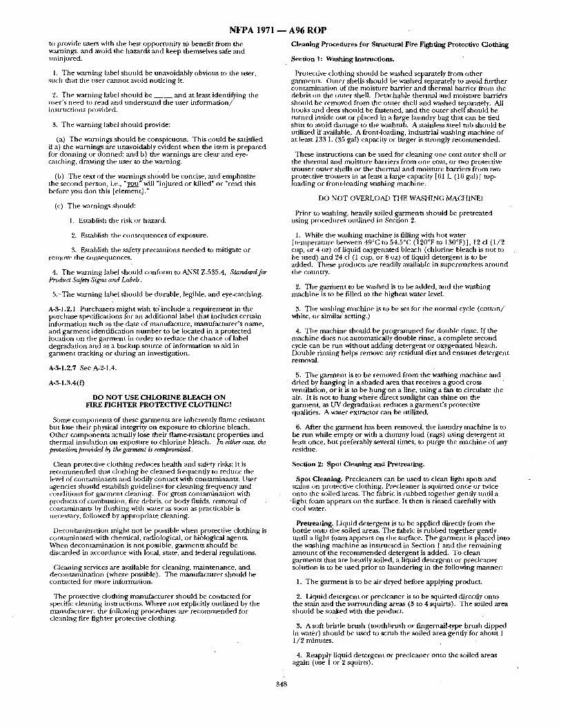
NFPA 1971 to provide users with the best opportuni ty to benefit f rom the warnings, and aw~id the hazards and keep themselves safe and uninjured.
1. The warning label should be unavoidably obvious to the user, such that the user cannot aw:fid not icing it.
2. The warning label should be _ _ and at least identifying die user 's need to read and unde r sumd the user in fo rmat ion / instructions provided.
3. The warning label should provide:
(a) The warnings should be conspicuous. This could be satisfied if a) the warnings are unavoidably evident when the i tem is prepared fi~r donn ing or donned; ,and b) the warnings are clear and eye- catching, drawing the user to the warning.
(b) The text o f the warnin!~rs shou ld be concise, ,and emphasize the second person, i.e., "oZ.Q~ will " injured or killed" or "read this before you don this [element! ."
(c) The warnings should:
1. Establish the risk or hazard.
2. Establish the consequences o f exposure.
3. Establish the safety precautions needed to mitigate or remove the consequences.
4. The warning label should confi)rnl to ANSI Z.535.4, Standard for Product Safety Signs and Labels.
5.~The warning label should be durable, legible, and eye-catching.
A-3-1.2.1 Purchasers migh t wish to ' include a r equ i rement in the p u r c h ~ e specifications for an additional label that includes certain infi)rnaation such as the date o f mantffacture, manufac turer ' s name, and ga rmen t identification n u m b e r to be located in a protected location on the ga rmen t in order to reduce the chance of label degradation and as a backup source of information to aid in garment tracking or dur ing an investigation.
A-3-1.2.7 See A-2-1.4.
A-3-1.3.4(f)
DO NOT USE CHLORINE BLEACH ON FIRE FIGHTER PROTECTIVE CLOTHING!
Some componen t s of these garments are inherent ly flame resistant but lose their physical integrity on exposure to chlorine bleach. Other componen ts actually lose their flame-resistant propert ies ,and thermal insulation on exposure to chlorine bleach. In either case, the protgction prod,ideal ~ the garment is compromised.
Clean protective clothing reduces heal th and safety risks; it is r e c o m m e n d e d that clothing be c leaned frequently to reduce the level of contaminants and bodily contact with contaminmlts . User agencies should establish guidel ines for cleaning frequency and cotlditions fi~r ga rment cle:ming. For gross contaminat ion with products of combust ion, fire dehris, or body fluids, removal of ccmtaminants by f lushing with water as soon as practicable is necessary, followed by appropriate cleaning.
Decontaminat ion might not be possible when protective clothing is contamina ted with chemical, radiological, or biological agents. Wben decontaminat ion is not possible, garments should be discarded in accorckmce with local, State, and federal regulations.
Cleaning services are available for cleaning, maintenance , and decontaminat ion (where possible). The manufac tu re r should be contacted for more infornmtion.
The protective clothing manufac ture r should be contacted for specific cleaning instructions. Where no t explicitly out l ined by the manufacturer , the following procedures are r e c o m m e n d e d for cleaning fire fighter protective clothing.
A96 ROP Cleaning Procedures for Structural Fire Fighting Protective Clothing
Section 1: Washing Instructions.
Protective clothing should be washed separately f rom other garments . Outer shells should be washed separately to avoid fiwther contaminat ion of the moisture barrier and thermal barrier f rom the debris on the outer shell. Detachable thermal and moisture barridrs should be removed f rom the outer shell and washed separately. All hooks ,and dees should be fastened, and the outer shell should be tu rned inside out or placed in a large laundry bag that can be tied shu t to avoid damage to the washtub. A stainless steel tub should be utilized if available. A front-loading, industrial washing machine of at least 133 L (35 gal) capacity or larger is strongly recommended .
These instructions can be used for cleaning one coat outer shell or the thermal and moisture barriers f rom one coat, or two protective trouser outer shells or the thermal and moisture barriers f rom two
rOtective trousers in at least a large capacity [61 L (1 fi gal)] top- ading or front-loading washing machine.
DO NOT OVERLOAD THE WASHING MACHINEI
Prior to washing, heavily soiled garments should be pretreated using procedures out l ined in Section 2.
1. While the washing machine is filling with hot water [ temperature between 49°C to 54.5°C (120°F to 130°F)], 12 cl (1 /2 cup, or 4 oz) o f liquid oxygenated bleach (chlorine bleach is no t to be used) mid 94 cl (1 cup, or 8 oz) of liquid de tergent is to be added. These products ,are readily available in supermarkets a round the country.
2. The ga rmen t to be washed is to be added, and the washing machine is to be filled to the highest water level.
3. The washing machine is to be set for the normal cycle ( co t ton / white, or similar setting.)
4. The machine should be prograrmned for double rinse. If the machine does not automatically double rinse, a complete second cycle can be run without adding detergent or oxygenated bleach. Double rinsing helps remove ,any residual dirt a n d e n s u r e s de tergent removal.
5. The ga rmen t is to be removed f rom the washing machine and dried by hang ing in a shaded area that receives a good cross ventilation, or it is to be h u n g on a line, us ing a fan to circulate the air. It is no t to hang where direct sunl ight can shine on the garment , as UV degradation reduces a ga rmen t ' s protective qualities. A water extractor can be utilized.
6. After the ga4"ment has been removed, the laundry machine is to be run while empty or with a dunmay load (rags) using detergent at least once, but preferably several times, to purge the machine of any residue.
Section 2: Spot Cleaning and Pretreating.
Spot Cleaning. Precleaners can be used to clean light spots and stains on protective clothing, Precleaner is squirted once or twice onto the soiledhreas. The fabric is rubbed together gently until a
.light fi:~am appears on the surface. It then is r insed carefully with cool water.
Pretreating. Liquid de te rgent is to be applied directly f rom the bottle onto the soiled areas. The fabric is rubbed together gently until a light foam appears on the surface. The ga rmen t is placed into the washing machine as instructed in Section 1 and the remain ing a m o u n t of the r e c o m m e n d e d de tergent is added. To clean g a r m e n t s that are heavily soiled, a liquid de tergent or precleaner solution is to be used prior to launder ing in the following manner :
1. The ga rmen t is to be air dryed before applying product.
2. Liquid de te rgent or precleaner is to be squir ted direcdy onto the stain and the su r round ing areas (3 to 4 squirts), The soiled area should be soaked with the product.
3. A soft bristle brush ( toothbrush or fingernail-type brush dipped in water) should be used to scrub the soiled area gently for about I 1/2 minutes.
4. Reapply liquid de tergent or precleaner onto the soiled areas again (use 1 or 2 squirts).
348
NFPA 1971
5. The ga rmen t is to be placed into the washing machine as instructed in Section 1.
Launder ing and Cleaning Products. There are industrial c leaner / degreaser products available for protective clothing that the user ntight wish to purchase fiJr cleaning. T he mantffacturer or a local fire equipnlent distributor should be contacted for additional information. Instructions tilt use shonld be conf i rmed with the manufactm'er in :u~y case, Some examples of household products that may he utilized for cleaning, spot cleaning, and pretreating are ;Ls follows:
Cleaning
Liquid Wisk Liquid Cheer Liquid Tide Liquid Fab
Oxygenated Bleaches
Liquid Clorox 2 Liqt, id Vivid
DO NOT USE CHLORINE BLEACH ON FIRE FIGHTER PROTECTIVE CLOTHING!
Spot Cleaning and Pretreating
Liquid Spray & Wash Liquid Tide Liquid Shout Liqt, id dishwashing detergent
The purchaser should maintain protective clothing only in accordance with manufac turer ' s instructions. Maintenance should include regnktr inspection, proper repair, and re t i rement when appropriate. Protective clothing that is retired should be destroyed.
DO NOT HANG OR STORE GARMENTS IN DIRECT SUNLIGHT!
UV DEGRADATION WILL REDUCE THE GARMENT'S PROTECTIVE QUALITIES.
Storage in direct sunl ight can reduce the useful life of the ga rment substantially and reduce the protective qualities of the ga rment that might not be visually apparent . Color fading or color change in a ga rmen t can be the beginning visual signs of UV degradation,
The trim should be inspected :and examined tbr the effectiveness of the trim performance unde r daytime and night t ime condit ions and should be replaced as necessary. It is impor tant that high visibility be mainta ined at all possible orientations to the light source.
A-~1.3.7 Stored Energy Tes t (SET). It has been repor ted that strt,ctural fire fighters can receive second-degree burns while working in thermal exposure condit ions that are considerably lower than those of flashover. These exposures generally are of 5 minutes or longer, and the exposure energy levels generally are not sufficient to damage tu rnou t shell fabric.
The intent of the SET is to provide information on thepoten t ia l for burn injury for a fire fighter working for approximately 5 m i n u t e s in a structural fire within a room that has an average surface tempera ture of approximately 500°F but has not reached a flashover condition. The SET at tempts to simulate fire fighter experience reader these condit ions where the heated tt, rnou t layered systems are suddenly compressed against the fire fighter 's body due Ul ei ther a flexing action of tile limbs or the acdon of compress ing the tu rnout ga rment against a structt,ral wall or o ther fixed surface. The SET provides an estimate of the t ime that would be needed for a fire fighter under these condit ions to feel pain and to receive a second- degree burn.
SET and TPP Test Comparison. Both the SET and TPP tests provide information on the potential for burn injury. The TPP test provides information for a flashover condit ion with a very high heat
2 fhtx of 2.0 ca l /cm / sec for shor t exposure time~. The SET provides information unde r nmch less severe condit ions with a heat flux of
2 0.135 ca l / cm / sec but for much longer exposure times. The TPP exposure t ime generally is 17.5 seconds to 25 seconds, while the SET exposure time is 5 minutes to 6 minutes (300 seconds to 360 seconds).
SET Method and Results. The SET provides informathJn on the potential for burn injury unde r a considerably less severe thermal exposure than would be exper ienced in a flaslmver condition, but the SET exposure is applied for a t ime much longer than 5 minutes. The combined SET radiant/convective heat flux of 0.135 ca l / cm z/ sec generally is not sufficient to damage the tu rnou t shell fabric, but
A96 ROP it is sufficient to build up a significant level of stored energy in the tu rnou t system fabric layers. This stored energy can be rapidly released if the t u rnou t fabric layers are suddenly compressed against a copper calorimeter sensor. This compression simulates the sudden compression of the t u rnou t ga rmen t against a fire f ighter 's body due to a flexing action of the limbs or compression against a stxuctural w:dl or o ther fixed surface.
The SET provides specific information on the time to pain sensation [t (pain)], the t ime to receive a second-degree burn [t (burn) ], and the alarm time [t (alarm) ], which is def ined ,as the difference between t (burn) and t (pain). All t imes are provided in seconds.
t (alarm) = t (burn) - t (pain)
Wet and Dry Conditions. Since fire fighters can experience the SET condit ions while their bodies are wet f rom fire con ta inmen t water or sweat, or both, the SET is per formed under wet, as well as dry, conditions. Generally, the presence of water on the body side o f the mrno t , t system can cause t (pain), t (burn), and t (alarm) to decrezt~e; conseqnently, the worst case wet condit ion (i.e., with water added to the body side of the t u rnou t system) is the wet condition that is tested. Water added to the outside of the t u rn o u t system generally canses t (pain), t (burn) , and t (alarm) to increase, and, consequently, provides a less severe test configuration. Water added to the outside of the tu rnou t system is not a test configuration for the SET.
A-3-2.1 See A-3-1.1.
A-3-2.2.1 Purchasers might wish m include a r equ i rement in purchase specifications for an "additional label containing certain information such as date of manufacture , m:mufactnrer ' s name, and he lmet identification n u m b e r to be located in a protected location in the he lmet to reduce the chance of label degradation and as a backup source of information to aid in he lmet tracking or dur ing an investigation.
A-3-2.2.5 See A-2-1.4.
A-$-2.3.4 A s ta tement should be included in the user information specifying that, upon the purchaser ' s request, the manufac tnre r is to furnish all docvmenta t ion required by this s tandard and the test data showing compliance with dais sumcktrd. A s ta tement also should be included in the user information specifying that, upon the purchaser ' s reqt,est, the mantffactnrer is to furnish a complete specification of all materials and componen t s compris ing each certified helmet.
A-3-2.3.4(a) Precautions. Because helmets can be damaged, they should not be abused. They should be kept free f rom abrasions,
• scrapes, and nicks and should not be dropped, thrown, or used as supports. This applies especkdly to helmets in tended to afford protection against electrical hazards. Helmets should be stored at room tempera ture and out of direct sun l igh t
Painting. Caution should be exercised ffshells are to be painted, since some paints and th inners can attack and damage the shell, reduce protection, or increase flammability. The manufac ture r should be consul ted with regard to paints or cleaning materials for its particular products.
A-$-2.3.4(c) Periodic Inspection. All components , shells, suspensions, headbands, sweatbands, and any accessories should be inspected before use for signs of dents, cractcs, penetrat ion, or any damage due to impact, rough t reatment , or wear that migh t reduce the degree of protection originally provided. /May helmet that requires replacement, or replacement of any worn or damaged part, should be removed f rom service until the condit ion of wear or damage has been corrected.
DO NO T HANG O R STORE HELMETS IN DIRECT SUNLIGHT! UV DEGRADATION WILL REDUCE THE HELMET'S
PROTECTIVE QUALITIES.
Materi,"ds utilized in hehne t constrnction are susceptible to nltraviolet and chemical degradation. An exanaple is loss of surface gloss followed by flaking of the surface. Periodic examinat ion should be made for these conditions, and the shell shonld be replaced immediately when they are ev iden t
A-3-2.3.4(0 Cleaning. He lmet shells should be scrubbed with a mild de tergent and r insed in clear water [approximately 60°C (140°F)]. After rinsing, the shell should be inspected carefully for signs of
349
N F P A 1971 - - A96 R O P
dalrmge. Remov,'d of tars, paints, oils, and other nmterials can necessitate the use of a solvent. Since many solvents can attack and dmnage the shell, the hehnet manufacturer should be consulted with regard to ~ul acceptable solvent for a particular helmet.
A-tO-3.1 See A-3-1.1.
A-3-3.2.1 Purchasers might wish to include a requirement in purchase specifications for an additional label containing certain information such as date of mantffacture, manufacturer 's name, and glove identification number to be located in a protected location in the glove to reduce the chance of label degradation and as a backup source of information to aid in glove tracking or during an investig~ttion.
A-3-3.2.5 See A-2-1.4.
A-3-3.3.4 A statement should be included in the user information advising that, upon the purchaser 's request, the manufacturer is to furnish all documentat ion required by this standard and the test data showing compliance with this standard. A statement also should be inchtded in the user infigrmation advising that, upon the purchaser 's request, the manufacturer is to furnish a complete specification of all materials and components comprising each certified glove.
A-3-3.3.4 (f)
DO N O T USE CHLORINE BLEACH O N FIRE FIGHTER PROTECTIVE GLOVES!
Some components of these gloves are inherently flame resistant but lose their physical integrity on exposure to chlorine bleach. Other components actually lose their flame-resistant properties and thermal insulation on exposure to chlorine bleach. In dther case, the protection provided by the gloves is compromised.
Clean protective clothing reduces health and safety risks. It is r ecommended that gloves be cleaned frequently to reduce the level of bodily contact with contarninant~ User agencies should establish guidelines for cleaning frequency and conditions for glove cleaning. For gross contantinadon with products of combustion, fire debris, or body fluids, removal of contaminants by flushing with water as soon as practicable is necessary, followed by appropriate cleaning.
Decontamination might not be possible where gloves are contaminated with chemical, radiological, or biological agents. Where decontamination is not possible, gloves should be discarded in accordance with local, state, and federal regulations.
(:leaning services are available for cleaning, maintenance, and decontamination (where possible). The manufacturer should be contacted for more information.
A-3-4.1 See A-3-1.1.
A-3-4.2.1 Purcha~sers might wish to include a requirement in purchase specifications fi)r an additional label containing certain infi)nnation such as date of manufacture, maJnufacturer's name. and bout identification number to be located in a protected location in the boot to reduce the chance o f label degradation and as a backup source of infi)rmation to aid in boot tracking or during an investigation.
A-3-4.2.5 .See A-2-1.4.
A-3-4.3.4 A statentent should be included in the user information advising that, upon the purchaser 's request, the mantifacturer is to furnish "all documentat ion required by this standard and the test data showing compliance with this standard. A statement also should be included in the user information advising that, upon the purchaser 's request, the manufacturer is to furnish a complete specification of all materials and components comprising each certified footwear.
A-'C-4.3.4(a) The greatest percentage of ankle injuries are caused by slipping, twisting, and turning of the fi)ot. These injuries can be mini mized by:
(a) Wearing the correct size and width footwear as fitted by the manufacturer 's representative or by using their fitting guidelines.
(b) ~tcing lace-up style footwear to th e top of the eyelets so the footwear fits comfortably yet snugly a round the heel and ankle.
(c) Retiring worn footwear that no longer provides adequate foot and ankle support nor provides adequate slip resistance.
(d) Use of proper moundng and dismounting techniques, such as maintaining three points o f contact when climbing on and off ladders, equipment, machinery, or ramps.
(e) Avoiding jumping off equipment, machineryl or structures.
(f) Maintaining housekeeping in work facilities and paying careful attention to placement of tools ,and equipment on emergency incidents to minimize tripping and slip hazards.
A-3-4.3.7 The Brannock Scientific Foot Measuring Device can be obtained from the Brannock Device Company, 509 East Fayette Street, Syracuse, NY 13202; 315-475-9862.
A-3-5.1 See A-3-1.1.
A-3-5.2.5 See A-2-1.4.
A-3-5.3.4 A statement should be included in the user information advising that, upon the purchaser 's request, the manufacturer is to furnish all documentat ion required by this standard and the test data showing compliance with this standard. A statement also should be included in the user information advising that, upon the purchaser 's request, the manufacturer is to furnish a complete specification of all materials and components comprising each certified hood.
A-4-1 A protective ensemble consisting of both a protective coat and protective trousers is required to be utilized for structural fire fighting by 5-2.1 and 5-2.6 of NFPA 1500, Standard on Fire Department Occupational Safety and Health Program, for protection of the fire fighter's torso and limbs. An overlap of coat and trousers by measurement of the garments on the wearer ,also is required by 5- 2.1.1 of NFPA 1500. Utilizing three-quarter-length boots instead of protective trousers leads to increased burn injury for the lower torso, since they significantly reduce leg, groin, and buttock protection. Wearing three-quarter-length boo~ instead of protective trousers is prohibited by 5-2.1 of NFPA 1500.
Purchasers of protective clothing should realize that fire fighters have to wear many items of protective clothing and equipment. Any interference by one item with the use of another might result in inefficient operations or unsafe situations. Chest girth, sleeve length, and coat length should be required for protective coats; waist girth, inseam length, and crotch rise should be required for protective trousers; chest girth, sleeve length, waist girth, outseam length from the underarm to the pant cnff, and trunk length from the base of neck to the crotch fold should be required for protective coveralls. Since manufacturers ' patterns vary, to ensure proper fit, measnrement for sizing shonld be done by the manufacturer 's representative or by a trained person in accordance with the manufacturer 's insu-uctions,
A-4-1.2 Purchasers might wish to specify additional reinforcement or padding in high-wear or load-bearing areas, such as pockets, cuffs, knees, elbows, and shoulders. Padding could include additional thermal barrier material meet ing requirements as specified herein. Reinforcing material could include the outer shell material or leather. Purchasers are cautioned that additional weight caused by excessive reinforcement or padding could lead to fatigue or result in injury.
A-4-1.3 The fastener system should be specified by the purchaser. Fastener system methods can include, but are not limited to, entirely securing the thermal barrier and moisture barrier to a component part o f the outer shell with snap fasteners or fastener tape; zipping the thermal barrier and vapor barrier to the outer shell; stitching the thermal barrier and moisture barrier into the coat in the neck and into the tronser in the waist area, with snap fasteners or hook and pile fasteners, securing the. remainder'. , or endrely stitching .the thermal barner and moisture barner to the outer shell. It ts strongly recommended that the thermal barrier and moisture barrier be detachable to facilitate cleaning of the garments.
A-4-1.7 Purchasers should consider specifying requirements for hook and pile fastener service life, for dry and wet operation, and for thermal stability including shrinkage, melt, char, and drip requirements where tested in accordance with Section 6-6.
A-4-1.11 Purchasers should spedfy pockets large enough to hold the items normally carried. Placement should `allow for access to the pockets while wearing SCBA. Specifying ballooned pockets can
350
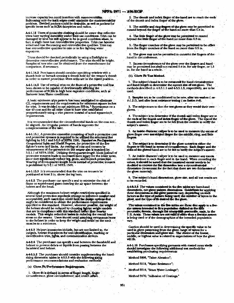
increase capacity but~ould interfere wi& manet~erah~. , " Ball6oning-onty the.~kedges coutd mllahuize the mmm~." lity p~blem.- ~'ded 'pockcet O3ukl be desirable, as ~ as pocket~ for specific items such as SC~A ~ and radioS. :
A-4--I.III Usemo~ pro~cfive d o ~ n g ~ h o ~ l d be aware that reflective trims have v a r y ~ g - ~ .nde~r'~leld, use condi~mlL Trlm r .~ be d a r n e d by beat ~ t m ~ et m a at~x-ar to be "m ~t, od ¢ondmo~ ~ , in fact, it might have lost retroreflectlvepmperties. Tfltn can betome soiled and lose fluorescing and retroreflective qualities T rim'ca~ lose re~oreflective qualitiesifi rain or in fire fighting water _ exp~ures.
Trims should be checked periodically by using a fiashlit~ht to determine retroreflecfive peffo/'-mance. The trim ~;houl~] be bright. Samples of new trim can" be obtained from the manufacturer for comparison, if necessary.
A-4-LI4.2 Purchasers should consider specifying wristletvwKh a thumb hole or barrack creating a thumbhole for the wearor's thumb in order to enmnre protection whenar i~ are inthe ~ ' p o s i ~ n . .
A-4-1.14.5 Use of vertical trim o n the fl~3t of a p ~ co~t]~has been shown to be _ ~ble * f d e u ~ t m e n ~ ~ffe~tiggdm ~ .,'i" pertommmm of S C l ~ in hlghheat e~po~re condieohs. ~Uch as' * flashover heat/flame conditions. ,
A basic minimum trim pattern bas been ~ e d t0.eJiminate CIL requirements and thexequirements fo fml~mum square inches for ~im, It was d e ~ . t ~ ~ i n m m 5 2 ~ t fiU~9 ~ .ry*:rmaceon a size 40 coat and for,all 6t l~i clOtS ~ rhaveu~n ~ t ~ h e d proportionately using a trim pattern instead of actual square.inch requirement~
It is recommended thatthe circumferential bands onthe~coat not= be aligned. An irregul~ pattern of fiands ' .u~proves the consplc = uous~4ess of~fieuser. " - -
A-4-1.1S.I A protectiv e ensen~.le con~iming of b~gh a p , m ~ v e
Owupational Safe,and H ~ P ~ _ , for~ti0n -of the f i r e f ~ t e r ' s torso and limbs, ~A~ O ~ o f ~ c ~ apd I~, mers' by - measurement of the gatq'ne~et ~n t l~,weai~ abo tit _t~lah~..by .... 5-2.1.1 of NFPA 1500. U l ~ n g th 're'~, uarte~length l ~ o o ~ , ~ d of protective t romen leads ~ i n ~ i m m ~ for the love,, .r~torm,
wea~ng of three-qua~e~4e~g~h ~instead o f ~ is prohibited by 5-~.1 of NFPA 1500. -
A-4-1.15.3 It is recommended that the trim on trousers be positioned-at least 3 in. abovethe leg hem.
A-4-2.2 The purchaser can specify a seal to minimize the, risk of flame or superheated gases entering the air space between the helmet and the head,
Although the maximum helmet weisht ~ 6 0 ~ spedfled in several head p ro~Oon ~ a u : . e ~ . m ~ c e ~ a n d
Sl~cifi~ in this standard~ Howeve~,wherever poafble, th~ Wt4g~t of.
strem on the ~w, arer. .Uteri shoukt a V O i d ~ i ~ e m ~ t o .~. iten~ to thehel met in order to [r,,eep thew~ight a~ !:~-on * the neck muscles to a minimum.
A-462.8 Helmet ~ i n c l u ~ bm are no t !!mired to, the insignia, helmet fron~ieces f~r: mflt i ~ , k k ~ f m ; ~ Or identification trim, l~gh~ and cormnunication deviceL
A-4-2.6 The purchaser can specify a seal between the fa¢.,eshlekl and heime~ to prevent debris or fiquids from passing between the faceshleld and helmet.
A-4&G.~ The purchaser should consider,mpplemendng the hand- s~zing dimension tables in 4-~3.s with the f~ving_#~tng performance recommendations and evaluation n~ihod~ ,
. (a) ~ o ~ _ . / P ~ . ~ W ~
1. ~lo e t = d c f u ~ m ~ m ~ ~ f i n g e r circumference, glove c l r c u ~ e , and ~ f ~ t .
21 T h e ' ~ aacl 'md~ ~ l e ~ ofthe~hand ~ e to r e a ~ theends; of the thunM~ and Index finger o~th~g~Ve.
s. The md~e m d ~ ! ~ m / ~ t b e ¢ ~ e may be permitted extend beyond the fmge~ c~the ha~t no more tliaa 0:4 i n .
5.~ The finger croeches .of:the glove .may b e . ~ to be from the finger crotches of the hand no j~ore.titan 0.5 in.
6. "Ebe~vemaynot~bepermitted~mconstrict , thefinge~ofthe - hand in c t r c u ~ c e .
7. Excescircumference~fftheglove over the t ingedand hand-- may be pern~itted but i ~ ! : n o t exceed 0.4:in. fola~y finger, or ' l .5 in. for the htmd as wwhole. " . "
(b~ "ObOe lqtT~t Method.
I. The mbject'z haml ttto be memnz~ for head ci~m~erence andhand-len~h;to detemiae the. ¢~rett tim Oftett~love: The methods described in 4-~.5~I.I and 4.5.5.1.5, respectively, are to be used.
2. ~umptm are m be conditioned~be:new,after t~mdte~ ( s~. 6-1.2~1) , and,after beat resistance testing ( ~ Y, w t l~ 6,6). "
~. The.subjecasare:u~ don ~etmtOove, se~ywou~ thet~ own, gloves,.
4. The uUbject htm~letennlne if the tht~tll~ add index-finger are at the e a d ~ t h e ~ m n b and ' tade ten l~r O f ~ e litove, The dl~ ~ t h e thumb and indent finger me to be felt from the buuide to veri~fl~e subjecCs amswer.
S. An.~mkle ~ ca~per b~o be used to mmm~th~ etcem of ~ finger o~r ~ eag~ fur e~e ~ddle,.~ng, antl ~e
e. The ~ it to deemaIM ~ ~e fdove ~onmlctt ettherthe engemere~tmd in tem~-of~tceatlereaoe. ,g~h ~ a~i-the sidu,of th~e.~tand al~ robe felt tO ~tlfy the ~itm,awer.
7. An inside diameter caliper is to be eeed ~ measure any e~em cir~nce in each fin86ramd in the hand. When recording the vaine~ ~ t , t h o u i d - b e n o t e d ~ t h e ~ e s , ~ need~m be
dimemion.(t~accouat for the fa~t t tm there are two thlelme~e~ of the ~ve mated~_). " "
8. The subjec, t's handdiawmiom~ glove size, and all ~ resales are to be recorded. - - -
A-COJ~ a'he vaht~,conedaedkin ~e.~e tat~ei are bare.hand
a u i ~ z , ~ ~ o R t ~ ~ , ~ I d i l 4 ~ t . n ~ t o ~ -: ,.
U ~ Army, "fheee ~ ia~aet ~ W ¢ ~ i e v ~ . a ~ a ~ t e m is be lngmed or if the demographic~ of*the intended population vary.
Caution should be used in determining ~ ~ value to be
pat~ar mnimttm a6d~ ~t~. The et~meofthe ~we~. middle, or highett valae is related to ~ o r t s of how the glove will f i t
aaouldimesegae the-foflowi~ .addltional test ~ r " establiaxlng purchasing requirement~
Method 580~, "I 'ab~ Abrasion';
Method 551~, "W~ter Resistance';
* MetfiodS516, "Seam~yater,Leakage';
Method 5970, "Adhezion o f Coatings"
SS!
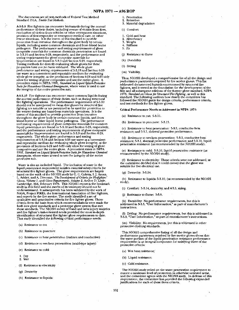
/-
N F P A 1 9 7 1 - - A 9 6 R O P
The documents are all test,~methods of Federal Test Method Standard 191A, Textile Test Methods.
A-5-3.9 Fire fighters can encounter biohazards during the normal perfonnance of their duties, including rescue of'victims from fires, extrication of victims from vehicles or other en t rapment situations, provision of first responder or emergency medical care, or o ther
- rescue situations. It is the intent of this standard to provide
~i rotection from intrusion throughout the glove body by certain quids, including some common chemicals and f rom blood borne
pathogens. The performance and testing requirements o f glove composite materials for common chemicals penetration are found in 5-3.10 ,and Section 6-28, respectively, ,and the performance and testing requirements for glove composite materials for biopenetration are fourid in 5-3.9 and Section 6-29, respectively. Testing methods for directly evaluating whole gloves for these properties have not yet been validated. The whole glove performance and testing requirements of 5-3.18 and'Section 6-33 use water as a convenient and repeatable medium for evaluating whole glove integrity, as the provisions of Sections 6-28 and 6-29 only allow for testing of glove composites and not the entire glove. A precedent exists in NFPA 1992, Standard on Liquid Splash-Pro~tive Suits for Hazardous ChemicalEmergendes, where water is used to test the integrity of the entire protective suit.
A-5-3.10 Fire fighters can encounter many common liquids during the normal, performance of their duties, such as during stntcmral
f i re fighting operations. The performance requirement of 5-3.10 should rmt be interpreted to mean that gloves for structural fire fighting are suitable or are permitted to be used for protection to the wearer during any hazardous materials operations. It is the intent of this standard to provide protection from intrnsion throughout the glove I?ody by certain common liquids, and from blood borne or other liquid borne pathogens. The performance and testing requirements of glove composite materials for common liquid penetration are found in 5-3.10 and Section 6-'28, respectively, and the performance and testing requirements of glove composite materials for biopenetration are found in 5-3.9 and,Section 6-29, respectively. The whole glove performance and testing requirements of 5-3.18 and Section 6-33 use water as a convenient and repeatable medium for evaluating whole glove integrity, as the provisions of Sections 6-28 and 6-29 only allow for testing of glove composites and not the entire glove. A precedent exists in NFPA 1999. Standard on Liquid Splash-Protective Suits for Hazardous Chemical Emergencies, where water is used to test the integrity of the entire protective suit.
Water is also an included liquid: The inclusion of water in the liquid penetration requi rement satisfies essential safety criteria for structural fire fighter gloves. The glove requirements are largely based on the work of the NIOSH study by G. C. Coletta, I.J. Arons, L. Ashley, and A(l)rennan, TheDa,elopment of Criteria for Firefighters' Gloves, Volume 1, and Glove Requirements,.Volume 2, Arthur D. Little, Gambridge, MA; February 1976. This NIOSH report is the landmark study in this field and the merits o f its testimony should not be underestimated. It subsequently has been validated by the work of NASA, Project FIRES, the International Association of Fire Fighters, and reports by the fire service. The study identified a set o f qualitative and quantitative criteria for fire fighter gloves. Those criteria form the basis from which recommendzt ions were made for both new glove standards and a prototype glove system that met those standards. The NIOSH survey of hand and wrist injury statistics and fire fil~hter's task-oriented needs provided the most in-depth identiticauon of structural fire fighter ~love requirements to date. That study identified the following Critical performance needs:
(a) Resistance to cut
(b) Resistance to poncture
(c) Resisumce to heat penetration (radiant and conductive
(d) Resistance to wet heat penetra~on (scald-type injury)
(e) Resistance to cold:
1. Dry 2. Wet
(f) Resistance to electricity
(g) Dexterity
(h) Resistance to liquids:
1. Pene t ra t ion . 2. Retention 3. Material degradation
(i) Comfort:
1. Cold and heat 2. Absorbency 3. Weight 4. Stiffness 5. Fit
(j) Resist.ance to flame
(k) Durability
(1) Drying
(m) Visibility.
Thus, NIOSH developed a comprehensive list of all the design and performance parameters required by fire service gloves. This list addressed documented hazards encountered by structural fire fighters, and it served as the foundation for the development of the first and all subsequent editions of the former glove standard, NFPA 1973, Standard on Gloves for Structural Fire Fighting, as well as this standard. The following outlines how closely the committee has followed the NIOSH guide for design criteria, performance criteria, and test methods for fire fighter gloves.
Critical Performance Needs as Addressed in NFPA 1971:
(a) Resistance to c u t 5-3.il.
(b) Resistance to puncture: 5-3.13.
(c) Resistance to heat penetration: 5-3.5, conductive heat resistance; and 5-3.1, thermal protective performance.
(d) Resistance to wet heat penetration: 5-3.5, conductive.heat resistance; 5-3.1, thermal protective performance; and 5-3.10, liquid penetration resistance (as r ecommended by the NIOSH study).
(e) Resistance to cold: 5-3.10, liquid penetration resistance (as r ecommended by the NIOSH study).
(f) Resistance to electricity: These criteria were not addressed, as the committee decided that it could convey that the glove was suitable for live electrical use.
(g) Dexterity: 5-3.14.
(h) Resistance to liquids: 5-3.10, (as recommended by the NIOSH study).
(i) Comfort: 5-3.14, dexterity;, and 4-3.5, sizing.
(j) Resistance to flame: 5-3.6.
(k) Durability: No performance requirements, but this is addressed in 3-3.3, "User Information." as part of manufacturer 's instructions,
(1) Drying: No performance requirements, but this is addressed in $-3.3, "User Information," as part o f manufacturer 's insmactions.
(m) Visibility: No requirements, but this is addressed in other protective clothing standards.
This NIOSH comprehensive listing of all the design and performance parameters required by fire service gloves shows that the water portion of the liquid penetration resistance performance requirement is an integral componen t for satisfying three of the protective criteria:
(a) Wet heat resistance;
(b) Liquid resistance:
(c) Cold resistance.
The NIOSH study relied on the water penetration requirement m ensure a minimum level o f protection in otherwise untested areas, and the committee agrees with the NIOSH study. In defense o f this requirement, the committee has provided the following expanded
justifications for each of these three criteria.
355
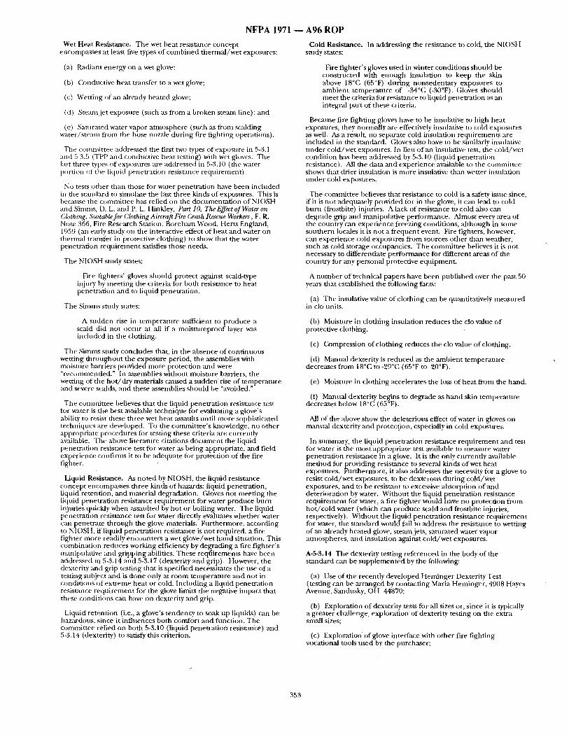
N F P A 1971 ~ A96 R O P
Wet Heat Resistance. The wet heat resistance concept encompasses at least five types of combined the rma l /we t exposures:
(a) R;tdiant energy on a wet glove;
(b) Con ductive heat transfer to a wet glove;
(c) Wetting of an ~dready heated glove;
(d) Stean~ jet exposure (such as f rom a broken stemn line); and
(e) Saturated water vapor a tmosphere (such as from scalding water/steain f rom the hose nozzle dur ing fire fighting operations).
The commit tee addressed the first two types of exposure in 5-3.1 and 5-3.5 (TPP and conductive heat testing) with wet gh~ves. The I:LSt three types of exposures are addressed in 5-3.10 (the water portion ~f the liquid penetration resistance requirement) .
No tests o ther than those for water penetrat ion have been included in the s tandard to simuhtte the la~st three kinds o f exposures. This is because the commit tee ha.s relied on the documenta t ion of NIOSH and Simms, D. L. and P. L. Hinkley, Part 10, TheEffect of Water on Clothing, Suitable for C, loO~ing Aircraft Fire Crash Rescue Workers, F. R. Note 366, Fire Research Station, Boreham Wood, Herts Englmld, 1959 (an early study on the interactive effect of heat mad water on thern~al transfer in protective clothing) to show that the water penetrat ion requi rement satisfies those needs.
The NIOSH study states:
Fire fighters ' gloves should protect against scald-type injury by ineeting the criteria fi~r both resistance to heat penetrat ion and to liquid penetrat ion.
The Simms study states:
A sudden rise in tempera ture sttfficient to produce a scald did not occur at all if a mois tnreproof Iwer was included in the clothing.
The Simms study concludes that, in the absence of cont inuous wetting th roughou t the exposure period, the assemblies with moisture barriers provided more protection and were "rec~mmmnded." In assemblies without moisture barriers, the wetting of the ho t / d ry materials caused a Sudden rise of tempera ture and severe scalds, and these assemblies should be "avoided."
The commit tee believes that the liqtfid penetrat ion resistance test for water is the best available technique for evaluating a glove's ability to resist these three wet heat assaults until more sophisticated techltiques are developed. To the commit tee ' s knowledge, no other appropriate [)rocedures for testing these criteria are currently available. The above literature citations d o c u m e n t the liquid penetrat ion resistance test for water as being appropriate, and field experience confirn~s it to be adequate for protection of the fire fighter.
Liquid Resistance. As noted by NIOSH, the liquid resistance concept encompasses three kinds of hazards: liquid penetration, fiquid retention, and material degradation. Gloves not meet ing the liquid penetrat ion resistance reqtf irement for water produce burn irljuries quickly when assaulted by hot or boiling water. The liquid penetrat ion resistance test for water directly evaluates whether water can penetrate through the glove materials. Fur thermore, according to NIOSH, if liquid penetrat ion resistance is not required, a fire fighter more readily encounters a wet glove/wet hand situation. This combinat ion reduces working efficiency by degrading a fire f ighter 's mani[)ulative and gripping abilities. These reqi~irements have been addressed in 5-3.14 and 5-3.17 (dexterity :rod grip). However, the dexterity and grip testing that is specified necessitates the use of a testing subiect and is done only at room tempera ture and not in condit ions of extreme hea t or cold. Including a liqnid penetrat ion resistance requ i rement for the glove limits the negative impact that these condit ions can have on dexterity and grip.
Liquid retention (i.e., a glove's tendency to soak t,p liquids) can be haz~dous , since it influences both comfor t and function. The commit tee relied on both 5-3.10 (liquid penetrat ion resist:race) and 5-3.14 (dexterity) to satisfy this criterion.
Cold Resistance. In addressing the resistance to cold, the NIOSH study states:
Fire f ighter 's gloves used in winter condit ions should be constrocted with enough insulation to keep the skin above 18°C (65°F) dnr ing nonsedentary exposures to ambient tempera ture of -34°C (-30°F). Gloves should meet the criteria for resistance to liquid penetrat ion as an integral part of these criteria.
Because fire fighting gloves have to be insulative to high heat exposures, they nornlally are effectively insulative to cold exposures as well. As a resnh, no separate cold insulation requirements are included in the standard. Gloves also have to be similarly insulative unde r cold/wet exposures. In lieu of an insulative test, the cold/wet condition has been addressed by 5-3.10 (liquid penetrat ion resistance). All the data and exper ience available to the commit tee shows that drier insulation is more insulative than wetter insulation unde r cold exposures.
The commit tee believes that resistance to cold is a safety issue since, if it is no t adequately provided for in the glove, it c;m lead to cold burn (frostbite) injuries. A lack of resistance to cold also can degrade grip ,and manipulative performance. Almost every area of the country can experience freezing conditions, a l though in some southern locales it is not a f requent event. Fire fighters, however, can experience cold exposnres f rom sources other than weather, such as cold storage occupancies. The commit tee believes it is not necessary to differentiate performance for different areas o f the country fi)r :my personal protective equipment .
A mmthe r of technical papers have been published over the past 50 years that established the following facts:
(a) The insulative value of clothing can be qu:mtitatively measured in clo units.
(b) Moisture in clothing insulation reduces the rio value of protective clothing.
(c) Compression o f c l o t h i n g r e d u c e s t h e c l o v a l u e o f c l o t h i n g .
(d) Manual dexterity is reduced as the ambient tempera ture decreases f rom 18°C to -29°C (65°F to -20°F).
(e) Moisture in clothing accelerates the loss of heat f rom the hand.
(f) Manual dexterity begins to degrade as hand skin tempera ture decreases below 18°C (65°F).
All of the above show the deleterions effect of water in gloves on manual dexterity and protection, especially in cold exposures.
In summary, the liquid penetrat ion resistmace requ i rement and test fi)r water is the most appropriate test available to measure water penetrat ion resistance in a glove. It is the only currently available me thod for providing resistance to several kinds of wet heat exposures. Fur thermore, it also addresses the necessity for a glove to resist cold/wet exposures, to be dexterous dur ing cold/wet exposures, ;rod to be resistant to excessive absorption of and deterioration by water. Without the liquid penetrat ion resistance requ i rement for water, a fire fighter would have no protection f rom ho t / co ld water (which can prodt,ce scald mad lkosthite injuries, respectively). Wi thout the liquid penetrat ion resistance requ i rement for water, the stan&trd would fail to address the resistance to wetting of an already heated glove, ste~unjets, satt, rated water vapor atmospheres, and insulation against cold/wet exposures.
A-5-3.14 The dexterity testing referenced in the body of the s tandard can be supp lemen ted by the following:
(a) Use of the recently developed Heminge r Dexterity Test (testing can be arranged by contact ing Maria Heminger , 4908 Hayes Avenue, Sandusky, OH 44870;
(b) Exploration of dexterity tests for all sizes or, since it is typically a greater challenge, exploration of dexterity testing on the extra small sizes;
(c) Exploration of glove interface with o ther fire fighting vocational tools used by the purchaser;
353
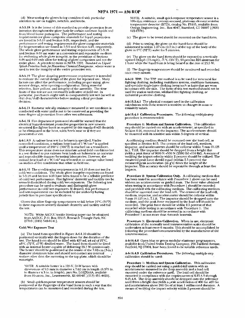
N F P A 1971 ~ A96 R O P
(d) Wear-testing the gloves being considered with particular at tention to nse on toggles, switches, and knobs.
A-5-3.18 It is the in tent of this st:mcLard to provide protection from intrusion th roughou t tile glove body by certain c o m m o n liquids and from blood borne pathogens. The performance and testing requirements fi)r glove composite materials for liquid penetrat ion are fi)und in 5-3.10 and Section 6-28, respectively, and the perforn/ance and testing requi rements fi)r glove composite materials fi~r biopenetrat ion are found in 5-3.9 and Section 6-29, respectively. The whole glove performance and testing requi rements o f 5-3.18 and Section (3-33 use water as a convenient and repeatable m e d i u m fi)r evaluating whole glove integrity, as the provisions of Sections 6-~)8 and 6-29 only allow for test ing of glove composites and not the entire glove. A precedent exists in NFPA 1992, Standard on Liquid Spkzsh-Protective Suits for Hazardous Chemical Emagtncia~" , where water is used to test the integrity o f the entire protective suit.
A-5-3.19 Tile glove dor!ning perform:mce requ i rement is in tended to evaluate the overall design of the glove for repeated use. Many factors can affect the per-tbrntance, including proper sizing, glove interior design, wrist open ing configuration, lining material selection, liner pullout, and integrity of the assembly. The time limits of dais test are not necessarily indicative o f field use. In particul~u'.purchasers might wish to comparatively test wet (as well as dry) d o n / d o f f characteristics before making a final p u r c h ~ e decision.
A-fi-4.13 Footwear sole slip resistance measured in wet condit ion is conduc ted with water mid is not to be cons t rued as providing the same degree of protection from o ther wet substances.
A-fi-4.15 Fire d e p a r u n e n t personnel should be warned that the electrical hazard-resistant protective propert ies in new tmworn structural fire fighter boots as required by this s tandard will diminish or be el iminated ,'~ file boot, so les /heels wear or if they are punc tu red or cut.
NOTE: A suitable, small quick-response tempera ture sensor is a 100-ohm resistance, ceramic-encased, p la t inum e lement resistive tempera ture detector (RTD), catalog No. F3105, available f rom Omega Engineering, Inc., Box 4047, Stamford, CT 06907 [(800) 622-23781.
(c) The glove to be tested should be moun ted on the hand fi)rna.
(d) Prior to testing, the glove on the h a n d form should be submersed to within 1.27 cm (0.5 in.) o f the top of the body of the glove in 0°C (32°F) water for 5 minutes .
(el The glove on the hand form should be exposed to a vertically upward 24-kph (15-mph), -7-°C (20-°F), 50-percent RH alrstream for 1 hour while the hand form is being heated at the rate of 23.5 W.
(0 The fingertip temperatures should be moni to red and recorded once every minute .
A-6-10 TPP. The TPP test m e t h o d is to be used for structural fire fighting clothing, including multilayer systems, multilayer laminates, and specialty single-layer c lothing items such as knits that are worn in contact with the skin. The form of this test me thod should not be used for station tmiforms, wildland fire f ight ing clothing, or industrial protective clothing.
A-6-10.5.4.1 The physical constant used in the calibration calculations with these sensors is sensitive to changes in mass or emissivity values.
A-6-15.4.9 Calibration Procedures. The following multiple-step procedure is r ecommended :
Procedure 1: Medium and System Calibration. This calibration step should be carried ou t with an accelerometer, as specified in Secdon 6-16, m o u n t e d in the impact0r, The accelerometer should be moun ted with its sensitive axis within 5 degrees of vertical.
A-6-1.8.8 A radi:mt heat test fi)r helmets is specified, t i nde r control led conditions, a radiant heat load of 1 W / c m z is applied until a tenlperature o f 260°C (500°F) is reached on a t ransducer. This tempera ture alone does not simulate actual field coilditions but is a test devised to put ext reme heat loads on helmets in :ul accurate and reproducible rammer by testing laboratories. However, the radiant heat load of 1 W / c m ~ was selected as an average ~due based on studies of fire condit ions that relate to field use.
A-6-1.10 The condi t ioning r equ i r emen t in 6-1.10 does not test figr cold/wet conditions. The whole glove integrity reqtf irements figund in 5-3.18 :rod Section 6-33 have been found to be a reliable predictor of cold/wet performance. Fire fighters ' dexterity and tactility can be severely d iminished dur ing co ld /wet exposures. The following test procedure can be used to evaluate and distingnish glove performance in cold /wet exposures. If desired, this per formance and test r equ i rement can be included by the authority having jurisdiction in purchase specifications.
Gloves that allow fingertip temperatu, 'es to fidl below 10°C (50°F) in these exposures severely diminish dexterity and tactility and fail tile test.
NOTE: White AATCC textile blotting paper can be obta ined from AATC, C, p .o . Box 12215, Research Triangle Park, NC 27709 [ (919) 549-8141].
Cold/Wet Exposure Test
(a) The hand fi)rm specified in Figure A-6-1.10 should be positioned vertically with the fingers down for the durat ion o f the test. The hand fcwm should be filled with 420 ml, ±4 ml o f 22°C, +3°C (72°F~ +5°F) distilled water. The h a n d form should be fitted with an internal heater capable o f delivering 23.5 W continnously. The beater shou ld be posi t ioned at the center of the 7.62-cm (3-in.) diameter a lumimtm tube and should not contact any internal surface - t h e r than tile m oun t i ng to the top plate, which should be watertigh t.
N( )TE: A suitable heater ' is a 120-V, 50-W heater with d imensions of9.5 m m in diameter x 7.62 cm in length (0.375 in. in diameter x 3 in. in length), part No. LG2JX44A, available from Heau'on, htc., Leavenworth, KS 66048 [(913) 651-4420].
(b) Small quick-response tempera ture sensors should be posit ioned at the fingertips o f the h a n d form in such a way that the temperatures can be moni to red and recorded dur ing the test.
A calibrating med ium should be m o u n t e d over the load cell, as specified in Section 6-15. The centers of the load cell, med ium, impactor, and accelerometer should be colinear within 3 m m (0.125 in.), T.I.R. The impactor shonld be d ropped from a he igh t that yields a peak force of 9000N +500 N (2000 Ibf +110 Ibf). A means of verifying the impact velocity within 2 percent should be u t i l ized .The measured peak force should equal (within 2.5 percent) the measured peak acceleration (in g's) t imes the weight o f the impactor. This accuracy should be repeatable th rough at least five impacts.
Procedure 2: System Calibration Only. A calibrating medium that has been tested in accordance with Procedure 1 above can be used without an accelerometer or guided mass. The force value obtained when testing in accordance with Procedure 1 should be recorded and provided with the calibrating medium. The calibrating med ium should be m o u n t e d over the load cell. The centers of the load cell, medium, impactor, and accelerometer should be colinear within 3 m m (0.125 in.), T.I.R. The impactor shon ld be d ropped onto the medium, mad the peak force measured by the load cell should be recorded. The peak force should be within 2.5 percent of that recorded while testing in accordance with Procedure 1. The calibrating m e d i u m should be retested in accordance with Procedure 1 at no t more than 4-month intervals.
Procedure 3: Electronics Calibration. When in use, electronic calibration of the normally used ins t rumentat ion scales should be under taken at least every 6 months . This should be accompFlshed by following the procedures r e c o m m e n d e d by the manufac tu re r of the instrumentat ion.
A-6-16.4.8 Open blue or green modula r elastomer programmers , available f rom Uni ted States Test ing Company, 291 Fairfield Avenue, Fairfield, NJ 07004, have been found to be suitable reference anvils.
A-6-16.4.9 Calibration Procedures. The following multiple-step calibration should be used:
Procedure 1: Medium and System Calibration. This calibration step should be carried out using a guided-fall system with an accelerometer m o u n t e d in the drop assembly and a load cell m o u n t e d unde r the reference anvil. The load cell should be m o u n t e d in compliance with the requi rements o f 6-15.4.3 through 6-15.4.8. The drop assembly should be d ropped onto the reference anvil f rom a he ight that fields a peak acceleration o f 400 Gn ±20 Gn and accelerations above 200 Gn of at least 1 millisecond duration. A means of ver i f#ng the impact velocity within 2 percent should be
354
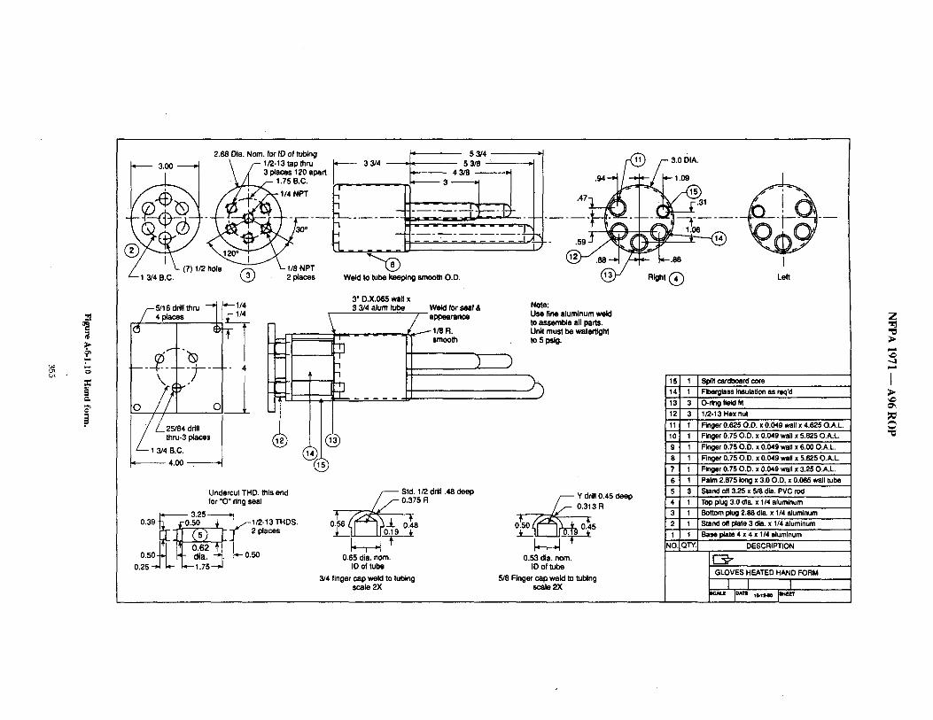
'..,,o
,:p
¢=,
:z:
2.88 Dia. Nora. for IO of tubing 3.00 ~ \ f - 1/2-13 tapthru
I | \ A ' 3 places 120 apart __L... / " ~/_.L_ / - 1.75 B.C.
. _
/ ' ~.- (71 I/2 hole ~ ~- 1/8 NPT - 1 3/4 B.C. ~ 2 places
33/4 • 5 3 /4 )
~ I = L " 4 3553/8 )
- - _-_- . - -
Weld to tube keeping smooth O.D.
.47 ' ~
5/16 drill thru ' ~ places
)----?---
0 / ~ 2 5 / 8 4 drill 0
thru-3 places
"--- 1 3/4 B.C. 4.00
I - " 4
3" D.X.065 wall x 3 3/4 alum tube We~ for seal &
appearance
_
Note: Use fine aluminum weld to assemble all parts. Unit must be watertight to 5 psig.
Undercut THD. this end for *O" ring seal
3.25 0.39 -~. ;-0.50 ~ ,, /-! /2-13 THDS. ~ ~ j - 2plac.s
0.25-~ ~- ~,--1.75--~
0• Std. 1/2 drill .48 deep 0,375 R
og
0.65 dia. nora. tD of tube
3/4 finger cap weld to tubing scale 2X
0•Y drill 0.45 deep
3R
5 J.. II II 0.19 t
0.53 dia. nora. ID of tube
5/8 Finger cap weld to tubing scale 2X
F 3.0 DIA,
- 1.09
,31
Right ( ~
I Left
15
14 13 12 11 10 9
8
7 6
5 4
3 2 1
~10.
1 S~.ca~b=rdcore 1 Fiberglass insulation as req'd 3 O-ring fietd fit 3 1/2-13 Hex nut 1 Finger 0.625 O.D. x 0.049 wall x 4.625 O.A.L.
Finger 0.75 O.D. x 0.049 wall x 5.625 O.A.L. Finger 0.75 O.D, x 0.049 wall x 6.00 O.A.L. Finger 0.75 O.D. x 0.049 wall x 5.625 O.A.L.
1 Finger 0.75 O.D. x 0.049 wall x 3.25 O.A.L. 1 Palm 2.875 long x 3.00.D. x 0.065 wall tube 3 Stand off 3.25 x 5/8 dia. PVC rod 1 Top p4ug 3.0 dia. x 1/4 aluminum 1 Bottom ptug 2.88 dia, x 1/4 aluminum 1 Stand off plate 3 dia. x 1/4 aluminum
Base plate 4 x 4 x 114 aluminum DESCRIPTION QTY.
GLOVES HEATED HAND FORM
I I I
Z
;>
-.,4
I ;>
c
N F P A 1971 - - A 9 6 R O P
utilized. The measured pe:tk fi)rce should equal (within 90 percent) the measured peak accelerati¢ n (in g's) times the weight of the drop assembly. This accuracy should be repeatable th rough at l e~ t five impacts.
Procedure 2: Electronics Verification. When in use, electronic verification o f the normally used ins t rumentat ion scales should be m~dertaken at least weekly. This should be accomplished by fi)[lowing the procedures r econmlended by the manufac tu re r of the instrumentat ion.
A-6-17.4.1.3 This prevents missile tumble, helps to protect the operator if the tube extends to within a short distance of the device being tested, and allows the exact room necessary for insertion of the missile at the top. Partkd shielding of the headform migh t be advisable to pr )te :tHae operator 's feet.
A-6-17.5.1.3 The stee[ balls move at ckmgernus speeds, and o ther forms of s~ffety devices, such as interlocks and palm switches, might be desirable in a particular setup.
A-6-92.4.6 A practical, easy to use technique for achieving this control utilizes a reference material wi thknown cut resistance. For example, the following vinyl tapes manufac tu red by the 3M (~:~mpany, or their equivalents, c~m be used:
Table A-6-22.4.6 Tape Identification, Minimum Welght for Cut
No. 470 White vinyl tape 10 lb (4.5 kg) No. 472 Black vinyl tape 12 lb (5.4 kg)
A-6-28.4.2 Aqueous f ihn4orming foam of 3 percent concentrat ion is available f rom 3M Fire Protection Systems, (~mlmerciai Chemicals Division, St. Paul, MN 55144. Fire-resistant hydraulic fluid is awtilable from Jaws of Life Rescue System, products of Hale Fire Pump Company, 7000 Spring Mill Avenue, (a~nshohocken, PA I9428 [ (215)-825-6300]. A representative swinuning pool chlor inat ing chemical conta in ing a 65 percent free chlorine "sock-iC is available from HTH Chemicals, Olin Water Products and Services, Olin (~rpora t ion , 120 Long Ridge Road, Stamford, CT 06904.
A-6-33.4.1 An example o f an inner glove fabric is a lightweight, tightly woven (e.g., 2.2 ox/yd, 92, x 88), m e d i u m - o r dark-colored, 100-percent polyester tabric without surface treatment .
A-6-33.5.3 A 0.1 weight percent solution o f Surfynol 104H (available f rom Air Products and Chemicals, Inc., Performance Chemicals, Box 538, Allentown, PA 18105) with water is reported to provide a surface tension of 33.8 dynes /cm.
A-6-45.5.1 The Gardner piw)tal sphere hazemeter is described in ASTM D 1003. Test Metlwd Jor Haze and Luminous Transmigrate of Trineparent ['k~stics.
A-6-48.5.1.3 Greater acct,racy can be obta ined by exposing the calorimeter for 20 seconds or 30 seconds, ex tending the straighf-line po, t ion of the curve to this time, and multiplying the response by 2 or 3, respectively.
A-6-48.5.6 A simple me t hod for per forming the test is to start a stopwatch, start the prehea t t ime at 10 seconds, start the recorder at 5 minutes, and remove the cover plate and position the sensor assembly at 5 minutes , 10 seconds.
A-6-49.4.1 A 0.1 weight percent ofSurfonyl 104H (available f rom Air Products and C'hemical, Inc., Performance Chemicals, Box 538, Allentown, PA 181(15) with water is reported tO provide a surface tension of 33.8 dynes/era .
A-6-49.5.1 A heavy, fiat metal plate with two upr ight th readed posts, large slotted metal bar, and heavy<tuty metal bolts is a preferred means fi:w moun t ing the m m m e q u i n in the spray chamber to prevent :my effects of the mannequ in m o u n t i n g on the clothing specimen. A-6-49.6.1 The anthori ty havingjur iMict ion can request a diagnosis of the mechan i sm of failure.
A-8-49.7.9 In order to complete this inspection, it migh t be necessary to release one or more se;uns at the end o f the test.
Appendix B Evaluation of Heat Loss of Materials
This Appe~zdix is not a part of the requirements of this NFPA document but is included for informational purposes only.
The commit tee org~mized the Task Force on Heat Stress to address test methods suitable for evaluating materials used in fire f ighter protective clothing. The task force has developed and standardized the test methodology that follows based on the heated, sweating, flat plate apparatus. The task force established a calibration procedure to assess comparisons o f fabric measurements of insulation and permeability f rom different laboratories.
Four i ndependen t laboratory groups (Comfort Technology, W. L Gore & Associates, Inc., Kansas State University, and North Carolina State University) have used the test m e t h o d and its calibration procedure in evaluating the insulation and evaporative heat transfer of four three-layer composites represent ing a range o f available structural fire f ighting protective clothing ensembles. A simple c r i t e r ion- - the W / m 2 of heat t ransferred th rough the compts i t e by the combined dry and evaporative heat exchanges f rom a 35-°C (95-°F), fully sweating test plate surface in a 25-°C (77-°F), 65- percent RH environment---provides a single value for compar ing each fabric ensemble.
The actual differences in garraents made from these fabric ensembles will be much smaller because the insulation of the garments will be two to three times greater due to the air .layers in garments that are no t accotmted for on the flat test plate. Therefore, the actual W / m ~ of heat transfer will be between one-half to one-third less than the values obtained by the test method. The actual heat transfer will be decreased even further by environmental temperatures and ht,midity that are higher than those used in the test procedure.
These factors led the task force to the following impor tant conclusions that should be considered when us ing the results f rom the fi)ll0wing test method:
1. It is only in mild envi ronments or at low work levels that differences in protective clothing materials are likely to have any appreciable effect on heat stress.
2. In the most stressful situations of high temperature or high work rates, mate~al changes are unlikeO to make any significant improvements in tolerance time.
3. Heat stress should be addressed th rough o ther means in addition to, or instead of, material specifications,
NOTICE TO THE READER
The following test me thod is provided so that persons who are interested in evaluating and compar ing the hea t transfer qualities of fabrics can do so to an established method. This test m e t h o d is NOT a requ i rement of this document , and noth ing contained herein can be construed to be a part o f the mandatory requirements of this document . The use of the term "shall" in this test me thod is to emphasize Critic,'d procedures that are part of the test and does not indicate a mandittory requ i rement of this document .
Total Heat Loss Test
NOTE: Practitioners of this m e t h o d should be intimately fanfiliar with/LSTM D 1518, Test Method for Thermal Transmittance of TcxtileMaterials, al though this total hea t loss test contains significant differences.
1. The test plate ~md guard ring shall have a wettable surface.
NOTE: One usefifl sweating hot plate apparatus is available f rom Holometrix, Inc., 99 Erie Street, (_~arnbridge, MA 02139; [ (617) 868-8050]. All envi ronmenta l chamber with air temperature , humidity, and air velocity control also is required.
2. The test plate shall have a tempera ture o f 35°C, ±0.5°C (95°F, ±1 °F). The guard ring and bot tom plate shall be controlled to el iminate lateral and downward heat f rom the test plate.
3. The local environmenta l climate shall be ~5°C, ~ . 5 ° C (77°F, +1 °F) and 65 percent RH, ±4 percent RH. The air velocity shall be the same for all calibrations and tests. These condit ions shall be measured continuously in the free flow airstream, un inf luenced by the boundary of the test plate. Apparatus used to measure tempera ture shall be accurate to within i-0.25°C. Apparatus used to measure humidi ty shall be accurate to within i-4 percent RH.
356
N F P A 1971 ~ A96 R O P
4. The average bare plate thermal resistance, inch,ding tim air layer and any apparatus contribution (Rcbp), shall be :in average of at least three me:~surenlents with noth ing moun t ed on the test plate.
5. The average intrinsic thermal resistance of the smnple alone (Rcf) shall be de t e rmined by subtract ing the average bare plate resistance (Rcbp) f rom the average of the total thermal resistance (Rct) of the specimens tested.
6. The total thermal resistance (Rct) of the specimen shall be calculated from the following equation:
Rct = (T~'-Ta) A H
where:
Rot = Total thermal resistance of the specimen and surface air layer (°C/ nl"/W)
T~ = Tempera tu re at the plate surts.ce (°C)
T = Tempera tu re in the local env i ronment (°(2)
A = Area of the test plate (m 2)
H = Power input (W).
7. Data shall be collected when equil ibrium is reached. Data shall be collected every 5 minutes . Equilibrium shall be a rate o f change of less than 3 percent per hour o f calculated thermal resistance over a period of not less than 30 minutes . The stancLard deviation of the calculated thermal resistance shall be less than 1 percent.
8. A sample shMl include at least three individual specimens.
0. The specimens shall be m o u n t e d on the test plate in the same orientation in which they will be positioned in the finished ga rmen t from the skin surface (plate surface) to the outside.
10. The apparatos shall be calibrated m meet tim following constraints:
a. A graph of total thermal resistmlce versus the n u m b e r of layers of 7.5-oz/yd a Nomex duck shall be linear for the bare plate value and one, two, three, and four layers.
b. The slope of the linear regression shall be 0 .0206°C/m 2/W, ± 1 0 percent,
c. No individual data measu remen t shall be outside +10 percent of the value predicted by the linear regression.
d. The intrinsic thermal resistance of four layers of 7.5~)z/yd = Nomex duck shall be 0 .082°C/m=/W, +10 percent.
NOTE: The s tandard s:mlple of 7.5-oz/yd = Nomex duck should be obt:dned f rom ()ffice of Standard Reference Materials, National Institute of Standards and Technologies, Gaithersburg, Maryland '20899 [(301) 975-6776].
11. The average intrinsic thermal resistance of the specimens shall be de te rmined by averaging all values obtained over the equil ibrium period ( m i n i m u m of six). The average intrinsic thermal resistance of the sample shall be de te rmined by averaging the wdues for all specimens. If the results for any of the three individnal specimens vary more than ±10 percent f rom the average of all three, then the test shall be repeated on the specimen(s) lying outside the +10 percent limit, lf the retest produces a value(s) within the ±10 percent limit, then the new value(s) shall be used instead. If the retest remains outside the ±10 percent limit, then an additional three specimens shall be tested, and all original mad retest results shall be reported along with the average and stm~dard deviation for intrinsic thermal resistance and a s ta tement identifying this ~m~ple as having a high variability.
12. Water shall be led to the test plate and gnard ring so that water uniformly wets the test plate and guard ring surface.
13. The test plate and guard ring shall be covered with a liquid barrier that prevents wetting of the test specimen by the liquid water. The permeability index of the bare plate with the liquid barrier in place shall be greater than 0.7.
NOTE: The permeability index of the bare plate should be calculated f rom file following equation:
i m = 0.061 x Rcbp /Rebp
where:
i m = Permeability index
Rcbp = Average bare plate thermal resistance (without liquid barrier) described in paragraph 4 ( ° C / m z/W)
Rebp = Aver:Ne bare plate evaporative resistance (with liquid barrier in place) described in paragraph 14 (kPa /m z/W)
One source fl)r uncoated cellophane that is suitable fi)r this purpose is Olin, Ecusta Paper and Film Group, NC 28768.
14. The average bare plate evaporative resistance, including the air layer, the liquid barrier, and any apparatus contribution, (Rebp) shall be an average of at least three m e ~ u r e m e n t s with only the liquid barrier moun ted on the plate, The local environmental climate may be permit ted to be increased above 25°C (77°F), if necessary, to maintain test plate tempera ture at 35°C (95°F).
15. The apparent tot:d evaporative resistance (ARet) of the specimen shall be calculated from die following equation:
ARet= ( P - P ) A *t-~- ( T - T ) A Rct ,
ARet = Apparent total evaporative resist:race of the specimen ,and surface air layer (kPa /m2 /W)
P, = Water vapor pressure at the plate surface (kPa)
P~ = Water vapor pressure !n the local env i romnent (kPa)
A = Area of the test plate (m x)
H = Power inpu t (W)
T = Tempera tu re at the plate surface (°C)
T~ = Tempera tn re in the local env i ronment (°C)
Rct= Total thermal resistance of the specimen and surface air layer ( °C/m2/W) .
NOTE: The term "apparent" is used as a modifier for evaporative resistance to reflect the fact ~hat condensat ion can occur within the specimen.
16. Data shall be collected when equil ibrium is reached. [)am shall be collected every 5 minutes. Equilibrium shall be a rate of change of less than 3 percent per hour of calculated apparent evaporative resistance over a period not less than 30 minutes. The stancktr~t deviation of the calculated apparent evaporative resistance shall be less than 1 percent. If data collection cannot be comple ted within 4 hours after m o u n t i n g the specimen on the test plate, the specimen shall be removed from the test plate and allowed to dry for at least 24 hours at 16°C, +iS°C (60°F, +80°F) before retesting. Subsequent data report ing shall state that drying was required. If the retest of the specimen still canno t mee t these constyaints, it tiaen shall be reported that the specimen cannot be tested by this method.
17. The average apparen t intrinsic evaporative resistance of the sample alone (ARef) shall be the apparent total evaporative resistance (ARet) minus the average bare plate evaporative resistance (Rebp).
18. TI.m apparatus shall be calibrated to meet the fi)llowing CO nstr:nn Is:
(a) A graph of apparen t total evaporative resistm/ce versus number of layers of7.B-oz/yd 2 Nomex duck shall be linear for tile bare plate wdue ;rod one, two, three, ,and four layers.
(b) The slope of the linear regression shall be 0.005 k P a / m ~/W, +10 percent.
(c) No individual data ineasnrement shall be outside +10 percent of die value predicted by the lineal, regression.
(d) The apparent intrinsic evaporative resistance of four layers of 7.5-c)z/yd ~ Nomex duck shall be 0.090 kPa /m~/W, ±10 percent.
357
N F P A 1971 - - A 9 6 R O P
I!L The average apparent intrinsic evaporative resistance of the specimen shall be de te rmined by averaging all wdues obtained over the equil ibrium period (mi n i mum of six). The average apparent intrinsic evaporative resist~mce of the sample shall be de t e rmined by averaging the values of all specimens. If the results for any o f the three individual specimens vary more than ±10 percent f rom the average o f all three, then the test shall be repeated on the specimen (s) lying outside the ±10 percent limit, If the retest produces a wdue(s) within the ±10 percent limit, then the new value(s) shall be used instead, f f t he retest remains outside the ±10 percent limit, then an additional three specimens shall be tested, and all original and retest results shall be reported along with the average and sumdard deviation for apparen t intrinsic evaporative resisumce and a s ta tement identifying this sample its having a high variability.
20. The average total heat lo~s of the sample shall be de te rmined and reported, subject to the report ing requi rements in paragraphs 11, 16. and 19. Tile totai heat loss of the sample shall be calculated from the tbllowing equation:
Q * = 10°C + 3.57 kPa t Rcf + .04 ARef + 0.0035
where:
Q = Total heat loss ( W / m ~) t
Rcf= Average intrinsic thermal resistance o f the sample de te rmined in paragraph 5 ( ° C / m e/W)
ARef = Average apparent intrinsic evaporative;; resistance o f the sample de t e rmined in paragraph 17 ( k P a / m - / W ) .
* e These valu¢s are appropriate for a surface air layer at an air tempera ture of 25°C (77°F), a relative humidity of 65 percent, a skin temperature of 35~C (95'T), and a nominal effective air velocity o f ~) I D / S e C .
NOTE: This calculation is based on the teuaperature and vapor pressure differences between the test plate and local envi ronmenta l climate specified in this procedure. Other environmenta l condit ions might alter the performance measured . Using the total hea t loss calculated unde r the condit ions used here to extrapolate to o ther environmenta l tempera tures and o ther environmental humidi ty also migh t produce inaccurate results because of possible condensa t ion within a composite that would not be accounted for. The permeability index o f the specimen and its associated air layer also might be calculated by us ing the following equation:
i m = 0.061 x Rct /ARet
where:
i,, = Permeabilit), index
Rct = Toud thermal resistance described in paragraph 6 ( °C/ mVW) /
ARet = ADDarent total evaporative resistance described in v 2 r
paragraph 15 ( k P a / m / w ) .
An i ,, is the measure of the efficiency o f evaporative heat t ransport in a clothing system. An i m of I indicates that the clothing system allows no evaporative heat transfer. An i ~ of 1 indicates that the clothing system achieves the theoretical m a x i m u m evaporative heat transfer allowed by its insulation. Casual dress clothing typically has values fi)r i m of 0.3 to 0.5. Protective clothing typically has values of i m of O.l to 0 .3 . .
Appendix C Referenced Publications
C-I The following document s or port ions thereof are referenced within this s tandard for informational purposes only and thus are not considered part of the requi rements o f this document . The edition indicated for each reference is the cur rent edition as o f the date of the NFPA issuance o f this document .
C-I.1 NTPA Publications. National Fire Protection Association, 1 Batterymarch Park, P.O. Box 9101, Quincy, MA 02269-9101.
NFPA 1500, Standard on Fire Department Occupational Safety and Health Program, 1992 edition.
NFPA 1973, Standard on Gloves for Structural Fire Fighting, 1993 edition.
NFPA 1975, Standard on Station~Work Uniforms for Fire Fighters, 1994 edition.
NFPA 1992, Standard on Liquid &plash-Protective Suits for Hazardous ChemicalEmergendes, 1994 edition.
NFPA 1999, Standard on ProtecHve C lothingforEmergeney Medical Operations, 1992 edition.
C-1.2 Other Publications.
C-I.2.1 ANSI Publication. American National Standards Institute, 11 West 42nd Street, New York, NY 10036.
ANSI Z87.1, Occupational and Educational Eye and Face Protection, 1989.
ANSI Z535.4, Standard for Product .Safety Signs and Labels, 1991.
O1.2.2 ASTM Publication. American Society for Testing and Materials, 1916 Race Street, Philadelphia, PA 19013.
ASTM D 471, Standard Test Method for Rubber Property - - Effect of Liquids, 1991.
ASTM D 1003, Standard Test Method for Haze and Luminous Transmittance of Transparent Plastics , 1988.
ASTM D 1518, Test Method for Thermal Transmittance of Textile Materials, 1985.
ASTM F 903, Standard Test Method for t?a~iatanc~e of Protective Clothing Materials to Penetration ~. Liquids, 1990.
ASTM F 1001, Standard Guide for Selection of Chemicals to Evaluate Protecth,e Clothing Matdrials, 1989.
O1.2.3 GSA Publication. General Services Administration, Specifications Activity, Printed Materials Supply Division, Building 197, Naval Weapons Plant, Washington, DC 20407.
Federal Test Method Standard 191A, Textile Test Methods, July 20, 1978.
OI .2 .4 NIOSH Publications.
NIOSH Publication 77-134-A, The Development of Criteria for Firefighters' Gloves, Vol. 1, 1976.
NIOSH Publication 77-134-B, Glove Requirements, Vol. 2, 1976.
C-1.2.5 U. S. Government Publication. Super in tenden t Of Documents, U.S. Government Printing Office, Washington, DC 204O2.
Title 29, Code of FederalRegulations, Part 1910, Section 133 (29 CFR 1910.133); "Eye and Face Protect ion, ' Ju ly 1, 1987.
0 1 . 2 . 6 s imms, D. L. a n d P . L Hinkley, PartlO, The Effect of Water on Clothing, Suitable for Clothing Aircraft Fire Crash Rescue Workers, F. R. Note 366, Fire Research Station, Boreham Wood, Hefts, England, 1959.
358
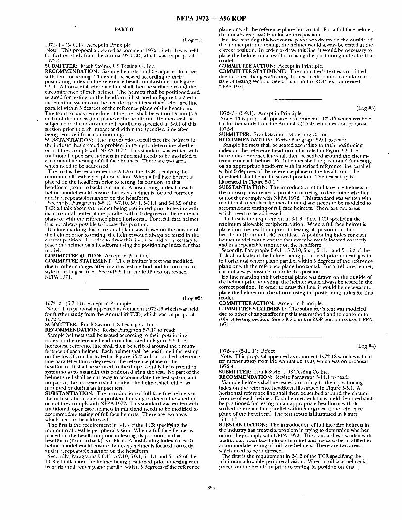
N F P A 1972 ~ A 9 6 R O P
PART II
(I2:~g #1 ) 1972- 1 - (5-6.11): Accept in Principle Note: This proposal appeared as comment 1972-15 which was held
tor flirther study front the Aamual 9"-' T(Z), which was on proposal 197~-4. SUBMITTER: Frank Savino, I ~S Testing Co Inc. RECOMMENDATION: Sample helmets shall be adjusted to a size sufficient figr testing. They shall be seated according to their positioning index on the reference headform illustrated in Fignre 5-5.1. A horizontal reference line shall then be scribed ,around the circunfference of each helmet. The helmets shall be positioned and secured flgr testing on the headfi)rm illustrated in Figure 5-6.2 with its retention systems on the headfi)rm and its scribed reference line parallel within 5 degrees of the reference plane of the headform. The front-to-back centerline of the shell shall be within 13 mm (0.5 inch) of the mid-sagittal plane of the headform. Hehnets shall be snbjected to the environmental conditions specified in 5-6.1 of this section prior to each impact and within the specified time after being removed front conditioning. SUBSTANTIATION: The introduction of frill face fire helmets in tile industry has created a problem in trying to determine whether ~w not they comply with NFPA 1972. Tiffs stmMard was written with traditional, open face helmets in mind and needs to be modified to accommocktte testing of frill face helmets. There :ire two areas which need to be addressed.
The first is the reqnirement in 3-1.3 of the TCR specifying the minimum ,allowable peripheral vision. When a fifllface helmet is placed on the head.form prior to testing, its position on that headfi)rm (front to back) is critical. A positioning index for each helmet model would ensure that every helmet is located correctly and in a repeatable manner on the headform.
Secondly, Paragraphs 5-6.11, 5-7.10, 5-9.1, 5-11.1 mad 5-15.2 of the T(LR all talk about the helmet being positioned prior to tesdng with its horizontal center plane parallel within 5 degrees of the reference plane or with the reference plane horizontal. For a finll face helmet, it is not always possible to locate this position.
If a line tnarking this horizontal plane was drawn on the outside of the helmet prior to testing, tile helmet would always be tested in the correct position. In order to draw this line, it would be necessary to place the hehnet on a headfigrm using the positioning index for that model. COMMITTEE ACTION: Accept in Principle. COMMITTEE STATEMENT: The submitter's text was modified due to other changes affecting this test method and to conform to style of testing section. See 6-15.5.1 in the ROP text on revised NFPA 1971.
(LOg #2) 1972- 2 - (5-7.10): Accept in Principle Note: This proposal appeared as comment 1972-16 which was held
fl~r fitrther study from the Annual 92 TCD, which was on proposal 1972-4. SUBMITrER: Frank Savino, US Testing (ko Inc. RECOMMENDATION: Revise Paragraph 5-7.10 to read:
Sample helmets shall be seated according to their positioning index on the reference headform illustrated ill Figure 5-5.1. A horizont.al reference line shall then be scribed around the circum- ference of each helmet. Each helmet shall be positioned for testing on the headform illustrated in Figure 5-7.2 with its scribed reference line par,'dlel within 5 degrees of the reference plane of the headform. It shali be secured to the drop assembly by its retention system so as to maintain this position during the test. No part of the helmet shell shall be cut away to accommodate the test system, and no part of the test system shall contact the helmet shell either as mounted or during an impact test. SUBSTANTIATION: The introdnction of full face fire helmets in the industry has created ap rob lem in trying to determine whether or not they comply with NFPA 1972. This standard was written with traditional, open face helmets in mind and needs to be modified to accommodate testing offidt face helmets. There are two areas which need to be addressed.
The first is the requirement in .9-1.3 of the TCR specifying the minimum allowabl'e peripheral vision. When a fidlface helmet is placed on the headform prior to testing, its position on that headfi)rm (front to back) is critical. A positioning index for each helmet model would ensure that every helmet is located correctly and in a repeatable manner on the headform.
Secondly, Paragraphs 5-6.11, 5-7.10, 5-9.1, 5-11.1 and 5-15.2 of the TCR all talk about the helmet being positioned prior to testing with its horizontal center plane parallel within 5 degrees of the reference
plane or with the reference plane horizonv, d. For a rill face hehnet, it is not ~dways possible t o locate this position.
If a line marking this horiznntal plane was drawn on the ot,tside of the helmet prior to testing, the helmet would always be tested in the correct position. In order to draw this line, it would be necessary to place the helmet on a headform using the positioning index for that modeh COMMITTEE ACTION: Accept in Principle. COMMITTEE STATEMENT: The snbmitter's text was modified due to other changes affecting this test method and to configrm to style of testing section. See 6-16.5.1 in the ROP text on revised NFPA 1971.
(Log #3) 1972- 3 - (5-9.1): Accept in Principle Note: This proposal appeared as conmaent 1972-17 which was held
for fiirther study from the Annual 92 T(~), which w,~s on proposal 19724. SUBMIT'rE_R: Frank Savino, l IS Testing Co Inc. RECOMMENDATION: Revise Paragraph 5-9.1 to read:
"Sample helmets shall be seated according to their positioning index on the reference beadform ilhtstrated in Figure 5-5.1 A horizontal reference line shall then be scribed ,around the circum- ference of each helmet. Each helmet shall be positioned for testing on an appropriate headform with its scribed reference line parallel within 5 degrees of the reference plane of the headform. The faceshield shall be in the stowed position. The test set-up is illustrated in Figure 5-9.1." SUBSTANTIATION: The intloducti.on offldl face fire hehnet~ in the industry has created a problem in trying to determine whether or not they comply with NFPA 1972. This standard was written with traditional, open face helmets in mind and needs to be modified to accommodate testing of till face hehnets. There are two areas which need to be addressed.
The first is the requirement in 3-1.3 of the TCR specifying the minimum allowable peripheral vision. When a flfllface helmet is
~ laced on the headfi)rm prior to testing, its position on that eadfl)rm (front to back) is critical. A positioning index for each
helmet model would ensure that every helmet is located correcdy and in a repealable manner on the headform.
Secondly, Paragraphs 5-6.11, 5-7.10, 5-9.1, 5-11.1 and 5-15.2 of the T(2R ,all talk about the helmet being positioned prior to testing with its horizontal center plane parallel within 5 degrees of the reference
~ lane or with the reference plane horizontal. For a fn[l face helmet, is not always possible to locate this position.
I ra line marking this horizontal plane was drawn on the outside of the helmet prior to testing, the helmet would always be tested in the correct position. In order to draw this line, it would be necessary to place the helmet on a headform using the positioning index for that model. COMMITTEE ACTION: Accept in Principle. COMMITTEE STATEMENT: The submitter's text was modified due to other changes affecting this test method and to conform to style of testing section. See 6-3.5.1 in the ROP text on revised NFPA 1971.
(Log #4) 1972- 4- (5-11.1): Reject Note: This proposal appeared as comment 1972-18 which was held
for further study from the Annual 92 TCX), which was on proposal 1972-4. SUBMITTER: Frank Savino, US Testing (k~ Inc. RECOMMENDATION: Revise Paragraph 5-11.1 to read:
"Sample helmets shall be seated according to their positioning index on the reference headform illustrated in Figure 5-5.1. A horizontal reference line shall then be scribed around the circum- ference of each helmet. Each helmet, with faceshield deployed shall be positioned for testing on an appropriate headform with its scribed reference line paraUel within 5 degrees of the reference plane of file headfi~rm. The test set-up is illustrated in Figlwe 5-11.1."
SUBSTANTIATION: The introduction of hill face fire helmets in the industry has created a problem in trying to determine whether or not they comply with NFPA 1972. This standard was written with traditional, open face helmets in mind and needs to be modified to accommodate testing of full face helmets. There are two areas which need to be addressed.
The first is the requirement in 3-1.3 of the TCR specifying the minimum allowable peripheral vision. When a ful/face helmet is placed on the headform prior to testing, its position on that .
359
N F P A 1 9 7 2 / 1 9 7 3 ~ A 9 6 R O P
Iteadfi;irn/ (front to back) is critical. A posit ioning index fl)r each helntet ntodel would ensure that every he lmet is located correctly and in a repeatable m a n n e r on the headform.
Secondly, Paragraphs 5-6.11, 5-7.10, 5-9.1, 5-11.1 and 5-15.2 of the TC.R all talk abont the he lmet being posit ioned prior to testing with its horizontal center plane parallel within 5 degrees of the reference plane or with the reference plane horizontal. For a full face helmet, it is not always possible to locate this position.
If a line marking this horizontal plane was drawn on the outside of the he lmet prior to testing, the he lmet would always be tested in the correct position. In order to draw this line, it would be necessary to place the he lmet on a headform using the posit ioning index for that model. COMMITTEE ACTION: Reject. COMMITTEE STATEMENT: The content o f 5-11.1 (now 6-3.6.1 ) b~t~ ch:ulged and no longer reqnires a he lmet to be part of the test prilcednre.
(Log #5) 1972- 5 - (5-15.2): Accept in Principle Note: This propos:d appeared as c o m m e n t 1972-19 which was held
h~r fur ther study from tile Annual 92 TCD, which was on proposal 1972-4. SUBMITTER: Frank Savino, US Test ing Oa Inc. RECOMMENDATION: Revise Paragraph 5-15.2 to read:
"Sanlple helmets shall be seated according to their posit ioning index on the reference headfo rm illnstrated in Figure 5-5.1. A horizontal reference line shall then be scribed a round the circum- ference of each helmet. Each helmet shall be posit ioned and secured for testing so that its scribed reference line is horizontal. Each a t tachment point of the crown straps shall be tested by :tpplying a force pull perpendicular to the reference line to a maximtnn load of 45 N + 5N ( 10 lb + 1 Ib). The force shall be incre~sed f rom 0 N (0 lb) u) 45 N + 5 N (10 Ib + 1 lb) at a load rate of 25 m m + 5 m m (1 in. + 0.2 in.) per minute. The force shall be applied through the centerl ine o f each a t t achment point." SUBSTANTIATION: The introduction of full face fire helmets in the industry has created a problem in trying to de te rmine whether or not they comply with NFPA 1972. This s tandard was written with traditional, open face helmets in m i nd and needs to be modif ied m acconmlodate testing offitll face helmets. There are two areas which need to be addressed.
The first is the r equ i rement in 3-1.3 of the TCR specifying the m i n i m u m allowable peripheral vision. When a full face he lmet is
]~ laced on the headform prior to testing, its position on that eadform (front to back) is critical. A posit ioning index for each
hehne t model would ensure that every he lmet is located correctly and in a repeatable m a n n e r on the headform.-
Secondly, Paragraphs 5-6.11, 5-7.10, 5-9.1, 5-11.1 and 5-15.2 of the TCR :dl talk about the hehne t being posit ioned prior to testing with its horizontal center plane parallel within 5 degrees of the reference plane or with the reference plane horizontal. For a full face helmet, it is not always possible to locate this position.
If a line marking this horizontal plane was drawn on the outside of the be lmet prior to testing, the he lmet would always be tested in the correct position. In order to draw this line, it would be necessary to place the he lmet on a headform using the posit ioning index for tha t model. COMMITTEE ACTION: Accept in Principle. COMMITTEE STATEMENT: The submit ter ' s text was modif ied oMy to conform to the style of the testing section. See 6-36.5.1 in the ROP text on revised NFPA 1971.
(Log #CP1 ) 1972- 6 - (Entire [)octnnent): Accept SUBMITTER: Technical Commit tee on Fire Service Protective Clothing and Equipment RECOMMENDATION: ( ~ m b i n e NFPA 1972, S t a n d a r d o n Helmets for Structural Fire Fighting, 1992 Edition, with the complete revision of NFPA 1971, Standard on P~otective Clothing for Structural Fire Fighting, 1991 Edition. This revision will also incorporate NFPA 1973, Standard on Gloves for Structural Fire Fighting, 1993 Edition, and NFPA 1974, Stan&ard on Protective Footwear for Structural Fire Fighting, 1992 Edition, into a single documen t with a new title: NFPA 1971, Standard on Protective Ensemble for Sttatctnral Fire Fighting. SUBSTANTIATION: The Ca~mmittee has completely revised NFPA 1971, St~mdard on Protective C~othing for Structural Fire Fighting, 1991 Edition, to combine protective coats, protective trousers, helmets, gloves, ,and footwear, a long with the interface components , into a single ensemble document- This consolidation will create a single d o c u m e n t on a protective ensemble for strnctnral fire f ighting
and will allow more consistency of performance requirements and test methods for the various e lements of the protective ensemble. COMMITTEE ACTION: Accept.
PART 11I
(Log #1 ) 1973- 1 - (2-5.1): Accept Note: This proposal appeared ,as c o m m e n t 1973-16 which was held
for fur ther study from the Annual 93 TCJ), which was on proposal 197.%5. SUBMITFER: Bill Grilliot, Morning Pride Mfg. Co. RECOMMENDATION: Add to product label:
"Authorized Mark o f C, ertification Organization". SUBSTANTIATION: 1. End user should know certification orgaJfization.
2. As in o ther Standards (1977 etc. in TCR). 3. By adding to product label, the mark, is protected because it
mus t be located inside of glove. COMMITTEE ACTION: Accept.
See 3-3.2.9 in the ROP text on revised NFPA 1971.
(Log #2) 1973- 2 - (4-2.1): Accept in Principle Note: This proposal appeared ,as c o m m e n t 1973-25 which was held
for fur ther study from the Annual 93 TCD, which Was on proposal 1973-5. SUBMITrEi~, Jeffrey o . StuU, TRI/Environmenta l , Incorporated RECOMMENDATION: Remove the word *melt." SUBSTANTIATION: All materials mel t when contacted by flame. The s tandard and test m e t h o d offers insufficient criteria to de termine whether a material has melted. This causes ambiguity in this specific requirement- COMMITTEE ACTION: Accept in Principle. COMMITTEE STATEMENT: A new definition for "melt" has been added which provides easier interprem.tion of material bu rn ing behavior. See Section 1-3, Definitions in the ROP text on revised NFPA 1971.
(Log #3) 1973- 3 - (44;1): Accept in Principle Note: This proposal appeared as c o m m e n t 1973-26 which was held
for fur ther study from the Annual 93 TCD, which was on proposal 197.%5. S U B M I T r E ~ Jeffrey O. Stull, TRI/Environmenta l , Incorporated RECOMMENDATION: Remove the word "melt." SUBSTANTIATION: All materials mel t when contacted by flame. The s tandard and test m e t h o d offers insufficient criteria to de termine whether a material has melted. This caltses ambiguity in this specific requirement . COMMITTEE ACTION: Accept in Principle. COMMITTEE STATEMENT: See Commit tee Action taken on 1973- 2 (Log #2).
(Log #4) 1973- 4 - (5-5): Accept in Principle Note: This proposal appeared as c o m m e n t 1973-73 which was held
fi)r t~nrther study from the Annual 93 TCqD, which was on proposal 197.%5. SUBMITFER: Jeffrey o . Stull, TRI/Envi ronmenta l , Incorporated RECOMMENDATION: Replace test m e t h o d in Section 5-5, with fi) llowing:
5-5 Flame Resistance Test- 5-5.1 Sample specimens shall be tested as specified in Method
5903.1, Flame Resistance of Cloth; Vertical, of Federal Test Method ,Standard 191A, Textile Methodsl Mth the following modifications:
(a) Sample specimens shall be precondi t ioned as specified in 5-1.1 of this chapter, and then shall be condi t ioned for dry condition as specified in 5-1.2 of this chapter.
(b) Sample specimens shall consist of the composite used in actual glove construction, including gauntlets and wristlets, with all layers a r ranged in proper order. In each test, the sample spec imen ' s normal outer surface shall be exposed to the flame.
360
NFPA 1973/1974 ---, A96 I~()P
, (c) If a glove construction has seams in the outer shell, an equal n~lmber of additional sample specimens having these seams shall be tested. Tile seam shall run in the direction of long dimension of the sample specimen.
(d) Sample specimens shall be prepared as described in ASTM F 1358, St:m&u'd Test Method for Resistance of Promctive Clothing Materials to Flanm ImpingemenL using a folded test specimen, in lieu of tile straight test specimen described in Method 5903.1.
(e) The sample specimen shall be weighed before and after the fl:mm exposnre, and the percent change m weight calculated.
(f) Following testing, sample specimens and sample specimens of gauntlets or wrists, it" any, shall be examined, measured; ,'rod weighed to determine pass/fail. SUBSTANTIATION: The current method does n'ot represent the most severe exposure when compared to tests for other structural fire fighter prbtective clothing. The proposed procedure takes advmmage of tile vertical specimen orientation achieved in a new ASTM test method, while pr~viding for exposure on the normal outside surface of the glove composite. Wrisdlet materials m-e generally uniti)rm and should be tested in accord~mce with the procedures in FTMS 191A.5903.1 withont modification with the exception of noting weight change. COMMITTEE ACTION: Accept in Princii~le. COMMITTEE STATEMENT: Section 6-4 has replaced Section 5-5 "to provide a modified test method for the measurement of glove composite flame resistance. This modification involves a more severe flame exposure which is considered appropriate for a composite material. All other aspects of the test method remain the same. See Sec,tion 6-4 in the ROP text on revised NFPA 1971•
( Log #CP 1 ) i973-5- (Entire Document): Accept SUBMITrER: Technical Committee on Fire Service Protective Clothing and Equipment RECOMMENDATION: Co.mbine NFPA 1973, S tandardon Gloves fl~r Struct~lral Fire Fighting, 1993 Edition, with the complete revision of NFPA 1971, Smaldard on Protective Clothing for Structural Fire Fighting, 1991 Edition. This revision will ,also incorporate NFPA 1972, Standard on Helmets for Structural Fire Fighting, 1992 Edition, and NFPA 1974, Standard on Protective Footwear for Structural Fife Fighting 1992 Edition, into a single document with a new title: NFPA 1971, Standard on Protective Ensemb e for Strncturai Fire Fighting. SUBSTANTIATION: T h e Committee has completely revised NFPA 1971, Stanckard on Protective Clothing for Structural Fire Fightiug, 1991 Edition; to combine" protective coats, protective trousers, helmets, gloves, and footwear, along with the interface components , into as ingle ensemble docttme~nt. This consolidation will create a single document on a protective ensemble for strnctural fire fighting :.rod will allow more consistency of perform:mce requirements and test methods for the various elements of the protective ensemble. COMMITTEE ACTION: Nccept
PART IV
, ( Log #I ) 1974- 1 - (3-1.4): Accept in Principle Note: This proposal appeared as comment 1974-11 which was held
fi)r fnr ther study from the Annual 92 TCD, which was on proposal 1974-2. SUBMrI'TER: William Hillermeier, Teaneck TWP Fire Dept. RECOMMENDATION: Revise as follows:
"The area of protection for the bottom of the foot shall be increased to ensure non-penetration of new vulnerable insole area. Protection shall be provided to prevent passage of sharp objects !ts small as hypodermic needles." SUBSTANTIATION: Recent incident in our Department of foot penetrated through bottom of insole by straight pin requiring medical attention and tetanus shot. COMMITTEE ACTION: Accept in Principle. COMMITTEE STATEMENT: The Committee agrees that protec- tion should be increased in the area of the arch and made appropri- ate oh:rages to the standard. See 4-4.5, 5-4.11, ,and the associated test method in Section 6-21 in the ROP t tx t on revised NFPA 1971.
(Log #2 ) 1974-2 - (4-1 (New)): Accept in Principle Note: This proposal appeared as comment 1974-14 which was held
fi)r filrther study from the Annual 92 TC£), which was on,proposal 1974-5. SUBMITTER: Jeffrey o . Stall, TRl/Environmental , Incorporated RECOMMENDATION: Add new requirement:
"4-1.x Protective footwear upper shall not allow penetration of chemicals when tested as specified in Section 5-Y, l_lpper Chemical Penetration Resistance Test, of this Standard. ; SUBSTANTIATION: Protective footwear should prevent contact of common fire fighting liquids from wearer 's foot including unleaded gasoline, AFFF, battery acid, hydraulic liquid, and swimming pool chlorine additives. The cnrrent requirement for water-tight integrity " , following flexing does not address this performance area. T h i s perfonluance area is also under consideration for fi~e fighter protective gloves (NFPA 1973). Sufficient information is available for the effectiveness of the test method as well as the basis fi~r the .-" requirement. coMMITTEE~C TION! Accept in Principle. " COMMITTEE STATEMENT: The Committee agreed with the proposed requirement but ,also felt that other hreas of the footwear should be'tested as'well. An appropriate performance requirement wa s added to the standard. See 5-4.8 in the ROP text on revised NFPA 1971.
(Log #3) • 1974- 3 - (4-1.11, 5-6): Reject
Note: This proposal appeared as commen t 1974-18 which was held- for filrther study from the Annual 92 TCD, which was on proposal 1974-5. SUBMITTER: Jack Sawicki, GEOMET Technologies, Inc. RECOMMENDATION: .'Revise as follows: 4-1.11: Delete after ~shall" and substitute: "have a TPP.of not less than 35.0 when tested in accordance with
5-6, Thermal Protection Performance Testing." 5-6: Delete text and add "TPP test from NFPA 1971."
SUBSTMffrIATION: Using this test method estal?lishes a dual level of protection for fire fighters compared to the standm'dly accepted test used for coats/trouser, gloves, hoods, earflaps, etc. Test can be readily done on samples of boots materials~ COMMITTEE ACTION: Reject. COMMITTEE STATEMENT: Protective footwear constructed to meet current NFPA 1974 requirements have TPP's far in excess of 35, therefore, inclusion of this test is unnecessary and would not enhance the safety levels durrently requi red in NFPA 1974..
"(Log #4) 1974- 4 - (5(y) (New)): Accept in Principle , Note: This proposal appeared ,as comment 1974-21 which was held
for fiJrther study from the Annual 92 TCD, which was on proposal 1974-5. SUBMITrER: Jeffrey O. Stnll, TRI/Environmenml', Incorporated RECOMMENDATION: Provide new test method 5-Y, as follows:
5-Y Chemical Penetration Resistance Testing. 5-Y.1 Chemical penetration testing shall be conducted in accor-
dance with ASTM F903, Test Method for Resistance of Protective Clothing Materials to Penetration by Liquids, Usin~ exposure procedure C
5-Y.2 Test specimen shall be taken f rom sample gloves at the palm, back, ,and seam areas: Three replicate specimens for each area shall be tested.
5-Y.3 Each of the following chemicals shall be tested separately against glove ,area specimens:
(a) Unleaded gasoline (b) Battery Acid (37 percentsulfiJric acid) (c) Aqueous Film Forming Foam (AFFF), 3 pdrcent concentrate (d) Fire resistant hydraulic fluid, ful ls trength - (e) Swimming pool chlorinating chemicid containing at least 65
oercent free ch orine (saturated solutiqn) - - " ~ " ' n e 5-Y.4 Results shall be reported as pass/fail. Fmlure of any o specimen constitutes failure of the glove m this test.
A-5-Y.3 AFF, 3 percent concentrate is available from 3M Fire Protection Systems, Commercial Chemicals Division; St. Paul, MN 55144, Fire resistant hydraulic f lnidis available from Jaws of Life Rescue System, Products o f Hale Fire Pump Company, 7000
, Sprinkler Mill Avenue, Conshohocken, PA 19428(215-825-6300)- A representative swimming pool chlorinating chemical contalnin~ a 65 percent free chlorine "shock4t" is available from HTH chemicms.
NFPA 1974 - - A96 RO P
SUBSTANTIATION: Test m e t h o d reflects proposed test require- men t in previous public comment . COMMITTEE ACTION: Accept in -Principle. COMMITTEE STATEMENT: T he Commit tee agreed with the need for the proposed test m e t h o d but did no t adopt the m e t h o d exactly as it was provided by the submitter. See Section 6-28 in the ROP text on revised NFPA 1971.
(Log #5) 1974-5 - (5-10.1): Reject Note: This proposal appea red as c o m m e n t 1974-27 which was held
for fi lr ther study frr~m the Annual 9'~ TC, D, which was on proposal 1974-5. SUBMITTER: Fr, mk Figge & Prakash, Devasthali. Servus Footwear Co.
dRECOMMENDATION: Revise as f611ows: "Protective footwear shall be tested to 14,000 volts (RMS) and one
(1) minute in accordance with ,Section 5.1.2 0 f A,STM FI 116-88 procedt,re B. Standard test m e t h o d for de te rmin ing dielectric strength o f overshoe footwear." SUBSTANTIATION: The cur ren t s tandard does no t adequately address the concern for electrical hazard. It tests tire boots in a dry env i ronment only, whereas the majority of the time firefighters are working in xaset conditions. The cur ren t electrical hazards test is misleading firefighters to believe tha t they are pro tec ted f rom electrical hazards regardless o f the condit ions because cu r ren t test me thods do no t test the dielectric s l rength o f the footwear in wet environment .
Thej p roposed pi 'ocedure tests the footwear in. practical condit ions firefighters encoun t e r on a regular basis. T hus the .proposed test Agidves better assurance o f protection than the cur ren t standard.
option o f this test me thod will ensure greater safety for the firefighters in actual field conditions. Most fires have wet areasl
COMMITTEE ACTION: Reject. COMMITTEE STATEMENT: Current test is a l imited wet exposur'e test a n d the Commit tee feels it represents the majority of exposures and is adequate as a m i n i m u m requirement .
( l o g #CP1) 1974- 6 - (Entire Document) : Accept SUBMITTER: Technical Commit tee on Fire Service Protective CJothing ,and Equipment RECOMMENDATION: Combine NFPA 1974, Standard on Protective Footwear for Structural Fire Fighting, 1992 Edition. with the comple te revision of NFPA 1971, Standard on Protective Clothing for Structural Fire Fighting, 1991'Edition. This revision will als0 incorporate NFPA 1972, Standard on Helmets for SmJcmral Fire Fighting, 1992 Edition, and NFPA 1973, S tandard on Gloves for Structural Fire Fighting, 1993 Edition, into a single d o c u m e n t with a new tide: NFPA 1971, Standard on Protective Ensemble for Structural Fire Fighting. SUBSTANTIATION: The Commit tee has completely revised NFPA 1971, Standard on Protective Clothing for Structural Fire Fighting, 1991Edition, to combine protective coats, protective trousers, helmets, gloves, and foo-twear, a long with the interface components , into a single ensemble document . This consolidation will create a single d o c u m e n t on a protective ensemble for structural fire fighting and will allow more consistency o f per formance requi rements and test me thods for the various e lements o f the protective ensemble. COMMITTEE ACTION: Accept.
$62
NOTICE: This portion of the Report contains the Comments on the Report on Proposals that appears on the preceding pages regarding NFPA 1971.
Report of the Committee on
Fire and Emergency Service Protective Clothing and Equipment
Technical Correlating Committee
Richard M. Duff)', Chair lnt 'l Assn. of Fire Fighters, DC [L]
Rep. Int'l Assn. of Fire Fighters
Wayde B. Miller, ,Secretary. Mine Safety Appliances, PA [M]
Rep. (~gmpressed (;as Assn.
Thomas Augherton, Safety Equipment Inst., VA [RT] Dennis W. Browner, Scott Aviation, NC [M]
Rep. Industrial Safety Equipment Assn. Loui Clem, Alpine Center for Rescue Studies, CO [U]
Rep. Nat'l Assn. for Search and Rescue Paul H. Crawford, Southern Area Fire Equipment Assn., CA [U]
Rep. Southern Area Fire Equipment Assn. Robert Dahl, The duPont Co., DE [M] Robert A. Freese, Glove Mfg. Co. NH [M] William L. Grilliot, Morning Pride Mfg. Co., Inc., OH [M]
Rep. Fire and Emergency Mfrs. and Services Assoc. James s. Johnson, Lawrence Livermore Nat'l Labs, CA [RT] Cy Long, Texas Commission on Fire Protection, TX [E] David G. Matthews, United Kingdom Fire Brigades Assn., England [SE]
Rep. Int'l Standards Organization Jim Minx, Oklalloma State Firefighters Assn., OK [C] Ted Putnam, I ISDA Forest Service, MT [E] Jeffrey o . Stull, Int'l Personnel Protection, Inc., "IX [SE] Frank P. Taylor, Lion Apparel Inc., OH [M] Robert D. Tutterow, Jr., Charlotte Fire Dept., NC [M]
Rep. Fire Industry Equipment Research Organization Bruce H. Varner, City of (2anollton Fire Dept., TX [U]
Rep. Int'l Fire Service Training Assn. John Watt, California Dept. of Forestry, CA [U] Ann Marie W'dliams, Springs Industries, SC [M] Harry Winer, U.S. Navy, MA [RT] Thomas L. Wolian, Underwriters Laboratories Inc., NC [RT]
Alternates
Mark B. Chambers, Texas Commission on Fire Protection, TX [E] (All. to C. IJ)ng)
Robert H. Chiostergi, Southern Mills Inc., (;A [M] (Alc u~ A. M. Williams)
NicholasJ. Curtis, Lion Apparel, Inc., OH [M] (All. to F. P. Taylor)
WilliamJ. Erny, Industrial Safety Equipment Assn., VA [M] (Alt. to D. W. Browner)
Patricia A. Freeman, (;love Mfg. Co., NH [M] (Alt. to R. A. Freese)
Patricia A. Gieason, Safety Equipment Inst., VA [RT] (Alt. to T. Augherton)
Virgil Hathaway, San Diego Fire r)ept., CA [U] (AlL to P. H. (~awford)
Bob Montgomery, Hoechst Celanese (kgrp., NC [M] (All. to R. Dahl)
Daniel P. Ryan, l_Inderwriters Laboratories Inc., NC [RT] (All. to T. L. Wollan)
Nonvoting
Don R. Fnrrest, United Firefighters of Los Angeles City, CA [L] Bryan C. Heirston, Oklahoma State Dept. of Labor, OK [L]
Rep. Int'l Assn. of Fire Fighters Richard Mangan, US1-)A Forest Service, MT [RT] Kirk H. Owen, Piano Fire l-)ept., TX [U]
Rep. NFPA Fire Service Section Christopher B. Preu, Louisville Division of Fire, KY [U] Alexander W. Santora, New York City Fire Dept., NY [U] Jerry Swinford, Texas Commission on Fire Protection, TX [E]
Committee Scope: This Committee shall have primary responsibility fi~r documents on the design, performance, testing, ,and certification of protective clothing and protective equipment manufactured for fire and emergency services organizations and personnel, to protect against exposures encountered during emergency incident operations. This Committee shall also have the primary responsibility for documents on the selection, care, and maintenance of such protective clothing and protective equipment by fire and emergency services organizations and personnel.
Technical Committee on
Structural Fire Fighting Protective Clothing and Equipment
Kirk H. Owen, (.?hair Piano Fire Dept., TX [U]
Rep. NFPA Fire Service Section
Patrlcia A. Freeman, Secretary Globe Mfg. Co., NH [M]
Peter V. Ackerman, South Plainfield, NJ [C] Rep. Nat'l Volunteer Fire Council
Donal d Aldridge, Lion Apparel Inc., OH [M] Donald G. Beason, Lawrence Livermore Nat'l Lab, CA [RT] Donna P. Brehm, Virginia Beach Fire DepL, VA [Ll] Michael Carlin, LaMesa Fire Dept., CA [U] Rand-Scott Coggan, City of Oxnard Fire Dept., CA [El
Rep. Int'l Assn. of Fire Chiefs Guy D. Eckert, The Warrington Group Ltd, DE [M] Don R. Forrest, United Firefighters of Los Angeles City, CA [L] Mary I. GrUliot, Morning Pride Mfg. Co., Inc., OH [M] Cliff Haskeil, IAFF Local 592, ( ~ [L]
Rep. Int'l Assn. of Fire Fighters Larry Horn, City of Pordand, OR [U] James R. Lawson, U.S. Nat'l Inst. of Standards and Technology, MD [ RT] Cy Long, Texas Commission on Fire Protection, TX [E] William T. McCutcheon,Jr., Cairns & Brother, lnc., NJ [M] Scott H. Nicholas, Quaker Safey Products Corp., PA [M] Robert William O'Gorman, Inchcape Testing Services NA Inc., NY [RT] Christopher B. Preu, Louisville Division of Fire, KY [U] Charles A. Quinn, Ranger Firefighter Footwear, IA [M] Tom Ragan, Shelby Specialty Gloves, TN [M] Alexander W. Santora, New York City Fire Dept., NY [U] Dennis IL Stout, E. D. Bullard Co., KY [M] Jeffrey o . stuli, Int'l Personnel Protection, Inc., TX [SE] Robert D. Tutterow, Jr., Charlotte Fire Dept., NC [U] Harry Wirier, U.S. Navy, MA [RT] Thomas L. Wolian, Underwriters Laboratories Inc., NC [RT]
Alternates
Roger L. Barker, North Carolina State University, NC [M] (Alt. to P. A. Freeman)
Mark B. Chambers, Texas Commission on Fire Protection, TX [E] (Alt. to C. Long)
KerryW. Gordon, Cairns & Brother, Inc., NJ [M] (AlL to W. T. McCutcheon)
William L. Grilliot, Morning Pride Mfg. Co., Inc., OH [M] (AlL to M. I. Grilliot)
Kimberly Henry, Underwriters Laboratories Inc., NC [RT] (Alt. to T. L. Wollan)
James s. Johnson, Lawrence Livermore Nat'l Labs, CA [RT] (All. to D. (;. Beason)
Richard A. Oleson, E. D. Bullard Co., KY [M] (AlL to D. K. Stout)
Mel Seng, Norcross Safety Products, IL [M] (All. to C. A. Quinn)
Gerard Speer, New York City Fire Dept., NY [U] (All. to A. W. Santora)
Frank P. Taylor, Lion Apparel Inc., OH [M] (All. to D. Aldridge)
Robert Vettori, U.S. Nat'l Inst. of Standards and Technology, MD [RT]
(Alt. toJ. R. Lawson) Woody Walter~ Minnesota State Fire Center, MN [M]
(Alt. to P. V. Ackerman)
363
Nonvot ing
Glen E. Gardner , U.S. Occupation~d Safety & Health Admin, DC [E]
Stuff Liaison: Bruce W. Tee le
Committee Scope: This Commit tee shall have primary responsibility for document s on protective clothing and protective equipment , except respiratory protective equipment , that provides hand, foot, torso, limb, head, and interface protection for fire fighters or o ther emergency services responders dur ing incidents involving structural fire f ighting operations. These operat ions include the activities of rescue, fire suppression, and property conservation in buildings, enclosed structures, vehicles, rruarine vessels, or like properties that are involved in 'a fire or emergency siutation. Additionally, this commit tee shall have primary responsibility for docmnen t s on the selection, care, and main tenance of strnctnral fire f ighting protective clothing and protective eqn ipmen t by fire and emergency services organizations and personnel.
These list~ r~7~resent ttm nu, onbership at the time each Committee was balloted on the text of this edition. Sirme that time. cluznges in the memb,q'ship may have occurred. A ko to clasdfications is found at the front of the book.
This portion of the Technical Commit tee Report of the Commit tee on Structural Fire Fighting Protective Clothing and Equipment is presented fi)r adoption.
This Report on (k)mments was prepared by the Technical Committee on Structural Fire Fighting Protective Clothing and Equipment ,and document s its action on the comment s received on its Report on Proposals on NFPA 1971, Standard on Protective Ensemble for Structural Fire Fighting, 1991 edition, as publ ished in the Report on ProposMs fi~r the 1996 Annu:d Meeting.
Please note tiffs d o c u m e n t incorporated NFPA 1972, Standard on Helmets for Structural Fire Fighting, 1992 edition, NFPA 1973, Standard on Gloves for Structural Fire Fighting, 1993 edition, and NFPA 1974, Standard on Protective Footwear for Structural Fire Fighting, 1992 edition.
This Report on (kJmments has been submit ted to letter ballot of the Technical Commit tee on Structural Fire Fighting Protective Clothing and Equipment , which consists o f 27 voting members , in 4 Segments.
Se. g m e n t N o . 1 consists o f Comment s 1971-177 th rough 1971-182, 1971-201 through 1971-203, 1971-213 th rough 1971-214, and 1971- 331.
On Segment No. 1, 18 w~ted affirmatively, 8 negatively ,after circulation of negative ballots (Ms. Freeman, Messrs. McCutcheon, Nicholas, Qninn, Ragan, Stout, Winer, and Wollan), m~d 1 abstained (Mr. Lawson).
Ms. Freeman wgted negatively stating: "I have a re,'d concern about the issue of viral penetrat ion in
general. Al though I agree that fire fighters may come into contact with blood, without actual risk m a n a g e m e n t assessment I believe we are sending an inaccurate message about disease transmission. Ft,rther, unlike the hea t and f lame characteristics that are inhe ren t to the fibers we use in the manufac ture of protective clothing, the viral penetrat ion at some point does go away - with no warning, no notice and possibly no physical change to the garment . Since it is my unde r sumding that if this s egmen t is defeated we revert to the
• text conta ined in the Report on Proposals, we would still be requiring the moisture barrier fabric to meet viral penetrat ion requirements . By not requir ing scants to mee t the viral penetrat ion test, I would hope that the message will be conmaunicated more clearly: the moisture barrier fabric will ,afford some, limited, protection. This is a m i n i m u m s tandard for fire fighters and with the option of NFPA 1999, fire depar tments have a choice of
~ ecifying, financing, and manag ing a different level of protection ff at is desirable to t hemF
Mr. McCutcheon w)ted negatively stating: "For seams, no test data has ever been presented which
demonstra tes the effectiveness o f this test. Considering the difficulties inheren t in sealing curved seams, confidence that curved seams could consistently pass the test may never be achieved.
There is no effective field test available to de termine the endur ing performance of the seam to bacteria resistance.
The question of.sterilization is. not adequately.. . addressed in the proposed test method, and the p re -cond iuonmg of the samples has not been fltily addressed. Both are pre-reqnisites for adoption of the test."
Mr. Nicholas w~ted negatively stating: "We are concerned that these regulations would increase the cost
of t u rnou t gear dramatically, which in turn could lead to many depar tments pos tponing their purchase decisions."
Mr. Quinn voted negatively stating: "Based on limited testing and the lack o f information concern ing
seams at this t ime in relation to being a barrier for viral penetration, I feel a negative vote is necessary in order to mislead the Fire Service in believing the protection presently exists."
Mr. l~igan voted negatively stating: "I am against a viral penetrat ion requ i rement on barriers and their
seams."
Mr. Stout voted negatively stating: "This test has not been properly researched by the Commit tee prior
to the decision making process. Reports f rom test labs and ga rmen t manufacturers demonst ra tes the lack of unders tand ing of how this test is conduc ted and what restdts f rom this requirement .
A portion of this test requires the area to be tested be deconuunina ted prior to testing. This decontaminat io n process was never discussed in the commit tee meeting. Two labs differ on the interpretat ion and means of decontaminat ion prior to testing. The virile penetrat ion test, as o f this date, cannot be per formed on curved seams, f fyou canno t test an impor tant c o m p o n e n t such as a shoulder seam, how can your verify pass/fail criteria? This information was not discussed in the commit tee meeting.
I believe it wot, ld be reckless for this Commit tee to approve / rettnire a test of this type before we have a full unders tand ing of the impacts of this performance requirement ."
Mr. Winer ra ted negatively stating: "I suppor t testing fi)r viral penetrat ion as written in the Report on
Proposals. I feel that this was an initial a t tempt for the commit tee to offer the fire fighter l imited protection. By including seams this gives the fire fighter the feeling o f total protection. We as a commit tee never evaluated seam data. Limited data f rom manufacturens concern ing seam tesfing is very sketchy. The test procedure in ASTM has a problem being vague in the area o f pre- sterilizing the samples, which could have a major effect on the tape, ano ther unknown. A m e m o I received stated this would be corrected. This did not satisfy me since dais is a commit tee which would have to vote on any change to the test procedure, and they migh t not have the votes to make the change as we need it. Just look at their voting on a revised TPP procedure. The test doesn ' t exist in ASTM today becanse they couldn ' t agree. We fur ther complicate matters by now requir ing two precondit ioning, oven and launder ing and in what order do we perform this on the seams, the tape may
r e a c t differently if they are per formed in one sequence compared to another . Where is the data? Another question I have is how long does the protection last. The way garments are designed this layer is free to move and rub against o ther layers, is this abrasion reducing the protection level. I don ' t th ink you would f ind this in a glove or a EMS ga rmen t which is normMly a tri-laminate and you wouldn ' t have abrasion ag~dnst the f lm. Where is the data? As I read the s tandard all seams would have m be tested, but are they, I 'm unde r the unders tand ing that currently labs are only testing straight seams for water and o ther tests. Would dais be adequate for viral, I would assume not. A little water leaking th rough a curved seam wouldn ' t h a rm a fire fighter, but what about viral penetrat ion th rough a curve seam. Jus t ano the r area that is unknown. I feel that it is in the best interest of this commit tee m tell the fire fighter that his ga rmen t offers limited viral penetrat ion for the cur ren t time. This is an increase over the cur ren t s tandard a n d tha t the vi ra lpenetra t ion of the semns should be hand led the same way as the SET test and the increased he lmet penetrat ion test, he ld for fur ther study until we have answers."
Mr. Wollan voted negatively stating: "The Commit tee has insufficient experience with the proposed
procedure which, at the "eleventh hour" was revised to include taped seams and precondi t ioning in the form of an oven exposure as well as a wash-dry exposure. We cannot suppor t a test procedure which is unproven and heretofore not used. The only preliminary tests that have been conduc ted by one mantffacturer using this procedure in fact showed a high n u m b e r of failures on ga rment seams which, in the past, have per formed acceptably in the field."
364
Mr. Lawson absudned sutting: "1 ,'un undecided about; this issue and am unable to provide a
positive w)te."
Segmen tNo . 2 consists o f (k~rmaaents 1971-1 $5 and 1971-187.
On geglnent No. 2, 16 voted aff, 'matively, 9 negatively after . circulation of neg~ttive ballots (Mr. Ackerman, Ms. Brehm, Ms.
Freeman, Messrs .Horn , McCutcheon, Nicholas, Ragan,.Stout, Wirier. Wollan). mid 1 abst :dned (Mr. O'(~;orina~l).
PLease note that this s egm en t did not achieve the required t-a~> thirds Technic~d (~)mmittee approval.
Mr. Ackerm:m wgted negatively stating: "The volunteers feel that the elimination of the imprevious liner
would be too expensive for most volunteer fire deparmaents."
Ms. Brehm voted negatively stating: "I do not suppor t us ing the guarded sweating hot plate test as the
m e t h o d to el iminate non-permeable moisture barriers. It is part of a comprehensive heat stress research package, as is the issue o f permeabil i ty/breathabil i ty arid deserves more considerat ion than we have given it in the last cycle. Because it was no t a test in the body of the d o c u m e n t the "public" would not have reviewed it as a substantial ch:mge and also did not have the opportnni ty to review tile impact of the p:tss/fail c'riteria established. I believe in the long run it is : e t te" to educate, rather than mauda te ,to, the fire service in such areas where they have the choices available u) improve the he:at stress levels of the composites they purchase. If it is simply our in tent to eliminate a type of product then there are far more "to the point" tests that could.be used for that purpose. We mus t begin to consider cost-benefit :malysis as we alter our document , for ~ - b e n e f i t . "
Ms. Freeman voted negatively stadng: "I am totally opposed to the total heat loss test ,as it is currenny
proposed for the 1997 edition. W hen theTechn ica l Commit tee is advised by three o f the four testing facilities who are acttmlly able to perform the test that it is a p o o r indicator at best, and when the Chair o f the now d i sbandedTask Group on Heat Stress speaks against its inclusion, I ,am forced to question the validity of the test" Further absolutely no th ing about the test has changed since tile , 1991 edition of NFPA 1971, when it was inc uded as an appendix item. At tha t t ime the Technical Commit tee felt obligntted to include a prelude to this test, even though it was not a r equ i r emen t , its follows: . :
1. It is only in mild envw )nmen t s or at low work levels that differences in protective c lo th ing materials are'likely to have any appreciable effect on heat stress.
2. In ' the most'stressfifl si tuations of high temperature or high work rates, m aterial,ch,'mges are unlikely'to make any significant improvements in tolerance time.
3. Heat stress should be addressed through o ther means in additio_n to, or instead'of, material specifications."
Mr. Horn w)ted negatively stating: "1 feel that this test is unnecessary because the experts in physiology
stated that moisture barriers d o n ' t make any difference at high work levels. Also, it is going to increase the Cost of the garment ."
Mr. McCt/tcheon voted negatively stating: "Tile proposed test and performance.cri teria do not correlate to
:u;tual hea t stress encoun te red by the wearer. The deve!opers of the test stated that this me thod was not a viable measure of heat stress aTId stated that tile test should not b e included in tile stancktrd."
Mr. Nicholas, voted negatively stating: "We ,are conce rned that these regulat ions would increase the cost
of n rnou t gear dramatically which, in turn could lead to many depar tments pos tponing their purchase decisions."
Mr.--Ragan voted negatively stating: "Based on today's data, barrier breathability unde r normal fire
f ighting condit ions is i rrelevant"
Mr. Stout voted negatively stating: "1 agree with the comment s f rom other members concern ing the
validity and necessity of the addition o f this tes t By adoption of this requi rement , we im t tile availability of products to consumers without con.sideration o f their, preferences. Consume/s shotdd be educa ted about moisture harrier options and given the opportuni ty tO choose based upon their needs.
Mr. Wine;r voted negatively stating: "Since 1989, I have only specified fire garments with breathable
membranes , bu t I 'm against manda t ing breathable vnembranes in the stand~trd fi)r-the fi)llowing r, easons: Breathable m e m b r a n e s as discussed d u d n g the Technical Cdmmi t tee meet ings do not work in the range that a fire fighter olSerates at the fire ground. All.the experts who gave presentat ions agreed on that one point. So why manda te additional cQsts to all fire fighters by requir ing an expensive testl The only th ing the cu r ren t requi rements is do ing is e l iminat ing impermeable moisture barriers ,and possibly some heavy inexpensive lini.ng systems. If it was the in tent of the commit tee to eliminate these products f rom the marke t place it could have been done at a lower cost to all. Instead we place a very expensive test, that is not normally used as a pass or fail test, bu t as a test that is used for ranking purposes (as stated by some of the experts in Hilton Head). This added overall costs to ga rments could force fire deparunen i s to maintain garments that shou ld have been retired, because o f budget restraints. Whereas they migh t have previously _ been able to replace all their suits with a less cosdy NFPA s u i t We have to cont inue to remind ourselves that this is a m i n i m u m standard, and not manda te file ul t imate g a r m e n t for all."
Mr. Wollan voted negatively slating: . "1. Dur ing the ¢tevelolSment of the present 1991 edi t ion of NFPA
1971, the COmmittee agreed that- there Was insufficient data a n d background regarding use of this test m e t h o d to place it in tha t edition. Also, there was insufficient information to set :t performance level. This issue was therefore relegated to an nfi~rmational i tem'in the Appendix. Late in the present cycle (Logs #313 and #187) it was proposed that
this m e t h o d be moved to the body of NFPA 1971 as a ~ test with an acceptance level. Note: the acceptance level in each o f these logs is different.
It is evident that there has.been little or no work done on structural fi?efighter clothing with this test methc/d since the development o f the 1991 edition.
2. It is only in mild env i ronments or at low work levels that differences in protective clothing materials are likely to show any" appreciable difference with regard tO breathabi l i ty /heat stress as detected by this tes t Firefighters ,are afzfected by hea t stress at -, modera te to high,work levels which canno t be addressed by this test _ and the proposed per formance requirements .
3, This test, at the proposed r equ i r emen t level, does little mope than discriminate between the breathable and non-breathable barriers. There is a more cost effective test which can be used to separate breathable f rom non-breathable barriers if this is in fact the desire of the C o m m i t t e e . " , ~,
Mr. O 'Gorman abstained stating: "With regard to my abs,tention on the i_ssue of the sweating ho t
plate; I believe very strongly that the commit tee ' s c o m m i t m e n t to reduce hea t stress for the fire service shou ld be a #1 ~riority. I am not convinced, however, tha t this new procedure wih .ensure meaningful relief to the end user with regard to the heat stress issne. My recollection of both , the presentat ion by Mr. Bove and the oppos ing View of the Professor f rom Kansas State is that while they pi 'esented evidence to demonst ra te differer~t normal work rates for fire fighters they both also presented evidence tha t I believe suggests that a t h i g h e r work rates the difference between breathables and non breathables was negligible."
Segment No, 3 consists o f Comment s 1971-146 th rough 1971-151, and 1971"-3.66 through 1971-370. "
On Segmm) i No. 3, 14 voted affirmatively.
Segjnent N 6. 4 consists of the balance of the C o m m e n t s . .
,On S e g m e n t N o . 4, 14 voted affirmatively.
This Report on Commen t s has ,also been balloted as a whole by 13 : members of the Technical CommRtee on Structural Fire Fighting
" Protective Clothing and Equipment . All 13 members voted affirmatively.
This Report on Commen t s has als0 been snbmit ted to letter ballot of the Technical Con'elat ing Commit tee onFi re and Emergency Services Protective Clothing and Equ ipmen t , which consists of 22 w)ting members; o f whom all 22 voted affirmatively. •
365
NFPA 1971 - -
(Log #1) 1971- 1 - (Entire Document): Reject S U B ~ Walter V. Zimmer'er, Sr., Shaker Heights Fire Dept.,- OH " COMMENT ON PROPOSAL NO: 1971-21 RECOMMENDATION: Maintain separate sumdard for NFPA 1971, NFPA 1972, NFPA t973, and NFPA t~74. SUBSTANTIATION: Combining standards does not provide a document that is user friendly, but complicates the standards which will discourage fire departments from using the standards. While consistency of performance requirements and test methods fi~r the various elements of the protectwe ensemble is important, ease of use of reference is even more importanL The standards must be user friendly or they will be used by only a very small percentage of the intended audience. Further, the proposed combination standards world be extremely difficult to update.
The committee members would have to have an extremely wide knowledge base andextensive expertise to intelligently consider the num&rous proposals and comments that would be received during each revision cycle. The fire service would be better served by having individual standards for each element of the protective ensemble. COMMITTEE ACTION: Reject COMMITTEE STATEMENT: Combining of the documents provides for consistency of performance criteria and test methods for ~ e various elements of the strnctural fire fighting ensemble. All fimwe editions will be updiued simultaneously rather then being spread over several years. The combined ensemble provides a single source for the fire service to be used when developing purchase specifications for such elements. To the contrary of the submitter's clai m, ~ single combined document streamlines the committee process and expedites the revision process. The reorganization of the project provides a single technical committee for structural fu'e fighting equipment.
(Log #66) 1971- 2 - (Entire Document): Reject SUBMITrER: BarrieJ. Lough, City of Winnipeg Fire Dept.. Canada COMMENT ON PROPOSAL NO: 1971-21 RECOMMENDATION: A task group should be created to study further requi~ments necessary to address total garment testing to include: 1) stored energy, 2) thermal protection, 3) heat soak, and 4) heat dissipation rates to predict perforrhance in i n t e r n e areas, and total performance under all types of exposure conditions. SUBSTANTIATION: To provide better information to allow prevention of burn injuries. Current accepted testing of the day (T.P.P. and R.P.P.) does not adequately reflect the3needs of the Fire Service today. COMMITTEE ACTION: Reject. COMMITteE STATEMENT: The submitter has requested that a task group be formed and has not provided specific recommendations for change in the A96-Report on Proposals. Therefore, the committee is rejecting the comment. However, the Technical Committee has and will continue to review and address each of the subjects provided in the comment.
(Log ~ 9 5 ) 1971- 3 - (Entire Document)" Reject SUBMITrER: Paul H. Crawford, Riverside, CA COMMENT ON PROPOSAL NO: 1971-21 RECOMMENDATION: The current partial eye/face protective interface component text in NFPA 1971 A96 Report on Proposals, the Standard on Protective Ensemble figr Structural Fire Fighting, should remain as written to allow the option of having the partial eye/face protective interface component attached to, or detached from, the helmet. SUBSTANTIATION: In the 1992 edition of NFPA 1972, Standard on Helmets for Suatctural Fire Fighting, the only partial eye/face protective interface component addressed is the faceshield, which is required to be attached to, and tested as, part of the helmet. The proposed 1996 edition of NFPA 1971 allows for partial eye/face protection to be provided in the form o f a faceshieid or goggles which meet the specific requirements of the standard. The proposed standard allows an option to have either: (1) the partial eye/face protective interface component attached to the helmet and tested as part of the helmet; or (2)detached from the helmet and tested as a separate component of the protective ensemble. The fire service is divided on the benefits and detriments of each method of providing the parti,'d eye/face protective interface component. Leaving the partial eye/face protective interface component language as written will allow fire service organizations and members to individtmlly choose the method of providing eye/face protection.
Partial eye/face protective interface components attached to the
1¢96 ROC
helmet have the distinct advantage of being readily deployed with a single hand movement. On6 popular opinion says this is the only
~hY tO have most fire fighters consistently use eye/face protection. is opinion possibly was valid when faceshields .were first
introduced in the 1984 edition of NFPA 1972. Since 1984 eye/face ,~rotection has significantly improved through increased use of
CBA during bothinterior, exterior, and the overhanl phases of fire fighting operations; through protective equipment training emphasis on total body protection; and through vastly improved technology in eye/face protective devices.
Partial eye/face protective interface components attached to the helmet provide several detriments'to consistent protection: (1) When stored on the helmet and worn into the lyre environment, the device is subjected to severe heat and smoke exposure, often causing distortion and clouding of the lens material, resulting in inadequate visual clarity and luminous transmittance; (2) During normal use, handling, and storage the protective component is continually subjected to abrasion and damage; (3) Damaged eye/face protective devices must be routinely replaced, adding expense to fire department budget; (4) Permanently attaching the component to the helmet adds weight and balance problems to the head and spine of the wearer.
Partial eye/face protective interface components detached from the helmet are not as readily available for useas the helmet mounted components. The component will have to be retrieved from a pocket of storage location and donned before use. When retrieved from a protected storage location the component will have the following advantages: (1) The component will not have been subjected too intense heat and smoke while not in use; (2) A larger selection of partial eye/face protective components will be available to the user because they will not be dependent on helmet design compatibility;, (3) Longevity of the component will increase, reducing total budget costs for providing eye/face protection.
NFPA 1500, Fire Department Occupational Safety and Health Program, Chapter 5, Section 5-10 states, "Pd~aa~ face and eye protection appropriate for a given specific hazard shall be provided and used by members exposed to that specific hazard. Such l?.l~[lt_Ilt_Ilt_Ilg~ face and eye protection shall meet the requirements Of ANSI Z87.1."
Faceshieids provide immediate partial protection, not meeting any of the ANSI Z87.1 requirements for primary eye protection. ANSI Z87.1 specifically states, "Faceshields are ~ protectors and shall be used only with primary protectors. Goggles are classified in ANSI Z87.1 as ~ protectors and may be used alone or in conjunction with other protectors. Faceshields now are often used incorrectly in place of primary eyeprotection. The options written into the NFPA 1971 Ag,fi Report on Proposals
are designed to improve the level Of eye/face protection provided to the fire fighter. Please leave this valuable addition to fire fighter safety in the final version of the standard. COMMrrTEE ACTION: Reject. C O ~ STATEMENT: See Committee Action on Comment 1971-115 (Log #128).
(Log #CC3) 1971- 4 - (Entire Document): Accept SUBMITrER: Technical Correlating Committee on Fire and Emergency Services Protective Oothfng and Equipment COMMENT ON PROPOSAL NO: 1971-21 RECOMMENDATION: Remove all text from NFPA 1971 regarding warnings and warning labels by the following revisions and deletions:
Revise Section 1-3, Definitions, for "Labeled," at the end of the definition, in the parenthesis, to read: "(See also Product Label.)"
Revise Section 1-3. Definitions, for "Product Label" to delete: "The warning label can be part of the product label. (See also Warning Label.) *
Revise Section 1-3, Definitions, to delete the term and definition "Warning Label." Revise 2-1.3 (ROP numbering) to read: "All individual compliant
elements of the prttective ensemble shall be labeled and listed. All individual compliant elements of the protective ensemble shall also have a product label that meets the requirements for the specific element as specified in 5-1.1, 5-2.1, 5-3.1, 3-4.1. or 5-5.1, as applicable."
Delete 2-3.2 (ROP numbering); renumber the remaining paragraphs..
Delete subsection 5-1.1 (ROPnumbering); renumber the remaining subsections.
Delete 3-1.1.1 (ROP numbering). Move $-1.2.2 and $-1.2.3 to follow existing $-1,2.11 (all ROP
numbering), and format and revise as follows (new numbering shown):
"5-1.1.8 Supplementary Product Labels." Renumber the 5-1.2.2 (ROP numbering) to be 5-1.1.8.1, and revise
to read: "Where the garment's outer...shall have a supplementary product label permanently attached..."
366
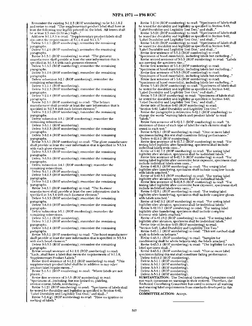
N F P A 1971 ~ F96 R O C
Renumber the existing 3-1.2.3 (ROP numbering) to be 3-1.1.8.2 and revise to read: "The supplementary product label shall have at least the following text legibly printed on the label. All letters shall be at least 2.5 mm (0.10 in.) bigh..." Add new 3-1.1.8.3 to read: "Supplementary product labels shall
als~ meet tile reqnirements of 3-1.1.4 and 3-1.1.5." Delete 3-1.2.5 (ROP numbering); renumber the rein:thing
paragraphs. Delete 3-1.2.6 (ROP numbering); renumber the remaining
paragrapbs. Revise 3-1.3.1 (ROP numbering) to read: "The garment
manufacturer sh:dl provide at least the user infi)rmation that is specified in ~G1.3.4 with each garment element."
Delete 3-1.3.5 (ROP numbering); renumber the remaining paragraph s. Delete 3-1.3.6 (ROP numbering); renumber the remaining
paragra[~tls. Delete subsection 3-2.1 (ROP numbering); renumber the
remaining subsections. Delete 3-2.1. l (ROP numbering). Delete 3-2.2.3 (R()P numbering); renumber the remaining
paragraphs. Delete 3-2.2.4 (ROP numbering); renumber the remaining
paragrapl/s. Revise 3-2.3.1 (ROP numbering) to read: "The helmet
manutacmrer shall provide at least tile user information that is specified in 3-2.3.4 with eacb helmet element."
Delete 3-2.3.5 (ROP numbering); renumber the remaining paragraphs. Delete subsection 3-3.1 (ROP numbering); renumber the
remaining subsections. Delete 3-3.1.1 (ROP numbering). Delete 3-3.2.3 (ROP numbering); renmnber the remaining
paragraphs. " Delete 3-3.2.4 (ROP numbering); renumber the remaining
paragraphs. Revise 3-3.3.1 (ROP numbering) to read: "The glove manufacturer
shall provide at least the user information that is specified in 3-3.3.4 with each glove element."
Delete 3-3.3.5 (ROP nmnbering); renumber the remaining paragraphs.
Delete 3-3.3.6 (ROP numbering); renumber the remaining paragraphs.
Delete subsection 3-4.1 (ROP numbering); renumber the remaining subsections.
Delete 3-4.1.1 (ROP numbering). Delete 3-4.2.3 (ROP numbering); renumber the remaining
paragraphs. Delete 3-4.2.4 (ROP numbering); renumber the remaining
paragraphs. Revise 3-4.3.1 (ROP numbering) to read: "The footwear
manufacturer shall provide at least the user information that is specified in 3-4.3.4 with each footwear element."
Delete 3-4.3.5 (ROP numbering); renumber the remaining paragraphs.
Delete 3-4.3.6 (ROP numbering); renumber the remaining paragvaphs.
Delete subsection 3-5.1 (ROP numbering); renumber the vemMning subsections.
Delete 3-5.1.1 (ROP numbering). Delete 3-5.2.3 (ROP numbering); renumber tile remaining
paragraphs. Delete 3-5.2.4 (ROP nulnbering); rennmber the remmning
paragraphs. Revise 3-5.3.1 (ROP numbering) to read: "The hood mantffacturer
shall provide at least the user information that is specified in 3-5.3.4 with each hood element"
Delete 3-5.3.5 (ROP numbering); renumber the remaining paragraphs. Revise second sentence of 4-1.2.2 (ROP numbering) to read:
"Each...shall have a label that meets the requirements of 3-1.1.8, Supplementary Product Labels."
Revise third sentence of 4-1.2.2 (ROP numbering) to read: "This supplemenutry product label shall be in addition to any other product label requirements..."
Revise 5-1.3.1 (ROP numbering) to read: "Where labels are not placed..."
Revise first sentence of5-1.5 (ROP numbering) to read: "Specimens of...inclnding, but not limited to, padding, reinfi)rcement, labels, interfacing..." Revise 5-1.21 (ROP numbering) to read: "Specimens of labels shall
be tested for durability and legibility as specified in Section 642, 'Lal)el Durability and Legibility Test One,' and shall..." Revise 5-2.4(g) (ROP numbering) to read: "Have no ignition or
melting of labels."
Revise 5-2.14 (ROP nmnbering) to read: "Specimens of labels shall be tested for durability and legibility ,as specified in Section 6-43, 'Label Durability and Legibility Test Two,' and shall..."
Revise 5-3.21 (ROP numbering) to read: "Specimens of labels shall be tested fi)r durability and legibility as specified in Section 6-42, 'Label DurabUity and Legibility Test One,' and shall..." Revise 5-4.20 (ROP numbering) to read: "Specimens of labels shall
be tested for durability and legibility as specified in Section 6-42, 'Label Durability and Legibility Test One,' and shall..." Revise first'sentence of 5-5.3 (ROP numbering) to read:
"Specimens of hood material(s), including labels but excluding..." Revise second sentence of 5-5.3 (ROP numbering) to read: "Labels
not meeting the specimen size..." Revise first sentence of 5-5.4 (ROP numbering) to read:
"Specimens of hood material(s), including labels but excluding..." Revise first sentence of 5-5.5 (ROP numbering) to read:
"Specimens of hood material(s), including labels but excluding..." Revise first sentence of 5-5.6 (ROP numbering) to read:
"Specimens of hood material(s), including labels but excluding..." Revise 5-5.10 (ROP numbering) to read: "Specimens of labels shall
be tested for durability and legibility ,as specified in Section 642, 'Label Durability and Legibility Test One,' and shall..." Revise 5-7.8 (ROP numbering) to read: "Specimens of labels shall
be tested for durability ,and legibility as specified in Section 6-43, 'Label Durability and Legibility Test Two,' and shall..." Revise title of Section 6-42 (ROP numbering) to read:
"Section 6-42, Label Durability mad Legibility Test One." Revise the paragraphs in subsection 642.1 (ROP numbering) to
change the words "warning labels and product labels" to read: "labels."
Revise first sentence of 6-42.2.1 (ROP numbering) to read: "A minimmn of three of each type of label for each element shall be tested in each test."
Revise 6-42.6.1 (ROP numbering) to read: "One or more label specimens falling this test shall constitute falling performance."
Delete 6-42.6.2 (ROP numbering). Revise first sentence of 6-42.7.1 CROP numbering) to read: "For
testing label l%dbility :ffter laundering, specimens-shall include individual labels sewn onto..." Revise of 6-42.7.2 (ROP numbering) to read: "For testing label
legibility ,ffter ab~tsion, specimens shall be individual labels." Revise first sentence of 6-42.7.3 (ROP numbering) to read: "For
testing label legibility after convective heat exposure, specimens shall include individual labels sewn onto..."
Revise 6-42.8.1 (ROP numbering) to read: "For testing label le~'bility after lanndering, ps ecimens shall include corn-rplete hoods wtth labels attached."
Revise of 6-42.8.2 (ROP numbering) to read: "For testing label legibility after abrasion, specimens shall be individual labels." Revise first sentence of 6-42.8.3 (ROP numbering) to read: "For
testing label legibility after convective heat exposure, specimens shall include individual labels sewn onto..."
Revise 6-42.9.1 (ROP numbering) to read: "For testing label legibility after laundering, specimens shall include complete gloves with labels attached."
Revise of 642.9.2 (ROP numbering) to read: "For testing label legibility ,after abrasion, specimens shall be individual labels,"
Revise 6-42.10.1 (ROP numbering) to read: "For testing label legibility after laundering, specimens shall include complete footwear with labels attached."
Revise of 6-42.10.2 (ROP numbering) to read: "For testing label legibility ,after abrasion, specimens shall be individual labels."
Revise title of Section 6-43.(ROP numbering) to read: "Section 6-43; Label Durability and Legibility Test Two."
Revise 643.1,1 (ROP nnmbering) to read: "This test method shall apply to labels on helmets."
Revise 6-43.3.1 (ROP numbering) to read: "Samples for conditioning shall be whole helmets with the labels ,attached."
Revise 6-43.5.1 (ROP numbering) to read: "The legibility for each label specimen shall..." Revise 6-43.6.1 (ROP numbering) to read: "One or more label
specimens failing this test shall constitute falling performance. Delete 6-43.6.2 (ROP numbering). Delete A-3-1.1 (ROP numbering). Delete A-3-2.1 (ROP numbering). Delete A-3-3.1 (ROP numbering). Delete A-3-4.1 (ROP numbering). Delete A-3-5.1 (ROP numbering).
SUBSTANTIATION: The Technical Correlating Committee could not reach consensus on warnings in their entirety. Therefore, the Technical Correlating Committee has voted to remove all warning and warning label requirements from standards developed in this Project. COMMITTEE ACTION: Accept.
367
NFPA 1971 ~ F96 ROC
(D)g #296) 1971- 5 - (Various Sections): Accept SUBMITTER: Paul H. C~twford, Riverside, CA COMMENT O N PROPOSAL NO: 1971-21 RECOMMENDATION: Editorial corrections made by the He lmet T:~sk Group.
5-2.'2 Tide the table "Table 5-2.2", correct spelling of "gravitational'. 6-15.5.1 (~3rrect spelling ofsufficient. 6-17.5.1.1 Last sentence to read: "The velocity of the steel ball shall
be de te rmined at a distance not greater than 25 m m (0.8 in.) f rom point of impact."
6-19.5.2 Second sentence should read: "A toted of two penetrat ion teses fi~r each of the four envi romnenta l condit ions specified in 6-1.3, 6-1.5, 6-1.6, 6-1.7 and 6-1.8 shall be conduc ted in such a m a n n e r that at least one penetrat ion test shall be per formed in each of the test are:Ls def ined in Figure 6-1.8.1 ."
6-2'2.4.2 Second sentence should read: "The locking mechan i sm shall be used when the blade is being replaced or when the specimen is being moved into or f rom the testing position."
6-32.5.1 Rewrite to read: "Any cur rent leakage or evidence of breakdown shall be recorded for each footwear item."
6-48.5.2.'2 Second sentence should read: "All fi)ur sides of the outer shell of the protective clothing composite specimen shall be secured to the holder with cont inuous strips o f heavy-duty duct tape.
A-.%l.l.3(a) Should read: "(a) The warnings should be conspicuous. This could be sax.isfied if (A) the warning are nnaw)idably evident when the item is prepared for d o n n i n g or donned , ;rod (B) rite warning are clear and eye-catching, drawing the user to the warning."
A-4-1.12 Second sentence shou ld read: "Trim can be damaged by heat, but still appear to be in good cohdit ion when, in fact, it migh t have lost retroreflective properties." A-4-1.15.1 Thi rd sentence should read: "Utilizing three-quarter
length boots instead of protective trousers lead to increased burn iJ~jnry to the lower torso, since they significantly reduce leg, groin, and buttock protection." (Also note: elintinate hyphen between the words, "quarter length.")
A-4-3.5.2 (a) Rewrite to read: "Excess circtnrLference of the glove over the fingers and hand m a y b e permitted, but shall no t exceed 0.4 in. for any finger, or 1.5 in. Ibr the hand :Ls a whole."
A-3-1.3 Wet and Dry (~)ndidons. End of first sentence should read: "...the SET is per formed tinder wet, as well as dry conditions." (Elinfinate c o m m a :alter "dry.") A-6-16.4 Procedure 1: Medium and System Calibration. Fifth
sentence should read: "The measured peak per formance shonld equal (within 2 percent) the measured peak acceleration (in g's) times the weight of the drop ,assembly."
Appendix B: Total Heat Loss Test #16: Fifth sentence should read: "If (ktta collection c~mnot be comple ted within 4 hr after moun t ing the specimen on the test plate, the specimen shall be removed f rom the test plate and allowed to dry for at least 24 hr at 16 degrees C + 2.5 degrees C' (60 degrees F, +8 degrees F) before retesting." SUBSTANTIATION: None. COMMITTEE ACTION: Accept`
(Log #51) 1971- 6 - ( 1-3 AccessorieS): Reject SUBMITTER: Abbot tA. Lane, Firequip Helmets, Inc. COMMENT ON PROPOSAL NO: I971-21 RECOMMENDATION: Change the word "goggles r to "Partial Eye/ Face Protective Interface C omponen t s ~. SUBSTANTIATION: t inder the proposed specification, goggles are only one of the potential Partial Eye/Face Protective Interface Components , none of which are required in section 4-2.2. COMMITTEE ACTION: Reject. COMMITTEE STATEMENT: See Commit tee Action on (~gnmaent 1971-115 (Log #128).
(Log ~9) 1971- 7 - ( 1-3 Accessories): Accept SUBMITTER: Bill Grilliot, MOrning Pride Mfg (kg. COMMENT ON PROPOSAL NO: 1971-21 RECOMMENDATION: Remove -goggles- f rom definition of accessories. SUBSTANTIATION: Partial eye/goggle per formance requi rements are in standard. COMMITTEE ACTION: AccepL
(Log #120) 1971- 8 - ( 1-3 Accessories): Accept SUBMITTER: Kerry W. Gordon, Cairns & Brother, Inc. COMMENT ON PROPOSAL NO: 1971-21 RECOMMENDATION: Delete "goggles."
SUBSTANTIATION- Goggles are no longer an accessory, they are covered unde r partial eye/ face protective device. COMMITTEE ACTION: Accept`
(Log #35) 1971-9- (1-3 Brim Line): Accept . SUBMITrER: Dennis Stout, E.D. Bullard Company COMMENT O N PROPOSAL NO: 1971-21 RECOMMENDATION: Revise the definition of Brim Line to read:
Brim Line. A horizontal plane intersecting the point of the front open ing of the he lmet at the midsagital plane. SUBSTANTIATION: Brim line ,as currently described uses the reference "lowest point of the brim opening" which would lead you to select the rear of the helmet. By using the reference "brow" in
~ lace of brim, proper location for testing locates the front of the elmet.
COMMITTEE ACTION: Accept
(Log #52) 1971- 10 - (1-3 Dielectric Test Plane): Reject SUBMITI'ER: Abbott A. Lane, Firequip Helmets, Inc. COMMENT O N PROPOSAL NO: 1971-21 RECOMMENDATION:" Add "A plane that runs horizontally through the headform 1.3 cm + 6 m m above the reference plane" as specified in 6-31.4.2 (e). SUBSTANTIATION: The definition of the Dielectric Test Plane ° and 6-31.4.2(e) are conflicting. COMMITTEE ACTION: Reject` COMMITTEE STATEMENT: See Commit tee Action on Co~ranent 1971-335 (Log #379).
(Log #100) 1971- 11 - (1-3 Functional (New)): Accept SUBMITrER: Bill Grilliot, Morning Pride Mfg (~9. COMMENT O N PROPOSAL NO: 1971-21 RECOMMENDATION: Add to definitions:
Functional. The ability of an e lement or c o m p o n e n t of an e lement to cont inue to be utilized for its in tended purpose. SUBSTANTIATION: Definition is also needed for 5-1.20, 5-2.13, 5- 3.20, 5-4.1, and 5-4.19. COMMITTEE ACTION: Accept.
( l_xJg #209) 1971- 12 - (1-3 Lettering (New)): Reject SUBMITTER: Janice Lzff'rance, 3M COMMENT ON PROPOSAL NO: 1971-21 RECOMMENDATION: Add the following defni f ion:
Lettering. A retroreflective single character(s) a t tached to the back of tile outermost surface of protective ensemble used for identification and visibility enhancement , SUBSTANTIATION: Lettering is included in the body of the d o c u m e n t requir ing the f lame resistance test, however, no definition is provided. COMMITTEE ACTION: Reject. COMMITTEE STATEMENT: Standard definition by Websters is stffficient. Let ter ing does not need to be reflective.
(Log #CCI) 1971- 13 - (1-3 Model, 2-4): Accept SUBMITrER: Technical Correlating Commit tee on Fire and Emergency Services Protective Clothing and Equipment COMMENT ON PROPOSAL NO: 1971-21 RECOMMENDATION: Add new definition for "Model" to Section 1-3 to read:
1-3 Model. The collective te rm used to identify a group of individual e lements o f the same basic design ,and componen ts f rom a single manufac tnre r produced by the same manufac tur ing and quality assurance procedures that are covered by the same certification.
Add a new Section 2-4 to read: 2-4 Recertification. 2-4.1 All individual e lements of the protective ensemble that are
labeled as being compliant with this s tandard shall undergo recertification on ,an annual basis. This recertification shall include inspection and evaluation to all design requirements and testing to ,all per formance requi rements as required by this s tandard on all mantffacturer models and components .
2-4.1.1 Any change tha t affects the e lement ' s performance u n d e r the design or performance requi rements o f this s tandard shall constitute a different model.
368
NFPA i971 - - F96 ROC
2-4.1.2 For the purpose of this standard, models shall include each unique pattern, style, or design, of the individual element.
2-4.2 Samples of manufac turer models mid componen t s for recertification shall be acquired f rom the manufac turer or componen t supplier dur ing r andom mid t , nannounced visits ms part of the follow-up inspection progrmn.
2-4.3 The manufac ture r shall maintain all design and performance inspection and test data f rom the certification organization used in the recertification of n lmmfacturer models and components . The manutktctnrer shall provide snob data, upon request, to the purchaser or authority having jurisdiction.
Renumber exist ing Section 2 4 as Section 2-5. SUBSTANTIATION: Within the Fire and Emergency Services Protective Clothing and Equipment Project, recertification is already required in s me do : u m e n t s a n ;1, for c)nsistency, the Technical Correlating Commit tee will see that it is added ra) each documen t that does not currently have it dur ing the normal revision process.
The periodic recertitmation of compliant product is a necessary measure to assure that the future production of compliant product cont inues to be compliant. Without specific criteria for retesting and recertification, different certification organizations could have widely divergent programs and the possibility of nnncompl iml t product being produced and reaching the field is significantly increased. COMMITTEE ACTION: Accept.
(La N #36) 1971- 14 - (1-3 Model Weight): Reject SUBMITrER: Dennis Stout, E.D. Bullard Company COMMENT O N PROPOSAL NO: 1971-'21 RECOMMENDATION: Delete the definition of Model Weight. SUBSTANTIATION: Accessories negates the use of reference to Model Weight. The definition of Basic Weight defines the need for all componen ts required lbr certification approval. All other c o l n p o n e n t s are defined as accessories. COMMITTEE ACTION: Reject. COMMITTEE STATEMENT: Model weight definition is needed in the d o c u m e n t for unders tand ing of the labeling requ i rement and to differentiate between model weight and basic weight. -
(Log #145) 1971- 15 - (t-3 Outersbeli): Reject SUBMITTER: Rober tT . Montgomery~Hoechst Celanese Corp. COMMENT O N PROPOSAL NO: 1971-21 RECOMMENDATION: Revise text as fi)llows:
Outershell . The outer most layer of the composite designed for primary flame Drotection. The outer shell does not include U-im, hardware, reinlorcing materials, ~md wristlet material. SUBSTANTIATION: Moisture and thermal barrier definitions both include the primary purpose of the barrier. The outer shell definition does not as written and should. COMMITTEE ACTION: Reject. COMMITTEE STATEMENT: The definition applies to all elements, not jus t garments, ~md the outer shell provides other prilnary protection in addition to flame.
(Log #38) 1971- 16 - (1-3 Partial Eye/Face Protective Interface Component ) : Reiect SUBMITrER: Dennis Stout, E.D. Bullard Company COMMENT O N PROPOSAL NO: 1971-21 RECOMMENDATION: Revise definition o f Partial Eye/Face Protective Interface C o m p o n e n t to read:
"Partial Eye/Face Protective "Device'." SUBSTANTIATION: All sections that refer to Partial Eye/Face Protective "Interface Component" should be replaced with "Device". Device defines in a clearer fashion the subject that is referenced. This will also permit/~onsistency in the d o c u m e n t where device is used in place of interface c o m p o n e n t as now written. COMMITTEE ACTION: Reject. COMMITTEE STATEMENT: See Commit tee Action on C o m m e n t 1971-115 (Log #128).
(Log #39) 1971- 17 - (1-3 Partial Eye/Face Protective Interface Cmmponent) : Roec t
BMITTER: Dennis Stout, E.D. Bullard Company COMMENT O N PROPOSAL NO: 1971-21 RECOMMENDATION: Delete all references to Eye/Face Protective Interface Componen t s or Device. Replace these references with faceshield per formance requi rements as written in NFPA 1972, Helmets tbr Smlctural Fire Fighting, 1992 edition.
SUBSTANTIATION: Current Report on Proposals creates potential hazard for personal inju ry be el iminat ing the requ i rement of eye /
• face protection being mancLatory on the helmet. Additional eye protection is not forbidden in NFPA 1972-1992 and is in fact r e c o m m e n d e d in Appendix A-I-3. Current ROP actually diminishes one level o f protection by el iminating coverage of the "face" in design limits. COMMITTEE ACT10 N: Reject. COMMITTEE STATEMENT: The Technical Commit tee has chosen to require faceshield a n d / o r goggles, therefore adop t ing 1972 language vefl:,atim would not meet the intent of the Technical ( ',ommittee.
(Log #37) 1971- 18- (1-3 Retroreflection): Reject SUBMITTER: Dennis Stout, E.D. Bullard Company COMMENT O N PROPOSAL NO: 1971-21 RECOMMENDATION: Delete the definition of Retroreflection. SUBSTANTIATION: Cumbersome ,and complex without purpose. The definition Retrorefiective Markings states clearly the purpose of retroreflectivity and needs not be duplicated. COMMITTEE ACTION: Reject. COMMITTEE STATEMENT: The commit tee disagrees with the submit ter and believes both definitions are needed fi)r clear unders tanding.
(Log #298) 1971- 19 - (1-3 Separate): Reject SUBMITrER: Jeffrey O. Stull, International Personnel Protection, Inc. COMMENT O N PROPOSAL NO: 1971-21 RECOMMENDATION: Revise definition for "Separate" as follows:
Separate. A material response as evidenced by full or partial delamination, flaking or visible loss o f nmterial, and splitting. SUBSTANTIATION: Separation as currently def ined remains ambiguous and does no t ,allow the testing laboratory to consistently interpret this phenomena . The revised definition permits a clearer interpretation. COMMITTEE ACTION: Reject. COMMITTEE STATEMENT: The definition of "separate" is s tandardized among all the documents in this Project. ( :hanging this definition could adversely affect items beyond the isst,e addressed in Public C o m m e n t 1971-273 (Lx~g#405).
(D)g #346) 1971- 20 - (1-3 Thermal :rod Moisture Facing (New)): Reject SUBMITI'ER: Donald Aldridge, Lion Apparel, Inc. COMMENT O N PROPOSAL NO: 1971-21 RECOMMENDATION: Add a new definition to read:
Thermal and Moisture Facing. Tha t part o f the protective ga rmen t which connects to the thermal liner ,and moisture b a m e r an d is used to satisfy the over lap requirements of this standard. SUBSTANTIATION: A public c o m m e n t has been sent in which adds this term to 4-1.4. See 1971-81 (Log #360). COMMITTEE ACTION: Reject. COMMITTEE STATEMENT: See (~mmfit tee Action on O~mment 1971-81 (Log #360).
(Log # 144) 1971- 21 - (1-3 Thermal Barrier): Reject SUBMITI'ER: Robert T. Montgomery, Hoechst C, elanese Corp. COMMENT O N PROPOSAL NO: 1971-21 RECOMMENDATION: Revise text as follows:
Thermal Barrier. The portion o f thep ro tec t ive ensemble e lement composite that is des igned to provide thermal conduct ion protection. SUBSTANTIATION: Thermal protection is too wide a definition. For example, it could mean flame protection. COMMITTEE ACTION: Reject. COMMITTEE STATEMENT: Standardized definition has been developed by the commit tee for this term.
369
N F P A 1971 ~ F 9 6 R O C
(Dog #2!0) 1971-22- (1-3Trim): Reject SUBMITYER: Janice LaFrance, 3M COMMENT ON PROPOSAL NO: 1971-21 RECOMMENDATION: Add the following to the Trim definition aftex die word material in ~he fist sentence: "2 in. a n d / o r 3 in. in width." SUBSTANTIATION: Provides clarificati~n and distinguishes trim from ~ preventing confusion between the two definitions. COMMITTEE ACTION: Reject. COMMITTEE STATEMENT: The Commit tee feels this is design restrictve.
(Log #101 ) 1971- 23 - (1-3 Vertical (New)): Reject SUBMITFER: Bill Grilliot, Morning Pride Mfg (k). COMMENT ON PROPOSAL NO: 1971-21 RECOMMENDATION: Add to definitions: Vertical. Being at r ight angle to the horizon.
SUBSTANTIATION: Definition is needed for tr im on garments 4- 1.14.5. COMMITTEE ACTION: Reject. COMMITTEE STATEMENT: StandardWebsters definition.
(Log #17) 1971- 24 - ( (~ap te r 2 TCC Note I): Reject SUBMITrER; Patricia A. Freeman, Globe Manufactur ing (k~., Inc. COMMENT ON PROPOSAL NO: 1971-21 RECOMMENDATION: Errata as appeared in the Fire News:
Reject TCC proposal for required annual retesting. SUBSTANTIATION: This subject was discussed at several Technical (~k~mmittee Meetings dur ing the last three years. The consensus has been that it would add avery cosdy burden to the fire service, with little reu~rn. As the s tandard is currently worded:
2-3.9 Any change ilt the design, construction, or material o f a compliance product shall necessitate new inspection and testing to verify compliance to ;dl applicable requi rements of this s tandard such that t.lle certification organization determines can be ,affected by such change. This recertification shall be conduc ted before labeling the modified product as being compl iant with this standard.
This r eqn i rement by itseff insures that there can be no changes without the approval o f the third party lab and f f the third party lab is already doing their jobs, the addit ion and manda ted yearly recerfification of the entire process is r ed tmdan t and extremely expensive. COMMITTEE ACTION: Reject. COMMITTEE STATEMENT: See (12Jmmittee Action on (k )mment 1971-13 (Log #CC1).
(Log #129) 1971- 25 - (£hhapter 2 TCC Note 1): Reject SUBMITrER: Peter Witch, FireGear Inc. COMMENT O N PROPOSAL NO: 1971-21 RECOMMENDATION: There has been a proposal on annual recertification of certified products and the Technical Correlating G~mmittee is seeking input on this proposal. SUBSTANTIATION: The cur ren t edition of NFPA 1971 (1991) requires third party certification. The proposed draft of the 1996 edition, section 2-2.7 requires r andom sampl ing and inspection of products to verify compliance to die s tandard. T h e 1996draft also requires a Manufaculrer ' s Quality Assurance Program. Requir ing manufacturers to perform annua l recertification o f c e r t i f e d p r ,duc t s is redundant . There is a large cost ,associated with this and the fire service would bear the cost. Protective clothing naanufactnrers would reduce the n u m b e r o f designs and Options made av;dlable to the fire service. Protective clothing manufac turers that produce goods u n d e r o ther NFPA (i.e., 19991, 1975, 1976) s tandards are already us ing Manufacturer ' s Quality Assurance Programs. These quality assurance programs are audi ted by the third party certifier. Any changes made to designs, materials and " construction methods are required to be recertified or tested. The cur rent system is working without annual recertification. COMMITTEE ACTION: Reject. COMMITTEE STATEMENT: See Commit tee Action on £ b m m e n t 1971-13 (IJ)g #CC1).
1971- 26 - (2-2.7): Reject (D)g #5) SUBMITTER: Patricia A. Freeman, Globe Manufactur ing Co., Inc. COMMENT ON PROPOSAL NO: 1971-21 RECOMMENDATION: Delete s e c t o n on sample product.
The requ i rement will now read: 2-2.7 The certification organization shall have a follow-up
inspection program of the manufac tur ing facilities of the cer t i fed product, with at least two r andom and u n a n n o u n c e d visits per 1"2- mon th period. SUBSTANTIATION: Since many g a ~ e n t manufacnl rers produce
custom made gear, taking a comple ted ga rmen t f rom a production line for testing could cause hardship to the fire fighter whose gear was chosen. I ra deparmaent has waited the normal cycle t ime for production, it wolfld be unfair to expect them to wait an additional cycle for gear that was destroyed in r andom testing. In the case o f taking gear f rom open market, there is no provision to insure that the gear was rnantffactured at a certain date or is in like new condition. Even gear that has only been sitting on a sheff can show signs o f deterioration if no t properly s tored and this is a c i rcumstance over which the manufac tu re r has no control. If an i ndependen t testing agency is doing its job, it will be able to identify, segregate, and test all pieces of the final product without the need to destroy customized gear. If an i ndependen t lab is no t going itsjob, adding ano ther requ i rement will no t help. COMMITTEE ACTION: Reject. COMMITTEE STATEMENT: The cur ren t text allows three sampl ingcho ices and the (kJmmittee feels that the manufac ture r has responsibility for its product in the open market prior to purchase.
1971- 27 - (2,2.7): Reject (Log #21) SUBMITTER: O~ristopher Gandette, Reflexite Corporation COMMENT O N PROPOSAL NO: 1971-21 RECOMMENDATION: The following sentence should be added as the third sentence in section '2-2.7:
"All samples of product chosen by the certification organization shall be representative o f the f inished product." SUBSTANTIATION: It is impor tan t that the materials taken for test are representative of the f inished product. It is no t appropriate to test a material that is a c o m p o n e n t o f the f inished product. If materials and samples are to be taken f rom the manufacturers product ion line, they should be taken only f rom the final stage and not inter im stages. COMMITTEE ACTION: Reject. COMMITTEE STATEMENT: The suggested language is r e d u n d an t to the requirement . Submitter s h o u l d s e e definition for "Product".
(Log #CC4) 1971- 28 - (2-2.9, A-2-2.9): Accept SUBMITrEIR: Technical Commit tee on Structural Fire Fighting Protective Clothing and Equ ipment COMMENT ON PROPOSAL NO: 1971-21 RECOMMENDATION: Add a new 2-2.9 to read:
2-2.9* The certification organization shall require the manufac ture r to have a product recall system as part of the manufac turer ' s quality assurance program.
R e n u m b e r the remaining paragraphs. Add a new A-2-2.9 to read: A-2-2.9 For filrther information and guidance on recall programs,
see Tide 21, Code of Federal Regallations, Part 7, Subpart C (21 CFR 7, Subpart C). SUBSTANTIATION: The Technical Correlating Commit tee has r e c o m m e n d e d new text for Chapter 2 that applies to product certification mid quality control. This text applies to all p roduct and is to be added to all document s within-the Project. COMMITTEE ACTION: Accept.
(Log #300) 1971- 29 - (2-9.1 (New)): Accept SUBMITTER: Jeffrey o . Stull, International Personnel Protection, Inc. COMMENT O N PROPOSAL NO: 1971-21
[ RECOMMENDATION: Provide test matrix tables for garments ,
I gloves, hoods, and footwear. See proposed paragraphs and tables below.
R e n u m b e r paragraph 2-9.1.1 ,as 2-9.1.2.
370
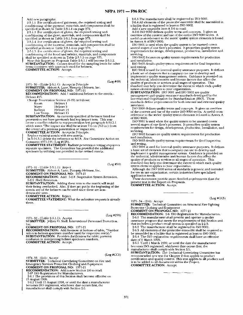
N F P A 1971 ~ F96 R O C
Add new paragraphs: 2-3.1.1 For certification of garments , the required testing and
condit ioning of the garment , materials, and componen t s shall be specified as shown in Table 2-3.1.1 on page 372.
2-3.1.3 For certification of gloves, the required testing and condi t ioning of the glove, materials, and componen t s shall be specified as shown in Table 2-3.1.3 on page 373.
2-3.1.4 For certification of gloves, the required testing and condi t ioning of the fi~otwear, materials, and componen ts shall be specified as Shown in Table 2-3.1.4 on page 374.
2-3.1.5 For certification of gloves, the required testing and condi t ioning of the hood and wristlet, materials, and component~ shall be specified as shown in Table 2-3.1.5 on page 375.
Note that Report on Proposals Table 2-3.1.1 will become 2-3.1.2. SUBSTANTIATION: Creates detail for the sampl ing levels for o ther items consistent with approach used for helmets. COMMITTEE ACTION: Accept.
(Log #49) 1971-30- (Table 2-3.1.1): Accept in Principle SUBMITrER: Abbott A. Lane, Firequip Helmets, Inc. COMMENT O N PROPOSAL NO: 1971-21 RECOMMENDATION: Add 1 additional he lmet to the matrix - Helmet #15.
C, hange Penetration Section (6-19) ,as fi~llows: Room Helmet 1 Water Hehne t 3 Radien t Helmet 14 Low Temp. Helmet 15
SUBSTANTIATION: As currently specified all helmets listed for penetrat ion test have previously had top impact tests. This may create a conflict relative to top penetrat ion test paragraph 6-19.5.1 which states "The impact site shall be at least 7.6 cm (3.0 in.) f rom the center of a previous penetrat ion or impact site. COMMITTEE ACTION: Accept in Principle.
Replace existing matrix with new matrix. In 6-16.3.1 delete the reference to 6-t.8. See C~ommittee Action on
C o n m m n t 1971-115 (Log #128). COMMITTEE STATEMENT: Radiant penetrat ion testing requires a separate specimen. The Commit tee has provided the additional specimen by utilizing one provided in the revised matrix.
( LOg #50) 1971- 31 - (Table 2-3.1.1): Reject SUBMITTER: Abbott A. l~me, Firequip Helmets, Inc. COMMENT ON PROPOSAL NO: 19'71-21 RECOMMENDATION: Add: 5-2.8 Suspension System Retention.
5-2.9 Shell Retention. SUBSTANTIATION: Adding these tests to the matrix will avoid their being overlooked. Also, if they ,are put in the beginning of the matrix any of the helmets can be nsed since these are non- destructive tests.. COMMITTEE ACTION: Reject. COMMITTEE STATEMENT: What the submit ter requests is already there.
(L~g #299) 1971- 32 - (Table 2-3.1.1): Accept SUBMITrER: Jeffrey o . Stull, International Personnel Protection, Inc. COMMENT ON PROPOSAL NO: 1971-21 RECOMMENDATION: Add foomote at bot tom of table, "Number refers to hehne t specimen n u m b e r used for respective test(s)." SUBSTANTIATION: Provides clarification for table; prevents coiffusion in interpret ing he lmet specimen numbers . COMMITTEE ACTION~ AccepL
(Log #CC2) 1971- 33 - (2-6): Accept SUBMITrER: Technical Correlating Commit tee on Fire and Emergency Services Protective f_aothing and Equipment COMMENT ON PROPOSAL NO: 1971-21 RECOMMENDATION: Add a new Section 2-6 to read:
2-6* ISO Registration for Manufacturers. 2-6.1 The provisions of this Section shall become effective on
15 Augatst 1998. 2-6.2Until 15 August 1998, or until the date a mannfacuwer
becomes ISO registered, whichever date occurs first, the manufac tnrer shall comply with Section 2-5.
2-6.3 The manufac ture r shall be registered to ISO 9001. 2-6.4 All e lements of the protective ensemble shall be assembled in
a facility that is registered at least to ISO 9002. Add a new appendix i tem A-2-6 to read: A-2-6 ISO 9000 defines quality terms and concepts. It gives an
overview of the con ten t and use o f the entire ISO 9000 series. A useful cross-reference to the series' quality system elements is found in Annex A o f lSO 9000.
ISO 9001 is used when the quality system to be assessed covers several stages of one f irm's processes. It prescribes quality system requirements for design, development, production, installation and servicing.
ISO 9002 fi)cuses on quality system requirements for production and installation.
ISO 9003 details qu:dity system requirements for final inspection and testing.
IS() 9004 is used for internal quality assurance purposes. It defines a basic set of e lements that a company can use to develop and implement a quality m a n a g e m e n t system. Guidance is provided on the technical, administrative and humml factors that ,affect the quality of products or services at all stages o f operation. This st,andatrd may help you determine the extent to which each quality system e lement applies to your organization. SUBSTANTIATION: ISO 9001 and ISO 9002 are quality m a n a g e m e n t and quality assur,'mce st,andards developed by the International Organization for Standardization (1SO). These stanchrds define requirements for both internal and extern=d quality a s s n Fal3 c e ,
ISO 9000 defines quality terms mid concepts. It gives an overview of the con ten t and use of the entire ISO 9000 series. A usefld cross- reference to the series' quality system elements is f oun d in Annex A of ISO 9000.
ISO 9001 is used when the quality system to be assessed covers several stages of one f irm's processes. It prescribes quality system requirements for design, development, production, installation, an d servicing.
ISO 9002 focuses on quality system requirements for production and installation.
ISO 9003 details quality system requirements tbr final inspection and testing.
ISO 9004 is used fi)r internal quality assurance purposes. It defines a basic set o f e lements that a company can use to develop an d implemen t a quality m a n a g e m e n t system. Gui&ance is provided on the technical, administrative and h u m a n factors that affect the quality of products or services at all stages of operation. This st~mdard may help you de termine the extent to which each quality system e lement applies to your organization.
Although the IS() 9000 series of s tandards is generic and in tended for use in may organization, cert;dn industries have specialized application needs.
These document s provide more detailed requirements than the present text in the Report on Proposals. COMMrITEE ACTION: Accept.
(Log #CC5) 1971- 34 - (2-6): Accept SUBMITTER: Technical Commit tee on Structural Fire Fighting Protective Clothing and Equ ipment COMMENT ON PROPOSAL NO: 1971-'21 RECOMMENDATION: 2-6 ISO Registration for Manufacturers.
2-6.1 The manufac turer shal lprovide and operate a quality a s s u ~ m c e p r o g r a m that meets the requi rements of dais Section and that includes a product recall system ,as specified in 2-2.9.
2-6.2 The manufac ture r shall be registered to ISO 9001. 2-6.3 All e lements of the protective ensemble shall be required to
be ,assembled in a facility tha t is registered at least to ISO 9002. 2-6.4 The ISO registration requirements shall have an effective
date of 1 March 1999. 2-6.5 Until 1 March 1999, or until the date the mantffacturer
becomes ISO registered, whichever date occurs first, the mantffacturer shall comply with Section 2-5. SUBSTANTIATION: The Technical Cx~rrelating Commit tee has r e c o m m e n d e d new text for Chapter 2 that applies to product certification and quality control. This text applies txj all p roduct ,and is to be added to all document s within the Project. COMMITTEE ACTION: Accept.
371
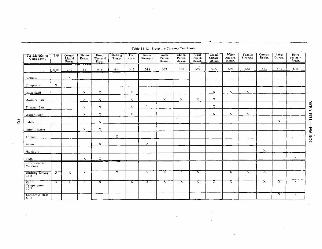
t . - I
Table 2-3.1.1 Protective Garment Test Matrix
Test Material or TPP Overall Flame Heat / Melting Tear Seam Water Chem. Viral Clean. Water Tensile Corros. Label Retro- Component Lkluid Resist. Thermal Temp. Resist. Strength Penei. Penet. Penet. Chrink. Absorb. Strength Resist; Durab. reflect/
Penet, Resist. Resist. Resist. Resist. Reisst. Resist. Fluor. I
6-10 ] 6-49 6-2 6-16 6-11 6-12 6-14" 6-27 6-28 6-29 6-25 6-26 6-51 6-30 642 6-46 I
Clothin~ X . . . .
Composite
Outer Shell X X X X X X
Moisture Barr. X X X X X X X
The, 'mal Barr. X X X X
Winter Liner X X X X X
Labels X
x
x
X
Othe, Textiles
Thread
Seams
Hardware
Tr im
'Environmenta~ Condition
Washing /DtTing 6-1.2
Room Tempera tu re 6-1.3
Convective Heat 6-1.7
X
X
X X
'J X X X X
X X
X
X X
X X X X
X X
Z ,.¢
~ D
i,,,,,t
I O ' ,
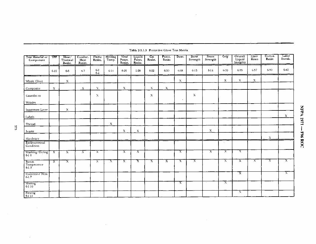
I i
Table 2-3.1.3 Protective Glove Test Matrix
T~,M~,~o~I.~ I .o~ I~oo~u~ J ~,am~l.o,~l V~ I~.~1 ~o, I .u.~ [O~[ "~ [ So.m L ~i~ IOv~ra I Lio~ Component Thermal Heat Resist. Temp. Penet. .~net. Resist. Resist Strength Strength Liquid Reten Resist. Resist. Resist. R .'sist. , ,,. Integrity
, , , , ,
Corros. ] Label Resist Durab.
6-30 [ 6-42
Wbole Glove X X
Composite X X X X X X
Gauntlet or X X
Wristlet
Innermost Laver X
Labels
Thread X
Seams X X
Hardwale Emironmental Condition
W~hing/Dry ing X X X X X X X 6-1.2
Room X X X X' X X X X X Temperature 6-1.3
Convective Heat 6-1.7
Wetting X 6-1.10
Flexing 6.1,11
X X X
X
X
X
X X
X X
X
Z
I
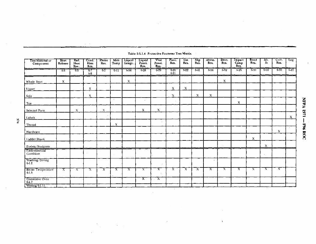
~o
Test Material or Component
Whole Boot
Upper
Sole
Toe
Selected Parts
Labels
Thread
Hardware
Ladder Shank
Eyele,ts/'Studposts
Environmental Condition
Washing/Drying 6-1.2
Room Temperature 6-1.3
Convective Oven 5-1.7 Wetting 6-1.11
d i • I " - t e l I I I
Table 2-3.1.4 Protective Footwear Test Matrix
Release Heat Heat Res. Temp lntegr, Penet. Penet. Res. Res. Res. Res. ges. C~er~y Res. St Res. Res.. Res. Res. Res.. . . . .
I ~ 1 ~ l ~ s l ~ J ~ i "~ I "~ I "~ I ~°~:1 "~ I ~ I ' ~ i "~ I " ~ I ~o I ~o 1 .o I ~
x x x
'1 X X X
X X X X
X X X X
, X
I I r'
X
I I I X
X X X X X X 'X X X X X X X X X X X
X X
2
, q
I
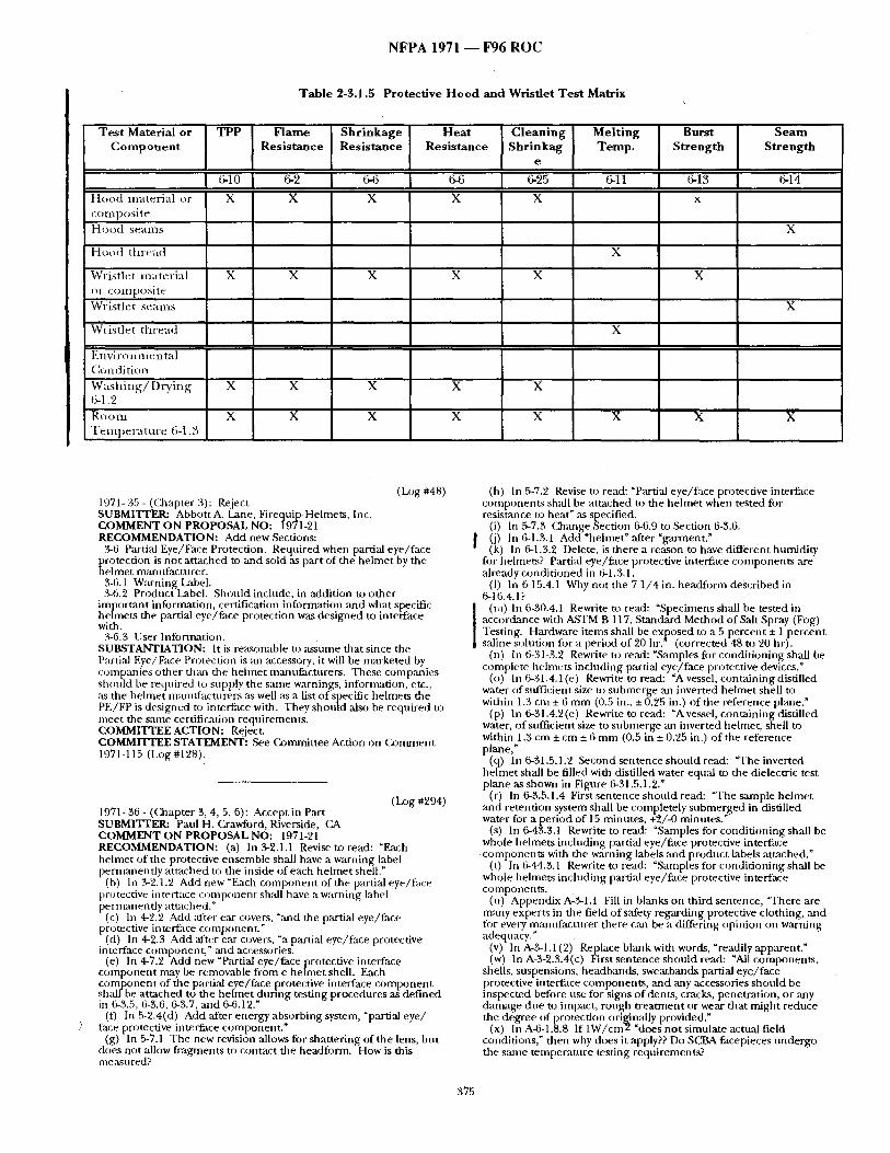
N F P A 1971 ~ F96 R O C
Table 2-3,1.5 Protective Hood and Wristlet Test Matrix
Test Material or Component
H o o d m a t e r i a l o r r o t t l p o s i t e
H o o d sealllS
H o o d t t ll't~Ttt:l
Wr i s t l e t m a t e r i a l tit- c o l l I p o s i t e
W r i s t l e t s e a m s
Wr i s t l e t t h r e a d
E n v i r o n i n e n t a l C o n d i t i o n
W a s h i n g / D r y i n g 6-1.2
Ro o Ill T e m p e r a t u r e 6-1,3
TPP
I 6-10 X
X
X
X
Flame Resistance
6-2
X
X
Shrinkage Resistance
6-6
X
X
Heat Resistance
6-6
X
X
Cleaning Shrinkag
e
6-25
X
X
Melting Temp.
6-ll
X
Burst Strength
6-13
Seam Strength
X
X
X
X X X X
X X X X X , X X
(D)g #48) 1971- 35 - (Chapter 3) : Reject SUBMITTER: Abbott A. Lane, Firequ!p Helmets, Inc. COMMENT ON PROPOSAL NO: 1971-21 RECOMMENDATION: Add new Sections:
3-6 Partial Eye/Face Protection. Required when partial eye/ face protection is no t a t tached to and sold as part of the he lmet by the he lmet manufacturer .
3-6.1 Warning Label. 3-6.2 ProductLabel . Should include, in addition to o ther
impor tan t information, certification information and what specific hehnets the partial eye/face protection was des igned to interface with.
3-6.3 User Information. SUBSTANTIATION: It is re:tsonable to assume that since the Partial Eye/Face Protection is zm accessory, it will be marketed by companies o ther than the hehne t mzmufactnrers. These comp~mies should be required to supply the same warnings, information, etc., as the he lmet manufacturers as well as a list of specific helmets the PE/FP is designed to interface with. They should also be required to meet the Salne certification requirements . COMMITTEE ACTION: Reject. COMMITTEE STATEMENT: See Commit tee Action on Gommen t 1971-115 (Log #128).
(Log #294) 1971- 36 - (Chapter 3, 4, 5, 6): Accept in Part SUBMITTER; Patti H. Crawford, Riverside, (2& COMMENT ON PROPOSAL NO: 1971-21 RECOMMENDATION: (a) In 3-2.1.1 Revise to read: "Each helmet of the protective ensemble shall have a warning label permanent ly a t tached to the inside of each he lmet shell."
(b) In 3-2.1.2 Add new "Each componen t of the partial eye/face protective interface c o m p o n e n t shall have a warning label perntanentiy atmcbed."
(c) In 4-2.2 Add al'ter ear covers, "zmd the partial eye/face protective interface component . "
(d) In 4-2.3 Add alter ear covers, "a partial eye/face protective interface component , " and accessories.
(e) In 4-7.2 Add new "Partial eye/face protective interface c o m p o n e n t may be removable f rom e he lmet shell. Each c o m p o n e n t of the partial eye/face protective interface c o m p o n e n t shal l be at tached t o t h e he lmet dur ing testing procedures a~ def ined in 6-3.5, 6-3.6, 6-3.7, and 6-6.12."
(f) In 5-2.4(d) Add after energy absorbing system, "partial eye / face protective interface component . "
(g) In 5-7.1 The new revision allows for shat ter ing of the lens, but does not allow f ragments to contact the headform. How is this me:Lsu red?
(h) In 5-7.2 Revise m read: "Partial eye/face protective interface componen ts shall be a t tached to the he lmet when tested for resistance to heat" ,as specified.
(i) In 5-7.3 Change Section 6-6.9 to Section 6-3.6. 0) In 6-1.3.1 Add "helmet" after "garment." (k) In 6-1.3.2 Delete, is there a reason to have different humidity
fi)r helmets? Partial eye/face protective interface componen ts ,are already condi t ioned in 6-1.3.1.
(1) In 6-15.4.1 Why not the 7 1 /4 in. headform described in 6-16.4.1?
(ra) In 6-30.4.1 Rewrite to read: "Specimens shall be tested in accordance with ASTM B 117, Standard Method of Salt Spray (Fog) Testing. Hardware itents shall be exposed to a 5 percent + 1 percent saline solution for a period of 90 h r . " (corrected 48 to 20 hr).
(n) In 6-31-3.2 Rewrite to read: "Samples for condi t ioning shall be complete hehnets including partial eye/face protective devices."
(o) In 6-31.4. I (e) Rewrite to read: "A vessel, conta ining distilled water of sufficient size to submerge ,an inverted he lmet shell to within 1.3 cm ± 6 m m (0.5 in., +0.25 in.) of the reference plane."
(p) lit 6-31.4.2(e) Rewrite to read: "Avessel, containing distilled water, of sufficient size to submerge an inverted helmet, shell to within 1.3 cm ± cm + 6 m m (0.5 in ± 0.25 in.) of the reference plane,"
(q) In 6-31.5.1.2 Second sentence should read: "The inverted helmet shall be filled with distilled water equal to the dielectric test plane as shown in Figure 6-31.5.1.2."
(r) In 6-3.5.1.4 First sentence should read: "The sample he lmet and retention system, shall, be corn p letely submerged, in distilled water for a per iod of 15 minutes, +2/-0 minutes."
(s) In 6-43.$.1 Rewrite to read: "Samples for condi t ioning shall be whole helmets including pamal eye/face protective interface componen ts with the warning labels ~md product labels attached."
(t) In (5-44.3.1 Rewrite to read: "Samples for condi t ioning shall be whole helmets including partial eye/face protective interface components .
(n) Appendix A-3-1.1 Fill in blmlks on third sentence, "There are many expert.s in the field of safety regarding protective clothing, mad fi)r every mamffacturer there can be a differing opinion on warning adequacy."
(v) In A-3-1.1 (2) Replace blank with words, "readily apparent." (w) In A-3-2.3.4(c) First sentence should read: "All components ,
shells, suspensions, headbands, sweatbands partial eye/ face protective interface components , and any accessories should be inspected before use for signs of dents, cracks, penetrat ion, or any damage due to impact, rough t rea tment or wear that might reduce the degree of protection originally provided."
(x) In A-6-1.8.8 If 1W/cm2 "does no t simulate actual field conditions," then why does it apply?? Do SCBA facepieces unde rgo the same tempera ture testing requirements?
375
N F P A 1971 ~ F96 R O C
SUBSTANTIATION: The comments listed are provided by Hehnet T,~k Group members for consideration by the Technical Committee during public comment review. COMMITTEE ACTION: Accept in Part.
(a) Reject. (b) Reject. (c) Accept in Principle. (d) Accept in Principle. (el Reject. (t) Accept in Principle. (g) Reject. (h) Accept in f'rinciple. (i) Reject. (i) Accept. (k) Reject. (I) Reject. (m) Accept. (n) Accept in Principle. (o) R e j e c t . (p) Reject. (q) Accept in Principle. (r) Accept in Principle. (s) Accept in Principle. (t) Accept in Principle. (u) Reject. (v) Reject. (w) Accept in Principle~ (x) Reject.
COMMITTEE STATEMENT: (a) ,See (a)mrnittee Action on C.omment 1971-4 (Log #CC3).
(b) Technical Committee bas eliminated all warning labels. (c) See Committee Action on Comment 1971-115 (Log #128). (d) See Committee Action on Comment 1971-115 (Log #128). (el Technical Committee has made facesbields a n d / o r goggles a
mandatory helmet component . (f) See Gommittee Action on Comment 1971-115 ( l~g #128), (g) Improper format, asks a question. (h) See (2)mmittee Action on (}~mment 1971-115 (Log #128). (i) Not applicable to the paragraph. (k) See Committee Action on Comment 1971-115 (Lx)g#33), (1) Subnlitter asks a question, no proposal. (n) See (a)mmittee Action on Comment 1971-115 (Log #128). (o) Tap water is adequate. (p) Standard laboratory practice indicates no difference in results
with water used. (q) See Conmfittee Action on ( ~ m m e n t 1971-115 (D)g #128). (r) See Committee Action on Comment 1971-115 (la~g # 128). (s) See Committee Action on Comment 1971-115 (Log #128). (t) See Conmfittee Action on Comment 1971-115 (la:)g #128). (u) See Committee Action on Comment 1971-4 (Log#C, C3). (v) See Committee A(ztion on (2Jmment 1971-4 (La)g #(1(23). (w) See Cotmnittee Action on Comment 1971-115 (Log #128). (x) Submitter asks a question.
WARNING
For structural fire fighting operations, both protective coat and protective trousers must be worn for l imb/torso protection. Protective coat/protective trousers overlap is required by NFPA 1500. Outer shell, moisture barrier, and thermal barrier meeting requirements of NFPA 1971 must be utilized and ,all garment closures must be fastened when in use. Do not use protective coat ,and protective trousers alone for strncmral fire fighting operations; other protective equ ipment - helmet, SCBA, gloves, footwear, P/L% - is required for protection. Do not keep this garment in direct contact with flames. This garment may not provide protection fi~r proximity or fire entry applications or for protection from chemicM, radiological, or biological agents. Keep the garment clean as soiling will reduce protective qualities.
-DO NOT USE CHLORINE BLEACH-
Chlorine bleach will significantly compromise the protection afforded by the textile and film materials t,tilized in the construction of this garment. Users must clemL maintain, ,and ,alter only in accor&mce with manufacturer 's instruction. Do not store in direct , sunlight. No protective clothing can provide complete protection from all conditions. Use extreme care for all emergency operations. Failure to comply with these warnings may result in serious injury or death.
Underwriters Eaboratories classified mark Manufacturer's name Manufactt,rer's address (kmntry of mamtfactnre Manufacturer 's garment identification number [)ate of manufactnre Size Cleaning and drying instructions Fiber contents
"Do not remove this label"
SUBSTANTIATION: The existing label was the result of a consensus process and represents a true and accurate reflection of what the Technical Committee determined to be necessary minimum warnings to the fire service. The purpose of this label is not, and never has been, to protect the mantifacturer, but is in tended to protect the fire fighter who depends upon his NFPA compliant gear. Regardless of the current NFPA legal opinion, I firmly believe that the technical committee has a duty to the fire service to establish nfinimnm warnings.
Also, see my Public Comments on items 3-1.2.2, 1971-44 (Log #6) and 3.1.3.5, 1971-55 (Log #7). COMMITTEE ACTION: Reject. COMMITTEE STATEMENT: See Committee Action on Comment 1971-4 ( ~ g #CC3).
(Log #214) 1971-37- (3-1.1, ,3-2.1, 3-3.1, 3-4.1, 3.5.1): Reject SUBMITTER: Alexander W. Santnra, New York City Fire Dept., NY COMMENT ON PROPOSAL NO: 1971-21 RECOMMENDATION: The text should be revised and the warning label should be written as in current NFPA 1971. SUBSTANTIATION: The text should spell out the wording of the warning label fi:)r each part of the ensemble. This is a minimum requirement and if the nlmmfacturer chooses to add to the text in h is /her component , so be it. In this way there is some consistency. The fire service would be better served. COMMITTEE ACTION: Reject. COMMITTEE STATEMENT: See (kJmmittee Action on (k~mment 1971-4 (Log #CC3).
( l~g #339) 1971-39- (3-1.1.2 (New)): Reject SUBMITTER: Murrey E. Loflin, Virginia Beach Fire Dept, VA COMMENT ON PROPOSAL NO: 1971-21 RECOMMENDATION: Add a new paragraph 3.1.1.2 to read:
"The information provided on the warning label shall remain legible for the life o f the garment." SUBSTANTIATION: Cnrrent method used for warning labels do not withstand constant use, cleaning including machine washing ,and drying. Information becomes non-legible and the warning label becomes brittle and tears. COMMITTEE ACTION: Reject. COMMITTEE STATEMENT: See Committee Action on Comment 1971-4 (Log #CC3).
( l_x)g #3) 1971-38- (3.1.1.1): Reject SUBMITTER: Patricia A. Freeman, (;lobe Manufacturing (kJ., Inc. COMMENT ON PROPOSAL NO: 1971-21 RECOMMENDATION: Under Section 3-1.1.1 of the Report on Proposals, insert the verbiage from the NFPA label currently found in the 1991 edition of NFPA 1971.
Label Verbiage: This structural fire f ighdng protective garment meets the reqnirements of NFPA 1971, Standard on Protective Clothing forStructural Fire Fighting, 1996 edition. NFPA 1500, Standard on Fire Department Occupational S:-ffety and Health Program, provides use requirements for protective clothing.
(Log #386) 1971- 40 - (3-1.1.2 (New)): Reject SUBMITrER: Michael W. Wade, VA Beach, VA COMMENT O N PROPOSAL NO: 1971-21 RECOMMENDATION: Add another paragraph 3-1.1.2:
"The warning label shall be made from products that would keep the label legible for the life of the garment." SUBSTANTIATION: The current labeling material used becomes brittle and deteriorates after ex tended use and machine lannderings. This makes the sizing and all required labeling
' information not legible. COMMITTEE ACTION: Reject.
376
N F P A 1971 - - F96 R O C
COMMITTEE STATEMENT: See Commit tee Action on (~)mment 19714 (Log #CC3).
(Log #340) 1971-41 - (3-1.2 (New)): Reject SUBMITTER: Murrey E. Loflin, Virginia Beach Fire Dept, VA COMMENT ON PROPOSAL NO: 1971-21 RECOMMENDATION: Add a new paragraph to read:
"The infi)rmation provided on the product label shall remain legible for the life of the garment . This sh,"dl include the suDplementary label." SUBSTANTIATION: This sball insure that per t inent information is legible fi)r the end user, in the event of serious injury or death. Infi)rmation on the label contains valuable information about the n tmmfactur ing of the g a r m e n t COMMITTEE ACTION: Reject. COMMITTEE STATEMENT: There is no way to measure "for the life of the garment". The (~X)nunittee has addressed the durability and legibility of product labels in 5-1.21, 5-2.14, 5-3.21, 54.20, 5-5.10, and 5-7.8.
(La:)g #388) 1971-42- (3-1.2.1(a) (New)): Reject SUBMITTER: Michael W. Wade, VA Beach, VA COMMENT ON PROPOSAL NO: 1971-21 RECOMMENDATION: Add new text:
%1.2.1 (a) The produc t label shall be made f rom products that would keep the label legible for the life of the g a r m e n t SUBSTANTIATION: The cur ren t labeling material used become brittle and deteriorates ,'trier ex tended use and launderings. This makes the product label information almost impossible to read. COMMITTEE ACTION: Reject COMMITTEE STATEMENT: See Commit tee Action on ( ~ m m e n t 197141 (Log #340).
SUBSTANTIATION: This subparagraph is a product warning label. If the NFPA will no t allow its s tandards making process to require specific m i n i m u m language for product warning labels, it should stay totally out of the business of warnings. COMMITTEE ACTION: Accep t COMMITTEE STATEMENT: See (k~mmittee Action on (~)inment 1971-4 (Log #CC3).
(Log#121) 1971-46- (3-1.2.3 (New)): Reject SUBMITTER: Peter Wirth, F i r e (ea r Inc. COMMENT O N PROPOSAL NO: 1971-21 RECOMMENDATION: Wording is unde r review by the Technical Omlmi t t ee and Technical Correlating Committee. SUBSTANTIATION: It is impor tant to maintain a consistent and appropriate warning label that is used and accepted by everyone that is inw)lved in this st~mdards making process. NFPA standards have always been a shared responsibility, shared by the NFPA that produce the standards, fire depar tments that use the equipment , manufacturers that produce the raw materials, testing companies that ensure compliance to the stmtdards and mantffacturers that make the end product that is used by the fire fighters. There is a lot of clout by having a shared s tandard that everyone underwrites. P~s a former Fire Chief I used NFPA standards as a basis fi)r our operations. I used them in a court of law to defend our actions made on the fire ground. The NFPA is a t tempt ing to relieve itseff f rom the liability of a warning label, yet the NFPA is a -damant about being involved with the s tandards making process and the ability to tPhubtish the many s tandards it publ ishes . I would r e c o m m e n d that
e warning language be included in this standard, similar to the 1991 revision and the Technical Commit tees research other options and resolve the issues dur ing the next five years. COMMITTEE ACTION: Reject COMMITTEE STATEMENT: See Commit tee Action on C o m m e n t 1971-4 (Log #CC3).
(h~g #366) 1971- 43 - (3-1.2.2): Accept SUBMITrER: Nichok~sJ. Curtis, Lion Apparel, Inc. COMMENT ON PROPOSAL NO: 1971-21 RECOMMENDATION: Delete "...to the inside of the layer in a conspicuous location so that the notice can be seen by the user when d o n n i n g that layer." SUBSTANTIATION: This clause is design restrictive, and may reduce the a m o u n t of text, type size and graphics that can be included ill a wmning label. COMMITTEE ACTION: Accept.
(Log #368) 1971-47- (%1.2.4, 3-2.2.2, 3-3.2.2, %4.2.2, 3-5.2.2): Accept SUBMITTER: NicholasJ. Curtis, Lion Apparel, Inc. COMMENT ON PROPOSAL NO: 1971-21 RECOMMENDATION: Delete "however, all labelpieces compris ing the entire product label shall be located adjacent to each other." SUBSTANTIATION: This clause is design restrictive, and may reduce the a m o u n t o f text, type size and graphics that can be included in a warning label. COMMITTEE ACTION: Accept
(D)g #6) 1971- 44 - (3-1.2.2, 3-1.2.3): Accept in Part SUBMITTER: Patricia A. Freeman, Globe Manufactur ing Co., Inc. COMMENT O N PROPOSAL NO: 1971-21 RECOMMENDATION: Eliminate entire 3-1.2.2 and 3-1.2.3. SUBSTANTIATION: Although couched ,as a product label, the text is clem'ly a warning. C;iven the NFPA opinion that we should not be writing warning label text, this requi rement becomes an anomaly. If we as a commit tee are going to pick and choose what needs to be on the product label, I do not agree that the most important th ing is the assembly. I have a hard time justifying dropping all required references to overlap, fastening closures, f lame linfitations, use restrictions (i.e., entry applications, biological, chemical or radiological constraints), or consequences of using bleach, dangm~ of storing in sunlight, etc. in favor of o_Rlg warning against no t wearing a single layer. It would be more appropriate to include this warning in section 3-1.3.4 (user guidelines) or %1.3.6 (warning about cont inued water resistance), or both. COMMITTEE ACTION: Accept in Par t COMMITTEE STATEMENT: 3-1.2.2 Reject, modified per 197143 (L~g #366).
3-1.2.3 Accept. See 1971-45 (IJ)g #367).
1971- 45 - (3-1.2.3): Accept SUBMrVrER: NicholasJ. C, urtis, Lion Apparel, Inc. COMMENT ON PROPOSAL NO: 1971-21 RECOMMENDATION: Delete th~ entire subparagraph.
(Log #367)
(Log #79) 1971-48- (3-1.2.7, 3-2.2.5, 3-3.2.5, 34.2.5, %5.2.5): Accept SUBMITrERa Harry P. Winer, U.S. Navy COMMENT O N PROPOSAL NO: 1971-21 RECOMMENDATION: Insert the word "permanently" before the word "attached".
New wording should read: "The certification organization's label, symbol, or identifying mark
shall be permanent ly at tached to the product label or shall be part of the product label." SUBSTANTIATION: If no t part of the label, this identifying mark may be jus t stuck on with an adhesive. With use, the mark may peel off, therefore it should be at tached by a pe rmanen t m e t h o d such ,as stitching. COMMrrTEE ACTION: Accept
(Log #265) 1971-49- (3-1.2.7, %3.2.5, 3-4.2.6, %5.2.5): Accept in Principle SUBMITrER: Tom Wollan/Kimberly Henry, Underwriters Laboratories, Inc. COMMENT ON PROPOSAL NO: 1971-21 RECOMMENDATION: Delete the paragraphs. SUBSTANTIATION: The certification organization label, symbol or klentifying nutrk is required on the product label as part of sec t ion/ paragraphs %1.2.11, 3-3.2.5, 3-4.2.8 ,and 3-5.2.9. It is no t necessary to state the same wording twice. COMMITTEE ACTION: Accept in Principle.
Delete 3-1.2.11 (a), 3-2.2.9(a), %3.2.5(a), 3-4.2.8(a), and 3-5.2.9(a).
377
N F P A 1 9 7 1 - - 1¢96 R O C
COMMITTEE STATEMENT: The Committee agrees with the sul:,mitter, but chose to remove the redundancy from 3-1.2.11, 3-2.2.9, 3-3.9.5, .3-4.2.8, and 3-5.2.9.
(Log #122) 1971- 50 - (3-1.2.10): Accept in Part SUBMITTER: Peter Wirth, FireGear Inc. COMMENT ON PROPOSAL NO: 1971-21 RECOMMENDATION: Revise text as follows:
~This (Typ_e of g~,trment, c .s-., c,~at, h-ouzc r . , or c,~;c ral! , shall be stared here.) meets the g'~temerrt-requtrements of NFPA 1971, Standard on Protective Ensemble for Structural Fire Fighting, 1996 edition."
Delete the words "coat, trouser, or coverall", garment. Insert the word "garment".
SUBSTANTIATION: Requiring manufacturers to carry a label for e ~ h coat, trouser or coverall is unnecessary. If the user can ' t figure out that the garment that he or she has in their hands is a coat, trouser or cove~dl, they should be in another line of work. The word garment is used universally throughout the needle trades indus0y and is accepted by the public. COMMITTEE ACTION: Accept in Par t
Delete the type of garments but keeping the second "garment". To read:
"This garment meets the garment requirements of NFPA 1971 ..." COMMITTEE STATEMENT: The second word "garment" is necesszu'y to define which of the various e lement requirements are being met. Wording is consistent with other 1971 elements.
(Log #27) 1971-51 - (3-1.2.11, 3-2.2.9, 3-3.2.9, 3-4.2.9): Reject SUBMITrER: r lonna P. Brehm, Virginia' Beach Fire Dept , VA COMMENT ON PROPOSAL NO: 1971-21 RECOMMENDATION: Delete the requirement that "cleaning precantions" be included on the product label of all ensemble elements. SUBSTANTIATION: "Precautions" denotes a warning or hazard and should not be on the product label. To be consistent with recent direction on warning labels, this information belongs in the ll~;el~ len~2srnUtt~::: sec t ion ~h e/ee ~tn~ac:an benage~ualt2Y2ed~e~ed and
. , ry ; " g ~ p .~ ' ' appropriate by the mantffactnrer. COMMITTEE ACTION: Reject. COMMITTEE STATEMENT: The committee believes, and the industry and general publid ,accepts, the needs to require general precautions for laundering. Laundry precautions are required for ,all consumer garments.
(Log #369) 1971- 52 - (3-1.3.2): Accept in Principle SUBMITTER: NicholasJ. Curtis, Lion Apparel, Inc. COMMENT O N PROPOSAL NO: 1971-21 RECOMMENDATION: Revise last clause to read:
"...it is not possible to use the garment without being aware of the avallabilitv of the infi~rmation." SUBSTANTIATION: A.s currently written, the clause nfisplaces the responsibility for actually reading the information. COMMITTEE ACTION: Accept in Principle.
C, ommittee agrees with the change mad fiwther makes the change in 3-2.3.2, 3-3.3.2, 3-4.3.2, and .3-5.3.2. COMMITTEE STATEMENT: Similar wording appears for the other elements.
(Log #104) 1971-54- (3-1.3.4, 3-2.3.4, 3-3.3.4, 3-4.3.4, 3-5.3.4): Accept SUBMITrER: Bill Grilliot, Morning Pride Mfg Co. COMMENT ON PROPOSAL NO: 1971-21 RECOMMENDATION: Add to end (e) Use:
"...and 29 CFR 1910.132" SUBSTANTIATION: Addition~d "use" statements Would be helpful in user infix. COMMITTEE ACTION: Accept.
(Log #7) 1971- 55 - (3-1.3.5): Accept SUBMITI'F_,R: Patricia A. Freeman, Globe Manufacturing CO., Inc. COMMENT O N PROPOSAL NO: 1971-21 RECOMMENDATION: Delete [such that the user understands that conformance to the instructions will mitigate the risk and consequence] fi'om this requirement.
The requirement will now read: 3-1.3.5 The garment mantffactnrer shall integrate applicable
warnings identifying risks and consequences into the user information where appropriate. SUBSTANTIATION: It is absolutely impossible figr the mantffacturer to ascertain that user understands the information contained in the user information. Since it is an impossible requirement to meet. there is no way for a third party testing agency to determine that the manufacturer has complied with this. COMMITTEE ACTION: Accept COMMITTEE STATEMENT: See Committee Action on Comment 1971-4 (Log #CC3).
(Log #251) 1971- 56 - (3-1.3.5): Reject SUBMITTER: Denise N. Smtham, Southern Mills, Inc. COMMENT O N PROPOSAL NO: 1971-21 RECOMMENDATION: Replace 3-1.3.5 with 2-4.1 from NFPA 1971- 1991. SUBSTANTIATION: Precedent has been for the NFPA to supply suggested warning label language. Certainly the responsibility of identifying all risks and consequences of wearing bunker gear should not be born entirely by the garment mannfacturers. COMMITTEE ACTION: Reject. COMMITTEE STATEMENT: See Committee Action on Comment 1971-4 (Log #CC3).
(Log #375) 1971- 57 - (3-1.3.5): Accept SUBMITrER: Catherine R. Dodgen /Rober t O'Gorman, Inchcape Testing Services/ETL Testing Laboratories Inc. COMMENT O N PROPOSAL NO: 1971-21 RECOMMENDATION: Delete 3-1.3.5 in its entirety. SUBSTANTIATION: Section 3-1.5.5 is ambignous and therefore potentially problematic in determining compliance, particularly with respect to the phrases "where appropriate" and "user understands." Who determines these parameters? Using what criteria? The user iufigrmation necessary has already been specifically delineated within the preceding paragraphs. COMMITTEE ACTION: Accept. COMMITTEE STATEMENT: See Cx~mmittee Action on (kgmment 1971-4 (I_xJg #CC3).
(Log #102) 1971-53- (3-1.3.4, 3-2.3.4, 3-3.3.4, 3-3.3.4, 3-5.3.4): Reject SUBMITI'ER: Bill Grilliot, Morning Pride Mfg Co. COMMENT O N PROPOSAL NO: 1971-21 RECOMMENDATION: (a) Delete
• Safety Considerations • Limitations of Use
SUBSTANTIATION: The committees could not reach a consensus on warnings and warning issues. "Safety Considerations" and "Limitations of Use" are warning issues and should be removed. COMMITTEE ACTION: Reject COMMITTEE STATEMENT: The committee believes it is important for the manufacturer to include information on safety considerations and limitation of use with the user information.
(Log #244) 1971- 58 - (3-1.3.5, 3-2.3.5, 3-3.3.5, 3-4.3.5, 3-5.3.5, A-3-1.1, A-3-2.1, A-3-3.1, A-3-4.1, A-3-5.11: Accept SUBMITrER: Dan Gohlke, W.L Gore & Assoc. COMMENT O N PROPOSAL NO: 1971-21 RECOMMENDATION: Delete 3-1.3.5, 3-2.3.5, 3-3.3.5, 3--4.3.5, 3-5.3.5, A-3-1.1, A-3-2.1, A-3-3.1, A-3-4.1, A-3-5.1. SUBSTANTIATION: The content o f the warning label is the responsibility of the manufacturer. Any guidance given by NFPA, beyond requiring a warning label, is unnecessary, unwise and unwanted. COMMITTEE ACTION: Accept. COMMrrTI~E STATEMENT: See Gommktee Action on Conmaent 1971-4 (Log #CC3).
378
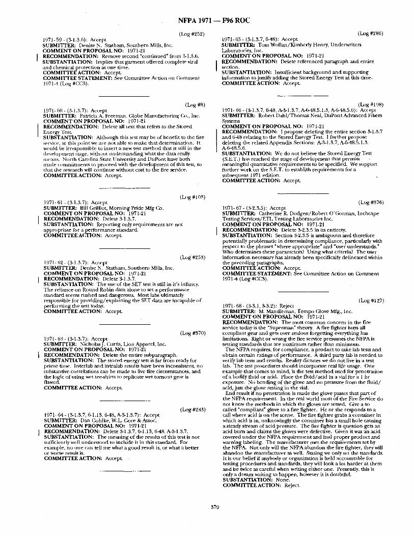
N F P A 1971 ~ F96 R O C
( I~g #952) 1971- 59- (%1.3.6): Accept SUBMITTER: Denise N. Statham, Southern Mills, Inc. COMMENT ON PROPOSAL NO: 1971-91
I RECOMMENDATION: Remove second "continued" f rom 3-1.3.6. SUBSTANTIATION: Implies that ga rmen t offered complete viral and chemical protection at one time. COMMITTEE ACTION: Accept. COMMITTEE STATEMENT: See Commit tee Action on (k )mment 1971-4 (Log #C, C3).
(Log #986) 1971-65 - (3-1.3.7, 6-48): Accept SUBMITTER: Tom Wollan/Kimber ly Henry, Underwriters Laboratories, Inc. COMMENT O N PROPOSAL NO: 1971-91 RECOMMENDATION: Delete referenced paragraph and entire section. SUBSTANTIATION: Insufficient backgrotmd and suppor t ing information to justify adding the Stored Energy Test at this time. COMMITTEE ACTION: Accept.
(Log #8) 1971- 60 - (3-1.3.7): Accept SUBMITTER: Patricia A. Freeman, (;lobe Manufactur ing Co., Inc. COMMENT ON PROPOSAL NO: 1971-21 RECOMMENDATION: Delete all text that refers to the Stored Energy Test. SUBSTANTIATION: Although this test may be of benefit to the fire service, at this point we are not able to make that determinat ion. It would be irresponsible to insert a new test me thod that is still in the development stage, without unders tanding what the data really means. North Carolina State University and DuPont have both made commimmnt.s to proceed with the development of this test, so that the research will cont inue without cost to the fire service. COMMITTEE ACTION: Accept.
(Log #103) 1971- 61 - (3-1.3.7): Accept SUBMI'VrER: Bill (;rilliot, Morning Pride Mfg Co. COMMENT O N PROPOSAL NO: 1971-21 RECOMMENDATION: Delete 3-1.3.7. SUBSTANTIATION: Report ing only requirements are not appropriate for a performance standard. COMMITTEE ACTION: Accept.
(Log #953) 1971- 62 - (3-1.3.7): Accept SUBMITTER: Denise N. Statham, Southern Mills,' Inc. COMMENT ON PROPOSAL NO: 1971-21 RECOMMENDATION: Delete 3-1.3.7. SUBSTANTIATION: T he use of the SET test is still in it's infancy. The reliance on Round Robin data alone to set a performance s tandard seems rushed and dmlgerons. Most labs ultimately responsible for providing/expla ining the SET data are incapable of per forming the test today. COMMITTEE ACTION: Accept.
(Log #370) 1971- 63 - (3-1.3.7): Accept SUBMITI'ER: NicholasJ. Curtis, Lion Apparel, Inc. COMMENT ON PROPOSAL NO: 1971-21 RECOMMENDATION: Delete the entire subparagraph. SUBSTANTIATION: The stored energy test is far f rom ready for pr ime time. lnterlab and intralab results have been inconsistent, no st, bst~mtive correlations can be made to live fire circumstances, and the logic of using wet tee-shirts to replicate wet t u rnou t ge,'tr is flawed. COMMITTEE ACTION: Accept.
( h ) g #943) 1971-64- (3-1.3.7, 6-1.13, 6-48, A-3-1.3.7): Accept SUBMITI'ER: [)an Gohlke, W.L. Core & Assoc. COMMENT O N PROPOSAL NO: 1971-21 RECOMMENDATION: Delete 3-1.3.7, 6-1.13, 6-48, A-3-1.3.7. SUBSTANTIATION: The mean ing of the results of this test is not sufficiently well unders tood to include it in this st:mdard. For exan~ple, no one can tell me what a good result is, or what a better or worse result is. COMMITTEE ACTION: Accept.
(Log #198) 1971- 66 - (3-1.3.7, 6-48, A-3-1.3.7, A-6-48.5.1.3, A-6-48.5.6): Accept SUBMITTER: Robert D a h l / T h o m a s Neal, DuPont Advanced Fibers Systems COMMENT ON PROPOSAL NO: 1971-91 RECOMMENDATION: I propose delet ing the entire section %1.3.7 and 6-48 relating to the Stored Energy Test. I filrther propose delet ing the related Appendix Sections: A-3-1.3.7, A-6-48.5.1.3, A-6-48.5.6. SUBSTANTIATION: We do not believe the Stored Energy Test (S.E,T.) has reached the stage of deve lopment that permits - meaningflfl quantitative requi rements to be specified. We suppor t fur ther work on the S.E.T. to establish requi rements for a subsequent 1971 edition. COMMITTEE ACTION: Accept.
(Log #376) 1971- 67 - (3-9.3.5): Accept SUBMITrEI~ Catherine R. Dodgen /Robe r t O 'Gorman , Inchcape Testing Services/ETL Test ing Laboratories Inc. COMMENT ON PROPOSAL NO: 1971-21 RECOMMENDATION: Delete %9.3.5 in its entirety. SUBSTANTIATION: Section %2.3.5 is ambiga~ous an d therefore potentially problematic in de te rmin ing compliance, particularly with respect to the phrases "where appropriate" ,and "user understands." Who determines these parameters? Using what criteria? The user information necessary has already been specifically del ineated within the preceding paragraphs. COMMITTEE ACTION: Accept. COMMITTEE STATEMENT: See Commit tee Action on (Z~mment 1971-4 (Log #CC3).
(Log #127) 1971- 68 - (3-3.1, %3.2): Reject SUBMI'IX'ER: M. Mandlen~m, T e m p o Glove Mfg., Inc. COMMENT O N PROPOSAL NO: 1971-21 RECOMMENDATION: The most c o m m o n concern in the fire service today is the "Superman" theory. A fire fighter buys all compliant gear ,and gets over zealous forgett ing everything has limitations. Right or wrong the fire service presumes the NFPA is sett ing s tandards that are m a x i m u m rather than min imum.
The NFPA requires, for compliance, a product to take lab tests and obtain certain ratings of performance. A third party lab is needed to verify lab tests and results. Reality dictates we do not live in a test lab. The test procedures should incorporate real life usage. On e example tha t comes to mind, is the test m e t h o d used for penetrat ion of a bodily fluid or acid. Place the f lu id /ac id in a vial for a 1 hr exposure. No bending of the glove and no pressure f rom the f lu id / acid, jus t the glove resting in the vial.
End result if no penetrat ion is made the glove passes tha t part o f the NFPA requirement . In the real world most of the Fire Service do not know the methods in which the gloves are tested. Give a so called "compliant" glove to a fire fighter. He or she responds to a call where acid is on the scene. The fire fighter grabs a container in which acid is in, unknowingly the conta iner has a small hole causing a steady stream of acid pressure. The fire f ighter is question gets an acid burn ~md claims the gloves were defective. Given it was an acid covered unde r the NFPA requ i rement and had proper product and warning labeling. The mantffacturer met the requirements set by the NFPA. Not only will the NFPA abandon the fire fighter, they will abandon the manufac tu re r as well. Stating we only set the standards. It is our belief if anybody or organization is held accountable for testing procedures and standards, they will look a lot harder at t hem and be twice ,as careful when writing ei ther one. Presently, this is only a d ream waiting to happen, however it is doubtful. SUBSTANTIATION: None. COMMITTEE ACTION: Reject.
379
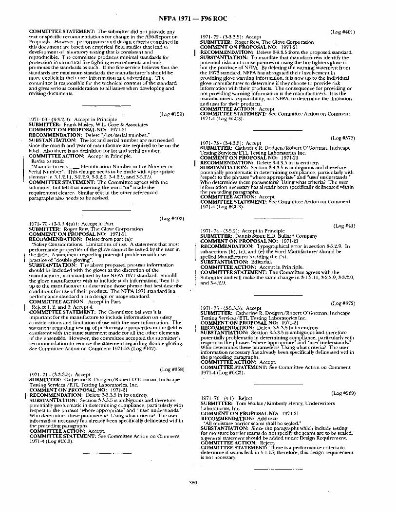
N F P A 1 9 7 1 - - F 9 6 R O C
COMMITTEE STATEMENT: The submitter did not p/ovide any text oi" specific recommendations for change in the A96-Report on Proposals. However, pertbmnance and design criteria contained in this document are based on empirical field studies that lead to development of laboratory testing that is consistent and reproducible. Tile committee produces minimal standards for protection in structural fire fighting environments and only promotes the stan&ards as such. If the fire service believes that the st;mdards are maximum standards the manufacturer 's should be more explicit in their user infornmtion and advertising. The committee is responsible for the technical content of the standard and gives serious consideration to all issues when developing and revising documents.
([xJg #159) 1971- 69 - (3.3.2.9): Accept in Principle SUBMITTER: Frank Masley, W.L. ( ~ r e & Associates COMMENT ON PROPOSAL NO: 1971-21 RECOMMENDATION: Delete "/ lot /serial number." SUBSTANTIATION: The lot and serial number ,are not needed since the month and year of manufacture are required to be on the label. Also there is no definition for lot and serial ntnnber. COMMITTEE ACTION: Accept in Principle.
Revise to read: "Mant,facturer's _ _ Identification Number or Lot Number or
Serial Number". This change needs to be made with appropriate e lement in 3.1.2.11, 3-2.2.9, 3-3.2.9, 3-4.2.9, and 3-5.2.9. COMMITTEE STATEMENT: The Committee agrees with tile submitter, but felt that inserting the word "or" made the requirement clearer. Similar text in the other referenced paragraphs also needs to be revised.
(Log #401) 1971- 72 - (3-3.3.5): Accept SUBMITTER: Roger Rew, The Glove Corporation COMMENT ON PROPOSAL NO: 1971-21 RECOMMENDATION: Delete 3-3.3.5 from the proposed standard. SUBSTANTIATION: To mandate that manufacturers identify the potential risks and consequences of ttsing the fire fighters glove is not the province of NFPA. By deleting the warning statement from the 1973 standard, NFPA has abrogated their involvement in providing glove warning information, it is now up to the individual glove manufacturer to determine if they choose to provide risk information with their products. The consequence for providing or not providing warning information is the manufacturers. It is the mantffacturers responsibility, not NFPA, to determine the limitation and uses for their products. COMMITTEE ACTION: Accept. COMMITTEE STATEMENT: See Committee Action on Comment 1971-4 ( I~g #CC3).
1971- 73 - (3.4.$.5): Accept (Log #373) SUBMITrER: Catherine R. Dodgen /Rober t O'Gorman, Inchcape Testing Services/ETL Testing LaBoratories Inc. COMMENT O N PROPOSAL NO: 1971-21 RECOMMENDATION: Delete 3-4.3.5 in its entirety. SUBSTANTIATION: Section 3-4.3.5 is ambignous and therefore potentially problematic in determining compliance, particularly with respect to the phrases "where appropriate" and "user understands." Who determines theseparameters? Us ing what criteria? The user information necessary has already been specifically delineated within the precedingparagraphs. COMMITrEE ACTION: Accept. COMMITTEE STATEMENT: See Committee Action on ( b m m e n t 197 I-4 (Log #CC3).
(I_xJg #402) 1971- 70 - (3-3.3.4(a)): Accept in Part SUBMITrER: Roger Rew, The Glove Ca~rporation COMMENT ON PROPOSAL NO: 1971-21 RECOMMENDATION: Delete from part (a):
"S,'dety Considerations. Limitations of use. A statement that most performance properties of the glove cannot be tested by the user in the field. A statement regarding potential problems with user practice of "double gloving". SUBSTANTIATION: The above proposed pre-user information should be included with the gloves at the discretion of the manufacturer, not mandated by the NFPA 1971 standard. Should the glove manufacturer wish to include such information, then it is up to the manufactnrer to de termine those phrase that best describe conditions for use of their product. The NFPA 1971 standard is a performance standard not a design or usage standard. COMMITTEE ACTION: Accept in Part.
I Reject 1, 2, and 3; Accept 4. COMMITTEE STATEMENT: The (~mmit tee believes it is important fi~r the manufactnre to include information on s~ffety considerations and limitation of use with the nser information. The statement regarding testing of performance properties in the field is consistent with the same statement made for ,all the other elements of ttle ensemble. However, the committee accepted the submitter 's recommendation to remove the statement regarding double gloving. See (~mmit tee Action on Comment 1971-53 (Log #102).
(Log #358) 1971- 71 - (3-3.3.5): Accept
- SUBMITTER: Catherine R. Dodgen /Rober t O'Gorman, Inchcape Testing Services/ETL Testing Laboratories, Inc. COMMENT O N PROPOSAL NO: 1971o21
I RECOMMENDATION: Delete 3-3.3.5 in its entirety. SUBSTANTIATION: Section .3-3.3.5 is ambil~.lous and therefore potentially problematic in determining compliance, particularly with respect to the phrases "where appropriate" ,and " user understands." Who determines these parameters? Using what criteria? The user information necessary h~s already been specifically delineated within the preceding paragraphs. COMMITTEE ACTION: Accept. COMMITTEE STATEMENT: See (kmmfittee Action on Comment 1971-4 (Log #CC3).
(Log #41) 1971- 74- (3.5.2): Accept in Principle SUBMITTER:, Dennis Stout,~ E.D. Bullard Company COMMENT O N PROPOSAL NO: 1971-21 RECOMMENDATION: Typographical error in section 3-5.2.9. In sub-sections (b), (c), and (el the word Manufacturer should be spelled Mantffacturer's adding the ('s). SUBSTANTIATION: Editorial. COMMITTEE ACTION: Accept in Principle. COMMITTEE STATEMENT: The Committee agrees with the Submitter and will make the same change in 3-1.2.11, 3-2.2.9, 3-3.2.9, and 3-4.2.9.
(I.~g #372) 1971-75 - (3-5.3.5): Accept SUBMITrER: Catherine R. Dodgen /Rober t O'Gorrruan, Inchcape Testing Services/ETL Testing Laboratories Inc. COMMENT O N PROPOSAL NO: 1971-21 RECOMMENDATION: 'Delete 3-5.3.5 in its entirety. SUBSTAd~,ITIATION: Section 3-5.3.5 is ambiguous and therefore potentially problematic in determining compliance, particularly with r-espect to the phrases "where approprl'ate" and "user understands." Wh-o determin~es theseparameters? Us ing what criteria? The user information necessary has already been specifically delineated within the precedingparagraphs. COMMITTEE ACTION: Accept. COMMITTEE STATEMENT: See Committee Action on Comment 1971-4 (Log #CC3).
( I~g #269) 1971- 76- (4-1): Reject SUBMITTER: Tom WoJlan/Kimberly Henry, Underwriters Laboratories, Inc. COMMENT O N PROPOSAL NO: 1971-21 RECOMMENDATION: Add text:
"All moisture barrier seams shall be sealed." SUBSTANTIATION: Since the paragraphs which include testing for moisture barrier seams do not specify the ~seams are to be sealed, a general statement shonld be added under Design Requirement. COMMITTEE ACTION: Reject. COMMITTEE STATEMENT: There is a performance criteria to determine if seams leak in 5-1,15; therefore, this design requirement is not necessary.
380
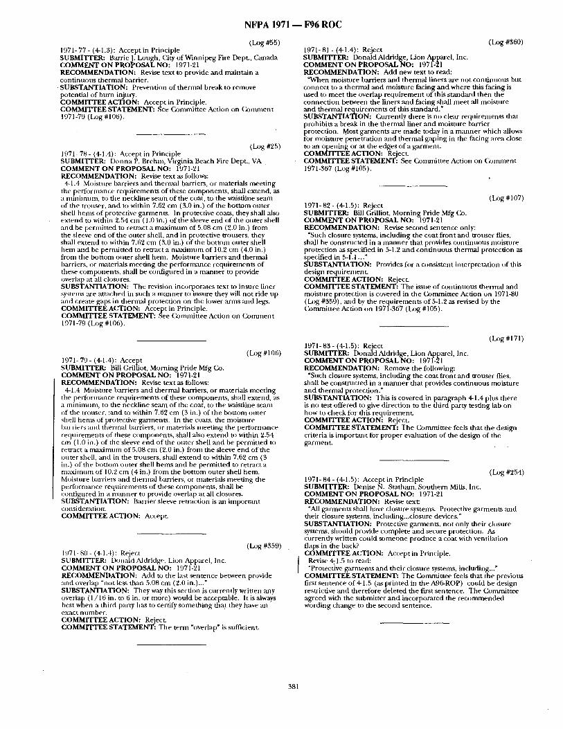
N F P A 1971 - - F96 R O C
(la)g #55) 1971- 77 - (4-1.3): Accept in Principle SUBMITTER: BarrieJ. Lough, City of Winnipeg Fire Dept., Canada COMMENT ON PROPOSAL NO: 1971-21 RECOMMENDATION: Revise text to provide and maintain a cont inuous thermal barrier. SUBSTANTIATION: Prevention of thermal break to remove potential of burn injury. COMMITTEE ACTION: Accept in Principle. COMMITTEE STATEMENT: See Commit tee Action on (29mment 1971-79 (h~g #106).
(~ )g #25) 1971-78- (4-1.4): Accept in Principle SUBMITrER: Donna P. Brehm, Virginia Beach Fire Dept., VA COMMENT ON PROPOSAL NO: 1971-21 RECOMMENDATION: Revise text as figllows:
4-1.4 Moisture barriers ,and thermal barriers, or materials meet ing the per formance requirements of these components , shall extend, as a min inmm, to the neckline seam of the coat, to the waistline seam of the trouser, and to within 7.62 cm (3.0 in.) of the bot tom outer shell hems of protective garments. In protective coats, they shall also ex tend to within "2.54 cm (1.0 in,) of the sleeve end of the outer shell and be permit ted to retract a m a x i m u m of 5.08 cm (2.0 in.) f rom the sleeve end of the outer shell, and in protective trousers, they shall ex tend to within 7.62 cm (3.0 in.) of the bot tom outer shell h e m ,-and be pernfitted to retract a n tax imnm of 10.2 cm (4.0 in.) f rom the bot tom outer shell hem. Moisture barriers and thermal barriers, or materials meet ing the per formance requirements of these components , shall be conf igured in a m a n n e r to provide overlap at all closures. SUBSTANTIATION: The revision incorpomttes text to insure liner systems are at tached in such a m a n n e r to insure they will not ride up and create g~tps in thermal protection on the lower arms :rod legs. COMMITTEE ACTION: Accept in Principle. COMMITTEE STATEMENT: See (k)mmittee Action on C o m m e n t 1971-79 (Log #106).
( l o g #106) 1971- 79 - (4-1.4): Accept SUBMITTER: Bill Grilliot, Morning Pride Mfg Co. COMMENT O N PROPOSAL NO: 1971-21 RECOMMENDATION: Revise text as follows:
4-1.4 Moisture barriers and thermal barriers, or materials meet ing the performance requirements of these components , shall extend, as a min imum, to the neckline seam of the coat, to the waistline seam of the trouser, ;and to within 7.69 cm (3 in.) of the bot tom outer shell hems of protective garments. In the coats, the moisture barriers and thermal barriers, o r materials meet ing the performance requirements of these components , shall also ex tend to within 2.54 cm ( 1.0 in.) of the sleeve end of the outer shell and be permit ted to reuzact a m a x i m u m of 5.08 cm (2.0 in.) f rom the sleeve end of the outer shell, and in the trousers, shall ex tend to within 7.62 cm (3 in.) of the bot tom other shell hems and be permit ted to retract a m a x i m u m of 10.2 cm (4 in.) f rom the bot tom outer shell hem. Moisture barriem and thermal barriers, or materials meet ing the performance requi rements o f these components , shall be configt!red in a m a n n e r to provide overlap at all closures. SUBSTANTIATION: Barrier sleeve retraction is an impor tant consideration. COMMITTEE ACTION: Accept.
(Log #359) 1971- 80- (4-1.4): Re~ject SUBMITTER: Douald Aldridge, Lion Apparel, Inc. COMMENT ON PROPOSAL NO: 1971-21 RECOMMENDATION: Add to the l:Lst sentence between provide and overlap "not legs than 5.08 cm (2.0 in.)..." SUBSTANTIATION: They way this section is currently written any overlap (1 /16 in. to 6 in. or more) would be acceptable. It is always best when a third party has to certify someth ing tha t they have an exact number . COMMITTEE ACTION: Reject. COMMITTEE STATEMENT: The term *overlap" is sufficient.
(log #360) 1971- 81 - (4-1.4): Reject SUBMITTER: Donald Aldridge, Lion Apparel, Inc. COMMENT ON PROPOSALNO: 1971-21 RECOMMENDATION: Add new text to read:
"When moisture b:wriers and thermal liners are not cont inuous but connect to a thermal and moisture facing and where this facing is used to meet the overlap r equ i r emen t of this s tandard then the connect ion between the liners and facing shall mee t all moisture and thermal requi rements o f this standard." SUBSTANTIATION: Currently there i s no clear requi rements that prohibits a break in the thermal liner and moisture barrier protection. Most garments are made today in a m a n n e r which allows for moisture penetrat ion and thermal gaping in the facing ,area close to an open ing or at the edges of a garment . COMMITTEE ACTION: Reject. COMMITTEE STATEMENT: See Commit tee Action on ( b m m e n t 1971-367 (Log #105).
( l o g #107) 1971- 82 - (4-1.5): Reject SUBMITrER: Bill Grilliot, Morning Pride Mfg Co. COMMENT ON PROPOSAL NO: 1971-21 RECOMMENDATION: Revise second sentence only:
"Such closure systems, including the coat f ront and trouser flies, shall be constructed in a m a n n e r tha t provides cont inuous moisture protection as specified in 5-1.2 and cont inuous thermal protection as specified in 5-1.1 ..." SUBSTANTIATION: Provides for a consistent interpretat ion of this design reqttirement. COMMITTEE ACTION: Reject. COMMITTEE STATEMENT: The issue of cont inuous thermal an d moisture protection is covered in the Commit tee Action on 1971-80 ( h ) g #359), ~md by the requirements of 5-1.2 as revised by the Commit tee Action on 1971-367 (Log #105).
(Log#171) 197.1- 83 - (4-1.5): Reject SUBMITI'ER: Donald Aldridge, Lion Apparel, Inc. COMMENT ON PROPOSAL NO: 1971-21 RECOMMENDATION: Remove the following:
"Such closure systems, including the coat f ront and trouser flies, shall be const ructed in a m a n n e r tha t provides cont inuous moisture and thermal protection." SUBSTANTIATION: This is covered in paragraph 4-1.4 plus there is no test offered to give direction to the third party testing lab on how to check fi~r this requirement . COMMITTEE ACTION: Reject. COMMITTEE STATEMENT: The Commit tee feels that the design criteria is impor tant for proper evaluation of the design of rite garment .
(Log#254) 1971- 84- (4-1.5): Accept in Principle SUBMITTER: Denise N. Statham, Southern Mills, Inc. COMMENT ON PROPOSAL NO: 1971-21 RECOMMENDATION: Revise text:
*All garments shall have closure systems. Protective garments and their closure systems, including.. .closure devices." SUBSTANTIATION: Protective garments , no t only their closure systems, should provide complete and secure protection. As currently written could someone produce a coat with ventilation flaps in the back? COMMITTEE ACTION: Accept in Principle.
Revise 471.5 to read: "Protective garments and their closure systems, including..."
COMMITTEE STATEMENT: The Commit tee feels that the previom first sentence o f 4-1.5 (as pr inted in the A96-ROP) could be design restrictive and therefore deleted the first sentence. The Commit tee agreed with the submit ter and incorporated the r e c o m m e n d e d wording change to the second sentence.
381
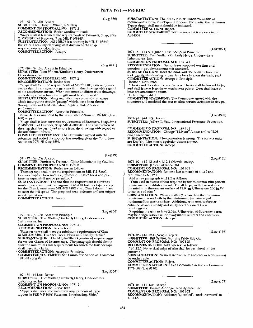
L
N F P A 1971 - - F96 R O C
(Log #80) 1971- 85 - (4-1.6): Accept SUBMITTER: Harry P. Winer, U.S. Navy COMMENT ON PROPOSAL NO: 1971-21 RECOMMENDATION: Revise wording to r~ad:
"Snaps shall at least meet the requirements of Fasteners, Snap, Style 2, MS27980E of Fastener, Snap MIL-F-10884F. SUBSTANTIATION: MS 27980E' is a drawing in MIL-F-19884F therefi~re, I ,am only clarifying what document the snap requirements are taken from. COMMITTEE ACTION: Accept.
(Log #271) 1971-86- (4-1.6): Accept in Principle SUBMI'VrER: Tom Wo[lan/Kimberly Henry, Underwriters I~d)oratories, Inc. COMMENT ON PROPOSAL NO: 1971-21 RECOMMENDATION: Revise text:
"Snaps shall meet the requirements of MS 27980E, Fastener, Snap except that the construction may vary from the drawings with regard to the at tachment means. When construction differs from drawings, equivalency of at tachment strength must be confirmed." SUBSTANTIATION: Many mantifacturers presently use snaps which incorporate double "prongs" which, have been shown through tests and field evaluation to give equal or better peffo rman ce. COMMITTEE ACTION: Accept in Principle.
Revise 4-1.6 as amended by the (k~mmittee Action on 1971-85 (Log #80) to read:
"Snaps shall at least meet the requirements of Fasteners, Snap, Style 2, MS27980E of Fastener, Snap MIL-F-10884F. The construction of the snap shall be permitted to vary from the drawings with regard to the at tachment means." COMMITTEE STATEMENT: The Committee agreed with ttt4 submitter :rod added the appropriate wording given the (kJmrnittee Action on 1971-85 (Lx)g #80).
SUBSTANTIATION: The FED-V-F-106F Standard consists of requirements for various Types of zippers. For clarity, the minimum Type a zipper shall meet should be indicated. COMMITTEE ACTION: Reject. COMMITTEE STATEMENT: Text is correct as it appears in the A96-ROP.
(Log #274) 1971-90- (4-1.9, Figure 4-1.9): Accept in Principle SUBMITI'ER: Tom Wollan/Kimberly Henry, Underwriters Laboratories, Inc. COMMENT O N PROPOSAL NO: 1971-21 RECOMMENDATION: Do not have proposed wording until question in problem statement is answered. SUBSTANTIATION: Does the hook and dee construction have took e a..~f~_~fl -like drawing or can there be a loop on the back, etc.? COMMITTEE ACTION: Accept in Principle.
Revise 4-i .9 to read: "Hooks and dees shall be nonferrous. Hooks shall be inward facing
and shall have at least three at tachment points. Dees shall have at least two at tachment points."
Delete Fignre 4-1.9. COMMITTEE STATEMENT: The Committee agreed with the submitter ,and modified the text to allow certain variations iri design.
(Log #301) '1971-91 - (4-1.12): Accept SUBMITTER: Jeffrey O. Stnll, International Personnel Protection, I n c .
COMMENT O N PROPOSAL NO: 1971-21 RECOMMENDATION: C~ange "12.9 cm2/ l inear cm" to %.08 cm2/ l inear cm' . SUBSTANTIATION: The conversion is wrong. The correct units are English. The metric equivalent is not correct. COMMITTEE ACTION: Accept.
(Log #9) 1971- 87 - (4-1.7): Accept SUBMITTER: Patricia A_ Freeman, Globe Manufacturing CxJ., Inc. COMMENT O N PROPOSAL NO: 1971-21 RECOMMENDATION: Revise text as follows:
"Fastener tape shall meet the requirements of MIL-F-21840G, Fastener Tapes, Hook and Pile, Synthetic. Class 2 hook and pile fastener tapes shall not be permitted." SUBSTANTIATION: The way that the requirement is currently worded, you could n t ~ e :m argument that all ~astener tape, except fiJr the Class 2, must meet MIL-F-21840G (i.e., Cla~s 2 doesn ' t have to meet the rail spec.) The proposed text is cleaner and not subject to interpretation. COMMITTEE ACTION: Accept.
(Log #260) 1971- 88 - (4-1.7): Accept in Principle SUBMITTER: Tom Wollan/Kimberiy Henry, Underwriters Ld~oratories, Inc. COMMENT O N PROPOSAL NO: 1971-21 RECOMMENDATION: Revise text:
"Fastener tape shall meet the minimum requirements of Class in MIL-F-21840G, Fastener Tapes, Hook and Pile, Synthetic." SUBSTANTIATION: The MIL-F-21840Gconsistsofrequirements fi)r various Cl:~sses of fastener tape. The paragraph should clearly state the rain iron m Class requirements for which the fastener tape sball meet, fi)r clarity. COMMITTEE ACTION: Accept in Principle. COMMITTEE ~TATEMENT: See Committee Action on (k)mment 1971-87 (Log #9).
( I~g #207) 1971-89- (4-t.8): Reject SUBMITrER: Tom Wollan/Kimberly.Henry, Underwriters Laboratories, Inc. COMMENT ON PROPOSAL NO: 1971-21 RECOMMENDATION: Revise text:
"Zippers shall meet the minimum requirements of Type zippers in FED-V-F-106F, Fasteners, Interlocking, Slide."
(Log #129) 1971-92 - (4-1.12 and 4-1.12.2 (New)): Accept SUBMI'VrER: Janice LaFrance, 3M COMMENT ON PROPOSAL NO: 1971-21 RECOMMENDATION: Remove last sentence of 4-1.12 and renumber as 4-1.12.1. Add a new paragraph 4-1.12.2 as follows: "Trim used in excess of that required by the minimum trim pattern
requirements established in 4-1.12 shall be oermitted to not meet the minimum fluorescent surface of 12.9 crn 2/ l inear cm (2.0 in .2 / linear in.) of trim." SUBSTANTIATION: Wearer visibility is based on the minimum requirement as set forth by the minimum trim pattern and minimum fluorescent surface. Additional trim used to further enhance wearer visibility and safety need not .meet these requirements.
Requiring the trim to have 2.0 in. 2/ l inear in. o f fluorescent area may be design restrictive for many mantffacturers and end users. COMMITTEE ACTION: Accept.
(Log #108) 1971-93- (4-1.12.1 (New)): Reject SUBMIT/'ER: Bill Grilliot, Morning Pride Mfg Co. COMMENT O N PROPOSAL NO: 1971-21 RECOMMENDATION: Add new text as follows:
"4-1.12.1 No vertical strips of trim shall be permitted on the garment." SUBSTANTIATION: Vertical strips of trim and coat or trousers may be undesirable. COMMITTEE ACTION: Reject. COMMITTEE STATEMENT: See Committee Action on Comment 197t-104 (Log #170).
(Log #173) 1971- 94 - (4-1.13): Accept SUBMITTER: Donald Aldridge, Lion Apparel, Inc. COMMENT O N PROPOSALNO: 1971-21 RECOMMENDATION: Add after "specified", "and illustrated" in 4-1.14.5.
382
N F P A 1971 ~ F 9 6 R O C
SUBSTANTIATION: It is unclear if more than the m i n i m u m trim pattern i s present can you cover any part of the required pattern or does the pattern as ilhtstrated must always be unobscured . COMMITTEE ACTION: Accept.
(I~Jg #98) 1971-95 - (4-1.14 (New)): Accept in Principle SUBMITTER: Richard A. Lash, ¢c]eveland Fire Deparunent , OH COMMENT ON PROPOSAL NO: 1971-21 RECOMMENDATION: Add new 4-1.14 and r enumber existing 4-1.14 and the remaining paragraphs:
"Warning and Product Labels shall he located or manuPactnred so that cturing the life of the ga rmen t they can still be legible. Life of ga rment is 10 wztshings or 10 years." SUBSTANTIATION: If yon intent is to be able to track a ga rmen t in c~Lqe of problems or in some org:mization tu rnout gear is reissued these labels must be legible. COMMITTEE ACTION: Accept in Principle. COMMITTEE STATEMENT: The commit tee has addressed the durability mid legibility of prodt,ct labels in 5-1.21, 5-2.14, 5-3.21, 54.~)0, 5-5.10, ~uld 5-7.8. See Commit tee Action on C o m m e n t 1971- 39 (Log #3.~9) and 197141 (Log #340).
(DJg #56) 1971-96- (4-1.14.2): Accept in Principle SUBMITTER: BarrieJ. Lough, City of Winnipeg Fire Dept., Canada COMMENT O N PROPOSAL NO: 1971-21 RECOMMENDATION: Revise text that will provide and maintain a cont inuous thermal barrier. SUBSTANTIATION: To prevent a break in the therm;d barrier to hlwer potential of burn injury. COMMITTEE ACTION: Accept in Principle. COMMITTEE STATEMENT: See Commit tee Action on C o m m e n t 1971-79 ( I ~ g #10(5).
(I~lg #109) 1971- 97 - (4-1.14.2): Reject SUBMITI'ER: Bill Grilliot, Morning Pride Mfg (~). COMMENT ON PROPOSAL NO: 1971-21 RECOMMENDATION: 4-1.14.'2 Each coat sleeve shall have a protective wristlet permanent ly at tached to the moisture barrier or thermal barrier sleeve end, which extends a ronnd the wrist, with a catch provided for the thumb, that meets the requi rements specified in Sections 4-6 and 5-6.' SUBSTANTIATION: Barrier sleeve retraction is an important consideration. COMMITTEE ACTION: Reject. COMMITTEE STATEMENT: The (k)mmittee feels that the r e c o m m e n d e d text could be unnecessari ly restrictive.
(Log #10) 1971- 98 - (4-1.14.3): Accept SUBMITI'ER: Patricia A. Freeman, (;lobe Manufactur ing Cxj., Inc. COMMENT O N PROPOSAL NO: 1971-21 RECOMMENDATION: Revise text to read as follows:
"(2oats shall have a composite collar at least 10.2 Cln (4.0 in.) in he ight at any point and shall have a closure system. The collar and closure system shall consist of an outer shell, moistnre barrier, and thermal barrier, or of materials that mee t all applicable performance requirements as specified in Section 5-1 ." SUBSTANTIATION: There was a question raised by UL in the past about which materials could be used in the collar confignration. The intent here is to simply clarify the requirement . COMMITTEE ACTION: Accept.
(la)g #57) 1971- 99 - (4-1.14.5): Accept in Principle SUBMITTER: BarrieJ. Lough, City of Winnipeg Fire Dept., Canada COMMENT O N PROPOSAL NO: 1971-21 RECOMMENDATION: Revise text to read:
"The trim configuration for the coat shall be in accordance with Figure 4-1.14.5. The m i n i m u m trim pattern for the coat shall consist of two circumferential bands o f tr im ; one band of horizontal t r im at the chest level and one band of horizontal t r im at the bot tom of the coat near the hem. No vertical strips shall be permit ted on the f ront
or back of the coat. One band shall be placed on each arm between the wrist and elbow apart fi 'om the wrist interface, and shall not exceed haft the c i rcumference of the sleeve." SUBSTANTIATION: To reduce the risk of circumferential burn injuries that may threaten limbs due to reduced blood flow.
To reduce the risk of burn injury caused by the ability of the vertic,'d tr im to build a f l ame front. COMMITTEE ACTION: Accept in Principle.
Revise 4-1.14.5" to read: "The trim confignration for the coat shall be in accordance with
Figawe 4-1.14.5. The m i n i m u m trim pat tern for the coat shall consist of one circunfferential b~md of trim a round the bot tom of the coat near the hem. The front of the coat shall also have at least one band of horizontal trim at the chest level. No vertical strips o f trim shall be pernfitted on the front of the coat. The back of the coat shall also have a min imuln of either two vertical strips of trim, perpendicular to the bot tom band and loca tedon the left and right side of the hack of the coat, or a m i n i m u m one horizontal band of trim at the ches t / shou lde r blade level. The m i n i m u m trim configuration for the sleeves shall be a one circumferential band or a staggered 360 degree visibility pattern, meet ing or exceeding the surface area of a cont inuous circumferential band between the wrist and elbow area." COMMITTEE STATEMENT: The commit tee agrees with the submit ter ' s in tent and has developed text offering alternative sleeve patterns for optional trim placement.
(D)g #59) 1971- 100- (4-1.14.5): Reject SUBMITTER= BarrieJ. Lovgh, City of Winnipeg Fire Dept., Canada COMMENT ON PROPOSAL NO: 1971-21 RECOMMENDATION: Revise text:
"Additional square inches of reflective trim shall only be placed in ,areas which overlap protective trousers." SUBSTANTIATION: To reduce the potential for burn injtury and enhance visibility of fire fighters. COMMITTEE ACTION: Reject. COMMITTEE STATEMENT: The submit ter ' s r ecommenda t ion does not allow a great de~d of flexibility for fire d e p m t m e n t s to use tr im for identification or ass ignment purposes.
(Log #64) 1971- 101 - (4-1.14.5): Reject SUBMITTER: BarrieJ. Lough, City of Winnipeg Fire Dept., Canada COMMENT ON PROPOSAL NO: 1971-21 RECOMMENDATION: A task group should be created to study the length of reflective trim considered to be effective in performance and safety in areas of non-garment overlap. SUBSTANTIATION: To provide more information on the ability of trim materials to perform safely u n d e r adverse conditions. COMMITTEE ACTION: Reject. COMMITTEE STATEMENT: The submitter has requested that a task group be fo rmed and has not provided specific r ecommenda t ions for change in the A96-Report on Proposals. Therefore, the commit tee is rejecting the comment . However, the Technical Commit tee has and will cont inue to review an d address each of the subjects provided in the comment .
(Log #130) 1971- 102 - (4-1.14.5): Reject SUBMITTERa [)ave Engler, 3M COMMENT O N PROPOSAL NO: 1971-21 RECOMMENDATION: Modify the last sentence of 4-1.14.5 by adding the following to tile end of the last sentence ,after ". . .blade level,":
"or, two strips of trim in the pattern of an 'X.'" Modify the corresponding Figure 4-1.14.5 by adding "Back View
Option Three" ,and the corresponding drawing. SUBSTANTIATION: This configuration is suggested by EN471 which is a widely accepted s tandard in Europe for "High Visibility Clothing." This would provide ano ther configuration-which has good conspicuity, and allows differentiation between the f ront and the back of the garment , COMMITTEE ACTION: RejecL COMMITTEE STATEMENT: See Cx)mmittee Action on C o m m e n t 1971-104 (Log #170).
38~
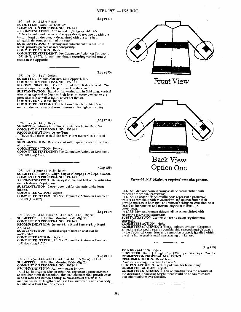
N F P A 1971 - - F96 R O C
(Log#131) 1971- 103- (4-1.14.5): Reject SUBMITTER: Jmlice LaFrance, 3M COMMENT ON PROPOSAL NO: 1971-~21 RECOMMENDATION: Add to end of paragraph 4-1.14.5:
"The circunfferential trim on the arnts should not line up with the bot tom b,'md on the coat, as de t e rmined with the arms laid alongside the torso port ion of the coat." SUBSTANTIATION: Offsetting arm trim bands f rom coat trim bands provides greater wearer conspicuity. COMMITTEE ACTION: Reject. COMMITTEE STATEMENT: See Commit tee Action on (~ ,mmen t 1971-99 (Lz)g #57). A recommenda t ion regarding vertic;d trim is fi:mnd in the Appendix.
(Log #170) 1971- 104- (4-1.14.5): Reject SUBMITI'ER: Donald Aldridge, Lion Apparel, Inc. COMMENT O N PROPOSAL NO: 1971-21 RECOMMENDATION: D e l e t e " f r o n t o f t h e ' . It shon ld read : "No verdczd strips of trim sh:dl be permit ted on the coat." SUBSTANTIATION: Based on lab testing and in field usage vertical trim when exposed to fi,'une or high heat c~m cause ckunage to the protective coat :is well as injury to the fire fighter. COMMITTEE ACTION: Reject. COMMITTEE STATEMENT: The Commit tee feels that there is utility in the u ~ of vertical trim to p romote fire fighter visibility.
(LOg #341) 1971- 105 - (4-1.14.5): Reject SUBMITTER: Murrey E. Loflin, Virginia Beach Fire Dept, VA COMMENT ON PROPOSAL NO: 1971-21 RECOMMENDATION: i)elete Test:
"The back o f the coat sh:dl also have ei ther two vertical strips of trim," SUBSTANTIATION: Be consistent with requi rements for the front of the coat. COMMITTEE ACTION: Reject. COMMITTEE STATEMENT: See Commit tee Action on C o m m e n t 1971-104 (Log #170).
(LOg #58) 1971- 106 - (Figure 4-1.14.5): Reject SUBMITrER: BarrieJ. Lough, City o f Winnipeg Fire Dept., Canada COMMENT O N PROPOSAL NO: 1971-21 RECOMMENDATION: Delete option two and half of the wrist trim on each sleeve of option one. SUBSTANTIATION: Lower potential for circumferential burn injuries. COMMITTEE ACTION: Reject. COMMITTEE STATEMENT: See Commit tee Action on O ) m m e n t 1971-99 (Log #57).
(LOg #110) 1971- 107 - (4-1.14.5, Figure 4-1.14.5, A-4-1.14.5): Reject SUBMITTER: Bill Grilliot, Morn ing Pride Mfg Co. COMMENT O N PROPOSAL NO: 1971-'21 RECOMMENDATION: Delete 4-1.14.5 and Figure 4-1.14.5 and A-4-1.14.5. SUBSTANTIATION: Vertical strips of trim on coat may be undesirable. COMMITTEE ACTION: Reject. cOMMITTEE STATEMENT: See (~)nmaittee Action on C o m m e n t 1971-104 (Log #170).
(Log #111) 1971- 108 - (4-1.14.6, 4-1.14.7, 4-1.15.4, 4-1.15.5 (New)): Hold SUBMITTER: Bill Grilliot, Morning Pride Mfg Co. COMMENT ON PROPOSAL NO: 1971-21 RECOMMENDATION: Add new text as follows:
4-1.14.6 In order to label or otherwise represent a protective coat as compliant with this standard, the manttfacturer shall provide coats in both men and women ' s sizing, in ches t sizes o f at [east 2 in. increments , sleeve lengths of at least 1 in. increments , and coat body lengths of at least 1 in. increments .
Front View
Back View Opdon One
l~g~er. 4-I.I.4.~ MJnimum r~/ub'~d co~t ~ . m i m ~
4-1.14.7 Men and women sizing shall be accomplished with respective individual patterning.
4-1.15.4 In order to:label or otherwise represent a protective trouser as compliant with this standard, th~ mantffac-turer shall provide trousers in both men and women ' s sizing, in waist sizes o f at least 2 in. increments , and inseam lengths of at least 1 in, increments .
4-1.15.5 Men and women sizing shall be accomplished with respective individual patterning. SUBSTANTIATION: Garments have nO sizing requi rements currently. COMMITTEE ACTION: Hold. COMMITTEE STATEMENT: The submitters c o m m e n t proposes someth ing that would require considerable research and-discussion by the Technical C, ommif tee and canno t be properly handled within the t ime f rame established for processing the Report.
(Log #60) 1971-109- (4-1.15.3): Rq ect SUBMITrER: Barrie i. Lou~n. ~ltv (Winn ipeg Fire Dept., Canada COMMENT O N PROPOSAL NO: )71-21 RECOMMENDATION: Revise text:
Land overlapping protective footwear". SUBSTANTIATION: To reduce potential for burn injury. COMMITTEE ACTION: Reject, COMMITTEE STATEMENT: The Commit tee feels the because of the variations in footwear he ight there would be no way to ensure that t r im would be over the area.
384
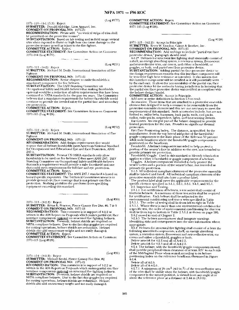
N F P A 1971 ~ F 9 6 R O C
(Lx)g #177) 1971- 110- (4-1.15.3): Reject SUBMITTER: Donald Aldridge, Lion Apparel, Inc. COMMENT ON PROPOSAL NO: 1971-21 RECOMMENDATION: Please add: "no vertical strips of trim shall be permit ted On the protective trouser". SUBSTANTIATION: Based on lab testing and in field usage vertical trim when exposed to flmne or high heat can c a u ~ dmnage to the protective tronser as well as injury to the fire fighter. COMMITTEE ACTION: Reject. COMMITTEE STATEMENT: See ())rmnittee Action on C o m m e n t 1971-104 (L~,g #170).
(Log #211 ) 1971-111-(4-2): Reject SUBMITTER: Richard M. Duffy, International A~ssociation of Fire Fighters COMMENT ON PROPOSAL NO: 1971-21 RECOMMENDATION: Revise chapter to make faceshields a mandatory componen t fi)r fire helmets. SUBSTANTIATION: The IAFF Standing Comntit tee on ()ccupatiomd Safety and Health believes that making faceshields optional wonld be a reduction of s:ifety reqtt irements that have been contained in NFPA sumdards ti:w the past ten years. The Commit tee believes that a mandatory reqn i rement for he lmet faceshields would conti ime to provide the needed safety for partial face and secondary eye protection. COMMITTEE ACTION: Reject. COMMITTEE STATEMENT: See ( ) )mmit tee Action on Cx~mment 1971-115 (Log #128).
(Log #212) 1971- 112 - (4-2): Reject SUBMITTER: Richard M. Duffy, International Association of Fire Fighters COMMENT ON PROPOSAL NO: 1971-21 RECOMMENDATION: Add design requirements that would require that all hehne t faceshields meet American National Stan&ard fi:~r ()ccupational and Educational Eye and Face Protection, ANSI Z87.1. SUBSTANTIATION: Present US OSHAstandards onlyallow faceshields to be used on fire helmets if they meet ANSI Z87. IAFF Standing Commit tee on Occupational Safety and Health believes that such a r equ i rement wouldprovide a safer faceshield and one that could meet requirements for fldl face and eye protection. COMMITTEE ACTION: Reject. COMMITTEE STATEMENT: The ANSI Z87.1 stan&trd is based on hazard specific exposures. The Technical Committees intent is to [)rovide general eye/face coverage that is not primary eye/face protection. Noth ing prohibit.s the purchaser from specifying equ ipment exceeding this standard.
(Log #30) 1971- 113- (4-2.2): Reject SUBMITTER: Bryan K. Pearson, Pierce County Fire Dist. #6, 7 & 9 COMMENT ON PROPOSAL NO: 1971-21 RECOMMENDATION: This c o m m e n t is in suppor t of 4-2.2 as written in the A96 Report on Proposals which makes partial eye/face interface componen t s ~ on structural fire fighting hehnets. SUBSTANTIATION: Presently, he lmet shields are required on NFPA compliant helmets. Due to the fact that goggles are required for cutt ing operations, he lmet shields are rednndant . Hehne t shields also add unnecessary weight and are e~i ly damaged. COMMITTEE ACTION: Reject. COMMITTEE STATEMENT: See Commit tee Action on Colrunent 1971-115 (Log #128).
1971- 114 - (4-2.2): Reject (La3g #31) SUBMITTER: Michael Keohi, Pierce (k3unty Fire Dist. #2 COMMENT ON PROPOSAL NO: 1971-21 RECOMMENDATION: This c o m m e n t is in suppor t of 4-2.2 as written in the A96 Report on Proposals which makes partial eye/face interface componen ts ~ on structural fire fighting helmets. SUBSTANTIATION: Presently, he lmet shields are required on NFPA compliant helmets. Due to the fact that goggles are required for cutt ing operations, he lmet shields are redundant . Helmet shields also add unnecessary weight and are easily &amaged.
COMMITTEE ACTION: Reject. COMMITTEE STATEMENT: See (k~mmittee Action on C o m m e n t 1971-115 (Log #128).
(Log #128) 1971- 115 - (4-2.2): Accept in Principle SUBMITTER: Kerry W. Gordon, ( ;aims & Brother, Inc. COMMENT ON PROPOSAL NO: 1971-21 RECOMMENDATION: Add verbiage to include "partial eye/face protective device," paragraph should read:
4-2.2* Helmets for strnctural fire fighting sb,'dl essentially consist of a shell, an energy absorbing system, a retention system, f luorescent and retroreflective trim, ear covers, and ei ther a faceshield, or goggles, or both, m*d partial eye/face protective device. SUBSTANTIATION: Adding partial eye face protective device to the design requirements ensures that this interface c o m p o n e n t will be tested fi)r high heat resistance ~L~ intended. It also insures that this interface c o m p o n e n t will be certified ~ it will potentially worn by the end user. It allows for accountability of the partial eye/face protective device by the authority having jurisdiction in knowing that the partial eye/face protective device was certified as compliant with the he lmet des ign /model . COMMITTEE ACTION: Accept in Principle.
Add new or revise definitions to Section 1-3 to read: Accessories: Those itenks that are at tached to a protective ensemble
e lement but designed in such a m a n n e r to be removable f rom the protective ensemble e lement and that are not necessary to meet the requirements of this standard. Such accessories include, but are not limited to, utility belts, hm'nesses, back packs, tools, tool packs, radios, radio packs, suspenders, lights, and heat sensing devices.
Ear Covers. An integral part of the he lmet designed to provide limited protection for the ears. Provides no signific:mt thermal protection.
Eye/Face Positioning Index. The distance, as specified by the manufacturer , f rom the top lateral midpoin t of the faceshield/ goggle componen t s to the Basic plane of the Alderson 50 percent adult male headform where the faceshield/goggle c o m p o n e n t is posit ioned on the headform.
Faceshield. A he lmet c o m p o n e n t in tended to help protect a portion o f the wearer's face in addition to the eyes, no t in tended to provide primary eye protection.
Faceshield/Goggle. Used in this s tandard to identify criteria that applies to ei ther a faceshield or goggle c o m p o n e n t of a helmet.
Goggles. A he lmet c o m p o n e n t in tended to help protect the wearer's eyes and a portion of the wearer 's face, no t in tended ,as primary eye protection.
2-1.3 All individual coinpliant e lements of the protective ensemble shall be labeled and listed. All individual compliant e lements of the protective ensemble shall also have a product label.
The product label shall mee t the applicable requirements fi)r the specific e lement specified in 3-1.1, 3-2.1, 3-3.1, 3-4.1, and 3-5.1.
2-3 Inspection and Testing. 2-3.1.1 For certification of helmets, a test series shall consist of
fourteen hehnets. A m i n i m u m of three test series shall be reqttired for certification. Each hehne t shall be subjected to the environmental condi t ioning and test or tests specified in Table 2-3.1.1. The order of testing shall be f rom left to right in Table 2-3.1.1. Where there is more than one environmenta l condit ion fi)r a specific test, the order of environmental condi t ioning for that test shall be from top to bot tom in Table 2-3.1.1 as shown on page 386.
2-3.2 moved to end of Chapter 2. 3-2.3.5 The helmet manufac turer shall integrate warnings
identifying risks mad consequences into the user informatioia where appropriate.
4-2.2 Helmets for stnlctural fire fighting shall consist of at least the fi)llowing assembled components , a shell, an energy absorbing system, a retention system, f luorescent and retroreflective trim, ear covers and ei ther a faceshield, goggles or both.
Delete asterisk fi)r 4-2.2 arid all of A-4-2.2. Delete asterisk fi)r 4-2.3 ,'u~d all of A-4-2.3. 4-2.4 The helmet, with the faceshield/goggle componen ts stowed,
shall provide peripheral vision clearance of at least 105 ° to each side of the Mid-Sagittal Plane when seated according to its he lmet positioning index on the reference headform illustrated in Figure 4-2.4.
Delete all of 4-2.6. Delete all of A-4-2.6. 4-2.7.1 A m i n i m u m of 26 cm 2 (4.0 in. 2) of the retroreflective area
of the trim shall be visible when the helmet, with faceshield/goggle c o m p o n e n t in the stowed position, is viewed f rom any angle at or above the reference plane at a distance of 2.44 m (8.0 ft).
385
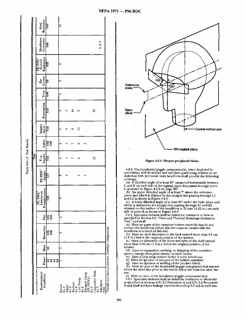
NFPA 1971 ~ F96 ROC
-2.
¢
~ . o
~ 1.4 ¸ ~ 0 ~ u
.~.~
u
e ~ t ~
.'~, E =
[...
= O
~. ig~ ~;~ -
,.o o0 o
.
o ~ ~ . : ~ o q . ~. . ~ '~"
. . . ' ;S"" i ...... "'",, Z #o I t t ~
Reference plane "--"--~ ~ o ~ " ,
> " 1 |
w ~ S
Basic Ol~me -----" .
Mid-sagittal plane
Figure 4-2.4 H e l m e t peripheral vision.
4-2.8 The faceshie ld/goggle component ( s ) , when deployed in accordance with its he lmet and eye/face posi t ioning indexes on an Alderson 50th percentile male headform shall provide the following coverage.
(a) A dihedral angle o f at least 85 ° measured horizontally between L and K on each side of the sagittal plane that passes th rough point L as shown in Figure 4-2.9 on page 387.
(b) An uppe r dihedral angle o f at least 7 ° above the reference plane and which is def ined by the straight line passing th rough L1 and L2 as shown in Figure 4-2.9.
(c) A lower dihedral angle of at least 40 ° unde r the basic plane an d which is def ined by the straight line passing through K1 and IC?, si tuated on the surface of the headform at 31 m m (1.22 in.) on each side o f point K as shown in Figure 42.9.
5-2.4 ,Specimen helmets shall be tested for resistance to heat as specif iedin Section 6-6, "Heat and Thermal Shrinkage Resistance Test," and shall:
(a) Have no parts of the complete he lmet assembly that do not contact the headform before this test come in contact with the headform as a result o f this test.
(b) Have no shell distortion in the back ex tend more than 4.0 cm (1.6 in.) below the original position of the helmet.
(c) Have no distortion o f the f ront and sides o f the shell ex tend more th;m g.00 cm (1.2 in.) below the original position of the helmet.
(d) Have no separation, melting, or dr ipping of the retention system, energy absorption system, or each covers.
(e) Have a chin strap closure device remain fimctionai. (f) Have no ignition of any part o f the he lmet assembly. (g) Have no ignition or melt ing o f the product labels. (h) Have no part o f the faceshield/goggle c o m p o n e n t that was not
below the brim line prior to the test be below the brim line after the test.
(i) Have no part of the faceshie ld/goggle c o m p o n e n t drip. 5-2.6 Specimen helmets shall be tested for resistance to electricity
,as specified in sections 6-31.5.1 Procedure A and 6-31.5.~ Procedure B and shall no t have leakage cur ren t exceeding 3.0 mA in each test.
386
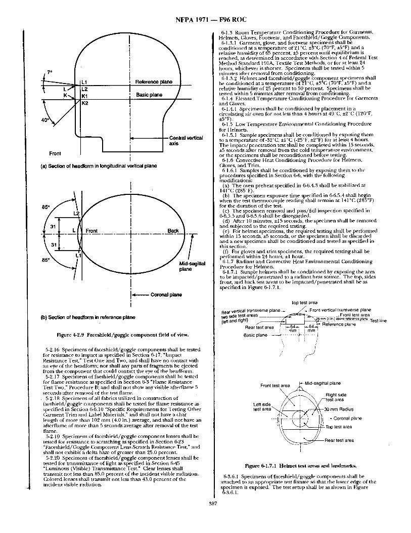
N F P A 1971 ~ F 9 6 R ( ) C
I O .n.a, ve.,ca, ,ont ! i lax"
I (a) Section of headform in longitudinal vertical plane
I |
Front _ _ . ~ . ~ Back
I
I i
I , ~ - - - - - - Coronal plane I
I
(b) Section of headform in reference plane
Figure 4-2.9 Faceshield/goggle componen t field of view.
5-'2.16 Specimens of faceshie ld/goggle componen ts shall be tested for resistance to impact as specified in Section 6-17, "Impact Resistance Test," Test One and Two, and shall have no contact with an eye of the h~ td fonn ; nor shall any parts of fragTnenr, s be ejected from the c o m p o n e n t that could contact the eye of the headform.
5-2.17 Specimens of faeshie ld /goggle componen t s shall be tested fi)r flmne resistance as specified in Section 6-3 "Flame Resistance Test Two, ~ Procedure B; and shall no t show ,any visible afterflame 5 seconds ,after remow, d of the test flame.
5-2.18 Specimens of all fabrics utilized in consu-uction of faeshie ld/goggle componen ts sh~dl be tested for flmne resistance as .l-s )ecified in ,.Secti )n 6-6.10 "Specific. Reqt i rements for Test ing Other Garment Tr im and Label Materials," and shall not have a char length of more than 102 m m (4.0 in.) average, ,and shall no t have an :ffterflame of more than 5 seconds average ,after removal of the test flame.
5-2.19 Specimens of faceshie ld/goggle c o m p o n e n t lenses shall be tested for resist:race to scratching as specified in Section 6-23 "Faceshield/G~)ggle (~)mponent Lens Scratch Resistance Test," and shall not exhibit a delta haze of greater than 95.0 percent.
5-2.20 Specimens of faceshie ld/goggle c o m p o n e n t lenses shall be tested for t ransmitumce of light as specified in Section 6-45 "Luminous (Visible) Transmit tance Test." Clear lenses shall t ransmit not less than 85.0 percent o f the incident visible radiation. Colored lenses shall t ransmit no t less than 45.0 percent o f the incident visible radiation.
6-1.3 Room Tempera tu re C, ondi t ioning Procedure for Garments , Helmets, (;loves, Fbotwear, and Faceshie]d/Goggle Components .
6-1.3.1 Garment , glove, and footwear specimens shall be condi t ioned at a tempferatnre of 21 °C, ±3°C ', (70°F, +5°F) and a relative humidity o f 65 percent, ±5 percent until equil ibrium is reached, as de t e rmined in accordance with Section 4 o f Federal Test Method Standard 191A, Textile Test Methods, o r f o r at least 24 hours, whichever is shorter. Specimens shall be tested within 5 minutes after removal f rom condit ioning.
6-1.3.2 Helmet and faceshield/goggle c o m p o n e n t specimens shall be condi t ioned at a tempera ture of2"l °C, ±3~C (70°F, +5°F) and a relative humidity o f 25 percent to 50 percent. Specimens shall be tested within 5 minutes ,after removal f rom condit ioning.
6-1.4 Elew, ated Tempera tu re Condi t ioning Procedure for Garments and Gloves.
6-1.4.1 Specimens shall be condi t ioned by p lacement in a circulating ,air oven for not less than 4 hours at 49°C, ±2°C (120°F, ±5°F).
6-1.5 Low Tentperatnre Environmental (~nd i t ion ing Procedure fi)r Helmets.
6-1.5.1 Sample specimens shall be condi t ioned by exposing them to a tempera ture of-32°C, ±1 °C (-25°F, ±t~°F) for at least 4 hours. The impac t /pene t ra t ion test shall be comple ted within 15 seconds, ±5 secohds "after rentoval f rom the cold tempera ture environment , or the specimens shall be recondi t ioned before testing.
6-1.6 Convective Heat (23nditioning Procedure for Helmets, Gloves, ,and Trim.
6-1.6.1 Samples shall be condi t ioned by exposing d iem to the procednres. . specified in Section 6-6, with the following modificaUons:
(a) The oven preheat specified in 6-6.4.3 shall be stabilized at 141 °C (285°F).
(b) The specimen exposure time specified in 6-6.5.4 shall b e ~ n when the test the rmocouple reading shall rem,'dn at 141°C (98, °F) for the durat ion o f the test.
(c) The specimen remowd and pass/fall inspection specified in 6-6.5.5 and-6-6.5.6 shall be disregfzded.
(d) After 10 minutes, ±15 seconds, the specimen shall be removed and sni~iected to the reqtfired testing.
(e) For he lmet specimens, the reqnired testing shall be pe r fo rmed within 15 seconds, ±5 seconds, or the specimen shall be discarded and a new specimen shall be condi t ioned and tested as specified in this section.
(f) For gloves and tr im specimens, the required testing shall be performed within '24 hours, ±l hour.
6-1.7 Radiant and Convective Heat Environmental Condi t ioning Procedure fi)r Helmets.
6-1.7.1 Sample helmets shall be condi t ioned by exposing the area to be impac ted /pene t ra t ed to a radiant heat source. The top, sides front, and back test areas to be impac ted /pene t r a t ed shall be as specified in Figure 6-1.7.1.
Top test area Rear vertical transverse plane ~ _ ~ / / ~ F r o n t vertical transverse plane two side test areas _ _ _ _ _ ~ - - ~ _-Front lest area
nd d-ht) ~ " - , , ~ 2 5 m m (1 m ) abov e reference plane Test line (lett a ',.,J ~ ~-----~, -"' . ~ ~ ~Reference plane Rear test area jr ~.~__ . . _ _ ~ i ! ram', ! turn
Basic plane . . . . ~ ~ ° i . . . . !1_ , J : /
/
Front test a r e a . ~ i d ' s a g i t t a l plane
Right side
Left side / / / ~ i ~ x / - - t e s t area ' test a r e a ' ~ / ~ i ~ 3 0 mm Radius
- / I 1 - ~ . ,~ -J I l l . . . . . Coronal plane
~ Rear test area
I
Figure 6-1.7.1 H e l m e t test areas and landmarks.
6-3.6.1 Specimens o f faceshie ld/goggle componen t s shall be at tached to an appropriate test fixture so that the lower edge of the specimen is exposed. The test se tup shall be ,as shown in Fignre 6-3.6.1.
387
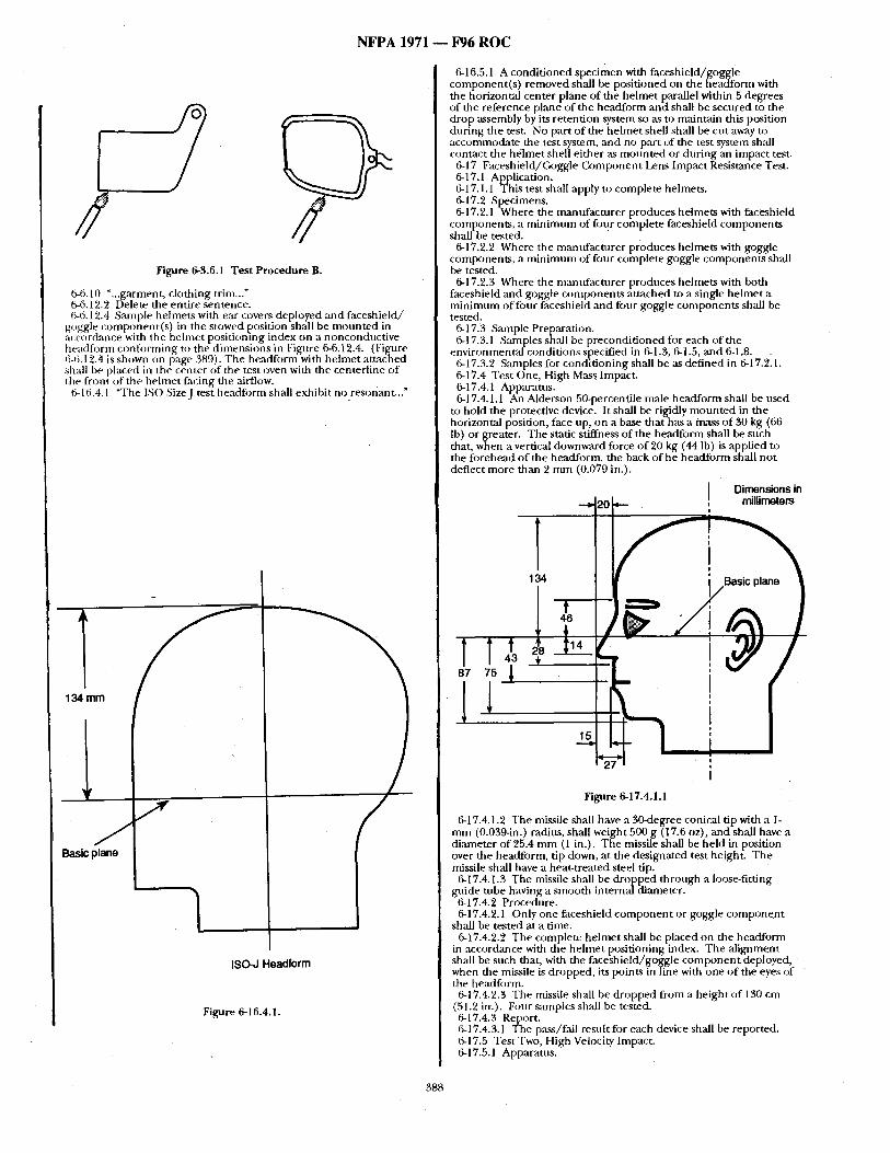
2 Figure 6-3.6.1 Test Procedure B.
6-6.10 ".. .garment, c lothing trim..." 6-6.12.2 Delete the entire sentence. 6-6.12.4 Sample helmets with ear covers deployed and faceshie ld/
goggle component ( s ) in the stowed position shall be m o u n t e d in accordance with the he lmet posit ionlng index on a nonconduct ive headform confi~rming to the d imens ions in Figure 6-6.12.4. (Figure 6-6.12.4 is shown on page 389). The headform with hehne t at tached shall be placed in tht~ center of the test oven with the centerl ine of the front of the hehne t facing tile airflow.
6-16.4.1 "The ISO SizeJ test headform shall exhibit no resonant.. ."
134 mm
1 7
1 ISO-J Headform
Figure 6-16.4.1.
/ Basic plane
N F P A 1971 m F96 R O C
6-16.5.1 A condi t ioned specimen with faceshield/goggle component ( s ) removed shall be posit ioned on the headform with the horizontal center plane of the he lmet parallel within 5 degrees of the reference plane of the headform and shall be secured to the drop assembly by its retention system so ,as to maintain this position dur ing the test. No part o f the he lmet shell shall be cut away to accommodate the test system, and no part of the test system shall contact the he lmet shell ei ther ,as m o u n t e d or dur ing an impact test.
6-17 Faceshield/C, oggle C o m p o n e n t Lens Impact Resistance Test. 6-17.1 Application. 6-17.1.1 This test shall apply to complete helmets, 6-17.2 ,Specimens. 6-17.2.1 Where the manufac ture r produces helmets with faceshield
components , a m i n i m u m of four comple te faceshield componen t s shall be tested.
6-17.2.2 Where the manufac ture r produces helmets with goggle components , a m i n i n m m of four complete goggle componen ts shall be tested.
6-17.2.3 Where the m~mufacturer produces helmets with both faceshield and goggle componen ts at tached to a single he lmet a m i n i m u m offi)ur faceshield and four goggle componen t s shall be tested.
6-17.3 Sample Preparation. 6-17.3.1 Samples shall be precondi t ioned for each of the
environmental condit ions s~0ecitied in 6-1.3, 6-1.5, a n d 6-1.8. 6-17.3.2 Sanlples fi)r condi t ioning shall be as def ined in 6-17.2.1. 6-17.4 Test One, High Mass Impact. 6-17.4.1 Apparatus. 6-17.4.1.1 An Alderson 50-percentile male headform shall be used
to hold the protective device. It shall be rigidly m o u n t e d in the horizontal position, face up, on a base that has a mass o f 30 kg (66 lb) or greater. The static stiffness of the headform shall be such that, when a vertical downward force o f 20 kg (44 lb) is applied to the forehead o f the headform, the back of he head lbrm shall no t deflect more than 2 m m (0.079 in.).
I Dimensions in
6 - -~ 20 , millimeters
i
Figure 6-17.4.1.1
6-17.4.1.2 The missile shall have a 30-degree conical tip with a 1- m m (0.039-in.) radius, shall weight 500 g (17.6 oz), and shall have a d iameter of 25.4 m m (1 in.). The missile shall be he ld in position over the headform, tip down, at the designated test height. The missile shall have a heat-treated steel tip.
6-17.4.1.3 The missile shall be d ropped through a loose-fitting guide tube having a smooth internal diameter.
6-17.4.2 Procedure. 6-17.4.2.1 Only one faceshield c o m p o n e n t or goggle c o m p o n e n t
shall be tested at a time. 6-1").4.2.2 The complete he lmet shall be placed on the headform
in accordance with file he lmet posit ioning index. The a l ignment shall be such that, with file faceshie ld/goggle c o m p o n e n t deployed, when the missile is dropped, its points in line with one o f the eyes of the headform.
6-17.4.2.3 The missile Shall be d ropped from a he ight o f 130 cm (51.2 in.). Four samples shall be tested. 6-17.4.3 Report. 6-17.4.3.1 The pass/f,'dl result fi)r each device shall be reported. 6-17.5 Test Two, High Velocity Impact. 6-17.5.1 Apparatus.
388
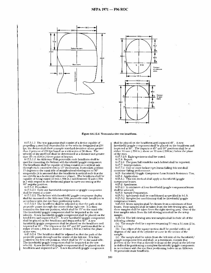
NFPA 1971 1 F96 ROC
33 0
• 4 - - - , - . - t 0 0 0 . i . . . l ~
200.0
R e f e , e n ~ pba~e
I
Basic plane
T49.9 ~
~7",°:;°~, r)~ane
~ b a s i ¢ ~ n e
Figure 6-6.12.4 Nonconductive test headform.
6-17.5.1.1 The test apparatus shall consist of a device capable of propelling a steel ball reproducible at the velocity designated at 250 fps, the device shall show a sanq~le stancktrd deviation of not greater than 2 percent of 250 fps based on a test series of 30 shots. The veh)city of the steel ball sh~dl be determined at a distance not greater than 25 cm (9.8 in . ) f rom point of impact,
6-17.5.1.2 An Alderson 50th percentile male headform shall be used fur mounting the hehnet with ff~ceshield/goggle component. The headform shall be capable of being rotated on a vertical axis through each corneal vertex in 15 ° increments, from a first position 15 degrees to the nasal side of straight-ahead-viewing out to 90 ° temporally (it is ~ sum ed that the headform is vertical such that the two eyes lie in a horizontal reference plane). The headform shall be capable of being raised 10 mm (.394 in.) and lowered 10 mm (.394 in.) with respect to the horizontal plane to carry out testing at the 90 ° angular position.
6-17.5.2 Procedure. 6-17.5.2.1 ()nly one faceshield component or goggle component
shall be tested at a time. 6-17.5.2.2 The helmet with faceshield/goggle component deploy
shall be mounted to the Alderson 50th percentile male headfi)rm in ac(:ordance with the eye/face positioning index.
6-17.5.2.3 The headform shall be adjusted so that the path of the proiectile p:Lsses through the center of the right eye. It is then rot~ted to the first test position, which shall be 15 ° to the nas:d side. The taceshield/goggle component sh:dl be impacted at the test velocity. A new faceshield/goggle component shall be placed on the head form and impacted at 0 °. A new faceshield/goggle component shall be placed on the headform and impacted at 45 °. A new faceshield/goggle component shall be placed on the headform and impacted at 90". The impacts at the 45 ° and 90 ° positions shall be at either 10 mm (.394 in.) above or 10 mm (.394 in.) below the plane of the eyes.
6-17.5.2.4 The headform shall be adjusted so that the path of the projectile passes throughout the center of the left eye. It is then rotated to the first test position, which shall be 15 ° to the nasal side. The faceshield/goggle component .shall be im pacted at the test velocity. A new faceshield/goggle component shall be placed on the headfi~rm and impacted at 0 °. A new faceshield/goggle component
shall be placed on file headforln and impacted 45 °. A new faceshield/goggle component shall be placed on the headform and impacted at 90 ° . The impacts at 45 ° and 90 ° positions shall be at either 10 mm (.394 in.) above or 10 mm (.394 in.) below the plmle of the eyes.
6-17.5.2.5 Eight specimens shall be tested. 6-17.6 Report. 6-17.6.1 The pass/fail resnlt for each helmet shall be reported. 6-17.7 Interpretation. 6-17.7.1 One or more helmet specimens failing this test shall
constitute failing performance. 6-23 Faceshield/(~)ggle Component Lens Scratch Resistance Test. 6-23.1 Application. 6-23.1.1 This test method shall apply to faceshield/goggle
component lenses. 6-23.2 Specimens. 6-23.2,1 A minimum offi)ur faceshield/goggle component lenses
shall be selected. 6-23.3 Sample Preparation. 6-23.3.1 Specimens shall be conditioned as specified in 6-1.3. 6-23.3.2 Samples for conditioning sh:dl be faceshield/goggle
component lenses. 6-23.3.3 Seven samples shall be chosen from a nfinimum offi)ur
lenses. Four samples sh~dl be taken from the left viewing area, and three samples shall be taken from the right viewing area. One of the four samples taken from the left viewing area shall be the setup sample.
6-23.3.4 The left viewing area test samples shall include all of the following criteria:
(a) The sample shall be a square measuring 51 mm x 51 mm (2 in. x 2 in.)
(b) Two edges of the square section shMl be parallel within +2 degrees of the axis of the cylinder or cone in the center of the sample.
(c) The sample shall be taken from the left side of the faceshield/ goggle component lens and shall, as a minimum, contain that portion of the lens that is directly in front of the pupil of the left eye as defined by positioning a complete faceshield/goggle component in accorckmce with the eye/face positioning index on an Alderson 50 percentile male headfi)rm.
389
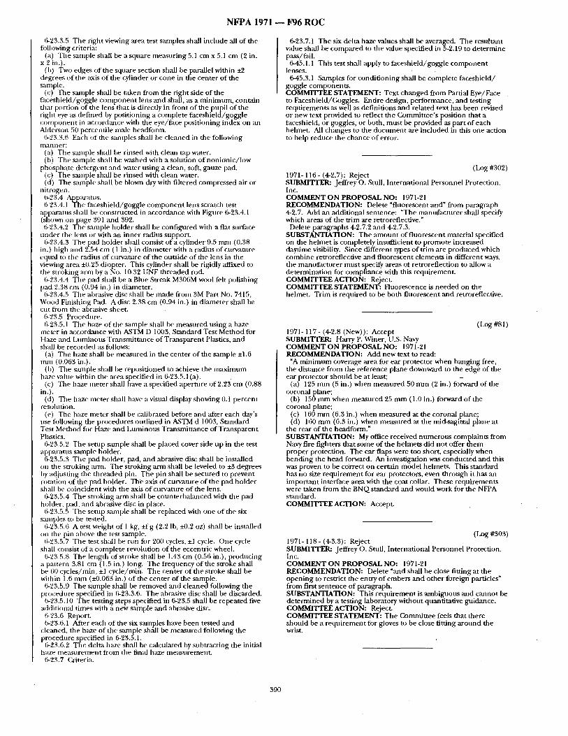
N F P A 1971 ~ F96 R O C
6-23.3.5 The right viewing area test samples shall include all of the following criteria:
(a) The sample shall be a square measur ing 5.1 cm x 5.1 cm (2 in. x 2 in.).
(b) Two edges of the square section shall be parallel within +2 degrees of the axis o f the cylinder or cone in the center of the sample.
(c) The sample shall be taken f rom the right side of the faceshield/goggle c o m p o n e n t lens and shall, as a min imum, contain that portion of the lens that is directly in front of the pupil of the right eye as def ined by posit ioning a complete faceshie ld/goggle o:)mponent in accordmlce with the eye/face posit ioning index on an Alderson 50 percentile male headfonn .
6-23.3.6 Each of the samples shall he cleaned in the following n t a n n eF:
(a) The sample shall he rinsed with clem+ tap water. (b) The s+tmple shall be washed with a solution o f non ion ic / low
phosphate de tergent ,and water using a clean, soft, gauze pad. (c) The sample shall be rinsed with clean water. (d) The sample shall be blown dry with filtered compressed ,'fir or
nitrogen. 6-23.4 Apparatus. 6-23.4.1 The faceshie ld/goggle c o m p o n e n t lens scratch test
apparatus shall be const ructed in accordance with Figure 6-23.4.1 (shown on page 391 and 392. 6-23.4.2 The sample holder shall be conf igured with a flat surface
unde r the lens or with an inner radius support~ 6-23.4.3 The pad holder shall consist of a cylinder 9.5 m m (0.38
in.) high and 2.54 cm ( 1 in.) in d iameter with a radius of curvature equal to the radius of curvatnre of the outside o f the lens in rite viewing area +0.25 diopter. This cylinder shall be rigidly affixed to the stroking arm by a No. 10-32 UNF threaded rod.
6-23.4.4 The pad shall be a Blue Str~tk M306M wool felt polishing pad 2.38 cm (0.94 in.) in dimneter.
6-23.4.5 The abrasive dis(: shall be made f rom 3M Part No. 7415, Wood Finishing Pad. A disc 2.38 cm (0.94 in.) in d iameter shall be cut f rom the abrasive sheet.
6-23.5 Procedure. 6-23.5.1 The haze o f the sample shall be measured using a haze
meter in accordance with ASTM D 1003, Standard Test Method for Haze and Luminous Transmithance of Transparen t Plastics, and shall he recorded as follows:
(a) The haze shall be measured in the center of the sample :1:1.6 rrmt (0.063 in.).
(b) The sample shall be reposit ioned to achieve the m a x i m u m haze value within the area specified in 6-23.5.1 (a).
(c) The haze meter shall have a specified aper ture of 2.23 cm (0.88 in.).
(d) The haze meter shall have a visual display showing 0.1 percent r e s o h l t i o n .
(e) The haze meter shall be calibrated before and ~ffter each day's use following the procedures out l ined in ASTM d 1003, Standard Test Me thod fo r Haze and Luminous Transmit tance of Transparen t Plastics.
6-23.5.2 The setup smnple shall be placed cover side np in the test apparatus sanlple holder.
6-23.5.3 The pad holder, pad, ,and abrasive disc shall be installed on the stroking arm. The stroking arm shall be leveled to :t:3 degrees by adjusting the th readed pin. The pin shall be secured to prevent rotation of the pad holder. The axis of curvature of the pad holder shall be coincident with the axis of curvature o f the lens.
6-23.5.4 The stroking arm shall be counterbalanced with the pad holder, pad, and abrasive disc in place.
6-23.5.5 The setup santple shall be replaced with one o f the six samples to be tested.
6-23.5.6 A test weight of 1 kg, : f ig (2.2 Ib, i-0.2 oz) shall be installed on the pin above the test sample.
6-23.5.7 The test sh~dl be run R)r 200 cycles, :1:1 cycle. One cycle shall consist of a complete revolution of the eccentric wheel.
6-23.5.8 The length of stroke shall be 1.43 cm (0.56 in.), p roducing a pattern 3.81 cm ( 1.5 in.) long. The frequency of the stroke shall be 60 cycles/min, el cycle/min. The center o f the stroke shall be within 1.6 rmn (i-0.063 in.) o f the center of the sample.
6-23.5.9 The santple shall be removed and cleaned following the procedure specified in 6-23.3.6. The abrasive disc shall be discarded.
6-23.5.10 The testing steps specified in 6-23.5 shall be repeated five additional t imes with a new sample ,and abrasive disc.
6-23.6 Report. 6-23.6.1 After each o f the six samples have been tested and
cleaned, the haze of the s~unple shall be measured following the procedure specified in 6-23.5.1.
6-23.(3.2 The delta haze shall be calculated by subtract ing the initial haze lneasure lnent f rom the final haze measnremenL
6-23.7 Criteria.
6-23.7.1 The six delta haze values shall be averaged. The resultant value shall be compared to the value specified in 5-2.19 to de termine pass/fail.
6-45.1.1 This test shall apply to faceshield/goggle c o m p o n e n t lenses.
6-45.3.1 Samples fi)r condi t ioning shall be complete faceshie ld/ goggle components . COMMITTEE STATEMENT: Text changed from Partial Eye/Face to Faceshield/Goggles. Entire design, performance, and testing requirements ,as well as definit ions and related text has been revised or new text provided to reflect the Commit tee ' s position that a faceshield, or goggles, or both, mus t be provided as part of each helmet. All ch;mges to the d o c u m e n t are included in this one action to help reduce the chance of error.
(Log #302) 1971- 116- (4-2.7): Reject SUBMITTER: Jeffrey o . Stall, International Personnel Protection, Inc. COMMENT ON PROPOSAL NO: 1971-21 RECOMMENDATION: Delete "fluorescent and" from paragraph 4-2.7. Add an additional sentence: "The mantffactnrer shall specify which areas of the trim are retroreflective."
Delete paragraphs 4-2.7.2 and 4-2.7.3. SUBSTANTIATION: The a m o u n t n f f luorescen t material specified on the he lmet is completely insttfficient to promote increased daytime visibility. Since different types o f trim are p roduced which combine retroreflective and f luorescent e lements in different ways, the mamffacturer mus t specify areas of retroreflection to allow a determinat ion for compliance with this requiremenL COMMITTEE ACTION: Reject. COMMITTEE STATEMENT: Fluorescence is needed on the helmet. Trim is required to be both f luorescent and retroreflective.
(Log #81) 1971- 117- (4-2.8 (New)): Accept SUBMITI'ER: Harry P. Winer, U.S. Navy COMMENT O N PROPOSAL NO: 1971-21 RECOMMENDATION: Add new text to read:
"A m i n i m u m coverage ,area for ear protector when hanging free, the distance f rom the reference plane downward to the edge of the ear protector should be at least;
(a) 125 m m (5 in.) when measured 50 m m (2 in.) fi)rward of the coronal plane;
(b) 150 m m when measured 25 m m (1.0 in.) forward of the coronal plane;
(c) 160 m m (6.3 in.) when measured at the coronal plane; (d) 160 m m (6.3 in.) when measured at the mid-sagittal plane at
the rear of the headform." SUBSTANTIATION: My office received n u m e r o u s complaints f rom Navy fire fighters that some of the helmets did not offer t hem
~ roper protection. The ear flaps were too short, especially when end ing the head forward. An investigation was conduc ted an d this
was proven to be correct on certain model helmets. This s tandard has no size requ i rement for ear protectors, even th rough it has an impor tant interface ,area with the coat collar. These requirements were taken f rom the BNQ standard and would work for the NFPA standard. COMMITTEE ACTION: Accept.
(Log #303) 1971- 118- (4-3.3): Reject SUBMI'[ 'rER: Jeffrey O. Stull, International Personnel Protection, Inc. COMMENT ON PROPOSAL NO: 1971-21 RECOMMENDATION: Delete ~and shall be close fitting at the open ing to restrict the entry o f embers and o ther foreign particles" f rom first sentence of paragraph. SUBSTANTIATION: This r equ i rement is ambiguous and cannot be de te rmined by a testing laboratory without quantitative guidance. COMMITTEE ACTION: Reject. COMMH'TEE STATEMENT: The Gommit tee feels that there should be a r equ i rement for gloves to be close fitting a round the wrist.
390
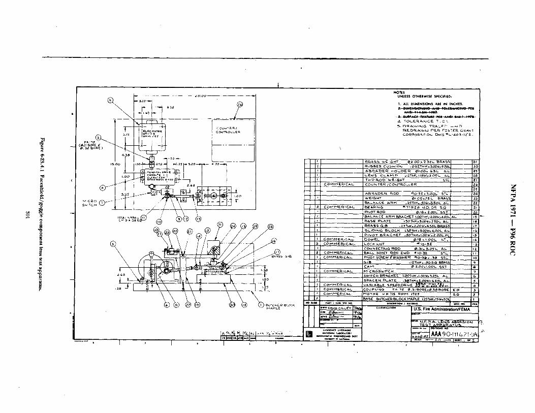
P
o
E
0
D |
. . . . . . . . . . . . . RO.~@
a o o . ~ ~ 3 8 , ~
t ,,1_,_ .
- - ' - . I , 1 . I '" I ' - I - l " ' l " 1 " - [ ' - -
I , t ,
NOTES UNLESS OTHERWhSE SPECIFIED,
1. ALL DIMENSIONS ARE IN I N C H E S ,
d. T O L ~ J C E " ! = . C L
• O3ZT~<, ~OOwx~OL
CO~P~IC~L CO~J KJ TE~::~ / C O M T ~ . O L L E R
CO--HElICaL
CO~MERIC~L-
~*ALA:MCE ARF"~ E>t:%~CR~T LOOTHK,?..00W~4.SBL E~l~.¢~ I= F~LP%'TE hSOTk}K~5.OOW~.~OL /~L BRASS GI~ ~ Z~T~K.Z.OO~/x~50L 8~h55
.~LsOII,JG 85~.OCK L~STgK,~O0V/=4.0DL /~.
P I V O T ~ ~,CK~T ..,~OTNkC,=I,OOg/=Z.~OL.~L D O w ' E . L . ~ . t 8 ~ I . O O l . . S T L-
CO M IvIEC%~C~,L- L O C K kJUT #' I 0 - 5 Z CO~.IMECTlt.~G I: tOO ¢P.~I= ~ .2FL. ALL
COMI~C~LL ~LL 301~T ~OD E~JD ~0-SZ 5TL-
C O P'~ P'~ ~-~ ~ C ~I~LL f'Vll C Q-O ~ W f1"C k4 I
3C
,:Z6 .ZS"
• Z3 • ZZ
Zl
• Z0 i
~- I ~9 1 8 1 7
~ 3
•10
,g , 7
I 5~,c.F. l : ; I . ¢:%.~,'IF-. . ~ I " N K . Z . 0 0 ~ V = & . Z ~ L /z,~.l 5 VA ~ A I='F- Z i l a .o - I~A~. ~'-- I
I 3 f COI~t'~E.RICb..L. f "~o ' rOR ~.P ~/15 R p P ~ ITZ~ I E Q JZ
. . . . . . . . . . ¢-r ],vz, v~l ......... i u.~j. Fire Administrafl0NFEMA |
LmWlIN¢| LI¥||MQ~| I J % .~,.~.T#~ , , l~, , . :_~ . , , AAA c)0-I 11L~ 21-0~
I ~ ' ~ ' ~ . o ~ i~ . , , , I o, z I
Z
"-4
I
P= A
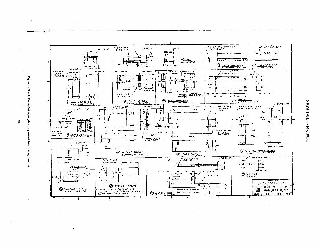
uo
@ 9~
.z,J
E
E
B 0
ol ~ 22 ~.Z19
~Wl~r(~i.i EM~ACI¢ET
L - " L ~ r ' * L eoZ I~ :#Z { .38 @4 [ a . 1 3 1
/ f.iZ
~ L ~ O
@ LE~J~, C I_ ~F'a ,~2 T~4K ~xLu~-~
2,:s8
0,20
T - -
( ~ T M D ROE) v~ErG ~'J'T c~-EE_ (11~E00)
- - - = J
(SET 5CakE~) .252,~.
J r - ; ~ o
.iz .z5
i.oo • -.25 "1 r ± -1-t'~.
~T~4~4 c&S5 ~TEEL-
--1- ; o L
~ o ®~ L.* 10.3Z 'r/~l=
hSO ZOO
I-.-.=, / ~ ~.zr ~J L.- .~o -.-" ~,oo ~-~
LL~;%%~'&-
F--~.- ---1j_ ~ - : _ ~ , ALu~"JU~J (I ~E~O)
~r~ . % S ( t Q.EO IC))
r-O.~'O P~ESS ~ ' I T . . . . . . . _ .ZS-ZO,~P -For- /-.s,,, ~,~ .. "~r - ' ~ r i
U ~ -- ~ ~ ~ : ~e" I
~L.UM~JU~4 (t P.EO O)
,~-- i ~ (1~,199) E)~ILL . . . . . . . . . ~.'---2 3Z q
/
?~" 4 0 0 .50 OEE~ ,/- 'ool ~ -tt-~x
* !~20 I!! ,,! ]_i
I { ~ BA~E PLATE
' -J.,oL~ . . . . .
, .~.o~ I I I I , / , , ~
I 6 I $ J 4 3
j ¢LASSlPI¢*nO"
~|AWtNG NO C~* I ~ 90JJ' '~J ~ ~
. SCALe ~Z.O ~ ISHUT Z OF~
Z
I
I
N F P A 1971 ~ F96 R O C
( h ) g #112) 1971- 119 - (4-4.3): Accept in Principle SUBMrI~rER: Bill Grilliot, Morning Pride Mfg (~). COMMENT ON PROPOSAL NO: 1971-21 RECOMMENDATION: Revise text as follows:
4-4.3 Footwear he ight shall be a m i n i m u m of 20.32 cm (8.0 in.). The height shall be de t e rmined by measur ing inside the boot f rom the center of the heel at the insole level up to ,any point on the top line. Removable insole inserts shall be removed prior to measurement . SUBSTANTIATION: Min imum height is required all a round top line, no t jn s t at the back :ts is now written. COMMITTEE ACTION: Accept in Principle.
Revise 4-4.3 to read: "Footwear height shall be a m i n i m u m of 20.32 cm (8.0 in.). The
height shall be de te rmined by measur ing inside the boot f rom the center of the insole at the heel up to a perpendicular reference line ex tending across the width of the boot at the lowest point of the top line. Removahle insole inserts shall be removed prior to n l e a s l l r e n l e H t." COMMITTEE STATEMENT: The Commit tee agrees with snbmit ter and h~Ls incorporated concept into a revised 4-4.3.
COMMITTEE STATEMENT: The Commit tee agrees with submit ter and has added suggested text to 44.8.1 and re-inserted requ i rement for Brannock device sizing charts to improve proper sizing and fit.
(Log #307) 1971- 123 - (4-4.8.2): Accept in Principle SUBMITFER: Jeffrey O. Stull, International Personnel Protection, Inc. COMMENT ON PROPOSAL NO: 1971-21 RECOMMENDATION: Ghange the paragraph to read:
"Full :rod half sizes shall be accomplished by individual ,and un ique lasts to provide proper fit, ~ SUBSTANTIATION: The requ i rement as currently written allows footwear manufac turers to use lasts to be used for multiple sizes ,among genders and between fnll and haft sizes. Footwear fit can best be achieved when un ique are created for each size, COMMITTEE ACTION: Accept in Principle.
Full and haft sizes, in each of the three required widths, shall be accomplished by individual ,and un ique lasts to provide proper fit. COMMrrTEE STATEMENT: The Commit tee agrees with submit ter and text will be added to r enumbered paragraph 44.8.3
(D)g #304) 1971- 1 2 0 - (4-4.4): Accept SUBMITTEI~ Jeffrey o . Stull, International Personnel Protection, Inc. COMMENT O N PROPOSAL NO: 1971-21 RECOMMENDATION: Delete "The sides and the rear of the heel shall not be flared or tapered," in subject paragraph. SUBSTANTIATION: This design requ i rement cannot be adequately assessed without fur ther definition of tapered or flared. As such the reqt t i rements is ambiguous and cannot be uniformly interpreted by the test laboratory. COMMITTEE ACTION: Accept.
( l.x)g #82) 1971- 124- (4-5.3): Reject SUBMITFEI~ Harry P. Winer, U.S. Navy COMMENT ON PROPOSAL NO: 1971-21 RECOMMENDATION: Figure n u m b e r in 4-5.3 reads Figure 6.16.4, should read Figure 6-16.4.1. SUBSTANTIATION: Typographical error. COMMITTEE ACTION: Reject. COMMITTEE STATEMENT: See Caommittee Action on £ ) )mment 1971-125 (Log #353).
(Dgg #30,.5) 1971- 121 - (4-4.4): Accept in Principle SUBMITTER: Jeffrey O. Stull, International Personnel Protection, Inc. COMMENT ON PROPOSAL NO: 1971-21 RECOMMENDATION: Add to pa ragraph 4-4.4:
"The width of the footwear heel shall be equal to or greater than the width of the sole , excluding any calendar roll if present, at the intersection of the heel breast and the sole bottom." SUBSTANTIATION: Statistics compiled by both the U.S. Fire Administration and NFPA show a significant n u m b e r of all fire fighter injuries due to foot or ankle strains ,and sprains. The Technical Commit tee has not addressed the issue of ankle support , which is ,affected by sever:d factors of footwear design including adequate heel width. Narrow width heels do not provide adequate foot stability as demons t ra ted by Neeves et at., "Physiological and Biomechanical Changes in Fire Fighters Due to Boot Modifications," A Research Study Funded by the IAFF and FEMA, August 1989. The proposed requ i rement will assist in providing better ,ankle suppor t in fire fighter boots and lessen ankle injnries. COMMITTEE ACTION: Accept in Principle. COMMITTEE STATEMENT: Modified text gives direction for e~tluation by the certification organizatio0.
(D~g #306) 1971- 122 - (4-4.8.1): Accept in Principle SUBMrVI'ER: Jeffrey o . Stull, International Personnel Protection, Inc. COMMENT ON PROPOSAL NO: 1971-21 RECOMMENDATION: Increase requ i rement f rom two to three widths for both Men's and W o m e n ' s sizes. SUBSTANTIATION: Statistics compiled by both the U.S. Fire Administ~zttion and NFPA show a significant n u m b e r of all fire fighter injuries due to foot or ankle strains and sprains. The Technical Conmaittee has not addressed the issue of ankle support, which is ~fffected by several factors of footwear design including availability o f st~]ficient footwear sizes. Two widths is no t sufficient to provide adequate s iz ingof fire fighters. The additional of o ther widths would p r o m o t e b e t t e r sizing and help reduce ,ankle injuries in the fire service. COMMITTEE ACTION: Accept in Principle.
Change "two widths ~ to "three widths" in 4-4.8.1. Also add back in paragraph %2-2 f rom old 1974 d o c u m e n t on Brannock device sizing charts as new 4-4,8.2. Current 4-4.8.2 to be r enumbered ms 4-4.8.3.
(Log #353) 1971- 125 - (4-5.3): Accept SUBMI'VrER: Bob O 'Gorman , Inchcape Tes t ingServices /ETL Test ing Laboratories, Inc. COMMENT O N PROPOSAL NO: 1971-21 RECOMMENDATION: In the second sentence, remove %ize 7 1/4 headform, as specified in Fignre 6-16.4." and replace with "ISO sizeJ reference Headform." SUBSTANTIATION: The size 7 1 /4 headform specified in Fignre 6- 16.4 is no t a complete headform and would no t allow for a hood to be "donned properly in the position in which it is in tended to be worn" ,as specified in this section. The ISO headform referenced above is of similar d imensions of the one specified in section 6-16.4, however, it includes d imensions which replicate nose and jawbone strnctnre. COMMITTEE ACTION: Accept.
(I.agg #194) 1971- 126 - (4-5.4 (New)): Reject SUBMITFER: StephenJ . Asthalter, Life Liners, Inc. COMMENT O N PROPOSAL NO: 1971-21 RECOMMENDATION: Add new text:
4-5.4 The hood shall be des igned with a face opening. Other than where the hood. face open ing is des igned to interface ~ t h a specific SCBA face piece or where the hood face open ing is designed to be adjustable, the hood face open ing shall measure 15 in. when stretched along a linear plane (+/- 1 in.) and recover to its relaxed d imension (+/- 1 in.). SUBSTANTIATION: We believe the face open ing should stretch to 15 in. to facilitate easy donning. Fire fighters wear the h o o d down a round their necks and bring it up and over the head after the SCBA mask is donned. If the open ing doesn ' t stretch enough , t ime is wasted in what becomes a real struggle. The face open ing should return to its relaxed shape to ensure against sagging that would prevent a t ight seal ,-after repeated nse. We believe specifying relaxed face open ing size is design restrictive. COMMrI'TEE ACTION: Reject. COMMITTEE STATEMENT: The Commit tee feels that the critical d imension of the face open ing is in the relaxed position. Paragraph 5-5.1 contains the per formance requ i rement fi~r the stretch of the face opening.
393
N F P A 1971 - - 1796 R O C
(Log #61) 1971- 1"27- (4-6.3): Accept in Principle SUBMITTER: BarrieJ. Lough, City of Winnipeg Fire Dept., Canada COMMENT O N PROPOSAL NO: 1971-21 RECOMMENDATION: Revise tenet:
"In a m a n n e r that will no t permi t a gap in the thermal barrier." SUBSTANTIATION: To provide better thermal protection and lower potential for burn injury. COMMITTEE ACTION: Accept in Principle.
Revise 4-6.3 to read: %.coat sleeve in a m a n n e r that will no t pernti t a gap in the thernlal
protection." Also revise 4-1.14.X to read: "...in a n tanner that will not permit a gap in rile thermal protection
and that meets..." COMMITTEE STATEMENT: The ( ~ m m i t t e e agrees with the submit ter only changing the word "barrier" to "protection".
(Log #250) 1971- 131 - (4-7.1): Accept in Principle SUBMITTER: Kevin S. Ester, San Diego, CA City Fire /Occ Safety/ Health COMMENT ON PROPOSAL NO: 1971-21 RECOMMENDATION: Revise text:
"The he lmet shall be provided with ei ther a faceshield or goggles based on the purchasers preference." SUBSTANTIATION: Our depa r tmen t does not recognize faceshields as eye protection. Require the use of either a faceshield or goggle c o m p o n e n t on helmets to allow depar tments to select what is best suited to their needs. Eliminates an expense to a depa r tmen t that is trying to be NFPA compliant but wishe s to better protect its members . COMMITTEE ACTION: Accept in Principle. COMMITTEE STATEMENT: See Cx~mmittee Action on C o m m e n t 1971-I 15 (Log #I'28).
( I~g #113) 1971- 128- (4-6.3): Reject SUBMITTER: Bill Grilliot, Morning Pride Mfg Co. COMMENT ON PROPOSAL NO: 1971-21 RECOMMENDATION: Revise text ,as follows:
4-6.3 The wristlet shall ex tend a round the wrist, have a catch fi~r the thumb, and be perntanently a t tached to the moisture barrier or thermal barrier sleeve end. SUBSTANTIATION: Barrier sleeve penetrat ion is an impor tan t s:ffety consideration. COMMITTEE ACTION: Reject. COMMITTEE STATEMENT: See Commit tee Action on (k~mment 1971-129 (Log #62).
(LOg #62) 1971- 129- (4-6.4 (New)): Reject SUBMITTER: BarrieJ. Lough, City of Winnipeg Fire Dept., C,'mada COMMENT ON PROPOSAL NO: 1971-21 RECOMMENDATION: Add new text to read:
"Wrisdets shall have a t h u m b hole or bartack creating a t h u m b hole for the wearer 's t h u m b in order to ensure protection when arms are in the raised a n d / o r ex tended position." SUBSTANTIATION: To prevent exposure of the wrist area and lower potential fl:~r burn injury, COMMITTEE ACTION: Reject. COMMITTEE STATEMENT: The ( ~ m m i t t e e feels that the fire service can decide which type of wristlets is most appropriate for their use.
(Log #119) 1971- 130- (4-7, 4-7.1, 5-7): Accept in Principle SUBMITrER: B.J. Thomas, Dallas Fire Dept., TX COMMENT ON PROPOSAL NO: 1971-21 RECOMMENDATION: Add new text to let fire fighters use goggles, flip-down shield, or fidl-face shields, instead of requir ing only face shields. SUBSTANTIATION: I received 2nd degree s team burns on my face and neck at a rubbish fire. I was in full protective gear, bunker boots /pants , coat (fully but ton, collar up), hood (umked inside my coat), and he lmet (with ear flaps and face shield down). Steam got t rapped unde r the full face shield and scalded my face. I also had burns to the inside of my mou th and nose. I received medical t reatment, including debr idement for abou t 2 weeks. I s topped burn ing when I was able to raise my full face shield into the stowed position. My c o m n m n d i n g officers and I ~l feel I wouldn ' t have gotten burned had I no t pulled that full face shield down. I would welcome a phone call on this matter.
In summat ion , I welcome the new change your propose. I will have some type o f eye protection, but I do no t want that face shield on my helmet. The fidl face shield is heavy, cumbersome, and it will t rap steam causing burns. In fact, we are told not to pull the face shields down when fighting propane tank fires dur ing training. COMMITTEE ACTION: Accept in Principle. COMMITTEE STATEMENT: See Commit tee Action on C o m m e n t 1971-115 (Log #128).
(Log #270) 1971-132- (5-1): Accept in Principle SUBMrVrER: Tom Wollan/Kimber ly Henry, Underwriters Labnratories, Inc. COMMENT O N PROPOSAL NO: 1971-21 RECOMMENDATION: Add new text:
"Seam brealdng strength shall be considered acceptable when the fabric s t rength is less than the required seam strength specified in 5-1.12.1 o f this section, providing the fabric fails without failure of the seam below the applicable forces specified in 5-1.12." SUBSTANTIATION: Paragraph 5-1.19 requires that outer shells and collar lining have a m i n i m u m tensile strength of 140 Ib, while the Major A seams are required a m i n i m u m breaking strength o f 150 Ib in 5-1.12. These paragraphs contradict each o ther without the above new requirement . The above paragraph was in the 1991 edition. COMMITTEE ACTION: Accept in Principle. COMMITTEE STATEMENT: The Commit tee agreed with the submit ter ' s c o m m e n t mid made appropriate changes in the n u m b e r i n g sequences in the document . See Commit tee Action on C o m m e n t 1971-162 (Log #75).
(Log #315) 1971- 133- (5-1.X (New)): Hold SUBMITTER: Jeffrey (7). SmU, International Personnel Protection, Inc. COMMENT ON PROPOSAL NO: 1971-21 RECOMMENDATION: Add a new requirement:
5-1.X Specimens of ga rment composites consisting of outer shell, moisture barrier, thermal barrier, and additional layers provided for re inforcement at ga rmen t shoulders, elbows, and knees shall be tested for stored energy effects ,as specified in Section 6-48, "Stored Energy Test," and shall have an alarm t ime of no t less than 10 sec and a time-to-burn of not less than 60 sec. SUBSTANTIATION: The utility of the stored energy test lies in being able to assess hea t sink effects for areas o f the ga rmen t which are reinforced and are in tended to provide additional protection. Fire fighters should expect protective garments to provide at least 1 min o f protection f rom burn injury and ample t ime to detect the onse t of burn injury u n d e r the prescribed "routine" condit ions o f the test. COMMITTEE ACTION: Hold. COMMITTEE STATEMENT: The submitters c o m m e n t proposes someth ing that would require considerable research and discussion by the Technical Commit tee and canno t be properly handled within the t ime f l ame established for processing the report.
(Log #314) 1971- 134- (5-1.X, 6-X): Hold SUBMITI'ER: Jeffrey o . Stull, International Personnel Protection, Inc. COMMENT O N PROPOSAL NO: 1971-21 RECOMMENDATION: Add the following requ i rement and test method: "
Add the following criteria: 5.1.X Specimens of ga rmen t outer shells and collar lining material
shall be tested for f lame resistance while unde r a cons tant load as specified in Section 6-X, "O~nstant Tension Flame Resistance "Break Open" Test," and shall have a failure t ime of no t less than 5 seconds.
394
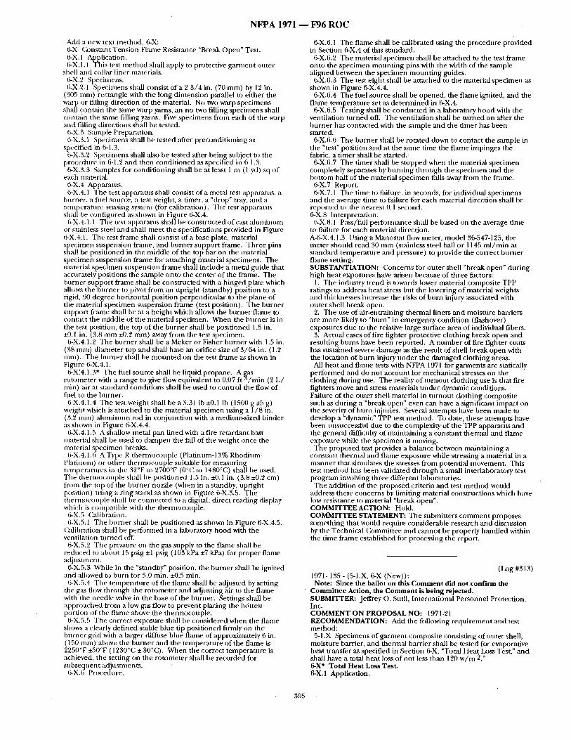
N F P A 1971 ~ F 9 6 R O C
Add a new text method, 6-X: 6-X (k)nstant Tension Flanle Resistance "Break Open" Test. 6-X.1 Application. 6-X.1.1 This test me thod shall apply to protective ga rmen t outer
shell and collar liner nlaterials. 6-X.2 Specimens. 6-X.2.1 Specimens shall consist o f a 2 3 / 4 in. (70 mm) by 12 in.
(305 ntm) rectangle with the long dintension parallel to either the warp or tilling direction of the material. No two warp specimens shall conufin the same warp yarns, an no two filling specimens shall contain the sanle filling yarns. Five specimens from each of the warp and filling directions shall be tested.
6-X.3 S~unple Preparation. 6-X.3.1 Specimens shall be tested after precondi t ioning as
specified in 6-1.3. 6-X.3.2 Specimens shall also be tested after being snbject to the
procedure in 6-1.2 and then condi t ioned as specified in 6-1.3. 6-X.3.3 Samples fi)r condi t ioning shall be at least 1 m (1 yd) sq of
each material. 6-X.4 Apparatus. 6-X.4.1 The test appani tus shall consist o f a metal test apparatus, a
burner, a fiiel source, a test weight, a timer, a "di'op" tray, and a temperature sensing system (fi)r calibration). The test apparatus shall be configured as shown in Figure 6-X.4.
6-X.4.1.1 The test apparauls sh~dl be constructed of cast a l uminum or stainless steel and shall meet the specifications provided in Fignre 6-X.4.1. The test franle shall consist of a base plate, material specimen suspension f f ~ l e , and burner suppor t frame. Three pins sh;dl be posit ioned in die middle of the top bar on the material specimen suspension f lame fi~r at taching material specimens. The material specimen suspension frame shall include a metal guide that accurately positions the sample onto the center of the frame. The burner snppor t f rame shall be consU-ucted with a h inged plate which allows the burner to piw)t f rom an upr ight (standby) position to a rigid, 90 degree horizontal position perpendicular to the plane o f tile material specimen suspension frame (test position). The burner suppor t frzm/e shall be at a height which allows the burner flame to contact the nfiddle of the mater i~ specimen. When the burner is in the test position, the top of the burner shall be positioned 1.5 in. +0.1 in. (3.8 m m i-0.2 ram) away f rom the test specimen.
6-X.4.1.2 Tile burner shall be a Meker or Fisher burner with 1.5 in. (38 ram) dianmter top and shall have ml orifice size of 3 /64 in. (1.2 ram). The burner shall be m o u n t e d on the test f lame as shown in Figure 6-X.4.1.
6-X~4.1.3" The fuel source shall be liquid propane. A rotonteter with a range to give flow equivalent to 0.07 I t . / m i n (2 L / rain) ,air at st,-mdard condit ions shall be used to control the flow of fiml to the burner .
6-X.4.1.4 The test weight shall be a 3.31 Ib -z-0.1 Ib (1500 g ~B g) weight which is a t tached to the material specimen using a 1/8 in. (3.2 mm) a lumimlm rod in conjunction with a medium-sized binder as shown in Figamre 6-X.4.4.
6-X.4.1.5 A shallow metal pan lined with a fire reu~rdant batt material shall be used to dampen the fall of the weight once the material specimen breaks.
6-X.4.1.6 AType R ther inocouple (Platinum-13% Rhodium- Platinum) or o ther thermocouple suitable for measur ing temperatures in the 32°F to 2700°F (0°C to 1480°C) shall be used. The therInocouple shall be posit ioned 1.5 in. :tO. 1 in. (3.8 ±0.2 cm) from the top o f the bt ,rner nozzle (when in a st.'mdby, upr ight position) using a ring starrd as shown in Figure 6-X.3.5. The thernlocouple shall be connec ted to a digital, direct reading display which is compatible with the thermoconple .
6-X.5 Calibration. 6-X.5.1 The burner shall be posit ioned as shown in Figure 6-X.4.5.
Calibration shall be per formed in a laboratory hood with the ventilation tu rned off.
6-X.5.2 The pressure on the gas supply to the flame shall be reduced to about 15 psig +1 wig (103 kPa ±7 kPa) for proper flanle adjustInent.
6-X.5.3 While in the "standby" position, the burner shall be ignited and ,allowed to bt,rn fi:w 5.0 rain. i-0.5 rain.
6-X.5.4 The tempera ture of the f lame shall be adjusted by setting tile gas flow through the rotometer and adjust ing air to the fi,'une with the needie valve in the base o f the burner . Settings shall be approached from a low gvts flow to prevent placing the hottest portion of the flame above tile t i lermocouple.
6-X.5.5 The correct exposure shall be considered when the flame shows a clearly def ined stable blue tip posit ioned firmly on the burner grid with a larger diffuse blue fl,'une of approximately 6 in. (150 ram) above the burner mid the tempera ture of the flame is "2~250°F +50°F (1230°C :l: 30°C). When the correct tempera ture is achieved, the setting on the ro tometer shall be recorded for subsequent adjusmlen is.
6-X.6 Procedure.
6-X.6. I The f lame shall be calibrated using the procedure provided in Section 6-X.4 of this stzmdard.
6-X.6.2 The material specimen shall be a t tached to the test f lame onto the specimen moun t ing pins with the width of the sample al igned between the spec imen moun t ing guides.
6-X.6.3 The test e ight shall be a t tached to the nmterial spec imen as shown in Figure 6-X.4.4.
6-X.6.4 The fuel source shall be opened, the f lame ignited, and the flame tempera ture set as de t e rmined in 6-X.4.
6-X.6.5 Test ing shall be conducted in a laboratory h o o d with the ventilation tu rned off. The ventilation shall be t u rned on after the burner has contacted with the sample and the t imer has been started.
6-X.6.6 The burner shall be rotated down to contact the sample in the "test" position and at the same t ime the flame impinges the fabric, a t imer shall be st'u-ted.
6-X.6.7 The t imer shall be s topped when the material specimen completely separates by burn ing th rough the specimen and the bot tom half of tile material specimen falls away from the frame.
6-X.7 Report. 6-X.7.1 The time to fidlure, in seconds, for individual specimens
and the average time ta~ faihlre fi)r each material direction shall be reptwted to the nearest 0. l ~ c o n d . 6-X.8 Interpretation.
6-X.8.1 Pass/fail performance shall be based on the average t ime to failure for each material direction. A-6-X.4.1.3 Using a Manostat flow meter, model 36-547-125, die meter should read 30 m m (stainless steel ball or 1145 m l / m i n at s tandard tempera ture and pressure) to provide the correct burner flame setting. SUBSTANTIATION: Concerns for outer shell "break open" dur ing high heat exposures have arisen becanse of three factors:
1. The industry t rend i s towards lower material composite TPP ratings to address heat stress but the lowering o f materi~d weights and thickalesses increase the risks o f burn injury associated with outer shell break open.
2. The use of air-entraining thermal liners and moisture barriers are more likely to "burn" in emergency condit ion (flashover) exposures due to the relative l ~ g e surface area of individual fibers.
3. Actual cases of fire fighter protective clothing break open and resulting burns have been reported. A n u m b e r of fire fighter coats has sustained severe damage as the result of shell break open with the location of burn injury unde r the damaged clothing areas.
All heat and flame tests with NFPA 1971 for garments are statically per formed and do not account for mechanical stresses on the clothing dur ing use. The reality of tu rnou t clothing use is that fire fighters move and stress materials unde r dynamic conditions. Failure of the outer shell material in t u rnou t clothing composite such as dur ing a "break open" even can have a significant impact on the severity o f burn injuries. Several a t tempts have been made to develop a " d y n a ~ c " TPP test method. To date, these at tempts have been unsuccessful due to the complexity of the TPP apparatus and the gener~d difficulty of mainta in ing a const~mt t h e r m a l a n d flame exposure while the specimen is moving.
The proposed test provides a balance between mainta in ing a constant thermal and flame exposure while stressing a material in a manne r that simulates the stresses f rom potential movement . This test me thod has been validated th rough a small interlaboratory test progrmn inw)lving three different laboratories.
The addition of the proposed criteria and test me thod would address these concerns by limiting material construct ions which have low resistance to material "break open". COMMITTEE ACTION: Hold. COMMITTEE STATEMENT: The submitters c o m m e n t proposes someth ing that would require considerable research and discussion by the Technical (2)mmittee and cannot be properly handled within the t ime frame established fi)r processing the report.
(Log #313) 1971- 135 - (5-1.X, 6-X (New)):
Note: Since the ballot on this Comment did not confirm the Committee Action, the Comment is being rejected. SUBMI'VI'ER: Jeffrey o . Stull, International Personnel Protection, Inc. COMMENT ON PROPOSAL NO: 1971-21 RECOMMENDATION: Add tile following requ i rement and test method:
5-1.X Specimens of ga rmen t composite consisting of outer shell, moisture barrier, and thermaJ barrier shall be tested for evaporative heat transfer ,as specified in Section 6-X, "Total Heat Loss Test," and shall have a total heat loss of not less than 120 w / m 2." 6-X* Total Heat Loss Test. 6-X.1 Application.
395
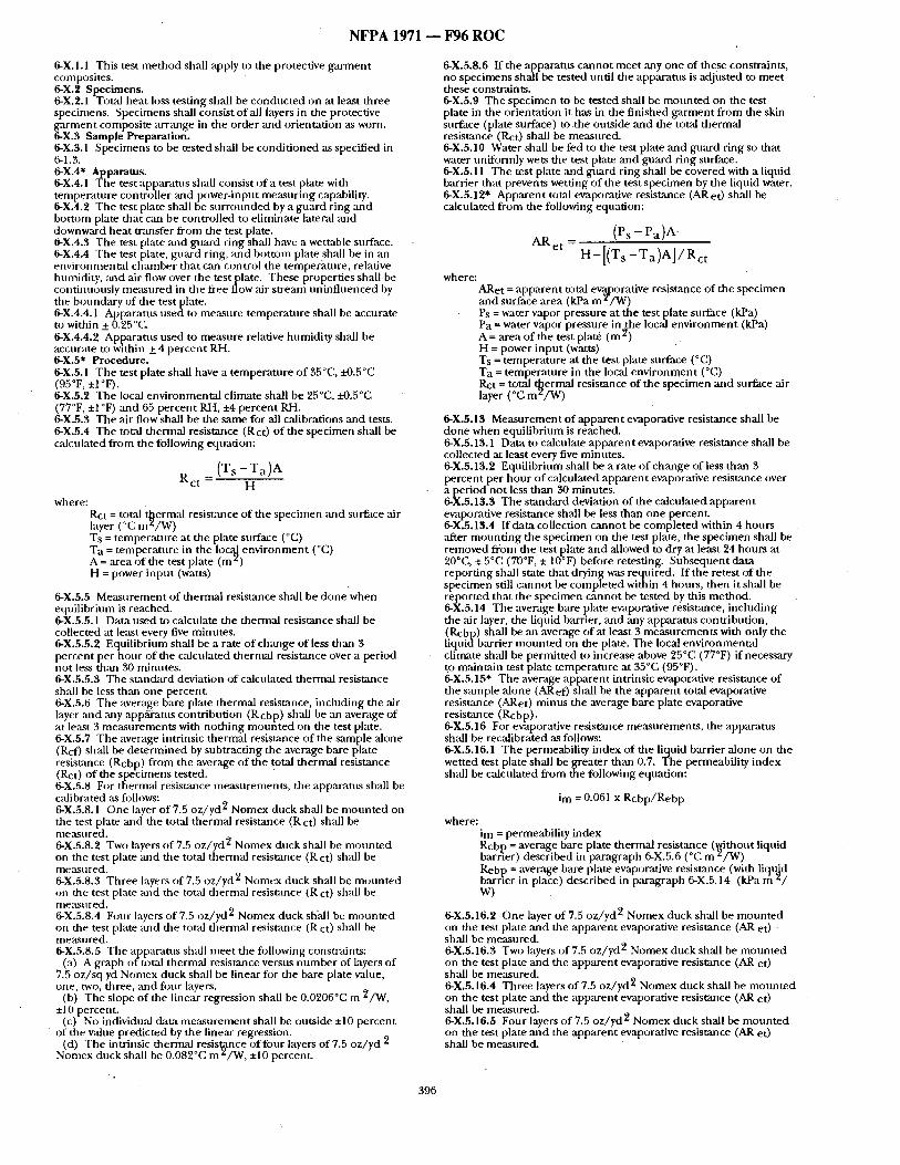
N F P A 1971 ~ F96 R O C
6-X.I.I This test me thod shall apply to the protective ga rmen t composites. 6-X.2 Specimens. 6-X.2.1 Total heat loss testing shall be conducted on at least three Specimens. Specimens shall consist of all layers in the protective ga rmen t composite arrange in the order and orientation as worn. 6-X.3 Sample Preparation. 6-X.3.1 Specimens to be tested shall be condi t ioned as specified in 6-1.3. 6-X.4" Apparatus. 6-X.4.1 The test apparatus shall consist o f t test plate with tempera ture controller and power-input measur ing capability. 6-X.4.2 The test plate shall be su r rounded by a guard r ing mad bot tom plate that can be controlled to eliminate lateral and downward heat transfer f rom the test plate. [J-X.4.3 The test plate and guard ring shall have a wettable surface. . 6-X.4.4 The test plate, guard ring, mad bot tom plate shall be m an environmenta l chamber that can control the temperature , relative humidity, and air flow over the testplate. These properties shall be continuously measured in the flee flow air stremll un inf luenced by the bonn&try of the test [~late. 6-X.4.4.1 Apparatus usect to measure tempera ture shall be accurate to within +_ 0.25'~C. 6-X.4.4.2 Apparatus used to measure relative humidity shall be accurate to within +_ 4 percent RH. 6-X.5" Procedure. 6-X.5.1 The test plate shall have a t empera ture o f 35 °C, ~'-0.5°C (95°F, ±1 °F). 6-X.5.2 The local environmenta l climate shall be 25°C, ±0.5°C (77°F, ±1 °F) and 65 percent RH, ±4 percent Rid. 6-X.5.3 The air flow shall be the same for all calibrations and tests. 6-X.5.4 The total thermal resistance (Rct) o f the specimen shall be calculated f rom the following equation:
( T s - T a ) a R c t - H
where: Rct = total t~ermal resistance of the specimen ~md surface air layer (°C m ~ / W ) Ts = tempera ture at the plate surface (°C) Ta = tempera ture in the loc~ env i ronmen t (°C) A = area o f the test plate (m z) H = power inpu t (watts)
6-X.5.5 Measurement o f thermal resistance shall be done when equil ibrium is reached. 6-X.5.5.1 Data used to calculate the thermal resistance shall be collected at least every five minutes. 6-X.5.5.2 Equilibrium shall be a rate o f change of less than 3 percent per hour of the calculated thermal resistance over a period not less than 30 minutes . 6-X.5.5.3 The s tandard deviation of calculated thermal resistance shall be less thml one percent. 6-X.5.6 The average bare plate thermal resistance, including the ,'air layer and ,any app,~ratus contributh)n (R cbp) shall be an average of at least 3 measurements with noth ing moufi ted on the test plate. 6-X.5.7 The average intrinsic thermal resistance o f the sample alone (Rcf) shall be de t e rmined by subtract ing the average bare plate resisumce (Rcbp) f rom the average of the total thermal resistance (Rct) o f the specimens tested. 6-X.5.8 For thermal resistance measurements , the apparatus shall be calibrated as follows: 6-X.5.8.1 One layer of 7.5 oz /yd 2 Nomex duck shall be m o u n t e d on the test plate and the total thermal resistance (R ct) shall be nteasured. 6-X.5.8.2 Two layers o f 7.5 oz /yd 2 Nomex duck shall be m o u n t e d on the test plate and the total thermal resistance (Rct) shall be measured. 6-X.5.8.3 Three layers of 7.5 oz /yd 2 Nomex duck sh',dl be m o u n t e d on the test plate and the total thermal resist,'mce (R ct) shall be measured. 6-X.5.8.4 Four layers of 7.5 oz /yd 2 Nomex duck shall be m o u n t e d on the test plate and the total thermal resistance (R ct) shall be measu red. 6-X.5.8.5 The apparatus shall meet the fi)llowing constraints:
(a) A graph of total thermal resistance versus n u m b e r o f layers of 7.5 oz / sq yd Nomex duck shall be linear fi~r the bare plate value, one, two, three, and four layers,
(b) The slope o f the linear regression shall be 0.0206"C m 2/W, ±10 percent.
(c) No individual data m e a s u r e m e n t shall be outside ±10 percent of the value predicted by the linear regression.
(d) The intrinsic thermal res is~nce of four layers of 7.5 oz /yd 2 Nomex dnck shall be 0.082°C m z /W, ±10 percent.
396
6-X.5.8.6 If the apparatus cannot meet any one of these conslraints, no specimens shall be tested until the apparatus is adjusted to meet these const.raints. 6-X.5.9 The spec imen to be tested shall be m o u n t e d on the test plate in the orientation it has in the f inished ga rmen t f rom the skin surface (plate surface) to the outside and the total thermal resistance (Rct) shall be measured. 6-X.5.10 Water shall be fed to the test plate and guard ring so that water uniformly wets the test plate and guard ring surface. 6-X.5.11 The test plate and guard ring shall be covered with a liquid barrier that prevents wetting of the test spec imen by the liquid water. 6-X.5.12" Apparen t to~l evaporative resistance (AR et) shall be calculated f rom the following equation:
( P s - P a ) A
AR et - H - [ ( T s - T a ) A l / R c t
where: ARet = apparent total ev'al0orative resistance of the specimen and surface area (kPa m z / W ) Ps = water vapor, pressure at. the test plate .surface (kPa) Pa = water vapor pressure r a t h e local e n w r o n m e n t (kPa) A = area o f the test plate (m 2) H = power inpu t (watts) Ts = tempera ture at the test plate surface (°C) Ta = tempera ture in the local env i ronment (°C) Rct= total ~ e r m a l resistance of the spec imen and surface air layer (°C m ~ / W )
6-X.5.13 Measurement o f apparen t evaporative resistance shall be done when equil ibrium is reached. 6-X.5.13.1 Data to calculate apparen t evaporative resistance shall be collected at least every five minutes . 6-X.5.13.2 Equilibrium shall be a rate o f change of less than 3 percent per hour o f calculated apparen t evaporative resistance over a period not less than 30 minutes. 6-X.5.13.3 The s tandard deviation of the calculated apparent evaporative resistance shall be less than one percent. 6-X.5.13.4 If data collection canno t be comple ted within 4 hours ,after m o u n t i n g the spec imen on the test plate, the spec imen shall be removed from the test plate and allowed to dry at least 24 hours at 20°C, ± 5°(: (70°F, ± 10°F) before retesting. Subsequent data report ing shall state tha t drying was required. If the retest of the specimen still canno t be comple ted within 4 hours, then it shall be reported that the specimen canno t be tested by this method. 6-X.5.14 The average bare plate evaporative resistance, including the air layer, the liquid barrier, and any apparatus contribution, (Rcbp) shall be ,an average of at least 3 measu remen t s with only the l iquidbarr ier m o u n t e d on the plate. The local envi ronmenta l climate shall be permit ted to increase above 25°C (77°F) if necessary t,o maintain test plate tempera ture at 35°C (95°F). 6-X.5.15" The average apparen t intrinsic evaporative resistance o f the sample alone (ARef) shall be the apparent total evaporative resistance (ARet) minus the average bare plate evaporative resistance (Rcbp). 6-X.5.16 For evaporative resistance measurements , the apparatus shall be recalibrated as follows: 6-X.5.16.1 The permeability index of the liquid barrier a lone on the wetted test plate shall be greater than 0.7. The permeability index shall be calculated f rom the following equation:
im = 0.061 x R c b p / R e b p
where: im = permeability index Rcbp = average bare plate thermal resistance (~dithont l iqu id barner) described in paragraph 6-X.5.6 (°C m /W) Rebp = average bare plate evaporative resistance (with liql~d
. . . . h barner m place) descnbed m paragraph 6-X.5.14 (kPa m / w)
6-X.5.16.2 One layer of 7.5 oz /yd 2 Nomex duck shall be m o u n t e d on the test plate and the apparent evaporative resistance (AR et) sball be measured. 6-X.5.16.3 Two layers o f 7.5 oz /yd 2 Nomex duck shall be m o u n t e d on the test plate and the apparent evaporative resistance (AR et) shall be measured. 6-X.5.16.4 Three layers of 7.5 oz /yd 2 Nomex duck shall be m o u n t e d on the test plate and the apparent evaporative resistance (AR et) shall be measured. 6-X.5.16.5 Four layers o f 7.5 oz /yd 2 Nomex duck shall be m o u n t e d on the test plate and the apparent evaporative resistance (AR et) shall be measured.
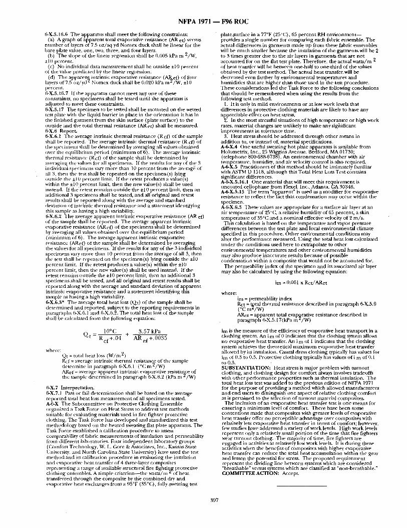
N F P A 1971 - - F96 R O C
6-X.5,16.6 The apparatus shall meet the following constraints: (a) A graph of apparent total evaporative resistance (AR et) versus
n umber of layers of 7.5 oz /sq yd Nomex duck shall be linear for the bare plate value, one, two, three, and fi)ur layers.
(b) The slope of the linear regression shall be 0.005 kPa m 2/W, +10 percent.
(c) No individual data measurement shall be outside ±10 percent of the value predicted by the linear regression.
(d) The appareng intrinsic evaporative resistance (Al~ef) offi~ur layers of7.5 oz/yct ~ Nomex duckshall be 0.020 kPa nag/W, +]0 percent. 6-X.5,16.7 If the apparatus cannot meet any one of these constraints, no specimens shall be tested until the apparatus is adjusted to meet these constraints. 6-X.5.17 The specimen to be tested shall be m o u n t e d on the wetted test plate with the liquid barrier in place in the orientation it has in tbe finished ga rmen t f rom the skin surface (plate surface) to the outside and the total thermal resistance (AR et) shall be measured. 6-X.6 Report. 6-X.6.1 The average intrinsic thermal resistance (Rcf) of the sample shall be reported. The average intrinsic thermal resistance (R cf) of the specimens shall be de te rmined by averaging all values obtained over the equil ibrium period (mi n i mum of 6). The average intrinsic thermal resistance (Rcf) of the sample shall be de te rmined by averaging the values for all specimens. If the results fi~r any of the 3 individual specimens vary more than 10 percent from the average: of :ill 3, then the test shall be repeated on the specimen(s) lying ~mtside the +10 percent limit. If the retest produces a value(s) within the +10 percent linfit, then the new value(s) shall be used instead. If the retest rein:fins outside the ±10 percent limit, then an additional 3 specimens shall be tested, :and all original and retest results shall be reported a long with the average and s tandard deviation of intrinsic thermal resistance and a s ta tement identifying this sample as having a high variability. 6-X.6.2 The average apparent intrinsic evaporative resistance (AR ef) of the sample shall be reported. The average apparent intrinsic evaporative resistance (AR el') of the specimens shall be de te rmined by averaging all values obta ined over the equil ibrium period ( m i n i m u m of 6). The average apparent intrinsic evaporative resistance (ARef) of the sample shall be de te rmined by averaging the values for all specimens. If the results for may of the 3 individual specimens vary more than 10percen t f rom the average of all 3, then tile test shall be repeated on the specimen(s) lying outside the ±i0 percent limit. If the retest produces a value(s) within the ±10 percent limit, then the new value(s) shall be used instead. If the retest renmins ot,tside the +10 percent limit, then an additional 3 specimens sball be tested, and all original and retest results shall be reported a long with the average and s tandard deviation of apparent intrinsic evaporative resistance and a s ta tement identifying this sample as having a high variability. 6-X.6.3" The average total heat loss (Qt) of the sample shall be de te rmined and reported, subject to the report ing requirements in paragraplls 6-X.6.1 and 6-X.6.2. The total heat Io,~s of the sample shall be calculated from the following equation:
1 0 ° C + 3 .57 kPa
Q t - R c f + . 0 4 A R e f + . 0 0 3 5
where: Qt = total heat loss ( W / m 2) Rcf = ave rage in trin sic thermal resistance of the sample de termine in paragraph 6-X.6.1 (°C m 2/W) ARef = average apparent intrinsic evaporative resistarLce of the s:unple de te rmined in paragraph 6-X.6.2 (kPa m a /W)
6-X.7 Interpretation. 6-X.7.1 Pass or fail determinat ion shall be based on the average reported total hea t loss measu remen t of all specimens tested. A-6-X The Subcommit tee on Protective Clothing Ensemble organized a Task Force on Heat Stress to address test methods suiuable for evaluating materials used in fire fighter protective clothing. The Task Force bas developed and standardized this test methodology based on the heated sweating flat plate apparatus. The Task Force established a calibratiun procedure to assess comparability of fabric measurements of insulation and permeability from different laboratories. Four i ndependen t laboratory groups (Omlfi)rt Technology, W. L. Gore & Associates, Inc., ICztnsas State University, and North Carolina State I hfiversity) have used the test me thod and its calibration procedure in evaluating the insulation an d evaporative h eat tran sfe r o f 4 th ree-laye r corn p~)sites represent ing a range of available structural fire fightir~2g protective clothing ensembles. A simple c t i t e r ion- - the wat ts /m of beat transferred through the composite by t.tie combined dry and evaporative heat exchanges f rom a 95°F (35 °C), fidly sweating test
plate,surface in a 77°F (25°C), 65 percent RH e n v i r o n m e n t - - provides a single n u m b e r fi)r compar ing each fabric ensemble. The actual differences in garments made up from these fabric ensembles will be much smaller becanse the insulation o f the garments will be 2 to 3 t imes greater due to the air layers in garments that are not accounted for on the flat test plate. Therefore, the actual wat t s /m 2 of heat transfer will be between one-half to one-third of the values obtained by the test method. The actual hea t t ransfer will be decreased even farther by environmenta l temperatures and humidit ies that are h igher than those used in the test procedure. These considerations led the Task Force to the following conclusions that should be r emembered when using the results f rom the following test method.
1. It is only in mild envi ronments or at low work levels that differences in protective clothing materials are likely to have any appreciable effect on heat stress.
2. In the most stressful s iumtions of high tempera ture or high work rates, material changes are unlikely to make any sighificant improvements in tolerance time.
3. Heat stress should be addressed th rough o ther means in addition to, or instead of, material specifications. A-6-X.4 One useful sweating hot plate apl~aratns is available f rom Holometrix, Inc., 25 Wiggins Avenue, Bedford, MA 01730; ( te lephone 800-688-673~). An environmental ch, 'unber with ,-air temperature, tnnnidity, and ,air velocity control is also required. A-6-X.5 Practitioners of this me thod should be intimately familiar with ASTM D 1518, a l though this Total Heat Loss Test contains significant differences. A-6-X.5.16.1 One material that will mee t this r equ i rement is uncoated cel lophane from Flexel, Inc., Atlanta, GA 30346. A-6-X.5.15 The term "apparent" is used as a modifier for evaporative resistance to reflect the fact that condensat ion may occur within the specimen. A-6-X.6.3 These values :are appropriate for a surface air layer at an air tempera ture of 25°C, a relative humidity of 65 percent, a skin tempera ture of 35°(; and a nominal effective velocity of 2 m / s .
This calculation is based on the tempera ture and vapor pressure differences between the test plate andloca l envi ronmenta l climate specified in this procedure. Other environmenta l condit ions may alter the performance measured. Using the total hea t loss calcnlated unde r the condit ions used here to extrapolate to o ther environmental temperatalres and o ther environmenta l humidit ies may also produce inaccurate results because o f possible condensat ion within a composite that would no t be accounted for.
The permeability index of the specimen and its associated air layer may also be calculated by using the following equation:
i m = 0.061 x Rc t /ARet
where: im = permeability index Rct= Wtal thermal resistance described in paragraph 6-X.5.9 (°C m~/W) ARet = apparen t total evaporative resistance described in paragraph 6-X.5.17(kPa m z / W )
im is the measure of the efficiency of evaporative heat t ransport in a clothing system. An i m of 0 indicates that the clothing system allows no evaporative heat transfer. An i m of I indicates that the clothing system achieves the theoretical m a x i m u m evaporative heat transfer allowed by its insulation. (hsual dress clothing typically has values for im of 0.3 to 0.5. Protective clothing typically has values o f i m of 0.1 to 0.3. SUBSTANTIATION: Heat stress is m a j o r p r o b l e m with tu rnout clothing, and clothing design for comfort always inw)lves wadeoffs with o ther perforrrmnce properties such as thermal insulation. The total heat loss test was added to the previous edition o f NF16A 1971 for the purpose o f providing a me thod which allowed manufacturers and endus~ r s to di-stinguish- one aspect of relative clothing comfort as it pert ' t ined to the selection of tu rnou t material composites.
The inclusion of an evaporative heat transfer test is one means for ensur ing a m i n i m u m level of comfort. There have been some con teuuons made that composites with greater levels of evaporative heat transfer offer no perceptible advantage over composites with relatively less evaporative he-at transfer in terms of comfort; however, few studies have addressed a variety of work levels. High work levels r e p r e ~ n t only a relatively small portion o f the time that fire fighters wear tu rnout ch)thing. T h e ma.jority of time, fire fighters are engaged in :activities at relatively low work levels. It is dur ing these activities when the benefits of composites with higher evaporative heat transfer can reduce the total heat accumulat ion within the gear and lessen the potential for stress. The proposed requ i rement represent the dividing line between systems which ar~ considered "breathable" versus systems which a.re classified as "non-breathable." COMMITTEE ACTION: Accept.
397
N F P A 1971 - - F96 R O C
(Log #2) 1971- 136- (5-1.1): Accept in Principle SUBMITTER: St;mleyJ. Shnrfleff, Aldan Rubber Co. COMMENT ON PROPOSAL NO: 1971-21 RECOMMENDATION: Delete "for overall liquid penetration resisGtnce". SUBSTANTIATION: 5-1.1 is a TPP requirement p~agraph.
5-1.2 has the appropriate overall liquid penetration requirement. COMMITTEE ACTION: Accept in Principle. COMMITTEE STATEMENT: See Committee Action on Cotrunent 1971-144 (Log #268).
(Log #65) 1971- 137 - (5-1.1): Reject SUBMITTER: BarrieJ. Lough, C, ity of Winnipeg Fire Dept., Canada COMMENT ON PROPOSAL NO: 1971-21 RECOMMENDATION: A task group should be created to study the inconsistency in performance of clothing in areas where similar T.P.P. ratings are found. SUBSTANTIATION: To provide information as to why different materials or components that have similar levels of protection (TPP) allow burns of differing degrees of severity. COMMITTEE ACTION: Reject. COMMITTEE STATEMENT: The snbmitter has requested that a task group be formed and has not provided specific recommendations for change in the A96-Report on Proposals. Therefore, the committee is rejecting the comment. However, the Technical Committee has and will continue to review and address each of the subjects provided in the conunent.
SUBSTANTIATION: This is a misquote of what was intended. COMMITTEE ACTION: Accept in Principle. COMMITTEE STATEMENT: See CxJmmittee Action on Comment 1971-144 (Log #268).
(Log #203) 1971- 142- (5-1.1): Accept in Principle SUBMITrER: Robert Dah!/Donald Shaffer, DuPont COMMENT ON PROPOSAL NO: 1971-21 RECOMMENDATION: We propose modifying Section 5-1.1 by changing the words, "liquid penetration resistance" to the words "thermalprotecdve penormance." SUBSTANTIATION: This appears to be simple transcription error that needs to be corrected as we have proposed. COMMITTEE ACTION: Accept in Principle. COMMITTEE STATEMENT: See Committee Action on Comment 1971-144 (Log #268).
(Log #255) 1971- 143 - (5-1.1): Accept in Principle SUBMITTER: Denise N. Statham, Southern Mills, Inc. COMMENT ON PROPOSAL NO: 1971-21 RECOMMENDATION: Change "...overall liquid penetration ri-~sistant..." to "...their thermal protective performance..." SUBSTANTIATION: Appears to be a typographical error. COMMITTEE ACTION: Accept in Principle. COMMITTEE STATEMENT: See Committee Action on Comment 1971-144 (Log #268).
1971- 138- (5-1.1): Accept in Principle SUBMITrER: Harry P. Winer, U.S. Navy COMMENT ON PROPOSAL NO: 1971-21 RECOMMENDATION: Revise text:
Delete "liquid penetration resistance'. Replace with "thermal protective performarlce".
SUBSTANTIATION: Section 6-10 is thermal protective performance not liquid penetration resism.nce. COMMITTEE ACTION: Accept in Principle. COMMITTEE STATEMENT: See £kJmmittee Action on (~k~mment 1971-144 (Log #268).
(Log #83)
(Log #114) 1971- 139 - (5-1.1): Accept in Principle SUBMITrER: Bill Grilliot, Morning Pride Mfg Co. COMMENT ON PROPOSAL NO: 1971-21 RECOMMENDATION: CJlange "overall liquid penetration resistance" to "thermal performance." SUBSTANTIATION: Editorial. COMMITTEE ACTION: Accept in Principle. COMMITTEE STATEMENT: See Committee Action on Comment 1971-144 (Log #268).
(Log #140) 1971- 140- (5-1.1): Accept in Principle SUBMITTER: Diane B. Hess, Hoechst Celanese Corporation COMMENT ON PROPOSAL NO: 1971-21 RECOMMENDATION: Incorrect 5-1.1: "...thermal barrier shall be tested for overall [iauid oenetration resistance as specified in Section 6-10,.." Should read: "...thernlal barrier shall be tested for overall t h e ~
performance as specified in Section 6-10..." SUBSTANTIATION: Section 6-10 is Thermal Protective Performance (TPP) Test not liquid penetration. Must be a type. Performance requirement of 35 is for TPP value. COMMITTEE ACTION: Accept in Principle. COMMITTEE STATEMENT: See Committee Action on (2Jrnment 1971-144 (Log #268).
(l~)g # 180) 1971- 141 - (5-1.1): Accept in Principle SUBMITTER: r)onald Aldridge, Lion Apparel, Inc. COMMENT ON PROPOSAL NO: 1971-21 - RECOMMENDATION: Remove "overall liquid penetration resistance" and add "thermal protection".
(Log #268) 1971- 144- (5-1.1): Accept SUBMITrER: Tom Wollan/Kimberly Henry, Underwriters Laboratories, Inc. COMMENT O N PROPOSAL NO: 197!-21 RECOMMENDATION: Revise text:
"Specimens of garment composite consisting of outer shell, moisture barrier, and thermal bamer shall be tested for thermal insulation as specified in Section 6-10, "Thermal Protective Performance (TPP) Test", and shall have an average thermal protective performance (TPP) of not less than 35.0." SUBSTANTIATION: The paragraphs states that a garment composite "shall be tested for overall liquid penetration resistance", ' and references the TPP Test. The TPP Test does not measure liquid penetration resistance as does the "liquid Penetration Test" stated in paragraph 5-1.2. COMMITrEE ACTION: Accept.
(Log #355) 1971- 145 - (5-1.1): Accept in Principle SUBMITrER: Catherine R. Dodgen, Inchcape Testing Services / ETL Testing Laboratories, Inc. COMMENT O N PROPOSAL NO: 1971-21 RECOMMENDATION: Delete *overall liquid penetration resistance" ,and substitute "thermal protective performance" in its place. SUBSTANTIATION: 5-1.1 is clearly intended to refer to thermal protective performance testing and its relevant performance requirements; the reference to liquid penetration resistance is simply a typographical error. COMMITrEE ACTION: Accept in Principle. COMMITTEE STATEMENT: See Committee Action on Comment 1971-144 (Log #268).
(Log #115) 1971- 146 - (5-1.2): Accept in Principle SUBMITrER: Bill Grilliot, Morning Pride Mfg Co. COMMENT O N PROPOSAL NO: 1971-21 RECOMMENDATION: Revise text as follows:
5-1.2 Specimen garment shall be tested for overall liquid penetration resistance as specified in ,Section 6-49, "Liquid Penetration Test," and shall allow no evidence of liquid on the liquid-absorptive garment. SUBSTANTIATION: Test methods and pass/fail interpretations should be equal to NFPA 1999/92. COMMITTEE ACTION: Accept in Principle.
398
N F P A 1971 ~ F96 R O C
COMMITTEE STATEMENT: See Comntit tee Action on £~)nunent 1971-367 (Log #105).
(I~)g #125) 1971- 147- (5-1.2): Reject SUBMITTER: Peter Wirth, F i re(~ar Inc. COMMENT ON PROPOSAL NO: 1971-21 RECOMMENDATION: Delete entire p a ~ g r a p h . SUBSTANTIATION: Requiring structural protective clothing to meet the requirements of the test me thods as described in Section 6- 49 is unrealistic and unnecessary. The test procedure is the ASTM F1359, Standard Practice for Evaluating the Liquid-Tight integrity of (~]~emical Protective clothing. Structural fire suits that mee t the requi rement of the proposed section will increase heat stress and reduce the mobility to the fire fighter. The commit tee should evaluate :mother test me t hod that would realistically simulate a light rain thll ,)r water spray from fire fighting operations. I have not heard any comments in my 15 years o f fire fighting that our g~rments need to be water tight. COMMITTEE ACTION: Rejece COMMITTEE STATEMENT: See Commit tee Action on £~)mment 1971-367 (Log #105).
(Log #342) 1971- 148- (5-1.2): Reject SUBMITrER: Murrey E. Loflin, Virginia Beach Fire Dept, VA COMMENT O N PROPOSAL NO: 1971-21 RECOMMENDATION: Delete the entire paragraph. SUBSTANTIATION: This test me t hod serves no real purpose other than to change the collar and front closure systems on the tu rnout coat. I th ink the most impor tant issue is if this test me thod passes, has the Technical Commit tee considered the changes that have to be made with the SCBA facepiece/col lar interface. From the prototypes that I have seen, there is no interface and it is impossible to wear a SCBA facepiece with the collar closure. As an end user, I am happy with our cvr ren t me thods and do not suppor t the "Liquid Penetration Test" as specified in Section 6-49. COMMITTEE ACTION: Reiect. COMMITTEE STATEMENT: See ( ~ m m i t t e e Action on (~)rrunent 1971-367 (Log #105).
(Log #387) 1971- 149- (5-1.2): Reject SUBMI'VrER: Michael W. Wade, VA Beach, VA COMMENT O N PROPOSAL NO: 1971-21 RECOMMENDATION: Delete this section. SUBSTANTIATION: First the testing s tandard does not create a realistic test. Second the new prototype collars I have seen are cumbersome and do no t interface well with the SCBA. Has any though t gone into the design of coats to ensure a better interface. COMMITTEE ACTION: Reject. COMMITTEE STATEMENT: See Commit tee Action on (2 )mment 1971-367 (Log #105).
(Log #24) 1971- 150- (5-1.2, 6-49): Reject SUBMITI'ER: D onna P. Brehm, Virginia Beach Fire Dept., VA COMMENT ON PROPOSAL NO: 1971-21 RECOMMENDATION: Delete requ i rement for ga rmen t overall liquid penetrat ion resistance (5-1.2) and relevant sections of the test me thod 6-49 that apply to garments . SUBSTANTIATION: This r equ i rement has not received sufficient testing and evaluation to insure inter-laboratory consistency. After a limited series of tests it was clear that significant design changes were going to have to be made in g a r m e n t s to insure compliance. The design changes needed could very realistically negatively impact efforts to reduce heat stress and ergonomics o f the garments . Also, ch~mges in the Report on Proposals decreased distances between liners and shells ~md will impact results of this test. COMMITTEE ACTION: Reject. COMMITTEE STATEMENT: See Commit tee Action on C o m m e n t 1971-367 (Log #105).
(Log #248) 1971- 151 - (~1.2, 6-49): Reject SUBMITTEIL~ Kevin S. Ester, San Diego, CA City F i r e /Oc t Safety/ Health COMMENT ON PROPOSAL NO: 1971-21 RECOMMENDATION: Delete or revise to reduce exposure duration. SUBSTANTIATION: This will create a ga rment that is hot ;rod non- breathing. When used in combinat ion with 5-1,16 viral penetration, the concept of a dual certified (1971-1999) is created. This will greatly increase cost of the g ~ m e n t and the heat stress potential we are striving to eliminate. Make "dual certified" optional to depa r tmen t that recognize a need. COMMITTEE ACTION: Reject. COMMITTEE STATEMENT: See Commit tee Action on C o m m e n t 1971-367 (Log #105).
(Log #~04) 1971- 152 - (5-1.3): Reject SUBMrITER: Robert D a h l / T h o m a s Neal, DuPont Adv,~ced Fibers ~ O steins
MMENT O N PROPOSAL NO: 1971-21 RECOMMENDATION: I propose modifying Section 5-1.3, starting at the end o f line 3:
"including but not l imited to labels, padding, reinforcement. . .) ." Add the word ~labels."
SUBSTANTIATION: Labels should also be f lame resistant. Previously, this r equ i r emen t was removed because f lame resistant labels failed legibility r e q u i r e m e n t Legibility problem for FR labels has now been solved. Also, hood labels (5-5.3) are required to pass flame resistance. Garment labels need to be held to the same requirement . COMMITTEE ACTION: Reject. COMMITTEE STATEMENT: The Commit tee feels that when labels are placed on the interior of the garment , flamnmbifity is not as crucial as legibility/durability. See Commit tee Action on C o m m e n t 1971-154 (Log #54).
(Log #403) 1971- 153- (5-1.3): Accept in Principle SUBMITrER: Janice LaFrance, 3 M COMMENT O N PROPOSAL NO: 1971-21 RECOMMENDATION: Add the following in 5-1.3 after lettering:
"if lettering is transfer film, it shall also be tested after the transfer is laminated to the base material." SUBSTANTIATION: Transfer cannot be tested until the transfer is properly applied to the base garment . Therefore it should only be tested ,after transferred. COMMITTEE ACTION: Accept in Principle.
Add new 6-2.1.7 to read: "Modification to this test me thod for testing lettering which is
transfer film shall be as specified in 6-2.13." Add new subsection 6-2.13 as follows: 6-2.13 Specific Requirements fi)r Test ing Lettering Which is
Transfer Film. 6-2.13.1 Lettering which is transfer film shall be applied to outer
shell material meet ing the requi rements of this s tandard for testing as specified in 6-2.13.2.
6-2.13.2 Letter ing specimens for flammability testing shall be at least 5.08 cm (2 in.-) wide and no more than 7.6 cm (3in.) in width. Samples shall be selected where lettering is most dense.
6-2,13.3 Samples for condi t ion ingshal l include material sewn onto a 1-m (1-yd) square of ballast material no closer than 5.08 cm (2 in.) apart in parallel strips. The ballast material shall be ,as specified in ANSI/AATCC 135, Dimensional Changes in Automatic H o m e Launder ing of Woven and Knit Fabrics. Specimens shall be removed f rom the ballast material prior to testing." COMMITTEE STATEMENT: No specific techni~lue has been provided to test lettering which is transfer film. New text has been a dded to address this need.
(L~g #54) 1971- 154- (5-1.3.1): Accept SUBMITTER; Patricia A. Freeman, Globe Manufactur ing Co., Inc. COMMENT O N PROPOSAL NO: 1971-21 RECOMMENDATION: Revise text to read:
5-1.3. l Labels shall be tested as specified in 5-1.3 only when placed on the exterior of the garment; zippers and seam sealing materials shall be tested as specified in 5-1.3 only if placed on the exterior o f the ga rmen t or if they directly contact the wearer 's body; and elastic and hook ,and pile fasteners shall be tested ,as specified in 5-1.3 only ff they directly contact the wearer's body.
399
N F P A 1971 ~ F96 ROC
SUBSTANTIATION: This is in tended to clarit~ the requirement . The proposed text is cleaner and el iminates any change o f this requi rement being subject to interpretation. COMMITTEE ACTION: Accept.
(Log #275) 1971- 155- (5-1.3.1): Accept in Principle SUBMITrER: Tom Wollan/Kimber ly Henry, Underwriters Laboratories, Inc. COMMENT ON PROPOSAL NO: 1971-21 RECOMMENDATION: Revise text:
"5-1.3.1 Where labels are n o t p l a c e d ...items shall be excluded from the testing specified in 5-L3." SUBSTANTIATION: Su[ggest the words "warning or product" be re n .ved, jus t the work lanels covers all situations. COMMITTEE ACTION: Accept in Principle. COMMITTEE STATEMENT: See Commit tee Action o n (~)mment 1971-154 (Log #54).
(U)g # 146) 1971- 156 - (5-1.4, 5-1.5, 5-1.7): Reject SUBMITTER: Robert T. Montgomery, Hoechs t Celanese Corp. COMMENT ON PROPOSAL NO: 1971-21 RECOMMENDATION: 1. All paragraphs refer to Hea t and Thermal Shrinkage Test and are redundant .
2. C'ombine paragraphs. SUBSTANTIATION: Simplification. COMMITTEE ACTION: Reject. COMMITTEE STATEMENT: T he language in the A96-Report on Proposals is correct.
(l.~g # 178) 1971- 157- (5-1.5, 5-1.6): Reject SUBMITTER: Donald Aldridge, Lion Apparel, Inc. COMMENT ON PROPOSALNO: 1971-21 RECOMMENDATION: Change both to "shall nq t melt, drip, separate or ignite". SUBSTANTIATION: It is only reasonable to require similar results from the s~une test. COMMITTEE ACTION: Reject. COMMITTEE STATEMENT: The language in the A96-Report on Proposals is correct.
(l~)g #308) 1971- 158- (5-1.7): Hold SUBMITTER: Jeffrey O. Stull, International Personnel Protection, Inc. COMMENT ON PROPOSAL NO: 1971-21 RECOMMENDATION: Add "moisture barriers, thermal barriers and winter liners, where provided," to list of specimens. SUBSTANTIATION: The requ i rement for resisting charr ing should be applied to all layers of the ga rmen t composite as charr ing creates a condit ion in the material layer which with movemen t may cause splitting or separation of fabric. This p h e n o m e n a potentially and significantly reduces the protection offered to the wearer. COMMITTEE ACTION: Hold. COMMITTEE STATEMENT: The submit ters c o m m e n t proposes someth ing that would require considerable research and-discussion by the Technical Commit tee and canno t be properly handled within the t ime f l ame established for processing thb report.
(l~)g #116) 1971- 159- (5-1.7, 6-6.8.5): Hold SUBMITTER: Bill Grilliot, Morn ing Pride Mfg (k~. COMMENT ON PROPOSAL NO: 1971-'21 RECOMMENDATION: Add - fo!lowing shells:
"... moisture barriers, thermal barriers, and" SUBSTANTIATION: Charr ing of any of the main composite, unde r this exposure, could be life threatening. Shells are not permit ted to char in 5-1.7 - it would be eqtmlly undesirable if o ther e lements o f the main composi te were permit ted to char t inder this exposure. Charr ing will cause failure o f system. COMMITTEE ACTION: Hold. COMMITTEE STATEMENT: T he submit ters c o m m e n t proposes someth ing that would require considerable research and discussion by the Technical (~)mmittee and canno t be properly handled within the t ime frame established for processing the report.
(Log#152) 1971- 160- (5-1.9): Accept SUBMITrER: Vincent Diaz, Atlantic Thread & Supply Co., Inc. COMMENT ON PROPOSAL NO: 1971-21 RECOMMENDATION: Revise text as follows:
"All sewing thread utilized in the construction of garments shall be made of an inherently fl:une resistant fiber which shall no t melt below 260°C when tested as specified in Section 6-11." SUBSTANTIATION: The reference made to a " thread heat resist~mce test" is inaccurate. The reference test method, E-794, does not measure this p h e n o m e n o n for sewing thread. Please refer to (kJmmentor ' s remarks pertaining to Section 6-11. COMMITTEE ACTION: Accept.
(Log #309) 1971- 161 - (5-1.10): Reject SUBMITTER: Jeffrey O. Stull, International Personnel Protection, Inc. COMMENT ON PROPOSAL NO: 1971-21 RECOMMENDATION: Reduce the r equ i r emen t for trapezoickd tear resistance to "not less than 9.1 kg (20.0 lb)." SUBSTANTIATION: The cur ren t tear resistance requ i rement contr ibuted to the use o f relatively rigid fabrics which have an impact on the flexibility o f the garments and as a consequence affect the mobility of the wearer. A tradeoff exists between material s t rength (as ascertained by trapezoidal tear resistance) and flexibility. A slight redtlction in the m i n i m u m requ i remen t for tear resist~mce would benefit the fire service by allowing the introduct ion of more stipple and flexible (but inherent ly f lame resistant) outer shell fabrics. COMMITTEE ACTION: Reject. COMMITTEE STATEMENT: There is no relationship between fabric rigidity and its tear strength.
(Log #75) 1971- 162- (5-1.12): Accept SUBMIT'rER: StanleyJ. Shurtleff, Aldan Rubber Co. COMMENT ON PROPOSAL NO: 1971-21 RECOMMENDATION: Add the following as paragraph 5-1.19.2:
5-1.12.2 Seam breaking strength shall be considered acceptable when the fabric s t rength is less than the required seam strength specified in 5-1.12.1 of this section, providing the fabric fidls without failure o f the seam below the applicable forces specified in 5-1.12.1.
R e n u m b e r 5-1.12.2 to 5-1.12.3. SUBSTANTIATION: The 1975 and 1981 revisions o f NFPA 1971 stated that "Each load bearing seam, including pockets, their dividers, ,and the s torm flap shall possess a breaking strength of at le,~st 80 Ib or 80 percent of the outer shell material when tested in accordance with ASTM D 1683-68".
The 1986 revision of NFPA 1971 changed this to read "All seams shall possess a bre~ffd ng s trength o f not less than 80 percent o f the fabric when tested in accordance with ASTM D1683".
In the 1991 revision, the ambiguity o f "all seam" was recognized, and t l~ following seam definitions were added in 1-3: Major A Seams. Outer shell seam assemblies where rupture could reduce the
rOtection of the ga rmen t by exposing the moisture barrier, thermal rrier, the wearer 's s ta t ion/work uniform, o ther clothing, or skin.
Major B Seams. Moisture barrier or thermal barrier seam assemblies where rupture could reduce the protection of the g , ~ e n t by expos ing the nex t layer o f the garment , the wearer's s ta t ion/work uniform, o ther clothing, or skin.
Minor Se,'mas. Remaining se:un assemblies that are no t classified as Major A or Major B se,'mks.
Sewn Seam Strength was defined ,as: The m a x i m u m resistance to rupture o f th%junction fo rmed by sti tching two or more planar structures, sucla as textile fabrics. Section 4-1.2 established a breaking s t rength of 150 lb (675 N) force for Major A seams, 75 lb (337.5 N) force fi~r Major B seams, and 40 lb (180 N) force for Minor Seams.
Dur ing the task group and subcommit tee reviews of these changes, it was pointed out that the breaking strength of the cot ton/polyester fabric used in the neoprene coa tedmois tu re barrier, and the E89 spun lace non woven fabric used in the film laminated moisture barriers was below the breaking strength l:e. qui red for the Minor Seams; however, both o f these types of moisture barriers have been extensively used in garments which have seen long te rm use by the Fire Service with no reported evidence o f moisture barrier seam failure. It was r e c o m m e n d e d to, and voted on by the snbcommittee, to add the following section to the 1991 edition:
4-1.2.1 Seam braking s t rength shall be considered acceptable when e fabric s t rength is less than the required seam strength specified in
400
NFPA 1971
4-1.2 of this section, providing the fabric fails without failure of the seam below the applicable forces specified in 4-1.2.
The validity of retaining this paragraph was discussed dur ing the 1996 revision cycle for the 1971 edition, and has been in the1971- SFFE 96-01, -02, and -03 revision versions. Review of personal notes and minutes o f all of the Task Groups, Subcommit tee , and Technical Commit tee meetinl~s on Fire Service Protective Clothing do not show that a vote was taken t o delete or change the wording o f that section.
Adding the Section 4-1.2.1 cited above as a requ i rement in Section 5-1.12 will also clarit~ the requ i rement in 5-1.19 where the tensile strength o f the outer shell is 63.6 kg (140 Ib) or 10 lb Less than the seanl s t rength specified for the Major A outermost layer seam. COMMITTEE ACTION: AccepL
(I~3g #11) 1971- 163- (5-1.12.1): Accept in Principle SUBMIT'['ER: Patricia A. Freeman, Globe Manufactur ing Co., Inc. COMMENT ON PROPOSAL NO: 1971-21 RECOMMENDATION: Add a new sentence to read as follows:
"Seam breaking strength shall be considered acceptable when the fabric s t rength is less than the required seam strength specified herein, providing the fabric fails without failure of the seam below the appl-icable forces specified." SUBSTANTIATION: With the high seam strength requirements contained in NFPA 1971, the above caveat has been extremely impor tan t and I believe it was inadvertently omit ted in the combin ing of the documents . However, it is necessary in that no t ,all fabrics can reach the high breaking s t rength necessary to attain the m i n i m u m semn breaking s t rengths required. Without this provision, seams would be deemed to have failed,, when in fact they are s t ronger than the material they are tested on. COMMITTEE ACTION: Accept in Principle. COMMITTEE STATEMENT: The Commit tee agreed with the submit ter ' s c o m m e n t and made appropriate changes in the number ing sequences in the document . See Commit tee Action on (kamment 1971-162 (Log #75).
1796 ROC
SUBSTANTIATION: There is no test m e t h o d for nonwoven sear~s or o ther planar structure seams. This oversight could be misapplied and become a design restriction. Also, the most popular substrate for semi-permeable moisture barriers is currendy nei ther woven nor knit, and no clear interpretation exists as to how to rest its seams. COMMITTEE ACTION: Accept in Principle.
Add new paragraph to read: 6-14.2.2.3 Specimens of ga rmen t seam assemblies constructed from
other than woven or knit textiles shall be tested as specified in 6- 14.2.2.1.
Revise 5-1.12.2 to read: "Specimens of all knit or stretch woven ga rmen t seam assemblies..." Revise 6-14.2.2.2 to read: "Where twopieces o f knit or stretch woven ga rment fabric..." Revise 6-14.4.2 to read: ~All knit seana assemblies and all stretch woven semn assemblies..."
COMMITTEE STATEMENT: The Commit tee believes that there should be a single me thod which should be applied to materials that are nei ther knits or wovens. See Commit tee Action on ( ~ m m e n t 1971-162 (Log #75).
(Log #365) 1971- 167- (5-1.12.4 (New)): Accept in Principle SUBMITI'ER: NicholasJ. Curtis, Lion Apparel, Inc. COMMENT ON PROPOSAL NO: 1971-21 RECOMMENDATION: Add new text to read as follows:
"Seant breaking strength shall be considered acceptable when the fabric strength is less than the required seam strength specified in 5-12.1.1, 5-1.12.2 car 5-1.12.3 respectively, provided the fabric fails without failure of the sem'n below the applicable forces specified fi~r
t rmen t se~mls. BSTANTIATION: Se~tm strength requirements are arbitrary mad
may be more s t r ingent than textile strength requirements . COMMITTEE ACTION: Accept in Princi~ole. COMMITTEE STATEMENT: The Conumttee agreed with the submit ter ' s c o m m e n t and made appropriate changes in the n u m b e r i n g sequences in the document . See Commit tee Action on C~)mment 1971-162 (Log #75).
(Log #196) 1971- 164 - (5-1.12.1.1): Accept in Principle SUBMITI'ER: Robert D a h l / T h o m a s Neal, DuPont Advanced Fibers Systems COMMENT O N PROPOSAL NO: 1971-21 RECOMMENDATION: We propose adding a new section 5-1.12.1.1 as follows:
"Seam breaking strength sh~l be considered acceptable when the fabric s t rength is le~ than the required seam strength specified in 5-1.12.1 of this section, providing the fabric falls without failures of the se~ml below the applicable fi)rces specified in 5-1.12.1." SUBSTANTIATION: This section was used in the 1991 edition and the Task Group w)ted to retain this provision in the 1996 edition. This test is for seam strength and there is no adwmtage for the seam strength to exceed fabric strength. Fabric must mee t s t rength requirements . COMMITTEE ACTION: Accept in Principle. COMMITTEE STATEMENT: The Commit tee agreed with the submit ter ' s c o m m e n t mad made appropriate changes in the n u m b e r i n g sequences in the document . See Commit tee Action on C o m m e n t 1971-1[i2 (Log #75).
(LOg #256) 1971- 165 - (5-1.12.2): Accept SUBMITTER: Denise N. S-tatham, Southern Mills, Inc. COMMENT ON PROPOSAL NO: 1971-21 RECOMMENDATION: Change 18 kg force to the appropriate value in Newtons. SUBSTANTIATION: K i l o g r a ~ is a measure of mass, no t force. The unit "kilogram force" does not exist in the St measu remen t system. "Newtons" is the correct SI uni t for force. COMMITTEE ACTION: Accept.
(Log #$64) 1971- 166 - (5-1.12.3 (New)) : Accept in Principle SUBMITI'ER: NicholasJ. Curds, Lion Apparel, Inc. COMMENT ON PROPOSAL NO: 1971-21 RECOMMENDATION: Add new text to read ,as follows:
"Specimens of ga rmen t seam assemblies constructed from other than woven or knit textiles shall be tested us inge i the r of the me thods specified in 6-14.2.2.1 or 6-14.2.2.2, whichever me t hod is most appropriate fi~r rite construction, and shall demonst ra te se,'utl s t rengths equal car greater to those required for woven or knit se:mls, respectively."
(I~ag #84) 1971- 168- (5-1.13): Reject SUBMITrER: Harry P. Winer, U.S. Navy COMMENT ON PROPOSAL NO: 1971-21 RECOMMENDATION: Delete the complete paragraph. SUBSTANTIATION: We already have a low pressure water resistance test in the s tandard which is far more practical o f a test than the high resistance test. COMMITTEE ACTION: Reject. COMMITTEE STATEMENT: Two test methods are referenced for different performance requirements . The high and low pressure tests evaluate different characteristics. The Commit tee feels that high pressure barrier capability is important .
( l ~ g #362) 1971- 169- (5-1.13): Reject SUBMITI'ER: Don,-dd Aldridge, Lion Apparel, Inc. C O M M E N T O N PROPOSALNO: 1971-21 RECOMMENDATION: Revise text to read as follows:
"Specimens of garments moisture barrier, moisture barrier seams including the collar seam which attaches the body of the ga rmen t to the collar shall be tested..." SUBSTANTIATION: Although the collar must have the same moisture resistance as the rest of the garment , the seam which attaches the body of the ga rmen t to the collar does not. Lab test and field use has shown this area- to be a high le,'ff, age area. COMMITTEE ACTION: Reject. COMMITTEE STATEMENT: See Ck~mmittee Action on O)nmlen t 1971-367 (Log #105).
( l ~ g #310) 1971- 170- (5-1.13, 5-1.15, 6-27): Hold SUBMITrER: Jeffrey o . Stull, International Personnel Protection, Inc. COMMENT O N PROPOSAL NO: 1971-21 RECOMMENDATION: In paragraph 5-1.13, replace ",and 0.07 kg / cm2 (1.0 psi)" with "shall show no penetrat ion o f water".
Change paragraph 5-1.15 to read: "Specimens of ga rmen t moisture barrier se,'mls shall be tested for
resistance to water penetrat ion as specified in Section 6-27, "Water Penetration Test for Moisture Barriers," ,and shall allow no penetrat ion o f water."
401
N F P A 1971 ~ F 9 6 R O C
Change paragraph 6-27.4.2.1 to read: "Specimens sha l lbe tested in accordance with ASTM F903,
Standard Test-Method fi)r Resistance o f Protective Clothing Materials to Penetration by IAqttids, using Procedure D against water with an exposure period of 2 rain at a pressure o f 0.07 k g / c m 2 ( 1 psi)." SUBSTANTIATION: The test me t hod specified in 6-28 is a more appropriate test procedure fi)r measur ing water (liquid) penetrat ion than the archaic test procedure currently specified in 6-27. COMMITTEE ACTION: Hold. COMMITTEE STATEMENT: The submitters c o m m e n t proposes someth ing that would require considerable research and discussion by the Technical ( ) )mmit tee and canno t be properly handled within the t ime frame established for processing the report.
barriers failed the proposed chemical resistance test after two washings. The fire depa r tmen t that did the testing plans on submit t ing a public conunen t on this i~ue. Heat stress is still a ntajor issue in the fire service. Any reduction i the breathability of moisture barriers to add a chemical chal lenge in this s tandard would be a mistake. On incidents that require chemical protection, our fire depa r tmen t wears chemical suits that mee t the reqnirements of the exposure. Fur ther evaluation needs to be done before this becomes par t of this stan&ard. COMMITTEE ACTION: Reject. COMMITTEE STATEMENT: The Commit tee believes that the moisture barrier should withstand the commonly encoun te red chemicals associated with structural fire fighting. This test addresses that need.
(Log #77) 1971- 171 - (5-1.14): Accept in Principle SUBMITTER: StanleyJ. Shurtleff, Aldan Rubber Co. COMMENT ON PROPOSAL NO: 1971-21 RECOMMENDATION ~. 5-1.14 Delete mad substitute:
5-1.14* Specimens of the protective ga rmen t composi te consisting of the outer shell and moisture barrier shall be tested for resistance to liquids penetrat ion :Ls specified in Section 6-28, "Liquid Peneu~don Resist~mce Test," and shall show no penetrat ion of the test liquids fi3r at least 1 hr.
6-28.1.1 Delete mad substitute: 6-28.1.1 This test shall apply to protective ga rmen t composi te
consisting of the outer shell and moisture barrier, protective gloves, and protective footwear.
6-28.1.2 Delete mad substitute: 6-28.1.2 Modifications to this test me t hod for testing the protective
~ a rmen t composite consisting o f the outer shell and moisture arrier shall be as specified in 6-28.7. 6-28.7.2 Delete and substitute: 6-28.7.2 Specimens shall consist of the protective ga rmen t
composite consisting o f the outer shell and moisture b,'u'rier. Page 1139 between the lines ~will fit" and "A-5-1.18", add the
following: A-5-1.14 Fire fighters can encoun te r many c o m m o n liquids dur ing
the normal performance of their duties, such ,as dn ring structnral fire fighting operations. The per formance ~equirements of 5-1.14 should not be irrterpreted to mean that the protective garnaents are suitable or are permit ted to be used for protection to the wearer dur ing any hazardous materials operation. It is the intent of this sumdard to provide protection f rom intrusion th roughou t the protective g a r m e n t body by certain liquids, including some c o m m o n chemicals. The performance and testing requirements of protective ga rment composite materials for c o m m o n chemicals penetrat ion are found in 5-1.14 and Section 6-28, respectively. A testing me thod for directly evaluating the whole protective g a r m e n t for this property has not yet been evaluated. A precedent exists in NFPA 1993, Standard on Suppor t Ftmction Protective Clothing for Hazardous C, hemical Operat ions where water is used to test the integrity of the entire protective g a n n e n c SUBSTANTIATION: Only the moisture barrier of the protective ga rmen t is used as the specimen in the liquid penetrat ion test. Since the moisture barrier is always worn trader the outer shell, it should be tested with the stone criteria and unde r the s,'une test condit ions as the o ther items in the protective ensemble. As stated in 5-3.10, composite spec imens fi-om the glove body are used in Section 6-28. Liquid Penetrat ion Resis~mce Test. Section A-5-3.10 fur ther clakifies the use of composi te specimens as well ,as caut ioning the user that gloves are not suitable or permit ted to be used for protection to the wearer dur ing hazardous operations. This same wording and precaution has been included in this c o m m e n t for the protective garments. COMMITTEE ACTION: Accept in Principle. COMMITTEE STATEMENT: See (kommittee Action on C o m m e n t 1971-175 (Log #336).
(Log #124) 1971- 172 - (5-1.14): Reject SUBMITTER: Peter Wirth, FireGear Inc. COMMENT ON PROPOSAL NO: 1971-21 RECOMMENDATION: Delete the entire paragraph. SUBSTANTIATION: No scientific testing or evaluation has been done to the best of nay knowledge that compares any loss o f breathability on breathable moisture barriers with moisture b,'m-iers that offer chemical resisumce. I know of one test that was per formed on moisture barriers that were exposed to heat (unde r 500 degrees for under five minutes) and multiple washings where the moisture
(kxJg #246) 1971- 173 - (5-1.14): Hold SUBMITTER: Dan Gohlke, W.L. Gore &Assoc. COMMENT ON PROPOSAL NO: 1971-21 RECOMMENDATION: Add "and seams" ,after "barriers". SUBSTANTIATION: Seams, if no t required to be tested, can be a significant source of leakage and exposure. This change would bring the ga rmen t moisture barrier seam quality into conformity with those in gloves mad boots. See 6-28.8.1 and 6-28.9.2. COMMITTEE ACTION: Hold. COMMITTEE STATEMENT: The submitters c o m m e n t proposes someth ing that would reqtfire considerable research and discussion by the Technical Commit tee and canno t be properly bandied within the t ime frame established for processing the report.
(Log #273) 1971-174- (5-1.14, 5-1.16): Accept in Part SUBMITTER: Tom Wollan/Kimberly Henry, Underwriters Laboratories, Inc. COMMENT ON PROPOSAL NO: 1971-21 RECOMMENDATION: Revise text:
"Moisture barrier seams should also be subjected in Liquid Penetration Resistance Test and Viral Penetrat ion Resistance Test." SUBSTANTIATION: Moisture barrier seams, if not sealed correctly, may allow penetrat ion of blood-borne pathogens and chemicals to the wearer. Therefore, moisture barriers and ntoistnre barrier seams should be tested for the Liquid and Viral Penetrat ion Tests. COMMITTEE ACTION: Accept in Pa r t
Hold for fur ther study the part relating to Liquid Penetrat ion Resistance Testing.
Accept the part relating to Viral Penetrat ion Resistance Testing. See Commit tee Action on C o m m e n t 1971-178 (Log #245).
COMMIT.TEE STATEMENT: The submit ters c o m m e n t proposes someth ing that would require considerable research and discussion by the Technical Commit tee and canno t be properly handled within the t ime f rame established for processing the report.
(Log #336) 1971- 175 - (5-1.14, 6-28): Accept SUBMITrER: Daniel Silvestri, Aldan Rubber Co. COMMENT O N PROPOSAL NO: 1971-21 RECOMMENDATION: 5-1.14 Delete and substitute:
"Specimens of protective ga rmen t materials shall be tested for resistance to liquids penetPation as specified in Section 6-28 "Liquid Penetrat ion Resistance Test ' , and shall show no penetra t ion of the test liquids for at least 1 hr."
6-28.1.1 Delete and substitnte: "This test sh,'dl apply to protective garmefi t materials, protective
gloves, and footwear." 6-28.1.2 Modifications to this test m e t h o d for testing protective
ga rmen t materials are 6-28.7.1, 6-28.7.2, and 6.28.7.3. 6.28.7.2 Specimens shall consist Of composi te o f layers, which act as
a barrier. All layers mus t be ar ranged in proper order. Page 1139 between the lines "will fit" and ~A-5-1.18", add the
following: A-5-1.14 Fire fighters can enconn te r many c o m m o n liquids dur ing
the normal performance o f their duties, such as doing suaictural fire fighting operations. The performance requi rements of 5-1.14 should no t be interpreted to mean that the protective garments are suitable or are permit ted to be used for protection to the wearer dur ing any hazardous materials operation. It is the in tent of this s tandard to provide protection f rom intrusion th roughou t the protective g a r m e n t body by certain liquids, including some c o m m o n chemicals. The performance and testing requi rements of protective
402
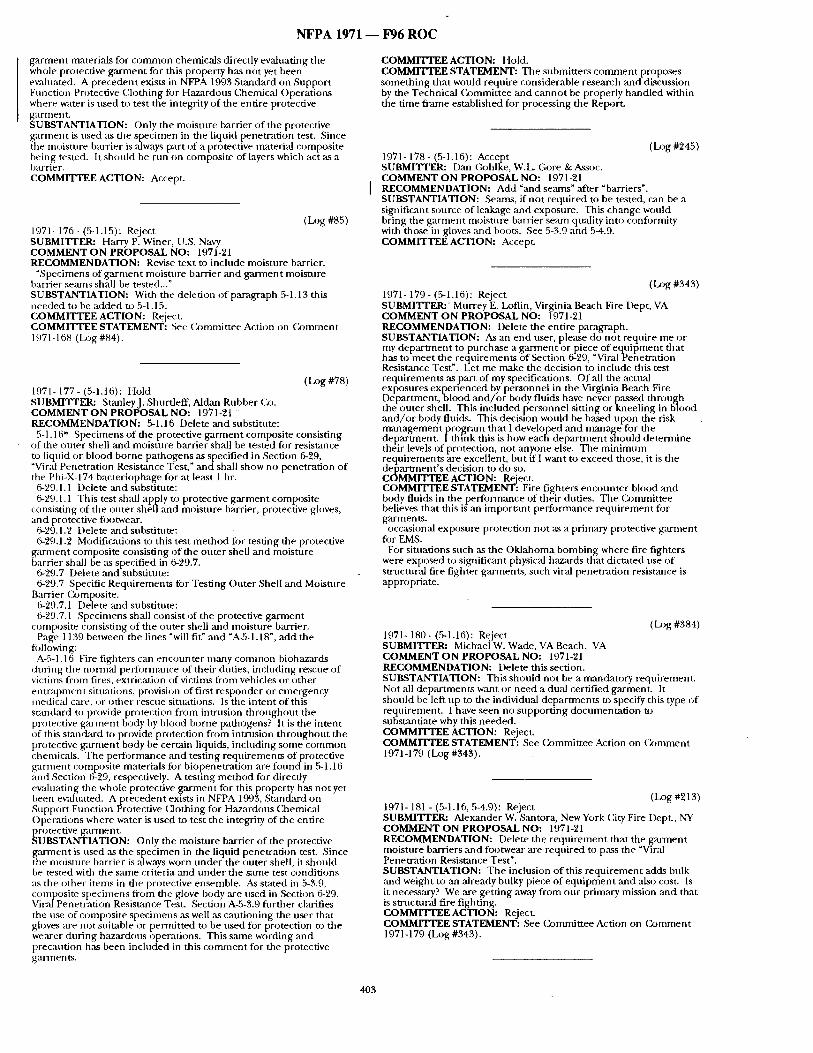
N F P A 1971 ~ 1796 R O C
ga rmen t materi:ds for c o m m o n chemicals directly evaluating the whole protective ga rmen t for this property has not yet been ewduated. A precedent exists in NFPA 1993 Standard on Suppor t Function Protective Clothing for Hazardous Chemical Operat ions where water is used to test the integrity o f the entire protective garment . SUBSTANTIATION: Only the moisture barrier of the protective ga rment is used as tbe specimen in the liquid penetrat ion test. Since the moisture barrier is alwws part cff a protective material composite being tested. It should be run on composite of layers which act as a barrier. COMMITTEE ACTION: Accept.
(Log #85) 1971- 176- (5-1.15): Reject SUBMITTER: Harry P. Winer, U.S. Navy COMMENT O N PROPOSAL NO: 1971-21 RECOMMENDATION: Revise text to include moisture barrier.
"Specimens of ga rmen t moisture barrier and ga rmen t moisture barrier semns shall be tested..." SUBSTANTIATION: With the deletion o f paragraph 5-1.13 this needed to be added to 5-1.15. COMMITTEE ACTION: Reject. COMMITTEE STATEMENT: See ( ) )mmit tee Action on (kmtment 1971-11i8 (Log #84).
(Log #78) 1971- 177 - (5-1.16): Hold SUBMITTER: StanleyJ. Shurtleff, Aldan Rubber Co. COMMENT O N PROPOSAL NO: 1971-21 RECOMMENDATION: 5-1.16 Delete and substitute:
5-1.16* Specimens o f the protective ga rmen t composite consisting of the outer shell and moisture barrier shall be tested fi~r resistance to liquid or blood borne pathogens as specified in Section 6-29, "Viral Penetration Resistance Test," and shall show no penetrat ion of the Phi-X-174 bacteriophage for at least 1 hr.
6-29.1.1 Delete :rod substitute: 6-29.1.1 This test shall apply to protective ga rmen t composite
consisting of the outer shell and moisture barrier, protective gloves, and protective fi~otwear.
6-29.1.2 Delete and substitute: 6-29.1.2 Modifications to this test m e t h o d fbr testing the protective
ga rmen t composite consisting of the outer shell and moisture barrier shall be as specified in 6-29.7.
6-'29.7 Delete and substitute: 6-29.7 Specific Requirements fi~r Testing Outer Shell and Moisture
Barrier (~mposi te . 6-29.7.1 Delete and substitute: 6-29.7.1 Specimens shall consist of the protective ga rment
composite consisting of the outer shell and moisture barrier. Page 1139 between the lines "will fit" mad "A-5-1.18", add the
following: A-5-1.16 Fire figiaters can encoun te r many common biohazards
dur ing the normal per lormance of their duties, including rescue of victints f rom fires, extrication of victims from vehicles or o ther en t r apmen t situations, provision of first responder or emergency medical c:tre, or o ther rescue situations. Is the intent of this s tandard to provide protection f rom intrusion th roughou t the protective ga rmen t body by blood borne pathogens? It is the intent of this stan,~trd to provide protection f rom intrusion th roughou t the protective g~trment body be certain liquids, including some c o m m o n chemicals. The performance and testing requirements of protective ga rment composite materials for biopenetrat ion are found in 5-1.16 and Section 6-29, respectively. A testing m e t h o d for directly evaluating the whole protective ga rmen t for this property has no t yet been evaluated. A precedent exists in NFPA 1993, Standard on Support Function Protective CJothing for Hazardous (3aemical Operat ions where water is ttsed to test the integrity of the entire protective garmenL SUBSTANTIATION: Only the moisture barrier of the protective ga rment is used as the specimen in the liquid penetrat ion test. Since the moisture barrier is always worn unde r the outer shell, it should be tested wida the same criteria and unde r the same test condit ions :Ls the other i tems in the protective ensemble. As stated in 5-3.9, composite specimens from the glove body are used in Section 6-29. ViralPenetrat ion Resistance Test. Section A-5-3.9 ftlrther clarifies the use of composi te specimens as well ,as caut ioning the user that gkwes ,are not suitable or pemti t ted to be used for protection to the wearer dur ing hazardous operations. This same wording and precantion has been included in this c o m m e n t for the protective garments.
COMMITTEE ACTION: Hold. COMMITTEE STATEMENT: The submitters c o m m e n t proposes some th ing tha t would require considerable research and discussion by the Technical Commit tee ~md canno t be properly handled within the t ime f rame established fi)r processing the Report.
(Dgg #245) 1971- 178- (5-1.16): Accept SUBMITTER: Dan (~Jhlke, W.L. Gore & Assoc. COMMENT O N PROPOSAL NO: 1971-21 RECOMMENDATION: Add "and seams" after "barriers". SUBSTANTIATION: Seams, if no t required to be tested, can be a significant source of leakage and exposure. This change would bring the ga rmen t moisture barrier seam quality into conformity with those in gloves and boots. See 5-3.9 and 5-4.9. COMMITTEE ACTION: Accept.
(Log #343) 1971- 179 - (5-1.16): Reject SUBMITTER:' Murrey E. Loflin, Virginia Beach Fire Dept, VA COMMENT O N PROPOSAL NO: 1971-21 RECOMMENDATION: Delete the entire paragraph. SUBSTANTIATION: As an end user, please do not require me or m y d e p a r tment to p.urchase a g arment-or, piece of e . c~ui p men t tha t . has to meet the reqturements of Sectmn 6-29, "Vl ra lPenemmon Resistance Test". Let me make the decision to include dais test requirements a spa r t of my specifications. Of all the actual exlSosures expeffenced by pe-rsonnel in the Virginia Beach Fire Department , b lood a n d / o r body fluids have never passed through the-outer shell. This included personnel sitting or kneel ing in bqood a n d / o r body fluids. This decision would be based upon the risk m a n a g e m e n t prog(,'un that I developed and manage for rite depar tment . I t h m k this is how each depa r tmen t should de termine the-ir levels of protection, not anyone els-e. The m i n i m u m reqtt i rements are excellent, but if I want to exceed those, it is the depar tment ' s decision to do so. COMMITTEE ACTION: Reject. COMMITTEE STATEMENT: Fire fighters encoun te r blood and body fltfids in the per formance of their duties. The Commit tee believes that this is an impor tant performance requ i rement for garments.
occasional exposure protection not as a primary protective ga rment fi~r EMS.
For situations such as the Oklahoma bombing where fire fighters were exposed to significant physical hazards that dictated use of structural fire fighter garments , such viral penetrat ion resistance is appropriate.
(Log #384) 1971- 180- (5-1.16): Reject SUBMITFER: Michael W. Wade, VA Beach, VA COMMENT O N PROPOSAL NO: 1971-21 RECOMMENDATION: Delete this section. SUBSTANTIATION: This should not be a mandatory reqtfirement. Not all depar tments want or need a dual certi.fied garment . It should be left up to the individual depar tments to specify dais type of requirement . I have seen no suppor t ing documenta t ion to substantiate why this needed. COMMITTEE ACTION: Reject. C O M M r r T E E STATEMENT: See Commit tee Action on Conwaent 1971-179 (Log #343).
(IJ)g #213) 1971- 181 - (5-1.16, 5-4.9): Reject SUBMITTER: Alexander W. S,'mtora, New York City Fire Dept., NY COMMENT O N PROPOSAL NO: 1971-21 RECOMMENDATION: Delete the r equ i rement that the garment moisture barriers and footwear are required to p ~ s the "Viral Penetrat ion Resistance Test". SUBSTANTIATION: The inclusion o f this r equ i rement adds bu |k and weight to an ,already bnlky piece of equ ipmen t and also cost. Is it necessary? We are gett ing away from onr primary mission and that is smmtnra l fire fighting. COMMITTEE ACTION: Reject. COMMITTEE STATEMENT: See Commit tee Action on ( ~ m n a e n t 1971-179 (Log #343).
403
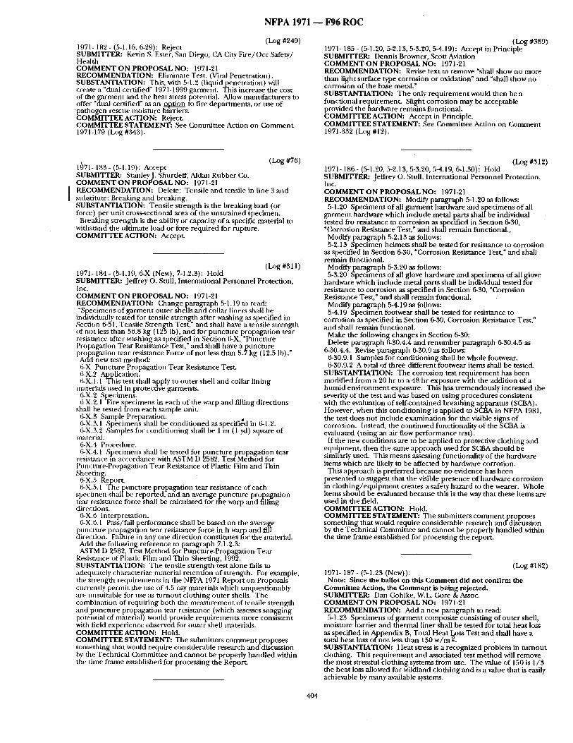
N F P A 1971 - - F96 R O C
(Log #249) 1971- 182 - (5-1.16, 6-29): Reject SUBMITrER: Kevin S. Ester, San Diego, CA City Fire/()cc Safety/ Health COMMENT O N PROPOSAL NO: 1971-21 RECOMMENDATION: Eliminate Test. (Viral Penetrat ion). SUBSTANTIATION: This, with 5-1.2 (liquid penetrat ion) will create a "dual certified" 1971-1999 garment . This increase the cost of the ga rmen t and the heat stress potential. Allow mantffacturers to offer "dual certified" ~u~ an ~ to fire depar tments , or use o f p a t h o g e n rescue moisture b,'u-riers. COMMITTEE ACTION: Reject. COMMITTEE STATEMENT: See ( b m m i t t e e Action on C o m m e n t 1971-179 (Log #343).
(LOg #389) 1971- 185 - (5-1.20, 5-2.13, 5-3.20, 5-4.19): Accept in Principle SUBMITTER: Dennis Browner, ,Scott Aviation COMMENT O N PROPOSAL NO: 1971-21 RECOMMENDATION: Revise text to remove "sbaU show no more than light surface type corrosion or oxidation" and "shall show no corrosion of the base metal." SUBSTANTIATION: The only requ i rement would then be a funct ional requirement . Slight corrosion may be acceptable provided theha rdware remains functional. COMMITTEE ACTION: Accept in Principle. COMMITTEE STATEMENT: See Commit tee Action on C o m m e n t 1971-332 (Log #12).
(Log #76) 1~71- 183- (5-1.19): Accept SUBMITTER: StanleyJ. Shurtleff, Aldzm Rubber Co. COMMENT O N PROPOSAL NO: 1971-21 RECOMMENDATION: Delete: Tensile and tensile in line 3 and subst i tu te :Breaking and breaking. SUBSTANTIATION: Tensile strength is the breaking load (or torce) per uni t cross-sectional area of the uns t ra ined specimen.
Breaking strength is the ability or capacity of a specific material to withstand the ult imate load or fore required for rupture. COMMITTEE ACTION: Accept
(Log#S11) 1971- 184- (5-1.19, 6-X (New), 7-1.2.3): Hold SUBMITrER: Jeffrey O. Stnll, International Personnel Protection, Inc. COMMENT O N PROPOSAL NO: 1971-21 RECOMMENDATION: ( ~ a n g e paragraph 5-1.19 to read: "Specimens of ga rmen t outer shells and collar liners shall be
individually tested for tensile strenKth ,after washing as specified in Section 6-51, Tensile Strcmgth Test," and shall have a tensile s t rength of not less than 56.8 kg (1'25 Ib), and for punc ture propagat ion tear resistance "after washing ,as specified in Section 6-X, "Ptmcture Propagation Tear Resistance Test," and shall have a p t m c t u r e propagation tear resistance Force o f not less than 5 .7kg (12.5 Ib)."
Acid new test method: 6-X Puncture Propagation Tear Resistance Test. 6-X.2 Application. 6-X. 1.1 This test shall apply to outer shell and collar lining
materials used in protecuve garments . 6-X.2 Specimens. 6-X.2.1 -Fire specimens in each o f the warp and filling directions
shall be tested from each sample unit. 6-X.3 Sanaple Preparation. . 6-X.3.1 Specimens shall be condi t ioned as specified in 6-1.'/. 6-X.3.2 Samples for condi t ioning shall be 1 m (1 yd) square of
materi:fl. 6-X.4 Procedure. 6-X.4.1 Specimens shall be tested for punctnre propagation tear
resistance in accordance with A,STM D 2582, Test Method fi~r Puncture-Propagation Tear Resistance of Plastic Film and Thin Sheeting.
6-X.5 Report. 6-X.5.1 The punc ture propagation tear resistmace of each
specinten sh:dIbe reported, and an average punc tu re propagat ion tear resistance fi3rce shall be calculated for the warp and fillihg directions.
6-X.6 Interpretation. &X.6.1 Pass/fail [~erfolxnance shall be based on the average
puncture propagation tear resistance force in h warp ,and fill directicn. F~dlure in any one direction constitutes for the material.
Add the fi)llowing reference to paragraph 7-1.').3: ASTM D 2582, Test Method for~Puncture-Propagation Tear
Resistance of Plastic Film and Thin Sheeting, 1992. SUBSTANTIATION: The tensile s t rength test alone fails to adequately characterize material retention of strength. For example, the s trength requi rements in the NFPA 1971 Report on Proposals currently permit the use of 4.5 osy materials which unquest ionably are unsuitable fl)r use as tu rnou t c lothing outer shells. The combinat ion of requir ing both dae m e a s u r e m e n t of tensile strength and .punc tn re prop:tgation tear resistance (which assesses snagging potential of nutterial) would provide requi rements more consistent with field experience observed for outer shell materials. COMMITTEE ACTION: Hold. COMMITTEE STATEMENT: The submitters c o m m e n t proposes someth ing that would require considerable research and discussion by the Technical (~)mmittee and canno t be properly handled within the time frame established for processing the Report.
404
(Log #312) 1971- 186 - (5-1.20, 5-2.13, 5-3.20, 5-4.19, 6-1.30)i Hold SUBMITrER: Jeffrey o . Stull, International Personnel Protection, Inc. COMMENT O N PROPOSAL NO: 1971-21 RECOMMENDATION: Modify paragraph 5-1.20 as follows:
5-1.20 Specimens o f all g a r m e n t hardware and specimens o f all ga rmen t hardware which include metal parts shall be individual tested fro resistance to corrosion as specified in Section 6-30, "Corrosion Resistance Test," and shall remain fnnctional. ,
Modify paragraph 5-2.13 as follows: 5-2.13 Specimen helmets shall be tested for resistance to corrosion
as specified in Section 6-30, "Corrosion Resistance Test," and shall remain functional.
Modify paragraph 5-3.20 as follows: 5-3.20 Specimens of all glove hardware and specimens oral! glove
hardware which include metal parts shall be individual tested for resistance to corrosion as specified in Section 6-30, "Corrosion Resistance Test," and shall remain funct ional .
Modifyparagrapb 5-4.19 as follows: 5-4.19 Specimen footwear shall be tested for resistance to
corrosion as specified in Section 6-30, Corrosion Resistance Test," and shall remain functional.
Make the fi)llowing changes in Section 6-30: Delete paragraph 6-30.4.4 and r e n u m b e r paragraph 6-30.4.5 as
6-30.4.4. Revise paragraph 6-30.9 as follows: 6-30.9.1 Samples for condi t ioning shall be whole footwear. 6-30.9.2 A total of three different footwear i tems shall be tested.
SUBSTANTIATION: The corrosion test r equ i rement has been modif ied f rom a 20 hr to a 48 hr exposure with the addition of a h u m i d env i ronment exposure. This has t remendously increased the severity o f the test ,'rod was based on us ing procedures consistent with the evaluation of serf-contained breathing apparatus (SCBA). However, when this condi t ioning is applied to SCBA in NFPA 1981, the test does not include examinat ion for the visible signs of corrosion. Instead, the cont inued fimctionality o f the SCBAis evaluated (using an air flow performance test).
If the new condit ions are to be applied to protective clothing and equipment , then the same approach used for SCBA should be similarly used. This means assessing functionality of the hardware items which are likely to be affected by hardware corrosion.
This approach is preferred because no evidence has been presented to suggest that the visible presence o f hardware corrosion in c lo th ing / equ ipmen t creates a safety hazard to the wearer. Whole items should be evaluated because this is the way that these i tems are used in the field. COMMITTEE ACTION: Hold. COMMITTEE STATEMENT: The submitters co rmnen tp roposes someth ing that would require considerable research and-disc- ussion by the Technical Commit tee and canno t be properly handled within the t ime f rame established for processing the report.
(Log #182) 1971- 187- (5-1.23 (New)):
Note: Since the ballot on this C o m m e n t did not confi rm the Commit tee Action, the C o m m e n t is being rejected. SUBMITTER: Dan Gohlke, W.L. Gore &Assoc. COMMENT O N PROPOSAL NO: 1971-21 RECOMMENDATION: Add a new paragraph to read:
5-1.23 Specimens of gacment composi te consisting of outer shell, moisture barrier and thermal liner shall be tested for total heat loss as specified in Appendix B, Total Heat Loss Test and shall have a total hea t loss of no t less than 150 w / m 2 . SUBSTANTIATION: Heat stress is a recognized problem in tu rnou t clothing. This requ i rement and associated test m e t h o d will remove the most stressful c lothing systems f rom use. The value of 150 is 1 /3 the hea t loss allowed for wildland clothing and is a value that is easily achievable by rmany available systems.
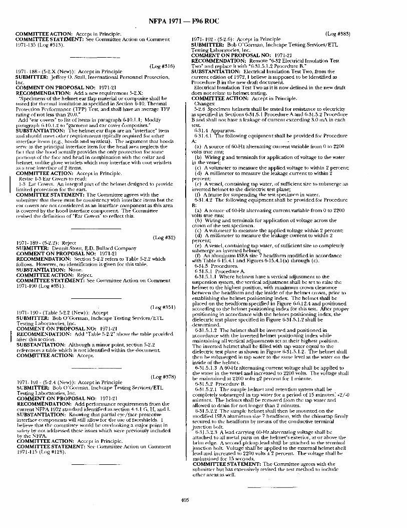
N F P A 1971 - - 10'96 R O C
COMMITTEE ACTION: Accept in Principle. COMMITTEE STATEMENT: See Commit tee Action on (k~mment 1971-135 (Log #313).
(Log #316) 1971- 188- (5-2.X (New)): Accept in Principle SUBMITTER: Jeffrey o . Stnll, International Personnel Protection, Inc. COMMENT ON PROPOSAL NO: 1971-21 RECOMMENDATION: Add a new requ i rement 5-2.X:
"Specimens of the he lmet ear flap material or composi te shall be tested for thermal insulation ,as specified in Section 6-10, Thermal Protection Performance (TPP) Test, and shall have an average TPP rating of not less than 20 .0 :
Add "ear covers" to list of items in paragraph 6-10.1.1; Modify paragraph 6-10.1.2 to "garment and ear cover ~omposites." SUBSTANTIATION: Tile behne t ear flaps m-e an "interface" item and should meet o ther requi rements typically required for o ther interface items (e.g., hoods and wristlets). The a rgumen t that hoods serve ,'~ the principal interface item fl)r the head :urea neglects the fact that the hood actually provides the only protection for some portions of tile face and head in contbination with the collar mid helmet, unlike glove wristlets which may interface with coat wristlets as a true interface of 2 items. COMMITTEE ACTION: Accept in Principle.
Revise 1-3 Ear Covers to read: 1-3 Ear Covers. An integral part of the he lmet designed to provide
limited protection for tile ears. COMMITTEE STATEMENT: The Commit tee agrees with the submit ter that there must be consistency with interface i tems but tile ear covers are not considered as an interface c o m p o n e n t as this area is covered by the hood interface component . The Czommittee revised the definition of "Ear Covers" to reflect this.
(Log #32) 1971- 189- (5-2.2): Reject SUBMIIq?ER: Dennis Stout, E,.D. Bnllard Company COMMENT ON PROPOSAL NO: 1971-21 RECOMMENDATION: Section 5-2.2 refers to Table 5-2.2 which follows. However, no identification is given for this table. SUBSTANTIATION: None. COMMITTEE ACTION: Reject. COMMITTEE STATEMENT: See C~-Jmmittee Action on ( ~ m m e n t 1971-190 (Log #351 ).
(La~g #351 ) 1971- 190 - (Table 5-2.2 (New)): Accept SUBMITTER: Bob O'C, o rman, Inchcape Test ing Services/ETL Testing Laboratories, Inc. COMMENT ON PROPOSAL NO: 1971-21 RECOMMENDATION: Add "Table 5-2.2" above the table provided after this section. SUBSTANTIATION: Although a minor point, section 5-2.2 references a table which is no t identified within the document . COMMITTEE ACTION: Accept.
(Log #378) 1971- 191 - (5-2.4 (New)): Accept in Principle SUBMITTER: Bob O 'Corman , Inchcape Testing Services/ETL Testing Laboratories, Inc. COMMENT ON PROPOSAL NO: 1971-21 RECOMMENDATION: Add performance requirements f rom the current NFPA 1972 sumdard identified as section 4-4.1 G, H, and I. SUBSTANTIATION: Knowing that partial eye/face protective inter~hce componen t s will still allow fi)r file use of faceshields. I believe that the commit tee would be overh)oking a major point in salety by not :~ddressed these issues which were previously included by the NFPA. COMMITTEE ACTION: Accept in Principle. COMMITTEE STATEMENT: See (kmunit tee Action on C o m m e n t 1971-115 (Log #128).
(Log #383) 1971- 192- (5-2.6): Accept in Principle SUBMITrER: Bob O'C, orn~ul, Inchcape Testing Services/ETL Test ing Laboratories, Inc. COMMENT ON PROPOSAL NO: 1971-21 RECOMMENDATION: Remove ~6-32 Electrical Insulation Test Two" and replace it with "6-31.5.1.2 Procedure B." SUBSTANTIATION: Electrical Insulation Test Two, f rom the cur rent edition of 1972, I believe is supposed to be identified ,as Procedure B in the new draft document .
Electrical Insulation Test Two as it is now def ined in the new draft does not relate to hehne t testing. COMMITTEE ACTION: Accept in Principle.
Changes: 5-2.6 Specimen helmets shall be tested for resistance to electricity
as specified in Sections 6-31.5.1 l~rocedure A and 6-31.5.2 Procedure B and sh:dl no t have a leakage of cu r ren t exceeding 3.0 mA in each test.
6-31.4 Apparatus. 6-31.4.1 The following equ ipmen t shall be provided for Procedure
A: (a) A source of 60-Hz al ternating cur ren t variable f rom 0 to 2200
volts true rms; (b) Wiring g and terminals fi)r application o f voltage to the water
in the vessel; (c) A voltmeter to measure the applied voltage to within 2 percent; (d) A millimeter to measure the leal(age cur rent to within 2
percent; re) A vessel, conta ining tap water, of sufficient size to submerge ml
inverted he lmet to the dielectric test plane; (f) A frame for suspending the test specimen in water. 6-31.4.2 The fi)llowing equ ipmen t shall be provided for Procedure
B: (a) A source of 60-Hz ,alternating cur rent variable f rom 0 to 2200
volts true nns; (b) Wiring and terminals figr application of voltage across the
crown of tile test specimen. (c) A w~lmleter to measure the applied voltage within 2 percent ; (d) A millimeter to measure the leakage cur rent to within 2
percent; re) A vessel, conta in ing tap water, o f stffficient size to completely
submer~e an inverted helmet; (f) Aft :a luminum ISEA size 7 headform modif ied in accordance
with Table 6-15.4.1 and Figures 6-15.4.1(a) th rough (c). 6-31.5 Procedures. 6-31.5.1 Procedure A. 6-31.5.1.1 Where hehnets have a vertical ad jusunent to the
suspension system, the vertical ad jus tment shall be set to raise the he lmet to the highest position, with m a x i m u m crown clearance between the headform and the inside o f the he lmet crown, prior to establishing the he lmet posit ioning index. The he lmet shall be placed on the headform specified in Figure 6-6.12.4 and posit ioned according to the he lmet posit ioning index for this test. After proper posit ioning in accordance with the he lmet posit ioning index, the dielectric test plane specified in Figure 6-31.5.1.2 shall be de t e rmined .
6-31.5.1.2 The helmet shall be inverted and posit ioned in accordance with the inverted he lmet positioning index while mainta ining all vertical adjusunent.s set at their highest position. The inverted helmet shall be filled with tap water equal to the dielectric test plane as shown in Figure 6-31.5.1.2. The he lmet sball then be submerged in tap water to the same level as the water on the inside of the helmet.
6-31.5.1.3 A 60-Hz al ternating CUiTent volutge shall be applied to the water in the vessel and increased to 2200 volts. Tile voltage shall be nudnmined at 2200 volts +2 percent for 1 minute.
6-31.5.2 Procedure B. 6-31.5.2.1 The sample he lmet and retention system shall be
completely s l ,bmerged in tap water for a period of 15 minutes ; +2/-0 minutes . The helmet shall be removed f rom the tap water and allowed to drain fi~r not longer than 2 minutes .
6-31.5.2.2 The sanlple he lmet shall then be m o u n t e d on the modified ISEA ahmt inum size 7 headform, with the chinstrap firmly secured to the headform by metals of the conductive terminal junct ion bolt.
6-31.5.2.3 A lead carrying 60-Hz alternating voltage shall be attached to all metal parts on the helmet's exterior, at or above the brim edge. A second pickup lead shall be attached to the terntinal jnncthm bolt. Voltage shall be applied to the external helmet shell lead and increased to 2200 w~Its + 2 percent. The voltage shall be maintained for 15 seconds. C O M M I T T E E STATEMENT: The Committee agrees with the submitter but has extensively revised the test method to inchlde other areas as well.
405
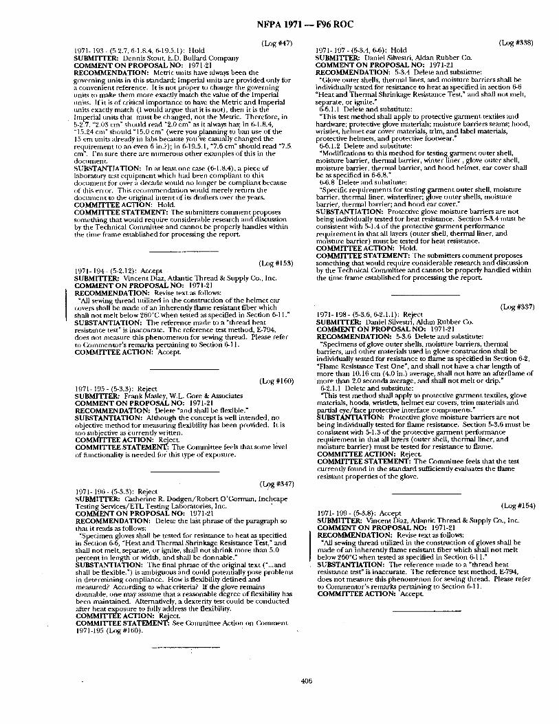
NFPA 1971 - - F96 ROC
(Log #47) 1971- 193- (5-2.7, 6-1.8.4, 6-19.5.1): Hold SUBMITrER: Dennis Stout, E.D. Bullard Company COMMENT ON PROPOSAL NO: 1971-21 RECOMMENDATION: Metric units have always been the governing units in this standard; Imperial units are provided only for a convenient reference. It is no t proper to change the governing units t~) make t hem more exactly match the value o f the Imperial units. If it is of critical impor tance to have the Metric mad Imperial units exactly match (I would argne that it is not), then it is the
• Imperial units that mus t be changed, not the Metric. Therefore, in 5-2.7. "2.03 cm" should read "9.0 cm" as it always has; in 6-1.8.4, "15.24 cm" should "15.0 cm" (were you p lanning to ban use o f the 15 c~a units already in labs because you've casually changed the req}firement to an even 6 in.?); in 6-19.5.1, "7.6 cm" should read "7.5 cm . I 'm sure there are numerous o ther examples o f this in the docuJnenL SUBSTANTIATION: In at least one case (6-1.8.4), a piece of laboratory test equipulen t which had been compliant to this d o c u m e n t for over a decade wonld no longer be compliant because of this erro,'. This recomnaendat ion would merely return the d o c u m e n t to the original intent of its d~ffters over the years. COMMITTEE ACTION: Hold. COMMITTEE STATEMENT: The st, bmitters c o m m e n t proposes someth ing that would require considerable research mid discussion by the Technical Commit tee and cannot be properly handles within the t ime frame established for processing the report.
(Log #153) 1971- 194- (5-2.12): Accept SUBMITrER: Vincent Diaz, Atlantic T h read & Supply Co., Inc. COMMENT O N PROPOSAL NO: 1971-21 RECOMMENDATION: Revise text as follows:
"All sewing thread utilized in the constrnction of the he lmet ear covers shall be made of an inherently flame resistant fiber which shall no t mel t below 260°C when tested as specified in Section 6-11." SUBSTANTIATION: The reference made to a "thread heat resistance test" is inaccurate. The reference test method, E-794, does not measure this p h e n o m e n o n for sewing thread. Please refer to (2~mmenugr's remarks pertaining to Section 6-11. COMMITTEE ACTION: Accept.
(Log #16O) 1971- 195 - (5-3.3): Reject SUBMI'VrER: Frank Masley, W.L. Gore & Associates COMMENT O N PROPOSAL NO: 1971-21 RECOMMENDATION: Delete "and shall be flexible." SUBSTANTIATION: Although the concept is well in tended, no objective me t hod for measur ing flexibility has been provided. It is too subjective as Owrently written. COMMITTEE ACTION: Reject. COMMITTEE STATEMENT: T he Commit tee feels that some level of functionality is needed fi~r this type o f exposure.
(Log #347) 1971- 196- (5-3.3): Reject SUBMITTER: Catherine R. D o d g e n / R o b e r t O' (karman, Inchcape Testing Services/ETL Test ing Laboratories, Inc. COMMENT ON PROPOSAL NO: 1971-21 RECOMMENDATION: Delete the last phrase of the paragraph so that it reads as follows:
"Specimen gloves shall be tested for resistance to heat as specified in Section 6-6, "Heat and Thermal Shrinkage Resistance Test," and shall no t melt, separate, or ignite, shall no t shr ink more than 5.0 percent in length or width, and shall be donnable." SUBSTANTIATION: T he final phrase of the original text ( ' . . .and shall be flexible.") is ambiguous and could potentially pose problems in de termining compliance. How is flexibility def ined and measured? According to what criteria? If the glove remains donnable, one may assume that a reasonable degree o f flexibUity has been maintained. Alternatively, a dexterity test could be conduc ted ,after heat exposure to f i t ly address the flexibility. COMMITTEE ACTION: Reject. COMMITTEE STATEMENT: ,See Commit tee Action on (kmament 1971-195 (Log #1601. ,
(Log #338) 1971- 197 - (5-3.4, 6-6): Hold SUBMITrER: Daniel Silvestri, Aldan Rubber Co. COMMENT O N PROPOSAL NO: 1971-21 RECOMMENDATION: 5-3.4 Delete and substitute:
"Glove outer shells, thermal lines, and moisture barriers shall be individually tested for resistance to heat as specified in section 6-6 "Heat and Thermal Shrinkage Resistance Test," and shall no t melt, separate, or ignite."
6-6.1.1 Delete and substitute: "This test me thod shall apply to protective ga rm en t textiles and
hardware; protective glove materials; moisture barriers seams; hood, wristlet, he lmet ear cover materials, trim, and label materials, protective helmets, and protective footwear."
6-6.1.2 Delete and substitute: "Modifications to this m e t h o d for testing ga rmen t outer shell,
moisture barrier, thermal barrier, winter l iner , glove outer shell, moisture barrier, thermal barrier, and hood helmet, ear cover shall be as specified in 6-6.8."
6-6.8 Delete and substitute: "S,p.ecific re q u i rements for testing, ga rmen t outer shell , .moisture
barrier, thermal liner, winterhner; glove outer shells, motsture barrier, thermal barrier; and hood ear cover." SUBSTANTIATION: Protective glove moisture barriers are not being individually tested for heat resistance. Section 5-3.4 mus t be consistent with 5-1.4 of the protective ga rmen t per formance requ i rement in that all layers (outer shell, thermal liner, an d moisture barrier) mus t be tested for hea t resistance. COMMITTEE ACTION: Hold. COMMITTEE STATEMENT: The submitters c o m m e n t proposes someth ing that would require considerable research an d discussion by the Technical Commit tee and canno t be properly handled within the t ime frame established for processing the report.
(Log #337) 1971- 198- (5-3.6, 6-2.1.1): Reject SUBMITI'ER: Daniel Silvestri, Aldan Rubber Co. COMMENT ON PROPOSAL NO: 1971-21 RECOMMENDATION: 5-3.6 Delete and substitute:
"Specimens of glove outer shells, moisture barriers, thermal barriers, and o ther materials used in glove construct ion shall be individually tested for resistance to f lame as specified in ,Section 6-2, "Flame Resistance Test One", and shall no t have a char length of more than 10.16 cm (4.0 in.) average, shall no t have an afterflame of
m o r e than 2.0 seconds average, andsha l l no t melt or drip." 6-2.1.1 Delete and substitute: "This test me thod shall apply to protective g a r m e n t textiles, glove
materials, hoods, wristlets, he lmet ear covers, t r im materials an d
~ artial eye/face protective interface components ." UBSTANTIATION: Protective glove moisture barriers are not
being individually tested for f lame resistance. Section 5-3.6 mus t be consistent with 5-1.3 o f the protective ga rmen t performance reqt t i rement in that all layers (outer shell, thermal liner, an d moisture barrier) mus t be tested for resistance to flame. COMMITTEE ACTION: Reject. COMMITTEE STATEMENT: The Commit tee feels that the test currently fo tmd in the s tandard sufficiently evaluates the flame resistant properties of the glove.
(Log #154) 1971- 199 - (5-3.8): Accept SUBMITI'ER: Vincent Diaz, Atlantic Thread & Supply Co., Inc. COMMENT ON PROPOSAL NO: 1971-21 RECOMMENDATION: Revise text as follows:
"All sewing thread utilized in the construction of gloves shall be made of an inherent ly f lame resistant fiber which shall no t mel t below 260°C when tested as specified in Section 6-11." SUBSTANTIATION: The reference made to a " thread heat resistance test" is inaccurate. The reference test method, E-794, does not measure this p h e n o m e n o n for sewing thread. Please refer to Commen to r ' s remarks pertaining to Section 6-11. COMMITTEE ACTION: Accept.
406
N F P A 1971 - - 1796 R O C
(I_xJg #317) 1971- 200- (5-3.8): Reject SUBMITTER: jeffrey o . Stull, International Personnel Protection, Inc. COMMENT ON PROPOSAL NO: 1971-"21 RECOMMENDATION: Delete paragraph 5-3.8. SUBSTANTIATION: Provisions with Section 5-2 in gloves entail whole glove testing for hea t resistance. This evaluation of the whole product inw)lves an ,assessment of thread heat resistance as it is used in the overall product. COMMITTEE ACTION: Reject. COMMITTEE STATEMENT: See ( b m m i t t e e Action on C o m m e n t 1971-211 (Log #320).
There is a t rend being set and we believe figr the worse. The dexterity seems to be ,affected by the thicker liners being used. As a result of a thicker liner, some are looking into using th inner leather. Compromis ing safety to give a false or less effective protection is misleading to the Fire Service. This is evident by the glove life decline pattern we are seeing on the market. Obviottsly, 3 oz of leather gives more protection than 1 1/2 oz of leather.
These are all serious problems we feel need to be addressed immediately. Tempo Glove cannot speak for o ther Mantifacturers, bu t we would offer both types of gloves, letting the people using the gloves decide what is and is no t best for their needs. COMMITTEE ACTION: Reject. COMMITTEE STATEMENT: See (k)mmittee Action on C o m m e n t 1971-"201 (Log #344).
(I~)g #344) 1971- `201 - (5-3.9): Reject SUBMITFER: Mnrrey E. Loflin, Virginia Beach Fire Dept, VA COMMENT ON PROPOSAL NO: 1971-`21 RECOMMENDATION: Delete the entire paragraph. SUBSTANTIATION: As an end user, please do not require me or my depa rmlen t to purchase a ga rmen t or piece of equ ipmen t that has to meet the requirements of Section 6-`29, "Viral Penetrat ion Resistance Test". Let me make the decision to include this test requi rements ,as part of my specifications. Of all the actual exposures exper ienced by personnel in the Virginia Beach Fire Deparunent , blood a n d / o r body fluids have never passed through the outer shell. This included personnel sitting or kneel ing in blood a n d / o r body fluids. This decision would be based upon the risk n t anagemen t p rogram that I developed and manage for the dep:wtment. I t h i n k this is how each depa r tmen t should de termine their levels of protection, not anyone else. The m i n i m u m requi rements are excellent, but ifI want to exceed those, it is the depa runen t ' s decision to do so. COMMITTEE ACTION: Reject. COMMITTEE STATEMENT: Fire fighters encounter blood and body fluids in tile per formance of dteir dut ies . The (k~mmittee believes that this is an impor tan t perIbrrmmce reqt t i rement fi)r gloves.
(Log #1 "26) 1971- 202 - (5-3.9, 5-3.10): Reject SUBMITrER: M. Mandleman, T e m p o Glove Mfg., Inc. COMMENT ON PROPOSAL NO: 1971-21 RECOMMENDATION: Our solution is basically pretty simple; Give the Fire Service the option to buy a moisture barrier if that is what they desire. In contrast, if the Fire Service believes the moisture barrier is not what they are looking for, give them that option as well. The only th ing this will effect will be the liner suppliers pockets, not the Fire Service S,'ffety. When the NFPA sets mininml standards they must stay consistent. By giving this option we believe they do. SUBSTANTIATION: We are sure the NFPA as well as others know how Tempo Glove stands on the moisture barrier concept. Nevertheless, we would like to inquire a little deeper into this matter. We read what is required and we will no t only state what we see as debatable. We will offer ,an alternative that is undeniably more effective fi)r the Fire Service,
Let us go back in time and look at the history of the moisture harrier. In 1983, it was in t roduced to the Fire Service as the end all be "all solution. It could not only keep your hands dry but gives more all a round protection. In 1988, NFPA required the moisture barrier to be part of the s tandard for reasons ment ioned . Later in the year, the NFPA implemented the TIA. By doing so the moisture barrier was not removed, but left as an option. In 1993, the NFPA reinstated the moisture barrier as part of the standards, no exceptions. Back m the t ime at hand and on the door step o f setting standards for 1996.
Whether you agree or disagree with the following, you will ,agree there is a problem witll m:ff, ing a decision on s tandards without having all the proper information.
From the start and even today there are no tests showing a glove with a moisture harrier rakes more heat or s team than a glove that does not have a moisture barrier. A critical issue that is rarely discussed is liner integrity. The whole basis of even having a moisture barrier is ta) at least guarantee dryness. We mean through the barrier itself no t th rough the wristlet. If a fire f ighter hits a glove on a corner or point o f an object its liner integrity is in jeopardy. A pin hole to a blood borne pa thogen is like a wide open door. When testing there never is a life expectancy of the liner reqtfired. Due to the fact once implemen ted into the glove, it would be impossible to check integrity let alone guarantee its performance.
(I~)g #272) 1971- 903 - (5-3.10): Accept SUBMITrER: Tom Wollan/Kimberty Henry, Underwriters Laboratories, Inc. COMMENT O N PROPOSAL NO: 1971-21 RECOMMENDATION: Revise text:
"Specimen glove body composi te ,and seams shall be tested for resisumce to liquid penetrat ion as specified in Section 6-28, Liquid Penetrat ion Resistance Test ,and shall allow no penetrat ion of test liquids fi~r at least 1 hr." SUBSTANTIATION: Paragraph states "specimen gloves shall", which is no t consistent with o ther paragraphs in this section which state testing to be conduc ted on glove body composite and seams. COMMITTEE ACTIO N: Accept.
(Log #318) 1971- 204- (5-3.12): Reject SUBMITTER: Jeffrey o . Stull, International Personnel Protection, Inc. COMMENT ON PROPOSAL NO: 1971-21 RECOMMENDATION: Change requ i rement to "7.2 kg (16.0 lb)." SUBSTANTIATION: A higher r e q m r e m e n t was chosen even though the original basis for the cut resistance requ i rement in a report prepareB by NIOSH r e c o m m e n d e d 7.2 kg ~G. C. Coletta et al, "The Development of Criteria for Firefighters' Gloves, Volume Ii: Glove Criteria and Test Methods," NIOSH, 1976, p. 13). There is no apparent reason for this discrepancy between the originally r e c o m m e n d e d criterion and the cur rent criterion. " COMMITTEE ACTION: Reject. COMMITTEE STATEMENT: The Commit tee feels that the "Cut Resistance Test" should remain as shown in the AO6-ROP. The Commit tee felt that there was no reason or evidence provided to justify reducing the cur ren t level of perfornaance.
(D~g #319) 1971- 205 - (5-3.13): Hold SUBMITrER: Jeffrey O. Stull, International Personnel Protection, Inc. COMMENT O N PROPOSAL NO: 1971-21 RECOMMENDATION: Change requ i rement to "4.0 kg (8.8 lb)." SUBSTANTIATION: The puncture requ i rement is the most limiting requ i rement for ~gloves which in turn impacts the thickness of tile leather. This r e q m r e m e n t is believed to have the most significant effect on wearer dexterity. The original basis for the puncture resisumce requ i rement was ta) select-an applied force which approximates the point of consistent epiderr0al and dermal penetrat ion by the selected puncture probe d imens ions (corresponding to a 4d lath nail). This applied force was then doubled to set an adequate safety factor in the G. C. Coletta et al, "The l-)evelopment of Criteria for Firefighters' Gloves, Volume II: Glove Crlterm and Test Methods," NIOSH, 1976, p. 19. The relevance o f this high reqt t i rement may be ques t ioned by the rare occurrence of reportable puncture injuries ~hrough fire fighter gloves. A decrease in the ptmcture resistance requ i rement is likely to permit th inner leathers and consequential better dexterity, the n u m b e r one compla in t of gloves f rom fire fighters. It is instructive to point ou t that me cur ren t requ i rement for gloves is the same ,as that used for footwear uppers (see paragraph 5-4.11) yet is well known that fire fighter fobtwear experiences h igh levels of puncture hazards at greater penetrat ion forces and velocities. COMMITTEE ACTION: Hold. COMMITTEE STATEMENT: The submitters c o m m e n t proposes someth ing that would require considerable research and discussion by the Technical Commit tee and canno t be properly handled within the t ime f rame established fi~r processing the report.
407
N F P A 1 9 7 1 1 F 9 6 R O C
(Log #413) 1971- 206 - (5-3.14): Accept in Principle SUBMITTER: M. Mandleman, T e m p o Glove Mfg., Inc. COMMENT ON PROPOSAL NO: 1971-'21 RECOMMENDATION: Shonld not all sizes that are being offered to the Fire Service be tested for dexterity. SUBSTANTIATION: In section 4-3.5.2 it states "The Manufactnre shall provide gloves in not less than 5 separate and distinct sizes." As well as fit the hand d imension range chart. Our First t hough t is why NFPA requires 5 separate and distinct sizes to be provided yet only test~ 1 size fi)r dexterity.
We know one glove liner supplier offers ~mly 2 size opticms fi)r their liners. By the d imension ranges you have set, a Mannfacture could take the 2 liners and make 5 separate sizes. However, we are not sure how distinct they wonld be for obvious reasons. Our c o m m e n t or suggestions if you will, is to require 5 dift?~rent size liners to be more trite to the memfing of distinct sizes. With this th rough in mind, the Mamffacture should submit samples of sizes required for testing its dexterity. COMMITTEE ACTION: Accept in Principle.
Change 6-38.4.2 to read: "Test Subjects shall be..." for all required glove sizes in 4-3.5.3. Change 6-38.4.4 to read: "Each test snl~ject shall test a m i n i m u m of three pairs o f santple
gloves fi)r the respective size as reqt,ired in 4-3.5.3." COMMITTEE STATEMENT: The Commit tee agrees that dexterity testing in all required sizes of gloves is import,ant and made the appropriate chauges in Section 6-38.
(Log #155) 1971- 210 - (5-4.6): Accept SUBMITTER: Vincent Diaz, Atlantic Thread & Supply Co., Inc. COMMENT O N PROPOSAL NO: 1971-21 RECOMMENDATION: Revise text as follows:
"All sewing thread utilized in the construction of footwear shall be made o f an inherent ly f lame resistant fiber which shall no t mel t below 260°C when tested as specified in Section 6-11." SUBSTANTIATION: The reference made to a "thread heat resistance test" is inaccurate. The reference test method, E-794, does not measure this p h e n o m e n o n for sewing thread. Please refer to Commento r ' s remarks pertaining to Section 6-11. COMMITTEE ACTION: Accept.
(Log #3:20) 1971- 211 - (5-4.6): Reject SUBMITTER: Jeffrey o . Stull, International Personnel Protection, Inc. COMMENT O N PROPOSAL NO: 1071-21 RECOMMENDATION: Delete paragraph 5-4.6. SUBSTANTIATION: Provisions with Section 5 4 for footwear entail whole fi)otwear testing for heat resistance. This evaluation o f the whole product involves an ,assessment of thread heat resistance ,as it is used in the overall product. - , COMMITTEE ACTION: Reject. COMMITTEE STATEMENT: The Commit tee feels that the thread performance criteria and test m e t h o d is important .
(l_a N #247) 1971-207- (5-3.19): Accept in Principle in Part SUBMITrER: Kevin S. Ester, San Diego, CA City Fire /Occ Safety/ HeMth COMMENT ON PROPOSAL NO: 1971-21 RECOMMENDATION: Add new text:
"Gloves shall not separate liners f rom shell when hands are pulled from gloves, This shall be a dry hand and wet hand test. Liner shall have moisture in it to simulate a sweating hand of a working fire fighter." SUBSTANTIATION: Our depa r tmen t has exper ienced liner separation in NFPA gloves when hands have sweated inside liner, made the lining wet, and the wearer pulled their hands out. This effectively puts the fire fighter ou t of service. . COMMITTEE ACTION: Accept in Principle in Part. COMMITTEE STATEMENT: The ( ~ m m i t t e e agreed with the need fi)r a wet test ,'rod added a precondi t ioning requirement . However, the C, ommit tee felt that the cur ren t pass/fail criteria was adequate. Also, see (k~nunittee Action on Conmlen t 1971-346 (Log #26).
(Log #406) 1971- 208 - (5-4.1.9): Reject
• SUBMITTER: Ruth Payne, ARTE(3"-I Footwear Testing Lab COMMENT ON PROPOSAL NO: 1971-21 RECOMMENDATION: Revise paragraph 5-4.19 to read:
"Place the entire boot in the salt spray chamber and set per lbrmance requi rements after exposure rather than cosmetic appearance, hnpac t and compression test shotdd be per formed with the safety toe as constructed in the boot. The remain ing componen t s such ,'is eyelets, l~uncture resistance device should be tested as single components . SUBSTANTIATION: None. COMMITTEE ACTION: Reject. COMMITTEE STATEMENT: See Commit tee Action on (~)mment 1971-217 (Log #321 ).
(Log 0408) 1971- 212 - (5-4.6): Reject SUBMITrER: Ruth Payne, ARTECH Footwear Testing Lab COMMENT ON PROPOSAL NO: 1971-21 RECOMMENDATION: Delete paragraph 5-4.6:
"Thread Heat Resistance TesL T h e entire boot including threads are being tested for mel t in Section 6-4.14.4." SUBSTANTIATION: None. COMMITTEE ACTION: Reject. COMMITTEE STATEMENT: See Commit tee Action on C o m m e n t 1971-211 (Log #320).
(l.~g #345) 1971- 213 - (5-4.9): Reject SUBMITrER: Murrey E. Loflin, Virginia Beach Fire Dept, VA COMMENT ON PROPOSAL NO: 1971-21 RECOMMENDATION: Delete the entire paragraph. SUBSTANTIATION: As an end user, please do no t require me or my deparmaent to purchase a ga rmen t or piece of eq u ip m en t that has to meet the requirements of Section 6-29, "Viral Penetrat ion Resistance Test". Let me make the decision to include this test requi rements as part of my specifications. Of all the actual exposures exper ienced by personnel in the Virginia Beach Fire Department , blood a n d / o r body fluids have never passed t h r o u g h the outer shell. This included personnel sitting or kneel ing in blood a n d / o r body fluids. This decision would be based upon the risk m a n a g e m e n t program that I developed and manage for the depar tmenL I think this is how each depa r tmen t should de termine their levels of protection, no t ,anyone else. The m i n i m u m reqtt i rements are excellent, bu t if I want to exceed those, it is the deparmaent ' s decision to do so. COMMITTEE ACTION: Reject, COMMITTEE STATEMENT: Fire fighters encoun te r blood arid body fluids in the per formance of their duties. The C~mmit tee believes that this is ,an impor tan t per formance requ i rement for boots.
(Log #92) 1971- 209 - (5-4.5): Accept in Principle SUBMITrER: Robert Hall, Navy Clothing & Textile Research Facility COMMENT ON PROPOSAL NO: 1971-2.1 RECOMMENDATION: Revise text:
No requ i rement stated fi)r char length. Section 6-5 "Flarne Resistance Test Four" includes char length. SUBSTANTIATION: None. COMMITTEE ACTION: Accept in Principle. COMMITTEE STATEMENT: See (k)rmnittee Action on C o m m e n t 1971-266 (Log #238).
(Log #385) 1.971- 214- (5-4.9): Reject SUBMITTEI~ Michael W. Wade, VA Beach, VA COMMENT ON PROPOSAL NO: 1971-21 RECOMMENDATION: Delete this section. SUBSTANTIATION: This should not be a mandatory requirement . There is no suppor t ing documenta t ion to substantiate why this is needed. COMMITTEE ACTION: Rejec t . COMMITTEE STATEMENT: ,See Commit tee Action on C o m m e n t 1971-213 (Log #345).
408
N F P A 1971 - - F96 R O C
(I.xJg #151) 1971- ')15 - (5-4.12): Accept SUBMITrER: D o n n a P. Brehm, Virginia Beach Fire Dept., VA COMMENT ON PROPOSAL NO: 197U21 RECOMMENDATION: Replace the words "upper lining" with "upper composite." SUBSTANTIATION: The term q in ing could be misleading since there may be multiple linings. This suggestion also parallels the text used in the cu t resistance test for gloves (5-3.12). T he test is to prevent cut th rough of the entire upper composite. COMMITTEE ACTION: Accept.
(l..og #411) 1971- 216 - (5-4.15): Accept in Principle SUBMITrEI~ Ruth Payne, ARTECa-I Footwear Testing Lab COMMENT ON PROPOSAL NO: 1971-21 RECOMMENDATION: Revise text to read:
5-4.15 Cur ren t leakage requirements has been changed to the stone ,as helmets. However, he lmets ,-are subjected to 2,200 AC while boor.s are subjected to I4,000 AC. I r e c o m m e n d boots 5.0 currendy remain. SUBSTANTIATION: None. COMMITTEE ACTION: Accept in Principle.
Change 5-4.15 to read: "...have no leakage in excess of 5.0 mA."
COMMITTEE STATEMENT: T he Commit tee feels that the figrmer test used to evaluate the dielectric properties is appropriate.
(Log#321) 1971-217- (5-4.19, 6-1.X, 6-18.3.2, 6-40.3.2, 6-50.3.2): Hold SUBMITrER: Jeffrey o . Stull, International Personnel Protection, Inc. COMMENT O N PROPOSAL NO: 1971-21 RECOMMENDATION: Delete paragraph 5-4.19.
Add new secdon 6-I.X 6-1.X Salt Sp ray /Humid Envi ronment Condi t ioning for Footwear
Hardware. 6-1.X. 1 Specimens shall be condi t ioned in accordance with ASTM
B 117, Sumdard Method of Salt Spray (Fog) Testing. Specimens sh~dl be exposed to a 5 percent, ±1 percent saline solution for a period of 48 hr.
6-1.X.2 Specimens shall then be s tored in an env i ronmen t of 22°C, ±3°C (72°F. ±5°F) with 60 percent, ~.5 percent relative bumidi tyfor a period of 48 hr.
6-1 .X.3 hnmediate ly following the storage specified in 6-1.X.2, specimens shall be r insed unde r warm runn i ng tap water and dried with compressed air.
6-1 .X.4 Following drying, the specimens shall be subjected to the required testing.
Change paragraph 6-19.3.2 (Impact and Compression Tests), 6-40.3.2 (Ladder Shank Bend Test), and 6-50.3.2 (Attachment Test for Eyelets and Staid Post) to "Specimens shall be condi t ioned as
cified in 6-1.X." TANTIATION: The corrosion test r equ i rement has been
modit ied f rom a 20 h r to a 48 hr exposure with the addition o f a h u m i d env i ronmen t exposure. This has t remendously increased the severity of the test and was based on u s i ngp rocedu re s consistent with the evaluation of self-contained breaifiing apparatns (SCBA). However, when this condi t ioning is applied to SCBA in NFPA 1981, the test does not include examinat ion for the visible signs of corrosion. Instead. the con t inued fnnctionality of the SCBA is ev;duated (using an :dr flow per formance test).
{ " - " . - - .
If the new c )nd luons are to be apphed to footwear, then the same approach used for SCBA should be similarly used. This means , ,x~sessing characteristics of footwear pe r fo rmance which are likely to be ,'fffected by hardware corrosion. Tests meet ing this criterion would include Impact and Compress ion Tests, the Ladder Shank Bend Test, ,and th/~ At tachment Tes t for Eyelets and Stud Posts. Using the same approach for condi t ioning SCBA, ent ire footwear items would be c t f id i t ioned by exposure to salt spray and a humidif ied envi ronment , and then evaluated for the suggested properties.
This approach is preferred because no evidence has been presented to suggest that hardware corrosion in footwear creates a s~ffety h~zard to the wearer. Whole footwear should be evaluated because this is the way that these i tems ,are used in the field. COMMITTEE ACTION: Hold. COMMITTEE STATEMENT: The submitters c o m m e n t proposes someth ing that would require considerable research a n d discussion by the Technical (k~mmittee a nd canno t be properly handled within the t ime f rame established for processing the report.
(Log #195) 1971- 218 - (5-5.1 (New)): Reject SUBMITTER: StephenJ . Asthalter, Life Liners, Inc. COMMENT ON PROPOSAL NO: 1971-21 RECOMMENDATION: Add new text:
5-5.1 Specimens of hood face openings that are no t manually adjustable or that are not des igned for interface with a specific SCBA facepiece, shall be tested for shape retention as specif iedin Section 6-47, "Hood Open ing Size Retention Test," and shall no t increase in original size open ing more than 1 in. SUBSTANTIATION: Restricting relaxed face size is no t necessary we believe specifying relaxed face open ing size is design restrictive. COMMITTEE ACTION: Reject. COMMITTEE STATEMENT: The Commit tee feels that this c o m m e n t is design restrictive and has addressed the same issue in 5-5.1.
(Log #42) 1971- 219 - (5-5.1.2): Accept SUBMITTER: Dennis Stout, E.D. Bullard Company COMMENT O N PROPOSAL NO: 1971-21 RECOMMENDATION: Revise section 4-5.4.2. SUBSTANTIATION: Section 5-5.1.2 references improper design section 4-5.2.2, a typographical error. C O M M r I ' r E E ACTION: Accept.
(Log #8fi) 1971- 220 - (5-5.1.2): Accept SUBMITTER: Harry P. Wirier, U.S. Navy COMMENT ON PROPOSAL NO: 1971-21 RECOMMENDATION: 4-5.2.2 shou ld be 4-5.4.2. SUBSTANTIATION: Typographical error, there is no 4-5.2.2. COMMITTEE ACTION: Accept.
( Log #156) 1971- 221 - (5-5.7): Accept SUBMITIT_,R~ Vincent Diaz, Atlantic Thread & Supply Co., lnc. COMMENT ON PROPOSAL NO: 1971-21 RECOMMENDATION: Revise text as follows:
"All sewing thread utilized in the construction of hoods shall be made o f an inherent ly f lame resistant fiber which shall no t mel t below 260°C when tested as specified in Section 6-11." SUBSTANTIATION: The reference made to a " thread hea t resistance test" is inaccurate. The reference test method, E-794, does not measure this p h e n o m e n o n for sewing thread. Please refer to Commen to r ' s remarks per ta ining to Section 6-11. C O M M I E ACTION: Accept.
(I.~g #157) 1971- 222 - (5-6.6): Accept SUBMITIT_,R: Vincent Diaz, Adantic Thread & Supply Co., Inc. COMMENT O N PROPOSAL NO: 1971-21 RECOMMENDATION: Revise text as follows:
"All sewing th read utilized in the construction of wristlets shall be made of an i nhe rendy flame resistant fiber which shall no t melt below 260°C when tested as specified in Section 6-11." SUBSTANTIATION: The reference made to a " thread heat resistance test" is inaccurate. The reference test method, E-794, does not measure this p h e n o m e n o n for sewing thread. Please refer to Cornmentor ' s remarks pertaining to Section 6-11 .- COMMITTEE ACTION: Accept.
(Log #371) 1971- 223 - (5-7): Reject SUBMITrER: Glenn P. Benarick, Fairfax County Fire Dept., VA COMMENT O N PROPOSAL NO: 1971-21 RECOMMENDATION: In each paragraph of this section, add the wording %Vhere partial eye/ face protective devices are a t tached to the helmet," to the beginning of each paragraph in the section as currendy stated in 5-7.2 o f the Report on Prop- -osals. SUBSTANTIATION: It appears to be the clear in tent o f this revision to make the faceshields on the helmets an option. We agree that this is a positive step. OSHA requires full eye protection in certain instances that these faceshields do not meet. Many depar tments cur rendy provide compl iant eye protection for this
409
N F P A 1971 - - F96 R O C
purpose. These items should not be subjected to the requirements of this section. It is simply not necessary. The proposed wording makes the intent clearer. COMMITTEE ACTION: Reject. COMMITTEE STATEMENT: See Committee Action on Comment 1971-115 (Log #128).
(Log #53) 1971- '224- (Chapter 6): Hold SUBMITTERx Andrew E. Pompe, Philadelphia Fire Deparlment, PA COMMENT ON PROPOSAL NO: 1971-21 RECOMMENDATION: Add a l-)urability Performance Test. Enough species of moisture barrier should be condit ioned cumulatively to allow a single species to have completed at least three (3) cycles:
,STEP DI~SO~IPTION OF TEST PARAGRAPH # 1) Room temperature conditioning 6-1.3 2) Heat resistance testing 6-6.5
(This could be reduced to 300 ° to 350 ° for 3 to 5 minutes to better reflect f ireground conditions)
3) . 5 wash and dry cycles 6-1.2 4) Vir,'fl Penetration Tdst 6-29 5) Liquid Penetration Test 6-28 6) Water Penetration Test 6-27
This would constitute one cycle and should be repeated two more times: . SUBSTANTIATION: Although technology now allows an end user to have water, liquid and viral penetration resistance in bunker gear (through the moistnre barrier), the point in time that failure occurs, especially in liquid a n d / o r vir~d protection, is totally tmpredictable.
In an at tempt to discriminate between the two moisture barriers that will meet NFPA 1971 and NFPA 1999, the Philadelphia Fire Department, along with Jeff Stull o f International Personnel Protection, Inc., developed a series~of test conditions that evaluated the durability performance of each product (Attachment A). The goal was to determine when a product failed for each type of barrier resistance it claimed o have.
The testing revealed that a moisture barrier can maintain its water resistance properties while no longer havin!~ liquid or viral penetration resistance properties. This is of great concern to the end user. The moisture barrier is not visible for inspection (as other components are) and therefore the level of protection perceived by the end user can not eqtml, with certainty, what is actually present.
If the NFPA is to require liquid and viralpenetration resistance testing in this standard there should be a durability test added (or arranged from existing tests already in the standard) to ensure a minimum protection performance level for this type of product. 1 realize the NFPA sets minimum standards but shouldn ' t a moisture barrier be able to resist water, liquid and viral penetration equally? Why not develop tests that allow species of garments to undergo cumulative conditioning? Wouldn ' t a fire fighter's bunker gear be exposed to these hazards cumulatively? Why is the end nser paying for something he has NO way of knowing is there, but is led to believe is there?
My recommendation is that either you remove the liquid and viral penetration resistance testing from the standard, or add a durability test that encompasses severalcondit ioning procedures to produce a cumtdative test based on performance.
NOTE: Supporting material is available for review at NFPA Headquarters. COMMITTEE ACTION: Hold. COMMITTEE STATEMENT: The submitters comment proposes something that would require considerable research and discussion by the Technical (~)mmhtee and cannot be properly handled within the time frame established fi)r processing the Report.
(Log #14s) 1971- 225 - (6-1.2): Accept SUBMITrER: Robert T. Montgomery, Hoechst Celanese Corp. COMMENT O N PROPOSAL NO: 1971-21 RECOMMENDATION: Specimens should be subject to 5 cycle~ SUBSTANTIATION: Precondit ioning for TPP, Flame Resistance Test one, Thermal Shrinkage Test andWate r Absorption Test should be 5 not 10. COMMITTEE ACTION: Accept.
I
(LOg #4) 1971- 226 - (6-1.2.1): Accept SUBMITTER: Patricia A. Freeman, Globe Manufacturing Co., Inc. cOMMENT ON PROPOSAL NO: 1971-21 RECOMMENDATION: Change the wash dry cycles from ten back " to five in Section 6-1.2.1. SUBSTANTIATION: There was a great deal of discussion during this revision as to whether the wash cycles should increased from5 to I0. Briefly, this began with a Task Group meeting in Washington I)C in Augttst of 1994. This task group voted down a motion to increase the laundry cycles by a vote of 7 to 17. Since there was still some concern, Chairman Owen appointed a Task Group in December of 1994 at the Anstin meeting. Specifically, this group was charged with:
1. To validate the 22 Ib t rap/ tear requirement before laundering. 2. To discriminate against excessivedegradation of outer shell
material strength as a result of required laundering. This shall be done by subjecting existing outer shell material to common test methods after 5 and 10 launderings.
3. Establish a pass/fail performance requi rement and select an appropriate test method.
At the January 1995 meeting in Hilton Head, "Chairman Crawford reported that the Durability Task Group would meet and report at the April meeting.
In April of 1995, the Durability Group recommended that the "trap tear test remain as is, with five lannderings. They also recommended that a new test be added for Tensile Strength and that 10 launderings be added as the precondit ioning for this test.
I think it is important to remember that the laundering is only a precondit ioning to testing and is no t intended to predict durability, etc. In reviewing the documentation, it is evident that the change to 10 cycles was intended for the new tensile test and the report does not discnss any of the o ther tests that currently in the document. Since no lab work was done with these other test requirements, I question the wisdom of increasing the cycles. COMMITTEE ACTION: Accept.
(Log #22) 1971- 227 - (6-1.2.1): Accept SUBMITFER: Christopher Gandette, Refiexite Corporation COMMENT O N PROPOSAL NO: 1971-21 RECOMMENDATION: Section 6-1.2.1 should read:
"Speclmens shall subjected to five cycles of washing and drying in accordance with the procedure specified in Machine Cycle I, Wash Temperature V, and Drying Procedure Ai ofANSI/AATCC 135, Dimensional Change in Automatic Home Laundering of Woven and Knit Fabrics. A 1.82 kg +/-0.1 kg (4.0 ib +/-0.2 Ib) load shall be used. A laundry bag shall not be used." SUBSTANTIATION: The Trim Task Group based all of their work on five wash cycles. All o f the drafts and working documents that have been reviewed up until the July, Washington DC meeting reference five wash cycles as the performance level required for trim and other materials. The NFPA 1971-ROP distr ibutednow specifies 10 was cycles. This change can no t be made across the hoardfor all materials without the appropriate testing to validate the requirements. . Changag.'n the requirements, that the task groups have based their work on at th~s stage, undernunes what has been accomplished. It may be necessary to have two wash tests that are spedfic to various components . Further, the NFPA 1971 appendix item A-3-1.3.4 gives Cleaning
Procedures for Structural Fire Fi~'hting Protective Clothing that are • far less severe than the specificauon product requirements. The
section implies the following~ 1) it is only a recommendation that clothing be cleaned frequently, 2) the manufacturer should be contacted for information on cleaning, $) the recommended was temperature for the garment is between 49 ° to 54.5°C, 4) it is r ecommended that the garment is dried by hanging in a shaded area that receives a good cross ventilation, or it is to be hung on a line, nsing a fan to circulate the air.
How do the test requirements relate to the test procedures and NFPA recommendat ions to the fire service? If laundering o f a garment is only a recommendation, then the proposed ten cycles is excessive. The number of cycles should remain at five cycles based on previous specification work. NFPA 1971, 1991 edition specified five cycles. ANSI/AATCC 135 specifies four or more, which could be how five was arrived a~ The ISO Draft Document also propose s five cycles o f washing ,and drying in Section 5.4, ISO/TC 94/SC 13 N 197. It is r ecommended that the garments be washed at temperatures
that are 5.5 ° to 11.0°C lower than required by the procedure. How can there be such a large interval and difference?
Lastly, the recommendation of hang drying the garment is drastically different than the procedure used in this document . The
410
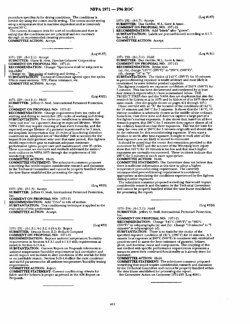
NFPA 1971 - - F96 R O C
procedure specifies Ai for drying conditions. The conditions is tumble dry using the cotton sturdy setting. The cotton sturdy setting using a temperature that is machine dependen t and is commonly arot, nd 5O°C..
The current document tests for a Set o f conditions and then is saying that the conditions are not practical and not necessary throt, gh its r ecommended cleaning procedure. COMMITTEE ACTION: Accept.
(Log #1S7) 1971- 2 3 2 - (6-1.7): Accept SURMITrER: Dan Gohlke, W.L Gore & Assoc. COMMENT O N PROPOSAL NO: 1971-21
I RECOMMENDATION: Add "labels ~ after "gloves'. SUBSTANTIATION: Labels are precondi t ioned according to 6-1.7. See 6-42.4.3.1. COMMITTEE ACTION: Accept.
(l.~g #137) 1971- 228 - (6-1.2.1): Accept SUBMI'Iq'ER: Diane B. Hess, Hoechst Celanese (k~rporation COMMENT ON PROPOSAL NO: 1971-21 RECOMMENDATION: Change: "Specimens shall be subjected to ~ea£z.v_~ez"
Change to: "vfiy_e...~;.~ of washing and d ry ing . . : SUBSTANTIATION: Technical Committee agreed upon five cycles. Effects many sections: TPP, Flame resistance, etc. COMMITTEE ACTION: Accept.
(Log #322) 1971- 229 - (6-1.2.1): Hold SUBMITrER: Jeffrey o . Stull, International Personnel Protection, Inc. COMMENT ON PROPOSAL NO: 1971-21 RECOMMENDATION: Change requirement from ten cycles of washing and drying to twenty five (25) cycles of washing and drying. SUBSTANTIATION: Ten cycles are insufficient to simulate the ~wear and tear" on a garment during its expected lifetime. While NFPA 1500 may require cleaning at least every 6 months, and the expected average lifetime of a garment is presumed to be 5 years, the simplistic interpretation that 10 cycles of laundering therefore constitutes an adequate test of ~durability" falls to account for the impact from daily garment wear over that same period. Fire fighters should expect their gear to maintain adequate minimum performance (given proper care and maintenance) over 25 cycles. These concerns ,are currently and similarly addressed for station/ work uniforms in NFPA 1975 through the requirement of 10O laundering cycles. COMMITTEE ACTION: Hold. COMMITTEE STATEMENT: The submitters comment proposes something that would require considerable research and discussion by the Technical Committee and cannot be properly handled within the time frmne established for processing the report.
(l_~g #323) 1971- 280 - (6-1.3): Accept SUBMITTER: Jeffrey o . Stull, International Personnel Protection, Inc. COMMENT O N PROPOSAL NO: 1971-21 RECOMMENDATION: Add "Trim" to tide of section. SUBSTANTIATION: This conditioning technique is applied to the evaluation of tri~n performance. C O M M I T I ~ E ACTION: Accept.
(Log #88) 1971:231 - (6-1.3.1, 6-1.3.2, 6-19.4.4): Reject SUBMITrER: Dennis Stout, E.D. Bullard Company COMMENT ON PROPOSAL NO: 1971-21 RECOMMENDATION: Replace ~ b i e n t temperature/humidi ty requirements in Sections 6-1.3.1 and 6-1.8.2 with requirements as s~ ted in Section 6-19.4.4. SUBSTANTIATION: Current Report on Proposals references to :unbient temperature /humidi ty requirements lack correlation and would require test facilities to alter conditions of the test lab for little or no justifiable reason. Section 6-19.4.4 offers the most consistent and t)sefnl p~amete r s for all ambient teml~erature/humldity testing requirements. COMMITTEE ACTION: Reject. COMMITTEE STATEMENT: Current conditioning criteria for fabric and for helmets is proper as printed in the A96 Report on Proposals.
(Log#iS1) 1971- 283 - (6-1.7.1): Hold SUBMITrER: Dan Gohlke, W.L. Core & Assoc. COMMENT ON PROPOSAL NO: 1971-21 RECOMMENDATION: Revise text:
(a), (b), change "141°C (285°F)" to "260°C (500°F) ". (d), change "lO ~ to "5".
SUBSTANTIATION: The choice of 141°C (285°F) for 10 minutes as precondit ioning exposure is totally arbitrary and most likely is constrained by some inferior product capability.
Fire fighters routinely see exposure conditions of 260°F (500°F) for 5 minutes. This has been documented and confirmed by at least four research reports which I have summarized below. THE PROJECT FIRLS data and the NASA data are duplicates but also the research by (~)letm et al in 1975 and by Abbott et al in 1975 show the same result. (See the graphs shown on pages 412 through 415.)
I have overlaid with an "X ~ the location o f the conditions of 141 °C for 10 minutes and 260°C for 5 minutes. It shows that the 141 °C, 10 mimlte condition is arbitrarily chosen in the middle of the ordinary, hazardous, class three zone and does not capture a large part of a fire fighter's normal exposures. It also shows that, based on all four research papers, that 2600( ', for 5 minutes does capture almost all o f the ordinary hazardous class three exposures. This was the basis for using the oven test at 260°C for 5 minutes originally and should also be the rationale for this reconditionin[~ exposure. If you want a p(oduct to worth after heat exposure, it ought to work after all the heat exposure you are likely to intend to encounter.
It should be noted that the recent documentation provided to this committee by NIST and the account of the Winnipeg burn injury show that 141°C for 10 minutes is too low and that much higher exposures are normally encountered. These incidents indicate that 260°C for 5 minutes is much more appropriate. COMMITTEE ACTION: Hold. COMMITTEE STATEMENT: The (bmmi t tee does not believe that there is sufficient information at this time to adopt a higher temperature precondit ioning requirement. The currently recommended precondit ioning requirement is considered appropriate as simulating the conditions experienced by fire fighters during routine exposures.
The submitters comment proposed something that would require considerable research and discussion by the Technical Committee and cannot be properly handled within the time frame established for processing the report.
(Log #324) 1971- 234 - (6-1.7.1): Hold SUBMITrER: Jeffrey o . Stuii, International Personnel Protection, Inc. COMMENT O N PROPOSAL NO: 1971-21 RECOMMENDATION: (~ange "141 °C (285°F)" to "260°C (500°F) ~ in subparagraphs (a) and (b); Change "10 minutes" to "5 minutes" in subparagraph (d). SUBSTANTIATION: There is no basis for the choice of the specified exposure condition of 141 °C (285°F) for 10 minutes. A 5 minute heat exposure at 250°C (500°F) is consistent with established practices used to assess the heat resistance of garment, helmet, glove, and footwear, items and components. The coupling of this test method with specific performance requirements represents a means to assess their cont inued functionality as is already done for hardware. COMMITTEE ACTION: Hold. C O M M r r r E E STATEMENT: The submitters comment proposed something that would require considerable.research and discussion by the Technical Committee and cannot be properly handled within the time frame established for process ingthe report.
See Committee Action on Comment 1971-238 (Log #181 ).
411
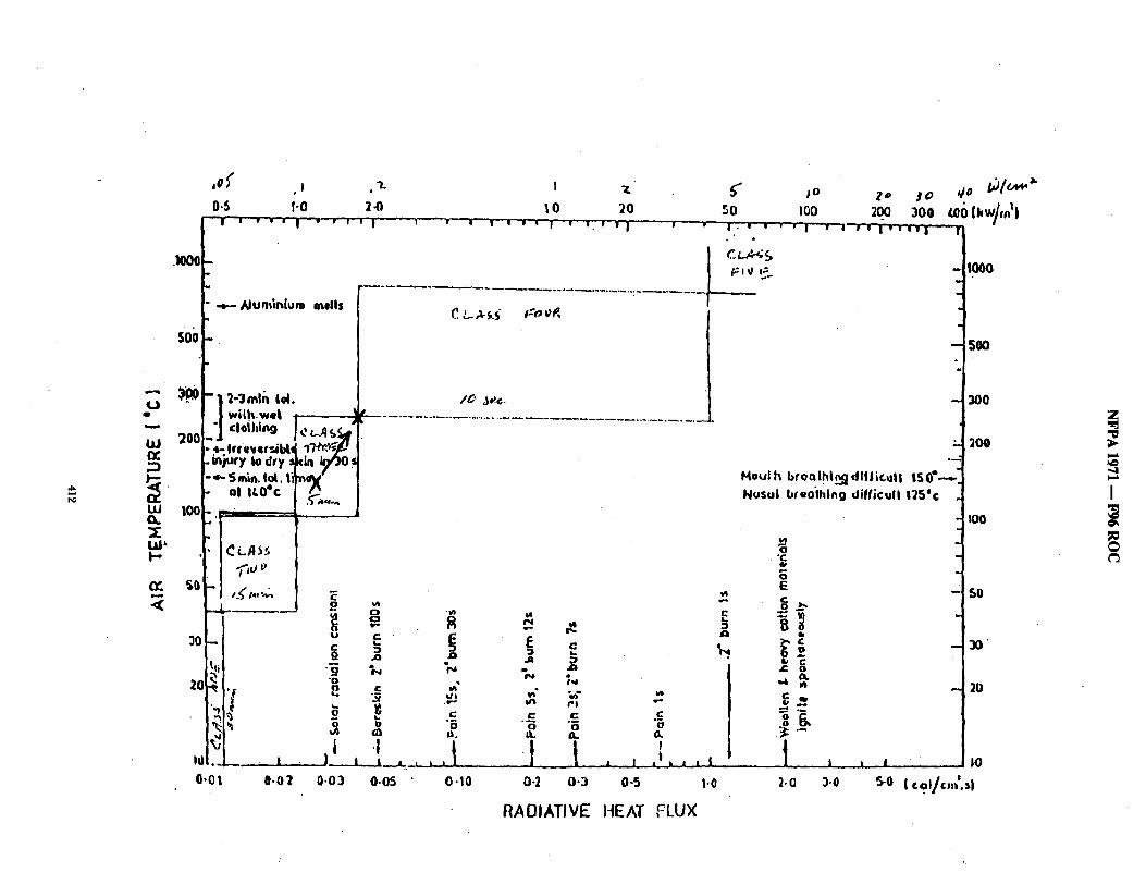
I..) 411
I.IJ g
1,1,1 (1.
1.11~' I -
.<(
.11000
so0
200
100
S{
,0~' ,~ ,1.
0,5 I-0 2.0 I ' ~ ' - " i " ' " ' ~ " ' I . . . .
' ....+--- Alunfinlum mells
"1 2 - 3 m l n I d . I' w i l h w e t t a ]
-"4- Irr i+e+~i~,[ +)'ffO+~ .injury IoUry ~ ~sO+ - ~ 5m~n. tot. li)'noV
o, ,t.OeC l .p+.,,... '
-..~ -" . . . . J.
_ j , m
30 - i
20 ; . I
11¢ 10J :_ i
0,01 0-02
U
" 0
2
, I 1 1
0.03
I 7 .
tO 20 1 • I " I I i ~ l - i ! . ~ I'--| I " •
I D 3~.¢.
C ) " ~ wz
o R
. O JCI .411
~, "N % c
.I I I J+ • . . , . , , 1 . . . . . I
O.OS 0.10 0-2
v~
I~- Jr-,
c % . a
P l
" B o 0+. O.
• 1 . _ I l _ j 1
0 - 3 0 -5 1.0
R A D I A T I V E HEAT FLUX
~" ~o z" jro ,/o # / o , + " ,oo . _+.oo 3 o 0
l + ' -w • ' " ~ - I :w ] - - + v I v ~ w v i
H o u I tx b f o o l . h l ~ dl l l i r . ,u l ! IS 0°--..., ,.
Nus . l bre0"lhlng d i l [ icu l l 13Sec
0
0 E
Ib
+lw l u C r o
,,,i i ,4 I/I
• - q ° ~
° g
t ,
l .O 3.11
I000
,500
3OO
- 300 °.,.,.."
I00
+
50 i
- - 211
n I i0
5-o I col/c,,/.+l
Z
",,,4
I
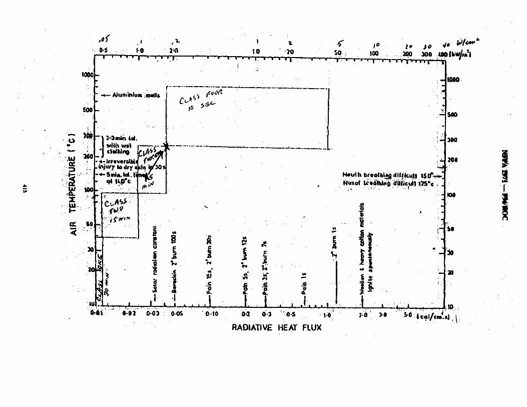
. o ( ., . i. I z ( lo 4o ~ / ~ " ~ 0.5 1'0 34) I 0 • Z P J 0
, _ , . . . . , . . . - , : , , , _ . . ,- . ~ . . - , ~ . . . - ~ , . ~ o . , ~ : = . ~ o = , . i , . ,
~e i / i wlll~ Wel , - - ; - 3 1 ;- . . . . . . . . . . :~- . . . . - - - - . . . . . . . " " ; I "! cl l lhin9 ie~ :~AI f¶ Z
• 200 J " K , . l : ; . , . . , , . , .~d 'o: , ,<7 ~ ] :._ ~ ,
,1"-'~ ~" : l - ~ - S l n t l h l Q l . | ~ l ( ~ 1 I ~ u l h breol l f l . .~dl t lk~l ~ I S I ~ . ~ . !
f: ..... f 1 f ~ l ~ . :
o o " o
,,,~1 o , . , , , . . . . I . .t , t- , , . t . . . , .t , ~ , , .~ :.~,,,, ~ i " ' o : o ' i "i i .o3 o .o~ ~ . . . . o , i o 0.2 o:3 '"o.,, - ~.e:' ~.o" ) . , : ' :~ '~ .~ ,oV, d.,~ 1
R A D I A T I V E HEAT FLUX
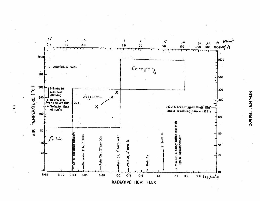
+,.+.. ,I+.
.I000
2o0
. o J . , 100 O. ~E O.k
.t-.-
~o
20
0-01
, 0 ~ ' I 1 .
0.5 1-0 2.0 ' ', " ~ " ' I - - " "- ' "-I"
Alum~ni~m mefls
\
• '~ 2-3 m i n 1,ol. 1[ with wet "] ¢1,othin9
. injury Io dry '*kin " " " Smirk. Sol. 1,im~
o[ I~,O*c
I
0.02
- - I • p' ' |
.s" 5O
X
/ 30s
X
| 7.
!,0 20 ' ' ' I w ..i ; - i
E
0
1
0.03
R ~ ,.,
° °
u ~ ~ j
'~ "5 "'G "~
0-05 0.10 0.2 0"-3
RADIATIVE
I o
iO0 2 0
.200 30
300
. / , tJ/~'~" olkw/,n'| +
I '~ . w" I • s '1' 'Iv ~ I" 1 - 1 " ' t r I i w'w i ' w ' l - ~
,A qed~
I
*il
S. o
J I , l . l . I
0.5 t.0
HEAT FLUX
!
H0ulh brealhln4]dlf/lcu|l 150~--. 14usul l~reoll~inO difficull 125'¢ .
IO00
o
o E t -
o,_~
Ib
>- c ~ o
n, ~dP *,4
Z.O 3.0
s0~
30O
+ I
SO
J I0 ~o. { c 91/cm'.s )
30
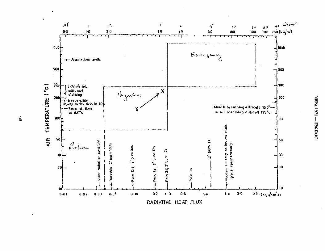
/
,D~ . I ,"L.
0,5 I-0 2-0 lO
I001
AI ~nl~nium .nells
wiih wel 200 clollimg
::)
CC LU R.
UJ b--
lO0
- 4 - Irleve,~l~e . injury Io ~lry skio ir~ 30 - * " Stain. Id. l i m o - o l ItO*c
~r" liO 1 -
U 10 - ~
2~ 'o -- f
0
i ~ l . _ _ t l ,~
0.01 0.02 0-03
i L
X
c
L. au ~ j :~
% % e. 1,J c v~ . L~ ~ " "~"
t ~ ¢ ' I r - c" I I :
D 0 0 I~. It. 0,.
O-OS 0.10 0'2 O.:)
RADIATIVE
7_
2G zo #o ~o ,;u,_,~..,~"
iO0 300 ~o l kw ] ,21 ~ - - r - T - - r ~ --r-r-- r ~ r . r - r r . . - ~
tO00
- 500
-I
201)
Moul h b r o o l h | ~ d l f l i c u | | 15 0 Q---- 14cJsul breO[h[~ O d l f / i cu l | I~5"c
i
IO0 [
o~
-~ ;o
50 100
E
[ j , , , t ~ ' o,5 ~.0
HEAT FLUX
0
g~
"6 E C o~
I# )~, iE
C
C aa
t 1-0
~ . , , i |
3.0 5-0
50
I0
NFPA 1971 - - F96 ROC
(L~)g #350) 1971- 235 - (6-1.7.1 (a)): Accept SUBMI'VI'ER: Bob O 'Gorman , Inchcape Tes t ingServices /ETL Testing Laboratories, Inc. COMMENT ON PROPOSAL NO: 1971-21 RECOMMENDATION: Add a tolerance tJ) the tempera ture specified. Based on the tolerance provided for the 500 ° oven test. I propose the Conunit tee add +1 OF and -OF. SUBSTANTIATION: Ensures a t ighter control on the m e t h o d the ( ~ m m i t t e e has adopted. COMMITTEE ACTION: AccepL
(Log #90) 1971- 236 - (6-1.7.1 (a), (b)): Hold SUBMITTER: Harry P. Winer, U.S. Navy COMMENT O N PROPOSAL NO: 1971-21 RECOMMENDATION: Replace 141°C (285°F) with 260~'C (500°F). SUBSTANTIATION: 1. 500°C is a stmadard tempera ture within this st~mdard, that o ther componen t s have to meet.
2. Gloves since individual componen t s ,are not tested as in the coat yon have no way of el iminat ing t)~ermoplastics f rom the construction, 285°F will allow thermoplast ic components .
3. Trim is the most outer c o m p o n e n t of an ens/~mble and still should work ,'fixer 500°F.
4. Helmets are examined after 500°F, therefore we should also test them :tfter 500°F. COMMITTEE ACTION: Hold. COMMITTEE STATEMENT: The submit ters c o m m e n t proposed someth ing tha t would require considerable research and discussion by the Technical Commit tee and canno t be properly handIed within the t ime frame established for p rocess ing the report.
See (i~)nunittee Action on O ) n u n e n t 1971-233 (Log #181 ).
(I-z~g #91) 1971- 237 - (6-1.7.1 (d)): Hold SUBMITTER: H,'uTy P. Winer, U.S. Navy COMMENT ON PROPOSAL NO: 1971-21 RECOMMENDATION: Replace 10 minutes with 5 minutes . SUBSTANTIATION: Increasing tempera ture in (a), (b) to 500°F should decrease t ime to 5 rain for standardization. COMMITTEE ACTION: Hold. COMMITTEE STATEMENT: The submit ters c o m m e n t proposed someth ing that would require considerable research and discnssion by the Technical Commit tee and canno t be properly handled within the t ime f rame established for p rocess ing the report.
See Cormnittee Action on C o m m e n t 1971-233 (Log #181 ).
(I_z)g #161) 1971- 238 - (6-1.7.1 (d)): Accept SUBMITTER: Frank Masley, W.L. Gore & Associates COMMENT O N PROPOSAL NO: 1971-21
[ RECOMMENDATION: Revise to read: "+15/-O" seconds SUBSTANTIATION: T he t ime is in tended to be for the stated durat ion with an allowance to go over a certain a m o u n t but not under . COMMITTEE ACTION: Accept.
COMMITTEE STATEMENT: The Commit tee agreed with the temperature change but only to apply to gloves as the layers are not tested separately. See Commit tee Action on C o m m e n t 1971-233 (Log #181).
( I~g #179) 1971- 240 - (6-1.13.2): Reject SUBMITEER: Donald Aldridge, Lion Apparel, Inc. COMMENT O N PROPOSALNO: 1971-21 RECOMMENDATION: Add new text to read:
"but no spec imen shall come in contact with any o ther specimen". SUBSTANTIATION: Al though good lab practice would no t do this, someone could stack three specimens on top o f each other in one bag and there could migration of water f rom such contact. COMMITTEE ACTION: Reject. COMMITTEE STATEMENT: See Commit tee Action on C o m m e n t 1971-60 "(Log #8).
(Log #277) 1971- 241 - (6-2): Accept in Principle SUBMITTER: Tom Wollan/Kimber ly Henry, Underwriters Laboratories, Inc. COMMENT O N PROPOSAL NO: 1971-21 RECOMMENDATION: Need text to specify m e t h o d for "odd-' shaped" samples. SUBSTANTIATION: Modifications to test m e t h o d fi)r testing small i tems such as emblems, hanger loops, patches, etc., should be included in this section since their size and configuration do not fall within test specimen size requi rements specified for Flame Resistance Test. COMMITTEE ACTION: Accept in Principle.
Add new 5-1.3.2 to read: 5-1.3.2 .Small spec imens such as hange r loops, and emblems
(patches) which are no t large enough to mee t the specimen size requirements in 6-2.2.1, shall be tested for resistance to flame as specified in Section 6-2, Flame Resistance Test One, arid shall no t be totally consumed, shall no t have an afterflame of more than 2.0 seconds average, and shall no t mel t or drip.
Add new 6-2.1.7 to read: 6-2.1.7 Modifications to this m e t h o d for testing small specimens
not mee t ing the specimen size requi rements in 6-2.2.1 shall be tested as specified in 6-2.13.
Add new 6-2.13 to read: 6-2.13 Specific requi rements for testing small spec imens no t
meet ing m e size requi rements in 6-2.2.1. 6-2.13.1 Five specimens at tached to the textile layer as used in the
protective garments shall be tested. The specimens shall be a t tached to the textile layer such that the bot tom (exposure) edge o f the item coincides with the bot tom (exposure) edge of the textile suppor t layer.
6-2.13.2 Samples for condi t ioning shall be at least I m (1 yd) square of the textile layer on which the small specimens are attached.
6-2.13.3 Test ing shall be per formed as specified in 6-2.2 th rough 6-27, o ther than char length shall no t be measured . COMMITTEE STATEMENT: The Commit tee agrees with the submit ter and developed the necessary text.
( I_~g #132 ) 1971-239- (6-1.7(a) ,and (b)): Accept in Principle SUBMITTER: [)ave Engler, 3M COMMENT ON PROPOSAL NO: 1971-21 RECOMMENDATION: Change the preheat and exposure tempera ture to 177°C (350°F) in p,'u'agraphs (a) and (b) of 6-1.7. SUBSTANTIATION: 177°C (350°F) is cl~ser to the actual use condit ions o f fire righters than the cur ren t specified temperatures . COMMITTEE ACTION: Accept in Principle.
Revise 6-1.7(a) to read: "...141 °C (285°F) for helmets and trim." Add new 6-1.7.1 (b) to read: "The oven prehea t specified in 6-6.4.3 shall be stabilized at 1770C
(350°F) for gloves only." Reletter the remain ing subparagraphs. Revise 6-1.7.1 (b) (as shown in the A96 Report on Proposals) to
read: "recovers to the tempera ture as specified in 6-1.7.1(a) or (b) as
applicable."
(Log #205) 1971- 242 - (5-2.1.6): Reject SUBMITrER: Robert D a h l / T h o m a s Nea], DuPont Advanced Fibers Systems COMMENT ON PROPOSAL NO: 1971-21 RECOMMENDATION: Modify Section 5-2.1.5 by adding the words "garment label materials ~[l~" before the words hood label." Section should read:
6-2.1.6 Modifications to this test for testing a-arment label materials ,and hood label materials shall be as specif iedln 6-2.12. SUI~TANTIATION: Labels shou ld also be f lame resistant. Previously, this r equ i r emen t was removed because f lame resistant labels failed legibility requirement . Legibility problem for FT labels has now been solved. Also, hood labels (5-5.3) are requi red to pass f lame resistance. Garment labels need to be he ld t o t h e same requi remen~ COMMITTEE ACTION: Reject. COMMITTEE STATEMENT: See Commit tee Action on Comment s 1971-152 (Log#204) and 1971-154 (Log#54) .
416
NFPA 1971 - - F96 ROC
(Log #2421 1971- 243 - (6-2.2.1): Accept in Principle SUBMI'Iq'ER: Dan Gohlke, W.L, Gore & Assoc. COMMENT O N PROPOSAL NO: 1971-21 RECOMMENDATION: Add a sentence at e n d to read:
~Fallure in either direction constitutes failure o f the material." SUBSTANTIATION: This makes it clear that the criterion applies to the material in either direction. C O M M I T ~ E ACTION: Accept in Principle.
Add a new 6-2.7.2 to read: ~F~dlure in either direction shall constitute Kailure of the material."
COMMITTEE STATEMENT: Comment is in the proper paragraph for this subsection 6-2.7. The correct terminology must be used.
(Log #142) 1971- 248 - (6-2.9.1): Accept in Principle SUBMFrrER: Diane B. Hess, Hoechst Celanese Corporation COMMENT O N PROPOSAL NO: 1971-21 RECOMMENDATION: Change from: "Five specimens from each of the ward and fillin~ directions..."
Change to: "Five s i~cimens from each of the wales and courses direction.. ." SUBSTANTIATION: Differences between woven and knitted fabrics. COMMITTEE ACTION: Accept in Principle. COMMITTEE STATEMENT: See Committee Action on Ck~mment 1971-249 (Log #257).
(LOg #201) 1971- 244- (6-2.3.1): Reject SUBMITrER: Robert Dahl /Donald Shaffer, DuPont COMMENT O N PROPOSAL NO: 1971-21 RECOMMENDATION: Revise text:
~Specimens shall be tested both before and after being subjected to the procedure specified in Secdon 6-1.2.1." SUBSTANTIATION: Test reference should refer to specific number of wash cycles to be used. Five cycles should be specified because results do not change beyond 5 cycles. COMMITTEE ACTION: Reject COMMITTEE STATEMENT: Current language in 6-2.3 is appropriate.
(LOg #349) 1971- 245 - (6-2.3.1): Reject SUBMITTER: Bob O'Gorman, lnchcape Testing Services/ETL Testing Laboratories, Inc. COMMENT O N PROPOSAL NO: 1971-21 RECOMMENDATION: Remove "both before and". SUBSTANTIATION: This document is a minimum performance standard. By evahmting these materials both before and after laundering, it is my opinion what we are creating additional costs to rmanufacturers with out basis and we are "clouding" the isstie of nfinimum performance. COMMITTEE ACTION: Reject. COMMITTEE STATEMENT: Testing both before and after laundering is necessary because (1) finishes on materials can be flmmnable before materials are laundered, ,and (2) flame retard,ant finishes on materials an be removed by laundering.
(LOg #354) 1971- 246- (6-2.3.1): Reject SUBMITrER: Catherine R. Dodgen /Rober t O'Gorrman, lnchcape Testing Services/ETL Testing Laboratories, Inc. COMMENT O N PROPOSAL NO: 1971-21 RECOMMENDATION: Revise 6-2.3.1 to read as follows:
"Specimens shall be tested after being subjected to the procedure specified in 6-1.2." SUBSTANTIATION: Conducting the required testing both before and after laundering (or other preconditioning) does not provide additional meaningfid information to the manufacturer or to the end user; particularly in the light of the fact that dual levels o f performance are not being proposed. COMMITTEE ACTION: Reject. COMMITTEE STATEMENT: See Committee Action on Comment 1971-245 (Log #349).
(Log #241) 1971- 247 - (6-2.6.1): Accept SUBMITTER: Dan Gohlke, W.L. Gore & Assoc. COMMENT O N PROPOSAL NO: 1971-21 RECOMMENDATION: Add "in each direction" after "material". SUBSTANTIATION: This makes it clear that the report applies to the material in each direction. COMMITTEE ACTION: Accept.
(Log#257) 1971- 249 - (6-2.9.1): Accept SUEMITTER: Denise N. Statham, Southern Mills, Inc. COMMENT O N PROPOSAL NO: 1971-21 RECOMMENDATION: Replace ~warp and filling" with ~wale and c o u r t 2 ~ .
SUBSTANTIATION: Wale and coarse are th~ accepted textile terms for machine ,and x-machine directions in knitted fabrics. COMMITTEE ACTION: Accept.
(Log #2o) 1971- 250 - (6-2.11.1): Reject SUBMITTER: £hhristopher Gaudette, Reflexite Corporation COMMENT O N PROPOSAL NO: 1971-21 RECOMMENDATION: In section 6-2.11.1 the length dimensions of the trim specimen needs to be increased. The first sentence o f this section should be:
~Trim specimens fi~r flammability testing shall be at least 50.8 mm (2 in.) wide and not less than 200 n u n (7.875 in.) in length." SUBSTANTIATION: The flammability test requirement for trim is that the char length be less than equal to 4 in. The length needs to be increased to allow testing to the requirements. NFPA 1971, 1991 edition specified a length of 12 in. for the specimen. This length is not necessary for completing the test. A specimen with the length of 200 mm (7.875 in.) is sufficient. COMMITTEE ACTION: Reject. COMMITTEE STATEMENT: Paragraph 6-2.2.1 sets the dimensional requirements for test specimens. No need to repeat the specimen size in 6-2.11.1.
( Log # 133) 1971- 251 - (6-2.11.1): Accept SUBMITTER: Loft Kuller, 3M COMMENT ON PROPOSAL NO: 1971-21 RECOMMENDATION: Revise the first sentenc~ to read:
L.. and no more than 7.6 cm (3 in.) wide." SUBSTANTIATION: Provides correction of a previous "type." The above wording is what was originally intended. COMMITTEE ACTION: Accept. COMMITTEE STATEMENT: See Committee Action on Comment 1971-252 (Log #276).
(Log #276) 1971- 252 - (6-2.11.1): Accept in Principle
, SUBMITrER: Tom Wollan/KimberiyHenry, Underwriters Laboratories, Inc. COMMENT ON PROPOSAL NO: 1971-21 RECOMMENDATION: Revise text:
~Five trim specimens for flammability testing shall be at least 5.08 cm (2 in.) wide and 7.6 cm (3 in.) in length." SUBSTANTIATION: Paragraph did not state number of specimens to be tested. It also included "no more than 7.6 cm (3 in.) in length" which is redundant if paragraph already states that the specimens shall be at least a specific width and length. COMMITIT~ AGq'ION: Accept in Principle.
Revise the first sentence to add "Five" to beginning of sentence. This sentence is fur ther revised by Committee Action on Gomment 1971-251 (Log #133). COMMFIq'EE STATEMENT: The change of the text to width and length is incorrect; see Committee Action on Comment 1971-251 (Log #133).
417
N F P A 1971 - - F96 R O C
( Log #206) 1971- 253 - (@2.12): Reject SUBMIq['I'ER: Robert Dahl/Thomas Neal, DuPontAdvanced Fibers Systems COMMENT O N PROPOSAL NO: 1971-21 RECOMMENDATION: I propose modifying ,Section 6-2.12 by adding the words "(hrment Label Materials and ~. The section wonld read:
@2.12 Specific Requirements for Testing Garment Label Materials and HoodLabel Materials. SUBSTANTIATION: Labels should also be flame resistant. Previously, this requirement was removed because flame resistant labels failed legibility requirement. Legibility problem for F'I" labels has now been solved. Also, hood labels (5-5.3) are required to pass fl,'une resishance. Garment labels need to be held to the same requirement. COMMITTEE ACTION: Reject. COMMITTEE STATEMENT: See (k~mmittee Action on ~ m m e n t 1971-152 (Log #204) and 1971-154 (Log #54).
- (Log #207) 1971- 254- (@2.12.1): Reject SUBMITrFJt: Robert Dahl/Thomas Ncal, DuPontAdvanced Fibers Systems COMMENT O N PROPOSAL NO: 1971-21 RECOMMENDATION: I propose modifying Section 6-2.12.1 by adding to underlined words.
6-2.12.1 Five snecimens of warment labels attached to the ~rarment material and fivi." specimens 6f hood labels attached to the hood material shall be tested. The ~trment label soecimen and the hood label specimen shall be cut t~dm conditionedsamples, svch that the edge of the t~rment label or the edge of the hoodlabel is at the boitom of tile specimen. SUBSTANTIATION: Labels should also'be flame resistant. Previously, this requirement was removed because flame resistant labels failed legibility requirement. Legibility problem for FT labels has now been solved. Also, hood labels (5-5,3) are required to pass flame resistance. Garment labels need to be held to the same requirement. COMMITTEE ACTION: Reject. COMMITTEE STATEMENT: See Committee Action on Comment 1971-152 (Log #204) and 1971-154 (Log #54).
(Log #208) 1971- 255 - (6-2.12.2): Reject SUBMFVrER: Robert Ddhl/Thomas Neal, DuPont Advanced Fibers Systems COMMENT O N PROPOSAL NO: 1971-21 RECOMMENDATION: I propose modifying section 6.2.12.2 by adding the underlined words:
@2.12.2 Samples for conditioning shall be whole warments and whole hoods including labels ,as normally attached. - SUBSTANTIATION: Labels should also be flame resistant. Previously, this requirement was removed because flame resistant labels failed legibility requirement. Legibility problem for FT labels has now been solved. Also, hood labels (5-5.3) are required to pass flame resistance. Garment labels need to be held to the same requiremenL COMMITTEE ACTION: Reject. COMMITTEE STATEMENT: See Committee Action on Comment 1971 - 152 (Log #204) and 1971-154 (Log #54).
('Log #382) 1971- 257 - (Figure 6.3.7.1 (c)): Accept SUBMITrER: Bob O'Gorman, Inchcape Testing Services/ETL Testing Laboratories, Inc. COMMENT O N PROPOSAL NO: 1971-21 RECOMMENDATION: Remove "50 ram" from the figure that is referenced. When referencing metric units throughout the document be
consistent and "mm" or "cm ~, not both. SUBSTANTIATION: As discussed several times at the committee level, 50 mm as referenced in the figure, indicates to the reader and test technicians that the flame shall be 50 nun in length from base to tip. Figure 6-3.7.2 clearly indicates that the flame shall be less than what is presented in the figure. This creates confusion and leaves room for error when conducting evaluations. COMMITTEE ACTION: Accept.
(Log #97) 1971- 258 - (6.4.1): Reject SUBMITrER: Robert Hall, Navy Clothing & Textile Research Facility COMMENT O N PROPOSAL NO: 1971-21
"RECOMMENDATION: Sample i~reparation should be described since it is not adequately covered m ASTM F 489. SUBSTANTIATION: ,Samples are usually taken from component sole and heel materials. It ts very difficult to cut samples from footwear. Sample thickness may also influence test results. COMMITTEE ACTION: Reject. COMMITTEE STATEMENT: Submitter has not given correct paragraph reference and committee is unable to follow intent.
(Log#162) 1971- 259 - (6-4.3.1): Reject SUBMITI'EI~a Frank Masley, W.L. Core & Associates COMMENT ON PROPOSAL NO: 1971-21 RECOMMENDATION: Delete entire 6-4.3.1. SUBSTANTIATION: This instruction does not hav e any meaning. Either it should be deleted or an appropriate sample preparation. PcrOCedure should be specified.
OMMrrTEE ACTION: Reject. COMMrlWEE STATEMENT: See Committee Action on Comment 1971-260 (Log #240).
(Log #240) 1971- 260- (6-4.3.1): Accept SUBMITFER: [)an Gohlke, W.L. Gore &Assoc. COMMENT O N PROPOSAL NO: 1971-21 RECOMMENDATION: Change reference to "6.1.1 ~ to read "6.1.2".
..SUBSTANTIATION: Editorial. COMMITTEE ACTION: Accept.
1971- 261 - (6.4.3.2): Accept SUI~blI'I'I'Ei~ [)an Gohlke, W.L. Gore & Assoc. COMMENT O N PROPOSAL NO: 1971-21 RECOMMENDATION: Change "6-1.2" to "6.1.3". SUBSTANTIATION: Editorial. COMMITTEE ACTION: Accept.
(Log #'239)
(la)g #325) 1971- 256 - (6-3.3): Reject SUBMITrER: Jeffrey O. Stull, International Personnel Protection, I n L . COMMENT ON PROPOSAL NO: 1971-21 RECOMMENDATION: Delete current paragraph 6-3.3.1 and replace with:
6-3.3.1 Smnples for conditioning shall be whole helmets without ear flaps.
6-3.3.2 Specimens shall be conditioned as specified in 6-1.3. SUBSTANTIATION: Some form of conditioning should be applied in all tests, even if it is only conditioning at room temperatnre and humidity. COMMITTEE ACTION: Reject. COMMrWTEE STATEMENT: Absence ofa pre-conditioning was. intentional, preconditioning will not alter results.
(Log #9~) 1971- 262 - (6.4.4.3): Accept in Principle SUBMITrEPa Robert Hall, Navy £aothing & Textile Research Facility COMMENT O N PROPOSAL NO: 1971-21 RECOMMENDATION: The illustration shows test cabinet as used in TM 5905.1. TIM 5905 does not use a cabinet. It would be difficult to remove flame from test specimen when using a cabinet. I believe it would not be possible to measure after flame to 0.2 seconds with this method. SUBSTANTIATION: None. COMMITTEE ACTION: Accept in Principle. COMMITTEE STATEMENT: See Committee Action on Comment 1971-263 (Log #326).
418
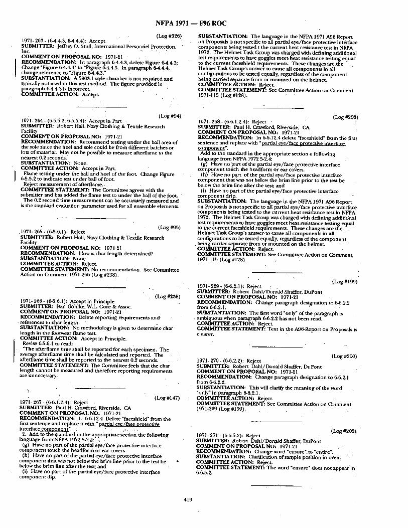
N F P A 1971 - - F96 R O C
(Log #326) 1971- 263 - (64.4.3, 6-4.4.4): Accept - SUBMITrF_~ Jeffrey O. Stull, International Personnel Protection, Inc. ~, " : . COMMENT ON PRoPosAL NO: 1971-21 RECOMMENDATION: I n paragraph 64.4.3, delete Figure 6-4.4.3; C&ange "Figure 6-4.4.4 ~ to "Figure 6-4.4.3. In paragraph 6-4.4.4, change reference to "Figure 6-4.4.3. ~ SUBSTANTIATION: A 5903.1-style chamber is not required and typically not used in this test me/.fiod. The figure provided in paragraph 6-4.4.3 is incorrect. COMMITTEE ACTION: Accept.
SUBSTANTIATION: The langtmge in the NFPA 1971 A96 Report on Proposals is not specific to all partial eye/face protective int&face components being tested t the current heat resistance test in NFPA 1972. The Helmet Task Group was charged with defining additional test requirements to have goggles meet, heat resistance testing equal ~ to the current faceshield requirements. These changes are t h e Helmet Task Group's answer to cause all components in all configurations to be tested equally, regardless of the componen t being carried separate from or mounted on the helmet. COMMITTEE ACTION: Reject. COMMITTEE STATEMENT: See Committee Action on Comment 1971-115 (Log #128).
1971- 264- (6-515:2, 6-5.5.4): •Accept in Part (LOg #94) SUBMITrER: Robert Hall, Navy Clothing & Textile Research Facility COMMENT ON I/ROPOSAL NO: 1971-21 RECOMMENDATION: Recommefid testing t inder the ball ,area of the sole since the heel and sole could be from different batches or lots of material. May not be possible to measure afterflame to the nearest 0.2 seconds. SUBSTANTIATION: None. COMMITTEE ACTION: Accept in ParL
I Flame testing tinder the ball and heel of the foot. Change Figure 6-5.5.2 to indicate, test under ball of foot.
Reject measurement of afterflame. ~ COMMrI'rEE STATEMENT: The Committee agrees with the submitter and has added the flame test to under the ball of the foot.
The 0.2 second time measurement can be accurately measnred and is the standard evaluation parameter used for all ensemble elements.
(Log #95) • 1971- 265 - (6-5.6.1): Reject SUBMITTER: Robert Hall, Navy Clothing & Textile Research ' Facility COMMENT ON PROPOSAL NO: 1971-21 RECOMMENDATION: How is char length determined? SUBSTANTIATION: None. COMMITTEE ACTION: Reject. COMMITTEE STATEMENT: No recommendation. See Committee Action on (k)mment 1971-266 (LOg #238).
- .
1971-266- (6-5.6.1): Accept in Principle (Log #'238) SUBMI'ITER: Dan Gohlke, W.L. Gore &Assoc. COMMENT ON PROPOSAL NO: 1971-21 RECOMMENDATION: Delete report ing requirements a n d
- references to char length. " - . SUBSTANTIATION: No methodology is given to determine char length in the footwear flame test. COMMITTEE ACTION: Accept in Principle.
Revise 6-5.6. i to read: " "The afterflame time shall be r epor t ed fo r each specimen. The average afterflame time shall be calculated and reported. The afterflame time shall be reported to the nearest 0.~ seconds. , COMMITTEE STATEMENT: The Committee feels that the char length cannot be measured and therefore report ing requirements are unnecessary.
\
197]- 267 - (6-6.1.2A): Reject (I_~g #147) SUBMITTER: Paul H. Crawford, Riverside, CA COMMENTON PROPOSAL NO: 1971-21. RECOMMENDATION: 1. 6-6.12.4 Delete "faceshield" from the first sentence and replace it with "partial eve / face orotectiv¢ interface comooneqt7. : o. ,.," -
2. Add to the standard, in the appropriate section the fi)llowing language f r0mNFPA 1972 5-2.4: :~
(g) Have no part o f the pfirfal eye/face protective interface componen t touch the headform or ear covers
(h) Have no part o f the partial eye/face protective interface componen t that was not below the brim line prior to the test be " below the brim line after the test; and
(i) Have no part of the partial eye/face protective interface componen t dip.
1971- 268- (6-6.1.2.4): Reject • . (Log #.293) SUBMITrER: Paul H. C, mwford, Riverside, CA COMMENT ON, PROPOSAL NO: 1971-21 RECOMMENDATION: In 6-6.12.4 delete "faceshield" from the first s en~nce ,and replace with ~ nartial eve/face nrotective interface comnonen t ~. Add to the standard in the appropriate section e following
language from NFPA 1972 ~2.4: (g) Have no i)art of the partial eye/face protective-interface
componen t touch the headform or ear covers. (h) Have no part 0 f t h e partial eye/face protective interface
componen t that was not below the brim line prior to the test be below the brim line after the test; and
(i) Have no part o f the partial eye/face protective interface componen t drip. SUBSTANTIATION: The language in the NFPA 1971 A96 Report on Proposals.is not specific to all partial eye/face protective interface. components oemg tested to the current heat resistance test in NFPA 1972. The Helmet Task Group was charged with defining additional test requirements to have goggles meet heat.resistance testing equal to the current faceshield requirements. These changes are the - . Helmet Task Group's answer to cause all components in all configurations to be tested equally, regardless of the c o m p o n e n t being carrier separate from or mounted on the helmet. COMMITTEE ACTION: Reject. COMMITTEE STATEMENT: See Committee Action on Comment 1971-115 (Log #128).
(Log #199) 1971-269- (6-6.2.1): Reject . SUBMITrER= Robert Dahl /Donald Shaffer, DuPont COMMENT ON PROPOSAL NO: 1971-21 RECOMMENDATION: Change paragraph designation to 6-6.2.2 from 6-6.2.1. • . SUBSTANTIATION: The first word 'only" c)fthe pm'agraph is ambiguous when paragraph 6-6.2.2 has no t been read. COMMITTEE ACTION: Reject. CoMMrrrEE STATEMENT: Text in the A96-Report on Proposals is clearer.
(Log #200) 1971- 270 - (6-6.2.2): Reject SUBMITI'ER: Robert Dahl /Donald Shaffer; DuPont COMMENT ON PROPO.SAL NO: 1971-21 RECOMMENDATION: Change paragraph designation to 6-6.2.1 from 6-6.2.2. SUBSTANTIATION: This will clarify the meaning o f the word "only" in paragraph 6-6.2.1. ! COMMITTEE ACTION: Reject. COMMrrTEESTATEMENT: ,See Committee Action on Comment 1971-269 (Log #199).
(Log #202) 1971- 271 - (6-6.5.2): Reject SUBMITrER: Robert Dalai/Donald Shaffer, DuPont COMMENT ON PROPOSAL NO: 1971-21 . - RECOMMENDATION: Change word'~ensure' , to ~entire". SUBSTANTIATION: Clfirificati0n of sample position in oven. COMMITTEE ACTION: Reject. . COMMITTEE STATEMENT: T h e word "ensure" does not appear in 6-6.5.2.
419
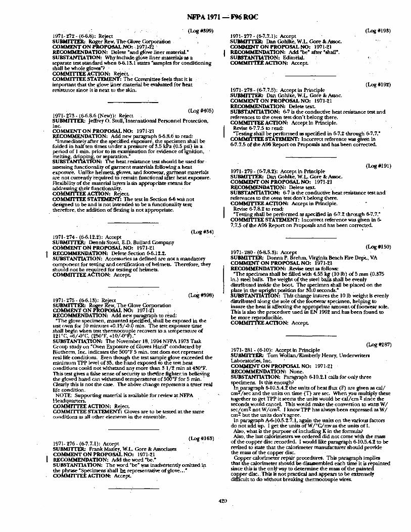
N I ~ A 1971 ~ F96 ROC
1971~ 272- (6-6.8): Reject . . . . . . " . (Log#S99) S U ~ Roger gew, The.Cdove ¢'~rporati0n COMMENT ON ,PROPOSAL N O : , 1971.21 RECOMMENDATION: D~iete "and g4bve liner material." SUBSTANTIATION: Why include glove liner materials as a separate test standard when 6-6.13.1 states ~samples for conditioning shall be whole gloves'? . COMMITTEE ACTION: Reject. . . . . COMMITTEE STATEMENT: The Committee feels that it is important that the glove liner-material be evaluated for heat resistance since it is next to the skin.
1971-27B - (6-0.8.6 (New)): Reiect (Log #405) SUBMITrEI~ Jeffrey o. Stull,-International Personnel Protection, Inc. COMMENT ON PROPOSAL NO: 1971:21 RECOMMENDATION: Add new paragraph 6-6.8.6 to read:
"Immediately after the specified exposure, the specimen shall be folded in half ten times under a pr--~sure of $.5 kPa (0.5 psi) in a period of I vain. prior to its ¢xarhination for evidence of ~gnition, melting, dripping, or separation." SUBSTANTIATION: The heat resistance test should be used for assessing fimctionality of garment materials following a heat exposure. Unlike helmets, gloves, and footwear, garment materials are not currently ~qu i red to remain functional after heat exposure. Flexibility of the material layers is atl appropriate means for addressing their fimctionality. CoMMrrTEE ACTION: Reject. COMMrrTEE STATEIi~gNT: The test in Section 6-6 was not designed to be and is not intended to be a functionality test; therefore, the addition of flexing is not appropriate.
(Log #~4) 1971- 274- (6-6.12.2): Accept SUBMITrER: Dennis Stout, E.D. Bnllard Company COMMENT ON PROPOSAL NO: 1971-21 R E C O ~ A T I O N : Delete Section 6-6.12.2. SUBSTANTIATION: Accessories as defined are not a mandatory component for testing and certification of helmets. Therefore, they should not be required for testing of helmets. COMMITTEE ACTION: Accept.
1971- 275 - (6-6.13): Reject (Log#398) SUBMITTER: Ro~er l~ew, The Glove Corporation COMMENT ON PROPOSAL NO: 1971-2"1 RECOMMENDATION: Add new paragraph to read:
"The glove specimen, mounted sl3ec'ff~ed, shall be exposed in the test oven for I0 minutes +0.15/-0.0 rain. The test exposure time shall begin when test thermocouple recovers to a temperature of 121°C, +6/-0°C, (250°F, +I0/-0°F)." SUBSTANTIATION: The November 18, 1994 NFPA 1973 Task Group study on YOven Exposure of Gloves Han'd" conducted by Biotherm, Inc. indicates the 500°F 5 mia. test does not represent real life conditions. Even though the test sample glove exceeded the minimum TPP leve! of 35, the hand exposed to the test heat conditions could not withstand any more than 3 1/2 min at 4300F. This test gives a false sense of security to the*fire fighter in believing the gloved hand c,-m withstand temperatures of 5000F for 5 mln. Oearly this is not the case. The above change represents a truer real life condition.
NOTE: Supporting material is available for review at NFPA Headquarters. COMMrI'FEE ACTION: Reject. COMMITTEE STATEMENT: Cloves are to be tested at the same conditions as all other elements in the ensemble.
(Log#16S) 1971- 276 - (6-7.7.1): Accept SUBMITFER: FrankMasley, W.L Gore & Associates COMMENTON PROPOSAL NO: 1971-21 RECOMMENDATION: Add the word "be," SUBSTANTIATION: The word "be" was inadvertently omitted in the phrase "Specimens shall be representative of glove.,." COMMITTEE ACTION: Accept.
1971- 277 - (6-7.7.1): Accept SUBMITrER: Dan Gohlke, W.L Gore & Assoc. COMMENT ON PROPOSAL NO: 1971-21 RECOMMENDATION: Add "be" after .'shall'; SUBSTANTIATION: Editoi'ial. COMMrI 'IY~ ACTION: Accept.
(Log #19S)
(Log #192) 1971- 278 - (6-7.7.5): Accept in Principle SUBMITrFJt: Dan Gohlke, W.L Gore & Assoc. COMMENT ON PROPOSAL NO: 1971-21 RECOMMENDATION: Delete text. SUBSTANTIATION: 6-7 is the conductive heat resistance test and references to the oven test don ' t belong there. COMMITTEE ACTION: Accept in Principle.
Revise 6-7.7.5 to read: "Testing shall be performed as specified in 6-7.2 through 6-7.7."
C O ~ S T A ~ : Incorrect reference was given in 6-7.7.5 of the A96 Report on Proposals and has been corrected.
(Log #191) 1971- 279 - (6-7.8.2): Accept in Principle S ~ Dan Gohlke, W.L Gore & Assoc. COMMENT ON PROPOSAL NO'. 1971-21 RECOMMENDATION: Deletetext. SUBSTANTIATION: 6-7 is the conductive heat resistance test and references to the oven test don ' t belong there. COMMITTEE ACTION: Accept in Principle.
Revise 6-7.8.2 to read: ~Testing shall be performed as specified in 6-7.2 through 6-7.7."
COMMITTEE STATEMENT: Incorrect reference was given in 6- 7.7.5 o f the A96 Report on Proposals and has been corrected.
(Log#150) 1971- 280 - (6-8.5.3): Accept SUBMITTEI~ Donna P. Brehm, Virginia Beach Fire DelJt. , VA COMMENT ON PROPOSAL NO: 1971-21 RECOMMENDATION: .Revise text as fol lo~:
"The specimen shall be filled with 4.55 kg(10 Ib) of 5 mm (0.375 in.) steel balls. The weight of the steel balls shall be evenly distributed inside the boot. The specimen shall be placed on the plate in the Upright position for 30.0 seconds." SUBSTANTIATION: This change insures the 10 Ib weight is evenly distributed along the sole of the footwear specimen, helping to insure the heat is affecting the appropriate amount of footwear sole. This is also the procedure used in EN1992 and has been found to be more reproducible. COMMITTEE ACTION: Accept.
(Log #2a7) 1971- 281 - (6-10): Accept in Principle SUBMITFER: Tom Wollan/Kimberly Henry, Underwriters Laboratories, inc. COMMENT ON PROPOSAL NO: 1971-21 RECOMMENDATION: None. SUBSTANTIATION: Paragraph 6-10.2.1 calls for only three specimens. Is this enough? lmn~/aragraph 6-10.5.4.2 the units of heat flux (F) are given as cal /
cm /sec and the units on time (T) are sec. When you multiply these together to get TPP it seems the units would be cal /cm 2 since the seconds would cancel. This would make the conversion to watts W/ sec/cm2 not W/cm2. I know TPP has always been expressed as W / cm2 but the units don ' t agree.
In paragraph A-6-10.5.2.7.1, again the units on the various factors do not add up. I get the units of W/°C/mv as the units of I.
Also, what is the purpose of including K in the formula? Also, the last calorimeters we ordered did not come with the mass
of the copper disc recorded, i would like paragraph 0-10.5.4.2 to be revised to state that the calorimeter manufacturer should provide the mass of the copper disc. Copper calorimeter repair procedures. This paragraph implies
that the calorimeter should be disassembled each time it is repainted since this is the onl~ way to determine the mass of the p a i n t e d copper disc.. This is not practical and appears to be extremely difficult to do without breaking thermocouple wires.
420
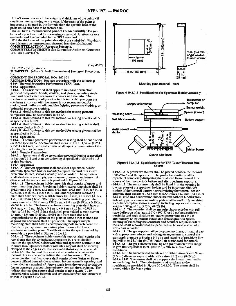
NFPA 1971 - - F96 ROC
I don ' t know how much the weight and thickness of the paint will v , ~ from one repainting to the next. ff the mass of the paint is important to be used in the formula then the specific heat o f the paint would also have to be factored in.
Do you have a r ecommended paint o f known emissiCity? Doyou know of a good method for measuring emissivity? A reference to a method should be included in the NFPA standard.
Will the thickness of the paint also effect the emissivity? Shouldn ' t the thickness be measured and factored into the calculations? COMMITTEE ACTION: Accept in Principle. COMMITTEE STATEMENT: ,See Committee Action on Comment 1971-282 (Log #327).
(Log #327) 1971- 282 - (6-10): Accept SUBMITTER: Jeffrey O. Stull, International Personnel Protection, Inc. COMMENT ON PROPOSAL NO: 1971-21 RECOMMENDATION: Replace procedure with the following: 6-10" Thermal Protective Performance (TPP) Test. 6-10.1 Application. 6-10.1.1 This test method shall apply to multilayer protective garment composites, hoods, wrisdets, and gloves, including single layer knit hood which are worn in contact with the skin. The specimen mount ing configuration in this test which positions the specimen in contact with the sensor is not recommended for station/work uniforms, wildland fire fighting protective clothing, or industrial protective clothin[g. 6-10.1.2 Modifcadons to this test method for testing garmenf composites shall be ,as specified in 6-10.8. 6-10.1.3 Modifications to this test method for testing hoods shall be ,as specified in 6-10.9. 6-10.1.4 Modifications to this test me thod for testing wrisdets shall be as specified in 6-10.10. 6-10.1.5 Modifications to this test me thod for testing gloves shall be as specified in 6-10.11. 6-10.2 Specimens. 6-10.2.1 Thermal protective performance testing shall be conducted on three specimens. Specimens shall measure 6 x 6 ±1/4 in. (152.4 x 152.4 ± 6.4 mm) and shall consist o f all layers representative of the clothing item to be tested. 6-10.3 Sample Preparation. 6-10.3.1 Specimens shall be tested after precondit ioning as specified in Section 6-1.2 and then conditioning as specified in ,Section 6-1.3 of this Standard. 6-10.4 Apparatus. 6-10.4.1" The test apparatus shall consist o f a specimen holder assembly, specimen holder assembly support, thermal flux source, protective shutter, sensor ,assembly, and recorder. The apparatus shall aiso have a gas supply, Kas rommeter, burners, and sensor. A diagranl o f the test apparatns is provided in Figure 6-10.4.1. 6-10.4.1.1 The specimen holder assembly shall consist of upper and lower mount ing plates. Specimen holder maintaining plates shall be 203.2 ram x 203.2 mm, ±1.6 mm, x 6.4 mm, ± 0.8 mm (8 in. x 8 in., ± 0.063 in. x 0.25 in., ± 0.313 in.). The lower specimen mount ing plate shall have centered, a 101.6 m m x 101.6 ram, ± 1.6 mm (4in. x 4 in., ± 0.063 in.) hole. The upper specimen mount ing plate shall have centered a 130.2 mm x 150.2 ram, + 1.6 mm (5.13 in. x 5.13 in., +0.063 in.) hole. The lower specimen mount ing plate shall have a 25.4 nun, + 1.6 mm high, x 3.2 man, +0.8 mm (LOin., +0.063 in. high, x 0.13 in., +0.0313 in.) thick s teeipost welded to each corner 6.4 mm, +1.6 mm (0.25 in., +0.063 in.) f rom each side and perpendicular to the plane of the plate or some other method for ,aligning the specimen shall be provided. The upper sample mounting plate shall have a corresponding hole in each corner so that the upper specimen mount ing plate fits over the lower specimen mount ing plate. Specifications for the specimen holder assembly are provided in Figure 6-10.4.1.1. 6-10.4.1.2 The specimen holder assembly support shall consist of a steel frame that rigidly holds and positions in a reproducible manner the specimen holder assembly and specimen relative to the thermal flux. :Specimen holder assembly support shall be securely clamped at the edges such that specimen shrinkage is prevented. 6-10.4.1.3 The thermal fhix source shall consist of a convective thernaal flux source and a radiant thermal flux source. The convective thermal flux source shall consist o f two Meker or Fisher burners affixed beneath the specimen holder assembly opening, and subtended at a nominal 45 degree angle from the vertical so that the flames converge at a point immediately beneath the specimen. The radiant thermal flux source shall consist o f nine quartz T-150 infrared tubes affixed beneath and centered between the burners as shown in Figure 6-10.4.1.3.
6 in. 052 m m ) . - ~ - ~
E
¢q
tt~ v - v
e -
(2s ram)
Mounting plate material - steel
~A in. (6.4 ram) an~e welded to each corner
J
lrtgure 6-10.4.1.1 Specifications for Specimen Holder Assembly
To recordar or Copper calodmet~r r ~ computer
"~ { ~ Sensor weight I \ . . I I r - s -mr 'if . . . . .
Insulalingboard "iJ • ' ° - - '
T~st fabric-----> , _ . , . . . . " ~ Bottom support
t Water shutterC°°led ~ J~'J "~" ~, F:=:=
c E . ,
Quartz tube bank
Figure 6-10.4.1.3 Specifications for TPP Tester Thermal Flux Source
6-10.4.1.4 A protective shutter shall be placed between the thermal flux source and the specimen. The protective shutter shall be capable of completely dissipating thermal load from thermal flux source of the time periods before and after specimen exposure.
" 6-10.4.1.5 The sensor assembly shall be fitted into the opening in the top plate o f the specimen holder and be in contact with the surface of the thermal barrier normally facing the wearer. Sensor assembly shall consist of 133.4 m m x 133.4 mm x 12.7 mm (5.25 in. x 5.25 in. x 0.5 in.) heat-resistant block that fits without binding into hole of upper specimen mount ing plate shall be uniformly weighted such that complete sensor assembly, including copper calorimeter, weights 1000 g, ±10 g (2.2 Ib, i~.022 lb). 6-10.4.1.6 The recorder shall he any strip chart recorder with full scale deflection of at least 150°C (500°F) or 10 mV and sufficient sensitivity and scale divisions to read exposure time to ± 0.1 s; alternatively, an equivalent automated data acquisition system meeting or exceeding the sensitivity and accuracy requirements of the strip chart recorder shall be permitted to be used instead of a strip chart recorder. 6-10.4.1.7 The gas supply shall be propane, methane, or natural gas with appropriate reducer and waiving arrangements to control the gas supply pressure at 8 psig ± Q.1 psig and capable of providing flow equivalent to 2 L /min (0.07 ft ~ /min) air at standard conditions. 6-10.4.1.8 The gas rotameter shall ~ any gas rotameter with r a n g e to give flow equivalent to 2L (0.07 ft ) / m i n air at standard conditions. 6-10.4.1.9 The burners shall be Meker or Fisher burners with 38 nun (1.5 in.) diameter top and with orifice size of 1.2 mm (0.05 in).
* 6-10.4.1.10 The sensor shall be a copper calorimeter mounted in an insulating block. The calorimeter shall conform to the specificationsprovided in Figure 6-10.4.1.10. The sensor shall be coated with a flat black paint.
421
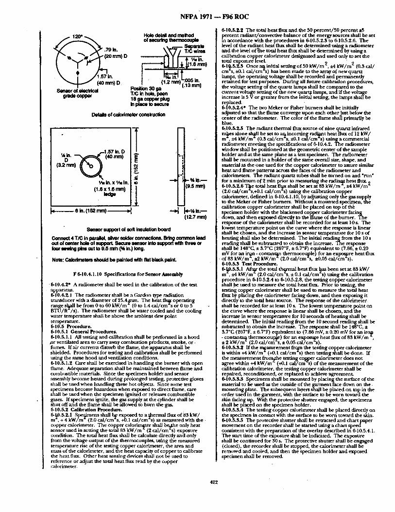
NFPA 1971 - - F96 R O C
\ i / .57 in. (~omm)O
Sensor ofelecldcal
Hole detail and melhod of ~ ~rmocoup~
" ~ . . ~ . . ~1.6 nlm)
Position 30 ga (1.2 mm) (.13 . r~) TIC in hole, 18 gacopper pkJg In place Io secure
De~Is of calorimeter oormtruc~on
(3.2 ram)
~/,, In. x ~/m in. (1.6 x 1.6 ram) lecm
~--- - - - - - - e in. ( 1 ~ ram) . ~ . .
¢1
"~1
/ o!
, .o!
ilO.S mini 1
112.7 mini
Sensor ~zpOort of soft Insulation board
Connect 4T/C in parallel, eUwr 8older connections. ~ common load out of center hole of suppocL Secure sensor into support with three or four ~mvtng pine cut to 9.5 mm (~ in.) long.
Note: Galodrrmlmr8 should be painlod with flat black paint.
F 6-10.4.1.10 Specif ications for SensorAasembly
• 6-10.4.2" A radiometer shall be used in the calibration of the test apparatus. 6-10.4.2.1 The radiometer shall be a Gardon type radiation transducer with a diameter of 25.44mn. The heat flt~ operating range s l~ l be from 0 to 60 kW/m "0 to 1.4 ca l / cm 's or 0 to 5 BTU/ft /s). The radiometer shall be water cooled and the cooling water temperature shall be above the ambient dew point temperature. 6-10.5 Procedure. 6-10.5.1 General Procedures. 6-10.5.1.1 All testing and calibration shall be performed in a hood .or ventilated area to carry away combustion products, smoke, or. fume~ If air currents disturb the flame, the apparatus shall be shielded. Procedures for testing and calibration shall be performed using the same hood and ventilation conditions. 6-10.5.1.2 Care shall be exercised in handling the burner with open flame. Adequate separation shall be maintained between flame and combustible materials. Since the specimen holde'r and sensor assembly become heated during prolonged testing, protective gloves shall be used when handling these hot objects. Since some test specimens become hazardous when exposed to direct flame, care shall be used when the specimen ignited or releases combustible gases. If specimens ignite, the gas supply at the cylinder shall be shut off and the flame shall be allowed to burn the gas. 6-10.5.2 Calibration Procedure. 6-1~0.5.2.1 Specimens shall b¢ exposed to a t~hermal flux of 83 kW/ m , + 4 kW/m (2.0 cal/cm*s, +0.1 cal/cm~s) as measured with the copper calorimeter~ The copper calorimeter shall bed.he only heat sensor used in setting the total 83 kW/m * (2 cal/cm s ~ ) exposure condition. The total heat flux shall be calculate directly and only from the voltage output of the thermocouples, using the measured temperature rise of the testing copper calorimeter, the area and mass of the calorimeter, and the heat capacity of copper to calibrate the heat flux. Other heat sensing devices shall not be used to reference or adjust the total heat flux read by the copper calorimeter.
6-10.5.2.2 The total heat flux and the 50 percent/50 percent 3=5 percent radiant/convective balance of the energy sources shall be set in accordance with the procedures in 6-10.5.2.3 to 6-10.5.2.6. The level of the radiant heat flux shall be determined using a radiometer and the level of~he total heat flux shall be determine~by using a calibration copper calorimeter designated and used only to set the total exposure revel. 2 " 6-1~.5.2.3 Once a~ initial setting of 50 kW/m , ~4 kW/m z (0.3 ca// cm s, 3=0.1 cal/cm s) has been made to the array of new quartz lamps, the operating voltage shall be recorded and permahently retained for test purposes. During all future calibrationprocedures, the voltage setting of the quartz lamps shall be comparedto the current voltage setting of the new quart~ lamps, and if the voltage increase is 5 V or greater from theinitial setting, the lamps shall be replaced. 6-10.5.2.4" The two Meker or Fisher burners shall be initially adjusted so that the flame converge upon each other just below the center of the radiometer. The color of the flame shall primarily be blue. ~10.5.2.5 The radiant thermal flux source of nine quartz infrared tulles alone sl~ll be set to a~ incoming r a d ~ t heat flux of 12 kW/ m , x,-4 kW/m (0.5 cal/cm~s, x'O.1 cal/cm~s) using a commercial radiometer meeting the specifications of 6-10.4.2. The radiometer window shall be positioned at the geometric center of the sample holder and at the same plane as a test specimen. The radiometer shall be mmmted in a holder of the same overall size, shape, and material as the one used for the copper calorimeter to assure similar heat and flame patterns across the faces of the radiometer and calorimeters. The radiant quartz tubes shall be turned on and "run" for a minimum of 2 rain prior to measuring the radiaa, t heat flux. 9 6-10.5.2.6 T~e total heat flp, x shall be set at 83 kW/m ~, 3=4 kW/m ~ (2.0 cal/cm s,+0.1 cal/cm~s) using the calibration copper calorimeter, defined in 6-10.4.1.10, by adjusting only the gas supply to the Meker or Fisher burners. Without a mounted specimen , the calibration copper calorimeter shall be placed on top ofth6 specimen holder with the blackened copper calorimeter facing down, and then exposed directly to the flame of the burner. The response of the calorimeter shall be recorded for at least 10 s. The lowest temperature point on the curve where the response is linear shall be chosen, and the increase in sensor temperature for 10 s of heating shall also be determined. The initial reading from the 10 s reading shall be subwacted to obtain the increase. The response shall be 148°C, 3= 5.7°C (267°F, ± 6.7°F) equivalent to (7.86, 3= 0.20 mV for an iron - contant~,n thermocou, ple) for an expo~re heat flux of 83 kW/m"~ ~=2 kW/m" (2.0 cal/cm~s, ~-0.05 cal /cm's) . 6-10.5.3 Test Procedure. 6-12fl.5.3.1 Aftr2r the total thfdTnal heat flux IJas been set at 83 kW/ m , 3=4 kW/m (2.0 cal/cm~s, + 0.1 cal /cm's) using the calibration procedure in 6-10.5.2.4 to 6-10.5.2.8, the testing copper calorimeter shall .be used to measure the total heat flux. Prior to testing, the testing copper calorimeter shall be tm~d to measure the total heat flux by placing the calorimeter facing down, and then exposing it directly to the total heat source. The response of the calorimeter shall be recorded for at least 10 s. The lowest temperature point on the curve where the response is linear shall be chosen, and the increase in sensor temperature for 10 seconds of heating shall be determined. The initial reading from the 10 second reading shall be subtracted to obtain the increase. The response shall be 148°C, 3= 3.7°C (267°F, 3= 6.7°F) equivalent to (7.86 mV, 3= 0.20 mV for an iro~ - contanta~ thermocoul~e ) for an exposure heat flux of 83 kW/m , 3= 2 kW/m* (2.0 cal/cm~s, 3= 0.05 cal/cm~s). 6-10.5.3.2 If the n~asurement frqln the testing copper calorimeter is within +4 kW/m (+0.1 cal/cms~-) then testing shall be done. If the measurement fron~2tl~e testing COl~per calorimeter does not agree within +4 kW/m (+0.1 cal/cm~s) of the measurement of the calibration calorimeter, the testing copper calorimeter shall be repaired, reconditioned, or replaced to achieve agreement. 6-10.5.3.3 Specimens shall be mounted by placing the surface of the material to be used as the outside of the garment face down on the. mounting plate. The subsequent layers shall be placed on top in the order usedin the garment, with the surface to be worn toward the skin facing up. With the protective shutter engaged, the specimens shall be placed on the specimen holder. 6-10.5.3.4 The testing copper calorimeter shall be placed directly on the specimen in contact with the surface to be worn toward the skin. 6-10.5.3.5 The protective shutter shall be retracted and chart paper movement on the recorder shall be started using a chart s p e e d consistent with the preparation of the overlay described in 6-10.5.4.1. The start time of the exposure shall be indicated. The exposure shall be continued for 30 s. The protective shutter shall be engaged (closed), the recorder shall be stopped, the calorimeter shall be removed and cooled, and then the specimen holder and exposed specimen shall be removed.
422
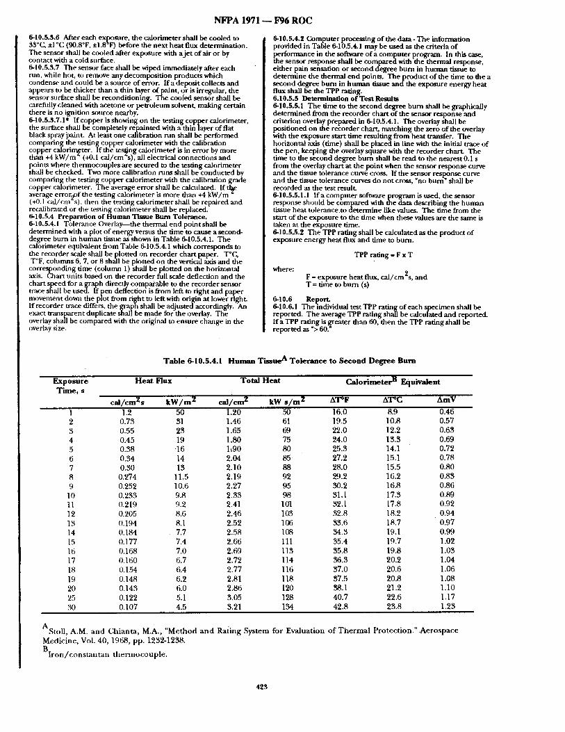
NFPA 1971 - - F96 RO C
6-10.5.3.6 After each exposore, the calorimeter shall be cooled to 33 _~ +1 C (90.8 F, ±1.8 F) before the next heat flux deternunataon. The sensor shall be cooled ,after exposure with a je t of air or by contact with a Cold surface. 6-10.5.3.7 The sensor face shall be wiped immediately ,after each rnn, while hot, to remove any decomposition products which condense and could be a source of error. If a deposit collects and appears to be thicker than a thin layer of paint, or is irregular, the sensor surface shall be reconditioning. The cooled sensor shall be carefiflly cleaned with acetone or petroleum solvent, making certain there is no ignition source nearby. 6-10.5.$.7.1" Ifcopperisshowingon the testing copper calorimeter, the surface shall be completely repainted with a thin layer of flat black spray ]3aint. At least one calibration rnn shall be performed comparinl~ the testing copper calorimeter with the calibration copper calorirr~ter. If the testing calorimeter is in error by more than +4 kW/m (+0.1 cal/cm~s), all electrical connections and points where thermocouples are secured to the testing calorimeter shall be checked. Two more calibration runs shall be conducted by comparing the testing copper calorimeter with the calibration grade copl~er calorimeter. The average error shall be calculated. I f t l~ average error~f the testing calorimeter is more than +4 kW/m ~ (+0.1 cai/cm s), then the testing calorimeter shall be repaired and recalibrated or the testing calorimeter shall be replaced. 6-10.5.4 Preparation of Human Tissue Burn Tolerance. 6-10.5.4.1 Tolerance Overlay--the thermal end point shall be determined with a plot of energy versus the time to cause a second- degree burn in human tissue as shown in Table 6-10.5.4.1. The calorimeter equivalent from Table 6-10.5.4.1 which corresponds to the recorder scale shall be plotted on recorder chart paper. T°C, T°F, columns 6, 7, or 8 shall be plotted on the vertical axis and the corresponding time (column 1) shall be plotted on the horizontal axis. Cahart units based on the recorder full scale deflection and the chart speed for a graph directly comparable to the recorder sensor trace shall be used. lf pen deflection is from left m right and paper movement down the plot from right to left with origin at lower right. If recorder trace differs, the graph shall be adjusted accordingly. An exact transparent duplicate shall be made for the overlay. The overlay shall be compared with the original to ensure change in the overlay fize.
6-10.5.4.2 Ca)mputer processing of the data - The information provided in Table 6-10.5.4.1 may be used as the criteria of p~rforrmance in the software of a computer program. In this case,
e sensor response shall be compared with the thermal response, either pain sensation or second degree burn in human tissue to determine the thermal end points. The product of the time to the a second degree burn in human tissue and the exposure energy heat flux shall be the TPP rating. 6.10.5.5 Determination of Test Results 6-10.5.5.1 The time to the second degree burn shall be graphically determined from the recorder chart of the sensor response and criterion overlay prepared in 6-10.5.4.1. The overlay shall be positioned on the recorder chart, matching the zero of the overlay with the exposure start time resulting from heat transfer. The horizontal axis (time) shall be placed in line with the initial trace of the pen, keeping the overlay square with the recorder chart. The time to the second degree burn shall be read to the nearest 0.1 s from the overlay chart at the point when the sensor response curve and the tissue tolerance curve cross. If the sensor response curve and the tissue tolerance curves do not cross, "no burn" shall be recorded as the test result 6-10.5.5.1.1 Ifa computer software program is used, the sensor response should be compared with the data describing the human tissue heat tolerance to determine like values. The time from the start of the exposure to the time when these values are the same is taken at the exposure time. 6-10.5.5.2 The TPP rating shall be calculated as the product of exposure energy heat flux and time to burn.
TPP rating = F x T
where: F = exposure heat flux, cal/cm 2s, and T = time to burn (s)
6-10.6 Report. 6-10.6.1 The individual test TPP rating of each specimen shall be reported. The average TPP rating shall be calculated and reported. If a TPP rating is greater than riO, then the TPP rating shall be reported as % 60."
Table 6-10.5.4.1 Human Tissue A Tolerance to Second Degree Burn
Exposure Heat Flux Time, s
ca l /cm2s k W / m 2
Total Heat Calorimeter B Equivalent
c a l / c m Z kW s / m 2 ATOF AT°C AmV
1 1.2 50 2 0.73 31 3 0.55 23 4 0.45 19 5 0.38 q6 6 0.34 14 7 0.30 13 8 0.274 11.5 9 0.252 10.6
10 0.233 9.8 11 0.219 9.2 12 0.205 8.6 13 0.194 8.1 14 (I.184 7.7 15 0.177 7.4 16 0.168 7.0 17 0.160 6.7 18 0.154 6.4 19 0.148 6.2 20 0.143 6.0 25 0.122 5.1 30 0.107 4.5
1.20 50 16.0 8.9 0.46 1.46 61 19.5 10.8 0.57 1.65 69 22.0 12.2 0.63 1.80 75 24.0 13.3 0.69 1:90 80 25.3 14.1 0.72 2.04 85 27.2 15.1 0.78 2.10 88 28.0 15.5 0.80 2.19 92 29.2 16.2 0.83 2.27 95 ~'~.2 16.8 0.86 2.33 98 31.1 17.3 0.89 2.41 101 32.1 17.8 0.92 2.46 103 32.8 18.2 0.94 2.52 106 33.6 18.7 0.97 2.58 108 34.3 19.1 0.99 2.66 111 35.4 19.7 1.02 2.69 113 35.8 19.8 1.03 2.72 114 36.3 20.2 1.04 2.77 116 37.0 20.6 1.06 2.81 118 37.5 20.8 1.08 2.86 120 38.1 21.2 1.10 3.05 128 40.7 22.6 1.17 3.21 134 42.8 23.8 1.23
AStoU, A.M. and Chianta , M.A., "Method a n d Ra/ing Medicine, Vol. 40, 1968, pp. 1232-1238.
B I r o n / c o n s t a n t a n t h e r m o c o u p l e .
System for Evaluation of T h e r m a l Protect ion." .Aerospace
423
N F P A 1971 - - F96 R O C
6-10.6.2 The condition o f the specimen shall be reported as specified in 6-10.5.4.3. 6-10.7 Interpretation. 6-10.7.1 Pass or fail determinat ions shall be based on the average reported TPP rating of all specimens tested. 6-10.7.2 If an individual result from any test set varies more than +8 Pdiercent from the average result, the results from the test set shall be
scarded and another set of specimens shall be tested. 6-10.8 Specific Requirements for Testing Garments. 6-10.8.1 Specimens shall consist of outer shell, moisture barrier, and thermal barrier. Winter liners shall not be included in the test composite. Collar lining fabric shall be permit ted to be included in the protective garment collar fabric composite specimen. Specimens shall not include seams. Specimens shall not be stitched to hold individual layers together. 6-10.8.2 Samples for condit ioning shall be at least 1 meter square ( 1 yard square) o f each material. 6-10.8.3 Testing shall be performed as described in paragraphs 6-10.2 through 6-10.7 above.
6-10.9 Specific Requirements for Testing Protective Hoods. 6-10.9.1 Specimens shall consist of materials from the portion of the protective h o o d that covers the neck and facial area. Specimens sh:dl not inch,de seams. Specimens shall not be stitched to hold individual layers together. 6,10.9.2 Samples fi)r conditioning shall include hood material which is a minimum of 178 mm (7 in.) square. 6-10.9.3 Testing shall be performed as described in paragraphs 6-10.2 through 6-10.7 above . 6,10.10 Specific Requirements for Testing Protective Wristlets. 6-10.10.1 Specimens shall consist o f materials from the portion of the protective wristlet that covers the wrist area. Specimens shall no t include seams. Specimens shall not be stitched to hold individual layers together. 6-10.10.2 Samples for conditioning shall include wristlet material which is a minimum of 178 mm (7.0 in.) square. 6-10.10.3 Testing shall be performed as described in paragraphs 6-10.2 through 6-10.7 above.
6,10.11 Specific Requirements for Testing Protective Glove Body Composites and Gauntlets. ' 6,10.11.1 Specimens shall consist of the composite ~,tsed in the actu',d glove construction, with the layers arranged in proper order. Specimens shall not include seanls, where multiple layers are involved. Specimens shall not be stitched to hold individual layers together. 6,10.11.2 S .ambles for condit ioning shall include glove material which is a mimmum of 178 mm (7 m.) square consisting o f the composite used in the actualglove construction, with thee layers ,arranged in p.roper order ands t i t ched using the same thread used in the construcuon of the glove. 6,10.11.3 Testing shall be performed as described in paragraphs 6-10.2 through 6-'10.7 above. A-6-10 The TPP test method described in Section 6-10 is in tended for the measurement of structural fire fighter protective clothing including garment composites, hoods, and gloves. The test me thod is not r ecommended for station/work uniforms and wUdiahd fire fighting protective clothing. A-6,I0.4.1 A TPP device meetin~ these requirements is available from Indecor, Inc., 34 Bevins Dnve, Suite I0, New Castle, DE 19720 (~J2-325-0900). A-6,10.4.1.10 A suitable paint is Medtherm flat black paint having an absorptivity of 0.96 mad temperature rating of 182°( ̀ (350°F) available from Medtherm Corporation, P. O. Box 412, Huntsville, AL 35804 (205-837-2000). A-6,10.4.2 A combination total calor imeter / radiometer Model 64P- 5-24 from Medtherm Corporation, P. O. Box 412, Huntsville, AL 35804 (205-837-2000) has been found satisfactory for this purpose. A-6-10.5.2.4 The convergence of the Meker burners may be checked using a colored piece of flame resistant material and operating the burners for a couple of seconds. The pattern of discoloration on the raaterial should appear to be uniform and in the center o f the specimen. Any non-circular or non-uniform discoloration should be cause for adjusunent of the Meker burners to achieve convergence. A-6-10.5.2.7.1 Copper Calorimeter Calibration Procedures. Calibration of the copper calorimeter is based on the following equath)n:
I = 41.84 - ~ -
where: I is the incident heat flux, kW/m 2, 41.84 is the conversion factor to kW/m 2 from cal/cm2s, d T / d t is the rate of temperature ~ for the calorimeter indicated by mV/°C, and (MC/KAE) represents the calorimeter 's physical constant which includes the variables A, ~, and M.
M, is the finished mass (g) o f the calorimeter which includes the copper disk and flat black paint mass on the sensing surface minus the. thermocou, a plle mass: C, is. the heat capacity, of pure co.ppe r which ts 0.0927 ca l /g °C K, ts the thermocouple converszon constant (0.053 mv/°C) for the TypeJ, Iron-Constantan thermocouple at an average test temperature of 65°C. A, is the surface area (12.49 cm ") for the calorimeter 's front surface which is exposed to the test heat flux. E, is the emissivity or absorptivity of the black paint used on the calorimeter 's f ront surface, usually a value not less than 0.95.
The physical constant used in calibration calculations with these sensors is sensitive to changes in mass a n d / o r emissivity values.
For the copper disk calorimeter used in the TPP test, t h e p u n c h e d out and drill/~d copper slug mass must be between 17.5 a n d l 8 . 0 g to meet the temperature rise over 10 second rate requirement.
The calorimeter 's physl~Cal constant can be calculated based on the above discussion. Check the repaired calorimeter 's performance by substituting it with the calibration calorimeter. After proving equivalence, the test calorimeter may be placed back into service. Copper Calorimeter Repair Procedures. The copper disk may be removed from its support board and checked to ensure that all thermocouple to disk connections are securely made. Any loose connections should be repaired. To repair loose connections, the thermocouple data transfer wire shou l dbe removed, while leaving the short thermocouple wires extending from the sensor's back side. The sensing surface should be smoothed, cleaned and repainted with a qtudity flat black paint o f known emissivity, with a value of no less than 0.95. It may take two or three light coats to completely and evenly cover the surface. After the paint has thoroughly dried, the finished calorimeter should be carefully weighed, and its total mass recorded to an accuracy of 0.01 g. The total mass should include the copper disk mass with the short thermocouple wires attached, and also includes the mass of flat black paint applied to the calorimeter's surface. The calorimeter 's finished mass should be determined by subtracting the sensor's thermocouple wire mass from the sensor's total mass. This is accomplished by measuring the sensor's thermocou[,)le wire lengths from their ends down to the calorimeter s back surface. Then the total wire mass should be calculated based on the number of wires and their lengths. This value should then be subtracted from the total mass of the calorimeter assembly to obtain the finished mass. After the finished mass is determined, the data transfer wires should be securely reconnected, and the sensor repositioned in its support board. SUBSTANTIATION: The Report on Proposals test method contains several errors which are corrected in the new draft. COMMITTEE ACTION: Accept.
(Log #136) 1971- 283 - (6-10.3.i): Accept in Principle SUBMITI'ER: Robert T. Montgomery. Hoechst Celanese C, or p. COMMENT ON PROPOSAL NO: 1(#/1-21 RECOMMENDATION: Delete 6-10.S.1. SUBSTANTIATION: Submitting samples to 1200F for 4 hours then bring them to 70°F for 24 hr isn't required. Washing will be sttfficient preconditioning. COMMITTEE ACTION: Accept in Principle. COMMITTEE STATEMENT: See Committee Action on Comment 1971-282 (Log #327).
(Log #357) 1971- 284- (6-10.3.1): Reject SUBMITrER: Catherine R. Dodgen, Inchcape Testing Services / ETL Testing Laboratories, Inc. COMMENT ON PROPOSAL NO: 1971-21 RECOMMENDATION: Delete 6-10.3.1 in its entirety. SUBSTANTIATION: Conducting the required testing both before and afier laundering (or o ther l~reconditioning) does not provide additional meaningful information to the manufacturer or to the end user; particularly in light o f fact that dual levels o f performance ,are not being proposed. COMMITTEE ACTION: Reject COMMITTEE STATEMENT: Precondit ioning is necessary to assure all materials are tested in a like manner.
(Log #13) 1971- 985 - (6-10.3.2): Reject . " S U B M I ~ Patricia A. Freeman, Globe Manufacturing Co., Inc. COMMENT ON PROPOSAL NO: 1971-21 RECOMMENDATION: Delete ,Section 6-10.3.2 (Laundering as preconditioning).
424
N F P A 1 9 7 1 ~ F 9 6 R O C
SUBSTANTIATION: It has been recognized in the industry that lanndering always increases the TPP ratings of materials currently in use today. Discussions at the technical committee level indicated that the lanndering was a redundant requirement, adding unnecessary expense to the fire'service. COMMITTEE ACTION: Reject. COMMITTEE STATEMENT: See Committee Action on (kgmment 1971-284 (Log #357).
(LOg #390) 1971- 286 - (5-10.4.1.1): Accept in Principle SUBMIqZlTER: Roger L. Barker, Textile Protection & Comfort (:enter COMMENT O N PROPOSAL NO: 1971-21 RECOMMENDATION: Revise the fifth sentence to read:
"...from each side ,and perpendicular to the plane of the plate, or some other method for aligning the sample shall be provided." SUBSTANTIATION: Adding this verbiage allows testing labs to use alternative methods for aligning the sample holder, without affecting test results. COMMITTEE ACTION: Accept in Principle. COMMITTEE STATEMENT: See Cormnittee Action on (2)mment 1971-28`2 (Log #3`27).
( Log #391 ) 1971- 287 - (5-10.4.1.4): Accept in Principle • SUBMITTER: Roger L. Barker, Textile Protection & t_~mfort (:;enter COMMENT ON PROPOSAL NO: 1971-21 RECOMMENDATION: Delete the last sentence:
"the protective sh utter shall be controlled by means of an automatic timer with a resolution of not less than 0.10 sec". SUBSTANTIATION: It is not necessary to control the protective shutter by an atttomatic timer. While this feature is available on most TPP testing units, it is not essential to this testing procedure. COMMITTEE ACTION: Accept in Principle. COMMITTEE STATEMENT: See Committee Action on Comment 1971-28`2 (Log #327).
(Log #392) 1971- `290 - (5-10.4.1.7): Accept in Principle SUBMITTER: Roger L. Barker, Textile Protection & (k, mfort Center COMMENT O N PROPOSAL NO: 1971-21 RECOMMENDATION: Revise text to read:
"the gas st,pply shall be propane, methane or natural gas with appropriate reducer and valving ,arrangements to control the gas supply pressure at 8 psig ± 0.1 psig." SUBSTANTIATION: As long as hea t flux is calibrated, the type of gas used to achieve the exposure is not critical to test results.
Controlling gas pressure at ± O.1 psig provides for tighter gas pressure and appropriate flow control. COMMITTEE ACTION: Accept in Principle. COMMITTEE STATEMENT: See (2Jmmittee Action on Comment 1971-282 (Log #327).
(Log #393) 1971- 991 - (6-10.5 (New)): Accept in Principle SUBMITrER: Roger L. Barker, Textile Protection & Comfort Center COMMENT O N PROPOSAL NO: 1971-21 RECOMMENDATION: Add the following subsection:
"Perform the test in a hood or ventilated area to carry away combustion products, smoke and fumes. If air currents disturb the flame, shield the apparatus. Exercise care in handling the burner with the open flame. Maintain adequate separation between flame and combustible materials. The specimen holder and sensor assembly become heated during prolonged testing. Use protective gloves when handling these hot objects. Some test specimens may be hazardous when exposed to direct flames. Use car when the specimen ignites or releases combustible gases. Shut off the gas supply at the cylinder and allow the flame to burn the gas." SUBSTANTIATION: Appropriate lab safety practice requires averting potential hazards that my be encountered in conducting TPP tests. COMMITTEE ACTION: Accept in Principle. COMMITTEE STATEMENT: See Committee Action on Comment 1971-282 (Log #327).
( l_x~g #356) 1971-288- (6-10.4.1.6): Accept in Principle SUBMITTER: Catherine R. Dodgen, Inchcape Testing Services / ETL Testing Laboratories, Inc. COMMENT O N PROPOSAL NO: 1971-21 RECOMMENDATION: Insert text as foUows:
"The recorder shall be any strip chart recorder with full-scale deflection of at least 150°(2 (300°F) or 10 mV and stffficient sensitivity and scale divisions to read exposure times to ± 0.10 sec; alternatively, an equivalent automated data acquisition system meeting or exceeding the sensitivity and accuracy requirements of the strip chart recorder may be substituted." SUBSTANTIATION: The current language does not recognize advances in technology allowing more accurate determinations using automated dam collection systems which minimizeoperator error and provide better quality of data to the end user, it is impractic~al to mandate a specific method of dam collection which has been surpassed by current technology. COMMITTEE ACTION: Accept in Principle. COMMITTEE STATEMENT: See Committee Action on ( ~ m m e n t 1971-'282 (Log #327).
(Log #26O) 1971- 289 - (5-10.4.1.7): Reject SUBMITI'ER: Denise N. Statham, Southern Mills, Inc. COMMENT ON PROPOSAL NO: 1971-21 RECOMMENDATION: Change "...Liquid Propane or Natural (?,as..." to "...Liquid Propane..." SUBSTANTIATION: One way to minimize variation among labs performing TPP Tests is to specify one gas: Do not offer a choice. COMMITTEE ACTION: Reject. COMMITTEE STATEMENT: See Committee Action on Comment 1971-`282 (Log #327).
(Log #394) 1971- 292 - (5-10.5 (New)): Accept in Principle SUBMITrER: Roger L. Barker, Textile Protection & Comfort Center COMMENT ON PROPOSAL NO: 1971-21 RECOMMENDATION: Add the following subsection:
"Procedures for calibration and for testing specimens shall be performed using the same hood or ventilation conditions." , SUBSTANTIATION: Tests should be performed in a hood or ventilated area to carry away combustion products. Differences in air currents, if they should exist between calibration and testing, could influence results. COMMITTEE ACTION: Accept in Principle. COMMI'VrEE STATEMENT: See Committee Action on Comment 1971-282 (Log #327).
(Log #'261) 1971- 293 - (5-10.5.1.2): Reject SUBMITrER: Denise N. Statham, Southern Mills, Inc. COMMENT O N PROPOSAL NO: 1971-21 RECOMMENDATION: Change "50 percent /50 percent" to "30 percent /70 percent". SUBSTANTIATION: In our round robin experience with the new calibration procedures, we were unable to acl~ieve 1.0 cal /cm 2/sec with the specified radiometer. The highest practical radiant load we achieved was 0.7 cal /cm 2/sec or about a 30/70 mix of radiant and convective heat. To the best o f our knowledge, all TPP testing to date (since 1985), including certification testing, has been ~un using the 30/70 mix. COMMITTEE ACTION: Reject. COMMITTEE STATEMENT: Use of the current calibration
rocedure will provide a ratio of convective to radiant heat in that is to 50.
425
N F P A 1971 - - P 9 6 R O C
(Log #252) 1971- 294- (6-10.5.1.4): Reject SUBMITI'ER: Denise N. Statham, Southern Mills, Inc. COMMENT ON PROPOSAL NO: 1971-21 RECOMMENDATION: Change "...l.0 ca l /cm2/sec" to L..0.7 cal/ cm2/sec ' . SUBSTANTIATION: We were only able to measure 0.7 cal /cm 2 / sec using the specified radiometer. COMMITTEE ACTION: Reject. COMMITTEE STATEMENT: See (k~mmittee Action on Comment 1971-293 (Log #261).
(Log #89) -1971- 295 - (6-10.5.2.1): Accept in Principle SUBMITrER: Hm-ry P. Winer, U.S. Navy COMMENT O N PROPOSAL NO: 1971-21 RECOMMENDA.TION: Delete words "gas purged and".
Deleted sentence will read L..and shall be water cooled. ~ SUBSTANTIATION: The transducer is used only for calibration. A gas purged transducer is for clearing the window when burning a smnple. Here the window remains clean and all you need is a water cooled transducer. COMMITTEE ACTION: Accept in Principle. COMMITTEE STATEMENT: ,See Committee Action on (k:mmlent 1971-282 (Log #327).
(Log #395) 1971-296- (6-10.5.2.1): Accept in Principle SUBMITTER: Roger L. Barker, Textile Protection & Gomfort (:enter COMMENT ON PROPOSAL NO: 1971-21 RECOMMENDATION: Revise to read:
"the radiometer shall be a Gordon type radiation transducer with a diameter of 25.4 mm and a minimum 60 degree view angle. The heat flux operating range shall be from 0 to a minimum of 1.4 cal / cm2/sec (0 to 5 BTU/f t2/sec ."
Delete the remaining verbiage in this section.. SUBSTANTIATION: Apparatus requirements for the radiometer should be peril)finance based rather than written for one pa~cu la r model. Performance is adequately described in terms of transducer diameter, view ,angle and heat flux operating range. COMMITTEE ACTION: Accept in Principle. COMMITTEE STATEMENTz See Committee Action on Comment 1971-282 (Log #327).
(Log #396) 1971- 297 - (6-I0.5.2.6): Accept in Principle SUBMITrF_~ Roger L. Barker, Textile Protection & Comfort Center COMMENT ON PROPOSAL NO- 1971-21 RECOMMENDATION: Revise to read:
"After each exposure, the calorimeter shall be cooled to 32 to 34°C before the next heat flux determination. The sensor shall be cooled ,after exposure with a je t of air or by contact with a cold surface. Do not adjust. The zero setting of the recorder shall not be adjusted." SUBSTANTIATION: Starting temperature of 34°C or less is critical to resnlts. Temperature should be as measured, not indicated by contact with the palm of the hand. COMMITTEE ACTION: Accept in Principle. COMMITTEE STATEMENT: See Committee Action on Gomment 1971-282 (Log #327).
(Log #263) 1971- 298 - (6-10.5.$.4): Reject SUBMITrERx Denise N. Statham, Southern Mills, Inc. COMMENT O N PROPOSAL NO: 1971-21 RECOMMENDATION: Change "The testing copper..." to %ghen the specimen is multilayer, the testing copper calorimeter.., toward the skin. When the specimen is single layer, the sensor is spaced 6.4 nun (1 /4 in.) away fxom the back surface of the specimen." SUBSTANTIATION: We do not believe this to be an issue of how garments are worn or the spacing between the garment and the skin. The TPP is used to test the ability of material to protect the w~arer from a thermal exposure. The TPP test, modified to run without a space has been demonstra ted to give falsely higher "TPP" ratings to fabrics that will contribute to combustion (burn) during an actual thermal exposure. Laboratory data produced over the past 15 years
conclusively shows that only Thermal Protective Performance (TIP) testing run on single layer fabrics with the space gives an accurate evahmtion of their protective capability. When the test is run in a non-spaced confignration it is completed so quickly that potentially dangerous conditions ,are not reflected in e results. Non-spaced test results only reflect the weight of a fabric sample and do not provide affy indication of its thermal stability or propensity to burn.
Full scale manikin testing (installations such as those at the University of Alberta and NC State) is the current state-of-art for replicating actual flashover or flash fire conditions. Data produced in several studies comparing spaced TPP and non-spaced TPP with full scale instrumented manikins repeatedly shows that non-spaced tests have poor or even negative correlations with manikin testing. In other words the non-spaced TPP tests gave higher values to some fabrics that actually provided lower protection when tested on the manikin. Spaced TPP tests on the other hand, because they show the contribution of combustion from some fabrics, have given positive, relatively high correlations to instrumented manikin testing. COMMITTEE ACTION: Reject. COMMITTEE STATEMENT: The Committee believes that only one technique for mounting specimens is appropriate for TPP testing under this standard.
(Log #397) 1971- 299 - (6-10.5.4.1): Accept in Principle SUBMITrER: Roger L Barker, Textile Protection & Comfort Center COMMENT O N PROPOSAL NOz 1971-21 RECOMMENDATION:
Revise to show:
Where: 1 is the incident heat flux, ca l /cm 2/sec: I -~-T I is
the rate o f tempera tn re rise for the calorimeter ind~tedl~Ll by Am.._~V At
SUBSTANTIATION: The conveNio~4184 is not needed since the
TPP is in.units o f ca l /cm 2 . S e c . I,-Ii_~l should be expressed in mV k - )
per sec to have consistent units. COMMITTEE ACTION: Accept in Principle. COMMITTEE STATEMENT: See Committee Action on Comment . 1971-282 (Log #327).
(Log~6) 1971- 300 - (6-10.6.2): Reject SUBMITrER: Robert Hall, Navy Clothing & Textile Research Facility COMMENT O N PROPOSAL NO: 1971-21 RECOMMENDATION: Delete "by one of the" in the second sentence and insert "in the". SUBSTANTIATION: More than one term may be applicable. COMMITTEE ACTION: Reject. COMMITTEE STATEMENT: See Gommittee Action on Comment 1971-282 (Log#327).
(Log #139) 1971- 301 - (6-10.6.2): Reject SUBMITrER: Diane B. Hess, Hoechst Celanese Corporation COMMENT O N PROPOSAL NO: 1971-21 RECOMMENDATION: Change: "Thee f fec to f theexDosuresha l i be described by o n e o f the following terms:..."
Change to: "The effect o f the exposure shall be described by the following terms:..." SUBSTANTIATION: Effect of exposure description should not be limited to one term, several terms maymore accurately describe the specimen. COMMITTEE ACTION: Reject. COMMITFEE STATEMENT: See Committee Action on Comment 1971-282 (Log #327).
426
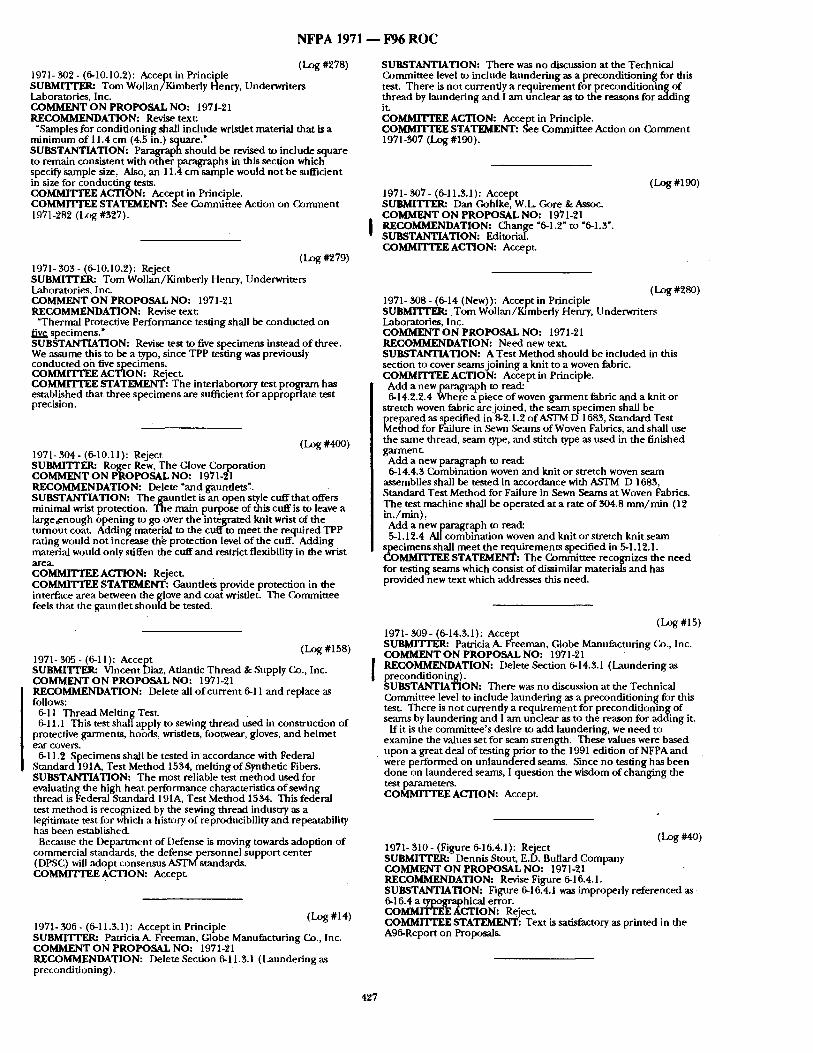
N F P A 1971 - - F96 R O C
(Log #278) 1971- 302 - (6-10110.2): Accept in Principle SUBMITTER: Tom Wollan/Kimberly Henry, Underwriters Laboratories, Inc. COMMENT ON PROPOSAL NO: 197L21 RECOMMENDATION: Revise text:
"Samples for condit ioning shall include wristlet material that is a minimum of 11.4 cm (4.5 in.) square." SUBSTANTIATION: Paragraph should he revised to include square to remain consistent with other paragraphs in this section which specify Sample size, Also, an 11.4 cm sample would not be sufficient in size for conducting tesus. COMMITTEE ACTION: Accept in Principle. COMMrlTEE STATEMENT: See Committee Action on Comment 1971-282 (I~)g #327).
(Log #279) 1971- 303- (6-10.10.2): Reject SUBMITTER: Tom Wollan/Kimberiy Henry, Underwriters Laboratories, Inc. COMMENT ON PROPOSAL NO: 1971-21 RECOMMENDATION: Revise text:
"Thermal Protective Performance testing shall be conducted on five specimens." SUBSTANTIATION: Revise test to five specimens instead of three. We assume this to be a .typo, since TPP testing was previously conducted on five spectmens. COMMITTEE ACTION: Reject. COMMITTEE STATEMENT: The interlabortory test program has estab.l!shed that three specimens are sufficient for appropriate test prectslon.
(Log #400) 1971- 304- (6-10.11): Reject SUBMITrER: Roger Rew, The Glove Corporation COMMENT ON PROPOSAL NO: 1971-21 RECOMMENDATION: Delete "and gauntlets". SUBSTANTIATION: The gauntlet is an open style cuff that offers minimal wrist protection. The main purpose of this cuffis to leave a large,enough opening to go over the integrated knit wrist o f the turnout coat. Adding material to the cuff to meet the required TPP rating would not increase th~ protection level o f the cuff. Adding material would only stiffen the cuff and restrict flexibility in the wrist area. COMMITTEE ACTION: Reject. COMMITTEE STATEMENT: Gauntlets provide protection in the interface area between the glove and coat wristlet. The Committee feels that the ganndet should be tested.
(Log #15s) 1971- 305 - (6-1 l): Accept SUBMITIT.R: Vincent Diaz, Atlantic Thread & Supply Co., Inc. COMMENT ON PROPOSAL NO: 1971-21 RECOMMENDATION: Delete all o f current 6-11 and replace as follows:
6-11 Thread Melting Test. 6-11.1 This test shall apply to sewing thread used in construction of
protective garments, hoods, wristlets, footwear, gloves, and helmet ear covers,
6-1 1,2 Specimens shall b'e tested in accordance with Federal Standard 191A, Test Method 1534, melting of Synthetic Fibers. SUBSTANTIATION: The most reliable test method used for evaluating the high heat performance characteristics o f sewing thread isFederal Standard 191A, Test Method 1534. This federal test method is recognized by the sewing thread industry as a legitimate test for which a history of reproducibility and repeatability has been established.
Because the Depar tment of Defense is moving towards adoption of commercial standards, the defense personnel support center (DPSC) will adopt consensus ASTM standards. COMMITTEE ACTION: Accept.
(Log #14) 1971- 30fi - (6-11.3.1): Accept in Principle SUBMITrER: Patricia A. Freeman, Globe Manufacturing Co., Inc, COMMENT ON PROPOSAL NO: 1971-21 RECOMMENDATION: Delete Section 6-11.3.1 (Laundering as preconditioning).
SUBSTANTIATION: There was no discussion at the Technical Committee level m include laundering as a precondit ioning for this test. There is not currently a requirement for precondit ioning of thread by lanndering and I am unclear as to the reasons for adding it. COMMITTEE ACTION: Accept in Principle. COMMIq[WEE STATEMENT: See Committee Action on Comment 1971-307 (Log #190).
1971- 307 - (6-11.3.1): Accept SUBMITTER: Dan Gohlke, W.L Gore &Assoc. COMMENT ON PROPOSAL NO: 1971-21 RECOMMENDATION: ¢.~ange ~6-1.2" to "6-1.3L SUBSTANTIATION: Editorial. COMMITTEE ACTION: Accept.
(Log #190)
(LOg#280) 1971-308- (6-14 (New)): Accept in Principle SUBMITrER: Tom Wollan/Kimberly Henry, Underwriters Laboratories, Inc. COMMENT ON PROPOSAL NO: 1971-21 RECOMMENDATION: Need new text. SUBSTANTIATION: A Test Method should be included in this section to cover seams joining a knit to a woven fabric. COMMrr'rEE ACTION: Accept in Principle. Add a new paragraph to read: 6-14.2.2.4 Where a piece of woven garment fabric and a knit or
stretch woven fabric are joined, the seam specimen shall be prepared as specified in 8-2.1.2 of ASTM D 1683, Standard Test Method for Failure in Sewn Seams of Woven Fabrics, and shall use the same thread, seam type, and stitch type as used in the finished garment.
Add a new paragraph to read: 6-14.4.3 Gombination woven and knit or stretch woven seam
assemblies shall be tested in accordance with ASTM D 1683, Standard Test Method for Failure in Sewn Seams at Woven Fabrics. The test machine shall be operated at a rate of 304.8 ram/rain (12 in./min)~ Add a new paragraph to read: 5-1.12.4 Allcombinat ion woven and knit or stretch knit seam
Cimens shall meet the requirements specified in 5-1.12.1. MMI'Iq'EE STATEMENT: The Committee recognizes the need
for testing seams which consist of dissimilar materials and has provided new text which addresses this need.
(Log #15) 1971- 309- (6-14.$.1): Accept SUBMITrER: Patricia A. Freeman, Globe Manufacturing Co., Inc. COMMENT ON PROPOSAL NO: 1971-21 RECOMMENDATION: Delete Section 6-14.3.1 (Laundering as preconditioning). SUBSTANTIATION: There was no discussion at the Technical Committee level to include laundering as a precondit ioning for this test. There is not currently a requirement for precondit ioning of seams by laundering and I am unclear as to the reason for adding it.
If it is the committee 's desire to add laundering, we need to examine the values set for seam strength. These values were based upon a great deal of testing prior to the 1991 edition of NFPA and were performed on unlaundered seams. Since no testing has been done on laundered seams, I question the wisdom of changing the test parameters. COMMITTEE ACTION: Accept.
(Log #40) 1971- 310 - (Figure 6-16.4.1): Reject SUBMITrER: Dennis Stout, E.D. Bullard Company COMMENT ON PROPOSAL NO: 1971-21 RECOMMENDATION: Revise Figure 6-16.4.1. SUBSTANTIATION: Figure 6-16.4.1 was improperly referenced a s 6-16.4 a typographical error. COMMITTEE ACTION: Reject. COMMITTEE STATEMENT: Text is satisfactory as printed in the A96-Report on Proposal~
427
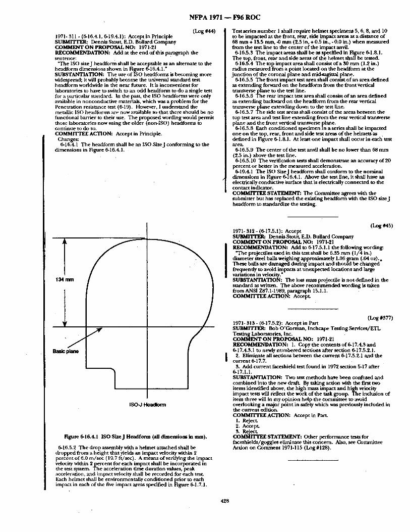
N F P A 1971 - - F96 R O C
(Log #44) 1971- 311 - (6-16.4.1, 6-19.4.1): Accept in Principle SUBMITYER: Dennis Stout, E.D. Bullard Company COMMENT ON PROPOSAL NO: 1971-21 RECOMMENDATION: Add at the end o f this paragraph the sentence:
"The ISO sizeJ headform shall be acceptable as an alternate to the headform d imens ions shown in Figure 6-16.4.1." SUBSTANTIATION: T he use o f ISO headforms is becoming more widespread; it will probably become the universal s tandard test h~ td fo rm worldwide in the near future. It is inconvenient for laboratories to have to switch to an odd headform to do a single test for a p:uticular sh'mdard. In the past, the ISO headforms were only available in nonconduct ive rmaterials, which was a p rob lem for the Penetration resistance test (6-19). However, 1 unde r s t and the metallic ISO headforms are now available so tha t there should be no functional barrier to their use. T he proposed wording would permi t those laboratories now iLsing the older (non-ISO) headforms to cont inue to do so. COMMITTEE ACTION: Accept in Principle.
Changes: 6-16.4.1 The headfo rm shall be an ISO Sizej con fo rming to the
d imens ions in Figure 6-16.4. I.
Test series n u m b e r I shall require he lmet specimens 5, 6, 8, and 10 to be impacted a t the front, rear, side impact areas at a distance o f 68 m m + 13.5 ram, -0 m m (2.5 in, +0.5 in., -0 .0 in.) when measured f rom the test line to the center o f the impact anvil.
6-16.5.3 The impact areas shall be as specified in Figure 6-1.8.1. The top, front, rear and side areas of the he lmet shall be tested.
6-16.5.4 T h e top impact area shall consist o f a 30 m m (1.2 in.) radius measured f rom a point located on the headform at the junc t ion o f the coronal plane and mid-sagittal plane.
6-16.5.5 The f ront impact test a rea shall consLst o f an area def ined as ex tending forward on the headfo rm fTom the f ront vertical transverse plane to the test line.
6-16.5.6 The rear impact test a rea shall consist o f an a rea def ined as ex tending backwardon the headfo rm f rom the rear vertical t ransverseplane ex tend ing down to the test line.
6-16.5.7 The side test areas shall consist o f the areas between the top test area and test line ex tending f rom the rear vertical transverse plane a n d the f ront vertical transverse plane.
6-16.5.8 Each condi t ioned spec imen in a series shall be impacted one on the top, rear, f ront and side test areas o f the helmets as • def ined in Figure 6-1.8.1. At least one impact shall occur in each test area.
6-16.5.9 The center o f the test anvil shall be no lower than 68 m m (2.5 in.) above the test line.
6-16.5.10 The verification tests shall demons t ra te an accuracy o f 20 percent or better in the measured acceleration.
6-19.4.1 The ISO SizeJ headform shall conform to the nomina l d imens ions in Figure 6-16.4.1. Above the test fine, it shall have an electrically conductive Surface tha t is electrically connec ted to the contact indicator. COMMITTEE STATEMENT: The Commit tee agrees with the submit ter bu t has replaced the existing headfo rm with the ISO sizeJ headfo rm to standardize the testing.
1 134mm
1 /
Basic plane
1 ISO-J Heatiform
Figure 6-16.4.1 ISO SizeJ Headform (all dimensions ~ mm).
6-16.5.2 The drop assembly with a he lmet a t tached shall be d ropped f rom a height tha t yields an impact velocity within 2 percent o f 6.0 m / s e c (19.7 f t /sec) . A means o f verifying the impact velocity within 2 p e r c e n t for each impact shall be incorporated in the test system. T he acceleration t ime durat ion values, peak acceleration, and impact velocity shall be recorded for each test. Each he lmet shall be environmental ly condi t ioned prior to each impact in each o f the five impact areas specified in Figure 6-1.7.1.
(Log #45) 1971- 312 - (6-17.5.1): Accept SUBMITrER: Dennis Stout, E.D. Bullard Company COMMENTON PROPOSAL NO: 1971-21 RECOMMENDATION: Add to 6-17.5.1.1 t he following wording:
"The projectiles used in this test shall be 6.35 n u n ( 1 / 4 in.) d iameter steel balls weighing approximately 1.06 g ram (.04 oz ) . , These balls are damaged dur ing impact a n d shou ld be ch an g ed frequently to avoid impacts at unexpec ted locations an d large variations in velocity." SUBSTANTIATION: The loss mass projectile is n o t def ined in the s tandard as written. The above r e c o m m e n d e d wording is taken f rom ANSI Z87A-1989, paragraph 15.1.1. COMMITTEE A C T I O N : A c c e p t .
(Log#S77) 1971- 313 - (6-17.5.2): Accept in Part S U B M r r r E R : Bob O'GornmJa, Inchcape Tes t ingServices /ETL Test ing Laboratories, Inc. COMMENT ON PROPOSAL NO: 1971-21 RECOMMENDATION: I. Copy the contents o f 6-17.4.3 a n d 6-17.4.3.1 to newly n u m b e r e d sections after section 6-17.5.2.1.
2. Eliminate all sections between the cu r ren t 6-17.5.2.1 and the cu r ren t 6-17.7.
3 . Add cur ren t faceshield test f ound in 1972 section 5-17 after 6-17.1.1. SUBSTANTIATION: Two test me thods have been confused an d combined into the new draft. By taking action with the first two i tems identified above, the h igh mass impact a n d h igh velocity impact tests will reflect the work o f the task group. The inclusion of i tem three will in my opinion he lp the commit tee to avoid overlooking a major point in safety which was previously included in the cu r ren t edition. COMMITTEE ACTION: Accept in Part.
1. Reject. 2. Accept. 3. Reject.
COMMITTEE STATEMENT: Other per formance tests for faceshields/goggles el iminate this concern. Also, see Commit tee Action on C o m m e n t 1971-115 (Log #128).
428
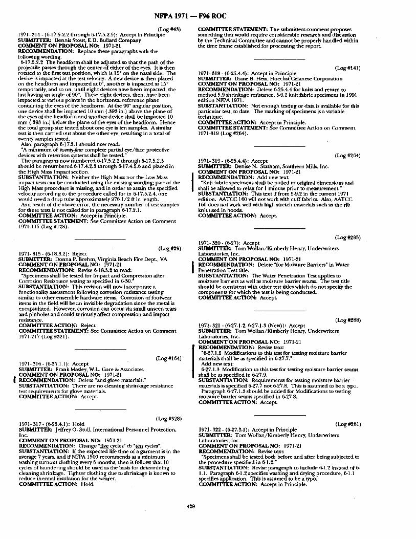
N F P A 1971 - - 13)6 R O C
(Log #43) 1971-314- (6-17.5.2.2 through 6-17.5.2.5): Accept in Principle SUBMI'IWER: Dennis Stout, E.D. Bullard Company COMMENT O N PROPOSAL NO: 1971-21 RECOMMENDATION: Replace these paragraphs with the following wording.
6-17.5.2.2 The headform shall be adjusted so that the path of the projectile passes through the center o f ei ther o f the eyes. It is then rotated to the first test position, which is 15 ° on the nasal side. The device is impacted at the test velocity. A new device is then placed on the headform and impacted at 0 °, another is impacted at 15 ° temporarily, and so on, until e ight devices have been impacted, the last having an mlgle of 90 °. These eight devices, then, have been impacted at v~l-ious points in the horizontal reference plane containing the eyes of the headform. At the 90 ° angnlar position, one device shall be impacted 10 nun (.393 in.) above the plane of the eyes of the headform and another device shall be impacted 10 mm (.393 in.) below thep lane of the eyes of the headform. Hence the total group size tes tedabout one eye is ten samples. A similar test i s then carried out about the o ther eye, resulting in a total of twenty samples tested.
Also, paragraph 6-17.2.1 should now read: "A minimum of t~n~-four complete partial eye/face protective
devices with retention systems shall be tested." Theparagraphs now numbered 6-17.5.2.2 through 6-17.5.2.5
shou ldbe renumbered 6-17.4.2.3 through 6-17.4.2.6 and placed in the High Mass Impact section. SUBSTANTIATION: Neither the High Mass nor the I_¢~w Mass impact tests can be conducted using the existing wording; part o f the High Mass procedure is missing, and in order to attain the specified velocity according to the procedure called for in 6-17.5.2.4, one would need a drop tnbe approximately 976 1/2 ft in length.
As a result of the above error, the necessary number of test samples for these tests is not called for in paragraph 6-17.2.1. COMMITTEE ACTION: Accept in Principle. COMMITTEE STATEMENT: See Committee Action on Gomment 1971-115 (Log #128).
(LOg#29) 1971- 315 - (6-18.3.2): ReJect $UBMITTER: Donna P. Brehm, Virginia Beach Fire Dept., VA COMMENT O N PROPOSAL NO: 1971-21 RECOMMENDATION: Revise 6-18.3.2 to read:
~Specimens shall be tested for Impact and Compression after Gorrosion Resistance testing ,as specified in 6-30. SUBSTANTIATION: This revision will now incorporate a fimctionality a~sessment following corrosion resistance testing similar to other ensemble hardware items. Corrosion offi)otwear items in the field will be an invisible degradation since the metal is encapsulated. However, corrosion can occur via small unseen tears and pinholes and could seriously affect compression and impact resistance. COMMrrTEE ACTION: Reject. COMMITTEE STATEMENT: See Committee Action on Comment 1971-217 ( I_~ #321).
(Log #164) 1971- 316 - (6-25.1.1): Accept SUBMITrER: Frank Masley, W.L. Gore & Associates COMMENT O N PROPOSAL NO: 1971-21
I RECOMMENDATION: Delete "and glove materials." SUBSTANTIATION: There are no cleaning shrinkage resistance test requirements for glove nmterials. COMMITTEE ACTION: Accept.
COMMITTEE STATEMENT: The submitters comment proposes something that would require considerable research anddiscnssion by the Technical Committee and cannot be properly handled within the time frame established for processing the report.
(LOg#141) 1971-318- (6-25.4.4): Accept in Principle SuBMrITER: Diane B. Hess, Hoechst Celanese C~rporatiou COMMENT O N PROPOSAL NO: 1971-21 RECOMMENDATION: Delete 6-25.4.4 for knits and return to method 5.9 shrinkage resistance, 5-9.2 knit fabric specimens in 1991 edition NFPA 1971. SUBSTANTIATION: Not enough testing or data is available for this particular test, to date. The marking of specimens is a variable technique. COMMITTEE ACTION: Accept in Principle. COMMITTEE STATEMENT: See Committee Action on Comment 1971-319 (Log #264).
(Log #264) 1971- $19 - (6-25.4.4): Accept S U B M ~ Denise N. Statham, Southern Mills, Inc. COMMENT O N PROPOSAL NO: 1971-21 RECOMMENDATION: Add new text:
"Knit fabric specimens shall be puUed to original dimensions and shall be allowed to relax for 1 minute prior to measurement. ~ SUBSTANTIATION: This text if f rom 5-9.2 in the current 1971 edition. AATCC 160 will not work with cufffabrics. Also, AATCC 160 does not work well with high stretch materials such as the rib knit used in hoods. C O ~ ACTION: Accept.
(Log#285) 1971- 320 -(6-27): Accept SURMrI ' rEI~ Tom Wollan/Kimberly Henry, Underwriters Laboratories, Inc. COMMENT O N PROPOSAL NO: 1971-21
J RECOMMENDATION: Delete "for Moisture Barriers" in Water Penetration Test title. SUBSTANTIATION: The Water Penetration Test applies to moisture barriers as well as moisture barrier seams. The test title should be consistent with other test tides which do not specify the components for which the test is being conducted. COMMITTEE ACTION: Accept.
(Log#288) 1971-321 - (6-27.1.2, 6-27.1.3 (New)): Accept S U B M I T r E ~ Tom Wollan/Kimberly Henry, Underwriters Laboratories, Inc. COMMENT O N PROPOSAL NO: 1971-21 KECX)MMENDATION: Revise text:
"6-27.1.2 Modifications to this test for testing moisture barrier materials shall be as specified in 6-27.7." Add new text: 6-27.1.3 Modification to this test for testing moisture barrier seams
shall be as specified in 6-27.9. SUBSTANTIATION: Requirements for testing moisture-barrier materials is specified 6-27.7 not 6-27.8. This is assumed to be a typo.
Paragraph 6-27.1.3 should be added for Modifications to testing moisture barrier seams specified in 6-27.8. COMMITTEE ACTION: Accept.
(Log #328) 1971- 317 - (6-25.4.1): Hold SUBMITTER: Jeffrey o . Stull, International Personnel Protection, Inc. COMMENT O N PROPOSAL NO: 1971-21 RECOMMENDATION: ( ~ ange " f i~ cycles" tb "ten cycles'. SUBSTANTIATION: If the expected life time of a garment is in the average 7 years, and if NFPA 1500 recommends as a minimum washing turnout clothing every 6 months, then it follows that 10 cycles o f laundering should be nsed as the basis for determining cleaning shrinkage. Tighter clothing due to shrinkage is known to reduce thermal insulation for the wearer. COMMITTEE ACTION: Hold.
(Log #281) 1971-322- (6-27.$.1): Accept in Principle SUBMFFrER: Tom Wollan/Kimberly Henry, Underwriters Laboratories, Inc. COMMENT O N PROPOSAL NO: 1971-21 RECOMMENDATION: Revise text:
"Specimens shall be tested both before and after being subjected to the procedure specified in 6-1.2. ~ SUBSTANTIATION: Revise paragraph to include 6-1.2 instead of 6- 1.1. Paragraph 6-1.2 specifies washing and drying procedure, 6-1.1 specifies application. This is assumedto be a typo. COMMITTEE ACTION: Accept in Principle.
429
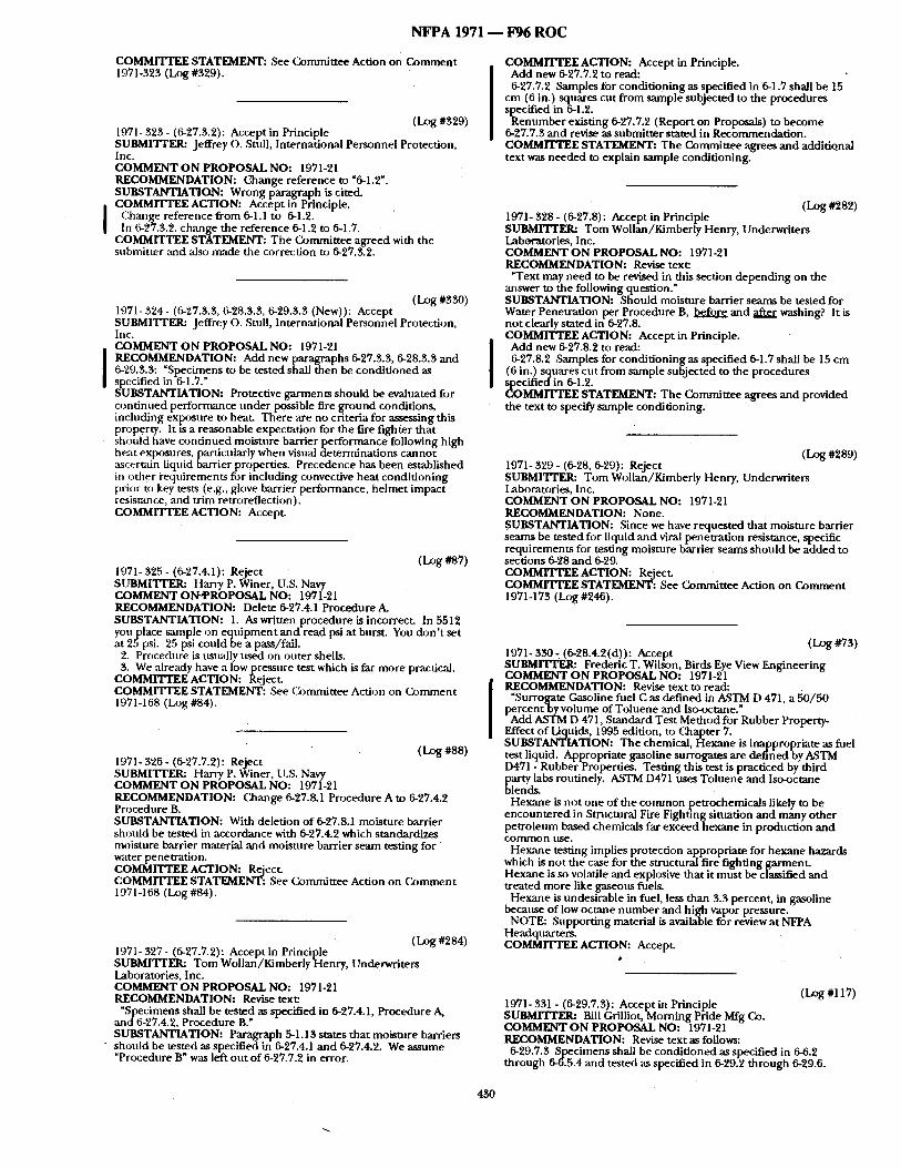
NFPA 1971 - - F96 ROC
COMMITTEE STATEMENT: See Committee Action on Comment 1971-323 (Log #329).
(Log#329) 1971- 323 - (6-27.3.2): Accept in Principle SUBMITTER: Jeffrey O. Stull, International Personnel Protection, Inc. COMMENT O N PROPOSAL NO: 1971-21 RECOMMENDATION: L~ange reference to "6-1.2". SUBSTANTIATION: Wrong paragraph is cited. COMMITTEE ACTION: Accept in Principle.
Change reference fi'om 6-1.1 to 6-1.2. In 6-27.3.2. change the reference 6-1.2 to 6-1.7.
COMMITTEE STATEMENT: The Committee agreed with the submitter and also made the correction to 6-27.3.2.
(Log #330) 1971-324- (6-27.3.3, 6-28.3.3, 6-29.3.3 (New)): Accept SUBMITrER: Jeffrey o. Sttdl, International Personnel Protection, Inc. COMMENT O N PROPOSAL NO: 1971-21 RECOMMENDATION: Add new paragraphs 6-27.3.3, 6-28.3.3 and 6-29.3.3: "Specimens to be tested shall then be conditioned as specified in 6-1.7." SUBSTANTIATION: Protective garments should be evaluated for continued performance under possible fire ground conditions, including exposure to heal Tfiere are no criteria for assessing this property. It is a reasonable expectation for the fire fighter that should have continued moisture barrier performance following high heat exposures, particularly when visual determinations cannot ascertain liquid barrier properties. Precedence has been established in other i'equirements for including convective heat conditioning prior to key tests (e.g., glove barrier performance, helmet impact resistance, and trim retroreflection). COMMITTEE ACTION: Accept
(Log #87) 1971- 325 - (6-27.4.1): Reject SUBMITrER: Harry P. Winer, U.S. Navy COMMENT ONqPROPOSAL NO: 1971-21 RECOMMENDATION: Delete 6-27.4.1 Procedure A. SUBSTANTIATION: 1. As written procedure is incorrect. In 5512 youplace sample on eqnipment and read psi at burst. You don t set at 25psi. 25 psi couldbe a pass/fail.
2. Procedure is usually used on outer shells. 3. We already have a lowpressure test which is far more practical.
COMMITTEE ACTION: Reject. COMMITTEE STATEMENT: See Committee Action on Q)mment 1971-168 (Log #84).
(Log #88) 1971- 326 - (6-27.7.2): Reject SUBMITrER: Harry P. Winer, U.S. Navy COMMENT O N PROPOSAL NO: 1971-21 RECOMMENDATION: Change 6-27.8.1 Procedure A to 6-27.4.2 Procedure B. SUBSTANTIATION: With deletion of 6-27.8.1 moisture barrier should be tested in accordance with 6-27.4.2 which standardizes moisture barrier material and moisture barrier seam testing for water penetration. COMMITTEE ACTION: Reject COMMITTEE STATEMENT: See Gommittee Action on Comment 1971-168 (Log #84).
( Log #284) 1971-327- (6-27.7.2): Accept in Principle SUBMITrER: Tom Wollan/Kimberly Henry, Underwriters Laboratories, Inc. COMMENT O N PROPOSAL NO: 1971-21 RECOMMENDATION: Revise text:
"Specimens shall be tested as specified in 6-27.4.1, Procedure A, and 6-27.4.2, Procedure B." SUBSTANTIATION: Paragraph 5-1.13 states that moisture barriers
" should be tested as specified in 6-27.4.1 and 6-27.4.2. We assume "Procedure B" was left out of 6-27.7.2 in error.
COMMITTEE ACTION: Accept in Principle. Add new 6-27.7.2 to read: 6-27.7.2 Samples for conditioning as specified in 6-1.7 shall be 15
cm (6 in.) squares cut from sample subjected to the procedures specified in 6-1.2.
Renumber existing 6-27.7.2 (Report on Proposals) to become 6-27.7.3 and revise as submitter stated in Recommendation. COMMITTEE STATEMENT: The Committee agrees and additional text was needed to explain sample conditioning.
(Log#282) 1971- 328 - (6-27.8): Accept in Principle SUBMITrER: Tom Wollan/Kimberly Henry, Underwriters Laboratories, Inc. COMMENT O N PROPOSAL NO: 1971-21 RECOMMENDATION: Revise text: "Text may need to be revised in this section depending on the
answer to the following question." SUBSTANTIATION: Should moisture barrier seams be tested for Water Penetration per Procedure B, before and after washing? It is not clearly stated in 6-27.8. COMMITTEE ACTION: Accept in Principle. Add new 6-27.8.2 to read: 6-27.8.2 Samples for conditioning as specified 6-1.7 shall be 15 cm
(6 in.) squares cut from sample subjected to the procedures sl~ecified in 6-1.2. (]oMMrrTEE STATEMENT: The Committee agrees and provided the text to specify sample conditioning.
(Log 0~89) 1971- 329 - (6-28, 6-29): Reject SUBMITTER: Tom Wollan/Kimberiy Henry, Underwriters Laboratories, Inc. COMMENT O N PROPOSAL NO: 1971-21 RECOMMENDATION: None. SUBSTANTIATION: Since we have requested that moisture barrier seams be tested for liquid and viral penetration resistance, specific requirements for testing moisture barrier seams should be added to sections 6-28 and 6-29. COMMITTEE ACTION: Reject CoMMrI 'rEE STATEMENT: See Committee Action on Comment 1971-173 (Log #246).
(Log #73) 1971- 330- (6-28.4.2(d)): Accept SUBMITrER: Frederic T. Wilson, Birds Eye View Engineering COMMENT O N PROPOSAL NO: 1971-21 RECOMMENDATION: Revise text to read:
"Surrogate Gasoline fuel C as defined in ~STM D 471, a 50/50 percent by volume of Toluene and Iso-octane." Add ASTM D 471, Standard Test Method for Rubber Property-
Effect of Liquids, 1995 edition, to Chapter 7. SUI~TANTIATION: The chemical, Hexane is inappropriate as fuel testliquid. Appropriate gasoline surrogates are defined by ASTM D471 - Rubber Properties. Testing this test is practiced by third party labs routinely. ASTM D471 uses Toluene and Iso~ctane blends.
Hexane is not one of the common petrochemicals likely to be encountered in Stnmtural Fire Fighting situation and many other petroleum based chemicals far exceed hexane in production and common use.
Hexane testing implies protection appropriate for bexane hazards which is not the case for the structural fire fighting garment Hexane is so volatile and explosive that it must be classified and treated more like gaseous fuels.
Hexane is undesirable in fuel, less than 3.3 percent, in gasoline because of low octane number and high vapor pressure.
NOTE: Supporting material is available for review at NFPA Headquarters. COMMITTEE ACTION: Accept
(Log #117) 1971- 331 - (6-29.7.3): Accept in Principle S U B M ~ Bill Grilliot, Morning Pride Mfg Go. COMMI~NT O N PROPOSAL NO: 1971-21 RECOMMENDATION: Revise text as follows:
6-29.7.3 Specimens shall be conditioned as specified in 6-6.2 through 6-6.5.4 and tested as specified in 6-29.2 through 6-29.6.
4?,0
N F P A 1971 - - 1796 R O C
SUBSTANTIATION: Moisutre barrier material mus t provide resistance to viral penetrat ion ,after exposure to heat to be ~m effective barrier in the field under actual use. COMMITTEE ACTION: Accept in Principle. COMMITTEE STATEMENT: See Cormnittee Action on C o m m e n t 1971-324 (Log #330).
(I.zgg #12) 1971- 332 - (6-30): Accept in Principle SUBMITI'ER: Patricia A. Freeman, Globe Manufactur ing Co., Inc. COMMENT ON PROPOSAL NO: 1971-21 RECOMMENDATION: 1. Revise 6-30.1.2 to read:
"Modifications to this test for testing ga rmen t hardware shall be as specified in 6-30.7."
2. Renumber remain ing sections so that 6-30.1.3 refers only to glove hardware, ,and each subsequent section moves up one.
3. Section 6-30.7 should be altered to delete reference to gloves, leaving only ga rmen t hardware.
4. Add section 6-30.7.3 to read: "Few ga rmen t hardware testing only, the durat ion of the test shall
be a period o f 20 hours." 5. Add section 6-30.7.4 to read: "Functionality of hardware shall not be evaluated." 6. For consistency sake, it will be necessary to r enumber the
remain ing sections fi~llowing 6-30.7. (i.e., 6-30.8 becomes Specific Requirements for Test ing (;love Hardware; 6-30.9 becomes Specific Requirements for Test ing Helmets and Partial Eye/Face Protective Devices, etc.) SUBSTANTIATION: When the document s were combined, all hardware was to be tested using the same criteria as was used for SCBA units. However, the SCBA did not make reference to light surface corrosion, which would automatically fail the majority of the ga rment hardware in use today. Likewise, it is not possible to de termine the fimcdonality of the various componen t s used in garment construction. (For example, the post of a snap does not t r ac t ion by it~se[f). Therefore, since there appear to be no problems with existing hardware rusting prematurely, the technical commit tee r e c o m m e n d e d a return to the requ i rement currently in NFPA 1971. COMMITTEE ACTION: Accept in Principle.
Revise 6-30.1 to read: "Specimens shall be tested in accordance with AS'TM B 117,... for a
period of 20 hours." Delete pm,'agraph 6-30.4.2. Renumber paragr~tph 6-30.4.3 as 6-30.4.2 and 6-30-4.4 as 6-30.4.3 Revise new paragraph 6-30.4.2 to reference paragraph 6-30.4.2.1.
COMMITTEE STATEMENT: The Commit tee believes that the 48 br salt spray is inappropriate for protective e lement hardware when the pass/fail criteria are based solely on an examinat ion of the hardware specimens fi)r evidence of corrosion.
(Log #379) 1971- 335 - (6-31.4.1 (e)): Accept in Principle SUBMITTER: Bob O 'Gorman , Inchcape Test ing Services/ETL Test ing Laboratories, Inc. COMMENT O N PROPOSAL NO: 1971-21 RECOMMENDATION: Remove "an inverted he lmet to within 1.3 cm, +6 m m of the reference plane" and insert wording as follows:
"an inverted he lmet to a level equal to that o f the dielectric test
~ lane." UBSTANTIATION: This wording would reflect the TIA me thod
balloted earlier this year. COMMITTEE ACTION: Accept in Principle. COMMITTEE STATEMENT: See Commit tee Action on ( ~ m m e n t 1971-192 (Log #383).
(Log #380) 1971 - 336 - (6-31.4.1 (e)): Accept in Principle SUBMITTER: Bob O' (k)rman, Inchcape Tes t ing Services/ETL Test ing Laboratories, Inc. COMMENT ON PROPOSAL NO: 1971-21 RECOMMENDATION: Remove wording after "of sufficient size" and replace with "to completely submerge a complete helmet." SUBSTANTIATION: The cur ren t wording does no t reflect the me thod used in the cur rent "elecwical test #2" and leaves a laboratory unable to properly follow the method. COMMITTEE ACTION: Accept in Principle. COMMITTEE STATEMENT: See Gommit tee Action on (komment 1971-192 (Log #383).
(Log #148) 1971-337 - (6-31.4.3 (New), 6-31.5.1.1): Accept in Principle SUBMITI'ER: Paul H. Crawford, Riverside, CA COMMENT O N PROPOSAL NO: 1971-21 RECOMMENDATION: 1. Add new Sect.ion 6-31.4.3 to read:
6-31.4.3 The he lmet shall be placed on the headform specified in Figure 6-31.5.1.2 and posi t ioned according to the he lmet posit ioning index for this test. After proper posit ioning in accordance with the he lme tpos i t i on ing index , the dielectric test plane specified in Figure 6-31.5.1.2 shall be determined.
2. Revise Section 6-31.5.11 Procedure A to read as follows: At the end of the last sentence add: "and the dielectric test plane"
after "the he lmet posit ioning index." SUBSTANTIATION: The language for the dielectric test plane was approved in Tentative Inter im A m e n d m e n t 1972-TIA-LOG 475. This language was inadvertently left ou t o f the NFPA 1971 A96 Report on Proposals. COMMITTEE ACTION: Accept in Principle. COMMITTEE STATEMENT: See Commit tee Action on C~nunen t 1971-192 (Log #383).
(Log #283) 1971- 333 - (6-30.3): Accept in Principle SUBMITTER: Tom Wollan/Kimber ly Henry, Underwriters Laboratories, Inc. COMMENT ON PROPOSAL NO: 1971-21 RECOMMENDATION: Delete entire section. SUBSTANTIATION: Hardware does not need to be condi t ioned before being placed in a salt sprayI This is a waste o f t ime and money. COMMITTEE ACTION: Accept in Principle.
Revise 6-30.3.1 to read: ~Specimens shall no t be conditioned." Delete 6-30.3.2,
COMMITTEE STATEMENT: Condi t ioning is no t needed for hardware items.
( ~ g #118) 1971- 334 - (6-30.4.1): Accept in Principle SUBMITI'EI~ Bill Grilliot, Morn ing Pride Mfg Co. COMMENT ON PROPOSAL NO: 1971-21 RECOMMENDATION: Change to 20 hr exposure and all else as in cur ren t 1971/91 edition o f standard. SUBSTANTIATION: Current 1971/91 s tandard is satisfactory. Keep it as it is. COMMITTEE ACTION: Accept in Principle. COMMITTEE STATEMENT: See Commit tee Action on C ~ m m e n t 1971-332 (Log #12).
(Log #292) 1971- 338 - (6-31.4.3 (New), 6-31.5.1.1): Accept in Principle SUBMITrER: Panl H. Crawford, Riverside, CA COMMENT O N PROPOSAL NO: 1971-21 RECOMMENDATION: Add new Section 6-31.4.3 to read:
6-31A.3 The he lmet shall be placed on the headform specified in Fignre 6-31.5.1.2 ,and posi t ioned according to the he lmet posit ioning index for this test. After proper posit ioning in accordance with the he lmet posit ioning index, the dielectric test plane specified in Figure 6-31.5.1.2 shall be determined.
Revise Section 6-31.5.1.1 Procedure A to read as follows: At the end of the last sentence add: "and the dielectric test plane"
after "the he lmet posi t ioning index." SUBSTANTIATION: The language for the dielectric test plane was approved in Tentative ln ter im A m e n d m e n t 1972-TIA-LOG 475. This language was inadvertently left ou t of the NFPA 1971 A96 Report on Proposals. COMMITTEE ACTION: Accept in Principle. COMMITTEE STATEMENT: See Commit tee Action on C o m m e n t 1971-192 (Log #383).
(Log #381) 1971, 339 - (6-31.5): Accept in Principle SUBMITTER: Bob O 'Gorman , Inchcape Test ing Services/ETL Test ing Laboratories, Inc. COMMENT O N PROPOSAL NO: 1971-21 RECOMMENDATION: 6-31.5.1 should include all port ions of the d o c u m e n t that ,are now identified in sections 6-31.5.L2 th rough 6-31.5.1.3.
431
"NFPA 1971
Section 6-31.5.1.2 should be changed to only include wording from sections 6-31.5.1.4 through 6-31.5.1.6.
6-31.5. 1.5 after "bolt" add "identified in Figure 6-15.4.1 (b)." SUBSTANTIATION: The first two comments identified above would clarify the two test methods for electrical testing to what I believe was the intention of the helmet task group and the TIA discussed by the committee earlier this year.
The third comment provides guidance since the junct ion bolt is ,an "add on" featnre of the headform. COMMITTEE ACTION: Accept in Principle. COMMITTEE STATEMENT: See Committee Action on (~)nunent 1971-192 (Log #383).
(Log #165) 1971-340- (6-33.5.1): Accept in Principle SUBMITTER: Frank Masley, W.L. Core & Associates COMMENT O N PROPOSAL NO: 1971-21 RECOMMENDATION: Revise text to read: "provided for size extra small and size extra large gloves..." SUBSTANTIATION: The previous wording specifies size small and
_ size large. It was decided by the glove rusk force that glove sizes close '~ to the ends of the scale, specifically sizes extra small and extra large
would be used for testing purposes. COMMITTEE ACTION: Accept in Principle. COMMITTEE STATEMENT: See Committee Action on Comment 1971-351 (Log #169).
(Log #166) 1971- 341 - (6-33.5.3): Accept in Principle SUBMITrER: Frank Masley, W.L. (;ore & Associates COMMENT O N PROPOSAL NO: 1971-21 RECOMMENDATION: Revise text to reach %5 dynes/cm" SUBSTANTIATION: The previous text o f "-24 dynes/cm" is inconsistent with the text in 6-33.4.2 which states "+5 dynes/cm." COMMITTEE ACTION: Accept in Principle.
Change to read: " . . .~ dynes/cm.. ."
COMMrlTEE STATEMENT: The Committee agreed with the submitter and made the appropriate change.
(Log #409) 1971- 342 - (6-34): Accept in Principle SUBMITTER: Ruth Payne, ARTECH Footwear Testing Lab COMMENT ON PROPOSAL NO: 1971-21 RECOMMENDATION: Revise text to read:
6-34 Overall Liquid Integrity Test Two. 6-34.4.1 Protective footwear shall be tested in accordance with
Footwear Industries of America Standard 1209, Appendix B. The level of the water shall be .50 in. above the vamp or throat of the boot. SUBSTANTIATION: None. COMMITTEE ACTION: Accept in Principle.
Revise 6-34.4.1 to read: "Protective footwear shall be tested in accordance with Appendix B
of Footwear Industries of America Standard 1209, Whole Shoe Flex. The level of the water shall be no less than 2.54 cm (1.0 in.) from the lowest point of the throat." COMMITTEE STATEMENT: The Committee agrees with intent o f submitter and will revise.
(Log #410) 1971- 343 - (6-34.4.3, 6-34.4.4): Accept in Principle | SUBMITTER: R u t h Payne, ARTECH FootwearTesting Lab COMMENT O N PROPOSAL NO: 1971-21 RECOMMENDATION: Delete 6-34.4.3 and 6-34.4.4:
"Leather boots which are constructed with a membrane will entrap water between the leather upper and membrane. However, the lining next to the foot is dry. IF the boot is filled with water after flexing it will appear to leak due to the water en t lapped between the membrane anduppe r . The purpose of this test is to prevent the feet from becoming wet and the membrane is performing this task." SUBSTANTIATION: None. COMMITTEE ACTION: Accept in Principle. I COMMrlq'EE STATEMENT: .See Committee Action on Comment 1971-344 (Log #331 ).
F96 ROC
(Log #331) 1971-344- (6-34.4.3, 6-34.4.4, 6-34.5.1, A-6-34.4.3): Accept SUBMITrEI~ Jeffrey o . StuU, International Personnel Protection, Inc. COMMENT ON PROPOSAL NO: 1971-21 RECOMMENDATION: Change paragraphs to read:
6-34.4.3* After flexing, the footwear specimen shall bep laced in a container which allows its immersion in tap water, t reated with a dye ,and surfactant which achieves a surface tension of 34 dynes/cm, :t-4 dynes/cm, to a height not less than 2.54 cm (1.0 in.) from the lowest point of the throat. The paper toweling reqtlired in FIA 1209 shall be placed inside the footwearspecimen such that the paper towling intimately contacts all areas inside the footwear specirhefi to a height not less than 2.54 cm (1.0 in.) from the lowest point o f the throat.
6-34.4.4 After 2.0 hr, + 10 min, the paper towling shall be removed ,and examined for evidence of liquidleakage.
6-34.5.1 The appearance of an); liquid or / the removed paper towling shall be repor ted as failure for the tested specime'n. ~
Add new paragraph to appendix: A-6-34.4.3 A0.1 weight percent ofSurfynol 104H (available from
Air Products and Chemickls, Inc., Performance Chemicals, Box 538, Allentown, PA 18105) with water is reported to provide a surface tension of 33.8 dynes/cm. SUBSTANTIATION: The current does not correctly assess the liquid-tight integrity of the footwear item since it relies on filling the specimen with water. Since the flexing procedure is conducted with a portion of the specimen partially submerged in water, it is possible that water can leak into some portions of the specimen but not the interior. Subsequent release of t rapped water between the barrier and exterior levels can be mistaken for failure of the item under the current procedures. The proposed revisions address evaluation of footwear integrity in a manner consistent with the approach used for gloves and garments. COMMITTEE ACTION: Accept. COMMITTEE STATEMENT: The Committee agreed with the submitter and changes.
(Log #407) 197t-345- (6-$4.5.1): Accept in Principle SUBMITI'ER: Ruth Payne, ARTECH Footwear Testing Lab COMMENT O N PROPOSAL NO: 1971-21 RECOMMENDATION: Revise 6-34.5.1 to read:
"Remove paper towels and inspect for evidence of water leakage." SUBSTANTIATION: None. COMMITTEE ACTION: Accept in Principle. COMMITTEE STATEMENT: ,See Committee Action on Comment 1971-344 (Log #$31).
(Log #26) 1971- 346 - (6-37.4.5): Accept SUBMITFER: Donna P. Brehm, Virginia Beach Fire Dept., VA COMMENT O N PROPOSAL NO: 1971-21 RECOMMENDATION: Revise section 6-57.4.5 to require condit ioning of gloves as specified in section 6-1.10.1, WET conditioning. SUBSTANTIATION: Glove liner pullout is most evident in the field when gloves are wet, especially on the inside from body sweat. This would be a far more challenging test but one that more closely mirrors a real problem in the field. COMMITTEE ACTION: Accept.
(Log #1~7) 1971- 347 - (6-37.4.5): Accept SUBMITTER: Frank Masley, W.L. Gore & Associates COMMENT O N PROPOSAL NO: 1971-21 RECOMMENDATION: Revise text to: "as specified in 6-1.2. ~ SUBSTANTIATION: The previous wording was "as specified in 6-1.1.' The washing and drying procedure is desired as specified in 6-1.2. COMMITTEE ACTION: Accept.
1971- 348 - (6-37.4.5): Accept SUBMITrFA~ Dan Gohlke, W.L Gore & Assoc. COMMENT O N PROPOSAL NO: 1971-21 RECOMMENDATION: Change "6-1.1" to "6-1.2". SUBSTANTIATION: Editorial. COMMITTEE ACTION: Accept.
(L~ #189)
432
N F P A 1971 ~ F 9 6 R O C
1971- 349 - (6-37.4.6): Accept SUBMI'VI'EI~ Dan Gohlke, W.L Gore & Assoc. COMMENT ON PROPOSAL NO: 1971-2I
I RECOMMENDATION: Change ~6-37.4.4 ~ to "6-~7.4.5 ". SUBSTANTIATION: Editorial. COMMITTEE ACTION: Accept.
(Log #188)
(Log #168) 1971- 350- (6-38.2.1): Reject SUBMITTER: Frank Masley, W.L. Core & Associates COMMENT ON PROPOSAL NO: 1971-21 RECOMMENDATION: Revise text to read:
"A m i n i m u m of three glove p,'drs for size extra small and size extra ~ s h a l l be used for testing." SUBSTANTIATION: The previous text required each glove size to be tested. Tha t would require r edundan t testing. Testing o f the size extra small and the size extra large is adequate represent~ition for the liner retention test. COMMITTEE ACTION: Reject. COMMITTEE STATEMENT: See Commit tee Action on Comment s 1971-351 (Log #169) and 1971-206 (Log #413).
(Log #169) 1971- 351 - (6-39.5.2): Accept in Principle SUBMITI'ER: Frank Masley, W.L. Gore & Associates COMMENT ON PROPOSAL NO: 1971-21 RECOMMENDATION: Revise text to: "provided for size extra small and size extra large gloves in..." SUBSTANTIATION: For consistency with the o ther test procedures and to test gloves close to the ends of the scale, the size extra srmall and size extra large were specifically r e c o m m e n d e d by the glove task force. COMMITTEE ACTION: Accept in Principle.
i Change ~extra small" to "small" in paragraphs 6-37-2.1, 6-37.4.1, and 6-39.2.1
Change "extra large" to qarge" in paragraphs 6-37.2.1, 6-37.4.1, and 6-39.2.1 COMMITTEE STATEMENT: The same sizegloves should be used fi)r MI whole glove tests, with the, exception o f dexterity. Two sizes of gh)ves are cofisidered app ro p riate to ~valuate whole g~love performance (except dexterity).
(Log #28) 1971- 352 - (6-40.3.2): Reject SUBMITI'ER: Donna P. Brehm, Virginia Beach Fire Dept., VA COMMENT ON PROPOSAL NO: 1971-21 RECOMMENDATION: Revise 640.3.2 to read:
"Specimens shall be tested for Ladder Shank Bend Resistance after Corrosion Resistance testing as specified in 6-30." SUBSTANTIATION: This revision will now incorporate a functionality assessment following ladder shank bend rexsistance similar to o ther ensemble hardware items. Corrosion of footwear i tems in the f e l d will be an invisible degradation since the metal is encapsulated. However, corrosion could occur via small unseen tears, pinholes and abrasions and could seriously affect ladder shank bend per formance . COMMITTEE ACTION: Reject. COMMITTEE STATEMENT: See Commit tee Action on C o m m e n t 1971-217 (Log #321 ).
( I_x~g #348) 1971- 353 - (6-44.4.1, 6-44.5.1): Accept SUBMITI'EI~ Bob O 'Gorman , Inchcape Test ing Services/ETL Test ing Laboratories, Inc. COMMENT ON PROPOSAL NO: 1971-21 RECOMMENDATION: 6-44.4.1 Thi rd line, remove the word ~and" ,after "of the he lmet shell" and insert "while a t tached to".
6-44.5.1 Second line, remove the words "chin strap" and replace with "Helmet Shell ' . SUBSTANTIATION: If the m e t h o d was per formed as currently written, it would appear that a chin strap retent ion test modif ied to hold the shell f irm was being performed. To test shell breakaway the same fixture can be used but, the force mus t be applied to the shell perpendicular to the reference plane in a direction away f rom the Iine-r and the chin strap (upward). To simply pull on the chin strap is a test of the strap retention system no t always the shell unless we are design specific. COMMITTEE ACTION: Accept.
(Log #46) 1971- 354 - (6-44.5.1): Reject SUBMITTER: Dennis Stout, E.D. Bullard Company COMMENT ON PROPOSAL NO: 1971-21 RECOMMENDATION: C~ange the value "36.5 kg (80 lb)" to "445 N, ±5 N (100 lbf, ±1 IbiS". SUBSTANTIATION: There are two reasons for this proposed change:
1. A Kilogram is not a uni t o f force. "2. The value of 445N is consistent with the Retent ion System Test,
paragraph 6-35.5.'2. COMMITTEE ACTION: Reject. COMMITTEE STATEMENT: 1. The uni t of measure is in tended to be kilograms since the measure is o f a load.
2. Requ i rement is no t the same as chinstrap retention.
(Log #18) 1971- 355 - (6-46.4.1.1): Accept in Principle SUBMITI'ER: Chris topher Gaudette, Reflexite Corporation COMMENT ON PROPOSAL NO: 1971-21 RECOMMENDATION: The following editorial changes should be made in section 6-46.4.1.1:
(c) Emrance angle = -4 degrees (d) The Photoreceptor shall be provided with an ent rance
aper ture of 26 m m (1.024 in.) in diameter. (e) The exit aper ture o f the source shall be circular and 26 m m
(1.024 in.) in diameter. SUBSTANTIATION: These editorial changes are r e c o m m e n d e d based on wording used in the NFPA 1971, ASTM E809, and ASTM E810 documents .
Part (c) should be changed to an ent rance angle of -4 degrees to be consistent with NFPA 1971, 1991 edition. Also, it is a c o m m o n practice to use -4 as an ent rance angle for measurements .
The way the parts (d) and (e) are currently worded in h draft they are saying the same th ing us ing two different ways. ASTlVl E810 uses wording similar to what is provided above for describing the
aratus. IT'I~E ACTION: Accept in Principle.
Accept (c). Revise 6-46.4.1.1 (d) to read: (d) The receiver shall be provided with an ent rance aper ture of 26
m m (1.024 in.), _+_5%, in d iameter which is equivalent to 0.1 ° angular aperu~re.
Revise 6-46.4.1.1 (e) to read: (e) The exit aperture of the source shall be circular and 26 m m
(1.024 in.), +5%, in d iameter which corresponds to 0.1" angular erture.
MMITrEE STATEMENT: The Commit tee agrees with the submit ter but has modif ied the text to conform to s tandards language.
(Log #134) 1971- 356 - (6-46.4.1.1): Accept SUBMITI'ER: Brit Billingsley, 3M COMMENT ON PROPOSAL NO: 1971-21
I RECOMMENDATION: Revise text as follows: " 'The coefficient o f retroreflection (R a) shall be de t e rmined in
accordance with ASTM E809..." SUBSTANTIATION: R1 is no t def ined at all as it is presently written. Ra is calculated in 6-46.4.1.2 us ing R 1 as measured in 6-46.4.1.1 As it is presently written, R a is measured in 6-46.4.1.1 and then calculated in 6-46.4.1.2. COMMITTEE ACTION: Accept.
(Log #29O) 1971- 357 - (6-46.4.1.2): Accept SUBMITI'FJR: Tom Wollan/Kimber ly Henry, Underwriters Laboratories, Inc. COMMENT ON PROPOSAL NO: 1971-21 RECOMMENDATION: Revise texu
~Ar shall be calculated..." SUBSTANTIATION: To remain consistent with equat ion given, A r should appear instead o f Ar. COMMITTEE ACTION: Accept.
433
NFPA 1971 - - F96 RO C
(Log #332) 1971- 358 - (6-46.4.3.2): Accept SUBMITTER: Jeffrey O. Stull, International Personnel Protectionl Inc. COMMENT O N PROPOSAL NO: 1971-21 RECOMMENDATION: In paragra~)h 6-46.4.3.2, replace "while rainfall test is in progress" with "2 minute, ±15 sec ,after the rainfall exposure has been started' . SUBSTANTIATION: The current test me thod does not specify precisely enough the time of measurement. The proposedrevision is consistent with EN 471 upon which the requirement is based. COMMITTEE ACTION: Accept.
(I~)g #16) 1971- 359 - (6-46.4.4): Accept in Principle SUBMITTER: Patricia A. Freeman, Globe Manufacturing O)., Inc. COMMENT O N PROPOSAL NO: 1971-21 RECOMMENDATION: Delete Section 6-46.4.4 which is the Soiling Test. SUBSTANTIATION: Do we really need a test to tell us that soiled trim is not as reflective as unsoiled trim? How will this improve the trim that is currently in the marketplace? Soiling is a condition over
which the mantffacturers of the trim have no control and I believe that if this test is necessary, it would be more appropriate in a Users Guide and not in a minimum performance standard. COMMITTEE ACTION: Accept in Principle. COMMITTEE STATEMENT: See Committe.e Action on Comment 1971-361 (Log #333).
SUBSTANTIATION: The way that the section is currently written may allow someone to interpret the pass/fail criteria based on the average of all the specimens subjected to the procedures specified in 6-46.4.1, 6-46.4,3, ¢~-46.4.4, and 6-46.4.5. This would not allow evaluation of each of the procedures
individually. By no t evaluating the procedures individually, a group of non-conforming specimens may be allowed as a pass since they would be averagedwith groups that performed better through different procedures. COMMITTEE ACTION: Accept.
(Log #352) 1971-363- (6-47.5.1): Accept in Principle SUBMII"rER: Bob O'Gorman, Inchcape Testing Services/ETL Testing Laboratories, Inc. COMMENT O N PROPOSAL NO: 1971-21 RECOMMENDATION: Remove "the size 7 1 /4 headform specified in Fignre 6-16.4.1." and replace with "an ISO sizeJ reference Headform." SUBSTANTIATION: As identified in a previous comment regarding section 4-5.3, the headform identified by the standard does not allow fi)r proper donning of eqtfipment as required by the standard because it only represents thebasic and reference planes and is not anatomically correct. The Reference Headform suggested is of the same dimensions as the ISO impact headform being described in the Report on Proposals drawing. COMMITTEE ACTION: Accept in Principle. COMMITTEE STATEMENT: See Committee Action on Comment 1971-311 (Log #44).
(Log #135 ) 1971- 360 - (6--46.4.4): Hold SUBMITrER: Brit Billingsley, 3M COMMENT O N PROPOSAL NO: 1971-21 RECOMMENDATION: Change referenced soiling test f rom IMO AI6/RES 658 to AATCC Test Method 123-1989. Run time for the | test, five minutes using synthetic soil. [ SUBSTANTIATION: The IMO Test Method is not relevant for trim. | This test method involves coating the Irim with flammable solvents for 24 hour followed by wiping with additional solvents. The IMO Test Method is designed for life rafts and other devices that may wind up soaking in oil-fouled waters for a long period of time.
The AATCC Test Method is proposed as an alternative because it involves a soil and method that is more appropriate fi~r trim. This dirt includes carbon black, iron oxide, andminera l oil. This method involves grinding the dirt into the trim using a ball mill.
NOTE: Supporting material is available fiJr review at NFPA Headquarters. COMMITTEE ACTION: Hold. COMMITTEE STATEMENT: The submitters comment proposes something that wotdd require considerable research and discussion ! by the Technical Committee and cannot be properly handled within I the time frame established for processing the report.
(Log #333) 1971- 361 - (6-46.4.4): Accept SUBMITTER: Jeffrey O. Stull, International Personnel Protection, Inc. COMMENT O N PROPOSAL NO: 1971-21 RECOMMENDATION: Delete procedure for soiling test. Delete references to paragraph 6-46.4.4 in paragraphs 6-46.5.1.6, 6-46.5.2, and 6-46.6.1. SUBSTANTIATION: Insttfficient detail is provided in the current test in order to evaluate the effect o f soiling on trim performance. Moreover, test is inappropriate for measuring wire owing to long contact periods with contaminants and original application of method to buoys. COMMITTEE ACTION: Accept.
(Log #19) 1971- 362 - (6.46.6.1): Accept SUBMITrER: Christopher Gaudette, Reflexite Corporation COMMENT ON PROPOSAL NO: 1971-21 RECOMMENDATION: Section 6-46.6.1 (Interpretation) shotfld be reworded to:
"For tr im retroreflectivity, pass/fail performance shall be determined using the average coefficient of retroreflection (R a) reported for each group of specimens for ~ach of the procedures specified in 6-40.4:1, 6-46.4.3, 6-40.4.4, and 6-46.4.5."
(Log #138) 1971- 364- (6-48): Accept SUBMITTE~ Diane B. Hess, Hoechst Celanese Corporation COMMENT O N PROPOSAL NO: 1971-21 RECOMMENDATION: Need to delete entire Section o f 6-48 Stored Energy Test. SUBSTANTIATION: 1. Neither section or test are referred to f o r performance requirements in document.
2. Very limited number o f labs have actual eqtfipment. Not enough scientific analysis of test method, let alone meaningful results relating to real life scenarios. COMMITTEEACTION: Accept.
(Log #~97) 1971- 365 - (6-48): Accept SUBMITrF.,R: James H. Veghte, Biotherm Inc. COMMENT O N PROPOSAL NO: 1971-21 RECOMMENDATION: Delete the Stored Energy Test (6-48) in its entirety. SUBSTANTIATION: REASONS:
1. There has been insttfficient testing to determine the PASS/FAIL criteria for a dry or wet radiant heat exposure.
Substantiation: 1) O n l y a l i m i t e d n u m b e r o f t u r n o u t e n s e m b l e s have been tested to the SET protocol. 2) The effect of moisture in the turnout ensemble has been limited to wetting the inner thermal liner at only one moisture level (representing a sweating fire fighter). What about the effect of moisture in the shell resulting from fire fighting operations or being nozzle man on the hose? Until a number of protective turnout ensembles are tested under both dry ,and all wet conditions, a realistic PASS/FAIL criteria cannot be established.
2. The radiant load of 0.135 cals/cm2/sec for 5 minutes is unrealistic.
A. A load of 0.23 ca l s / cm2/sec for 1 minute is recommended by Gempol and Burgess (1977) who measured the radiant heat load from transducers mounted on Boston fire fighter's helmets. These radiant loads were measured while fire fighters fotmt 134 structural fires (Ref. Gempel, R.F. and W.A. Burgess 1977. Thermal environment during structural fire fighting. Final.Pt. NFPCA Grant 76010 by Harvard School of Public Health for the National Fire Prevention and Control Administration, Washington, DC.) They found 1) peak total heat flux (radiant) over 0.12 cals/cm Z/sec occurred in only 10 percent of the structural fires. 2) The highest (radiant) flux Observed in all the fires measured was 0.20 ca l /cm~: / sec. 3) Temperatures measured with beat sensitive labels during 1553 fires in Boston indicated 63 percent o f measured surface temperatures on their helmets reached 125°F, 25 percent were 150°F, 6 percent were 175°F and 6 percent were 200°F.
434
N F P A 1971 - - ~96 R O C
The authors concluded: "protective clothing fi~r municipal fire fighters be designed to withstand a radiant heat flux of 0.23 ca l / cm2 / sec for up to 1 minu te without significant degradation."
B. Also, D-nPont's thermocouples on the thermal liners measured average temperatures o f 227°F at the end of the 5 minute
~ reheat ing phase. If the thermal liner had been in contact with the re f ighter 's skin dur ing the preheat ing phase, thermal burns would
have occurred before the actual SET measurements had been taken. 3. The addition of 6 grams of water to the thermal liner or wetted
T-shirt unde r the thermal liner may be excessive. The a m o u n t was de te rmined by the premise that to have 2 grams of water in the T- shirt at the start of the SET procedure, you have to start with 6 grams of water at the start of the 5 minute preheat ing phase.
Substantiation: After the wetted T-shirt SET exposures, the T-shirts were weighed and found to have over 3 grams of water still left in the T-shi rt.
These result should provide enough data to establish a realistic PASS/FAIL criteria for the f imlre NFPA standard.
Based on the above information and the need for a relevant radiant test in the standard, I would suggest future SET R ound Robin tests condit ions to consider:
1. Nominal preheat ing i.e., exposnre to a radiant load o f 1.0 c a l / c m 2 / s e c for 30 seconc(s.
Re,xson: Fire fighters usually are exposed to high radiant loads only as they enter a structure on fire. Clothing temperatures are no t exposed to a high radiant load for 5 minutes before they go in ,and fight the fire. Another point is consider is that TPP slmlples are not preheated before testing.
2. The t u rnou t ensemble be exposed to 0.23 ca ls /cm 2 / sec fi~r 1 minute.
Reason: Based on Gempel ' s findings. 3. Two grams of water are sprayed on individual and collective
layers of the turnouts: (a) ei ther the inside of the thermal liner or innermost layer or on
the T-shirt; (b) on the shell ,alone; and (c) on both the shell and thermal liner or T-shirt.
COMMITTEE ACTION: Accept.
(I~)g #23) 1971- 366 - (6-49); Reject [ SUBMITFER: Andrew E. Pompe, Philadelphia Fire Department , PA I COMMENT ON PROPOSAL NO: 1971-21 RECOMMENDATION: Delete all reference to Liquid Penetration Test. SUBSTANTIATION: If the rest of this s tandard stays intact, having a moisture barrier mee t chemical and viral penet ra t ion resistance testing should suffice in protect ing against b loodborne pathogens. To have a ga rmen t constructed to meet this test is to us, a step backwards. What h a p p e n e d to the concern about heat stress? Since at least over 95 percent of our t ime is spent doing things o ther than "fire fighting", can we assume you have no SCBA or hood on. Wha t
~ rotection against b loodborne pathogens a re we providing for the ead area? Unless we have bloodborne pa thogen resistant helmets ,and hoods,
what good is this test? The primary areas o f possible contaminat ion I th rough bunker gear (not count ing holes) are at the knees, elbows, I shoulders, buttocks and hips, due to compression. Isn ' t the moisture barrier in these areas already tested for liqnid and viral penetrat ion, including the seams?
While this test has the intention o f affording protection to the neck and f ront closure area, what data was it basedon? Have there been reported injuries of infectious disease contaminat ion that occurred ,as a result of a lack of protection at the neck area? How do these statistics stack tip against the injuries caused by hear related problems and heat stress?
The ga rmen t construct ion that this test demands places fire fighters at more risk o f heat stress than they would every have faced from bloodborne pathogens. In addition, if the chemical and viral penetrat ion resistance tests are e l iminated f rom this standard, this | type liquid penetrat ion test should still be removed until fur ther I data can suppor t such a drastic change. Bloodborne pa thogen Ptlrotection should not receive equal consideration to heat stress in
ae design construction of protective clothing for structural fire fighting.
A ga rment having to mee t this design criteria will definitely increase heat stress; but it will no t ~ protect us f rom bloodborne pathogens. COMMITTEE ACTION: Reject. COMMrlq"EE STATEMENT: See Commit tee Action on C o m m e n t 1971-367 (Log #105).
(LOg #105) 1971- 367 - (6-49): Accept in Principle SUBMITI'ER: Bill Grilliot, Morning Pride Mfg Co. COMMENT O N PROPOSAL NO: 1971-21 RECOMMENDATION: Use the liquid penetra t ion test and pass / fail f rom NFPA 1999/92. SUBSTANTIATION: Test me thods and applicable pass/fail interpretat ions should be equal to NFPA 1991/92 - no t more s t r ingent ,as is written in Report on Proposals. COMMITTEE ACTION: Accept in Principle.
Modify 6-49.4.1 (b) to read: "Maniquin used in testing shall be fully upr ight and shall have
straight arms and legs with the arms posit ioned at the maniqu in ' s side.
Delete 6-49.4.1 (c). Delete 6-49.7.2 and 6-49.7.3.
COMMITTEE STATEMENT: Commit tee agreed with submit ter and took the above actions to modify the test method. The Commit tee fi~rther feels that a m i n i m u m requ i rement for liquid penetrat ion resistance of the whole ga rmen t is necessary jus t as there are m i n i m u m requi rements for liquid penetra t ion resistance of the boot and glove elements.
(Log #291) 1971- 368- (6-49): Reject SUBMITrER: Tom Wollan/Kimberly Henry, Underwriters Laboratories, Inc. COMMENT ON PROPOSAL NO: 1971-21 RECOMMENDATION: Delete Watert ight Integrity Test. SUBSTANTIATION: Insufficient background and data to suppor t the test me thod at this time. COMMITTEE ACTION: Reject. COMMITTEE STATEMENT: See Conm~ittee Action on £k)mment 1971-367 (Log #!05).
(Log #186) 1971 - 369 - ( 6-49.4.1 (a) ) : Accept SUBMITrER: [)an Gohlke, W.L. Gore & Assoc. COMMENT ON PROPOSAL NO: 1971-21 RECOMMENDATION: Change "32 d y n e s / c m + 2 dynes /cm" to "35 d y n e s / c m ± 5 dynes /cm". SUBSTANTIATION: When we participated in the round robin of this me thod and followed the mixing procedure for the surfactant we ended u p with a solution that measured 36 to 39 d y n e s / c m varying daybe day. This change would cover our experience and not, in out opinion, effect the ou tcome of the test. COMMITTEE ACTION: Accept.
(Log #184) 1971- 370 - (6-49.10,1): Accept SUBMITTER: Dan Gohlke, W.L. Gore &Assoc. COMMENT O N PROPOSAL NO: 1971-21 RECOMMENDATION: Change "the mannequ in ankles" to "8 in. above the bo t tom of the heel." SUBSTANTIATION: You are not interested in the performance of the ga rmen t for these bot tom 8 in. because it will be covered by the boot. COMMITTEE ACTION: Accept.
(Log #334) 1971- 371 - (6-50): Accept SUBMITTER: Jeffrey o . Stull, International Personnel Protection, Inc. COMMENT ON PROPOSAL NO: 1971-21 RECOMMENDATION: Change title to "eyelet and s tud post a t tachment test". SUBSTANTIATION: Title is inconsistent with o ther titles used for test me thods within standard. COMMITTEE ACTION: Accept.
(Log #74) 1071- 372 - (6-51): Accept SUBMITI'ER: StanleyJ. Shurtleff, Aldan Rubber Co. COMMENT O N PROPOSAL NO: 1971-21 RECOMMENDATION: 6-51 Delete: Tensile a n d substitute Breaking.
435
N F P A 1971 ~ F96 R O C
I 6-51.1.1 Delete: woven ,and substitute: g a ~ e n t outer shell and collar lining.
6-5i.4.1 mid 6-51.5.1 Delete: tensile and substithte: breaking. SUBSTANTIATION: Tensile strength is the breaking load (or force) per unit cross-sectional area of the unstraine&specimen. Breaking strength is the ability or capacity of a specific material to withst~md the ultimate load or fi)rce required for rupture.
In Section 5-1.19, only the outer shell and collar lining are cited. COMMITTEE ACTION: Accept.
(Log #335) 1971- 373 - (6-51.3.1): Accept SUBMITTER: Jeffrey o . Stull, International Personnel Protection, Inc. COMMENT ON PROPOSAL NO: 1971-21
~ RECOMMENDATION: Change "6.1.2.1" to "6-1.2". SUBSTANTIATION: Wrong reference is provided. COMMITTEE ACTION: Accept.
(Log #236) 1971- 377 - (A-3-2.3.4(a)): Accept in Principle SUBMITTER: Robert Tutterow, Charlotte Fire Dept., NC COMMENT ON PROPOSAL NO: 1971-21 RECOMMENDATION: Revise text:
For information on selection, contact: SAFER PPE CARE AND USE GUIDELINES 8920 Limo n ite Ave., # 169 Riverside, CA 92509
or F.I.E.R.O. PPE CARE AND USE GUIDELINES 1029 Lansdowne Road Charlotte, NC 28270
SUBSTANTIATION: More thorough and updated information. COMMITTEE ACTION: Accept in Principle. COMMITTEE STATEMENT: See Committee Action on Comment 1971-378 (Log #231).
(Log #404) 1971- 374- (Appendix (New)): Reject SUBMITFER: Jeffrey o . sufll, International Personnel Protection, Inc. COMMENT ON PROPOSAL NO: 1971-21 RECOMMENDATION: Add a new appendix to standard similar to Appendix C.in NFPA 1991 which lists each requirement, a description of the respective test me thod and the basis for the selected performance criteria. A document will be provided at the Technical Coxpanittee meeting. SUBSTANTIATION: The usefulness o f t h e standard for the end user will be dramatically improved by adding this supplemental infi~rmation. COMMITTEE ACTION: Reject. COMMITTEE STATEMENT: There is no specific text provided to the Committee to consider for inclusion in the Appendix.
(Log #231) 1971- 378- (A-3-2.3.4(a) through (f)): Accept SUBMI'I'rER: Robert Tutterow, Charlotte Fire F)ept-, NC COMMENT O N PROPOSAL NO: 1971-21 RECOMMENDATION: Revise text to read:
User information on care, cleaning, and use of protective clothing and equipment can be obtained from either:
SAFER PPE CARE AND USE GUIDELINES 8920 Limonite Ave., #169 Riverside, CA 92509
or F.I.E.R.O. PPE CARE AND USE GUIDELINES 1029 Lansdowne Road Charlotte, NC 28270
SUBSTANTIATION: More thorough and updated information. COMMITTEE ACTION: Accept.
(Log #237) 1971- 375 - (A-3-1.3.4(0): Accept SUBMITPER: Robert Tntterow, Charlotte Fire Dept., NC COMMENT ON PROPOSAL NO: 1971-21 RECOMMENDATION: Revise text to read:
User information on care, cleaning, and use of protective clothing and equipment can be obtained from either: -
SAFER PPE CARE AND USE GUIDELINES 8920 Limonite Ave., #169 Riverside, (N 92509
or F.I.E.R.O. PPE CARE AN[) USE GUIDELINES 1029 Lansdowne Road Charlotte, NC 28270
SUBSTANTIATION: More thorough and updated information. NOTE: Supporting material is available for review at NFPA
Headqua~ers. COMMITTEE ACTION: Accept.
(Log #230) 1971- 379 - (A-3-3.3.4): Reject SUBMITTER: Robert Tutterow, Charlotte Fire Depc, NC COMMENT O N PROPOSAL NO: 1971-21 RECOMMENDATION: Revise text:
For information on selection, contact: SAFER PPE CARE AND USE GUIDELINES 8920 Limonite Ave., #169 Riverside, CA 92509
or F.I.E.R.O. PPE CARE AND USE GUIDELINES 1029 Lansdowne Road Charlotte, NC 28270
SUBSTANTIATION: More thorough and updated information. COMMITTEE ACTION: Reject. COMMITTEE STATEMENT: Reference is not applicable to 3-3.3.4.
(Log #232) 1971- 376 - (A-3-2.2.1): Reject SUBMITI'ER: Robert Tutterow, Charlotte Fire Dept., NC
C O M M E N T O N PROPOSAL NO: 1971-21 RECOMMENDATION: Revise text:
For information on selection, contac t SAFER PPE CARE AND USE GUIDELINES 8920 Limonite Ave., #169 Riverside, CA 92509
or F.I.E.R.O. PPE CARE AND USE GUIDELINES 1029 Lansdowne Road Charlotte, NC 28270
SUBSTANTIATION: More thorough and updated information. COMMITTEE ACTION: Reject. COMMITTEE STATEMENT: This reference is not applicable to 3-2.2.1.
(Log #235) 1971-380- (A-3-3.3.4(f)): Accept SUBMITTER: Robert Tutterow, Charlotte Fire Dept., NC COMMENT O N PROPOSAL NO: 1971-21 RECOMMENDATION: Revise text to read:
User information on care, cleaning, and use o f protective clothing and equipment can be obtained from either:
SAFER PPE CARE AND USE GLIIDELINES 8920 Limonite Ave., #169 Riverside, CA 92509
or F.I.E.R.O. PPE £2ARE AND USE GUIDELINES 1029 Lansdowne Road Charlotte, NC 28270
SUBSTANTIATION: More ~ o r o u g h and updated information. COMMITTEE ACTION: Accept.
436
N F P A 1971 - - F96 R O C
(Log #229) 1971- 381 - (A-3-4.2.1): Reject SUBMITrER: Robert Tutterow, Charlotte Fire Dept., NC COMMENT ON PROPOSAL NO: 1971-21 RECOMMENDATION: Revise text:
For information on selection, contact: SAFER PPE CARE AN[) USE GUIDELINES 8920 Limonite Ave., #169 Riverside, CA 92509
o r
F.I.E.R.O. PPE CARE AND USE GUIDELINES 1029 Lansdowne Road Charlotte, NC 28270
SUBSTANTIATION: More thorough affd upda ted information. COMMITTEE ACTION: Reject. COMMITTEE STATEMENT: Reference is not applicable to 3-4.2.1.
(IJ)g #226) 1971- 385 - (A-3-5.3.4): Reject SUBMITTER: Robert Tutterow, Charlotte Fire Dept., NC COMMENT O N PROPOSAL NO: 1971-21 RECOMMENDATION: Revise text:
For information on selection, contact: SAFER PPE CARE AND USE GUIDELINES 8920 Limonite Ave., #169 Riverside, CA 92509
or F.I.E.R.O. PPE CARE AND USE GUIDELINES 1029 Lansdowne Road Charlotte, NC 28270
SUBSTANTIATION: More thorough and upda ted information. COMMITTEE ACTION: Reject. COMMITTEE STATEMENT: Reference is no t applicable to 3-5.3.4.
(I_x~g #228) 1971- 382 - (A-3-4.3.4): Reject SUBMITrER: Robert Tutterow, Charlotte Fire Dept., NC COMMENT O N PROPOSAL NO: 1971-21 RECOMMENDATION: Revise text:
For information on selection, contact: SAFER PPE CARE AND USE GUIDELINES 8920 Limonite Ave., #169 Riverside, CA 92509
o r
F.LE.R.O. PPE CARE AN[) USE GUIDELINES 1029 Lansdowne Road Charlotte, NC 28270
SUBSTANTIATION: More thorough and upda ted information. COMMITTEE ACTION: Reject. COMMITTEE STATEMENT: Reference is no t applicable to 3-4.3.4.
(Log #225) 1971- 386 - (A-4-1): Accept SUBMITrER: Robert Tutterow, Charlotte Fire Dept., NC COMMENT ON PROPOSAL NO: 1971-21 RECOMMENDATION: Add to A-4-1:
Additional user information on selection'can be obta ined f rom either:
SAFER PPE (ARE AND USE GUIDELINES 8920 Limonite Ave., #169 Riverside, CA 92509
or F.I.E.R.O. PPE CARE AND USE GUIDELINES 1029 Lansdowne Road Charlotte, NC 28270
SUBSTANTIATION: More thorough and upda ted information. COMMITTEE ACTION: Accept.
(Log #233) 1971- 383 - (A-3-4.3.4(a)): Accept SUBMITTER: Robert Tutterow, Charlotte Fire Dept., NC COMMENT ON PROPOSAL NO: 1971-21 RECOMMENDATION: Revise text to read:
User information on care, cleaning, and use of protective clothing and e q u i p m e n t can be obta ined f rom either:
SAFER PPE CARE AND USE GUIDELINES 8920 Limonite Ave., # 169 Riverside, CA 92509
OF
F.I.E.R.O. PPE (2ARE AN[) USE GUIDELINES 1029 Lansdowne Road Charlotte, NC' 28270
SUBSTANTIATION: More thorough ~md updated information. COMMITTEE ACTION: Accept.
(Log #227) 1971- 384- (A-3-4.3.7): Reject SUBMITFER: Robert Tutterow, Charlotte Fire Dept., NC COMMENT ON PROPOSAL NO: 1971-21 RECOMMENDATION: Revise text:
For information on selection, contact: SAFER PPE CARE AND USE GUIDELINES 8920 Limonite Ave., # 169 Riverside, CA 92509
o r
F.I.E.R.(). PPE CARE AND USE GUIDELINES 1029 La0sdowne Road Charh)tte, NC 28270
SUBSTANTIATION: More thorough and updated information. COMMITTEE ACTION: Reject.. COMMITTEE STATEMENT: Reference is no t applicable to 3-4.3.7.
(Log #234) 1971- 387 - (A-4-1.2): Accept in Principle SUBMITI'ER: Robert Tutterow, Charlotte Fire Dept., NC COMMENT ON PROPOSAL NO: 1971-21 RECOMMENDATION: Revise text:
For information on selection, contact: SAFER PPE CARE AND USE GUIDELINES 8920 Limonite Ave., #169 Riverside, CA 92509
o r
F.I.E.R.O. PPE (kARE AND USE GUIDELINES 1029 Lansdowne Road Charlotte, NC 28270
SUBSTANTIATION: More thorough and upda ted information. COMMITTEE ACTION: Accept in Principle. COMMITTEE STATEMENT: See Commit tee Action on C o m m e n t 1971-386 (Log #225) which covers all of Section 4-1.
(Log #224) 1971- 388 - (A-4-1.3): Accept in Principle SUBMITTER: Robert Tutterow, Charlotte Fire Dept., NC COMMENT O N PROPOSAL NO: 1971-21 RECOMMENDATION: Revise text:
For information on selection, contact: SAFER PPE CARE AND USE GUIDELINES 8920 Limonite Ave., #169 Riverside, CA 92509
or F.I.E.R.O. PPE CARE AND USE GUIDELINES 1029 Lansdowne Road Charlotte, NC 28270
SUBSTANTIATION: More thorough and upda ted information. COMMITTEE ACTION: Accept in Principle. COMMITTEE STATEMENT: See Commit tee Action on C2~mment 1971-386 (Log #225) which covers all of Section 4-1.
437
N F P A 1971 - - F96 R O C
(Log #223) 1971- 389 - (A-4-1.7): Accept in Principle SUBMITYER: Robert Tutterow, Charlotte Fire Dept., NC COMMENT ON PROPOSAL NO: 1971-21 RECOMMENDATION: Revise text:
For information on selection, contact: SAFER PPE CARE AND USE GUIDELINES 8920 Limonite Ave., #169 Riverside, CA 92509
o r
F.I.E.R.O. PPE ( ~ R E AND L!SE GUIDELINES 1029 Lansdowne Road
• Charlotte, NC 28270 SUBSTANTIATION: More thorough and updated information. COMMITTEE ACTION: Accept in Principle. COMMITTEE STATEMENT: See (k)mmittee Action on Comment 1971-386 (Log #225) which covers ,all of Section 4-1.
(Log #220) 1971- 393 - (A-4-1.14.2): Accept in Principle SUBMITrER: Robert Tutterow, Charlotte Fire Dept., NC COMMENT O N PROPOSAL NO: 1971-21 RECOMMENDATION: Revise text:
For information on selection, contac t ,SAFER PPE CARE AND USE GUIDELINES 8920 Limonite Ave., #169 Riverside, C_A 92509
o r
F.I.E.R.O. PPE CARE AND I.ISE GUIDELINF~S 1029 Lansdowne Road. Charlotte, NC 28270
SUBSTANTIATION: More ~horough and updated information. COMMITTEE ACTION: Accept in Principle. COMMITTEE STATEMENT: See Committee Action on Comment 1971-386 (Log #225) which covers all o f Section 4-1.
(Log #222) 1971- 390 - (A-4-1.11): Accept in Principle SUBMITTER: Robert Tutterow, Charlotte Fire Dept , NC COMMENT O N PROPOSAL NO: 1971-21 RECOMMENDATION: Revise text:
For information on selection, contact: , SAFER PPE (~,RE AND USE GUIDELINES 8920 Limonite Ave., #169 Riverside, (LA 92509
o r
F.I.E.R.O. PPE CARE AND USE GUIDELINES 1029 Lansdowne Road Charlotte, NC 28270
SUBSTANTIATION: More thorough and updated information. COMMITTEE ACTION: Accept in Principle. COMMITTEE STATEMENT: See Committee Action on Comment 1971-386 (Log #225) which covers all of Section 4-1.
(Log#221) 1971- 391 - (A-4-1.12): Accept in Principle SUBMITI'ER: Robert Tutterow, Charlotte Fire Dept., NC COMMENT O N PROPOSAL NO: 1971-21 RECOMMENDATION: Revise text:
For information on selection, contac t SAFER PPE (;ARE AND USE GUIDELINLS 8920 Limonite Ave., #169 Riverside, CA 92509
o r \ F.I.E.R.O. PPE (~kRE AN[) USE CUIDELINES 1029 Lansdowne Road C, hariotte, NC 28270
SUBSTANTIATION: More thorough and updated information. COMMITTEE ACTION: Accept in Principle. COMMITTEE STATEMENT: See Committee Action on Comment 1971-386 (Log #225) which covers all of Section 4-1.
(Log #63) 1971- 392- (A-4-1.14.2): Reject SUBMITTER: BarrieJ. Lough, City of Winnipeg Fire Dept., Canada COMMENT O N PROPOSAL NO: 1971-21 RECOMMENDATION: Delete the complete paragraph of A-4-1.14.2. SUBSTANTIATION: Move to Section 4 to lower potential for hum injury. COMMITTEE ACTION: Reject. COMMITTEE STATEMENT: It is necessary to keep this advisory information in the appendix to inform readers of possible options. Also see Committee Action on Comment 1971-129 (Log #62).
(Log #175) 1971- 394 - (A-4-1.14.5): Reject SUBMI'VrEP~ Donald Aldridge, Lion Apparel,-Inc. COMMENT O N PROPOSAL NO: 1971-21 RECOMMENDATION: Add between "front off - "and back": New text will read: "front and back of..." SUBSTANTIATION: Field experience has shown injury to the fire fighter occurs in the rear shoulder area where trim is applied vertically and has been exposed to very high temperatures or flame. COMMITTEE ACTION: Reject. COMMITTEE STATEMENT: See Committee Action on Comment 1971-104 (Log #170).
(Log #219) 1971- 395 - (A-4-1.14.5): Accept in Principle SUBMITrER: Robert Tutterow, Charlotte Fire Dept., NC COMMENT ON PROPOSAL NO: 1971-21 RECOMMENDATION: Revise text:
For information on selection, contact: ,SAFER pPE (?ARE AND USE GUIDELINES 8920 Limonite Ave., #169 Riverside, CA 92509
F.I.E.R.o. or PPE CARE AND USE GUIDELINES 1029 Lansdowne Road Charlotte, NC 28270
SUBSTANTIATION: More thorough and updated information. COMMITTEE ACTION: Accept in Principle. COMMITTEE STATEMENT: See Committee Action on Comment 1971-386 (Log #225) which covers all of Section 4-1.
(LOg #218) 1971- 396 - (A-4-1.15.1): Accept in Principle SUBMITYER: Robert Tuttero~¢, Charlotte Fire Dept., NC COMMF.~T O N PROPOSAL NO: 1971-21 RECOMMENDATION- Revise text:
For information on selection, contact: SAFER PPE CARE AND USE GUIDELINES 8920 Limonite Ave., #169 Riverside, CA 92509
or F.I.E.R.O. PPE (L~,.E AND USE GUIDELINE,S 1029 Lansdowne Road Charlotte, NC 28270
SUBSTANTIATION: More thorough and updated information. COMMITTEE ACTION: Accept in Principle. COMMITTEE STATEMENT: See Committee Action on Comment 1971-386 (Log #225) which covers all of Section 4-1.
438
N F P A 1971 ~ F06 R O C
(Log #174) 1971- 397 - (A-4-1.15.3): Reject SUBMITTER: l-)on:dd Aldridge, Lion Apparel, Inc. C O M M E N T O N PROPOSALNO: 197f-21 RECOMMENDATION: Add new text to read:
"Vertical t r im applied to a ga rmen t has been shown to cause injt, ry to the fire fighter iuhen exposed to very high tempera tures or flame. Dmnage to the protective ga~nen t when vertical t r im is destroyed ex tend far beyond the actual lengtl) of the trim. Al though the area covered by the trim seems to afford a h igher level o f pro~ection to the wearer the area jus t above the vertical t r im does not." SUBSTANTIATION: None. COMMITTEE ACTION: Reject. COMMITTEE STATEMENT: See Commit tee Action on Conunen t 1971-104 (Log #170).
(Log #217) 1971-398- (A-4-1.15.3): Accept in Principle SUBMITTER: Robert Tutterow, Charlotte Fire Dept., NC COMMENT ON PROPOSAL NO: 1971-21 RECOMMENDATION: Revise text:
For information on selection, contact: SAFER PPE CARE AN[) USE GUIDELINES 8920 Limonite Ave., #169 Riverside, CA 92509
or F.I.E.R.O. PPE CARE AND USE GUIDELINES 1029 Lansdowne Road Charlotte, NC 28270
SUBSTANTIATION: More thorough and upda ted irfformation. COMMITTEE ACTION: Accept in Principle. COMMITTEE STATEMENT: See (2~mmittee Action on C o m m e n t 1971-386 (Log #225) which covers all of Section 4-1.
(Log #197) 1971- 401 - (A-6-10): Accept in Principle SUBMITTER: Robert D a h l / T h o m a s Neal, DuPont Advanced Fibers Systems COMMENT ON PROPOSAL NO: 1971-21 RECOMMENDATION: I propose modifying the last sentence o f Section A-6-10 to read as follows:
"This specimen moun t ing procedure in which the specimen is m o u n t e d in contact with the sensor is no t r e c o m m e n d e d for station uniforms, wildland fire f ighting clothing or industrial protective clothing." SUBSTANTIATION: This modification clarifies the section by indicating exactly what part of the TPP test me thod is no t r e c o m m e n d e d for station uniforms, wildland fire fighting clothing and industrial protective clothing. COMMITTEE ACTION: Accept in Principle. COMMITTEE STATEMENT: See Commit tee Action on C o m m e n t 1971-282 (Log #327).
(Log #258) 1971-402 - (A-6-10): Accept in Principle in Part SUBMITI'ER: M.T. Stanhope, Southern Mills, Inc. COMMENT ON PROPOSAL NO: 1971-21 RECOMMENDATION: Add new text:
"The TPP test me thod as described in section 6-10 is to be used ... multilayer laminates and protective hoods. The spaced m o u n t i n g system as described in A~STM D 4-108-87 should b~ used for single layer materials used in station uniforms, wildland fire fighting clothing or industrial protective clothing." SUBSTANTIATION: The text as written is no t clear. The replacement text will insure that future readers unders tand the intent o f the committee. COMMITTEE ACTION: Accept in Principle in Part. COMMITTEE STATEMENT: See Commit tee Action on C o m m e n t 1971-282 (Log #327).
(Log#216) 1971- 399 - (A-4-2.2): Accept SUBMITTF.~ Robert Tutterow, Charlotte Fire Dept., NC COMMENT ON PROPOSAL NO: 1971-21 RECOMMENDATION: Add to A-4-2.2:
Additional user information can be obtained f rom either: SAFER PPE ([2ARE. ANID USE GUI1-)ELINES 8920 Limonite Ave., #169 Riverside, CA 92509
or F.I.E.R.O. PPE CARE AN[) USE GUIDELINES 1029 Lansdnwne Road Charlotte, NC 28270
SUBSTANTIATION: More thorough and upda ted information. COMMITTEE ACTION: Accept.
(Log #215) 1971- 400 - (A-4-2.6): Accept SUBMITFER: Robert Tutterow, Charlotte Fire Dept., NC COMMENT ON PROPOSAL NO: 1971-21 RECOMMENDATION: Add to A-4-2.6:
Additional user information can be obtained f rom either: SAFER PPE CARE AN[} USE GUIDELINES 8920 Limonite Ave., # 169 Riverside, CA 92509
or F.I.E.R.O. PPE CARE AN[) USE GUIDELINES 1029 Lamsdowne Road Charlotte, NC 28270 SAFER PPE ( ~ R E AND USE GUIDELINES 8920 Limonite Ave., # 169 Riverside, CA 92509
or F.I.E.R.O. PPE CARE AND USE GUIDELINES 1029 Lansdowne Road Charlotte, NC 28270
SUBSTANTIATION: More thorough and upda ted information. COMMITTEE ACTION: Accept.
(Log #259) 1971- 403 - (A-6-10): Reject SUBMITrER: Denise N. Statham, Southern Mills, Inc. COMMENT ON PROPOSAL NO: 1971-21 RECOMMENDATION: Delete A-6-10 TPP entirely. SUBSTANTIATION: Please see substantiation for 6-10.5.3.4. Spaced TPP configuration should always be used for single layer fabrics. COMMITTEE ACTION: Reject. COMMITTEE STATEMENT: See Commit tee Action on C o m m e n t 1971-282 (Log #327).
(Log #176) 1971- 404- (Appendix B): Accept SUBMITrEI~ Donald Aldridge, Lion Apparel, Inc. COMMENT O N PROPOSALNO: 1971-21 RECOMMENDATION: Delete the entire Appendix B. SUBSTANTIATION: This is no t the proper use o f the appendix. Appendix material should be used to explain text or give examples of requirements in the document . There is no requ i rement in the d o c u m e n t which this appendix supports or explains. COMMITTEE ACTION: Accept.
1971- 405 - (Appendix B): Accept in Principle SUBMITTER: Dan Gohlke, W . L Gore & Assoc. COMMENT ON PROPOSAL NO: 1971-21 RECOMMENDATION: Editorial Corrections
Appendix B
2. add "transfer" after "heaC. 6. the units for Rct are "°C m2 /W" . 9. make "soecimens" sintmlar. 10b. change ~ ° C / m 2 / W " t~)"°C m 2 / W ". 10d change " ° C / m Z / W " to "°C m Z / W ". 10d delete NOTE 13 NOTE change "°C/m2/W" to "°_C m2/W ".
change "kPa lm 2/W" to "kPa m,~/W". change "Olin, Ecusta Paper and Film Group, "Flexel, Inc., Atlanta, GA 30346".
15. the correct equat ion is:
(Log #183)
NC 28768: to
439
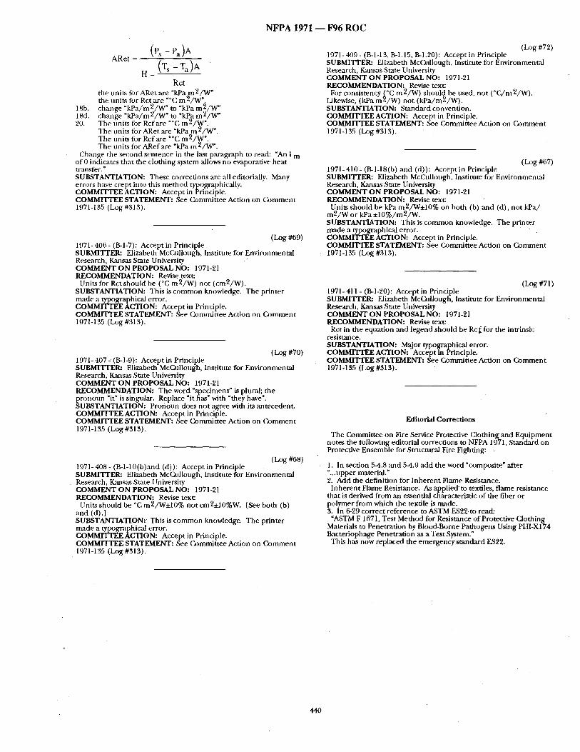
N F P A 1971 - - F96 R O C
(Ps - Pa) A ARet =
H (Ts - Ta)A
Rot the units for ARet are "kPa m2/W" the units for Rct are "°C m2/W".
18b. change "kPa/m2/W" to"kPa m2/W" 18¢t. change "kPa/m2/W" to "kPa m2/W" 20. The Units fi)r Rcf are "°C m 2/W".
The unim for ARet are "kPa mE/W ". The units fi)r Rcf are "°C m2/W ". The units fi)r ARef are "kPa m2/W ".
Change the second sentence in the last paragraph to read: "An i m of 0 ifidicates that the clothing system ,allows no ewaporative heat transfer." SUBSTANTIATION: These corrections are all editorially. Many errors have crept into this method typographically. COMMITTEE ACTION: Accept inPrinciple. COMMITTEE STATEMENT: See (~k)mmittee Action on (k)nmlent 1971-135 (Log #313).
(Log #69) 1971- 406 - (B-l-7): Accept in Principle SUBMIq~I'ER: Elizabeth McCafllough, Institute for Environmental Research, Kansas State University COMMENT O N PROPOSAL NO: 1971-21 RECOMMENDATION: Revise text:
Units for Rct should be (°C m2/W) not (cm2/W). SUBSTANTIATION: This is common knowledge. The printer made a typographic,-d error. COMMITTEE ACTION: Accept in Principle. COMMITTEE STATEMENT: See Committee Action on Comment 1971-135 (Log #313).
(LOg #70) 1971- 407 - (B-l-9): Accept in Principle SUBMITI'ER: Elizabeth McCullough, Institute for Environmental Research, K~msas State University COMMENT O N PROPOSAL NO: 1971-21 RECOMMENDATION: The word %pecimens" is plural; the pronoun "it" is singular. Replace "it has" with "they have". SUBSTANTIATION: Pronoun does not agree with its antecedent. COMMITTEE ACTION: Accept in Principle. COMMITTEE STATEMENT: See Committee Action on (~)mment 1971-135 (Log #313 ).
(LOg #68) 1971- 408 - (B-l-10(b)and (d)): Accept in Principle SUBMI'I'rER: Elizabeth McCnllough, Institute for Environmental Research, Kansas State 1 lniversity COMMENT O N PROPOSAL NO: 1971-21 RECOMMENDATION: Revise text:
Units should be °C m2/W±10% not cm2±10%W. [See both (b) and (d).] SUBSTANTIATION: This is common knowledge. The printer nmde a typographical error. COMMITTEE ACTION: Accept in Principle. COMMITTEE STATEMENT: See Committee Action on Comment 1971-135 (Log #313).
(LOg #72) 1971-409- (B-I-13, B-1.15, B-1.20): Accept in Principle SUBMITI'ER: Elizabeth McCullough, Institute for Environmental Research, Kansas State University COMMENT O N PROPOSAL NO: 1971-21 RECOMMENDATION: Revise text:
For consistency (°C m2/W) should be used not (°C/m2/W). Likewise, (kPam2/W) not (kPa/m2/W). ' SUBSTANTIATION: Standard convention. COMMITTEE ACTION: Accept in Principle. COMMITTEE STATEMENT: See Committee Action on Comment 1971-135 (Log #313).
( l~g #67) 1971- 410 - (B-l-18(b) and (d)): Accept in Principle SUBMITrER: Elizabeth McCafllongb, Institute figr Environmental Research, Kansas State University COMMENT O N PROPOSAL NO: 1971-21 RECOMMENDATION: Revise text:
Units should be kPa m2/W+10% on both (b) and (d), not kPa/ m2/W or kPa +10%/m2/W. SUBSTANTIATION: This is common knowledge. The printer made a typographical error. COMMITTEE ACTION: Accept in Principle. COMMITTEE STATEMENT: See Committee Action on Comment 1971-135 (Log #313).
(I~g #71) 1971- 411 - (B-I-20): Accept in Principle SUBMITTER: Elizabeth McCullough, Institute for Environmental Research, Kansas State University COMMENT O N PROPOSAL NO: 1971-91 RECOMMENDATION: Revise text:
Rct in the equation and legend should be Rc f for the intrinsic resistan ce. SUBSTANTIATION: Major typographical error. COMMITTEE ACTION: Accept in Principle. COMMrrTEE STATEMENT: See Committee Action on Comment 1971-135 (Log #313).
Editorial Corrections
The Committee on Fire Service Protective Clothing and Equipment notes the following editorial corrections to NFPA 1971, Standard on Protective Ensemble for Strnctnral Fire Fighting:
1. In section 5-4.8 and 5-4.9 add the word "composite" after L..upper material." 2. Add the definition for Inherent Flame Resistance.
Inherent Flame Resistance. As appliedto textiles, flame resistance that is derived from an essential characteristic of the fiber or polymer from which the textile is made. 3. In 6-29 correct reference to A~STM ES2gto read:
"ASTM F 1671, Test Method for Resistance of Protective Clothing Materials to Penetration by Blood-Borne Pathogens Using PHI-X174 Bacteriophage Penetration ,as a Test System." This has now replaced the emergency standard E,$22.
440
N F P A 1971 - - F96 R O C
Note: The following draft o f NFPA 1971-1991 edition incorporates • the Committee Actions on the Public Comments which make up the
Report on Comments and which appear on the preceding pages. The draft is presented only as an aid to the reviewer.
NFPA 1971
Standard on Protective Ensemble for
Structural Fire Fighting
1997 Edition
NOTICE: An asterisk (*) following the number or letter designating a paragraph indicates explanatory material on that p~u'agraph in Appendix A.
lnfi:Jrn~ttiotl on i 'eferenced publications can be fi~und in Chapter 7 and Appendix B.
Chapter I Administration
1-1" Scope.
1-1.1 This stmldacd shall specify the minimum design, performance, cerfitication'requirements, and test methods for a protective ensemble that include protective coats, protective trousers, protective coveralls, helmets, gloves, footwear, and interface components designed to provide a minimum level of protection for fire fighters ,against adverse environmental effects during struculral fire fighting operations ,and certain other emergency operations.
1-1.2 This standacd shall apply to the design, mantffacturing, and certification of new protective ensembles or new individual elements of the protective ensemble. . This standard shall not apply to structural fire f ighung protective clothing and equipment mantffac- tured to previous editions of NFPA 1971, Standard on Protective Clothing for StTuctural Fire Fighting; NFPA 1972, Standard on Helmets for Structural Fire Fighting; NFPA 1975, Starwlard on Gloves for Structural Fire Fighting, an d N FPA 1974, Standard on Protective Footwear for Structural Fire Fighting.
1-1.3 This standard shall not apply to specialized protective ensembles for wildiand tire fighting operations; for approach, entry, proximity, or other such specialty fire fighting operations; or for hazardous materials emergency operations. This standard shall not apply to protection from radiological agents, protection from all biologic~d agents, or protection from all hazardous chemicals. ,,
1-1.4 Certification of the structural fire fighting protective en- semble, or individual elements of the protective ensemble, to the requirements of this standard shall not preclude certification to additional appropriate standards where the protective ensemble or elements of the protective ensemble meet all applicable require- ments of each standard.
1-1.5 The reqnirements of this st~mdard shall not apply to accesso- ries that might be attached to any e lement of the structural fire fighting protective ensemble unless specifically addressed herein.
1-1.6 Nothing herein Shall restrict any jurisdiction or mamffacturer from exceeding these minimum requirements.
1-2" Purpose.
1-2.1 The purpose of this standard shall be to provide minimum requirements for the design, construction, evaluation, and certifica- tion of the individual elements comprising the protective ensemble utilized during structural fire fighting operations, and certain other emergency operations where there is a threat of fire or where certain l)hysic'd' , h~tzards, are likely, to be encountered, such. as during, non- fire-related rescne operations, emergency medical operauons, and victim extrication.
1-2.2" (k)ntrolled laboratory tests used to determine compliance with the performance requirements of this standard shall not be deemed as establishing performance levels for all situations to whicli strnctnral fire fighting personnel can be exposed.
1-2.3 This standard is not in tended to be utilized as a detailed manufacutring or purchase specification but shall be permitted to be referenced in purchase specifications as minimum requirements.
1-3 De fmhions.
Accessories. Those items that are attached to a protective ensemble e lement but designed in such a manner to be removable from the protective ensemble e lement and that are not necessary to meet the requirements of this standard. Such accessories include, but are not limited to, utility belts, harnesses, back packs, tools, tool I?ac.ks, radios, radio packs, suspenders, lights, ,and heat sensing oevaces.
Approach Fire Fighting~. Limited, specialized exterior fire fighting operations at incidents revolving tires producing very high levels of conductive, convective, ,and radL~mt h o t , such ~ bulk flammable gas ,and bulk flammable liquid fires. Specialized thermal protection from exposure to high levels of radiant heat is necess~/ry fi)r the persons]nwglved in ~uch operations due to the limited scope of these operations ,and thegrea te r distance from the fire at which these operations are conducted. Approach fire fighting is not entry, proximity, or structural fire fighting. ( See also Entr~ Fire Fighting, Proximity Fi~ e Fighting, and StructuraI Fire Fighting . ) "
Approved.* Acceptable to the authority having jurisdiction.
Arch. The bottom curve of the foot, from the heel to the ball.
Authority Having Jurisdiction.* The organization, office, or individual responsible for approving eqtfipment, an installation; or a procedure.
Barrier Material. A single-layer fabric or a laminated/coated, multi[ayer material that is considered ,as a single-layer fabric that limits transfer from the face of the layer to the other side.
Basic Plane. A helmet term for the plane through the centers o f the external ear openings and the lower edges o f the eye sockets.
Basic Weight. The weight of the helmet, including ,all components specified in 4-2.1.
Biological Agents. Biological materials that could be capable of causing a disease or long-term damage to the human body.
Bitragion Coronal Arc.* A helmet term for the arc between the right and left tragion as measured over the top of the head in a plane perpendicular to the mid-sagittal plane.
Bitragion Inion Arc.* A helmet term for the arc between tragion ,as measured over the inion. For test purposes, the Bitragion Inion Arc is identified as Datum Plane 10 in Fignres 6-15.4.1 (a) through (c).
Body Fluids. Fhfids produced by the body including, but not limited to, blood, semen, mucus, feces, urine, vaginal secretions, breast milk, amniotic fluid, cerebrospin,'d fluid, synovial fluid, ,and pericardial fluid.
Brim. A part of the shell of the helmet extending around the entire circumference of the helmeL
Brim Line. A horizontal phme intersecting the point o f the front opening of the helmet at the midsagittal pFane.
Cargo Pockets. Pockets located on the protective garment exterior.
Certification/Certified. A system whereby a certification organiza- tion determines that a mantffacturer has demonstrated the ability to produce a product that complies with the requirements of this standard, atlthorizes the manufacturer to u sea label on listed products that comply with the requirements of this standard, and establishes a follow-up program conducted by the certification org~anization as a check on the methods the mantffacturer uses to determine compliance with the requirements of this standacd.
Certification Organization. An independent , third-party organiza- tion that determines product compliance with the requirements of this standard with a labeling/listing/follow-up program.
Char. The formation of a brittle residue when material is exposed to thermal energy.
Chin Strap. An adjustable strap, titting trader the chin, to help secure the helmet to the head.
Coat. A protective garment; an e lement of the protective ensemble designed to provide minimum protection to upper torso and arms, excluding the hands and head.
Collar Lining. Tbat part of collar fabric composite that is next to the skin when the collar is closed in the raisedposition.
441
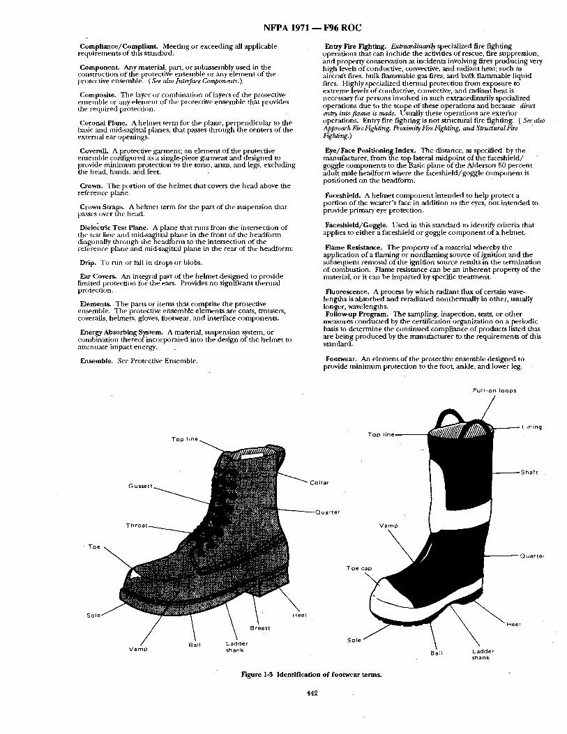
N F P A 1971 - - 1796 R O C
Compliance/Compllant . Meeting or exceeding all appficable requirements of th~s standard.
Component. Any material, part, or subassembly used in the construction o f the protective ensemble or any e lement of the protective ensemble . ( See also Interface Components.)
Composite. The layer or combination o f layers o f the protective ensemble or rely e lement of the protective ensemble that provides the required protection.
Coronal Plane. A hehnet term Ibr the plane, perpendicular to the basic and mid-sagi.ttal ph'mes, that p:L¢,se,~ through the centers of the external ear opera ngs.
Coverall. A protective garment; an e lement of the protective ensemble configured as a single-p.iece garment and designed to provide minimum protection to ~ e torso, arms, and legs, excluding t-he head, hands, ,'m-d feet. •
Crown. The portion of the helmet that covers the head above the reference plane.
Crown Straps. A hehnet term for the part of tire suspension that passes (wer me Ilead.
Dielectric Test Plane. A plane that runs from the intersection of the test line and rnid-sagitt:d plane in the front o f the headfonn diagonally through t h e h e a d f o n n to the intersection of the referen :e plane :rod mid-sagittal plane in the rear of the headfi)rm
Drip. To rnn or fall in drops or blobs.
Ear Covers. An integral part of the helmet designed to provide limited protecdon for the ears. Provides no significant thermal protection.
Elements. The p;u-ts or items that comprise the protective ensemhle. The protective ensemble elements are-coats, trousers, coveralls, helmets, gloves, footwear, and interface components.
Energy Absorbing System. A material, suspension system, or combination thereof incorporated into the design of the helmet to attenuate impact energy.
Ensemble. See Protective Ensemble.
Entry Fire Fighting. Extraordinarih specialized fire fighting operations that can include the aciivities o f rescue, fire suppression, ,and property conservation at incidents involving fires producing very high levels of conductive, convective, ,and radiant heat; such ,as ,aircraft fires, bulk flammable gas fires, and bulk flammable liquid fires. Highly specialized thermal protection from exposure to extreme levels o f conductive, convective, and radiant heat is necessary fi)r persons involved in such extraordinarily specialized operations due to the scope of these operations and because direct ~t~. intoflames is mcute. Usttally these operations are exterior operations. Entry fire fighting is not structural fire fighting. ( Seealso Approach Fire Fighting. Proximity Fire Fighting, and Structural Fire Fighting. )
Eye/Face Positioning Index. The distance, as specified by the manufacturer, f rom ~ae top lateral midpoint o f the faceshield/ goggle components to the Basic plane of the Alderson 50 percent adult male headform where the faceshield/gnggle component is positioned on the headform.
Faceshield. A helmet componen t intended to help protect a portion of the wearer's face in addition to the eyes, not intended to provide primary eye protection.
Faceshield/Goggle. l lsed in this standard to identLfy criteria that applies to either a faceshield or goggle componen t of a helmet.
Flame Resistance. The property of a material whereby the application of a flaming or nonflaming source of ignition and the subsequent removal o f the ignition source restflts in the termination of combustion. Flame resistance can be an inherent property of the material, or it can be imparted by specific treatment.
Fluorescence. A process by which radiant flux of certain wave- lengths is absorbed and reracliated nonthermally in other, usually longer, wavelengths. F011o~up Program. The sampling, inspection, tests, or other
measures conducted by the certification organization on a periodic basis to determine the cont inued compliance of prodncts listed that ,are being produced by the mantffacturer to the requirements of thls standard.
Footwear, An element of the protective ensemble designed tO provide minimum protection to the foot, ankle, and lower leg.
P u l l - o n l o o p s
T~n l i n ~ Top
" roe C
- - Q u a r t e r
So
V a m p shank
S o l e
Figure 1-3 Identification of footwear terms.
442
BaH L a d d e r shank
.~el
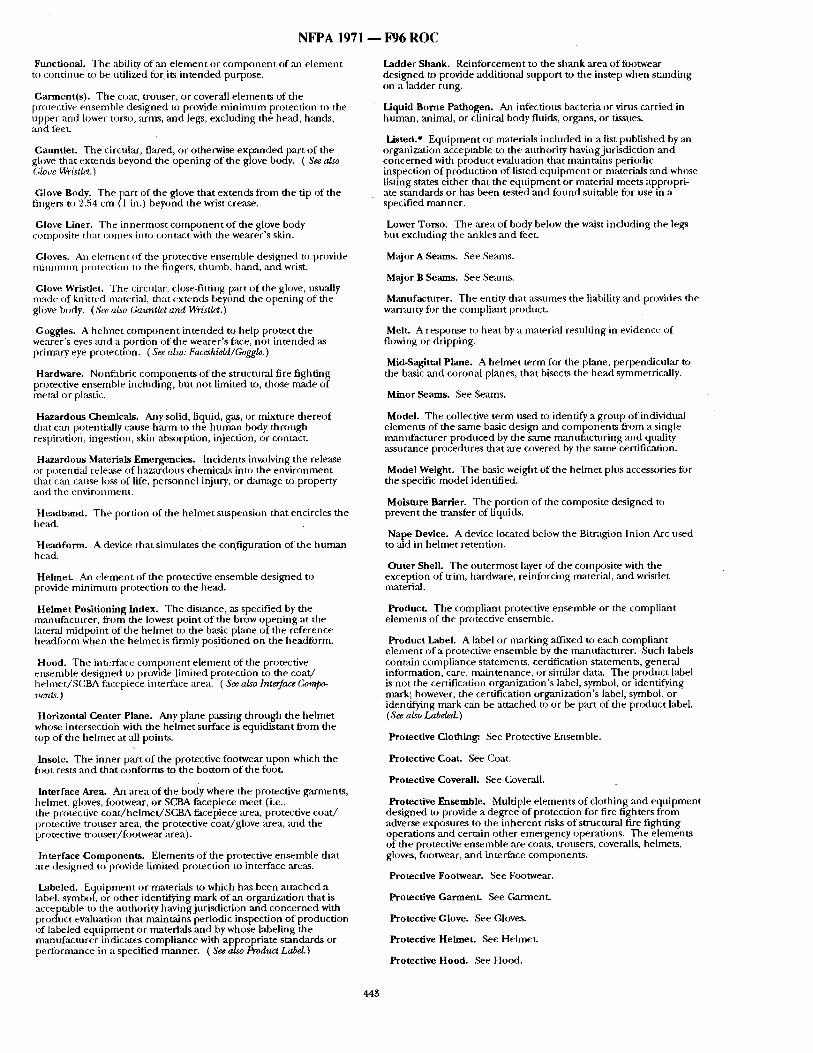
N F P A 1971 - - F96 R O C
Functional. The ability of an e l ement or c o m p o n e n t of an e lement to cont inue to be utilized for its in tended purpose.
Garment(s) . The coat, trouser, or coverall e lements of the protective ensemble des igned to provide m i n i m u m protection to the npper and lower torso, rems, and legs, excluding the head, hands, and feet.
Gauntlet. The circular, flared, or otherwise expanded part o f the glove that extends beyond the open ing o f the glove body. ( See also Glove Wristlet.)
Glove Body. The par t of the glove that extends f rom the tip of the fingers to 2.54 cm (1 in.) beyond the wrist crease.
Glove Liner. The innermost c o m p o n e n t o f the glove body composite that comes into contact with the wearer 's skin;
Ghwes. An e lement o f the protective ensemble designed to provide tnnf imum protection u) the fingers, thumb, hand, and wrist.
Glove Wristlet. The circular, close-fitting part of the glove, usually made of knitted material, that extends beyond the open ing of the glove body. ( See also Gauntlet and W~ist£'L )
Goggles. A hebne t c o m p o n e n t in tended to help protect the wem'er's eyes and a portion of the wearer 's face, no t in tended as primao, eye protection. (Seealso:Faceshidd/Goggle.)
Hardware. Nonfabric compon_ents o f the structural fire fighting protective ensemble incloding, but no t limited to, those made of metal or plastic.
Hazardous Chemicals. Any Solid, liquid, gas, or mixture thereof that can potentially cause ha rm to the h u m a n body through respiration, ingestion, skin absorption, injection, or contact.
Hazardous Materials Emergencies. Incidents invxJlving the release or potential release of hazardous chemicals into the env i ronment that can cause loss of life, personnel injury, or dan~tge to property and the environment .
Headband. The portion of the he lmet suspension that encircles the bead.
Headform. A device that simulates the con, figuration of the h u m a n head.
Helmet. An e lement of the protective ensemble des igned to provide m i n i m u m protection to the head.
Helmet Positioning Index. The distance, as specified by the m:mufacturer , f rom the lowest point o f the brow opening at the lateral midpoin t of the he lmet to the basic plane of the reference headform when the he lmet is firmly posit ioned on the headform.
Hood. The interface c o m p o n e n t e lement of the protective ensemble des igned u) provide limited protection to the coa t / he lmet /SCBA facepiece interface area. ( See also Interface Compo- ~t~tt.~. )
Horizontal Center Plane. Any pirate passing through the he lmet whose intersection with the he lmet surface is equidistant f rom the top of the hehne t at "all points.
Insole. The inner part o f the protective footwear upon which the fi)ot rests and that conforms to the bot tom of the foot.
Interface Area. An area of the body where the protective gammnts , helmet, gloves, footwear, or SCBA facepiece meet (i.e., the protective coa t /he lme t /SCBA facepiece area, protective coa t / protective trouser area, the protective coat /glove area, and the protective t rouser / footwear area).
interface Components . Elements of the protective ensemble that are designed to provide limited protection to interface areas.
Labeled. Equipment or materials to which has been at tached a label, symbol, or o ther identifying mark o f an organization that is acceptable to the attthority having jurisdiction and conce rned with product evaluation tha t mainta ins periodic inspection o f production of labeled equ ipmen t or materials and by whose labeling the manufac turer indicates compliance with appropriate s tandards or perforn~mce in a specified manner . ( See also Product Label.)
Ladder Shank. Reinforcement to the shmlk area o f fi)otwear designed to provide additional suppor t to the instep when s tanding on a ladder nmg.
Liquid Borne Pathogen. An infections bacteria or virns carried in human , animal, or clinical body fluids, organs, or tissues.
Listed.* Equ ipment or materials included in a list publ ished by ,an organization acceptable to the authori ty having jurisdiction and conce rned with product evaluation that maintains periodic inspection o f product ion of listed equ ipmen t or materials and whose listing states ei ther that the equ ipmen t or material meets appropri- ate s tandards or has been tested and fiJund suitable fi)r use in a specified manner .
Lower Torso. The area of body below the waist including the legs but excluding the :mkles and feet.
Major A Seams. See Seams.
Major B Seams. See Semns.
Manufacturer . The entity that assumes the liability and provides the warranty for the compliant product.
Melt. A response to beat by a material resulting in evidence of flowing or dripping.
Mid-Sagittal Plane. A he lmet term for the plane, perpendicular to the basic and coronal planes, that bisects the head symmetrically.
Minor Seams. See Seams.
Model. The collective te rm used to identify a grot,p of individual e lements of the same basic design and componen ts f rom a single manufac turer p roduced by the same manufac tur ing and quality assurance procedures that are covered by the same certification.
Model Weight. The basic weight of the hehne t plus accessories fi)r the specific model identified.
Moisture Barrier. The portion o f the composi te designed to prevent the transfer of Uquids.
Naive Device. A device located below the Bitragion Inion Arc used to aid in he lmet retention.
Outer Shell. The outermost layer of the composite with the exception of trim, hardware, reinfi)rcing material, mad wristlet materiM.
Product. The compliant protective ensemble or the compliant e lements of the protective ensemble.
Product Label. A label or marking affixed to each compliant e lement of a protective ensemble by the mannfacturer . Such labels contain compliance statements, certification statements, general information, care, maintenance , or similar data. The prodt,ct label is no t the certification organization's label, symbol, or identifying mark; however, the certification organization's label, symbol, or identifying mark can be at tached to or be part of the product label. (See also Labeled.)
Protective Clothing: See Protective Ensemble.
Protective Coat. See Coat.
Protective Coverall. See Coverall.
Protective Ensemble. Multiple e lements o f clothing and equ ipmen t designed to provide a degree of protection for fire fighters f rom adverse exposures to the inheren t risks of structural fire f ighting operations and certain other emergency operations. The e lements of the protective ensemble are coats, trousers, coveralls, helmets, gloves, footwear, and interface components .
Protective Footwear. See Footwear.
Protective Garment . See Garment .
Protective Glove. See Gloves.
Protective Helmet. See Helmet.
Protective Hood. See Hood.
443
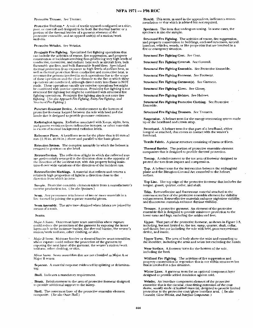
N F P A 1971 - - F 9 6 R O C
Protective Trouser . See Trouser.
Protective Uniform.* A uni t of textile apparel conf igured ~ a shirt, pant, or coverall and designed to be both the the rmaibar r i e r or a portion o f tile thermal barrier of a ga rmen t e lement of the protective ensemhle, and ,an apparel unit(s) of a s ta t ion/work unifiwm.
Protective Wristlet. See Wristlet.
Proximity Fire Fighting, Specialized fire f ighting operat ions that can include the activities o f rescue, fire suppression, and property conservation at incidents involving fires p roduc ing very high levels of conductive, convective, and radiant heat such ~ aircraft fires, bulk flanunable gas fires, and bulk flamn~able liquid fires. Specialized tt~ern~d protection from exposure to high levels of radiant heat, as well as therntal protection from condl,ctive and convective heat, is necessary for persons involved in such operat ions dtm to the scope of these operat ions and the close distztnce to the fire at which these operations are conducted, a l though direct entry into flame is NOT ntade. These operat ions usually are exterior operat ions but migh t be coinbined with interior operations. Proximity fire f ight ing is no t structural fire fighting but migh t be combined with strnctural fire fighting operations. Proximity fire f ighting also is no t entry fire fighting. (See aLvo Approach Fire Fighting. Entry. Fire Fighting, arm Structural Fi~ e Fighting.)
Puncture-Resistant Device. A reinfi)rcement to the bot tom of protective footwear located between the sole with heel and the insole that is des igned to provide punc ture resistance.
Radiological Agents. Radiation associated with X-rays, alpha, beta, and g-,'mnna emissions f rom radioactive isotopes, or other ntaterials in excess o f nornlal background radiation levels.
Reference Plane. A headform temn for the plane tha t is 60 m m ±1 mm (2.36 in. ~L04 in.) above and parallel to the basic plane.
Retention System. Tile complete asserltbly by which the hehne t is reudned in position on the head.
Retroreflection. The reflection of light in which the reflected rays are preferentially re turned in the direction close to the opposite of the direction of the incident rays, with dais property being main- t~d ned over wide variations o f the direction o f the incident rays.
Retroreflective Markings. A material that reflects and re turns a relatively high proport ion of light.in a direction close to the direction from which it came.
Sample. Protective ensemble e lements taken from a memtffacturer's current production lot. ( See also A~eeimen.)
Seam. /Mly p e r m a n e n t atlvachment o f two or more materials in a lira- fornmd by.joining tile separate material pieces.
Seam Assembly. T he smlc tu re obtained when fabrics are j o ined by lneans of a sealn.
Seams.
MajorA Seams. Outermos t layer seam assemblies where rupture couh:l reduce the protection o f the ga rmen t by exposing the inner layers st,ch :ks the moisture barrier, the thermal barrier, the wearer's station/wcwk uniform, o ther clothing, or skin.
Majo~ B S~rns. Moisture barrier or thermal barrier semn assemblies where rupture could reduce the protection of the ga rment by exposing tile next layer o f the garment , the wearer 's s ta t ion/work mliform, o ther clothing, or skin:
Minor Sea~'. Seam assemblies that are not classified as Ma:jor A or Major B sean~s.
Separate. A material response evidenced by splitting or delaminat- ing.
Shall. Indicates a mandatory requirement .
Shank. Reinlbrcement to the area of protective footwear des igned • to provide additional suppor t to the instep.
Shell. The outermost layer of the protective ensemble e l ement co mposite. ( See also Outer Shell.)
Should. This term, as used in the appendices, indicates a recom- mendat ion or that which is advised but not required.
Specimen. The item that undergoes testing. In some cases, the specimen is ,also the sample.
Structural Fire Fighting. The activities of rescue, fire suppression, ,and property conservation in buildings, enclosed structures, aircraft interiors, vehicles, vessels, or like properties that are involved in a fire or emergency situation.
Structural Fire Fighting Coat. See (k)at.
Structural Fire Fighting Coverall. See Coverall.
Structural Fire Fighting Ensemble. See Protective Ensemble.
Structural Fire Fighting Footwear. See Footwear.
Structural Fire Fighting Garment(s) . See Garment .
Structural Fire Fighting Glove. See Gloves.
Structural Fire Fighting Helmet. See Helmet.
Structural Fire Fighting Protective ClothLqg. See Protective Ensemble.
Structural Fire Fighting Trousers . See Tronsers.
Suspension. A he lmet te rm for the energy a t tenuat ing system made up of the headband and crown strap.
Sweatband. A he lmet term for that part o f t headband, ei ther integrai or at tached, that comes in contact with the wearer 's forehead.
Texti le Fabric. A planar structure consist ing of yarns or fibers.
Thermal Barrier. The portion o f protective ensemble e lement composites that is des igned to provide thermal protection.
Toecap. A re inforcement to tile toe area of footwear designed to protect the toes f rom impact ,and compression.
Top. A he lmet term for the intersection between the mid-sagittal plane and the Bitragion-C0ronal Arc ex tended to the he lmet surface.
Top Line. The top edge of the protective footwear that includes the tongue, gatsset, quitrter, collar, and shaft.
T r i~ . Retroreflective and f luorescent material a t tached to the ou te rmos t surface of the protective ensemble e lement for visibility enhancemen t . Retroreflective materials enhance nightt ime visibility, ,and f luorescent materials enhance daytime visibility.
Trouser. A protective garment . An e lement of the protective ensemble that is designed to provide m i n i m u m protection to the lower torso and legs, excluding the ankles and feet.
Upper. Tha t part of the protective footwear, as shown in Figure 1-3, including, bu t not l imited to, the toe, vamp, quarter, shaft, collar, and throat; bu t not including the sole with heel, puncture:-resistant device, and insole.
Upper Torso. The area of body above the waist an d extending to tile shotflder, including the arms and wrists but excluding the hands.
Wear Surface. A footwear te rm for the bot tom of the sole, including the heel.
Wildland Fire Fighting. Tile activities of fire suppression and property conservation in vegetation that is not within structures but that is involved in a fire situation.
Winter Liner. A ga rmen t term for an optional c o m p o n e n t layer designed to provide added insulation against cold.
Wristlet. An interface c o m p o n e n t e lement o f the protective ensemble that is the circular, close-fitting extension o f the coat sleeve, usually made of knitted material, desigried to provide limited protection to the protective coat /glove interface area. ( See also Gauntlet, Glove Wristlet. and Interface Components.)
444
N F P A 1971 ~ F96 R O C
1-4 Units.
1-4.1 In this sumdard, values fi)r m e a s u r e m e n t are fi)llowed by :m equivalent in parentheses, but only the first stated value shall be regarded as rite r equ i remenc Equivalent values in parentheses shall not be considered as the requirement , as these values might be approximate.
Chapter 2 Certification
2-1 General.
2-1.1 All individual e lements of the protective ensemble that are labeled :Ls being compliant with this s tandard shall meet or exceed all applicable requirements specified in this s tandard and shall be certified.
2-1.2 All certification shMl be per formed by an approved certifica- tion organization that meets at least the requirements specified in Section 2-~.
2-1.3 All individu:d complkmt e lements of the protective ensemble sball be kibeled mid listed. All individual compliant e lements of the protective ensemble shall also have a product label.
Tile product label shall meet the applicable requirements for the specific e lement specified in 3.1.1, 3.2.1, 3-3.1, 3-4.1, and 3.5.1.
2-1.4" The certification organization's label, symbol, or identifying mark sh:dl be a t tached to the product label or shall be part o f the product label.
2-2 Certification Organization.
2-2.1" The certification organization shall no t be owned or controlled by manufacturers or vendors of the product being certified. The certification organization sh,'fll be primarily engaged in certification work and shall no t have a monetary interest in the product ' s ult imate profitability.
2-2.2 The certification organization shall refnse to certify products to this s tandard that do not comply with all applicable requirements of this standard.
2-2.3* Tile contractnal provisions between the certification " organization ;rod the manufac turer shall specify that certification is cont ingent on compliance with all applicable requirements of this stancktrd. There shall be no conditional, temporary, or partial certifications. Manufacturers shall no t be authorized to use any label or reference to the certification organization on products that are not mannfacu t red in compliance withall applicable require- ments of this stmtdard.
2-2.4* The certification organization shall have laboratory facilities and equ ipment available for conduc t ing proper tests, a program for calibration ,:,fall ins t ruments shall be in place and operadng, and procedures shall be in,use to ensure proper control of "all testing.
)od practice shall be foil ~wed regarding the use of laboratory manuals, form data sheets, documen t ed calibration and calibration routines, performance verification, proficiency testing, and start qt, alification and training programs.
2-2.5 The certification organization shall require the mamffacturer to establish and maintain a program of product ion inspection and testing that at least meets the requirements specified in Section 2-4. The certification organization shall andi t the manufac ture r ' s quality assurance program to ensure that the quality assu~mce program provides cont inued product compli, 'mce with this standard.
2-2.6 The certification organization and the manufac turer shall e~duate mty changes ;~ 'ecting the form, fit, or fimction of the certified product m de termine the product ' s cont inued compliance to this standard.
2-2.7* The certification organization shall have a follow-up inspection program of the manufac tur ing facilities of the certified product, with at least two r andom and u n a n n o u n c e d visits per 12- mon th period. As part of the follow-up inspection progrmn, the certification orgmlization shall select sample product at r andom froin the ntmmfacturer ' s product ion line, f rom the manufac turer ' s in-house stock, or f rom the open market. Sample product shall be inspected and tested by the certification organization to verify the product ' s con t inued compliance.
2-2.8 The certification organization shall have a program for investigating field reports alleging rmatperformance or failure of listed products.
2-2.9* The certification orlvmization shall require the nuantffacturer to have a pr ,xluct recall system as part o f the mantffacturer 's quality assurance program.
2-2.10 The certification org:mization's operat ing procedures shall provide a mechan i sm for the manufac tu re r to appeal decisions. The procedures shall include the presentat ion of infonnat ion from both sides o f a controversy to a designated appeals panel.
2-2.11 The certification organization shall be in a position to use legal means to protect the integrity of its name and label. The n:mte and label shall be registered and legally defended.
2-3 Inspection and Testing.
2-3.1 Sampling levels for testing and inspection shall be established by the certification organization and the mmmfac tu re r to ensure a re:~:mable mad acceptable reliability at a reasonable mid acceptable confidence level that products certified to this stancLard are compliant, unless such sampling levels ,are specified herein. lnfornuttion about s,'mtpling levels shall be provided to tile pur- chaser upon request.
2-3.1.1 For certification of garments , file required testing and condi t ioning of the garment , materials, and componen t s shall be specified as shown in Table 2-3.1 shown on page 446.
2-3.1.2 For certification of helmets, a test series shall consist of fourteen helmets. A m i n i m u m of three test series shall be required for certification. Each hehne t shall be subjected to the envi ronmen- tal condi t ioning and test or tests specified in Table 2-3.1.2. The order of testing sh:dl be f rom left to r ight in Table 2-3.1.2. Where there is more than one environmental condit ion for a specific test, the order of environmenta l condi t ioning for that test shall be from top to bot tom in Table 2-3.1.2 shown on page 447.
2-3.1.3 For certification o f gloves, the required testing and condi t ioning of the glove, materials, and componen t s shall be specified as shown in Table 2-3.1.3 shown on page 448.
2-3.1.4 For certification of gloves, the required testing and condi t ioning of the footwear, materials, and componen ts shall be specified as shown in Table 2-3.1.4 shown on page 449.
2-3.1.5 For certification of gloves, the required testing and condi t ioning of the hood and wristlet, materials, and componen t s shall be specified as shown in Table 2-3.1.5 on page 450,
2-3.2 Inspection by the certification organization shall include a review of all product labels to ensure that all required label a t tachment , compliance statements, certification statements, and other product information are at least as specified for the specific protective ensemble e lement in 3-1.1, 3-2.1, 3-3.1, 3-4.1, and 3-5.1.
2-3.3 Inspection by the certification organization shall include a review of any graphic representat ions used on product labels, as permit ted by 3-1.1.5, 3-2.1.5, 3.3.1.5, 3-4.1.5, and 3-5.1.5, to ensure that the symbols ,are consistent with the worded statements, readily understood, and clearly communica te the in tended message.
2-3.4 Inspection by the certification organization sh=dl include a review of the user information required by 3-1.2, 3-2.2, 3-3.2, 3-4.2, and 3-5.2 to ensure that the information has been developed and is available.
2-3.5 Inspection by the certification organization for deternt ining compliance with the design requirements specified in Chapter 4 shall be per formed on whole or complete products.
2-3.6 Testing conducted by the certification o rgan i~ t ion in accordance with the testing requirements of Chapter 6, for de termining product compliance with the applicable performance requi rements specified in Chapter 5, shall be pe f fonned on e lement samples or e l ement sample specimens that ,are representative of materials and componen ts used in the actual construction of protective ensemble e lement products. The certification organiza- tion also shall be permit ted to use sample materials cut or taken f rom a representative product.
445
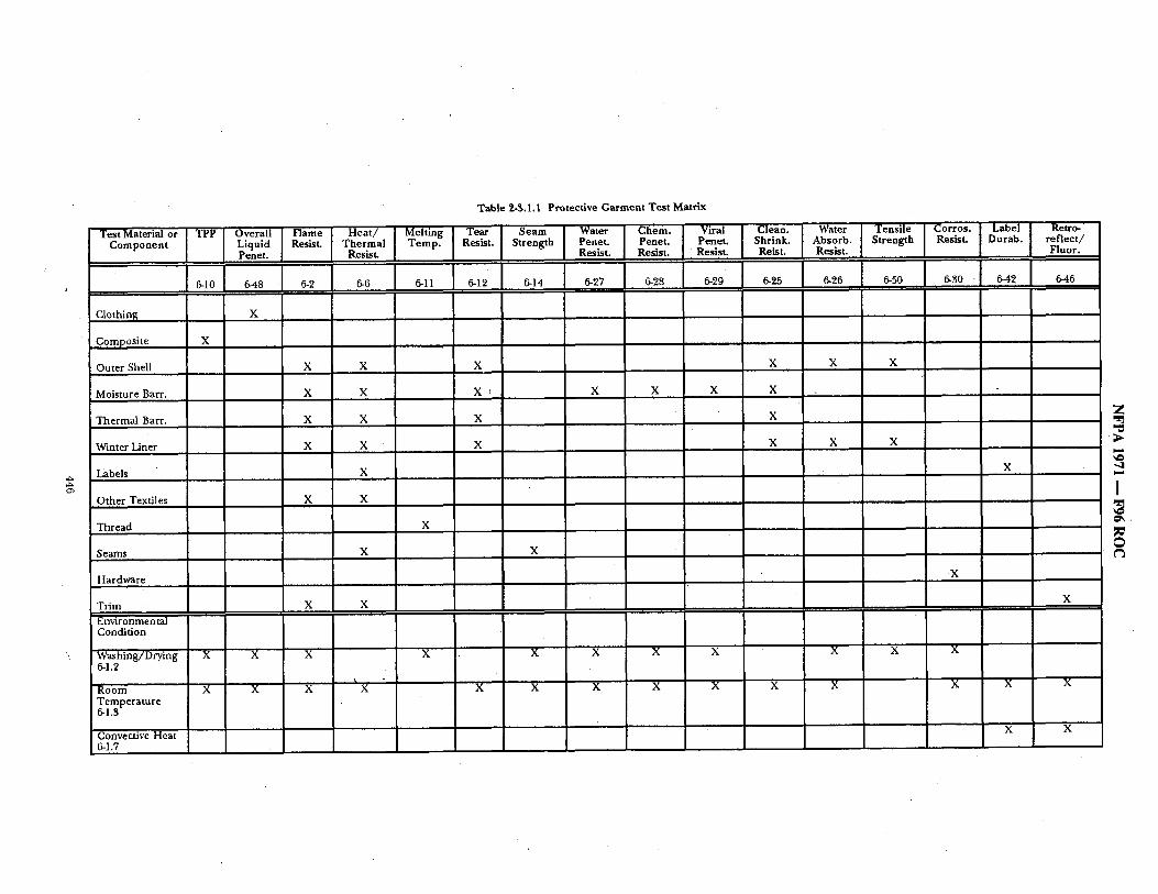
Table 2-$.1.1 Protective Garment Test Matrix
Test Material or [ TPP I O v e r a l l [ F l a m e [ Heat/ I Melting I Tear I Seam I Water ] Chem. I Viral [ Clean" I Water ] Tensile I C° r r ° s ' l Label I Retro- Component Liquid Resist. Thermal Temp. Resist. Strength Penet. Penet. Penet. Shrink. Absorb. Strength Resist. Durab. reflect/
Penet. Resist. Resist. Resist. Resist. Reist. Resist. Fluor.
Clothin~ X
Composite X
Outer Shell X X X X X X
Moisture Bart. X X X X X X X
Thermal Barr. X X X X
Winter Liner X X X X X X
Labels X
Other Textiles X X
Thread X I
Seams X X
Hardware
Trim X X Environmental Condition
Washing/D~, ing X X X X X X X X X X 6-1 .~'
Room X X X X X X X X X X X Temperature 6-1.3
Convective Heat 6-1.7
X
X
X
X
X
X X
Z
I
O ¢3
I
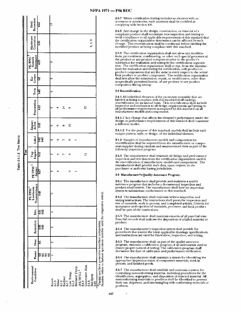
N F P A 1 9 7 1 I ~ 6 R O C
~k
(~ o.i
o [ -
°1 -oil
o~
o2
e~
~ o 2
H (.J
:o2E
d. 0 2 o2 ~o2 ¢: [" L9 > >. I ~'~-
~ .~ ~ ~ ~ ~ ~. I~.~
. - J ~ ~ , ~ ¢ ~ p Z
~ 1
2-3.7 Where certification testing includes an e lement with an access~)ry or accessories, each accessory shall be certified as complying with Section 4-8.
2-3.8 Any change in the design, construction, or material of a compliant product shall necessitate new inspection and testing to verify complimlce to all applicable reqt , i rements of this smncktrd that tile certification orgmlization de termines can be affected by such change. This recertification shall be conduc ted befi)re labeling the re(Miffed product as being compliant with this stan&ard.
2-3.9 The certification organization shall not allow any modifica- tions, pretreatment , condit ioning, or other such special processes of the product or any product c o m p o n e n t prior to the product ' s submission fi)r evahmtion and testing by the certification organiza- tion. The certification organization shall accept, f rom the manuffac- turer for evaluation and testing for certification, only product or product componen t s that ,are the s~tme in every respect to the actual final product or product component . The certification organization shall not allow the snbstitntion, repair, or modification, other than ,as specifically permit ted herein, of any product or any product c o m p o n e n t dur ing testing.
2-4 Recertification.
2-4.1 All individual e lements of the protective ensemble that are labeled ,'~s being compliant with this s tandard shall nndergo recertification on an annual basis. This recertification shall include inspection and evahmtion to all design requirements and testing to all per formance requi rements ,as requ- ireffby this s tandard on all manufac turer models and components .
2-4.1.1 Any ch,'mge that affects the e lement ' s performance unde r the design or performance requirements of this st,-mdard shall consti tute a different model.
2-4.1.2 Fur the purpose of this sumckard, models shall include each tmique pattern, style, or design, of the individual element .
2-4.2 Samples of manuf , tcturer models and componen ts for recertification shall be acquired f rom the manufac turer or compo- nen t supplier dur ing random and u n a n n o t m c e d visits as part of the follow-up inspection program.
2-4.3 Tile mmlufacturer shall maintain ,all design and performance inspection and test dam from the certification organization used in the recertification of manufactx~rer models and components . The manlffacturer shall provide such data, upon request, to the purchaser or anthority having jurisdiction.
2-5 Manufacturer's Quality Assurance Program.
2-5.1 The manufac ture r shall provide and mainudn a quality assurance program that includes a d o c u m e n t e d inspection and product recall system. The manufac ture r shall have an inspection system to substantiate conformance to this standard.
2-5.2 The manufac turer shall maintain written inspection and testing instructions. The instructions shall prescribe inspection mad test o f materials, work in process, and comple ted articles. Criteria fi:)r acceptance and rejection of materials, processes, and final product shall be part of the instrnctions.
2-5.3 The manuRtcturer shall maintain records of all pass/fall tests. Pass /~ i l records shall indicate the disposition o f a failed material or product.
2-5.4 The mantffacturer 's inspection system shall provide for procedures that ensure the latest applicable drawings, specifications, and instructions are used for fabrication, inspection, and testing.
2-5.5 The manufac turer shall, as part o f the quality assurance progrmn, maint:fin a calibration program of all ins t ruments used to ensure proper control o f testing. The calibration program shall d o c u m e n t the date of calibration ~md per formance verification.
2-5.6 The manufac turer shall maintain a system for identifying the appropriate inspection status of c o m p o n e n t materials, work in process, and f inished goods.
2-5.7 The n~mufacturer shall establish ,and m~dntain a system for controll ing nonconfo rming material, including procedures for the identification, segregation, and disposition o f rejected material. All nonconfo rming materials or products shall be identified to prevent their use, shipment , and in termingl ing with conforming materials or products.
447
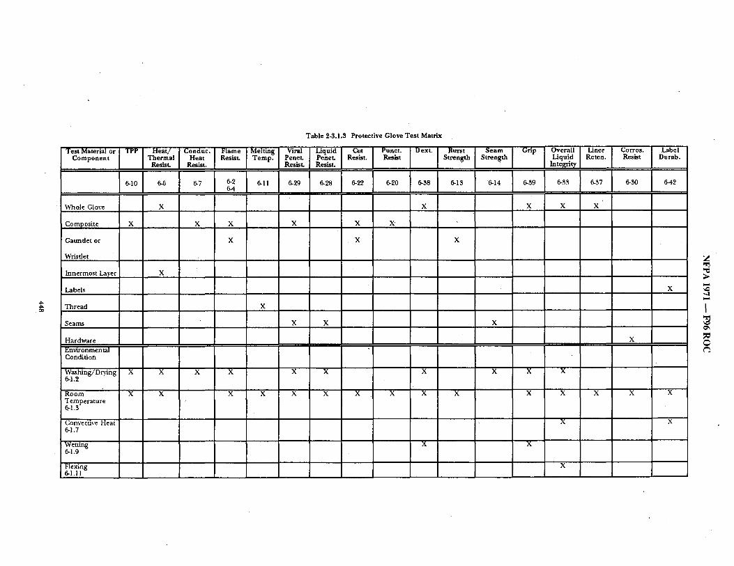
Table 2-3.1.3 Protective Glove Test Matrix
Test Material or TPP I Heat/ [ Conduc. I Flame Melting[ Viral ] Liquid I Cut [ Punct. ] Dext. [ Burst I Seam I Gri P I Overall I Liner I Corros. [ Label Component Thermal Heat Resist. Temp. Penet. Penet. Resist. Resist Strength Strength Liquid Reran. Resist Durab.
Resist. Resist. Resist. Resist. Integrity
Whole Glove X X X X X
Composite
Gauntlet or
Wristlet
Innermost Layer
Labels
Thread
Seams
Hardware Environmental Condition
• . | '
| m m m m m m m m m m
OO
X
X
X X X
X
Z "r3
x
I
Washing/Drying X 6-1.2
Room X Temperature ~-l.a
Convective Heat 6-1.7
X X X X X
X X X X X X X
X X
X
X
X
X
X X
Wetting 6.1.9
Flexing 6-1.11
X X
X
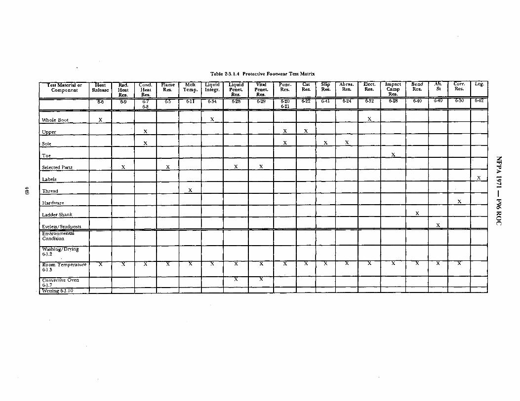
Table 2-3.1.4 Protective Footwear Test Matrix
Te.t~.,or,.o, i~,~, i ~ I~on~ I ~= i "o* IL~u~] Liqu'~ I W~ i ~ = l ~u, i S~ [~r.~ i Oo~ t'mpa~, I ~ I ~' I ~o** i ~ Component ,,lease Heat Heat Res. Temp. Integr. Penet Penet. Res. Res. Res. Res. Res. Camp Res. St Res. Res. Res. Res. Res. Res.
,,,,~,,
" , ~1 ~ - ~ 1 I I i I I, i i ,i ~ Whole Boot X X X
Upper X X
Sole X X
Toe
Selected Parts
Labels
Thread
H a r d ~ r e
Ladder Shank
X
X X
X
X X X X
X
X
X
Evelets/Studposts Em@onmental Condition
Washing/Drying 6-1.2
Room Temperature 6-1.3
Convective Oven 6-1.7 Wettin~ 6-1.10
X X X X X X X X
X X
Z
I
C
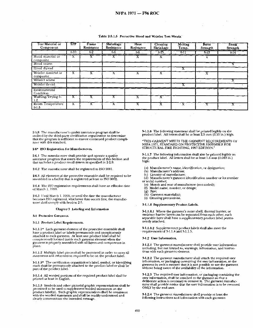
NFPA 1971 F96 ROC
Test Material or Componen t
Hood material or composi te Hood seams Hood t h r e a d ' Wristlet material or composi te Wristlet seams Wristl et thread
Table 2-3.1.5 Protective Hood and Wristlet Test Mat r ix
TPP [ Flame Shrlnkag, Heat Resistance Resistano Resistance
I 6-10 I '6-2 I 6-6 I ~ " I X X
X X
Cleaning s e a m [ Melting Burst Temp. [ Shrinkage I Stren~h Strenp[th
[ 6-95 [ 6-11 [ 6-13 I 6-14 X
X X
Environmental Go udi ti on Washing/Drying 6- X X X X 1.2 Room Tempera ture X X X X 6-1.3
X X
X
i X ¸
X
X
X X
2-5.8 The manufacturer 's quality assurance program shall be andited by the third-party certification organization to determine that the progrmn is sufficient to ensure cont inued product compli- ance with this stm~dard.
2-6* [SO Registration for Manufacturers.
2-6.1 The mantffacturer shall provide and operate a quality assurance program that meets the requirements of this Section and that includes a product recall system ,as specified in 2-2.9.
2-6.2 The manufacturer shall be registered to ISO 9001.
2-6.3 All elements of the protective ensemble shall be required to be assembled in a facility that is registered at least to ISO 9002,
2-6.4 The ISO registration reqtfirements shall have an effective &tte of March 1, 1999.
2-6.5 Until March 1, 1999, or tmtil the date the manufacturer becomes ISO registered, whichever date occurs first, the mantffac- turer shall comply with Section 2-5.
Chapter 3 Labeling and Information
3.1 Protective Garments.
3-1.1 Product Label Requirements.
3-1.1.1" Each garment e lement of the protective ensemble shall have a product label or labels i~ermanently and conspicuously attached to each garment. At le,~t one product label shall be conspicuously located inside each garment e lement when the g~trntent is properly assembled with ,all layers and components in place.
,9,-1.1.2 Multiple label pieces sh~l be permitted in order to carry all statements and infl)rmation required to be on the product label.
3-1.1.3" The certification organization's label, symbol, or identifying mark shall be permanently attached to the product label or shall be part of the product label,
3.1.1.4 All worded portions of the required product label shall be printed at least in English.
3-1.1.5 Symbols and other pictorial graphic representations shall be permitted to be used to supplement worded statements on the product label(s). Such graphic representations shall be consistent with the worded statements and shall be readily understood and clearly communicate the in tended message.
3-1.1.6 The following statement shall be pr inted legibly on the prodnct label. All letters shall be at least 2.5 mm (0.10 in.) high.
"THIS GARMENT MEETS THE GARMENT REQUIREMENTS OF NFPA 1971, STANDARD ON PROTECTIVE ENSEMBLE FOR STRUCTURAL FIRE FIGHTING, 1997 EDITION."
3-1.1.7 The following information shall also be pr inted legibly on the product label. All letters shall be at least 1.6 nun (0.063 in.) high:
(a) Mantffacturer's name, identification, or designation; (b) Mantffacturer's address; (c) Country of manufacture; (d) Manufacturer 's garment identification number or lot number
or serial number; (e) Month and year of manufacture (not coded); (f) Model name, number, or design; (g) Size; (h) Garment material(s); (i) Cleaning precautions.
3-1.1.8 Supplementary Product Labels.
3-1.1.8.1 Where the garment 's outer shell, thermal barrier, or moisture barrier layers can be separated from each other, each separable layer shall have a supplementary product label perrrm- nendy attached.
3.1.1.8.2 .Supplementary product labels shall also meet the requirements of 3-1.1.4 and 51.1.5.
3.1.2 User Information.
3-1.2.1 The garment manufacturer shall provide user information including, but not limited to, warnings, information, and instruc- tions with each garment element.
3.1.~'.2 The garment mantffacturer shall attach the required user infi~rmation, or packaging containing the user information, to the g a ~ e n t in such a manner that it is not possible to use the garment without being aware of the availability of the information.
3.1.2.3 The required user information, or packaging containing the user information, shall be attached to the garrnentso that a deliberate action is necessary to remove it. The garment manufac- turer shall provide notice that the user information is to be removed ONLY by the end user.
3.1.2.4 The garment manufacturer shall provide at least the following instructions and information with each garment:
450
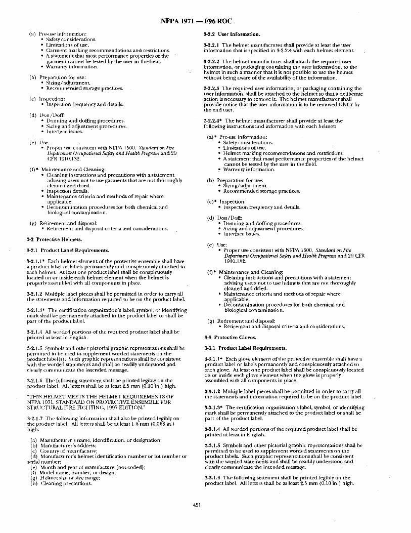
N F P A 1971 1 F96 R O C
(a) Pre-use information: • Safety considerations. • Limitations of use. • Garment marking recommenda t ions and restrictions. • A s ta tement that most performance properties of the
ga rmen t cannot be tested by the user in the field. • Warranty information.
(b) Preparation for use: • Sizing/adjustment . • R e c o m m e n d e d storage practices.
(c) Inspection: • Inspection frequency and details.
(el) Don/Doff : • Donn ing ,'rod doffing procedures. • Sizing :rod ad jus tment procedures. • Interface issues.
(e) I Ise: • Proper use consistent with NFPA 1500, Standard on Fire,
Dq~artrnr'nt Occupational Safe~ and Health Program mad 29 GFR 1910.132.
(f)* Main tenance and Cleaning: • CJeaning instructions and precautions with a s ta tement
advising users not to use garments that are no t thoroughly c leaned and dried.
• Inspection details. • Maintenance criteria and methods of repair where
applicable. • Deconumaination procedures for both chemical and
biological contmninat ion.
(g) Ret i rement and disposal: • Ret i rement and disposal criteria and considerations.
3-2 Protective Helmets.
3-2.1 Product Label Requirements .
3-2.1.1" Each he lmet e lement of the protective ensemble shall have a product label or labels permanent ly and conspicuously at tached to each helmet. At least one product label shall be conspicuously located on or inside each he lmet e lement when the he lmet is properly assembled with all componen t s in place.
3-2.1.2 Multiple label pieces shall be permit ted in order to carry all the s ta tements and information required to be on the product label.
3-2.1.3" The certification organization's label, symbol, or identifying mark shall be permanent ly at tached to the product label or shall be part of the product label.
"~2.1.4 All worded port ions of the required product label shall be printed at least in English.
3-2.1.5 Symbols and other pictorial graphic representat ions shall be permit ted to be used to supp lemen t worded s tatements on the product label (s). Such graphic representat ions shall be consistent with the worded s tatements and shall be readily unders tood and clearly cominunicate the in tended message.
3-2.1.6 The following s ta tement shall be pr in ted legibly on the product label. All letters shall be at least 2.5 m m (0.10 in.) high.
~THIS HELMET MEETS THE HELMET REQUIREMENTS OF NFPA 1971, STANDARD ON PROTECTIVE ENSEMBLE FOR STRI ~CTI IRAL FIRE FIGHTING, 1997 EDITION."
3-2.1.7 Tbe following information shall also be printed legibly on the product label. All letters shall be at least 1.6 m m (0.063 in.) high:
(a) Manufacturer ' s name, identification, or designation; (b) Manufacturer ' s address; (c) (k)i,ntry of mmltffacture; (d) Manufacturer ' s he lmet identification n u m b e r or lot n u m b e r or
serial number ; (e) Month and year of mantf facmre (not coded); (f) Model name, number , or design; (g) Helmet size or size range; (h) Cleaning precautions.
3-2.2 User Information.
3-2.2.1 The he lmet mamlfac turer shall provide at least the user information that is specified in $-2.2.4 with each he lmet element.
3-2.2.2 The he lmet manufac tu re r shall attach the required user information, or packaging containing the user information, to the he lmet in such a m a n n e r that it is no t possible to use the he lmet without being aware o f the availability o f the information.
3-2.2.3 The required user information, or packaging containing the user information, shall be a t tached to the he lmet so that a deliberate action is necessary to remove it. The he lmet mann facmre r shall provide notice tha t the user information is to be removed ONLY by the e n d user.
3-2.2.4* The he lmet manufac ture r shall provide at least the following instructions and information with each helmet:
(a)* Pre-use information: • Safety considerations. • Limitations of use. • He lmet marking recommenda t ions and restrictions. • A s ta tement that most per formance properties of the he lmet
cannot be tested by the user in the field. Warranty information.
(b) Preparation for use: • Sizing/adjustment . • R e c o m m e n d e d storage practices.
(c)* Inspection: • Inspection frequency and details.
(d) Don/Doff : • Donn ing ,and doffing procedures. • Sizing and ad jus tment procedures. • Interface issues.
(e) Use: • Proper use consistent with NFPA 1500, Standard onFi~e
Department Occupational Safe~y and Health Program and 29 CFR 1910.132.
(f)* Maintenance and Cleaning: • Cleaning instructions and precautions with a s ta tement
advising users no t to use helmets that ,are not thoroughly c leaned and dried.
• Maintenance criteria and methods of repair where applicable.
• Decontaminat ion procedures for both chemical and biological contaminat ion.
(g) Ret i rement and disposal: • Ret i rement and disposal criteria and considerations.
3-3 Protective Gloves.
3-3.1 Product Label Requirements.
3-3.1.1" Each glove e lement of the protective ensemble shall have a product label or labels pe rmanendy and conspicuously a t tached to each glove. At least one product label shall be conspicuously located on or inside each glove e lement when the glove is properly assembled with ,all componen t s in place.
3-3.1.2 Multiple label pieces shall be permit ted in order to carry all the s ta tements and information required to be on the product label.
3-3.1.3" The certification organization's label, symbol, or identifying mark shall be permanent ly at tached to the product label or shall be part of the product label.
3-3.1.4 All worded port ions o f the required product label shall be printed at least in English.
3-$.1.5 Symbols and other pictorial graphic representat ions shall be permit ted to be used to supp l emen t worded statements on the product labels. Such graphic representat ions shall be consistent with the worded s tatements and shall be readily unders tood and clearly communica te the in tended message.
3-$.1.6 The following s ta tement shall be pr in ted legibly on the product label. All letters shall be at least 2.5 m m (0.10 in.) high.
451
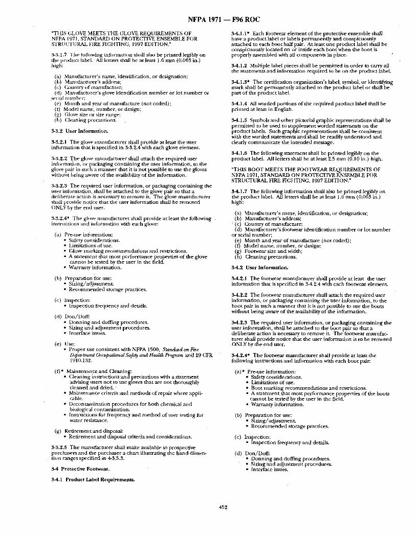
N F P A 1971 - - F96 R O C
"THIS GLOVE MEETS THE GLOVE REQUIREMENTS OF NFPA 1971, STANDARD ON PROTECFIVE ENSEMBLE FOR STRUCTURAL FIRE FI(?;HTING, 1997 EDITION."
3-3.1.7 The tbllowing information shail also be pr inted legibly on the product label. All letters shall be at least 1.6 m m (0.063 in.) high:
(a) Manufacturer ' s name, identification, or designation; (b) Manufacturer ' s address; (c) Country of man tffactnre; (d) Mannfactnrer ' s glove identification nt, mber or lot n u m b e r or
serial numl)er; (e) Month and year of manufac ture (not coded); (f) Model name, number , or design; (g) ([;love size or size range; (h) Cleaning precautions.
3-3.2 User Information.
3-."1.2.1 The glove mantffacturer shall provide at least the user infi)rmation that is specified in 3-3.2.4 with each glove element .
3-3.2,2 The glove mann tac tu re r shall attach the required nser information, or packaging conta in ing the user information, to the glove pair in such a m a n n e r that it is no t possible to use the gloves without being aware o f the availability of the information.
3-.'/.2.3 The required user information, or packaging conta in ing the user information, shall be a t tached to the glove pair so that a deliberate action is necessary to remove it. The glove mamtfac turer shall provide notice that the user information shall be removed ()NLY by the end user.
3-3.2.4* The glove rnantffactnrer shall provide at least the following instructions :md information with each glove:
(a) Pre-use infi)rmation: • Safety considerations. • Limitations of use. • (?;love marking recommenda t ions and restrictions. • A s ta tement that most per formance properties of the glove
cannot be tested by the user in the f ield. Warranty information.
(b) Preparation for use: • Sizing/adjustment . • R e c o m m e n d e d storage practices.
(c) Inspection: • Inspection frequency and details.
(d) Don/DofE • Donn ing ,and doffing procedures. • Sizing and ad jus tment procedures. • Interface issues.
(e) Use: • Proper use consistent with NFPA 1500, Standard on Fire
D~partnwnt Oc~,upational Safety and Health Program and 29 GFR 1910.132.
(1)* Maintenance and Cleaning: • Cleaning instructions anct precaut ions with a s m t e m e n t
advising users not to use gloves that are no t thoroughly cleaned and dried.
• Maintenance criteria and methods o f repair where appli- cable.
• Decontaminat ion procedures for both chemicai and biologic;d contaminat ion.
• I nstr tmtions for f requency and m e t h o d of user testing for water resistml eel
(g) R.etirement and disposal: • Ret i rement and disposal criteria and considerations.
3-8.2.5 The manufact t , rer shall make available to prospective purchasers ~md t h e p u r c h a s e r a char t illustrating the h a n d dimen- sion ranges specif ied in 4-3.5.3.
3-4 Protective Footwear.
3-4.1.1" Each footwear e lement o f the protective ensemble shall have a product label or labels permanent ly and conspicuously at tached to each boot half pair. At least one product label shall be conspicuously located on or inside each boot when the boot is properly assembled with all componen ts in place.
3-4.1.2 Multiple label pieces shall be permit ted in order to carry all the s ta tements and infi)rmation required to be on the product label.
3-4.1.3" The certification organization's label, symbol, or identifying mark shall be permanent iy a t tached to the product label or shall be part of the product label.
34.1.4 All worded port ions of the required product label shall be pr inted at least in English.
3-4.1.5 Symbols and o ther pictorial graphic representat ions shall be permit ted to be used to supp lemen t worded s tatements on the product, labels . ,Such graphic re presentations, shall be consistent with the worded s ta tements and shall be readily unders tood and clearly communica te the in tended message.
3-4.1.6 The following s ta tement shall be pr in ted legibly on the product label. All letters shall be at least 9.5 m m (0.10 in.) high.
"THIS BOOT MEETS THE FOOTWEAR REQUIREMENTS OF NFPA 1971, STANDARD ON PROTE£~IVE ENSEMBLE FOR STRUCTURAL FIRE FIGHTING, 1997 EDITION."
3-4.1.7 The following information shall also be pr in ted legibly on the product label. All letters shall be at least 1.6 m m (0.063 in.) high:
(a) Manufacturer ' s name, identification, or designation; (b) Mantffactnrer 's address; (c) Gountry ofmant f facmre ; (d) Mannfacturer ' s footwear identification n u m b e r or lot n u m b e r
or serial number ; (e) Month and year of manufac tu re (not coded); (f) Model name, number , Or design; (g) Footwear size and width; (h) Cleaning precantions.
3-4.2 User Information.
3-4.2.1 The footwear m, 'mnfacturer shal lprovide at least the user information that is specified in .54.2.4 with each footwear element.
3..4.2.2 The footwear mannfac ture r shall attach the requi red user information, or packaging containing the user information, to the boot pair in such a m a n n e r that it is not possible to use the boots without being aware o f the availability o f the information.
3-4.2,3 The reqtfired user information, or packaging containing the user information, shall be a t tached to the boot pair so that a deliberate action is necessary to remove it. The footwear mantffac- turer shall provide notice that the user information is to be removed ONLY by the end user.
3-4.2.4* The footwear mamffacturer shall provide at least the following instructions and information with each boot pair:
(a)* Pre-use information: • Safety considerations. • Limitations of use.
Boot marking recommendat ions and restrictions. A s ta tement that most perfonn, 'mce properties of the boots cannot be tested by the user in the field.
• Warranty information.
(b) Preparation for use: : Sizing/adjustment ,
R e c o m m e n d e d storage practices.
(c) Inspection: • m s p e c u o n frequency and details.
(d) D0n/Doff." • Donn ing and doffing procedures. • Sizing and ad jus tment procedures. • Interface issues.
3-4.1 Product Label Requirements.
452
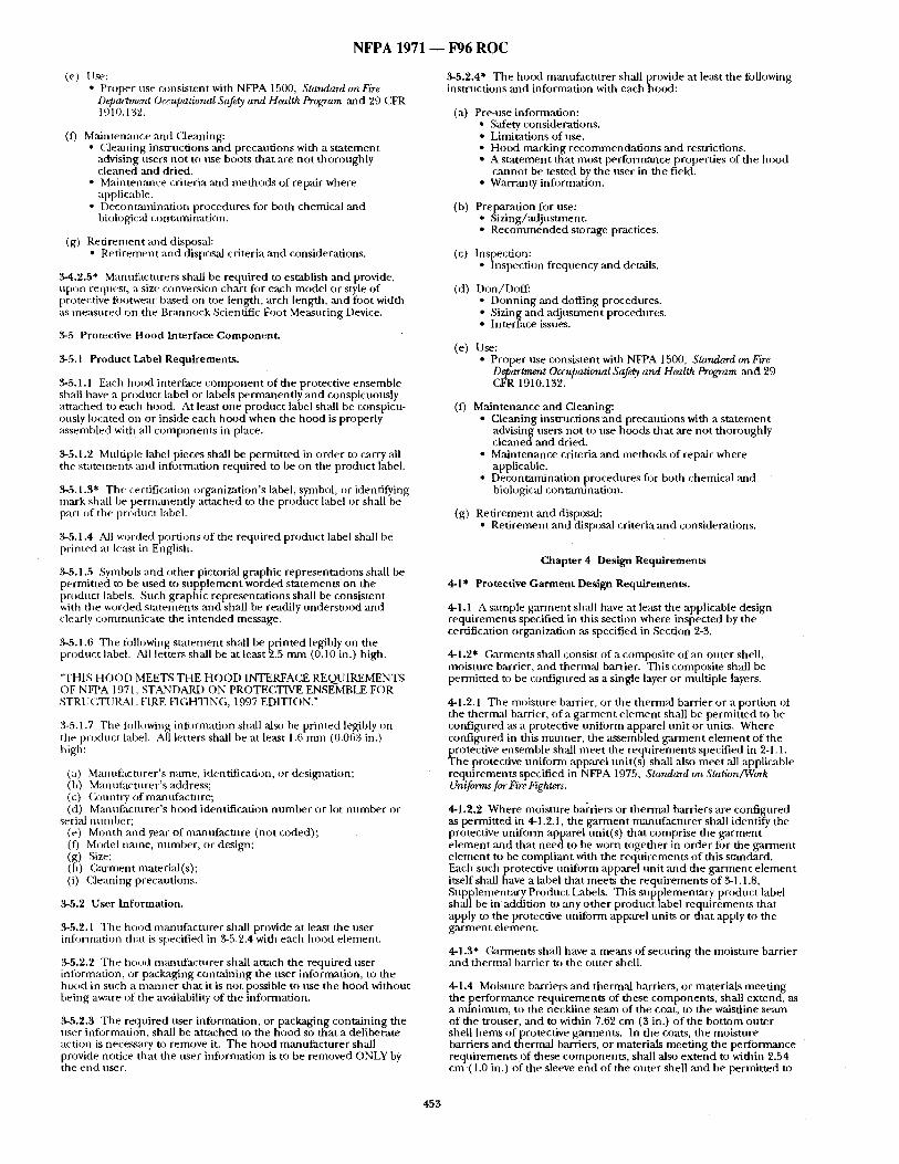
N F P A 1971 - - F96 R O C
(e) ! lse: • t ' roper use consistent with NFPA 1500. Standard on Fire
Departrm-r~t Occupational Safe~y and Health Program and 29 CFR 1910.132.
(f) Maintenance and Cleaning: • Cleaning instructions and precautions with a s ta tement
advising users not to use boots that are not thoroughly cleaned and dried.
• Maintenance criteria and methods of repair where applicable.
• Decontaminat ion procedures fi~r both chemical and biologic:d contaminat ion.
(g) Ret i rement and disposal: • Ret i rement and disposal criteria and considerations.
.'4-4.2.5* Manufacturers shall be required to establish and provide, upon request, a size conversion char t fi~r each model or style of protective footwear h~tsed on toe length, arch length, ,and foot width ~s measured on the Brannock Scientific Foot Measuring Device.
:~-5 Protective Hood Interface Component .
3-5.1 Product Label Requirements.
3-5.1.1 Each hood interface c o m p o n e n t of the protective ensemble shall have a product label or labels permanent ly ,and conspicuously at tached to each hood. At least one product label shall be conspicu- ously located on or inside each hood when the hood is properly assembled with all componen t s in place.
3-5.1.2 Multiple label pieces shall be permit ted in order to carry all the s tatements and information required to be on the product label.
3-5.1.3" The certification organization's label, symbol, or identifying mark shall be perm,'mently a t tached to the product label or shall be part of the product label.
3-5.1.4 All worded portions of the required product label shall he printed at least in English.
3-5.1.5 Symbols and other pictorial graphic representat ions shall be permit ted to be used to supp lemen t worded s tatements on the product labels. Such graphic representat ions shall be consistent with the worded s tatements and shall be readily unders tood and clearly communica te the in tended me~age .
3-5.1.6 The following s ta tement sh~dl be pr in ted legibly on the product label. All letters sh,'dl be at least 2.5 m m (0.10 in.) high.
"THIS HOOD MEETS THE H O O D INTERFACE REQUIREMENTS OF NFPA 1971, STANDARD ON PROTECTIVE ENSEMBLE FOR STRUCTURAL FIRE HGHTING, 1997 EDITION."
3-5.1.7 Tile ti3llowing information shall also be pr inted legibly on the product label. All letters shall be at least 1.6 m m (0.063 in.) high:
(a) Manufacturer ' s name, identification, or designation; (b) Manufacturer ' s address; (c) (~un t ry of manufacture; (d) Manufacturer ' s hood identification n u m b e r or lot n u m b e r or
serial number ; (e) Month and year of m~mufacture (not coded); (O Model nmne, number , or design; (g) Size; (h) Garment material(s); (i) Cleaning precautions.
.'g5.2 User Information.
3-5.2.1 Tile hood m~umfacturer shall provide at least the user inti)rmation that is specified in .3-5.2.4 with each hood element.
3-5.2.2 The hood mmmfac ture r shall attach tile required user infi:,rmation, or packaging containing the user information, to the hood in such a m a n n e r that it is not possible m use the hood without being aware of the awdlability of the information.
3-.5.9.3 The required user information, or packaging containing the user information, shall be at tached to the hood so that a deliberate action is necessary to remove it. The hood manufac tu re r shall provide notice that the user information is to be removed ONLY by the end user.
3-5.2.4* The hood mamffacturer shall provide at least the fi)llowing instructions ,and information with each hood:
(a) Pre-use information: • Safety considerations. • Limitations of use. • Hood marking r ecommenda t ions and restrictions. • A s ta tement that mos t per formance properties of the hood
canno t be tested by the user in the field. " WaITanty information.
(b) Preparation for use: • Sizing/adjustment . • R e c o m m e n d e d storage practices.
(c) Inspection: • Inspection frequency and details.
(d) Don/Doff : • Donn ing and doffing procedures. • Sizing and ad jus tment procednres. • Interface issues.
(e) Use: • Proper use consistent with NFPA 1500, Standard on Fire
Department Occupational Safety and Health Program and 29 CFR 1910.132.
(f) Maintenance and Cleaning: • Cleaning instructions a n d precautions with a s ta tement
advising users not to use hoods tha t ,are not thoroughly c l e a n e d a n d dried.
• Maintenance criteria and methods of repair where applicable.
• Decontaminat ion procedures fi)r both chemical ,and biological contaminat ion.
(g) Ret i rement and disposal: • Ret i rement and disposal criteria and considerations.
Chapter 4 Design Requirements
4-1" Protective Garment Design Requirements.
4-1.1 A sample ga rmen t shall have at least the applicable design requirements specified in this section where inspected by the certification organization as specified in Section 2-3.
4-1.2" Garments shall consist of a composite o f a n outer shell, moisture barrier, ,and thermal barrier. This composite shall be permit ted to be configured ,as a single layer or multiple layers.
4-1.2.1 The moisture barrier, or the thermal barrier or a portion of the thermal barrier, of a ga rmen t e lement shall be permit ted to be confignred as a protective uni form apparel uni t or units. Where confignred in this manner , the assembled ga rmen t e lement of the protective ensemble shall mee t the requirements specified in 2-1.1. The protective un i form apparel unit(s) shall also meet all applicable requirements specified in NFPA 1975, Standard on Station/Work Uniforms for Fire Fighters.
4-1.2.2 Where moisture barriers or thermal barriers are configured as permit ted in 4-1.2.1, the ga rmen t mamffacmrer shall identify the protective un i form apparel unit(s) that comprise the ga rmen t e lement and that need to be worn together in order for the ga rment e lement to be compl iant with the requi rements of this standard. Each such protective uni form apparel uni t and the ga rmen t e lement itself shall have a label that meets the requi rements o f 3-1.1.8, Supplementary Product Labels. This supplementary product label sha l lbe in addition to :my o ther product label requirements that apply to the protective uni form apparel units or that apply to the ga rmen t element .
4-1.3" G ~ e n t s shall have a means of securing the moisture barrier ,and thermal barrier to the outer shell.
4-1.4 Moisture barriers and thermal bamers , or materials meet ing the per formance requirements of these components , shall extend, as a min imum, to the neckline seam of the coat, to the waistline seam of the trouser, and to within 7.62 cm (3 in.) of the bot tom outer shell hems of protective garments . In the coats, the moisture barriers and thermal barriers, or materials meet ing the performance requi rements of these components , shall also ex tend to within 2.54 cm,(1.O in.) of the sleeve end of the outer shell and be permit ted to
4523
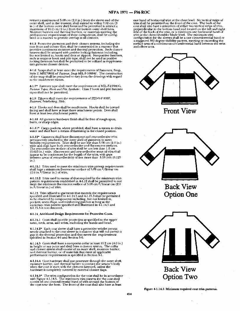
N F P A 1971 ~ F96 R O C
remlct a m a x i m u m of 5.08 cm (2.0 in.) f rom the sleeve end of the outer shell, and in the trousers, shall ex tend to within 7.62 cm (3 in.) of the bottom outer shell hems and be permit ted to retract a m:tximum of 10.'2 cm (4 in.) f rom the bot tom outer shell liem. Moisture barriers and thermal barriers, or materials meet ing the per tbrmance requi rements o f these components , shall be config- ured in a m a n n e r to provide overlap at all closures.
4-1.5 Protective garments and their closure systems, including the coat front and trot~ser flies, shall be const ructed in a m a n n e r that
rovides cont inuous moisture and thermal protection. Such closure stems shall be secured with positive locking fasteners inclnding,
tit no t limited to, hooks a n d d e e s or zippers. Nonpositive fasteners, such ~Ls snaps or hook and pile tape, sha l l no t be used as positive locking fasteners but sh,--dl be permit ted to be utilized as supplemen- tary ga rmen t closure devices.
4-1.6 Snaps shall at least meet the requi rements of Fasteners, Snap, Style 2, MS27980E of Fastener, Snap MIL-F-10884F. The construction of the snap shall be permi t ted to v a ~ from the drawings with regard to the a t t achment me,ms.
4--1.7" Fastener tape shall mee t the requirements of MIL-F-2184OG, Fa,~t~u~r Tap~, Hook and Pi& ,Si~m&etic. (:aass 2 hook and pile fastener tapes shall not be permitted.
4-1.8 Zippers shall mee t the requi rements o f FED-V-F-106F, Fasteners, Interlocking. Slide.
4-1.9 Hooks and dees shall be nonferrous . Hooks shall be inward facing and shall have at least three a t t achment points. Dees shall have at least two a t t achment points.
4-1.10 All g a r m e n t hardware finish shall be free o f rough spots, burrs, or sharp edges.
4-1.11" Cargo pockets, where provided, shall have a means to d r a i n water and shallqaave a means oI fas tening in the closed position.
4-1.12* Garments shall have f luorescent and retroreflecdve trim permanent ly a t tached to the outer shell o f garments to meet v-isibility requirements . Trim shall be not less than 5.08 cm (~'.0 in.) wide mad shall have both retroreflective and f luorescent surfaces. The retroreflective st, trace o f trim shall be not less than 1.6 cm (0.6'25 in.) wide. Fluorescent and retroreflective areas of tr im shall appear to be continuotts for the length of the trim, with gaps between areas of retroreflectivity o f not more than 3.18 m m (0.125 in.).
4-I.12.1 Trim used to mee t the m i n i m u m trim patter2a requi rements shall ha~e a m i n i m u m fluorescent surface o f 5.0-8 cm z / l inea r cm (2 0 in / l i nea r in ) of trim.
4-1.12.2 Trim used in excess o f tha t required by the m i n i m u m trim pattern requi rements established in 4-1.12 sha l lbe permi t ted to no t haeet the m i n i m u m f luorescent surface of 5.08 cm Z/ l inear cm (2.0 in .2 / l inear in.) o f trim.
4-1.13 Trim affixed t o g a r m e n t s that exceeds the requi rements specified and i l lustratedin 4-I. 14.5 and 4-1.15.3 shalf b e p e r m i t t e d to be obscured by componen t s including, but no t l imitedto, pockets, s torm flaps, an-d reinforcing patches as tong as the hf in imum trim pa-ttern specified and illustrated in 4-1.14.5 and 4-1.15.3 is no t obscured.
4-1.14 Additional Design Requi rements for Protective Coats.
4-1.14.1 Coats shall provide protection as specified to the upper torso, neck, arms, and wrists, excluding the hands a n d head.
4-1.14.2* Each coat sleeve shall have a protective wristlet perma- nently a t tached to the coat sleeve in a m a n n e r that will no t permi t a gap in the therntal protection and tha t meets the requirements specified in Section 4-6 and Section 5-6.
4-1.14.3 Coats shall have a composi te collar at least 10.'2 cm (4.0 in.) in height at any point mid shall have a closure system. The collar and cliJsure system shall consist o f an outer shell, moisture barrier, and thernaalbarrier , or of materials tha t mee t all applicable performance requi rements as specified in Section 5--1.
4-IA4.4 Coat hardware shall no t penetrate th rough the outer shell, moisture barrier, and thermal barrier to contact the wearer 's body when the coat is worn with the closures fastened, unless the hardware is completely covered by external closure flaps.
4-1.14.5" The trim configuration for the coat shall be in accordance with Figure 4-1.14.5, The m i n i m u m trim pattern for the coat shall consist o f one circumferential band of trim a round the bot tom of the coat near the hem. The front of the coat shall also have at least
454
one band of horizontal trim at the chest level. No vertical strips of trim shall be permit ted on the front o f the coat; Th e back o f the coat shall also have a m i n i m u m of ei ther two vertical strips of trim, perpendicul,'u" to the bot tom band and located on the left ~md right side o f the back of the coat, or a m i n i m u m one horizontal hand of tr im at the ches t / shou lde r blade level. The m i n i m u m trim configuration for the sleeves shall be a one circumferential band or a s taggered 360 degree visibility pattern, meet ing or exceeding the surface area of a cont inuous circumferential band between the wrist and elbow area.
Front View
Back View Option One
Back View Option Two
Figure 4-1.14.5 Minimum required coat trim patterns.
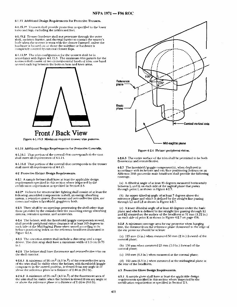
N F P A 1971 - - F96 R O C
4-1.15 Additional Des'tgn Requirements for Protective Trousers.
4-1.15.1" Trousers shall provide Drotection as specified to the lower torso and legs, excluding file ankles ,'rod feet.
4-1.15.2 Trouser hardware shall no t penetrate th rough the outer shell, muismre barrier, and thermal barrier to contact the wearer's body when the trouser is worn with the closure fastened, tmless the hardware is located on or above the waisdine or hardware is completely covered by external closure flaps.
4-1.15.3" The trim configuration fi)r the trousers shall be in accordance with Fignre 4-1.15.3. The m i n i m u m trim pattern for the nouse r s shall consist of two circumferential bands of trim: one band : H O l l n d each leg between the bot tom h e m and knee areas.
OBB~ SS~ I ~%b'b B • ! •
Z j s J| q
/ ' / I t ."i ] j l
i m i •
Reference '~ plane " - - - - ~ f , ~ "
Basic plane
i i
0
Front / Back View Figure 4.1.15.3 Min imum required t rouser trim patterns.
4-1.16 Additional Design Requirements for Protective Coveralls.
4-1.16.1 That portion o f the coverall that corresponds to the coat shall mee t all requirements of 4-1.14.
4.1.16.2 That portion of the coverall that corresponds to the trouser shall meet ,'all requirements of 4.1.15.
4.2 Protective Helmet Design Requirements .
4-2.1 A ~tmple helmet shall have at least the applicable design requirements specified in this section where inspected by the certification organization as specified in Section 2-:5.
4-2.2* Helmets fi:~r structnral fire f ighting shall consist o f at least the fi)llowing assembled components : a shell, an energy absorbing system, a retention system, f luorescent and retroreflective trim, ear covers and ei ther a faceshield, goggles or both.
4-2.3 There shall be no openings penetra t ing the shell o ther than those provided by the manufac ture r for moun t i ng energy absorbing systems, retention systems, and accessories.
4-2.4 The hehnet , with the faceshie ld/goggle componen t s stowed, shall provide peripheral vision clearance of at least 105 degrees to each side of the Mid~Sagittal Pkme when seated according to its helmet positioning index on the reference headfi)nn illustrated in Figure 4-2.4.
4.2.5 The retention system shall include a chin strap and a nape device. The chin strap shall have a m i n i m u m width of 1.9 cm (0.75 in.).
4-2.6 The helmet shall have f luorescent and retrorefiective trim on the shell exterior.
4.2.6.1 A m i n i m u m of 26 cm 2 (4.0 in. 2) of the retroreflective area of the trim shall be visible when the helmet , with faceshie ld/goggle c o m p o n e n t in the stowed position, is viewed f rom any angle at or above the reference plane at a distance of 2.44 m (8.0 It).
4-2.6.2 A m i n i m u m of 26 cm 2 (4.0 in. 2) o f the f luorescent area of the trim shall be visible when the he lmet is viewed f rom any angle at or above the reference plane at a dist~mce of 2.44 m (8.0 it).
Mid-sagittal plane
Figure 4-2.4 Helmet peripheral vision.
4-2.6.$ The entire surface of the tr im shall be permit ted to be both f luorescent ,and retroreflective.
4-2.7 The faceshie ld/goggle component ( s ) , when deployed in accordance with its he lmet and eye/face posit ioning indexes on ,an Alderson 50th percentile male headforrn shall provide the following coverage.
(a) A dihedr:fl ,angle of at least 85 degrees measured horizontally between L and K on each side of the sagittal plane that passes through point L as shown in Figure 4-2.7.
(b) An upper dihedral angle of at least 7 degrees above the reference plane and which is def ined by the straight line passing th rough L1 and L2 as shown in Figure 4-2.7.
(c) A lower dihedral angle of at least 40 degrees unde r the basic plane a n d which is def ined by the straight line passing th rough K1 and K2 situated on the surface of the headform at 31 m m (1.22 in.) on each side of poin t K as shown in Figure 4-2.7 on page 456.
4-2.8 A m i n i m u m coverage area for ear protector when hanging free, the distance f rom the reference plane downward to the edge of the ear protector should be at lease
(a) 125 m m (5 in.) when measured 50 m m (2 in.) forward of the coronal plane;
(b) 150 m m when measured 25 m m (1.0 in.) forward of the coronal plane;
(c) 160 m m (6.3 in.) when measured at the coronal plane;
(d) 160 m m (6.3 in.) when meas~lred at the mid-sagittal plane at the rear of the headform.
4.$ Protective Glove Design Requirements .
4-3.1 A sample glove shall have at least the applicable design requirements specified in this section where inspected by the certification organization as specified in Section 2-3.
455
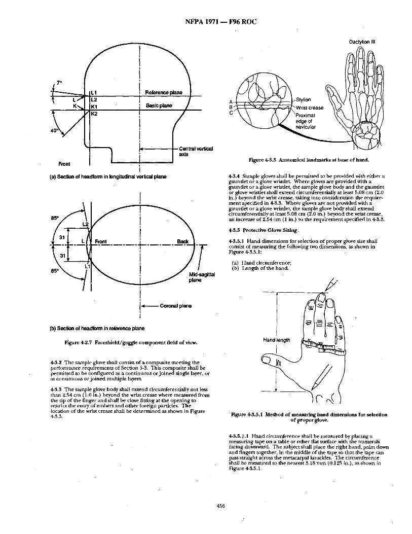
N F P A 1971 - - F96 R O C
,o j i .
K~, I K1 ; Basic plane /
~, ~ I~ ! Central verlical
/ i I "x" Front
I (a) Section of headform in longitudinal vertical plane
I I •
I I
I -~-------- Coronal plane I
I
(b) Section of headform in reference plane
Figure 4-2.7 Faceshield/goggle component field of view.
4-3.2 The ,~tmple glove shall consist of a composite meeting the perfi3rmance requirements of Section 5-3. This composite shall be permitted to be contigured as a continuous orjoinedsingle layer, or as con tmmus or joined multiple layers.
4-3.3 The sample glove body shall extend circumferentially not less than 2.54 cm ( 1.0 in.) beyond the wrist crease where measured from the tip of the finger and shall be close fitting at the opening to restrict the entry of embers and other foreign particles. The location of the wrist crease shall be determined as shown in Figure 4-3.3.
T
Daclylion III
A ~ S W r ~ i ~ ; ; r e a s e \.~-,~: \ ~\ /~/~ )1 ~ / ~ ~ ~ l
Figure 4-3.3 Anatomical landmarks at base of hand.
4-3.4 Sample gloves shall be permitted to be provided with either a gauntlet or a glove wrisdet. Where gloves are provided With a gauntlet or a glove wrisdet, the sample glove body and the gauntlet or glove wristlet shall extend circumferentially at least 5.08 cm (2.0 in.) beyond the Wrist crease, taking into consideration the require- ment specified in 4-3.3. Where gloves are not provided with a gaundet or a glove wrisdet, the sample glove body shall extend circumferentially at least 5.08 cm (2.0 in.) beyond the wrist crease, an increase of 2.54 cm (1 in.) to the requirement specified in 4-3.3.
4-3.5 Protective Glove Sizing.
4-3.5.1 Hand dimensions for selection of proper glove size shall consist of measuring the following two dimensions, as shown in Figure 4-3,5.1:
(a) Hand circumference; (b) length of the hand.
F
Figure 4-3.5.1 Method of measuring hand dimensions for selection of proper glove.
4-3.5.1.1 Hand circumference shall be measured by placing a measuring tape on a table or other fiat surface with the numer,'ds facing downward. The subject shall place the right hand, palm down and fingers together, in the middle of the tape so that the tape can pass straight across the metacarpal knuckles. The circumference shall be measured to the nearest 3.18ram (0.125 in.), as shown in Figure 4-3.5.1.
456
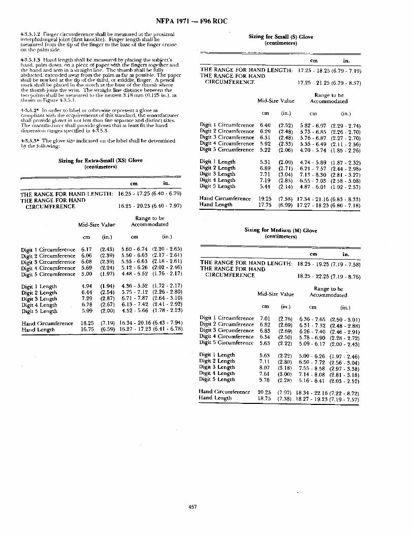
N F P A 1971 ~ F 9 6 R O C
4-3.5.1.2 Finger circtmfference shall be measured at the proximal interphalangealjoint (first knuckle). Finger length shallbe ine:~st red fr m the tip of the finger to the base of the finger crease on the pahn side.
4-315.1.3 Hand length shall be measured byplacing the subject's hand, palm down, on a piece of paper with tile fingers together ,and the hand mid arm in a straight line. The thumb shall be fiflly abducted, extended away from the palm as far as possible. The paper shall be marked at the tip of the third, or middle{finger. A pencil mark shall be placed in the notch at the base of the thumb where tile thumb joins the wrist. The straight line distance between the two points shall be measured to the nearest 3.18 mm (0.125 in.), as shown in Figure 4-3.5.1.
4-3.5.2* In order to label or otherwise represent a glove as compliant with the requirements of this standard, the mamffacturer shaft provide gloves in not less than five separate ,and distinct sizes. The manuf:lcturer shallj3rovide gloves that at least fit the hand dimension ranges specined in 4-3.5.3.
4-3.5.3* Tile glove size indicated on the label shall be determined by tile fl:~llowing:
Sizing for Extra-Small (XS) Glove (centimeters)
cm in.
THE RANGE FOR HAND LENGTH: THE RANGE FOR HAND
CIRCUMFERENCE
16.25 - 17.25 (6.40 - 6.79)
16.25 - 20.25 (6.40 - 7.97)
Sizing for Small (S) Glove (centimeters)
cm in.
17.25 - 18.25 (6,79 - 7.19) THE RANGE FOR HAND LENGTH: THE RANGE FOR HAND
CIRCUMFERENCE
Mid-Size Value
cm (in.)
Digit 1 Circumference 6.40 (2.52) Digit 2 Circumference 6.29 (2.48) Digit 3 Circumference 6.31 (2.48) Digit 4 Circumference 5.92 (2.33) Digit 5 Circumference 5.22 (2.06)
Digit 1 Length 5.31 (2.09) Digit 2 Length 6.89 (2.71) Digit 3 Length 7.71 (3.04) Digit 4 Length 7.19 (2.83) Digit 5 Length 5.44 (2.14)
Hand Circumference 19.25 (7.58) Hand Length 17.75 (6.99)
17.25 - 21.25 (6.79 - 8.37)
Range to be Accommodated
cm (in.)
5.82 - 6.97 (2,29 - 2.74) 5.73 - 6.85 (2,26 - 2.70) 5.76 - 6.87 (2,27 - 2.70) 5 . 3 5 - 6 . 4 9 (2 .11-2 .56) 4.70 - 5.74 (1.85 - 2.26)
4.74 - 5.89 (1,87 - 2.32) 6.21 - 7.57 (2.44 - 2.98) 7 . 1 3 - 8 . 3 0 (2.81 -3.27) 6.55 - 7.03 (2,58 - 3.08) 4.87 - 6.01 (l,92 - 2.37)
17.34 - 21.16 (6,83 - 8.33) 17.27 - 18.23 (6,80 - 7.18)
Mid-Size Value
cm (in.)
Range to be Accommodated
cm (in.) Sizing for Medium (M) Glove
(centimeters)
Digit 1 Circumference 6.17 (2.43) 5.60 - 6.74 (2.20 - 2.65) Digit 2 Circumference 6.06 (2.39) 5.50 - 6.63 (2.17 - 2.61) Digit 3 Circumference 6.08 (2.39) 5.53 - 6.63 (2.18 - 2.61) Digit 4 Circumference 5.69 (2.24) 5.12 - 6.26 (2~02 - 2.46) Digit 5 Circumference 5.00 (1.97) 4.48 - 5.52 (1.76 - 2.17)
Digit 1 Length 4.94 (1.94) 4.36 - 5.52 (1.72 - 2.17) Digit 2 Length 6.44 (2.54) 5.75 - 7.12 (2.26 - 2.80) Digit 3 Length 7.29 (2.87) 6.7l - 7.87 (2.64 - 3.10) Digit 4 Length 6.78 (2.67) 6.13 - 7.42 (2.41 - 2.92) Digit 5 Length 5.09 (2.00) 4.52 - 5.66 (1.78 - 2.23)
Hand Circumference 18.25 (7.19) Hand Length 16.75 (6.59)
16.34 - 20,16 (6.43 - 7.94) 16.27 - 17,23 (6.41 - 6.78)
c m in.
T H E RANGE FOR HAND LENGTH: 18.25 - 19.25 (7.19 - 7.58) T H E RANGE FOR HAND
CIRCUMFERENCE 18.25 - 22.25 (7.19 - 8.76)
Range to be Mid-Size Value Accommodated
cm (in.) cm (in.)
Digit ! Circumference 7.0l (2.76) 6.36 - 7.65 (2.50 - 3.01) Digit 2 Circumference 6,82 (2.69) 6.31 - 7.32 (2.48 - 2.88) Digit 3 Circumference 6.83 (2.69) 6.26 - 7.40 (2.46 - 2.91) Digit 4 Circumference 6,34 (2.50) 5.78 - 6.90 (2.28 - 2.72) Digit 5 Circumference 5,63 (2.22) 5.09 - 6.17 (2.00 - 2.43)
Digit 1 Length 5.63 (2.22) 5 .00- 6.26 (1 .97-2 .46) Digit 2 Length 7.11 (2.80) 6.50 - 7.72 (2.56 - 3.04) Digit 3 Length 8.07 (3.18) 7.55 - 8.58 (2,97 - 3.38) Digit 4 Length 7.61 (3.00) 7.14 - 8.08 (2.81 - 3.18) Digit 5 Length 5.78 (2.28) 5.16 - 6.41 (2.03 - 2.52)
Hand Circumference 20.25 (7.97) Hand Length 18.75 (7.38)
18.34 - 22.16 (7,22 - 8.72) 18.27 - 19.23 (7,19 - 7.57)
457
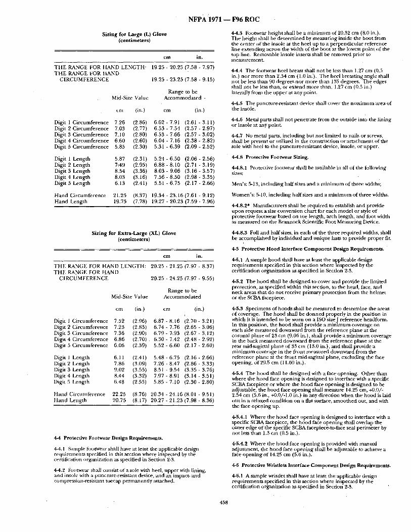
NFPA i971 - - F96 ROC
Sizing for Large (L) Glove (centimeters)
cm in.
T H E RANGE FOR HAND LENGTH: T H E RANGE FOR HAND
C I R C U M F E R E N C E
Mid-Size Value
19.25 - 20.25 (7.58 - 7.97)
19.25 - 23.25 (7.58 - 9.15)
Range to be Accommoda ted -
cm (in.) cm (in.)
Digit 1 C i rcumference 7.26 (2.86) 6.62 - 7.91 (2.61 - 3.11) Digit 2 C i rcumference 7.03 (2.77) 6.53 - 7.54 (2.57 - 2.97) Digit 3 C i rcumference 7.10 (2.80) 6.53 - 7.66 (2.57 - 3.02) Digit 4 C i rcumference 6.60 (2.60) 6.04 - 7.16 (2.38 - 2.82) Digit 5 C i rcumference 5.85 (2.30) 5.31 - 6.39 (2.09 - 2.52)
Digit 1 Leng th 5.87 (2.31) 5.24 - 6.50 (2.06 - 2.56) Digit 2 Leng th 7:49 (2.95) 6.88 - 8.10 (2.71 - 3.19) Digit 3 Leng th 8.54 (3.36) 8.03 - 9.06 (3.16 - 3.57) Digit 4 Leng th 8.03 (3.16) 7.56 - 8.50 (2.98 - 3.35) Digit 5 Leng th 6.13 (2.41) 5.51 - 6.75 (2.17 - 2.66)
H a n d Ci rcumference 21.25 (8.37) 19.34 - 23.16 (7.61 - 9.12) H a n d Leng th 19.75 (7.78) 19.27 - 20.23 (7.59 - 7.96)
Sizing for Extra-Large (XL) Glove (centimeters)
cm in.
T H E RANGE FOR HAND LENGTH: T H E RANGE FOR HAND
C I R C U M F E R E N C E
20.25 - 21.25 (7.97 - 8.37)
20.25 - 24.25 (7.97 - 9.55)
Range to be Mid-Size Value Accommoda t ed
cm (in.) cm (in.) i
Digit 1 Ci rcumference 7.52 (2.96) 6.87 - 8.16 (2.70 - 3.21) Digit 2 Ci rcumference 7.25 (2.85) 6.74 - 7.76 (2.65 - 3.06) Digit 3 C i rcumference 7.36 (2.90) 6.79 - %93 (2.67 - 3,12) Digit 4 Ci rcumference 6.86 (2.70) 6.30 - 7.42 (2.48 - 2.92) Digit 5 Ci rcumference 6.06 (2.39) 5.52 - 6.60 ( 2 . 1 7 , 2 . 6 0 )
Digit 1 Leng th 6.11 (2.41) 5.48 - 6.75 (2.16 - 2.66) Digit 2 Length 7.86 (3.09) 7.26'- 8.47 (2.86 - 3.33) Digit 3 Leng th 9.02 (3.55) 8.51 - 9.54 (3.35 - 3.76) Digit 4 Length 8.44 (3.32) 7.97 - 8.91 (3.14 - 3.51) Digit 5 Leng th 6.48 (2.55) 5.85 - 7.10 (2.30 - 2.80)
H a n d Ci rcumference 22.25 (8.76) 20.34 - 24.16 (8.01 - 9.51) H a n d Length 20.75 (8.17) 20.27 - 21.23 (7.98 - 8.36)
4-4 Protective Footwear Design Requirements .
4-4.1 Salnple footwear shall have at least the applicable design requi rements specified in this section where inspected by the certification organization as specified in Section 2-3.
4-4.2 Footwe~u" shall consist o f a sole with heel, upper with lining, and insole with a punctt,re-resistant device, and an impact- ~md compression-resistant toecap permanent ly attached.
4-4.3 Footwear he ight shall be a m i n i m u m of 20.32 cm (8.0 in.). The height shall be de te rmined by measur ing inside the boot f rom the center of the insole at the heel up to a perpendicular reference line ex tending across the width of the boot at the lowest poin t of the top line. Remowtble insole inserts shall be removed prior to measurement .
4-4.4 The footwear heel breast shall no t be less than 1.27 cm (0.5 in.) nor more than 2.54 cm (1.0 in.'). The heel breasting angle shall no t be less than 90 degrees nor more than 135 degrees. The edges shall no t be less than, or ex tend more than, 1.27 cm (0.5 in.) laterally f rom the upper at any point,
4-4.5 The puncture-resistant device shall cover the maximt ,m area of the insole.
4-4.6 Metal parts shall not penetra te f rom the outside into the l ining or insole at ,any point.
4-4.7 No metal parts, including but no t l imited to nails or screws, shall be present or utilized in the construct ion or a t t achment o f the sole with heel to the puncture,resistant device, insole, or upper .
4-4.8 Protective Footwear Sizing.
4-4.8.1 Protective footwear shall be available in ~dl of the following sizes:
Men's: 5-13, including half sizes and a m i n i m u m of three widths;
Women 's : 5-10, including half sizes and a m i n i m u m of three widths.
4-4.8.2* Mant~mture r s shall be required to establish an d provide u ~ ) n request a size conversion char t for each model or style o f protective footwear based on toe length, arch length, and foot width as measured on the Brannock Scientific Foot Measur ing Device.
4-4.8.3 Full and haft sizes, in each of the three required widths, shall be accomplished by individual and un ique lasts to provide proper fit.
4-5 Protective Hood Interface Componen t Design Requirements .
4-5.1 A sample hood shall have at least the applicable design requi rements specified in this section where inspected by the certification organization as specified in Section 2-3.
4-5.2 The hood shall be des igned to cover and provide the limited protection, as specified within this section, to the head, face, mid neck areas that do not receive primary protection f rom the h eh n e t or the SCBA facepiece.
4-5.3 Specimens of hoods shall be m e ~ u r e d to de te rmine the areas of coverage. The hood shall be d o n n e d properly in the position in which it is in tended to be worn on a ISO sizeJ reference headforrn. In this position, the hood shall provide a m i n i m u m coverage on each side measured downward f rom the reference plane at the coron:d plane of 23 cm (9.06 in.), shall provide a m i n i m u m coverage in the back measured downward f rom the reference plane at the rear mid-sagittal plane of 33 cm ( 13.0 in.), and shall provide a m i n i m u m coverage in the front measured downward from the reference plane at the front mid-sagittal plane, excluding the face opening, of 29.5 cm (11.60 in.).
4-5,4 The hood shall be des igned with a face opening. Other than where the hood face open ing is des igned to interface with a specific SCBA facepiece or where the hood face open ing is des igned to be adjustable, the hood face open ing shall measure 14.25 cm, +0.0/- 2.54 cm (5.6 in., +0.0/-1.0 in.) in any direction when the h o o d is laid out in a relaxed condit ion on a flat surface, smoo thed out, an d with the face open ing up.
4-5.4.1 Where the hood face open ing is des igned to interface with a specific SCBA facepiece, the hood face open ing shall overlap the outer edge o f the specific SCBA facepiece-to-face seal perimbter by not less than 1.3 cm (0.5 in.).
4-5.4.2 Where the hood face open ing is provided with manual adjustment , the hood face open ing shall be adjustable to achieve a face open ing o f 14.25 cm (5.6 in.).
4-6 Protective Wristlets Interface Component Design Requirements.
4-6.1 A sample wristlet shall have at least the applicable design requi rements specified in this section where inspected by the certification organization as specified in Section 2-3.
458
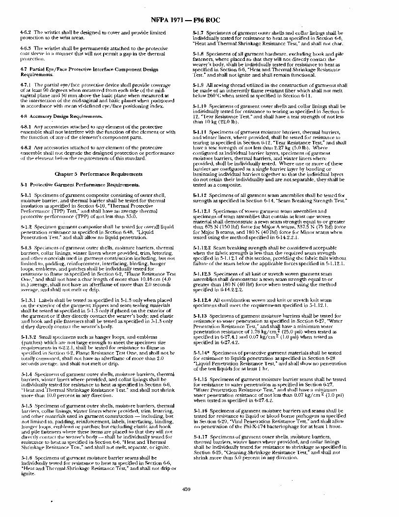
N F P A 1971 - - F96 R O C
4-6.2 The wristlet shall be des igned to cover ~md provide limited protection to the wrist areas.
4-6.3 The wristlet shall be permanent ly at tached to the protective coat sleeve in a m~mner that will not permit a gap in the thermal protection.
4-7 Partial Eye/Face Protective Interface Component Design Requirements.
4-7.1 The partial eye/face protective device shall provide coverage of at least 90 degrees when measured from each side of the mid- sagittal plane mid 50 m m above the basic plane when measured at the intersection of the mid-sagittal and basic planes when posit ioned in accordance with mean vf-defined eye/face posit ioning index.
4-8 Accessory Des'~n Requirements.
4-8.1 Any accessories at tached to ,any e lement of the protective e, tsemble shall no t interfere with the f imction of the e l ement or with the fimction of any of the e lement ' s c o m p o n e n t pa~s.
4-8.2 Any accessories at tached to any e lement of the protective ensemble shall no t degrade the des igned protection or perfi)rmance of the elemeJ~t below the requirements of this st~mdard.
Chapter 5 Performance Requirements
~1 Protective Garment Performance Requirements.
5-1.1 Specimens of ga rmen t composite consist ing of outer shell, moisture barrier, and thermal barrier shall be tested for thermal insulation as specified in Section 6-10, "Thermal Protective Performance (TPP) Test," and shall have ,an average thermal protective perfi)rmance (TPP) of no t less than 35.0.
5-1.2 Specimen ga rmen t composite shall be tested fi)r overall liquid
~ enetrat ion resistance as specified in Section 6-48, "Liquid enetrat ion Test," and shall ,allow no liquid penetration.
5-1.3 Specimens of ga rmen t outer sheUs, moisulre barriers, thermal barriers, collar linings, winter liners where provided, trim, lettering, and other materials used in ga rment construction including, but not limited to, padding, reinfi)rcement, interfacing, binding, hanger loops, emblems, and patches shall be individually tes tedfor resistance to flame as specified in Section 6-2, "Flame Resistance Test One," and shall not have a char length o f more than 10.16 cm (4.0 in.) average, shall no t have an :ffterflame of more than 2.0 seconds average, and shall no t mel t or drip.
5-1.3.1 Labels shall be tested as specified in 5-1.3 only when placed on the exterior of the garment; zippers ,and seam sealing materials shall be tested as specified in 5-1.3 only if placed on the exterior o f the ga rmen t or if they directly contact the wearer 's body; and elastic and hook and pile fasteners shall be tested as specified in 5-1.3 only if they directly contact the wearer 's body.
5-1.3.2 Small specimens such as hanger loops, and emblems (patches) which are not large enough to meet the specimen size requirements in 6-2.2.1, shall be tested for resistance to fiame as specified in Section 6-2, Flame Resistance Test One, and shall no t be toudly consumed, shall no t have an af ter~ame of more them 2.0 seconds average, ,and shall no t mel t or drip.
5-1.4 Specimens of ga rmen t outer shells, moisture barriers, thermal barriers, winter liners where provided, and collar linings shall be individually tested for resistance to heat as specified in Section 6-6, "Heat and Thermal Shrinkage Resistance Test," and shall not shrink more than 10.0 percent in any direction.
5-1.5 Specimens of ga rmen t outer shells, moisture barriers, thermal barriers, collar linings, winter liners where provided, trim, lettering, and o ther materials used in ga rmen t construction - - including, but not limited to, padding, reinforcement , labels, interfiicing, binding, hanger loops, emblems or patches; but excluding elastic and hook and pile tasteners where these i tems are placed so that they will not directly contact the wearer's body - - shall be individually tested fi~r resisumce to heat as specified in Section 6-6, "Heat ~md Thermal Shrinkage Resistance Test," and shall not melt, separate, or ignite.
5-1.6 Specimens of ga rment moisture barrier seams shall be individually tested for resistance to heat as specified in Section 6-6, "Heat ,and Thermal Shrinkage Resistance Test, ~ and shall not drip or ignite.
5-1.7 Specimens o f ga rmen t outer shells and collar linings shall be individually tested for resistance to hea t ,as specified in Section 6-6, "Heat and Thermal Shrinkage Resistance Test," and shall not char.
5-1.8 Specimens o f all g a rmen t hardware, excluding hook and pile fasteners, where placed so that they will no t directly contact the wearer's body, shall be individually tested for resis~mce to heat ,as specified in Section 6-6, "Heat and Thermal Shrinkage Resistance Test," and shall no t ignite ,and shall remain functional.
5-1.9 All sewing thread utilized in the construct ion of garments shall be ir~tde of an inherently flame resistant fiber which shall not melt below 260°C when tested as specified in Section 6-11.
5-1.10 Specimens of ga rmen t outer shells and collar linings shall be individually tested for resistance to tearing ,as specified in Section 6- 12, "Tear Resistance Test," and shall have a tear s t rength of not less than 10 kg (22.0 lb).
5-1.11 Specimens o f ga rmen t moisture barriers, thermal barriers, and winter liners, where provided, shall be tested for resistance to tearing as specified in Section 6-12, "Tear Resistance Test," and shall have a tear strength of not less than 2.27 kg (5.0 Ib). Where configured as individual bttrrier layers, specimens of ga rmen t moisture barriers, thermal barriers, and winter liners where provided, shall be individually tested. Where one or more o f these barriers are configured as a single barrier layer by bonding or laminat ing individual barriers together so that the individual layers do not retain their individuality and are not separable, they shall be tested as a composite.
5-1.12 Specimens o f all ga rmen t semn assemblies shall be tested fi)r s t rength as specified in Section 6-14, "Seam Breaking Strength Test."
5-1.12.1 Specimens of woven ga rmen t seam ,assemblies and specimens o f seam assemblies tha t contain at least one woven material shall demonst ra te a sewn seam strength equal to or greater than 675 N (150 lbf) force for Major A se:tms, 337,5 N (75 lbf) force fi)r Major B seams, and 180 N (40 lbf) fi)rce fi)r Minor seams when tested using the me thod specified in 6-14.2.2.1.
5-1.12.2 Seam breaking strength shall be considered acceptable when the fabric strength is less than the required seam strength specified in 5-1.12.1 of this section, providing the fabric fails without failure of the seam below the applicable forces specified in 5-1.12.1.
5-1.12.3 Specime;ns of,'dl knit or stretch woven ga rmen t seam assemblies shall demonst ra te a sewn seam strength eqnal to or greater than 180 N (40 Ibf) fi)rce when tested using the me thod specified in 6-14.2.2.2.
5-1.12.4 All combinat ion woven and knit or stretch knit seam specimens shall meet the requirements specified in 5-1.12.1.
5-1.13 Specimens of ga rmen t moisture barriers shall be tested for resistance to water penetrat ion as specified in Section 6-27, "Water PenetKttion Resistance Test," mid shall have a m i n i m u m water penetrat ion resistance of 1.76 k g / c m 2 (25.0 psi) when tested as specified in 6-27.4.1 and 0.07 k g / c m z (1.0 psi) when tested as specified in 6-27.4.2.
5-1.14" Specimens of protective ga rmen t materials shall be tested for resistance to liquids penetrat ion as specified in Section 6-28 "Liquid Penetrat ion Resistance Test," and shall show no penetrat ion of the test liquids for at least I hr.
5-1.15 Specimens of ga rment moisture barrier se~u~s shall be tested for resistance to water penetrat ion as specified in Section 6-27, "Water Penetration Resistance Test," and shall have a m i n i m u m water penetrat ion resistance of not less than 0.07 k g / c m 2 (1.0 psi) when tested as specified in 6-27.4.2.
5-1.16 Specimens of ga rmen t moisture barriers and scants shall be tested for resistance to liquid or blood borne pathogens as specified in Section 6-29, "Viral Penetration Resistance Test," mid shall allow no penetrat ion o f the Phi-X-174 bacteriophage for at least 1 hvJur.
5-1.17 Specimens of ga rmen t outer shells, m¢~isture barriers, thermal barriers, winter liners where provided, and collar linings shall be individually tested for resistance to shrinkage as specified in Section 6-25, "Cleaning Shrinkage Resistance Test," and shall not shrink more than 5.0 percent in any direction.
459
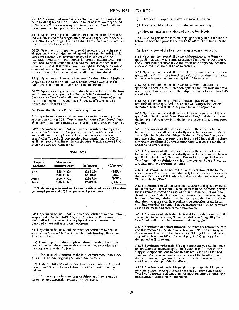
N F P A I971 - - F96 R O C
5-1.18" Specimens o f g a r m e n t outer shells and collar linings shall be individually tested fi)r resistance to water absorption as specified in Section 6-26, "Water Absorption Resistance Test," and shall no t have more than 30.0 percent water absorption.
5-1.19 Specimens of ga rmen t outer shells and collar lining shall be individnally tested fi~r s t rength after washing as specified in Section 6-50, "Bre:tking Strength Test," and shall have a breaking strength of not less than 63.6 kg (140 Ib).
.5-1.20 Specimens of all g a rmen t metal hardware and specimens of all ga rment hardware that include metal ~arts shall be individually tested fi)r resistance to corrosion as specified in Section 6-30, "Corrosion Resistance Test." Me~ds mherent iy resistant to corrosion inclnding, but not limited to, stainless steel, brass, copper, alumi- num, and zinc shall show no more than light surface-type corrosion or oxidation mid shall remain functional. Ferrous metals shall show no corrosion o f the base metal and shail remain fimctional.
5-1.21 Specimens of labels shall be tested for durability and legibility as specified in Section 6-42, "Label Durability and Legibility Test One." and shall remain in place and shall be legible.
.5-1.22 Specimens of ga rmen t tr im shall be tested for retroreflectivity and fluorescence as specified in Section 6-46, "Retrorefiectivity and Fluorescence Test," and shall have a Coefficient of Retroreflection (Ra) of not less than 100 c d / h t x / m 2 (cd / fc / f t2 ) and shall be designated as fluorescent.
5-2 Protective Helmets Per formance Requ i rements .
5-2.1 Specimen hehnets shall be tested for resistance to impact as specified ill Section 6-15, "Top Impact Resistance Test (Force)," and shall have no sample t ransmit a force of more than 3780 N (850 lblO.
5-2.2 Specimen helmets shall be tested for resistance to impact ,as specified in Section 6-16, "Impact Resistance Test (Acceleration)," and shall have no sample exceed the m a x i m u m acceleration specified in Table 5-2.2. Any acceleration duration above 200 Gn shall not exceed 3 milliseconds; acceleration durat ion above 150 Gn sh:dl not exceed 6 milliseconds.
Table 5-2.2
Impact Maximum Location Acceleration* (m/see/see) (ft/sec/sec)
Top 150 × Gn (1471.5) (4830) Front 300 × Gn (2943.0) (9660) Sides 300 × Gn (2943.0) (9660) Back 300 × Gn (2943.0) (9660)
* On denotes gravitational acceleration, which is defined as 9.81 meters per second per second (32.2 feet per second per second).
5-2.5 Specimen hehnets sh,'dl be tested for resistmlce to penetrat ion , as specified in Section 6-19, "Physical Penetrat ion Resistance Test," and shall exhibit no electrical or physical contact between the penetrat ion test striker and the headfonn .
5-2.4 Specimen he lmetssha l l be tested for resistance to heat as specified in Section 6-6, "Heat and Thermal Shrinkage Resistance Test," and shall:
(a) Have no parts o f the complete he lmet assembly that do not contact tile headfi)rm before this test come in contact with the headform as a restdt o f this test.
(b) Have no shell distortion in the back ex tend more than 4.0 cm (1.6 in.) below the original position of the helmet.
(c) Have no distortion o f the f ront and sides o f the shell ex tend more than 3.00 cm (1.2 in,) below the original position of the helmet.
(d) Have no separation, melting, or dr ipping of the retentio'i] system, energy absorption system, or each covers.
(e) Have a chin strap closure device remain fimctional.
(f) Have no ignition of any part of tile he lmet assembly.
(g) Have no ignition or melt ing o f the product labels.
(h) Have no part of the faceshie ld/goggie comp o n en t that was no t below the brim line prior to the test be below the brim line after the test.
(i) Have no part of the faceshield/goggle c o m p o n e n t drip.
5-2.5 Specimen helmets shall be tested for resistance to f lame .'is specified in Section 6-3, "Flame Resistance Test Two," Procedures A and C. and shall not show any visible afterfiame or glow 5.0 seconds after removal f rom the test f lame in each test.
5-2.6 Specimen helmets shall be tested for resistance to electricity as specified in 6-31.5.1 Procedure A and 6-31.5.2 Procedure B and shall no t have leakage cur ren t exceeding 3.0 mA in each test.
5-2.7 Specimen hehnets shall be tested for retention ability as specified in Section 6-35, "Retention System Test." without any break occurring and without any resulting slip o r stretch of more than 2.03 cm (0.8 in.).
5-2.8 Specimen he lmet suspension systems shall be tested for retention ability as specified in Section 6-36, "Suspension System Retention Test," andsha l l no t separate f rom the he!met shell.
5-g.9 Specimen helmets shall be tested for shell retent ion ability as specified in ,Section 6-44, "Shell Retention Test," an d shall no t have the he lmet shell separate f rom the he lmet suspension an d retent ion systems.
5-2.10 Specimens o f all materials utilized in the constnlct ion of he lmet ear covers shall be individually tested for resistance to f lame as specified in Section 6-2, "Flame Resistance Test One," and shall no t have a char length greater than 10.2 cm (4.0 in.), shall no t show any visible afterflame 2.0 seconds ,after removal f rom the test flame, andsha i l not mel t or drip.
5-2.11 Specimens o f all materials utilized in the construction of he lmet ear covers shall be individually tested for resistance to heat ,as
eCified in Section 6-6, "Heat ~md Thermal Shrinkage Resistance st," and shall not shrink more than 10.0 percent in any direction,
and shall not melt" separate, or ignite.
5-2.12 All sewing thread utilized in the construct ion of the he lmet ear covers shall be made o f an inherent ly f lame resistant fiber which shall not mel t below 260°C ' when tested as specified in Section 6-1 l , "Th r~ld Melting Test."
5-2.13 Specimens o f all he lmet metal hardware and specimens o f all he lmet hardware that include metal parts shall be individually tested for resistance to corrosion as specified in Section 6-30, "Corrosion Resistance Test." Metals inherent ly resistant to corrosion including, but not l imited to, stainless steel, brass, copper, a luminum, and zinc shall show no more than light surface-type corrosion or oxidation and shall remain ftmctional. Ferrous metals shall show no corrosion of the base metal and shall remain functional.
5-2.14 Specimens o f labels shall be tested for durability a n d legibility ,as specified in Section 6-43, "Label Durability and Legibility Test Two," and shall remain in place and shall be legible.
5-2.15 Specimens o f he lmet tr im shall be tested for retroreflectivity and f luorescence as specified in Section 6-46 "Retroreflectivity and Fluorescence Test," and shall h a v e a Coefficient o f Retroreflection (Ra) o f no t less than 100 c d / l u x / m 2 (cd / fc / f t2 ) an d shall be designated as fluorescent.
5-2.16 Specimens of facesh ie ld /goggle componen t s shall be tested for resistance to impact as specified in Section 6-17, "Faceshield/ Goggle C o m p o n e n t I_~ns Impact Resistance Test, ~ Test One and Two, and shall have no contact with an eye o f the headform; nor shall any parts of fragment~ be ejected from the c o m p o n e n t that could contact the eye of the headform.
5-2.17 Specimens of faeshie ld/goggle componen t s shall be tested for flame resistance as specified in Section 6-3 ~Flame Resistance Test Two," Procedure B; and shall no t show any visible afterflame 5 seconds ,after removal of the test flame.
460
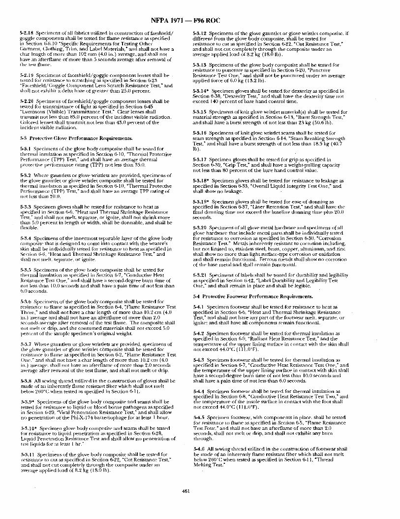
N F P A 1971 - - F 9 6 R O C
5-2.18 Specimens of all fabrics utilized in construction of faeshie ld / goggle componen t s shall be tested for flame resistance ,as specified in Section 6-6.10 "Specific Re~luirements for Test ing Other Garnaent, Clothing, Trim, anct Label Materials," ,and shall not have a char length of more than 102 m m (4.0 in.) average, and shall not have : m afterflame of more than 5 seconds average ,after removal of the test flame.
5-2.19 Specimens of faceshie ld/goggle c o m p o n e n t lenses shall be tested fi3r resistance to scratching its specified in Section 6-23 "Faceshield/Goggle C o m p o n e n t Lens Scratch Resistance Test," mad shall not exhibit a delta haze of greater than 25.0 percent.
,5-2.20 Specimens of facesbield/goggie c o m p o n e n t lenses shall be tested fi~r t ransmit tance of light as specified in Section 6-45 "LtmLinons (Visible) Transmit tance Test." (:lear lenses shall transmit not less than 85.0 percent of the incident visible radiation. (ik~lored l e n d s shall t ransmit no t less thzm 43.0 percent o f the incident visible radiation.
5-3 Protective Glove Performance Requirements.
5-3.1 Specimens of the glove body composite shall be tested for tttermal insulation as specified in Section 6-10, "Thern~al Protective PeFfornlance (TPP) Test," and shall have :m average thermal protective perfornaance rating (TPP) not less than 35.0.
5-3.2 Where gauntlets or glove wristlets are provided, specimens of the glove gaunt le t or glove wristlet composite shall be tested for thenn~d insulation ,as specified in Section 6-10, "Thermal Protective Performance (TPP) Test," and shall have an average TPP rating of not less than 20.0.
5-3.3 Specimen gloves shall be tested for resistance to heat as specified in Section 6-6, "Heat and Thermal Shrinkage Resistance Test," and shall no t melt, separate, or ignite, shall no t shrink more than 5.0 percent in length or width, shall be donnable , and shall be flexible.
5-3.4 Specimens of the innermos t separable layer of the glove body composite that is des igned to come into contact with the wearer:s skin shall be individually tested for resistance to heat as specified in Section 6-6, "Heat :rod Thermal Shrinkage Resistance Test," and shall not melt, separate, or ignite.
~3.5 Specimens of the glove body composite shall be tested for thermld insulation its specified in Section 6-7, "Conductive Heat Resistance Test One," :mr shall have a second-degree burn t ime of not less than 10.0 seconds and shall have a pain time of not less than 6.0 seconds.
5-3.6 Specimens of the glove body composite shall be tested figr resistance to f l~ne ,as specified in Section 6-4, ".Flame Resistance Test Three," and shall no t have a char length of more than 10.2 cm (4.0 in.) average and shall no t have an afterflame of more than 2.0 seconds average after removal of the test flame. The composite shall not melt or drip, and the consumed materials shall not exceed 5.0 percent of the ~ample spec imen ' s original weight.
~3.7 Where gauntlets or glove wristlets are provided, specimens of the glove gauntlet or glove wristlet composite shall be tested fi~r resistance t~ fl:une its specified in Section 6-2, "Flame Resistance Test One." ztnd shall not have a char length of more than 10.2 cm (4.0 in.) average, shall no t have an ~ te r t l ame of more than 2.0 seconds average after removal of the test flame, ,and shall no t melt or drip.
5-3,8 All sewing thread utilized in the construction of gloves shall be made of an inherently f lame resistant fiber which shall no t melt below 260°C, when tested ,as specified in Section 6-11.
~3.9" Specimens of the glove body composite and seams shall be tested fi:~r resistance to liquid or blood borne pathogens as specified in Section 6-29, "Viral Penetrat ion Res is tanceies t , " and shall allow no penetrat ion of the Ptti-X-174 bacteriophage for at least 1 hour.
5-3.10* Specimen glove body composite ~md seams shall be tested fi~r resistance to liquid penetrat ion as specified in Section 6-28, Liquid Penetration Resistance Test and sh:dl allow no penetrat ion of test liquids fi~r at least 1 hr."
5-3.11 Speciniens of the glove body composite shall be tested for resistance t o cut ,as specified in Section 6-22, "Cut Resistance Test," and shall not cut completely th rough the composite unde r an average applied load of8.2 kg (18.0 Ib).
5-3.12 Specimens of the glove gaunt le t or glove wristlet composite, if different f rom the glove body composite, shall be tested for resistance to cut as specified in Section 6-22, "Cut Resistance Test," and shall m~t cut completely th rough the composite unde r an average applied load of 8.2 kg (18.0 lb).
5-3.13 Specimens of the glove body composite shall be tested for resistance to puncture ,as specified in Section 6-20, "Puncture Resistance Test One," lind shall no t be punc tured unde r ,an average applied force o f 6.0 kg ( 13.2 lb).
5-3.14" Specimen gloves shall be tested for dexterity as specified in Section 6-38, "Dexterity Test," and shall have the dexterity t ime no t exceed 140 percent of bare h a n d control time.
5-3.15 Specimens of knit glove wristlet material(s) shall be tested fi)r material s trength as specified in Section 6-13, "Burst Strength Test," and shall have a burst s trength of not less than 23 kg (50.6 lb).
5-3.16 Specimens of knit glove wristlet seams shall be tested for seam strength as specified in Section 6-14, "Seam Breaking Strength Test," and shall have a burst s trength of not less than 18.5 kg (40.7 Ib).
5-3.17 Specimen gloves shall be tested for grip ,as specified in Section 6-39, "Grip Test," and shall have a weight-pulling capacity not less than 80 percent of the b~tre h a n d control value.
5-3.18" Specimen gloves shall be tested for resistance to leakage as specified in Section 6-33, "Overall Liquid Integrity Test One," and shall show no leakage.
5-3.19" Specimen gloves shall be tested fi)r ease of donn ing as specified in Section 6-37, "Liner Retention Test," ,and shall have the finai d o n n i n g time not exceed the baseline donn ing time plus 20.0 seconds.
5-3.20 Specimens o f all glove metal hardware ,and specimens of all glove hardware that include metal parts shall be individually tested fi)r resist.ance to corrosion as specified in Section 6-30, "Corrosion Resistance Test." Metals inherently resistant to corrosion including, bu t not limited to, stainless steel, brass, copper, almlfinnm, lind zinc shall show no more than light surf, ace-type corrosion or oxidation and shall remain fimctional. Ferrous metals shldl show no corrosion of the base metal ,and sh~dl remain fimctional.
5-3.21 Specimens of labels shall be tested for durability and legibility ,as specified in Section 6-42, "Label Durability and Legibility Test One," and shall remain in place and shall be legible.
5-4 Protective Footwear Performance Requirements,
5-4.1 Specimen footwear shall be tested for resistance to heat ,as in Section 6-6, "Heat and Thermal Shrinkage Resistance
st," and shall not have any part of the fi~otwear melt, separate, or ignite; and shall have all componen t s remain fimctional.
5-4.2 Specimen footwear shall be tested fi)r thermal insulation as specified in Section 6-9, "Radiant Heat Resist,'mce Test," and the temperature of the upper lining surface in contact with the skin shall not exceed 44.0°(; (111.0°F).
5-4.3 Specimen fi)otwear sh:dl be tested for thermal insulation as specified in Section 6-7, "Conductive Heat Resistance Test One," and the tempera ture of the upper l ining surface in contact with skin sh~ l have a second-degree burn time of not less than 10.0 seconds and shall have a pain time of not less than 6.0 seconds.
5-4.4 Specimen footwear shall be tested for thermal insulation as specified in Section 6-8, "C2mductive Heat Resistance Test Two," and the tempera ture of the insole surface in contact with the fi)ot shall not exceed 44.0°C (111.0°F).
5-4.5 Specimen footwear, with componen ts in place, shall be tested for resistance to fl:une its specified in Section 6-5, "Flame Resist~mce Test Four," and shall no t have an ,"ffterflame of more than 2.0 seconds, shall no t melt or drip, and shall no t exhibit any burn- through.
5-4.6 All sewing thread tttilized in the construct ion of fi~otwear shall be made of ,an inherently flame resistant fiber which shall no t melt below 260°C when tested as specified in Section 6-11, "Thread Melting Test."
461
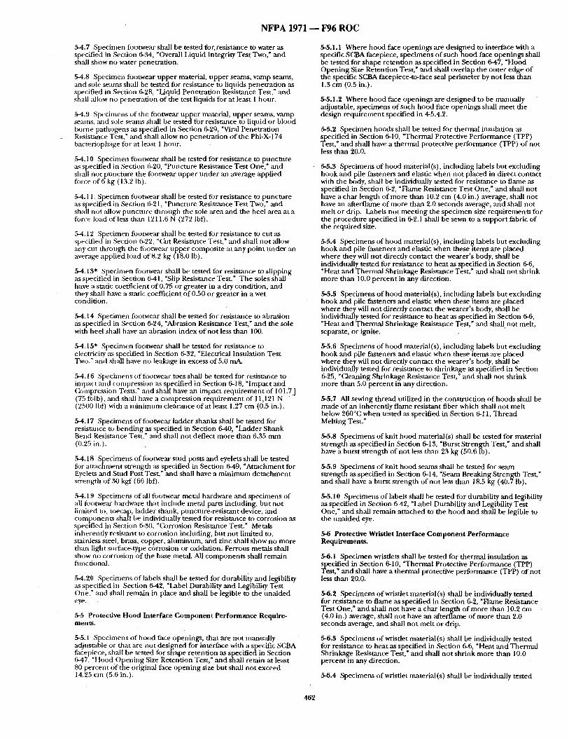
N F P A 1971 ~ 1¢96 R O C
5-4.7 Specinmn fi)otwear shall be tested for.resistance to water as specified in Section 6-34, "Overall Liquid Integrity Test Two," and shall show no water penetrat ion.
5-4,8 Specimen fi:u3twear upper material, uppe r se,'mts, varnp seams, and sole seams shall be tested fi)r resistance to liquids penetrat ion :is specified in Section 6-28, "Liquid Penetrat ion Resistance Test," and shall :dlow no penetrat ion o f the test liquids for at least 1 hour .
5-4.9 Specimens of the footwear upper material, upper seanls, vamp seams, ,'uqd sole scants shall be tes tedfor resistance to liqnid or blood borne pathogens as specified in Section 6-29, "Viral Penetrat ion Resistance Test," ~md shall allow no penetrat ion o f the Phi-X-174 bacteriophage for at least I hour~
g4.10 Specimen fi~otwear shall be tested for resistance to puncture as specified in Section 6-20, "Puncture Resistance Test One," a n d shall not puncture the foutwear upper unde r an average applied fi)rce of 6 kg (13.2 lb).
5-4.11 Specimen footwear sh:dl be tested fi~r resistance to punc ture as specified in Section 6-21, "Puncture Resistance Test Two," and shaH not allow punc tu re through the sole area and the heel area at a fi)rce load of less than 1211.6 N (27") lbf).
,5-4.12 Specimen fi)otwear shall be tested fi)r resistance to cut as specified in Section 6-22, "Cut Resist~0ace Test," and shall no t ,allow any cut through the fi)otwear upper composite at any point unde r an average applied load of8 .2 kg (18.0 Ib).
5-4.13" Specimen footwear shall be tested for resistance to slipping ,as specified in Section 641, "Slip Resistance Test." The soles shall have a static coefficient o f 0.75 or greater in a dry condit ion, and they shall have a static coefficient o f 0.50 or greater in a wet condition.
5-4.14 Specimen footwear shall be tested for resistance to abrasion as specified in Section 6-24, "Abrasion Resistance Test," and the sole with heel shall have an abrasion index of not less than 100.
5-4.15" Specimen footwear shall be tested for resistance to electricity ,as specified in Section 6-32, "Electrical Insulation Test Two," :rod shall have no leakage in excess of 5.0 n~&
5-4.l 6 Specimens of footwear toes shall be tested for resistzmce to impact and compression as specified in Section 6-18, "Impact and (a)mpression Tests," and shall have an impact r equ i rement of 101.TJ (75 ft-lb), and shall have a compression requ i rement of 11,121 N (`)500 Ibt3 with a m i n i m u m clearance of at least 1.27 cm (0.5 in.).
5-4.17 Specimens o f footwear ladder shanks shall be tested for resistm~ce to bending as specified in Section 6-40, "Ladder Shank Bend Resistance Test," and shall no t deflect more than 6.35 mrn (0.25 in.).
,5-4.18 Specimens of footwear s tud posts and eyelets shall be tested for a t t achment s t rength as specified in Section 6-49, "At tachment for Eyelets and Stud Post Test, ~ and shall have a m i n i m u m de t achmen t strength o f 30 kgf (66 lbf).
5-4.19 Specbnens of :dl footwear metal hardware and specimens of all figotwear hardware that include metal parts including, but not linfited to, toecap, ladder shank, puncture-resistant device, and componen t s shah be individually tested for res i s~nce to corrosion as specified in Section 6-30, "Corrosion Resistance Test." Metals inherently resistant to corrosion inchlding, bu t not limited to, stainless steel, brass, copper, a luminum, and zinc shall show no more than light surface-type corrosion or oxidation. Ferrous metals shall show no corrosion o f the base metal. All componen t s shall remain fimctional.
5-4.20 Specimens o f labels shall be tested for durability and legibility as specified in Section 6-42, "Label Durability and Legibility Test One," and shall remain in place and shall be legible to the unaided eye.
5-5 Protective Hood Interface Component Performance Require- mentS.
g5.1 Specimens of hood face openings, that are not mmmally adjustable or that are not designed for interface with a specific SCBA facepiece, shall be tested for shape retention as specif iedin Section 5-47, "Hood Open ing Size Retention Test," and shall retain at least 80 percent o f the original face open ing size but shall no t exceed 14.25 cm (5.6 in.).
5-5.1.1 Where hood face openings are des igned to interface with a specific SCBA facepiece, specimens o f such hood face openings shall be tested for shape retention as specified in Section 6-47, "Hood Open ing Size Retention. Test," and shall overlap the outer edge o f the specific SCBA faceptece-to-face se,al per imeter by not less than 1.3 cm (0.5 in.).
5-5.1.2 Where hood face openings ,are des igned to be manually adjustable, spec imens of such hood face openings shall meet the design requ i rement specified in 4-5.4.2.
5-5.2 Specimen hoods shall be tested for thermal insulation as ,]PeeCified in Section 6-10, "Thermal Protective Performance (TPP)
st," and shall have a thermal protective performance (TPP) o f not less than 20.0.
5-5.3 Specimens of hood material(s), including labels but excluding hook and pile fasteners and elastic when not placed in direct contact with the body, sh;dl be individually tested for resistance to flame ,as specified in Section 6-2, "Flame Resistance Test One," and shall not have a char length o f more than 10.2 cm (4.0 in.) average, shall not have an after'flame of more than 2.0 seconds average, an d shall not mel t or drip. Labels not meet ing the spec imen size requirements for the procedure specified in 6-2.1 shall be sewn to a suppor t fabric of the reqttired size.
5-5.4 Specimens of hood material(s), including labels but excluding hook ,and pile fasteners and elastic when these items are placed where they will no t direcdy contact the wearer 's body, shall be individually tested for resistance to heat as specified in Section 6-6, "Heat and Thermal Shrinkage Resistance Test," and shall no t shr ink more than 10.0 percent in any direction.
5-5.5 Specimens o f hood material(s), including labels but excluding hook and pile fasteners a n d elastic when these i tems are placed where they will no t direcdy contact the wearer 's body, shall be individually tested for resistance to heat as specified in Section 6-6, "Heat and Thermal Shrinkage Resistance Test," and shal l not melt, separate, or ignite.
5-5.6 Specimens of hood material(s), including labels but excluding hook and pile fasteners and elastic when these i tems are placed where they will no t directly contact the wearer's body, shall be individually tested for resistance to shrinkage as specified in Section 6-25, ~Cleaning Shrinkage Resistance Test," and shall not shrink more than 5.0 percent in any direction.
5-5.7 All sewing thread utilized in the construct ion o f hoods shall be made o f an inherent ly f lame resistant fiber which shall no t mel t below 260°C when tested as specified in Section 6-11, Thread Melting Test."
5-5.8 Specimens of knit hood material (s) shall be tested for material s t rength as specified in Section 6-I 3, "Burst Strength Test," and shall have a burst s t rength of not less than 23 kg (50.6 lb).
5-5.9 Specimens of knit hood seams shall be tested for seam s t reng th as specified in Section 6-14, "Seam Breaking Strength Test," and shall have a burst s trength of no t less than 18,5 kg (40.7 lb).
5-5.10 Specimens o f labels shall be tested for durability and legibility as specified in Section 6-42, "Label Durability and Legibility Test One," and shall remain at tached to the h o o d and shall be legible to the una ided eye.
5-6 Protective Wristlet Interface Component Performance Requirements.
5-6.1 Specimen wristlets shall be tested for thermal insulation as SlPeseCified in Section 6-10, "Thermal Protective Performance (TPP)
t," and shall have a thermal protective per formance (TPP) of not less than 20.0.
5-6.2 Specimens o f wristlet material(s) shall be individually tested for resistance to flame as specified in Section 6-2, "Flame Resistance Test One," and shall no t have a char length of more than 10.2 cm (4.0 in.) average, shall no t have an afterflame of more than 2.0 seconds average, and shall no t mel t or drip.
5-6.3 Specimens of wristlet material(s) shall be individually tested for resistance to heat as specified in Section 6-6, "Heat and Thermal Shrinkage Resistance Test," and shall no t shr ink more than 10.0 percent in any direction.
5-6.4 Specimens of wristlet material(s) shall be individually tested
462
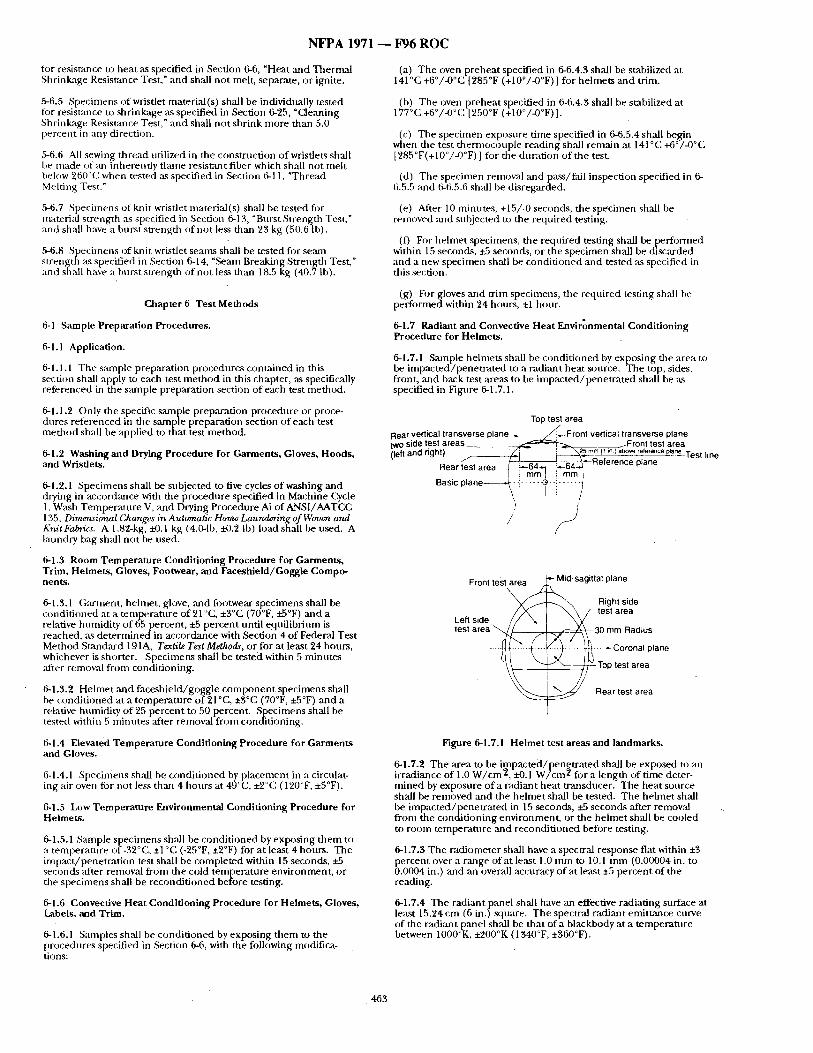
N F P A 1971 - - F 9 6 R O C
for resistance tO heat as specified in Section 6-6, "Heat ,and Thernud Shrinkage Resistance Test," and shall no t melt, separate, or ignite.
~6.5 Specimens of wristlet material(s) shall be individually tested fi~r resistance to shrinkage as specified in Section 6-25, "Cleaning Shrinkage Resistance Test," and shall no t shrink more than 5.0 percent in any direction.
5-6.6 All sewing thread utilized in the construction of wristlets shall be made of :m inherently dante resisumt fiber which shall no t melt below 260°(i ', when tested ,~s specified in Section 6-11, "Thread Melting Test."
5-6.7 Specimens of knit wristlet material(s) shall be tested for material s trength as specified in Section 6-13, "Burst Strength Test," and shall have a hurst strength of not less than 23 kg (50.6 lb).
5-6.8 Specimens of knit wristlet seams shall be tested fi)r semn s t rength its specified in Section 6-14, "Seam Breaking Strength Test," and shall have a burst s trength of no t less than 18.5 kg (40.7 lb).
Cahapter 6 Test Methods
6-1 Sample Preparation Procedures.
6-1.1 Application.
6-1.1.1 The sample preparation procedures contained in this section shall apply to each test m e t h o d in this chapter, as specifically referenced in the smnple preparation section of each test method.
6-1.1.2 Only the specific sample preparation procedure or proce- dures referenced in the sample preparation section of each test me thod shall be applied to that test method.
6-1.2 Washing and Drying Procedure for Garments, Gloves, Hoods, and Wristlets.
6-1.2.1 Specimens shall be subjected to five cycles of washing ,and drying in accordance with the procedure specified in Machine (~cle 1, Wash Tempera tu re V, and Drying Procedure Ai of ANSI/AATCC 135, Dimensional Changes in Automatic Home Laundering of Woven and KnitFalrtic.~. A 1.82-kg, ±0.1 kg ('4.0-tb, -1-0.2 Ib) load shall be used. A laundry bag shall no t be nsed.
6-1.3 Room Temperature Conditioning Procedure for Garments , Trim, Helmets, Gloves, Footwear, and Faceshield/Goggle Compo- nents.
6-1.3.1 Garment , helmet, glove, ;rod footwear specimens shall be condi t ioned at a tempera ture of 91 °C, +3°C (70°F, :I:5°F) and a relative humidity o f 65 percent , ~r5 percent tmtil equil ibrium is reached, as de te rmined in accordance with ,Section 4 o f Federal Test Method Standard 191A, Textile Test Methods, or for at least 24 hours, whichever is shorter. Specimens shall be tested within 5 minutes after removal f rom condit ioning.
6-1.3.2 Helmet and faceshie ld/goggle c o m p o n e n t specimens shall be condi t ioned at a tempera ture o f 21°C, ±3°C (70°F, ±5°F) and a relative humidity of 25 percent to 50 percent. Specimens shall be tested within 5 minutes after removal f rom condit ioning.
6-1.4 Elevated Tempera ture Condit ioning Procedure for Garments and Gloves.
6-1.4.1 Specimens shall be condi t ioned by p lacement in a circulat- ing air oven fi~r not less than 4 hours at 49°C, +2°C (120°F, ±5°F).
6-1.5 Low Tempera ture Environmental Condit ioning Procedure for Helmets.
6-1.5.1 Smnple specimens shall be condi t ioned by exposing t hem to a tempera ture of-32°C, ±1 °C (-25°F, +2°F) for at least 4 hours. The impac t /pene t ra t ion test shall be comple ted within 15 seconds, ~.5 seconds :dter removal f rom the cold tempera ture environment , or the specimens shall be recondi t ioned before testing.
6-1.6 Convective Heat Conditioning, Procedure for Helmets, Gloves, Labels, and Trim.
6-1.6.1 Sitmples shall be condi t ioned by exposing them to the procedures specified in Section 6-6, with the following modifica- tions:
(a) The oven preheat specified in 6-6.4.3 shall be stabilized at 141 °C +6°/-0°C [285°F (+10°/-O°F) ] for helmets and trim.
(b) The oven prehea t specified in 6-6.4.3 shall be stabilized at 177oc +6o/-0oc [250OF (+IO°/-O°F)].
(c) The specimen exposure t ime specified in 6-6.5.4 shall begin when the test thermocouple reading shall remain at 141°C +6°/-0°C [285°F(+I0°/-O°F) ] for the durat ion of the test.
(d) The specimen removal lind p~s / f a i l inspection specified in 6- 6.5.5 and 6-6.5.6 shall be disregarded.
(e) After 10 minutes, +15/-0 seconds, the specimen shall be removed mid subjected to the required testing.
(f) For he lmet specimens, the required testing shall be performed within 15 seconds, +5 seconds, or the spec imen shall be discarded and a new specimen shall be condi t ioned mad tested as specified in this section.
(g) For gloves and tr im specimens, the required testing shall be performed within 24 hours, ±1 hour.
6-1.7 Radiant and Convective Heat Environmental Condit ioning Procedure for Helmets.
6-1.7.1 Smnple helmets shall be condi t ioned by exposing the area to be impacted/pene. t ra ted to a radiant heat source, The top, sides, front, and back test areas to be impacted/penet r i t ted shall be its specified in Figure 6-1.7.1.
Top test area
Rear vertical t ransverse plane ~ ~ ' ~ ' ~ F r o n t vert ical t ransverse plane two side test areas . . . . .....=:z::=~:=:=,~ .~= , . . ~ _ ~ F r o n t test area t~ ~* ~ n r ' l r i n h t ~ , / i - i "~2S mm (1 in ) above relerence ptane ~ , t ie- - . . . . ~- - , ~ - - - - ~ I i - ~ - - ~ " . . . . . . . . . . . . lest line
/ ~ R e f e r e n c e plane Rear test area ~ 7 - m 6 4m~"
/ / J
si0e \ V -testa ea
~ R e a r test area
I
Figure 6-1.7.1 Helmet test areas and landmarks.
6-1.7.2 The area to be impac ted /pene t r a t ed shall be exposed to ml irradiance of 1.0 W / c m 2, ~-0.1 W / c m 2 for a length of t ime deter- mined by exposure o f t radiant hea t t ransdncer. The heat source shall be removed and the he lmet shall be tested. The he lmet shall be impac ted /pene t ra ted in 15 seconds, ~25 seconds after removal f rom the condi t ioning environment , or the he lmet shall be cooled to room tempera ture and recondi t ioned bed)re testing.
6-1.7.3 The radiometer shall have a spectral response fiat within +3 percent over a rmlge of at least 1.0 m m to 10.1 nun (0.00004 in. to 0.0004 in.) and ,an overall accuracy o f at least ±5 percent of the reading.
6-1.7.4 The radiant panel shall have an effective radiating surface at least 15.24 cm (6 in.) square. The spectral radiant emit tance curve of the radiant panel shall be that o f t blackbody at a tempera ture between 1000°K, ±200°K (1340°F, ±360°F).
463
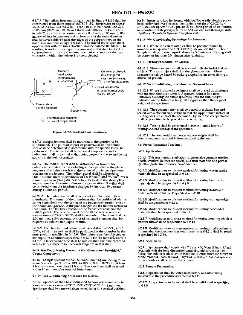
N F P A 1971 - - F 9 6 R O C
6-1.7,5 Tile radiant Iieat transdt,cer shown in Figaare 6-1.8.5 shall be constructed from shee t copper, ASTM B 152, Specification for Copper Shee~ Strip Plate, arut Rolled Bar, Type 110 ETP, haft hard, 0.64 m m ~4).05 nun (0.025 in., :L-0.002 in.) thick and 5.08 cm, ±0.4 m m (2.00 in., ~).02 in.) square. A constantan wire 0.81 ram, i4).05 m m (0.032 in., +0.002 in.) in d iameter and an iron wire of the same diameter shall be silver soldered near the edges o f the copper sheet on the sanle side, as shown lit Figure 6-1.8.5. The side of the copper shee t opposite that with the wires a t tached shall be painted flat black. The resulting t ransducer is a Type.J the rmocouple that shall be used in col~junction with appropriate ins t rumenta t ion to moni tor the heat exposure to which the he lmet is to be subjected.
painted flat black
Brazed or Ceramic or phenolic hard solder (insulating) rod thermocouple cross section area<_ c o n n e ~ i o n s ~ \ _ ~ ~--- --~ 1.6 rnm 2 (0.0625 sq in.)
L " - " ~ II ~ ' " ~,-~.lron & constantan ][6.-" wires to thermocouple
readout device
Copper sheet '
, , Thermocouple locations )", on rear of copper sheet
Figure 6-1.7.5 Radiant heat transducer,
6-1.7.6 Sample helmets shall be m o u n t e d in the position to be condit ioned. The point of impac t or penetrat ion on the he lmet shell shall be de t e rmined in accordance with the specific test to be performed. The helmet shall be removed temporarily, and a radiometer shall be located at that point perpendicular to and facing away from tile hehne t surthce.
6-1.7.7 The radiant panel shall be in t roduced in f ront of the radiometer with its effective radiating surface parallel to the plane tazlgent to the he lmet surface at the center of the impact /pene t ra - tion site on the helmet. The radiant panel shall be adjusted to obutin a stable uni form irradiance of 1.0 W / c m 2, iO.1 W / c m 2 over a m i n i m u m 7.5-cm (3-in.) d iameter circle located on the above plane and centered at the center o f impact or penetration. Stability shall be achieved when the irradiance changes by less than 10 percent dur ing a ~ m i n u t e period.
6-1.7.8* The radiometer shall be replaced with the radiant heat transducer. The center o f the t ransducer shall be posit ioned with its center coincident with the center o f the impac t /pene t ra t ion site on tile he lmet and parMlel to the plane t angen t to the he lmet surface at that point. The flat black surface o f the t ransducer shall face the radiant panel. The time required for the t ransducer to reach a tempera ture of 260°C (500°F) shall be recorded. Tha t t ime shall be ~.50 minutes, +15.0 seconds. A closed insulated chamber shall be reqt,ired to achieve this exposure time.
6-1.7.9 The chamber and he lmet shall be stabilized at 25°C, ±50C (77°F, ±9°F). The he lmet shall be posit ioned in the chambe r in the stone position specified in 8-1.7.6. The he lmet shall be subjected to the exposure condit ions specified in 6-1.7.1 for the t ime recorded in
.6-1.7.8. The exposure t ime shall be not less than the t ime recorded in fi-1.7.8, nor more than 5 seconds longer than that time.
6-1.8 Wet Conditioning Procedure for Helmets and Faceshield/ Goggle Componen t .
6-1.8.1 Smnple spec imens shall be condi t ioned by immers ing them in water at a tempera ture of 20°C to 28°C (68°F to 82°F) for at least 4 hours but not more than 24 hours. The specimen shall be tested within 10 minutes .after removal f rom water.
6-1.9* Wet Condit ioning Procedure for Gloves.
6-1.9.1 Specimens shall he condi t ioned by complete immers ion in water at a tempera ture of 21°C, ±3°G(70°F, ±5°F) for 2 minutes. Specimens shall be removed from water, h u n g in a vertical position
for 5 minutes, and laid horizontal with AATCC textile blotting p a p e r both unde r and over the soecimen nnde r a weight of 0.0020 k g / cm 2, ±0.0002 k g / c m 2 (0.~0 psi, ±0.05 psi) for a period of 20 minutes in accordance with paragraph 7.2 of AATCC 70, Test Method for Water RepeUer~: TumbleJar Dynamic Absorption Test.
6-1.10 Wet Conditioning Procedure for Footwear.
6-1.10.1 Where indicated, samples shall be precondi t ioned by immersion in tap water o f 21°C (70.0°F) for not less than 1.0 hour. Samples shall be dra ined upside down for 5,0 minutes . Testing shall be done not less than 5.0 minutes after draining.
6-1.11 Flexing Procedure for Gloves.
6-1.11.1 Glove spec imens shall be selected to fit the individual test subject. The test subject shall don the glove specimen. Glove specimens shall be f lexed by making a t ight fist ten t imes dur ing a 30-second periock
6-1.12 Wet Condit ioning Procedure for Garment Liner.
6-1.12.1 Where indicated, spec imens shall be placed on a balance with the face cloth side down and sprayed, us ing a fine mist, uniformly covering the entire specimen until the final weight indicated on the balance is 6.0 g, ~ . 1 g greater than the original weight of the specimen.
6-1.12.2 The spec imen then shall be placed in a plastic bag and sealed with sufficient t rapped air so that the uppe r inner surface of the bag does not contact the specimen. Up to three wet specimens shall be permit ted to be placed in the same bag.
6-1.12.3 Test ing shall be per formed between 1 a n d 2 hours o f wetting and bag sealing o f the specimen.
6-1.12.4 The total weight and water add-on weight shall be de t e rmined and recorded before conduc t ing the test.
6-2 Flame Resistance Test One.
6-2,1 Application.
6-2.1.1 This test me thod shall apply to protective g a rm en t textiles, hoods, wristlets, he lmet ear covers, and trim materials and partial eye/ face protective interface components .
6-2.1.2 Modifications to this test m e t h o d for testing woven textile materials shall be as specified ha 6-2.8.
6-2.1.3 Modifications to this test m e t h o d for testing knit textile materials shall be as specified in 6-2.9.
6-2.1.4 Modifications to this test m e t h o d for testing nonwoven textile materials shall be as specified in 6-2.10.
6-2.1.5 Modifications to this test m e t h o d for testing trim materials shall be .as specified in 6-2.11.
6-2.1.6 Modifications to this test m e t h o d for testing hood label materials shall be as specified in 6-2.12.
6-2.1.7 Modification to this test m e t h o d for testing let tering which is transfer film shall be as specified in 6-2.13.
6-2.1.8 Modifications to this test m e t h o d for t esdng small specimens not meet ing the specimen size requirements in 6-2.2.1 shall be tested as specified in 6-2.14.
6-2.2 Specimens.
6-2.2.1 Specimens shall consist o f a 7.6-cm × 30.5-cm (gin . x 12-in.) rectangle, with the long d imension parallel, to e i ther the warp or filling; the wale or coarse; or the mach ine or cross mach ine direction of the material. Each separable layer o f multilayer material systems or composites shall be individually tested.
6-2.3 Sample Preparation.
6-2.3.1 Specimens shall be tested both before and after being subjected to the procedure specified in 6-1.2.
6-2.3.2 All specimens to be tested shall be condi t ioned as specified in 6-1.3.
464

N F P A 1971 ~ F 9 6 R O C
6-2.4 Apparatus.
6~2.4.1 The test a[,paratus specified in Method 5903.1, "Fl~une Resistance of (1 ()tn; Vertica ," )f Fede "al Test Meth :d Stan :lard 191A, Textile T~:st Methods, shall be used.
6-2.5 Procedure.
6-2.5.1 Flame resistance testing shall b e p e r f o r m e d in accord;race with Metht)d 5q03.1, Flame Resistance of Clotb; Vertical, of Federal Test Method Standard 191A, Textile Test Methods.
6-2.5.2 Each specimen shall lye examined for evidence of melt ing or dripping.
6-2.6 Report.
6-2.6.1 Af*erflanle thne and chin" length shall be reported for each s[ e ;inten. The average "aiterflame tinte ~md char length for each material in each direction sh~dl be calculated and reported. The atterflame tin/e shall lye reported to the nearest 0.2 second and the char length to tile nearest 3.2 m m (0.125 in.).
6-2.6.2 ()lyservati()l~s ot melt ing or dr ipping lot each specimen shall be reported.
6-2.7 Interpretation.
6-2.7.1 Pass/l:dl pe['k~rmance shall be based on any observed melt ing or dripping, .the average afterflame time, and tile average char length.
6-2.7.2 Failure in ei ther direction shall constitute f;dlure of the materi;d.
6-2.8 Specific Requirements for Testing Woven Textile Materials.
%2.8.1 Five specimens fronl each of the wm'p and filling directions shall be tested. No two warp specimens sh:dl contain tile same warp yalq ~s, aYid n ( ) two filling specimens shall contain tile same filling yarns.
6-2.8.2 Samples tor condi t ioning shall be at least 1 m (1 yd) square of each lnaterial.
6-2.8.3 Testing shall be pe f tb rmed as specified in 6-2.2 through %2.7.
6-2.9 Specific Requirements for Testing Knit Textile Materials.
6-2.9.1 Five specirnens front each of the w:de and course directions shall be tested.
6-2.9.2 Samples for condi t ioning shall include material that is a n / in imnm of 7.6 cm x 30.5 cm (3 in. × 12 in.).
6-2.9.3 Test ing shall be perliyrmed as specified in 6-2.2 thrcmgh 6-2.7.
6-2.10 Specific Requirements for Testing Nonwoven Textile Materials.
6-2.10.1 Five specimens f rom each of the machine and cross machine directions shall be tested.
6-2.10.2 Samples fiyr condi t ioning shall be at least 1 m (1 yd) square of each material.
6-2.10.3 Testing shall be per formed as specified in 6-2.2 through %2.7.
6-2.11 Specific Requirements for Testing Trim Materials.
6-2.11.1 Five trim specimens for flammability testing shall be at least 5.08 cm (2 in.) wide ~md no more than 7.6 cm (3 in.) wide, Where triin material specimens ,are not wide enough to fit into the test frame, a narrower test f rame of sufficient width to accolnnloda.te the available trim width shall be constructed. The cnt edge of tile trim specimen shall be o r i enmd st) that it is exposed directly to the burner ]~]arne.
6-2,11.2 Samples li)r condi t ioning sh;dl include material sewn onto a l-m (1-yd) square of ballast material no closer than 5,08 cm (2 in,) apart in parallel strips. The ballast material shall be as specified in ANSI/AATCC 135, Dimz'nsional Changes in Automatic Home Laundering of Woven arm Knit FaN~cs. Specimens shall be removed f rom the ballast material prior to testing.
6-2.11.3 Testing shall be perfi)rnled as specified in 6-2.2 through 6-2.7.
%2.12 Specific Requirements for Testing Hood Label Materials.
6-2.12.1 Five specimens of hood labels at tached to the hood material sh~dl be tested. The hood label specimen shall be cut front condi t ioned samples so that the edge of the hood label is at the bot tom of the specimen.
6-2.12.2 Samples for condi t ioning shall be whole hoods, including the label as normally attached.
6-2.12.3 Testing shall be performed as specified in 6-2.2 through 6- 2.7.
6-2.13 Specific Requirements for Testing Lettering Which is Transfer FUm.
6-2.13.1 Lettering which is transfer fihn shall be applied to outer shell material ineeting the requirements of this s tandard for testing as specified in 6-2.13.2.
6-2.13.2 Lettering specimens tor i lammabi l i ty testing shall be at ]e:Lst 5.08 cm (2 in.) wide and no inore than 7.6 cm (3 in.) in width. Samples shall he selected where lettering is most dense.
6-2.13.3 Samples lor condi t ioning shall include material sewn onto a 1-m (1-yd) square of ballast material no closer than 5.08 cm (2 in.) apart in parallel strips. The ballast material shall be as specified in ANSI/AATCC 135, Dimz'nsional Changes in Automatic Home Laurut~,~n E of Woven rout Knit Fabrics. Specimens shall be reinoved from the ballast materi:d prior to testing.
%2,14 Specific Requirements'for Testing Small Specimens.
6-2.14.1 Five specimens at tached to the textile layer as used in the protective garments shall lye tested. The specimens shall be a t tached to the textile layer such that the bot tom (exposure) edge of the item coincides with the bot tom (exposure) edge (~t the textile support layer.
%2.14.2 &mlples tbr condi t ioning shall be at least 1 ill (1 yd) square of tile textile layer on which tile small specimens are attached.
6-2.14.3 Testing shall be per formed as specified in 6-2.2 through 6- 27, o ther th,'m char length shall not be measured.
6-3 Flame Resistance Test Two.
6-3.1 Application.
%3.1.1 This test n le thod shall apply to protective hehnets and partial eye/face protective interface components .
6-3.2 Specimens.
6-3.2.1 Specimens shall be selected as specified in 2-3.9.
6-3.:'~ Sample Preparation.
6-3.3.1 No sample condi t ioning shall be performed.
6-3.4 Apparatus.
6-3.4.1 A s tandard Bunsen bu rne r shall be n ~ d .
6-3.4.2 The Bunsen burner shall be fueled by a bottled m e t h a n e gas, lab grade or better, of 3.72 x 1 0 7 j / m 3, +1.8 x 1 0 6 j / m 3 (1000 Bin / ft 3, ±50 Btu/f t3) .
6-3.4.3 A control valve system with a delivery rate designed to fiwnish gas to the burner tinder a pressure of 0.0020 k g / c m 2 +0.0004/-0.0 k g / c m 2 (0.5 psi, +0.1/4).0 psi) at the btlrner shall be utilized.
6-3.4.4 The barrel of the Bunsen burner shall be 12 ram, ±3 m m (0.5 in., :tO. 125 in.) in diameter. A flame spreader shall no t be used.
6-3.5 Procedure A.
6-3.5.1 Sample helmets shall be seated on tile reference lieadform specified in Figure %1.5.1 according to the helmet ' s posit ioning index, as specified in tile manufac turer ' s instructions for tile specific hehnet . The test setup shall be :ts shown in Figure %3.5.1.
465
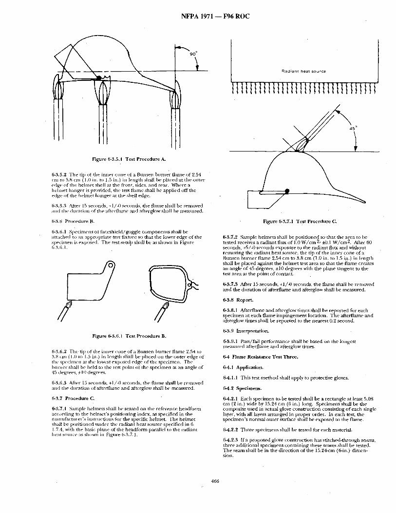
N F P A 1971 ~ F 9 6 R O C
9 0 °
Figure 6-3.5.1 Test Procedure A.
6-3.5.2 Tile tip of the inner cone of a Bunsen burner flame c,f 2.54 Cln [O ~4.8 c n r ( 1 .(} ill. tO 1.5 in . ) ill length shall be placed at the outer edge of the he lmet shell at the front, sides, and rear. Where a h elnlet hanger is provided, tile test f lame shall be applied off file edge of tile he lmet hanger at the shell edge.
6-:4.5.3 After 15 seconds, +1/-13 seconds, the flame shall be removed and tile duration of ttre afterflame and afterglow shall be measured.
6-3.6 Procedure B.
6-3.6A St:~ecinmnsoffaceshield/goggle componen t s shall be attached to ml appropriate test fixture so that tile lower edge o f the specimen is exposed. The test sem]~ shall be ~Ls shown in Figure 6-3.6.1.
# Figure 6-3.6.1 Test Procedure B.
6-3.6.2 The rip of the i lmer cone of a Bunsen burner fl,'une 2.54 U~ 3.8 cm (1.0 to 1.5 in.) in length shall he placed on the outer edge o f the specinmn at tile lowest exposed edge of the specimen. The burner shall he held to the test point of the specimen at an angle of 45 degrees, ±10 degrees.
6-3.6.3 After 15 seconds, +1/-0 seconds, the flame shall be removed and the duration of aftevflame and ,afterglow shall be measured.
6-3.7 Procedure C.
6-3.7.1 Sample hehnets shall be seated on the reference headform according to ttle helmet ' s posit ioning index, as specified in the manufac turer ' s instructions for tile specific helmet. The he lmet shall be positioned unde r the radiant heat source specified in 6- 1.7.4, with t he b:~sic plane of the headform par,'dlel to the radiant heat source as sh~wn in Figure 6-3.7.1.
R a d i a n t h e a t s o u r c e
t l l l t t t l t l l l IIII l
Figure 6-3.7.1 Test Procedure C.
6-3.7.2 Sample helmets shall be posit ioned so that the ,area to be tested receives a radiant flux of 1.0 W / c m 2, ±0.1 W/cm 2 . After 60 seconds, +5/-0 seconds exposure to the radiant flux and without removing the radiant heat source, the tip of the inner cone o f t Bunsen burner flame 2.54 cm to 3.8 cm (1.0 in. to 1.5 in.) in length shall be placed against the he lmet test area so that tile flame creates ,an angle o f 45 degrees, ±10 degrees with the plane tangent to the test area at the point of contact.
6-3.7.3 After 15 seconds, +1/-0 seconds, the f lame shall be rentoved ,and the duration of afterflame and ,afterglow shall be measured.
6-3.8 Report.
6-3.8.1 Afterflame and ,afterglow times shall be reported for each specimen at each flame impingemen t location. The afterflame and ,afterglow times shall be reported to the nearest 0.2 second.
6-3.9 Interpretation.
6-3.9.1 Pass/fail perfi)rmance shall be based on the longest measured afterfl,'une and ~'terglow times.
6-4 Flame Resistance Test Three.
6-4.1 Application.
6-4.1.1 This test m e t h o d shall apply to protective gloves.
6-4.2 Specimens.
6-4,2.1 Each specimen t~xbe tested shall be a rectangle at least 5.08 cm (2 in.) wide by 15.24 cm (6 in.) long. Specimens shall be the composite nsed in actual glove constrtiction consisting o f each single layer, with all layers a r ranged in proper order. In each test, file spec imen 's normal outer surface shall be exposed to the flame.
6-4.2.2 Three specimens shall be tested for each material.
6-4.2.3 If a proposed glove construct ion has st i tched-through seams, three additional specimens containing these seams sh,'dl be tested. The seam shall be in the direction of the 15.24-cm (6-in.) dimen- sion.
466
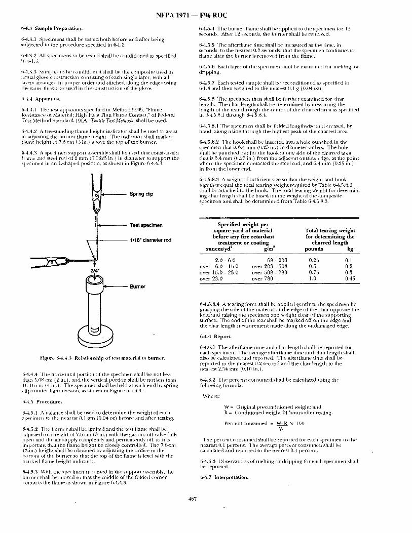
NFPA 1971 - - F96 r o c
6-4.3 Sample Preparation.
6-4.3.1 Specimens shall be tested both before and after heing subjv_cted to tile procedure specified in 6-1.2.
6-4.3.2 ,~1 specinlens to be tested shall be conditioned :L~ specified ill 1i-1.3.
64.3.3 Samples t() be conditioned shall be the composite used in actnal glove COl/strnction consisting of each single layer, with all layvl s ar(anged in proper order and stitch ed ah n ig the edges using tile SalllV th I e a d as t l sed ill th e COllStr t lct ion of the glove.
6-4.4 Apparatus.
64.4.1 The test apparatns specified ill Method 5905. ~Flame Resistance of Material; High Heat FhLx Flame (k)ntact," of Federal Test Method Standard 191A, Textile Test Methods, shall be used.
6-4.4.2 A treestanding flame height indicator shall be used to ~tssist in ad}usting the b u l l e t flame height. The indicator shall mark a flame height ot 7.6 cm (3 in.) al)ove the top of the burner.
6-4.4.3 A specimen support ~Lssembly shall be used that consists of a trame and steel rod (:if 2 mm ((}.0(i25 in.) in diameter to support the sl)e(-imen in an L:sha[)ed [)(isition, ~s shown in Figure 64.4.3.
t Spring clip
Test specimen 1/16" diameter rod
11/4"
8umor
Figure 6-4.4.3 Relationship of test material to burner.
6-4.4.4 The horizontal portion of the specimen shall be not less them 5.0s cm (2 in.). and tile vertical portioil shall be not less than 10.16 cm (4 i,/.). Tile specimen shall be held at each end by spring cli-ps under light tension, ~s shown in Figure 6-4.4.3.
64.5 Procedure.
6-4.5.1 A balance shall be nsed to determine the weight of each specimen to the nearest 0.1 gm (0.04 oz) belore ~md after testing.
6-4.5.2 Tile burner shall be ignited and the test flaine shall be ac{justed to a height of7.6 cm (3 in.) with the K, ts on/offvalve filly open mid the Nr supply co/npletely and permanently off, ~Ls it is important that the flame height be closely controlled. Tile 7.6-cm (3-in.) height sh:dl he obt:dned by adjusting the orifice in the I:lottom (~f the knm/er so that tile top of the flame is level with tile ntarked fl~une height indican)r.
64.5.3 With the specimen mounted in the stLpport :tsseinbly, tile h(n-nel sh:dl be moved so that tile middle of the folded corner , ontacts the flame ~ks shown in Figure 6-4.4.3.
6-4.5.4 The burner flame shall be applied to the specimen for 12 seconds. After 12 seconds, the burner shall be removed.
6-4.5.5 The afterflame time shall be measured ~s the time, in seconds, to tile nearest 0.2 seconds, that the specimen conthmes to flame :filer the burner is renloved from the flame.
64.5.6 Each layer of the specinten shall be examined fi)r mehing or dripping.
64.5.7 Each tested smnple shall be reconditioned :m specified in 6-1.3 ;rod then weighed to the nearest 0.1 g (0.04 oz).
6-4.5.8 The specimen then shall be further examined fi)r char length. The char length shall be deternfined by me;L~uring the length of the tear through the center of the charred area ~s specified in 6-4.5.8,1 through 64.5.8.4.
6-4.5.8.1 Tile specimen shall be fi)lded lengthwise and creased, by hand, along a line throt,gh the highest peak of tile charred area.
6-4.5.8.2 Tile tlook shall be inserted into a hole punched in the specimen that is 6.4 mm (0.25 in.) in ¢fiameter or less. The hole shall be punched ont for tile hook at one side of tile charred area that is (5.4 mm ((I.25 in.) fi-onl tile adjacent outside edge, :it the point where the specimen contacted the steel r(id, and 6.4 mn~t (0.25 in.) in f r -m the Mwer end.
6-4.5.8.3 A weight of sufficient size so that the weight and hook together equal the total tearing weight required by Table 6-4.5.8.3 shall be attached to the hook. The total tearing weight for determin- ing char length shall be based on the weight of the composite specimen and shall be determined from Table 6-4.5.8.3.
Specif ied weight per square yard of material Total tearing weight
before any fire retardant for de termining the treatment or coat ing charred length
ounces / yd ~ g/m ~ pounds kg
2.0 - 6.0 68 - 203 0.25 0.1 over 6.0 - 15.0 over 203 - 508 0.5 0.2 over 15.0 - 23.0 over 508 - 780 0.75 0.3 over 23.0 over 780 1.0 0.45
6-4.5.8.4 A tearing fi)rce shall be applied gently to the specimen by gr:~sping the side of the material at the edge of the char opposite the load and raising tile specimen and weight clear of the supporting surface. The end of the tear sh:dl be marked off on the edge and tile char length measurement made along the undamaged edge.
6-4.6 Report.
6-4.6.1 The :ffterflame time and char length shall tie reported fi)r each specimen. Tile average afterflame time and char length shall also be calculated and reported, The afterfl~une time shall be reported to tile ne~trest 0.2 second and tile char length to tile nearest 2.54 mm (0.10 in.).
64.6.2 The percent consumed shall be calculated using the tilllowing iin'mula:
Where:
W = Original preconditioned weight: and R = Conditioned weight 24 hotzrs after testing.
Percent consumed = W-R x 100 W
Tile percent consnmed shall be reported tor each specimen to the nearest O. 1 percent. Tile average percent consumed shall be calculated and reported to tile nearest 0.1 percent.
6-4.6.3 Observations of melting or dripping fin" each specimen shall be reported.
6-4.7 Interpretation.
467
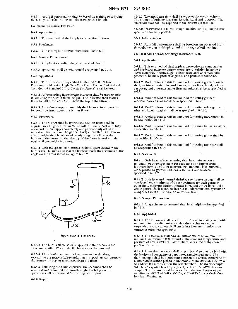
NFPA 1971 - - F96 R( )C
6-4.7.1 Pass/tail perli:)rmam:e shall he based on melt ing or dripping, the :~verage :lftert]ame tinle, and tile average char length.
6-5 Flame Resistance Test Four.
6-5.1 Application.
6-5.1.1 Tiffs test me thod shall apply to protective footwear.
6-5.2 Specimens.
6-5.2.1 Three c(mlplete ti:)otwear i tems shall be tested.
6-5.3 Sample Preparation.
6-5.3.1 Samples for condi t ioning shall be whole hoots.
6-5.3.2 Specimens shall he condit ioned as specified in 6-1.3.
6-5.4 Apparatus.
6-5.4.1 Tile test appararus specified in Method 5905, "Flame Resistm~(;e of Material; High Heat Flux Flame Q:mtact," of Feder:d Test Method Standard 191A, Textile T¢~t Methods, shall be used.
6-5.4.2 A freestanding fl,'tme height indicator shall be used u) assist in adjusting tile burner flame height. The indicator shMl mark a flame height of 7.6 cm (3 in.) above the top of the burner.
6-5.4.3 A specimen suppor t assembly shall be used to suppor t tile fi:)otwear specimen above tile burner flame.
6-5.5 Prc)cedure.
6-5.5.1 Tile burner shall be ignited and the test f lame shall be a(tiusted t(~ a height of 7.(i cm (3 in.) with the gas on /o f fva lve fidly ~)pell mid die air supply completely and ~:~ermanently off, as it is imp~wtaiJt that tile flame height be closely controlled. The 7.6-cm (3-in.) he ight shall be obtadned by adiust ing the orifice in the I)()m)m of tile burner so that tile t o p 0 f the flame is level with the marked flzuue height indicator.
6-5.5.'2 With the specimen m o u n t e d in tile suppor t assembly, the burner shall be moved so that the flame contacts the specimen at the angles in the areas shown in Figure 6-5.5.2
~_,,/90
Figure 6-5.5.2 Test areas.
6-5.5.3 The burner flzuue shall be applied to the specimen fi)r 12 seconds. Alter 12 ~conds , t he burner shall be removed.
6-5.5.4 The afierflame time shldl be measured as the t ime, in seconds, to tile nearest 0.2 seconds, that the specimen cont inues to flame after the burner is removed from tile f ame .
6-5.5.5 Following file f lame exposure, the spec imen shall be removed lind examined for burn- through. Each layer of the specimen shall be examined for mel t ing or dripping.
6-5.6 Report.
6-5.6.1 Tile iffterflame time shall be reported for each specimen. The average afterfl~une time shall he calculated and reported. The afterflame time shall be reported to the nearest 0.2 seconds.
6 -5 .6 .20hserva t ions of burn through, melting, or dr ipping for each specimen sh~dl he reported.
6-5.7 Interpretation.
6-5.7.1 Pass/f~fil performance shall be based on any observed burn- through, melt ing or dripping, and the average afterflame time.
6-6 Heat and Thermal Shrinkage Resistance Test.
6-6.1 Application.
6-6.1.1 This test me thod shall apply to protective ga rmen t textiles and hardware; moisture barrier seance; hood, wristlet~ he lmet e ~ cover materials, innermost glove finer, trim, imd label materials;
-protective helmets, protective gloves, and protective fi)otwear.
6-6.1.2 Modifications to this test me thod fi~r testing ga rmen t outer shell, moisture b,'uTier, thermal barrier, winter liner, hood, he lmet ear cover, and innermost glove liner materials shall be as spec i fed in 6-6.8.
6-6.1.3 Modifications to this test me thod for testing ga rmen t moisture barrier seams shall be as specified in 6-6.9.
6-6.1.4 Modifications to this test me thod for testing other garment, trim, and lahel materials shall be as specified in 6-6.10.
6-6.1.5 Modifications to this test me thod for testing hardware shall be as specified in 6-6.11.
6-6.1.6 Modifications to this test me thod for testing helmets shall be its specified in 6-6.12.
6-6.1.7 Modifications to this test me thod for testing gloves shMl be as specified in 6-6.13.
6-6.1.8 Modifications to this test me thod for testing footwear shall be its specified in 6-6.14.
6-6.2 Specimens.
6-6.2.1 Only heat resistance testing shall be conducted on a m i n i m u m of three specimens for each moisture barrier seam, hardware item, glove liner material, trim material, label material, o ther protective ga rmen t materials, helmets, and footwear no t specified in 6-6.2.2.
6-6.2.2 Both heat and thermal shrinkage resistance testing shall be conducted on a m i n i m u m of three specimens for each g a rm en t outer Shell, moisture barrier, thermal liner, and winter liner; and on whole gloves. Each separable layer of multilayer material systems or composites shall be tested as an individual layer.
6-6.3 Sample Preparation.
6-6.3.1 All specimens to be tested shall be condi t ioned ,~s specified in 6-1.3.
6-6.4 Apparatus.
6-6.4.1 The test oven shall be a horizontal flow circulating oven with nf in imnm interior d imensions so that the specimens can be suspended and are at least 5.08 cm (2 in.) f rom ally interior oven surface or o ther test specimens.
6-6.4.2 The test oven shall have an ifirtlow rate of 38 m / r a in to 76 m/ r a in (125 f t /min to 250 f t /min ) at the s tandard tempera ture and pressure of 21 °C (70°F) at 1 a tmosphere , measured at the center point of the oven.
6-6.4.3 A test thermocouple shall be posit ioned so that it is level with the horizontal centerl ine o f a m o u n t e d sample specimen. The t i lermocouple shall be equidistant between the vertical centerl ine of a m o u n t e d specimen placed in the middle o f the oven and the oven wall where the ,airflow enters the test chamber . The thermocouple shall be an exposed bead, TypeJ or Type K, NO. 30 AWG thermo- couple. The test oven shall be heated and the test thermocouple stabilized at 260°C, +6°/43°£', (500°F, +10°/-0°F) for a period o f not less than 30 minutes.
468
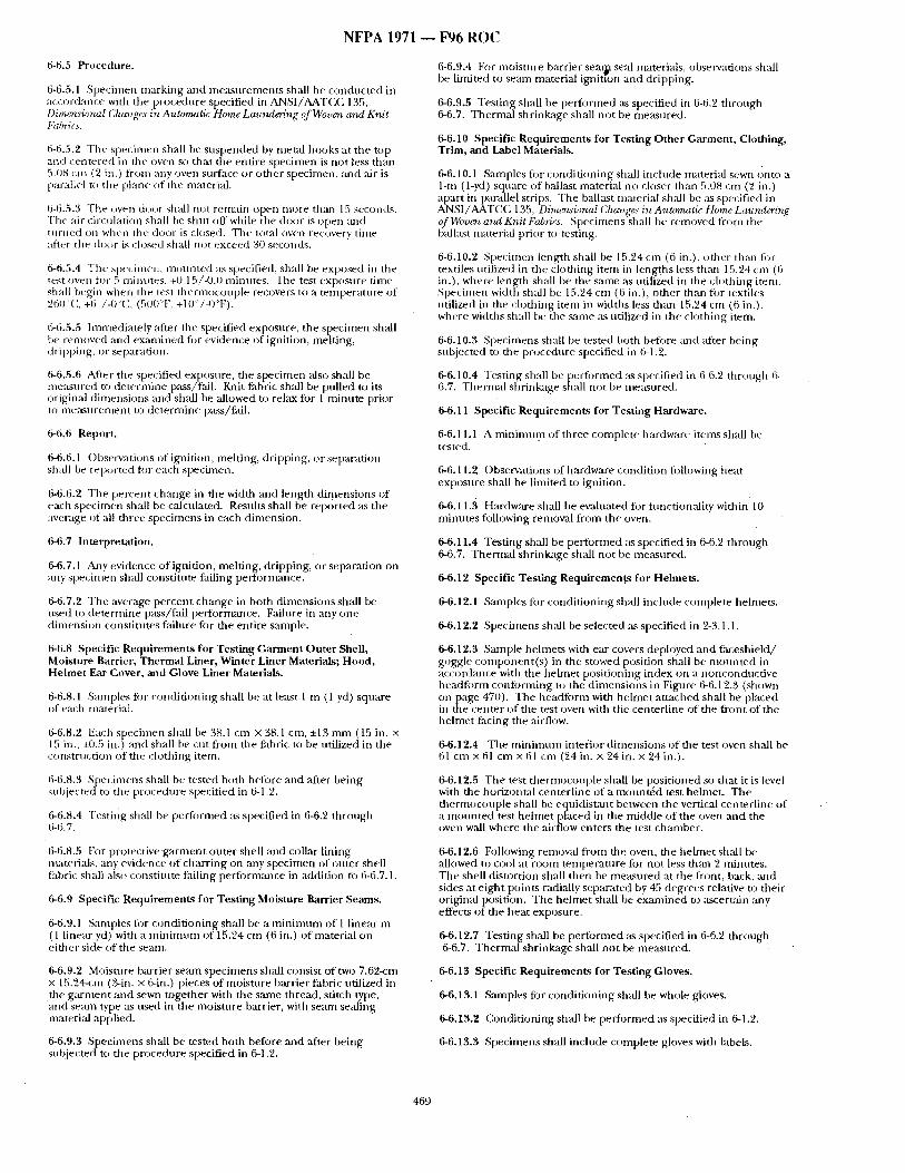
N F P A 1971 ~ F96 R O C
6-6.5 Procedure.
6-6.5.1 Speciinen inarking and me~csurements shall be conducted in accordai)ce with tile procedure specified in ANSI/AATCC 135, Dimensioruzl Changes in Automatic Home Laundering of Woven and Knit Fabrics.
6-6.5.2 The specimen shall he suspended by metal hooks at the top and centered in the oven so that tile entire specimen is not less than 5.08 cm (2 in.) fi'om ai)y oven surface or other specimen, and ,air is parallel t(~ the plane of the material.
6-6.5.3 The ~wen door shall not remain open more th:m 15 seconds. Tt/e air circuhttion shall be shut off while the door is open :rod t i l l ' l ied ()U w h e n t i le d o o r is ch)sed . T h e total (])veil r e c o v e l ~ time afier the door is ch)sed shall not exceed 30 seconds.
6-6.5.4 The specimen, mounted ~Ls specified, shall be exposed in the test (wed tot 5 minutes, +0.15/-0.0 minutes. The test exposure time shall hegin when the test thennocouple recovers to a temperature of 260"C, +6 '/-0"C, (500°F, +10'~/-0'T).
6-6.5.5 Immediately :filer the specified exposure, the specimen shall be removed and examined tor evidence of ignition, melting, dripping, o r separation.
6-6.5.6 After the specified exposure, the specimen ~dso sball be me:usured to deterinine pass/fall. Knit fabric shall be pulled to its original dimensions and shall be allowed to relax for 1 minute prior to ineasurement to determine p~ss/fail.
6-6.6 Report.
6-6.6.1 ()bservati(ms ofigrtition, melting, dripping, or separation shall be reported for each specimen.
6-6.6.2 Tile percent change ill the width mTd length din)ensions of each spe(:imen shall be calculated. Results shall be reported :Ls the average of all three specimens in each dimension.
6-6.7 Interpretation.
6-6.7.1 Aaly evidence of ignition, melting, dripping, or separation on any specilnetl shall constitute failing performance.
6-6.7.2 The average percent change in both dimensions shall be used to determine p~tss/fail performance. Failure in any one dimension constitutes failure for the entire sample.
6-6.8 Specific Requirements for Testing Garment Outer Shell, Moisture Barrier, Thermal Liner, Winter Liner MateriaLs; Hood, Helmet Ear Cover, and Glove Liner MateriaLs.
6-6.8.1 Samples fi)r (-onditi(ming shall be at least 1 m (1 yd) square of each material.
6-6.8.2 Each specimen shall be 38.1 c m x 38.1 cm, :1:13 mm (15 ill. X 15 in., :t0.5 ill.) and shall be cut from tile fabric to be utilized in the construction of the clothing item.
6-6.8.3 Specimens shall be tested both before and ,after being subjected to tile procedure specified in 6-1.2.
6-6.8.4 Testii{g shall be perIbrmed ,-ks specified in 6-6.2 through 6-6.7.
6-6.9.4 For moisture barrier sea~ seal materials, observations shall be limited to semn material igniuon and dripping.
6-6.9.5 Testing shall be performed :ts specified in 6-6.2 dmmgh 6-6.7. Thermal shrinkage shall not be measured.
6-6.10 Specific Requirements for Testing Other Garment, Clothing, Trim, and Label Materials.
6-6.10.1 Samples for conditioning shall inchtde material sewn onto a 1-m (1-yd) square of ballast material no closer than 5.08 cm (2 in.) apart in parallel strips. The balhLst material shall be as specified in ANSI/AATCC 135, Dimensional Changes in Automatic Home Laundering of Woven and Knit Fab*ics. Specintens shall be removed from the balkLst material prior to testing.
6-6.10.2 Specimen length shall be 15.24 cm (6 in.), other thin) fi)r textiles t,tilized in the clothing item in lengths less than 15.24 cm (6 in.), where length shall be the same :~s utilized in the chxhing item. Specimen width shall be 15.')4 cm (6 in.), other th:m fi)r textiles utilized in tile dodTing item in widths less than 15.24 cm (6 in.), where widdTs shall be the same as utilized ill the clothing item.
6-6.10.3 Specimens shall be tested both befi)re :rod after being suhjected to the procedure specified in 6-1.2.
6-6.10.4 Testing shall be t)erfi)rmed ,as specified in 6-6.2 through 6- 6.7. Thermal shrinkage snail not be measured.
6-6.11 Specific Requirements for Testing Hardware.
6-6.11.1 A mininmm of three complete hardware items shall be tested.
6-6.11.2 Observations of hardware condition lollowing heat exposure shall be limited to ignition.
6-6.11.3 Hardware shall be evahmted for fimctionality within 10 minutes following removal from the oven.
6-6.11.4 Testing shall be performed as specified ill 6-6.2 through 6-6.7. Thermal shrinkage shall not be measured.
6-6.12 Specific Testing Requiremengs for Helmets.
6-6.12.1 Samples fi~r conditioning shall include complete helmets.
6-6.12.2 Specimens shall be selected :Ls specified in 2-3.1,1.
6-6.12.3 Sample helmets with ear covers deployed and faceshieM/ goggle component(s) in the stowed position shall be mounted in accordance with the helmet positioning index on a noncondnctive headfiwm conforming to tile dimensions in Figure 6-6.12.3 (shown onpage 470). The headform with helmet attached shall be placed in the center ofdae test oven with the centerline of the front ofdae helmet facing the airflow.
6-6.12.4 The minimum interior dimensions of the test oven shall be 61 c m x 61 c m x 61 cm (24 in. x 24 in. x 24 in.).
6-6.12.5 The test thermocouple shall be positioned so that it is level with tile horizontal centerline of a mounted test helmet. The dmrmocouple shall be equidist~mt between the vertical centerline of a mounted test hehnet placed in the middle of the oven and the oven wall where the ,airflow enters the test chamber.
6-6.8.5 For protective ~t rment outer shell and collar lining materiMs, any evidence of charring on ally specimen of outer shell fabri( shall also constinlte failing performance in addition to 6-6.7.1,
6-6.9 Specific Requirements for Testing Moisture Barrier Seams.
6-6.9.1 Samples fi)r conditioning shall be a mininmm of I linear m ( l linear yd) with a minimum of 15.24 cm (6 in.) of material on either side of the seam.
6-6.9.2 Moisture bmTier seam specimens shall consist of two 7.62-cm x 15.24-cnt (,3-in. x 6-in.) pieces of moisture barrier fabric utilized in the garment and sewn together with the same thread, stitch type, and seam type as used in the moistnre barrier, with seam sealing material applied.
6-6.9.3 Specimens shall be tested both before and ,after being subjected to the procedure specified in 6-1.2.
6-6.12.6 Following removal from the oven, file helmet shMl be allowed to cool at room temperature for not less thml 2 minntes. The shell distortion shall then be me~tsured at file front, back, and sides at eight points ~)dially separated by 45 degrees relative to their original position. The helmet shall be ex~mTined to ascertain any effects of the heat exposure.
6-6.12.7 Testing shall be performed as specified ill 6-6.2 through 6-6.7. Thermal shrinkage shall not be measured.
6-6.13 Specific Requirements for Testing Gloves.
6-6.13.1 Samples for conditioning shall be whole gloves.
6-6.13.2 Conditioning shall be performed as specified in 6-1.2.
6-6.13.3 Specimens shall include complete gloves with labels.
469
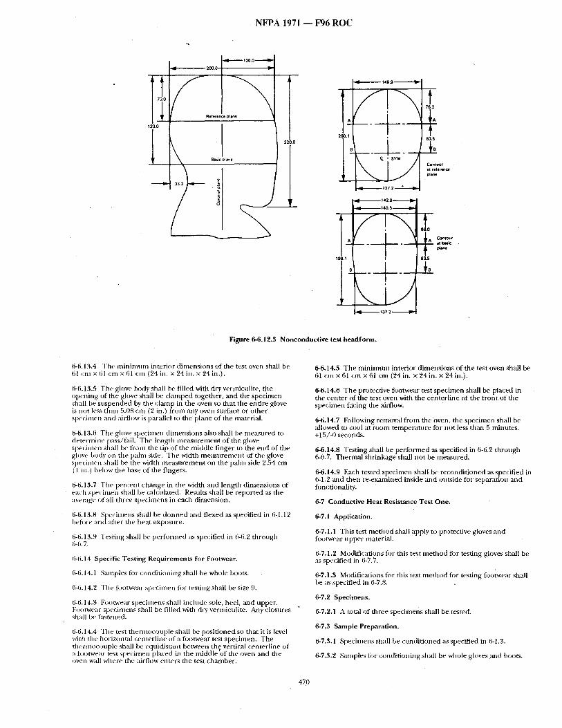
N F P A 1971 - - F96 R O C
I 133.0
"------'Ira
i Basic Diane
220.0
I _L
149.9
Contour at reference plane
-9l'~-----.~ ' 37
6e;0 . ~ Contour
A It I~siC
198. I 63.S
01
91-.------~ 137.2 ~
Figure 6-6.12.3 Nonconductive test headform.
6-6.13.4 The m i n i m u m interior d imens ions o f the test oven shall be 61 cm x 61 cm x 61 cm (24 in. x 24 in. x 24 in.).
6-6.13.5 The glove body shall be filled with dry vermiculite, the opening of the glove shall be c lamped together, and the specimen shall be suspended by the cl, ' ,np in the oven so that the entire glove is not less than 5.08 cm (2 in.) from ally oven surface or o ther specimen alld ~fi rfl ow is p:u'allel to the plane of the material.
6-6.13.6 The gh~ve specimen d imensions also shall be measured to de termine p:tss/fail. The length measu remen t o f the glove specimen shall be f rom the tip of tile middle finger to the end of the glove body ~n the palm side. Tile width measu remen t of the glove specimen shall be the width m e a s u r e m e n t on the pahn side 2.54 cm ( 1 in.) below tire b~Lse of file fingers.
6-6.13.7 Tile percent chm/ge in the width and length d imensions of each specimt~n shall be calculated. Restflts shall be reported ~Ls the average ol all three spechnens in each dimension.
6-6.13.8 Specimens sh~dl be d o n n e d :rod f/exed as specified ill 6-1.1 2 heft:we and after tile heat exposure.
6-6.13.9 Testing shall be peril)treed ,'ts specified in 6-6.2 through ti-6.7.
6-6.14 Specifle Testing Requirements for Footwear.
6-6.14.1 Samples tbr condi t ioning shall be whole boot~.
6-6.14.2 The li)otwear specimen li:w testing shall be size 9.
6-6.14.3 Footwear specimens sh:dl include sole, heel, :rod upper. Fo<~twear specimens shall be filled with dry vermiculite. Any closures shall be fr~stened.
6-6.14.4 Tile test thermocouple shall be posi t ioned so that it is level with the h o r i z o n t a l centerl ine nf a fl)otwear test specimen. The thermocouple shall be equidist~mt between thve vertical centerl ine of a fi:)otwear test specimen placed in the n-fiddle of the oven and tile oven wall where the airflow enters file test chamber .
6-6.14.5 The m i n i m u m interior d imensions of tile test oven shall be 61 cm x 61 cm x 61 cm (24 in. × 24 in. × 24 in.).
6-6.14.6 The protective footwear test specimen shall be placed in the center of the test oven with the centerl ine of file f ront of the specimen facing the airflow.
6-6.14.7 Following removal f rom the-oven, the specimen shall be allowed to cool at room temperature for not less than 5 minutes, +15/-0 seconds.
6-6.14.8 Testing shall be per formed ,as specified in 6-6.2 through 6-6.7. Thermal shrinkage shall no t be measured.
6-6.14.9 Each tested specimen sh,'dl be recondi t ioned ,as slpecified in 6-1.2 and then re-examined inside and outside figr separatton and fimctionality.
6-7 Conductive Heat Resistance Test One.
6-7.1 Application.
6-7.1.1 This tes t me thod shall apply to protective g lovesand fi~otwear upper material.
6-7.1.2 Modifications for this test m e t h o d for testing gloves shall be as specified in 6-7.7.
6-7.1.3 Modifications fi)r this test me thod for testing footwear shall be as specified in 6-7.8.
6-7.2 Specimens.
6-7.2.1 A total of three specimens shall be tested.
6-7.3 Sample Preparation.
6-7,3.1 Specimens shall be condit ioned ,'is specified in 6-1.3.
6-7,3.2 Samples fi)r condi t ioning shall be whole gloves and boots.
470
6-7A Procedure.
6-7.4.1 Sample ~ . c i m e n . l s h a l l T ~ ; ~ m ~ d a n c e with ASTM F 1060, S t a n d a r ~ f e s t ~ f c r ~ e ~ l P r o t 4 ~ o s P ~ u m ~ o f Martials for ~ Ctothing fir H~ S u r ~ ~ .
6-7.4.2 Sample:e~ecimens shaiIbe, t e s t e d . ~ t e m p ~ u r e of$]~0*C ~536°F). ~ p r ~ ~[~i~dnr~g the test shall be 0.0020 ~ / c m ,-~'0.0001 kW'cmZ (0.5 psi, ~0.0~ 1~i).
6-7.4.3 The time in seconds to .pain and to secimd2degree bum, blister, ~ pro~lieted by the Stoll Human Tissue Bum Tolerance Criteria~ shall berecorded.
• 6-7.5 ,Report.
6-7.5.1 The time to pain and time to second-degree burn for each specimen shall be r'eported. The average ti~ae to pain and time to second-degree bum shall be ~alculated and reported. If the time to pain,or time to second-degree bum is greater than 30 seconds, the time to pain or time to second-degree b n m shall be reported as "> 30 see."
6-7.6 Interpretation.
6-7.6.1 Pass or fail'determlnations shall be based on the average time to pain and time to second-degree bum of all specimens tested.
6-7.6.2 ! f an individfial result from any test set varies more than ±8 percent from the average result, the restflt s f~om the test set shall be discarded and another set of specimens shall be tested.
6-7.7 Specific Requirement for Testing Gloves.
6-7.7.1 Specimens shall be representatlveofgiove body composite constrnction at the palm ofth~ hand and at the palm side of the fingers.
6-7.7.2 Specimens shall be stitched around the perimeter using the same threa~d used in glove construction.
6-7.7.3 (;love specimens shall be tested before and after being subjected a) the procedure specified in 6-1.2.
6-7.7.4 Specimens shall also be tested after wet conditioning as specified-in 6-1.9.
6-7.7.5 Tesdng shall be performedas specified in 6-7.2 through:6- 7.6.
6-7.8 Specific Requirements for Testin~Footwear Upper Materials.
6-7.8.1 Footw~,,t~ speeimensshatl include the thinnest portions of the footwear upper.
6-7.8.2 Testing shall be performed as specified in 6-7.2 through 6- 7.6.
6-8 Conductive Heat ReMslatlCeT~t Two,
6-8.1 Application. %
6-8.1.1 This t ~ t method shall apply to the protective footwear sole.
6-8.2 Specimens.
6-8.2.1 A minimum of three complete footwear items shall be tesmd.
6-8.3 Sample Preparation.
6-8.3.1 Sam pies for conditioning shall be whole footwear~
6=8.3.2 Specimens shall be preconditioned as specified in fM.3.
6-8.4 Apparatus.
6=8.4.1 The apparatns shall confist of an i~on plate' measuring 2.54 -cm-x 15.24 cm x 46 cm (l in. x 6 in. x 18 iia.) a n d a n oven capable of heating the plate to a temperafure of 5000C (932"F), a Type,]" or Type K thermocouple, and a meter to read the thermoconple temperature.
t
6-8.5 Procedure.
6-s.5.] The ~ e ~ .sha~be ~ to the ~ , ~ of the specimen,~xt tothe foot, directly above'tke ballof the foot. The thermocouple shall be taped to the surface with electrical tape to hold it onto the insole sur~a:e:
6,8J;;II. TheoPla~ s ha~be heated to a temperature,of 500°C, +lOqC (952 F, ±18 F) and shall hmintain ~ temperau,re th/'oughout the test period.
~6-&5.3 The specimen shall be filled with 4.55 kg (IO Ib) ~f,5 mm (0.375 in.) steel halls. Theweight of the steel b~l]s Shaft be evenly distributed~inside the boot The specimen shall be placed on the plate in the upright position for 30.0 seconds.
6-8.5.4 The thermocopple~temperat~we shall be recorded at 30.0 seconds, +2/-0 seconds after the specimen is placed on the heated metal plate.
6-8 .6 Report.
6-8.6.1 The teml~rature ~t 30.0 seconds of exposure shall be reported for ea~'M)ecimen. The average tempframr¢ at 30.0 seconds of exposure for all specimens shall also be calculated and reported.
68,7 Interpretation.
6-8.7.1 The average temperature at $0.0 seconds o f e x ~ u r e for all specimens shall be nsed to determine pass/fail performance~
6-9 Radiant Heat Resistance Test.
6-9.1 Application.
6-9.1.1 This test method shall apply to protective footwear.
6-9 .2 Specimens.
6-9.2.1 A minimum of three complete footwear items shallbe tested.
6-9.3 Sample Preparation.
• . . . r 6-9.5.1 Samples for conditioning shall be complete footwear.
6-9.$,2 Specimens shall be conditioned in accordance with 6-1.3and 6-1.10.
6~.4 Apparatm.
6-9.4,1 The apparatus shall consist of the following:
(a) A radiometer with a spectral response fiat to within ±3.0 percent of not Mss than I.I0 mm to 10.0 rrffn with an accuracy of ~:5.0 percent;
(b) A radiant panel with an effective radiating surface of not less than 15.24 cm~x 15.24 cm (6 in. x 8 in.) and an emittance approxi- mating that of a blackbody of 1000°K, :t200°K ( 1 MOW, ~3600F);
( ~ A thermocouple with meter;,
(d) A test chamber thaf prevents interference from air movement.
6-9.5 Procedure.
6-9.5.1 T~ests shall be done on the toe, vamp, quarter, gtisset if present, and shaft. ~different types or thicknesses of materials are utilized for other areas of the upper, these areas shall also be tested.
6-9.5,2 The radtantpanel shall be placed in front of the radiometer, parallel W the p~ane tangfn t to the radion~ter. The radiant panel sh~l ~ adjmtc:d io obiain a stablei,uniform irradiance of 1.0 W/ cm ,+O~O1/-0.0,W/cmZ 0vera minimum 7.6-cm (3~0-in.) diaraeter circle located 0wthe above plane and ceritered at the center of test area. Calibration shall be achieved when the irradlance changes by less than 10 percent during a 3.0-minute period.
6-9.5.3 The thermocouple shall be affixed to the inside surface of the lining next to the foot, in the cente[ of the test areo_ The radiometer shall be replaced with the protective footwear with the test area oriented para]tel to the plane tangent to the heat source, at the same distance from the heat source. The area shall be exposed for 1.0 minute, +5/-0 seconds.
471
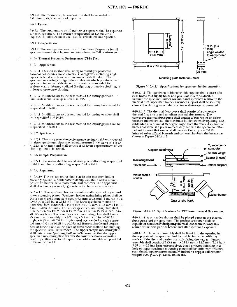
NFPA 1971 ~ F96 ROC
6-9.5.4 The thermocouple temperature shall be recorded at 1.0 minute, +5/-0 seconds of ex'posnre.
6-9.6 Report.
6-9.6.1 The temperature at 1.0 minute of exposure shall be reported for each specimen. The average texn[0eratufe at 1.0 minute of
'exposure fi~r all specimens shall also oe calculated and reported.
6-9.7 Interpretation.
6-9.7.1 The average tern peratu re at 1.0 mi m~te of exposu re for all Sl)ecin~ens tested shall be used to determine p;tss/fail peffomtance.
6-10" Thermal Protective Performance (TPP) Test.
6-10.1 Application.
6-10.1.1 This test method sh,'-dl apply to multilayer protective garnmi*t composites, hoods, wristlets, and gloves, inclnding single layer knit hood which are w¢)rn in contact with the skin. The specimen monnting confign~ttion in this test which positions the specimen in contstct with the sensor is not recommended for station/work uniforms, wildland fire fighting protective clothing, or industrial protective clothing.
6-10.1.2 Mod, ificafi(.)ns to this test method fi:)r testing g~trinent C()lnp()sites shall be as specified in 6-10.8.
6-10.1.3 M()diti,-ations n) this test ntethod for testing hoods shall be as specified in 6-10.9.
6-10.1.4 Modifications to this test method for testing wristlets shall I:)e as specified in 6-10.10.
6-10.1.5 Modifications to this test method for testing gloves shall be as specified in 6-10.11.
6-10.2 Specimens.
6-10.2.1 Thermal protective performance testing shall be conducted on three specimens. ,Specimens shall measure 6 x 6, +1/4 in. (152.4 x 152.4, + 6.4 mm) andshall consist of all layers representative of the ch:)thing iteln t o be tested.
6-111.3 Sample Preparation.
6-10.3.1 Specimens shall be tested :ffter preconditioning as specified in 6-1.2 and then conditioning as specified in 6-1.3.
6-10.4 Apparatus.
6-10.4.1" The test apparatus shall consist o f t specimen holder :Lsselnbly, specinten holder assembly snDport, thermal flux source, protective shutter, sensor assembly, anct recorder. The apparatus shall :dso have a gas supply, gas rotameter, burners, and sensor.
6-10.4.1.1 The specimen bold(r assembly shall consist of upper and lower moundng plates. Specimen bolder maint,aining plates shall be 203.2 m m x 203.2 ram, ±1.6 mm, x 6.4 mm, ± 0.8 mm (8 in. x.8 in., ± 0.063 in. x 0.25 in., ± 0.313 in.). The lower specimen mounting plate sh:dl have centered, a 101.6 mm x 101.6 ram, ± 1.6 mm (4 in. x 4 in., ± 0.063 in.) bole. The upper specimen monntJng plate shall have centered a 130.2 m m x 130.2 mm, + 1.6 m m (5.13 in. x 5.13 in., +0.o63 in.) hole. The lower specimen mounting p[ate shall have a 25.4 ram, + 1.6 mm high, x 3.2 ram, + 0.8 mm (1.0 in., +0.063 in. high, x 0.13 in., +0.0313 in.) dfick steel post welded to each comer 6.4 ram, +1.6 mm (0.25 in., +0.063 in.) from each side and perpen- dicular to the plane of the plate or some other method fi)r aligning the specimen shall be provided. The upper sample mount ing plate shall have a corresponding hole in each comer so that die upper specimen mounting phtte fits over the lower specimen mount ing plate. Specifications fi)r the specimen holder ,assembly ,are provided in Figure 6-10.4.1.1.
~ E
(102 mm)
A
E E 04 tO
C
( D
- ~ - 6 in. (152 mm)-- - - - - -~
E
~,6 in. (6.4 mm) angle welded
, ~ corner
(25 mm)
Mounting plate material - steel
Figure 6-10.4.1.1 Specifications for specimen holder assembly.
6-10.4.1.2 The specimen holder assembly support shall consist of a steel frame that i-igidly holds and positions in a reproducible manner the specimen holder assembly and specimen relative to the dmrmal flux. Specimen holder assembly support shall be securely clampe~t at the edges such that specimen shrinkage is prevented.
6-10.4.1.3 The thermal flux source shall consist of a convective thermal flux source and a radiant thermal flux source. The convective thermal flux source shall consist of two Meker or Fisher burners affixed beneath the specimen holder assembly opening, and subtended at a nominal 45 degree angle from the vertical so that the flames converge at a point immediately beneath the specimen. The radiant thermal flux source shall consist of nine quartz T-150 infrared tubes affixed beneath and centered between the burners as shown in Figure 6-10.4.!.3.
To recorder or Copper calorimeter ), computer
" ~ # ~ Sensor weight
l A 17, c r("us l Insulating board ~ I IJ .......................... j . J l " Test fabric ~ , ~ , . L ~ . . Bottom support
t Water cooled ----~1 / ~ : = shutter J~" ~" . ~-
04 'q' ~ ¢ , )
urn.
• Quartz tube bank
Figure 6-10.4.1.3 Specifications for TPP tester thermal flux source.
6-10.4.1.4 A pi'otective shutter shall be placed between the thermal flux source ,and the specimen. The protective shutter shall be capable 0f completely dissipating thermal load from thermal flux source of the time periods before and ,after specimen exposure.
6-10.4.1.5 The sensor assembly shall be fitted into the opening in tile top plate of the specimen holder ,and be in contact with the surface of the thermal barrier normally facing the wearer. Sensor ,assembly shall consist of 133.4 mm x 133.4 mm × 12.7 mm (5.25 in. x 5.25 in. x 0.5 in.) heat-resistant block that fits without binding into hole of upper specimen mount ing plate shall be uniformly weighted such that complete sensor assembly, including copper calorimeter, weights 1000 g, +10 g (2.2 lb, ±0.022 lb).
• 472
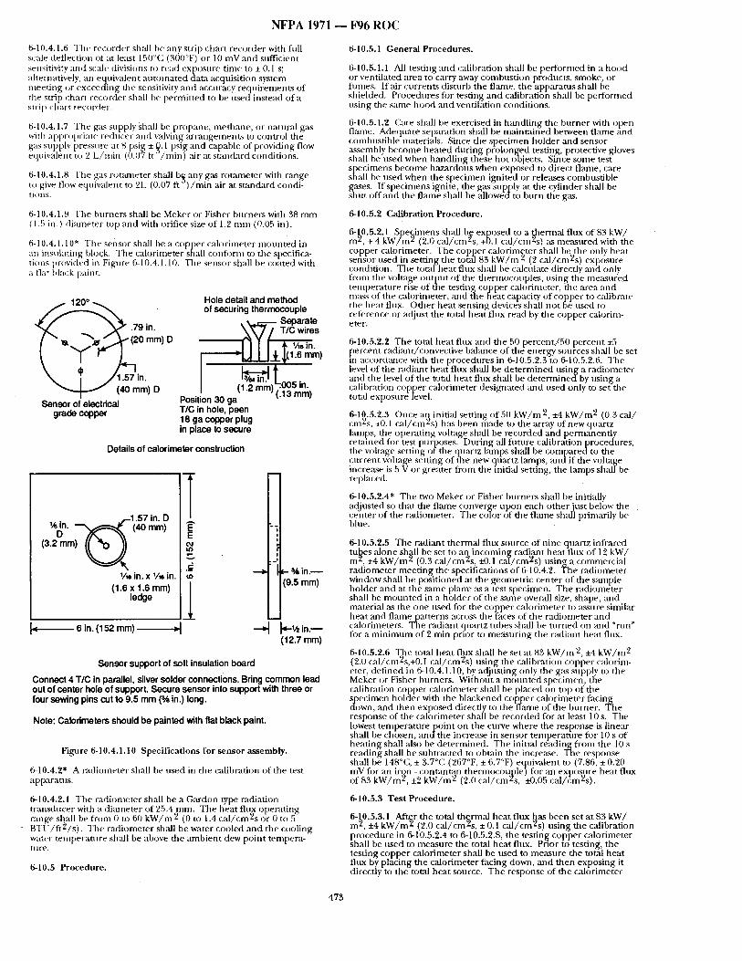
NFPA 1971 ~ F96 R()C
6-10.4.1.6 The recorder sh:dl be any strip chart recorder with full scale deflection of at least 150"(?, (300°F) or 10 mV and sufficient sensitivity a n d scale divisions to read expost,re time to + 0.1 s; ahernatively, an ec~uivalent automated data acquisition system meeting or exceeaing the sensitivity and accuracy requirements of the strip chart recorder shall be permitted to be used instead of a strip chart recorder.
6-10.4.1.7 The g:~s supply shall be propane, methane, o r natural g:Ls with a[)pr()priate reducer :rod valving arrangement~ to control the egas supply pressure at 8 psi 8 + ,~. 1 psig and capable of providing flow
quivale[{t to 2 L/min (0.07 t " / m i n ) air at standard conditions.
6-10.4.1.8 The g:ts r<mmmter shall I)$ any gas roumaeter with range to give flow equivalent m 2L (0.07 t't ) / ra in air at standard condi- tic:ins.
6-10.4.1.9 The burners shall be Meker or Fisher burners with 38 mm ( 1.5 in.) diameter n)p and with orifice size of 1.2 mm (0.05 in).
6-10.4.1.10* The sensor shall be a copper calorimeter mounted in an insulating block. The calorimeter shall conform to the specifica- tions provided in Figure 6-10.4.1.10. The sensor shall be coated with a fiat Mack paint.
~ ~,>" .79 in.
\ i / 1 .57 in. (40 mm) O
Sensor of eleclrical grade copper
Hole detail and method of securing thermocouple
.~1.6 mm)
Position 30 ga TIC in hole, peen 18 ga copper plug in place to secure
Details of calorimeter construction
(3.2 ram) ~
%a in. x %a in. (1.6 x 1.6 ram)
ledge
< I - - - - - - - 6 in. (152 mm) . ~ - - . ~
E E ID
e-
(D
I
i
i
i ._ l
- - ~ ' I ~-~in~ (9.5 mm)
---=. <--~,~ in.--- (12.7 ram)
Sensor support of soft insulation board
Connect 4 T/C in parallel, silver solder connections. Bring common lead out of center hole of support. Secure sensor into support with three or four sewing pins cut to 9.5 mm (% in.) long.
Note: Calorimeters should be painted with flat black paint.
Figure 6-t0.4.1.10 Specifications for sensor assembly.
6-10.4.2" A radiometer shall be used in the calibration of the test appamtus.
6-10.4.2.1 The radiometer shall be a G~don type radiation transducer with a diameter of 25.4 ram. The heat flux operating range shall be trom 0 to 60 kW/m 2 (0 to 1.4 cal/cm2s or 0 to 5 BTU/ft2/s) . The radiometer shall be water cooled and the cooling water temperature sb:dl be above the ambient dew point tempera- trite.
6-10.5 Procedure.
6-10.5.1 General Procedures.
6-10.5.1.1 All testing and calibration shall be performed in a hood or ventilated area to carry away combustion products, smoke, or fumes. If mr currents disturb the flame, the apparatus shall be shielded. Procedures for testing and calibration shall be performed using the same hood and ventilation conditions.
6-10.5.1.2 C:u'e shall be exercised in tl:mdling the burner with open flame. Adequate separation sh,'-dl be maintained between flame and combustible materials. Since the specimen holder and sensor assembly become heated during prolonged testing, protective gloves shall be used when handling thege hot objects. Since some test specimens become hazardous when exposed to direct flame, care shall be used when the specimen ignited or releases combustible g~ses. If specimens ignite, the gas~upply at the cylinder sh~l be shut of fand the flame shall be allowed to burn the g~.
6-10.5.2 Calibration Procedure.
6-[,0.5.2.1 Specimens shall be exposed to a ~bermal flux of 83 kW/ mZ, + 4 kW/m (2.0 cal/cm2s, +0.1 cal/cm2s) as measatred with the copper calorimeter. The copuer calorimeter shall be the only heat sensor used in setting the to{a] 83 kW/m 2 (2 cal/cm2s) exposure condition. The total beat flux shall be calculate directly ,'m~l only from the voltage output of the thermocouples, using the me;Lsured temperature rise of the testinj~ copper calorimeter, the area and m ~ s of tim calorimeter, and tile neat capacity of copper to calibrate the heat flux. Other heat sensing devices shall not bee used to reterence or adjust the total heat flux read by the copper calorim- eter.
6-10.5.2.2 The total heat flux and the 50 percent/50 percent +5 percent radiant/convective bat:race of thd energy soni-ces sh:dl be set m accord:race with the procedures in 6-10.5.2.3 to 6-10.5.2.6. The level of the radiant heat flux shall be determined using a radiometer and the level of the m~d heat flux shall be determinedby using a calibration copper calorimeter designated and used only to set the total exposure level.
6-10.5.2.3 Once ap a initial setting of 5(1 kW/m 2 ±4 kW/m 2 (0.3 cat/ cm2s, +0.1 cal/cmZs) ta:L~ been made to the array of new quartz lamps, the operating voltage shall be recorded and permanently retained for test purposes. During all future calibrationprocedures, the w)ltage setting of the qn~tz lamps shall be compared to the current voltage setting of the new quartz l,'mnps, m/d i f the w)lmge in :reuse is 5 V r greater from theinitial setting, the lamps shallbe rephtced.
6-10.5.2.4" The two Meker or Fisher burners shall be initially ad'ustedtj so that the. flame converge upon each other just below the center of the rad,ometer. The color of the flame shall primarily be blue.
6-10.5.2.5 The radi:mt thermal flux sonrce of nine quartz infrared tubes alone sh~l be set to an incomimz radiant heat flux of 12 kW/ m2, +4 kW/m 2 (0.3 cal/cm2s, i-0.1 ca'l'/cm2s) using a cormnercial radiometer meeting the specifications of 6-10.4.2. The radiometer window shall be positioned at the geometric center of the sample holder and at the same phm'e its a test specimen. The radiom&er shall be mounted in a holder of the santo overall size, shape, and material ,as the one used for the copper calorimeter to assure similar heat and flame patterns across the faces of the radiometer and calorimeters. The radiant ~uartz tubes shall be turned on ~md "run" for a minimum of 2 min prior m measuring the radiant heat flux.
6-10.5.2.6 The total heat flux shall be set at 83 kW/m 2, +4 kW/m 2 (2.0 cal/cm2s,+0.1 cal/cm2s) using the calibration copper calorim- eter, defined in 6-10.4.1.10, by adjusting only the gas supply to the Meker or Fisher burners. Without a mounted specimen, the calibration copper calorimeter shall be placed on top of the specimen holder with the blackened copper calorimeter facing down, and then exposed directly to the-ffanae of the burner. The response of the calorimeter sh:dl be recorded for at least 10 s. The lowest temperature point on the curve where the response is linear shall be chosen, and the increase in sensor temperature for 10 s of heating shall also be determined. The initial reading from the 10 s reading shall be subtracted to obtain the increase. The response shall be 148°C, ± 3.7°C (267°F, ± 6.7°F) equiwalent to (7.86, ± 0.20 mV for an irRn - contant~m thermocou~ple) for an exposure heat flux of 83 kW/m 2, +2 kW/m 2 (2.0 cal/cmZs, i-0.05 cal/cm2s).
6-10.5.3 Test Procedure.
6-,1,0.5.3.1 Aft,er the total thermal heat flux ,~as been set at 83 kW/ m 2, +4 kW/m2 (2.0 cal /cm s, + 0.1 cal/cm" s) using the calibration procedure in 6-10.5.2.4 to 6-10.5.2.8, the tesdng copper calorimeter shall be used to measure the total heat flux. Prior to testing, the testing copper calorimeter shall be used to measure the total heat flux by placing the calorimeter facing down, and then exposing it directly to the total heat source. The response of the calorimeter
473
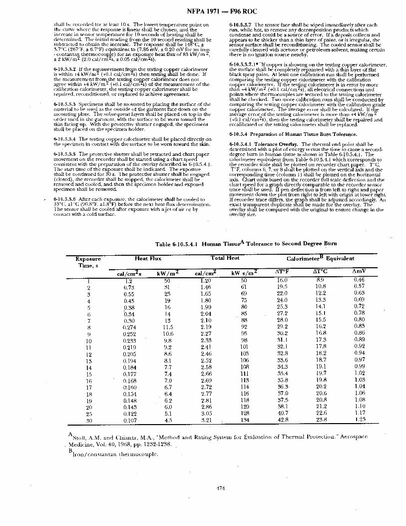
NFPA 1971 ~ F96 ROC
shall I)¢~ recorded fi)r at least 10 s. The lowest tempe~t ture point on the curve where the response is linear shall be chosen, and the incre:Lse in sensor tempera ture for 10 seconds of heat ing shall be determined. The4nitifil reading from the 10 second reading shall be subn'acted to obtain the increase. The response shall be 148°C, 3.7°C (267°F, • 6.7°F) equivalent to (7.86 mV, • 0.20 mV for an iro~ - cont~mtan thermocoup~!e) tbr an exposure heat flux o f83 k W / m ' , • 2 k W / m 2 (2.0 cal /cm2s, • 0.05 ca l /cm2s) .
6-10.5.3.2 If the measu remen t f rom the testing cooper calorimeter is within +4 k W / m 2 (+0.1 ca l /cm2s) then testing shall be done . If the m e a s u r e m e n t f rom the testing cop~er calorimeter does not agree within +4 k W / m 2 (+0.1 ca l / cm 2~s) of the m e a s u r e m e n t of the calibration calorimeter, the testing copper calorimeter shall be repaired, recondit ioned, or replaced to achieve agreement .
6-10.8.3.3 Spechnens shall be moun t ed by placing the surface of the material to be used ~Ls the outside of the ga rmen t face down on the monnt ingp la te . The subsequent layers shall be placed on top in the order used in the g~u'ment, with the snFface to be worn toward the skin facing; up. With the protective shut ter engaged, the specimens shah be pmced on the specimen hoMer.
6-10.5,3.4 The testing copper calorimeter shall be placed directly on the specimen in contact with the surface to be worn toward the skin.
6-10.5.3.5 The protective shut ter shall be retracted and chart paper movemen t on the recorder shall be started us ing a char t s p e e d consistent with the preparation of the overlay described in 6-10.5.4.1. The start t ime of the exposure shall be indicated. The exposure shall be cont inued ibr 30 s, The protective shut te r shall be engaged (closed), the recorder shall be stopped, the calorimeter shall be removed ;rod cooled, and then the spec imen holder and exposed specimen shall be removed.
6-10.5.3.6 After each exposure, the calorimeter shall be cooled to 33"C. •1 °C (90.8°F, +1.8 F) before the next heat flux determinat ion. The sensor shall be cooled ,after exposure with a je t of air or by contact with a cold surface.
6-10.5.3.7 The sensor face shall be wiped irmnediately ,'ffter each run, while hot, to remove any decomposi t ion products which condense and could be a source of er-ror. If a-deposit collects ,and appears to be thicker than a thin layer of paint, or is irregular, the sensor surface shall be recondit ioning. The cooled sensor shall be carefully cleaned with acetone or pe t ro leum solvent, mak ing cert~dn there is no ignition source nearby.
6-10.5.3.7.1" "If copper is showing on the testing copper calorimeter, the surface shall bd c- ompletely re-painted with a thifi layer of flat black spray paint. At l e~ t one cafibration run shall be pe r fo rmed compar ing the testing copper calorimeter with the calibration
( . . . . . c )pper calonrneter. I f the tesUng calorimeter ~s m error by more than +4 k W / m 2 (+0.1 cal /cm2s) ' ; all electrical connect ions and points where thermocouples are secured to the testing calorimeter shall be checked. Two more calibration runs shall be conducted by comparin the. testin co, pper cah)rimeter with {he calibration rade copper c~2)nmeter, gFhe average error shall be calculated. I f t ~ average erro,~.of the testing calorimeter is more th:m +4 k W / m 2 (+0.1 ca l /cm2s) , then the testing calorimeter sh~ll be repaired and recalibrated or the testing calorimeter shall be replaced.
6-10.5,4 Preparation of Human Tissue Bum Tolerance.
6-10.5.4.1 Tolerance Overlay. The thermal end point shall be de te rmined with a plot of energy versus the t ime to cause a second- f tegree burn m h u m a n tissue ~s shown in Table 6-10.5.4.1. The calorimeter equivalent f rom Table 6-10.5.4.1 which ~:orresponcks to the recorder s~ale shall be [~lotted on recorder chart paper-. T°C, T°F, o)lumms 6, 7, or 8 shall be plotted on the vertical ,axis and the
corresponding time (column 1) shall bep lo t t ed on the horizontal ,axis. ( h a r t units based on the recorder fifll scale deflection and the chart speed for a graph directly comparable to the recorder sensor trace shall be u s e d . l'f pen deflectioti is f rom left to r ight and paper
( . . . . - - _ _
m )vement down the plot f rom right to left with o n g m at lower right. If recorder trace differs, the graph shall be adjustedaccordingly. A~1 exact t ransparent duplicate shall be made for the overlay. The
V - - ' " " " o erlay shall be compared with the ongma} to ensure change m the overlay size.
Exposure Time , s
Table 6-10.5.4.1 H u m a n Ti s sue A T o l e r a n c e to S e c o n d D e g r e e Burn
Heat Flux Tota l Heat C a l o r i m e t e r B Equivalent
ea l / cm~t s k W / m 2 c a l / c m 2 k W s / m 2 AT°F AT°C A m Y
1 1.2 50 1.20 50 16.0 8.9 0.46 2 0.73 31 1.46 61 19.5 10.8 0.57 3 0.55 23 1.65 69 22:0 12.2 0.63 4 0.45 19 1.80 75 24.0 13.3 0.69 5 0.38 16 1.90 80 25.3 14.1 0.72 {5 i3.34 14 2.04 85 27.2 15.1 0.78 7 0.30 13 2.10 88 28.0 15.5 0.80 8 0.274 11.5 2.19 92 29.2 16.2 0.83 9 0.252 10.6 2.27 95 30.2 16.8 0 .86
10 0. 233 9.8 2 .33 98 31.1 17.3 0.89 11 0.219 9.2 2.41 101 32.1 17.8 0.92 12 0.205 8.6 2.46 103 32.8 18.2 0.94 13 0.194 8.1 2.52 106 33.6 18.7 0.97 14 0.184 7.7 2.58 108 34.3 19.1 0.99 15 0.177 7.4 2 .66 111 35.4 19.7 1.02 16 0.168 7.0 2.69 113 35.8 19.8 1.03 17 0.160 6.7 2.72 114 36.3 20.2 1.04 18 0.154 6.4 2.77 116 37.0 20.6 1.06 19 0.148 6.2 2.81 118 37.5 20.8 1.08 20 0.143 6.0 2.86 120 38.1 21.2 1.10 25 0.122 5.1 3.(15 128 40.7 22.6 1.17 30 0.107 4.5 3.21 1.'54 42.8 23.8 1.23
ASto l l , A.M. a n d C h i a n t a , M.A., " M e t h o d a n d R a t i n g . M e d i c i n e , Vol. 40, 1968, pp . 1232-1238.
B l r o n / c o n s t a n t a n t h e r m o c o u p l e .
S y s t e m fo r E v a l u a t i o n o f T h e r m a l P r o t e c t i o n . " A e r o s p a c e
474
NFPA 1971
6-10.5.4.2 Computer Processing of the D a t a . The information provided in Table 6:10.5.4• 1 shall be permit ted to be used as the criteria of~3erform,'mce ill the software of a compute r program. In
,this c~L~e, me , sensor response shall be compared with the t he rma l " response, either pain sensation or second degree burn in h u m a n tissue to de termine the thermal end points. Tile product o f the t ime to th~ a secofid degree burn in ]roman tissue and the exposure energy heat flux shall be tile TPP rating.
6.10.5.5 Determination of Test Results.
6-10.5.5.1 The time to tile second degree burn shall be graphically d e t e r m i n e d f r o m t i l e recorder chart of tile sensor response a n d .
criteriml overlay prepared in 6 - 1 0 5 4 l The overlay sh,'dl be pos t ioned on tile recorder ch~u:t match ing the zero of the overlay • \ . , . w th the ex 3osure start t ime result ing f rom heat transfer. The horizontal axis (time) shall 13¢ p aced in line with tile initial trace o f the pen, kee'ping tile over ay sqt are with the recorder chart~ The time to the second degree bnrn sh:dl be read to tile nearest 0.1 s from tile overlay chart at the point When the sensor response curve , a n d t i l e t i s s u e t o l e r ~ f f l c e C u r v e c r o s s . If t h e s e u s o r response C u r V e
and tile tiK~tle tolerance curves d0 not cross, "no burn" shall be recorded as tile test resulL
6-10.5.5.1.1 l f a compute r software progrm/1 is used the sensor response shall be compared with tile &ata descril3ing tile hnm~m tissue heat tolerance to determine ' l ike values. The time from the start of tile exposure to the time when these values are the same sl)all be taken at tile exposure time•
6-10.5.5.2 T i l e TPP-rating shall be calculated as the product of exposure ene.rgy I)eat flux and time to burn.
TPP ra t ing= / : 5< T
where; -F = expost re heat flux, c,qJ/c|n ~,s, mad T = time to burn (s)
6-10.6 Report.
6-10.6.1 The individtud test TPP rating o f each specimen shall be reported. Tile average TPP rating sh,'dl be calculated ,and reported I f a TPP rating is greater than 60, then the TPP rating shall be - reported as "> 60."
6-10.6.2 The condition o f the specimen shall be reported ,'is _specified in 6-10.5.4.3.
6-10.7 In terpretathm.
6-10.7 1 Pass o;" t~til de terminat ions shall be based on the average ' r epor ted TPP rating of,all specimens tested..
6-10.7.2 If an individual result f rom any test set varies more than +8 percent f rom tile average result, the results f rom the test set sh~ l be discarded and anofller set of specimens shall Be tested.
6-10.8 Specific Requirements for Test ing Ga.rments.
6-10.8.1 Specinl-ens st]all consist of outer shell, moisture barrier, and thermal barrier. Winter liners shall not be inchlded in the test composite. Collar lining fitbric shall be permit ted to lle included in the protective g a r m e n t collar fabric composite specimen. Speci- mens shall not include seams. Specimens shall no t be st i tched to hold individual I~iyerstogether.
6-10.8.2 Samples fi3r condit ioning'shall be :it least 1 meter square (I yard square) of~ach material.
6-10.823 Testing shall b-e per formed as descril)ed in 6-10.2 through 6-10•7 above. .
6-i0.9 Specific Requirements for Testing Pr0teetive Hoods.
• 6~10.9; 1 "Specimens shall consist of materials f rom the portion of the protective hogd: tha t covers the neck and facial area• Specimens shall not include seams., Specimens shall not be st i tched to hold individual layers together.
6-10.9.2 Samples fi)r condi t ioning sh~dl include hood materifd which is a min imu l/ of 178 nml (7 in.) square.
6-10.9.3 Testing Shall be per formed as described in 6-10.2 through 6- l 0.7 above.
F 9 6 R O C "
6-10.10 Specific Requirements for Testing Protective W risdets.
6-10.10.1 Specimens shall consist of materials f rom tile portion of the protective wiqstiet that covers the wrist area. Specimens shall no t include seanas. Specimens sh~ l not be st i tched to hold individu,'Ll" layers together.
6-10.10.2 Samples for condi t ioning shrdl inch, de wristlet material which is a m i n i m u m of 178 m m (7.0 in.) square.
6-10.10.3 Test ing shall be per fornmd as described in 6-1'0.2 through 6-10.7 above:
6-10.11 Specific Requirements for Testing. Protective.Glove Body Composites and Gauntlets.
6-10111.1 Specimens shall consist of the composite used in the actu M glove constrnction, with the layers a r ranged in proper order• Specimens shall no t inch, de seams, where mult iple layers are involved. Specimens-shall not be st i tched to hold individual layers , together.
6-10.11.2 Samples for Conditioning shall include glove material which is a m i n i m u m of 178 m m (7 in.) square consist ing o f the composite used in tile actual glove constroction, with the layers a r ranged in proper order and stitched using the same thread used in the construction o f tile glove.
6-10.11.3" Test ing shall be perfl)rmed as described' in 6-10.2 through 6,10.7 above.
6-11 Thread Mel t ingTest .
6-11.1 This test'shall apply-to sewing thread used in consm,c t ion of- protective garments , hoods, wristlets, fi)otwear, gloves, and he lmet ear covers.
6-11.2 Specimens shall be tested in accord,'~nce with Federal Standard 191A, Test Method 1534, Melting of Synthetic Fibers.
6-12 Tear Resistance Test.
6-12.1 Application.
6-12.1.1 This test shall apply to woven materials used in protective gammnts , hoods, and, wristlet.
6-12.2 Specimens.
6-12.2.1 Five specimens [n each of file warp and filling directions shall be tested from each sample unit, Specimens shall be 7.62-cm x 15.24-cm (3-in. × 6-in.) rectangles. The long d imens ion sh~dl be parallel to the warp for warp tests and parallel to the filling for filling tests. No two spec imens for warp tests shall contain the same warp yarns, no r shall any two specimens fi)r filling tests contain the same filling yams. The specimen shall be token no closer to the salvage
• than one-tenth o f thewidth of the clothing.
6-12.2.2 An isosceles Ixapezoid having ,an altitude of 7.02 cm (3 in.) and bases of 2.54 cm (1 in.) and 10.16 cm (4 in.) in length, respectively, slmll be marked on each specimen with the aid o f a template. A cut 9.5 m m (0.375 in.) in length shall then be made ill tile center of a line perpendicular to tile 2.54-cm (1-in.) edge.
6-12.3 Sample Preparation.
6-12.3.1 Specitnens shall be condi t ioned ,as specified in 6-1.3.
6-12.3.2 Samples for condi t ion ingshal l be 1 m (1 yd) square o f material.
6-12.4 Apparatus.
6-12.4.1 Apparatus shall consist of a straining mechanism, two cl:unps for holding specimens, and load.and elongation recording mechanisms, wherein the specimen is held between-two c lamps and sty,fined by a uni form movemen t of the pulling clamp. The test machine shall be operated at a rate o f 30.48 c m / m i n (12 in . /min ) .
)
6-12.4.2 The-straining n)echanism Shall be of such capacity that tile m a x i m u m load necessary to break the specimen shall be not greater th,'m 8.5 p, erceut or less than. 15 percen]: o f the manufac ture r ' s rated capacity.
475
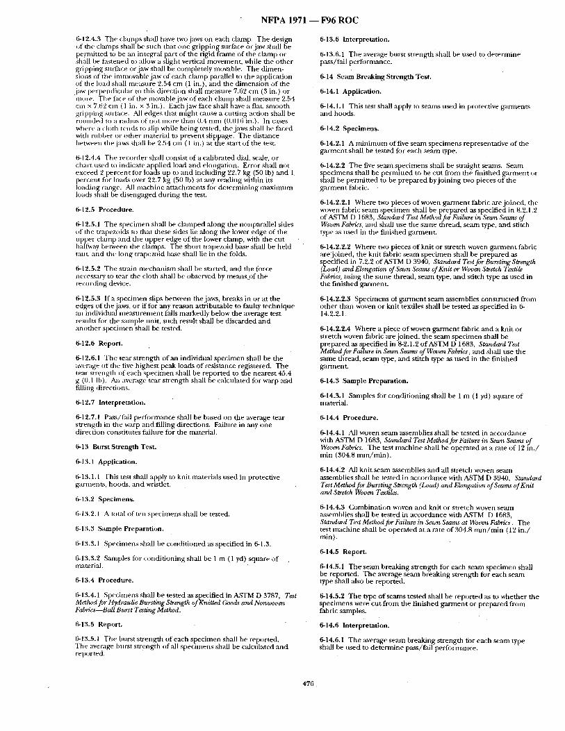
N F P A 1971 - - F96 R O C
6-12.4.3 The clamps shall have two jaws on each clmnp. The design of the clamps shall be such that one gripping surface or jaw shall be pernfitted to be an integral part of the rigid f~tme of the clamp or shall be fastened to alh)w a slight vertical movement, while the other gripping surface or jaw shall be completely movable. The dimen- sions of the immovable jaw of each clamp parallel to the application of the load shall measure 2.54 cm (1 in.), and the dimension of the jaw perpendicular to this direction shall measure 7.62 cm (3 in.) or in~re. The face of tile movable jaw of each clanlp sh~dl measnre 2.54 cm × 7.62 cm ( 1 in. x 3 in.). Each jaw face sh~l have a flat, smooth gripping stu-ttme. All edges that might cause a cutting action shall be rounded to a radius of not more th,'m 0.4 mm (0.016 in.). In cases where a cloth tends to slip while being tested, the jaws shall be faced with rubber or other nmterial to prevent slippage. The distance between the jaws shall be 2.54 cm (1 in.) at the start of the test.
6-12.4.4 Tile recorder shall consist of a calibrated dial, scale, or chart used to indicate applied load and elongation. Error shall not exceed 2 percent for loads up to and including 22.7 kg (50 lb) and 1 percent for loads over 2.2.7 kg (50 lb) at any reading within its loading range. All machine attachments for determining maximum loads shall be disengaged during the test.
6-12.5 Procedure.
6-12.5,1 The specimen shall be clamped along the nonparallel sides of the trapezoids so tbat these sides lie ,along the lower edge of the upper clanap and the upper edge of the lower clamp, witla the cut halfway between the clamps. The short trapezoid base shall be held taut, and the long trapezoid base shall lie in the folds.
6-12.5.2 The strain mecbanism shall be started, and the force necessary u) tear the cloth sh~dl be observed by means.of the recording device.
6-12.5.3 If a specimen slips between the jaws, breaks in or at the edges of the jaws, or if for any reason attributable to faulty technique an individual measurement falls markedly below the average test results for the sample unit, such result shall be discarded and another specimen shall be tested.
6-12.6 Report.
6-12.6.1 The tear strength of an individual specimen shall be the average of the five highest peak loads of resist,'mce registered. The tear strength of each specimen shall be reported to the nearest 45.4 g (0.1 Ib). An average tear strength shall be calcu ated for warp and filling di rections.
6-12.7 Interpretation.
6-12.7.1 Pass/f~dl performance shall be based on the average tear strength in the warp and filling directions. Failure in any one direction constitutes failure for the material.
6-13 Burst Stren~h Test.
6-13.1 Application.
6-13.1.1 This test shall apply to knit materials used in protective garments, hoods, :rod wristlet.
6-13.2 Specimens.
6-13.2.1 A u~tal of ten specimens shall be tested.
6-13.3 Sample Preparation.
6-13.3.1 Specimens shall be conditioned as specified in 6-1.3.
6-13.3.2 Smnples for conditioning shall be 1 m (1 yd) square of t~=tterial.
6-13.4 Procedure.
6-13.4.1 Specimens shall be tested as specified in A,STM D 3787, Test Mettwd for Hydraulic Bursting Strength of Knitted Goods and Nonwoven Fabrics Ball Burst Testing Method.
6-13.5 Report.
6-13.5.1 The bnrst strength of each specimen shall be reported. The average burst strength of ,all specimens shall be calculated and reported.
6-13.6 Interpretation.
6-13.6.1 The average bnrst strength shall be used to determine pass/fail performance.
6-14 Seam Breaking Strength Test.
6-14.1 Application.
6-14.1.1 This test shall apply to seams used in protective garments and hoods.
6-14.2 Specimens.
6-14.2.1 A minimum of five seam specimens representative of the garment shall be tested for each seam type.
6-14.2.2 The five seam specimens shall be straight seams. Seam specimens shall be permitted to be cut from the finished garment or shall be permitted to be prepared by joining two pieces of the garment fabric.
6-14.2.2.1 Where two pieces of woven garment fabric are joined, the woven fabric seam specimen shall be prepared as specified in 8.2.1.2 of A,STM 1-) 1683, Starutarcl Test Method for Failure in Sewn Seams of WovenFatrdcs, and shall use the same thread, se,'un type, and stitch type as used in tile finished garment,
6-14.2.2.2 Where two pieces of knit or stretch woven garment fabric are] t ined, the knit fabric seam specimen shall be prepared ,as specified in 7.2.2 of A,STM D 3940, Standard Test for Bursting Strength (Load) and Elongation of Sewn Seams of Knit or Woven Stretch Textile Fabrics, using the s~mle thread, seam type, and stitch type as used in the finished garment.
6-14.2.2.3 Specimens of garment seam assemblies constructed from other than woven or knit textiles shall be tested as specified in 6- 14.2.2.1.
6-14.2.2.4 Where a piece of woven garment fabric and a knit or stretch woven fabric are joined, the seam specimen shall be prepared as specified in 8-2.1.2 ofASTM D 1683, Standard Test Method for Failure in Sewn Seams of Woven Fabrics, and shall use the same thread, seam type, ,and stitch type as used in the finished g'armen~
6-14.3 Sample Preparation.
6-14.3.1 Samples fi)r conditioning shall be 1 m (1 yd) square of material.
6-14.4 Procedure.
6-14.4.1 All woven seam assemblies shall be tested in accordance with ASTM D 1683, Standard Test Method for Failure in Sewn Seams of Woven Fabrics. The test machine shall be operated at a rate of 12 in . / min (304.8 m m / m i n ) .
6-14.4~2 All knit seam assemblies and all stretch woven seam assemblies shall be tested in accordance with ASTM D 3940, Starutard Test Metlwd for Bursting Strength (Load) and Elongation of Seams of Knit and Stretch Woven T6"xtiles.
6-14.4.3 Combination woven and knit or stretch woven seam assemblies shall be tested in accordance with P~STM D 1683, Standard Test Method for Failure in Sewn ,Seams at Woven Fabrics. The test machine shall be operated at a rate of 304.8 m m / m i n (12 in. / min).
6-14.5 Report.
6-14.5.1 Theseam breaking strength for each seam specimen shall be reported. The average seam breaking strength for each seam type shall also be reported.
6-14.5.2 The type of seams tested shall be reported as to whether the specimens were cut from the finished garment or prepared from fabric samples.
6-14.6 Interpretation.
6-14.6.1 The average seanl breaking strength for each seam type shall be used to determine pass/fail peril)finance.
476
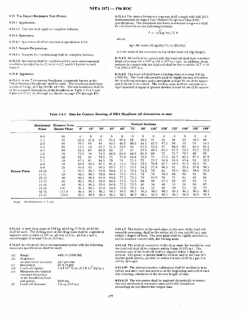
N F P A 1971 ~ F 9 6 R O C
6-15 T o p I m p a c t Res i s tance T e s t ( F o r c e ) .
6 - 1 5 . 1 Application.
6-15.1.1 This rest shall al)ply to complete helmets.
6-15.2 Specimens.
6-15.2.1 Specimens shall be selected ~s specified in 2-3.9.
6-15.3 Sample Preparation.
6-15.3.1 Samples for conditioning shall be complete hehnets.
6-15.3.2 Specimens shall be conditioned for each environmental c~mdition specified in 6-I .3, 6-1.6, 6-1.7, and 6-1.8 prior to each impact.
6-15.4 Apparatus.
6-15.4.1 A size 7 alnminnm headtorm, commonly known ,as the "ISEA Standard Headlorm" shall be used: The headform shall have a mass of 3.6 kg, +0.5 kg (8.0 Ib, ±1.0 lb). The test headli)rm shall be of the nominal dimensions of the headlorm in Table 6-15.4. l and Figures 6-15.4.1 (a) through (c) shown on page 478 through 479.
6-15.4.4 The system frequency response shall comply with SAEJ211, Instrumz'atationfc, rlmpact Test, Channel Frequency Class 1000, specifications. The mininmm mechanical resonant frequency shall be calculated from the fi)llowing fi~rmnla:
f = UTg/m)/2 where:
kg = the load cell rigidity [ N / m (~bf/ft)]
m = the mass of the structure on mp of the load cell [kg (slugs) ].
6-15.4.5 All surfaces in contact with the load ceil shall have a surface finish of at least 0.8 x 10 -6 m (32 x 10 -6 in.) rms. In addition, those surfaces in contact with the load cell shall be flat to within 12.7 × 10- 6 m (500 x 10 -6 in.).
6-15.4.6 The load cell shall have a backup mass of at least 540 kg (1201") lb). The load ceil assembly shall be rigidly mounted between the headform structure and a steel plate at least 30 cm ( 1 ft) square and 2.54 cm (1 in.) thick. The backup mass shall be concrete or a rigid material of equal or greater density at le;~st 61 cm (2 ft) square.
T a b l e 5 -6 .2 Data for C o n t o u r D r a w i n g o f I S E A H e a d f o r m (al l d i m e n s i o n s in m m )
H o r i z o n t a l D i s t a n c e f r o m V e r t i c a l S e c t i o n s P l a n e D a t u m P l a n e 0 ° 15 ° 3 0 ° 4 5 ° 6 0 ° 7 5 ° 9 0 ° 105 ° 1 2 0 ° 1 3 5 ° 150 ° 165 ° 180 °
D a t u m P l a n e
0-0 99 0 0 0 0 0 0 0 0 0 0 0 0 0 1 - 1 95 22.5 22.5 23 25.5 26.5 28 28.5 31 33 36 39 38.7 40 2-2 90 39.5 40 40 40.5 40.5 40.5 41.5 43.5 47.5 50 53 53 54.5 3-3 85 53.5 54 55.7 51.5 50.5 50 51.5 53.5 57 60.5 64 64.5 65.5 4-4 80 62.5 63 60.9 59 57 57 57.5 60.5 63.5 673 70.7 707 72.2 5-5 70 72.5 74 71.5 68.2 65.5 64.5 65.3 68 72 757 79.1 80 82 6-6 60 82 82 . 79.5 75 71.t) 69.4 70.1 73 77.5 81.7 85.1 87.5 87.9 7-7 50 87.3 87 84.5 79 74 71.5 72 75.7 809 85.8 89.4 91 923 8-8 40 902 90.5 87.5 81 5 75.5 730 73.5 76.9 82.7 88.3 91 3 935 95 9-9 20 940 94 90.5 83.5 77.1 73.7 74.2 77.8 84.3 91 95.5 97.6 98.5
I 0 - 1 0 (/ 965 96.5 93.0 84.6 77 5 73.5 74.2 79 85 92.5 965 98.8 99.9 11-11 20 96.5 96.5 93.0 84.6 77.5 73.5 72 70 785 84 90 91 95 12-12 40 96.5 96.5 93.0 84.6 77.5 73.5 70 63.5 70 75 81 82 84 13-13 60 96.5 96.5 930 84.6 77.5 73.5 68 58 57.5 63 69 69 72 14-14 80 965 96.5 93.0 846 77.5 735 66 54 48 53 59 60 63 15-15 1011 965 96.5 93.0 84.6 77.5 73.5 64 52 48 49 54 56 59 16-16 1159 96.5 96.5 96.5 96.5 96.5 96.5 96.5 96.5 96.5 96.5 965 96.5 96.5 17-17 12,8.6 96.5 96.5 96.5 96.5 96.5 96.5 96.5 96.5 965 96.5 96.5 96.5 965
Note: All dimensions + 5 mm
6-15.4.2 A steel drop mass of 3.58 kg, ~41.05 kg (7.90 lb, +0.10 Ih) shall he used. The striking face of the drop mass shall be a spherical segment with a radius of 4.8 cm, +8 mm (1.9 in., ±0.3 in.) and a chord length of at least 7.6 cm (3.0 in.).
6-15.4.3 An ele,;tronic force measurement system with the following minimum specifications shall be used:
(a) Range 4450 N (1000 lbf) (b) Pe:tk force
measurement accn~tcy +~.5 percent (c) Resohltion 22 N (5 ~bf) (d) Load cell rigidity 4.4 ¥ 10 ~ N / m (2.5 ¥ 107 lbf/in.) (el Minimum mechmfical
resonant frequ en cy of the headfl.)rm/load cell system 5000 Hz
(t) I2~ad cell diameter 7.6 cm (3.0 in.)
6-15.4.7 The surface of the steel plate, in the area of the load cell assembly mounting, shall be flat within e0.15 mm (±0.005 in.) and within 1 degree of level. The steel plate shall be rigidly attached to, and in intimate contact with, the backup mass.
6-15.4.8 The vertical centerline of the drop rrmss, the headform, and the load cell shall all be colinear within 3 mm (0.125 in.). The sensitive ,axis of the load cell shall be aligned within 1 degree of vertical. The guide or guides shall be vertical, ,and in the case of a double guide system, parallel, to within 6.4 mm (0.25 in.) per 3 m ( 10 ft) of length.
6-15.4,9" The instrmnentation calibration shall be verified at least before and ,'alter each test series or at the beginning and end of each day of testing, whichever is the shorter length of time.
6-15.4,10 The test system shall be analyzed dynamically to ensure that any mechanical resonance associated with transducer mountings do not distort the output data.
477
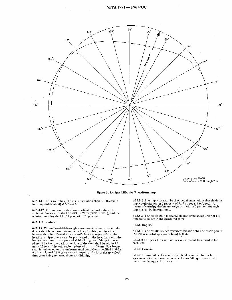
N F P A 1971 i ~ 6 R O C
1 3 5 °
\
120 ° ~ 105 ° 90° 75 °
45 °
150 ° 3 0 °
165 °
0 °
150 °
135 °
120 ° 105 ° 90 °
75 °
60 °
Datum plane 10-10 Circumference 55.88 c m (22 in.)
Figure 6-15.4.1(a) ISEA size 7 headform, top.
6-15.4.11 Prior to testing, the ins t rumentat ion shall be allowed to warm up until stability is achieved.
6-15.4.12 T h r o u g h o u t calibration, verification, :rod testing, the ambient tempera ture shall be 20'~C to 28%1 (68°F to 82°F), and the relative htnnidity shall be 30 percent to 70 Percent
6-15.5 Procetiure.
6-15.5.1 Where faceshie ld/goggle component ( s ) are provided, the device shall be removed from the he lmet for this test. Specimen hehnets shall be adjusted to a size sttfficient to properly fit on the headform. Specimens shzdl be posi t ioned on the headform with the horizont=d center plane parallel within 5 degrees of the reference plane. The front-to,back centerl ine of the shell shall be within 13 m m (0.5 in.) of the mid-sagittal plane of the headYorm. Specimens shzdl be subjected to the environmenta l condit ions specified in 6-1.3, 6-1.6, 6-1.7, and 6-1.8 prior to each impact and within the specified time after being removed f rom condit ioning.
6-15.5.2 The impactor shall be d ropped f rom a he ight that yields an impact velocity within 2 percent of 5.47 m / s e c (17.9 f t /sec) . A means of verifying the impact velocity to within 2 percent for each impact sh~dl be incorporated.
6-15.5.3 The verification tests shall demonst ra te an accuracy of 2.5 percent or better in the measured force.
6-18;.6 Report.
6-15.6.1 The results of each system verification sh,'dl be made part of the test results for specimens being tested.
6-15.6.'~ The peak force and impact velocity shall be recorded for each tes t
6-18.7 Criteria.
6-18.7.1 Pass/fail per tbrmance sh~dl be de te rmined fi)r each specimen. O n e o r more he lmet specimens failing this testshall constitute failing performmme.
478
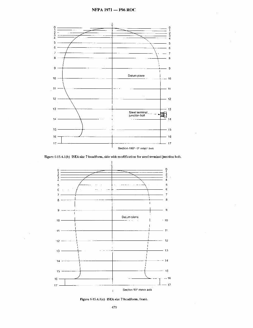
N F P A 1971 - - F 9 6 R O C
0 1 2 3 4
5
6 / 7 - -
8 - -
9
10
11
12
13
14
15
16
17
/ /
f /
f
-.%
\
Datum plane
Steel terminal junction bolt
Section .180 °+ 0 ° major axis
o 1 2 3 4
5
6
- - 7
- - 8
9
lO
11
12
13
14
15
16
17
Figure 6-15.4.1 (b) ISEA size 7 headform, side with modification for steel terminal junction bolt.
. . 1
1 0 - -
11 - -
1 2 - -
13
14
15
16
17
f /
/ /
/ +-.....
-,-., \
\
Datum plane
. . . . ,
Section 90 ° minor axis
o I 2 3 . 4
lO
- - 1 1
12
- - 13
14
15
16
17
Figure 6-15.4.1(c) ISEA size 7 headform, front.
479
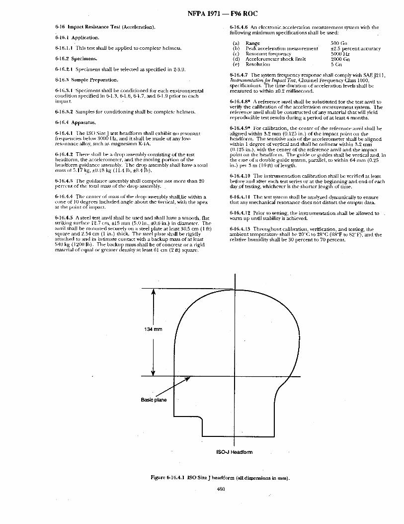
N F P A 1971 - - F 9 6 R O C
6-16 Impact Resistance Test (Acceleration).
6-16.1 Application.
6-16.1.1 T h i s test shall be applied to complete helmets.
6-16.2 Specimens.
6-16.2.1 Specimens shall be selected as specified in 2-3.9.
6-16.3 Sample Preparation.
6-16.3.1 Specimens shall be condi t ioned for each environmenta l condition specified in 6-1.3, 6-1.6, 6-1.7, ,and 6-1.9 prior to each impact.
6-16.3.~' San~ples for condi t ioning shall be complete helmets.
6-16.4 Apparatus.
6-16.4.1 The ISO SizeJ test heaffform shall exhibit no resonant frequencies beh)w 3000 Hz, and it shall be made of any low- resonance alh)y, such as magnes ium K-1A.
6-16.4.2 There shall be a drop assembly consisting of the test headt0rm, the accelerometer, ~md the moving portion of the headform guidance assembly. The drop assembly shall have a total mass of5.17 kg, +0.18 kg (11.4 Ib, N).4 Ib).
6-16.4.3 The guidance assembly shall comprise not more than 20 percent of the u)tal mass of the drop assembly.
6-16.4.4 The center of mass o f the drop assembly shall lie within a cone of l0 degrees included angle about the Certic;d, with the apex at tim point o f impact.
6-16.4.5 A steel test anvil shall be used and shall have a smooth, flat striking surface 12.7 cm, :t:15 m m (5.0 in., !-0.6 in.) in diameter. The anvil shall be n lounted securely on a steel plate at least 30.5 cm (1 ft) square and 2.54 cm (1 in.) thick. The steel plate shall be rigidly amtched to and in intimate contact with a backup mass o f at least 540 kg (1200 lb). The backup nmss shall be of concrete or a rigid material of equal or greater density at least 61 cm (2 ft) square.
6-16.4.6 An electronic acceleration measu reme n t system with the following m i n i m u m specifications shall be used:
(a) Range 500 Gn (b) Peak acceleration measu remen t ±2.5 percent accuracy (c) Resonant frequency 5000 Hz (d) Accelerometer shock limit 2000 Gn (e) Resolution 5 Gn
6-16.4.7 The system frequency response shall comply with SAEJ211, Instrumentation for Impact Test, Channel Frequency Class 1000, specifications. The time durat ion of acceleration levels shall be measured to within ±0.2 millisecond.
6-16.4.8" A reference anvil shall be substituted fi)r the test anvil to verify the calibration of the acceleration measu rem en t system. The reference anvil shall be const ructed o f any material that will yield reproducible test results dur ing a period o f at least 4 months .
6-16.4.9" For calibration, the center of the reference anvil shall be al igned within 3.2 m m (0.125 in.) of the impact point on the headform. The sensitive axis of the accelerometer shall be ,aligned within 1 degree of vertical and shall be colinear within 3.2 m m (0.125 in.), with the center of the reference anvil an d the impact point on the headform. The guide or guides shall be vertical and, in the case of a double guide system, parallel, to within 64 m m (0.25 in.) per 3 m (10 ft) of length.
6-16.4.10 The ins t rumentat ion calibration shall be verified at le,'~st before and ,'after each test series or at the beginning and end of each day o f testing, whichever is the shorter length of time.
6-16.4.11 The test system sh:dl be analyzed dynamically to ensure that ~my mechanical resommce does not distort the ou tpu t data.
6-16.4.12 Prior to testing, the ins t rumentat ion shall be allowed to warm up until stability is achieved.
6-16.4.13 T h r o u g h o u t calibration, verification, and testing, the ambient tempera ture shall be 20°C to 28°(2 (68°F to 82°F), and the relative httmidity shall be 30 percent to 70 percent.
1 j
1 Basic plane
Y 134 mm
ISO-J Headform
Figure 6-16.4.1 ISO SizeJ headform (all dimensions in mm).
480 /
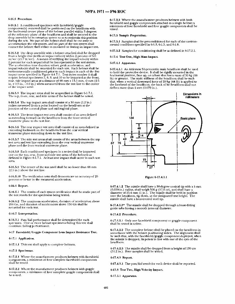
N F P A 1971 ~ F96 R O C
6-16.5 Procedure.
6-16.5.1 A conditioned specimen with faceshield/goggle component(s) removed shall be positioned on the [aeadform with the horizontal center plane of the helmet parallel within 5 degrees of the reference plane of the headform and shall be secured to the drop :~sembly by its retention ~stem so as to maintain this position during the test. No part of the helmet shell shall be cut away to accommodate the test system, and no part of the test system shall contact the helmet shell either as mounted or during an impact test.
6-16.5.2 The drop as~mbly with a hehnet attached shall be dropped from a heigiat that yields an impact velocity within 2 percent of 6.0 m / ~ c (19.7 ft/sec). A means of verifying the impact veh:~city within 2 percent for each impact shall be incorporated in the test system. The acceleration time duration values, peak acceleration, ,-aid impact velocity shall be recorded for each test. Each helmet sh:dl be enviromnentally conditioned prior to each impact in each of the five impact areas specified in Figure 6-1.7.1. Test series number 1 shall require hehnet specimens 5, 6, 8, and 10 to be impacted at the front, rear, side impact areas at a distmlce of 68 mm + 13.5 ram, -0 mm (2.5 in, + 0.5 in., - 0.0 in.) when measured from the test line to the center of the iinpact :mvil.
6-16.5.3 The impact areas shall be as specified in Figure 6-1.7.1. Tile top, front, rear, ,and side areas of the helmet shall be tested.
6- ! 6.5.4 The top impact area shall consist of a 30 mm (1.2 in.) radius measuredfrom a point located on the headtbrm at the junction of the coronal plane ,and mid-sagittal ph'me.
6-16.5.5 The front impact test areashall consist of an area defined as extending fi~rward on the headform from the front vertical transverse plane to the test line.
6-16.5.6 The rear impact test area shall consist of an area defined as extending backward on the headfornl from the rear vertical transverse pkme extending down to the test line.
6-16.5.7 The side test areas shall consist of the areas between the top test area and test line extending from the rear vertical transverse plane :rod the front vertical transverse plane.
6-16.5.8 Each conditioned specimen in a series shall be impacted one on the top, rear, front :rod side test areas of the helmets as defined in Figure 6-1.7.1. At least one impact shall occur in each test a r e a .
6-16.5.9 The center of the test anvil shall be no lower than 68 mm (2.5 in.) above the test line.
6-16.5.10 The verification tests shall demonstrate an accuracy of 20 percent or better in the measured acceleration.
6-16.6 Report.
6-16.6.1 The results of each system verification shall be made part of the test results for the specimens being tested.
6-16.6.2 Tile maximum acceleration, duration of acceleration above 200 Gn, and duration of acceleration above 150 Gn shall be recorded for each test.
6-16.7 Interpretation.
6-16.7.1 Pass/fall perforrmance shall be determined for each specimen. One or more helmet specimens failing this test shall constitute tailing pertormance.
6-17 Faceshield/Goggle Component Lens Impact Resistance Test.
6-17.1 Application.
6-17.1.1 This test shall apply to complete helmets.
6-17.2 Specimens.
6-17.2.1 Where the manufacturer produces helmets with faceshield components, a minimum of fi)ur complete faceshield components shall be tested.
6-17.2.2 Where the mantffacmrer produces helmets With goggle components, a minimum of four complete goggle components shall be tested.
6-17.2.3 Where the nvanufacturer produces helmets with both faceshield and goggle components attached to a single helmet a minimum of four faceshield and four goggle components shall be tested.
6-17.3 Sample Preparation.
6-17.3.1 Samples shall be preconditioned for each of the environ- mental conditions specified in 6-1.3, 6-1.5, and 6-1.8.
6-17.3.2 Samples fi)r conditioning shall be as defined in 6-17.2,1.
6-17.4 Test One, High Mass Impact.
6-17.4.1 Apparatus.
6-17.4.1.1 An Alderson 50-percentile male headform shall be used to hold the protective device. It shall be rigidly mounted in the horizontal position, face up, on a base that has a mass of 30 kg (66 lb) or greater. The static stiffness of the headform shall be such that, when a vertical downward force of 20 kg (44 lb) is applied to the forehead of the headform, the back of he headform shall not deflect more than 2 mm (0.079 in.).
I D i m e n s i o n s in - - ~ ZO - - , mi l l imeters
i
1 i t
! |
I
q F -
2
Figure 6-17.4.1.1
6-17.4.1.2 The missile shall have a 30-degree conical tip with a 1-nun (0.039-in.) radius, shall weigh 500 g (17.6 oz), and shall have a diameter of 25.4 m m (1 in.). The missile shall be held in position over the headform, tip down, at the designated test height. The missile shall have a heat-treated steel tip.
6-17.4.1.3" The missile shall be dropped through a loose-fitting guide tube having a smooth internal diameter.
6-17.4.2 Procedure.
6-17.4.2.1 ()nly one faceshield component or goggle component shall be tested at a time.
6-17.4.2.2 The complete helmet shall be placed on the headform in accordance with the helmet positioning index. The ,alignment shall be such that, with the faceshield/goggle component deployed, when the missile is dropped, its points in line with one of the eyes of the headform.
6-17.4.2.3 The missile shall be dropped from a height of 130 cm (51.2 in.). Four samples shall be tested.
6-17.4.3 Report.
6-17.4.3.1 The pass/fail resuh for each device shall be reported.
6-17.5 Test Two, High Velocity Impact.
6-17.5.1 Apparatus.
481
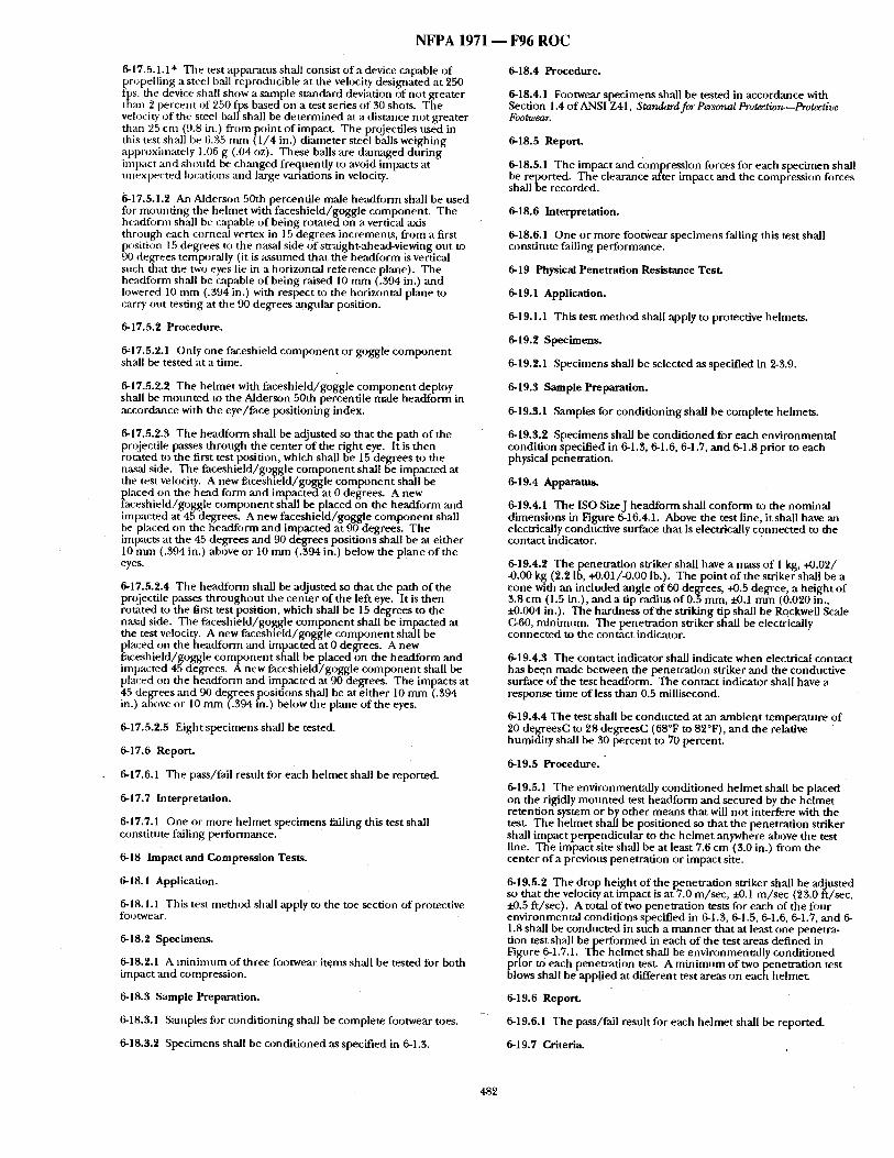
N F P A 1971 - - F96 R O C
6-17.5.1.1 * The test apparatns shall consist o f a device capable o f propell ing a steel ball reproducible at the velocity designated at 250 fps, the device shall show a sample s tandard deviation of no t greater than 2 percent of 250 fps based on a test series of 30 shots. The velocity o f the steel ball shall be de t e rmined at a distance not greater than ")5 cm (9.8 in.) f rom point o f impact. The projectiles used in this test shall be 6.35 m m (1 /4 in.) d iameter steel balls weighing approximately 1.06 g (.04 oz). These balls are damaged dur ing impact and should be changed frequently to avoid impacts at unexpec ted locations and large variations in velocity.
6-17.5.1.2 An Alderson 50th percentile male headform shall be used for moun t ing the hehne t with faceshie ld /goggle component . The headfi:~rm shall be capable o f being rotated on a vertical axis through each corneal vertex in 15 degrees increments , f rom a first position 15 degrees to the nasal side o f straight-ahead-viewing out to 90 degrees temporally (it is ~ssumed tha t the headform is vertical such that the two eyes lie in a horizontal re terence plane). The headform shall be capable o f being raised 10 m m (.394 in.) and lowered 10 m m (.394 in.) with respect to the horizontal plane to carry out testing at the 90 degrees angular position.
6-17.5.2 Procedure.
6,17.5.2.1 Only one faceshield c o m p o n e n t or goggle c o m p o n e n t shall be tested at a time.
6-17.5.2.2 The he lmet with faceshie ld/goggie c o m p o n e n t deploy shall be moml ted to the Alderson 50th percentile male headform in accordance with the eye/ face posi t ioning index.
6-17.5.2.3 The headform shall be adjusted so that the path o f the projectile passes th rough th~ center o f the r ight eye. It is then rotated to the first test position, which shall be 15 degrees to the nasal side. The faceshie ld /goggie c o m p o n e n t shall be impacted at the test velocity. A new faceshie ld/goggle c o m p o n e n t shall be placed on the h~ td form and impacted at 0 degrees. A new faceshie ld/goggie c o m p o n e n t shall be placed o n the headfo rm and impacted at 45 degrees. A new faceshie ld/goggle c o m p o n e n t shall be placed on the headform and impacted at 90 degrees. The impacts at the 45 degrees and 90 degrees positions shall be at ei ther 10 nma (.394 in,) above or 10 m m (.394 in.) below the plane o f the eyes.
6-17.5.'*.4 The headform shall be adjusted so tha t the path o f the projectile passes t h roughou t the center of the left eye. It is then rotated to the first test position, which shall be 15 degrees to the nasal side. The faceshie ld /goggle c o m p o n e n t shall be impacted at the test velocity. A new faceshie ld /gnggle c o m p o n e n t shall be placed on the headform arid i mpac t eda t 0 degrees. A new faceshielcl/goggie c o m p o n e n t shall be placed on the heaciform and impacted 4.5 degrees. A new faceshie ld/goggie c o m p o n e n t shall be placed on the headform and impacted at 90 degrees. The impacts at 45 degrees and 90 degrees positions shall be at e i ther 10 m m (.394 in.) above or I0 m m (.394 in.) below the plane of the eyes.
6-17.5.2.5 Eight specimens shall be tested.
6-17.6 Report.
6-17.6.1 The pass/fall result for each he lmet shall be reported.
6-17,7 Interpretation.
6-17.7.1 One or more he lmet specimens failing this test shall constitute failing performance.
6-18 Impact and Compress ion Tests.
6-18.1 Application.
6-18.1.1 This test me t hod shall apply to the toe section of protective footwear.
6-18."* Specimens.
6-18.2.1 A m i n i m n m of three footwear items shall be tested for both impact ,and compression.
6-18.3 Sample Preparation.
6-18.3.1 Sanlples fi)r condi t ioning shall be complete footwear toes.
6-18.3.2 Specimens shall be condi t ioned as specified in 6-1.3.
6-18.4 Procedure.
6-18.4.1 Footwear specimens shall be tested in accordance with Section 1.4 of ANSI Z41, Standard for Personal Protection.--Protective Footwear.
6-18.5 Report.
6-18.5.1 The impact and compression forces for each specimen shall be reported. The clearance after impact and the compression forces shall be recorded.
6-18.6 Interpretation.
6-18.6.1 One or more footwear specimens falling this test shall constitute failing performance.
6-19 Physical Penetrat ion Resistance Test.
6-19.1 Application.
6-19.1.1 This test me thod shall apply to protective helmets.
6-19.2 Specimens.
6-19.2.1 Specimens shall be selected as specified in 2-3.9.
6-19.3 Sample Preparation.
6-19.3.1 Samples for condi t ioning shall be complete helmets.
6-19.3.2 Specimens shall be condi t ioned for each envi ronmenta l condit ion specified in 6-1.3, 6-1.6, 6-1.7, a n d 6-1.8 prior to each physical penetration.
6-19.4 Apparatus.
6-19.4.1 The ISO SizeJ head fo rm shall conform to the nominal d imensions in Figure 6-16.4.1. Above the test line, it shall have an electrically conductive surface that is electrically connec ted to the contact indicator.
6-19.4.2 The penet ra t ion striker shall have a mass o f 1 kg, +0.02/ -0.00 kg (2.2 Ib, +0.01/-0.00 lb.). The point of the striker shall be a cone with an included angle o f 60 degrees, +0.5 degree, a he ight o f 3.8 cm (1.5 in.), and a tip radius o f 0.5 mm, i-0.1 m m (0.020 in., ~ . 0 0 4 in.). The hardness of the striking tip shall be Rockwell Stale C-60, min imum. The penetra t ion striker shall be electrically connec ted to the contact indicator.
6-19.4.3 The contact indicator shall indicate when electrical contact has been made between the penetrat ion striker an d the conductive surface of the test headform. The contact indicator shall have a response t ime of less than 0.5 millisecond.
6-19.4.4 The test shall be conduc ted at an ambien t tempera ture o f 20 degrees(', to 28 degrees(" (68°F to 82°F), and the relative humidi ty shall be 30 percent to 70 percent .
6-19.5 P r o c e d u r e .
6-19.5.1 The environmental ly condi t ioned he lmet shall be placed on the rigidly mo tmted test headform and secured by the he lmet retention system or by o ther means that will no t interfere with the test. The he lmet shall be posit ioned so that the penetrat ion striker shall impact perpendicular to the he lme t anywhere above the test line. The impact site shall be at least 7.6 cm (3.0 in.) f rom the center of a previous penetrat ion or impact site.
6-19.5.2 The drop he igh t of the penetra t ion striker shall be adjusted so that the velocity at impact is at 7.0 m/sec , :t-0.1 m / s e c (23.0 ft /sec, • -0.5 f t /sec). A total o f two penetra t ion tests for each of the four environmenta l condit ions specified in 6-1.3, 6-1.5, 6-1.6, 6-1.7, and 6- 1.8 shall be conducted in such a m a n n e r that at least one penetra- tion test shall be per formed in each o f the test areas def ined in Figure 6-1.7.1. The he lmet shall be environmental ly condi t ioned prior to each penetrat ion test. A m i n i m u m of two penetra t ion test blows shall be applied at different test areas on each helmet.
6-19.6 Report.
6-19.6.1 The pass/fail result for each he lmet shall be reported.
6-19.7 Criteria.
482
N F P A 1971 - - F96 R O C
6-19.7.1 One or more hehnet specimens failing this test shall constitute failing pefform~m ce.
6-20' Puncture Resistance Test One.
6-20.1 Application.
6-20.1.1 This test method sh,-dl apply to protective gloves and footwear uppers.
6-20.2 Specimens.
6-20.2.1 A mininmm of three specimens measuring at least 15.24 cm (6 in.) square shall be tested.
6-20.3 Sample Preparation.
6-20.3.1 Samples tot conditioning shall be complete gloves or footwear npper sections.
6-20.3.2 Specimens shall be tested after conditioning ,as specified in 6-1.3.
6-20.4 Procedure.
6-20.4.1 Specimens shall be tested in accordance with ASTM F 1342, StarMm~l Test Method for Protective Clothing Material Resistance to Puncture.
6-20.5 Report.
6-20.5.1 The puncture force in kg force (Ib force) shall be reported fi:w each specimen. The average puncture force in kg force (Ib fi~rce) shall be reported for all specimens tested.
6-20.6 Interpretation.
6-20.6.1 The average puncture force shall be used to determine pass/fail performance:
6-20.7 Specific Requirements for Testing Gloves.
6-20.7.1 Specimens shail consist of each composite of the palm, pahn side of the fingers, and back of the glove used in the actual glove construction, with the layers arranged in proper order. Where the specimen composites of the palm, palm side of the fingers, and back of the glove are identical, only one representative composite shall be required to be tested.
6-20.7.2 Glove specimens shall also be tested after wet condition as specified in 6-1.10.
6-20.7.3 Testing shall be performed as specified in 6-20.2 through 6-20.6.
6-20.8 Specific Requirements for Testing Footwear Uppers.
6-20.8.1 Specimens shall consist of each composite of footwear item used in the actual fi~otwear construction, with the layers arranged in proper order. Specimens sh~dl be taken from the thinnest portion of the fi:>otwear upper.
6-20.8.2 Testing shall be per tbrmed as specified in 6-20.2 through 6-20.6.
6-21 Puncture Resistance Test Two.
6-21.4 Procedure.
6-21.4.1 Puncture resistance tests shall be performed in accord,'mce with ANSI Z41, Standard for Personal Prote~twn,---Protective Footwear.
6-21.5 Report.
6-21.5.1 The force necessary to puncture the sole reinforcement device of each specimen shall be reported,
6.21.6 Interpretation.
6-21.6.1 One or more footwear specimens failing this test shall constitute failing performance.
6-22 Cut Resistance Test.
6-22.1 Application.
6-22.1.1 This test method shall apply to protective gloves and footwear u ppers.
6-22.2 Specimens.
6-22.2.1 A minimum of three specimens measuring at least 15.2 cm (6 in.) square shall be tested.
6-22.3 Sample Preparation.
6-22.3.1 Specimens shall be tested after conditioning as specified in 6-1 .~,.
6-22.4 Apparatus.
6-22.4.1 The static cut test apparatus shall consist of an L-shaped metal frame and pivoted ,arm that lowers a sharp-edged blade onto a sample specimen, as shown in Figalre 6-22.4.1.
D i l t t ~ t ~ v ~
Figure 6-22.4.1 Static cut test apparatus.
6-21.1 Application.
6-21.1. I This test method shall apply to protective footwear soles.
6-21.2 Specimens.
6-21.2.1 A minimum of three footwear soles shall be tested.
6-21.3 Sample Preparation.
6-21.3.1 Samples fi)r conditioning shall be footwear sole sections.
6-22.4.2 A locking mechanism shall be mounted upright on the L- frame to engage the pivoted arm and secure it in a neutral position above the sample specimen. The locking mechanism shall be used when the blade is being replaced or when the specimen is being moved into or from the testing position.
6-22.4.3 The blade shall be mounted in a blade holder at the outer end of the pivoted arm, as shown in Figure 6-22.4.3. The blade shall be mounted so its sharp edge is tangential.
6-21.3.2 Specimens shall be condit ioned ,as specified in 6-1.3.
488
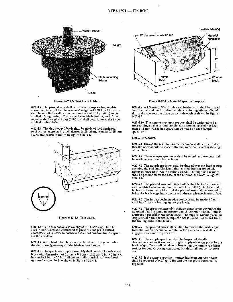
N F P A 1971 - - F96 R O C
k Weight
Leather backing
ide mounting :ures
Blade
Figure 6-22.4.3 Test blade holder.
6-22.4.4 T h e p i v o t e d ,ann shall be capable o f suppor t ing weights above the blade holder. Incremental weights o f 0.91 kg (2 lb) each shall be supplied to allow a m a x i m u m force o f 9.1 kg (20 Ib) to be applied ditring testing. The pivoted arm, blade holder, and b l a d e together shall weigh 0.91 kg (2 Ib) and shall contr ibute to the force applied to the blade.
6-22.4.5 The sharp-edged blade shall be made o f tool-hardened steel with ,an edge having a 60-degree inclined angle and a 0.025-mm (0.001-in.) radius as shown in Figure 6-22.4.5.
I/32
t"
Q 1"
Figure 6-22.4.5 Test blade.
6-22.4.6* The sharpness or geometry of the blade edge shall be closely moni to red and controlled to prevent changes in cut t ing characteristics in order to ensure a consistent baseline fi~r interpret- ing the cut data.
6-22.4.7 A test blade shall be ei ther replaced or r e sha rpened when the sharpness (geometry) o f the blade edge changes.
6-22.4.8 The specimen suppor t assembly shall consist of a soft wood block with d imens ions ofS.1 cm x 5.1 cm x 10.2 cm (2 in. x 2 in. x 4 in.) and a 1.9-cm (0.75-in.) diameter, half-rounded, soft wood rod m o u n t e d to the block ,as shown in Figure 6-22.4.8. •
len
Figure 6-22.4.8 Material specimen support.
6-22.4.9 A 1.3-mm (0.05-in.) thick soft leather strip shall be draped over the rod and block tos imula te the cush ioning effects of h an d skin and to protect the blade on a cut- through as shown in Figure 6-22.4.8.
6-22.4.10 The sample specimen suppor t shall be des igned to be f rees tanding so that several parallel-cut at tempts, spaced not less than 3.18 m m (0.125 in.) apart, can be made on each sample specimen.
6-22.5 Procedure.
6-22.5.1 Dur ing the test, the sample spec imen shall be or iented so that the normal outer surface is the first to be contacted by the edge of the blade.
6-22.5.2 Three sample specimens shall be tested, and two cuts shall be made on each sample specimen.
6-22.5.3 The sample specimen shall be draped over the leather strip covering the rod and block and then tacked, but not stretched, tightly in place as shown in Figure 6-22.4.8. The suppor t ,assembly shall be posit ioned on the base of the L-frame, as shown in Figure 6-22.4.1.
6-22.5.4 The pivoted arm and blade holder shall be initially loaded with weights to the m a x i m u m force of 9.1 kg (20 lb). A blade shall be inserted into the holder, and the pivoted ,arm shall be lowered to br ing the blade edge into contact with the sample specimen surface.
6-22.5.5 The initial specimen-edge contact shall be made 3.0 m m (1 /8 in.) f rom the leading end of the blade.
6-22.5.6 The specimen assembly shall be drawn smoothly u n d e r the weighted blade at a rate no greater than 51 c m / m i n (20 in . /min ) in a direction parallel to the blade edge. The suppor t assembly shall be s topped when the specimen-edge contact is 0.3 cm (0.125 in.) f rom the trailing edge o f the blade.
6-22.5.7 The pivoted arm shall be lifted to remove the blade edge from the sample specimen, and the locking mechan i sm shall be engaged to secure the pivot arm.
6-22.5.8 The sample specimen shall be inspected visually to de termine whether it was cu t th rough completely at any point by the blade edge. Care shall be taken in inspect ing the sample specimen surface for cut. Grooving can occur, bu t this shall not consti tute a cut.
6-22.5.9 If the sample specimen surface has been cut, the weight shall be reduced by 0.91 kg (2 lb) and the test procedure shall be repeated.
484
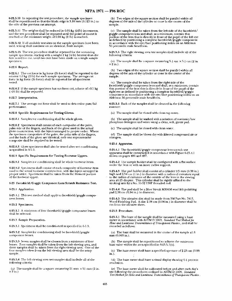
N F P A 1971 ~ F 9 6 R O C
6-22.5.10 In repeat ing the test procedure, the sample specimen shall be reposit ioned so that the blade edge is 3.18 m m (0.125 in.) to the side of the previous cut at tempt.
6-22.5.11 The weights shall be reduced in 0.91-kg (2-1b) increments , and the test procedure shall be repeated until the point of no-cut is reached or the m i n i m u m weight of 0.91 kg (2 lb) is reached.
6-22.5.12 If all available test sites on the sample specimen have been used, testing shall cont inue on an identical, fresh sample.
6-22.5.13 The test procedure shall be repeated for the remaining sample specimens, st:u'ting with a weight 2 kg (4 lb) heavier thml the first noted for cut, tmfil two cuts have been made on a single sample s[)ecinlen.
6-2"& 6 Report.
6-22.6.1 The cut force in kg force (lb force) shall be reported to the nearest 1.0 kg (2 Ib) for each smnple specimen. The average cut , fi)rce in kg force (lb force) shall be reported for all specimens tested.
6-22.6.2 If the sample specimen has not been cut, a force of>9.1 kg (>20 lb) shall be reported.
6-22.7 Interpretation.
6-22.7.1 The average cut force shall be used to de termine pass/fail performance.
6-22.8 Specific Requirements for Testing Gloves.
6-22.8.1 S:m/ples for condi t ioning shall be whole gloves.
6-'~2.8.2 Specimens shall consist o f e ~ h composite o f the palm, palm side of the fingers, and back of the glove used in the actual glove construction, with the layers a r ranged in proper order. Where the specimen composites of the palm, the pa lm side of the fingers, and ttle back of the glove are identical, only one representative composite shall be required to be tested.
6-22.8.3 (;love spec imens shall also be tested after wet condi t ioning as specified in 6-1.9.
6-22.9 Specific Requirements for Testing Footwear Uppers.
6-22.9.1 Santples ti,r condi t ioning shall be whole footwear itents.
6-22.9.2 Specimens shall consist of each composite of footwear item used in the actual footwear construction, with the layers a r ranged in proper order . .Spec imens shall be taken f rom the th innest portion of the R~otwear upper.
6-23 Faceshield/Goggle Component Lens Scratch Resistance Test.
6-23.1 Application.
6-23.1.1 This test me thod sh~d[ apply to faceshield/goggle compo- nen t lenses.
6-23.2 Specimens.
6-23.2.1 A ininimtml of four faceshield/goggle c o m p o n e n t lenses shall be selected.
6-23.3 Sample Preparation.
6-23.3.1 Specimens shall be condi t ioned as specified in 6-1.3.
6-23.3.2 Samples for condi t ioning shall be faceshield/goggie c o m p o n e n t lenses.
6-23.3.3 Seven samples shall be chosen from a min imt ,m of four lends . Four sanlples shall be taken from the left viewing area, and three samples shall be taken from the right viewing area. One of the four smnples taken from the left viewing area shall be the setup sample.
6-23.3.4 The left viewing :flea test samples shall include all of the tollowing criteria:
(a) The sample shall be a square measur ing 51 m m x 51 m m (2 in. x 2 in.)
(b) Two edges of the square section shall be parallel within ±2 degrees o f the axis o f the cylinder or cone in the center o f the sample.
(c) The sample shall be taken f rom the left side of the faceshield/ goggle c o m p o n e n t lens and shall, as a min imum, contain that portion o f the lens that is directly in front of the pupil o f the left eye as def ined by posit ioning a complete faceshie ld/goggle c o m p o n e n t in accordance with the eye/ face posi t ioning index on an Alderson 50 percentile male headform.
6-23.3.5 The right viewing area test samples shall include all of tile following criteria:
(a) The sample shall be a square measur ing 5.1 cm x 5.1 cm (2 in. x 2 in.).
(b) TWO edges of the square section shall be parallel within ±2 degrees o f the axis of the cylinder or cone in the center o f the sample.
(c) The sample shall be taken f rom the right side of the faceshie ld/guggle c o m p o n e n t lens and shall, as a min imum, contain that portion of the lens that is directly in f ront of the pupil of the right eye as defined by posit ioning a complete faceshie ld/goggle c o m p o n e n t in accordance with the eye/ face posit ioning index on an Alderson 50 percentile rr~tle headform.
6-23.3.6 Each of the samples shall be cleaned in the following m~lner :
(a) The sample shall be r insed with clean tap water.
(b) The sample shall be washed with a solution of nonionic / Iow phospha te de tergent and water using a clean, soft, gauze pad.
(c) The sample shall be rinsed with clean water.
(d) The sample shall be blown dry with filtered compressed air or nitrogen.
6-23.4 Apparatus.
6-23.4.1 The faceshield/goggle c o m p o n e n t lens scratch test apparatus shall be consmlc t ed in accordance with Figure 6-23.4. l shown on pages 486 and 487.
6-23.4.2 The sample holder shall be conf igured with a flat surface unde r the lens or with an inner radius support.
6-23.4.3 The pad holder shall consist of a cylinder 9.5 m m (0.38 in.) high and 2.54 cm (1 in.) in d iameter with a radius of curvature equal to the radius of curvature of the outside of the lens in the viewing area i-0.25 diopter. This cylinder shall be rigidly affixed to the stroking arm by a No. 10-32 UNF threaded rod.
6-23.4.4 The pad shall be a Blue Streak M306M wool felt polishing pad 2.38 cm (0.94 in.) in diameter.
6-23.4.5 The abrasive disc shall be made from 3M Part No. 7415, Wood Finishing Pad. A disc 2.38 cm (0.94 in.) in d iameter shall be cut f rom the abrasive sheet.
6-23.5 Procedure.
6-23.5.1 The haze of the sample shall be measured us ing a haze meter in accordance with ASTM D 1003, Standard Test Methocl for Haze and Luminous Transmittance of Transpat~'nt Plastics, and shall be recorded as follows:
(a) The haze shall be measured in the center of the sample ±1.6 m m (0.063 in.).
(b) The sample shall be reposit ioned to achieve the m a x i m u m haze value within the area specified in 6-23.5.1 (a).
(c) The haze meter shall have a specified aper ture of 2.23 cm (0.88 in.).
(d) The haze meter shall have a visual display showing 0.1 percent resolution.
(e) The haze meter shall be calibrated before and after each day's use fi~llowing the procedures out l ined in ASTM D 1003, Standard Test Method for Haze and Luminous Transmittance of Transparent Plastics.
485
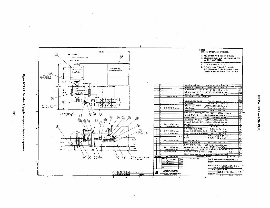
@
E tO C~
m ¢0
g
0
g N
. . . . . . . . . . . . 2 0 . 0 0
~ 3 8
T - - - "~ 2 . . . . . , 2 ; " ~ ; t t ; o , . C ' ,
. . . . • ~ ' - - - . I .L I ~ !1
I I , -'1,~1 - '1' ~° r "- ~ . - - - - - -
"°°i ~"'~"+t ~"r'°°q"-'°°-'l ==-+:='- , ~ / LO0 ,Pu t COW
.L+ ',\~j ++~ ii:-r ~ - - " : +t .++ ~ i ,+ + ~ \ ' , ~ \ \, .I , _ ¢ _ \
. -F , r .
NOTES UNLESS OTHERW|SlE SP|CIFIED,
1, ALL D I M E N S I O N S ARE IN INCHES;
[ ]
C O H PI F..RI C ~ i _
C O ~ M E ~ I C~,t-
C O PA H E R . i C Ikl,..
CO--MEtriCaL
c o,,,'~M E ~ , C ~,.t. C O ~'1P,~ ~.G i C ca, L C oP~ t-~.R ic ~4_
L E M ¢ ~ C~l_/~.f~.~, ,FZTklK, h l S W = ~ . O O L A~-
C O U M T E I ~ / C O ~ I " R O L L F . ~ .
~v It I G H T ~ I . 0 0 x 3 5 L. ~ ' i~A$ i ,
E A I : I l k t G = ' / 3 1 ~ Z 4 k,l.O. O1~ F-Q
I::hvo'r R O D ~ . 1 8 ~ 2.OOL ¢~57 ~ALA I~ ICE A=IP1 ~:~.~.C~.T 1.0OT~K*2.0OW=4.8~L E'Ac.IIE PL~'TE 1.5OTHI<~.(.~tV. 5,$OI- AL.
S L I D i n G ~ L O ~ LMTHK=E~O~/~d.DOL A~ ~IVOT ~ I~ ¢~C. K ET . 50 "FNK. LOO ~v i Z O01. ~,L
)OV/EL (~,18 • I.OOL 5 7 L ~.OCK ~JUT I~ 1 0 " S Z COI~I~JECTIk~G R O D G~,51. 3 , 2 5 L AL . I~l~,LL 3 0 1 k i t I~OO E~JD I l O ' ~ . Z S T L
~ : ~ v o x $C~E~ ~W&SHE~ ~I0-5Z . .~ STL
G I ~ . I Z T H K ~ .~O S Q B,R&S~
~ASE ~U' fCHER~,LOCI~ M~PLE L2~tI4K, tSW=ZO
31
3 0 Z~ ZB
Z? g&
25 Z4
Z3 ZZ ZI
A'*. 19 P8 J? n~
~S
13 I?. Iq
I0 <)
5 4
pAlv/ IlNI IVl NO
c . D z ~ . ~ l,+y./,,J
NA V ~ ' U I ~ A T ~ V ~2~:£E.=-".,, J l ,
~-Q I 21
C L , . ' < A , m ~ U . ~ . F i r e A d m i n i s t r e t i o n / F E M A
r- . ,
I TE~ A P P ~ R ~ , ~ ; L J ~
~ N " + + o . , , , +~, ~,, +, £ ,< . , , - , + . o ~ , . , . , o,, -
1 , 2
Z
; >
-,4
I
p=
C
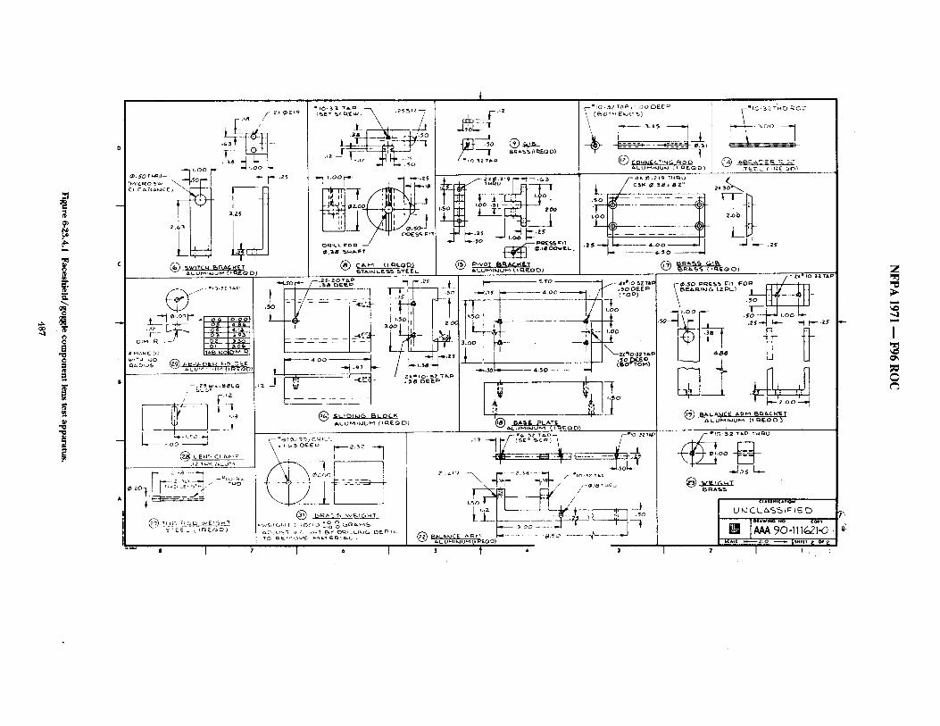
',,qr
3 ~p
P P
--...
g
el
g
9
/.~ 2x @.ZI9 , ;_l~ //
(,.,,,~,~ o s,.,., \ i ' z ~ ci E ~AMCE;
C
i
- ~ I. LU~ , ;Jl/ {l~lEDO}
' --;)~L%,...SLG .,? L ~ ~"
[____~_.____J __J
0 I
,X-
i .oo -.zs "t, I" ± lZ2,.
O~LL ~o
t
I ~ iz J.;oL..-
-- - ~ _ ~ , b - b - - , o o ~ 1
L / - ; w ; ; z ; t ..S..
h
"~ ( [ L ~ ; - - - - - ~ k - I I.:O0
,~ •
®
~L UMIkJU~ (if nEO D)
I 6 I ~ t '
~1 . ~0
-~--t ~'- "t t ' ' - ' a S P ' -
ALUMI~.JUM (I ~.QO~$ 4;.::,g ~uJ .'~ 5
@ ~
1 . . . . . . . . . . . . ,,11 ~" 90-III¢21-0 ~
~ ~I ~ ~ I ~Ilv ~i ~i i
7
Z
",ql
I @%
N F P A 1971 1 F96 R O C
6-23.5.2 The setup sanlple shall be placed cover side up in the test apl:~aratns sample bolder.
6-23.5.3 The pad holder, pad, ,and abrasive disc shall be installed on the stroking arm. The stroking arm shall be leveled to ±3 degrees by adjusting the threadedpin. The pin shall be secured to prevent rotation of the pad holcler. The axis of curvature of the pad holder shall be coincident with the axis of curvature of the lens,
6-23.5.4 The stroking ~ shall be counterbalanced with the pad holder, pad, and abrasive disc in place,
6-23.5.5 The setup s~unple shall be replaced with one of the six samples to be tested.
6-23.5.6 A test weight of 1 kg, ±8 g (2.2 lb, ±0.2 oz) shall be installed on the [:fin above the test sample,
6-23.5.7 The test shall be run for 200 cycles, ±1 cycle. One cycle shall consist of a complete rew)lution of the eccentric wheel.
6-2%5.8 The length of stroke shall be 1.43 cm (0.56 in,), producing a pattern 3.81 cm (1.5 in.) long. The frequency of the stroke shall be 60 cycles/min, ±1 cycle/rain. The center of the stroke shall be within 1.6 mm (±-0.063 in,) of the center of the sample,
6-23.5.9 The s~mlple shall be removed and cleaned following the procedure specified in 6-23,3.6. The abrasive disc shall be discarded.
6-23.5.10 The testing steps specified in 6-23.5 shall be repeated five additional t imes with a new sample and abrasive disc.
6-23.6 Report.
6-23.6.1 After each of the six samples have been tested and cleaned, the haze of the sample shall be measured following the procedure specified in 6-23.5.1.
6-2:~.6.2 The delta haze shall be calculated by subtract ing the initial haze m e a s u r e m e n t f rom the final haze measurement .
6-23.7 Criteria.
6-23.7.1 The six delta h~Lze values shall be averaged. The resultant value shall be compared to the value specified in 5-2.19 to de termine pass/fidl.
6-24 Abrasion Resistance Test.
6-24.1 Application.
6-24.1.1 This test m e t h o d shall apply to protective footwear soles ancl heels.
6-24.2 Specimens.
6-24.2.1 A m i n i m u m of three fi)otwear soles with heels shall be tested.
6-24.3 Sample Preparation.
6-24.3.1 Samples for condi t ioning shall be complete footwear soles with heel.
6-24.3.2 Specimens shall be condi t ioned as specified in 6-1.3.
6-24.4 Procedure.
6-24.4.1 Puncturexesis tmlce tests shall be per formed in accordance with A~STM i) 1630, Starutard Test Method for Rubber Property--Abrasion R~ist~zrwe (Footwea~ Abr~uter).
6-24.5 Report.
6-24.5.1 The ,'ibrasion resistance rating of each spec imen shall be reported.
6-24.6 Interpretation.
6-24.6.1 f )ne or more footwear spec imens falling this test shall constitute failing performance.
6-25 Cleaning Shrinkage Resistance Test.
6-25.1 Application.
6-25.1.1 This test me thod shall apply to the protective g a rm en t outer shell, moisture barrier, thermal barrier, and winter liner; and the hood and wristlet.
6-25.1.2 Modifications to this test me thod fi~r testing woven textile materials shall be as specified in 6-25.7.
6-25.1.3 Modifications to this test m e t h o d for testing knit and stretch woven materials shall be as specified in 6-25.8.
6-25.2 Specimens.
6-25.2.1 Cleaning shrinkage resistance testing shall be conducted on three specimens o f each material, and each separable layer of a composite material shall be tested separately.
6-25.3 Sample Preparation.
6-25.3.1 Specimens to be tested shall be condi t ioned as specified in 6-1.3.
6-25.4 Procedure.
6-25.4.1 Specimens shall be tested us ing five cycles o f Machine Cycle 1, Wash Tempera tu re V, and Drying/Procednre Ai of ANSI/AATCC 1 b5, Dimensional Cnanges in Automatic' Home Laundering of Woven and Knit Fabrics.
6-25.4.2 A 1.8-kg, i4).1 kg (4.0-1b, ±0.2 lb) load shall be used. A laundry bag shall no t be used.
6-25.4.3 Specimen marking and measuremen t s shall be conducted in accordance with the procedure specified in ANSI/AATCC 135, Dimensional Changes in Automatic. Honw Laundering of Woven and Knit Fabrics.
6-25.4.4 Knit fabric specimens shall be pul led to original d imensions ,and shall be allowed to relax for I minu te prior to measurement .
6-25.5 Report .
6-25.5.1 The percent change in the width and length d imensions of each spec imen shall be calculated. Results shall be reported as the average of all three specimens in each dimension.
6-25.6 Interpretation.
6-25.6.1 The average percent change in both d imens ions shall be used to deternfine pass/fail performance. Failure of ei ther d imens ion shall constitute failure for the entire sample.
6-25.7 Specific Requi rements for Testing Woven Textile Materials.
6-25.7.1 Each specimen shall be 38.1 cm × 38.1 cm, +1.3 cm (15 i t . × 15 in., ±0.5 in.) and shall be cu t f rom the fabric to be utilized in the construction of the clothing item.
6-25.7.2 Samples for condi t ioning shall be at least 1 m (1 yd) square of each material.
6-25.7.3 Test ing shall be pe r fo rmedas Specified in 6-25.2 through 6- 25.6.
6-25.8 Specific Requi rements for Testing Knit and Stretch Woven Textile Materials.
6-25.8.1 Other than for wristlets, the d imensions of each specimen shall be 38.1 x 38.1 cm, ±1.3 cm (15 x 15 in., ±0.5 in.) and shall be cut f rom the fabric to be utilized in the constralction o f the clothing item.
6-25.8.2 The d imensions of wristlet spec imens shall be 11.5 × 11.5 mm, ±1.3 cm (4.5 × 4.5 in., ±0.5 in.) and shall be cut f rom the wristlet fabric to be utilized in the construction of the clothing item.
6-25.8.3 Samples for condi t ioning shall include material that is at least 5.08 cm (2 in.) larger in each o f the two required specimen dimensions.
6-25.8.4 Test ing shall be per formed as specified in 6-25.2 through 6- 25.6.
6-26 Water Absorption Resistance Test.
6-26.1 Application,
488
lqFPA~YTI-.: I~6"M{~
6-~, f~l This test method shall appl], to the p r o ~ e v e garment &zter shell and collar lining nmt~dais.
6-se.~ spectme~
6-26.2.1 Tl~r~e speC" . ~ o f o m e r shell matm-hd and collar " L ~ g material measuring at | ea~ 20.3 c r a g 20,3 cm (8 in. × 8 i n . ) i ~ a l i b e tested separately for ~ absorption.
6-26.8 Sample l'repan~on.
6-~.3.1 Samples for condltioning shall be at least'l m (l yd) square_ of each material.
0-26.3.2 ,Specimens shall be tested after beingsubjected to the procedure specified in 6-1.2.
6-26.4 ProceduFe. °"
6-26.4.1 Specimens shah be tested in accordance with Method 5504, "Water Resistance of (~a ted CJoth; Spray Absorption Method," of Federal Test Method Standard 191A, Tex#//~ Tat Meth0ds. The normal outer surface shall .be exposed to the water spray.
6-26.4.2 Fo~ collar lining materials, the exposu?e surface shall be the surface of the fabric that is next to theskin when the collar is closed jn the raised position.
6-26,5 Report.
6-26.5.1 The percent wa~r absorbed for each specimen shah be reported. The average percent Water ~sorp t ion shall be calculated and reported,
6-26.6 Interpretation.
6-26.6.1 The average percent water absorption shall be used for determining pass/fail performance.
6-2"/ Water Penetration Test.
6-27.~ Appncatio~.
0-27.1.1 This test method shallapply to moisture barrier materials an d seams.
0-27.1.2 Modifications to this test for testing moisture barrier materials shall be as specified in 6-2%7,
0-27.1.3 Modifi~:ation to this test for testing moisture barrier: seams shall be as specified in 6-27.8.
6-27.2 Specimens.
6-27.2.1 A minimum of five specimens of moistxtre barrier material shall be tested.
0-27.2.2 ,Seam specimens shall be cut so that the seam divides the specimen into two equal halves.
6-27.3 Sample Preparation.
6-27.3.1 .Specimens shall be tested both before and after being subjected, to the procedure-spei:ified in 6-1.2.
"6-27.3.2 Specimens to be tested shall be conditioned as specified in 6-1.7.
0-27.3.3 Specimens to be tested shall then be conditioned as specified in 6-1.7.
6-27.4 Procedures.
6-27.4.1 Procedure A.
6-27.4.1A Specimens shah be tested at 1.76 kg/cm 2 (25 psi) in accordance with Method 5512, "Water Resistance of Coated CIoth; High Range, Hydrostatic Pressure Method," of Federal Test Method ,Standard 191A, T~xtll~ T~st M~tAods.
6-27.4.2 Procedure B.
6-27.4.2.1 S p e c i m e n s ~ be testedat 0,07 ks/cm 2 (I psi) for5 minutes in accordan~fe WtthMfithod 5516, "Water Resistance of Cloth; Water Permeability;, Hy&ostatic Pressure Method," of Federal Test Method Standard 191A, T~xtibT~sgMsthods.
6.27.5 Report.
6-27.5.1 Thepau / fa i l result~ for each specimen shall be reported.
6-~.~ [ n ~ .
6.27.6.1 The ~ c e of any water shallconstitute failure.
6-27.6.2 One or more test failures of any specimen against any liquid shall constitute failure of the material.
6-27.7 Specific Requkements for Tes th~ Moisture Barrier Materials.
6-27.7.1 Samples for conditioning shall be at least I m (I yd) ~uare .
6-27.7.2 ,Samples for conditioning as specified in 6-1.7 shall bed 5 cm (6 in.) squares cut from sample subjected to the procedures specified in 6-1.2: "
6-27.7.5 Specimens shall be tested as specified in 6-27.4,1, Proce- dure Al and 6-27.4.2, l~cethlre B.
0-2"L8 Specific l~quiremmlts for Testb~ Molmmre l~m4erSeamL
6-27.8.1 Samples for conditioning shall be at least 15.2 cm × 1 m (6 in. × I yd), with the seambisecting theisample:in the longitudinal direction.
6-27.&2 Sample~or conditioning as s p e d f l ~ in 6.1.~' si~14~ 15 cm (6 in.) squares cut fromsample subjected to the procedures specified in 6=1.2~
6-27.8.5 .Specimens shall be tested as specified in 6-27.4,2, "Proce- dure B." -'
6-28 Liquid Penetradbn ReMsum~ Test;
6-28.1 Application.
6-28.1.I This test shall applyto protective garment materials, protective gloves, a n d footwear.
6-28.1.2 Modlfications,to this test method for testing pro~ve 2~8.~.~ materials shall be as specified in 0-28.'7d, 6-28.7.2, and
6-28.1.3 Modifications to this test method for testing protective gloves shall be.as specified in 6-28.8.
6-28.1.4 Modifications to this test method for testing,protective footwear shall be as specified in 0-28.9.
6-28.2 SpectmenL
6-28.2.1 A minimum of three specimens shall be tested. Specimens shall consist of three 7.6.c~ (3-m.): squares for each:nmteri~ type.
6.28.3 Sample Preparation.
6-28.3,1 Specimens shall be tested after being subjected to the procedure specifiledin 6-1.2.
6-28.3.2 Specimens to be tested shall be conditioned as specified in O-L3;
6-28.3.3 Specimens to be tested shall then be conditi0ned ~ specified in 6-1.7.
6.2~8.4 ]k~'ecedm'e,
6-28.4.1 Liquid penetration resistance testing shall be conducted in accordance with ASTM F 905, Standard Test Mdchod for li~'istanc, of Pro~tivc Clothing Materials to Poutration by Liquids, using exposure ~" Procedure C.
6-28.4.2* Each of the following liquids shall be tested separately against each sample specimen;
(a) Aqueous film-forming foam (AFFF), 3 percent concentrate;
(b) Battery acid (37 percent w/w sulfuric acid);
(c) Fire-resistant hydraulic fluid, phosphate ester base;
489
N F P A 1971 - - F96 R O C
(d) Surrogate G;~)line fi~el C as defined in ASTM D 471, a 50/50 percent by vohtme of Toluene and lso-~)ctane;
(e) Swimming pool chlorinating chemical containing at least 65 percent free chlorine (safurated solution).
6-28.4.3 The normal outer surface of the material shall be exposed to the liquid as oriented in the clothing item.
6-28.5 Report.
6-28.5.1 The pass/fail result for e~ch specimen shall be reported.
6-28.6 Interpretation.
6-28.6.1 One or more test failures of any specimen against any liquid shall constitute failure of the material.
6-28.7 Specific Requirements for Testing Moisture Barrier Materials.
6-28.7. ! Samples fi:w conditioning shall be a least l m (1 yd) square.
6-28.7.2 Specimens shall consist of a composite of layers that act as a barrier. All layers must be ,arranged in proper order.
6-28.7.3 Testing shall be performed as specified in 6-28.2 through 6-28.6.
6-28.8 Specific Requirements for Testing Glove Materials.
6-28.8.1 Three specimens each shall be taken from the sample gloves at the palm, back, and seam areas.
6-28.8.2 Samples for condit ioning shall be whole gloves.
6-28.8.3 Testing shall be performed as s p e c k e d in 6-28.2 through 6-28.6.
6-28.9 Spe~:ific Requirements for Testing Footwear Materials.
6-28.9.1 Samples for conditioning shall be whole footwear.
6-28.9.2 Three specimens each shall be taken from the upper, the upper m sole seen1, and any upper seam areas.
6-28.9.3 Testing shall be performed ,as described in 6-28.2 through 6-28.6.
6-29 Viral Penetration Resistance Test.
6-29.1 Application.
6-29.1.1 This test shall apply to protective garment moisture barriers, protective gloves, and protective footwear.
6-29.1.2 Modifications to this test method for testing moistnre barriers shall be as specified in 6-29.7.
6-29.2 Specimens.
6-29.2.1 A minimum of three specimens shall be tested. Specimens shall consist o f tiwee 7.6-cm (3-in.) squares for each material type.
6-29.3 Sample Preparation.
6-29.3.1 "Specimens shall be tested after being subjected to the procedure specified in 6-1.2.
6-29.3.2 Specimens to be tested shall be condit ioned as specified in 6-1.3.
6-29.3.3 Specimens to be tested shall then be condit ioned as specified in 6-1.7.
6-2~.4 Procedure.
6-29.4.1 Liquid penetration resistance testing shall be conducted in accordance with A,STM ES 22, Err~'rgen~ Standard Test Mahodfor Resistar~e of Protective Clothing Materials to Penetration ~. Blood-Borne Pathogerts Using Viral Penetration as a Test ,~stern.
6-29.5 Report.
6-29.5.1 The pass/fail result for each specimen shall be reported.
6-29.6 Interpretation.
6-29.6.1 A failure of any specimen against any chemical constitntes failure of the material.
6-29.7 Specific Requirements for Testing Moisture Barrier Materials.
6-29.7.1 Specimens shall consist of the moisture barrier or that material in tended to act ,as the moisture barrier.
6-29.7.2 Samples for conditioning shall be at least 1 m (1 yd) square.
6-29.7.3 Testing shall be ,as described in 6-29.2 through 6-29.6.
6-29.8 Specific Requirements for Testing Glove Materials.
6-29.8.1 Three specimens each shall be taken from sample gloves at the palm, back, ,and seam areas.
6-29.8.2 Samples fi)r conditioning shall be whole gloves.
6-29.8.3 Testing shall be as described in 6-29.2 through 6-29.6.
6-29.9 Specific Requirements for Testing Footwear Materials.
6-29.9.1 Three specimens each shall be taken from the upper, the upper to sole seam, and any upper seam areas.
6-29.9.2 Samples for conditioning shall be whole footwear.
6-29.9.3 Testing shall be as described in 6-29.2 through 6-29.6.
6-30 Corrosion Resistance Test.
6-30.1 Application.
6-30.1.1 This test method shall apply to hardware items On protective garments, helmets, gloves, footwear, and partial eye/face protective devices.
6-30.1.2 Modifications to this test for testing garment and glove " hardware shall be as specified in 6-30.7.
6-30-1.3 Modifications to this test for testing helmet and partial eye/ face protective devices shall be as specified in 6-30.8.
6-30.1.4 Modifications to this test for testing footwear shall be as specified in 6-30.9.
6-30.2 Specimens.
6-30.2.1 A total o f three specimens of each hardware type shall be tested.
6-30.3 Sample Preparation.
6-30.3.1 Specimens shall not be conditioned.
6-30.4 Procedure.
6-30.4.1 Specimens shall be tested in accordance with AtTM B 117, Standard Method of Salt Spray (Fog) Testing. Hardware items shall be exposed to a 5 percent, =el percent saline solution for a period of 20 hours.
6-30.4.2 Immediately following the storage specified in 6-30.4.1 and prior to examination, specimens shall be rinsed under warm, running tap water and dr ied with compressed air.
6-30.4.3 Specimens shall then be examined visually with the unaided eye to determine the presence of corrosion.
6-30.4.4 The fnnctionality of each specimen shall be evaluated.
6-30.5 Report.
6-30.5.1 The presence of corrosion and the functionality for each specimen shall be reported.
6-30.6 Interpretation.
6-30.6.1 One or more hardware specimens failing this test shall constiulte failing performance for the hardware type.
490
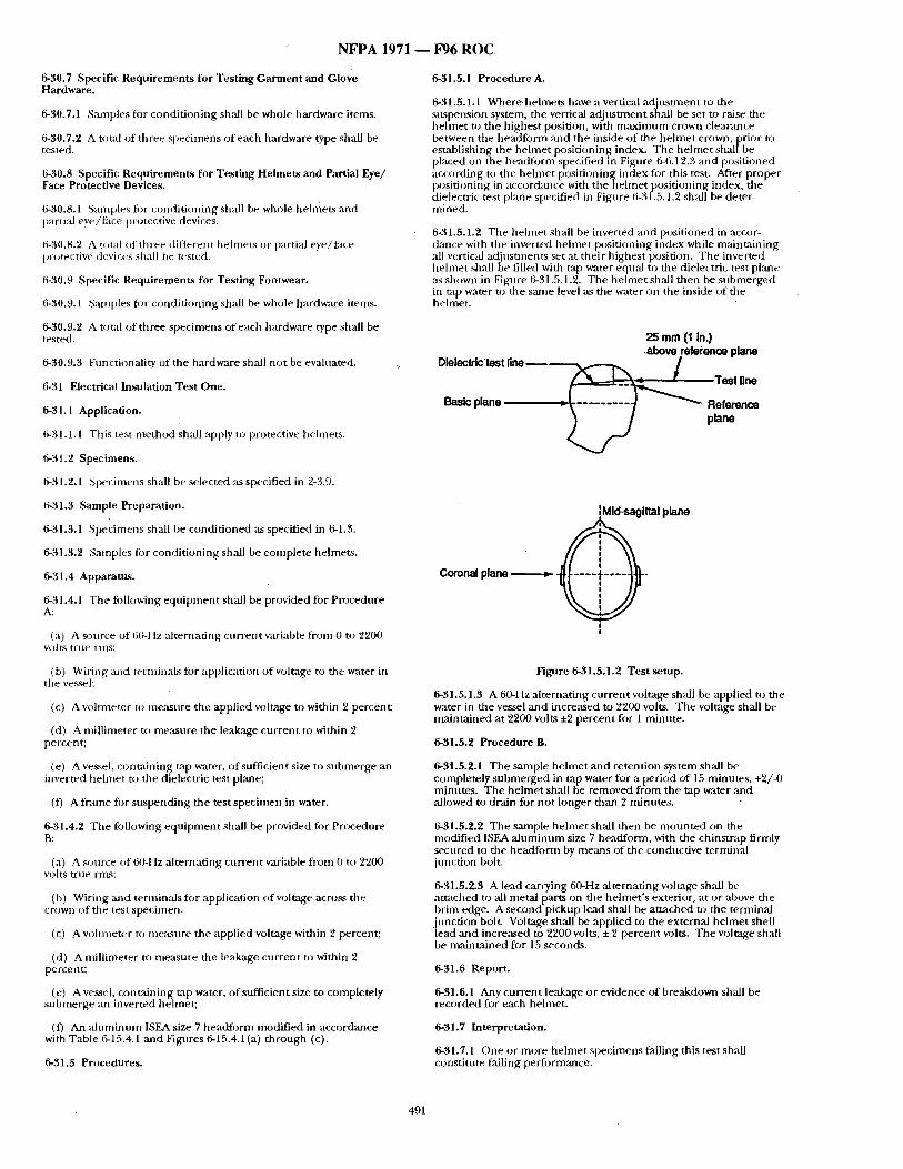
N F P A 1971 - - F96 R O C
6-30.7 Specific Requi rements for Testing Garment and Glove Hardware.
6-30.7.1 Santples for condi t ioning shall be whole hardware items.
6-30.7.2 A total of three specimens of each hardware type shall be tested.
6-30.8 Specific Requi rements for Test ing Helmets and Partial Eye/ Face Protective Devices.
6-30.8.1 Samples fi~t- condi t ioning shall be whole helmets and partial eye/face protective devices.
6-30.8.2 A total of three- different helmets or partial eye/face p,:~te_ctive devices shall be tested.
5-30.9 Specific Requi rements for Testing Footwear.
6-30.9.1 Samples fi)r condi t ioning shall be whole hardware items.
6-30.9.2 A total of three specimens of each hardware type shall be tested.
6-30.9.3 Functionality of the hardware shall no t be evaluated.
6-31 Electrical Insulation Test One.
6-31.1 Application.
6-31.1.1 This test me thod shall apply to protective laehuets.
6-31.2 Specimens.
6-31.2.1 Specimens shall be selected as specified in 2-3.9.
6-31.3 Sample Preparation.
6-31.3.1 Specimens shall be condi t ioned as specified in 6-1.3.
6-31.3.2 Samples fi~r condi t ioning shall be complete helmets.
6-31.4 Apparatus.
6-31.4.1 The following equip inent shall be provided for Procedure A:
(a) A source of 60-Hz al ternating cur rent variable from 0 to 2200 v e i l ' S trl.l¢ - r i l lS :
6-31.5.1 Procedure A.
6-31.5.1.1 Where, helmets have a verticai ad jus tment to the suspension system, the vertical adjusmaent shall be set to raise the he lmet to the highest position, with m a x i m u m crown clearance between the head tb rm and the inside of the he lmet crown, prior to establishing the he lmet posit ioning index. The he lmet sha l lbe placed on the headfi:wm specified in Figalre 6-6.12.3 and posit ioned according to the he lmet posit ioning index fi)r this test. After proper posit ioning in accordance with the hehne t posit ioning index, the dielectric test plane specified in Figure 6-31.5.1.2 shall be deter- mi ned.
6-31.5.1.2 The hehne t shall be inverted and posit ioned in accor- dance with the inverted he lmet posit ioning index while mainta ining all vertical adiusunents set at their h ighest position. The inverted hehnet shall be filled with tap water equal to the dielectric test plane its shown in Figure 6-31.5.1.2. The he lmet shall then be submerged in tap water to the same level as the water on the inside of the helmet.
25 mm (1 in.) ,above reference plane
DielectrlC test ~ n e ~ ~ Test line
Basic plane =~ ----------/ ~ Reference piano
IMid-sagittal plane
I !
(b) Wiring and termiuals fi)r application of voltage to the water in the vessel:
(c) A voltmeter to measure the applied voltage to within 2 percent;
(d) A millimeter to me:~sure the leakage cur ren t to within 2 percent;
(e) A vessel, conta in ing tap water, of sufficient size to submerge an inverted he lmet to the dielectric test plane;
(f) A fr:m~e fi~r suspend ing the test specimen in water.
6-31.4.2 The following equ ipmen t shall be provided for Procedure B:
(a) A sere're of 60-Hz al ternating cur rent variable f rom 0 to 2200 VO]t~q r f n e r m s :
(b) Wiring and terufinals for application o f voltage acro~s the crown of the test specimen.
(c) A wAtmeter to measure the applied voltage within 2 percent;
(d) A mill imeter to m e ~ n r e the leak:~ge cur rent to within 2 percent;
(e) A vessel, conta ining tap water, o f sufficient size to completely submerge an inverted hehnet;
(f) An a l u m i n u m ISEA size 7 headfo rm modif ied in accordance with Table 6-15.4.1 and Figures 6-15.4.1 (a) th rough (c).
6-31.5 Procedures.
Figure 6-31.5.1.2 Test setup.
6-31.5.1.3 A 60-Hz al ternat ing cur rent voltage shall be applied to the water in the vessel and increased to 2200 volts. The voltage shall be mainta ined at 2200 volts ±2 percent fi~r 1 minute.
6-31.5.2 Procedure B.
6-3t.5.2.1 The sample he lmet and retention system shall be completely submerged in tap water for a period of 15 minutes , +2/-0 minutes. The helmet shall be removed f rom the tap water and allowed to drain for no t longer than 2 minutes .
6-31.5.2.2 The sample he lmet shall then be m o u n t e d on the modif ied ISEA a l u m i n u m size 7 headform, with the chinstrap firmly secured to the headform by means of the conductive terminal junc t ion bolt.
6-31.5.2.3 A lead carrying 60-Hz al ternating wAtage shall be at tached to all metal parts on the he lmet ' s exterior, at or above the brim edge. A second pickup lead shall be at tached to the terminal
i unction bolt. Voltage shall be applied to the external he lmet shell ead and increased to 2200 volts, ± 2 percent volts. The voltage shall
be mainta ined for 15 seconds.
6-31.6 Report.
6-31.6.1 Any cur ren t leakage or evidence of breakdown shall be recorded for each helmet.
6-31.7 Interpretation.
6-31.7.1 One or more he lmet specimens falling this test shall constitute failing performance.
491
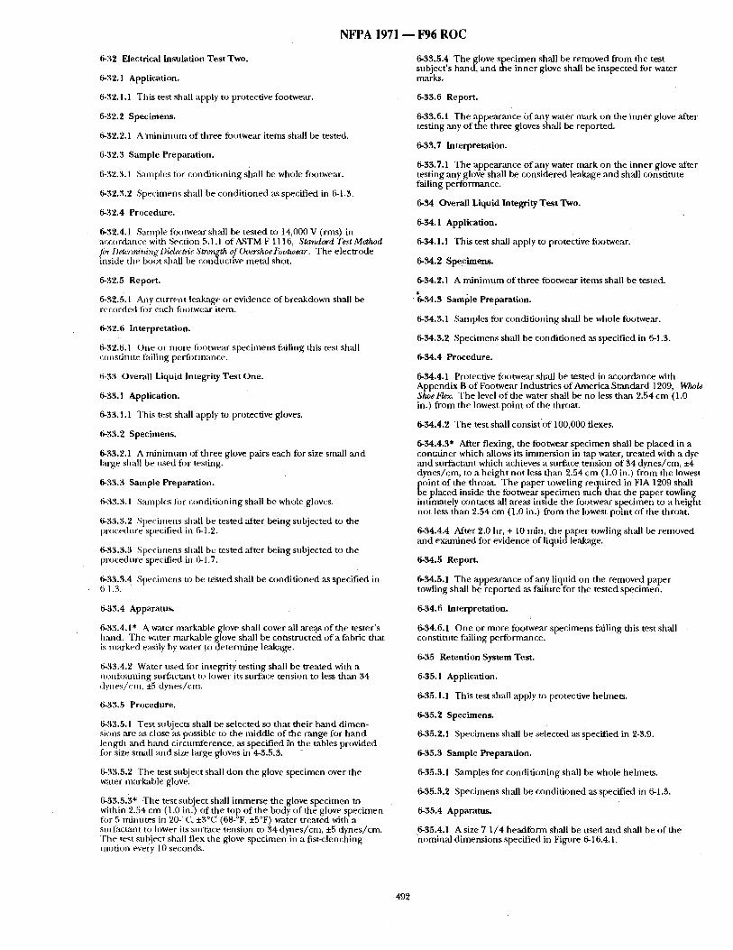
NFPA 1971 - - F96 ROC
6-32 Electrical Insulation Tes t Two.
6-32.1 Application.
6-32.1.1 This test shall apply to protective footwear.
6-32.2 Specimens.
6-32.2.1 A rain inm m of three fi~otwear i tems shall be tested.
6-32.3 Sample Preparation.
6.32.3.1 Samples for condi t ioning shall be whole fi:~otwear.
6-32.3.2 Specimens shall be condi t ioned as specified in 6-1.3.
6-32.4 Procedure.
6-32.4.1 Sample footwear shall be tested to 14,000 V (rms) in accordance with Section 5.1.1 of ~STM F 1116, Starulard Test Method firr Detc~vnining Diel~tric Strength of Ov,~shoe Footwear. The electrode inside the boot shall be conductive metal shot.
6-32.5 Report.
6-32.5.1 AJay cur ren t leakage or evidence of breakdown shall be recorded for each footwear item.
6-32.6 Interpretation.
6-32.6.1 One or more fi:u)twear spec imens failing this test shall ccmstitnte failing performance.
6-33 Overall Liquid Integrity Tes t One.
6-33.1 Application.
6-33.1.1 This test shall apply to protective gloves.
6-33.2 Specimens.
6-33.2.1 A nf in imum of three glove pairs each for size small and large shall be used for testing.
6-33.3 Sample Preparation.
6-33.3.1 Samples tor condi t ioning shall be whole gloves.
6-33.3.2 .~;pecimens shall be tested after being subjected to the procedure specified in 5-1.2.
6-33.3.3 Specimens shall be tested after being subjected to the procedure specified in 6-1.7.
6-33.3.4 Specimens to be tested shall be condi t ioned as specified in 6-1.3.
6-33.4 Apparatu,~
6-33.4.1" A water markable glove shall cover all areas of the tester 's hand. The water markable glove shall be coiastructed of a fabric that is marked e~Lsily by water ~co de termine leakage.
6-33.4.2 Water used fi:~r integrity testing shall be treated with a nonfoaming snr~actant to lower its surface tension to less th:m 34 dynes /cm, *5 dynes/era .
6-33.5 Procedure.
6-33.5.1 Test subjects shall be selected so tha t their hand dimen- sions are :~s close as possible to the middle of the range for h a n d length and ha nd circumference, ,as specified rn the tables provided for Size small and size large gloves in 4-3.5.3. -
6-33.5.2 The test subject shall don the glove specimen over the water markable glove.
6-33.5.3* The test subject shall immerse the glove specimen to within 2.54 cm (1.0 in.) of the top of the body of the glove spec imen fi)r 5 minutes in 20-%'.. ±3°C " (68-°F, ±5°F) water treated with a surfactaot to lower its su~'ace tension to 34 dynes /cm, ±5 dynes /cm. The test sub ect shall flex the glove specimen in a fist-clenching motion eVe,'y 10 seconds.
6-33.5.4 The glove specimen shall be removed f rom the test subject 's hand, and the inner glove shall be inspected for water marks.
6-33.6 Report.
6-33.6.1 The appearance o f any water mark on the inner glove after testing any of the three gloves shall be reported.
6-33.7 Interpretation.
6-33.7.1 The appearance o f any water mark on the inner glove after testing any glove shall be considered leakage and shall constitute failing performance.
6-34 Overall Liquid Integrity Test Two.
6-34.1 Application.
6-94.1.1 This test shall apply to protective footwear.
6-34.2 Specimens.
6-34.2.1 A m i n i m n m of three footwear i tems shall be tested.
"6-34.3 Saml~le Preparation.
6-34.3.1 Samples for condi t ioning shall be whole footwear.
6-34.3.2 Specimens shall be condi t ioned ,as specified in 6-1.3.
6-34.4 Procedure.
6-34.4.1 Protective footwear shall be tested in accordance with Appendix B of Footwear Industries o f America Standard 1209, Who/e ShoeFle~ The level of the water shall be no less than 2.54 cm (1.0 in.) f rom the lowest point of the throat.
6-34.4.2 The test shall consist 'of 100,000 flexes.
6-34.4.3* After flexing, the footwear spec imen shall he placed in a container which allows its immersion in tap water, treated with a dye and surfactant which achieves a surface tension of 34 dynes /cm, +4 dynes /cm, to a he igh t no t less than 2.54 cm (1.0 in.) f rom the lowest
~ oint of the throat. The paper toweling reqnired in FIA 1209 shall e placed inside the footwear specimen such that the paper towling
intimately contacts all areas inside the footwear spec imen to a height not less than 2.54 cm (1.0 in.) f rom the lowest point o f the throat.
6-34.4.4 After 2.0 hr, + 10 rain, the paper towling shall be removed and examined for evidence of liquid leakage.
6-34.5 Report.
6-34.5.1 The appearance o f any liquid on the removed paper towling shall be reported ,as failure fi~r the tested specimen.
6-34.6 Interpretation.
6-34.6.1 One or more footwear specimens failing this test shall constitnte failing performance.
6-35 Retention System Test.
6-35.1 Application.
6-35.1.1 This test shall apply to protective helmets.
6-35.2 Specimens.
6-35.2,1 Specimens shall be selected as specified in 2-3.9.
6-35.3 Sample Preparation.
6-35.3.1 Samples for condi t ioning shall be whole helmets.
6-35.3.2 Specimens shall be condi t ioned as specified in 6-1.3.
6-35.4 Apparatus.
6-35.4.1 A size 7 1 /4 headform shall be used an d shall be of the ~lominal d imensions specified in Figure 6-16.4.1.
492
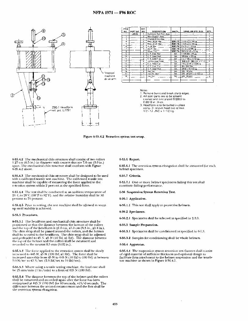
N F P A 1971 - - F 9 6 R O C
i r - ~
I
] ~ - - ' q Z90.1 Headfo m
I TEM BHT NO, PART NO. NO,
/ 1 L8539 2 2 3 2 4 2
5 2 6 2 7 2 8 2 9 2
2 10 11 2 12 2 ~3 2 14 2 15 2 16 2 17 t t8 I
DESCRIPT ION Re lenhon TeSI Fix1. Assy
Ma,n Support Assy Knur led KnoO ASSy Rec I A l um Bat Reel A l um Bar ~ l um 8at A l om BaF A lu~ Flat C F Steel Rod C ~ Slee Rod C F Sleel Flat HollOw Steel Tube C F Sle~l Flat C ~ Ste~i ~lat C F Steel Rod l,~ex Nu l
He~ Hd Boll
~e~ Nu l
MAT 'L . VEND. OR STR. SIZE QTY . 1 I
2 6061 .T6 1 112 x 3 x 14 L~ 1 ~061-T6 I 1/2 x 3 x 14 Lg. I 6061-T6 2 x2~ 7112Lg . I 6(~1 -T6 2 x 2x 1296L~1 I 6061.T6 314 x 4 1/2 x 5 Lg. 1
Stl. 1 , / 40 i a . x 4 L g . 1 Sl l 3 /8 Dia. • 22 Lg. 1 Stl. I • I 1/4 x 1 112 Lg I Stl. .S000 .O . 3~1 [~ x 1 1/2 Z Sit 1/4 x 3 114 x 3 3/4 Lg 2 St~ 39 x :1/4 Thk 2
St l 3 /4 ~ x , 01 /2 Lg 2 S I I 3 /4 • 10 Unc 2 SII 3/8 • 24 Un ! x 2 ' / 2 Lg 3 S t l 3/El 24 Un f 3
Notes: 1. Remove burrs and break sharp edges. 2. All steel parts are to be solvent
cleaned and zinc plated 0.0003 to 0.0010 in. thick.
3. Headform is to be bohed in place using-3--socket head cap screws 1/2-13 UNC x 1 1/2 Lg.
Figure 6-35.4.2 Retention system test setup.
6-35.4.2 The mech,'micM chin sU-ucture shall consist of two rollers 1.27 cm (0.5 in.) in diarneter with centers that are 7.6 cm (3.0 in.) apart. The mechanical chin structure shall conform with Fignre 6-35.4, 2 above.
6-35.4.3 The mech,'mical chin structure shall be designed to be used with a calibrated tensile test machine. The calibrated tensile test machine shall be capable of measuring the force applied to the retention system within 2 percent at the specified force.
6-35.4.4 Tile test sball be conducted at ,'m ~unbient temperature of 20°C to 28°C (68°F to 82°F), and the relative humidity shall be 30 percent to 70 percent.
6-35.4.5 Prior u~ testing, the test machine shall be allowed to warm up until stability is achieved.
6-35.5 Procedure.
6-35.5.1 The headfi)rm and mechanical chin su'ncmre shall be positioned so that the distance between the bottom of the rollers and the top of the headform is 21.0 cm, +1.0 cm (8.3 in., :t0.4 in.). Tile chin strap shall be passed around the rollers, and the helmet shall be secured to the headform. The chin strap shall be adjusted and preloaded to 45 N, +5 N (10 lbf, +1 Ibf). The dist~mce between the top of the helmet and the rollers shall be measured and recorded t~) the nearest 0.5 mm (0.02 in.).
6-35.5.2 "Fhe fi)rce applied to the retention system sh:dl be slowly incre:L~ed to 445 N, +5 N (100 lbf, +1 IbO. The fi)rce shall be iocre:~ed smoothly from 45 N to 445 N (10 lbfto 100 lbf) at between 9.0 N/sec to 45 N/see (2.0 lbf/sec to 10 lbf/sec).
6-35.5.3 Where using a tensile testing machine, the load rate shall be 25 ram/rain ( 1 in. /min) to a limit of 445 N (100 lbf).
6-35.5.4 The disumce between the top of the helmet and the rollers shall be measured and recorded agMn ,after the force has been maintained at 445 N (100 lbf) for 60 seconds, +15/-0 seconds. The difference between the second measnrement and the first shall be the retention system elongation.
6-35.6 Report.
6-35.6.1 The retention system elongation shall be measnred for each helmet specimen.
6-35.7 Criteria.
6-35.7.1 One or more hehnet specimens failing this test shall constitute failing perfi)rmance.
6-36 SusperLsion System Retention Test.
6-36.1 Application.
6-36.1.1 This test shall apply to protective helmets.
6-36.2 Specimens.
6-36.2.1 Specimens shall be selected as specified in '2-3.9.
6-36.3 Sample Preparation.
6-36.3.1 Specimens shall be conditioned as specified in 6-1.3.
6-36.3.2 Samples for conditioning sh:dl be whole helmets.
6-36.4 Apparatus.
6-36.4.1 The suspension system retention test fixtures sh:dl consist of rigid material of sufficient thickness and optional design to facilitate firm attachment to the hehnet suspension ;rod the tensile test machine ,as shown in Figure 6-36.4.1.
493
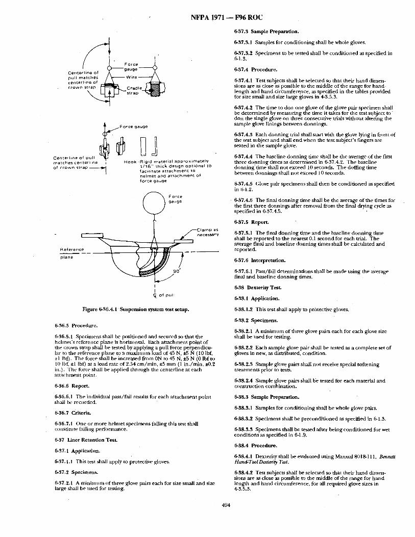
N F P A 1971 - - F96 R O C
Force ¢L
Centerline of ~'--"~ g a uge ~ pull matches , ~ - - ~ Wire ~ centerline of r-~ crown strap [-- l- ""11~,~, Cradle ~,_l~(~y~l .~
_1 - " ' u a p " - r ( / # ~ -
j . ~ F or ce gauge
CenterLine of pull matches centerline of crown strap
Hook -R igicl material approximately 1/16" thick design opt ional to factl itate attachment to helmet and attachment of force gauge
(
- R e f e r e n c ~ =) plane
Force gauge
Go_ of pull
Figure 6-36.4.1 Suspension system test setup.
6-36.5 Procedure.
6-36.5.1 Specimens shall be positioned and secured so that the helmet 's reference plane is horizontal. Each at tachment point o f the crown strap shall be tested by applying a pull force perpendicu- 1~" to the reference plane to a maximum load of 45 N, +5 N (10 Ibf, ±1 Ihf). The force shall be increased from ON to 45 N, +5 N (0 lbf to 10 Ibf, ±1 Ibf) at a load rate of 2.54 cm/min , :t:5 mm (1 in . /min, x'-0.2 in:). The force shall be applied through the centerline at each at tachment point.
6-36.6 Report.
6-36.6.1 The individu:d pass/fail results for each a t tachment point shall be recorded.
6-36.7 Criteria.
6-36.7.1 One or more helmet specimens failing this test shall constitnte failing pectormance.
6-37 Liner Retention Test.
6-37.1 Application.
6-37.1.1 This test shall apply to protective gloves.
6-37.2 Specimens.
6-37.2.1 A minimum of three glove pairs each for size small and size large shall be used for testing.
6-37.3 Sample Preparation.
6-37.3.1 Samples for conditioning shall be whole gloves.
6-37.3.2 Specimens to be tested shall be condit ioned as specified in 6-1.3.
6-37.4 Procedure.
6-37.4.1 Test subjects shall be selected so that their hand dimen- sions are as close as possible m the middle of the range for hand. length and hand circumference, as specified in the tables provided for size small and size large gloves in 4-3.5.3.
6-37.4.2 The time to don one glove of the glove pair specimen shall be determined by measuring the time it takes for the test subject t o don the single glove on three consecutive trials without altering the sample glove linings between donnings.
6-37.4.3 Each donning trial shall start with the glove lying in front of the test subject :utd shall end when the test subject's fingers are seated in the sample glove.
6-37.4.4 The baseline donning time shall be the average of the first three donning times as determined in 6-37.4.2. The baseline donning time shall not exceed 10 seconds. The doffing time between donnings shall not exceed 10 seconds.
6-37.4.5 Glove pair specimens shall then be condit ioned as specified in 6-1.2.
6-37.4.6 The final donning time shall be the average of the times for the first three donnings after removal from the final drying cycle as specified in 6-37.4.5.
6-37.5 Report.
6-37.5.1 The final donning time and the baseline donning time shall be reported to the nearest 0.1 second for each trial. The average final and baseline donning times shall be calculated and reported.
6-37.6 Interpretation.
6-37.6.1 Pass/fail determinations shall be made using the average final and baseline donning times.
6-38 Dexterity Test.
6-38.1 Application.
6-38.1.2 This test shall apply to protective gloves,
6-38.2 Specimens.
6-38.2.1 A minimum of three glove pairs each for each glove size shall be used for testing.
6-38.2.2 Each sample glove pair shall be tested as a complete set o f gloves in new, as distributed, condition.
6-38.2.3 Sample glove pairs shall not receive special softening treatments prior to tests.
6-38.2.4 Sample glove pairs shall b'e tested for each material and construction combinat ion.
6-38.3 Sample Preparation.
6-38.3.1 Samples for conditioning shall be whole glove pairs.
6-~8.3.2 Specimens shall be precondi t ioned as specified in 6-1.3.
6-38.3.3 Specimens shall be tested after being condi t ioned for wet conditions as Specified in 6-1.9.
6-38.4 Procedure.
6-38.4.1 Dexterity shall be evaluated using Man ual 8018-111, Bennett Hand-ToolDexteri~. Test.
6-38.4.2 Test subjects shall be selected so that their hand dimen- sions are as close as possible to the middle of the range for band length and hand circumference, for all required glove sizes in 4-3.5.3.
494
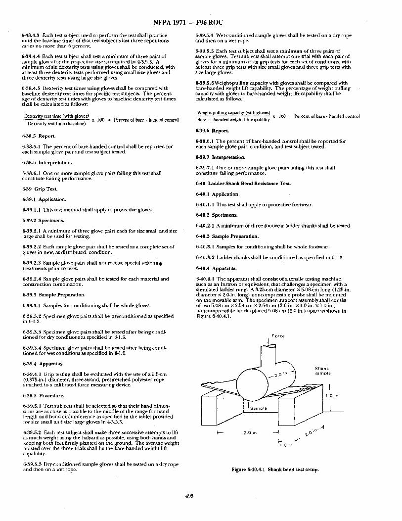
N F P A 1971 ~ F96 R O C
6-38.4.3 Each test subject used t 0 perform the test shall practice until the baseline times of that test subject's last three repetitions varies no more than 6 percent.
6-38.4.4 Each test subject shall test a minimum of three pairs o f ~tmple gloves fi)r the respective size as required in 4-3.5.3. A tninlmum of six dexterity tests using gloves shall be conducted, with at least three dexterity tests performed ttsing small size gloves and three dexterity tests using large size gloves.
6-38.4.5 Dexterity test times using gloves shall be compared with baseline dexterity test dines for specific test subjects. The percent- age of dexterity test times with gloves to baseline dexterity test times shall be calculated as follows:
Dexterity test time (with gloves) x 100 --- Percent of bare - handed control
Dexterity test time (baseline)
6.38.5 Report.
6-38.5.1 The percent o f bare-handed control shall be reported for each s:unple glove pair ~md test subject tested.
6-38.6 Interpretation.
6-38.6.1 One or more s~mlple glove pairs failing this test shall constitute failing performance.
6.39 Grip Test.
6-39.1 Application.
6-39.1.1 This test method shall apply to protective gloves.
6.39.2 Specimens.
6-39.2.1 A minimum of three glove pairs each for size small and size large shall be used fi)r testing.
6-39.2.2 Each sample glove pair shall be tested as a complete set o f gloves in new, as distributed, condition.
6-39.2~3 S:mtple glove pairs shall not receive special softening treatments prior to tests.
6-39.2.4 Smnple glove pairs shall be tested for each material ,and construction combination.
6-$9.3 Sample Preparation.
6.39.3.1 Samples ibr conditioning shall be whole gloves.
6-39.3.2 Specimen glove p~drs shall be precondit ioned as specified in 6.1.2.
639.5.4 Wet-conditioned sample gloves shall be tested on a dry rope and then on a wet rope.
6-39.5.5 Each test subject shall test a minimum of three pairs of sample gloves. Test subjects shall at tempt one trial with each pair of gh)ves for a minimum of six grip tests for each set o f conditions, with at least three grip tests with size small gloves and three grip tests with size large gloves.
6-39.5.6 Weight-pulling capacity with gloves shall be coml~ared with bare-handed weight lift capability. The percentage of weight pulling capacity with gloves to bare-handed weight lift capability shall be calculated as follows:
Weight pulling capacity (with gloves) x 100 = Percent of bare - handed control
Bare - handed weight lift capability
6-39.6 Report.
6-39.6.1 The percent o f bare-handed control shall be reported for each sample glove pair, condition, and test subject tested.
6-39.7 Interpretation.
6-39.7.1 One or more sample glove pairs failing this test shall constitute failing performance.
6-40 Ladder Shank Bend Resistance Test.
6-40.1 Application.
6-40.1.1 This test shall apply to protective footwear.
6-40.2 Specimens.
6-40,2.1 A minimum of three footwear ladder shanks shall be tested.
6-40.3 Sample Preparation.
6-40.3.1 Samples for conditioning shall be whole footwear.
6-40.3.2 Ladder shanks shall be condit ioned as specified in 6-1.3.
6-40.4 Apparatus.
6-40.4.1 The apparatus shall consist o f a tensile testing rmtchine, such as an Instron or equivalent, that challenges a specimen with a simulated ladder rung. A 3.25-cm diameter x 5.08-cm long ( 1.25-in. diameter x 2.0-in. long) noncompressible probe shall be mounted on the movable arm. The specimen support assembly shall consist
r, of two 5.08 c m x 2.54 c m x 2.a4 cm (2.Oin. x 1.0 in. x 1.0 in.) noncompressible blocks placed 5.08 cm (2.0 in.) apart as shown in Figure 0-40.4.1.
6-39.3.3 Specimen glove pairs shall be tested after being condi- t ioned for dry conditions ,as specified in 6-1.3.
6-39.3.4 Specimen glove pairs shall be tested after being condi- t ioned for wet conditions as specified in 6-1.9.
6.39.4 Apparatus.
6-39.4.1 Grip testing shall be evaluated with the use of a 9.5-cm (0.375-in.) di,'mleter, three-strand, prestretched polyester rope attached to a calibrated force measuring device.
6.39.5 Procedure.
6-39.5.1 Test subjects shall be selected so that their hand dimen- sions are as close as possible to the middle of the range for hand length mad hand circnrrdi~rence as specified in the tables provided figr size small and size large gloves in 4-3.5.3.
6-39.5.2 Each test snbject shall make three successive attempts to lift as much weight using the halyard as possible, using both hands and keeping both feet firmly planted on the ground. The average weight hoisted over the three trials shall be the bare-handed weight lift capability.
6-39.5.3 Do-condi t ioned sample gloves shall be tested on a dry rope and then on a wet rope.
Force
1
S h a n k " " ~ n ' l D l e
0 irl.
~-- 2 . 0 in, ~ Q(3
1 0 in.
Figure 6-40.4.1 Shank bend test setup.
495
N F P A 1971 ~ F 9 6 R O C
6-40.5 Procedure.
6-40.5.1 The ladder shank shall be pktced on moun t ing blocks as it would be or iented toward the ladder, when the shank is affixed into the protective fi)otwear, and subjected to force on its center with the test probe operated at 5.1 c m / m i n (2 in . /min ) .
640.6 Report.
6-40.6.1 Detlection at 18~.0 kg (400.0 lb) shall be repor ted to the nearest 1 m m (0.05 in.). The average deflection shall be calculated and reported to the nearest 1 m m (0.05 in.).
640.7 Interpretation.
640.7.1 Pass/fall per formance sh~dl be de te rmined us ing the average deflection for all specimens tested.
6-41 Sllp Resistance Test.
641.1 Application.
6-41.1.1 This test me thod shall apply to the footwear sole and heel sectioll.
6-41.2 Specimens.
6-41.2.1 A n t in imnm of three complete footwear itent~ shall lye tested.
641.3 Sample Preparation.
641.3.1 Sanaples for condi t ioning shall be the whole footwear items.
641.3.2 Specimens shall be condi t ioned as specified in 6-1.3.
6-41.4 Procedure.
6-4 1.4.1 Slip resistance shall he per formed in accordance with A,STM F 489, Standard Test Method for Static Coejg~cient of Friction of Shoe Sole arut Heel Materials as Measured by the James Machine, in both a dry and a wet condition.
6-41.5 Report.
6-41.5.1 The static coefficient of friction of each specimen tinder both car T and wet condit ions shall be reported. The average static coefficien t of friction of each specimen tinder both dry ,and wet condit ions shall be calculated and reported.
6-41.6 Interpretation.
6-41.6.1 One or more footwear specimens failing this test shall constitute failing performance.
6-42 Label Durability and Legibility Tes t One.
642.1 Application.
642.1. I This test me thod shall apply to labels on protective garments , hoods, gloves, and hoots.
6-42.1.2 Mtydificaticyils to this test me thod fi)r testing ga rmen t labels shall lye ,as specified in 6-42.7.
6-42.1.3 Modifications to this test me t hod for testing hood labels shall lye ~Ls specified in 6-42.8.
642.1.4 Modifications to dais test m e t h o d for testing glove labels shall be as specified in 6-42.9.
642.1.5 Modifications to this test me t hod for testing footwear labels shall lye as specified in 642.10.
642.2 Specimens.
6-42.2.1 A m i n i m u m of three of each type of label for each e lement shall lye tested in each test. If labels have areas of "write-in" information, two additional specimens shall be tested tha t include tllose areas, with sample information written in.
642.5 Sample Preparation.
642.3.1 Specimens shall be condi t ioned as specified in 6-1.3.
6-42.4 Procedures.
6-42.4.1 Launder lng Durability Test.
6-42.4.1.1 Specimens shall be subjected to ten cycles o f i a n n d e r i n g and drying using Machine Cycle 1, Wash Tempera ture V, and Drying Procedure Ai of ANSI/AATCC 135, Dimensional Changes in Automatic Home Laundering of Woven and Knit Fabrics.
642.4.1.2 A 1.8-kg, i-O. 1 kg (4.0-1b, i-0.2 lb) load shall be used. A laundry bag shall no t be used.
642.4.1.3 Specimens shall be examined for legibility to the una ided eye by a person with 20/20 vision, or vision corrected to 20/20, at a nonlinal distance o f 30.5 cm (12 in.) in a well-illuminated area.
642.4.2 Abrasion Durability Test.
642.4.2.1 Specimens shall be subjected to abi~sion in accor "dance with/LSTM D 4966, Standard Test Method for Abrasion Resistance of Textile Fabrics, with the following modifications:
(a) The s tandard abrasive fabric and the felt backing fabric shall be soaked for 24 hours or agitated in distilled water so that they are thoroughly wet.
(b) The stzmdard abrasive fabric shall be rewetted after each set of cycles by applying 20 ml (0.68 oz) of distilled water f rom a squeeze bottle by squirt ing on the center o f the abrasive composite pad.
• (c) Specimens shall be subjected 200 cycles, 3200 revolutions, of the test apparatus.
642.4.2.2 Specimens shall be examined for legibility to the una ided eye by a person with 20/90 vision, or vision corrected to 20/20, at a nominal distance o f 30.5 cm (12 in.) in a well-illuminated area.
642.4.3 Heat Durability Test.
642.4.3.1 Specimens shall be subjected to convective heat as specified in 6-1.7.
642.4.3;2 Specimens shall be examined for legibility to the una ided eye by a person with 20/ ')0 vision, or vision corrected to 20/20, at a nominal dist~mce of 30.5 cm ( 12 in.) in a well-illuminated area.
642.5 Report.
642.5.1 The legibility for each specimen shall be repor ted as acceptable or unacceptable.
642.6 Interpretation.
642.6.1 One or more label specimens failing this test shall constitute failing performance.
642.7 Specific Requi rements for Test ing Garment Labels.
642.7.1 For testing label legibility ,after lanndering, specimens shall include individual labels sewn onto a l-m (l-yd) square ballast material no closer than 5.1 cm (2 in.) apart in parallel strips. The ballast material shall be as specified in ANSI/AATCC 135, Dimer~- sional Changes in Automatic Home Laundering of Woven and Knit Fabrics.
642.7.2 For testing label legibility ,after abrasion, specimens shall be individual labels.
642.7.3 For testing label legibility after convective heat exposnre, specimens shall include individual labels sewn onto a separate 38- cm, +1.3 m m (15-in., i-0.5 in.) square o f material that meets the outer shell requirements of this standard.
642,7.4 Sample condi t ioning shall be the same condi t ioning as specified for the respective tests.
642.7.5 Specimens shall be tested separately for legibility after laundering, abrasion, and heat durability tests as specified in 6- 42.4.1,642.4.2, and 6-42.4.3, respectively.
6-42.8 Specific Requirements for Testing Hood Labels.
642.8.1 For testing label legibility after laundering, specimens shall include complete hoods with labels at tached.
496
N F P A 1971 - - F96 R O C
6-42.8.2 For testing label legibility alter abrasion, specimens shall be individual labels.
6-42.8.3 For testing label legibility after convective heat exposure, specimens shall include individual labels sewn onto a separate 38- cm. ±1.3 mm (15-in., zt0.5 in.) square of hood material that meets the hood material requirements of this standard.
6-42.8.4 Sample conditioning shall be the same conditioning as specified fi:~r the respective tests.
6-42.8.5 Specimens shall be tested separately for legibility after launderiJ~g, abrasion, and heat dnral)ility tests as specified in 6- 42.4.1, 6-42.4.2, and 6-42.4.3, respectively.
6-42.9 Specific Requirements for Testing Glove Labels.
6-42.9.1 For testing label legibility after laundering ,and convective heat exposure, specimens shall include complete gloves with labels attach ed.
6-44.1.1 This test shall apply to protective helmets.
6-44.2 Specimens.
644.2.1 Specimens shall be selected ,as specified in 2-3.9,
6-44.3 Sample Preparation.
6-44.3.1 Samples fi)r conditioning shall be whole helments.
644.3,2 Specimens shall be condit ioned as specified in 6-I .3.
6-44.4 Apparatus.
6-44,4.1 The shell retention test fLxtures shall consist o f rigid material o f sufficient thickness and optional design to facilitate firm attachment of the helmet shell while attached to the chin strap tensile testing machine.
644.5 Procedure.
6-42.9.2 For testing label legibility after abrasion, specimens shall be individual labels.
6-42,9.3 Sample conditioning shall be the same conditioning as specified for the respective tests.
6-42.9.4 Specimens shall be tested separately for legibility ,after lanndering, abrasion, and heat durability tests as specified in 6- 42.4,1, 6-42.4.~, and 6-42.4.3, respectively.
6-42.10 Specific Requirements for Testing Footwear Labels.
6-42.10.1 For testing warning label and product label legibility after laundering, specimens shall include complete footwear with labels attached.
6-42.10.2 For testing label legibility ,after abrasion, specimens shall be individual labels.
6-42.10.3 Sample conditioning shall be the same conditioning as specified for the respective tests.
6-42.10.4 Specimens shall be tested separately for legibility after abrasion ,and heat durability tests ,as specified in 6-42.4.2 and 6- 42.4.3, respectively,
6-43 Label Durability and Le~bility Test Two.
6-43.1 Application.
6-43.1. I This test method sh~dl apply to labels on helmets.
6-43.2 Specimens.
6-43.2.1 Specimens shall be selected as specified in 2-3.9.
6-43.3 Sample Preparation.
6-43.3.1 Samples for conditioning shall be whole helmets-with the [abels attached.
6-43.3.2 Specimens shall be condit ioned as specified in 6-1.3, 6-1.6, 6-1.7, and 6-1.8.
6-43.4 Procedure.
6-43.4.1 Label specimens shall be examined for legibility by a person with 20/20 vision, or vision corrected to 20/20, at a nomin,'d distance of 30.,5 cm ( 12 in.) in a well-illuminated area.
6-43.5 Report.
643.5.1 The legibility for each label specimen shall be reported as acceptable or unacceptable.
6-43.6 Interpretation.
6-43.6.1 One or more label specimens failing this test shall constitute falling performance.
6-44 Shell Retention Test.
6-44.1 Application.
6-44.5.1 The specimen shall be tested by applying a pull force to the helmet shell perpendicular to the reference plane to a maximum load of 3fi.5 kg (80 lb) within B0 seconds. The maximum load shall be malntalnedfi)r l minute, +5/4) seconds.
6-4416 Report.
644.6.1 The pass/fail results shall be recorded.
6-44.7 Interpretation.
6-44.7.1 Any one specimen falling the test shall constitute failing performance for the item being tested.
6-45 Luminous (Visible) Transmittance Test.
6-45.1 Application.
645.[.1 This test shall apply to faceshield/goggle component lenses.
6-45.2 Specimens.
6-45.2.1 Specimens shall be selected as specified in 2-3.1.1.
6-45.3 Sample Preparation.
6-45.3.1 Samples for conditioning shall be complete faceshield/ gnggle components.
6-45.3.2 Specimens shall be condit ioned as specified in 2-3.1 .I.
645.4 Apparatus.
6-45.4.1 The standard source of radiant energy used in the measurement of luminous transmittance of filter lenses shall be a projection-type lamp No. T-8, or other high-powered, gas-filled, tungsten-filament incandescent lamp, operated at the color temperature corresponding to Commission Internationale de l'Eclairage (CIE), Source A,
645.5 Procedure.
6-45.5.1" Luminous transmittance shall be determined by one of the following means:
(a) By measuring the spectral transmittance and calculating the luminous transmittance through the use of published data on the spectral radi,'mt energy of CIE, Source A, and the relative luminons efficiency of the average eye; or
(b) By using a Gardner pivotal sphere haze meter and the standards of luminons transmittance maintained by the National Bureau of Standards.
6-45.6 Report.
645.6.1 The percent o f light transmission shall be reported for each specimen. The average light transmission of all specimens tested shall be calculated ,and reported.
6-45.7 Criteria.
497
NFPA 1971 - - F96 ROC
645.7.1 Pass/fall performance shall be based on the average light transmission measured.
6-46 Retroreflectivity and Fluorescence Test.
6-46.1 Application.
646.1.1 This test method shall apply to trim materials nsed on protective garments and helmets.
6-46.1.2 Trim materials shall be tested for each procedure specified in q~-46.4.
6-46.2 Specimens.
648.2.1 A minimum of three trim test specimens shall be tested.
646.2.2 Each trim test specimen shall consist of a 30.5-cm x 30.5-cm (12-in. x 12-in.) composite made up of multiple strips of the finished trim product. Where retroreflective and nonretroreflective surface are,xs are Combined to form a trim, the complete finished product consisting of the retroreflective and nonretroreflective portions shall be used to form the composite test specimen.
646,3 Sample Preparation.
6-46.3.1 Samples for conditioning shall include 30.5-cm (12-in.) long sections of trim.
646.3.2 Specimens shall be conditioned as specified in 6-1.3.
646.4 Procedures.
646.4.1 Measurement of Coefficient of Retroreflection.
6-46.4.1.1 The coefficient of retroreflection (R a) shall be deter- mined in accorckmce with ASTM E 809, Standard Praaice for Measuring Photometric Characteristics of Raroreflectors, using the following modifications:
(a) Test distance = 15.2 m (50 ft);
(b) Observation angle = 0.2 degree;
(c) Entrm/ce angle =-4 degree:
(d) The receiver shall be provided with an entrance aperture of 26 nun (1.024 in.), ±5%, in diameter which is equivalent to 0.1 degree angular aperture:
(e) The exit aperture of the source shall be circular and 26 mm (i.024 in.), ±5%, in diameter which corresponds to 0.1 degree angular aperture;
(O Retroreflector reference angle ~ 90 degrees; and
(g) Datum mark shall be placed as specified by the trim mantffac- turer.
6-46.4.1.2 The coefficient of retroreflection (R a) shall be calculated by the following equation:
R a = R 1/Ar
where:
R 1 is the coefficient of luminous intensity measured as specified in 6-46.4.1.1; and
A r represents only the retroreflective surface area of the trim test specimen's surface area. Ar shall be calculated by subtracting the nonretrorefiective surface area from the test specimen's total surface are~
648.4.2 Evaluation of Fluorescence.
6-46.4.2.1 Trim fluorescence shall be determined by examining the materi~ under a black light at a distance of 30.5 cm (1~ in.) for a period of 30 seconds.
6-46.4.2.2 Specimens that exhibit fluorescence shall be designated as fluorescent~ Specimens that do not exhibit fluorescence shall be desigqlated as nonfluorescent.-
646.4.3 Rainfall Test.
6-46.4.3.1 Specimens of trim shall be tested for retroreflectivity when wet as specified in Annex A, "Method of Measuring Wet Retrorefective Performance," of EN 471, High Visibili~. Wwraing Clothing, at a rate of 10.9 cm/hr (4.3 in./hr).
6-46.4.3.2 The coefficient of retroreflectivity (Ra) shall be measured as specified in 6-46.4.1, 2 minutes, ± 15 seconds after the rainfall exposure has been started.
6-46.4.4 Convective Heat Exposure Test.
6-46.4.4.1 Specimens of trim shall be tested for retroreflectivity after convective heat exposure as specified in 6-1.6.
6.46.4.4.2 The coefficient of retroreflection (Ra) shall be measured as specified in 6-46.4.1.
6-46.4.4.3 The fluorescence shall be evaluated as specified in 6-46.4.2.
6-46.5 Report.
6-46.5.1 The coefficient of retroreflection (Ra) shall be reported for each specimen. The average R a of all specimens shall be calculated and reported separately for each of the test procedures specified in 6-46.4.1, 6-46.4.3, and 6-46.4.4.
6-46.5.2 The number of fluorescent and nonfluorescent specimens shall be reported separately for each of the test procedures specified in 6-46.4.2, 6-46.4.3, and 6-46.4.4.
6-46.6 Interpretation.
6-46.6.1 For udm retrore~lectivity, pass/fail performance shall be determined using the average coefficient of retroreflection (R a) reported for each group of specimens for each of the procedures specified in 6-46.4.1, 6-46.4.3, and 6-46.4.4.
6-46.6.2 For trim fluorescence, any nonfluoresceftt specimens in any test procedure shall constitute failing performance.
6-47 Hood Opening Size Retention Test.
647.1 Application.
647.1.1 This test shall apply to the face openings or SCB~ facepiece interface openings of protective hoods.
647.1.2 Protective hoods with either elastic face openings or manually adjustable face openings shall be tested by the procedure specified in 6-47.4.
647.1.3 Protective hoods designed for interface with a SCBA facepiece(s) shall be tested by the procedure specified in 6-47.5.
6-47.2 Specimens.
647.2.1 A minimum of three whole hoods shall be tested.
647.3 Sample Preparation.
647.3.1 Samples for conditioning shall be whole hoods.
6-47.3.2 Specimens shall be conditioned as specified in 6-1.3.
647.4 Procedure for Elastic or Manually Adjusted Face Openings.
647.4.1 The hood shall be laid on a flat surface with the face opening facing up.
647.4.2 The hood face opening shall he measured at a minimum of eight separate locations around the entire perimeter of the face opening. The locations of measurement shall be marked on the hood.
6-47.4.3 The hood shall b e positioned on the size 7 1/4 headform specified in Figure 6-16.4.1 so that the hood is around the neck area of the headform with the neck and head area of the headform protruding through the face opening of the hood. The hood shall then be donned and doffed for 50 cycles, passingthe hood face opening up and over the headform to cover thehead, forehead, sides of face, chin, and neck each time and then passing the h ,~d back down over the headform to the starting area around the neck. Hoods with manually adjustable face openings shall have the face opening adjusted during each cycle, once after donning and again before doffing.
498
N F P A 1971 ~ F96 R O C
6-47.4.4 Following the 50 cycles, the hood shall be removed f rom the headfigrm and the hood shall be allowed to relax for 1 minute .
6-47.4.5 The hood shall be laid on a flat surface with the face open ing facing up.
6-47.4.6 The open ing d imensions shall then be measured at the same locations marked a round the entire per imeter of the face opening specified in 6.47.4.2.
6-47.4.7 Tire percent difference of the hood face open ing dimen- sions befi)re and :filer donn i ng shall be determined.
6-47.5 Procedure for SCBA Facepiece Interface Openings .
647.5.1 The S(LBA facepiece, that the hood is designed to interface with, sh:dl be properly mounted , according to the SCBA manufac turer ' s instructions, on the size 7 1 /4 headform specified in Figure 6-16.4.1.
6-47.5.2 The hood shall then be d o n n e d on the headform, placing it over the S(:~A facepiece.
6-47.5.3 The contact surface of the hood face open ing with the SCBA l~cepiece shall be measured at a m i n i m u m of eight separate locations a round the cad re per imeter of the face open ing contact are~e Fhe locations of m e a s u r e m e n t shall be marked on the hood.
6"47.5.4 With the S(~BA facepiece in place, the hood shall then be posit ioned so that the hood is a round the neck area of the headform with the neck and head area of the headforrn prot rnding th rough the face open ing of the hood. The hood shall then be d o n n e d and doffed for 50 cycles, passing the hood face open ing up and over the headform to cover the head and to contact the SCBA facepiece a round the entire per imeter of the face open ing contact area each time, and then passing the hood back down over the headfiJrm to the start ing area a round the neck. Where such hoods are designed m be mmmally adjustable arot, nd the hood face open ing /SCBA facepiece interface area, the manual ad jus tment shall be made dur ing each cycle, once after d o n n i n g and again before doffing.
6-47.5.5 Following the 50 cycles, the hood shall be removed f rom tim headform, and the hood sh,'dl be allowed to relax for 1 minute.
6-47.5.6 The hood shall then be d o n n e d on the headform, placing it over the SCBA facepiece.
8-47.5.7 The contact snrtace of the hood face open ing with the SCBA facepiece shall be measured at the same locations marked a round the entire per imeter of the face open ing contact area specified in 6-47.5.3.
647.5.8 The percent difference o f the hood face open ing dimen- sions before and after d o n n i n g shall be determined.
647.6 Report.
6-47.6.1 The percent difference o f the hood face open ing dimen- sious sh:dl be reported for each specimen. The average difference of tire hood face open ing d imensions shall be calculated and reported.
6.47.7 Interpretation.
6-47.7.1 Pass/f~dl per formance shall be based on the average difference of the hood face open ing dimensions.
6-48 Liquid Penetration Test.
6-48.1 Application.
6-48.1.1 This test me thod shall apply to protective garments .
648.1.2 Modifications to this test me t hod for testing protective coats shall be as specified in 6.48.8.
648.1.3 Modifications to this test m e t h o d for testing protective trousers shall be as specified in 6.48.9.
648.1.4 Modificathms to this test m e t h o d for testing protective coat and trouser seL~ or protective coveralls shall be as specified in 6- 48.10.
6-48.2 Specimens.
6-48.2.1 A m i n i m u m of three spec imens shall be tested. Specimens shall consist o f individual coats, trousers, coveralls, or sets of coats and trousers. Each e lement shall have in place all layers that are required figr the e l ement to be compliant.
6-48.2.2 The size of the e lements compris ing the specimens shall be chosen to conform with the d imens ions of the mannequ in for proper fit o f the specimen on the m a n n e q u i n in accordance with the manufac turer ' s sizing system. The size of the e lements compris ing the specimen shall be the same size as the mannequ in in terms of chest circumference, waist circumference, and inseam height.
6-48.3 Sample Preparation.
8-48.3.1 Specimens to be tested shall be condi t ioned as speckqed in 6-1.9.
6-48.3.2 Samples to be condi t ioned shall be complete garments.
6-48.4 Apparatus.
6-48.4.1" The apparatus and supplies for testing shall be those specified in ASTM F 1359, Standard Practice for Evaluating the Liquid- Tight Integri~ of Chemical Protective Clothing, with the following modifications:
(a) The surface tension of the water used in testing shall be 35 dynes /cm, ~.5 dynes /cm.
(b) The m a n n e q u i n used in testing shall be fillly upr ight ,and shall have straight a rms and legs, with the arms pos i t ioneda t the m a n n e q u i n ' s side.
6-48.5 Procedure.
6-48.5.1" L iqu idpene t ra t ion testing of garments shall be conducted in accordance with ASTM F 1359, Standard Practice for Evaluating the Liquid-Tight Integri~ of Chemical Protective Clothing, with the following modification s:
(a) No provision for partial garments shall be permitted.
(b) Blocking of the specimen shall be as specified in 6-49.8, 6-49.9, and 6-49.10, ,as appropriate, for the type of specimen being tested.
(c) The me thod used for moun t ing of the mannequ in in the spray chamber shall no t interfere with the water spray.
(d) The normal outer surface of the material shall be exposed the liquid as or ien ted in the c lothing item.
(e) Fluorescent or visible dyes shall no t be used in the water for spraying the suited mannequ in .
(t) The suited mannequ in shall be exposed to the liquid spray for a total of 20 minutes, 5 minutes in each o f the four mannequ in orientations.
(g) At the end of the liquid spray exposure period, excess liquid shall be removed from the surface o f the specimen.
(h) The specimen shall be inspected within 10 minutes of the end of the liquid spray exposure period for evidence of liquid penetra- tion.
648.6 Report.
648.6.1" A diagram shall be prepared for each test that identifies the Iocadons of any liqvid leakage as detected on the liquid- absorptive ga rmen t and the interior o f the garment .
648.7 Interpretation.
648.7.1 Any evidence of liquid on the liquid-absorptive garment , as de te rmined by visual, tactile, or absorbent toweling, shall constitute failure o f the specimen.
6-48.8 Specific Requirements for Testing Coats.
648.8. I The liquid-absorptive ga rmen t shall only cover the upper torso and arms of the mannequ in f rom the middle of the manne- quin neck, down to the m a n n e q u i n waistline, a n d d o w n to the mannequ in wrist crease.
499
N F P A 1971 - - F 9 6 R O C
6-48.8.2 The coat shall be d o n n e d on the m a n n e q u i n in accordance with the manufac turer ' s instructions for proper wearing.
6-48.8.3 The Coat collar shall be placed in the "up" position on the mannequ in . The head o f the m:umequ in shall be sealed off with a pkLstic bag. The plastic bag shall e x t e n d o v e r the collar by a distance of not greater than ~7.54 cm (1 in) and shall be taped down using duct tape or similar waterproof tape. The collar neck seam sha l / no t be covered.
648.8.4 The test shall be conduc ted with the m a n n e q u i n hands removed. The coat sleeve h e m shall be taped smoothly to a can, or an obiect of similar cylindrical, rigid shape, o f the same nomina l diameter as the s eeve opening. The can or cylindrical object shall be fitted over the wristlet and t inder the coat sleeve hem. The tape shall be duct tape or similar waterproof tape
6-48.8.5 The coat shall be tested in conjunct ion with the protective trousers specified by the mantffacturer, even where the trmtsers are not being specifically evaluated by this test.
6-48.9 Specific Requirements for Testing Trousers.
6-48.9.1 The liquid-ab~:wptive gm'ment shall only cover the lower t(~'so and legs of the mannequ i n f rom the mannequ in waisdine down to the mzmnequin ankles.
6-48.9.2 The trousers shall he d o n n e d on the mannequ in in accordance with the manufac ture r ' s instructions for proper wearing.
"6-48.9.3 Trousers shall be tested in conjunct ion with the protective coat specified by the manufacturer , even where the coat is no t being specifically evaluated by this test.
6-48.9.4 Absorbent toweling, or similar material, shall be placed unde rnea th the mannequ i n in order m prevent water splashing up inside the t rouser leg.
648.10 Specific Requirements for Testing Coveralls and for Test ing Sets of Coats and Trousers.
6-48.10.1 The liquid-abmrptive ga rmen t shall only cover the torso, arms, and legs o f the mannequ i n from the middle of the mannequ in neck, down to the m a n n e q u i n wrist crease, and down to 8 in. above the bot tom of the heel.
6-48.10.2 The coverall or set of coat and trousers shall be d o n n e d on the mannequ in in accordance with t h e m a n u f a c t n r e r ' s instruc- tions figr proper wearing.
6-48.10.3 The coat collar shall be placed in the "up ~ position on the m:mnequin . The head of the m a n n e q u i n shall be sealed offwith a plastic bag. The plastic bag shall ex tend over the collar by a distance of not greater than ~2.54 cm (1 in.) and shall be taped down using duct tape or similar waterproof tape. The collar neck seam shall not be covered.
6-48.10.4 The test sh;dl be conducted with the mannequ in hands removed. The coat sleeve h e m shall be taped smoothly to a c;m, or an ut~ject of similar cylindrical, rigid shape, of the santo nominal diameter as the sleeve opening. The can or cylindrical object shall be fitted over the wristlet and t inder the coat sleeve hem. The tape shall be duct tape or similar waterproof tape.
6-48.10.5 Absorbent toweling or sinfilar material shall be placed unde rnea th the m a n n e q u i n in order to prevent water splashing up inside the trouser leg.
6-49 Eyelet and Stud Post Attachment Test.
6-49.1 Application.
649.1.1 This test me thod shall apply to protective footwear eyelets and s tud posts.
6-49.2 Specimens.
6-49.2.1 S p e c i m e n s shall total two eyelets and two stud posts on three separate footwear items.
6-49.2.2 Specimens shall be removed f rom the footwear and shall be 2.54 cm x5 .08 cm (1.0 in. x 2.0 in.).
6-49.3 Sample Preparation.
649.3.1 Samples for condi t ioning shall be whole footwear.
6-49.3.2 The eyelets or s tud post specimens shall be condi t ioned as specified in 6-1.3.
6-49.4" Apparatus.
649.4.1 A tensile testing machine shall be used with a traverse rate orS.1 c m / m i n (2 in . /min ) . Clamps measur ing 2.5 c m x 3.8 cm (1 in. x 1.5 in.) shall have gripping surfaces tha t are parallel, fiat, and capable of prevent ing slippage o f the specimen dur ing the test.
649.5 Procedure.
6-49.5.1 The s tud post or eyelet puller shall be inserted or at tached to the upper position o f the tensile machine. The traverse rate shall be se t at 5 c m / m i n (.2.0 in . /min) . The test eyelet or stud post shall be a t tached using the appropriate puUer fixture. The eyelet stay shall be clamped, but c lamping the metal portion o f the eyelets or s tud hook in the lower clamps shall no t be permitted. The distance between the clamps and s tud hooks or eyelets shall be 1.6 m m to 3.2 m m (0.063 in. to 0.125 in.). The test shall then be started.
6-49.6 Report.
649.6.1 The force will reach a peak, decline slightly, an d then increase to complete failure; however, the value at which the force first declines shall be recorded and repor ted as the initial failure point, as this is the separation point of the material a ro u n d the eyelet or s tud post. The average force shall be calculated an d reported.
649.7 Interpretation.
649.7.1 The average force shall be used to de termine pass/fall.
6-50 Breaking Strength Test.
6-50.1 Application.
6-50.1.1 This test shall apply to ga rmen t outer shell and collar lining materials used in protective garments .
6-50.2 Specimens.
6-50.2.1 Five specimens in each of the warp andf i l l ing directions shall be tested f rom each sample unit.
6-50.3 Sample Preparation.
6-50.3.1 Specimens shall be condi t ioned as specified in 6-1.2.
6-50.5.2 Samples for condi t ioning shall be 1 m (1 yd) square of nmterial.
6-50.4 Procedure.
6-50.4.1 Specimens shall be tested for breaking strength in accordance with ASTM D 5034, Standard Method for Breaking Farce and Elongation of Textile Fables (C~ab Test).
6-50.5 Report.
6-50.5.1 The breaking force o f each spec imen shall be reported, an d an average breaking strength shall be calculated for the warp and filling directions,
6-50.6 Interpreation.
6-50.6.1 Pass/fall performance shall be based on the average breaking strength in the warp and fill directions. Failure in any one direction consistutes failure for the material.
Chapter 7 Referenced Publications
7-I The following document s or port ions thereof are referenced within this s tandard and shall be considered part of the require- ments of this document . The edit ion indicated for each reference is the curi 'ent edition as of the date o f the NFPA issuance of this document .
7-1.1 NFPA Publications. National Fire Protection Association, 1 Batterymarch Park, P.O. Box 9101, Quincy, MA 02269-9101.
500
N F P A 1971 ~ F96 R O C
NFPA 1500, Starutard on Fire D~artrtwnt Occupational Safety and Health Pw~am, 1992 edition.
NFPA 1972, Standard on Helmets for Structural Fire Fighting, 1992 edition.
NFPA 1973, Standard on Gloves for Structural Fire Fighting, 1993 edition.
NFPA 1974, Starutard on Protective Footwear for Structural Fire Fighting, 1992 edition.
NFPA 1975, Standard on Station~Work ~ lniforms for Fire Fighters, 1994 edition.
7-1.2 Other Publications.
7-1.2.1 AATCC Publication. American Association of Textile Cheofists and (~)lorists. P.(). Box 12215, Research Triangle Park, NC 27709.
AATCC 70, Test Method f ~ Watcr R~ellencT: TumbleJar £~namic Abstrrption T~t, 1988.
7-1.2.2 ANSI Publications. American National Standards Institute, 1450 Broadway, New York, NY 10018.
ANSI Z41, Starutard for Personal Protection---Protective Footwear, 1991.
ANSI Z87.1, Occupational and Educational Eve and Face Protection, 1989.
ASTM F 903, Standard Test Method for Resistance of Protective Clothing Materials to Penetration by, Liquids, 1990.
ASTM F 1060, Standard Test Method for Thermal Protective Performance of Materials for Protective Clothing for Hot Surface Contact, 1987.
ASTM F 1116, Standard Test Method for Determining Dielectric Strength of Overshoe Footwear, 1988.
ASTM F 1342, Standard Test Method for Protective Clothing Material Resistance to Puncture, 1991.
ASTM F 1359, Standard Practice for Evaluating the Liquid-Tigkt Integrity of Chemical Protective Clothing, 1991.
7-1.2.4 CSA Publication. Canadian S~mdards Association, 178 Rexd~de Boulevard, Toronto M9WI R3, Ganad~.
(NA St;mdard Z 195-M, Standard for Protective Footwear, Occupational Health arm Safety, 1984.
7-1.2.5 Commission Internationale de I'Eclairage.
7-1.2.6 EN Publication.
EN 471, High Visibility Warning C l o t h i n g , .
7-1.2.7 FIA Publications. Footwear Industries of America, 1420 K Street, NW, Suite 600, Washington, DC 20005.
FIA Standard 301, NBS Abrasion.
ANSI/AATCC 135, Dimensional Changes in Automatic, Home Launder- ing of Wov~,-a and Knit Fabrics, 1989.
7-1.2.3 ASTM Publications. American Societyfi~r Testingand Materials, 1916 Race Street, Ph iladelphia, PA 19103.
A,STM B 117, Starulmrl Method of Salt Spray_ (Fog)Testing, 1985.
ASTM B 152, Sp'~,ifiaztion for Ccpper Sheet, Stn'p Plate, and Rolled Bar, 1986.
ASTM D 471, Starutard Test Method for Rubber Proper~, Effect of Liquids, 1995 edition.
FIA Standard 1209, Whole Shoe Flex.
7-1.2.8 GSA Publications. General Services Administration, Specifications Activity, Printed Materials Supply Division, Building 197, Naval Weapons Plant, Washington, DC 20407.
Federal Specification FED-V-F-106F, Fasteners. Interlocking, Slide, June 23, 1987.
Federal Test Method Standard 191A, Textile Test Methods, July 20, 1978.
7-1.2.9 IMO Publication.
ASTM D 1003, Stanclard Test Method for Haze and Luminous Transmit- tance of T~anspare~tt Plastics, 1988.
ASTM D 1630, Standard Test Method for Rubber Property--Abrasion Resistance (Footwear Abrader), 1994.
ASTM D 1683, Standard Test Method for Failure in & ~ n Seams of Wo~Jen Fabrics, 1990.
ASTM D 3787 Stand<~d Test Method for Hy&aulic Bursting Stn,~gth of Knitted (;oods and Nonwoven Fabrics--BaU Burst Testing Method, 1989.
A,STM D 3940 Starutard Test Method for Bursting Strength (Load) and Elongation of Sewn Seams of Knit or Woven Stretch Textile Fabrics. 1983.
ASTM D 4108, Standard Test Method for Thermal Protective Performance of Materials for Clothing ~ Open-Flame Method, 1978.
A,STM D 4966, Stazutmd Test Method for Abrasion Resistance of Textile Fa&ics, 1989.
ASTM E 794, Standard Test Method for Melting and Crystallization T~.rnperamr~" by Thermal Analysis, t 989.
A,STM E 809, Stardard Practice for Measuring Photometric Cka~actt~stic, s of Retrortflecto~. 1994.
/~STM E 810, StarMard Test Method for Coefficicvzt of Re, troreflection of Retroreflective Sheeting, 1981.
A~STM E 1247, Standard Test Method for Identifying Fluoresce'nee in Obj~.t-Colcrr Specimc'r~s b~ Spectrophotemet~, 1992.
A~STM ES 22, Eme'rgen~ Standard Test Method for Reaistanoe of Protective Clothing Materials to Penetration by Blood-Borne Pathogens Using Viral Po*etration as a Test 5~ystem, 1992.
( A,qTM F 489, Starulard Test Method for Static Coefficient of Friction of Shoe Sole arm Heal Materials as Measured by_ the James Machine, 1977.
IMO A16/Res. 658, Use and Fitting of Retro-Reflective Materials on Life Saving Appliances; .
7-1.2.10 NBS Publications. National Bt,rean of Standards.
7-1.2.11 Psychological Corporation Publication. Psychological Corporation, 555 Academic Court, San Antonio, TX 78204.
Manual 8018-111. Bennott Hand-Tool Dexterity Test, 1981.
7-1.2.12 SAE Publication. Society of Automotive Engineers, 400 Commonwealth Drive, Warrendale, PA 15096.
SAEJ211, Instrumentation for Impact Test, 1988.
7-1.2.13 U. S. Naval Publications. Naval Publications and Forms Center, 5801 Tabor Avenue, Philadelphia, PA 19120.
MIL-F-21840G, Fastener Tapes, Hook and Pile. Synthetic, December 16, 1987.
MS 27980E, Fastener, Snap, November 30, 1984.
7-1.2.14 Stoll, A. M. and M. A. Chianta, "Method and Rating System for Ewduation of Thermal Protection," ;~erospace Medicine, Vo[. 40, 1968, pp. 1232-38.
Appendix A Explanatory Material
This Appendix is not part of the requirements of this NFPA document but is included for informational purposes enl 3.
A-I-I Organizations responsible for specialized functions including, but not limited to, wildland fire fighting,,proximity find other specialized fire fighting, emergency medical service, special operations, and hazardous materi,'ds response should use appropri- ate protective clothing and protective equipment specifically designed for those ,activities.
501
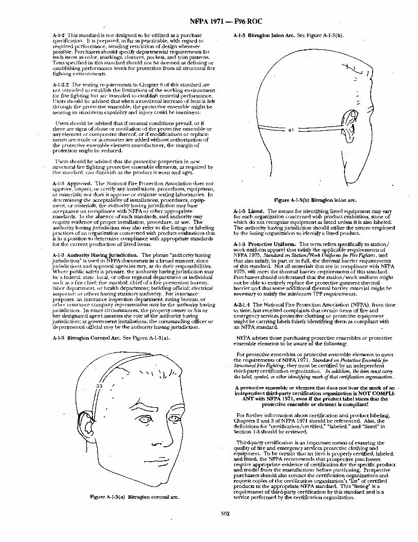
N F P A 1971 - - F96 R O C
A-I-2 This standard is not designed to be utilized as a purchase specification, It is prepared, as far as practicable, with regard to required performance, aw~iding restriction of design wherever possible. Purchasers should specify departmental requirements for such items as color, markings, closures, pockets, and trim patterns. Tests specified in this standard should not be deemed as defining or establishing performance levels for protection from all structuralfire fighting environments.
A-1-2.2 The testing requirements in Chapter 6 of this standard are not intended to establish the limitations of the working environment for fire fighting but are intended to establi,51a material perfornaance. Users should be advised that when a continual increase of heat is felt through the protective ensemble, the protective ensemble ffdght be nearing its maximum capability and injury could be imminent.
Users should be advised that if tmusual conditions prevail, or if there are signs of abuse or mutilation of the protective ensemble or any e lement or component thereof, or if modifications or replace- menLs are made or accessories are added without authorization of the protective e n ~ m b l e e lement manufacturer, the margin of protection might be reduced.
Users shonld be advised that the protective properties in new structural fire fighting protective ensemble elements, as required by this standard, can diminish :Ls the product is worn and ages.
A-I-3 Approved. The National Fire Protection Association does not approve, inspect, or certify any insudlations, procedures, equipment, or materials; nor does it approve or ev;duate testing laboratories. In determining the acceptability of installations, procedures, equip- ment, or materials, the authority having jurisdiction may base accepumce on compliance with NFPA or other appropriate sumdards. In the absence of such sumdards, saidauthority may require evidence of proper insmJlation, procedure, or use. The authority having jurisdiction may also refer to the listings or labeling prartices of an organization concerned with product evaluations that is in a position to determine compliance with appropriate standards for the current production of listed items.
A-I-3 Authority Having Jurisdiction. The phrase "authority having jurisdiction" is used in NFPA documents in a broad manner, since jurisdictions mad approval agencies ~try, as do their responsibilities. Where public safety is primary, the authority having jurisdiction rmay be a federal, state, local, or other regional depar tment or individual such :ts a fire chief; fire marshal: chief of a fire prevention bureau, labor deparunent, or health department; building official; electrical inspector; or others having statutory authority. For insurance purposes, aab insu~mce inspection department , rating bureau, or other insurance company representative may be the authority having jurisdiction, In many circumstances, the property owner or his or her designated agent assumes the role of the attthority having jurisdiction; at government installations, the commanding officer or departmental official may be the authority having jurisdiction.
A-I-3 Bitragion Coronal Arc. See Fignre A-1-3(a).
33 /
Figure A-l-3(a) Bitraglon coronal arc.
A-I-3 Bitragion Inion Arc. See Fignre A-l-3(b).
Figure A-l-$(b) Bitragion inion arc.
A-I-3 Listed. The means for identifying listed equipment may vary for each organization concerned with product evaluation, some of which do not recognize equipment as listed unless it is also labeled. The anthority havingjnrisdiction should utilize the system employed by the listing organization to identify a listed product.
A-l-3 Protective Uniform: The term refers specifically to station/ work uniform apparel that satisfy the applicable requirements of NFPA 1975, Standard on Station/Work Uniforms for Fire Fighters, an d that also satisfy, in part or in full, the thermal barrier requirements of this standard. Not all materials that are in compliance with NFPA 1975, will meet the thermal barrier requirements of this standard. Purchasers should understand that the station/work uniform might not be able to entirely replace the protective garment thermal barrier ~md that some additional thermal barrier material might be necessary to satisfy the minimum TPP requirements.
A-2-1.4 The National Fire Protection Association (NFPA), from time to time, has received complaints that certain items of fire and emergency services protective clothing or protective equipment might be carrying labels falsely identifying them as compliant with an NFPA standard.
NFPA advises those purchasing protective ensembles or protective ensemble elements to be aware of the following:
For protective ensembles or protective ensemble elements to meet the requirements of NFPA 1971, Standard on Protective Ensemble for Structural Fire Fighting, they must be certified by an independent third-party certification organization. In addition, the item must cany the labe~ symbol, or other identijging mark of that certification organization.
A protective ensemble or e lement that does not bear the mark of an , independent third-party certification organization is NOT COMPLI-
ANT with NFPA 1971, even if the product label states that the protective ensemble or e lement is compliant!
For fnrther information about certification and product labeling, Chapters 2 and 3 of NFPA 1971 should be referenced. Also, the definitions for "certification/certified," qabeled," and qisted" in Section 1-3 should be reviewed.
Third-party ce~ification is an important means of ensuring the quality of fire and emergency services protective clothing and equipment. To be certain that ,an item is properly certified, labeled, and listed, the NFPA recommends that prospective purchasers require appropriate evidence of certification for the specific product and model from the manufacturer before purchasing. Prospective purchasers should also contact the certification organizations and request copies of the certification organization's "list" of certified products to the appropriate NFPA standard. This "listing" is a requirement of third-party certification by this standard and is a service performed by the certification organization.
502
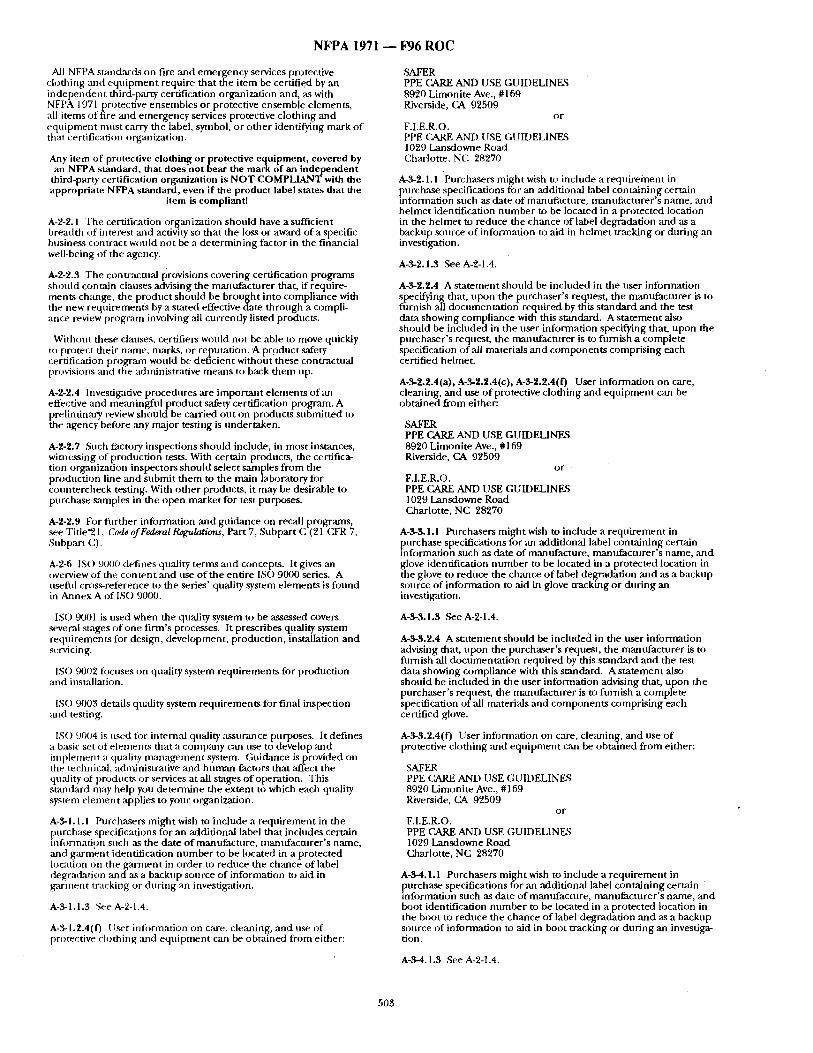
N F P A 1971 ~ 1796 R O C
All NFPA standards on fire and emerl~ency services protective clothing and e q u i p m e n t require that m e i tem be certified by an i ndependen t third-party certification organization and, ,as with NFPA 1971 protective ensembles or protective ensemble elements, all i tems of fire and emergency services protective clothing and equ ipmen t mus t carry the label, symbol, or o ther identifying mark o f that certification org~mization.
Any item of protective clothing or protective equipment , covered by an NFPA standard, that does not bear the mark of an independent
third-party certification organization is N O T COMPLIANT with the appropriate NFPA standard, even if the product label states that the
item is compliant!
A-2-2.1 The certification organization should have a sufficient breadth of interest mid activity st) that the loss or award of a specific business contract would not be a de te rmin ing factor in the financial well-being of the agency.
A-2-2.3 The contractual provisions covering certification programs should contain clauses advising the manufac ture r that, if require- ments change, the product should be b rought into compliance with the new requirements by a stated effective date th rough a compli- ance review program involving ,all currently listed products.
Without these clauses, cttrtifiers would not be able to move quickly to protect their name, marks, or reputation. A product safety certification progr,'un would be deficient without these contractual provisions and the administrative means to back them up.
A-2-2.4 Investigative procedures are impor tan t e lements o f an effective ;rod meaningfnl product safety certification program. A Phreliminary review should be carried out on products submit ted to
e agency before :my major testing is under taken.
A-2-2.7 Such factory inspections should include, in most instances, witnessing of production tests. With certain products, the certifica- tion organization inspectors should select samples f rom the production line ,and submit them to the main laboratory for countercheck testing. With o ther products, it may be desirable to purchase s;mlples in the open market for test purposes.
A-2-2.9 For fl lr ther information and guidance on recall programs, see Title'21, Code of Federal IZeKulations, Part 7, Subpart C (21 CFR 7, Subpart C).
A-2-6 IS() 9000 defines quality terms and concepts. It gives ,an overview of the con ten t and use o f the entire IS() 9000 series. A usefid cross-reference to the series' quality system e lements is found in Annex A of IS() 9000.
ISO 9001 is used when the quality system to be assessed covers several stages o f one f i rm's processes. It prescribes quality system requi rements for design, development, production, installation and servicing,
ISO 9002 focuses on quality system requirements for production and installation.
lSO 9003 details quality system requirements for final inspection and testing.
ISO 9004 is used fi)r intenaal quality ,assurance purposes. It defines a basic set o f e lements that a company can use to develop ,and implelnent a quality m a n a g e m e n t system. Guidance is provided on the technical, administrative and h u m a n factors that affect the quality of products or services at all stages o f operation. This s tandard may help you de termine the extent to which each quality system e lement applies to your organizatinn.
A-3-1.1.1 Purchasers migh t wish to include a requi rement in the purchase specifications for an additional label that inchldes certain infl)rmatign such as the date of manufacture , manufac turer ' s name, :rod ga rmen t identification n u m b e r to be located in a protected location on the ga rmen t in order to reduce the chance of label degradation and ms a backup source o f information to aid in ga rmen t tracking or dur ing an investigation.
A-'¢-1.1.3 See A-2-1.4.
A-3-1.2.4(0 l lser information on care, cleaning, and use of protective clothing and equ i pmen t can be obtained from either:
SAFER PPE CARE AND USE GUIDELINES 8920 Limonite Ave., #169 Riverside, CA 92509
or F.I,E.R.O. PPE C~nd~E AND USE GUIDELINES 1029 Lansdowne Road Charlotte, NC 28270
A-3-2.1.1 Purchasers might wish to include a require inent in purchase specifications for an ,additional label containing certain reformation such as date of manufacture, manufac turer ' s name, and he lmet identification n u m b e r to be located in a protected location in the he lmet to reduce the chance of label degradation and as a backup source of information to aid in he lmet tracking or dur ing an investigation.
A-3-2.1.3 See A-2-1.4.
A-3-2.2.4 A s ta tement should be included in the user information specifying that, upon the purchaser ' s request, the manufac ture r is to flirnish ,all documenta t ion required by this s tandard and the test data showing compliance with this standard. A s ta tement also should be included in the user information specifying that, upon the purchaser ' s request, the mmnffactnrer is to furnish a complete specification of all materials and componen t s compris ing each certified helmet.
A-3-2.2.4(a), A-3-2.2.4(c), A-g-2.2.4(F) User information on care, cleaning, and use o f protective clothing and equ ipmen t can be obta ined f rom either:
SAFER PPE CARE AND USE GUIDELINES 8920 Limoni te Ave., #169 Riverside, CA 92509
o r
F.I.E.R.O. PPE CARE AND USE GUIDELINES 1029 Lansdowne Road Charlotte, NC 28270
A-3-3.1.1 Purchasers migh t wish to include a r equ i rement in purchase specifications for ,an additional label conta in ing certain
formation such as date of manufacture , mantffacturer 's name, and glove identification n u m b e r to be located in a protected location in the glove to reduce the chance o f label del~,q'adation and as a backup source of information to aid in glove tracking or dur ing an inv~stigafion.
A-$-3.1.3 See A-2-1.4.
A-$-3.2.4 A s ta tement should be included in the user information advising that, upon the purchaser ' s request, the manufac ture r is to filrnish ,all documenta t ion required by this s tandard and the test data showing compliance with this standard. A s ta tement also should be included in the user information advising that, upon the purchaser ' s request, the manufac ture r is to furnish a complete specification o f ,all materials and componen t s compris ing each certified glove.
A-3-3.2.4(f) User information on care, cleaning, and use of protective clothing ,and equ ipmen t can be obta ined f rom either:
SAFER PPE CARE AND USE GUIDELINES 8920 Limoni te Ave., #169 Riverside, CA 92509
o r
F.I.E.R.O. PPE CARE AND USE GUIDELINES 1029 Lansdowne Road Charlotte, NC 28270
A-3-4.1.1 Purchasers migh t wish to include a requ i rement in purchase specifications for an additional label conta in ing certain information such as date of manufacture , manufac ture r ' s name, and boot identification n u m b e r to be located in a protected location in the boot to reduce the chance o f label degradation and as a backup source of information to aid in boot tracking or dur ing an investiga- tion.
A-3-4.1.3 See A-2-1.4.
503
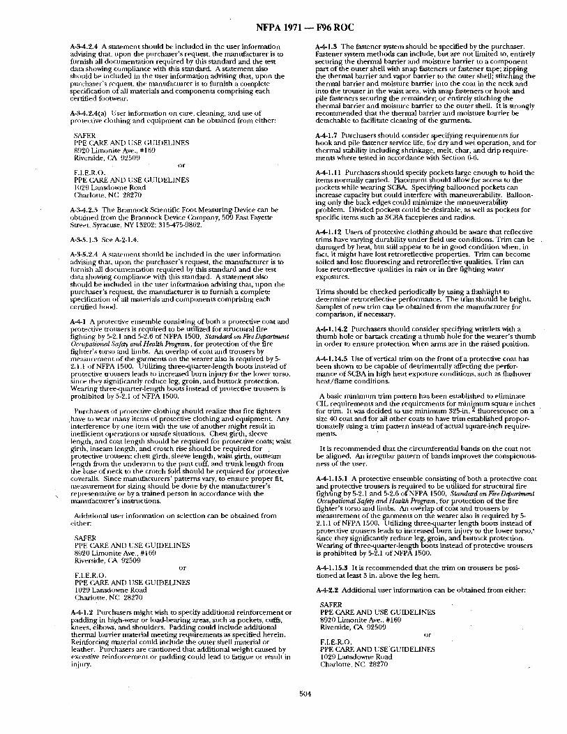
N F P A 1971 ~ F96 R O C
A-3-4.2.4 A s ta tement should be included in the user information advising that, upon the purchaser ' s request, the mantffacturer is to furnish all documenta t ion required by this s tandard and the test • tta showing compliance with this standard. A s ta tement also should be included in the user information advising that, upon the purchaser ' s request, the mannfac ture r is to furnish a complete specification of all materials and componen t s compris ing each certified fi~otwear.
A-3-4.2.4(a) l lser information on care, cleaning, and use o f protective clothing and equ ipmen t can be obtained from either:
SAFER PPE £~kRE AN[) USE £;UIDELINES 8(.)20 Limonite Ave., #169 Riverside, £~A 92509
or F.I.E.R.O. PPE CARE AN[) I ISE £;UIDELINES 1029 Lansdowne Road C, harlotte, NC 28270
A-3-4.'~.5 The Brannock Scientific Foot Measuring, Device can be obtained from the Brannock Device £kJmpany, 509 East Fayette Street, Syracuse, NY 13202; 315-475-9862.
A-3-5.1.3 See A-2-1.4.
A-3-5.2.4 A s ta tement should be included in the user infornmtion advising that, upon the purchaser ' s request, the manufac tu re r is to furnish all documenui t ion required by this stan&ard and the test data showing compliance with this standard. A s ta tement also should be included in the user in tbrmat ion advising that, upon the purchaser ' s request, the mantffacturer is to furnish a complete specification of all materials and componen t s compris ing each certified hood.
A-4-1 A protective ensemble consisting of both a protective coat and protective trottsers is required to he utilized for structural fire fighting by 5-2.1 ,and 5-2.6 of NFPA 1500, Standard on Fire Department Occupational Safety and Health Program, for protection of the fire f ighter 's torso and limbs. An overlap of coat and trousers by me~Lsurement of the garments on the wearer also is required by 5- 2.1.1 of NFPA 1500. Utilizing three-quarter-length boots instead of protective trousers leads to increased burn injury fi~r the lower torso, since they significantly reduce leg, groin, a n d b u t t o c k protection. Wearing three-quarter-length boots instead of protective trousers is prohibited by 5-2.1 of NFPA 1500.
Purchasers of protective clothing should realize that fire fighters ,have to wear many items of protective clothing and equipment . Any interference by one i tem with the use of ano the r might result in inetticient operations or unsafe situations. Chest girth, sleeve length, and coat length should be required for protective coats; waist girth, inseam length, and crotch rise should be required for protective trousers; chest girth, sleeve length, waist girth, ou t seam length from the u n d e r a r m to t h e p a n t cuff, and t runk length f rom the base of neck to the crotch f iMdshould be requi red for protective coveralls. Since nmmtfacturers ' pat terns vary, to ensure proper fit, m e a s u r e m e n t for sizing should be done by the mantffacturer 's representative or by a t ra ined person in accordance with the manufac ture r ' s instructions,
Additional user infi~rnlation on selection can be obtained from either:
.SAFER PPE (2&RE AN[) USE GUIDELINE,S 8920 Limonite Ave., # 169 Riverside, CA 92509
or F.I.E.R.O. PPE CARE AND I JSE GUIDELINES 1029 L:msdowne Road Charlotte, NC 28270
A-4-1.2 Purchasers migh t wish to specify additional re inforcement or
[ adding in high-wear or load-bearing areas, such as pockets, cuffs, nees, elbows, and shoulders. Padding could include additional
thermal barrier material meet ing requi rements as specified herein. Reinforcing material could include the outer shell material or leather. Purchasers are caut ioned that additional weight caused by excessive reinfl)rcement or padding could lead to fatigue or result in injury.
A-4-1.3 The fastener system should be specified by the purchaser . Fastener system me thods can include, bu t are no t l imited to, entirely securing the thermal barrier and moisture barrier to a c o m p o n e n t part o f the outer shell with snap fasteners or fastener tape; zipping the thermal barrier and vapor barrier to the outer shell; st i tching the thermal barrier and moisture barrier into the coat in the neck ,and into the trouser in the waist area, with snap fasteners or hook an d pile fasteners secur ing the remainder; or entirely stitching the thermal barrier and moisture barrier to the outer shell. It is strongly r e c o m m e n d e d that the thermal barrier and moisture barrier be detachable to facilitate cleaning of the garments .
A 4 1 . 7 Purchasers should consider specifying requirements for hook and pile fastener service life, for dry and wet operation, and for thermal stability including shrinkage, melt, char, and drip require- ments where tested in accordance with Section 6-6.
A-4-1.11 Purchasers should specify pockets large enough to hold the items normally carried. Placement should allow for access to the pockets while wearing SCB/L Specifying bal looned pockets can increase capacity but could interfere with maneuverability. Balloon- ing only the back edges could minimize the maneuverabili ty problenn. Divided pockets could be desirable, ,-as well as pockets for specific i tems such as S£33A facepieces and radios.
A-4-1.12 Users of protective clothing shou ld be aware that reflective trims have varying dt,rability unde r field use conditions. Trim can be damaged by heat, but still appear to be in good condit ion when, in fact, it might have lost retroreflective properties. Tr im can become soiled and lose fluorescing mad retroreflective qualities. Tr im can lose retroreflective qualities in rain or in fire f ight ing water exposures.
Trims should be checked periodically by using a flashlight to de termine retroreflective performance. The tr im should be bright. Samples of new trim can be obta ined f rom the manufac tnre r for comparison, if necessary.
A41 .14 ,2 Purchasers shoutd consider specifying wrisdets with a t h u m b hole or barrack creating a t h u m b hole for the wearer's t h u m b in order to ensure protection when arms are in the raised position.
A-4-1.14.5 Use o f vertical t r im on the front of a protective coat has been shown to be capable o f detrimentally affecting the perfor- mance o f SCBA in high heat exposure conditions, such as flashover hea t / f l ame conditions.
A basic m i n i m u m trim pattern has been established to el iminate CIL requi rements and the requi rements for m i n i m u m square inches fi)r trim. It was decided to use m i n i m u m 325-in. 2 f luorescence on a size 40 coat and for all o ther coats to have tr im established propor- tionately using a tr im pattern instead of actual square-inch require- ments.
It is r e c o m m e n d e d that the circumferential bands on the coat not be aligned. An irregular pat tern of bands improves the conspicuous- ness of the user.
A-4-1.15.1 A protective ensemble consisting of both a protective coat ,and protective trousers is required to be utilized for structural fire fighting by 5-2.1 and 5-2.6 og NFPA 1500, Standard on Fire Department Occupational Safety and Health Program, for protection of the fire f ighter 's torso and limbs. /Mi overlap of coat and trousers by m e a s u r e m e n t of the garments on the wearer also is required by 5- 2.1.1 of NFPA 1500. Utilizing three-quarter length boots instead o f protective trousers leads to increased burn injury to the lower torso," since they significantly reduce leg, groin, a n d b u t t o c k protection. Wearing of three-quarter-length boots instead of protective trousers is prohibited by 5-2.1 o f NFPA 1500.
A-4-1.15.3 It is r e c o m m e n d e d that the tr im on trousers be posi- t ioned at least 3 in. above the leg hem.
A42. '~ Additional user information can be obta ined f rom either:
SAFER PPE CARE AND USE GUIDELINES 8920 Limonite Ave., #169 Riverside, CA 92509
or F.I.E.R.O. PPE £~RE AND USE GUIDELINF_;S 1029 Lansdowne Road Charlotte, NC 28270
504
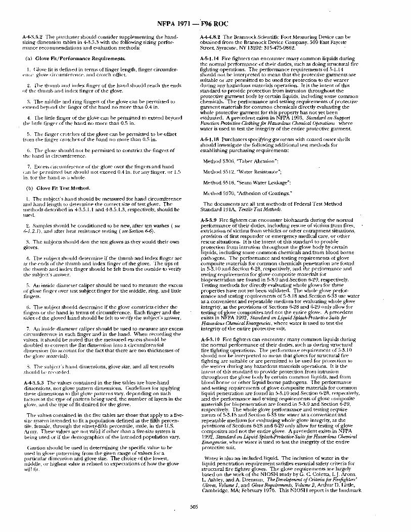
NFPA 1971 ~'F96 ROC
A-4-3.5.2 The purchaser should consider supp lement ing the hand- sizing dimension tables in 4-3.5.3 with the following sizing perfor- nlance recommenda t ions and evahlation methods:
(a) Glove Fit/Performance Requirements.
1. (;love fit is def ined in terms of finger length, f ingercircnnffer- ~'llCe, glove circ/inllerence, and crotch oifset.
2. The thtunb and index finger of the h a n d should reach the ends of the t h u m b and index finger of the glove.
3. The middle and ring fingers of the glove can be perraitted to ex tend beyond the finger of the hand no more than 0.4 in.
4. The little f inger of the glove can be permit ted to extend beyond tile little f inger of the h a n d no more than 0.5 in.
5. The finger crotches of the glove can be permit ted to be offset from the finger crotches of the hand no more than 0.5 in.
6. The glove should not be permit ted to constrict the fingers of the band in circumference.
7. Excess circuinferenre of the glove over the fingers and hand can be permit ted I:)tu should not exceed 0.4 in. for any finger, or 1.5 in. for tile hand as a whole.
(b) Glove Fit Test Method.
1. The subject 's hand should be m e ~ u r e d for hand c i rcumference and hand length to de termine the correct size of test glove. The methods described in 4-3.5.1.1 and 4-3.5.1.3, respectively, should be used.
2. Samples should be condi t ioned to be new, ,after ten washes ( see 6-1.2.1), and "after heat resistance testing ( see Section 6-6).
3. The subjects should don the test gloves as they would their own gloves.
4. The subject should de termine if the t h u m b and index finger are at the ends of the t humb and index finger o f the glove. The tips of tile t humb and index finger should be felt f rom the outside to verify the snt)ject's answer.
5. AJ] inside diameter caliper should be used to measure the excess of glove f inger over test subject f inger for the middle, ring, and little fingers.
6. Tile subject should de termine if the glove constricts ei ther the fingers or the hand in terms of circumference. Each finger and the sides of the gloved h a n d should be felt to verify the subject 's answer,
7. An inside diameter caliper should be used to measure any excess r i rcunfference in each finger and in the hand. When recording the values, it should be noted that the measured excess should be dot,bled m convert the flat d imension into a circnnfferential d imension (to account for the fact that there are two thicknesses of the glove material).
8. The sul)ject's baud dimensions, glove size, and all rest results £bnnlcI be re{~)rded.
A-4-3.5,3 The values cont~dned in the five tables ,are bare-braid dimensions, not glove pattern dimensions. C, nidelines fi~r applying these d imensions to flat glove patterns vary, depend ing on such factors as the type of pattern being used, the n u m b e r of layers in the glove, and the type of fit desired for the glove.
The values contained in the five tables are those that apply to a five- size system in tended to fit a population defined as the fifth percen- tile, (era~de, th rough the ninety-fifth percentile, male, in the U.S. Army. These vah,es are not valid if o ther than a five-size system is being used or ff the demographics of the in tended populat ion vary.
Caution should be used in de termining the specific value to be used in glove pat terning from the given range of values fi)r a particnlar d imension and glove size. The choice of the lowest, middle, ~)r highest value is related to expectations of how the glove will fit.
A-4-4.8.2 The Brannock Scientific Foot Me,'tsnring Device can be obtained from the Brannock Device Company, 509 East Fayette Street, Syracuse, NY 13202; 315475-9862.
A-,gl. 14 Fire fighters can encoun te r many c o m m o n liquids dur ing the normal performance of their duties, such as doing structural fire fighting operations. The per lbrmance requirements of 5-1.14 sh )uld not )e interpreted to mean that the protective g a ~ e n t s are suitable or are permit ted to be used for protection to the wearer dur ing any hazardous materials operation. It is the intent of this s tandard to provide protection f rom intrusion th roughou t the protective g a ~ e n t body by certain liquids, including some colrmlon chemicals. The performance and testing requirements of protective ga rmen t materials for c o m m o n chemicals directly evaluating the whole protective ga rment for this property has not yet been evaluated. A precedent exists in NFPA 1993, Standard on Support Function Protective Clothing for Hazardous Chemical Operations where water is used to test the integrity of the entire protective garment .
A-g l . 18 Purchasers specifying garments with coated outer shells should investigate the following additional test methods fi)r establishing purchasing requirements:
Method 5306, "Taber Abrasion":
Method 5512, "Water Resist~ulce";
Method 5516, "Seara Water Leakage";
Method 5970, "Adhesion of Coatings."
The documents are all test methods of Federal Test Method Standard 191A, Textile Test Methods.
A-fi-3.9 Fire fighters can encoun te r biohazards dur ing the normal performance o f their dr,ties, including rescue of victims from fires, ex~ication o f victims from vehicles or o ther e n t r a p m e n t situations, provision of first responder or emergency medical care, or o ther rescue situations. It is the intent of this s tandard to provide protection from intrusion th roughou t the glove body by certain liquids, including sonle c o m m o n chemicals and f rom blood borne pathogens. The performance and testing requirements of glove composite raaterials fi)r c o m m o n chemicals penetrat ion are fi)und in 5-3.10 and Section 6-28, respectively, ,and the performance and testing requirements for glove composite materials fi~r biopenetration are found in 5-3.9 and Section 6-29, respectively. Testing methods fo~" directly evaluating whole gloves for these properties have not yet been validated. The whole glove perfor- raance and testing requirements of 5-3.18 and Section 6-33 use water as a convenient and repeatable med ium fi~r evaluating whole glove integrity, as the provisions of Sections 6-28 and 6-29 only allow fi~r testing o f glove composites ,and no t the entire glove. A precedent exists in NFPA 1992, Standard on Liquid Splash-Protective Suits for Hazardous ChemicalEmergencies, where water is used to test the integrity of the entire protective suit.
A-5-3.10 Fire fighters can encoun te r many c o m m o n liquids dur ing the normal performance o f their duties, such as dur ing strnctural fire f ighting operations. The perforraance requi rement of 5-3.10 should not be interpreted to mean that gloves for structt,ral fire fighting are suitable or are permit ted to be used fi~r protection to the wearer dur ing ~my h,~trdot ts materials opegtfions. It is the intent of this s tandard to provide protection from intrusion th roughout the glove body by certain c o m m o n liquids, and from blood borne or other liquid borne pathogens. The performance and testing requirements of glove composite materials for com m o n liquid penetrat ion are fi~und in 5-3.10 and Section 6-28, respectively, and the performance and testing requirements of glove composite materials for biopenetrat ion are found in 5-3.9 ,and Section 6-29, respectively. The whole glove perforraance and testing require- ments of 5-3.18 ,and Section 6-33 use water as a convenient and repeatable med ium fi~r evaluating whole glove integrity, as the provisions of Sections 6-28 and 6-29 only allow for testing of glove composites and not the entire glove. A precedent exists in NFPA 1992, Standard on Liquid Splash-Proteetive Suits for Hazardous Chemical Erntqgendes, where water is used to test the integrity of the entire protective suit.
Water is also an included liquid. The inclusion of water in the liquid penetrat ion requ i rement satisfies essential safety criteria for structural fire fighter gloves. The glove requirements ,are largely based on the work o f the N1OSH study by G. C. Coletta, I.J. Arons, L. Ashley, and A. Drennan, The Development of CriteriaforFirefighters' Gloves, Volume 1, and Glove Reefuirernents, Volume 2, Arthur D. Little, Cambridge, MA; February 1976. This NIOSH report is the landmark
505
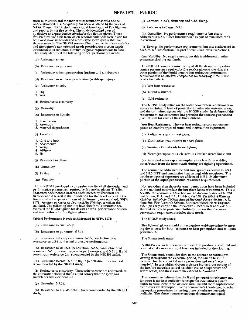
N F P A 1971 - - F 9 6 R O C
study in this field and the merits o f its testimony should not be underestimated. It subsequently has been validated by the work of NA~SA, Project FIRES, the International Association o f Fire Fighters, mid reports by the fire service. The study identified a set o f qu,'ditative and quantitative criteria for fire fighter gloves. Those criteria form the basis from which recommendat ions were made for both new glove standards and a prototype glove system that met those st~m&trds. The NIOSH survey of hand and wrist injury statistics and fire f ighter 's msk<wiented needs provided the most in-depth identification of structural fire fighter glove requirements to date. That study identified the following critical performance needs:
(a) Resismm:~ t~:J [;lit
(b) Resistance to puncture
(c) Resistance to heat penetration (radi~mt and conductive)
(d) Resisr~mce to wet heat penetration (scald-type injury)
(e) Resistance to cold:
1. Dry 2, Wet
(f) Resistance to electricity
(g) Dexterity
(h) Resist:race to liquids:
1. i 'enetration 2. Retention 3. Material degradation
(i) Conffort:
I. Cz)ld and heat 2. Absorbency 3. 'Weight 4. Stiffness 5. Fit
(J) Resistance to flame
(k) Durability
(1) Drying
'(m) Visibility,
Thns, N1OSH developed a comprehensive list of all the design and performance parameters required by fire service gloves. This list addressed documented hazards enconnte red by strnctural fire fighters, and it served as the foundation for the development of the first and all subsequent editions of the former glove standard, NFPA 1973, Standard on Gloves for Structural Fire Fighting, as well as this standard. The following outlines how closely the committee has fi)llowed the NIOSH guide for design criteria, performance criteria, and test methods for fire fighter gloves.
Critical Performance Needs as Addressed in NFPA 1971:
(a) Resist,ance to cut: 5-3.11.
(b) Resistance us puncture: 5-3.13.
(c) Resistance to heat penetration: 5-3,5, conductive heat resistance; and 5-3.1, thermal protective performance.
(d) Resistance to wet heat penetration: 5-5.5, conductive heat resistance; 5-3.1, thermal protective performance; and 5-3.10, liquid penetration resistance (as r ecommended by the NIOSH study).
(e) Resistarme to cold: 5-3.10, liquid penetration resistance (as recommended by the NIOSH study).
(t) Resisumce to electricity: These criteria were not addressed, as the committee decided that it could convey that the glove was suitable for live electrical use.
(g) Dexterity: 5-3.14.
(h) Resistance to liquids: 5-3.10, (as r ecommended by the NIOSH study).
(i) Comfort: 5-$.1'4, dexterity;, and 4-3.5, sizing.
(j) Resistance to flame: 5-3.6.
(k) Dnrability: No performance requirements, but this is addressed in 3-3.3, "User Information," as part of manufacturer 's instructions.
(I) Drying: No performance requirements, but this is addressed in 3-3.3, "User Information," as part o f manufacturer 's insm~ctions.
(m) Visibility: No requirements, but this is addressed in o the r protective clothing standards.
This NIOSH comprehensive listing of all the design and perfor- mance parameters reqtfired by fire service gloves shows that the water portion of the liquid penetration resistance performance requirement is an integral componen t for Satisfying three of the protective criterim
(a) Wet heat resistance;
(b) Liquid resistance;
(c) Cold resistance.
The NIOSH study relied on the water penetration requirement to ensure a minimt,m level o f protection in otherwise tmtested areas, and the committee agrees with the NIOSH study. In defense of this requirement. . . , the committee has provided. . the following expanded justifications for each of these three criteria.
Wet Heat Resistance. The wet heat resistance concept encom- passes at least five types of combined thermal /wet exposures:
(a) Radiant energy on a wet glove;
(b) Conductive heat transfer to a wet glove;
(c) Wetting of an already heated glove;
(d) Steam je t exposure (such as from a broken steam line); and
(e) Saturated water vapor a tmosphere (such as from scalding water/s team from the hose nozzle during fire fighting operations).
The committee addressed the first two typ~ of exposnre in 5-3.1 and 5-3.5 (TPP and conductive heat testing) with wet gloves. The last three types of exposures are addressed in 5-3.10 (the water portion of the liquid penetration resistance requirement).
No tests o ther than those for water penetration have been included in the standard to simulate the last three kinds of exposures. This is because the committee has relied on the documentat ion of NIOSH and Simms, D. L. and P. L. Hinldey, Part 10, The Effect of Water on Clothing. Suitable for Clothing Aircraft Fire Crash Rescue Workers, F. R. Note 366, Fire Research Station, Boreham Wood, Hefts England, 1959 (an early study on the interactive effect o f heat and water on thermal transfer in protective clothing) to show that the water penetration requirement satisfies those needs.
The NIOSH study states:
Fire fighters' gloves should protect against scald-type injury by meet- ing the criteria for both resistance m heat penetration and to liquid penetration.
The Simms stndy states:
A sudden rise in temperature sufficient to produce a scald did not occur at all if a moistureproof layer was included in the clothing.
The Simms study concludes that, in the absence of continuous wetting throughout the exposure period, the assemblies with moisture barriers provided more protection and were ?recom- mended." In assemblies without moisture barriers, the wetting of the ho t /d ry materials caused a sudden rise of temperature and severe scalds, and these assemblies should be "avoided."
The committee believes that the liquid penetrat ion resistance test for water is the best available technique for evaluating a glove's ability to resist these three wet heat assaults until more sophisticated techniques are developed. To the committee 's knowledge, no other appropriate procedures for testing these criteria are currently available. The above literature citations document the l iquid
506
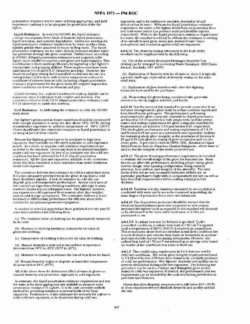
N F P A 1971 ~ F 9 6 R O C
penetrat ion resistance test fi3r water ,as being appropriate, and field experience confirms it to be adequate fi)r protection of the fire fighter.
Liquid Resistance. A.s noted by NIOSH, the liquid resistance concept encomp`asses three kinds of hazards: liquid penetrat ion, liquid retention, and material degradation. Gloves not meet ing the liquid penetrat ion resisumce requ i rement for water produce burn injuries quickly when assaulted by ho t or boiling water. The liquid penetrat ion resistance test for water directly evahmtes whether water cart penetrate through the glove materials. Fur thernmre, according to NIOSH, if liquid penetrat ion resistance is no t required, a fire fighter more readily encounters a wet glove/wet hand situation. This combinat ion reduces working efficiency by degrading a fire f ighter 's manipulative and gr ipping abilities. These requirements have been addressed in 5-.'?,. 14 ,and 5-3.17 (dexterity and grip). However, the dexterity and grip testing that is specified necessitates the use of a testing subject and is done only at room tempera tore and not in condit ions of ext reme hea t or cold. Including a liquid penetrat ion resistance requ i rement for the glove limits the negative imp:rot that these condit ions can have on dexterity and grip.
Liquid retention (i.e., a glove's tendency te soak up liquids) can he haz:u'dous, since it influences both comfort and flmction. The coTnmittee relied on both 5-3.10 (liquid penetrat ion resist~/ce) and 5-3.14 (dexterity) to satisfy this criterion.
Cold Resistance. In addressing the resistance to cold, the NIOSH study states:
Fire f ighter 's ghwes used in winter condit ions should be constructed with enough insulation to keep the skin above 18°C (65°F) dur ing nonsedenutry exposures to :mlbient tempera ture of -34°C (-30°F). Gloves should meet the criteria for resistance to liquid penetrat ion as an integral part of these criteria.
Becanse fire fighting gloves have to be insutative to high heat exposures, they nonrually are effectively insulative to cold exposures ,as well. As a result, no separate cold insulation requirements are included in the standard. Gloves also have to be similarly insvlative raider cold/wet exposures. In lieu o f an insulative test, the cold/wet condition has been addressed by 5-3.10 (liquid penetrat ion resistance). All the data and experience available to the commit tee shows that drier insulation is more insulative than wetter insulation unde r cold exposures.
The commit tee believes that resistance to cold is a safety issue since, if it is no t adequately provided for in the glove, it can lead to cold burn (frostbite} injuries. A lack of resistance to cold also can degrade grip and rmmipulative performance. Almost every area of the country can experience freezing conditions, a l though in some southern locales it is not a f requen t event. Fire fighters, however, can exper ience cold exposures f rom sources o ther than weather, such ,'ks cold storage occupancies. The commit tee believes it is no t necessary to differentiate per formance for different are`as of the country ibr any personal protective e q u i p m e n c
A n u m b e r of technical papers have been published over the past 50 years that established the following facts:
(a) The insulative value of clothing can be qnantitatively me`asured in clo units.
(b) Moisture in clothing insulation reduces the clo value of protective clothing.
(c) Compression of clothing reduces the clo value of clothing.
(d) Manual dexterity is reduced ,as the ambient temperature decreases f rom 18°C to -29°C (65°F to -20°F).
(e) Moisture in clothing accelerates the loss of heat f rom the hand.
(t) Manual dexterity begins to degrade as hand skin temperatt , re decreases below 18°C (65°F).
All of the above show the deleteriovs effect of water in gloves on manua l dexterity and protection, especially in cold exposures.
In sumnmry, the liquid penetra t ion resistance requiremet~t and test ti)r water is the most appropriate test available to measure water penetrat ion resistance in a glove. It is the only currently available me thod for providing resistance to several kinds of wet heat exposures. Fur thermore, it also addresses the necessity for a glove to resist cold/wet exposures, to be dexterous dur ing cold/wet
exposures, and to be resistant to excessive absorption o f ,and deterioration by water. Without the liquid penetrat ion resistance requ i rement for water, a fire fighter would have no protection f rom ho t / co ld water (which can produce scald and frostbite injuries, respectively), Withont the liquid penetrat ion resistance requ i rement fi~r water, the s tandard would fail to address the resistance to wetting of ,an already heated glove, s team jets, saturated water vapor atmospheres, and insulation against co ld /wet exposures.
A-5-3.14 The dexterity testing referenced in the body of the s tandard can be supp lemen ted by the following:
(a) Use of the recently developed Heminge r Dexterity Test (testing can be ar ranged b~, contact ing Maria Heminger , 4908 Hayes Avenue, Sandusky, OH 44870;
(b) Exploration of dexterity tests for all sizes or, since it is typically a greater challenge, exploration of dexterity testing on the extra small sizes;
(c) Exploration of glove interface with o ther fire fighting vocational tools used by the purchaser:
(d) Wear-testing the gloves being considered with particular at tention u) use on toggles, switches, and knobs.
A-5-3.18 It is the in tent o f this s tandard to provide protection from intrusion th roughou t the glove body by certain c o m m o n liquids and from blood borne pathogens. The performance and testing reqa,irements fi)r glove composite materials for liquid penetrat ion are fi)und in 5-3.10 and Section 6-28, respectively, and the perfor- mance and testing requirements for glove composi te materials for biopenetration are found in 5-3.9 and Section 6-29, respectively. The whole ghwe performance and testing reqa, i rements o f 5-3.18 and Section 6-33 use water ,as a convenient and repeatable m e d i u m for evaluating whole glove integrity, as the provisions of Sections 6- 28 ,and 6-29 only allow fi)r testing of glove composites and not the entire glove. A precedent exists in NFPA 1992, :~tandard on Liquid Splash-Protective Suits fin Hazardous Chemical Emergencies, where water is' used to test the integrity o f the entire protective suic
A-5-3.19 The glove donn ing performance requ i rement is in tended to evaluate the overall design of the glove for repeated use. Many fitctors can affect the performance, inch,ding proper sizing, glove interior design, wrist open ing corifigt, ration, lining material selection, liner pullout, and integrity o f the assembly. The time limits of this test are not necessarily indicative o f field use. In particular, purchasers migh t wish to comparatively test wet (as well as dry) don/dof fcharac te r i s t ics before making a final purchase decision.
A-5-4.13 Footwear sole slip resistance m e ~ u r e d in wet condition is conduc ted with water and is no t to be cons t rued as providing the same degree of protection from other wet substances.
A-5-4.15 Fire depa r tmen t personnel should be warned that the electrical hazard-resistant protective properties in new unworn structt,ral fire fighter boots as required by this st,anditrd wilt diminish or be el iminated as the boot, soles /heels wear or if they are punc tu red or cut.
A-6-1.7.8 A radiant heat test for helmets is specified, t i nde r controlled conditions, a radiant heat load of 1 W / c m 2 is applied until a tempera ture o f 260°C (500°17) is reached on a transducer. This tempera ture alone does no t simulate actual field condit ions but is a test devised to put ext reme hea t loads on helmets in an accurate and reproducible m a n n e r by testing laboratories. However, the radiant heat load of 1 W / c m 2 was selected ,as an average value based on studies of fire conditions that relate to field use.
A-6-1.9 The condi t ioning requi rement in 6-1.9 does no t test for cold/wet conditions. The whole glove integrity requi rements found in 5-3.18 and Section 6-33 have been found to be a reliable predictor of cold/wet performance. Fire fighters ' dexterity mad tactility can be severely d iminished dur ing cold/wet exposures. The following test procedure can be used to evaluate and distinguish glove perfor- mance in cold /wet exposures. If desired, this per formance and test r equ i rement can be included by the authority having jurisdiction in purchase specifications.
Gloves that allow fingertip temperatures to fall below 10°C (50°F) in these exposures severely diminish dexterity and tactility and fall the test.
507
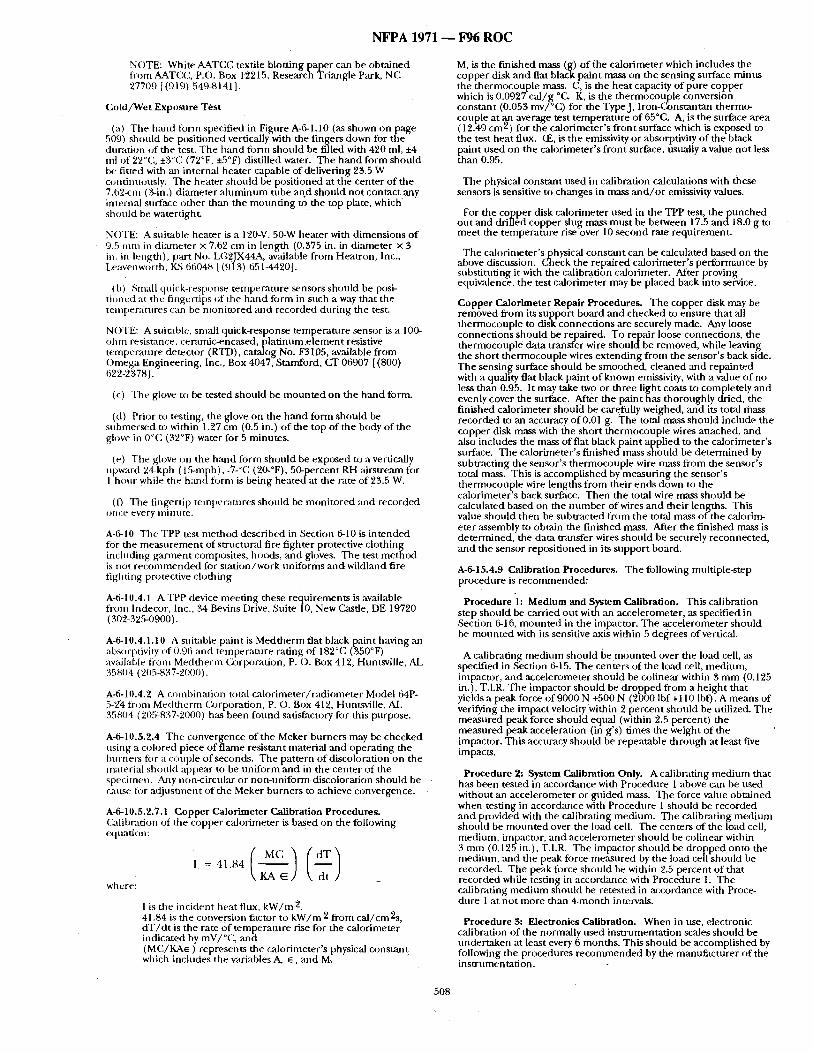
N F P A 1971 ~ F96 R O C
NOTE: White AATCC textile blotting paper can be obta ined from AATCC, p.o. Box 12215, Research Triangle Park, NC 27709 [ (919) 54%8141 ].
Cold /Wet Exposure Test
(a) The hand tbrm specified in Figure A-6-1.10 (as shown on page 509) should be posit ioned vertically with the fingers down for the duration of the test. The hand figrm should be filled with 420 ml, ±4 ml of 22°C, ±3°C (72°F, ±5°F) distilled water. The h a n d form should be fitted with an internal heater capable of delivering 23.5 W contixmously. The heater should be posit ioned at the center of the 7.62-cm (3-in.) d iameter ahmf i num tube and should not con tac t any internal surface other than the moun t i ng to the top plate, which should be watertight.
NOTE: A suitable heater is a 120-V, 50-W heater with d imens ions of • 9.5 m m in dianaeter x 7.62 cm in length (0.375 in. in diameter × 3
in. in length), part No. LG2JX44A, available f rom Heatron, Inc., Leaven worth, ILS 66048 [ (913) 651-4420].
(b) Small quick-response tempera ture sensors shou ld be posi- t ioned at the fingertips of the hmld form in such a way that the tenaperatures can be moni to red and recorded dur ing the test.
NOTE: A suitable, small quick-response tempera ture sensor is a 100- oh m resistance, ceramic-encased, p la t inum.e lement resistive tempera ture detector (RTD), catalog No. F3105, available f rom Omega Engineering, Inc., Box 4047, Stamford, CT 06907 [(800) 622-2378].
(c) The glove to be tested should be m o u n t e d on the hand form.
(d) Prior to testing, the glove on the h a n d form should be submersed to within 1.27 cm (0.5 in.) o f the top of the body of the glove in 0°C (32°F) water for 5 minutes .
(e) The glove on the hand fi~rm should be exposed to a vertically npwm'd 24-kph (15-mph), -7-°C (20-°F), 50-percent RH airstream for 1 hour while the hand f i ) rm is being heated at the rate of 23.5 W.
(f) The fing.ertip mmpera tures should be moni tored and recorded once every nunllte.
A-6-10 The TPP test me t hod described in Section 6-10 is in tended for the m e a s u r e m e n t of structural fire f ighter protective c lothing including ga rmen t composites, hoods, and gloves. The test m e t h o d is not r e c o m m e n d e d for s ta t ion/work uni forms andwi ld land fire fighting protective clothing.
A-6-10,4.1 A TPP device meet ing these requirements is available f rom lndecor, Inc., 34 Bevins Drive, Su i t e l0 , New Castle, DE 19720 (302-3"25-0900).
A-6-10.4.1.10 A suitable paint is Medtherm flat black paint having an absorptivity of 0.96 and tempera tnre rating of 182°C (350°F) available *tom Medtherm (a)rporation, P. O. Box 412, Huntsville, AL 35804 (205-837-2000).
A-6-10.4.2 A combinat ion total ca lor imeter / rad iometer Model 64P- 5 - ~ fi'om Medtlaerm (~)rporation, P. O. Box 412, Huntsville, AL 35804 (205=837-2000) has been found satisfactory for this purpose.
A-6-10.5.2.4 The convergence of the Meker burners may be checked using a colored piece o f f lame resistant material mad operat ing the burners fi:,r a couple o f seconds. The pattern o f discoloration on the material should appear to be uni form and in the center of the specimen. Any non-circular or non-un i fo rm discoloration should be cause for ad jus tment of the Meker burners to achieve convergence.
A-6-10.5.2.7.1 Copper Calorimeter Calibration Procedures . (2dibration of the copper calorimeter is based on the following equation:
I
where:
1 is the incident heat flux, k W / m 2 41.84 is tim conversion factor to k W / m 2 f rom ca l /cm2s , d T / d t is the rate o f tempera ture rise for the calorimeter indicated by mV/°C, and ( M C / K A e ) represents the calorimeter 's physical cons tant which includes the variables A, ~, and M.
M, is the f inished mass (g) o f the calorimeter which includes the copper disk and fiat black paint mass on the sensing surface minus the thermocouple mass. C, is the heat capacity of pure copper which is 0.0927 ca l /g °C. K, is the thermocouple conversion constant (0.053 mv/°C) for the Type J, Iron-Constantan thermo- couple at an average test t empera ture o f 65°C. A, is the surface area ( 12.49 cm 2) for the calorimeter 's f ront surface which is exposed to the test hea t flux, (E, is the emissivity or absorptivity of the black Pthaint used on the calorimeter 's f ront surface, usually a value no t less
an 0.95.
The physical constant used ill calibration calculations with these sensors is sensitive to changes in mass a n d / o r emissivity values.
For the copper disk calorimeter used in the TPP test, t h e p u n c h e d ou t and driI l td copper slug mass mus t be between 17.5 a n d l 8 . 0 g to meet the tempera ture rise over 10 second rate requirement .
The calorimeter 's physic:d cons tan t can be calculated based on the above discussion. ¢~eck the repaired calorimeter 's per formance by substituting it with the calibration calorimeter. After proving equivalence, the test calorimeter may be placed back into se/vice.
Copper Calorimeter Repair Procedures. The copper disk may be removed f rom its suppor t board and checked to ensure that all thermocouple to disk connect ions are securely made. Any loose connect ions shou ld be repaired. To repair loose connections, the thermoconple data transfer wire s h o u l d b e removed, while leaving the shor t therrnocouple wires ex tending f rom the sensor 's back side. The sensing surface should be smoothed , c leaned an d repainted with a quality flat black paint of known emissivity. , with a value of no less than 0.95. It may take two or three hght coats to completely and evenly cover the surface. After the paint has thoroughly dried, the f inished calorimeter should be carefully weighed, ,and its total mass recorded to ,an accuracy of 0.01 g. The total mass should i n d n d e the copper disk mass with the short thermocouple wires attached, and also includes the mass of flat black paint applied to the calorimeter 's surface. The calorimeter 's f inished mass should be de te rmined by subtract ing the sensor 's thermocouple wire mass f rom the sensor 's total mass. This is accomplished by measur ing the sensor 's thermocoflple wire lengths f rom their ends down to the calorimeter 's back surface. Then the total wire mass should be calculated based on the n u m b e r of wires and their lengths. This value should then be subtracted f rom the total mass of the calorim- eter ,assembly to obtain the f inished mass. After the f inished mass is determined, the claut transfer wires should be securely reconnected, and the sensor reposi t ioned in its suppor t board.
A-6-15,4.9 Calibration Procedures. The following multiple-step procedure is reconunended:
Procedure 1: Medium and System Calibration. This calibration step should be carried ou t with an accelerometer, as specified in Section 6-16, m o u n t e d in the impactor. The accelerometer should be moun ted with its sensitive axis within 5 degrees of vertical.
A calibrating med ium should be m o u n t e d over the load cell, as specified in Section 6-15. The centers of the load cell, medium, impactor, and accelerometer should be colinear within 3 m m (0.125 in.), T.I.R. The impactor should be d ropped f rom a he igh t that yields a peak force of 9000 N +500 N (2000 lbf +110 lbf). A means of verifying the impact velocity within 2 percent shou ld be utilized. The measured peak force should equal (within 2.5 percent) the measured peak acceleration (in g's) t imes the weight of the impactor. This accuracy should be repeatable through at least five impacts.
Procedure 2: System Calibration Only. A calibrating med ium that has been tested in accordance with Procedure 1 above can be used without an accelerometer or guided mass. The force value obtained when testing in accordance with Procedure 1 should be recorded and provided with the calibrating medium. The calibrating m ed iu m should be m o u n t e d over the load cell. The centers of the load cell, medium, impactor, and accelerometer should be colinear within 3 rain (0.125 in.), T.I.R. The impactor should be d ropped onto the medium, and the peak force measured by the load cell should be recorded. The peak force should be within 2.5 percent of that recorded while testing in accor "dance with Procedure 1. The calibrating med ium should be retested in accordmlce with Proce- dure 1 at no t more than 4-month intervals.
Procedure 3: Electronics Calibration. When in use, electronic calibration of the normally used ins t rumentat ion scales shonld be under taken at least every 6 months . This should be accomplished by following the procedures recoffmaended by the manufac ture r of the ins t rumentat ion.
508
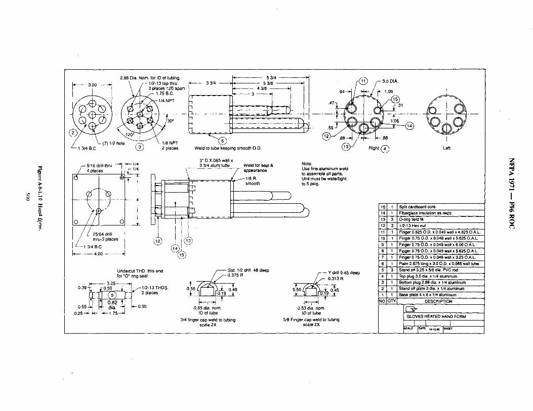
."3.
2.88 Dia. Nora. for ID of tubing 3.00 ~ ~ 1 / 2 - 1 3 tap thru
3 places 120 apart ~ 1.75 B.C.
L (7)1/2 hole ~ ~-1/8 NPT - 1 3/4 B,C. ~ 2 places
5 3/4 J' 33/4 - - ~ ~ 53/8 ~'l
7 7 7 ~,----~ 3 ~ _ ~
Weld to tube keeping smooth O.D,
3" 0.X.065 wall x
.94
/ - - 5/16 drill thru ~ ~ 1/4 3 3/4 alum tube Weld for seal & Note: l l ~ _ _ I / / p p e a r a n c e Use fine aluminum weld
to assemble all parts. ( ~ 4 p~aces J9
/ thru-3p,acas @ L__ 1 3/4 B.C.
4.00
Undercut THD. this end for "O" ring seal
3 . 2 5 ~ 0.39 ~, 0.50~L9.....~i I, /-t/2-13 THDS
2place°
0,25 -~ ~ ~ 1,75 - '~
/ - - - Std. 1/2 drill 148 deep .375 R
o.,56 LV"'-I~-I- o.48 ,
0.85 din. nom. ID o1 tube
3/4 finger cap weld to tubing scale 2X
Y drill 0.45 deep
0.53 dia. nora. ID of tube
5/8 Finger cap weld to tubing scale 2X
I .Y?.oT
.31
"- t - - ~ - - - -
~ - ~ .88 ~
Right ( ~
t Left
15 f 14 1
13 3,,, 12 3 11 1 10 1 9 1
8 1
7 1 6 I
5 3 4 1
3 1 2 1 1 1
~o,i QTYI
Split cardboard core Fiberglass insulation as req'd ., O-ring field fit 1/2-13 Hex nut Finger 0.625 O. D. x 0'.049 wall x 4.625 O.A.L Finger 0.75 O.D. x 0.049 wall x 51625 O.A.L. Finger 0.75 O.D. x 0.049 wall x 6.00 O.A.L. f~og,et 0.75 O.D. x 0.049 wall x 5.625 O.A.L. Finger 0.75 O.O. x 0.049 waft x 3.25 O.A,L Palm 2.875 Iong x 3.0.O,D, xO.065 wail tube Stand off 3.25 x 5/8 dia. PVC rod Top plug 3.0 die. 'x 1/4 aluminum Bottom plug 2.88 dia. x 1/4 aluminum' Stand off ~ate 3 dia. x 1/4 aluminum Base plata 4 x 4 x 1/4 aluminum
DESCRIPTION
GLOVES HEATED HAND FORM
. . . . . I °" ' - " 1""
Z
I
NFPA 1971 - - F96 ROC
A-6-16.4.8 Open blue or green modular elastomer programmers, awdlable from United States Testing Company, 291 Fairfield Avenue, Fairfield, NJ 07004, have been found to be suitable reference anvils.
A-6-16.4.9 Calibration Procedures. The following mnltiple-step calibration should be u~d:
Pr,Jcedure 1: Medium and System Calibration. This calibration step should he carried out using a guided-fall system with an accelerometer mounted in the drop ,assembly and a load cell mounted under the reference anvil. The load cell shonld be mounted in compliance with the requirements of 6-15.4.3 through 6- 15.4.8. The drop as~mbly should be d ropped onto the reference mwil from a height that yields a peak acceleration of 400 Gn ±20 Gn and accelerations above 200 Gn of at least 1 millisecond duration. A means of verifying the impact velocity within 2 percent should be utilized. The measured peak perfi)rmance should equal (within 2 percent) the measured peak acceleration (in g's) times the weight of the drop assembly. This accuracy should be repeatable through at le:~st five impacts.
Procedure 2: Electronics Verification. When in use, electronic verification of the normally used instrumentation scales should be undertaken at least weekly. Tiffs should be accomplished by !ollowing the. pr,)cedures recouunended by the manufacturer of the I n s t r t l n l e rl t a t l Ot ' l .
A-6-17.4.1.3 This prevents missile ramble, helps to protect the operator if the tithe extends to within a short distance of the device being tested, and allows the exact room necessary for insertion of the missile :it the top. Partial shielding of the head.form might be advisable to protect the operator 's feet.
A-6-17.5.1.1 The steel balls move at dangerous speeds, and other t0rms of s:ffety devices, such as interlocks and palm switches, might be desirable in a particular setup.
A-6-22.4.6 A practical, easy tx~ use technique for achieving this control utilizes a reference material withknown cut resistmlce. For example, the following vinyl tapes manufactured by the 3M (k)mpany, or their equivalents, c,'m be used:
Table A-fi-22.4.6 Tape Identification, Minimum Weight for Cut
No. 470 White vinyl tape 10 Ib (4.5 kg) No. 472 Black vinyl tape 12 Ib (5.4 kg)
A-6-28.4.2 Aqueous fi lm4orming fixun of 3 percent concentration is available from 3M Fire Protection Systems, Commercial Chemicals Division, St. Paul, MN 55144. Fire-resistant hydraulic fluid is available from Jaws of Life Rescue System, products o f Hale Fire Pump ( ~ " . i': mpany, 7000 Spnng Mdl Avenue, (_~nshohocken, PA 19428 [ (215)-825-6300]. A representative swimming pool chlorinating chemical containing a 65 percent tree chlorine ~sock-R" is available from HTH (%emic:ds, Olin Water Products and Services, Olin (k)rporation, 120 Long Ridge Road, Stamford, CT 06904.
A-6-33.4.1 An example of an inner glove fabric is a lightweight, tightly woven (e.g.. 2.2 ox/yd, 92 x 88), medium- or dark-colored, 100-percent polyester t#tbric without surface treatment.
A-6-33.5.3 A 0.1 weight percent solution ofSurfynol 104H (available from Air Products and Chemicals, Inc., Performance Chemicals, Box 538, Allentown, PA 18105) with water is reported to provide a surface tension of 33.8 dynes/cm.
A-6-34.4.3 A 0.1 weight percent of Surfynol 104H (available from Air Products :rod Chemicals, Inc., Performance Chemicals, Box 538, Allen town ~, PA 18105) with water is reported to provide a snrface tension of 33.8 dynes/cm.
A-6-45.5.1 The Gardner pivotal sphere hazemeter is described in A,STM D 1003, Test Mettwd for Haze and Luminous Transmittance of Transparent Pla,~tics.
A-6-48.4.1 A 0.1 weight percent ofSurfonyl 104H (available from Air Products :rod Chemical,Jnc.. Performance Chemicals, Box 538, Allentown, PA 18105) with water is reported to provide a surface tension of 33.8 dynes/cm.
#.-6-48.5.1 A heavy, flat meted plate with two upright threaded posts, large slotted metal bar, and heavy-duty metal bolts is a preferred means fi)r mounting the mannequin in the spray chamber to prevent rely effects of the mmmeqnin mounting on the clothing specimen.
A-6-48.6.1 The attthority having jurisdiction can request a diagnosis of the mechanism of failure.
Appendix B Referenced Publications
B-I T h e following documents or portions thereof are referenced within this standard for informational purposes only and thus are not considered part of the reqnirements of this documenu The edition indicated for each reference is the current edition ,as of the date of the NFPA issnance of this docnment .
B-I.1 NFPA Publications. National Fire Protection Association, 1 Batterymarch Park, P.O. Box 9101, Quincy, MA 02269-9101.
NFPA 1500, Starwlard on Fire Department Occupational Safe~. and Health Program, 1992 edition.
NFPA 1973, Stamtard on Glovea" for Structural Fire Fighting, 1993 edition.
NFPA 1975, Standard on Station/Work Uniforms for Fire Fighters, 1994 edition.
NFPA 1992, Standard on Li~luid Splash-Protective Suits for Hazardous Ch~vnicalErn~gencies, 1994 edition.
NFPA 1999, Stamtard on Protective Clothing for Emergen~ Medical Operations, 1992 edition.
B-1.2 Other Publications.
B-1.2.1 ANSI Publication. American National Standards Institnte, 11 West 42nd Street, New York, NY 10036.
ANSI Z87.1, Occupational and Educational Eye and Face Protection, 1989.
ANSI Z535.4, Standard for Product Safe~ Signs and Labels, 1991. I
B~1.2.2 ASTM Publication. American Society for Testing and Materials, 1916 Race Street, Philadelphia, PA 19013.
ASTM D 471, Standard Test Method for Rubber ProperO. - - Effect of Liquids, 1991.
ASTM 1") 1003, Standard Test Method for Haze arwl Luminous Transmit- taru'~ of Transparent Plastica, 1988.
ASTM F) 1518, Test Method for Thermal Transmittance of Textile Materials, 1985.
ASTM F 903, Standard Test Method for Resistance of Protective Clothing Materials to Penetration by. Liquids, 1990.
ASTM F 1001, Standard (bride for Selection of Chemicals to Evaluate Protective Clothing Materials, 1989.
B-1.2.3 GSA Publication. General Services Administration, Specifications Activity, Printed Materials Supply Division, Building 197, Naval Weapons Plant, Washington, DC 20407.
Federal Test Method Standard 191A, Textile Test Methods, July 20, 1978.
B-1.2.4 NIOSH Publications.
NIOSH Publication 77-134-A, The Development of Criteria for Firefighters' Gloves, Vol. 1, 1976..
NIOSH Publication 77-134-B, Glove Requirements, Vol. 2, 1976.
B-1.2.5 U.S. Government Publication. Super intendent of Docu- ments, U.S. Government Printing Office, Washington, I)C 20402.
Title 29, Code of Federal Regulations, Part 1910, Section 133 (29 C$'R 1910.133); "Eye and Face Protection," July 1, 1987.
B-1.2.6 Simms, D. L. and P. L. Hinkley, Part 1 O, The Effect of Water on Clothing, Suitable for Clothing Aircraft Fire Crash Rescue Workers, F. R. Note 366, Fire Research Station, BorehamWood, Herts, England, 1959.
510