Embed Size (px)
Citation preview

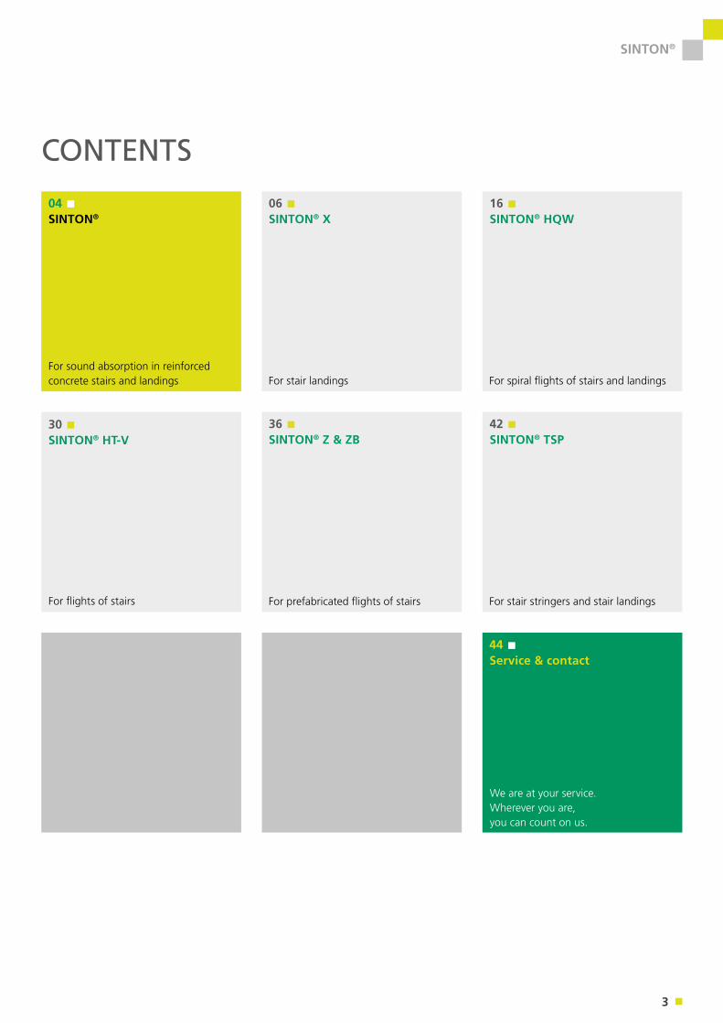
For sound absorption in reinforced concrete stairs and landings
SINTON®
Sealing Thermal insulation Formwork Sound insulation Reinforcement Connection Accessories

2
SINTON®
OUR MISSION: FORWARD CONSTRUCTING.
Not just to reflect the current state of building technology, but always to be a decisive step ahead – this is our promise. This is why we constantly achieve pioneering work in all prod-uct areas. Our employees consistently use their extensive practical experience and creativity to benefit our customers. Through regular collaborative dialogue with our target groups, we develop today the products which are needed tomorrow. With our dynamics we set consistently milestones in building technology – yesterday, today and tomorrow. This is what we mean by Forward Constructing.
3
SINTON®
CONTENTS
For sound absorption in reinforced concrete stairs and landings
04 SINTON®
06 SINTON® X
16 SINTON® HQW
30 SINTON® HT-V
44 Service & contact
We are at your service. Wherever you are, you can count on us.
For stair landings For spiral flights of stairs and landings
For flights of stairs
36 SINTON® Z & ZB
42 SINTON® TSP
For prefabricated flights of stairs For stair stringers and stair landings
4
SINTON®
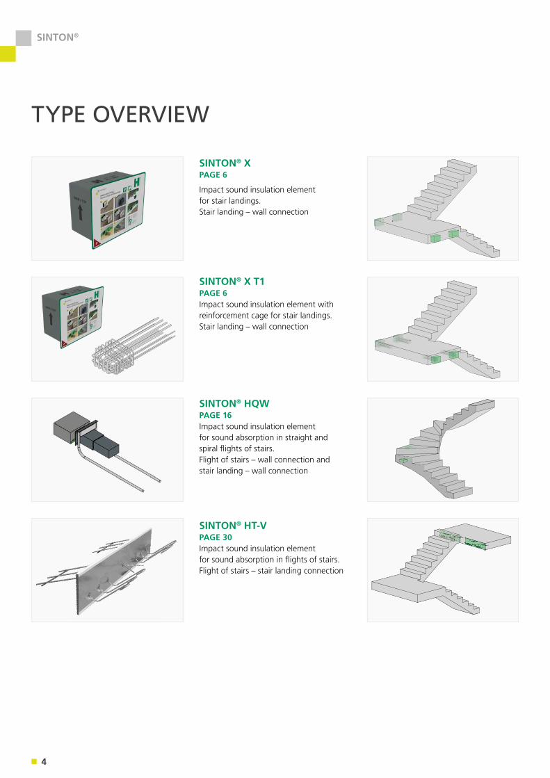
SINTON® XPAGE 6
Impact sound insulation element for stair landings. Stair landing – wall connection
SINTON® X T1PAGE 6Impact sound insulation element with reinforcement cage for stair landings. Stair landing – wall connection
SINTON® HQW PAGE 16Impact sound insulation element for sound absorption in straight and spiral flights of stairs. Flight of stairs – wall connection and stair landing – wall connection
TYPE OVERVIEW
SINTON® HT-V PAGE 30Impact sound insulation element for sound absorption in flights of stairs. Flight of stairs – stair landing connection
5
SINTON®
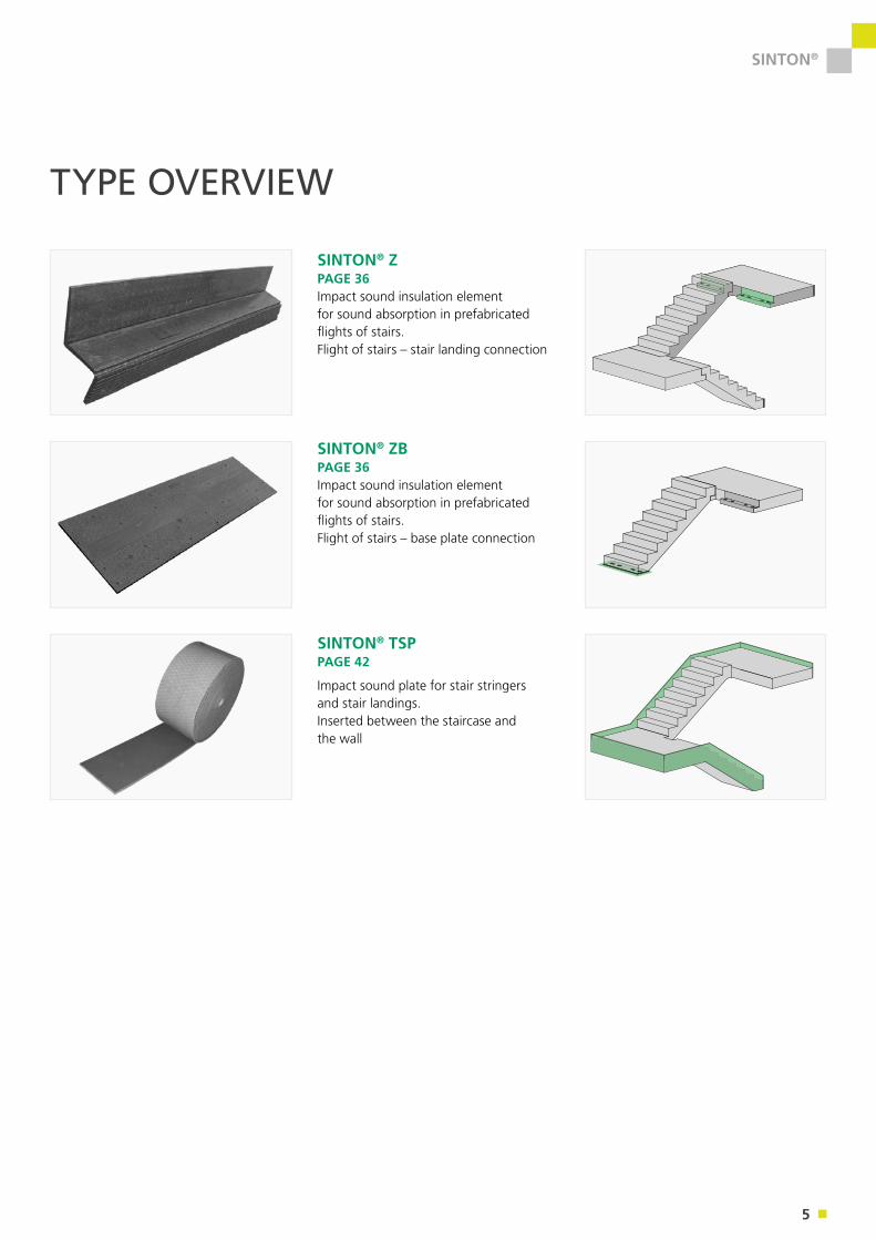
SINTON® Z PAGE 36Impact sound insulation element for sound absorption in prefabricated flights of stairs. Flight of stairs – stair landing connection
SINTON® ZB PAGE 36 Impact sound insulation element for sound absorption in prefabricated flights of stairs. Flight of stairs – base plate connection
SINTON® TSP PAGE 42
Impact sound plate for stair stringers and stair landings. Inserted between the staircase and the wall
TYPE OVERVIEW
6
SINTON® X
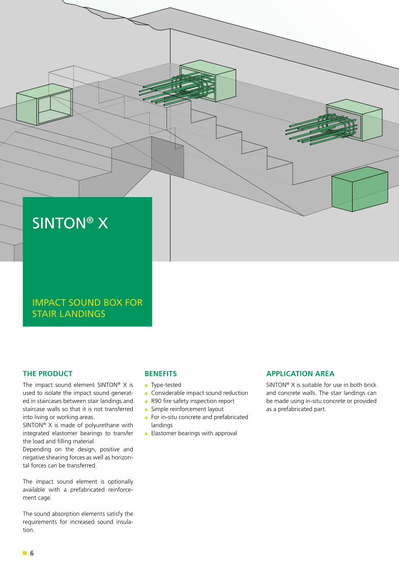
THE PRODUCTThe impact sound element SINTON® X is used to isolate the impact sound generat-ed in staircases between stair landings and staircase walls so that it is not transferred into living or working areas. SINTON® X is made of polyurethane with integrated elastomer bearings to transfer the load and filling material. Depending on the design, positive and negative shearing forces as well as horizon-tal forces can be transferred.
The impact sound element is optionally available with a prefabricated reinforce-ment cage.
The sound absorption elements satisfy the requirements for increased sound insula-tion.
APPLICATION AREASINTON® X is suitable for use in both brick and concrete walls. The stair landings can be made using in-situ concrete or provided as a prefabricated part.
BENEFITS▪ Type-tested▪ Considerable impact sound reduction▪ R90 fire safety inspection report▪ Simple reinforcement layout▪ For in-situ concrete and prefabricated landings
▪ Elastomer bearings with approval
SINTON® X
IMPACT SOUND BOX FOR STAIR LANDINGS
7
SINTON® X
Stair landing
SINTON® X
SINTON® X
SINTON® X
SINTON® XFlight of stairs
Flight of stairsFlight of stairs
Stair landing
SINTON® TSP PL peripheral impact sound plateFlight of stairs and landings
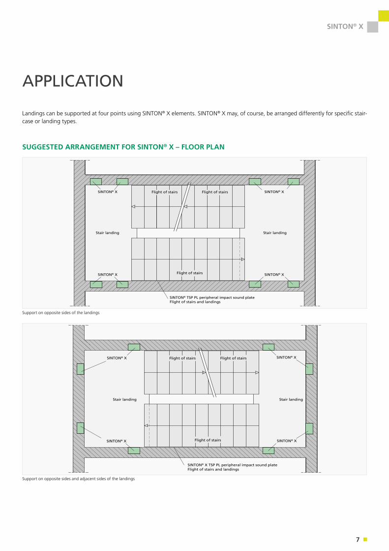
SUGGESTED ARRANGEMENT FOR SINTON® X – FLOOR PLAN
Stair landing
SINTON® X
SINTON® X
SINTON® X
SINTON® XFlight of stairs
Flight of stairsFlight of stairs
Stair landing
SINTON® X TSP PL peripheral impact sound plateFlight of stairs and landings
Landings can be supported at four points using SINTON® X elements. SINTON® X may, of course, be arranged differently for specific stair-case or landing types.
Support on opposite sides of the landings
Support on opposite sides and adjacent sides of the landings
APPLICATION
8
SINTON® X
PRODUCT OVERVIEW
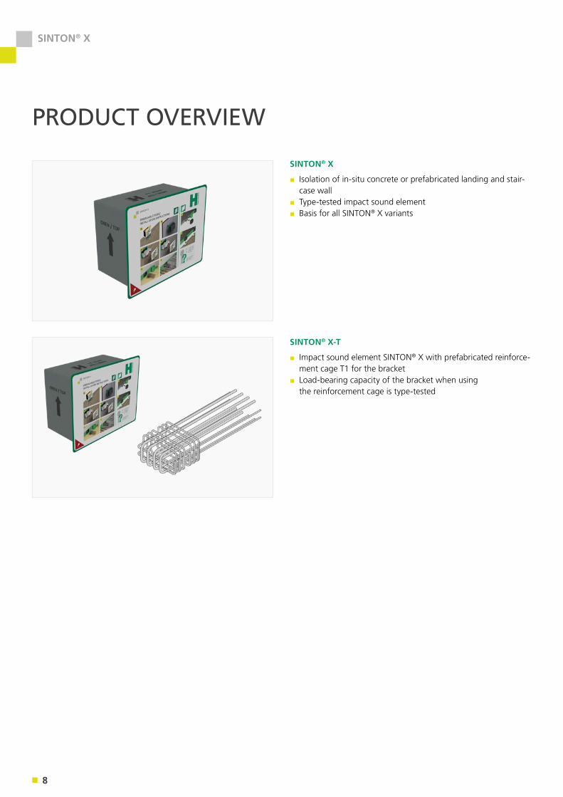
SINTON® X
▪ Isolation of in-situ concrete or prefabricated landing and stair-case wall
▪ Type-tested impact sound element▪ Basis for all SINTON® X variants
SINTON® X-T
▪ Impact sound element SINTON® X with prefabricated reinforce-ment cage T1 for the bracket
▪ Load-bearing capacity of the bracket when using the reinforcement cage is type-tested
9
SINTON® X
APPLICATION – ELEMENT CONSTRUCTION
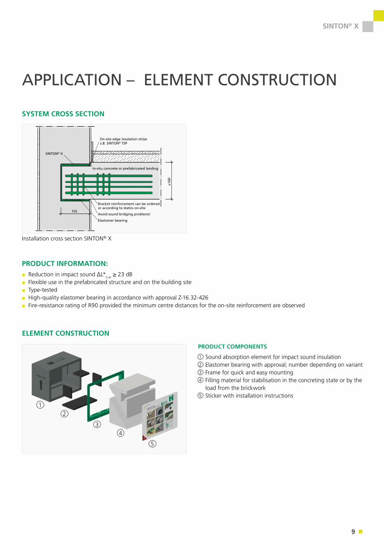
SYSTEM CROSS SECTION
155
≥160
SINTON Typ TSB-F
Randdämmstreifen bauseitsz.B. SINTON TSP
Elastomerlager
Fertigteilpodest
Schallbrücke vermeiden!
Konsolenbewehrung nach Statik bauseits
Elastomer bearing
Avoid sound bridging problems!
Bracket reinforcement can be ordered or according to statics on-site
Elastomerlager
Schallbrücke vermeiden!
Konsolenbewehrung im Betonwürfel
155
≥160
SINTON® X
On-site edge insulation stripsz.B. SINTON® TSP
In-situ concrete or prefabricated landing
155
≥160
ISOBOX® Typ TSB-BT
Randdämmstreifen bauseitsz.B. Trittschallplatte TSP
Podest
155
≥160
SINTON Typ TSB-MB
Randdämmstreifen bauseitsz.B. SINTON TSP
Elastomerlager
Ortbetonpodest
Schallbrücke vermeiden!
Konsolenbewehrung nach Statik bauseits
Installation cross section SINTON® X
PRODUCT INFORMATION:▪ Reduction in impact sound ΔL*n,w ≥ 23 dB▪ Flexible use in the prefabricated structure and on the building site▪ Type-tested▪ High-quality elastomer bearing in accordance with approval Z-16.32-426▪ Fire-resistance rating of R90 provided the minimum centre distances for the on-site reinforcement are observed
12
34
5
1
2
3
4
5
ELEMENT CONSTRUCTION
PRODUCT COMPONENTS
Sound absorption element for impact sound insulationElastomer bearing with approval; number depending on variantFrame for quick and easy mountingFilling material for stabilisation in the concreting state or by the load from the brickworkSticker with installation instructions
10
SINTON® X
PRODUCT DEFINITION
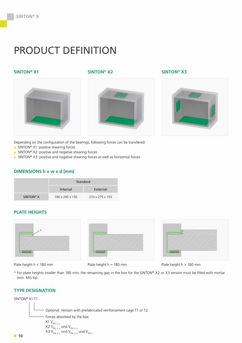
SINTON® X1 SINTON® X2 SINTON® X3
Depending on the configuration of the bearings, following forces can be transfered:▪ SINTON® X1: positive shearing forces▪ SINTON® X2: positive and negative shearing forces▪ SINTON® X3: positive and negative shearing forces as well as horizontal forces
DIMENSIONS h x w x d [mm]
Standard
Internal External
SINTON® X 180 x 245 x 150 210 x 275 x 155
TYPE DESIGNATION
SINTON® X1-T1
Optional: Version with prefabricated reinforcement cage T1 or T2
Forces absorbed by the boxX1 VRd, z, u
X2 VRd, z, u und VRd, z, o
X3 VRd, z, u und VRd, z, o und VRd, x
PLATE HEIGHTS
Plate height h < 180 mm Plate height h = 180 mm Plate height h > 180 mm
* For plate heights smaller than 180 mm, the remaining gap in the box for the SINTON® X2 or X3 version must be filled with mortar (min. MG IIa).
*
11
SINTON® X
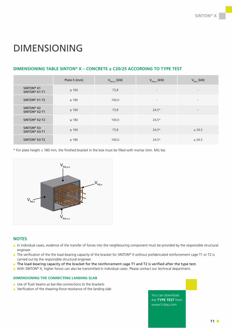
DIMENSIONING
DIMENSIONING TABLE SINTON® X – CONCRETE ≥ C20/25 ACCORDING TO TYPE TEST
* For plate height < 180 mm, the finished bracket in the box must be filled with mortar (min. MG IIa).
VRd,z,o
VRd,x
VRd,z,u
VRd,x
NOTES ▪ In individual cases, evidence of the transfer of forces into the neighbouring component must be provided by the responsible structural engineer.
▪ The verification of the the load-bearing capacity of the bracket for SINTON® X without prefabricated reinforcement cage T1 or T2 is carried out by the responsible structural engineer.
▪ The load-bearing capacity of the bracket for the reinforcement cage T1 and T2 is verified after the type test.▪ With SINTON® X, higher forces can also be transmitted in individual cases. Please contact our technical department.
DIMENSIONING THE CONNECTING LANDING SLAB
▪ Use of flush beams as bar-like connections to the brackets▪ Verification of the shearing-force resistance of the landing slab
You can download the TYPE TEST fromwww.h-bau.com
Plate h [mm] VRd,z,u [kN] VRd,z,o [kN] VRd,x [kN]
SINTON® X1SINTON® X1-T1 ≥ 160 73,8 - -
SINTON® X1-T2 ≥ 180 100,0 - -
SINTON® X2SINTON® X2-T1 ≥ 160 73,8 24,5* -
SINTON® X2-T2 ≥ 180 100,0 24,5*
SINTON® X3SINTON® X3-T1 ≥ 160 73,8 24,5* ± 24,5
SINTON® X3-T2 ≥ 180 100,0 24,5* ± 24,5
12
SINTON® X
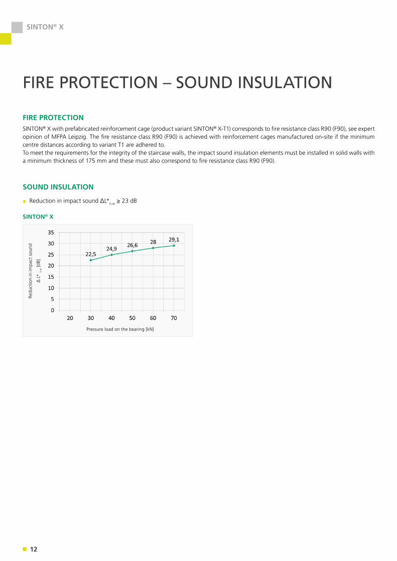
FIRE PROTECTION – SOUND INSULATION
FIRE PROTECTIONSINTON® X with prefabricated reinforcement cage (product variant SINTON® X-T1) corresponds to fire resistance class R90 (F90), see expert opinion of MFPA Leipzig. The fire resistance class R90 (F90) is achieved with reinforcement cages manufactured on-site if the minimum centre distances according to variant T1 are adhered to.To meet the requirements for the integrity of the staircase walls, the impact sound insulation elements must be installed in solid walls with a minimum thickness of 175 mm and these must also correspond to fire resistance class R90 (F90).
SOUND INSULATION
▪ Reduction in impact sound ΔL*n,w ≥ 23 dB
SINTON® X
Pressure load on the bearing [kN]
Redu
ctio
n in
impa
ct s
ound
∆ L
* n,
w [d
B]
13
SINTON® X
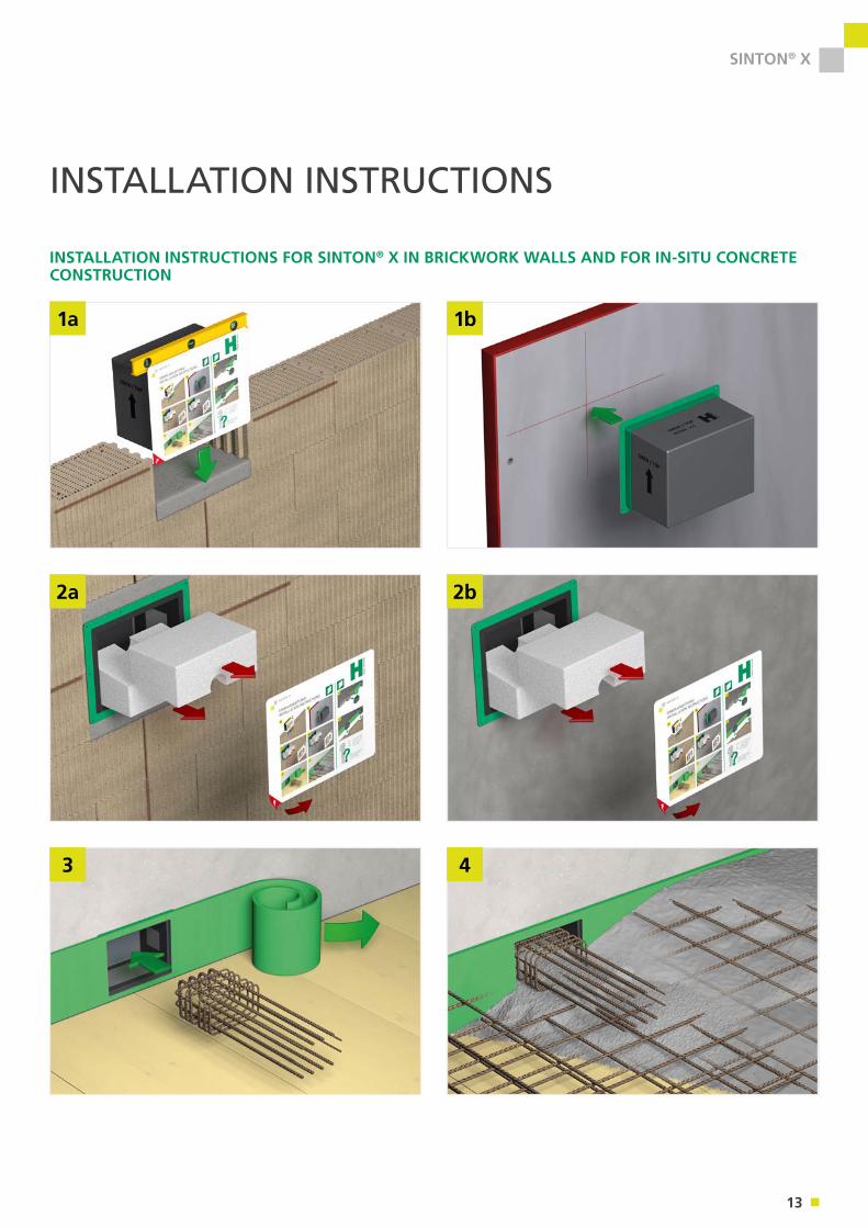
INSTALLATION INSTRUCTIONS
INSTALLATION INSTRUCTIONS FOR SINTON® X IN BRICKWORK WALLS AND FOR IN-SITU CONCRETE CONSTRUCTION
1a 1b
2a 2b
3 4
14
SINTON® X
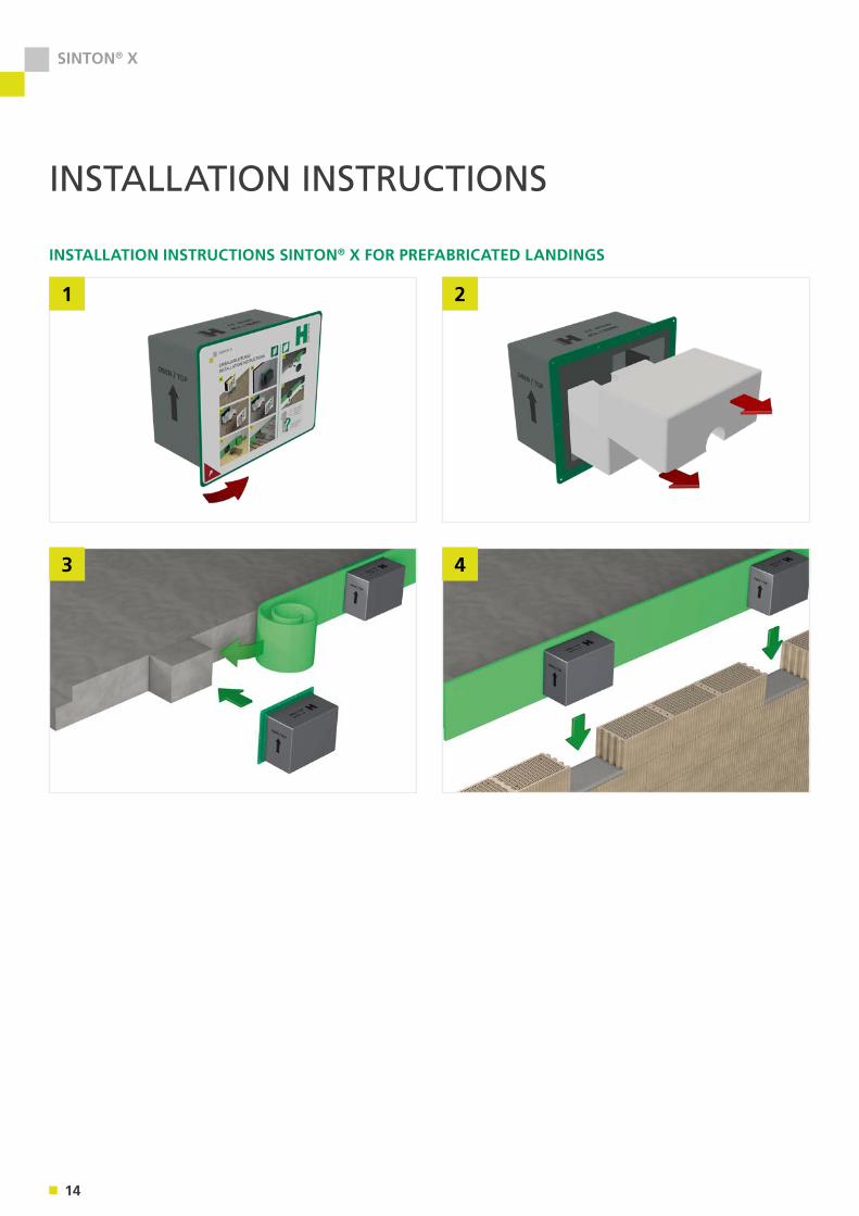
INSTALLATION INSTRUCTIONS
INSTALLATION INSTRUCTIONS SINTON® X FOR PREFABRICATED LANDINGS
1 2
3 4

15
SINTON® HQW
16
SINTON® HQW
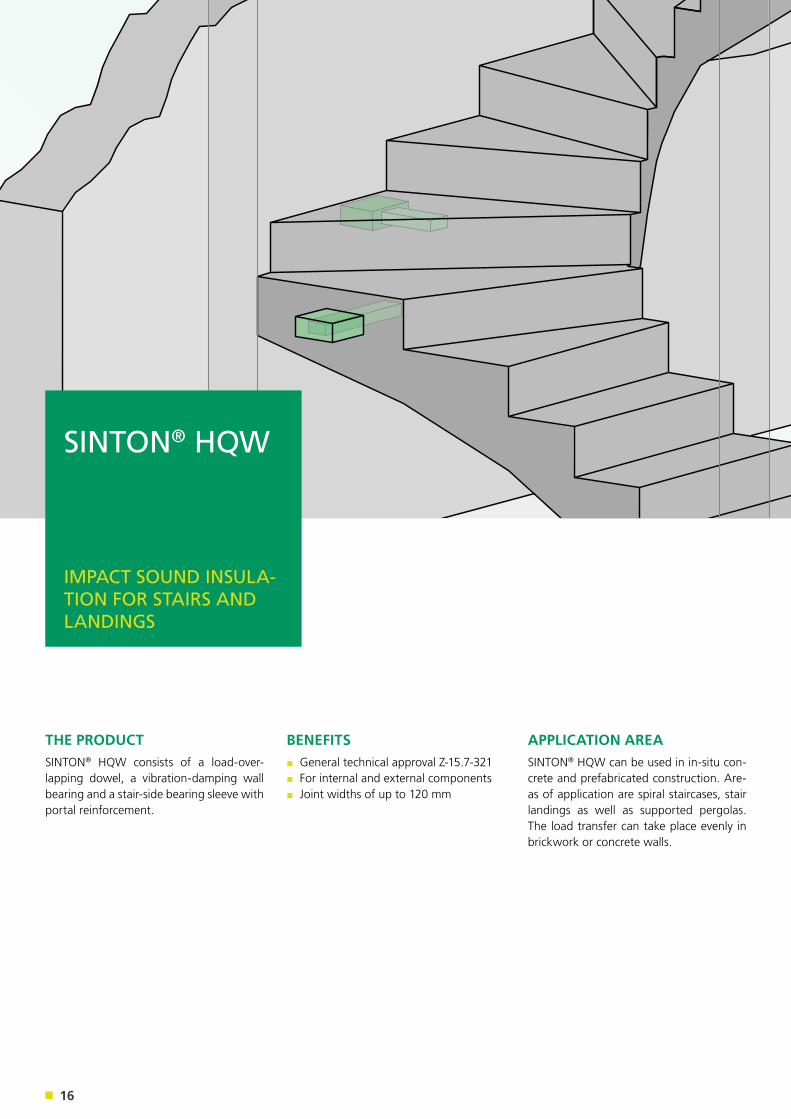
THE PRODUCTSINTON® HQW consists of a load-over-lapping dowel, a vibration-damping wall bearing and a stair-side bearing sleeve with portal reinforcement.
APPLICATION AREASINTON® HQW can be used in in-situ con-crete and prefabricated construction. Are-as of application are spiral staircases, stair landings as well as supported pergolas. The load transfer can take place evenly in brickwork or concrete walls.
BENEFITS▪ General technical approval Z-15.7-321▪ For internal and external components ▪ Joint widths of up to 120 mm
SINTON® HQW
IMPACT SOUND INSULA-TION FOR STAIRS AND LANDINGS
17
SINTON® HQW
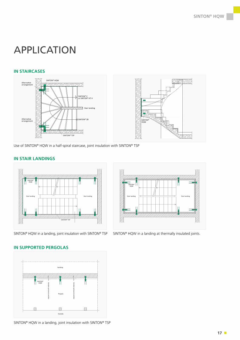
APPLICATION
Alternative arrangement
Alternative arrangement
Stair landing
IN STAIRCASES
SINTON® HQW
SINTON® Zor SINTON® HT-V
SINTON® ZB
SINTON® TSP
SINTON® HQW
Use of SINTON® HQW in a half-spiral staircase, joint insulation with SINTON® TSP
SINTON® HQW in a landing, joint insulation with SINTON® TSP SINTON® HQW in a landing at thermally insulated joints.
IN STAIR LANDINGS
SINTON® HQW
SINTON® TSP
SINTON® HQW
Stair landing Stair landing Stair landing Stair landing
SINTON® HQW in a landing, joint insulation with SINTON® TSP
IN SUPPORTED PERGOLAS
SINTON® HQW
Building
Pergola
tension-pressure anchor
tension-pressure anchor
Outside
18
SINTON® HQW
PRODUCT OVERVIEW
PRODUCT COMPONENTS
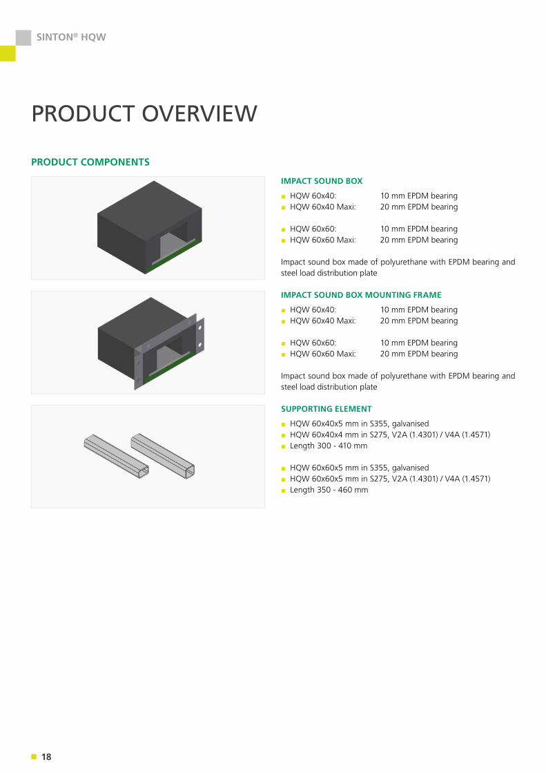
IMPACT SOUND BOX
▪ HQW 60x40: 10 mm EPDM bearing▪ HQW 60x40 Maxi: 20 mm EPDM bearing
▪ HQW 60x60: 10 mm EPDM bearing▪ HQW 60x60 Maxi: 20 mm EPDM bearing
Impact sound box made of polyurethane with EPDM bearing and steel load distribution plate
SUPPORTING ELEMENT
▪ HQW 60x40x5 mm in S355, galvanised▪ HQW 60x40x4 mm in S275, V2A (1.4301) / V4A (1.4571)▪ Length 300 - 410 mm
▪ HQW 60x60x5 mm in S355, galvanised▪ HQW 60x60x5 mm in S275, V2A (1.4301) / V4A (1.4571)▪ Length 350 - 460 mm
IMPACT SOUND BOX MOUNTING FRAME
▪ HQW 60x40: 10 mm EPDM bearing▪ HQW 60x40 Maxi: 20 mm EPDM bearing
▪ HQW 60x60: 10 mm EPDM bearing▪ HQW 60x60 Maxi: 20 mm EPDM bearing
Impact sound box made of polyurethane with EPDM bearing and steel load distribution plate
19
SINTON® HQW
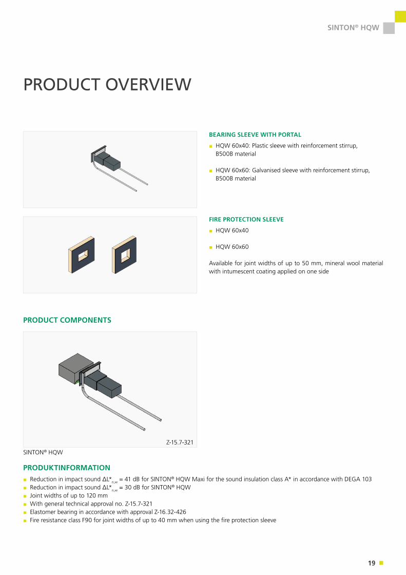
BEARING SLEEVE WITH PORTAL
▪ HQW 60x40: Plastic sleeve with reinforcement stirrup, B500B material
▪ HQW 60x60: Galvanised sleeve with reinforcement stirrup, B500B material
FIRE PROTECTION SLEEVE
▪ HQW 60x40
▪ HQW 60x60
Available for joint widths of up to 50 mm, mineral wool material with intumescent coating applied on one side
PRODUCT OVERVIEW
PRODUCT COMPONENTS
SINTON® HQW
Z-15.7-321
PRODUKTINFORMATION▪ Reduction in impact sound ΔL*n,w = 41 dB for SINTON® HQW Maxi for the sound insulation class A* in accordance with DEGA 103▪ Reduction in impact sound ΔL*n,w = 30 dB for SINTON® HQW▪ Joint widths of up to 120 mm▪ With general technical approval no. Z-15.7-321▪ Elastomer bearing in accordance with approval Z-16.32-426 ▪ Fire resistance class F90 for joint widths of up to 40 mm when using the fire protection sleeve
20
SINTON® HQW
DIMENSIONS
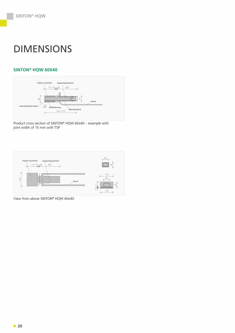
SINTON® HQW 60X40
Product cross section of SINTON® HQW 60x40 – example with joint width of 15 mm with TSP
View from above SINTON® HQW 60x40
Impact sound box Supporting element
Load distribution plateEPDM bearing
Bearing sleeve
Portal
Impact sound box Supporting element
Portal
21
SINTON® HQW
DIMENSIONS
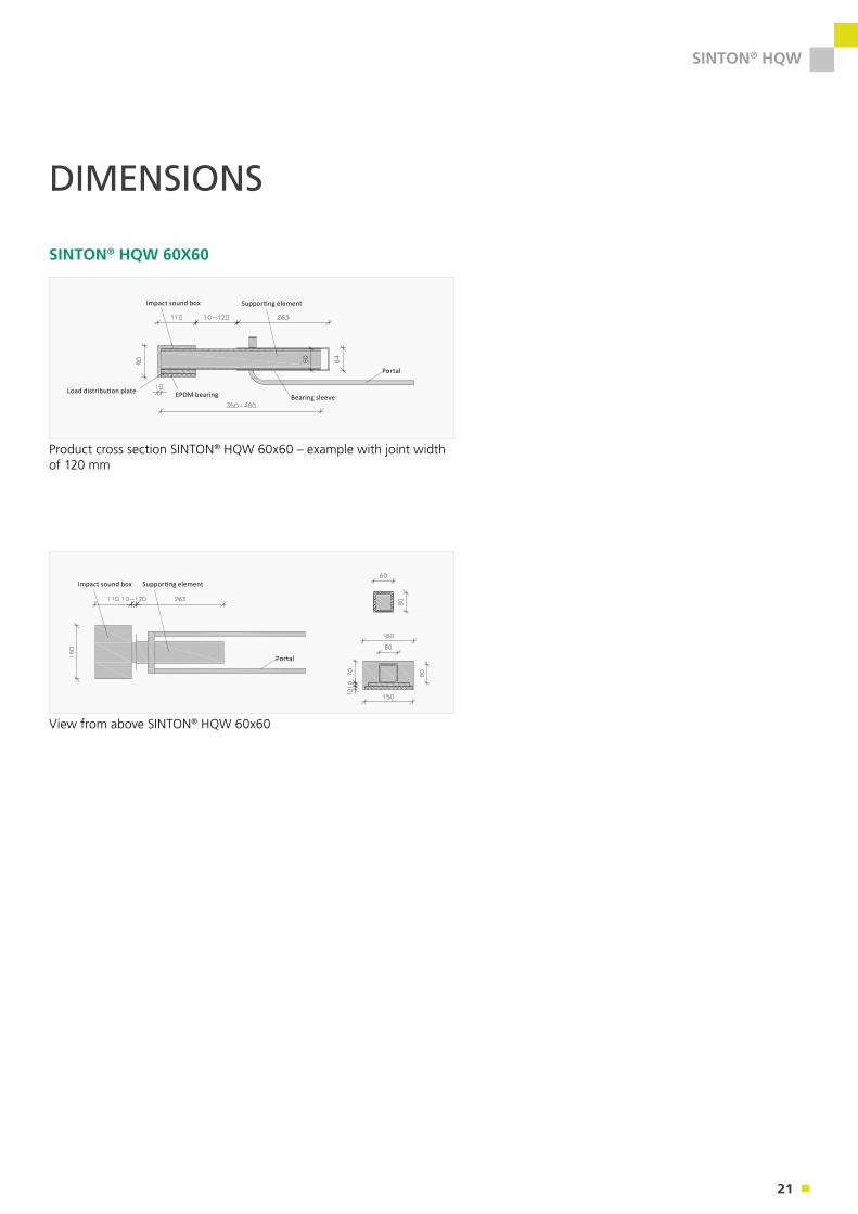
SINTON® HQW 60X60
Product cross section SINTON® HQW 60x60 – example with joint width of 120 mm
View from above SINTON® HQW 60x60
Impact sound box Supporting element
Load distribution plate EPDM bearing Bearing sleeve
Portal
Impact sound box Supporting element
Portal
22
SINTON® HQW
SINTON® HQW 60x40 HQW 60x60
Joint width f [mm]
Dowel length l [mm]
HQW 60x40x5 S 355 VZ
HQW 60x40x4 S 275 V2A / V4A
Dowel length l [mm]
HQW 60x60x5 S 355 VZ
HQW 60x60x5 S 275 V2A / V4A
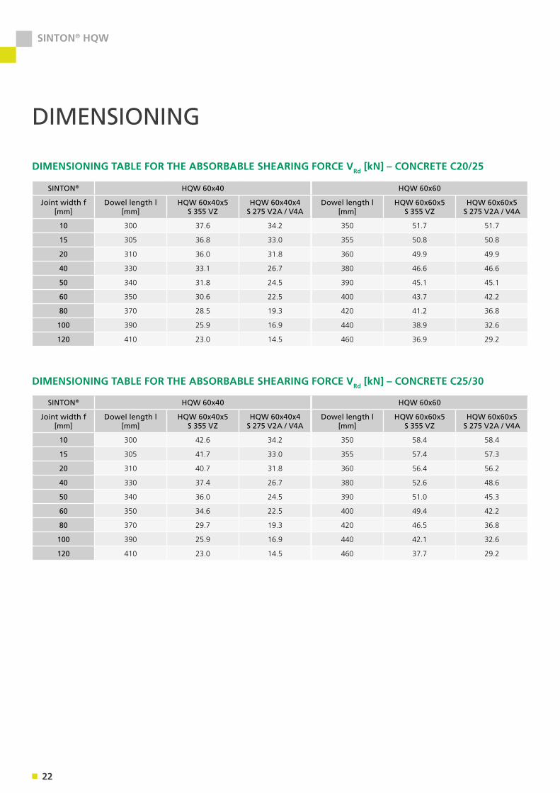
10 300 37.6 34.2 350 51.7 51.7
15 305 36.8 33.0 355 50.8 50.8
20 310 36.0 31.8 360 49.9 49.9
40 330 33.1 26.7 380 46.6 46.6
50 340 31.8 24.5 390 45.1 45.1
60 350 30.6 22.5 400 43.7 42.2
80 370 28.5 19.3 420 41.2 36.8
100 390 25.9 16.9 440 38.9 32.6
120 410 23.0 14.5 460 36.9 29.2
DIMENSIONING
DIMENSIONING TABLE FOR THE ABSORBABLE SHEARING FORCE VRd [kN] – CONCRETE C20/25
SINTON® HQW 60x40 HQW 60x60
Joint width f [mm]
Dowel length l [mm]
HQW 60x40x5 S 355 VZ
HQW 60x40x4 S 275 V2A / V4A
Dowel length l [mm]
HQW 60x60x5 S 355 VZ
HQW 60x60x5 S 275 V2A / V4A
10 300 42.6 34.2 350 58.4 58.4
15 305 41.7 33.0 355 57.4 57.3
20 310 40.7 31.8 360 56.4 56.2
40 330 37.4 26.7 380 52.6 48.6
50 340 36.0 24.5 390 51.0 45.3
60 350 34.6 22.5 400 49.4 42.2
80 370 29.7 19.3 420 46.5 36.8
100 390 25.9 16.9 440 42.1 32.6
120 410 23.0 14.5 460 37.7 29.2
DIMENSIONING TABLE FOR THE ABSORBABLE SHEARING FORCE VRd [kN] – CONCRETE C25/30
23
SINTON® HQW
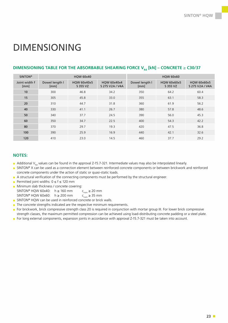
SINTON® HQW 60x40 HQW 60x60
Joint width f [mm]
Dowel length l [mm]
HQW 60x40x5 S 355 VZ
HQW 60x40x4 S 275 V2A / V4A
Dowel length l [mm]
HQW 60x60x5 S 355 VZ
HQW 60x60x5 S 275 V2A / V4A
10 300 46.8 34.2 350 64.2 60.4
15 305 45.8 33.0 355 63.1 58.3
20 310 44.7 31.8 360 61.9 56.2
40 330 41.1 26.7 380 57.8 48.6
50 340 37.7 24.5 390 56.0 45.3
60 350 34.7 22.5 400 54.3 42.2
80 370 29.7 19.3 420 47.5 36.8
100 390 25.9 16.9 440 42.1 32.6
120 410 23.0 14.5 460 37.7 29.2
DIMENSIONING TABLE FOR THE ABSORBABLE SHEARING FORCE VRd [kN] – CONCRETE ≥ C30/37
DIMENSIONING
NOTES:
▪ Additional VRd values can be found in the approval Z-15.7-321. Intermediate values may also be interpolated linearly.▪ SINTON® X can be used as a connection element between reinforced concrete components or between brickwork and reinforced concrete components under the action of static or quasi-static loads.
▪ A structural verification of the connecting components must be performed by the structural engineer.▪ Permitted joint widths: 0 ≤ f ≤ 120 mm▪ Minimum slab thickness / concrete covering: SINTON® HQW 60x40: h ≥ 160 mm cnom ≥ 20 mm SINTON® HQW 60x60: h ≥ 200 mm cnom ≥ 35 mm
▪ SINTON® HQW can be used in reinforced concrete or brick walls.▪ The concrete strengths indicated are the respective minimum requirements.▪ For brickwork, brick compressive strength class 20 is required in conjunction with mortar group III. For lower brick compressive strength classes, the maximum permitted compression can be achieved using load-distributing concrete padding or a steel plate.
▪ For long external components, expansion joints in accordance with approval Z-15.7-321 must be taken into account.
24
SINTON® HQW
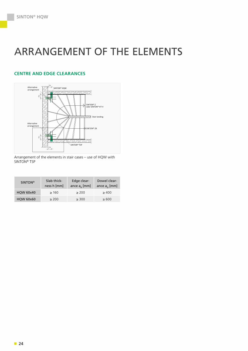
ARRANGEMENT OF THE ELEMENTS
Alternative arrangement
Stair landing
CENTRE AND EDGE CLEARANCES
Arrangement of the elements in stair cases – use of HQW with SINTON® TSP
SINTON® Zoder SINTON® HT-V
SINTON® ZB
SINTON® TSP
Alternative arrangement
SINTON® HQW
SINTON® Slab thick-ness h [mm]
Edge clear-ance aR [mm]
Dowel clear-ance aD [mm]
HQW 60x40 ≥ 160 ≥ 200 ≥ 400
HQW 60x60 ≥ 200 ≥ 300 ≥ 600
25
SINTON® HQW
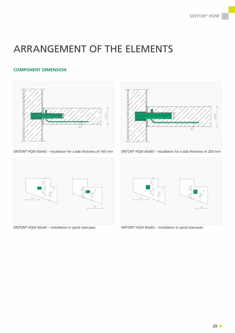
ARRANGEMENT OF THE ELEMENTS
COMPONENT DIMENSION
SINTON® HQW 60x40 – Installation for a slab thickness of 160 mm SINTON® HQW 60x60 – Installation for a slab thickness of 200 mm
SINTON® HQW 60x40 – Installation in spiral staircases SINTON® HQW 60x60 – Installation in spiral staircases
26
SINTON® HQW
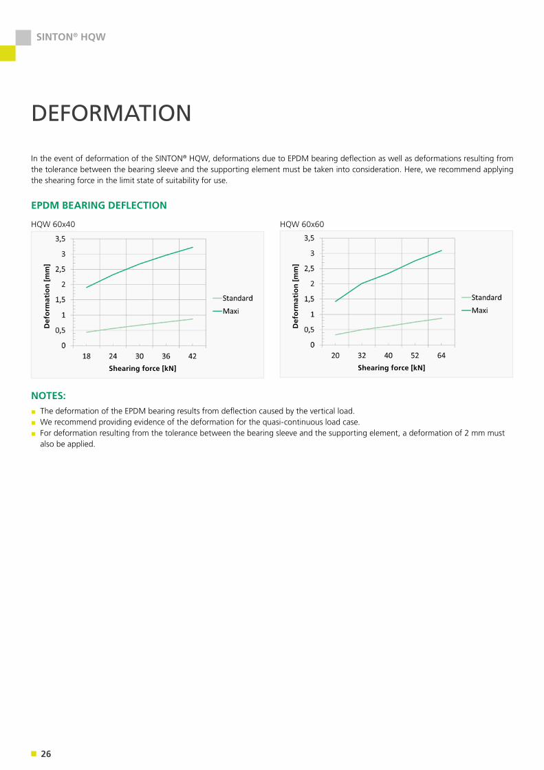
DEFORMATION
In the event of deformation of the SINTON® HQW, deformations due to EPDM bearing deflection as well as deformations resulting from the tolerance between the bearing sleeve and the supporting element must be taken into consideration. Here, we recommend applying the shearing force in the limit state of suitability for use.
EPDM BEARING DEFLECTION
HQW 60x40 HQW 60x60
NOTES:▪ The deformation of the EPDM bearing results from deflection caused by the vertical load.▪ We recommend providing evidence of the deformation for the quasi-continuous load case. ▪ For deformation resulting from the tolerance between the bearing sleeve and the supporting element, a deformation of 2 mm must also be applied.
Def
orm
atio
n [m
m]
Def
orm
atio
n [m
m]
Shearing force [kN] Shearing force [kN]
27
SINTON® HQW
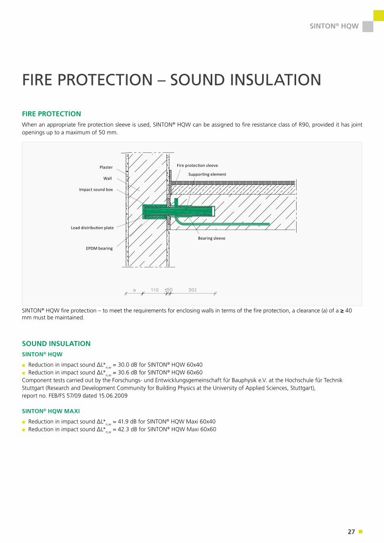
FIRE PROTECTION – SOUND INSULATION
FIRE PROTECTIONWhen an appropriate fire protection sleeve is used, SINTON® HQW can be assigned to fire resistance class of R90, provided it has joint openings up to a maximum of 50 mm.
SOUND INSULATIONSINTON® HQW
▪ Reduction in impact sound ΔL*n,w = 30.0 dB for SINTON® HQW 60x40 ▪ Reduction in impact sound ΔL*n,w = 30.6 dB for SINTON® HQW 60x60
Component tests carried out by the Forschungs- und Entwicklungsgemeinschaft für Bauphysik e.V. at the Hochschule für Technik Stuttgart (Research and Development Community for Building Physics at the University of Applied Sciences, Stuttgart), report no. FEB/FS 57/09 dated 15.06.2009
SINTON® HQW MAXI
▪ Reduction in impact sound ΔL*n,w = 41.9 dB for SINTON® HQW Maxi 60x40 ▪ Reduction in impact sound ΔL*n,w = 42.3 dB for SINTON® HQW Maxi 60x60
Wall
Plaster
Impact sound box
Load distribution plate
EPDM bearing
Fire protection sleeve
Supporting element
Bearing sleeve
SINTON® HQW fire protection – to meet the requirements for enclosing walls in terms of the fire protection, a clearance (a) of a ≥ 40 mm must be maintained.
28
SINTON® HQW
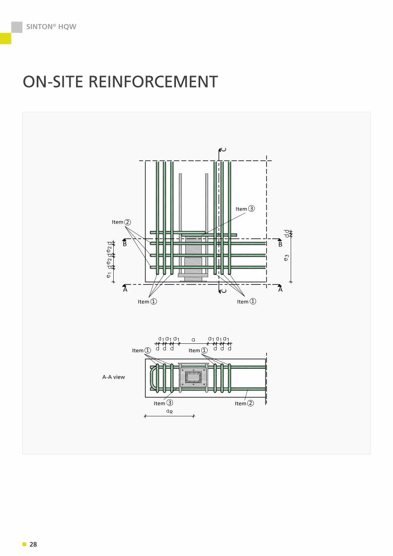
ON-SITE REINFORCEMENT
Item
Item
Item Item
Item Item
Item Item
A-A view
29
SINTON® HQW
SINTON® HQW
Dimensions and clearances Reinforcement
a [mm]
a1 [mm]
e1 [mm]
e2 [mm]
e3 [mm] d [mm] Item 1 Item 2 Item 3
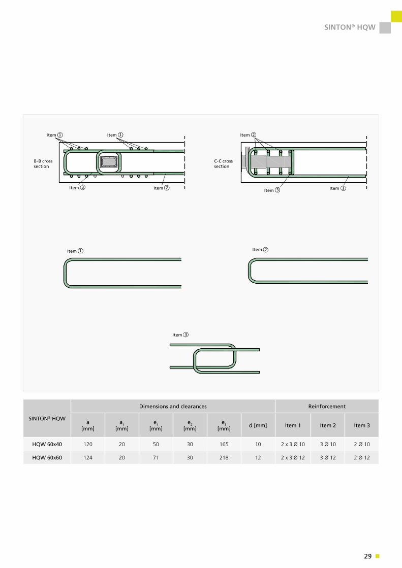
HQW 60x40 120 20 50 30 165 10 2 x 3 Ø 10 3 Ø 10 2 Ø 10
HQW 60x60 124 20 71 30 218 12 2 x 3 Ø 12 3 Ø 12 2 Ø 12
Item
B-B cross section
C-C cross section
Item
Item Item
Item Item
Item
Item
Item Item
30
SINTON® HT-V
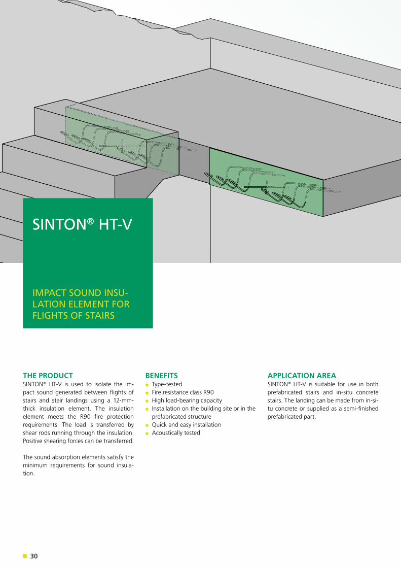
THE PRODUCTSINTON® HT-V is used to isolate the im-pact sound generated between flights of stairs and stair landings using a 12-mm-thick insulation element. The insulation element meets the R90 fire protection requirements. The load is transferred by shear rods running through the insulation. Positive shearing forces can be transferred.
The sound absorption elements satisfy the minimum requirements for sound insula-tion.
APPLICATION AREASINTON® HT-V is suitable for use in both prefabricated stairs and in-situ concrete stairs. The landing can be made from in-si-tu concrete or supplied as a semi-finished prefabricated part.
BENEFITS▪ Type-tested▪ Fire resistance class R90▪ High load-bearing capacity▪ Installation on the building site or in the prefabricated structure
▪ Quick and easy installation▪ Acoustically tested
SINTON® HT-V
IMPACT SOUND INSU-LATION ELEMENT FOR FLIGHTS OF STAIRS
31
SINTON® HT-V
Stair landing
Flight of stairs Flight of stairs
Stair landing
Flight of stairs
APPLICATION – PRODUCT OVERVIEW
APPLICATION
PRODUCT OVERVIEW
Stair landing
Flight of stairs
Stair landing
Flight of stairs
900 - 1600
1000 - 1600
Stair landing100 100 100 100 100 100 100 100
100 100 100 100 100 100
900 - 1600
100 100 100 100
Flight of stairs
Stair landing
Flight of stairs
Stair landing
Flight of stairs
900 - 1600
1000 - 1600
Stair landing100 100 100 100 100 100 100 100
100 100 100 100 100 100
900 - 1600
100 100 100 100
Flight of stairs
Stair landing
Flight of stairs
Stair landing
Flight of stairs
900 - 1600
1000 - 1600
Stair landing100 100 100 100 100 100 100 100
100 100 100 100 100 100
900 - 1600
100 100 100 100
Flight of stairs
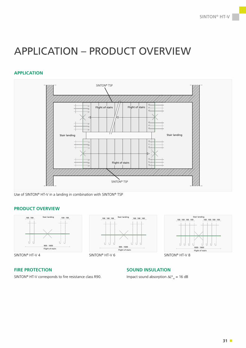
FIRE PROTECTIONSINTON® HT-V corresponds to fire resistance class R90.
SOUND INSULATIONImpact sound absorption L*w = 16 dB
SINTON® TSP
SINTON® TSP
Use of SINTON® HT-V in a landing in combination with SINTON® TSP
SINTON® HT-V 4 SINTON® HT-V 6 SINTON® HT-V 8
32
SINTON® HT-V
12
≥ 190
160
- 25
0
lb,net, hook
lb,net, straight
On-site reinforcement as per structural analysis
U-profile
U-profile Element length l
Insulating body F90
Insulating body F90
Horizontal rod Ø 6
Horizontal rod Ø 6
Shear rod Ø 6
Shear rod Ø 6
12
160
- 25
0
160
- 25
0
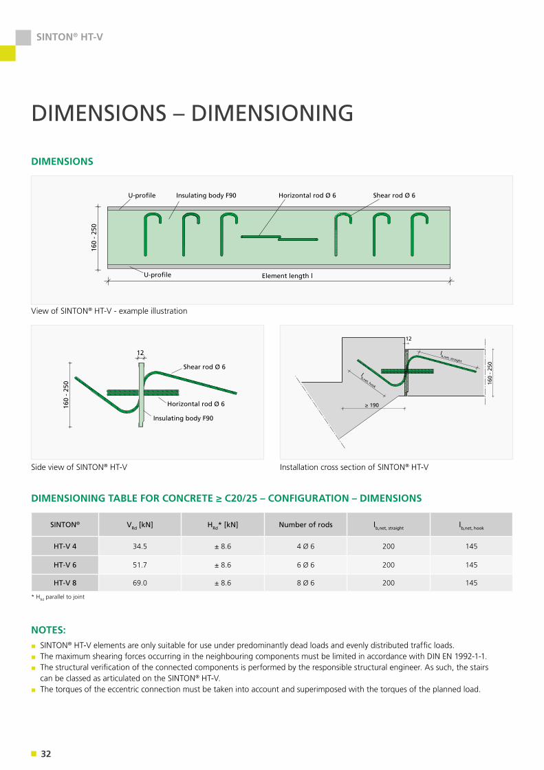
DIMENSIONS
DIMENSIONS – DIMENSIONING
U-profile
U-profile Element length l
Insulating body F90
Insulating body F90
Horizontal rod Ø 6
Horizontal rod Ø 6
Shear rod Ø 6
Shear rod Ø 6
12
160
- 25
0
160
- 25
0
* HRd parallel to joint
DIMENSIONING TABLE FOR CONCRETE ≥ C20/25 – CONFIGURATION – DIMENSIONS
SINTON® VRd [kN] HRd* [kN] Number of rods lb,net, straight lb,net, hook
HT-V 4 34.5 ± 8.6 4 Ø 6 200 145
HT-V 6 51.7 ± 8.6 6 Ø 6 200 145
HT-V 8 69.0 ± 8.6 8 Ø 6 200 145
NOTES:▪ SINTON® HT-V elements are only suitable for use under predominantly dead loads and evenly distributed traffic loads.▪ The maximum shearing forces occurring in the neighbouring components must be limited in accordance with DIN EN 1992-1-1.▪ The structural verification of the connected components is performed by the responsible structural engineer. As such, the stairs can be classed as articulated on the SINTON® HT-V.
▪ The torques of the eccentric connection must be taken into account and superimposed with the torques of the planned load.
View of SINTON® HT-V - example illustration
Side view of SINTON® HT-V Installation cross section of SINTON® HT-V
33
SINTON® HT-V
Ø 8
Ø 8
Ø 8Stirrup as per structural analysis
Stirrup as per structural analysis
2 stirrups Ø 6
Attachment reinforcement as per structural analysis
Lower reinforcement as per structural analysis
Upper reinforcement as per structural analysis
Ø 8
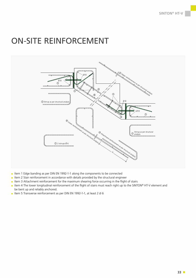
ls
▪ Item 1 Edge banding as per DIN EN 1992-1-1 along the components to be connected ▪ Item 2 Stair reinforcement in accordance with details provided by the structural engineer▪ Item 3 Attachment reinforcement for the maximum shearing force occurring in the flight of stairs▪ Item 4 The lower longitudinal reinforcement of the flight of stairs must reach right up to the SINTON® HT-V element and be bent up and reliably anchored.
▪ Item 5 Transverse reinforcement as per DIN EN 1992-1-1, at least 2 Ø 6
ON-SITE REINFORCEMENT
34
SINTON® HT-V
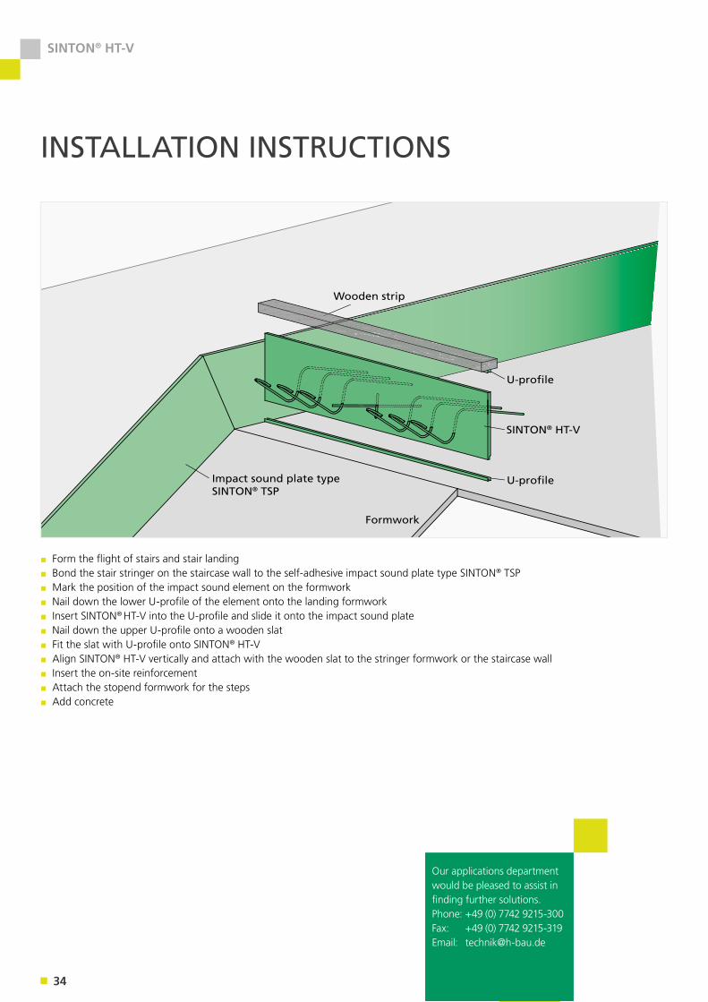
INSTALLATION INSTRUCTIONS
Impact sound plate type SINTON® TSP
Formwork
U-profile
U-profile
SINTON® HT-V
Wooden strip
▪ Form the flight of stairs and stair landing▪ Bond the stair stringer on the staircase wall to the self-adhesive impact sound plate type SINTON® TSP▪ Mark the position of the impact sound element on the formwork▪ Nail down the lower U-profile of the element onto the landing formwork▪ Insert SINTON® HT-V into the U-profile and slide it onto the impact sound plate▪ Nail down the upper U-profile onto a wooden slat▪ Fit the slat with U-profile onto SINTON® HT-V▪ Align SINTON® HT-V vertically and attach with the wooden slat to the stringer formwork or the staircase wall▪ Insert the on-site reinforcement▪ Attach the stopend formwork for the steps▪ Add concrete
Our applications department would be pleased to assist in finding further solutions. Phone: +49 (0) 7742 9215-300Fax: +49 (0) 7742 9215-319Email: [email protected]

35
SINTON®
36
SINTON® Z & ZB
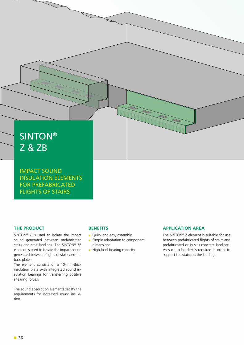
THE PRODUCTSINTON® Z is used to isolate the impact sound generated between prefabricated stairs and stair landings. The SINTON® ZB element is used to isolate the impact sound generated between flights of stairs and the base plate. The element consists of a 10-mm-thick insulation plate with integrated sound in-sulation bearings for transferring positive shearing forces.
The sound absorption elements satisfy the requirements for increased sound insula-tion.
APPLICATION AREAThe SINTON® Z element is suitable for use between prefabricated flights of stairs and prefabricated or in-situ concrete landings. As such, a bracket is required in order to support the stairs on the landing.
BENEFITS▪ Quick and easy assembly▪ Simple adaptation to component dimensions
▪ High load-bearing capacity
SINTON® Z & ZB
IMPACT SOUND INSULATION ELEMENTS FOR PREFABRICATED FLIGHTS OF STAIRS
37
SINTON® Z & ZB
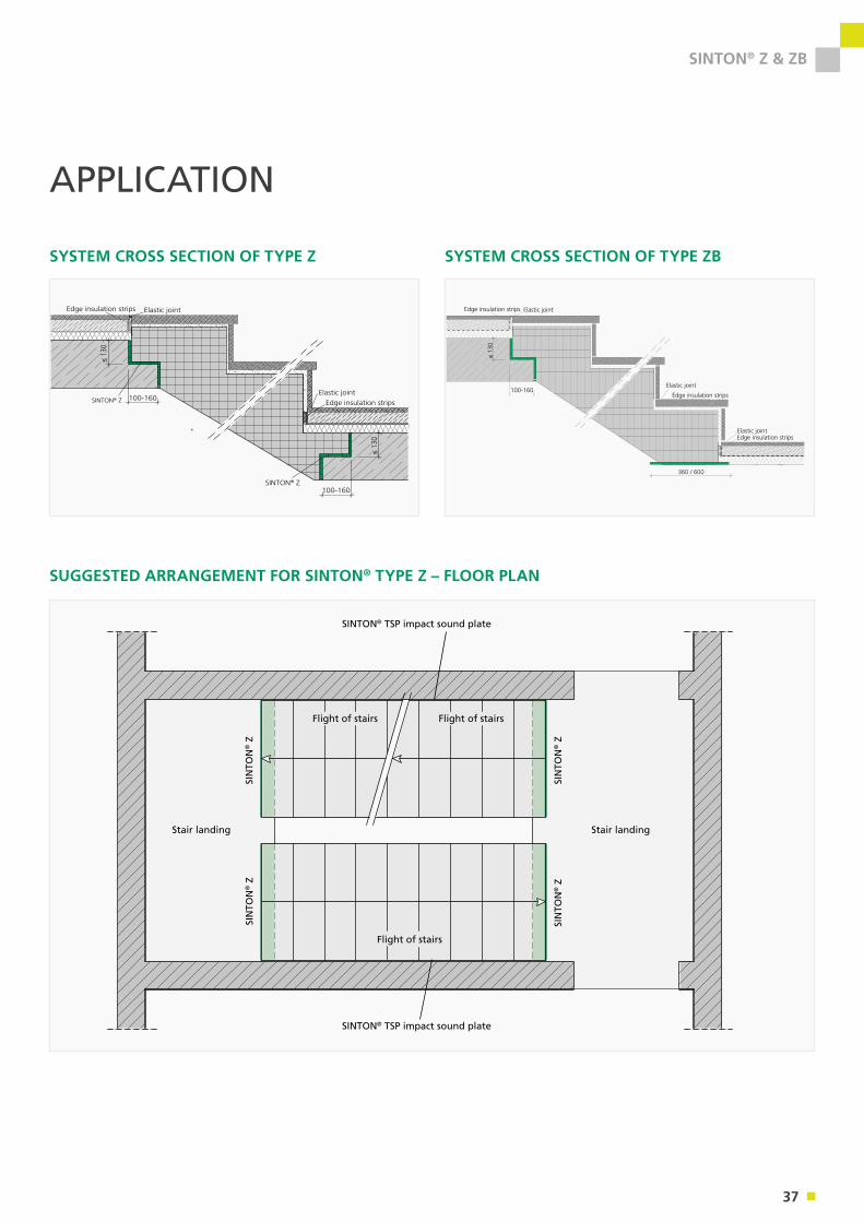
APPLICATION
Stair landing
SIN
TON
® Z
SIN
TON
® Z
SIN
TON
® Z
SIN
TON
® Z
Flight of stairs
Flight of stairs
SINTON® TSP impact sound plate
SINTON® TSP impact sound plate
Flight of stairs
Stair landing
SUGGESTED ARRANGEMENT FOR SINTON® TYPE Z – FLOOR PLAN
100-160
≤ 13
0
Edge insulation strips Elastic joint
Edge insulation strips
Elastic joint
Edge insulation stripsElastic joint
360 / 600
SYSTEM CROSS SECTION OF TYPE ZB
100-160
100-160
≤ 13
0
≤ 13
0
Edge insulation strips Elastic joint
Edge insulation stripsElastic joint
SINTON® Z
®
SINTON® Z
SYSTEM CROSS SECTION OF TYPE Z
38
SINTON® Z & ZB
DIMENSIONING & DIMENSIONS
DIMENSIONS
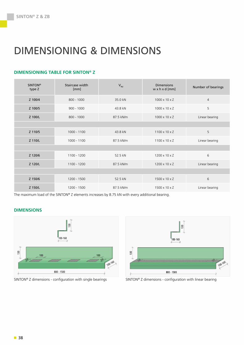
DIMENSIONING TABLE FOR SINTON® Z
SINTON®
type ZStaircase width
[mm] VRd Dimensions
w x h x d [mm] Number of bearings
Z 100/4 800 - 1000 35.0 kN 1000 x 10 x Z 4
Z 100/5 900 - 1000 43.8 kN 1000 x 10 x Z 5
Z 100/L 800 - 1000 87.5 kN/m 1000 x 10 x Z Linear bearing
Z 110/5 1000 - 1100 43.8 kN 1100 x 10 x Z 5
Z 110/L 1000 - 1100 87.5 kN/m 1100 x 10 x Z Linear bearing
Z 120/6 1100 - 1200 52.5 kN 1200 x 10 x Z 6
Z 120/L 1100 - 1200 87.5 kN/m 1200 x 10 x Z Linear bearing
Z 150/6 1200 - 1500 52.5 kN 1500 x 10 x Z 6
Z 150/L 1200 - 1500 87.5 kN/m 1500 x 10 x Z Linear bearing
100-160
800 - 1500
100
50 50
130
130
100
100-160
100-160
800 - 1500
100
50 50
130
130
100
100-160
The maximum load of the SINTON® Z elements increases by 8.75 kN with every additional bearing.
SINTON® Z dimensions - configuration with single bearings SINTON® Z dimensions - configuration with linear bearing
39
SINTON® Z & ZB
DIMENSIONS
DIMENSIONING & DIMENSIONS
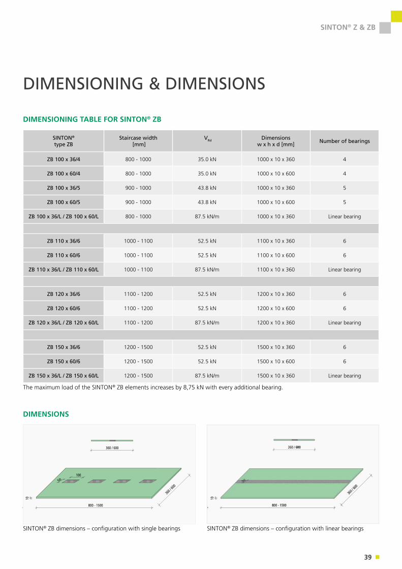
DIMENSIONING TABLE FOR SINTON® ZB
SINTON®
type ZBStaircase width
[mm] VRd Dimensions
w x h x d [mm] Number of bearings
ZB 100 x 36/4 800 - 1000 35.0 kN 1000 x 10 x 360 4
ZB 100 x 60/4 800 - 1000 35.0 kN 1000 x 10 x 600 4
ZB 100 x 36/5 900 - 1000 43.8 kN 1000 x 10 x 360 5
ZB 100 x 60/5 900 - 1000 43.8 kN 1000 x 10 x 600 5
ZB 100 x 36/L / ZB 100 x 60/L 800 - 1000 87.5 kN/m 1000 x 10 x 360 Linear bearing
ZB 110 x 36/6 1000 - 1100 52.5 kN 1100 x 10 x 360 6
ZB 110 x 60/6 1000 - 1100 52.5 kN 1100 x 10 x 600 6
ZB 110 x 36/L / ZB 110 x 60/L 1000 - 1100 87.5 kN/m 1100 x 10 x 360 Linear bearing
ZB 120 x 36/6 1100 - 1200 52.5 kN 1200 x 10 x 360 6
ZB 120 x 60/6 1100 - 1200 52.5 kN 1200 x 10 x 600 6
ZB 120 x 36/L / ZB 120 x 60/L 1100 - 1200 87.5 kN/m 1200 x 10 x 360 Linear bearing
ZB 150 x 36/6 1200 - 1500 52.5 kN 1500 x 10 x 360 6
ZB 150 x 60/6 1200 - 1500 52.5 kN 1500 x 10 x 600 6
ZB 150 x 36/L / ZB 150 x 60/L 1200 - 1500 87.5 kN/m 1500 x 10 x 360 Linear bearing
360 / 600 800 - 1500
10050
10
360 /
600
360 / 600 800 - 1500
10050
10
360 /
600
The maximum load of the SINTON® ZB elements increases by 8,75 kN with every additional bearing.
SINTON® ZB dimensions – configuration with single bearings SINTON® ZB dimensions – configuration with linear bearings
40
SINTON® Z & ZB
FIRE PROTECTION – SOUND INSULATION
FIRE PROTECTIONThe SINTON® Z & ZB sound absorption elements have a construction material class of B2 according to DIN 4102. In accordance with DIN 4102-4, stairs are connected monolithically to landings with joint widths of ≤ 30 mm. In order for the bracket support to correspond to resistance class R90, the conditions specified in DIN 4102-4 Section 3.2.5 for the dimensions of the bracket and minimum centre distances of the reinforcement must be observed.
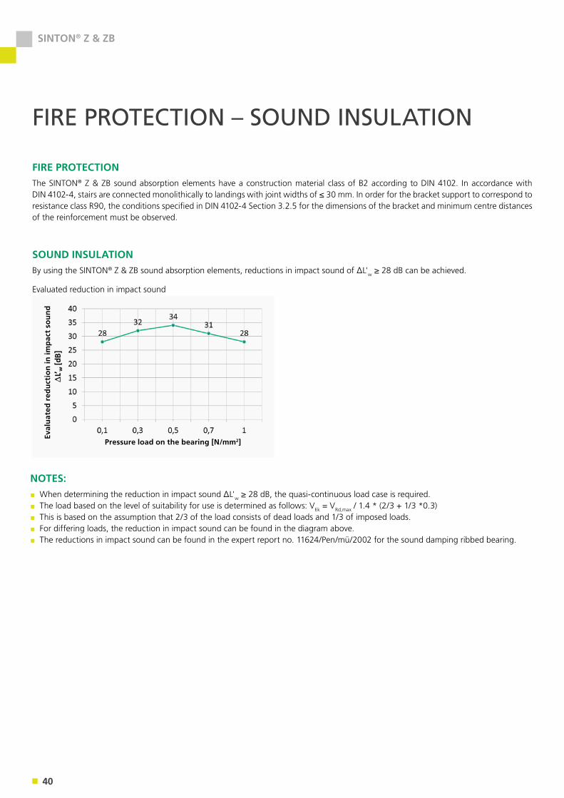
SOUND INSULATIONBy using the SINTON® Z & ZB sound absorption elements, reductions in impact sound of ΔL'w ≥ 28 dB can be achieved.
Evaluated reduction in impact sound
NOTES:▪ When determining the reduction in impact sound ΔL'w ≥ 28 dB, the quasi-continuous load case is required.▪ The load based on the level of suitability for use is determined as follows: VEk = VRd,max / 1.4 * (2/3 + 1/3 *0.3)▪ This is based on the assumption that 2/3 of the load consists of dead loads and 1/3 of imposed loads. ▪ For differing loads, the reduction in impact sound can be found in the diagram above.▪ The reductions in impact sound can be found in the expert report no. 11624/Pen/mü/2002 for the sound damping ribbed bearing.
Pressure load on the bearing [N/mm2]
Eval
uat
ed r
edu
ctio
n in
imp
act
sou
nd
41
SINTON® Z & ZB
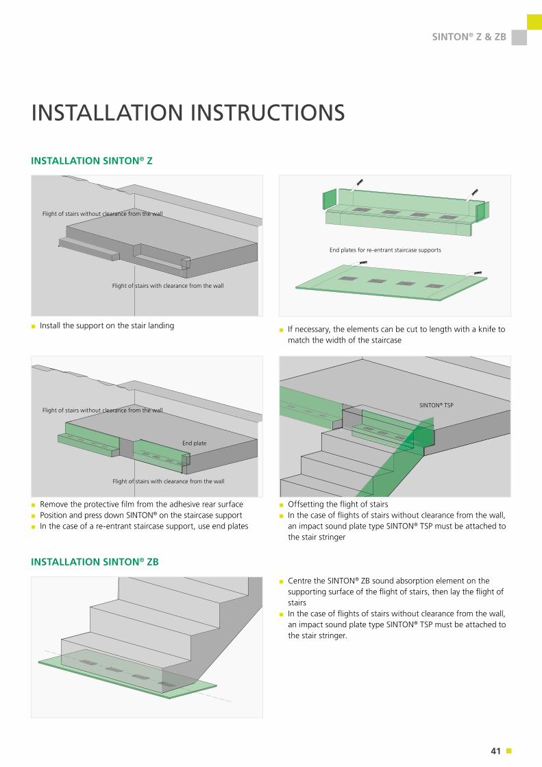
INSTALLATION INSTRUCTIONS
▪ If necessary, the elements can be cut to length with a knife to match the width of the staircase
▪ Install the support on the stair landing
▪ Remove the protective film from the adhesive rear surface▪ Position and press down SINTON® on the staircase support▪ In the case of a re-entrant staircase support, use end plates
▪ Offsetting the flight of stairs▪ In the case of flights of stairs without clearance from the wall, an impact sound plate type SINTON® TSP must be attached to the stair stringer
▪ Centre the SINTON® ZB sound absorption element on the supporting surface of the flight of stairs, then lay the flight of stairs
▪ In the case of flights of stairs without clearance from the wall, an impact sound plate type SINTON® TSP must be attached to the stair stringer.
INSTALLATION SINTON® ZB
INSTALLATION SINTON® Z
Flight of stairs without clearance from the wall
Flight of stairs with clearance from the wall
End plates for re-entrant staircase supports
Flight of stairs without clearance from the wall
Flight of stairs with clearance from the wall
End plate
SINTON® TSP
42
SINTON® TSP
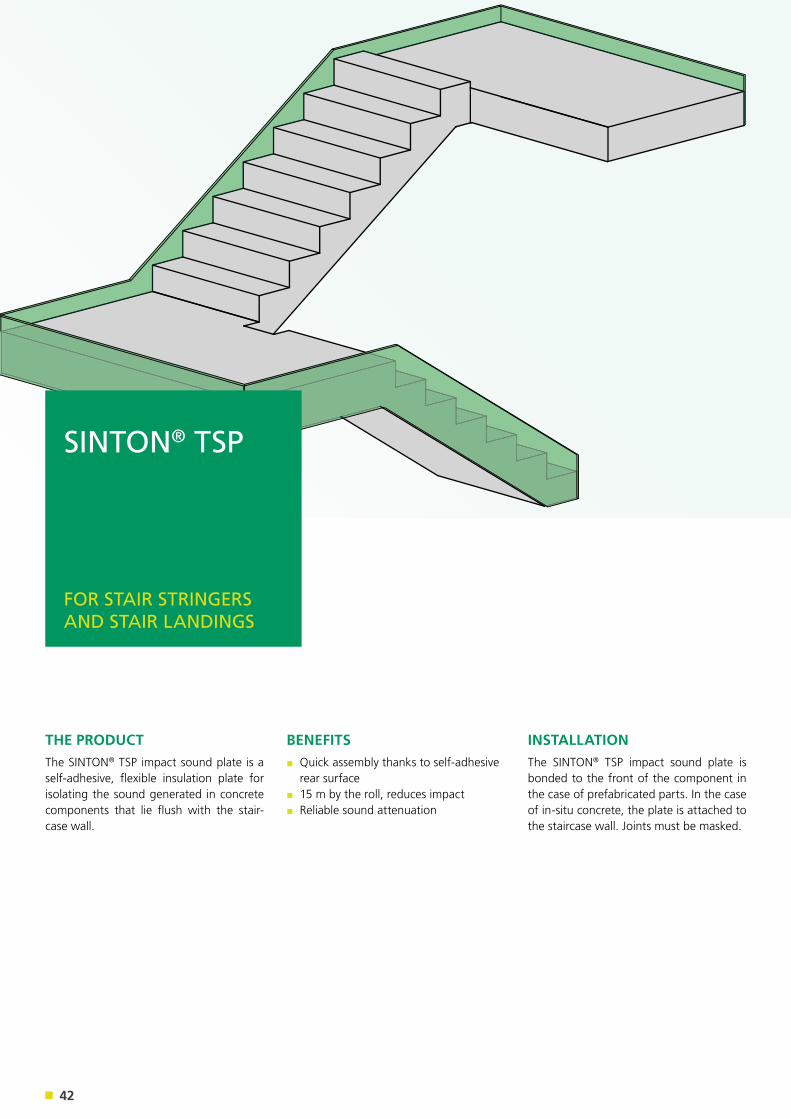
THE PRODUCTThe SINTON® TSP impact sound plate is a self-adhesive, flexible insulation plate for isolating the sound generated in concrete components that lie flush with the stair-case wall.
INSTALLATIONThe SINTON® TSP impact sound plate is bonded to the front of the component in the case of prefabricated parts. In the case of in-situ concrete, the plate is attached to the staircase wall. Joints must be masked.
BENEFITS▪ Quick assembly thanks to self-adhesive rear surface
▪ 15 m by the roll, reduces impact▪ Reliable sound attenuation
SINTON® TSP
FOR STAIR STRINGERS AND STAIR LANDINGS
43
SINTON® TSP
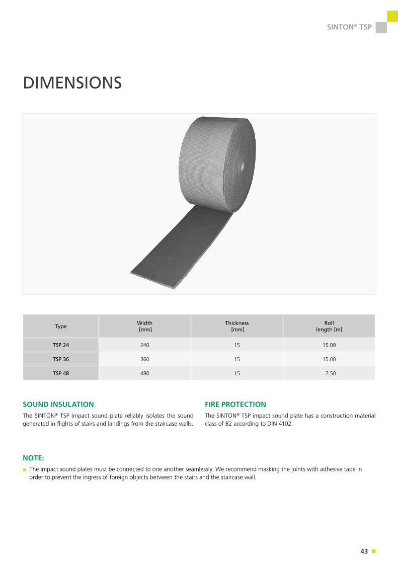
SOUND INSULATIONThe SINTON® TSP impact sound plate reliably isolates the sound generated in flights of stairs and landings from the staircase walls.
NOTE:▪ The impact sound plates must be connected to one another seamlessly. We recommend masking the joints with adhesive tape in order to prevent the ingress of foreign objects between the stairs and the staircase wall.
Type Width [mm]
Thickness [mm]
Rolllength [m]
TSP 24 240 15 15.00
TSP 36 360 15 15.00
TSP 48 480 15 7.50
DIMENSIONS
FIRE PROTECTIONThe SINTON® TSP impact sound plate has a construction material class of B2 according to DIN 4102.

44
SINTON®
A FORWARD CONSTRUCTING SERVICE: WE ARE ALWAYS THERE FOR YOU.You can rely on our excellent service: We accompany you through every phase of the project – either over the phone, online or in person, directly at your site. As a true partner, we place special value on offering our customers added value – take a look at our comprehensive range of services and see for yourself.
EVERYTHING ONLINE: OUR DOWNLOAD AREA.You can download all brochures, test re-ports, approvals, our current price list and much more from our website.
FOR PLANNING AND APPLICATION: OUR VIDEOS AND SOFTWARE.In addition to our installation and refer-ence films, we also provide you with vari-ous software solutions, such as calculation programs, free of charge on our website.
READY TO GO: OUR TENDER DOCUMENT TEMPLATES.Our tender document templates can be quickly and easily embedded in your tender program, e.g. with the tender managers at www.ausschreiben.de or www.heinze.de.
Personalised support when planning and executing projects:
Answers to any questions you have about delivery times, shipping, sales prices and the entire process of fulfilling your orders you receive from our PohlCon sales service Germany, division H-BAU:
HOTLINES
Hotline: +49 (0) 7742 9215-300Email: [email protected]
Hotline: +49 (0) 30 68283803 Email: [email protected]
APPLICATION TECHNOLOGY SALES (GERMANY)

45
SINTON®
TAILOR-MADE: OUR SPECIAL CONSTRUCTIONS.Unable to find what you’re looking for in our wide range of products and services? Our engineers and applications specialists can develop tailor-made product solutions for you on request.
FROM PERSON TO PERSON: OUR NETWORK OF CONSULTANTS.Get the answers to your technical questions face-to-face at your site: Our consultant engineers will be happy to come to your site.
THE LATEST NEWS: OUR NEWSLETTER.Subscribe to our newsletter and you will always be kept up-to-date: Find out more about our product innovations, trade shows and current trends in the sector.
Answers to any questions you have about delivery times, shipping, sales prices and the entire process of fulfilling your orders at an international level you receive from our PohlCon international sales service, division H-BAU:
We will be happy to send you our techni-cal brochures and planning documents:
Hotline: +49 (0) 30 68283806 Email: [email protected]
Hotline: +49 (0) 7742 9215-0Email: [email protected]
SALES (INTERNATIONAL) HEAD OFFICE

46
SINTON®
H-BAU TECHNIK GMBH Am Güterbahnhof 20 79771 Klettgau, Germany Phone: +49 (0) 7742 9215-0 Fax: +49 (0) 7742 9215-129 Email: [email protected] www.h-bau.com
PRODUCTION NORTH-EAST Brandenburger Allee 30 14641 Nauen OT Wachow, Germany Phone: +49 (0) 33239 775-0 Fax: +49 (0) 33239 775-90 Email: [email protected]
PRODUCTION CHEMNITZ Beyerstraße 21 09113 Chemnitz, Germany Phone: +49 (0) 371 40041-0 Fax: +49 (0) 371 40041-99Email: [email protected]
FORWARD CONSTRUCTING CONTACTS: WE WILL BE WHEREVER YOU ARE.Thanks to our global sales network, expert specialist advisers are available to you on a national level and on an international level. If there is no contact partner listed for your country, contact our Head Office in Klettgau – we will be happy to provide you with further assistance.
HEAD OFFICE
47
SINTON®
Disclaimer
1. This work and all parts thereof are protected by
copyright law. Use of this work shall not be permitted
without the agreement of H-BAU Technik GmbH.
2. All texts and diagrams in this printed product have
been developed and compiled with the utmost care
and are designed to provide preliminary information.
Nevertheless, errors cannot be completely excluded.
The publisher shall assume no liability, irrespective of
the legal grounds for this. Previous documents shall
become invalid with the issue of this document.
GLOBAL PARTNERS
SWITZERLANDJORDAHL H-BAU AGZürichstrasse 38a8306 Brüttisellen/Zürich, SwitzerlandPhone: +41 (0) 44 8071717Fax: +41 (0) 44 8071718Email: [email protected]
AUSTRIAJORDAHL H-BAU Österreich GmbHStraubingstrasse 194030 Linz, AustriaPhone: +43 (0) 732 321900Fax: +43 (0) 732 321900-99Email: [email protected]
DENMARKJordahl & Pfeifer Byggeteknik A/S Risgårdevej 66 9640 Farsø, DenmarkPhone: +45 (0) 98 631900 Phone: +45 (0) 98 631939Email: [email protected]
HUNGARYPFEIFER Garant Kft. Gyömröi út 128 1103 Budapest, HungaryPhone: +36 (0) 1 2601014 Fax: +36 (0) 1 2620927 Email: [email protected]@pfeifer-garant.hu
UNITED KINGDOMJ&P Building Systems Ltd. Unit 5Thame Forty Jane Morbey Road THAME, OXON OX9 3RR, UKPhone: +44 (0) 1844 215200 Fax: +44 (0) 1844 263257 [email protected]
UKRAINEJORDAHL & PFEIFER Technika Budowlana ul. Pawlyka 17a 76-018 Ivano-Frankivsk, UkrainePhone Reg. East: +380 (0) 67442 8578 Phone Reg. West: +380 (0) 67442 8579Email: [email protected]
CZECH REPUBLICJordahl & Pfeifer Stavební technika s.r.o. Bavorská 856/14 15500 Prague 5, Czech RepublicPhone: +420 (0) 272 700701 Fax: +420 (0) 272 700704 Email: [email protected]
SPAINPFEIFER Cables y Equipos de Elevación, S.L. Avda.de Los Pirineos, 25 – Nave 20 San Sebastian de los Reyes 28700 Madrid, SpainPhone: +34 (0) 91 659 3185 Fax: +34 (0) 91 659 3139 Email: [email protected]
SINGAPOREJ&P Building Systems Pte Ltd. No. 48 Toh Guan Road East #08-104 Enterprise Hub SINGAPORE 608586Phone: +65 (0) 6569 6131 Fax: +65 (0) 6569 5286 Email: [email protected]@jnp.com.sg
ROMANIAS.C. JORDAHL & PFEIFER TEHNICÃ DE ANCORARE S.R.L Str. Malului Nr. 7, et.1 550197 Sibiu jud. Sibiu, RomaniaPhone: +40 (0) 269 246098 Fax: +40 (0) 269 246099 Email: [email protected]
POLANDJORDAHL & PFEIFER TECHNIKA BUDOWLANA SP. Z O. O.ul. Wrocławska 6855-330 Krępice k/Wrocławia, Poland Phone: +48 (0) 71 3968264Fax: +48 (0) 71 3968105 Email: [email protected]
www.h-bau.com
H-BAU TECHNIK GMBH
Am Güterbahnhof 20
79771 Klettgau, Germany
Phone: +49 (0) 7742 9215-0
Fax: +49 (0) 7742 9215-129
Email: [email protected]
01/2
020


