Embed Size (px)
Citation preview

0
SLAM and Exploration using DifferentialEvolution and Fast Marching
Santiago Garrido, Luis Moreno and Dolores BlancoRobotics Lab, Carlos III University of Madrid
Spain
1. Introduction
The exploration and construction of maps in unknown environments is a challenge forrobotics. The proposed method is facing this problem by combining effective techniquesfor planning, SLAM, and a new exploration approach based on the Voronoi Fast Marchingmethod.The final goal of the exploration task is to build a map of the environment that previously therobot did not know. The exploration is not only to determine where the robot should move,but also to plan the movement, and the process of simultaneous localization and mapping.This work proposes the Voronoi Fast Marching method that uses a Fast Marching techniqueon the Logarithm of the Extended Voronoi Transform of the environment’s image providedby sensors, to determine a motion plan. The Logarithm of the Extended Voronoi Transformimitates the repulsive electric potential from walls and obstacles, and the Fast MarchingMethod propagates a wave over that potential map. The trajectory is calculated by thegradient method.The robot is directed towards the most unexplored and free zones of the environment so as tobe able to explore all the workspace.Finally, to build the environment map while the robot is carrying out the exploration task, aSLAM (Simultaneous Localization and Modeling) algorithm is implemented, the EvolutiveLocalization Filter (ELF) based on a differential evolution technique.The combination of these methods provide a new autonomous exploration strategy toconstruct consistent maps of 2D indoor environments.
2. Autonomous exploration
Autonomous exploration and mapping are fundamental problems to solve as an autonomousrobot carries out tasks in real unknown environments. Sensor based exploration, motionplanning, localization and simultaneous mapping are processes that must be coordinated toachieve autonomous execution of tasks in unknown environments.Sensor based planning makes use of the sensor acquired information of the environmentin its latest configuration and generates an adequate path towards the desired followingposition. Sensor-based discovery path planning is the guidance of an agent - a robot - withouta complete a priori map, by discovering and negotiating the environment so as to reach agoal location while avoiding all encountered obstacles. Sensor-based discovery (i.e., dynamic)path planning is problematic because the path needs to be continually recomputed as newinformation is discovered.
4
2 Will-be-set-by-IN-TECH
In order to build a map of an unknown environment autonomously, this work presents firsta exploration and path planning method based on the Logarithm of the Extended VoronoiTransform and the Fast Marching Method. This Path Planner is called Voronoi Fast Marching(8). The Extended Voronoi Transform of an image gives a grey scale that is darker nearthe obstacles and walls and lighter when far from them. The Logarithm of the ExtendedVoronoi Transform imitates the repulsive electric potential in 2D from walls and obstacles.This potential impels the robot far from obstacles. The Fast Marching Method has beenapplied to Path Planning (34), and their trajectories are of minimal distance, but they are notvery safe because the path is too close to obstacles and what is more important, the path isnot smooth enough. In order to improve the safety of the trajectories calculated by the FastMarching Method, avoiding unrealistic trajectories produced when the areas are narrowerthan the robot, objects and walls are enlarged in a security distance that assures that the robotdoes not collide and does not accept passages narrower than the robot’s size.The last step is calculating the trajectory in the image generated by the Logarithm of theExtended Voronoi Transform using the Fast Marching Method. Then, the path obtainedverifies the smoothness and safety considerations required for mobile robot path planning.The advantages of this method are the ease of implementation, the speed of the method andthe quality of the trajectories. This method is used at a local scale operating with sensorinformation (sensor based planning).To build the environment map while the robot is carrying out the exploration task, a SLAM(Simultaneous Localization and Modelling) is implemented. The algorithm is based onthe stochastic search for solutions in the state space to the global localization problem bymeans of a differential evolution algorithm. This non linear evolutive filter, called EvolutiveLocalization Filter (ELF) (23), searches stochastically along the state space for the best robotpose estimate. The set of pose solutions (the population) focuses on the most likely areasaccording to the perception and up to date motion information. The population evolvesusing the log-likelihood of each candidate pose according to the observation and the motionerrors derived from the comparison between observed and predicted data obtained from theprobabilistic perception and motion model.In the remainder of the chapter, the section 3 presents the state of the art referred to explorationand motion planning problems. Section 4 presents our Voronoi Fast Marching (VFM) MotionPlanner. The SLAM algorithm is described briefly in Section 5. Then, section 6 describes thespecific Exploration method proposed. Next, section 7 demonstrates the performance of theexploration strategy as it explores different environments, according to the two possible waysof working for the exploration task. And, finally the conclusions are summarized in section 8.
3. Previous and related works
3.1 Representations of the worldRoughly speaking there are two main forms for representing the spatial relations in anenvironment: metric maps and topological maps. Metric maps are characterized by arepresentation where the position of the obstacles are indicated by coordinates in a globalframe of reference. Some of them represent the environment with grids of points, definingregions that can be occupied or not by obstacles or goals (22) (1). Topological maps representthe environment with graphs that connect landmarks or places with special features (19)(12). In our approach we choose the grid-based map to represent the environment. Theclear advantage is that with grids we already have a discrete environment representationand ready to be used in conjunction with the Extended Voronoi Transform function and FastMarching Method for path planning. The pioneer method for environment representation in
82 Advances in Robot Navigation

SLAM and Exploration using Differential Evolution and Fast Marching 3
a grid-based model was the certainty grid method developed at Carnegie Mellon Universityby Moravec (22). He represents the environment as a 3D or 2D array of cells. Each cell storesthe probability of the related region being occupied. The uncertainty related to the positionof objects is described in the grid as a spatial distribution of these probabilities within theoccupancy grid. The larger the spatial uncertainty, the greater the number of cells occupied bythe observed object. The update of these cells is performed during the navigation of the robotor through the exploration process by using an update rule function. Many researchers haveproposed their own grid-based methods. The main difference among them is the functionused to update the cell. Some of them are, for example: Fuzzy (24), Bayesian (9), HeuristicProbability (2), Gaussian (3), etc. In the Histogramic In-Motion Mapping (HIMM), each cell,has a certainty value, which is updated whenever it is being observed by the robots sensors.The update is performed by increasing the certainty value by 3 (in the case of detection of anobject) or by decreasing it by 1 (when no object is detected), where the certainty value is aninteger between 0 and 15.
3.2 Approaches to explorationThis section relates some interesting techniques used for exploratory mapping. They mixdifferent localization methods, data structures, search strategies and map representations.Kuipers and Byun (13) proposed an approach to explore an environment and to representit in a structure based on layers called Spatial Semantic Hierarchy (SSH) (12). The algorithmdefines distinctive places and paths, which are linked to form an environmental topologicaldescription. After this, a geometrical description is extracted. The traditional approachesfocus on geometric description before the topological one. The distinctive places are definedby their properties and the distinctive paths are defined by the twofold robot control strategy:follow-the-mid-line or follow-the-left-wall. The algorithm uses a lookup table to keepinformation about the place visited and the direction taken. This allows a search in theenvironment for unvisited places. Lee (16) developed an approach based on Kuipers work(13) on a real robot. This approach is successfully tested in indoor office-like spaces. Thisenvironment is relatively static during the mapping process. Lee’s approach assumes thatwalls are parallel or perpendicular to each other. Furthermore, the system operates in a verysimple environment comprised of cardboard barriers. Mataric (19) proposed a map learningmethod based on a subsumption architecture. Her approach models the world as a graph,where the nodes correspond to landmarks and the edges indicate topological adjacencies.The landmarks are detected from the robot movement. The basic exploration process iswall-following combined with obstacle avoidance. Oriolo et al. (25) developed a grid-basedenvironment mapping process that uses fuzzy logic to update the grid cells. The mappingprocess runs on-line (24), and the local maps are built from the data obtained by the sensorsand integrated into the environment map as the robot travels along the path defined by theA∗ algorithm to the goal. The algorithm has two phases. The first one is the perceptionphase. The robot acquires data from the sensors and updates its environment map. Thesecond phase is the planning phase. The planning module re-plans a new safe path to thegoal from the new explored area. Thrun and Bucken (37) (38) developed an explorationsystem which integrates both evidence grids and topological maps. The integration of the twoapproaches has the advantage of disambiguating different positions through the grid-basedrepresentation and performing fast planning through the topological representation. Theexploration process is performed through the identification and generation of the shortestpaths between unoccupied regions and the robot. This approach works well in dynamicenvironments, although, the walls have to be flat and cannot form angles that differ more
83SLAM and Exploration using Differential Evolution and Fast Marching
4 Will-be-set-by-IN-TECH
than 15◦ from the perpendicular. Feder et al. (4) proposed a probabilistic approach to treatthe concurrent mapping and localization using a sonar. This approach is an example of afeature-based approach. It uses the extended Kalman filter to estimate the localization of therobot. The essence of this approach is to take actions that maximize the total knowledge aboutthe system in the presence of measurement and navigational uncertainties. This approachwas tested successfully in wheeled land robot and autonomous underwater vehicles (AUVs).Yamauchi (39) (40) developed the Frontier-Based Exploration to build maps based on grids.This method uses a concept of frontier, which consists of boundaries that separate the exploredfree space from the unexplored space. When a frontier is explored, the algorithm detects thenearest unexplored frontier and attempts to navigate towards it by planning an obstacle freepath. The planner uses a depth-first search on the grid to reach that frontier. This processcontinues until all the frontiers are explored. Zelek (42) proposed a hybrid method thatcombines a local planner based on a harmonic function calculation in a restricted window witha global planning module that performs a search in a graph representation of the environmentcreated from a CAD map. The harmonic function module is employed to generate the bestpath given the local conditions of the environment. The goal is projected by the global plannerin the local windows to direct the robot. Recently, Prestes el al. (28) have investigated theperformance of an algorithm for exploration based on partial updates of a harmonic potentialin an occupancy grid. They consider that while the robot moves, it carries along an activationwindow whose size is of the order of the sensors range.Prestes and coworkers (29) propose an architecture for an autonomous mobile agent thatexplores while mapping a two-dimensional environment. The map is a discretized modelfor the localization of obstacles, on top of which a harmonic potential field is computed. Thepotential field serves as a fundamental link between the modelled (discrete) space and the real(continuous) space where the agent operates.
3.3 Approaches to motion planningThe motion planning method proposed in this chapter can be included in the sensor-basedglobal planner paradigm. It is a potential method but it does not have the typical problemsof these methods enumerated by Koren- Borenstein (11): 1) Trap situations due to localminima (cyclic behavior). 2) No passage between closely spaced obstacles. 3) Oscillationsin the presence of obstacles. 4) Oscillations in narrow passages. The proposed methodis conceptually close to the navigation functions of Rimon-Koditscheck (33), because thepotential field has only one local minimum located at the single goal point. This potentialand the paths are smooth (the same as the repulsive potential function) and there are nodegenerate critical points in the field. These properties are similar to the characteristics of theelectromagnetic waves propagation in Geometrical Optics (for monochromatic waves withthe approximation that length wave is much smaller than obstacles and without consideringreflections nor diffractions).The Fast Marching Method has been used previously in Path Planning by Sethian (36) (35),but using only an attractive potential. This method has some problems. The most importantone that typically arises in mobile robotics is that optimal motion plans may bring robotstoo close to obstacles (including people), which is not safe. This problem has been dealtwith by Latombe (14), and the resulting navigation function is called NF2. The VoronoiMethod also tries to follow a maximum clearance map (7). Melchior, Poty and Oustaloup(21; 27), present a fractional potential to diminish the obstacle danger level and improvethe smoothness of the trajectories, Philippsen (26) introduces an interpolated NavigationFunction, but with trajectories too close to obstacles and without smooth properties and Petres
84 Advances in Robot Navigation

SLAM and Exploration using Differential Evolution and Fast Marching 5
(30), introduces efficient path-planning algorithms for Underwater Vehicles taking advantageof the underwaters currents.LaValle (15), treats on the feedback motion planning concept. To move in the physical worldthe actions must be planned depending on the information gathered during execution.Lindemann and Lavalle (17) (18) present a method in which the vector field globally solvesthe navigation problem and provides robustness to disturbances in sensing and control. Inaddition to being globally convergent, the vector field’s integral curves (system trajectories)are guaranteed to avoid obstacles and are C∞ smooth, except in the changes of cells. Theyconstruct a vector field with these properties by using existing geometric algorithms topartition the space into simple cells; they then define local vector fields for each cell, andsmoothly interpolate between them to obtain a global vector field that can be used as afeedback control for the robot.Yang and Lavalle (41) presented a randomized framework motion strategies, by defininga global navigation function over a collection of spherical balls in the configuration space.Their key idea is to fill the collision free subset of the configuration space with overlappingspherical balls, and define collision free potential functions on each ball. A similar idea hasbeen developed for collision detection in (31) and (32).The proposed method constructs a vectorial field as in the work by Lindemann, but the fieldis done in the global map instead of having local cells maps with the problem of havingtrajectories that are not C∞ in the union between cells. The method has also similitudes withthe Yang and Lavalle method. They proposed a series of balls with a Lyapunov potentialassociated to each of them. These potentials are connected in such a way that it is possible tofind the trajectory using in each ball the gradient method. The method that we propose, hasa unique global Lyapunov potential associated with the vectorial field that permits build theC∞ trajectory in a single pass with the gradient method.To achieve a smooth and safe path,it is necessary to have smooth attractive and repulsivepotentials, connected in such a way that the resulting potential and the trajectories haveno local minima and curvature continuity to facilitate path tracking design. The mainimprovement of the proposed method are these good properties of smoothness and safety ofthe trajectory. Moreover, the associated vector field allows the introduction of nonholonomicconstraints.It is important to note that in the proposed method the important ingredients are the attractiveand the repulsive potentials, the way of connecting them describing the attractive potentialusing the wave equation (or in a simplified way, the eikonal equation). This equation canbe solved in other ways: Mauch (20) uses a Marching with Correctness Criterion with acomputational complexity that can reduced to O(N). Covello (5) presents a method that canbe used on nodes that are located on highly distorted grids or on nodes that are randomlylocated.
4. The VFM Motion Planner
Which properties and characteristics are desirable for a Motion Planner of a mobile robot?The first one is that the planner always drives the robot in a smooth and safe way to thegoal point. In Nature there are phenomena with the same way of working: electromagneticwaves. If in the goal point, there is an antenna that emits an electromagnetic wave, then therobot could drive itself to the destination following the waves to the source. The conceptof the electromagnetic wave is especially interesting because the potential and its associatedvector field have all the good properties desired for the trajectory, such as smoothness (it isC∞) and the absence of local minima. This attractive potential still has some problems. The
85SLAM and Exploration using Differential Evolution and Fast Marching

6 Will-be-set-by-IN-TECH
most important one that typically arises in mobile robotics is that optimal motion plans maybring robots too close to obstacles, which is not safe. This problem has been dealt with byLatombe (14), and the resulting navigation function is called NF2. The Voronoi Method alsotries to follow a maximum clearance map (6). To generate a safe path, it is necessary to adda component that repels the robot away from obstacles. In addition, this repulsive potentialand its associated vector field should have good properties such as those of the electrical field.If we consider that the robot has an electrical charge of the same sign as the obstacles, thenthe robot would be pushed away from obstacles. The properties of this electric field are verygood because it is smooth and there are no singular points in the interest space (Cf ree).The third part of the problem consists in how to mix the two fields together. This unionbetween an attractive and a repulsive field has been the biggest problem for the potential fieldsin path planning since the works of Khatib (10). In the VFM Method, this problem has beensolved in the same way that Nature does so: the electromagnetic waves, such as light, havea propagation velocity that depends on the media. For example, flint glass has a refractionindex of 1.6, while in the air it is approximately one. This refraction index of a medium is thequotient between the velocity of light in the vacuum and the velocity in the medium underconsideration. That is the slowness index of the front wave propagation in a medium. Alight ray follows a straight line if the medium has a constant refraction index (the medium ishomogeneous) but refracts when there is a transition of medium (sudden change of refractionindex value). In the case of a gradient change in refraction index in a given medium, the lightray follows a curved line. This phenomenon can be seen in nature in hot road mirages. In thisphenomenon, the air closer to the road surface is warmer than the higher level layers. Thewarmer air has lower density and lower refraction index. For this reason, light rays comingfrom the sun are curved near the road surface and cause what is called the hot road mirage,as illustrated in fig. 1. This is the idea that inspires the way in which the attractive and therepulsive fields are merged in our work.For this reason, in the VFM method, the repulsive potential is used as refraction index of thewave emitted from the goal point. In this way, a unique field is obtained and its associatedvector field is attractive to the goal point and repulsive from the obstacles. This methodinherits the properties of the electromagnetic field. Intuitively, the VFM Method gives thepropagation of a front wave in an inhomogeneous media.In Geometrical Optics, Fermat’s least time principle for light propagation in a medium withspace varying refractive index η(x) is equivalent to the eikonal equation and can be writtenas ||∇Φ(x)|| = η(x) where the eikonal Φ(x) is a scalar function whose isolevel contours arenormal to the light rays. This equation is also known as the Fundamental Equation of theGeometrical Optics.The eikonal (from the Greek "eikon", which means "image") is the phase function in a situationfor which the phase and amplitude are slowly varying functions of position. Constant valuesof the eikonal represent surfaces of constant phase, or wavefronts. The normals to thesesurfaces are rays (the paths of energy flux). Thus the eikonal equation provides a methodfor "ray tracing" in a medium of slowly varying refractive index (or the equivalent for otherkinds of waves).The theory and the numerical techniques known as Fast Marching Methods are derived froman exposition to describe the movement of interfaces, based on a resolution of the equationson partial differential equations as a boundary condition problem. The Fast Marching Methodhas been used previously in Path Planning by Sethian(35; 36), but using only an attractivepotential.
86 Advances in Robot Navigation
SLAM and Exploration using Differential Evolution and Fast Marching 7
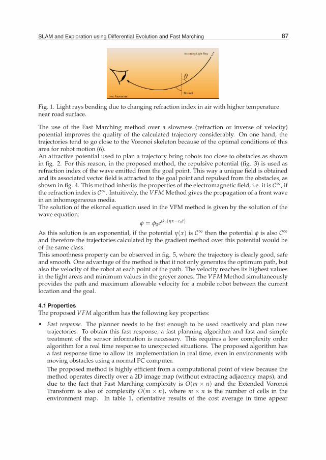
Fig. 1. Light rays bending due to changing refraction index in air with higher temperaturenear road surface.
The use of the Fast Marching method over a slowness (refraction or inverse of velocity)potential improves the quality of the calculated trajectory considerably. On one hand, thetrajectories tend to go close to the Voronoi skeleton because of the optimal conditions of thisarea for robot motion (6).An attractive potential used to plan a trajectory bring robots too close to obstacles as shownin fig. 2. For this reason, in the proposed method, the repulsive potential (fig. 3) is used asrefraction index of the wave emitted from the goal point. This way a unique field is obtainedand its associated vector field is attracted to the goal point and repulsed from the obstacles, asshown in fig. 4. This method inherits the properties of the electromagnetic field, i.e. it is C∞, ifthe refraction index is C∞. Intuitively, the VFM Method gives the propagation of a front wavein an inhomogeneous media.The solution of the eikonal equation used in the VFM method is given by the solution of thewave equation:
φ = φ0eik0(ηx−c0t)
As this solution is an exponential, if the potential η(x) is C∞ then the potential φ is also C∞
and therefore the trajectories calculated by the gradient method over this potential would beof the same class.This smoothness property can be observed in fig. 5, where the trajectory is clearly good, safeand smooth. One advantage of the method is that it not only generates the optimum path, butalso the velocity of the robot at each point of the path. The velocity reaches its highest valuesin the light areas and minimum values in the greyer zones. The VFM Method simultaneouslyprovides the path and maximum allowable velocity for a mobile robot between the currentlocation and the goal.
4.1 PropertiesThe proposed VFM algorithm has the following key properties:
• Fast response. The planner needs to be fast enough to be used reactively and plan newtrajectories. To obtain this fast response, a fast planning algorithm and fast and simpletreatment of the sensor information is necessary. This requires a low complexity orderalgorithm for a real time response to unexpected situations. The proposed algorithm hasa fast response time to allow its implementation in real time, even in environments withmoving obstacles using a normal PC computer.The proposed method is highly efficient from a computational point of view because themethod operates directly over a 2D image map (without extracting adjacency maps), anddue to the fact that Fast Marching complexity is O(m × n) and the Extended VoronoiTransform is also of complexity O(m × n), where m × n is the number of cells in theenvironment map. In table 1, orientative results of the cost average in time appear
87SLAM and Exploration using Differential Evolution and Fast Marching

8 Will-be-set-by-IN-TECH
Fig. 2. Attractive potential, its associated vector field and a typical trajectory.
Fig. 3. The Fast Marching Method applied to a L-shaped environment gives: the slowness(velocity inverse) or repulsive potential and its associated vector field.
a) b)
Fig. 4. a) Union of the two potentials: the second one having the first one as refractive index.b) Associated vector field and typical trajectories obtained with this method.
88 Advances in Robot Navigation
SLAM and Exploration using Differential Evolution and Fast Marching 9
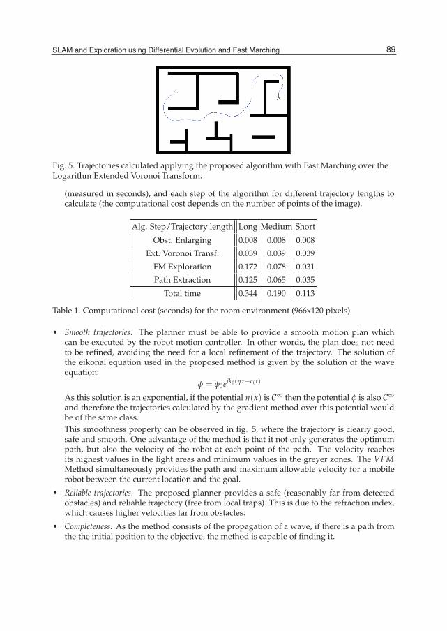
Fig. 5. Trajectories calculated applying the proposed algorithm with Fast Marching over theLogarithm Extended Voronoi Transform.
(measured in seconds), and each step of the algorithm for different trajectory lengths tocalculate (the computational cost depends on the number of points of the image).
Alg. Step/Trajectory length Long Medium Short
Obst. Enlarging 0.008 0.008 0.008
Ext. Voronoi Transf. 0.039 0.039 0.039
FM Exploration 0.172 0.078 0.031
Path Extraction 0.125 0.065 0.035
Total time 0.344 0.190 0.113
Table 1. Computational cost (seconds) for the room environment (966x120 pixels)
• Smooth trajectories. The planner must be able to provide a smooth motion plan whichcan be executed by the robot motion controller. In other words, the plan does not needto be refined, avoiding the need for a local refinement of the trajectory. The solution ofthe eikonal equation used in the proposed method is given by the solution of the waveequation:
φ = φ0eik0(ηx−c0t)
As this solution is an exponential, if the potential η(x) is C∞ then the potential φ is also C∞
and therefore the trajectories calculated by the gradient method over this potential wouldbe of the same class.This smoothness property can be observed in fig. 5, where the trajectory is clearly good,safe and smooth. One advantage of the method is that it not only generates the optimumpath, but also the velocity of the robot at each point of the path. The velocity reachesits highest values in the light areas and minimum values in the greyer zones. The VFMMethod simultaneously provides the path and maximum allowable velocity for a mobilerobot between the current location and the goal.
• Reliable trajectories. The proposed planner provides a safe (reasonably far from detectedobstacles) and reliable trajectory (free from local traps). This is due to the refraction index,which causes higher velocities far from obstacles.
• Completeness. As the method consists of the propagation of a wave, if there is a path fromthe the initial position to the objective, the method is capable of finding it.
89SLAM and Exploration using Differential Evolution and Fast Marching
10 Will-be-set-by-IN-TECH
5. Differential evolution approach to the SLAM
Localization and map building are key components in robot navigation and are requiredto successfully execute the path generated by the VFM planner in the exploration methodproposed in this work. Both problems are closely linked, and learning maps are requiredto solve both problems simultaneously; this is the SLAM problem. Uncertainty in sensormeasures and uncertainty in robot pose estimates make the use of a SLAM method necessaryto create a consistent map of the explored environment.The SLAM algorithm used in this work is described in (23). It is based on the stochasticsearch of solutions in the state space to the localization problem by means of a differentialevolution algorithm. A non linear evolutive filter, called Evolutive Localization Filter (ELF),searches stochastically along the state space for the best robot pose estimate. The proposedSLAM algorithm operates in two steps: in the first step the ELF filter is used at a local levelto re-localize the robot based on the robot odometry, the laser scan at a given position anda local map where only a low number of the last scans have been integrated. In a secondstep, the aligned laser measures, together with the corrected robot poses, are used to detectwhen the robot is revisiting a previously crossed area. Once a cycle is detected, the EvolutiveLocalization Filter is used again to reestimate the robot position and orientation in order tointegrate the sensor measures in the global map of the environment.This approach uses a differential evolution method to perturb the possible pose estimatescontained in a given set until the optimum is obtained. By properly choosing the costfunction, a maximum a posteriori estimate is obtained. This method is applied at a locallevel to re-localize the robot and at a global level to solve the data association problem. Themethod proposed integrates sensor information in the map only when cycles are detectedand the residual errors are eliminated, avoiding a high number of modifications in the mapor the existence of multiple maps, thus decreasing the computational cost compared to othersolutions.
6. Implementation of the explorer
In order to solve the problem of the exploration of an unknown environment, our algorithmcan work in two different ways. First, the exploration process can be directed giving to thealgorithm one or several successive goal points in the environment which the robot must driveto during the exploration process. Second, that is the second form to work of our algorithm,the exploration can be carried out without having any previously fixed objective point. Insuch case, the algorithm must automatically determine towards where the robot must drivein order to complete the exploration process.
6.1 Case IIn the first one, the initial information is the localization of the final goal. In this way, therobot has a general direction of movement towards the goal. In each movement of the robot,information about the environment is used to build a binary image distinguishing occupiedspace represented by value 0 (obstacles and walls) from free space, with value 1. The ExtendedVoronoi Transform of the known map at that moment gives a grey scale that is darker nearthe obstacles and walls and lighter far from them. The Voronoi Fast Marching Method givesthe trajectory from the pose of the robot to the goal point using the known information. Inthis first way of working, the SLAM algorithm described in (23) is used to avoid localizationerrors being translated into the map built during the exploration process.
90 Advances in Robot Navigation

SLAM and Exploration using Differential Evolution and Fast Marching 11
Fig. 6. Flowchart of case 1.
In this first case, the robot has a final goal: the exploration process the robot performs in thealgorithm described in the flowchart of fig. 6.
6.2 Case IIIn the second way of working of the algorithm, the goal location is unknown and robotbehavior is truly exploratory. We propose an approach based on the incremental calculationof a map for path planning.We define a neighborhood window, which travels with the robot, roughly the size of its lasersensor range. This window indicates the new grid cells that are recruited for update, i.e., if acell was in the neighborhood window at a given time, it becomes part of the explored spaceby participating in the EVT and Fast Marching Method calculation for all times. The set ofactivated cells that compose the explored space is called the neighborhood region. Cells thatwere never inside the neighborhood window indicate unexplored regions. Their potentialvalues are set to zero and define the knowledge frontier of the state space, the real space inour case. The detection of the nearest unexplored frontier comes naturally from the ExtendedVoronoi Transform calculation. It can also be understood from the physical analogy withelectrical potentials that obstacles repel while frontiers attract.Consider that the robot starts from a given position in an initially unknown environment. Inthis second method, there is no direction of the place where the robot must go.A initial matrix with zeros in the obstacles and value 1 in the free zones is considered. This firstmatrix is built using the information provided by sensors and represents a binary image of theenvironment detected by sensors. The first step consists of calculating the EVT of the obstaclesin this image. A value that represent the distance to the nearest obstacle is associated to eachcell of the matrix. A matrix W of grays with values between 0 (obstacles) and 1 is obtained.This W matrix gives us the EVT of the obstacles found up until that moment.A second matrix is built darkening the zones that the robot has already visited. Then, the EVTof this image is calculated and the result is the VT matrix.Finally, matrix WV is the sum of the matrices VT and W, with weights 0.5 and 1 respectively.
WV = 0.5 ∗ VT + W
91SLAM and Exploration using Differential Evolution and Fast Marching

12 Will-be-set-by-IN-TECH
Fig. 7. Flowchart of algorithm 2.
In this way, it is possible to darken the zones already visited by the robot and impel it to goto the unexplored zones. The whitest point of matrix WV is calculated as max(WV), thatis, the most unexplored region that is in a free space. This is the point chosen as the newgoal point. Applying the Fast Marching method on WV, the trajectory towards that goal iscalculated. The robot moves following this trajectory. In the following steps, the trajectoryto follow is computed, calculating first W and VT at every moment, and therefore WV, butwithout changing the objective point. Once the robot has been arrived at the objective, (that isto say, that path calculated is very small), a new objective is selected as max(WV).Therefore, the robot moves maximizing knowledge gain. In this case or in any other situationwhere there is no gradient to guide the robot, it simply follows the forward direction. Theexploration process the robot performs in the second method described is summarized in theflowchart of fig. 7.The algorithms laid out in fig. 6 (flowchart of case 1) can be inefficient in very largeenvironments. To increase speed it is possible to pick a goal point, put a neighborhoodwindow the size of the sensor range, run into the goal point, then look at the maximal initialboundary, and recast and terminate when one reaches the boundary of the computed region.Similar improvements can be made to algorithm 2.
7. Results
The proposed method, has been tested using the manipulator robot Manfred, see website:roboticslab.uc3m.es. It has a coordinated control of all degree of freedom in the system (themobile base has 2 DOF and the manipulator has 6 DOF) to achieve smooth movement. Thismobile manipulator use a sensorial system based on vision and 3-D laser telemetry to perceiveand model 3-D environments. The mobile manipulator will include all the capabilities neededto navigate, localize and avoid obstacles safely through out the environment.
92 Advances in Robot Navigation

SLAM and Exploration using Differential Evolution and Fast Marching 13
To illustrate the performance of the exploration method based on the VFM motion plannerproposed, a test in a typical office indoor environment as shown in fig. 8, has been carriedout. The dimensions of the environment are 116x14 meters (the cell resolution is 12 cm), thatis the image has 966x120 pixels.The VFM motion planning method provides smooth trajectories that can be used at lowcontrol levels without any additional smooth interpolation process. Some of the steps of theplanning process between two defined points are shown in fig. 9. In this figure, the trajectorycomputed by the VFM planner is represented (the red line represents the crossed path, andthe blue one represents the calculated trajectory from the present position to the destinationpoint). This figure shows also the map built in each step using the SLAM algorithm.
Fig. 8. Environment map of the Robotics Lab.
The results of two different tests are presented to illustrate both cases of exploration that thiswork contemplates in the same environment. In this case the size of image is 628x412 pixels.Figs. 10 and 11 represent the first case for implementing the exploration method (directedexploration) on the Environment map shown in fig. 5. A final goal is provided for therobot, which is located with respect to a global reference system; the starting point ofthe robot movement is also known with respect to that reference system. The algorithmallows calculating the trajectory towards that final goal with the updated information of thesurroundings that the sensors obtain in each step of the movement. When the robot reachesthe defined goal, a new destination in an unexplored zone is defined, as can be seen in thethird image of the figure.The results of one of the tests done for the second case of exploration described are shown infigs. 12 and 13. Any final goal is defined. The algorithm leads the robot towards the zonesthat are free of obstacles and unexplored simultaneously (undirected exploration).
Fig. 9. Consecutive steps of the process using the first case of the exploration algorithm. Thered line represents the crossed path and the blue one represents the calculated trajectory fromthe present position to the destination point.
93SLAM and Exploration using Differential Evolution and Fast Marching

14 Will-be-set-by-IN-TECH
Fig. 10. Simulation results with method 1, with final objective. Trajectory calculated. The redline represents the crossed path and the blue one represents the calculated trajectory from thepresent position to the destination point.
Fig. 11. Simulation results with method 1. Map built. The red line represents the crossed pathand the blue one represents the calculated trajectory from the present position to thedestination point.
94 Advances in Robot Navigation

SLAM and Exploration using Differential Evolution and Fast Marching 15
Fig. 12. Simulation results with method 2, without final objective. Trajectory calculated.
Fig. 13. Simulation results with method 2. Map built.
8. Conclusion
This work presents a new autonomous exploration strategy. The essential mechanismsused included the VFM method (8) applied to plan the trajectory towards the goal, a new
95SLAM and Exploration using Differential Evolution and Fast Marching

16 Will-be-set-by-IN-TECH
exploratory strategy that drives the robot to the most unexplored region and the SLAMalgorithm (23) to build a consistent map of the environment. The proposed autonomousexploration algorithm is a combination of the three tools which is able to completely constructconsistent maps of unknown indoor environments in an autonomous way.The results obtained show that the Logarithm of Extended Voronoi Transform can be usedto improve the results obtained with the Fast Marching method to implement a sensor basedmotion planner, providing smooth and safe trajectories.The algorithm complexity is O(m × n), where m × n is the number of cells in the environmentmap, which lets us use the algorithm on line. Furthermore, the algorithm can be used directlywith raw sensor data to implement a sensor based local path planning exploratory module.
9. References
[1] J. Borenstein and Y. Koren, “Histogramic in-motion mapping for mobile robot obstacleavoidance.”, IEEE Journal of Robotics, vol. 7, no. 4, pp. 535–539, 1991.
[2] A. Elfes, “Sonar-based real world mapping and navigation.”, IEEE Journal of Roboticsand Automation, vol. 3, no. 3, pp. 249–265, 1987.
[3] A. Elfes, “Using occupancy grids for mobile robot perception and navigation.”,Computer Magazine, pp. 46–57, 1989.
[4] H. Feder, J. Leonard and C. Smith, “Adaptive mobile robot navigation and mapping.”,International Journal of Robotics Research, vol. 7, no. 18, pp. 650–668, 1999.
[5] P. Covello and G. Rodrigue, “A generalized front marching algorithm for the solutionof the eikonal equation.”, J. Comput. Appl. Math., vol. 156, no. 2, pp. 371–388, 2003.
[6] S. Garrido, L.Moreno, and D.Blanco, “Voronoi diagram and fast marching applied topath planning.” in 2006 IEEE International conference on Robotics and Automation. ICRA2006., pp. 3049–3054.
[7] S. Garrido, L. Moreno, M. Abderrahim, and F. Martin, “Path planning for mobile robotnavigation using voronoi diagram and fast marching.” in Proc of IROS’06. Beijing. China.,2006, pp. 2376–2381.
[8] S. Garrido, L. Moreno, and D. Blanco, Sensor-based global planning for mobile robotnavigation., Robotica 25 (2007), 189–199.
[9] A. Howard and L. Kitchen, “Generating sonar maps in highly specular environments.”in Proceedings of the Fourth International Conference on Control, Automation, Robotics andVision, 1996.
[10] M. Khatib and R. Chatila, “An extended potential field approach for mobile robotsensor-based motions.” in Proceedings of the IEEE Int. Conf. on Intelligent AutonomusSystems, 1995.
[11] Y. Koren and J. Borenstein, “Potential field methods and their inherent limitations formobile robot navigation” in Proceedings of the IEEE Int. Conf. on Robotics and Automation,pp. 1398–1404, 2004.
[12] B. Kuipers and T. Levitt, “Navigation and mapping in large-scale space.”, AI Magazine,vol. 9, pp. 25–43, 1988.
[13] B. Kuipers and Y. Byun, “A robot exploration and mapping strategy based on a semantichierarchy of spatial representations.”, Robotics and Autonomous Systems, vol. 8, pp. 47–63,1991.
[14] J.-C. Latombe, Robot motion planning. Dordrecht, Netherlands: Kluwer AcademicPublishers, 1991.
[15] S. M. LaValle, 2006. Planning Algorithms, Cambridge University Press, Cambridge, U.K.
96 Advances in Robot Navigation

SLAM and Exploration using Differential Evolution and Fast Marching 17
[16] W. Lee, “Spatial semantic hierarchy for a physical robot.”, Ph.D. dissertation,Department of Computer Sciences, The University of Texas, 1996.
[17] S. R. Lindemann and S. M. LaValle,“ Simple and efficient algorithms for computingsmooth, collision-free feedback laws”, International Journal of Robotics Research, 2007.
[18] S. R. Lindemann and S. M. LaValle, “Smooth feedback for car-like vehicles in polygonalenvironments.” in Proceedings IEEE International Conference on Robotics and Automation,2007.
[19] M. Mataric, “Integration of representation into goal-driven behavior-based robots.”,IEEE Transaction on Robotics and Automation, vol. 3, pp. 304–312, 1992.
[20] S. Mauch, “Efficient algorithms for solving static hamilton-jacobi equations.”, Ph.D.dissertation, California Inst. of Technology, 2003.
[21] P. Melchior, B. Orsoni, O. Laviale, A. Poty, and A. Oustaloup, “Consideration of obstacledanger level in path planning using A* and Fast Marching optimisation: comparativestudy.”, Journal of Signal Processing, vol. 83, no. 11, pp. 2387–2396, 2003.
[22] H. Moravec and A. Elfes, “High resolution maps from wide angle sonar.” in Proceedingsof the IEEE International Conference on Robotics and Automation, March, 1985, pp. 116–121.
[23] L.Moreno, S.Garrido and F.Martin. “E-SLAM solution to the grid-based Localizationand Mapping problem”, in 2007 IEEE International Symposium on Intelligent SignalProcessing (WISP’2007). Alcala Henares. Spain. pp.897-903, 2007.
[24] G. Oriolo, M. Vendittelli and G. Ulivi,“On-line map-building and navigation forautonomous mobile robots.” in Proceedings of the IEEE International Conference on Roboticsand Automation, 1995, pp. 2900–2906.
[25] G. Oriolo, G. Ulivi and M. Vendittelli, “Fuzzy maps: A new tool for mobile robotperception and planning.”, Journal of Robotic Systems, vol. 3, no. 14, pp. 179–197, 1997.
[26] R. Philippsen and R. Siegwart, “An interpolated dynamic navigation function.” in 2005IEEE Int. Conf. on Robotics and Automation, 2005.
[27] A. Poty, P. Melchior and A. Oustaloup, “Dynamic path planning by fractionalpotential.” in Second IEEE International Conference on Computational Cybernetics, 2004.
[28] E. P. Silva., P. Engel, M. Trevisan, and M. Idiart, “Exploration method using harmonicfunctions.”, Journal of Robotics and Autonomous Systems, vol. 40, no. 1, pp. 25–42, 2002.
[29] E. P. Silva, P. Engel, M. Trevisan, and M. Idiart, “Autonomous learning architecture forenvironmental mapping.”, Journal of Intelligent and Robotic Systems, vol. 39, pp. 243–263,2004.
[30] C. Petres, Y. Pailhas, P. Patron, Y. Petillot, J. Evans and D. Lane, “Path planning forautonomous underwater vehicles.”, IEEE Trans. on Robotics, vol. 23, no. 2, pp. 331–341,2007.
[31] S. Quinlan and O. Khatib. “Elastic bands: Connecting path planning and control. ” inIEEE Int. Conf Robot and Autom., pp 802-807, 1993.
[32] S. Quinlan and O. Khatib, “Efficient distance computation between nonconvex objects.”in IEEE Int. Conf Robot and Autom., pp. 3324-3329, 1994.
[33] E. Rimon and D.E. Koditschek, “Exact robot navigation using artificial potentialfunctions.”, IEEE Transactions on Robotics and Automation, vol. 8, no. 5, pp.501–518, 1992.
[34] J. A. Sethian, “A fast marching level set method for monotonically advancing fronts.”,Proc. Nat. Acad Sci. U.S.A., vol. 93, no. 4, pp. 1591–1595, 1996.
[35] J. A. Sethian, “Theory, algorithms, and aplications of level set methods for propagatinginterfaces.”, Acta numerica, pp. 309–395, Cambridge Univ. Press, 1996.
[36] J. Sethian, Level set methods. Cambridge University Press, 1996.
97SLAM and Exploration using Differential Evolution and Fast Marching

18 Will-be-set-by-IN-TECH
[37] S. Thrun and A. Bücken, “Integrating grid-based and topological maps for mobilerobot.” in Proceedings of the 13th National Conference on Artificial Intelligence (AAAI-96),1996, pp. 944–950.
[38] S. Thrun and A. Bücken, “Learning maps or indoor mobile robot navigation.”CMU-CS-96-121, Carnegie Mellon University, Pittsburgh, PA, Tech. Rep., 1996.
[39] B. Yamauchi, “A frontier-based exploration for autonomous exploration.” in IEEEInternational Symposium on Computational Intelligence in Robotics and Automation,Monterey, CA, 1997, pp. 146–151.
[40] B. Yamauchi, A. Schultz, W. Adams and K. Graves, “Integrating map learning,localization and planning in a mobile robot.” in Proceedings of the IEEE InternationalSymposium on Computational Intelligence in Robotics and Automation, Gaithersburg, MD,1998, pp. 331–336.
[41] L. Yang and S. M. LaValle, “A framework for planning feedback motion strategies basedon a random neighborhood graph” in Proceedings IEEE International Conference onRobotics and Automation, pages 544–549, 2000.
[42] J. Zelek, “A framework for mobile robot concurrent path planning and execution inincomplete and uncertain environments.” in Proceedings of the AIPS-98 Workshop onIntegrating Planning, Scheduling and Execution in Dynamic and Uncertain Environments,Pittsburgh, PA, 1988.
98 Advances in Robot Navigation


