Embed Size (px)
Citation preview

850
© 2014 Pearson Education, Inc., Upper Saddle River, NJ. All rights reserved. This material is protected under all copyright laws as they currently exist. No portion of this material may be reproduced, in any form or by any means, without permission in writing from the publisher.
11–1. The load binder is used to support a load. If the force applied to the handle is 50 lb, determine the tensions T1 and T2 in each end of the chain and then draw the shear and moment diagrams for the arm ABC.
SOLUTION
12 in.50 lb
T2
T1
3 in.
A
B
C

851
© 2014 Pearson Education, Inc., Upper Saddle River, NJ. All rights reserved. This material is protected under all copyright laws as they currently exist. No portion of this material may be reproduced, in any form or by any means, without permission in writing from the publisher.
11–2. Draw the shear and moment diagrams for the shaft The bearings at A and D exert only vertical reaction on the shaft. The loading is applied to the pulleys at B and C and E.
SOLUTION
A
B
14 in. 20 in. 15 in. 12 in.
80 lb110 lb
35 lb
CD
E

852
© 2014 Pearson Education, Inc., Upper Saddle River, NJ. All rights reserved. This material is protected under all copyright laws as they currently exist. No portion of this material may be reproduced, in any form or by any means, without permission in writing from the publisher.
11–3. The engine crane is used to support the engine, which has a weight of 1200 lb. Draw the shear and moment diagrams of the boom ABC when it is in the horizontal positions shown.
5 ft3 ft
CB
4 ft
A
SOLUTION

853
© 2014 Pearson Education, Inc., Upper Saddle River, NJ. All rights reserved. This material is protected under all copyright laws as they currently exist. No portion of this material may be reproduced, in any form or by any means, without permission in writing from the publisher.
*11–4. Draw the shear and moment diagrams for the cantilever beam.
2 kN/m
6 kN�m2 m
A
SOLUTION

854
© 2014 Pearson Education, Inc., Upper Saddle River, NJ. All rights reserved. This material is protected under all copyright laws as they currently exist. No portion of this material may be reproduced, in any form or by any means, without permission in writing from the publisher.
11–5. Draw the shear and moment diagrams for the beam.
2 m 3 m
10 kN 8 kN
15 kN�m
SOLUTION

855
© 2014 Pearson Education, Inc., Upper Saddle River, NJ. All rights reserved. This material is protected under all copyright laws as they currently exist. No portion of this material may be reproduced, in any form or by any means, without permission in writing from the publisher.
11–6. Express the internal shear and moment in terms of x and then draw the shear and moment diagrams.
SOLUTION
A B
x
L2
L2
w0

856
© 2014 Pearson Education, Inc., Upper Saddle River, NJ. All rights reserved. This material is protected under all copyright laws as they currently exist. No portion of this material may be reproduced, in any form or by any means, without permission in writing from the publisher.
11–7. Draw the shear and moment diagrams for the compound beam.
SOLUTION
BA CD
2 m 1 m 1 m
5 kN/m
857
© 2014 Pearson Education, Inc., Upper Saddle River, NJ. All rights reserved. This material is protected under all copyright laws as they currently exist. No portion of this material may be reproduced, in any form or by any means, without permission in writing from the publisher.
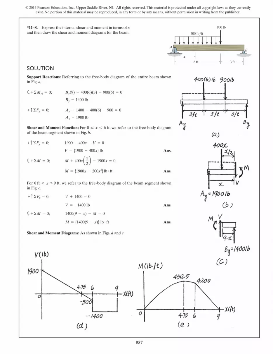
*11–8. Express the internal shear and moment in terms of x and then draw the shear and moment diagrams for the beam.
SOLUTION
AB
900 lb
400 lb/ft
6 ft 3 ft
x

858
© 2014 Pearson Education, Inc., Upper Saddle River, NJ. All rights reserved. This material is protected under all copyright laws as they currently exist. No portion of this material may be reproduced, in any form or by any means, without permission in writing from the publisher.
11–9. Express the internal shear and moment in terms of x and then draw the shear and moment diagrams for the overhanging beam.
SOLUTION
AB
6 kN/m
x
4 m 2 m

859
© 2014 Pearson Education, Inc., Upper Saddle River, NJ. All rights reserved. This material is protected under all copyright laws as they currently exist. No portion of this material may be reproduced, in any form or by any means, without permission in writing from the publisher.
11–10. Members ABC and BD of the counter chair are rigidly connected at B and the smooth collar at D is allowed to move freely along the vertical slot. Draw the shear and moment diagrams for member ABC.
SOLUTION
A
D
BC
P � 150 lb
1.5 ft1.5 ft1.5 ft

860
© 2014 Pearson Education, Inc., Upper Saddle River, NJ. All rights reserved. This material is protected under all copyright laws as they currently exist. No portion of this material may be reproduced, in any form or by any means, without permission in writing from the publisher.
11–11. Draw the shear and moment diagrams for the pipe. The end screw is subjected to a horizontal force of 5 kN. Hint: The reactions at the pin C must be replaced by an equivalent loading at point B on the axis of the pipe.
SOLUTION
80 mm
400 mm
5 kN
A
B
C

861
© 2014 Pearson Education, Inc., Upper Saddle River, NJ. All rights reserved. This material is protected under all copyright laws as they currently exist. No portion of this material may be reproduced, in any form or by any means, without permission in writing from the publisher.
*11–12. A reinforced concrete pier is used to support the stringers for a bridge deck. Draw the shear and moment diagrams for the pier when it is subjected to the stringer loads shown. Assume the columns at A and B exert only vertical reactions on the pier.
SOLUTION
1 m 1 m 1 m 1 m1.5 m60 kN 60 kN35 kN 35 kN 35 kN
1.5 m
A B

862
© 2014 Pearson Education, Inc., Upper Saddle River, NJ. All rights reserved. This material is protected under all copyright laws as they currently exist. No portion of this material may be reproduced, in any form or by any means, without permission in writing from the publisher.
11–13. Draw the shear and moment diagrams for the rod. It is supported by a pin at A and a smooth plate at B. The plate slides within the groove and so it cannot support a vertical force, although it can support a moment.
SOLUTION
4 m
A
B
2 m
15 kN

863
© 2014 Pearson Education, Inc., Upper Saddle River, NJ. All rights reserved. This material is protected under all copyright laws as they currently exist. No portion of this material may be reproduced, in any form or by any means, without permission in writing from the publisher.
11–14. The industrial robot is held in the stationary position shown. Draw the shear and moment diagrams of the arm ABC if it is pin connected at A and connected to a hydraulic cylinder (two-force member) BD. Assume the arm and grip have a uniform weight of 1.5 lb> in. and support the load of 40 lb at C.
SOLUTION
10 in.4 in.
50 in.A B C
D
120�

864
© 2014 Pearson Education, Inc., Upper Saddle River, NJ. All rights reserved. This material is protected under all copyright laws as they currently exist. No portion of this material may be reproduced, in any form or by any means, without permission in writing from the publisher.
11–15. Draw the shear and moment diagrams for the overhang beam.
SOLUTION
4 kN/m
3 m 3 m
AB

865
© 2014 Pearson Education, Inc., Upper Saddle River, NJ. All rights reserved. This material is protected under all copyright laws as they currently exist. No portion of this material may be reproduced, in any form or by any means, without permission in writing from the publisher.
*11–16. Determine the placement distance a of the roller support so that the largest absolute value of the moment is a minimum. Draw the shear and moment diagrams for this condition.
SOLUTION
A
P
a
P
B
L–2
L–2
866
© 2014 Pearson Education, Inc., Upper Saddle River, NJ. All rights reserved. This material is protected under all copyright laws as they currently exist. No portion of this material may be reproduced, in any form or by any means, without permission in writing from the publisher.
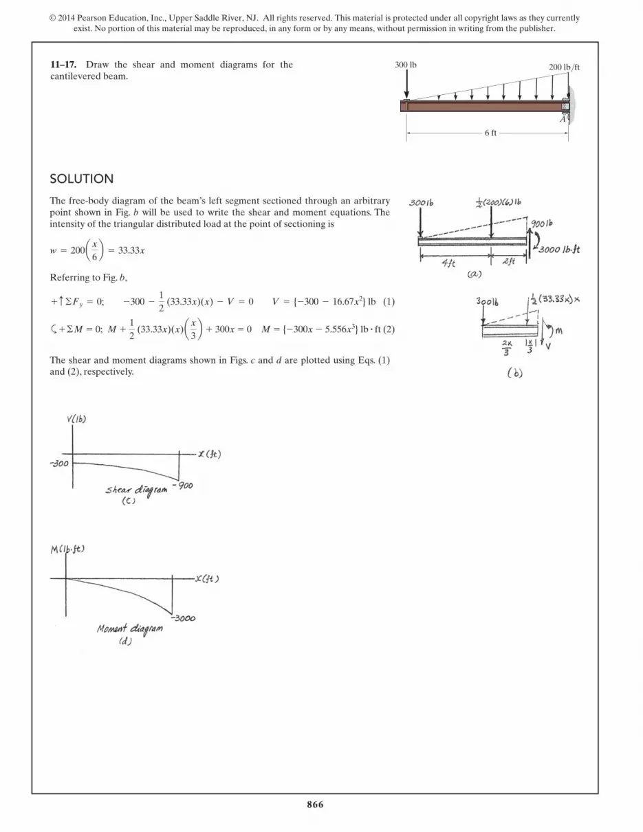
11–17. Draw the shear and moment diagrams for the cantilevered beam.
SOLUTION
300 lb 200 lb/ft
A
6 ft

867
© 2014 Pearson Education, Inc., Upper Saddle River, NJ. All rights reserved. This material is protected under all copyright laws as they currently exist. No portion of this material may be reproduced, in any form or by any means, without permission in writing from the publisher.
11–18. Draw the shear and moment diagrams for the beam, and determine the shear and moment throughout the beam as functions of x.
SOLUTION
6 ft 4 ft
2 kip/ft 8 kip
x
10 kip
40 kip�ft

868
© 2014 Pearson Education, Inc., Upper Saddle River, NJ. All rights reserved. This material is protected under all copyright laws as they currently exist. No portion of this material may be reproduced, in any form or by any means, without permission in writing from the publisher.
11–19. Draw the shear and moment diagrams for the beam.
SOLUTION
A
30 kip�ft
B
5 ft 5 ft
2 kip/ ft
5 ft

869
© 2014 Pearson Education, Inc., Upper Saddle River, NJ. All rights reserved. This material is protected under all copyright laws as they currently exist. No portion of this material may be reproduced, in any form or by any means, without permission in writing from the publisher.
*11–20. Draw the shear and moment diagrams for the overhanging beam.
SOLUTION BA
12 ft
3 kip/ft
6 ft

870
© 2014 Pearson Education, Inc., Upper Saddle River, NJ. All rights reserved. This material is protected under all copyright laws as they currently exist. No portion of this material may be reproduced, in any form or by any means, without permission in writing from the publisher.
11–21. The 150-lb man sits in the center of the boat, which has a uniform width and a weight per linear foot of 3 lb>ft. Determine the maximum bending moment exerted on the boat. Assume that the water exerts a uniform distributed load upward on the bottom of the boat.
SOLUTION
7.5 ft 7.5 ft

871
© 2014 Pearson Education, Inc., Upper Saddle River, NJ. All rights reserved. This material is protected under all copyright laws as they currently exist. No portion of this material may be reproduced, in any form or by any means, without permission in writing from the publisher.
11–22. Draw the shear and moment diagrams for the beam.
SOLUTION
w0
A B
L3
L3
L3

872
© 2014 Pearson Education, Inc., Upper Saddle River, NJ. All rights reserved. This material is protected under all copyright laws as they currently exist. No portion of this material may be reproduced, in any form or by any means, without permission in writing from the publisher.
11–23. Draw the shear and moment diagrams for the beam.
SOLUTION
BA4.5 m 4.5 m
5 kN/m5 kN/m

873
© 2014 Pearson Education, Inc., Upper Saddle River, NJ. All rights reserved. This material is protected under all copyright laws as they currently exist. No portion of this material may be reproduced, in any form or by any means, without permission in writing from the publisher.
*11–24. Draw the shear and moment diagrams for the compound beam.
SOLUTION
BA
6 ft
150 lb/ft 150 lb/ft
3 ft
C
874
© 2014 Pearson Education, Inc., Upper Saddle River, NJ. All rights reserved. This material is protected under all copyright laws as they currently exist. No portion of this material may be reproduced, in any form or by any means, without permission in writing from the publisher.
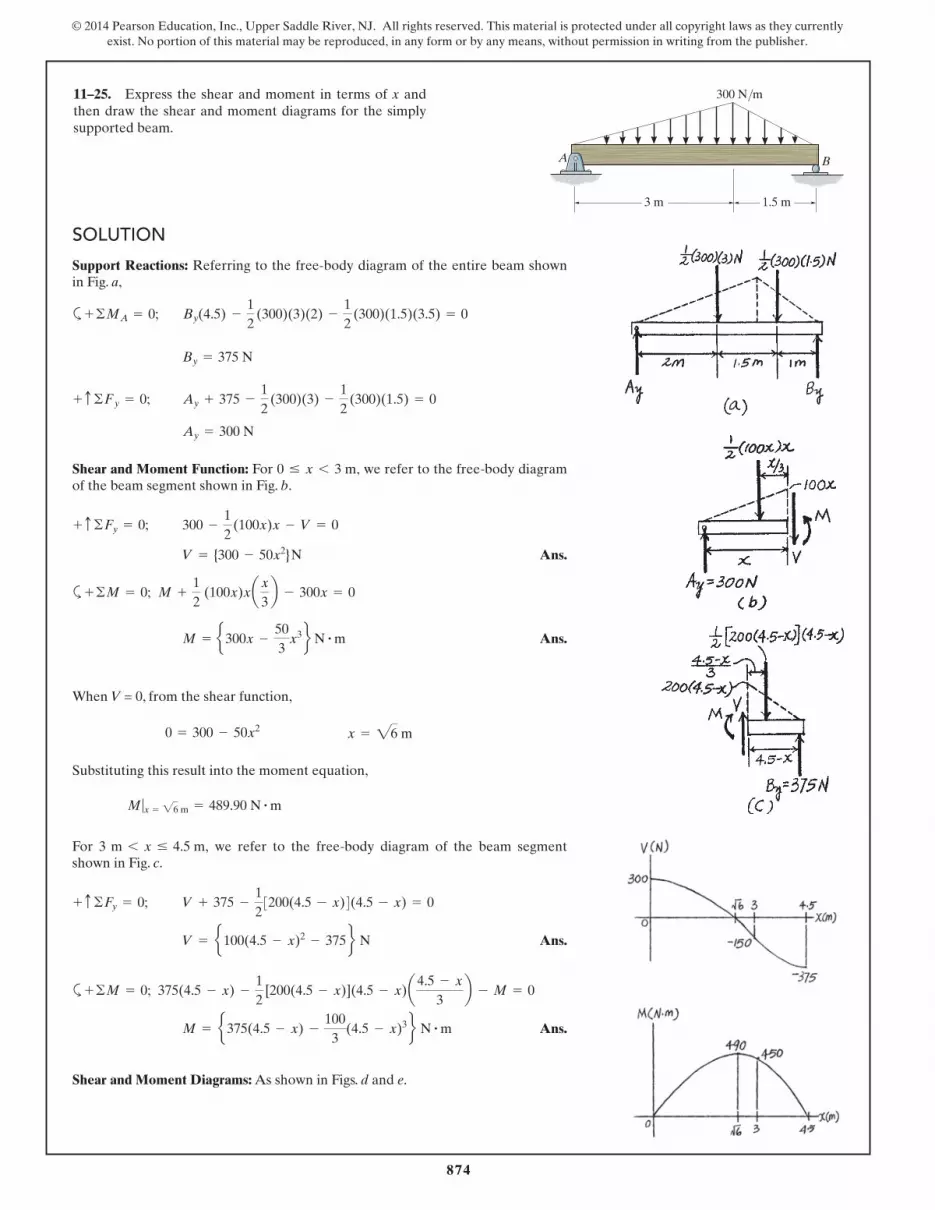
11–25. Express the shear and moment in terms of x and then draw the shear and moment diagrams for the simply supported beam.
SOLUTION
A B
3 m 1.5 m
300 N/m

875
© 2014 Pearson Education, Inc., Upper Saddle River, NJ. All rights reserved. This material is protected under all copyright laws as they currently exist. No portion of this material may be reproduced, in any form or by any means, without permission in writing from the publisher.
11–26. Draw the shear and moment diagrams for the beam and determine the shear and moment in the beam as functions of x, where 4 ft < x < 10 ft.
SOLUTION
200 lb�ft
B
x
4 ft 4 ft
150 lb/ft
6 ft
200 lb�ft
A

876
© 2014 Pearson Education, Inc., Upper Saddle River, NJ. All rights reserved. This material is protected under all copyright laws as they currently exist. No portion of this material may be reproduced, in any form or by any means, without permission in writing from the publisher.
11–27. The ski supports the 180-lb weight of the man. If the snow loading on its bottom surface is trapezoidal as shown, determine the intensity w, and then draw the shear and moment diagrams for the ski.
SOLUTION
180 lb
w w1.5 ft 3 ft 1.5 ft
3 ft

877
© 2014 Pearson Education, Inc., Upper Saddle River, NJ. All rights reserved. This material is protected under all copyright laws as they currently exist. No portion of this material may be reproduced, in any form or by any means, without permission in writing from the publisher.
*11–28. Draw the shear and moment diagrams for the compound beam.
SOLUTION
3 m 3 m1.5 m 1.5 m
5 kN3 kN/m
AB C D

878
© 2014 Pearson Education, Inc., Upper Saddle River, NJ. All rights reserved. This material is protected under all copyright laws as they currently exist. No portion of this material may be reproduced, in any form or by any means, without permission in writing from the publisher.
11–29. Draw the shear and moment diagrams for the simply supported beam.
SOLUTION
AB
2 m 2 m
10 kN 10 kN
15 kN�m
2 m

879
© 2014 Pearson Education, Inc., Upper Saddle River, NJ. All rights reserved. This material is protected under all copyright laws as they currently exist. No portion of this material may be reproduced, in any form or by any means, without permission in writing from the publisher.
11–30. Draw the shear and moment diagrams for the overhang beam.
SOLUTION
AB
M � 10 kN�m2 m 2 m 2 m
6 kN18 kN

880
© 2014 Pearson Education, Inc., Upper Saddle River, NJ. All rights reserved. This material is protected under all copyright laws as they currently exist. No portion of this material may be reproduced, in any form or by any means, without permission in writing from the publisher.
11–31. The beam is used to support a uniform load along CD due to the 6-kN weight of the crate. If the reaction at bearing support B can be assumed uniformly distributed along its width, draw the shear and moment diagrams for the beam.
SOLUTION
2.75 m 2 m0.75 m0.5 m
C
BA
D
881
© 2014 Pearson Education, Inc., Upper Saddle River, NJ. All rights reserved. This material is protected under all copyright laws as they currently exist. No portion of this material may be reproduced, in any form or by any means, without permission in writing from the publisher.
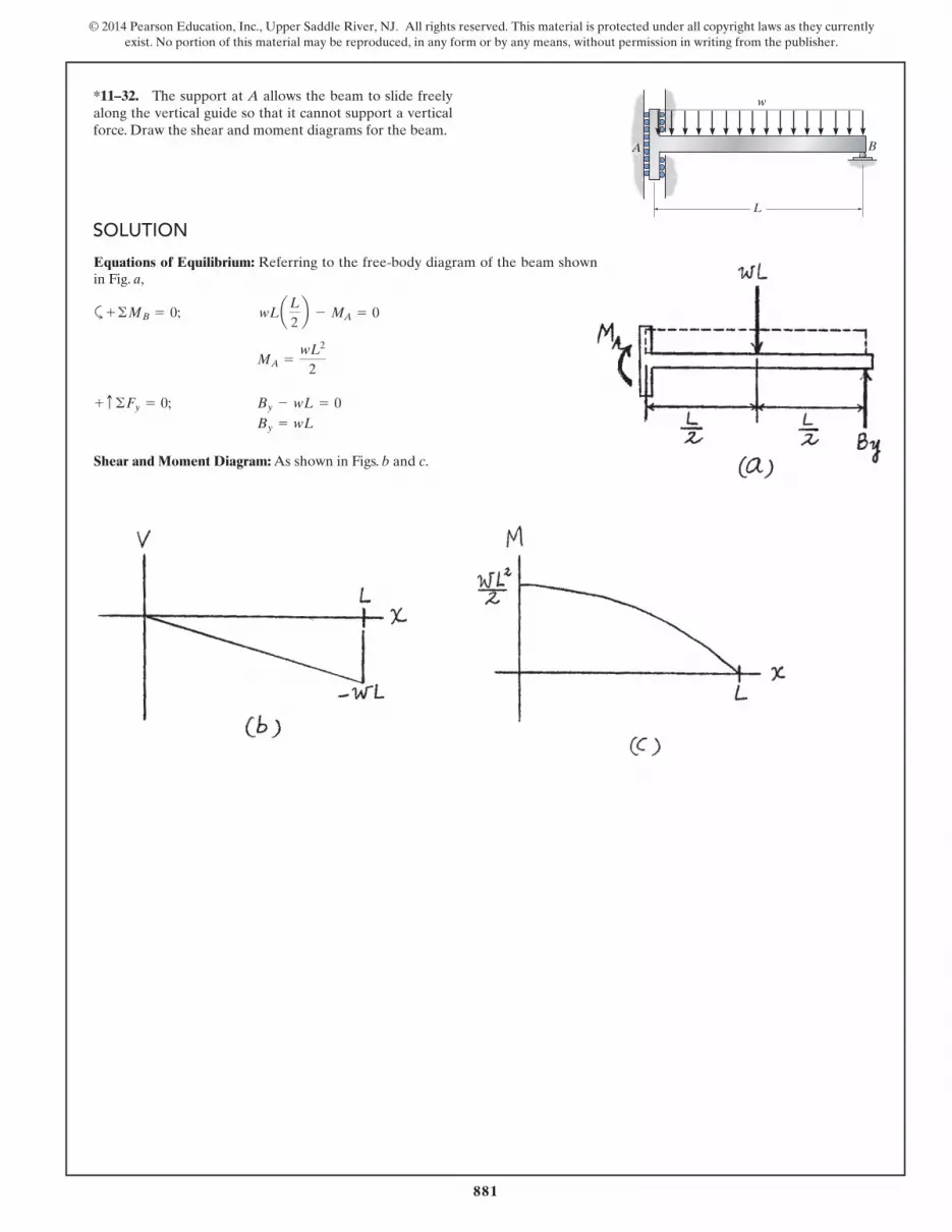
*11–32. The support at A allows the beam to slide freely along the vertical guide so that it cannot support a vertical force. Draw the shear and moment diagrams for the beam.
SOLUTION
BA
L
w

882
© 2014 Pearson Education, Inc., Upper Saddle River, NJ. All rights reserved. This material is protected under all copyright laws as they currently exist. No portion of this material may be reproduced, in any form or by any means, without permission in writing from the publisher.
11–33. The shaft is supported by a smooth thrust bearing at A and a smooth journal bearing at B. Draw the shear and moment diagrams for the shaft.
SOLUTION
A B
900 N
600 N�m
0.8 m 0.8 m 0.8 m
883
© 2014 Pearson Education, Inc., Upper Saddle River, NJ. All rights reserved. This material is protected under all copyright laws as they currently exist. No portion of this material may be reproduced, in any form or by any means, without permission in writing from the publisher.
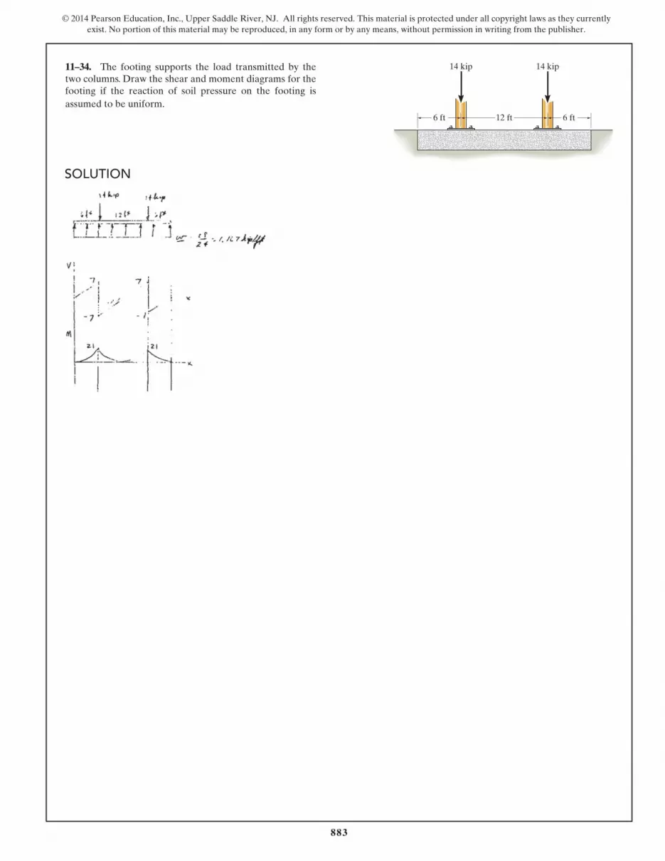
11–34. The footing supports the load transmitted by the two columns. Draw the shear and moment diagrams for the footing if the reaction of soil pressure on the footing is assumed to be uniform.
SOLUTION
6 ft 12 ft 6 ft
14 kip14 kip

884
© 2014 Pearson Education, Inc., Upper Saddle River, NJ. All rights reserved. This material is protected under all copyright laws as they currently exist. No portion of this material may be reproduced, in any form or by any means, without permission in writing from the publisher.
11–35. If the A-36 steel sheet roll is supported as shown and the allowable bending stress is 165 MPa, determine the smallest radius r of the spool if the steel sheet has a width of 1 m and a thickness of 1.5 mm. Also, find the corresponding maximum internal moment developed in the sheet.
SOLUTION
r

885
© 2014 Pearson Education, Inc., Upper Saddle River, NJ. All rights reserved. This material is protected under all copyright laws as they currently exist. No portion of this material may be reproduced, in any form or by any means, without permission in writing from the publisher.
*11–36. Determine the moment M that will produce a maximum stress of 10 ksi on the cross section.
SOLUTION
3 in.
D
A B
0.5 in.
M
0.5 in.
3 in.
C
10 in.
0.5 in.0.5 in.
886
© 2014 Pearson Education, Inc., Upper Saddle River, NJ. All rights reserved. This material is protected under all copyright laws as they currently exist. No portion of this material may be reproduced, in any form or by any means, without permission in writing from the publisher.
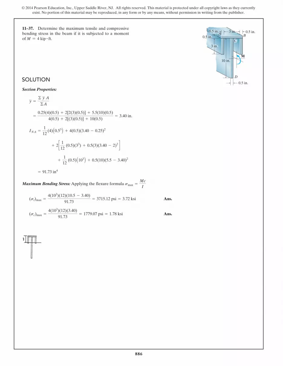
11–37. Determine the maximum tensile and compressive bending stress in the beam if it is subjected to a moment of M = 4 kip # ft.
SOLUTION
3 in.
D
A B
0.5 in.
M
0.5 in.
3 in.
C
10 in.
0.5 in.0.5 in.
887
© 2014 Pearson Education, Inc., Upper Saddle River, NJ. All rights reserved. This material is protected under all copyright laws as they currently exist. No portion of this material may be reproduced, in any form or by any means, without permission in writing from the publisher.
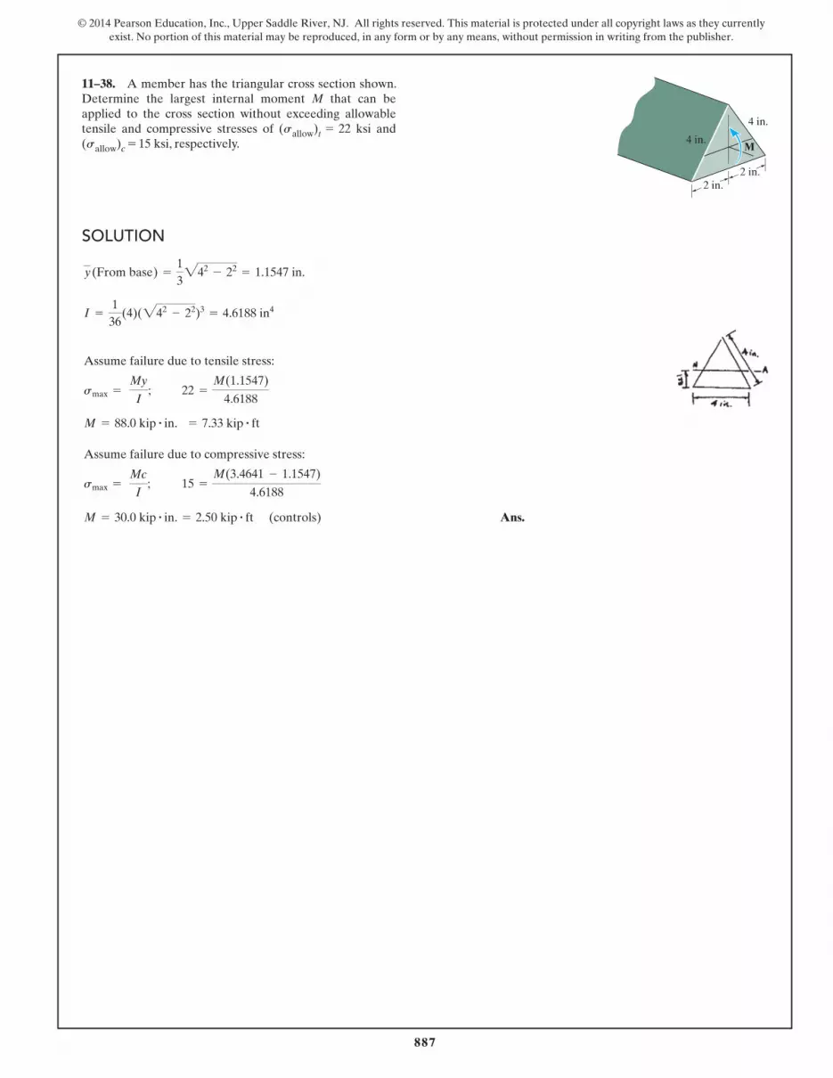
11–38. A member has the triangular cross section shown. Determine the largest internal moment M that can be applied to the cross section without exceeding allowable tensile and compressive stresses of (sallow)t = 22 ksi and (sallow)c = 15 ksi, respectively.
SOLUTION
2 in.2 in.
4 in.
M4 in.

888
© 2014 Pearson Education, Inc., Upper Saddle River, NJ. All rights reserved. This material is protected under all copyright laws as they currently exist. No portion of this material may be reproduced, in any form or by any means, without permission in writing from the publisher.
11–39. A member has the triangular cross section shown. If a moment of M = 800 lb # ft is applied to the cross section, determine the maximum tensile and compressive bending stresses in the member. Also, sketch a three-dimensional view of the stress distribution action over the cross section.
SOLUTION
2 in.2 in.
4 in.
M4 in.

889
© 2014 Pearson Education, Inc., Upper Saddle River, NJ. All rights reserved. This material is protected under all copyright laws as they currently exist. No portion of this material may be reproduced, in any form or by any means, without permission in writing from the publisher.
*11–40. If the beam is subjected to an internal moment of M = 30 kN # m, determine the maximum bending stress in the beam. The beam is made from A992 steel. Sketch the bending stress distribution on the cross section.
SOLUTION
50 mm
150 mm
15 mm
10 mm
15 mm
A
50 mm
M

890
© 2014 Pearson Education, Inc., Upper Saddle River, NJ. All rights reserved. This material is protected under all copyright laws as they currently exist. No portion of this material may be reproduced, in any form or by any means, without permission in writing from the publisher.
11–41. If the beam is subjected to an internal moment of M = 30 kN # m, determine the resultant force caused by the bending stress distribution acting on the top flange A.
SOLUTION
50 mm
150 mm
15 mm
10 mm
15 mm
A
50 mm
M

891
© 2014 Pearson Education, Inc., Upper Saddle River, NJ. All rights reserved. This material is protected under all copyright laws as they currently exist. No portion of this material may be reproduced, in any form or by any means, without permission in writing from the publisher.
11–42. Two designs for a beam are to be considered. Determine which one will support a moment of M = 150 kN # m with the least amount of bending stress. What is that stress?
SOLUTION
200 mm
300 mm
(a) (b)
15 mm
30 mm
15 mm
200 mm
300 mm
30 mm
15 mm
30 mm
892
© 2014 Pearson Education, Inc., Upper Saddle River, NJ. All rights reserved. This material is protected under all copyright laws as they currently exist. No portion of this material may be reproduced, in any form or by any means, without permission in writing from the publisher.
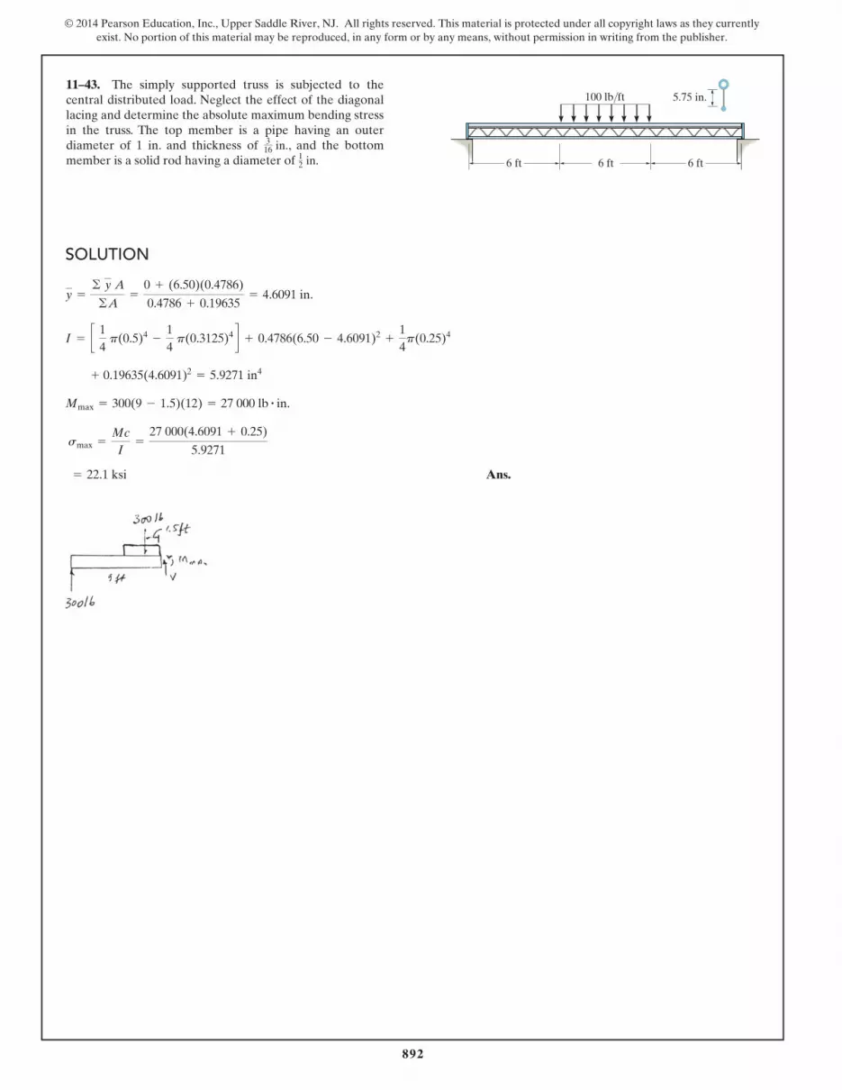
11–43. The simply supported truss is subjected to the central distributed load. Neglect the effect of the diagonal lacing and determine the absolute maximum bending stress in the truss. The top member is a pipe having an outer diameter of 1 in. and thickness of 3
16 in., and the bottom member is a solid rod having a diameter of 12 in.
SOLUTION
6 ft
5.75 in.
6 ft 6 ft
100 lb/ft

893
© 2014 Pearson Education, Inc., Upper Saddle River, NJ. All rights reserved. This material is protected under all copyright laws as they currently exist. No portion of this material may be reproduced, in any form or by any means, without permission in writing from the publisher.
*11–44. A box beam is constructed from four pieces of wood, glued together as shown. If the moment acting on the cross section is 10 kN # m, determine the stress at points A and B and show the results acting on volume elements located at these points.
SOLUTION
20 mm 20 mm
250 mm
M � 10 kN�m
160 mm
25 mm
25 mm B
A

894
© 2014 Pearson Education, Inc., Upper Saddle River, NJ. All rights reserved. This material is protected under all copyright laws as they currently exist. No portion of this material may be reproduced, in any form or by any means, without permission in writing from the publisher.
11–45. Determine the absolute maximum bending stress in the 1.5-in.-diameter shaft which is subjected to the concentrated forces. The sleeve bearings at A and B support only vertical forces.
SOLUTION
12 in.
18 in.
B
A
400 lb
15 in.
300 lb

895
© 2014 Pearson Education, Inc., Upper Saddle River, NJ. All rights reserved. This material is protected under all copyright laws as they currently exist. No portion of this material may be reproduced, in any form or by any means, without permission in writing from the publisher.
11–46. Determine the smallest allowable diameter of the shaft which is subjected to the concentrated forces. The sleeve bearings at A and B support only vertical forces, and the allowable bending stress is sallow = 22 ksi.
SOLUTION
12 in.
18 in.
B
A
400 lb
15 in.
300 lb

896
© 2014 Pearson Education, Inc., Upper Saddle River, NJ. All rights reserved. This material is protected under all copyright laws as they currently exist. No portion of this material may be reproduced, in any form or by any means, without permission in writing from the publisher.
11–47. The beam is subjected to a moment of M = 30 lb # ft. Determine the bending stress acting at point A and B. Also, stetch a three-dimensional view of the stress distribution acting over the entire cross-sectional area.
SOLUTION
3 in.
1 in.
1 in.
A
B
M � 30 lb�ft

897
© 2014 Pearson Education, Inc., Upper Saddle River, NJ. All rights reserved. This material is protected under all copyright laws as they currently exist. No portion of this material may be reproduced, in any form or by any means, without permission in writing from the publisher.
*11–48. The shaft is supported by a smooth thrust bearing at A and smooth journal bearing at D. If the shaft has the cross section shown, determine the absolute maximum bending stress in the shaft.
SOLUTION
A C DB
3 kN 3 kN
0.75 m 0.75 m1.5 m
40 mm 25 mm

898
© 2014 Pearson Education, Inc., Upper Saddle River, NJ. All rights reserved. This material is protected under all copyright laws as they currently exist. No portion of this material may be reproduced, in any form or by any means, without permission in writing from the publisher.
11–49. The axle of the freight car is subjected to wheel loadings of 20 kip. If it is supported by two journal bearings at C and D, determine the maximum bending stress developed at the center of the axle, where the diameter is 5.5 in.
SOLUTION
C DA B
20 kip 20 kip
10 in. 10 in.60 in.

899
© 2014 Pearson Education, Inc., Upper Saddle River, NJ. All rights reserved. This material is protected under all copyright laws as they currently exist. No portion of this material may be reproduced, in any form or by any means, without permission in writing from the publisher.
11–50. If the built-up beam is subjected to an internal moment of M = 75 kN # m, determine the maximum tensile and compressive stress acting in the beam.
SOLUTION
300 mmA
M
20 mm
10 mm
10 mm
150 mm
150 mm
150 mm

900
© 2014 Pearson Education, Inc., Upper Saddle River, NJ. All rights reserved. This material is protected under all copyright laws as they currently exist. No portion of this material may be reproduced, in any form or by any means, without permission in writing from the publisher.
11–51. If the built-up beam is subjected to an internal moment of M = 75 kN # m, determine the amount of this internal moment resisted by plate A.
SOLUTION 300 mmA
M
20 mm
10 mm
10 mm
150 mm
150 mm
150 mm

901
© 2014 Pearson Education, Inc., Upper Saddle River, NJ. All rights reserved. This material is protected under all copyright laws as they currently exist. No portion of this material may be reproduced, in any form or by any means, without permission in writing from the publisher.
*11–52. If the compound beam in Prob. 11–7 has a square cross section of side length a, determine the minimum value of a if the allowable bending stress is sallow = 150 MPa.
SOLUTION

902
© 2014 Pearson Education, Inc., Upper Saddle River, NJ. All rights reserved. This material is protected under all copyright laws as they currently exist. No portion of this material may be reproduced, in any form or by any means, without permission in writing from the publisher.
11–53. If the crane boom ABC in Prob. 11–3 has a rectangular cross section with a base of 2.5 in., determine its required height h to the nearest 1
4 in. if the allowable bending stress is sallow = 24 ksi.
SOLUTION

903
© 2014 Pearson Education, Inc., Upper Saddle River, NJ. All rights reserved. This material is protected under all copyright laws as they currently exist. No portion of this material may be reproduced, in any form or by any means, without permission in writing from the publisher.
11–54. A shaft is made of a polymer having an elliptical cross section. If it resists an internal moment of M = 50 N # m, determine the maximum bending stress developed in the material (a) using the flexure formula, where Iz = 14p (0.08 m)(0.0 m)3, (b) using integration. Sketch a three-dimensional view of the stress distribution acting over the cross-sectional area.
SOLUTION
y
z x
M � 50 N�m
80 mm
160 mm
y———(40)
2
2
z———(80)
2
2� � 1

904
© 2014 Pearson Education, Inc., Upper Saddle River, NJ. All rights reserved. This material is protected under all copyright laws as they currently exist. No portion of this material may be reproduced, in any form or by any means, without permission in writing from the publisher.
11–55. Solve Prob. 11–54 if the moment M = 50 N # m is applied about the y axis instead of the x axis. Here Iy = 14p (0.04 m)(0.08 m)3.
SOLUTION
y
z x
M � 50 N�m
80 mm
160 mm
y———(40)
2
2
z———(80)
2
2� � 1

905
© 2014 Pearson Education, Inc., Upper Saddle River, NJ. All rights reserved. This material is protected under all copyright laws as they currently exist. No portion of this material may be reproduced, in any form or by any means, without permission in writing from the publisher.
*11–56. Determine the absolute maximum bending stress in the tubular shaft if di = 160 mm and do = 200 mm.
SOLUTION
A B
di do
3 m 1 m
15 kN/m
60 kN � m

906
© 2014 Pearson Education, Inc., Upper Saddle River, NJ. All rights reserved. This material is protected under all copyright laws as they currently exist. No portion of this material may be reproduced, in any form or by any means, without permission in writing from the publisher.
11–57. The tubular shaft is to have a cross section such that its inner diameter and outer diameter are related by di = 0.8do. Determine these required dimensions if the allowable bending stress is sallow = 155 MPa.
SOLUTION
A B
di do
3 m 1 m
15 kN/m
60 kN � m

907
© 2014 Pearson Education, Inc., Upper Saddle River, NJ. All rights reserved. This material is protected under all copyright laws as they currently exist. No portion of this material may be reproduced, in any form or by any means, without permission in writing from the publisher.
11–58. The wood beam has a rectangular cross section in the proportion shown. Determine its required dimension b if the allowable bending stress is sallow = 10 MPa.
SOLUTION
500 N/m
2 m 2 m
1.5b
bA B

908
© 2014 Pearson Education, Inc., Upper Saddle River, NJ. All rights reserved. This material is protected under all copyright laws as they currently exist. No portion of this material may be reproduced, in any form or by any means, without permission in writing from the publisher.
11–59. If the beam is subjected to an internal moment of M = 100 kN # m, determine the bending stress developed at points A, B, and C. Sketch the bending stress distribution on the cross section.
SOLUTION
M300 mm
150 mm
30 mm
150 mm
C
30 mm
B
A

909
© 2014 Pearson Education, Inc., Upper Saddle River, NJ. All rights reserved. This material is protected under all copyright laws as they currently exist. No portion of this material may be reproduced, in any form or by any means, without permission in writing from the publisher.
*11–60. If the beam is made of material having an allowable tensile and compressive stress of (sallow)t = 125 MPa and (sallow)c = 150 MPa, respectively, determine the maximum allowable internal moment M that can be applied to the beam.
SOLUTION
M300 mm
150 mm
30 mm
150 mm
C
30 mm
B
A
910
© 2014 Pearson Education, Inc., Upper Saddle River, NJ. All rights reserved. This material is protected under all copyright laws as they currently exist. No portion of this material may be reproduced, in any form or by any means, without permission in writing from the publisher.
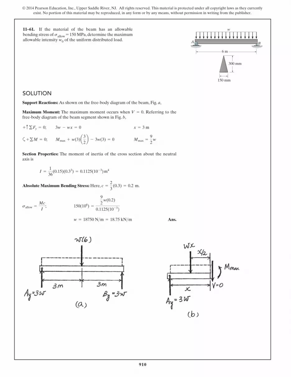
11–61. If the material of the beam has an allowable bending stress of sallow = 150 MPa, determine the maximum allowable intensity w0 of the uniform distributed load.
SOLUTION
6 m
150 mm
300 mm
A B
w

911
© 2014 Pearson Education, Inc., Upper Saddle River, NJ. All rights reserved. This material is protected under all copyright laws as they currently exist. No portion of this material may be reproduced, in any form or by any means, without permission in writing from the publisher.
11–62. If the compound beam in Prob. 11–24 has a square cross section, determine its dimension a if the allowable bending stress is sallow = 150 MPa.
SOLUTION

912
© 2014 Pearson Education, Inc., Upper Saddle River, NJ. All rights reserved. This material is protected under all copyright laws as they currently exist. No portion of this material may be reproduced, in any form or by any means, without permission in writing from the publisher.
11–63. If the beam in Prob. 11–22 has a rectangular cross section with a width b and a height h, determine the absolute maximum bending stress in the beam.
SOLUTION

913
© 2014 Pearson Education, Inc., Upper Saddle River, NJ. All rights reserved. This material is protected under all copyright laws as they currently exist. No portion of this material may be reproduced, in any form or by any means, without permission in writing from the publisher.
*11–64. The shaft is supported by a smooth thrust bearing at A and smooth journal bearing at C. If d = 3 in., determine the absolute maximum bending stress in the shaft.
SOLUTION
A C Dd
B
3 ft 3 ft
3600 lb
1800 lb3 ft

914
© 2014 Pearson Education, Inc., Upper Saddle River, NJ. All rights reserved. This material is protected under all copyright laws as they currently exist. No portion of this material may be reproduced, in any form or by any means, without permission in writing from the publisher.
11–65. The shaft is supported by a smooth thrust bearing at A and smooth journal bearing at C. If the material has an allowable bending stress of sallow = 24 ksi, determine the required minimum diameter d of the shaft to the nearest 1
16 in.
SOLUTION
A C Dd
B
3 ft 3 ft
3600 lb
1800 lb3 ft

915
© 2014 Pearson Education, Inc., Upper Saddle River, NJ. All rights reserved. This material is protected under all copyright laws as they currently exist. No portion of this material may be reproduced, in any form or by any means, without permission in writing from the publisher.
11–66. The man has a mass of 78 kg and stands motionless at the end of the diving board. If the board has the cross section shown, determine the maximum normal strain developed in the board. The modulus of elasticity for the material is E = 125 GPa. Assume A is a pin and B is a roller.
SOLUTION
B CA1.5 m 2.5 m
350 mm
20 mm30 mm
10 mm 10 mm 10 mm

916
© 2014 Pearson Education, Inc., Upper Saddle River, NJ. All rights reserved. This material is protected under all copyright laws as they currently exist. No portion of this material may be reproduced, in any form or by any means, without permission in writing from the publisher.
11–67. The two solid steel rods are bolted together along their length and support the loading shown. Assume the support at A is a pin and B is a roller. Determine the required diameter d of each of the rods if the allowable bending stress is sallow = 130 MPa.
SOLUTION
B
A
2 m
80 kN20 kN/m
2 m

917
© 2014 Pearson Education, Inc., Upper Saddle River, NJ. All rights reserved. This material is protected under all copyright laws as they currently exist. No portion of this material may be reproduced, in any form or by any means, without permission in writing from the publisher.
*11–68. Solve Prob. 11–67 if the rods are rotated 90� so that both rods rest on the supports at A (pin) and B (roller).
SOLUTION
B
A
2 m
80 kN20 kN/m
2 m

918
© 2014 Pearson Education, Inc., Upper Saddle River, NJ. All rights reserved. This material is protected under all copyright laws as they currently exist. No portion of this material may be reproduced, in any form or by any means, without permission in writing from the publisher.
11–69. The beam is subjected to a bending moment of M = 20 kip # ft directed as shown. Determine the maximum bending stress in the beam and the orientation of the neutral axis.
SOLUTION
16 in.
10 in.
8 in.
14 in.
y
z
M
B C
A D
45�

919
© 2014 Pearson Education, Inc., Upper Saddle River, NJ. All rights reserved. This material is protected under all copyright laws as they currently exist. No portion of this material may be reproduced, in any form or by any means, without permission in writing from the publisher.
11–70. Determine the maximum magnitude of the bending moment M that can be applied to the beam so that the bending stress in the member does not exceed 12 ksi.
SOLUTION
16 in.
10 in.
8 in.
14 in.
y
z
M
B C
A D
45�

920
© 2014 Pearson Education, Inc., Upper Saddle River, NJ. All rights reserved. This material is protected under all copyright laws as they currently exist. No portion of this material may be reproduced, in any form or by any means, without permission in writing from the publisher.
11–71. If the resultant internal moment acting on the cross section of the aluminum strut has a magnitude of M = 520 N # m and is directed as shown, determine the bending stress at points A and B. The location y of the centroid C of the strut’s cross-sectional area must be determined. Also, specify the orientation of the neutral axis.
SOLUTION
20 mm20 mm
z BC
–y
200 mm
y
M � 520 N�m
125 13
200 mm 200 mmA
20 mm

921
© 2014 Pearson Education, Inc., Upper Saddle River, NJ. All rights reserved. This material is protected under all copyright laws as they currently exist. No portion of this material may be reproduced, in any form or by any means, without permission in writing from the publisher.
*11–72. The resultant internal moment acting on the cross section of the aluminum strut has a magnitude of M = 520 N # m and is directed as shown. Determine maximum bending stress in the strut. The location y of the centroid C of the strut’s cross-sectional area must be determined. Also, specify the orientation of the neutral axis.
SOLUTION
20 mm20 mm
z BC
–y
200 mm
y
M � 520 N�m
125 13
200 mm 200 mmA
20 mm
922
© 2014 Pearson Education, Inc., Upper Saddle River, NJ. All rights reserved. This material is protected under all copyright laws as they currently exist. No portion of this material may be reproduced, in any form or by any means, without permission in writing from the publisher.
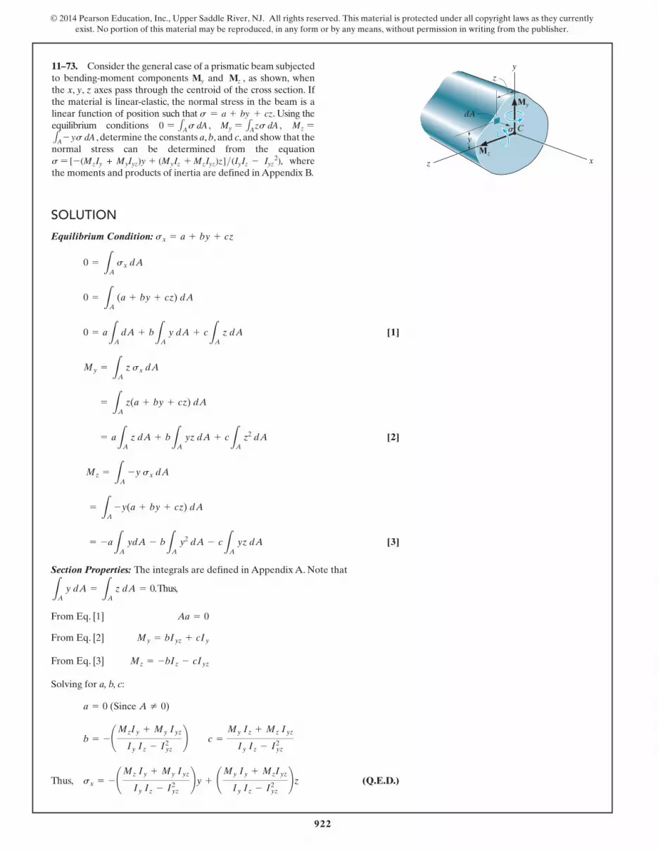
11–73. Consider the general case of a prismatic beam subjected to bending-moment components My and Mz , as shown, when the x, y, z axes pass through the centroid of the cross section. If the material is linear-elastic, the normal stress in the beam is a linear function of position such that s = a + by + cz. Using the equilibrium conditions 0 = 1As dA , My = 1Azs dA , Mz =1A - ys dA , determine the constants a, b, and c, and show that the normal stress can be determined from the equation s = [- (MzIy + MyIyz)y + (MyIz + MzIyz)z]>(IyIz - Iyz
2), where the moments and products of inertia are defined in Appendix B.
SOLUTION
y
y
z x
z
dAMy
C
Mz
s
923
© 2014 Pearson Education, Inc., Upper Saddle River, NJ. All rights reserved. This material is protected under all copyright laws as they currently exist. No portion of this material may be reproduced, in any form or by any means, without permission in writing from the publisher.
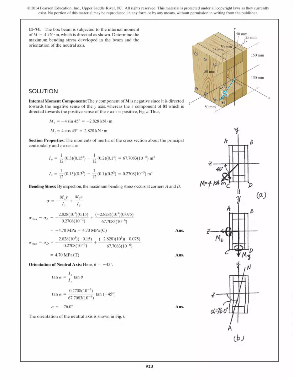
11–74. The box beam is subjected to the internal moment of M = 4 kN # m, which is directed as shown. Determine the maximum bending stress developed in the beam and the orientation of the neutral axis.
SOLUTION
z
y
x
150 mm
150 mm
25 mm50 mm
50 mm
50 mm
50 mm
45�
25 mm
M

924
© 2014 Pearson Education, Inc., Upper Saddle River, NJ. All rights reserved. This material is protected under all copyright laws as they currently exist. No portion of this material may be reproduced, in any form or by any means, without permission in writing from the publisher.
11–75. If the wood used for the box beam has an allowable bending stress of (sallow) = 6 MPa, determine the maximum allowable internal moment M that can be applied to the beam.
SOLUTIONz
y
x
150 mm
150 mm
25 mm50 mm
50 mm
50 mm
50 mm
45�
25 mm
M

925
© 2014 Pearson Education, Inc., Upper Saddle River, NJ. All rights reserved. This material is protected under all copyright laws as they currently exist. No portion of this material may be reproduced, in any form or by any means, without permission in writing from the publisher.
*11–76. For the section, Iy� = 31.7(10-6) m4, Iz� = 114(10-6) m4, Iy�z� = 15.1(10-6) m4. Using the techniques outlined in Appendix A, the member’s cross-sectional area has principal moments of inertia of Iy = 29.0(10-6) m4 and Iz = 117(10-6) m4, computed about the principal axes of inertia y and z, respectively. If the section is subjected to a moment of M = 2500 N # m directed as shown, determine the stress produced at point A, using Eq. 11–17.
SOLUTION
60 mm
60 mm
60 mm 60 mm
140 mm
80 mm
z¿
y¿
10.10�
M � 2500 N�mC
A
z
y

926
© 2014 Pearson Education, Inc., Upper Saddle River, NJ. All rights reserved. This material is protected under all copyright laws as they currently exist. No portion of this material may be reproduced, in any form or by any means, without permission in writing from the publisher.
11–77. Solve Prob. 11–76 using the equation developed in Prob. 11–73.
SOLUTION
60 mm
60 mm
60 mm 60 mm
140 mm
80 mm
z¿
y¿
10.10�
M � 2500 N�mC
A
z
y

927
© 2014 Pearson Education, Inc., Upper Saddle River, NJ. All rights reserved. This material is protected under all copyright laws as they currently exist. No portion of this material may be reproduced, in any form or by any means, without permission in writing from the publisher.
11–78. If the beam is subjected to the internal moment of, M = 1200 kN # m, determine the maximum bending stress acting on the beam and the orientation of the neutral axis.
SOLUTION
150 mm
150 mm
150 mm
150 mm
300 mm
150 mm
y
xz
M
30�

928
© 2014 Pearson Education, Inc., Upper Saddle River, NJ. All rights reserved. This material is protected under all copyright laws as they currently exist. No portion of this material may be reproduced, in any form or by any means, without permission in writing from the publisher.
11–79. If the beam is made from a material having an allowable tensile and compressive stress of (sallow)t = 125 MPa and (sallow)C = 150 MPa, respectively, determine the maximum allowable internal moment M that can be applied to the beam.
SOLUTION
150 mm
150 mm
150 mm
150 mm
300 mm
150 mm
y
xz
M
30�
929
© 2014 Pearson Education, Inc., Upper Saddle River, NJ. All rights reserved. This material is protected under all copyright laws as they currently exist. No portion of this material may be reproduced, in any form or by any means, without permission in writing from the publisher.
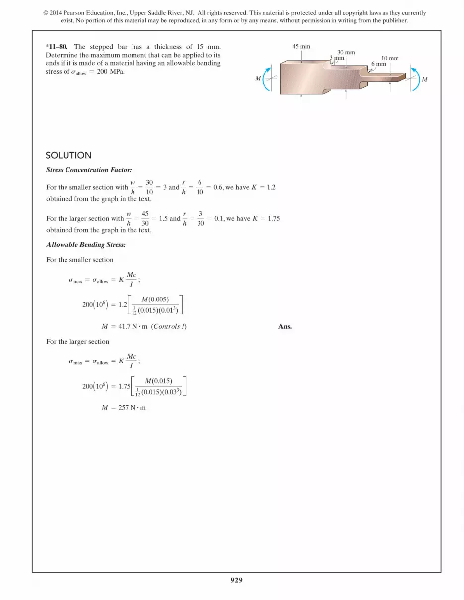
*11–80. The stepped bar has a thickness of 15 mm. Determine the maximum moment that can be applied to its ends if it is made of a material having an allowable bending stress of sallow = 200 MPa.
SOLUTION
M
10 mm
M
30 mm45 mm
3 mm6 mm
Stress Concentration Factor:
For the smaller section with and , we have
obtained from the graph in the text.
For the larger section with and , we have
obtained from the graph in the text.
Allowable Bending Stress:
For the smaller section
Ans.
For the larger section
M = 257 N # m
200 A106 B = 1.75B M(0.015)112 (0.015)(0.033)
R
smax = sallow = K Mc
I ;
M = 41.7 N # m (Controls !)
200 A106 B = 1.2B M(0.005)112 (0.015)(0.013)
R
smax = sallow = K Mc
I ;
K = 1.75r
h=
330
= 0.1wh
=4530
= 1.5
K = 1.2r
h=
610
= 0.6wh
=3010
= 3

930
© 2014 Pearson Education, Inc., Upper Saddle River, NJ. All rights reserved. This material is protected under all copyright laws as they currently exist. No portion of this material may be reproduced, in any form or by any means, without permission in writing from the publisher.
11–81. If the radius of each notch on the plate is r = 0.5 in., determine the largest moment that can be applied. The allowable bending stress for the material is sallow = 18 ksi.
SOLUTION
12.5 in.
14.5 in.1 in.
MM

931
© 2014 Pearson Education, Inc., Upper Saddle River, NJ. All rights reserved. This material is protected under all copyright laws as they currently exist. No portion of this material may be reproduced, in any form or by any means, without permission in writing from the publisher.
11–82. The symmetric notched plate is subjected to bending. If the radius of each notch is r = 0.5 in. and the applied moment is M = 10 kip # ft, determine the maximum bending stress in the plate.
SOLUTION
12.5 in.
14.5 in.1 in.
MM

932
© 2014 Pearson Education, Inc., Upper Saddle River, NJ. All rights reserved. This material is protected under all copyright laws as they currently exist. No portion of this material may be reproduced, in any form or by any means, without permission in writing from the publisher.
11–83. The bar is subjected to a moment of M = 40 N # m. Determine the smallest radius r of the fillets so that an allowable bending stress of sallow = 124 MPa is not exceeded.
SOLUTION
80 mm
20 mm 7 mm
M Mr
r

933
© 2014 Pearson Education, Inc., Upper Saddle River, NJ. All rights reserved. This material is protected under all copyright laws as they currently exist. No portion of this material may be reproduced, in any form or by any means, without permission in writing from the publisher.
*11–84. The bar is subjected to a moment of M = 17.5 N # m If r = 5 mm, determine the maximum bending stress in the material.
SOLUTION
80 mm
20 mm 7 mm
M Mr
r
934
© 2014 Pearson Education, Inc., Upper Saddle River, NJ. All rights reserved. This material is protected under all copyright laws as they currently exist. No portion of this material may be reproduced, in any form or by any means, without permission in writing from the publisher.
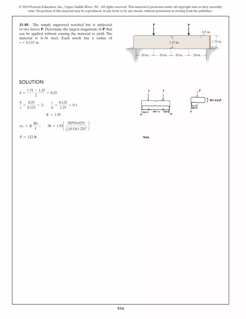
11–85. The simply supported notched bar is subjected to two forces P. Determine the largest magnitude of P that can be applied without causing the material to yield. The material is A-36 steel. Each notch has a radius of r = 0.125 in.
SOLUTION
20 in. 20 in.
1.75 in.
0.5 in.
P P
1.25 in.
20 in. 20 in.

935
© 2014 Pearson Education, Inc., Upper Saddle River, NJ. All rights reserved. This material is protected under all copyright laws as they currently exist. No portion of this material may be reproduced, in any form or by any means, without permission in writing from the publisher.
11–86. The simply supported notched bar is subjected to the two loads, each having a magnitude of P = 100 lb. Determine the maximum bending stress developed in the bar, and sketch the bending-stress distribution acting over the cross section at the center of the bar. Each notch has a radius of r = 0.125 in.
SOLUTION
20 in. 20 in.
1.75 in.
0.5 in.
P P
1.25 in.
20 in. 20 in.

936
© 2014 Pearson Education, Inc., Upper Saddle River, NJ. All rights reserved. This material is protected under all copyright laws as they currently exist. No portion of this material may be reproduced, in any form or by any means, without permission in writing from the publisher.
11–87. The bar is subjected to a moment of M = 153 N # m. Determine the smallest radius r of the fillets so that an allowable bending stress of sallow = 120 MPa is not exceeded.
SOLUTION
60 mm40 mm 7 mm
M M
r
r

937
© 2014 Pearson Education, Inc., Upper Saddle River, NJ. All rights reserved. This material is protected under all copyright laws as they currently exist. No portion of this material may be reproduced, in any form or by any means, without permission in writing from the publisher.
*11–88. The bar is subjected to a moment of M = 17.5 N # m. If r = 6 mm determine the maximum bending stress in the material.
SOLUTION
60 mm40 mm 7 mm
M M
r
r

938
© 2014 Pearson Education, Inc., Upper Saddle River, NJ. All rights reserved. This material is protected under all copyright laws as they currently exist. No portion of this material may be reproduced, in any form or by any means, without permission in writing from the publisher.
11–89. The beam is made from three boards nailed together as shown. If the moment acting on the cross section is M = 650 N # m, determine the resultant force the bending stress produces on the top board.
SOLUTION
M � 650 N�m
250 mm
15 mm
125 mm 20 mm
20 mm

939
© 2014 Pearson Education, Inc., Upper Saddle River, NJ. All rights reserved. This material is protected under all copyright laws as they currently exist. No portion of this material may be reproduced, in any form or by any means, without permission in writing from the publisher.
11–90. The beam is made from three boards nailed together as shown. Determine the maximum tensile and compressive stresses in the beam.
SOLUTION
M � 650 N�m
250 mm
15 mm
125 mm 20 mm
20 mm

940
© 2014 Pearson Education, Inc., Upper Saddle River, NJ. All rights reserved. This material is protected under all copyright laws as they currently exist. No portion of this material may be reproduced, in any form or by any means, without permission in writing from the publisher.
11–91. Draw the shear and moment diagrams for the shaft if it is subjected to the vertical loadings of the belt, gear, and flywheel. The bearings at A and B exert only vertical reactions on the shaft.
SOLUTION
A B
200 mm
450 N
150 N
300 N
200 mm400 mm 300 mm
941
© 2014 Pearson Education, Inc., Upper Saddle River, NJ. All rights reserved. This material is protected under all copyright laws as they currently exist. No portion of this material may be reproduced, in any form or by any means, without permission in writing from the publisher.
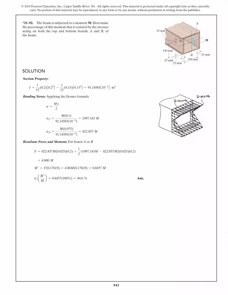
*11–92. The beam is subjected to a moment M. Determine the percentage of this moment that is resisted by the stresses acting on both the top and bottom boards, A and B, of the beam.
SOLUTION
150 mm
25 mm
25 mm
150 mm
M
25 mm
25 mm
B
A
D
Section Property:
Bending Stress: Applying the flexure formula
Resultant Force and Moment: For board A or B
Ans.scaM¿Mb = 0.8457(100%) = 84.6 %
M¿ = F(0.17619) = 4.80M(0.17619) = 0.8457 M
= 4.800 M
F = 822.857M(0.025)(0.2) +12
(1097.143M - 822.857M)(0.025)(0.2)
sD =M(0.075)
91.14583(10-6)= 822.857 M
sE =M(0.1)
91.14583(10-6)= 1097.143 M
s =My
I
I =112
(0.2) A0.23 B -1
12 (0.15) A0.153 B = 91.14583 A10-6 B m4

942
© 2014 Pearson Education, Inc., Upper Saddle River, NJ. All rights reserved. This material is protected under all copyright laws as they currently exist. No portion of this material may be reproduced, in any form or by any means, without permission in writing from the publisher.
11–93. Determine the moment M that should be applied to the beam in order to create a compressive stress at point D of sD = 30 MPa. Also sketch the stress distribution acting over the cross section and compute the maximum stress developed in the beam.
SOLUTION
150 mm
25 mm
25 mm
150 mm
M
25 mm
25 mm
B
A
D
Section Property:
Bending Stress: Applying the flexure formula
Ans.
Ans.smax =Mc
I=
36458(0.1)
91.14583(10-6)= 40.0 MPa
M = 36458 N # m = 36.5 kN # m
30 A106 B =M(0.075)
91.14583(10-6)
s =My
I
I =112
(0.2) A0.23 B -1
12 (0.15) A0.153 B = 91.14583 A10-6 B m4

943
© 2014 Pearson Education, Inc., Upper Saddle River, NJ. All rights reserved. This material is protected under all copyright laws as they currently exist. No portion of this material may be reproduced, in any form or by any means, without permission in writing from the publisher.
11–94. A shaft is made of a polymer having a parabolic cross section. If it resists an internal moment of M = 125 N # m, determine the maximum bending stress developed in the material (a) using the flexure formula and (b) using integration. Sketch a three-dimensional view of the stress distribution acting over the cross-sectional area.
SOLUTION
y
z
x
M � 125 N· m
50 mm
100 mm
50 mm
y � 100 – z
2/ 25

944
© 2014 Pearson Education, Inc., Upper Saddle River, NJ. All rights reserved. This material is protected under all copyright laws as they currently exist. No portion of this material may be reproduced, in any form or by any means, without permission in writing from the publisher.
11–95. Determine the maximum bending stress in the handle of the cable cutter at section a–a. A force of 45 lb is applied to the handles. The cross-sectional area is shown in the figure.
SOLUTION
4 in.
45 lb20�
a
a
3 in.
5 in.
A
45 lb
0.75 in.
0.50 in.

945
© 2014 Pearson Education, Inc., Upper Saddle River, NJ. All rights reserved. This material is protected under all copyright laws as they currently exist. No portion of this material may be reproduced, in any form or by any means, without permission in writing from the publisher.
*11–96. The chair is supported by an arm that is hinged so it rotates about the vertical axis at A. If the load on the chair is 180 lb and the arm is a hollow tube section having the dimensions shown, determine the maximum bending stress at section a–a.
SOLUTION
1 in.
3 in.
a
a
A
180 lb
2.5 in.
0.5 in.8 in.

946
© 2014 Pearson Education, Inc., Upper Saddle River, NJ. All rights reserved. This material is protected under all copyright laws as they currently exist. No portion of this material may be reproduced, in any form or by any means, without permission in writing from the publisher.
11–97. Draw the shear and moment diagrams for the beam and determine the shear and moment in the beam as functions of x, where 0 … x 6 6 ft .
SOLUTION
6 ft 4 ft
2 kip/ ft
50 kip�ft
8 kip
x

947
© 2014 Pearson Education, Inc., Upper Saddle River, NJ. All rights reserved. This material is protected under all copyright laws as they currently exist. No portion of this material may be reproduced, in any form or by any means, without permission in writing from the publisher.
11–98. The wing spar ABD of a light plane is made from 2014–T6 aluminum and has a cross-sectional area of 1.27 in.2, a depth of 3 in., and a moment of inertia about its neutral axis of 2.68 in4. Determine the absolute maximum bending stress in the spar if the anticipated loading is to be as shown. Assume A, B, and C are pins. Connection is made along the central longitudinal axis of the spar.
SOLUTION
2 ft DBA
C3 ft 6 ft
80 lb/in.


![IAC 8/11/21 Revenue[701] Ch 40, p.1 CHAPTER 40](https://img.pdfslide.net/doc/110x75/63188abac51d6b41aa040da4/iac-81121-revenue701-ch-40-p1-chapter-40-.jpg)


![IAC 11/3/21 Human Services[441] Ch 109, p.1 ... - Iowa.gov](https://img.pdfslide.net/doc/110x75/631d5919f7af5f2ec200de7b/iac-11321-human-services441-ch-109-p1-iowagov.jpg)


