Embed Size (px)
Citation preview
KYAMBOGO UNIVERSITY
P.O.BOX, 1 KYAMBOGO – KAMPALA, UGANDA
www.kyambogo.ac.ug
FACULTY OF ENGINEERING
DEPARTMENT OF ELECTRICAL AND EECTRONICS ENGINEERING
INDUSTRAL TRAINING REPORT CARRIED OUT SMART TELECOM-UGANDA.
BY:
MWASAMPIJJA FABIA11/U/261/ETD/GV
AN INDUSTRIAL TRAINING REPORT SUBMITTED TO FACULTY OFENGINEERING, DEPARTMENT OF ELECTRICAL AND ELECTRONICSENGINEERING IN PARTIAL FULFILMENT OF THE REQUIREMENTSLEADING TO THE AWARD OF BACHELOR OF ENGINEERING INTELECOMMUNICATION ENGINEERING OF KYAMBOGOUNIVERSITY
JUNE-AUGUST 2014
DECLARATION
I hereby, declare that this is the original copy of the writtenindustrial training report of my third year of study.I have written it myself basing on the practical work done duringmy industrial training at Smart Telecom and basing on the researchdone on the internet, text books, discussions with other traineesand the observation I made during the industrial training.
Signature: ....................................................Date..................................Name: MWASAMPIJJA FABIA Tel: 0706412633
i
APPROVAL
The industrial training Report has been submitted for examination
with the approval of the following people.
Signature……………………………… Date…………………………
Miss Regina Mwenyango.
Company supervisor/ Head of Core Networks,
Smart Telecom.
Tel: +256-742020218
Email: [email protected]
Signature……………………………….. Date…………………………………………….
Miss Harriet Nassuna.
Academic supervisor,
ii

Kyambogo University.
Tel: +256772562074.
DEDICATION
I dedicate this report to my beloved family for emptying theirpockets into my studies so that I can have a better and brighttomorrow.
iii

ACKNOWLEGEMENTS
There are really very important people whom I am indebted to andneed to be acknowledged for making this training a success.
Firstly I thank God for keeping me alive, for his love, grace,provisions and mercy upon my life.
Secondly I thank engineer MWENYANGO REGINA for the invaluableinformation and guidance she provided. I also thank the entirestaff of SMART TELECOM for their great cooperation and guidancethroughout the entire training process.
iv

I am deeply indebted to MRS. NASUUNA HARRIET, my supervisor whoguided me and provided professional advice.
Last but not least I send my sincere thanks and gratitude to myparents and siblings because they have been my holders this farand played a very big role towards my Education.
ABSTRACT
v
Training was carried out at Smart Telecom Uganda during the period
16th June to 15th August 2014. This report hereby presented gives
a summary of the knowledge and skills acquired as well as the
activities carried out. This trainings prime objective was to
enable the student to acquire basic skills and techniques of the
practical work performed in the field by the experts.
Chapter one entails the background of Smart Telecom Uganda.
Chapter two discusses the descriptions of telecommunication
systems.
Chapter three discusses the practical work which included cable
termination, SIM activations, Tagging of Smart equipment, SFP
replacement, IDU installation among others.
Chapter four discusses the conclusions and the recommendations.
At the end of this report, I have provided the references for my
report.
I wish to make it clear that the report has been proof read andany errors to the document are completely human.
vi
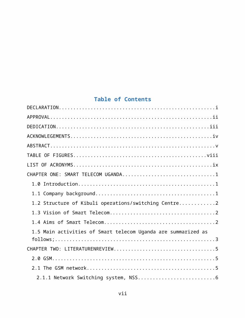
Table of Contents
DECLARATION......................................................iAPPROVAL........................................................iiDEDICATION.....................................................iiiACKNOWLEGEMENTS.................................................ivABSTRACT.........................................................vTABLE OF FIGURES..............................................viiiLIST OF ACRONYMS................................................ixCHAPTER ONE: SMART TELECOM UGANDA................................11.0 Introduction...............................................11.1 Company background.........................................11.2 Structure of Kibuli operations/switching Centre............21.3 Vision of Smart Telecom....................................21.4 Aims of Smart Telecom......................................21.5 Main activities of Smart telecom Uganda are summarized as follows;.......................................................3
CHAPTER TWO: LITERATURENREVIEW...................................52.0 GSM........................................................52.1 The GSM network............................................52.1.1 Network Switching system, NSS..........................6
vii
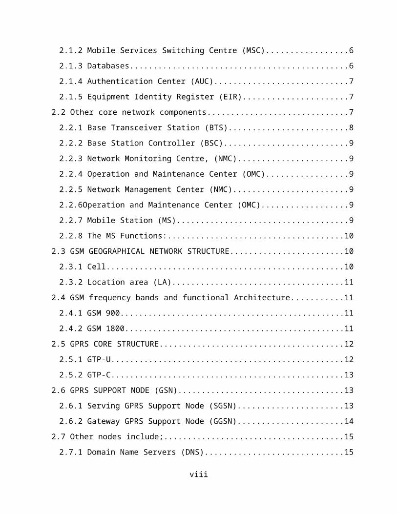
2.1.2 Mobile Services Switching Centre (MSC).................62.1.3 Databases..............................................62.1.4 Authentication Center (AUC)............................72.1.5 Equipment Identity Register (EIR)......................7
2.2 Other core network components..............................72.2.1 Base Transceiver Station (BTS).........................82.2.2 Base Station Controller (BSC)..........................92.2.3 Network Monitoring Centre, (NMC).......................92.2.4 Operation and Maintenance Center (OMC).................92.2.5 Network Management Center (NMC)........................92.2.6Operation and Maintenance Center (OMC)..................92.2.7 Mobile Station (MS)....................................92.2.8 The MS Functions:.....................................10
2.3 GSM GEOGRAPHICAL NETWORK STRUCTURE........................102.3.1 Cell..................................................102.3.2 Location area (LA)....................................11
2.4 GSM frequency bands and functional Architecture...........112.4.1 GSM 900................................................112.4.2 GSM 1800...............................................11
2.5 GPRS CORE STRUCTURE.......................................122.5.1 GTP-U.................................................122.5.2 GTP-C.................................................13
2.6 GPRS SUPPORT NODE (GSN)...................................132.6.1 Serving GPRS Support Node (SGSN)......................132.6.2 Gateway GPRS Support Node (GGSN)......................14
2.7 Other nodes include;......................................152.7.1 Domain Name Servers (DNS).............................15
viii
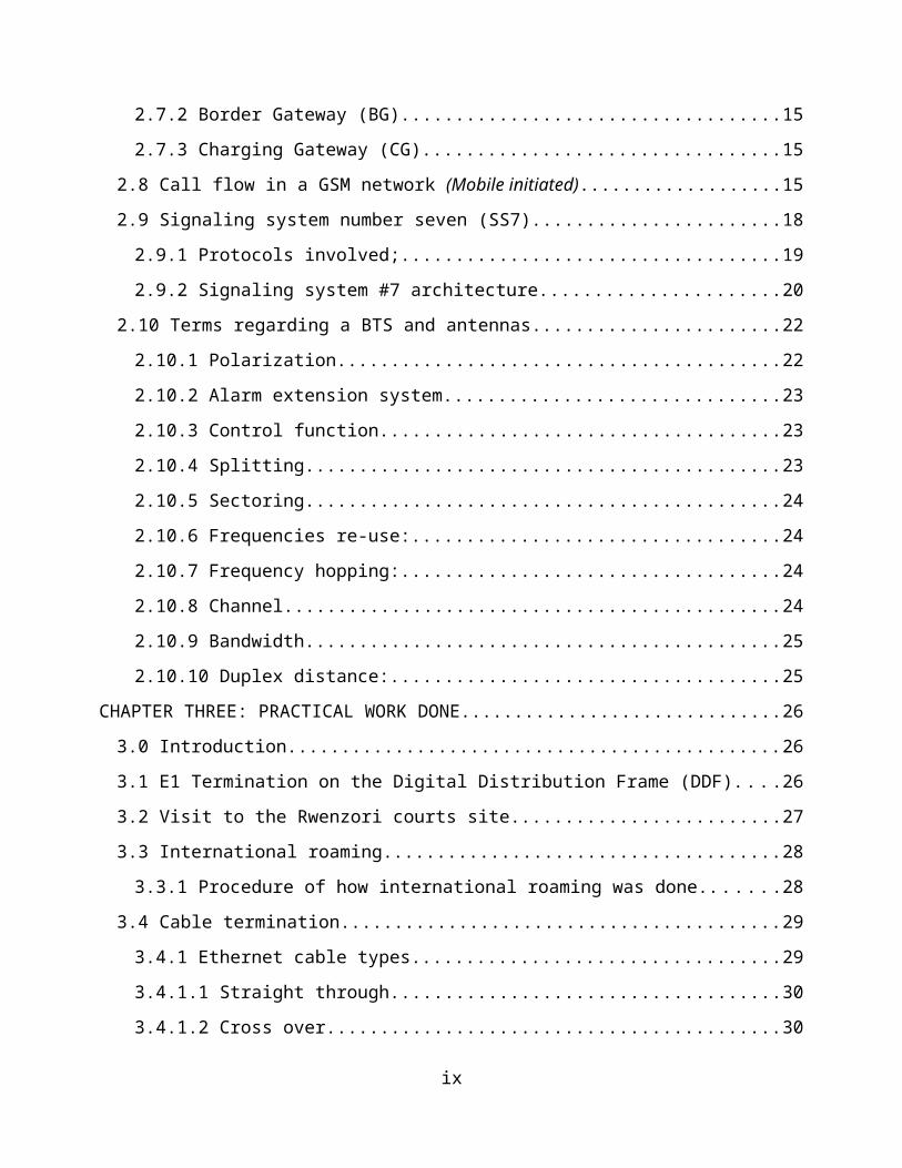
2.7.2 Border Gateway (BG)...................................152.7.3 Charging Gateway (CG).................................15
2.8 Call flow in a GSM network (Mobile initiated)...................152.9 Signaling system number seven (SS7).......................182.9.1 Protocols involved;...................................192.9.2 Signaling system #7 architecture......................20
2.10 Terms regarding a BTS and antennas.......................222.10.1 Polarization.........................................222.10.2 Alarm extension system...............................232.10.3 Control function.....................................232.10.4 Splitting............................................232.10.5 Sectoring............................................242.10.6 Frequencies re-use:..................................242.10.7 Frequency hopping:...................................242.10.8 Channel..............................................242.10.9 Bandwidth............................................252.10.10 Duplex distance:....................................25
CHAPTER THREE: PRACTICAL WORK DONE..............................263.0 Introduction..............................................263.1 E1 Termination on the Digital Distribution Frame (DDF)....263.2 Visit to the Rwenzori courts site.........................273.3 International roaming.....................................283.3.1 Procedure of how international roaming was done.......28
3.4 Cable termination.........................................293.4.1 Ethernet cable types..................................293.4.1.1 Straight through....................................303.4.1.2 Cross over..........................................30
ix
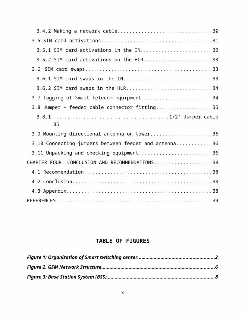
3.4.2 Making a network cable................................303.5 SIM card activations......................................313.5.1 SIM card activations in the IN........................323.5.2 SIM card activations on the HLR.......................33
3.6 SIM card swaps............................................333.6.1 SIM card swaps in the IN..............................333.6.2 SIM card swaps in the HLR.............................34
3.7 Tagging of Smart Telecom equipment........................343.8 Jumper – feeder cable connector fitting...................353.8.1 ...........................................1/2’ Jumper cable
353.9 Mounting directional antenna on tower.....................363.10 Connecting jumpers between feeder and antenna............363.11 Unpacking and checking equipment.........................36
CHAPTER FOUR: CONCLUSION AND RECOMMENDATIONS....................384.1 Recommendation............................................384.2 Conclusion................................................384.3 Appendix..................................................38
REFERENCES......................................................39
TABLE OF FIGURES
Figure 1: Organization of Smart switching center........................................................2
Figure 2. GSM Network Structure...................................................................................6
Figure 3: Base Station System (BSS)...............................................................................8
x
Figure 4: The Base Transceiver Station (BTS).................................................................8
Figure 5. GSM Functional Architecture and Principal Interfaces.................................10
Figure 6: GSM frequency bands......................................................................................11
Figure 7. Structure of Support Functions.............................................................................12
Figure 8: Call Flow in GSM a Network..........................................................................17
Figure 9: Display of call flow on the MSC.....................................................................18
Figure 10: An illustration of call setup.........................................................................21
Figure 11: SS7 layers in comparison with the OSI model layers.................................22
Figure 12: Termination on the DDF using a chroming tool. Far right is the media
gateway.........................................................................................................................27
Figure 13: Trouble shooting using a laptop (left) and use of a compass for sector
2&3 antenna alignment (right).....................................................................................27
Figure 14: E1 colour coding...........................................................................................29
Figure 15: Straight through colour coding...................................................................30
Figure 16: cross over colour coding..............................................................................30
Figure 17: Fitting an RJ-45 to make a network cable...................................................31
Figure 18: Display on the CRM......................................................................................32
Figure 19: Smart label on the BBU................................................................................35
xi
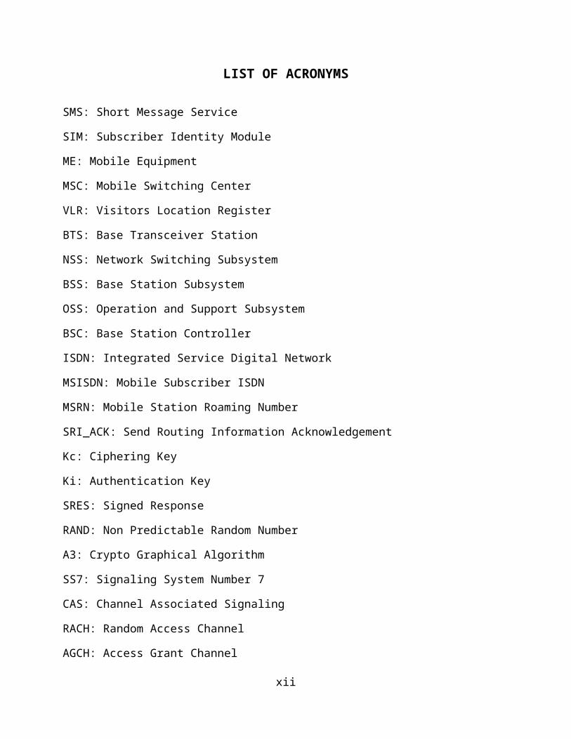
LIST OF ACRONYMS
SMS: Short Message Service
SIM: Subscriber Identity Module
ME: Mobile Equipment
MSC: Mobile Switching Center
VLR: Visitors Location Register
BTS: Base Transceiver Station
NSS: Network Switching Subsystem
BSS: Base Station Subsystem
OSS: Operation and Support Subsystem
BSC: Base Station Controller
ISDN: Integrated Service Digital Network
MSISDN: Mobile Subscriber ISDN
MSRN: Mobile Station Roaming Number
SRI_ACK: Send Routing Information Acknowledgement
Kc: Ciphering Key
Ki: Authentication Key
SRES: Signed Response
RAND: Non Predictable Random Number
A3: Crypto Graphical Algorithm
SS7: Signaling System Number 7
CAS: Channel Associated Signaling
RACH: Random Access Channel
AGCH: Access Grant Channel
xii
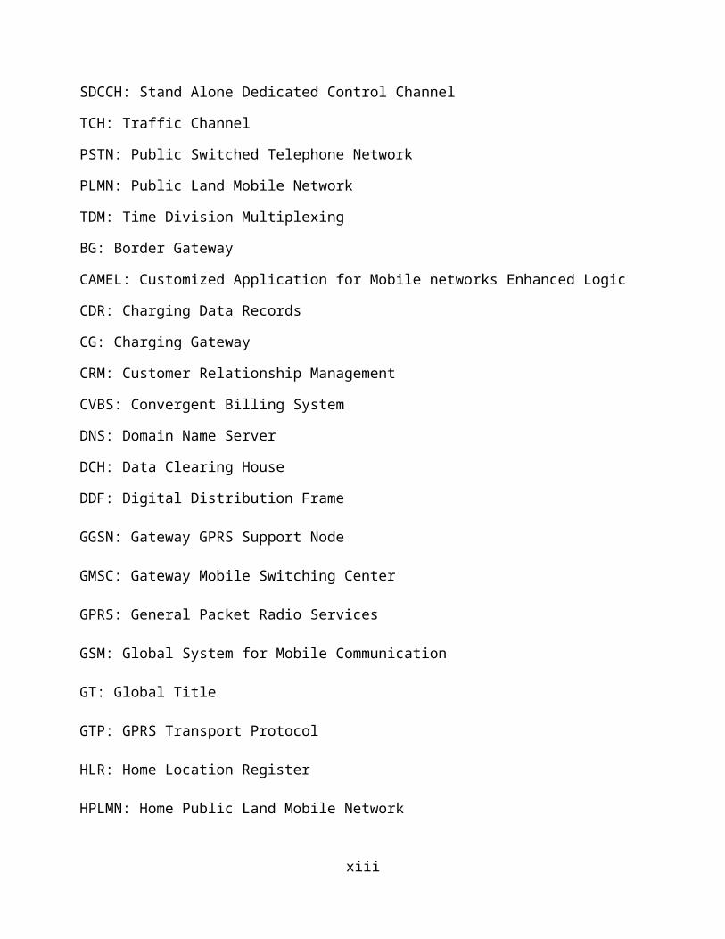
SDCCH: Stand Alone Dedicated Control Channel
TCH: Traffic Channel
PSTN: Public Switched Telephone Network
PLMN: Public Land Mobile Network
TDM: Time Division Multiplexing
BG: Border Gateway
CAMEL: Customized Application for Mobile networks Enhanced Logic
CDR: Charging Data Records
CG: Charging Gateway
CRM: Customer Relationship Management
CVBS: Convergent Billing System
DNS: Domain Name Server
DCH: Data Clearing House
DDF: Digital Distribution Frame
GGSN: Gateway GPRS Support Node
GMSC: Gateway Mobile Switching Center
GPRS: General Packet Radio Services
GSM: Global System for Mobile Communication
GT: Global Title
GTP: GPRS Transport Protocol
HLR: Home Location Register
HPLMN: Home Public Land Mobile Network
xiii
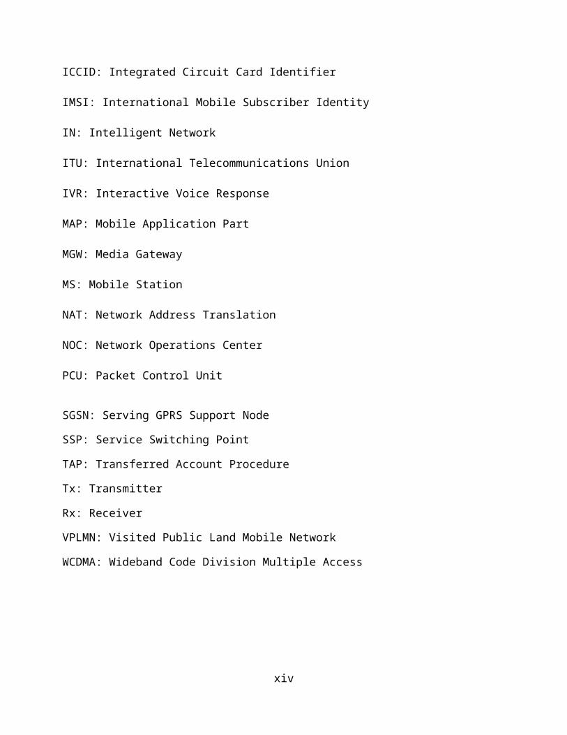
ICCID: Integrated Circuit Card Identifier
IMSI: International Mobile Subscriber Identity
IN: Intelligent Network
ITU: International Telecommunications Union
IVR: Interactive Voice Response
MAP: Mobile Application Part
MGW: Media Gateway
MS: Mobile Station
NAT: Network Address Translation
NOC: Network Operations Center
PCU: Packet Control Unit
SGSN: Serving GPRS Support Node
SSP: Service Switching Point
TAP: Transferred Account Procedure
Tx: Transmitter
Rx: Receiver
VPLMN: Visited Public Land Mobile Network
WCDMA: Wideband Code Division Multiple Access
xiv
CHAPTER ONE: SMART TELECOM UGANDA
1.0 Introduction
Industrial training is a requirement for the award of a
bachelor’s degree of telecommunications engineering and it is
carried out in organizations within departments that involve
communication though not limited to telecommunication systems.Industrial training is beneficial to trainees in a way that they gain
practical experience, get exposed to the working environment, learn
work ethics, implement technological ethics as well as understand the
relationship between telecommunications and other departments that
makeup a company.
During industrial training students are expected to learn the
practical applications of what they have learnt in class as well
as acquire skills from people already in the field of engineering
and other related fields.
The specific objectives of this training included;
To provide the learners with the practical idea of the GSM
system components and their application in the
telecommunication industry.
Exposing students to real life problem solving in business
related fields.
Helping students understand professional work ethics and
challenges.
To train students to develop personal and communications
skills and a sense of responsibility towards society.
1
To improve on interpersonal skills and self-confidence at
doing professional tasks.
Smart Telecom Uganda organized our training at its Operations
center, situated at Kibuli-Kampala, Uganda mainly under the
department of Core Networks though we also worked with Access and
Intelligent Network (IN) departments at some instances.
1.1 Company background
Smart Telecom (Uganda) is a telecommunications company in Uganda.It launched its operations in Uganda on 17th March 2014. Smartevolved from Sure telecom Uganda Limited. Sure telecom had beenin existence since 2010 and had made its first call in December2012. By then the company was being managed by Time turnsLimited. In April 2013 Aghakhan bought 51% of the company sharebecoming the majority shareholder. The Company is now owned andoperated by Industrial Promotion Services, a subsidiary of theAga Khan Fund for Development (AKFED). The company was firstlaunched in Uganda but later expanded to Burundi and Tanzania.Smart Telecom provides the following services namely;Telecommunications, IT (Information Technology) and carrierservices. The Smart send routing information (SRI) code is 074.
1.2 Structure of Kibuli operations/switching Centre.
The organizational structure of Smart Telecom Uganda at Kibuliswitching center is summarized below.
2
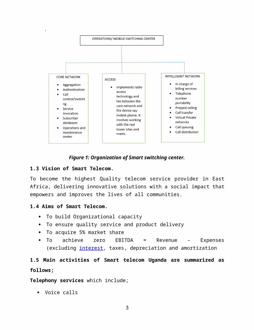
Figure 1: Organization of Smart switching center.
1.3 Vision of Smart Telecom.
To become the highest Quality telecom service provider in EastAfrica, delivering innovative solutions with a social impact thatempowers and improves the lives of all communities.
1.4 Aims of Smart Telecom.
To build Organizational capacity To ensure quality service and product delivery To acquire 5% market share To achieve zero EBITDA = Revenue – Expenses
(excluding interest, taxes, depreciation and amortization
1.5 Main activities of Smart telecom Uganda are summarized as
follows;
Telephony services which include;
Voice calls
3
Short Message Services
Data services. This is basically to internet subscribers.
Supplementary services. These GSM services support a
comprehensive set of supplementary services that can
complement and support both telephony and data services.
Supplementary services are defined by GSM and are
characterized as revenue-generating features. A partial
listing of supplementary services follows.
Call forwarding -This service gives the subscriber theability to forward the incoming calls to another number ifthe called mobile unit is not reachable, if it is busy, ifthere is no reply, or if call forwarding is allowedunconditionally.
Barring of outgoing calls -This service makes it possible
for a mobile subscriber toprevent all outgoing calls. Barring of incoming calls-This function allows the
subscriber to prevent incoming calls. The following twoconditions for incoming call barring exists: barring of allincoming calls and barring of incoming calls when roamingoutside the home PLMN.
Advice of charge (AoC) - The AoC service provides the mobilesubscriber with an estimate of the call charges. There aretwo types of AoC information: one that provides thesubscriber with an estimate of the bill and one that can beused for immediate charging purposes. AoC for data calls isprovided on the basis of time measurements.
Call hold- This service enables the subscriber to interruptan ongoing call and then subsequently re-establish the call.The call hold service is only applicable to normal telephony
4
Call waiting - This service enables the mobile
subscriber to be notified of an incoming call during a
conversation. The subscriber can answer, reject, or
ignore the incoming call. Call waiting is applicable to
all GSM telecommunications services using a circuit-
switched connection.
Multiparty service - The multiparty service enables a
mobile subscriber to establish a multiparty
conversation - that is, a simultaneous conversation
between three and six subscribers. This service is only
applicable to normal telephony.
Calling line identification presentation/restriction - Theseservices supply the called party with the integratedservices digital network (ISDN) number of the calling party.The restriction service enables the calling party torestrict the presentation. The restriction overrides thepresentation.
Closed user groups (CUGs) - CUGs are generally comparable toa PBX. They are a group of subscribers who are capable ofonly calling themselves and certain numbers.
5
CHAPTER TWO: LITERATURENREVIEW.
2.0 GSM
Global System for Mobile communication, GSM is a Second
generation technology composed of several functional entities
whose functions and interfaces are specified. 2G mobile systems
are digital and bring significant advantages in terms of service
sophistication, capacity and quality. GSM is part of an
evolution of wireless mobile telecommunication.
6
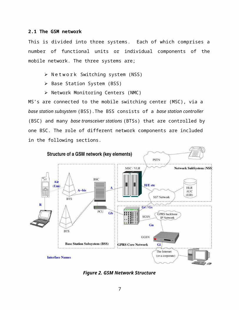
2.1 The GSM network
This is divided into three systems. Each of which comprises a
number of functional units or individual components of the
mobile network. The three systems are;
N e t w o r k Switching system (NSS) Base Station System (BSS) Network Monitoring Centers (NMC)
MS’s are connected to the mobile switching center (MSC), via a
base station subsystem (BSS).The BSS consists of a base station controller
(BSC) and many base transceiver stations (BTSs) that are controlled by
one BSC. The role of different network components are included
in the following sections.
Figure 2. GSM Network Structure
7
2.1.1 Network Switching system, NSS
NSS is the main component of the public mobile network GSM.
The NSS has the following components:
2.1.2 Mobile Services Switching Centre (MSC)
This controls all connections via a separated network to/from
a mobile terminal within the domain of the MSC - several BSC
can belong to a MSC.
2.1.3 Databases
These are important in the sense of scalability, high capacity and low delay and they include:
- Home Location Register (HLR)This is a central master database containing user data,
permanent and semi-permanent data of all subscribers
assigned to the HLR (one provider can have several HLRs)
- Visitor Location Register (VLR)This is a local database for a subset of user data,
including data about all users currently in the domain of
the VLR.
2.1.4 Authentication Center (AUC)
This generates user specific authentication parameters on
request of a VLR. These authentication parameters are used for
authentication of mobile terminals and encryption of user data
on the air interface within the GSM system
8
2.1.5 Equipment Identity Register (EIR)
This registers GSM mobile stations and user rights. Stolen or
malfunctioning mobile stations can be locked and sometimes even
localized.
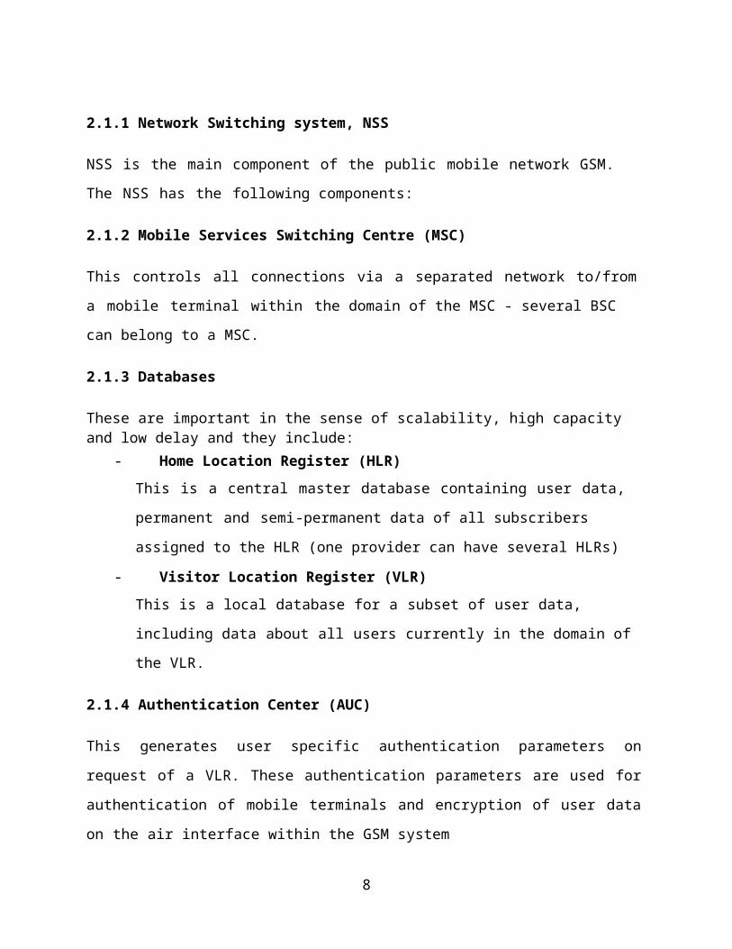
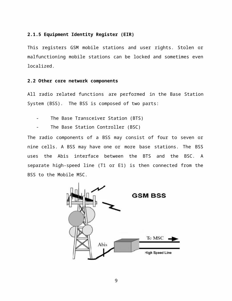
2.2 Other core network components
All radio related functions are performed in the Base Station
System (BSS). The BSS is composed of two parts:
- The Base Transceiver Station (BTS)- The Base Station Controller (BSC)
The radio components of a BSS may consist of four to seven or
nine cells. A BSS may have one or more base stations. The BSS
uses the Abis interface between the BTS and the BSC. A
separate high-speed line (T1 or E1) is then connected from the
BSS to the Mobile MSC.
9
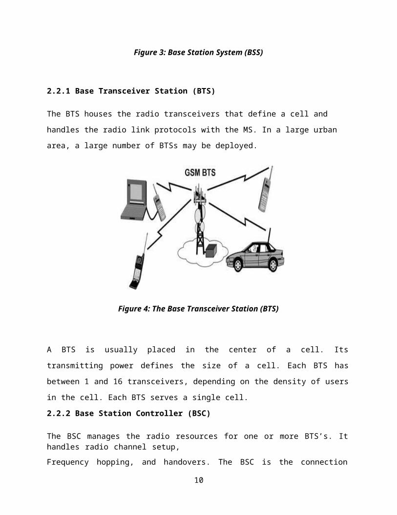
Figure 3: Base Station System (BSS)
2.2.1 Base Transceiver Station (BTS)
The BTS houses the radio transceivers that define a cell and
handles the radio link protocols with the MS. In a large urban
area, a large number of BTSs may be deployed.
Figure 4: The Base Transceiver Station (BTS)
A BTS is usually placed in the center of a cell. Its
transmitting power defines the size of a cell. Each BTS has
between 1 and 16 transceivers, depending on the density of users
in the cell. Each BTS serves a single cell.
2.2.2 Base Station Controller (BSC)
The BSC manages the radio resources for one or more BTS’s. Ithandles radio channel setup,Frequency hopping, and handovers. The BSC is the connection
10
between the mobile and the MSC.
2.2.3 Network Monitoring Centre, (NMC)
This includes
2.2.4 Operation and Maintenance Center (OMC)
An OMC is a computerized monitoring center which is connected
to other network components such as MSCs and BSCs via X.25 data
network links. There may be one or several OMCs within a network
depending on the network size.
2.2.5 Network Management Center (NMC)
Centralized control of a network is done at a Network Management
Center (NMC). Only one NMC is required for a network and this
controls the subordinate OMCs thus hierarchical approach to
network monitoring.
2.2.6Operation and Maintenance Center (OMC)
This offers different control capabilities for the radiosubsystem and the network subsystem.
2.2.7 Mobile Station (MS)
The MS consists of the physical equipment, such as the radio
transceiver, display and digital signal processors, and the SIM
card. It provides the air interface to the user in GSM networks.
As such, other services are also provided, which include:
Voice tele-services Data bearer services
11
The features' supplementary services
2.2.8 The MS Functions:
The MS also provides the receptor for SMS messages, enabling
the user to toggle between the voice and data use. Unlike other
standards, in GSM the subscriber is separated from the mobile
terminal. Each subscriber's information is stored as a "smart
card" SIM. The SIM can be plugged into any GSM mobile terminal.
The SIM provides personal mobility so that the user can have
access to all subscribed services irrespective of both the
location of the terminal and the use of a specific terminal.
12
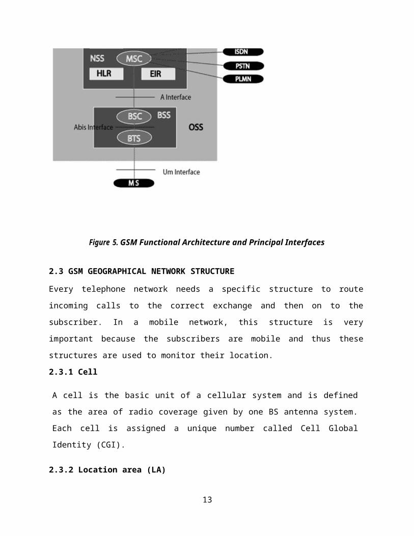
Figure 5. GSM Functional Architecture and Principal Interfaces
2.3 GSM GEOGRAPHICAL NETWORK STRUCTURE
Every telephone network needs a specific structure to route
incoming calls to the correct exchange and then on to the
subscriber. In a mobile network, this structure is very
important because the subscribers are mobile and thus these
structures are used to monitor their location.
2.3.1 Cell
A cell is the basic unit of a cellular system and is defined
as the area of radio coverage given by one BS antenna system.
Each cell is assigned a unique number called Cell Global
Identity (CGI).
2.3.2 Location area (LA)
13
A Location Area (LA) is defined as a group of cells. Within
the network a subscriber’s location is linked to the LA in
which they are currently located. The identity of the current
LA is stored in the VLR. When an MS crosses the boundary
between two cells belonging to different LA’s, it must report
its new Location Area to the network.
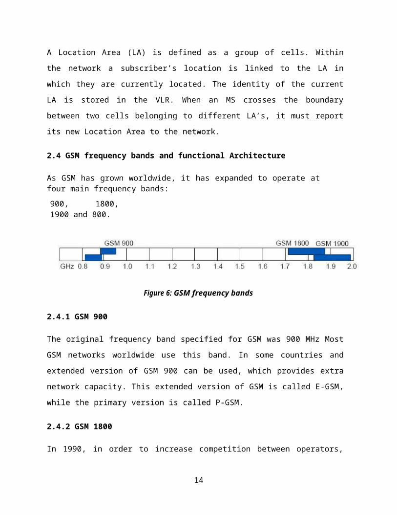
2.4 GSM frequency bands and functional Architecture
As GSM has grown worldwide, it has expanded to operate atfour main frequency bands:900, 1800,1900 and 800.
Figure 6: GSM frequency bands
2.4.1 GSM 900
The original frequency band specified for GSM was 900 MHz Most
GSM networks worldwide use this band. In some countries and
extended version of GSM 900 can be used, which provides extra
network capacity. This extended version of GSM is called E-GSM,
while the primary version is called P-GSM.
2.4.2 GSM 1800
In 1990, in order to increase competition between operators,
14
the United Kingdom requested the start of a new version of GSM
adapted to the 1800 MHz frequency band. Licenses have been
issued in several countries and networks are in full
operation. By granting licenses for GSM
1800 in addition to GSM 900, a country can increase the number
of operators. In this way, due to increased competition, the
service to subscribers is improved.
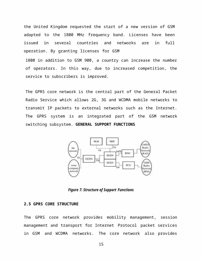
The GPRS core network is the central part of the General Packet
Radio Service which allows 2G, 3G and WCDMA mobile networks to
transmit IP packets to external networks such as the Internet.
The GPRS system is an integrated part of the GSM network
switching subsystem. GENERAL SUPPORT FUNCTIONS
Figure 7. Structure of Support Functions
2.5 GPRS CORE STRUCTURE
The GPRS core network provides mobility management, session
management and transport for Internet Protocol packet services
in GSM and WCDMA networks. The core network also provides
15
support for other additional functions such as billing and
lawful interception. It was also proposed, at one stage, to
support packet radio services in the US D-AMPS TDMA system,
however, in practice, all of these networks have been
converted to GSM so this option has become irrelevant.
Like GSM in general, GPRS module is an open standards driven
system. The standardization body is the 3GPP
2.5.1 GTP-U
For transfer of user data in separated tunnels for eachPacket Data Protocol (PDP) context for control reasonsincluding:
Setup and deletion of PDP contexts Verification of GSN reach ability Updates; e.g., as subscribers move from one SGSN to another.
2.5.2 GTP-C
For transfer of charging data from GSNs tothe charging function.
GGSNs and SGSNs (collectively known as GSNs) listen for GTP-C
messages on UDP port 2123 and for GTP-U messages on port 2152.
This communication happens within a single network or may in
the case of international roaming, happen internationally,
typically across a GPRS roaming exchange (GRX).
The Packet Control Unit (PCU) separates the circuit switched and
the packet switched traffic from the user and sends it to the GSM
16
and GPRS networks respectively. It also performs most of the
radio resource management functions of the GPRS network. The PCU
can be either located in the BTS, BSC or between the MS and the
MSC.
The Charging Gateway Function (CGF) listens to GTP' messages
sent from the GSNs on TCP or UDP port 3386. The core network
sends charging information to the CGF, typically including PDP
context activation times and the quantity of data which the end
user has transferred. However, this communication which occurs
within one network is less standardized and may, depending on
the vendor and configuration options, use proprietary encoding
or even an entirely proprietary system.
GTP version zero supports both signaling and user data under one
generic header. It can be used with UDP (User Datagram
Protocol) or TCP (Transmission Control Protocol) on the
registered port 3386. GTP version one is used only on UDP. The
control plane protocol GTP-C (Control) using registered port
2123 and the user plane protocol GTP-U (User) using registered
port 2152.
2.6 GPRS SUPPORT NODE (GSN)
A GSN is a network node which supports the use of GPRS in the
GSM core network. All GSNs should have a Gn interface and
support the GPRS tunneling protocol. There are two key variants
of the GSN, namely Gateway and Serving GPRS Support Node.
17
2.6.1 Serving GPRS Support Node (SGSN)
A Serving GPRS Support Node (SGSN) is responsible for the
delivery of data packets from and to the mobile stations within
its geographical service area. Its tasks include packet routing
and transfer, mobility management (attach/detach and location
management), logical link management, and authentication and
charging functions. The location register of the SGSN stores
location information (e.g., current cell, current VLR) and user
profiles (e.g., IMSI, address (es) used in the packet data
network) of all GPRS users registered with this SGSN....
Common SGSNFunction
Detunnel GTP packets from the GGSN (downlink) Tunnel IP packets toward the GGSN (uplink) Carry out mobility management as Standby mode mobile moves
from one Routing Area to another Routing Area
Billing user data
2.6.2 Gateway GPRS Support Node (GGSN)
The Gateway GPRS Support Node (GGSN) is a main component of the
GPRS network. The GGSN is responsible for the interworking
between the GPRS network and external packet switched networks,
like the Internet and X.25 networks.
Functions of the GGSN are given below;
Routing mobile destined packets coming from external
networks to the relevant SGSN.
18
Routing packets coming from the mobile station to the
correct external network.
Interfaces with external I.P networks and also Routing
handles security of the network.
Collects charging data and data traffic.
Allocates dynamic or static I.P addresses to mobiles
either by itself or with the help of a DHCP or a RADIUS
server.
The GGSN is involved in the establishment of tunnels with
the SGSN and with other external networks and VPNs.
Hence the GGSN is simply a router to an IP sub-network. When the
GGSN receives data addressed to a specific user in the mobile
network, it first checks if the address is active. The GGSN then
forwards the data to the SGSN serving the mobile. If the address
is inactive, the data is discarded. The GGSN also routes mobile
originated packets to the correct external network.
2.7 Other nodes include;
2.7.1 Domain Name Servers (DNS)
These devices convert IP names into IP addresses and there exists
both primary and secondary DNS.
2.7.2 Firewalls
A firewall protects an IP network against external attack by
hackers from internet/mobile users. In the GPRS network, the
firewall may be configured to reject all packets that are not
19
part of a GPRS subscriber initiated connection. The firewall can
also include a network address translation (NAT)
2.7.2 Border Gateway (BG)
The BG is a router that can provide direct GPRS tunnel between
different operators GPRS networks. This is referred to as inter-
PLMN data network. It is more secure to transfer data between two
operators’ PLMN networks through a direct connection rather than
via the public internet. The BG commences operation once the GPRS
roaming agreements are between operators have been signed. This
enables a subscriber to connect to a company intranet through the
home GGSN via the visiting PLMN network.
2.7.3 Charging Gateway (CG)
GPRS users have to be charged for the use of the network. In GSM,
charging is based on destination, duration, and time for a call.
However, GPRS offers connectionless service to users so it is not
possible to charge subscribers on the connection duration.
Charging has to be based on volume, destination, QoS etc. The
GPRS charging data is generated by all the GGSNs and SGSNs in the
network. This data is called Charging Data Record (CDRS). One
data session may generate a number of CDRs so these need to be
collected and processed. The CG collects all the records, sorts
them, processes them and then passes them to the billing system.
Here, the GPRS subscriber is billed for data transaction. All
CDRs contain a unique subscriber and connection identifiers to
distinguish them. A protocol called GPRS Transport Protocol (GTP)
20
is used for the transfer of data between GSNs and the charging
gateway.
2.8 Call flow in a GSM network (Mobile initiated)
When an MS is switched on, authentication is performed to protect
the network form any form of fraud. Authentication of the SIM
which is mandatory for any MS is based on the crypto graphical
algorithm A3, and the secret subscriber authentication key Ki.
Both A3 and Ki are located on the SIM.
The authentication procedure is initiated from the MSC/VLR by
sending RAND (non-predictable Random number) to the MS. The MSC/VLR
fetches the triplets from the HLR. The MS then calculates the
SRES (Signed Response) and Kc (Ciphering key) using the same algorithms
as the AUC. The calculated SRES will be sent to MSC/VLR which
compares this SRES received from the MS with the one in the
triplet from the AUC. If the two are same access will be granted.
The calculated Kc will be stored in the SIM card.
User keys in the number of the called party and presses send. The
MS transmits a request on uplink signaling channel i.e. the MS
uses Random Access Channel (RACH) to request for a signaling
channel. The BSC allocates a signaling channel, using Access
Grant Channel (AGCH).The MS sends a call set-up request via Stand
Alone Dedicated Control Channel (SDCCH) to the MSC/VLR. Over this
SDCCH, all signaling preceding a call takes place. This includes;
marking the MS as “active” in the VLR, the authentication
procedure, and start ciphering and equipment identification. If
21

network can process the call, BTS sends channel allocation
message. Network proceeds to setup the connection.
MSC determines the current location of target mobile using HLR,
VLR and by communicating with other MSCs. This is done by
querying the Home Location Register (HLR) to find out which VLR
the MS is currently registered with (Send Routing Information). The HLR
will send a request to the VLR of the MS indicating a call setup.
The VLR generates the MSRN for the call and sends it back to the
HLR. The network then passes the MSRN to the MSC that is
originating the call. The originating MSC then contacts the
desired MS's MSC and uses the MSRN to setup the call. Source MSC
initiates a call setup message to MSC covering target area.
Target MSC initiates a paging message. BTSs forward the paging
message on downlink channel in coverage area. If mobile is ON
(monitoring the signaling channel), it responds to BTS. BTS sends a
channel allocation message and informs MSC. MSC completes two
halves of the connection and sends ringing tone to the calling
party and notifies the called party of the call.
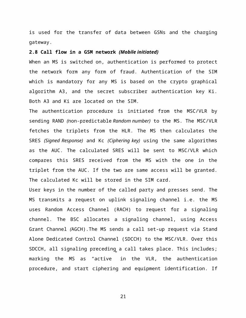
22
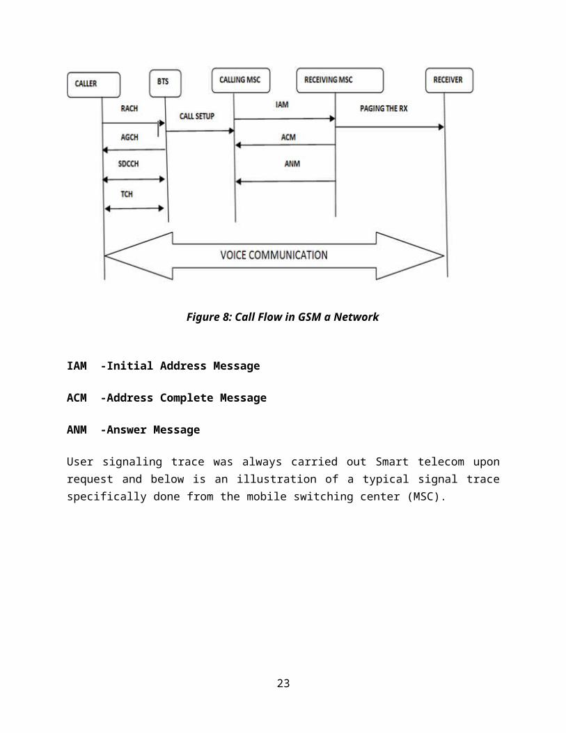
Figure 8: Call Flow in GSM a Network
IAM -Initial Address Message
ACM -Address Complete Message
ANM -Answer Message
User signaling trace was always carried out Smart telecom uponrequest and below is an illustration of a typical signal tracespecifically done from the mobile switching center (MSC).
23
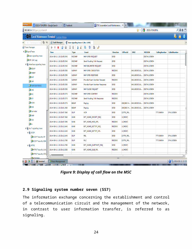
Figure 9: Display of call flow on the MSC
2.9 Signaling system number seven (SS7)
The information exchange concerning the establishment and controlof a telecommunication circuit and the management of the network,in contrast to user information transfer, is referred to assignaling.
24
Signaling is used to indicate the following information;
Calling and called party
Availability/non availability of network resources suchas trunks
Availability of the called party
Billing information
Network information such as busy trunks, faultytelephones etc.
Routing information as regards to how the call has to berouted.
To provide special information such as calling cardfacility, toll-free numbers, called party, paying thetelephone bill etc.
The four main functions of switch signaling are:
Alerting
Transmitting Address Information
Supervising
Transmitting Information.
The protocol that is used in the signaling network is calledSignaling System Seven (SS7). Signaling System No.7 (SS7) is aparticular type Of Common Channel Signaling employed by moderntelephone networks. It is very similar to the five-layerInternet model, but the layers have different names. In SS7,any Central Office or other telecommunications switchingfacility is called a Service Switching Point (SSP).
25
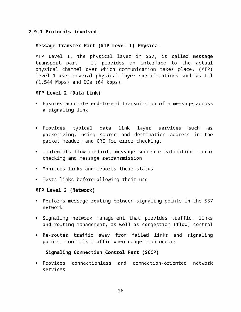
2.9.1 Protocols involved;
Message Transfer Part (MTP Level 1) Physical
MTP Level 1, the physical layer in SS7, is called messagetransport part. It provides an interface to the actualphysical channel over which communication takes place. (MTP)level 1 uses several physical layer specifications such as T-l(1.544 Mbps) and DCa (64 kbps).
MTP Level 2 (Data Link)
Ensures accurate end-to-end transmission of a message acrossa signaling link
Provides typical data link layer services such aspacketizing, using source and destination address in thepacket header, and CRC for error checking.
Implements flow control, message sequence validation, errorchecking and message retransmission
Monitors links and reports their status
Tests links before allowing their use
MTP Level 3 (Network)
Performs message routing between signaling points in the SS7network
Signaling network management that provides traffic, linksand routing management, as well as congestion (flow) control
Re-routes traffic away from failed links and signalingpoints, controls traffic when congestion occurs
Signaling Connection Control Part (SCCP)
Provides connectionless and connection-oriented networkservices
26
Provides global title translation (GTT) capabilities aboveMTP level 3; translates numbers to DPCs and subsystemnumbers
Provides more detailed addressing information than MTPs
Used as transport layer for TCAP (Transaction capabilitiesapplications part) based services
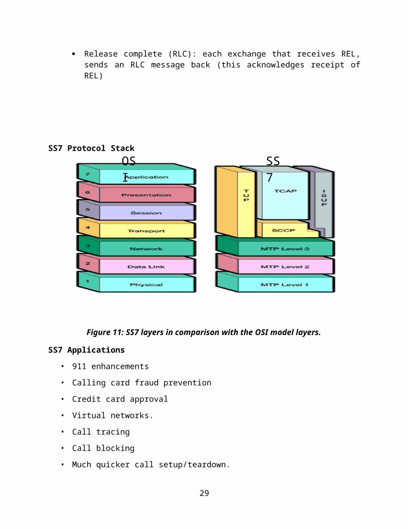
Upper Layers (TUP, TCAP, and ISUP).
These are three protocols at the upper layers and theyperform the following functions;
Telephone user port (TUP) is responsible for setting upvoice calls. It receives the dialed digits and routes thecalls.
Transaction capabilities application port (TCAP) providesremote calls that let an application program on a computerinvoke a procedure on another computer.
ISDN user port (ISUP) can replace TUP to provide servicessimilar to those of an ISDN network.
2.9.2 Signaling system #7 architecture
The SS #7 network is a packet switched network that controlsthe setting up, management and release of telephone calls.
• The network also provides services for intelligent networks,cellular mobile networks and integrated service digitalnetwork (ISDN). There are three important devices:
1. Signal switching point (SSP): SS7 capabletelephone switches. They originate, terminate, orswitch calls.
2. Signal Transfer point (STP): SS7 data packetswitches. They receive and route incoming signalingmessages to the proper location
27
3. Signal Control point (SCP): Databases distributedalong the network. They allow advanced call processingcapabilities.
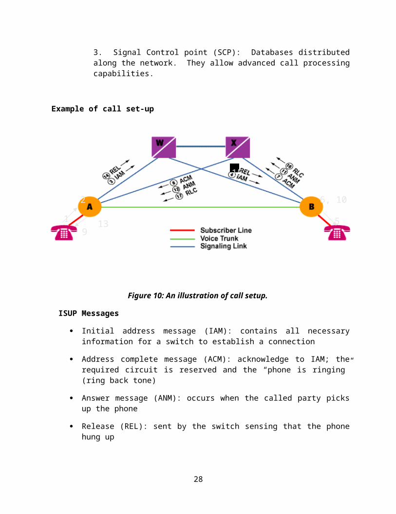
Example of call set-up
Figure 10: An illustration of call setup.
ISUP Messages
Initial address message (IAM): contains all necessaryinformation for a switch to establish a connection
Address complete message (ACM): acknowledge to IAM; therequired circuit is reserved and the “phone is ringing”(ring back tone)
Answer message (ANM): occurs when the called party picksup the phone
Release (REL): sent by the switch sensing that the phonehung up
28
1
6, 10
9
2
513
15
Release complete (RLC): each exchange that receives REL,sends an RLC message back (this acknowledges receipt ofREL)
SS7 Protocol Stack
Figure 11: SS7 layers in comparison with the OSI model layers.
SS7 Applications
• 911 enhancements
• Calling card fraud prevention
• Credit card approval
• Virtual networks.
• Call tracing
• Call blocking
• Much quicker call setup/teardown.
29
OSI
SS7
2.10 Terms regarding a BTS and antennas.
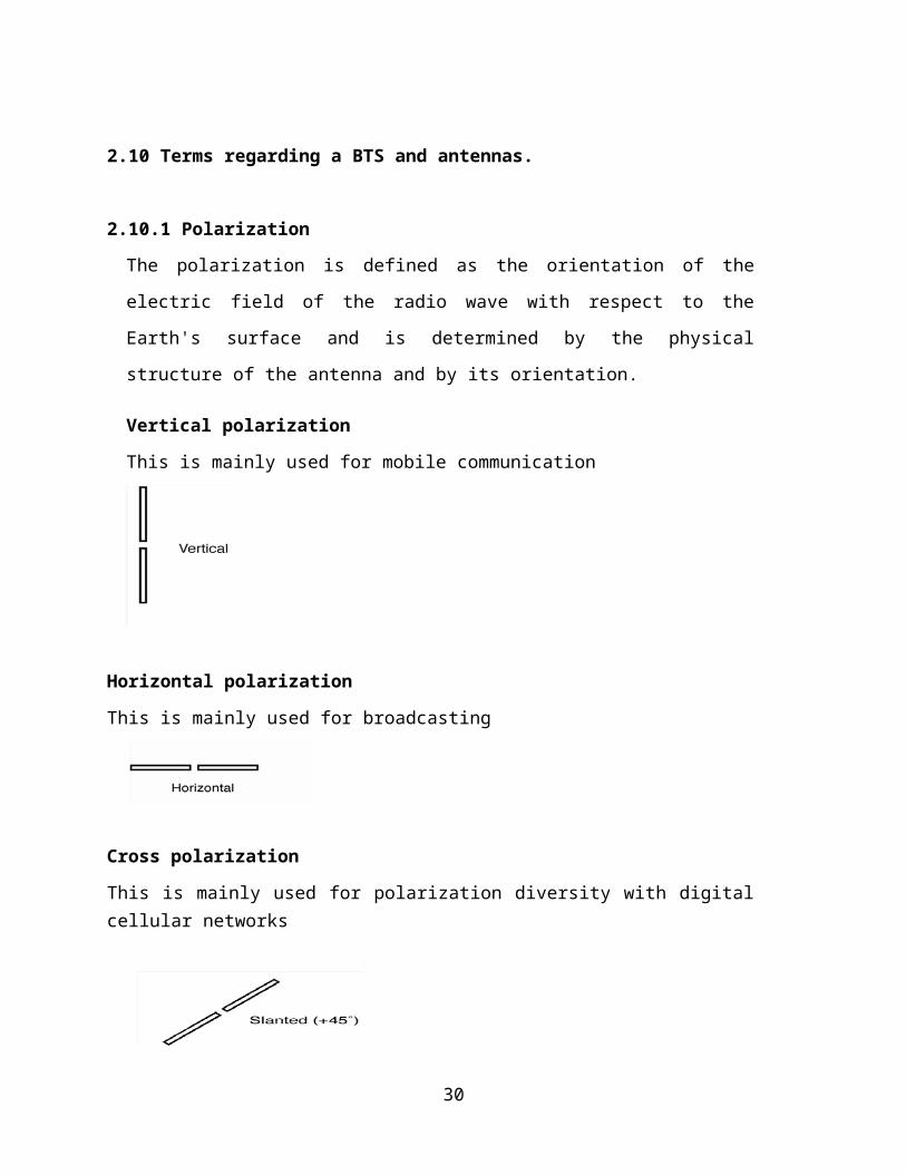
2.10.1 Polarization
The polarization is defined as the orientation of the
electric field of the radio wave with respect to the
Earth's surface and is determined by the physical
structure of the antenna and by its orientation.
Vertical polarization
This is mainly used for mobile communication
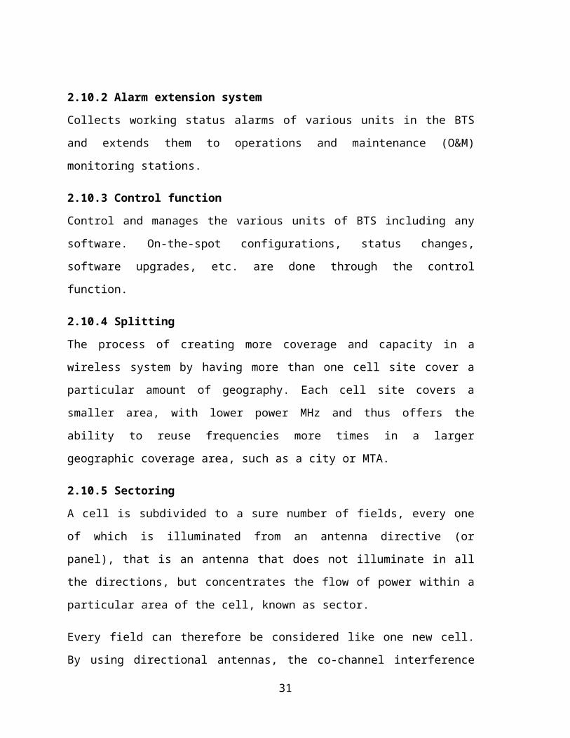
Horizontal polarization
This is mainly used for broadcasting
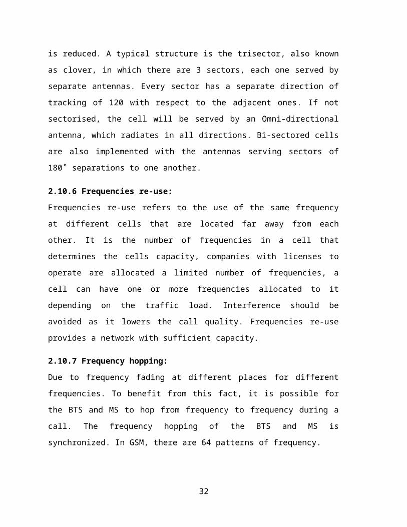
Cross polarization
This is mainly used for polarization diversity with digitalcellular networks
30
2.10.2 Alarm extension system
Collects working status alarms of various units in the BTS
and extends them to operations and maintenance (O&M)
monitoring stations.
2.10.3 Control function
Control and manages the various units of BTS including any
software. On-the-spot configurations, status changes,
software upgrades, etc. are done through the control
function.
2.10.4 Splitting
The process of creating more coverage and capacity in a
wireless system by having more than one cell site cover a
particular amount of geography. Each cell site covers a
smaller area, with lower power MHz and thus offers the
ability to reuse frequencies more times in a larger
geographic coverage area, such as a city or MTA.
2.10.5 Sectoring
A cell is subdivided to a sure number of fields, every one
of which is illuminated from an antenna directive (or
panel), that is an antenna that does not illuminate in all
the directions, but concentrates the flow of power within a
particular area of the cell, known as sector.
Every field can therefore be considered like one new cell.
By using directional antennas, the co-channel interference
31
is reduced. A typical structure is the trisector, also known
as clover, in which there are 3 sectors, each one served by
separate antennas. Every sector has a separate direction of
tracking of 120 with respect to the adjacent ones. If not
sectorised, the cell will be served by an Omni-directional
antenna, which radiates in all directions. Bi-sectored cells
are also implemented with the antennas serving sectors of
180˚ separations to one another.
2.10.6 Frequencies re-use:
Frequencies re-use refers to the use of the same frequency
at different cells that are located far away from each
other. It is the number of frequencies in a cell that
determines the cells capacity, companies with licenses to
operate are allocated a limited number of frequencies, a
cell can have one or more frequencies allocated to it
depending on the traffic load. Interference should be
avoided as it lowers the call quality. Frequencies re-use
provides a network with sufficient capacity.
2.10.7 Frequency hopping:
Due to frequency fading at different places for different
frequencies. To benefit from this fact, it is possible for
the BTS and MS to hop from frequency to frequency during a
call. The frequency hopping of the BTS and MS is
synchronized. In GSM, there are 64 patterns of frequency.
32
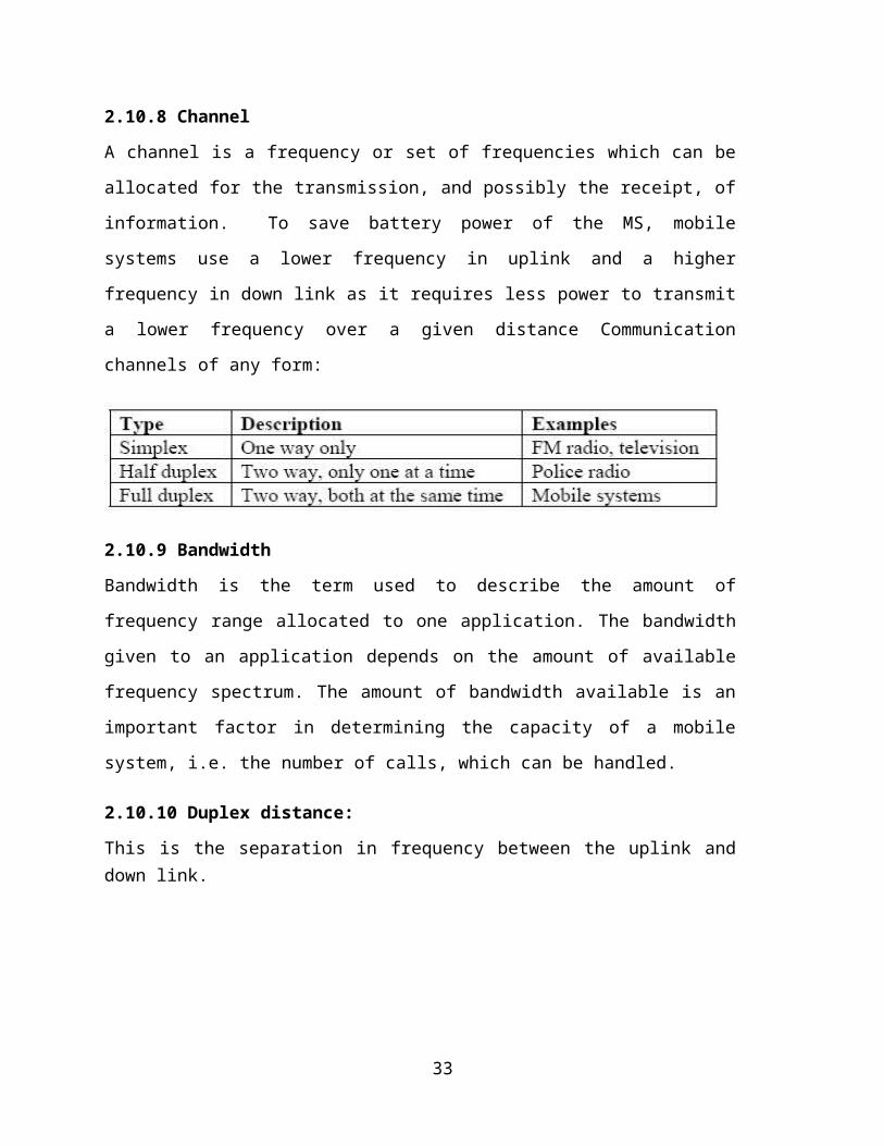
2.10.8 Channel
A channel is a frequency or set of frequencies which can be
allocated for the transmission, and possibly the receipt, of
information. To save battery power of the MS, mobile
systems use a lower frequency in uplink and a higher
frequency in down link as it requires less power to transmit
a lower frequency over a given distance Communication
channels of any form:
2.10.9 Bandwidth
Bandwidth is the term used to describe the amount of
frequency range allocated to one application. The bandwidth
given to an application depends on the amount of available
frequency spectrum. The amount of bandwidth available is an
important factor in determining the capacity of a mobile
system, i.e. the number of calls, which can be handled.
2.10.10 Duplex distance:
This is the separation in frequency between the uplink anddown link.
33
CHAPTER THREE: PRACTICAL WORK DONE
This chapter entails the practical work done during the
industrial training period at Smart Telecom-Uganda.
3.0 Introduction
This chapter discusses some of the activities in which I was
involved in order to acquire new skills as well as to get an
appreciation of the relationship between what am taught in class
and what is actually available in the field.
3.1 E1 Termination on the Digital Distribution Frame (DDF)
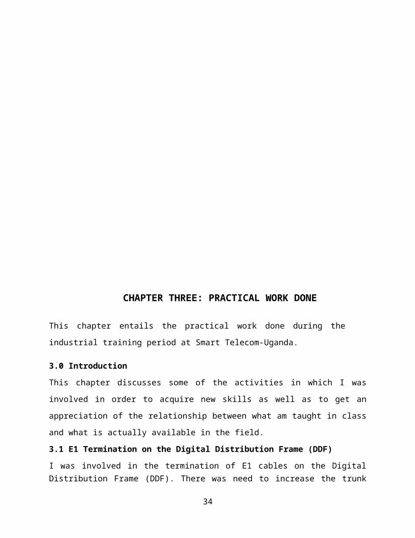
I was involved in the termination of E1 cables on the DigitalDistribution Frame (DDF). There was need to increase the trunk
34
capacity from Smart Telecom to Uganda Telecom since the existingcapacity was full.
The various points onto the DDF where these connections had to bemade were determined by me with the help of a Jumper cable. Usinga pair of pliers, I got 10 E1s from the E1 cable after which Iused a chroning tool to terminate them onto the DDF.
Since the DDF has two sides i.e. one side (the upper) hasconnections to the various nodes e.g. GGSN, MGW etc. and theother side (lower side) has connections to the IDU of thetransmission racks, I had to terminate these E1s on either sidesof the DDF ensuring that the Tx and Rx points on the DDFcorrespond on both the upper and lower sides. For example, Tx 139(on the lower side) had to correspond to Tx 31 (on the upperside) of the DDF. Similarly Rx 139 had to correspond to Rx 31.
The other DDF points on the upper side were Tx-Rx pairs 43, 44,45 and 46 while there corresponding Tx-Rx pairs on the lower sidewere 135, 136, 137, 138.
To ensure that these connections were correctly aligned, the LEDlights on board-8 of the MGW had to stop blinking and they showedfull light hence the termination was successful.
35
333
hg
Figure 12: Termination on the DDF using a chroming tool. Far right is the mediagateway.
3.2 Visit to the Rwenzori courts site.
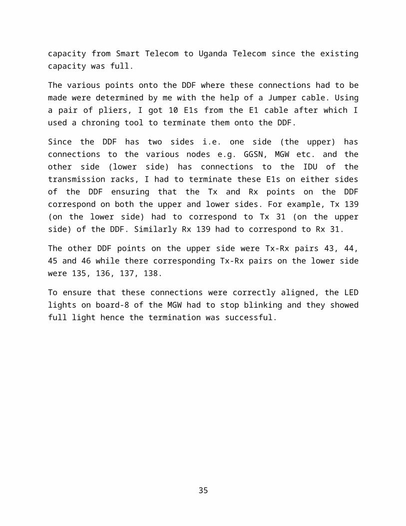
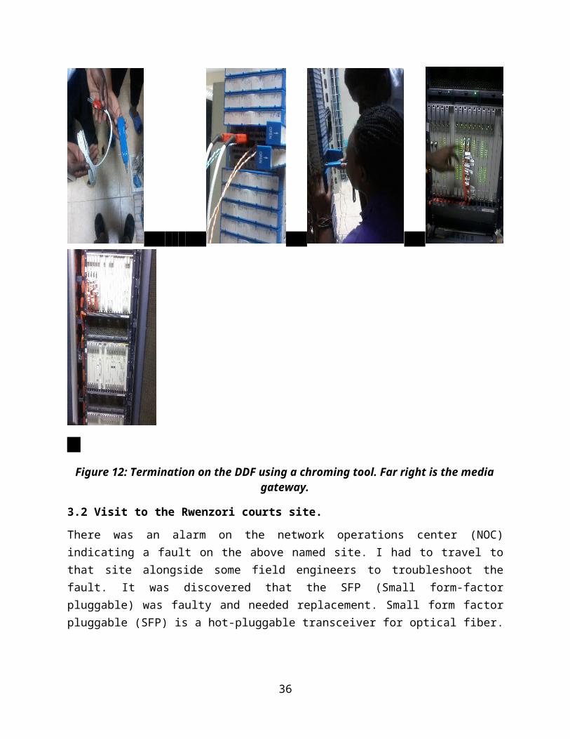
There was an alarm on the network operations center (NOC)indicating a fault on the above named site. I had to travel tothat site alongside some field engineers to troubleshoot thefault. It was discovered that the SFP (Small form-factorpluggable) was faulty and needed replacement. Small form factorpluggable (SFP) is a hot-pluggable transceiver for optical fiber.
36
There was also need to re-align sector-2 and sector-3 antennas onthis site which I personally did with the help of a compass thathelped me to orient this antenna in the correct azimuth.
Figure 13: Trouble shooting using a laptop (left) and use of a compass for sector2&3 antenna alignment (right)
3.3 International roaming.
Roaming is a general term referring to the ability fora cellular customer to automatically make and receive voicecalls, send and receive data, or access other services, includinghome data services, when travelling outside the geographicalcoverage area of the home network, by means of using a visitednetwork.
When customers travel abroad and use their phones whilst on aforeign (“visited”) network, this is known as internationalroaming. . GSM Association Permanent Reference Documents (PRDs)define the tests required. All the participating operators arebound by the terms of the GSM MoU.Point-to-point connections are not feasible because of the costinvolved in setting up and maintaining links. Usually, thewireless service provider utilizes the service offered byestablished international carriers for cost-efficient
37
internetwork connectivity. Smart Telecom uses BICS and PCCW astheir international carriers.There are some documents used in the international roaming tests.AA.12 document, in conjunction with AA.13 and AA.14 comprise theGSMA’s standard international roaming agreement for operators whowould like to establish BILATERAL international roaming services. AA.12 contains the general terms and conditions that bind the 2parties. AA.13 document begins with the description on agreementmanagement principles on how to update roaming agreement; i.e.Information on Billing Data, Settlement Procedure, Testing, andFraud. AA.13 is the common annexes that bind the 2 operators in aBilateral roaming arrangement. AA.14 document contains operator specific information, some ofthe information is classified as Operator Confidential, such asthe Inter-Operator Tariff.IR.21 document contains operator specific technical details; i.e.GSMA roaming database for each operator Billing and TransferInformation is the summarized information required for TAP filestransfer and other billing and details of the operator. Thisdocument is now part of AA.14. IR.24 defines the tests for MAPinterworking and basic circuit-switched (CS) services. Thesetests are applicable for 2G and 3G CS environments. The tests for GPRS (2.5G) and 3G packet-switched (PS) servicesare defined in IR.35. IR.32 defines the tests, which are performed to ensure CAMELinterworking for prepaid roaming.
3.3.1 Procedure of how international roaming was done.
A. First look for the roaming partners. This was done bylogging in onto the ITU (international telecommunicationsunion) where we got the roaming partners from.
38
B. Send the IR (international roaming) documents which includeAA13 and AA12 which are supposed to be previewed and signedby both parties and retain copies.
C. Exchange SIM cards for both partners involved which includepostpaid, prepaid and GPRS SIM cards.
D. Make configurations on the HLR and MSC which is made by CCS7SCCP/MAP connectivity to link the HPLMN HLR and the VPLMNVLR. This is achieved by putting their VLR address andpointing their GT (global tittle) to Smart’s MSC and this isdone on the HLR. Then on the MSC put their GT and point toit to Smart code office.
E. Do now the practical tests on the SIM cards dependingwhether they are postpaid or prepaid or GPRS. In this stepcalls are made testing different situations say callinginternational numbers, home country numbers, emergencynumbers, call barring, call forwarding and sending SMS. Forthe case of GPRS web browsing is done.
F. Then there is exchange of TAP (transferred accountprocedure) files which are sent to the DCH (data clearinghouse). The TAP file has data records, including theapplicable wholesale charges. The TAP files are generatedfrom the CDRs (call detail records).
G. Tests are verified and notifications sent to both theroaming partners.
H. Open roaming.
3.4 Cable termination.
We looked at the standards used in networking i.e. standard A andstandard B. Standard A and B are standards in colour coding usedin terminating Ethernet cables in networking. One can either usestandard A, standard B or both A and B to terminate an Ethernet
39
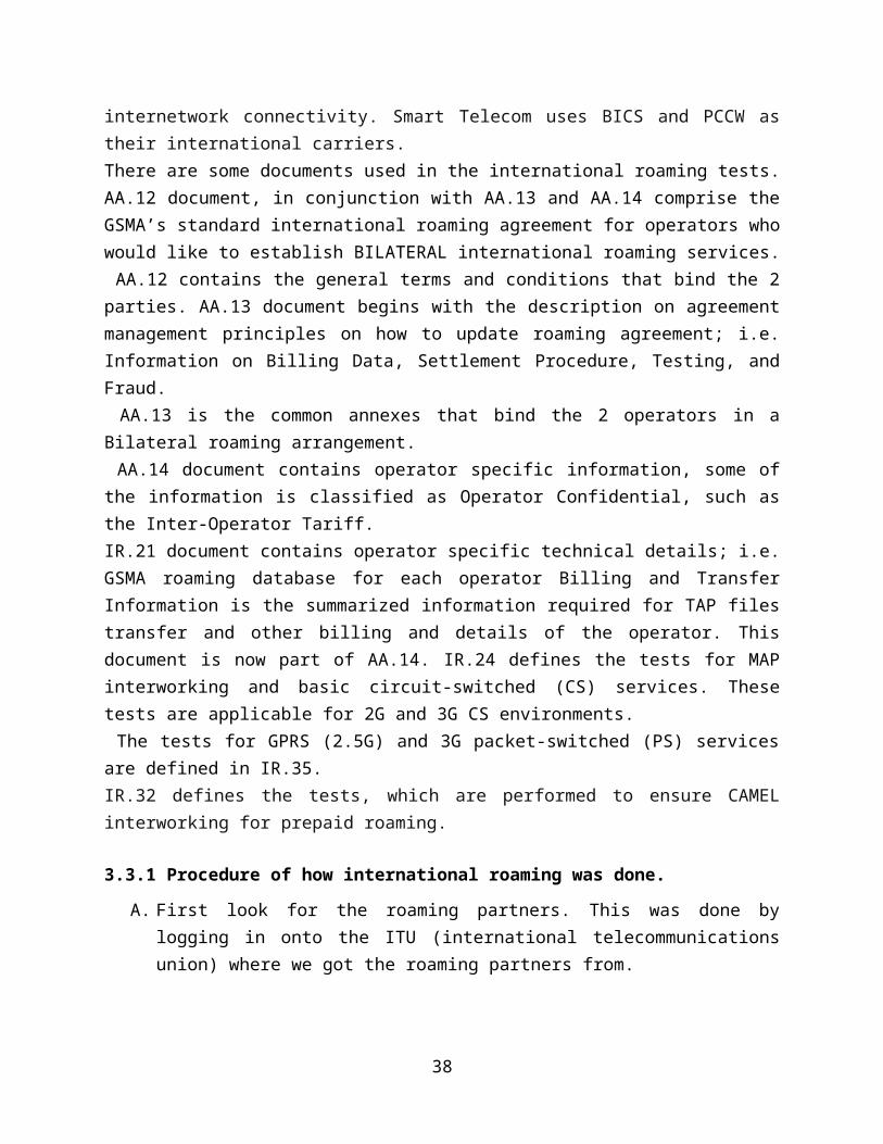
cable.Standard A code colour protocol is;
White green, green, white orange, blue, white blue, orange, whitebrown, brown.
Standard B code colour protocol is;
White orange, orange, white green, blue, white blue, green, whitebrown, brown.
Illustration of colour coding;
Figure 14: E1 colour coding
3.4.1 Ethernet cable types.
After knowing the standards we had to differentiate the main twoways of making Ethernet cables namely;
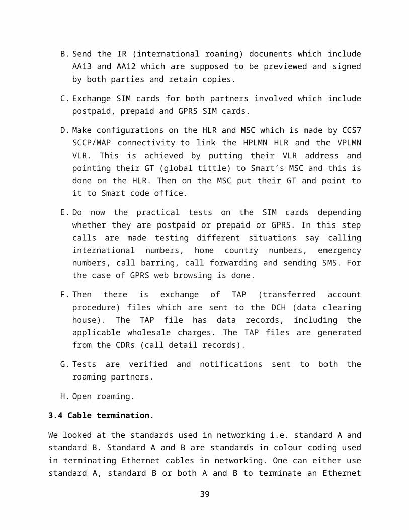
3.4.1.1 Straight through
In this case, we connect two different devices, i.e. pc to hub.With a straight through, both ends have the same standard. EitherA or B but not both.
Illustration of straight thru colour coding;
40
Figure 15: Straight through colour coding
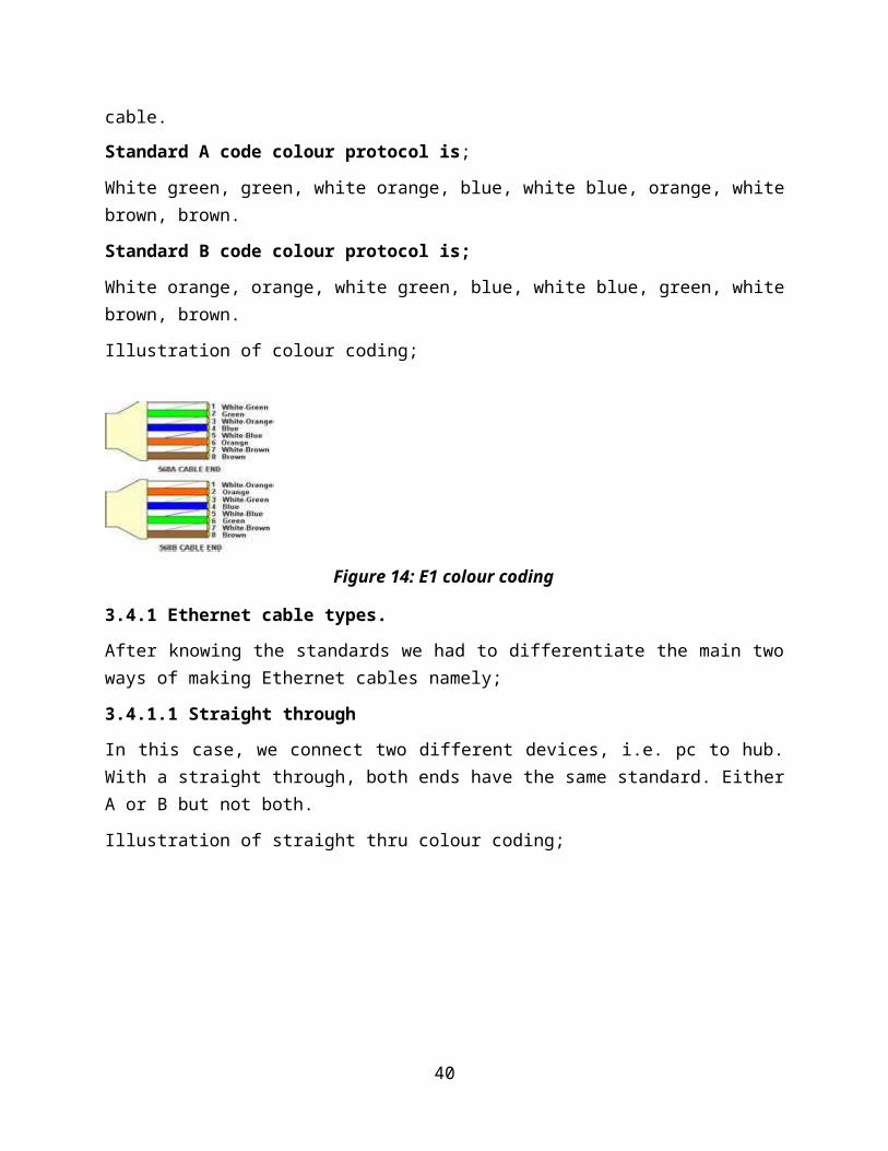
3.4.1.2 Cross over
In this case, we connect the same devices, i.e. pc to pc. With across over, one end is standard A and the other standard B
Illustration of cross over colour coding
Figure 16: cross over colour coding
3.4.2 Making a network cable
While at Smart, we made network cables. We used cat5 cables andthe network using standard B in terms of protocol.Procedure followed when making a network cable;
A. Get a 1metre long cable and trim both ends of the wire to areasonable level which fits the RJ45 connectors, this needsa lot of care so as not to destroy the inner conductingwires.
B. Untwist the cables on removal of the top most shields, in asense that they are eight free wires.
41
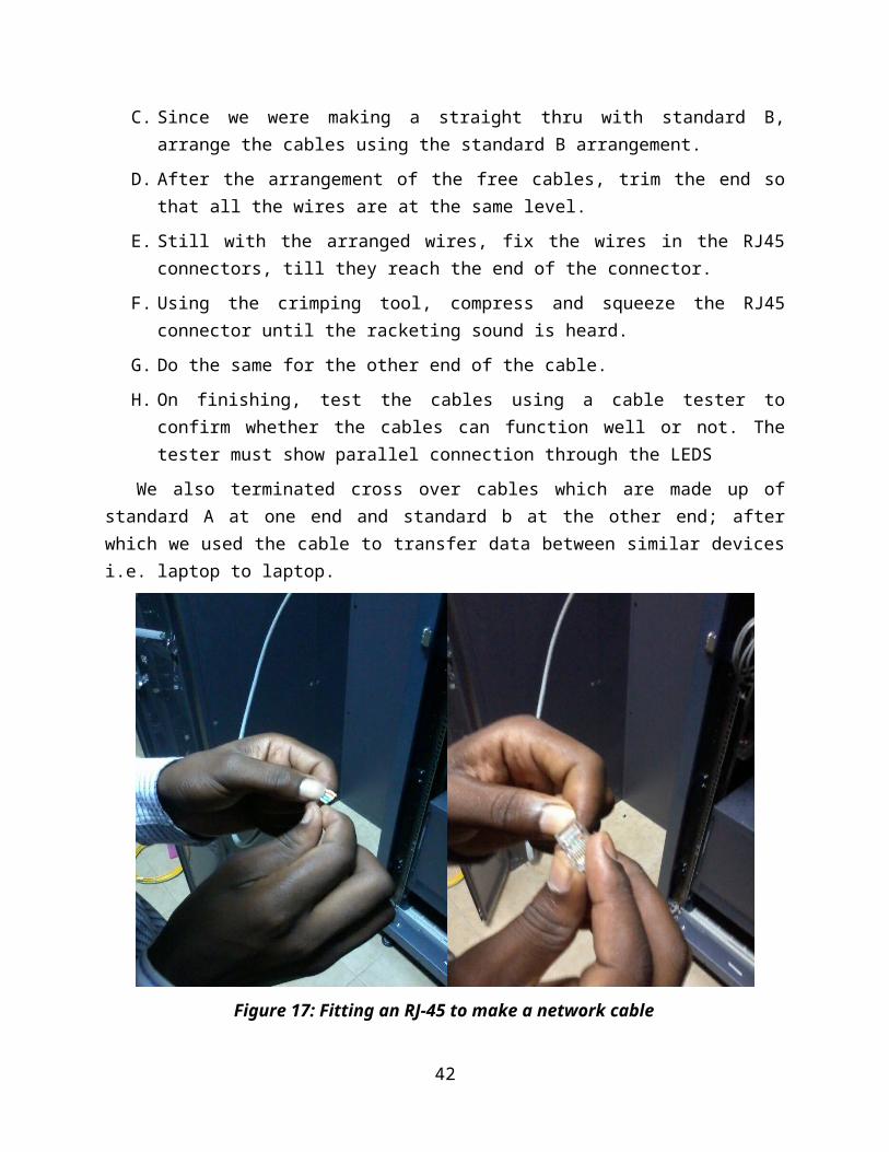
C. Since we were making a straight thru with standard B,arrange the cables using the standard B arrangement.
D. After the arrangement of the free cables, trim the end sothat all the wires are at the same level.
E. Still with the arranged wires, fix the wires in the RJ45connectors, till they reach the end of the connector.
F. Using the crimping tool, compress and squeeze the RJ45connector until the racketing sound is heard.
G. Do the same for the other end of the cable.H. On finishing, test the cables using a cable tester to
confirm whether the cables can function well or not. Thetester must show parallel connection through the LEDS
We also terminated cross over cables which are made up ofstandard A at one end and standard b at the other end; afterwhich we used the cable to transfer data between similar devicesi.e. laptop to laptop.
Figure 17: Fitting an RJ-45 to make a network cable
42
3.5 SIM card activations.
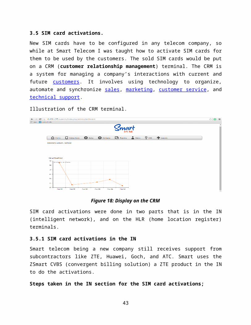
New SIM cards have to be configured in any telecom company, sowhile at Smart Telecom I was taught how to activate SIM cards forthem to be used by the customers. The sold SIM cards would be puton a CRM (customer relationship management) terminal. The CRM isa system for managing a company’s interactions with current andfuture customers. It involves using technology to organize,automate and synchronize sales, marketing, customer service, andtechnical support.
Illustration of the CRM terminal.
Figure 18: Display on the CRM
SIM card activations were done in two parts that is in the IN(intelligent network), and on the HLR (home location register)terminals.
3.5.1 SIM card activations in the IN
Smart telecom being a new company still receives support fromsubcontractors like ZTE, Huawei, Goch, and ATC. Smart uses theZSmart CVBS (convergent billing solution) a ZTE product in the INto do the activations.
Steps taken in the IN section for the SIM card activations;
43
A. Log in the CVBS terminal, which takes you to the homepagehaving two sections that is the customer delegate sectionand the billing center engineer.
B. So go to the billing center engineer section which will openhaving other tabs in it.
C. Go to the inventory tab which also still opens up othertabs.
D. Click the SIM card stock in tab which will open with a fillin form in which you will put the following;
Telecom region of the network equipment and then selectUganda
Go to the SIM card type and choose an option say CUG(closed user group) or GSM2 or GSM convert 4. For thecase of SIM cards I did I always filled in the GSM2.
Fill in the ICCID (integrated circuit card identifier) ofthe SIM card which is obtained from some list having allthe SIM card details.
Last on this form fill in the IMSI(international mobilesubscriber identity) and click ok
E. After that go the SIM card stock out tab and fill in theICCID and the company name
F. Go to the number distribution tab and fill in thetransaction type say CUG 3 or GSM prepaid 2 or per sec 4 orprepaid 5 but I always filled in the GSM prepaid 2, telecomregion of network equipment, ISDN(integrated servicesdigital network), and lastly the company name.
G. After that go back to the homepage and open the customerdelegate section
H. Go to the add customer tab and fill in the ISDN, then clickok.
44
I. Now go to the new connection tab, select the product of theSIM card, wait till it loads and then fill in the ISDN againand the ICCID and finally click the payment button.
3.5.2 SIM card activations on the HLR
The HLR (home location register) is a permanent data base whichstores subscriber information. The company created an account forus on the HLR so we were able to log in for as long we neverchanged anything.
Steps taken in SIM card activation on the HLR;
A. Log in on to the HLR web agent
B. Go to the frequent command tab
C. Click the individual number allocation tab, query for theproduct say prepaid test and fill in the ISDN and the IMSIand then click the execute button. A success reply willappear or else fail meaning something is wrong with the SIMcard.
3.6 SIM card swaps.
SIM card swaps are generally done both in the IN and on the HLR.Reasons why SIM card swaps are done is that customers may losethe their SIM cards or damage them but do not want to buy new SIMcards so they would prefer to retain their numbers and have themswapped and attached to a new IMSI generated from a new ICCID.
3.6.1 SIM card swaps in the IN.
The SIM card details to be swapped are gotten from the CRM andthe procedure of swapping is as follows;
A. Log in on to the CVBS and go to the billing centerengineer section.
45
B. Steps taken in the SIM card swaps are the same in stockin and stock out as described earlier on for the SIM cardactivations.
C. Go to the home page again and go to the customer delegatesection.
D. Copy the ISDN of the SIM card to be swapped from the CRMand place it for querying so as to see its details andcheck if they are correct.
E. Now go to the products tab which opens another page withother tabs.
F. Go to the duplicate card tab which will open a form andput the new ICCID then click the payment button. Afeedback will appear showing a fail or success.
3.6.2 SIM card swaps in the HLR
SIM card swaps on the HLR are dealt with according to thefollowing procedure;
A. Log in onto the HLR web agent and go to the WCDMA (widebandcode division multiple access) tab.
B. Then go to the query subscriber button using the IMSI orISDN in order to check if the old IMSI is attached to thatISDN SIM card and see if they match.
C. Check for the GPRS and CAMEL (customized application formobile network enhanced logic) services if they are correctand to know the products to which the SIM card has sayprepaid or postpaid.
D. Go to the delete button and delete the IMSI and click ok.
46
E. Lastly do the SIM card activation with its new IMSI andfollow the same procedure for activating SIM cards in theHLR as described earlier on.
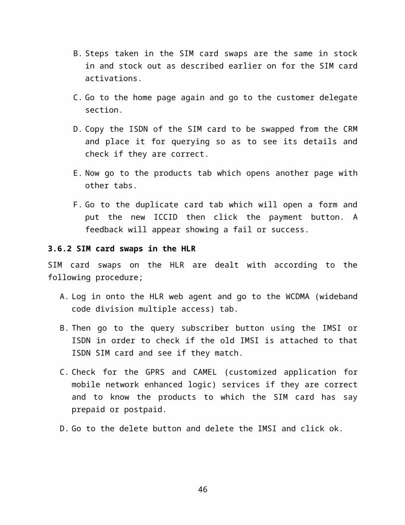
3.7 Tagging of Smart Telecom equipment.
On a few occasions, we went out and did labelling of someequipment that belongs to Smart Telecom on certain sites forexample at the Kitende site. We used a bar-code scanner toachieve the labels as shown in the figure below.
Figure 19: Smart label on the BBU.
3.8 Jumper – feeder cable connector fitting
3.8.1 1/2’ Jumper cable
Tools required
Two 19 mm spanners
Two 24mm spanners
One male connector
One cutting blade
One brush
47
Procedure
Trim the cable cover at a given position with a cabletool.
Chamfer the inner conductor with a flat file andsmoothen it.
Clean the cable with a brush and Screw the clamp onto
the outer conductor using the right dimension prescribed
in the manual.
Verify the dimension.
Screw the conductor head into the clamp
Fix the cable clamp and cable steady and screw connectorhead into the cable clamp tightly
NOTE:
The Clamp (bottom of connector) is tightened anti
clockwise direction while the top part is tightened in the
clockwise direction
3.9 Mounting directional antenna on tower
This was carried out at Mukono-Seeta site and the following stepswere under taken;
A. The antenna in pulled to the required position on top of
the tower using a rope and a pulley at the top of the
tower.
B. According to the work order issued by the client,
determine the direction and azimuthal angle the antenna
is to fulfill, determine the azimuthal angle and
48
direction using a compass. Normally, sector 1 is in the
north. Sector 2 lies in the clockwise 1200 direction and
sector 3 in the next clockwise 1200 direction, by
turning the antenna slightly, the personnel can adjust
the azimuth angle till it satisfies the design index.
Usually, the error of the azimuth angel should be ≤50.
C. Place the antenna on the supports found on the tower and
tighten the antenna brackets onto the supports enough
for the antenna not to move out of position due to wind.
Looseness may cause loose connection while too much
tension may damage the antenna sheathing.
D. Make the waterproof curve of the antenna jumper,
distribute and bind the jumpers along the cross bar of
the stand using the black cable tie, and cut off the
extra tail of the cable tie.
3.10 Connecting jumpers between feeder and antenna
This was done at Entebbe-Kubayita site and the following stepswere considered;
A. Connect the jumper with the feeder. The jumpers should
bend in a natural manner. The bending radius should be
20 times longer than the jumper diameter.
B. Applying weather proof.
49
3.11 Unpacking and checking equipment
This describes how to unpack the cases and check the items
in the cases. Check whether the cases delivered on site
contain all the items mentioned in the packing list.
Check whether the number of products in the packing
cases is the same as is mentioned in the packing list.
If they are not the same then make a report to your
immediate boss.
Check whether the packing cases are intact.
Check whether the cases have the same number and types
of items as are mentioned in the packing list.
The following should also be considered when transportingthe package to site.
When transporting or moving the equipment, components,
or parts, ensure that they do not collide with doors,
walls, shelves, or other objects.
When transporting, moving, or installing the equipment,
components, or parts, avoid touching their uncoated
metal surfaces with sweaty or dirty gloves
50
CHAPTER FOUR: CONCLUSION AND RECOMMENDATIONS
4.1 Recommendation
According to the challenges I faced during training, I wish torecommend the following:
The internee to be given some little pay in terms oftransport to enable him/her come in time daily.
The station should at least provide some lunch to thetrainees.
4.2 Conclusion
The conclusion made in this report was based on experiences andwhat was being observed during the field attachment. Theexperience was very beneficial and all enriching that exposed theinternee a lot of practical things that go in the social workprofession and the field work practice at large.
51
Despite of having acquired skills and being exposed to theoriesin class, the experiences made the internee reflect on thebroader perspectives in the field. This was due to the view thatall what had been acquired from the university required practicalevidence.
However, field attachment is quite challenging and very importantto students who are getting almost to the entry level.
4.3 Appendix
A copy of my mark sheet was attached.
REFERENCES
1. Smart website, www.smart.co.ug (Accessed on 5th July 2014)
2. GSM system survey, Ericsson, Published by Ericsson Radio Systems AB
3. Overview of the Global System for Mobile Communications, Author: John Scoria
4. SDH Introduction for Engineers, Marconi Training Services
52
5. http://www. e ri c sson. c om and Ericsson Site Manuals6. http://www.hu a w e i. c om and Huawei Site Manuals
7. Microsoft power point slides from the supervisor.
8. Wikipedia.
9. Practical work carried out.
53


