Embed Size (px)
Citation preview
NATL INST. OF STAND & TECH
AlllOb MQ70S0
^ IlpUBUCAT10NS|
NBSIR 81-2433
F£fl 3 1932
Smoke Movement and SmokeControl on Merchant Ships
I
I
U.S. DEPARTMENT OF COMMERCENational Bureau of Standards
National Engineering Laboratory
Center for Fire Research
Washington, DC 20234
December 1981
Final Report
Prepared for:
Office of Merchant Marine Safety
QC U.S. Coast Guard100 Washington, DC 20593U56m. 81 -24331981

FEB 3 1982
•ATIOMAI4 BUSKAO09 BTAKDAmUl
UBBABTNBSIR 81-2433
SMOKE MOVEMENT AND SMOKECONTROL ON MERCHANT SHIPS
John H. Klote and Richard H. Zile
U S. DEPARTMENT OF COMMERCENational Bureau of Standards
National Engineering Laboratory
Center for Fire Research
Washington, DC 20234
December 1981
Final Report
Prepared for:
Office of Merchant Marine Safety
U.S. Coast GuardWashington, DC 20593
U.S. DEPARTMENT OF COMMERCE, Malcolm Baldrige, Secretary
NATIONAL BUREAU OF STANDARDS, Ernest Ambler, Director

-a-'- jf?> '
‘fr
TABLE OF CONTENTS
Page
LIST OF FIGURES v
LIST OF TABLES vi
Abstract 1
1. INTRODUCTION 1
2. BACKGROUND 2
2.1 Smoke Movement ...... 3
2.1.1 Stack Effect 3
2.1.2 Buoyancy 6
2.1.3 Wind 7
2.1.4 HVAC System 8
2.2 Principles of Static Smoke Control 9
2.3 Principles of Dynamic Smoke Control 102.3.1 Air Flow 112.3.2 Pressurization . 13
2.4 Door Opening Forces 152.5 Dynamic Smoke Control Systems ...... 16
2.5.1 Pressurized Stairwells 162.5.2 Zone Smoke Control 17
3. FIELD TEST PROGRAM 18
3.1 Tracer Test Procedures 193.2 Tests on the Exxon Houston 21
3.2.1 Test No. 1 223.2.2 Test No. 2 233.2.3 Test No. 3 233.2.4 Test No. 4 . 243.2.5 Test No. 5 24
3.3 Tests on the Sea-Land Express 253.3.1 Test No. 1 263.3.2 Test No. 2 273.3.3 Test No. 3 283.3.4 Test No. 4 283.3.5 Test No. 5 29
4. DISCUSSION 29
4.1 Horizontal Smoke Movement . 294.2 Vertical Smoke Movement 304.3 Smoke Control Problem 314.4 Pressurized Stairwells 314.5 Zone Smoke Control 324.6 Pressurized Stairwell with Zone Smoke Control 32
iii
TABLE OF CONTENTS (cont’d)
Page
4.7 Smoke Exhaust System 32
4.8 Test Methods 33
4.9 Engine Room Fire 33
5. RECOMMENDATIONS 33
5.1 Fire Tests 33
5.2 Computer Analysis 34
5 . 3 Engine Room Fires 34
5.4 Passenger Ships 34
5.5 Military Ships ..... 35
6. ACKNOWLEDGEMENTS 35
7. REFERENCES . 35
Iv
LIST OF FIGURES
Page
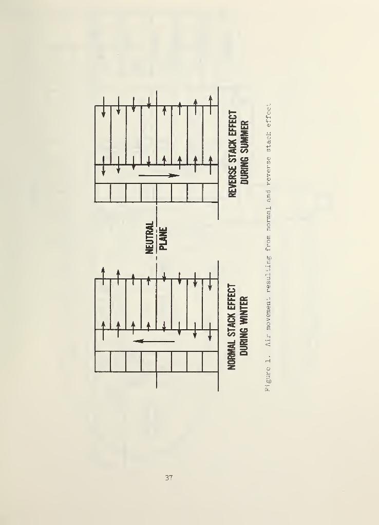
Figure 1. Air movement resulting from normal and reversestack effect 37
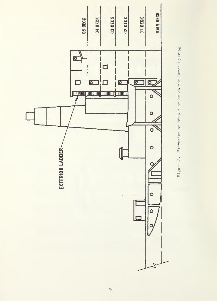
Figure 2. Elevation of ship's house on the Exxon Houston ... 38
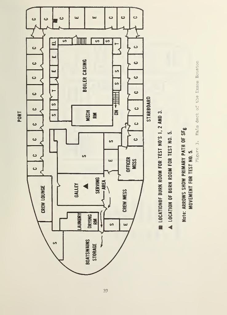
Figure 3. Main deck of the Exxon Houston 39
Figure 4. The 01 deck of the Exxon Houston ^0
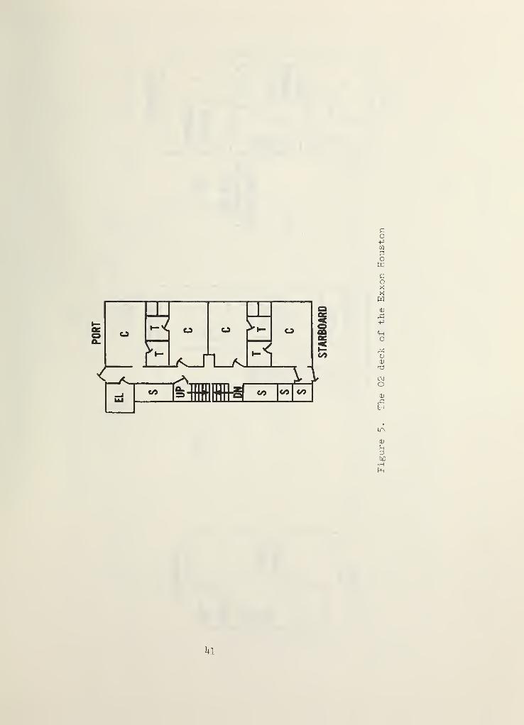
Figure 5. The 02 deck of the Exxon Houston
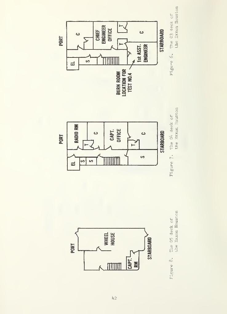
Figure 6. The 03 deck of the Exxon Houston h2
Figure 7. The 04 deck of the Exxon Houston ^2
Figure 8. The 05 deck of the Exxon Houston h2
Figure 9. Wind direction diagram ^3
Figure 10. SF^ concentrations for test no. 3 on the Exxon Houston hh
Figure 11. SF^ concentrations for test no. 4 on the Exxon Houston ^5
Figure 12. Elevation of ship's house on the Sea-Land Express . 46
Figure 13. Main deck of the Sea-Land Express 4T
Figure 14. The 01 deck of the Sea-Land Express . . . 48
Figure 15. The 02 deck of the Sea-Land Express 49
Figure 16. The 03 deck of the Sea-Land Express 50
Figure 17. The 04 deck of the Sea-Land Express ........ 51
Figure 18. The 05 deck of the Sea-Land Express 52
Figure 19. The 06 deck of the Sea-Land Express 53
Figure 20. Fan coil unit on the Sea-Land Express 54
Figure 21. SF^ concentrations on 04 deck for test no. 1 onthe Sea-Land Express 55
Figure 22. SF^ concentrations on different decks for testno. 1 on the Sea-Land Express 56
V
LIST OF FIGURES (cont’d)
Page
Figure 23., SFg concentrations on 04 deck for test no. 2 on theSea-Land Express . ........ . 57
Figure 24.. SF^ concnetrations on 01 deck for test no. 3 on theSea-Land Express 58
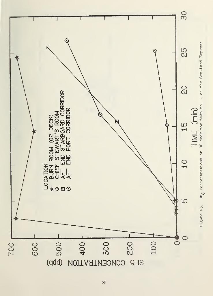
Figure 25. SF^ concentrations on 02 deck for test no. 4 on theSea-Land Express 59
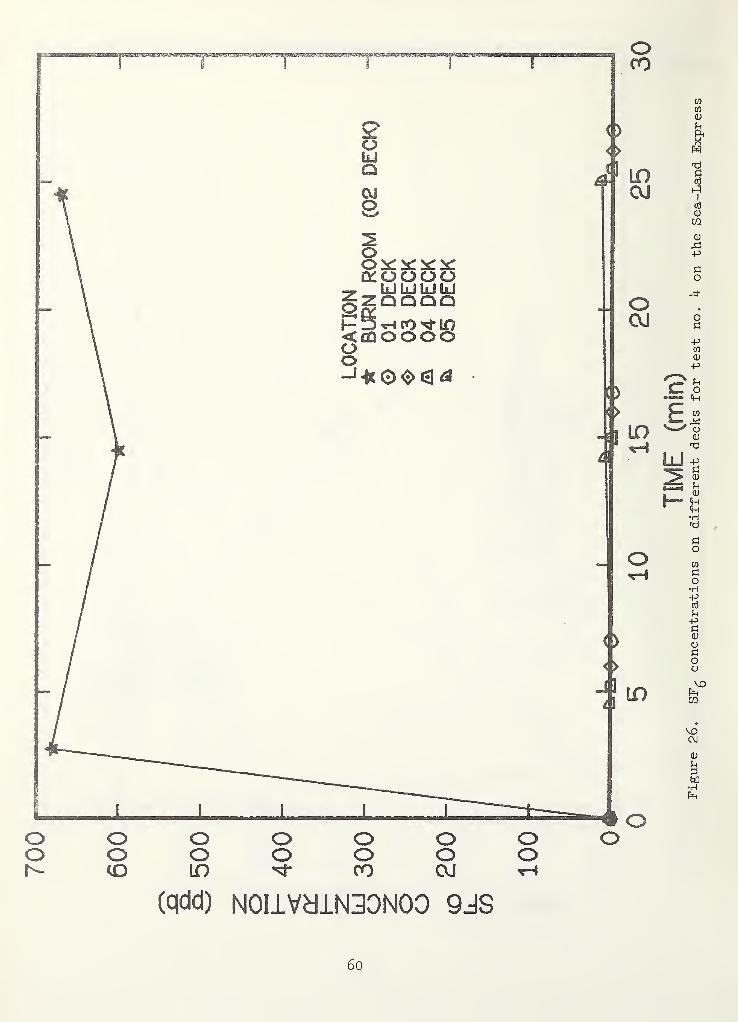
Figure 26. SFg concentrations on different decks for test no. 4
on the Sea-Land Express ^9
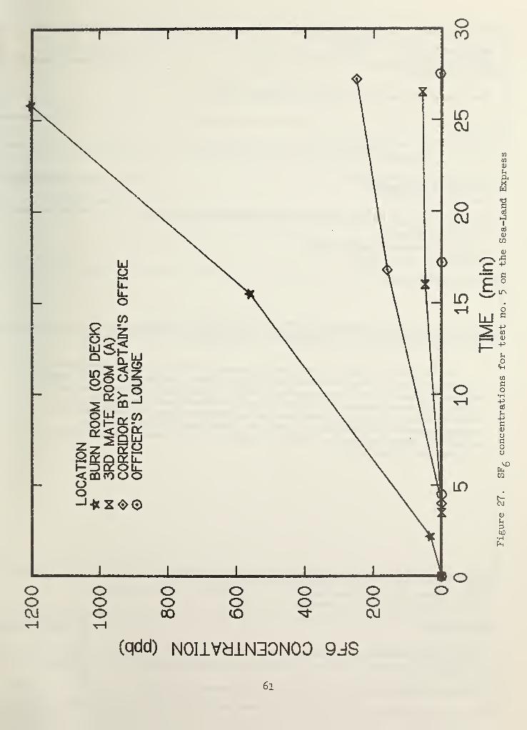
Figure 27., SF^ concentrations for test no. 5 on the Sea-LandExpress 6l
LIST OF TABLES
Page
Table 1. Summary Data for Tracer Tests on the EXXON Houston . , 22
Table 2. Summary Data for Tracer Tests on the Sea-Land Express . 26
vi
SMOKE MOVEMENT AND SMOKE CONTROL ON MERCHANT SHIPS
John H. Klote and Richard H. Zile
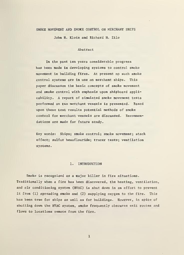
Abstract
In the past ten years considerable progress
has been made in developing systems to control smoke
movement in building fires. At present no such smoke
control systems are in use on merchant ships. This
paper discusses the basic concepts of smoke movement
and smoke control with emphasis upon shipboard appli-
cability. A report of simulated smoke movement tests
performed on two merchant vessels is presented. Based
upon these test results potential methods of smoke
control for merchant vessels are discussed. Recommen-
dations are made for future study.
Key words: Ships; smoke control; smoke movement; stack
effect; sulfur hexaflourlde; tracer tests; ventilation
systems
.
1 . INTRODUCTION
Smoke is recognized as a major killer in fire situations.
Traditionally when a fire has been discovered, the heating, ventilation,
and air conditioning system (HVAC) is shut down in an effort to prevent
it from (1) spreading smoke and (2) supplying oxygen to the fire. This
has been true for ships as well as for buildings. However, in spite of
shutting down the HVAC system, smoke frequently obscures exit routes and
flows to locations remote from the fire.
1
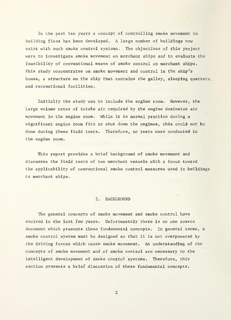
In the past ten years a concept of controlling smoke movement in
building fires has been developed. A large number of buildings now
exist with such smoke control systems. The objectives of this project
were to investigate smoke movement on merchant ships and to evaluate the
feasibility of conventional means of smoke control on merchant ships.
This study concentrates on smoke movement and control in the ship’s
house, a structure on the ship that contains the galley, sleeping quarters,
and recreational facilities.
Initially the study was to include the engine room. However, the
large volume rates of intake air required by the engine dominates air
movement in the engine room. While it is normal practice during a
significant engine room fire to shut down the engines, this could not be
done during these field tests. Therefore, no tests were conducted in
the engine room.
This report provides a brief background of smoke movement and
discusses the field tests of two merchant vessels with a focus toward
the applicability of conventional smoke control measures used in buildings
to merchant ships.
2 . BACKGROUND
The general concepts of smoke movement and smoke control have
evolved in the last few years. Unfortunately there is no one source
document which presents these fundamental concepts. In general terms, a
smoke control system must be designed so that it is not overpowered by
the driving forces which cause smoke movement. An understanding of the
concepts of smoke movement and of smoke control are necessary to the
intelligent development of smoke control systems. Therefore, this
section presents a brief discussion of these fundamental concepts.
2
2 . 1 Smoke Movement
The driving forces causing smoke movement are stack effect, buoyancy,
wind, and the HVAC system. Discussion of these concepts as they pertain
to smoke movement in buildings can be found in the literature [1-4]^.
The principles Involved are also valid for smoke movement on ships.
Generally, in a fire smoke movement will be caused by a combination of
these driving forces. The following is a brief discussion of these
driving forces.
2.1.1 Stack Effect
During winter there is frequently an upward movement of air within
shafts in buildings. These shafts may be stairwells, elevator shafts,
dumbwaiter shafts, mechanical shafts or even mail chutes. In these
cases air flows into the lower portion of the shaft and flows out of the
upper portion of the shaft. This phenomenon referred to as stack effect,
is caused by differences in hydrostatic pressure due to two air columns
at different temperatures. The pressure difference is expressed as:
AP = (p^ - p) gh
where
p^= air density outside the shaft
p = air density inside the shaft
g = acceleration due to gravity
h = distance from the neutral plane.
The neutral plane is an elevation where the hydrostatic pressure
inside the shaft equals the hydrostatic pressure outside the shaft.
Using the ideal gas law the above relation can be expressed as
Numbers in brackets refer to the literature references at the end ofthis paper.
3
AP ( 2 . 1 )=
R̂ ;) h
where
P = absolute atmospheric pressure
R = gas constant of air
= absolute temperature outside the shaft
T = absolute temperature inside the shaft.
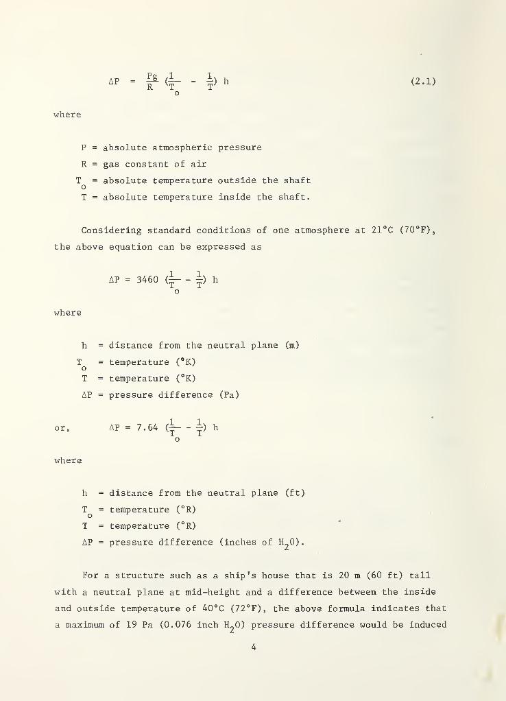
Considering standard conditions of one atmosphere at 21°C (70°F),
the above equation can be expressed as
AP = 3460 (~ - |) h
o
where
h = distance from the neutral plane (m)
T = temperature (°K)o
T = temperature (°K)
AP = pressure difference (Pa)
or, AP = 7.64 (^^ ^
o
where
h = distance from the neutral plane (ft)
= temperature (°R)
T = temperature (°R)
AP = pressure difference (inches of H2O).
For a structure such as a ship's house that is 20 m (60 ft) tall
with a neutral plane at mid-height and a difference between the inside
and outside temperature of 40°C (72°F), the above formula indicates that
a maximum of 19 Pa (0.076 inch H2O) pressure difference would be induced
4
by stack effect. The condition described earlier consisting of an
upward air flow in shafts in the winter is sometimes called normal stack
effect. This is to distinguish it from the downward air flow in shafts
encountered in the summer when the outside air temperature is greater
than the inside air temperature. This downward air flow condition is
called reverse stack effect. Stack effect is usually thought of as
existing between a building and the outside. The air movement in
buildings caused by both normal and reverse stack effect is illustrated
in figure 1. In this case the pressure differences in the above equations
would actually refer to the pressure difference between the shaft and
the outside of the building.
In unusually tight buildings with exterior stairwells, reverse
stack effect has been observed even during winter conditions [5]. In
this situation, the exterior stairwell temperature was considerably
lower than the building temperature; i.e., the stairwell was the cold
column of air and other shafts within the building were the warm columns
of air.
When considering stack effect between a building and the outside,
if the leakage paths are fairly uniform with height then the neutral
plane will be located near the mid-height of the building. However,
when the leakage paths are not uniform, the location of the neutral
plane can vary considerably, as in the case for shafts which are vented.
McGuire and Tamura [4] provide methods for calculating the location of
the neutral plane for some vented conditions.
Smoke movement from a building fire can be dominated by stack
effect. The following are descriptions of the different types of smoke
movement which can result from normal and reverse stack effect.
In a building with normal stack effect the existing air currents
(as shown in figure 1) can move smoke considerable distances from the
place of fire origin. If a fire is below the neutral plane, smoke moves
with the building air into and up the shafts. Once above the neutral
5
plane the smoke flows out of the shafts into the upper floors of the
building. If the leakage between floors is negligible, the floors below
the neutral plane will all be smoke free with the exception of the fire
f loor
.
Smoke from a fire located above the neutral plane would be carried
by the building air flow to the outside through leaks in the exterior of
the building. If the leakage between floors is negligible, then all the
other floors will remain smoke free. When the leakage between floors is
not negligible then there would be an upward smoke movement to the floor
above the fire floor.
The air currents caused by reverse stack effect are also shown in
figure 1. As would be expected these forces affect smoke movement in
the reverse of normal stack effect.
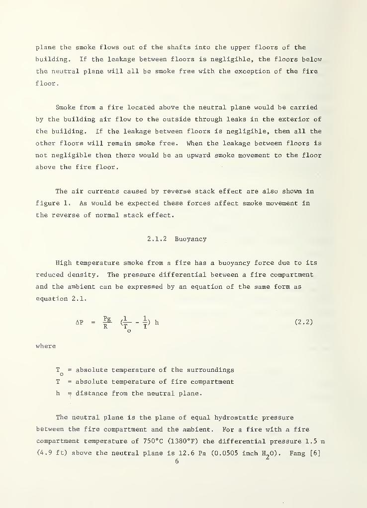
2.1.2 Buoyancy
High temperature smoke from a fire has a buoyancy force due to its
reduced density. The pressure differential between a fire compartment
and the ambient can be expressed by an equation of the same form as
equation 2.1.
AP = ^ (^ - |) h (2.2)
o
where
T^ = absolute temperature of the surroundings
T = absolute temperature of fire compartment
h = distance from the neutral plane.
The neutral plane is the plane of equal hydrostatic pressure
between the fire compartment and the ambient. For a fire with a fire
compartment temperature of 750°C (1380°F) the differential pressure 1.5m
(4.9 ft) above the neutral plane is 12.6 Pa (0.0505 inch H^O) . Fang [6]
has studied pressures caused by room fires during a series of full-scale
fire tests. During these tests the maximum differential pressure
reached was 16 Pa (0.064 inch H2O)
.
In a building with leakage paths in the ceiling of the fire room,
this buoyancy induced pressure causes smoke movement to the floor above
the fire floor. In addition, this pressure causes smoke to move through
any leakage paths in the walls or around the doors of the fire compartment.
As smoke travels away from the fire, its temperature drops due to heat
transfer and dilution. Therefore, the effect of buoyancy decreases with
distance from the fire.
2.1.3 Wind
In many instances wind can have a pronounced effect on smoke movement
within a building. The pressure, P^, that the wind exerts on a surface
can be expressed as
PV y C p V'
2 w o(2.3)
where
= pressure coefficient
p = outside air densityo
V = wind velocity
The pressure coefficients are in the range of -0.8 to 0.8, with
positive values for windward walls and negative values for leeward
walls. The pressure coefficient depends on building geometry and varies
locally over the wall surface. For buildings located in relatively flat
terrain, wind velocity increases with height due to the boundary layer
effect. Detailed information concerning wind velocity variations and
pressure coefficients is available from a number of sources [7-10].
7
A 60 km/s (37 mph) wind produces a pressure on a structure of 130 Pa
(0.52 inch H2O) when the pressure coefficient is 0.80. The effect of
wind on air movement within tightly constructed buildings with all doors
and windows closed is slight. However, the effects of wind can become
important for loosely constructed buildings or for buildings with doors
or windows open. Usually the resulting air flows are complicated and
for practical purposes computer analysis is required for an approxi-
mation of building air flows.
Frequently in fire situations a window breaks in the fire compart-
ment. If the window is on the leeward side of the building, the negative
pressure due to the wind vents the smoke from the fire compartment.
This can greatly reduce smoke movement throughout the building. However,
if the broken window is on the windward side then the wind forces the
smoke throughout the fire floor and frequently throughout a number of
floors above and below the fire floor. This both endangers the lives of
building occupants and hampers fire fighting.
Pressures induced by the wind in this type of situation can be
relatively large and can easily dominate air movement throughout the
building
.
2.1.4 HVAC System
The HVAC system frequently transports smoke during building fires.
In the early stages of a fire the HVAC system can serve as an aid to
fire detection. When a fire starts in an unoccupied portion of a
building, smoke is transported by the HVAC system to a space where
people can smell the smoke. However, as the fire progresses the HVAC
system will transport smoke to every area that it serves, thus endangering
life in all those spaces. The HVAC system also supplies air to the fire
space which aids combustion. For these reasons, HVAC systems have been
traditionally shut down when fires have been discovered. Even with the
HVAC system off smoke can flow through the HVAC ducts to endanger life
8
j
at places far from the fire. If there are fire dampers in these ducts,
generally considerable smoke will flow past the dampers before the
fusible links melt. In addition, shutting down the HVAC system does
nothing to prevent smoke movement through other paths due to stack
effect, buoyancy, or wind. In the last ten years a concept has arisen
which uses the HVAC system to limit smoke movement within a building.
This concept will be discussed in section 2.5.
2.2 Principles of Static Smoke Control
Smoke control can be either static or dynamic. For static smoke
control, components such as partitions, doors, and floors are used to
stop the movement of smoke. Aboard ships the names of these components
are different; however, they still can be used for static smoke control.
The driving force of smoke movement for static smoke control is buoyancy,
whereas the driving forces for dynamic smoke control are the HVAC system
and specially dedicated fans.
The two basic principles of static smoke control are:
1. Smoke movement can be limited by components such as decks,
bulkheads and hatches.
2. Smoke can be removed from a fire space by smoke vents or smoke
shafts.
The effectiveness of a component in limiting smoke movement depends
on the leakage paths in the component and on the pressure difference
across the component. Pipe penetrations through decks or bulkheads,
cracks where bulkheads meet decks, and cracks around hatches are a few
of the possible leakage paths. In ship construction many of these
leakage paths can be eliminated by welding components together and by
sealing or gasketing other cracks. The pressure difference across these
components depends upon stack effect, buoyancy, wind, and the HVAC
system, as discussed in section 2.1.
9
The effectiveness of smoke vents and smoke shafts depends on the
proximity to the fire, the buoyancy of the smoke, and the presence of
other driving forces.
Elevator shafts and stairwells in buildings have been used as smoke
shafts. In fires these shafts frequently distribute smoke to floors far
from the fire. This problem can be eliminated by the use of smoke
shafts which have essentially no leakage on floors other than the floor
of the fire.
2.3 Principles of Dynamic Smoke Control
Dynamic smoke control uses the components (bulkheads, decks, hatches,
etc.) of static smoke control in conjunction with pressure differentials
and air velocities generated by mechanical fans. The two basic principles
of dynamic smoke control are:
1. Air flow by Itself can control smoke movement provided that
the air velocities are of sufficient magnitude.
2. Pressure differentials across barriers can act to control
smoke movement.
Because dynamic smoke control relies on air flow and pressure
differentials produced by fans, it has the following advantages:
1. Dynamic smoke control is less dependent upon tight barriers.
Reasonable leakage areas in barriers can be allowed for in the
design.
2. Stack effect, buoyancy, and wind are less likely to overcome
dynamic smoke control than static smoke control. In the
absence of dynamic smoke control, these driving forces cause
smoke movement to the extent that leakage paths allow. How-
10
ever, in dynamic smoke control these driving forces are
opposed by the differential pressures and velocities of the
system.
3. Dynamic smoke control can be designed to prevent smoke flow
through an open doorway in a barrier by the use of air velocity
Doors in barriers are open during evacuation and are sometimes
accidentally left open or propped open throughout fires. In
the absence of dynamic smoke control, smoke flow through these
doors is common.
Unfortunately dynamic smoke control does have the disadvantage that
the system cannot operate in the event of a power failure to the system
fan. The ideal solution to this problem is for the system to be designed
to convert to a static smoke control system in the event of power failure
The following sections discuss the basic principles of dynamic
smoke control.
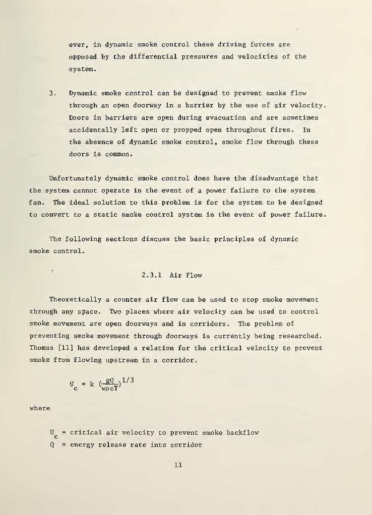
2.3.1 Air Flow
Theoretically a counter air flow can be used to stop smoke movement
through any space. Two places where air velocity can be used to control
smoke movement are open doorways and in corridors. The problem of
preventing smoke movement through doorways is currently being researched.
Thomas [11] has developed a relation for the critical velocity to prevent
smoke from flowing upstream in a corridor.
U = kc
,^, 1/3wpcT'^
where
= critical air velocity to prevent smoke backflow
Q = energy release rate into corridor
11
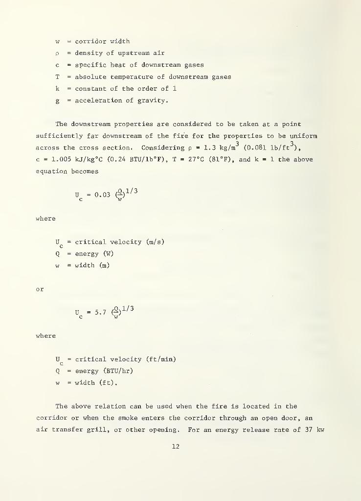
w = corridor width
p = density of upstream air
c = specific heat of downstream gases
T = absolute temperature of downstream gases
k = constant of the order of 1
g = acceleration of gravity.
The downstream properties are considered to be taken at a point
sufficiently far downstream of the fire for the properties to be uniform3 3
across the cross section. Considering p = 1.3 kg/m (0.081 Ib/ft ),
c = 1.005 kJ/kg°C (0.24 BTU/lb°F), T = 27°C (81°F), and k = 1 the above
equation becomes
U = 0.03 (%^/^c w
where
= critical velocity (m/s)
Q = energy (W)
w = width (m)
or
U =5.7 (%^^^^c w
where
= critical velocity (ft/min)
Q = energy (BTU/hr)
w = width (ft)
.
The above relation can be used when the fire is located in the
corridor or when the smoke enters the corridor through an open door, an
air transfer grill, or other opening. For an energy release rate of 37 kw
12
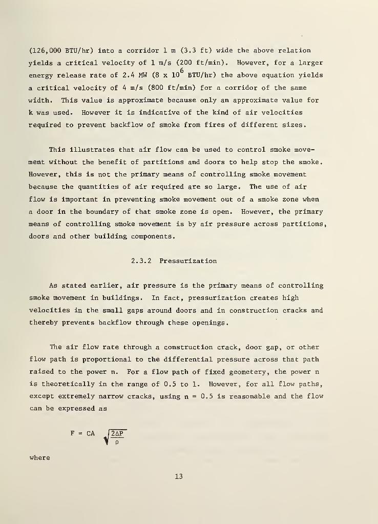
(126,000 BTU/hr) into a corridor 1 m (3.3 ft) wide the above relation
yields a critical velocity of 1 tn/s (200 ft/min). However, for a larger
energy release rate of 2.4 MW (8 x 10 BTU/hr) the above equation yields
a critical velocity of 4 m/s (800 ft/min) for a corridor of the same
width. This value is approximate because only an approximate value for
k was used. However it is indicative of the kind of air velocities
required to prevent backflow of smoke from fires of different sizes.
This illustrates that air flow can be used to control smoke move-
ment without the benefit of partitions and doors to help stop the smoke.
However, this is not the primary means of controlling smoke movement
because the quantities of air required are so large. The use of air
flow is important in preventing smoke movement out of a smoke zone when
a door in the boundary of that smoke zone is open. However, the primary
means of controlling smoke movement is by air pressure across partitions,
doors and other building components.
2.3.2 Pressurization
As stated earlier, air pressure is the primary means of controlling
smoke movement in buildings. In fact, pressurization creates high
velocities in the small gaps around doors and in construction cracks and
thereby prevents backflow through these openings.
The air flow rate through a construction crack, door gap, or other
flow path is proportional to the differential pressure across that path
raised to the power n. For a flow path of fixed geometery, the power n
is theoretically in the range of 0.5 to 1. However, for all flow paths,
except extremely narrow cracks, using n = 0.5 is reasonable and the flow
can be expressed as
where
13
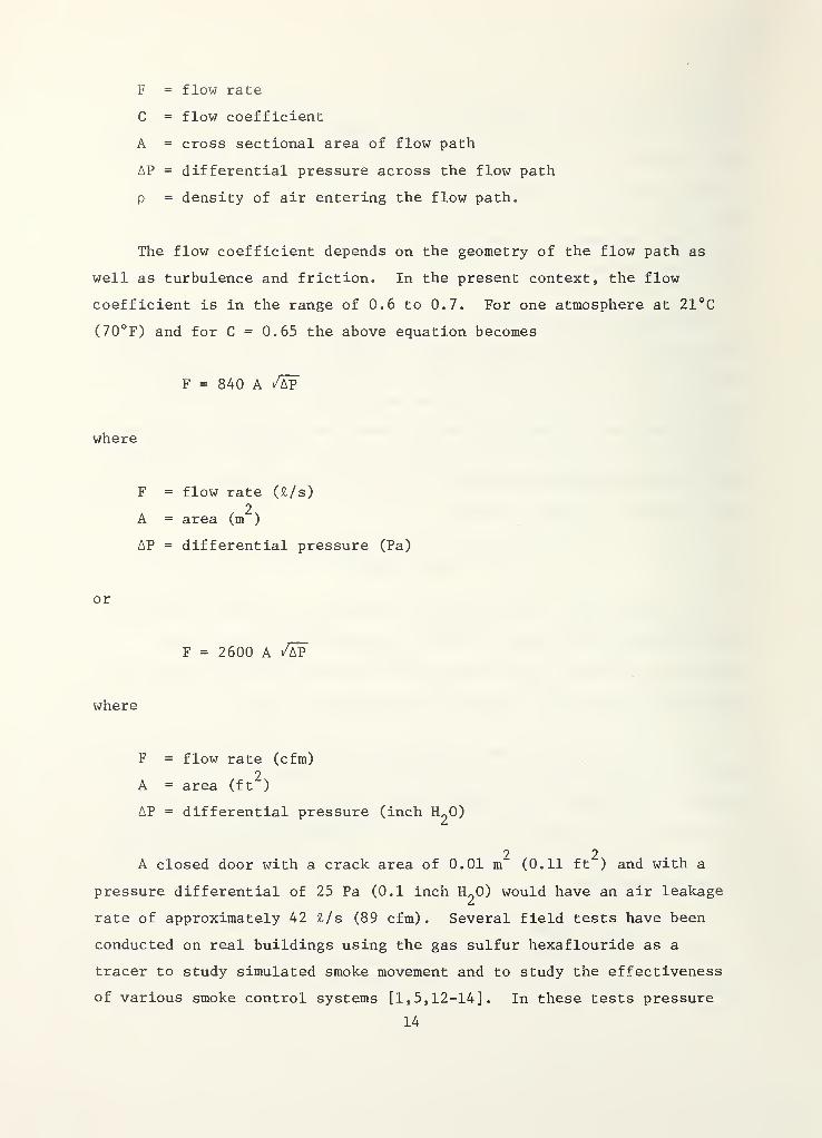
F = flow rate
C = flow coefficient
A = cross sectional area of flow path
AP = differential pressure across the flow path
p = density of air entering the flow path.
The flow coefficient depends on the geometry of the flow path as
well as turbulence and friction. In the present context, the flow
coefficient is in the range of 0.6 to 0.7. For one atmosphere at 21°C
(70°F) and for C = 0.65 the above equation becomes
F = 840 A
where
F = flow rate (£/s)
A = area (m )
AP = differential pressure (Pa)
or
F = 2600 A /ap
where
F = flow rate (cfm)
2A = area (ft )
AP = differential pressure (inch H2O)
2 2A closed door with a crack area of 0.01 m (0.11 ft ) and with a
pressure differential of 25 Pa (0.1 inch H^O) would have an air leakage
rate of approximately 42 £/s (89 cfm). Several field tests have been
conducted on real buildings using the gas sulfur hexaflouride as a
tracer to study simulated smoke movement and to study the effectiveness
of various smoke control systems [1,5,12-14]. In these tests pressure
14
on the order of 1 Pa (0.004 inch H2O) across partitions and closed doors
has been sufficient to prevent upstream migration of the simulated
"smoke"
.
In order to control smoke movement, the pressures produced by a
smoke control system must be sufficiently large so that they are not
overcome by stack effect, smoke buoyancy, and the forces of the wind.
However, the differential pressure produced by a smoke control system
should not be so large as to result in unreasonably high door opening
forces
.
2.4 Door Opening Forces
The determination of what is a reasonable door opening force is
difficult. Clearly, a person's physical condition is a major factor in
determining a reasonable door opening force for that person. The Life
Safety Code of the National Fire Protection Association (NFPA) [15]
states that the force required to open any door in a means of egress
shall not exceed 222 N (50 lb). Many smoke control system designers
consider this a very high value. On a merchant vessel it is probably
reasonable to assume that the officers and crew are in good physical
condition under normal circumstances. However, it should be realized
that exposure to smoke during a fire can adversely affect a person's
physical capabilities, further complicating the determination.
The force required to open a door is the sum of the forces to
overcome the differential pressure across the door and to overcome the
door closer. This can be expressed as
FT
WAAP2(W-t)
where
= the total door opening force
F_ = the force to overcome the door closerC
W = door width
A = door area
AP = differential pressure across door
t = distance from the door knob to the knob side of the door.
•
This relation assumes that the door opening force is applied at the
knob.
2.5 Dynamic Smoke Control Systems
The principles presented in section 2.3 have been employed to
provide dynamic smoke control systems in buildings. The two most common
systems are pressurized stairwells and zone smoke control and are dis-
cussed in the following sections.
2.5.1 Pressurized Stairwells
In an effort to provide smoke-free stair passages during a fire, a
number of stairwells have been built with pressurization systems.
Ideally these systems use air pressure to prevent smoke infiltration. A
number of papers have been written concerning analysis, design and field
testing of pressurized stairwells [1,2, 3, 5].
A stairwell pressurization system must maintain sufficient pressures
to prevent smoke infiltration when all doors are closed. For this case
the flow rate of pressurization air would be low because it would only
consist of leakage air around the closed doors and through building
cracks and any other small leakage areas. If this flow rate is too high
then the resulting high levels of pressurization can result in unreason-
ably high door opening forces. However, a much larger air flow rate
would be needed when stairwell doors are open in order to prevent smoke
backflow through the open doors.
16
Pressurization systems have been built which achieve these different
air flow rates by means of automatic control. An alternate solution is
to supply the larger air flow rate to the stairwell even when all doors
are closed and to vent the excessive air to prevent unreasonably high
door opening forces. The excessive air can be vented through a transfer
grill or a barometric damper. This alternate approach is less compli-
cated and less expensive than using automatic controls.
In the winter, the pressures across the upper doors of a pressurized
stairwell can be quite high while the pressures across the lower doors
can be very low or even negative. The opposite condition can exist in
the summer. An equation has been derived by Klote [15] for the air flow
rate in a simple building when the outside and inside temperatures are
different. The simple building consists of one without leakage paths
between building levels. However, a real ship house may have leakage
through the decks or vertical connections by means of shafts. In order
to analyze a pressurized stairwell connected to such a ship house a
computer program could be used. Such a computer program has been
developed at NBS [16] . In the design of a pressurized stairwell it is
recommended that initial calculations be performed on the simple building
model. If the resulting pressure differentials are acceptable then no
computer analysis is required because this method is conservative.
2.5.2 Zone Smoke Control
The zone system of smoke control generally uses the HVAC system to
control smoke movement. Specially dedicated smoke control fans can also
be used. When this system is employed a building is divided into a
number of smoke zones. In the event of a fire, air is exhausted from
the smoke zone where the fire is located and air is supplied to the
other zones. These air flows acting over the leakage areas of a smoke
zone cause pressure differences across the boundaries of the smoke zone
in which the fire exists. Ideally this pressurization will prevent
smoke movement to building spaces outside of the zone in which there is
a fire.
17
When the HVAC system is used for smoke control the following events
should occur when the system is activated:
1. The supply air to the zone where the fire is located should be
shut off.
2. The return air system is placed in 100 percent exhaust mode
for the zone where the fire is located.
3. The supply air to all zones where there is no fire is set at
100 percent outside air.
4. The return air system is shut off for all zones where there is
no fire.
A number of such systems have been built and tested [12,13]. These
systems are generally automatically activated with provision for manual
override. However, these systems should not be activated by a pull box
because such activation cannot determine the smoke zone in which the
fire is located.
3. FIELD TEST PROGRAM
Methods which have been used at NBS for smoke movement and smoke
control research are (l) fire tests, (2) chemical smoke tests, (3)
tracer tests, and (4) pressure mapping. These field tests were to be
performed on merchant ships under normal operation. Real fire tests and
chemical smoke tests were eliminated because these tests would Interfere
with normal ship operation. Pressure mapping consists of measuring
differential pressures across barriers, i.e. closed doors. This is done
by placing a flexible plastic tube in a crack around the closed door and
attaching one end of it to a differential pressure transducer. Unfor-
tunately, the doors of interest on these ships were so tightfittlng that
the tube was crushed and differential pressures could not be measured.
Therefore, field measurements were restricted to tracer tests.
18
The gas sulfur hexaflouride (SF^) has been extensively used as a
tracer in smoke movement and smoke control tests because it is ( 1 )
2colorless, (2) odorless, (3) nontoxic , and (4) stable. These attributes
result in tests which do not interfere with the normal operation of the
facility being tested. In addition, SF^ is virtually unused industrially
in the United States. This means that SF, can be used as a tracer with6
practically no fear of interference of SF^ from another source.
Field tests were performed on two ships and were restricted to the
house which contains living quarters, galley and other service spaces.
3.1 Tracer Test Procedures
The tracer gas, SF,, was released at a constant rate in the simu-3
°
lated burn room . In all these tests the burn room door was open to the
corridor of the ship and all of the burn room samples were taken in the
doorway. It was anticipated that the tracer tests on the ship would be
different than similar tests in buildings. In large buildings SF^ is
released at a constant rate. Because the volumes of the buildings are
large and because of the existing air currents in buildings, the burn
room concentration remains relatively constant. However, on ships it
was expected that because of the lower air movement and smaller volume
of the house, that the burn room concentration of SF, would increaseo
throughout the test. For this reason a flow meter which operated in a
lower range (0.70 to 75 m2, of SF, per min) was obtained for these tests.D
The release rates were varied from test to test until it was determined
that a release rate of 4.5 m£/min would yield good test results.
Air samples throughout the house were collected and analyzed to
determine smoke movement in the event of a fire. Generally samples were
collected at the same location three or four times during a test. In
2OSHA concentration limit of SF5 is 1000 ppm as set forth in theFederal Register, Vol. 36, No. 157, August 13, 1971. However, concen-trations used in the tests described in this paper do not exceed 2 ppm.
3The term "burn room" will be used from here on to mean simulated burnroom.
19
some cases spot samples were collected at a location at only one time
during the test. These spot samples were collected to determine if a
location were free of SF^ or to determine the path of SF^ movement. Gas
samples were analyzed by a portable gas chromatograph having an electron
capture cell fitted with a 200 me tritium source. Data reduction was
obtained by means of a calibration curve for concentrations from 0 to
180 ppb. Samples of concentration higher than 180 ppb were diluted and
then analyzed.
The purpose of these tracer tests was to determine the paths of
smoke movement in the event of a real fire. However, smoke from a real
fire has a buoyant force that the tracer test does not simulate. The
tracer tests simulate cold smoke movement which results from low energy4
fires . The relative concentrations of smoke resulting from a high
energy fire would be different; however the paths of smoke movement
would most probably be the same.
The tests discussed in the following sections show that the SF^
concentrations did increase with time as expected. The peak concentra-
tions of SF^ varied from 320 to 1200 ppb. For this reason the figures
in this report have different scales for the SF, concentration. TheD
scales were chosen for each test so that the concentrations throughout
the ship could be easily compared with the burn room concentration for
that test. Care should be exercised in comparing the results of dif-
ferent tests.
At present no method has been developed for evaluating the hazard
to human life in a real fire based on the results of a tracer test.
However, the presence of SF, at a location indicates the existence of ab
path which could transport smoke to that location during a real fire.
The quantity of smoke thus transported would depend on the quantity and
Cold smoke movement also exists at a considerable distance from a highenergy fire. However, because of the limited size of a ship housethis situation is only partially relevant to this study.
20
temperature of smoke produced by the fire and the extent to which other
driving forces such as stack effect and wind exist. For these reasons
all but very small concentrations of SF^ are of concern. For discussion
in this paper, all concentrations of SF^ greater than one percent of the
maximum burn room concentration will be considered significant.
3.2 Tests on the Exxon Houston
The Exxon Houston is a sixteen year old oil tanker. The ship’s
house has six levels, and the general arrangements of the decks are
shown in figures 2-8. The symbols used in these figures are listed on
figure 4.
The HVAC system in this ship is a 100 percent outside air system.
Outside air is heated or cooled as necessary and distributed throughout
the house from the fan room located on 01 deck. An exhaust system draws
air from equipment spaces and toilets and reuses it for spot cooling in
the engine room. Additional ventilation air for the machinery room is
also supplied from the outside and combustion air for the boiler is
drawn from the top of the boiler room. The net effect of this is that
the boiler room is maintained at a considerable overpressure with
respect to both the outside and to the ship's house.
Five simulated smoke movement tests were performed on the Exxon
Houston. Outside temperatures, wind data, status of the HVAC system and
the flow rates of SF^ are provided in the following table.
21
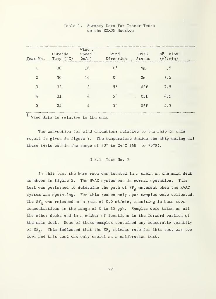
Table 1. Summary Data for Tracer Testson the EXXON Houston
Test No.
OutsideTemp (°C)
WindSpeed(m/ s)
WindDirection
HVACStatus
SF^ Flow(m£/min)
1 30 16 0° On .5
2 30 16 0° On 7.5
3 32 3 5° Off 7.5
4 31 4 5° Off 4.5
5 25 4 5° Off 4.5
Wind data is relative to the ship
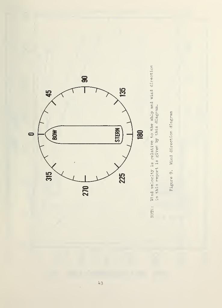
The convention for wind directions relative to the ship in this
report is given in figure 9. The temperature inside the ship during all
these tests was in the range of 20° to 24°C (68° to 75°F).
3.2.1 Test No. 1
In this test the burn room was located in a cabin on the main deck
as shown in figure 3. The HVAC system was in normal operation. This
test was performed to determine the path of SF^ movement when the HVAC
system was operating. For this reason only spot samples were collected.
The SF^ was released at a rate of 0.5 mii/min, resulting in burn room
concentrations in the range of 0 to 15 ppb. Samples were taken on all
the other decks and in a number of locations in the forward portion of
the main deck. None of these samples contained any measurable quantity
of SF, . This indicated that the SF, release rate for this test was too6 6
low, and this test was only useful as a calibration test.
22
3.2.2 Test No. 2
This test was a repeat of test No. 1 except that the SF^ flow rate
was increased to 7.5 m£/tnin. In this test the burn room concentration
of SF^ rose to 900 ppb at 3 minutes. During this test spot samples were
taken at a number of locations to determine the path of SF, movement.o
SFg flowed from the burn room through the adjacent section of corridor
and into the adjacent equipment room where it entered an exhaust grill.
This air was dumped into the engine room for spot cooling. At 30 minutes
into the test the spot cooling supply at the main console in the engine
room had 65 ppb SF , . There were also concentrations on all the above0
decks in ranges from 11 to 39 ppb with the lower concentrations on the
upper decks. Again a number of locations were sampled in the forward
portion of the main deck such as the officer’s mess and the boatswain’s
store and none of these samples contained any measurable quantity of
SFg. During this test the first assistant engineer stated that frequently
the engineer on duty in the engine room is the first to smell smoke from
a fire in the house. This is reasonable and confirms the findings,
because the air exhausted from the house is supplied to the engine room
as spot cooling.
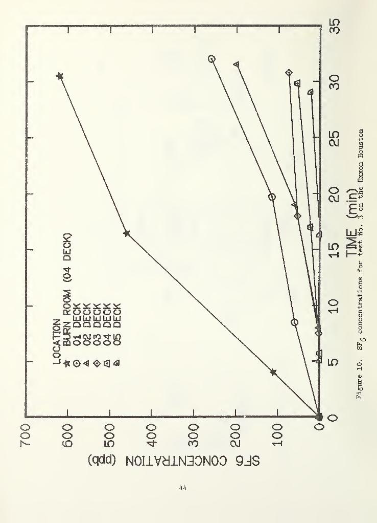
3.2.3 Test No. 3
This test was similar to the second test except that the supply and
exhaust systems were turned off to simulate the current practice for
real fire situations. Figure 10 shows the SF^ concentrations on different
decks for this test. These samples were all measured in the corridor
near the stairs. As can be seen from figure 10 the concentration decreases
with deck height. In previous tests in buildings, this type of air flow
has been found to be characteristic of the situation where the leakage
paths are primarily between floors and not due to leakage through shafts.
Samples were also collected in the forward portion of the main deck and
as in test no. 2 the levels of SF^ were negligible in all these samples.
23
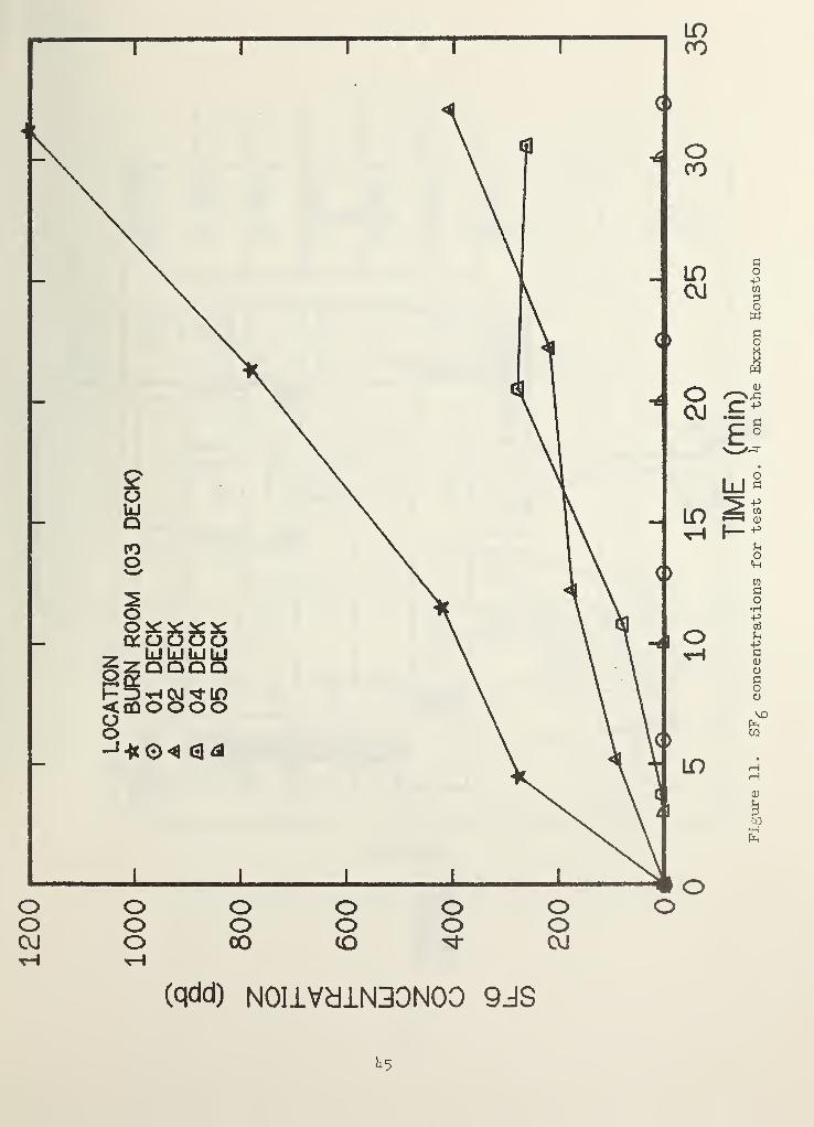
3.2.4 Test No. 4
The burn room for this test was the first assistant engineers
quarters on 03 deck. Because the volume of 03 deck was small a lower
release rate of 4.5 m£/min was used. The supply and exhaust fans were
turned off as in test no. 3. This test was made to determine the
vertical SF^ movement, and figure 11 shows SF^ concentrations on different
decks during this test. The concentrations of SF^ on the decks directly
above and below the fire room were very high. However, the levels of
SFg on all other decks is negligible. Again this type of flow is charac-
teristic of the situation where the leakage is primarily between the
decks. Spot samples were collected at a number of locations on the main
deck and the SF, concentrations in these samples were again negligible,o
3.2.5 Test No. 5
The burn room for this test was located in the galley on the main
deck. The supply and exhaust systems were again turned off as would be
the case in the event of a real fire. The samples taken on the port and
starboard corridors of the main deck within the first five minutes of
the test had no traceable level of SF , . Once this was realized spotD
samples were taken throughout the forward portion of the main deck. The
primary movement of SF^ was through the galley serving window into the
crew mess and down the corridor and into the boatswain storage area.
This flow path is shown in figure 3. A constant flow of air to the
outside was observed through a hatch in the ceiling of the boatswain
storage area. The SF also migrated into the officers mess and the portD
corridor by the galley. The concentrations in these areas were about
one-fourth the concentration in the path from the galley to the boatswain
storage area. Samples were also collected in the forward corridor of
the main deck as well as on all the other decks and the SF, concentrations6
in all these samples were negligible.
24
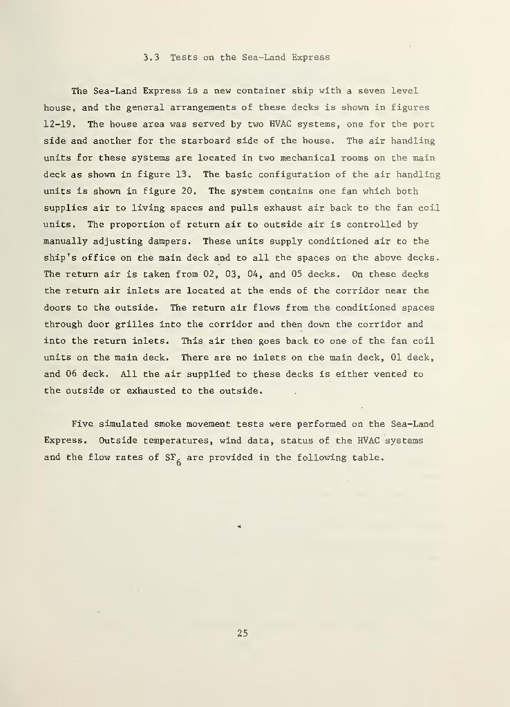
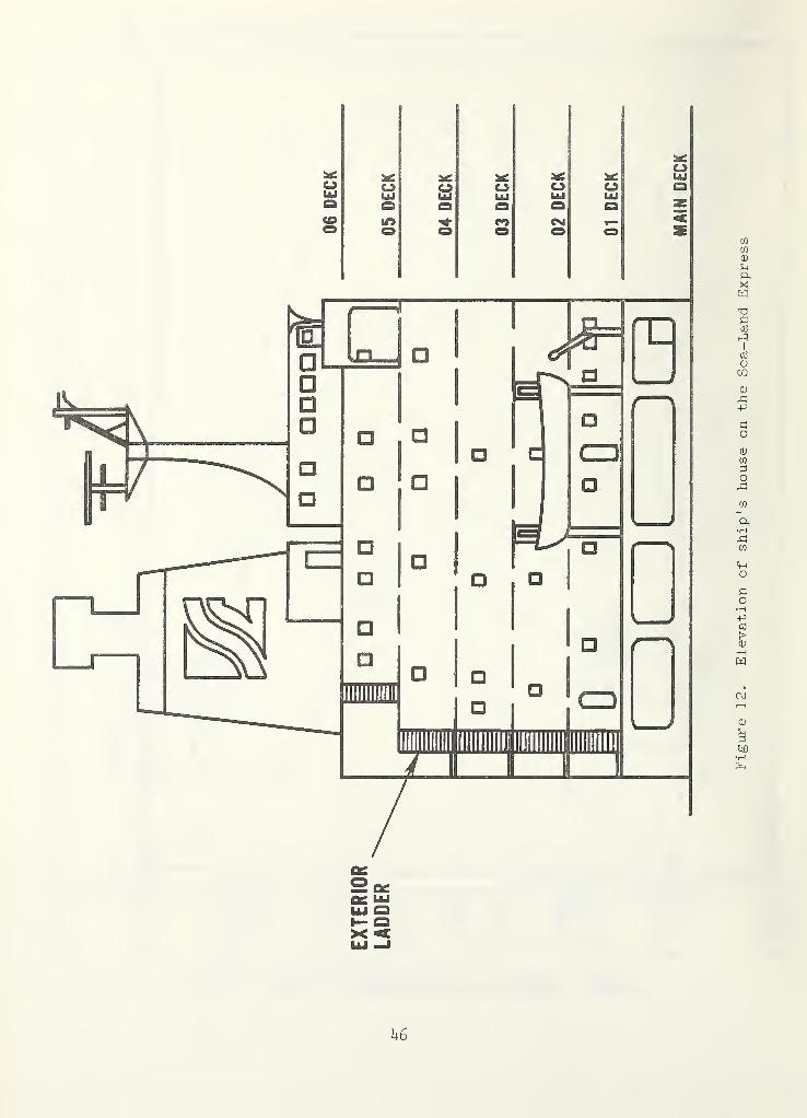
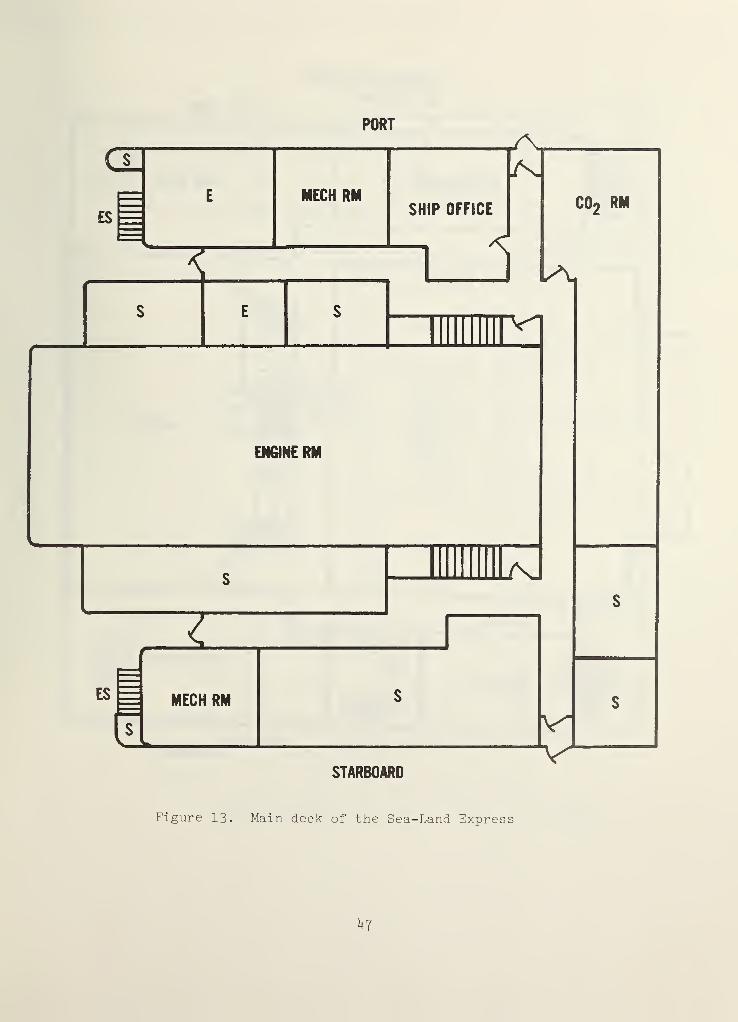
3.3 Tests on the Sea-Land Express
The Sea-Land Express is a new container ship with a seven level
house, and the general arrangements of these decks is shown in figures
12-19. The house area was served by two HVAC systems, one for the port
side and another for the starboard side of the house. The air handling
units for these systems are located in two mechanical rooms on the main
deck as shown in figure 13. The basic configuration of the air handling
units is shown in figure 20. The system contains one fan which both
supplies air to living spaces and pulls exhaust air back to the fan coil
units. The proportion of return air to outside air is controlled by
manually adjusting dampers. These units supply conditioned air to the
ship's office on the main deck and to all the spaces on the above decks.
The return air is taken from 02, 03, 04, and 05 decks. On these decks
the return air inlets are located at the ends of the corridor near the
doors to the outside. The return air flows from the conditioned spaces
through door grilles into the corridor and then down the corridor and
into the return inlets. This air then goes back to one of the fan coil
units on the main deck. There are no inlets on the main deck, 01 deck,
and 06 deck. All the air supplied to these decks is either vented to
the outside or exhausted to the outside.
Five simulated smoke movement tests were performed on the Sea-Land
Express. Outside temperatures, wind data, status of the HVAC systems
and the flow rates of SF, are provided in the following table.D
44
25
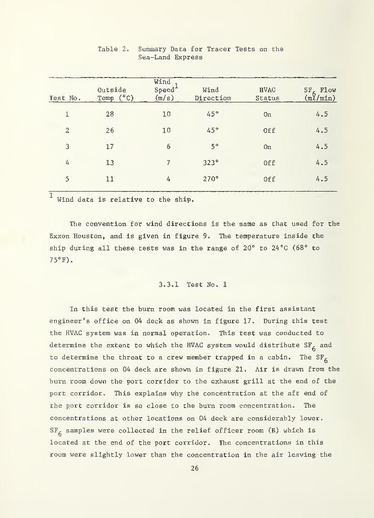
Table 2. Summary Data for Tracer Tests on the
Sea-Land Express
Test No.
OutsideTemp (°C)
Wind^
Speed(m/s)
WindDirection
HVACStatus
SF, Flow(mS/min)
1 28 10 45° On 4.5
2 26 10 45° Off 4.5
3 17 6 5° On 4.5
4 13 7 323° Off 4.5
5 11 4 270° Off 4.5
^ Wind data is relative to the ship
The convention for wind directions is the same as that used for the
Exxon Houston, and is given in figure 9. The temperature inside the
ship during all these tests was in the range of 20° to 24°C (68° to
75°F).
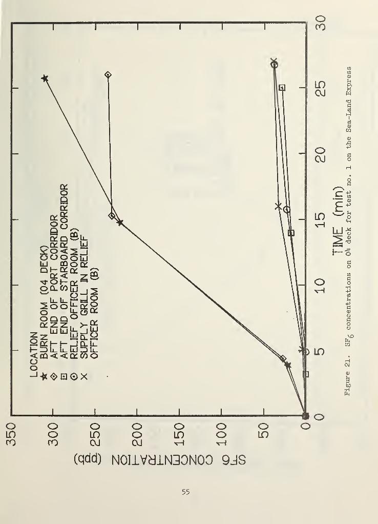
3.3.1 Test No. 1
In this test the burn room was located in the first assistant
engineer's office on 04 deck as shown in figure 17. During this test
the HVAC system was in normal operation. This test was conducted to
determine the extent to which the HVAC system would distribute SF^ and
to determine the threat to a crew member trapped in a cabin. The SF^
concentrations on 04 deck are shown in figure 21. Air is drawn from the
burn room down the port corridor to the exhaust grill at the end of the
port corridor. This explains why the concentration at the aft end of
the port corridor is so close to the burn room concentration. The
concentrations at other locations on 04 deck are considerably lower.
SFg samples were collected in the relief officer room (B) which is
located at the end of the port corridor. The concentrations in this
room were slightly lower than the concentration in the air leaving the
26
supply grill in the ceiling of the room. This indicates the SF^ in the
relief officer room (B) was primarily coming from the HVAC system. This
was anticipated because there was a very noticable air flow from the
room to the corridor which would inhibit SF, infiltration to the room6
from the corridor.
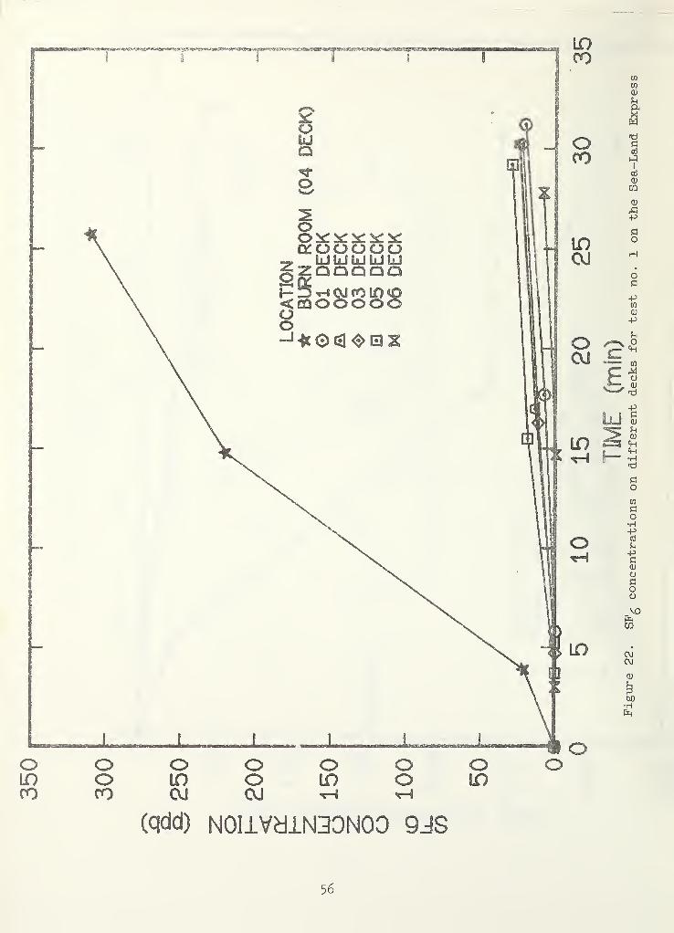
The SF- concentration on the other decks of the ship's house andD
the burn room concentration are shown in figure 22. The concentrations
on the other decks are similar to the concentrations measured in the
relief officer room (B) in figure 21. The SF^ on these other decks waso
transported through the HVAC system and possibly to some extent by
leakage paths between decks.
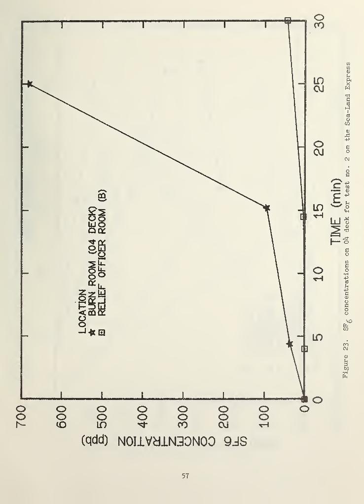
3.3.2 Test No. 2
This test was the same as test no. 1 except that the HVAC system
was shut off as would be the case in a real fire. A major reason for
this test was to determine the SF, movement to the other decks, and6
samples were collected on all the other decks throughout the test. The
SF^ concentrations on the other decks were negligible throughout the
test. This showed that there was essentially no vertical leakage within
the ship's house.
In order to determine the threat to a crew member trapped in a
cabin, samples were collected in the relief officer room (B) and these
are shown in figure 23. The door to the relief officer room (B) had an
open return air grill in it and this was obviously the primary path for
the significant quantity of SF, that entered this cabin. The concentra-o
tions in this cabin were very similar for both tests no. 1 and 2.
However, in test no. 1 the SF^ in this cabin entered primarily through
the HVAC system.
27
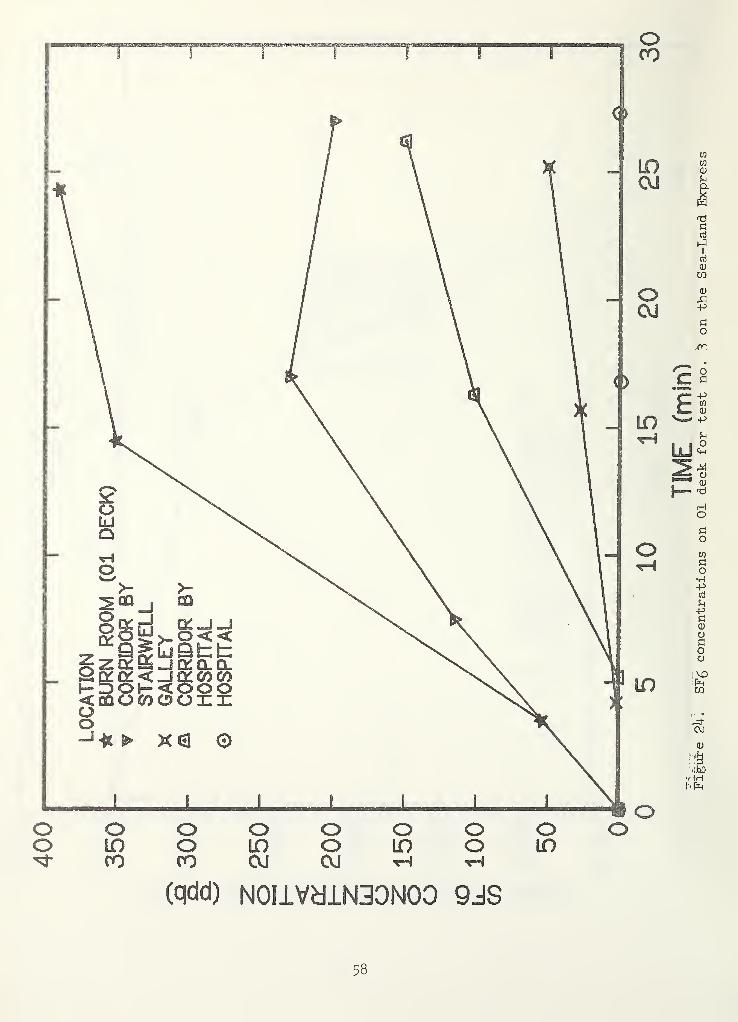
3.3.3 Test No. 3
The burn room for this test was the crew lounge on 01 level as
shown on figure 14. The HVAC system was operating normally for this
test and the galley exhaust fans were shut off. The SF, concentrationsD
for the burn room and other locations on the 01 level are shown in
figure 22. As one might expect, the SF^ concentrations in the 01 levelD
corridor decrease with distance from the burn room. The concentration
in the galley was less, but still significant. However, the concen-
tration of SF, in the hospital was insignificant. In addition, SF^D b
samples were also collected on the other decks and the SF, concentrationsb
of these samples were all negligible. This indicates that again there
was essentially no vertical leakage within the ship's house even though
the HVAC was operating. The HVAC system did not recirculate the SF^ as
in test no. 1 because there are no air returns on level 01 where the SF,b
was released.
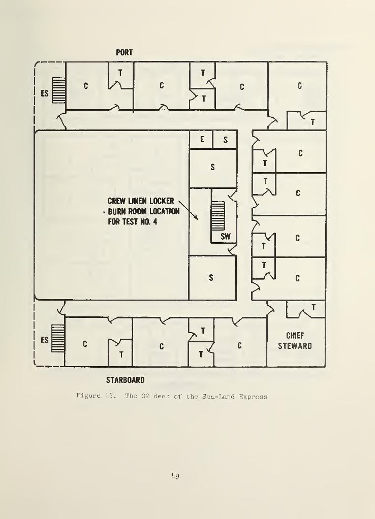
3.3.4 Test No. 4
The crew linen locker on level 02 was used as the burn room for
this test as shown in figure 15. The HVAC was shut off as would be the
case in a real fire. This test was made to determine the extent of SF,6
movement on the deck of the burn room and to determine the extent of
vertical SF^ movement. In order to determine the extent of danger to a
crew member trapped in a cabin samples were collected in the Chief
Steward's room on 02 level with the door closed. The SF, concentrations6
on 02 deck for this test are shown in figure 25. The SF^ concentration
in the corridor of 02 deck was quite high. It can be seen from figure
25 that the SF^ level in the Chief Steward's room was significant. As
in the case of test no. 2 this cabin door had an open return air grill
which was obviously the primary path for SF, flowing into the cabin. Itb
is apparent from figure 25 that there was a high level of SF, in theb
corridors of 02 deck.
28
Samples were also collected on other decks and these concentrations
are shown in figure 26. It can be seen that the SF^ concentrations are
essentially zero for all the levels sampled excepted for 05 deck. A
slight quantity of SF^ reached 05 deck, undoubtably by stack effect. A
number of pressure measurements were made in a effort to find the shaft
which transported the SF^ to the 05 level. Unfortunately this was
unsuccessful. In any event the concentration of SF^ on 05 deck was so
low that this unidentified leakage path probably presents no serious
threat.
3.3.5 Test No. 5
For this test the first mate's office on 05 deck was used as the
burn room as shown in figure 18. The HVAC system was again shut off as
would be the case in a real fire. This test was made to determine if
similar smoke movement would exist when the burn room was on 05 deck as
happened on other decks in the test nos. 2 and 4. The SF, concentrationso
from this test are shown in figure 27. As in earlier tests the corridor
concentration was high. Samples were collected in the third mate's room
with the door closed. Again, as in test nos. 2 and 4, the SF^ concen-
trations in the third mate's room were significant. However, the SF,D
concentrations in the officer lounge were negligible, most likely due to
its distance from the burn room and the fact that it was separated from
the corridor by a closed door. Air samples were also collected on the
other decks and the SF^ concentrations were negligible.
4. DISCUSSION
4.1 Horizontal Smoke Movement
The main emphasis of the tests on the Exxon Houston was vertical
SF^ movement, with the exception of test no. 5. Test no. 5 was the
special case of a simulated galley fire where SF, was carried by the5
existing air currents out of the ship after passing through the crew's
mess and the boatswains storage. However, on the Sea-Land Express all
29
of the tests clearly indicated only horizontal movement. As might be
expected SF concentrations within the corridor decreased with distanceb
from the burn room. Test nos. 2, 4 and 5 (sections 3.3.2, 3.3.4, and
3.3.5) all show that there is significant SF^ movement from the corridor
into cabins on the fire deck. This SF^ movement was through the venti-
lation return grills located in the cabin doors.
These grills are located in the lower part of the doors and the
extent of smoke infiltration would probably be somewhat less in the
event of an actual fire due to buoyancy effects. Nonetheless, this
poses a life threat in a real fire situation. In addition, high smoke
concentrations in the corridor would hinder evacuation as well as fire
fighting.
4.2 Vertical Smoke Movement
In test no. 4 on the Sea-Land Express the burn room was 02 level
and the other decks had no SF^ except for a slight quantity on 05 deck,
presumably due to stack effect. There was no evidence of SF^ movement
by stack effect in any of the other tests on the Sea Land Express or on
the EXXON Houston.
There was essentially no leakage of SF. between decks on the Seab
Land Express (test nos. 2-5). However, there was considerable leakage
of SF^ between decks (test nos. 3 and 4) of the Exxon Houston. While
the exact leakage paths and the events that created them could not be
determined, it is important to remember that such leakage can exist.
Smoke control systems that are developed for merchant vessels should
probably be capable of satisfactory performance even if such leakage
paths exist between decks.
30
4.3 Smoke Control Problem
Based upon the preceding discussion of horizontal and vertical
smoke movement one possible scenario of a fire in a cabin, storage room
or equipment space can be developed. The smoke flows out of the burn
room into the corridor and into the HVAC return. The HVAC system
spreads the smoke throughout the ship's house. Someone smells the smoke
and turns in an alarm, and the HVAC system is shut off. The corridor of
the fire floor is totally obscured. Possibly sleeping crew members are
trapped as smoke enters the return grills in their cabin doors. If
there are leakage paths between decks, smoke flows into other decks.
Valuable time is wasted determining on which deck the fire is located.
Once the fire deck is determined, more valuable time is wasted locating
the fire through the obscured corridor. During this wasted time the
fire grows larger and the threat to any trapped crew members becomes
greater.
Ideally a smoke control system including smoke detectors should be
part of the fire protection system in order to limit the smoke movement
problems, and thus allow faster location and extinction of such fires.
4.4 Pressurized Stairwells
Pressurized stairwells (1) provide a means of exit from the fire,
(2) can be used as a staging area for firefighters, and (3) provide air
flow which can clear the corridor of smoke from the corridor to the burn
room door. Air flow from a stairwell to a corridor exists when the
stairwell door is open. In order to clear a corridor of smoke, the air
flow rate into the corridor must be sufficiently large as discussed in
section 2.3.1. The analysis provided in section 2.3.1 is for air
flowing in one direction through a corridor that has essentially no
leakage paths in the sidewalls. This is different from the case on a
merchant ship which has return air grills in the doors, and further
study is needed. Air for such a system could be provided by the HVAC
system or a special fan.
31
4.5
Zone Smoke Control
The zone smoke control concept could be used to exhaust the smoke
from the fire deck and pressurize the other decks. Such a system would
prevent or reduce smoke leakage through decks. Even though this system
would remove some smoke from the fire deck, obscuration and toxic gases
would still possibly be a problem on the fire deck.
The use of existing HVAC system for zone smoke control poses
problems. HVAC systems that lend themselves to zone smoke control have
separate fans for supply and exhaust. The recirculating HVAC system
(figure 20) has no exhaust fan. The 100 percent outside air system has
both fans but modification to zone smoke control would require expensive
ductwork changes and addition of smoke dampers. Considering the limited
benefit of zone smoke control to the particular smoke problem described
in section 4.3, it is doubtful if such a system would be justified for a
retrofit situation. In the case of new ships further study of zone
smoke control is in order.
4.6
Pressurized Stairwell with Zone Smoke Control
This system provides the advantages of both systems, i.e., pres-
surized stairwells and zone smoke control. It can prevent smoke from
moving to other decks and it can provide a smoke free section of corridor
from the stairwell to the burn room when the stairwell door is opened.
However, the same considerations concerning retrofit for the zone smoke
control also apply to this system.
4.7
Smoke Exhaust System
Test nos. 1 and 2 on the Exxon Houston showed that when the HVAC
system was operating, it purged SF^ from the ship house. This is
because this ship has a HVAC system which operates on 100 percent out-
side air. The exhaust air from the house was used for spot cooling in
the engine room.
32
A possible method of smoke control for such a ship would be to
leave the exhaust system operating during a fire but to duct the exhaust
air directly outside rather than through the engine room. However, even
though this system would remove some smoke from the fire deck, obscura-
tion and toxic gases would possibly still be a problem. And, because
this system does not include pressurization of the other decks, smoke
flow to those decks is also possible.
4.8 Test Methods
The tracer tests performed on these two ships provided considerable
information on leakages and the paths of smoke movement in the event of
a real fire. However, because the tracer lacked buoyant forces, obscura-
tion and toxicity, these tests should not be Interpreted as providing
complete information regarding the actual smoke danger presented from a
fire.
4.9 Engine Room Fire
As discussed in the introduction, tests could not be performed in the
engine rooms during this test series. However, an important observation
can be made. As in the case of the ship's house, smoke obscuration in
the event of an engine room fire can prolong location and extinguishment
of the fire. This problem is made more severe because of the large size
of the engine room. Furthermore, the potential of an engine room fire
is relatively high due to the presence of fuels and lubricants. This
problem needs further investigation.
5. RECOMMENDATIONS
5.1 Fire Tests
The use of pressurized stairwells and zone smoke control is feasible
for merchant vessels. Full-scale fire tests are needed (1) to determine
33
the effectiveness of zone smoke control in reducing the levels of
obscuration and of toxic gases on the fire deck and (2) to investigate
the smoke clearing effect of air flowing from an open door of a pres-
surized stairwell into the fire deck. Emphasis is placed on the fire
deck because reduction of obscuration on this deck can save valuable
time during fire fighting.
5.2
Computer Analysis
It is recommended that a computer model of smoke movement and smoke
control in a merchant ship’s house be developed. This model could be
used as a research tool to gain a better understanding of smoke control
on the fire deck, to extend the test results to other geometries, and to
develop design guidelines.
5.3
Engine Room Fires
It is recommended that a study of smoke control in engine rooms be
undertaken. In these large spaces, buoyancy would be a major driving
force of smoke movement. Accordingly, tracer tests would not be appro-
priate because of absence of any buoyant force in such tests. The most
appropriate tests would be full-scale fire tests. Possibly a system
which used power venting would be appropriate for engine room fires.
5.4
Passenger Ships
It is recommended that future studies be made concerning smoke
movement and smoke control on passenger ships. The passenger ship is
more complex due to the larger number of people, the more complicated
architecture, and the more complex HVAC systems. Basic information
concerning flow paths and leakages is needed for passenger vessels and
SF^ tests would be an appropriate way in which to obtain this information.
34
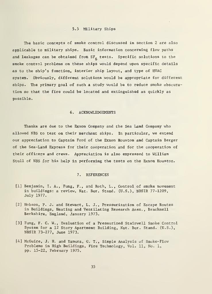
5.5 Military Ships
The basic concepts of smoke control discussed in section 2 are also
applicable to military ships. Basic information concerning flow paths
and leakages can be obtained from SF^ tests. Specific solutions to the
smoke control problems on these ships would depend upon specific details
as to the ship’s function, interior ship layout, and type of HVAC
system. Obviously, different solutions would be appropriate for different
ships. The primary goal of such a study would be to reduce smoke obscura-
tion so that the fire could be located and extinguished as quickly as
possible.
6 . ACKNOWLEDGEMENTS
Thanks are due to the Exxon Company and the Sea Land Company who
allowed NBS to test on their merchant ships. In particular, we extend
our appreciation to Captain Ford of the Exxon Houston and Captain Berger
of the Sea-Land Express for their cooperation and for the cooperation of
their officers and crews. Appreciation is also expressed to William
Stull of NBS for his help in performing the tests on the Exxon Houston.
7 . REFERENCES
[1] Benjamin, I. A., Fung, F., and Roth, L., Control of smoke movement
in buildings: a review, Nat. Bur. Stand. (U.S.), NBSIR 77-1209,July 1977.
[2] Hobson, P. J. and Stewart, L. J., Pressurization of Escape Routesin Buildings, Heating and Ventilating Research Assn. ,
BracknellBerkshire, England, January 1973.
[3] Fung, F. C. W.,Evaluation of a Pressurized Stairwell Smoke Control
System for a 12 Story Apartment Building, Nat. Bur. Stand. (U.S.),NBSIR 73-277, June 1973.
[4] McGuire, J. H. and Tamura, G. T., Simple Analysis of Smoke-FlowProblems in High Buildings, Fire Technology, Vol. 11, No. 1,
pp. 15-22, February 1975.
35
[5] Klote, J. H. j Stairwell Pressurization, ASHRAE Transactions 1980,American Socieity of Heating Refrigerating and Air-ConditioningEngineers, Vol. 86, Part I, pp. 604-623, 1980.
[6] Fang, J. B., Static Pressures Produced by Room Fires, Nat. Bur.
Stand. (U.S.), NBSIR 80-1984, February 1980.
[7] Sachs, P., Wind Forces in Engineering, Pergamon Press, New York,1972.
[8] Houghton, E. L. and Carruther, N. B. ,Wind Forces on Buildings and
Structures, John Wiley & Sons, New York, 1976.
[9] Simiu, E. and Scanlan, R. H., Wind Effects on Structures: An
Introduction to Wind Engineering, John Wiley & Sons, New York,1978.
[10] MacDonald, A. J., Wind loading on Buildings, John Wiley & Sons, NewYork, 1975.
[11] Thomas, P. H.,Movement of Smoke in Horizontal Corridors Against an
Air Flow, Institution of Fire Engineers, Quarterly, Vol. 30, No.
77, pp. 45-53, 1970.
[12] Fung, C. W. F. and Zile, R. H. , Test and Evaluation of the SmokeControl Capabilities of the San Diego Veterans AdministrationHospital, Nat. Bur. Stand. (U.S.), NBSIR 77-1225, April 1977.
[13] Fung, C. W. F. and Ferguson, J. B., Test and Evaluation of theSmoke Control Features of the Seattle Federal Building, Inter-national Conference on Firesafety in High-Rise Buildings, GeneralServices Administration, November 1974.
[14] Integrated Systems, Inc., Smoke Movement Studies at the NIHClinical Center, Nat. Bur. Stand. (U.S.), NBS-GCR-79-183, November1979.
[15] Code for Safety to Life from Fire in Buildings and Structures,NFPA 101-1981, National Fire Protection Association, Inc.,Batterymach Park, Quincy, MA, 1981, 5-2. 1.1. 4. 3.
[16] Klote, J. H. , Smoke Control by Stairwell Pressurization, EngineeringApplications of Fire Technology Workshop, Society of Fire ProtectionEngineers, Boston, MA, to be published.
[17] Klote, J. H. , A Computer Program for Analysis of PressurizedStairwells and Pressurized Elevator Shafts, Nat. Bur. Stand.(U.S.), NBSIR 80-2157, January 1981.
36
1 1 1n
J_ I
t
J_ t
.
tV 1
||2
-Po0)
CmCmCD
CJ
-Pcn
(L)
K)
P(L)
>(U
M
Tl!
Gaj
cd
nPoc;
BopCm
tjJj
G•iH
-pI—
I
GwQJ
P
G(D
B(U
>oE
P•H<
opG
•HP=-!
37
38
Figure
2.
Elevation
of
ship's
house
on
the
Exxon
Houston
CREW
LOUNGE
39
Figure
3.
Main
deck
of
the
Exxon
Houston
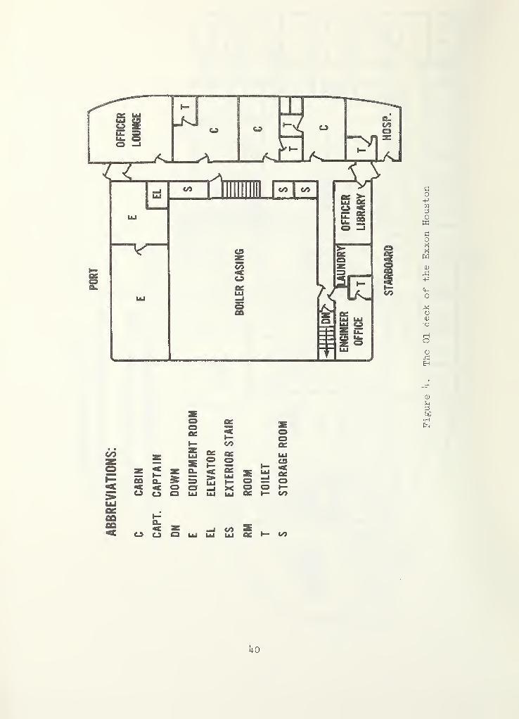
ABBREVfATIONS:
0£
I— CO
_ g QC OS— ^ o oZ ^ Z ^ ^fio a. » =3 2 ^ o< < O o _J X OO O Q Lkl LiJ UJ Z
CO<zoI—CO
o CO
Uo
Figure
h.
The
01
deck
of
the
Exxon
Houston
PORT
hi
oflfi
PC
c/5
GO-P
l+H WO G
Op:! WCJ
(D G^ O
XOO Xo PI
OJ CD
rG rGEh -P
VD
CD
GGtsD
•H
zPCoo
Jjo
CAPT. OFFICE ^“
<^
.
-1LU
c/5I
03PC<H—C/3
GO-P
Gh mo G
orX ffi
OCD GtG O
XXo H
(D CD
rG GEh G
E-
CD
GGW
•rH
(G
GO
G mo G
oG KoCD GG O
XiG XO HCD CD
G GEH G
OO
CD
GGcC
Pp
42
tn
o
-pCJ
(D
nd
TdC•H
CO
C •
cd SKi
ft P•H t)0
ft <d
CO -Hft
<D
ftft
ftO ftft
<L) ft>•H id
ft 0)
cd >I—[ ‘H(L) M
CO
CO -H
ft
ft O•rH ftl
O (L)
O ^I—
I
OJ CO
> *Hft
ft ft
•H <d
rs -H
wEHo
Bcd
EDcd
•Hft
U3
Figure
9-
Wind
direction
LOCATION
600
-
^
burn
room
(04
DECK)
0
01
DECK
A
02
DECK
(qdd) N0IiVaiN30N00 9JS
o o o o o oo o o o oLO ro OJ
Figure
10.
SF^
concentrations
for
test
iio.
3on
the
Exxon
Houston
LOCATION
1000
“
^
burn
room
(03
DECK)
0
01
DECK
A
02
DECK
o o o o oo o o oCO CO OJ
(qdd) N0IiVdiN30N00 9JS
h5
Figure
11.
SF^
concentrations
for
test
no.
4on
the
Exxon
Houston
h6
Figure
12.
Elevation
of
ship's
house
on
the
Sea-Land
Express
PORT
ES
A.E MECH RM
SHIP OFFICE CO2 RM
/<f
<
ENGINE RM
zES
0MECH RM
STARBOARD
Figure 13- Main deck of the Sea-Land Express
^7
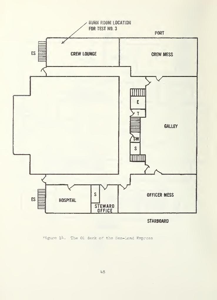
Figure 1^. The 01 deck of the Sea-Land Express
U8
PORT
Figure 15. The 02 deck of the Sea-Land Express
kg
PORT
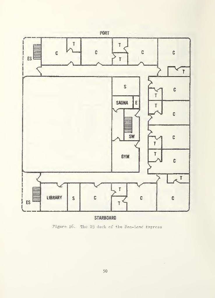
Figure l6. The 03 deck of the Sea-Land Express
50
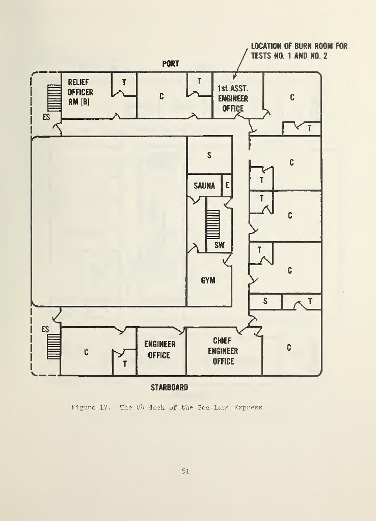
Figure IT- The OU deck of the Sea-Land Express
51
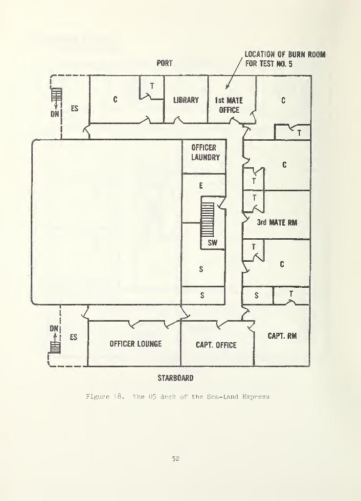
Figure l8. The 05 deck of the Sea-Land Express
52
00
53
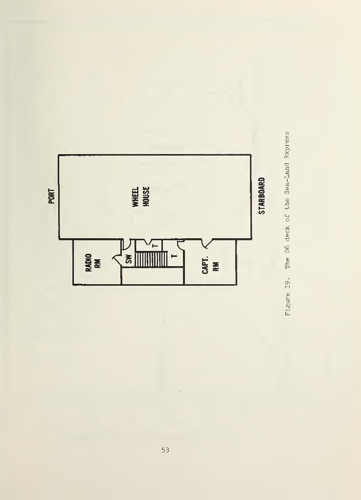
Figure
19
.
The
06
deck
of
the
Sea-Land
Express
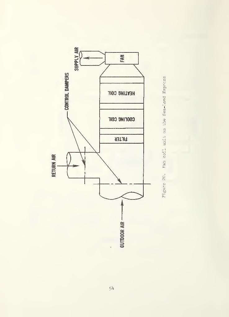
RETURN
AIR
5U
T TI
OCO
$
(qdd) NOIiVyiN30NOO 9JS
o o O o o o o oLO o lO o LO o lOCO ro OJ OJ —
1
55
TIME
(min)
Figure
21.
SF^
concentrations
on
Oh
deck
for
test
no,
1on
the
Sea-Land
Express
350
(qdd) N0IlVaiN30N00 9JS
56
TIME
(min)
Figure
22.
SF^
concentrations
on
different
decks
for
test
no.
1on
the
Sea-Land
Express
T T T T
O00
(qdd) N0IiVaiN30N00 9JS
o o o o o o o oo o o o o o oh- CO LO CO OJ vH
57
TIME
(min)
SFg
concentrations
on
deck
for
test
no.
2on
the
Sea-Land
Express
(qdd) N011VaiN30N00 9JS
58
.
TIME
(’min')
Figure
2\.
SF
5
concentrations
on
01
deck
for
test
no.
Ton
the
Sea-Land
Express
700
(qdd) N011VaiN30N0O 9JS
59
TIME
(min)
Figiire
25.
SF^
concentrations
on
02
deck
for
test
no.
^on
the
Sea-Land
Express
700
(qdd) N0IiVaiN33N00 9JS
6o
TIME
(min)
Figure
26.
SFg
concentrations
on
different
decks
for
test
no.
Uon
the
Sea-Land
Express
(qdd) N0IiVaiN30N00 9JS
6i
TIME
(min)
Figvire
2?.
SFg
concentrations
for
test
no.
5on
the
Sea-Land
Express
NBS»114A (REV. 2-80
U.S. DEPT. OF COMM.
BIBLIOGRAPHIC DATASHEET (See instructions)
L PUBLICATION ORREPORT NO,
NBSIR 81- 2h23
2o Performing Organ. Report NoJ 3. Publication Date
IJanuary 1982
4, TITLE AND SUBTITLE
SMOKE MOVEMENT AND SMOKE CONTROL ON MERCHANT SHIPS
So AUTHOR(S)
John H. Klote and Richard H. Zile
6. PERFORMING ORGANIZATION (If joint or other than N BS, see instructions)
national bureau of standardsDEPARTMENT OF COMMERCEWASHINGTON, D.C. 20234
7. Contract/Grant No.
8. Type of Report & Period Covered
Final Report
9. SPONSORING ORGANIZATION NAME AND COMPLETE ADDRESS (Street. City, State, ZIP)
U.S. COAST GUARDOFFICE OF MERCHANT MARINE SAFETYWASHINGTON, D.C, 20593
10.
SUPPLEMENTARY NOTES
1^2] Document describes a computer program; SF-185, FIPS Software Summary, is attached.
11.
ABSTRACT (A 200-word or less factual summary of most significant information. If document includes a significantbibliography or literature survey, mention it here)
In the past ten years considerable progress has been made in developing
systems to control smoke movement in building fires. At present no such smoke
control systems are in use on merchant ships. This paper discusses the basic
concepts of smoke movement and smoke control with emphasis upon shipboard
applicability. A report of simulated smoke movement tests performed on two
merchant vessels is presented. Based upon these test results potential
methods of smoke control for merchant vessels are discussed. Recommendations
are made for future study.
12.
KEY WORDS (S/'x to twelve entries; alphabetical order; capitalize only proper names; and separate kev words by semicolon s)
Ships; smoke control; smoke movement; stack effect; sulfur hexaflouride;tracer tests; ventilation systems.
13. AVAILABILITY
Su nl imited
I I
For Official Distribution. Do Not Release to NTIS
[~n Order From Superintendent of Documents, U.S. Government Printing Office, Washington, D.C.20402.
Order From National Technical Information Service (NTIS), Springfield, VA. 22161
14. NO. OFPRINTED PAGES
67
15. Price
$9 .00
USCOMM-DC 6043-P80


i
I
i
f


