Embed Size (px)
Citation preview
1
SNOWBLOWER
OPERATORS
AND
PARTS MANUAL
MANUFACTURED BY:
SMYTH WELDING & MACHINE SHOP LTD.
R.R.#2
37452 GLEN’S HILL RD.
AUBURN, ONTARIO
N0M 1E0
TEL: (519) 529-7212
FAX: (519) 529-3277
2
INTRODUCTION
Thank you for choosing a Smyth Welding snowblower. We are
confident this equipment will meet your requirements in terms of
quality, performance and reliability.
This manual was made to help you in the safe operation of your new
snowblower. It contains important information which will help you
operate your snowblower and help it perform to its fullest capabilities.
Please read this manual completely before operating your snowblower
and keep it for future reference.
Before starting the machine, you or any other person who will be
operating the snowblower must familiarize yourself with the safety
recommendations and the operating instructions. Please read
carefully and be sure to understand and follow all recommendations
and procedures.
If you require additional information on your snowblower, please
contact your Smyth Welding dealer.
Now take this moment to enter the serial number (on the silver sticker
on the back of the unit) and date of purchase on your snowblower on
the “important information” sheet.
When ordering parts from your dealer please refer to these numbers.
Use Smyth parts for replacements.
3
Important Information
This manual has been prepared to provide the owner and operator with the
information required to properly operate and maintain their unit. It is important
that you, the owner or operator read this manual prior to operating or performing
any maintenance work on the unit. This manual is for all snowblower models.
Date of purchase:_______________________________________________________
Serial Number:__________________________________________________________
Information needed for ordering parts.
Model
Number:___________________________________________________________
Special
Options:________________________________________________________________
________________________________________________________________________
________________________________________________________________________
________________________________________________________________________
________________________________________________________________________
________________________________________________________________________
________________________________________________________________________
4
Warranty Information
Smyth Welding Ltd. products are warranted for a period of twelve (12) months
from the original date of purchase, by original purchaser, to be free from defects
in material and workmanship under correct, normal agricultural use and proper
applications.
Smyth Welding Ltd.’s obligations under this warranty shall be limited to the repair
or exchange, at Smyth Welding’s option, of any Smyth Welding product or part
which proves to be defective as provided. The customer will return his unit to his
dealer where it was purchased and if the dealer agrees with the warranty must
then notify Smyth Welding to get authorization.
The equipment must be installed (when applicable), operated and maintained in
accordance with Smyth Welding’s instructions.
This warranty does not extend to goods damaged or subject to accident, abuse or
misuse after shipment from Smyth Welding, nor to goods altered or repaired by
anyone other than an authorized Smyth Welding representative, nor to bolt on
cutting edges.
Smyth Welding shall in no event be responsible for any consequential damages of
any nature whether special or general, direct or indirect.
Any warranty or claim which differs from that set out is unauthorized by Smyth
Welding Ltd. and is the warranty only of the party making it. Smyth Welding Ltd.
makes no other warranty express or implied and the original user’s sole remedy
for breach thereof is as set forth.
To obtain warranty a copy of original bill of sale is required and all claims must be
submitted within a thirty (30) day period from date of failure repair.
5
SAFETY
General Safety
WHEN YOU SEE THIS SYMBOL
ATTENTION!
This symbol warns you of the possibility of DANGER. Carefully read this manual
and follow the recommendations before operating your snowblower.
1. Careful operation is the best assurance against accidents. It is the
owner’s responsibility to make sure that anyone who will operate this
snowblower will read this manual before operating this equipment.
2. Familiarize yourself with all controls and always be ready to stop the
snowblower quickly in case of emergency.
3. Never let a child operate the snowblower.
4. Do not modify the snowblower. Any non-authorized modifications may
affect the efficiency and/or safety of the equipment and will
automatically void the warranty.
5. Never operate the snowblower with defective parts or if damaged in any
way. Have it repaired before operating.
6. Make sure all fasteners are in place and properly secured or tightened.
7. NEVER wear loose fitting clothing when working with the snowblower.
These could get entangled in moving parts of the equipment.
8. Prolonged exposure to noise may hamper hearing. Protect yourself by
wearing adequate hearing protection devices.
9. Hydraulic fluids under pressure can damage your skin. Do not use your
hands to locate leaks.
10. Before the beginning of the snow season inspect all areas where the
snowblower will be used and remove any object which may cause an
accident and/or damage the unit.
11. Never operate the snowblower in poor visibility or without proper
lighting conditions.
6
SAFETY IN OPERATION
1. Be sure that there are no obstructions around the equipment and that
there is no one standing near the equipment when in operation.
2. Do not operate an engine in a confined or non-ventilated area.
3. Do not perform any adjustments, cleaning, maintenance or repairs with
the engine running. The engine must be stopped and the PTO
disengaged. Preferably remove the key from the ignition.
4. Adjust skid shoes for proper ground clearance of the cutting edge.
5. Before operating make sure the PTO is properly installed and secured.
6. Before starting the snowblower make sure the auger and drum areas
are free of ice.
7. Put the PTO control in the neutral position before starting the engine.
8. Keep hands, feet and clothing away from the moving parts of the
snowblower. Stay away from the discharge chute.
9. Before performing maintenance or repairs such as unplugging the
chute, always disengage the PTO, stop the engine and relieve all
hydraulic pressures.
10. Do not operate in excessive inclined areas. Be careful when turning on
slopes.
11. Never operate your snowblower with missing guards or without
protective devices in place.
12. Do not operate your snowblower near buildings, windows or other
vehicles without proper and prior adjustment to the chute deflector.
13. Never aim the discharge chute towards people or animals. This may
cause serious injury.
14. Always reduce operating speed in slippery conditions.
15. Be careful when backing-up, make sure you have good visibility.
16. Always be on the look-out for objects which may enter the snowblower.
17. If undue vibrations are felt, disengage the PTO, stop the engine and
look for causes of vibration. Vibration is usually the indicator of a
problem.
18. At the end of operation, disengage the PTO, lower the snowblower, put
the transmission in neutral, apply parking brake, stop the engine and
remove the key from the ignition.
19. NEVER perform any work under the snowblower while it is supported
only by the tractor’s hydraulic system. It must be completely supported
by wooden blocks or other safety means.
7
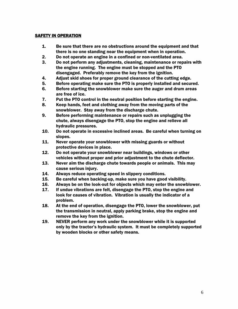
DECALS
Safety Decals are affixed wherever special safety precautions are indicated.
Locate them on your machine and read them carefully. If a decal is damaged, lost or illegible,
install a new one.
**Observe the correct PTO speed.
DO NOT exceed the correct PTO
speed. PTO speed is 540 rpm on all models
except 108HD which is 1000 rpm.
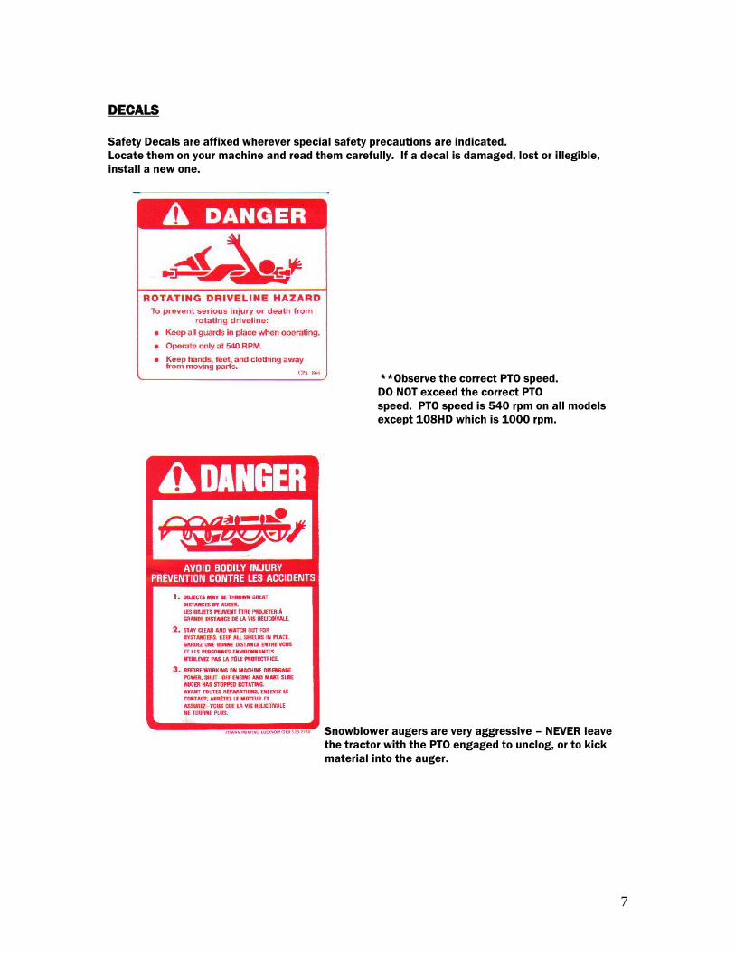
Snowblower augers are very aggressive – NEVER leave
the tractor with the PTO engaged to unclog, or to kick
material into the auger.
8
Maintenance
Stop the unit, disengage the PTO drive and completely shut down the tractor
engine with the snowblower set on the ground or completely unhooked from the
tractor before doing any adjustments or service.
Installing New Chain
Before installing new chain carefully check the teeth on the sprocket. If the teeth
are worn to a hooked shape, the sprockets should be replaced to assure full
capacity performance and a satisfactory life from the new chain. Tight chain
causes an additional load which increases wear on chain joints, sprockets and
shaft bearings. Slack chain produces vibration, which may result in excessive
chain wear, noise or shock loading.
Tighten chain allowing ¼” sag in the bottom span as the chain wears.
Sprocket Inspection
Check for these common sprocket problems which lead to replacement.
1. Wear on the sides, which is due to misalignment.
2. Tooth wear (indicated by hooking).
3. Broken teeth.
4. Cracks that might lead to failure.
5. Wobbling of sprockets on shaft.
Grease – Bearings
For the best results, the grease should be pumped into the bearings slowly until a
very slight bead of grease forms around the bearing seals on the shaft. This bead,
in addition to acting as an indication of adequate lubrication, provides extra
protection against entry of foreign material. To prevent premature failure, always
make sure the grease zerk, grease gun tip, and the grease are clean and free of
any dirt, grit, paint or foreign material.
9
Shear bolts
Shear bolts are built to break under shocks on the fan or on the auger. However,
under certain circumstances, this security is not adequate. Example: A sudden
high impact shock on the fan may, in some cases, break the fan shaft without
breaking the shear bolt.
If the shear bolt breaks, make sure to always replace it with a same category bolt
(grade 5 for PTO series 20-40-50-60, and grade 8 for PTO series 80). It is
necessary to always maintain this bolt very tight, in order to keep the efficiency of
the shearing mechanism.
WARNING:
The gearbox fan shafts are made with a special alloy steel. Moreover, they are
case hardened to increase capacity to shock load. These shafts cannot be broken
under normal snow loads. However, undesirable objects may enter the fan and
either bend or break the gearbox shaft. It is understood that the gearbox cannot
be built to resist every possible overloads, and consequently, gearbox fan shafts
will not be replaced under warranty. Therefore, the user of the snowblower must
be very careful.
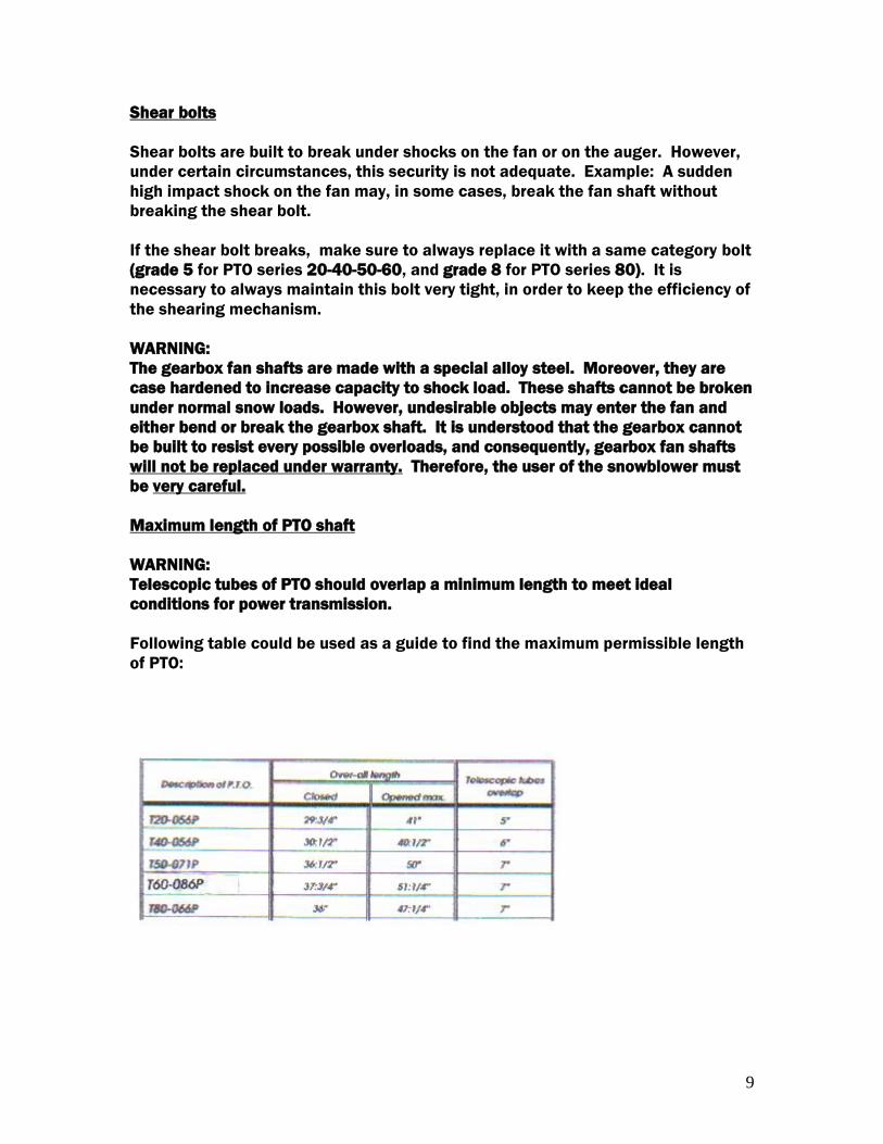
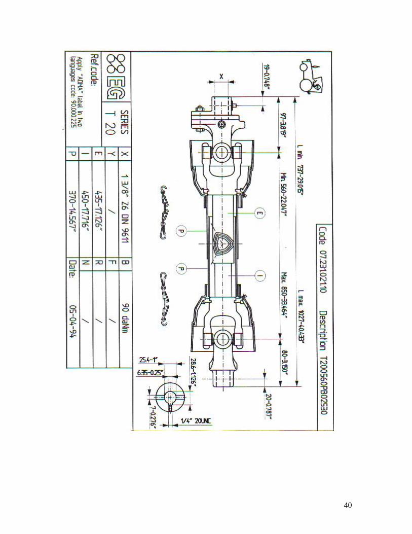
Maximum length of PTO shaft
WARNING:
Telescopic tubes of PTO should overlap a minimum length to meet ideal
conditions for power transmission.
Following table could be used as a guide to find the maximum permissible length
of PTO:
10
Installation Instructions for Better
PTO Shaft & Gearbox Operation
A proper initial installation will give you years of satisfactory service on your equipment. Please
read carefully the following instructions, which have been specially made to help you and your
satisfaction with your purchase.
WARNING: Unfortunately, the snowblower will be faced with forgotten or hidden objects under
the snow, such as, chain, tires, stones, pieces of wood, etc…in spite of our snowblower’s
strength and durability, they are not built to handle all of these conditions.
Danger: Tractor Too Large
It is dangerous to use a tractor, which is too big or too powerful. The tractor may be able to
overload the blower, even if the machine is already at maximum capacity. If the tractor is too
high, extreme angles at PTO shaft universal joints will result, and the life of these U-joints will
be shortened dramatically.
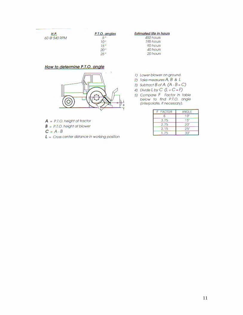
PTO Shaft Angles
PTO shafts are made to transmit power with angles at universal joints. However, these angles
should be kept to a minimum. The larger the angle, the shorter the life of the PTO shaft. Take
for example a snowblower made for a tractor capacity of 60-70HP, which would be attached to
a 60HP tractor, operating at maximum capacity (60HP continuous).
11
12
13
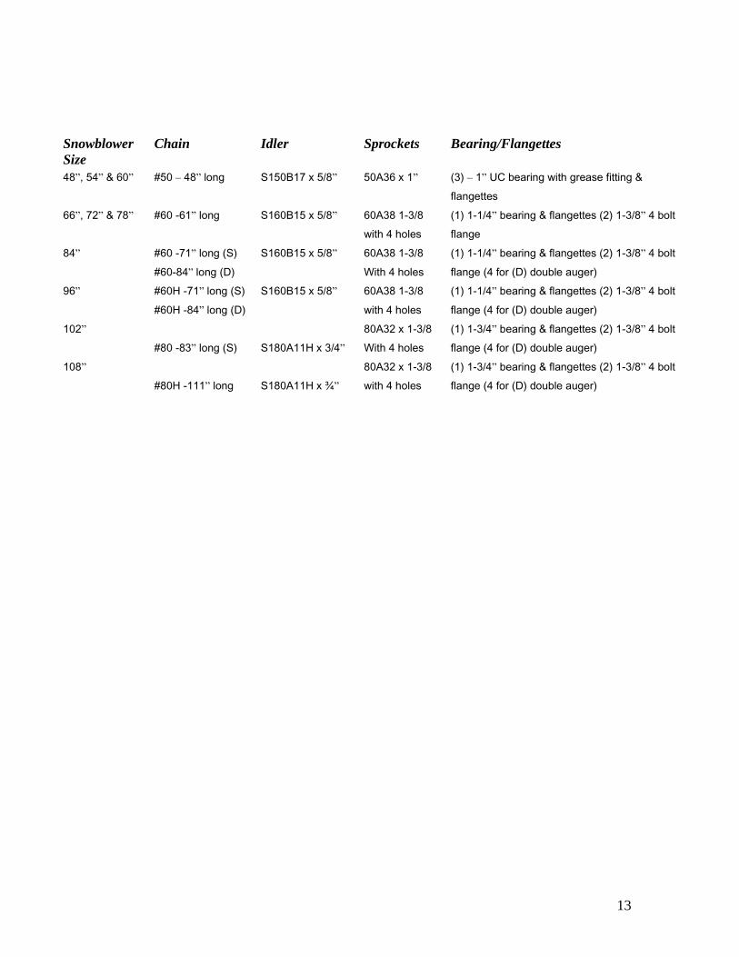
Snowblower
Size
Chain Idler Sprockets Bearing/Flangettes
48”, 54” & 60” #50 – 48” long S150B17 x 5/8” 50A36 x 1” (3) – 1” UC bearing with grease fitting &
flangettes
66”, 72” & 78” #60 -61” long S160B15 x 5/8” 60A38 1-3/8
with 4 holes
(1) 1-1/4” bearing & flangettes (2) 1-3/8” 4 bolt
flange
84” #60 -71” long (S)
#60-84” long (D)
S160B15 x 5/8” 60A38 1-3/8
With 4 holes
(1) 1-1/4” bearing & flangettes (2) 1-3/8” 4 bolt
flange (4 for (D) double auger)
96” #60H -71” long (S)
#60H -84” long (D)
S160B15 x 5/8” 60A38 1-3/8
with 4 holes
(1) 1-1/4” bearing & flangettes (2) 1-3/8” 4 bolt
flange (4 for (D) double auger)
102”
#80 -83” long (S) S180A11H x 3/4”
80A32 x 1-3/8
With 4 holes
(1) 1-3/4” bearing & flangettes (2) 1-3/8” 4 bolt
flange (4 for (D) double auger)
108”
#80H -111” long S180A11H x ¾”
80A32 x 1-3/8
with 4 holes
(1) 1-3/4” bearing & flangettes (2) 1-3/8” 4 bolt
flange (4 for (D) double auger)
14
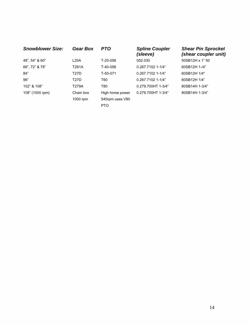
Snowblower Size: Gear Box PTO Spline Coupler Shear Pin Sprocket
(sleeve) (shear coupler unit)
48”, 54” & 60” L25A T-20-056 052.030 50SB12H x 1” 50
66”, 72” & 78” T281A T-40-056 0.267.7102 1-1/4” 60SB12H 1-/4”
84” T27D T-50-071 0.267.7102 1-1/4” 60SB12H 1/4"
96” T27D T60 0.267.7102 1-1/4” 60SB12H 1/4”
102” & 108” T279A T80 0.279.700HT 1-3/4” 80SB14H 1-3/4”
108” (1000 rpm) Chain box High horse power 0.279.700HT 1-3/4” 80SB14H 1-3/4”
1000 rpm 540rpm uses V80
PTO
15
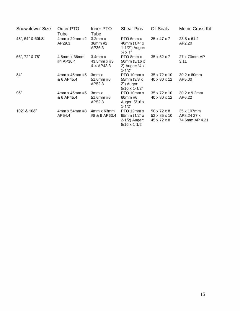
Snowblower Size Outer PTO
Tube Inner PTO Tube
Shear Pins Oil Seals Metric Cross Kit
48”, 54” & 60LS 4mm x 29mm #2 AP29.3
3.2mm x 36mm #2 AP36.3
PTO 6mm x 40mm (1/4” x 1-1/2”) Auger: ¼ x 1”
25 x 47 x 7 23.8 x 61.2 AP2.20
66”, 72” & 78” 4.5mm x 36mm #4 AP36.4
3.4mm x 43.5mm x #3 & 4 AP43.3
PTO 8mm x 50mm (5/16 x 2) Auger: ¼ x 1-1/2”
35 x 52 x 7 27 x 70mm AP 3.11
84” 4mm x 45mm #5 & 6 AP45.4
3mm x 51.6mm #6 AP52.3
PTO 10mm x 55mm (3/8 x 2”) Auger: 5/16 x 1-1/2”
35 x 72 x 10 40 x 80 x 12
30.2 x 80mm AP5.00
96” 4mm x 45mm #5 & 6 AP45.4
3mm x 51.6mm #6 AP52.3
PTO 10mm x 60mm #6 Auger: 5/16 x 1-1/2”
35 x 72 x 10 40 x 80 x 12
30.2 x 9.2mm AP6.22
102” & 108” 4mm x 54mm #8 AP54.4
4mm x 63mm #8 & 9 AP63.4
PTO 12mm x 65mm (1/2” x 2-1/2) Auger: 5/16 x 1-1/2
50 x 72 x 8 52 x 85 x 10 45 x 72 x 8
35 x 107mm AP8.24 27 x 74.6mm AP 4.21
16
17
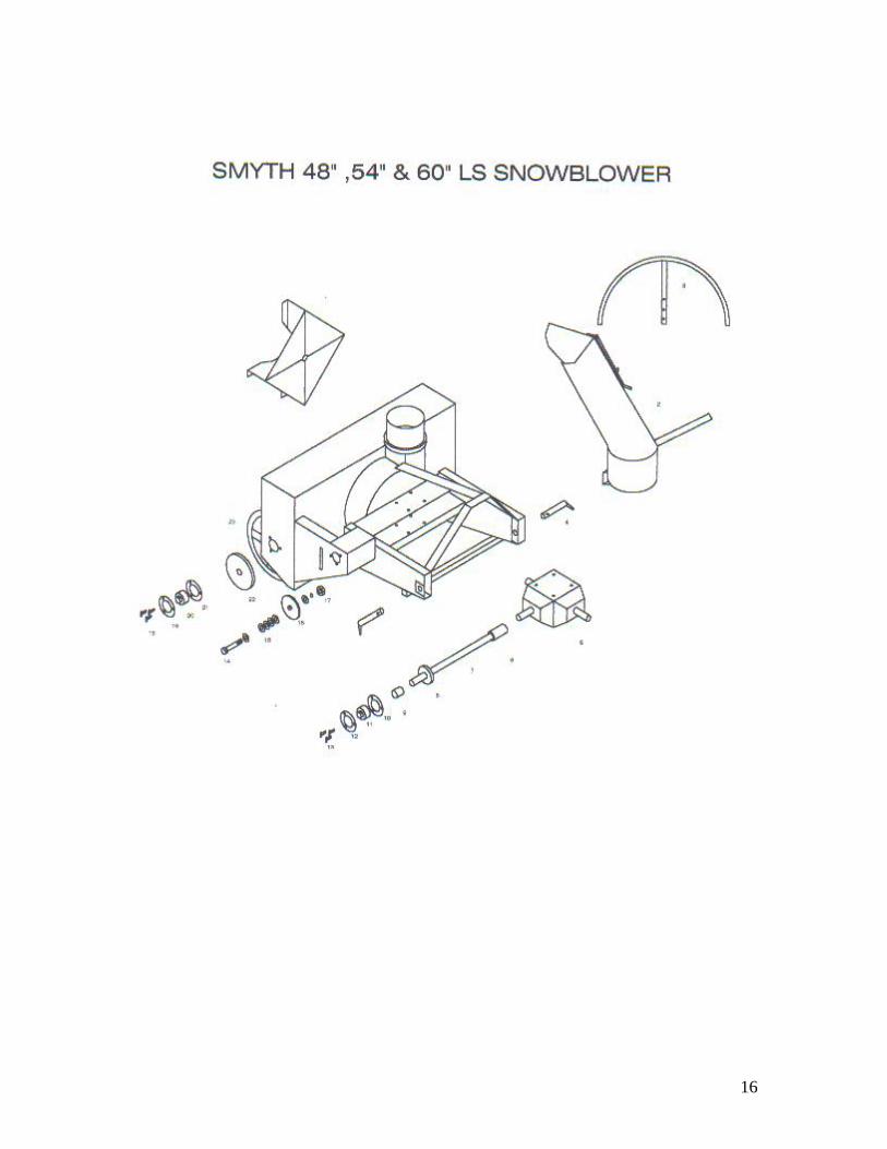
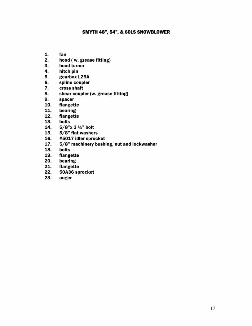
SMYTH 48”, 54”, & 60LS SNOWBLOWER
1. fan
2. hood ( w. grease fitting)
3. hood turner
4. hitch pin
5. gearbox L25A
6. spline coupler
7. cross shaft
8. shear coupler (w. grease fitting)
9. spacer
10. flangette
11. bearing
12. flangette
13. bolts
14. 5/8”x 3 ½” bolt
15. 5/8” flat washers
16. #5017 idler sprocket
17. 5/8” machinery bushing, nut and lockwasher
18. bolts
19. flangette
20. bearing
21. flangette
22. 50A36 sprocket
23. auger
18
SMYTH 66”, 72” & 78” SNOWBLOWER
19
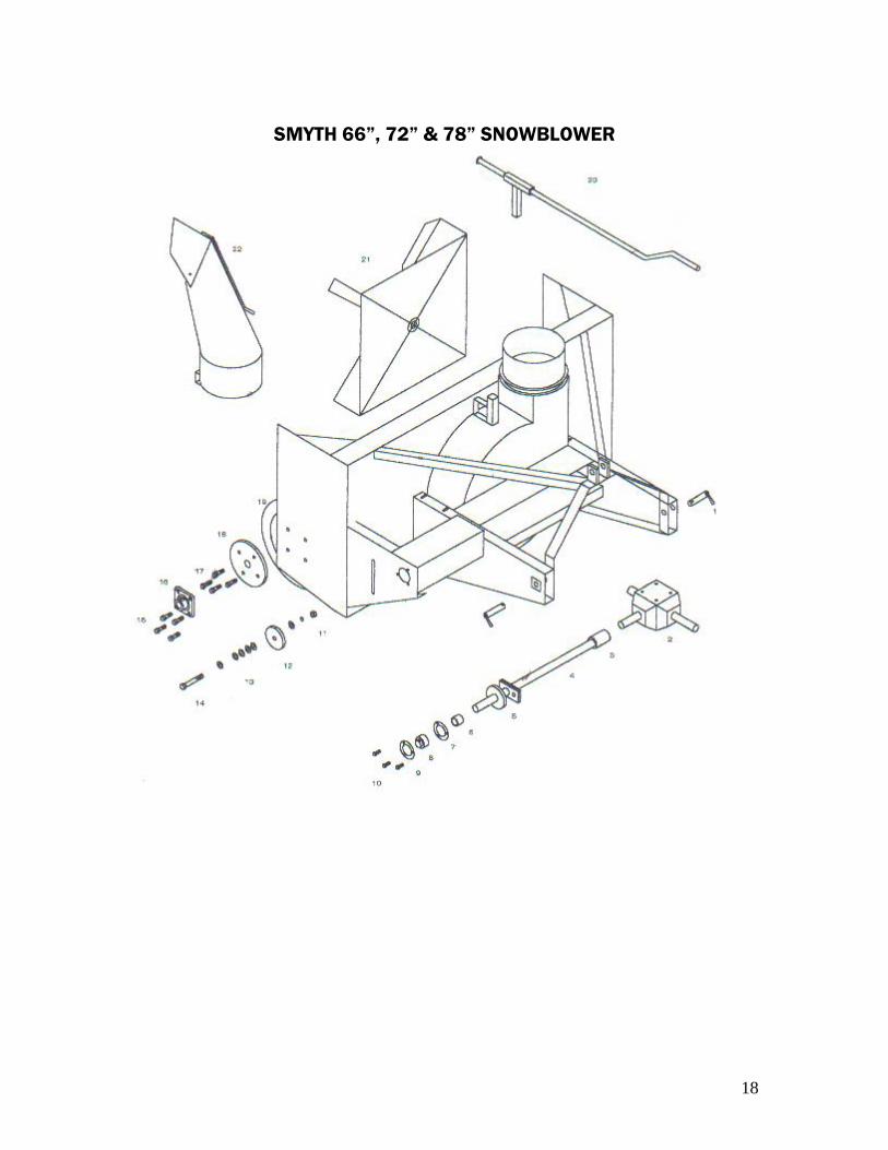
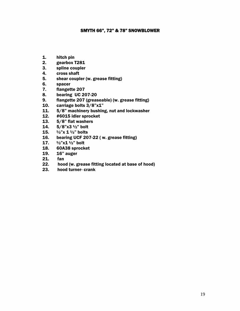
SMYTH 66”, 72” & 78” SNOWBLOWER
1. hitch pin
2. gearbox T281
3. spline coupler
4. cross shaft
5. shear coupler (w. grease fitting)
6. spacer
7. flangette 207
8. bearing UC 207-20
9. flangette 207 (greaseable) (w. grease fitting)
10. carriage bolts 3/8”x1”
11. 5/8” machinery bushing, nut and lockwasher
12. #6015 idler sprocket
13. 5/8” flat washers
14. 5/8”x3 ½” bolt
15. ½”x 1 ½” bolts
16. bearing UCF 207-22 ( w. grease fitting)
17. ½”x1 ½” bolt
18. 60A38 sprocket
19. 16” auger
21. fan
22. hood (w. grease fitting located at base of hood)
23. hood turner- crank
20
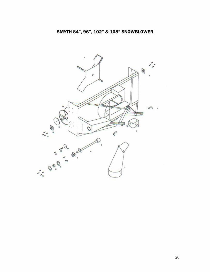
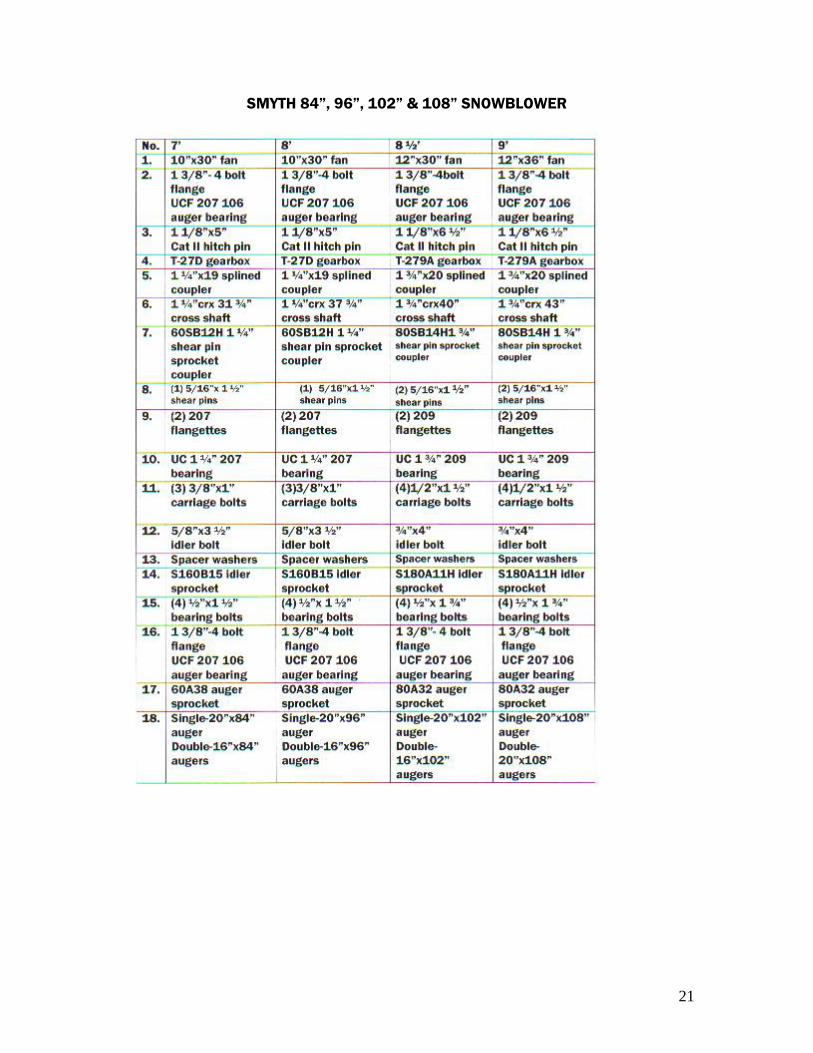
SMYTH 84”, 96”, 102” & 108” SNOWBLOWER
21
SMYTH 84”, 96”, 102” & 108” SNOWBLOWER

22
66” Pull Type Snowblower Replacement Parts
1. 8” x 24” Fan 2. T281A Gear Box 3. 61” of #60 Auger Drive Chain 4. S160B15 x 5/8”Idler Sprocket 5. #60A38 x 1-3/8” Auger Sprocket 6. #60SB12H 1-1/4” Shear Sprocket 7. (2) UC207-22 -1-3/8” 4 Bolt Flange Auger Bearings 8. (8) ½ x 1-3/4” Gr.5 Bolts, Nuts & Lock Washers (For Auger Bearings) 9. UC207-22-1-1/4” Cross Shaft Bearing 10. 90” of 3/16” Cable (2) Cable Clamps (On D-Ring Turner) 11. T40 PTO 12. 67” of 3/8 x 4 flat bar (for cutting edge) 13. (2) 7/8 x 5 Cat. 1 Hitch Pins 14. ¼ x 1-1/2 bolt Grade 2 or 5 (Shear Bolts for Auger) 15. PTO Shear Pins (8mm x 50) Grade 8.8 16. Oil Seals (35 x 52 x 7) 17. 1-1/4” 19 Spline Coupler

23
78” Pull Type Snowblower Replacement Parts
1. 8” x 24” Fan 2. T281A Gear Box 3. 61” of #60 Auger Drive Chain 4. S160B15 x 5/8”Idler Sprocket 5. #60A38 x 1-3/8” Auger Sprocket 6. #60SB12H 1-1/4” Shear Sprocket 7. (2) UC207-22 -1-3/8” 4 Bolt Flange Auger Bearings 8. (8) ½ x 1-3/4” Gr.5 Bolts, Nuts & Lock Washers (For Auger Bearings) 9. UC207-22-1-1/4” Cross Shaft Bearing 10. 90” of 3/16” Cable (2) Cable Clamps (On D-Ring Turner) 11. T40 PTO 12. 79” of 3/8 x 4 flat bar (for cutting edge) 13. (2) 7/8 x 5 Cat. 1 Hitch Pins 14. ¼ x 1-1/2 bolt Grade 2 or 5 (Shear Bolts for Auger) 15. PTO Shear Pins (8mm x 50) Grade 8.8 16. Oil Seals (35 x 52 x 7) 17. 1-1/4” 19 Spline Coupler
24
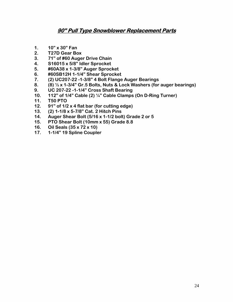
90” Pull Type Snowblower Replacement Parts
1. 10” x 30” Fan 2. T27D Gear Box 3. 71” of #60 Auger Drive Chain 4. S16015 x 5/8” Idler Sprocket 5. #60A38 x 1-3/8” Auger Sprocket 6. #60SB12H 1-1/4” Shear Sprocket 7. (2) UC207-22 -1-3/8” 4 Bolt Flange Auger Bearings 8. (8) ½ x 1-3/4” Gr.5 Bolts, Nuts & Lock Washers (for auger bearings) 9. UC 207-22 -1-1/4” Cross Shaft Bearing 10. 112” of 1/4” Cable (2) ¼” Cable Clamps (On D-Ring Turner) 11. T50 PTO 12. 91” of 1/2 x 4 flat bar (for cutting edge) 13. (2) 1-1/8 x 5-7/8” Cat. 2 Hitch Pins 14. Auger Shear Bolt (5/16 x 1-1/2 bolt) Grade 2 or 5 15. PTO Shear Bolt (10mm x 55) Grade 8.8 16. Oil Seals (35 x 72 x 10) 17. 1-1/4” 19 Spline Coupler
25
26
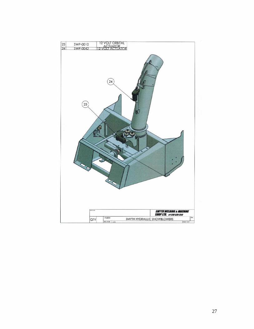
27
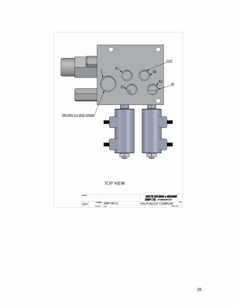
28
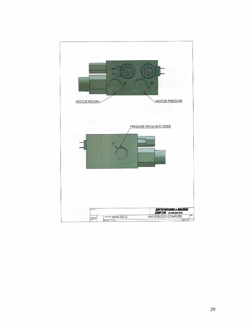
29
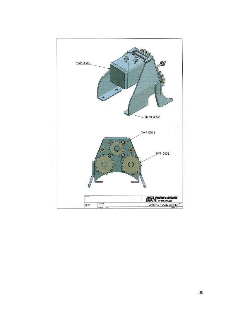
30
31
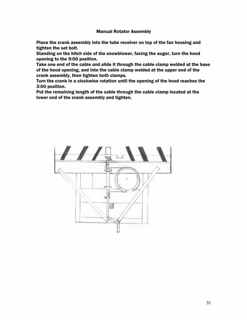
Manual Rotator Assembly
Place the crank assembly into the tube receiver on top of the fan housing and
tighten the set bolt.
Standing on the hitch side of the snowblower, facing the auger, turn the hood
opening to the 9:00 position.
Take one end of the cable and slide it through the cable clamp welded at the base
of the hood opening, and into the cable clamp welded at the upper end of the
crank assembly, then tighten both clamps.
Turn the crank in a clockwise rotation until the opening of the hood reaches the
3:00 position.
Put the remaining length of the cable through the cable clamp located at the
lower end of the crank assembly and tighten.
32
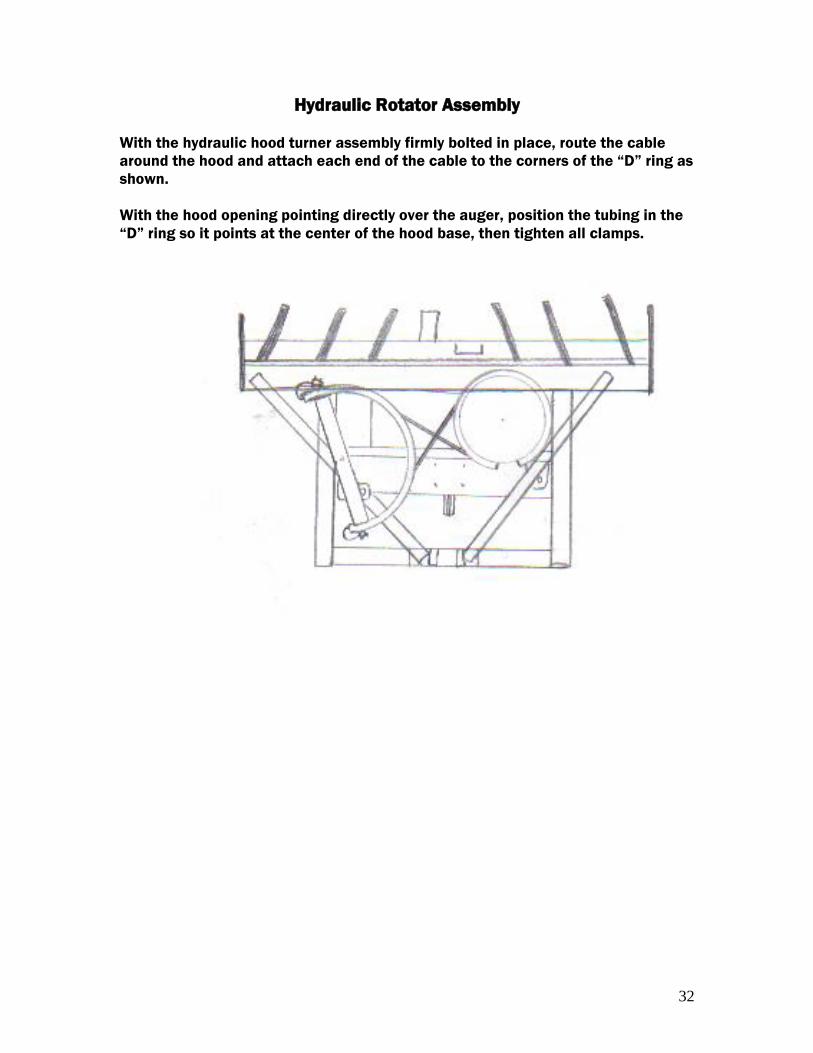
Hydraulic Rotator Assembly
With the hydraulic hood turner assembly firmly bolted in place, route the cable
around the hood and attach each end of the cable to the corners of the “D” ring as
shown.
With the hood opening pointing directly over the auger, position the tubing in the
“D” ring so it points at the center of the hood base, then tighten all clamps.
33
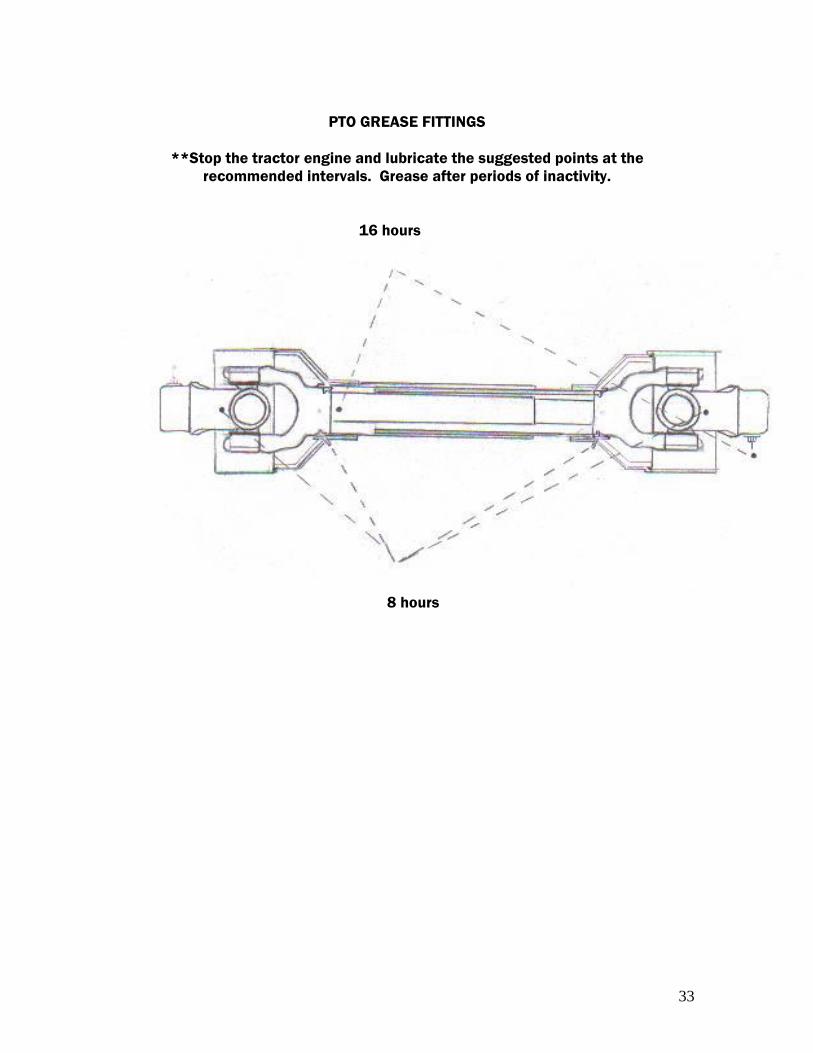
PTO GREASE FITTINGS
**Stop the tractor engine and lubricate the suggested points at the
recommended intervals. Grease after periods of inactivity.
16 hours
8 hours

34
TROUBLESHOOTING
Item Avoidable
Damages
Possible Causes Corrective Actions
QUICK-
DISCONNECT
YOKE
-quick
disconnect pin
tight or
completely
seized
-quick-disconnect
pin
dirty (insufficient
maintenance)
-clean, oil and follow
service instructions
-quick-
disconnect pin
damaged
(broken or bent)
-quick-disconnect
pin
defective(forced
engagement,
incorrect
handling)
-replace quick-
disconnect pin
-quick-
disconnect pin
damaged in the
locking
portion
-excessive shaft
length
-shorten shaft length(cut both
telescopic tubes as well as shields
and remove burrs)
-axial loads too
high
-replace disconnect pin
-clean and grease telescopic tubes,
and replace both tubes, if necessary
-replace quick-disconnect pin
**NOTE- Quick-disconnect pins must be cleaned and greased every 16 working hours
YOKE
-yoke ears deformation
-excessive shaft length
-shorten shaft length(cut
both telescopic tubes as
well as shields and remove
burrs)
-replace defective yokes
-axial loads too high -clean and grease
telescopic tubes, and
replace both tubes, if
necessary
-replace defective yokes
-excessive working angle
and torque
-verify compatibility
between shaft & working
conditions(torque vs.
angle)
-disengage tractor PTO
during cornering or when
lifting or lowering the
implement
-change to a larger PTO
size
-replace defective yokes
-yoke ears distorted -overload caused by high
starting and peak torques
-engage PTO more
carefully
-use appropriate safety
device
-replace defective yokes

35
-yoke ears worn or
pounded
-excessive working angle -avoid excessive working
angle
-disengage tractor PTO
during cornering
-replace defective yokes
CROSS KIT -cross arms broken -extreme torque peak or
shock load
-use appropriate safety
device
-change to a larger PTO
size
-axial loads too high -shorten PTO shaft
-replace defective cross
bearings
-bearing caps turning in
their cross journal
-excessive continuous
torque and/or excessive
working angle
-verify compatibility
between shaft and
working conditions
-overheated bearing
caps
-inadequate greasing -carefully follow greasing
instructions
-replace defective cross
bearings
-accelerated wear of
cross kit
-excessive continuous
torque and/or excessive
working angle
-verify compatibility
between shaft and
working conditions
-inadequate greasing -carefully follow greasing
instructions
-replace defective cross
bearings
NOTE: CROSS BEARINGS MUST BE GREASED EVERY 8 WORKING HOURS
TELESCOPIC
TUBE
-telescopic tubes
failure or twisting
-extreme torque peak or
shock load
-use appropriate safety
device
-change to a larger PTO
size
-short tube engagement -replace the PTO drive
shaft with one having
adequate length
-replace defective tubes
-accelerated wear
telescopic tubes
-extreme load when sliding -change to a PTO drive
shaft with rilsan coated
inner tube
-short tube engagement -replace the PTO drive
shaft with one having
adequate length
-inadequate greasing -carefully follow greasing
instructions
-contaminants(sand, etc.) -replace defective tubes
NOTE: TELESCOPIC TUBES MUST BE CLEANED AND GREASED EVERY 16 WORKING HOURS
SHIELD -excessive wear of
shield bearings
-insufficient lubrication -follow lubrication
instructions
-incorrect chain mounting -mount chain to allow
maximum angularity
-shield interfering with
implement
-avoid contact of the
shields with fixed parts of
the machine or tractor
-chain moving or failure -shield interfering with
implement
-avoid contact of the
shields with fixed parts of
the machine or tractor

36
-incorrect chain mounting -mount chain to allow
maximum angularity
-replace defective parts
-guard cone damaged -guard cone in contact with
components on the tractor
and/or implement
-eliminate interference
between guard cones and
any part on the tractor
and/or implement
-replace damaged guard
cones
-guard tubes
damaged(deformed
and split at one end)
-guards in contact with
components on the tractor
and/or implement
-eliminate interference
between guard cones and
any part on the tractor
and/or implement
-replace damaged tubes
-guard tubes overlap too
short or no overlap at all
with extended PTO drive
shaft
-adjust guard tubes length
with longer tubes
NOTE: SHIELD BEARING MUST BE GREASED EVERY 8 WORKING HOURS
37
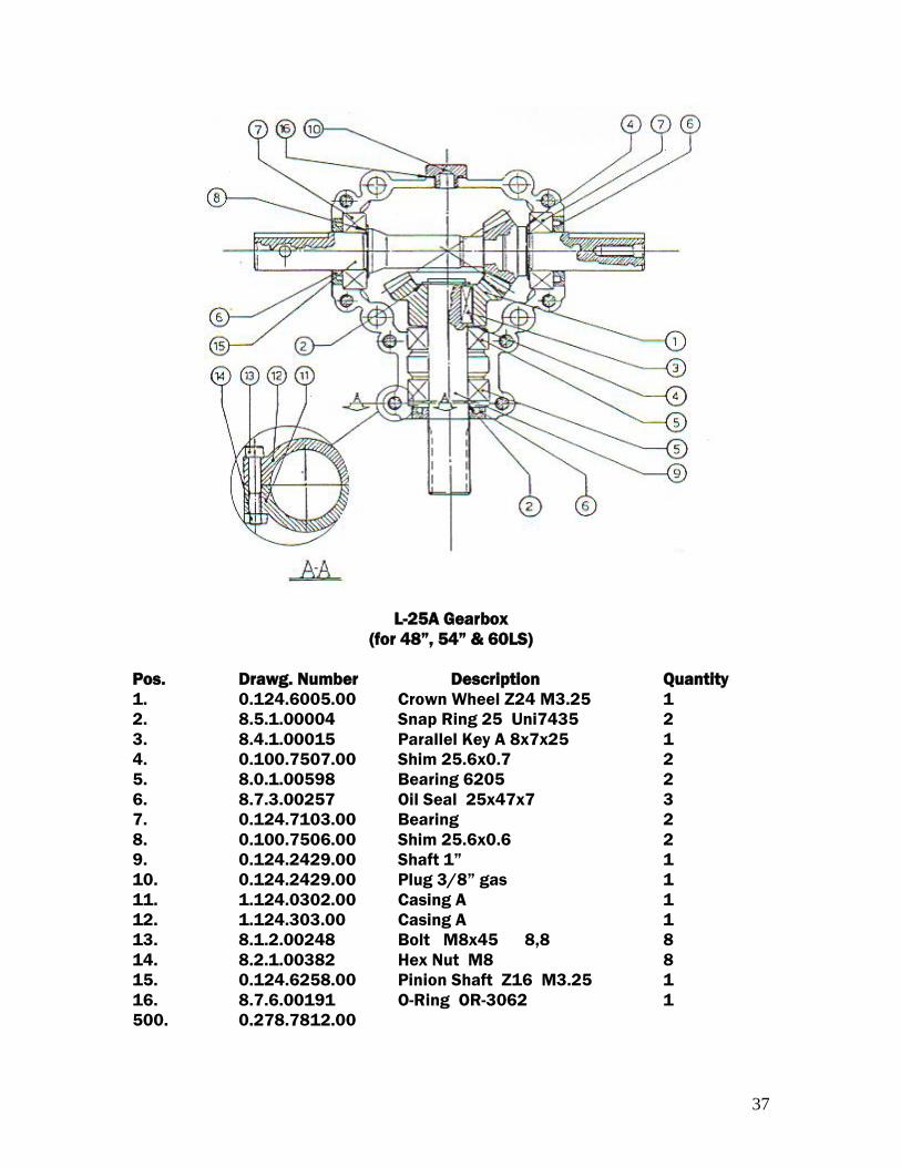
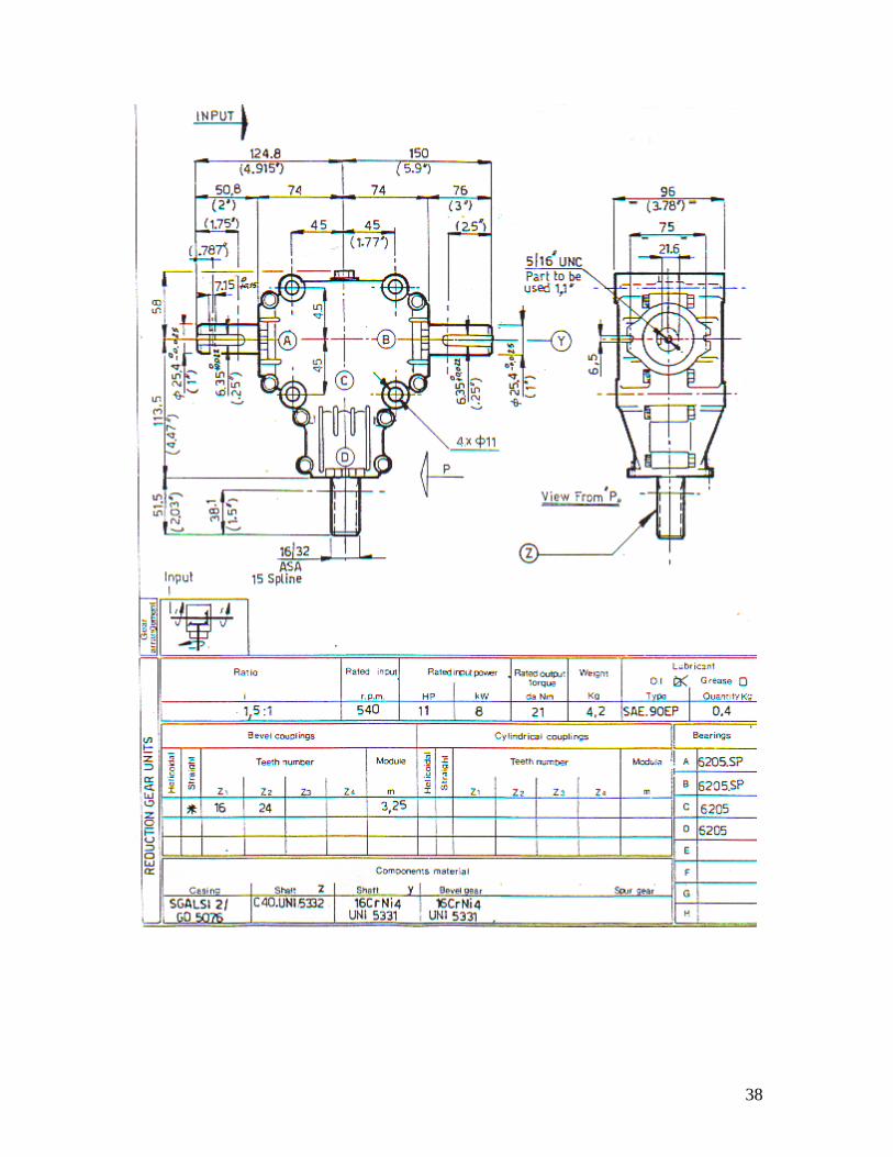
L-25A Gearbox
(for 48”, 54” & 60LS)
Pos. Drawg. Number Description Quantity
1. 0.124.6005.00 Crown Wheel Z24 M3.25 1
2. 8.5.1.00004 Snap Ring 25 Uni7435 2
3. 8.4.1.00015 Parallel Key A 8x7x25 1
4. 0.100.7507.00 Shim 25.6x0.7 2
5. 8.0.1.00598 Bearing 6205 2
6. 8.7.3.00257 Oil Seal 25x47x7 3
7. 0.124.7103.00 Bearing 2
8. 0.100.7506.00 Shim 25.6x0.6 2
9. 0.124.2429.00 Shaft 1” 1
10. 0.124.2429.00 Plug 3/8” gas 1
11. 1.124.0302.00 Casing A 1
12. 1.124.303.00 Casing A 1
13. 8.1.2.00248 Bolt M8x45 8,8 8
14. 8.2.1.00382 Hex Nut M8 8
15. 0.124.6258.00 Pinion Shaft Z16 M3.25 1
16. 8.7.6.00191 O-Ring OR-3062 1
500. 0.278.7812.00
38
39
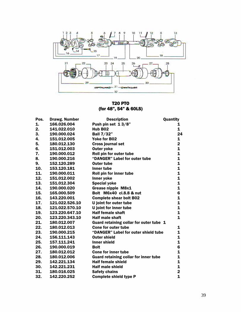
T20 PTO
(for 48”, 54” & 60LS)
Pos. Drawg. Number Description Quantity
1. 166.026.004 Push pin set 1 3/8” 1
2. 141.022.010 Hub B02 1
3. 190.000.024 Ball 7/32” 24
4. 151.012.005 Yoke for B02 1
5. 180.012.130 Cross journal set 2
6. 151.012.003 Outer yoke 1
7. 190.000.012 Roll pin for outer tube 1
8. 190.000.216 “DANGER” Label for outer tube 1
9. 152.120.289 Outer tube 1
10. 153.120.181 Inner tube 1
11. 190.000.011 Roll pin for inner tube 1
12. 151.012.002 Inner yoke 1
13. 151.012.304 Special yoke 1
14. 190.000.020 Grease nipple M8x1 1
15. 165.000.509 Bolt M6x40 cl.8.8 & nut 6
16. 143.220.001 Complete shear bolt B02 1
17. 121.022.526.10 U joint for outer tube 1
18. 121.022.570.10 U joint for inner tube 1
19. 123.220.647.10 Half female shaft 1
20. 123.220.343.10 Half male shaft 1
21. 180.012.007 Guard retaining collar for outer tube 1
22. 180.012.013 Cone for outer tube 1
23. 190.000.215 “DANGER” Label for outer shield tube 1
24. 156.111.143 Outer shield 1
25. 157.111.241 Inner shield 1
26. 190.000.019 Bolt 6
27. 180.012.012 Cone for inner tube 1
28. 180.012.006 Guard retaining collar for inner tube 1
29. 142.221.134 Half female shield 1
30. 142.221.231 Half male shield 1
31. 180.016.025 Safety chains 2
32. 142.220.252 Complete shield type P 1
40
41
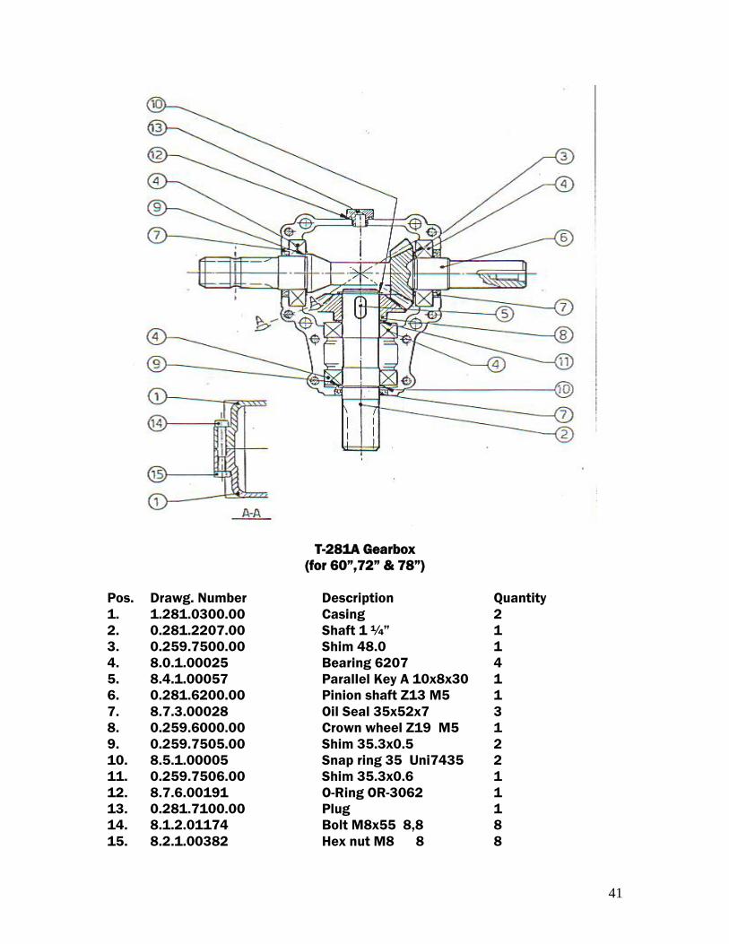
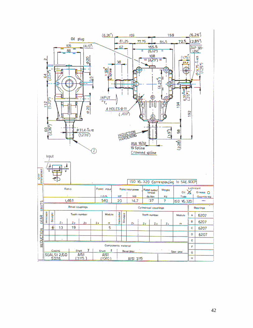
T-281A Gearbox
(for 60”,72” & 78”)
Pos. Drawg. Number Description Quantity
1. 1.281.0300.00 Casing 2
2. 0.281.2207.00 Shaft 1 ¼” 1
3. 0.259.7500.00 Shim 48.0 1
4. 8.0.1.00025 Bearing 6207 4
5. 8.4.1.00057 Parallel Key A 10x8x30 1
6. 0.281.6200.00 Pinion shaft Z13 M5 1
7. 8.7.3.00028 Oil Seal 35x52x7 3
8. 0.259.6000.00 Crown wheel Z19 M5 1
9. 0.259.7505.00 Shim 35.3x0.5 2
10. 8.5.1.00005 Snap ring 35 Uni7435 2
11. 0.259.7506.00 Shim 35.3x0.6 1
12. 8.7.6.00191 O-Ring OR-3062 1
13. 0.281.7100.00 Plug 1
14. 8.1.2.01174 Bolt M8x55 8,8 8
15. 8.2.1.00382 Hex nut M8 8 8
42
43
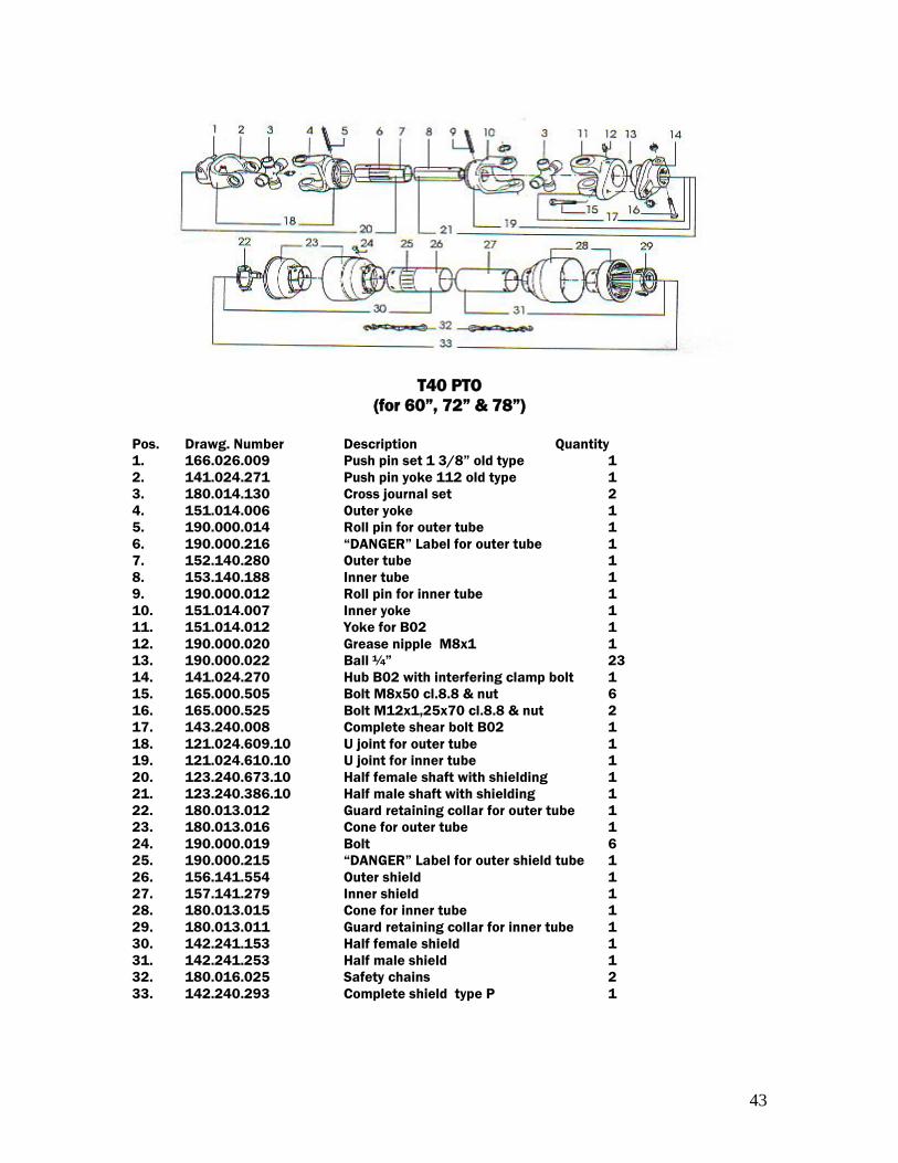
T40 PTO
(for 60”, 72” & 78”)
Pos. Drawg. Number Description Quantity
1. 166.026.009 Push pin set 1 3/8” old type 1
2. 141.024.271 Push pin yoke 112 old type 1
3. 180.014.130 Cross journal set 2
4. 151.014.006 Outer yoke 1
5. 190.000.014 Roll pin for outer tube 1
6. 190.000.216 “DANGER” Label for outer tube 1
7. 152.140.280 Outer tube 1
8. 153.140.188 Inner tube 1
9. 190.000.012 Roll pin for inner tube 1
10. 151.014.007 Inner yoke 1
11. 151.014.012 Yoke for B02 1
12. 190.000.020 Grease nipple M8x1 1
13. 190.000.022 Ball ¼” 23
14. 141.024.270 Hub B02 with interfering clamp bolt 1
15. 165.000.505 Bolt M8x50 cl.8.8 & nut 6
16. 165.000.525 Bolt M12x1,25x70 cl.8.8 & nut 2
17. 143.240.008 Complete shear bolt B02 1
18. 121.024.609.10 U joint for outer tube 1
19. 121.024.610.10 U joint for inner tube 1
20. 123.240.673.10 Half female shaft with shielding 1
21. 123.240.386.10 Half male shaft with shielding 1
22. 180.013.012 Guard retaining collar for outer tube 1
23. 180.013.016 Cone for outer tube 1
24. 190.000.019 Bolt 6
25. 190.000.215 “DANGER” Label for outer shield tube 1
26. 156.141.554 Outer shield 1
27. 157.141.279 Inner shield 1
28. 180.013.015 Cone for inner tube 1
29. 180.013.011 Guard retaining collar for inner tube 1
30. 142.241.153 Half female shield 1
31. 142.241.253 Half male shield 1
32. 180.016.025 Safety chains 2
33. 142.240.293 Complete shield type P 1
44
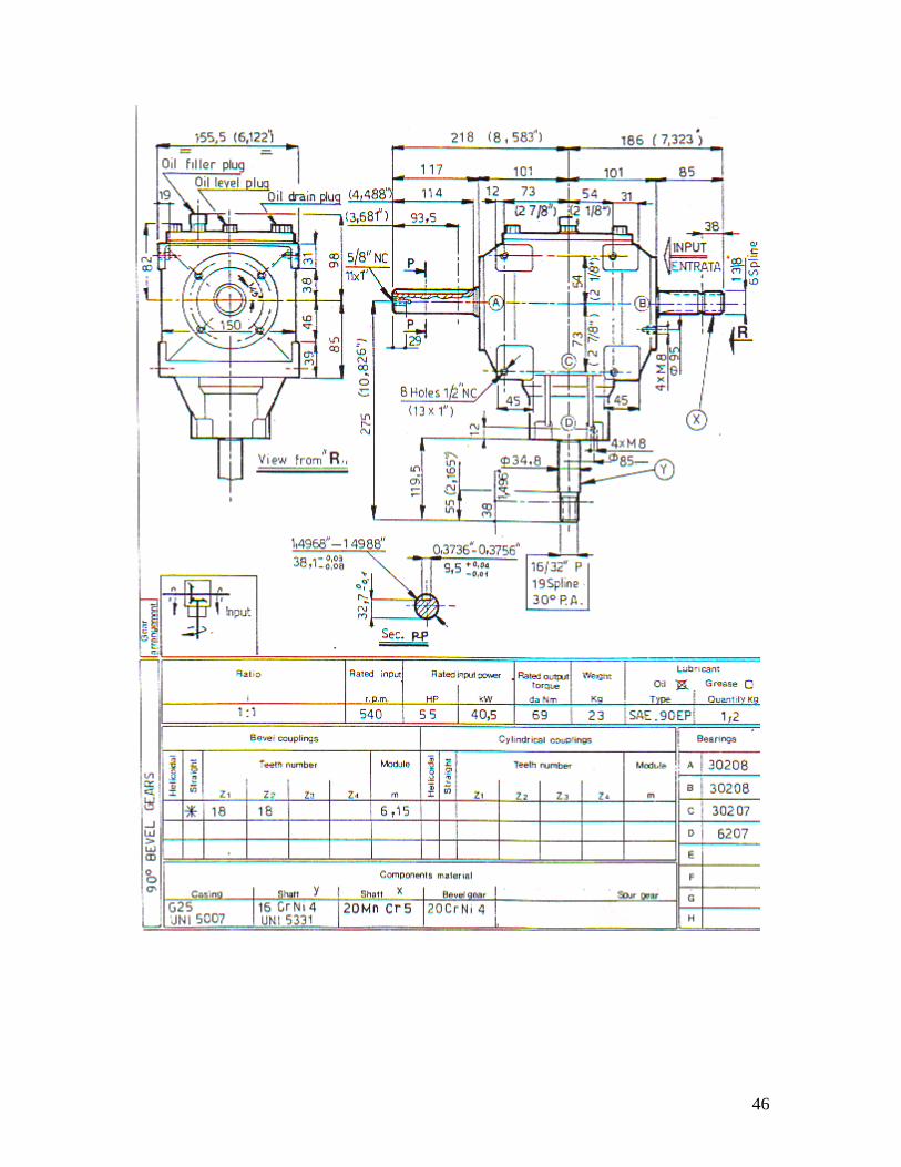
45
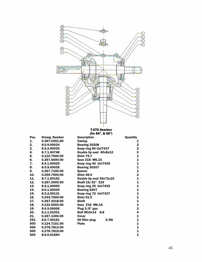
T-27D Gearbox
(for 84”, & 96”)
Pos. Drawg. Number Description Quantity
1. 0.267.0301.00 Casing 1
2. 8.0.9.00024 Bearing 30208 2
3. 8.5.2.00030 Snap ring 80 Uni7437 2
4. 8.7.1.00748 Double lip seal 40x8x12 2
5. 0.110.7500.00 Shim 79,7 1
6. 0.267.5000.00 Gear Z18 M6.15 1
7. 8.5.1.00029 Snap ring 40 Uni7435 1
8. 8.0.9.00026 Bearing 30207 1
9. 0.267.7100.00 Spacer 1
10. 0.259.7500.00 Shim 48.0 2
11. 8.7.1.00152 Double lip seal 35x72x10 1
12. 0.267.2000.00 Shaft 16/32” Z19 1
13. 8.5.1.00005 Snap ring 35 Uni7435 1
14. 8.0.1.00025 Bearing 6207 1
15. 8.5.2.00131 Snap ring 72 Uni7437 1
16. 0.244.7500.00 Shim 51.5 1
17. 0.267.4218.00 Shaft 1
18. 0.132.5002.00 Gear Z18 M6.15 1
19. 8.6.5.00006 Plug 3/8” gas 2
20. 8.1.1.01031 Bolt M10x14 8,8 4
21. 0.267.1300.00 Cover 1
251 8.6.7.00161 Oil filler plug 3/8G 1
500 0.124.7101.00 Plate 1
500 0.278.7813.00 1
500 0.278.7819.00 1
500 8.6.0.01684 1
46
47
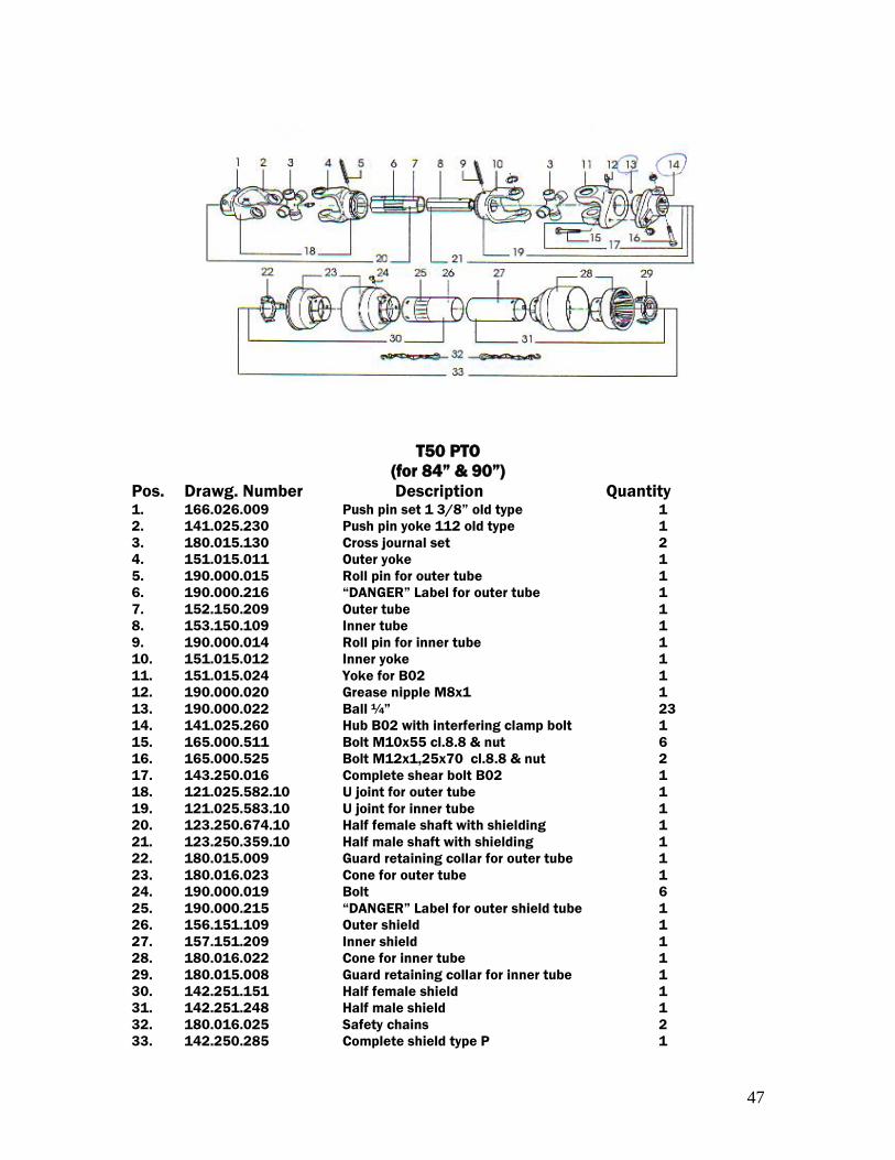
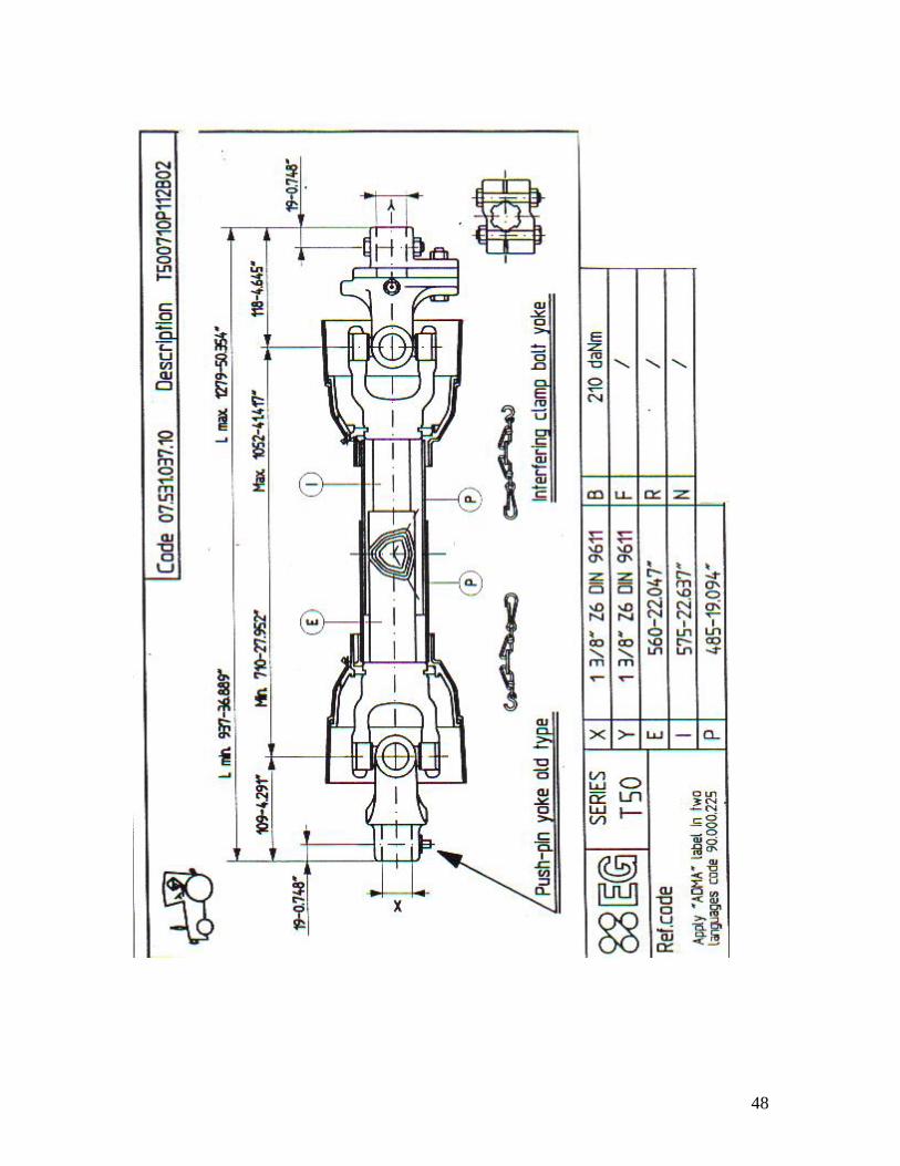
T50 PTO
(for 84” & 90”)
Pos. Drawg. Number Description Quantity 1. 166.026.009 Push pin set 1 3/8” old type 1
2. 141.025.230 Push pin yoke 112 old type 1
3. 180.015.130 Cross journal set 2
4. 151.015.011 Outer yoke 1
5. 190.000.015 Roll pin for outer tube 1
6. 190.000.216 “DANGER” Label for outer tube 1
7. 152.150.209 Outer tube 1
8. 153.150.109 Inner tube 1
9. 190.000.014 Roll pin for inner tube 1
10. 151.015.012 Inner yoke 1
11. 151.015.024 Yoke for B02 1
12. 190.000.020 Grease nipple M8x1 1
13. 190.000.022 Ball ¼” 23
14. 141.025.260 Hub B02 with interfering clamp bolt 1
15. 165.000.511 Bolt M10x55 cl.8.8 & nut 6
16. 165.000.525 Bolt M12x1,25x70 cl.8.8 & nut 2
17. 143.250.016 Complete shear bolt B02 1
18. 121.025.582.10 U joint for outer tube 1
19. 121.025.583.10 U joint for inner tube 1
20. 123.250.674.10 Half female shaft with shielding 1
21. 123.250.359.10 Half male shaft with shielding 1
22. 180.015.009 Guard retaining collar for outer tube 1
23. 180.016.023 Cone for outer tube 1
24. 190.000.019 Bolt 6
25. 190.000.215 “DANGER” Label for outer shield tube 1
26. 156.151.109 Outer shield 1
27. 157.151.209 Inner shield 1
28. 180.016.022 Cone for inner tube 1
29. 180.015.008 Guard retaining collar for inner tube 1
30. 142.251.151 Half female shield 1
31. 142.251.248 Half male shield 1
32. 180.016.025 Safety chains 2
33. 142.250.285 Complete shield type P 1
48
49
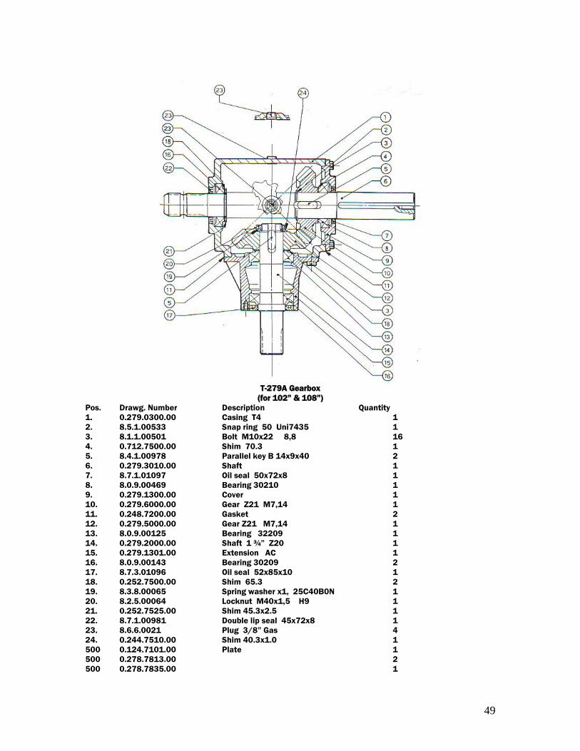
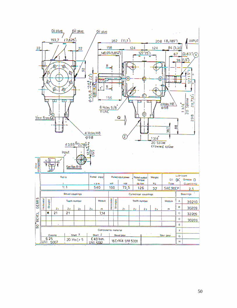
T-279A Gearbox
(for 102” & 108”)
Pos. Drawg. Number Description Quantity
1. 0.279.0300.00 Casing T4 1
2. 8.5.1.00533 Snap ring 50 Uni7435 1
3. 8.1.1.00501 Bolt M10x22 8,8 16
4. 0.712.7500.00 Shim 70.3 1
5. 8.4.1.00978 Parallel key B 14x9x40 2
6. 0.279.3010.00 Shaft 1
7. 8.7.1.01097 Oil seal 50x72x8 1
8. 8.0.9.00469 Bearing 30210 1
9. 0.279.1300.00 Cover 1
10. 0.279.6000.00 Gear Z21 M7,14 1
11. 0.248.7200.00 Gasket 2
12. 0.279.5000.00 Gear Z21 M7,14 1
13. 8.0.9.00125 Bearing 32209 1
14. 0.279.2000.00 Shaft 1 ¾” Z20 1
15. 0.279.1301.00 Extension AC 1
16. 8.0.9.00143 Bearing 30209 2
17. 8.7.3.01096 Oil seal 52x85x10 1
18. 0.252.7500.00 Shim 65.3 2
19. 8.3.8.00065 Spring washer x1, 25C40B0N 1
20. 8.2.5.00064 Locknut M40x1,5 H9 1
21. 0.252.7525.00 Shim 45.3x2.5 1
22. 8.7.1.00981 Double lip seal 45x72x8 1
23. 8.6.6.0021 Plug 3/8” Gas 4
24. 0.244.7510.00 Shim 40.3x1.0 1
500 0.124.7101.00 Plate 1
500 0.278.7813.00 2
500 0.278.7835.00 1
50
51
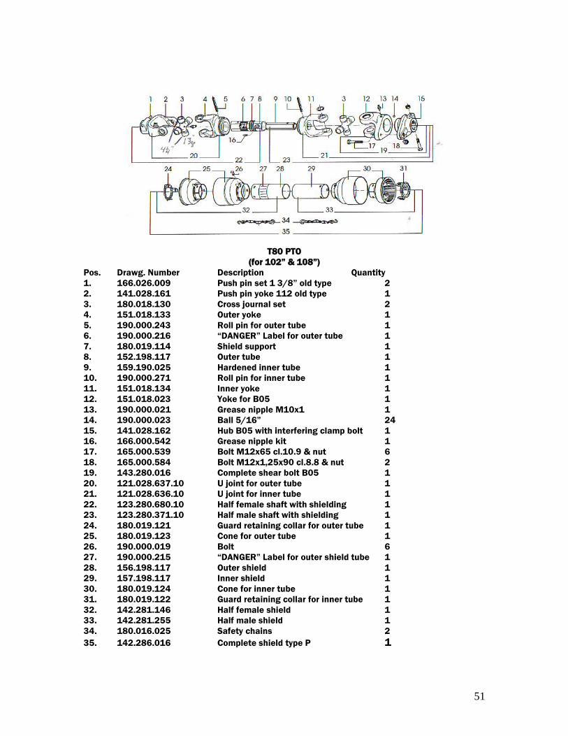
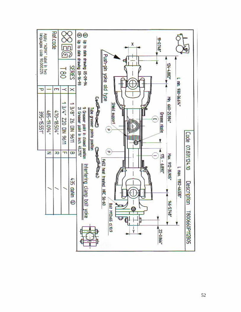
T80 PTO
(for 102” & 108”)
Pos. Drawg. Number Description Quantity
1. 166.026.009 Push pin set 1 3/8” old type 2
2. 141.028.161 Push pin yoke 112 old type 1
3. 180.018.130 Cross journal set 2
4. 151.018.133 Outer yoke 1
5. 190.000.243 Roll pin for outer tube 1
6. 190.000.216 “DANGER” Label for outer tube 1
7. 180.019.114 Shield support 1
8. 152.198.117 Outer tube 1
9. 159.190.025 Hardened inner tube 1
10. 190.000.271 Roll pin for inner tube 1
11. 151.018.134 Inner yoke 1
12. 151.018.023 Yoke for B05 1
13. 190.000.021 Grease nipple M10x1 1
14. 190.000.023 Ball 5/16” 24
15. 141.028.162 Hub B05 with interfering clamp bolt 1
16. 166.000.542 Grease nipple kit 1
17. 165.000.539 Bolt M12x65 cl.10.9 & nut 6
18. 165.000.584 Bolt M12x1,25x90 cl.8.8 & nut 2
19. 143.280.016 Complete shear bolt B05 1
20. 121.028.637.10 U joint for outer tube 1
21. 121.028.636.10 U joint for inner tube 1
22. 123.280.680.10 Half female shaft with shielding 1
23. 123.280.371.10 Half male shaft with shielding 1
24. 180.019.121 Guard retaining collar for outer tube 1
25. 180.019.123 Cone for outer tube 1
26. 190.000.019 Bolt 6
27. 190.000.215 “DANGER” Label for outer shield tube 1
28. 156.198.117 Outer shield 1
29. 157.198.117 Inner shield 1
30. 180.019.124 Cone for inner tube 1
31. 180.019.122 Guard retaining collar for inner tube 1
32. 142.281.146 Half female shield 1
33. 142.281.255 Half male shield 1
34. 180.016.025 Safety chains 2
35. 142.286.016 Complete shield type P 1
52
53
Instruction for snowblowers
Chain box maintenance
** This chain box has double functions.
1. Reduce angles at both ends of PTO in working position by
increasing the input shaft height of 8”
2. Increase PTO capacity by increasing speed from 540 RPM to
1000 RPM.
In order to obtain a longer life expectancy of this chain box
which is constantly submitted to high shock loads, a
minimum care is essential.
A. PTO shear bolt
Because the PTO is running at 1000 RPM instead of 540
RPM, the shear bolt value must be changed. In fact, on a
PTO size 80, the shear bolt is 12mm, grade 8 (10.9) for
540 RPM. Thus, it has to be changed to a shear bolt
7/16” dia. Grade 2 (6.6) for 1000 RPM.
IMPORTANT: The shear bolt cannot protect against all
possible overloads. Unfortunately,
snowblowers will be faced with forgotten or
hidden objects under snow, such as : chain,
tires, stones, pieces of wood, etc…Inspite of
all our efforts, machines are not built to resist
all those conditions.
B. Adjustment of the chain’s tension
After 10 working hours, the chain’s adjustment must be
checked. In order to do so, verify the backlash between
the input and the output shaft by turning the input shaft in
both directions while the output shaft remains still. If
there is a play of 10 and 15, the chain must then be
readjusted as follows:
1. Remove PTO from the chain box.
54
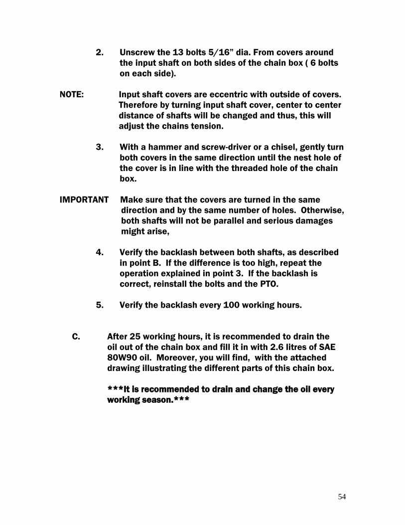
2. Unscrew the 13 bolts 5/16” dia. From covers around
the input shaft on both sides of the chain box ( 6 bolts
on each side).
NOTE: Input shaft covers are eccentric with outside of covers.
Therefore by turning input shaft cover, center to center
distance of shafts will be changed and thus, this will
adjust the chains tension.
3. With a hammer and screw-driver or a chisel, gently turn
both covers in the same direction until the nest hole of
the cover is in line with the threaded hole of the chain
box.
IMPORTANT Make sure that the covers are turned in the same
direction and by the same number of holes. Otherwise,
both shafts will not be parallel and serious damages
might arise,
4. Verify the backlash between both shafts, as described
in point B. If the difference is too high, repeat the
operation explained in point 3. If the backlash is
correct, reinstall the bolts and the PTO.
5. Verify the backlash every 100 working hours.
C. After 25 working hours, it is recommended to drain the
oil out of the chain box and fill it in with 2.6 litres of SAE
80W90 oil. Moreover, you will find, with the attached
drawing illustrating the different parts of this chain box.
***It is recommended to drain and change the oil every
working season.***
55
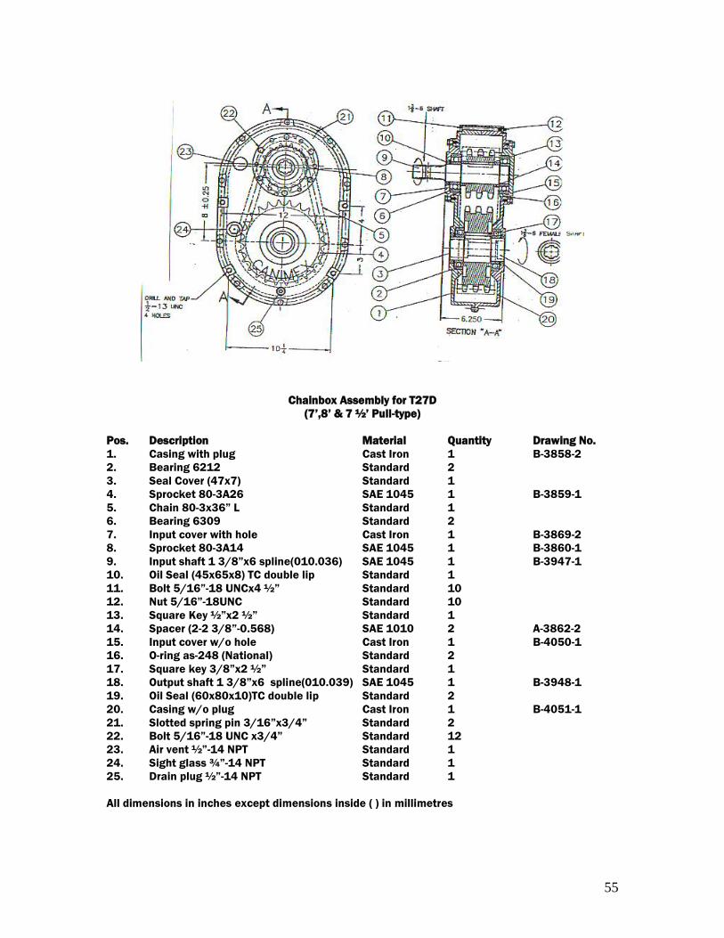
Chainbox Assembly for T27D
(7’,8’ & 7 ½’ Pull-type)
Pos. Description Material Quantity Drawing No.
1. Casing with plug Cast Iron 1 B-3858-2
2. Bearing 6212 Standard 2
3. Seal Cover (47x7) Standard 1
4. Sprocket 80-3A26 SAE 1045 1 B-3859-1
5. Chain 80-3x36” L Standard 1
6. Bearing 6309 Standard 2
7. Input cover with hole Cast Iron 1 B-3869-2
8. Sprocket 80-3A14 SAE 1045 1 B-3860-1
9. Input shaft 1 3/8”x6 spline(010.036) SAE 1045 1 B-3947-1
10. Oil Seal (45x65x8) TC double lip Standard 1
11. Bolt 5/16”-18 UNCx4 ½” Standard 10
12. Nut 5/16”-18UNC Standard 10
13. Square Key ½”x2 ½” Standard 1
14. Spacer (2-2 3/8”-0.568) SAE 1010 2 A-3862-2
15. Input cover w/o hole Cast Iron 1 B-4050-1
16. O-ring as-248 (National) Standard 2
17. Square key 3/8”x2 ½” Standard 1
18. Output shaft 1 3/8”x6 spline(010.039) SAE 1045 1 B-3948-1
19. Oil Seal (60x80x10)TC double lip Standard 2
20. Casing w/o plug Cast Iron 1 B-4051-1
21. Slotted spring pin 3/16”x3/4” Standard 2
22. Bolt 5/16”-18 UNC x3/4” Standard 12
23. Air vent ½”-14 NPT Standard 1
24. Sight glass ¾”-14 NPT Standard 1
25. Drain plug ½”-14 NPT Standard 1
All dimensions in inches except dimensions inside ( ) in millimetres
56
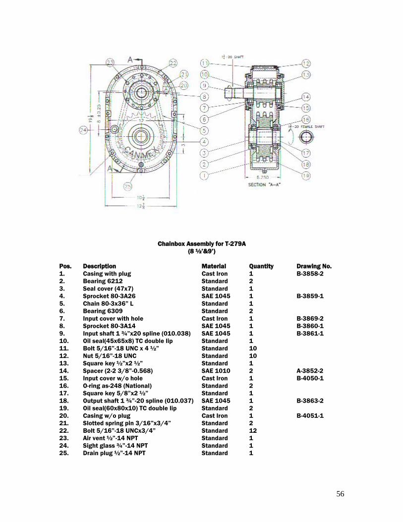
Chainbox Assembly for T-279A
(8 ½’&9’)
Pos. Description Material Quantity Drawing No.
1. Casing with plug Cast Iron 1 B-3858-2
2. Bearing 6212 Standard 2
3. Seal cover (47x7) Standard 1
4. Sprocket 80-3A26 SAE 1045 1 B-3859-1
5. Chain 80-3x36” L Standard 1
6. Bearing 6309 Standard 2
7. Input cover with hole Cast Iron 1 B-3869-2
8. Sprocket 80-3A14 SAE 1045 1 B-3860-1
9. Input shaft 1 ¾”x20 spline (010.038) SAE 1045 1 B-3861-1
10. Oil seal(45x65x8) TC double lip Standard 1
11. Bolt 5/16”-18 UNC x 4 ½” Standard 10
12. Nut 5/16”-18 UNC Standard 10
13. Square key ½”x2 ½” Standard 1
14. Spacer (2-2 3/8”-0.568) SAE 1010 2 A-3852-2
15. Input cover w/o hole Cast Iron 1 B-4050-1
16. O-ring as-248 (National) Standard 2
17. Square key 5/8”x2 ½” Standard 1
18. Output shaft 1 ¾”-20 spline (010.037) SAE 1045 1 B-3863-2
19. Oil seal(60x80x10) TC double lip Standard 2
20. Casing w/o plug Cast Iron 1 B-4051-1
21. Slotted spring pin 3/16”x3/4” Standard 2
22. Bolt 5/16”-18 UNCx3/4” Standard 12
23. Air vent ½”-14 NPT Standard 1
24. Sight glass ¾”-14 NPT Standard 1
25. Drain plug ½”-14 NPT Standard 1