Embed Size (px)
Citation preview

Available online at www.sciencedirect.com
Acta Astronautica 52 (2003) 455–465www.elsevier.com/locate/actaastro
Space technology three: mission overview and spacecraftconcept description
W.D. Deiningera ;∗, M.C. Noeckera, D.J. Wiemera, J.S. Eternoa, C. Clevenb,K.C. Patelb, G.H. Blackwoodb, L.L. Livesayb
aBall Aerospace and Technologies Corp., P.O. Box 1062 Boulder CO 80306-1062, USAbJet Propulsion Laboratory, California Institute of Technology, 4800 Oak Grove Drive, Pasadena CA 91109, USA
Abstract
Space Technology Three (ST3), the third NASA New Millennium Program space technology mission, is focused onvalidation of key technologies for future separated spacecraft interferometers, such as Terrestrial Planet Finder and theMicro-Arcsecond X-ray Imaging Mission. The main technologies to be demonstrated are autonomous formation 8ying (AFF)and separated spacecraft interferometry (SSI). This mission uses two spacecraft called the Combiner and Collector, launchedtogether, to validate these technologies. After on-orbit checkout, the spacecraft separate and are maintained within a rangeof 50–1000 m. The AFF sensors and control capabilities are validated over a 2 month period followed by three months ofSSI operations. Launch into an Earth-trailing heliocentric orbit is tentatively planned for March 2005 on a Delta II 7325.JPL is responsible for formation 8ying sensors and the interferometer instruments. Ball, selected as ST3 prime and workingwith JPL, provides the two spacecraft, system integration and test, and operations over the six-month mission duration. Thispaper summarizes the baseline mission concept and describes the spacecraft bus design in more detail, as de=ned at thestart of the program in November 1999.c© 2002 Elsevier Science Ltd. All rights reserved.
1. Introduction
Human interest in =nding extrasolar planets isvery strong, particularly Earth-like planets. Sev-eral missions are proposed to search for extrasolar,Earth-like planets including Terrestrial Planet Finder(TPF) [1], Terrestrial Planet Imager (TPI), and theMicro-Arcsecond X-ray Imaging Mission (MAXIM).TPF is planned for launch in 2011 and will for the=rst time isolate and analyze the light coming fromthe remote planet itself. The planet detection goals ofTPF require a telescope arrangement some 50–100 m
∗ Corresponding author.
long though a capability to expand the array to 100’sof meters in size would greatly enhance mission ca-pabilities. TPI is the follow-on to TPF and will createimages of the planet’s surface features. TPI mightrequire a telescope array spanning thousands ofkilometers, surely requiring a separated spacecraftapproach. Each would need nanometer resolution op-tical path control. These missions rely on a capabilityto image the exo-planets directly, a diCcult activ-ity due to the bright light emitted from the parentstar. Researchers have proposed and re=ned a nullinginterferometric method of selectively removing thebright starlight before detection, by superimposingthe on-axis light from two telescopes (apertures)so that the stellar wavefronts interfere destructively
0094-5765/03/$ - see front matter c© 2002 Elsevier Science Ltd. All rights reserved.PII: S0094 -5765(02)00188 -1

456 W.D. Deininger et al. / Acta Astronautica 52 (2003) 455–465
enabling detection of the weaker oG-axis light fromexo-planets [2–4].
MAXIM and its precursor, called MAXIMPath=nder, would require 2 or more spacecraft or clus-ters of spacecraft separated by tens to thousands ofkilometers. These missions would need subnanometerprecision optical path control.
The New Millennium Program ST3 mission is fo-cussed on validating separated spacecraft interferom-eter methods in space using two free-8ying spacecraftas the two apertures [4–7]. ST3 will launch in March2005 into an Earth-trailing heliocentric orbit. The tech-nologies of formation 8ying and separated spacecraftinterferometry (SSI) will be demonstrated. Precisionformation 8ying [8] is required to maintain properalignments and spacings between the two spacecraftto enable use of the interferometer payload. ST3will validate an ability to control two independentspacecraft so that their relative velocity is less than10 microns/s while maintaining separation distancesof up to 1000 m to a precision of 10 cm. Once thiscapability is established, ST3 will measure fringevisibility amplitudes within the interferometer as anSSI technology demonstration mission.
Ball Aerospace and Technologies Corp. was se-lected by JPL as the prime contractor for ST3 inNovember 1999. JPL is responsible for the formation8ying sensors and interferometer instruments. Ballprovides the two spacecraft, system integration andtest, and operations over the six month mission dura-tion. This paper summarizes the baseline mission con-cept and describes the two spacecraft, as de=ned at thestart of the program in November 1999, in more detail.
2. Launch and mission design
Both ST3 spacecraft are stacked on a Delta II7325 and launched. The Delta II third-stage solidmotor directly injects the two spacecraft into anEarth-trailing heliocentric orbit and then separatesfrom the two spacecraft. The spacecraft are designedand stacked to allow complete bus and payload check-out in a cluster mode. This helps to ensure a safeformation acquisition immediately after separation.After formation acquisition, the spacecraft deploytheir sun-shades, and begin the month-long forma-tion 8ying check-out and experiment period. This is
followed by the 1.5-month Combiner-mode interfer-ometry check-out and observation period in whichonly the Combiner instrument is used. The baselinemission is completed by executing a three-monthseparated spacecraft-mode interferometer check-outand observation period.
Due to the baseline dimensions of the Combinerspacecraft payload, the 3-m (10-ft) payload fairingis baselined for the ST3 mission. The mission willuse the standard 3712C Delta payload attach =tting(PAF) interface. The constellation complies withcenter-of-gravity and thermal launch constraints forDelta II. The ST3-to-Delta electrical interface is basedon the GFO design.
3. Flight system description
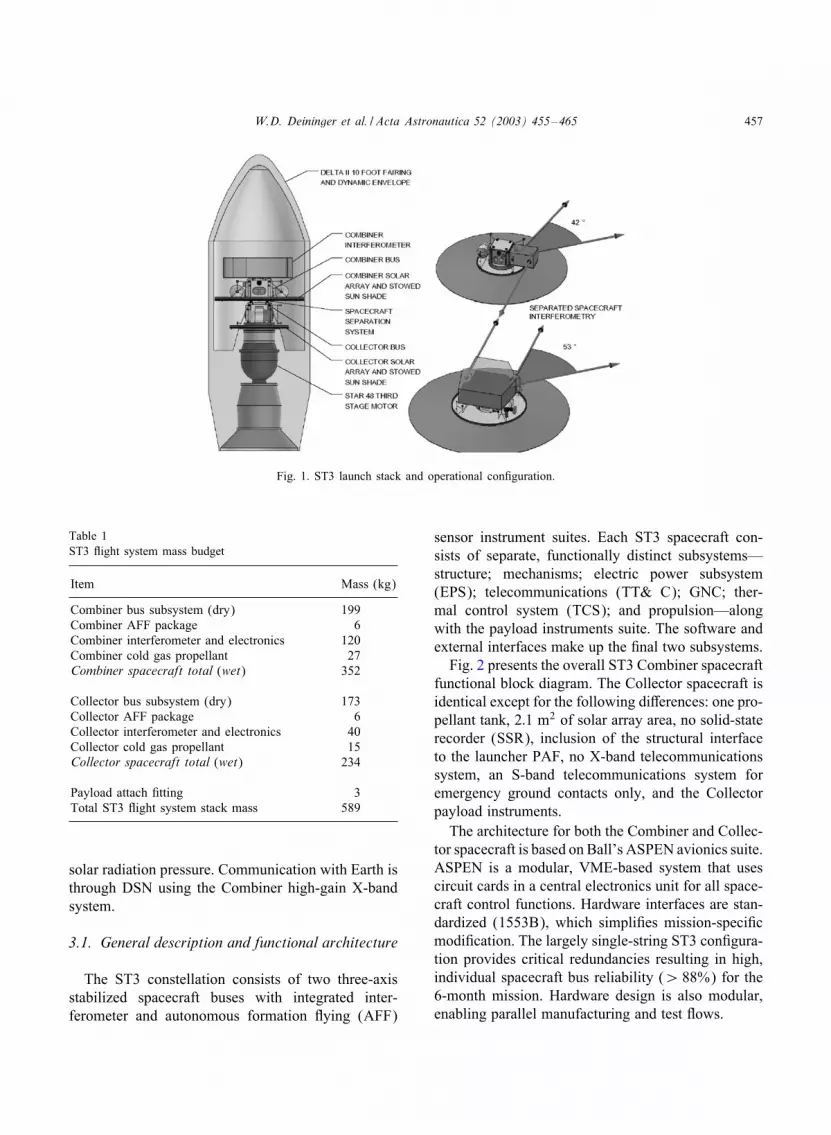
The two-spacecraft ST3 concept is shown stackedin the launch fairing and in its operational con=g-uration in Fig. 1. The Combiner spacecraft has themajor interferometry instrumentation on top while theCollector spacecraft shows a smaller side-mountedsiderostat system. The mission drivers includedformation 8ying accuracies of 10 cm over separationdistances of up to 1000 m, packaging of the twospacecraft onto a single launcher with adequate massmargins, and a low onboard jitter environment toenable the interferometer to lock on and track fringes.
The main performance characteristics of the twospacecraft include a total launch mass of approx-imately 590 kg, an attitude control capability of0:67 arcmin, relative velocity control in formation8ying mode of 42 �m=s, jitter characteristics above10 Hz of better than 0:05 arcsec, a power margin of25%, and a downlink margin of 20%. The generalspacecraft mass budget is shown in Table 1.
Component and subsystem commonality aremaximized between the two spacecraft buses tosimplify integration and test and ensure low cost. Bothspacecraft have identical primary structures, GNC,and spacecraft control computers. The power and coldgas propulsion systems are virtually identical, withthe Combiner having a larger solar array area andtwo propellant tanks instead of one. Both spacecraftemploy in8atable sunshades sized to reduce glint be-tween the two spacecraft and match their mass/arearatios to within better than 1%, minimizing eGects of
W.D. Deininger et al. / Acta Astronautica 52 (2003) 455–465 457
Fig. 1. ST3 launch stack and operational con=guration.
Table 1ST3 8ight system mass budget
Item Mass (kg)
Combiner bus subsystem (dry) 199Combiner AFF package 6Combiner interferometer and electronics 120Combiner cold gas propellant 27Combiner spacecraft total (wet) 352
Collector bus subsystem (dry) 173Collector AFF package 6Collector interferometer and electronics 40Collector cold gas propellant 15Collector spacecraft total (wet) 234
Payload attach =tting 3Total ST3 8ight system stack mass 589
solar radiation pressure. Communication with Earth isthrough DSN using the Combiner high-gain X-bandsystem.
3.1. General description and functional architecture
The ST3 constellation consists of two three-axisstabilized spacecraft buses with integrated inter-ferometer and autonomous formation 8ying (AFF)
sensor instrument suites. Each ST3 spacecraft con-sists of separate, functionally distinct subsystems—structure; mechanisms; electric power subsystem(EPS); telecommunications (TT& C); GNC; ther-mal control system (TCS); and propulsion—alongwith the payload instruments suite. The software andexternal interfaces make up the =nal two subsystems.
Fig. 2 presents the overall ST3 Combiner spacecraftfunctional block diagram. The Collector spacecraft isidentical except for the following diGerences: one pro-pellant tank, 2:1 m2 of solar array area, no solid-staterecorder (SSR), inclusion of the structural interfaceto the launcher PAF, no X-band telecommunicationssystem, an S-band telecommunications system foremergency ground contacts only, and the Collectorpayload instruments.
The architecture for both the Combiner and Collec-tor spacecraft is based on Ball’s ASPEN avionics suite.ASPEN is a modular, VME-based system that usescircuit cards in a central electronics unit for all space-craft control functions. Hardware interfaces are stan-dardized (1553B), which simpli=es mission-speci=cmodi=cation. The largely single-string ST3 con=gura-tion provides critical redundancies resulting in high,individual spacecraft bus reliability (¿ 88%) for the6-month mission. Hardware design is also modular,enabling parallel manufacturing and test 8ows.

458 W.D. Deininger et al. / Acta Astronautica 52 (2003) 455–465
Fig. 2. ST3 combiner spacecraft general block diagram.
3.2. Instrument accommodation
Each spacecraft is designed to fully accommodateits ST3 instrument suite. A composite top deck pro-vides the support needed for Combiner instruments,the required dimensional stability and stiGness, alongwith completely unobstructed =elds-of-view (FOV).The Collector spacecraft provides a side-mountaccommodation of the Collector instrument withcompletely unobstructed FOV. The AFF antennas onboth spacecraft are located at the edge of the solarpanels to maximize horizontal and vertical separationdistances without any deployments and to minimizemultipath interference.
The in8atable sun shade provides complete block-age of the sun over a ±45◦ angle for the inter-
ferometer instruments on both spacecraft. It has aknife-edge to minimize stray light and is made froman RF-transparent, non-re8ecting material to mini-mize multipath eGects. It also cants down from themounting plane to further reduce multipath eGects andprovide cleaner FOVs. Finally, the Collector sunshadeis oversized to enable the mass/area ratios of the twospacecraft to be within 0.1% at each other at launch.
The spacecraft bus provides all required power(including cabling and connectors), pointing, ther-mal, structural, and data interfaces as neededby the ST3 instrument suites and furnishes anon-contaminating environment that is critical for thesensitive optics.
The use of composites enables tailoring of theinterferometer mounting environment to minimize

W.D. Deininger et al. / Acta Astronautica 52 (2003) 455–465 459
vibrational- and thermally-induced distortions. Theeasily accessible external mounting interfaces for theoptical instruments on both ST3 spacecraft and AFFantennas enable rapid and simple alignments duringI&T.
4. Technology payloads
The technology payloads consist of the interferom-eter and formation 8ying package (FFP).
4.1. Interferometer
The interferometer instrument is described in detailelsewhere [4–7] and summarized here. The opticallayout is shown in Fig. 3. The Combiner spacecraftincludes a =xed-baseline, stand-alone interferometer.Here, a pair of outboard siderostats feed into an afocalgregorian compressor with a =eldstop at the internalfocus. The incoming beams are then compressed andfed through delay lines, one =xed and one moveable,to the Combiner. The =xed delay line in the right armprovides a 20 m delay to compensate for the extra pathlength in the dogleg path of the Collector instrument.An outer annular portion of each beam is stripped oGfor guiding, and the central portion of one interferingoutput beam used for fringe tracking. The centralportion of the other beam is dispersed in a prism andintegrated coherently on a CCD fringe spectrometer.The moveable delay line can be fed directly withstarlight or be fed by a beam from the Collectorspacecraft to accomplish SSI.
In order for the Combiner/Collector interferome-ter system to work properly, it must have the properon-orbit geometry. During SSI, the Combiner space-craft resides at the focus of a parabola while theCollector spacecraft moves along the arc of theparabola (see Fig. 3). As long as the two spacecraftmaintain this geometry (and the proper orientationrelative to each other), the 20 m =xed delay line in theCombiner spacecraft can compensate for the doglegpath length in the Collector instrument.
4.2. Formation 7ying package
The FFP enables the two spacecraft to achieve aprecise enough relative position and orientation that
Fig. 3. Optical interferometer layout and on-orbit geometry.
the delay lines can allow SSI. The FFP must measureinter-spacecraft relative distances and angles to±1 cmand ±0:3 mrad (both to 1�). Further, actuators musthave small enough control authority to keep relativevelocity between the two spacecraft to ¡ 10 �m=s.
The AFF sensor uses GPS-like signaling amongmultichannel transceivers on the two spacecraft [8].Each spacecraft transmits a carrier and pseudorangesignal which is received by multiple antennas on theother spacecraft. Multiple patch antennas on eachspacecraft allow for both 4� steradion coverage aswell as determination of relative angle and range. Fig.3 also shows the operational geometry.
5. Spacecraft bus subsystem designs
Each of the main subsystems is described in moredetail below.

460 W.D. Deininger et al. / Acta Astronautica 52 (2003) 455–465
5.1. Structure
Both ST3 spacecraft use nearly identical, GFO-type,unibody, composite structures to minimize mass andclosely match interferometer optical bench charac-teristics. The common primary structure is a simple,rectangular-box-shaped unibody with a single re-movable side panel, and top and bottom decks. TheCollector spacecraft also includes a thrust tube/launchvehicle adapter cylinder that transitions the loadsfrom the square bus cross-section to the round v-bandseparation system on the Delta upper stage launcherinterface ring. The top deck of the Combiner space-craft supports the interferometer payload. Radiator=ns are attached at the corners on the spacecraft to al-low the removal of excess heat. Most of the spacecraftbus components are mounted on the interior and ex-terior surfaces of the sidewalls and removable panel.
The structure is constructed of graphite/cyanate-estercomposite face sheets bonded to a honeycomb corewith embedded metal attach =ttings. The =xed solarpanels attach to the bottom deck of each spacecraftand are stiGened with struts as shown in Fig. 1.The solar panel substrates are also made of graphite/cyanate-ester composite facesheets and honeycombconstruction as the main structure.
The instruments will be mounted on the spacecraftusing kinematic mounts to prevent mounting stresseson the instrument optical benches. The baseline isto have a true three-point kinematic mount consist-ing of mono-ball, double anti-rotation link, and singleanti-rotation link.
5.2. Mechanisms
During launch, the two spacecraft are held togetherwith four electronically activated separation nuts. Theseparation nut uses redundant-shaped memory alloytriggers to open a segmented nut and release a boltwith up to a 2500-lb preload. After release, there arefour separate spring canisters, located adjacent to theseparation nuts, which provide the force to separatethe spacecraft.
The sunshields of both spacecraft are in8atabletoruses deployed after the spacecraft separate fromeach other. The sunshields are attached to the outerperimeter of the solar panel substrate. Prior todeployment, they are stowed in a small toroidal
volume along the backside edge of the solar panels.The sunshields consist of thin =lm, in8atable andrigidizable materials that are deployed through thein8ation of struts using an inert gas (∼ 3 psig). Thebaseline rigidization technique is UV curable com-posite laminates due to multipath concerns. UV cur-able laminates are composite pre-pregs of epoxy and=berglass that are encapsulated in thin =lms and curedonly by exposure to the speci=ed UV wavelength.The in8atable elements would then be vented through“T” =ttings. The gas canister and in8ation systemare also attached to the backside of the solar arraysubstrate.
5.3. Telecommunications subsystem
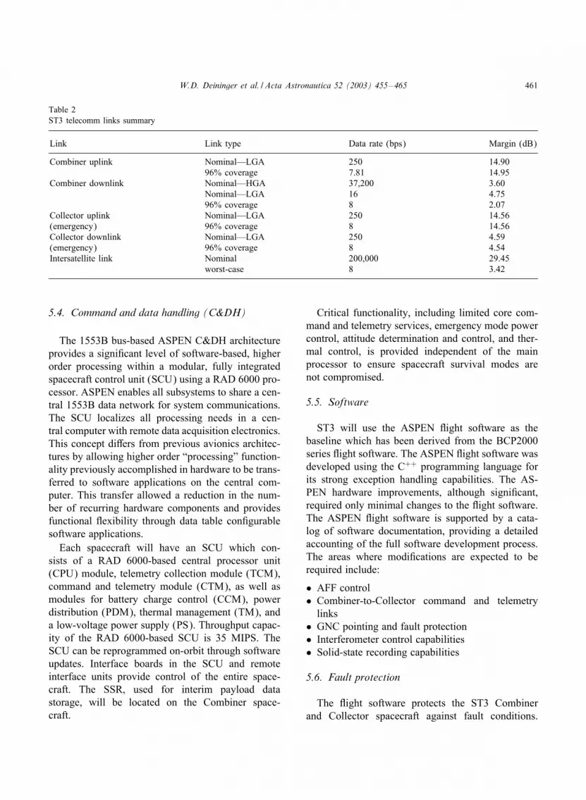
There are two telecommunications subsystemson each ST3 spacecraft: an ultra high frequency(UHF) intersatellite link and a satellite-ground sub-system. The Combiner spacecraft has an X-bandsatellite-ground link to facilitate high data rateST3 constellation earth-ground communicationsand is based on the small deep space transponder(SDST) while the Collector spacecraft has an S-bandsatellite-ground system for emergency communica-tions only, at low data rates through the 70-m DSN.An existing UHF subsystem is selected for the inter-satellite links on both spacecraft. The UHF systemis sized to enable communications out to 200 km incase anomalous behavior causes the spacecraft to driftbeyond the 2-km speci=cation. A detailed commandand telemetry link analysis shows substantial marginsfor all modes of operation, as summarized in Table 2.
The Combiner spacecraft RF system supports up-link rates of 250 or 7:8125 bps, along with downlinkrates of 37200 or 16 bps at 0:1 AU using the 34-mDSN ground stations. The intersatellite link uses UHFtransceivers and provides a data rate of 250; 000 bps,full-duplex, at 2000 m and communications capabilityout to 200 km in any attitude.
The Collector spacecraft RF system includes a du-plicate UHF intersatellite link to communicate withthe Combiner. The Collector spacecraft also has thecapability to communicate directly with Earth duringsafe mode operations using the S-band. Uplink ratesfrom earth of 250 or 7:8125 bps and downlink rates of16 or 7:8125 bps are supported in any spacecraft atti-tude at 0:1 AU using the 70-m DSN ground stations.
W.D. Deininger et al. / Acta Astronautica 52 (2003) 455–465 461
Table 2ST3 telecomm links summary
Link Link type Data rate (bps) Margin (dB)
Combiner uplink Nominal—LGA 250 14.9096% coverage 7.81 14.95
Combiner downlink Nominal—HGA 37,200 3.60Nominal—LGA 16 4.7596% coverage 8 2.07
Collector uplink Nominal—LGA 250 14.56(emergency) 96% coverage 8 14.56Collector downlink Nominal—LGA 250 4.59(emergency) 96% coverage 8 4.54Intersatellite link Nominal 200,000 29.45
worst-case 8 3.42
5.4. Command and data handling (C&DH)
The 1553B bus-based ASPEN C&DH architectureprovides a signi=cant level of software-based, higherorder processing within a modular, fully integratedspacecraft control unit (SCU) using a RAD 6000 pro-cessor. ASPEN enables all subsystems to share a cen-tral 1553B data network for system communications.The SCU localizes all processing needs in a cen-tral computer with remote data acquisition electronics.This concept diGers from previous avionics architec-tures by allowing higher order “processing” function-ality previously accomplished in hardware to be trans-ferred to software applications on the central com-puter. This transfer allowed a reduction in the num-ber of recurring hardware components and providesfunctional 8exibility through data table con=gurablesoftware applications.
Each spacecraft will have an SCU which con-sists of a RAD 6000-based central processor unit(CPU) module, telemetry collection module (TCM),command and telemetry module (CTM), as well asmodules for battery charge control (CCM), powerdistribution (PDM), thermal management (TM), anda low-voltage power supply (PS). Throughput capac-ity of the RAD 6000-based SCU is 35 MIPS. TheSCU can be reprogrammed on-orbit through softwareupdates. Interface boards in the SCU and remoteinterface units provide control of the entire space-craft. The SSR, used for interim payload datastorage, will be located on the Combiner space-craft.
Critical functionality, including limited core com-mand and telemetry services, emergency mode powercontrol, attitude determination and control, and ther-mal control, is provided independent of the mainprocessor to ensure spacecraft survival modes arenot compromised.
5.5. Software
ST3 will use the ASPEN 8ight software as thebaseline which has been derived from the BCP2000series 8ight software. The ASPEN 8ight software wasdeveloped using the C++ programming language forits strong exception handling capabilities. The AS-PEN hardware improvements, although signi=cant,required only minimal changes to the 8ight software.The ASPEN 8ight software is supported by a cata-log of software documentation, providing a detailedaccounting of the full software development process.The areas where modi=cations are expected to berequired include:
• AFF control• Combiner-to-Collector command and telemetry
links• GNC pointing and fault protection• Interferometer control capabilities• Solid-state recording capabilities
5.6. Fault protection
The 8ight software protects the ST3 Combinerand Collector spacecraft against fault conditions.

462 W.D. Deininger et al. / Acta Astronautica 52 (2003) 455–465
Fault conditions autonomously cause fault recoverysteps to be initiated, allowing the software to grace-fully recover from software and/or hardware anoma-lous conditions. Spacecraft fault conditions such asunder-voltage conditions, data transients, and singleevent upsets (SEU) are all supported. GNC faultconditions, such as orbit propagation errors, orbit ve-locity errors, attitude control calculation errors, andwheel over-speed errors are also supported.
A watchdog timer is used to protect against los-ing processor control resulting from SEUs, operatorerrors, and other anomalies. The watchdog timer iscontinuously monitoring the 8ight software for cor-rect operation, and if a problem occurs, it will force aprocessor reset and bring the spacecraft into a knownsafe operational state.
5.7. Guidance, navigation and control subsystem(GNC)
The GNC subsystem provides continuous six-degree-of-freedom (6-DOF) control capability duringall phases of the ST3 mission. The architecture ofboth the Combiner and Collector spacecraft GNC areidentical to provide 8exibility and reduce costs.
Attitude determination is accomplished usingcoarse sun sensors, star trackers, a =ber-optic ratesensor, and inputs from the AFF sensor. A single BallCT-633 star tracker per spacecraft will be the primaryattitude reference for all phases of the mission. Thestar tracker will be mounted as closely as possible tothe instrument bench to minimize alignment errors.
Primary attitude actuation is accomplished usingthree reaction wheels. Momentum is managed in thebackground using thrusters, based on wheel speedlimits, while observing no-thrust periods for interfer-ometer data collection. Small wheels provide low jitteroperation while providing suCcient momentum capa-bility to compensate for solar pressure torques duringno-thrust periods.
A comprehensive control system analysis wasperformed to determine GNC performance for allST3 mission modes. A detailed simulation of the ST3separated spacecraft interferometry mode was cre-ated to demonstrate the compliance of the proposedST3 GNC system with the mission requirements. Inaddition, a translational and rotational control systemwas simulated to show the ability of the proposed
Table 3Position control performance
Parameter Position error Velocity error(cm) (�m=s)
Minimum impulse bit ±3 ±6:7AFF 3� ±3 ±300Filtered AFF data 3� ±3 ±30Solar radiation press 3� ±1:4 ±28RSS 3� ±4:5 ±41:6Requirement ±10 ±100Margin 122% 140%
ST3 GNC system to maneuver and orient the Com-biner and Collector spacecraft during this mode,while satisfying all performance parameters includingquiescence during the 1000 s observation windows.
Table 3 illustrates the translational control bud-get for the Combiner and Collector spacecraft. Solarradiation pressure forces are included, along with theassumed minimum impulse bit from the thrusters. Po-sition errors after the separated spacecraft interferom-etry mode’s 1000-s thrust-free observation windoware used in the budget, because this is the most de-manding requirement on the position control system.
5.8. Electric power subsystem (EPS)
The Ball ST3 EPS concept (identical on both space-craft except for solar array size) exploits the ASPENavionics architecture, leading to substantial weightsavings. The performance of the EPS on each space-craft for the main operating modes is summarizedin Table 4. Power is available for each spacecraft tooperate at full capacity for all phases of the mission,including the cluster-mode spacecraft check-out pe-riod. Power available in checkout mode is higher thanin normal mode since the solar arrays are normal tothe sun instead of at up to 45◦ angle from the sun line.
The EPS is a direct energy transfer system witha battery clamped bus voltage. The system usesidentical components for both the Combiner andCollector spacecraft, with the exception of the solararray shape and size. The main EPS elements includethe solar array, battery, relay box, SEP with remoteinterface units, and the power cards mounted in theASPEN C&DH. The power cards include battery

W.D. Deininger et al. / Acta Astronautica 52 (2003) 455–465 463
Table 4ST3 operational-mode spacecraft bus power budget
Item Value (W)
Combiner bus power 203Combiner instrument electronics 144Total combiner spacecraft 347Available combiner array power (EOL) 446
Combiner power margin 99Collector bus power 147Collector instrument electronics 60Total collector spacecraft 207Available collector array power (EOL) 259Collector power margin 52
charge control, bus power control and distribution, andthermal system operation. The solar arrays on bothspacecraft consist of non-deployable =xed panels,oriented up to ±45◦ to the Sun.
The power control circuitry (PCC) providesautonomous battery charge control, undervoltage,overvoltage, overtemperature, overpressure, and bat-tery imbalance fault protection. The PCC also controlsthe fault-protected relays that switch power to theessential bus (ESB), non-essential bus (NEB), andthe power switched components. The NEB suppliespower to the ST3 instruments.
The solar arrays provide prime power to eachspacecraft in all but emergency mode. The solarpanels have a total projected area of 3:2 m2 for theCombiner spacecraft and 2:1 m2 for the Collectorspacecraft. The concentric con=guration allows bothspacecraft to be fully powered during the clusteredspacecraft check-out mode with the arrays normal tothe sun. Solar array switches and power bus relaysare in the relay box. The Collector spacecraft array isbasically a circle 180 cm in diameter, interrupted byonly the launch attach ring. The Combiner spacecraftarray covers an annulus from 180 cm ID to 269 cmOD. They are populated with GaAs cells similar to thetype used on GFO. The direct radiating con=gurationof the arrays allows them to run cool and eCciently.
The battery is used during launch to provide powerto the critical spacecraft components. The battery willonly be used on-orbit if the spacecraft enters the emer-gency mode. A nickel hydrogen battery was selected
as the baseline energy storage system for our ST3spacecraft. It is a 22-cell, single-pressure vessel (SPV)unit with a rated capacity of 15 A-h.
5.9. Thermal control subsystem
The TCS uses passive thermal design techniques(multilayer insulation (MLI) blankets, paint andthermal tape, and localized radiators) coupled withlimited-use active heaters to allow continuous opera-tions in all sun angles and modes of operation. Thecomposite structure is also part of the TCS. Based onour GFO experience with composite spacecraft, wewill use K1100 =bers in the lay-up of the structure toaid in moving the heat dissipated in the boxes to theradiator =ns mounted at the edges of each spacecraft.There are no moving parts. The arrangement of inter-nal equipment is also used to aid thermal control andminimize the need for supplemental heaters.
5.10. Propulsion
A trade was done to select the reaction controlpropulsion subsystem. Options included helium coldgas, nitrogen cold gas, pulsed plasma thrusters (PPT),=eld emission electric propulsion (FEEP), and hydro-gen peroxide micro-propulsion. Drivers included thesmall impulse bits required (eliminated mono-propand bi-prop), the short duration of mission operations(6 months), contamination, and the tight mission costconstraints (technology maturity). We have selectednitrogen cold gas for ST3 to maximize the reliabil-ity of demonstrating separated spacecraft formation8ying and interferometry.
The spacecraft cold-gas propulsion system consistsof the propellant storage tank(s), pressure regulator,twelve 4.5-mN cold gas thrusters, latch valves, =l-ter and service valves along with tubing, bracketryand =eld joints. The tanks are located to minimizeCG shifts during on-orbit operations and enable sim-ple balancing within the launch fairing. The thrusterlocations and orientations are selected to minimizethe possibility of payload equipment contamination,while allowing the necessary attitude and translationmaneuvers to be conducted. The nitrogen cold gasthrusters operate at a nominal speci=c impulse of 68 s.

464 W.D. Deininger et al. / Acta Astronautica 52 (2003) 455–465
6. Reliability and lifetime
A detailed reliability prediction was performed forthe ST3 spacecraft bus con=guration. The reliabilityprediction was derived by comparing ST3 items withproven designs and similar hardware con=gurationsused on past Ball spacecraft programs, along withspeci=c vendor-provided reliability values for individ-ual boxes. The predicted reliability for the Combinerand Collector spacecraft buses are 0.88 and 0.89, re-spectively.
7. Spacecraft system design features for missiontechnologies validation
7.1. AFF sensor validation
The AFF system will be integrated with the GNChardware and software, enabling on-orbit calibrationoperations to measure the accuracies of the AFF sensoroutputs. The key to this process will be validating thattime references and range, range rate, and bearing dataachieve their speci=ed performance levels.
To achieve required AFF sensor performance, theAFF antennas must have transparent lines of sightat all formation operating geometries (achieved byantenna placement and choice of spacecraft materi-als). Measurement errors due to the spacecraft systemdesign must be minimized.
AFF operation on orbit begins with the sequence oflaunch and separation actions. The two spacecraft arelaunched into a cluster mode, then separated, and theAFF sensor operation initialized to control the forma-tion. Upon completion of this sequence, the FormationFlying Checkout and Experiment phase will begin.
Validation of AFF system performance involvesall four modes of the Formation Flying Checkout andExperiment phase, including Formation Initialization,Formation Rotation, Formation Retargeting Slew,and Formation Resizing.
7.2. Combiner-only interferometry
The spacecraft meet the ST3 translation andangle jitter requirements, which permits the JPLinstrument to perform to its requirements. In this1.5-month phase, the AFF system must keep the
Collector beyond a minimum range from the Com-biner. The Collector’s thruster =rings will establishand maintain adequate range, and its reaction wheelswill constrain it to attitudes suitable to avoid glintproblems.
7.3. Separated spacecraft interferometry
ST3 separated spacecraft interferometry requiresthe two spacecraft to point at a common target, andto use bearing and range data to establish the desiredparabolic position oGset. Then the system must re-spond to =ne adjustments of position and attitude toassist in white-light fringe acquisition. These opera-tions depend critically on AFF sensor linearity andaccuracy in measuring bearing and range, which areneeded to estimate optical path diGerence (OPD) andto acquire fringes quickly.
The AFF system will move and retarget theCombiner and Collector spacecraft for the desiredinterferometer observations in the =nal three monthsof the mission. During the formation observationmode the AFF system will keep two spacecraftface-to-face for all observing baselines.
8. ST3 near-term plans
ST3 is currently re=ning requirements and conduct-ing architecture, instrument, and spacecraft trade stud-ies. The project anticipates its System Architectureand Requirements Review in August of 2000.
Acknowledgements
The work described in this paper was developed bya team of people at Ball Aerospace & TechnologiesCorp. as part of our ST3 (DS3) Proposal eGort. Theauthors sincerely thank the Proposal Team for theirwork in developing this winning design.
References
[1] C.A. Beichman, N.J. Woolf, C.A. Lindensmith (Eds.), TheTerrestrial Planet Finder (TPF)—A NASA Origins Program toSearch for Habitable Planets, JPL Publication 99-3, May 1999.

W.D. Deininger et al. / Acta Astronautica 52 (2003) 455–465 465
[2] R.N. Bracewell, Detecting nonsolar planets by spinninginfrared interferometer, Nature 274 (1978) 780–781.
[3] P.M. Hinz, J.R.P. Angel, W.F. HoGmann, D.W. McCarthy, Jr.,P.C. McGuire, M. Cheselka, J. L. Hora, N. J. Woolf, Imagingcircumstellar environments with a nulling interferometer,Nature 395 (1998) 251.
[4] R.P. Lin=eld, P.W. Gorham, Science Capabilities of the ST3Mission, Dana Point Conference, 1999.
[5] K. Lau, M. Colavita, M. Shao, The new millennium separatedspacecraft interferometer, Dana Point Conference, 1999.
[6] O.P. Lay, G.H. Blackwood, S. Dubovitsky, P.W. Gorham, R.P.Lin=eld, Design of the ST3 formation 8ying interferometer,Dana Point Conference, 1999.
[7] P.W. Gorham, W.M. Folkner, G.H. Blackwood, Enablingconcepts for a dual spacecraft formation-8ying opticalinterferometer for NASA’s ST3 Mission, Dana PointConference, 1999.
[8] G. Purcell, D. Kuang, S. Lichten, S.C. Wu, L. Young,Autonomous formation 8yer (AFF) sensor technologydevelopment, AAS 98-062, 1998.


