Embed Size (px)
Citation preview
INDEX SSE-MAESTRO .................................................................................................................................. 3
Maestro 8-Multi I/O Module ............................................................................................................ 5
Maestro 24-Channel Digital Input Module ....................................................................................... 5
Maestro 24-Channel Digital Output Module .................................................................................... 6
Maestro 8-Channel Analog Output Module ..................................................................................... 6
8 Channel RS232 Multiplexer ........................................................................................................... 7
Jordan Module (GSM Modem) .........................................................................................................7
Galvanic Isolation with Surge Protection for Analogue Inputs (3, 4 or 8 Channels) ........................ 8
Interposing Relay Output (2, 4 or 8 Channels) .................................................................................8
Digital Input Surge Protection (4 or 8 Channel) ...............................................................................9
Digital input surge protection (2 or 16 Channel) .............................................................................9
Load Shed .......................................................................................................................................10
Look@ LCD Display .........................................................................................................................10
Loop Powered Display Module .......................................................................................................11
Liquid Crystal Display and Keyboard................................................................................................11
Load – Switch ..................................................................................................................................12
Typical Remote Station ...................................................................................................................12
SSE-Switched Mode Power Supply .................................................................................................13
The SSE-OPC Server Configurator ...................................................................................................15
Specialist System
Engineering
Product Brochure
31 Kersieboom Crescent, Zwartkop Ext 4, 0157, South Africa P O Box 7170, Centurion, 0046, South Africa Tel: +27 861 773 444 Fax: +27 12 663 4335 Website: www.sse.co.za
SSE-MAESTRO Introduction The SSE-MAESTRO is one of the series of advanced Remote Terminal Units (RTU’s) for the remote monitoring and control of equipment over long distances. The SSE series of RTU’s can connect seamlessly through the SSE-OPC Server, to almost any of the popular SCADA systems. The SSE-MAESTRO can be expanded to accommodate additional I/O modules. Communication Mediums The SSE-MAESTRO can use a number of communication mediums to communicate data from point to point or through to SCADA systems. The SSE-MAESTRO can make use of the following communication mediums:
Analogue Radio Data Radios Landline Dial-up Modem Cell Dial-Up Modem Cell SMS Cell GPRS Cell HSCSD
RS232/485 Fiber Optic Ethernet.
Features The SSE-MAESTRO has the following features:
Powerful-modular software design. A real-time I/O device. Intelligent Data Logger. Remote time stamping of event and logged data. Totally configurable and programmable from the Picasso
Configuration Toolbox.
Modular and easily expandable. Excellent EMI Protection. Programmable with powerful “PLC” type instruction set. Industrial standard high speed 16 bit processor. On-Board 1Meg-Word Flash and 2Meg-Word non volatile
RAM. On-Board FFSK Radio Modem for analogue radios. On-Board Real-time clock and watch-dog timer. On-Board LED’s indicating the Digital Input and Digital
Output Status. Through a Communication Orchestrator, the SSE-
MAESTRO can extract data for PLC’s, Intelligent Flow meters, controllers, etc.
Build to ISO 9000 Standards. 24 I/O’s on the main processor board of the SSE-
MAESTRO, 8 DIN, 8 AIN, 8 DOT. Additional I/O modules can be added through the parallel
expansion bus. Connects to a wide range of interface modules:
2, 4 and 8 channel I/O lightning protection units. 3, 4 and 8 channel galvanic isolation units for AIN’s. 2, 4 and 8 channel 10 Amp interposing relay modules.
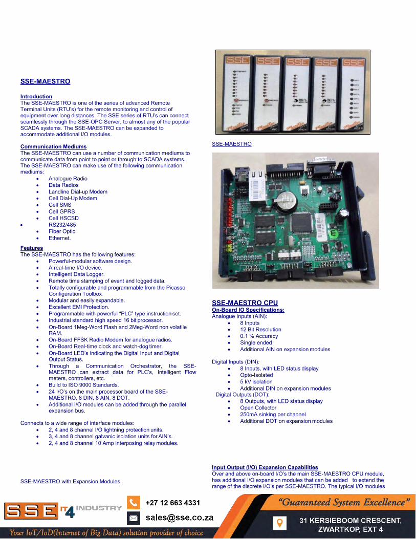
SSE-MAESTRO with Expansion Modules
SSE-MAESTRO
SSE-MAESTRO CPU On-Board IO Specifications: Analogue Inputs (AIN):
8 Inputs 12 Bit Resolution 0.1 % Accuracy Single ended Additional AIN on expansion modules
Digital Inputs (DIN):
8 Inputs, with LED status display Opto-Isolated 5 kV isolation Additional DIN on expansion modules
Digital Outputs (DOT): 8 Outputs, with LED status display Open Collector 250mA sinking per channel Additional DOT on expansion modules
Input Output (I/O) Expansion Capabilities Over and above on-board I/O’s the main SSE-MAESTRO CPU module, has additional I/O expansion modules that can be added to extend the range of the discrete I/O’s per SSE-MAESTRO. The typical I/O modules
that can be added are: Multi I/O Module (8 DIN, 8 AIN, 8 DOT) Maestro 24-Channel Digital Input Module. Maestro 24-Channel Digital Output Module. 8 Channel Analogue Output Module.
Other Specifications Voltage: 9 to 17 Volts DC Power Consumption: < 120mA
2 x RS232 ports (300 to 57600 bps) RJ45(EIA-561 Compatible)
One FFSK Analogue Radio Modem Port PTT, DCD and Test LED’s
Software Functionality The SSE-MAESTRO is packed with powerful features and functions such as:
Digipeating. (Store and forward) All individual I/O are configurable by alarm rising, falling,
delta change (Analogue) or state change (Digital) Programmable as a PLC I/O Mapping Intelligent Data Logger Report by change of state Communication Orchestrator
Digi-Peating (Digital Repeating) – (Store & Forward) Digi-Peating is a method by which a message can be stored and then forwarded to a destination station through other SSE- MAESTRO remote stations. Three intermediate SSE-MAESTRO Stations can be used to digi-Peat (repeat) the message to reach the destination station. Thus, any SSE-RTU equipped remote station can be used to reach stations at far end points. It eliminates the use of expensive repeaters. Configurable The SSE-MAESTRO is totally configurable by using the Configuration Toolbox of the SSE-OPC Server. The SSE-OPC Server can be used to configure and program hundreds of settings and options available in the SSE-MAESTRO. Fault Finding The SSE-OPC Server can also be used to configure the SSE- MAESTRO, and has powerful features by which detailed and comprehensive fault finding tests can be executed on the SSE- MAESTRO.
PLC Programmability The SSE-MAESTRO can also be programmed to be used to execute control and other PLC decision making tasks. Although it does not have the quick cycle times of a PLC, complex tasks can still be executed. The PLC instruction set programming can be done inside the SSE-OPC Server programming and configuration Toolbox and can then be remotely downloaded via any of the selected communication medium.
Not only local control can be done, but also remote control. Any SSE-MAESTRO can control any other SSE-MAESTRO through a selected communication medium. Intelligent Data Logging A very powerful logger is part of the SSE-MAESTRO functionality. The logger can log data under the following conditions:
Log user selectable digital inputs on change of state, either high going or low going edges.
Log user selectable analogue inputs on user definable change of value. The analogue input can be averaged over a user definable time period and the average can then be logged.
Log user selectable digital inputs and/or analogue input on user selectable regular time intervals such as every 5 Sec, or 5 Minutes, etc.
I/O Mapping
Any SSE-MAESTRO can request data from any other SSE- MAESTRO, and/or report any data to any other SSE-MAESTRO on the communication network. By using I/O Mapping, the transmitted data or received data can be mapped or routed to the received SSE- MAESTRO internal data structure to be used for control and decision making purposes. Data Reporting Data can be reported to any number of other SSE-MAESTRO’s or SCADA’s on the communication network. The reporting can happen either on change of state for digital or change of value for analogue inputs. Data will also be transmitted when requested by the base station were the SSE-OPC Server resides.
Any analogue or digital input can be configured as event driven inputs. All parameters to make the inputs are user configurable from the SSE-OPC configuration toolbox.
All change of state events are time stamped at the SSE-MAESTRO. The new value with the time stamp will then be transmitted to the destination for processing. Communication Orchestrator (Multiple Protocols) The SSE-RTU has a unique functionality by which it can be configured to extract data from a number of other intelligent devices such as PLC’s, flow meters, controllers, power meters, etc. The following protocols are supported:
Modbus RTU Master teleRANGER* Modbus RTU Slave ABB Magmaster IEC 60870-5-101 (Slave) HART® DNP 3 (Slave - Level 3) Tag Reader* Hectronic LOOK@* GPU Enermax (*Proprietary Protocols) SMS Reporting Over and above the reporting of Change of State values to other RTU’s or SCADA system, the SSE-MAESTRO can also be configured to send text messages to Mobile Cell Phone users to report alarms. The text describing the alarm condition received on the Mobile phone is completely configurable by the end user or client.
SSE-OPC Server SSE has a comprehensive and powerful OPC Server which makes the SSE-RTU equipment a truly open system. Any SCADA or other third party software with OPC Client drivers can interface with the SSE Telemetry equipment via the SSE OPC Server. Ordering Information
SSE-MAESTRO with 14-Way pluggable ribbon connectors: SSE-MAESTRO/14.
SSE-MAESTRO with 10-Way pluggable screw terminal connectors: SSE-MAESTRO/10.
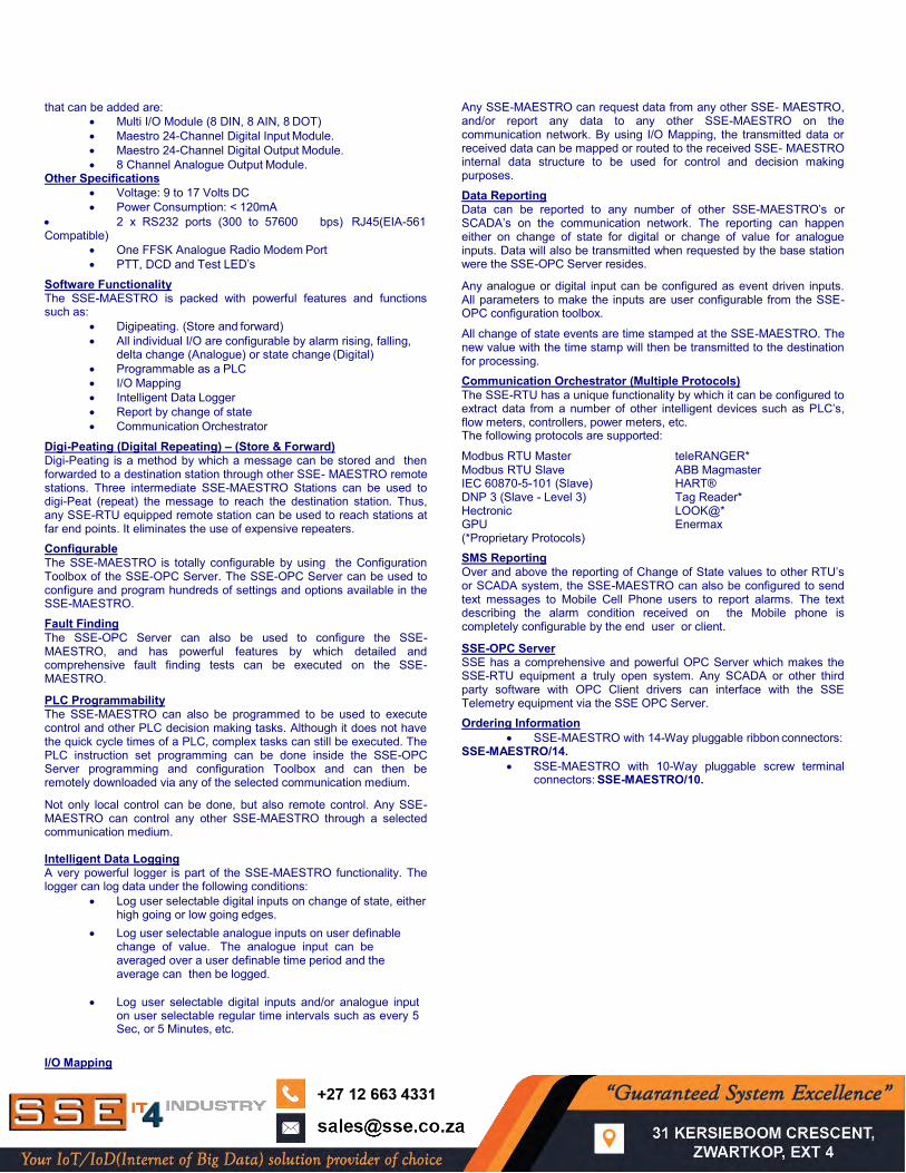
Maestro 8-Multi I/O Module This module is used to connect additional discrete Inputs and Outputs to the SSE-MAESTRO. This Unit duplicates the IO configuration found on the SSE-MAESTRO. The unit is connected to the SSE-MAESTRO and powered via a 26-Way ribbon Bus connecter.
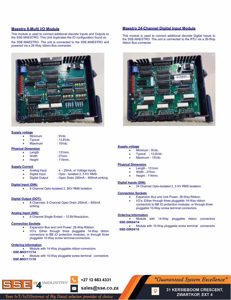
Maestro 24-Channel Digital Input Module This module is used to connect additional discrete Digital Inputs to the SSE-MAESTRO. The unit is connected to the RTU via a 26-Way ribbon Bus connecter.
Supply voltage
Minimum : 9Vdc. Typical : 13,8Vdc. Maximum : 15Vdc.
Physical Dimension Length : 131mm. Width : 27mm. Height : 114mm.
Supply Current
Analog Input : 4 – 20mA, or Voltage inputs. Digital Input : Opto - Isolated 2, 5 KV RMS. Digital Output : Open Drain 250mA – 600mA sinking.
Digital Input (DIN):
8 Channel Opto-Isolated 2, 5KV RMS Isolation.
Digital Output (DOT): 8 Channels: 8 Channel Open Drain 250mA – 600mA
sinking Analog Input (AIN):
8 Channel Single Ended – 12 Bit Resolution. Connection Sockets
Expansion Bus and Unit Power: 26-Way Ribbon. I/O’s: Either through three pluggable 14-Way ribbon
connectors to BB IO protection modules, or through three pluggable 10-Way screw terminal connectors.
Ordering Information
Module with 14-Way pluggable ribbon connectors : SSE-MIO/111/14
Module with 10-Way pluggable screw terminal connectors : SSE-MIO/111/10
Supply voltage Minimum - 9Vdc. Typical - 13,8Vdc. Maximum - 15Vdc.
Physical Dimension
Length - 131mm. Width - 27mm. Height - 114mm.
Digital Inputs (DIN):
24 Channel Opto-Isolated 2, 5 KV RMS Isolation. Connection Sockets
Expansion Bus and Unit Power: 26-Way Ribbon. I/O’s: Either through three pluggable 14-Way ribbon
connectors to BB IO protection modules, or through three pluggable 10-Way screw terminal connectors.
Ordering Information
Module with 14-Way pluggable ribbon connectors : SSE-DIN24/14
Module with 10-Way pluggable screw terminal connectors : SSE-DIN24/10
Maestro 24-Channel Digital Output Module Maestro 8-Channel Analog Output Module
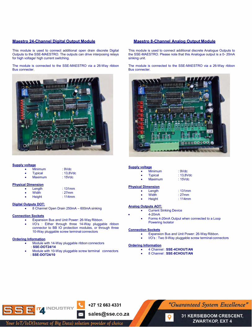
This module is used to connect additional open drain discrete Digital Outputs to the SSE-MAESTRO. The outputs can drive interposing relays for high voltage/ high current switching. The module is connected to the SSE-MAESTRO via a 26-Way ribbon Bus connecter.
This module is used to connect additional discrete Analogue Outputs to the SSE-MAESTRO. Please note that this Analogue output is a 0- 20mA sinking unit. The module is connected to the SSE-MAESTRO via a 26-Way ribbon Bus connecter.
Supply voltage
Minimum : 9Vdc Typical : 13,8Vdc Maximum : 15Vdc
Physical Dimension
Length : 131mm Width : 27mm Height : 114mm
Digital Outputs DOT:
8 Channel Open Drain 250mA – 600mA sinking Connection Sockets
Expansion Bus and Unit Power: 26-Way Ribbon. I/O’s : Either through three 14-Way pluggable ribbon
connector to BB IO protection modules, or through three 10-Way pluggable screw terminal connectors
Ordering Information
Module with 14-Way pluggable ribbon connectors : SSE-DOT24/14
Module with 10-Way pluggable screw terminal connectors : SSE-DOT24/10
Supply voltage
Minimum : 9Vdc Typical : 13,8Vdc Maximum : 15Vdc
Physical Dimension
Length : 131mm Width : 27mm Height : 114mm
Analog Outputs AOT:
Current Sinking Device 4-20mA
Forms 4-20mA Output when connected to a Loop Powering Isolator
Connection Sockets
Expansion Bus and Unit Power: 26-Way Ribbon. I/O’s : Two 9-Way pluggable screw terminal connectors
Ordering Information
4 Channel : SSE-4CHOUT/AN 8 Channel : SSE-8CHOUT/AN
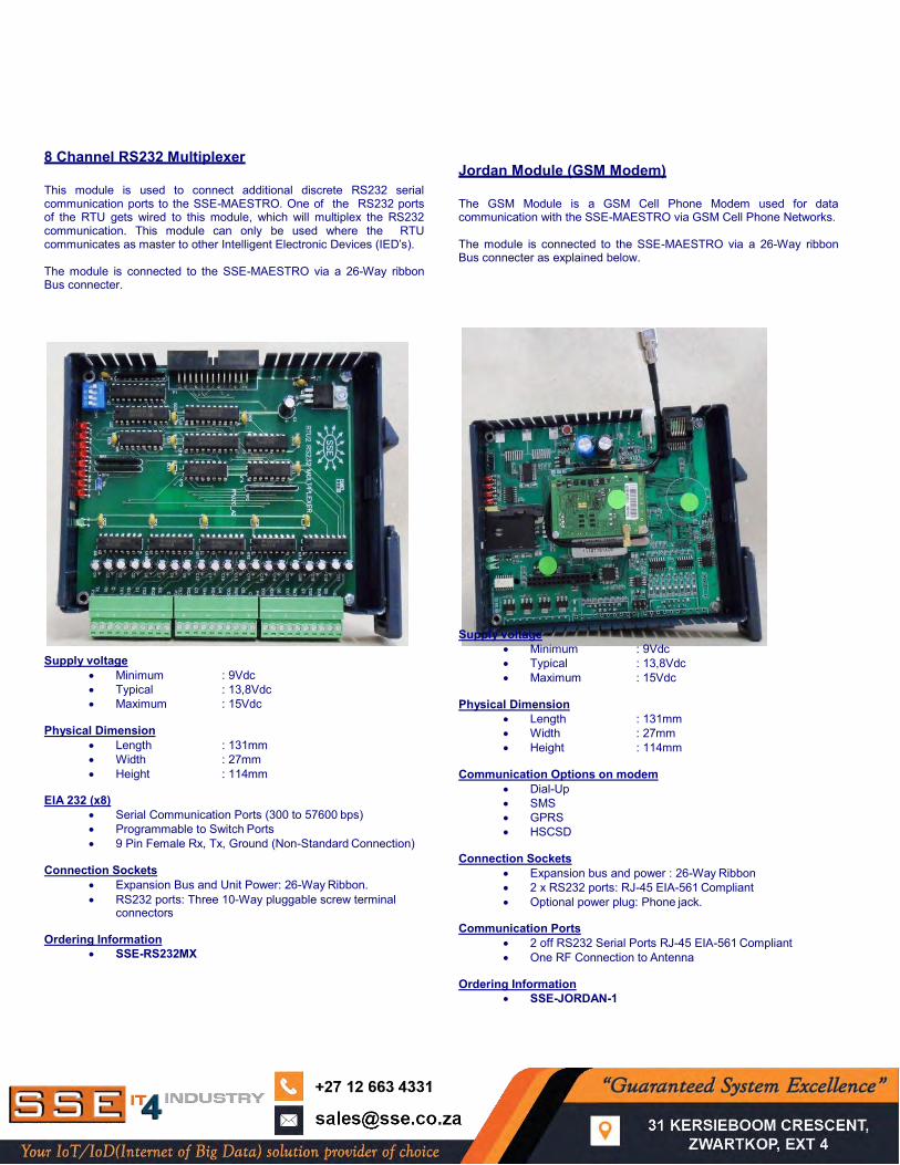
8 Channel RS232 Multiplexer This module is used to connect additional discrete RS232 serial communication ports to the SSE-MAESTRO. One of the RS232 ports of the RTU gets wired to this module, which will multiplex the RS232 communication. This module can only be used where the RTU communicates as master to other Intelligent Electronic Devices (IED’s). The module is connected to the SSE-MAESTRO via a 26-Way ribbon Bus connecter.
Jordan Module (GSM Modem) The GSM Module is a GSM Cell Phone Modem used for data communication with the SSE-MAESTRO via GSM Cell Phone Networks. The module is connected to the SSE-MAESTRO via a 26-Way ribbon Bus connecter as explained below.
Supply voltage
Minimum : 9Vdc Typical : 13,8Vdc Maximum : 15Vdc
Physical Dimension
Length : 131mm Width : 27mm Height : 114mm
EIA 232 (x8)
Serial Communication Ports (300 to 57600 bps) Programmable to Switch Ports 9 Pin Female Rx, Tx, Ground (Non-Standard Connection)
Connection Sockets
Expansion Bus and Unit Power: 26-Way Ribbon. RS232 ports: Three 10-Way pluggable screw terminal
connectors Ordering Information
SSE-RS232MX
Supply voltage
Minimum : 9Vdc Typical : 13,8Vdc Maximum : 15Vdc
Physical Dimension
Length : 131mm Width : 27mm Height : 114mm
Communication Options on modem
Dial-Up SMS GPRS HSCSD
Connection Sockets
Expansion bus and power : 26-Way Ribbon 2 x RS232 ports: RJ-45 EIA-561 Compliant Optional power plug: Phone jack.
Communication Ports
2 off RS232 Serial Ports RJ-45 EIA-561 Compliant One RF Connection to Antenna
Ordering Information
SSE-JORDAN-1
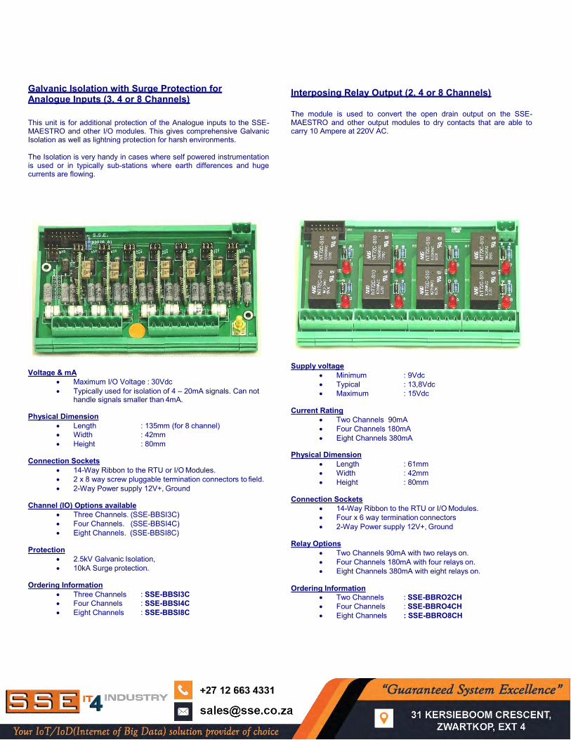
Galvanic Isolation with Surge Protection for Analogue Inputs (3, 4 or 8 Channels) This unit is for additional protection of the Analogue inputs to the SSE-MAESTRO and other I/O modules. This gives comprehensive Galvanic Isolation as well as lightning protection for harsh environments. The Isolation is very handy in cases where self powered instrumentation is used or in typically sub-stations where earth differences and huge currents are flowing.
Interposing Relay Output (2, 4 or 8 Channels) The module is used to convert the open drain output on the SSE- MAESTRO and other output modules to dry contacts that are able to carry 10 Ampere at 220V AC.
Voltage & mA
Maximum I/O Voltage : 30Vdc Typically used for isolation of 4 – 20mA signals. Can not
handle signals smaller than 4mA. Physical Dimension
Length : 135mm (for 8 channel) Width : 42mm Height : 80mm
Connection Sockets
14-Way Ribbon to the RTU or I/O Modules. 2 x 8 way screw pluggable termination connectors to field. 2-Way Power supply 12V+, Ground
Channel (IO) Options available
Three Channels. (SSE-BBSI3C) Four Channels. (SSE-BBSI4C) Eight Channels. (SSE-BBSI8C)
Protection
2.5kV Galvanic Isolation, 10kA Surge protection.
Ordering Information
Three Channels : SSE-BBSI3C Four Channels : SSE-BBSI4C Eight Channels : SSE-BBSI8C
Supply voltage
Minimum : 9Vdc Typical : 13,8Vdc Maximum : 15Vdc
Current Rating
Two Channels 90mA Four Channels 180mA Eight Channels 380mA
Physical Dimension
Length : 61mm Width : 42mm Height : 80mm
Connection Sockets
14-Way Ribbon to the RTU or I/O Modules. Four x 6 way termination connectors 2-Way Power supply 12V+, Ground
Relay Options
Two Channels 90mA with two relays on. Four Channels 180mA with four relays on. Eight Channels 380mA with eight relays on.
Ordering Information
Two Channels : SSE-BBRO2CH Four Channels : SSE-BBRO4CH Eight Channels : SSE-BBRO8CH
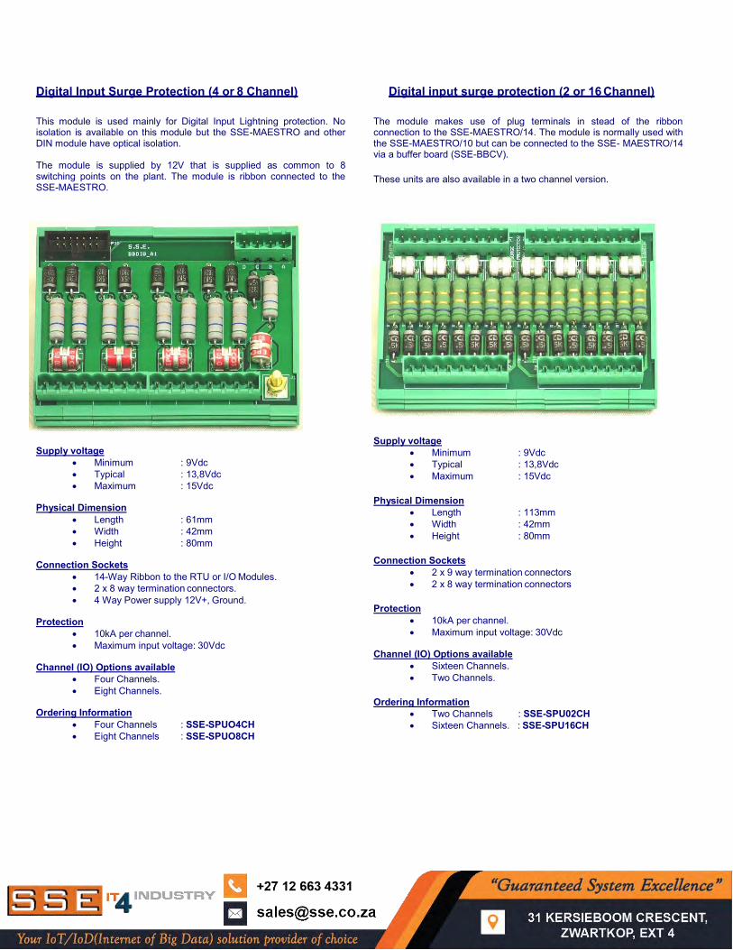
Digital Input Surge Protection (4 or 8 Channel) Digital input surge protection (2 or 16 Channel) This module is used mainly for Digital Input Lightning protection. No isolation is available on this module but the SSE-MAESTRO and other DIN module have optical isolation. The module is supplied by 12V that is supplied as common to 8 switching points on the plant. The module is ribbon connected to the SSE-MAESTRO.
The module makes use of plug terminals in stead of the ribbon connection to the SSE-MAESTRO/14. The module is normally used with the SSE-MAESTRO/10 but can be connected to the SSE- MAESTRO/14 via a buffer board (SSE-BBCV). These units are also available in a two channel version.
Supply voltage
Minimum : 9Vdc Typical : 13,8Vdc Maximum : 15Vdc
Physical Dimension
Length : 61mm Width : 42mm Height : 80mm
Connection Sockets
14-Way Ribbon to the RTU or I/O Modules. 2 x 8 way termination connectors. 4 Way Power supply 12V+, Ground.
Protection
10kA per channel. Maximum input voltage: 30Vdc
Channel (IO) Options available
Four Channels. Eight Channels.
Ordering Information
Four Channels : SSE-SPUO4CH Eight Channels : SSE-SPUO8CH
Supply voltage Minimum : 9Vdc Typical : 13,8Vdc Maximum : 15Vdc
Physical Dimension
Length : 113mm Width : 42mm Height : 80mm
Connection Sockets
2 x 9 way termination connectors 2 x 8 way termination connectors
Protection
10kA per channel. Maximum input voltage: 30Vdc
Channel (IO) Options available
Sixteen Channels. Two Channels.
Ordering Information
Two Channels : SSE-SPU02CH Sixteen Channels. : SSE-SPU16CH
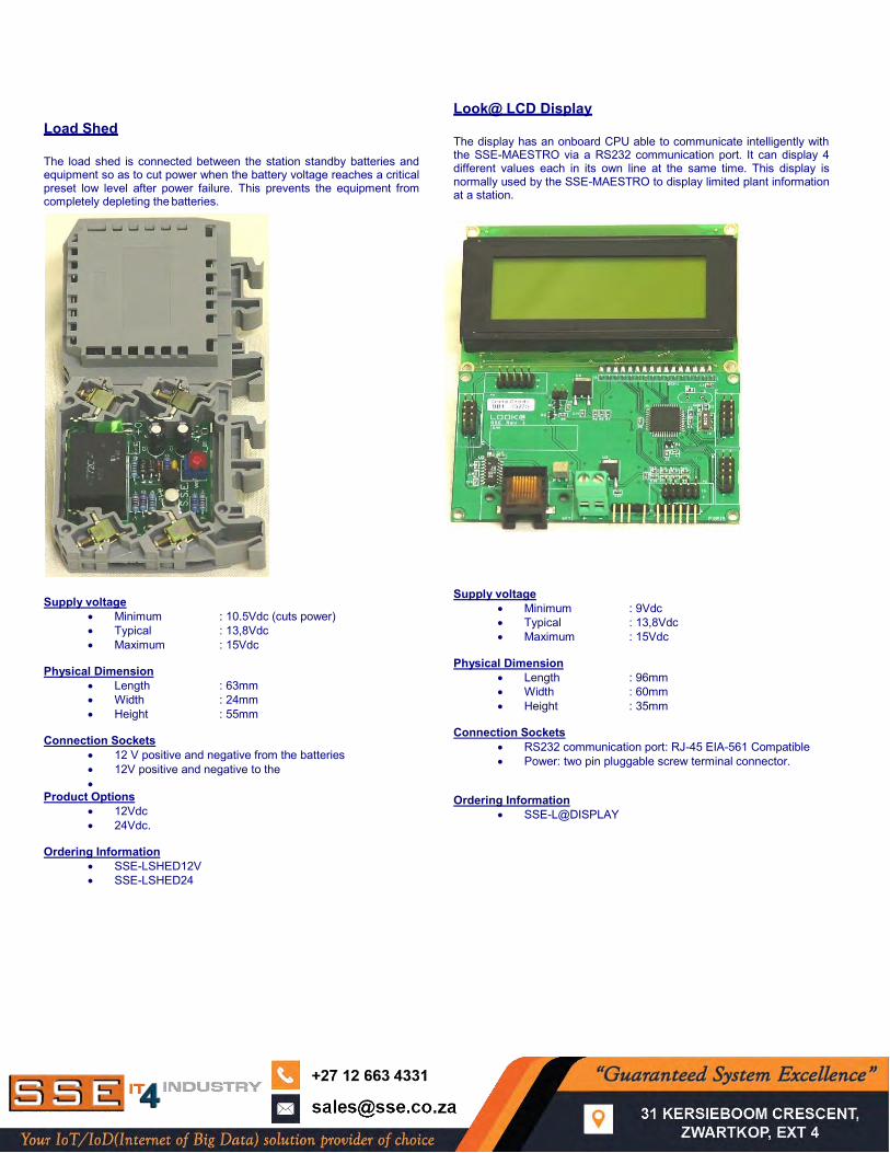
Load Shed The load shed is connected between the station standby batteries and equipment so as to cut power when the battery voltage reaches a critical preset low level after power failure. This prevents the equipment from completely depleting the batteries. Supply voltage
Minimum : 10.5Vdc (cuts power) Typical : 13,8Vdc Maximum : 15Vdc
Physical Dimension
Length : 63mm Width : 24mm Height : 55mm
Connection Sockets
12 V positive and negative from the batteries 12V positive and negative to the
Product Options 12Vdc 24Vdc.
Ordering Information
SSE-LSHED12V SSE-LSHED24
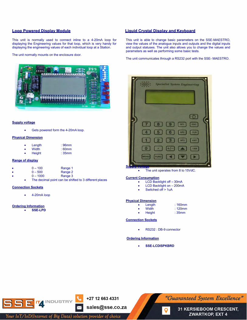
Look@ LCD Display The display has an onboard CPU able to communicate intelligently with the SSE-MAESTRO via a RS232 communication port. It can display 4 different values each in its own line at the same time. This display is normally used by the SSE-MAESTRO to display limited plant information at a station. Supply voltage
Minimum : 9Vdc Typical : 13,8Vdc Maximum : 15Vdc
Physical Dimension
Length : 96mm Width : 60mm Height : 35mm
Connection Sockets
RS232 communication port: RJ-45 EIA-561 Compatible Power: two pin pluggable screw terminal connector.
Ordering Information
SSE-L@DISPLAY
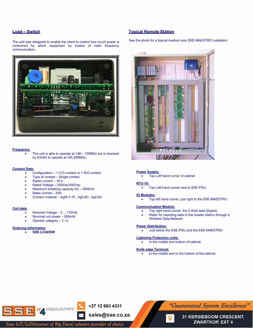
Loop Powered Display Module Liquid Crystal Display and Keyboard
This unit is normally used to connect inline to a 4-20mA loop for displaying the Engineering values for that loop, which is very handy for displaying the engineering values of each individual loop at a Station. The unit normally mounts on the enclosure door.
This unit is able to change basic parameters on the SSE-MAESTRO, view the values of the analogue inputs and outputs and the digital inputs and output statuses. The unit also allows you to change the values and parameters as well as performing some basic tests. The unit communicates through a RS232 port with the SSE- MAESTRO.
Supply voltage
Gets powered form the 4-20mA loop. Physical Dimension
Length : 96mm Width : 60mm Height : 35mm
Range of display 0 – 100 Range 1 0 – 500 Range 2 0 – 1000 Range 3
The decimal point can be shifted to 3 different places Connection Sockets
4-20mA loop Ordering Information
SSE-LPD
Supply Voltage
The unit operates from 8 to 15VdC. Current Consumption
LCD Backlight off – 30mA LCD Backlight on – 200mA Switched off > 1uA
Physical Dimension
Length : 160mm Width : 120mm Height : 35mm
Connection Sockets
RS232 : DB-9 connector
Ordering Information
SSE-LCDISPKBRD
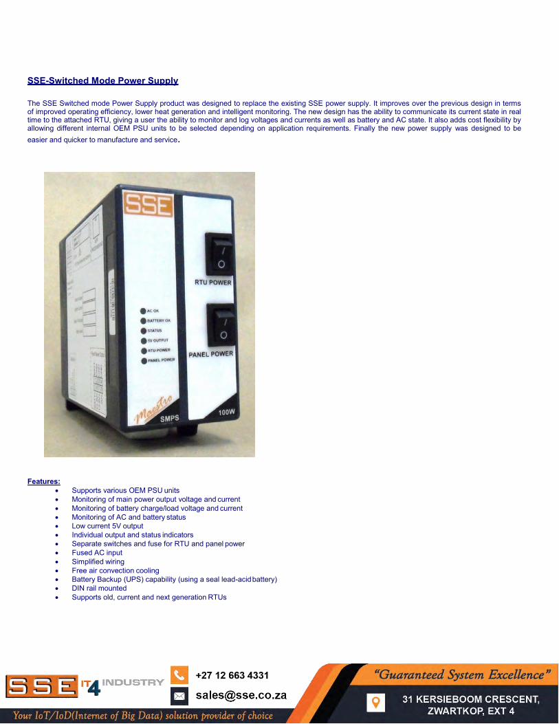
Load – Switch Typical Remote Station The unit was designed to enable the client to control how much power is consumed by which equipment by means of radio frequency communication.
See the photo for a typical medium size SSE-MAESTRO outstation.
Frequency:
The unit is able to operate at 146 – 155MHz but is licensed by ICASA to operate at 150.250MHz.
Contact Data:
Configuration – 1 C/O contact or 1 N/O contact Type of contact – Single contact Rated current – 16 A Rated Voltage – 250Vac/440Vac Maximum breaking capacity AC – 4000VA Make current – 25A Contact material – AgNi 0.15 , AgCdO , AgCdO
Coil data:
Nominal Voltage – 5….110Vdc Nominal coil power – 500mW Operate category – 2 / b
Ordering Information
SSE-LOADSW
Power Supply:
Top Left hand corner of cabinet RTU-10:
Top Left hand cornet next to SSE-PSU. IO Modules:
Top left hand corner, just right to the SSE-MAESTRO Communication Module:
Top right hand corner, the 2 Watt data (Digital) Radio for reporting data to the master station through a
Wireless Data Network. Power Distribution:
Just below the SSE-PSU and the SSE-MAESTRO Lightning Protection units:
In the middle and bottom of cabinet. Knife edge Terminal:
In the middle and to the bottom of the cabinet.
SSE-Switched Mode Power Supply The SSE Switched mode Power Supply product was designed to replace the existing SSE power supply. It improves over the previous design in terms of improved operating efficiency, lower heat generation and intelligent monitoring. The new design has the ability to communicate its current state in real time to the attached RTU, giving a user the ability to monitor and log voltages and currents as well as battery and AC state. It also adds cost flexibility by allowing different internal OEM PSU units to be selected depending on application requirements. Finally the new power supply was designed to be easier and quicker to manufacture and service.
Features: Supports various OEM PSU units Monitoring of main power output voltage and current Monitoring of battery charge/load voltage and current Monitoring of AC and battery status Low current 5V output Individual output and status indicators Separate switches and fuse for RTU and panel power Fused AC input Simplified wiring Free air convection cooling Battery Backup (UPS) capability (using a seal lead-acid battery) DIN rail mounted Supports old, current and next generation RTUs
Specifications: Base PCB designed to support 7A panel power output and 4A RTU power output Max measurable current: 10A (panel and RTU combined), 3.5A ( Battery charge) Max measurable voltage: 14V ( panel/ RTU and Battery) 5V output: 1A max Single 13.8V (12V) SLA battery only
Power supply specifications are determined by the OEM PSU module used. Here are specifications for two recommended models: Mean Well PSC-60: Input: 90~264VAC, 47~63Hz
Typical input current: 1.6A Output: 13.8V (tunable), max 4.3A (split between Dc output and battery charge) Battery charge: max 1.5A Rated power: 60W Short circuit, overload and over-voltage protection Battery low, battery polarity protection
Mean Well PSC-100: Input: 90~264VAC, 47~63Hz
Typical input current: 2A Output: 13.8V (tunable), max 7A (split between Dc output and battery charge) Battery charge: max 2.5A Rated power: 100W Short circuit, overload and over-voltage protection Battery low, battery polarity protection
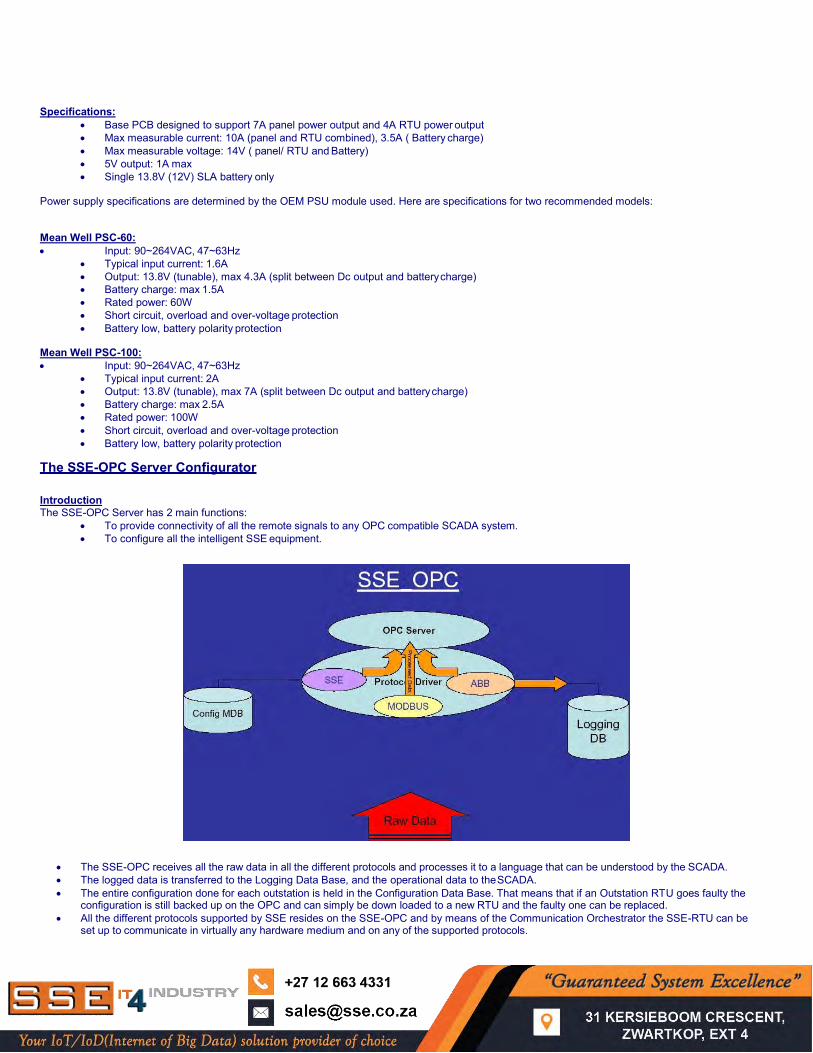
The SSE-OPC Server Configurator Introduction The SSE-OPC Server has 2 main functions:
To provide connectivity of all the remote signals to any OPC compatible SCADA system. To configure all the intelligent SSE equipment.
The SSE-OPC receives all the raw data in all the different protocols and processes it to a language that can be understood by the SCADA. The logged data is transferred to the Logging Data Base, and the operational data to the SCADA. The entire configuration done for each outstation is held in the Configuration Data Base. That means that if an Outstation RTU goes faulty the
configuration is still backed up on the OPC and can simply be down loaded to a new RTU and the faulty one can be replaced. All the different protocols supported by SSE resides on the SSE-OPC and by means of the Communication Orchestrator the SSE-RTU can be
set up to communicate in virtually any hardware medium and on any of the supported protocols.
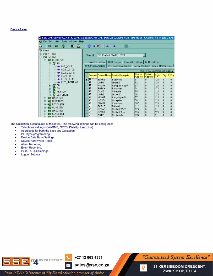
Device Level The Outstation is configured at this level. The following settings can be configured:
Telephone settings (Cell-SMS, GPRS, Dial-Up, Land Line). Addresses for both the base and Outstation. PLC type programming. Device Data Base Settings. Device Hard Ware Profile. Alarm Reporting. Event Reporting. Push To Talk Settings. Logger Settings.
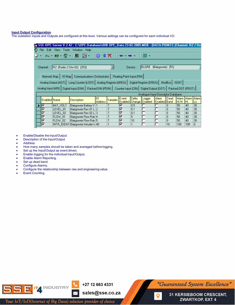
Input Output Configuration The outstation Inputs and Outputs are configured at this level. Various settings can be configured for each individual I/O:
Enable/Disable the Input/Output. Description of the Input/Output. Address. How many samples should be taken and averaged before logging. Set up the Input/Output as event driven. Enable logging for the individual Input/Output. Enable Alarm Reporting. Set up dead band. Configure Alarms. Configure the relationship between raw and engineering value. Event Counting.
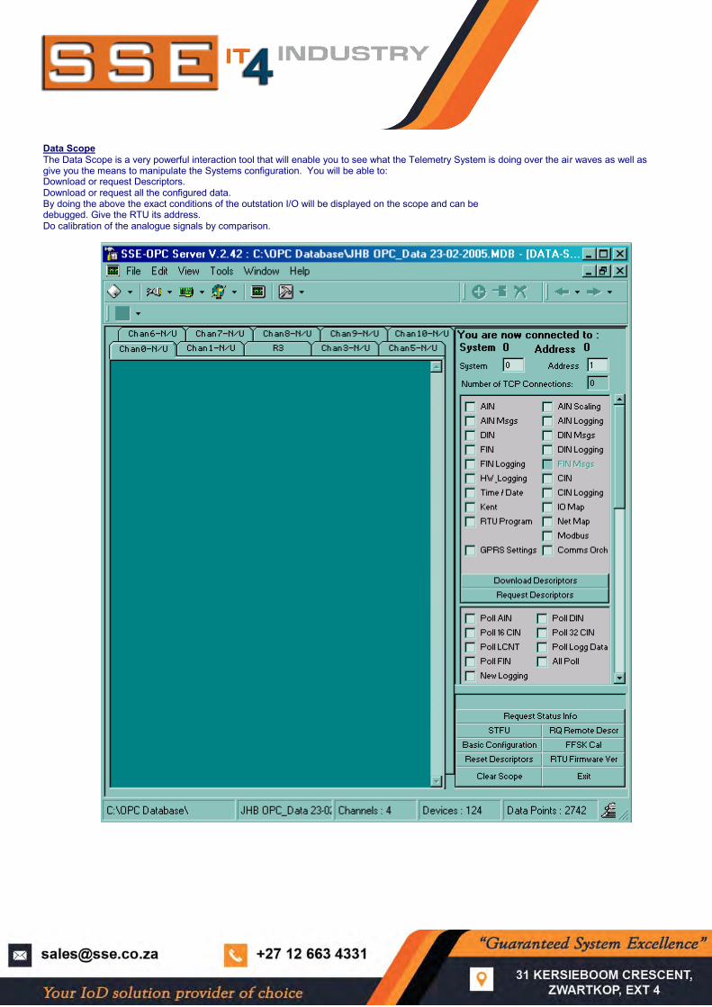
Data Scope The Data Scope is a very powerful interaction tool that will enable you to see what the Telemetry System is doing over the air waves as well as give you the means to manipulate the Systems configuration. You will be able to: Download or request Descriptors. Download or request all the configured data. By doing the above the exact conditions of the outstation I/O will be displayed on the scope and can be debugged. Give the RTU its address. Do calibration of the analogue signals by comparison.


