Embed Size (px)
Citation preview

������������� ��������������� ��� ���������������������������� ��� ������
���������� ������� ������
������ ����
������� ���

�� ��� ���!"�#�#$����������������%��"$� �
��������������� ���������������
������������������
�������������� ���������������������������� ����������������������
����������������� ����������������������������������� �����
��� ��� ���������������������������� ������������� ��������������
�� ������� ��������� �� ����������������������� ����������������
����� ���������������� ������������������������
���������� �������� �!"##�$$$�%���� �%�#&&'(� ���������������
��� ���)*+���,����������������� -���%��� �����������./��
���������������
0���������1�/���
��� ���)*+�2�����������-������������ ����������������
�����������������-���������-����������������� ������������

#�&'���(������� ���
)*+,-��+...)
���������� ������� ������
������ ����
������� ���

�/ ��� ���!"�#�#$����������������%��"$� �
������ ����
������� �� �����������
������� �� ���������� ������ ��������
������� �� ������ �� ���� � � ������� !������
������� "� ��������� ������� � ������ !���

#�&'���(������� /
#�$������ ����
������� %� ������� !������ #�$������
������� &� ����� �'� !����������
������� � (��� �'� !����������
������� �� )������� (�� ����� ����*�������
������� � ������ (�� ����� �$��������
������� +� ��$� (�� ����� ������ )��������
������� �� ��� ( ����� ������ *� ����
������� �� #�*���� ����������

/� ��� ���!"�#�#$����������������%��"$� �
,�#''
#������������(���������� ����0���$' ���'0�&������ �&0��1������ � ��2���'� ���&'���� �/� $�'�3
4�� ��������� �������(�����$� ��&�(�����$���������� ���!"�#��� ������������
#���/�� ������&'����5$�0���������&���/������(�0��� �$����� �� ��&� �����������6��"$� ��

#�&'���(������� �

�� ��� ���!"�#�#$����������������%��"$� �

#�&'���(������� ���
��������
������ ����������� �� �����������
"�����4�� 0�(���!���''���� ������������������������������������������������������������������������� �+7
�� 2�8�$�������� ���������������������������������������������������������������������������������� �+7
4�������8�$��#$����������� ��������������������������������������������������������������������� �+7
9������������2�9'� � ������������������������������������������������������������������������������ �+)
���� 2���#$����������� ������������������������������������������������������������������������� �+)
��� �����!���''���� �������������������������������������������������������������������������������������� �+*
!���''������!���(� ����� ������9� ������������������������������������������������������� �+*
:���������9�������� ����������������������������������������������������������������������������� �+*
���� 2������!���(� ����� ������������������������������������������������������������������� �+;
!����������!���(� ����� ���������������������������������������������������������������������� �+;
�� 2����8�$��!���''���� ������������������������������������������������������������������������ �+-
����� ������#$����������� ������������������������������������������������������������������� �+-
����� ������#$���������������������''���<�1 ����������������������������� �+-
����� ������#$��������������������$�� ������������������������������������� �+�
����� ����������$������������''���<�1 �������������������������������������� �+�
����� ����9������������ �������������� �������������������������������������� �+�
!���������'������ ������������������������������������������������������������������������������������� �+�
�$ 2�!���''���� �������������������������������������������������������������������������������������� �+�.
:�����'������ ���� �������������������������������������������������������������������������������� �+��
�$���� �#��'�#$����!���''���� ���������������������������������������������������������������� �+�7
�����'�9���������(���� ������������������������������������������������������������������������ �+�7
9���������������� ������� ������������������������������������������������������������������� �+�7
!���''������#$��� ���������������������������������������������������������������������������������� �+�)
��$����#$��� ������������������������������������������������������������������������������������� �+�)
��2��������� ���� ����������������������������������������������������������������������������� �+�*
!��� ���� �������:�����'�#��'�#$����=������ ���������������������������� �+�;
�'������������� �9�'���0 ��������������������������������������������������������������� �+�-
� ���>��������� �?1�������<�� 2� ��������������������������������������������� �+�,

�/ ��� ���!"�#�#$����������������%��"$� �
��$�������#��'� ������������������������������������������������������������������������������������� �+��
����$����0����4�@$������� �������������������������������������������������������������������� �+��
��(�����!���''���� �������������������������������������������������������������������������������������� �+7.
!���''�����������'�9������ ����������������������������������������������������������������� �+7.
������''�����������'�9������ ������������������������������������������������������������� �+7�
#���?#�9�9������ ���������������������������������������������������������������������������������� �+7�
��(��������+���9��&'��� ��������������������������������������������������������������������� �+7�
#� �� �'��$���� �������������������������������������������������������������������������������������������� �+77
<�(������''��� ��������������������������������������������������������������������������������������������� �+77
������0 ����������������������������������������������������������������������������������������������������� �+77
������� �� ���������� ������ ��������
���!��� $ ����������� ���!"�##$����������� ������������������������������������������������������������������������������������������������� <+7
���$��� ������������������������������������������������������������������������������������������������������� <+7
#��#$��������������������� ���������������������������������������������������������������� <+7
#��������� ������������� ���������������������������������������������������������������� <+)
#�������''���<�1 ��������������������������������������������������������������������������������������� <+*
�/��'�&'��:����� ���������������������������������������������������������������������������������������� <+;
#��� �����0�A� ����������������������������������������������������������������������������������������� <+;
�������������#$����������� ���������������������������������������������������������������������� <+-
� 5$�������"�&���� ����� '� ������������������������������������������������������������������ <+-
� 5$���������� �� ����#�$��<������� ������������������������������������������������ <+,
#��� 5$����'�� �� ����&������������''��1��B ��������������������������������������� <+,
#�� ���'�����C��1���� 5$����B ��������������������������������������������������������� <+�
#�� ���'�����>��1���� 5$����B ��������������������������������������������������������� <+�
4��'� �������������'� ���� '���$ �������������������������������������������������������� <+�
4�������<� 2'�������������� ������������������������������������������������������������ <+�.
� 5$�����#$����#��'������ ������������������������������������������������������������������������ <+��
�$&�� �����#$��������������������� �������������������������������������������������� <+�*
������������������''���<�1 ���������������������������������������������������������������������� <+�;
�������������9�����������?�/������� �������������������������������������������������� <+�,
�������(���������$�� ���������������������������������������������������������������������������� <+�,
�������(����'���0�=��2� ������������������������������������������������������������������������������ <+��
#�&'���(������� /
������� �� ������ �� ���� � � ������� !������
��������������'�9������ ������������������������������������������������������������������������� �+7
!(�8�$���� ���'���� ������������������������������������������������������������������������������������������� �+)
?1�'�������������'�9�������� ���� ����������������������������������������������������������� �+*
���$�<�� ������������������������������������������������������������������������������������������������������ �+*
��� �� �#��'�<�� ��������������������������������������������������������������������������������������� �+*
#$���������'�#��'&�� �������������������������������������������������������������������������������� �+-
:$�$��#��'�<�� ����������������������������������������������������������������������������������������� �+,
!��$��#��'�<�� �������������������������������������������������������������������������������������������� �+�
? ����� �� ������������������������������������������������������������������������������������������������� �+�
��$��<�� ��������������������������������������������������������������������������������������������������� �+�.
9�������4�� �$ ���������������������������������������������������������������������������������������� �+��
�� ����!�(��9���' ������������������������������������������������������������������������������������ �+��
D���(0���� �� ��������������������������������������������������������������������������������������������� �+�7
������� "� ��������� (�� ����� � ������ !���
��(�'0�4$��������#$����������� ����������������������������������������������������������������� =+7
��(�0�4$'�� ������������������������������������������������������������������������������������������������� =+7
�� 2����������������� ��������������������������������������������������������������������� =+7
4���/��� 5$�����A�0���� ����� �� ����������������������������������������������������� =+7
=�������� ����#��' ���������������������������������������������������������������������������������� =+7
������4���#��' ������������������������������������������������������������������������������������� =+7
��$��������$����#��' ������������������������������������������������������������������������ =+)
�� $��������2��� � �������������������������������������������������������������������������������� =+)
#$��������� '��<0���� �<�(���������� ���������������������������������������������� =+)
��������� '��4���������� ���������������������������������������������������������������� =+)
#������''���' ������� 2������ �=��/����=�/� �� ��������������������������������� =+)
��2����?������ 0����� ���������������������������������������������������������������������������� =+*
�������������?������ 0�����<$�� ���������������������������������������������� =+*
�����������������$���A�0&��� ���������������������������������������������������� =+*
��������������������� �������������������������������������������������������������������� =+;
4$������������'�����9������ ���������������������������������������������������������������������� =+-
:����#$������� ����������������������������������������������������������������������������������������� =+-
� 5$���D���(0������� ����������������������������������������������������������������������������� =+,

/� ��� ���!"�#�#$����������������%��"$� �
� 5$����=���'�0 ������������������������������������������������������������������������������������� =+,
� 5$����#��'�9������ ���������������������������������������������������������������������������� =+�
� 5$������ 2 ���������������������������������������������������������������������������������������� =+�.
=�(������#��' ������������������������������������������������������������������������������������������� =+��
��'� ���#��'�(��������&���0 �������������������������������������������������������������� =+��
��'� ���#��'�(���D���(� ���� ���������������������������������������������������������������� =+�7
D���(0�#$������� ��������������������������������������������������������������������������������������� =+�)
=�0�4$�������9������ ��������������������������������������������������������������������������� =+�*
��$�������2��� � ��������������������������������������������������������������������������������� =+�-
4$����9������ ���������������������������������������������������������������������������������������� =+�-

#�&'���(������� /��
#�$������ ����������� %� ������� !������ #�$������
�&�$��������'�9�������!���(� � ������������������������������������������������������������� ?+7
����������������<�� ������������������������������������������������������������������������������������ ?+7
��������� ������ �9���'� ����������������������������������������������������������������������������� ?+)
������9�������? ����� ��� ��������������������������������������������������������������������� ?+)
��������9���������� �� ������������������������������������������������������������������������� ?+*
���������� ����!�(����� �� ����������������������������������������������������������������� ?+*
��������D���(0���� �� ����������������������������������������������������������������������������� ?+;
��������E��������'�9���' ����������������������������������������������������������������������� ?+-
��������:�������9���' ��������������������������������������������������������������������������� ?+,
������#��'�<��� ������������������������������������������������������������������������������������������������ ?+�
����������� �� �#��'&�� ����������������������������������������������������������������������� ?+�
��������!��$��#��'&�� ���������������������������������������������������������������������������� ?+�
��������:$�$��#��'&�� ������������������������������������������������������������������������� ?+�.
��������#$���������'�#��'&�� �������������������������������������������������������������� ?+��
����������$��<�� ���������������������������������������������������������������������������������� ?+�7
�����������$�<�� ���������������������������������������������������������������������������������������� ?+�)
��'�����$ ���������������������������������������������������������������������������������������������������� ?+�)
���������� ����������������������������������������������������������������������������������������� ?+�*
:���������� ��������������������������������������������������������������������������������������� ?+�;
�'���������� ��������������������������������������������������������������������������������������� ?+�-
��/�������� ���������������������������������������������������������������������������������������� ?+�,
��/��������������� ������������������������������������������������������������������������������� ?+�,
9���������� ���������������������������������������������������������������������������������������� ?+��
9������$�������� ����������������������������������������������������������������������������� ?+��
:���������4� ���9������ �������������������������������������������������������������������� ?+7.
?1�������� ������������������������������������������������������������������������������������������ ?+7.
? �����$ ���������������������������������������������������������������������������������������������������� ?+7�
�� �������� ��������������������������������������������������������������������������������������� ?+7�
4� �������� ��������������������������������������������������������������������������������������� ?+77
�$������� ������������������������������������������������������������������������������������������ ?+77
���0������� ���������������������������������������������������������������������������������������� ?+77
/��� ��� ���!"�#�#$����������������%��"$� �
9���������� ����������������������������������������������������������������������������������������� ?+77
�'���������� ����������������������������������������������������������������������������������������� ?+77
=�'�������������� ������������������������������������������������������������������������������� ?+7)
��� ������� ������������������������������������������������������������������������������������������ ?+7)
4��'� �������� ������������������������������������������������������������������������������������� ?+7*
"�������������� ���������������������������������������������������������������������������������� ?+7;
4��$�&��������� ��������������������������������������������������������������������������������� ?+7;
�� 2������� ������������������������������������������������������������������������������������������ ?+7,
��'� ����������� �������������������������������������������������������������������������������� ?+7�
D�������$ ��������������������������������������������������������������������������������������������������� ?+7�
9������������� ������������������������������������������������������������������������������������ ?+7�
�� ����!�(�������� ���������������������������������������������������������������������������� ?+7�
E��������'������� ������������������������������������������������������������������������������� ?+7�
:�������9���'������� ������������������������������������������������������������������������ ?+).
D���(0���� ��������� �������������������������������������������������������������������������� ?+).
#��'&���������� ����������������������������������������������������������������������������������� ?+).
9����������$ �������������������������������������������������������������������������������������������� ?+)�
4$�F�����$�������� ��������������������������������������������������������������������������� ?+)�
D���(0������� ���������������������������������������������������������������������������������������� ?+))
?������4$����������� �������������������������������������������������������������������� ?+)*
9�$��������� ���������������������������������������������������������������������������������������� ?+)*
��� �' ������� ���������������������������������������������������������������������������������� ?+);
���������� ������������������������������������������������������������������������������������������ ?+);
#��'�����$ �������������������������������������������������������������������������������������������������� ?+)-
��$����&���0������� ��������������������������������������������������������������������������� ?+)-
���������� �? �����������'� ���������������������������������������������������������������� ?+)�
��'� �#��'������� �������������������������������������������������������������������������������� ?+)�
��'� �#��'������������ ���������������������������������������������������������������������� ?+*.
���(��$���#$���������� ���������������������������������������������������������������������� ?+*.
:������#$���������� ������������������������������������������������������������������������� ?+*�
��$�����$ ������������������������������������������������������������������������������������������������� ?+*7
���9������������� ������������������������������������������������������������������������������ ?+*)
>����9������������� ���������������������������������������������������������������������������� ?+*)
E���������������� ������������������������������������������������������������������������������ ?+**
4$��������������� ����������������������������������������������������������������������������� ?+*;
D���(0�������������� �������������������������������������������������������������������������� ?+*,
��F�� 2������������ ����������������������������������������������������������������������� ?+;�
"���9������������� ��������������������������������������������������������������������������� ?+;�

#�&'���(������� �1
���� ������0����������� ��������������������������������������������������������������� ?+;7
����������� ��������������������������������������������������������������������������������������� ?+;7
:((���������� ������������������������������������������������������������������������������������� ?+;*
���� '�������� ����������������������������������������������������������������������������������� ?+;;
<� 2'��������� ��������������������������������������������������������������������������������� ?+;-
��(������������� ������������������������������������������������������������������������������ ?+;-
9��(���� ��������� ����������������������������������������������������������������������������� ?+;,
��� ��9��(���� �� ������������������������������������������������������������������������������������� ?+-.
��� ������$ ��������������������������������������������������������������������������������������������� ?+-�
��� � �������� ����������������������������������������������������������������������������������� ?+-�
#�'�������� ������������������������������������������������������������������������������������������ ?+-�
��������! ���������� ������������������������������������������������������������������������� ?+-�
��� ������������� ���������������������������������������������������������������������������� ?+-�
��'�����$ ��������������������������������������������������������������������������������������������������� ?+-7
��'�������� ���������������������������������������������������������������������������������������� ?+-7
!� �1������� ��������������������������������������������������������������������������������������� ?+-7
��������'�������� ������������������������������������������������������������������������������ ?+-7
��/��������������� �������������������������������������������������������������������������� ?+-7
4������������������� ��������������������������������������������������������������������� ?+-)
#����(���=�0������� ������������������������������������������������������������������������ ?+-)
�&�$����#����������� ����������������������������������������������������������������������� ?+-)
��'� ���������� � ��������������������������������������������������������������������������������������� ?+-*
��'� ��������� �������9��+������$� ������������������������������������������������� ?+-*
9�������? ����� ���9��+$�����$ ����������������������������������������������������� ?+-*
9���������� ���9��+$�����$ �������������������������������������������������������������� ?+--
D���(0���� ���9��+$�����$ ������������������������������������������������������������������ ?+-,
E��������'�9���'�9��+$�����$ ������������������������������������������������������������ ?+-,
��'� ��������� ����������A�0� ����������������������������������������������������������� ?+-�
��'� ��������� �������#��'&��� ������������������������������������������������������������ ?+,.
9����������� �������������� ��������������������������������������������������������������������� ?+,�
9����������#��'&��� ���������������������������������������������������������������������������������� ?+,�
9������������� ������ �9���'� �������������������������������������������������������������� ?+,�
9����������9�������? ����� ��� ���������������������������������������������������������� ?+,7
��/���������������9������ ���������������������������������������������������������������� ?+,7
=� 2������ ��'��������� ������ �#��'&��� ������������������������������������������ ?+,)
=� 2����� �������������� ������������������������������������������������������������������� ?+,)
�'������� �������������� ������������������������������������������������������������������ ?+,)
1 ��� ���!"�#�#$����������������%��"$� �
������#����$��9������ ������������������������������������������������������������������������������ ?+,*
��' ����9���' ������������������������������������������������������������������������������������������� ?+,*
!���(� ����� �9���' ���������������������������������������������������������������������������������� ?+,;
"�����'�9���' ��������������������������������������������������������������������������������������������� ?+,;
�����'�9���' ���������������������������������������������������������������������������������������������� ?+,,
������� &� ����� �'� !����������
#��?'�������(�������9���9������ ������������������������������������������������������������� �+7
�����������(������ � ������������������������������������������������������������������������������������� �+)
!� ������'��� �������GH��� �I �������������������������������������������������������������� �+*
�&��'$���� ��������GJ��� �I �������������������������������������������������������������������� �+*
�2���GK��� �I��� �:�����'��2���GF��� �I ������������������������������������������������� �+*
#��$������2��� � ��GKIB ��������������������������������������������������������������������������� �+*
#��$����2��� � ��GKI��������������B ���������������������������������������������������� �+;
#��$�����:�����'��2��� � ��GFIB ������������������������������������������������������������ �+;
#��$�����:�����'��2��� � ��GFI��������������B ������������������������������ �+;
��� �4���G���� �I ������������������������������������������������������������������������������������� �+;
9��������0��� ���G"��� ��I ��������������������������������������������������������������������� �+-
#��!�����'�����"��$� ���������������������������������������������������������������������������� �+-
#�������"��$� ����������������������������������������������������������������������������������������� �+-
#������"��$� ������������������������������������������������������������������������������������������ �+,
#������� ��0 '��"��$� ���������������������������������������������������������������������������� �+,
#��9������������� ��"��$� ����������������������������������������������������������������� �+�
#��9�����9�������"��$� ������������������������������������������������������������������������� �+�
#������ ������0����"��$� ������������������������������������������������������������������� �+�
#��9�'���9�����������"��$� ����������������������������������������������������������������� �+�
#���������������$� �����"��$� ��������������������������������������������������������� �+�
C��1������� ������(�������9����G!��� �I ����������������������������������������������� �+�
!��$���'� �����$�&���G���� �I �������������������������������������������������������������� �+�
>��1������� ������(�������9����GA��� �I ��������������������������������������������� �+�.
���'���(��� �4���'$������������$����G���� �I ������������������������������������� �+�.
��� �''����$���� ���G���� ��I ����������������������������������������������������������������� �+�7
�77B�:$�$��$�����9�����������'� ������������������������������������������������������ �+�)
���B4�$���(�����$&���������"�� ������������������������������������������������������� �+�;
��.;B�:�������������� �������������������������������������������������������������������������� �+�;
<'� 2��$�&���G���� �I ����������������������������������������������������������������������������� �+�-

#�&'���(������� 1�
�$&��������<'� 2��$�&���G:��� �I ������������������������������������������������������� �+�,
�$&��������4�(���� ���$�&���G9��� �I ������������������������������������������������ �+�,
9� 2�=���GL��� �I ���������������������������������������������������������������������������������� �+�,
4� �$���(��� ��=��''���������� �����G4��� �I ��������������������������������������� �+��
���� '������ �G���� �I ����������������������������������������������������������������������������� �+��
#��'���'� ����G#��� �I ������������������������������������������������������������������������������ �+��
C��1������� �����GC�������� �I ���������������������������������������������������������������� �+��
>��1������� �����G>�������� �I ��������������������������������������������������������������� �+��
��������� �� ������������������������������������������������������������������������������������������ �+��
"�����'�9������������$�������� ��������������������������������������������������������������� �+7.
������� � (��� �'� !����������
�������!�����'�����9���������� ���������������������������������������������������������������� "+7
��� $'���!�����'�����9���������� �������������������������������������������������������������� "+)
4��� �#��/�����9���������� ������������������������������������������������������������������������� "+;
����� ��0 '��9���������� ���������������������������������������������������������������������������� "+-
������",7��� �",) ������������������������������������������������������������������������������������� "+,
4�$������$� �������������������������������������������������������������������������������������������� "+�
������",, ���������������������������������������������������������������������������������������������������� "+�
� ����#����� �������������������������������������������������������������������������������������������� "+�
<����� ������������������������������������������������������������������������������������������������������� "+�.
������",� �������������������������������������������������������������������������������������������������� "+��
������"�. �������������������������������������������������������������������������������������������������� "+��
������"����� �"�) ����������������������������������������������������������������������������������� "+�7
��'����!�����'�����9���������� �������������������������������������������������������������� "+�)
<�M�����$�/������ ����� � ���������������������������������������������������������������������� "+�*
"������ �''0�=�(��������<�M�����$�/� ���������������������������������������������������� "+�*
9����������������'����!�����'���� ������������������������������������������������� "+�-
������������ �������'����!�����'���� ������������������������������������������������ "+�,
�$&��������9���������� ��������������������������������������������������������������������������� "+��
������'������$&������� ������������������������������������������������������������������������ "+��
������� �� )������� (�� ����� ����*�������
��������������������� � ������������������������������������������������������������������������� �+7

1�� ��� ���!"�#�#$����������������%��"$� �
������"7� ���������������������������������������������������������������������������������������������������� �+)
������"7�����������9������ ������������������������������������������������������������������� �+)
������"7��<�(������������(������ ������������������������������������������������������ �+)
������"7� ���������������������������������������������������������������������������������������������������� �+)
������9�'���9���������� ������������������������������������������������������������������������������ �+*
������� �'������ �4�������� �� ������������������������������������������������������������������ �+;
� �'��� ���������������������������������������������������������������������������������������������������������� �+;
4�������� �� ��������������������������������������������������������������������������������������������� �+;
�$'��'��#��'�9���������� ���������������������������������������������������������������������������� �+-
�������$'��'��#��'��� �� �������������������������������������������������������������������������� �+-
<� 2��� ���$��� �������������������������������������������������������������������������������������� �+,
?��&'��������4�(���� ��#��' ����������������������������������������������������������������� �+,
?��&'������#��'�:((��� ����������������������������������������������������������������������������� �+�
#������8�$���$'��'��#��'�9������ ���������������������������������������������������������� �+�
4$������������'���$'��'��#��'����9������ ����������������������������������������������� �+�
:����#$������ ����������������������������������������������������������������������������������������� �+�
=�(������#��'� ����������������������������������������������������������������������������������������� �+�.
� 5$���D���(0������� ���������������������������������������������������������������������������� �+��
D���(0�$������ ���������������������������������������������������������������������������������������� �+�7
�����4�(���� ��#��' ����������������������������������������������������������������������������� �+�)
��� �����������(���#$������ ��������������������������������������������������������������� �+�)
��$����#��'���� ����2��� � �������������������������������������������������������������� �+�)
?��&'�����#��'�:((����(���#��'�7��� �#��'�) ������������������������������������ �+�*
!����'�M�������2��� ��:����� ����������������������������������������������������������������� �+�;
=�0�4$�������9������ ��������������������������������������������������������������������������� �+�;
��$�������2��� � ��������������������������������������������������������������������������������� �+�-
4$����9������ ���������������������������������������������������������������������������������������� �+�,
��������:�����'��$���� �#��'�#$��� ����������������������������������������������� �+��
#����2����$���������������� �(� ���'��� ����������������������������������������� �+��
#��������$�������������� ����������������������������������������������������������������� �+��
#��� ��� �������������������������������������������������������������������������������������������������������� �+��
9�����������(���#��� ��� ��������������������������������������������������������������������� �+7.
#��'��� �������������������������������������������������������������������������������������������������������� �+7�
�$������(+��� �#��� � ������������������������������������������������������������������������ �+7�
!�����'�#��� ��� ������������������������������������������������������������������������������������� �+77
<�(����8�$������� �������������������������������������������������������������������������������������� �+77

#�&'���(������� 1���
���������(���#��� ��� �������������������������������������������������������������������������� �+77
������� � ������ (�� ����� �$��������
�� ����� �������� ������0���� ����������������������������������������������������������������� !+7
�������� ������4�'�������#$����������� ������������������������������������������ !+7
�� �������� ����� ������������������������������������������������������������������������������������ !+)
���2����� ����� ��������������������������������������������������������������������������������������� !+)
�$'��'������ �������0���� ���������������������������������������������������������������������� !+*
��� �4����� �=����(��$ ����������������������������������������������������������������������������� !+;
���� '������ � �������������������������������������������������������������������������������������������������� !+-
��� �4����� ����� '������ ���'� ��� ���������������������������������������������������������� !+-
�$&�� ������ ����'��� ����������������������������������������������������������������������������������� !+-
#��'�#0��� ��������������������������������������������������������������������������������������������������������� !+,
�� ��#��'� ������������������������������������������������������������������������������������������������������ !+,
9������#��'� ������������������������������������������������������������������������������������������������ !+�
<������#��'� �������������������������������������������������������������������������������������������������� !+�
9��(�'����#��'� ���������������������������������������������������������������������������������������������� !+�
#��� ����#��'� �������������������������������������������������������������������������������������������� !+�
��$��������$����#��' ������������������������������������������������������������������������������ !+�.
������������#��'� �������������������������������������������������������������������������������������� !+��
������� +� ��$� ������� ������ )��������
��(�0�4$'�� ������������������������������������������������������������������������������������������������������� E+7
�������(�0�"'����� ������������������������������������������������������������������������������������ E+7
A����8�$���� ����#��' ���������������������������������������������������������������������������� E+7
"��$� ��''�#��'� ������������������������������������������������������������������������������������������ E+7
A��������(�0����' ����9'� � ����������������������������������������������������������������� E+7
4���/��� 5$�����A�0���� ����� �� ������������������������������������������������������ E+7
A���������2�������'��� �������������������������������������������������������������������������� E+)
�/�� ���=������$��?�/������� ��������������������������������������������������������������� E+)
A����������� �D����������0�(������?@$����� ��������������������������������� E+)
9��/������$���M� �������(����:����������#$����������� ����������� E+)
=�������� ����#��' ������������������������������������������������������������������������������������ E+)
������4���#��' ��������������������������������������������������������������������������������������� E+)

1�/ ��� ���!"�#�#$����������������%��"$� �
=���������������'0 ������������������������������������������������������������������������������������ E+*
�� $��������2��� � ���������������������������������������������������������������������������������� E+*
=�����:/����� ���������������������������������������������������������������������������������������� E+*
���������$����#��'��!��#������ ���� ��������������������������������������������������� E+*
=�� ���� �#��'��<�(�������/� ��� �������������������������������������������������������������� E+*
�/�� �� � ���'������� ���������������������������������������������������������������������������� E+*
����4� ����� � �� �������� ������������������������������������������������������������������� E+;
#������''���' ������� 2������ �=��/����=�/� �� ����������������������������������� E+;
A�������'������0�(����?'� �� �'���������� ��������������������������������������� E+;
=�����:���������� ������ �����!�('$�� ���(��' ��'����=�$�� �� E+;
�/�� �=���� �������'��4$���������� ��� ���������������������������������������� E+;
��(�0��� 2'�� ������������������������������������������������������������������������������������������������� E+-
����� �����$�� � �������������������������������������������������������������������������������������������� E+,
?������ 0����� ����������������������������������������������������������������������������������������������� E+�
������� �� ��� ( ����� ������ *� ����
"��� ���&0�"��$� ��������������������������������������������������������������������������������������������� A+7
���� ���&0�"��$� �������������������������������������������������������������������������������������������� A+*
������� �� #�*���� ����������
����4�&�� �!������������2� ���������������������������������������������������������������������� �+7
#��!���(� ������� �� ����������������������������������������������������������������������������������� �+*
9��������������(�����4�&�� ������ �� ����������������������������������������������� �+;
�$'��'��4�&����� �������������������������������������������������������������������������������������� �+-
#������� �� ����������������������������������������������������������������������������������������������� �+,
������'���(����F4�&������$�� ���� ����������������������������������������������������� �+�
������'��4�&�� �!������������9������ ��������������������������������������������������� �+��
���-
!� �1 ����������������������������������������������������������������������������������������������������������������� 7+�
��� ���!"�#�#$������������� �����0���� ����������������������������������������������������� �
� �������� ����������������������������������������������������������������������������������������������������� �
�$���� �#��'�#$��� ��������������������������������������������������������������������������������� �

#�&'���(������� 1/
#��'�#$����#��'����9� 2��� ���������������������������������������������������������������������� �
#$��������������1$���A� �������������������������������������������������������������������������� �
#��'�9������ �#��'� ����������������������������������������������������������������������������������� �
���&� ��!������� ���������������������������������������������������������������������������������������� �
���&� ��!� �1�&'��#��'���' ������!���� ����������������������������������������������� �
�'$���$��#$�������� 2�9� 2��� ������������������������������������������������������������� �
<�����#$�������� 2�9� 2��� ��������������������������������������������������������������������� �
<�����#$�������� 2�9� 2��� ��������������������������������������������������������������������� �
�� ���&'����1�#$�������� 2�9� 2��� ��������������������������������������������������� �
9���&'���������������� ����������������������������������������������������������������������������� �
�����$ 2�4�&�� �!���(� � ������������������������������������������������������������������������� �
9��$��� ����' �:����� �������������������������������������������������������������������������� �.
�$��� $'$�F��(���� ������������������������������������������������������������������������������������ �.
������� ����������������������������������������������������������������������������������������������������� �.
��������9��5� ����������������������������������������������������������������������������������������� �.
!��� $ �������������2&��2�G�$ ���? ����I ������������������������������������ �.
!��� $ �������������2&��2�G#�� ���? ����I ������������������������������������ �.
#�2'��2��$��� $'$�������� ���������������������������������������������������������������������������� �.
����$����� � ����$(� $�����(���#$����� �������������������������������������������� �.
����#� ��'��0�(���#$����� ���������������������������������������������������������������������� �.
������(���� ������������������������������������������������������������������������������������������������ �.
��� ������#$����� ����������������������������������������������������������������������������������� �.
��� ������#$������(������ ��� �������������������������������������������������������������� �.

1/� ��� ���!"�#�#$����������������%��"$� �

!���''���� �+�
������ #���� $�� �����������
�������� �����������
�������� ������ #�.���������
��$����� �����������
��� ����� �������
�����������
����/� ����� ������� �

����6��"$� �B��� ������+7
������ #���� $�� �����������Before connecting and running your new Turning Center, you should:
01 Check your shipment to make sure you received everything you need.
2. Register your Turning Center so you are covered by your warranty.
21 Prepare a work space for the Turning Center and controller.
31 Unpack and set up the Turning Center.
41 Install the interface card in the computer.
Once these procedures are complete, connect the spectraLIGHT TurningCenter and Controller Box to your personal computer, and install the ControlProgram.
� ��5 6��� � ������
The first thing you must do after receiving your Turning Center is inspectthe packaging for any visible signs of damage. If there is damage to the outsidepackaging, contact the shipping company as well as Light Machines Corp.After checking the packaging, locate the packing slip. This slip lists all of theitems you should have received with your Turning Center. Check all of theitems on the list. If any item is missing, contact Light Machines' CustomerService Department (800/221/2763).
The Turning Center components include:
� spectraLIGHT Turning Center
� Controller Box
� Interface Card
� Control Program Software
� Documentation
� Accessory Kit
#������� 6��� ������� ������
You’ll find a registration card in the small box with the documentation andsoftware disks. Clearly print all the requested information and return thiscard to Light Machines Corporation.

!���''���� �+)
(!)#��'�7
<���$�����2�����''��(����������' ����������� ������ ���!"�##$��������������������� ����$' ��0� ������������ ���&����$��� ����(� ��0������ 2�����1� '0����0�������� ��/� �
������ ������������������������������������������ ������������������������ ������������������������������������� ������
����)'
#����� ���!"�#�#$����������������������1����'0��.���$� ��<��/��0� ���($'�����'�(������
!������ � � ,��5 !����
Make sure you have all the items on hand necessary to perform the installation.To install the spectraLIGHT Turning Center, you must have:
� A sturdy table on which you’ll place the Turning Center and your com-puter. Placing the table against a wall provides more stability. Make surethe wall has a 120VAC, 15 Amp polarized outlet, or a 220VAC, 8 Ampoutlet for international users.
� A personal computer running Windows 95 or Windows NT version3.51 (or greater). See page A-19 for a complete list of the necessarycomputer equipment.
� Your PC Owner’s Manual or equivalent documentation.
�����5 � � ������� ������
For each standard Turning Center you order, you should receive two large car-tons. One carton contains the Turning Center. The other carton contains theController Box, the Interface Card, the Control Program software, the docu-mentation, and the Accessory Kit.
01 Unpack the Controller Box container and use the packing slips to con-firm that you have received all the items listed.
81 Open the Turning Center container and remove the foam inserts.
21 Lift the Turning Center out of the box and onto the table.
31 Inspect the Turning Center chassis for signs of visual damage such as abroken shield, a dent in the chassis, or damaged cables. If any damage isnoted, or if you find any discrepancies between the packing slips and theitems received, call Light Machines’ Customer Service Department (800/221/2763).
41 Remove the protective paper from the safety shield.
'����
����� ����� ���$����(���/�'����$�������� ����� �'����(�'���(��0�$�� ���$����0����

����6��"$� �B��� ������+*
�������� �����������The following paragraphs review the procedures for installing the hardwarecomponents of the spectraLIGHT Turning Center. You should already haveyour personal computer set up in accordance with the directions in the com-puter owner’s manual.
The first thing you have to do is install the spectraLIGHT Interface Card inyour personal computer.
,�#''
=����� ���� �����������#$����������������� ���$��$��'�����$ � ��� ����������(�''��������� � $����
��������� � � ����$��� ���� �� � � !�
The Interface Card can be installed in any full-size slot designated for expansioncard use. Refer to your computer owner’s manual to determine particular expan-sion card restrictions.
,�#''
=������'$���������� �� �(������9�� ����������������$'��$��'��''�����''�������� � $�����/��&���� ���'�� �� ��� ������ �/������&���� '��� �
)������ � � !� � �����
To install the Interface Card, you must remove the cover of the personalcomputer. Refer to the installation instructions supplied with your computerfor details on removing the cover. Generally, the cover is secured by fourscrews through the rear panel; however, some personal computers may havepush latches, or screws in different locations.
'����
#��!���(� ����� ����(� ��0������������������ ����������������/� (���<��0� � �� �������9��!F:�� ��������N.)�.��1�N���!(��������1������� �� �����'��� 0�����''� ��������������� ������ ��� ������� ����%#� �� �'��$�����=��������(������''����� ������� ��

!���''���� �+;
,�#''
=�� ���� �������(����0�$���������'� ���$���&�(�������������� ������ �/��3
#$����((������������ ��� �����/���������� �� ������$��������'� �� �'�������'����������������� �/����������/� �
Set the cover aside and locate an open slot in which to install the InterfaceCard. Remove the blank slot cover (if any). Removing the slot cover requires re-moving a screw at the top rail of the rear panel. You may choose to discard thecover, but save the screw for installing the Interface Card.
�����5��� � � ����$��� ����
The card is shipped inside an antistatic envelope. Be careful not to create anystatic discharge when removing the card from the envelope; touch agrounded surface such as the PC enclosure first. Slide the card out of theenvelope and inspect it for signs of damage, such as bent or broken compo-nents or a warped circuit card. If damage is noted, contact Light MachinesCorporation immediately.
�������� � � ����$��� ����
The following procedures describe how to insert and secure the Interface Cardin the computer.
01 Grasp the Interface Card at the front and back.
81 Position the card above the bus connector at the chosen slot. The inter-face connector on the end of the card should face the rear panel of thecomputer chassis.
21 Slide the card into the bus connector. The interface connectors on the cardshould protrude from the rear panel of the computer. Carefully wigglethe Interface Card back and forth to assure its tightness in the bus con-nector. Components on the Interface Card should not touch adjacentcards or other components.
31 Secure the Interface Card to the top rail of the rear panel with the screwyou saved when removing the blank slot cover.
41 Pay particular attention to the location of the slot in which you insertedthe Interface Card. Do not get the Interface Card mixed up with the par-allel port or serial port which use the same types of connectors.
'����
!���0�&��&���(� ��'���'�&�'�� ���� ���������&� 2�����'��(���9�(������0�� ���(� �����

����6��"$� �B��� ������+-
� ��5��� 6��� �����������
After installing the Interface Card, replace the computer chassis cover. Connectthe computer power cord and turn the computer on. The computer shouldperform an internal check, then start the Windows operating system.
If the PC fails to start-up, turn off the power, open the chassis and checkyour installation to be sure that the Interface Card is located in an appropriateslot and is properly seated.
When the C:> prompt appears, turn off the power and install the other hard-ware components.
���������� � � ������� ������
The following paragraphs review the procedures for connecting your computerwith the Turning Center and Controller Box. The Interconnection Diagram onthe following page has been provided as a visual aid for the recommended con-nections.
,�#''
=����� ���� �����������#$��������������������''���<�1����� ���$���$��'�����$ � ��� ����������(�''�������� � $����
��/��� ���� ���� �� ���� ��� �&'����������������3�#����''� �$��� ���������������''���<�1� ��/�� ���������
:��������#$����������������''� �&'���(���'0��� $�� �
���������� � � ������� ������ �� � � ���������� ��-
The interface cables and power cords are long enough to allow the ControllerBox to be located up to five feet away from the Turning Center. Make sure theTurning Center is placed on a stable, flat surface and leveled properly.
The Controller Box can be placed beside the Turning Center, or mounted on ashelf beneath the Turning Center. Make sure the power switch on the front ofthe Controller Box is readily accessible. Keep in mind that you may need tocheck the fuses on the rear panel of the Controller Box. Locate the ControllerBox in an area where it will not be exposed to metal chips or cutting fluid.

!���''���� �+,
��������
�� ������� ������ ������ �������
������� "������
G���
��/���
��(��0���I
15-P
in M
achi
ne /C
ontr
olle
r C
able
Spi
ndle
Pow
er C
ord
25 P
in In
terf
ace/
Con
trol
ler
Cab
le
9 P
in In
terf
ace/
Spi
ndle
Cab
le
120V
, 60H
zA
C O
utle
t
Com
pute
r
Con
trol
ler
Box
(rea
r pa
nel)
Mag
nifie
d vi
ewof
com
pute
rco
nnec
tions
MO
TO
R D
RIV
ES
M
AIN
3A
1
2A
AC
C 2
AC
C 1
S
PIN
DLE
3A
3
A
5
A
CO
MP
UT
ER
TT
L I/O
A &
B A
XE
S
C
AX
IS
120V
AC
, 60H
z, 1
5A
120V
AC
, 5A
120V
AC
, 3A
SP
IND
LE
AC
C1
AC
C2
120V
AC
, 3A
fuse fuse
fuse
fuse fuse
fuse
fuse fuse
fuse
fuse fuse
fuse
fuse fuse
fuse
ON
LY O
PE
RA
TE
WIT
H A
LL C
AB
LIN
GS
EC
UR
ELY
FA
ST
EN
ED
BE
TW
EE
N T
HE
MA
CH
INE
TO
OL
AN
D T
HIS
BO
X
WA
RN
ING
!D
O N
OT
OP
EN
NO
US
ER
SE
RV
ICE
AB
LEP
AR
TS
INS
IDE
LMC
LMC
Not
dra
wn
to s
cale
LMC
LMC
Con
trol
ler
Pow
er C
ord
Com
pute
r P
ower
Cor
d
spec
traL
igh
t T
urn
ing
Cen
ter
(rea
r vi
ew)
or 2
20V
, 50-
60 H
z fo
rIn
tern
atio
nal U
sers

����6��"$� �B��� ������+�
01 Route the Spindle Power Cable from the Turning Center to the Con-troller Box as shown in the Interconnection diagram.
81 Insert the AC power plug from the Turning Center's Spindle PowerCable into the three-prong receptacle marked SPINDLE on the rearpanel of the Controller Box.
21 Insert the 15-Pin plug from the Turning Center into the 15-Pinreceptacle marked A & B AXES on the rear panel of the Controller Box.
31 Make sure the 15-Pin Connector is secured with screw locks.
���������� � � ������� ������ �� � � ��������
The Interface Card/spindle cable is attached to the rear panel of the TurningCenter and is terminated with a 9-Pin plug. Insert this plug into the 9-Pin re-ceptacle on the computer Interface Card you installed earlier.
���������� � � �������� �� � � ���������� ��-
01 Route the 25-Pin Interface/Controller Cable between the Computer andthe Controller Box.
81 Connect the end of the cable marked COMPUTER to the 25-Pin connectorprotruding from the LMC Interface Card in the rear of the computer. Asmentioned before, make sure you are plugging the cable into the InterfaceCard connector, not the parallel port.
21 Connect the other end of the cable to the 25-Pin connector markedCOMPUTER on the rear panel of the Controller Box.
31 Make sure all connectors are secured.
����)'
A���������������� �� ���������(����������(� � �&'����#�������� �� �� �� ��������������&'�������������'�'��������������(� � �&'���
MOTOR DRIVES MAIN
3A 12A
ACC 2 ACC 1 SPINDLE
3A 3A 5A
COMPUTER TTL I/O A & B AXES C AXIS
ONLY OPERATEWITH ALL CABLING
SECURELY FASTENEDBETWEEN THE MACHINE
TOOL AND THIS BOX
WARNING!DO NOT OPEN
NO USER SERVICEABLEPARTS INSIDE
120VAC, 60Hz, 15A
120VAC, 5A
120VAC, 3A
SPINDLE
ACC1
ACC2
120VAC, 3A
fuse fusefuse fuse fusefuse
fuse fusefusefuse fusefuse fuse fusefuse
#��'� ������(���N����$��N� ���� ������������''���<�1�
���������� � � ������� ������ �� � � ���������� ��-9 ����1

!���''���� �+�
���������� !���� �� � � �������� ����������
The Controller Box must be plugged into a grounded 120VAC, 60Hz, 15Apolarized wall outlet (220VAC, 50-60 Hz, 8A for International Users), asshown in the Interconnection Diagram. This outlet must be capable of sup-plying up to 12 Amps (6 Amps) of power to the Controller Box.
Locate the loose power cord that came with the Turning Center; this is thepower cord for the Controller Box. Insert the receptacle end of this cord intothe 120VAC (220VAC) three-prong connector on the back of the ControllerBox. Insert the plug end of this cord into a grounded, three-hole, 120VAC,60Hz (220VAC, 50-60Hz) wall outlet.
������������ �����
If you are an international user and you need to change the plug on the endof the electrical cord to accommodate 220VAC, 50 Hz service, the wiring iscolor coded as follows:
Line: white
Neutral: black
Ground: green with a yellow stripe
MOTOR DRIVES MAIN
3A 12A
ACC 2 ACC 1 SPINDLE
3A 3A 5A
COMPUTER TTL I/O A & B AXES C AXIS
ONLY OPERATEWITH ALL CABLING
SECURELY FASTENEDBETWEEN THE MACHINE
TOOL AND THIS BOX
WARNING!DO NOT OPEN
NO USER SERVICEABLEPARTS INSIDE
120VAC, 60Hz, 15A
120VAC, 5A
120VAC, 3A
SPINDLE
ACC1
ACC2
120VAC, 3A
fuse fusefuse fuse fusefuse
fuse fusefusefuse fusefuse fuse fusefuse
1.5A 1.5A 2.5A
1.5A 6A
220-240VAC, 2.5A 220-240VAC, 1.5A
220-240VAC,1.5A 220-240VAC, 50Hz, 6A
4����/�����(���!���������'�����''���<�1
#����'$�������������������� �� � ���$��0����� ��� '���!���������'�$�������� ����$� ���� ���$��������� �&'��(������� �$��0�

����6��"$� �B��� ������+�.
� ��5 �����������A three jaw chuck is a standard accessory for the spectraLIGHT turningCenter. Installation instructions for the chuck follow.
01 Remove any device attached to the Turning Center spindle.
81 Insert the Spindle Locking Pin (from the Accessory Kit) through thehole in the spindle to lock it in place.
21 Holding the Locking Pin with one hand, thread the chuck onto thespindle nose and hand tighten securely. Remove the Locking Pin.
���� '����� '���� 2����9��

!���''���� �+��
#�� ���� ����� �����0����������''��<�1��$������ �����0�9���� �������&'�
'����
4���/�������� �/�� ���(�������'$��� ��(���� �����0�9���� �������&'�&�(���������������������� �����0 ���� �������������''���<�1�
MOTOR DRIVES MAIN
3A 12A
ACC 2 ACC 1 SPINDLE
3A 3A 5A
COMPUTER TTL I/O A & B AXES C AXIS
ONLY OPERATEWITH ALL CABLING
SECURELY FASTENEDBETWEEN THE MACHINE
TOOL AND THIS BOX
WARNING!DO NOT OPEN
NO USER SERVICEABLEPARTS INSIDE
120VAC, 60Hz, 15A
120VAC, 5A
120VAC, 3A
SPINDLE
ACC1
ACC2
120VAC, 3A
fuse
fusefuse
fuse
fusefuse
fuse
fusefuse
fuse
fusefuse
fuse
fusefuse
Accessory Port Adapter Cable
Plug end(to ACC1 on the Controller Box)
Receptacle end
Power Cord (from an Accessory)
)������� �����������
If you have purchased the optional Air Chuck, plug the power cord from thesolenoid valve on the vise into the receptacle end of the accessory port adaptercable. Plug the other end of the accessory port adapter cable into the recep-tacle labelled ACC 1 on the rear panel of the Controller Box.
You can also connect a second 120VAC accessory to your lathe. Plug theaccessory’s power cord into the receptacle end of another accessory port adaptercable. Insert the plug end of the cable into the receptacle labelled ACC 2 onthe rear of the Controller Box; the current draw for such accessories, however,is limited to 3 amps.
A 9-Pin male connector (labeled TTL I/O) is provided on the rear panel ofthe Controller Box for interfacing to an I/O device such as a robot. See theReference Guide, Section L for details on interfacing with robots.

����6��"$� �B��� ������+�7
��������� ���� ������ �����������The following paragraphs describe the installation procedures for the Auto-matic Tool Turret option.
������� !������ ��$�����
After you install the Control Program software on your computer, run theSetup.exe program that was installed in the WSLT program group. In theConfigure WSLT Window that appears, select the Control tab. You mustcheck Tool Turret Installed on the Turret Settings box before you can usethe turret on the spectraLIGHT Turning Center. You will need to adjustyour NC coding for tool turret installation.
!���������� ��������������
It is important to understand that since the turret is mounted on the backsideof the cross slide (on the backside of the workpiece), the polarity of the X axis isreversed. Therefore, you will see references to this reversed X axis situationthroughout this guide.
The reversal in X axis polarity does not mean you must program in the -Xquadrant to get your programs to work. Write your NC programs as younormally would, in the +X quadrant, and the Control Program software willtake care of the conversion by your indication of the installed tool turret, andnormal or frontside versus backside operation. The only type of program-ming you should not consider with the turret is cutting from backside, whichis now the front side.
!���''���� �+�)
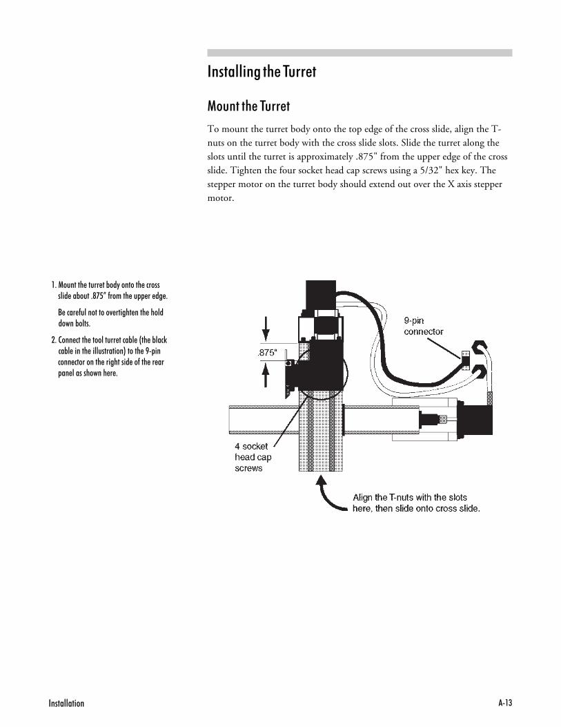
��������� � � ������
(���� � � ������
To mount the turret body onto the top edge of the cross slide, align the T-nuts on the turret body with the cross slide slots. Slide the turret along theslots until the turret is approximately .875" from the upper edge of the crossslide. Tighten the four socket head cap screws using a 5/32" hex key. Thestepper motor on the turret body should extend out over the X axis steppermotor.
�����$����$����&� 0������� ���������'� ���&�$���,;O�(������$������ ���
����<�� ���($'�������/����������' ���� ����&�'��
7������� �����'�$���� �&'��G��&'� 2���� �&'��������''$������I������+������� ���� �������������� ���(���������������'�������������

����6��"$� �B��� ������+�*
(�5� � � �����������
Attach the 9-pin connector from the turret stepper motor to the 9-pin con-nector on the Turning Center as shown.
You'll find an 8-Pin round connector on the rear panel of the Turning Cen-ter. This is the turret interface connector.
Use the cable with an 8-Pin circular connector at one end and a 9-pin con-nector at the other end to connect the Turning Center to the ControllerBox. Insert the 8-Pin circular connector of the cable into the 8-Pin circularreceptacle on the rear panel of the Turning Center. Push and turn the con-nector collar to lock the connector in place.
Insert the 9-pin connector of the cable into the mating 9-pin connector la-beled C AXIS on the rear panel of the Light Machines Controller Box (seeInterconnection Diagram on following page). Tighten the screws on theconnector.

!���''���� �+�;
���������� ������� ������ �������
������� ���
)������
� ���� ������
15-P
in M
achi
ne /C
ontr
olle
r C
able
Spi
ndle
Pow
er C
ord
25 P
in In
terf
ace/
Con
trol
ler
Cab
le
9 P
in In
terf
ace/
Spi
ndle
Cab
le
120V
, 60H
zA
C O
utle
t
Com
pute
r
Con
trol
ler
Box
(rea
r pa
nel)
Mag
nifie
d vi
ewof
com
pute
rco
nnec
tions
MO
TO
R D
RIV
ES
M
AIN
3A
1
2A
AC
C 2
AC
C 1
S
PIN
DLE
3A
3
A
5
A
CO
MP
UT
ER
TT
L I/O
A &
B A
XE
S
C
AX
IS
120V
AC
, 60H
z, 1
5A
120V
AC
, 5A
120V
AC
, 3A
SP
IND
LE
AC
C1
AC
C2
120V
AC
, 3A
fuse fuse
fuse
fuse fuse
fuse
fuse fuse
fuse
fuse fuse
fuse
fuse fuse
fuse
ON
LY O
PE
RA
TE
WIT
H A
LL C
AB
LIN
GS
EC
UR
ELY
FA
ST
EN
ED
BE
TW
EE
N T
HE
MA
CH
INE
TO
OL
AN
D T
HIS
BO
X
WA
RN
ING
!D
O N
OT
OP
EN
NO
US
ER
SE
RV
ICE
AB
LEP
AR
TS
INS
IDE
LMC
LMC
Not
dra
wn
to s
cale
LMC
LMC
Con
trol
ler
Pow
er C
ord
Com
pute
r P
ower
Cor
d
spec
traL
igh
t T
urn
ing
Cen
ter
(rea
r vi
ew)
Spi
ndle
Pow
er C
ord
AC
Con
trol
ler P
ower
Cor
d
25-P
in In
terf
ace/
Con
trol
ler C
able
8-P
in C
onne
ctor

����6��"$� �B��� ������+�-
����� � � ����� ����� !�������
To complete the turret installation, you must alter a connection to changethe sense of the limit switch. This is to accommodate the reversal in X axispolarity mentioned earlier.
Turn the Turning Center onto its side (spindle side down) so you can safelyreach the connectors underneath. If you look under the Turning Center, youcan see that there are several small white connectors. Locate the two connec-tors marked NT (for non-turret) and L (for limit). They should be con-nected to each other.
To disconnect the NT and L connectors, press down and hold the lever onthe L connector and pull them apart.
#�� �� ���� ������� ��#� ���� ����� �������� ��' � ������'�/���������� ���� �������$''������ ���� ���������
Locate the connector marked T (for turret). Connect the L and T connec-tors. You will be able to feel the two connectors “snap” together. Carefullylower the Turning Center back onto it’s feet.
=�� ���� ������� ��#� ���� ������ ���� ������� �#� ���� �����#� ���� ��������2�0� �G�����@$��������� �������$� ����I������������� �� ���(���1����$���������

!���''���� �+�,
31 Using the 3/16 pan head machine screws that came with the extensionbracket, attach the extension bracket to the adjustable bracket as shownabove.
41 Attach the limit switch to the opposite end of the extension bracket, us-ing the two screws that you retained earlier.
:1 Return the adjustable bracket to its original position on the bed andtighten the thumb screw.
��� � � ; ����� ����� %-������� ����5��
With the tool turret mounted to the cross slide, the tool turret face may hit thechuck with the limit fully extended. The solution to this problem is to attachan extension that moves the limit switch out far enough so the tool turretface does not contact the chuck. To install the extension:
01 Locate the Z limit switch on the lathe bed. (For the location of the limitswitch, see the illustration on page B-3). The limit switch is fastened tothe bed by an adjustable bracket. Loosen the thumb screw to remove theadjustable bracket and, therefore, the limit switch from the lathe bed.
81 Remove the screws that hold the limit switch onto the adjustablebracket. Retain the screws, you will use them again later in this proce-dure.
21 Remove the extension bracket (and accompanying 3/16 pan head ma-chine screws) from its package. The extension bracket can be found inthe Accessory Kit that was shipped with the Turning Center.
%-������� ����5��
:������'�������� �� �����G7I
��<����*������� ����� ����5��
)F�-�9����� �� ����G7I ����� �����
&���� =���

����6��"$� �B��� ������+��
(������� � � �����
The tool turret will support up to eight different tools at one time. All toolsmust be mounted upside down in the tooling plate since, when using thetool turret, the workpiece rotates in a clockwise direction which brings thematerial into the tool from the bottom, up.
The tooling plate has three slots (1, 3 and 7) for holding right-hand, left-hand, profiling and external threading tools, and four holes (2, 4, 6 and 8)for holding boring, drilling and internal threading tools. Tool position 5 isfor the cut off tool. To mount a tool, lay it in a slot, or insert it in a hole, andtighten the two set screws.
��������7��8�$���0�$����� �� ��((+�+��'(���'����&$�����0��/����&���� �(�� ����� ����������2����'��&� �
#����'�����$������1�� ��������.�-7;N�(�������'�����'���
#����'�'�����$��(����������.;.O��'��
������ ������((������#��'���9� 2������ ���������/����0�(���� �� ���'������ ���&������ �(�� ����� ��''0�(���$���������'�$����
��������7��<�(���� $������2���$������� ���'����$((� ���� '����� ������� ���������������� $ 2������2��� ��������������'�����'� � �
!�������� �������� $�����'
��'���(���&�����&����� ��''���� �
�'���(������(�'�����'���� �

!���''���� �+��
�������� ������ #�.���������The spectraLIGHT Control Program runs on a 586/120MHz personalcomputer. The computer must have:
� Windows 95 or Windows NT 3.51 or higher. (Windows NT users:check the Readme file for new information).
� 16MB RAM minimum for Windows 95. 20MB RAM minimum forWindows NT.
� A 3.5" floppy drive.
� A hard drive with at least 5MB of available space.
� An available expansion slot.
� VGA graphics controller and monitor.
� A Windows-compatible mouse.

����6��"$� �B��� ������+7.
��$����� �����������The spectraLIGHT Control Program must be installed on the hard drive onyour computer. The spectraLIGHT Control Program is shipped on two3.5", 1.4MB disks. The Control Program must be installed on a hard driverunning either Windows 95, or Windows NT version 3.51 (or higher). Youmust have at least 5MB of free space on your hard drive to perform this in-stallation. (See above for system requirements.)
��������� � � ������� !������
The following instructions assume that your hard drive is drive C, and yourfloppy drive is drive A.
01 Turn on the computer. Wait for it to go through its internal checks andfor it to complete the start up process.
8. When your Windows desktop appears, insert the spectraLIGHT disk inthe computer floppy drive.
21 Using the Windows Explorer, (Start Menu>Programs>WindowsExplorer) open the floppy drive. Note: If you are installing on WindowsNT, use either the File Manager to access the floppy drive, or select"Run" from the Program Manager.
31 Double click on Setup.exe to start the installation.
41 The Welcome screen appears. You are warned to exit all other runningprograms. If no other programs are running, click Next.
:1 The next screen requests that you enter the destination directory for theControl Program. If you would like to place the Control Program in adirectory other than the default directory, click on Browse and select analternate destination. Otherwise, click Next.
>1 A window appears, displaying installation progress, and prompting youon how to proceed. After installation is complete, you are prompted toview the Readme file. It is beneficial to view the Readme file at this timebecause it contains important information about the software and thelathe that may not be included in this guide.
?1 Run the Control Program by double clicking the program icon.
@1 If running Windows NT, you need to reboot the computer.
����)'
��2���$���0�$���� ��''�����(�0����$ ������������$� ��&�(���0�$���������$���������'9������������#$�����������(�����(��������
����)'
#����� ���!"�#������� ��2���������� �����+���� � �G�����+���� ���� ����������I�����/���� � ���'� ���$ �����(����(����������������/������������ ���3��������� �$�������2���� ��0��(��� ��2����'��0������ ��2���������(���'� �����0(���������$�'����� ���� �

!���''���� �+7�
������������ � � ������� !������
In the event you need to remove the Control Program from your hard drive,there is an uninstall program included on the software disks. The uninstallprogram was copied onto your hard drive when you installed the ControlProgram.
To uninstall the Control Program, just double click the Remove Programicon (it should be in the same folder as the Control Program). A message ap-pears asking if you are sure you wish to remove the program and all its files.Click on Yes to uninstall, or Cancel to exit the Uninstall program.
� � �%��! !������
The Control Program automatically sets most variables for you.
If you will be using the Automatic Tool Turret, you must confirm this in theConfigure WSLT Window. Choose the Control tab, and on Turret Settings,check Tool Turret Installed.
If you need to access the Setup Program for other configurations, see theReference Guide: Section E in this manual.
'����
��������������''�����������''��� �'�����0����(�'�����0�$���0��/� ���� ����$�� ��������(�����
��$����� �����A�� !��*����
If you are experiencing start-up problems after installing the ControlProgram software, check the items listed below.
� Are the computer and monitor adequately supplied with power froman AC outlet?
� Is the monitor correctly connected to the computer?
� Are all the interface connections secure?
� Are the monitor and the computer turned on?
� If you are using a mouse, was the mouse driver software loaded before the Control Program software?
� Do you have enough memory on the computer to run the ControlProgram? More RAM can be gained by closing other applications.
If the WSLT Window is still not displayed after following the steps in theControl Program Installation process, refer to your PC Owner's Manual orcall Technical Support for assistance.
����6��"$� �B��� ������+77
��� ����� �������Should you require technical assistance, contact your local Light Machinesdealer. If you are unable to resolve your problem through your local dealer, freetechnical support is available by phone, fax or email from 8:15 A.M. to 5:00P.M. EST.
��$��� �������
Make sure you have the following information gathered before contactingour Technical Support group.
� The product serial number.� The name of the owner of the product.� The specifications of your computer (e.g. hard drive size, clock speed, etc.).� Notes on any Control Program error messages.
When you call, make sure you have access to both your Turning Center andyour computer. This will allow our technical support representatives to walkthrough the problem with you. Our technical support numbers are:
U. S. (800) 221-2763Canada (800) 637-4829
Fax (603) 625-2137email [email protected]
WWW Site http://www.lmcorp.com/lmcorp
,�������
Light Machines' products (excluding software) carry a one-year limited war-ranty from date of purchase. Defective products may be returned for repair orreplacement according to the conditions outlined in the Terms and Conditionsof Sale agreement. If you need to return a product, call Light Machines and aTechnical Support representative will issue you a Return Materials Authori-zation number (RMA). You must write the RMA and your return address onthe outside of the product carton or crate. Failure to do so can result in a de-lay in the return of your product.
(!)#��'�7
<���$�����2��������''���� ��''��(���������'� ����������� ���#$�������������������� ����$' ���0 ������������ ���&����$��� ����(� ��0���� 2����(������������1� '0����0�������� ��/� �
������ �������''����&����������&'�(�����0� �������� $��� � $���������������� ������������������$��� ������������'��� 2����������'��

��� ���!"�#��0������� ���� <+�
�� ����������� �� � � ����������
������� ������
)����� �����������
(���������� � � ������� ������
(���������� � � ���������� ��-
(���������� � � !� �� � � �� %�B��������
���������� ������ ��������
����/� ����� ������� �

����6��"$� �B��� ����<<+7
�� ����������� �� � � ����������������� ������The spectraLIGHT Turning Center is a two-axis tabletop lathe which you canrun directly from your personal computer. The spectraLIGHT Control Pro-gram, which you load onto your computer, accepts standard EIA RS-274DG&M codes that CNC machine tools recognize. You'll find a comprehensivelist of options and accessories for the spectraLIGHT Turning Center on thelast page of this guide.
&�������
Some of the spectraLIGHT Turning Center’s most notable hardware andsoftware features include:
� X axis travel of 4.6 inches (116mm)
� Z axis travel of 6 inches (152mm)
� Feed rates up to 12 ipm (rapid traverse up to 30 ipm)
� Feed rate and spindle speed override functions
� Tailstock
� EIA RS-274D standard G&M code programming
� Multiple tool programming
� Computer-controlled spindle speeds from 200 to 2,500 RPM
� A built-in full-screen NC program editor
� User's Guide and Introduction to CNC Workbook
� An on-line help utility
� Safety shield and limit switches
� Emergency stops from the Turning Center and computer keyboard
� � ������� ������ ����������
There are, of course, more components on the Turning Center than thoseshown here, but, to begin, you need only be concerned with the depictedmajor components.

��� ���!"�#��0������� ���� <+)
� � (��� (�� ��� ����������
The Safety Shield encloses the turning area to help protect the operator fromflying chips. A magnetic Shield Interlock Switch prevents the machine fromoperating with the shield open.
The X and Z motion of the machine is performed by Stepper Drive Motors oneach axis. There is an adjustable Limit Switch mounted under the chuck toprevent the machine from crashing.
The Spindle Head supports a 1/2 hp DC permanent magnet Spindle Motor.
You can’t miss the most important control on the machine; the EmergencyStop button. When pressed, this bright red palm button immediately haltsmachine operation. To resume operation, the button must be pulled backout. It’s important that this button be pressed before performing any manualoperations, like changing the stock or the tooling.
Use the Spindle Speed switch to establish the spindle speed. The min andmax positions on the switch are equivalent to approximately 200 (min) to2,500 (max) RPM. Use the Computer position when you want to set spindlespeeds from the Control Program.
Emergency StopButton
Spindle SpeedSwitch
X AxisDrive Motor
3-Jaw Chuck
Tool Post
Safety Shield
Z Axis Drive Motor
Tailstock
Lathe Bed
CrossSlide
Limit Switch
Safety Interlock
Adjustable Limit Switch

����6��"$� �B��� ����<<+*
� � ���������� ��-
The Controller Box houses the power- and interface-related controls for themachine. The power switch and keylock switch are on the front panel of thebox. The Key Lock switch keeps unauthorized persons from turning on themachine. Once the Key Lock is in the unlocked position, the Power switchcan be turned on. The Power switch lights up when power is on.
The rear panel houses the power and interface connectors, and the fuses. Themachine has five fuses; for Main Power, the Spindle, the Stepper Motors,and the two accessory outlets (labeled ACC 1 and ACC 2). The values forthese fuses are clearly printed next to the fuse receptacles. Do not use fuseswith amperages other than those shown on the machine.
The interface connectors are used to interface the Controller Box with theTurning Center and your computer. Cables are provided in the AccessoryKit for this purpose. Refer to Section A for correct installation procedures.
MOTOR DRIVES MAIN
3A 12A
ACC 2 ACC 1 SPINDLE
3A 3A 5A
COMPUTER TTL I/O A & B AXES C AXIS
ONLY OPERATEWITH ALL CABLING
SECURELY FASTENEDBETWEEN THE MACHINE
TOOL AND THIS BOX
WARNING!DO NOT OPEN
NO USER SERVICEABLEPARTS INSIDE
120VAC, 60Hz, 15A
120VAC, 5A
120VAC, 3A
SPINDLE
ACC1
ACC2
120VAC, 3A
fuse fusefuse
fuse fusefuse
fuse fusefuse
fuse fusefuse
fuse fusefuse
�����''���<�1�4����9���'

��� ���!"�#��0������� ���� <+;
� � ��������� ���
The Accessory Kit that comes with the Turning Center contains all the toolsand hardware necessary for installing and maintaining the Turning Center. Italso contains a collet and tools to get you started; other tool holding devicesand tools are available as options.
The accessories that come standard with the Turning Center are:
� One indexable Tool Holder
� One carbide profiling tool
� One spindle locking pin
� Five Allen keys (5/32", 3/32", 1/8", 5/64", and 9/64")
� One 25-Pin Cable
� One AC Power Cord
�B����*�� )������
Light Machines Corporation offers a variety of Turning Center accessories,CAM software, curriculum and documentation. For more informationabout these products, call your local Light Machines dealer, or call LightMachines directly at (800)221-2763 or (603)625-8600.
A convenient listing of products is located on the last page of this User'sGuide.

����6��"$� �B��� ����<<+-
(���������� � � ������� ������Performing preventative maintenance, like routine cleaning, lubrication, andcorrect adjustment, on your spectraLIGHT Turning Center ensures a longer,trouble-free life for the machine.
��<������ � � �*� ��� �������
Gibs are fitted at the rear of the saddle and on the right-hand side of thecross slide. A gib is a wedge that is adjusted by loosening the gib lockingscrews and pushing the gib inward until any play is eliminated. Correct ad-justment of the gibs will ensure smooth and steady operation of the slide.
If any end play develops in the main spindle, it can be eliminated by readjustingthe preload unit.
01 Remove the upper safety shield from the Turning Center. Remove thedrive belt.
81 Remove the main pulley from the spindle.
21 Loosen the setscrew and tighten the preload nut while turning thespindle until the play is removed.
31 Tighten the preload nut just enough to remove excess play or the bear-ings may be damaged (0.0002-inch play is recommended).
'����
4�$���� '��������� �'$&�� �������� ���� �� 5$������(�����&����''���$�����'���������'�(��

��� ���!"�#��0������� ���� <+,
��<������ � � ���� ����� � ���� ��������
You should periodically inspect the lead screw bearings because they canloosen over time. These brass bearings are mounted on the lead screw nextto the flexible couplings on each axis. Tighten the bearings whenever youmeasure the backlash and it is more than 0.008-inch, or whenever you see agap between one of the bearings and the cross slide.
�� ��<��� � � ���� ����� *������� �� ��� �-���
01 There is a black boot covering the lower portion of the flexiblecoupling. Loosen the set screw that is visible above the black boot.
81 Slide the black boot up to expose the lower half of the flexible coupling.
21 Loosen the set screw on the lower half of the flexible coupling.
s p e c t r a L I G H TT u r n i n g C e n t e r
LIGHT MACHINESC O R P O R A T I O N
M A N C H E S T E R , N E W H A M P S H I R E , U . S . A .
EMERGENCY STOP
Spindle Speed
Computer
MaxMin
BootFlex Coupling
Set Screw
Lift boot to reveal lower portion of coupling
Set Screw

����6��"$� �B��� ����<<+�
�� �������� � � C �-�� ��<��������
31 Press the lathe table toward the front of the Turning Center by exertingpressure on the stepper motor.
41 While still pressing the stepper motor, press the flexible coupling in thesame direction.
:1 While holding the stepper motor and flexible coupling in place, tightenthe lower set screw, then release the flexible coupling and stepper motor.
>1 Slide the boot down and tighten the top set screw.
�� �������� � � ; �-�� ��<��������
31 Pull the cross slide toward the Z axis stepper motor.
41 While still pulling the cross slide, press the flexible coupling in the oppo-site direction, toward the cross slide.
:1 While holding the cross slide and flexible coupling in place, tighten thelower set screw, then release the flexible coupling and cross slide.
>1 Slide the boot down and tighten the top set screw.

��� ���!"�#��0������� ���� <+�
#�������� � � ����� ����� ������ '��
If the backlash is still more than 0.008 inch after you tighten the bearings, youmay need to replace the cross slide saddle nut.
To replace the cross slide saddle nut:
1. Remove the X axis stepper motor from its bracket by removing the fourscrews holding it to the bracket.
2. Turn the flexible coupling to the right to turn the cross slide lead screw.As you turn the lead screw, you can see that it pulls the cross slide in the+X direction (toward the saddle). Turn the lead screw until the front-most edge of the cross slide is flush with the front-most edge of thesaddle.
You should now be able to see the saddle nut. The saddle nut is insertedin a recess in the front of the saddle.
3. The saddle nut is held in place by an set screw. The set screw is embeddedinside the saddle directly beneath the saddle nut. The only way to accessthe set screw is from beneath the front of the saddle. You should be ableto probe the underside of the saddle with an Allen wrench, locate the setscrew and loosen it to release the pressure on the saddle nut.
4. Once you have loosened the set screw, press the cross slide down towardthe front of the Turning Center (in the -X direction). The cross slidelead screw should move with the cross slide and appear out of the recessin which the saddle nut resided.
5. The saddle nut should be threaded onto the end of the lead screw. Un-screw the old saddle nut and screw on a new one (part number L4089).
6. Push the cross slide back into its original position. The lead screw willfollow, pulling the new saddle nut into the recess in the front of the saddle.
7. Reach back under the saddle with the Allen wrench and tighten the setscrew until you can feel a slight resistance when you turn the lead screw.
8. Turn the flexible coupling to the left to move the cross slide down in the-X direction (enough so you can replace the X axis stepper motor).

����6��"$� �B��� ����<<+�.
#�������� ���5��� ������������
Backlash is the amount of play in the lead screws. Backlash compensation re-moves excess play whenever the machine changes direction. The amount ofplay in these screws is minimized by adjustments made during assembly andtest of the Turning Center at the factory. However, you should still check thebacklash compensation after the first four or five hours of use, and every 10to 20 hours of use thereafter, or whenever you find parts outside acceptabletolerances.
01 Mount a dial indicator on the lathe bed or chip tray with the tip of theindicator touching a tool post or the cross slide. Carefully align the indi-cator parallel to the axis you are calibrating. Calibrate the X axis first,then the Z axis.
81 Turn on the computer and the Controller Box, and start the ControlProgram.
21 Select Backlash from the Setup Menu, and set the distance for all axes tozero.
31 Set the speed for all axes to 3ipm (75mm/min.).
41 Use the Jog Keypad to jog 0.020-inch in one direction along the X axis.Take a reading from the dial indicator.
:1 Jog 0.020 in the other direction on the X axis and take a second readingfrom the dial indicator.
>1 Calculate the difference between the two readings and subtract this valuefrom 0.020 to get the actual backlash.
?1 Select Backlash from the Setup Menu and change the X axis distance tothe value found in Step 7.
@1 Align the dial indicator on the lathe bed parallel to the Z axis and followSteps 5 through 8 to determine the actual backlash value for the Z axis.
0D1 Select Backlash from the Setup Menu and change the Z axis distance tothe value found in Step 7.
001 Reactivate the safety interlock on the shield if you have deactivated it.

��� ���!"�#��0������� ���� <+��
��<������ ������ ���� ���� ��The Automatic Tool Turret (ACC-5601) is an option that allows yourTurning Center to make automatic tool changes while running NC pro-grams. It is critical for part tolerances that the tool tip and spindle centerlinelie on the same plane.
Because different tools may be set up differently, you may need to make somegross adjustments of the tool turret before you can make fine adjustmentsand start machining parts. There are several steps involved in tool turret ad-justment:
1. Mount all the tools you intend to use.
2. Attach a chuck to the spindle and mount a dead center in the chuck. Thedead center is used as a reference for the spindle centerline.
3. Rotate each tool as close as possible to the tip of the dead center. Sometools may fall below the spindle centerline, some may fall above the cen-terline. Some tools may be even with the centerline. Record the distancefrom the centerline for each tool.
4. If any tools fall below the spindle centerline, place a shim beneath theturret to bring the lowest tool even with the spindle centerline. (The shimthickness should be equal to the distance between the lowest tool and thespindle centerline.) This means that the remaining tools will be above thecenterline, but that will be remedied by making fine adjustments.
SpindleCenterline
Direction ofstock rotation
Stock
1
2
4
5
6
8
7
3

����6��"$� �B��� ����<<+�7
�� $������'�������������� '�� ����'����'��/��������''�$&�������� 2��������(������(� ���� $��
�� $������'�������'0��������� �'���������� '�� ����'���� $����� 2� '���'0�
�� $������'�'������������� '�� ����'�����$&�������������2��� ������������� ���� ������(����� 2�
Spindlecenterline
Stock
Direction ofstock rotation
Direction of tool movement
Spindlecenterline
Stock
Direction ofstock rotation
Direction of tool movement
Spindlecenterline
Stock
Direction ofstock rotation
Direction of tool movement

��� ���!"�#��0������� ���� <+�)
5. Make the fine adjustments to each tool.
a. Remove the dead center and place a piece of stock in the chuck.
b. Rotate a tool into cutting position and make a facing cut on the stock.
c. Stop the machine just before the tool reaches the spindle centerline. Vi-sually check the position of the tool in relation to the center of the stock.
If the tool is even with the centerline, you do not need to make any fur-ther adjustment.
If the tool is below the centerline, adjust the shim below the turret andbegin the fine adjustment process again.
If the tool is above the centerline, allow the tool to continue past thecenter of the stock. Stop the machine. There should be a small nub leftat the center of the face of the stock. Use calipers to measure the diam-eter of the nub of material. Divide the measured value by two. The re-sulting value is the amount that the tool must be shimmed to bring itdown to the centerline of the spindle.
Place shims above the tool holder as shown below. The thickness of theshims should be equal to the radius of the leftover nub.
Direction ofstock rotation
Diameter of nub left on stock after facing cut
Stock
1
2
8
3
Shim added
StockSpindle centerline

����6��"$� �B��� ����<<+�*
��*�������� ������� ������ ����������
If the Turning Center sits idle for two weeks or more, you should clean andoil it to prevent dust buildup. In addition, you should always clean the crossslide, saddle, and bed at the end of each work session. Periodically maintainthe following parts:
� Bed, saddle, cross slide. Use a light oil, such as sewing machine oil, onall points where there is a sliding contact. You should do this immedi-ately after each cleanup.
� Lead screw, cross slide screw. Place a light oil along all threads regularly.At the same time, check that the threads are free of any metal chips. Alsoput a few drops of light oil between the lead screw bushings and the sta-tionary bushings to minimize wear and increase the capabilities of thedrive motors.
� Tailstock spindle. On a weekly basis, wind out the spindle as far as itwill go and oil it with a light oil.
� Headstock bearings. These bearings are lubricated at the factory andsealed to last the lifetime of the machine. They should not need furtherlubrication if the seals remain unbroken.
� Thrust bearings. For every 80 hours of machine use, you should lubri-cate the bearings on both axes with an all-purpose grease.
The bearings are located under the flexible couplings inside the steppermotor brackets. Slide the black boot covering the flexible coupling to ex-pose the blue bearing. After lubricating, make sure to slide the black bootback to its original position.
Boot
Flex Coupling
Lift boot to reveal blue bearing.BlueBearing

��� ���!"�#��0������� ���� <+�;
(���������� � � ���������� ��-The spectraLIGHT Controller Box requires no special maintenance, exceptthat it should be kept in a dust-free environment.
If you are having problems with the AC Outlet function, or if the steppermotors are not running, you may need to change a fuse in the ControllerBox. A blown fuse can occur if you overload one of the AC outlets. Tochange a fuse:
01 Turn the power off, and disconnect the power cords to the ControllerBox and the Turning Center.
,�#''
���������$�������#�����9���������� � �������$��?'� �� ��� 23
�'��0�� �� ���� �����������������&�(�������/� ����������''���<�1����#$������������
81 The fuse holders are externally mounted on the rear panel of the Con-troller Box and are labelled to correspond with each AC outlet. Locatethe correct fuse holder.
21 Remove the fuse by turning the fuse cap counterclockwise while pressingslightly inward. The fuse is removed with the cap.
31 Visually inspect the fuse. If the fuse element appears broken, it is blown.You can also use an ohm meter to check the continuity of each fuse.
fusefusefus
e
fuse
fusefuse
fuse
fusefuse
fuse
fusefuse
fuse
fusefuse
�����''���<�1��$����� �����

����6��"$� �B��� ����<<+�-
41 Replace the blown fuse with a standard Slo-Blo fuse of the appropriate rat-ing. Three-amp (1.5A for International Users) fuses are used for the mo-tor drives, ACC 1, and ACC 2. A five-amp (2.5A) fuse is used for thespindle, and a twelve-amp (6A) fuse is used for main AC power.
:1 Replace the fuse holder cap by pushing inward and turning clockwise.
>1 Reconnect power.
MOTOR DRIVES MAIN
1.5A 6A
ACC 2 ACC 1 SPINDLE
1.5A 1.5A 2.5A
COMPUTER TTL I/O A & B AXES C AXIS
220-240VAC, 50Hz, 6A
220-240VAC, 2.5A
220-240VAC, 1.5A
SPINDLE
ACC1
ACC2
220-240VAC, 1.5A
fusefusefuse
fuse fusefuse
fuse fusefuse
fuse fusefuse
fuse fusefuse
ONLY OPERATEWITH ALL CABLING
SECURELY FASTENEDBETWEEN THE MACHINE
TOOL AND THIS BOX
WARNING!DO NOT OPEN
NO USER SERVICEABLEPARTS INSIDE
Fuses�$���'� �����������!���������'�����''���<�1
#��!���������'������''���<�1�$���������;��($���������-��($����� ����7�;��($���
��� ���!"�#��0������� ���� <+�,
(���������� � � !� �� � � �� %�B��������Here are a few general guidelines for maintaining your personal computerand software in a shop environment. See your owner’s manual for mainte-nance procedures specific to your computer.
������ $�� � � ��������
Follow these general rules for computer care.
� Keep the computer and peripherals (mouse, keyboard, external drive,printer) out of direct sunlight and away from sources of heat and in arelatively clean environment (i.e., not right next to the foundry room).
� Keep liquids (soda, coffee, cutting fluid, grease) away from the computerand peripherals.
� Keep oil, grease, metal chips and excess dust away from the computer,keyboard and floppy disks. You should consider erecting a clear plasticshield between the computer and the lathe to keep chips off the computer.
� Use grounded, three-prong outlets for the computer and peripherals. Takeprecautions against current overload. A line-surge suppression unit canbe purchased at your local computer store to help alleviate this problem.
� Don’t block the vent holes in the computer or drives; they are required forair circulation.

����6��"$� �B��� ����<<+��
������ $�� &����� "��5�
Floppy disks are simple to use but require a few precautions to maintain theirintegrity.
� Don’t touch the magnetic disk part of the disk (the shiny, record-likepart inside the disk jacket). Dust or grease from your hand can ruin anypart of the disk that you touch and can possibly destroy the entire disk.
� Keep disks in a disk box or special disk container instead of spreadingthem out on your work space.
� Handle disks gently, don’t bend or crease them.
� Don’t write on disk labels with a ball point pen. If you must write on thelabel, always write very lightly with a felt tip pen.
� Keep disks in a clean, cool environment away from excess amounts ofdust, heat, or sun.
� Beware of getting machining fluids on the disks. If you spill a liquid orcutting fluid on a disk, it is almost percent certain that the disk and allthe data on it can never be used again.
� Keep disks away from all magnetic sources including telephones, high-voltage power sources and lathe motors.
� Make backup copies of all NC program disks each time you update them.
� Print copies of all NC programs in case of disk failure or lost disks.
No matter how cautious you are, disks will go bad; they develop bad blocks (un-readable surfaces). If this happens while you are editing a program, the programwill be lost. The solution to this disaster is simple—make backup copies.

"�������A�����������'�9������ �+�
�������� � � ������� !������
$ 6�� '��� ����111
%-������� � � ������� !������ ������
������ �� ���� � � ������� !������
������ ����� ������� �

����%��"$� �B��� ������+7
�������� � � ������� !������To start the spectraLIGHT Control Program:
From Windows 95 select Start from the Task Bar, then select “Progams” and theWSLT folder. In that folder, select WSLT Windows CNC Control. You canalso create a Windows 95 shortcut by opening the WSLT directory and draggingWSLT.EXE onto your desktop.
From Windows NT double-click the WSLT icon in the WSLT Group.
You should have the controller box connected and powered up before startingthe control software, unless you are going to be working in the Simulate Mode.The safety shield should be closed, and the Emergency Stop button pulled out.
!(���� ��'���&�1�������������0�$������������'�9�������
������(� �� �� ��� �������0�$��#$�����������������
&����������'0�����''� �G����4�(���� ��"$� �B��� ����?I�
!(�0�$� ������/��������(� �� �� �����''� ��0�$� �����''�� �
�� �/���(0��������������������$���#$������������&0
�$�������������'�9�������������$'����� ��
#�������������'�9�������������$'����� �����'� ���� �'�
��������1� ��'���&�1������������'� ����$'���
�������� � � ������� !������ �� �������� (���

"�������A�����������'�9������ �+)
$ 6�� '��� ����111You can access online help by using the commands under the Help Menu, orby pressing F1.
For information on many of the functions and screens in the WSLT software,you can also refer to the Reference Guide: Section E.

����%��"$� �B��� ������+*
%-������� � � ������� !������ ������You should become familiar with the main parts of the Control Programscreen before you begin using the Control Program to run NC part pro-grams. The following are the default components that make up the screen.
(��� ���
The Menu Bar contains all of the menu commands for the Control Program. Foran explanation of each menu and its relative commands, refer to the ReferenceGuide: Section E.
�������� ���� ���
The Standard Tool Bar provides easy access to the most often used com-mands available in the Control Program.
:$�$��#��'�<��
#�'��<��
!��$��#��'�<��
9�������4�� �$
�� ����!�(�
D���(0���� ��
��������<�����$�<��
��� �� �#��'�<��
? ����� ��
��$��<��
#$���������'

"�������A�����������'�9������ �+;
���� &�������
��� <��������������������������(�'��
:��� :��������1���������������������(�'��
��/� ��/�� $��������������������(�'���� ��2���� ��/��
9��� ��� ������������������
����1���'� :&�����'�������'� � ��&5� �
E��������' � ����E��������'�9���'�
:�������9���' � ����:������������'�9���'�
���� :������F�� 2������ ��'���&�1�
D���(0 D���(0��� $��������������������
4$��G�����I 4$���� $��������������������
9�$���G0�''��I 9�$����� $����'0��$���������������������
����G�� I ��'��� $����'0��$���������������������
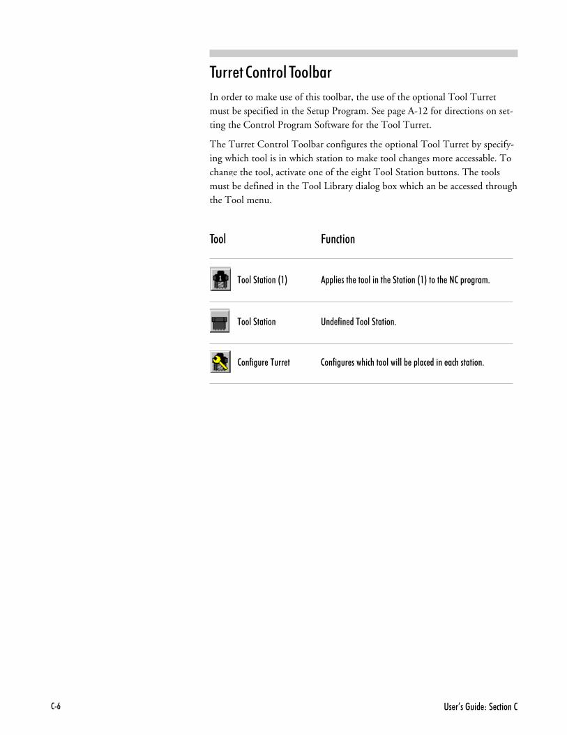
����%��"$� �B��� ������+-
������ ������� ����*��
In order to make use of this toolbar, the use of the optional Tool Turretmust be specified in the Setup Program. See page A-12 for directions on set-ting the Control Program Software for the Tool Turret.
The Turret Control Toolbar configures the optional Tool Turret by specify-ing which tool is in which station to make tool changes more accessable. Tochange the tool, activate one of the eight Tool Station buttons. The toolsmust be defined in the Tool Library dialog box which an be accessed throughthe Tool menu.
���� &�������
#��'�������G�I ���'��������'������������G�I����������������
#��'������ �� �(��� �#��'�������
���(��$���#$��� ���(��$������ ���'���''�&���'� � ������ �������

"�������A�����������'�9������ �+,
)������ ���� ���
The Outputs Tool Bar is an active tool bar. It provides switches to supplypower to the spindle, and to the Accessory outlets on the Controller Box.Switches for Robotic outputs 1 and 2 are also provided. Power is on whenthe buttons are depressed.
���� &�������
���� '��:$�$ 9��/� ����������������� '��
� ��:$�$ 9��/� �������������� ���$'������������''���<�1
� 7�:$�$ 9��/� �������������� 7��$'������������''���<�1
4�&����:$�$ 9��/� �������������##��!F:� ���� �������������''��
<�1�(���4�&�� �:$�$���G4�(���� ��"$� �B��� �����I�
4�&��7�:$�$ 9��/� �������������##��!F:� ���� ������������''��
<�1�(���4�&�� �:$�$�7�G4�(���� ��"$� �B��� �����I�

����%��"$� �B��� ������+�
����� ���� ���
The Inputs Tool Bar is an inactive tool bar. It provides information only onthe state of the Emergency Stop, the Safety Shield, and the negative limitswitch. Indicators for Robotic inputs 1 and 2 are also provided. An input isactive (on) when the button is depressed.
���� &�������
?+��� !� � ����������?������ 0�������������� �
��(�0����' !� � ������������(�0����' ���������
�����/������ !� � ���������������/��>��������� �����&������
4�&����!��$ !� � ��������4�&�� �!��$���G4�(���� ��"$� �B
�� �����I��������
4�&��7�!��$ !� � ��������4�&�� �!��$�7�G4�(���� ��"$� �B
�� �����I��������

"�������A�����������'�9������ �+�
%��� ,�����
Whenever you open an NC part program file it appears in its own editwindow. These windows have the same characteristics as other Windows 95windows (scroll bars, minimize/maximize buttons, etc.). You can havemultiple edit windows open at a time, the maximum number of whichdepends on available memory.
By default, each new window is locked; you can not edit a locked window.To unlock the window, use the Lock command under the Edit Menu.
�������������� ����� ���(������������������#�4�:�?������������
(!)#��'�7
�'��0��/���(0��������������(��� ����������$�����0�$�� �������''���� �$�������'� ���3

����%��"$� �B��� ������+�.
������ ���
The left side of the Status Bar provides information about the currently selectedfunction. The right side of the status bar provides information on:
� Whether or not the Turning Center is homed
� Whether or not the Caps Lock key is activated
� Whether or not the Num Lock key is activated
� The current line and total number of lines in the program
� Whether or not the current NC part program is locked
� Whether or not the current NC part program has been modified
� The current time according to your computer
When the indicator is dimmed, the function is in the off condition.
�$�����($� �����������
������ 2����
�$���� 2����
�$����������B�#��'��������'���� 2����
��'���� �(0����
�$��������

"�������A�����������'�9������ �+��
�$���������/��$���� ���1�&'� 2
!������� #������
The Position Readout provides information on the current X and Z coordi-nates of the tool position. The units of measure in the Position Readout aredetermined by the Units command under the Setup Menu.
(�� ��� �$� !����
The Machine Info Panel provides information on the current tool, toolreference point, feed rate, spindle speed, number of passes made, coordi-nate system in use, as well as the current block and total number ofblocks in the program.
�����
�8�$� ��� �$&'�+ '� 2������9������4�� �$���� �����&�����$����"��#�9������� ��'���&�1�
�8�$� �����/����9�������4�� �$��� �����������'� ����������� �������' ���'� �������� '� 2��� � �������� ����:� ��0�$���'�������'��� ����$���2�0������� �����0�������������������!(�0�$���/������� ���&� 2���� � 2��������������''��$���� �''0 � 2�
��!(�0�$���������� �����������('������� '� 2���������$���&$���������� ������ �$� � 2�P � 2�&'��O�#���� ��� �����'0�&������M� ������������ � 2�&'��
������������(�������������/��������M������ � � 2������� �������(������4�(���� ��"$� �B��� ����?�
�����
�8�$� �����/������ ����!�(��9���'�������������(���� ��������' ���' �������� '� 2��� � ����������'�:� ��0�$���'�������'��� �����$��2�0��������'���''���0������������������!(�0�$���/��������'�&� 2���� � 2��������������''��$���� �''0 � 2�
��!(�0�$�����������'���������('������� '� 2���������$���&$�����������'���� �$� � 2�P � 2�&'��O�#�����'� �����'0�&������M� ������������ � 2�&'��
������������(�������������/��������M������ � � 2��������'�����(������4�(���� ��"$� �B��� ����?�
���������������������$���������!�(��9���'�'������/� ��� 0���� ���'�0��(����'���� �� ������������ ��'������&'� 2��( � ������� $����'0&������1� $� �
?'���� ������� � ���
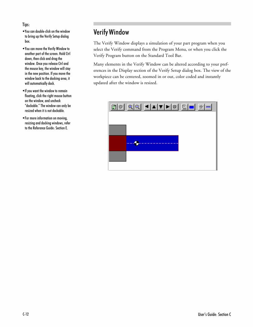
����%��"$� �B��� ������+�7
=���$� ,�����
The Verify Window displays a simulation of your part program when youselect the Verify command from the Program Menu, or when you click theVerify Program button on the Standard Tool Bar.
Many elements in the Verify Window can be altered according to your pref-erences in the Display section of the Verify Setup dialog box. The view of theworkpiece can be centered, zoomed in or out, color coded and instantlyupdated after the window is resized.
�����
�8�$� ��� �$&'�+ '� 2��������� ����&�����$����D���(0���$�� ��'��&�1�
�8�$� �����/����D���(0���� ���������������(���� ��������' ���' �������� '� 2��� � �������� ����:� ��0�$���'�������'��� ����$���2�0������� �����''���0������������������!(�0�$���/������ ���&� 2����� � 2�������������''��$���� �''0� � 2�
�!(�0�$���������� �����������('������� '� 2���������$���&$���������� ������ �$� � 2P � 2�&'��O�#����� ��� �����'0�&�����M� ������������� � 2�&'��
������������(�������������/��������M������ � � 2������� �������(������4�(���� ��"$� �B��� ����?�

#$����'B��� ������������'��9�� =+�
��$��� #������ � � ������� ������
#������ � ������ '� !������
��������� (�� ����� � ������ !���
���� ����� ������� "

����6��"$� �B��� ����==+7
��$��� #������ � � ������� ������Like any other power tool, the spectraLIGHT Turning Center is a poten-tially dangerous machine if operated in a careless manner. The importance ofsafely operating the spectraLIGHT Turning Center, including the need forprotection against personal injury and the prevention of damage to theequipment, can not be stressed enough. You will find more information onsafe machining in the Reference Guide: Section J.
��$��� #����
Proper setup of the Turning Center is essential for safe machining. These proce-dures must be followed each time a new tool is mounted. General setup re-quirements for the Turning Center include checking components for cleannessand lubrication, mounting the cutting tool, setting the limit switch, mount-ing the workpiece, and setting the spindle rotation speed.
The following safety rules should be practiced by all operators of the spectra-LIGHT Turning Center for each use.
� ��5��� ��� � ����������Always examine the bed saddle, cross slide and lead screw to be sure they arefree of shavings and particles from previous operations. Remove such debrisfrom the lathe to avoid possible binding of components which may result inpossible damage to the lathe, the workpiece or the operator.
Always make sure the machine is properly lubricated.
#���B� ��<������ ���� ��� ,���� ��Make a habit of checking that keys and adjusting wrenches are removedfrom the Turning Center before operating the machine.
"� '�� &���� � ����Select the feed rate and depth of cut best suited to the design, construc-tion and purpose of the cutting tool. It is always better to take too light acut than too heavy a cut.
��� � � #�� � ����Select the type of cutting tool best suited to the turning operation. Don’tforce a tool or attachment to do a job it wasn’t designed to do.

#$����'B��� ������������'��9�� =+)
(������� � � ������� ����Each cutting tool used in the machining operation must be sharp and tightly in-serted in the tool post. The cutting edge of the tool must be on the centerline orjust below the centerline (0.004 inch or 0.1mm maximum) of the axis of ro-tation of the lathe.
������ � � ,��5�����The workpiece can be held in a three or four jaw chuck, or with a collet. Becertain that you have firmly secured the workpiece on the cross slide and thecutting tool in the spindle before turning on the spindle motor.
���� � � ������� �� ���� ��$��� ��������Manually turning the spindle allows you to safely determine that the tool willnot hit the Turning Center bed, cross slide, or stock on start up.
��� � � ������� #������� �����The spectraLIGHT Turning Center is equipped with an electronically-con-trolled spindle motor which produces a comprehensive range of spindle rota-tion speeds. Speed can be set with the Control Software or by using an Scode in the NC program. With the Control Software select Spindle from theSetup menu, and adjust the spindle speed. The spindle can also be turned onor off from this dialog box.
��� ��� ��� �������9 ���5��� ��� "��B��� "�B����Tighten the work holders and tool holders. Do not overtighten these devices.Overtightening may damage threads or warp parts, thereby reducing accuracyand effectiveness.

����6��"$� �B��� ����==+*
'����
8�$���$' �$�����?������ 0����&$����� �� ���� ����������#$���������������� ���������'�����������$������������/��������2��� ��
9'� ����9�$��� ����� ��� ���#��'������ ����� �G�.-I����0�$��������������:� ������$�������1� $� ��$�������?������ 0�����&$���� ��������#$���������������' �
����0�$�����(����� ����� ������� '���������' ��9$''��$��?������ 0�����&$������������?��������� ���$���2�0&��� �����$����$����������������
(�5��� %�������� �����
Before you run the spectraLIGHT Turning Center for the first time, youshould know how to stop the machine should an emergency situation arise.There are a number of ways an emergency stop can be initiated on the Turn-ing Center: by pressing the Emergency Stop button, by simultaneously press-ing the Control and Space Bar keys on the computer keyboard, by activating oneof the limit switches, or by activating the safety shield interlock switch.
�������� ��� � � %�������� ���� ������
There is an Emergency Stop button located on the front panel of the TurningCenter; it has an oversized red cap. Before power can be applied to the TurningCenter, the Emergency Stop button must be pulled fully out from the frontpanel. The full-out position allows power to be supplied to the Turning Center.The Emergency Stop button disables the spindle even if the computer isturned off.
In the event that a tool crashes into the workpiece, you can immediately killpower to the Turning Center by pushing in the Emergency Stop button. TheEmergency Stop button should be your first target in an emergency situation.Pushing in the Emergency Stop button terminates the part program. Waituntil the Turning Center has completely stopped moving before opening thesafety shield.
When the tool crash has been cleared and the Emergency Stop button is reset(pulled back out), edit the part program to remove the cause of the tool crashbefore running the program again. Reset the tool position using the Set Posi-tion command from the Setup Menu.
�������� ��� � � �������� ���*����
The execution of the part program can be interrupted by pressing keys on thecomputer keyboard. Unlike using the Emergency Stop button, this methodof stopping the Turning Center does not cause the software to lose track ofthe tool position.
To stop the part program with the keyboard, press the Control key andSpace Bar simultaneously. The cutting stops immediately and the cuttingtool remains in position. To restart the program from a keyboard-gener-ated stop, select the Run/Continue command from the Program Menu.In the Start At Line box, enter the number of the last line executed, thenclick on the Run Program button. (When you stopped the program, the lastline executed is displayed on the Machine Info Panel, and the cursor isplaced on the same line in the file.)

#$����'B��� ������������'��9�� =+;
�������� ��� � ����� �����
The spectraLIGHT Turning Center is equipped with a limit switch on the Zto sense the end of travel in the negative Z direction (i.e., when the tool trav-els left towards the work piece). If the Z axis travel exceeds the end of travel,the limit switch is activated and shuts down machine operation.
Once the limit switch is activated, the tool must be jogged away from it usingthe Jog Control Panel (see the Reference Guide, Section E). To move thespindle away from the limit switch, you must jog it in the opposite direction,in the positive Z direction.
If the spindle comes close enough to the end of travel to activate the limitswitch, the following procedure must be followed to restore normal operation.
01 Select Jog Control from the View Menu or from the Standard Tool Bar.
81 Click on the appropriate jog key on the jog keypad, to move the spindleaway from the triggered limit switch.
21 Check your initial machine set up to make sure it was performed correctly.
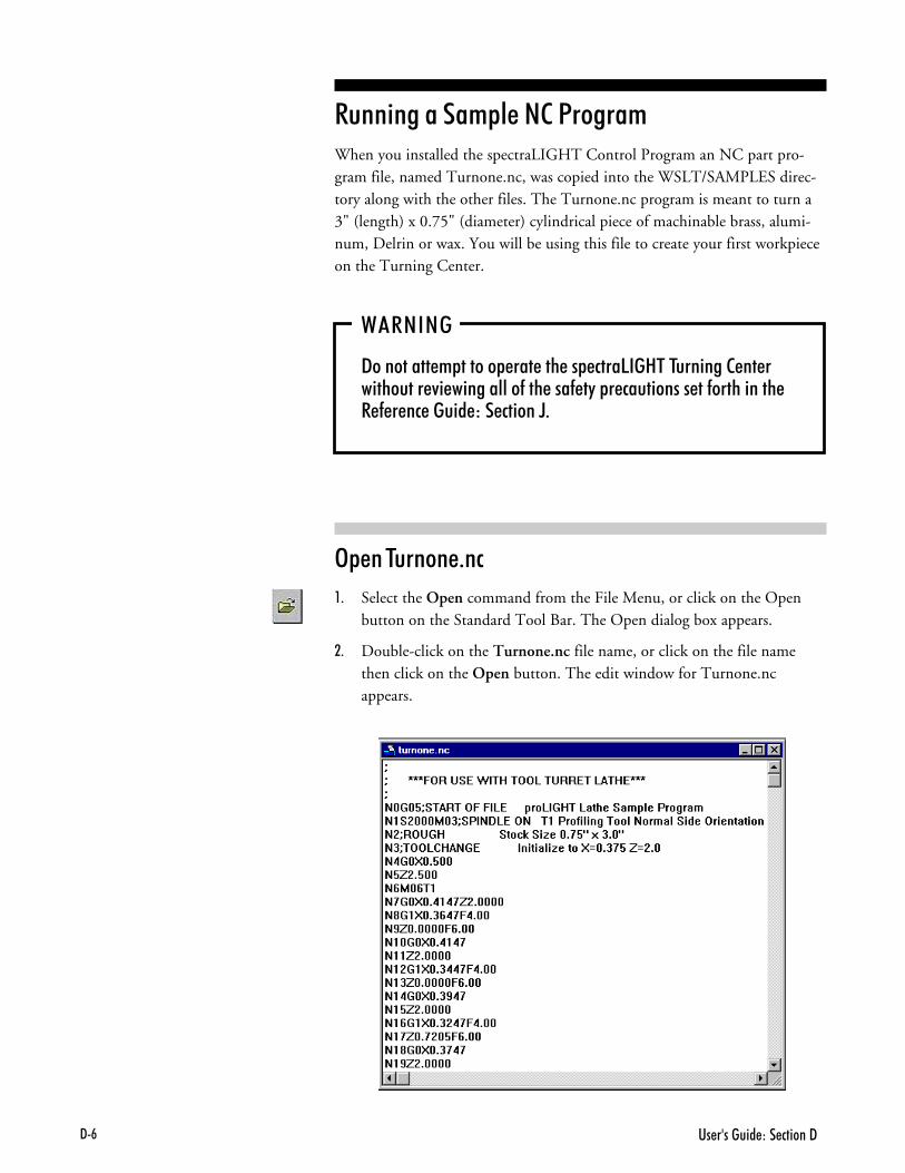
����6��"$� �B��� ����==+-
#������ � ������ '� !������When you installed the spectraLIGHT Control Program an NC part pro-gram file, named Turnone.nc, was copied into the WSLT/SAMPLES direc-tory along with the other files. The Turnone.nc program is meant to turn a3" (length) x 0.75" (diameter) cylindrical piece of machinable brass, alumi-num, Delrin or wax. You will be using this file to create your first workpieceon the Turning Center.
,�#''
=������������������������ ���!"�#�#$��������������$���/��������''��(�����(�0���� �$��������(�������4�(���� ��"$� �B��� ����E�
)��� �������1��
01 Select the Open command from the File Menu, or click on the Openbutton on the Standard Tool Bar. The Open dialog box appears.
81 Double-click on the Turnone.nc file name, or click on the file namethen click on the Open button. The edit window for Turnone.ncappears.

#$����'B��� ������������'��9�� =+,
��<��� � � =���$� ��������
After opening the NC program, you need to adjust the Verify Settings for thepart you are about to turn. To view the Verify Settings dialog box, selectVerify Window from the View Menu; double click on the Verify window whenit appears. Alternatively, you may select Verify Settings from the Setupmenu.
��<��� � � "������
01 Select the Display tab.
81 Use the Zoom controls to alter the size of the workpiece, and to positionthe workpiece in the Verify window, as shown in the Preview Window.
21 Use the Verify Speed control to alter the speed at which the verify pro-gram will be executed in the Verify Window. If you would like to viewthe verify program in slow motion, move the slider to the left. If youwould like to view the verify program at a faster speed, move the slider tothe right.
31 Use the Colors controls to choose the color indicators for the back-ground, stock and tool in the Verify Window.
41 Check Auto Refresh on Resize so that you may adjust the Verify Win-dow size if necessary without disturbing the Verify program.
#��D���(0�������� ��'���&�1��''���0�$����'�����/���������(�����'�� ����2��� �������=���'�0���� ���
#��=���'�0�����'��''����0�$��B
� >��������M�����$����(�''������ ��&0���'� �����''
� �����������2��� �������D���(0��� ��
� =� � ���� � �'������''��� � ����&� 2���$� ���� 2���� ���'�����9��/������� ��
� ������ ��������0�$��/�� ����(�����D���(0�9�����������9��/������� ��
� ������������ ����� ���/���(0��� ������''�&���1� $� �����D���(0���� ��
� �$���� �''0�$� ����� ���'�0�����D���(0���� ����(���0�$��/�����M� ������ ���&0� � 2�����������

����6��"$� �B��� ����==+�
��<��� � � ���� !�������
01 Select the Tool Position tab.
81 Enter the Initial Tool Position for the Turnone.nc part program.The positions are Z=2.01" and X=.375". These points are based onthe origin and the size of the stock and are always positive values.
21 Select Below Stock for the Tool Location for this sample NC program.If you have a tool turret installed, you will need to select Above Stock.
2.0"0.5"(inside chuck)
Initialization Point
0.5"(outside chuck)
!����'�#��'�9������

#$����'B��� ������������'��9�� =+�
"���������� � � ����5 ��E�
1. Check your NC part program for the maximum X value. This valueis used to determine the required diameter of the workpiece. For in-stance, if the maximum X value in your program is 0.45 inches, youwill need a workpiece with a 1-inch diameter.
When writing a part program for a turned part, the maximum X value inthe program is equal to the radius of the largest portion of the finishedpart. Multiply the radius of the largest portion of your finished work-piece by 2 to approximate the required diameter of the workpiece.
2. Check your NC part program for the maximum Z value. This value isused to determine the required length of the workpiece. If the maximumZ value in your program is 1.9 inches, you would assume that you needa workpiece 2 inches long. In addition, you have to account for the stockheld inside the chuck by adding 0.5 inch to the workpiece length. Also,you should add another 0.5 inch so that the tool does not hit the chuck.
Therefore, to turn a part with a finished length of 1.9 inches, you need aworkpiece thatis 2" + 0.5" + 0.5", or 3 inches long. When entering thisstock size in the stock window, only the usable dimensions are defined.
.45"
1.0"

����6��"$� �B��� ����==+�.
��<��� � � ����5
01 Select the Stock tab.
81 Enter the stock Dimensions for the Turnone.nc part program. The stockdimensions are Z=2.0" and X=0.75". These dimensions should definethe usable dimensions of the stock, excluding the amount clamped in thespindle chuck.
21 Set the Origin of Stock to Z=0.5" and X=0". The origin of the stock isbased on where your 0,0 point is set on the machine, relative to the leftcenter of the stock.
31 Check the box labeled Show Chuck and Origin Marker to view theseitems in the Preview and Verify Windows.
41 Select OK. The dialog box closes, and your changes are applied to theworkpiece in the Verify Window.
#���� 2�����'��''����0�$��B
� ?������ �����������(������2��� �
� �����������(��������(��������2��� �
� ��������/�������$ 2��� �:���������2��������9��/������ �D���(0���� ���

#$����'B��� ������������'��9�� =+��
"�$��� � � ����
To turn this part, you will use a diamond profiling tool. You will use the pa-rameters for this particular tool for the tool path verification as well. To definethe tool parameters, first select the tool from the tool library, then select thetool for verification.
������ � � ���� $��� � � ��*����
01 Select Setup Library from the Tools Menu. The Setup Tools dialog boxappears. There are already a number of tools defined. From these, selectTool 01, a left hand diamond profiling tool with outside orientation.
81 Click on the Apply button.
21 Click on OK to exit the Tool Library.

����6��"$� �B��� ����==+�7
������ � � ���� $�� =���$�������
01 Select the Select Tool command from the Tools Menu. The SelectTool for Use dialog box appears.
81 Select the tool you previously defined by using the Tool pull-down list.
21 Click on the Select Tool button.

#$����'B��� ������������'��9�� =+�)
=���$� �������1��
Tool path verification allows you to check for programming errors before ac-tually running the part program on the Turning Center.
01 Select Verify from the Program Menu or from the Standard Tool Bar.The Verify Program dialog box appears. The default starting line for theprogram is Line 1. When verifying a program for the first time, youshould begin on Line 1.
81 Click on the Verify Program button, then watch the Verify Window.You will see the Turnone.nc program executed on the cylindrical work-piece. Turnone.nc has a programmed pause. The operator must pressCycle Start from the Operator Panel or Go from the status line to seethe entire verification process.
21 After verification is completed, the Normal Program Stop dialog box isdisplayed. Select OK.

����6��"$� �B��� ����==+�*
�� <�� � � �����
�'� 2������������������1���&$��������E���A�0�� �
#��?��&'��&$����''�����������&$��������� ���$���2�0&��� ����'��&��$�� ���5�������'��:� ����&$�������E��������'�9���'����&����� �/�� ���?��&'��&$�������$���� �''0� �/�� �
#����'���/����������� ��� � ���� ���'� � �$����������� ��� ����&$����
#������ ���� ������G ���� ��I�����E���A�0�� ����� �(��� �&0���E��������� ����� �$� �������$�����$�
#����/������'������ ����$�$����������'� ������#����'���''� ����$������/����'����������1���&$������ ������� �
'����
=�$&'�+ '� 2���������E���A�0�� ��������E���������� ��'���&�1�
'����
#��$��������� '������ � �������'� ��:�������9���'���� �� 5$�������� '����� ���.H����������������$���0�$��0��������� ������������ �
���� <$���
���<$���
"�� #�� � � '� !������
Before you run your part program for the first time, you should perform adry run (run the program with no stock mounted). This will ensure that allthe movements of the Turning Center make sense and that the tool is in nodanger of striking any fixtures of the Turning Center. Although you shoulddry run the program with no stock mounted, set the point of origin using theworkpiece and then remove it.
Begin with the Emergency Stop button pressed in, and the spindle speedturned all the way down. The tool should be mounted in the tool post.
01 Mount the workpiece in the chuck. Your workpiece should be a cylindri-cal piece, 3" by 0.75" diameter.
81 Close the Safety Shield and pull out the Emergency Stop button.
21 Select Jog Control from the View Menu (or the Standard Toolbar). TheJog Keypad appears.
31 Use the Jog Keypad to jog the tool to the bottom of the front right cor-ner of the workpiece (the end of the stock furthest from the chuck and atthe edge of the stock). If a Tool Turret is installed, jog the tool to the topof the front right corner of the workpiece, instead of the bottom.
2.0"
Initialization Point
0.5"(outside chuck)
0.5"(inside chuck)
3.0"

#$����'B��� ������������'��9�� =+�;
?1 Jog the tool up and away from the workpiece. Press the Emergency Stopbutton, open the Safety Shield and remove the workpiece.
@1 Return the Safety Shield to the closed position and pull out the EmergencyStop button.
0D1 Put on a pair of safety glasses and complete the Safety Checklist (refer tothe Reference Guide: Section J).
001 Select Run/Continue from the Programs Menu. The Run Program dialogbox appears.
081 Click on the Run Program button.
021 As the part program runs, observe the tool motion in relation to thechuck (and eventually the workpiece). Look for signs of a possible toolcrash and be prepared to press the Emergency Stop switch on the Turn-ing Center. Edit the program as required. When you are satisfied thatthe tool motions are correct, you can mount the workpiece.
41 Select Set Position from the Setup Menu. The Set Position dialog box appears.
:1 Enter Z= 2.0 and X= 0.375.
>1 Click on OK. The values in the Position Readout all change to zero.

����6��"$� �B��� ����==+�-
(���� � � ,��5�����
01 Using the Jog Keypad, jog the tool post up and out of the way.
81 Before mounting the workpiece, push the Emergency Stop button in.
21 Mount the 3"x.75" workpiece in the chuck. Take care to position theworkpiece perpendicular to the tool post.
31 Pull the Emergency Stop button out.
41 Jog the tool to position the center of the tool tip at the top of the front,right corner of the workpiece. Jog until the tip of the end mill touchesthe surface of the workpiece.
:1 Select the Set Position command from the Setup Menu and enter Z=2.0 and X= 0.375. Select the Operator Panel and check that the spindlespeed is set to 100%.
The workpiece is now correctly mounted.
#�� � � !������
Before executing the Turnone.nc program, check that all safety precautionshave been taken. The Turning Center safety shield should be closed, and youshould be wearing safety glasses.
If anything goes wrong, immediately press the Emergency Stop button onthe Turning Center to stop the operation. A safety checklist has been pro-vided in the Reference Guide: Section J of this guide. Post a copy of thischecklist near the Turning Center and review it before you run any NC pro-gram.
To run the program:
01 After reviewing the Safety Checklist, select the Run/Continue commandfrom the Program Menu. The Run Program dialog box appears.

#$����'B��� ������������'��9�� =+�,
81 Make sure that the Start Line box is set to line 1 of the program.
21 Click on the Run Settings button. The Run Settings dialog box appears.
31 Make desired changes in the Run Settings dialog box, then select OK.
41 Click on the Run Program button to begin running your program.
:1 After the part is turned, press the Emergency Stop button before openingthe safety shield and removing the finished part.
�� � ���� ��� �$ � � #�� ���������
�'� 2����������6�� � 2&�1��#��4$���������� '$ �B
������ ���������''����0�$����$����������������������'���������������$�����(����� �'��������1� $� �
)������� �5������4� ����M������������'�2��� � ��GF�I�
)������� �������9�$��������������������0��.�� � ��
%��*�� ��*�������������$��&������(�������������$�����$&���������
��� ������� ��������������4� ����M����H� � ���� � ��������� ������(����� ��������� ������'�/�'$����'��/����������(����� �
����� ,������� �� %�����������'������������������������������$�����������������
#������ ���� (��� , �� "���4����������������'�$����� ��G�� ��������� I������ '�����(���$����$�� ����� $����������������
=���$� , ��� #�����������''�������'���/���(� �������� $����'������������������$�����������#$������������
8�$��(����� �������$' �'��2�����'������������ $�� �����

����6��"$� �B��� ����==+��

?+������'�9�������4�(���� �
������� !������ #�$������
#�$������ ����� ������� %
�*��� � � ������� !������ ����$���
����� � � (������ ���
����� ,������ ��� !�����
����� ����*���
����� � � (��� ���
����� � � ������ ���
��������� ��������
!���������� ������ ����������
����� � � ����� !������
����� � � )$$��� ��*��
,��5��� �� ���������� (���

?+7 4�(���� ��"$� �B��� ����?
�*��� � � ������� !������ ����$���The Control Program interface (the screen) is composed of several componentsthat allow you to create NC part programs and interact with the TurningCenter.
����� � � (������ ���The Message Bar is located directly beneath the Menu Bar. When an NCprogram is running or being verified, the Message Bar displays the name ofthe NC file currently being run, or the most recent operator message. Whena program is running, the Message Bar also displays control buttons (Go orStop). When there is no program running, the Message Bar displays theControl Program copyright notice.
=� 2�������
#��'&���
��� ���F9���'�
��$�<��
�������<��
=� 2�������
=� 2�������
���$�<��

?+)�����'�9�������4�(���� �
����� ,������ ��� !�����Windows can be used to display information or accept input from the machineoperator. Some windows can be docked or they can be floating windows (seeDocking and Floating Windows and Toolbars later in this section). Windowsare activated or hidden using the commands under the View Menu.
Panels are used to control machine operation. They can also be docked orthey can be floating windows.
The following windows and panels are available:
� Program Edit Windows
� Position Window
� Machine Info Window
� Verify Window
� Jog Control Panel
� Operator Panel
����� !������ %��� ,������
When you open an existing NC part program file, or create a new one, theprogram appears in a program edit window. Program Edit Windows have allof the features common to other windows, including a title bar which dis-plays the program file name and controls for minimizing, maximizing, andclosing the window.
Program Edit Windows appear in the Edit Area (the large central area) of thescreen. The Edit Area can be closed and moved. First select Cascade fromthe Window menu, then the window is movable and resizable. The Edit Areacan contain multiple Edit Windows.
If a Program Edit Window is locked, the background of the edit window isgray. In the locked position, no edits can be made. If the window is un-locked, it is white. The lock command can be found in the Edit menu of themenu toolbar.
When other windows, panels, and toolbars are closed, the space that theirdocking areas occupy is given to the Edit Area.
When other windows, panels, and toolbars are open, the space that theirdocking areas occupy is taken from the Edit Area.
The Windows Menu has several commands for managing program EditWindows, and allows you to select a particular window from a list of all cur-rent windows, identified by file names.

?+* 4�(���� ��"$� �B��� ����?
'����
�����$�������������'�9������������$'����� �����"��� ����� ��''������/������ ���������� �(�� � ��� �������!���''����$'����/�����������������'���/��������� ��� �����������9��������� ���
����� � � !������� ,�����
This is a dynamic display. When a program is running or being verified, thecurrent position of the tool is indicated here.
If you double-click on this window, the Goto Position dialog box appears,allowing you to move the tool to specific coordinates.
����� � � (�� ��� �$� ,�����
The information displayed in the Machine Info Window varies with theparticular operation being performed:
When the machine is idle, the Machine Info Window displays informationabout the:
� Current tool number
� Tool reference point
� Feed rate
� Spindle speed
� Number of passes* made forthe current program
� Coordinate system being used
� Current block number*
� Number of blocks* in the current program
(*The passes, current block, and total number of blocks refer to the last pro-gram verified or run.)
When a program is running, the Machine Info Window becomes a dynamicdisplay. In addition to updating the previously mentioned information, eachline of code (as it is executed) is displayed along with the previous and nextlines of code. Also, a clock provides the elapsed run time for the program.
�����
� 8�$� �����/������ ����!�(���� ����������������(��� �����&0��' ��������'�2�0� ������� '� 2������ � ����������� ����!�(����� ���
� �������� ����!�(����� �����('������G��� � 2� I�0�$� �������M���5$��'�2����0�������� ����#����/�������� ���(�����/�� � 2��������+ '� 2��������� ���� �$�+ � 2���=� 2�&'� ����� �

?+;�����'�9�������4�(���� �
When a program is being verified, the Machine Info Window displays thecurrent line of code, plus the previous and next lines, along with all informa-tion given for an actual run of the program.
����� � � =���$� ,�����
The Verify Window can be openedand closed by selecting the VerifyWindow command from the ViewMenu.
The Verify Window displays asimulation of your part program(tool path verification) when youselect the Verify command fromthe Program Menu, or when youclick the Verify Programbutton on the Standard Toolbar.
Choices made in the Verify Setup dialog box will be displayed in this VerifyWindow. These choices include a centered view, a view zoomed in or out,colors, the speed of the Verify Program and updating the Window afterresizing it.
�����
� 8�$� ��� �$&'�+ '� 2������D���(0��� �����&�����$����D���(0��$�� ��'���&�1�
� 8�$� �����/����D���(0���� ���������������(���� �����&0�' ��������'�2�0� ������� '� 2������ � ������������� ���
� 9����������������$���2�0���'������D���(0���� ��� ���'�0�������+$�����$����D���(0+��'�� ����� ��
� ������D���(0���� ������('�����G��� � 2� I�0�$� �������M����5$�'�2����0�������� ����#�����/������� ���(�����/��� � 2�������+ '� 2��������� ����� �$�+ � 2���=� 2�&'�� ����� �

?+- 4�(���� ��"$� �B��� ����?
����� � � +�� ������� !����
The Jog Control Panel is accessed by selecting the Jog Control command underthe View Menu, or by clicking on the Jog Control button on the StandardToolbar. The Jog Control Panel allows you to manually move (jog) the toolon the Turning Center.
Each axis on the machine is represented by buttons. The Z axis is representedby two horizontal buttons, one for negative motion and one for positive mo-tion. The X axis is represented by two vertical buttons, one for negative mo-tion and one for positive motion. Pressing any of the axis buttons moves thetool in the indicated direction as long as the system is not in Simulate Mode.
Jogging occurs in specific increments of speed and distance. The speed anddistance values are selected on this panel as well. You can alter the speed anddistance parameters for jogging by selecting the Jog Settings command underthe Setup Menu, or by double clicking on the Jog Control Panel.
To jog a tool:
0. Define the Speeds and Steps (distances) for jogging by selecting the JogSettings command under the Setup Menu.
8. Click on the Axis button on the Jog Keypad to move the tool in the de-sired direction. The tool moves at the speed and distance indicated bythe Speed and Step buttons.
�����
� =�$&'�+ '� 2���������E��������'9���'���������E���������� ��'��&�1�
� !(�0�$������0�$� �����/����E�������'�9���'��������������(��� �����&0��' ��������'�2�0� ������� '� 2������ � ����������E�������'�9���'�
����
#����/������'������ ����$�$����������'� �������#����'���'' ����$������/�����'����������1��&$������ ������� �
'����
#��C��1���������/���� �������#��'#$���������������#������&� �$����#��'�#$�����������������'G�I��&�/������2��� ����� ��$�����2����������/��@$� �����#���(�������/�'$���(�C����������/���� �����2��������� ���� ����������������������
�������
�����#��'�#$��������''� ���E��������'�9���'��''����5���������&���������/��G&� 2��� � �$��� '� 2����I��� ������/�G(������ �� '� 2����I� ��� �����E��������� ���'�������������������/�� ��� ��������''��� �����/������'0����������/� ���� ��������''��� �����&$����������������/����������������/� (������$�''0����/� ������#��'#$������''���������������$' �&�����������/�� ��� �������/�� ���������#��'�#$����
+�� ������� !���� )������������ ��� ���� ������ ��������
����G=���� �I������'�
�����/��>��1��������'
�����$�$����� ������'
���� ������'�
9����/��>���1��������'
9����/��C��1��������'
�����/��C��1��������'
?��&'�������'

?+,�����'�9�������4�(���� �
����
8�$� �����/����:�������9���'�������������(���� �����&0��' �������'�2�0� �������� '� 2������ ����������:�������9���'�
����� � � )������� !����
The Operator Panel provides controls that are used while running an NCprogram on the Turning Center.
The Operator Panel controls include:
����� Optional Skip: Allows you to execute or ignore any optional skips( / codes) you have embedded in the NC program.
����� Optional Stop: Allows you to execute or ignore any optional stops(M01 codes) you have embedded in the NC program.
����� Single Step: Causes the NC program to pause after each block is ex-ecuted. This allows you to check each step of the cutting operation.
����� Stop: Immediately halts the currently running NC program. This but-ton works the same as the Ctrl + Space Bar combination.
����� Cycle Start: Begins running the current NC program from the begin-ning or from a paused condition.
����� Feedhold: Pauses the currently running NC program. To continue run-ning the program from a Feedhold, press the Feedhold button again orpress the Cycle Start button.
����� Feed Rate Override: Overrides the programmed feed rate.
����� Spindle Speed Override: Overrides the programmed spindle speed.
:�����'��2�� ���
���� '�:/���� �
��� �'
�0 '�����
��� �4��:/���� �
����'�����
:�����'����

?+� 4�(���� ��"$� �B��� ����?
����� ���� ����Toolbars carry buttons that correspond to frequently used menu commands.You can click on these buttons to quickly select the associated menu com-mand. Toolbars also operate Outputs and display the state of Inputs. Toolbarscan be placed anywhere on your screen, and can be hidden if you do not usethem often or want the additional space for program windows. Toolbars arerevealed and hidden using the Toolbars command under the View Menu.
The toolbars include:
� Standard Toolbar
� Inputs Toolbar
� Outputs Toolbar
� Turret Control Toolbar
����� � � �������� ����*��
The Standard Toolbar provides quick-access buttons for the following menucommands:
�������� ���� ���
New Create a new program edit window
Verify Verify the current NC part program
Run Run the current NC part program
Pause Pause the currently running NC part program
Stop Immediately halt the currently running NC program
Open Open an existing NC program file
Save Save an NC program file
Print Print an NC program
Context Help This button can help you instantly find informationon the items you see on the screen. For instance, clickon the Context Help button, then click on a menuitem, toolbar button, window or other screen element.The Help topic for that particular item appears.
�����-�A�������B�
#�����$'���(�0�$��� ������� ���� ������������0�$� '� 2������������������0�$����� $����'0���(�������

?+������'�9�������4�(���� �
Jog Control Panel Show or hide the Jog Control Panel
Operator Panel Show or hide the Operator Panel
Home Sets/Checks the machine’s Home, or referencepoint
Verify Verify the current NC part program
Run Run the current NC part program
Pause Pause the currently running NC part program
Stop Immediately halt the currently running NC program
����� � � ����� ����*��
The Inputs Toolbar isn’t really a toolbar, in that you can not use it to inter-act with the various Control Program inputs. It is a monitoringdevice that keeps track of the state of the various machine inputs.
The state of each input is indicated by the position of its button. If a buttonis depressed, the input is “on” or “high.” If a button is not depressed, theinput is “off” or “low.” You can also check the condition of an input byclicking on it or by holding the mouse over the input button. The state ofthe input is displayed on the Status Bar at the bottom of the screen.
The inputs on the Inputs Toolbar include:
� The Emergency Stop condition. This input is in the “on”condition (depressed) if the Emergency Stop button on theTurning Center is pushed in.
� The Safety Shield condition. This input is in the “on”condition (depressed) if the Safety Shield on the TurningCenter is open.
� The Negative Limit condition. This input is in the “on”condition (depressed) if the negative Z axis limit has been hit.
� The Robot Input 1 condition. This input is in the “high”condition (depressed) if robotic input #1 (on the TTL I/Oconnector on the Controller Box) is currently in a high state.
� The Robot Input 2 condition. This input is in the “high”condition (depressed) if robotic input #2 (on the TTL I/Oconnector on the Controller Box) is currently in a high state.
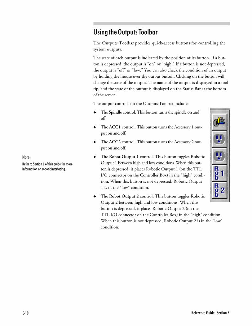
?+�. 4�(���� ��"$� �B��� ����?
����� � � )������ ����*��
The Outputs Toolbar provides quick-access buttons for controlling thesystem outputs.
The state of each output is indicated by the position of its button. If a but-ton is depressed, the output is “on” or “high.” If a button is not depressed,the output is “off” or “low.” You can also check the condition of an outputby holding the mouse over the output button. Clicking on the button willchange the state of the output. The name of the output is displayed in a tooltip, and the state of the output is displayed on the Status Bar at the bottomof the screen.
The output controls on the Outputs Toolbar include:
� The Spindle control. This button turns the spindle on andoff.
� The ACC1 control. This button turns the Accessory 1 out-put on and off.
� The ACC2 control. This button turns the Accessory 2 out-put on and off.
� The Robot Output 1 control. This button toggles RoboticOutput 1 between high and low conditions. When this but-ton is depressed, it places Robotic Output 1 (on the TTLI/O connector on the Controller Box) in the “high” condi-tion. When this button is not depressed, Robotic Output1 is in the “low” condition.
� The Robot Output 2 control. This button toggles RoboticOutput 2 between high and low conditions. When thisbutton is depressed, it places Robotic Output 2 (on theTTL I/O connector on the Controller Box) in the “high” condition.When this button is not depressed, Robotic Output 2 is in the “low”condition.
'����
4�(������� �������(�����$� ��(���������(�������������&�� �����(� ����

?+�������'�9�������4�(���� �
����� � � ������ ������� ����*��
The Turret Control Toolbar provides quick-access buttons for tools whichare defined under the Tool menu in the Tool Library. The button that isdepressed is the tool that is selected for use in an NC program.
The Tool Turret controls on the Turret Control Toolbar include:
� Tool Station 1 through Tool Station 8.In the toolbar above, Tool Sta-tions #1, #4 and #5 are defined, while Tool #1 is selected. Five Tool Sta-tions are undefined and are still available for input information and use.The tools must be defined in the Tool Library dialog box which can beaccessed throught he Tool menu.
'����
#���#$���������'�#��'&��������'0$�� ������������'�#��'�#$���

?+�7 4�(���� ��"$� �B��� ����?
����� � � ������ ���
The Status Bar displays miscellaneous information about the Turning Center
and the computer. The left side of the Status Bar is reserved for operatormessages such as the one displayed here.
If any of the following are grayed-out, the feature is considered “off.”
� The machine Homed state: Black if the machine is currently homed.
� The Caps Lock key state: Black if the Caps Lock feature is on. Some NCprogrammers prefer to type their programs in capital letters. When theCaps Lock feature is on anything you type will be displayed in capitalletters. Press the Shift key to type lower case letters.
� The Num Lock key state: Black if the Num Lock feature is on. SomeNC programmers prefer to use the numeric keypad on the keyboard toenter figures. The Num Lock feature must be on to do this.
� Current Line : Total Lines: Displays the line the cursor is currently on,and the total number of lines in the program.
� The file Locking state: Black if the NC program file is locked.
� The file Modified state: Black if the NC program has been modifiedsince being opened.
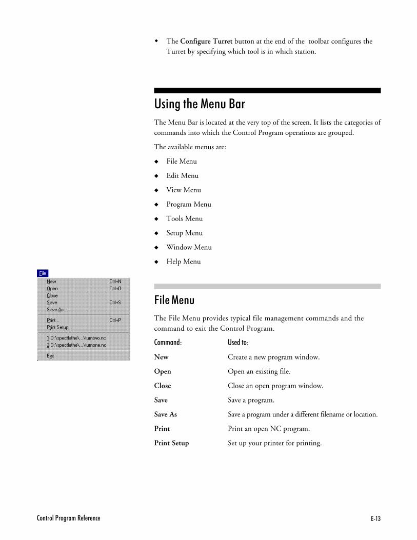
?+�)�����'�9�������4�(���� �
� The Configure Turret button at the end of the toolbar configures theTurret by specifying which tool is in which station.
����� � � (��� ���The Menu Bar is located at the very top of the screen. It lists the categories ofcommands into which the Control Program operations are grouped.
The available menus are:
� File Menu
� Edit Menu
� View Menu
� Program Menu
� Tools Menu
� Setup Menu
� Window Menu
� Help Menu
&��� (���
The File Menu provides typical file management commands and thecommand to exit the Control Program.
�������� ���� ���
New Create a new program window.
Open Open an existing file.
Close Close an open program window.
Save Save a program.
Save As Save a program under a different filename or location.
Print Print an open NC program.
Print Setup Set up your printer for printing.

?+�* 4�(���� ��"$� �B��� ����?
Recently opened files Open one of the eight most recently used files.
Exit Exit the Control Program.
'�� �������
Use the New command under the File Menu to create a new program editwindow. You can create a new program edit window at any time. The num-ber of program edit windows that you have open at one time is limited by theamount of memory on your computer.
�������������$���(�����? ����� ��������������������Q�������/��$�'0�1��������� ������ ����������� ���������� ������������� ��0���� �� � � �G�((���(������ ����I������� ��������/���&'���#���'�0�$ ���&�� ������������� ������$��������� � �� ����� ��!(���(�'����P'� 2� �O���&� 2���$� ��(���? ���� ���������0������������� ���(��#$������ ����������

?+�;�����'�9�������4�(���� �
To create a new program window, select New from the File Menu, or pressCtrl+N. A new program window is created. The filename on the Title Bar is“Untitled,” indicating that this is a new program. The program will remainuntitled until you save it. You should save a new program before it is run orverified.
#��������0�� �'�:����(�'�� ��'���&�1�
)��� �������
Use the Open command under the File Menu to open an existing NC pro-gram. The number of program edit windows that you have open at one timeis limited by the amount of memory on your computer.
�� ���� �� �-������ '� ��������
01 Select Open from the File Menu, or press Ctrl+O. The Open dialog boxappears.
81 In the dialog box, locate and highlight the desired NC file.

?+�- 4�(���� ��"$� �B��� ����?
21 Click the Open button or press Enter. The selected NC program file isopened. The Title Bar on the Edit Window displays the name of the file.
�� ������ � $��� � �� �� ������� �����
� If the open file has changed since it was opened, you are prompted to reloadthe original version of the file or to cancel the opening procedure.
� If the open file has not changed since it was opened, it becomes the ac-tive Program Edit Window.
����� �������
You can close a program window at any time. Unless you have already doneso, you will be prompted to save any changes made to the program file.
To close a program window:
01 Make sure the program window you want to close is selected.
81 Select one of several ways to close the open window:� Select the Close command from the File Menu.� Single-click the icon on the far left of the Title Bar and select Close
from the drop-down menu. (If the Edit window is maximized, theicon will be at the far left of the Menu Bar.)
� Double-click the icon on the far left of the Title Bar. (If the Editwindow is maximized, the icon will be at the far left of the Menu Bar.)
� Click on the Close button on the far right of the Title Bar. (If theEdit window is maximized, the icon will be at the far right of theMenu Bar.)
� Press Ctrl+F4.

?+�,�����'�9�������4�(���� �
21 If there are unsaved changes to the current program, the File Save dialogbox appears, prompting you to save the changes. Click one of the buttonsin the dialog box:� Click Yes to save the changes.� Click No to discard the changes.� Click Cancel to exit the dialog box without saving the changes or
closing the program window.
��B� �������
Use the Save command under the File Menu to save the current program asan NC file.
'����
����0�$��������(�'��� ���� ����������(�'����''�&��$�� �����' ���0������$������=:�������� ����)��&�(����0�$��2��� /�������(��� �����;�'����(�'��������
If the current NC program was previously saved, selecting Save saves thechanges to the same file without bringing up a dialog box. If the current pro-gram is new (and still has the name “Untitled”), selecting Save brings up theSave As dialog box, with which you name, choose a location for, and savethe new program.
To save a program, select Save from the File Menu, or press Ctrl+S.
The current program is saved to a file. If this is a new program, the Save FileAs dialog box appears. Choose a name and location for the new file.
��B� �� 111 �������
Use the Save As command under the File Menu to save the current programto an NC file using a new name or location.
� � ��B� �� "����� ��-
The Save As dialog box in the WSLT Control Program functions in thesame manner as in other Windows 95 applications.
����
!(�0�$����&'�����$���/��(��$��G������$�����$F9��(���� ��I��0�$����2���''�&����/� ��$���� �''0�����$'�������/�'��������(����$���/�(��$�������� ����� � Q��(��$���/����������&'� ��0�$���$' ���/��0�$�(�'���(��@$��'0����0�$����2�

?+�� 4�(���� ��"$� �B��� ����?
To use the Save As dialog box:
01 Select a destination for the file using the Save in:, Up one level andCreate new folder buttons.
81 Enter a filename in the File Name: field.
21 Select a file type in the Save as type: field.
31 Click Save or press Enter to save the file.
41 Click Cancel or press Esc to cancel and exit the dialog box.
�� ��B� � ������� ����� � ��� ���� �� ���������
01 Select Save As from the File Menu. The Save As dialog box appears (seeabove). It displays the name and location of the current program file.
81 Choose a new drive and directory for the file, if desired.
21 Type in a new file name, if desired.
31 Click Save to save the file, or Cancel to exit the dialog box.
'����
����0�$��������(�'��� ���� ����������(�'����''�&��$�� �����' ���0������$������=:�������� ����)��&�(����0�$��2��� /�������(��� �����;�'����(�'��������
!���� �������
Use the Print command under the File Menu to print the current NC program.
To print the program:
01 Use one of the following methods to open the Print dialog box:� Click the Print button on the toolbar.� Select the Print command from the File Menu.� Press Ctrl+P.
The Print dialog box appears.
'����
#�� �(�$'���������������''���('� �� ������� ���� ���� �(�$'��������

?+�������'�9�������4�(���� �
81 Choose the desired print options in the dialog box. Clicking Propertiesopens the Print Setup dialog box.
21 This dialog box will give options that are specific to your printer, such aspaper, graphics, and device options. customize your print job then select OK.
31 Select OK to print, or select Cancel to exit the Print dialog box withoutprinting the NC program.
You can print to any printer that is supported by Windows. See your printermanual or Windows documentation for more information on installing and usingprinters with Windows.
!���� ����� �������
Use the Print Setup command under the File Menu to select a printer. ThePrint Setup dialog box allows you to establish parameters for printing yourNC part programs.
To choose print settings:
'����
#�� �(�$'���������������''���('� �� ������� ���� ���� �(�$'��������

?+7. 4�(���� ��"$� �B��� ����?
01 Select Print Setup from the File Menu. The Print Setup dialog box appears.
81 Select the desired print settings, including:� The destination printer.� The size of the paper.� The paper tray.� The orientation of the paper.
21 Select OK to print, or select Cancelto exit the Print dialog box withoutsetting the printing parameters.
)������ � #����� !������
Use the numeric (1, 2, 3, … 8) com-mands under the File Menu to openany of the most recently opened files(up to the last eight files).
The names and paths of the most recent files appear in the reverse order inwhich they were opened.
For instance, in this example, 1 turntwo.nc is the most recently opened file.
The file 2 turnone.nc is the second most recently opened file.
To open one of the listed NC program files, simply select the filename fromthe list. The recent program you selected is opened. Once the file Edit Win-dow is open, the Title Bar displays the name of the program file.
%-�� �������
Use the Exit command under the File Menu to exit the Control Program.You should always exit the Control Program before you exit Windows.
Use one of the following methods to exit the Control Program:
� Select the Exit command from the File Menu.
� Single-click the icon on the far left of the Control Program Title Bar. Se-lect Close from the drop-down menu.
� Double-click the icon on the far left of the Control Program Title Bar.
� Click on the Close button on the far right of the Title Bar.
� Press Alt+F4.
If there are unsaved changes to any program window, a dialog box appearsfor each unsaved program window, prompting you to save the changes.

?+7������'�9�������4�(���� �
� Click Yes to save the changes and exit.
� Click No to ignore the changes and exit.
� Click Cancel or press Esc to cancel the Exit command and return to theControl Program.
%��� (���
The Edit Menu provides typical text editing commands. Before you can editthe text in an NC program, you must select the text.
�������� ���� ��B
Undo Undo the most recent editing command.
Redo Redo the most recent Undo command.
Cut Cut selected text to the Windows clipboard.
Copy Copy selected text to the Windows clipboard.
Paste Paste text from the Windows clipboard into thecurrent NC program.
Clear Delete selected text.
Delete Line Delete the line the cursor is currently on.
Find Locate a sequence of characters in an NC program.
Replace Replace one sequence of characters with another,one or more times.
Goto Line Jump to a particular line in the NC program.
Renumber Modify or insert N codes in an NC program .
Lock Lock or unlock the Program Edit Window to pre-vent or allow modification to the NC program.
Select Font Change the font currently being used.
���� �������
The Undo command reverses the most recent editing action taken. It is use-ful for recovering from accidental deletion or inclusion of a block of text.
To undo the last change, select Undo from the Edit Menu, or press Ctrl+Z.
'����
!(�0�$����������������'� 2� ������'0� �������������/��'�&'����0�$����&�������� �������� ������� &�������������?+7,�(�����(����������$�'� 2��������������

?+77 4�(���� ��"$� �B��� ����?
� If your last editing action deleted selected text, the text is restored.
� If your last editing action deleted a character, the character is restored.
� If your last editing action pasted text, the text is removed.
� If your last editing action typed a character, the character is removed.
� If Undo is grayed-out in the Edit Menu, no changes can be undone.
#��� �������
The Redo command reverses the action of the most recent undo command.For example, if you delete a portion of text in an NC program, then decidethat wasn’t such a good idea, the Undo command will return the text to itsoriginal position. If you then decide that the deletion was appropriate afterall, select the Redo command to once again remove the text.
��� �������
Use the Cut command under the Edit Menu to remove text from the NCprogram (the text is copied to the Windows clipboard). The text can then bepasted anywhere in the current program, into another program, or into an-other application such as Notepad. The text remains on the Windows clip-board until it is replaced by another Cut or Copy operation.
To cut text to the Clipboard:
01 Select the text you wish to cut.
81 Select Cut from the Edit Menu, or press Ctrl+X.
���� �������
Use the Copy command under the Edit Menu to duplicate selected text in anNC program.
To copy text to the Clipboard:
01 Select the text you wish to copy.
81 Select Copy from the Edit Menu, or press Ctrl+C. The selected text iscopied to the Clipboard.
!���� �������
You can use the Paste command to insert text from the Windows clipboardinto your NC program.
To paste text from the Clipboard:
01 Place the cursor at the point in the NC program where you wish to inserttext that has been previously cut or copied to the Windows clipboard.
��������� ��-�
���������$��������� �$�R������2�0 ��&�����������'� �����������(�0�$������������(��� $��������������� ��0����
�� ������ ��-� ����� � � ������� 5����
�� ��������������2�0������������ $���������&����������(����1��&����'� � �
7� 9���������(�2�0��� ��' �� ������'��$�������������2�0�����/���� $����������� ��(���1���&����'� � �
)� 4�'���������(�2�0�
�� ������ ��-� ����� � � ������
�� 9'� ���� $���������&���������(����1���&����'� � �
7� �'� 2��� ��' ���'�(���$��&$���
)� ��/���� $��������������� ��(���1���&����'� � �
*� 4�'���������$���&$���
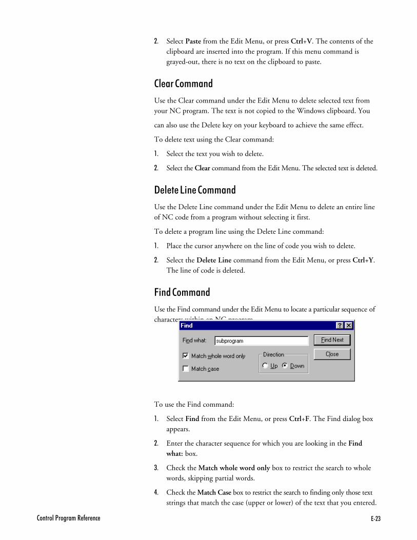
?+7)�����'�9�������4�(���� �
81 Select Paste from the Edit Menu, or press Ctrl+V. The contents of theclipboard are inserted into the program. If this menu command isgrayed-out, there is no text on the clipboard to paste.
����� �������
Use the Clear command under the Edit Menu to delete selected text fromyour NC program. The text is not copied to the Windows clipboard. You
can also use the Delete key on your keyboard to achieve the same effect.
To delete text using the Clear command:
01 Select the text you wish to delete.
81 Select the Clear command from the Edit Menu. The selected text is deleted.
"����� ���� �������
Use the Delete Line command under the Edit Menu to delete an entire lineof NC code from a program without selecting it first.
To delete a program line using the Delete Line command:
01 Place the cursor anywhere on the line of code you wish to delete.
81 Select the Delete Line command from the Edit Menu, or press Ctrl+Y.The line of code is deleted.
&��� �������
Use the Find command under the Edit Menu to locate a particular sequence ofcharacters within an NC program.
To use the Find command:
01 Select Find from the Edit Menu, or press Ctrl+F. The Find dialog boxappears.
81 Enter the character sequence for which you are looking in the Findwhat: box.
21 Check the Match whole word only box to restrict the search to wholewords, skipping partial words.
31 Check the Match Case box to restrict the search to finding only those textstrings that match the case (upper or lower) of the text that you entered.

?+7* 4�(���� ��"$� �B��� ����?
41 Select Up or Down from the Direction box to search through the textbefore or after the cursor position, respectively.
:1 Click Find Next or press Alt+F to begin the search. Click Close or pressESC to exit the Find dialog box without performing the search.
#������ �������
Use the Replace command under the Edit Menu to replace an existing char-acter string with a new character string.
If the Match Case box is checked, this feature is “case-sensitive.” If you entera character string in lower case letters, but your NC program is written in allupper case letters, Replace will not find any occurrence of the string. Makesure you enter the existing character string exactly as it is shown in the NCprogram.
To use the Replace command:
01 Select Replace from the Edit Menu. The Replace dialog box appears.
81 Enter the existing character string in the Find what: box.
21 Enter the new character string in the Replace with: box.
31 Check the Match whole word only box to restrict the search to wholewords, skipping partial words.
41 Check the Match Case box to restrict the search to finding only those textstrings that match the case (upper or lower) of the text that you entered.
:1 To locate the first and successive instances of the character string, clickFind Next.
>1 Select Replace to replace the currently located character string which hasbeen highlighted for you with the word or phrase which you have indicated.Replace changes one word at a time, starting at the location of the cursor.
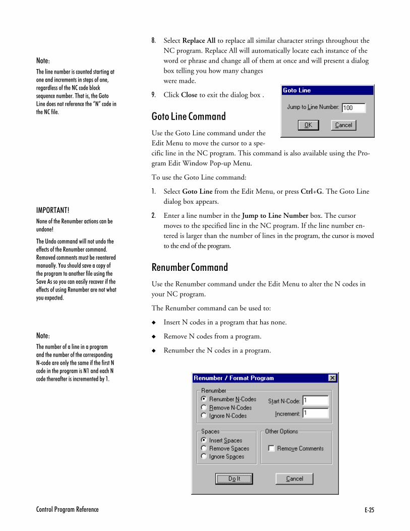
?+7;�����'�9�������4�(���� �
?1 Select Replace All to replace all similar character strings throughout theNC program. Replace All will automatically locate each instance of theword or phrase and change all of them at once and will present a dialogbox telling you how many changeswere made.
@1 Click Close to exit the dialog box .
��� ���� �������
Use the Goto Line command under theEdit Menu to move the cursor to a spe-cific line in the NC program. This command is also available using the Pro-gram Edit Window Pop-up Menu.
To use the Goto Line command:
01 Select Goto Line from the Edit Menu, or press Ctrl+G. The Goto Linedialog box appears.
81 Enter a line number in the Jump to Line Number box. The cursormoves to the specified line in the NC program. If the line number en-tered is larger than the number of lines in the program, the cursor is movedto the end of the program.
#����*�� �������
Use the Renumber command under the Edit Menu to alter the N codes inyour NC program.
The Renumber command can be used to:
� Insert N codes in a program that has none.
� Remove N codes from a program.
� Renumber the N codes in a program.
(!)#��'�7
������(���4��$�&���� ����� ���&�$� ���3
#���� �� ����� ���''����$� ����((� ���(���4��$�&��� ����� �4���/� � ��������$��&��������� ���$�''0��8�$���$' ���/���� ��0��(������������������(�'��$��������/��������0�$� �������'0��� �/����(���((� ���(�$�����4��$�&������������0�$��1�� � �
'����
#���$�&����(���'������������������ ����$�&����(��� �������� ����+ � ��������'0���������(���(����� � ����������������������� ��� �� � ������(�������� ������ �&0���
'����
#��'�����$�&������ �$�� ��������������� ��� ����������������(���������� '�����(������ � ��&'� 2��@$�� ���$�&����#��������"������� ���������(���� ����P�O� � ���������(�'��

?+7- 4�(���� ��"$� �B��� ����?
� Insert, remove or ignore spaces between NC commands.
� Remove comments from the program.
����� ' �����
To insert or renumber the N codes in your program:
01 Select Renumber from the Edit Menu. The Renumber/Format Programdialog box appears.
81 Select Renumber N Codes or press Alt+N.
21 Click on the Start N Code box (or press Alt+T), then enter the numberof the first N code. The default starting number is N1.
31 Click on the Increment box (or press Alt+I), then enter the increment youwish to use. For instance, if you wish to have each N code numbered inincrements of 5, enter 5 in the Start N Code box and enter 5 in the In-crement box. The N code sequence will then be: N5, N10, N15,N20…and so on.
This option is useful if you are renumbering a portion of the program to beinserted into another program, and the N codes must start with a num-ber greater than 1. Using increments greater than 1 allows you to insertadditional numbered lines without having to renumber the whole program.
41 Select Do It, or press Alt+O, to execute the Renumbering options youselected. Select Cancel, press Alt+C, or press Esc, to exit the Renumber/Format Program dialog box without altering the NC program.
#����*����� ��� ��*��������
Although the Renumber command automatically changes P codes used withM99 codes, it does not renumber P codes used with M98 codes, nor does itrenumber O codes. Although O codes are not altered, the lines which theyoccupy are counted. So, the very next N code is numbered as though the Ocode has been renumbered, too.
For instance, N41XN42X…O25G…N44…
In this example, although the O code has not been renumbered, the line itresides on has been counted. The N code on the following line reflects thenext number in the sequence.
����� �� #���B� ������
To insert or remove spaces between the NC words in your program:
01 Select Renumber from the Edit Menu. The Renumber/Format Programdialog box appears.

?+7,�����'�9�������4�(���� �
81 Choose a Spaces option.����� Insert Spaces inserts a space between each NC word (to the left of
the comment code).����� Remove Spaces removes any spaces between NC words (to the left
of the comment code).����� Ignore Spaces ignores any spaces in the NC program.
21 Select Do It, or press Alt+O, to execute the Spaces options you selected.Select Cancel, press Alt+C, or press Esc, to exit the Renumber/FormatProgram dialog box without altering the NC program.
#���B� ��������
To remove comments from your program:
01 Select Renumber from the Edit Menu. The Renumber/Format Programdialog box appears.
81 Select Remove Comments.
21 Select Do It, or press Alt+O, to execute the Remove Comments com-mand. Select Cancel, press Alt+C, or press Esc, to exit the Renumber/Format Program dialog box without altering the NC program.
#���B� ' �����
To remove the N codes from your program:
01 Select Renumber from the Edit Menu. The Renumber/Format Programdialog box appears.
81 Select Remove N Codes or press Alt+R.
21 Select Do It, or press Alt+O, to execute the Remove N Codes command.Select Cancel, press Alt+C, or press Esc, to exit the Renumber/FormatProgram dialog box without altering the NC program.
���5 �������
Use the Lock command under the Edit Menu to prevent or allow changes toyour NC programs. When an NC program is unlocked, it can be modified bythe commands on the Edit Menu. When an NC program is locked, the programcannot be changed by any commands. By default, when you open a file it isautomatically locked to prevent accidental changes. You can change this de-fault setting in the Preferences dialog box (Seup Menu/Editor Tab).
There are three ways to determine if a selected program is locked or unlocked:
01 If a check mark appears next to the Lock command, the current NC pro-gram is locked.
81 A locked NC program can be identified by the background color of itsEdit Window. If the background is gray, the file is locked; if it is white,the file is unlocked.
'����
#���� �� ����� ���''����$� ����((� ���(���4���/��������� ����� ��4���/� � ��������$�&������� ����������$�''0��8�$��$' ���/���� ��0��(������������������(�'��$���������/���� ����� ������0�$� �������'0�� �/����(����((� ���(�$����4��$�&�������������0�$��1�� � �
'����
�����$'��'����������? ����� ��������������� ������ �/� $�''0�'� 2� ����$�'� 2� �

?+7� 4�(���� ��"$� �B��� ����?
21 The Lock Indicator on the Status Bar is gray if the program is unlocked,black if the program is locked.
To toggle an NC program between the locked and unlocked states, select theLock command from the Edit Menu, press Ctrl+L, or double-click the LockIndicator on the Status Bar.
������ &��� �������
Use the Select Font command under the Edit Menu to change the font settingsfor open NC programs. The font settings control the font and font size usedin the program Edit Window. The fonts listed are the true type fonts alreadyinstalled on your system. Font Settings are intended for viewing and printingpurposes only. They do not affect the NC program in any way and are not
'����
#���� �� ����� � �������$� ���(���������� �����
stored within the program file. All open program windows use the same fontsettings.
To use the Select Font command:
01 Select the Select Font command from the Edit Menu. The Font dialogbox appears.
81 Select a font from the Font list.
21 Select a Font Style.

?+7������'�9�������4�(���� �
31 Select a font size from the Size list.
41 Click OK to change the font, or click Cancel or press Esc to exit theFont dialog box without changing the fonts.
=��� (���
The View Menu commands control the display of windows and toolbars.
�������� ���� ���
Position Open or close the Machine Position Window.
Machine Info Open or close the Machine Info Window.
Jog Control Open or close the Jog Control Panel.
Operator Panel Open or close the Operator Panel.
Verify Window Open or close the Verify Window.
Toolbars Open or close one of the toolbars.
!������� �������
Use the Position command on the View Menu to open or close the PositionWindow.
To open or close the Position window, select Position from the View Menu.A check mark appears next to the Position command when the PositionWindow is open.
(�� ��� �$� �������
Use the Machine Info command on the View Menu to open or close theMachine Info window.
To open or close the Machine Info window, select Machine Info from theView Menu. A check mark appears next to the Machine Info commandwhen the Machine Info Window is open.
+�� ������� �������
Use the Jog Control command on the View Menu to open or close the Jog Con-trol Panel. You can also use the Jog Control button on the Standard Toolbar.
#�� � 2���2��������D�������$�� � ��������� ����!�(����� ���� ���D���(0���� �������&�������#��������� ������������'��������������

?+). 4�(���� ��"$� �B��� ����?
To open or close the Jog Control window, select Jog Control from the ViewMenu. A check mark appears next to the Jog Control command when theJog Control Panel is open.
)������� !���� �������
Use the Operator Panel command on the View Menu to open or close theOperator Panel.
To open or close the Operator Panel, select Operator Panel from the ViewMenu. A check mark appears next to the Operator Panel command when theOperator Panel is open.
=���$� ,����� �������
Use the Verify Window command on the View Menu to open or close theVerify Window.
To open or close the Verify Window, select Verify Window from the ViewMenu. A check mark appears next to the Verify Window command whenthe Verify Window is open.
����*��� �������
Use the Toolbars command on the View Menu to show or hide the Toolbars.
To show or hide a toolbar:

?+)������'�9�������4�(���� �
01 Select Toolbars from the View Menu. The list of available toolbars isdisplayed. Toolbars that are visible have a check mark beside them.
81 Select the toolbar that you wish to show or hide.
!������ (���
The Program Menu commands allow you to Run, Verify, or Stop an NCprogram.
�������� ���� ���
Run/Continue Start running or resume running the current NCprogram.
Verify Verify the current NC program.
Estimate Runtime Estimate the runtime of the current NC program.
Pause Pause the currently running NC program.
Feedhold Stop movement of all axes.
Stop Immediately halt the currently running NC program.�������
��������������(�0��'�������� '��������(�0����' �&�(����$������������������������#$���������������������&���/����$���� ���(�0���� �$�����
#��F�������� �������
The Run/Continue command under the Program Menu runs the currentNC program on the Turning Center. When you select Run/Continue fromthe Program Menu, the Run Program dialog box appears.
The Run Program dialog box allows you to select an NC program to run, toset the program block from which to begin running the program, and to ac-cess the Run Settings and Verify Settings dialog boxes.
01 Select an NC Program.
If you have more than one NC program open, use the Program drop-down list, or press Alt+P, to select the program you wish to run.
81 Select a Starting Line.

?+)7 4�(���� ��"$� �B��� ����?
When you are running an NC program for the first time, it is wise tostart the program from the first line. When you start at a line other thanline one, the control program parses through the program to the speci-fied start point. As it parses, it performs operations such as turning thespindle on, but it will not execute a Dwell or Pause command, and itwill not move the tool.
To specify a starting block, click on the Start at Line box, or pressAlt+L, and enter the line number.
21 Set the Run Settings
To bring up the Run Settings dialog box click on the Run Settings button,or press Alt+U.
31 Set the Verification Settings
To bring up the Verify Settings dialog box click on the Verify Settingsbutton, or press Alt+E.
41 Run the Program
To start running the program, click on the Run Program button, orpress Alt+R. To cancel running the program, click on the Cancel but-ton, or press Esc.
While a program is running, the Machine Info Window and the Message Barkeep you informed by providing information on:
� The name of the NC program.
� Which tool is being used.
� The tool reference.
� The feed rate.
� The spindle speed.
� The number of passes made.

?+))�����'�9�������4�(���� �
� The coordinate system in use.
� Which block is currently being executed.
� How many blocks are in the program.
'����
!(�0�$�����/���(0������������������(����(���������0�$���$' �&������/���(� �������'��������
� Operator messages such as which block paused the program or the errorthat caused the program to stop.
=���$� �������
The Verify command allows you to view tool path verifications of your NCpart programs. When you select Verify from the Program Menu, the VerifyProgram dialog box appears.
This dialog box allows you to select a program to verify from a pull-down listof currently open NC part programs. Prior to verifying the part program,you may wish to alter the Run Settings, alter the Verification Settings, or se-lect a starting line in the program. The default starting line is line one.
Begin the verification by pressing the Verify Program button. If the VerifyWindow is not already open, it will open automatically.

?+)* 4�(���� ��"$� �B��� ����?
Tool path verification is displayed in the Verify Window. The workpieceand tool are displayed according to the choices you made in the Verify Settingsdialog box.
Here is an example of how the Verify Window may appear for the part programTurnone.nc.
%������� #������ �������
Use the Estimate Runtime command to calculate the approximate amount oftime the spectraLIGHT Turning Center requires to turn your part, and the ap-proximate distance the machine travels while turning your part.
The Estimate Runtime command accounts for Dwell times and subprogramswhen calculating estimated run time, but it can not account for stops thathave indefinite length of stop time. These program stops include:
� Pause (G05/M00)
� Chain (M20)
� Skip (/)
� Wait for input high/low (G26/G25)
� Write to file (M22)
� Rerun (M47)
The Estimate Runtime command treats M47 Rewind codes as M2 End ofProgram codes.
This command also verifies the syntax of your NC programs while calculat-ing the estimated run time. If an error is found, the Estimate Run Timecommand alerts you with a dialog box, and places the cursor near the error.
!���� �������
Use the Pause command to pause a running NC program. Pause may also beused during tool path verification. The pause is not immediate; it takes effectafter the current NC block has been executed.
�� ��� � � !���� ��������
Select Pause from the Program Menu, or click the Pause button on the StandardToolbar.
'����
�������������� ����'���&������� �&0�����������?������ 0�����<$�������(��������'��(���#$���������������&0�����������'������� �
'����
#����' $'�� �=���� ���������' ���� ��������'��� �����2��� ����/�������'��������� �����?/��0�'�������� ����� ������G����� �I������'�����G'���S�@�IG 1T 1R MT MI��#����'��������� � ��������0��' ��������' ���� ���#��(�� ������(��� ���������� �/� � �������'����� �' $'�����P� ��'O�����(����� �������G���$�����M���+ ���$�� �������/���� ��� ���(����� �'��������� � � �'������I��#������������� � ���������0��' ����'������� �����

?+);�����'�9�������4�(���� �
�� ������ ������� � ������� �$��� � !�����
Press F5, click the Run button on the Standard Toolbar, or click the Go buttonon the Message Bar.
&��� ��� �������
The Feedhold command is very similar to the Pause command. It is used to pause arunning NC program. The differences between a Pause and a Feedhold are:
� A Feedhold pause the NC program immediately; it does not wait untilthe current block is executed.
� Feedhold does not work during tool path verification.
�� ��� � � &��� ��� ��������
Select Feedhold from the Program Menu.
�� ������ ������� � ������� �$��� � &��� ����
Press F5, click the Run button on the Standard Toolbar, or click the Go buttonon the Message Bar.
���� �������
You can use the Stop command under the Setup Menu to halt a running NCprogram. The Turning Center immediately halts cutting and the current toolposition is stored by the computer.
�� ��� � � ���� ��������
01 Select Stop from the Program Menu, press Ctrl+Space, or click the Stop(red) button on the Standard Toolbar.
81 A message box appears. Clear the box by clicking OK or pressing Enter.You are automatically returned to the Edit mode.
�� ������� � � '� ��������
01 Manually jog the tool so it is above the workpiece to avoid a tool crash.
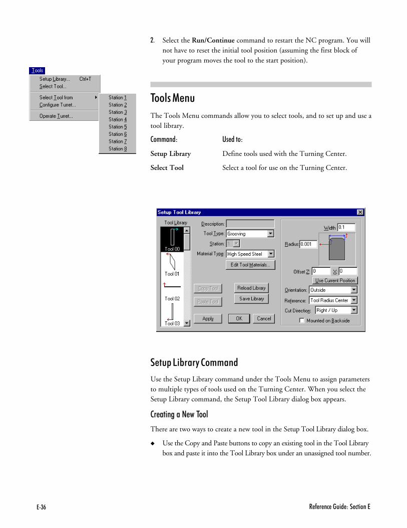
?+)- 4�(���� ��"$� �B��� ����?
81 Select the Run/Continue command to restart the NC program. You willnot have to reset the initial tool position (assuming the first block ofyour program moves the tool to the start position).
����� (���
The Tools Menu commands allow you to select tools, and to set up and use atool library.
�������� ���� ���
Setup Library Define tools used with the Turning Center.
Select Tool Select a tool for use on the Turning Center.
����� ��*���� �������
Use the Setup Library command under the Tools Menu to assign parametersto multiple types of tools used on the Turning Center. When you select theSetup Library command, the Setup Tool Library dialog box appears.
�������� � '�� ����
There are two ways to create a new tool in the Setup Tool Library dialog box.
� Use the Copy and Paste buttons to copy an existing tool in the Tool Librarybox and paste it into the Tool Library box under an unassigned tool number.

?+),�����'�9�������4�(���� �
Assigned tool numbers are displayed with a tool icon. Unassigned tool num-bers have no tool icon.
� Manually create a tool using the features available in the Setup Tool Librarydialog box.
�� �������� ������ � ��� �����
01 Select an unassigned tool number from the Tool Library list.
81 Select a tool type, such as Grooving, from the Tool Type drop-down menu.
21 Enter a name for the tool in the Description field.
31 Enter the Material Type from which the tool is made, such as HighSpeed Steel.
41 Enter a tool Width, Radius, Right Angle, and/or Angle depending onthe type of tool that you have selected.
:1 Enter a tool Offset value. You may also click on the Use Current Posi-tion button to establish the current Z, X position of the tool as theOffset.
>1 Enter an Orientation, either inside (for boring, tapping or drillingapplications),outside (for cuts made on the outside of a workpiece), orfacing.
?1 Enter a point of Reference, either Tool Radius Center for the middle ofthe workpiece or Theoretical Sharp Corner for the top or bottom edge ofthe workpiece.
@1 Enter a Cut Direction, either Right/Up (cutting away from the chuck)or Left/Down (cutting toward the chuck).
0D1 If the tool is mounted on the backside, check the box labeled Mountedon Backside. See page A-12 for a diagram.
001 Apply the new parameters to the selected tool number by clicking theApply button.
081 Press Enter or click on OK to accept the new tool information. Click onCancel to exit the Tool Library dialog box without changing the tool library.
�� ����� �� �-������ �����
01 Select an existing tool from the Tool Library list.
'����
������� ���$�� �(�����'�$��� ��(��$������

?+)� 4�(���� ��"$� �B��� ����?
81 Make the desired changes to the tool parameters, then click on theApply button.
�������� ��� %������ (��������
There is a secondary library for tool materials. You can use this library to cre-ate new materials or edit existing materials. To do this, click on the EditTool Materials button, then:
01 Click on the Add button.
81 Enter a material Name.
21 Select a Material Class.
31 Enter a Multiplier. This should be set to “1” for now. This is used whenintegrating with CAM for calculating feed rates and spindle speeds whengenerating tool paths.
41 Click on the Delete button to remove tool materials you no longer need.
:1 Press Enter or click on OK to accept the new material. Click on Can-cel to exit the Tool Material Type dialog box without changing the ma-terial library.

?+)������'�9�������4�(���� �
21 Press Enter or click on OK to accept the new tool information. Click onCancel to exit the Tool Library dialog box without changing the tool library.
������ ���� �������
Use the Select Tool command under the Tools Menu to select a tool for useon the Turning Center.
To select a tool:
01 Select the Select Tool command from the Tools Menu. The Select Toolfor Use dialog box appears.
81 Select a tool from the drop-down Tool list. The tool parameters appearin the window to the right of the list.
21 Select an action to exit the dialog box:
� Click Select Tool button if the tool is already in the mounted spindle.
� Click Insert Tool to perform a tool change cycle. When the TurningCenter spindle stops, you are prompted to insert a tool into the toolpost. After you insert the tool and press F5, the Turning Centerreturns to its original position.
When using a tool turret which has already been homed, the InsertTool command will turn the turret to the station that holdes the se-
lected tool. If the turret has not yet been homed, the following dia-log box will appear.
Click on OK to home the tool turret.

?+*. 4�(���� ��"$� �B��� ����?
������ ���� &��� �������
After choosing and mounting tools in the turret, you must identify for thesoftware program which tools are in the turret and which positions they arein. When you have defined the tools and assigned each one a tool station, theturning program will then know which position to rotate the turret to whencutting. The foolowing tool turret commands will be available to you.
The Select Tool From command provides quick access to each of the toolswhich are defined for the tool turret. Each of the eight stations are listed foreasy selection.
���$����� ������ �������
Once you have defined tools to be used by the tool turret, you must identifywhere the tools are located in the tool turret. This allows the software tomove the turret to the proper place to perform the cutting operations.
All eight tool stations are displayed in the Configure Turret dialog box. whenyou defined the tool, you also should have selected a station. If you click onthe station box, the tool number (which may be different than the stationnumber) will show below the box, allowing you to selectit.

?+*������'�9�������4�(���� �
)������ ������ �������
The Operate Turret dialog box allows you to home the Tool Turret, as wellas test turret operation.
Click on the Home button, indicated by the icon, to move the turret to thehome position. When the turret reaches the home position, a black dot ap-pears the circle on the Homed button.
The up and down arrows under the Home Sensor button allow you to checkthe operation of the sensor. Clicking on either arrow will move the turret inthe indicated direction, until the turret encounters either a hard stop or tripsthe home sensor. When the Home Sensor is activated, a dot appears on thebutton. Clicking on the button has no affect on the sensor.
The Home Sensor button and arrows are primarily for diagnostic purposes,and are used to verify the operation of the turret and the sensor.
Click on the Done button to exit the Operate Turret dialog box.

?+*7 4�(���� ��"$� �B��� ����?
The Set Turret Home Position box appears. You may click on MoveTurret Home to move the turret to its home position and leave itthere. you must then reselect the desired tool. You can also Click onMove Turret Home, then Move Back to Station1, or a different sta-tion as indicated. The turret will then home and then move to theproper station.
� Click Cancel to exit the Select Tool for Use dialog box withoutselecting a tool.
����� (���
The Setup Menu commands control the parameters for tool positioning, jog-ging, running and verifying programs, coordinate systems, tool offsets, etc.
�������� ���� ���
Set Position Establish the X and Z position of the tool.
Zero Position Set the current tool position to X0, Z0.
Jog Settings Establish speed and distance parameters for joggingthe tool.
Run Settings Establish options for running an NC part program.
Verify Settings Establish options for verifying an NC part program.
Set/Check Home Establish or check a fixed known position on themachine.
Goto Position Automatically move the tool to a specific set ofcoordinates on the Turning Center.
Units Select Inch or Metric units of measure.
Coordinate Systems Define multiple coordinate systems for theTurning Center.
Offsets Modify the table of Offset values used for certainNC codes.
Spindle Specify a spindle speed if you have not used an Scode in your NC program.
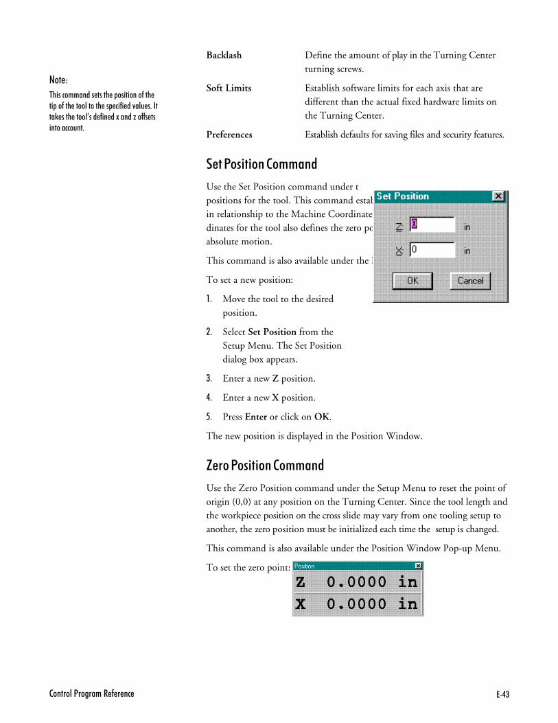
?+*)�����'�9�������4�(���� �
Backlash Define the amount of play in the Turning Centerturning screws.
Soft Limits Establish software limits for each axis that aredifferent than the actual fixed hardware limits onthe Turning Center.
Preferences Establish defaults for saving files and security features.
��� !������� �������
Use the Set Position command under the Setup Menu to set new X and Zpositions for the tool. This command establishes a World Coordinate Systemin relationship to the Machine Coordinate System. Setting the X and Z coor-dinates for the tool also defines the zero point of the coordinate system forabsolute motion.
This command is also available under the Position Window Pop-up Menu.
To set a new position:
01 Move the tool to the desiredposition.
81 Select Set Position from theSetup Menu. The Set Positiondialog box appears.
21 Enter a new Z position.
31 Enter a new X position.
41 Press Enter or click on OK.
The new position is displayed in the Position Window.
;��� !������� �������
Use the Zero Position command under the Setup Menu to reset the point oforigin (0,0) at any position on the Turning Center. Since the tool length andthe workpiece position on the cross slide may vary from one tooling setup toanother, the zero position must be initialized each time the setup is changed.
This command is also available under the Position Window Pop-up Menu.
To set the zero point:
'����
#��� ����� ����������������(������(�����'�������� �(�� �/�'$����!�2�������'%�� �(��� �1��� �M��((�������� �$��

?+** 4�(���� ��"$� �B��� ����?
01 Move the tool to the point on the workpiece you intend to establish asthe zero point.
81 Select Zero Position from the Setup Menu. The new position (0,0) isdisplayed in the Position Window.
+�� �������� �������
Use the Jog Settings command to open the Jog Settings dialog box. This dialogbox is used to enter speed and distance values for the Jog Control Panel. The
Jog Settings command is also available through the Jog Control Panel Pop-upMenu.
To set jog parameters:
01 Select Jog Settings from the Setup Menu. The Jog Settings dialog boxappears.
81 Enter the desired jog speeds and distances.
21 Select OK or press Enter. The new values are applied to the Jog ControlPanel.
+�� �����
The jog speed is the rate at which the tool moves along the X and Z axes. Se-lect the speed by entering the desired speed in the Jog Settings dialog box,then press the appropriate button (Slow, Medium or Fast) on the Jog Con-trol Panel.
The default values for speed are:
� 1 ipm for Slow� 15 ipm for Medium� 25 ipm for Fast
These feed rates can be set as high as 30 inches per minute.
�(�����������5������� ���� ����������E���������� ��'���&�1������'�������'0���/� �$����������� ��� ����&$���������E��������'�9���'�

?+*;�����'�9�������4�(���� �
+�� "������� G�����H
Distance values determine how far the tool moves each time a key is pressed.Referred to as Steps, the distance is selected by pressing the A, B or C buttonson the Jog Control Panel. Using the Jog Settings dialog box, the distance canbe set at a low value (for instance 0.0005 inch) to move the tool for a precisecut, or at a high value (e.g. 5 inches) to position a tool.
These are the default values for steps:
� 0.001 inch for Step A� 0.01 inch for Step B� 0.1 inch for Step C
Pressing the Continuous (Cont.) button moves the tool continuously as longas the axis button is depressed. Once the axis button is released, the toolstops.
#�� �������� �������
Use the Run Settings dialog box to set or clear options for running your NCprogram. The available options are:
� Single Step
� Optional Skip
� Optional Stop
� Enable Subprograms
� Arc Centers Incremental
� Treat Warnings as Errors
� Restore Unit Mode When Done
� Verify While Running
������ ����
This option inserts a Pause after each block of the NC program. To move onto the next block in the program, you can:
� Click the Run button on the Standard Toolbar.
� Click the GO button on the Message Bar.
� Press F5.
� Press Enter.

?+*- 4�(���� ��"$� �B��� ����?
� Select Run/Continue from the Program Menu.
)������� �5��
Use this option to enable or disable the optional skip code. The optional skipcode allows you to skip blocks of code as the NC program is run.
Make sure to check off the Optional Skip box in the Run Settings dialog boxor activate the Optional Skip button on the Operator Panel. Then place aforward slash ( / ) in front of each line in the NC program you want to skip.
With Optional Skip off, each skip code is ignored and each block of code isexecuted. With Optional Skip on, each skip code is recognized and eachblock of code that has been tagged with a skip code is skipped.
To execute particular blocks every nth pass, place a number after the optionalskip. For example: /5G28; Home every fifth pass
)������� ����
Use this option to enable or disable the optional stop code (M01). The op-tional stop code allows you to place an optional stop in your NC program.
Make sure to check off the Optional Stop box in the Run Settings dialog boxor activate the Optional Stop button on the Operator Panel. Place an M01on the line of code where you would like to pause.
With the Optional Stop option on, the M01 works like a G05. With OptionalStop off, the M01 code is ignored, the other codes on the block are executedas usual.
%��*�� ��*��������
Use this option to enable or disable the use of subprograms. With this optiondisabled, M98 commands generate an error. Running or verifying a programwith subprograms enabled takes longer to start because the software parsesthe entire file for subprogram information. This extra delay should only benoticeable with very large programs.
��� ������� ����������
Use this checkbox to specify the default mode for programming arc centers.If this box is checked, the default mode is the Fanuc mode, in which arc centersare always incremental. If this box isn’t checked, the default mode is EIA-274, in which arc centers follow the general programming mode: absolutewhen the mode is absolute, and incremental when the mode is incremental.
����� ,������� �� %�����
This command is used for special applications, such as laser welding, whereyou don’t want any unexpected pauses in the program execution. For example,
'����
#����������������'(� ����/���� ��� �(�$'�&0��'� ������!� ������'��� �������GHI�����&��'$���� �������GJI� � ��������(����'�����(���(�'��

?+*,�����'�9�������4�(���� �
when a warning is displayed and the program pauses, waiting for your inputbefore it continues.
When this item is checked, any warning will halt the program, performing aprogram Stop. When motion is stopped, all outputs are turned off.
#������ ���� (��� , �� "���
If you normally work in one unit mode (inch or metric) but would like torun a program in another mode without disrupting your default settings,check this box.
Select a specific unit mode by using one of the G20/G21 or G70/G71commands at the beginning of your NC program. Once the NC program isexecuted, your default unit mode will be restored.
For instance, if you normally work in Inch Mode, but have a particular pro-gram you would like to run in Metric Mode, check the Restore Unit ModeWhen Done box. Place a G21 code at the beginning of your program, thenrun it. When the program is finished, the default for your system will still beInch Mode.
=���$� , ��� #������
If this box is checked, the Verify window will display the program verificationwhile the program is running. The verification does not show exactly what is
happening on the Turning Center. There is a delay between each tool motion.You will see each tool motion on the screen, but the screen will pause untilthe machine finishes the motion and the next program block is read.

?+*� 4�(���� ��"$� �B��� ����?
=���$� �������� �������
Use the Verify Setup dialog box to control the appearance of the tool pathverification. You can also access this dialog box using the Verify WindowPop-up Menu.
The Verify Settings dialog box is tabbed, with the settings organized intothree groups: the Display Panel, Tool Position Panel and Stock Panel.
"������ !����
The Display Panel allows you to control the view. It offers a selection of viewpreferences.
Zoom
Use these buttons to control the size of the stock in the Verify Window. Youcan click on the buttons or use Alt key combinations (Alt++, Alt+-, and Alt+A).Each mouse click or key combination used zooms by an increment of one.
������ &�������
+ Zoom in on the stock.- Zoom away from the stock.
All Fit the stock into the window.Arrows Move in the indicated direction.
Center the stock.
Colors
Use these buttons to select which colors will indicate the background, stock,and tool in the Preview Window. Color options can be viewed by clickingon the down arrow to access a bar of various colors.
Verify Speed
Use the slider to alter the speed at which the Verify Program will be executedin the Verify Window. If you would like to view the verify program in slowermotion, move the slider to the left. If you would like to view the Verify Pro-gram at a faster rate, move the slider to the right.
� � !��B��� ,�����
The Preview Window appears in the Display and Stock Panels. The PreviewWindow shows you approximately what the Verify Window will look like.The preferences for the Preview and Verify Windows are set in the DisplayPanel.

?+*������'�9�������4�(���� �
Other Options
If the Auto Refresh on Resize box is checked, the Verify Window automati-cally refreshes the display of the workpiece if the Verify Window is resizedduring verification. When Auto-refresh is disabled, you will need to manu-
ally cause the verify window to update by selecting the Redraw commandfrom the window’s context menu. This setting only affects refreshing thewindow when no verification is in progress.
���� !������� !����
The Tool Position Panel controls the initial tool position and the tool loca-tion in reference to the stock.
Initial Tool Position
You can select a tool start point using Initial Tool Position. Only use InitialTool Position for verification, not for actually running a program. The Ini-tial Tool Position is used when you verify a program; when verifying an NCprogram while running it, the actual physical position of the tool is used asthe initial tool position.

?+;. 4�(���� ��"$� �B��� ����?
Tool Location
The specification of tool location depends on where your tool will bemounted according to the NC program you are using. You must check ei-
ther Above Stock or Below Stock. Usually the a single tool is mounted onthe tool post below the stock and the optional tool turret is mounted abovethe stock.
����5 !����
The Stock Panel allows you to specify particular information about the stockand tool position for tool path verification.
All stock values are interpreted according to the Units Mode in effect at thetime they are set. To quickly see which Units Mode is currently in effect, checkthe Position window.
Dimensions
Use this area to set the dimensions of the stock used in the verificationprocess. You will see the stock in the Preview Window change as soon as youenter a dimension.
Origin
�������
The OK button at the bottom of the dialog box applies the changes you havemade and closes the dialog box.
The Cancel button closes the dialog box without applying any of the changesyou have made.
The Help button brings up the Help topic.

?+;������'�9�������4�(���� �
Use this area to adjust the verification for different workpiece setups. MostNC programs set the 0,0 point at the left center of the stock, immediately infront of the chuck. The origin of the stock must be based on this 0,0 point.
The origin of the stock is always 0,0. The stock initialization point varies de-pending on where the origin is relative to the stock.
Show Chuck and Origin Marker
Check this box to display the Chuck and the Origin Marker in the Previewand Verify Windows.
���F� ��5 ���� �������
The Set/Check Home command performs two functions, it sets a referenceposition on the machine and it helps you to check the reference position onthe machine. When you select the Set/Check Home command the followingdialog box appears.
The Set Home button opens the Reference Point Wizard, which aids you insetting a machine reference point. Just follow the directions.
The Use Current button uses the last defined Reference Point. Home mustalready be set in order for this button to work.
'����
��'����4�(���� ��9������M�� ���� �/������� ����(�� ��������'���� ��7�;�����8�$� �������'������(�� ����
���������
!(�0�$�����$�����"7,����"7�� � �����0�$��������������0�$��$��$����4�(���� ��9������M�� ���������� ����(����
'����
!(�0�$���$' �'�2������'�����/�'����4��� �(�� ������ '� 2�������#�����&$�������� �
01 Enter the coordinates for thenew tool position.
81 Enter the feed rate at which youwould like the tool to travel.
21 Click on the Go button. Thetool moves to the new positionat the defined feed rate.

?+;7 4�(���� ��"$� �B��� ����?
(!)#��'�7
�� ���� ��� �������������&'��� �&0����������0���������&'����������(�������������� ���(���/�'�����#$�������������:� �����&'��� ����� ��� �������������(�1� ��?� ����0�$�$��������#$�������������� $������� ������������������� ������� ���� ��� ������0����C.�>.�
���2� ��� ���������� �((���������0�$�$��������9������� ����� �������������(����������������2��� ��0�$������ $�''0������������������������((���(������(�1� ��� ������������#������������ $������0�$�$�����"�7� � ��
���2����� �������������(�1� Q��0 ���&�����&'��� ���0����������0����&0�$���������������9������ ����� ������"�7� � ��
����������2����� ������0�$� ������������� ��� ������0�����$������ � ���";*���$��";���������$������ ������0����� ��'���&�1�
!(�0�$�����������2����� ���������������"�7� � ���������� ��'��&�1����";*+";������ ������0����((������''� ������ �� ���'0�
!(�0�$���������� ������'��$�������� ������0���������((������''���&���((� � �
The Move Home button moves the machine to the reference point coordi-nates so you can manually measure the machine position to make sure no po-sition has been lost.
��� !������� �������
The Goto Position command opens the Goto Position dialog box. Use theGoto Position dialog box to move the tool to a particular coordinate posi-tion on the Turning Center.
This command is also available under the Position Window Pop-Up Menuand Jog Control Panel Pop-up Menu. To use the Goto Position command:
����� �������
Use the Units command under the Setup Menu to select the unit of measurefor the application. When you select the Units command, a fly-out menu ap-pears allowing you the option of using Inch (standard) or Metric measurement.
���������� ������� �������
Use the Coordinate Systems command under the Setup Menu to define multiplecoordinate systems for machining more than one workpiece. This is oftendone for production runs of the same part. This command is also availableunder the Position Window Pop-up Menu.
�� ������ �� �-������ ���������� �������
01 Select Coordinate Systems from the Setup Menu. The coordinates fly-out menu appears.

?+;)�����'�9�������4�(���� �
81 Select an existing coordinate system from the fly-out menu. Select one ofthe available coordinate systems available, CS1 through CS6, (these areequivalent to using the codes G54 through G59 in your NC program).
OR
Select the Work Coordinates command to cancel the Coordinate Systemoffsets and return to Work Coordinates.
�� ��$��� � ��� ���������� �������
01 Select Coordinate Systems from the Setup Menu.
81 Select Setup from the fly-out menu. The Setup Coordinate Systems dia-log box appears.
21 Select a coordinate system, then enter and apply the offsets.
a) Select a CS from the System list.
The system titled “Work CS” contains the current values for the workcoordinate system. This is like adding a G92 code to your NC pro-gram. You can change the default for the work coordinate system byentering new values in the Offsets boxes. These values are an offset fromthe true origin of a coordinate system and affect all coordinate systems.
b) Select the offsets for a user coordinate system by:
� Entering X and Z offset values in the Offsets boxes.

?+;* 4�(���� ��"$� �B��� ����?
� Clicking the Current Pos button to establish offset values basedon the current tool position.
� Selecting a Marker in the Preview Area for the coordinate sys-tem and dragging it to the desired position.
� Copying offsets from one CS to another using the Copy Offsetsand Paste Offsets buttons.
c) Make the currently selected CS the active CS by checking the ActiveOffset box.
d) Apply the coordinates or exit the dialog box:
� The OK button applies the changes you have made and closesthe dialog box.
� The Cancel button closes the dialog box without applying anyof the changes you have made.
� The Apply button applies the changes you have made to the se-lected CS (you can still cancel changes once they have been appliedby selecting the Cancel button).
)$$���� �������
Use the Offsets command under the Setup Menu to compensate for varia-tions in the cutting tools being used. The offset values are used for cuttercompensation and tool offset adjustment NC codes.
�� ����� � ������������ �$$����
01 Select Offsets from the Setup Menu. The Setup Offsets dialog box appears.

?+;;�����'�9�������4�(���� �
81 Click on an Offset Number (the numbers 1 through 199 are available).This number only acts as a designation (a name) for the offset.
3. Enter an Offset Value in the Value box, or select the Current Z buttonto use the current Z position (also useful for defining tool heights if youare using G43 or G44 to specify tool heights).
31 Press Enter or click on OK. The Offset Value has been associated withthe Offset Number. The next time you open the Offsets table, you willsee the new offset.
� � )$$��� ��*��
The Offset Table stores up to 200 values which are used in several operationsincluding tool offset adjustment, cutter compensation, and tool length com-pensation to ensure uniform application of an offset value. The numbers arestored as unit-less values; their interpretation depends on the Units defaultcurrently in effect.
Set the values in the Offset Table using the Offsets command under the SetupMenu.
������� �������
Use the Spindle command under the Setup Menu to specify a spindle speedif you have not used an S code in your NC program.
The spindle speed is primarily determined by the Mode Switch on the TurningCenter front panel. If the Mode Switch is set to Manual Mode, spindle speedis controlled by the Spindle Speed Control Knob, also on the front panel. If
'����
#���(��$��� ��������/���� ������ � ������������������

?+;- 4�(���� ��"$� �B��� ����?
'����
8�$���$' ������� �(0�����'����(��&� 2'���(�� ��������0�$���''���� � �'�0���� ���������1������&� 2'�� ������ ��� ����
the Mode is set to computer, spindle speed is determined by an S code in theNC program. If there is no S code in the NC program, spindle speed is de-termined by the Setup Spindle dialog box.
�� �����$� � ������� ������
01 Select the Spindle command from the Setup Menu. The Spindle Setupdialog box appears.
81 Select a spindle speed by entering a value in the RPM box, or by usingthe slider and arrow buttons.
���� �� � �� ������ *�-�
� Reset the spindle override value to 100% by clicking on the Reset Overrideto 100% button.
� Change the On/Off state of the spindle using the Spindle On andSpindle Off buttons.
� Select Done to close the dialog box.
���5��� �������
Use the Backlash command under the Setup Menu to define the amount ofplay in the Turning Center turning screws. The system default is set at abacklash value of 0.0 on both axes, with a feed rate of 10 ipm.
To establish new backlash parameters:
01 Select Backlash from the Setup Menu. The Setup Backlash dialog boxappears.
(!)#��'�7
��(�'��������� �(��� ������'���������� ���� ��� �����Q����(����0�$��$��������#$�����������&�(����$�������(�'��������(�'�������������(�� � ��(���#$�����������������&������� �

?+;,�����'�9�������4�(���� �
81 Enter the desired backlash distances and feed rate.
21 Press Enter or click on OK to accept the new backlash parameters, orclick on Cancel to exit the Setup Backlash dialog box without settingnew backlash parameters.
��$� ������ �������
Use the Soft Limits command under the Setup Menu to establish softwarelimits for each axis. The limits are different than the actual fixed hardwarelimits on the Turning Center. Soft limits can confine the tool travel to anarea smaller than the normal maximum travel.
The Turning Center shuts down if it trips a soft limit, just as it does when ittrips one of the limit switches. This is helpful when working with devicessuch as robots, or when you have installed fixtures within the normal workarea that you don’t want the tool to hit.
To establish software limits on the Turning Center:
01 Select Soft Limits from the Setup Menu. The Setup Soft Limits dialogbox appears.
81 Enter the coordinates that define the software perimeter you wish toestablish.
21 Click on the Enable Soft Limits option to enable soft limits. Use thisoption to turn soft limits on or off as you need to use them.
31 Press Enter or click on OK to accept the new soft limit parameters, orclick on Cancel to exit the Setup Soft Limits dialog box without settingnew soft limit parameters.
!��$������� �������
Use the Preferences command under the Setup Menu to establish defaults forsaving files and setting security features.
�� ����� � � ������ ���$��������
01 Select the Preferences command from the Setup Menu. The Preferencesdialog box appears.
'����
8�$��$��&�����������(���������������� �����?��&'������(��������!(�0�$������$�� ���(�����(������������� ���(�������������&'� �����0�$� '������ ��'��&�1���0���''�&���$���� �''0 ���&'� ��� �0�$���''�&������$ � ��5������� ���������������(���������(���0�$� ������0�$� �����������(������� ��'���&�1��� ����&'����

?+;� 4�(���� ��"$� �B��� ����?
81 Select one of the Editor ,Security or Misc. preferences tabs.
%����� !��$�������
The Editor preferences allow you to automatically save your NC programfiles at regular intervals, and establish a default directory in which to storeyour files. When you select the Editor tab in the Preferences dialog box, theEditor panel appears (depicted above).
To select AutoSave features:
� Select Save when idle and enter a value in the Every:___ minutes box tosave your NC programs automatically at the specified time increment.
� Select Save Before Running to save changes to your NC program priorto running it for the first time with the changes.
To select File Default features:
� Enter an Extension for your NC part program files. The default is “NC.”
� Select Lock Files When Opened to have your NC programs locked by de-fault. Deselect this feature to have your NC programs unlocked by default.
� Select the Set button to specify a target directory in which to save yourNC program files. The default directory appears in the Directory box.

?+;������'�9�������4�(���� �
Other features:
� Select Hilite Comments to distinguish the comments from commands inyour NC program.
� Select Quick Run/Verify by Default to always run or verify without beingprompted to select the file or the start line.
To exit the Preferences dialog box:
Press Enter or click on OK to accept the new preference settings, or click onCancel to exit the Preferences dialog box without setting new Editor orSecurity preferences.
To access Help for this panel:
Select the Help button to access the Help files for this panel.
�������� !��$�������
The Security preferences allow you to control which features others may use.When you select the Security tab in the Preferences dialog box, the Securitypanel appears.
The Security preferences panel offers two modes, User and Administrator.Administrator Mode allows a supervisor, such as a teacher in a classroom, toturn commands on or off using the Allowed Commands list. User Modedoes not have access to this feature.
To secure the software using Administrator Mode:
01 Set the Default Mode to User. (This will not change the current mode.)
81 Use the Change Password button to create a password. The default pass-word is blank — no password.
21 Select the Allowed Commands. Double-click on the listed commands toenable or disable them. If the commands are enabled, they are markedwith an X. A description of each selected command is displayed on theright side of the panel.
31 Use the Change Mode button to change to User Mode.
41 Select OK or press Enter to exit the Preferences dialog box.
The software is now running in User Mode. The next time you open thePreferences dialog box, the Security preference panel is displayed in UserMode. In this mode it is not possible to turn commands on or off.
To return to Administrator Mode:
(!)#��'�7
������� $��0�����$������(�''�������$��(��$�������� ���&'� �&0� �(�$'��������(������������������ ��
� ���� ������0�����G�� ���'�� (��$���I
� :((���
� ��(������
� 9��(���� ��#�� ����� �������&'� ��&$��'� ��������''�������(����� ����������������� �&�(�����9��(���� ��� ��'���&�1���������
� <� 2'��
#��4������������� ����� �$� ������'�����$�����'��� ���&'� �&0 �(�$'�

?+-. 4�(���� ��"$� �B��� ����?
(���1 !��$�������
The Misc. preferences allows you to choose to Confirm the reference pointby checking the Confirm ‘Zero Position’ Command box. By checking thisbox, the warning “Are you sure you want to reset the current position toZERO on all axes?” will appear every time the Zero Position Command isactivated in the Setup menu. You must then select Yes to apply the com-mand.

?+-������'�9�������4�(���� �
01 Use the Change Mode button to toggle the Mode from User to Admin-istrator. A dialog box appears, prompting you to enter your password.
81 Enter your password and press Enter or click on OK.
To change your password:
01 Click on the Change Password button.
81 Enter your current password.
21 Enter the new password.
31 Enter your new password again to verify that it is correct.
To exit the Preferences dialog box:
Press Enter or click on OK to accept the new preference settings, or click onCancel to exit the Preferences dialog box without setting new Editor orSecurity preferences.
To access Help for this panel:
Select the Help button to access the Help files for this panel.
,����� (���
The Window Menu commands allow you to manipulate the arrangement ofthe Program Edit Windows.
�������� ���� ���
Cascade Layer the open edit windows.
Tile Tile the open edit windows.
Arrange Icons Arrange any minimized edit windows along thebottom of the edit area.
Window List Display and select between the currently open NCprograms by their file names.
������� �������
Similar to the standard Windows/Cascade command, this command placesthe open Program Edit Windows in a layered format, cascading down to theright with the currently selected window on top.

?+-7 4�(���� ��"$� �B��� ����?
���� �������
Similar to the standard Windows/Tile command. Places the open ProgramEdit Windows in a tiled format, filling the Edit Area from top to bottom.
������� ���� �������
When you minimize a Program Edit Window, it becomes a small icon. TheArrange command under the Window Menu arranges these icons along thebottom of the edit area.
,����� ���� �������
Lists the currently open Program Edit Windows. The currently selected win-dow is designated with a check mark. You may select any window by clickingon the window itself, or by selecting the window name from this list.
���� (���
The Help Menu commands allow you to navigate through the Help files, tosave or restore parameters set throughout the current session, and provideshandy tips and other information about the Control Program.
�������� ���� ���
Help Display Help for the current task or command.
Index List Help topics.
Using Help Display instructions about how to use Help.
Save Settings Saves the current machine and application settings.
Restore Settings Resets the machine and application settings fromdefaults.
Tip of the Day Display a Tip of the Day.
About WSLT Display program information, version number andcopyright.
���� �������
Use the Help command to access the Help contents. You can also press theF1 key to get information about the currently highlighted command on adrop-down or pop-up menu.
'����
:���''�����'����=�(�$'�&$���������������'�9���������$���(� ��0��� �(�$'����''�/�'$������������'�����&��� ������$����(�����$�����'� � �������$������������' ����9���'�

?+-)�����'�9�������4�(���� �
���- �������
Use the Help Index command access an index of available Help topics.
����� ���� �������
Use the Using Help command to obtain information on how to use theHelp utility.
��B� �������� �������
The Save Settings command brings up a dialog box that allows you to retaincurrent library, security, screen and control settings as defaults.
� Click on a particular setting(s) to tag it, then click on the Save button tosave the selected items and exit the dialog box.
� Click on the Save All button to save all settings without having to selecteach one.
� Click on the Cancel button to exit the Save Defaults dialog box withoutchanging the existing defaults.
#������ �������� �������
The Restore Settings command allows you to restore all or some of the cur-rent settings to the defaults you set using the Save Settings command (UserDefaults) or to the factory set defaults.
� Click on a particular setting(s) to tag it, then click on a Restore Fromoption. Click the Restore button to restore the selected items and exitthe dialog box.
� Click on the Restore All button to restore all settings without having toselect each one.

?+-* 4�(���� ��"$� �B��� ����?
� Click on the Cancel button to exit the Restore Defaults dialog box with-out changing the existing defaults.
��� �$ � � "�� �������
This command brings up information about the operation of the Turning Cen-ter, tips and tricks for using the Control Program and NC programming ideas.
�*��� ,��� 111 �������
This command simply brings up an information box. Included is informa-tion on the Control Program version number, the release date, and copyrightinformation.
��������� ��������There are a few different ways to select commands in the Control Program.Use the method that is most convenient for you.
������ � ������� ����� !��A�� (����
Clicking the right mouse button on certain windows or panels brings up apop-up menu. Each pop-up menu is context-sensitive. Commands whichcannot be performed at that time are grayed out.
To select a pop-up menu command:
01 Position the cursor on the window or panel.
81 Click and hold down the right mouse button. The context-sensitivemenu appears.
21 Highlight a command by moving the mousepointer over it, then release the right mousebutton.
The following windows have pop-up menus:
� Program Edit Window
� Position Window
� Verify Window
� Jog Control Panel

?+-;�����'�9�������4�(���� �
The Machine Info Window and Operator Panel only provide the Dockableand Hide commands on their Pop-up menus.
!������ %��� ,����� !��A�� (���
The Program Edit Window Pop-Up Menu contains different combinationsof these commands, depending on whether the file is running or being veri-fied, and whether or not text is selected.
��� �������
Cut is the same as selecting the Cut command from the Edit Menu.
���� �������
Copy is the same as selecting the Copy command from the Edit Menu.
!���� �������
Paste is the same as selecting the Paste command from the Edit Menu.
����� �������
Clear is the same as selecting the Clear command from the Edit Menu.
%B������ ��������� �������
Evaluate Selection will process an equation which is highlighted and replace it witha result. If the selected text is not a valid numerical equation, there is no result.
��� ���� �������
Goto Line is the same as selecting the Goto Line command from the Edit Menu.
#����*�� �������
The Renumber command is the same as selecting Renumber from the Edit Menu.A dialog box appears that allows you to alter the N codes in the NC program.
��B� �������
Save brings up the Save As dialog box.
I���5#�� �������
The QuickRun command is a shortcut that runs the currently selected NCpart program. When you click the right mouse button on this command, theprogram behaves as though you had selected the Run/Continue Commandfrom the Program Menu with the following exceptions:
� You do not have the option of selecting a starting line.
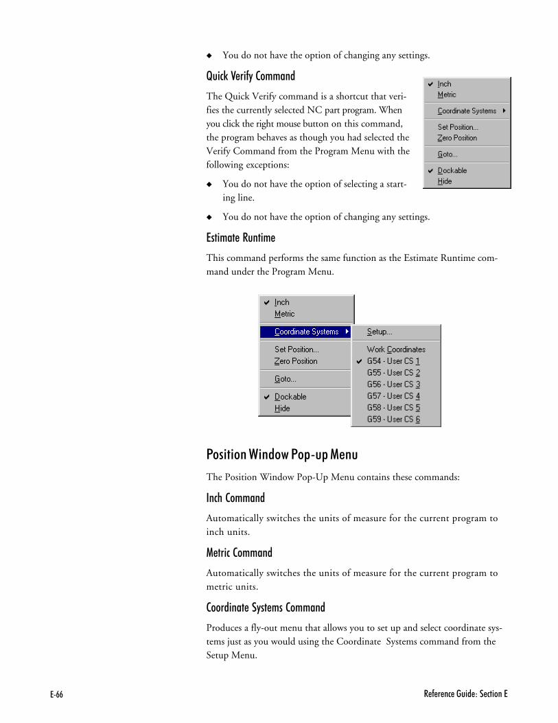
?+-- 4�(���� ��"$� �B��� ����?
� You do not have the option of changing any settings.
I���5 =���$� �������
The Quick Verify command is a shortcut that veri-fies the currently selected NC part program. Whenyou click the right mouse button on this command,the program behaves as though you had selected theVerify Command from the Program Menu with thefollowing exceptions:
� You do not have the option of selecting a start-ing line.
� You do not have the option of changing any settings.
%������� #������
This command performs the same function as the Estimate Runtime com-mand under the Program Menu.
!������� ,����� !��A�� (���
The Position Window Pop-Up Menu contains these commands:
�� �������
Automatically switches the units of measure for the current program toinch units.
(����� �������
Automatically switches the units of measure for the current program tometric units.
���������� ������� �������
Produces a fly-out menu that allows you to set up and select coordinate sys-tems just as you would using the Coordinate Systems command from theSetup Menu.

?+-,�����'�9�������4�(���� �
��� !������� �������
Opens the Set Position dialog box.
;��� !������� �������
Sets the current tool position to zero on both axes.
��� �������
Opens the Goto Position dialog box.
"��5�*�� �������
The Dockable command toggles the window between being a dockable win-dow and being undockable. See Docking and Floating Windows for moreinformation.
This command is available on all pop-up menus for the windows and panelsavailable under the View Menu.
���� �������
The Hide command closes the window. To open the window again, select itfrom the View Menu.
This command is available on all pop-up menus for the windows and panelsavailable under the View Menu.
=���$� ,����� !��A�� (���
The Verify Window Pop-Up Menu contains these commands:
����� �������
This command opens the Verify Settings dialog box.
#����� �������
This command repeats the most recent tool pathverification simulation.
���� #����� �������
This command interrupts the verification currently in progress.
#���� �������
This command resets the Verify Window; it clears the tool path lines and re-sets the tool to the starting position.
"��5�*�� �������
The Dockable command toggles the window between being a dockable win-dow and being undockable. See Docking and Floating Windows for moreinformation.

?+-� 4�(���� ��"$� �B��� ����?
This command is available on all pop-up menus for the windows and panelsavailable under the View Menu.
���� �������
The Hide command closes the window. To open the window again, select itfrom the View Menu.
This command is available on all pop-up menus for the windows and panelsavailable under the View Menu.
+�� ������� !���� !��A�� (���
The Jog Control Panel Pop-Up Menu containsthese commands:
����� �������
This command opens the Jog Settings dialog box.
��� �������
This command opens the Goto Position dialog box.
���F� ��5 ���� �������
This command opens Machine Home/Reference Point dialog box.

?+-������'�9�������4�(���� �
"��5�*�� �������
The Dockable command toggles the window between being a dockable win-dow and being undockable. See Docking and Floating Windows for moreinformation.
This command is available on all pop-up menus for the windows and panelsavailable under the View Menu.
���� �������
The Hide command closes the window. To open the window again, select itfrom the View Menu.
This command is available on all pop-up menus for the windows and panelsavailable under the View Menu.
������ � ������� ����� ��� ����
Some menu commands have one or more key designations next to them; thoseare the hot keys for that command. Pressing the hot key(s) selects the corre-sponding command. For example, press Ctrl+S to save your file. Other hotkeys are also available for controlling machining functions; for instance, usethe Ctrl+KeyPad+ combination to increase feed rate override.
Here’s a list of the available hot keys:
���G�H� (���F��������
Ctrl+C Edit Menu/CopyCtrl+F Edit Menu/FindCtrl+G Edit Menu/Goto LineCtrl+H Setup Menu/Set/Check HomeCtrl+L Edit Menu/LockCtrl+N File Menu/NewCtrl+O File Menu/OpenCtrl+P File Menu/PrintCtrl+R Setup Menu/Run SettingsCtrl+S File Menu/SaveCtrl+Space Program Menu/StopCtrl+T Tools Menu/Setup LibraryCtrl+V Edit Menu/PasteCtrl+X Edit Menu/CutCtrl+Y Edit Menu/Delete LineCtrl+Z Edit Menu/UndoCtrl+Shift+Z Setup Menu/Zero PositionF1 Help Menu/HelpF2 Edit Menu/Delete Line
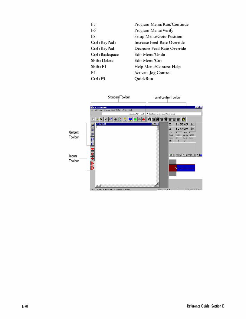
?+,. 4�(���� ��"$� �B��� ����?
F5 Program Menu/Run/ContinueF6 Program Menu/VerifyF8 Setup Menu/Goto PositionCtrl+KeyPad+ Increase Feed Rate OverrideCtrl+KeyPad- Decrease Feed Rate OverrideCtrl+Backspace Edit Menu/UndoShift+Delete Edit Menu/CutShift+F1 Help Menu/Context HelpF4 Activate Jog ControlCtrl+F5 QuickRun
��� �� �#��'&��
:$�$�#��'&��
!��$�#��'&��
#$���������'�#��'&��

?+,������'�9�������4�(���� �
Ctrl+F6 Quick VerifyCtrl+TAB Next Edit WindowCtrl+Insert Edit Menu/CopyShift+Insert Edit Menu/PastePause Edit Menu/Pause
������ � ������� ����� ����*���
The Tool Bars contain buttons that correspond to frequently used menucommands. Clicking a button on a toolbar is equivalent to selecting the samecommand from a menu, and is usually quicker. The Control Program pro-vides Standard, Input, Output , and Turret Control toolbars. Use the com-mands under the View Menu to control whether each tool bar is displayed orhidden.
!���������� ������ ����������The Control Program interface is easily configured and optimized by open-ing, closing, resizing, and repositioning the screen components.
!���������� ����*���
You can reposition any of the toolbars (Standard, Inputs, Outputs, or TurretControl) simply by dragging them off their docking areas. Once away fromthe docking area, the toolbar becomes a floating window, which can betreated the same as any other window (E.G. move it, resize it, close it). Tomove the toolbar, click on the toolbar background (the area behind the but-tons) and drag.
!���������� ,������ ��� !�����
The windows and panels, (Position Window, Machine Info, Jog ControlPanel, Operator Panel, Verify Window) are initially docked on the dockingarea on the right side of the screen. If these items are moved away from thedocking area, they become floating windows or panels until they are movedback to the docking area. (See Docking and Floating Windows and Toolbarson the following page.) The Verify Window is initially not dockable.
�� ��B� � ������ �� ����� G������ � $������� ������H�
01 Press and hold the Ctrl key.
81 Click on the window/panel with the left mouse button.
21 Hold and drag the window/panel off the docking area.
"��5��� �����
#�����0���������(���� �����������'&�������� ������ ���(������������������'� � �����������0��&5� ��
�''�����'&�������� ������ �����'�(�$� �$� �����D�������$� ���&����������� �
#����'&������ '$ �B
� !��$��#��'&��� :$�$��#��'&��� ��� �� �#��'&��
#����� ������ '$ �B
� 9���������� ��� �� ����!�(����� ��� E��������'�9���'� :�������9���'� D���(0���� ��

?+,7 4�(���� ��"$� �B��� ����?
41 When the floating window is over its new location, release the mousebutton. You can now treat the area the same as you would any otherwindow (e.g., move it, resize it, close it).
�� ������ � $������� ������ �� ��� ���5��� �����
(The Dockable command must be invoked for a window/panel before it canbe docked. See Docking and Floating Windows and Toolbars.)
01 Click on the title bar of the floating window.
81 Drag the area back to the docking area.
21 Release the mouse button.
!���������� !������ %��� ,������
Program Edit Windows can be moved, resized or closed just like any otherwindow. The only restriction is that the Edit Windows can not be movedout of the edit area. For instance, you can not move an Edit Window to adocking area.

?+,)�����'�9�������4�(���� �
��B��� � � ��������� !�������
After changing a component’s position on the screen, you can save it’s positionby checking the Window Positions box on the Save Settings dialog box (se-lect Save Settings from the Help Menu). The next time you use the ControlProgram, the component appears in the new position. To restore the defaultposition (the factory preset position), use the Restore Settings command un-der the Help Menu.
"��5��� ��� &������� ,������ ��� ����*���
Windows and Toolbars can behave in two ways; they can be placed in a sta-tionary state, docked, or they can be in a free-floating state, and moveable.
"��5��� ������ ����������
A docked screen component is fixed in place, unlike a floating componentwhich can be placed anywhere on the screen. When a screen component isdocked, the window frame and title disappear.
&������� ������ ����������
A floating screen component can be moved to any position on the screen,unlike a docked screen component, which is fixed in place. When a screencomponent is floating it has a window frame and title.
�� ������ � � "��5���F&������� ����� �$ � ����*���
� Click on the background area of the toolbar and drag it away from thedocking area to float it.
� Click on the background or the title bar of the toolbar and drag it to thedocking area to dock it.
�''�����'&�������� ������ �����'�(�$� �$� �����D�������$� ���&� � 2� ����('������
#����'&������ '$ �B
� !��$��#��'&��� :$�$��#��'&��� ��� �� �#��'&��� #$���������'�#��'&��
#����� ������ '$ �B
� 9���������� ��� �� ����!�(����� ��� E��������'�9���'� :�������9���'� D���(0���� ��
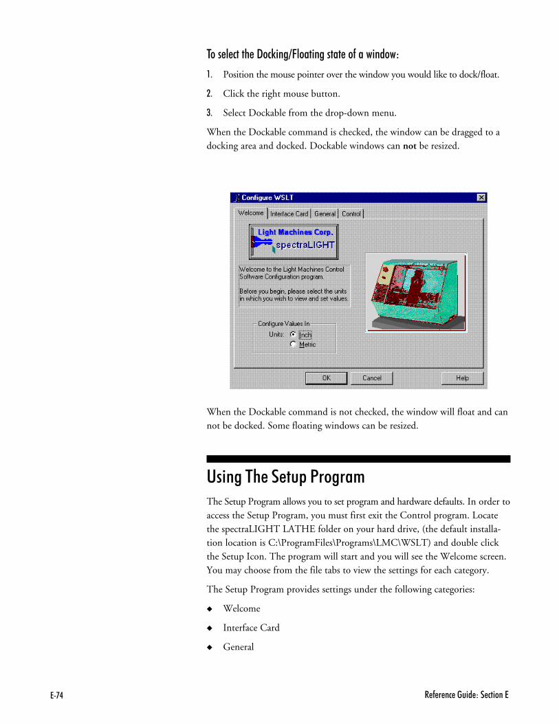
?+,* 4�(���� ��"$� �B��� ����?
�� ������ � � "��5���F&������� ����� �$ � �������
01 Position the mouse pointer over the window you would like to dock/float.
81 Click the right mouse button.
21 Select Dockable from the drop-down menu.
When the Dockable command is checked, the window can be dragged to adocking area and docked. Dockable windows can not be resized.
When the Dockable command is not checked, the window will float and cannot be docked. Some floating windows can be resized.
����� � � ����� !������The Setup Program allows you to set program and hardware defaults. In order toaccess the Setup Program, you must first exit the Control program. Locatethe spectraLIGHT LATHE folder on your hard drive, (the default installa-tion location is C:\ProgramFiles\Programs\LMC\WSLT) and double clickthe Setup Icon. The program will start and you will see the Welcome screen.You may choose from the file tabs to view the settings for each category.
The Setup Program provides settings under the following categories:
� Welcome
� Interface Card
� General

?+,;�����'�9�������4�(���� �
� Control
'����
:���''�����'����=�(�$'�&$���������������'�9���������$���(� ��0��� �(�$'��(�����/�'$�������� $��������'���''�/�'$������������'�����&��� ������$����(�����$�����'� � �������' ����9���'�

?+,- 4�(���� ��"$� �B��� ����?
,������ !����
This panel provides one option, Units Default. This option sets the default unitof measure for the Control Program and the Setup Program. When runningthe Control Software, you can change the default using the Units commandunder the Setup Menu.
����$��� ���� !����
This panel allows you to change the Interface Card Address. Once you haveinstalled the Interface Card and software, and performed the initial Setup,this address should not change. The only time you might consider changingthe address is if there is a hardware conflict.
������ !����
This panel allows to you alter several software defaults.
����� Run Offline starts the Control Program in Simulate Mode withoutchecking for a machine connection.
Simulation Mode is provided to allow the Control Program to be usedwhen your computer is not connected to a spectraLIGHT TurningCenter. This is primarily to support the off-line development of NCprograms.
NC program verification and running is supported in Simulation Mode.Programs will Run in the same amount of time that they would if a ma-chine were attached (excluding stops that have indefinite length of stoptime, see Estimate Runtime).
The principal difference between Simulation Mode and Normal Modeis, since no machine is available to send and receive data, there are no In-puts and Outputs. The Inputs and Outputs buttons on the toolbars areinoperable. If your program contains commands to wait for certain inputvalues that are not the default, the events will never occur. If the valuesare the default, the wait will occur immediately.
'����
!� ������������1��$���$�&����� ����(��$&�����������@$������'��'0����������0�����'����0�$�$����������������� ���'�1��$&���������0�$���$' ������� ��� ��������/�'$���
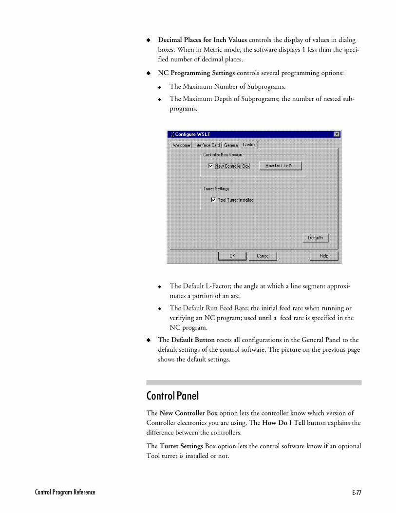
?+,,�����'�9�������4�(���� �
����� Decimal Places for Inch Values controls the display of values in dialogboxes. When in Metric mode, the software displays 1 less than the speci-fied number of decimal places.
����� NC Programming Settings controls several programming options:
����� The Maximum Number of Subprograms.
����� The Maximum Depth of Subprograms; the number of nested sub-programs.
����� The Default L-Factor; the angle at which a line segment approxi-mates a portion of an arc.
����� The Default Run Feed Rate; the initial feed rate when running orverifying an NC program; used until a feed rate is specified in theNC program.
����� The Default Button resets all configurations in the General Panel to thedefault settings of the control software. The picture on the previous pageshows the default settings.
������� !����
The New Controller Box option lets the controller know which version ofController electronics you are using. The How Do I Tell button explains thedifference between the controllers.
The Turret Settings Box option lets the control software know if an optionalTool turret is installed or not.

?+,� 4�(���� ��"$� �B��� ����?

�+�<��� �����9����������
����� �'� !����������
� � %������� �$ �� '� !��� !������
���������� �$ '� ����
������ !���������� �����������
#�$������ ����� ������� &

�+7 4�(���� ��"$� �B��� �����
� � %������� �$ �� '� !��� !������Part programs generally incorporate two types of instructions: those whichdefine the tool path (such as X and Z axis coordinates), and those whichspecify machine operations (such as turning the spindle on or off). Each in-struction is coded in a form the computer can understand.
An NC program is composed of blocks (lines) of code. The maximum number ofblocks per program is limited by the memory (RAM) on your computer. Youcan, if necessary, chain programs together to form very large part programs.
Each block contains a string of words. An NC word is a code made up of analphabetic character (called an address character) and a number (called a pa-rameter or value). There are many categories of address characters used in NCpart programs for the spectraLIGHT Turning Center (see Categories of NCCode).
Each block of NC code specifies the movement of the cutting tool on theTurning Center and a variety of conditions that support it. For example, ablock of NC code might read:
N1G90G01X.5Z1.5F1
If the machine is currently set for inch units, the individual words in thisblock translate as:
N1 This is the block sequence number for the program. Block 1 is thefirst block in the program.
G90 This indicates absolute coordinates are used to define toolposition.
G01 This specifies linear interpolation.
X.5 This specifies the X axis destination position as 0.5".
Z1.5 This specifies the Z axis destination position as 1.5". The cuttingtool will move to the absolute coordinate position (0.5,1.5).
F1 This specifies a feed rate of 1 inch per minute, the speed at which thetool will advance to the specified coordinate points.

�+)<��� �����9����������
���������� �$ '� ����Many categories of NC codes can be used to program the spectraLIGHTTurning Center. Here is a list of the NC codes (designated by the address char-acter) supported by the spectraLIGHT Turning Center.
����� &��������
% Incremental Arc Centers (Fanuc).$ Absolute Arc Centers.\ Skip./ Optional skip.F Feed rate in inches per minute; with G04, the number of
seconds to dwell.G Preparatory codes.H Input selection numberI Arc center, X axis dimension (circular interpolation).K Arc center, Z axis dimension (circular interpolation).L Loop counter; Program cycle (repeat) counter for blocks and sub-
programs, angle of arc resolution.M Miscellaneous codes.N Block number (user reference only).O Subprogram starting block number.P Subprogram reference number (with M98 or M99).Q Peck depth for pecking canned cycle.R Arc radius for circular interpolation (with G02 or G03); Starting
reference point for peck drilling (with canned cycle codes).S Spindle speed.T Tool selection.U Incremental X motion dimension.W Incremental Z motion dimension.X X axis motion coordinate.Z Z axis motion coordinate.; Comment.

�+* 4�(���� ��"$� �B��� �����
���������� ��� ������ GJ ����H
The incremental arc center code selects the Fanuc mode for programming arccoordinates. This mode is selected for the entire NC program as well as forany chained programs.
In the Fanuc mode, arc centers are always incremental, regardless of whetherthe system is in G90 (absolute) or G91 (incremental) mode. In contrast, arccenter specifications in EIA-274 mode follow the selected programmingmode, absolute or incremental.
You can specify the default arc center mode in the Run Settings dialog box inthe Setup menu.
This character must stand alone on the first line of the NC program inwhich it appears.
�*������ ��� ������� GK ����H
The absolute arc center code selects the EIA-274 mode of programming arccoordinates. This mode is selected for the entire NC program as well as forany chained programs.
In the EIA-274 mode, the mode of programming arc centers follows the selectedprogramming mode, absolute (G90) or incremental (G91). In contrast, arccenter specifications in Fanuc mode1 are always incremental, regardless ofwhether the system is in absolute or incremental mode.
You can specify the default arc center mode in the Run Settings dialog box.
This character must stand alone on the first line of the NC program inwhich it appears.
�5�� GL ����H ��� )������� �5�� GF ����H
The Skip and Optional Skip codes allow you to skip particular lines of codein your program.
�� ��� � � �5�� ���� GLH�
Place the code at the beginning of the line you wish to skip. When you runthe NC program, the specified line will be skipped.
'����
#��������'��2���GFI� � �����2����'0������:�����'��2������������(�����4$��������� ��'���&�1�������
�+;<��� �����9����������
�� ��� �5�� ���� GLH ��� � ����������
Use the Skip code with a parameter to instruct the Control Program to executethe line of code every nth pass. Place the code at the beginning of the lineyou wish to skip. The syntax is: \n, where n is the number of passes betweenexecutions.
For example, if you want to execute a block of code every 5 passes, place \5as the first code at the beginning of the block.
�� ��� � � )������� �5�� ���� GFH�
01 Place the code at the beginning of the line you wish to skip.
81. Select the Optional Skip option from the Run Settings dialog box or theOperator Panel.
When you run the NC program, the specified line will be skipped. If you donot select the Optional Skip option in the Run Settings dialog box, the skipcode is ignored and the line is executed normally.
�� ��� � � )������� �5�� ���� GFH ��� � ����������
Use the Optional Skip code with a parameter to instruct the Control Program toexecute the line of code every nth pass. Place the code at the beginning of theline you wish to optionally skip.
The syntax is: /n, where n is the number of passes between executions.
For example, if you want to execute a block of code every 5 passes, place /5as the first code at the beginning of the block.
&��� #��� G& ����H
The F Code is used to specify the rate of speed at which the tool moves (thefeed rate in inches or millimeters per minute, depending on the selected unitof measure). For example, F3 equals 3 ipm when in inch units or 3mmpmwhen in metric units.
The feed rate should be set to a low value (up to 30 ipm) for cutting operations.Feed rate values are in millimeters per minute (mpm) when using metricunits. The Control Program limits the programmed feed rate so it doesn’t ex-ceed the maximum allowed by the Turning Center.
The F Code is also used to specify the number of seconds to dwell when usedwith the G04 code. For example, G04F5 causes the machine to dwell for fiveseconds.
�+- 4�(���� ��"$� �B��� �����
!���������� ����� G �����H
G codes take effect before a motion is specified. They contain informationsuch as the type of cut to be made, whether absolute or incremental dimen-sioning is being used, whether to pause for operator intervention, and so on.
More than one G code from different groups can appear in each NC block. However,you may not place more than one G code from the same group in the same block.
The G codes supported by the spectraLIGHT Turning Center Control Pro-gram fall into the following groups:
� The Interpolation Group
� The Units Group
� The Wait Group
� The Canned Cycle Group
� The Programming Mode Group
� The Preset Position Group
� � ������������ ����
The Interpolation Group allows you to specify the type of motion for inter-polation. These G codes are retained until superseded in the NC program byanother code from the Interpolation Group.
The supported interpolation G codes are:
G00 Rapid traverseG01 Linear interpolation (default)G02 Circular interpolation (clockwise)G03 Circular interpolation (counterclockwise)
Refer to Section G for more information on these functions.
� � ����� ����
By default, an NC program is interpreted using the units of measure (inch ormetric) specified using the Units command on the Setup Menu.
The codes in the Units Group, G70 (inch) and G71 (metric), are used tooverride the Units command for the entire program.
If the code is placed at the beginning of the program before any tool motions aremade, that unit of measure is assumed for the entire program. Otherwise, it affectsthe rest of the program following the code. You can use these codes to switch be-tween inch and metric modes throughout your program at your convenience.
The Fanuc equivalents, G20 (inch) and G21 (metric), can also be used.

�+,<��� �����9����������
The Units Group Codes are:
G70 Inch UnitsG71 Metric UnitsG20 Fanuc inch unitsG21 Fanuc metric units
� � ,��� ����
Wait Group codes apply only to the block in which they appear. The programdoes not continue until the wait conditions are satisfied.
The supported Wait Group codes are:
G04 Dwell (wait): Pause between motions on all axes for the number of sec-onds specified by the F code, then continue the program. This is used pri-marily for robot integration. Because the F code is used to specify the num-ber of seconds, you cannot also specify a new feed rate in the same block.Example: G04F10;Wait for 10 seconds
G05 Pause: Used for operator intervention. Stop motion on all axes untilthe operator manually resumes program execution using the Run/Continue command.
G25 Wait until TTL input #1 (Robot 1 or user input 5) goes high beforeexecuting the operations on this block. Used for robot synchroniza-tion (see Section L for more information). Use the H code tospecify an input other than the default, H5.
G26 Wait until TTL input #1 (Robot 1 or user input 5) goes low beforeexecuting the operations on this block. Used for robot synchroniza-tion (see Section L for more information). Use the H code tospecify an input other than the default, H5.
� � ������ ����� ����
Canned cycle codes allow you to perform a number of tool motions by specifyingjust one code. Canned Cycle codes are typically used for repetitive operationsto reduce the amount of data required in an NC program. Canned cycle codesare retained until superseded in the program by another canned cycle code.
The supported Canned Cycle codes are:
G32 Canned cycle thread cuttingG72 Canned cycle arc turning, clockwiseG73 Canned cycle arc turning, counterclockwiseG77 Canned cycle side turningG79 Canned cycle end turningG80 Canned cycle cancelG81 Canned cycle drillingG83 Canned cycle peck drilling
Refer to Section G for more information on these functions.
(!)#��'�7
=�����$���".*�(�����'� ������������ '���(����������Q�$���".;�(������$������

�+� 4�(���� ��"$� �B��� �����
� � !���������� (��� ����
Programming mode G codes select the programming mode, absolute (G90)or incremental (G91). These codes remain in effect until superseded by eachother. The default code on program start up is G90.
With absolute programming, all X and Z coordinates are relative to origin ofthe current coordinate system. With incremental programming, each motionto a new coordinate is relative to the previous coordinate.
The supported Programming Mode codes are:
G90 Absolute programming modeG91 Incremental programming mode
� � !����� !������� ����
The preset position G codes move the tool to a predetermined position, oraffect how future motions will be interpreted.
The supported Preset Position codes are:
G28 Set reference point: This code moves the machine to its home posi-tion and sets the machine position to 0,0. The G28 code performs anautomatic calibration of the axes.
G29 Return to reference point: Moves the tool to a coordinate specifiedby XZ. Typically used after a G27 or G28 code.
G92 Preset position: This code works like the Set Position commandunder the Setup Menu. The X and Z coordinates following a G92code define the new current position of the tool.
G98 Rapid move to initial tool position after canned cycle complete.G99 Rapid move to point R (surface of material or other reference
point) after canned cycle complete.
� � ���������� ������ ����
Use the Coordinate System codes to establish multiple coordinate systems onone or more workpieces to create multiple parts.
For instance, you can run a part program using a typical coordinate system(with the point of origin on the left side of the workpiece next to the chuck,along the centerline of the workpiece), then select another coordinate systemwhich has its origin at a different point on the surface of the workpiece.
Multiple coordinate systems can be useful for different size workpieces, orfor special set-up conditions
There are seven coordinate system codes. One of these codes (G53) is used tomake a rapid traverse motion to specified machine coordinates. The other sixcodes allow you to make up to six individual parts on the same workpiece byspecifying different work coordinate systems for each part.

�+�<��� �����9����������
The coordinate system codes are G54 through G59, referring to coordinatesystems 1 through 6 respectively. These coordinate systems may be setthrough the Coordinate Systems command on the Setup Menu.
� � !���� !���������� ����
The Polar Programming Group codes allow you to perform polar program-ming operations, based on polar coordinates. Refer to Section H for more in-formation on using polar programming.
The supported Polar Programming codes are:
G15 Polar programming OFFG16 Polar programming ON
� � ������������ &�������� ����
Use the compensation NC codes to automatically compensate for scaling androtation adjustments. Refer to Section H for more information on using scal-ing and rotation.
The supported Compensation codes are:
G50 Cancels scaling.G51 Invokes scaling.G68 Invokes rotation.G69 Cancels rotation.
���� ��������� '��*�� G� ����H
The H code is used to specify inputs and outputs in robot integration.
Use the H code in conjunction with:
� The wait codes G25 and G26, to specify the input number. If the H code isnot used with these G codes, input 5 is assumed.
� The transmit codes M25 and M26 for interfacing with robots or other exter-nal devices, to specify the output number. If the H code is not used withthese M codes, output 4 (Robot 1) is assumed.
C �-�� ���������� �$ ������ !���� G ����H
In absolute programming mode (G90), the I code specifies the X axis coordinate ofthe center point of an arc or circle when using circular interpolation. In incre-mental mode (G91), the I code specifies the X axis distance from the start point

�+�. 4�(���� ��"$� �B��� �����
of motion to the center point of the arc for circular interpolation. If no I code isspecified, the system uses the current X axis location as the X axis center of the arc.
In Fanuc mode, all arc centers are incremental.
The I code is also used with the G51 code to specify the scale factor for the X axiswhen performing scaling functions, including scaling each axis and mirror scal-ing. Refer to Section H for more information on using scaling.
; �-�� ���������� �$ ������ !���� G� ����H
In absolute programming mode (G90), the K code specifies the Z axis coordinateof the center point of an arc or a circle when using circular interpolation. Inincremental mode (G91), the K code specifies the Z axis distance from the startpoint of motion to the center point of the arc for circular interpolation. If no Kcode is specified, the system uses the current Z axis location as the center of the arc.
In Fanuc mode, all arc centers are incremental.
The K code is also used with the G51 code to specify the scale factor for the Zaxis when performing scaling functions, including scaling each axis and mirrorscaling. Refer to Section H for more information on using scaling.
����� �$ ��� #���������9 ���� ������� G� ����H
The L code specifies the angle of arc resolution in circular interpolation pro-gramming. When the system executes a circular motion, it actually splits thearc into a series of line segments to approximate the circle. The L code speci-fies the angle in degrees which a line segment approximates a portion of thearc. The smaller the angle, the smoother the cut. A negative value for L willgenerate a normalized L factor (degrees x radius {in inches}) so larger radii havesmaller degree values. For example, with the default L factor of -1:
� An arc with a radius of 1 inch will have line segments approximating ev-ery 1 degree of the arc.
� An arc with a radius of .5 inches will have line segments approximatingevery 2 degrees of the arc. (Degrees = -L/R, or Degrees = -(-1) / .5,which is 2)
The default setting for the Turning Center is 2 degrees, and typically thiswill work quite well. You may notice the Turning Center hesitating on arcs ifthe resolution is too fine. The L code can be a fraction of a degree (such as L.5),but it must be large enough so the Turning Center will move at least the mini-mum motion (.0005") on each of the straight line motions.
'����
#��'������������������� �&0�������'�M� ��� � �������'��0������1����'0��������'�������� '�����(����� %���� �$����G#�'�����(����� ��������&������������� �&0��� �'��������������1� '0�������I�

�+��<��� �����9����������
Use the L code with:
� The M98 code as a loop counter for subprograms.
� The M47 code as a program cycle counter, to repeat a program a finitenumber of times.
� The G27 code to specify tolerance with homing commands (this is anLMC-specific NC language extension). The difference between the cur-rent position and 0 is compared to a tolerance value specified using theSetup Program; use the L code to override this tolerance value.
� An L code that is not used by one of these codes is used as an Arc Reso-lution factor.
L20
CenterPoint
θ
R
c
����� ���������D�'$���(�#���0�=������
#���@$������� �' $'����������$��� ����'����B�������θ�S��)-. ��������������������������������7�4�����1���'����� �' $'����������$��� �/�'$��(����� �� �'�����(��..�N��� ������ �������� �$���(��;N��0�$��$' ���������@$�������B
θ�S �)-.G�..�I�S���*-�
2π.5
#���(������S���*-

�+�7 4�(���� ��"$� �B��� �����
(������������ ����� G( �����H
M codes control a variety of Turning Center functions while a part programis running. Only one M code should be specified per NC block. M codesand motion commands should be placed on separate blocks to avoid confu-sion over whether an M code is activated during or after a motion command.
M codes can also be used to chain a second program to the end of a part pro-gram, or to repeat an NC program.
The supported M codes are:
M00 Pause: Allows you to place a pause in your code. Acts like a G05 pause.M01 Optional Stop: Allows you to place an optional pause in your code.
Place an M01 in the block of code where you would like to pause.There are switches to activate or deactivate the Optional Stop code inthe Run Settings dialog box and on the Operator Panel.With Optional Stop on, the M01 works like a G05 pause.With Optional Stop off, the M01 code is ignored, and the othercodes on the block are executed as usual.
M02 End of Program: Takes effect after all motion has stopped; turnsoff drive motors, and all outputs, including the spindle and the ac-cessory outlets.
M03 Spindle Motor On: Activated concurrently with motion specifiedin the program block; remains in effect until superseded by M05.
M05 Spindle Motor Off: Activated after the motion specified in the pro-gram block; remains in effect until superseded by M03.
M06 Tool Change: Pauses all operations, turns off spindle, retracts thecross slide for tool change.
M08 Accessory #1 On: Turns on ACC 1 accessory AC outlet concur-rently with the motion specified in the program block; remains ineffect until superseded by M09. This is the same as using the M25H2 codes.
M09 Accessory #1 Off: Turns off ACC 1 accessory AC outlet after themotion specified in the program block is completed; remains in ef-fect until superseded by M08. This is the same as using the M26H2 codes.
M10 Accessory #2 On: Turns on ACC 2 accessory AC outlet concur-rently with the motion specified in the program block; remains ineffect until superseded by M11. This is the same as using the M25H3 codes.
M11 Accessory #2 Off: Turns off ACC 2 accessory AC outlet after themotion specified in the program block is completed; remains in ef-fect until superseded by M10. This is the same as using the M26H2 codes.
'����
�''��� � ���$�� ���$�������� �/� ���$ ���������� '����1� $�����&����������(�����'�������(����&'� 2��(���� � ��
�''��� � ���$�� ���$����((��� �/� ��1� $���(�������'�������(����&'� 2���� ���'�� �
#���/�� � ��($�����������������������������'� ���� � ��������&'� 2��������(������������ ����� ��

�+�)<��� �����9����������
M20 Chain to Next Program: This code is used to chain several NCfiles together. It appears at the end of a part program and is fol-lowed on the next line by the file name of another program whichis executed when all motion stops. Here’s an example of a part pro-gram chain to another program:
N37 Z.2
N38 M20
PROGRAM2.NC; Chain to PROGRAM TWO
If the two programs you are chaining are not in the same directoryon your computer, you must specify the full path name for thenext program file. If the software cannot locate the specified file,you will be prompted to find it.
M22 Output current position or other information to file.M25 Set TTL output #1 (Robot 1 or Output 4) On: Used for robot
synchronization (see Section L for more information). Use the Hcode to specify an output other than the default, H4.
M26 Set TTL output #1 (Robot 1 or Output 4) Off: Used for robotsynchronization (see Section L for more information). Use the Hcode to specify an output other than the default, H4.
M30 End of program: Same as M02.M35 Set TTL output #2 (Robot 2, or Output 5) On: Used for robot
synchronization (see Section L for more information).M36 Set TTL output #2 (Robot 2, or Output 5) Off: Used for robot
synchronization (see Section L for more information).M38 Drive MotorsStandby: Typically used to turn the drive motors to
standby (low power) before a pause (G05); activated after the mo-tion specified in the program block. M38 is useful when the machineis left unattended for a long time, such as the interval before reloadinga part.
M47 Rewind: Restarts the currently running program; takes effect afterall motion comes to a stop. Typically used with an L code to repeata program a set number of times.
M98 Call to subprogram. Use the P code to specify the subprogram start-ing block number. Use the L code to specify the number of times thesubroutine is executed. You can nest subprogram calls to a depth of 20.
M99 Return from Subprogram; Goto.M105 Operator Message (nonstandard Light Machines code).M111 Home the X axis.M112 Home the Z axis.
(88� )����� ������� !������� �� &���
The M22 code is used to write information to a file while a program is run-ning. Typically, this code is used when digitizing to write the current X andZ machine coordinates to a file. The proper format for using this code is:M22(filename) Data to Write to File.
'����
!�(���������&�$� ����M���������/� � ������ ����M����� 2���������� �����'��(����������'����� �''������ �����#� �� �'��$�����
�+�* 4�(���� ��"$� �B��� �����
The first time the Control Program encounters an M22 code, it opens thespecified file. You must enclose the name of the file in parentheses for theControl Program to recognize it. If you do not specify any DatatoWritetoFiletext, the default data is output. This default is the current position, equiva-lent to specifying ‘X@X Z@Z’. The @X,@Z ‘macros’ are replaced by the ac-tual machine position when the data is written.
Each M22 code automatically adds a linefeed to the end of its output so thenext M22 starts on a new line.
If the file name is followed by “,A” (e.g., test.nc,A), the Control Program doesnot delete previous information from the file, it appends the information to theend of the existing information. If the file does not exist, it is created.
If you use more than one M22, only the first occurrence must have the filename in the parentheses. The remaining M22’s may have empty parentheses,( ), or may specify a different file.
If you want to generate more than one file at a time, you must include thefilename each time you specify M22. If a filename is not specified, the firstfile opened is used.
Example:
. . . ; code to move to position; Open my1.xz, discard contents, write coordinatesM22(my1.xz). . . ; code to move to next position; Append to currently open data fileM22( ). . . ; code to move to next position;Open my2.xz and append coordinatesM22(my2.xz,A)
Special codes that can be used with M22 to generate run-time reports.
@X Current X position (in current coordinate system)@Z Current Z position (in current coordinate system)~ (tilde) New line (starts a new line in the file)@TD Time of day (12hour): “11:59:59AM”@TC Time (elapsed) for cycle: “99:11:59” (0’s trimmed from left)@TT Time total (of program run): “99:11:59”@TA Time Average (per cycle): “99:11:59” (“??:??” if first part)@TL Current Tool number: “5”@C Cycle number (current pass): “3”@D Date: “12/31/97”@FN Current file (without path): “PART.NC”
(“UNTITLED.NC” if untitled)\t Tab\\ Outputs a single backslash (‘\’) character to the file
'����
�''��1�����������&'� 2���(���� '���������������������$�$����(�'�������''�/�'� ��� ����&�������'� � ���������������
�+�;<��� �����9����������
Example:
; Start of file… ; Process a single part; Output part time statistics to file c:\Reports\Stats.txt (c:\Reportsdirectory must exist)M22 (c:\Reports\Stats.txt,A) Part #@C processed in @TC.M47 L50 ; We want to process 50 parts.
(@@�#����� $��� ��*�������9 ���
The M99 code has two specific uses; it can be used as a command to returnfrom a subprogram or it can be used as a goto command.
����� (@@ ��� ��*��������
When used in a subprogram, this code returns you to the block followingthe last M98 (Call to Subprogram) command. If the M98 used an L code tospecify multiple calls to the subprogram, the M99 will return to the blockcontaining the M98 until all the specified number of subprogram calls havebeen made; then it will proceed to the block following the M98.
You can use the P code plus a block number to override the block returned to;however, if this feature is used from a nested subprogram call, all return tar-gets are discarded. The rules for a Goto target block apply to this use as well.
����� (@@ �� � ��� �������
This command can be used in the main NC program as a Goto command tojump to any line before the first subprogram (as denoted by the O code).
Use the P code to identify the block number being jumped to. Control istransferred to the first occurrence of this N code; it cannot be used to trans-fer control between chained programs (see M20).
This command can be used anywhere in the program to change the flow ofprogram execution. It is good programming practice to place this commandon a line by itself to improve the program’s readability.
(0D4� )������� (������
This command is used to display messages in the Control Program. It pro-vides a way to display messages to the operator on the message bar while anNC program is running. You can also pause the program with a custom mes-sage if the first character is “!”. This is a nonstandard, Light Machines code.
By default, the message is centered, displayed as a Normal Message, and is persis-tent (not cleared until the program clears it or until the next message is displayed).

�+�- 4�(���� ��"$� �B��� �����
����� � � ������� &����� $�� � �� ����
M105(the message);comment
For instance, the following line of code displays a simple message:
M105(End of Roughing Segment);Normal Message; doesn’t pause
(������� ������� ����� ��������� � ��������
! Displays the message and performs a pause requiring operator interven-tion to continue.
~ Displays the message as a Warning Message.
\b Beeps when the message is shown.
����� � � (0D4 ���� ��� �� ��������� � �������
M105(alternate character plus the message) ;comment
For example:
M105(~WARNING);Warning Message , doesn’t pause
)� �� %-������ �$ ����� � �� ����
M105( ) ; clears current messageM105(!Please stop and read this!) ; Normal Message, pausesM105(~!I MEAN IT!) ; Warning Message, pausesM105(\b\b\b) ; Clears current message, beeps 3 times, and doesn’tpause
����5 '��*�� G' ����H
N codes have two uses:
� To provide destinations for Gotos (M99) elsewhere in the program.
� To clearly show the organization of the code and improve readability.
Using the N code is optional; however, when you do use the N code, it mustbe the first character in the block.
Other than for the above stated uses, N codes are ignored by the ControlProgram. Their presence, absence, or sequential value does not affect the ex-ecution of the NC program in any way (unless the target of a goto is missing).
You may have N codes on some blocks and not on others. N code sequencenumbers do not have to be in order, but regular sequential order does make iteasier to follow and reference sections of the program. The Control Programcan change the N codes in a program by inserting, removing, or renumber-ing the codes.

�+�,<��� �����9����������
��*������� ����5 '��*�� G) ����H
The O code is used to indicate the start of a subprogram, and must be fol-lowed by a number which identifies the subprogram. The O code replacesthe N code in the first block of the subprogram.
To call a subprogram, use the M98 code; use the P code to specify whichsubprogram to execute. To return from the subprogram, use the M99 code.
Only the first block in the subprogram contains the O code. The remainingblocks may contain N codes. The O and N code numbers may be used to helpidentify and set apart the subprogram to improve readability, for example:
M98 P50000 ;call to first subprogram…;after first subprogram is finished, M99 code returns to this point…M98 P60000 ;call to second subprogram…;after second subprogram is finished, M99 code returns to this point…O50000 ;start of subprogramN50010 ;first line of subprogramN50020 ;second line of subprogramN50030 M99 ; last line of subprogram…O60000 ;second subprogramN60010 ;first line of second subprogramN60020 ;second line of second subprogramN60030 M99 ; last line of second subprogram
��*������� #�$������ '��*�� G! ����H
Use the P code with:
� The G31 code to reference a goto target block.
� The M98 code to reference a subprogram using the subprogram block number.
� The M99 code to specify a return block number as a goto target.
!��5 "��� GI ����H
The Q code is used with the G83 code in canned cycle peck drilling to specifythe incremental depth of each peck.

�+�� 4�(���� ��"$� �B��� �����
#����� �$ ���9 "������� ����� �������� G# ����H
As an alternative to specifying the center point of an arc (I Code or K Code)you can specify the arc radius. Use the same value for the radius in both ab-solute and incremental programming modes.
G02 or G03 specifies the direction of motion.
Positive values for R (radius) are specified for arcs up to 180°. Negative val-ues are used for arcs greater than 180°. Full circle arcs cannot be performedwith an R code. Split the circle into two arcs, or use center point (I and K)values for full 360° circles.
Use the R code in canned cycles to specify a Z axis reference point for peckdrilling. The point can be at the material surface or at another referencepoint. The R code is also used to specify the rotation angle, in degrees, withthe G68 code.
������� ����� G� ����H
Use the S code to set the spindle speed from within the NC program. Spindlespeed is specified by the address character “S” followed by a parameter thatrepresents the speed in RPM. For example, S750 is the designation for aspindle speed of 750 RPM. For the spindle speed to have an effect thespindle must be turned on by the M03 command. If the spindle is off, thespindle speed is stored and used when the spindle is turned on again withinthe program. Use the M05 command to turn the spindle off.
���� ��������� G� ����H
T codes specify the tool (number) in the Tool Library in multiple tool ma-chining operations. Tools are specified by the address character “T” followedby a parameter that represents the number of the tool. For example, T3 is thedesignation for tool number three.
C �-�� ���������� GC �� � ����H
An X code specifies the coordinate of the destination along the X axis. A Ucode is used in absolute programming mode (G90) to specify an incrementalX motion. You cannot use the U code to mix incremental and absolute pro-gramming in the same block.
����)'
�������$'��'����'�������� /�� � ������������� ��$' ����&������� &0���������$�(���'������$���������� ���!"�##$������������
'����
=������'� ���&��'$���� �� ������'� ����� �����������&'� 2�������1���'�B"�.C�D�����''������� $ ����1�� � ��������

�+��<��� �����9����������
; �-�� ���������� G; �� , ����H
The Z code specifies the coordinate of the destination along the Z axis(spindle axis). A W code is used in absolute programming mode (G90) tospecify an incremental Z motion. You cannot use the W code to mix incre-mental and absolute programming in the same block.
������� �����
The Control Program allows you to add comments (notes) to your NC codelines. The Control Program recognizes two comment codes, a semicolon “;”and an open parenthesis “(”. These two comment codes are equivalent. Theuse of either of these codes within an NC block indicates that a commentfollows.
Comments must follow all other NC codes in the block. Comments areignored when the part program is executed. Comments can be placed on ablock without any NC codes to document what is occurring within a pro-gram. NC programmers use these comments to annotate their programs.
Here is an example of an NC block with a comment:
X0Z0;MOVE TO ZERO POINT
The comment tells us that the X and Z codes in this block command the cut-ting tool to move to the zero point (coordinate 0,0).
Comments can be combined with the G05 pause and the M06 Tool Changecodes to display messages to the operator during program execution. Here isan example of an NC block with a pause coded comment:
M05(SPINDLE OFFG05(ROUGH DIAMETER SHOULD BE 0.5 in.)
When the program pauses, the comment is displayed on the message bar,telling the operator to verify the diameter of the workpiece before continu-ing. The M105 code provides a more versatile and powerful message facility.
The Control Program can strip comments from a program with a singlecommand; however, the comments can not be subsequently replaced.

�+7. 4�(���� ��"$� �B��� �����
������ !���������� �����������The following rules should be followed when writing NC part programs.
1. The sequence of words (address characters plus parameters) in an NCblock must appear in the following order: J9 K9 L9 F9 ' G)H9 9 C G�H9; G,H9
9�9 #9 I9 �9 &9 �9 �9 (9 !9 M�A different order may cause unpredictable results.
81 In many cases, a word need not be repeated in the next block (line). Thesystem assumes no change in codes unless a new code appears. Some ofthe codes this does not apply to: N words, I and K, G04, G05, G25, G26,G92, F used for dwell, M02, M20, M25, M26, M30, M47, M98 or M99.
21 You can use more than one G code in a block; however, you can useonly one G code from any one group in a single block.
31 N codes (sequence numbers) are not required in a part program; however,they can be useful in identifying a block when editing a long NC partprogram.
An O code is required to mark the beginning of a subprogram and doesnot have to be in sequence with the N codes.
41 The first instruction in a part program should move the tool to the start-ing position. This makes restarts much easier.
:1 The last block of a program should move the tool back to the startingposition. The tool will then be in position to start cutting another part.
>1 Part programs should reference the zero point with Z0 at the pointwhere the tool just touches the work piece. This convention allows forstandardization of programming.
?1 Before running an NC part program:a. Look for the typical coding error that places two X codes or two Z
codes in the same block.b. Be sure that all required coordinates have been written into appro-
priate blocks.c. Verify the part program to discover any program errors.d. Run the part program without mounting stock in the Turning Cen-
ter to see if the tool movements are logical.
@1 The first portion of a part program should turn on the spindle and establishthe feed rate and spindle speed.
0D1 M codes should be placed on separate blocks to avoid confusion overwhether an M code is activated during or after a motion command.
001 Double-check all program blocks against your coding sheet to locate andcorrect typographical errors.

"+������ ���� 9����������
(��� �'� !����������
������ ������������ !����������
�������� ������������ !����������
#���� ���B���� !����������
������ ����� !����������
������ ������������ !����������
��*������� !����������
#�$������ ����� �������

"+7 4�(���� ��"$� �B��� ����"
#0�� �'���'���/�����$�����'�����������'�����
������ ������������ !����������Linear interpolation is the movement of the tool in a line from its currentposition to a coordinate location specified by an NC code. Here’s a typicalline of NC code using linear interpolation:
N5G90G01X1Z.5F2
Broken down into individual words:
N5 The line sequence number is 5G90 Coordinates are given using absolute dimensioningG01 Linear interpolation is specified
X1 X axis coordinate of end point = 1Z.5 Z axis coordinate of end point = .5F2 Feed rate is 2 inches per minute
The G01 code is required when switching from circular interpolation orrapid traverse positioning back to linear interpolation. If we assume the cur-rent position of the tool is X.7, Z1.2, the tool movement generated by theabove line is something like this:
An equivalent movement is achieved with incremental dimensioning (G91):
N5G91G01X.3Z-.7F2
����� !����GC�,�>��7I
%�� !����GC��>�;I
R�C��1��
. ���������; ������������������
R�>��1��
�;
�
��� � �����������
������9���GC.�>.I

"+)����� ���� 9����������
Here are two typical lines of NC code using circular interpolation:
N9G90X0Z1;SET START POINTN10G02X1Z0I0K0F2;CLOCKWISE TO X1,Z0
The first line defines the starting point. The second line defines the endpoint and the center of the arc. Broken down into individual words, the sec-ond line reads:
N10 The line sequence number is 10G02 The tool will proceed in a clockwise direction from the starting
point to specified (X, Z) coordinates; center point of arc is speci-fied by (I,K) coordinates
X1 X axis coordinate of end point = 1Z0 Z axis coordinate of end point = 0I0 I coordinate of center point of arc = 0 (relative to start point)
K0 K coordinate of center point of arc = 0 (relative to start point)F2 Feed rate is 2 inches per minute
�������� ������������ !����������Circular interpolation moves the cutting tool along an arc from the startingpoint specified in one line, to an end point specified in the next line. Thecurvature of motion is determined by the location of the center point (I orK), which must also be specified in the second NC line.
The direction of rotation from the starting point determines the actual shapeof the arc relative to the spindle axis. A G02 code moves the tool in a clock-wise (CW) motion from the starting point. A G03 code moves the tool in acounterclockwise (CCW) motion from the starting point.
".7�G��I��� �".)�G���I� $�������
'����
#���������������������(��!� ������'��� ��������� ���?�����H� � ������$�� ����&����������(����������������� ������!� ������'�������'� � �����4$��������� ��'���&�1�

"+* 4�(���� ��"$� �B��� ����"
Assuming the start point is X0,Z1, the tool path generated by the precedinglines is something like this:
#0�� �'���'���/�����$����� �� $'��������'�����
An equivalent movement is achieved with incremental dimensioning (G91):
N9G91X0Z1;SET START POINTN10G02X1Z-1I0K-1F2;CLOCKWISE TO X1,Z0
In this NC line, the X and Z values are the distance the tool is to move fromits current position. In both cases, the I and K values are equal to the X andZ distance from the start point to the center point.
#��'������
?� �9���GC��>.I
����9���GC.�>�I
������9���GC.�>.I
��� � �����������
>��1��
C��1��
. �; �
�
�;
"+;����� ���� 9����������
#���� ���B���� !����������On the spectraLIGHT Turning Center, the rapid traverse code (G00) canmove the tool at the maximum available feed rate (30 ipm) to specified coor-dinates. Rapid traverse is used to reposition the tool before ending a program, orin preparation for the next cut.
,�#''
#����'���$' ���� &�������� ������ $���������������'���/���������������'� ����3
Rapid traverse can be used for all tool positioning motions. This will reducethe run time for the part program. The G00 code remains in effect until lin-ear (G01) or circular (G02, G03) interpolation is again specified. Linear orcircular interpolation resumes at the feed rate last specified prior to the rapidtraverse motion(s) unless you specify a new feed rate.
Rapid traverse is not affected by the feed rate scale factor. If all the position-ing motions are done in rapid traverse (G00) and all the cutting motions aredone in linear (G01) or circular interpolation (G02, G03), cutting rates canbe adjusted up or down using the feed rate scale factor without affectingrapid traverse motions.
Here’s a sequence of typical NC lines using rapid traverse:
G90G01X1F2; MOVE IN A STRAIGHT LINE TO X = 1 AT 2 IPMG00X2; RAPID TRAVERSE TO X=2X3; RAPID TRAVERSE TO X=3G01X4; MOVE IN A STRAIGHT LINE TO X=4 AT 2 IPM
"+- 4�(���� ��"$� �B��� ����"
������ ����� !����������Canned cycle commands allow you to perform many operations by specify-ing just a few codes. They are typically used for repetitive operations to reducethe amount of data required in an NC program. Canned cycle codes are re-tained until superseded in the program by another canned cycle code.
The supported canned cycles codes are:
G32 Canned cycle thread cutting (see Section H for more information)G72 Canned cycle arc turning (clockwise)G73 Canned cycle arc turning (counterclockwise)G77 Canned cycle side turning (Fanuc G90)G79 Canned cycle end turning (Fanuc G92)G80 Canned cycle cancelG81 Straight drillingG83 Peck drilling
These codes are used in conjunction with canned cycle codes:
G98 Rapid to initial position after canned cycle complete; this is thesystem default.
G99 Rapid to point R after canned cycle complete.
K Code Specifies the number of repeats. The default is 1. When K=0,drilling data is stored.
P Code Specifies the length of dwell time in seconds.Q Code Specifies the depth of cut. In peck drilling each peck uses the
same Q value. The Q value is always positive. If a negative valueis specified, it is converted to a positive value. In side and end turn-ing cycles the Q value is used to specify the depth of each roughingcut.
R Code Used for specifying a starting reference point for peck drilling or forspecifying tapers for side and end turning cycles. The point can beat the material surface or at another reference point.

"+,����� ���� 9����������
'������� ���� ��� �$��$������ 0 '� �����'0�&�����(���� �������@$� ���Q��� ������&�����(���� � �����@$� �����
G0X0.001Z1
G73X.5Z.5I0K.5Q.004
G80
G0X0.001Z1
G72X.5Z.5I0K.5Q.04
G80
#�� �� �'������������������'�������(���� �&0�0�� �'�",7��� ",)��������
����� >8 ��� >2
G72 can be used to cut an arc in one quadrant in a clockwise direction, forinstance:
G0X0.001Z1;START POINT
G72X.5Z.5I0K.5Q.04
G80
In the second block of code, G72 specifies a clockwise arc, uses I and K codes tospecify the center point of the arc, and uses a Q for the depth of the cut. G73works the same way, except it specifies a counterclockwise arc. These cuts aremade using a facing orientation and a profiling tool.
������������1���'���(���",)� � �$�� �����������/��L�/�'$��
".C�;>�",)C.�..�>�;!�;A�;L+�.*"�.
.�.
>S��;
CS��;

"+� 4�(���� ��"$� �B��� ����"
����� >>
The G77 code can be used to perform four functions: for straight side turning,for roughing cuts (using the Q code for depth of cut), for making tapers andfor boring.
Straight Side Turning
Straight side turning is a simple operation with the G77 code. The toolmakes a rapid move to the X depth, feeds to the Z coordinate, then backs outand returns to the start point. The following is an example of code usingstraight side turning.
G0X.6Z.8
G77X.4Z.5F10
G80
The tool movement for this example would be similar to that shown below.
#��� ��� ����
Performing roughing cuts with the G77 code works the same as straight sideturning, except that a Q code is placed in the block to specify the depth ofeach cut. For instance, this block
G0X.6Z.8
G77X.25Z.5Q.02F10
G80
tells the tool to make 0.0200-inch roughing cuts until it reaches the speci-fied X and Z coordinates.
�� ���� � 0 '��$�����",,�(���������� ��$������ (�� �*��;
���� !����'�9���
(�� ����

"+������ ���� 9����������
�� ���� � 0 '��$�����",,�(����$����� $��
#��&'� 2�",,C�7;>�;4+����.��� $ ���9����/��#�����+�$����������/��4�/�'$��
#��&'� 2�",,C�7;>�;4����.��� $ ���9����/��#�����+�$����������/��4�/�'$��
������ ������
Tapers are created by adding an R code. The following examples show a positivetaper (using a negative R value) and a negative taper (using a positive R value).
!����'�9���
!����'�9���
(��
(�� (��
(��
����
����
����
����
+4
R4
����
����
(��
(��
�*����;
L+ ����( $S��.7
!����'�9���
� 7;����;
� 7;����;

"+�. 4�(���� ��"$� �B��� ����"
#���&'� 2
",,C�7;>�;L�.74����.
��� $ �����9����/��#����� ���� �����$����� $��GL� � �I�
������
Boring (inside turning cycle) inside is done by using a smaller X value at thebeginning of the operation than at the end of the operation. The tool movesinto the workpiece nears the center, then moves outward with each cut. AnR value can be added to turn an inside taper. To perform a boring opera-tion, the code would be something like:
G0X0
G77X.375Z.5Q.03F10
G80
�� ���� � 0 '�����������$����",,�(���&������
�7;��;
LR4
���� (�� !����'9���
<�(����<�����
�(���<�����
� 7;����;

"+������� ���� 9����������
����� >@
The G79 code can be used to perform an end turning cycle. The cuts aremade on the face of the stock. G79 can be used with a Q code and R codejust like G77. A typical use for G79 is shown in the following example.
G0;START POINT
G79X.2Z.8Q.03F10
G80
����� � 0 '�� $���� ��$�����",���������/���� ������/��4� � ���
�� ���� � 0 '�����������$�����",��
+4�/�'$� R4�/�'$�
�� 2
�� ��9'��
#��' $
����
�'$���
����� ?D
To cancel a canned cycle, use the G80 code. This code cancels the currentlyrunning canned cycle and resumes normal operation. All other turning datais canceled as well. You can also cancel canned cycles by using a G00 or G01code; a G80 is automatically performed before the G00 or G01.

"+�7 4�(���� ��"$� �B��� ����"
����� ?0 ��� ?2
The G81 code performs straight drilling operations. G83 is used for peckdrilling. By specifying an R value of zero, the tool will return to the initialpoint after drilling to point Z. The G98 code is the default for rapid move-ment to the initial point, or you could also use G99 to rapid to point R. Weplaced both rapid return codes in this sample to show how they should beplaced in the program.
G0X0Z1;RAPID TO 0,1G81Z.9R1F2;CENTER DRILL TO DEPTH OF Z.9 FROM Z1 FEED 2,RAPID TO INITIAL POINTG83Z.5R1Q.1F3;PECK DRILL TO Z.5 FROM Z1 EACH PECK .1,RAPID TO POINT RG80;CANCEL CANNED CYCLEM2;END PROGRAM
�� ���� ��� 2���� 0 '��$�����"�)�� �"����#����'����� ���������4����� ��(���!����'�9���������� �(��� ���� � 0 '��
�� ���� � ��''���� 0 '��$�����"����� "����#����'������$��� ���������'������������ ��(��� ���� 0 '��
This program will generate tool motions similar to this:
!����'�9���
!����'�9���9����4
9����>
LL L
9����4
9����>
�..;O�..;O

"+�)����� ���� 9����������
���B
�$���=��� ��$��2� � $�/������<+��'������� �������������� ���".7��� �".)���� � ���
������ ������������ !����������In addition to Linear and Circular interpolation, the Turning Center sup-ports geometric curve definition using Spline interpolation. This feature isincluded for advanced users who wish to use a CAD software package to gen-erate drawing information (end point and control point information) for useon the spectraLIGHT Turning Center.
Whereas circular interpolation defines arcs as portions of a circle, spline interpola-tion defines curves based on non-colinear points. These more flexible curves arecalled Bezier curves. Unlike arc coordinates defined by a start point and anend point relative to a center point, coordinates on Bezier curves are definedrelative to two end points and two control points.
��������<�M�����$�/�U
��<�M���� $�/�����������'��'���� ����(������ ��������G?�I����� ������7G?7I��#�� $�/��(�''����������'����G����� �� I����$��(������ �� ����������� ����'������
���� ����'������7�G�7I������/� ��� $�/������$''� ��'�����������'�������$���&�������7��� �?7�
���� ����'��������G��I������/� ������&����������� �?�����������������$''������ $�/���$�(�������������'���������
C1 C2
E2E1
C2C1
E2E1
E1 E2
C2
C1

"+�* 4�(���� ��"$� �B��� ����"
��E��� ���B� � �������������
The end points of a Bezier curve are anchored and do not move, so the shape of aBezier curve is dependent on the position of the control points. The controlpoints can change the shape of the curve in any number of ways, allowing forgreater flexibility in curve definition.
������������ "�$����� � ��E��� ���B�
Normally, Bezier curves used in machining operations are generated by aCAD software package; they are not performed manually. All you need toknow is where the start, end and control points are. Once you plot the coor-dinates for these points, the computer can perform the mathematical func-tions necessary to generate the Bezier curve. The following is a simple methodfor producing a Bezier curve by construction.
��������������� ��� � ����'�������������&'��� ��� �'�������� �����&����������#��'�������� �����(����?��������(���������7���� �(����?7����7�
��1����'����G'�����I���� �����(������� ������(���?�F���'��������� ������(�����F�7�'����
C1 C2
E2E1
1
C1 C2
E2E1

"+�;����� ���� 9����������
��'����G'����7I���� �����(������� ������(�����F�7�'��������� ������(����7F?7�'����
��'����G'����)I���� �����(������� ������(�'������������ ������('����7�
#���&�/����� � $������������ $�����'��������7��� �)������ $ �'�����*���$����
#������ ������������� �$��'��<�M���� $�/�����(���� �
C1 C2
E2E1
C1 C2
E2E1
C1 C2
E2E1
C1 C2
E2E1
3
2
4
65 7
9
8

"+�- 4�(���� ��"$� �B��� ����"
!���������� ��� ������ ������������
You can assign coordinates to the start, end and control points of a curve andenter this information as part of your NC part program. Here is a block of NCcode using spline interpolation:
N24G0X.5Z3;START POINT
N25G101X2Z.5I1.5K3A2C1.5
N26G1Z0
Block N24 moves the tool to the start point.
The second NC block (N25) can be analyzed as:
N25 Block sequence number = 25
G101 The preparatory code for spline interpolation
X2 X-axis coordinate of the end point
Z.5 Z-axis coordinate of the end point
I 1.5 X-axis coordinate of the first control point
K 3 Z-axis coordinate of the first control point
A2 X-axis coordinate of the second control point
C1.5 Z-axis coordinate of the second control point
If the start point is X.5, Z3, the curve generated will be similar to the oneshown below.
��<�M�����$�/������������ ���� ������
.
�
7
)
C
;� 7 )
(���� ����'�����
�� �� � ����'�����
�����'�����
�� �����

"+�,����� ���� 9����������
����� � � � ���� �� ������ ������������
Previously, when you used circular interpolation, you defined segments of anarc in degrees using the L code. In spline interpolation the L code can beused to define the number of segments required to complete a curve like theone shown on the previous page. The more segments there are in the curve,the smoother the curve approximation by the cutter.
Values for L that are too large or too small can create problems. Large values forL will bog-down the computer and cause the tool motion to slow down.
���''���/�'$�����''� �$����� $�/���&��/��0���$��
��������/�'$�����''�&��� ����� ���$����� � �$����1����'0��'����'�������
�3
�8

"+�� 4�(���� ��"$� �B��� ����"
��*������� !����������Subprograms are used to execute repetitive routines in an NC program. Sincea subprogram can be called again and again, you don’t have to enter the samedata more than once. This is especially useful if the machining operation youwish to repeat is lengthy or complex. The NC codes used forsubprogramming on the spectraLIGHT Turning Center are:
M98 Call to subprogram.M99 Return from subprogram.
P Code The P code is used to reference the first line of the subprogram(which begins with an O code). The P code immediately followsan M98.
L Code The L code is used as a loop counter when used insubprogramming. The computer executes the subprogram as manytimes as defined by the L code. For instance, if the code is L5, thesubprogram is executed five times. (Optional)
O Code The O code replaces the N code on the first line of a subprogram.
A subprogram is called by an M98 and a P code. When an M98 calls the sub-program, the main program is interrupted while the subprogram is executed.
The P code references the subprogram’s address (the first line of the subpro-gram). The first line of the subprogram uses an O code instead of an N codefor line numbering.
When the M99 is executed, the main portion of the NC program continuesto execute from the line after the subprogram was called.
Subprogram calls can also be nested within other subprogram calls. Thismeans that while a subprogram is being executed, it can call another subpro-gram. The default number of levels that subprograms can be nested is 20 lev-els deep. You can change the default by using the Setup Program (click onthe Setup icon in the WSLT program group).
'����
#���� � ������'���$�� ������������� 0 '�� �$�������������� ����(���'���'����(���� � �����0�$���������������*,��.�������������1� $�������������(�������������� ���$����������������� ��� ��$����������� ����(����������
'����
8�$� ����'������(����������9�N'����$�&��N������� ��(����$&��������#�����$��������������������������� �(�� �'�����!%��'�2������$������������

"+������� ���� 9����������
� ������ '� ��*�������
This subprogram makes a series of light chamfered grooves. It's set up forstock with a 0.75" diameter and 2" length so you should use a piece slightlylonger 0.75" X 2.5".
Note that the file uses absolute programming in the main program and incre-mental programming in the subprogram. This makes it necessary to use theG90 after the subprogram is executed to allow motion back to the start point.
;THIS FILE FOR 2.5 INCH BY 0.75 INCH STOCK MOUNTED IN CHUCK
;USE WITH A PROFILING TOOL NORMAL SIDE ORIENTATION
;SET THE START POINT AT Z2 X0.375
G0G90M03;ABSOLUTE PROGRAMMING
G0X0.380Z2
M98P1000L4;CALLS SUBPROGRAM 1000 AND EXECUTES IT 4 TIMES
G90;ABSOLUTE PROGRAMMING
G0X0.38
G0Z2
M02;END OF PROGRAM
O1000;START OF SUBPROGRAM
G91;INCREMENTAL PROGRAMMING SELECTED
G1X-0.040Z-0.040F3
G1Z-0.125
G1X0.040Z-0.040
G0Z-0.20
M99;END OF SUBPROGRAM
#���&'� 2� �''�����$&��������G���I��&���������&'� 2�:�...�G��(���� � �&0�9�...I�� ��''������������(�/�������G�*I��#����� �� �'�����$&��������

"+7. 4�(���� ��"$� �B��� ����"

� /�� � �����9���������� �+�
����� � � ������ ��������
����� !���� !����������
����� ������� ��� #������� �����
(������� ���� !����������
#������ � ������ (������� ���� !������
� �������
)������� (�� ����� ����*�������
#�$������ ����� ������� �

����6��"$� �B��� ������+7
����� � � ������ ��������The Set/Check Homing command under the Setup Menu allows you to es-tablish a point of origin at the ends of travel on the Turning Center. Thehoming commands (G27, G28, G29) allow you to return to and check thisestablished position. The Turning Center uses this point as a reference for allmachine coordinate movements. This allows you to use the Soft Limits andCoordinate Systems commands (under the Setup Menu) to move the Turn-ing Center consistently to the same location.
Before you can use any homing commands, or the Soft Limits and CoordinateSystems commands, you must use the Set/Check Home command to estab-lish an initial reference point. See Section E for information on using theSet/Check Home command.
"7���������� ������(���� �����������'���������F�� 2����� ����� �(��������$�����$�

� /�� � �����9���������� �+)
����� 8?
The G28 code moves the machine to the coordinates previously establishedby the Reference Point Wizard as the home position, and then sets the ma-chine position to 0,0. If a reference point has not been defined, a warning isgenerated and the G28 command is skipped. The G28 code performs an au-tomatic calibration of the axes.
����� 8? �� �� '� !������
The G28 code homes the machine and sets the Machine Coordinates to zero.Use a G27 if you want to check the home position, but do not want to setthat position to zero.
The G54 calls up coordinate system one, which contains the offset valuesrelative to the machine’s home position. These would be the values whichwere entered for coordinate system one in the Offset from Machine Zero dia-log box under the Set Coordinates dialog box. The coordinates in the Posi-tion Window on the screen change to the coordinates of “coordinate systemone.”
The next line (G0X0Z0) would call for the machine to perform a rapid traversemotion from the Home position to point 0,0 in “coordinate system one.”
����� 8? ��$��� ������� ��$� ������
Remember, Soft Limits are based on Machine Coordinates. You can not use SoftLimits until you have set the machine to the reference point using the Set/CheckHome command under the Setup Menu.
����� 8@
The G29 code moves the tool at a rapid traverse rate to a coordinate specifiedby XZ. If you have set an intermediate point on one or more axes, the ma-chine first rapids from the current position to the intermediate point thencontinues to the specified destination. If you command a G29 code in Incre-mental mode, your specified XZ point is relative to the intermediate point. Ifyou have not specified an intermediate point, your specified XZ point is rela-tive to the current position. Use the G29 code after a G28 code to return thetool to a position closer to the part. The example below shows the use of aG28 code and a G29 code.
N1G28X2Z-1; INTERMEDIATE POINT THEN HOMEN2G29X4Z1; GO TO G29 POINT

����6��"$� �B��� ������+*
����� !���� !����������Using polar coordinates allows you to specify a radius and an angle by speci-fying a G16 code (polar programming on), then X and Z codes. The X codespecifies the radius. The Z code specifies the angle in degrees. A G15 is usedto cancel the polar programming mode. This programming method can beused in both absolute and incremental programming.
Polar programming is especially useful when writing programs for machin-ing bolt holes. An L code can be used as a multiplier for the angle value. Forinstance, this bit of code:
G0X0Z0.07M03G16G91X2Z0M98P1L12M2O1Z30G81Z-.1R0G80M99
combines the use of polar programming with a canned cycle and a subprogramto drill a hole at 30o increments. The L value was determined by dividing360 degrees by 30.
You can also cut an arc using code similar to:
G16G91X2Z0M98P1L360G15M2O1Z1M99
In polar programming, the center point is the origin if you specify G90 andthe radius (X code). If you specify G91 and the radius (X code), the centerpoint is the current point. If you specify only the angle (Z code), the centerpoint is the current center.

� /�� � �����9���������� �+;
����� ������� ��� #������� �����Scaling and rotating codes can be used separately or they can be combined.Each of these functions is described in the following paragraphs.
�������
Use the scaling codes to scale one or more axes of a part from a fixed scalingorigin. You can scale the entire piece uniformly, or set different scaling fac-tors for each axis. Use the following codes for scaling:
G50 Cancels scalingG51 Invokes scaling
Given the information that in G51 X and Z are the origin of the scale, I andJ are the scale factors. I = X and J = Z.
Here is an example of an NC program line using Scaling. In this example,X,Z is set at zero and is the origin of scale, and both axes are scaled by two.
G51X0Z0I2.J2.
#������� �����
Rotation codes allow you to rotate a programmed shape around a rotationorigin. Lathe programs are rarely rotated, however, it funtions in the samemanner as scaling.
G68 Invokes rotationG69 Cancels rotation
Here is an example of an NC program line using Rotation. In this example,X,Z is the rotation center, and 90 is the rotation value in degrees.
G68X0Z0R90.

����6��"$� �B��� ������+-
(������� ���� !����������The spectraLIGHT Turning Center allows you to designate up to 8 differenttool offsets for tool changes during turning operations. Using multiple toolprograms provides the power-user with a great deal of flexibility and freedomfrom tool changes. It also allows the user to create more complex parts on theTurning Center. To designate the tool number, tool diameter and tool offset,select Setup Library from the Tools Menu.
Multiple tool programing can be set to either wait for a manual change of thetool, or can be set to move to another tool which is already mounted on aseparate tool post, based on offset values. If a tool turret is installed, the ma-chine will automatically change tools.
There are four basic steps in setting up the Turning Center for multiple tooloperation:
01 Placing the appropriate codes in your NC program,
81 Establishing a reference tool,
21 Establishing the offsets for other tools from that reference, and
31 Testing your program.
����� (������� ���� �����
The T code is used in the NC program to offset the cutter so that the NCprogram becomes independent of the cutter length, which is set up in ToolDefinitions. This means you can replace a worn tool with a tool of a differentlength without changing the NC program, just by entering new offsets. TheT code can be located anywhere within the block of NC code, but it is nor-mally placed after any G codes.
When you place T codes in your program for tool changes, you should also usethe M06 code to shut off the spindle and to retract the cross slide. The M06code is placed after the T code. This code instructs the Turning Center toshut off the spindle, while it pauses until you manually change the tool. Press-ing the Return key will turn the spindle back on to continue with the NCprogram.
The tool that is shown in the Machine Info window is the default tool forthe start of a program. The Control Program uses this tool unless anothertool is specified with a T code. Once a tool is specified, any X and Z coordi-nates are applied to that tool until another T code is encountered in the NCprogram.
'����
#�������������������2��(���'� ������������������������'���� ������ ������������������(������������'������������������

� /�� � �����9���������� �+,
���5 ���� �������
All of the X coordinates for a tool cutting on the back side of a workpieceshould be negative unless the tool crosses the centerline into a positivequadrant, in which case the value of the point would be positive. Whenswitching to a tool that cuts on the back side of a workpiece within an NCprogram which is primarily frontside orientation, make sure that your pro-gram reflects the change from a positive quadrant to a negative quadrant.
For example, if T2 is a cut-off tool on the back side of a 3" long, 0.375" di-ameter workpiece, the codes T2Z1
X1
would tell the tool to cut right through the middle of the workpiece and stopat 1 inch on the other side of the centerline in the positive quadrant, which isbeyond the necessary cut. For a more precise cut, the codes that should havebeen used are:
T2Z1 or T2Z1X.1 X0
%���*��� ��� � � #�$������ ����
When using multiple tools for manual changing, a reference tool, normallyTool #1, is set to zero for the Z axis. This establishes a reference tool positionwhich is used as a reference point for additional tools. For demonstrationpurposes, we will use Tool #1 as the reference tool and Tool #2 as theadditional tool.
To set the reference tool:
01 Decide on a reference point (a point on the workpiece, or on a gauge,where you will jog the tip of each tool).
81 Open the Jog Control Panel (select Jog Control from the View Menu).With the tool installed in the spindle, jog Tool #1 to the reference point.The tip of the tool should barely touch the workpiece, or zero-out areference gauge.
21 Select Set Position from the Setup Menu. Set the current position ofTool #1 to zero on the Z and X axes.
Tool #1 is now established as the reference tool.

����6��"$� �B��� ������+�
%���*��� ��� ���� )$$����
Now that the reference tool is established, additional tools can be assignedoffsets. You can move the tool and accept its current Z and X axes positionas the offset value, or you can manually enter offset values.
To set the offset for Tool #2:
01 The reference tool must first be set to the reference point as previouslydescribed.
81 With tool #2 selected, jog the tool turret to touch the surface of theworkpiece, or offset sensor, at the previously determined reference point.In the Position Window, the current Z and X coordinates will be dis-played. These are your offset values from the reference tool.
21 To enter these values as the offset values, select Setup Library from the ToolsMenu and select the Use Current Postion bar. This will automatically enterthe ofset values for you. Alternatively, you may manually enter the offset val-ues for the Z and X axes by copying the values from the Postion Window.
The offset for Tool #2 is now established.
������� 6��� (������� ���� !������
After setting all of the tool offsets, test run your program without a work-piece mounted.
01 After installing Tool #1, close the safety shield, put on your safetyglasses, and complete the safety checklist.
81 Select the Run/Continue command from the Program Menu. Select lineone as the start line and select Start. Throughout the test, be prepared topress the emergency stop button on the Turning Center in case of a toolcrash. The computer will run the program until it reaches the M06code.The M06 stops the Turning Center.
21 When the spindle has completely stopped and the Pause message appearson the screen, push in the emergency stop button on the Turning Center.
31 Open the safety shield.
41 Remove Tool #1 and install Tool #2, making certain it is securely fas-tened to the tool post.
:1 Close the shield, and pull out the emergency stop button. Press the Re-turn key on the computer keyboard. The spindle turns on and the crossslide moves to the previous position. Operation continues as pro-grammed until the next M06 code is encountered.
����)'
<�(������0���'� ������&���$����5����� $�������'����0(���������2��� �����/�� �� ������������������� ��������0�$�����2��� ��

� /�� � �����9���������� �+�
>1 At each pause, repeat Steps 3 through 6, installing the appropriatetool at the appropriate points in the program.
#������ � ������ (������� ���� '� !������When you installed the spectraLIGHT Control Program an NC part pro-gram file, named turntwo.nc, was copied into the WSLT directory along withthe other files. The turntwo.nc program is meant to turn a 3" (length) x 0.75"(diameter) cylindrical piece of machinable brass, aluminum, Delrin or wax.You will be using this file to create your a workpiece on the Turning Centerusing multiple tool programing.
,�#''
=������������������������ ���!"�#�#$��������������$���/��������''��(�����(�0���� �$��������(�������4�(���� ��"$� �B��� ����E�
)��� �������1��
01 Select the Open command from the File Menu, or click on the Openbutton on the Standard Tool Bar. The Open dialog box appears.
81 Double-click on the turntwo.nc file name, or click on the file name thenclick on the Open button. The edit window for turntwo.nc appears.

����6��"$� �B��� ������+�.
"�$��� � � �����
To turn this part, you will use three tools. To define the tool parameters, firstselect Setup Library from the Tools menu.
01 Select Tool 01, a Right-Hand tool, for Tool #1. The specifications are asfollows: Description: Left Hand Diamond
Tool Type: DiamondStation: 1 (May be different with tool turret installed)Material Type: High Speed SteelRadius: 0.0001Angle: 30Orientation: OutsideReference: Tool Radius CenterCut Direction: Left/Down
81 Select Tool 02, a Left-Hand tool, for Tool #2. The specifications are asfollows: Description: Facing Grooving
Tool Type: GroovingStation: 2 (May be different with tool turret installed)Material Type: High Speed SteelRadius: 0.0001Width: 0.01Orientation: FacingReference: Tool Radius CenterCut Direction: Right/Up
21 Select Tool 03, a Parting Tool, for Tool #3. The specifications are asfollows: Description: Backside Grooving
Tool Type: GroovingStation: 3 (May be different with tool turret installed)Material Type: High Speed SteelRadius: 0.0001Width: 0.0313Orientation: OutsideReference: Tool Radius CenterCut Direction: Left/Down

� /�� � �����9���������� �+��
��<��� � � =���$� ��������
After opening the NC program, you need to adjust the Verify Settings for thepart you are about to turn, as you did in the turntwo.nc program. To viewthe Verify Settings dialog box, select Verify Window from the View Menu;double click on the Verify window when it appears.
You may also select Verify from the Program Menu, or from the StandardToolbar, then click on the Verify Settings button. The Verify Settings dialogbox appears. Adjust the verify settings for the Display, Tool Position andStock. The Initial Tool Position is Z=2.01, X=0.375. The Stock Dimensionsare Z2.5, X0.75. The Origin is Z0.5, X0.

����6��"$� �B��� ������+�7
=���$� �������1��
Tool path verification allows you to check for programming errors before ac-tually running the part program on the Turning Center.
Since we supplied this program, you shouldn't encounter any errors duringverification. You should, however, make a habit of verifying your programsmore than once to ensure there are no errors before running them on theTurning Center.
01 Select Verify from the Program Menu or from the Standard Tool Bar.The Verify Program dialog box appears. The default starting line for theprogram is Line 1. When verifying a program for the first time, youshould begin on Line 1.
81 Click on the Verify Program button, then watch the Verify Window.You will see the turntwo.nc program executed on the cylindrical work-piece.

� /�� � �����9���������� �+�)
����)'
�������������������$'��'����'���&�����������0���'��������� $����'0��'� � ���0��$��������� �� 2�������2��� ��
�� 2�����������(������������ '��$��� ��((��� ��������2��� ������/� ��$����������'�+������ ������2��$������ �''�������� $��
�������� ��� �� $�� �������1��
Now that you’ve got the NC program ready to run, you are ready to get theworkpiece and stock set up.
(���� � � ����� ��� ,��5�����
You should have a Right-Hand tool (tool 1), a Left-Hand tool (tool 2) and aParting tool (tool 3) mounted in posts as shown in the following illustration.You should also mount a 3"x.75" workpiece in the chuck with approximately.5-inch of the workpiece inside the chuck.
Tool 3
Tool 2
Tool 1
0.50"
2.00"
Chuck
0.50"
'���� !(�0�$�����$�������������'�$���� �#��'�#$�������$�����@$��� ���'������ �� �� ����������$ ���������� �������(����$� ��
��'� ������(�����'������$�����������(���� ����'��� �((�����������'��(�������(���� ���5$�����0�$���$' ��(����'���������$�� ������ �����'� ��
��� � � #�$������ ����
When using multiple tools, a reference tool, normally Tool #1 is set to zerofor both axes. This established position is then used as a reference point forthe other tools.

����6��"$� �B��� ������+�*
81 Close the Safety Shield and pull out the Emergency Stop button.
21 Select Jog Control from the View Menu (or the Standard Toolbar). TheJog Keypad appears.
31 Use the Jog Keypad to jog the tool to the bottom of the front right corner ofthe workpiece (the end of the stock furthest from the chuck and at the edgeof the stock). You can also select another point on the workpiece as a refer-ence point. However, this reference point must be consistent for all tools.
41 Select Set Position from the Setup Menu. The Set Position dialog box appears.
:1 Enter zero in the Z and X boxes to establish work origin.
>1 Click on OK. The values in the Position Readout all change to zero.
?1 Jog the tool up and away from the workpiece. Press the Emergency Stopbutton, open the Safety Shield and remove the workpiece.
Begin with the Emergency Stop button pressed in, and the spindle speedturned all the way down. The tool should be mounted in the tool post.
01 Mount the workpiece in the chuck.
%���*��� � � ���� )$$���� $�� ���� 8 ��� ���� 2
The second tool for this program is a Left-Hand tool used for performingthe facing cuts. The third tool is a cutoff tool. To set the multiple tool offsetsfor these two tools:
1. Jog the second tool to the same reference point as Tool #1. Jog in smallincrements to move the tool to the exact position of the reference point.
2. Open the Tool Library. For Tool #2, check Use Current Position. Se-lect OK to accept the new offset.
3. Repeat these two steps for Tool #3.

� /�� � �����9���������� �+�;
�������E� � � ,��5����� )�����
To initialize the workpiece origin, you must do one of the following:
In the Setup menu, select Set Position. Enter the desired values for X and Z.
Or use the G92 code,Preset position. This code works like the Set Positioncommand under the Setup Menu. The X and Z coordinates following a G92code define the new current position of the tool.
Or use the G54 code, Use Coordinate System One, to use this preset posi-tion.
"�� #�� � � '� !������
Before you run this multiple tool part program for the first time, you shouldperform a dry run (run the program with no stock mounted). This will en-sure that all the movements of the Turning Center make sense and that noneof the tools are in no danger of striking any fixtures of the Turning Centersuch as the headstock or workpiece. Although you should dry run the pro-gram with no stock mounted, you must first set the point of origin using theworkpiece as previously instructed, and then remove it.
Begin with the Emergency Stop button pressed in, and the spindle speedturned all the way down. The tool should still be mounted in the tool post.
01 Jog the tools up and away from the workpiece. Press the Emergency Stopbutton, open the Safety Shield and remove the workpiece.
81 Return the Safety Shield to the closed position and pull out the EmergencyStop button.
21 Put on a pair of safety glasses and complete the Safety Checklist (refer tothe Reference Guide: Section J).
31 Select Run/Continue from the Programs Menu. The Run Program dialogbox appears.

����6��"$� �B��� ������+�-
081 Click on the Run Program button.
021 As the part program runs, observe the tool motion in relation to thechuck (and eventually the workpiece). Look for signs of a possible toolcrash and be prepared to press the Emergency Stop switch on the Turn-ing Center. Edit the program as required. When you are satisfied thatthe tool motions are correct, you can mount the workpiece and run theprogram.
(���� � � ,��5�����
01 Using the Jog Keypad, jog the tool post up and out of the way.
81 Before mounting the workpiece, push the Emergency Stop button in.
21 Mount the 3"x.75" workpiece in the chuck. Take care to position theworkpiece perpendicular to the tool post.
31 Pull the Emergency Stop button out.
41 Jog Tool #1 to position the center of the tool tip at the top of the front,right corner of the workpiece or which ever reference point you have setfor each of the three tools. Jog Tool #1 to the corner of the workpiece.
:1 Select the Set Position command from the Setup Menu and enter Z=2.0", the length of the workpiece, and X= 0.375", the radius of the work-piece.
The workpiece is now correctly mounted.

� /�� � �����9���������� �+�,
#�� � � !������
Before executing the turntwo.nc program, check that all safety precautionshave been taken. The Turning Center safety shield should be closed, and youshould be wearing safety glasses.
If anything goes wrong, immediately press the Emergency Stop button onthe Turning Center to stop the operation. A safety checklist has been pro-vided in the Reference Guide: Section J of this guide. Post a copy of thischecklist near the Turning Center and review it before you run any NC pro-gram.
To run the program:
01 After reviewing the Safety Checklist, select the Run/Continue commandfrom the Program Menu. The Run Program dialog box appears.
�� � ���� ��� �$ � � #�����������
�'� 2����������6�� � 2&�1��#��4$���������� '$ �B
������ ���������''����0�$����$����������������������'��������������$������(����� �'��������1� $� �
)������� �5������4� ����M�����������'��2��� � ��GF�I�
)������� �������9�$��������������������0��.�� � ��
%��*�� ��*�������������$��&������(�������������$�����$&���������
��� ������� ����������4� ����M�����H� � ���� � �������� ������(������ ��������� ������'/�'$����'��/�����������(����� �
����� ,������� �� %�����������'������������������������������$�����������������
#������ ���� (��� , �� "���4����������������'�$����� ��G�� ��������� I������ '�����(���$����$�� ����� $����������������
=���$� , ��� #�����������''�������'���/���(� �������� $����'������������������$�����������#$�����������
81 Make sure that the Start Line box is set to line 1 of the program.
21 Click on the Run Settings button. The Run Settings dialog box appears.
31 Make desired changes in the Run Settings dialog box, then select OK.
41 Click on the Run Program button to begin running your program.
:1 After the part is turned, press the Emergency Stop button before open-ing the safety shield and removing the finished part.

����6��"$� �B��� ������+��
����� � � )������� ��������� ���� ������
When using the Automatic Tool Turret for multiple tool operations, use theConfigure Turret button on the Turret Control Toolbar or the ConfigureTurret command in the Tool menu to define each tool in its current positionin the Turret. To establish tool offsets, use the same procedure used for toolsmounted on the cross slide; make one tool the reference tool and offset allother tools from that reference. Another option is to enter the offsets valuesfrom the Z axis in the Setup Library from the Tools Menu.
You must use an M06 code with the T codes for multiple tool operationswith the Tool Turret. If you do not use an M06 code, the machine will usethe tool currently selected in the turret and interpret the T code as an offsetreference only.
When used with an M06, the T code simply indicates, by number, whichtool and which offset to use. For example, M06T2 tells the turret to rotate totool #2 and use offset #2.
�� ��5� � � ������ ������ �� � �����$�� ����111
Select the tool you would like to use by selecting the proper Tool Stationbutton from the Turret Control Toolbar.
You can also select the proper tool in the Select Tool From command fromthe Tool menu which will show you a list of each of the defined tools thatare on the Turret Control Toolbar.
�� ��� � � ������ ��������111
Whenever starting up the machine, you should home the turret to the Tool#1 position. The turret can then move correctly to any other tool position.To home the turret, you can use the Set/Check Home command to establishan initial reference point. See section E for information on using the Set/Check Home Command.
��������7
��2���$�������'���/�� '����� �(�������� 2��� � $ 2�&�(�����'� ��������/������$����

� /�� � �����9���������� �+��
L
9� �S��� F���
9�
� �������Generally, machine screws used in the United States conform to the Ameri-can National, or Unified Thread System. Threads are specified by the outsidediameter of the thread, then the threads per inch, such as 1/4-20.
Threading with a single point tool is accomplished by taking a series of cutsin the same helix of the thread (also known as chasing a thread).
The pitch of the thread is the distance that the tool moves along the Z axis foreach revolution of the spindle. The pitch is specified by the F code in theNC program as the inverse of the number of threads per inch. For example,the F code parameter for a 1/4-20 UNC thread is specified as 1/20 or 0.05.
A direct ratio exists between the spindle speed, the feed rate, and the pitch ofthe thread.
The pitch of the thread multiplied by the spindle speed determines the Z axisfeed rate of the Turning Center.
F (IN/REV) x S(REV/MIN) = Feed Rate (IN/MIN)
So, cutting a 1/4-20 thread with a spindle speed of 200 RPM results in afeed rate of F0.05 x S200 = Feed Rate 10 ipm.
It is important to specify an appropriate spindle speed for the pitch of thethread to keep the required Z axis feed rate below the machine's maximumcutting feed rate of 12 ipm. Specifying an inappropriate spindle speed willresult in a bad thread being cut.
'����
#��� ������������ ���!"�##$��������������$' �&�����(���� ��'������� '������ ��G.���7..49�� ���� ������������ �������� I�
'����
�'��0���������������� '������ ��� ������#$����������������P����$��O���������(������ $������
On many lathes the gear ratio is altered by manually changing gears or by us-ing a quick change gear box. These gear changes increase or decrease the rate atwhich the lead screw turns, thereby changing the feed rate of the tool. ThespectraLIGHT Turning Center, however, utilizes an F code in the NC programto instruct the Z axis drive motor, which turns the lead screw.

����6��"$� �B��� ������+7.
'����
!�������������������� ��(������ '������������������'������� ������� �/�'$�&�(��������� �������������� ���#��� ���'���������� �(0������ '������ �(������ ������ ��''�(�����/���'��� �� ��
The spectraLIGHT Turning Center uses electronic gearing. An opticalencoder on the spindle measures the speed of the spindle and instantaneouslyvaries the speed of the Z axis to keep a constant ratio for cutting a thread.An index sensor, which triggers once per revolution of the spindle, is alsoused, so the thread is started at the same point on the rotation of the partfor multiple passes to rough out the thread.
!���������� $�� � �������
Here's a typical NC program for cutting a 20-pitch thread on a .25” diam-eter rod:
G0X.125Z1.5;TO SET THE START POINT
S200M03;SPINDLE SPEED 200RPM
G04F5;DWELL FOR 5 SECONDS
G32X.095Z1Q.002F.05;X & Z ENDPOINTS, Q=DEPTH, F=PITCH
G80;END CANNED CYCLE
The recommended Q depth for threading is very small; from .001 to .003.
#�����������������$�� ���$�����F7O+'�����F*+7.���� �
8�$� ���(�� ��� ��0��(�����������P#�4?�=7.���O���������#�?F�������(�'��F���F���#� ��� ��0�
Start Point(.125,1.5)
.1,.095
Q=depth of cut
Chuck
0.50"0.50"

� /�� � �����9���������� �+7�
60
�������
Most threads are cut with a 60o threading tool. For fine threads, the tool can beground to a sharp point. For coarse threads, you may wish to radius thepoint.
A threading tool is used for external threading operations. An inside thread-ing tool is used for internal threading, like on a nut.
������� ��$�A���� � �����
Most threaded parts are made with right-hand threads. The Turning Centercan turn both right-hand and left-hand threads. The same tool is used forboth left- and right-handed threading; the direction of the cut is altered.
The procedure for cutting left-hand threads on the Turning Center is thesame as for right-hand threads, except the feed is reversed so the cut is madefrom the left to the right.
Make sure the workpiece is tightly secured in the chuck or collet since thetool will be pulling the workpiece away from the holding device.
FeedFeed
��(+��� �#��� ��� 4��+��� �#��� ���

����6��"$� �B��� ������+77
������� � �������
Most of the same rules that apply to external threading also apply to internalthreading. You have to remember that your starting X value will be smallerthan the ending X value. Also, you won't be able to see the tool, so use cau-tion.
To perform single point internal threading, a hole is first drilled to 1/16 inch di-ameter less than the minor diameter. A boring bar is then used to bore thehole to the minor diameter of the thread. Holes that are smaller than theminimum diameter the boring bar can turn can not be tapped.
��$��� 6�� �����111
Before cutting a thread, you should cut a groove, or a relief behind the endpoint of the thread. This is so the tool isn’t abruptly removed from the work-piece after the final thread is cut, making the end of the helix straight.
Make sure the start point is away from the workpiece on the Z axis becauseyou want the tool and workpiece to be in motion before cutting begins.
������� �� $�� � �������
The workpiece should be mounted in a chuck or in a collet. Set the toolheight exactly on the centerline of the workpiece for a correct thread angle.Locate the zero point of the workpiece just as you would for other turningoperations.
Relief
Feed
You still have to cut a relief groove to provide a starting place for the tool.Make sure you have sufficient relief on the right side of the tool as well.

"�����'��� ������!�(������� !+�
������ (�� ����� �$��������
������������� ���������� �������
&��� #��� ��� "��� �$ ���
������� ������
&��� #��� ��� ������� ����� ���������
��*������� ��� ��������
���� �����
(������� � � ������� ����
� �������� � � �����
#�$������ ����� �������

4�(���� ��"$� �B��� ����!!+7
������������� ���������� �������For a beginning user, understanding coordinate systems can be difficult. Thefirst thing to remember is, before performing most machining operations, youare required to set the machine to “home” position. This returns the machineto the machine zero point, and acts as a reference point for all operations. Itis a good idea to home the machine every time you run the control software.
��� ����������� #����� �� � � ������� ������
In machining, the Z axis is always the spindle axis. The Z axis on a machinetool can be horizontal (as on a lathe) or vertical (as on a vertical mill).
On the spectraLIGHT Turning Center the Z axis is horizontal (parallel tothe spindle axis). The X axis is also considered horizontal, but perpendicularto the Z axis and parallel to the cross slide. The Y axis is not used because thetool does not move vertically.
In NC programming, the programs are written as though the workpiece isstationary and the tool is moving. The motion of the tool from right to leftor left to right, is along the Z axis. The motion of the tool from front to back(in and out of the workpiece) is along the X axis.
The point of origin can be located anywhere on the workpiece, but is usuallylocated on the Z axis centerline on the plane along the front of the chuck.This way, all the work is done in Quadrant 1, with positive values for X andZ. What this means is that all tool motions will be determined by positivevalues. This does not mean that the tool will always move in the positive di-rection, only that the numbers which describe the coordinates will be posi-tive. For example, when the tool move into the workpiece, it moves in thenegative X direction.
'����
����1�'���� ������ �����������$����(���#��'�#$���������'���0��(��C��1��������/���� �
-Z
+Z
+X
-X
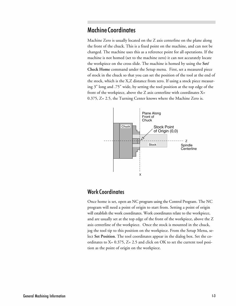
"�����'��� ������!�(������� !+)
(�� ��� �����������
Machine Zero is usually located on the Z axis centerline on the plane alongthe front of the chuck. This is a fixed point on the machine, and can not bechanged. The machine uses this as a reference point for all operations. If themachine is not homed (set to the machine zero) it can not accurately locatethe workpiece on the cross slide. The machine is homed by using the Set/Check Home command under the Setup menu. First, set a measured pieceof stock in the chuck so that you can set the position of the tool at the end ofthe stock, which is the X,Z distance from zero. If using a stock piece measur-ing 3" long and .75" wide, by setting the tool position at the top edge of thefront of the workpiece, above the Z axis centerline with coordinates X=0.375, Z= 2.5, the Turning Center knows where the Machine Zero is.
,��5 �����������
Once home is set, open an NC program using the Control Program. The NCprogram will need a point of origin to start from. Setting a point of originwill establish the work coordinates. Work coordinates relate to the workpiece,and are usually set at the top edge of the front of the workpiece, above the Zaxis centerline of the workpiece. Once the stock is mounted in the chuck,jog the tool tip to this position on the workpiece. From the Setup Menu, se-lect Set Position. The tool coordinates appear in the dialog box. Set the co-ordinates to X= 0.375, Z= 2.5 and click on OK to set the current tool posi-tion as the point of origin on the workpiece.
X
Z
SpindleCenterline
Plane AlongFront ofChuck
Stock Pointof Origin (0,0)
Chuck
Stock

4�(���� ��"$� �B��� ����!!+*
(������� ���������� �������
For more advanced operations, such as machining multiple partson the samepiece of stock, you can set up multiple coordinate systems. For example, ifyou have an NC program that machines a complex shape and you want tomachine that shape in multiple places on the same part, use the followingprocedure.
Move the tool tip to the work coordinate point of origin (0,0) using the SetPosition command from the Setup Menu. After setting this location on theworkpiece as the origin, select the Coordinate Systems command from theSetup Menu. The Setup Coordinate Systems dialog box appears. Select oneof the G54 to G59 codes, enter the coordinates for the first workpiece, andclick on Apply. Repeat this procedure for as many coordinate systems asnecessary by setting up a coordinate system for each point on the part thatcorresponds to the zero point of the shape you are turning. Then in yourprogram, you move to each coordinate system and run the subprogram thatcontains the NC code for the complex shape. (For more information aboutthe Setup Coordinate Systems procedure, see Section E.)
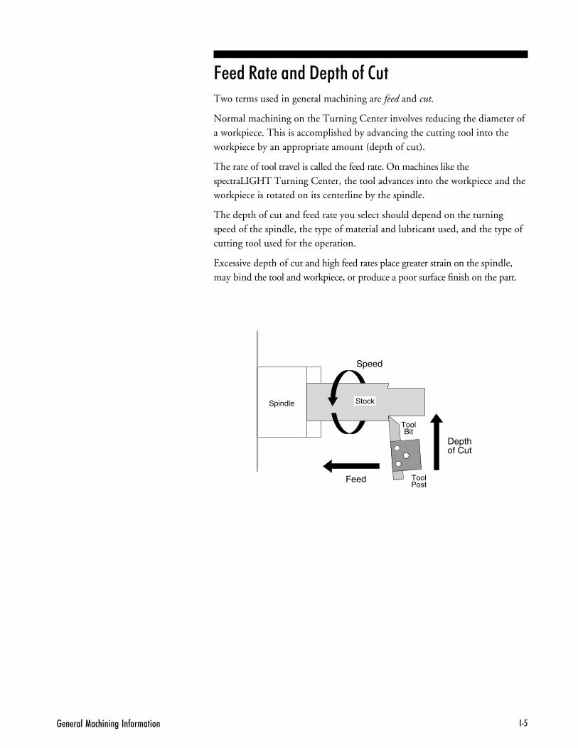
"�����'��� ������!�(������� !+;
&��� #��� ��� "��� �$ ���Two terms used in general machining are feed and cut.
Normal machining on the Turning Center involves reducing the diameter ofa workpiece. This is accomplished by advancing the cutting tool into theworkpiece by an appropriate amount (depth of cut).
The rate of tool travel is called the feed rate. On machines like thespectraLIGHT Turning Center, the tool advances into the workpiece and theworkpiece is rotated on its centerline by the spindle.
The depth of cut and feed rate you select should depend on the turningspeed of the spindle, the type of material and lubricant used, and the type ofcutting tool used for the operation.
Excessive depth of cut and high feed rates place greater strain on the spindle,may bind the tool and workpiece, or produce a poor surface finish on the part.
Spindle
ToolBit
ToolPost
Stock
Depthof Cut
Speed
Feed

4�(���� ��"$� �B��� ����!!+-
������� ������Turning speed is inversely proportional to the diameter of the workpiece; thelarger the workpiece, the slower the recommended turning speed. The rela-tive hardness of the material also affects turning speed; the harder the mate-rial is, the slower the speed should be.
High spindle speeds may produce excess heat which causes the workpiece toexpand. If the workpiece expands, the cutting tool will rub rather than cutthe material, resulting in a poor surface finish. Slow spindle speeds cause noharm, but may be inappropriate for finishing certain types of materials.
The load put on the spindle motor must also be taken into account. Heavycuts at low speeds will make the motor run hotter than lighter cuts at higherspeeds. The selected feed rate and depth of cut should not cause the spindlemotor to greatly lose speed or cause the tool to chatter against the workpiece.
&��� #��� ��� ������� ����� ���������Feed rate selection for turning parts on the spectraLIGHT Turning Centerdepends on factors such as type of material, type of cut, diameter of roughstock, depth of cut, and spindle speed. The type of tool chosen to make thecuts also affects the depth of cut and, therefore, the feed rate. Consult yourmachinist’s handbook for selecting a feed rate based on spindle speed andmaterial type. Experience and experimentation will enable you to establishfeed rates best suited to particular applications.
��*������� ��� ��������Lubricants remove heat from the tool and workpiece and are often used whenhigh production rates are required or when cutting very hard materials, such asstainless steel. A mixture of one part soluble oil to six parts water may beused on steel to assist in producing a smoother finish and to reduce toolchatter. Aluminum and aluminum alloys may require the use of paraffin, oilor kerosene to prevent chips from welding to the tool’s cutting edge. Brassand cast iron are always turned dry.
When lubrication is necessary, small amounts of water-soluble cutting fluidsare recommended for use on the spectraLIGHT Turning Center. Lubricantsshould be wiped from the machine after use, because some petroleum-basedfluids may deteriorate the electrical wiring insulation, the plastic safetyshield, or the computer enclosure.
'����
#����� ���!"�#�#$����������������� ������ �(���('�� � ��'��������''���$����(� ��'�����0�&�����'�� ������'������� ����2��� ��&�(�����������������$��
'����
���+�$������''������� ���������=�'�������'$���$���������� ���!"�##$������������ ���������@$������$���(� ��'���

"�����'��� ������!�(������� !+,
���� �����Cutting tools are usually made from hardened steel and are ground to vari-ous shapes. The clearances ground behind cutting edges are adjusted for thetype of material the tool will cut and the direction the tool will be fed alongthe workpiece. Tools are often ground to shape by the operator to suit a par-ticular cutting requirement.
Insufficient clearance behind the cutting edge will cause the tool to rub. Ex-cessive clearance will produce a ridged or wavy finish due to the small lengthof tool edge in contact with the workpiece. Standard tool types are: turningtools, side tools, parting tools and boring tools. Carbide tooling has becomepopular in recent years. Carbide is more brittle than steel, but has a longertool life.
���� �����
Side tools are used to face-off the ends of shoulders or to make facing cuts inthe surface of a workpiece held in a chuck. They may also be used as turningtools.
Right side (or right-hand) tools feed from right to left and are used to reducethe workpiece to a desired diameter. The shape of the cutting edge and theclearance (behind the point between the end of the tool and the workpiece)determine the surface finish of the workpiece. Rough cuts are made in smallincrements until the tool is within approximately 0.010 inch (0.25mm) ofthe desired diameter. Final cuts are made at slow feed rates with a very shal-low depth of cut.
Left side (or left-hand) tools feed from left to right. Side tools cut very flatsurfaces and can be used to produce a part with an exact thickness.
4��+��� �#$������#��'��(+��� �#$������#��'

4�(���� ��"$� �B��� ����!!+�
��9�����������$�((���'������2
!������ �����
A parting tool has a dual-edged, dovetail-shaped cutting end which is used tocutoff workpieces. The parting tool is plunged into the workpiece and thecross slide is moved across the lathe bed until the workpiece is severed.
Parting tools are clamped to a special tool post with a minimum of over-hangfor maximum rigidity and chatter-free operation. The cutoff point should belocated as close to the spindle center as possible. The cutting end of the part-ing tool should be perpendicular to the workpiece to avoid sideward drift. Asmall square is useful in aligning the tool perpendicular to the workpiece.
Also, the height of the tip of the tool should be positioned so it is verticallyaligned with the center of the stock.
Cutoff operations are performed at a slow turning speed because the partingtool has a large amount of cutting edge in contact with the workpiece. If thetool chatters or produces noise, the turning speed and feed rate should be re-duced.
��2���$������'����������(��� $�((��'������ ������(����� 2
�� 2 �$����#��'

"�����'��� ������!�(������� !+�
������ �����
Boring tools are used to enlarge or modify a drilled or cored hole in a work-piece. Clearance must be maintained behind the cutting point of the tool.
A slow feed rate and frequent tool withdrawals are required with boring toolsbecause chips cannot freely escape from the hole. Depth of cut and feed ratesmust be reduced to avoid chatter. The tool should not be driven deeply intoa hole. When boring a hole where a flat bottom is required, stop the feed atleast 0.002 inch from the desired depth of the smaller hole being bored out.
�� $���0�/�����(���<��������'������2
!��$����� �����
Profiling tools are quite popular in CNC applications because they can cuton both sides and in both directions. A profiling tool cuts in the same wayas a turning tool.
� ������� �����
Most threads are cut with a 60o threading tool. For fine threads, the tool can beground to a sharp point. For coarse threads, you may wish to radius thepoint.
A threading tool is used for external threading operations. An inside thread-ing tool is used for internal threading, like on a nut.
60

4�(���� ��"$� �B��� ����!!+�.
(������� � � ������� ����Each cutting tool used in the machining operation must be sharp and tightly in-serted in the tool post. The cutting edge of the tool must be on the centerline orjust below the centerline (0.004 inch or 0.1mm maximum) of the axis of ro-tation of the lathe.
The cutting tool is mounted by loosening the mounting screws at the top ofthe tool post and positioning the tool in the slot beneath the mountingscrews. To assure a rigid mounting and to avoid chatter, the cutting edge ofthe tool should not protrude more than necessary from the tool post. Thefurther the tool extends from the tool post, the more chatter will occur.
You must make sure that only the very tip of the tool is doing the cutting. Alltools must be positioned in a manner that allows them to access all areas theyare to cut. The exception to this is the cutoff tool, which should always beperpendicular to the stock. Backside tools should be mounted upside-downand on the centerline or just above.
The position of the cutting edge relative to the centerline of rotation can bechecked at the headstock center. Loosen the bolt holding the tool post to thecross slide and slide the tool post as close as possible to the center. Check thelocation of the cutting edge position.
Tighten the tool holding bolts, reposition the tool post on the cross slide andtighten the cross slide bolt.
#������'����� ���� �(��������+�� �$��������'�
#�������'��������� ���� �(��������+�� �$��������'�

"�����'��� ������!�(������� !+��
� �������� � � �����A cutting tool must be sharpened regularly to preserve its original cuttingangle and shape. Longer tool life will be obtained from cutting edges if theyare finished with a small oilstone. Only the cutting end and sides of the toolshould be ground as required. Never grind the top face of the tool.

4�(���� ��"$� �B��� ����!!+�7

��(��#$������������:������� E+�
��$� ������� ������ )��������
��$��� #����
��$��� � ��5����
����� �� ���������
%�������� �����
#�$������ ����� ������� +
4�(���� ��"$� �B��� ����EE+7
��$��� #����The following safety rules should be reviewed and practiced by all operatorsof the spectraLIGHT Turning Center.
,��� ��$��� ������
Foresight is better than no sight. During operation any power tool canthrow foreign objects and harmful chemicals into your eyes. Always puton safety glasses or eye shields before starting up the Turning Center. Safetyglasses or shields should provide full protection at the sides, as well as thefront of the eyes.
���� 6��� (�� ��� ����
Read this guide carefully before you use the Turning Center and keep itreadily accessible for quick reference. Know the intended applications andlimitations of the Turning Center as well as its hazards.
����� ��� �����
The Turning Center has an AC power cord terminated by a three-prongplug. The power cord should be plugged into a three-hole, grounded recep-tacle. If a grounding adapter is used to accommodate a two-prong receptacle,the adapter wire must be attached to a known ground. Never remove thethird prong from the plug on the AC power cord.
���� � � ��$��� � ���� �� !����
The safety shield should remain in place whenever the spindle motor ison or the cross slide is moving.
#���B� ��<������ ���� ��� ,���� ��
Make it a habit to check that keys and adjusting wrenches are removedfrom the Turning Center before turning on the machine.
���'�(������ ��0������$'����������(�0��� 2'������ ����������0�$�����2������(���@$� 2���(���� ��

��(��#$������������:������� E+)
���� � � ,��5 ���� �����
Cluttered work areas and bench tops invite accidents.
�B��� � "�������� %�B��������
Don’t use the Turning Center in damp or wet locations. Never operate elec-trical equipment in the presence of volatile and flammable petroleum-basedsolvents and lubricants.
���� ��������� =������� ���� $��� � � %.�������
Children and visitors unfamiliar with the hazards of rotating machineryshould always be kept away from the work area.
!��B��� ����� ���E�� ����� $��� )�������� � �������� ������
Lock and remove the key from the Turning Center control panel when thesystem is not in use.
"� '�� &���� � ����
Select the feed rate and depth of cut best suited to the design, construc-tion and purpose of the cutting tool. It is always better to take too light acut than too heavy a cut.
��� � � #�� � ����
Select the type of cutting tool best suited to the turning operation. Don'tforce a tool or attachment to do a job it wasn't designed to do.

4�(���� ��"$� �B��� ����EE+*
"���� �������������
Don't wear loose clothing or jewelry which can get caught in moving parts.Wear a hat or hair net, or tie your hair back to keep it away from movingparts.
������ � � ,��5�����
Be certain that you have firmly secured the workpiece in the spindle and thecutting tool to the cross slide before turning on the spindle motor.
"� '�� )B������
Keep your footing and balance at all times so you won’t fall into or grabthe moving machine.
(������� ������� ����� � ��� ���������
Keep cutting tools sharp and clean. Lubricate and clean Turning Centercomponents on a regular basis.
"��������� ����� ��$��� ���B�����
Always use the emergency stop switch to disconnect power and disable thespindle motor before mounting or removing the workpiece, or changingtools. Do not rely solely on a programmed Pause command to disable Turn-ing Center operation.
�B��� ���������� ��������
Make sure the power switch on the control box is off before plugging inthe Turning Center power cord.

��(��#$������������:������� E+;
��� #���������� �����������
To avoid stressing the Turning Center and creating a hazardous machining en-vironment, use only those accessories designed for use with the spectraLIGHTTurning Center, available through Light Machines Corporation.
��� ��� ��� �������9 ���5��� ��� "��B��� "�B����
Do not overtighten tool holding devices. Overtightening may damage threadsor warp parts, thereby reducing accuracy and effectiveness.
���� ������� ���� $��� %��������� ����������
Do not allow coolant to splash into or near the computer.
"� '�� )������ � � (�� ��� ����� � � �$������ �$���� �� �� "����
Alcohol or drugs may impair your judgement and reaction time, whichcould contribute to an on-the-job accident.
�B��� "����������� , ��� #������ � � (�� ���
Use simple common sense and pay attention while operating any piece ofmachinery.

4�(���� ��"$� �B��� ����EE+-
��$��� � ��5����
������� ���� ����� �� ��� � ����!
❏ 0��� ��� ������� ��������
❏ ���� �� -� ������ ���� ���� ��������
❏ 3����� 4������ �� ������� ����%� �� ������ ���� ������� ����
������� "� ������ �� ���!
❏ ��-�� ���� ���� ����� ���� �� �� ����� ��� ���� 4���
❏ /� ��� ���� ����� �������
❏ ��-�� ���� ���� ����� ���������� ����� ����� ������� ��������5���
❏ 6����� ���� ,�� ����� ��� ���� ������ ������ � �������
❏ 3����� ���� ������ ����� ���� ��� ��� ��� ���� � �����
❏ 3����� ��4������� -���� ���� ��� ���� ��
���� � �����
❏ ������ ���� ������� �������
❏ 7���� ������� ���� � ����� ����� ������ ������� ������� ��
���� ����
❏ 0���� �� ��� ��8
❏ /��� ���� �������� ���� ���� �� ��� ������� ������ �����
��������
❏ ��-�� ������ ����� ��� ��� ��-��� �� ��� ��� ��
❏ 3��� ���� ,�� ����� ��� �-�� ���� ���� ���� ����� �-�
������ ������ ������� ���� ����� ����� �� ��-��� �� ��
��� ��
❏ ����� ��������� ���� ��� ��%� ������� �� ��� ���
��-��� �� ��� ���� � �����
❏ 9���� ������� ����� ��� ���� ��� �� ��� ���� �����%� ��� ����
�� ��� �� ��� ���� ��%� ���� ������ ���� ������ ��� �� ��
��������
#���� "� ������ �� ���!
❏ :�� ���� ��� �� ������ �� �������� �����
❏ 0���� ���� ;���� �� /���� ������� ������ �������� ���� ������
�������
❏ 7���� ����� ���� ������� ������� ����� ���� �������� ���� �������
��������
❏ 0���� ���� ;���� �� /���� ������� �������� �������� �����
�� �������� �� ������� �� ��-��� ��
❏ 0���� ���� ;���� �� /���� ������� ���� ����� ����� ������� ���
������� �������
❏ 9���� ���� ��������5��� ������� ����� ��� ���� ��-� ����
(!)#��'�7
9��� �������(���� � 2'����������2�������D���(0����''��������� � 2� +�((����������� ����������(������ ���!"�##$������������

��(��#$������������:������� E+,
����� �� ���������
����� ��� ������ ��� ��� $���� ��� ��%�&�!
❏ 1��� ���� ������� ��� ���������
❏ 0� ��� � ������ ��� ������� �� ��� ���� ���� ���4��
❏ ,�� ���� 4���<�� ��8� � �������%� �������� �� ���4���
����� ��� ��%�&��� �� "$'����� ���� ���(�!
❏ 1����5�� ��� ��������� �� ��� ���� ��� ����4��� ��������� ��
���� �� ��� ��� ��� �������� ��� ���� ��=������
❏ ��������� =��� ��� ���� �>�� ��� ��� ��������� ��� ���� ��� ����
��� ����5���� �� �������
❏ 3������ ������ ���� ������ �������� �� ���=������ ��4��� ��� ��
?�������� ������ ������ ���� �������� ��� ��� ?������
�����@�� ��� ���� �����
❏ ����� ��� ������ ��� ��������� ������ ��� �4� ���� ���=���
���� �>�� ��� ��� ?�������
❏ ���� ���� ������� ��� ����� ��5� ��� ��� ���� ���
�������� �������� �� ���� ���5�� ��� ����4��� ��������� =��� �����
���� ���������� ����� �� ����
❏ ������� ��� ���5�� ��� ���4�� �� ��� ����� A����� ���� ���������� �
������� ������ ��� ��� ��� ������ ��� ���������
❏ ��������� =��� ������ ���� ���� ���� ��� ������� ����� �����
����5�����
❏ ��������� ���� �<=������ ����������� ��4��� ��� ��� ��4�
��� ������%� ���������� �� ���=���� /�������
;�@ �� ��
�������� ��%�&�� �� "$'����� ���� ���(�!
❏ ,�� �� �������� ��� ������ ��� ��������� ������� =��� ��
���������� ����� �4� ������� ��� ������� 0������
������ ����� ��� ���>�� ��� B0��� ��� ;���� ��C�
❏ 0������� ������ ��� ���>�� ��� B0��� ��� ;���� ��C
������ ��� ����� ���� ��������%� ��� ���=��� �� �����
���� ���5�� ��� ����4��� D���� ��� ���>�� ��� B0��� ��
;���� ��C� �����@�� ��� ����� ������� ��� ������ ��
���������
❏ ��������� ����� ���� E��� ��� ���4�� �� ����� ������� ��
�����5����
N(!)#��'�%7
9��$�� ����������'�V���� ���&�5���D���(�@$��@$��� ���'���$��������� � � �������� � � ���$���������� �� ��'��V@$����

4�(���� ��"$� �B��� ����EE+�
%�������� �����All spectraLIGHT operators must be fully aware of how to shut down themachine quickly, should the need arise.
There are two ways an emergency stop can be initiated on the spectraLIGHTTurning Center:
� By pressing the emergency stop switch on the Turning Center.
� By pressing a key on the computer keyboard.

"��� ����� ������� �&0�"��$� A+�
��� ( ����� ������ *� ����
����� *� ����
( ����� *� ����
#�$������ ������ ������� �

4�(���� ��"$� �B��� ����AA+7
G00 Rapid traverse.
G01 Linear interpolation.
G02 Circular interpolation (clockwise).
G03 Circular interpolation (counterclockwise).
G90 Absolute coordinate programming: All X and Z axes coordinates arerelative to a (0,0) location on a lathe.
G91 Incremental coordinate programming: Each command is relative to theone before it in the program.
G70 Inch: Used to instruct the lathe that inches are the unit of measure forthe part program. (Fanuc G20)
G71 Metric: Used to instruct the lathe that millimeters are the unit of measurefor the part program. (Fanuc G21)
G04 Dwell (wait): Equals the value of the feed rate (F code) in seconds (usedprimarily for robotic operations). G04 excludes motion commands with anew feed rate on the same line (block).
G05 Pause: Used for operator intervention. The order of action for the pauseand dwell codes in one NC block is G05, G04 (pause, dwell).
G25 Wait for robot input #1 to be high: Used in conjunction with H code,which specifies input number. The default is H5. Used for robotsynchronization (see Section L).
G26 Wait for robot input #1 to be low: Used in conjunction with H code,which specifies input number. The default is H5. Used for robotsynchronization (see Section L).
G15 Polar programming cancel.
G16 Begin polar programming.
G53 Rapid traverse to specified machine coordinate in Absolute programmingmode. (e.g. G53X0Z0 rapids to machine reference point)
G54 Use coordinate system one.
G55 Use coordinate system two.
G56 Use coordinate system three.
G57 Use coordinate system four.
G58 Use coordinate system five.
G59 Use coordinate system six.
����������������
!����������(��� ����
���������
,�������
����� *� ����
!���� !��������������
���������� ������ ����

"��� ����� ������� �&0�"��$� A+)
G32 Canned cycle thread cutting
G72 Canned cycle arc turning, clockwise
G73 Canned cycle arc turning, counterclockwise
G77 Canned cycle side turning
G79 Canned cycle end turning
G80 Canned cycle cancel.
G81 Canned cycle drilling.
G83 Canned cycle peck drilling.
G27 Check reference point: This code moves the tool to its home position onthe Machining Center to perform automatic calibration of the axes.
G28 Set reference point: Sets machine position to 0,0.
G29 Return to reference point: Moves the tool to a coordinate specified byXZ. Typically used after a G27 or G28 code.
G92 Set position: This code works like the Set Position function under theSetup Menu (see Section E). The X and Z coordinates following a G92code define the new current position of the tool.
G98 Rapid move to initial tool position after canned cycle complete (Section G).
G99 Rapid move to point R (surface of material or other reference point) aftercanned cycle complete (Section G).
G50 Cancel scaling.
G51 Invoke scaling. Use this code to scale axes by a single factor or byindependent factors around a fixed origin. The default scale factor is 1.
G68 Invoke rotation. Use this code to rotate geometry by an arbitrary anglearound a specified point.
G69 Cancel rotation.
������ ���������
!����� !�����������
������� ����
#������� ����

4�(���� ��"$� �B��� ����AA+*
M00 Pause: Allows you to place a pause in your code. Acts like a G05 pause.
M01 Optional Stop: Allows you to place an optional stop in your code. Place anM01 in the block of code where you would like to pause. With OptionalStop on, the M01 works like a G05. With Optional Stop off, the M01code is ignored, the other codes on the block are executed as usual.
M02 End of Program: Takes effect after all motion has stopped; turns off drivemotors, spindle and accessory outlets.
M30 Program stop: Same as M02.
M03 Spindle Motor On: Activated concurrently with motion specified in theprogram block; remains in effect until superseded by M05.
M05 Spindle Motor Off: Activated after the motion specified in the programblock; remains in effect until superseded by M03.
M06 Tool Change: Used in conjunction with a T code to perform multipletool operations. See Section H.
M08 ACC1 On: Turns on accessory ACC1 outlet concurrently with themotion specified in the program block; remains in effect until supersededby M09.
M09 ACC1 Off: Turns off accessory ACC1 outlet after the motion specified inthe program block; remains in effect until superseded by M08.
M10 Clamp ACC2: Turns on ACC2. Closes air vise accessory concurrentlywith the motion specified in the program block; remains in effect untilsuperseded by M11.
M11 Unclamp ACC2: Turns off ACC2. Opens air vise accessory after themotion specified in the program block; remains in effect until supersededby M10.
M25 Set robot output #1 on: Used for robot synchronization. Used inconjunction with H code to specify output number. The default is H4.
M26 Set robot output #1 off: Used for robot synchronization. Used inconjunction with H code to specify output number. The default is H4.
M35 Set robot output #2 on: Used for robot synchronization.
M36 Set robot output #2 off: Used for robot synchronization.
!������ ����F%�� ����
������� ����
���� � ���� ����
F) ����
( ����� *� ����

"��� ����� ������� �&0�"��$� A+;
M20 Chain to Next Program: This code appears at the end of a part programand is followed on the next line by the file name of another programwhich is executed when all motion stops. Here’s an example of a partprogram chain to another program:
N37Z.2N38M20PROGRAM TWO
If the two programs you are chaining are not in the same directory, youmust specify the full pathname for each file. If the specified file is notfound, the Open dialog box appears so you can locate it.
M22 Output to file: Outputs information to a file. The first time the ControlProgram encounters an M22 code, it opens the specified file. You mustenclose the name of the file in parentheses for the Control Program torecognize it.
The proper format for using this code is: M22([filename.ext [,A]]) [textand macros]. Items in brackets [ ] are optional, except that a filename isrequired for the first M22. If no text is specified to be output to the file,the current axis positions are output. M22 automatically adds a tilde (~)to the output text, so the next M22 starts on a new line in the file.
If you use more than one M22, only the first occurrence must have thefilename in the parentheses. The remaining M22's may have emptyparentheses, ( ). If you want to generate more than one file at a time youmust include the filename each time you specify M22. If a filename is notspecified, the first file opened is used.
Following is a list of special codes that can be used with M22 to generaterun-time reports.
@X Current X position (in current coordinate system)@Z Current Z position (in current coordinate system)~ (tilde) New line (starts a new line in the file)@TD Time of day (12hour): “11:59:59AM”@TC Time (elapsed) for cycle: “99:11:59” (0’s trimmed from left)@TT Time total (of program run): “99:11:59”@TA Time Average (per cycle): “99:11:59” (“??:??” if first part)@TL Current tool number: “5”@C Cycle number (current pass): “3”@D Date: “12/31/94”@FN Current file (without path): “PART.NC”
(“UNTITLED.NC” if untitled)\t Tab\\ Outputs a single backslash character to the file
The M22 code supports multiple output files. The first occurrence of afilename opens the file. In the name M22(FILE.OUT,A) TEXT... theoutput is appended to the file (if it exists). Each unique filename opens aseparate file. For backward compatibility, empty parentheses M22( )TEXT... cause the M22 output to go to the first file that was opened withan M22.
!������ (��������� ����

4�(���� ��"$� �B��� ����AA+-
M47 Rewind: Restarts the currently running program; takes effect after allmotion comes to a stop. Use the L code to repeat a finite number oftimes. The L code defines the number of times to run. For example,M47L2 rewinds once.
M98 Call to subprogram
M99 Return from subprogram: Returns you to the block following the initialM98 command.
Go to: Used with P code. P code defines N code destination. Goes to firstoccurrence of N code within the main program. The N code can notfollow any subprogram (O code).
M105 Operator message: A nonstandard Light Machines code used to displaymessages in the Control Program.
M111 Home the X axis
M112 Home the Z axis

4�&�� �!�������� �+�
#�*���� ����������
#�$������ ����� ������� �
��� #�*���� ���������� ,��5�
� � ����$��� ���������
� ������ �$ ��� �F#�*�� �������������
� ������ #�*���� ���������� '� !������

4�(���� ��"$� �B��� ������+7
��� #�*���� ���������� ,��5�The spectraLIGHT Turning Center has a simple interface for interactingwith common robots, like those used for automatic part loading betweenturning operations. The Turning Center and the robot communicate by wayof an interface connector (labeled TTL I/0) located on the rear panel of theTurning Center's Controller Box.
The method of communication between the Turning Center and robot isvery basic. They are both able to transmit and receive high or low signals.Since communication signals are typically 0 and 5 volts, a high signal is 5volts (or 3.5 volts or greater) which turns the Turning Center or robot on;and a low signal is 0 volts (or 1.5 volts or less) which turns the Turning Cen-ter or robot off. See the figure below.
There are NC codes that you can place in a part program to instruct theTurning Center to transmit a high or low signal to the robot. There are alsocodes that instruct the Turning Center to wait for a high or low signal fromthe robot. The Turning Center and robot are set up to recognize any changein signal state; a low signal must go high, or a high signal must go low for thechange to be detected by either machine.
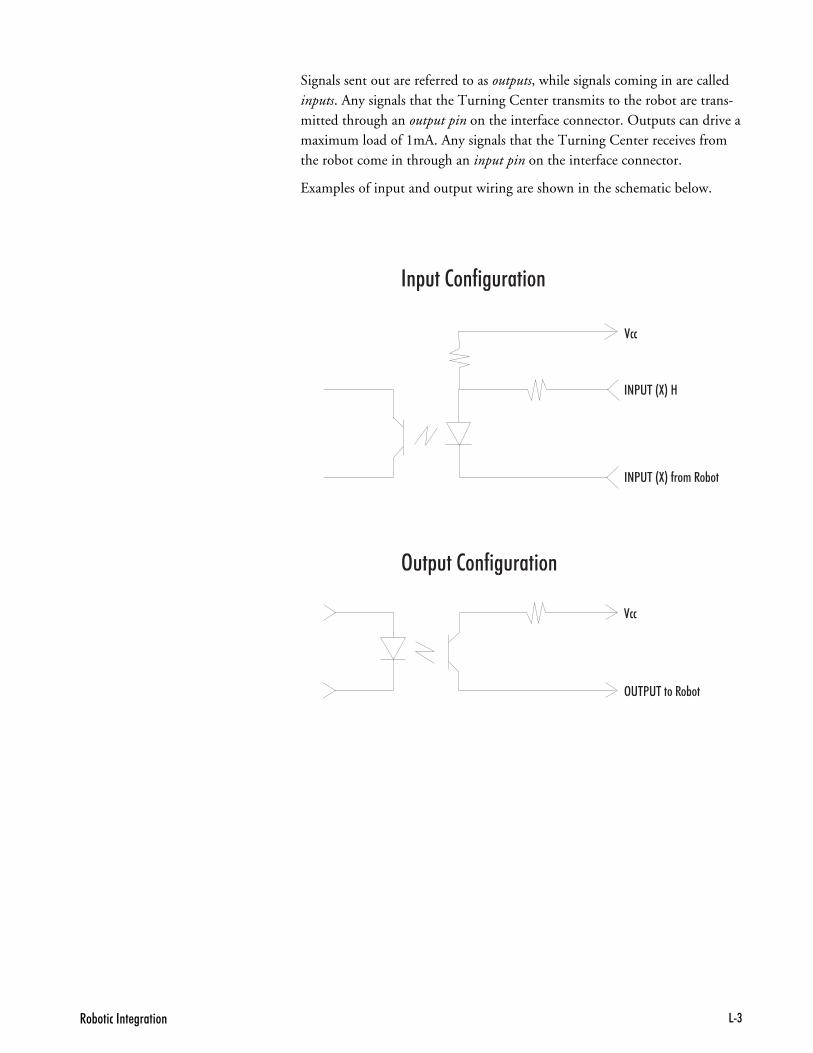
4�&�� �!�������� �+)
Signals sent out are referred to as outputs, while signals coming in are calledinputs. Any signals that the Turning Center transmits to the robot are trans-mitted through an output pin on the interface connector. Outputs can drive amaximum load of 1mA. Any signals that the Turning Center receives fromthe robot come in through an input pin on the interface connector.
Examples of input and output wiring are shown in the schematic below.

4�(���� ��"$� �B��� ������+*
� � ����$��� ���������The 9-pin I/O connector on the interface connector provides a number ofways for the Turning Center to communicate with robots and other externalmechanisms such as an additional limit switch.
The inputs and outputs on the Turning Center are designated as follows:
!�� &������� F) ��B��� '���
1 Input 1 +5V INP 1L
2 External Limit 0 or +5V ELim
3 Output 2 +1V to +3.5V OUTPUT 2
4 Output 1 +1V to +3.5V OUTPUT1
5 Common GND
6 Input 2 0 or +5V INPUT 2
7 Input 1H See Note INPUT 1H
8 Input 2H See Note INPUT 2H
9 Common GND
Other Input/Output Notes:
� All User outputs are disabled by an ESTOP condition.
� Never apply a negative voltage or an AC voltage to an input.
� Outputs are set to source current only. The maximum load on each output is1mA.
� Do not operate relays, motors or other inductive loads with the TTLI/O outputs. This will damage the machine. You may however, run anoptical relay.
� The external limit signal can be used to detect motion problems and shutoff the Turning Center. Use a switch that sets that signal (Pin 2) toGround (Pins 5 or 9). Grounding this signal has the same affect as whena limit switch is tripped on the Turning Center.
'����
8�$� ��� � 2�����$���(��� ����$��� �$�$�&0�$�������!��$��� �:$�$#��'&���������������'�9�������
'�����
"��$� ������������� �-���''� �$�������$���&���$��
!��$������� �7��������'0��$�� ������'�� ����$��� ����� ��������''��<�1��$��&����� �(� �''0� ��(��$�� �
�������9����
�������9����
� � #�*���� ����$��� ���������

4�&�� �!�������� �+;
!�� ����������� $�� � � #�*���� ���������
!�� '�1 &������� ��*�� �����
1 Robot Input No. 1 Purple2 External Limit Input White3 Robot Output No. 2 Yellow4 Robot Output No. 1 Orange5 Ground Blue6 Robot Input No. 2 Black7 Robot Input No. 1 Red8 Robot Input No. 2 Brown9 Ground Green
'����
#��������'������$ 2�G������ �����I�� '$ ���������������� �&'��(������(� ��������&�� � ���� ����� ��������&���

4�(���� ��"$� �B��� ������+-
(������� #�*�� ���
There are two groups of input and output pins (group #1 includes pins 1, 4,5 and 7, and group #2 includes pins 3, 6, 8 and 9). Having two pin group-ings allows you to interface the Turning Center with more than one robot(or other device) at a time. Each pin grouping is made up of two input pins,one output pin, and one ground pin.
In most cases, input signals coming from the robot are in a normally-highstate (input pins 1 and 6). The robot must make the signal go low for theTurning Center to recognize a change of state. There are cases where a nor-mally-low state is preferred. That is the reason for the existence of second in-put pins for each grouping (pins 7 and 8); they are normally-low and therobot must make them go high for the Turning Center to recognize thechange.
"4:��=
#)�! 0
#)�! 8
!�9�#�G�����''0����I
!�9�#�G�����''0����I
"4:��=
:�#9�#!�9�#�G�����''0����I
?C#?4�����!�!#�!�9�#
!�9�#�G�����''0����I:�#9�#

4�&�� �!�������� �+,
������� '����
8�$���$' ����$����0 '��������� ����M����G"�)�I�
8�$���$' �$��� �$������(���������'0�/�� �$�������0�"� � ���� ���@$������� �/������(����0 '������&$���
8�$���0�������(�''�����W"7-��%�&'� 2�����W"7;��%� ����� ��������� �0�$����������0 '������&$����(����"7-����"7;������$��'�0�$���'�������0 '������&$���&�(���� ����$����
� � '� �����
The NC codes used in robotic communication are:
G25 - wait for High signalG26 - wait for Low signalM25 - transmit High signalM26 - transmit Low signalH# - specifies the input or output (default is H1)
The H code is used in conjunction with the wait codes and transmit codes.For example, G25H3 tells the Turning Center to wait until the state at input#3 goes high.
Assuming the robot’s initial output state is low, if you place this line of codeat the beginning of your program, the Turning Center waits until input #3goes high, then executes the next line of code.
If the external device sends a low signal, nothing happens because the TurningCenter is waiting for a high signal. If there’s no change to a high signal, theTurning Center does not execute the next line of NC code in the program.
When the robot sends a high signal, the Turning Center responds by con-tinuing with the NC program. If the Turning Center does not respond to therobot as you have programmed it to, check that you have correctly wired therobot to the interface, and that the robot’s initial output state was notchanged to high during the connection of the robot.

4�(���� ��"$� �B��� ������+�
����#��#$������������������������ $ 2G���I��������������������'�G�7;I������&����� ������(��������G��I������'G"7;I�
�������� ��� G84H
,��� $�� ��� G(84H
� ������ �$ ��� �F#�*�� �������������As previously explained, communication between the Turning Center androbot is very simple. They only use and recognize high or low signals. Oncethe Turning Center sends a signal to the robot, it goes into a wait state andcontinues to wait until the robot sends the appropriate signal back. Whenthe signal is recognized, the Turning Center executes the next instruction inthe part program. After executing the instruction, it sends a signal to the ro-bot. The robot, which has been in a wait state since its last transmission, re-ceives the signal, performs as it has been programmed, then again signals theTurning Center.
This reciprocal system of communication is made possible by the placementof G and M codes in the part program. The G codes provide the wait in-structions to the inputs, while the M codes provide the transmit instructionsto the outputs.
The following sequence is typical of communication between the TurningCenter and a robot. Since the robot’s initial output state is low, the lathe’sinputs have already been pulled down to a low state. This sequence assumesthe Turning Center is equipped with an air chuck.

4�&�� �!�������� �+�
;���#��#$�������������� ��/�����'��������'(��������&���� �&���������� �����������
*���#����&����'�����������2���� ���� '��/��������2�������!�����������'��������'������������0�(���������2������
)���#��#$�������������� ��/����������'� '����������� $ 2�G��.I����������'��G�7-I����&������ $ 2���� '��� ��#��#$�������������������G"7-I�(�����'��������'�(�������&��
7���#����&���'� ��������2���� ������ $ 2��� �������������������'����#$�������������� � �������������2�0�� '������ $ 2�
G�7-I
G"7-I

4�(���� ��"$� �B��� ������+�.
�.���������������� 0 '��&�����������G�*,I�
,�����������&���� ��/����������'��������� �����#$��������������������������� ���� ������������'�����#$�����������
����#����&������/�����(����� �����(��������2��������� ��'� ����������������������� �� �����������������������������&����� '���� ���'��%�����2����������� ����'��������'�����#$������������
����������#$�������������� ��/������������'������������ $ 2�G���I�����'������(����� �����������'������&��G�7-I��� �����G"7-��'��I�
-���������#$���������������(����� ��������������'������&��G�7;I��� �����2��������� ������G"7;I�(�������������'�
G�7-I
G"7-I
G�7-I
G"7-I

4�&�� �!�������� �+��
#�*�� ����� �5���
#�*�� ����� �5���
'� !������
#������������''$������������0���$��"������ ��� � ���������(� ��������&���#�� � ��������� �(�����&�����(� �����������&�' �
� ������ #�*���� ���������� '� !������
N0M11;OPEN CHUCKN1M25H2;TRANSMIT HIGH SIGNAL THROUGH OUTPUT 2N2G25H1;WAIT FOR HIGH SIGNAL THROUGH INPUT 1N3M10;CLOSE CHUCKN4M26H2;TRANSMIT LOW SIGNAL THROUGH OUTPUT 2N5G26H1;WAIT FOR LOW SIGNAL THROUGH INPUT 1
N0G0G90X.26Z1.01;MOVE TOOL AWAY FROM WORKPIECEN1M3;TURN ON SPINDLEN2X.25;MOVE TOOL TO START POINTN3G1X.23F2;FIRST ROUGH CUT, SET FEED RATEN4Z.4N5G0X.25;BACK OUT AND RETURNN6Z1.01N7G1X.21;SECOND ROUGH CUTN8Z.44N9G0X.23;BACK OUT AND RETURNN10Z1.01N11G1X.19;THIRD ROUGH CUTN12Z.48N13G0X.21;BACK OUT AND RETURNN14Z1.01N15G1X.17;FOURTH ROUGH CUTN16Z.52N17G0X.19;BACK OUT AND RETURNN18Z1.01N19G1X.15;FIFTH ROUGH CUTN20Z.66N21G0X.17;BACK OUT AND RETURNN22Z1.01N23G1X.13;SIXTH ROUGH CUTN24Z.7N25G0X.15;BACK OUT AND RETURNN26Z1.01N27G1X.11;SEVENTH ROUGH CUTN28Z.74N29G0X.13;BACK OUT AND RETURNN30Z1.01N31G1X.1;FINISH CUTN32Z.75N33X.16Z.63N34Z.53N35X.25Z.35N36G0Z1.01;RAPID TRAVERSE TO START POINTN37M05;END OF TURNING PORTION OF CYCLE
N38M25H2;TRANSMIT HIGH SIGNAL THROUGH OUTPUT 2N39G25H1;WAIT FOR HIGH SIGNAL THROUGH INPUT 1N40M11;OPEN CHUCKN41M26H2;TRANSMIT LOW SIGNAL THROUGH OUTPUT 2N42G26H1;WAIT FOR LOW SIGNAL THROUGH INPUT 1N43M47L3;CYCLE BACK TO N0N44M2;END OF PROGRAM

4�(���� ��"$� �B��� ������+�7

���-
#�$������ ����
���-
���������� ������� ������ ��������� ����

��� ���!"�#�#$����������������%��"$� �!+7
���*���
J� � ����+*H� � ����+)� �+*F� � ����+)� �+*Q� � ����+)� �+��K� � ����+*
�
�&�$����#� ����� ��?+-7����?+-)�&��'$���� � ������ � ����+*�&��'$�� ��� ����������������� � ���A+7�����:$�$���+,� ?+�.���7�:$�$���+,� ?+�.� ����������E+;� �����0�A���<+;� �����0��((� � ���A+*� �����0���� � ���A+*� ����� ��� �����+7� 5$����
"�&���� ����� '���<+-��� �� ����<$�������<+,C��1����<+�
� ������������ ���?+;��'����1��������'��?+),���'���(��� �����'$���� � ����+�.�� � ����
C��1��� ��������� � ����+)>��1��� ��������� � ����+)
�� ��������!� ������'��?+*;� ?+*-�� ��� �$�� � ����+)��������! ���� ����� ��?+-��$���� �#��'�#$������
����� �������+�*�����'�#��'&�����+-!���''�������+�7� �+�)9����������� ���� ����������+�7$���������+��
�$���/���?+;�
�
<� 2'����<+�.<� 2'��� ����� ��?+*7� ?+;-<� 2'�������������������������<+�.<�M�����$�/�
���� ����� ���"+�*"������ �''0�=�(�������"+�*
<'� 2��$�&��� � ����+)� �+�-<'� 2�
��1��$���$�&�����������������+7:(���� � ����+7
<������� ���� � 0 '�� � ��(����"+�.
<��������'���!+�
�
��''����$&�������� � ���"+������� � 0 '�
��� �'��"+-� "+��"� � ����"+-9������������"+-������ ��''�����"+�7
����� � 0 '�� � ����A+)������� 2���+�.������� 2�A�0������?+�7��� � �� ����� ��?+-����������1����������A+;�������� ���?+;�������9������ ��?+;����� ����$�&�����+�.�� 2�0�$�����������+7�$ 2���+�.��� $'���������'����
�'� 2������ � ��(����A+7��$��� '� 2������ � ���A+7
��� $'���������'������������������"+)�'�������7� � ���A+*�'���� ����� ��?+7�� ?+-;�'���� ����� ��?+�)� ?+�-������ �����'� �����?+-*������� � ����+)� �+���������������((����?+;*���������9����������/�������?+,7������������� 2����#$�������������=+7����$�����������(����<+�,���(��$���#$���������� ���+-����� ���
����$������� ����''���&�1���+�9����������� �������+�#$�����������
���� ���$�����+����� ����''���&�1���+-
����� ������:�����'���+������1���'����+;� ?+������'�9���'��?+,,�����'�9������
��'����+)!���''�������+7.!���(� ���?+7� ��������+*�����������+7������''������+7�
�����'�#��'&����#��'�#$������+-�����''���<�1
=�� ��������(��<+*��������������<+�;
���-

!� �1 !+)
�����''���<�1�������?+,,���'�����!+-���� ������0���
�� ����A+7������ ��?+*7� ?+;7� ?+--=�(�����������?+;)��'� �����1�������?+;7�0��������4�'���������#$�������������!+7$� ����� ���� ��� ������0������!+7
���0� ����� ��?+7�� ?+-*�$�����&'� 2���+�.�$�����������?+�7�$�����9��������:$�$�����'����+�)�$���������/� ����+7� �+)�$� ����� ��?+7�� ?+-*�0 '�������?+,
"
=� ���'�9'� ���(���!� �D�'$����?+,-=�(�$'
������?+,*D�'$���(������� ��?+**
=�'�������� ����� ��?+7�=����(� $�� �(��� ��!+;=� 2�&'�� ����� ��?+--� ?+-,� ?+-�=� 2� �� ����� ���������?+,)=� 2����#��'&�����?+,)=� 2������� �����?+,)=����!���'� 2���� ��=+*=�������(�0��E+7=��''��������'� ����� � ����+��=��''� � ���A+7
%
?+����!��$���+�? �
���$��?+7�#��'�������'���?+)�
? ����� �����+���/�����?+,7
? ����9��(���� ����?+;,?������ 0������=+*
��� ���(��E+����������$���A�0&��� ��=+*
?������ 0�����<$����=+*?������ 0�����!��$��?+�?��&'����(��������?+;,?��&'���$&����������?+*;� ?+*-?� ��(��������� � ���A+*?������������������������?+*;� ?+*-?��&'��������'��((������+�*?������4$����� ����� ��?+)�� ?+)*� ?+-;?1�� ����� ��?+�)� ?+7.
&
�� � ����+)� �+;
��� �4�� �(��� ��!+;��� ����� � ����+)� �+;:/���� ���?+,��'� �����!+-
��� �' � ����� ��?+)�� ?+);��'�
=�(�$'��?+;��� 2���������?+�7���$��?+�)�� �(�� ������?+�7
��� � ����� ��?+7��'������� ����� ���������?+,)�'��������� �����?+,�
=� 2�����?+,)�$����� � 2������ � ��������<+*
"� � ����+)� �+-����� � 0 '�����$����+,������������($� ��������$����+����� ������0�������$����+�!�����'��������$����+-9�'������������������$����+�9����������������$����+�9������������� �����$����+���������$����+-�������$����+,
"�7��?+;)"�&���� 5$������<+-"'���������(�0��E+7"���� � ���A+-"��
����� ��?+--� ?+-������ ����� ��?+7�� ?+-;9������� ����� ��?+*7� ?+;�
�
�� � ����+�� �+,��� �����!���''�������+*��'�
����� ��?+-7�����'�9���������+)!� �1� ����� ��?+-7��'� ������+)
�� �� ����� ��?+-,� ?+-������������ ���+;���� ������?+�7���������+�.������� ����� ���$���������+7���A�0���?+-�
!� � ����+)� �+�!F:� ���� �����+*!��������� ����?+7-

��� ���!"�#�#$����������������%��"$� �!+*
!� � ����� ��?+--!� ������������� � ���A+7!� ������'��� ������� � ����+)� �+*!� ������'� ��� ����������������� � ���A+7!� ������'�C������� � ����+)!� ������'�>������� � ����+)!� �1� ����� ��?+-7!��$���'� �����$�&��� � ����+�!��$��#��'&�����+�� ?+�!����
���� ����?+7;��� ����?+7-
!���''�����$���� ���'�$������+�7�����'�9���������+7."�������� 0�(�����+7��� �������+*#��'�#$������+�7!���(� ����� ���+*��(�������+7.
!���(� ����� �� 2����0�$������''�������+-!������������+;$��� 2��������+;
!���(� ����� �� ������?+,;!���(� ����� �����''�������+*� �+-!���(� ����� �9���'��?+,;!���(� ������� �����+*!���'� 2���� ��=+*!�����'���� ������+77!���������'������
�����'�<�1���+������'�<�1��$�����<+�-
!�����'������� $'����"+)��������"+7��'�����"+�)
!��� $ �����#$�������������<+7
+
E��������'��?+7� ����� ��?+7�9���'��?+-� ?+�
9��+$�����$� ����� ���?+-,E��������'� ����� ���+;E���=���� ���?+**E�����������?+**E���������� ����� ��?+*7E������� ��?+**
�
A� � ����+)� �+�.A�0��� 2���� ��<+*
�
�� � ����+)� �+�.� "+�,� "+��
��� �� ����&$�������� 5$������<+,��(+�� ���� ����+7���������
�'��������'���0���+�-?������ 0�������=+;>��1����1���������+�,
�������� ����=+*�������!�����'����
� ���A+7�������������"+7
����� �����$�� � ��E+,�� 2� ����� ��?+7��� 2� � ����� ���+�.����� �$���� � ����+)� �+�.� "+���$&�� �����!+-
(
�� � ����+)� �+�7���� ��
"�����+�;:�����������������+�;4�$���������$&����������+�;
�� ���� ����������<+)�� �������� �������!+)�� ����!�(�� ����� ��?+7��� ����!�(����� ����?+*� ?+)7����������
�����''���<�1����<+�;�������� ������/����/���<+-��1��$��&'� 2����������������+7���$�<�����+*� ?+�)��������<����?+7� ?+)7���� � � ���A+7���� � ����� ��?+--��''F��&�� ���$�� �������+�� �+���� �''����$�� � �����+)� �+�7�� ���� �����������?+;��� ��� ������?+;��� ���������?+;��� �(�� ������� ���+�.��$����
�$����#��'��!+�.�$'��'�� ��� ������0������!+*�$'��'����'
�� ��������$����+�)�$'��'����'� � ����$�������+-�$'��'����'���������������+-�$'��'�����?+)�
'
�� � ����+)� �+�-��� � �
(�����&�� � ���$�� �������+,��� � ��� ����������(���+)������������������+7���9������������������?+,-

!� �1 !+;
�����/�������!��$��?+����� ����� ���+;� ?+�� ?+�)� ?+�*���������''���<�1��?+,,������'�� ����������?+)-�$���� 2���+�.�$���� 2�A�0������?+�7�$���� '���<+�
)
:� � ����+)� �+�,� "+��:((��
����� ��?+*7�$�&����?+;*#�&'���?+;*
:���� ����� ��?+�� ?+�)� ?+�;:������'�� ����� ���+;:���������4� ���9��������?+7.:�������9���'��?+,� ?+�� ?+).:�������9���'� ����� ���+;� ?+7�:�����'
�2����?+,� ?+*;�2��� � ����+)� �+*�����?+,� ?+*;� ?+*-���� � ���A+*
:�������<+;:������9���'��D���(0���������?+;.:�������?+;.:$�$���(�'�� � ���A+;:$�$��#��'&�����+,� ?+�.
!
9� � ����+)� �+�,9� � ��� �''�����$&����������"+��9���'���������������?+,�9��������'���!+�9������
���������?+;����������?+;�
9���� ����� ��?+7�� ?+-;9�$��
"� � ��(����A+*�� � ��(����A+7
9�$��� ����� ���+;� ?+�� ?+�� ?+)�� ?+)*9� 2� ��� � ����+)� �+�,9� 2� ��''���� � ���"+-9������'� ���$�����@$����������+)9� ����� ���+��9�'�����������������+*
��� �'� � ���A+7�� ���A+7
9��+������$��'� ���� ����� ������?+-*
9��+$�����$E��������'�9���'��?+-,9���������� ����?+--9�������? ����� ����?+-*
D���(0���� ����?+-,9������� ����� ��?+7�9�������4�� �$���+��9���������� ��
������ ��?+*9��+$�����$� ����� ���?+--
9���������!�(���������������?+,�9�������? ����� �����?+,7� ����� ����������?+,�#��'&�����?+,�
9����/�������!��$���+�9������9��/� ������+)9��+'�� ��������� 5$������<+-9��(���� ��
����� ��?+*7� ?+;,?1������?+;��� $��0��?+;�
9��������0� � �����+)� �+-9��/������� ����?+*�9�����?+��9���� ����� ���+;� ?+�� ?+�)9������$���?+��9������$�� ����� ��?+�)9��(�'������'���!+�9������� 0 '�� � ����+)9�������? ����� ����?+)
9��+$�����$��?+-*9�������? ����� �����������������?+,79����������$��?+)�9����������� � ���A+*9����������
(�������'�$������+�7(������ ������+7.
9������������$�����������+7.
I
L� � ����+)� �+�,L$� 24$���?+-;L$� 2D���(0��?+-;
#
4� � ����+)� �+��4� �$���(��� � � ����+��4��� ������� � ����A+)4��� ��������'��������� � ���"+-4��� ��������4� � ���"+-4��� ���/����
9������������"+;4��� ���/����� � ���A+74�� ���(�'����+7.4� ��'0������ �(�'����?+�)4� �� ����� ��?+7�� ?+774� �����?+-,4�(���� ����'�����&'��������+,4����������0�$��#$��������������+7

��� ���!"�#�#$����������������%��"$� �!+-
4���/�����������?+7,4���/������ ����?+7,4���/����� ����?+7-4��$�&��� ����� ��?+7�� ?+-;4��$�&�������� ��$&����������?+7-4����� � ����+)4��'� �� ����� ��?+7�4���������� ��?+-,4����:/���� ���?+;;4�������&� 2'��� ������������<+�.4������������� ����� ��?+-7� ?+-)4������������ ���?+*;� ?+*-4�$���(�����$&�������� � ���"+��4�$�������(���� ������� � ���A+)4���� � � ���A+-4�&����!��$���+�4�&����:$�$���+,4�&��7�!��$���+�4�&��7�:$�$���+,4�&��!��$����?+�4�&��!��$�7��?+�4�&��:$�$����?+�.4�&��:$�$�7��?+�.4�&���0� ����M����� � ����A+74�&�� ������ ��
9����������������+;4�&�� �!��������
����'�����9���������+��4�&�� ��������������������2����+74�&��
���$�� �������+�� �+�4��������+;
� ���(�����+;� A+)4�$����� $���"+�4$'������(�0��E+�� E+74$�
����� ���+;� ?+�� ?+�:(('���� ����� ��?+,-������� ����� ��?+)7� ?+*7� ?+*;
4$�F�����$�� ����� ��?+)�� ?+);4$������������'�����9��������=+-� =+�-� �+
�� �+�,
�
�� � ����+)� �+���� '���$��<+���(�0��=+7
=�����E+7=��������'� 2���� ��=+*"'�������E+74$'����=+7� E+�� E+7���' ��<+)���' �!��$���+�� ?+�
��(�0��� 2'����E+-<�(����?����������2�������E+-<�(������ ��������9����E+-
��'���� ��������9����E+-��/����� ����� ��?+�)� ?+�,��/�����=��'���<�1��?+�,��/�� ����� ��?+�� ?+�)� ?+�,� ?+-;��/����'�� ����� ���+;��/��������� ����� ��?+-7��/���������������9��������?+,7� �'������+;
� ���(����A+)�� ��1�����+;
� ����������������������������?+,���'� �����1������ ��� ������0�����?+;7��'� ����� ����� ��?+7���'� �#��'� ����� ��?+)���'� ���������� ���?+-*���9������� ����� ��?+*7� ?+*)� ?+--�����(���� ������� � ���A+)�����&���$�$� � ���A+*��F�� 2������ ����� ��?+-������
��(�'�������+)����������(���� ����'���+�)��$�
������ ��?+-,��&���0� ����� ��?+)-���$��?+*79��������?+,*#��'��=+��
�?#�9�9���������+7�������������'���!+�����' �!���'� 2���� ��<+)���' �:��������������.�� ����'���!+,����'�������?+,� ?+*;�2��� � ����+*��(������� ����� ��?+*7� ?+;-��(���������''�������+7.��� �(0
����(� $� � ���"+-'�����(� ��''� � ���"+-�$�&����(�������� � ���"+-���������(���� ������� � ���"+-
��� ������#$������������ ������ '���<+7���� '�
� 5$������<+- ����� ��?+*7� ?+;;������((� � ���A+*�������� � ���A+*:$�$���+,� ?+�.���� �:/���� ���?+,
���� '������ ���!+-�� ����+)� �+����'� �����!+-
��'����������'������"+�)� "+�-��� �� �#��'&�����+*� ?+��������<'� 2��?+)�

!� �1 !+,
��$��<�����+�.� ?+���� 2�=�����������?+;.���� ����� ���+;� ?+,� ?+�� ?+�� ?+)�� ?+
);����4� �����?+-,������ ��''�����"+�7������ ��''���� � ���"+-�������� ��$�������"+��$&����������?+7-� "+��
&'� 2��$�&��� � ����+)� �+�,��''��� � ���A+-���� ��"+����(���� ��&'� 2� � ���"+����(���� ���$�&��� � ����+)� �+�,��$���(���� � ���A+-
�$&�������������&'���?+*;�0����4�@$����������+��
�
#� � ����+)� �+��#�������"+�#� �� �'��$�������+77#��� ������+��
������'���+77��'����+7�� !+�
#��� ���'�(+�� ���+7�#�'�� ����� ��?+-�#������+�.#����(���=�0� ����� ��?+-7� ?+-)#��'
������ � ���A+*��&���0��?+),����� ����������?+)-��'� ���� � ����+)� �+����(������ ����� ��?+,-#0����?+),
#��'�:((��������&'��������+�#��'������������� ���+-#��'�#$���
���� ��������+�*����� �������+�*�����'�#��'&�����+-� ?+������������+����$���������+�)�������������� �(� ���'���+��$���������+��
#��'�0�����!+,#��'&���
����� ��?+7�� ?+).=� 2�����?+,)������������?+,�$���������'� � ����� ���?+,.
#��'���E+*"��$� �����E+7���$��?+)-��$������������'�$������+��
��������!+����(�'�����!+��� ���!+,��� �����!+�
#��'��������?+�7#��/�'���1����<+7#����������������?�������?+*;#$�����������
�$&�� ����������������<+�*#$�������
=�(������#��'��=+��=�0�4$����9��������=+�*��$�������2��� ���=+�-:��������=+-#��'�D���(� ������=+�7D���(0��=+�)
�
�� � ����+)� �+���� '��������/���� � ���A+*�� �� ����� ��?+7�������''���
�����'�9���������+7������ ����� ��?+*7� ?+;7�����=�(�$'����$���?+,*���� 2�������� ��������������+)������� ���?+;���������'�� ����� ��?+-7
=
D���(0 ����� ��?+)�� ?+))=���'�0�#�&��=+,��������=+,� ?+)7� ?+*,� �+��������� ����� ��?+*7�� 2�#�&��=+�.��'��4$�������?+*;� ?+*,��� ����?+;� ?+).
D���(0� ����� ���+;D���(0���� �����+�7
������ ��?+7�9��+$�����$��?+-,
D�������$��?+7�D����9���'
D���(0���������?+*�
,
�� � ����+)� �+���������������������������?+*-������0���+77��&�������+77��' ����9���'��?+,*��� ��
('�������?+,����� ����� ��?+-����$��?+-�

��� ���!"�#�#$����������������%��"$� �!+�
��� ���������������?+,���������� �����?+)
��� ��������+7���2� ��� �������!+)���2�9'� �����������������+)���� ����E+7
C
C��1��� 5$������<+� ��� ����� � ����+�������� ��� ����� � ����+)
C� � ����+)� �+��
;
>��1������ �������+������ ������(� ���������� � ����+�.������ ��� ����� � ����+)
>� � ����+)� �+��>����9������� ����� ��?+*7� ?+*)� ?+-->�����?+*�
!� �1 !+�
�����������
��������� ���� ������
This computer-controlled 8-stationtool turret (ACC-5601) providesautomatic tool changing ability.The turret accommodates four1/4" square shank tools, four 1/4"round shank tools and a partingtool.
This package also includes all itemslisted below in the tool TurretTooling Package.
���� ������ ������� !��5���
The Tool Turret Tooling Package(ACC-5605) includes:
� A profiling tool holder
� Two profiling carbide inserts(.016" and .031")
� A cut off tool (.045")
� A threading tool
� A boring tool
� A hex key
������� ������ &�-���� ���
The fixture kit (ACC-5610)includes:
� A collet set (1/16", 1/8", 3/16", 1/4", and 5/16")
� One live center for the tailstock
� One dead center for the tailstock
� One dead center for theheadstock
� One faceplate
� One lathe dog
���� !���� ��� �����
This tool and post set (ACC-5650)includes:
� Two two-position tool posts
� One carbide tool set with aright-hand cutting tool, aleft-hand cutting tool and athreading tool
� One high-speed steel tool setwith a right-hand cuttingtool, a left-hand cutting tooland a boring tool
� One cutoff tool holder
� One cutoff tool
� One hex key driver (5/32")
���*��� ����� ���
This set (ACC-5630) containsthree carbide inserts for use withthe Carbide Indexable ToolHolder.
���*��� ���-�*�� ���� ��������� �����
This set (ACC-5640) includes onecarbide indexable tool holder andone carbide insert.
�������� ������� ����5 !��5���
The aluminum stock package(PKG-9320) is made from 2001Series aluminum and includesfourteen pieces each of 1/2" x 2",1/2" x 3", 3/4" x 2", and 3/4" x 3"stock.
����� ������� ����5 !��5���
The brass stock package (PKG-9330) is made from 360 free ma-chining brass and includes:
� Four 1/2" x 3" pieces
� Four 3/4" x 3" pieces
� Six 1/2" x 2" pieces
� Six 3/4" x 2" pieces
����� ������� ����5 !��5���
The brass stock package (PKG-9140) is made from 360 freemachining brass and includes:
� Thirty 3/4" x 3" pieces
(�� ���*�� ,�- ������� ����5!��5���
The machinable wax stockpackage (PKG- 9350) containstwenty pieces of blue machinablewax 1" diameter x 12" long.
!����*�� ��� ����������
The portable air compressor(PNU-4535) is an intermittentduty, 3/4 hp, oil-less air compressorwith a built-in color-coded regulatorand pressure selection chart. Itdelivers 2.1 CFM at 90 psi.
��� � ��5 #�*���� ����$���
This pneumatic air chuck (PNU-4615) allows automatic securingof a workpiece for productionapplications. It is ideal for use ina computer-integrated manufac-turing system (CIM), a flexiblemanufacturing system (FMS), orfor automated factory simulationwith robotics.
���������� ������� ������ ��������� ����

��� ���!"�#�#$����������������%��"$� �!+�.
��( ��$�����
���������( �������
spectraCAM is an industrialCAD/CAM package that generatespart programs that can be run onthe spectraLIGHT TurningCenter. spectraCAM (CAM-6601) can import part geometryfrom CAD programs that exportDXF files (such as AutoCAD).
���������( ������� $�� ,������
This Windows 95 version ofspectraCAM (CAM-6741) is anindustrial CAM package thatincorporates CAD into the CAMprogram to provide the mostcomprehensive and user friendlypackage available. Solid modeltool path verification is featured.
!�������� � ���� )�����
This is a computer-controlledshield opener that providesautomatic opening and closing ofthe Turning Center shield (PNU-4625). It is ideal for use in acomputer-integrated manufac-turing system (CIM), a flexiblemanufacturing system (FMS), orfor automated factory simulationwith robotics.
����������F��$�����
� ��� ���
The Chess Set software package(DOC-7561) includes a profilingtool, a two-position tool post,software with NC programs, anddocumentation to machine acomplete chess set. Softwaresupplied on 3.5" disks.
� ��� ��� !��<���
The Chess Set Project (DOC-7552) is a series of NC programsused for the manufacture of achess set. The project consists ofa floppy disk containing NCprograms, a special high-speedsteel profiling tool, pre-cut blankbrass and aluminum stock anddocumentation. Software suppliedon 3.5" disks. (Requires the useof a self-centering industrialgrade chuck.)
����������� �� �'� ,��5*��5G������� %������H
A student workbook (DOC-
7631) presenting topics such asusing the lathe, coordinate systems,NC programming, editing partprograms, and verifying and run-ning part programs. IncludesCNC turning projects.
����������� �� �'� ,��5*��5G���� �� %������H
This teacher's workbook (DOC-7641) is similar to the studentworkbook, but includes teachernotes and instructions to assist inthe presentation of the topics.Answers to post-test reviews areprovided. Includes sampleprograms for turning projects on3.5" disks.
��5���5 ���������� ������
�������� ����� (���$�������� $���������
The fifteen activity curriculumguide includes versions for boththe students and the teachers.These guides provide instructionfor using the CAM-6741spectraCAM Turning for Win-dows software.
�'� ��� ������ $�� �������
This fifteen activity curriculumguide includes versions for boththe students and the teachers.These guides provide instructionfor using the spectraLIGHTTurning Center with the Win-dows 95 control software.


