Embed Size (px)
Citation preview
Speedy 400Operating manual
8047OM 8047_3.4_EN (09/2019)
ENGLISH (Translation)
Speedy 400Operating manual
8047OM 8047_3.4_EN (09/2019)
ENGLISH (Translation)
Trotec Laser GmbH
+43 7242 [email protected]
Trotec Laser Pty Ltd
Trotec Laser BelgiëTrotec Laser Belgique
+31 850 70 51 [email protected]
Trotec Laser Canada
+1 800 663 [email protected]
Trotec Laser AG
+41 [email protected]@troteclaser.com
Trotec Laser GmbH
+86 189 500 735 [email protected]
Trotec Laser DeutschlandGmbH
+49 89 322 99 [email protected]
Trotec Laser España
+34 93 102 50 [email protected]
Trotec Laser France SAS
+33 1 72 62 20 [email protected]
Trotec Laser UK
+44 0191 4188 [email protected]
Trotec Laser Srl
+39 02 9475 [email protected]
Trotec Laser JapanCorporation
Tokyo: +81 42 313 0740
Osaka: +81 6 6180 [email protected]
High Speed Laser Systems S.de R.L. de C.V.
+52 55 [email protected]
Trotec Laser B.V.
+31 850 70 51 [email protected]
Trodat Polska Sp. z o.o.
+48 22 339 35 [email protected]
Trotec Laser Inc.
+1 866 226 8505, Option [email protected]
Rubber Stamp & Engraving
+27 875 [email protected]
2 ENGLISH (Translation)
Trotec Laser GmbH
Freilingerstraße 99
4614 Marchtrenk, Austria
Invoice Address:
Linzerstraße 156
4600 Wels, Austria
Tel.: +43 7242 239-0
General contact to Technical Support:
Tel.: +43 7242 239-7000
E-mail: [email protected]
www.troteclaser.com
ENGLISH (Translation) 3

Technical Changes Technical specifications are subject to change without notice.Trotec Laser GmbH reserves the right to improve or modify any of the products withoutprior notice.
© Copyright This documentation with all illustrations is intellectual property of Trotec Laser GmbH.The entire documentation is given to the user for personal use only. Reproduction,translation or any distribution to third parties is not permitted without the prior consent ofTrotec Laser GmbH. Any breach of law will be prosecuted.
4 ENGLISH (Translation)
Content
Content
1 General Information................................................................................................... 81.1 Information about this manual.............................................................................................. 8
1.1.1 Storage of the manual............................................................................................................8
1.1.2 Complementary documentation..............................................................................................8
1.2 Explanation of symbols..........................................................................................................91.3 Liability and warranty........................................................................................................... 101.4 Scope of delivery (standard configuration)........................................................................111.5 Type plate...............................................................................................................................12
2 Safety......................................................................................................................... 132.1 General safety notes.............................................................................................................13
2.1.1 Intended use.........................................................................................................................13
2.1.2 Improper use.........................................................................................................................14
2.1.3 Residual risk......................................................................................................................... 14
2.1.4 Machine modification............................................................................................................14
2.1.5 Operating modes.................................................................................................................. 14
2.1.6 Applicable safety regulations................................................................................................15
2.2 Laser safety........................................................................................................................... 172.2.1 Laser classification............................................................................................................... 17
2.3 Areas of responsibility......................................................................................................... 192.3.1 Responsibilities of the operating company...........................................................................19
2.3.2 Responsibilities of the operating personnel......................................................................... 20
2.4 Requirements for operating an service personnel............................................................202.5 Machine identification (warning and safety stickers)....................................................... 212.6 Safety devices....................................................................................................................... 222.7 Technical protective measures............................................................................................22
2.7.1 Main switch...........................................................................................................................22
2.7.2 Key switch.............................................................................................................................22
2.7.3 Temperature sensor..............................................................................................................22
2.7.4 Emergency stop button........................................................................................................ 23
2.7.5 Interlock safety switches...................................................................................................... 24
2.7.6 Acrylic top lid........................................................................................................................ 24
2.7.7 Side cover.............................................................................................................................24
2.7.8 In case of safety device malfunction....................................................................................24
2.8 Secondary (indirect) hazards...............................................................................................252.8.1 Fire hazard............................................................................................................................25
ENGLISH (Translation) 5

Content
2.8.2 Gases, fumes and dust........................................................................................................ 25
2.8.3 Reflection through materials.................................................................................................26
2.8.4 Information about damaged optics.......................................................................................27
2.8.5 Protective measures for damaged optics.............................................................................27
2.9 In case of emergency........................................................................................................... 28
3 Technical Data.......................................................................................................... 303.1 Dimensions and weight........................................................................................................ 303.2 Electrical requirements of the machine..............................................................................313.3 Exhaust system requirements............................................................................................. 323.4 Computer requirements........................................................................................................353.5 Materials................................................................................................................................. 36
4 Machine overview.....................................................................................................404.1 General overview...................................................................................................................404.2 Front door.............................................................................................................................. 434.3 Pass-through..........................................................................................................................434.4 Dynamic status display........................................................................................................ 464.5 Tables (multifunctional table concept)................................................................................484.6 Lens(es).................................................................................................................................. 514.7 Nozzles................................................................................................................................... 52
5 Transport................................................................................................................... 535.1 Safety notes........................................................................................................................... 535.2 Delivery state......................................................................................................................... 535.3 Temperature and humidity................................................................................................... 545.4 Required tools for unloading and transport...................................................................... 555.5 Place of storage.................................................................................................................... 555.6 Transport inspection and reporting of defects.................................................................. 555.7 Unpacking the machine........................................................................................................555.8 Relocation of the machine................................................................................................... 56
6 Setup and installation..............................................................................................586.1 For your safety...................................................................................................................... 586.2 Temperature and humidity................................................................................................... 586.3 Space requirements.............................................................................................................. 596.4 Setup.......................................................................................................................................596.5 Connections........................................................................................................................... 60
6.5.1 Mains connection..................................................................................................................60
6.5.2 Connection the PC............................................................................................................... 60
6.6 Connection of additional components............................................................................... 606.6.1 Exhaust system.................................................................................................................... 60
6 ENGLISH (Translation)
Content
6.6.2 Cooling unit...........................................................................................................................61
7 Operation...................................................................................................................637.1 Before commissioning..........................................................................................................637.2 Software..................................................................................................................................637.3 Power On/Off......................................................................................................................... 637.4 Control panel......................................................................................................................... 66
7.4.1 Keypad..................................................................................................................................66
7.5 Lense placement................................................................................................................... 717.6 Focusing methods................................................................................................................ 72
7.6.1 Focus tool............................................................................................................................. 73
7.6.2 Sonar TechnologyTM............................................................................................................. 74
7.6.3 Software focus...................................................................................................................... 75
7.7 Rotary attachment (option).................................................................................................. 777.7.1 Installation and commissioning of the rotary attachment..................................................... 78
7.7.2 Mounting the work piece in the rotary attachment...............................................................78
7.7.3 Engraving process................................................................................................................79
7.8 Gas-kit light............................................................................................................................80
8 Maintenance.............................................................................................................. 828.1 Safety notes........................................................................................................................... 828.2 Maintenance schedule.......................................................................................................... 828.3 Changing of the laser source filter mat..............................................................................838.4 Cleaning..................................................................................................................................84
8.4.1 Machine.................................................................................................................................84
8.4.2 Optics in general.................................................................................................................. 84
8.4.3 Lens...................................................................................................................................... 85
8.4.4 Mirror.....................................................................................................................................86
8.4.5 Ultrasonic sensor (Option Sonar TechnologyTM).................................................................. 87
9 Troubleshooting........................................................................................................889.1 Error, cause and remedy......................................................................................................88
9.1.1 How to create a service file................................................................................................. 89
10 Contact details..........................................................................................................9111 Disassembly..............................................................................................................9212 Disposal.....................................................................................................................9313 Appendix....................................................................................................................94
13.1 Datasheet 8047 Speedy 400.................................................................................................9513.2 CE 8047 Speedy 400 Redesign............................................................................................99
ENGLISH (Translation) 7
General Information
1 General Information
For reasons of better legibility, gender-neutral form of address (e. g. "he/she") are not used in the operatingmanual. It is expressly stated that in all text passages where natural persons or groups of persons arementioned, people of both sexes are always meant.
1.1 Information about this manual
Before beginning any work on the machine, read this manual completely and carefully.Keep the manual for further consultation close to the machine.
This manual describes how to operate the machine properly and safely. Be sure to follow the safetyinstructions given here, as well as any local accident prevention regulations and general safety regulationsapplicable to the field of usage. Before beginning any work on the machine, ensure that the manual, inparticular the chapter entitled "Safety Information" and the respective safety guidelines, has been read in itsentirety and fully understood.
1.1.1 Storage of the manual
This manual is an integral part of the machine and must therefore be kept in the direct vicinity of the machineand be accessible at all times.
1.1.2 Complementary documentation
Complementary documentation can be found on the supplied DVD.
Software manualTrotec Laser GmbH JobControl®
8 ENGLISH (Translation)
General Information
1.2 Explanation of symbols
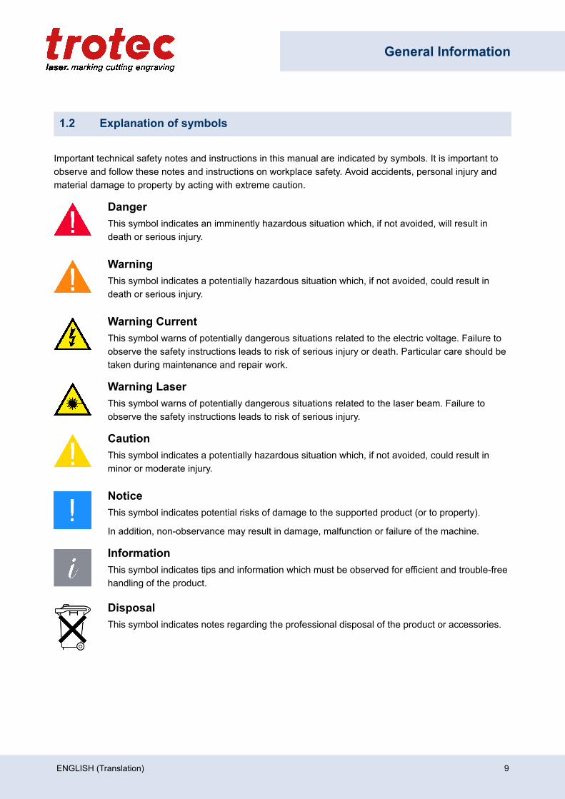
Important technical safety notes and instructions in this manual are indicated by symbols. It is important toobserve and follow these notes and instructions on workplace safety. Avoid accidents, personal injury andmaterial damage to property by acting with extreme caution.
DangerThis symbol indicates an imminently hazardous situation which, if not avoided, will result indeath or serious injury.
WarningThis symbol indicates a potentially hazardous situation which, if not avoided, could result indeath or serious injury.
Warning CurrentThis symbol warns of potentially dangerous situations related to the electric voltage. Failure toobserve the safety instructions leads to risk of serious injury or death. Particular care should betaken during maintenance and repair work.
Warning LaserThis symbol warns of potentially dangerous situations related to the laser beam. Failure toobserve the safety instructions leads to risk of serious injury.
CautionThis symbol indicates a potentially hazardous situation which, if not avoided, could result inminor or moderate injury.
NoticeThis symbol indicates potential risks of damage to the supported product (or to property).
In addition, non-observance may result in damage, malfunction or failure of the machine.
InformationThis symbol indicates tips and information which must be observed for efficient and trouble-freehandling of the product.
DisposalThis symbol indicates notes regarding the professional disposal of the product or accessories.
ENGLISH (Translation) 9

General Information
1.3 Liability and warranty
Warranty periods specified in the manufacturers "warranty terms and conditions" shall be binding for thebuyer. If no warranty periods are specified, the general terms and conditions of sale, delivery and paymentapply.
All information, illustrations, tables, specifications and diagrams contained in this operating manual havebeen carefully compiled according to the current state of technology. No liability is accepted with regard toerrors, missing information and any resulting damage or consequential loss.
Strict compliance with the safety procedures described in this operating manual and extreme cautionwhen using the equipment are essential for avoiding and reducing the possibility of personal injury ordamage to the equipment. The manufacturer shall not be liable for any damage and or faults resulting fromnonobservance of instructions in this manual.
Nonobservance of the operation, maintenance and service instructions described within this manualabsolves Trotec Laser GmbH from any liability in case of a defect.
Furthermore, Trotec Laser GmbH shall accept no liability whatsoever for damage caused by the use of non-original parts and accessories.
Additionally, Trotec Laser GmbH shall not be held responsible for any personal injury or property damage, ofan indirect or specific nature, consequential loss, loss of commercial profits, interruption to business, or lossof commercial information resulting from use of the equipment described in this manual.
It is strictly prohibited to make any alterations, to prepare translations, decompile, disassemble, reverseengineer or copy the software.
Trotec Laser GmbH reserves the right to update any of the information, illustrations, tables, specificationsand diagrams contained in this operating manual with regard to technical developments at any time withoutnotice.
10 ENGLISH (Translation)

General Information
1.4 Scope of delivery (standard configuration)
1. Laser machine2. DVD (with laser software, printer driver and operating manual)3. Focusing tool(s) (according to lens order)4. Cleaning kit for optics5. Nozzles (2 pcs.: ø3 and ø7)6. Lenses according to order7. Working tabel according to order8. Allen key kit (8-part)9. Power cable10. USB computer connection cable11. Exhaust connection cable (according to order)12. I/O-Plug
The actual scope of delivery may be different, depending on the special model, additional order options ornewest technical changes.
ENGLISH (Translation) 11
General Information
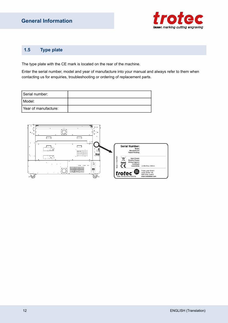
1.5 Type plate
The type plate with the CE mark is located on the rear of the machine.
Enter the serial number, model and year of manufacture into your manual and always refer to them whencontacting us for enquiries, troubleshooting or ordering of replacement parts.
Serial number:
Model:
Year of manufacture:
12 ENGLISH (Translation)

Safety
2 Safety
TO AVOID POSSIBLE HARM READ AND FOLLOW THESE INSTRUCTIONS.
The machine is built at the time of it's development and production according to applicable, establishedtechnical rules and is considered to be safe to operate.
Dangers can be caused by the machine if the machine:
• is operated by unqualified personnel,• the personnel have not been trained,• the machine is used improperly or not as intended,• or if the machine is used for other intended purposes.
This chapter provides an overview of all important safety aspects that are necessary for optimum protectionof persons and safe and trouble-free operation of the machine. Other chapters of this manual contain specificsafety notes for the avoidance and prevention of hazards.
2.1 General safety notes
2.1.1 Intended use
The machine described in this manual is intended exclusively for laser engraving and laser cutting,of material according to the intended use of the machine using the supplied software.
For material details see chapter "Materials" or contact your local Trotec representative, or your localTechnical Support.
The system must be operated, maintained and repaired only by trained personnel familiar with thedesignated field of use and the dangers of the machine.
Operate the machine only in technically flawless condition and when it fully complies with the EC MachineryDirective.
The intended use of this machine also includes that all personnel involved in installation, set-up, operationmaintenance and repair of the machine must have read and understood the Manual and in particular the"Safety" section, and comply with the instructions.
Organisational measures:• Personal protective equipment• Inspection of the laser protection wall• Laser safety instructions/laser safety training• Monitoring by Laser Safety Officer
ENGLISH (Translation) 13
Safety
2.1.2 Improper use
Use of the machine for any purposes other than those intended or described in the present manual isregarded as improper and therefore prohibited. Trotec Laser GmbH will not accept any liability for damagecaused by improper use. The risks in case of improper use are exclusively borne by the user.
Non-observance of the operation, maintenance and service instructions described within this manualabsolves Trotec from any liability in case of a defect.
2.1.3 Residual risk
Even if all safety regulations are observed, a residual risk remains during operation.
2.1.4 Machine modification
It is strictly prohibited to alter, refit or modify the machine in any way without the express consent of themanufacturer.
Likewise, it is strictly prohibited to remove, bridge or bypass any safety devices. Operating conditions andconnection and setup values stated in the data sheet must be complied with at all times.
Operation of the system is permitted only with original parts and accessories by the manufacturer. Use ofthird-party parts affects machine safety.
2.1.5 Operating modes
Normal operation
For normal operation the following conditions must be met:• Intended use of the machine (see chapter "Intended use").• Operation of the machine only by trained personnel.• Full functional and mounted safety devices.• Machine must be in technically flawless condition.• Processing of permissible materials according to the material list.• Maintenance and service are not included.
NoticeDuring normal operation it is not necessary to wear safety glasses.
14 ENGLISH (Translation)
Safety
Service operationService activities may be carried out only by authorized, trained service technicians. If side panels as well ascovers get removed and safety devices get bypassed, it can lead to direct and indirect scattered radiation.The service operation is therefore declared as laser class 4 (US: class IV) and proper precautions need to betaken (see "Laser classification").
2.1.6 Applicable safety regulations
The following directives and guidelines must be observed to avoid hazards when operating Trotec lasersystems:
Guidelines/Regulations2006/42/EC EC Machinery Directive2014/30/EU EMC Guideline
Applied harmonized standardsEN ISO 12100:2011-03 Safety of machinery - General principles for design - Risk assessment and
risk reduction.IEC 60825-1:2014,EN 60825-4:2011
Safety of laser products - Part 1: Equipment classification and requirements.
IEC 60204-1:2005 Safety of machinery - Electrical equipment of machines - Part 1: Generalrequirements.
ISO/DIS 11553-1:2009-03 Safety of machinery - Laser processing machines - Part 1: General safetyrequirements.
IEC 61000-6-4:2007-02 Electromagnetic compatibility (EMC) - Part 6-4: Generic standards -Emission standard for industrial environments.
ISO 13857:2008 Safety of machinery - Safety distances to prevent hazard zones beingreached by upper and lower limps.
EN 55011+A1:2016-05 Industrial, scientific and medical equipment - Radio-frequency disturbancecharacteristics - Limits and methods of measurement.
ENGLISH (Translation) 15

Safety
NoticeSafety norms and regulations.
The general guidelines and directives listed within this manual may differ according to locality,region or country.
Therefore, always observe the directives as well as the regulations of the institutions forstatutory accident insurance association applicable to you. The operator is responsible forfulfilling all safety requirements, as Trotec Laser GmbH has no influence on the proper use ofthe machine.
Observe the official regulations for your business location in accordance with the applicablelocal legal regulations (on accident prevention regulations or employee protection), e.g. DGUVregulation 11 for Germany.
16 ENGLISH (Translation)
Safety
2.2 Laser safety
2.2.1 Laser classification
The laser safety class indicates the risk potential from accessible laser radiation.
The laser system is a Class 2 (US: Class II) laser marking system as per IEC 60825-1 "Safety of LaserProduct". With the option "pass-through" the laser system corresponds to class 4.
The integrated laser source is a Class 4 (US: Class IV) laser marking system according to IEC 60825-1 andidentified as such.
Warning LaserLaser radiation of Class 2 (US: class II)
For Class 2 (US: class II) laser is short term exposure (up to 0.25 seconds) harmless tothe eyes and can therefore be operated without additional protective measures. However itcan cause irritation of the eyes if the natural avoidance reaction (staring into the laser beamdeliberately) or eyelid closure reflex is suppressed.
– Do not suppress the eyelid closure reflex.– Do not stare directly into the laser beam.– Close eyes, turn away.– Never look at the laser beam directly with an optical instrument, e.g. a lens.
Warning LaserLaser radiation of Class 4 (US: class IV)
Exposure to laser radiation of Class 4 (US: class IV) can cause injury to the eyes and skin.
– The skin and eyes must not be exposed to direct or reflected or scattered radiation.– Wear suitable laser safety protection glasses.– When dealing with Class 4 (US: Class IV) laser machines, it is necessary to appoint a
trained laser safety officer to evaluate potential hazards and to ensure that appropriatecontrol measures are implemented.
NoticeLaser classification
It is the responsibility of the operator to comply with the national official and statutory regulationsfor the operation of a class 4 (US: class IV) laser system or laser system with a build in lasersource of class 4 (US: class IV).
Class 2 (US: class II)
ENGLISH (Translation) 17
Safety
The accessible laser radiation of Class 2 (US: Class II) laser systems does not pose any hazard for the skin.Diffuse reflections as well as any short-term irradiation of the eyes (exposure time max. 0.25 seconds) alsopose no risk due to the low output power.
However, it is possible to suppress the natural eyelid closure reflex and stare into the class-2 laser beam fora time long enough for the eyes to get injured.
Class 4 (US: class IV)
Class 4 (US: class IV) high powered lasers (visible or invisible) considered to present potential acute hazardto the eye and skin for both direct and scatter (diffused) conditions.
Also have potential hazard considerations for fire (ignition) and byproduct emissions from target or processmaterials. It is the responsibility of the operator of the machine to take appropriate measurements toeliminate any dangers such as fire or explosions through the laser beam.
Precautions when dealing with a class 4 (US: class IV) laser machine
Warning LaserObligations of the operator for the operation of class 4 lasers (US: class IV):
– Observe official regulations for the business location in accordance with the applicable locallegal regulations (on accident prevention regulations or employee protection), e. g. DGUVregulation 11 for Germany.
– According to DGUV regulation 11 "Laser radiation", as well as national regulations:Written appointment of a competent laser safety officer for compliance with the relevantregulations.
– Mark the danger zone as such by attaching warning lights and warning signs on the outside.– Protect the danger zone against unauthorized access.– Wear appropriate laser safety glasses within the danger zone that are matched to the
wavelength and power of the laser.– Install an additional and well visible warning light to warn the operator of the presence of
laser radiation.
Compliance with the points above does not absolve the operator from meeting the relevant standards andguidelines for the operation of a Class 4 laser system.
18 ENGLISH (Translation)

Safety
2.3 Areas of responsibility
2.3.1 Responsibilities of the operating company
The operator has the following responsibilities:• It is the responsibility of the operator to comply with the national official and statutory regulations for the
operation of a class 4 (US: class IV) laser system or laser system with a build in laser source of class 4(US: class IV).
• In addition to the safety notes and instructions stated in this manual, consider and observe the localaccident prevention regulations and general safety regulations that apply at the operation site of themachine.
• A CO2 fire extinguisher must always be at hand, as the laser beam can ignite flammable materials.• If the machine is used industrially, the operator is subject to the legal obligations concerning industrial
safety.• All personnel involved in installation, set-up, operation, maintenance and repair of the machine must
have read and understood this manual and in particular the “Safety” section. The personnel must betrained and informed about all the functions, potential dangers and safety issues of the machine on ayearly basis.
• The user is recommended to prepare company internal instructions considering the occupationalqualifications of the personnel employed in each case, and the receipt of the instruction/this manual orthe participation in the introduction/training should in each case be acknowledged in writing.
• Keep the manual in the immediate vicinity of the machine so that it is accessible at all times to allpersons working on or with the machine.
• Authority for the individual activities relating to the application of the machine (e.g. installation, operation,maintenance and cleaning) must be clearly defined and observed, so that no unclear competenciesresult under the aspect of safety. This applies in particular to work to be performed on the electricalequipment that may only be performed by qualified specialists.
• Maintenance and repair work as specified in the manual must be carried out regularly.• For all activities concerning installation, set-up, start-up, operation, modifications of conditions and
methods of operation, maintenance, inspection and repair, the switch-off procedures that may beprovided in the manual must be observed.
• Provide appropriate personal protection equipment (e.g. protective goggles according to wavelength andlaser power).
• The operator is responsible for the safety-related state of the machine.• Do not store any flammable materials in the working area or in the immediate vicinity of the device.
Particularly, residues of processed materials have to be removed to prevent any fire hazard.• The operator must ensure cleanliness and accessibility at and around the machine by corresponding
instructions and controls.
ENGLISH (Translation) 19
Safety
2.3.2 Responsibilities of the operating personnel
The operating personnel has the following responsibilities:• Always wear personal protective equipment.• It is the duty of the operating personnel to check the machine before start of work for externally visible
damage and defects, and to immediately report any changes that appear (including behavior duringoperation) that may affect the safety of the machine. It must be made sure that the machine is operatedonly in perfect condition.
• The machine must not be left unattended while it is operating (supervised operation).• Switch off the machine described herein at the main switch for periods of non-use.• Operate the machine described here only with a lens in place. A missing lens may cause the unfocused
laser beam to be reflected out of the housing.• Stop this machine immediately in case of failure.• No working methods are permitted that affect the safety of persons or of the machine.• Always keep clean the machine and its components such as lens and mirrors.
CautionThe adjustment of the beam path may only be carried out by service personnel of Trotec LaserGmbH.
2.4 Requirements for operating an service personnel
The requirements for the operating and service personnel are:• The personnel must have read and understood this manual and in particular the "Safety" section.• The personnel must not be under the influence of drugs, alcohol or reactivity affecting medication when
working on or with the machine.• The personnel must be familiar with using the CO2 fire extinguisher.• The personnel must be trained in order to be qualified to operate the machine. If the personnel lack the
necessary knowledge for working on or with the machine, they must first be trained and note down thetraining in the training verification form.
Activity Intended user group Definition
Control/operation/otheractivities (e.g. troubleshooting,maintenance)
Qualified personnelor Trotec servicetechnicians
Qualified personnel are those who canjudge the work entrusted to them and detectpotential risks based on their occupationaltraining, knowledge and experience aswell as their understanding of the relevantregulations.
20 ENGLISH (Translation)
Safety
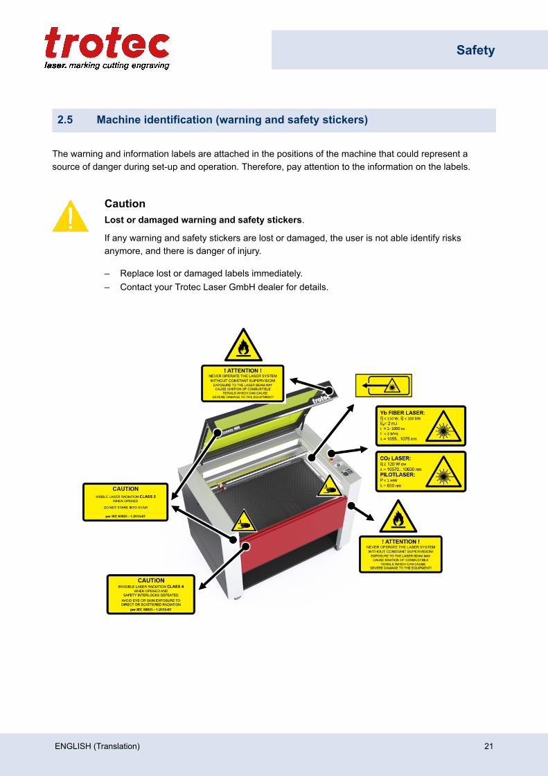
2.5 Machine identification (warning and safety stickers)
The warning and information labels are attached in the positions of the machine that could represent asource of danger during set-up and operation. Therefore, pay attention to the information on the labels.
CautionLost or damaged warning and safety stickers.
If any warning and safety stickers are lost or damaged, the user is not able identify risksanymore, and there is danger of injury.
– Replace lost or damaged labels immediately.– Contact your Trotec Laser GmbH dealer for details.
ENGLISH (Translation) 21
Safety
2.6 Safety devices
2.7 Technical protective measures
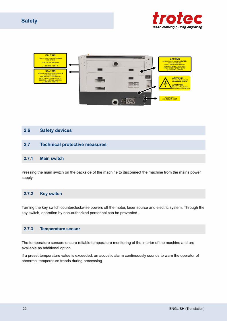
2.7.1 Main switch
Pressing the main switch on the backside of the machine to disconnect the machine from the mains powersupply.
2.7.2 Key switch
Turning the key switch counterclockwise powers off the motor, laser source and electric system. Through thekey switch, operation by non-authorized personnel can be prevented.
2.7.3 Temperature sensor
The temperature sensors ensure reliable temperature monitoring of the interior of the machine and areavailable as additional option.
If a preset temperature value is exceeded, an acoustic alarm continuously sounds to warn the operator ofabnormal temperature trends during processing.
22 ENGLISH (Translation)
Safety
WarningFire hazard
The acoustic alarm upon startup of the machine indicates that the sensors are operatingproperly. However, the sensors do not guarantee fire prevention.
– The unit must not operate unattended despite the integrated temperature sensors.– If the acoustic alarm does not sound when the machine is switched on, check the
functionality of the sensors.– In case of questions, contact our experienced Technical Support in your local area.
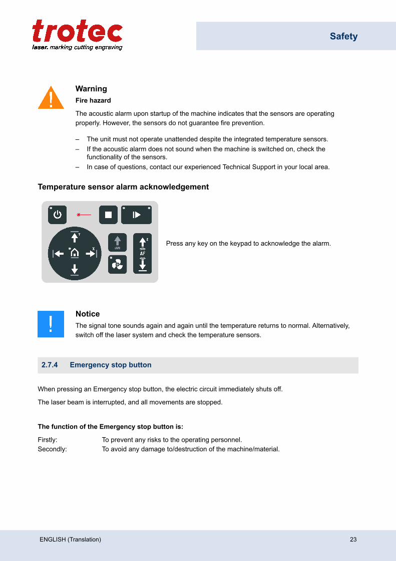
Temperature sensor alarm acknowledgement
Press any key on the keypad to acknowledge the alarm.
NoticeThe signal tone sounds again and again until the temperature returns to normal. Alternatively,switch off the laser system and check the temperature sensors.
2.7.4 Emergency stop button
When pressing an Emergency stop button, the electric circuit immediately shuts off.
The laser beam is interrupted, and all movements are stopped.
The function of the Emergency stop button is:
Firstly: To prevent any risks to the operating personnel.Secondly: To avoid any damage to/destruction of the machine/material.
ENGLISH (Translation) 23
Safety
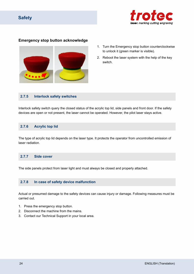
Emergency stop button acknowledge1. Turn the Emergency stop button counterclockwise
to unlock it (green marker is visible).
2. Reboot the laser system with the help of the keyswitch.
2.7.5 Interlock safety switches
Interlock safety switch query the closed status of the acrylic top lid, side panels and front door. If the safetydevices are open or not present, the laser cannot be operated. However, the pilot laser stays active.
2.7.6 Acrylic top lid
The type of acrylic top lid depends on the laser type. It protects the operator from uncontrolled emission oflaser radiation.
2.7.7 Side cover
The side panels protect from laser light and must always be closed and properly attached.
2.7.8 In case of safety device malfunction
Actual or presumed damage to the safety devices can cause injury or damage. Following measures must becarried out.
1. Press the emergency stop button.2. Disconnect the machine from the mains.3. Contact our Technical Support in your local area.
24 ENGLISH (Translation)
Safety
2.8 Secondary (indirect) hazards
2.8.1 Fire hazard
WarningFire hazard
Fire hazard from gas and processing of inflammable materials.
– Do not operate the device without supervision.– Keep CO2 fire extinguisher ready at hand in the immediate vicinity of the device.
If a main laser beam comes into contact with inflammable material, e.g. paper, the latter may ignite, quicklyleading to fire. Therefore, before switching on the laser and after deactivating the Standby-mode you mustmake sure that there is no inflammable material in the path of the laser beam.
Furthermore, gases formed beneath the material being processed may ignite, especially if the extractionrequirements are not met.
The risk of flaming is increased in case of insufficient care and cleaning as well.
Additionally, regularly control the air cooling system on your laser. In particular, the filters and ventilatorsshould be checked regularly for proper function to avoid defects caused by overheating.
2.8.2 Gases, fumes and dust
Depending on the materials being processed and the parameters selected, laser processing may generategases, fumes, aerosols or dust. Depending on the material, such by-products may be toxic. In individualcases, the reaction products may be electrically conductive dusts. If these enter electric systems, short-circuiting with personal injury and property damage may occur.
The operator is responsible for ensuring presence of a suitable extraction system and compliance with therelevant guidelines in order to protect persons and the environment. The guideline VDI 2262 1-3 "Workplaceair" provides, among other things, additional remarks.
The operator must also ensure that gases, fumes or dust do not settle on the processing lens. Any dirtaccumulating on the processing lens can lead to loss of performance, poor processing results and damageto the device.
ENGLISH (Translation) 25
Safety
2.8.3 Reflection through materials
WarningDanger from laser beam.
Invisible laser radiation of reflecting materials can cause serious injury or material damage.
– Only material according to the intended use of the machine may be used.– Do not use material with high reflecting surfaces such as aluminum, chromium, precious
metals, metal foils, stainless steel, brass, copper and titanium.– Take special care with surfaces formed convex and concave.– Do not leave or put objects on the work surface/working area.
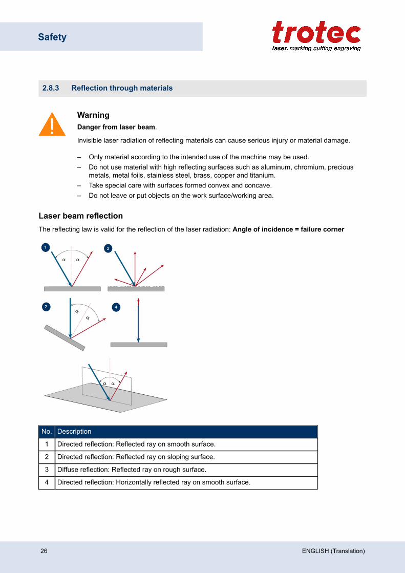
Laser beam reflectionThe reflecting law is valid for the reflection of the laser radiation: Angle of incidence = failure corner
No. Description
1 Directed reflection: Reflected ray on smooth surface.
2 Directed reflection: Reflected ray on sloping surface.
3 Diffuse reflection: Reflected ray on rough surface.
4 Directed reflection: Horizontally reflected ray on smooth surface.
26 ENGLISH (Translation)
Safety
2.8.4 Information about damaged optics
WarningDamage to optics.
Soiled optics absorb laser radiation and can thus be destroyed. Broken or damaged lenses aswell as thermal decomposition of lenses release particles which cause serious damage to thehealth.
– The passive reflectors and optics in the area of the laser beam guidance should be cleanedregularly.
– Special care is required when handling, attaching and cleaning these elements.– Do not exert non-uniform pressure.– Do not use tools or hard objects to clean the surface.– Never touch the optics with your bare fingers.– Never use cleaning tissues twice.– When lenses get broken, damaged or thermal decomposed follow the protective measures.– Disposal according to regulations and laws valid in the user's country.– Lenses with scratches or lenses with penetrations must not be used anymore!
Scratched or destroyed lens surfaceBe aware that scratches in the coating may release small quantities of thorium, which may be harmful uponinhalation or swallowing.
Thermal decompositionUpon thermal decompositions, vapors of selenium oxide and zinc oxide are formed. Upon inhalation orswallowing there is danger of poisoning. Indicators for thermal decomposition of ZnSe include deposits in theform of red or white powder and an unpleasant odor.
Broken lensesWhen optical components of zinc selenide (ZnSe) are destroyed, toxic dusts and vapors are formed whichmust not be inhaled. The dust can additionally cause irritations of the eyes, skin and respiratory tract. If alens has been destroyed during operations, care is to be taken during removal and cleaning.
2.8.5 Protective measures for damaged optics
Protective measures in case of thermal decomposition and scratched or broken lenses• For disposal use a protective mask or respiratory filter to prevent inhalation or ingestion of thorium.• Wash hands thoroughly after contact with a scratched coating.
ENGLISH (Translation) 27

Safety
Protective measures in case of a broken lens• Upon perception of an unpleasant odor, switch off the machine.• Hold your breath.• Leave the area of the machine.• Before approaching the system again, wait for at least 30 min until the reaction has abated.• Wear proper protective clothing (respiratory protection, protective goggles, protective suit, rubber or
plastic gloves).• Provide ventilation.• When approaching the system again, pay attention to odors.• Remove all lens fragments.• Avoid raising or dispersing dust.
DisposalThe ZnSe dust and the lens are to be collected drily and disposed of with fragments, broom,shovel and protective clothing into hermetically sealable containers or plastics bags ashazardous waste.
Do not dispose of optical components as domestic waste, and do not let them enter thesewer or water bodies.
Dispose of according to regulations and laws valid in the users' country.
2.9 In case of emergency
In case of malfunction
• In case of unusual operating states, open the acrylic top lid to stop working process or respectively pressthe Emergency stop button, if available and switch off the laser device.
• When appropriate disconnect the machine from the mains.• Inform laser safety officer and supervisor.• Follow the Operating manual.• Have repair work performed by Trotec Laser GmbH service technicians only.• In case of fire: Use only CO2 fire extinguisher to quench the fire, insofar as this is possible without
endangering yourself.
NoticeAfter a deletion, Trotec Technical Support must be involved before the system is put back intooperation.
In case of accident, First Aid
• If due to laser irradiation eye injury has occurred (upon exceedance of the maximum allowable irradiationrate), the accident victim must immediately be presented to an ophthalmologist.
• Assumption of eye injury is justified whenever laser irradiation has occurred and the maximum allowableirradiation rate may have been exceeded.
28 ENGLISH (Translation)

Safety
• First aider must pay attention to self-protection.• Power off the device.• Remove injured person from the danger zone and provide First Aid.• Call emergency doctor!
ENGLISH (Translation) 29
Technical Data
3 Technical Data
The technical data sheet can be found in the appendix of this manual.
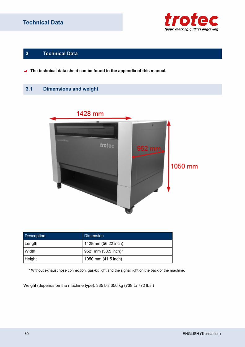
3.1 Dimensions and weight
Description Dimension
Length 1428mm (56.22 inch)
Width 952* mm (38.5 inch)*
Height 1050 mm (41.5 inch)
* Without exhaust hose connection, gas-kit light and the signal light on the back of the machine.
Weight (depends on the machine type): 335 bis 350 kg (739 to 772 lbs.)
30 ENGLISH (Translation)
Technical Data
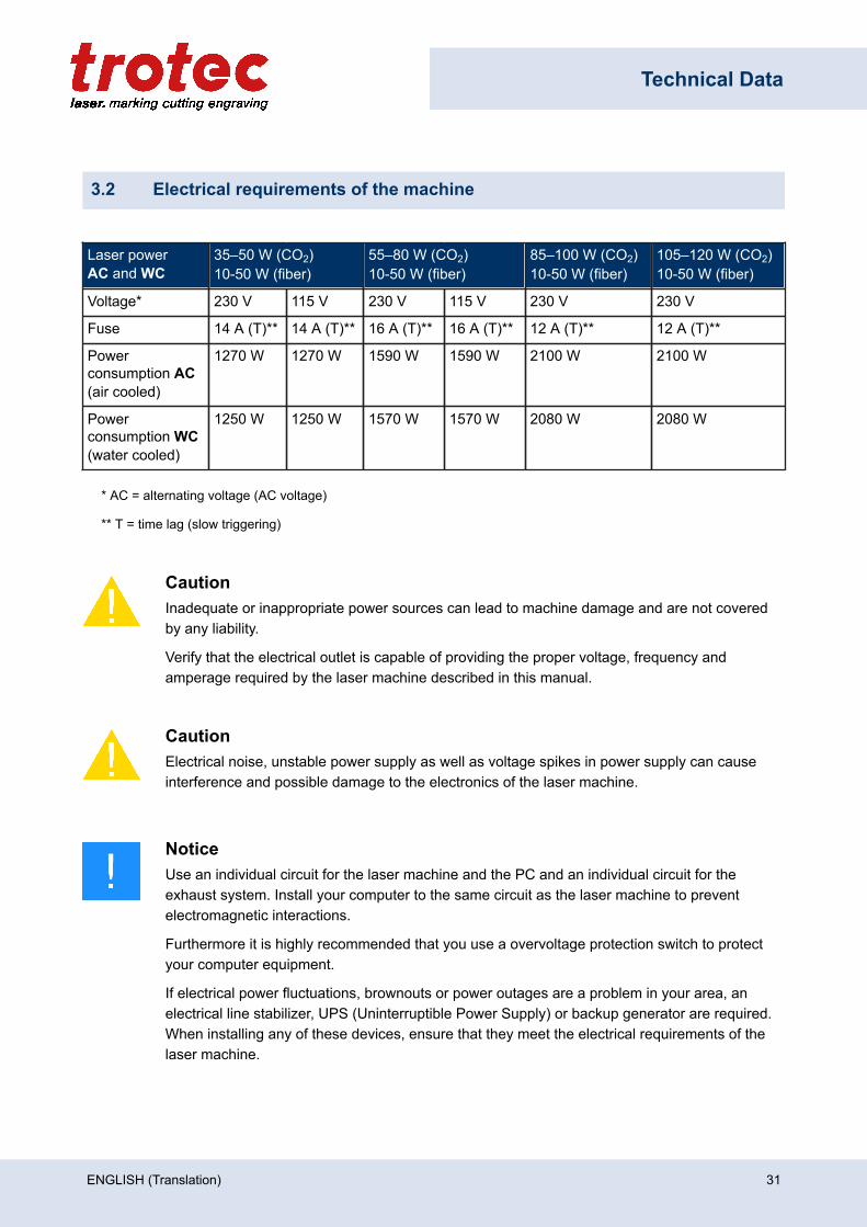
3.2 Electrical requirements of the machine
Laser powerAC and WC
35–50 W (CO2) 10-50 W (fiber)
55–80 W (CO2) 10-50 W (fiber)
85–100 W (CO2)10-50 W (fiber)
105–120 W (CO2)10-50 W (fiber)
Voltage* 230 V 115 V 230 V 115 V 230 V 230 V
Fuse 14 A (T)** 14 A (T)** 16 A (T)** 16 A (T)** 12 A (T)** 12 A (T)**
Powerconsumption AC(air cooled)
1270 W 1270 W 1590 W 1590 W 2100 W 2100 W
Powerconsumption WC(water cooled)
1250 W 1250 W 1570 W 1570 W 2080 W 2080 W
* AC = alternating voltage (AC voltage)
** T = time lag (slow triggering)
CautionInadequate or inappropriate power sources can lead to machine damage and are not coveredby any liability.
Verify that the electrical outlet is capable of providing the proper voltage, frequency andamperage required by the laser machine described in this manual.
CautionElectrical noise, unstable power supply as well as voltage spikes in power supply can causeinterference and possible damage to the electronics of the laser machine.
NoticeUse an individual circuit for the laser machine and the PC and an individual circuit for theexhaust system. Install your computer to the same circuit as the laser machine to preventelectromagnetic interactions.
Furthermore it is highly recommended that you use a overvoltage protection switch to protectyour computer equipment.
If electrical power fluctuations, brownouts or power outages are a problem in your area, anelectrical line stabilizer, UPS (Uninterruptible Power Supply) or backup generator are required.When installing any of these devices, ensure that they meet the electrical requirements of thelaser machine.
ENGLISH (Translation) 31
Technical Data
3.3 Exhaust system requirements
DangerDanger of emission of toxic gases, vapors or dust.
During laser operation, toxic aerosols may be produced.
– The laser system may be operated only with properly installed and operating exhaustsystem.
– Check with the material manufacturer for its toxic effect.
CautionThe laser may only be operated with properly installed and operating exhaust system. Damageto the system, caused by the use of not any exhaust system or improper extraction equipment,will not be covered by any liability.
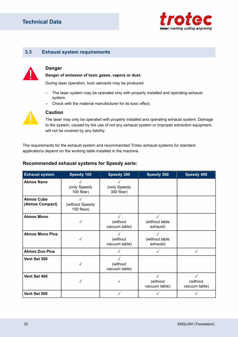
The requirements for the exhaust system and recommended Trotec exhaust systems for standardapplications depend on the working table installed in the machine.
Recommended exhaust systems for Speedy serie:
Exhaust system Speedy 100 Speedy 300 Speedy 360 Speedy 400
Atmos Nano ✓(only Speedy
100 fiber)
✓(only Speedy
300 fiber)
Atmos Cube (Atmos Compact)
✓(without Speedy
100 flexx)
Atmos Mono✓
✓(without
vacuum table)
✓(without table
exhaust)
Atmos Mono Plus✓
✓(without
vacuum table)
✓(without table
exhaust)
Atmos Duo Plus ✓ ✓ ✓
Vent Set 300✓
✓(without
vacuum table)
Vent Set 400✓ ✓
✓(without
vacuum table)
✓(without
vacuum table)
Vent Set 500 ✓ ✓ ✓
32 ENGLISH (Translation)
Technical Data
NoticeConnection has to be carried out by our Technical Support.
Observe instructions for operation and maintenance according to the operating manual of theexhaust system.
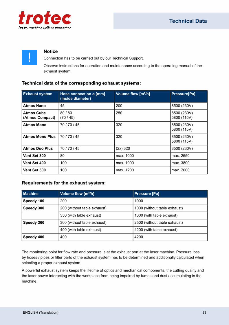
Technical data of the corresponding exhaust systems:
Exhaust system Hose connection ø [mm](inside diameter)
Volume flow [m³/h] Pressure[Pa]
Atmos Nano 45 200 8500 (230V)
Atmos Cube (Atmos Compact)
80 / 80(70 / 45)
250 8500 (230V)5800 (115V)
Atmos Mono 70 / 70 / 45 320 8500 (230V)5800 (115V)
Atmos Mono Plus 70 / 70 / 45 320 8500 (230V)5800 (115V)
Atmos Duo Plus 70 / 70 / 45 (2x) 320 8500 (230V)
Vent Set 300 80 max. 1000 max. 2550
Vent Set 400 100 max. 1000 max. 3800
Vent Set 500 100 max. 1200 max. 7000
Requirements for the exhaust system:
Machine Volume flow [m³/h] Pressure [Pa]
Speedy 100 200 1000
200 (without table exhaust) 1000 (without table exhaust)Speedy 300
350 (with table exhaust) 1600 (with table exhaust)
300 (without table exhaust) 2500 (without table exhaust)Speedy 360
400 (with table exhaust) 4200 (with table exhaust)
Speedy 400 400 4200
The monitoring point for flow rate and pressure is at the exhaust port at the laser machine. Pressure lossby hoses / pipes or filter parts of the exhaust system has to be determined and additionally calculated whenselecting a proper exhaust system.
A powerful exhaust system keeps the lifetime of optics and mechanical components, the cutting quality andthe laser power interacting with the workpiece from being impaired by fumes and dust accumulating in themachine.
ENGLISH (Translation) 33

Technical Data
NoticeThe exhaust power available for the application will be reduced by e. g. bends, small hosediameters and long hoses.
You should therefore note the following:– Avoid bends.– Keep hose as short as possible.– Use hose diameters as large as possible.
Applications generating large amounts of dust or fumes may require a stronger exhaust system.Use of separate exhaust systems for head and table exhaust may also be necessary.
In this case it is absolute necessary to consult your distributor.
34 ENGLISH (Translation)
Technical Data
3.4 Computer requirements
Using a more powerful computer will create graphics faster. Computing times become shorter and datatransfer faster.
The following recommendation represents the minimum requirements:
• Operating systems:Windows 10® 32/64-bit Windows 8.1® 32/64-bit Windows 7® 32/64-bit
• Microsoft® .NET framework 3.5• Microsoft® .NET framework 4.7.2• Adobe® Reader 9.0 or later• Local administrator privileges (for required software installations)• 2 GHz processor or faster• 2 GB RAM or greater (Windows 7 / 8.1 / 10)• 80 GB hard driver or larger• 1024 x 768 monitor resolution or greater• True Color graphics card (24-bit color depth)• 2 free USB interfaces• DVD-ROM drive
ENGLISH (Translation) 35
Technical Data
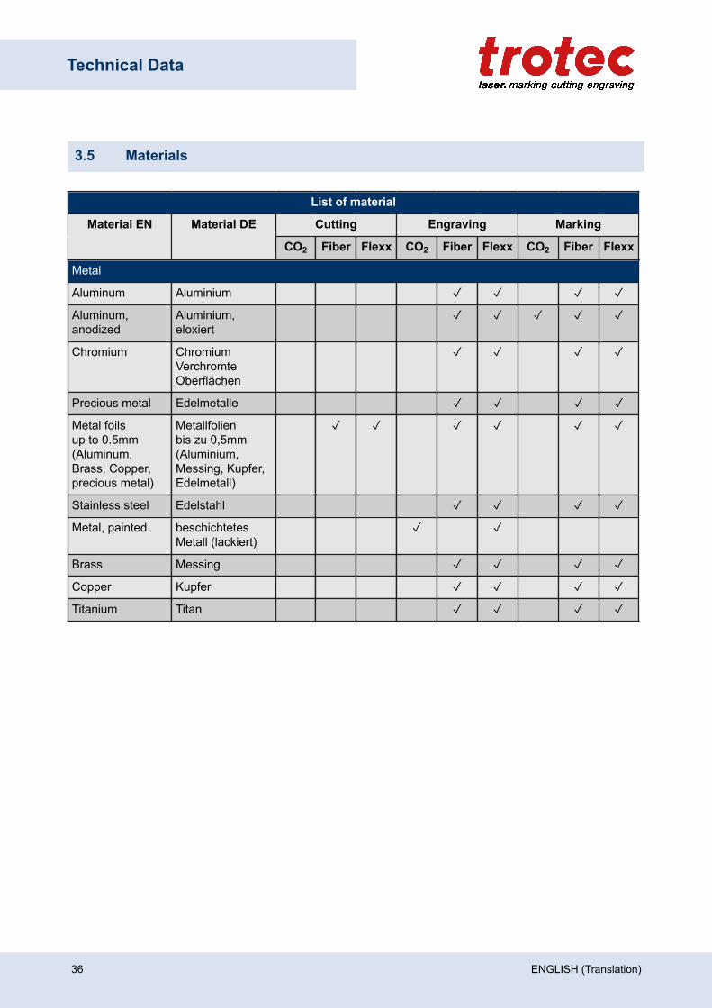
3.5 Materials
List of material
Cutting Engraving MarkingMaterial EN Material DE
CO2 Fiber Flexx CO2 Fiber Flexx CO2 Fiber Flexx
Metal
Aluminum Aluminium ✓ ✓ ✓ ✓
Aluminum,anodized
Aluminium,eloxiert
✓ ✓ ✓ ✓ ✓
Chromium ChromiumVerchromteOberflächen
✓ ✓ ✓ ✓
Precious metal Edelmetalle ✓ ✓ ✓ ✓
Metal foilsup to 0.5mm(Aluminum,Brass, Copper,precious metal)
Metallfolienbis zu 0,5mm(Aluminium,Messing, Kupfer,Edelmetall)
✓ ✓ ✓ ✓ ✓ ✓
Stainless steel Edelstahl ✓ ✓ ✓ ✓
Metal, painted beschichtetesMetall (lackiert)
✓ ✓
Brass Messing ✓ ✓ ✓ ✓
Copper Kupfer ✓ ✓ ✓ ✓
Titanium Titan ✓ ✓ ✓ ✓
36 ENGLISH (Translation)
Technical Data
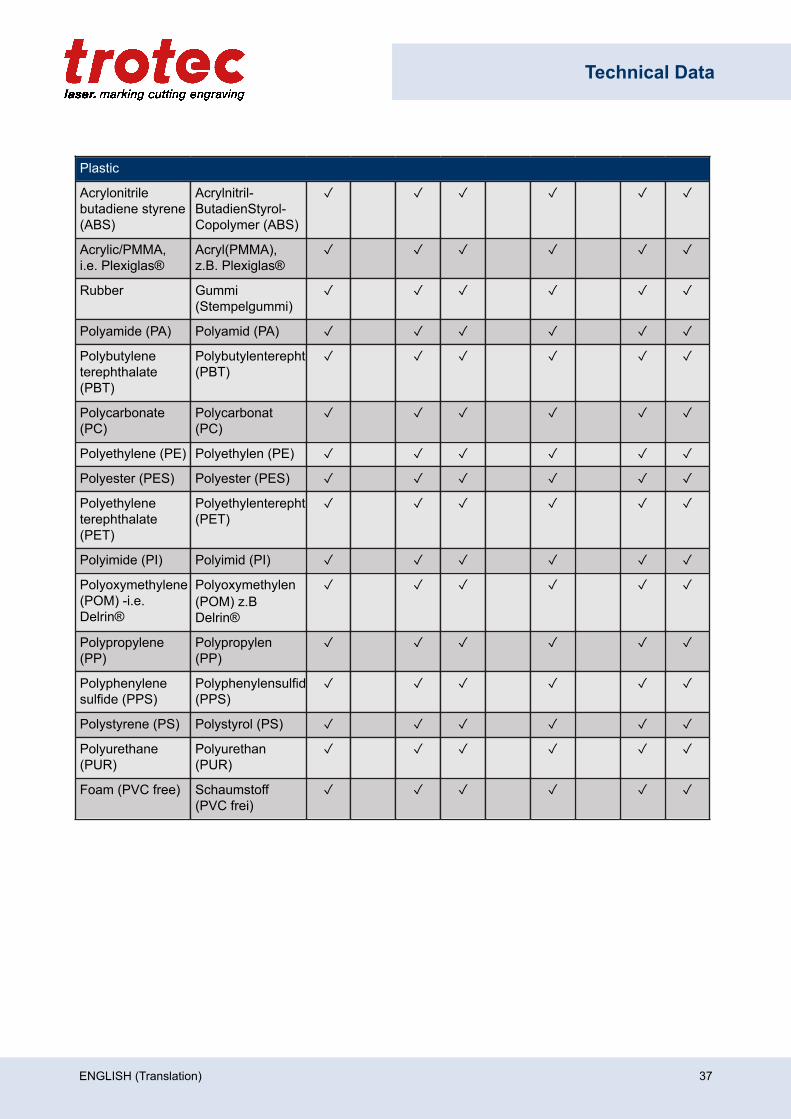
Plastic
Acrylonitrilebutadiene styrene(ABS)
Acrylnitril-ButadienStyrol-Copolymer (ABS)
✓ ✓ ✓ ✓ ✓ ✓
Acrylic/PMMA,i.e. Plexiglas®
Acryl(PMMA),z.B. Plexiglas®
✓ ✓ ✓ ✓ ✓ ✓
Rubber Gummi(Stempelgummi)
✓ ✓ ✓ ✓ ✓ ✓
Polyamide (PA) Polyamid (PA) ✓ ✓ ✓ ✓ ✓ ✓
Polybutyleneterephthalate(PBT)
Polybutylenterephthalat(PBT)
✓ ✓ ✓ ✓ ✓ ✓
Polycarbonate(PC)
Polycarbonat(PC)
✓ ✓ ✓ ✓ ✓ ✓
Polyethylene (PE) Polyethylen (PE) ✓ ✓ ✓ ✓ ✓ ✓
Polyester (PES) Polyester (PES) ✓ ✓ ✓ ✓ ✓ ✓
Polyethyleneterephthalate(PET)
Polyethylenterephthalat(PET)
✓ ✓ ✓ ✓ ✓ ✓
Polyimide (PI) Polyimid (PI) ✓ ✓ ✓ ✓ ✓ ✓
Polyoxymethylene(POM) -i.e.Delrin®
Polyoxymethylen(POM) z.BDelrin®
✓ ✓ ✓ ✓ ✓ ✓
Polypropylene(PP)
Polypropylen(PP)
✓ ✓ ✓ ✓ ✓ ✓
Polyphenylenesulfide (PPS)
Polyphenylensulfid(PPS)
✓ ✓ ✓ ✓ ✓ ✓
Polystyrene (PS) Polystyrol (PS) ✓ ✓ ✓ ✓ ✓ ✓
Polyurethane(PUR)
Polyurethan(PUR)
✓ ✓ ✓ ✓ ✓ ✓
Foam (PVC free) Schaumstoff(PVC frei)
✓ ✓ ✓ ✓ ✓ ✓
ENGLISH (Translation) 37
Technical Data
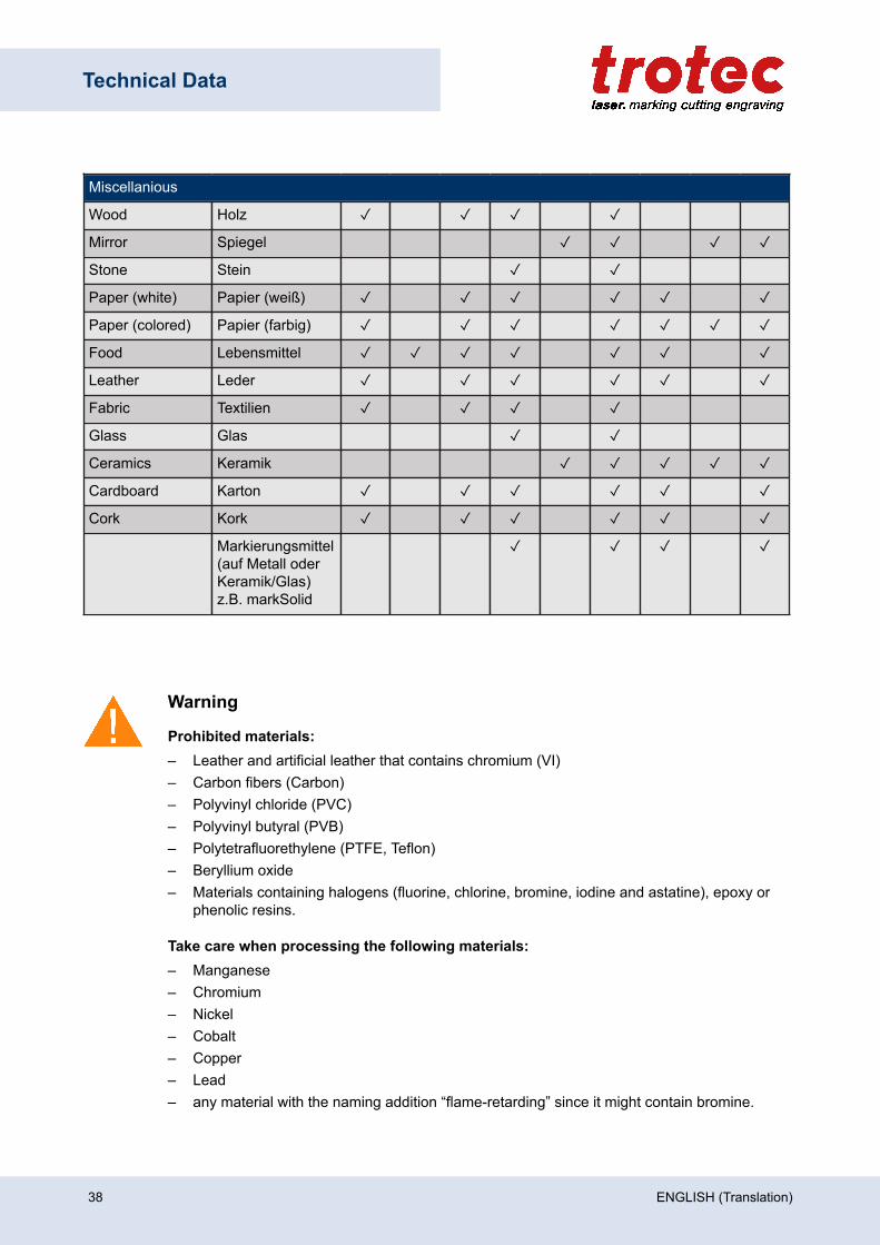
Miscellanious
Wood Holz ✓ ✓ ✓ ✓
Mirror Spiegel ✓ ✓ ✓ ✓
Stone Stein ✓ ✓
Paper (white) Papier (weiß) ✓ ✓ ✓ ✓ ✓ ✓
Paper (colored) Papier (farbig) ✓ ✓ ✓ ✓ ✓ ✓ ✓
Food Lebensmittel ✓ ✓ ✓ ✓ ✓ ✓ ✓
Leather Leder ✓ ✓ ✓ ✓ ✓ ✓
Fabric Textilien ✓ ✓ ✓ ✓
Glass Glas ✓ ✓
Ceramics Keramik ✓ ✓ ✓ ✓ ✓
Cardboard Karton ✓ ✓ ✓ ✓ ✓ ✓
Cork Kork ✓ ✓ ✓ ✓ ✓ ✓
Markierungsmittel(auf Metall oderKeramik/Glas)z.B. markSolid
✓ ✓ ✓ ✓
Warning
Prohibited materials:– Leather and artificial leather that contains chromium (VI)– Carbon fibers (Carbon)– Polyvinyl chloride (PVC)– Polyvinyl butyral (PVB)– Polytetrafluorethylene (PTFE, Teflon)– Beryllium oxide– Materials containing halogens (fluorine, chlorine, bromine, iodine and astatine), epoxy or
phenolic resins.
Take care when processing the following materials:– Manganese– Chromium– Nickel– Cobalt– Copper– Lead– any material with the naming addition “flame-retarding” since it might contain bromine.
38 ENGLISH (Translation)

Technical Data
WarningSerious injury or material damage.
The use of prohibited or unreleased materials can cause serious injury or material damage andwill not be covered under warranty.
Only use approved and released materials.
NoticePlease contact our experienced application specialists or a sales partner near you, if:
– You are unsure about the processing of a material.– You have additions for further materials for us or in your opinion a material was not listed.
We recommend performing a material processing test with the above mentioned material, usingthe appropriate configuration.
Trotec Laser GmbH assumes no responsibility for any consequences of laser processing in anyapplication, especially with medical or pharmaceutical applications.
ENGLISH (Translation) 39
Machine overview
4 Machine overview
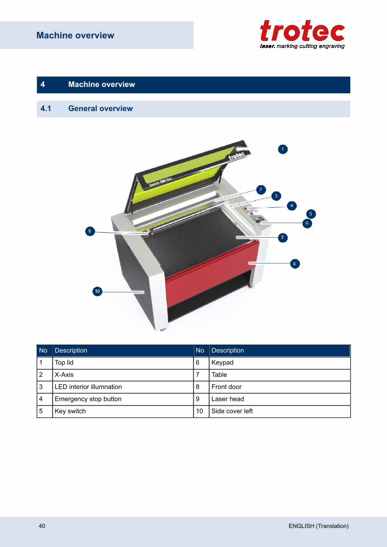
4.1 General overview
No Description No Description
1 Top lid 6 Keypad
2 X-Axis 7 Table
3 LED interior illumnation 8 Front door
4 Emergency stop button 9 Laser head
5 Key switch 10 Side cover left
40 ENGLISH (Translation)
Machine overview
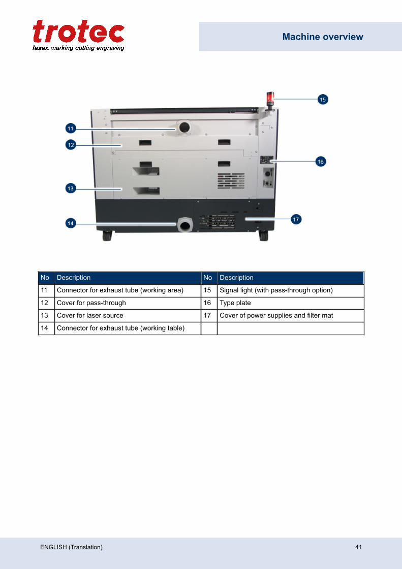
No Description No Description
11 Connector for exhaust tube (working area) 15 Signal light (with pass-through option)
12 Cover for pass-through 16 Type plate
13 Cover for laser source 17 Cover of power supplies and filter mat
14 Connector for exhaust tube (working table)
ENGLISH (Translation) 41
Machine overview
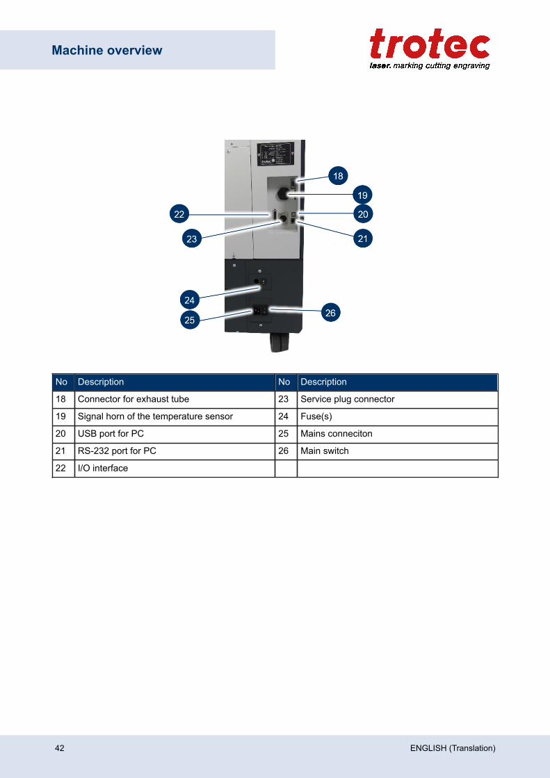
No Description No Description
18 Connector for exhaust tube 23 Service plug connector
19 Signal horn of the temperature sensor 24 Fuse(s)
20 USB port for PC 25 Mains conneciton
21 RS-232 port for PC 26 Main switch
22 I/O interface
42 ENGLISH (Translation)
Machine overview
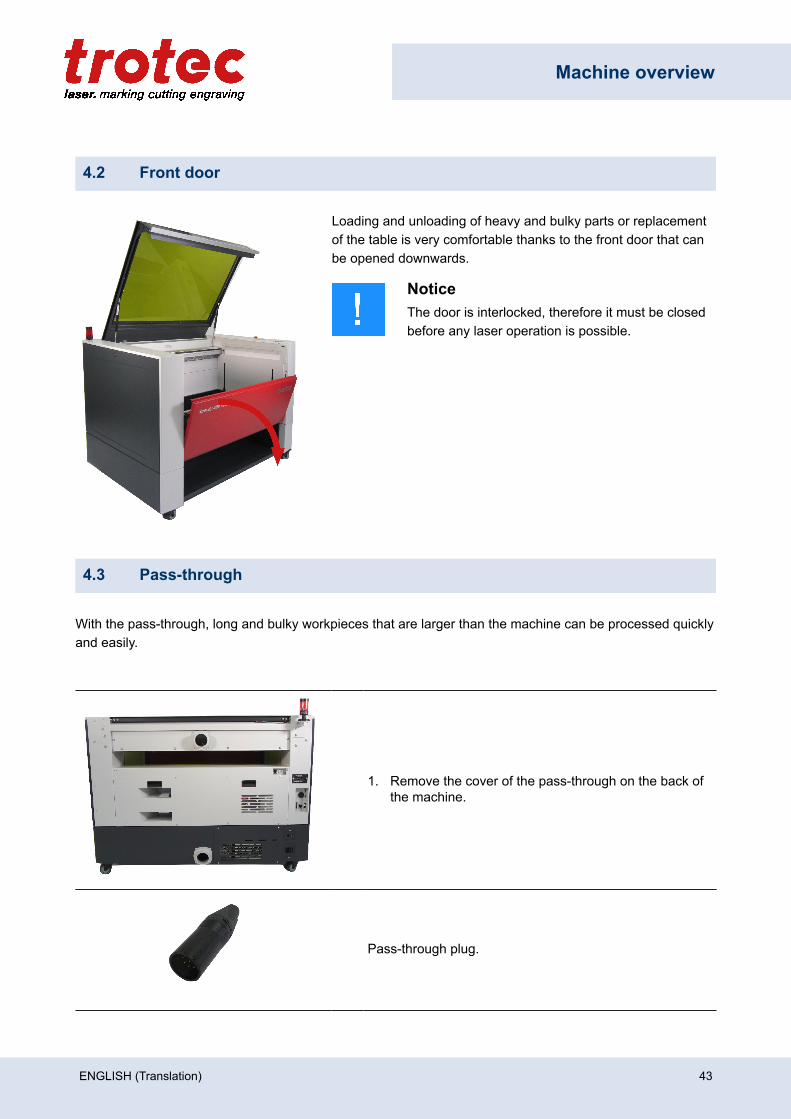
4.2 Front door
Loading and unloading of heavy and bulky parts or replacementof the table is very comfortable thanks to the front door that canbe opened downwards.
NoticeThe door is interlocked, therefore it must be closedbefore any laser operation is possible.
4.3 Pass-through
With the pass-through, long and bulky workpieces that are larger than the machine can be processed quicklyand easily.
1. Remove the cover of the pass-through on the back ofthe machine.
Pass-through plug.
ENGLISH (Translation) 43
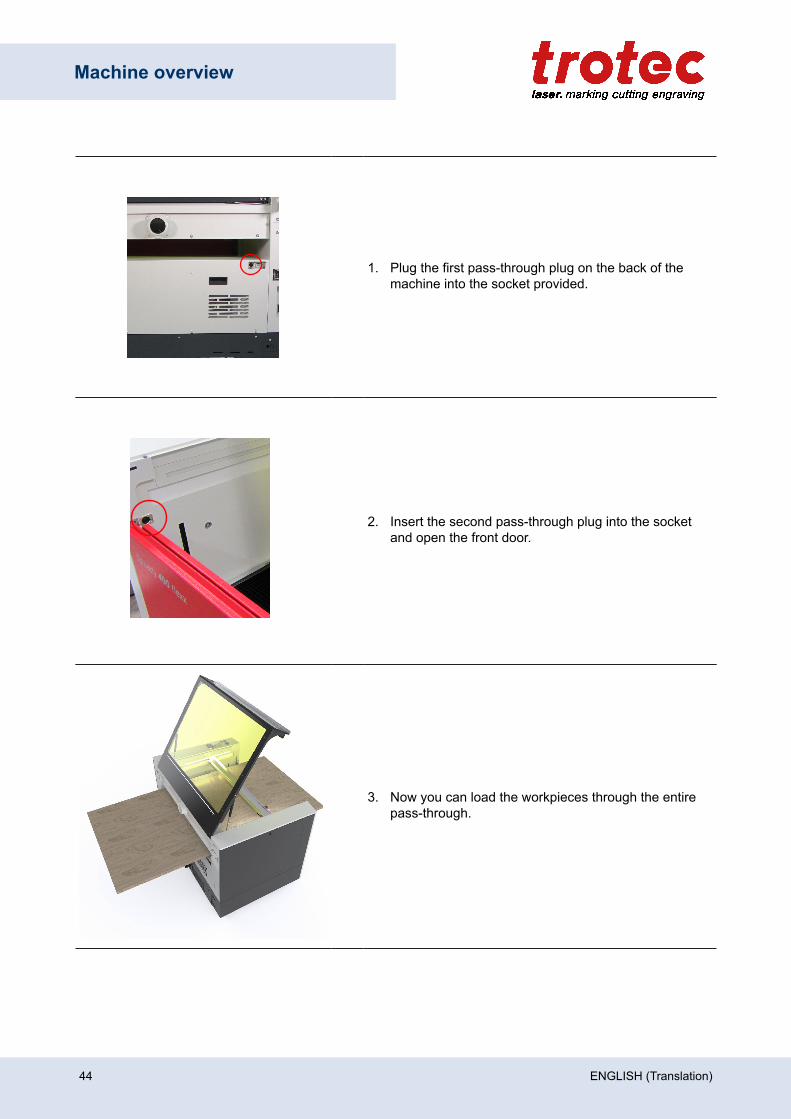
Machine overview
1. Plug the first pass-through plug on the back of themachine into the socket provided.
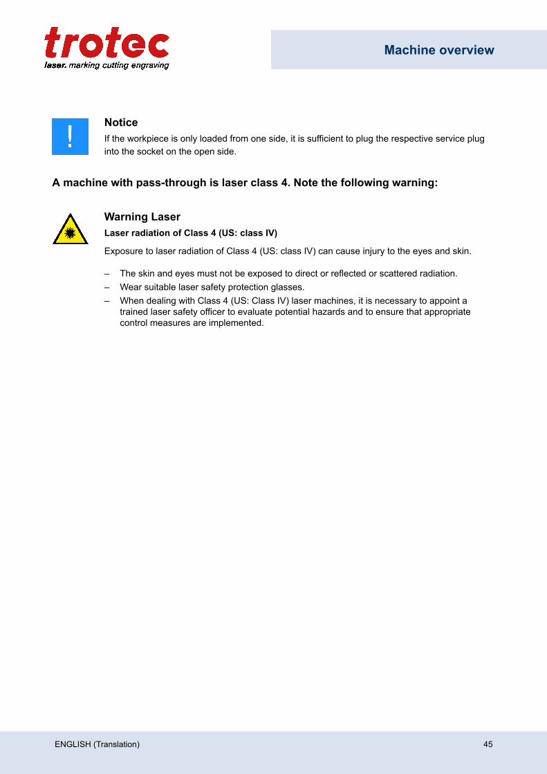
2. Insert the second pass-through plug into the socketand open the front door.
3. Now you can load the workpieces through the entirepass-through.
44 ENGLISH (Translation)
Machine overview
NoticeIf the workpiece is only loaded from one side, it is sufficient to plug the respective service pluginto the socket on the open side.
A machine with pass-through is laser class 4. Note the following warning:
Warning LaserLaser radiation of Class 4 (US: class IV)
Exposure to laser radiation of Class 4 (US: class IV) can cause injury to the eyes and skin.
– The skin and eyes must not be exposed to direct or reflected or scattered radiation.– Wear suitable laser safety protection glasses.– When dealing with Class 4 (US: Class IV) laser machines, it is necessary to appoint a
trained laser safety officer to evaluate potential hazards and to ensure that appropriatecontrol measures are implemented.
ENGLISH (Translation) 45
Machine overview
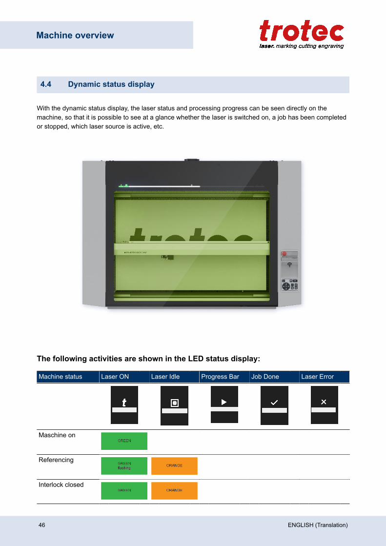
4.4 Dynamic status display
With the dynamic status display, the laser status and processing progress can be seen directly on themachine, so that it is possible to see at a glance whether the laser is switched on, a job has been completedor stopped, which laser source is active, etc.
The following activities are shown in the LED status display:
Machine status Laser ON Laser Idle Progress Bar Job Done Laser Error
Maschine on
Referencing
Interlock closed
46 ENGLISH (Translation)
Machine overview
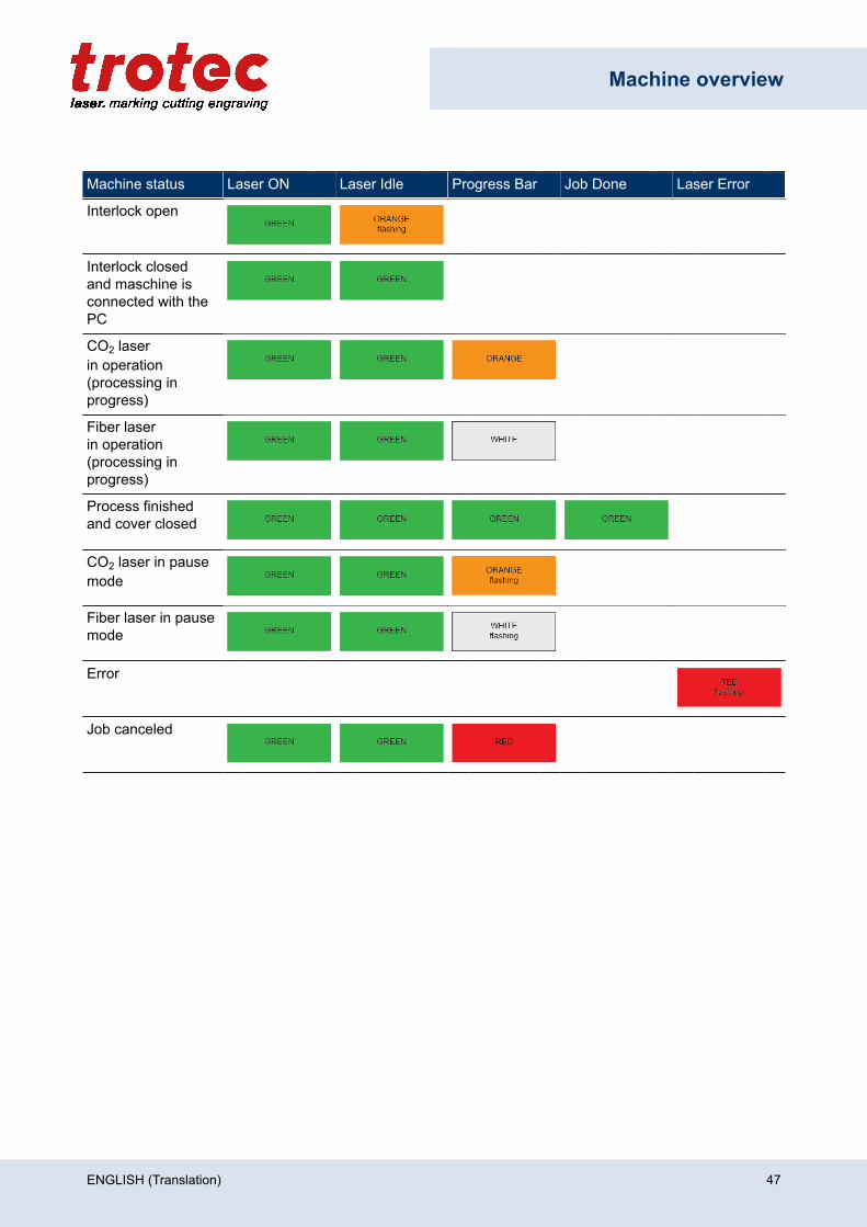
Machine status Laser ON Laser Idle Progress Bar Job Done Laser Error
Interlock open
Interlock closedand maschine isconnected with thePC
CO2 laserin operation(processing inprogress)
Fiber laserin operation(processing inprogress)
Process finishedand cover closed
CO2 laser in pausemode
Fiber laser in pausemode
Error
Job canceled
ENGLISH (Translation) 47
Machine overview
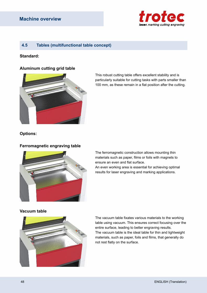
4.5 Tables (multifunctional table concept)
Standard:
Aluminum cutting grid tableThis robust cutting table offers excellent stability and isparticularly suitable for cutting tasks with parts smaller than100 mm, as these remain in a flat position after the cutting.
Options:
Ferromagnetic engraving tableThe ferromagnetic construction allows mounting thinmaterials such as paper, films or foils with magnets toensure an even and flat surface.An even working area is essential for achieving optimalresults for laser engraving and marking applications.
Vacuum tableThe vacuum table fixates various materials to the workingtable using vacuum. This ensures correct focusing over theentire surface, leading to better engraving results. The vacuum table is the ideal table for thin and lightweightmaterials, such as paper, foils and films, that generally donot rest flatly on the surface.
48 ENGLISH (Translation)
Machine overview
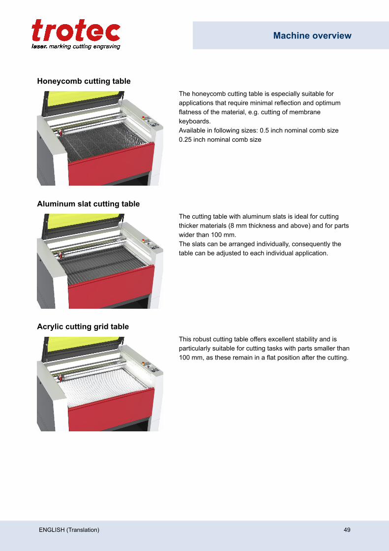
Honeycomb cutting tableThe honeycomb cutting table is especially suitable forapplications that require minimal reflection and optimumflatness of the material, e.g. cutting of membranekeyboards. Available in following sizes: 0.5 inch nominal comb size0.25 inch nominal comb size
Aluminum slat cutting tableThe cutting table with aluminum slats is ideal for cuttingthicker materials (8 mm thickness and above) and for partswider than 100 mm. The slats can be arranged individually, consequently thetable can be adjusted to each individual application.
Acrylic cutting grid tableThis robust cutting table offers excellent stability and isparticularly suitable for cutting tasks with parts smaller than100 mm, as these remain in a flat position after the cutting.
ENGLISH (Translation) 49
Machine overview
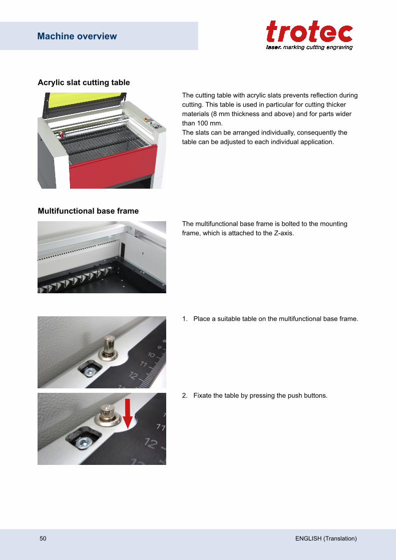
Acrylic slat cutting tableThe cutting table with acrylic slats prevents reflection duringcutting. This table is used in particular for cutting thickermaterials (8 mm thickness and above) and for parts widerthan 100 mm. The slats can be arranged individually, consequently thetable can be adjusted to each individual application.
Multifunctional base frameThe multifunctional base frame is bolted to the mountingframe, which is attached to the Z-axis.
1. Place a suitable table on the multifunctional base frame.
2. Fixate the table by pressing the push buttons.
50 ENGLISH (Translation)
Machine overview
NoticeAll table variants rest on the base frame. However the ferromagnetic engraving table may alsobe placed directly on the mounting frame without the base frame.
Maximum material load is:– For static loads up to 220 lbs (100 kg).– For dynamic loads up to 66 lbs (30 kg).
CautionDamage of the multifunctional base frame or impairment of the exhaust function.
When workpieces are processed directly in the multifunctional base frame without a table, thebase frame be damaged, and impairment of the exhaust function is possible.
– Process workpieces only on a suitable and inserted table variant.
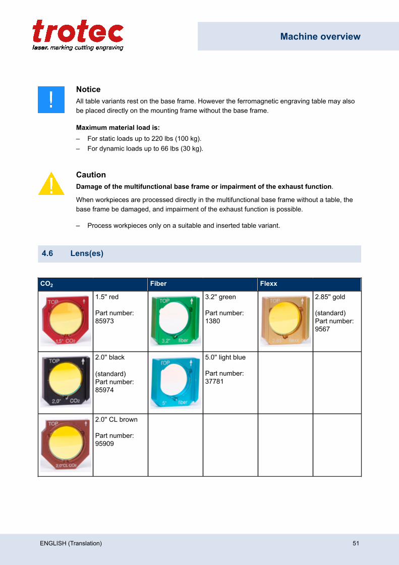
4.6 Lens(es)
CO2 Fiber Flexx
1.5'' red
Part number:85973
3.2'' green
Part number:1380
2.85'' gold
(standard)Part number:9567
2.0'' black
(standard)Part number:85974
5.0'' light blue
Part number:37781
2.0'' CL brown
Part number:95909
ENGLISH (Translation) 51
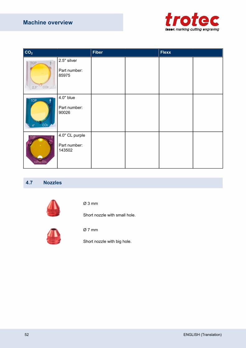
Machine overview
CO2 Fiber Flexx
2.5'' silver
Part number:85975
4.0'' blue
Part number:90026
4.0'' CL purple
Part number:143502
4.7 Nozzles
Ø 3 mm
Short nozzle with small hole.
Ø 7 mm
Short nozzle with big hole.
52 ENGLISH (Translation)

Transport
5 Transport
5.1 Safety notes
WarningRisk of injury
There is risk of injury from falling parts during transport, loading and unloading of the machine.
– Follow the safety notes.
Observe the safety notes to avoid damage to the machine from improper handling during transport:• Always move the machine with utmost care and attention.• Transport the machine/machine components only in its original packaging.• Take the machine’s center of gravity into account when transporting it (minimize the risk of tipping over).• Observe the packaging symbols (e.g. transport the machine only in upright position).• Take measures to prevent the machine from slipping sideways, tipping or falling over.• Transport the machine as carefully as possible in order to prevent damage.• Avoid vibrations.• When transporting the machine overseas, the device must be packaged airtight and protected against
corrosion.• When transporting outdoors, transport only in vehicles with roof or sufficient weather protection.• Protect the machine against transportation damage using straps and inserts, and leave sufficient gaps to
other transported items.• Do not place any other loads or items on the machine or machine components.
5.2 Delivery state
Unless otherwise agreed, the machine is delivered in a wooden crate that contains the laser machine andadditional accessories. Transport the machine only in its original packaging.
CautionRisk of injury
There is risk of injury from falling parts during transport, loading and unloading of the machine.
– Follow the safety notes.
ENGLISH (Translation) 53
Transport
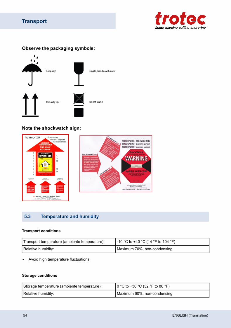
Observe the packaging symbols:
Note the shockwatch sign:
5.3 Temperature and humidity
Transport conditions
Transport temperature (ambiente temperature): -10 °C to +40 °C (14 °F to 104 °F)
Relative humidity: Maximum 70%, non-condensing
• Avoid high temperature fluctuations.
Storage conditions
Storage temperature (ambiente temperature): 0 °C to +30 °C (32 °F to 86 °F)
Relative humidity: Maximum 60%, non-condensing
54 ENGLISH (Translation)

Transport
• Avoid high temperature fluctuations.
5.4 Required tools for unloading and transport
Required tools:
• Unloading - Forklift• Transport - Pallet truck
5.5 Place of storage
• Keep the machine sealed in its packaging until it is assembled or installed.• The storage location must be dry, free of dust, caustic materials, vapors and combustible materials.• Store in a storage room or packaged with adequate weather protection.• Avoid exposure of the machine to shocks or vibrations.• Avoid extreme temperature fluctuations.• Take particular care when packing away electronic components.• When storing for a longer period, apply a coat of oil to all bare-metal machine parts.• Regularly check the overall condition of all parts and of the packaging.
5.6 Transport inspection and reporting of defects
• Immediately after receipt inspect the delivery to ensure that it is complete and has not suffered anydamage.
• If any transport damage is visible, do not accept the delivery, or accept it only with reservation.• Record the scope of the damage on the transport documents or delivery note.• For all defects that are not discovered upon delivery, be sure to report them as soon as they are
detected, since damage claims must be filed within a certain period, as mandated by law.
5.7 Unpacking the machine
Only trained and authorized personnel are permitted to transport and unpack the machine. To avoid falling offof any wooden parts or tipping of the machine, be very careful when opening the transport case.
NoticeKeep the original packaging case, in case of machine needs to be transported or relocate.
Dispose all waste according to the applicable waste disposal law.
ENGLISH (Translation) 55
Transport
CautionThe lens unit should be unpacked only after installation of the machine. The lenses are high-quality optical components which must be kept clean in order to ensure optimum markingresults. Never touch the lenses with bare fingers.
Steps:
1. Position the transport case vertically on level ground (using a pallet truck or forklift).
2. Remove any vertical tightening straps.
3. First remove the top and afterwards the side plates of the transport case.
4. Slide out the two wooden rails in the form of ramps that are stored beneath the machine.
5. To secure the machine against moving, the wheels are locked using wooden blocks. In order to remove those blocks, put the two wooden rails together, push the upper part of the rails underone side of the machine and press down the rail in order to reach a levering effect.
6. Pull out the blocks.
7. Repeat this procedure on the opposite side as well.
8. Now you can pull out the blocks.
5.8 Relocation of the machine
Steps:
1. Switch off the machine.
2. Disconnect the power cable.
3. Remove the exhaust system.
4. Reposition the machine (e.g. with auxiliary equipment if necessary) and place it on a level, clean floor.
5. Adjust the machine.
6. Initial commissioning of the electrical system.
7. Carry out function test.
CautionTransport the machine only in its original packaging. Ensure the wooden crates are properlysecured otherwise the crates can slip, tip or fall over during transport.
Observe the corresponding safety norms and regulations from the chapters "Safety notes" and"Transport".
– When transporting over long distances, use transport boxes including transport securing.
56 ENGLISH (Translation)

Transport
NoticeIf you would like to relocate the machine, contact our experienced Technical Support in yourlocal area.
ENGLISH (Translation) 57

Setup and installation
6 Setup and installation
6.1 For your safety
NoticeThe setup has to be carried out by Technical Support.
6.2 Temperature and humidity
Ambiente conditions
Operating temperature (ambiente temperature): +15 °C to +25 °C (59 °F to 77 °F)
Relative humidity: 45% to 65%, non-condensing
• If the system has been exposed to large temperature fluctuations, it must first be brought back to roomtemperature before commissioning.
Environmental conditions
• Provide sufficient illumination at the workplace.• Ensure a dust-free environment (II° according to IEC60947-1).• Shielding from EMC.• Freedom of interfering electrical installations, hoses and pipe lines.• Power supply free of fluctuations.
58 ENGLISH (Translation)
Setup and installation
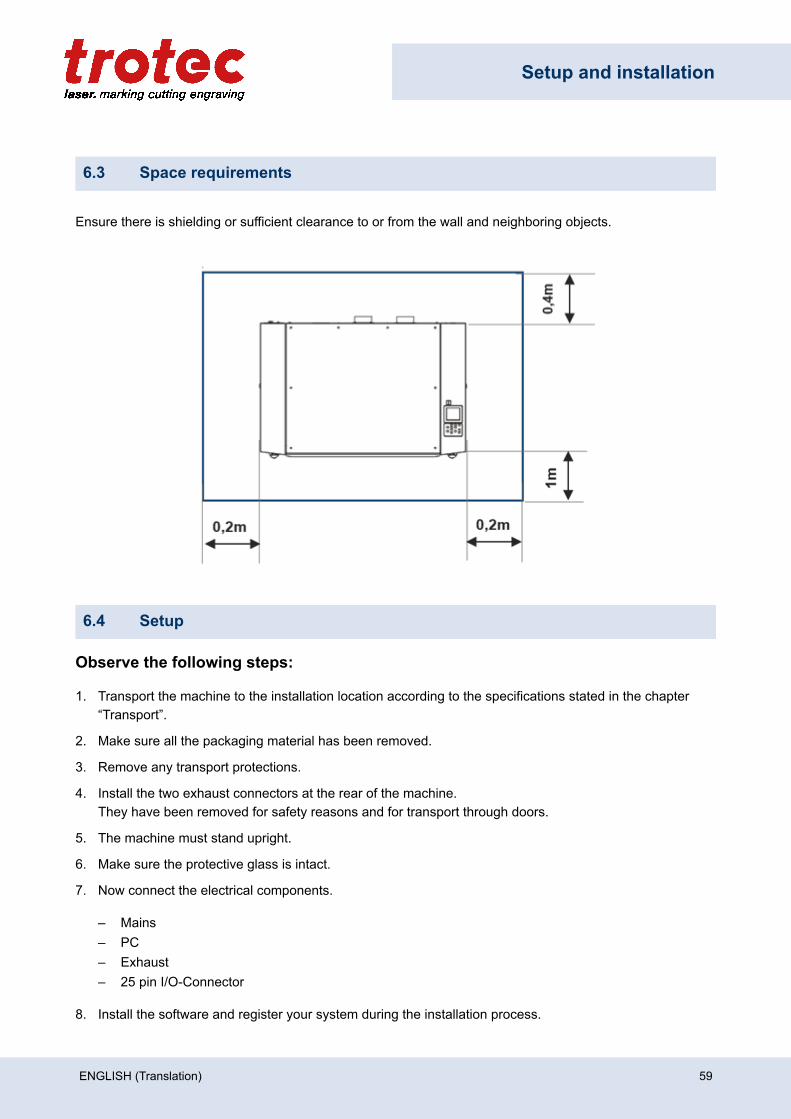
6.3 Space requirements
Ensure there is shielding or sufficient clearance to or from the wall and neighboring objects.
6.4 Setup
Observe the following steps:
1. Transport the machine to the installation location according to the specifications stated in the chapter“Transport”.
2. Make sure all the packaging material has been removed.
3. Remove any transport protections.
4. Install the two exhaust connectors at the rear of the machine.They have been removed for safety reasons and for transport through doors.
5. The machine must stand upright.
6. Make sure the protective glass is intact.
7. Now connect the electrical components.
– Mains– PC– Exhaust– 25 pin I/O-Connector
8. Install the software and register your system during the installation process.
ENGLISH (Translation) 59

Setup and installation
6.5 Connections
CautionInstall the connections exactly in the order described, otherwise electrostatic charging candamage your computer and/or the electronics of the laser system.
6.5.1 Mains connection
• Connect the end of the mains connection cable to the main connection socket.
Warning CurrentWrong voltage can cause damage to the machine.
Do not operate the machine, if the mains voltage does not match the voltage required by theexhaust system, as this may cause damage to the machine.
Make sure that the mains voltage matches the voltage required by the exhaust system.
NoticeDepending on the laser type and region, the main fuses (6) are either covered or open next tothe connector.
6.5.2 Connection the PC
1. Connect the laser to a free interface or USB port on your computer.
2. Connect the computer to the mains.
3. Switch on the computer.
6.6 Connection of additional components
6.6.1 Exhaust system
Warning CurrentWrong voltage can cause damage to the machine.
Do not operate the machine, if the mains voltage does not match the voltage required by theexhaust system, as this may cause damage to the machine.
Make sure that the mains voltage matches the voltage required by the exhaust system.
60 ENGLISH (Translation)
Setup and installation
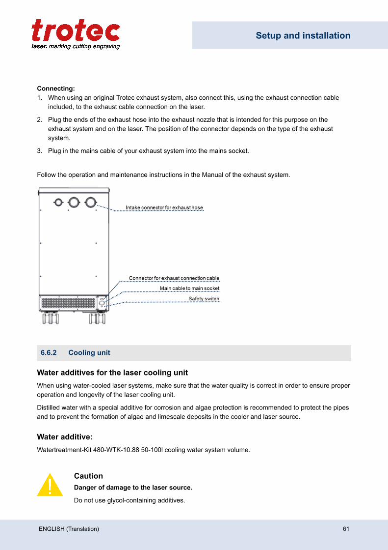
Connecting:1. When using an original Trotec exhaust system, also connect this, using the exhaust connection cable
included, to the exhaust cable connection on the laser.
2. Plug the ends of the exhaust hose into the exhaust nozzle that is intended for this purpose on theexhaust system and on the laser. The position of the connector depends on the type of the exhaustsystem.
3. Plug in the mains cable of your exhaust system into the mains socket.
Follow the operation and maintenance instructions in the Manual of the exhaust system.
6.6.2 Cooling unit
Water additives for the laser cooling unitWhen using water-cooled laser systems, make sure that the water quality is correct in order to ensure properoperation and longevity of the laser cooling unit.
Distilled water with a special additive for corrosion and algae protection is recommended to protect the pipesand to prevent the formation of algae and limescale deposits in the cooler and laser source.
Water additive:Watertreatment-Kit 480-WTK-10.88 50-100l cooling water system volume.
CautionDanger of damage to the laser source.
Do not use glycol-containing additives.
ENGLISH (Translation) 61

Setup and installation
Filling or water change:
• The water change must be carried out once a year.• Order twice the amount of distilled water (one filling approx. 35-40 l), as half is required for the cleaning
rinse.• In case of extremely strong impurities the additive Nalco CCL2567 is recommended for the cleaning
rinse.
NoticeThe conductivity of the water must not exceed 1000 μS. This value should not be reached ifthe additives are used correctly according to the enclosed instructions. A conductivity meter isavailable on request from Trotec Laser GmbH.
Order adress für additives:CTA GmbH
Voithstraße 1
71640 Ludwigsburg / Germany
E-mail: [email protected] or [email protected]
62 ENGLISH (Translation)
Operation
7 Operation
WarningPersonal injury or damage to property due to improper operation.
Improper operation can lead to serious personal injury or damage to property.
– Work on the laser machine may only be carried out by authorized and instructed personnelfamiliar with the operation of the machine, observing all safety regulations.
7.1 Before commissioning
Check the following points before commissioning:
• Completeness and technically flawless condition of the machine and safety devices.• Order and cleanliness at the workplace.• Cleanliness of optical components (free of dust and dirt).• Activated exhaust system.• Complete electrical installation.• Correct input voltage of the electrical installation.• Environmental conditions according to technical specification.• Compliance with all laser safety regulations and measures.• Fulfill and compliance with all laser safety requirements.
If errors or functional deviations should occur during the inspection of the listed points, the machine is notconsidered to be safe to operate and must not (no longer) be put into operation until the cause has beenclarified!
If you have any questions, contact our experienced Technical Support in your local area.
7.2 Software
For information on how to use the software, please read the accompanying software manual, which can befound on the supplied DVD.
7.3 Power On/Off
NoticeIn order not to restrict or obstruct the freedom of movement of the mechanics, no objects of anykind may be located in the machining area.
All safety protection covers have to be fully functional and closed.
ENGLISH (Translation) 63
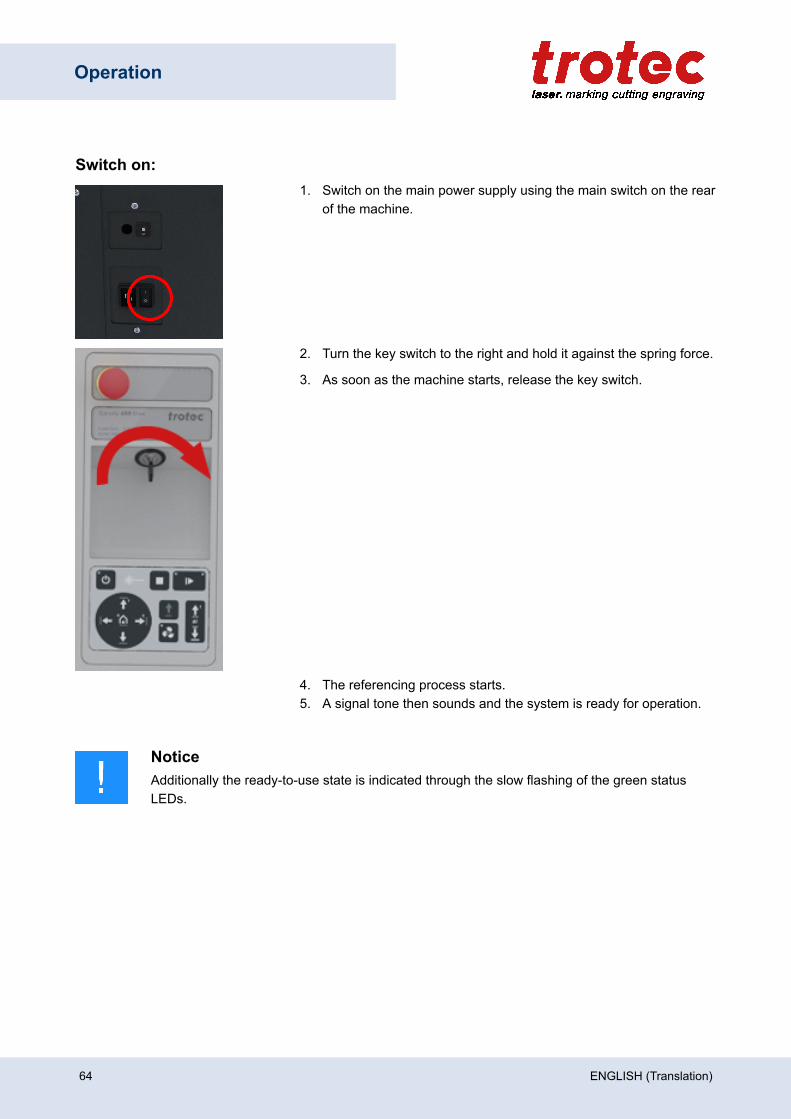
Operation
Switch on:1. Switch on the main power supply using the main switch on the rear
of the machine.
2. Turn the key switch to the right and hold it against the spring force.
3. As soon as the machine starts, release the key switch.
4. The referencing process starts.5. A signal tone then sounds and the system is ready for operation.
NoticeAdditionally the ready-to-use state is indicated through the slow flashing of the green statusLEDs.
64 ENGLISH (Translation)
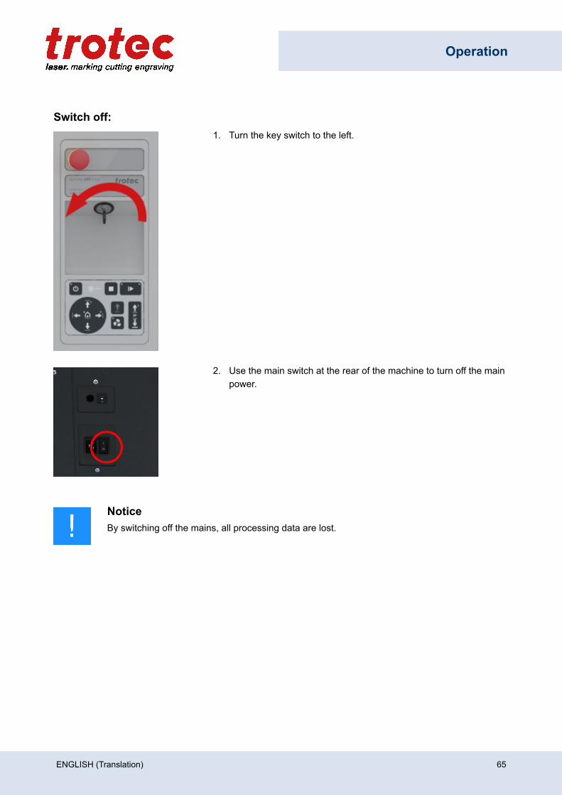
Operation
Switch off:1. Turn the key switch to the left.
2. Use the main switch at the rear of the machine to turn off the mainpower.
NoticeBy switching off the mains, all processing data are lost.
ENGLISH (Translation) 65
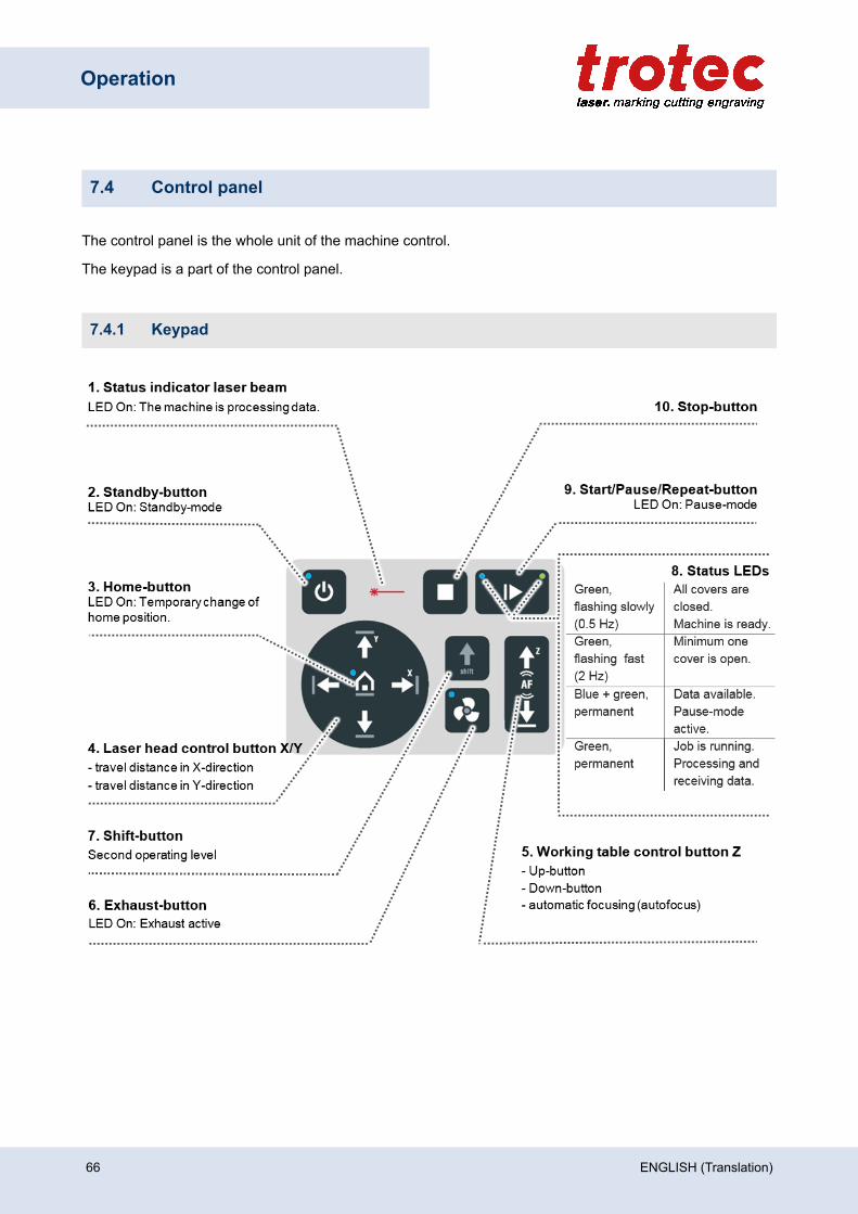
Operation
7.4 Control panel
The control panel is the whole unit of the machine control.
The keypad is a part of the control panel.
7.4.1 Keypad
66 ENGLISH (Translation)
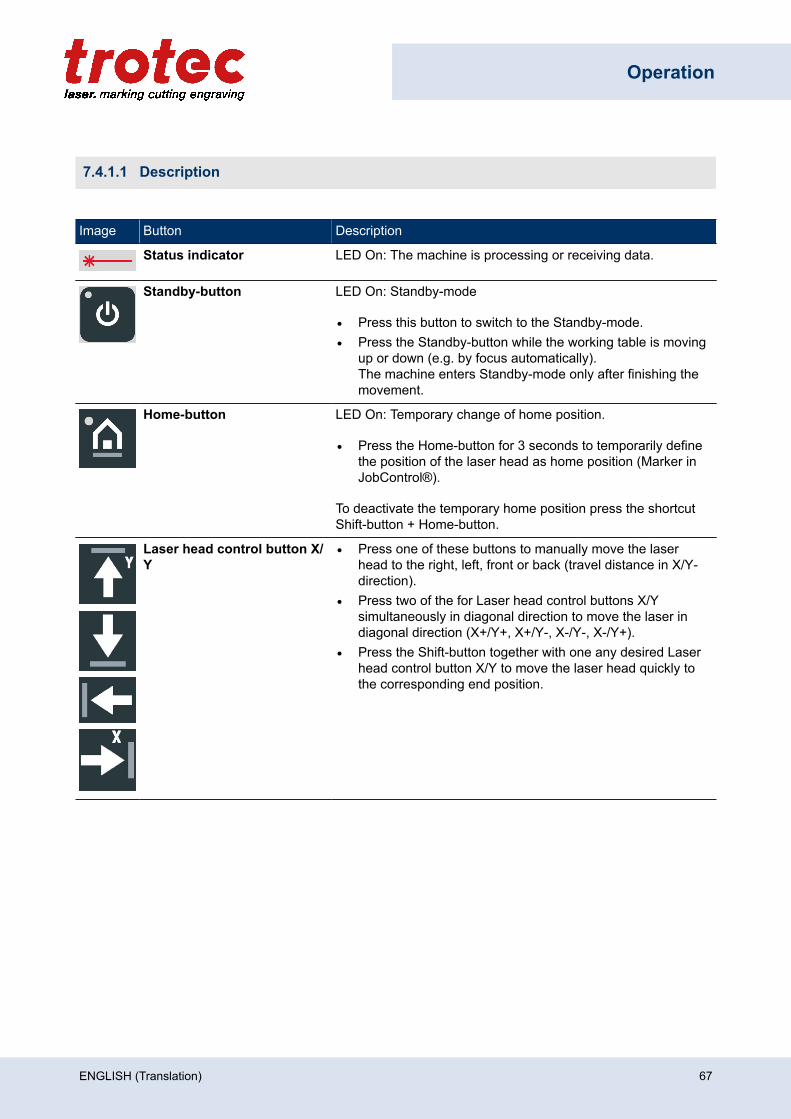
Operation
7.4.1.1 Description
Image Button Description
Status indicator LED On: The machine is processing or receiving data.
Standby-button LED On: Standby-mode
• Press this button to switch to the Standby-mode.• Press the Standby-button while the working table is moving
up or down (e.g. by focus automatically).The machine enters Standby-mode only after finishing themovement.
Home-button LED On: Temporary change of home position.
• Press the Home-button for 3 seconds to temporarily definethe position of the laser head as home position (Marker inJobControl®).
To deactivate the temporary home position press the shortcutShift-button + Home-button.
Laser head control button X/Y
• Press one of these buttons to manually move the laserhead to the right, left, front or back (travel distance in X/Y-direction).
• Press two of the for Laser head control buttons X/Ysimultaneously in diagonal direction to move the laser indiagonal direction (X+/Y+, X+/Y-, X-/Y-, X-/Y+).
• Press the Shift-button together with one any desired Laserhead control button X/Y to move the laser head quickly tothe corresponding end position.
ENGLISH (Translation) 67
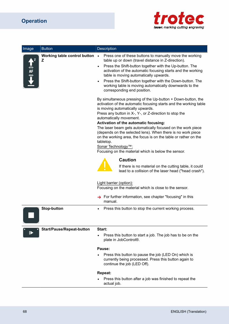
Operation
Image Button Description
Working table control buttonZ
• Press one of these buttons to manually move the workingtable up or down (travel distance in Z-direction).
• Press the Shift-button together with the Up-button. Theactivation of the automatic focusing starts and the workingtable is moving automatically upwards.
• Press the Shift-button together with the Down-button. Theworking table is moving automatically downwards to thecorresponding end position.
By simultaneous pressing of the Up-button + Down-button, theactivation of the automatic focusing starts and the working tableis moving automatically upwards.Press any button in X-, Y-, or Z-direction to stop theautomatically movement.Activation of the automatic focusing:The laser beam gets automatically focused on the work piece(depends on the selected lens). When there is no work pieceon the working area, the focus is on the table or rather on thetabletop.Sonar Technology™:Focusing on the material which is below the sensor.
CautionIf there is no material on the cutting table, it couldlead to a collision of the laser head ("head crash").
Light barrier (option):Focusing on the material which is close to the sensor.
For further information, see chapter "focusing" in thismanual.
Stop-button • Press this button to stop the current working process.
Start/Pause/Repeat-button Start:• Press this button to start a job. The job has to be on the
plate in JobControl®.
Pause:• Press this button to pause the job (LED On) which is
currently being processed. Press this button again tocontinue the job (LED Off).
Repeat:• Press this button after a job was finished to repeat the
actual job.
68 ENGLISH (Translation)
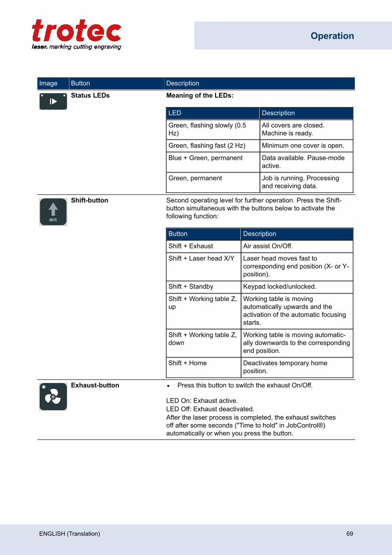
Operation
Image Button Description
Status LEDs Meaning of the LEDs:
LED Description
Green, flashing slowly (0.5Hz)
All covers are closed.Machine is ready.
Green, flashing fast (2 Hz) Minimum one cover is open.
Blue + Green, permanent Data available. Pause-modeactive.
Green, permanent Job is running. Processingand receiving data.
Shift-button Second operating level for further operation. Press the Shift-button simultaneous with the buttons below to activate thefollowing function:
Button Description
Shift + Exhaust Air assist On/Off.
Shift + Laser head X/Y Laser head moves fast tocorresponding end position (X- or Y-position).
Shift + Standby Keypad locked/unlocked.
Shift + Working table Z,up
Working table is movingautomatically upwards and theactivation of the automatic focusingstarts.
Shift + Working table Z,down
Working table is moving automatic-ally downwards to the correspondingend position.
Shift + Home Deactivates temporary homeposition.
Exhaust-button • Press this button to switch the exhaust On/Off.
LED On: Exhaust active.LED Off: Exhaust deactivated.After the laser process is completed, the exhaust switchesoff after some seconds ("Time to hold" in JobControl®)automatically or when you press the button.
ENGLISH (Translation) 69
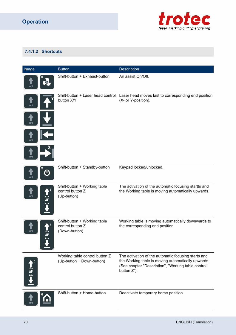
Operation
7.4.1.2 Shortcuts
Image Button Description
Shift-button + Exhaust-button Air assist On/Off.
Shift-button + Laser head controlbutton X/Y
Laser head moves fast to corresponding end position(X- or Y-position).
Shift-button + Standby-button Keypad locked/unlocked.
Shift-button + Working tablecontrol button Z(Up-button)
The activation of the automatic focusing startts andthe Working table is moving automatically upwards.
Shift-button + Working tablecontrol button Z(Down-button)
Working table is moving automatically downwards tothe corresponding end position.
Working table control button Z(Up-button + Down-button)
The activation of the automatic focusing starts andthe Working table is moving automatically upwards.(See chapter "Description", "Working table controlbutton Z").
Shift-button + Home-button Deactivate temporary home position.
70 ENGLISH (Translation)
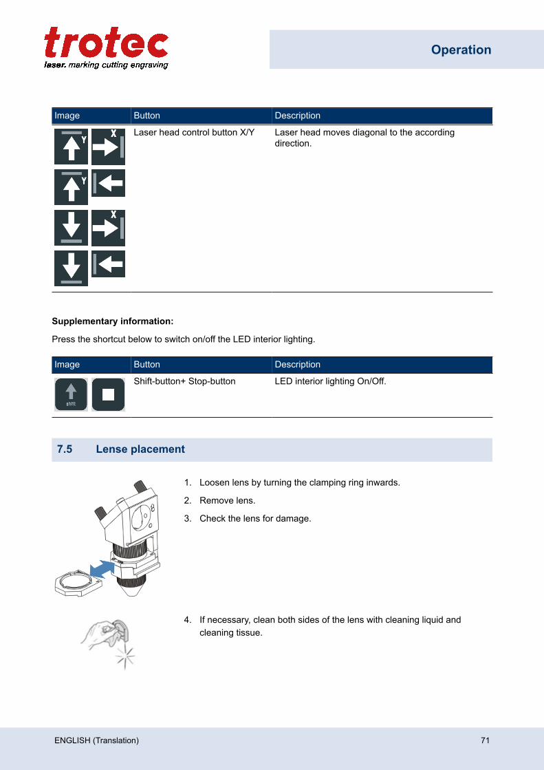
Operation
Image Button Description
Laser head control button X/Y Laser head moves diagonal to the accordingdirection.
Supplementary information:
Press the shortcut below to switch on/off the LED interior lighting.
Image Button Description
Shift-button+ Stop-button LED interior lighting On/Off.
7.5 Lense placement
1. Loosen lens by turning the clamping ring inwards.
2. Remove lens.
3. Check the lens for damage.
4. If necessary, clean both sides of the lens with cleaning liquid andcleaning tissue.
ENGLISH (Translation) 71
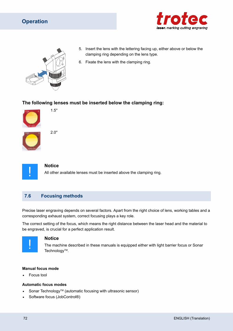
Operation
5. Insert the lens with the lettering facing up, either above or below theclamping ring depending on the lens type.
6. Fixate the lens with the clamping ring.
The following lenses must be inserted below the clamping ring:1.5''
2.0''
NoticeAll other available lenses must be inserted above the clamping ring.
7.6 Focusing methods
Precise laser engraving depends on several factors. Apart from the right choice of lens, working tables and acorresponding exhaust system, correct focusing plays a key role.
The correct setting of the focus, which means the right distance between the laser head and the material tobe engraved, is crucial for a perfect application result.
NoticeThe machine described in these manuals is equipped either with light barrier focus or SonarTechnologyTM.
Manual focus mode• Focus tool
Automatic focus modes• Sonar TechnologyTM (automatic focusing with ultrasonic sensor)• Software focus (JobControl®)
72 ENGLISH (Translation)
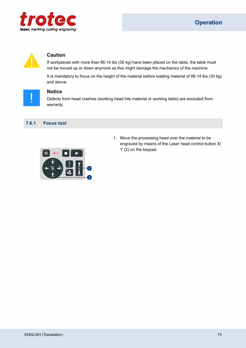
Operation
CautionIf workpieces with more than 66.14 lbs (30 kg) have been placed on the table, the table mustnot be moved up or down anymore as this might damage the mechanics of the machine.
It is mandatory to focus on the height of the material before loading material of 66.14 lbs (30 kg)and above.
NoticeDefects from head crashes (working head hits material or working table) are excluded fromwarranty.
7.6.1 Focus tool
1
2
1. Move the processing head over the material to beengraved by means of the Laser head control button X/Y (2) on the keypad.
ENGLISH (Translation) 73
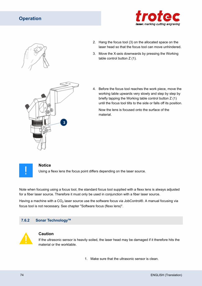
Operation
2. Hang the focus tool (3) on the allocated space on thelaser head so that the focus tool can move unhindered.
3. Move the X-axis downwards by pressing the Workingtable control button Z (1).
4. Before the focus tool reaches the work piece, move theworking table upwards very slowly and step by step bybriefly tapping the Working table control button Z (1)until the focus tool tilts to the side or falls off its position.
Now the lens is focused onto the surface of thematerial.
NoticeUsing a flexx lens the focus point differs depending on the laser source.
Note when focusing using a focus tool, the standard focus tool supplied with a flexx lens is always adjustedfor a fiber laser source. Therefore it must only be used in conjunction with a fiber laser source.
Having a machine with a CO2 laser source use the software focus via JobControl®. A manual focusing viafocus tool is not necessary. See chapter "Software focus (flexx lens)".
7.6.2 Sonar TechnologyTM
CautionIf the ultrasonic sensor is heavily soiled, the laser head may be damaged if it therefore hits thematerial or the worktable.
1. Make sure that the ultrasonic sensor is clean.
74 ENGLISH (Translation)
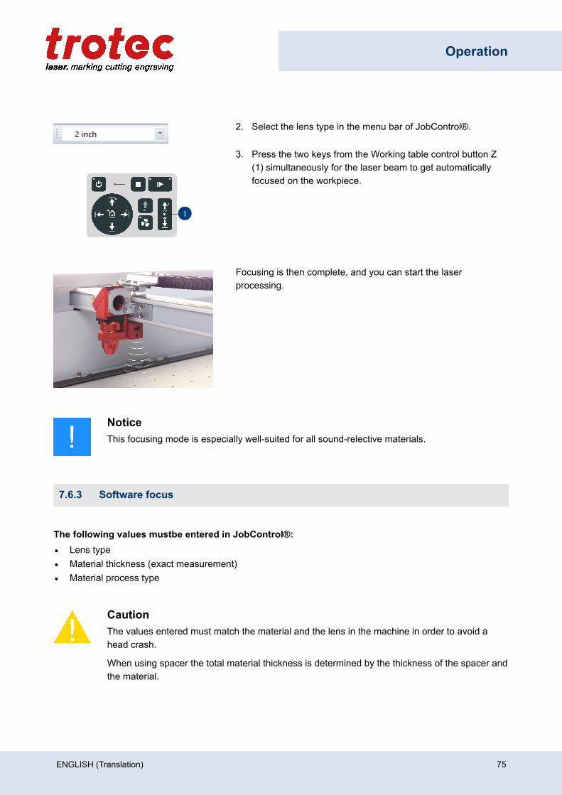
Operation
2. Select the lens type in the menu bar of JobControl®.
1
3. Press the two keys from the Working table control button Z(1) simultaneously for the laser beam to get automaticallyfocused on the workpiece.
Focusing is then complete, and you can start the laserprocessing.
NoticeThis focusing mode is especially well-suited for all sound-relective materials.
7.6.3 Software focus
The following values mustbe entered in JobControl®:• Lens type• Material thickness (exact measurement)• Material process type
CautionThe values entered must match the material and the lens in the machine in order to avoid ahead crash.
When using spacer the total material thickness is determined by the thickness of the spacer andthe material.
ENGLISH (Translation) 75
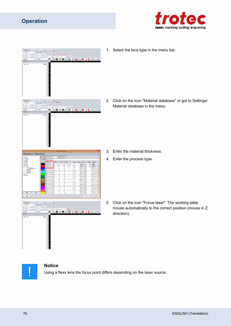
Operation
1. Select the lens type in the menu bar.
2. Click on the icon "Material database" or got to Settings/Material database in the menu.
3. Enter the material thickness.
4. Enter the process type.
5. Click on the icon "Focus laser". The working tablemoves automatically to the correct position (moves in Zdirection).
NoticeUsing a flexx lens the focus point differs depending on the laser source.
76 ENGLISH (Translation)
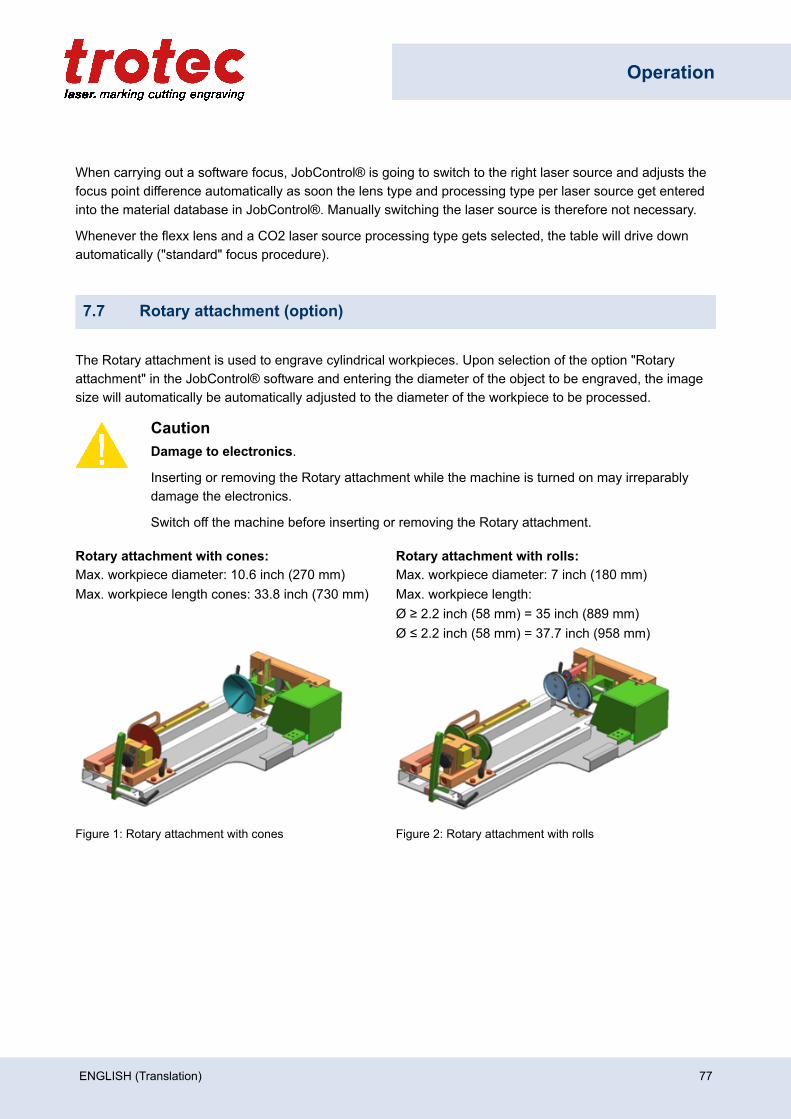
Operation
When carrying out a software focus, JobControl® is going to switch to the right laser source and adjusts thefocus point difference automatically as soon the lens type and processing type per laser source get enteredinto the material database in JobControl®. Manually switching the laser source is therefore not necessary.
Whenever the flexx lens and a CO2 laser source processing type gets selected, the table will drive downautomatically ("standard" focus procedure).
7.7 Rotary attachment (option)
The Rotary attachment is used to engrave cylindrical workpieces. Upon selection of the option "Rotaryattachment" in the JobControl® software and entering the diameter of the object to be engraved, the imagesize will automatically be automatically adjusted to the diameter of the workpiece to be processed.
CautionDamage to electronics.
Inserting or removing the Rotary attachment while the machine is turned on may irreparablydamage the electronics.
Switch off the machine before inserting or removing the Rotary attachment.
Rotary attachment with cones: Rotary attachment with rolls:Max. workpiece diameter: 10.6 inch (270 mm)Max. workpiece length cones: 33.8 inch (730 mm)
Max. workpiece diameter: 7 inch (180 mm)Max. workpiece length:Ø ≥ 2.2 inch (58 mm) = 35 inch (889 mm)Ø ≤ 2.2 inch (58 mm) = 37.7 inch (958 mm)
Figure 1: Rotary attachment with cones Figure 2: Rotary attachment with rolls
ENGLISH (Translation) 77
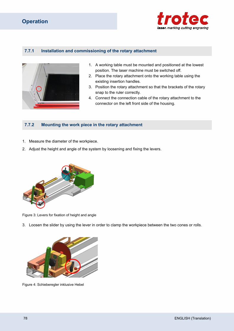
Operation
7.7.1 Installation and commissioning of the rotary attachment
1. A working table must be mounted and positioned at the lowestposition. The laser machine must be switched off.
2. Place the rotary attachment onto the working table using theexisting insertion handles.
3. Position the rotary attachment so that the brackets of the rotarysnap to the ruler correctly.
4. Connect the connection cable of the rotary attachment to theconnector on the left front side of the housing.
7.7.2 Mounting the work piece in the rotary attachment
1. Measure the diameter of the workpiece.
2. Adjust the height and angle of the system by loosening and fixing the levers.
Figure 3: Levers for fixation of height and angle
3. Loosen the slider by using the lever in order to clamp the workpiece between the two cones or rolls.
Figure 4: Schieberegler inklusive Hebel
78 ENGLISH (Translation)
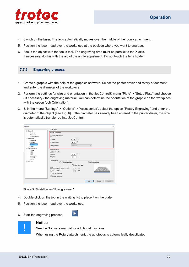
Operation
4. Switch on the laser. The axis automatically moves over the middle of the rotary attachment.
5. Position the laser head over the workpiece at the position where you want to engrave.
6. Focus the object with the focus tool. The engraving area must be parallel to the X axis.If necessary, do this with the aid of the angle adjustment. Do not touch the lens holder.
7.7.3 Engraving process
1. Create a graphic with the help of the graphics software. Select the printer driver and rotary attachment,and enter the diameter of the workpiece.
2. Perform the settings for size and orientation in the JobControl® menu "Plate" > "Setup Plate" and choose- if necessary - the engraving material. You can determine the orientation of the graphic on the workpiecewith the option “Job Orientation”.
3. 3. In the menu "Settings" > "Options" > "Accessories", select the option "Rotary Engraving" and enter thediameter of the object (see Fig. 6). If the diameter has already been entered in the printer driver, the sizeis automatically transferred into JobControl .
Figure 5: Einstellungen "Rundgravieren"
4. Double-click on the job in the waiting list to place it on the plate.
5. Position the laser head over the workpiece.
6. Start the engraving process.
NoticeSee the Software manual for additional functions.
When using the Rotary attachment, the autofocus is automatically deactivated.
ENGLISH (Translation) 79
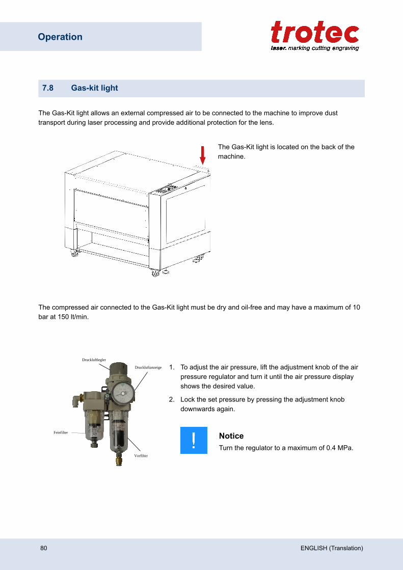
Operation
7.8 Gas-kit light
The Gas-Kit light allows an external compressed air to be connected to the machine to improve dusttransport during laser processing and provide additional protection for the lens.
The Gas-Kit light is located on the back of themachine.
The compressed air connected to the Gas-Kit light must be dry and oil-free and may have a maximum of 10bar at 150 lt/min.
Druckluftlegler
Druckluftanzeige
Vorfilter
Feinfilter
1. To adjust the air pressure, lift the adjustment knob of the airpressure regulator and turn it until the air pressure displayshows the desired value.
2. Lock the set pressure by pressing the adjustment knobdownwards again.
NoticeTurn the regulator to a maximum of 0.4 MPa.
80 ENGLISH (Translation)

Operation
CautionThe maximum value at the pressure flow indicator must not exceed 0.4MPa. In case of non-compliance, the tubing or lens may be damaged.
Maintenance note:The filters of the Gas-Kit light (maintenance unit) must be checked regularly for liquid formation. This liquidwould be blown onto the material, reach the lens and contaminate it.
– Check air pressure preparation!– Only connect dry and oil-free compressed air.
If you have any questions, please contact our experienced technical support in your area.
ENGLISH (Translation) 81
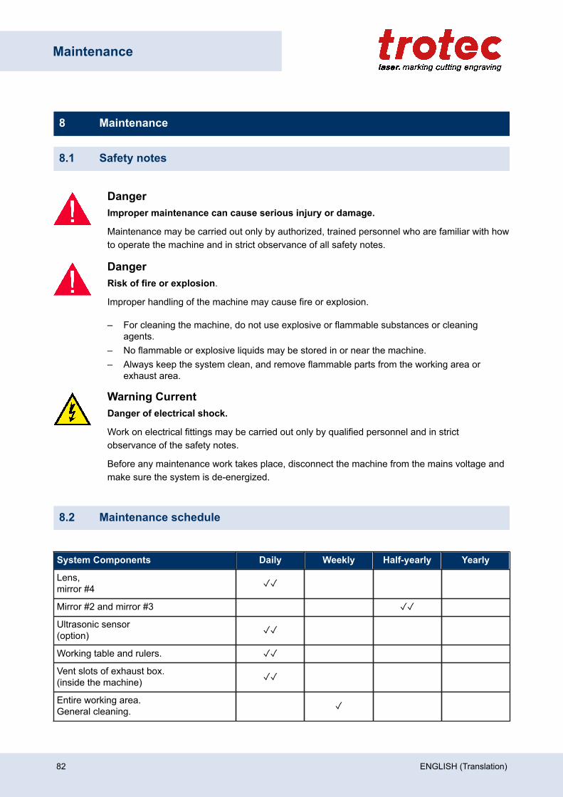
Maintenance
8 Maintenance
8.1 Safety notes
DangerImproper maintenance can cause serious injury or damage.
Maintenance may be carried out only by authorized, trained personnel who are familiar with howto operate the machine and in strict observance of all safety notes.
DangerRisk of fire or explosion.
Improper handling of the machine may cause fire or explosion.
– For cleaning the machine, do not use explosive or flammable substances or cleaningagents.
– No flammable or explosive liquids may be stored in or near the machine.– Always keep the system clean, and remove flammable parts from the working area or
exhaust area.
Warning CurrentDanger of electrical shock.
Work on electrical fittings may be carried out only by qualified personnel and in strictobservance of the safety notes.
Before any maintenance work takes place, disconnect the machine from the mains voltage andmake sure the system is de-energized.
8.2 Maintenance schedule
System Components Daily Weekly Half-yearly Yearly
Lens,mirror #4 ✓✓
Mirror #2 and mirror #3 ✓✓
Ultrasonic sensor(option) ✓✓
Working table and rulers. ✓✓
Vent slots of exhaust box.(inside the machine) ✓✓
Entire working area.General cleaning. ✓
82 ENGLISH (Translation)
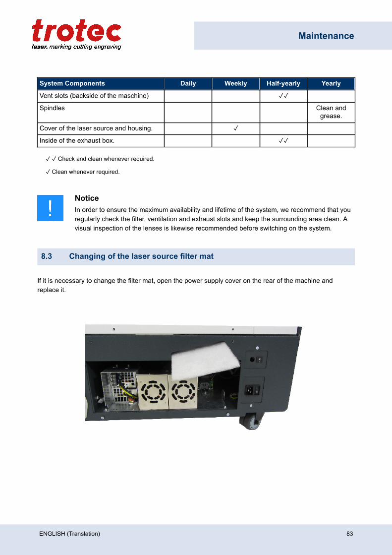
Maintenance
System Components Daily Weekly Half-yearly Yearly
Vent slots (backside of the maschine) ✓✓
Spindles Clean andgrease.
Cover of the laser source and housing. ✓
Inside of the exhaust box. ✓✓
✓ ✓ Check and clean whenever required.
✓ Clean whenever required.
NoticeIn order to ensure the maximum availability and lifetime of the system, we recommend that youregularly check the filter, ventilation and exhaust slots and keep the surrounding area clean. Avisual inspection of the lenses is likewise recommended before switching on the system.
8.3 Changing of the laser source filter mat
If it is necessary to change the filter mat, open the power supply cover on the rear of the machine andreplace it.
ENGLISH (Translation) 83
Maintenance
8.4 Cleaning
8.4.1 Machine
1. Move the working table into a position in which it is easiest for you to clean the surface with a windowcleaning agent and paper towels.
2. Switch off and disconnect the machine from the mains.
3. Open the transparent acrylic top lid and front panel.
4. Thoroughly remove all loose dirt particles and deposits in the interior of the machine (e.g. with a vacuumcleaner or broom).
5. Clean the air guide plate and vent slots of the exhaust box inside the machine using a dry or damp clothor brush.
6. Clean the cover of the laser source and vent slots at the back of the machine using a dry or damp cloth.
7. Clean the transparent acrylic top lid using a dry or slightly damp cotton cloth. Do not use paper towels asthey could scratch the acrylic.
8.4.2 Optics in general
Trotec Laser GmbH recommends to use the cleaning set enclosed. Alternatively, use high-quality cottonswabs together with the provided cleaning liquid.
Notice
The following cleaning products are available as accessory parts:– Lens cleaning cloth (Part number 69249)– Lens cleaning liquid (Part number 69248)
84 ENGLISH (Translation)
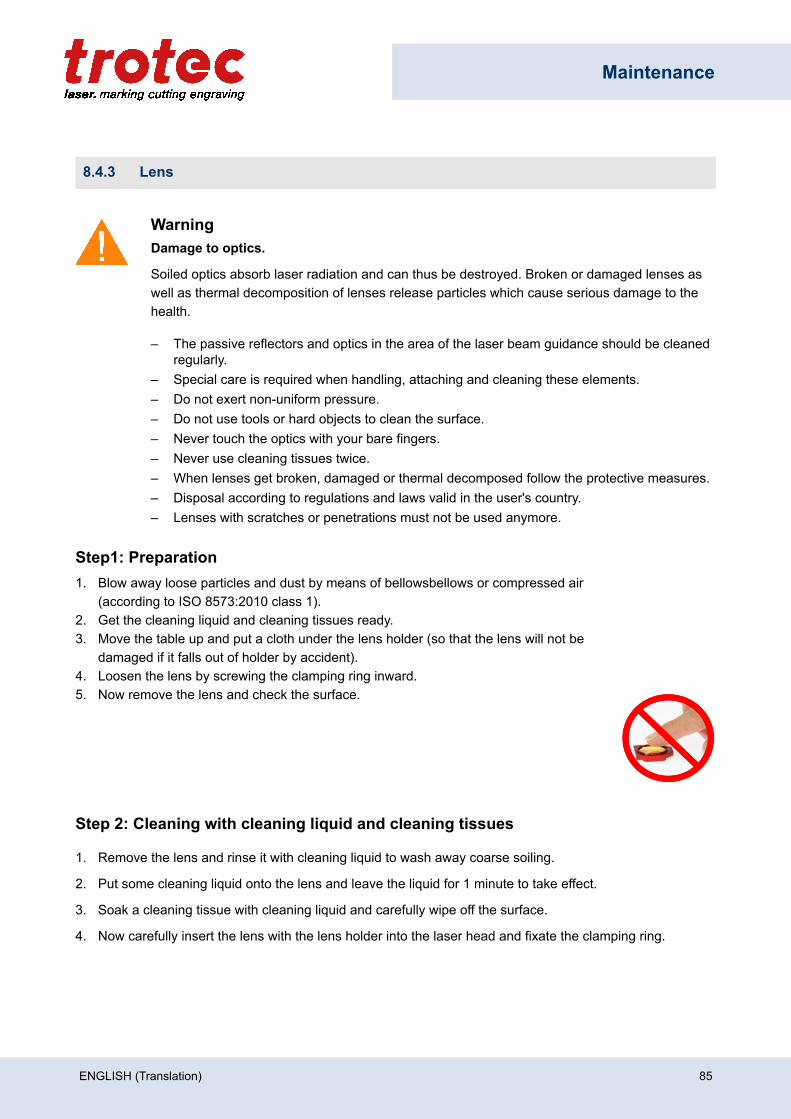
Maintenance
8.4.3 Lens
WarningDamage to optics.
Soiled optics absorb laser radiation and can thus be destroyed. Broken or damaged lenses aswell as thermal decomposition of lenses release particles which cause serious damage to thehealth.
– The passive reflectors and optics in the area of the laser beam guidance should be cleanedregularly.
– Special care is required when handling, attaching and cleaning these elements.– Do not exert non-uniform pressure.– Do not use tools or hard objects to clean the surface.– Never touch the optics with your bare fingers.– Never use cleaning tissues twice.– When lenses get broken, damaged or thermal decomposed follow the protective measures.– Disposal according to regulations and laws valid in the user's country.– Lenses with scratches or penetrations must not be used anymore.
Step1: Preparation1. Blow away loose particles and dust by means of bellowsbellows or compressed air
(according to ISO 8573:2010 class 1).2. Get the cleaning liquid and cleaning tissues ready.3. Move the table up and put a cloth under the lens holder (so that the lens will not be
damaged if it falls out of holder by accident).4. Loosen the lens by screwing the clamping ring inward.5. Now remove the lens and check the surface.
Step 2: Cleaning with cleaning liquid and cleaning tissues
1. Remove the lens and rinse it with cleaning liquid to wash away coarse soiling.
2. Put some cleaning liquid onto the lens and leave the liquid for 1 minute to take effect.
3. Soak a cleaning tissue with cleaning liquid and carefully wipe off the surface.
4. Now carefully insert the lens with the lens holder into the laser head and fixate the clamping ring.
ENGLISH (Translation) 85
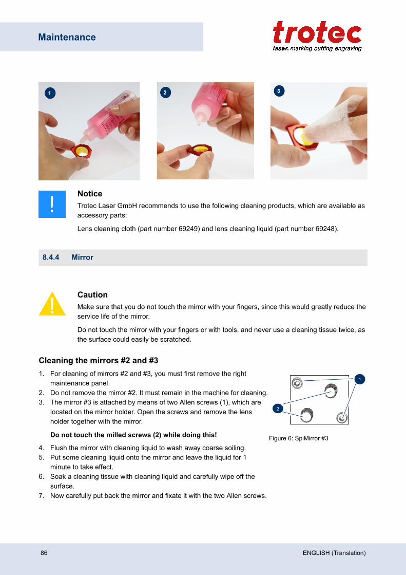
Maintenance
NoticeTrotec Laser GmbH recommends to use the following cleaning products, which are available asaccessory parts:
Lens cleaning cloth (part number 69249) and lens cleaning liquid (part number 69248).
8.4.4 Mirror
CautionMake sure that you do not touch the mirror with your fingers, since this would greatly reduce theservice life of the mirror.
Do not touch the mirror with your fingers or with tools, and never use a cleaning tissue twice, asthe surface could easily be scratched.
Cleaning the mirrors #2 and #31. For cleaning of mirrors #2 and #3, you must first remove the right
maintenance panel.2. Do not remove the mirror #2. It must remain in the machine for cleaning.3. The mirror #3 is attached by means of two Allen screws (1), which are
located on the mirror holder. Open the screws and remove the lensholder together with the mirror.
Do not touch the milled screws (2) while doing this! Figure 6: SpiMirror #34. Flush the mirror with cleaning liquid to wash away coarse soiling.5. Put some cleaning liquid onto the mirror and leave the liquid for 1
minute to take effect.6. Soak a cleaning tissue with cleaning liquid and carefully wipe off the
surface.7. Now carefully put back the mirror and fixate it with the two Allen screws.
86 ENGLISH (Translation)
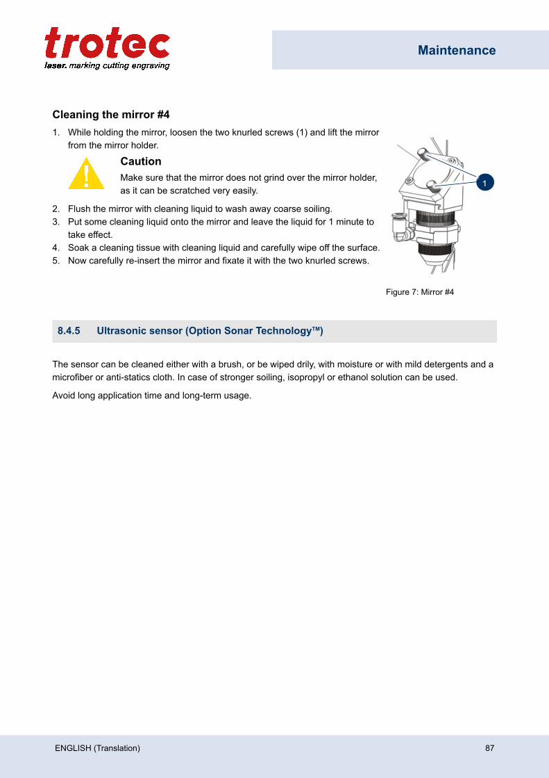
Maintenance
Cleaning the mirror #41. While holding the mirror, loosen the two knurled screws (1) and lift the mirror
from the mirror holder.
CautionMake sure that the mirror does not grind over the mirror holder,as it can be scratched very easily.
2. Flush the mirror with cleaning liquid to wash away coarse soiling.3. Put some cleaning liquid onto the mirror and leave the liquid for 1 minute to
take effect.4. Soak a cleaning tissue with cleaning liquid and carefully wipe off the surface.5. Now carefully re-insert the mirror and fixate it with the two knurled screws.
Figure 7: Mirror #4
8.4.5 Ultrasonic sensor (Option Sonar TechnologyTM)
The sensor can be cleaned either with a brush, or be wiped drily, with moisture or with mild detergents and amicrofiber or anti-statics cloth. In case of stronger soiling, isopropyl or ethanol solution can be used.
Avoid long application time and long-term usage.
ENGLISH (Translation) 87
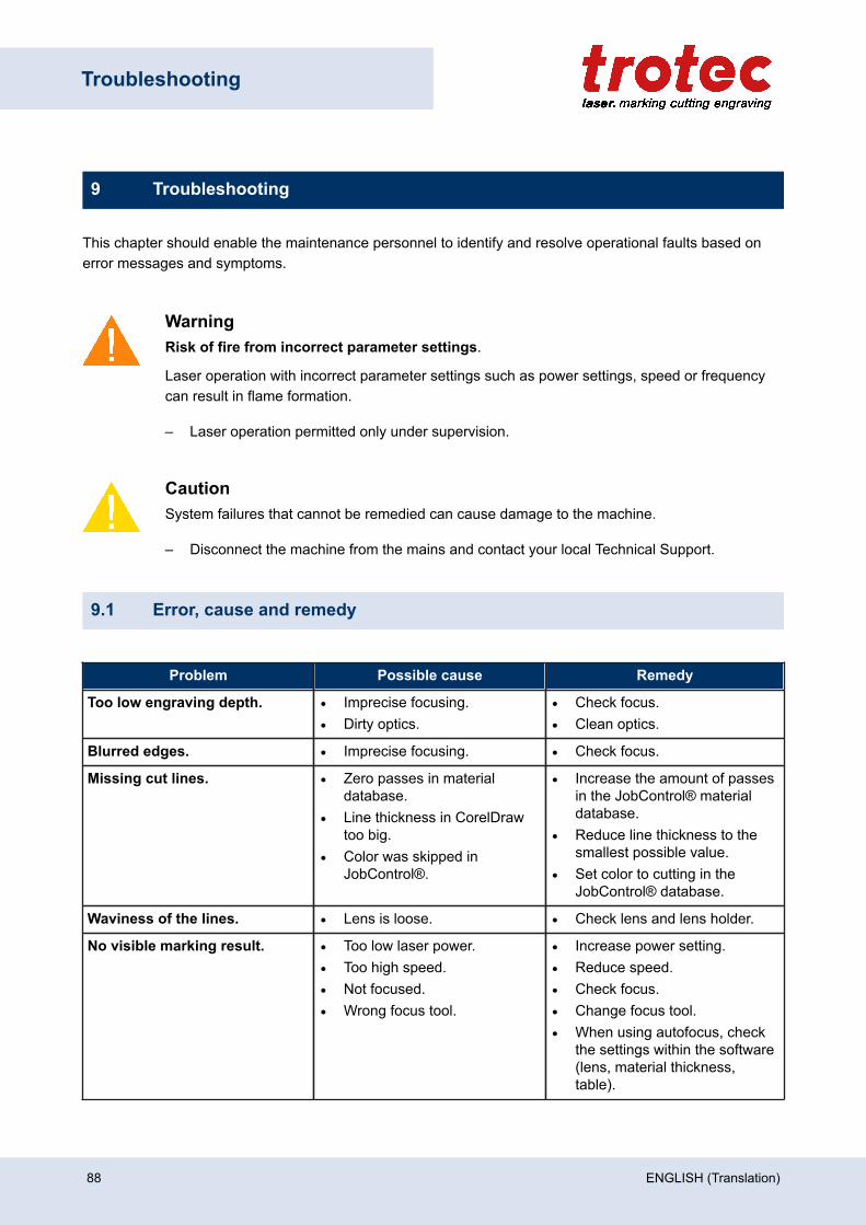
Troubleshooting
9 Troubleshooting
This chapter should enable the maintenance personnel to identify and resolve operational faults based onerror messages and symptoms.
WarningRisk of fire from incorrect parameter settings.
Laser operation with incorrect parameter settings such as power settings, speed or frequencycan result in flame formation.
– Laser operation permitted only under supervision.
CautionSystem failures that cannot be remedied can cause damage to the machine.
– Disconnect the machine from the mains and contact your local Technical Support.
9.1 Error, cause and remedy
Problem Possible cause Remedy
Too low engraving depth. • Imprecise focusing.• Dirty optics.
• Check focus.• Clean optics.
Blurred edges. • Imprecise focusing. • Check focus.
Missing cut lines. • Zero passes in materialdatabase.
• Line thickness in CorelDrawtoo big.
• Color was skipped inJobControl®.
• Increase the amount of passesin the JobControl® materialdatabase.
• Reduce line thickness to thesmallest possible value.
• Set color to cutting in theJobControl® database.
Waviness of the lines. • Lens is loose. • Check lens and lens holder.
No visible marking result. • Too low laser power.• Too high speed.• Not focused.• Wrong focus tool.
• Increase power setting.• Reduce speed.• Check focus.• Change focus tool.• When using autofocus, check
the settings within the software(lens, material thickness,table).
88 ENGLISH (Translation)
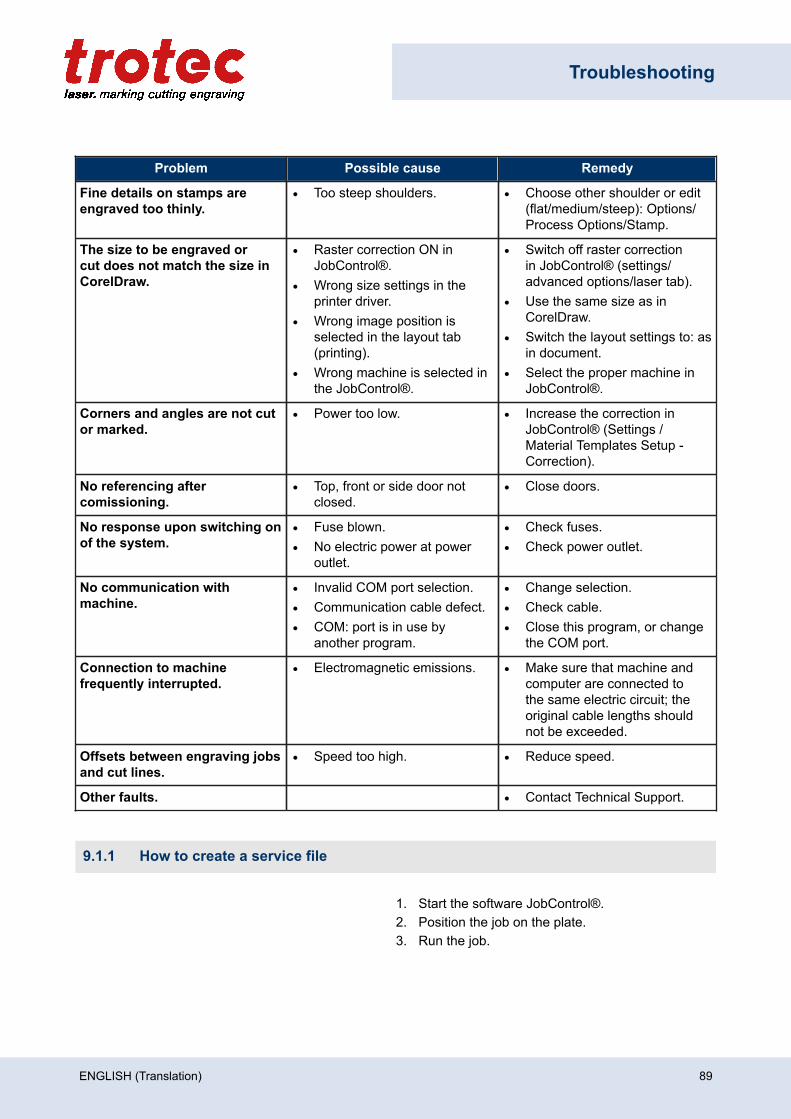
Troubleshooting
Problem Possible cause Remedy
Fine details on stamps areengraved too thinly.
• Too steep shoulders. • Choose other shoulder or edit(flat/medium/steep): Options/Process Options/Stamp.
The size to be engraved orcut does not match the size inCorelDraw.
• Raster correction ON inJobControl®.
• Wrong size settings in theprinter driver.
• Wrong image position isselected in the layout tab(printing).
• Wrong machine is selected inthe JobControl®.
• Switch off raster correctionin JobControl® (settings/advanced options/laser tab).
• Use the same size as inCorelDraw.
• Switch the layout settings to: asin document.
• Select the proper machine inJobControl®.
Corners and angles are not cutor marked.
• Power too low. • Increase the correction inJobControl® (Settings /Material Templates Setup -Correction).
No referencing aftercomissioning.
• Top, front or side door notclosed.
• Close doors.
No response upon switching onof the system.
• Fuse blown.• No electric power at power
outlet.
• Check fuses.• Check power outlet.
No communication withmachine.
• Invalid COM port selection.• Communication cable defect.• COM: port is in use by
another program.
• Change selection.• Check cable.• Close this program, or change
the COM port.
Connection to machinefrequently interrupted.
• Electromagnetic emissions. • Make sure that machine andcomputer are connected tothe same electric circuit; theoriginal cable lengths shouldnot be exceeded.
Offsets between engraving jobsand cut lines.
• Speed too high. • Reduce speed.
Other faults. • Contact Technical Support.
9.1.1 How to create a service file
1. Start the software JobControl®.2. Position the job on the plate.3. Run the job.
ENGLISH (Translation) 89
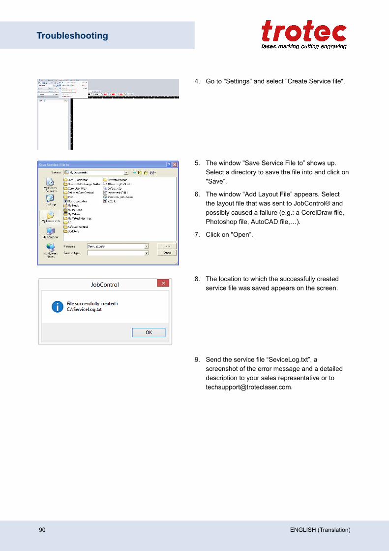
Troubleshooting
4. Go to "Settings" and select "Create Service file".
5. The window "Save Service File to” shows up.Select a directory to save the file into and click on"Save”.
6. The window "Add Layout File” appears. Selectthe layout file that was sent to JobControl® andpossibly caused a failure (e.g.: a CorelDraw file,Photoshop file, AutoCAD file,…).
7. Click on "Open”.
8. The location to which the successfully createdservice file was saved appears on the screen.
9. Send the service file “SeviceLog.txt”, ascreenshot of the error message and a detaileddescription to your sales representative or [email protected].
90 ENGLISH (Translation)

Contact details
10 Contact details
Technical SupportIn case of questions, contact our experienced Technical Support in your local area.
For global service contact numbers and further information please see our website, section "Support":www.troteclaser.com
When calling, please make sure that the machine is in your immediate vicinity, and that you have thefollowing information ready (see response form):
At which working process did the problem occur?
What you have done so far to correct the problem.
Serial no (see type plate).
Error code.
Local Offices / SalesOur store locator and detailed information on our offices in your area can be found on our website in section"Contact", "Local Office": www.troteclaser.com
Technical DocumentationFor feedback or to suggest changes to this manual, contact:
Technical documentation: +43 (0) 7242 239 - 7000
E-Mail: [email protected]
ENGLISH (Translation) 91
Disassembly
11 Disassembly
WarningDanger of injury when disassembling the machine.
There is danger of injury when disassembling the machine.
Always wear suitable protective clothing (e.g. safety goggles, safety shoes, safety gloves).
Warning CurrentElectric current.
The machine must be disconnected from the main power supply.
Notice
– Always use suitable tools to disassemble the machine.– Mind the springs.– Follow chapter "Disposal".
Process:
1. Remove all workpieces from the system.
2. Turn the key switch to switch off the machine.
3. Switch off the main switch at the back of the machine.
4. Remove the exhaust system.
5. Disconnect all cables at the back of the machine.
92 ENGLISH (Translation)

Disposal
12 Disposal
DisposalDo not dispose of the machine with domestic waste!
Electronic devices have to be disposed of according to the regional directives on electronic andelectric waste disposal.
In case of further questions, please ask your supplier.
Use suitable tools if you have to dissemble the machine. All parts need to be sorted into theindividual material types and be disposed of according to the regional directives on electronicand electric waste disposal.
ENGLISH (Translation) 93

Appendix
13 Appendix
✓ Technical Data
✓ Conformity Declaration
✓ Acceptance report
✓ Response form
✓ Training verification form
94 ENGLISH (Translation)
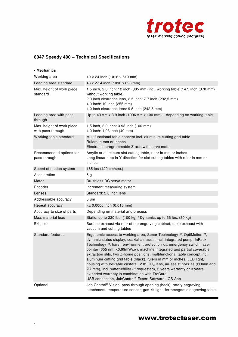
www.troteclaser.com
1
8047 Speedy 400 – Technical Specifications
• Mechanics
Working area 40 × 24 inch (1016 × 610 mm)
Loading area standard 43 x 27.4 inch (1096 x 698 mm)
Max. height of work piece
standard
1.5 inch, 2.0 inch: 12 inch (305 mm) incl. working table (14.5 inch (370 mm)
without working table)
2.0 inch clearance lens, 2.5 inch: 7.7 inch (292,5 mm)
4.0 inch: 10 inch (255 mm)
4.0 inch clearance lens: 9.5 inch (242,5 mm)
Loading area with pass-
through
Up to 43 x ∞ x 3.9 inch (1096 x ∞ x 100 mm) – depending on working table
Max. height of work piece
with pass-through
1.5 inch, 2.0 inch: 3.93 inch (100 mm)
4.0 inch: 1.93 inch (49 mm)
Working table standard Multifunctional table concept incl. aluminum cutting grid table
Rulers in mm or inches
Electronic, programmable Z-axis with servo motor
Recommended options for
pass-through
Acrylic or aluminum slat cutting table, ruler in mm or inches
Long linear stop in Y-direction for slat cutting tables with ruler in mm or
inches
Speed of motion system 165 ips (420 cm/sec.)
Acceleration 5 g
Motor Brushless DC servo motor
Encoder Increment measuring system
Lenses Standard: 2.0 inch lens
Addressable accuracy 5 µm
Repeat accuracy <± 0.0006 inch (0,015 mm)
Accuracy to size of parts Depending on material and process
Max. material load Static: up to 220 lbs. (100 kg) / Dynamic: up to 66 lbs. (30 kg)
Exhaust Surface exhaust via rear of the engraving cabinet, table exhaust with
vacuum and cutting tables
Standard features Ergonomic access to working area, Sonar TechnologyTM, OptiMotionTM,
dynamic status display, coaxial air assist incl. integrated pump, InPack
Technology™, harsh environment protection kit, emergency switch, laser
pointer (655 nm, <0,99mWcw), machine integrated and partial coverable
extraction slits, two Z-home positions, multifunctional table concept incl.
aluminum cutting grid table (black), rulers in mm or inches, LED light,
housing with lockable casters, 2.0" CO2 lens, air-assist nozzles (Ø3mm and
Ø7 mm), incl. water-chiller (if requested), 2 years warranty or 3 years
extended warranty in combination with TroCare
USB connection, JobControl® Expert Software, iOS App
Optional Job Control® Vision, pass-through opening (back), rotary engraving
attachment, temperature sensor, gas-kit light, ferromagnetic engraving table,
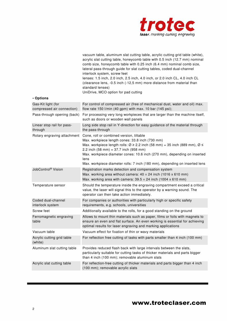
www.troteclaser.com
2
vacuum table, aluminum slat cutting table, acrylic cutting grid table (white),
acrylic slat cutting table, honeycomb table with 0.5 inch (12.7 mm) nominal
comb size, honeycomb table with 0.25 inch (6.4 mm) nominal comb size,
lateral pass-through guide for slat cutting tables, coded dual-channel
interlock system, screw feet
lenses: 1.5 inch, 2.0 inch, 2.5 inch, 4.0 inch, or 2.0 inch CL, 4.0 inch CL
(clearance lens, -0.5 inch (-12,5 mm) more distance from material than
standard lenses)
UniDrive, MCO option for pad cutting
• Options
Gas-Kit light (for
compressed air connection)
For control of compressed air (free of mechanical dust, water and oil) max.
flow rate 150 l/min (40 gpm) with max. 10 bar (145 psi);
Pass-through opening (back) For processing very long workpieces that are larger than the machine itself,
such as doors or wooden wall panels
Linear stop rail for pass-
through
Long side stop rail in Y-direction for easy guidance of the material through
the pass-through
Rotary engraving attachment Cone, roll or combined version, tiltable
Max. workpiece length cones: 33.8 inch (730 mm)
Max. workpiece length rolls: Ø ≥ 2.2 inch (58 mm) = 35 inch (889 mm), Ø ≤
2.2 inch (58 mm) = 37.7 inch (958 mm)
Max. workpiece diameter cones: 10.6 inch (270 mm), depending on inserted
lens
Max. workpiece diameter rolls: 7 inch (180 mm), depending on inserted lens
JobControl® Vision Registration marks detection and compensation system
Max. working area without camera: 40 × 24 inch (1016 x 610 mm)
Max. working area with camera: 39.5 × 24 inch (1004 x 610 mm)
Temperature sensor Should the temperature inside the engraving compartment exceed a critical
value, the laser will signal this to the operator by a warning sound. The
operator can then take action immediately.
Coded dual-channel
interlock system
For companies or authorities with particularly high or specific safety
requirements, e.g. schools, universities
Screw feet Additionally available to the rolls, for a good standing on the ground
Ferromagnetic engraving
table
Allows to mount thin materials such as paper, films or foils with magnets to
ensure an even and flat surface. An even working is essential for achieving
optimal results for laser engraving and marking applications
Vacuum table Vacuum effect for fixation of thin or wavy materials
Acrylic cutting grid table
(white)
For reflection free cutting of tasks with parts smaller than 4 inch (100 mm)
Aluminum slat cutting table Provides reduced flash back with large intervals between the slats,
particularly suitable for cutting tasks of thicker materials and parts bigger
than 4 inch (100 mm); removable aluminum slats
Acrylic slat cutting table For reflection-free cutting of thicker materials and parts bigger than 4 inch
(100 mm); removable acrylic slats
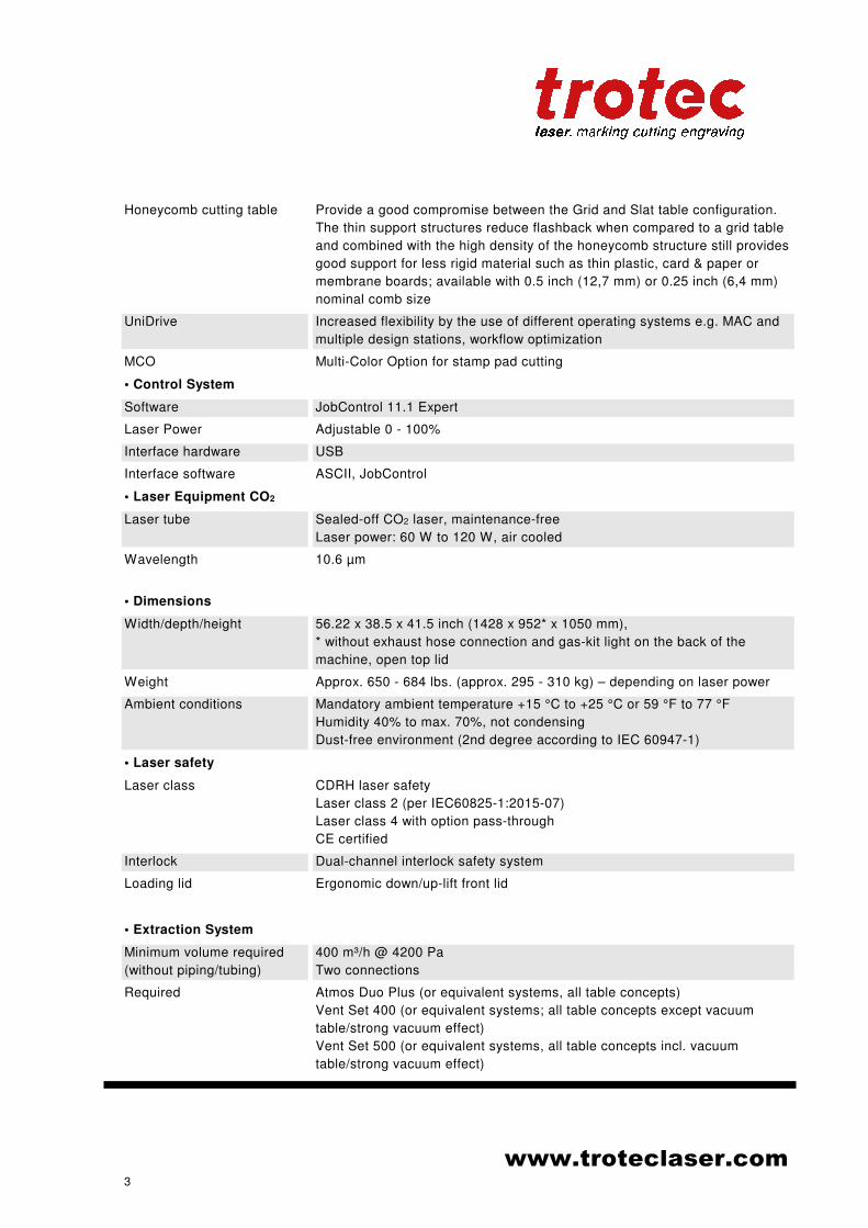
www.troteclaser.com
3
Honeycomb cutting table Provide a good compromise between the Grid and Slat table configuration.
The thin support structures reduce flashback when compared to a grid table
and combined with the high density of the honeycomb structure still provides
good support for less rigid material such as thin plastic, card & paper or
membrane boards; available with 0.5 inch (12,7 mm) or 0.25 inch (6,4 mm)
nominal comb size
UniDrive Increased flexibility by the use of different operating systems e.g. MAC and
multiple design stations, workflow optimization
MCO Multi-Color Option for stamp pad cutting
• Control System
Software JobControl 11.1 Expert
Laser Power Adjustable 0 - 100%
Interface hardware USB
Interface software ASCII, JobControl
• Laser Equipment CO2
Laser tube Sealed-off CO2 laser, maintenance-free
Laser power: 60 W to 120 W, air cooled
Wavelength 10.6 µm
• Dimensions
Width/depth/height 56.22 x 38.5 x 41.5 inch (1428 x 952* x 1050 mm),
* without exhaust hose connection and gas-kit light on the back of the
machine, open top lid
Weight Approx. 650 - 684 lbs. (approx. 295 - 310 kg) – depending on laser power
Ambient conditions Mandatory ambient temperature +15 °C to +25 °C or 59 °F to 77 °F
Humidity 40% to max. 70%, not condensing
Dust-free environment (2nd degree according to IEC 60947-1)
• Laser safety
Laser class CDRH laser safety
Laser class 2 (per IEC60825-1:2015-07)
Laser class 4 with option pass-through
CE certified
Interlock Dual-channel interlock safety system
Loading lid Ergonomic down/up-lift front lid
• Extraction System
Minimum volume required
(without piping/tubing)
400 m³/h @ 4200 Pa
Two connections
Required Atmos Duo Plus (or equivalent systems, all table concepts)
Vent Set 400 (or equivalent systems; all table concepts except vacuum
table/strong vacuum effect)
Vent Set 500 (or equivalent systems, all table concepts incl. vacuum
table/strong vacuum effect)

www.troteclaser.com
4
• Electrical equipment
Power consumption Approx. 1200 W to 2100 W (depending on laser power)
Subject to change without notice. Errors and omissions reserverd. February 2019
Acceptance report
Dear customer!
We request your confirmation of properly completed transfer of the machine. Please transmit a copy of this document - filled out and signed by an authorized company representative - to an employee of our sales affiliate for forwarding to the manufacturer.
Please check applicable items:
Machine parts checked for shipping damage.
Machine parts checked against delivery note.
Setup of the machine discussed.
Startup of the machine discussed.
Operation of the machine discussed.
Maintenance of the machine discussed.
Electrical voltage checked.
Safety notes discussed.
Trial run performed.
Deficiencies determined.
The machine with the machine designation:
has been checked according to the listed items and has been handed over properly.
City, DateName, Position
Company stamp, Signature(Instructed person)
Response form
Dear customer!
In case of any trouble with the machine, please provide the following information and additional-ly create a service file.
Description of the problem
Serial number:JobControl® version:Driver version: Layout Software:Firmware version:
Name:Country:Phone:E-mail:Date:
Contact details Machine data
Does an error message show up on the PC , and if so, which?
What happened before the error occurred? (Thunder and lightning, Windows-Update...)
What attempts were made to solve the problem?
Please send the information to your sales representative, to your local support or to following e-mail address: [email protected].
Training verification form
Trainee:
Trainer:
Date of Training:
The employee named above was instructed in the operation of the ........................................laser system. Especially the following topics were covered:
Machine function
Danger areas
Warnings
Position of the Emergency stop button
Personal protective equipment
Operating equipment
Workflow
Setting-up
Startup and Shutdown
Reporting of unexpected working results and actions to be taken.
Signature Trainer Signature Trainee
Reporting of failure and actions to be initiated.
Responsibility for troubleshooting.
Operating manual and it´s storage location for inspection.


