Embed Size (px)
Citation preview

Design, Converting and Handling TechniquesDesign, Converting and Handling Techniques
for Electro-Plating ABS and ABS/PC Alloysfor Electro-Plating ABS and ABS/PC Alloys
OverviewOverview 33
Design for PlatingDesign for Plating 33
Design Considerations to aid Plated Part AppearanceDesign Considerations to aid Plated Part Appearance 33
Integral PartsIntegral Parts 44
PlanesPlanes 44
GatesGates 44
Ribs and BossesRibs and Bosses 44
Edges and CornersEdges and Corners 5 5
Parting LinesParting Lines 5 5
Design Considerations to Improve Plated Part PerformanceDesign Considerations to Improve Plated Part Performance 55
Wall ThicknessWall Thickness 5 5
Plate AdhesionPlate Adhesion 6 6
Plate uniformityPlate uniformity 7 7
Table 1 Recommended Electroplate ThicknessTable 1 Recommended Electroplate Thickness 8 8
Design for Plate UniformityDesign for Plate Uniformity 88
AnglesAngles 8 8
EdgesEdges 99
Flat Bottom GroovesFlat Bottom Grooves 99
Table 2 Recommended Radii for Indentations of Various DepthsTable 2 Recommended Radii for Indentations of Various Depths.. 99

2 of 182 of 18
V GroovesV Grooves 1010
Blind HolesBlind Holes 1010
SlotsSlots 1010
RibsRibs 1111
BossesBosses 1111
Raised DetailsRaised Details 12 12
Design Considerations to Accommodate RackingDesign Considerations to Accommodate Racking 1212
Converting Methods And ProcessingConverting Methods And Processing 1313
Injection Moulding GradesInjection Moulding Grades 1313
Mould Design and SpecificationsMould Design and Specifications 1414
Mould SurfaceMould Surface 1414
TexturingTexturing 1414
Mould ShrinkageMould Shrinkage 1414
GatingGating 1414
VentingVenting 15 15
NozzlesNozzles 15 15
Moulding Conditions and ProceduresMoulding Conditions and Procedures 15 15
Typical Processing ConditionsTypical Processing Conditions 16 16
MachinesMachines 16 16
Mould LubricationMould Lubrication 16 16
RegrindRegrind 16 16
PurgingPurging 17 17
HANDLING OF FORMED PARTS FOR PLATINGHANDLING OF FORMED PARTS FOR PLATING 1717

3 of 18
Overview
The enormous demand for plated plastics in recent years has resulted in an exponentialgrowth around the world. The transportation, appliance,communications, hardware and marine industries have been in the vanguard of thatdemand.Much of the growth is attributable to the many advantages that plated plastics offermanufacturers who traditionally had utilised plated metal products. Among the advantagesare design freedom, weight reduction and lower costs.ABS/PC alloys, available in application-oriented grades, gives the designer, molder andelectroplater superior features to facilitate platingtechniques.
Design for Plating
The success of a metal plated ABS/PC part starts with design.
A design must accommodate moulding, plating and part performance. Easy-to-platecontours will invariably provide a more uniform distribution of the electro-deposited metaland will provide a finish having better performance at a reduced processing cost.Many of the suggestions and design recommendations that follow are based on actualexperience acquired in electroplating ABS plastics. Some are based on good plasticdesign principles while others are similar to those for metal parts which are to beelectroplated.
If followed, these recommendations will help assure plated ABS or ABS/PC parts of high
quality appearance, also good functional and part performance. For further guidance,designers should consult the electroplater and or molder.
1. As they aid plated part appearance.2. As they improve part performance or function.3. As they facilitate ease of racking and plating parts.
Design Considerations to aid Plated Part Appearance
Appearance is a key factor in the acceptance level of plated plastics because more than90% of current applications are decorative parts. The part's final appearance begins with

the application of proper design practices and is further influenced by rnolding, plating andhandling techniques.

4 of 18
Since surface defects are more pronounced on a highly reflective metal surface than onthe bare plastic material, the following practical design considerations will help optimize
the surface appearance of the plated part.
Integral Parts
Whenever possible, components should be designed as one piece since good platingappearance is difficult to achieve over welded or cemented
joints.Parts are sometimes plated and then assembled via screws, hot staking, snap fits, etc.
Planes
Large planes should be crowned with a curvatureof about 0.06 mm / 100mm. Crowning tends tocamouflage minor surface irregularities becausethe eye is not as capable of focusing on a wideexpanse of curvature as it is on a flat surface(figure l.)As an alternative, shallow, well radiusedtexturing can be used to effectively break up flatareas and mask minor molding, thermoforming,handling or plating imperfections.
Figure 1
Gates
Gates should be located on non-critical appearance surfaces, as gate and trimmingmarks, too, are exaggerated by the metal plate. If this is not practical, a feature can bemade of the gate area. For instance, on a small plated knob, with a slightly peaked convextop surface, the gate could be placed at the apex, where it may be noticeable, but notobjectionable.
Ribs and Bosses
Care should be taken in locating ribs, bosses or other heavy sections on the reverse sideof appearance areas. Unless properly designed, they will cause sink marks which are
more noticeable after plating.

Thermal cycle performance can be improved if excessive bulk is removed from thick crosssections (figure 4). In this way a more uniform wall thickness is obtained, and the plastic
has less tendency to expand and overcome the strength of the metal plate.
Figure 4.
Plate uniformity
The heavy mass electroplated spherical ball
(far left) failed three cycles -17°C - 70°C
After internal mass was removed and partwas designed into two parts using a snap fit(top right), the required three cycles of 30°C- 82°C / was met.
Removing excess internal bulk (left centre)provides a more uniform cross section;adding external serrations (left) acts asexpansion joints which accommodateplastics thermal expansion
Uniformity of electroplate thickness is improved by designing parts with gently curvingconvex surfaces. Non-uniformity of thickness is caused by an unequal distribution ofcurrent density on the part. Technically, this problem arises because the recessed areasof a part (slots, grooves, blind holes, etc.) are normally low current density areas. Theseareas are starved of their share of the electroplate, while the high current density areas(corners, edges, ribs, fins and other features) are apt to have plate build-up out ofproportion. Low current density areas may have less than one-fourth the amount ofelectroplate generally deposited on the part’s surface. (figure 5).
These thinly plated areas are commonly thesite of first failure from abrasion, corrosionor wear.Auxiliary anodes can be used in low currentdensity areas to improve plate uniformity,but the designer must be aware that thistechnique may be more expensive thanstandard plating practices. The minimumcoating thickness recommendations forABS are given in Table 1.
Figure 5.

Table 1 Recommended Electroplate Thickness
Service Conditions Recommended ThicknessMILD - Exposure indoors in Nickel strike Adequate to covernormally warm dry Bright acid copper 15 - 20 µmatmospheres Bright nickel 05 - 08 µm
Conventional chromium 0.2 - 0.4 µmMODERATE - Exposure to Nickel strike Adequate to coverhigh humidity and mildly Bright acid copper 15 - 20 µmcorrosive atmosphere. Semi-bright nickel 08 - 10 µm
Bright nickel 05 - 08 µm
Conventional chromium 0.2 - 0.4 µmSEVERE - Exposure to high Nickel strike Adequate to coverhumidity, wide temperature Bright acid copper 15 - 20 µmvariations and severe Semi-bright nickel 10 - 15 µmcorrosive atmosphere. Bright nickel 08 - 10 µm
* Special nickel 2.5 µm
Conventional chromium 0.2 - 0.4 µm* Required for inducing micro porosity or micro cracking
Design for Plate Uniformity
Angles
All angles should be as large as possible.Minimum inside and outside radii of 0.8 mmand 0.8 mm respectively are suggested.Sharp angles increase plating time andcosts for plate uniformity and reduce thedurability of the plated part
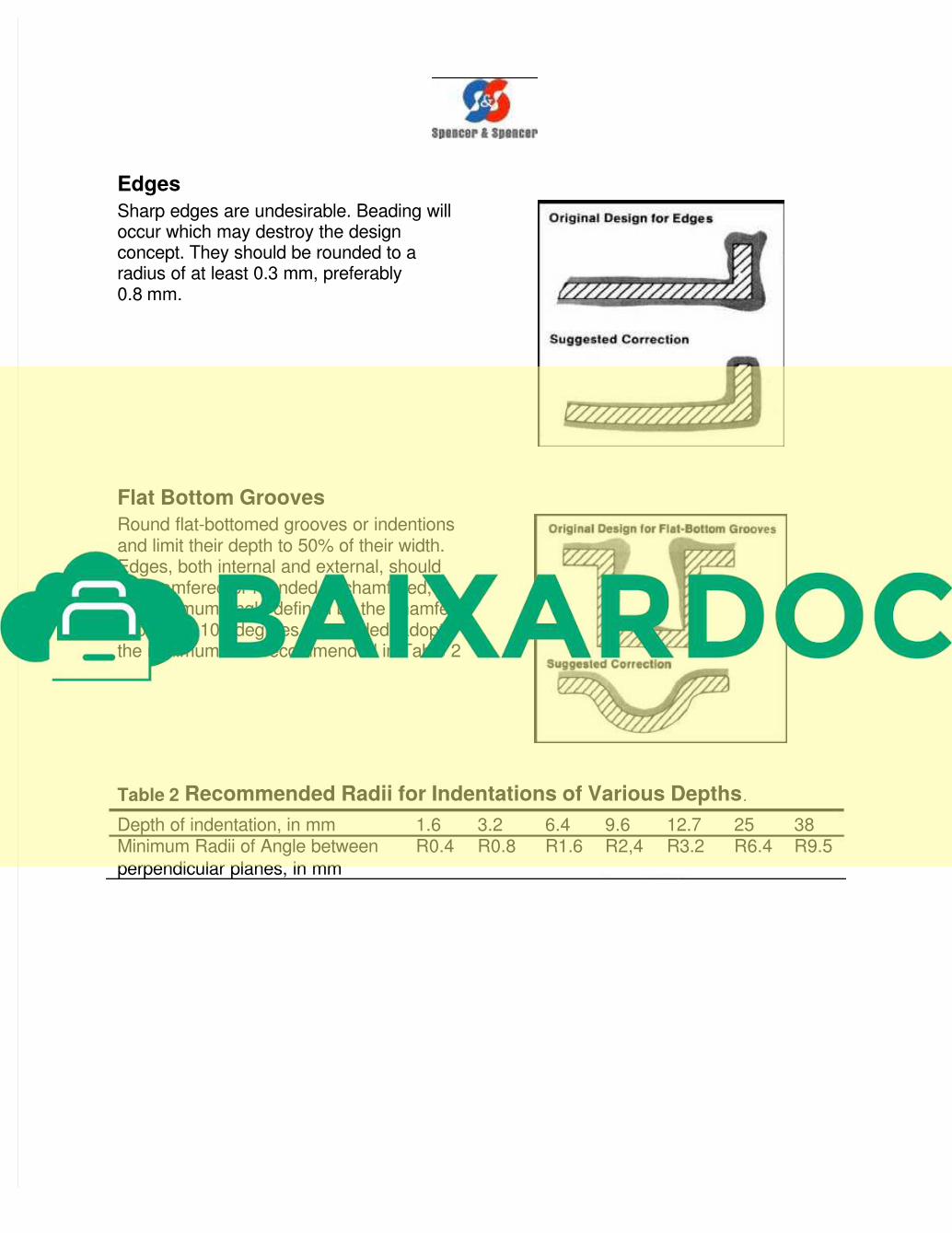
Edges
Sharp edges are undesirable. Beading willoccur which may destroy the designconcept. They should be rounded to aradius of at least 0.3 mm, preferably0.8 mm.
Flat Bottom Grooves
Round flat-bottomed grooves or indentionsand limit their depth to 50% of their width.Edges, both internal and external, shouldbe chamfered or rounded. If chamfered,the minimum angle defined by the chamfershould be 100 degrees. If rounded, adoptthe minimum radii recommended in Table 2
Table 2 Recommended Radii for Indentations of Various Depths.
Depth of indentation, in mm 1.6 3.2 6.4 9.6 12.7 25 38Minimum Radii of Angle between R0.4 R0.8 R1.6 R2,4 R3.2 R6.4 R9.5
perpendicular planes, in mm

containers to prevent scuffing and scratching. Cotton gloves again are normally usedin handling the parts just prior to plating. The finished parts are usually wrappedindividually and shipped in strong packing containers to the end users.

18 of 18
Parts to be packaged in polyethylene bags must be cooled to below 37°C before
packaging.


