Embed Size (px)
Citation preview
Spill Prevention Control and Countermeasure (SPCC) Plan
Prepared for:
University of California, San Diego (UCSD), Elliott Field Station Facility 10205 Pomerado Road, San Diego CA, 92131
Prepared by:
Amec Foster Wheeler 9210 Sky Part Court San Diego, CA 92123 www.amecfw.com
USCD Elliott Field Station SPCC
Table of Contents
UCSD Elliott Field Station Spill Prevention Control and Countermeasure (SPCC) Plan ............... 1
Facility Description .................................................................................................................................... 1 Facility Overview ....................................................................................................................................... 1
I. Self-Certification Statement (§112.6(b)(2)) .......................................................................... 2
II. Record of Plan Review and Amendments, Technical Amendments, Applicable Requirements and Professional Engineer Certifications (§112.5(a), (d) and 112.6(b)(2)) .................................... 4
III. Plan Requirements ........................................................................................................... 5
1. Facility Diagram (§112.7(a)(3)): ........................................................................................................ 5 2. Oil Storage Containers (§112.7(a)(3)(i)): ........................................................................................... 5 3. Oil Spill Control (§§112.7(a)(3)(ii) & (iii)): .......................................................................................... 6 4. Procedures for Discharge Discovery, Response & Cleanup (§112.7(a)(3)(iv) & (v), 112.7(a)(5)): ...... 7 5. Contact List (§112.7(a)(3)(vi)) ........................................................................................................... 8 6. NRC Notification Procedure (§112.7(a)(4)) ....................................................................................... 9 7. SPCC Spill Reporting Requirements (Report within 60 days) (§112.4): .............................................. 9 8. Containers with Potential for an Oil Discharge (§112.7(b)): ............................................................ 11 9. Containment or Diversionary Structures or Equipment to Prevent Oil Discharge (§112.7(c)) ......... 12 10. Containment Impracticability (§112.7(d)): ...................................................................................... 12 11. Inspection, Tests, Records (§112.7(e), 112.8(c)(6) & (d)(4), 112.9(c)(3), 112.12(c)(6) & (d)(4)): ... 12 12. Training for Oil Handling Personnel (§112.7(f)): .............................................................................. 12 13. Implementation and Description of Security Measures (§112.7(g): ................................................ 13 14. Facility Tank Car and Tank Truck Loading/Unloading Rack (excluding offshore facilities, farms, and oil production facilities) (§112.7(h)): ............................................................................................................ 13 15. Field Constructed Aboveground Containers (§112.7(i)): ................................................................. 13 16. Conformance with Other Applicable Requirements (§112.7(j)): ..................................................... 14
IV. Onshore Facilities (non-production) (§§112.8(b) - (d), 112.12(b) - (d)): ............................... 15
Attachment 1 – Five Year Review and Technical Amendment Logs ......................................... 18
Attachment 1.1 – Five Year Review Log ................................................................................................... 18 Attachment 1.2 – Recertification of Technical Amendments ................................................................... 18
Attachment 2 – Oil Spill Contingency Plan ............................................................................. 19
Attachment 3 – Inspections, and Personnel Training Logs ...................................................... 20
Attachment 3.1 –Sample Inspection Log ................................................................................................. 20 Attachment 3.2 – Bulk Container Inspection Schedule – onshore facilities (excluding production) ......... 22 Attachment 3.3 – Oil-handling Personnel Training and Briefing Log ........................................................ 23
Attachment 4 –Discharge Notification Form .......................................................................... 24
Attachment 5 – Facility Photos/Maps/Diagrams .................................................................... 25
Attachment 5.1 – Site Photos .................................................................................................................. 26 Attachment 5.2 – Elliott Field Station Area Map ...................................................................................... 29 Attachment 5.3 – Elliott Field Station, Englekirk Structural Engineering Labs .......................................... 31 Attachment 5.4 – Elliott Field Station, Shake Table Basement ................................................................. 33
Attachment 6 – UCSD Emergency Response Guide ................................................................. 36
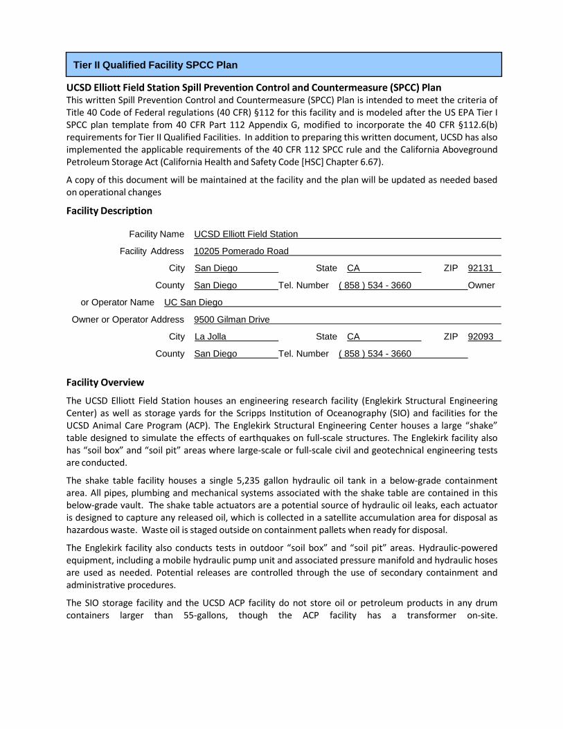
UCSD Elliott Field Station Spill Prevention Control and Countermeasure (SPCC) Plan This written Spill Prevention Control and Countermeasure (SPCC) Plan is intended to meet the criteria of Title 40 Code of Federal regulations (40 CFR) §112 for this facility and is modeled after the US EPA Tier I SPCC plan template from 40 CFR Part 112 Appendix G, modified to incorporate the 40 CFR §112.6(b) requirements for Tier II Qualified Facilities. In addition to preparing this written document, UCSD has also implemented the applicable requirements of the 40 CFR 112 SPCC rule and the California Aboveground Petroleum Storage Act (California Health and Safety Code [HSC] Chapter 6.67).
A copy of this document will be maintained at the facility and the plan will be updated as needed based on operational changes
Facility Description
Facility Name UCSD Elliott Field Station
Facility Address 10205 Pomerado Road
City San Diego State CA ZIP 92131
County San Diego Tel. Number ( 858 ) 534 - 3660 Owner
or Operator Name UC San Diego
Owner or Operator Address 9500 Gilman Drive
City La Jolla State CA ZIP 92093
County San Diego Tel. Number ( 858 ) 534 - 3660
Facility Overview
The UCSD Elliott Field Station houses an engineering research facility (Englekirk Structural Engineering Center) as well as storage yards for the Scripps Institution of Oceanography (SIO) and facilities for the UCSD Animal Care Program (ACP). The Englekirk Structural Engineering Center houses a large “shake” table designed to simulate the effects of earthquakes on full-scale structures. The Englekirk facility also has “soil box” and “soil pit” areas where large-scale or full-scale civil and geotechnical engineering tests are conducted.
The shake table facility houses a single 5,235 gallon hydraulic oil tank in a below-grade containment area. All pipes, plumbing and mechanical systems associated with the shake table are contained in this below-grade vault. The shake table actuators are a potential source of hydraulic oil leaks, each actuator is designed to capture any released oil, which is collected in a satellite accumulation area for disposal as hazardous waste. Waste oil is staged outside on containment pallets when ready for disposal.
The Englekirk facility also conducts tests in outdoor “soil box” and “soil pit” areas. Hydraulic-powered equipment, including a mobile hydraulic pump unit and associated pressure manifold and hydraulic hoses are used as needed. Potential releases are controlled through the use of secondary containment and administrative procedures.
The SIO storage facility and the UCSD ACP facility do not store oil or petroleum products in any drum containers larger than 55-gallons, though the ACP facility has a transformer on-site.
Tier II Qualified Facility SPCC Plan
I. Self-Certification Statement (§112.6(b)(2))
The owner or operator of a facility certifies that each of the following is true in order to utilize this template to comply with the SPCC requirements:
I Tod Ferguson certify that the following is accurate:
1. I am familiar with the applicable requirements of 40 CFR part 112;
2. I have visited and examined the facility;
3. This Plan was prepared in accordance with accepted and sound industry practices and standards, and with the requirements of 40 CFR part 112;
4. Procedures for required inspections and testing have been established;
5. I will fully implement the Plan;
6. This facility meets the following qualification criteria (under §112.3(g)(2)):
a. The aggregate aboveground oil storage capacity of the facility is 10,000 U.S. gallons or less; and
b. The facility has had no single discharge as described in §112.1(b) exceeding 1,000 U.S. gallons and no two discharges as described in §112.1(b) each exceeding 42 U.S. gallons within any twelve month period in the three years prior to the SPCC Plan self-certification date, or since becoming subject to 40 CFR part 112 if the facility has been in operation for less than three years (not including oil discharges as described in §112.1(b) that are the result of natural disasters, acts of war, or terrorism).
7. The Plan does not deviate from any requirement of this part as allowed by §112.7(a)(2) and 112.7(d), or include an exemption/measures pursuant to §112.9(c)(6) for produced water containers and any associated piping and appurtenances downstream from the container, except as provided in §112.6(b)(3); and
8. This Plan and individual(s) responsible for implementing this Plan have the full approval of management and I have committed the necessary resources to fully implement this Plan.
I also understand my other obligations relating to the storage of oil at this facility, including, among others:
1. To report any oil discharge to navigable waters or adjoining shorelines to the appropriate authorities. Notification information is included in this Plan.
2. To review and amend this Plan whenever there is a material change at the facility that affects the potential for an oil discharge, and at least once every five years. Reviews and amendments are recorded in an attached log [See Five Year Review Log and Technical Amendment Log in Attachments 1.1 and 1.2.]
3. Optional use of a contingency plan. A contingency plan:
a. May be used in lieu of secondary containment for qualified oil-filled operational equipment, in accordance with the requirements under §112.7(k), and;
b. Must be prepared for flowlines and/or intra-facility gathering lines which do not have secondary containment at an oil production facility, and;
c. Must include an established and documented inspection or monitoring program; must follow the provisions of 40 CFR part 109; and must include a written commitment of manpower,
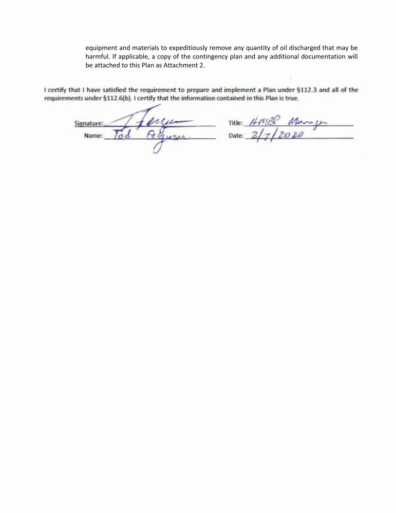
equipment and materials to expeditiously remove any quantity of oil discharged that may be harmful. If applicable, a copy of the contingency plan and any additional documentation will be attached to this Plan as Attachment 2.

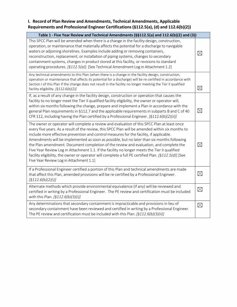
I. Record of Plan Review and Amendments, Technical Amendments, Applicable Requirements and Professional Engineer Certifications (§112.5(a), (d) and 112.6(b)(2))
Table 1 - Five Year Review and Technical Amendments (§§112.5(a) and 112.6(b)(2) and (3))
This SPCC Plan will be amended when there is a change in the facility design, construction, operation, or maintenance that materially affects the potential for a discharge to navigable waters or adjoining shorelines. Examples include adding or removing containers, reconstruction, replacement, or installation of piping systems, changes to secondary containment systems, changes in product stored at this facility, or revisions to standard operating procedures. [§112.5(a)] [See Technical Amendment Log in Attachment 1.2]
Any technical amendments to this Plan (when there is a change in the facility design, construction, operation or maintenance that affects its potential for a discharge) will be re-certified in accordance with Section I of this Plan if the change does not result in the facility no longer meeting the Tier II qualified facility eligibility. [§112.6(b)(2)]
If, as a result of any change in the facility design, construction or operation that causes the facility to no longer meet the Tier II qualified facility eligibility, the owner or operator will, within six months following the change, prepare and implement a Plan in accordance with the general Plan requirements in §112.7 and the applicable requirements in subparts B and C of 40 CFR 112, including having the Plan certified by a Professional Engineer. [§112.6(b)(2)(ii)]
The owner or operator will complete a review and evaluation of this SPCC Plan at least once every five years. As a result of the review, this SPCC Plan will be amended within six months to include more effective prevention and control measures for the facility, if applicable. Amendments will be implemented as soon as possible, but no later than six months following the Plan amendment. Document completion of the review and evaluation, and complete the Five Year Review Log in Attachment 1.1. If the facility no longer meets the Tier II qualified facility eligibility, the owner or operator will complete a full PE certified Plan. [§112.5(d)] [See Five Year Review Log in Attachment 1.1]
If a Professional Engineer certified a portion of this Plan and technical amendments are made that affect this Plan, amended provisions will be re-certified by a Professional Engineer. [§112.6(b)(2)(i)]
Alternate methods which provide environmental equivalence (if any) will be reviewed and certified in writing by a Professional Engineer. The PE review and certification must be included with this Plan. [§112.6(b)(3)(i)]
Any determinations that secondary containment is impracticable and provisions in lieu of secondary containment have been reviewed and certified in writing by a Professional Engineer. The PE review and certification must be included with this Plan. [§112.6(b)(3)(ii)]
II. Plan Requirements
1. Facility Diagram (§112.7(a)(3)):
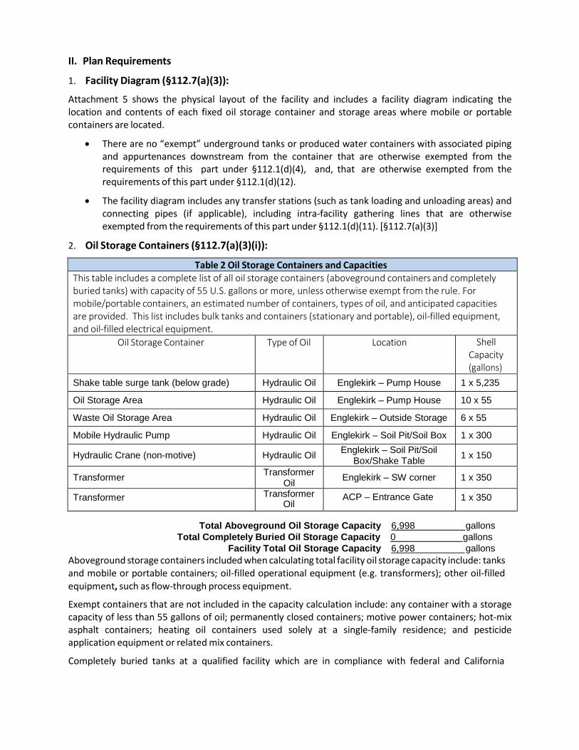
Attachment 5 shows the physical layout of the facility and includes a facility diagram indicating the location and contents of each fixed oil storage container and storage areas where mobile or portable containers are located.
• There are no “exempt” underground tanks or produced water containers with associated piping and appurtenances downstream from the container that are otherwise exempted from the requirements of this part under §112.1(d)(4), and, that are otherwise exempted from the requirements of this part under §112.1(d)(12).
• The facility diagram includes any transfer stations (such as tank loading and unloading areas) and connecting pipes (if applicable), including intra-facility gathering lines that are otherwise exempted from the requirements of this part under §112.1(d)(11). [§112.7(a)(3)]
2. Oil Storage Containers (§112.7(a)(3)(i)):
Table 2 Oil Storage Containers and Capacities This table includes a complete list of all oil storage containers (aboveground containers and completely buried tanks) with capacity of 55 U.S. gallons or more, unless otherwise exempt from the rule. For mobile/portable containers, an estimated number of containers, types of oil, and anticipated capacities are provided. This list includes bulk tanks and containers (stationary and portable), oil-filled equipment, and oil-filled electrical equipment.
Oil Storage Container Type of Oil Location Shell Capacity (gallons)
Shake table surge tank (below grade) Hydraulic Oil Englekirk – Pump House 1 x 5,235
Oil Storage Area Hydraulic Oil Englekirk – Pump House 10 x 55
Waste Oil Storage Area Hydraulic Oil Englekirk – Outside Storage 6 x 55
Mobile Hydraulic Pump Hydraulic Oil Englekirk – Soil Pit/Soil Box 1 x 300
Hydraulic Crane (non-motive) Hydraulic Oil Englekirk – Soil Pit/Soil
Box/Shake Table 1 x 150
Transformer Transformer
Oil Englekirk – SW corner 1 x 350
Transformer Transformer Oil
ACP – Entrance Gate 1 x 350
Total Aboveground Oil Storage Capacity 6,998 gallons
Total Completely Buried Oil Storage Capacity 0 gallons
Facility Total Oil Storage Capacity 6,998 gallons
Aboveground storage containers included when calculating total facility oil storage capacity include: tanks and mobile or portable containers; oil-filled operational equipment (e.g. transformers); other oil-filled equipment, such as flow-through process equipment.
Exempt containers that are not included in the capacity calculation include: any container with a storage capacity of less than 55 gallons of oil; permanently closed containers; motive power containers; hot-mix asphalt containers; heating oil containers used solely at a single-family residence; and pesticide application equipment or related mix containers.
Completely buried tanks at a qualified facility which are in compliance with federal and California
underground storage tank requirements and permitted as USTs under a UPA permit are excluded from the SPCC rule (per 40 CFR 112.1(d)(4) and are not counted toward the qualified facility applicability threshold. However, completely buried USTs must be identified/listed in the SPCC Plan and marked on the facility diagram.
There are no buried or underground storage tanks at this facility - all storage is aboveground.
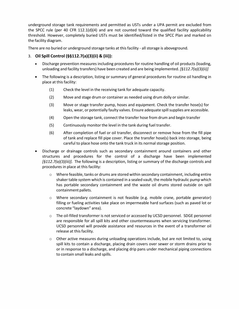
3. Oil Spill Control (§§112.7(a)(3)(ii) & (iii)):
• Discharge prevention measures including procedures for routine handling of oil products (loading, unloading and facility transfers) have been created and are being implemented. [§112.7(a)(3)(ii)]
• The following is a description, listing or summary of general procedures for routine oil handling in place at this facility:
(1) Check the level in the receiving tank for adequate capacity.
(2) Move and stage drum or container as needed using drum dolly or similar.
(3) Move or stage transfer pump, hoses and equipment. Check the transfer hose(s) for leaks, wear, or potentially faulty valves. Ensure adequate spill supplies are accessible.
(4) Open the storage tank, connect the transfer hose from drum and begin transfer
(5) Continuously monitor the level in the tank during fuel transfer.
(6) After completion of fuel or oil transfer, disconnect or remove hose from the fill pipe of tank and replace fill pipe cover. Place the transfer hose(s) back into storage, being careful to place hose onto the tank truck in its normal storage position.
• Discharge or drainage controls such as secondary containment around containers and other structures and procedures for the control of a discharge have been implemented [§112.7(a)(3)(iii)]. The following is a description, listing or summary of the discharge controls and procedures in place at this facility:
o Where feasible, tanks or drums are stored within secondary containment, including entire shaker table system which is contained in a sealed vault, the mobile hydraulic pump which has portable secondary containment and the waste oil drums stored outside on spill containment pallets.
o Where secondary containment is not feasible (e.g. mobile crane, portable generator) filling or fueling activities take place on impermeable hard surfaces (such as paved lot or concrete “laydown” area).
o The oil-filled transformer is not serviced or accessed by UCSD personnel. SDGE personnel are responsible for all spill kits and other countermeasures when servicing transformer. UCSD personnel will provide assistance and resources in the event of a transformer oil release at this facility.
o Other active measures during unloading operations include, but are not limited to, using spill kits to contain a discharge, placing drain covers over sewer or storm drains prior to or in response to a discharge, and placing drip pans under mechanical piping connections to contain small leaks and spills.
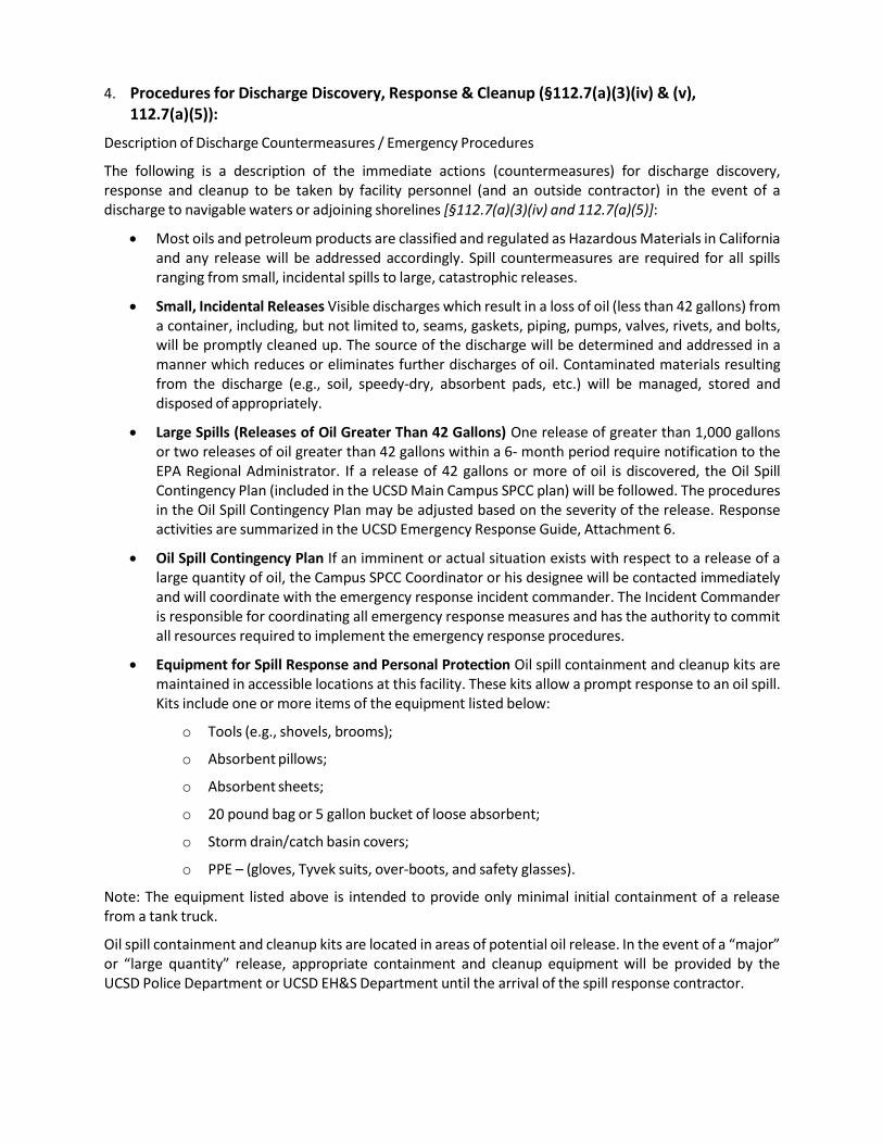
4. Procedures for Discharge Discovery, Response & Cleanup (§112.7(a)(3)(iv) & (v), 112.7(a)(5)):
Description of Discharge Countermeasures / Emergency Procedures
The following is a description of the immediate actions (countermeasures) for discharge discovery, response and cleanup to be taken by facility personnel (and an outside contractor) in the event of a discharge to navigable waters or adjoining shorelines [§112.7(a)(3)(iv) and 112.7(a)(5)]:
• Most oils and petroleum products are classified and regulated as Hazardous Materials in California and any release will be addressed accordingly. Spill countermeasures are required for all spills ranging from small, incidental spills to large, catastrophic releases.
• Small, Incidental Releases Visible discharges which result in a loss of oil (less than 42 gallons) from a container, including, but not limited to, seams, gaskets, piping, pumps, valves, rivets, and bolts, will be promptly cleaned up. The source of the discharge will be determined and addressed in a manner which reduces or eliminates further discharges of oil. Contaminated materials resulting from the discharge (e.g., soil, speedy-dry, absorbent pads, etc.) will be managed, stored and disposed of appropriately.
• Large Spills (Releases of Oil Greater Than 42 Gallons) One release of greater than 1,000 gallons or two releases of oil greater than 42 gallons within a 6- month period require notification to the EPA Regional Administrator. If a release of 42 gallons or more of oil is discovered, the Oil Spill Contingency Plan (included in the UCSD Main Campus SPCC plan) will be followed. The procedures in the Oil Spill Contingency Plan may be adjusted based on the severity of the release. Response activities are summarized in the UCSD Emergency Response Guide, Attachment 6.
• Oil Spill Contingency Plan If an imminent or actual situation exists with respect to a release of a large quantity of oil, the Campus SPCC Coordinator or his designee will be contacted immediately and will coordinate with the emergency response incident commander. The Incident Commander is responsible for coordinating all emergency response measures and has the authority to commit all resources required to implement the emergency response procedures.
• Equipment for Spill Response and Personal Protection Oil spill containment and cleanup kits are maintained in accessible locations at this facility. These kits allow a prompt response to an oil spill. Kits include one or more items of the equipment listed below:
o Tools (e.g., shovels, brooms);
o Absorbent pillows;
o Absorbent sheets;
o 20 pound bag or 5 gallon bucket of loose absorbent;
o Storm drain/catch basin covers;
o PPE – (gloves, Tyvek suits, over-boots, and safety glasses).
Note: The equipment listed above is intended to provide only minimal initial containment of a release from a tank truck.
Oil spill containment and cleanup kits are located in areas of potential oil release. In the event of a “major” or “large quantity” release, appropriate containment and cleanup equipment will be provided by the UCSD Police Department or UCSD EH&S Department until the arrival of the spill response contractor.
• Spill Response Contractor UC San Diego maintains an active contract for emergency response to oil spills. A current list of spill response contractors is provided in Table 3, below.
Disposal of Recovered Materials
The following is a description of the methods of disposal of recovered materials in accordance with applicable legal requirements [§112.7(a)(3)(v)]:
• All materials recovered after a spill or a release will be evaluated for re-use or disposal with respect to applicable hazardous waste regulations.
• Where appropriate, recovered materials may be returned to the process (such as clean hydraulic oil recovered from containment.)
• All hazardous wastes will be contained, stored and disposed of in accordance with UCSD hazardous waste policies and procedures.
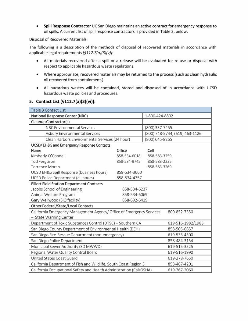
5. Contact List (§112.7(a)(3)(vi)):
Table 3 Contact List
National Response Center (NRC) 1-800-424-8802
Cleanup Contractor(s)
NRC Environmental Services (800) 337-7455
Asbury Environmental Services (800) 748-5744; (619) 463-1126
Clean Harbors Environmental Services (24 hour) (800) 645-8265
UCSD/ EH&S and Emergency Response Contacts Name Office Cell Kimberly O’Connell 858-534-6018 858-583-3259 Tod Ferguson 858-534-9745 858-583-2225 Terrence Moran 858-583-3269 UCSD EH&S Spill Response (business hours) 858-534-3660 UCSD Police Department (all hours) 858-534-4357
Elliott Field Station Department Contacts Jacobs School of Engineering 858-534-6237 Animal Welfare Program 858-534-6069 Gary Wellwood (SIO facility) 858-692-6419
Other Federal/State/Local Contacts
California Emergency Management Agency/ Office of Emergency Services 800-852-7550 – State Warning Center
Department of Toxic Substances Control (DTSC) – Southern CA 619-516-1982/1983
San Diego County Department of Environmental Health (DEH) 858-505-6657
San Diego Fire-Rescue Department (non-emergency) 619-533-4300
San Diego Police Department 858-484-3154
Municipal Sewer Authority (SD MWWD) 619-515-3525
Regional Water Quality Control Board 619-516-1990
United States Coast Guard 619-278-7650
California Department of Fish and Wildlife, South Coast Region 5 858-467-4201
California Occupational Safety and Health Administration (Cal/OSHA) 619-767-2060
USCD Elliott Field Station SPCC
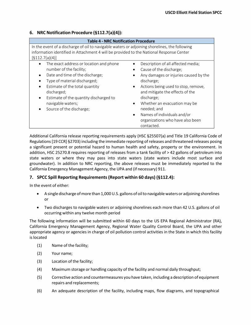
6. NRC Notification Procedure (§112.7(a)(4)):
Table 4 - NRC Notification Procedure In the event of a discharge of oil to navigable waters or adjoining shorelines, the following information identified in Attachment 4 will be provided to the National Response Center [§112.7(a)(4)]
• The exact address or location and phone • Description of all affected media; number of the facility; • Cause of the discharge;
• Date and time of the discharge; • Any damages or injuries caused by the • Type of material discharged; discharge;
• Estimate of the total quantity • Actions being used to stop, remove, discharged; and mitigate the effects of the
• Estimate of the quantity discharged to discharge; navigable waters; • Whether an evacuation may be
• Source of the discharge; needed; and • Names of individuals and/or
organizations who have also been contacted.
Additional California release reporting requirements apply (HSC §25507(a) and Title 19 California Code of Regulations [19 CCR] §2703) including the immediate reporting of releases and threatened releases posing a significant present or potential hazard to human health and safety, property or the environment. In addition, HSC 25270.8 requires reporting of releases from a tank facility of > 42 gallons of petroleum into state waters or where they may pass into state waters (state waters include most surface and groundwater). In addition to NRC reporting, the above releases must be immediately reported to the California Emergency Management Agency, the UPA and (if necessary) 911.
7. SPCC Spill Reporting Requirements (Report within 60 days) (§112.4):
In the event of either:
• A single discharge of more than 1,000 U.S. gallons of oil to navigable waters or adjoining shorelines or
• Two discharges to navigable waters or adjoining shorelines each more than 42 U.S. gallons of oil occurring within any twelve month period
The following information will be submitted within 60 days to the US EPA Regional Administrator (RA), California Emergency Management Agency, Regional Water Quality Control Board, the UPA and other appropriate agency or agencies in charge of oil pollution control activities in the State in which this facility is located
(1) Name of the facility;
(2) Your name;
(3) Location of the facility;
(4) Maximum storage or handling capacity of the facility and normal daily throughput;
(5) Corrective action and countermeasures you have taken, including a description of equipment repairs and replacements;
(6) An adequate description of the facility, including maps, flow diagrams, and topographical
maps, as necessary;
(7) The cause of the reportable discharge, including a failure analysis of the system or subsystem in which the failure occurred; and
(8) Additional preventive measures you have taken or contemplated to minimize the possibility of recurrence
(9) Such other information as the Regional Administrator may reasonably require pertinent to the Plan or discharge
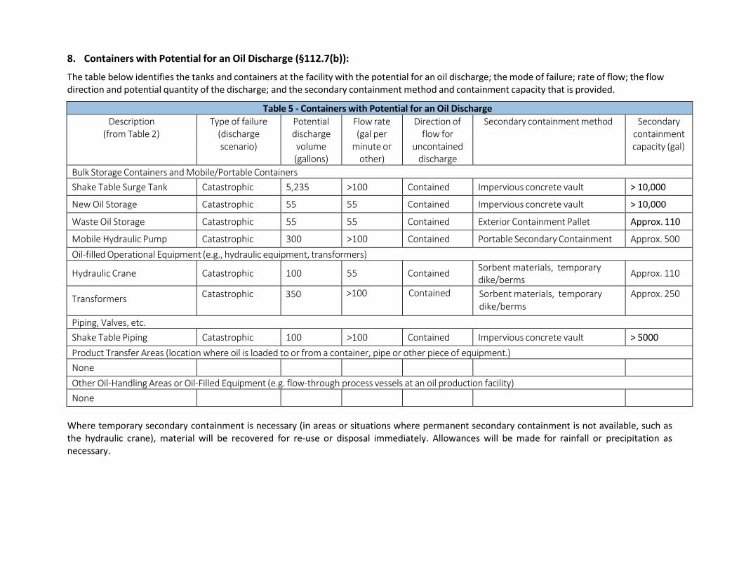
8. Containers with Potential for an Oil Discharge (§112.7(b)):
The table below identifies the tanks and containers at the facility with the potential for an oil discharge; the mode of failure; rate of flow; the flow direction and potential quantity of the discharge; and the secondary containment method and containment capacity that is provided.
Table 5 - Containers with Potential for an Oil Discharge
Description Type of failure Potential Flow rate Direction of Secondary containment method Secondary (from Table 2) (discharge discharge (gal per flow for containment
scenario) volume minute or uncontained capacity (gal) (gallons) other) discharge
Bulk Storage Containers and Mobile/Portable Containers
Shake Table Surge Tank Catastrophic 5,235 >100 Contained Impervious concrete vault > 10,000
New Oil Storage Catastrophic 55 55 Contained Impervious concrete vault > 10,000
Waste Oil Storage Catastrophic 55 55 Contained Exterior Containment Pallet Approx. 110
Mobile Hydraulic Pump Catastrophic 300 >100 Contained Portable Secondary Containment Approx. 500
Oil-filled Operational Equipment (e.g., hydraulic equipment, transformers)
Hydraulic Crane Catastrophic 100 55 Contained Sorbent materials, temporary dike/berms
Approx. 110
Transformers Catastrophic 350 >100 Contained Sorbent materials, temporary dike/berms
Approx. 250
Piping, Valves, etc.
Shake Table Piping Catastrophic 100 >100 Contained Impervious concrete vault > 5000
Product Transfer Areas (location where oil is loaded to or from a container, pipe or other piece of equipment.)
None
Other Oil-Handling Areas or Oil-Filled Equipment (e.g. flow-through process vessels at an oil production facility)
None
Where temporary secondary containment is necessary (in areas or situations where permanent secondary containment is not available, such as the hydraulic crane), material will be recovered for re-use or disposal immediately. Allowances will be made for rainfall or precipitation as necessary.
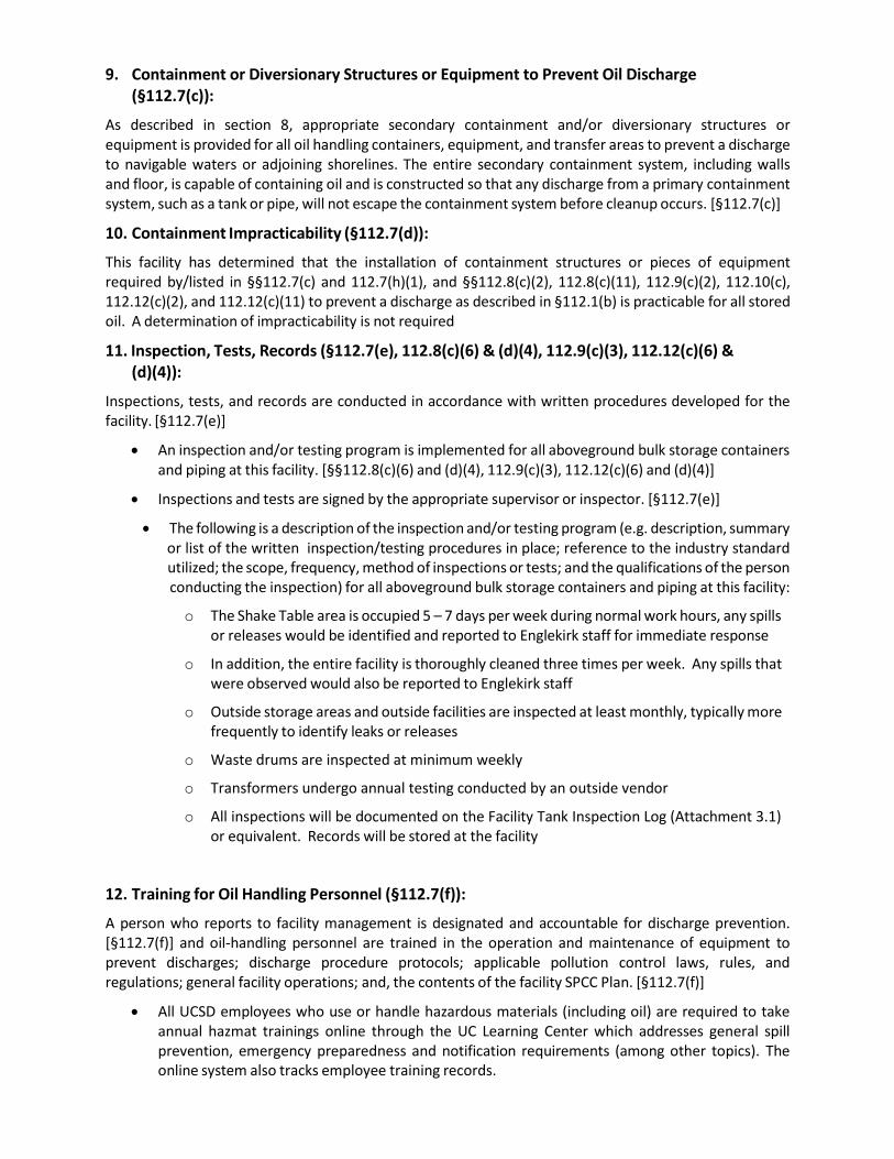
9. Containment or Diversionary Structures or Equipment to Prevent Oil Discharge (§112.7(c)):
As described in section 8, appropriate secondary containment and/or diversionary structures or equipment is provided for all oil handling containers, equipment, and transfer areas to prevent a discharge to navigable waters or adjoining shorelines. The entire secondary containment system, including walls and floor, is capable of containing oil and is constructed so that any discharge from a primary containment system, such as a tank or pipe, will not escape the containment system before cleanup occurs. [§112.7(c)]
10. Containment Impracticability (§112.7(d)):
This facility has determined that the installation of containment structures or pieces of equipment required by/listed in §§112.7(c) and 112.7(h)(1), and §§112.8(c)(2), 112.8(c)(11), 112.9(c)(2), 112.10(c), 112.12(c)(2), and 112.12(c)(11) to prevent a discharge as described in §112.1(b) is practicable for all stored oil. A determination of impracticability is not required
11. Inspection, Tests, Records (§112.7(e), 112.8(c)(6) & (d)(4), 112.9(c)(3), 112.12(c)(6) & (d)(4)):
Inspections, tests, and records are conducted in accordance with written procedures developed for the facility. [§112.7(e)]
• An inspection and/or testing program is implemented for all aboveground bulk storage containers and piping at this facility. [§§112.8(c)(6) and (d)(4), 112.9(c)(3), 112.12(c)(6) and (d)(4)]
• Inspections and tests are signed by the appropriate supervisor or inspector. [§112.7(e)]
• The following is a description of the inspection and/or testing program (e.g. description, summary or list of the written inspection/testing procedures in place; reference to the industry standard utilized; the scope, frequency, method of inspections or tests; and the qualifications of the person conducting the inspection) for all aboveground bulk storage containers and piping at this facility:
o The Shake Table area is occupied 5 – 7 days per week during normal work hours, any spills or releases would be identified and reported to Englekirk staff for immediate response
o In addition, the entire facility is thoroughly cleaned three times per week. Any spills that were observed would also be reported to Englekirk staff
o Outside storage areas and outside facilities are inspected at least monthly, typically more frequently to identify leaks or releases
o Waste drums are inspected at minimum weekly
o Transformers undergo annual testing conducted by an outside vendor
o All inspections will be documented on the Facility Tank Inspection Log (Attachment 3.1) or equivalent. Records will be stored at the facility
12. Training for Oil Handling Personnel (§112.7(f)):
A person who reports to facility management is designated and accountable for discharge prevention. [§112.7(f)] and oil-handling personnel are trained in the operation and maintenance of equipment to prevent discharges; discharge procedure protocols; applicable pollution control laws, rules, and regulations; general facility operations; and, the contents of the facility SPCC Plan. [§112.7(f)]
• All UCSD employees who use or handle hazardous materials (including oil) are required to take annual hazmat trainings online through the UC Learning Center which addresses general spill prevention, emergency preparedness and notification requirements (among other topics). The online system also tracks employee training records.
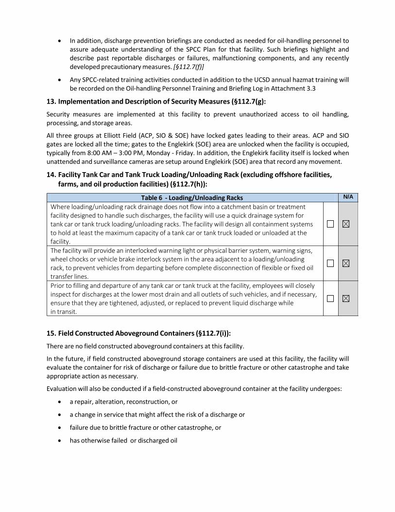
• In addition, discharge prevention briefings are conducted as needed for oil-handling personnel to assure adequate understanding of the SPCC Plan for that facility. Such briefings highlight and describe past reportable discharges or failures, malfunctioning components, and any recently developed precautionary measures. [§112.7(f)]
• Any SPCC-related training activities conducted in addition to the UCSD annual hazmat training will be recorded on the Oil-handling Personnel Training and Briefing Log in Attachment 3.3
13. Implementation and Description of Security Measures (§112.7(g):
Security measures are implemented at this facility to prevent unauthorized access to oil handling, processing, and storage areas.
All three groups at Elliott Field (ACP, SIO & SOE) have locked gates leading to their areas. ACP and SIO gates are locked all the time; gates to the Englekirk (SOE) area are unlocked when the facility is occupied, typically from 8:00 AM – 3:00 PM, Monday - Friday. In addition, the Englekirk facility itself is locked when unattended and surveillance cameras are setup around Englekirk (SOE) area that record any movement.
14. Facility Tank Car and Tank Truck Loading/Unloading Rack (excluding offshore facilities, farms, and oil production facilities) (§112.7(h)):
15. Field Constructed Aboveground Containers (§112.7(i)):
There are no field constructed aboveground containers at this facility.
In the future, if field constructed aboveground storage containers are used at this facility, the facility will evaluate the container for risk of discharge or failure due to brittle fracture or other catastrophe and take appropriate action as necessary.
Evaluation will also be conducted if a field-constructed aboveground container at the facility undergoes:
• a repair, alteration, reconstruction, or
• a change in service that might affect the risk of a discharge or
• failure due to brittle fracture or other catastrophe, or
• has otherwise failed or discharged oil
Table 6 - Loading/Unloading Racks N/A
Where loading/unloading rack drainage does not flow into a catchment basin or treatment facility designed to handle such discharges, the facility will use a quick drainage system for tank car or tank truck loading/unloading racks. The facility will design all containment systems to hold at least the maximum capacity of a tank car or tank truck loaded or unloaded at the facility.
The facility will provide an interlocked warning light or physical barrier system, warning signs, wheel chocks or vehicle brake interlock system in the area adjacent to a loading/unloading rack, to prevent vehicles from departing before complete disconnection of flexible or fixed oil transfer lines.
Prior to filling and departure of any tank car or tank truck at the facility, employees will closely inspect for discharges at the lower most drain and all outlets of such vehicles, and if necessary, ensure that they are tightened, adjusted, or replaced to prevent liquid discharge while in transit.
and appropriate action will be taken as necessary.
16. Conformance with Other Applicable Requirements (§112.7(j)):
In addition to the minimal prevention standards listed under this section, the following is a complete discussion of conformance with any applicable more stringent State rules, regulations, and guidelines. [§112.7(i)]:
• There are no additional applicable state rules, regulations or guidelines related to oil spill prevention that apply to this facility
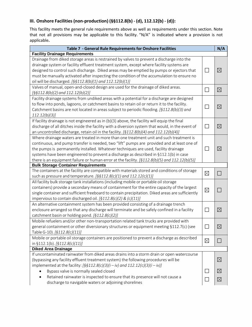
III. Onshore Facilities (non-production) (§§112.8(b) - (d), 112.12(b) - (d)):
This facility meets the general rule requirements above as well as requirements under this section. Note that not all provisions may be applicable to this facility. “N/A” is indicated where a provision is not applicable.
Table 7 - General Rule Requirements for Onshore Facilities N/A Facility Drainage Requirements
Drainage from diked storage areas is restrained by valves to prevent a discharge into the drainage system or facility effluent treatment system, except where facility systems are designed to control such discharge. Diked areas may be emptied by pumps or ejectors that must be manually activated after inspecting the condition of the accumulation to ensure no oil will be discharged. [§§112.8(b)(1) and 112.12(b)(1)]
Valves of manual, open-and-closed design are used for the drainage of diked areas. [§§112.8(b)(2) and 112.12(b)(2)]
Facility drainage systems from undiked areas with a potential for a discharge are designed to flow into ponds, lagoons, or catchment basins to retain oil or return it to the facility. Catchment basins are not located in areas subject to periodic flooding. [§112.8(b)(3) and 112.12(b)(3)]
If facility drainage is not engineered as in (b)(3) above, the facility will equip the final discharge of all ditches inside the facility with a diversion system that would, in the event of an uncontrolled discharge, retain oil in the facility. [§112.8(b)(4) and 112.12(b)(4)]
Where drainage waters are treated in more than one treatment unit and such treatment is continuous, and pump transfer is needed, two “lift” pumps are provided and at least one of the pumps is permanently installed. Whatever techniques are used, facility drainage systems have been engineered to prevent a discharge as described in §112.1(b) in case there is an equipment failure or human error at the facility. [§112.8(b)(5) and 112.12(b)(5)] Bulk Storage Container Requirements
The containers at the facility are compatible with materials stored and conditions of storage such as pressure and temperature. [§§112.8(c)(1) and 112.12(c)(1)]
All facility bulk storage tank installations (including mobile or portable oil storage containers) provide a secondary means of containment for the entire capacity of the largest single container and sufficient freeboard to contain precipitation. Diked areas are sufficiently impervious to contain discharged oil. [§112.8(c)(2) & (c)(11)]
An alternative containment system has been provided consisting of a drainage trench enclosure arranged so that any discharge will terminate and be safely confined in a facility catchment basin or holding pond. [§112.8(c)(2)]
Mobile refuelers and/or other non-transportation related tank trucks are provided with general containment or other diversionary structures or equipment meeting §112.7(c) (see Table G-10). [§112.8(c)(11)]
Mobile or portable oil storage containers are positioned to prevent a discharge as described in §112.1(b). [§112.8(c)(11)] Diked Area Drainage
If uncontaminated rainwater from diked areas drains into a storm drain or open watercourse (bypassing any facility effluent treatment system) the following procedures will be implemented at the facility: [§§112.8(c)(3)(i – iv) and 112.12(c)(3)(i – iv)]
• Bypass valve is normally sealed closed
• Retained rainwater is inspected to ensure that its presence will not cause a discharge to navigable waters or adjoining shorelines
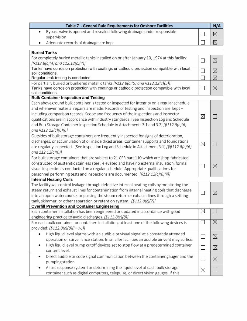
Buried Tanks
For completely buried metallic tanks installed on or after January 10, 1974 at this facility: [§112.8(c)(4) and 112.12(c)(4)] Tanks have corrosion protection with coatings or cathodic protection compatible with local soil conditions. Regular leak testing is conducted.
For partially buried or bunkered metallic tanks [§112.8(c)(5) and §112.12(c)(5)]: Tanks have corrosion protection with coatings or cathodic protection compatible with local soil conditions.
Bulk Container Inspection and Testing
Each aboveground bulk container is tested or inspected for integrity on a regular schedule and whenever material repairs are made. Records of testing and inspection are kept – including comparison records. Scope and frequency of the inspections and inspector qualifications are in accordance with industry standards. [See Inspection Log and Schedule and Bulk Storage Container Inspection Schedule in Attachments 3.1 and 3.2] [§112.8(c)(6) and §112.12(c)(6)(i)]
Outsides of bulk storage containers are frequently inspected for signs of deterioration, discharges, or accumulation of oil inside diked areas. Container supports and foundations are regularly inspected. [See Inspection Log and Schedule in Attachment 3.1] [§§112.8(c)(6) and 112.12(c)(6)]
For bulk storage containers that are subject to 21 CFR part 110 which are shop-fabricated, constructed of austenitic stainless steel, elevated and have no external insulation, formal visual inspection is conducted on a regular schedule. Appropriate qualifications for personnel performing tests and inspections are documented. [§112.12(c)(6)(ii)] Internal Heating Coils
The facility will control leakage through defective internal heating coils by monitoring the steam return and exhaust lines for contamination from internal heating coils that discharge into an open watercourse, or passing the steam return or exhaust lines through a settling tank, skimmer, or other separation or retention system. [§112.8(c)(7)] Overfill Prevention and Container Engineering
Each container installation has been engineered or updated in accordance with good engineering practice to avoid discharges. [§112.8(c)(8)]
For each bulk container or container installation, at least one of the following devices is provided: [§112.8(c)(8)(i – iv))]
• High liquid level alarms with an audible or visual signal at a constantly attended operation or surveillance station. In smaller facilities an audible air vent may suffice.
• High liquid level pump cutoff devices set to stop flow at a predetermined container content level.
• Direct audible or code signal communication between the container gauger and the pumping station.
• A fast response system for determining the liquid level of each bulk storage container such as digital computers, telepulse, or direct vision gauges. If this
Table 7 - General Rule Requirements for Onshore Facilities N/A
• Bypass valve is opened and resealed following drainage under responsible supervision
• Adequate records of drainage are kept
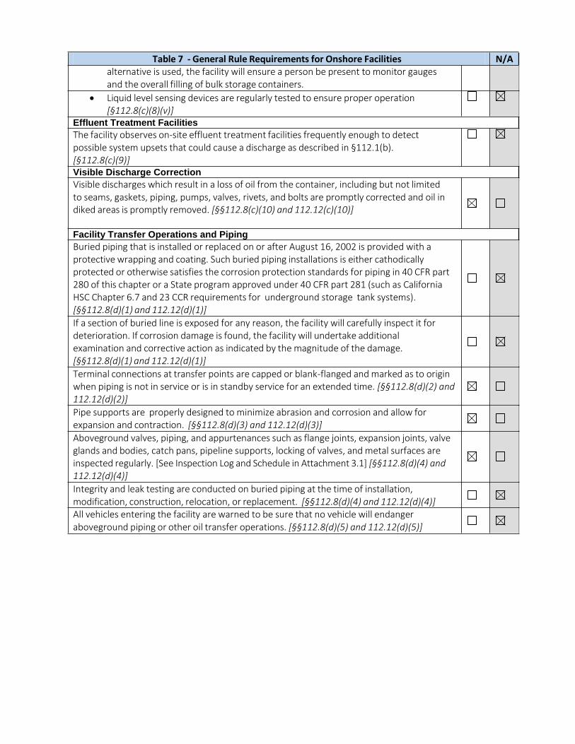
Table 7 - General Rule Requirements for Onshore Facilities N/A alternative is used, the facility will ensure a person be present to monitor gauges and the overall filling of bulk storage containers.
• Liquid level sensing devices are regularly tested to ensure proper operation [§112.8(c)(8)(v)]
Effluent Treatment Facilities
The facility observes on-site effluent treatment facilities frequently enough to detect possible system upsets that could cause a discharge as described in §112.1(b). [§112.8(c)(9)] Visible Discharge Correction
Visible discharges which result in a loss of oil from the container, including but not limited to seams, gaskets, piping, pumps, valves, rivets, and bolts are promptly corrected and oil in diked areas is promptly removed. [§§112.8(c)(10) and 112.12(c)(10)]
Facility Transfer Operations and Piping
Buried piping that is installed or replaced on or after August 16, 2002 is provided with a protective wrapping and coating. Such buried piping installations is either cathodically protected or otherwise satisfies the corrosion protection standards for piping in 40 CFR part 280 of this chapter or a State program approved under 40 CFR part 281 (such as California HSC Chapter 6.7 and 23 CCR requirements for underground storage tank systems). [§§112.8(d)(1) and 112.12(d)(1)]
If a section of buried line is exposed for any reason, the facility will carefully inspect it for deterioration. If corrosion damage is found, the facility will undertake additional examination and corrective action as indicated by the magnitude of the damage. [§§112.8(d)(1) and 112.12(d)(1)]
Terminal connections at transfer points are capped or blank-flanged and marked as to origin when piping is not in service or is in standby service for an extended time. [§§112.8(d)(2) and 112.12(d)(2)]
Pipe supports are properly designed to minimize abrasion and corrosion and allow for expansion and contraction. [§§112.8(d)(3) and 112.12(d)(3)]
Aboveground valves, piping, and appurtenances such as flange joints, expansion joints, valve glands and bodies, catch pans, pipeline supports, locking of valves, and metal surfaces are inspected regularly. [See Inspection Log and Schedule in Attachment 3.1] [§§112.8(d)(4) and 112.12(d)(4)]
Integrity and leak testing are conducted on buried piping at the time of installation, modification, construction, relocation, or replacement. [§§112.8(d)(4) and 112.12(d)(4)] All vehicles entering the facility are warned to be sure that no vehicle will endanger aboveground piping or other oil transfer operations. [§§112.8(d)(5) and 112.12(d)(5)]
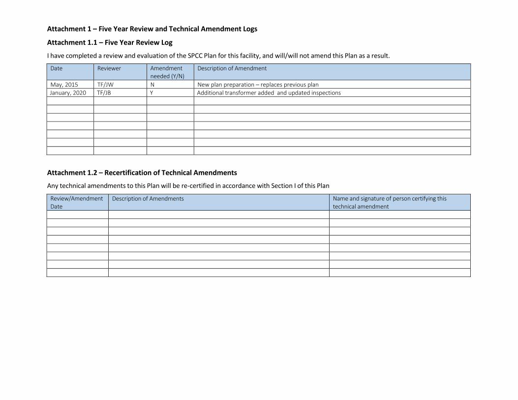
Attachment 1 – Five Year Review and Technical Amendment Logs
Attachment 1.1 – Five Year Review Log
I have completed a review and evaluation of the SPCC Plan for this facility, and will/will not amend this Plan as a result.
Date Reviewer Amendment needed (Y/N)
Description of Amendment
May, 2015 TF/JW N New plan preparation – replaces previous plan
January, 2020 TF/JB Y Additional transformer added and updated inspections
Attachment 1.2 – Recertification of Technical Amendments
Any technical amendments to this Plan will be re-certified in accordance with Section I of this Plan
Review/Amendment Date
Description of Amendments Name and signature of person certifying this technical amendment
Attachment 2 – Oil Spill Contingency Plan
An oil spill contingency plan meeting the requirements of 40 CFR part 109 and a written commitment of resources is required for:
• Any bulk container, tank or area where secondary containment has been determined to be impracticable (40 CFR part 112.7(d)
• Qualified oil-filled operational equipment which has no secondary containment (40 CFR part 112.7(k)
• Flowlines and intra-facility gathering lines at oil production facilities
These criteria do not apply to this facility (secondary containment (either permanent or temporary) is available for all stored oil).
As needed, this facility would be included in general oil spill and hazardous materials release response measures for the UCSD main campus.
If a release of 42 gallons or more of oil is discovered, the UCSD Main Campus Oil Spill Contingency Plan would be followed. The procedures in that Oil Spill Contingency Plan may be adjusted based on the severity of the release.
If an imminent or actual situation exists with respect to a release of a large quantity of oil, the UCSD Campus SPCC Coordinator or his designee will be contacted immediately and will coordinate with the emergency response incident commander. The Incident Commander is responsible for coordinating all emergency response measures and has the authority to commit all resources required to implement the emergency response procedures.
The UCSD Main Campus contingency plan is consistent with all applicable state and local plans, Area Contingency Plans, and the National Contingency Plan (NCP). The UCSD Emergency Response Guide (Attachment 6) summarizes response actions.
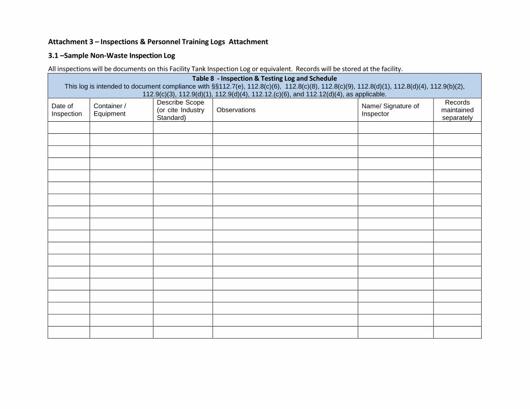
Attachment 3 – Inspections & Personnel Training Logs Attachment
3.1 –Sample Non-Waste Inspection Log
All inspections will be documents on this Facility Tank Inspection Log or equivalent. Records will be stored at the facility.
Table 8 - Inspection & Testing Log and Schedule This log is intended to document compliance with §§112.7(e), 112.8(c)(6), 112.8(c)(8), 112.8(c)(9), 112.8(d)(1), 112.8(d)(4), 112.9(b)(2),
112.9(c)(3), 112.9(d)(1), 112.9(d)(4), 112.12.(c)(6), and 112.12(d)(4), as applicable.
Date of Inspection
Container / Equipment
Describe Scope (or cite Industry Standard)
Observations Name/ Signature of Inspector
Records maintained separately
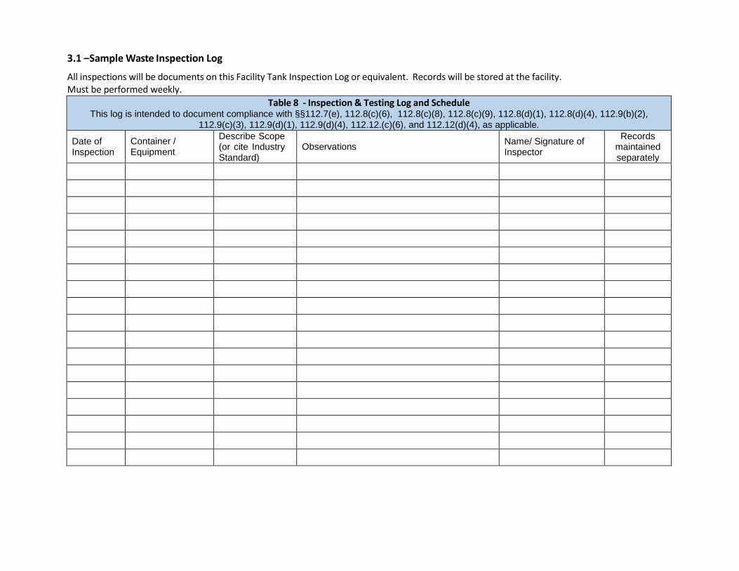
3.1 –Sample Waste Inspection Log
All inspections will be documents on this Facility Tank Inspection Log or equivalent. Records will be stored at the facility. Must be performed weekly.
Table 8 - Inspection & Testing Log and Schedule This log is intended to document compliance with §§112.7(e), 112.8(c)(6), 112.8(c)(8), 112.8(c)(9), 112.8(d)(1), 112.8(d)(4), 112.9(b)(2),
112.9(c)(3), 112.9(d)(1), 112.9(d)(4), 112.12.(c)(6), and 112.12(d)(4), as applicable.
Date of Inspection
Container / Equipment
Describe Scope (or cite Industry Standard)
Observations Name/ Signature of Inspector
Records maintained separately
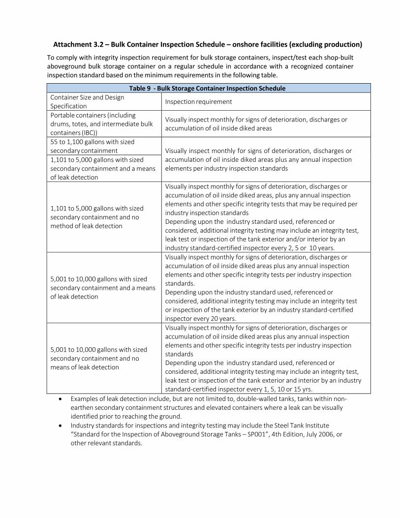
Attachment 3.2 – Bulk Container Inspection Schedule – onshore facilities (excluding production)
To comply with integrity inspection requirement for bulk storage containers, inspect/test each shop-built aboveground bulk storage container on a regular schedule in accordance with a recognized container inspection standard based on the minimum requirements in the following table.
Table 9 - Bulk Storage Container Inspection Schedule Container Size and Design Specification
Inspection requirement
Portable containers (including drums, totes, and intermediate bulk containers (IBC))
Visually inspect monthly for signs of deterioration, discharges or accumulation of oil inside diked areas
55 to 1,100 gallons with sized secondary containment
Visually inspect monthly for signs of deterioration, discharges or accumulation of oil inside diked areas plus any annual inspection elements per industry inspection standards
1,101 to 5,000 gallons with sized secondary containment and a means of leak detection
1,101 to 5,000 gallons with sized secondary containment and no method of leak detection
Visually inspect monthly for signs of deterioration, discharges or accumulation of oil inside diked areas, plus any annual inspection elements and other specific integrity tests that may be required per industry inspection standards Depending upon the industry standard used, referenced or considered, additional integrity testing may include an integrity test, leak test or inspection of the tank exterior and/or interior by an industry standard-certified inspector every 2, 5 or 10 years.
5,001 to 10,000 gallons with sized secondary containment and a means of leak detection
Visually inspect monthly for signs of deterioration, discharges or accumulation of oil inside diked areas plus any annual inspection elements and other specific integrity tests per industry inspection standards. Depending upon the industry standard used, referenced or considered, additional integrity testing may include an integrity test or inspection of the tank exterior by an industry standard-certified inspector every 20 years.
5,001 to 10,000 gallons with sized secondary containment and no means of leak detection
Visually inspect monthly for signs of deterioration, discharges or accumulation of oil inside diked areas plus any annual inspection elements and other specific integrity tests per industry inspection standards Depending upon the industry standard used, referenced or considered, additional integrity testing may include an integrity test, leak test or inspection of the tank exterior and interior by an industry standard-certified inspector every 1, 5, 10 or 15 yrs.
• Examples of leak detection include, but are not limited to, double-walled tanks, tanks within non- earthen secondary containment structures and elevated containers where a leak can be visually identified prior to reaching the ground.
• Industry standards for inspections and integrity testing may include the Steel Tank Institute “Standard for the Inspection of Aboveground Storage Tanks – SP001”, 4th Edition, July 2006, or other relevant standards.
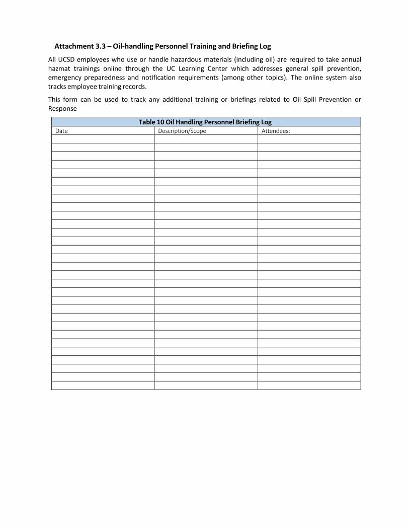
Attachment 3.3 – Oil-handling Personnel Training and Briefing Log
All UCSD employees who use or handle hazardous materials (including oil) are required to take annual hazmat trainings online through the UC Learning Center which addresses general spill prevention, emergency preparedness and notification requirements (among other topics). The online system also tracks employee training records.
This form can be used to track any additional training or briefings related to Oil Spill Prevention or Response
Table 10 Oil Handling Personnel Briefing Log Date Description/Scope Attendees:
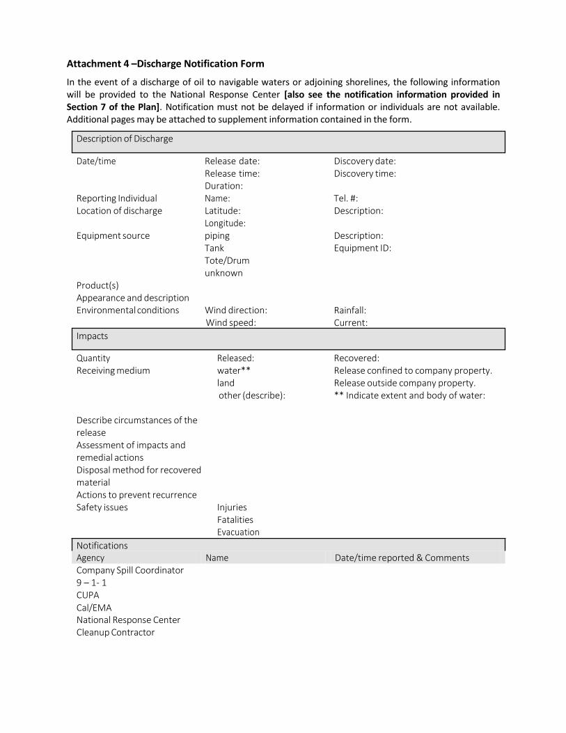
Attachment 4 –Discharge Notification Form
In the event of a discharge of oil to navigable waters or adjoining shorelines, the following information will be provided to the National Response Center [also see the notification information provided in Section 7 of the Plan]. Notification must not be delayed if information or individuals are not available. Additional pages may be attached to supplement information contained in the form.
Date/time Release date:
Release time: Duration:
Discovery date: Discovery time:
Reporting Individual Name: Tel. #: Location of discharge Latitude:
Longitude: Equipment source piping
Tank Tote/Drum unknown
Description:
Description: Equipment ID:
Product(s) Appearance and description Environmental conditions Wind direction:
Wind speed:
Rainfall: Current:
Quantity Released: Recovered: Receiving medium water**
land other (describe):
Release confined to company property. Release outside company property. ** Indicate extent and body of water:
Describe circumstances of the release Assessment of impacts and remedial actions Disposal method for recovered material Actions to prevent recurrence Safety issues Injuries
Fatalities Evacuation
Notifications Agency Name Date/time reported & Comments Company Spill Coordinator 9 – 1- 1 CUPA Cal/EMA National Response Center Cleanup Contractor
Impacts
Description of Discharge
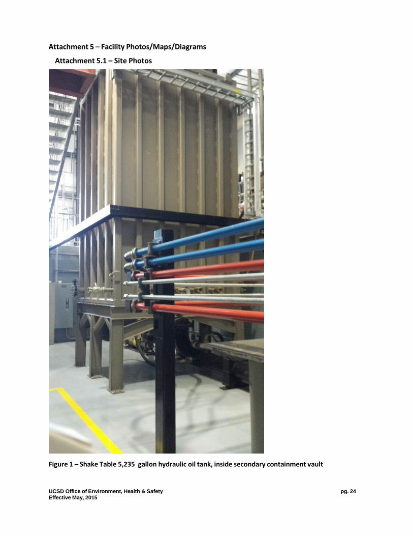
Attachment 5 – Facility Photos/Maps/Diagrams
Attachment 5.1 – Site Photos
Figure 1 – Shake Table 5,235 gallon hydraulic oil tank, inside secondary containment vault
UCSD Office of Environment, Health & Safety pg. 24 Effective May, 2015
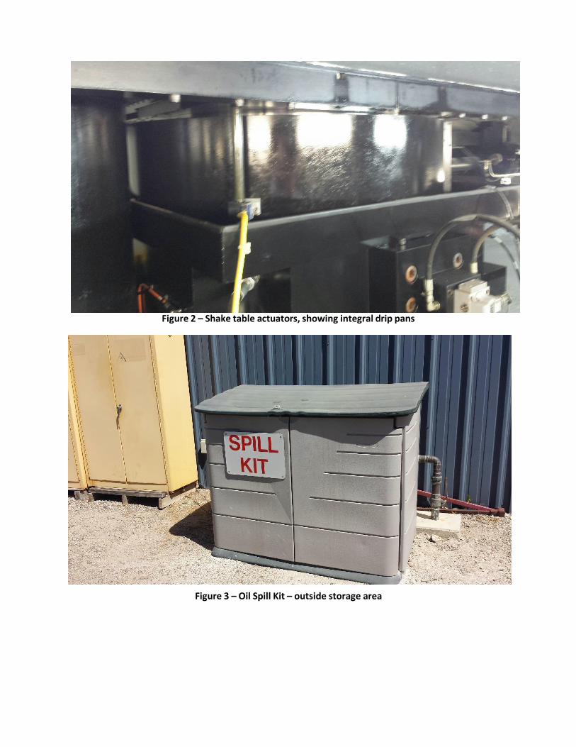
Figure 2 – Shake table actuators, showing integral drip pans
Figure 3 – Oil Spill Kit – outside storage area
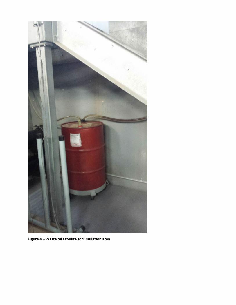
Figure 4 – Waste oil satellite accumulation area
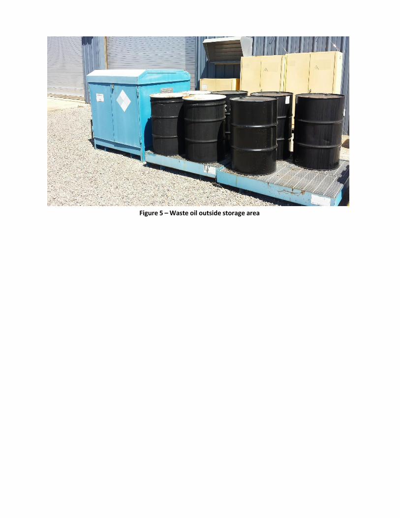
Figure 5 – Waste oil outside storage area

Attachment 5.2 – Elliott Field Station Area Map

Attachment 5.3 – Elliott Field Station, Englekirk Structural Engineering Labs

Attachment 5.4 – Elliott Field Station, Shake Table Basement

Attachment 6 – UCSD Emergency Response Guide