Embed Size (px)
Citation preview

arX
iv:p
hysi
cs/0
4080
92v1
[ph
ysic
s.fl
u-dy
n] 2
0 A
ug 2
004
Spontaneous pinch-off in rotating Hele-Shaw flows
R. Folch,1 E. Alvarez-Lacalle,2 J. Ortın,2 and J. Casademunt2
1Universiteit Leiden, Postbus 9506, 2300 RA Leiden, The Netherlands2Departament ECM, Universitat de Barcelona, Av. Diagonal 647, E-08028, Barcelona, Spain
The dynamics of the interface between two immiscible fluids in a rotating Hele-Shaw cell are stud-ied experimentally, theoretically and by phase-field simulations of the H-S equations using standardboundary conditions. As the central, denser fluid is centrifuged, it forms fingering patterns withlong, thin radial filaments ended by a droplet, alternating with incoming fingers of the outer, lessdense fluid. Simulations show the length (width) of the filaments to grow (decay) roughly exponen-tially, and the incoming finger tips to asymptotically approach a finite radius for n-fold symmetricinitial conditions; these thus tend to a stationary-shape “star-fish”, whose form is calculated. Thefilament width decays with a time constant which depends only on the viscosity contrast, whereasits length exhibits a completely universal growth rate; the latter is related to the run away of anisolated droplet, for which we give an exact solution. The exponential behavior is clear for highviscosity contrasts A, but important deviations are found for low A. Both experiments and simula-tions show systematic pinch-off of the droplets at the tips of the filaments for low and not for highA. A lubrication approximation is derived and successfully accounts for the filament thinning andthe differences with A; in particular, it explains why pure exponential thinning is not observed forlow A, and it could clarify the presence or absence of finite-time pinch-off itself, since the agree-ment of experiments and simulations suggests that this phenomenon is contained in the Hele-Shawequations. This agreement includes both high- and low-A morphologies, and the growth rate ofthe filament length for high A; for low A, the experimental time constant appears to be differentfrom that predicted by standard Hele-Shaw boundary conditions and observed in simulations. Aneffective slip condition for the Poiseuille flow of inner liquid across the cell gap in the case of twoliquids gives a possible explanation of this discrepancy.
PACS numbers: 47.55.Dz, 47.20.Ma, 47.11.+j, 68.03.Cd
I. INTRODUCTION
Topological singularities such as interface pinch-off influid flows have been the object of intense study in thelast decades [1, 2, 3, 4, 5, 6, 7, 8, 9, 10, 11, 12, 13, 14]. Thepinch-off of a droplet from a volume of fluid embedded inanother one is easy to observe in everyday life, and hasfascinated both physicists and applied mathematicians.Because the interface between the two fluids shrinks toarbitrarily small scales at the point of detachment, a con-tinuum, coarse-grained description must break down atsome stage. The failure of the macroscopic description isreflected in the spontaneous generation of singular behav-ior. In the neighborhood of such singularities, the prob-lem might become scale-free, giving rise to self-similarscaling behavior, for which some degree of universalityis naturally expected [1]. Interestingly, hydrodynamicsalone have been found sufficient to account for the oc-currence of finite-time pinch-off in several cases. It isremarkable that the continuum, hydrodynamic descrip-tion may correctly predict the occurrence of finite-timesingularities out of a smooth initial condition, and prop-erly describe them all the way to the very microscopicscales where atomic-scale forces take over. These forcesthen implement the interface breakup and reconnection.This is the case, for instance, of three-dimensional jets[2]. The pursuit of this idea in the specific context ofrotating Hele-Shaw flows is the basic motivation of thepresent study.
Recently, macroscopic hydrodynamic equations have
also been used as a basic ingredient in the dynamics ofnanojets [3, 4], or in very thin membranes, where theeffects of Van der Waals forces must be taken into account[5, 6]. These are examples of nonlinear processes wherethe macroscopic dynamics coupled with molecular forcesor thermal noise lead to pinch-off phenomena.
In the narrow gap between the two parallel glass platesof a Hele-Shaw cell, the scale where the effective two-dimensional “macroscopic” description fails is basicallythe thickness of the cell gap [7]. Although this cutoffis much larger (typically, of the order of the millime-ter) than the microscopic cutoff of the hydrodynamic de-scription of 3d jets, it still makes sense to investigate towhat extent the 2d effective dynamics in a Hele-Shaw cell(playing the role of the “macroscopic” dynamics) lead tothe spontaneous occurrence of finite-time singularities.The interface recombination will certainly introduce newphysics (not contained in the ordinary Hele-Shaw equa-tions) which could easily depend on details that may notbe universal, such as wetting conditions, 3d structure ofthe meniscus, contact line motion, etc.; the precise timeof the pinch-off may also depend on these details. How-ever, the underlying idea is that the effective cutoff andthe details of the actual 3d pinch-off can in principle bearbitrarily reduced, for instance changing the cell gap.So, ultimately, the relevant question is what the pre-diction of the effective 2d (Hele-Shaw) dynamics is: Ifthe 2d dynamics lead themselves to finite-time pinch-off,this would certainly assure the existence of finite-timepinch-off in the real experiments, and would also define

2
an upper bound for the actual experimental pinch-off. If,on the contrary, no finite-time pinch-off is obtained forthe Hele-Shaw dynamics, it will be relevant to study theevolution of a thin neck as predicted by the effective 2ddynamics, in order to elucidate, in each particular case,whether actual pinch-off would be expected invoking theadditional 3d effects. In this context, the simulationsperformed within a phase-field scheme are particularlyappropriate, because they incorporate a natural cutoff(the interface thickness) which controls the actual pinch-off and which, like the cell gap in Hele-Shaw flows, canbe modified at will to postpone the pinch-off of a narrowfluid filament.
It is well known that the effective two-dimensionalHele-Shaw dynamics can lead per se to pinch-off. In fact,it was for this type of dynamics that finite-time pinch-off singularities in a hydrodynamic description were firstfound [8, 9]. As opposed to the 3d case of a cylin-drical interface, a 2d fluid filament (two parallel inter-faces) is stable to the Rayleigh criterion: The total in-terface length (at constant area) is larger for any per-turbation around straight interfaces. However, surfacetension alone has been shown to drive a configuration oftwo droplets of fluid connected by a neck to finite-timepinch-off in two-dimensional simulations, for certain ini-tial conditions [10, 11]. A straight filament of fluid canalso be made to pinch at infinite time (and sometimesalso at finite time), with very specific boundary condi-tions [8, 9, 12, 13, 14]. However, two-dimensional pinch-off in unprepared situations emerging spontaneously inexternally driven dynamics, such as in traditional vis-cous fingering experiments, has not been addressed. Oneof our main goals is to account for the spontaneous ap-proach to pinch-off singularities often observed while ahighly nonlinear pattern develops following a morpho-logical instability, in particular for rotating Hele-Shawflows. Pattern formation and pinch-off singularities canindeed be intimately related, as it will become apparentin the case studied here.
Another issue that it is worth addressing is the roleof the viscosity contrast or Atwood ratio A ≡ (µin −µout)/(µin +µout) (where µin and µout are the viscositiesof the inner and outer fluids respectively) in the pinch-off process. It is known that this parameter has a stronginfluence on the interface shape near pinching in threedimensions [6], but only recently has it been remarkedthat the most studied limit A → 1 might be a very spe-cial case also in three dimensions [15]. In effectively twodimensions, experiments performed in this limit, with airdisplacing a liquid in a channel geometry, show that thefingers formed due to the morphological instability com-pete until a single finger is left [16]; the neck of the tran-sient and final finger(s) does not even pinch. In con-trast, when a denser liquid is put on top of a less denseone of similar viscosity (typically A ∼0–0.5) in the samebut tilted channel, fingers do not compete, but elongateto form thin filaments with a droplet at their tip [17],which can indeed pinch off [18]. One possible scenario
to explain this different tendency to pinch-off might con-sist in relating the absence of competition for low A withthe formation of long filaments, which could then pinchby mechanisms not qualitatively different from those ofprevious studies [8, 9, 10, 11, 12, 13, 14].
We have performed experiments in a rotating Hele-Shaw cell, where a drop of the more dense fluid is placedat the center and the instability is driven by the cen-trifugal force. The idea is to favor the formation of long(radial) filaments by the use of a driving force which in-creases as the fingers become longer. The natural ques-tion to pose is then whether these long filaments will alsopinch for high viscosity contrasts.
Long fingers are indeed formed and they stretch andnarrow for any viscosity contrast A. However, forhigh values of A we only observe pinch-off sporadically,whereas we find it systematically for low ones. This rulesout the above scenario. It rather suggests that the pre-cise nonlinear dynamics close to pinch-off, and not onlythe overall morphology, is also dependent on the viscositycontrast A. This dependence could either be contained inthe (2d) Hele-Shaw dynamics or, instead, enter throughdifferent wetting properties for air-oil (high A) and oil-oil (low A) interfaces when the width of the filamentsbecomes comparable to the cell gap in our experiments.
We have run phase-field simulations of the two-dimensional dynamics which lead to pinch-off singular-ities for low, but not high viscosity contrast. Althoughwe can only track the first stages of the approach, the ma-jor dependence of the pinching dynamics on the viscositycontrast thus seems to be contained in the Hele-Shawequations. In particular, our simulations indicate thatfinite-time pinch-off could be contained (at least) in low-A Hele-Shaw dynamics for more general settings thanthose originally studied in Refs. [8, 9, 10, 11, 12, 13, 14].Therefore, it is plausible that the effect of the cutoff (here,the cell gap), although entering the problem earlier thanin usual three-dimensional cases, can still be regardedas an implementation of pinch-off and reconnection, notnecessarily affecting significantly the approach to pinch-off, which is governed by the Hele-Shaw dynamics.
The rest of the paper is organized as follows: In Sec. IIwe present the experimental results, with an indication ofscaling behavior. This is then explained in the followingsection by simple theoretical arguments valid asymptot-ically. In Sec. IV we test this basic picture by numericalsimulations of the Hele-Shaw equations. These confirmtheory and experiments to agree for high viscosity con-trasts, whereas puzzles remain for low ones. One of thesecan be solved by rethinking the experimental time scaleas done in Sec. V, while another requires a refinementof the theory which is performed in Sec. VI. The resultsare summarized and further discussed in Sec. VII.

3
II. EXPERIMENTAL RESULTS
We have performed two sets of experiments in a rotat-ing Hele-Shaw cell: one for high and one for low viscositycontrast. These two types of experiments were alreadyperformed for other purposes in [19] and [20]; we repeatthem here to address the scaling behaviors and the pres-ence of pinch-off as functions of viscosity contrast. Ourcell consists of two horizontal glass plates, 7 or 10 mmthick and 390 mm in diameter, separated by differentspacers of height b = 0.5, 0.7, 0.8, 1.0, 1.4 mm. The cellis rotated around a vertical axis intersecting its center,with a controlled frequency Ω, and the interface shape isrecorded with a CCD camera.
In a first set of experiments, a silicone oil of viscosityµin = 50cp and density ρin = 975 ± 10kg/m3 at 20Cand air are used as inner an outer fluids, respectively, ina prewetted cell [21]. This yields A = 1 and ∆ρ = ρin −ρout ≃ 0.98g/cm3, and an interfacial tension σ = 20.7mN/m. In a second set of experiments, we use anothersilicone oil (µin = 530 ± 50cp, ρin = 975 ± 10kg/m3) asinner, and a vaseline oil (µout = 190±50cp, ρout = 875±10kg/m3) as outer fluid. In this case A = 0.45 ± 0.05,∆ρ ≃ 0.10 g/cm3, σ = 1.8 ± 0.7mN/m. Mean values aregiven at 20C, and the uncertainty in the viscosities (andtheir contrast A) accounts for temperature variations.
Figures 1(a,b) and 1(c,d) show the typical patternsformed at two different stages, for high (A = 1) and low(A ≃0.45) viscosity contrast, respectively. Although thenonlinear dynamics depend significantly on the viscositycontrast, as we can see, let us focus for the moment onthose features which are generic to any value of A: Aftersome latency time, the linear instability leads to smallundulations on the initial circle of radius R0. These un-dulations grow into radial fingers of silicone oil. As theyare further centrifuged, the fingers develop overhangs;their tips evolve into differentiated droplets, whereas theoverhang regions themselves narrow and stretch to be-come thin filaments, which continue to stretch and nar-row. In parallel with this, incoming fingers of less densefluid advance towards the cell center. However, they donot develop thin filaments nor droplets, and they slowdown as they approach the cell center.
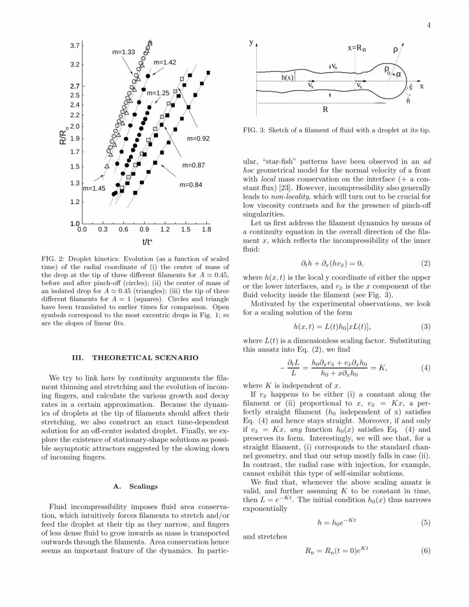
The filament thinning and the dynamics of the incom-ing fingers are rather difficult to measure accurately andnot very sharply defined experimentally. In contrast, thestretching of an individual filament, or, more precisely,the radial coordinate of the droplet at its tip, R, is morereadily accessible. The squares (A = 1) and the circles(A ∼ 0.45) in Fig. 2 indicate this droplet position (evenafter pinch-off) in units of the radius R0 of the initialcircle and in log scale, as a function of time t in units ofthe time scale
t∗ =12(µin + µout)
b2Ω2∆ρ. (1)
The open squares and circles indicate the evolution of thefurthest droplet in Figs. 1(a,b) and 1(c,d) respectively.
FIG. 1: Pattern evolution for A = 1, b = 0.5mm, Ω =120rev/min and R0 = 50 mm (a,b), and A ≃ 0.45, Ω =180rev/min and R0 = 38 mm (c,d). Snapshots (3R0 × 3R0)16.5s (a) and 22.5s (b), and 122s (c) and 158s (d) after be-ginning rotation.
As we can see, the growth tends to be roughly ex-ponential, at least for R/R0 > 2. (Note that R/R0 < 2corresponds rather to relatively small fingers, rather thandroplets at the tip of thin filaments). It seems reasonableto measure a growth rate —the slope of linear fits (solidlines) in Fig. 2; this yields m = 0.8–1.0 with good linear-ity beyond R = 2R0 for A = 1, and m = 1.25 − 1.5for A ≃ 0.45. A ≃ 0.45 curves tend to bend a bitmore, but this eventual bending is uncorrelated with thedroplet pinch-off: To check this, we have performed anexperiment with an isolated, off-center circular droplet;it roughly keeps its circular shape and runs away at avery similar rate (m = 1.45, triangles).
The most striking difference between high (A = 1)and low (A ≃ 0.45) viscosity contrast is the system-atic droplet pinch-off observed for low, but not high A.For the latter, filaments keep on growing and stretching,while reaching a width comparable to the cell gap, thatis close to the natural cutoff. While we have not spannedthe whole range of A, all previous evidence shows thatthe so-called low contrast behavior is qualitatively un-changed for most of the range of A, and only very closeto A = 1 significant differences are found. This has beenrecently discussed in Refs. [19, 22].
Another difference seems to be the growth rate ofdroplets (connected or not to filaments). The uncertain-ties in the viscosities are not sufficient to account for it:droplets seem to be centrifuged faster in dimensionlesstime for low than for high viscosity contrasts. Our dis-cussion on this is postponed to Sec. V.
4
0.0 0.3 0.6 0.9 1.2 1.5 1.81.01.0
1.2
1.3
1.5
1.7
1.9
2.0
2.2
2.42.52.72.7
3.2
3.7
*
m=1.25
m=1.42
m=1.45
m=1.33
m=0.87
m=0.84
m=0.92R/R
o
t/t
FIG. 2: Droplet kinetics: Evolution (as a function of scaledtime) of the radial coordinate of (i) the center of mass ofthe drop at the tip of three different filaments for A ≃ 0.45,before and after pinch-off (circles); (ii) the center of mass ofan isolated drop for A ≃ 0.45 (triangles); (iii) the tip of threedifferent filaments for A = 1 (squares). Circles and trianglehave been translated to earlier times for comparison. Opensymbols correspond to the most excentric drops in Fig. 1; mare the slopes of linear fits.
III. THEORETICAL SCENARIO
We try to link here by continuity arguments the fila-ment thinning and stretching and the evolution of incom-ing fingers, and calculate the various growth and decayrates in a certain approximation. Because the dynam-ics of droplets at the tip of filaments should affect theirstretching, we also construct an exact time-dependentsolution for an off-center isolated droplet. Finally, we ex-plore the existence of stationary-shape solutions as possi-ble asymptotic attractors suggested by the slowing downof incoming fingers.
A. Scalings
Fluid incompressibility imposes fluid area conserva-tion, which intuitively forces filaments to stretch and/orfeed the droplet at their tip as they narrow, and fingersof less dense fluid to grow inwards as mass is transportedoutwards through the filaments. Area conservation henceseems an important feature of the dynamics. In partic-
vn
vx
y
xh(x)
ρ
α
x=Rn
vx
R
0ρ
s
n
FIG. 3: Sketch of a filament of fluid with a droplet at its tip.
ular, “star-fish” patterns have been observed in an ad
hoc geometrical model for the normal velocity of a frontwith local mass conservation on the interface (+ a con-stant flux) [23]. However, incompressibility also generallyleads to non-locality, which will turn out to be crucial forlow viscosity contrasts and for the presence of pinch-offsingularities.
Let us first address the filament dynamics by means ofa continuity equation in the overall direction of the fila-ment x, which reflects the incompressibility of the innerfluid:
∂th+ ∂x(hvx) = 0, (2)
where h(x, t) is the local y coordinate of either the upperor the lower interfaces, and vx is the x component of thefluid velocity inside the filament (see Fig. 3).
Motivated by the experimental observations, we lookfor a scaling solution of the form
h(x, t) = L(t)h0[xL(t)], (3)
where L(t) is a dimensionless scaling factor. Substitutingthis ansatz into Eq. (2), we find
− ∂tL
L=h0∂xvx + vx∂xh0
h0 + x∂xh0= K, (4)
where K is independent of x.If vx happens to be either (i) a constant along the
filament or (ii) proportional to x, vx = Kx, a per-fectly straight filament (h0 independent of x) satisfiesEq. (4) and hence stays straight. Moreover, if and onlyif vx = Kx, any function h0(x) satisfies Eq. (4) andpreserves its form. Interestingly, we will see that, for astraight filament, (i) corresponds to the standard chan-nel geometry, and that our setup mostly falls in case (ii).In contrast, the radial case with injection, for example,cannot exhibit this type of self-similar solutions.
We find that, whenever the above scaling ansatz isvalid, and further assuming K to be constant in time,then L = e−Kt. The initial condition h0(x) thus narrowsexponentially
h = h0e−Kt (5)
and stretches
Rn = Rn(t = 0)eKt (6)

5
(where Rn = x | ∂th0(x, t) = 0) with a time constantset by the inner fluid velocity. Figure 3 schematicallyshows the in- and outgoing flow in this case. Eq. (6)is a statement that a reference point on the interface isadvected with the filament as this is stretched. In partic-ular, if applied to the neck of the filament just before thedroplet as represented in Fig. 3, it would predict the to-tal filament length to grow with the same time constantK with which its width decays. However, note that theoutgoing flux of inner fluid at the neck can go into thedroplet or contribute to the filament stretching. If somefraction of it actually goes into the droplet (as observedin the experiments), the scaling of the radial coordinateof the neck will be delayed with respect to the thinningrate K.
Finally, in order to relate this filament scaling withthe incoming fingers, consider a reference circle of radiusRref intersecting all filaments near their root, where theybegin to look straight. The outwards flux of denser fluidthrough the circle and inside each filament is 2h(t)vx(x =Rref), and assuming again that vx(Rref) does not dependon time, we find it to scale as e−Kt. In general, the areaof denser fluid enclosed by this reference circle a shouldhence asymptotically decay with the same rate,
a = a(t→ ∞) + [a(t = 0) − a(t→ ∞)] e−Kt. (7)
A similar slowing down can then be expected for theradial position of the tips of identical incoming fingers.
B. Exponential behavior and time constant
We now show that, for a straight filament, vx is linearin x as we anticipated, and we find the time constant K,which we have seen to set the time scale of the variousexponential behaviors discussed so far. For that purpose,let us compute the tangential velocity jump across theinterface.
The 2d velocity field ui is proportional to the gradientsof the pressure field pi (Darcy’s law), where the subscripti labels the inner (i =in) and outer (i =out) fluids. Fora rotating cell [19]
~ui = − b2
12µi
(
~∇pi − ρiΩ2rr
)
, (8)
where r is distance to the rotation axis and r is a unitradial vector pointing outwards. Using the standardboundary condition of Laplace law for the capillary pres-sure jump across the interface, p|in − p|out = σκ, wherethe bar | stands for the limit value when approaching theinterface from either side and κ is the interface curvaturein the cell plane, we obtain
s · (~u|out − ~u|in) =b2
6(µin + µout)
(
σ∂sκ− ∆ρΩ2rr · s)
+As · (~u|in + ~u|out) , (9)
where s is a coordinate tangential to the interface and sthe unit vector in that direction.
In our sketch (Fig. 3), we identify vx ≃ ~u|in · s, whichis a function of the local interface geometry and (1 −A)~u|out · s, the solution of a non-local problem. To keepthe problem local, we now assume that the outer fluidapproaches the filament normal to it, ~u|out ⊥ s (Notethat this assumption is not necessary for A = 1).
For a straight (κ = 0) radial (x ‖ r) filament, we obtainthe anticipated vx = Kx and the time constant
K =b2∆ρΩ2
6(µin + µout)(1 +A)=
2
1 +A
1
t∗=b2∆ρΩ2
12µin(10)
[case (ii) above]. One might wonder how a scale-free so-lution is possible without requiring the filament width tobe much smaller than any other length scale, as it is le-gitimate to do close enough to pinch-off [1]. The answeris that the assumption of flatness has removed the capil-lary length (proportional to σ) from the local problem; itstill sets, together with the radius of the initial conditionR0, the size of e.g. the droplet at the tip of the filaments,but no external length scale can be felt when droppingthe nonlocal term (1 − A)~u|out · s. This allows for scal-ing solutions to exist well before pinch-off for A ≡ 1. Itis this approach to pinch-off, rather than the pinch-offphenomenon itself, which will be further studied in thisarticle.
For a tangential filament, K = 0 and the filamentis stationary [case (i) above], which is consistent withour observations for the tangential segments of some fil-aments. These segments are found where a tip split (forA = 0, see Fig. 1(c,d)) or at the point where an incom-ing finger was overcome and stopped by its neighbors (forA = 1, see Fig. 1(a,b)).
For the case of viscous fingering in a channel, the linearincrease in the centrifugal force is replaced by a constantgravity (or equivalent injection). We can easily track thisdifference to yield a fluid velocity inside a filament par-allel to the gravity or injection direction vx independentof x. The filament width will again be stationary [case(i) above]. We see by comparison that rotation not onlyensures the formation of long filaments as we expected,but also brings the two interfaces close together.
For not completely straight filaments h(x), vx 6= Kx.Therefore, strictly speaking, the scaling solution Eq. (3)does not hold for any h0(x), but only for a straight fil-ament. It remains an approximate solution for slightlycurved filaments (see Sec. VI), but it makes little sensefor the droplets at the tip of the filaments. This raises theissue of dynamics of the droplet, which could potentiallyaffect the filament stretching.
C. Isolated droplet
The velocity found for the filament stretching has anelementary interpretation: In the overdamped limit as-sociated to Darcy’s law, all forces balance. The inner

6
fluid velocity vx will hence be that which makes frictionbalance the other external forces, namely the centrifugalforce and the force exerted by the outer fluid through itspressure gradients. The latter can be derived from an-other force balance, now in the outer fluid. There, theviscous forces vanish in the x direction with our assump-tion ~uout ⊥ s ≃ x, or even without this assumption forA = 1, since it corresponds to µout = 0. Thanks to this,the other forces in the outer fluid (centrifugal and pres-sure gradients) balance in this direction. Thus, back inthe inner fluid, friction, 12µinvx/b
2, only needs to com-pensate for centrifugal forces, ∆ρΩ2x. This gives rise tothe velocity found, vx = Kx with K given by Eq. (10).
For a droplet (a closed interface), in contrast, the outerfluid needs to be moved in the x direction. The outerviscosity and velocity field enter the force balance, andvx ≤ Kx, where vx is now the velocity of the centerof mass of the droplet, and the equality holds only forA = 1. Except for A = 1, it is clear that the filamentstretching will indeed be affected by this lower dropletvelocity. Furthermore, vx will depend on the outer flowfield, and hence on the droplet shape.
For a slightly off-center circular droplet, vx is known:Such a droplet corresponds to the mode 1 in a linearstability analysis of a circular, centered drop. Its growthrate is K ′ = 1/t∗ = b2∆ρΩ2/[12(µin + µout)] [19], wherewe readily see that it is the sum of viscosities, and notonly the inner one, what counts.
We now compute the velocity for a circular droplet∂sκ = 0 rigorously. Preserving the circular shape re-quires that ~uin = R x everywhere (R is distance fromthe rotation axis to the center of the droplet), so thatthe circle be just translated as a whole. We express theunit vectors tangential (s) and normal (n) to the inter-face and the radial vector ~r connecting the rotation axisand a point on the interface in polar coordinates (ρ, α)with respect to the center of the droplet (see Fig. 3),
and compute s · ~u|in = −R sinα and ~r · s = −R sinα.For A = 1, Eq. (9) reduces to a simple geometric re-lation between the two. Interestingly, like the filamentscaling, this is verified either for a channel under injec-tion or gravity (R is then a constant) or for a rotating
cell as presented here, R = K ′R, but not for a generaldriving force or geometry. We hence find that a circularoff-center droplet is a time-dependent solution in a chan-nel or rotating cell for A = 1 as was previously foundusing conformal mapping techniques in [24].
For A < 1, the outer flow enters the problem. If a cir-cular droplet is to remain a solution, it has to match thelinear regime. At that stage, we will still have R = K ′R,regardless of the viscosity contrast. Substituting this intoEq. (9), we find s · ~u|out = −s · ~uin = R sinα. Con-tinuity of normal velocities across the interface gives usn · ~u|out = R cosα, and we thus find the outer velocity
on the interface to be ~u|out = R(x cos 2α+ y sin 2α). Wethen propose the outer velocity field to be the productof its value on the interface and a function of ρ only. Wefind that this can indeed fulfill incompressibility if the
droplet is isolated, i.e., if there are no other boundaryconditions to be satisfied elsewhere. For the channel ge-ometry, this corresponds to the limit in which the dropletis much smaller than the distance between the walls. Thecomplete solution reads
~uin = Rx, (11a)
~uout = R(ρ0/ρ)2(x cos 2α+ y sin 2α), (11b)
R = R(t = 0)eK′t. (11c)
The corresponding streamlines in the outer fluid ρ/ρ0 ∝sin(α), are circles of different radii tangential to y = 0and passing through the center of the droplet, althoughthey change into horizontal lines inside it (see Fig. 10bottom right).
Hence, an off-center circle turns out to be an exacttime-dependent solution for any viscosity contrast andindependent of it, even beyond the linear regime. ForA = 1, K ′ = K and the filament stretching and thedroplet runaway coincide regardless of the droplet shapeand whether it is near a filament or not. This single timeconstant should hence be robust, and indeed an onlyslightly lower value [(0.8–1.0)/t∗] is systematically ob-served in our experiments (squares in Fig. 2). For A < 1,in contrast, K ′ < K, and an isolated, circular droplet hasa time constant down to twice smaller (for A = 0) thanthat of the filament stretching. For a droplet connectedto the tip of a filament (neither isolated nor circular), wedo not know its dynamics rigorously. Our experimentsare puzzling in this respect: Isolated droplets (trianglesin Fig. 2) and those connected to a filament (circles) dis-play the same growth rate; consistency with the theorythen requires it to be K ′ (the same than for A = 1), sincethe isolated droplet solution is exact. However, we seemto find a growth rate of K [(1.25–1.5)/t∗], and, in anycase, higher than the measured value for A = 1. Oursimulations will help clarify this point.
D. Stationary-shape solution
The various scaling behaviors derived so far point at anasymptotic pattern enclosing a finite area [Eq. (7); seeFig. 4] with radial, semi-infinite [Eq. (6)] and straight[Eqs. (6) and (5)] filaments of zero width [Eq. (5)] (seeFig. 4) with a droplet at their tip.
In a stationary state, ~uin = ~uout = 0 by definition, andthe interface shape must balance exactly surface tensionwith the centrifugal force in Eq. (9):
σ∂sκ = ∆ρΩ2~r · s. (12)
Noting that s = d~r/ds, where s is arclength along theinterface, we can integrate the above equation once tofind
κ(s) = κ(s = 0) + ∆ρΩ2/(2σ) [r2(s) − r2(s = 0)]. (13)
We see that the curvature of the interface κ increasesmonotonically with the distance r to the rotation axis.

7
FIG. 4: Stationary solutions in a rotating H-S cell with four-and six-fold symmetry.
In general, the interface will go from convex to concaveas r is increased. The solutions of Eq. (12) which dochange concavity do not resemble our observed patterns,but have a petal shape and are unstable [25]. We henceturn to purely convex stationary solutions of Eq. (12),up to the point where κ = 0. These will represent theasymptotic incoming fingers. To connect them with theradial, straight filaments, we impose locally radial andstraight ends at an arbitrary distance r(s = 0) from therotation axis as boundary conditions. Any other connec-tion would cause ∂sκ in Eq. (12) to diverge.
For given experimental parameters ∆ρΩ2/σ, this com-pletely determines the solution, an arch covering a certainangle. This angle is a continuous function of the only di-mensionless ratio we can construct, ∆ρΩ2r(s = 0)3/σ,and hence only for discrete values of this ratio is the an-gle a submultiple of 2π. This then allows one to connectan integer number of equal arches to form an apparentlyclosed interface, as we show in Fig. 4. This could notbe a stationary solution on its own, since actually clos-ing the interface would imply that the arches meet incusps. We continue each arch end by a straight, semi-infinite radial line, replacing each cusp with an infinite,straight filament of zero width. These filaments presentno flux inside (finite velocity but zero width) nor induceany flow outside. They are hence compatible with sta-tionary arches. Finally, the interface is closed by placinga droplet of arbitrary size at the tip of each infinite fila-ment. Although a moving droplet does induce an outsideflow around it, this finite disturbance vanishes near thecenter for an infinite filament.
Thus, we have constructed a solution which shape isstationary at finite distances. Its physical relevance, how-ever, remains to be checked. The slowing down of in-coming fingers derived above and the flattening of aninitially curved filament h(x) [Eqs. (6) and (5)] are sug-gestive that such a solution can indeed be an attractor ofthe dynamics for initial conditions with the appropriaten-fold symmetry, and the numerical simulations in nextsection and the results of Sec. VI further support thisidea.
A related issue is the selection of the length scaler(s = 0) of the stationary arches. For fixed boundaryconditions, only discrete values of the dimensionless ra-tio ∆ρΩ2r(s = 0)3/σ allow equal arches to meet without
crossing. Therefore, for given experimental parameters,the stationary-shape solutions only exist for discrete val-ues of r(s = 0) (note that unequal arches cannot meet ata single distance r(s = 0) from the center). This sets upa selection problem for the values of r(s = 0).
Dynamically, such a solution will be approached witha certain number of fingers. This number may not beunambiguously defined for unequal finger configurations,and it is indeed a dynamic variable for high viscosity con-trasts. Furthermore, the initial condition is genericallynonsymmetric, with some fingers competing and advanc-ing over others. As a consequence, real experiments andnumerical simulations can evolve towards configurationsclose to the above stationary-shape solutions during atransient but will eventually depart from them. How-ever, for initially equal fingers as those one can producein simulations (see next section), the dynamics conservethe number of fingers regardless of the viscosity contrast.Hence, only the stationary-shape solution of length scaler(s = 0) with the number of fingers of the initial condi-tion can be approached. This then unambiguously selectsthe scale r(s = 0) and the area enclosed by the stationaryinterface a(t→ ∞) (Eq. 7).
We thus see that the combination of the scaling solu-tions and the stationary state derived could specify theasymptotic dynamics of equal fingers and the ultimate in-terface shape. As for its relevance for unequal fingers, wepoint out two facts: First, we find reasonable agreementbetween the exponential rate predicted by this simpletheory and that measured experimentally for the radialposition of the droplets at the tip of the filaments. Sec-ond, the existence of the above symmetrical stationarysolutions could explain the experimental observation ofplateaux in the evolution of the area of inner fluid con-tained in a reference circle, as a function of time in Ref.[19]. In fact, in those experiments the interface could suc-cessively visit the neighborhood of stationary states fordifferent numbers of fingers, and correspondingly slowdown the dynamics close to them until some event (typ-ically a pinch-off) would trigger again the dynamics.
IV. NUMERICAL TESTS
We test the basic picture presented above by phase-field simulations of the full Hele-Shaw dynamics. Theyare compared to experimental results and to a numericalsolution for the stationary arches.
A. Method
First we adimensionalize the problem: lengths will bemeasured in units of the initial drop radius R0, and timein units of t∗ as given by Eq. (1). All quantities ap-pearing below will be dimensionless. The scaling lawsin the previous section can be casted into dimensionless

8
form just by considering all quantities appearing theredimensionless and redefining K = 2/(1+A) and K ′ = 1.
The standard Hele-Shaw dynamics is defined by the in-
compressibility condition already used before (~∇·~ui = 0),together with the continuity of normal velocities acrossthe interface and the tangential velocity jump [Eq. (9)]as boundary conditions. Thanks to incompressibility, we
can define a stream function ~u = ~∇× ψz (where z is thedirection perpendicular to the plates), which is contin-uous across the interface. We thus obtain the followinggoverning equations [26, 27]:
∇2ψ = 0, (14a)
∂sψ|in = ∂sψ|out = −vn (14b)
∂ψ
∂n|out −
∂ψ
∂n|in = Γ, (14c)
where the first expresses that the flow is irrotational ineach fluid, the second is the continuity of normal veloci-ties, and the third, their tangential jump. The magnitudeof this jump is the strength Γ of a divergent vorticitypeaked on the interface, Γ ≡ γ + A(∂nψ|in + ∂nψ|out),
where γ/2 ≡ (B~∇κ− rr) · s is its local part. We see thatthe dynamics are controlled only by two dimensionlessparameters: the viscosity contrast A and the dimension-less surface tension B = σ/[∆ρΩ2R3
0] (the ratio of stabi-lizing to destabilizing forces). Remarkably, none of thescalings derived in the previous section depends on B.
Simulations were run using a phase field model pre-sented in [28] and extensively tested in [29]:
ǫ∂ψ
∂t= ∇2ψ +A~∇ · (θ~∇ψ) +
1
ǫ
1
2√
2γ(θ)(1 − θ2),(15a)
ǫ2∂θ
∂t= f(θ) + ǫ2∇2θ + ǫ2κ(θ)|~∇θ|
+ ǫ2z · (~∇ψ × ~∇θ), (15b)
where θ is the phase field, an auxiliary field distinguishing
between the two fluids, f(θ) ≡ θ(1 − θ2), γ(θ)2 ≡ s(θ) ·
(B~∇κ(θ) + y) and κ(θ) ≡ −~∇ · n(θ), with n(θ) ≡ ~∇θ
|~∇θ|
and s(θ) ≡ n(θ) × z.Apart from the physical control parameters A and B,
the dynamics in this model also depend on an artificialinterface thickness ǫ and a relaxation time for the streamfunction (which is diffusive, not Laplacian) ǫ. In the limitǫ, ǫ → 0, the dynamics are strictly those of Eqs. (14a–14c). For finite values of ǫ, ǫ, an error bound is guaran-teed for any given magnitude by conveniently decreasingǫ, ǫ [29].
A very interesting feature of this type of model is thatboth fluids and the interface between them are treatedas bulk. One consequence of this is that the model iswell behaved as two interfaces break up and reconnect,which enables us to study the dynamics after pinch-offin a very natural way. This has been demonstrated very
recently [30] for the model used here [28, 29] reformu-lated in terms of the velocity vector. Let us add a noteof caution: When two interfaces approach to distancescomparable to their thicknesses ǫ (more precisely, below5ǫ from numerical tests) they attract each other. Thistriggers the pinch-off. One could think of this effect as aphenomenological “pinch rule”. We nevertheless do notpretend the phase-field dynamics near pinch-off to rep-resent the effect of the third dimension nor the eventualbreakdown of a hydrodynamic description. Our approachis to simulate only the bidimensional Hele-Shaw dynam-ics down to distances of O(ǫ), and continue to simulatethem once the reconnected interfaces have separated adistance of the same order, very much as in the experi-ments, where the Hele-Shaw dynamics can be consideredto be accurate before and after the two interfaces wereseparated a distance of O(b). The crossover from theHele-Shaw dynamics to interface interaction via their fi-nite thicknesses is very abrupt, enabling us to clearlyseparate one from the other.
For reliable quantitative comparison with theory andexperiments, we explicitly check convergence of the timeconstant K in ǫ, ǫ, since ǫ conveys some finite diffusiontime to the flow, and ǫ delays the interface advance withrespect to the normal fluid velocities [28]. We thus es-tablish exponential rate values for the ǫ, ǫ→ 0 limit, i.e.,for the Hele-Shaw dynamics, and bounds for ǫ, ǫ to ob-tain those values in practice. For ǫ, a value of ǫ = 0.5turns out to suffice, and it is used in the following unlessotherwise stated. Convergence in ǫ is discussed case bycase.
We numerically integrate the above model with an Eu-ler scheme and centered differences. The time step dt istaken to be close to the stability limit; dt = 0.2ǫdx2 un-less otherwise stated, where dx is the mesh size. Conver-gence of the solution is also tested changing dx (dx = ǫgenerally suffices as shown in [29]). Our initial conditionis some perturbation of a centered circle of unit radius,i.e., r = 1 + ∆r(ϕ) where r, ϕ are polar coordinateswith respect to the rotation axis and ∆r(ϕ) < 1. In thenext two subsections, we consider only identical fingers(n-fold symmetry), ∆r(ϕ) = (2π/n)q cos(nϕ), where q isthe amplitude to wavelength ratio of the perturbation,and n is the (integer) number of fingers. Unless other-wise stated, we use a dimensionless surface tension B forwhich n is the most unstable mode in the linear regimeand q = 0.05.
B. Filament thinning
We test here the filament thinning scaling by lookingat a dumbbell-shaped pattern: two droplets connectedby a filament (n = 2, see Fig. 5). This case has twoadvantages: a width can be unambiguously defined asthat at the axis of rotation (the midpoint between the twodroplets); on the other hand, there are no neighboringfilaments to influence its dynamics.

9
FIG. 5: Filament thinning: Initial condition (top, q = 0.05)and one later interface for B = 0.09, ǫ = 0.008, dx = ǫ/2 andA = 1 (middle) or A = 0 (bottom).
Figure 5 displays the patterns thus obtained at theend of our run (A = 1) or just after the first pinch-off(A = 0). In the last case, new pinch-off events quicklyfurther shorten the central filament from its ends. Wewill refer to this phenomenon as “pearling”. The twoupper curves in Fig. 6 (B = 0.09) show the evolutionof the filament width at the midpoint for the whole run(A = 1) or up to the relaxation of the last central segmentin a round shape, which makes the width increase again(A = 0). The latter occurs when pearling reaches therotation axis, shortly after the first pinch-off, indicatedby the vertical lines. We see that the asymptotic decayis grossly exponential for A = 1 as predicted, althoughit is only observed for roughly a decade. For A = 0, thefilament thinning is strictly not exponential since the ef-fective exponential rate varies slowly in time. It shouldbe noticed that it is the flatness, not the width of thefilament, what determines the goodness of the approx-imation of last section. One might think that pinch-offprevents the formation of long and hence straight enoughfilaments for A = 0, but, indeed, just before it the A = 0filament is just as straight as the A = 1 one at the sametime; the A = 1 filament already exhibits a clear expo-nential behavior, whereas the A = 0 one does not.
A closer look reveals that the thinning rate is well re-laxed to its asymptotic value for the last third of the runfor A = 1, with a value of K = 0.98 consistent with thepredicted K, but not for A = 0 because pearling reachesthe center when the rate begins to approach (from above)a value of K = 2. No disturbance is observed from theprevious pinch-off events. Runs for A = 0.5 and A = 0.8(not shown) are also in reasonable agreement with thelaw K = 2/(1 +A).
One might blame the high dimensionless surface ten-sion B = 0.09 used or the finite interface thickness ǫ orrelaxation time ǫ in the model for either the slow relax-ation of the exponential rate or the pinch-off itself in thelow-A case, since B enters the problem as long as the fil-ament is not perfectly straight. The lower curves in Fig.6 for a lower dimensionless surface tension, B = 0.01,and at different values of ǫ and dx/ǫ rule out both possi-bilities. Using a more deformed circle (q = 0.2), to avoidthe appearance of other modes which are linearly unsta-ble, we can confirm the results obtained for B = 0.09.For high viscosity contrast, the good decay even for thecoarsest mesh and interface profile allows to establish the
FIG. 6: Filament thinning: Width at rotation axis (in logscale) vs. time. Dashed, solid and dotted line(s): dx = ǫ,dx = ǫ/2 and dx = ǫ/4, respectively. Upper curves (B =0.09): ǫ = 0.008 (runs in Fig. 5, q = 0.05). Lower curves(B = 0.01, q = 0.2): three curves at ǫ = 0.02, 0.01 and0.005 for dx = ǫ and three at ǫ = 0.02, 0.01, and 0.0067 fordx = ǫ/2 shown for each value of A. For A = 0, lower curvescorrespond to lower values of ǫ. The only dx = ǫ/4 curve isfor A = 1, ǫ = 0.02. The dashed (solid) vertical lines indicatethe interval during which the droplet at the tip pinches off fordx = ǫ (ǫ/2).
value of the rate K unambiguously at K = 0.99−1.00 bystudying the convergence in ǫ and dx. For low viscositycontrast runs (A = 0), the values of the rates again seemto relax towards the end of the runs to a value compat-ible with the theoretical value K = 2 although they areagain badly defined.
Pinch-off is systematically observed for low (A = 0,0.5), but not high (A = 0.8, 1) viscosity contrasts. Forthe latter, a numerical instability due to noise in the (rel-atively) inviscid fluid often sets in abruptly at late times,especially for the coarser discretization dx = ǫ. Becauseit is so abrupt, it is easy to separate from valid data. Forthe former, the pinch-off itself cannot be considered aspurious effect due to a finite interface thickness, since thepinch-off time increases only marginally when decreasingthe interface thickness ǫ, and in any case stays boundedby the vertical lines in Fig. 6. Only for the coarsestinterface profile can we detect that the center of the fila-ment anomalously “anticipates” the first pinch-off at itstip; for lower values of ǫ it actually continues to narrowunaffected after the first pinch-off and until the subse-quent pearling reaches it. Interestingly, when decreasingthe mesh size dx from dashed to solid lines, pinch-off isappreciably accelerated, so that it must also remain inthe continuum limit.
We conclude that the theoretical exponential thinningand the values of the exponential rates derived in lastsection are a good approximation to the observed behav-ior, especially for high viscosity contrasts. Deviations doexist and are intrinsically much stronger for low viscos-ity contrasts, but, because they are not less apparent for

10
FIG. 7: Approach to the stationary shape for B = 0.0213and ǫ = 0.01. Left: initial (dotted) and latest (solid line)interfaces for A = 1, dx = 0.5ǫ and ǫ = 0.5. Right: Blow-upof central region with intermediate interfaces (solid lines) atconstant time intervals. Thicker line: receding interface (afterpearling) for A = 0, dx = ǫ and ǫ = 1. Dashed line: numericalsolution of Eq. (13) for the predicted stationary shape.
a surface tension almost one order of magnitude lower,they cannot be due to it.
C. Stationary-shape solution
We now increase the number of fingers arising from thelinear regime to n = 4, so that the incoming fingers en-close a finite area. This enables us to test the approach tothe stationary-shape composite solution derived in Sec.III D.
Figure 7 (left) shows the initial condition (dotted line)and the last interface (solid line) of our most refined(ǫ = 0.01, dx = 0.5ǫ and ǫ = 0.5) run for A = 1, justbefore spurious pinch-off occurs. The latter is unavoid-able because the filament width reaches 0.05–0.07, at theedge of diffuse-interface attraction (∼ 5ǫ). A = 0 runspinch much faster, presumably due to a physical phe-nomenon and not to the finite interface thickness, sincehere, as well as for n = 2, this is not cured by decreas-ing ǫ. Due to this different behavior, A = 0 runs donot lead to the star-like pattern shown here, but, after afirst pinch-off event at moderate radii, they quickly emitseveral droplets while the central drop recedes.
The blowup in Fig. 7 (right) shows the last interfacesfor A = 1 at constant time intervals (thinner solid lines)compared to a numerical solution of Eq. (13) for the com-posite stationary pattern derived in Sec. III D (dashedline). The latter seems a plausible asymptotic solution inthe sense that it has not been overcome by the incomingfingers of our run, although visually these seem to asymp-totically approach less curved arches. For a quantitativeestimate, we fit a slowing down of the type of Eq. (7)[i.e., we fit a(t → ∞), a(t = 0) − a(t → ∞) and K] bothto the time evolution of the area enclosed by a referencecircle of various radii Rref , and to that of the radial coor-dinate of the incoming finger tips. We find K = 1.06 forthe area enclosed by a circle of radius Rref = 1.25, where
the filament begins to look straight, and K = 0.9 − 1for the incoming finger tip. Both are in good agreementwith the theoretical value K = 1. The area enclosed bysmaller circles decays with smaller exponents (0.93 for acircle of radius Rref = 1 and 0.81 for Rref = 0.75), buta worse agreement is understandable, since the filamentsare less straight at the latest times we can explore.
Regarding the tip of the incoming fingers and the to-tal enclosed area in the center, the numerical solutionof Eq. (13) predicts rmin = 0.133 and a(t → ∞) =0.0937 respectively. The numerical simulations here pre-sented show that the filament still contains a significantamount of inner fluid, yielding an asymptotic enclosedarea which decreases with the radius of the reference cir-cle (a(t → ∞) = 0.36 for Rref = 1.25, a(t → ∞) = 0.27for Rref = 1 and a(t → ∞) = 0.20 for Rref = 0.75).As for the asymptotic tip position of the incoming fin-gers, we find rmin = 0.2, with little sensitivity to thetime window used. We thus seem to find that the tipsand the area enclosed reach roughly half of those pre-dicted by Eq. (13). This mismatch is most probably dueto the fact that we do not yet probe close enough to thestationary-shape solution. This is indeed the case regard-ing the filaments since, as explained above, they have notreached its zero-width asymptotic state because the finalarea is not independent of the reference circle radius (asit should be if Rref < r(s = 0)).
However, the evolution of the interface for A = 0 af-ter pinch-off does hint that this exact solutions have animportant effect on the dynamics. After the pearlingprocess of the filaments for A = 0, the incoming fingerscontinue to approach the rotation axis and the dropletsleft at the tip of the filaments recede. When they reachthe central region roughly delimited by the ends of thearches of our predicted stationary-shape solution, surfacetension finally stops the advance of the incoming fingers.The whole drop left at the center relaxes towards a cir-cular shape. The thicker solid line in Fig. 7 (right) cor-responds to such a central shape at the time when theincoming fingers stop before the relaxation to a circularshape. Although the shape displayed is not an asymp-totic one, the remarkable resemblance of the tip of theincoming fingers and the steady-state asymptotic arches(dashed lines) and the fact that incoming fingers preciselystop (their velocity crosses zero) when approaching thisshape is suggestive that our steady-shape solution (orparts of the solutions found in [25] very similar to it)is indeed the attractor for sets of initial conditions withn-fold symmetry.
D. Unequal finger dynamics
Finally, we address the more realistic case of unequalfingers. The goal here is no longer to test our theoret-ical results, but to directly compare with experimentalpatterns. We thus check whether the differences betweenlow and high viscosity contrasts A observed in experi-

11
ments, including systematic or not pinch-off events, canbe explained by the Hele-Shaw equations.
In order to compare with the patterns shown in Fig.1, which have 15–16 filaments for A = 1 [Figs. 1(a,b)]and 20-21 for low A ∼ 0.45 [Figs. 1(c,d)], we use a di-mensionless surface tension of B = 1.03 × 10⁻³, whichcorresponds to a most unstable mode n = 18. The ideais to use exactly the same initial condition and physi-cal and computational parameters for both low and highviscosity contrast A, except for A itself. Thus, any dif-ference we observe can only be due to the different valuesof A.
We adopt the less refined choices dx = ǫ and ǫ = 1with an interface thickness down to ǫ = 0.005, in orderto avoid possible spurious pinch-off events. As alreadyobserved for the dumbbell-shaped pattern in Sec. IVB,we find that, whenever pinch-off occurs, a lower rate ofdx/ǫ does not prevent it, but even accelerates it.
As for the initial condition, if we start with a pertur-bation where sine and cosine modes have uniformly orGaussian distributed random amplitudes up to a certaincut-off (here n = 40), we cannot reproduce the strongasymmetry of the experimental patterns for high viscos-ity contrast A = 1 [Figs. 1(a,b)]. We traced this backto the fact that, in the experiments, the deviations froma circle first become visible in particular spots, and notuniformly on the interface. For the experiment of Figs.1(a,b), this happens roughly on three spots. We mimicthis by multiplying our random initial condition by an ex-ponential envelope peaked at three uniformly distributedrandom angles, keeping ∆r(ϕ) ≤ 0.004. We do not at-tempt to truly copy the experimental initial condition,but to use a somehow “statistically” similar one.
If some details look alike, these will then indicate somegeneral common trends representative of the dynamics,as opposed to a particular initial condition.
This initial asymmetry in the deviations from a circleis largely preserved throughout the whole evolution forhigh [A = 1; Figs. 8(a,b)], but not low viscosity con-trast [A = 0, 0.5 runs; Figs. 8(c,d) and Figs. 8(e,f),respectively]. We hence conclude that both an asym-metric initial condition and a high viscosity contrast arenecessary to obtain asymmetric patterns. This effect ofthe viscosity contrast is due to the incoming finger com-petition for high A, although it is less apparent here thanin the channel geometry, due to the geometric decreaseof available room fingers experience.
Figure 8 is indeed the simulation analogue of Fig. 1.Experimental patterns in Fig. 1 were rotated at will tomake the “statistical” resemblance with the simulationsmore apparent; simulations are presented with the ver-tical and horizontal directions parallel to the computa-tional grid, although lattice anisotropy is not appreciablehere.
Patterns are shown at two different times: t = 1.32[Figs. 8(a,c,e)] and t = 1.74 [Figs. 8(b,d,f)], for all vis-cosity contrasts. Rather than comparing these simula-tions with experiments at equal dimensionless times, we
FIG. 8: Pattern evolution for a random initial condition (seetext) and B = 1.03×10⁻³ , ǫ = 0.005, dx = ǫ, ǫ = 1 and A = 1(a,b), A = 0.5 (c,d) or A = 0 (e,f). Snapshots (3R0 × 3R0)shown at t = 1.32 (left) and t = 1.74 (right).
present all the patterns when their envelope has roughlyattained twice [Figs. 1(a,c) and 8(a,c,e)] and three times[Figs. 1(b,d) and 8(b,d,f)] the initial circle radius. Directcomparison of the time scales is left for Sec. V.
Let us first compare patterns at the earlier stage [Fig.1(a) with Fig. 8(a), and Fig. 1(b) with Fig. 8(b)].The similarity between experiments and simulations isremarkable, especially if one takes into account that theinitial conditions were only “statistically” similar (seeabove). Furthermore, the common features (overall mor-phology, filament accomplished or frustrated branching,droplet size, the already mentioned incoming fingers) arewell reproducible in other simulation runs and experi-ments. This all indicates that the excellent agreement inthe typical morphologies between experiments and sim-ulations is not fortuitous. This is noteworthy, since achange in the wetting conditions for the high viscositycontrast experiments, for instance, completely changesthe observed morphology [20].
¿From this earlier stage it would seem that pinch-offis not significantly more present for the lower (A = 0.5)

12
than higher (A = 1) viscosity contrasts. However, sim-ulation offers us the possibility to go to the ideal limitA = 0, in which both fluids have strictly equal viscosi-ties. Fig. 8(e) shows that most droplets have pinched-offby the same time for A = 0. Comparing Figs. 8(a,c,e)between them, it is clear that pinching arises as the vis-cosity contrast is decreased.
Another possibility is to go to later times. The ex-periments still show no pinch-off for A = 1 [Fig. 1(b)],but most filaments have emitted at least one droplet forA ≃ 0.5 [Fig. 1(d)]. The simulations would seem lessconclusive, since they display some pinch-off events forA = 1 [Fig. 8(b)]. However, these are most likely to bespurious: They occur for very narrow filaments, whosewidth is comparable to the interface thickness ǫ, and weknow from earlier work [28, 29] that overlapping diffuseinterfaces attract each other. Most importantly, pinchingis inhibited as ǫ is decreased (the same run with a largervalue of ǫ displays more pinching).
Simulations for low viscosity contrasts [A = 0.5, Fig.8(d) and A = 0, Fig. 8(f)], show much more pinching(the lower A, the more). The first pinch-off at the tipof a filament does not significantly change with ǫ, verymuch like we observed for the dumbbell-shaped patternin Sec. IVB. Some pinch-off events disappear, whileother appear; some are reentrant in ǫ (they disappearfor a middle value of ǫ but reappear when ǫ is furtherdecreased), . We hence conclude that these first pinch-offevents are not spurious. In any case, longer and thinnerfilaments are achieved as ǫ is decreased.
Pearling (successive pinch-off events shortening a fil-ament from its outer end) is increased when decreasingǫ, even though it is less present in the experiments [Fig.1(d)]. It is interesting to note the absence of pinchingat the base of the filaments, near the rotation axis, forA = 0 [Fig 8(f)], as opposite to the A = 0.5 and A = 1runs [Figs 8(b,d), respectively]. Since we saw pinchingto be spurious for the A = 1 run, this suggests that suchevents at the base of a filament are also spurious. Fur-thermore, they are not observed in the experiments.
We conclude that simulations reproduce very accu-rately the experimental morphologies before pinching,which strongly supports the idea that the dynamics canbe considered to be the standard Hele-Shaw for that pur-pose. They also indicate that these bidimensional dy-namics do lead to finite-time pinching for low, but nothigh viscosity contrasts. The crossover occurs somewherebetween A = 0.5 and A = 1.
E. Filament stretching and droplet dynamics
We have postponed the study of the filament stretch-ing and droplet scalings to present it in a unified way,for all the cases (n = 2, 4 and 18 filaments) consideredabove. Let us first summarize what we can expect fromthe theory in Sec. III: Droplets at the tip of a filamentshould run away roughly exponentially in time, with a
rate comprised between K ′ = 1 (for an isolated droplet)and K = 2/(1 + A) (the filament thinning rate). Thelower bound K ′ corresponds to the idealized case wherethe filament does not perturb the droplet shape nor theflow created by it, so that the droplet still obeys the exactsolution for an isolated and circular one. This assump-tion is more realistic for high viscosity contrasts, since wehave seen that in the A→ 1 limit the homogeneous flowinside an isolated circular droplet holds for any closed in-terface, regardless of its shape and whether it is isolatedor not. Note, however, that a droplet at the tip of a fil-ament is not completely closed, so that a deviation fromK ′ is still possible.
The upper bound K is based on another idealization,where no fluid is fed into the droplet, so that all thefluid expelled by the filament as it narrows is used toextend it. Therefore, the radial coordinate of the neck ofthe filament just before the droplet scales with the sameexponent K as the filament width. If the shape of thedroplet is stationary, the radial coordinate of the dropletcenter of mass is then just that of the neck of the filamentplus a constant.
The purpose of this section is to determine which is theactual evolution of the radial coordinate of the dropletscenter of mass. Our experiments have not clearly an-swered this question: Droplets are seen to (i) run awaywith roughly the same rate whether connected to a fila-ment or isolated, but (ii) this observed rate seems to beK (filament thinning) rather than K ′ (isolated droplet).The problem is that (ii) is inconsistent with the exact
isolated droplet solution.
Fig. 9 shows the evolution of the radial coordinate ofa droplet center of mass for the dumbbell-shaped patternin Fig. 5 (n = 2, dashed lines) and some of the furthestdroplets in Fig. 8 (n = 18, solid lines), compared tothat of an isolated circular droplet (n = 1, dotted lines).Bold (thinner) lines correspond to A = 1 (0). Curvesare shown till the end of the respective runs, except forthe isolated droplet, which is shown only until it beginsto “feel” the finite simulation box. Note that for n ≥2 curves make little sense for R < R0, and this parthas been removed for the n = 18 runs, since the codeactually detected a different droplet at those early stages.More details on how the curves were obtained can befound below. Although the range of R/R0 monitoreddecreases with increasing n, the final aspect ratio of thepattern (droplet radius to length of filament for n ≥ 2,or droplet radius to radial coordinate of center of massof the isolated droplet) attained is similar.
Clearly, all droplets scale with roughly the same ratem, although runs with A = 1 show a good linearity,whereas those for A = 0 do not. More precisely, forA = 1 (0), one measures (in the straightest segment ofthe curves) m = 0.8 (0.7) for n = 2, m = 0.82 (0.75)for n = 18, and m = 0.88 (0.83) for n = 1. Runs forn = 4, 6, 8, 11 and 12 fingers, give similar results, alsofor intermediate values of the viscosity contrast (A = 0.5,0.8).

13
FIG. 9: Radial position (in log scale) of the center of massof various droplets vs. time, for A = 1 (bold) and A = 0(thinner curves). Solid, dashed and dotted lines correspondto the droplets indicated with an “x” in Figs. 8(a,b,e,f), thosein Fig. 5, and the isolated droplet in Fig. 10 bottom-right,respectively. Curves are shown till the end of the respectiveruns, except for the isolated droplet, which is shown only untilit begins to “feel” the finite simulation box. Inset: Linearregime of the isolated droplet, continued in the main plot aftertranslating the (dotted) curves to earlier times for comparisonwith the others. The inset preserves slopes with respect to themain plot.
Since all droplets scale with a same rate, roughly in-dependent of A and close to K ′ = 1, it is clear thatthe droplet scaling is dominated by that of an isolateddroplet. This rate is found to be insensitive to pinch-off,and it also holds for the experimental isolated droplet inFig. 9 (dotted lines), which further supports this idea,and confirms this part of our experimental conclusions(i). However, the fact that droplets scale roughly withK ′ = 1 for any viscosity contrast A in our simulations(m ∼ 0.8) and certainly not with K = 2/(1+A) confirmsthat there is some problem with the statement (ii) thatthe experimental growth rate be K = 2/(1 + A), as al-ready expected from the exact isolated droplet solution.We address this issue in the following section.
The mismatch between the droplet scaling (m ∼ 0.8)and the filament thinning K = 2/(1 + A) accounts forthe fluid fed into the droplet. This is relatively smallfor A = 1 (K = 1), but not for A = 0 (K = 2). Thisexplains the experimental and numerical observation thatdroplets grow faster and larger as A is decreased. Thebad linearity of the A = 0 runs is also probably duethis large mismatch, although we recall that the filamentthinning itself displays a less constant exponent for A = 0than A = 1.
The center of mass of the droplets for n = 2, 18 in Fig.9 was computed subtracting the final droplet radius tothe droplet tip position, which is not rigorous, becausethe droplet radius changes during the evolution. How-ever, if one subtracts, say, the final distance from thedroplet tip to the neck of the filament before the dropletfor comparison, rates increase by 0.1 only (not shown).
FIG. 10: Stream lines induced for A = 0 by a dumbbell-shaped pattern as that in Fig. 5 (top; a quarter of the in-terface shown, B = 0.09, ǫ = 0.0067, dx = ǫ/2, ǫ = 0.5) orby an off-center circular droplet (bottom right; a half shown,B = 0.32, ǫ = 0.02, dx = ǫ, ǫ = 0.1, dt = 0.25ǫdx2). Bottomleft: Blow-up (y enlarged 30× more than x coordinate) of theforming neck in the top pattern. Interface (thicker lines) andcontour plot of the stream function (thinner lines) at equallyspaced levels (different in each graph); x = y = 0 is the rota-tion axis.
We have also extracted the neck position (not shown) ofthe same droplets (marked with an “x”) in Fig. 8, andmeasured an exponent up to m = 0.9 (for A = 0.5). Wealso confirmed that a droplet which pinches only at theend of the run (marked with “+”) scales with the samerate than one of the first to pinch (marked with “x”).
In the end, the main effect of the filament on the scal-ing of the center of mass of the droplet seems to comefrom the injection of inner fluid into it, rather than per-turbing the droplet environment. This should mean thatthe flow of the inner fluid is much more affected thanthat of the outer by the presence of the filament. Thelatter is illustrated for the most sensitive case (A = 0) inFig. 10, where stream lines are superimposed to the in-terface for a quarter of a dumbbell-shaped pattern (top),as that in Fig. 5, and for half an isolated droplet (bot-tom right): The most remarkable difference is the higherdensity of stream lines (higher velocity) at the entranceof the droplet and inside it, which breaks the flow uni-formity within the droplet; the outer flow is qualitativelysimilar near the droplet (note that stream lines are notshown at the same levels for a maximum resolution ofthe flow details in both cases, so that the modulus of thevelocity cannot be compared).
When a neck is formed (blowup, bottom left, in Fig.10), the flow is affected also outside the droplet, butmostly near the neck. Because pinching then also occursin a time scale sensibly shorter than that of the filamentstretching, the effect is not perceived in the latter. TheA = 0 droplets tracked in Fig. 9, for instance, pinch dur-ing t ∈ (0.9, 0.96) for n = 18 and t ∈ (2.3, 2.4) for n = 2,but they curve down well after or before it, respectively.
One could also wonder why the exponents measuredfor the isolated droplet run are not strictly m = K ′ = 1,

14
but this is certainly a finite-interface-thickness correctiondue to the less refined value used (ǫ = 0.02). Our purposehere was merely to check that the exact solution for theisolated droplet has some finite basin of attraction, aswe find it to be the case: The droplet stays circular andruns away exponentially with a very steady rate fromthe linear (q = 0.005, inset of Fig. 9) to deep into thenonlinear (main plot) regimes. The droplet depicted inFig. 10 bottom right corresponds to the end of the linear(and beginning of the nonlinear) regime. The type of flowpredicted by the exact solution [Eqs. (11)], is apparenthere.
V. TIME SCALE
In Sec. IVE we saw that the statement that the exper-imental growth rate be K = 2/(1+A) and not K ′ = 1 isinconsistent not only with the exact isolated droplet so-lution, but also with numerical simulations of the Hele-Shaw equations. This statement relies only on the ob-served A = 0.45 rates, since for A = 1 K = K ′ = 1 (ingood agreement with the measured values). This indi-cates that our experiments for low A do not follow thestandard Hele-Shaw dynamics.
A three-dimensional study of the proper effectiveboundary conditions to apply on an idealized two-dimensional interface, as performed for air displacing aliquid [31], is lacking for the case of two liquids. Thislow-A case might be different, since a second viscosityis involved when a layer of vaseline oil (outer fluid) wetsthe plates also inside the silicone oil (inner fluid) domain.Note that, for A = 1, such a wetting layer (in this case,of silicone oil) is to be found in the air. However, differ-ent boundary conditions should in general not produceexperimental patterns so similar to the outcome of sim-ulations using standard boundary conditions as those inSec. IVD. Especially, they should not necessarily pre-serve the pinch-off for low A.
The inferred dimensionless rates for the experimentaldroplet runaway rely on the measured rates and on thetime scale t∗. A modification of the latter can hence al-ready account for the observed discrepancy between the-ory and simulations. To further realize this, it is instruc-tive to compare again experimental (Fig. 1) and simula-tion (Fig. 8) patterns: The similarity in the morpholo-gies is obvious, but time scales are not straightforwardto compare, since the degree of deviation from a perfectcircle in the experimental initial condition is unknown.This results in an effective “latency time”, during whichno significant departure from a circle is observed.
However, we can compare the time elapsed for the pat-tern envelope to grow from a radius of 2R0 [Figs. 1(a,c)and 8(a,c,e)] to 3R0 [Figs. 1(b,d) and 8(b,d,f)]. This is∆t =6s(36s) for A=1(0.45) in the experiments. With themeasured values of the physical parameters, t∗ in Eq. 1is t∗ = 15.5s(134s), which results in a dimensionless timeinterval ∆t/t∗ = 0.39(0.27) for A=1(0.45). This is to
be compared with ∆t/t∗ = 0.42 ∀A in the simulations.The mismatch between experiments and simulations isnot significant (taking into account the viscosity uncer-tainty and the subjectivity in the snapshots to compare)for A = 1, but it is for A = 0.45. This is just a (sta-tistical) confirmation of the droplet scaling, since it isthis scaling what determines the growth of the patternenvelope, but makes it clear that the main difference be-tween experiments and simulations is the time scale forA = 0.45.
A simple explanation is that the vaseline wetting layerhas a more obvious effect than modifying the effectivetwo-dimensional boundary conditions on the interface: itchanges the expression for Darcy’s law [Eq. (8)]. Thetwo-dimensional velocity in Darcy’s law results from anaverage over the cell gap of the three-dimensional veloc-ity field. We simply point out that one should averageover the fraction of the gap actually filled with siliconeoil when computing the averaged silicone oil velocity. As-suming stick boundary conditions for the vaseline on theglass plates, and no-slip between vaseline and silicone,we average the silicone velocity in a region closer to itsmaximum (at the midplane between the two glass plates)than in the absence of the vaseline wetting layer. Thisresults in a higher velocity, further enhanced by the factthat vaseline is less viscous. More precisely, we find
~uin = −b2[1 + ∆b2]
12µin(~∇pi − ρiΩ
2rr), (16)
where
∆b2 =2w
b+
(
8 + 6µin
µout
)
(w
b
)2
, (17)
with w the thickness of the vaseline wetting layer ateach glass plate. The effect of this on the time scaleof the dynamics t∗ in Eq. (1) is to replace µin there byµin/[1+∆b2] (~uout stays unchanged). For a wetting layerof thickness w 10% of the total cell gap b, our A = 0.45time scale should decrease by a factor 0.78. This re-sets the rate at which droplets run away to m = 0.97–1.17, in reasonable agreement with theory and simula-tions. We have not measured the thickness of the wettinglayer w, and possibly other effects like the effective two-dimensional boundary conditions on the interface mightplay a role, but this gives a plausible explanation of ourobservations.
VI. LUBRICATION THEORY
The purpose of this section is to derive the time evolu-tion of a gently curved filament in a more systematic way.In particular, we would like to account for the strikingdifference between the filament thinning of high and lowviscosity contrast dynamics.
To do so, we perform a lubrication approximation forthe interface. This assumes the interface height h(x, t)

15
in Fig. 3 to vary in a scale ∆h much smaller than thescale of horizontal variations ℓ, and expands formally allquantities in powers of ε = ∆h/ℓ. We then find an evo-lution equation for h up to first order in ε. The idea isto see whether the viscosity contrast can affect the rela-tive importance of the various terms and to what orderit enters.
We begin by rewriting the free boundary problem ofEqs. (14) into an exact evolution equation for h: Usingthe vortex-sheet formalism of Refs. [26, 32], we have
∂th = Uy − Uxhx, (18)
where U(x, t) = Uxx + Uy y is the mean fluid velocityat the interface, which we assume to vary only in the xdirection:
~U(x, t) = 12πP
∫ +∞
−∞(h(x′)−h(x),x−x′)
(x−x′)2+(h(x′)−h(x))2 Υ(x′)dx′
− 12πP
∫ +∞
−∞(−h(x′)−h(x),x−x′)
(x−x′)2+(h(x′)+h(x))2 Υ(x′)dx′,
(19)
where P is the Cauchy principal part and Υ = Γ(1 +h2x)
(γdefined in Sec. IVA) becomes
Υ/2 = B∂xκ−A~U · (x+ y∂xh) + x+ h∂xh. (20)
We now scale h with ∆h, x with ℓ, and the interface
velocity ~U with V0 = (B/ℓ2)+ℓ. We expand any quantityQ as Q = Q(0) + ǫQ(1) + ǫ2Q(2), so that the evolutionequation for h up to O(ε) becomes
∂th = U(1)y − ∂xhU
(0)x + ε(U
(2)y − ∂xhU
(1)x ), (21)
where we have anticipated that U(0)y = 0. ~U and Υ are
indeed expanded along the same lines as in Refs. [14, 32],to further find
U(0)x =
1
2Υ(0) U
(1)x =
1
2Υ(1) +H [∂x(hΥ(0))] (22)
U(1)y = −1
2[∂x(hΥ(0)) + h∂xΥ(0)] (23)
U(2)y = −1
2[∂x(hΥ(1)) + h∂xΥ(1)] − hH [∂2
x(hΥ(0))], (24)
Υ(0) =2L
(1 +A)Vo
η(x)x (25)
Υ(1) =2B
(1 +A)VoL2∂3
xh− 2A
1 +AH [∂x(hΥ(0))], (26)
where H(x) = π−1P∫ +∞
−∞f(x′)dx′/(x−x′) is the Hilbert
transform of f(x), and η(x) is an arbitrary cut-off func-tion in the centrifugal force to render H finite, which is 1up to a certain distance xF and then decreases to zero in
an arbitrary way. We pursue the calculation and checkwhether the result is independent of the shape of η. Thiscut-off is necessary, as opposed to the channel case, be-cause the zero order of the vorticity in a rotating cellis neither zero nor a constant but, Υ(0) ∝ x. The othermajor difference between the weakly nonlinear expansionperformed in [32] and this lubrication approximation isthe appearance of the second integral in (19). Its ex-pansion is not trivial as pointed out in [14]; there it wassolved using limiting procedures, the Plemelj formula,and delta function representations.
Substituting these results into Eq.(21), undoing onlythe scaling of the velocity, and dropping the cut-off func-tion η(x), which is not necessary for finite or asymptoti-cally straight infinite filaments, we finally obtain
1+A2 ∂th = −∂x(xh) − εB∂x(h∂3
xh)
−ε (1−A)1+A
∂x (hH [∂x(xh)]) .(27)
We see that this is a simple continuity equation for h,namely that already used in Sec. III A, ∂th = −∂x(hvx)[Eq. (2)], but now with an inner fluid velocity along thex direction
vx =2
1 +A
(
x+ εB∂3xh+ ε
1 −A
1 +AH [∂x(xh)]
)
(28)
which is no longer just vx = Kx as used in Sec. III B, buttakes into account all the terms entering the tangentialvelocity jump there [Eq. (9)].
We now present a general solution when the order ε inEq.(27) is neglected. Any given initial condition h0(x)evolves following a simple scaling h(x, t) = Lh0(Lx) [Eq.(3)] with L = e−Kt and K = 2/(1+A). This agrees withthe scaling found in Sec. III A for an initially straight in-terface. Here, we find that the result is more general and,as a consequence, any interface approaches zero at leastat infinite time. In this way, rotation produces pinch-off at infinite time independently of the initial interface.This is to be compared with the influence of a gravity jetwhich only produces a shift in the moving frame.
This leading behavior smooths out the gradients bothby lowering height differences [Eq. (5)] and by stretchingneighboring points apart [Eq. (6)]. One would expectstraight filaments to be stable, and the solution to be-come increasingly accurate in time. This smoothing ef-fect of the centrifugal force through the zeroth order termvx = Kx presumably competes with the higher orderterms: The term in dimensionless surface tension B, forinstance, is known to lead to finite-time pinch-off in theabsence of any other force and for an inviscid outer fluid(A = 1), for certain initial conditions [10, 11, 14]. Theanalysis of the interplay between rotation and surfacetension and their competing effects deserves an in-depthseparate analysis that will be carried out elsewhere.
However, we can address in this framework the system-atic observation of pinch-off events in experiments and

16
simulations for low viscosity contrasts A = 0–0.5 and thelack of them for high viscosity contrast. This fact cannotbe explained by the two first terms in the r.h.s of (27).If such singularities and differences are contained in theHele-Shaw dynamics as the simulations seem to indicate,they should be linked to the remaining non local termof order ε. Although this term does indeed play a rolefor A < 1, we have seen that it enters at the same or-der than the surface tension term. The question is thenhow this, in principle, higher order term can affect thegeneral asymptotic scaling of filaments which typicallybecome straight for any viscosity contrast.
The answer is in the non-local nature of the new term.Hence, a locally straight filament is still influenced by acurvature elsewhere. Real filaments are finite, and thismeans that the upper and lower interfaces necessarilymeet in a highly curved region (in practice, a droplet atthe tip), where the ε expansion breaks down. Becausethis will be felt by an elsewhere straight filament, the εexpansion is much more delicate for low viscosity con-trast, and significant deviations from the scaling of Eqs.(3) or (5) can be expected. The influence of a curved re-gion decays with distance, so that these deviations shoulddecay for the central part of a filament as it grows longenough for its ends to have little effect on it.
Although it is difficult to address the precise effect ofthe non-local term analytically, we can gain some in-sight by considering the simplest possible situation: aperfectly straight filament of time-dependent arbitrarywidth. More precisely, we consider only an upper straightinterface given by y = h(t) in Fig. 3 and the regiony > 0, x > 0, with no-flux boundary conditions on theaxis y = 0 and x = 0, exactly as in our simulations inSec. IVB. Proposing a stream function ψ (bi)linear in xand y to solve the full Hele-Shaw equations [Eqs. (14)],we find
ψin = Kinxy, (29a)
ψout = h(Kin −Kout)x+Koutxy, (29b)
h = h(t = 0)e−Kint, (29c)
Kin = K +(1 −A)
1 +AKout, (29d)
where we recall that K = 2/(1 +A).For A = 1, we recover Kin = K because the inner
fluid and interface dynamics are completely specified anddecoupled from the outer flow. For A < 1, however, thewhole solution depends on the outer flow, and hence onactual external boundary conditions. For a semiinfinitefilament and no external breaking of the translationalsymmetry, Kout = 0, and the scaling solution is againvalid and exact.
For a finite filament, though, there will necessarily bea recirculation (not to speak of the flow created by adroplet): Stream lines going out of the filament at its tipwill come back to different points of the interface, in aloop of the size of the filament length R itself. The outerflow solution proposed will no longer be valid, but, for
a long enough filament, we can assume that the solutionstill holds for x ≪ 1. Given the fact that recirculationrequires a positive hyperbolic profile close to the origin(see Fig. 10), Kout must be positive and therefore Kin >K, slowly approaching K as the filament grows longer.This is consistent with the filament thinning exponentfor A = 0 observed in Fig. 6.
One could speculate that this effect becomes strongeras one approaches the filament tip (although the flowalso looks different), making the local, effective thinning(and its rate) increase. This would lead to the forma-tion of a more shallow region (the neck) and thus initiatethe pinch-off. The forming neck then happens to receivea much higher density of incoming stream lines that itsvicinity (see Fig. 10, blowup at the bottom left), pushingit further down. Surface tension enters the problem asthe filament is locally curved, so that it is not possibleto tell whether the pinch-off itself is due to the non-localterm or to surface tension, or yet to a combination of thetwo unless a careful analysis is performed. It is neverthe-less clear that the non-local term does provide the initialdeparture from the scaling solution needed to overcomeits smoothing effect.
VII. DISCUSSION AND CONCLUSIONS
We have studied viscous fingering in a rotating Hele-Shaw cell from the point of view of the dynamical ap-proach to pinch-off singularities. We have found that thisis linked to a global scaling of the pattern: Radial fila-ments of denser inner fluid narrow and stretch; they pushaway the droplet at their tip, and incoming fingers of lessdense, outer fluid approach the rotation axis to compen-sate for the flux expelled through the filaments. For n-fold symmetric patterns, the system can approach eithera steady shape in infinite time or a finite-time pinch-offsingularity. The former consists of n convex arches end-ing in straight, formally semiinfinite radial filaments ofzero width with a droplet at their tip (at infinity) con-necting each pair of arches and running away with infinitevelocity.
Thus, we see that rotation enforces pinch-off as ex-pected, at least in an infinite time. More precisely, atthe lowest order in thickness variations of a lubricationapproximation for the filaments, they narrow exponen-tially in time. Incoming fingers slow down in the sameway, whereas the filaments stretch and the droplets attheir tips are centrifuged away also exponentially.
In the high viscosity contrast limit, A → 1, all theseexponential behaviors have the same time constant, 1/t∗,where t∗ is the characteristic time scale of the problem,and we have been able to observe all of them and confirmthis value by phase-field simulations and experiments.For low viscosity contrasts, the filament thinning has atime constant of K = 2/[(1 + A)t∗] in absolute value,whereas the droplet dynamics remain close to K ′ = 1/t∗
as for high viscosity contrasts. The droplet scaling is

17
thus universal in a first approximation, i.e., only weaklydependent on any dimensionless control parameter. Fur-thermore, we have found it not to be much affected bywhether the droplet is isolated or connected to a filament.We have derived an exact time-dependent solution (pre-viously found in the A → 1 limit [24]) for the case of anoff-center isolated circular droplet which shows that thisuniversality is rigorous for isolated circular droplets.
In a second approximation, droplets at the tip of thefilaments are actually found to scale with a time constantslightly below the theoretical value 1/t∗, so that this isalways below that of the filament thinning 2/[(1 +A)t∗].Some fraction of the fluid expelled by the filament as itnarrows is hence fed into the droplet. Because the timeconstant for the thinning increases above 1/t∗ as A isdecreased, the lower A the more flux the droplets receive,as observed in both experiments and simulations.
For experiments with two liquids (low A), comparisonwith the exact solution for an isolated circular dropletand extensive simulations have shown the time scale ofthe dynamics t∗ to be lower than its characteristic valuet∗ = 12(µin + µout)/(b
2Ω2∆ρ). We explain this by an ef-fective lower viscosity of the inner fluid µin, which comesfrom Darcy’s law corrected to take into account the pres-ence of a wetting layer of the outer liquid. This resultsin an increased inner liquid mobility.
Although rotation causes infinite-time pinch-off at thelowest order in the variations of the filament thickness,both the thickness decay and the stretching apart ofneighboring points smooth out thickness variations. Ro-tation also enters the other next order term: a non-localterm proportional to 1 − A. Because this term is non-local and the interface is necessarily highly curved in thedroplets at the end of the filaments, it can overcome thestabilizing effect of the lowest-order contribution of rota-
tion, and thus initiate finite-time pinch-off. The role ofsurface tension and the interplay with the local and non-local terms associated with rotation remain interestingopen questions.
In any case, this non-local term can account for the dif-ferences observed in both experiments and simulations,where finite-time pinch-off singularities appear system-atically for low values of A but not for high values ofA. Three-dimensional effects like wetting do not seem toaccount for the initiation of pinch-off, since simulationsare free of them and nevertheless reproduce well the ex-perimental morphologies and the pinch-off phenomenonitself. Corrections due to the non-local term are also themain reason for obtaining a less clear exponential behav-ior for low viscosity contrasts.
Note that, for the case of a channel under gravity orpressure-driven injection, this non-local term still arises,although it has another form. Therefore, it may alsoexplain the enhancement of finite-time pinch-off observedfor low A in these well known cases.
VIII. ACKNOWLEDGMENTS
R. F. acknowledges financial support through a Eu-ropean Community Marie Curie fellowship. R. F. andJ. C. also thank the Benasque Science Center for hospi-tality and the European Union high-level scientific con-ference and the NATO Advanced Studies Institute pro-grams for support during a summer school at which partof this work was carried out. Financial support fromMinisterio de Ciencia y Tecnologia (Spain) under projectBQU2003-05042-C02-02 and from European Commis-sion’s Research Training Network HPRN-CT-2002-00312(PHYNECS) are acknowledged.
[1] J. Keller and M. J. Miksis, SIAM J. Appl. Math. 43, 268(1983).
[2] J. Eggers, Rev. Mod. Phys. 69, 865 (1997).[3] M. Moseler and U. Landman, Science 289, 1165 (2000).[4] J. Eggers, Phys. Rev. Lett. 89, 084502 (2002).[5] A. Oron, S. H. Davis, and S. G. Bankoff, Rev. Mod. Phys.
69, 931 (1997).[6] W. W. Zhang and J. R. Lister, Phys. Fluids 11, 2454
(1999).[7] For a way to model scales below the cell gap, see H-G.
Lee, J.S. Lowengrub, and J. Goodman, Phys. Fluids 14,2492 (2002), Phys. Fluids 14, 514 (2002) .
[8] R.E. Goldstein, A.I. Pesci, and M.J. Shelley, Phys. Rev.Lett. 70, 3043 (1993).
[9] T.F. Duppont, R.E. Goldstein, L.P. Kadanoff, and S-M.Zhou, Phys. Rev. E 47, 4182 (1993).
[10] R. Almgren, Phys. Fluids 8,2 344 (1995).[11] R. Almgren, A. Bertozzi, and M. Brenner Phys. Fluids
8,6 1356 (1996).[12] P. Constantin, T.F. Duppont, R.E. Goldstein, L.P.
Kadanoff, M.J. Shelley, and S-M. Zhou, Phys. Rev. E
47, 4169 (1993).[13] R.E. Goldstein, A.I. Pesci, and M.J. Shelley, Phys. Rev.
Lett. 75, 3665 (1995).[14] R.E. Goldstein, A.I. Pesci, and M.J. Shelley, Phys. Fluids
10, 2701 (1998).[15] A. Sierou and J. R. Lister, J. Fluid Mech. 497, 381
(2003).[16] P.G. Saffman and G.I. Taylor, Proc. R. Soc. London A,
245, 312 (1958).[17] J. V. Maher, Phys. Rev. Lett., 54, 1498 (1985).[18] We recall here that injection and gravity are completely
equivalent, since both can be reparametrized into aunique driving force.
[19] E. Alvarez-Lacalle, J. Casademunt, and J. Ortın, Phys.Fluids. 16 908 (2004).
[20] E. Alvarez-Lacalle, J. Casademunt, and J. Ortın,(preprint).
[21] As demonstrated in [20], a thin uniform layer of the oilwetting the glass plates is necessary to reproduce the nu-merical results obtained with standard boundary condi-tions. This is done in practice by generating an advancing

18
stable annulus of the same oil before the experiment isperformed (see [33]).
[22] E. Paune, Interface dynamics in two–dimensional viscous
flows Ph. D. thesis, Universitat de Barcelona (2002).[23] Z. Csahok, C. Misbah and A. Valance, Physica D 128,
87 (1999).[24] F.X. Magdaleno, Ph. D. thesis, Universitat de Barcelona
(2000).[25] E. Alvarez-Lacalle, J. Casademunt, and J. Ortın, Phys.
Rev. Lett. 92, 054501 (2004).[26] G. Tryggvason and H. Aref, J. Fluid Mech. 154, 287
(1985).[27] For a step-by-step derivation (including a kind of vis-
cosity anisotropy), see R. Folch, J. Casademunt and A.
Hernandez-Machado, Phys. Rev. E 61, 6632 (2000).[28] R. Folch, J. Casademunt, A. Hernandez-Machado and L.
Ramırez-Piscina, Phys. Rev. E 60, 1724 (1999).[29] R. Folch, J. Casademunt, A. Hernandez-Machado and L.
Ramırez-Piscina, Phys. Rev. E 60, 1734 (1999).[30] T. Biben, C. Misbah, A. Leyrat and C. Verdier, Euro-
phys. Lett. 63, 623 (2003).[31] C.W. Park and G.M. Homsy, J. Fluid Mech. 139, 291
(1984).[32] E. Alvarez-Lacalle, J. Casademunt, and J. Ortın, Phys.
Rev. E 64, 016302 (2001).[33] L. Carrillo, J. Soriano, and J. Ortın. Phys. Fluids. 11 778
(1999).


