Embed Size (px)
Citation preview


Sports Turf

Other titles from E & F N Spon
The Golf Course Planning, design, construction and maintenance
F.W.Hawtree
Fungal Diseases of Amenity Turf Grasses
Third edition J.Drew Smith, N.Jackson and A.R.Woolhouse
Spon’s Landscape and External Works Price Book 1993
Edited by Derek Lovejoy Partnership and Davis Langdon & Everest
Spon’s Landscape Contract Second edition
H.Clamp
Amenity Landscape Management A resources handbook
Edited by R.Cobham
Recreational Land Management Second edition
W.Seabrooke and C.W.N.Miles
Spon’s Grounds Maintenance Contract Handbook
R.M.Chadwick
Grounds Maintenance A contractor’s guide to competitive tendering
P.Sayers
For more information about these and other titles please contact: The Promotion Department, E & F N Spon, 2–6 Boundary Row, London SE1 8HN. Telephone: 071 522 9966.

Sports Turf Science, construction and maintenance
V.I.Stewart Soil Science and Sports Turf Consultant
Published in association with the
National Playing Fields Association
E & FN SPON An Chapman An Imprint of Chapman & Hall
London • Glasgow • New York • Tokyo • Melbourne • Madras

Published by E & FN Spon , an imprint of Chapman & Hall, 2–6 Boundary Row, London SE1 8HN
This edition published in the Taylor & Francis e-Library, 2005.
To purchase your own copy of this or any of Taylor & Francis or Routledge’s collection of thousands of eBooks please go to www.eBookstore.tandf.co.uk.
Chapman & Hall, 2–6 Boundary Row, London SE1 8HN, UK
Blackie Academic & Professional, Wester Cleddens Road, Bishopbriggs, Glasgow G64 2NZ, UK
Chapman & Hall Inc., 29 West 35th Street, New York NY10001, USA
Chapman & Hall Japan, Thomson Publishing Japan, Hirakawacho Nemoto Building, 6F, 1–7–11 Hirakawa-cho, Chiyoda-ku, Tokyo 102,
Japan
Chapman & Hall Australia, Thomas Nelson Australia, 102 Dodds Street, South Melbourne, Victoria 3205, Australia
Chapman & Hall India, R.Seshadri, 32 Second Main Road, CIT East, Madras 600 035, India
First edition 1994
© 1994 V.I.Stewart
ISBN 0-203-62682-6 Master e-book ISBN
ISBN 0-203-63066-1 (Adobe e-Reader Format) ISBN 0-419-14950-3 (Print Edition)
Apart from any fair dealing for the purposes of research or private study, or criticism or review, as permitted under the UK Copyright Designs and
Patents Act, 1988, this publication may not be reproduced, stored, or transmitted, in any form or by any means, without the prior permission in writing of the publishers, or in the case of reprographic reproduction
only in accordance with the terms of the licences issued by the Copyright Licensing Agency in the UK, or in accordance with the terms of licences issued by the appropriate Reproduction Rights Organization outside the
UK. Enquiries concerning reproduction outside the terms stated here should be sent to the publishers at the London address printed on this
page. The publisher makes no representation, express or implied, with regard
to the accuracy of the information contained in this book and cannot accept any legal responsibility or liability for any errors or omissions that
may be made.
A catalogue record for this book is available from the British Library

Library of Congress Cataloging-in-Publication data Stewart, V.I.
Sports turf : science, construction, and maintenance/ V.I.Stewart.
p. cm. Includes index.
ISBN 0-419-14950-3 (Print Edition) 1. Athletic fields-Design and construction. 2. Athletic fields
-Maintenance and repair. 3. Turf management. I. title. GV413.5.S74 1993
725.7-dc20 93–2377 CIP
Contents
Preface viii Acknowledgements ix Introduction x About the NPFA xii
Part One General Principles 1
1 Identifying the problems 32 Components of a drainage scheme—function and installation 313 Alternative layouts 614 Design criteria—theory and practice 745 Cost benefit implications 1166 Interrelationships of sward biology, construction, maintenance
and use 126
7 Specification of materials—soils, sand and gravel 1448 Machinery, special equipment and DIY drainage 169
Part Two Specific Constructions 183
9 Introduction to Part Two 185
10 The sand-over-gravel approach, typically for greens and golf greens 195
11 The slit approach, typically for vigorous winter games such as rugby and soccer 218
12 Cricket 23913 Water-bound hard porous pitches 25914 DIY construction, package deals, patents, trade names and trade-
sponsored literature 278
Part Three Appendices 286
Appendix A Simple tests for the determination of soil texture and topsoil 288

quality Appendix B Simple tests for Stewart zone materials 303Appendix C Soil and sand amelioration 305
Appendix D Gradients 310Appendix E Drainage calculations 312Appendix F Grooming, verti-cutting, hollow-tine coring, and verti-draining as
aids in fine-turf management for golf and bowls 331
Appendix G Recording soil temperature 338 References 342 Index 344
Preface
This book has its origins in a pamphlet, produced for the National Playing FieldsAssociation Conference for Local Authorities in 1971. In this an attempt was made torationalize the new approaches to sports ground drainage which were then beingexplored. At that time these were fairly simply described as being either ‘all sand’ or ‘sand slit’ in character. These have now been much more fully researched andrefinements developed, greatly improving efficiency. Engineers and contractors have alsocontributed, developing purpose-built machinery whose potential has now to be takeninto account when determining how best to proceed.
This new publication aims to provide a rational, scientific appraisal of current practice and practical guidance to those with problems to solve. No attempt is made to describepatented or commercially packaged designs, or to specify particular machines andmaterials by their trade names. The purpose of the book is to establish general principlesand to illustrate these by reference to worked examples. It is assumed that clubs and localauthorities will wish to adapt the advice given to meet their own special circumstances,some utilizing design consultants and contractors; others proceeding stepwise on a do-it-yourself basis. Those involved in the training of groundsmen, greenkeepers, agronomists,horticulturalists, landscape architects, environmental scientists, soil scientists, ecologists,etc. may find the specifications for construction and maintenance a useful starting pointfor discussions where the aim is to stimulate constructive criticism.
The advice given in this publication is intended primarily for those working under moist temperate climatic conditions, where rainfall exceeds evapo-transpiration, at least seasonally, so that efficient soil drainage is a priority and irrigation no more than anoccasional benefit. The special needs of those working to create and maintain sportssurfaces under arid conditions are not given specific mention, although some aspects arecovered indirectly.

Acknowledgements
R.B.Gooch, F.F.S. (Technical Director, N.P.F.A.) assisted as co-author until his death in 1987 and was largely responsible for Chapter 8 and portions of Chapters 1 and 2. J.C.Parker, BSc(Hort), A.L. (Chief Landscape Manager, Kent County Council)contributed Chapter 5. E.D. Stewart, MA, PhD (currently Research Fellow, Department of Physics, University of Kyoto, Japan), contributed Appendix E and portions of Chapters 4 and 13. D.R.Stewart, BA(Design), (currently Illustrator/Graphic Designer,Reprographic Services, University of St. Andrews) contributed all the figures andillustrations. Secretarial and editorial assistance was provided by R.B.Gooch until 1987,then by P.J.Heseltine (formerly General Manager, N.P.F.A. Playground Services Ltd.)until 1989, and finally by Wm.C.Runciman, LLB (formerly Director, N.P.F.A. Scotland)and my wife, Shirley Stewart who saw the project through to its conclusion.
Introduction
Although the history of artificial land drainage can be traced back to Roman times andpossibly earlier, it was probably not until the latter part of the Middle Ages that any workof significance was carried out in Britain. This took the form of the still familiar systemof ridge and furrow ploughing.
From around 1600 land was gradually enclosed and the field ditch system began to take shape. By about 1700 urban populations were on the increase and the resultant risein demand for food led to the Enclosure Acts from which it has been said the origins ofmodern farming can be traced. A first effect was to show the need for more efficientmethods of drainage as an alternative to the surface run-off system in general use at that time. There were a few examples of early experiments with underdrainage and this ideawas followed by the use of such materials as brushwood (faggots), local stone and bakedclay roofing tiles (hence the term ‘tile drains’) as a means of maintaining a free flow ofwater underground. Various designs of baked clay piping were later developed but it wasnot until 1845 that a machine was invented for the manufacture of round clayware pipesby the extrusion method. This led to a great reduction in price and it became possible,under the supervision of the Enclosure Commission, for owners to borrow money fordrainage improvement against the security of their land. From this time on Governmentassistance by way of financial help and technical advice has consistently encouraged theimprovement of farmland by artificial drainage.
Through the centuries the stimulus for the development of methods of artificial drainage has been provided mainly by the need to improve crop yields, the modusoperandi for this being the installation of integrated systems of underdrains and/or openditches.
From a study of the history of land drainage it is hard to discover any reference to the drainage of land for recreational purposes until after the First World War. The few textbooks published that refer to playing fields and sports grounds advocate methods ofdrainage similar to those employed for agriculture, regardless of the fact that the problemis seldom one of a high ground watertable but much more frequently a problem of gettingsuperficial water off the grass playing surface. In consequence, many schemes ofdrainage for the improvement of recreational land, though carried out at considerableexpense, have failed to achieve their purpose. This has generally arisen because of thefailure to provide adequate means whereby surface water could be cleared to underdrainsthrough a topsoil made impermeable by the heavy treading of players’ feet in wet weather.
Research carried out since the mid-1960s in the USA, Britain and Europe, hasimproved our understanding of how best to use sand, either to improve permeability byameliorating the whole of the topsoil, or confining the sand to a full, integrated, by-pass system of vertical slits linked through to underdrains. As a consequence the drainage

designer can now adopt a more scientific approach to drainage problems and specify withgreater accuracy the rate of drainage likely to be attained.
However, successful sports ground construction is not solely a matter of getting thedrainage right. The end-product must promote healthy, vigorous grass growth, and meet the specific requirements of the games for which it is intended. This generally means that,while the nature of the construction will dictate major essential features of maintenance,so also will the specific requirements of the game and the equally characteristic featuresof wear that are the inevitable consequence of use. Nothing created in sports turf willremain for long as constructed unless maintained in a manner sensitive to the inherenttrends towards change that have to be continually controlled. Like the pilot of a hoveringhelicopter, a groundsman has to work hard merely to stand still.
If full advantage is to be taken of the modern techniques explained in detail in the following pages, there is no substitute for a careful initial design and diligent advanceplanning. Rarely will amendments after installation be as economic as getting it rightinitially.

About the NPFA
The National Playing Fields Association is a charity devoted to sport as recreation,education and fun. It is not involved with sport for political purposes or to helpprofessionals make money by creating spectacles for others to watch. The N.P.F.A. isinterested both in those who want to develop their physical skills through sport and thosewhose only wish is to participate in a game safely and enjoyably. They are on the side ofthe little boy who everyday kicks a tennis ball across a park on his way to school,counting the kicks, never wanting his self-imposed task to be made easier or thechallenge more predictable by the removal of any obstacle, the lowering of any bump orthe draining of any puddle have appeared overnight. They would also understand why thesame little boy would not see the point of cheering for a team if it was made up mainly ofplayers brought in from elsewhere to represent his school.
Sport involves tests of skill developed to deal with the predictable, but those of us who are concerned with providing the facilities must appreciate that too great an emphasis onpredictability and learned skills can lead to boredom. Out with the intensecompetitiveness of professional sport, games should also be fun. This vital, additionalelement is often a product of the intervention of chance, re-levelling the odds and demanding innovation, but too much unpredictability allows chance to take over socompletely that no worthwhile challenge remains.
For good, competitive sport we must create conditions under foot that will allow the game to fairly represent the nature of the challenge intended, but that does not necessarilyrequire that the playing conditions should be standardized. One of the great virtues ofsoil-based turf is its ability to vary in character according to location and weather conditions. This is of particular significance in games such as cricket, tennis and golfwhere the reaction of the ball off the surface is so very much part of the game. Even tostandardize the length of the grass in a game such as football would be to eliminate thedifferences between the more intricate skills of those, like the Brazilians, who prefer toplay their football on grass cut less short than is customary in England where traditionallywe have favoured a more open game involving longer passes.
In our provision for sport we should resist administrative and commercial pressures that may tend to propel us in the direction of dull uniformity. To achieve this we needinformed and independent advice, but such advice is only a small fraction of that onoffer. In promoting this book the N.P.F.A. has been concerned to make available in printthe principles upon which sports facilities can be economically and efficientlyconstructed, and effectively maintained, wherever possible making intelligent use oflocally available, natural materials. It is these materials that have helped to preserve ameasure of diversity to which local sport in Britain has been traditionally accustomed.
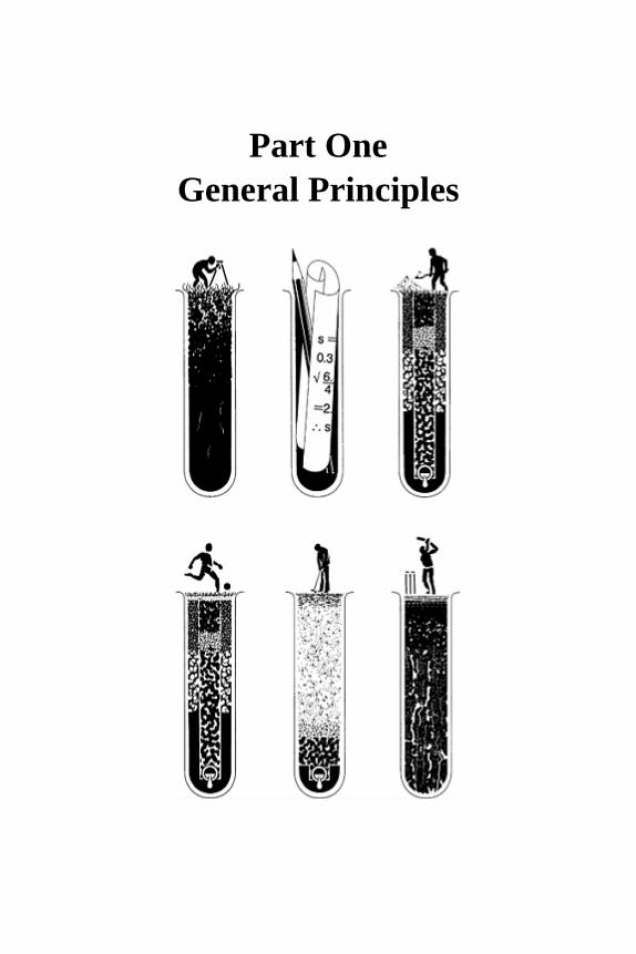
Part One General Principles


Chapter one
Identifying the problems

1.1 The needs of sport
Turf surfaces used for sport must be moist enough to sustain the grass, but not so moist asto affect adversely the quality of play. They will vary in character according to the specialrequirements of different games and the standard of provision that can be afforded. Forinstance, the artificial drainage system which a first-division soccer club might feel was essential to ensure play in all but the worst weather conditions could not normally beafforded or justified by the average sports club, or by a local authority responsible for theprovision and maintenance of playing fields out of public funds.
Those involved in new constructions are very frequently asked to specify the usage that can be expected from the final turf surface. Such a request seems reasonable, especiallyfrom a club or educational establishment for which use has to be matched to a fixture listor integrated into a fixed timetable. In this respect, however, grass pitches can be aproblem. Although grass is ideal as a playing surface when fit for play, it is not soreliably programmable as the more expensive synthetic surfaces.
An improvement in the quality of a surface, suiting it better to the skills of the game,can often be quite easy to assess. For example, the pace of a cricket pitch can bedetermined by the rebound of a cricket ball dropped dead onto the playing surface from aheight of 4.88 m (16 ft). A bounce height of less than 508 mm (20 in) is slow, 508–635 mm (20–25 in) easy paced, 635–726 mm (25–30 in) fast, and so on. The time a perfectly weighted bowl will take to roll to a stop over a standard distance of 30 yards (27.42 m)can be used to assess objectively the pace of a bowling green. A slow green will require aweighty, robust delivery to achieve the distance but will rapidly decelerate as it reachesthe mark, rolling to a halt in only 8–10 seconds after release. This compares with 14–18 seconds for a fast green where the bowl can be delivered with much less weight, or the 21seconds that can be achieved on New Zealand’s Cotula greens.
Improved performance in terms of the number of games a surface will take in a given period, though often asked for, is difficult to specify. Intensive use probably begins attwo adult games a week and accumulative damage can become critical at three games aweek, even if play is avoided when the surface is squelchy. One game played on asquelchy surface, at any time in the winter, may so damage the sward as to affectperformance for the rest of the season.
If play is confined to the summer period or to children of 12 or under, these criteria change dramatically. Five games per week, avoiding squelchy conditions, mightrepresent intensive use by children, but here the quality of play can be a problem,concentrating damage down the centre of the pitch and especially in the goal areas.
These conclusions on wear are supported by evidence of the following type.
1. A senior club playing first and second team games on their main home pitch may well average two games per week each season. By the end of the season most of these pitches are badly in need of far more renovation work than the average school or parks pitch would expect to get.
2. An extensive vegetation and soil survey of league soccer pitches at the end of one
season revealed how frequently pitch deterioration was blamed by the groundsman on the one game that was played when it should not have been (Thornton, 1978). The trouble is that once the sward has been broken there is virtually no chance of recovery during the winter. Instead, bared areas tend to extend because of the low shear strength of the non-root-bound surface.
3. Tear wear begins when a stud or heel breaks into the surface. This is most likely to happen when the surface is wet. A well-drained soil, though moist, will often feel firm underfoot. Under these conditions the weight of a child is scarcely sufficient to cause studs to penetrate but, with adults, stud penetration may be readily achieved. This explains the big difference in the effect of child and adult use, a point not always taken into account by those who advocate the dual use of school playing fields by children and adults.
4. A qualitative scale used in agriculture to monitor surface wetness after drainage makes use of the following hierarchy of categories:
(a) hard and cracked; (b) firm and dry but not cracked; (c) firm and moist; (d) moist and soft; (e) squelchy in patches; (f) squelchy all over; (g) pools of standing water; (h) surface awash.
If we could persuade referees, who are the only people officially sanctioned to cancel agame, to cancel all games when at least one third of the surface is squelchy, and to allowgames only exceptionally, i.e. no more than one game in a week, when the surfaceremains moist and soft, the staying power of our swards would be greatly enhanced.
5. Even with the same soil and the same general intensity of use, effects determined by climate, shading and standard of maintenance may also modify performance, as in the following examples.
(a) Features of climate such as rainfall and temperature vary significantly across Britain. Thus, in Wales, there is a risk of ‘puddling’ or ‘poaching’ because of excess soil moisture from September onwards, whereas in East Anglia, the same conditions are not to be expected until the beginning of December. In the north they have more frequently to face the dual hazards of rain and frost.
(b) Shading by grandstands can weaken growth through reduction in light intensity, reduced evaporation and increased persistence of frost.
(c) Height of cut, frequency of cutting, regular over-seeding with the stronger-growing grasses, proper fertilizing, pest control, special treatment and care of goal areas, the immediate treading back of turf torn out during play: all these features, in addition to good drainage, distinguish good maintenance from bad and affect the survival of a sward through the winter.
(d) Park pitches or school pitches cannot always be patrolled out of hours to stop boys ruining the goal areas by ‘kicking in’. Children would rather have the alternatives of
Sports Turf 6
mini-goals and a mini-pitch of their own but too few of these are provided.
With so many factors contributing to the fate of a sward in use through the winter itwould be foolhardy at present to predict the consequences of any particular pattern ofusage defined solely in terms of hours of play. What can be said is that soundconstruction, good maintenance, a dry climate and discretion in use will all contributefavourably.
1.2 Effects of poor drainage
Poor drainage quickly becomes apparent as soon as too much play is permitted in wetweather. It may then be too late to remedy the situation until the winter is over andmeantime, poor playing conditions, cancellations and disruption of fixture lists willprobably be difficult to avoid. It is, however, the long-term effects which are likely to bemost damaging. Excess surface moisture over a long period will generally lead to:
• greatly reduced aeration of the soil; • reduced root development; • less resistance to tear wear; • less resistance to drought; • inefficient use of plant nutrients; • late and slow growth in the spring; • increased susceptibility to disease.
The end result is a grass cover insufficiently durable to support the amount of usenormally expected from a winter games pitch.
Most of our sports-field drainage problems are not to be attributed to the ill effects oftoo high a ground watertable. More typically, water from a shower of rain fails topenetrate below the immediate surface even though the soil beneath is quite dry. Theproblem, in fact, is one of free water perched over trapped air.
Though air appears to be empty space available for filling by water, air must be able toescape before water can move in to take over the space that the air occupied. The problembecomes clear when water is poured too rapidly into a narrow-necked bottle. The watercannot get in if it blocks the only passage through which the air can get out. This is verysimilar to the situation in soil when a period of intense rain floods the surface and theinfiltration of water is then impeded by water obstructing the upward escape routes forair. Thus drainage can become as much a matter of the movement of air as the movementof water.
The problem of the competition for pore space between water and air becomes worsethe more uniform the pore size. Given a range of pore sizes the capillary forces willensure that eventually the water is preferentially drawn into the smallest pores. Thisleaves the air to coalesce into progressively larger bubbles in the larger pore spaces,making escape even more difficult unless the large pores form part of a continuouschannel linked through to the surface. Here is one benefit that earthworms, old root runs,cracks and soil granulation can confer to the mature soil, but this structure may be lost
Identifying the problems 7
during disturbance and stockpiling. It explains why the click of air bubbles bursting canoften be heard if one jumps to shudder the soil round a temporary pool of surface pondedwater.
Only where the soil is well endowed with large pores and is closely underlaid by adrained gravel bed is air likely to be pushed down through the soil and cleared along withthe drainage water. In all other circumstances it has probably to be cleared back up to thesurface, a possibility more likely to occur in response to light rain that fails to flood thewhole surface. The gentle fine rain that the farmer prefers can be safely absorbed by awell-structured soil into the small pores within soil aggregates, leaving the large pores between aggregates free for the simultaneous escape of the displaced air. However, onthe ‘poached’, de-structured surface of an abused sports field the whole soil is small-pore in character and a false surface water table can be rapidly established over a drier layer of air-locked pores.
This is the classic situation that requires drainage water to be by-passed through specially installed, freely permeable, vertical slits, linking the surface directly though tothe underdrains.
1.3 Climate
Climatic effects of importance to sports turf are not to be summarized simply byreference to temperature and rainfall considered separately. Frequently, it is anevaporative effect caused by the interaction of rainfall and temperature that more clearlydistinguishes the nature of the climatic stress and the manner in which grass growth isaffected in different parts of the country.
Because the range of climatic data available in published form for the whole of GreatBritain and Northern Ireland is very limited, detailed consideration of climate, as itaffects the construction and maintenance of sports turf, will be illustrated by reference toan analysis based only on the figures for England and Wales (Table 1.1). All the figures used are average values for the period 1941–70, and have been directly extracted from, orderived from, information available in Meteorological Office or Ministry of Agriculturepublications. However, take note of the Meteorological Office warning: ‘…it is an unusual year that follows the average pattern.’
From the data on average monthly rainfall, quoted in Table 1, it is evident that rainfall in Britain is fairly uniformly distributed throughout the year with amounts generallyhigher in the north and west. The figures for potential transpiration in England and Walesquoted in Table 1.2 show that roughly 500 mm (20 in) of this is returned annually, directto the atmosphere. This loss varies little throughout England and Wales because it ismainly determined by the input of solar energy, a feature of latitude. However, the inputof solar energy varies tenfold between midsummer and mid-winter, hence the special significance of the figures for excess winter rainfall (Table 1.2).
Field capacity, in so far as it represents the normal drained state, three days after saturation, reflects the combined effect of site drainage and pore-size composition. It does not guarantee the ideal air/water balance of 70% of total pore space filled with water and
Sports Turf 8

30% free for aeration that would benefit healthy root activity. If the site is poorly drained,e.g. an enclosed hollow, the soil within it may remain waterlogged for long after thethree-day period has elapsed, continuing to receive water as it drains down from higherup the slope. But even if the site is not in a receiving location, or does not restrict waterloss, the pores of the soil may be so small that they cannot be cleared of the water theyhold by capillarity, against the force of gravity, but only in response to the much slowerprocess of evaporation upwards. However, a well-structured soil (Figure 1(c)) in a free-draining site will lose water from the large, more than 30 µm diameter pores, between the water-stable, particle aggregations, and thereby will admit air. Meantime, the small pores,less than 30 µm in diameter, between the soil particles bound together within the aggregates, will retain their water, much of it released only in response to root absorption.A freely drained, well-structured soil, left undisturbed after saturation, may well, in threedays or less, achieve an ideal, air/water state for healthy root activity, but it may also stillbe sufficiently wet to smear and poach into a compact, destructured state, if animals,humans, or heavy machines are allowed to traffic across it. Only a frozen soil or a dry,clay-rich soil has sufficient structural cohesion to resist collapse in these circumstances. Thus, because even our free-draining, well-structured loam soils are liable to fill up and hover around or above field capacity from sometime in the autumn to sometime in thespring, throughout this period
Identifying the problems 9
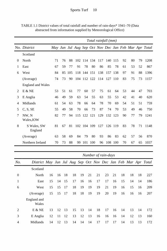
TABLE 1.1 District values of total rainfall and number of rain-days* 1941–70 (Data abstracted from information supplied by Meteorological Office)
Total rainfall (mm)
No. District May Jun Jul Aug Sep Oct Nov Dec Jan Feb Mar Apr Total
Scotland
0 North 71 76 88 102 114 134 117 140 115 92 80 79 1208
1 East 67 59 77 91 78 80 86 85 78 61 53 52 867
6 West 84 85 105 118 144 151 138 157 138 97 91 88 1396
(Average) 74 73 90 104 112 122 114 127 110 83 75 73 1157
England and Wales
2 E & NE 53 51 61 77 60 57 75 61 64 53 44 47 703
3 E Anglia 46 49 59 63 54 55 63 55 53 42 41 40 620
4 Midlands 61 54 63 78 66 64 78 70 69 54 51 51 759
5 C, S, SE 55 49 58 70 66 73 87 74 70 53 49 46 750
7 NW, N Wales,IOW
82 77 94 115 122 121 129 132 123 90 77 79 1241
8 S Wales, SW England
81 67 81 102 104 109 127 126 119 83 78 71 1148
(Average) 63 58 69 84 79 80 93 86 83 62 57 56 870
Northern Ireland 70 73 88 99 101 100 96 108 100 70 67 65 1037
Number of rain-days
No. District May Jun Jul Aug Sep Oct Nov Dec Jan Feb Mar Apr Total
Scotland
0 North 16 16 18 18 19 21 21 23 21 18 18 18 227
1 East 15 14 15 17 16 16 17 17 16 15 14 14 186
6 West 15 15 17 18 19 19 19 21 19 16 15 16 209
(Average) 15 15 17 18 18 19 19 20 19 16 16 16 207
England and Wales
2 E & NE 13 12 13 15 13 14 18 17 16 14 13 14 172
3 E Anglia 12 11 12 13 12 13 16 16 16 14 12 13 160
4 Midlands 14 12 13 14 14 14 17 17 17 14 13 13 172
Sports Turf 10
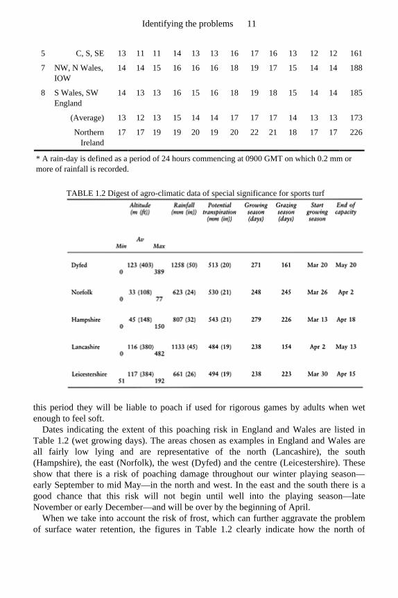
TABLE 1.2 Digest of agro-climatic data of special significance for sports turf
this period they will be liable to poach if used for rigorous games by adults when wetenough to feel soft.
Dates indicating the extent of this poaching risk in England and Wales are listed inTable 1.2 (wet growing days). The areas chosen as examples in England and Wales are all fairly low lying and are representative of the north (Lancashire), the south(Hampshire), the east (Norfolk), the west (Dyfed) and the centre (Leicestershire). Theseshow that there is a risk of poaching damage throughout our winter playing season—early September to mid May—in the north and west. In the east and the south there is agood chance that this risk will not begin until well into the playing season—late November or early December—and will be over by the beginning of April.
When we take into account the risk of frost, which can further aggravate the problemof surface water retention, the figures in Table 1.2 clearly indicate how the north of
5 C, S, SE 13 11 11 14 13 13 16 17 16 13 12 12 161
7 NW, N Wales, IOW
14 14 15 16 16 16 18 19 17 15 14 14 188
8 S Wales, SW England
14 13 13 16 15 16 18 19 18 15 14 14 185
(Average) 13 12 13 15 14 14 17 17 17 14 13 13 173
Northern Ireland
17 17 19 19 20 19 20 22 21 18 17 17 226
* A rain-day is defined as a period of 24 hours commencing at 0900 GMT on which 0.2 mm or more of rainfall is recorded.
Identifying the problems 11
England is likely to lose out on both wetness and frost, indicating a special need fordrainage and under-soil heating, whereas the south is the region most favoured.
By contrast, when the figures indicative of summer drought risk are considered (Table 1.2) these show that it is in the east, south and central regions of England that provision for irrigation might well be considered.
The start and the end of the growing season, as recorded in Table 1.2, is based on a threshold value for soil temperature of 6°C (43°F) at 300 mm (12 in) depth. Well belowthe surface the seasonal trends are more easily distinguished, uncomplicated by short-term effects of day-and-night or day-to-day fluctua-
tions. At 6°C on the surface, seeds will readily germinate. However, experience in WestWales suggests that the threshold value of 9–10°C (48–50°F) at the more easily reached depth of 250 mm (10 in) corresponds well with the onset of vigorous grass growth.
Soil temperature is well worthwhile monitoring weekly, from the end of February to the end of May, and again from the beginning of September to the middle of November,following the onset of growth in the spring and the cessation of growth in the autumn(Appendix 7). This can be done most easily under a uniform, fully exposed sward, eachtime using a metal spike to create a new hole for a metalshielded soil thermometer torecord the temperature at the required depth. Leave the thermometer in place for at leasttwo minutes to equilibrate. Record the information in a diary, or on a graph, plottingtemperature according to date. Also, at the same time, make notes on the weather, andany vegetation response such as grass starting to grow, daffodils starting to bloom, appletrees in blossom, tortoise stirring from its winter hibernation. All such events, both at thestart and the end of the growing season, will be seen to be related to soil temperature, and
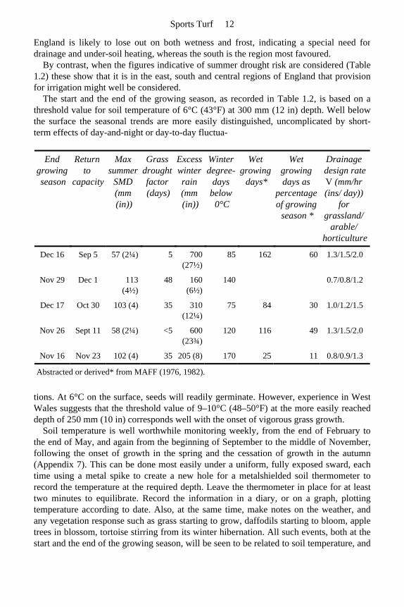
End growing season
Return to
capacity
Max summer
SMD (mm(in))
Grass drought factor (days)
Excess winter rain (mm (in))
Winter degree-
days below
0°C
Wet growing
days*
Wet growing days as
percentage of growing
season *
Drainage design rate V (mm/hr(ins/ day))
for grassland/
arable/ horticulture
Dec 16 Sep 5 57 (2¼) 5 700 (27½)
85 162 60 1.3/1.5/2.0
Nov 29 Dec 1 113 (4½)
48 160 (6½)
140 0.7/0.8/1.2
Dec 17 Oct 30 103 (4) 35 310 (12¼)
75 84 30 1.0/1.2/1.5
Nov 26 Sept 11 58 (2¼) <5 600 (23¾)
120 116 49 1.3/1.5/2.0
Nov 16 Nov 23 102 (4) 35 205 (8) 170 25 11 0.8/0.9/1.3
Abstracted or derived* from MAFF (1976, 1982).
Sports Turf 12
the reasons for variations, one year to another, explained. In time, the pattern of soiltemperature response for the locality will become evident and put to practical use forpredicting when best to sow seed or apply fertilizer, with good prospects of achieving thedesired response.
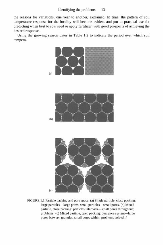
Using the growing season dates in Table 1.2 to indicate the period over which soiltempera-
FIGURE 1.1 Particle packing and pore space. (a) Single particle, close packing: large particles—large pores; small particles—small pores. (b) Mixed particle, close packing: particles interpack—small pores throughout; problems! (c) Mixed particle, open packing: dual pore system—large pores between granules, small pores within; problems solved if
Identifying the problems 13
granules water-stable.
ture is likely to favour growth, and the grazing season dates as indicating the soilmoisture state, we can estimate the number of days in the spring and autumn when soiltemperatures encourage growth but the roots supporting this growth have to function in asoil that is likely to be too wet for adequate aeration. Note the widely varying length ofthis period for the five regions of England and Wales being considered. These figureshave been derived from the difference in days between the date given for the start of thegrowing season in spring and the end of the poaching risk, plus the days between the dategiven for the return of the poaching risk in autumn and the end of the growing season.These totals point to very clear regional differences in the growing conditions likely to beexperienced by grass across England and Wales. It could well be this feature of climatethat has most to do with the variable performance in Britain of ‘continental’ grass species such as Poa pratensis (smooth-stalked meadowgrass). This potentially highly desirable,sports turf species, that does so well in parts of the USA, is claimed to be successful inNorfolk, but the many varieties so far tested in Dyfed have all succumbed hopelessly todisease.
It would be interesting to know more about the performance of Poa pratensis in the other regions, intermediate between these two extremes—for example, is Leicestershire favourable but Lancashire not?
The purpose of this brief review of some of the direct and indirect effects of climate on soil conditions has been to show how variable this can be even within the relatively smallarea represented by the lowlands of England and Wales. The extent of this variation issuch that it should not be ignored when interpreting the behaviour of existing pitches, ordesigning new, anywhere in Britain. For example, we should be less willing tocompromise on an overall design rate of 50 mm (2 in) per 24 hours for drainage in thenorth and west of Britain than in the south-east; more inclined to include Poa pratensis in a seeds mixture for sports turf in the south and east of England and less so elsewhere inBritain; more inclined to consider undersoil heating for professional sport in the north,east and inland areas of Britain, and more inclined to make provision for irrigation in thesouth-east.
1.4 Soil texture and soil structure
In site preparation for playing fields the first step is to provide a true surface, relieved andprotected by peripheral interception drainage. The next step is to make certain that thesoil on the playing area will infilter the water required to sustain grass growth and clearexcess so as to maintain an adequately aerated soil environment for healthy rootdevelopment. The means by which any given soil will have to be managed to achieve thedesired air/water balance will depend on its texture. The extent to which it is alreadyappropriately organized will depend on its structure.
While the qualities of soil structure are those concerned with the shape and stability ofthe functional units, loose particles, granular aggregates, clods, etc. into which the raw
Sports Turf 14

materials are organized, and through which the nature of the living space is determined,qualities of soil texture are those reflecting the nature of the primary components, stones,sand, silt, clay and organic matter.
Identifying the problems 15
1.4.1 Soil texture
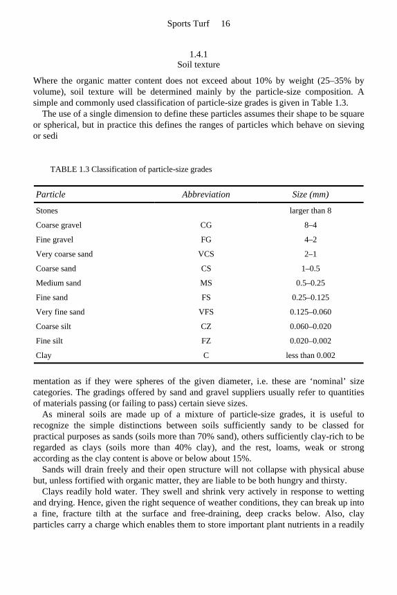
Where the organic matter content does not exceed about 10% by weight (25–35% by volume), soil texture will be determined mainly by the particle-size composition. A simple and commonly used classification of particle-size grades is given in Table 1.3.
The use of a single dimension to define these particles assumes their shape to be square or spherical, but in practice this defines the ranges of particles which behave on sievingor sedi
mentation as if they were spheres of the given diameter, i.e. these are ‘nominal’ size categories. The gradings offered by sand and gravel suppliers usually refer to quantitiesof materials passing (or failing to pass) certain sieve sizes.
As mineral soils are made up of a mixture of particle-size grades, it is useful to recognize the simple distinctions between soils sufficiently sandy to be classed forpractical purposes as sands (soils more than 70% sand), others sufficiently clay-rich to be regarded as clays (soils more than 40% clay), and the rest, loams, weak or strongaccording as the clay content is above or below about 15%.
Sands will drain freely and their open structure will not collapse with physical abuse but, unless fortified with organic matter, they are liable to be both hungry and thirsty.
Clays readily hold water. They swell and shrink very actively in response to wettingand drying. Hence, given the right sequence of weather conditions, they can break up intoa fine, fracture tilth at the surface and free-draining, deep cracks below. Also, clayparticles carry a charge which enables them to store important plant nutrients in a readily
TABLE 1.3 Classification of particle-size grades
Particle Abbreviation Size (mm)
Stones larger than 8
Coarse gravel CG 8–4
Fine gravel FG 4–2
Very coarse sand VCS 2–1
Coarse sand CS 1–0.5
Medium sand MS 0.5–0.25
Fine sand FS 0.25–0.125
Very fine sand VFS 0.125–0.060
Coarse silt CZ 0.060–0.020
Fine silt FZ 0.020–0.002
Clay C less than 0.002
Sports Turf 16
available state, thereby promoting fertility. The wide range of particle sizes present in loams encourages inter-packing and hence
fineparticle dominance of the pore system (Figure 1.1(b)). In their natural state loams have insuf-ficient sand to avoid the need for structure development to facilitate drainage and insufficient clay to structure themselves by intensive cracking. They are dependenton biological processes to be physically conditioned into the water-stable, granular state which is typical of a loam in ‘good heart’. This structure allows for water and nutrientretention within granules and free drainage between (Figure 1.1(c)) but is liable to collapse under physical abuse or decay of the organic binding agents.
If a system of granular aggregation disintegrates, the open structure will readily collapse to a compact arrangement of individual particles, very liable to hold water to theexclusion of air. Only clay-textured soils have sufficient clay to develop the bindingstrength necessary to resist collapse in the absence of any assistance from organic bindingagents. A loam, therefore, is potentially a problem soil. It is dependent on assistance fromorganic agents and biological processes for both the development and retention of theopen structure that it, like any other soil, requires to meet the demands of normal plantsfor easy root access, through well-aerated channels to adequate reserves of water. But both the biology and the open structure are liable to be adversely affected by humanactivity, e.g. failure to return organic residues, elimination of the vital soil organisms andphysical abuse leading directly to soil recompaction, much of which would appear to beinevitable under the management considered to be appropriate for sports turf.
The soil texture classes distinguished on a triangle of texture (Figure 7.1(a)) make no reference to stones or organic matter content, but no classification of soil texture iscomplete without some further, qualifying reference to these components—details are given in Appendix A, section A.5.2, pages 219–222.
Simple tests enabling soil texture and soil structure to be assessed are also described in Appendix A.
1.4.2 Soil structure and drainage
The extent to which water will either accumulate on the surface of the soil, or infilter,will depend on the intensity of the rainfall and the nature of the soil’s pore system, i.e. its structure. Pore sizes required for rapid infiltration and air release are large enough to beseen by the naked eye (macro-pores), the smallest correspond to those that would be formed by close-packed, very fine sand. Most soils in Britain have sufficient silt and clay in their make-up for these very fine particles to fill all the potential macro-pore space between any sand particles present, creating a structure entirely dominated by water-holding micro-pores (Figure 1.1). Thus for most soils in Britain, soil compaction must beavoided if the rapid infiltration of surface water is to be satisfactorily achieved.
Though sands and loamy sands, being more than 70% sand, may avoid becoming micro-pore dominated even when compact, and some soils that are adequately clay-rich may periodically regenerate an open structure by intensive cracking, for the greatmajority of soils, the loams, an open, free-draining structure can only be developed by a combination of cracking, root activity, worm tunnelling and worm aggregation. However,
Identifying the problems 17
this favourable, water-stable structure can be dispersed during storage and will fail toregenerate if earthworm activity is discouraged (Stewart and Scullion, 1989). It can bechurned out of existence by foot traffic if the surface is wet. It is at most risk when ourwinter games season is at its peak and most cattle farmers would have their animalscorralled on concrete. It is surprising, therefore, that any of our recreational areas escapelong periods of waterlogging during the winter.
The best hope for intensively used grass surfaces is to utilize adequately sandy surfaces linked to some system of sand-stabilized, vertical drainage. The aim should be to by-pass any compaction within the indigenous soil, clearing excess water laterally to a linked system of under-drains for final discharge off site.
The only alternative to sand or sand-modified soils for recreational use is to select awell-granulated, worm-worked, naturally free-draining soil and a site requiring minimalregrading so as to avoid the major soil disturbance of cut-and-fill. Use should then be controlled to give absolute priority to the well-being of the soil and the biological components responsible for its conditioning—see Tables 6.1 and 6.2.
1.5 Soil texture amelioration
For the satisfactory drainage of structureless soil it may be expedient to amend the textureto provide an adequate infiltration rate. To achieve this, sufficient sand must be added tobring the percentage of medium plus fine sand particles to at least 70%. Depending uponthe range of particle sizes present in the particular sand selected, the total proportion ofsand to silt and clay may have to be anything up to 90% to ensure a sufficient content ofsand in the medium-plus-fine range. Thus, in practice, the ratio of sand to topsoil couldvary from 2:1 to as much as 5:1. A method of calculating the amount of a specific sandrequired for the textural amelioration of a particular topsoil is described in Appendix 3.
1.6 Gradients and undulations
Although level grass surfaces are capable of being drained artificially, a slight slope isdesirable as a means of encouraging surface run-off following intense rainfall. Dependingon the standard of play anticipated, for team games a uniform gradient of between 1:50and 1:100 should be aimed at. Whenever possible, pitches should be sited so that they areas level as possible along their length with the crossfall occurring over their width.
To prevent ponding, particularly where major grading is involved, it is of the utmost importance that the final consolidation of both the subsoil and the playing surface is verycarefully carried out to avoid any chance of subsequent, differential settlement. Even ahollow left in a clay subsoil could retain water infiltrating through the topsoil and resultin that part of the pitch becoming wetter than the rest. It is worth noting that a generalslope of 1:50, on the surface, will not be sufficient to ensure the complete emptying of asurface depression 5 m (16 ft) in diameter, if the dip in the depth of the hollow exceeds
Sports Turf 18

50 mm (2 in).
1.7 Use and design rate
The extent to which artificial drainage is likely to be required depends not only on thenatural drainage capacity of the land and the rainfall expectancy, but also on the type andamount of use to which the playing surface may be subjected. Use factors which shouldbe taken into account include:
• the games to be catered for; • the standard of play; • the number of games and training sessions per pitch, weekly; • the pattern of use, e.g. weekends only, or weekends and mid-week, or both; • the age of the players, e.g. adults, school children, or both; • cancellation repercussions, e.g. loss of gate money or problems over time-tabling; • extent of any additional, casual use, e.g. for training or by local children kicking into a
goal. Casual use leading to localized severe wear can become such a problem that it may be worthwhile providing a purpose-made alternative on land specifically set aside.
A knowledge of these factors is necessary to enable the designer to arrive at anappropriate rate of drainage sufficient to satisfy the requirements of a given set ofcircumstances. This may be anywhere between an agricultural rate of 12 mm (0.5 in) of rainfall a day (24 hours) for a public recreation ground in the south-east of England, and 12 mm (0.5 in) an hour for golf and bowling greens. For the average winter games pitchit is likely that a design rate of 50 mm (2 in) a day will be adequate.
This means that the only grounds likely to have a natural drainage rate good enough to meet the requirements of winter games are those with the right kind of sand content in thetopsoil and a free-draining subsoil. However, most sports grounds in Britain are based onsoils with a much lower sand content than the 70% which is required and, therefore, mostdemand the assistance of some form of supplementary artificial drainage.
Where a gradient has been improved by major grading operations, thereby disruptingthe natural drainage channels, extra provision will have to be made for the interception ofextraneous water encroaching through the subsoil or as surface run-off.
Identifying the problems 19

1.8 The site
A thorough diagnosis of a drainage problem takes time and can be expensive.
1.8.1 Type of information required
1. An accurate plan of the area showing the banks and other physical features with details of any existing rights of way, drainage runs, manhole, siltpits, outfalls, perimeter drains, ditches and public utilities conveying gas, water, electricity or sewage.
2. A grid survey of surface levels at a minimum of half-metre height intervals to provide for contours of the area to be drained. Also record outfall levels and related benchmark.
3. Evidence from soil pits of the nature and extent of soil variation across the site to a depth of at least 500 mm (20 in). For a natural, undisturbed site, use evidence of variation in slope and vegetation to define areas likely to be uniform in character and dig trial holes in the centre of each of these. Then, confirm boundaries by auger examination of soil between the initial trial holes. On an existing pitch, which may well be on disturbed land, explore first within the four corner areas, in both goalmouths and at the centre, then supplement with auger examination. The evidence from the corner areas should indicate the general nature of the soil construction and the evidence from the goalmouths and the centre may well indicate any previous remedial action taken to cope with severe wear. The following features should be recorded:
(a) the depth and character of both topsoil and subsoil; (b) the depth and type of other material such as rock, sand and buried rubbish that
might affect the drainage layout; (c) whether ground water is present and, if so, the estimated level of the watertable at
different seasons; (d) whether the stone content of the soil to drain depth is such that it could cause
serious problems in trench excavation, subsoiling, etc.
4. Further examination of any existing drains and outfalls to ascertain their depth, capacity and condition, and the nature and extent of any backfill.
5. Notes on vegetation and any minor surface irregularities to be taken into account when soil sampling.
6. Location of representative soil samples taken for mechanical and/or chemical analysis. In some cases visual examination of auger borings may provide all the information required.
7. Information on the history of the field, especially information of any constructional work, drainage and maintenance that might previously have been carried out. Interviews with people familiar with past performance to help establish why particular
Sports Turf 20
problems have arisen. 8. Copies of specifications, plans and relevant correspondence relating to previous work.
1.8.2 Interpretation of information obtained
1. If existing rights of way, water courses or public utilities traverse the area, the appropriate authorities will have to be approached to establish the nature of any restrictions they may wish to impose.
2. The existence or absence of perimeter catchment drains will help to determine whether water is reaching the site from surrounding areas either on the surface or along underlying strata. The absence of efficient perimeter interception is often a prime cause of water-logging problems.
3. The colour of the soil profile can be a useful pointer to its condition. Tints of blue, dark grey, olive green or black usually indicate that aeration is poor because of permanent waterlogging. Rust-coloured mottling, usually localized to old root runs, suggests that the soil is prone to waterlogging only at certain times of the year. On the other hand a profile which is a uniform shade of brown or reddish brown generally signifies that aeration is good and that there are no serious drainage problems.
4. Where there is an existing drainage system, it is important that the flow from the outfall and through inspection chambers and silt-pits is checked during a wet period, ideally in winter. Lack of flow at these times does not necessarily mean that the pipe system is at fault. Lack of any substantial drain flow response to heavy rainfall, combined with persistent surface ponding, probably indicates that surface water is not able to infiltrate through the topsoil to reach the pipe drains below. This is perhaps the most common form of drainage failure and can usually be demonstrated by the relative dryness of the soil below 50 mm (2 in).
5. Surface undulations and depressions, particularly on fine-textured soils, tend to nullify the advantages of having a slight gradient as they can effectively impede surface run-off. Even if examined during drought, the vegetation may provide clues to the normal state of affairs in these hollows. For example, infestation by sedges and rushes indicates waterlogging for long periods.
6. Both chemical and physical soil analysis is necessary to determine the important inherent characteristics of the soil, i.e. its potential fertility, its potential to drain and its potential to be changed.
1.9 Differences in drainage requirements of agricultural land and sports
grounds
Land configuration, soil and the nature of use intended are the main factors governing thetype and design of the artificial drainage required. Differences between the drainagerequirements for farm land and sports turf have their origin in the very artificial anddisturbed nature of many of our playing-field soils, and the extremes of wear to which
Identifying the problems 21
they are often subjected.
1.9.1 Nature of site
For agricultural purposes the natural slope of the land and the natural texture of the soilmust generally be accepted. For sport, on the other hand, it is sometimes possible, or evenessential to import soil, or to modify texturally the indigenous soil, for example, byincorporation of sand.
Now that efficient earth-moving equipment is freely available, levelling by cut-and-fill and artificial grading are procedures commonly used to provide the uniform surfacesrequired for sport. Thus sports turf surfaces are fre-quently based on disturbed and biologically degraded soils.
However, while a farmer has to contend with a multitude of drainage situations varyingin size, shape and slope, the person with playing surfaces to drain has more predictablesituations to deal with. Every field on a farm may be different, but football pitches andbowling greens, for example, are each very much of a kind, wherever they are. Thismakes it reasonable to work towards fairly standardized designs to meet the individualneeds of the different sports.
1.9.2 Nature of use
For successful farming it is necessary to have an open, water-stable structure, at least to plough depth. To preserve this ideal state, excessive and untimely cultivations must beavoided and caution exercised over grazing and the passage of vehicular traffic. Thewhole success of farming requires that the creation and preservation of an open, topsoilstructure is continually kept in mind.
A true clay topsoil, appropriately structured, may infilter water at a rate as high as 250mm (10 in) per hour and, if effectively mole-ploughed to drain across to an underground pipe system, may achieve an overall peak discharge rate of 50 mm (2 in) per day. Such asoil avoids ever becoming really waterlogged but, in practice, will maintain this level ofperformance only so long as the mole channels continue to function and the managementof the land does nothing to degrade its structure.
Unfortunately, the farmer’s open structure is neither strong nor long lasting. It can be dispersed by bad weather and damaged by machinery and the treading of animals. It canbe dissipated if not continually regenerated from within by the appropriate soil biology.On a sports ground a similar open soil structure can be poached out of existence byplayers treading the surface while it is wet. This risk to structure is greatest when theneed for rapid infiltration of excess surface water is most urgent, at the very time of yearwhen agriculturists would advise staying off. It can also be lost if the topsoil has beenstockpiled prior to spreading and will threaten trouble for years after construction. Afarmer is usually in the fortunate position of being able to exercise some control over thetiming of his various farming operations and the grazing of stock. A groundsman, facedwith pitches unfit for play, fixture lists prepared weeks or months in advance, and players
Sports Turf 22
with only limited free time available, has to accept the referee’s arbitration based solely on whether play of a reasonable standard can proceed without risk to the players. If thesurface cuts up, however, such indiscriminate use may initiate a trend in swarddeterioration that cannot be arrested until grass growth resumes in the spring.
Because a farmer can control his pattern of field use he can preserve his soil structureor help to regenerate it periodically by cultivation. This generally takes care of theproblem of surface infiltration and makes it possible to limit the height of the permeablefill over the pipe drains to that required to intercept mole drainage. However, becausetopsoil structure is unlikely to survive winter use we now realize that, for sport, methodsmust be devised to continue artificial drainage interception right through to the surface.
Until the mid-1960s the drainage of sports grounds followed very closely the principlesand practices used for the drainage of agricultural land. When the cost of land for sportsground purposes began to increase substantially it became widely appreciated that, toimprove the quality of the pitches and increase the number of games played each week,would require improved drainage, but the methods of drainage then practised were farfrom adequate for the task. Even expensive schemes of pipe drainage, thought by expertsto be well designed and efficiently executed, were often found to be largely ineffective when used for play in winter. The sight of a muddy playing surface with relatively drysoil at 75 mm (3 in) and no significant flow in the pipe system is by no means anuncommon spectacle.
In the late 1960s and 1970s the author, amongst others, began to develop an interest in new methods by which the problems of topsoil impermeability on sports grounds couldbe overcome. One result was a paper given to the annual National Playing FieldsAssociation Conference for Local Authorities and published in booklet form under thetitle Drainage Problems on Playing Fields (Stewart, 1971). The main recommendationthat emerged from this research was to use sand to form a direct link to the underdrains,either in the form of a superimposed ameliorated sand topsoil, or confined to narrowvertical slits at close centres. The situation gradually finding acceptance today is thatsatisfactory drainage design rates can only be maintained by techniques which are notonly more sophisticated than hitherto but also much more expensive.
1.10 Cost
Though soil drainage can now be organized with a reasonable expectation of achieving aspecific design rate, the problem in practice is to bring the new techniques within reach ofthe client’s financial resources.
Fortunately there are usually two or more different arrangements that will give approximately the same rate of drainage so that by juggling with such features as length,width and depth of slits, different grades of fill, spacing of underdrains, etc. it is possibleto arrive at the most economical permutation. Key factors in the equation are often thecost of sand and gravel and the labour and machinery costs for excavating the trenchesand slits. (Chapter 4 has detailed information on design criteria.)
Identifying the problems 23
1.10.1 Winter games pitches—soccer and rugby
Complete schemes
For the efficient drainage of sports grounds the importance of ensuring that surface wateris able to find its way fairly rapidly through the topsoil to the pipe underdrains is nowprobably well understood. It is not always appreciated, however, that the extra cost ofachieving this desirable state of affairs, e.g. by the inclusion of slit drains at 1 m spacing(Chapter 11), can be two to three times the cost of a conventional pipe drain layout for the same area. As an example of comparable costs (UK, 1988), if a senior-size soccer pitch cost £19 000 to drain satisfactorily to a design rate of 50 mm (2 in) a day, anapproximate breakdown of this total might be:
The spacing of the lateral underdrains for the slit drainage system described above islikely to be of the order of 15–20 m (16–22 yards), whereas the old type conventional system without slit drains would probably have been designed with laterals at a muchcloser spacing of 6.5 m (7 yards). On this basis the capital costs in 1988 of a pipe lateralsonly scheme, plus manholes, main and outfall, would probably have been in the region of£8000, i.e. much less than half the cost of a slit drainage scheme for the same size of pitch.
With slit drainage the financial implications for maintenance have also to be borne inmind. It will be found that unless steps are taken to repeat the initial application of fine sand topdressing, at least once a year, the slits will gradually become so soil capped thatthey will no longer be able to perform their function of channelling water from thesurface to the pipe underdrains. In addition, if the soil is at all clay-rich, there is always a tendency for depressions to form along the lines of the slits as an effect of soil shrinkageduring the summer (Figure 6.1).
It is therefore of vital importance that, in addition to the capital cost of installation, there must also be included in maintenance budgets a sum sufficient to ensure thatdressings of fine sand can be applied annually. A slit drainage scheme not protected inthis way could eventually turn out to be a waste of money.
Further information on cost benefit implications for the drainage of winter games pitches is given in Chapter 5.
Installation of outfall, manholes, main pipes and lateral underdrains £3 000
Slit drainage £12 000
Preparation and seeding of slits and damaged areas £3 500
Minimum initial fine sand topdressing before allowing play £500
Total £19 000
Sports Turf 24
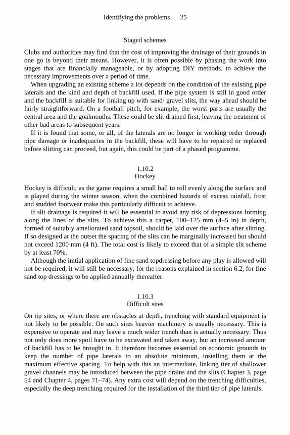
Staged schemes
Clubs and authorities may find that the cost of improving the drainage of their grounds inone go is beyond their means. However, it is often possible by phasing the work intostages that are financially manageable, or by adopting DIY methods, to achieve thenecessary improvements over a period of time.
When upgrading an existing scheme a lot depends on the condition of the existing pipelaterals and the kind and depth of backfill used. If the pipe system is still in good orderand the backfill is suitable for linking up with sand/ gravel slits, the way ahead should befairly straightforward. On a football pitch, for example, the worst parts are usually thecentral area and the goalmouths. These could be slit drained first, leaving the treatment ofother bad areas to subsequent years.
If it is found that some, or all, of the laterals are no longer in working order through pipe damage or inadequacies in the backfill, these will have to be repaired or replacedbefore slitting can proceed, but again, this could be part of a phased programme.
1.10.2 Hockey
Hockey is difficult, as the game requires a small ball to roll evenly along the surface andis played during the winter season, when the combined hazards of excess rainfall, frostand studded footwear make this particularly difficult to achieve.
If slit drainage is required it will be essential to avoid any risk of depressions forming along the lines of the slits. To achieve this a carpet, 100–125 mm (4–5 in) in depth, formed of suitably ameliorated sand topsoil, should be laid over the surface after slitting.If so designed at the outset the spacing of the slits can be marginally increased but shouldnot exceed 1200 mm (4 ft). The total cost is likely to exceed that of a simple slit schemeby at least 70%.
Although the initial application of fine sand topdressing before any play is allowed willnot be required, it will still be necessary, for the reasons explained in section 6.2, for fine sand top dressings to be applied annually thereafter.
1.10.3 Difficult sites
On tip sites, or where there are obstacles at depth, trenching with standard equipment isnot likely to be possible. On such sites heavier machinery is usually necessary. This isexpensive to operate and may leave a much wider trench than is actually necessary. Thusnot only does more spoil have to be excavated and taken away, but an increased amountof backfill has to be brought in. It therefore becomes essential on economic grounds tokeep the number of pipe laterals to an absolute minimum, installing them at themaximum effective spacing. To help with this an intermediate, linking tier of shallowergravel channels may be introduced between the pipe drains and the slits (Chapter 3, page 54 and Chapter 4, pages 71–74). Any extra cost will depend on the trenching difficulties, especially the deep trenching required for the installation of the third tier of pipe laterals.
Identifying the problems 25
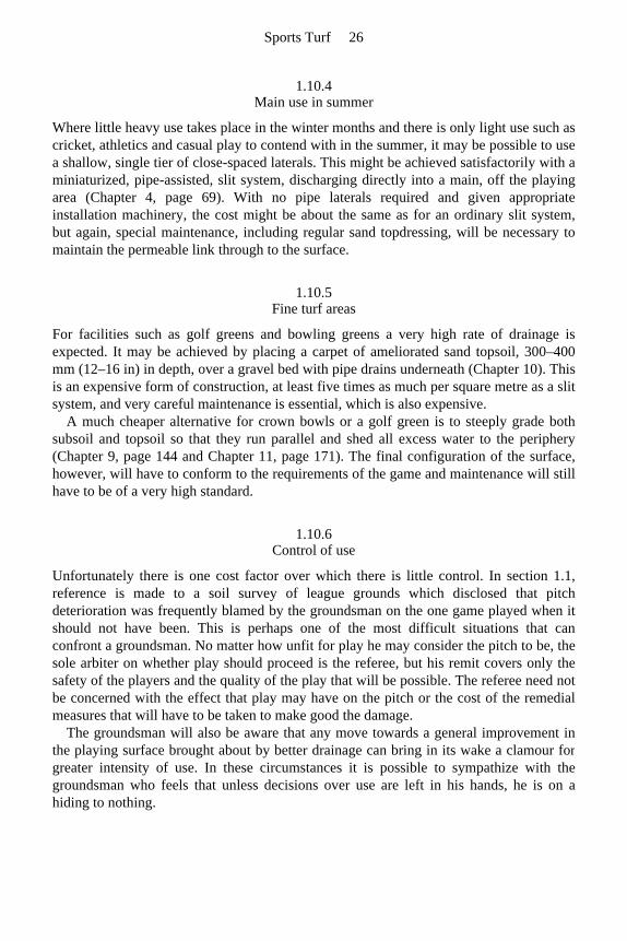
1.10.4 Main use in summer
Where little heavy use takes place in the winter months and there is only light use such ascricket, athletics and casual play to contend with in the summer, it may be possible to usea shallow, single tier of close-spaced laterals. This might be achieved satisfactorily with a miniaturized, pipe-assisted, slit system, discharging directly into a main, off the playing area (Chapter 4, page 69). With no pipe laterals required and given appropriate installation machinery, the cost might be about the same as for an ordinary slit system,but again, special maintenance, including regular sand topdressing, will be necessary tomaintain the permeable link through to the surface.
1.10.5 Fine turf areas
For facilities such as golf greens and bowling greens a very high rate of drainage isexpected. It may be achieved by placing a carpet of ameliorated sand topsoil, 300–400 mm (12–16 in) in depth, over a gravel bed with pipe drains underneath (Chapter 10). This is an expensive form of construction, at least five times as much per square metre as a slitsystem, and very careful maintenance is essential, which is also expensive.
A much cheaper alternative for crown bowls or a golf green is to steeply grade bothsubsoil and topsoil so that they run parallel and shed all excess water to the periphery(Chapter 9, page 144 and Chapter 11, page 171). The final configuration of the surface,however, will have to conform to the requirements of the game and maintenance will stillhave to be of a very high standard.
1.10.6 Control of use
Unfortunately there is one cost factor over which there is little control. In section 1.1, reference is made to a soil survey of league grounds which disclosed that pitchdeterioration was frequently blamed by the groundsman on the one game played when itshould not have been. This is perhaps one of the most difficult situations that canconfront a groundsman. No matter how unfit for play he may consider the pitch to be, thesole arbiter on whether play should proceed is the referee, but his remit covers only thesafety of the players and the quality of the play that will be possible. The referee need notbe concerned with the effect that play may have on the pitch or the cost of the remedialmeasures that will have to be taken to make good the damage.
The groundsman will also be aware that any move towards a general improvement in the playing surface brought about by better drainage can bring in its wake a clamour forgreater intensity of use. In these circumstances it is possible to sympathize with thegroundsman who feels that unless decisions over use are left in his hands, he is on ahiding to nothing.
Sports Turf 26

1.11 The importance of a clear, concise and comprehensive specification
For contractors and direct labour departments of public authorities to have a clearunderstanding of drainage work requirements, it is essential to prepare a sound andproperly detailed specification. This should include appropriate drawings and a bill ofquantities suitable as a basis for tendering.
Not only is a well drawn up specification essential for best results, it is also necessaryto enable contractors to tender on a common basis. A loosely worded specification, or nospecification at all, makes it impossible for tenders to be fairly compared.
If a contractor finds himself obliged to submit a specification with his quotation, he often words it in such a vague and equivocal manner that it is virtually impossible toarrive at any precise conception of what is to be provided for the money. Where it is theusual practice for the lowest tender to be accepted a situation may arise where acontractor, either through lack of the required experience, or because of uncertainty aboutthe authority’s requirements, quotes an unrealistically low price. He may then finish up doing a bad job to avoid losing money, or may himself lose money trying to do a goodjob. Either way it is unsatisfactory and all concerned are likely to suffer, includingreputable firms which may find themselves at a disadvantage through trying to maintaingood standards.
An increasingly serious problem is that those involved in soil disturbance, i.e.architects, surveyors, engineers, consultants, contractors, etc. are not always wellinformed on the biological basis of soil fertility and its significance for drainage. Thescientific content of this work has of late tended to change faster than the personnelconcerned. It is vital, therefore, that all are properly trained and keep abreast ofdevelopments. It is a sad state of affairs when only the most recent recruit is conversantwith the latest developments and the boss is isolated from enlightenment by his defensiveadherence to tradition. One aim of this book is to help senior personnel to updatethemselves, beyond rigid recipes to a more scientific understanding of general principlesthat will give them the confidence, not just to follow but to lead.
Where knowledge is lacking there is often a tendency to pass the buck to thecontractors in the sometimes mistaken assumption that they are the experts. The practiceof simply defining the end-product in terms of function, drainage design rate, or minimum time to playability after rain can lead in the end to expensive remedialmeasures and possible litigation.
A contractor is in business to make money and he can only do this if he is competitive.In the real world of commerce the sharp practice often necessary to achieve a competitiveadvantage can only be avoided by the employing authority setting out its requirements insufficient detail to ensure that they are fully understood. Only then can the specificationand terms of contract be effectively enforced by the employer while the work is inprogress.
There is a good moral reason for insisting on the employing authority itself preparing a detailed specification: it is manifestly unfair to put this time-consuming task onto the contractors when only one will get the contract. One practical consequence of this
Identifying the problems 27
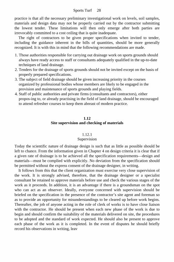
practice is that all the necessary preliminary investigational work on levels, soil samples,materials and design data may not be properly carried out by the contractor submittingthe lowest tender. These limitations will then only emerge after both parties areirrevocably committed to a cost ceiling that is quite inadequate.
The right of contractors to be given proper specifications when invited to tender, including the guidance inherent in the bills of quantities, should be more generallyrecognized. It is with this in mind that the following recommendations are made.
1. Those authorities responsible for carrying out drainage work on sports grounds should always have ready access to staff or consultants adequately qualified in the up-to-date techniques of land drainage.
2. Tenders for the drainage of sports grounds should not be invited except on the basis of properly prepared specifications.
3. The subject of field drainage should be given increasing priority in the courses organized by professional bodies whose members are likely to be engaged in the provision and maintenance of sports grounds and playing fields.
4. Staff of public authorities and private firms (consultants and contractors), either propos-ing to, or already practising in the field of land drainage, should be encouraged to attend refresher courses to keep them abreast of modern practice.
1.12 Site supervision and checking of materials
1.12.1 Supervision
Today the scientific nature of drainage design is such that as little as possible should beleft to chance. From the information given in Chapter 4 on design criteria it is clear that if a given rate of drainage is to be achieved all the specification requirements—design and materials—must be complied with explicitly. No deviation from the specification shouldbe permitted without the express consent of the drainage designer, in writing.
It follows from this that the client organization must exercise very close supervision of the work. It is strongly advised, therefore, that the drainage designer or a specialistconsultant be retained to approve materials before use and check the various stages of thework as it proceeds. In addition, it is an advantage if there is a groundsman on the spotwho can act as an observer. Ideally, everyone concerned with supervision should bebriefed on the specification in the presence of the contractor’s site agent and foreman so as to provide an opportunity for misunderstandings to be cleared up before work begins.Thereafter, the job of anyone acting in the role of clerk of works is to have close liaisonwith the contractor. He should be present when each new phase of the work is due tobegin and should confirm the suitability of the materials delivered on site, the proceduresto be adopted and the standard of work expected. He should also be present to approveeach phase of the work as it is completed. In the event of disputes he should brieflyrecord his observations in writing, leav
Sports Turf 28
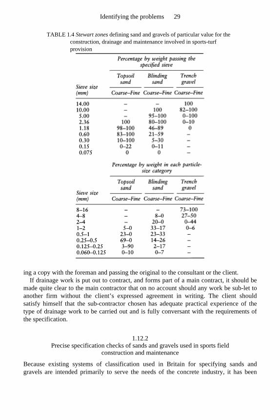
TABLE 1.4 Stewart zones defining sand and gravels of particular value for the construction, drainage and maintenance involved in sports-turf provision
ing a copy with the foreman and passing the original to the consultant or the client. If drainage work is put out to contract, and forms part of a main contract, it should be
made quite clear to the main contractor that on no account should any work be sub-let to another firm without the client’s expressed agreement in writing. The client should satisfy himself that the sub-contractor chosen has adequate practical experience of thetype of drainage work to be carried out and is fully conversant with the requirements ofthe specification.
1.12.2 Precise specification checks of sands and gravels used in sports field
construction and maintenance
Because existing systems of classification used in Britain for specifying sands andgravels are intended primarily to serve the needs of the concrete industry, it has been
Identifying the problems 29

found necessary to develop an alternative system for sports turf. This is summarized inTable 1.4 and is discussed more fully in Chapter 7. It is these materials to which reference will be made from Chapter 2 onwards. They will be referred to as Stewart zone trench gravels, blinding sands or topsoil sands or, more commonly, just trench gravels, blinding sands or topsoil sands without reference to their Stewart zone origin. The limits of these zones are described analytically in Tables 1.4 and 7.1, and graphically in Figure 7.6.
Although the designs featured in this book have been matched to a closely specifiedrange of materials that are commonly available, it does not mean that materials outsidethis range are necessarily useless. A locally available material may have a distinct costbenefit and, by some modification of the general design, may well be utilized toadvantage by someone adequately trained to calculate the necessary adjustments.Experience suggests, however, that not all contractors or technicians are aware of whatmay be available outside that provided by a narrow range of suppliers whose primarypurpose is to meet the needs of the building and concrete industry. The advice is to shoparound yourself before accepting pronouncements, favourable or unfavourable.
Sports Turf 30
Chapter two
Components of a drainage scheme function and installation

2.1 Field drainage
2.1.1 Peripheral, cut-off or interception drainage
It is important to ensure that the field to be drained is protected against the influx of waterfrom surrounding land. Within-field drainage then needs to be designed to cope only with the excess rain falling onto the field itself. In some cases it may be found that a goodsystem of perimeter drainage will obviate the need for anything more.
If there is the slightest risk of extraneous water reaching the area to be drained, either on the surface or below ground, its interception must be assured by the installation ofappropriately sited drains before work on the within-field drainage system is allowed to proceed. Without this protection the drainage designer cannot specify accurately adrainage system to a given design rate.
Interceptor drains may be in the form of ‘French’ or catchment drains, or open ditches leading to outfalls capable of taking the full amount of water likely to be collected underpeak conditions. Ideally, any peripheral interceptor drain should be monitored as an opentrench for a year to assess the efficiency of interception and the amount of flow, beforepiping and backfilling.
‘French’ or catchment drains
These are often fairly wide, tapering trenches, perhaps 300–450 mm (12–18 in) at the top, filled with clean, 12–38 mm (½–1½ in) stone, or 6–10 mm (¼–⅜ in) gravel, to within 25–50 mm (1–2 in) of the ground surface. The depth is usually between 600–900 mm (2–3 ft) but may be more where there are deep underground flows requiring interception.There should be a good fall towards the outfall. If the accumulation of water at peakperiods of rainfall is likely to be high, the rate of flow will be greatly improved if drainpipes of adequate capacity are laid along the bottom of the trench for at least the lowerpart of its length. This type of drain is widely used for interception along boundaries andat the foot of banks; also as a main where it can be sited clear of the playing and spectatorareas.
In certain situations, for example, as a catchment drain around a football pitch, or within banks where a continuous grass surface is required, a narrower trench, some 250mm (10 in) wide, may suffice. This should be piped if necessary and backfilled with trench gravel to within 100 mm (4 in) of the surface, then topped with blinding sand to ground level without a fine soil capping.
Open ditches
Ditches that are regularly cleaned out and maintained are the most effective water carriersas they are generally of large capacity with little or no impediment to the flow of water.On play areas, where they are in the way but have a drainage use, they must be piped
Components of a drainage scheme function and installation 33
before filling in. Elsewhere, such as along side boundaries, it is usually advantageous tokeep them open but they will then require proper maintenance. Open ditches are the bestsolution for the interception of surface run-off but, for the interception of undergroundwater only, they need not be kept open. Whether open or piped, however, they should bemade deep enough to ensure that all potentially troublesome flows are properlyintercepted.
2.1.2 Within-field, pipe underdrainage
Mains and laterals
The function of a lateral is to intercept water moving towards it through the soil or overthe surface. It should be looked upon as the combined system of perforated pipe andpermeable backfill, all contained within the same trench. The purpose of the permeablefill is to improve the efficiency of interception and direct the captured water down to apipe, perforated to accept it throughout its length, then convey it onwards to a main.
The function of a main is to collect drainage water gathered by the laterals and convey it without loss to the intended outfall. In a grid system, where slit drainage is proposed,the mains pipe should not normally be perforated and there is no need for the trenchbackfill to be other than soil. From the cost point of view this is an advantage, as tobackfill with gravel what is often a wide and progressively deepening trench, could bevery expensive.
Where a lateral pipe is perforated and surrounded by gravel, there is every chance thatwater will enter and flow laterally through the gravel as well as the pipe. At the junctionwith the main, therefore, there could be a problem because of water from the gravelaccumulating in the soil above and around the closed main. For this reason some largepipes are made to the design illustrated in Figure 2.1. The bottom half is unperforated and intended to be bedded within a purpose-made trough in the soil so that it can act as the main channel for water flow. The top half is perforated and intended to be enveloped in ashallow depth of gravel, linked to the gravel at the base of the laterals. Thus the mainneed no longer lie in a water-logged trench, acting as a sump for water not confined to thepipe system. But such a pipe is relatively expensive and may not be locally available.
Banks
Where natural banks exist, or major grading is proposed, it will almost certainly benecessary to install interceptor drains to prevent water flowing down banks onto theplaying areas. If only one is to be installed it is best placed along the foot of the bank but,if the bank itself is to be kept dry and stable, an interceptor drain may also be necessary atthe top of the bank, or within the slope. For example, in the course of excavations duringgrading operations water-bearing strata may be exposed or old land drains disturbed.Special attention will then have to be given to intercepting any outflow, diverting it to asafe outfall before further work proceeds
Sports Turf 34
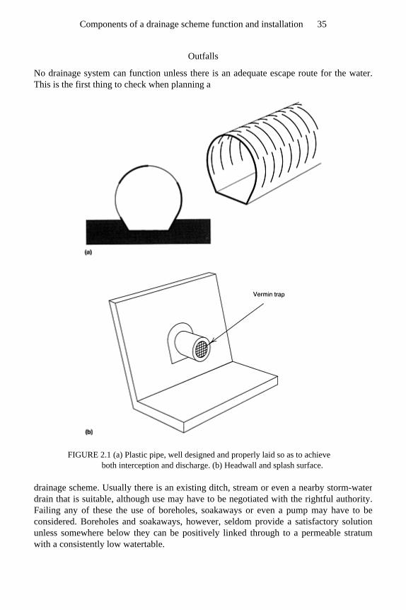
Outfalls
No drainage system can function unless there is an adequate escape route for the water.This is the first thing to check when planning a
FIGURE 2.1 (a) Plastic pipe, well designed and properly laid so as to achieve both interception and discharge. (b) Headwall and splash surface.
drainage scheme. Usually there is an existing ditch, stream or even a nearby storm-water drain that is suitable, although use may have to be negotiated with the rightful authority.Failing any of these the use of boreholes, soakaways or even a pump may have to beconsidered. Boreholes and soakaways, however, seldom provide a satisfactory solutionunless somewhere below they can be positively linked through to a permeable stratumwith a consistently low watertable.
Components of a drainage scheme function and installation 35
Pumps, either electric or diesel, are used mostly for the drainage of agricultural land but are also available for use on small areas such as sports grounds. They are generallycapable of operating automatically when water in a sump reaches a given height. Asolution on these lines, however, is not recommended, except in very specialcircumstances, as such equipment, with its ancillary housing, is expensive to install andrequires periodic attention to ensure that it is always in satisfactory working order. Usefulinformation on pumping systems is given in the MAFF leaflet, No. 14 Pumped Field Drainage.
All outfalls into ditches should be above peak high water wherever possible and atleast 150 mm (6 in) above normal water level. The outfall pipe should discharge througha properly built headwall and be fitted with a flap valve or vermin trap (Figure 2.1(b)). At least the last 1.5 m (5 ft) of buried pipe should be of a rigid type, held firm by beingclosely packed around with soil.
Differential settlement of the pipe and the headwall can lead to pipe displacement orfracture where the two meet. It would be wise, therefore, to check on the continuingefficiency of these junctions a year or so after construction.
As a general principle, to avoid a situation where intercepted water cannot easily becleared, work on drain installations should proceed backwards from outlet to inlet.
Drain falls
Pipe drains should not be laid to a fall of less than 1:200 as it is difficult to lay a drain tosuch a small fall uniformly; steeper falls are preferred. Mains should generally be laid toa slightly steeper gradient than laterals. This will ensure that there is no check to flowwater at the junction.
Drain falls should be kept as uniform as possible. Any reduction in fall along a drainrun may slow down the rate of flow to the extent that silt disposition will occur and thepipe eventually becomes blocked. Sharp bends should also be avoided unless aninspection chamber with silt trap can be provided at the change of direction.
Distance between laterals
The spacing between laterals depends on:
• climate, pattern of use and budgetary constraint; • the expected efficiency of other parts of the system—the slope and trueness of the
surface, the nature of the soil, and the capacity of any auxiliary system installed to intercept surface water and pass it on.
In practice the rate of drainage that is adequate for most clubs is likely to be between 25mm and 50 mm (1 and 2 in) per day depending on geographical location and nature ofuse. To achieve this most soils in Britain require a two-tier system of artificial drainage consisting of a lower tier of pipe drain laterals crossed at right angles by an upper tier ofclosely spaced sand/ gravel slits (Chapter 3, page 49 et seq provides a full discussion of ‘tier systems’). Details of spacings, depths, etc. are worked out on the basis of asimplified version of Hooghoudt’s drain spacing equation (Chapter 4, page 57 et seq),
Sports Turf 36
much depending on the characteristics of the backfill materials used in the slits. For thistype of design the spacing of the laterals commonly works out at around 10–20 m (11–22 yards).
Schemes aiming to avoid the need for some form of artificial, auxiliary system to intensify surface interception cannot expect to approach a satisfactory design for winteruse, even under favourable conditions of slope, soil and discriminate use, without lateralsspaced less than a maximum of 4 m (4½ yards) apart. However, reducing pipe spacingbelow 4 m (4½ yards) is unlikely to be economical compared to the cost of a two-tier system, unless the pipes and trenches are miniaturized.
Depths of drains and width of trenches
Extreme depth can add greatly to the cost, generally for no useful purpose. Extremeshallowness, on the other hand, may considerably reduce the efficiency of interceptionand court damage when the trenches are crossed by heavy equipment. For laterals thedepth to the surface of the pipe should exceed the depth of the freely permeable topsoiland should exceed, by a margin of at least 150 mm (6 in), the depth to which equipmentwill later be operating to install ancillary drainage such as sand/gravel slits or molechannels. Even then it is always worth checking, by means of an initial demonstration onsite, that the technique which the contractor proposes to use for the installation ofancillary drainage will not risk indirect pressure on the pipe system. The gravel backfillused in pipe trenches is loose, uniform in size and somewhat rounded, and will readilytransfer pressure downwards. This may lead to pipe damage when the rotating tines onthe excavating arm of a mechanical trencher exert downward pressure as they circleround the far end of the boom (section 11.4, pages 177–179). Where heavy, wheeled equipment is used, it may be necessary to adopt the precaution of using temporarybridging planks over each pipe trench to take the weight of the installation machinery asit crosses.
In practice laterals generally should be laid in trenches not less than 450 mm (18 in) nor more than 750 mm (2 ft 6 in) deep, although as much as 900 mm (3 ft) or more, maybe necessary where the drain has to be deepened along its run to obtain the necessary fall.Where there is to be mole drainage or subsoiling the depth should not normally be lessthan 650 mm (2 ft 2 in) nor more than 750 mm (2 ft 6 in), the distance between the top ofthe pipe and invert of the mole channel being not less than 100 mm (4 in), preferably 200mm (8 in).
It must be remembered that the deeper the trench, the greater will be the cost of excavating and carting away soil and then replacing it with permeable fill. For this reasonalso it is important to ensure that the width of trenches is kept as narrow as possible,consistent with ease of pipe installation; generally around twice the pipe diameter.
The difference in the outside diameter of perforated plastic piping and the clay tile equivalent should always be borne in mind when specifying depths and widths ofexcavations.
The depths of main drains must depend upon the layout and design of the system as a whole—for example, the depths of the laterals or the level of the outfall. For this reason, when designing, it is always wiser to work back from the final outlet so that any
Components of a drainage scheme function and installation 37
limitations on depth and fall are immediately apparent. In tight situations it is the depths of the peripheral, interceptor drains and ditches that
can be a problem. To be effective along the downhill margin of a site they have to bedeep enough to help control any ground watertable and deep enough to allow forunrestricted discharge from any field drains.
Pipe junctions
To avoid any obstructions to the flow of water from branch drains, purpose-made angle junctions should always be used. Manufacturers offer a range of such junctions but all toofrequently they are not available on site. The flash discharge, characteristic of modernsports field drainage, will not benefit from a sudden check to flow in a lateral mainthrough an indirect gravel bridge; and neither will a flow in a main benefit from beingchecked by the end of a lateral protruding into it. Such checks will encourage silting anda progressive deterioration in efficiency.
Pipe size, flow rates and overall design
Choice of pipe There are a large number of pipes on the market that can be used for land drainagepurposes but, for the majority of sports ground schemes, the types most generallyfavoured are the clay tile pipe and the flexible plastic pipe.
Sports fields are fairly restricted in their pipe drainage requirements:
• they seldom exceed 6 ha (15 acres); • gradients normally lie between 1:200 and 1:40; • design rates are generally adequate at a maximum of 50 mm (2 in) per day.
For an overall design rate of 50 mm per day and a gradient of 1:100, maximum pipe sizesnormally do not have to exceed 150 mm (6 in) internal diameter, and this maximum sizeis required only for the main running to the final outfall of a 2 ha (5 acre) field. For anarea the size of a football pitch the maximum requirement for the pipe at the outfall maywell not need to exceed 100 mm (4 in). Table 2.1 has been prepared to provide guidance on a selected range of pipe sizes currently in use for sports field drainage projects. Rates of flow and areas served are alsogiven but, because type of pipe and availability are bound to vary with time, these areoffered merely as general guidance.
Flow rates are of value for indicating the capacity required in the final outfall. A speed of flow in excess of 30 cm (1 ft) per second is likely to be adequate to carry fine sedimentout of a pipe drain line and this should be exceeded for all the examples listed, but onlywhen the drain is running full. Hence there is some virtue in not being over generous inpipe size provision. Joints on mains need to be sealed where there is a risk of speeds offlow in excess of 150 cm (5 ft) per second but this applies only to those examplesbracketed.
To calculate speeds of flow, measured in centimetres per second, from information on flow rates, in litres per minute, and internal pipe diameter, in millimetres, use the formula
Sports Turf 38
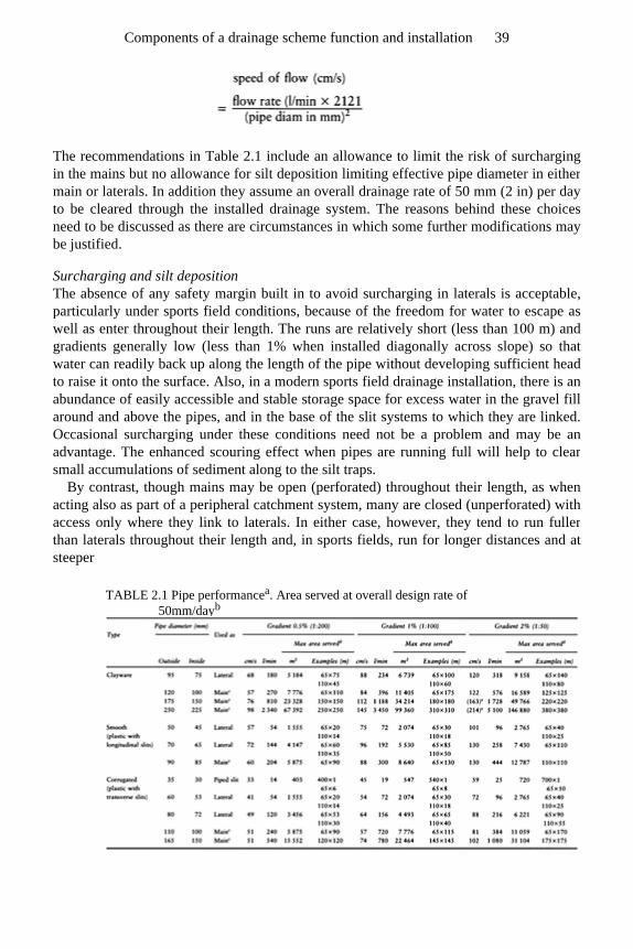
The recommendations in Table 2.1 include an allowance to limit the risk of surcharging in the mains but no allowance for silt deposition limiting effective pipe diameter in eithermain or laterals. In addition they assume an overall drainage rate of 50 mm (2 in) per dayto be cleared through the installed drainage system. The reasons behind these choicesneed to be discussed as there are circumstances in which some further modifications maybe justified.
Surcharging and silt deposition The absence of any safety margin built in to avoid surcharging in laterals is acceptable,particularly under sports field conditions, because of the freedom for water to escape aswell as enter throughout their length. The runs are relatively short (less than 100 m) andgradients generally low (less than 1% when installed diagonally across slope) so thatwater can readily back up along the length of the pipe without developing sufficient headto raise it onto the surface. Also, in a modern sports field drainage installation, there is anabundance of easily accessible and stable storage space for excess water in the gravel fillaround and above the pipes, and in the base of the slit systems to which they are linked.Occasional surcharging under these conditions need not be a problem and may be anadvantage. The enhanced scouring effect when pipes are running full will help to clearsmall accumulations of sediment along to the silt traps.
By contrast, though mains may be open (perforated) throughout their length, as whenacting also as part of a peripheral catchment system, many are closed (unperforated) withaccess only where they link to laterals. In either case, however, they tend to run fullerthan laterals throughout their length and, in sports fields, run for longer distances and atsteeper
TABLE 2.1 Pipe performancea. Area served at overall design rate of 50mm/dayb
Components of a drainage scheme function and installation 39
gradients than the laterals feeding to them. They must be protected, therefore, fromsurcharging or they will transfer their problem back along the laterals, particularly thoseentering lowest down slope. It is for this reason that the recommendations quoted formains in Table 2.1 include a safety margin to protect against surcharging. This isparticularly important with the ‘flash discharge’ potential of modern slit systems. It alsojustifies the further precaution of always erring on the generous side when faced with achoice between two reasonably close, pipe size options.
Mole drainage systems work best in cohesive soils, e.g. soils such as clays. In suchcases mole drainage is unlikely to increase the risk of siltation in the laterals, becausemoles should never be installed in other than cohesive soils. However, any risk ofsurcharging within the laterals into which they empty should be avoided. Theunstabilized mole drainage crack and tunnel system is very liable to collapse if allowed toremain full of water. In an effort to extend the effective life of such systems care shouldbe taken to keep the top of the pipe at least 20 cm (8 in) below the normal 450–525 mm (18–24 in) moling depth and an additional 10% margin of safety should be included inthe carrying capacity of the pipe system throughout.
When corrugated pipes are used, either for mains or laterals, the recommendations inTable 2.1 may have to be modified to take account of extremes in the pitch of the pipe corrugation. The value shown will underestimate by 10% the carrying capacity of acorrugated pipe where the pitch of the corrugation is less than th of the diameter of the pipe, or over-estimate by 10% where it begins to exceed
Because sports fields generally are fairly flat, small irregularities in the surface canmake it difficult to install pipes to an even gradient and deposition of silt in the low spotsmay ensue. In addition, the supply of silt may be enhanced by the open nature of thepermeable fill, the narrowness of the trenches and the weak structural state of the soil. Asno allowance is made for effects of siltation in the recommendations listed in Table 2.1the recommendations given are most appropriate for cohesive soils, over 35% clay.
For very unstable soils, mostly very fine sand and silt with less than 15% clay, it would be advisable to design the pipe layout with numerous silt traps allowing easy access topipes for clearance. Alternatively, trenches may be lined and pipes wrapped inappropriate synthetic filter fabrics. A small increase in pipe size alone will not besufficient.
For all other soils (i.e. soils 15–35% clay) it would be advisable to make a standardallowance of an additional 10% in pipe capacity as a safety margin against theconsequences of a small amount of siltation restricting flow. This applies particularly toopen mains where there is unlikely to be free access to an under-bedding of gravel into which any initial flush of silt in a new construction might otherwise escape.
Significance of overall design rate The advice on safety margins so far given is aimed primarily at ensuring the internalintegrity of the drainage system, avoiding troublesome bottlenecks so that once free waterhas been intercepted it can flow smoothly right through to the final outfall. However, thescale of the whole operation is conditioned from the start by the efficiency with which theoverall design rate meets the problems posed by the incident rainfall. In Table 2.1 the assumption is made that the objective is to be able to clear up to 50 mm (2 in) per daythrough the installed drainage system. In effect this could amount to at least 60 mm
Sports Turf 40
cleared in total if a pessimistic view is taken of the contribution likely to be added bynatural seepage which bypasses the installed system. The significance of the 50 mm perday target is that it comes very close to the maximum which agro-meterologists assume to be appropriate, in England and Wales, for mole-drainage assisted schemes, designed to meet the needs of all-the-year-round productive horticulture, the nearest equivalent wehave to the demanding requirements of sports turf (last column, Table 1.2). This target is reduced in the drier south-east of England to something close to 30 mm (1½ in) and rises to over 60 mm (2½ in) in hilly districts in the west.
However, the importance of this range of variation for sports turf should not beexaggerated as it need amount to no more than selecting the less generous or moregenerous option, according to circumstances. The cost difference will be a relativelysmall item in the overall cost of the drainage installation.
Short periods of intense rainfall may occur at anytime, but amounts of the order of 5 mm ( in) can usually be accommodated within the temporary storage space immediately available in the topsoil, the pipes, and the abundance of gravel fill in amodern slit drainage system. Storm conditions are probably best provided for by gradingthe surface so as to clear surface water off the playing area, to storm channels around theperiphery.
Filling material over pipe drains
All lateral pipe drains should be covered with permeable fill to help achieve theirfunction of interception. The grade, nature and depth of the fill layers will be dependentupon the type of drainage system to be installed. Where clay pipes are used the fillimmediately over and around them must be large enough to ensure that it cannot enter thepipes at joints where gaps may occur as a result of differential settlement. A suitablespecification for use with clay pipes might be
Backfill to 100 mm (4 in) over the pipe with 20–30 mm (¾–1¼ in) ‘beach’ or clean stone, followed by a layer of 5–10 mm in) clean trench gravel (e.g. SN7 in Table 7.1) up to within 150 mm (6 in) of the surface….
Where plastic pipes are used the ‘beach’ or stone should be omitted and the trench gravel layer taken right down to the pipe. This reduces the number of backfillingoperations and allows a small saving in cost. In addition, the tradition of using 95 mm(3¾ in) clay tiles as laterals where the smaller 60 mm (2⅜ in) plastic pipes would do should be discouraged as the wider trench required must necessarily involve an additionalcost for extra excavation and backfill.
Unless serving also as a peripheral catchment drain, the main need function only as acollector for the laterals to which it is linked. As such, it need not be perforated or thetrench backfilled with gravel. However, as some mains may also act as peripheralinterceptors of extraneous site water, the pipe used in these instances will have to beperforated and the backfill organized as for pipe laterals.
With laterals it is necessary to determine whether the gravel backfill should be toppedto the surface with topsoil or with sand. If the laterals are to be fed by a closely spacedsystem of slits, topping the laterals with sand becomes superfluous. Putting back neatlycut, carefully preserved, 50 mm (2 in) thick turfs on 50 mm (2 in) of good topsoil,
Components of a drainage scheme function and installation 41
supplemented with a phosphate-rich fertilizer, should not noticeably affect the efficiencyof the system and will make sward restoration easier. However, to avoid any risk of thesoil weeping down into the gravel, a 50 mm (2 in) layer of blinding sand (SN10 in Table 7.1) should be inserted between the soil and the gravel (Figures 4.2 and 11.1). This is particularly so where lateral trenches are excessively wide, as may well be the case whendug by a hydraulic excavator in stony ground.
On the other hand, laterals in narrow trenches at fairly close spacing and notaugmented with any slit drainage, should always be topped with sand in order to retainthe capability of infiltering surface water. The sand used should be a coarse-to-medium blinding sand (SN10 in Table 7.1), extended to 50 mm (2 in) above surface level with a topsoil sand compost (SN16 in Table 7.1) to allow for initial settlement and provide areasonable seed bed. For further information and more detailed advice on establishinggrass on sand-filled trenches, see Chapter 2, page 41.
On new grounds, the need to preserve the sand topping of the laterals uncontaminatedby soil presents difficulties when there is a need for a measure of surface cultivation priorto seeding. The only way to avoid this completely is to defer the installation of pipedrains until after the new sward has been established and the soil firmed into place. Thisis not always practical, however, and the establishment of the initial sward, with nodrains in place, may be adversely affected by surface waterlogging. The aim, therefore,must be to prevent too intimate a mix of soil and sand by cultivating parallel to thelaterals rather than across them.
If sand, or sand/gravel, slit drainage is intended, or is a future possibility, it is essential that the backfill of the pipe drain is not so coarse that the sand or gravel within the slitwill run into the backfill of the drain, impeding flow and causing the level of the fill inthe slit to drop.
Due priority must be given from the start to ensuring the compatibility of all thematerials likely to be used to achieve a fully integrated construction that will drainefficiently, whether or not all stages of the construction are to be implementedimmediately. The task of upgrading an existing construction is all too often hampered bylack of forethought on the part of those responsible for the initial design. Because of this,special consideration is given in Chapter 7 to the specification of appropriate materials, inparticular, soils, sands and gravels.
Installing pipe drains
Normal trenching As explained in the section on filling material over pipe drains, the details of thisoperation vary according to whether the gravel backfill is extended to the surface withtopsoil or sand.
The initial procedure for trenching in laterals normally involves excavating and carting away the soil as work proceeds. If the gravel backfill is to be covered by topsoil and turf,these should be excavated separately and placed beside the trench, ready for replacement.Excavating machinery which transfers the soil directly onto a trailer by appropriatelyscreened conveyer belting should leave a clear surface free of loose soil and stones.
Every effort should be made to ensure that subsoil from the trenches does not become
Sports Turf 42
mixed into topsoil. If this occurs it may have harmful effects on permeability andnutrition.
The trenching procedure for a main will be similar to that for a lateral if its function is not only to collect water from laterals but also to act as a catchment drain in its own right,e.g. along the perimeter of a site. Because in this case the pipe will have to be perforated,soil from the trench will have to be removed off-site and replaced with permeable fill.However, a main whose purpose is solely to collect water from laterals and convey thisonward to an appropriate outfall will not be perforated, entry being restricted to thepurpose-made junctions with laterals. In this case, the need for permeable fill does not arise and subsoil as well as topsoil should each be preserved separately for replacement toappropriate levels after the pipes have been laid.
It is most important that all piping is laid accurately to correct lines and falls. Clayware drains should be closely butted together and the top end of each run sealed by a brokentile. Plastic drain runs should be sealed by plugging with the appropriate end-stop accessory. All drain runs should be checked for accuracy of line and gradient beforebeing buried under backfill.
The order of installation is: the outfall, followed by inspection chamber and silt pit; then the main, complete with purpose-made pipe junctions for linking up with thelaterals; the laterals; finally, the sand or sand/gravel slits. Following this sequence ensuresthat any water invading the workings during construction can be cleared withoutdifficulty.
Sophisticated techniques such as laser beam projection are increasingly employed to ensure that levels and falls are consistently true and uniform.
As PVC pipes are liable to become brittle at low temperatures, they should not beinstalled, nor permeable fill placed over them, when the air temperature is less than 0°C.
Trenchless drainage On sites where good lengths of drain run are possible and the work is reasonably straight-forward, the ‘trenchless’ system, as commonly used for agricultural drainage, is sometimes a more economical system to employ. This type of drainer lays flexible plasticpiping with a mole plough pattern slitter, and back-fills the slit with small stone or gravelin one operation, without the need for excavating and removing any soil. Theemployment of the trenchless drainer is generally confined to the installation of drainsprior to the preparation of a seed bed. This requirement is dictated by the fact that themachine causes a considerable amount of unwanted surface heave that may have to betrimmed off level.
On grounds where major regrading is necessary, trenchless drainage should beinstalled before the topsoil is replaced and the gravel backfill brought right up to theexposed subsoil surface. Slit drainage can be organized through the topsoil later.
A trenchless drainer can be tractor drawn or winch operated, the latter method reducingthe risk of wheel rutting. Either way, it is necessary to dig a hole or enlarge the mainstrench at the beginning of each drain run so that the plough can be eased down to beginits run at the correct depth.
Components of a drainage scheme function and installation 43
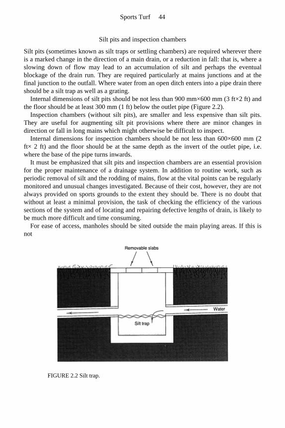
Silt pits and inspection chambers
Silt pits (sometimes known as silt traps or settling chambers) are required wherever thereis a marked change in the direction of a main drain, or a reduction in fall: that is, where aslowing down of flow may lead to an accumulation of silt and perhaps the eventualblockage of the drain run. They are required particularly at mains junctions and at thefinal junction to the outfall. Where water from an open ditch enters into a pipe drain thereshould be a silt trap as well as a grating.
Internal dimensions of silt pits should be not less than 900 mm×600 mm (3 ft×2 ft) and the floor should be at least 300 mm (1 ft) below the outlet pipe (Figure 2.2).
Inspection chambers (without silt pits), are smaller and less expensive than silt pits. They are useful for augmenting silt pit provisions where there are minor changes indirection or fall in long mains which might otherwise be difficult to inspect.
Internal dimensions for inspection chambers should be not less than 600×600 mm (2 ft× 2 ft) and the floor should be at the same depth as the invert of the outlet pipe, i.e.where the base of the pipe turns inwards.
It must be emphasized that silt pits and inspection chambers are an essential provision for the proper maintenance of a drainage system. In addition to routine work, such asperiodic removal of silt and the rodding of mains, flow at the vital points can be regularlymonitored and unusual changes investigated. Because of their cost, however, they are notalways provided on sports grounds to the extent they should be. There is no doubt thatwithout at least a minimal provision, the task of checking the efficiency of the varioussections of the system and of locating and repairing defective lengths of drain, is likely tobe much more difficult and time consuming.
For ease of access, manholes should be sited outside the main playing areas. If this is not
FIGURE 2.2 Silt trap.
Sports Turf 44
practicable, or there is likely to be unauthorized interference, the covers should be sunk150 mm (6 in) below the level of the finished surface and covered with soil and turf.Sunken manhole covers should be of thick reinforced concrete, sufficiently strong towithstand the passage of tractors, rollers, mowers, etc. but capable of being manhandled.The thickness of the covers should be 75–100 mm (3–4 in) according to span, and countersunk lifting rings should be fitted. If exposed at surface level, heavy duty coverscan be used and should be sited slightly below the surrounding turf so as not to interferewith mowing operations. Their positions, particularly if below ground, should becarefully measured and recorded. Inlet and outlet pipes should be salt-glazed or unperforated plastic.
Ancillary items
Important features of a drainage scheme such as purpose-made junctions, silt pits, inspection chambers, end-stops, headwalls, flap valves and vermin traps are often either inadequately provided or omitted altogether. They have their purpose and should alwaysbe included in a quality construction.
2.1.3 Iron ochre—a special problem
Silt pits and inspection chambers assume particular importance in areas where theenvironment is conducive to the formation of iron ochre (hydrated ferric oxide). It is not acommon problem, but tends to occur in proximity to waterlogged places where iron in thesoil forms iron sulphides (pyrites). Under certain conditions, such as when air is admittedto the system, the sulphides are oxidized to ferrous sulphate by sulphur bacteria. Thisferrous iron may then be further oxidized, either chemically or by iron bacteria such asThiobacillus ferroxidans, to a soft, often gelatinous orange/yellow material which, ondrying, becomes powdery, fibroid or a solid deposit of iron oxide (rust). Such depositsare often found in the vicinity of shale rock and coal seams where there has been disturbance for mining but are generally far more associated with peaty soils, or very acidsoils close to peat deposits. Ochre deposition, often accompanied by an oily film, mayshow up along the banks of ditches, in isolated pools of water or where spring wateremerges.
By introducing oxygen into the soil, a drainage system may set in motion a chain ofevents which might not otherwise have occurred. Iron ochre deposits, in manholes or atthe outfall, may be the first indication of the presence of an ochre problem which, onfurther investigation, may be seen to affect the pipes, the permeable fill in the trenchesand the adjacent soil. Hitherto, the measures most likely to be employed to dislodge ochredeposits have been mainly pressure jetting and/or rodding of the pipes. Recentlyexperiments with weathered conifer bark in field trials at the Macauley Institute of SoilResearch (Vaughan et al., 1984) have shown encouraging initial results in absorbing ferrous iron from solution before it is oxidized to the ochre form. These investigations arestill continuing.
Where the problem of iron ochre contamination is occurring, or is anticipated, it is
Components of a drainage scheme function and installation 45

suggested that, as a first step, water reaching the site from springs or undergroundseepage should be intercepted before it reaches the pitch areas, diverting it into a ditchsystem. The layout for the drains should then be designed to ensure that water from theopen ditch or trench system discharges into an inspection chamber before passing on intoa pipe drain. In severe ochre cases, chambers should be positioned at 30–35 m (33–40 yards) intervals along the main until the outfall is reached. In each chamber (1 mdiameter) four or five loose-weave polypropylene sacks containing a total of approximately 80 kg (dry weight) of weathered conifer bark should be placed, the sacksbeing arranged in the chamber sump in such a way that inlet water passes through thembefore reaching the outlet. The bark should last at least six months before requiringreplacement. In less severe ochre cases, the drainage pipes should be surrounded by a 1:1mixture of conifer bark and gravel during installation.
Sports Turf 46
2.2 Auxiliary soil drainage—assisting water movement through the soil
2.2.1 Soil by-pass systems (slit drainage)
Slitting can be looked upon as the sports field equivalent of agricultural mole drainage.Both procedures aim to improve surface infiltration and, by a direct continuous route,move the excess water rapidly sideways into the backfill over pipe under-drains. It is the continuity of the route for free water flow, right through from the surface to the assuredoutfall, that is so important and must be maintained. With mole drainage the route issimply the crack and tunnel system formed by the special plough drawn through the soil.With slits, the route, once excavated, is stabilized against collapse by freely permeablebackfill. Unlike surface spiking, these systems are intended to aid infiltration anddischarge without relying on much help from the fine pore system in the soil itself.
Mole drainage
Moling and subsoiling Mole ploughing and subsoiling are similar procedures involving a robust, sharp-edged blade being sliced vertically through the soil, drawn downwards to its working depth bythe action of a chisel toe protruding forwards from the base of the blade (Figure 2.3).
Subsoiling is primarily aimed at breaking up soil compaction and improving surface infiltration by the creation of a series of cracks spreading obliquely upwards from eitherside of the chisel end of the plough blade. To encourage extensive cracking thisprocedure is best
Components of a drainage scheme function and installation 47
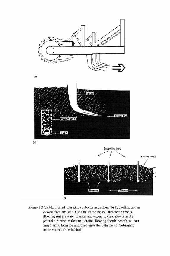
Figure 2.3 (a) Multi-tined, vibrating subboiler and roller. (b) Subboiling action viewed from one side. Used to lift the topsoil and create cracks, allowing surface water to enter and excess to clear slowly in the general direction of the underdrains. Rooting should benefit, at least temporarily, from the improved air/water balance. (c) Subsoiling action viewed from behind.
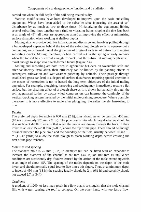
carried out when the full depth of the soil being treated is dry. Various modifications have been developed to improve upon the basic subsoiling
equipment. Wings have been added to the subsoiler shoe increasing the area of soildisturbance by as much as two to three times. Miniaturizing the equipment, linkingseveral subsoiling tines together on a rigid or vibrating frame, sloping the tine legs backat an angle of 45°: all these are approaches aimed at improving the effect or minimizing surface disruption when working at shallow depths.
Moling aims to provide both for infiltration and discharge and involves pulling througha bullet-shaped expander behind the toe of the subsoiling plough so as to squeeze out acontinuous, well-formed tunnel along the line of origin of each set of outwardly diverging subsoiling cracks. Moling, therefore, is best carried out in the spring or early summerwhen the topsoil has dried out enough to crack, but the subsoil at moling depth is stillmoist enough to shape into a well-formed tunnel (Figure 2.4).
Moling and subsoiling are both used in agriculture but even on favourable soils andafter satisfactory installation, their efficiency can be limited by the panning effects ofsubsequent cultivation and wet-weather poaching by animals. Their passage through established grass can lead to a degree of surface disturbance requiring special attention ifthe means of restoration is not to hazard the long-term objectives of the initial moling operation. For example, ploughing, harrowing and seeding may immediately restore a flatsurface but the shearing effect of a plough share as it is drawn horizontally through thesoil, aggravated further by tractor wheel compression, can interrupt the continuity of thevertical cracking system installed by the initial mole-draining procedure. Where possible, therefore, it is more effective to mole after ploughing, thereafter merely harrowing totrue.
Depths The preferred depth for moles is 600 mm (2 ft); they should never be less than 450 mm(18 in), commonly 525 mm (21 in). The pipe drains into which they discharge should beat a sufficient depth to ensure that when the moles are drawn through the backfill theirinvert is at least 150–200 mm (6–8 in) above the top of the pipe. There should be enoughdistance between the pipe drain and the boundary of the field, usually between 10 and 15m (11–17 yards) to allow the mole plough to reach working depth before crossing the first of the pipe trenches.
Mole size and spacing The standard mole is 75 mm (3 in) in diameter but can be fitted with an expander toincrease the diameter of the channel to 90 mm (3½ in) or 100 mm (4 in). When conditions are sufficiently dry, fissures caused by the action of the mole extend upwardsat an angle of about 45°. The spacing of the moles depends on the depth of the mole invert and should normally equal four to five times this figure. Thus, at a minimum depthto invert of 450 mm (18 in) the spacing ideally should be 2 m (6½ ft) and certainly should not exceed 2.7 m (9 ft).
Gradients A gradient of 1:200, or less, may result in a flow that is so sluggish that the mole channelfills with water, causing the roof to collapse. On the other hand, with too fast a flow,
Components of a drainage scheme function and installation 49

excessive scouring takes place and again blockage may occur. These extremes should beavoided, either by keeping the runs as short as possible or, in the case of a steep slope of1:40 or more, by drawing the moles diagonally across it.
As mole ploughs are not normally equipped with a grading device for ensuring an evenfall on the mole drain they cannot be operated successfully on undulating land. Generallythe most that manufacturers provide is a long and heavy beam that slides along theground to
Sports Turf 50
FIGURE 2.4 (a) Mole ploughing across piped system of underdrainage. Blade, toe, mole and expander of chisel plough producing subterranean tunnel, at approximately 500 mm (20 in) depth. (b) Mechanically induced crack system improves interception and links mole tunnel through to the surface. Intercepted drainage water cleared through mole tunnel to permeable fill over pipe in drain trenches. Ideally tunnel system formed in moist soil; cracks induced by mechanical disruption of dry soil, therefore timing critical. Use tractor wheel or roller along line of disturbance to re-true the surface. Worm action will then be required to keep the surface open.
prevent minor irregularities from affecting the general grade of the mole. However, lasercontrol is now available as a more efficient alternative.
Practical constrains liable to limit the effectiveness of mole drainage To maintain a beneficial effect it must be possible to repeat the moling operation atregular intervals, something to which a farmer can adjust, but much less so agroundsman.
Factors tending to promote crack and mole channel collapse are as follows.
1. Soil inadequately clay-rich—less than 35% clay and especially soils less than 15% clay.
2. Poor installation because of inappropriate soil moisture state at the time of installation. 3. Wet rather than dry weather immediately following installation, preventing maturation
of the newly exposed soil surfaces. 4. Inadequate slope and imperfect grading of the mole channel leading to water ponding
within the channel and increasing the risk that the adjacent, saturated soil will slump. 5. Excessive slope or excessive length of run increasing the risk of disruption by scour. 6. Boulders and other obstacles in the soil repeatedly impeding progress.
Mole drainage and subsoiling in sports fields Though, at first thought, moling would appear to be an ideal method of improving soildrainage it is generally much less useful in sports fields than in agriculture. When dealingwith a compact soil it is impossible to introduce extra pore space without displacing thesoil upwards. The consequent surface disruption may well require so much renovationthat such an operation could not be contemplated annually. It is only when the soil isalready maintained open by earthworm activity that moling can complete the task of re-aligning some of the available space to effect rapid lateral discharge without unduesurface disruption. This is likely to be the case only on a new site taken over in goodcondition from agriculture and maintained biologically active thereafter.
With discretion in use, however, mole drainage is a relatively cheap operation and canbe made to work on a suitable site with a suitable soil texture and an adequate level ofearthworm activity. For example, on a clay-rich, worm-worked soil, sloping uniformly at a gradient of 1:60, moles should be drawn diagonally down slope to cross pipe lateralsrunning in parallel succession at 30 m intervals down the other diagonal. To help leave alevel surface, spacing of the mole runs should be reduced to approximately twice workingdepth, e.g. 1 m (1 yard), so that the whole surface is loosened and lifted uniformly. Toavoid tearing the grass sward unevenly, a disc should be run ahead of the blade of themole plough, ensuring that the sward will be neatly slit apart and as neatly restored byimmediate rolling. There is much to be said for working at half the spacing of the tractorwheels. This will allow one tractor wheel to roll back any surface disruption along theprevious run as the next run is installed.
Subsoiling, which is essentially a soil-cracking operation, is useful as part of a soil-deepening procedure at the cut end of a cut-and-fill operation, or for the relief of compaction caused by heavy machinery during construction. Like moling, it may also beused to good effect on a potentially good soil to co-operate with earthworms in the relief of surface compaction prior to sward restoration in spring. However, such a soil-opening
Sports Turf 52
operation will not necessarily benefit grass growth unless the soil structure restored isadequately water-stable and the extra water infiltered can be cleared before it adversely affects soil aeration.
Both moling and subsoiling will tend to bring obstacles impeding progress up onto thesurface. On bouldery soils and tip sites this can be disastrous and may require theabandonment of the whole operation. Prior to starting on any such operation, therefore, examine the soil to the full working depth of your equipment. Water is more acceptableon the surface than stones, glass or scrap-iron!
Where a system of sand-and-gravel stabilized slits has been introduced soil drainage may have been greatly improved without necessarily improving the soil’s structural state between the slits. This may lead to a sward very sensitive to drought because its rootscannot fully exploit the soil in depth. Subsoiling to relieve compaction at this stage,however, will hazard the stability of the slit drainage system by creating horizontal cracksinto which sand fill may weep away sideways. Only subsoil through a slit system where,prior to subsoiling, the whole surface has been carpeted with a thick covering of sand topreserve sand continuity from the slit through to the surface. When time and resourcesallow, it is better, on a bad site, to first install the pipe underdrains, then improve thephysical condition of the soil by subsoiling before going on to install slit drainage.
In the hands of a conscientious, skilled groundsman, suitably equipped and familiar with both the technical procedure and the need for correct timing according to soilcondition, moling and subsoiling can be used effectively on sports fields to aid soildrainage. These are not techniques that lend themselves to effective use by a busycontractor, however, as correct timing is of the essence.
Sand and sand/gravel slits
The basic requirement for ensuring satisfactory drainage for winter games on a non-sandy soil is a sand or sand/gravel slit system linked below to pipe underdrains. The actualefficiency of such a system depends on the type of slits installed, their spacing, length ofrun and the continued effectiveness of their permeable link through to the surface.
All the main design features of a slit system, except slit spacing, can be resolved bycalculation. Once surface run-off has entered a slit system much can be done to design and choose suitable materials that will ensure that a certain design discharge rate can bemaintained through the slits to the pipe underdrains and final outfall. Slit spacing wasinitially determined by reference to the spacing used in agricultural mole drainage and bypractical experience of the extent to which a benefit could be felt underfoot immediatelyafter rain, either side of a lateral pipe drain. Both of these pointed to spacings of no morethan one pace. Subsequent unhappy experiences with schemes utilizing wider spacinghave tended to confirm the practical value of a 1 m (1 yard) limit. However, this featureof design will continue to be a subject for debate as so much depends in practice on thesmoothness and slope of the surface, the extent to which access to the slit is preservedand protected by a surface covering of sand, and the standard of efficiency demanded. Atypical scheme, evolved and tested by trial and error over the past 20 years, is illustratedin Figure 11.1.
The slits are normally formed by machine and vary in width from 25 to 75 mm (1 to 3
Components of a drainage scheme function and installation 53
in). Often the width is determined by the type of trench excavator employed. Slits greaterthan 38 mm (1½ in) are usually formed by excavation, therefore it is necessary to removeand cart away the surplus soil. In this operation great care must be taken to ensure that theexcavated soil is not accidentally scattered and left lying on the grass surface for anylength of time before being cleared away. With slits less than 38 mm (1½ in) in width, the cut is usually formed by pressure from the blade of a subsoiling plough leaving no soil tobe removed. Ground heave from this operation may be unavoidable, however, and anyattempt to retrue the surface by rolling afterwards requires care to avoid capping the slitsurface with soil.
Where slits are formed by excavation it may be found that the actual width of the slitdug out is greater than the rating for the machine. For example, a slit taken out by atrencher with a 50 mm (2 in) cutter may be found to measure as much as 75 mm (3 in)across in places, particularly on difficult, stony ground. If this is likely to happen, specialcare must be taken when calculating and costing the amount of backfill required.
The depth of slits will depend upon the drainage rate, the nature of the backfill materials, and the length of run between the relieving underdrains. Normally, depthsrange between 250 and 360 mm (10 and 14 in). However, soil impediments to trenching,or features of an existing pipe system may impose constraints necessitating a measure ofcompromise. There will then be a need for a compensating adjustment in some otherfeature of the scheme, such as slit width, slit spacing or the nature of the permeable fill.
Ideally, slits should run across the slope and be as near as possible to an angle of 90° to the pipe drain laterals into which they discharge. This will ensure maximum efficiency insurface water interception and minimum slit length before discharge.
Backfill for slits can be sand only or sand over gravel. If sand only is used the lateraldischarge along which water will flow to satisfy sports ground drainage requirements islimited to less than 5 m (5½ yards). In practice, therefore, the use of sand-only slits tends to be restricted to the improvement of existing schemes where there are already closelyspaced pipe drains with backfill suitable for satisfactory sand slit linkage.
Where drainage schemes are designed from the start with slit drainage discharging intopipe laterals, it is desirable for reasons of economy to space the pipe drains as widelyapart as possible. To achieve this the slits are backfilled first with clean 6-8 mm (¼–⅜ in) trench gravel to at least half slit depth, followed by 5 mm ( in) concreting sand (typically a blinding sand) to just above surface level. In this way the surface water infiltrates vertically through the sand and then flows laterally along the gravel layer todischarge into the gravel fill in the pipe-drain laterals. The spacings of the laterals are normally anywhere between 10 and 20 m (11 and 22 yards) according to the width, depthand spacing of the slits and the nature of their backfill materials.
There are calculations involved in all these design features which are described in Chapter 4. Schemes utilizing standard Stewart zone materials can make use of the simple relationship between the depth of the gravel layer in the sand/gravel slit and theacceptable length of run between laterals (Chapter 7, page 117).
For slits less than 50 mm (2 in) in width, a satisfactory grass cover can usually be established in a fairly short time by over-seeding with ryegrass and relying also on grassgrowth spreading in from the adjacent sward. The strong growth required can beencouraged by periodic, light applications of a nitrogenous fertilizer, plus irrigation if
Sports Turf 54
conditions threaten to become dry enough to halt growth. Where slit width is 50 mm (2in) or wider, special surface preparation and seeding will probably be necessary tocompete with the desiccating influence of the adjacent soil, weeds often succeedingwhere grass fails. The challenge is to achieve germination and establishment of grass on asandy surface that is very liable to dry out and become impoverished of nutrients.Weather conditions are crucial, spring and autumn being the most favourable seasons.The following type of procedure is required.
1. Apply a pre-seeding fertilizer. 2. Sow a ryegrass/fescue seeds mixture and bury by rolling or treading and covering with
a topdressing of damp, amorphous, sedge peat or grass clippings. 3. After germination apply small doses of general-purpose fertilizer, in liquid form, at
fortnightly intervals, until the new grass has rooted sideways and become fully established. Irrigate if seedlings are caught by a period of drought.
Under no circumstances should play be permitted until grass cover over the slits has beenfully re-established and the whole surface topdressed with a fine topsoil sand at a minimum rate of 80 tonne/hectare (30 tons/acre), i.e. a covering of 5 mm in) overall. Forgeneral advice on sward establishment and immediate aftercare see Chapter 6.
Transverse and longitudinal sub-surface gravel channels
Gravel channels, without pipes, are sometimes employed as one element of a drainagescheme where soil conditions are difficult for slit trenching below 200 mm (8 in) orthereabouts. As they are likely to have to be dug by the narrow bucket of a hydraulicexcavator the width will be around 150–200 mm (6–8 in). The backfill should be gravel (e.g. trench gravel) from a depth of around 400 mm (16 in) to within 150 mm (6 in) ofthe surface and, thereafter, a blinding layer of sand (e.g. blinding sand) followed by replaced topsoil and turf.
A system of gravel channels will normally be best aligned so as to intersect both thegravel layer in the sand/gravel slits and the gravel fill in the pipe trenches at right angles.Ideally, pipes and slits should be aligned parallel to each other, on one diagonal acrossslope, and the gravel channels, intercepting the slits and delivering to the pipeunderdrains, along the opposite diagonal.
Spacings will depend on the circumstances that condition the type and capacity of the slits but will normally be less than 5 m (5½ yards). At these relatively narrow intervals the gravel channels could be designed to run for distances of the order of 20–25 m (22–27 yards) before themselves discharging into pipe underdrains.
A gravel channel link in a tiered system of drainage may be useful when a stonysubsurface layer makes narrow trenching difficult for the full depth of a normalsand/gravel slit. It can also form the basis of a scheme designed to work on a soakawayprinciple. This may be necessary where there are difficulties over organizing anacceptable, final outfall for discharge off site. Such a construction has to be designed flatso as to stop drainage water surging about. The aim should be to hold any temporaryexcess in the slits and gravel channels below ground until it can leak away by naturalseepage.
Components of a drainage scheme function and installation 55
Mini-slitting
This is sometimes a preferred alternative to ordinary slitting where surface trueness is ofparticular importance, e.g. for hockey or a cricket outfield (see also section 11.2).
Mini-slits are formed by blade pressure, not excavation, and any slight heave can be settled by rolling along the line of the slits. The slitting machine is usually equipped witha sand hopper.
Mini-slit widths can vary from 15 to 30 mm (⅜ to 1¼ in) and depths from 200 to 300 mm (8 to 12 in) according to the type of machine used. Spacing ranges from 200 to 400mm (8 to 16 in). The backfill should be 5 mm ( in) concreting sand (i.e. a blinding sand).
As for the system involving gravel channels in the previous section, the mini-slits are probably best aligned diagonally across the slope, parallel to the pipe underdrains. Theycan then discharge into sand/gravel channels, running at 4 m (4/2 yards) intervals acrossthe slope on the other diagonal, and the gravel layer in the sand/ gravel channels candischarge into the gravel in the pipe trenches.
Piped mini-slits
Pipe-based, mini-slits, spaced about 1 m (1 yard) apart, are a recent development. Theyare liable to be more expensive and less efficient than a slit/pipe drain combination whereeach separate tier of drainage can be oriented to perform at maximum efficiencyaccording to function. However, they represent a useful compromise where the nature ofthe topsoil favours narrow trenching but the subsoil below 300 mm (12 in) would make deep trenching for pipe underdrains very difficult. As the orientation of the one trenchdetermines both the angle of interception and the gradient for flow, the piped mini-slits should compromise on an oblique orientation across the slope. The precise angle chosenshould give precedence to the need to assist discharge through the long runs of verynarrow, 35 mm, corrugated pipe used to convey water all the way to the peripheraloutfall. These very long runs of narrow pipe are not in themselves a speciallycommendable feature of the system, but they have to be made to function efficiently ifthe introduction of a pipe into each slit is to be justified.
This system certainly has merit where the subsoil does not favour deep trenching but elsewhere, though it may work, threatens to be expensive because it requires specialistmachinery to install and is unnecessarily extravagant in the use of pipe.
Micro-slitting
Micro-slitting is an ancillary or remedial procedure involving the cutting of continuous,thin slits along the surface. The aim is either to enhance the directional flow of surfacewater towards a previously installed, standard, slit-drainage system, or to improve the vertical infiltration of surface water to a sand drainage layer immediately beneath animpeding soil cap. To extend their effectiveness they can be sand-filled, and where expense is no problem, can be used overall to replace or supplement a topdressing ofsand.
Sports Turf 56
On a small area the job can be done manually with a spade but there are now machinesavailable that cut and fill several slits in one pass. The slits are of the order of 13 mm ½in) wide, 100 mm (4 in) deep and spaced about 200 mm (8 in) apart. They may be sand-packed simultaneously, or topdressed with a dry, free-pouring, medium topsoil sand (e.g. SN12, Table 7.1), well brushed in. At the end of the operation, sand should be left, piledalong each slit to compensate for any subsequent settlement, then rolled and maintainedmoist to encourage the grass to grow through. Interruption to play need be minimal.
2.2.2 Whole soil constructions
A shallow, ameliorated sand top, over a slit system and pipe underdrains
This is probably the most efficient system of drainage for winter games pitches but, beinga two-tier system plus a 100–125 mm (4–5 in) thick ameliorated sand carpet, issignificantly more expensive. If designed as such from the start, a slightly wider spacingof the slits than 1 m (1 yard) is permissible but should certainly not exceed 1200 mm (4ft). The surface carpet can either be an imported and suitably ameliorated sand, or aloamy sand topsoil. Because the slits are well covered, this type of construction canprovide the sort of true surface that is desirable for hockey.
Restricting the depth of the ameliorated sand carpet to around 100 mm (4 in) allows thegrass to root down to the moisture and nutrient reserves in the soil below. Thus the swardwill be protected from drought as well as waterlogging so long as the roots achieve andmaintain contact with the soil below. Critical to success is the quick establishment of thesward (Chapter 11, page 168), the quality of the original buried topsoil (Chapter 11, page 167), and the appropriateness of the maintenance programme (section 11.3).
Irrigation should be available to assist during the initial stages of sand placement and during sward establishment. It may be required to help stabilize the loose sand surfaceagainst wind-blow or to safeguard the seedling sward against desiccation prior to roots reaching through to the buried soil beneath the sand carpet.
A deep, ameliorated sand top, over a gravel drainage bed
The deeper sand carpet supporting the sward in this system is mainly required for thefinest turf surfaces used for golf and bowls. Because of the high cost of construction andmaintenance this approach can seldom be justified for the construction of large areas ofplaying surface. The depth of imported and suitably ameliorated sand topsoil required isbetween 300 and 400 mm (12 and 16 in). This is laid over a blinded gravel bed with pipeunderdrainage. Because the resistance of the sward to wear is minimal, great care andexpertise is required in its establishment and maintenance (Chapter 10).
The gravel bed provides for the clearance of excess water filtering through from above but, when clear of water, it acts like an air lock to create a perched watertable in the over-lying soil. Contradictory though this may seem, a gravel bed assists both drainage andwater retention in the topsoil. However, the water reserve available to the sward is strictlylimited to that in the topsoil and, as this could be exhausted in two to three weeks of dry
Components of a drainage scheme function and installation 57
summer weather, irrigation must always be on hand to avoid desiccation. To provide the desired rate of drainage the ameliorated topsoil must contain at least
75% of the right kind of sand, e.g. a topsoil sand (Table 7.1, SN12–15). This in turn determines its depth and is critical for aeration, tractive efficiency, drought risk, seedgermination, rooting and choice of grass species (section 4.2).
The bed should be 5–10 mm ( –⅜ in) gravel (e.g. trench gravel SN7, Table 7.1) topped by 50 mm (2 in) of concreting sand (e.g. blinding sand SN10, Table 7.1). The rate of drainage through the sandy topsoil layer should be taken into account when decidingon the thickness and the composition of the bed, and hence also, the spacing of theunderlying pipe drains. Using 125 mm (5 in) of trench gravel to form the gravel raft under a bowling green will allow the pipe underdrainage system to be reduced to a singlering system under the peripheral ditch.
Full details of such a construction are given in section 10.3.
2.3 Timing of drainage work on established grounds
Drainage work on existing sports grounds often has to be carried out at a time mostconvenient to the users. However, in a country such as Britain, where weather conditionsare so inherently variable, day to day, and only very approximately predictable accordingto season, the benefits to be derived from soil operations can depend very much ontiming. For example, pipe drainage should be installed, ideally, in late spring or earlyautumn. Working in dry summer conditions is hard on trenching equipment and can alsoresult in loss of turf, desiccated after disruption of the root system. Working in wetconditions creates unacceptable damage to the soil structure and to the grass. As hasalready been said, mole drainage is best carried out in the spring when the topsoil is dryenough to crack but the subsoil is still sufficiently moist to mould, and when there isevery chance that the newly exposed soil faces will have a chance to be stabilized bysummer desiccation. Sand slitting for winter games pitches should preferably beundertaken during the spring or summer months so that sward recovery can be achievedbefore winter sets in.
2.4 Sequence and timing of drainage operations on new grounds
On a site requiring major regrading, prior to the installation of pipe underdrains, there isno doubt that the topsoil will have to be removed to allow for redistribution of subsoil.However, there is then a choice to be made between installing the underdrainage prior to replacing the topsoil, or vice versa. The same choice arises when a new playing fieldsurface is to be formed by spreading a shallow sand carpet.
There are two good reasons against laying pipe drains prior to topsoil placement:
1. machinery may smear subsoil into the gravel or sand backfill, topping the drain trenches, thus hazarding the freely permeable link through into the topsoil;
Sports Turf 58
2. if, after using earthmoving equipment to regrade the subsoil, this equipment has to be retained to replace the topsoil after other equipment has been used to install the drains, on-site costs may increase enormously. The temporary removal of plant and equipment involves the doubling of haulage charges and possible delays in getting the machinery back again. Allowing the machinery to lie idle on site may incur the normal two-thirds standing hire rate.
Good reasons for installing drainage prior to topsoil placement are:
1. elimination of any risk of subsoil contaminating the topsoil during the trenching operation;
2. pipe drains can more satisfactorily be installed by the trenchless method. The subsoil presents a firmer surface than newly placed topsoil to work over and the ridges, heaved up either side of the trench, can be satisfactorily trued off prior to topsoil replacement.
When topsoil is replaced, unless it consists of sand, it should never by worked wet or itsstructure will suffer to the detriment of efficient drainage and vigorous grass growth.
In our climate, where heavy rain may occur at any time of the year, it is wise always towork uphill from an established outfall, avoiding any risk of the open trenches becomingflooded. Correct timing of operations during major construction work is very much amatter of judgement, often involving a measure of calculated risk.
2.5 Recording the position of pipe drains and slits
A record plan of a drainage scheme is a valuable document which should be carefullypreserved for future reference. Not only is this information important for ensuring that thesystem is properly maintained but, without it, any extension in the future is difficult toplan and may lead to unnecessary duplication of drains, manholes, etc. Unfortunately, thedetailed recording of drainage layouts in the past seems to have been badly neglected or,if it has been done, the plans seem generally to have been mislaid.
It is worth noting that where a scheme was grant-aided by the Ministry of Agriculture,Fisheries and Food, details of the work carried out will have been recorded and should beavailable from the Ministry’s Divisional Office for a period of at least 20 years fromwhen the grant was paid.
As soon as the installation of a drainage system is complete, the position of all branch,main and slit drains, silt pits, inspection chambers, outfalls, etc. should be accuratelychecked against the prepared plan and any alterations carefully recorded. Details as todepths, sizes and types should also be noted. The practice of marking important features,e.g. outfalls and hidden manholes, on nearby permanent surfaces, such as walls, can helpwith subsequent location.
Components of a drainage scheme function and installation 59

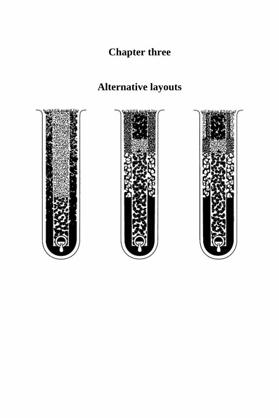
Chapter three
Alternative layouts

3.1 Options using existing topsoil
3.1.1 Assessment of priorities
When assessing a new site for sports turf development, or an existing facility forimprovement, the designer at some point will require to know the finance available. Inpractice it frequently happens that the client turns the question back to the designer,requesting some idea of the costs to be associated with all the possible options. This is thepoint at which real discussion begins on priorities.
The first priority is to isolate the site from extraneous surface and ground-water influences by the installation of peripheral, interception drainage. Thereafter, the leastsophisticated option would be:
1. grade the surface to an even slope of at least 1:60 so as to allow for substantial run-off at times of intense rainfall;
2. lime and encourage what drainage and structural improvements can be achieved by promoting earthworm activity;
3. control use to ensure that no play is allowed when the surface is soft.
This represents the minimum likely to be reasonably effective for general use on a naturalsite with a satisfactory soil profile. Unfortunately, in the majority of situations in Britainthe natural soil is unlikely to provide drainage to a standard sufficient to sustain a fullprogramme of winter use, unaided.
If it is the intention to provide facilities for a high standard of play, then early consideration may have to be given to the desirability of modifying the existing slope,recognizing that the soil disturbance involved will make sophisticated supplementarydrainage inevitable. If the area is large enough for several pitches, major grading intoterraces may be necessary and this will in turn affect the layout of any general system ofdrainage installed.
3.1.2 Technical considerations
Herringbone and grid systems of pipe underdrains
A herringbone system of pipe drainage involves a series of laterals linking into a maindrain, alternately from either side. The main in the middle runs directly down slope; thelaterals cross the slope diagonally.
A grid system consists of laterals, arranged in parallel succession, generally crossingthe slope diagonally (Figure 3.1), discharging into a main drain on one side only, usuallyoff the pitch or along the site boundary.
A grid system of drainage can be upgraded without difficulty by the addition of slit or
Alternate Layouts 63
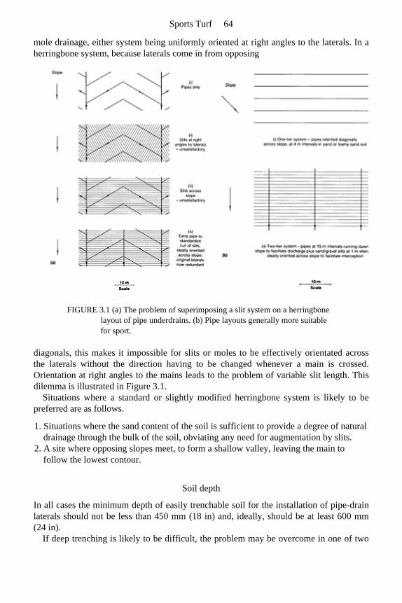
mole drainage, either system being uniformly oriented at right angles to the laterals. In aherringbone system, because laterals come in from opposing
FIGURE 3.1 (a) The problem of superimposing a slit system on a herringbone layout of pipe underdrains. (b) Pipe layouts generally more suitable for sport.
diagonals, this makes it impossible for slits or moles to be effectively orientated acrossthe laterals without the direction having to be changed whenever a main is crossed.Orientation at right angles to the mains leads to the problem of variable slit length. Thisdilemma is illustrated in Figure 3.1.
Situations where a standard or slightly modified herringbone system is likely to be preferred are as follows.
1. Situations where the sand content of the soil is sufficient to provide a degree of natural drainage through the bulk of the soil, obviating any need for augmentation by slits.
2. A site where opposing slopes meet, to form a shallow valley, leaving the main to follow the lowest contour.
Soil depth
In all cases the minimum depth of easily trenchable soil for the installation of pipe-drain laterals should not be less than 450 mm (18 in) and, ideally, should be at least 600 mm(24 in).
If deep trenching is likely to be difficult, the problem may be overcome in one of two
Sports Turf 64
ways:
1. inserting an intermediate system of transverse gravel channels between the surface slits and pipe underdrains to allow a marked reduction in the pipe required within the inhospitable sub-stratum—a three-tier system;
2. employing perforated plastic mini-pipes at the bottom of the surface slits—a one-tier system (Chapter 2, page 42).
3.1.3 Theoretical considerations affecting the design of grid systems
Pipe and slit efficiency
1. Pipes are generally laid on a gradient to direct discharge one way. Rather than attempting to impose an even gradient on the trench base, which implies an ever deepening trench with increasing cost both for excavation and backfill, it is usually best to give the pipes the benefit of any general, site slope. This allows the trench to be maintained throughout at a constant depth from the surface.
2. On sports fields, slits and gravel channels are most efficient for surface interception when laid flat across slope and, as such, are free to discharge equally at either end.
3. As indicated by the relationships in equations (4.4) and (4.6), pp 67–68, halving the length of run between outlets, S, or doubling the depth of the slit, H, will result in a four-fold (22) benefit to the discharge rate, i.e. the overall design rate V. Similarly, as the data in Table 7.2, page 119 indicate that hydraulic conductivity K is improved roughly three-fold for a doubling of D K (the effective particle size of the permeable fill), this is the order of benefit that will accrue to the overall design rate, V. However, a doubling of the slit width, or a halving of the interval between slits, will only increase the overall design rate two-fold.
4. If slits or gravel channels are oriented downslope and flow is redirected all one way, this will have two effects.
(a) Efficiency will be reduced, by the path length to discharge point having been extended.
(b) Though the extra push given by the gradient will tend to increase the rate of flow, this effect will not produce a net benefit until the slope exceeds a gradient that would be unacceptable on most playing surfaces (see also section 4.1.2, page 66).
Which tier system of layout?
Depending on circumstances there are, broadly speaking, three grid systems of artificialdrainage to choose from. These may be thought of as consisting of one, two or three tiersof artificially organized, horizontal flow and are summarized in Table 3.1.
One-tier systems In a one-tier system the dual functions of surface interception and pipe discharge arecarried out within one set of trenches, all of uniform depth, oriented in parallel
Alternate Layouts 65
succession, diagonally across the slope. The permeable backfill over the pipe, if broughtthrough to the surface, will intercept free water moving downhill, either over the surfaceor through the topsoil, letting this down to the pipe for discharge. The ideal orientationfor interception would be for the trench system to run directly across slope, but then thepipe would have no gradient to assist its discharge unless the expensive and cumbersomeexpedient were adopted of imposing a gradient on the base of each trench.
Running the trench system directly downhill, to give priority to discharge, wouldobviate the need for a graded fall to be artificially imposed on the trench but wouldadversely affect the efficiency of free water interception. The diagonal orientation is thusa logical compromise. It gives half the benefit of the slope to each of the two separatefunctions which, in a one-tier system, have both to be accomplished in a single trench.
TABLE 3.1 Drainage options
(A) Summary of options for new constructions
Layout Comments Immediate aftercare and annual maintenance
One-tier systems
(1) Subsoil pipe drains only, with permeable backfill topped to surface level.
When widely spaced this represents minimum drainage, minimum cost and minimum maintenance, but is seldom satisfactory on its own. It serves mainly as a basis for future slit drainage. If this cannot be contemplated, soil should be worm-worked, or made very sandy, and spacing of pipe drains should not exceed 4 m (13 ft). Orientation necessarily a compromise.
Occasional application of fine sand topdressing along pipe trenches to maintain surface level and avoid soil capping of pipe trenches.
(2) A miniaturized, pipe-assisted, slit system consisting of 35 mm, corrugated and perforated, plastic mini-pipes in slits 300–350 mm (12–14 in) deep, spaced at intervals of 1 m or less, backfilled with grit or fine gravel to the surface and discharging directly into the main, off the pitch. Orient pipes to fall
This system is particularly useful when finance and/or the trenchable depth is strictly limited, and where use is mainly in the summer, e.g. for cricket. However, very long runs of such a small-bore pipe make it vulnerable to silting. Orientation is necessarily a compromise.
Before any play is allowed, apply fine sand topdressing to the whole area at a minimum rate of 80 t/ha (32 tons/acre), followed by annual topdressings at 40 t/ha (16 tons/ acre). Or Micro-slit immediately using a medium sand fill. Slits approx. 13 mm (½ in) wide, 100 mm (4 in) deep, at 200 mm (8 in) intervals. Overfill slits to allow for settlement. Topdress with fine sand annually but repeat micro-
Sports Turf 66
diagonally across slope. slitting if the pipe slits become soil-capped.
Two-tier systems
(3) A deep, imported and suitably ameliorated sand or loamy sand topsoil, 300–400 mm (12–16 in) in depth, over a gravel drainage bed with pipe underdrains.
Liable to be expensive. Used mainly for golf and bowling greens with artificial watering. Not so suitable for rigorous winter games with studded footwear as, without worm activity, the grass will tend to become surface-rooting.
No topdressing necessary before play is allowed but annual topdressings, matched to the topsoil, essential. Maintenance must emphasize measures necessary to continually combat the tendency to accumulate thatch.
(4) Sand/gravel slits into pipe underdrains.
Generally very satisfactory and usually essential where construction has involved considerable soil disturbance, e.g. for levelling. Slits and pipe drains can both be optimally oriented.
Before any play is allowed, apply fine sand topdressing to the whole area at a minimum rate of 80 t/ha (32 tons/acre). Follow by annual topdressings at 40 t/ha (16 tons/ acre).
Layout Comments Immediate aftercare and annual maintenance
(5) A shallow, 100–125 mm (4–5 in) carpet of ameliorated fine sand, 100–125 mm thick, over a pipe drained and sand/gravel slit, fertile soil surface. Slits, ideally at 1 m intervals.
Provides for very efficient drainage and drought resistance. Slits and pipe drains can both be optimally oriented. Cost likely to be 50% more than for (4) above. True surface, suitable for hockey.
No topdressing necessary before play is allowed but annual topdressings of fine sand essential as in (4) above.
Three-tier systems
(6) Sand/gravel slits into an intermediate tier of gravel channels and then into widely spaced pipe drains.
An economical system for dealing with a site which is difficult to trench, e.g. a tip site. By linking the slits into fairly broad, e.g. 200 mm (8 in) wide, gravel channels at an intermediate depth, the pipe drains can be installed at much wider intervals, reducing the amount of deep trenching required. Orientation of tiers necessarily a compromise.
As for (4) above.
(7) Mini sand slits, 20 mm (¾ in) wide, 200–300 mm (8–12 in) deep, at 300–400 mm (12–16 in) intervals, linked
Useful where surface trueness is vital and option (5) is considered too expensive. Orientation of tiers necessarily a compromise.
As for (4) above.
Alternate Layouts 67
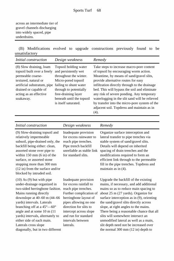
across an intermediate tier of gravel channels discharging into widely spaced, pipe underdrains.
(B) Modifications evolved to upgrade constructions previously found to be unsatisfactory Initial construction Design weakness Remedy
(8) Slow draining, loam topsoil built over a freely permeable coarse-textured, natural or artificial substratum, pipe drained or capable of acting as an effective soakaway.
Topsoil holding water and persistently wet throughout the winter. Micro-pored topsoil failing to shunt water through to potentially free-draining layer beneath until the topsoil is itself saturated.
Take steps to increase macro-pore content of topsoil by encouraging worm action. Meantime, by means of sand/gravel slits, provide alternative routes for easy infiltration directly through to the drainage bed. This will bypass the soil and eliminate any risk of severe ponding. Any temporary waterlogging in the slit sand will be relieved by transfer into the micro-pore system of the adjacent soil. Topdress and maintain as in (4).
Initial construction Design weakness Remedy
(9) Slow-draining topsoil and relatively impermeable subsoil, pipe-drained only, the backfill being either: clean, assorted stone over pipe to within 150 mm (6 in) of the surface, or assorted stone stopping more than 300 mm (12 in) from the surface and/or blocked by intruded soil.
Inadequate provision for excess rainwater to reach pipe trenches. Pipe trench backfill unreliable as stable link for standard slits.
Organize surface interception and lateral transfer to pipe trenches via stable system of sand/gravel slits. Details will depend on inherited spacing of drain trenches and the modifications required to form an efficient link through to the permeable fill in the pipe trenches. Topdress and maintain as in (4).
(10) As (9) but with pipe under-drainage organized in two-sided herringbone fashion. Mains running directly downslope at 40–60 m (44–66 yards) intervals. Laterals branching off at a 45°—60° angle and at some 10 m (11 yards) intervals, alternately to either side of each main. Laterals cross slope diagonally, but in two different
Inadequate provision for excess rainfall to reach pipe trenches. Further complication of herringbone layout of pipes allowing no one direction for slits to intercept across slope and run for standard intervals between laterals.
Upgrade the backfill of the existing mains, if necessary, and add additional mains so as to reduce main spacing to about 25 m (27 yards). Organize for surface interception as in (9), orienting the sand/gravel slits directly across slope, at right angles to the mains. There being a reasonable chance that all slits will somewhere intersect an unmodified lateral as well as a main, slit depth need not be increased over the normal 300 mm (12 in) depth to
Sports Turf 68
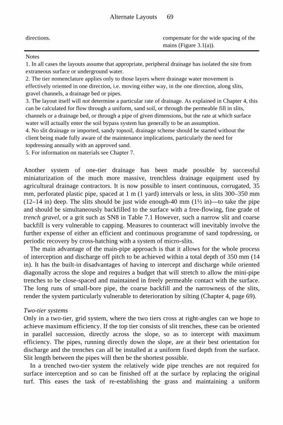
Another system of one-tier drainage has been made possible by successfulminiaturization of the much more massive, trenchless drainage equipment used byagricultural drainage contractors. It is now possible to insert continuous, corrugated, 35mm, perforated plastic pipe, spaced at 1 m (1 yard) intervals or less, in slits 300–350 mm (12–14 in) deep. The slits should be just wide enough-40 mm (1½ in)—to take the pipe and should be simultaneously backfilled to the surface with a free-flowing, fine grade of trench gravel, or a grit such as SN8 in Table 7.1 However, such a narrow slit and coarse backfill is very vulnerable to capping. Measures to counteract will inevitably involve thefurther expense of either an efficient and continuous programme of sand topdressing, orperiodic recovery by cross-hatching with a system of micro-slits.
The main advantage of the main-pipe approach is that it allows for the whole processof interception and discharge off pitch to be achieved within a total depth of 350 mm (14in). It has the built-in disadvantages of having to intercept and discharge while orienteddiagonally across the slope and requires a budget that will stretch to allow the mini-pipe trenches to be close-spaced and maintained in freely permeable contact with the surface.The long runs of small-bore pipe, the coarse backfill and the narrowness of the slits,render the system particularly vulnerable to deterioration by silting (Chapter 4, page 69).
Two-tier systems Only in a two-tier, grid system, where the two tiers cross at right-angles can we hope to achieve maximum efficiency. If the top tier consists of slit trenches, these can be orientedin parallel succession, directly across the slope, so as to intercept with maximumefficiency. The pipes, running directly down the slope, are at their best orientation fordischarge and the trenches can all be installed at a uniform fixed depth from the surface.Slit length between the pipes will then be the shortest possible.
In a trenched two-tier system the relatively wide pipe trenches are not required for surface interception and so can be finished off at the surface by replacing the originalturf. This eases the task of re-establishing the grass and maintaining a uniform
directions. compensate for the wide spacing of the mains (Figure 3.1(a)).
Notes 1. In all cases the layouts assume that appropriate, peripheral drainage has isolated the site from extraneous surface or underground water. 2. The tier nomenclature applies only to those layers where drainage water movement is effectively oriented in one direction, i.e. moving either way, in the one direction, along slits, gravel channels, a drainage bed or pipes. 3. The layout itself will not determine a particular rate of drainage. As explained in Chapter 4, this can be calculated for flow through a uniform, sand soil, or through the permeable fill in slits, channels or a drainage bed, or through a pipe of given dimensions, but the rate at which surface water will actually enter the soil bypass system has generally to be an assumption. 4. No slit drainage or imported, sandy topsoil, drainage scheme should be started without the client being made fully aware of the maintenance implications, particularly the need for topdressing annually with an approved sand. 5. For information on materials see Chapter 7.
Alternate Layouts 69
appearance. Because of budget constraints, or reluctance to risk prolonged loss of use, it may be
necessary to phase the work, first installing the pipe drains, then following with theinstallation of slits sometime later. Installation of the pipe system need not be an undulyexpensive operation and need not involve any loss of use if backfilling with gravel, sandand turf goes simultaneously with trench excavation and pipe laying. However, as thepipes run directly downslope this first phase will not confer much benefit on its own but,when funds and time are available to complete the job another year, the sand/gravel slitscan then be rapidly installed on a stable surface, starting early in the spring. This earlystart will allow ample time to reestablish the sward and apply a protective topdressing offine sand before winter use resumes.
Three-tier systems Generally, three-tier systems arise when there are special conditions to cope with, either at the surface, or at the depth of the pipe drains. For example, when trenching andartificial grading of the pipe system is likely to be particularly difficult because of theintractable nature of the substratum, a second tier of gravel channels is introducedbetween the pipe underdrains and the surface slits. This allows the number of pipeunderdrains required to be kept to a minimum.
In such a three-tier, intersecting, grid system it is inevitable that there will have to becompromises in efficiency unless the top tier is not a system of trenches but a substantialsand carpet. A top tier of slit trenches, oriented across the slope, would require the middletier of intersecting gravel channels to run down the slope, and they, therefore, woulddischarge mainly one way. As explained later (page 66), providing the gravel channelsare free to discharge either way, a slight slope on the trench will confer a small benefit onthe rate of water clearance to the underdrains. The orientation with slope, however, willadversely affect their interception efficiency, except where drainage water is delivereddirectly to them by the top tier of sand/gravel slits. Also, as the third tier of pipe trencheswould require to run across slope, any grading required for discharge would have to beachieved artificially. Alternatively, if priority is given to the third tier of pipe trenches,giving them the benefit of any natural slope, this would enable the second tier,represented here by the gravel channels, a chance to achieve their maximum efficiencyfor interception by being oriented directly across slope. However, the top tier ofsand/gravel slits would then be at a disadvantage for their main function of free waterinterception, because they would have to run in parallel succession down slope. Thecompromise of skewing all tiers to run alternately on one-or-other diagonal would incorporate some element of inefficiency in each tier. Inherited elements of the drainagesystem, or constraints imposed by the site will normally dictate which alternative tochoose.
Example 3.1 On many tip sites the assortment of rubble, domestic debris and blinding materialforming the substratum is not only difficult to trench and of uncertain permeability, it isoften covered by less than the minimum 450 mm (18 in) of easily trenchable soilnormally required for pipe drain installation. It may then be advisable to plan from thestart for minimum deep trenching. Thus, though we install from the bottom up, it is often
Sports Turf 70
useful to plan from the top down; in this case planning first for surface interception intosand/gravel slits. These can run at 1 m intervals in parallel succession across the slope,and beneath these an intermediate tier of gravel channels, 200 mm (8 in) wide, 350 mm(14 in) deep, at 4 m (13 ft) intervals, running downslope. The gravel channels will thenbe able to leak away into the tip blinding layer wherever they can, allowing a minimalpipe system to be installed within the rubble, at right-angles beneath the gravel channels, in trenches artificially graded to ensure discharge.
Example 3.2 Where surface trueness is vital, as for hockey, but there is insufficient money available toplan for a slit system covered by a 100–125 mm (4–5 in) deep, ameliorated sand carpet, a reasonable alternative is to plan for surface interception into a mini-slit system. For this, thin slits, 20 mm (¾ in) wide, 200 mm (8 in) deep, filled with a medium sand (e.g. SN12in Table 7.1) and spaced 300 mm (12 in) apart, should run in parallel succession, at right-angles across the slope. Beneath these there can be an intermediate tier of grit or finegravel channels, and at right-angles, beneath the gravel channels, an artificially graded final tier of pipes, or a stone soakaway.
In three-tier schemes neither the trenches forming the gravel channels nor the pipetrenches need be backfilled with freely permeable material right through to the surface.They can be finished off with a soil-based turf that will rapidly marry in with the rest of the sward. This leaves only the two-part, sand/ gravel slit system, or the mini-slit system to be directly re-seeded, or to grass itself over by reinvasion from the side.
Example 3.3 A temporary, three-tier system may arise by accident when a two-tier slit system is allowed to become soil-capped through maintenance neglect. Shallow micro-slits, aligned at right angles to the original slits, are used to reestablish surface interception.
Practical considerations arising on site
1. Whichever system is used, the layout should be so arranged that, as far as possible, main drains avoid the actual pitch areas. In particular, they should not pass under cricket tables.
2. It is desirable that space should be available for the side-or-end-shifting of winter games pitches so that worn areas can be given a chance to recover between seasons. About 10 m (11 yards) is normally allowed for movement either way and it is essential that, where these areas are provided, they should be fully covered by the drainage system.
3. To prevent displacement or penetration of pipe drains by roots, drain lines should be kept well away from trees and bushes. Where such contact is unavoidable, special precautions should be taken to prevent blockage of pipes, e.g. by using, for mains, glazed pipes with sealed joints.
Alternate Layouts 71
3.2 Options where there is also a need for the importation of new topsoil
If the soil is very shallow, or thoroughly degraded and subsoil in character, it may benecessary to consider creating a new topsoil by importing appropriate soil-forming materials. This is a procedure that will inevitably lead to a major escalation in cost unlessthe materials to be imported are available at artificially low prices.
The only other alternative is to allow time for the degraded soil to be reconditioned biologically before further developing the site for sports use. This does not mean merelyabandoning it to nature for a number of years as nature, unassisted, may take 50 years ormore to achieve what well directed, purposeful management can achieve in 5–10 years (Stewart and Scullion, 1989).
Essentially, the aim must be to rapidly introduce an adequate and appropriate earthworm population to a mechanically opened surface, encouraging the earthworms tothrive and remain active by the prior installation of an underdrainage scheme that willallow for full drainage benefit from regular subsoiling. Maintain under grass with soil pHabove 6. Avoid high concentrations of freely soluble fertilizer, and steer clear ofpesticides, many of which are harmful to earthworms though not specifically targetedagainst them. Return all organic residues by allowing clippings to fly, or carefullygrazing with sheep. An inoculum of earthworms, simply scattered onto the surface, willmerely feed the birds.
A new semi-artificial surface can be formed of topsoil sand plus appropriate ameliorants. This should be laid over one of two very different systems of underdrainage:
1. a slit system, bypassing excess, infiltered, surface water directly through the buried, problem layer;
2. a drained gravel bed protected from infiltration of fine sand from above and soil from below by shallow layers of a blinding sand or by sheets of a synthetic fabric filter.
Choice will involve considerations of cost and the type of playing surface required.
3.2.1 Cost
The gravel-bed approach involves two or three times the amount of imported material compared with that required for the slit-based alternative. On the other hand, although slit systems require much less imported material, they require special equipment to cut andbackfill the extensive system of narrow drain trenches.
3.2.2 Character
For winter games, a sward established on an ameliorated sand topsoil, and shallowenough at 100–125 mm (4–5 in) depth to ensure that the roots reach through to the waterand nutrient reserves retained by the slit-drained soil beneath, will be well buffered
Sports Turf 72

against waterlogging, drought and hunger. Under these conditions a strong-growing grass, such as ryegrass, can dominate and form an excellent, wear-tolerant sward for rigorous games such as soccer, rugby and hockey.
However, a sward established in a deeper layer 300–400 mm (12–16 in) of topsoil sandperched over a blinded and drained gravel bed will have to be well adapted to cope withthe dual threats of periodic waterlogging and periodic drought. The drought risk is aninevitable consequence of the severely limited depth of the soil layer. The waterlogging,which particularly affects the lower half of the soil, arises from the break in capillary continuity caused by the air that is locked within the gravel. In such a construction, watercan be rapidly shunted through the sandy topsoil to clear the surface, but even sandcannot then complete the job of drainage through to emptying enough of the pore spaceto allow for satisfactory aeration. Ryegrass yellows badly under these conditions andalso, being illadapted to cope with drought, gives way to the finer grasses which, thoughbetter adapted to cope with drought, are ill-adapted to cope with wear. The result is aconstruction that is only appropriate for the smooth, worm-free, close-cropped surfaces required for golf and bowling greens. They look well if protected from wear but they arethe most demanding and expensive of all swards to construct and maintain.
Thus, to plan construction we need to know the type of use and the standard of maintenance that can be anticipated, and then, taking the character of the site intoconsideration, progress stepwise through the possibilities until the client finds the bestmatch between the budget available and the standard of performance consideredacceptable.
Alternate Layouts 73

Chapter four
Design criteria-theory and practice


4.1 Transmission of water
Calculations are described in Chapters 4, 5, 7 and 13 that should be part of the stock-in-trade of any professional designer, but not everyone involved in sports-turf provision will feel that their concern obliges them to immediately get so deeply involved. Others,though wishing to make the effort, may initially experience difficulty because thepractical objectives are not yet sufficiently clear in their minds. Anyone thus deterredmight do well to move on first to page 62 of this chapter, chapter 7, pages 114–117 and then to Part 2, returning to the more detailed calculations when the need seems more clearly to justify the effort. Those with special skills in mathematics are referred toAppendix 5 where the subject is considered at the fundamental level necessary togenerate the equations used for design purposes in the main text of the book.
4.1.1 Theoretical considerations affecting design calculations
Darcy’s Law
Darcy’s law is the fundamental law which describes the flow of water through porousmedia. It is very similar to other fundamental laws of physics that describe the flow ofelectricity and the flow of heat. These state that, in the first instance, the flow is acharacteristic of the medium, some media being inherently better conductors than others.Thereafter, for water, the flow is directly proportional to the hydraulic head providing thepush, and inversely proportional to the resistance as determined by the nature of the poresystem and the path length through it. Thus Darcy’s law may be written
where Q is the quantity of water flowing per unit time, K is the hydraulic conductivity of the medium, A is the cross-sectional area through which water flow is limited, H/L is the hydraulic gradient, H being the hydraulic head, i.e. the height of the continuous watercolumn of free standing water within the medium and above it, and L the length of the path through the medium controlling flow.
Sports Turf 76

Hooghoudt’s drain-spacing equation
Dr Hooghoudt (1940) of the Netherlands published an equation which, on a level site,describes the interrelationships of all the factors controlling the lateral discharge ofdrainage water through soil to drainage trenches when input is balanced by output. Theconditions envisaged are illustrated in Figure 4.1 (a). At equilibrium the watertable is held at a fixed height H above the level of the water in the drainage ditches. In thesecircumstances Hooghoudt’s equation states
Design criteria-theory and practice 77
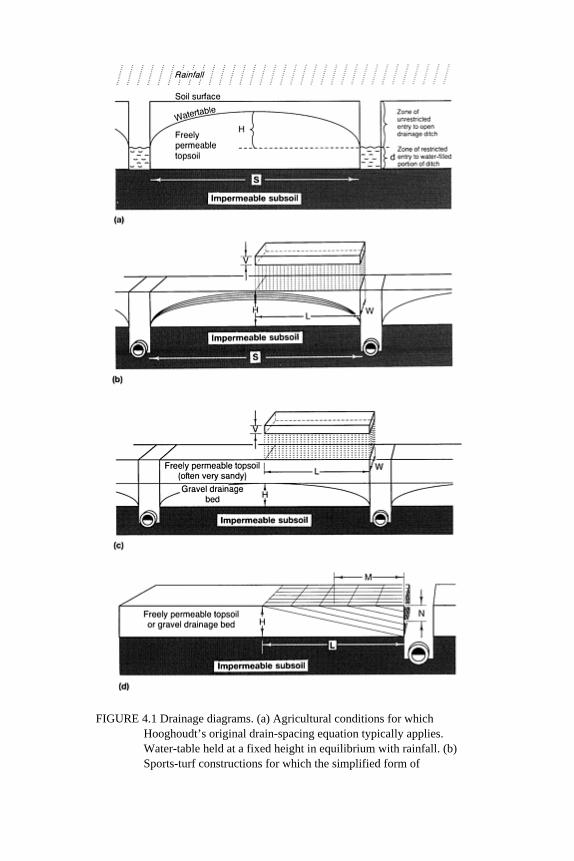
FIGURE 4.1 Drainage diagrams. (a) Agricultural conditions for which Hooghoudt’s original drain-spacing equation typically applies. Water-table held at a fixed height in equilibrium with rainfall. (b) Sports-turf constructions for which the simplified form of
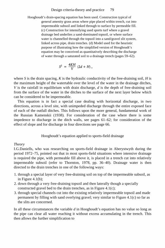
Hooghoudt’s drain-spacing equation has been used. Construction typical of general amenity grass areas where pipe placed within trench, cut into impermeable subsoil and linked through to surface by permeable fill. (c) Construction for intensifying used sports turf where a gravel drainage bed underlies a sand-dominated topsoil, or where surface water is channelled through the topsoil into a sand/gravel slit system, linked across pipe, drain trenches. (d) Model used for the heuristic purpose of illustrating how the simplified version of Hooghoudt’s equation may be conceived as quantitatively describing the discharge of water through a saturated soil to a drainage trench (pages 59–62).
where S is the drain spacing, K is the hydraulic conductivity of the free-draining soil, H is the maximum height of the watertable over the level of the water in the drainage ditches,V is the rainfall in equilibrium with drain discharge, d is the depth of free-draining soil from the surface of the water in the ditches to the surface of the next layer below whichcan be considered to be impermeable.
This equation is in fact a special case dealing with horizontal discharge, in two directions, across a level site, with unimpeded discharge through the entire exposed faceof each of the outfall ditches. This follows upon the more general, fundamental work ofthe Russian Kamenskii (1938). For consideration of the case where there is someimpedence to discharge in the ditch walls, see pages 61–62; for consideration of the effect of slope and for discharge in four directions see page 66.
Hooghoudt’s equation applied to sports-field drainage
Theory I.G.Daniells, who was researching on sports-field drainage in Aberystwyth during the period 1972–75, pointed out that in most sports-field situations where intensive drainage is required the pipe, with permeable fill above it, is placed in a trench cut into relativelyimpermeable subsoil (refer to Thornton, 1978, pp. 36–40). Drainage water is then directed to the drain trenches in one of the following ways:
1. through a special layer of very free-draining soil on top of the impermeable subsoil, as in Figure 4.1(b);
2. down through a very free-draining topsoil and then laterally though a specially constructed gravel bed to the drain trenches, as in Figure 4.1(c);
3. through special channels cut into the existing relatively impermeable topsoil and made permanent by filling with sand overlying gravel; very similar to Figure 4.1(c) so far as the slits are concerned.
In all these circumstances the variable d in Hooghoudt’s equation has no value so long as the pipe can clear all water reaching it without excess accumulating in the trench. Thisthen allows the further simplification to
Design criteria-theory and practice 79
When comparing Figure 4.1(a) with Figures 4.1 (b) and 4.1(c) it is important to note that in (b) and (c) the water cleared sideways falls into the drain trench from above. The pipeis installed at a depth that keeps it well clear of damage from construction work carriedout over it, and the drainage link with the surface is maintained by permeable fill. Watertumbling discontinuously down through the gravel in the pipe trench will contribute noextra pull and should not feature, therefore, in any assessment of hydraulic head. Hshould only take account of the height of the watertable perched above the surface of theimpermeable subsoil and should not include any additional allowance for the depth of thepipe.
When choosing an overall design rate for drainage the aim should be to avoid surfaceponding caused by the watertable breaking through the surface. Any water infilteredshould be cleared without this happening. Surface ponding resulting from soil conditionsimpeding infiltration should be treated separately. In the circumstances depicted in Figure 4.1(b) it might sometimes be more reasonable to design for the maximum height of the watertable H to be held just below the surface at peak capacity, for example 75 mm (3 in)down.
When utilizing a gravel bed (Figure 4.1(c)), as for golf and bowling greens, it can be assumed that lateral flow will take place through the gravel bed as if it existed in isolationfrom the overlying topsoil, its full depth being considered the maximum height available for any watertable perched within it. This leaves the sand soil above to be designed solelywith regard to efficient infiltration, vertical drainage, plant growth and playing character.In the similar circumstances of sand/ gravel slits, lateral discharge is also best consideredto be determined only by conditions within the gravel layer. The sand above is, to thegravel layer, merely the conduit through which the water to be cleared arrives.
To pursue the subject of water movement through soil, quantitatively, requires advanced mathematics. This is the purpose of Appendix 5. However, for those who arenot mathematicians a heuristic approach based on the model illustrated in Figure 4.1(d) will serve as an adequate starting point from which to proceed to the intelligent use ofHooghoudt’s equation and its extensions.
In Figure 4.1(d) flow is conceived as taking place across the drainage layer in a tightlypacked arrangement of small, square tubes, all sloping down diagonally from the surfacetowards the nearest outlet end of the free-draining layer. The total amount of watermoving laterally increases progressively as further increments enter from above and, inthe model, probably unlike reality, the soil beneath the main diagonal is virtuallyredundant.
When in equilibrium at peak capacity the rainfall which the model is designed toaccept just matches the water discharged through the pipe-trench face. For this shunting through of water to be simultaneous it must take place when the tubes are full, i.e. the soilis saturated.
Consider the situation in just one of the tubes, starting at distance M from the drain trench and discharging at the trench face, a distance N from the surface. The flow through this one tube can be quantitatively described by Darcy’s Law
Sports Turf 80

where q is the infiltration required at the inlet end of the tube, K is the hydraulic conductivity of the medium in the tube, a is the cross-sectional area of the tube, N/M is a reasonable approximation to the hydraulic gradient, M being very close to the path length through the tube when N (normally 100–200 mm) is very small compared with M(normally 100000–200000 mm).
Or, as all the tubes are conceived as grading uniformly, and N and M are proportional in length to H and L,
and the total flow through all the imagined tubes, to all intents and purposes, aggregatesto
where, referring also to Figures 4.1(b) and (c), Q is the total amount of rain, represented by the volume VLW, which must be cleared through the topsoil to achieve the desired design rate, and A is the approximate cross-sectional area of all the tubes discharging drainage water through the trench face with area HW. Substituting VLW for Q and HWfor A,
which can be simplified and re-arranged to
Since L=S/2, i.e. L is half the drain spacing, we have
which re-arranges to
All these are forms of the simplified Hooghoudt drain-spacing equation and may be used
Design criteria-theory and practice 81
as they best fit the type of calculator available. The dimensions must all be expressed inthe same units, e.g. S and H millimetres (inches), K and V in millimetres (inches) per hour.
In reality, flow is not constrained within tubes and does not traverse the drainage layer in straight lines, but the result from the heuristic model, where approximations of thiskind have been used to simplify the mathematics, appears to be identical to that reachedby Hooghoudt’s more rigorous approach. The fact is that the relationship summarized in Hooghoudt’s standard equation holds only over the normal range of conditionsencountered in constructions for sport. However, as shown in Appendix 5, Hooghoudt’s drain-spacing equation tends to slightly exaggerate performance. The error increases insignificance as S becomes progressively smaller compared with H but, even at spacings only of the order of 1 m and H values of the order of 300 mm, the error is unlikely to exceed 1%.
Practical considerations affecting design for drain interception of slits If the area through which water is free to discharge through the trench face is restricted,e.g. where the intersection between the gravel layer in a sand/gravel slit incompletelyintersects the gravel fill in a pipe trench or gravel channel, the heuristic model suggeststhis may reduce the rate of discharge significantly. The effect will be seen in theadjustment required in the H 2 factor of the standard Hooghoudt drainspacing equation. One of the two Hs involved should be reduced to represent the actual height of the window through which the drainage water can discharge at the trench face, i.e. theintersection link. The other H, representing the maximum height of the watertable over the level of the water in the drainage ditches, is unaffected. The message here is that, formaximum efficiency in a linked, tier system of drainage channels, the main dischargeroutes—normally the gravel layers—should intersect to the full depth of the gravel layerin the discharging tier.
In Figure 4.1(c), however, which is probably closer to reality, it is assumed that water accumulation in the freely permeable layer will reach a peak midway between the pipetrench outfalls, while clearance needs only take place through the base of the vertical,discharge face.
When it comes to effecting links of this nature in the field, e.g. between sand/gravelslits and pipe underdrains, these conflicting assumptions lead to two different conclusionson the most effective way to organize the junctions. Theoretically, Figure 4.1 suggests that in Figure 11.1, the layout for a standard slit system, the gravel layer in the slit trenches needs only a minimal depth of intersection with the top of the gravel layer ineach of the pipe trenches. What is illustrated is intersection to the full depth of the gravellayer in the slit trenches: hence the range of alternative depths indicated for the soil andgravel layers in the pipe trenches.
However, since it would be possible for the watertable at the mid-point between the drain outfalls to rise further, into the layer of blinding sand above, and even on to the surface temporarily, there needs for this reason alone to be some generosity in the designof the outlet from the slit into the pipe trench, as the heuristic model allows. At the sametime, the gravel drainage layers must be protected as much as possible from soil invasionby placing them as deep as possible, away from the topsoil where most of the lateral
Sports Turf 82
tunnelling of earthworms takes place. Thus the option to avoid any unnecessarily deepintersection between the slits and the pipe trenches should not be at the expense of overallslit depth. Figure 4.1(c) suggests that it would be theoretically acceptable to reduce thegravel layer in the pipe trenches to the absolute minimum required for a clean, horizontallink between the gravel at the base of the slits and the surface of the gravel in the pipetrenches. This would work, however, only if the flow through the horizontal interface wasadequate, because there would be no option for any substantial additional dischargesideways, along the pipe trench.
In the field we must expect to encounter practical difficulties over ensuring so critical a link without allowing a large margin for error. Should the normal differential settlementbetween the trenches and the soil lead to a drop in the relative height of the gravel at thetop of the drain trenches and the gravel at the bottom of the slits, or should additionaldrains be required after slitting, there will then be a risk, with a tight design, that thevertical, outfall face of the slits themselves will be unduly restricted to allow for peakflow. Thus, for practical reasons, the design of the vital link between the slits and the pipetrenches should err on generosity in a new construction. But there is some margin foradjustment when the specification has to be tight, or when installing slits to upgrade thedrainage provided by an existing pipe system, if soil conditions do not favour deeptrenching.
Preliminary note on the Stewart zone approach to design
When designing a drainage system involving superimposed sandy topsoils, or artificial,vertical drainage, bypassing the soil en route to the pipe system, the aim should be first to evaluate the flow required through each separate part of the integrated system then,secondly, to select materials that will meet these requirements, avoiding bottlenecks, andgetting maximum benefit for minimum cost.
In Chapter 7, pages 114–117, the Stewart zone system is described. This develops the idea of working with a limited range of the most commonly available materials, chosen tomake efficient design and specification much easier by eliminating the need for elaboratecalculations. This approach will be demonstrated throughout the remainder of thischapter, after examples have been worked through by the more rigorous procedure ofprecise calculation. See first example, page 71.
Fitting values to factors K and V in the simplified Hooghoudt equation
Hydraulic conductivity K available for lateral discharge through materials considered uniform Whatever the drainage medium through which water must pass to reach the pipe drains,whether it be soil, sand, gravel, or some special mixture, it is necessary to know the rateof flow through the material in question. This will be at a peak when saturated. It is thisvalue, the saturated hydraulic conductivity, that we determine in the laboratory and use todetermine from theory the nature of the backfill and the width, depth and spacing of thedrainage channels required to achieve any target design rate.
As indicated in Table 4.1 a granular loam may have something like the hydraulic
Design criteria-theory and practice 83
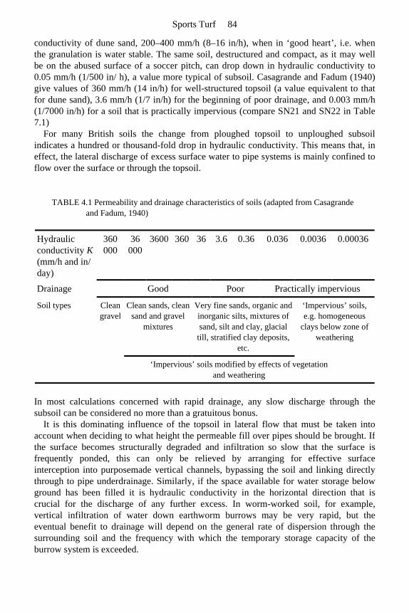
conductivity of dune sand, 200–400 mm/h (8–16 in/h), when in ‘good heart’, i.e. when the granulation is water stable. The same soil, destructured and compact, as it may wellbe on the abused surface of a soccer pitch, can drop down in hydraulic conductivity to0.05 mm/h (1/500 in/ h), a value more typical of subsoil. Casagrande and Fadum (1940)give values of 360 mm/h (14 in/h) for well-structured topsoil (a value equivalent to thatfor dune sand), 3.6 mm/h (1/7 in/h) for the beginning of poor drainage, and 0.003 mm/h(1/7000 in/h) for a soil that is practically impervious (compare SN21 and SN22 in Table 7.1)
For many British soils the change from ploughed topsoil to unploughed subsoil indicates a hundred or thousand-fold drop in hydraulic conductivity. This means that, in effect, the lateral discharge of excess surface water to pipe systems is mainly confined toflow over the surface or through the topsoil.
In most calculations concerned with rapid drainage, any slow discharge through thesubsoil can be considered no more than a gratuitous bonus.
It is this dominating influence of the topsoil in lateral flow that must be taken into account when deciding to what height the permeable fill over pipes should be brought. Ifthe surface becomes structurally degraded and infiltration so slow that the surface isfrequently ponded, this can only be relieved by arranging for effective surfaceinterception into purposemade vertical channels, bypassing the soil and linking directlythrough to pipe underdrainage. Similarly, if the space available for water storage belowground has been filled it is hydraulic conductivity in the horizontal direction that iscrucial for the discharge of any further excess. In worm-worked soil, for example, vertical infiltration of water down earthworm burrows may be very rapid, but theeventual benefit to drainage will depend on the general rate of dispersion through the surrounding soil and the frequency with which the temporary storage capacity of theburrow system is exceeded.
TABLE 4.1 Permeability and drainage characteristics of soils (adapted from Casagrande and Fadum, 1940)
Hydraulic conductivity K (mm/h and in/ day)
360 000
36 000
3600 360 36 3.6 0.36 0.036 0.0036 0.00036
Drainage Good Poor Practically impervious
Soil types Clean gravel
Clean sands, clean sand and gravel
mixtures
Very fine sands, organic and inorganic silts, mixtures of sand, silt and clay, glacial
till, stratified clay deposits, etc.
‘Impervious’ soils, e.g. homogeneous
clays below zone of weathering
‘Impervious’ soils modified by effects of vegetation and weathering
Sports Turf 84
Values for the hydraulic conductivity of isolated, disturbed samples of soil in thelaboratory are unlikely to relate very well to performance in the field. For uniformmaterials, such as the sands and gravels installed as horizontal layers in specialconstructions, or in the vertical channels of a drainage scheme, packing is uniform andwater movement is potentially the same in all directions. Therefore, in thesecircumstances hydraulic conductivity determined in the laboratory can be assumed torelate closely to that which can be expected to assist drainage in the field. However, thehydraulic conductivity of a material determined under ideal conditions of saturation in thelaboratory is likely to be an exaggerated version of that which occurs in situ. In the field the pore space is liable to become partially blocked by trapped air, especially when waterfilters down from above. Compensatory effects working in the opposite direction are: (a)the care taken to achieve maximum packing density when loose materials are tested in thelaboratory, whereas less perfect packing is likely to prevail in the field; (b) channels,assumed in a calculation to be of the precise width shown on the plans, frequently are tosome degree wider; (c) the soil, usually assumed to contribute nothing to rapid drainage,may in fact make some contribution. Theory and practice will therefore diverge but stillmuch can be done by calculation to locate possible bottle-necks so that materials or dimensions that could not possibly achieve the target design rate can be eliminated.
Because the hydraulic conductivity K of the medium is the factor in the simplified Hooghoudt equation for which a reliable value is normally least readily available, actualvalues for typical materials are given in Table 7.1. In Part 2, where specific constructions are described, the outline specifications for typical schemes utilize only Stewart zonematerials. Any modification involving the use of materials that fall outwith the prescribedStewart zones will require the whole scheme to be reviewed and appropriate adjustments made by calculation.
Averaging hydraulic conductivities available for lateral discharge through layered systems Where two freely permeable materials are to be laid in layers, one above the other, e.g. ina two-part, sand/gravel slit, it may be appropriate to assess their combined effect K a for the lateral discharge of drainage water. This can be done by using the following formulato determine an average value, weighted to take account of the hydraulic conductivity anddepth of each of the layers concerned. The average
However, the contribution of the sand layer in such a system is primarily to allow excesswater down to the gravel layer below and it is in the gravel layer that lateral dischargepredominantly takes place. This is why no allowance is made for the contribution tolateral discharge made by the sand layer in the simple, Stewart zone approach (Chapter 7, page 117).
Design rate V The design rate is the rainfall in millimetres (inches) which it is desired to clear throughthe system in a given time. It is the factor V in Figure 4.1.
Design criteria-theory and practice 85
As explained in Chapter 1 (pages 13–14), a design rate for sport and recreation in Britain might vary anywhere between the two extremes of 12 mm (½ in) of rainfall a day and 12 mm (½ in) of rainfall an hour, depending on climate, the demands of the game and standard of play.
When specifying design rates it should be appreciated that 2 mm ( in) per hour is about the minimum rate for hard porous surfaces (Chapter 13) and anything much in excess of this for turf is going to require vertical clearance of rainfall through a sand, orloamy sand topsoil to a gravel bed. Where lateral discharge has to take place through thetopsoil itself—either the whole topsoil or sand slits—maximum design rates are unlikely to exceed 2 mm/ h (2 in/day). A minimum rate normally considered to be reasonable for asports ground in Britain is between 1 and 2 mm/h (1 and 2 in/ day), according as rainfallranges between 500 and 1250 mm (20 and 50 in) a year.
Where, for reasons of economy, the under-drainage is inadequate to cope with the consequences of short periods of intense rainfall, provision should be made to grade thesurface to a fall of not less than 1:80. This should help to shed excess surface water toditches or some form of catchment drain, around the periphery.
4.1.2 Practical application of theory to problems of transmission of water
Basic schemes
The simplified Hooghoudt equation
is a convenient formula to use for the design of any closed system through which therapid transport of water is effectively confined, and for all parts of which the hydraulicconductivity can be predicted. It can seldom be used with the same confidence to predict the required spacing for drains, slits or gravel channels whose purpose is to interceptwater flowing through the very heterogeneous pore system of a normal soil. This isbecause it is difficult to ascribe to such a soil a reliable value for K. However, it can reasonably be used for the following.
1. To determine the materials required, and the spacing for drain trenches designed to intercept excess water shed to them at a given rate through a defined, homogeneous, stable layer of freely permeable soil—one-tier systems.
2. To determine the materials required and the design of a sand, or a sand/gravel slit system, whose purpose is to convey surfaceshed water at a given rate to a relieving system of underdrains, bypassing the intervening, relatively impermeable soil—a two-tier system.
3. To determine the materials required and the design of the sand, or sand/gravel slit system required to link to an intermediate system of deeper, transversely orientated gravel channels which, in turn, must be organized to discharge into a relieving system
Sports Turf 86

of pipe underdrains—a three-tier system. 4. To design gravel rafted schemes involving the vertical discharge of water through the
whole of the sandy topsoil to an underlying gravel bed, and thence laterally through the bed to a pipe system of underdrains—a two-tier system.
Notation and dimensions for worked examples of basic schemes
One-tier systems For a pipe-drained scheme, utilizing the entire topsoil as the route for water to drainlaterally to the pipe trenches, the notation should read:
S=distance between pipes in mm; H=depth of soil in mm forming the lateral conducting layer for which the K value is
known; K=hydraulic conductivity in mm/h for the lateral conducting soil layer; V=overall design rate in mm/h.
Two-tier systems For a pipe-drainage scheme, utilizing slits as the means of conducting surface waterthrough the topsoil to the pipe trenches, the notation should read:
S s=maximum effective length of slits in min; H s=total depth of permeable fill within slits, in mm; K s=hydraulic conductivity of the permeable fill (sand, gravel or sand and gravel)
within the slit in mm/h; V s=the overall design rate V in mm/r, modified according to the ratio of total surface to
slit surface as it is only at the slit that infiltration effectively occurs, i.e.
This assumes that the surface is level and the slits are placed close enough to ensure thatall surface-ponded water finds its way rapidly across the sward to the top of the slits.
Three-tier systems For a drainage scheme, involving slits, gravel channels and pipes the notation shouldread:
S s or S c=maximum effective length of slits or channels between outfalls to next lowertier of underdrainage in mm;
H s or H c=total depth of permeable fill within slits or channels, both in mm; K s or K c=hydraulic conductivity of the permeable fill (sand, gravel, or sand and
gravel) within slits or channels in mm/h; V s or V c=the overall design rate V in mm/ h, modified according to the ratio of total
surface to slit or channel surface.
Gravel-rafted schemes with clearance to pipe underdrains In gravel-rafted schemes the hydraulic conductivity of the whole of the topsoil
Design criteria-theory and practice 87
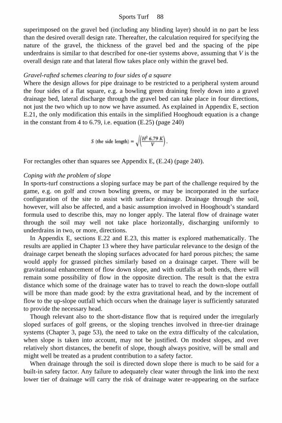
superimposed on the gravel bed (including any blinding layer) should in no part be lessthan the desired overall design rate. Thereafter, the calculation required for specifying thenature of the gravel, the thickness of the gravel bed and the spacing of the pipeunderdrains is similar to that described for one-tier systems above, assuming that V is the overall design rate and that lateral flow takes place only within the gravel bed.
Gravel-rafted schemes clearing to four sides of a square Where the design allows for pipe drainage to be restricted to a peripheral system aroundthe four sides of a flat square, e.g. a bowling green draining freely down into a graveldrainage bed, lateral discharge through the gravel bed can take place in four directions,not just the two which up to now we have assumed. As explained in Appendix E, section E.21, the only modification this entails in the simplified Hooghoudt equation is a changein the constant from 4 to 6.79, i.e. equation (E.25) (page 240)
For rectangles other than squares see Appendix E, (E.24) (page 240).
Coping with the problem of slope In sports-turf constructions a sloping surface may be part of the challenge required by the game, e.g. on golf and crown bowling greens, or may be incorporated in the surfaceconfiguration of the site to assist with surface drainage. Drainage through the soil,however, will also be affected, and a basic assumption involved in Hooghoudt’s standard formula used to describe this, may no longer apply. The lateral flow of drainage waterthrough the soil may well not take place horizontally, discharging uniformly tounderdrains in two, or more, directions.
In Appendix E, sections E.22 and E.23, this matter is explored mathematically. Theresults are applied in Chapter 13 where they have particular relevance to the design of the drainage carpet beneath the sloping surfaces advocated for hard porous pitches; the samewould apply for grassed pitches similarly based on a drainage carpet. There will begravitational enhancement of flow down slope, and with outfalls at both ends, there willremain some possibility of flow in the opposite direction. The result is that the extradistance which some of the drainage water has to travel to reach the down-slope outfall will be more than made good: by the extra gravitational head, and by the increment offlow to the up-slope outfall which occurs when the drainage layer is sufficiently saturatedto provide the necessary head.
Though relevant also to the short-distance flow that is required under the irregularlysloped surfaces of golf greens, or the sloping trenches involved in three-tier drainage systems (Chapter 3, page 53), the need to take on the extra difficulty of the calculation, when slope is taken into account, may not be justified. On modest slopes, and overrelatively short distances, the benefit of slope, though always positive, will be small andmight well be treated as a prudent contribution to a safety factor.
When drainage through the soil is directed down slope there is much to be said for abuilt-in safety factor. Any failure to adequately clear water through the link into the next lower tier of drainage will carry the risk of drainage water re-appearing on the surface
Sports Turf 88
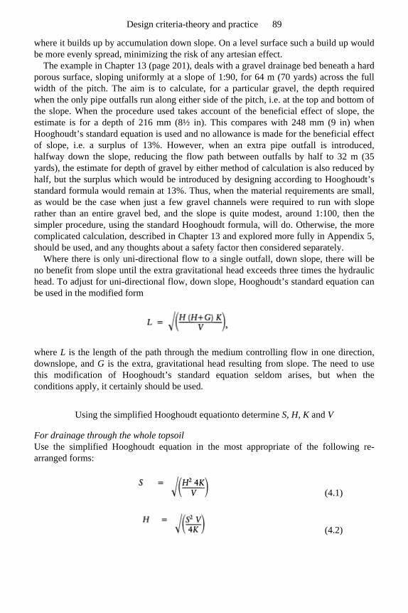
where it builds up by accumulation down slope. On a level surface such a build up would be more evenly spread, minimizing the risk of any artesian effect.
The example in Chapter 13 (page 201), deals with a gravel drainage bed beneath a hardporous surface, sloping uniformly at a slope of 1:90, for 64 m (70 yards) across the fullwidth of the pitch. The aim is to calculate, for a particular gravel, the depth requiredwhen the only pipe outfalls run along either side of the pitch, i.e. at the top and bottom ofthe slope. When the procedure used takes account of the beneficial effect of slope, theestimate is for a depth of 216 mm (8½ in). This compares with 248 mm (9 in) whenHooghoudt’s standard equation is used and no allowance is made for the beneficial effectof slope, i.e. a surplus of 13%. However, when an extra pipe outfall is introduced,halfway down the slope, reducing the flow path between outfalls by half to 32 m (35yards), the estimate for depth of gravel by either method of calculation is also reduced byhalf, but the surplus which would be introduced by designing according to Hooghoudt’s standard formula would remain at 13%. Thus, when the material requirements are small,as would be the case when just a few gravel channels were required to run with sloperather than an entire gravel bed, and the slope is quite modest, around 1:100, then thesimpler procedure, using the standard Hooghoudt formula, will do. Otherwise, the morecomplicated calculation, described in Chapter 13 and explored more fully in Appendix 5, should be used, and any thoughts about a safety factor then considered separately.
Where there is only uni-directional flow to a single outfall, down slope, there will beno benefit from slope until the extra gravitational head exceeds three times the hydraulichead. To adjust for uni-directional flow, down slope, Hooghoudt’s standard equation can be used in the modified form
where L is the length of the path through the medium controlling flow in one direction, downslope, and G is the extra, gravitational head resulting from slope. The need to usethis modification of Hooghoudt’s standard equation seldom arises, but when theconditions apply, it certainly should be used.
Using the simplified Hooghoudt equationto determine S, H, K and V
For drainage through the whole topsoil Use the simplified Hooghoudt equation in the most appropriate of the following re-arranged forms:
(4.1)
(4.2)
Design criteria-theory and practice 89
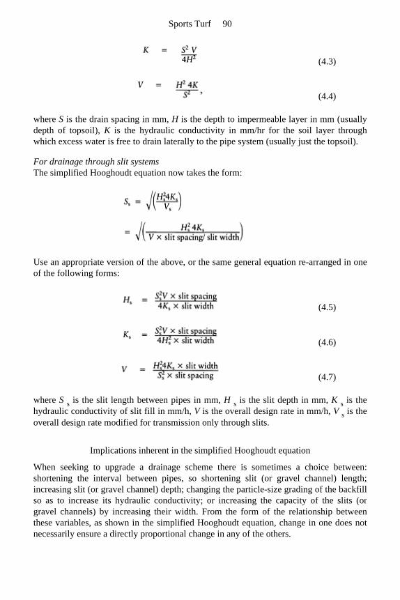
where S is the drain spacing in mm, H is the depth to impermeable layer in mm (usually depth of topsoil), K is the hydraulic conductivity in mm/hr for the soil layer throughwhich excess water is free to drain laterally to the pipe system (usually just the topsoil).
For drainage through slit systems The simplified Hooghoudt equation now takes the form:
Use an appropriate version of the above, or the same general equation re-arranged in one of the following forms:
where S s is the slit length between pipes in mm, H s is the slit depth in mm, K s is the hydraulic conductivity of slit fill in mm/h, V is the overall design rate in mm/h, V s is the overall design rate modified for transmission only through slits.
Implications inherent in the simplified Hooghoudt equation
When seeking to upgrade a drainage scheme there is sometimes a choice between:shortening the interval between pipes, so shortening slit (or gravel channel) length;increasing slit (or gravel channel) depth; changing the particle-size grading of the backfill so as to increase its hydraulic conductivity; or increasing the capacity of the slits (orgravel channels) by increasing their width. From the form of the relationship betweenthese variables, as shown in the simplified Hooghoudt equation, change in one does notnecessarily ensure a directly proportional change in any of the others.
(4.3)
(4.4)
(4.5)
(4.6)
(4.7)
Sports Turf 90
Thus, from the equation in the form
reducing the pipe spacing by half, i.e. halving the length of the slits S s, will allow the possibility of halving slit depth H s as this, though within the square root bracket, is itself a squared factor. However, if the change is to accommodate a change in any of the other,unsquared factors—K s, V, slit spacing or slitwidth—then halving S s or doubling H s will allow a four-fold reduction in K s or slit width, or a four-fold increase in V. Slit spacing, however, is not so automatically amenable to adjustment. It has been arbitrarily fixed notto exceed 1m, by experience, not by calculation.
Similarly, halving V will allow a halving of K or slit width but only a reduction of 1/√2 (i.e. 0.71) in H s or S s.
In practice it is important to recognize that it is modifications in S and H, or S s and H s, that have the greatest influence on the overall design rate V.
4.1.3 Worked examples of basic schemes
Calculations here do not include any adjustment for slope—see page 66—and are based on metric values only.
Pipe drainage only (i.e. one-tier systems)
Example 4.1
Given the minimum acceptable spacing S for the pipe drain laterals is 4000 mm (4¼yards), the depth of topsoil H is 300 mm (12 in) and the design rate V is 2 mm/h what is the minimum hydraulic conductivity required of the topsoil if the watertable is not tobreach the surface under the conditions specified? The site is flat and no slit drainage isintended. It may be assumed that the permeable backfill over the pipes will be trench gravel brought through to the surface as blinding sand.
By using the simplified Hooghoudt equation in the form
we have
Design criteria-theory and practice 91
A K value of the order of 75–100 mm/h is unlikely to be sustained by other than a puresand medium, with all the difficulties this would imply for grass growth. The most thatcould be relied upon after settlement from either a 3:1 by volume sand/peat mixture (e.g.Table 7.1, SN16), or a loamy sand soil more than 75% medium plus fine sand (e.g. Table 7.1 SN18) would be of the order of 25 mm/h.
What then should be done in the circumstances envisaged in the example? The drainspacing S could be reduced by half to 2 m (6½ ft) or the topsoil depth H increased to 600 mm (24 in), but these alternatives would probably be unreasonably expensive. Anotheralternative is to accept a lower standard of efficiency, i.e. accept a design rate V of 1 mm/h, a standard of performance considered satisfactory for agriculture. This wouldprobably be just acceptable for sport in areas of Britain with a relatively low rainfall, e.g.less than 700 mm (28 in) a year.
Changing the soil to a well-structured, granular loam (e.g. Table 7.1, SN21) could provide more than the required hydraulic conductivity K initially but the granulation might well not survive a winter of stud wear, and sand slitting would then be essential.
Generally, if drain spacings closer than 4 m (4¼ yards) are required, a two-tier system is more economical, using close-spaced sand or sand/gravel slits to intercept and then discharge excess surface water into the permeable fill of the trenches that carry the morewidely spaced under drains (see Example 4.2 below).
Theoretically at least, there would appear to be scope for the alternative of a miniaturized, one-tier, pipe-drainage scheme. With trenchless machinery, suitably modified to bury small bore, perforated, plastic pipe into narrow 20–40 mm (1–1½ in) slits, and simultaneously backfill to the surface with appropriate fine gravel, clean grit orcoarse sand, a type of pipe-assisted slit system could be created. However, the pipes would have to be very carefully installed so as to maintain flow for distances long enoughto justify their inclusion. On a flat site this will involve very accurate grading of trenchesto progressively greater depths. On an adequately sloping site, piped slits could beinstalled at a fixed, shallow depth of 250–350 mm (10–14 in) from the surface and, if oriented diagonally across slope, these will function for interception and discharge. But,in either case, the pipe being so small and the runs so relatively long, the very accurategrading required will make laser control of trench depth essential. The pipe performancedata in Table 2.1 indicates that continuous runs of the order of a pitch length and moreare possible. In these circumstances the permeable fill in the trench has only to allow theintercepted water down to the pipe. Virtually any clean sand could achieve this at anoverall design rate of 2 mm/ hr and a slit spacing to slit width ratio of 36:1, or less.
Sports Turf 92
Example 4.2
What permeable backfill would be appropriate for piped slits, 35 mm (1½ in) wide, spaced at 1 m (1 yard) intervals, and required to transfer water from the surface down tothe pipe at an overall design rate of not less than 2 mm/h ?
The hydraulic conductivity required of the permeable fill is
This could be provided even by clean, very fine sand. However, such a sand could infilterthe pipe perforations and would also be capable of ingestion by earthworms. It would bebetter, therefore, either to place trench gravel immediately over the pipe, followed by blinding sand through to the surface, or filter-wrap the pipe and then backfill withblinding sand only.
Pipe drainage augmented with slit drainage (i.e. two-tier systems)
Where the design of a drainage layout is planned to include surface interception by slitdrainage, the drainage rate must be calculated separately for each tier of the system,working always from the surface downwards.
It should be recognized at the outset that it is not possible to put a firm figure on surface flow as this depends on surface conditions of smoothness, gradient and grasscover. However, experience suggests that slits should be spaced at intervals of the orderof 1 m (1 yard) across slopes of the order of 1:100.
Note, it is only when the drainage water has entered the slit system that the calculationsinvolving the simplified Hooghoudt equation really apply. As in Example 4.2, calculations for a slit system assume that the surface water arriving as rain over the wholeplaying surface will be concentrated at the slits, according to the ratio of total surface toslit surface.
Example 4.3
If required to cope with rainfall of 2 mm/h (½ in/h) what would be the maximum slitlength between pipes for two-part, sand over gravel slits, spaced 1000 mm (39 in) apart, 50 mm (2 in) wide, 360 mm (14 in) deep, filled with 180 mm (7 in) of blinding sand (K=500 mm/hr) over 180 mm (7 in) of trench gravel (K=65 000 mm/h)?
Use the simplified Hooghoudt equation in the form
Design criteria-theory and practice 93

In this case
Step 1: the average K a for the two-part, sand over gravel slits
Note, the hydraulic conductivity value K s used to represent the combined effect of thesand and gravel layers in the slit will be the average value K a which has been weighted according to the depths and K values of the two materials concerned (see back to page 64).
Step 2: the overall design rate V, representing the rainfall the system as a whole isrequired to discharge, must be adjusted to take account of the fact that all runoff isassumed to be concentrated into the slits (see back to page 68).
Step 3: to determine the safe slit length between pipe trench outfalls use
which gives
Using Stewart zone materials (Chapter 4, page 62 and Chapter 7, pages 114–117) it is sufficient to take account only of the depth of the trench gravel layer. In a standard slit system, where slit spacing (e.g. 1000 mm) does not exceed more than 20 times slit width(e.g. 50 mm), every 1-cm depth of a trench gravel will safely provide for a minimum of a 1-m increment in the run of the slit between the intercepting pipe underdrains. In theabove example, therefore, if the gravel used in the slit had fallen well within the finer halfof the trench gravel zone, the 18-cm depth would have allowed the slits to run for a safe
Sports Turf 94

distance of 18 m between the relieving system of pipe underdrains at the 2 mm/hr designrate given.
This suggests a simple scheme of pipes at about 20 m intervals crossed at right-angles by sand/gravel slits at 1 m intervals.
Variations
1. If the slit is widened to 75 mm (3 in), V s changes by a factor of 50/75 and S s by √(75/ 50). Hence the maximum slit length becomes
2. If the original slit is filled with 360 mm (14 in) of blinding sand only (K s=500 mm/h) the maximum slit length becomes
This shows why slits most often are filled with two materials—sand over an appropriate gravel. The sand contributes little to the discharge capacity of the slit; none the less its presence is essential to allow the gravel to be placed well below the surface where it is less vulnerable to earthworm activity and other forms of soil disturbance. A purpose-made hopper, capable of backfilling simultaneously with two different materials, to two fixed depths, is an obvious practical asset.
3. If the overall depth of the 50 mm (2 in) wide slits is reduced to 250 mm (10 in) and each layer within it (sand over gravel) is reduced in depth to 125 mm (5 in) then the maximum slit length, which was 20.6 m, becomes
i.e. S s is reduced directly in proportion to the change in slit depth.
By the Stewart zone approach, 12.5 cm of a trench gravel such as SN7 in Table 7.1would allow a safe slit length of 12.5 m between pipe trench outfalls.
This example shows how a change in depth (being a squared factor) has a greater effect on maximum slit length (in this case drain spacing) than an equivalent change in slitwidth or the hydraulic conductivity of the permeable fill (refer back to page 68).
Design criteria-theory and practice 95
Pipe drainage augmented with gravel channels and surface slits (i.e. three-tier systems)
Under normal circumstances three-tier systems are not likely to be a first choice on a natural site. However, these may evolve, as in the following examples.
1. On an established site where a deep system of field drains already exists and contact with the permeable fill over the pipes may not be readily achieved by a simple system of sand/gravel slits. This could be because of the unsuitability of the fill over the pipes or the presence of obstacles to narrow slitting in the soil at 150–300 mm (6–12 in) from the surface.
2. On a tip site where the buried rubble has been covered by less than 250 mm (10 in) of stone-free topsoil and there is uncertainty over the extent to which the rubble fill will act as an effective soakaway. Because of the nature of the rubble fill it may well be necessary to use a large hydraulic excavator to dig out trenches and, if this cannot be done neatly or without great difficulty, it may be desirable to keep the number of pipe underdrains to a minimum.
In a three-tier system the extra tier, the gravel channels, is required to intercept thesurface tier of slits at the limit of their effectiveness, and then link across to the pipeunderdrains. Gravel channels of this type are likely to be at least 150 mm (6 in) wide, but their permeable fill need not be taken through to the surface as surface infiltration willalready be adequately covered by the slit system.
If necessary, consideration can be given to increasing channel width to compensate for any limitation in depth. However, as H is a squared factor in the simplified Hooghoudtequation, a reduction by half in the depth of the gravel channel will involve a reductionby half in its hydraulic capacity and will require a fourfold (i.e. 22) increase in channel width to compensate.
Careful attention to the grading of the permeable fill will be necessary, above andbelow: above to avoid loss by infiltration into large cavities within the underlying rubble(or the backfill of the pipe drain); below, to prevent infiltration of soil used to cap thesurface.
Example 4.4
Sand slits are required to clear surface water at 2 mm ( in)/h through a level, slow-draining but easily trenched, stone-free topsoil, 200–250 mm (8–10 in) deep. However, the topsoil rests on a compact foundation of stony, tip waste which becomesprogressively more difficult to trench with depth. What system of intercepting gravelchannels and pipes could be organized to complete the job of drainage, keeping deeptrenching to a minimum?
Step 1: the initial tier of surface slits might be, for example, 50 mm (2 in) wide, 225 mm (9 in) deep, at 1 m intervals, filled first with a 100 mm (4 in) layer of trench gravel (K=55 000 mm/h) and topped up to the surface with a 125 mm (5 in) layer of blinding
Sports Turf 96
sand (K=800 mm/h). To achieve a design rate of 2 mm ( in)/h such a system of slits would require
relieving into a second tier of drainage channels at intervals determined by the hydraulicconductivity K s of the sand/gravel slits:
We can then go on to determine slit length Ss which will also be the spacing of the gravelchannels if they intersect at right-angles:
Note, for the purpose of this example a particular 10 mm gravel, currently available inmid-Wales, has been cited because the particle-size composition and hydraulic conductivity are known. This material, precisely defined in accordance with the guidancegiven in Chapter 7, is 10 mm, rounded but somewhat platey gravel; D 15=2.8 mm, D85=8.9 mm, i.e. 70% of the particles, excluding 15% at either extreme are 2.8–8.9 mm in diameter; and K (the saturated hydraulic conductivity)=55000 mm/h. However, had another 10 mm gravel, known to be available in the south of Scotland, been used, the slitscould have been allowed to run 22 m (24 yards) between the gravel channels. This othermaterial, precisely defined, is 10 mm, single-size rounded gravel; D 15=5.8 mm, D 85=9.8 mm, K=225 000 mm/h, i.e. a material with 70% of its particles within the range 5.8–9.8 mm. Clearly it is very important to define materials used in drainage work more preciselythan simply to quote the sieve size through which all the material has passed (Chapter 7).
Using the Stewart zone approach, the incremental allowance per cm of gravel in the case of the first gravel used, a gravel wholly in the finer half of the trench gravel zone, would be 1 m. Hence the 100 mm (4 in) layer of gravel in the slit would be estimated toallow for slit runs to underdrain outfalls of the order of 10 m long (compare the 11 m by precise calculation). For the second gravel, a material wholly in the coarse half of thetrench gravel zone, the increment per cm of gravel would be 2 m. This would allow anestimate for slit runs of 20 m (compare the 22 m indicated by precise calculation).
Step 2: the medium immediately beneath the layer of superimposed topsoil on a tip site may have to keep the topsoil from seeping down into the large rubble below. Such a layermay contain numerous small stones making it difficult to slit but readily dug out by thenarrow, tapered bucket of a hydraulic excavator. Thus gravel channels may be installedthrough the intermediate, blinding layer of stony soil, say 200 mm (8 in) wide and asdeep as the larger rubble will allow efficient excavation, say 375 mm (15 in) deep. The
Design criteria-theory and practice 97
backfill will then have to take account of the nature of the exposed rubble and the need toform a clean link to the gravel layer at the base of the slits, say a backfill of trench graveltaken to within 125 mm (5 in) of the surface, then 25 mm (1 in) of blinding sand and the remainder, soil.
To maintain the overall design rate of 2 mm (½ in)/day, such a channel system, unless able to soak away efficiently into the rubble, will require relieving into a third tier of pipeunderdrains. As the pipes will have to be inserted into the least hospitable part of the tiprubble, where trenching may be particularly difficult, the aim should be to maximize thelength of the gravel channels so as to keep the requirement for pipes to a minimum.
In this example the gravel channels envisaged would require the pipe trenches to be spaced at no more than 11 m (12 yard) intervals:
This of itself achieves no benefit over a two-tier system of slits delivering to pipe drainsat 11 m (12 yard) intervals, except that the gravel channels are effective within theirlimits when laid flat, whereas the pipe runs have to be graded progressively deeper intotip rubble. To be economical on deep pipe trenching, therefore, the middle tier of pipelesschannels must deliver at the required design rate over a much wider spacing than the 11m calculated for the channels cited above.
To treble the spacing of the pipes the options are:
1. multiply the channel width by 32, to 1800 mm, but this would be ridiculous; 2. multiply channel depth by 3, to 750 mm, but this could be difficult if the bottom of the
trench had to be cut through the tip rubble; 3. reduce the design rate by one-ninth, to 0.22 mm/hr, but this would then be inadequate
for winter use; 4. multiply the hydraulic conductivity of the channel fill by 9 for the bottom 150 mm (6
in) of its depth, e.g. by changing this to a single size, 20 mm (¾ in), small to medium stone (K of the order of 900 000 mm/h).
To verify option 4 calculate first the hydraulic conductivity of the two-part gravel/small stone fill in the channel:
Then, calculate the maximum length of run for the gravel/stone channels between piperuns:
Sports Turf 98
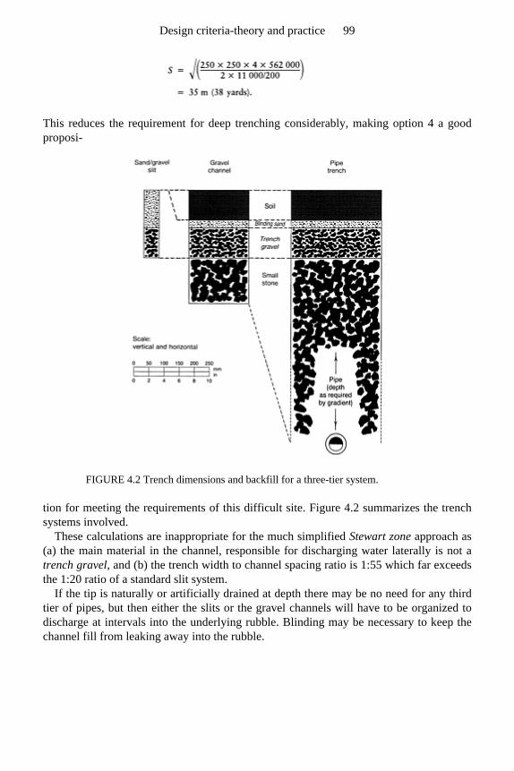
This reduces the requirement for deep trenching considerably, making option 4 a goodproposi-
FIGURE 4.2 Trench dimensions and backfill for a three-tier system.
tion for meeting the requirements of this difficult site. Figure 4.2 summarizes the trench systems involved.
These calculations are inappropriate for the much simplified Stewart zone approach as (a) the main material in the channel, responsible for discharging water laterally is not atrench gravel, and (b) the trench width to channel spacing ratio is 1:55 which far exceedsthe 1:20 ratio of a standard slit system.
If the tip is naturally or artificially drained at depth there may be no need for any third tier of pipes, but then either the slits or the gravel channels will have to be organized todischarge at intervals into the underlying rubble. Blinding may be necessary to keep thechannel fill from leaking away into the rubble.
Design criteria-theory and practice 99
Gravel-rafted schemes, generally for fine-turf surfaces
Where a freely permeable, sandy topsoil is laid over a drainage bed designed to do theentire job of lateral discharge to underdrains, the sandy topsoil has only to allow theincident rain water to drain vertically through to the gravel bed at the overall design rateV. However, in a layered construction it will be the hydraulic conductivity of the leastefficient layer that will be the rate-limiting bottleneck, particularly a junction between layers where particles of different size are free to interpack. In time, also as the swarddevelops, organic matter, living, dead and decaying, both within and on top of the soil,will further modify performance. All this is difficult to predict theoretically, even for theinitial, raw state.
Not only has the hydraulic conductivity of the different layers and layer boundaries tobe considered however; we also need to know the extent of the effective head. Atsaturation this will not correspond just to the thickness of the layer itself but will extendboth above and below into all layers that are effectively saturated.
Field checks on infiltration rates would seem to be the answer, but these are difficult to perform satisfactorily and, by the nature of things, can only be done after construction.
As general guidance, it would be worthwhile to assume that without worm activity tocontinually re-structure the soil for drainage, even a sand soil is unlikely to achieve aninfiltration rate more than 25–50 mm (1–2 in)/h when maintained under grass. However, even a value of 2 mm/h (2 in/day) would be enough to achieve the minimum overalldesign rate normally found adequate in Britain for general sports turf, but is close to therate required when the runoff is all concentrated into the sand at the top of sand slits.
For most sports we can make supplementary provision to cope with short bursts of intense rain by contouring the surface to clear excess surface water down slope to theperiphery. By contrast, on a flat surface, we must work to maintain the initial infiltrationof the raw surface by regular, sand topdressing, spiking and coring so as to make full useof the sand topsoil’s own capacity for temporary storage.
To determine the hydraulic head likely to be effective at the surface in such a layered construction, account should be taken of the depth of the coarse sand forming theblinding layer as well as the depth of the fine sand forming the topsoil. However, only ifthe effective pore systems of the two materials are similar in size, or the pores in theblinding layer are smaller, will they behave as one when wetted from above. If theeffective pores in the binding layer are large compared with those in the fine sand, thenonly after the fine sand has been more or less saturated will water be shunted through intothe blinding layer. Similarly the blinding layer will have to be more or less saturatedbefore it in turn will release water to drain away through the much larger pores in theunderlying gravel drainage bed.
After any initial phase of relatively rapid soil water re-distribution and drainage through the bulk of the pore space itself, there is still the possibility of further adjustmentby the much slower process of water movement through continuous films of water thatcreep over surfaces and cling tenaciously around individual particles. No doubt this alsoaccounts for the slow rate of further drainage that can be observed to continue for manydays after any initial phase of rapid drainage has ceased.
Sports Turf 100

For the sake of cost the depth of the gravel bed should be kept to a minimum, but so also should the amount of pipe work. The balance struck will depend on the relative costof the two features concerned.
Example 4.5
An organic-ameliorated, sand topsoil laid over a bed of trench gravel might have a Kvalue between 2 and 20 mm/h. Suggest a suitable depth for the gravel bed to cleardrainage water to pipe underdrains restricted to the periphery of a 40 m square, e.g. as fora bowling green. Assume the depth of the gravel bed is to be (a) restricted to 100 mm, (b)can exceed the 100 mm restriction. Compare for each case the effect of targeting overalldesign rates at the two extremes of 2 and 20 mm/h.
A suitable spacing for the pipe trenches can be determined by using the simplifiedversion of Hooghoudt’s drain-spacing equation
Substituting 100 mm for H, 2 mm (or 20 mm) for V and 65 000 mm/h as the K value for the typical trench gravel:
or
A suitable depth for the gravel bed when pipes are to be confined to the periphery of asquare bowling green can be determined by using an appropriately rearranged version ofthe simplified Hooghoudt equation and a change in the constant from 4 to 6.79 (referback to page 66). This will take account of the freedom in the situation for drainage waterto clear in four directions instead of just two. Thus,
Design criteria-theory and practice 101
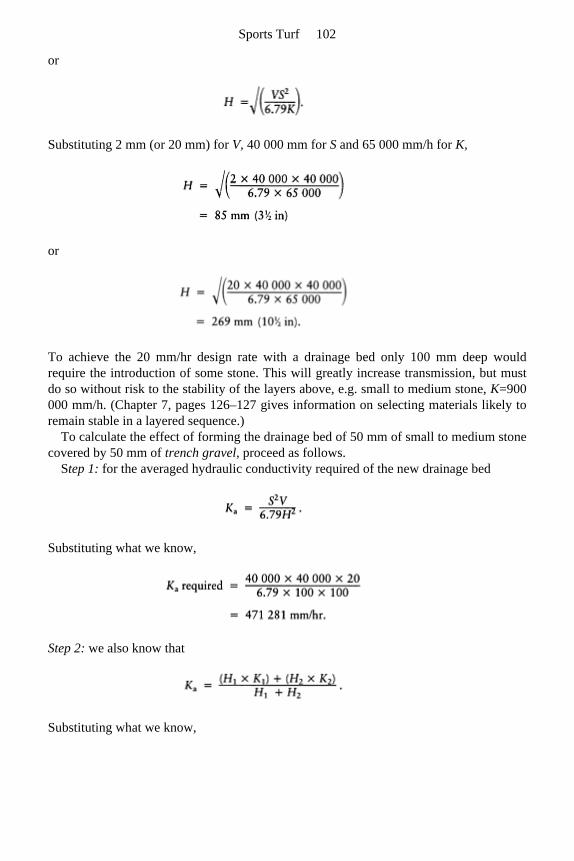
or
Substituting 2 mm (or 20 mm) for V, 40 000 mm for S and 65 000 mm/h for K,
or
To achieve the 20 mm/hr design rate with a drainage bed only 100 mm deep wouldrequire the introduction of some stone. This will greatly increase transmission, but mustdo so without risk to the stability of the layers above, e.g. small to medium stone, K=900 000 mm/h. (Chapter 7, pages 126–127 gives information on selecting materials likely to remain stable in a layered sequence.)
To calculate the effect of forming the drainage bed of 50 mm of small to medium stone covered by 50 mm of trench gravel, proceed as follows.
Step 1: for the averaged hydraulic conductivity required of the new drainage bed
Substituting what we know,
Step 2: we also know that
Substituting what we know,
Sports Turf 102
Therefore the hydraulic conductivity K 2 required of the 50 mm layer of small to medium stone can now be calculated as K 2= 877 562 mm/h.
This is a K value very close to the 900 000 mm/hr quoted for a small to medium stone referred to previously, page 73.
Note, it would not be wise to assume that if a particular small to medium stone isadequate to achieve the desired objective, an even bigger stone would be better. Too big astone would allow the gravel above to interpack, dramatically reducing the effectivenessof the two materials organized as a stable, two-layered system.
The soil base of a gravel drainage bed might well slope slightly to assist the flow of water towards the pipe underdrains. A flat base would tend to lie wet and locally puddled.For designs of this nature, see those suggested for hard porous pitches (Chapter 13, section 13.3).
4.1.4 Two examples of practical circumstances justifying modification of standard
schemes
Slope
Slope requires special consideration as the steeper the gradient the faster the runoff ofsurface water after rain. When the simplified Hooghoudt equation is applied to the slitsituation it is assumed that excess surface water will mainly reach the slit by unimpededflow over the surface. However, surface flow is bound to be much more effective on landwith an appreciable slope. Hence there is a case for spacing the slits slightly more widelyapart on slopes of the order of 1:50 or more, provided the slits run horizontally across theslope.
Availability of materials
A factor about which a designer must be particularly careful is the availability ofmaterials. Theoretical calculations are of little value if the sand and gravel materialsspecified cannot be supplied, or are only obtainable at a cost far in excess of what theclient can afford.
For efficient drainage we need to make use of materials that remain open, even when close-packed. Ideally, this means materials made up of rounded particles, all one size.However, the major users of sands and gravels are the construction industries and theyare often looking for materials that will inter-pack to achieve maximum density. Beforeproceeding to calculations, therefore, it is important that the designer should firstascertain what is the range of materials at his disposal. Where, for tendering purposes,materials have to be specified in advance, the contractor should be made aware that useof a different material to that specified may necessitate a change of layout. (Chapter 7
Design criteria-theory and practice 103
gives further information on the selection and specification of sands and gravels used inthe construction and drainage of sports turf facilities.)
4.2 Absorption and retention of water
4.2.1 Theoretical considerations affecting design calculations concerned with
capillarity and critical tension
Demonstrations
To understand how water is absorbed, retained and cleared by a porous medium such as asoil, we need to have some understanding of the twin phenomena of capillary rise andcritical tension. These are difficult to describe simply but can be demonstrated by thesequence of procedures illustrated in Figure 4.3.
For the experiments illustrated in Figure 4.3 (a.i—vii), the sand-filled glass tube is best made up initially of particles all of just one particle-size grade, e.g. all fine or all medium sand, and the base closed over with a small piece of finely woven, cotton cloth, securedwith an elastic band. For fine sand the sand column should be approximately 400 mm (16in) deep, and the tube some 200–300 mm (4–6 in) longer. For medium sand thesedimensions could all be halved.
Lower the sand-filled tube into a reservoir of water, holding it upright and keeping thecloth-covered base just below the surface of the water. Observe how the water is drawnup through the sand column by capillarity, then proceed to explore the relatedphenomenon of critical tension.
For the experiments illustrated in Figure 4.3 (b.viii–xiv) it is necessary first to determine the critical tension of the foam sponge used so that the two strips required forthe demonstrations that follow can be cut to the appropriate size and shape. Then explorehow water can be retained or drained according as the two strips are organized.
A soil, saturated to the surface, may still allow additional water to infilter so long as anequivalent amount of water can be cleared out below to a drainage outfall. It is the rate ofthis saturated flow with which Hoogboudt’s simplified equation is concerned (Chapter 4, section 4.1). However, having allowed additional water to be shunted through the water-filled pore space, the soil may not be able to complete the job of drainage by finallyemptying the pores to admit air.
The transmission of water is only one aspect of drainage which, when it ends, may still leave the transmitting pore system completely water-filled. This can be demonstrated by the procedure illustrated in Figure 4.3 (a.v.4) and (a.vii.6). Note, the column of saturated sand will transmit additional water—one drop in being matched by one drop out—but there is no further drainage thereafter. Even spiking is ineffective unless, for some reason,particle segregation, organic accumulation, or inappropriate topdressing has led to thecreation of a fine-textured cap. (See Appendix 6 and Figure 4.3 (a.vii).).
The water held up in a perched watertable is under tension, unlike water within a
Sports Turf 104
ground watertable. As indicated in Figure 4.3 (b.ix, xii and xiv), however, it is thistension which provides the ‘draw’ that can be organized to assist drainage. Note the drawdoes not originate in any underlying pipe but in the perched watertable that can beorganized in the trench fill above.
Theory
Wetting up from below is very effective—some might say too effective in that air will be readily displaced upwards, ahead of the rising water front—leaving the soil within the capillary fringe, virtually saturated to the exclusion of air. Unless water, wetting a soilfrom above, arrives in fine, dispersed droplets the surface will very rapidly flood over.This is because air bubbles have difficulty escaping upwards through a water-sealed surface, and cannot be displaced downwards through a compact subsoil. As a result,because most soils in the field are wetted primarily from above, some air-filled pores are bypassed by the downwardmoving water front. Thus topsoils tend only to becomecompletely waterlogged when wetted from above if this trapped air is subsequentlydislodged by the puddling action of wheeled traffic, or spiking treading.
Water is a polar liquid, i.e. the water molecules are charged both positive and negative,like little magnets, and thereby cohere to each other and adhere to the similarly chargedsurfaces of soil minerals such as quartz, or glass. This coherence also allows water tohave a certain tensile strength when suspended as a drop or extended into a fine,capillary-sized thread. It is the attraction of water to glass that holds a raindrop to thevertical face of a glass window until it is unstabilized by vibration or increasing weight. Itmay then slip down over the surface but will still remain a coherent droplet, attached atone side.
Close examination of the surface of the water around the edge of a glass shows howthe attraction of the glass raises the level of the water all around the rim. Now imagine the glass progressively reduced in diameter to a hair-like, capillary tube open at either end, the lower end immersed in a basin of water. The surrounding glass surface wouldthen be large compared with the contained volume so that water, free to move, will bedrawn some distance up the tube, like water into blotting paper. It is this process thatenables water to be drawn up through sand from a free-water reservoir until the attractive force (the pull) is balanced by the weight of the suspended water column (Figure 4.3 (a. iv)). The finer the capillary system the stronger the influence of the particle surface overthe water contained within it and, therefore, the higher the water can be raised. In section 4.2.2 this relationship is more fully explored by means of a formula which enables the extent of capillary rise to be predicted when the diameter of the capillary pathway isknown.
In a capillary tube the length of the fine, water column that can be suspended is not affected by whether the water arrives from above or below, provided air can be displacedto make room for it. However, in a uniform particle-size sand, for example, though the surface to void ratio in the pore system may ensure some positive capillary effect, thepore system is not strictly tubular. The simplest such system would consist of closelypacked uniform diameter spheres in which open cavities would be joined through funnel-like necks in a regular sequence, as illustrated in Figure 4.4.
Design criteria-theory and practice 105
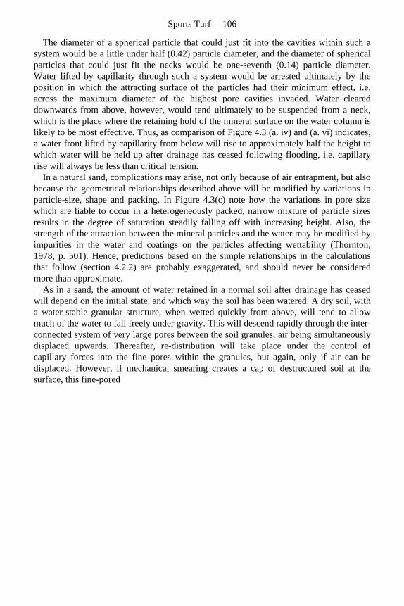
The diameter of a spherical particle that could just fit into the cavities within such a system would be a little under half (0.42) particle diameter, and the diameter of sphericalparticles that could just fit the necks would be one-seventh (0.14) particle diameter. Water lifted by capillarity through such a system would be arrested ultimately by theposition in which the attracting surface of the particles had their minimum effect, i.e.across the maximum diameter of the highest pore cavities invaded. Water cleareddownwards from above, however, would tend ultimately to be suspended from a neck,which is the place where the retaining hold of the mineral surface on the water column islikely to be most effective. Thus, as comparison of Figure 4.3 (a. iv) and (a. vi) indicates, a water front lifted by capillarity from below will rise to approximately half the height towhich water will be held up after drainage has ceased following flooding, i.e. capillaryrise will always be less than critical tension.
In a natural sand, complications may arise, not only because of air entrapment, but also because the geometrical relationships described above will be modified by variations inparticle-size, shape and packing. In Figure 4.3(c) note how the variations in pore size which are liable to occur in a heterogeneously packed, narrow mixture of particle sizesresults in the degree of saturation steadily falling off with increasing height. Also, thestrength of the attraction between the mineral particles and the water may be modified byimpurities in the water and coatings on the particles affecting wettability (Thornton,1978, p. 501). Hence, predictions based on the simple relationships in the calculationsthat follow (section 4.2.2) are probably exaggerated, and should never be considered more than approximate.
As in a sand, the amount of water retained in a normal soil after drainage has ceasedwill depend on the initial state, and which way the soil has been watered. A dry soil, witha water-stable granular structure, when wetted quickly from above, will tend to allowmuch of the water to fall freely under gravity. This will descend rapidly through the inter-connected system of very large pores between the soil granules, air being simultaneouslydisplaced upwards. Thereafter, re-distribution will take place under the control of capillary forces into the fine pores within the granules, but again, only if air can bedisplaced. However, if mechanical smearing creates a cap of destructured soil at thesurface, this fine-pored
Sports Turf 106
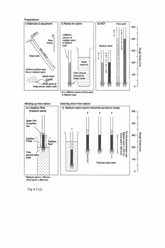
Fig 4.3 (a)
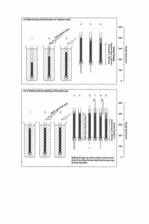
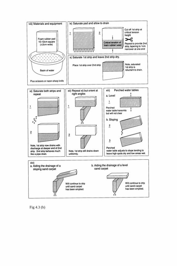
Fig 4.3 (b)
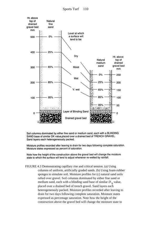
FIGURE 4.3 Demonstrating capillary rise and critical tension. (a) Using columns of uniform, artificially graded sands. (b) Using foam-rubber sponges to simulate soil. Moisture profiles for (c) natural sand soils rafted over gravel. Soil columns dominated by either fine sand or medium sand, each with a blinding sand base of similar D k value, placed over a drained bed of trench gravel. Sand layers each heterogeneously packed. Moisture profiles recorded after leaving to drain for two days following complete saturation. Moisture states expressed as percentage saturation. Note how the height of the construction above the gravel bed will change the moisture state to
Sports Turf 110
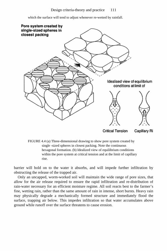
which the surface will tend to adjust whenever re-wetted by rainfall.
FIGURE 4.4 (a) Three-dimensional drawing to show pore system created by single -sized spheres in closest packing. Note the continuous hexagonal formation. (b) Idealized view of equilibrium conditions within the pore system at critical tension and at the limit of capillary rise.
barrier will hold on to the water it absorbs, and will impede further infiltration byobstructing the release of the trapped air.
Only an uncapped, worm-worked soil will maintain the wide range of pore sizes, that allow for the air release required to ensure the rapid infiltration and re-distribution of rain-water necessary for an efficient moisture regime. All soil reacts best to the farmer’s fine, wetting rain, rather than the same amount of rain in intense, short bursts. Heavy rainmay physically degrade a mechanically formed structure and immediately flood thesurface, trapping air below. This impedes infiltration so that water accumulates aboveground while runoff over the surface threatens to cause erosion.
Design criteria-theory and practice 111
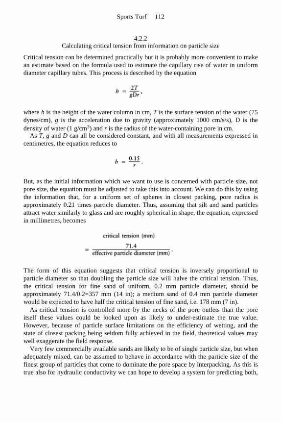
4.2.2 Calculating critical tension from information on particle size
Critical tension can be determined practically but it is probably more convenient to makean estimate based on the formula used to estimate the capillary rise of water in uniformdiameter capillary tubes. This process is described by the equation
where h is the height of the water column in cm, T is the surface tension of the water (75dynes/cm), g is the acceleration due to gravity (approximately 1000 cm/s/s), D is the density of water (1 g/cm3) and r is the radius of the water-containing pore in cm.
As T, g and D can all be considered constant, and with all measurements expressed in centimetres, the equation reduces to
But, as the initial information which we want to use is concerned with particle size, notpore size, the equation must be adjusted to take this into account. We can do this by usingthe information that, for a uniform set of spheres in closest packing, pore radius isapproximately 0.21 times particle diameter. Thus, assuming that silt and sand particlesattract water similarly to glass and are roughly spherical in shape, the equation, expressedin millimetres, becomes
The form of this equation suggests that critical tension is inversely proportional toparticle diameter so that doubling the particle size will halve the critical tension. Thus,the critical tension for fine sand of uniform, 0.2 mm particle diameter, should beapproximately 71.4/0.2=357 mm (14 in); a medium sand of 0.4 mm particle diameterwould be expected to have half the critical tension of fine sand, i.e. 178 mm (7 in).
As critical tension is controlled more by the necks of the pore outlets than the poreitself these values could be looked upon as likely to under-estimate the true value. However, because of particle surface limitations on the efficiency of wetting, and thestate of closest packing being seldom fully achieved in the field, theoretical values maywell exaggerate the field response.
Very few commercially available sands are likely to be of single particle size, but whenadequately mixed, can be assumed to behave in accordance with the particle size of thefinest group of particles that come to dominate the pore space by interpacking. As this istrue also for hydraulic conductivity we can hope to develop a system for predicting both,
Sports Turf 112
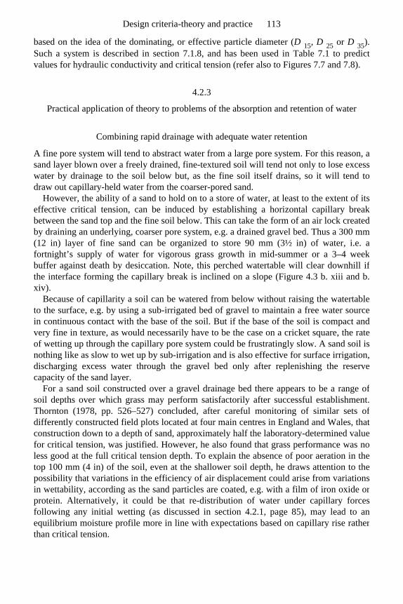
based on the idea of the dominating, or effective particle diameter (D 15, D 25 or D 35). Such a system is described in section 7.1.8, and has been used in Table 7.1 to predict values for hydraulic conductivity and critical tension (refer also to Figures 7.7 and 7.8).
4.2.3
Practical application of theory to problems of the absorption and retention of water
Combining rapid drainage with adequate water retention
A fine pore system will tend to abstract water from a large pore system. For this reason, asand layer blown over a freely drained, fine-textured soil will tend not only to lose excesswater by drainage to the soil below but, as the fine soil itself drains, so it will tend todraw out capillary-held water from the coarser-pored sand.
However, the ability of a sand to hold on to a store of water, at least to the extent of itseffective critical tension, can be induced by establishing a horizontal capillary break between the sand top and the fine soil below. This can take the form of an air lock createdby draining an underlying, coarser pore system, e.g. a drained gravel bed. Thus a 300 mm(12 in) layer of fine sand can be organized to store 90 mm (3½ in) of water, i.e. a fortnight’s supply of water for vigorous grass growth in mid-summer or a 3–4 week buffer against death by desiccation. Note, this perched watertable will clear downhill ifthe interface forming the capillary break is inclined on a slope (Figure 4.3 b. xiii and b. xiv).
Because of capillarity a soil can be watered from below without raising the watertableto the surface, e.g. by using a sub-irrigated bed of gravel to maintain a free water source in continuous contact with the base of the soil. But if the base of the soil is compact andvery fine in texture, as would necessarily have to be the case on a cricket square, the rateof wetting up through the capillary pore system could be frustratingly slow. A sand soil isnothing like as slow to wet up by sub-irrigation and is also effective for surface irrigation,discharging excess water through the gravel bed only after replenishing the reservecapacity of the sand layer.
For a sand soil constructed over a gravel drainage bed there appears to be a range of soil depths over which grass may perform satisfactorily after successful establishment.Thornton (1978, pp. 526–527) concluded, after careful monitoring of similar sets ofdifferently constructed field plots located at four main centres in England and Wales, thatconstruction down to a depth of sand, approximately half the laboratory-determined value for critical tension, was justified. However, he also found that grass performance was noless good at the full critical tension depth. To explain the absence of poor aeration in thetop 100 mm (4 in) of the soil, even at the shallower soil depth, he draws attention to thepossibility that variations in the efficiency of air displacement could arise from variationsin wettability, according as the sand particles are coated, e.g. with a film of iron oxide orprotein. Alternatively, it could be that re-distribution of water under capillary forcesfollowing any initial wetting (as discussed in section 4.2.1, page 85), may lead to an equilibrium moisture profile more in line with expectations based on capillary rise ratherthan critical tension.
Design criteria-theory and practice 113
However this may be, the practical evidence seems to support the idea that theconstruction depth for a sand soil, perched over a gravel drainage bed, should neither bemore than the critical tension nor less than half. Any blinding layer required beneath thesand soil should be included within this depth if the Dk values are similar, indicating thatthe pore systems present in both layers are likely to be compatible, i.e. similar in diameter(page 119). At the full critical tension extreme, the surface may tend to dry out so rapidlythat it will require repeated irrigation to remain sufficiently moist for seed germinationbut, thereafter, should encourage deeper rooting unless transformed by thatchdevelopment. At the shallowest extreme of half the critical tension, the surface shouldmore readily remain moist enough to encourage rapid seed germination but, thereafter,the grass may tend not to root as deeply, and there may be a greater risk of invasion byweeds, moss and disease. For a fine sand soil this points to an optimum range of between250 and 300 mm (10 and 14 in) for the consolidated sand soil over the top of the graveldrainage bed.
At the low concentrations of organic matter or mineral soil amelioration used in sandsoils we can assume heterogeneous packing and that the top as a whole will behave in amanner controlled by the sand. Any localized concentrations of organic matter, or fineparticles of soil, will exert their own greater tendency to hold on to water, acting as localreservoirs outwith the general situation dictated by the sand. However, should thedifferent materials segregate with agitation during placement, some form of layering maydevelop subsequently through downward migration and redeposition of silt and clay. Itwill then be the fine pore system in the deposition layers that will control the downwardclearance of water and provide localized, potentially anaerobic barriers to rootpenetration.
Counteracting risks of desiccation
When sand rests directly on soil, as in the case of a construction involving a surfacecarpet of sand, it should be appreciated that a freely drained soil at field capacity behavesas if it is equilibrated at a tension of the order of 1000 mm (40 in). The soil under thesand, therefore, will tend to withdraw water from the surface layer of sand. This meansthat the grass should be encouraged to root through into the underlying soil to acquire anassured water supply. For this reason, the sand carpet should not exceed 150 mm (6 in) indepth and due regard should be paid to the fertility of the buried soil before covering it. Italso explains why subsequent maintenance should aim to avoid any surface accumulationof organic debris or applied phosphate, both of which will encourage surface rooting.
For a similar reason, sand in slits will lose water to the soil with which it is in contact and the establishment of grass along the slit may well be difficult. To minimize thisproblem consideration should be given to the following features:
1. watering the surface by artificial means until germination and establishment has been achieved;
2. seeding only in the autumn when weather conditions are likely to be most favourable; 3. avoiding unnecessarily wide slits so that the grass can root sideways into the soil; 4. topdressing materials, such as grass clippings, moist peat, or seaweed to help retain
water near the surface.
Sports Turf 114

Chapter five
This chapter was contributed by J.C.Parker, B.Sc. Hort., A.L.I., Chief Landscape Manager, Kent County Council, based on a section originally included in Landscape Management and Maintenance—A Guide to its Costing and Organisation, published by Gower Technical, 1989.
Cost benefit implications

5.1 Assessing the value of drainage
The economic value of drainage on any plot of land is usually difficult to quantify inprecise terms. Even in agriculture where crop yields can be accurately measured, it is stillnot possible to predict with any certainty what would be the most economic level ofartificial drainage in terms of return on the capital involved. This does not mean that theadvantages of drainage are not discernible but it does mean that it is very difficult toestimate the optimum level of capital investment.
In sports-field drainage the advantages are even more difficult to assess in economic terms. At best the capital costs can only be compared with matches played or not played,or the number of days on which the surface is fit for use. Nevertheless, the costs ofdrainage can be considerable and it is important to at least try to predict what advantagescould accrue from the installation of various alternative systems. This is particularly sowhen the performance of a drainage system can be accurately designed, as shownelsewhere in this book.
The advantages of playing-field drainage are mainly that surface water (rainfall) iscleared more rapidly and that the soil provides a better playing surface and a bettergrowing medium for the turf. The latter advantage is often the most important inagriculture and promotes:
• earlier warming of the soil in spring because any substitution of air for water means lower specific heat;
• earlier spring regeneration of worn turf because of the beneficial effect on soil temperature;
• improved drought resistance because of deeper, more efficient rooting.
These improvements during the growing season can be considerable but during the wintermonths the more important effect of drainage is that rainfall is removed faster from thesurface so that play can take place on a reasonably firm surface and without undulydamaging the soil structure. This increased availability for play is the factor on whichmost players would base their judgement on the value or otherwise of a drainage system.
Sports Turf 118
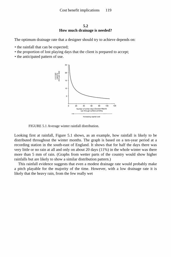
5.2 How much drainage is needed?
The optimum drainage rate that a designer should try to achieve depends on:
• the rainfall that can be expected; • the proportion of lost playing days that the client is prepared to accept; • the anticipated pattern of use.
FIGURE 5.1 Average winter rainfall distribution.
Looking first at rainfall, Figure 5.1 shows, as an example, how rainfall is likely to bedistributed throughout the winter months. The graph is based on a ten-year period at a recording station in the south-east of England. It shows that for half the days there was very little or no rain at all and only on about 20 days (11%) in the whole winter was theremore than 5 mm of rain. (Graphs from wetter parts of the country would show higherrainfalls but are likely to show a similar distribution pattern.)
This rainfall evidence suggests that even a modest drainage rate would probably make a pitch playable for the majority of the time. However, with a low drainage rate it islikely that the heavy rain, from the few really wet
Cost benefit implications 119
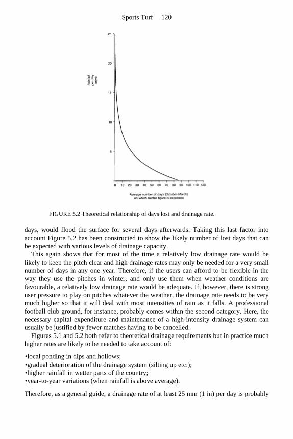
FIGURE 5.2 Theoretical relationship of days lost and drainage rate.
days, would flood the surface for several days afterwards. Taking this last factor intoaccount Figure 5.2 has been constructed to show the likely number of lost days that canbe expected with various levels of drainage capacity.
This again shows that for most of the time a relatively low drainage rate would be likely to keep the pitch clear and high drainage rates may only be needed for a very smallnumber of days in any one year. Therefore, if the users can afford to be flexible in theway they use the pitches in winter, and only use them when weather conditions arefavourable, a relatively low drainage rate would be adequate. If, however, there is stronguser pressure to play on pitches whatever the weather, the drainage rate needs to be verymuch higher so that it will deal with most intensities of rain as it falls. A professionalfootball club ground, for instance, probably comes within the second category. Here, thenecessary capital expenditure and maintenance of a high-intensity drainage system can usually be justified by fewer matches having to be cancelled.
Figures 5.1 and 5.2 both refer to theoretical drainage requirements but in practice much higher rates are likely to be needed to take account of:
•local ponding in dips and hollows; •gradual deterioration of the drainage system (silting up etc.); •higher rainfall in wetter parts of the country; •year-to-year variations (when rainfall is above average).
Therefore, as a general guide, a drainage rate of at least 25 mm (1 in) per day is probably
Sports Turf 120
needed for even a lightly used winter pitch and, at the other end of the scale, aprofessional football pitch might require as much as 25 mm (1 in) per hour to bereasonably confident of staging matches, whatever the weather. However, such a veryhigh drainage rate could only be achieved by a sand soil perched over a drained, gravelbed and such a soil needs special maintenance and shielding from too frequent use.
5.3 Effect of drainage system design on capital cost
When sports-field drainage systems are being designed there are often several differentways of achieving the same or similar results but the costs of the alternatives cansometimes be very different. In each situation the designer has to work out the likely costdifference and, for instance, decide between either a system of substantial surface slitsand few underdrains or simple slits with many closely spaced interceptors.
The final solution will depend on many factors, including the local availability of suitable materials, machinery and contractors, but the general principles given belowshould help as a guide towards achieving the lowest capital cost.
5.4 Spacing of underground laterals or interceptor drains
Underground laterals, with or without pipes, are nearly always more expensive toconstruct per metre than surface slits. For this reason alone it would appear more sensibleto use as few as possible. However, extra capital spent on underground laterals is usuallymore than amply repaid in drainage capacity and, as a general rule, a doubling of thenumber of underdrains will give the potential for a four-fold increase in drainage rate.
Example 5.1 If laterals are laid 10 m (11 yards) apart in a uniformly draining soil, 500 mm (20 in)deep with hydraulic conductivity of 10 mm/h , then, using equation (4.4) on page 67
the drainage rate V will be
If, however, the laterals are laid at 5-m (5½-yard) centres the drainage rate will be
Cost benefit implications 121
This example shows the advantages of extra underground laterals and illustrates that amisguided attempt to save capital costs by halving the number of laterals would reducethe drainage to a quarter of the original design rate.
This same principle will apply to the lower levels of any two- or three-tier system of underground drains connecting with surface sand slits. However, it does not apply to thetop layer of slits that collect rain water directly from the surface.
5.5 Spacing of surface slits
Surface slits are usually relatively cheap per metre run but, because they are closetogether and many metres have to be laid, their total cost is a major part of the capitaloutlay. It is therefore often tempting to space them as widely apart as possible.
TABLE 5.1 Costed schemes—examples of slit drainage systems with a design rate of 48 mm/day (2 mm/hr)
Surface slits
Dimensions (mm)
Spacing (m)
Backfill Approx. cost per hectare* (£)
Spacing of laterals
Width Depth Laterals Slits Total
‘Ideal’ schemes
A, 22 metres 60 300 1.0 Sand over gravel
2050 18000 20050
B, 4.7 metres 60 300 1.0 Medium sand 9570 10000 19570
C, 6.6 metres 60 300 0.5 Medium sand 6820 20000 26820
‘Cost cutting’ schemes
D, 18 metres 60 300 1.5 Sand over gravel
2500 12000 14500
E, 3.8 metres 60 300 1.5 Medium sand 11840 6670 18510
* Estimated 1989 prices, excluding mains, outlets, junctions, etc.: laterals at £4.50/m; sand/gravel slits at £l.80/m; sand-only slits at £l.00/m.
Sports Turf 122
The scope for such saving is severely limited as surface slits only have an effective influence over a very narrow band, simply because rain water can travel only very slowlyacross the grassed surface. Footmarks and the like will slow down the surface flow evenon a surface that has a gentle slope. In practice, therefore, a surface slit will drain a bandonly about 1.50 m (5 ft) wide. Thus, even if slits are placed at 2 m (6½ ft) apart there is a considerable risk of surface ponding or sogginess between the runs.
For this purely technical reason it is usually best to space surface slits about 1 m (1 yard) apart. Closer spacing will improve the efficiency of surface interception still furtherbut the costs will increase pro rata.
Savings on surface slits can sometimes be made by only slitting the heavily used or badly drained parts of a pitch or field. Alternatively a whole pitch can be slit at 1.5-m (5-ft) centres with additional slits put between to give 0.75 m (2½ ft) spacing of the wet or heavily used areas. (Note that this only gives a cost saving, compared with 1 m spacingoverall, if wet areas are less than half the total area.)
5.6 Cost comparisons of alternative systems
Some examples of possible costs of alternative systems are shown in Table 5.1. The figures (based on 1989 prices) have been deliberately simplified in order to illustrate thecomparisons and must only be used in that context. The availability of different materialsand machinery could well alter the conclusions and in each case the designer must workout the costs that are likely to apply to the specific site. Some comments on the data inTable 5.1 now follow.
1. There is little to choose between schemes A and B but B has the advantage that even underground laterals would give a fair measure of drainage if the permeable fill in the pipe trenches was brought through to the surface as sand, especially if the field was lightly used and retained a good surface structure. Scheme A might be preferred if ground conditions were difficult for deep trenching.
2. Scheme C has the same advantages as but the extra cost of the close-spaced slits is unlikely to be justified except on very heavily used areas—goalmouths, etc.
3. Scheme D is significantly cheaper than all the other options considered, but wider slit spacing would be less effective under heavy use, particularly where the ground is level.
4. Scheme E has only a slight cost advantage over A, B or C and would normally not be worth considering.
5. Schemes A and D could be upgraded to a design rate of 8 mm per hour by doubling the number of underground laterals at an extra capital cost of only around £4.50 per metre.
Cost benefit implications 123
5.7 Effect of drainage on total use
All the above have been concerned with the effect of drainage rates on the chances ofpitches being waterlogged at any one time and do not take account of the total hours ofuse once drainage problems have been eliminated. This total use is normally limited bythe amount of wear that the actual surface carpet of turf is able to bear. Improveddrainage will influence this to the extent that it encourages better growth and also that adrier surface discourages the players from sliding and damaging the turf by a shearingaction. However, the more important effect of adequate drainage is to make a pitchplayable throughout the season and allow considerably more play in the wettest monthsof the winter. Without drainage the pitch could be completely unplayable for weeks onend.
5.8 Cost-saving strategy for a new playing field
Artificial drainage is only necessary when the natural drainage is inadequate. When anew playing field is being planned it is extremely difficult to assess, in advance, what thenatural drainage rate will be. Soil structure can easily be destroyed by adverse weatherconditions during levelling and grading, or merely by the time the topsoil stays in astockpile.
Once a field is sown down to grass the natural soil structure may regenerate againwithin a year or two on heavy clays by the natural expansion and contraction of the clayparticles through the seasons. On silty soils however, the natural structure will always beweak and, once lost, may not reform for very many years. Therefore, depending on soiltype an elaborate and expensive drainage system could be of only temporary value or anabsolute necessity, essential in the long term.
In order to minimize the risks of either extreme it would be wise to install only a basic underdrainage system during the construction stage. Subsequently a slit drainage systemcould be added if it is found to be necessary. This could be laid out across the whole fieldor just across goalmouths and any especially wet areas. Alternatively in scheme A, Table 5.1, the major capital cost could at least be delayed until experience proves that a full slit system is needed.
In these and other ways capital costs can be kept to a minimum, but there are often administrative difficulties with obtaining an additional capital sum for sand slittingseveral years after the main part of the construction has been completed. It is thereforeessential to ensure that the promoters of the construction scheme are aware of thepossible need for extra works as the new playing field becomes established.
Finally, it cannot be over-emphasized that any drainage system will be largely wasted if it is not backed up by regular maintenance, not only to prevent pipe blockage andsmearing of sand slits, but also to retain as open a soil structure as possible.
Sports Turf 124

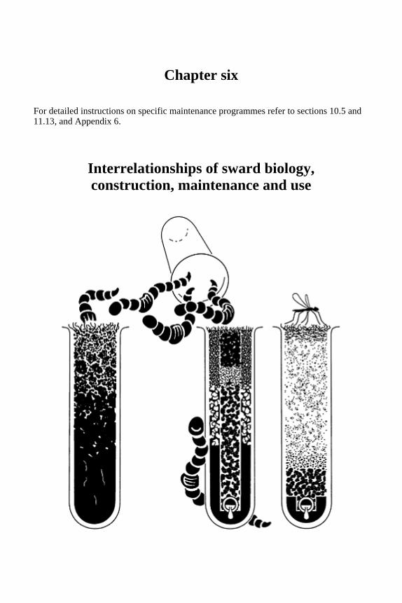
Chapter six
For detailed instructions on specific maintenance programmes refer to sections 10.5 and 11.13, and Appendix 6.
Interrelationships of sward biology, construction, maintenance and use

6.1 Establishment and immediate after-care prior to allowing play
While the soil is still relatively loose the juvenile roots of the grass may be encouraginglylong, but the sward will not be firmly established until the root system develops into afibrous, much-branched, intertwined tangle.
The introduction of sand or sand/gravel slits, to complete the job of surface water interception, may well be delayed until a sward has been established. This will make iteasier to excavate narrow, stable-sided trenches. Thus establishment of a sward may haveto proceed in two stages: first by an initial seeding prior to slitting, and then by over-seeding to repair damage following slitting. This can provide the opportunity to establish,at the initial phase, a sward of the slower-germinating, lower-growing, bottom grasses, such as the browntops and smooth-stalked meadow grasses. The more easily established, more vigorous growing rye grasses can be introduced later, e.g. by slit seeding.
Immediate after-care usually involves cleaning up, re-truing and firming down the soil surface, over-seeding to repair damage and fill gaps in the original sward; also fertilizing,irrigating and sand topdressing, nursing the sward through to a firmly anchored, dense,uniform covering of vigorously growing grass.
6.1.1 The soil surface
It is assumed that the bulk of the work required to achieve a true surface will have beencarried out before grassing up. However, if more drainage operations are carried outthrough the initial grassed surface, this may require further time to be spent on morestone picking, surface truing and light rolling. After this final construction stage furthersurface truing will have to be by repeated cycles of sand topdressing, co-ordinated with over-seeding.
6.1.2 The sward
Sward maintenance in the early stages of establishment should aim at vigorous growthand deep rooting. This is largely a matter of adequate moisture, good aeration, properfertilizing, and correct frequency and height of cut.
No play should be allowed until the whole surface is grass covered, including thesandy surfaces of pipe trenches and/or slits.
6.1.3 Fertilizing
Compensating for accelerated leaching losses
Constructions giving priority to drainage must inevitably risk continuous loss of readily
Sports Turf 128
soluble nutrients by leaching. This can be further aggravated by the fact that improveddrainage is usually dependent on the liberal use of sand which is a poor medium fornutrient retention. The approach to nutrition should aim, therefore, either at slow release,or little-and-often application. Slow release is inevitable with phosphate fertilizers asphosphate is so insoluble. The problem materials are the nitrate, ammonium andpotassium fertilizers which are generally highly soluble.
Sward establishment on the sand surface of slits or pipe trenches is bound to be difficult. Successful germination and establishment requires frequent re-wetting and this increases the risk of nitrogen and potassium loss by leaching. Therefore, special attentionmust be given to the regular replenishment of these nutrients until sideways rooting canbe established into the adjacent soil. This is a factor to be considered when contemplatingthe installation of trenches more than 50 mm (2 in) in width. It also stresses theimportance of the effort to try and include some nutrient and moisture-retaining organic component in the top 150 mm (6 in) of the sand backfill.
Any yellowing of the grass along the line of the slits and pipe trenches should be takenas a warning of a need for nitrogen, and possibly also potassium.
Stimulation of root branching
It has been known for years that root density is very much influenced by the distributionof organic matter. If the organic matter accumulates on the surface we have what mightbe described in soil terms as the ‘Mor’ condition, referred to in Table 8.1. Here, rooting is also concentrated at the surface, whereas with organic matter deeply incorporated, as inthe ‘Mull’ condition, roots are distributed throughout the soil. The reason for this relationship has been explained by experimental evidence (Drew, 1975) showing that rootbranching is a response to the presence in solution of available forms of nitrogen andphosphorus. This does not affect the behaviour of the primary, exploring roots; they seemto be adapted to explore the soil in depth, controlled only by their need for adequateaeration. Thus a medium providing for satisfactory rooting must allow for theexploitation of a large volume of soil by branch root proliferation in response toincorporated sources of available nitrogen and phosphorus. If the primary root can carrythis process deep into the soil then the plant will not only be well equipped to secure itsnutrient requirement, but also well anchored and buffered against drought.
All sources of phosphate applied to a soil are rapidly immobilized by association withcalcium, iron or aluminium, whereas ammonium and nitrate sources of nitrogen remainfreely soluble. It must frequently be the location of the applied phosphatic fertilizer,therefore, that will effectively control the distribution of the mass of plant feeding roots.With this in mind we should take advantage of the opportunity during construction tobuild sources of phosphate into the soil within rooting depth and, during subsequent maintenance, take steps to only apply phosphate when it can be fed down into spike holesor incorporated by a subsequent topdressing of sand or loam.
Interrelationships of sward biology, construction, maintenance and use 129
6.1.4 Fine sand topdressing
Topdressing with fine sand (e.g. a topsoil sand such as SN 12-15 in Table 7.1) is an important feature of the maintenance of any sward used for sport but, with newconstructions involving surface slitting, it is particularly important to topdress generouslybefore the first season of winter play. This general topdressing is necessary to help truethe whole surface and protect the slits from being capped by soil. The minimum coverthat should be achieved before allowing play is of the order of 80 tonne/ hectare (30tons/acre), i.e. a covering of 5 mm in) overall. To avoid any risk of smothering the swardthis should be applied in two increments, allowing adequate time for sward recovery aftereach application has been thoroughly worked into the base of the sward. Purpose-made machinery is now available to ensure an even spread at a rate that will achieve thenecessary application in each pass. Provided the sand can be kept dry, an alternative, DIYprocedure involving a tractor-drawn, rigid, metal lute, some 2 m wide, can be used tospread the sand from pre-placed heaps or regularly spaced bands, levelling the surfacesimultaneously. If the grass is not to be smothered, both the sand and the surface must bedry enough for the sand to fall freely into the base of the sward, exposing the leaf tips tosunlight.
In order that all the foregoing operations can be performed in the right conditions, eg. fertilizing and seeding when conditions are likely to remain moist and topdressing withfine sand when the surface is dry, it is essential to make adequate preparations inadvance.
6.2 Considerations for the long-term maintenance of new constructions
6.2.1 Surface sanding
A sand-slit top cannot hope to retain its trueness and drainage efficiency permanentlywithout continuous, careful maintenance. The differential response of sand and soil to theswelling and shrinking effects of wetting and drying leads to the slit surface sinkingrelative to the surrounding soil (Figure 6.1). The resulting washboard effect can be off-putting and dangerous for the players. If allowed to persist, or if corrected by heavyrolling in wet conditions, the end result will be drainage deterioration because of soilcapping the slits.
This trend must be anticipated and counteracted by an annual topdressing of fine sand (topsoil sand) applied during a dry spell in the late summer before the playing season starts. The method of application must ensure that the sand can be drag-brushed or luted into depressions, particularly the depressions along the line of the slits. After a 5 mm (
in) application of sand before the first season of play, the minimum annual rate of application thereafter should be of the order of 40 t/ha, or 2.5 mm overall (16 tons/acre or
in).
Sports Turf 130
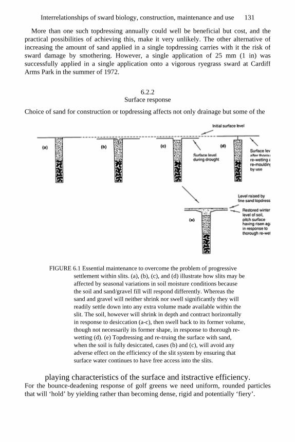
More than one such topdressing annually could well be beneficial but cost, and thepractical possibilities of achieving this, make it very unlikely. The other alternative ofincreasing the amount of sand applied in a single topdressing carries with it the risk ofsward damage by smothering. However, a single application of 25 mm (1 in) wassuccessfully applied in a single application onto a vigorous ryegrass sward at CardiffArms Park in the summer of 1972.
6.2.2 Surface response
Choice of sand for construction or topdressing affects not only drainage but some of the
FIGURE 6.1 Essential maintenance to overcome the problem of progressive settlement within slits. (a), (b), (c), and (d) illustrate how slits may be affected by seasonal variations in soil moisture conditions because the soil and sand/gravel fill will respond differently. Whereas the sand and gravel will neither shrink nor swell significantly they will readily settle down into any extra volume made available within the slit. The soil, however will shrink in depth and contract horizontally in response to desiccation (a-c), then swell back to its former volume, though not necessarily its former shape, in response to thorough re-wetting (d). (e) Topdressing and re-truing the surface with sand, when the soil is fully desiccated, cases (b) and (c), will avoid any adverse effect on the efficiency of the slit system by ensuring that surface water continues to have free access into the slits.
playing characteristics of the surface and itstractive efficiency. For the bounce-deadening response of golf greens we need uniform, rounded particlesthat will ‘hold’ by yielding rather than becoming dense, rigid and potentially ‘fiery’.
Interrelationships of sward biology, construction, maintenance and use 131
On a bowling green there is no need to make provision for bounce. Priority instead canbe given to trueness and the pace of the roll of the bowl. For these qualities to beachieved with a quick-draining sand soil, roundness and uniformity of particle size have not the same priority.
For vigorous winter games tractive efficiency depends on the dryness of the surface and the grip achieved by a studded boot. Players require the surface to give sufficiently toallow the studs to penetrate, but not to shear. To ‘give a stud’ without having to be wet, the sand forming the surface should have the same uniform roundness that is required ona golf green, but no sand of this type will provide any significant tractive strength whendry. This means that, for the most part, the tractive efficiency of such a surface, whendry, depends primarily on the root-binding strength of the sward.
However, such surfaces are seldom dust dry in winter and any moisture present cancontribute significantly to tractive efficiency, even without the assistance of grass. Withthe addition of water, tractive strength increases as particle size decreases, reaching a satisfactory level for play when water-bound, like fine sand in the inter-tidal zone of a beach.
To have maximum effect for the improvement of soil permeability a sand topdressing should be carefully chosen. It should not only work on its own to readily transmit water,but when worked into the soil, should rapidly ameliorate the particle-size spectrum to peak at over 75% in the medium-to-fine sand categories. Using a sand of a wide, particle-size range tends to lead to a hard, dense, slow-draining soil because of the inter-packing possibilities presented.
In practice this means: (a) we should topdress with a very narrow particle-size-range sand, like dune sand which has 95% of its particles in the medium-fine sand range (topsoil sands like SN12, 14 and 15 in Table 7.1); (b) we should aim to match the dominant particle size in the top-dressing sand to the dominant particle size in themedium-to-fine sand categories in the soil (Appendix C).
The soil brought to the top by burrowing earthworms may not be identical in texture to the original topsoil. There seems to be a limit of about 0.5 mm to the diameter of particlesingested by worms so that, in time, their activities can effect a small shift in soil texture atthe surface. One practical application of this knowledge is to use sand with a coarse sandmatrix in slits and pipe trenches where worm activity might be expected to threaten thesurvival of the permeable link through the topsoil to the surface.
6.2.3 Deciding a policy about earthworms
The decision that should not be deferred
To base one’s thoughts on construction and maintenance on the consequences that flownaturally from earthworms being present or absent may appear to be too abstruse andtheoretical to have practical significance. However, in pasture, earthworms may numbersome 2 500 000 per hectare (1 000 000 per acre or 200 per square yard), weighing around5 t/ha (2 tons/acre or 1 lb/sq yd) fresh weight. They turn over some 50 t/ha (20 tons/acreor 9 lb/sq yd) of fine soil annually, corresponding to some 25 mm (1 in) of fine soil
Sports Turf 132

placed onto the surface in the course of 10 years. They are well able to consume and buryall the grass clippings from a well-maintained sward in the course of a year. Theinfluence of earthworms on soil is so fundamental that to fail to take their presence orabsence into account would be like ignoring the influence of man when viewing theenvironment around us.
On sports turf a long-term decision has to be made on whether maintenance should encourage or discourage earthworms. It is particularly important that this subject isbrought up for consideration early, ideally prior to construction. As farmers who haveinherited land disturbed for opencast mining have good reason to lament, once lost, anearthworm population can take a generation or more to recover by natural colonization(Stewart et al., 1988).
To assist in the preservation of an existing earthworm population thought should be given to how any stockpiling of topsoil can be avoided. The aim should be to achievetransfer without any intervening period of temporary storage. Once in its new location,the topsoil should be worked through mechanically as little as possible becauseearthworms can be maimed and suffocated when their living space collapses aroundthem. It is one thing to repopulate a soil from a viable residual population, but quiteanother to recover from complete annihilation.
Thus, unless prior thought has been given to this problem at the construction stage, a groundsman may find that the decision whether to work with or without earthworms has
TABLE 6.1 Plant adaptation to the soil development dichotomy, conditioned by the presence or absence of burrowing earthworms
High, pH typically above 6—Lime—Low, pH typically below 5
Succulent, palatable, plentiful—Organic matter—Fibrous, unpalatable, insufficient
Physically and chemical benign—Human intervention—Physically and chemically hazardous
Effects of earthworm presence Effects of earthworm absence
Soils
Profile tending to be uniform Profile tending to become layered
Organic matter incorporated Organic matter unincorporated
Mineral soil aggregated (‘Mull’ condition, typical of brown earth soils)
Mineral soil compact (‘Mor’ condition, typical of podzol soils)
Freely drained and well aerated if site drainage satisfactory
Drainage impeded and aeration poor unless mineral soil very sandy
Plants
Deep rooted Surface rooted
III-adapted for drought and waterlogging Well adapted to cope with periodic drought and temporary waterlogging
Interrelationships of sward biology, construction, maintenance and use 133
already been taken for him. If he does take over a soil with a viable earthwormpopulation then he should review his proposed maintenance procedures for their likelyimpact on the population and the consequences for the playing surface should they beeliminated.
Encouraging the right worms
The importance of worm burrowing as an aid to infiltration, drainage, air circulation androoting is now generally recognized but less so their beneficial effects in counteractingthe build-up of thatch and in initiating the development of a granular soil structure (Stewart and Salih, 1981; Stewart, 1985).
As Table 6.1 suggests, there is much more that could be said about the possibleevolutionary significance of the important dichotomous relationship between soils andvegetation developed in the presence or absence of burrowing earthworms. The generalconsequences for sports turf are summarized in Table 6.2.
However, not all earthworms are equally effective for soil conditioning. Of the 25–30 species of earthworm found in Britain only five are of any great importance for theirbeneficial effects on the incorporation of organic residues and the natural drainage ofsoils under grass. These are generally the worms that grow to a size longer than 75–100 mm (3–4 in) when mature. Unfortunately, the relatively large worm species mostcommonly available to fishermen, the Brandling (Elsenia foetida) is not an effective soil burrower. It breeds readily in wet compost and sewage, but will ingest very little mineralmatter and does not survive long if introduced to a normal field soil.
Nutrition mediated through free-living bacteria in rhizosphere
Many conditioned to ‘special’ feeding mechanisms mediated by symbiotic relationships with fungi
Intolerant of drought, waterlogging and acidity, leading to problems of aluminium and iron toxicity
Intolerant of earthworms and disturbance, alkalinity leading to problems of low availability of iron
Vegetation
Floristically diverse, tending to be calcicole in character
Floristically restricted, tending to be calcifuge in character
Adapted from Stewart and Scullion, 1989.
TABLE 6.2 Construction options and maintenance requirements conditioned by the presence or absence of burrowing earthworms.
+ Increasing earthworm presence
Decreasing earthworm presence −
Sports Turf 134
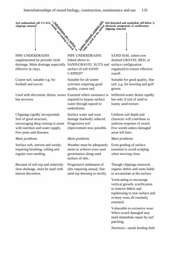
PIPE UNDERDRAINS supplemented by periodic mole drainage. Mole drainage especially effective in clays.
PIPE UNDERDRAINS linked above to SAND/GRAVEL SLITS and surface of soil SAND CAPPED*
SAND SOIL rafted over drained GRAVEL BED, or surface configuration organized to ensure effective runoff.
Coarse turf, suitable e.g. for football and soccer.
Suitable for all winter activities requiring good quality, coarse turf.
Suitable for good quality, fine turf, e.g. for bowling and golf greens
Used with discretion; drains, wears but recovers.
Essential where assistance is required to bypass surface water through topsoil to underdrains.
Infiltered-water drains rapidly but only if soil of sand or loamy sand texture.
Clippings rapidly incorporated. Soil of good structure, encouraging deep rooting to assist with nutrition and water supply. Few pests and diseases.
Surface water and wear damage markedly reduced. Progressive soil improvement now possible.
Uniform soil depth and character will contribute to uniform response of sward. Few weeds unless damaged areas left bare.
Main problems Main problems Main problems
Surface soft, uneven and weedy, requiring brushing, rolling and regular over-seeding.
Weather must be adequately moist to achieve even seed germination along sand surface of slits.
Even grading of surface essential to avoid scalping when mowing close.
Because of soft top and relatively slow drainage, must be used with utmost discretion.
Progressive settlement of slits requiring annual, fine sand top dressing to rectify.
Though clippings removed, organic debris and roots liable to accumulate at the surface.
Verticutting to encourage vertical growth, scarification to remove debris and topdressing to true surface and re-bury roots all routinely essential.
Vulnerable to excessive wear. When sward damaged may need immediate repair by turf patching.
Nutrition—needs feeding little
Interrelationships of sward biology, construction, maintenance and use 135
All that can be done at present to preserve and prosper an indigenous population ofburrowing earthworms under grass is to let the clippings lie, maintain the pH above 6 andavoid the adverse effects of pesticides. Many pesticides which are sold for the control ofinsects, nematodes, fungi and other organisms considered to be pests, also have lethalside-effects on earthworms.
Problems that the right worms bring with them
If earthworms are encouraged for the benefits they confer, it must be recognized that thesurface they create will tend to be weedy and soft. They bring buried, viable, weed seedsto the surface in their casts and, at the same time, their casts provide open sites foraerially dispersed weed seeds to invade. Casts need to be dispersed by brushing when dryand the surface periodically rolled to reconsolidate. If the rolling closes the burrowopenings the earthworms will soon open them again but the surface should never berolled when the soil is wet enough to smear and pan. The fine soil brought to the surfacein casts, yearly, can amount overall to a layer 2–3 mm in) thick, enough to cap an originally sandy surface unless diluted by the addition of further topdressings of sand.
Managing without the assistance of earthworms
On fine turf areas used for ball games such as lawn tennis, bowls, putting and croquet,where surface trueness is absolutely vital, worms cannot be tolerated and positivemeasures may have to be taken to discourage their presence. However, that should not beconsidered the end of the matter. In loamy soils the elimination of worms by wormicideor acidity leads to progressive soil compaction and associated problems with drainage.On the surface, organic residues accumulate leading to surface rooting, susceptibility todrought and an increased requirement for fertilizer which, if satisfied, can lead in turn tothe lush growth that encourages insect and fungal pests.
and often.
Water reserve limited by soil depth to approx 2 weeks mid-summer, therefore requires provision for efficient irrigation.
Vulnerable to pests and disease. Moss invades where grass cover is thin.
Notes See page 145 for special cases: hockey, cricket, tennis and horse racing. * See page 144 for the pros and cons of progressive sand accumulation by annual topdressing as against immediate sand carpeting. Adapted from Stewart and Scullion, 1989.
Sports Turf 136

All this has implications for construction and maintenance. The soil will either have tobe constructed of sand or the surface sloped to disperse accumulating water. Maintenancewill have to be of a very high order, incorporating tasks that earthworms would otherwiseaccomplish: removal of clippings and residual organic debris, top-dressing to bury exposed roots, extra fertilizing to compensate for the organic residues removed, greatervigilance over disease, pests and drought. It would be very negligent to wait until actualproblems arise as all these consequences should be predictable to anyone aware of thedynamic nature of a grassland eco-system (Appendix 6).
Practical conclusions and the search for a compromise
The decision to encourage or not to encourage earthworms varies for different games and,therefore, may vary within a single sports complex offering a range of specialist facilities.For example:
1. the beneficial effects of earthworms on drainage, soil structure and rooting are advantages that may tip the scales in their favour on areas in use throughout the winter;
2. assuming adequate provision for special maintenance, earthworms can be eliminated on small areas such as ornamental lawns, golf and crown bowling greens provided that slopes can be organized to achieve adequate surface runoff;
3. on large areas used for hockey or cricket, where a smooth surface is desirable, the situation is not so clear cut. Except for special venues these areas are too large to get the maintenance required, should earthworms be eliminated, and yet they could probably benefit from earthworm assistance with drainage.
What most groundsmen would like is a means of putting an earthworm population tosleep for the duration of a playing season, allowing them to return to full vigour for therest of the year. This seems a tall order but recent research by Salih (1978) and Al-Bakri (1984) suggests an approach which might be developed in this direction. Their researchhas shown that the well-known tendency for the deep-burrowing species to retreat from the surface during drought may be part of a general reaction to anything which threatenstheir well-being. The sense organs of earthworms are chemo-receptors, very sensitive to changes in the chemistry of the soil solution. This probably explains why both Salih andAl-Bakri found that earthworms tend to avoid the surface of the soil when it has been treated recently with even relatively innocuous chemicals such as lime and ammonium-rich fertilizers, if these are applied in highly soluble and concentrated form. Eventuallythey will return but only after the concentrations have been significantly reduced byleaching. It could well be that the agro-chemical industry will take this up and developpurpose-made chemicals of this type to provide short-term relief from surface casting.
Fortunately, it is not easy to eliminate an established earthworm population completely by one treatment of a wormicide. Much will depend on whether the worms have a chanceto take avoiding action. Though the adults are particularly vulnerable, recovery can beachieved within a year from any residual stock of viable cocoons. However, threetreatments over a year to eighteen months should thwart natural recovery from juvenilesand cocoons.
Interrelationships of sward biology, construction, maintenance and use 137
6.3 Construction options and maintenance implications
6.3.1 Options for the maintenance of a sufficiently sandy surface
Sand capping
Throughout this book a recurrent theme within maintenance is the need to apply regulartopdressings of fine sand. This has been mentioned in respect of surface truing,maintenance of effective surface infiltration into slits, burial of organic debris and surfaceroots when earthworms are absent, and the dilution of soil brought to the surface inearthworm casts.
An alternative to an annually topdressed, slit scheme is an ameliorated fine sand carpet,100–125 mm (4–5 in) deep, over slits placed between one and two metres apart. The large quantity of sand used in such a sand-carpeted scheme allows ample scope for heavy rain to be absorbed and temporarily stored within the sand carpet. This avoids any risk ofeven slight surface ponding, and the exposed sand surfaces of the underlying slits arevery well protected against soil capping.
However, on a sand carpet skill has to be used in establishing a new sward from seed.The immediate surface dries quickly and young roots need nursing through to theunderlying soil. As a seedling will have no difficulty pushing its way through loose sandto the surface, germination will be improved if the seed is well buried to a centimetre ormore and firmed into place by rolling. It is only prolonged drought and the attendant riskof sand loss by windblow that is liable to cause anxiety, prompting some thought ofprovision for surface irrigation. For this reason there is much to be said for the sand-carpeting operation being delayed until the autumn when seeding can take place in aseason not normally associated with drought.
As described in Chapter 6, the dynamic nature of a grass eco-system carries with it implications for maintenance that should be appreciated before decisions are taken onchoice of construction. If earthworms are still present in the buried soil under a sand-carpeted surface they will bring fine soil through to the new surface. This need cause noanxiety in the first few years, but will require monitoring by soil testing to determinewhen annual, sand topdressing should begin. If a complete soil cap is allowed to develop it may be necessary to undertake some form of surface cultivation or hollow-tine spiking to achieve the required amelioration with sand. And even if worms are absent, there willstill be a need to monitor the condition of the surface, in this case to look for signs ofsuperficial accumulation of organic residues. If this occurs and is not treated by periodicscarification and annual sand topdressing it may lead to reduced wear tolerance becauseof excessive surface rooting, and damage from disease and pests.
In fact, after many years of appropriate maintenance, the sand slit and sand-carpet approaches should converge to a similar end product. A simple slit system normally startswith the original sward established in the existing topsoil, then, by substantial initial
Sports Turf 138
topdressing and annual repetition, a sand-ameliorated carpet is built up and the sward keeps pace by growing through. The sand carpet approach also begins with a scarcelyless intensive slit-drained surface leading to piped underdrains. But what might bedescribed as a vast amount of sand is required to form the sand carpet, and this meansthat an entirely new sward has to be established under what can be drought-threatening circumstances until the young grass has rooted through to the soil beneath. In due coursethe sand carpet becomes progressively modified by the incorporation of soil from belowand organic residues from above so that again we can have a deep, sand-ameliorated surface overlying the original soil, and all the maintenance necessary to hold thisphysically viable.
Micro-slitting
This form of shallow, close-centred, sand slitting, aligned at right-angles to the main slits, can be used as an alternative to topdressing, but it is more expensive. If so used it can becarried out as the final constructional operation before play is permitted and then repeatedat regular intervals thereafter. Alternatively, it may be used to re-establish efficient surface interception where the original slit system has become soil capped throughmaintenance neglect.
6.3.2 Improving permeability of the whole soil
As explained in section 1.4, any lasting improvement in the permeability of moisture-retentive soils used for winter games can only be achieved by altering their texture.Structural improvement achieved by mechanical means is seldom likely to be more thantemporary.
Improving permeability at time of construction
Subsoil and topsoil cultivation Severe compaction of the subsoil by heavy machinery during grading operations can beminimized by the avoidance of working when wet. Structural damage to fine-textured soils resulting from wet working can be difficult to remedy. If the ground is stony,subsoil cultivation to alleviate compaction should be carried out before topsoilreplacement, then again to counteract effects of equipment used to return and spread thetopsoil. The subsoiling involved should always be carried out under dry conditions toensure maximum cracking and to avoid undue wheel damage.
Where a pipe drainage system is installed, further subsoil cultivation, or moleploughing across drains, can be beneficial as a stop-gap until biological structuring processes have had time to develop, or some sort of stabilized slit system installed.However, subsoil cultivation would have to be repeated annually and this would only bepossible if the damage to the sward was tolerable.
Topsoil inversion is no longer essential to clear the surface of weeds prior to seeding; chemicals can now do this job just as effectively. However, some light soil cultivation
Interrelationships of sward biology, construction, maintenance and use 139
may be necessary to re-true the surface and prepare a seed bed, e.g. by shallow chisel ploughing, spring-tine harrowing or spike-tine, rotary cultivation. Here again the benefitsto surface drainage will be temporary at best but can help through the phase of seedgermination and sward establishment. There is a risk, however, that merely replacing thewater-shedding efficiency of a compact surface by greatly improved surface infiltrationmay simply result in a soft, waterlogged topsoil unless there is also an adequate link tosome form of effective underdrainage.
Addition of soil ameliorants Whether earthworms are present or not there are good reasons in the dynamic nature of agrass eco-system why a sand top-dressing should feature in maintenance annually. It willeither be necessary to dilute a capping of fine soil brought to the surface by earthwormcasting, or to incorporate any residual surface accumulation of organic matter and roots.However, this also provides an opportunity for re-truing the surface, helping not only the run of a ball, but also the efficiency of water movement by surface flow to slits and, onfine turf in particular, the efficiency of close mowing. Nothing is worse than thealternation of lush growth in the low spots and moss struggling to green up the scalpedsurfaces of high spots, clear evidence of the need for surface regrading.
There is good reason to consider how any annual increment of sand should be applied, i.e. little and often or in one large application. Guidance on this is given in the generalinstructions on maintenance, sections 10.5 and 11.3. In any event, the minimum amount to be applied annually should be of the order of 40 tonne/hectare or 4 kg/m2 (16 tons/acre or 7½ lb/ sq yd). The sand should be of a type with a narrow, particle-size range (0.125–0.500 mm, e.g. a topsoil sand like SN 12, 14 and 15 in Table 7.1), biased towards the medium or fine sand end according to whichever of these particle sizes can be mosteasily reinforced to achieve dominance in the existing soil. To avoid loss of particles bysolution it should not be lime rich, but where earthworm activity is to be encouraged, ason a general grass area used for winter games, a 5% lime content would help keep soil pHabove 6. On acid, fine turf the sand should be lime-free or the sudden rise in pH may allow the opportunist fungal disease Ophiobolus graminis (now re-named Gaeumannamyees graminis) to invade, albeit temporarily. On the other hand, if a sward has long been established on a lime-rich soil, then further additions of a lime-containing sand will leave undisturbed the established biological equilibrium that in keepingOphiobolus at bay.
If the necessity arises for the importation of topsoil, the opportunity should never be missed of selecting soil in which the medium plus fine sand content exceeds 75%. Thisprovides a soil with good traction potential and a useful measure of rapid drainage, evenwhen compacted by use (Appendix C).
Techniques of routine maintenance aimed at preserving or improving surface drainage after constructional work has been completed
If no thought has been given to the problem of maintaining topsoil impermeability at thetime of construction, it may be extremely difficult to deal with this satisfactorily withoutincurring considerable extra expenditure on new drainage and the inconvenience of
Sports Turf 140
pitches being out of use while work is in progress. A variety of expedients are used bygroundsmen in an effort to allow play to continue, but all too frequently this involves agreat deal of work for a temporary benefit and in the long run, may only further aggravatea fundamentally unsound condition.
Spiking Spiking is a procedure which groundsmen employ with varying degrees of enthusiasm.At first glance it would appear to be an obvious means of improving aeration and surface infiltration. Unfortunately this will only be successful where the soil condition beingtreated is a compact surface cap over an otherwise free-draining soil. However, spiking is often pursued as if it were a universal remedy for all conditions of surface waterlogging,whether or not there is a free-draining outlet at the end of the spike hole.
Forcing a metal spike down into the soil will not create any extra pore space unless there is a coincidental rise in the general level of the soil. There must be extra volumebefore there can be extra space. All that spiking will do, without any change in overallsoil volume, is squeeze out a hole at the expense of pore space elsewhere, smearing thesides of the new hole in the process. The result can be a reservoir for infiltered water thatmay then be poached into the soil by treading.
If a real enthusiast for spiking is let loose on a field there is a risk that the whole process will have the same effect as the rodding of concrete. It is a useful experience torod saturated sand in a bucket and feel how the sand compacts from the bottom up,requiring the limit of rodding to be progressively raised. No wonder that layers ofcompaction can often be found at depths corresponding to the limit of spiking.
If spike holes are to be inserted into a water-logging surface this should only beconsidered as an occasional remedial treatment in situations where contact can be madewith free-draining material beneath. Otherwise, any insertion procedure should aim tocreate a continuous slit, linked across to the permeable fill of an artificial drainage outletsuch as a sand slit.
Hollow-tine spiking followed by removal of cores is a useful remedial treatment for the control of thatch, the deep placement of fertilizer or the progressive lowering oftroublesome high spots. But again, when the hole is used to insert a column of sand thiswill only benefit drainage if the sand links through to a freely permeable medium below.On desiccating high spots, in a sandy medium, the holes can be used to insert a plug ofloam that may help in the retention of moisture.
Sand filling of cracks in clay soils In clay soils the deep cracks that appear during periods of drought can be converted to aform of natural slit drainage by filling with a free flowing, medium or fine sand (e.g.SN12, 14 and 15 in Table 7.1).
This sand infiltration procedure will only be successful if carried out under very dry conditions with the surface smooth, the grass cut short, and the sand powder dry; easierstill on a bare, panned surface as might occur in the early stages of construction. Theprocedure can be repeated annually as part of a general, fine sand, topdressing procedure,compensating for the progressive fall of the sand level as the surrounding clay soil swellsand shrinks in response to changes in moisture content. So long as the cracks remainsand-filled to the surface they will improve the infiltration of water and, when linked to a
Interrelationships of sward biology, construction, maintenance and use 141
system of mole drainage or stabilized slits, should also function for lateral discharge. As this treatment is likely to be effective only for strong clay soils, here is one good
reason for learning how to distinguish such soils by the method described in Appendix A.
Subsoiling As described in Chapter 2, page 39, subsoiling can be an effective means of relievingcompaction at topsoil and subsoil levels, even after the work of construction has beencompleted. However, it is a procedure which must be approached with caution. Thenearer to the surface soil displacement takes place, the greater the risk of severe surfacedisruption. Under good conditions the heave can be organized to coalesce into an evenelevation of the surface overall, but major horizontal cracking can provide space into which sand can leak away sideways from a slit system, hazarding the link with thesurface. If the soil is bouldery or, worse still, incorporates debris such as glass or scrapmetal, the playing surface may be rendered unsafe and any potential improvement indrainage may not compensate for the cost of reinstatement after hazard removal.
Rolling Dry, loose surfaces or surfaces made soft by earthworm activity may become easilydisrupted and scored by play, making reconsolidation and re-levelling necessary. If rolling is used it should never be attempted when the soil is in a soft, squelchy condition,and should not be used to carry out what should really be a grading operation. Injudiciousrolling may achieve a temporary improvement in appearance, but if in the process thesurface becomes panned or slits sealed over with soil, the longterm effect may beharmful.
Rolling is best carried out when the soil surface is moist but firm, a condition underwhich the soil will adjust to pressure by crumbling. Large stones and potentiallyhazardous objects exposed by surface disruption should be removed, not rolled back in.The circumstance in which rolling is most obviously beneficial is the consolidation ofloose, sandy soil around seed. With loam and clay-textured soils, beware of panning thesurface and excluding air from the sealed-in seed.
On balance, treat rolling with caution unless money is available to pay for the remedialtreatment that may eventually become necessary. Re-truing by luting out topsoil sandwill often be a better option.
Finally, because of the importance of appropriate maintenance, it cannot be reiterated too frequently that money spent on scientifically designed schemes of construction maybe wasted if the subsequent standard of maintenance is not appropriate.
Sports Turf 142

Chapter seven
Specification of materials—soil, sand and gravel

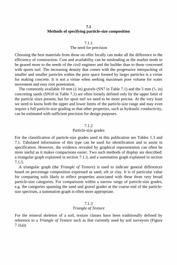
7.1 Methods of specifying particle-size composition
7.1.1 The need for precision
Choosing the best materials from those on offer locally can make all the difference to theefficiency of construction. Cost and availability can be misleading as the market tends tobe geared more to the needs of the civil engineer and the builder than to those concernedwith sports turf. The increasing density that comes with the progressive interpacking ofsmaller and smaller particles within the pore space formed by larger particles is a virtuefor making concrete. It is not a virtue when seeking maximum pore volume for watermovement and easy root penetration.
The commonly available 10 mm (⅜ in) gravels (SN7 in Table 7.1) and the 5 mm ( in) concreting sands (SN10 in Table 7.1) are often loosely defined only by the upper limit ofthe particle sizes present, but for sport turf we need to be more precise. At the very leastwe need to know both the upper and lower limits of the particle-size range and may even require a full particle-size grading so that other properties, such as hydraulic conductivity, can be estimated with sufficient precision for design purposes.
7.1.2 Particle-size grades
For the classification of particle-size grades used in this publication see Tables 1.3 and 7.1. Tabulated information of this type can be used for identification and to assist in specification. However, the evidence revealed by graphical representation can often bemore useful as it makes comparisons easier. Two such methods of display are described:a triangular graph explained in section 7.1.3, and a summation graph explained in section 7.1.5.
A triangular graph (the Triangle of Texture) is used to indicate general differences based on percentage composition expressed as sand, silt or clay. It is of particular valuefor comparing soils likely to reflect properties associated with these three very broadparticle-size categories. For comparisons within a narrow range of particle-size grades, e.g. the categories spanning the sand and gravel grades at the coarse end of the particle-size spectrum, a summation graph is often more appropriate.
7.1.3 Triangle of Texture
For the mineral skeleton of a soil, texture classes have been traditionally defined byreference to a Triangle of Texture such as that currently used by soil surveyors (Figure 7.1(a)).

TABLE 7.1 Drainage and soil materials for sports turf

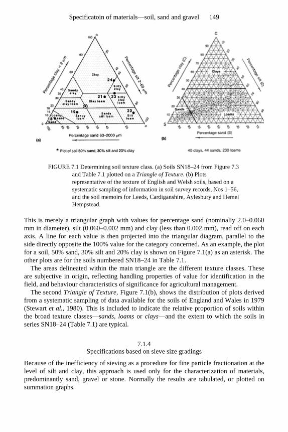
FIGURE 7.1 Determining soil texture class. (a) Soils SN18–24 from Figure 7.3 and Table 7.1 plotted on a Triangle of Texture. (b) Plots representative of the texture of English and Welsh soils, based on a systematic sampling of information in soil survey records, Nos 1–56, and the soil memoirs for Leeds, Cardiganshire, Aylesbury and Hemel Hempstead.
This is merely a triangular graph with values for percentage sand (nominally 2.0–0.060 mm in diameter), silt (0.060–0.002 mm) and clay (less than 0.002 mm), read off on each axis. A line for each value is then projected into the triangular diagram, parallel to theside directly opposite the 100% value for the category concerned. As an example, the plotfor a soil, 50% sand, 30% silt and 20% clay is shown on Figure 7.1(a) as an asterisk. The other plots are for the soils numbered SN18–24 in Table 7.1.
The areas delineated within the main triangle are the different texture classes. These are subjective in origin, reflecting handling properties of value for identification in thefield, and behaviour characteristics of significance for agricultural management.
The second Triangle of Texture, Figure 7.1(b), shows the distribution of plots derived from a systematic sampling of data available for the soils of England and Wales in 1979(Stewart et al., 1980). This is included to indicate the relative proportion of soils withinthe broad texture classes—sands, loams or clays—and the extent to which the soils in series SN18–24 (Table 7.1) are typical.
7.1.4 Specifications based on sieve size gradings
Because of the inefficiency of sieving as a procedure for fine particle fractionation at thelevel of silt and clay, this approach is used only for the characterization of materials,predominantly sand, gravel or stone. Normally the results are tabulated, or plotted onsummation graphs.
Specificatoin of materials—soil, sand and gravel 149
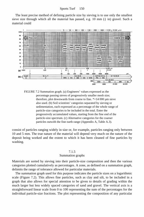
The least precise method of defining particle size by sieving is to use only the smallest sieve size through which all the material has passed, e.g. 10 mm (⅜ in) gravel. Such a material could
FIGURE 7.2 Summation graph. (a) Engineers’ values expressed as the percentage passing sieves of progressively smaller mesh size; therefore, plot downwards from coarse to fine. *=14 000 µm sieve also used. (b) Soil scientists’ categories separated by sieving or sedimentation, each expressed as a percentage of the whole range of particle-size categories to be included in the total. Enter the progressively accumulated values, starting from the fine end of the particle-size spectrum. (c) Alternative categories for the coarser particles outwith the fine earth range (Appendix A, Table A.3).
consist of particles ranging widely in size or, for example, particles ranging only between10 and 5 mm. The true nature of the material will depend very much on the nature of thedeposit being worked and the extent to which it has been cleaned of fine particles bywashing.
7.1.5 Summation graphs
Materials are sorted by sieving into their particle-size composition and then the variouscategories plotted cumulatively as percentages. A zone, as defined on a summation graph,delimits the range of tolerance allowed for particular materials.
The summation graph used for this purpose indicates the particle sizes on a logarithmic scale (Figure 7.2). This allows fine particles, such as clay and silt, to be included in a graph that also allows for special attention to be given to details of grading within themuch larger but less widely spaced categories of sand and gravel. The vertical axis is astraightforward linear scale from 0 to 100 representing the sum of the percentages for theindividual particle-size fractions. The plot representing the composition of any particular
Sports Turf 150
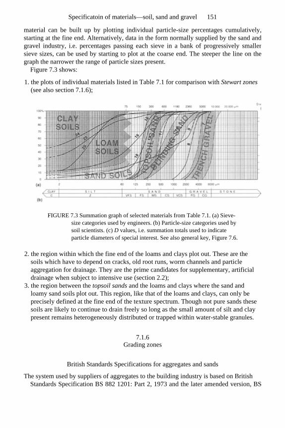
material can be built up by plotting individual particle-size percentages cumulatively, starting at the fine end. Alternatively, data in the form normally supplied by the sand andgravel industry, i.e. percentages passing each sieve in a bank of progressively smallersieve sizes, can be used by starting to plot at the coarse end. The steeper the line on thegraph the narrower the range of particle sizes present.
Figure 7.3 shows:
1. the plots of individual materials listed in Table 7.1 for comparison with Stewart zones (see also section 7.1.6);
FIGURE 7.3 Summation graph of selected materials from Table 7.1. (a) Sieve-size categories used by engineers. (b) Particle-size categories used by soil scientists. (c) D values, i.e. summation totals used to indicate particle diameters of special interest. See also general key, Figure 7.6.
2. the region within which the fine end of the loams and clays plot out. These are the soils which have to depend on cracks, old root runs, worm channels and particle aggregation for drainage. They are the prime candidates for supplementary, artificial drainage when subject to intensive use (section 2.2);
3. the region between the topsoil sands and the loams and clays where the sand and loamy sand soils plot out. This region, like that of the loams and clays, can only be precisely defined at the fine end of the texture spectrum. Though not pure sands these soils are likely to continue to drain freely so long as the small amount of silt and clay present remains heterogeneously distributed or trapped within water-stable granules.
7.1.6 Grading zones
British Standards Specifications for aggregates and sands
The system used by suppliers of aggregates to the building industry is based on British Standards Specification BS 882 1201: Part 2, 1973 and the later amended version, BS
Specificatoin of materials—soil, sand and gravel 151
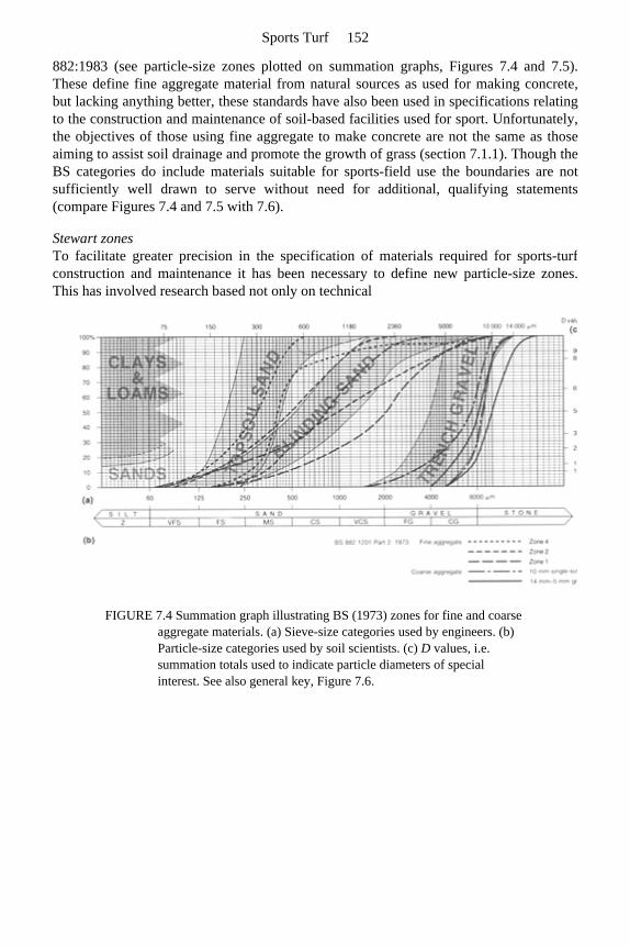
882:1983 (see particle-size zones plotted on summation graphs, Figures 7.4 and 7.5). These define fine aggregate material from natural sources as used for making concrete,but lacking anything better, these standards have also been used in specifications relatingto the construction and maintenance of soil-based facilities used for sport. Unfortunately,the objectives of those using fine aggregate to make concrete are not the same as thoseaiming to assist soil drainage and promote the growth of grass (section 7.1.1). Though the BS categories do include materials suitable for sports-field use the boundaries are not sufficiently well drawn to serve without need for additional, qualifying statements(compare Figures 7.4 and 7.5 with 7.6).
Stewart zones To facilitate greater precision in the specification of materials required for sports-turf construction and maintenance it has been necessary to define new particle-size zones. This has involved research based not only on technical
FIGURE 7.4 Summation graph illustrating BS (1973) zones for fine and coarse aggregate materials. (a) Sieve-size categories used by engineers. (b) Particle-size categories used by soil scientists. (c) D values, i.e. summation totals used to indicate particle diameters of special interest. See also general key, Figure 7.6.
Sports Turf 152
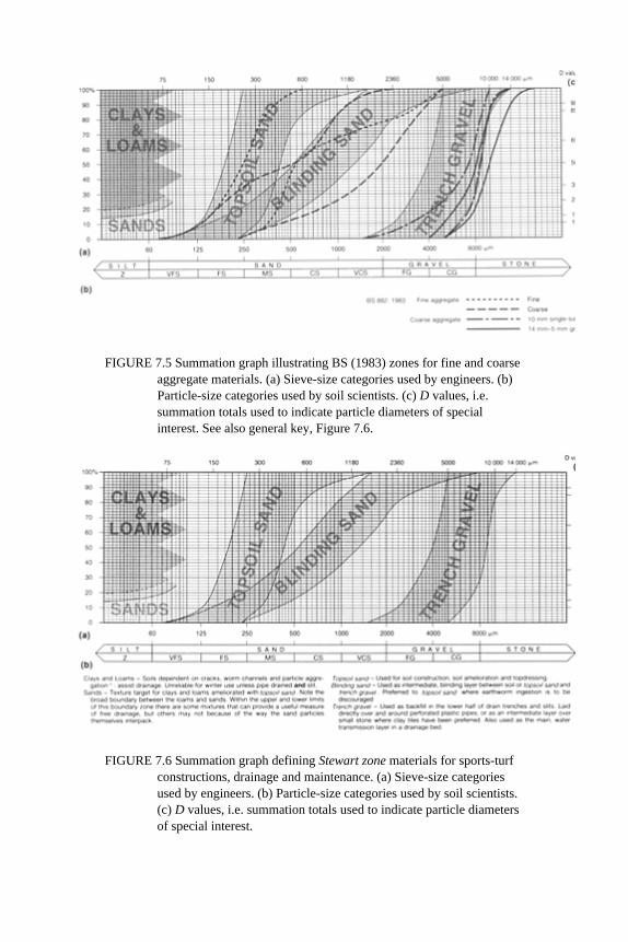
FIGURE 7.5 Summation graph illustrating BS (1983) zones for fine and coarse aggregate materials. (a) Sieve-size categories used by engineers. (b) Particle-size categories used by soil scientists. (c) D values, i.e. summation totals used to indicate particle diameters of special interest. See also general key, Figure 7.6.
FIGURE 7.6 Summation graph defining Stewart zone materials for sports-turf constructions, drainage and maintenance. (a) Sieve-size categories used by engineers. (b) Particle-size categories used by soil scientists. (c) D values, i.e. summation totals used to indicate particle diameters of special interest.
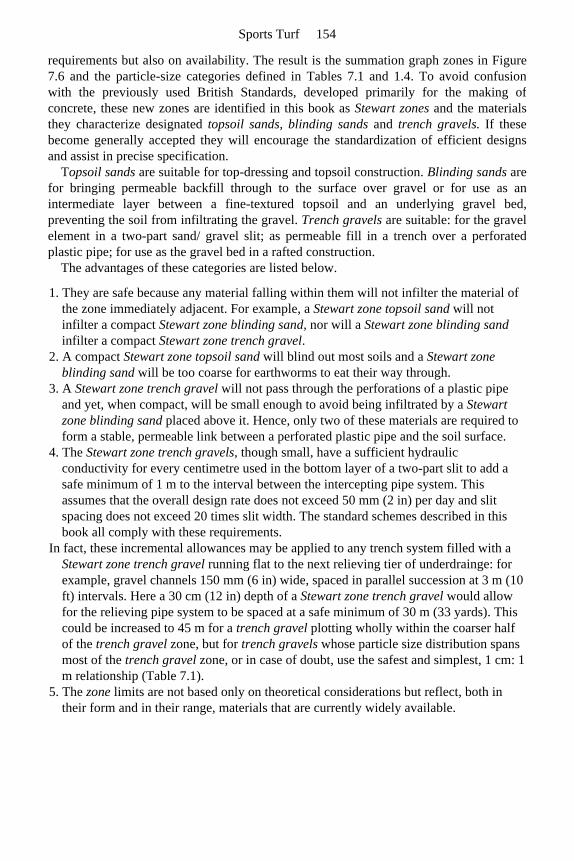
requirements but also on availability. The result is the summation graph zones in Figure 7.6 and the particle-size categories defined in Tables 7.1 and 1.4. To avoid confusion with the previously used British Standards, developed primarily for the making ofconcrete, these new zones are identified in this book as Stewart zones and the materials they characterize designated topsoil sands, blinding sands and trench gravels. If these become generally accepted they will encourage the standardization of efficient designsand assist in precise specification.
Topsoil sands are suitable for top-dressing and topsoil construction. Blinding sands are for bringing permeable backfill through to the surface over gravel or for use as anintermediate layer between a fine-textured topsoil and an underlying gravel bed,preventing the soil from infiltrating the gravel. Trench gravels are suitable: for the gravel element in a two-part sand/ gravel slit; as permeable fill in a trench over a perforatedplastic pipe; for use as the gravel bed in a rafted construction.
The advantages of these categories are listed below.
1. They are safe because any material falling within them will not infilter the material of the zone immediately adjacent. For example, a Stewart zone topsoil sand will not infilter a compact Stewart zone blinding sand, nor will a Stewart zone blinding sand infilter a compact Stewart zone trench gravel.
2. A compact Stewart zone topsoil sand will blind out most soils and a Stewart zone blinding sand will be too coarse for earthworms to eat their way through.
3. A Stewart zone trench gravel will not pass through the perforations of a plastic pipe and yet, when compact, will be small enough to avoid being infiltrated by a Stewart zone blinding sand placed above it. Hence, only two of these materials are required to form a stable, permeable link between a perforated plastic pipe and the soil surface.
4. The Stewart zone trench gravels, though small, have a sufficient hydraulic conductivity for every centimetre used in the bottom layer of a two-part slit to add a safe minimum of 1 m to the interval between the intercepting pipe system. This assumes that the overall design rate does not exceed 50 mm (2 in) per day and slit spacing does not exceed 20 times slit width. The standard schemes described in this book all comply with these requirements.
In fact, these incremental allowances may be applied to any trench system filled with a Stewart zone trench gravel running flat to the next relieving tier of underdrainge: for example, gravel channels 150 mm (6 in) wide, spaced in parallel succession at 3 m (10 ft) intervals. Here a 30 cm (12 in) depth of a Stewart zone trench gravel would allow for the relieving pipe system to be spaced at a safe minimum of 30 m (33 yards). This could be increased to 45 m for a trench gravel plotting wholly within the coarser half of the trench gravel zone, but for trench gravels whose particle size distribution spans most of the trench gravel zone, or in case of doubt, use the safest and simplest, 1 cm: 1 m relationship (Table 7.1).
5. The zone limits are not based only on theoretical considerations but reflect, both in their form and in their range, materials that are currently widely available.
Sports Turf 154
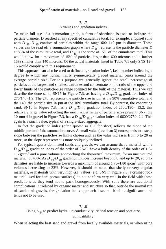
7.1.7 D values and gradation indices
To make full use of a summation graph, a form of shorthand is used to indicate theparticle diameter D reached at any specified cumulative total: for example, a topsoil sandwith D 85–D 15 consists of particles within the range 600–140 µm in diameter. These values can be read off a summation graph where D 85 represents the particle diameter Dat 85% of the cumulative total, and D 15 is the same at 15% of the cumulative total. Thiswould allow for a maximum of 15% of particles larger than 600 microns and a further15% smaller than 140 microns. Of the actual materials listed in Table 7.1 only SNS 12–15 would comply with this requirement.
This approach can also be used to define a ‘gradation index’, i.e. a number indicating a degree to which any normal, fairly symmetrically graded material peaks around theaverage particle size. For this purpose we generally ignore the small percentage ofparticles at the largest and smallest extremes and concentrate on the ratio of the upper andlower limits of the particle-size range spanned by the bulk of the material. Thus we can describe the dune sand, SN15 in Figure 7.3, as having a D 90/D 10 gradation index of 270/140=1.9. The 270 represents the particle size in µm at the 90% cumulative total and the 140, the particle size in µm at the 10% cumulative total. By contrast, the concretingsand, SN10 in Figure 7.3, has a D 90/D 10 gradation index of 2500/190= 13.2, thisrelatively large value reflecting the much wider range of particle sizes present. SN7, the10-mm ⅜ in gravel in Figure 7.3, has a D 90/D 10 gradation index of 6600/2750=2.4. Thisagain is a small value, typical of a single-sized aggregate.
In fact the gradation index (often quoted as G.I. for short) reflects the slope of the middle portion of the summation curve. A small value (less than 3) corresponds to a steepslope between the particle-size limits chosen and, as the value increases from 6 to 20 ormore, so the slope represented is more obliquely inclined.
For typical, quartz-dominated sands and gravels we can assume that a material with aD 90/D 10 gradation index of the order of 2 will have a bulk density of the order of 1.5–1.6 g/cm3 and a pore volume approaching the theoretical maximum, for an unstructured material, of 40%. As D 90/D 10 gradation indices increase beyond 6 and up to 20, so bulkdensities are liable to increase towards a maximum of around 1.75–1.80 g/cm3 with pore volumes decreasing to 33%. However, it should be noted that shelly or very angularmaterials, or materials with very high G.I. values (e.g. SN9 in Figure 7.3, a crushed rock material used for hard porous surfaces) do not conform very well in the field with thesepredictions as they tend not to pack homogeneously. With soils there are additionalcomplications introduced by organic matter and structure so that, outside the normal runof sands and gravels, the gradation index approach loses much of its significance andtends not to be used.
7.1.8 Using D K to predict hydraulic conductivity, critical tension and pore-size
compatibility
When selecting the best sand and gravel from locally available materials, or when using
Specificatoin of materials—soil, sand and gravel 155
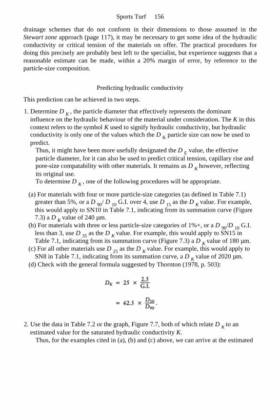
drainage schemes that do not conform in their dimensions to those assumed in theStewart zone approach (page 117), it may be necessary to get some idea of the hydraulic conductivity or critical tension of the materials on offer. The practical procedures fordoing this precisely are probably best left to the specialist, but experience suggests that areasonable estimate can be made, within a 20% margin of error, by reference to theparticle-size composition.
Predicting hydraulic conductivity
This prediction can be achieved in two steps.
1. Determine D K , the particle diameter that effectively represents the dominant influence on the hydraulic behaviour of the material under consideration. The K in this context refers to the symbol K used to signify hydraulic conductivity, but hydraulic conductivity is only one of the values which the D K particle size can now be used to predict.
Thus, it might have been more usefully designated the D E value, the effective particle diameter, for it can also be used to predict critical tension, capillary rise and pore-size compatability with other materials. It remains as D K however, reflecting its original use. To determine D K , one of the following procedures will be appropriate.
(a) For materials with four or more particle-size categories (as defined in Table 7.1) greater than 5%, or a D 90/ D 10 G.I. over 4, use D 15 as the D K value. For example, this would apply to SN10 in Table 7.1, indicating from its summation curve (Figure 7.3) a D K value of 240 µm.
(b) For materials with three or less particle-size categories of 1%+, or a D 90/D 10 G.I. less than 3, use D 35 as the D K value. For example, this would apply to SN15 in Table 7.1, indicating from its summation curve (Figure 7.3) a D K value of 180 µm.
(c) For all other materials use D 25 as the D K value. For example, this would apply to SN8 in Table 7.1, indicating from its summation curve, a D K value of 2020 µm.
(d) Check with the general formula suggested by Thornton (1978, p. 503):
2. Use the data in Table 7.2 or the graph, Figure 7.7, both of which relate D K to an estimated value for the saturated hydraulic conductivity K.
Thus, for the examples cited in (a), (b) and (c) above, we can arrive at the estimated
Sports Turf 156
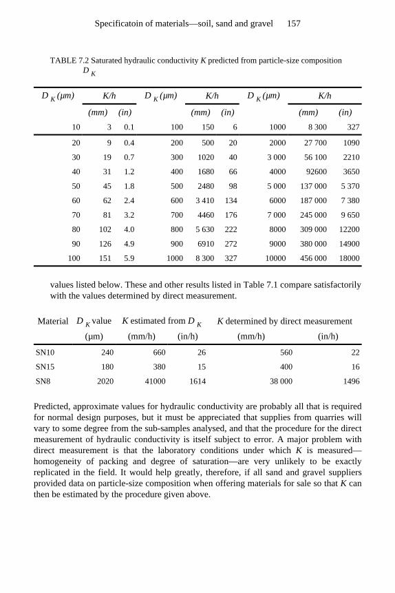
values listed below. These and other results listed in Table 7.1 compare satisfactorily with the values determined by direct measurement.
Predicted, approximate values for hydraulic conductivity are probably all that is required for normal design purposes, but it must be appreciated that supplies from quarries will vary to some degree from the sub-samples analysed, and that the procedure for the direct measurement of hydraulic conductivity is itself subject to error. A major problem with direct measurement is that the laboratory conditions under which K is measured—homogeneity of packing and degree of saturation—are very unlikely to be exactly replicated in the field. It would help greatly, therefore, if all sand and gravel suppliers provided data on particle-size composition when offering materials for sale so that K can then be estimated by the procedure given above.
TABLE 7.2 Saturated hydraulic conductivity K predicted from particle-size composition D K
D K (µm) K/h D K (µm) K/h D K (µm) K/h
(mm) (in) (mm) (in) (mm) (in) 10 3 0.1 100 150 6 1000 8 300 327
20 9 0.4 200 500 20 2000 27 700 1090
30 19 0.7 300 1020 40 3 000 56 100 2210
40 31 1.2 400 1680 66 4000 92600 3650
50 45 1.8 500 2480 98 5 000 137 000 5 370
60 62 2.4 600 3 410 134 6000 187 000 7 380
70 81 3.2 700 4460 176 7 000 245 000 9 650
80 102 4.0 800 5 630 222 8000 309 000 12200
90 126 4.9 900 6910 272 9000 380 000 14900
100 151 5.9 1000 8 300 327 10000 456 000 18000
Material D K value K estimated from D K K determined by direct measurement
(µm) (mm/h) (in/h) (mm/h) (in/h)
SN10 240 660 26 560 22
SN15 180 380 15 400 16
SN8 2020 41000 1614 38 000 1496
Specificatoin of materials—soil, sand and gravel 157

Predicting critical tension
For critical tension it is necessary to start by following through the procedure describedabove for determining D K from particle-size composition. An approximate value for critical tension can then be estimated by substituting D K for particle diameter in the equation developed for this purpose in section 4.2.2:
Thus, for a typical dune sand (SN15 in Table 7.1),
Alternatively, read value directly off graph, Figure 7.8.
Predicting pore-size compatibility
D K may be said to define the particle diameter most likely to dominate the pore systemof a mixed particle-size sand or gravel. As such it provides a useful basis upon which todecide if two otherwise unlike materials, laid one above the other, will blendhydraulically or behave as separate layers, tending to create a perched watertable abovethe junction.
Sports Turf 158
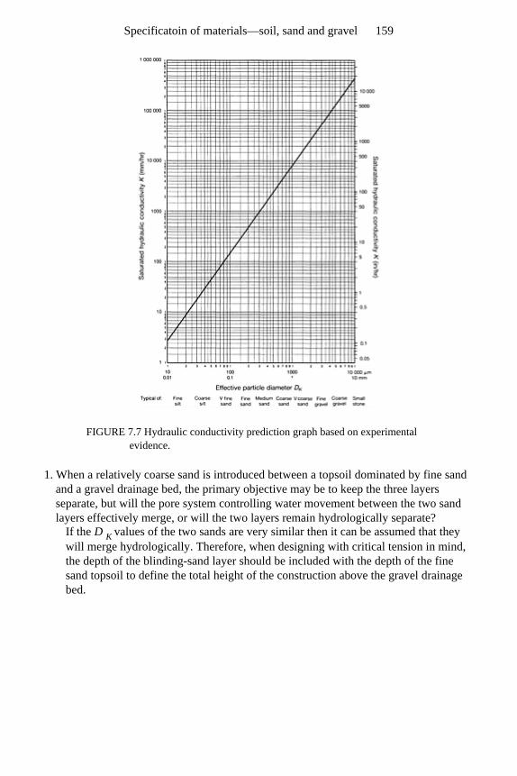
FIGURE 7.7 Hydraulic conductivity prediction graph based on experimental evidence.
1. When a relatively coarse sand is introduced between a topsoil dominated by fine sand and a gravel drainage bed, the primary objective may be to keep the three layers separate, but will the pore system controlling water movement between the two sand layers effectively merge, or will the two layers remain hydrologically separate?
If the D K values of the two sands are very similar then it can be assumed that they will merge hydrologically. Therefore, when designing with critical tension in mind, the depth of the blinding-sand layer should be included with the depth of the fine sand topsoil to define the total height of the construction above the gravel drainage bed.
Specificatoin of materials—soil, sand and gravel 159
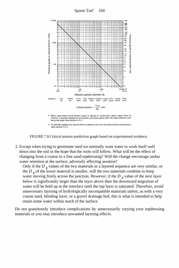
FIGURE 7.8 Critical tension prediction graph based on experimental evidence.
2. Except when trying to germinate seed we normally want water to work itself well down into the soil in the hope that the roots will follow. What will be the effect of changing from a coarse to a fine sand topdressing? Will the change encourage undue water retention at the surface, adversely affecting aeration?
Only if the D K values of the two materials in a layered sequence are very similar, or the D K of the lower material is smaller, will the two materials combine to keep water moving freely across the junction. However, if the D K value of the next layer below is significantly larger than the layer above then the downward migration of water will be held up at the interface until the top layer is saturated. Therefore, avoid unnecessary layering of hydrologically incompatible materials unless, as with a very coarse sand, blinding layer, or a gravel drainage bed, this is what is intended to help retain some water within reach of the surface.
Do not gratuitously introduce complications by unnecessarily varying your topdressing materials or you may introduce unwanted layering effects.
Sports Turf 160
7.2 Choosing the correct materials according to function
7.2.1 Introduction
Though several methods developed for the precise specification of soil-forming materials make use of data on particle-size composition, experience suggests that the easiest to implement is likely to be one based on zones defined on a particle-size, summation graph or in a table of sieve-grading limits. The following review of features likely to influencechoice of material according to function will therefore be based mainly on materialsdefined in Figure 7.6, or Tables A1.3 and A1.4 in Appendix A.
7.2.2 Choosing the correct soil
In situ or imported topsoil should be free of glass and other potentially dangerous material as well as being in a structurally water-stable state, i.e. in ‘good heart’ (section A.7). As such it will probably have a pH in the region 5.5–7.5 and an organic matter content between 4 and 10%. Thereafter, the performance of the soil will depend verymuch on its particle-size composition. It is impossible to predict from a knowledge of particle-size composition alone whether any particular soil will drain badly. However, if the soil when compact has the potential to drain badly because of its content of fineparticles, it should be considered a likely candidate for intensive, supplementarydrainage.
Sand, silt and clay content of the ‘fine earth’
Soils with less than 75% of the fine earth (particles less than 2 mm in diameter)consisting of sand, or more than 25% silt+clay are the loams and the clays (e.g. Table 7.1, SNs 19–24). They are soils dependent on worm channels and particle aggregation to maintain a structure favourable to the rapid infiltration of surface water. They areunreliable for winter use unless pipe-drained and slit.
By contrast, soils classified as loamy sands or sands (e.g. Table 7.1, SN18) have so little silt and clay that only when this fine material is concentrated into a layer will therebe a risk of developing a problem of drainage impedance. Loamy sands or sands are soilswith less than 25% silt plus clay and, as such, are good prospects for sports turf, generallyrequiring under-drainage only. (See note on Sands, Figure 7.6.)
If a sand soil is to be ameliorated by addition of a strongly granulated loam, no effort should be made to break down the granulation and homogenize the two materials or thedrainage efficiency of the sand will immediately be compromised. The aim should be toachieve a ‘spotted dog’ effect, i.e. granules of soil set in a matrix of sand. This is best done by careful mixing when dry.
Soils dominated by very fine sand and silt (e.g. Table 7.1, SN20) are particularly
Specificatoin of materials—soil, sand and gravel 161
difficult to deal with because they are water-holding, structurally very unstable and liable to wind-blow when left bare during construction. They may well benefit from steep grading (e.g. 2.5% or 1 in 40) to ensure that excess water will be shed off the surface.
Topsoil quality
Soil from a stockpile may well be structurally unstable in water, readily capping whenrained upon. This would be typical of subsoil but could also be topsoil that hasdeteriorated during storage. No matter how good the original quality of a topsoil, it willrapidly deteriorate in storage during the course of a single growing season, especially ifsoil temperature, soil aeration and soil moisture are adequate for biological activity tocontinue.
Storage under dry, cold, well-aerated conditions, or grassed over in a heap no more than 60 mm (2 ft) high, would be much less harmful. In the normal large stockpile,biological activity goes on but, because aeration below the surface is restricted, thesupply of oxygen is greatly reduced and the nature of the microbial activity changes. Thisresults in the dissipation of organic matter and production of noxious end-products. The structure deterioration that follows may require many years of special management torectify.
Soil degradation is a problem far more widespread than is generally recognized. It probably stems from the skills of our engineers in earth moving having gone beyond theirknowledge of soil as a dynamic, biological system. Before the advent of modern heavyequipment, earth-moving projects were achieved by manpower and a system of skips and rails; a procedure which probably limited the extent of such operations and the degree ofcompaction caused.
By careful selection of site we should aim at minimum disturbance and only veryminor grading within the topsoil, preserving soil structure and the organisms responsiblefor it. Time should be allowed for re-consolidation and root-binding after the loosening consequent upon the disturbance involved in grading. It is important to realize that unlessthe topsoil is fresh and not structurally degraded by stock-piling, it may prove quite unsuitable for the satisfactory establishment of a sports-turf sward. Note the adverse effect of structural collapse on hydraulic conductivity in the clay loam soil, SN22, Table 7.1.
In summary, if non-sandy soils are to have a satisfactory air/water balance for root development, they must be selected for their desirable structural state and then handled soas to preserve it. When using such soils the aims should be as follows.
1. Avoid disturbance if at all possible so that full benefit can be derived from existing worm channels and well-established, subsoil cracking systems.
2. If the soil has to be disturbed, work it only when it is dry enough to be brittle. Take every precaution to avoid either dusting or panning by injudicious and over-zealous use of machinery.
3. Avoid storage; if at all possible, arrange for direct transfer. If storage is necessary, then recognize that rapid structural deterioration will take place in a time span to be measured in months rather than years.
Sports Turf 162
Stones and boulders
Stones and boulders should not be so large or so numerous as to interfere with the smoothprogress of a slit trencher machine. This means that stones larger than 75 mm (3 in) inany dimension are liable to be unwelcome in the top 300–450 mm (12–18 in) of soil.
Total stone content should not exceed 15% by weight, 8% by volume, as even at this moderate level of stoniness all the soil agitation inherent in harrowing, raking and frostaction will tend to leave them concentrated on the surface where they are leastacceptable. To merely roll them back in is like forcing marbles into porridge withpredictable, adverse effect on surface infiltration.
In time, surface casting by earthworms will bury stones, but a made-up or severely disturbed soil is not likely to be well endowed with earthworms initially, and the rate ofreburial by this means is, in any case, bound to take years. In practice, therefore, anyadverse concentration of stones at the surface should be dealt with by some process ofmechanical removal before grassing up; particularly so if the stones are sharply angularfragments that could cause injury. Far better to avoid these problems by careful soilselection in the first place.
Peat
To be described as ‘peaty’ a soil needs to contain more than 25% dry weight of organicmatter, about two-thirds organic matter by volume. A true peat is made up of more than 35% dry weight of organic matter, more than three-quarters organic matter by volume (Figure A1.3, Appendix A).
Deep peat, once adequately drained, can provide a satisfactory grass surface for sport,especially for controlled use by juveniles, but there are special problems, unique to peat,that have to be taken into account.
1. Peats vary, most typically, according to their origin. Deep, fen-type peat is formed in the hollow of a natural catchment and, because of the stable nature of the ground water-table and the natural sequence of vegetation through which it has been built up, it may have a fibrous, reed-residue layer at the base. This can be utilized for the efficient, lateral discharge of drainage water once a satisfactory outfall has been established. Bog peats accumulate as a blanket in very high rainfall areas but are liable to dry out seasonally. This means they may be quite well humified and compact throughout, requiring a system of underdrains to assist with lateral discharge.
2. If the watertable is lowered, particularly in a fen-type peat, there will be considerable subsidence. Initially this will be as a result of the de-watering process but will then continue, albeit at a slower pace, because the peat itself will decompose in response to the improved aeration. These two processes can lead to falls equivalent to one third of the fall in the watertable height.
Though initially a saturated, fibrous peat may have a hydraulic conductivity comparable with that of fine sand, the combined effect of shrinkage and decomposition can reduce this to a value more comparable with silt. This may not yet make it unduly limiting for vertical infiltration down to the watertable but it
Specificatoin of materials—soil, sand and gravel 163
would be very slow for clearance laterally. It is important, therefore, that we should recognize not only the initial differences that may occur between peats but also the changes in performance that are likely to occur with time, especially if the site is completely de-watered. For example, there may be no benefit to be gained from attempting to de-water a basal layer of fibrous peat. This could be left waterlogged so that it could maintain, by efficient lateral flow, the water level in a peripheral ditch forming part of a pump drainage scheme, or a height-controlled outfall.
3. Improved aeration on sites showing the visual warning signs of ‘oily’ sheens on the surface of ditch water, or of red ochre staining around springs and drain outfalls, can lead to major problems caused by a build up of iron ochre deposition (section 2.1.3). If iron ochre deposition does occur it will be particularly devastating in the aerated channel system of slits and pipe under-drains.
4. There may be some difficulty over organizing a satisfactory outfall to allow the water-table to be lowered and maintained at an appropriate level. This may entail clearing a passage through a natural drainage barrier or turning instead to some form of pump assistance. In either event this problem should be thoroughly explored with professional help from the local drainage authority.
5. Because of the low density of drained, moist peat (about a quarter of the drained, moist density of a loam or a sand) and the risk of shallow rooting, any grass sward established may not be sufficiently anchored to resist the tear-wearing stress of studded footwear. As already pointed out in section 1.10.6, this would be much more of a problem with adults than juveniles.
6. The virtual necessity of an open ditch approach to ground-water control requires serious thought being given to the frequency with which balls will require to be recovered from this location. Though recovery poles may be made available for this purpose the menace of vandalism may result in their not being available to casual users. In these circumstances the task of ball recovery from open, slippery-sided, water-filled ditches will at best be a nuisance and, at worst, may constitute a serious child hazard.
With the above problems in mind, a peat project is best tackled in stages, firstconcentrating on lowering the ground watertable to no more than 1 m (1 yard) below theplaying surface. This is probably best done initially by a well-maintained system ofditches around individual pitches, linked up to an effective, controlled outfall.
Once de-watering has stabilized the surface enough to take the necessary light weight,load-spreading machinery, progress can be made with weed killing, removal of trash andregrading by minimal re-distribution of peat. Then the surface can be fertilized and firmedup by pushing out a carpet of topsoil sand, 50 mm (2 in)—100 mm (4 in) thick, accordingto resources. Finally the surface can be grassed and maintained as advocated in Section6.1. Only if, after 2–3 years of use this fails to satisfy should any consideration be givento the possible benefits of pipe and/or slit drain supplementation.
Tip sites
It may be found that the existing surface on a tip site is seriously contaminated with
Sports Turf 164
dubious or potentially harmful materials such as glass and noxious chemicals, or half-buried obstacles such as large stones and boulders, concrete, metal, refuse, etc. It isnormally unwise to attempt to clear such objects by trawling
through the soil with a subsoiling device; farbetter to aim at safe burial. After clearance of all loose debris and obstacles standing proud of the surface, burial
may involve importation of 450 mm (18 in) of good soil, sufficient to avoid any adverseeffect of frost heave, and to allow adequate clearance for soil cultivation and draintrenching. Since this should be regarded as a minimum safe depth, an additionalallowance of one-sixth of the final desired depth should be made to take account of long-term settlement.
If noxious chemicals are suspected, and these cannot be entirely removed by excavation, the surface to be buried should first be chemically screened by a 50–75 mm (2–3 in) layer of at least 25 mm (1 in) of lime, and then 25 mm (1 in) of peat. The lime will tend to inactivate by precipitation, and the peat will tend to trap by chelation. Theselayers should be firmed into place by rolling and thereafter should not be disturbed.
Should there be any doubt over the stability of the tip surface or the height to which the new surface can be raised, then the tip surface should be trued off with a freelypermeable, blinding layer of coarse sand, fine gravel or grit (unless already screened withpeat and lime) and covered by an appropriate, synthetic filter membrane prior totopsoiling. Where the drainage scheme to be adopted requires pipes to be installed underthe filter membrane these will have to be linked by permeable fill through the filtermembrane. If the imported topsoil is a free-draining sand, or loamy sand, this may suffice, but if the imported soil will require slit drainage, provision may have to be madeto continue the permeable fill in the pipe trenches well above the filter membrane. Thiscan be done by piling the required trench gravel in ridges on the membrane surface, along the line of the pipe trenches. Alternatively, by marking the line of each pipe runwith duct tracer tape (or equivalent), connection can be made later by trenching the linkdown from the new surface.
Obviously it would be advantageous to start with a stable tip, suitably trued off and blinded, and then to take time to find an adequate amount of good topsoil to build up tothe desired 450 mm (18 in). However, if only a shallow depth of topsoil is to be used overa synthetic filter membrane, a great effort should be made to secure a sufficiently sandysoil so as to obviate any need for further amendment by slitting. In either case, the detailsof the design need to be carefully worked out as any later upgrading that requirestrenching into the buried pit material could be very disruptive.
7.2.3 Choosing the correct sand and gravel
Because of the great importance of choosing the correct materials this subject has alreadybeen considered in Chapter 1 and the concept of the topsoil sands, blinding sands and trench gravels introduced on page 114 to simplify precise specification.
Sands for topdressing, soil amelioration and whole soil construction
Specificatoin of materials—soil, sand and gravel 165
These are typically the Stewart zone topsoil sands: the dune, filter, plaster and foundry sands listed as SN12, 14 and 15 in Table 7.1 and Figure 7.3. They have D 50 values between 0.18 and 0.40 mm and D 90/D 10 typically between 2 and 3.
When choosing a sand to ameliorate a soil, or for topdressing, the particle-size grading should be matched to the dominant, medium-to-fine particle-size category in the topsoil already in place. This will discourage any tendency to develop the sort of layering andinterpacking that inhibits the free movement of water in a vertical direction. Additionally,for golf and bowling greens, where the topsoil has already become biologically stabilizedunder acid conditions, the sand should be lime-free. To verify, check for the absence of vigorous fizzing when the sand is treated with a 10% solution of hydrochloric acid.However, where the in-situ topsoil has become biologically stable at an alkaline pH then top-dressing with a sand that is slightly calcareous will not harm. It will not upset theestablished biological equilibrium and, therefore, will not allow ephemeral diseaseorganisms the opportunity to invade. Sand for use as the primary ingredient in a speciallyconstructed, sports-field topsoil should be in the finer half of the topsoil sands, with D 50in the region of 0.18–0.22 mm, like SN15 in Figure 7.3. This will help to develop the tractive efficiency required for vigorous games. On bowling greens, where drainage canbe given priority over traction, a medium particle-size sand with D 50 more in the region of 0.27–0.31 mm (SN12–14 in Table 7.1) would be preferable if locally available at anacceptable price.
Sands for use in layered constructions, and in slit and pipe trenches
These are typically the Stewart zone blinding sands found amongst the concreting sands (SN10 in Table 7.1, Figure 7.3) with D 50 between 0.5 and 1.3 mm and D 90/D 10 between 8 and 23.
Blinding layer sands have to be looked at from several points of view.
1. Because they are relatively wide-ranging in their particle-size composition they will tend to interpack and form a relatively stable surface to work over.
2. For most blinding sands the D 15 particle-size grade will tend to determine the effective pore size and, if this matches the D K particle-size grade in any sand layer immediately above, the effective pore size will tend to be continuous through the two layers. This will then allow the two layers to function more or less as one with regard to the vertical infiltration of water, e.g. SN14 in Table 7.1 laid over SN10.
3. As blinding layers are frequently the layer sandwiched between fine sand above and gravel or small stone below, their particle-size grading should be specified so as to ensure that they will hold out the fine material above and not themselves infilter the gravel or stones beneath. To maintain a stable, layered system, and erring on the side of caution, the D 15 of the blinding layer should generally not exceed four times the D 85 of the fine material above. That is, the main range of larger-sized particles in the fine material above should be large enough not to filter through the necks of the pores formed by the main range of smaller-sized particles in the blinding layer below. Similarly, the D 15 of the underlying gravel or stone must not exceed four times the D 85 of the blinding layer.
Generally, for symmetrically graded sands and gravels made up of sub-angular and
Sports Turf 166
rounded particles, the procedure for determining the effective upper and lower particle-sizes can take into account the narrowness of the particle-size grading. Thus, D 15 and D 85 would be appropriate parameters for a wide particle-size grading, D 35 and D 65 for a narrow particle-size grading, and D 25 and D 7 5 for something intermediate between these two extremes. An important feature of the Stewart zone materials is that any Stewart zone topsoil sand will remain stable over any Stewart zone blinding sand, and this in turn will remain stable over any Stewart zone trench gravel (Figure 7.3 shows plots of typical materials with their D 15, D 25, D 35, D 65, D 75 and D 85 values indicated)
4. Where appropriate, because of the local supply situation, advantage can be taken of the reliably small perforations in plastic drainage pipes to allow the use of a suitable, washed grit, or washed concreting sand, immediately over the pipe. For this the appropriate D 85, D 75 or D 65 of the backfill material should exceed 4 mm ( in), i.e. twice the maximum width of the pipe perforations. However, because of the tendency for the particles in loose grits and concreting sands to segregate during handling, a good deal of the fine material may weep through into the pipe before a stable, coarse-particle envelope is established around the pipe. In practice, therefore, it is usually more expedient to search widely for a Stewart zone trench gravel for this purpose, especially as this type of material is also likely to be required on site for any associated system of sand/gravel slits.
5. For clay tiles the problem is the possibility of pipe misalignment, and for this reason only, the normal practice of using 20–32 mm (¾–1¼ in) stone can be justified, but an additional blinding layer of trench gravel will then be required to allow a blinding sand to continue the permeable link through to the topsoil.
6. Where sand is intended to form a permeable link through the topsoil, the sustained permeability of this link may be threatened by the activity of earthworms consuming the sand and mixing it with the adjacent soil. In this position, however, we should also avoid too open a material, such as a 10–15 mm (⅜–⅝ in) gravel which earthworms can squeeze through, plugging the pores with fine soil as they go. In this situation a blinding sand has the advantage of being dominated by pores too small for earthworms to squeeze through yet it is mainly made up of particles larger than 0.5–0.7 mm which are too large for most earthworms to consume.
Gravels for use as permeable fill in slit and pipe trenches and drainage beds
These are typically the Stewart zone trench gravels, single sized 10-mm (⅜-in) aggregatewith D 50 between 4 and 9 mm and D 90/D 10 less than 6 (e.g. SN16 in Table 7.1 andFigure 7.3). In sports-turf drainage there is seldom a need to contemplate the use ofanything larger. To do
so is to invite problems of infiltration by soiland the need for extra blinding layers.
Such gravels are used under sports turf for several purposes:
• as a drainage bed beneath a specially constructed topsoil; • as backfill immediately over perforated plastic drainage pipes;
Specificatoin of materials—soil, sand and gravel 167

• as the gravel fill in pipeless drainage channels; • as the gravel layer in two-part sand/gravel slits.
A useful feature of the Stewart zone trench gravels already pointed out (page 117) is thatevery centimetre depth of gravel used at the bottom of a normal two-part slit allows for anadditional one metre run between interception pipe laterals.
Soil, bound by grass roots, seems generally to remain stable except where there isactive redistribution by earthworms. However, where soil is liable to lie wet, as beneath agravel bed, some regard should be paid to the extent to which the D 85 of the soil is lessthan a quarter of the D 15 of the adjacent gravel. If this indicates the likelihood of soilinfiltration it may be necessary to blind the soil with an appropriate blinding sand, or asynthetic filter fabric which has similar blinding properties. Only where there is a real riskof ground water surging up from below, as on a flood plain or a lowland coastal site, is itsometimes necessary to contemplate extending the use of synthetic filter fabrics to liningthe walls of drainage trenches.
Soils will increase in stability according to clay content and degree of water-stablegranulation. However, where silt (SN20 in Table 7.1) or fine sand forms the bulk of thesoil, a check should be made on the nature of the backfill over the pipe and in the otherdrainage trenches to ensure that the soil will not infilter laterally. For this, check that theD 15 of the adjacent backfill is not more than four times the D 85 of the soil.
Sports Turf 168
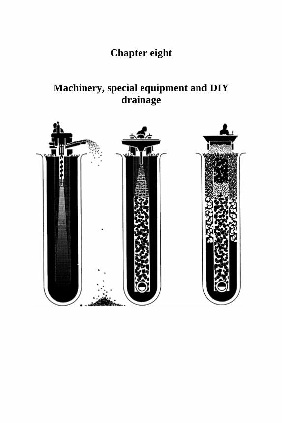
Chapter eight
Machinery, special equipment and DIY drainage

8.1 Operations involved
The purpose of this chapter is to describe the kinds of machinery and equipment requiredfor the various operations essential for the installation and efficient functioning ofmodern drainage systems. No attempt has been made to list or review the diversity ofmachines and equipment currently in use nor to comment on the attributes or otherwise ofindividual designs. The many possible design alternatives for achieving specified resultsare bound to lead to the development of new and better machines as time goes by so thatany review based on present performance will soon become dated. What is ofimportance, however, is the understanding of the requirement of each operation. This isexplained as fully as possible so that the capability of a particular machine can bechecked against the desired end result.
The following is a summary of the various operations involved in the installation of drainage systems:
• cutting narrow trenches for pipe drain laterals, and sub-surface gravel drains without pipes, on soils that are relatively obstacle free;
• trenching for main and outfall drains; • trenching for piped laterals in very stony or difficult ground; • trenching for interceptor drains, catchwater drains and open ditches; • installing pipes without soil excavation—trenchless drainage; • trenching for slit drainage; • ensuring uniformity of fall along the bottom of pipe trenches; • providing motive power; • disposing of soil from excavations; • backfilling, consolidating and re-truing the surface; • subsoiling; • applying sand topdressing; • spreading a sand carpet.
8.1.1 Cutting narrow trenches for pipe drain laterals, and sub-surface gravel drains
without pipes, on soils that are relatively obstacle free
The most commonly used external pipe diameter for perforated plastic, lateral drains iseither 60 or 80 mm (2 or 3 in); the clayware equivalents being 95 or 120 mm (4 or 5 in).This suggests minimum trench widths for installation of 100–200 mm (4–8 in) so long as the pipes can be handled within a comfortable working depth from the surface of theorder of 750 mm (30 in).
It is always advisable to allow a small gap between the trench wall and the side of the pipe so that the backfill can surround as much of the pipe as possible, minimizing soil entry into the pipe drain through perforations or gaps. However, it is also important tokeep the width of the trench no wider than is absolutely necessary for the size and kind of
Machinery, special equipment and DIY drainage 171
pipe used. Too great a width will not only involve the removal and disposal of anexcessive amount of soil, but also more expense for backfilling material and additionalcosts for grassing over. The trencher should be capable of cutting to a depth of at least1220 mm (4 ft), though trench depths for laterals seldom exceed 600–900 mm (2–3 ft).
If the purpose of the pipe drain is merely that of a conveyor, a closed pipe may be used with purpose-made junctions for lateral access. Soil may be substituted as backfill in place of gravel and sand.
8.1.2 Trenching for main and outfall drains
For mains and outfall drains the width of the trench has to be enough to take pipes of atleast 120 mm (5 in) or 175 mm (7 in) external diameter. Where a slope has to be imposedon the base of the trench the depth of cut may have to exceed 1000 mm (3 ft). At suchdepths obstacles and difficulties over pipe installation may well require much widertrenching but, the pipes being closed, the extracted soil can be used again for backfilling.
8.1.3 Trenching for piped laterals on very stony or difficult ground
Where there are difficult ground conditions, such as on tipped land or where large stonesabound, and trenching by chain cutter would be either uneconomic or impractical, theremay be no alternative but to use a more robust machine such as a hydraulic excavatorwith a dipper arm and bucket. Under the worst conditions the extra effort involved ininstalling the pipe drains, let alone the expectation of meeting similar problems in theinstallation of sand/ gravel slits, may make the cost of the whole scheme prohibitive.However, before abandoning the project, it may be worth considering the advisability ofimporting enough stone-free soil to raise the general level of the area sufficiently to enable at least the slits to be trenched in without difficulty. In these circumstances anypipe underdrainage should be installed, and trenches appropriately backfilled, before thenew stone-free topsoil is superimposed. As mentioned already, in Chapter 7, page 125, further trenching may well be required to extend the permeable fill of the pipe trenchesinto the lower half of the superimposed topsoil. It will help, therefore, if coloured tape isused to mark the surface of each run before burial.
8.1.4 Trenching for interceptor drains, catchment drains and open ditches
Drainage of this type is often required to intercept water encroaching from off site, eitheras surface runoff or as lateral seepage along impermeable sub-strata. Where surface flow is the problem, the width of the top of the trench should be adequate to ensure efficientinterception of all surface flow. An open ditch would be the most desirable option.However, to avoid creating an obstacle to play, the trench is usually piped and thenbackfilled to just proud of the surface with a graded series of freely permeable layers ofaggregate. No soil capping should be used to benefit grass growth as this will onlyimpede surface infiltration.
Sports Turf 172
The interception of moving ground water, seeping laterally over a relatively impermeable layer within the soil, requires only a narrow stone-filled trench, oriented across slope, and the trench extended below the seepage layer into the surface of theimpermeable stratum.
A safe compromise on a site located at the bottom of a natural or man-made slope is to create a tapering trench, 300–450 mm (12–18 in) wide at the top and 125–150 mm (5–6 in) wide at the bottom. It should be deep enough to intercept the lateral flow of groundwater, and organized at the top to capture all surface flow.
A suitable machine for excavation under difficult conditions of slope, surface wetnessand substrata is likely to be an hydraulic excavator with dipper arm and bucket. Bucketsare available in various widths, the smallest about 200 mm (8 in) tapering to 125 mm (5in). Machines of this type are the stock in trade of most local contractors.
8.1.5 Trenchless drainage
This involves the use of machines which slit open the soil and put pipe and backfill inplace all in one pass.
The use of the trenchless drainer on sports grounds is limited by the fact that to squeeze out even a narrow, 50–70 mm (2–3 in) wide slit without the extraction of soil isbound to cause considerable localized surface heave. Though these machines are robustenough to displace solid obstacles this can only be achieved at the expense of much soildisruption and may well lead to the lifting onto the surface of unwanted, potentiallydangerous objects. Furthermore, the simultaneous insertion of pipe and backfill preventsany check on the nature of the base on which the pipe is laid. However, in newconstructions, there should be no difficulty over the clearance and re-truing of the surface prior to grassing up.
Apart from the motive power, the main requirements of a trenchless drainer are asturdy slitter, an efficient device for guiding flexible plastic piping into the slit and,ideally, a two-part hopper capable of feeding in gravel to a fixed height, followed by a blinding sand.
Because of the narrowness of the slit trench it is particularly important to use a smallparticle-size gravel as backfill to discourage soil invasion, e.g. a Stewart zone trench gravel.
8.1.6 Trenching for slit drainage
Objectives
As interest in the sand/gravel slit method of drainage did not receive serious attention inthe UK until the late 1960s, the development of special drainage equipment for thispurpose is still of comparatively recent origin. The greater sophistication evident in thedesign of machines now available is a welcome advance.
Our aim must be so to improve efficiency that the cost falls more easily within the
Machinery, special equipment and DIY drainage 173
range that the many hundreds of small clubs and local authorities could contemplate forthe luxury of good outdoor playing conditions throughout the winter. However, evenwhen costed solely on the basis of the materials required, these schemes can never becheap. Probably the only scope for extending the market down to those with limitedfinances is to develop machinery for hire that will encourage the DIY approach. In suchan open-market situation, manufacturers with existing equipment, developed primarilyfor the agricultural or civil engineering sector, may see possibilities for a useful extensionof sales. In this there need be no harm so long as the design priorities for the sports-turf market are fully met.
The first priority of slit drainage is to install vertical channels, stabilized by permeable fill, at a spacing over which surface flow can be made effective, and along whichdischarge to a system of underdrains can be organized, with pipe interval as wide aspossible. The narrower the slit width, the shorter the run and the more adverse the effectof soil contaminating the fill margin, but the less the problem of reestablishing acomplete grass cover. The wider the slit, the greater the possibility for extending the runbetween pipes, but the more difficult the problem of re-establishing the sward along the line of the slit and, thereafter, maintaining growth uniformly over the whole playingsurface. Though various modifications are possible, experience to date has tended toconcentrate attention on 50 mm (2 in) wide slits, 300–350 mm (12–14 in) deep, spaced at 1 m (1 yard) intervals, backfilling typically with trench gravel in the lower half and blinding sand above. The slits are aligned across slope to maximize interception anddischarge below to pipe underdrains, running down slope, at 15–20 m intervals (Figure 11.1).
Trenching for slits by excavation
The basic requirements for excavator-type, slitting machines are:
1. to neatly excavate trenches as close as possible to 50 mm (2 in) wide, for depths down to 400 mm (16 in);
2. to remove the excavated spoil cleanly so that it can be conveyed off site without any need for a subsequent clearing-up operation;
3. a hopper capable of delivering and compacting into the trench, gravel and/or sand, in one operation, to predetermined depths. Loose packing and voids should be eliminated so as to prevent subsequent shrinkage;
4. hopper compartments large enough to hold sufficient quantities of backfill to avoid too frequent stops for reloading. Ideally, the size of the hopper should require reloading to take place only at the end, or at some fixed point along each run. The aim should be to keep vehicular traffic crossing the playing area to a minimum;
5. an ability to cope with stones and to slice the existing sward cleanly; 6. co-ordination of the various operations to avoid open trenches remaining unfilled and
vulnerable to collapse when rain intervenes; 7. speed, to allow this major task to be completed within the time span of fair-weather
prediction.
All of these requirements have to be met either in a series of separate operations or by
Sports Turf 174
machines capable of carrying out all, or several of the required operations in a singlepass.
Efficient machines capable of completing the whole operation in one pass are now on the market. Their advantages are that they will not leave trench runs in an unsafe,incomplete state, and, given good working conditions, they can slit an entire footballpitch in no more than two days. But they have their drawbacks: (a) their weight and themotive power required to move them; (b) the time lost in extracting and repositioning themachine when obstacles blocking progress have to be removed; (c) the length of themachine when space around the perimeter of the working area is limited. These arehighly specialized and expensive machines, unlikely to be used by anyone other than amajor, sports-field contractor.
To date the two main means of excavating narrow trenches, 50–75 mm (2–3 in) wide and 250–350 mm (10–14 in) deep have been either some form of circulating toothedchain or a toothed wheel, or a wide, subsoiling plough with a chisel foot angled to gougeout the soil in a continuous broad slice between two surface-stabilizing floats. To ensure clean excavation with the chisel type of trencher there needs to be a twin disc systemahead of the plough to slice through the turf along each margin of the trench to be slit.
Trenching for slits without excavation
Mini-slitting Slits of this type can be created by slicing the soil apart, either with a disc, or a blade likea subsoiling tine. By comparison with the more open base formed by the toe of asubsoiling tine, a disc-formed slit will be distinctly V-shaped, effective for surface interception, but limited in capacity for discharge. As both achieve their effect by soildisplacement the slit faces are bound to be smeared and compressed, and the surface ofthe soil is bound to be to some extent ridged up either side of the slit opening. This ridging has to be dispersed without adverse effect on the efficiency of surface-water interception.
In practice, slits formed in this way are generally restricted in width to something of the order of 25 mm (1 in). Mini-slits of this type can be installed fairly rapidly, but they have several potential disadvantages that require close attention by manufacturers anddesigners.
1. Because of their narrowness, backfilling with sand or gravel is difficult and to achieve the necessary compaction may require power assistance.
2. To have a discharge capacity equivalent to that of 50 mm (2 in) slits, spaced at 1 m (1 yard) intervals, 25 mm (1 in) wide slits have to be increased in number, or their interception by underdrains increased in frequency, all the more so if the backfill is changed from sand/gravel to coarse grit or blinding sand throughout.
3. Capping by soil, smeared over during play, will be difficult to avoid, and any sideways infiltration of soil from the slit walls into the backfill will immediately reduce their internal efficiency.
4. Because of the obvious tendency for a squeezed-out slit to close back rapidly once the blade has passed on, it is essential with this system that the backfilling and compaction
Machinery, special equipment and DIY drainage 175
operations be carried out simultaneously. One method utilizes a cavity maintained clear for this purpose immediately behind the solid part of the blade. If a vibrating mechanism can be fitted, this will not only help the smooth progress of the slitter through the soil but can also be used to improve the efficiency of the backfilling operation. The use of a winged, subsoiler shoe to relieve compaction in the same operation is tempting. It should be appreciated, however, that this may result in the backfill leaking away into the horizontal cavities that the wing feature is also likely to create.
5. There is now the possibility of greatly extending the capacity for lateral discharge of the slits themselves by inserting perforated plastic mini-pipes along the base. If the extra cost is to be justified, by greatly extending the length of run before discharge, the trench base must be very carefully graded to avoid the narrow pipes silting up. On flat sites, where a steady gradient has to be imposed, this will entail great skill in the cutting, grading and backfilling of narrow trenches at depth.
Micro-slitting Machines which will cut sets of narrow slits to shallow depths are now available and areused for enhancing the surface interception of standard slit systems. These micro-slits areof the order of 15 mm (½ in) wide, 100 mm (4 in) deep and spaced 150–225 mm (6–9 in)apart. In one pass they are drawn in at right-angles across the deeper, standard slits,simultaneously filled with closely packed sand and the surface trued off by rolling, readyfor immediate use.
Micro-slits are an expensive but useful alternative to the annual sand topdressingprocedure for maintaining sand continuity through to the surface. They are especiallyuseful for restoring the efficiency of slit systems soil-capped by maintenance neglect.Initially the benefit is unlikely to last for more than one winter season but, if the sandinjected is topsoil sand in character, in time, as the sand from successive treatmentsaccumulates, it will favourably ameliorate the texture of the original topsoil. However,because a fine sand must be dry to flow satisfactorily there is a tendency to think onlyshort term and use one of the readily available concreting sands that are freer flowingwhen moist. Unfortunately such a mixed particle-size sand may not favourably amelioratethe topsoil once both are thoroughly intermixed (Appendix C.1). It is important, therefore,that micro-slitting machines should be able to efficiently inject topsoil sand materials intothe micro-slits they create, even when the sand is moist enough to be sticky. Thealternative of purchasing specially dried sand can double the cost.
8.1.7 Ensuring uniformity of fall along the bottom of pipe trenches
Most land drainage machines have a sight rail or bar which will enable the operator to‘bone in‘the cutting blades, using profile boards previously established along the trenchline. For longer drainage runs, more sophisticated trenching machines can be laser guided,the digging depths being controlled automatically. For smaller machines, where thesefacilities are not available, it may be necessary to check the trench bottoms using a set ofboning rods, rectifying any imperfections by hand. In any event, if localized silting is to
Sports Turf 176
be avoided, it is essential to ensure that pipe runs are true and even. This cannot beguaranteed merely by installing at a fixed depth below an existing surface which itselfmay be undulating.
8.1.8 Motive power
Excavation of pipe and slit trenches on relatively obstacle-free soil
To meet the demand for a wide range of trench widths and depths there are a large varietyof power units available. On sports grounds the need to keep trench widths as narrow aspossible permits the use of comparatively small, self-propelled units with economical running costs and a low weight to bearing-surface ratio. These are normally fitted with interchangeable chain cutters to give trench widths of 100–200 mm (4–8 in) and depths of 300–1220 mm (1–4 ft).
Where tractor power has to be supplied from a separate source, the aim should be tolimit the risk of surface damage by spreading the load over more extensive bearingsurfaces, e.g. by using balloon tyres, four-wheel drive or caterpillar tracks.
Trenchless operations
Slitters and mole drainers can be drawn by four-wheel-drive tractor, crawler tractor or by tractor and winch. Whichever method is chosen it must be capable of pulling the ploughat full working depth, slowly, evenly and continously, so as to minimize the risk ofexcessive surface heave.
8.1.9 Disposing of soil from excavations
It is now common practice for most chain, wheel and chisel trenchers to have attachmentscapable of conveying spoil to an accompanying dumper, trailer or lorry. The alternativeof immediate scattering on the pitch is not to be recommended at the slitting stage as itcould compromise the need to maintain sand continuity right through to the surface.
8.1.10 Backfilling, consolidating and re-truing the surface
Hoppers may be towed separately or form an integral part of a trenching machine. Theyare generally available for backfilling with materials of most grades. Purpose-built, two-compartment hoppers, capable of backfilling gravel and sand in sequence to fixedheights, firming each layer and finishing to a smooth surface by rolling, are now moregenerally available. Without such purpose-made equipment, steps will have to be taken tolimit the almost inevitable risk of surface undulations resulting from progressivesettlement of trench fill. Loose materials will have to be tamped in by hand, or somemechanical equivalent, and then consolidated by a purpose-made, narrow roller or the
Machinery, special equipment and DIY drainage 177
wheel of a loaded vehicle running along (not across) the surface of the trench. This will squeeze back the soil to either side and leave a linear depression to be filled subsequentlywith topsoil sand ameliorated with peat, or lignite and seaweed, in which grass can beestablished from seed. The same approach can be used to disperse the heave created by atrenchless operation, but in all such situations, beware of crushing the pipes (section 11.4).
8.1.11 Subsoiling
As the aim is to relieve soil compaction it is inevitable that, when effective, the level ofthe surface will be raised. If this is to be achieved with minimum risk of an adverse effecton play, the lift must be general rather than localized to obvious lines.
It is because of these difficulties that the commonly available implements used for sub-soiling in agriculture are considered too crude for use through established sports turf,though valuable at the early stages of construction. However, specially designed multi-tined compaction breakers are now coming onto the market. These have a shallowworking depth, a clean cutting action and well-dispersed area of heave. All work on the same principle, using an upward sloping shoe or share, drawn through the ground at thebottom of an upright slitter, and progressing through a slit, cleanly pre-cut by a disc. Ideally, the motive power should be a crawler that will progress slowly and steadily so asto minimize the damage to the turf. Considerable power will be required to maintain aslow, even pace.
8.1.12 Applying sand topdressings
Because sand topdressings for grass surfaces that have been slit-trenched may have to be applied in single dressings of 50 tonnes/hectare (20 tons/acre), agricultural lime spreadershave sometimes been brought into use for this purpose but they are not entirelysatisfactory, being heavy to use and irregular in distribution. However, there now arepurpose-made, topdressing machines capable of providing a very uniform cover over the range of application rates required. Some can achieve this even with fine sand that isdamp enough to be sticky.
Alternatively, given that sand can first be metered out dry into stockpiles or windrowsthroughout the area to be topdressed, the final task of spreading overall and levelling canreadily be done by a large, purpose-made lute. Such a lute is essentially a robust, rectangular fabrication of metal struts, rear-mounted on the hydraulic, three-point linkage of a standard tractor. Pulled in one direction, the angle of the scraper bars will help in thespreading of the sand from the array of stockpiles. Pulled the other way, they will tend tosmooth over the surface to complete the job of levelling. This is a most important item ofequipment that should be readily available to every groundsman so that there is no excusefor a sand, topdressing procedure not being carried out annually.
A wide, rigid drag brush can be used to complement the action of a lute. The aim is towork dry sand down into the base of the sward so as to limit any risk of smothering the
Sports Turf 178
grass. Matting is mainly a smoothing operation best suited to a surface that is required toremain gently undulating, e.g. a golf green.
8.1.13 Spreading a sand carpet
In sand-carpeted constructions it is necessary for the slit-drained, soil surface to be covered with a uniform layer of ameliorated sand, 100–125 mm (4–5 in) deep. This should be pushed out from peripheral stockpiles by tracked, bulk spreading equipment.Wheeled vehicles are liable to founder in any deep layer of dry, rounded, uniformparticle-size sand or gravel. When pushing out a sand carpet, therefore, wheeled vehicles should be kept off until the sand surface has been consolidated moist. The surface will need blade grading to the required profile and repeated harrowing and rolling to true anduniformly consolidated. A deep sand construction over a gravel bed will have similarproblems.
The introduction of an organic ameliorant and phosphate-rich fertilizer reserve to the desired root zone beneath the surface can be done by pre-mixing off site or introduction on site. In either case it must be recognized that, when the mixture is dry, loose materialsdiffering so much in particle size and density will continually tend to segregate onagitation so as to leave the larger and less dense, supplementary materials on top. It isbetter, therefore, that these materials should be buried at 75–100 mm (3–4 in) beneath the eventual surface so that the bulk of the agitation involved in truing off to a final level cantake place in pure sand. Some of the buried organic matter and phosphate can then beworked up from below by just one or two slow passes of a shallow subsoiler, or springtined harrow, set to a depth that will just avoid penetrating the underlying soil. A finalpass across the line of the slit underdrains will encourage water movement in the rightdirection. Do not overdo cultivation as further upward migration of the ameliorants willbe encouraged by the disturbance involved in the final operations associated withseeding.
To assist seed germination on such a quick-drying surface, equipment should be usedthat will place the seed at a depth of 5–10 mm (about ¼ in) beneath the surface. Reliance on raking is unlikely to be very successful but this is what the contractor who lacks theappropriate machinery will suggest.
8.2 DIY drainage
As suggested in section 8.1.6, the DIY approach to slit drainage may sometimes be theonly way that smaller clubs and impecunious local authorities can finance a slit system ofland drainage for their playing fields.
Firms that hire out specialized equipment for this purpose have now had many years of practical experience in working this way. With consultant advice and the guidance thatthese firms are able to give, most organizations, especially where there is a groundsman,should be able to achieve a satisfactory and worthwhile scheme of DIY drainage,
Machinery, special equipment and DIY drainage 179
carefully phasing the work as money becomes available.
8.2.1 Machinery and equipment for hire
A suitable excavator is a tracked trencher that will dig trench widths from at least asnarrow as 60 mm (2⅜ in) for sand or sand/gravel slits, up to a minimum of 150 mm (6 in) for pipe laterals and mains.
Normally available for hire with the trencher are:
• a soil conveyor for raising the extracted soil to a height of at least 1.8 m (6 ft); • a backhoe with 300 mm (12 in) bucket (for manholes and difficult ground).
Other equipment usually required but not necessarily available from the same firmincludes:
• a dumper, tipping trailer or lorry, for the final carting away and disposing of excavated soil;
• a two-compartment hopper for simultaneous backfilling with gravel and sand, plus a dumper to fill the hopper;
• a clean-up chute and crumber to ensure that the trenches are free of loose soil and smooth at the base;
• a means of ensuring that the base of the trench is uniformly graded, even on undulating ground.
8.2.2 Typical conditions for the hire of trenching equipment are:
Conditions of hire
• a minimum period of hire, usually one or two weeks; • hire rates inclusive of any spare parts specially subject to wear, but not fuel and oil, or
delivery and collection charges; • the fuels and lubricants used must be approved by the hire firm; • training of operators to be carried out by hire firm on delivery; • fitting of new tines or blades to maintain the digging chain in good order is the
responsibility of the hirer; • breakdowns are rectified by the firm and the hire period extended to cover the loss; • damage to machines through misuse or accident rectified at the hirer’s expense; • the hirer is advised to insure against loss or damage to equipment hired and also to
cover injury to persons and damage to property caused by, or arising out of, the use of the equipment.
8.2.3 Comments from a hire firm
Summarized below are some helpful comments from one of the main hire firms regarding
Sports Turf 180
their experiences with sports clubs and local authorities.
1. Local authorities seem to have sufficient technical knowledge, back-up and resources to carry out schemes to a high standard. Sports clubs tend to need further advice but, providing they have a caring, full-time groundsman, manage very well.
2. If satisfactory underdrains do not exist they must first be provided. To determine their direction the fall of the field must be accurately assessed and there must be a suitable outfall to which the drainage scheme can be connected.
3. If money is short it is recommended that the worst areas only are done, i.e. usually the goal mouth and the centre circle.
4. Some drainage improvement can sometimes be achieved by sand-slitting across the underdrains at 1.8 m (6 ft) centres. Further slitting can be done between these at a later date (but the client should be warned this will generally be necessary).
5. The best times for sports-field work are the end of May and all of June, July, September and October. Most other months are usually too wet or too dry, but allowances have to be made for variation in the normal weather cycle.
6. Most playing fields are quite well graded with a fall in at least one direction but, if there are undulation problems, advice may be required on boning rod or laser grading.
7. Common snags encountered are:
• attempting to drain in the wrong weather and wrong soil conditions; • using the wrong type of backfill material; • tough ground conditions slowing down the work and so making it necessary to extend
the hire period.
8.2.4 Other practical considerations
1. Before deciding to proceed with a drainage scheme as a DIY project it should be realized that the hiring arrangements, the selection, ordering and checking of materials, the programming and supervision of the work, all require careful organizing and this can be quite time-consuming for the person responsible.
2. To ensure that, once begun, the work proceeds smoothly and quickly, it is essential that a specification and layout drawing is prepared by a knowledgeable person, and agreed well in advance by all concerned. The hiring of the appropriate machinery and the ordering of materials can then proceed in good time. As the day the machinery and equipment are delivered on site is the day the hire period commences, it is vital that all is ready, e.g. routes defined for the access of vehicles, lines of drains and manhole positions pegged out in advance, materials in nearby heaps, etc. The machinery can then be put to immediate and continuous use. Machines standing idle lead to mounting costs so that in the end there may be little saving over a contractor’s price.
3. Always begin the excavation of trenches and the installation of pipes and manholes at the lowest point of the system, i.e. the outfall if it is a completely new scheme, otherwise start from the point where the new work links up with existing drains. If work starts at the top end and heavy rain follows, the trenches and manholes will flood and work will have to cease until the water clears and any damage has been made
Machinery, special equipment and DIY drainage 181
good. 4. If it is necessary to cross open trenches or slits with wheeled or tracked vehicles,
planks should be laid at crossing points. 5. Try to plan operations so that, weather permitting, a given length of pipe drain or slit
drain is completed each day, i.e. each length is excavated, piped and backfilled to the surface so that there are no open trenches standing empty overnight, or only partially infilled and at the mercy of the weather or any other disturbance. If work has to be left vulnerable overnight, any accumulation of water, collapse of trench walls or other damage should be rectified before further pipe laying or backfilling proceeds.
6. If 75 mm (3 in) clayware tiles are to be used for the pipe drain laterals, a trench width of 125–150 mm (5–6 in) will be needed to allow access for the individual placement of each short length of pipe. For 60 mm (2⅜ in) perforated plastic piping, trench width need only be 100 mm (4 in). This will affect both the amount of soil that will have to be carted away and the amount of extra backfill material required.
7. Care should be taken to ensure that there are no dips in the drain trenches that might cause silting in the pipes and eventual obstruction to the flow of water. Any such low spots should be made up to an even fall with gravel, firmed by treading.
8. Upper ends of pipe runs should be plugged to prevent entry of solids. Manufacturer’s fittings should be used for junctions.
9. Before infilling the trenches always carefully check that the sand and gravel actually delivered is to the grading specified. As large quantities of materials may be required, continuity of supply may become a problem requiring approval of alternatives. Try and anticipate any such requirement so as to avoid being hustled into accepting the first alternative offered. Simple tests for sands and gravels are described in Appendix 2.
10. As a DIY, temporary expedient on small sites, much can be done to improve surface drainage by using a spade, opening up continuous, V-shaped slits, linked across the pipe drainage system and maintained open by infilling with topsoil sand. Where the slits actually cross the drain trenches, direct links to the permeable fill must be achieved, suitably blinded with trench gravel and/or blinding sand to prevent the slit fill leaking away.
Sports Turf 182
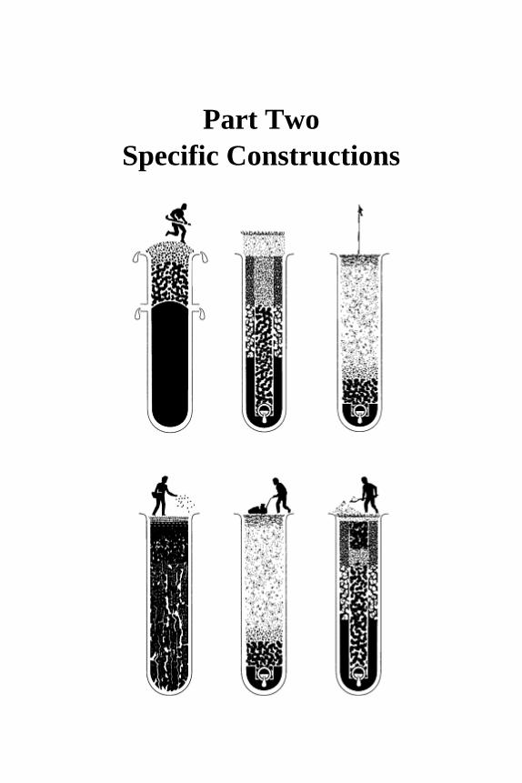
Part Two Specific Constructions


Chapter nine
Introduction to Part Two
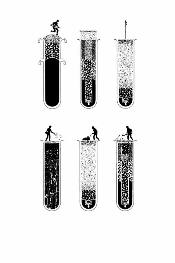

The first step in creating an outdoor sports facility is to provide an acceptable playing surface, isolated, if necessary, by peripheral, interception drainage. The next step is tomake certain that the soil on the playing area can infilter the water required to sustaingrass growth and then discharge any excess in order to maintain an adequately aeratedroot environment and a tractively efficient surface. Finally, when an appropriate grasssward has been established, it must be used and maintained in a manner that will retainthe virtues of the construction for the purpose intended.
9.1 Review of basic principles of construction
9.1.1 Surface configuration
Excess rainfall will tend to accumulate on the surface or within the soil and, given thechance, will run off downhill, more or less rapidly, according as the movement takesplace over the surface or through the soil.
We may take advantage of surface flow as one means of rapidly coping with the sort oftemporary excess that can arise at any time when rainfall intensity exceeds the infiltrationcapacity of the soil. However, the mere fact of surface flow carries with it the possibilityof the moving water accumulating in local depressions unless the surface as a whole is ata sufficient gradient to allow it to keep water moving downhill. This applies also to hardporous surfaces (Chapter 13) and synthetic surfaces. In fact, any sports surface willbenefit from being constructed with either a uniform, cross slope, or some form ofcrowned profile to minimize the risk of ponding, at least within the playing area.
9.1.2 Peripheral interception
Encroachments of surface and/or ground water, originating from sources outwith the site,may have to be located, intercepted and diverted away before work can begin on theproposed playing area. Whether the problem originates from water discharging downhill,off land further up slope, or from the periodic backing up of a ground watercourse,interception is likely to be best achieved initially by peripheral ditching. Though this maybe converted eventually to some form of catchwater drain (Chapter 2, page 23) the initial ditch system should be left open for as long as possible to confirm its effectiveness.
9.1.3 Soil structure and drainage
In British agriculture, the standard excess rainfall for which we make pipe underdrainageprovision is of the order of 1 mm/hr; in sports turf we usually double this figure. Inpractice, discharge rates of this order can be achieved, through soil to pipes at 5–10 m intervals, only if the soil itself is a loamy sand (more than 75% sand), or has an adequate,water-stable, granular structure such as might occur naturally under worm-worked
Sports Turf 188
pasture. The pore sizes required for rapid infiltration are those large enough to be seen by the
naked eye. Pores of this size are formed by particles or aggregates similar in size to thefine sand in sand dunes, but most soils have sufficient silt and clay to fill the pore spacewithin a close-packed arrangement of their coarser particle content. To avoid this a soil would have to be over 70% one grade of sand. Therefore, the rapid passage of excesswater through most soils is dependent on avoiding a close-packed arrangement of the primary particles.
A clay topsoil that has been ploughed and allowed to crack down to a fine blocky tilth,or a loam, stably aggregated by worm casting, may transmit water at the rate of 250 mmper hour—a rate approaching that of dune sand (compare SN15 and SN21, Table 7.1). Such a soil, providing its structure holds up, and providing it can discharge excess waterto an adequate subsoil soakaway, should never be waterlogged.
However, open structure, developed in loams by a combination of root activity,cracking and worm aggregation, is neither strong nor long lasting. It can disperse duringstorage and will fail to regenerate if the soil becomes acid and earthworms are therebyexcluded. It can easily be damaged by wheel traffic and machinery used in construction.It can be poached out of existence by players treading the surface when wet. It cannot bepreserved if the soil is abused at the very time of the year when most agriculturalistswould advise staying off. It is surprising, in fact, that any of our pitches escape beingwaterlogged if they are used when wet in the winter.
In most situations, therefore, the only hope for intensively used grass surfaces is to link the surface directly through to the permeable fill above pipe underdrains by an adequateand reliable system of drainage routes. The aim must be to by-pass any impediment to drainage within the indigenous soil, utilizing an interconnecting system of verticalchannels, stabilized by infilling with appropriate, freely permeable sands and gravels.
9.1.4 Precise specification of sands and gravels used in sports-field construction
Because existing systems of classification used in Britain for specifying sands andgravels are intended primarily to serve the needs of the building industry, it has beennecessary to develop alternative systems for sports turf. One such is the Stewart zone system, summarized in Table 1.4 and, in greater detail, utilizing summation graphs, in section 7.1.6. It is to these materials that reference will be made in the constructions described in the chapters that follow.
In the Stewart zone system a topsoil sand is a material suitable for topdressing and topsoil construction. A blinding sand is suitable for bringing permeable backfill through to the surface over gravel, or for preventing a fine-textured topsoil from infiltering an underlying gravel bed. A trench gravel is suitable for use as the gravel element in a two-part, sand/gravel slit or pipe trench, or for use as the gravel bed in a rafted construction.These are new terms introduced to improve the precision of specifications and theefficiency of the end product.
Introduction to part two 189
9.2 Construction options for sports turf
The main alternative approaches now used for the construction and maintenance ofsports-turf facilities are summarized in Table 6.2. Note the logical consequences that follow for construction and maintenance according as the eco-system established involves the presence or absence of burrowing earthworms. An import-ant consequence of this relationship is that maintenance has to be tailored to the special needs of the typeof construction chosen. All concerned should appreciate what this implies for equipment,manpower and long-term financial commitment, before construction begins.
9.2.1 Preliminaries
Preparatory site work
The initial circumstances of any site may well require some modification before theconstruction of the actual sports-turf facility can begin. The examples presented insubsequent chapters should progress only after the following conditions have beensatisfied.
1. The land does not require any further major grading, and existing slopes are acceptable.
2. The soil, if required to form the topsoil or to accommodate slit trenching, is free of toxins and other noxious materials liable to endanger players or the healthy growth of grass. In addition, the soil is free of buried obstructions that might impede excavations by normal methods of trenching.
3. Full perimeter drainage has been installed to intercept extraneous water likely to reach the site from surrounding land, making the area to be used for playing-field construction an isolated catchment.
Records
As no two situations are alike, details of specifications will vary and may even have to bemodified during the period of construction. Though during such negotiations verbalagreement may appear to have been reached it is important to keep written records,confirmed by both parties. The mere act of committing thoughts to paper can do wondersto clarify the mind and, in case of dispute, such records are often the only tangibleevidence of what was intended. For personal reference it is also a good idea to keep anote of all calculations until the work is completed and handed over.
Sports Turf 190
9.2.2 Options
Apart from sites where a very low limit is placed on financial expenditure, sports-turf constructions nowadays tend to take one of two main alternative routes: a slit drainagesystem capped by a shallow or deep layer of sand, or a sand soil rafted over a drained,gravel bed. The former is more generally adopted for the coarser turf surfaces used forthe more rigorous, winter games; the latter for the fine-turf surfaces on which the impact and roll of a small ball is a crucial part of the game.
With coarse turf, earthworm activity should be encouraged for its beneficial effect onthe incorporation of organic residues, drainage, deep rooting and nutrition. With fine turf,surface casting of earthworms can be a problem, particularly on the specially groomedsurfaces used for golf and bowls, but also, though to a lesser extent, cricket and hockey.
If the soil-conditioning activities of earthworms are excluded their beneficial effectsmust be achieved some other way. Much can be done by constructing the soil of sand andby very careful maintenance aimed at combating the inevitability of mat developmentwhich, in turn, will increase the risks of shallow rooting, desiccation, disease and insectpests. It is important for players as well as greenkeepers always to keep in mind that on amatted surface there may be nothing left from which natural regeneration can occur if adislodged divot is not immediately heeled back into place.
Low-budget constructions
An expensive construction may not be necessary if a site is selected which has a naturallyfree-draining soil and the users are prepared both to adapt their requirements to what isavailable and make arrangements to avoid casual use. Thus a worm-worked pasture with a modest drainage scheme may be developed for use by juveniles, or by adults when dryenough not to cut up, and not be very demanding on maintenance. On the no-earthworm side, providing the area is not large and can be adequately sloped to clear excess water bysurface run-off, a cheap but adequate playing surface can be created for crown bowls, orfor putting greens on a low-budget golf course with modest ambitions. However, the standard of maintenance will still have to be high to counteract the inevitable tendencyfor the surface to become organically matted.
Good quality coarse-turf surfaces for winter activities
A soil surface, drained vertically through sand/ gravel slits, linked for discharge to pipeunderdrains, may acquire a progressively deeper sand cap by successive topdressingsapplied annually. Alternatively it may be carpeted initially by a deep (e.g. 100-mm (4-in)) layer of ameliorated sand. Crucial to the long-term success of a standard slit system is themaintenance of the permeable link right through to the surface. With the sand-carpeted alternative the permeable link is assured, but there is then a further problem of keepingthe sward rooted through the sand carpet to benefit from the water and nutrient reservesin the underlying soil.
The sand carpet option provides such a reserve of readily available water storage
Introduction to part two 191
capacity that the risk of surface ponding is virtually eliminated. However, the extra sandrequired greatly increases the cost and does not reduce the need for further increments ofsand to be applied during maintenance (section 6.3.1). Where finance is limited, therefore, the100-mm (4-in) depth of sand in the carpet might better be regarded as a 20-year reserve of sand to be used for progressively building a sand-dominated surface by sand topdressings applied annually.
Good quality, fine-turf surfaces for flat rink bowling greens, golf greens and croquet lawns
The sand soil rafted over a gravel drainage bed represents by far the most expensiveapproach to construction, and though it might benefit from earthworm activity when usedfor a large area such as a soccer pitch, it will normally have to manage without.
The required maintenance is bound to be very demanding. All steps will have to be taken to avoid surface accumulation of organic debris and the attendant problems ofsurface-rooting fungal disease and insect pests. Therefore, due priority will have to begiven to continuous removal of organic debris and regular sand topdressing (Appendix F).
Any water reserve against drought is strictly limited to what can be stored within thefixed depth of the soil layer above the drained gravel bed, and even this can only beexploited to the effective rooting depth. In these circumstances there is no possibility ofany replenishment from below by capillarity from a ground water-table.
A depth of 150 mm (6 in) of root-exploited soil will provide of the order of 25 mm (1in) of available water reserve, starting from the drained state following saturation (fieldcapacity). Water loss per day from a fully grassed surface in summer will range mostlybetween 2½ and 5 mm ( – in) according to weather conditions. A week of hot, dry weather in mid-summer, therefore, is a significant drought and, in a sand soil, when desiccation threatens, any adverse effect is likely to be sudden. With a sand soil perchedover gravel, it is not only necessary to make provision for irrigation, it is necessary alsoto plan ahead how best to use the water supplied. For more specific advice on this subjectsee Chapter 10, page 162.
This type of construction is forced upon those requiring a quick-draining, worm-free, close-mown and smooth surface but, outside the extravagances of professional sport, itcan only be justified for the relatively small, specialized greens required for golf, bowlsand croquet.
Special difficulties involved in providing grass surfaces for hockey, cricket, tennis and horse racing
Hockey, cricket, tennis and horse racing are particularly challenging sports for which toprovide turf surfaces. They fall between the one extreme of soccer and rugby where thepitches can benefit greatly and suffer little from a soil continuously processed byearthworms, and the other extreme of the fine-turf surfaces required for golf and bowlswhere earthworms are unacceptable.
Sports Turf 192
Hockey, cricket and tennis The extensive, smooth surface required for hockey clashes with the fact that the game isplayed at a season of the year when a natural soil needs all the drainage benefit it can getfrom earthworm activity. No wonder that our hockey players turn increasingly to hardporous or synthetic surfaces, where these are available.
Similar conditions are required for cricket outfields as for hockey but, because cricket is a summer game, most County grounds try to get away without the assistance ofearthworms for drainage. However, they are liable to become a sorry sight when theheavens open during a thunderstorm unless slit drained to bypass surface water throughthe compacted soil.
The pros and cons of earthworms on cricket squares are discussed at length in Chapter 12, page 188. The choice is by no means as clear cut as the prejudices of those on eitherside of the argument might suggest.
On cricket squares and tennis courts the conditions required are similar, particularly attop level. Both games need a surface that is uniform, smooth, non-slippery and strong enough to provide the special qualities of true bounce and pace. To achieve all this on agrassed, soil surface not only must the grass tolerate frequent close mowing and remainanchored effectively within a compact soil, the soil itself must have sufficient clay tostrengthen the compact surface against deformation. Thus drainage through surfaces ofthis type can virtually be discounted when prepared for play.
Though the soil requirements for cricket and tennis are very demanding they do not preclude the retention of an earthworm population. Some groundsmen prefer on balanceto keep them because of their beneficial effects on root distribution and in counteractingany tendency towards surface layering. They appreciate that surface casting is a potentialproblem, especially if the soil brought on to the surface is texturally unsuitable for thedevelopment of pace. However, both cricket and tennis require dry surfaces for play andthese are the conditions when casting is minimal and any residual casts can be dispersedeasily by brushing.
Because of the extreme hardness of the ball used for cricket the soil-binding strength required makes a clay content over 25–30% a major objective. If this is a feature of the local soil then the topdressing involved in surface renovation may well be left to theearthworms to provide in their peak phase of casting during the warm, moist conditionsof autumn. But if the local soil is low in clay then a suitably clay-rich topdressing may have to be imported and problems may well arise over poor surface integration whenincompatible materials are allowed to form layers, liable to crack apart on drying(Chapter 12).
These problems also occur on the special courts used for major lawn tennis tournaments but such courts provide an inappropriate model for others to try and emulateas they tend to be used for only two or three weeks each year. Elsewhere a compromiseshould be accepted between the occasional hazard of a bad bounce off an undispersedcast and the work done by earthworms to keep the soil in good condition below ground.As so much is involved in the preparation and maintenance of the special turf surfacesrequired for hockey, cricket and tennis, consideration should be given to the desirabilityof providing alternative, synthetic surfaces to protect the grass surfaces from excessiveuse.
Introduction to part two 193

Horse racing A galloping horse puts tremendous strain on its own legs and on the shear strength of theturf. A soft, giving surface will cushion impact but may leave a hoof-print depression six inches or more deep. A firm surface will benefit forward movement but, if too hard, willjar joints severely on impact.
Judging from the extreme contrast seen in 1967 between the worm-worked soil profile at Newmarket and the worm deficient soil profile at The Curragh, there would appear tohave been no consensus of view at that time in the horse racing world on which type ofsoil is best for horse racing. If the thick turf at Newmarket gave way it would expose avery well granulated soil underneath, excellent for drainage but possibly a little too softto be ideal for traction. At The Curragh, the root-bound mat of unincorporated organic debris would have been like a cushioning layer of foam rubber over the compact mineralsoil beneath. This may have become soggy after heavy rain descended but would haveprovided the house with a shock-free landing and a firm, though turf-shearing, take-off.
We still need to know which of these two very contrasting surfaces the horses preferand how well they do if brought up and trained predominantly on one type of soil ratherthan the other. Only when we know this can we logically advise on the best way toconstruct and maintain a race course.
Sports Turf 194
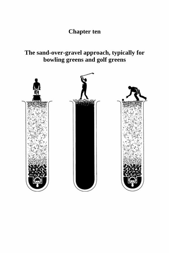
Chapter ten
The sand-over-gravel approach, typically for bowling greens and golf greens

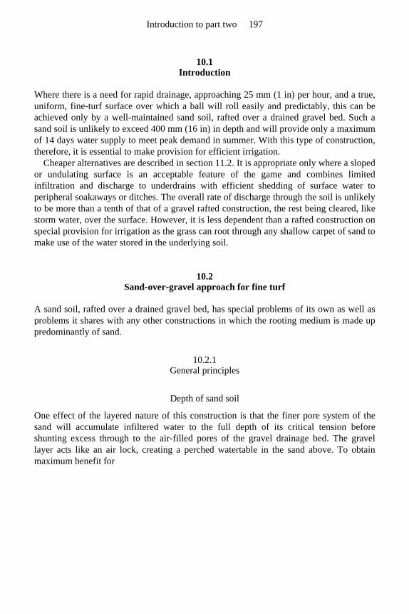
10.1 Introduction
Where there is a need for rapid drainage, approaching 25 mm (1 in) per hour, and a true,uniform, fine-turf surface over which a ball will roll easily and predictably, this can beachieved only by a well-maintained sand soil, rafted over a drained gravel bed. Such a sand soil is unlikely to exceed 400 mm (16 in) in depth and will provide only a maximumof 14 days water supply to meet peak demand in summer. With this type of construction,therefore, it is essential to make provision for efficient irrigation.
Cheaper alternatives are described in section 11.2. It is appropriate only where a slopedor undulating surface is an acceptable feature of the game and combines limitedinfiltration and discharge to underdrains with efficient shedding of surface water toperipheral soakaways or ditches. The overall rate of discharge through the soil is unlikelyto be more than a tenth of that of a gravel rafted construction, the rest being cleared, likestorm water, over the surface. However, it is less dependent than a rafted construction onspecial provision for irrigation as the grass can root through any shallow carpet of sand tomake use of the water stored in the underlying soil.
10.2 Sand-over-gravel approach for fine turf
A sand soil, rafted over a drained gravel bed, has special problems of its own as well asproblems it shares with any other constructions in which the rooting medium is made uppredominantly of sand.
10.2.1 General principles
Depth of sand soil
One effect of the layered nature of this construction is that the finer pore system of thesand will accumulate infiltered water to the full depth of its critical tension beforeshunting excess through to the air-filled pores of the gravel drainage bed. The gravel layer acts like an air lock, creating a perched watertable in the sand above. To obtainmaximum benefit for
Introduction to part two 197
FIGURE 10.1 Moisture profiles in sand soils, on level sites, rafted over gravel. (a) Deeper rooted, less matted turf. (b) Shallow, root-matted, turf. Initially, water applied to the surface of either soil will tend to accumulate to critical tension depth within the range of pore sizes present in the combined topsoil and blinding layers. Only as this layer is filled, to the extent that air entrapment and pore size allows, will excess then be shunted through the large-pore system of the gravel bed and onwards to underdrains. So long as the gravel bed remains sufficiently air-locked to form a capillary break at the sand/gravel interface, water within the critical tension zone of the sand layer will be retained after drainage from the gravel bed has ceased.
Where provision is to be made for sub-irrigation up through the gravel bed, there are advantages to be had from making provision for controlled air-venting from the top of the gravel.
water storage the sand soil should be built up to a height close to three-quarters of its critical tension (to predict, see Chapter 7, page 118). Under these circumstances theconstruction will combine the benefits of an even moisture profile with maximum waterstorage capacity and efficient clearance of excess (Figure 10.1). Too shallow a depth, i.e. half the critical tension of the sand used to form the topsoil or less, will encourage thepersistence of surface wetness after rain, especially in winter, and will not increase thereserve of stored water with which to avoid the ill-effects of desiccation during drought. Though this tendency for surface wetness to persist will assist sward establishment, byencouraging rapid and uniform seed germination, it will do likewise for weeds and moss.Too great a depth of soil over the gravel bed, i.e. a depth greater than the critical tensionof the sand used to form the topsoil, will not increase the water storage capacity butmerely place the stored water reserve further beneath the surface. The surface will thentend to dry off rapidly, becoming loose and difficult for the establishment of new grassfrom seed.
As no natural sand is likely to be formed of particles all exactly the same in size andshape, heterogeneous packing will ensure at least a twofold range in pore size and a
Sports Turf 198
diffuse upper boundary to the water storage zone (see Figure 4.3c where the situation in columns of two different sands is quantitatively described). Soil depth to gravel surface,therefore, is bound to be a compromise, though the critical tension of the sand thatdominates the topsoil will be the main consideration. Other factors will include the need to allow for long-term settlement, the need on some surfaces to incorporate slopes, andthe need to allow for the balance likely to be struck between removals and additions inthe course of maintenance.
Providing for slope
To construct the sloping surfaces required for golf greens and crown bowls there wouldappear to be two variations possible in the sand soil over gravel approach:
1. keep the surface of the gravel bed horizontal and vary both the depth and the character of the overlying soil;
2. incorporate the required undulations in the construction of the gravel bed and then make the overlying soil uniform in character and uniform in depth.
The first option requires the high spots to be created, either by an additional layer of finertextured sand, or by more of the initial fine sand suitably ameliorated with soil. In eithercase the effect will be to raise the level of the stored-water zone, coincident with the elevation of the surface.
The second option will require insertion of vertical barriers of polythene sheet around contours, e.g. at 100 mm (4 in) height intervals, to isolate the zones with potential forwater storage in the elevated areas. Without such barriers water retained in the pore spacewould tend to be dragged away, downslope, leaving the high spots dry.
However, neither approach is likely to be entirely successful without furtheradjustments during maintenance: for example, local modification of the texture of thesurface by careful choice of topdressing, especially when this can be incorporated afterhollow-tine spiking.
Type of sand
As no element of bounce is favoured either in golf or bowls, the sand forming the mineralskeleton of the topsoil should be spherical and of uniform particle size so as to beyielding enough to deaden bounce on impact.
The grade of sand chosen to form the topsoil should fall well within the topsoil sandcategory in the Stewart zone system. If the D K value (Chapter 7, page 118) is close to 0.170 mm, as might be the case for a fine topsoil sand, or 0.220 mm, as might be the case for a medium topsoil sand, then the surface should be built up to 350 mm (14 in) or 270mm (10½ in) respectively. But note, within these overall construction depths the 100 mm (4 in) of blinding sand is likely to be included (Chapter 7, page 120). To allow for long-term settlement the initial depths might be increased by a further 10–20%, according as the initial soil is organic rich and/or unconsolidated.
Despite the old prejudice against using even slightly calcareous sands on fine turf,many fine greens have been created and subsequently topdressed with local dune sand of
Introduction to part two 199
this type; those at Portrush in Northern Ireland and Newquay in Cornwall, being verygood examples. The prejudice against calcareous sands has merit in so far as limeencourages earthworms, but a sudden change in pH upwards may also allow Ophioboluspatch disease to flourish temporarily. This disease seems to behave like an opportunist,flourishing temporarily in an immature soil, or when a sudden change in the chemistry ofthe soil environment upsets the existing microbial community and presents it with anopportunity to flourish. If it does manage to invade then it may give trouble for a fewyears before being subdued again by the longer-term, competitive efficiency of othermicro-organisms.
There is much to be said for aiming at consistency in the sand used for construction and subsequent topdressing. This will avoid both the adverse effects of soil layering andalso any risk of upsetting an established, healthy equilibrium in the biology of the soil.The aim should be to select, at time of construction, sands that are not only cheap and meet the necessary physical requirements but also afford the prospect of long-term availability; keeping in mind the years of topdressing that lie beyond the initial task ofconstruction.
Consolidation during construction
To limit the risk of subsequent settlement upsetting the desired final levels, it is importantto take care over the initial consolidation of the construction layers. This can best beachieved by wetting up from below (section 10.4), but where the necessary facilities for sub-irrigation are not available, settlement may well continue into the first year following construction. Saturated or completely dry sand settles well but moist sand is very stickyand needs a great deal of heeling and prodding to ease the sand particles into a stable,close-packed arrangement. Until this is achieved any surface application of water maylead to the soggy feel of a surface buoyed up by trapped air. It is for this reason that each100–150 mm (4–6 in) layer of sand should be well consolidated before another layer isbuilt on above.
Problems at the perimeter
If, around the periphery, the sand of the green abuts a vertical face of fine-textured soil there will be a tendency for the finer pores in the soil to abstract water from the coarserpores in the sand. To protect against any consequent risk of localized desiccation,consideration should be given to inserting a vertical plastic barrier between the soil andthe sand. This need only extend from just below the surface to the full depth of thesand/soil junction (W in Figure 10.2), but if it extends to the whole depth of theexcavation, it will also protect the gravel bed from the lateral incursion of soil.
Ameliorating the sand
Any soil or organic supplements should not be added in quantities likely to take overphysical control of the medium, i.e. no more than 15% silt plus clay, or 10% organicmatter, both estimated as percentage dry weight. Horticultural lignite can provide a
Sports Turf 200
durable, particulate, organic source which, unlike coal, its harder more fully carbonizedrelative, is not biologically inert and seems to release enough nitrogen and phosphate toencourage root branching in its vicinity. Seaweed meal, and other properly preparedorganic residues, can provide a lush, biologically controlled, wide spectrum, slow releasesource of nutrients, valuable in a sandy medium which is not well endowed withmechanisms for soluble nutrient retention. A good topsoil might appear to be a cheaperalternative but it will be of value only so long as it retains its water-stable, granular structure. In the longer term the granular structure will collapse as the organic bindingagents are dissipated by microbial decay and there are no earthworms to achieve thenecessary restructuring. As a result the fine-particle components will then be free to migrate and may then block the free-draining pore space.
Grassing up
Choosing between direct seeding and turfing For instant, visual effect, e.g. to discourage vandalism, turfing has much to commend it,but in the time taken to achieve a top quality playing surface, there is unlikely to be muchdifference between starting from direct seeding on site and starting from bought-in turf, provided conditions are ideal for establishment either way. The problem with seed is toget rapid, uniform germination, especially on a very sandy soil where there is always theadded hazard of windblow, should the surface be allowed to dry out. Use of pre-germinated seed may shorten the period of anxiety but, having germinated, the seedlingmust not be left to desiccate. Part of the problem with turf is that not only must thespecies be appropriate but so must the soil that comes with it. A loam or organic-rich medium may be excellent for turf production but as a cap over the surface it may
Introduction to part two 201
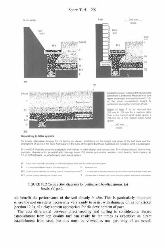
FIGURE 10.2 Construction diagrams for putting and bowling greens: (a) bowls; (b) golf.
not benefit the performance of the soil already in situ. This is particularly important where the soil on site is necessarily very sandy to assist with drainage or, as for cricket(section 12.2), of a clay content appropriate for the development of pace.
The cost differential between direct seeding and turfing is considerable. Sward establishment from top quality turf can easily be ten times as expensive as directestablishment from seed, but this must be viewed as one part only of an overall
Sports Turf 202
construction budget. Loss of income from green fees because of delays in swardestablishment will not help meet the interest payments on a loan. With turf, play maybegin as soon as the sward has been stabilized in place by root anchorage, whether or notthe playing characteristics are ideal. The only proviso is that the remedial actionnecessary to deal with any shortcomings in the playing surface can be carried out by thegreenkeeping staff without undue interference with play: for example, core extractionfollowed by solid-tine spiking to lower high spots caused by uneven settlement, or hollow tine coring followed by sand topdressing to progressively remove an inappropriatecapping of turf soil before it becomes buried, to persist as a drainage barrier underrepeated increments of sand topdressing. There are no short cuts to sward use afterestablishment from seed but, since the character of the soil should be ideal, the initialmaintenance can be concentrated solely on grooming the grass ready for play.
If the club can be persuaded that fine turf used for sport will require some provision for irrigation then it would be as well to install this at time of construction so as to have itavailable during the grassing-up period. It will be invaluable when seeding, not only tohelp initiate uniform and rapid germination and sustain subsequent growth, it will also bethere to stabilize the surface against windblow in the event of drought. With turf, it willbe there to wet up the soil surface before placement of the turves, encouraging rootextension into the underlying soil. It will be there also to keep the turves moist untilanchored against shrinkage. (Bounce variation arising from the shrinkage of new turveson a cricket square is discussed in Chapter 12, page 186.)
Turfing is an expensive option. Where economies are being sought, as with a DIY project, and seeding can be timed to take full advantage of warm, moist conditions, thenseeding is a cheaper alternative. In Britain, after seeding in late August or earlySeptember a good sward can be established before winter and brought into use afterthickening up in the following spring. (Further advice on seeding and working up a swardfor use is given in section 10.3 and 10.5.)
Choice of species The grass species chosen must be predominantly vertical in growth habit above ground,yet tolerant of frequent, close mowing. This could be achieved by a strongly rhizomatous,single grass species but, in Britain, is most commonly sought by seeding up with amixture of suitable varieties of agrostis and fescue.
Recognizing and dealing with the problem of seed size One problem with a fescue/agrostis mixture is that a single seed of fescue is some tentimes larger than a single seed of agrostis so that such a mixture will readily segregatewith agitation to leave the large fescue seed at the top and the fine agrostis at the bottom.This can happen in a seed hopper making it difficult to sow a mixture evenly. If possible,negotiate for the two species to be supplied separately, sowing them evenly in separatepasses, crossing at right angles (page 159).
10.2.2 Management
Some practical aspects of management are also discussed in Appendix F.
Introduction to part two 203
Earthworms
Earthworms must be eliminated from bowling and golf greens as surface casts interferewith play. Therefore, if the soil is to drain rapidly it must consist primarily of sand. Also,without earthworms, there will be no natural agent present to incorporate organic residuesoff the surface. This means that organic debris will have to be removed physically orcliented and buried by regular topdressing, primarily with sand (Appendix F).
Topdressing
Frequent mowing, plus the surface accumulation of organic matter and fertilizerphosphate, will encourage surface rooting. If ignored this will in time make the swardsensitive to drought and intolerant of wear. The essential counter-measures will include scarification, hollow-tine spiking and again, regular application of very sandytopdressings.
Pest control
Any neglect of maintenance that leads to the surface development of a stable, root-bound mat of amorphous organic matter, or a loose accumulation of fibrous thatch, will favourthe spread of the thread-like hyphae of fungal diseases and the root-eating larvae of insect pests.
10.3 Outline specifications for gravel-rafted golf and bowling greens
1. Excavate to form a foundation surface 125 mm deeper than the critical tension of the topsoil sand. For example, 125 mm+350 mm=475 mm (19 in) for a fairly fine topsoil sand intermediate between SN14 and SN15 in Table 7.1, or 125 mm+225 mm=350 mm (14 in) for a medium topsoil sand like SN12.
2. Blind the excavated, soil surface with a synthetic fabric filter, or excavate 30–40 mm deeper and use blinding sand in place of a fabric filter. The aim is to prevent the movement of soil up into the base of the gravel bed.
3. (a) For a bowling green, install a pipe drain of not less than 75 mm (3 in) in diameter in a shallow trench, 150 mm (6 in) wide and 150 mm (6 in) deep, located beneath the perimeter ditch. This should be organized to intercept all water flowing off the surface of the green and out of the gravel drainage bed, Figure 10.2. The pipe should fall at a steady gradient of not less than 1:200, proceeding both ways round the periphery to an outfall pipe at the opposite diagonal. Backfill the trench with trench gravel, tucking the edge of the synthetic filter fabric (if used) down the inner wall of the trench and anchoring with the gravel backfill.
(b) For a golf green, install one or more 150 mm (3 in minimum) pipe laterals in 150 mm (6 in) wide, 150 mm (6 in) deep trenches, linked through to a pipe main for discharge. This system of under-drains should be organized to intercept water
Sports Turf 204
according as it will flow through the gravel bed and discharge to a suitable outfall. If a synthetic filter fabric is to be used io blind the excavated soil surface, slit the fabric along the line of the drain trenches and tuck the spare fabric down, against the side walls, then put the pipes in place and backfill the trenches to the top with trench gravel. Again, a 10 mm layer of blinding sand can be used to blind the surface of the exposed soil in place of a fabric filter, Figure 10.2. Place plastic sheeting vertically around the side walls to prevent the surrounding soil from withdrawing stored water from the sand soil of the green.
4. Spread a 125 mm (5 in) deep carpet of a fine trench gravel, preferably somewhat angular to aid stability, following with 100 mm (4 in) of a fine blinding sand. Firm each layer into place by treading, heeling, raking and making good to appropriate levels. For both materials assume a requirement of 160 kilograms per square metre of surface for a layer intended to be 100 mm deep after consolidation.
5. Spread the topsoil, consisting of topsoil sand plus supplements, to a firmed, uniform, consolidated depth of 250 mm (10 in) or 125 mm (5 in), according as the sand is the fine or the medium topsoil grade. Supplement below 100 mm (4 in) with 2% by weight of horticultural lignite. The top 100 mm (4 in) should contain the full range of supplements listed below under (a). For an approximate estimate of the materials required assume 150 kg of dry topsoil sand per square metre of surface, for a layer intended to be 100 mm deep after supplementation and initial consolidation. Adjust for actual depth and area, then use this total to estimate the weight of each supplement required. When ordering the sand, however, add 5% to allow for wastage. Any excess should be stored under cover and used subsequently for topdressing.
Use one of two methods to mix supplements into the topsoil sand:
(a) Pre-mix batches of sand with supplements off site, using the following weights of supplement per 150 kg dry weight (1 m2) of topsoil sand:
3-4.5 kg low-fibre compost (i.e. C:N ratio less than 30) such as seaweed meal, worm compost, pelleted poultry manure, or composted farm yard manure 4.5 kg horticultural lignite 0.75 kg semi-organic, slow release or pre-seeding type of fertilizer, eg. 7% N: 10% P2O5: 7% K2O. Firm into place by repeated sequences of treading, heeling and raking to re-level, then roll in at least two directions. Throughout the firming process, try to keep the topsoil mixture slightly moist and as little agitated as possible so as not to allow the lighter components of the mix to segregate and rise to the surface. Check that the consolidated depth allows for further long-term settlement, assuming an organic-rich sandy layer may eventually settle a further th of its depth, and sand alone,
th. Make up with additional material, if necessary, and again firm into place before checking levels.
(b) Spread sufficient topsoil sand to raise the surface to a level 100 mm (4 in) short of the final height, and consolidate. Then, spread uniformly over this sand surface the total amount of supplements required to ameliorate the final increment of topsoil sand. If need be, dilute supplements with two to three times their volume of topsoil sand to make it easier to achieve a uniform distribution. Then cover with the amount of topsoil sand calculated to achieve the required final height after consolidation. Use
Introduction to part two 205
a spring-tine harrow, or equivalent subsoiling tine system, to reach through to the buried layer of supplements. Proceeding slowly and with caution, work the supplements up through the sand. Aim at an even mixture, getting under the supplement layer so as to avoid leaving any concentration at depth. Again, do not agitate excessively, e.g. by rotary cultivation, or light materials will tend to accumulate at the surface. Finally, tread, heel, rake and make good to consolidated design level as described in (a) above.
When a stone-free, sterilized topsoil is available with a water-stable, granular structure,and known particle-size composition, this may be used to form the whole topsoil ifsuitably ameliorated with topsoil sand (Appendix 3). The seaweed and fertilizersupplementation will still be required for the top 100 mm but the lignite can be left outentirely. The sand content of the soil can be used to cut down on the requirement fortopsoil sand. For example, if the soil is 25, 50, 75 or 100% silt plus clay this can be mixedin 1:1, 1:3, 1:5, or 1:7 dry-weight, soil:sand ratios, to form a free-draining, loamy-sandmedium no more than 12½% silt plus clay, reducing the requirement for topsoil sand byone half, one quarter, one sixth or one eighth.
6. After the trued and consolidated surface has been thoroughly wetted to a depth of 100 mm (4 in) by rain or overhead irrigation, and when weather conditions look favourable for seed germination, topdress with a low-nitrogen, pre-seeding fertilizer, at about 70 g/m2 (2 oz/sq yd). Seed with a fine-turf mixture consisting of about 80% fescue and 20% agrostis by weight, choosing modern varieties from the scored character list published by the Sports Turf Research Institute, Bingley. Sow a mixture at the rate of 34 g/ m2 (1 oz/sq yd). If the two species can be supplied ready for sowing separately, sow the fescue all in one direction at a rate of 27 g/m2 (¾ oz/sq yd) and the agrostis at right angles, using 7 g/m2 ( oz sq yd). To ensure good soil contact and help the seed to acquire the water necessary for germination, it is better for the seed to be worked into the top centimetre of the sand surface and then firmed into place by rolling. Irrigate if drought threatens to kill off the seedlings after germination has been achieved.
7. When the sward reaches a height of 40 mm (1½ in), roll to firm the soil round the roots. After vertical growth has been restored, top with a sharp mower set to a cutting height of 25 mm (1 in). Continue mowing at 25 mm (1 in), twice a week during the first eight weeks of growth, removing all clippings. After 2–3 cuts, fertilize as recommended for normal maintenance (section 10.5). Gradually lower the height of cut and mow correspondingly more frequently when preparing the surface for play.
10.4 Possibilities for further developments in the gravel bed approach
The gravel bed approach to construction is of special value under arid conditions whereprovision has to be made both for regular irrigation and the leaching away of salts. It canalso find application in the construction of cricket tables, though the benefits of a gravelraft for drainage are much less likely to be required for a game played in summer-time on
Sports Turf 206
a heavily rolled, clay-rich topsoil. The benefits of designs allowing for sub-irrigation through the basal gravel layer have
yet to be fully explored. This approach has great potential to assist on critical occasions.For example:
1. to eliminate air for quick and effective consolidation of sand at construction time; 2. to more effectively saturate before leaching under arid conditions; 3. to ensure uniform seed germination and rapid establishment at time of construction or
during pitch renovation; 4. to assist with cricket pitch preparation when the soil is deeply cracked and surface-
applied water tends to trickle down past the bulk of the soil, instead of invading the clods to wet up evenly;
5. to maintain the exposed sand surface of a badly worn pitch stable for play.
Where provision for sub-irrigation through the gravel bed is contemplated, separate provision must be made for air-venting at the top of the gravel. Without this, trapped air will cause surface disruption if it is forced upwards in large bubbles through the topsoil. As an additional benefit, such an air-venting system will allow the gravel bed to becleared separately after sub-irrigation, leaving the topsoil wet, e.g. to assist with sward establishment from seed.
10.5 Maintenance of fine, worm-free turf
Traditionally, autumn is the time for major renovation work and seeding. Spring is forboosting grass growth and removing weeds. However, completion of club tournamentsoften conflicts with the greenkeeper’s need to begin major renovation work in good time to allow for a period of recuperative growth before all such work must cease for thewinter. The alternative is to pursue a continuous renovation programme throughout thegrowing season, verti-cutting or lightly scarifying, spiking, over-seeding and topdressing a little every month, in harmony with the pattern of growth, rather than accumulatingthese tasks for one major effort in the autumn. Either way the players will be affected but,from the point of view of the sward, there is no doubt that the ‘little-and-often’ approach is preferable, unless arrangements can be made for play to be switched to alternativegreens. Much can be done to limit the extent of any interference with play by makingadequate provision for skilled manpower, efficient equipment, and the supply and safestorage of materials.
10.5.1 Maintenance that should be given priority in the autumn
Timing
As the autumn renovation work may well involve considerable damage to the sward itshould be started early enough to allow for topdressed seed to germinate and establish
Introduction to part two 207
before the onset of winter. In England and Wales the growing season, as dictated bytemperature, normally continues at sea level until the end of November, but withincreasing altitude, growth is liable to slow down progressively earlier, stopping beforethe end of October at 300 m (1000 ft). For topdressing with fine sand, however, dry sandand a dry surface are essential and generally this cannot be relied upon after September,except in the drier east. For these reasons autumn renovation work should be organizedfor completion during September. At an altitude of 300 m (1000 ft), or in Scotland, or thewetter northwest of England, a start should even be made as early as late August.
Scarification and spiking
Nitrate, ammonium and phosphate ions all stimulate root branching and even do so whenpresent as constituents of decomposing organic matter. Thus, any soil allowed toaccumulate organic debris at the surface will encourage shallow rooting, quite apart fromfostering surface wetness, disease, insect pests, and slowness of pace in a rolling ball.
It is inevitable where earthworms are absent that organic matter will tend to accumulate on the surface of the soil. Initially this will form a loose thatch of leaf debrisbut will subsequently settle down to form a root-bound mat. Therefore, steps to counteract this inevitable trend are essential in the worm-free conditions that we have to live with in our bowling green and golf green soils.
It would be best to look upon the sward-grooming procedures, carried out during themain playing season to improve the playing performance, as also contributing to lessthatch accumulation. These are combing, brushing, wire raking, verti-cutting and light scarification. Verti-cutting should be aimed primarily at cutting vertically through the living tissue that escapes horizontal mowing by sprawling and should be carried outroutinely throughout the growing season, e.g. at least once/month. Light scarificationshould be considered at best, as a crude form of verti-cutting that can be used to scratch through into the skin of organic debris that clings close to the soil surface as the thatchsettles down. Light scarification, to be effective, must reach through to disturb this water-proofing skin, just scoring the surface of the mat layer. Deep scarification, by contrast,should be confined to major renovation work carried out in the autumn and may involveup to four passes in different directions. (On a cricket square it is vital to remove all theyear’s accumulation of thatch so that the clay-loam topdressing, required for the promotion of pace, can integrate directly with a mineral surface. Thus scarification on acricket square can involve up to eight passes in different directions and considerablesward damage requiring subsequent re-seeding to repair.)
Solid-tine spiking or slitting are procedures used mainly with the aim of relieving soil compaction but with very mixed consequences. Unaccompanied by surface heave theycan do no more than re-distribute the existing pore space. Carried out repeatedly they are liable simply to transfer any problem of compaction one stage lower. These proceduresshould not be carried out routinely, but with discretion, primarily to help with therenovation of a matted surface or to help with the infiltration of irrigation water and theincorporation of phosphate-rich fertilizers, seed and sand. Gentle pricking of the surfacewith a spiked Sarel roller to disturb and bypass any developing skin of thatch can helpwith aeration and surface water infiltration.
Sports Turf 208
Hollow-tine spiking is typically the autumn procedure used curatively for long-term and accumulating benefit below ground. Ideally, this should be carried out annually,including the early years immediately after construction. The aim is to progressivelyremove more of each year’s increment of root-bound mat, allowing it to be diluted with sand as it sinks within the profile, keeping the subsoil free-draining. On any green, the extraction of cores is necessary where a layer has been allowed to develop which isadversely affecting drainage. However, it can be effective only to the depth of tinepenetration, and then much will depend on the nature of the soil beneath. At worst it willmerely ensure that a buried, organic layer is helped to remain wet and anaerobic byhaving surface water diverted directly into it rather than through it. As with all otherprocedures, check to see that you have achieved what you intended. (See also Appendix G.)
Fertilizing
Spiking or slitting will open the surface to allow, first fertilizer, and then fine sand topenetrate. The autumn fertilizer should be low in nitrogen but high in phosphorus andpotassium. Nitrogen (N) promotes lush growth, highly desirable in spring but too proneto frost damage and disease to be encouraged in the autumn. Potassium ions (K+), though retained by clay-rich soils, are liable, like the ammonium and nitrate ionic forms of fertilizer nitrogen, to be lost by leaching through free-draining, sandy soils. It could well be added, little and often, throughout the growing season and is applied in theautumn because of its value for promoting a degree of frost tolerance. All forms offertilizer phosphorus are so poorly soluble when added to soil that they persist whereplaced and can be applied in large annual or biennial increments. This should be doneafter the soil surface has been cleared by scarification and opened up by spiking to allowincorporation, and when subsequent sand topdressing will ensure burial beneath the newsurface.
A suitable, elemental, N:P:K ratio would be 4:7:7, or when expressed as N:P2O5:K2O (unfortunately also casually referred to as the NPK ratio) would be 4:16:8. There is noreal advantage in every year using an organic carrier such as peat; most fine turf swardssuffer from excess surface organic matter, not a deficiency. The aim during applicationshould be to work this autumn fertilizer off the surface into the spike holes. Left on the surface, the insoluble forms of fertilizer phosphorus will stay there to stimulate surfacerooting. Buried it will encourage root branching at depth; 35 g/m2 (1 oz/sq yd) being sufficient.
Sand topdressing
Topdress the scarified, cleaned-up and fertilized surface with an approved sand, at something like 4 kg/m2 (7 lbs/sq yd) if this is tackled only once a year. The purpose is to bury the fertilizer phosphorus, bury any residual organic debris, bury roots and re-true the surface. The sand, especially for the bounce-deadening character required of golf greens, should be fine and, normally, lime-free. It should be of a uniform particle size, like a plasterer’s sand, and the particles should be rounded rather than the sharply angular and
Introduction to part two 209

coarse material preferred by horticulturalists for potting composts. For bowls theserequirements can be relaxed a little as a firm surface would not be unacceptable.
All of this will help to provide an open, yielding surface for rapid drainage and fastpace rather than a surface that may settle to become rigid and fiery, encouraging bounce.Choice of sand, therefore, is vital and doubtful samples should be sent for testing beforeapplication.
Pace is a matter of sward composition, vertical growth, mowing height, surface dryness and the absence of the spongy effect caused by a surface mat of thatch and superficialroots. The holding character required to stop a golf ball, that is pitched high on to thegreen, is better sought by proper maintenance and correct choice of sand than by thesogginess of a dampened mat. For application, the sand should be perfectly dry or, whenbrushed, it will smear over the sward instead of working into the base. Ideally it shouldbe applied dry, onto a dry surface, systematically metered out in appropriate sized heapsand then luted into the base of the sward. The wider the lute the better as it will act as astraight edge to scrape sand off the high spots and leave extra in the hollows, sosmoothing out local irregularities. This will make close mowing possible withoutscalping, discouraging the spread of moss and truing the roll of the ball. A 3 m (10 ft) lutewould not be unduly wide for a flat bowling green but a drag mat or smaller lute will berequired to accommodate the gentle undulations that are a desirable feature of a golf, orcrown bowling green. Roll to consolidate.
The emphasis on sand as a topdressing is deliberate. It may be modified occasionally by the inclusion of a low fibre compost, such as milled seaweed, or a durable, particulateform of organic matter, such as a fine (less than 2 mm) grade of crushed lignite. This willbecome necessary if the zeal of the greenkeeper in scarification and sand topdressingleads eventually to a topsoil so raw and sandy as to be organic deficient.
After topdressing, the green will appear to be a sea of sand, but a shower of fine rain oran equivalent irrigation, will settle the sand and allow the grass to show through. On noaccount should the sward be left buried under a complete covering of sand or it will besmothered. For this reason, topdressing with sand should never be left so late that soilconditions are too wet, and the temperature too low, for recuperative growth.
Disease, worms and insect pests
Where drainage is good, irrigation not overdone, appropriate grasses sown, thatchremoved and luxury uptake of nitrogen avoided, as much as possible will have been doneto avoid undue trouble from the competitive efforts of disease and pest organisms.Thereafter, specific, early, curative treatment should follow clear visual evidence oftrouble, using spot treatments when the symptoms are well defined and localized.
For close mown, fine turf, earthworms, unfortunately, must be excluded. Normally this is an inevitable consequence of the removal of clippings limiting their food supply, andthe acid conditions that develop in a noncalcareous, sand soil, leached by high rainfalland acidified by the application of fertilizers containing sulphur. In addition they willhave been killed by many of the chemicals used against pests and diseases, e.g. benomyl(as in Benlate), thiophanate-methyl (as in Mildothane), and malathion (as in Malathion 60). In special circumstances, generally where lime in the sand keeps the soil pH up,
Sports Turf 210
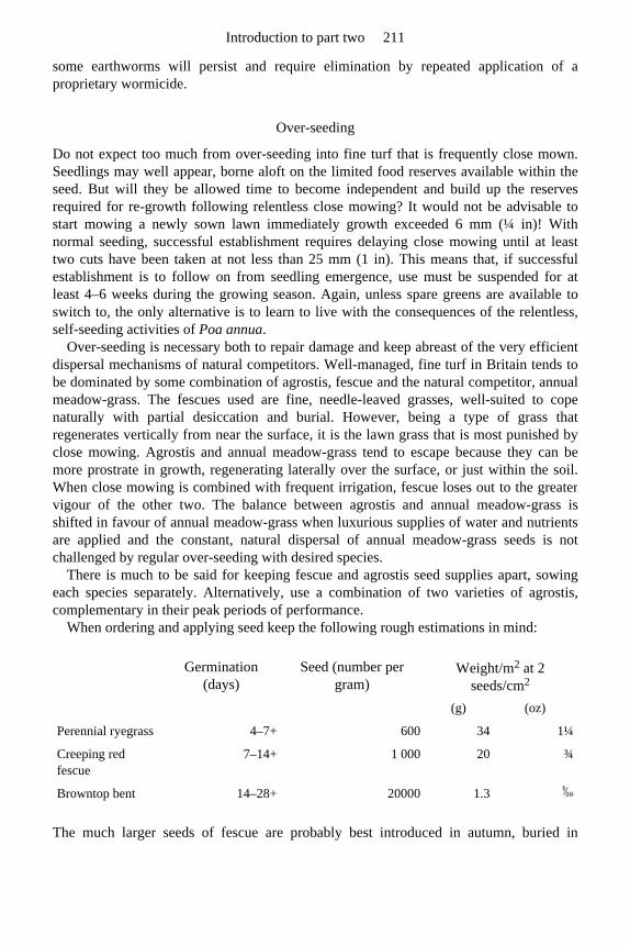
some earthworms will persist and require elimination by repeated application of aproprietary wormicide.
Over-seeding
Do not expect too much from over-seeding into fine turf that is frequently close mown. Seedlings may well appear, borne aloft on the limited food reserves available within theseed. But will they be allowed time to become independent and build up the reservesrequired for re-growth following relentless close mowing? It would not be advisable to start mowing a newly sown lawn immediately growth exceeded 6 mm (¼ in)! With normal seeding, successful establishment requires delaying close mowing until at leasttwo cuts have been taken at not less than 25 mm (1 in). This means that, if successfulestablishment is to follow on from seedling emergence, use must be suspended for atleast 4–6 weeks during the growing season. Again, unless spare greens are available toswitch to, the only alternative is to learn to live with the consequences of the relentless,self-seeding activities of Poa annua.
Over-seeding is necessary both to repair damage and keep abreast of the very efficient dispersal mechanisms of natural competitors. Well-managed, fine turf in Britain tends to be dominated by some combination of agrostis, fescue and the natural competitor, annualmeadow-grass. The fescues used are fine, needle-leaved grasses, well-suited to cope naturally with partial desiccation and burial. However, being a type of grass thatregenerates vertically from near the surface, it is the lawn grass that is most punished byclose mowing. Agrostis and annual meadow-grass tend to escape because they can be more prostrate in growth, regenerating laterally over the surface, or just within the soil.When close mowing is combined with frequent irrigation, fescue loses out to the greatervigour of the other two. The balance between agrostis and annual meadow-grass is shifted in favour of annual meadow-grass when luxurious supplies of water and nutrients are applied and the constant, natural dispersal of annual meadow-grass seeds is not challenged by regular over-seeding with desired species.
There is much to be said for keeping fescue and agrostis seed supplies apart, sowing each species separately. Alternatively, use a combination of two varieties of agrostis,complementary in their peak periods of performance.
When ordering and applying seed keep the following rough estimations in mind:
The much larger seeds of fescue are probably best introduced in autumn, buried in
Germination (days)
Seed (number per gram)
Weight/m2 at 2 seeds/cm2
(g) (oz)
Perennial ryegrass 4–7+ 600 34 1¼
Creeping red fescue
7–14+ 1 000 20 ¾
Browntop bent 14–28+ 20000 1.3
Introduction to part two 211
coreholes or slits and under sand topdressing to ensure good seed/soil contact for theabsorption of water. Agrostis seed, being very small and having a very limited foodreserve, should not be buried deep, merely pressed into the surface at any time during thegrowing season when the soil can be maintained moist (e.g. by covering and/or irrigating)until germination is achieved.
As Poa annua seeds all the year round, even at close-mowing height, and does not require burial to germinate, it is exceptionally well equipped to invade any bare spots.The challenge, therefore, is to ensure that there is always some agrostis seed in place tocompete. Hence, there is potentially some virtue in including at least some agrostis seedwith all sand topdressings applied during the growing season.
A new development which promises to greatly assist sward repair and establishmentfrom seed is the recent appearance of dry, pregerminated seed. This offers the possibilityof uniform germination in four days without the difficulties associated with handling wet,pregerminated seed. The dry, pre-germinated seeds can be stored after treatment for many weeks, without loss of viability and, except for appearing to be at some risk from residualeffects of herbicides such as paraquat, can be sown in the same way as ordinary seed. Theextra cost of the pre-germination treatment can be off-set against the possibility of a reduced seeding rate because of the rapid, more uniform germination.
For equal numbers of seeds per unit area, the weight of fescue seed required is ten times that of agrostis. When uniformly spread, 1 g/m2 of agrostis is equivalent in seeding rate to 10 g/m2 of fescue, each providing six seeds per square inch (6.5 cm2). Use this information to adjust seeding rate to visual evidence of need. For example, making agenerous allowance for the practical difficulties of achieving a perfect distribution, try ½g/m2 of agrostis seed (approximately 1 oz for an area 4 yards by 4 yards) mixed into each sand topdressing applied during the growing season. Alternatively, apply separately eachautumn 1 g/m2 of agrostis and 10 g/m2 of fescue (approximately 1 oz and 10 oz respectively for an area 6 yards by 6 yards.
Instant repair of localized sward damage
Fuel spillage, animal urination, mower scalping, weed removal, etc. may cause localizeddamage requiring instant repair by turf replacement. This points to the value of a smallarea of turf nursery on site, conveniently located where the soil, sward and maintenancecan replicate that on the green. A neatly cut, 50–100 mm (2–4 in) deep, stable, turf patch can then be instantly inserted, using a turfing iron or, where a core 108 mm (4¼ in) in diameter will suffice, a golf hole cutter.
Summary
The normal autumn renovations should proceed in the following sequence: mowing,scarification, removal of debris; spiking or hollow-tining plus removal of cores; over-seeding and fertilizing; sanding, brushing and luting to level out and integrate; irrigatingif necessary to finally settle in.
Sports Turf 212
10.5.2 Priorities for maintenance in spring and summer
Timing
Soil temperature dictates the onset of growth in spring and, apart from maintaining gooddrainage, the greenkeeper can do little about this. In general, growth starts about the thirdweek in March but may be a week earlier in the south of England and at least a week laterin the north. However, altitude can have a marked local effect. At 1000 ft (300 m) theonset of growth may be delayed for an additional three weeks, until the middle of April.Therefore, there are special difficulties for maintenance at altitude, both in the autumnand in the spring, and due allowance should be made for this in the late recovery of thegreens.
To enable some account to be taken of variations in season from year to year, it is worthwhile installing a soil temperature recording thermometer in an area of maintainedsward free from vandalism. In general, a soil temperature of 8°C (46°F) at 25 cm (10 in) depth can be taken to indicate the start of the growing season. However, beware falsesprings and delay the application of seed and fertilizer until soil temperature reaches theorder of 10°C (50°F) at 25 cm (10 in), when growth really begins to take off (Appendix A).
Scarification
According to the amount of grass growth and mowing over winter, there may be someneed to clean out the base of the sward and lift any sprawling horizontal shoots. Use ascarifying wire brush or verti-cutting mower to clean the surface top without penetrating the soil before fertilizing to promote new vertical growth in the spring. Deep scarificationwould not be advisable in the spring as the dry conditions of summer will discourage thehealing over of any score lines.
Weed and moss control
Spring is the best time to weed kill as some weed killers damage young grass and, in anycase, weeds are most susceptible when new leaves are exposed and the growth is thin-walled and lush. The grass, when growing vigorously, will rapidly fill in. The same canbe said for moss killing though moss should not be there if maintenance and managementare correct. Moss has no true roots and cannot compete; it can only fill in where damagesuch as tear wear or scalping has been caused and no immediate steps have been taken toachieve the necessary repair.
If certain weeds continually reappear consideration should be given to the possibility that these may originate either in the topdressing, Spergularia (Sandspurrey) being typical of dune sand, or in worm activity re-cycling buried, viable seeds from theunderlying soil.
Introduction to part two 213
Fertilizing
The spring fertilizer should mainly be nitrogen to promote green growth. On very sandymedia, however, potassium which, like nitrogenous fertilizers, is highly soluble and veryprone to leaching, should also be regularly applied during the growing season. A suitablenitrogen (N) to potassium (K) ratio would be 12:8. When expressed as nitrogen(N):potassium oxide (K2O) this becomes a ratio of 12:9. Apply on three or four occasionsbetween the end of March and mid-August, using a rate of 35 g/m2 (1 oz/sq yd) on each occasion. Do not apply in dry weather.
Avoid fertilizers that include much phosphorus during the growing season if theycannot be incorporated by burial. The buried autumn application will persist to carry thesward through.
Sand topdressing, light scarification and/or verti-cutting
With adequate staff and the facility to put greens temporarily out of use, topdress with 1kg/m2 (2 lbs/sq yd) of topsoil sand on each occasion after fertilizing during the springand summer. This will cut down the need for a large autumn application. A policy oflittle-and-often is to be preferred. As already indicated, it would be advisable to use these occasions to include the recommended over-seeding with agrostis.
Prior to application, ‘prick-spike’ and recondition the turf surface with a verti-cutting mower or a wire brush type of scarifier to remove thatch. This will also provide a betterseed bed and help any topdressing to integrate with the existing soil. However, as in thespring, do not cut into the soil as any desiccation will cause the cut to open up and persist,upsetting the true roll of a ball.
Prior to mowing, always give consideration to grooming. That means not just verti-cutting but combing and brushing to lift thatch or sprawling grass up to mowing height.For best effect, and certainly when preparing for a tournament, these operations should berepeated in two directions, each time finished off by mowing.
Mowing
Mowing should never be so low as to scrape the surface and should never involveremoval of more than ⅓rd of the grown height. Since growth may easily achieve 25 mm (1 in) per week at the peak of the growing season this means that a maintenance height of6 mm (¼ in) can only be achieved, without weakening the grass, if cut each day, i.e. after3 mm (⅛ in) of growth. This certainly applies during May, June and July. Removal of more than ⅓rd of the grown height cuts into reserves required for tillering or vigorous regrowth and most certainly affects the vigour of the vertical-growing grasses, in particular, fescue.
Cutting daily at 3 mm (⅛ in) should be considered only for special tournaments, andthen, only if the mower is perfectly set and the surface sufficiently smooth to avoid anyrisk of high spots being scalped. Severe mowing, i.e. close mowing at infrequentintervals, will weaken the sward and encourage the invasion of moss. Far better to
Sports Turf 214
concentrate more time on grooming and increased frequency of mowing rather than lowerthe height of cut.
Where close mowing cannot be achieved without some spots being scalped and othersbeing left too lush, steps should be taken steadily to improve the grading of the surface.High spots can be progressively lowered by extracting cores with a hollow-tine fork and not filling back with topdressing. Low spots can be raised by selectively topdressing orby turves being undercut and folded back to allow for extra sand to be inserted below.
Good equipment, skilfully used and properly maintained, is essential. Nothing is moredisastrous to the sharpness of a mower than mineral matter sticking to the grass at cuttingheight. This risk is most severe after scarification and sand topdressing, especially ifregular increments of fine sand are applied during the growing season, following eachapplication of fertilizer. However, trouble can be avoided, both from the sand, and fromthe fertilizer scorching in dry weather, if these various topdressings are washed into thebase of the sward by irrigation.
Irrigation
Facilities for irrigation are of value but should only be used to thoroughly soak atinfrequent intervals. That is to say, it should only be used for the benefit of the grass toavoid desiccation, to wash in fertilizer or to settle in a topdressing of sand. It should beregarded as an aid to maintenance and should never be controlled by players seeking toinfluence the pace of the greens. Little-and-often irrigation onto a dry soil will encourage shallow rooting and make the sward particularly sensitive to drought, disease and limitednutrient supply. However, little-and-often can be justified if started before the soil hasdried out in depth. This should keep the whole soil moist and, although such a moistregime will encourage annual meadow-grass and discourage fescue it will not promotesurface rooting, nor risk ‘dry patch’ (section F.3) and desiccation.
A viable compromise between these two extremes is to delay irrigation until there is amarked fall in the clippings harvest when mowing. Such a growth check during thegrowing season indicates that the moisture deficit, though still well short of wilting point,when death would occur, has reached the stage when cell enlargement and, therefore,growth is affected. At this point, irrigate to re-wet the top 50–75 mm (2–3 in) of the soil by 5–6 applications of 2–3 mm ( in), stopping only long enough between applications toprevent surface flooding leading to wasteful runoff. Supplement with a wetting agentwhere there has been a history of dry patch problems. Thereafter, until the drought isbroken, apply a single application of 2–3 mm ( in) daily to replenish at about the average, daily rate of evapo-transpiration loss in summertime. This approach will not discourage deep rooting or the maximum exploitation of the pace potential of a drysurface. What is vital is the skill to recognize the growth-check symptom and the ability then to react appropriately. With the advent of simple probe moisture meters this couldnow be more easily monitored.
Introduction to part two 215

10.5.3 Note for home-lawn owners
Too often the home-lawn owner gets carried away with the immaculate appearance of the sward on the local bowling green or golf green and jumps naively to the conclusion thatthis is all a consequence of choosing the correct seed mixture, fertilizing, lowering theheight of cut and removing all clippings. It is not always appreciated how devastating isthe effect of mowing at 6 mm (¼ in), just once a week, or, worse still, once a fortnight. This alone leads to weak growth of grass, loss of fescue and, in the absence ofearthworms, infill by moss, annual meadow grass and Yorkshire fog plus, withearthworms, daisies, plantains, and a wide range of other broad-leaved weeds. Most week-end gardeners would do better to maintain a sharp mower, raise height of cut to 25–35 mm (1–1½ in), and allow clippings to fly when they are fine enough not to smother. Then, in addition, lime, fertilize and weed kill in moderation, welcoming the assistancethat earthworms can give with drainage, incorporation of organic residues and efficientroot exploitation of the soil in depth (section 11.4).
Sports Turf 216

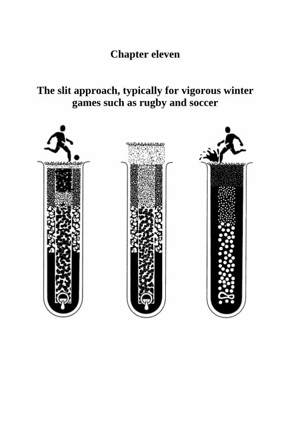
Chapter eleven
The slit approach, typically for vigorous winter games such as rugby and soccer


Winter use of natural turf for sports requires the surface to remain tractively efficient throughout the time of year when, in Britain, weather conditions are far from favourable.Because temperatures are low the grass growth is minimal, and because rainfall muchexceeds evaporation the shear strength of the turf is threatened by physical damage to thegrass and excessive wetness in the soil. To withstand the severe wear that vigorous playwith studded footwear can cause, the sward must enter the playing season thick at thebase and deeply rooted. Damage to the grass will tend to accumulate until repair by re-growth becomes possible the following spring. When conditions are not ideal therefore,the need for damage limitation may require discretion in use. Of the things we can do tohelp, efficient soil drainage should be regarded as the top priority.
11.1 Sand/gravel slits under coarse turf
11.1.1 Function
A slit system is merely the sports-field equivalent of the mole-assisted pipe system used in agriculture (Chapter 2, page 28). However, in sports turf, because we are working with a permanent sward not subject to periodic ploughing and re-seeding, the mole drainage approach can be made more efficient by concentrating and stabilizing the vertical slitwith permeable fill—top half sand, bottom half gravel.
As the first task of a sand/gravel slit system is to intercept excess rainfall that wouldotherwise pond on the surface, the permeable fill must be brought right through to thesurface. To maintain the infiltration routes clear, the top must be kept sandy, either byregular
Sports Turf 220
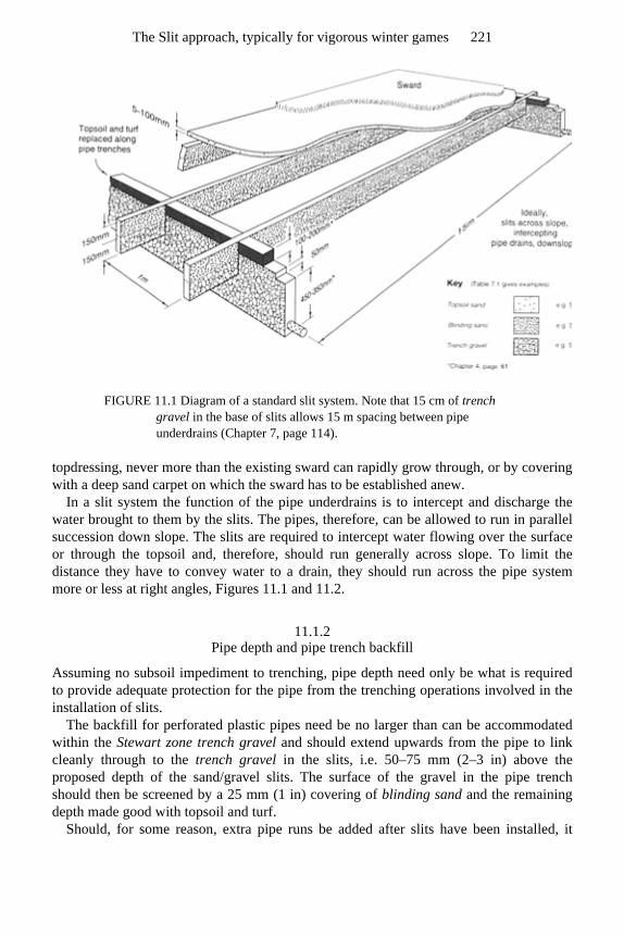
FIGURE 11.1 Diagram of a standard slit system. Note that 15 cm of trench gravel in the base of slits allows 15 m spacing between pipe underdrains (Chapter 7, page 114).
topdressing, never more than the existing sward can rapidly grow through, or by coveringwith a deep sand carpet on which the sward has to be established anew.
In a slit system the function of the pipe underdrains is to intercept and discharge the water brought to them by the slits. The pipes, therefore, can be allowed to run in parallelsuccession down slope. The slits are required to intercept water flowing over the surfaceor through the topsoil and, therefore, should run generally across slope. To limit thedistance they have to convey water to a drain, they should run across the pipe systemmore or less at right angles, Figures 11.1 and 11.2.
11.1.2 Pipe depth and pipe trench backfill
Assuming no subsoil impediment to trenching, pipe depth need only be what is requiredto provide adequate protection for the pipe from the trenching operations involved in theinstallation of slits.
The backfill for perforated plastic pipes need be no larger than can be accommodated within the Stewart zone trench gravel and should extend upwards from the pipe to linkcleanly through to the trench gravel in the slits, i.e. 50–75 mm (2–3 in) above the proposed depth of the sand/gravel slits. The surface of the gravel in the pipe trenchshould then be screened by a 25 mm (1 in) covering of blinding sand and the remaining depth made good with topsoil and turf.
Should, for some reason, extra pipe runs be added after slits have been installed, it
The Slit approach, typically for vigorous winter games 221
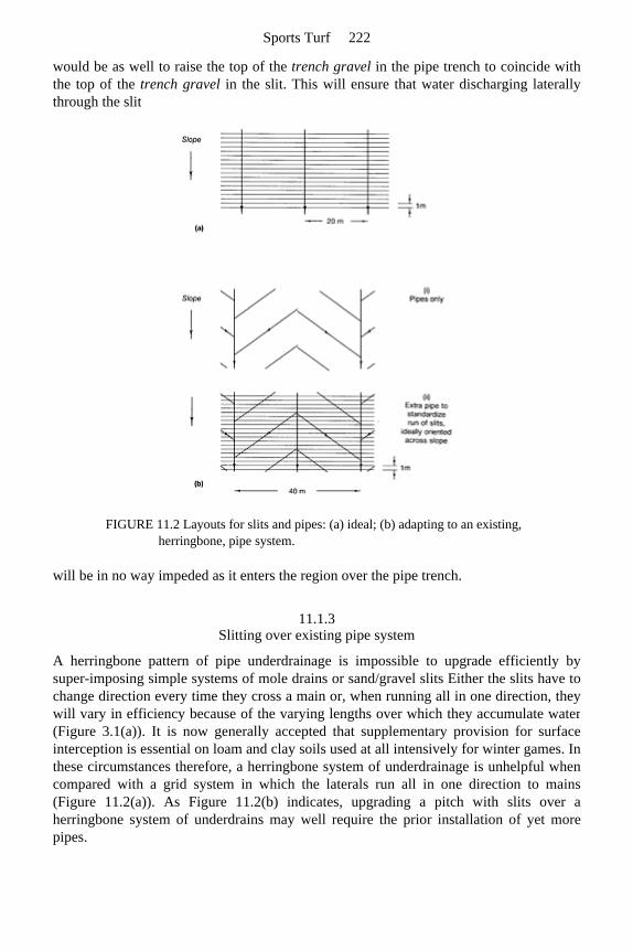
would be as well to raise the top of the trench gravel in the pipe trench to coincide with the top of the trench gravel in the slit. This will ensure that water discharging laterallythrough the slit
FIGURE 11.2 Layouts for slits and pipes: (a) ideal; (b) adapting to an existing, herringbone, pipe system.
will be in no way impeded as it enters the region over the pipe trench.
11.1.3 Slitting over existing pipe system
A herringbone pattern of pipe underdrainage is impossible to upgrade efficiently bysuper-imposing simple systems of mole drains or sand/gravel slits Either the slits have tochange direction every time they cross a main or, when running all in one direction, theywill vary in efficiency because of the varying lengths over which they accumulate water(Figure 3.1(a)). It is now generally accepted that supplementary provision for surfaceinterception is essential on loam and clay soils used at all intensively for winter games. Inthese circumstances therefore, a herringbone system of underdrainage is unhelpful whencompared with a grid system in which the laterals run all in one direction to mains(Figure 11.2(a)). As Figure 11.2(b) indicates, upgrading a pitch with slits over a herringbone system of underdrains may well require the prior installation of yet morepipes.
Sports Turf 222
11.1.4 Sand-capping the surface
Anyone installing slits should be forewarned of the need to take measures to counteractthe inevitable tendency for soil to cap over the surface. Sand and gravel in slits willrespond differently to repeated cycles of wetting and drying compared with the adjacentsoil. The end result is that the level of the sand and gravel in the slits progressively sinksrelative to the soil and, if the sand level is not maintained by topdressing, the soil willeventually seal over the surface (see the sequence in Figure 6.1). It is essential, therefore, that a slit-drained surface be protected from the start by an adequate, overall capping of sand. This may involve either a substantial topdressing repeated annually, or a deepcarpet of 75–125 mm (3–5 in) depth on which a new sward will have to be established. Alternatively, provision will have to be made for some form of regular, repeat micro-slitting, as described in Chapter 2, page 43.
11.1.5 Upgrading the original soil surface before carpeting with sand
A sand-carpeted, slit-drained pitch will generally stand up well to intensive use, both inwet and dry conditions, but there have been instances where the quality of the sward hasdeteriorated, particularly in response to drought. This may arise where there is a lack ofsufficient root penetration into the soil beneath the sand carpet.
Such a problem can originate in the sand having been laid directly over a made-up or degraded soil surface; for example, a soil without a satisfactory initial structure or anearthworm population capable of developing the structure that is so essential for a healthyrooting environment. As a result, the effective rooting medium is no more than the sandcarpet itself, which may soon become exhausted of its initial organic and chemicalsupplements and will be very limited in its water reserve. Though the original soil surfacein a sand carpet construction is to be buried out of sight, its quality should not be ignored.The long-term viability of the system depends on its biological vigour.
Therefore, before capping the surface with sand, consider what long-term advantages are to be gained from either of the following soil treatments carried out prior to slitting:
1. mechanical action to relieve soil compaction; 2. incorporation of lime and phosphate to counteract any acidity unfavourable to
earthworms and encourage invading roots to proliferate by branching; 3. delay for a year before proceeding to slitting so as to superimpose a minimum of 100
mm (4 in) of fresh, good quality topsoil, after the installation of the pipe drains. This would also entail raising the level of the top boundary of the gravel in the pipe trenches by an extra 100 mm (4 in), and establishing a temporary sward to re-stabilize the surface before starting the slitting operation.
The Slit approach, typically for vigorous winter games 223
11.1.6 Grassing up
The working-up period after seeding a new construction can be difficult. The contractor may be given the responsibility for the establishment of the sward but will be unhappyabout keeping men hanging about to ensure that all the necessary small operations arecarried out at the right time for maximum benefit. The local authority maintenance teamwill already have a full schedule of routine work and may be disinclined to take on anadditional commitment amounting to the medical equivalent of a period of intensive care.
In dry weather the establishment of a grass sward from seed on a sand surface is virtually impossible. The problem is to keep the seed in contact with moisture longenough to effect germination and then sustain the seedling until its roots have extendedinto a soil moisture reservoir. This is likely to be particularly difficult along a slit as thereis nothing immediately beneath the surface but sand and gravel. The adjacent soil, thoughpotentially a moisture reservoir, may intensify the desiccation threat initially byabstracting stored water from the sand.
To assist sward establishment the main aim should be to catch a period at the end of the growing season when the soil is moist but still warm (section G.2 and Figure G.1). Then, as a further precaution against surface desiccation, cover the seed with a mulch ofgrass clippings. Keep irrigation in reserve to sustain growth should the weather turn dryenough to threaten seedling establishment after germination has been achieved. No playshould be contemplated until the whole surface has been stabilized by a well-rooted sward. Once rooted into the adjacent soil the grass along the slit will be remarkablypersistent.
The sand-carpet-over-soil situation is likely to be less of a problem provided the seed is well incorporated to a depth of the order of 10 mm. Thus buried, the seed will beprotected against all but the extremes of desiccation and, with only loose sand to displace,there is no risk of a cap impeding shoot emergence. Even if the sand carpet eventuallydries out it will still act as a dry mulch to conserve water in the soil beneath. A major aimduring the period of sward establishment should be to coax the roots through the moistureand nutrient reserves in the buried soil layer, then keeping them there by avoiding the surface accumulation of organic debris and phosphate.
On any sand surface wait patiently for complete grass cover before allowing use.
11.1.7 Special maintenance required to sustain the efficiency of sand-capped and sand-
carpeted slit surfaces
General advice on maintenance is given in section 11.4. With a slit system of drainage brought through to the playing surface there is an
inevitable need to topdress the surface with sand annually. A substantial quantity of finesand will be required to make good the settlement along the line of the slits and maintainthe freely permeable link right through to the surface.
For the sake of the quality of the soil between slits, earthworm activity should be encouraged by adding lime to maintain the pH above 6.
Sports Turf 224
With inappropriate maintenance a sand-carpeted, slit pitch, devoid of worms, will first become green and mossy and then capped by an organic, phosphate-rich thatch, encouraging surface rooting and sensitivity to wear. Alternatively, with earthwormspresent to continually incorporate and recycle organic debris, there is then the problem offine soil brought up in casts gradually transforming the texture of the original sandsurface. Although one or the other of these adverse trends must be anticipated right fromthe start, in either event the remedy is the same. An annual sand topdressing will berequired either to dilute and bury organic and fertilizer residues or dilute the fine particlecontent of earthworm casts.
11.2 Possibilities for the use of mini-slits under fine turf
Mini-slits are generally 15–30 mm (⅜–1¼ in) wide, 200–300 mm (8–12 in) deep, and spaced 200–300 mm (8–12 in) apart. They are so thin they can be inserted by trenchlessmethods, without excavation, and without undue damage to the surface (Chapter 2, page 42).
The slit drainage approach to efficient drainage was developed originally to meet the needs of coarse turf used for vigorous winter games (e.g. as illustrated in Figures 11.1and 11.3). If miniaturized, however, it is possible to conceive of this same general approach to drainage being used under the fine turf of bowling and golf greens, tenniscourts and croquet lawns, cricket outfields and hockey pitches. To achieve this threepotential problems have to be overcome.
1. Different growing conditions are offered to grass rooting into the sand of a slit, or a pipe trench, compared with grass rooting through any general sand cap to the underlying topsoil.
2. Differential settlement of the surface is caused by the dissimilar swelling and shrinking of the sand in a slit compared with the adjacent soil.
3. For golf and crown bowling greens, there is the need to adapt the normal, rectilinear grid layout of pipes and slits to cope with surfaces that slope irregularly.
On the plus side, if the grass roots through the surface capping of ameliorated sand toexploit water stored in the underlying soil, this type of construction is less vulnerable todrought than a construction rafted over a drained gravel bed. Thus, elaborate provisionfor irrigation is less essential but, at the same time, a generally drier soil-moisture regime can be maintained which is more favourable to fescue and less favourable to annualmeadow-grass.
However, even if a drainage rate similar to that of a standard slit system is achieved—2 mm/h (2 in/day)—this is only a tenth of that which might be expected when rapid infiltration is possible over the entire surface of an all-sand topsoil, rafted over a drained gravel
The Slit approach, typically for vigorous winter games 225
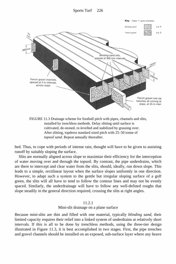
FIGURE 11.3 Drainage scheme for football pitch with pipes, channels and slits, installed by trenchless methods. Delay slitting until surface is cultivated, de-stoned, re-levelled and stabilized by grassing over. After slitting, topdress standard sized pitch with 25–50 tonne of topsoil sand. Repeat annually thereafter.
bed. Thus, to cope with periods of intense rain, thought will have to be given to assistingrunoff by suitably sloping the surface.
Slits are normally aligned across slope to maximize their efficiency for the interception of water moving over and through the topsoil. By contrast, the pipe underdrains, whichare there to intercept and clear water from the slits, should, ideally, run down slope. Thisleads to a simple, rectilinear layout when the surface slopes uniformly in one direction.However, to adapt such a system to the gentle but irregular sloping surface of a golfgreen, the slits will all have to tend to follow the contour lines and may not be evenlyspaced. Similarly, the underdrainage will have to follow any well-defined roughs that slope steadily in the general direction required, crossing the slits at right angles.
11.2.1 Mini-slit drainage on a plane surface
Because mini-slits are thin and filled with one material, typically blinding sand, their limited capacity requires their relief into a linked system of underdrains at relatively shortintervals. If this is all to be done by trenchless methods, using the three-tier design illustrated in Figure 11.3, it is best accomplished in two stages. First, the pipe trenchesand gravel channels should be installed on an exposed, sub-surface layer where any heave
Sports Turf 226
can be levelled out prior to the topsoil being superimposed, and without undue concernfor capping. Then, after the carpet of topsoil has been superimposed and stabilized bygrassing over, a direct link between the surface and the underdrains can be established byinstallation of the mini-slits. Alternatively, the gravel channels can be piped to extend their length of run so as to complete the scheme in just two tiers of artificial drainage.
Obviously, regular sand topdressing or repeat mini-slitting will have to be a feature of maintenance if the thin slit system is to remain linked directly through to the surface.
11.2.2 Possibilities for mini-slit and other forms of drainage on an irregularly sloping
surface
On a smooth surface, runoff will clear all excess water from the steeper slopes but willadd to the excess water accumulating on the longer, gentler slopes, and in the receivinghollows. The only practical alternatives available to cope with this situation are either toeliminate the hollows or introduce underdrainage beneath the hollows, linking this withthe surface through topsoil organized to provide for the necessary infiltration.
The simplest and probably the cheapest approach is to mould the required surface from the existing topsoil, grading throughout so as to avoid internal hollows and shed allsurface water to soakaways beyond the perimeter. Gradients, not less than 1:60 nor morethan 1:20, will probably suffice to provide for continuous flow within an overallconfiguration acceptable for play.
If an unwanted, enclosed hollow develops on a made-up surface, as a result of differential settlement, then either the hollow should be filled in or provided witheffective underdrainage.
To eliminate an enclosed hollow by infilling, fold back the turf and build up with more soil similar to the existing, grading as required to maintain surface flow across the newsurface. A depression that is merely infilled with sand will leave the water-holding surface intact and the sand will do no more than mask the presence of the water heldabove the buried soil layer. Only when a uniformly textured, continuously sheddingsurface has been established should topdressing with sand be contemplated.
If an underdrain is to be inserted through a fine-turf surface the job will have to be done very neatly. Using boards to work off, first remove cleanly cut turves along the lineof the pipe trench and store carefully for subsequent replacement. Excavate through the exposed soil a narrow trench no more than 50–75 mm (2–3 in) wide, i.e. the minimum necessary to allow for the insertion of the pipe. The object being to intercept surfacewater and discharge it directly into the pipe, the trench need be no deeper than is requiredto provide for any necessary grading to the outfall and to keep the pipe clear of allspiking operations; 300–450 mm (12–18 in) would normally be adequate. Backfill over the pipe with trench gravel to 150 mm (6 in) from the new surface, then blind with 50mm (2 in) of blinding sand and continue through to the new surface on which the turf isto be replaced, using topsoil sand ameliorated with 2% seaweed meal, and 2%horticultural lignite or equivalent. Topdress with a phosphate-rich fertilizer, saturate and then neatly replace the turf.
If the original soil is not particularly sandy, then replace the topsoil sand at the top of
The Slit approach, typically for vigorous winter games 227
the pipe trench with some of the original, excavated topsoil. Thin, sand-filled mini- or micro-slits can then be inserted across the trench to effect surface interception and link below into the layer of blinding sand in the pipe trench. Slicing open thin slits with a spade may well be all that is necessary but may have to be repeated periodically.
As with all made-up soils, the backfill in the pipe trench should be consolidated intoplace to reduce the extent of any subsequent, long-term settlement. This process should be repeated as each layer is put into place. Any residual settlement will have to be takenout by careful luting along the line of the trenches whenever a topdressing of sand isapplied subsequently.
The pipe trenches—often only one—should run through the base of the receiving hollows, aligned with slope. Any extension of the system will normally require onlygravel-filled channels or slits. The channels can be used to extend the underdrainage intosubsidiary, receiving hollows, the backfill matched to that in the pipe trench with which itis linked.
Slits to improve surface interception on the gentler slopes where runoff is sluggish should be aligned across slope, traversing around the contour. Should there be anyproblem about defining a contour it might not be inappropriate to apply the simpletechnique traditionally used in India for laying out irrigation channels. This makes use ofa man-sized A-frame with plumb bob suspended from the apex to swing free just belowthe level of the crossbar. The two feet of the frame will be at the same level when theplumb line intersects the crossbar at the mid point. Steady progress around a contour canthen be achieved by rotating the frame in half circles, one leg, the trailing leg, lifted clearof the ground at each turn. Pegs should be inserted to define the line as you go.
Because a uniform, smooth surface is essential for golf and bowls, the pipe-trenched and sand-slit surface should be masked by a uniform carpet of sand. The depth of thesand carpet must allow for effective infiltration and lateral discharge to the underdrainagesystem. With underdrainage interception at 1–2-m (1–2-yard) intervals a 100-mm (4-in) depth of a topsoil sand carpet will generally be adequate except, perhaps, in the receivinghollows. Above the sand carpet, however, a turfed surface layer will develop which, iffine sand, loamy sand or organic matter dominated, could become persistently wet,especially if perched over a coarser, e.g. medium-textured, sand carpet. It is important,therefore, that the surface should be managed so as to maintain the whole turf layersimilar to, or coarser than, the texture of the underlying sand carpet. Alternatively thesand carpet should be kept permanently linked through to the surface by hollow-tine core holes filled with sand of texture similar to, or coarser than, that of the sand carpet towhich it is linked.
Clearance of water through the sand carpet will depend on the nature of the underlyingsoil and the combined effect of sand depth and slope on the ability of the sand to pullwater down from the surface. There will be a tendency for the high spots to dry offexcessively but this can be counteracted by differential maintenance, e.g. less intensivelyhollow tining the high spots, or core filling with a finer textured sand. In low-lying areas the sand depth, from the top of the sand carpet to the top of the gravel layer in theunderdrainage trenches, should exceed the critical tension of the carpet sand (Figure 4.3(b)).
Do not ameliorate the sand carpet with either soil or peat as this will encourage water
Sports Turf 228

retention and risk souring the root zone by promoting anaerobic decay.
11.3 Upgrading an existing pitch for improved performance in winter
11.3.1 Initial state
Figure 11.4(a) illustrates two traditional constructions where surface drainage will almostinevitably break down under the strain of intensive winter use. Figure 11.4(b) illustrates how each may be improved. In one case a rubble foundation was intended to provide forall the necessary drainage; in the other, an agricultural pipe system. In effect, both havebeen provided with a potentially efficient underdrainage system but neither anticipatesany problem in getting excess surface water through a topsoil destructured by treading.Both cases require provision to allow for adequate surface infiltration and the directchannelling of any excess into the underdrainage provided.
The Slit approach, typically for vigorous winter games 229
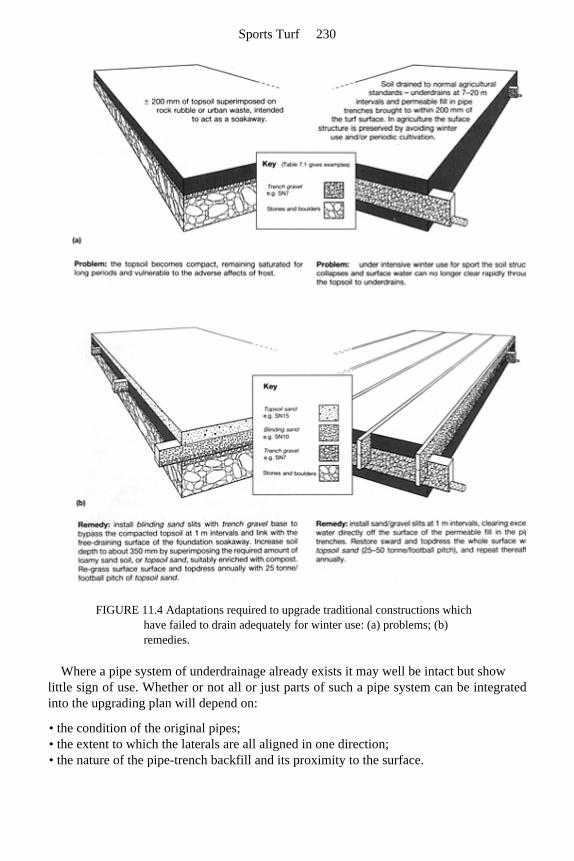
FIGURE 11.4 Adaptations required to upgrade traditional constructions which have failed to drain adequately for winter use: (a) problems; (b) remedies.
Where a pipe system of underdrainage already exists it may well be intact but show little sign of use. Whether or not all or just parts of such a pipe system can be integratedinto the upgrading plan will depend on:
• the condition of the original pipes; • the extent to which the laterals are all aligned in one direction; • the nature of the pipe-trench backfill and its proximity to the surface.
Sports Turf 230
Pipe interval is seldom a problem—the discharge potential of the pipe system usually being more than adequate.
11.3.2 Example of an advisory report on two slit systems
Pitch A is a slit system with progressive accumulation of a sand-capped surface, whereas pitch B is a slit scheme immediately covered with a thick, ameliorated, sand carpet.
Having seen the soils on pitches A and B there is no doubt that both require a schemeof sand/gravel slits to efficiently infilter surface water through to an upgraded system ofpipe underdrains. Under both pitches there is an intact pipe system of underdrains, butneither is organized to intercept through to the surface. From the dry, clean state of thechambers it seems unlikely that they have ever been called upon to carry very muchwater.
In A, because there is no stone restriction to deep trenching and the depth of the topsoil is satisfactory, a normal slit system can be introduced without difficulty, and sandtopdressing restricted merely to that required annually to protect the slit surfaces frombecoming capped by soil. In B, however, a relatively deep surface carpet of sand isrequired, not only to protect the slits from soil capping but, as we shall see, to deepen thetopsoil.
Sands and gravels are defined according to the Stewart zone system (Chapter 7, page 114).
Preliminaries
1. The sward on both pitches is very weedy. An effort should be made to get on top of this problem as soon as possible by using an appropriate weedkiller. Consideration should then be given to controlling the growth of the existing swards by mowing. To avoid rank growth during the reconstruction operations, do not apply fertilizer.
2. At A the surface is very uneven and requires re-truing. This should be achieved by minimum disturbance, importing good topsoil of similar texture to the existing to fill in the depressions. Consolidate any introduced soil, supplementing further if necessary to achieve true level, then re-loosen the surface to seed.
3. At B there is a need to increase the depth of the topsoil. At present it is only of the order of 100–125 mm (4–5 in) and lies directly over a compact subsoil with tip rubble beginning at 400 mm (16 in). This extra depth of topsoil can be an ameliorated sand carpet introduced after the pipe drains and slits have been installed.
Pipe drainage
1. In general, on both pitches, pipe provision should aim to support an overall design rate of 50 mm (2 in) per day. Choice of pipe will depend on area served, gradient and function (Table 2.1).
2. The pipe laterals that intercept the slits should run in parallel succession at 15-m (17-yard) intervals, directly downhill, linking into the existing catchment drains that run
The Slit approach, typically for vigorous winter games 231
along the down-slope margins. The links should be achieved by purpose-made junctions causing no interruption to flow.
3. The pipe laterals at A should be installed at a depth of 600 mm (24 in), below the depth of the existing herringbone system. All severed, old pipes to be positively linked into the new system from the uphill side. Downhill the old pipes should be closed off by an appropriate cap.
4. At B place laterals at the shallow depth of 450 mm (18 in). This will avoid most of the major obstacles in the rubble substratum.
5. The new laterals should be backfilled with trench gravel to within 150 mm (6 in) of the existing surface and, thereafter, 50 mm (2 in) of blinding sand, followed by replacement of the original turf, bedded in topsoil.
6. Examine all links into chambers and correct any adverse consequences of scour and differential settlement in the pipe trench adjacent to the chamber.
Aim to complete 1–6 by the end of autumn. Assuming the re-turfed and seeded areas takesuccessfully it may be possible for both pitches to be used with discretion over winter.
Slits and surface
1. Work to install slits in both pitches should begin as early as possible in the following spring.
2. The slits should be 50 mm (2 in) wide, 150 mm (12 in) deep, and should run in parallel succession at 1-m (1-yard) intervals, across slope, i.e. at right-angles to the lateral pipe system. Backfill should consist of a lower, 150 mm (6-in) layer of trench gravel, and an upper, 150-mm (6-in) layer of blinding sand, the sand layer being brought right throught to the surface.
3. At A, the slits should be over-topped to a height of 25 mm (1 in) with topsoil sand, ameliorated with 2% seaweed meal and 2% horticultural lignite (or an equivalent organic compost). Topdress overall with pre-seeding fertilizer and then overseed with a dwarf ryegrass/fescue-dominated seeds mixture, aiming to place the seed within the immediate surface of the sand. Make a second seeding pass along the line of each slit and then, rolling parallel to the slits, firm the sand around the buried seed.
4. At B, spread 100 kg/ha of urea and 300 kg/ ha of ground rock phosphate (or similar). Spread 480 t (dry weight) of topsoil sand per hectare, plus 30 t of horticultural lignite and 30 t of seaweed meal (or equivalent organic compost). Then cover with another 1120 t/ha (dry weight) of topsoil sand.
Using a spring-tine harrow (or similar), set to skim over the top of the original, buried soil, work the organic material up towards the surface. Two slow passes at right angles should be adequate. The aim is to mix but not bring very much of the buried organic matter right through to the surface. Roll and re-level repeatedly, using machinery that will avoid rutting. Use a 3 m (9–12 ft wide) bar-grader to achieve the final, consolidated, true surface. Protect against windblow by watering if necessary. Topdress with pre-seeding fertilizer and seed with a dwarf ryegrass/fescue-dominated seeds mixture. Insert seed by means that will work most of the seed some 10 mm (¼–½ in) under the surface. Roll to consolidate sand around the buried seed.
5. After seed germination, maintain both pitches as prescribed in the attached
Sports Turf 232
maintenance schedule (section 11.4). 6. Slitting and surface renewal may be achieved by the autumn, but ideally no play
should be allowed on either pitch until the following year. Growing season conditions will be required to develop a vigorous, thick sward and, in the case of pitch A, to apply protective topdressings of topsoil sand. These sand topdressings may well have to be concentrated first in the vicinity of the slits so as to counteract any tendency for the surface in this area to slump. And note, even on pitch B, where a deep, sand carpet will have been introduced, there will still also be a need for annual topdressings of sand to counteract any tendency to develop an organic or fine-soil cap (section 6.3.1).
11.4 General guidance on coarse turf maintenance where, on balance,
earthworm activity is considered to be potentially beneficial
Greater discretion in use and an improved programme of maintenance may alone achieveall the improvement that a beleaguered groundsman may require but, frequently, someinherent limitation of the site has to be overcome before even good maintenance can hopeto be effective.
Before proceeding with any expensive construction or re-construction programme it isimportant to realize the nature of the maintenance that will be necessary if all the potentialbenefits from the construction work are to be realized. Nothing created in sports turf willremain for long as constructed unless maintained in a manner sensitive to the inevitabletrends towards change that have to be continually controlled.
Much of the advice given under the heading of maintenance for fine turf (section 10.5)applies equally to a worm-worked sward. The features listed below simply draw attentionto those which are of special significance for winter games pitches where stud wear is aninevitable hazard and, on balance, the effects of earthworm activity are considered to bebeneficial.
11.4.1 Liming, fertilizing, weed-killing and over-seeding
1. Maintain soil pH above 5.5 by application of ground limestone. Where necessary, treat initially by means of a single application at the rate of 5 tonne/hectare (2 tons/acre). Spread evenly in calm, dry weather, at any time of the year. Check pH again after 2 years and thereafter every 4 years. Monitor pH only within the top 75 mm (3 in) of the soil.
2. In mid-April, or when soil temperature at 250 mm (10 in) has reached 10°C and there is ample evidence of renewed growth, consider if the sward needs weed killing as well as fertilizing. Remedy as necessary and apply the first of three fairly light, spring and summer dressings of a fine-particle fertilizer, supplying mainly (or solely) nitrogen and potassium. Repeat mid-June and mid-August. Do not apply in drought but when rain is expected within 24–48 hours. Eliminate one dressing if drought persists.
Each second year, apply a standard high-phosphate, low-nitrogen autumn dressing
The Slit approach, typically for vigorous winter games 233
(mid-September), on a thoroughly spiked or slit surface. To boost growth along sand- and gravel-filled drain trenches, consider applying nitrogen and potassium as a liquid feed at low concentration along the trench runs, using a sprayer or watering can. Treat during the growing season whenever the yellowing symptoms of nitrogen deficiency show up.
3. Do not leave bare patches to seed themselves or nature may insert a broad-leaved weed, an unsuitable grass, or moss. Immediately heel back all displaced turf after play and consider the need for selective over-seeding both in spring and autumn. Though early autumn is usually the best time to seed, over-seeding may well be necessary in spring to treat damage caused by winter use. If a machine that places seed directly into the surface of the soil is not available, prepare the surface by raking or close, shallow spiking. On sandy surfaces, roll after seeding to improve seed contact with the soil.
11.4.2 Mowing, brushing and sand topdressing
1. During the growing season use a sharp mower to cut at 50 mm (2 in) for rugby or 30 mm (1¼ in) for soccer, whenever the general growth height reaches 75 mm (3 in) and 50 mm (2 in) respectively. When the grass is growing well this will mean cutting once a week for rugby and once every 4–5 days for soccer. Remove clippings if earthworms are not active or if the grass is at risk of being smothered by clippings lying in swathes. To cut effectively at a height of 20–50 mm (1–2 in) a mower requires to be sharp. This means regular servicing, at the very least once a year in late autumn, after all topdressing and mowing has virtually ceased for the season.
2. Though worm activity can greatly benefit grass growth their casts will smear and give an unsightly appearance if the grass is cut too low. They can also be sites for weed invasion. For both these reasons it is desirable periodically to disperse the casts by brushing. A good rotary brush or a heavy drag brush can be effective for this purpose if the casts are fairly dry and crumbly at the time. Brushing is most likely to be required in spring and autumn when earthworm activity peaks. Brushing will also assist in grooming the sward, bringing sprawling shoots up to the mower for cutting.
3. Sand topdressing is essential to maintain the efficiency of modern sports-turf constructions where drainage depends on the maintenance of free-draining pathways, continuous from the surface right through to the pipe underdrains. In effect this means maintaining a sand surface overall, or at least along the surface of the installed drainage slits. Slits can be progressively down-graded by soil contamination resulting from foot traffic and earthworm activity. To counteract this, a uniform topdressing of the order of at least 40 tonne/hectare (16–17 tons/acre) of topsoil sand should be applied each summer during dry sunny weather. Spread the sand out in an evenly spaced arrangement of piles or wind-rows, until powder dry, then according as the priority is to true or merely topdress, lute or drag brush into the base of the sward.
Sports Turf 234
11.5 A cautionary tale illustrating what can go wrong during and soon after
construction
11.5.1 The initial concept
This is a story of unscientific design, inefficient workmanship, inadequate supervisionand inappropriate maintenance. It concerns a scheme of drainage for a new 14-hectare (35acre) sports ground, 700 m (765 yards) long, across slope, and 200 m (218 yards)wide, down slope. The final surface sloped uniformly at a gradient of 1:100 and wasmade up of material similar to subsoil.
Apart from two pitch areas set aside for hard porous and sand carpet constructions, thewhole of the playing field was underdrained by pipes laid out in a herringbone pattern.Mains were all directed down slope, laterals coming off alternately right and left,orientated diagonally across slope. As Figure 3.1(a) indicates, if such a system does not suffice on its own the orientation of the laterals makes it difficult to up-grade efficiently without adding more pipes. This is not to make good any shortfall in number but tocompensate for a layout that unnecessarily complicates the introduction of an efficientsystem of sand/gravel slits.
One of the two special areas was underdrained by mains and laterals laid out in a gridsystem, then sand/gravel slit and deeply sand carpeted. Initially, it was the only grasssurface on which it was possible to achieve a sustained programme of winter use. Theother special area was laid out as a hard porous construction like that discussed inChapter 13.
11.5.2 Ensuing problems
All available funds having been spent on the initial construction, the groundsman wasthen left to carry on as best he could with two potentially useful pitches and the rest of thearea rapidly falling out of use because the herringbone underdrainage was unable on itsown to prevent winter use churning the surface to mud. However, when the groundsmanbegan to investigate his problems, he started by looking at several persistent wet areasover drain runs. This revealed that he not only had problems of design but also inefficientinstallation. It was at this stage that outside advice was sought.
Field evidence and the lessons to be learnt
1. Many wet areas were associated with pipes crushed flat. In one instance this damage extended for a distance of 6 m (20 ft), presumably the result of heavy wheel pressure transmitted directly onto the pipes through the loose gravel backfill. Elsewhere, gaps were found at the junctions between laterals and mains, and wide gaps, up to 1 m in length, were found at junctions along mains. One pipe was found broken where it had
The Slit approach, typically for vigorous winter games 235
been laid across a sharp piece of buried metal. Twelve such faults were found on one pitch alone.
How did all this come about? Where was the clerk of works at the time of installation? What of the principle of inspection before cover? What should be our attitude now to weekend work, popular with contractors working away from home but unlikely to be capable of close supervision? How could such faults arise? Could some methods of installation involve an unsuspected measure of drag, when the pipe is covered immediately by backfill? Should we require a simple locking system at junctions?
2. On the sand-carpeted pitch the underdrainage consisted of a parallel succession of pipes running downhill at 15-m (16-yard) intervals and 500–600-mm (20–24-in) depth, plus gravel-filled trenches, running across slope at 2-m (2-yard) intervals and 350–400 mm (14–16 in) in depth. Here, seven instances were found of crushed or broken pipe where the gravel-filled trenches crossed the pipe system.
Could this evidence be indicating an effect of downward pressure from trencher tines transmitted through loose gravel? Or could it be an effect of one person’s eccentric method of backfilling and consolidating gravel within narrow trenches? The fully integrated methods now used for cutting trenches, laying pipes, placing and consolidating fill, all in just one or two passes of heavy machinery, may be quick and superficially tidy but who has checked to see the consequences below ground?
3. When a new contractor was called in to achieve a complete reconstruction, a new drainage system was superimposed with pipes running downslope 450 mm (18 in) deep, about the same depth as the suspect pipes in the original herringbone system. However, to avoid risk to the new pipes during subsequent slit trenching, the decision was made to first install gravel filled, slit trenches at fairly close intervals, across the slope, and then intercept these with the new pipe drains running down-slope. Finally, close-spaced, sand mini-slits were injected downslope to direct surface flow to the gravel slits and thence to the new system of pipe underdrains.
Great difficulty was experienced from the start because the trenchable topsoil that should have been installed to a placement depth of 30 mm (12 in) was found to be less than 150 mm (6 in) deep, and there it rested directly on a consolidated, stony subsoil of tipped rubble. The slit trenches were bound to be difficult to excavate to any depth and, since they were dug before the installation of the new pipe system, progress was further hampered during bad weather by the progressive accumulation of water within the working area. In this case the slits were installed in succession from the bottom to the top of the slope. Had this been done in reverse, i.e. top to bottom, the first slits installed might have helped to maintain the downslope area free of surface runoff, allowing progress to be maintained through a period of unsettled weather. Subsequent installation of the new pipe system by trenchless methods was also very difficult because the soil was still wet and this increased the risk of further damage to the original herringbone pipe system. Timing should always make generous allowance for this type of work to be carried out only when the soil is adequately dry. When upgrading an existing, suspect, drainage system by the introduction of new
Sports Turf 236
pipes, it is important not to superimpose the new pipes over the old without first checking that the old pipe system will still clear any water they intercept. Generally it is safer to trench-in the new pipes lower than the old, making positive links between the two systems wherever they cross, capping off the open end of the severed pipe on the down-slope side of the trench. However, nothing of this can be achieved if the new pipes are installed by trenchless methods. Considering the difficulties the contractor got into on the site in question, one wonders where the trained design team had got to. Was it yet another case of a foreman, far from base, abandoned to his own devices?
4. Once the mini-slit system had been installed at right-angles to the gravel filled slits, the sward recovered and, despite all the reconstruction difficulties, the surface performed well enough for two seasons. Then both slit systems were found to be capped over by soil to a depth of 20 m (¾ in).
As has already been said (section 6.2.1), it is of the utmost importance that anyone installing slits should be forewarned of the need to take measures to counteract the inevitable tendency to soil capping. Sand and gravel in slits will respond differently to repeated cycles of wetting and drying compared with the adjacent soil. The end result is that the level of the sand and gravel in the slits progressively sinks relative to the soil and, if the sand level is not maintained by topdressing, the soil eventually seals over the surface. This inevitable trend should be anticipated, and provision made from the start for protection by either regular sand topdressing or regular, remedial micro-slitting.
5. For the first seven years the sand-carpeted pitch and the hard porous pitch had to carry virtually the full burden of use for which the whole field was originally intended. Despite the problem of washouts, originating in storm runoff accumulating in blocked drains, the sand-carpeted pitch stood up well to intensive use. However, the quality of the sward deteriorated, particularly in its response to drought. This seemed to be related to the lack of any root penetration into the soil beneath the sand carpet.
The sand had been laid directly over the formation layer of subsoil and stony rubble. This degraded material had neither a satisfactory initial structure nor an earthworm population capable of assisting soil development in depth. The effective rooting medium was no more than the sand-carpet itself and this was now exhausted of its initial organic and chemical supplements. The message is that although the original soil surface in a sand-carpet construction is to be buried out of sight, its quality cannot be ignored; the long-term viability of the sward depends on its biological vigour.
11.5.3 Addendum
It should not be assumed that the case history described above is an isolated example.Other sites, if investigated as assiduously, might well reveal similar shortcomings. Themoney having all been spent, the inclination then is for the architect, the clerk of worksand the contractor to withdraw, leaving the groundsman to pick up the problems and thebrickbats.
The Slit approach, typically for vigorous winter games 237
Design is clearly one thing; implementation quite another. Had the groundsman in thiscase been appointed and on site during the construction period, the story might well havebeen very different.
11.6 Some other errors encountered
Examples of other problems encountered are listed below.
1. The slit capacity was unduly stretched by not being oriented at right-angles to the pipe trenches; in two instances they were aligned parallel to the pipe drains and therefore lacking any outlet whatsoever!
2. The slits were spaced too wide apart in a misguided attempt at economy: for example, sand/gravel slits on a flat site spaced at intervals of 2 m (2 yards) or more.
3. Some slits had inadequate capacity because of inappropriate dimensions or inappropriate backfill.
4. The slits and pipe drains failed to link because the permeable fill in the two trench systems was inappropriately matched, or the two systems failed even to intersect.
5. The slits were inadvertently covered with soil at time of construction. This can arise if soil debris or heaved ridges of topsoil are present on either side of a trench when backfilling takes place. Mould boards at the rear of a backfilling hopper may then drag soil into the slit as well as sand overspill. A following roller presses the mixture into the slit and this may then be obscured by a further covering of sand. The same risk arises when heavy machinery slithers about on too wet a surface.
6. The slits became capped with soil because of failure to maintain a freely permeable cap by regular, sand topdressing.
7. The slit surface was carpeted over with an insufficiently sandy soil. 8. Precipitate use before full grass cover had been established along the line of pipe
trenches and slits.
Sports Turf 238
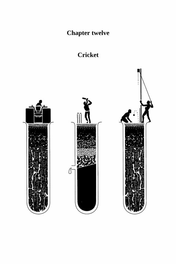
Chapter twelve
Cricket

12.1 Introduction
In cricket, even more than in golf, the reactions of the ball off the surface form an integralpart of the game. If predictable, its qualities can be exploited by those with the necessaryskills but, if unpredictable, it can thwart the intentions of the skilled and unskilled alike.Thus the character of the game can be determined by factors that affect the reactions ofthe playing surface: the weather, the soil and the skill of the groundsman.
The grass is scarcely visible above ground on a Test pitch prepared for play. It has to struggle to survive because most of what the groundsman has to do when preparing apitch is quite contrary to what he would choose to do to maintain the soil in good heartand the sward vigorous.
The information presented in this chapter derives mainly from a research study carried out in the 1960s and reported to the First International Turfgrass Research Conferenceheld in Harrogate in 1969 (Stewart and Adams, 1969), plus further field-work carried out in Australia and New Zealand in the 1980s. Though the main object of this research wasto investigate how best to achieve good pitches for County and Test matches, the fieldevidence soon showed how variable the standard of performance can be from one Countyground to another, and even from one pitch to another on the same square (Table 12.1). Later, as the study was extended overseas, it became evident how vastly different is thepotential for pace at Test venues world-wide (see Table 12.5). Meantime, P.L.K.Drury, 1978, County Playing Fields Officer, Nottinghamshire, has shown how big a differencethere is between the pace achieved on ordinary club and school grounds compared withthat achieved at County level (Table 12.1 footnote).
In effect, the main differences between the highest and lowest standards reflects either differences in preparation time or the combined effects of climate and clay content of thesoil. Thus, on County grounds, pitch preparation is likely to extend over a period of 10–14 days; this in addition to end of match, end of season and pre-season work. By contrast, most school and local club pitches are prepared in just one day or on the morning of thematch. Overseas we see many potentially very fast pitches based on soils much richer inclay than could ever be regularly dried out in a normal British summer. No wonder ourtop players require time to adapt as they move from one country to another.
Consistency at a modest pace is really all that the lesser clubs and schools can aim toachieve with only a modest period of preparation. This eliminates the use of soils and soilconditions upon which the development of real pace depends. However, with theconfidence that consistency allows, basic skills can be learnt that may flourish whentested at more demand-
Cricket 241
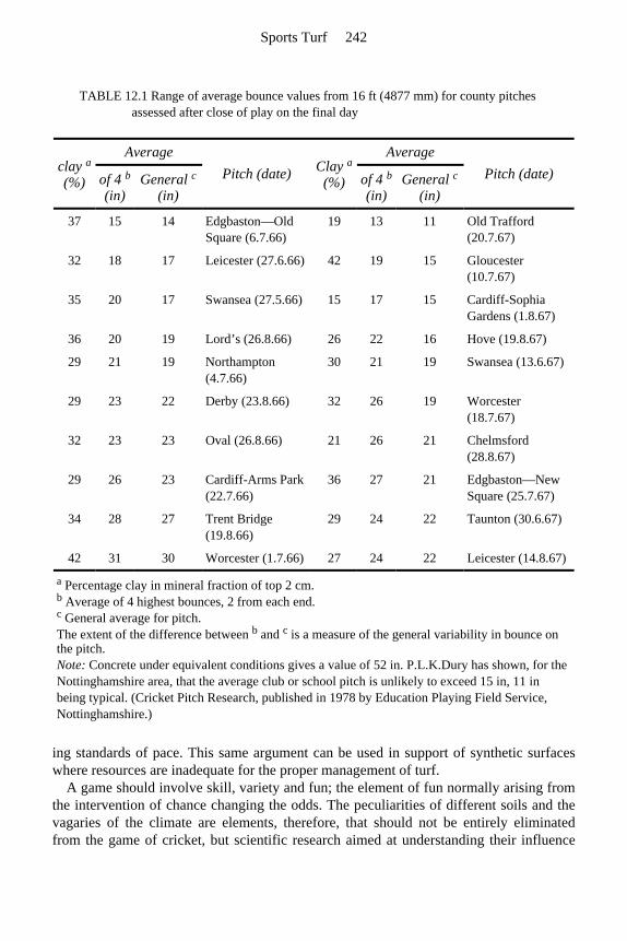
ing standards of pace. This same argument can be used in support of synthetic surfaceswhere resources are inadequate for the proper management of turf.
A game should involve skill, variety and fun; the element of fun normally arising fromthe intervention of chance changing the odds. The peculiarities of different soils and thevagaries of the climate are elements, therefore, that should not be entirely eliminatedfrom the game of cricket, but scientific research aimed at understanding their influence
TABLE 12.1 Range of average bounce values from 16 ft (4877 mm) for county pitches assessed after close of play on the final day
clay a
(%)
Average Pitch (date) Clay a
(%)
Average Pitch (date) of 4 b
(in) General c
(in) of 4 b
(in) General c
(in)
37 15 14 Edgbaston—Old Square (6.7.66)
19 13 11 Old Trafford (20.7.67)
32 18 17 Leicester (27.6.66) 42 19 15 Gloucester (10.7.67)
35 20 17 Swansea (27.5.66) 15 17 15 Cardiff-Sophia Gardens (1.8.67)
36 20 19 Lord’s (26.8.66) 26 22 16 Hove (19.8.67)
29 21 19 Northampton (4.7.66)
30 21 19 Swansea (13.6.67)
29 23 22 Derby (23.8.66) 32 26 19 Worcester (18.7.67)
32 23 23 Oval (26.8.66) 21 26 21 Chelmsford (28.8.67)
29 26 23 Cardiff-Arms Park (22.7.66)
36 27 21 Edgbaston—New Square (25.7.67)
34 28 27 Trent Bridge (19.8.66)
29 24 22 Taunton (30.6.67)
42 31 30 Worcester (1.7.66) 27 24 22 Leicester (14.8.67)
a Percentage clay in mineral fraction of top 2 cm. b Average of 4 highest bounces, 2 from each end. c General average for pitch. The extent of the difference between b and c is a measure of the general variability in bounce on the pitch. Note: Concrete under equivalent conditions gives a value of 52 in. P.L.K.Dury has shown, for the Nottinghamshire area, that the average club or school pitch is unlikely to exceed 15 in, 11 in being typical. (Cricket Pitch Research, published in 1978 by Education Playing Field Service, Nottinghamshire.)
Sports Turf 242

on pitch performance can help to strike the balance that the game requires.
12.2 Pitch assessment
In the 1960s Imperial measurements were in common use; therefore, measurements inthis chapter give these units priority.
12.2.1 Bounce test
The Test and Counties Cricket Board, which is now responsible for the selection of theEnglish national team, is concerned that first-class cricket should be played under conditions conducive to the promotion of the skills necessary for success at internationallevel. They
believe that this requires the game to be played on fast, true pitches. Trueness is a matterof consistency, pace a matter of bounce. Consistency of bounce, therefore, is not a bad
TABLE 12.2 Examples of variability in bounce on County pitches
Ground Sampling date Bounce (in) for ball dropped from 16 ft
New Road end
Worcester 18.6.67 9 12 13 14 18 22 19 31 17 17 16 16
Scoreboard end
25 17 20 20 24 23 24 20 22 22 11 10
Pavilion end
Edgbaston 25.7.67 17 23 28 26 16 28 13 21 18 28 16 17
Constance Road end
21 22 22 14 22 18 15 26 24 23 13 17
Pavilion end
Oval* 26.8.66 25 25 24 25 25
Vauxhall End
20 21 20 18 19
* Fewer samples taken at wider spacing on some pitches in the initial, 1966 survey. The variability in bounce on the pitch at Worcester was caused by the pitch breaking up. The variability at Edgbaston was caused by turf cracks still present 32 months after the surface had been renovated by re-turfing. The pitch at the Oval showed a clear pattern of variation between ends which the players recognized.
Cricket 243
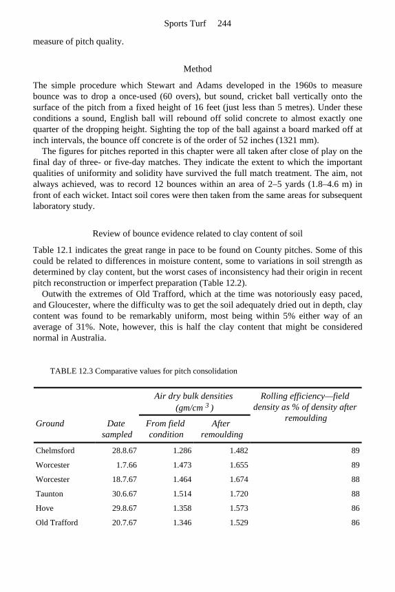
measure of pitch quality.
Method
The simple procedure which Stewart and Adams developed in the 1960s to measurebounce was to drop a once-used (60 overs), but sound, cricket ball vertically onto the surface of the pitch from a fixed height of 16 feet (just less than 5 metres). Under theseconditions a sound, English ball will rebound off solid concrete to almost exactly onequarter of the dropping height. Sighting the top of the ball against a board marked off atinch intervals, the bounce off concrete is of the order of 52 inches (1321 mm).
The figures for pitches reported in this chapter were all taken after close of play on the final day of three- or five-day matches. They indicate the extent to which the importantqualities of uniformity and solidity have survived the full match treatment. The aim, notalways achieved, was to record 12 bounces within an area of 2–5 yards (1.8–4.6 m) in front of each wicket. Intact soil cores were then taken from the same areas for subsequentlaboratory study.
Review of bounce evidence related to clay content of soil
Table 12.1 indicates the great range in pace to be found on County pitches. Some of this could be related to differences in moisture content, some to variations in soil strength asdetermined by clay content, but the worst cases of inconsistency had their origin in recentpitch reconstruction or imperfect preparation (Table 12.2).
Outwith the extremes of Old Trafford, which at the time was notoriously easy paced,and Gloucester, where the difficulty was to get the soil adequately dried out in depth, claycontent was found to be remarkably uniform, most being within 5% either way of anaverage of 31%. Note, however, this is half the clay content that might be considerednormal in Australia.
TABLE 12.3 Comparative values for pitch consolidation
Air dry bulk densities (gm/cm 3 )
Rolling efficiency—field density as % of density after
remoulding Ground Date sampled
From field condition
After remoulding
Chelmsford 28.8.67 1.286 1.482 89
Worcester 1.7.66 1.473 1.655 89
Worcester 18.7.67 1.464 1.674 88
Taunton 30.6.67 1.514 1.720 88
Hove 29.8.67 1.358 1.573 86
Old Trafford 20.7.67 1.346 1.529 86
Sports Turf 244
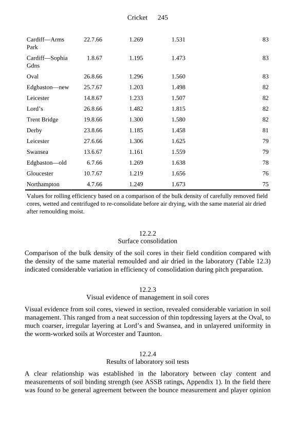
12.2.2 Surface consolidation
Comparison of the bulk density of the soil cores in their field condition compared withthe density of the same material remoulded and air dried in the laboratory (Table 12.3) indicated considerable variation in efficiency of consolidation during pitch preparation.
12.2.3 Visual evidence of management in soil cores
Visual evidence from soil cores, viewed in section, revealed considerable variation in soilmanagement. This ranged from a neat succession of thin topdressing layers at the Oval, tomuch coarser, irregular layering at Lord’s and Swansea, and in unlayered uniformity in the worm-worked soils at Worcester and Taunton.
12.2.4 Results of laboratory soil tests
A clear relationship was established in the laboratory between clay content andmeasurements of soil binding strength (see ASSB ratings, Appendix 1). In the field therewas found to be general agreement between the bounce measurement and player opinion
Cardiff—Arms Park
22.7.66 1.269 1.531 83
Cardiff—Sophia Gdns
1.8.67 1.195 1.473 83
Oval 26.8.66 1.296 1.560 83
Edgbaston—new 25.7.67 1.203 1.498 82
Leicester 14.8.67 1.233 1.507 82
Lord’s 26.8.66 1.482 1.815 82
Trent Bridge 19.8.66 1.300 1.580 82
Derby 23.8.66 1.185 1.458 81
Leicester 27.6.66 1.306 1.625 79
Swansea 13.6.67 1.161 1.559 79
Edgbaston—old 6.7.66 1.269 1.638 78
Gloucester 10.7.67 1.219 1.656 76
Northampton 4.7.66 1.249 1.673 75
Values for rolling efficiency based on a comparison of the bulk density of carefully removed field cores, wetted and centrifuged to re-consolidate before air drying, with the same material air dried after remoulding moist.
Cricket 245
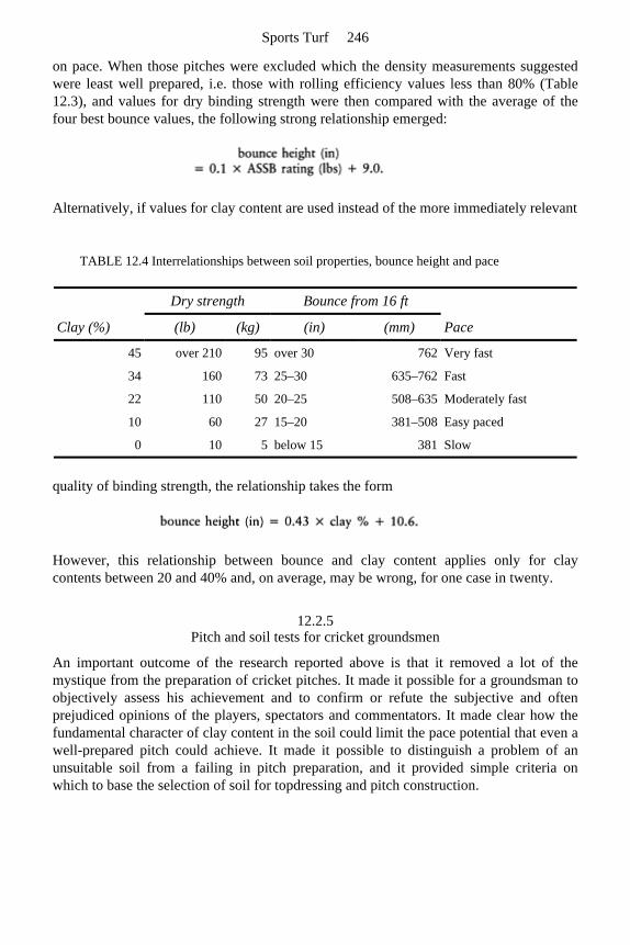
on pace. When those pitches were excluded which the density measurements suggestedwere least well prepared, i.e. those with rolling efficiency values less than 80% (Table 12.3), and values for dry binding strength were then compared with the average of thefour best bounce values, the following strong relationship emerged:
Alternatively, if values for clay content are used instead of the more immediately relevant
quality of binding strength, the relationship takes the form
However, this relationship between bounce and clay content applies only for claycontents between 20 and 40% and, on average, may be wrong, for one case in twenty.
12.2.5 Pitch and soil tests for cricket groundsmen
An important outcome of the research reported above is that it removed a lot of themystique from the preparation of cricket pitches. It made it possible for a groundsman toobjectively assess his achievement and to confirm or refute the subjective and oftenprejudiced opinions of the players, spectators and commentators. It made clear how thefundamental character of clay content in the soil could limit the pace potential that even awell-prepared pitch could achieve. It made it possible to distinguish a problem of an unsuitable soil from a failing in pitch preparation, and it provided simple criteria onwhich to base the selection of soil for topdressing and pitch construction.
TABLE 12.4 Interrelationships between soil properties, bounce height and pace
Clay (%)
Dry strength Bounce from 16 ft
(lb) (kg) (in) (mm) Pace
45 over 210 95 over 30 762 Very fast
34 160 73 25–30 635–762 Fast
22 110 50 20–25 508–635 Moderately fast
10 60 27 15–20 381–508 Easy paced
0 10 5 below 15 381 Slow
Sports Turf 246
Bounce height
Using the method described on page 183 the significance of the bounce height valuesobtained can be interpreted by reference to the standards listed in Table 12.4.
Low values, under 20 in (508 mm) or, worse still, under 15 in (381 mm) indicate a marked weakness in soil strength. This may be caused by any one of a combination offactors: a soil with an inadequate content of clay; unsatisfactory pitch preparation; orsomething unsatisfactory in the general management of the square. For example, on thepitches recorded in Table 12.1, the poor performance of the old part of the square at Edgbaston in 1966 could not be attributed to the clay content of the soil, whereas thisclearly was the problem at Old Trafford in 1967. The bounce values alone could not havemade this distinction.
A pitch, bouncing consistently between 25 and 30 in (635 and 762 mm) when a cricketball is dropped vertically onto it from 16 ft (4877 mm), probably represents a goodstandard for Test and County play, but the normal club or school game is played on turfpitches that seldom bounce more than 15 in (381 mm).
Particularly high bounce values were recorded at Abbeydale Park, Sheffield in the mid 1970s. Values consistently around 35 in (889 mm) were recorded on the pitch used forthe Yorkshire/West Indies match in 1976, and values two or three inches either side of anaverage of 37 in (940 mm) for the Yorkshire/ Middlesex match in 1976. All this wasachieved with a surface clay content of 35%. The injuries experienced by the Yorkshireplayers on both these occasions suggest that such pitches, even when consistent, are morelively than all but the most talented English batsmen can cope with, certainly whenencountered unexpectedly, and the fast bowlers are West Indians.
Consistency of bounce
From field observations and the data recorded in Table 12.1 it would seem reasonable to postulate that a discrepancy of more than 2 in (50 mm) between the general average for12 bounces at either end of a pitch (third column in Table 12.1), compared with the average of the two highest from either end (second column in Table 12.1), indicates some feature of management requiring attention, irrespective of any problem over clay content.Some examples now follow.
1. At Gloucester (1967) the immediate surface had cracked into a mosaic of very small hard blocks while an inch (25 mm) down, the strong clay soil was still moist enough to be plastic.
2. At Hove and Edgbaston (1967) both pitches were affected by abnormally low bounces along turf lines.
3. At Worcester (1967) the strong clay soil had not been adequately re-wetted and reconsolidated by rolling after previous use and so had cracked up dangerously by the end of the match, much to the benefit of the bowlers.
Cricket 247
Soil strength
A simple ASSB or motty test, described in Appendix 1, will indicate any soil strengthlimitation inherent in the clay content of the soil. For well made ‘motties’ every 4½ lb (2 kg) of breaking strength is equivalent to 1% clay. However, with Australian soils inmind, it should be pointed out that this applies best for clay contents within the range 20–40% and where the clay is not chemically dispersed, e.g. by incautious de-salination.
Interrelationships between soil properties, bounce height and pace
Table 12.4 shows how values obtained in the survey of County pitches carried out in 1966 and 1967 allowed relationships to be made between clay content and dry strength ofsoil, and between bounce values for a cricket ball dropped vertically onto the surfacefrom 16 ft (4877 mm) and player opinion of pace.
On a properly prepared, dry pitch, bounce height and true pace are likely to be relatedbecause both are beneficially affected by the extent to which the surface remains hard andunyielding on impact. Any give, or collapse, will reduce the rebound height and alsocheck forward movement so that a player will complain of the ball not coming nicelyonto the bat. The exaggerated forward movement of a ball skidding horizontally off awet, or excessively lush, green surface is false pace. True pace, where the angle ofdeparture is virtually the same as the angle of incidence, is what the player should be ableto anticipate when making an attacking stroke to a guileless delivery. By contrast, falsepace will deceive even the well-intentioned stroke. The potential to skid is not covered by the vertical bounce test and could not be predicted from the soil qualities of clay contentor dry strength.
12.3 Critical factors in pitch preparation
12.3.1 Achieving the soil’s maximum binding strength—theory
Using a soil sample from which gravel and stone have been removed, moisten justenough to allow any previous aggregation to be worked out by rubbing. Then, by rollingbetween cupped hands, form the whole mass into a firm, coherent plastic ball (motty)with a smooth, flawless surface. If the soil is too wet it will stick to everything; too dry itwill not cohere enough to avoid breaking up when rolled; just right it will mould reliably without cracking, sticking to itself but leaving other surfaces clean. The last stage isknown as ‘sticky point’. It can be achieved in any soil that has sufficient fine particles for a continuous moisture matrix to provide the necessary flexible cohesion.
On further drying, the water matrix is broken and plasticity gives way to a kind ofbrittleness, like that of partially set cement. This stage coincides with the colour changefrom dark to light because the removal of water by evaporation causes drying of thesurface first and entry of air into peripheral pore spaces.
Sports Turf 248
Finally, as the soil is left to dry out completely in the air, the residual films of water between clay sheets get thinner, contraction ceases and soluble cementing agents,concentrated by the loss of moisture, solidify to form rigid bonds of varying degrees ofpermanence.
It is this sequence of events which a groundsman should keep in mind when setting about the task of preparing a cricket pitch for play.
12.3.2 Linking theory to practice
When preparing a pitch for play a groundsman should attend to the following points.
1. He should make his soil sufficiently moist to enable him to achieve integration by rolling into one, coherent, plastic mass. The more clay-rich the soil the more difficult this will be. Hence, a clay content of 40% should be considered the upper limit for cricket pitch soils in Britain. Above this percentage the soil would be difficult to dry out in our climate anyway.
2. Rolling should continue so long as the soil remains plastic, but never drier than sticky point. That is, he should roll only so long as the surface remains dark in colour, or so that the dark colour can be restored by squeezing up moisture from below. If rolling is continued through to the brittle stage it will merely result in fine cracking, making the surface liable to break up during play. Re-wetting the surface from above may well trap air that will balloon on rolling to disrupt the soil horizontally. This may be the reason why the combination of spiking and rolling is a particularly effective way of achieving consolidation.
3. Final hardening of the pitch should be left to the drying of the atmosphere. Rolling of a thoroughly hard pitch may do no harm, but then neither does it do much good, except temporarily to tidy away loose soil and debris that shouldn’t be there in the first place.
12.3.3 Surface consolidation
Problem of soil layering
Though an open soil is required for the deep rooting that benefits growth, a hard,compact, level surface is required for the game of cricket. This can be achieved only by asystem of management that involves heavy rolling during pitch preparation. Topdressingsof heavy loam, 2–3 mm ( in) thick, should be applied annually to revive the sward, re-true the surface after scarification and spiking, incorporate fertilizer and seed, buryexposed roots and maintain the clay-rich character of the playing surface. This is thework which Man must take on to mimic the natural processes of opening the soil, buryingorganic residues and topdressing the surface, these being achieved by earthworms in afertile pasture. Whereas the natural process of earthworm churning succeeds inmaintaining a soil homogeneous, the field evidence points strongly to the man-made
Cricket 249
alternative ending up as a succession of horizontal layers. Wheeled traffic across a bare soil will lead to the surface developing a platy structure.
This happens even in a uniform soil, let alone one that begins already strongly layeredbecause of the build-up of successive layers of topdressing. While the soil is still moist,rolling may temporarily achieve a measure of cohesion between the layers but the massas a whole will only remain strongly coherent if nothing incompatible intervenes. Thismeans that soil topdressings must be applied to a clean surface, and the applied soil mustbe similar in its swelling and shrinking characteristics to the soil already in place. If not,the layers are liable to separate on drying with adverse consequences for pace.Compatibility can be assessed by a modification of the ASSB test described in Appendix A1.3.
Heterogeneous layers will react differentially in response to the uptake of water and thedisruptive action of frost. Therefore, reconsolidation of the soil in depth must be givendue priority in early spring, making use of the spike and roll combination to aidintegration and release trapped air.
Role of grass
To many, cricket is a game played on grass but, at County standard and above, a pitchwhen ready for play is 90% bare soil. However, grass on a square does have a role to playapart from just blending with the outfield when out of use. If the grass is well rooted indepth it can not only help directly with surface integration, it can help indirectly byactively extending the drying process deeper into the soil. The builders of clay-walled houses used to include straw in the mix to ensure steady drying in depth and prevent thesurface flaking off in layers, so the roots and stem bases of the sward will do likewise ona pitch. The premature drying of a surface skin is something that should be avoided.
Earthworms—are they welcome on a cricket square?
Despite the problem of surface casting, which some groundsmen seem to findinsuperable, there would seem to be much to be said for learning to work withearthworms, even on a cricket square. However, this is only true if the cast material thatthe worms bring to the surface is of an adequate clay content to act as a topdressing forthe promotion of pace. That means the clay content of the whole soil is important and notjust the playing surface. It is probably this limitation that accounts for the differentprejudices of groundsmen who have had experience of earthworm activity on theirsquares.
At the start of the research survey carried out in the 1960s, a gathering of ex-England captains agreed that three County grounds stood out as having been renowned for thesatisfactory pace of their pitches over the years: Worcester, Portsmouth and Taunton. Oncompletion of the survey, and despite a general prejudice against the presence ofearthworms on cricket squares, it was found that at three grounds earthworms had beenretained:-Worcester, Portsmouth and Taunton.
If a groundsman inherits a square on which earthworms are active, and the soil they bring up in their casts is sufficiently clay-rich to act as a suitable topdressing for the
Sports Turf 250
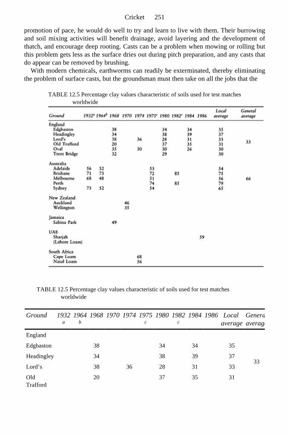
promotion of pace, he would do well to try and learn to live with them. Their burrowingand soil mixing activities will benefit drainage, avoid layering and the development ofthatch, and encourage deep rooting. Casts can be a problem when mowing or rolling butthis problem gets less as the surface dries out during pitch preparation, and any casts thatdo appear can be removed by brushing.
With modern chemicals, earthworms can readily be exterminated, thereby eliminatingthe problem of surface casts, but the groundsman must then take on all the jobs that the
TABLE 12.5 Percentage clay values characteristic of soils used for test matches worldwide
TABLE 12.5 Percentage clay values characteristic of soils used for test matches worldwide
Ground 1932 a
1964b
1968 1970 1974 1975c
1980 1982c
1984 1986 Local average
Generaaverage
England
33
Edgbaston 38 34 34 35
Headingley 34 38 39 37
Lord’s 38 36 28 31 33
Old Trafford
20 37 35 31
Cricket 251

--> earthworm would otherwise do. Eventually he may be faced with a surface so excessivelylayered that complete reconstruction becomes necessary.
Oval 35 30 30 26 30
Trent Bridge
32 29 30
Australia
Adelaide 56 52 53 54
66
Brisbane 71 73 72 85 75
Melbourne 68 48 51 56
Perth 74 85 79
Sydney 73 52 54 65
New Zealand
Auckland 46
Wellington 35
Jamaica
Sabina Park
49
UAE
Sharjah (Lahore Loam)
59
South Africa
Cape Loam
68
Natal Loam
56
a Piper, C.S. (1932) included in data from Greenland and Quirk (1966). b Greenland, D.J. and Quirk, J.P. (1966) Waite Research Institute, University of Adelaide. Personalcommunication, received 3 May 1966. c McIntyre, D.S. (1983) Australian cricket pitch soils and profiles, in The National Seminar on TurfManagement, ACT Region, Royal Australian Institute of Parks and Recreation, Canberra. Data re-calculated for mineral skeleton only.
Sports Turf 252
12.4 Overseas comparisons
12.4.1 Clay content
As shown by the data in Table 12.5, the soils encountered by our Test players overseasmay be very different from those to which they have become accustomed in Britain. Bestdocumented is the information from Australia. This indicates a preference for soils with aclay content exceeding 50% and a type of clay which, by comparison with that used inBritain, is markedly swelling in character. Their soils expand and contract a great deal inresponse to wetting and drying and, by this means, readily fracture.
The use of self-mulching, high-clay soils on cricket squares only begins to make sense when it is realized that first, cricket squares in Australia often form part of pitches used for various types of football during the winter, and secondly there can be a problem ofsalt accumulation at the surface which has to be leached away through the soilperiodically.
Strange though it may seem to use the hallowed turf of the square for vigorous games in the winter, there is some reason to believe that it is the winter game rather than thesummer game that suffers most from this pattern of use. The change in the feel underfootis somewhat disconcerting to a player striding out at full pace. However, studdedfootwear probably achieves a useful amount of churning to homogenize the topsoil, andany cracking will assist drainage and the removal of salts.
12.4.2 Grass
The preferred grass used in Australia, and other countries with a warm climate, isCynodon dactylon. This grass spreads very rapidly by surface runners and undergroundrhizomes. Its common name in Australia is ‘couch’, one of the names we use in Britain for the rapidly spreading, troublesome weed grass, Agropyron repens. Because Cynodondies back in the winter it benefits from the fine cracking of a strong clay soil toregenerate from below when the increase in temperature allows.
It may also be this contrast in origin of the renewal shoots that accounts for a difference in expression of our thatch problems. A strong clay pitch in South Africa issaid to be at its best only for the first two years after the surface has been renewed.Thereafter it becomes more and more difficult to re-integrate by rolling. From the visual examination of intact, core samples it would appear that this problem results from theprogressive build-up of grass fibre in an array of vertical cracks leading through to the surface from below. Contrast this with the horizontal orientation of our thatch problem inBritain where organic residues inhibit the integration of annual increments of topdressing.Since there is no mention of any similar problem of vertical integration in Australia,could it be that this is another favourable consequence of the churning achieved by winteruse and the annual need for some measure of surface renewal?
Cricket 253
12.3.3 Tips from down-under on surface consolidation
When making motties, for the soil strength test, it is useful to check periodically if thesoil ball being moulded is still moist enough to stick to absorbent paper pressed against it.Continued rolling beyond this critical limit of stickiness will risk the whole surfacebreaking up into a mosaic of fine cracks. This is a useful way of demon-strating to groundsmen why, valuable as rolling is for integrating a moist soil in depth, it should notbe continued through to the brittle stage.
This same message comes through from two practical procedures used in pitch preparation in the southern hemisphere. In South Africa there is a tradition of rolling overa covering of hessian, stopping rolling when the hessian no longer sticks to the soil, thenleaving the surface to bake hard in the sun. In Australia the advice is to scatter fresh grassclippings on the moist soil then roll, squeezing up water from depth, stopping when theclippings fail to adhere to the soil. These practical procedures seem to be aimed firstly atkeeping the soil plastic until uniformly consolidated in depth, and secondly at using theevidence of loss of surface stickiness to indicate the point on the drying cycle whenrolling should cease and any further consolidation left to the desiccating effect of theatmosphere. This could be useful advice for all groundsmen who are faced with the taskof consolidating a strong soil in depth without the surface drying out prematurely. (Referback to the problem pitch at Gloucester—Table 12.1 and pages 183 and 186.)
12.5 Creating a cricket field
In practice, there are two main approaches to the construction of a cricket field—one puts the emphasis on site selection and the other is manmade and expensive.
12.5.1 A natural cricket field
The simplest approach is to chose a level or gently sloping site that already has in placean earthworm-worked, clay loam or silty clay loam soil, 25–40% clay. Any problem of encroaching ground water should be controlled by peripheral ditches or catchment drains,placed beyond the boundary of the outfield. The surface, from the centre of the square tothe periphery of the outfield, should be trued by minimal soil disturbance, aiming to assistthe run-off of surface, storm water all the way to interception drainage beyond theboundary.
With summer use only, this could well suffice so long as management is sensitive, notonly to the needs of the players, but also to the welfare of the earthworm population thatis essential for the conditioning of the soil. Without some effort to avoid acidity and tofeed the earthworms by return of clippings, numbers will fall and the natural drainage ofthe soil will suffer in consequence. Allowed to go too far, this may then require theassistance of a full, sand-capped, slit system of drainage in the outfield, and a catchment
Sports Turf 254
drain around the square.
12.5.2 A purpose-made cricket square
Problems arising from the nature of the game
A clay loam, cricket square soil is required to remain level, grassed and consolidatedthroughout the summer but, as such, it is unlikely to contribute much to its own drainage.Priority has to be given to organizing interception of encroaching ground water andsurface runoff without interfering with play. Typically this is what a ‘French’ drain is meant to do but the problem is to fit such a drain around the periphery of the squarewithout unsightly consequences for the growth of the grass, or undue interference withplay. Dividing the square into well defined, pitch-wide strips, bordered by sand/gravelslits might appear to be another similar option. The problem with this would be tomaintain the slit surface freely permeable and level with the rest of the square withoutextending the area of sand contamination onto the playing surface of the pitches.
Unlike the situation with winter games pitches, where topdressing with sand isrecommended, sand, or even a sandy loam, should be kept off the clay-loam surface of a good quality cricket square. A light dusting of sand onto the surface of a prepared pitchcould be used to enhance response to spin but would not be considered sporting,especially if applied surreptitiously to influence the course of a game. But apart fromthese sporting considerations, it could have long-term, adverse effects on the performance of the playing surface. It will not become properly integrated into the existing surfacesoil, and any subsequent clay-loam topdressing will be difficult to integrate through itwith the layer below. As a result, the weak binding link at the junction will lead tohorizontal cracking as the soil dries out after rolling. This will deaden the bounce andeventually cause the surface to disintegrate.
Soil consolidation, like drainage, requires displacement of air and water. Both these potentially mobile components of soil can to some extent be brought up to the surface byspiking and rolling but it is also possible to impel them down through the soil if there isan underlying, drained gravel bed not too far below. Thus, though much attention isconcentrated on treating the surfaces of cricket squares to improve pitch performance,there is also scope for rational interference below ground with the same ultimateobjective in mind.
Construction
The need for soil compaction being inevitable, the soil on the square should be kept as shallow as possible, and rafted over a drainagebed of gravel. In design it can be very similar to the bowling green described in Chapter 10, but with the topsoil, above the coarse sand blinding layer, consisting of 100 mm (4 in)of a fertile, loamy sand soil, with 100 mm (4 in) of a fertile clay loam, or silty clay loamsoil to form the actual playing surface. Allowance should be made at time of placementfor long-term settlement, of the order of one sixth, after the initial firming down of each
Cricket 255
soil layer. This shallow soil construction is typical of what is at present used in Britainand Australia though there is, as yet, very little experimental evidence to support it indetail.
To assist the movement of wheeled traffic traversing the site during construction, and to add to the stability of the shallow soil profile, it would be advisable to choose anangular, fine version of a trench gravel for the gravel bed, and an angular, blinding sandto separate the gravel from the loamy sand soil above. Where ease of rolling out andtrueness are even more important than fast pace, for example at school and club level, theextra silt in a silty clay loam could be beneficial for the actual playing surface.
Essential aids to soil-moisture control
Covers In the process of pitch preparation it is essential that the soil surface is allowed to dry outprogressively after having been fully integrated by rolling out when moist. Any re-wetting will cause swelling and some risk of disruption which may then require re-integration by going right back to the initial stage of rolling out moist. Since the processof drying out may take anything from three to five days the protection of covers isessential if the process is to the completed by a specific date. There may then be otheruses for covers during the period of play but, whatever the prevailing rules of the gameallow in this respect, the vital role of covers in pitch preparation will remain. As aconsequence, provision must be made for intercepted rainfall to be discharged fromhosing attached to the gutters directly into the drainage system at either end of the square.
Irrigation The deep rooting of grass in a worm-worked soil is the best natural insurance against the risks inherent in drought but earthworms, more often than not, are by no means abundanton our major grounds. The alternative of effective irrigation is still something of a luxuryin Britain as, so often during a drought, water use is restricted.
It is essential, however, that a water source should be installed, accessible from the surface, and near enough to the square to assist with the irrigation required forpreparation and end renovation.
With a shallow soil in place over a drained gravel bed, sub-irrigation would seem to be an option that could help in pitch preparation and maintenance. The construction wouldhave to allow for each pitch area to be serviced separately. However, at this stage anymove in the direction of sub-irrigation would have to be considered experimental, as capillary flow through a compact clay loam will be very much slower than through sand.
12.5.3 A purpose-made outfield
A cricket outfield covers of the order of 1½ hectares (3–4 acres), a very large area of grass to maintain merely for cricket use in the summer. Alternative use varies from therigours of a full winter programme of football to occasional use for the more compatiblegame of hockey, or reversion to public use as might be the case on a village green. Over
Sports Turf 256

such a wide range of use no one prescription for construction and management could beexpected to apply, but there are certain general requirements that should be givenprecedence if opportunity allows. These are:
• efficient drainage • evenness of surface • uniformity of grass cover.
Efficient drainage is essential, even for a summer game, as play cannot take place on asurface that remains ponded after rain. It is not unknown for resumption of play in a Testmatch to be delayed because of water lying in the outfield.
Earthworms are invaluable for their assistance with drainage and the recycling of organic residues but regular brushing and weedkilling will be essential to maintain aneven, uniformly grassed surface suitable for close mowing and acceptable to fieldersrelying on the true roll of the ball.
Elimination of earthworms or intensive winter use means that, except on steeply sloping land or sand, drainage assistance will be essential. The form this takes will almostcertainly involve surface interception by slits linked to pipes. If the system chosen makesuse of 50 mm (2 in) wide, sand/gravel slits, the combination of an even surface for cricketand intensive use for vigorous play in winter favours covering the slit surface with a deepcarpet of ameliorated fine sand (section 11.2.2, pitch B). If surface interception isultimately placed in the hands of a mini- or micro-slit system, then surface trueness willbe less at risk from slit settlement but regular attention will still have to be paid to sandtopdressing and/or repeat slitting to maintain the thin slits functional (Chapter 2, pages 42 and 43).
Cricket 257

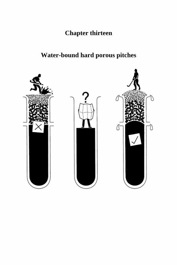
Chapter thirteen
Water-bound hard porous pitches

13.1 Function
The hard porous pitch is a non-grass surface rafted on a drained, gravel base. The surface functions very like the smooth, water-bound sand that forms continuously renewablesurfaces for play on our beaches, between tide levels.
This type of pitch does not provide the best surface for sport but it is an option that should be considered when grass cannot cope and a synthetic alternative threatens to befar too expensive. It can be a useful workhorse provided it is sensibly constructed andadequately maintained.
Unlike the expensive, wholly synthetic pitches, hard porous pitches are formed entirelyfrom particulate mineral matter and draw on the same scientific skills for design as havealready been discussed in relation to soil-based sports turf. However, in this case, we have no biological component to worry about and can give priority to factors such asdrainage, surface trueness and ease of management, albeit at some sacrifice to tractiveefficiency and comfort underfoot. It would be a pity if this simple and relatively cheap,non-grass playing surface were to lose out entirely to the sales pressure behind the muchmore expensive synthetic carpet approach because of poor choice of materials andinefficiencies in design, construction and maintenance.
13.2 General features of design
13.2.1 General layout appropriate to hard porous areas
Dissatisfaction with the performance of hard porous pitches has often been associatedwith persistent ponding in dished areas holding up play long after rainfall has ceased.This reflects the limited infiltration rate of the surfacing material and a surfaceconfiguration inadequately sloped to clear surplus water all the way to the periphery.Excavation through to the gravel layer beneath ponded areas will show that it is access tothe gravel layer, not flow through the gravel layer that is the cause.
The design of a hard porous pitch can take two forms: a uniform slope all the way across, or a central crown with even falls to a level perimeter. Choice is governed mainlyby the size and shape required, and cost. An exception is where the area is encircled by arunning track, when only the crowned type of construction is suitable. A hard poroussurface for the central area of a track may enable increased use for games throughout theyear but has the disadvantage that the hammer, discus and javelin cannot be thrownwithin the arena and a special grass area must be provided outside the track for theseevents.
Water-bound hard porous pitches 261
13.2.2 General form of the surface
The factor most likely to determine which form the design should take is the distancesurface water will have to travel to reach the perimeter and the steepness of the slope over which it will have to flow. Heavy rain on a long and/or steep slope is likely to result insevere scouring of the surface towards the bottom of the slope and a risk of fine surfacematerial being deposited in the drains and on adjacent land. To minimize this risk it isinadvisable to accept general gradients steeper than 1:80, especially where such slopesexceed a distance of 45 m (50 yards). On the other hand, too gradual a general slope, i.e.less than 1:120, is liable to result in excessive ponding in localized depressions.
Where the area to be surfaced is wider than would be permitted by the above limits, thecrown method of design should be adopted. This has the effect of limiting the length ofslope to half the width of the hard porous area, thereby greatly reducing the risk ofscouring.
13.2.3 Materials used to construct the playing surface
Without the assistance of root-binding and sward cover, surface stability on hard poroussurfaces can only be achieved by choosing materials of mixed particle-size composition and angular shape. The pore system must transmit water at more than 2–3 mm/h ( in) but must not empty by gravity, drying out instead by the relatively slow process ofevaporation upwards, e.g. a layer of fine-to-coarse sand, less than 150 mm (6 in) deep,placed over a bed of fine gravel. (Refer back to section 4.2 for a full discussion of the significance of critical tension and its role in the retention of water.) Water-binding is an essential feature of the surface layer, contributing to tractive efficiency and resistance towind erosion.
The most readily available materials used for the surface are by-products from stone quarries involved in rock crushing. These are mechanically crushed rocks with particle-size composition as summarized in Table 13.1 and Figure 13.1. A typical example, SN9, is included in Table 7.1. Because the particles are sharply angular and vary in size theywill interpack to form a relatively dense, rigid surface, retentive of water when placed ina thin layer over gravel. Drainage is controlled by the rock dust component of silt- and clay-sized particles present. When fine particle segregation reduces the infiltration rate of the surface to something less than 2–3 mm ( in)/h, even short bursts of intense rainfallmay give rise to surface flow.
Based on a survey of 15 samples, representative of nine different, marketed productsavailable in the 1970s (Table 13.1), hard porous materials are likely to contain of the order of 30–40% fine gravel, 15–20% medium-plus-fine sand, and 10–15% silt-plus-clay, with a fairly even spread between. However, this composition probably owes more to theready availability of these by-product materials than to scientific investigation. Furtherexperimentation could usefully explore the extent to which the silt-plus-clay component could be reduced and the gravel component eliminated. Despite the preponderence ofcoarse particles in hard porous, surfacing materials, it is the finer material packed into the
Sports Turf 262

pores between the larger particles that ultimately controls the rate at which water willpass through. Though the hydraulic conductivity of these materials, measured in thelaboratory or predicted from particle-size composition D 10, is likely to indicate values of the order of 25 mm/hour (1 in), irrigation water applied to established surfaces at ratesone-tenth of this have been observed to pond. This discrepancy is to be related to the practical problem of air entrapment. It further emphasizes the importance of adequatelygrading the surface so that any temporary excess of rainfall over infiltration can clear allthe way to a catchment drain at the periphery.
Wind and water movement inevitably result in the finest particles being either blownaway or washed downslope. With soft rock materials, such as 1–3, 9–11 and 15 in Table 13.1, fine-particle replenishment will result from
TABLE 13.1 Crushed rock materials used in the 1970s for hard porous, water-bound, reacreation surfaces
Attribute Measurement value
Percentage by weight for graded particle diameters (mm)
Material number c
1 2 3 4 5 6 7 8 9 10 11 12 13 14 15
Stones over 8.000
Coarse gravel 4.000–8.000
7 5 1 2 5 1 8 4 10 7 6 3 2 7 6
Fine gravel 2.000–4.000
36 33 20 31 24 17 36 42 53 49 21 21 34 22 23
Very coarse sand 1.000–2.000
12 10 20 8 9 38 8 15 12 15 13 20 20 30 21
Coarse sand 0.500–1.000
11 13 14 15 14 12 14 11 8 7 15 17 16 11 17
Medium sand 0.250–0.500
7 8 8 13 14 8 8 7 2 4 16 12 10 8 11
Fine sand 0.125–0.250
5 6 5 9 12 7 7 5 1 3 13 7 5 7 6
Very fine sand 0.060–0.125
5 6 7 5 6 5 6 5 2 1 8 5 3 2 4
Coarse silt 0.020–0.060
8 12 13 4 4 2 6 5 5 6 5 5 3 4 5
Fine silt 0.002–0.020 5 6 6 6 7 6 4 3 5 6 3 6 4 5 4
Clay less than 0.002 3 2 5 6 5 6 3 3 1 2 2 3 3 5 2
Dispersion 14 13 53 68 71 96 59 63 36 25 82 63 94 57 53
Water-bound hard porous pitches 263
wear so long as coarse-particle replenishment is maintained by topdressing. With a surfacing material from a hard rock source it could be that the dust component itself mayrequire replenishment from time to time, but before moving in this direction, it would beas well to seek clear evidence of need from an analytical survey.
As these hard porous materials can be expensive there is no point in building up a layerthicker than is necessary to avoid stud penetration through to the gravel layer beneath.Experience points to a minimum, consolidated depth of 35-40 mm (1⅜–1½ in).
13.2.4 The sub-structure
Without trying to provide for extreme conditions, it would be reasonable to design hardporous pitches in Britain to cope with a maximum, steady discharge of the order of 6 mm(¼ in) per hour through the gravel drainage bed. In most circumstances this will be more than adequate.
coefficent—percentage of total clay dispersible in water
Hardness classa 2 1 6 1 6 4 5 3 4 1 2 2 5 3 4
pH using glass electrode—water:soil ratio = 5:2
7.8 7.7 7.8 7.2 7.3 – 7.2 – 8.0 7.8 7.1 7.6 7.2 7.1
Lime statusb HC HC C SC SC SC SC NC HC HC NC HC SC SC HC
When homogeneously mixed all these materials could be characterized by their 10% summation value (D K 10%). This suggests that, on average, their hydraulic conductivity when newly laid should be approximately 25 mm (1 in)/hour. In time, however, being loose materials, particle segregation will tend to concentrate the coarser particles onto the surface, leaving the fine particles to form a much less permeable layer below. a Hardness class: 1, very soft; 2, soft; 3, fairly hard; 4, hard; 5, very hard; 6, extremely hard. b Lime status: NC, non-calcareous; SC, slightly calcareous; C, calcareous; HC, highly calcareous. c Materials (trade names): 1, Redgra 1; 2, Redgra 2; 3, Redgra 3; 4, Dripla 1; 5, Dripla 2; 6, Dripla 3; 7, Oliset 1; 8, Oliset 2; 9, Nortex 1; 10, Nortex 2; 11, PPS Redland; 12, Fyset; 13, Bolbriggan; 14, Coatsgate; 15, Red Blaes - used extensively in Scotland.
Sports Turf 264
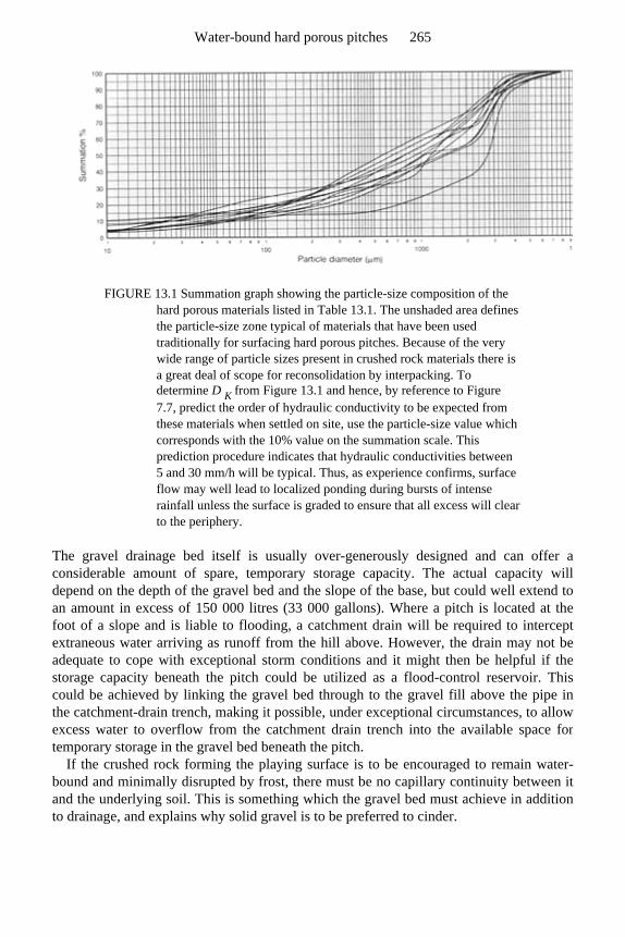
FIGURE 13.1 Summation graph showing the particle-size composition of the hard porous materials listed in Table 13.1. The unshaded area defines the particle-size zone typical of materials that have been used traditionally for surfacing hard porous pitches. Because of the very wide range of particle sizes present in crushed rock materials there is a great deal of scope for reconsolidation by interpacking. To determine D K from Figure 13.1 and hence, by reference to Figure 7.7, predict the order of hydraulic conductivity to be expected from these materials when settled on site, use the particle-size value which corresponds with the 10% value on the summation scale. This prediction procedure indicates that hydraulic conductivities between 5 and 30 mm/h will be typical. Thus, as experience confirms, surface flow may well lead to localized ponding during bursts of intense rainfall unless the surface is graded to ensure that all excess will clear to the periphery.
The gravel drainage bed itself is usually over-generously designed and can offer aconsiderable amount of spare, temporary storage capacity. The actual capacity willdepend on the depth of the gravel bed and the slope of the base, but could well extend toan amount in excess of 150 000 litres (33 000 gallons). Where a pitch is located at thefoot of a slope and is liable to flooding, a catchment drain will be required to interceptextraneous water arriving as runoff from the hill above. However, the drain may not beadequate to cope with exceptional storm conditions and it might then be helpful if thestorage capacity beneath the pitch could be utilized as a flood-control reservoir. This could be achieved by linking the gravel bed through to the gravel fill above the pipe inthe catchment-drain trench, making it possible, under exceptional circumstances, to allow excess water to overflow from the catchment drain trench into the available space fortemporary storage in the gravel bed beneath the pitch.
If the crushed rock forming the playing surface is to be encouraged to remain water-bound and minimally disrupted by frost, there must be no capillary continuity between itand the underlying soil. This is something which the gravel bed must achieve in additionto drainage, and explains why solid gravel is to be preferred to cinder.
Water-bound hard porous pitches 265
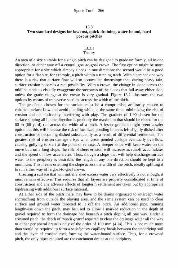
13.3 Two standard designs for low cost, quick-draining, water-bound, hard
porous pitches
13.3.1 Theory
An area of a size suitable for a single pitch can be designed to grade uniformly, all in onedirection, or either way off a central, goal-to-goal crown. The first option might be moreappropriate for a site which already slopes in one direction; the second would be a goodoption for a flat site, for example, a pitch within a running track. With clearance one waythere is a risk that surface flow will so accumulate downslope that, during heavy rain,surface erosion becomes a real possibility. With a crown, the change in slope across themidline tends to visually exaggerate the steepness of the slopes that fall away either side,unless the grade change at the crown is very gradual. Figure 13.2 illustrates the two options by means of transverse sections across the width of the pitch.
The gradients chosen for the surface must be a compromise, arbitrarily chosen to enhance surface flow and avoid ponding while, at the same time, minimizing the risk oferosion and not noticeably interfering with play. The gradient of 1:90 chosen for thesurface sloping all in one direction is probably the maximum that should be risked for the60 m (66 yard) run across the width of a pitch. A lesser gradient might seem a saferoption but this will increase the risk of localized ponding in areas left slightly dished afterconstruction or becoming dished subsequently as a result of differential settlement. Thegreatest risk of erosion damage arises when areas ponded upslope eventually overflow,causing gullying to start at the point of release. A steeper slope will keep water on themove but, on a long slope, the risk of sheet erosion will increase as runoff accumulatesand the speed of flow accelerates. Thus, though a slope that will help discharge surfacewater to the periphery is desirable, the length in any one direction should be kept to aminimum. This means orienting the slope across the width of the pitch, ideally splitting itto run either way off a goal-to-goal crown.
Creating a surface that will initially shed excess water very effectively is not enough: itmust remain effective. This requires that all layers are properly consolidated at time ofconstruction and any adverse effects of longterm settlement are taken out by appropriatetopdressing with additional surface material.
At either side of the pitch there may have to be drains organized to intercept waterencroaching from outside the playing area, and the same system can be used to clearsurface and ground water directed to it off the pitch. An additional pipe, runninglengthwise down the pitch, may be used to allow a marked reduction in the depth ofgravel required to form the drainage bed beneath a pitch sloping all one way. Under acrowned pitch, the depth of trench gravel required to clear the drainage water all the way to either peripheral drain is only of the order of 100 mm (4 in). This is not much morethan would be required to form a satisfactory capillary break between the underlying soiland the layer of crushed rock forming the water-bound surface. Thus, for a crowned pitch, the only pipes required are the catchment drains at the periphery.
Sports Turf 266

Traps and inspection chambers should be installed at either end of each pipe run to assist with the interception and clearance of silt. The looseness of the crushed rocksurface and the sorting effect of treading disturbance and frost heave will allow the fine,water-holding particles to escape into the drainage system. As this risk is greatest duringconstruction and the initial, settling down period, inspection prior to handover would be awise precaution.
The two pitches illustrated in Figure 13.2 aim to offer the best, low-cost alternatives for workaday pitches, designed to carry all the hard wear from which the grass pitches ina playing field need to be protected. The general form of the surface is established by theform into which the exposed, subsoil surface is graded, then above this, layers of trench gravel, blinding sand and crushed rock, hard porous material can be laid, each of uniformthickness. The trench gravel for the crowned pitch should be 105 mm (4¼ in) deep, and for the pitch
Water-bound hard porous pitches 267
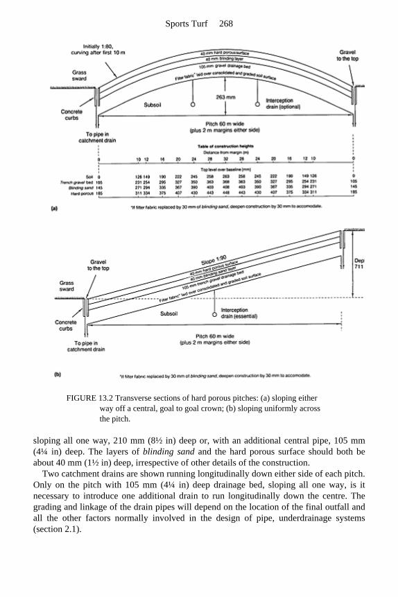
FIGURE 13.2 Transverse sections of hard porous pitches: (a) sloping either way off a central, goal to goal crown; (b) sloping uniformly across the pitch.
sloping all one way, 210 mm (8½ in) deep or, with an additional central pipe, 105 mm (4¼ in) deep. The layers of blinding sand and the hard porous surface should both be about 40 mm (1½ in) deep, irrespective of other details of the construction.
Two catchment drains are shown running longitudinally down either side of each pitch. Only on the pitch with 105 mm (4¼ in) deep drainage bed, sloping all one way, is it necessary to introduce one additional drain to run longitudinally down the centre. Thegrading and linkage of the drain pipes will depend on the location of the final outfall andall the other factors normally involved in the design of pipe, underdrainage systems(section 2.1).
Sports Turf 268

13.3.2 Calculation
Pitch sloping all one way
To calculate H, the depth of the gravel bed, follow procedures described in Appendix E2.2 (also refer to Figure 13.2(b)). The following are known:
Step 1: determine a using equation (E.31):
Step 2: determine β using relationship to a as described in the graph, Figure 13.3(a): when α =0.717, β=0.435.
Step 3: from equation (E.32)
giving
Knowing H, the depth of the gravel bed, and G, the difference in height either side of thepitch, we can if necessary calculate any one of S, K or V, knowing the other two. This can be done using equations (E.31) and (E.32), provided we can obtain values for α and β.
Step 1: from equations (E.31) and (E.32) we can relate α to β as follows
V – the overall design rate 6 mm/h
S – the width of the pitch including surrounds (drain to drain) 64 000 mm
– the slope 1/90
K – the hydraulic conductivity of the trench gravel used to form the bed 100 000 mm/h.
Water-bound hard porous pitches 269

and
This is a straight-line relationship, passing through the origin. Step 2: plot the straight-line relationship between α and β on the graph (Figure 13.3(a))
which describes the physical relationships involved in the actual construction. This canbe done by making use of the fact that when α= 0, β=0 and when α=1, β=2H/G, i.e.
The intersection between this line and the curve on the graph gives values α=0.717, β= 0.435.
Sports Turf 270
FIGURE 13.3 (a) Relationship between α and β for pitches with drainage bed sloping all one way, using equations (E.38) and (E.42). (b) Relationship between α and γ for crowned pitches with drainage bed sloping down to either side off a central crown, using equations (E.45) and (E.46).
Step 3: Using these values for α and β, equations (E.31) and (E.32) can then be used toobtain values for either S, K or V.
Instead of using 210 mm of gravel it may well be cheaper, and just as efficient to introduce an additional pipe drain to run lengthwise down the centre of the pitch, reducing S to 32 000 mm and gravel depth H to 105 mm (4¼ in).
Pitch clearing excess water to either side off a goal-to-goal crown
Water-bound hard porous pitches 271

In the following calculations it is assumed that no gradient should exceed 1:80 and itwould be practically more desirable to have a uniform, fixed depth for the graveldrainage bed.
To fix precise values to key features of the construction, follow calculation procedures described in Appendix E.2.3 and the definitions listed below; also refer to Figure 13.2 (a).
Step 1: determine a using equation (E.31):
Step 2: determine γ using relationship to a as described in the graph, Figure 13.3(b): when α =0.807, γ=0.422. Step 3: using equation (E.51)
giving
Step 4: using Equation (E.47), determine x 0, the distance from a drain at the edge of the
V – the overall design rate (6 mm/h)
G/S – the 1:80 gradient for the straight portion at either edge of the cross-sectional profile of the pitch
H – the depth of the gravel drainage bed (mm)
K – the hydraulic conductivity of the trench gravel used to form the drainage bed (100 000 mm/h)
x 1 – the total distance from the centre of the pitch to a peripheral drain, measured horizontally (mm)
x – any distance from a drain measured horizontally across the pitch (mm)
x 0 – the point along the horizontal above which the curving portion of the profile begins (mm)
g – the height above the horizontal base line (mm).
Sports Turf 272

pitch that defines the point on the surface where the uniform, 1:80 gradient begins to falloff to a steadily curving profile over the crown.
Step 5: using equation (E.50), determine the height (mm) of the top of the soil formation surface above a series of base line values for x. Choose values for x that will facilitate construction of the profile required. Height g at point x (valid only for curved portion of profile):
For x=10 100 mm (i.e. x 0)
=126 mm (i.e. for distance of 10 100 mm at gradient of 1:80, rise=126 mm). Similarly, after simplifying the calculation to
and again in reverse order for the far side of thecrown. This profile is then repeated 105 mm, 145 mm and 185 mm higher, for the top of thegravel bed, the top of the layer of blinding sand and the top of the crushed rock, surfacing material respectively (Figure 13.2(a)).
A crowned profile of this form could well be considered for use elsewhere than for
for x=12 000 mm x=16 000 mm x=20 000 mm x=24 000 mm x=28 000 mm x=32 000 mm
g=149 mm g=190 mm g=222 mm g=245 mm g=258 mm g=263 mm,
Water-bound hard porous pitches 273
hard porous pitches, e.g. beneath a suitably resilient surface, such as an outside arena forhorse riding.
13.3.3 Outline specification
1. The formation layer should be excavated and shaped to create a stable, consolidated surface of subsoil conforming exactly with one or other of the profiles illustrated in Figure 13.2. After initial site preparation the consolidated soil surface, covered with either filter fabric or 25 mm (1 in) of blinding sand, should be at a depth below the general level of the adjacent, undisturbed soil equal to the combined depth of the trench gravel, blinding sand and crushed rock layers used to create the drainage bed and playing surface. It is vital that the soil is disturbed as little as possible below excavation depth and is properly re-consolidated every 150 mm (6 in) where used as fill. Differential settlement after the whole construction is in place is a major hazard and care is required to minimize this risk.
2. Install perimeter drains along each side so as to intercept water reaching the area from surrounding land and to take water flowing out of the gravel foundation. The drains should run just inside a concrete edging, the trench at least 200 mm (8 in) wide. Pipes should be between 100 and 150 mm (4 and 6 in) in diameter according to the size of the area and the amount of water likely to be intercepted from surrounding land. See back to section 13.2.4 for a modification where precautions need to be taken against a risk of site flooding.
Ideally, the pipes should be laid to a fall of not less than 1:100, with depth to invert not less than 300 mm (12 in) below the level of the formation surface. Permeable backfill should be trench gravel, finishing at least 50 mm (2 in) proud of the formation surface so as to protect the freely porous backfill from becoming contaminated by soil as the work proceeds. They should link with other pipes via chambers with silt traps, and have access points along their length to aid inspection and jet clearance of silt. If additional, longitudinal drains are used within the pitch area they should be similar to those at the periphery.
3. Round-topped precast concrete edging, 150 ×50 mm (6×2 in), should be laid round four sides, bedded and haunched in concrete so that the top lies flush with the final surface level.
4. After applying total weedkiller to the formation surface and margins, the formation soil surface should be blinded with 25 mm (1 in) of blinding sand, or synthetic fabric filter, anchored by tucking the edge down the inner wall of the peripheral drain trenches.
5. Lay and spread a foundation, drainage layer of trench gravel to the depth indicated as appropriate in Figure 13.2. If a somewhat angular gravel is used this will assist trafficking during construction. Take pains to consolidate and true the surface to the required configuration.
6. Evenly blind the gravel drainage bed with 40 mm (1½ in) of blinding sand; true and consolidate.
Sports Turf 274
7. Lay and spread approved, crushed-rock surfacing material to an even, consolidated depth of 40 mm (1½ in) so as to finish flush with the top of the edging.
8. Initially the surface will be loose and inclined to be churned up by use unless gently firmed down, for example, by the continuous patter of feet when moist. Topdress with crushed rock to true off to the required profile overall.
9. The build-up over the level pitch margins and peripheral drains should conform with that of the pitch in general. As experience indicates where surface runoff accumulates, make local provision to clear ponded water directly into the gravel bed through a layer of fabric filter, buried at shallow depth beneath a cosmetic covering of the gravel fraction sieved out of the crushed-rock surfacing material.
13.4 Maintenance
13.4.1 Special problems likely to be revealed soon after construction
The main task of maintenance on water-bound, hard porous pitches is to keep the surfaceuniform in composition, consolidated and true, despite the tendency for a particulate,multi-particle-sized material to segregate when churned up by energetic play. Thisproblem will be worst immediately after construction but should decrease as moreeffective particle packing allows the surface to stabilize.
Differential settlement, which is also likely to be most pronounced in the initial yearsfollowing construction, may be sufficient to cause local, dished areas, liable toaccumulate surface runoff. These should be eliminated by topdressing with more surfacematerial before a deposit of eroded fine particles builds up to adversely affect infiltration.A reserve of 4–6 tonne of surfacing material will be required annually for re-truing andthe replacement of losses brought about by comminution and surface erosion.
Persistent problems of surface ponding should not occur if the surface is smooth andsuitably graded so as to clear all surface water to the periphery. However, if designed tooflat, problems of persistent surface ponding may require attention. This can beapproached in two ways. A disc, slicing device can be used to slit through the surfacematerial and reach the clean gravel below. If the slit is oriented across slope and filledwith coarse particles, either brushed off the surface or separated by sieving from the bulkreserve, it will function to intercept surface flow. However, any beneficial effect isunlikely to persist for more than a few months as surface wear will soon ensurefineparticle invasion of the coarse backfill. Alternatively, install, a small, 150 mm (6 in)diameter, readily accessible outfall in the base of each major depression so that it can beopened up to clear ponded water quickly when necessary. These covered outlets shouldtake the form of wide-necked funnels, each anchored with its neck in the underlyinggravel bed and bowl opening just below the surface. The inlet should be protected againstsilting by covering with a renewable, fabric filter, shielded against physical damage bycovering with a removable, wooden cap, lying flush with the surface.
Water-bound hard porous pitches 275

13.4.2 Surface renovation and surface protection
Routine maintenance involves luting, drag matting, brushing and rolling. Scarificationwill also be required, but only when the top needs opening up to help integrate a surfacetopdressing. Since agitation will inevitably lead to segregation of coarse particles onto thesurface, rolling should be carried out when the whole top is moist. This will make iteasier for the coarse particles to be pressed back into the finer material below. If not, theywill remain as a loose covering, unfavourable to efficient traction. The late F.W.Smith, the first Grounds Superintendent at the University of Lancaster, and great advocate ofhard porous surfaces, used to strongly advise rolling in the rain.
Provision for irrigation should be considered essential as the shallow, surface layer will readily dry out in hot weather, and then be vulnerable to windblow.
Hard porous materials are often wrongly described as ‘all weather’. In fact there are two weather-induced conditions when use should not be contemplated. Do not riskloosening the surface if irrigation cannot be used during hot weather to prevent the fineparticles required for water-binding being selectively removed by wind erosion. On noaccount use a hard porous surface after frost until it has thawed out and been thoroughlyre-consolidated by rolling. The expansion that follows the freezing of retained moisture may lead to considerable surface heave.
Salt will help to keep this type of surface ‘greasily’ moist through a dry spell and less inclined to freeze up in winter, but it will readily wash out and then encourage theleaching away of any clay component.
13.4.3 Manpower
Though much more suitable for programmed use than the normal, soil-based, grass surface, to sustain performance, provision must be made for frequent surface renovation.In practice, therefore, this type of non-grass facility should not be looked upon asallowing any very significant saving in maintenance manpower.
13.5 Further developments in the hard porous approach
13.5.1 Surfaces for schooling horses
If the blinding sand layer of a hard porous construction is overlaid with 100 mm (4 in) depth of topsoil sand, or any other medium approved for the purpose, it might well servefor the schooling of horses. In these circumstances the sand, or special alternative layer,should be placed over a layer of fabric filter to facilitate surface renewal without risk tothe integrity of the drainage bed. Provision for irrigation will be necessary to keep thesurface firmly water-bound.
Sports Turf 276

13.5.2 Nottinghamshire envelope system
Peter L.K.Dury, working in the Nottinghamshire playing-field service, has developed the idea of enveloping hard porous and dune-sand-like materials within free-draining and tractively efficient, filter fabrics (geotextiles). The early promise of this approach hasnow led on to diversification into a wide range of amenity applications from safe surfacesfor child play to cricket pitches, tennis courts and full-scale pitches for hockey and soccer. All of these have infill and surface fabrics matched to the special requirements ofthe user. Here then is a halfway house between the very expensive, wholly syntheticsurfaces, claimed to be allweather, and the much less sophisticated but relatively cheapworkhorse, the original hard porous pitch. They all aim to provide surfaces better suitedthan grass for intensive, programmed use.
Water-bound hard porous pitches 277

Chapter fourteen
DIY construction, package deals, patents, trade names and trade-sponsored literature

14.1 DIY approach to construction
14.1.1 Introduction
A well-managed complex of facilities that included, for example, a bowling green, achildren’s play area, an orderly arrangement of allotments and a multi-purpose playing field, all laid out around a club house, car park and maintenance yard, could do much tomeet the social needs of a community. In many circumstances the provision of just one ofthese facilities would be a welcome move in the right direction.
It has been a primary aim of this book to give practical support to the ideals and objectives of the National Playing Fields Association. This is a charity whose purpose isto help those who wish to use outdoor facilities for recreation. It provides grants andadvice either to assist in the improvement of existing facilities or to help create somethingentirely new. Being a charity with very limited resources it must be particularlyconcerned to achieve maximum benefit for minimum cost. One way of achieving this isto encourage community involvement in a DIY approach which may have the addedbonus of community concern for aftercare.
14.1.2 Advisory services
In previous chapters general guidance has been given to illustrate how theoreticalprinciples work out when applied to typical, practical examples. This guidance should beadequate to enable organizations intent on adopting a DIY approach to achieve this withthe technical support of the NPFA or an independent consultant.
Role of the adviser in a DIY project
1. To assist with site selection; 2. to provide the technical vetting that can eliminate mistakes in design and choice of
materials; 3. to inspect and provide guidance at critical periods during construction.
Role of the community in a DIY project
1. Planning permission must be obtained, and checks made with the local authority on arrangements for discharge of drainage water and obligations with regard to public utilities.
2. The adviser will require support in designing the various facilities, preparing layout and construction drawings, specifying the materials and staging the work.
3. The site will require marking out and checking against the specification. 4. As the construction work proceeds, it will be necessary to call on the adviser to inspect
Sports Turf 280

and instruct as each pre-determined stage in the construction is reached and before the next stage begins.
5. Working with the adviser a detailed programme of maintenance must be agreed, care having been taken at the planning stage to point out the general nature of the maintenance that will be required according to the scheme of construction adopted.
Payment
Independent advice can be a much undervalued commodity. We are happy to pay forgoods but we expect advice to be given free on the packet. The value of advice is oftennot immediately obvious and, if given verbally, tends to be regarded as a goodwilloffering. However, knowledge is a commodity well worth paying for and should not beconfused with sales talk.
An independent consultant will either work to a scale of fees based on time andexpenses, or charge a fixed percentage of the contract price. The NPFA expect the clientto cover all the expenses involved in advisory visits but may use charity money to coverthe cost of the adviser’s time.
14.1.3 Organizing community effort
Tasks
Working together can strengthen a community so that much is to be said, in a DIYproject, for spreading around the variety of tasks involved. These include:
• fund raising; • financial control; • design, preparation of drawings, specification of work and marking out; • timely ordering and provision of approved materials, equipment and mechanical aids; • timely provision of skilled manpower and willing labour; • site management to organize each stage of the work, to check on the standard of
workmanship and to maintain a tidy, wellorganized site; • organization of maintenance, from seeding onwards.
Each stage of the work should be finished off securely so that no harm will come to theprogress of the work should a long interruption intervene. Holes, trenches and depressionsshould not be left to fill up with water because no provision has been made to protectthem against surface-water flooding, or to clear accumulating water to a safe outfall.When working in the open the aim should be never to start what cannot be cleared up andmade safe before leaving.
Personnel
Recreational activities can attract a wide range of personalities. When allocating tasks fora DIY project it would be as well to remember how a psychologist is said to have
DIY construction, package deals, patents trade names 281

classified personality according to activity and intelligence:
• the active and intelligent—they are liable to develop neuroses and burn out early; • the inactive and unintelligent—they do not achieve very much but neither do they do
much harm; • the active but unintelligent—they are likely to be a menace; • the inactive but intelligent—these are the most useful because they will think twice
before committing themselves to action.
Beware the macho man, revved up with horse power and impatient to get started. Be onsite early to think ahead for him. Give simple, clear instructions for just one phase of thework at a time and keep your own, more reliable manpower to clear up afterwards. Be onsite to observe the large boulder that might otherwise end up just below the surface, orthe topsoil that was about to be buried when it should have been preserved for better useelsewhere. Reject no genuine offer of help but supervise diligently until experiencejustifies confidence.
14.2 Package deals
It is possible, at extra cost, to obtain package deals from consultants and contractorswhich may include:
1. details of model schemes requiring only local modification to fit the peculiarities of a particular site;
2. plans, specifications and details of quantities to achieve a specified purpose on a particular site;
3. a total package deal, covering both design and construction, plus immediate aftercare through to the point of handover for play.
The NPFA endeavours to keep abreast of this information and should be contacted bythose wishing to purchase information sheets listing appropriate consultants andcontractors.
Beware the tendency for package deals to escalate. From the contractor’s point of view the bigger the package that he can conveniently handle the better the financial prospectsof the deal. And the more ancillary aids he can build in, the less risk of failure. This willprotect the contractor against litigation, and suits the bigspending professionals whodemand play at any cost. It may well be cheaper to include irrigation and undersoilheating in one package along with drainage, but in most circumstances drainage alongwill suffice. Improved drainage, to the extent that it will keep the soil drier, will bringwith it less risk of damage from frost heave, and because of improved soil aeration, willencourage deeper rooting and therefore lessen the risk of sward damage from desiccation.
Many things are useful but that does not mean they are essential. Prudent spendingrequires that priorities are critically assessed, particularly when spending other people’s money.
Sports Turf 282
14.3 Patents
14.3.1 Extent of cover
Periodically, one is liable to come across mention of the fact that a particular constructionis protected by a patent. Sometimes the way this information is presented can mislead thereader into thinking that the patent covers every feature of the construction. This mayraise doubt as to the freedom with which others may develop their own design orimplement even traditional techniques to achieve their purpose.
The following advice on patent law has been checked by the NPFA and may be used as general guidance.
1. Nothing which is common knowledge can be patented. This covers traditional procedures and information freely available in the standard literature.
2. To secure a patent the inventor has to draw attention to the features of his invention that are novel and it is these only that the granting of a patent protects.
3. The impression of quality and reliability that might be given by association with the backing of the law is not always justified in practice because, for an invention to be patented, it does not necessarily have to work.
4. The DIY enthusiasts have little to fear in the patent world so long as no one involved in the special nature of the construction is using the invention for financial gain.
14.3.2 Examples
1. One sub-irrigation system of construction involves tanking an excavation with polythene, laying pipes and building a soil of a closely specified sand. The construction is said to be covered by a patent. Does this mean that any system of sub-irrigation or any sand construction is covered? In fact, sub-irrigation and constructing with sand are old ideas. In this case, all the patent actually protects is the ingenious way devised to ensure that laterals off the main fill up in an orderly succession, but this patented technique is not the only way of achieving the benefits of sub-irrigation.
2. A construction involving a thick, surface carpet of sand, used to be widely advertised, like the last, under a trade name. It drew attention to the fact that it was covered by a patent, but this lapsed in 1990. In this case sand is spread as a thick carpet over a soil drained by an integrated system of gravel channels and pipes, the sward being established directly on top of the sand carpet. Such a design sounds as if it might cover any sand-over-soil construction, but the novel feature of the invention referred to the belief, heretofore, that it was not practicable for grass seed to germinate in ‘uncontaminated sand’. The patent, therefore, only referred to a construction in which the sward was established from seed sown directly onto a surface layer of uncontaminated sand, at least 3–4 in in depth. Since it was unlikely that many people
DIY construction, package deals, patents trade names 283
would want to use sand for this purpose without including some soil, peat or other amendment, the patent had very little practical significance.
3. A lapsed patent for which application was first made in Austria in January 1965, appeared to cover all slit systems of surface drainage, but it repeatedly stressed the advantage in the invention of first strongly compacting the soil surface before slitting and seeding. The application of this patent, therefore, was again very narrowly defined, especially so when in the preamble it made clear that the strong compaction referred to was such as could be achieved by a road roller! No wonder the invention also referred to a special method of seeding involving a surface covering of straw, coated with asphalt.
It is obviously a very difficult thing to acquire the sort of all-embracing patent thatadvertisements seem sometimes to wish to imply. If in doubt, obtain a copy of the patentfrom The Patent Office, London WC2A 1AY.
14.4 Trade names
When a novel approach reaches the stage of commercial exploitation, minor variationswhich at best differ only marginally in principle, are hijacked by the marketing men forspecial promotion. This can then lead to exaggerated claims for significance based onpseudo-scientific terminology and the bogus distinction implied by a trade name.Fertilizers, weedkillers, hard porous surfacing materials, sand constructions and slitsystems of drainage, the less they differ in principle the more it seems that the distinctionof a trade name is required to secure a substantial share of the market.
14.5 Trade-sponsored literature
It would be naive to expect literature supported by advertising to be free of commercialpressures. Even technical articles are liable to be merely extensions of advertising. This isnot the type of literature to which scientists normally refer, but in a free market economywe must all learn to recognize partial information that is ‘economical with the truth’, andevaluate it accordingly.
The enthusiasm of the salesman should not be allowed to carry more weight thanexperience justifies. Though there must be some virtue in a well-tried recipe, for thesalesman it is essential to project the idea of novelty. Each year the market needs revivingand last year’s novelty has to be projected as superseded or set aside as obsolete. Toooften we have seen a minor innovation immediately proclaimed as a significantbreakthrough, but trades literature does not give equal prominence to its subsequentdemise. No sales representative is going to help you to discover the weak features of hisproduct; you must seek independent advice and then think things out for yourself, or findout by experience, too late. Listening, viewing and reading critically are skills whichrequire effort to acquire, but acquire them you must if you are to survive in a free marketsystem.
Sports Turf 284


Part Three Appendices

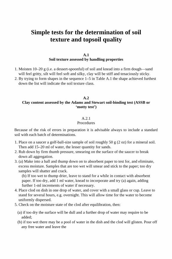
Simple tests for the determination of soil texture and topsoil quality
A.1 Soil texture assessed by handling properties
1. Moisten 10–20 g (i.e. a dessert-spoonful) of soil and knead into a firm dough—sand will feel gritty, silt will feel soft and silky, clay will be stiff and tenaciously sticky.
2. By trying to form shapes in the sequence 1–5 in Table A.1 the shape achieved furthest down the list will indicate the soil texture class.
A.2 Clay content assessed by the Adams and Stewart soil-binding test (ASSB or
‘motty test’)
A.2.1 Procedures
Because of the risk of errors in preparation it is advisable always to include a standardsoil with each batch of determinations.
1. Place on a saucer a golf-ball-size sample of soil roughly 50 g (2 oz) for a mineral soil. Then add 15–20 ml of water, the lesser quantity for sands.
2. Rub down by firm thumb pressure, smearing on the surface of the saucer to break down all aggregation.
3. (a) Make into a ball and thump down on to absorbent paper to test for, and eliminate, excess moisture. Samples that are too wet will smear and stick to the paper; too dry samples will shatter and crack.
(b) If too wet to thump drier, leave to stand for a while in contact with absorbent paper. If too dry, add 1 ml water, knead to incorporate and try (a) again, adding further 1-ml increments of water if necessary.
4. Place clod on dish in one drop of water, and cover with a small glass or cup. Leave to stand for several hours, e.g. overnight. This will allow time for the water to become uniformly dispersed.
5. Check on the moisture state of the clod after equilibration, then:
(a) if too dry the surface will be dull and a further drop of water may require to be added;
(b) if too wet there may be a pool of water in the dish and the clod will glisten. Pour off any free water and leave the
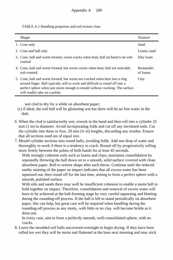
wet clod to dry for a while on absorbent paper; (c) if ideal, the soil ball will be glistening wet but there will be no free water in the
dish.
6. When the clod is satisfactorily wet, rework in the hand and then roll into a cylinder 25 mm (1 in) in diameter. Avoid incorporating folds and cut off any involuted ends. Cut the cylinder into three or four, 20 mm (¾ in) lengths, discarding any residue. Ensure that all sections used are of equal size.
7. Mould cylinder sections into round balls, avoiding folds. Add one drop of water and thoroughly re-work if there is a tendency to crack. Round off by progressively rolling more firmly between the palms of both hands for at least 45 seconds.
With strongly coherent soils such as loams and clays, maximize consolidation by repeatedly throwing the ball down on to a smooth, solid surface covered with clean absorbent paper. Roll to restore shape after each throw. Continue until the reduced earthy staining of the paper on impact indicates that all excess water has been squeezed out, then round off for the last time, aiming to form a perfect sphere with a smooth, polished surface. With silts and sands there may well be insufficient cohesion to enable a moist ball to hold together on impact. Therefore, consolidation and removal of excess water will have to be achieved at the ball-forming stage by very careful squeezing and blotting during the rounding-off process. If the ball is left to stand periodically on absorbent paper, this can help, but great care will be required when handling during the rounding-off process as any motty, with little or no clay, will become brittle as it dries out. In every case, aim to form a perfectly smooth, well-consolidated sphere, with no cracks.
8. Leave the moulded soil balls uncovered overnight to begin drying. If they have been rolled too wet they will be moist and flattened at the base next morning and may stick
TABLE A.1 Handling properties and soil texture class
Shape Texture
1. Cone only Sand
2. Cone and ball only Loamy sand
3. Cone, ball and worm formed, worm cracks when bent; ball inclined to be soft-centred
Silty loam
4. Cone, ball and worm formed, but worm cracks when bent; ball not noticably soft-centred
Remainder of loams
5. Cone, ball and worm formed, but worm not cracked when bent into a ring around finger. Ball typically stiff to work and difficult to round off into a perfect sphere when just moist enough to mould without cracking. The surface will readily take on a polish.
Clay
Appendix A 289
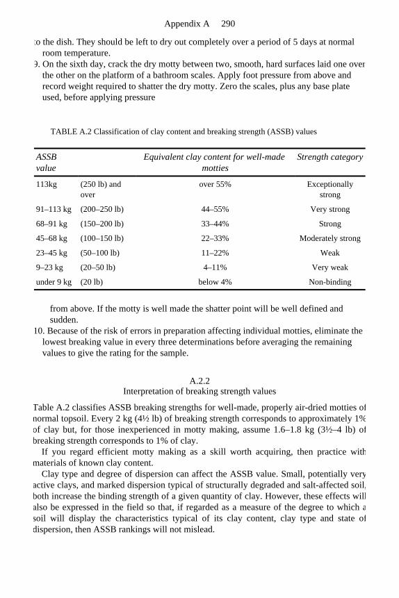
to the dish. They should be left to dry out completely over a period of 5 days at normal room temperature.
9. On the sixth day, crack the dry motty between two, smooth, hard surfaces laid one over the other on the platform of a bathroom scales. Apply foot pressure from above and record weight required to shatter the dry motty. Zero the scales, plus any base plate used, before applying pressure
from above. If the motty is well made the shatter point will be well defined and sudden.
10. Because of the risk of errors in preparation affecting individual motties, eliminate the lowest breaking value in every three determinations before averaging the remaining values to give the rating for the sample.
A.2.2 Interpretation of breaking strength values
Table A.2 classifies ASSB breaking strengths for well-made, properly air-dried motties ofnormal topsoil. Every 2 kg (4½ lb) of breaking strength corresponds to approximately 1%of clay but, for those inexperienced in motty making, assume 1.6–1.8 kg (3½–4 lb) ofbreaking strength corresponds to 1% of clay.
If you regard efficient motty making as a skill worth acquiring, then practice withmaterials of known clay content.
Clay type and degree of dispersion can affect the ASSB value. Small, potentially veryactive clays, and marked dispersion typical of structurally degraded and salt-affected soil,both increase the binding strength of a given quantity of clay. However, these effects willalso be expressed in the field so that, if regarded as a measure of the degree to which asoil will display the characteristics typical of its clay content, clay type and state ofdispersion, then ASSB rankings will not mislead.
TABLE A.2 Classification of clay content and breaking strength (ASSB) values
ASSB value
Equivalent clay content for well-made motties
Strength category
113kg (250 lb) and over
over 55% Exceptionally strong
91–113 kg (200–250 lb) 44–55% Very strong
68–91 kg (150–200 lb) 33–44% Strong
45–68 kg (100–150 lb) 22–33% Moderately strong
23–45 kg (50–100 lb) 11–22% Weak
9–23 kg (20–50 lb) 4–11% Very weak
under 9 kg (20 lb) below 4% Non-binding
Appendix A 290
A.3 Modification of the motty test to assess topdressing compatibility with the
topsoil already in place
As reported in Parks and Sports Grounds, May, 1987, Dr W.A.Adams has now introduced a modification to the motty test which is of particular value for checking onthe compatibility of different clay soil top-dressings used to promote pace on cricketpitches. The modification involves joining two half-motties together along the flattened face of each hemisphere. To help achieve a firm join, avoid trapping air along thejunction by ponding water over the upturned face of one hemisphere, then, after wettingthe face of the other hemisphere, bring the two together by inverting the secondhemisphere over the ponded surface of the first. Place the composite motty on absorbentpaper for a while to dry off excess water, and when no longer too tacky to handle,remould and consolidate into a ball, dry and determine breaking strength, asrecommended for loams and clays in paragraphs 7–9 of section A 2.1. If there is excessive differential shrinkage between the two halves on drying then the motty willreadily separate along the boundary. Compatible soils will hold together until the whole motty shatters at random. This difference cannot be confidently predicted fromdifferences in clay content alone, other factors such as clay type and state of dispersionalso being involved.
Needless to say, only materials that cohere well in such a test with the existing surfacesoil should be used for topdressing. This also suggests that when trying to effect changeby upgrading the binding strength of the soil used for topdressing, progress may have tobe gradual.
A.4 Sand content assessed by decantation of the silt and clay
When all the mineral particles in a soil have been freed to act as individuals they settleout in water at very different rates according to size. From a totally dispersed sample, 180mm (7 in) deep, left to sediment out in still water, all the sand will have settled to thebottom in one minute. A decantation of the supernatant will then contain only silt andclay. Repeated dispersions, followed by decantation, will eventually remove all the siltand clay, leaving only the sand.
For practical reasons it is probably best to carry out this determination starting with a cup-sized sample of soil left to dry for a week at room temperature and passed through a 2 mm sieve. From this weigh out 110 g (4 oz will do) for typical topsoil (5–10% organic matter), or 103 g for subsoil, and then puddle, using no more than a cupful of water.Work in a 9-litre (2-gallon) bucket, and rub the soil against the wall of the bucket with a pliable spatula. To assist with clay dispersion, add to the water a pinch of table salt and apinch, or a few drops of a non-frothing detergent (e.g. Calgon). The aim should be to free the individual soil particles by rubbing down any granular aggregations between thefingers. Once the soil has been converted to a smooth paste, make up with water to a
Appendix A 291
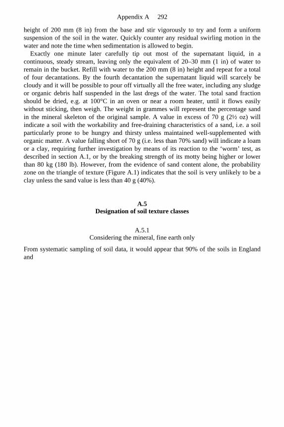
height of 200 mm (8 in) from the base and stir vigorously to try and form a uniformsuspension of the soil in the water. Quickly counter any residual swirling motion in thewater and note the time when sedimentation is allowed to begin.
Exactly one minute later carefully tip out most of the supernatant liquid, in a continuous, steady stream, leaving only the equivalent of 20–30 mm (1 in) of water to remain in the bucket. Refill with water to the 200 mm (8 in) height and repeat for a totalof four decantations. By the fourth decantation the supernatant liquid will scarcely becloudy and it will be possible to pour off virtually all the free water, including any sludgeor organic debris half suspended in the last dregs of the water. The total sand fractionshould be dried, e.g. at 100°C in an oven or near a room heater, until it flows easilywithout sticking, then weigh. The weight in grammes will represent the percentage sandin the mineral skeleton of the original sample. A value in excess of 70 g (2½ oz) will indicate a soil with the workability and free-draining characteristics of a sand, i.e. a soilparticularly prone to be hungry and thirsty unless maintained well-supplemented with organic matter. A value falling short of 70 g (i.e. less than 70% sand) will indicate a loamor a clay, requiring further investigation by means of its reaction to the ‘worm’ test, as described in section A.1, or by the breaking strength of its motty being higher or lowerthan 80 kg (180 lb). However, from the evidence of sand content alone, the probabilityzone on the triangle of texture (Figure A.1) indicates that the soil is very unlikely to be aclay unless the sand value is less than 40 g (40%).
A.5 Designation of soil texture classes
A.5.1 Considering the mineral, fine earth only
From systematic sampling of soil data, it would appear that 90% of the soils in Englandand
Appendix A 292
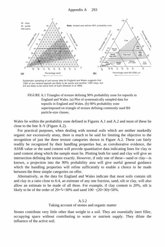
FIGURE A.1 Triangles of texture defining 90% probability zone for topsoils in England and Wales. (a) Plot of systematically sampled data for topsoils in England and Wales. (b) 90% probability zone superimposed on triangle of texture defining commonly used BS particle-size classes.
Wales lie within the probability zone defined in Figures A.1 and A.2 and most of these lie close to the line X-Y (Figure A.2).
For practical purposes, when dealing with normal soils which are neither markedly organic nor excessively stony, there is much to be said for limiting the objective to therecognition of just the three texture categories shown in Figure A.2. These can fairly readily be recognized by their handling properties but, as corroborative evidence, theASSB value or the sand content will provide quantitative data indicating lines for clay orsand content along which the sample must lie. Plotting both for sand and clay will give anintersection defining the texture exactly. However, if only one of these—sand or clay—is known, a projection into the 90% probability area will give useful general guidancewhich the handling properties will refine sufficiently to enable a choice to be madebetween the three simple categories on offer.
Alternatively, as the data for England and Wales indicate that most soils contain siltand clay in a ratio close to 6:4, an estimate of any one fraction, sand, silt or clay, will alsoallow an estimate to be made of all three. For example, if clay content is 20%, silt islikely to be of the order of 20× =30% and sand 100 −(20+30)=50%.
A.5.2 Taking account of stones and organic matter
Stones contribute very little other than weight to a soil. They are essentially inert filler,occupying space without contributing to water or nutrient supply. They dilute theinfluence of the active soil.
Appendix A 293
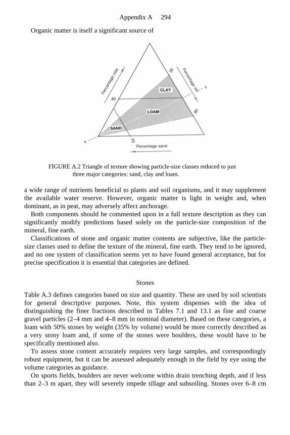
Organic matter is itself a significant source of
FIGURE A.2 Triangle of texture showing particle-size classes reduced to just three major categories: sand, clay and loam.
a wide range of nutrients beneficial to plants and soil organisms, and it may supplementthe available water reserve. However, organic matter is light in weight and, whendominant, as in peat, may adversely affect anchorage.
Both components should be commented upon in a full texture description as they cansignificantly modify predictions based solely on the particle-size composition of the mineral, fine earth.
Classifications of stone and organic matter contents are subjective, like the particle-size classes used to define the texture of the mineral, fine earth. They tend to be ignored,and no one system of classification seems yet to have found general acceptance, but forprecise specification it is essential that categories are defined.
Stones
Table A.3 defines categories based on size and quantity. These are used by soil scientistsfor general descriptive purposes. Note, this system dispenses with the idea ofdistinguishing the finer fractions described in Tables 7.1 and 13.1 as fine and coarse gravel particles (2–4 mm and 4–8 mm in nominal diameter). Based on these categories, a loam with 50% stones by weight (35% by volume) would be more correctly described asa very stony loam and, if some of the stones were boulders, these would have to bespecifically mentioned also.
To assess stone content accurately requires very large samples, and correspondingly robust equipment, but it can be assessed adequately enough in the field by eye using thevolume categories as guidance.
On sports fields, boulders are never welcome within drain trenching depth, and if lessthan 2–3 m apart, they will severely impede tillage and subsoiling. Stones over 6–8 cm
Appendix A 294
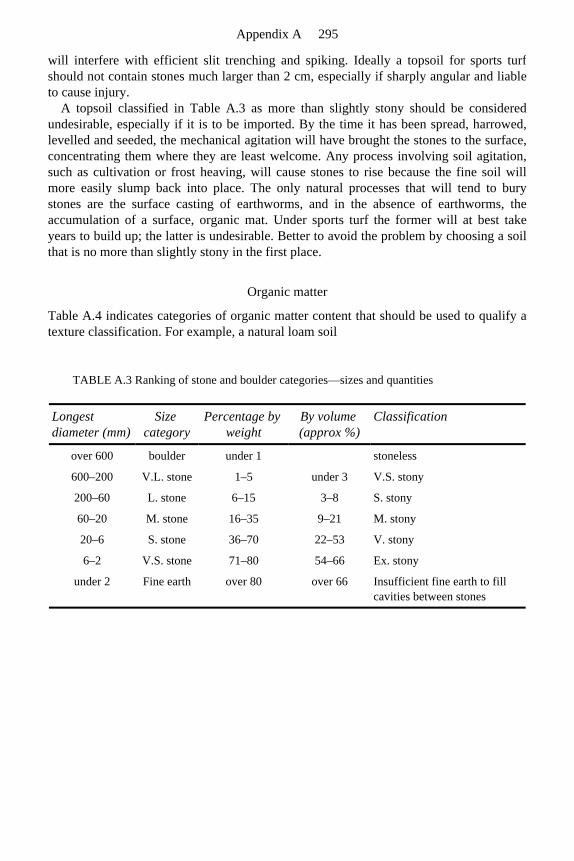
will interfere with efficient slit trenching and spiking. Ideally a topsoil for sports turfshould not contain stones much larger than 2 cm, especially if sharply angular and liableto cause injury.
A topsoil classified in Table A.3 as more than slightly stony should be consideredundesirable, especially if it is to be imported. By the time it has been spread, harrowed,levelled and seeded, the mechanical agitation will have brought the stones to the surface,concentrating them where they are least welcome. Any process involving soil agitation,such as cultivation or frost heaving, will cause stones to rise because the fine soil willmore easily slump back into place. The only natural processes that will tend to burystones are the surface casting of earthworms, and in the absence of earthworms, theaccumulation of a surface, organic mat. Under sports turf the former will at best takeyears to build up; the latter is undesirable. Better to avoid the problem by choosing a soilthat is no more than slightly stony in the first place.
Organic matter
Table A.4 indicates categories of organic matter content that should be used to qualify a texture classification. For example, a natural loam soil
TABLE A.3 Ranking of stone and boulder categories—sizes and quantities
Longest diameter (mm)
Size category
Percentage by weight
By volume (approx %)
Classification
over 600 boulder under 1 stoneless
600–200 V.L. stone 1–5 under 3 V.S. stony
200–60 L. stone 6–15 3–8 S. stony
60–20 M. stone 16–35 9–21 M. stony
20–6 S. stone 36–70 22–53 V. stony
6–2 V.S. stone 71–80 54–66 Ex. stony
under 2 Fine earth over 80 over 66 Insufficient fine earth to fill cavities between stones
Appendix A 295
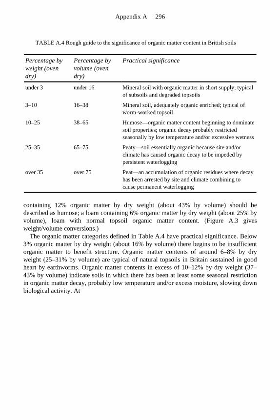
containing 12% organic matter by dry weight (about 43% by volume) should bedescribed as humose; a loam containing 6% organic matter by dry weight (about 25% byvolume), loam with normal topsoil organic matter content. (Figure A.3 gives weight/volume conversions.)
The organic matter categories defined in Table A.4 have practical significance. Below 3% organic matter by dry weight (about 16% by volume) there begins to be insufficientorganic matter to benefit structure. Organic matter contents of around 6–8% by dry weight (25–31% by volume) are typical of natural topsoils in Britain sustained in goodheart by earthworms. Organic matter contents in excess of 10–12% by dry weight (37–43% by volume) indicate soils in which there has been at least some seasonal restrictionin organic matter decay, probably low temperature and/or excess moisture, slowing downbiological activity. At
TABLE A.4 Rough guide to the significance of organic matter content in British soils
Percentage by weight (oven dry)
Percentage by volume (oven dry)
Practical significance
under 3 under 16 Mineral soil with organic matter in short supply; typical of subsoils and degraded topsoils
3–10 16–38 Mineral soil, adequately organic enriched; typical of worm-worked topsoil
10–25 38–65 Humose—organic matter content beginning to dominate soil properties; organic decay probably restricted seasonally by low temperature and/or excessive wetness
25–35 65–75 Peaty—soil essentially organic because site and/or climate has caused organic decay to be impeded by persistent waterlogging
over 35 over 75 Peat—an accumulation of organic residues where decay has been arrested by site and climate combining to cause permanent waterlogging
Appendix A 296
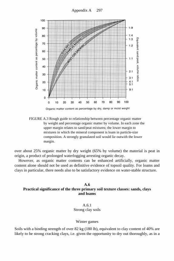
FIGURE A.3 Rough guide to relationship between percentage organic matter by weight and percentage organic matter by volume. In each zone the upper margin relates to sand/peat mixtures; the lower margin to mixtures in which the mineral component is loam in particle-size composition. A strongly granulated soil would lie outwith the lower margin.
over about 25% organic matter by dry weight (65% by volume) the material is peat inorigin, a product of prolonged waterlogging arresting organic decay.
However, as organic matter contents can be enhanced artificially, organic mattercontent alone should not be used as definitive evidence of topsoil quality. For loams andclays in particular, there needs also to be satisfactory evidence on water-stable structure.
A.6 Practical significance of the three primary soil texture classes: sands, clays
and loams
A.6.1 Strong clay soils
Winter games
Soils with a binding strength of over 82 kg (180 lb), equivalent to clay content of 40% arelikely to be strong cracking clays, i.e. given the opportunity to dry out thoroughly, as in a
Appendix A 297
long dry summer, they will form a system of deep cracks. If these are filled from the surface with fine, dry sand they will continue to assist with surface drainage throughoutthe succeeding winter.
To ensure a good packing of sand within the cracks, the sand-filling operation should be carried out with a uniform fine sand, when both sand and surface are dry, and thecracks wide open. Six millimetres (¼ in) of sand, equivalent to 100 tonnes/hectare (40 tons/acre), spread over the surface and brushed into the cracks, would not be an overestimate of the amount of sand required in the initial application. Topping up will benecessary in succeeding years when conditions are dry enough to re-open the cracks again.
Because of the tendency for strong clay soils to structure themselves by cracking, andthen to maintain this form by virtue of their binding strength, they are the soils mostlikely to respond favourably to mole ploughing (Chapter 2, page 35). For this reason, true clay soils are a much better proposition for drainage then the silty soils with which theyare so frequently confused. It is inadvisable therefore, to assume a texture based solely onsuperficial evidence without checking by means of a motty test. The difference in bindingstrength between silt and clay is so obvious that it leaves no margin for doubt.
Cricket tables
Pace is an essential feature of the performance of a cricket pitch and for this the claycontent of the soil is critical (Table 12.4, page 185). Appropriate ASSB values are as follows:
1. school and club standard, where durable pace is secondary to trueness and ease of preparation, 36–64 kg (80–140 lb);
2. first class County standard, where skilled time-consuming preparation is essential, 64–82 kg (140–180 lb);
3. breaking strength at which pitch preparation is likely to be difficult, and an inadequately prepared pitch dangerous, 82 kg (180 lb) and over.
A.6.2 Weak, very sandy soils
Soils with a binding strength of under 18 kg (40 lb), equivalent to a clay content of 9%,are likely to be sands, loamy sands or low clay versions of silt loams. To furtherdistinguish between these three alternatives, use handling properties or visualexamination (section A.1).
If revealed to be a loamy sand, such a soil can be expected to retain a useful amount of rapid drainage, even when compact, providing the infiltered water can be adequatelydischarged below ground.
If revealed to be a sandy silt loam or a silt loam, (i.e. less than 70% sand and less than 10% clay) such a soil should be avoided where, as under sports turf, it cannot berepeatedly cultivated. It will be inclined to slump and retain moisture. Water may not liefor long on the surface but the problem will be to clear water from the uniform, fine poresystem of the soil itself.
Appendix A 298
Even amongst soils more than 70% sand, problems of drainage can arise.
1. If the sand component is not of a uniform, particle-size composition, e.g. if it does not have of the order of 80% in the medium-to-fine (0.125–0.500 mm) particle-size range. Too wide a range of particle sizes allows for a substantial amount of interpacking within the sand itself, reducing the amount of silt and clay required to block the remaining pore space. Contrast the cement required to make up a cement mortar with that required for an equal volume of concrete. Where there is a wide range of particle sizes present in a sand, e.g. no two adjacent categories together exceeding 80%, then it may not be until the total sand content exceeds 90% that there will be insufficient silt and clay to fill the available pore space when the soil is compact.
2. If the silt and clay present is allowed to segregate into layers. This is particularly liable to happen if the clay is freely dispersible in water, i.e. not associated with organic matter in water-stable clusters. Such a dispersed state is typical of soil that has been stockpiled (refer to section A.7).
A.6.3 Loamy soils
The sands and strong clays together constitute only one quarter of the soils of Englandand Wales. The loams, that is soils with no more than 70% sand or 40% clay, are by farour commonest soils. For them particle aggregation is essential to provide the properbalance of water retentive (small) and free-draining (large) pores required to ensure an acceptable air/ water balance. As already discussed in section 1.4, with a fairly balanced mixture of particle sizes we do not automatically get the nice mixture of large and smallpores that one might expect because the different particle-size grades tend to interpack, leaving the finer grades in control of the pore space. Therefore, to provide a free-draining, macro-pore system in a loamtextured soil some form of aggregation into water-stable granules is absolutely essential.
Soil granulation in the loams is primarily a by-product of the processing of soil by earthworms, as they burrow and process fresh organic residues into the mineral soil.Typically it occurs under grass but only when earthworms are present.
In sports turf the twin problems of soil compaction and thatch appear when earthworms are absent. Associated features are: surface rooting, sensitivity to drought, and problemswith those pests and diseases that are encouraged by an organic-rich surface and the absence of earthworm browsing.
However, water-stable, soil granulation, though fairly stable to the patter of raindrops, cannot survive the sort of foot traffic that a football pitch receives in the winter. Whenpresent in such circumstances earthworms will continually re-open their burrows and thereby contribute to drainage, but the loss of soil granulation between the worm burrowsensures that the bulk of the soil is compact and water holding. When earthworm activityis absent, as on many made-up sites, or discouraged by the acidity promoted by sulphate-rich fertilizers, or failure to lime, a loam can rapidly become surface waterlogged, evenwhen perched over a free-draining gravel bed that is no more than 150 mm (6 in) under the surface.
Where a loam soil is to be subject to intensive winter use, beyond the capacity of an
Appendix A 299
active earthworm population to continually rehabilitate, spiking and surface sanding canat best provide only temporary relief. In fact, spiking, if overdone, can lead to newproblems of subsurface compaction. The only long-term solution for sports use is to install an intensive system of surface-opening, vertical slits, stabilized by appropriate permeable fill, and linked for discharge below into a pipe, or soakaway system.
A.7 Assessment of topsoil condition in loamy soils
A loam in good condition is likely to be associated with visual evidence of the presenceof earthworms, including their casts and burrows. There will be no evidence of a surface,organic mat. Instead, the organic matter content (5–10%) and the roots will be evenly distributed throughout a surface layer of soil, typically 225 mm (9 in)—300 mm (12 in) deep, well aggregated and water stable. The pH will probably lie between 5.5 and 7.5,limits ideal both for earthworms and grass.
As the water-stable aggregation is both the consequence of all the conditions being right to encourage earthworm activity, and the cause of the fertility which benefits grass growth, a test to assess the degree to which a loam soil is water-stably aggregated can be used as a general criterion of quality.
To carry out the simplest form of this test, air dry the soil, then sieve off any loose particles that will pass a domestic, culinary or flour sieve. Place a dessert spoonful of thematerial retained on the sieve into a glass containing approximately 100 mm (4 in) depthof cold water. Leave to soak for five minutes and then swirl ten times. If the solutionrapidly clears and the granules of the soil remain more-or-less coherent, the structure is water stable and the soil could be expected to be of a kind that a farmer would describe astopsoil in ‘good heart’. Check if the soil units that appear to be stable are indeed single,solid particles, or aggregates of particles that will crush down further to smallercomponents merely under finger pressure.
This test is not appropriate for sands, loamy sands and loams which have insufficient clay (less than 10%) to hold a structure. They will probably break down completely at thedry sieving stage anyway. However, of these, the sands and loamy sands have more than70% sand and can be readily amended for use as free-draining topsoils, merely by the addition of an organic compost. Loams with less than 10% clay are uncommon and arepotentially quite difficult to manage, even for agriculture, unless the cropping system andthe climate allow for periodic, mechanical disturbance to relieve compaction.
To improve the quality of the water-stability test there are several modifications that should be considered:
1. The whole sample can be used—set aside until just brittle-dry, then ease clods apart, teasing out roots so as to create a tilth that will all pass a 10-mm (¼–⅜-in) riddle. Avoid working the soil when it is inclined to smear or dust.
2. Sub-samples of the total soil sample prepared as above should be compared with:
(a) samples of similar texture but of known subsoil origin; (b) a selection of earthworm casts from the surface of a soil of similar texture, under
Appendix A 300

grass, and/or topsoil from undisturbed land around the edge of the field.
The aim should be to provide a scale of comparison ranging from the worst to the best that could reasonably be expected for the texture of the soil under examination.
3. Allow about one hour for the soil to soak, then swirl and allow five minutes for the material to settle. Note the relative cloudiness of the supernatant liquid. Looking up through the base of the glass beaker, against the light, decant off the supernatant if particularly cloudy, and then observe the extent to which the aggregation has remained water stable. The less cloudy the supernatant and the greater the amount of water-stable aggregation the better is the condition of the soil.
4. A loam or clay in good heart will settle out in water to leave a clear, or translucent, supernatant solution with light showing through the gaps between granules. This is best seen when the solution is gently agitated and viewed from below, against the light. A loam, or clay in poor condition will leave a cloudy effect in the supernatant solution, varying a little in proportion to the silt and clay content of the soil; any aggregation will collapse to form an opaque sludge at the base of the beaker. A chalk or limestone soil, because of its high lime content, may cause the supernatant solution to clear by flocculating any suspended clay. However, the true state of affairs will be evident in the curdiness of the flocculated deposit compared with the discrete, granular character of water-stable aggregates.
Appendix A 301

Simple tests for Stewart zone materials
For all materials it is assumed here that particle shape and mineral composition issatisfactory.
B.1 Stewart zone topsoil sand (uniform fine sand)
Often, small local suppliers are unable to provide numerical data to assist with theselection of appropriate sands. However, they are usually aware of the general nature oftheir materials and describe them either in terms of their use, or their source. Sands,described variously as dune, building, plaster, masonry, foundry or filter sands are allcandidates for consideration as topsoil sands. First eliminate the coarse, concreting and horticultural sharp sands by carrying out the sieve tests in section B.2 below. Use can then be made of a simple, infiltration test to weed out those that are too fine and dusty todo the job efficiently.
To carry out the hydraulic conductivity test use a cylindrical container, ideally 100–150 mm (4–6 in) tall, such as an old tin or plastic flower pot with the base removed and replaced by a muslin-covered fine mesh filter. The muslin should not be so coarse as toallow more than dust through from the fine sand, and should not be so fine as to preventwater passing through in a matter of seconds rather than minutes.
With the filter in place, fill the container half full of the fine sand under test, leaving 75mm (3 in) empty above. Stand in a bowl so that the base of the container will allow wateraccess from below. Fill the outer bowl with water to above the level of the sand in theinner container, maintaining this level until the surface of the sand within the containerbecomes wet. Tap the container to eliminate air bubbles and settle the sand, then top upwith more sand if necessary to compensate for any fall below halfway. Fill both the outerbowl and inner container with water until flush with the rim of the inner, sand-filled container.
Starting with the sand container brimming with water, lift it out of the bowl, resting it on a makeshift stand that will allow free drainage. Note the time taken for the water levelin the sand container to fall from the rim of the container to the surface of the sand. Thesand taking the least time to clear the 75 mm (3 in) column of water, from the rim to thesurface of the sand, will be the best. Times taken may vary from a few minutes to a fewhours, but a suitable material would take something of the order of 5–10 minutes.

B.2 Stewart zone blinding sand
The hydraulic conductivity test is not alone sufficient for selecting Stewart zone blindingsands from amongst fine sands, concreting sands or sharp sands. Its hydraulicconductivity, measured in the manner described in section B.1, is similar to or only a little faster than that of a Stewart zone topsoil sand, i.e. typically 1–5 minutes. However, it will have to be distinguished further by having 20–50% of coarse particles larger than 1 mm (i.e. failing to pass a domestic flour sieve).
B.3 Stewart zone trench gravel
A typical Stewart zone trench gravel will have 90% of particles between 2 mm in) and 12 mm (½ in) in effective diameter, with the great majority close to 6 mm (¼ in). This can be checked by using appropriate sieves or, more simply, by direct measurement ofindividual particles, using a ruler.
Appendix B 304
Soil and sand amelioration
C.1 Soil amelioration with sand
The long-term benefits from adding sand to soil as a means of improving drainage aregenerally much overrated. Theoretically, silt and clay need not be present as more than40% of the whole to fill all the pore space in the sand and thereby control drainage.However, even if the silt and clay content is reduced to just 10–15% of the whole it may still have a dramatic adverse effect on water flow, despite not filling all the pore space.Silt and clay particles are so much smaller than sand particles that they may filter downand concentrate in layers, e.g. above a filter fabric barrier. Alternatively, as one marble inthe right place can control drainage through the neck of a funnel, so silt and clay can dolikewise by blocking the narrow necks in a closely packed arrangement of sand particles.
To ameliorate a loam or clay-textured soil for use under sports turf, the minimum aimshould be to retain an excess of free-draining pore space (macro-pore space) over that which could be filled by the available silt and clay. In practice this means that we shouldbring the medium-to-fine sand content in the mix to a minimum of 75% (e.g. SN18 inTable 7.1). To achieve this with the minimum amount of sand, the sand itself must have amedium-to-fine sand content of the order of 90% or over.
As a general rule, adding sand is most effective in improving drainage when it is keptapart from the original soil, in core holes or vertical slits. When ameliorating a soil withsand, therefore, it would seem to be inappropriate to struggle too hard to achieve anintimately blended mixture when a more heterogeneous, randomly streaky mixture couldbe more effective. In the same way, every effort should be made to preserve any naturalgranulation in the original soil rather than cause this to collapse through a mixing processakin to grinding.
Because so much sand is normally required to effectively ameliorate a problem soil,some thought should be given to the object of the exercise as a whole. This is especiallyso when, as is generally the case, soil ameliration alone may achieve little unlessprovision is also made for the effective release of excess water to drainage from the baseof the ameliorated layer. As suggested in the example that follows, it may well be moreeffective to improve the drainage and nutrient status of the existing soil, then simplycover the surface with sand as in a sand-over-soil construction (section 11.3.2).
C.1.1 Calculation
To bring a given depth of existing soil up to a minimum content of 75% medium-plus-fine sand, use the following procedure.
1. Determine the medium-plus-fine sand content of the mineral skeleton of the original
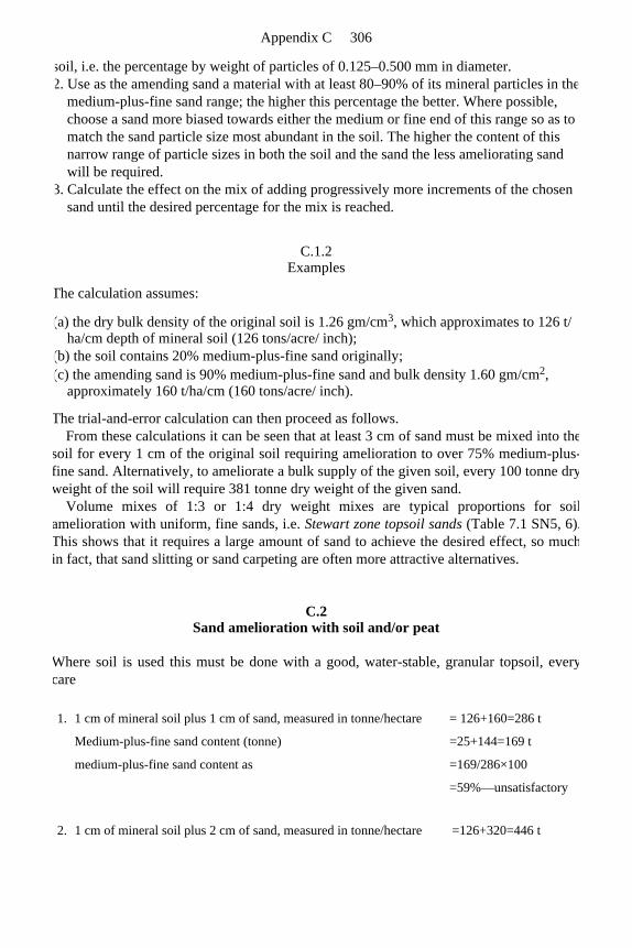
soil, i.e. the percentage by weight of particles of 0.125–0.500 mm in diameter. 2. Use as the amending sand a material with at least 80–90% of its mineral particles in the
medium-plus-fine sand range; the higher this percentage the better. Where possible, choose a sand more biased towards either the medium or fine end of this range so as to match the sand particle size most abundant in the soil. The higher the content of this narrow range of particle sizes in both the soil and the sand the less ameliorating sand will be required.
3. Calculate the effect on the mix of adding progressively more increments of the chosen sand until the desired percentage for the mix is reached.
C.1.2 Examples
The calculation assumes:
(a) the dry bulk density of the original soil is 1.26 gm/cm3, which approximates to 126 t/ ha/cm depth of mineral soil (126 tons/acre/ inch);
(b) the soil contains 20% medium-plus-fine sand originally; (c) the amending sand is 90% medium-plus-fine sand and bulk density 1.60 gm/cm2,
approximately 160 t/ha/cm (160 tons/acre/ inch).
The trial-and-error calculation can then proceed as follows. From these calculations it can be seen that at least 3 cm of sand must be mixed into the
soil for every 1 cm of the original soil requiring amelioration to over 75% medium-plus-fine sand. Alternatively, to ameliorate a bulk supply of the given soil, every 100 tonne dryweight of the soil will require 381 tonne dry weight of the given sand.
Volume mixes of 1:3 or 1:4 dry weight mixes are typical proportions for soilamelioration with uniform, fine sands, i.e. Stewart zone topsoil sands (Table 7.1 SN5, 6).This shows that it requires a large amount of sand to achieve the desired effect, so muchin fact, that sand slitting or sand carpeting are often more attractive alternatives.
C.2 Sand amelioration with soil and/or peat
Where soil is used this must be done with a good, water-stable, granular topsoil, everycare
1. 1 cm of mineral soil plus 1 cm of sand, measured in tonne/hectare = 126+160=286 t
Medium-plus-fine sand content (tonne) =25+144=169 t
medium-plus-fine sand content as =169/286×100
=59%—unsatisfactory
2. 1 cm of mineral soil plus 2 cm of sand, measured in tonne/hectare =126+320=446 t
Appendix C 306
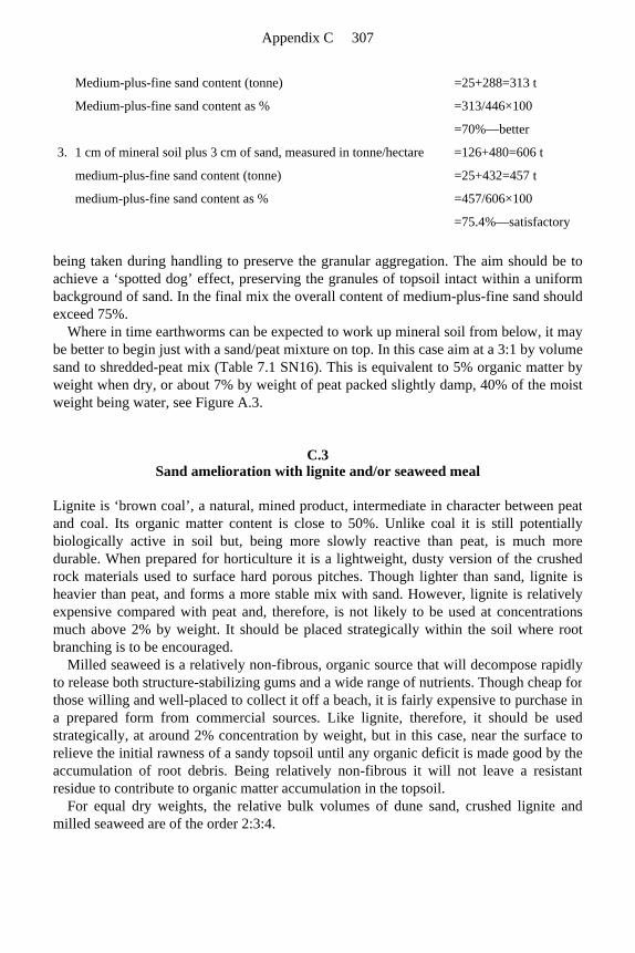
being taken during handling to preserve the granular aggregation. The aim should be toachieve a ‘spotted dog’ effect, preserving the granules of topsoil intact within a uniform background of sand. In the final mix the overall content of medium-plus-fine sand should exceed 75%.
Where in time earthworms can be expected to work up mineral soil from below, it maybe better to begin just with a sand/peat mixture on top. In this case aim at a 3:1 by volumesand to shredded-peat mix (Table 7.1 SN16). This is equivalent to 5% organic matter by weight when dry, or about 7% by weight of peat packed slightly damp, 40% of the moistweight being water, see Figure A.3.
C.3 Sand amelioration with lignite and/or seaweed meal
Lignite is ‘brown coal’, a natural, mined product, intermediate in character between peatand coal. Its organic matter content is close to 50%. Unlike coal it is still potentiallybiologically active in soil but, being more slowly reactive than peat, is much moredurable. When prepared for horticulture it is a lightweight, dusty version of the crushedrock materials used to surface hard porous pitches. Though lighter than sand, lignite isheavier than peat, and forms a more stable mix with sand. However, lignite is relativelyexpensive compared with peat and, therefore, is not likely to be used at concentrationsmuch above 2% by weight. It should be placed strategically within the soil where rootbranching is to be encouraged.
Milled seaweed is a relatively non-fibrous, organic source that will decompose rapidlyto release both structure-stabilizing gums and a wide range of nutrients. Though cheap forthose willing and well-placed to collect it off a beach, it is fairly expensive to purchase in a prepared form from commercial sources. Like lignite, therefore, it should be usedstrategically, at around 2% concentration by weight, but in this case, near the surface torelieve the initial rawness of a sandy topsoil until any organic deficit is made good by theaccumulation of root debris. Being relatively non-fibrous it will not leave a resistant residue to contribute to organic matter accumulation in the topsoil.
For equal dry weights, the relative bulk volumes of dune sand, crushed lignite and milled seaweed are of the order 2:3:4.
Medium-plus-fine sand content (tonne) =25+288=313 t
Medium-plus-fine sand content as % =313/446×100
=70%—better
3. 1 cm of mineral soil plus 3 cm of sand, measured in tonne/hectare =126+480=606 t
medium-plus-fine sand content (tonne) =25+432=457 t
medium-plus-fine sand content as % =457/606×100
=75.4%—satisfactory
Appendix C 307

C.4 Mixing precautions when ameliorating sand with shredded peat, milled
seaweed or crushed lignite
The problem, whether mixing is achieved offsite or on-site, is that the lighter, organic materials will tend to re-segregate if agitated, especially when dry. A slightly moist mixis more stable but may be more difficult to spread.
To mix in situ, place the organic components in a layer within cultivation depth by aspringtine harrow (or some similar implement), then work carefully upwards through acovering layer of sand. Avoid excessive cultivation or most of the organic matter will endup on the surface where it should not be.
Appendix C 308

This page intentionally left blank.
Appendix C 309
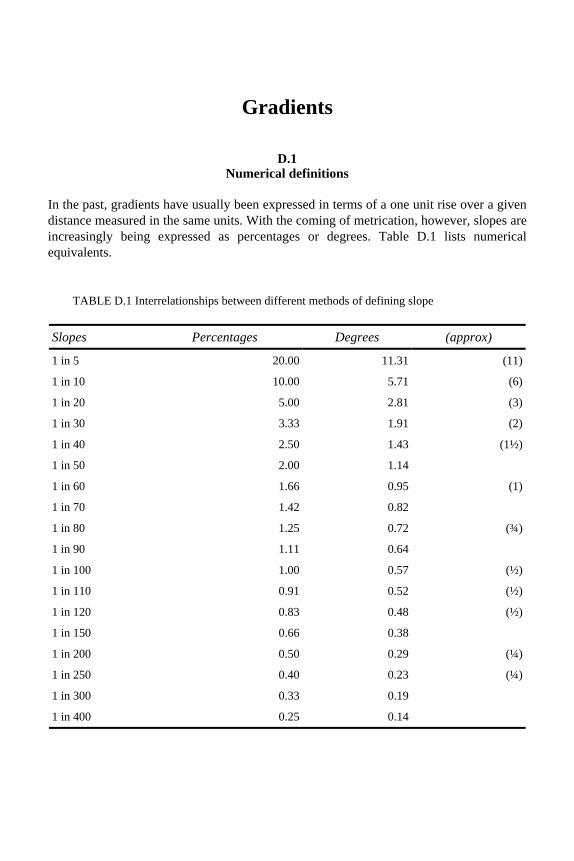
Gradients
D.1 Numerical definitions
In the past, gradients have usually been expressed in terms of a one unit rise over a givendistance measured in the same units. With the coming of metrication, however, slopes areincreasingly being expressed as percentages or degrees. Table D.1 lists numerical equivalents.
TABLE D.1 Interrelationships between different methods of defining slope
Slopes Percentages Degrees (approx)
1 in 5 20.00 11.31 (11)
1 in 10 10.00 5.71 (6)
1 in 20 5.00 2.81 (3)
1 in 30 3.33 1.91 (2)
1 in 40 2.50 1.43 (1½)
1 in 50 2.00 1.14
1 in 60 1.66 0.95 (1)
1 in 70 1.42 0.82
1 in 80 1.25 0.72 (¾)
1 in 90 1.11 0.64
1 in 100 1.00 0.57 (½)
1 in 110 0.91 0.52 (½)
1 in 120 0.83 0.48 (½)
1 in 150 0.66 0.38
1 in 200 0.50 0.29 (¼)
1 in 250 0.40 0.23 (¼)
1 in 300 0.33 0.19
1 in 400 0.25 0.14

This page intentionally left blank.
Appendix D 311
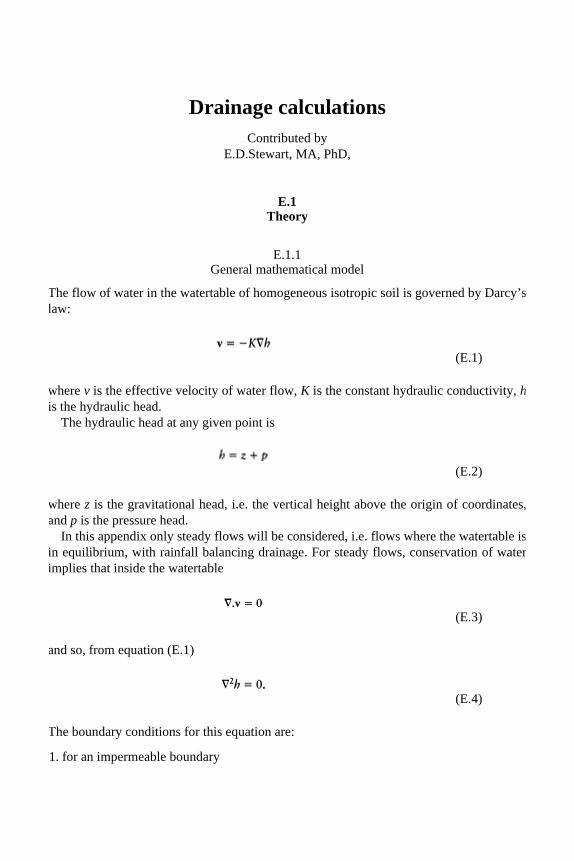
Drainage calculations Contributed by
E.D.Stewart, MA, PhD,
E.1 Theory
E.1.1 General mathematical model
The flow of water in the watertable of homogeneous isotropic soil is governed by Darcy’s law:
where v is the effective velocity of water flow, K is the constant hydraulic conductivity, his the hydraulic head.
The hydraulic head at any given point is
where z is the gravitational head, i.e. the vertical height above the origin of coordinates, and p is the pressure head.
In this appendix only steady flows will be considered, i.e. flows where the watertable is in equilibrium, with rainfall balancing drainage. For steady flows, conservation of waterimplies that inside the watertable
and so, from equation (E.1)
The boundary conditions for this equation are:
1. for an impermeable boundary
(E.1)
(E.2)
(E.3)
(E.4)

where n is the unit outward-pointing vector perpendicular to the boundary of the water-table;
2. for an outflow face (Figure E.1)
3. for a free surface with rainfall V
and
where is the unit vertically upward-pointing vector and so −V is the effective velocity of rainfall flow.
Using equations (E.1) and (E.2) these become, in terms of h:
1.
2.
3.
(E.5)
(E.6)
(E.7)
Appendix E 313
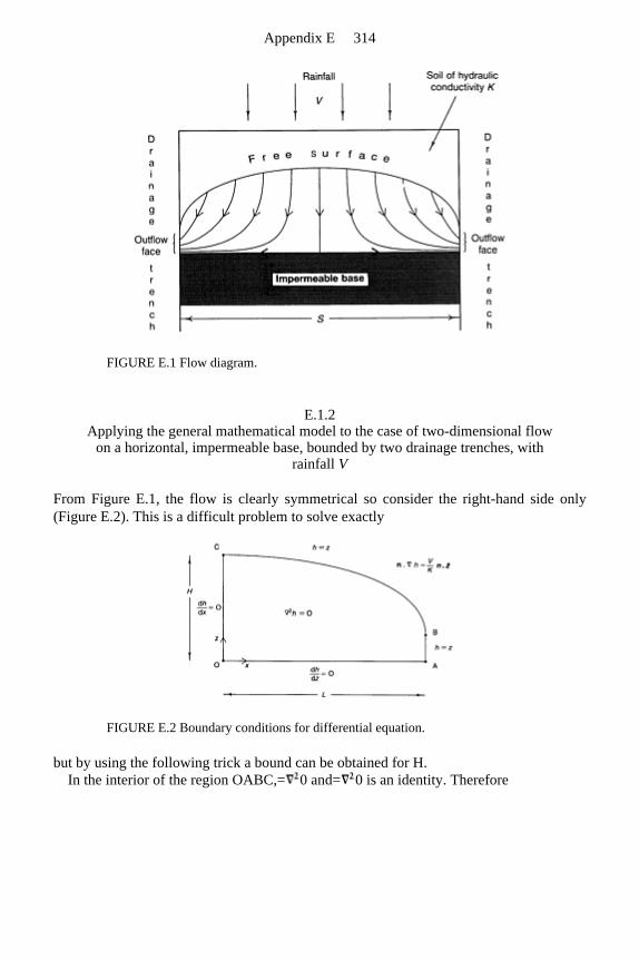
FIGURE E.1 Flow diagram.
E.1.2 Applying the general mathematical model to the case of two-dimensional flow
on a horizontal, impermeable base, bounded by two drainage trenches, with rainfall V
From Figure E.1, the flow is clearly symmetrical so consider the right-hand side only (Figure E.2). This is a difficult problem to solve exactly
FIGURE E.2 Boundary conditions for differential equation.
but by using the following trick a bound can be obtained for H. In the interior of the region OABC,= 0 and= 0 is an identity. Therefore
Appendix E 314

Now using the divergence theorem this is equal to an integral over the boundary of theregion OABC:
where is the unit vector (1,0). Now using the boundary conditions (Figure E.2)
But
Therefore,
and since the watertable is in equilibrium with rainfall balancing drainage
where v=(v x , v z ) and so, from (E.1),
(E.8)
Appendix E 315

Thus, from (E.8)
Therefore,
But on OC, v z ≤0 and at O, v z =0 and at C, v z =−V. Also, on OC, ∂v x /∂x≥0 and so, from equation (E.3) ∂v z /∂z≤0. Thus
and so, from equation (E.9)
and so
or equivalently
(E.9)
(E.10)
(E.11)
Appendix E 316

Now if K V or L2 H 2 (which are true for most practical cases) then a definite formulacan be given:
E.1.3 Approximate method that will be used for practical calculations
For this method it is assumed that
i.e. the flow is approximately horizontal. Now from equation (E.1) condition (E.14) is equivalent to
But from (E.7), h=z is one of the boundary conditions for the free surface of the water-table, therefore h(x,y) now gives the height of the free surface of the watertable.
Also, since the flow is steady with rainfall V, conservation of water now gives
where u is the depth of the watertable and v = (v x , v y ) and so from (E.l)
The only sensible boundary condition is to set u =0 where the soil meets a drainage trench. For two-dimensional flow this reduces to
Therefore,
(E.12)
(E.13)
(E.14)
(E.15)
(E.16)
Appendix E 317

with u=0 at a drainage trench boundary and where x=x 1 is the point where there is no flow of water. Now for the case discussed in section E.1.2, u=h and x 1 =0. Therefore,
so that
where h=H at x=0 has been used. Therefore
which is the equation of an ellipse. Now setting u=0 at x=L, i.e. h=0 at x=L
which agrees with the result obtained in section E.1.2 in the limit L 2 H 2, i.e. for an approximately horizontal flow.
E.2 Practical calculations
E.2.1 Three-dimensional flow on a horizontal rectangular impermeable base bounded
by drainage trenches with rainfall V
The watertable (Figure E.3) is determined from equation (E.15)
(E.17)
Appendix E 318
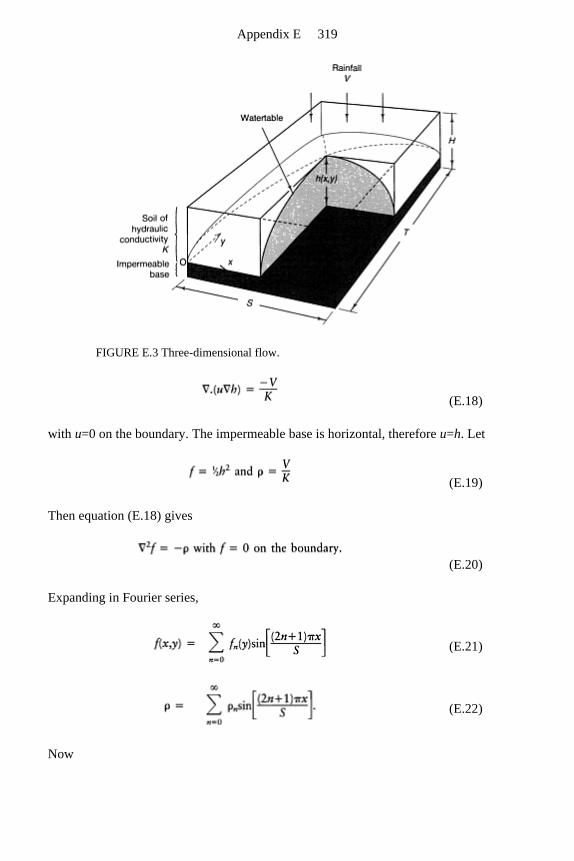
FIGURE E.3 Three-dimensional flow.
with u=0 on the boundary. The impermeable base is horizontal, therefore u=h. Let
Then equation (E.18) gives
Expanding in Fourier series,
Now
(E.18)
(E.19)
(E.20)
(E.21)
(E.22)
Appendix E 319

therefore
Now equations (E.20)—(E.22) give
which has the general solution
The boundary condition (E.20) now gives
Therefore
and
Appendix E 320

At peak capacity h(½S, ½ T )=H, therefore
Now
and
Therefore,
Note that as T→∞ the problem reduces to the two-dimensional problem and we recover the two-dimensional result (E.17), noting that S= 2L:
For T≥S the series (E.23) converges very quickly and can be very well approximated by
Of particular interest is the case of a square, T =S, when we get the formula
E.2.2
(E.23)
(E.24)
(E.25)
Appendix E 321

Two-dimensional flow on an impermeable base with constant slope G/S bounded by drainage trenches with rainfall V
The situation is represented by Figure E.4. The watertable is determined from equation(E.16)
with u=0 on the boundary. The left-hand side of this equation gives the flow of water in the negative x direction at
any given point as given by Darcy’s law, while the right-hand side gives the flow of water needed to maintain equilibrium. The impermeable base has constant slope G/S and so
x=x 1 is the point where there is no flow of water. Let x=x 0 be the point where the watertable touches the surface of the soil, i.e.
Now from equations (E.26) and (E.27)
therefore
Also, from equations (E.26) and (E.27)
Let
and
(E.26)
(E.27)
(E.28)
(E.29)
(E.30)
Appendix E 322

Therefore,
Let
therefore
and
There are two cases: 1. Case for α<1: using the substitution s−α=√(1−α2) cot θ, equation (E.34) gives
Therefore, from equation (E.33)
(E.31)
(E.32)
(E.33)
(E.34)
Appendix E 323
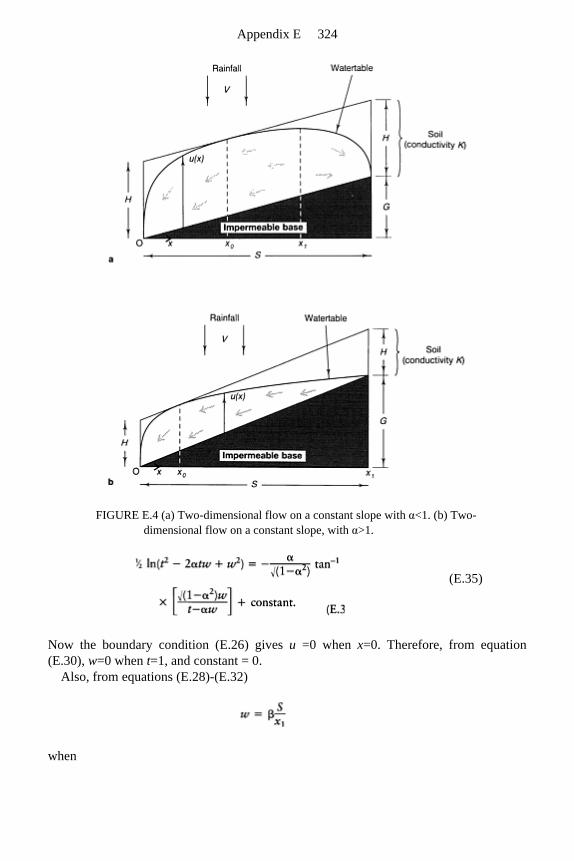
FIGURE E.4 (a) Two-dimensional flow on a constant slope with α<1. (b) Two-dimensional flow on a constant slope, with α>1.
Now the boundary condition (E.26) gives u =0 when x=0. Therefore, from equation (E.30), w=0 when t=1, and constant = 0.
Also, from equations (E.28)-(E.32)
when
(E.35)
Appendix E 324

Therefore, from equation (E.35) with constant=0,
Therefore
Also the boundary condition E.26 gives u= 0 when x=S. Therefore from equation (E. 30)
and from equation (E.35) with constant=0
where tan− 1 (0 −)=π must be taken for a consistent definition of tan−1. Therefore
and from equation (E.36)
Now equations (E.29), (E.31) and (E.32) give
Therefore,
(E.36)
(E.37)
(E.38)
(E.39)
Appendix E 325

2. Case for a > 1: from equation (E.34)
Therefore,
Therefore, from equation (E.33),
Now the boundary condition (E.26) gives u =0 when x=0. Therefore, from equation (E.30), w=0 when t=1.
Therefore
Now u=0 when x=0 or x=S and when u=0, i.e. w=0, equation (E.40) gives t= 0 or t=1. Therefore, from equation (E.30),
Now from equations (E.28)—(E.32) w=β when t=2αβ.
(E.40)
(E.41)
Appendix E 326

Therefore, from equation (E.40)
giving
Now equations (E.29), (E.31), (E.32) and (E.41) give
Therefore,
In summary, to calculate H or G use
and the graph of Figure 13.3(a). To calculate S, K or V draw the straight line
on the graph and the point of intersection will give α and β, and hence from
will give S, K or V. The graph is given by equations (E.38) for α<1 and (E.42) for α >1.
E.2.3 Two-dimensional flow on an impermeable base with optimum crowned profile
(E.42)
(E.43)
Appendix E 327
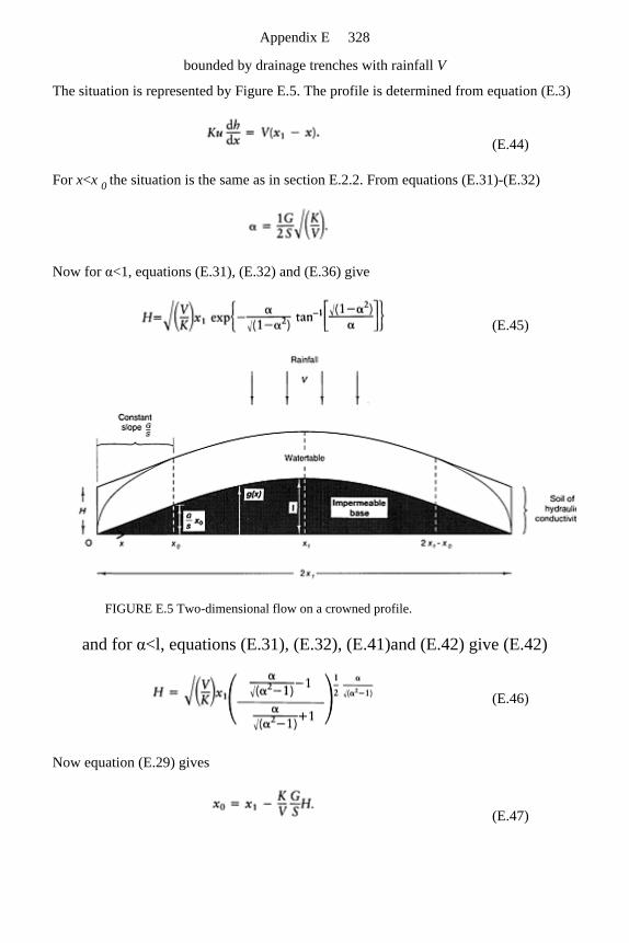
bounded by drainage trenches with rainfall V
The situation is represented by Figure E.5. The profile is determined from equation (E.3)
For x<x 0 the situation is the same as in section E.2.2. From equations (E.31)-(E.32)
Now for α<1, equations (E.31), (E.32) and (E.36) give
FIGURE E.5 Two-dimensional flow on a crowned profile.
and for α<l, equations (E.31), (E.32), (E.41)and (E.42) give (E.42)
Now equation (E.29) gives
(E.44)
(E.45)
(E.46)
(E.47)
Appendix E 328

For x 0<x<2x 1−x 0, u=H and h=g+H and so, from equation (E.44)
Therefore
Now, when x=x 0 , g=(G/S) x 0. Therefore, from equations (E.47) and (E.48)
Therefore
where H is given by equations (E.45) and (E.46). In summary, to calculate H, x1 or G/S use equation (E.31)
and
together with the graph of Figure 13.3 (b). To calculate K or V draw the straight line
on the graph and the point of intersection will give α and γ, and hence from
(E.48)
(E.49)
(E.50)
(E.51)
Appendix E 329

will give K or V. The graph is given by equations (E.45) for α <1 and (E.46) for α>1. The profile is given by
and
Appendix E 330
Grooming, verti-cutting, hollow-tine coring, and verti-draining as aids in fine-turf
management for golf and bowls
These are procedures aimed at counteracting inevitable trends towards mat developmentand soil compaction which are inherent in a soil deprived of earthworm activity. Theyshould be looked upon, not as alternatives, but as a combination of treatments whichtogether can be used by the greenkeeper to maintain the surface fit for play.
F.1 Terminology
This subject is confused by the fact that, where earthworms are absent from the soil, verysimilar organic-rich surface conditions can arise in forest, pasture or sports turf, but theircommon origin has not been generally recognized. This is a pity, because all concernedcould benefit their understanding by actively seeking out the additional knowledge onthis subject that exists outwith their specialisms (Tables 6.1 and 6.2).
Foresters, agriculturalists and greenkeepers have developed their own terminology in isolation. Thus the forester’s ‘mor’ is the equivalent of the agriculturalist’s ‘mat’ and the green-keeper’s ‘thatch’. The English words mat and thatch, however, have familiarmeanings in other contexts and it would be helpful to our understanding if we now usedthese meanings to rationalize our terminology. Thatch implies something fairly loose,laid on top; mat (or matted), something held tightly together by the intertwining ofthreads. Thus, under grass, it would be appropriate to use ‘thatch’ to describe the fresh and decaying, fibrous debris that sprawls across or is deposited upon the surface from shoots and clippings. In the presence of burrowing earthworms this will be rapidlyincorporated out of sight, into the underlying mineral soil. But in the absence ofearthworms, it will remain to accumulate in a discrete, wholly organic layer, unlessdiluted with mineral topdressing. In the cool, moist climate of Britain, such a surfaceorganic layer will not entirely disappear by decay in the course of a year. Annualincrements will build up and in time become invaded by fungal hyphae and grass roots,so becoming stabilized like a mat. As the grass root system tends to die back and shortenin response to frequent close mowing, the matted condition can get progressively tighterand the competition for the water and nutrients within it, intense. This is the conditionthat can lead to a spongy, water-holding and slow-playing surface.
For the benefit of play, therefore, the green-keeper should do everything he can to remove organic debris that would otherwise accumulate as thatch, doing this while it canbe fairly easily worked out from between the grass shoots. But to re-invigorate the root system and extract organic matter from within the mat is by no means easy if the integrity
of the sward is not to suffer. Thus it would be as well not to confuse the two terms,‘thatch’ and ‘mat’. Use ‘thatch’ when referring to the surface accumulation of loose,organic debris that can be removed continuously without harm to the aerial shoots of thegrass. Use ‘mat’ for the root-bound sod that holds the surface together; it may lose its cohesion if sliced, or may rip out if snagged by a spike. If only one of these words has tobe used for the combination of the two, then mat is probably to be preferred.
F.2 Mat development
Mat development is a natural and inevitable feature of any vegetated surface whereearthworm activity is unavailable to incorporate organic debris, not otherwise removedoff site. Microbial decomposition will achieve a certain reduction but, as withcomposting, much will remain to accumulate on the surface if not otherwise removed.Where earthworms are virtually absent, usually because of lack of appropriate food,acidity or other chemical irritants, a surface mat will develop in which a balance iseventually struck between the overall loss by microbial decomposition and input by litterdeposition. In a cool temperate climate, this balance may only be struck, under naturalconditions, when the mat is 100–150 mm (4–6 in) deep.
As such a mat accumulates, the development of new roots, and the disposal of thewhole rooting system, becomes more and more confined to the older layers of compostedmaterial that lie beneath the latest increment of litter. Being ultimately dependent on sucha rooting medium, the natural vegetation must be highly specialized in its feedingarrangements, and well adapted to cope with the twin stresses of periodic waterloggingand periodic drought (Table 6.1).
On worm-deficient sports turf the potential for mat development is much reducedbecause of the removal of clippings, but even here it can become over 50 mm (2 in) deepif other measures of control are not implemented. It is formed from clippings whichescape the box, die-back from leaf bases, surface roots and moss, plus organic residuesfrom inappropriate topdressings. At worst a mat becomes just a root-bound sod.
Whether earthworms are absent or not will determine whether organic matter depositedon the surface remains to form a mat or is intimately mixed with mineral soil andincorporated beneath the surface. In either case, decomposition will continue at arelatively fast rate, unlike in peat development where the persistence of anaerobicconditions, brought on by permanent waterlogging, effectively arrests decay.
F.3 Why bother anyway?
As organic matter decomposes at the surface, a greasy residue may impede drainage andfoster persistent wetness by holding on to water. Surface rooting will be encouraged andconsequences of poor aeration, such as denitrification and toxin production, willadversely affect plant growth. At the other end of the moisture range, during drought the
Appendix F 332
shallow rooting will severely limit the exploitation of residual water reserves at depth. Inthe organic mat, fungi and insects, including some that parasitize living plants, will thrivealongside the other, more benign organisms, involved in processes of decay. In the caseof Fusarium, a major grass disease, the fungus can survive for much of the time, living as a saprophyte on dead organic matter, and then invading living tissue as a parasite, whenthe atmosphere is humid and the sward is moist.
But not only is a surface mat a problem for the well-being of the grass; it is also, for players, a major cause of slowness of pace, except when threatening desiccation. Shouldit be allowed to desiccate, then it will behave as if waxy, failing to re-absorb water and threatening sward survival.
Mat development is the main natural problem which the greenkeeper has to strivecontinuously to control.
F.4 Measures to control thatch, additional to boxing off clippings
1. Brushing, combing or the use of grooming reels, are all aimed at lifting sprawling growth to cutting height so as to provide the tight, vertical growth required for a true playing surface. This is particularly important for agrostis (browntop bent) which can provide an excellent playing surface but has a marked tendency to sprawl. Incidentally, these procedures, aimed primarily at improving the quality of the surface for play, will also make a contribution to the removal of debris sheltering within the stem bases. When first used on a neglected sward they will expose bare patches smothered by sprawl and will noticeably roughen the surface. As routine procedures they are probably best carried out just once a week during the growing season.
2. Verti-cutting is a more vigorous form of grooming. The machine is a mower whose blades have to be kept sharp enough to cut through sprawling growth and remove the freed clippings. It must be treated with respect as a vertical mower and not blunted by the blades being lowered to scratch the surface of the soil. It contributes to thatch control by removing clippings that might otherwise escape a horizontal mower, and like grooming, helps to maintain the tight vertical growth required for a true playing surface. As a routine procedure it is probably best used once a month during the growing season, and always immediately prior to topdressing.
3. Topdressing with uniform, fine sandy material is intended, like grooming and verti-cutting, not only to help true the surface for play, but also to further reduce any tendency to mat accumulation by diluting the decomposing surface debris that escapes the action of the mowing and grooming procedures. As sand sticking to leaves would blunt both the horizontal and vertical mowers, it should be applied dry so that it can be worked into the base of the sward, and then watered to ensure that it settles firmly into the soil surface, out of the way of cutting blades. It is best added frequently, in monthly increments after verti-cutting, when it will have a good chance of uniformly diluting any residue of organic matter. The alternative of a relatively large, once-a-year autumn treatment, tends to encourage the layering that interferes with uniform moisture and root distribution.
Appendix F 333
Topdressing, without prior removal of organic debris, risks burying trouble out of sight,for once below the surface, it will accumulate water and develop a sour smell as itcontinues to decompose anaerobically. In the past, most bought-in turf contained a rooting base of loam or peat, and most topdressings were similarly afflicted. The legacyfor the greenkeeper has been the need to develop means to remove or bypass thesematerials so as to improve vertical drainage and prevent layers of anaerobicity developingas they sink out of reach from the surface, under successive layers of topdressing.
Providing the surface starts without a mat or soil-cap problem, the combination of horizontal and vertical mowing, plus boxing-off of clippings, grooming and sand topdressing should go a long way to controlling mat development without recourse to theremedial treatments discussed next.
F.5 Remedial treatments
These become necessary where continuous attention to thatch control has not beenadequately implemented, or where former construction and maintenance faults areresponsible for drainage problems built into the soil itself. Such problems may exist at thesurface (mats and caps), or within the immediate topsoil (introduced layers ofinappropriate material), and also at greater depth where the indigenous soil has becomeunduly compacted.
Initial poor construction, or subsequent differential settlement, may result in enclosed hollows where surface or subsoil drainage water may cause trouble by accumulating.This will further add to the problems associated with mat but will need more thanstandard maintenance techniques to remedy.
Soil examination in depth will be necessary before a logical decision can be made on the remedial action required.
F.5.1 Scarification
Where organic debris has not been adequately removed during the growing season,scarification will be required to remove it before the onset of winter restricts swardrecovery. The tines of the scarifier are designed to cope with soil abrasion but this doesnot mean that they should be set to penetrate so deeply that the roots of the living grassare put at risk. Better to proceed cautiously, by means of several passes in differentdirections, but even then the treated sward may require extensive over-seeding.
To be consistently successful as part of an annual programme of maintenance, the work should begin early in September. This does not fit well with the requirements ofyear-round golf, nor with bowlers reluctant for the season to end.
F.5.2 Hollow-tine coring with sand infill
This is required when mat development has reached the stage of being root bound, or
Appendix F 334
when an inappropriate layer of loam or peat enrichment has been introduced duringturfing, or in subsequent topdressing. The aim must be to remove a substantial amount ofthe offending material and bypass the remainder with the sand infill; doing all this withminimum loss of use. Note that 12 mm 1½ in) diameter cores every 75 mm (3 in) or 15mm (⅝ in) diameter cores every 50 mm (2 in) will remove only 5–8% of the offending layer in one pass, but the sward will require time and good growing conditions to recover.
To be successful, the coring must take place when the surface is just moist enough to allow for easy penetration and efficient core extration. Then, after core collection andremoval, to achieve a satisfactory infilling of the core holes with tightly packed sand, thetopdressing must be a dry, free-pouring sand, brushed into the core holes over a closely mown, clean, dry surface. Finally, to settle the sand firmly into the core holes, irrigate.When the surface is dry again, over-seed and apply a further topdressing of sand, then mat to level off the core holes and re-true the surface. All this points to treatment wellbefore the end of the growing season, and greens put temporarily out of use toaccommodate.
If the infill within the core holes is texturally similar to or coarser than the underlying material to which it is to form a drainage link, it will tend to empty as the final stage ofdrainage is reached, leaving the surface dry. However, if at least one particle-size category finer, the infill will tend to remain persistently saturated after rain. This mayusefully enhance drought resistance on high spots, but more generally will be seen todiscourage a thoroughly soaked surface from rapidly drying out (section 4.2.1).
Because of the importance of timing for successful coring and sand infilling this is notan operation that should be delegated to a contractor, or made dependent on hiring thenecessary equipment. It requires the timeliness of astute greenkeeping, backed up byready access to the necessary equipment and materials.
Note, even at St. Andrews, where there is an established programme of weeklygrooming plus monthly verti-cutting and topdressing throughout the growing season, still six greens each year are given the hollow-tining treatment to guarantee effective matcontrol. If the management for mat control throughout the growing season is inadequate,then all greens may require the hollow-tining treatment annually. American literaturesuggests that hollow-tine coring may be carried out more than once a year, typically in spring and autumn. At this frequency there must be appropriate equipment on hand totake full advantage of ideal weather conditions, there must be adequate staff, and theremust be alternative greens, or acceptable alternative arrangements, to allow play tocontinue.
F.5.3 Verti-draining
Where there is soil compaction impeding drainage at a depth beyond normal solid- or hollow-tine reach, it may be necessary to use the greater depth of action made possible bya verti-drainer. With this, the combined effect of penetration, lateral displacement and heave will tend to crack open the compaction and raise the surface uniformly so as toaccommodate the extra pore space. If the problem is simply confined to an impedinglayer which the vertidraining tines can bridge through to a free-draining material below,
Appendix F 335
then this may be all that is necessary, at least to achieve a significant, temporary benefit.However, if the subsoil beyond the depth of tine penetration is not free draining, then itmay be necessary to follow up with some form of continuous slitting to provide for thepositive clearance of excess water sideways to underdrains.
Disruption of an unstable soil will alone achieve only a temporary effect. The rate ofresettlement will depend on the binding strength provided by the clay content. Only in astrong, clay soil could the beneficial effect of mechanical disruption be expected to lastfor more than one or two years. However, verti-draining equipment has now been adapted for deep hollow tining. Thus, positive steps can be taken to progressively removean unfavourable material from depths down to 300–400 mm (12–16 in) and replace with sand. But, as with the normal, more shallow hollow-tining treatment, the condition of the infilling sand and the surface must be right, if the necessary substitution is to be whollyeffective.
F.6 General hints on diagnosis and treatment
Be guided at first by the general performance of the greens in play, and the organiccontent of the top 50 mm (2 in) of the soil. If generally black in colour, sour in smell, and not very sandy in appearance when examined closely through a times 10 lens, thensuspect an inadequate mat-control regime. Scarification and/or hollow-tine coring may well have to be introduced as an annual treatment until the surface of the soil has been re-conditioned. If it proves impossible, therefore, to get an appropriate grooming, verti-cutting and sand topdressing programme implemented throughout the growing season,make do with what proves possible and continue to make good with remedialscarification and hollow-tining treatments each autumn. The players and the greens staffmust accept one or other of these alternatives if they are ever to achieve the puttingsurfaces required.
If only particular greens are affected, examine the configuration of the surface to see if localized wetness could be resulting from surface water being shed into enclosedhollows. If so, consider how these hollows can be taken out. Slit draining through thehollow is an option, but the efficiency of the drainage through the surface to the drainwill have to be frequently renewed by spiking and/or sand-filling hollow-tine core holes.
Where surface configuration does not appear to account for a particular problem ofpersistent wetness, then examine the soil in depth, looking for a well-defined layer, suspended within the soil profile, that could be impeding vertical drainage. If present,decide if it could be treated satisfactorily by core extraction and sand in-filling. Aim to remove cores of the problem layer so as to link through to a free-draining material below, and then secure the bypass route by sand in-filling. The machine required will depend on depth.
Any general problem of soil compaction that continues in depth will originate in aninappropriate soil texture. To treat, this will require either deep disruption by verti-draining tines, sand-filling and provision for lateral discharge, or complete reconstruction with appropriate materials.
Appendix F 336

The ideal for any green is a good initial construction with appropriate materials, and a true, shedding surface, maintained throughout the growing season by routinely grooming,verti-cutting and sand topdressing. Scarification and hollow-tine coring then can be held in reserve for remedial treatment in those seasons when the normal maintenanceprogramme has not been fulfilled, or when surface disruption is welcome because there isto be a major effort at overseeding.
Appendix F 337
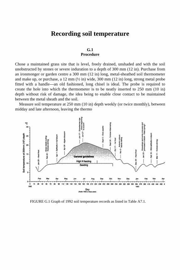
Recording soil temperature
G.1 Procedure
Chose a maintained grass site that is level, freely drained, unshaded and with the soilunobstructed by stones or severe induration to a depth of 300 mm (12 in). Purchase froman ironmonger or garden centre a 300 mm (12 in) long, metal-sheathed soil thermometer and make up, or purchase, a 12 mm (½ in) wide, 300 mm (12 in) long, strong metal probefitted with a handle—an old fashioned, long chisel is ideal. The probe is required tocreate the hole into which the thermometer is to be neatly inserted to 250 mm (10 in)depth without risk of damage, the idea being to enable close contact to be maintainedbetween the metal sheath and the soil.
Measure soil temperature at 250 mm (10 in) depth weekly (or twice monthly), betweenmidday and late afternoon, leaving the thermo
FIGURE G.1 Graph of 1992 soil temperature records as listed in Table A7.1.
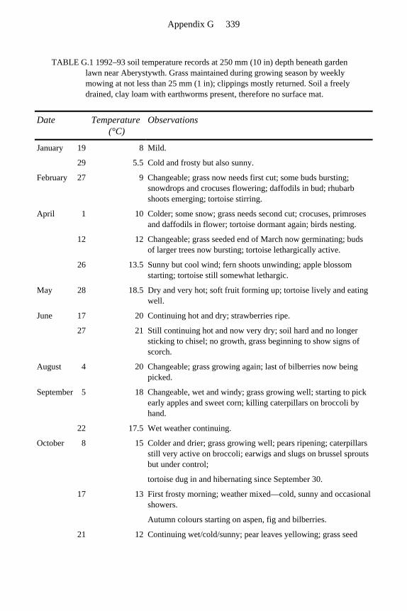
TABLE G.1 1992–93 soil temperature records at 250 mm (10 in) depth beneath garden lawn near Aberystywth. Grass maintained during growing season by weekly mowing at not less than 25 mm (1 in); clippings mostly returned. Soil a freely drained, clay loam with earthworms present, therefore no surface mat.
Date Temperature (°C)
Observations
January 19 8 Mild.
29 5.5 Cold and frosty but also sunny.
February 27 9 Changeable; grass now needs first cut; some buds bursting; snowdrops and crocuses flowering; daffodils in bud; rhubarb shoots emerging; tortoise stirring.
April 1 10 Colder; some snow; grass needs second cut; crocuses, primroses and daffodils in flower; tortoise dormant again; birds nesting.
12 12 Changeable; grass seeded end of March now germinating; buds of larger trees now bursting; tortoise lethargically active.
26 13.5 Sunny but cool wind; fern shoots unwinding; apple blossom starting; tortoise still somewhat lethargic.
May 28 18.5 Dry and very hot; soft fruit forming up; tortoise lively and eating well.
June 17 20 Continuing hot and dry; strawberries ripe.
27 21 Still continuing hot and now very dry; soil hard and no longer sticking to chisel; no growth, grass beginning to show signs of scorch.
August 4 20 Changeable; grass growing again; last of bilberries now being picked.
September 5 18 Changeable, wet and windy; grass growing well; starting to pick early apples and sweet corn; killing caterpillars on broccoli by hand.
22 17.5 Wet weather continuing.
October 8 15 Colder and drier; grass growing well; pears ripening; caterpillars still very active on broccoli; earwigs and slugs on brussel sprouts but under control;
tortoise dug in and hibernating since September 30.
17 13 First frosty morning; weather mixed—cold, sunny and occasional showers.
Autumn colours starting on aspen, fig and bilberries.
21 12 Continuing wet/cold/sunny; pear leaves yellowing; grass seed
Appendix G 339

meter in place to equilibrate for a period of about 5 min. Record in a diary, along withnotes about weather conditions, vegetation and other related observations, and enter as an additional plot on a continuously recorded, one-year graph. (Refer to Figure G.1 and associated observation records in Table G.1.)
Interest will develop as data accumulates to enable comparisons to be made, one year with another, and ideas about local norms and seasonal trends developed. This localknowledge will help to interpret variations in sward performance from one site to anotherand one year to the next, and will assist in the timing of management procedures such asfertilizing and seeding where the response is likely to be temperature dependent.
sown October 14 now germinating.
November 5 12 Mild; full autumn colours; leaves starting to fall.
15 10 Wet and windy; most trees now bare.
29 10 Mild with some wind and rain; snowdrop and daffodil shoots emerging.
December 10 9 Frosty morning but previously mild, wet and windy, grass-seeded patches still only sparsely covered with seedlings.
23 7 Cold and frosty but sunny; main lawn still growing slowly and should be trimmed to tidy.
28 5.5 Continuing frosty and sunny; soil surface hard frozen.
January 1 6 Sunny and mild following a week of hard frost.
23 9.5 Very mild, wet and windy; snowdrops all in flower plus occasional crocus and primrose; daffodils in bud; late-seeded grass still thin.
28 9 Still mild and moist; main lawn requires mowing but too wet; bluebell shoots now emerging; tortoise still hibernating under her sheltered pile of pine needles—will she respond to this false spring as she did last year?
February 1 8.5 Mild, dull and damp.
19 9.5 Continuing mild; fruit buds bursting grass growing well.
March 3 7.5 5 cold days; light snow and frost.
11 9 Mild and sunny; tortoise stirring.
24 10 Daffodils in full bloom and plum blossom fully out; grass due for third cut.
April 15 12 Apple blossom starting. Spring on its way. Tortoise active.
Appendix G 340

G.2 Aids to interpretation
1. The site to which the data in Figure G.1 refers is an unshaded garden lawn at 15 m (50 ft) above sea level, on the north side of a broad, east-west valley, 1½ km (1 mile) inland from the coast of mid-Wales, just north of Aberystwyth.
2. The soil temperature at 250 mm (10 in) tends to vary between a winter low of about 5°C and a summer high of about 20°C, with values of 9°C and above likely to promote growth, all other conditions being favourable. On this basis, the 1992 growing season began mid-March and continued until late November.
3. The soil temperature tends to rise at an average rate of 0.75°C per week through spring and into summer, falling again at a similar, or slightly slower rate, through autumn into winter. At these transition periods, however, a spell of low air temperatures will affect the surface of the soil and limit germination from seed and seedling growth.
4. Think of soil temperature, at or below 250 mm (10 in) depth, as reflecting the heat store available to warm the soil from below. However, once the soil surface becomes frozen the effect will reduce the influence of this heat store at least temporarily, but because it is maintained geothermally from below, the 250 mm (10 in) depth value will readily recover to its more normal winter range of 6–8°C, just enough to maintain a very slow rate of grass growth.
5. There is no point in applying highly soluble, readily leached fertilzers before soil temperature is adequate to enhance growth. Therefore, delay application of seed and nitrogen-rich fertilizer, until the spring surge of soil temperatures exceeds 9–10°C. In the autumn the fall in soil temperatures will lag behind the fall in air temperatures and this will affect the performance of seeds and seedlings at the surface. It is advisable, therefore, to avoid seeding in the autumn beyond the point at which soil temperature at 250 mm (10 in) falls below 14 or 15°C.
Appendix G 341
References
Al-Bakri, K.H. (1984) Biological Influences on the Development of Soil Structure . Ph.D. Thesis, University College of Wales, Aberystwyth.
Casagrande, A. and Fadum, R.E. (1940) Notes on Soil Testing for Engineering Purposes , Harvard Univ. Grad. School of Engineering, Publ. 268, quoted, p55, in Soil Mechanics in Engineering Practice by Karl Terzaghi and Ralph B. Beck, 2nd edn, Wiley, New York, 1967.
Drew, M.C. (1975) Comparison of the effects of a localised supply of phosphate, nitrate, ammonium and potassium on the growth of the seminal root system, and the shoot, in barley. New Phytologist 75 , 479–490.
Houghoudt, S.B. (1940) Versl. Landbouwk, Ond., 46, pp. 515–707, reviewed in English by Luthin, J.N., Drainage Engineering , Wiley, 1966, pp. 149–158.
Kamenskii, G.N. (1938) Dvizhenie gruntovykh vod v mezhdurechnom massive. (The movement of ground water in interfluvial tracks) quoted in Aravin, V.I. and Numerov, S.N. (1953) Theory of Fluid Flow in Undeformable Porous Media. Translated from Russian, Israel Program for Scientific Translations, Jerusalem, 1965, p. 85.
MAFF (1976) The Agricultural Climate of England and Wales , HMSO, London MAFF (1982) The Design of Field Drainage Pipe Systems , HMSO, London. Salih, R.O. (1978) The Assessment of Soil Structure and the Influence of Soil Treatment
on This Property. Ph.D. Thesis, University College of Wales, Aberystwyth. Stewart, V.I. (1971) Drainage Problems on Playing Fields , National Playing Fields
Association, London. Stewart, V.I. (1985) Functions of the soil. Introductory paper for European
Environmental Bureau Conference on Soil Protection in the European Community, Brussels, 1984, pp. 47–58. Reproduced in The Royal New Zealand Institute of Horticulture Annual Journal , (13) 1985, 45–48.
Stewart, V.I. and Adams, W.A. (1969) Soil factors affecting the control of pace on cricket pitches, in Proceedings of First International Turfgrass Research Conference , Harrogate, England, pp. 533–546
Stewart, V.I. and Salih, R.O. (1981) Priorities for soil use in temperate climates, in Biological Husbandry (ed. B. Stonehouse) Butterworths, London, pp. 19–37.
Stewart, V.I., Salih R.O., Al-Bakri, K.H. and Strong, J. (1980) Earthworms and Soil Structure, Report No. 21, Welsh Soils Discussion Group, pp. 103–114.
Stewart, V.I. and Scullion, J. (1989) Principles of managing man-made soils. Soils and Management , 5, 109–116.
Stewart. V.I., Scullion J., Salih, R.O. and Al-Bakri, K.H. (1988) Earthworms and structure rehabilitation in subsoils and topsoils affected by opencast mining for coal. Biological Agriculture and Horticulture , 5, 325–338.
Thornton, D.J. (1978) The Construction and Drainage of some Specified Sports Field Playing Surfaces . Ph.D. Thesis, University College of Wales, Aberystwyth.
Vaughan, D, Wheatley, R.E. and Ord, B.G. (1984) Removal of ferrous iron from field drainage waters by conifer bark. Journal of Soil Science , 35, 149–153.


Index
Adams and Stewart soil-binding (ASSB) test, see ‘Motty test’ Aggregates, BS Specifications 142 Agricultural land drainage requirements 18–9 Agropyron repens (grass) 237 Agrostis (browntop bent) 189, 314 Autumn maintenance 193–8
Backfilling 165, 205 Blinding sands 27, 144, 155–6, 157, 176
tests for 284 Boreholes 33 Boulders 152 Bounce height values 230
consistency of 231 Bounce test, cricket 226–7 Bowling greens 24, 54, 178, 185, 188
gravel-rafted specification 190 Brandling (earthworm) 126 Breaking strength values, motty 271 Brushing 200, 219, 314
Capillarity 98–100 Catchment drains, see French drains Clay soils
classification of 14 clay content determination 269–71 for cricket tables 279 for winter games 278–9
Clayware drains 39 Climatic features 5, 7–12 Coarse-turf surfaces 178 Combing 314 Community role 260, 262 Compaction breakers 167 Compatability test, clay dressings 271–2 Consolidation 165 Construction principles 175–6 Consultancy payment 261 Contouring 213 Coring, hollow-tine 314–6

Corrugated pipes 37 Costs
alternative schemes comparison 116–7 assessment of benefits 112–6 comparative 68
Crack filling 134 Cricket field, creation of 237–40 Cricket pitches 225
assessment 227–31 clay content 228
lab tests 228–30 overseas 236
clay content 235–6 preparation 231–3 soil cores 228 soil-moisture control 239 surface requirements 179 Critical tension 98–100, 106 predicting 148
Croquet lawns 179 Crushed rock materials 244 Cynodon dactylon (creeping finger grass) 237
D values (particle diameter) 144, 145 Darcy’s Law 71, 293 Deep trenching 61 Depth control, pipelaying 165 Desiccation, counteracting 109 Design criteria
water absorption and retention 97–100, 106–9 water transmission, see Water transmission
Difficult ground, trenching 161 Direct seeding 187, 188 Ditches, open 30, 161 DIY projects
adviser role 260 community role 260, 262 drainage trenching 162, 168–70
Drainage calculations design rates 17, 37, 112–4 practical 298–309 theory 293–8
Drainage costings capital 114–7 difficult sites 23 fine turf areas 23 hockey pitches 22 soccer and rugby pitches 21–2
Index 345

summer use pitches 23 Drainage problems, diagnosis of 6, 17–8 Drainage systems
herring-bone 59–60 installation 160
timing 54–5 mole, see Mole drainage systems peripheral 18, 30, 161–2, 175 specification 24 supervision 26 trenchless 162
Drains French 30 piped
backfill 39 depths 34, 205 design of 34–8 falls 33 flow rates 35 installing 40–1 junctions 35 laterals 31, 33 spacing 115 mains 31 pipe sizes 35 trench widths 34
slit, see Slit drainage Drought risk 10
Earthworms 177, 180, 280
benefits of 125–6, 129–30, 152 in cricket squares 233–6 elimination of 129, 189, 195–7 in natural cricket fields 237, 240
Envelope system 258 Equipment hire 168–9
Fertilizer applications
autumn 194–5 coarse-turf 218 leaching compensation 122 sand carpet 168 spring and summer 199
Fescue (grass) 189 Field capacity 7 Filter membranes 155 Fine earth 150 Fine-turf surfaces 94, 178
Index 346

management 312 French drains 30 Frost risk 10 Fusarium (grass disease) 314
Gaeumannamyees graminis, see Ophiobolus graminis Golf greens 24, 53, 178, 185, 188
gravel-rafted specification 190 Gradation indices (G.I.) 145 Gradients
definition of 291 surface 16
Grass seeds mixtures 196, 198 pre-germinated 198 sizes 188
Grass species choice of 189 fine-turf seed mixtures 189
Grass sward care of 6
character of 68–9 cricket pitch 233, 236 establishing cover 50, 121, 208
Grassing up 208 Gravel bed, developments 190 Gravel channels, sub-surface 51 Gravel specifications 27 Gravel-rafted schemes
design 82, 93–4 worked example 95–8
Grid drainage systems 59–60 design of 61–6
Grooming 314 Growing season 10–2
Hard porous pitches 243
developments 257 general design 243–6 maintenance 256–7 specification 255 standard designs 248–55
Herring-bone drainage systems 59–60 Hiring equipment 168–9 Hockey pitches 22, 52, 69
surface requirements 179 Hollows, infilling 212 Home-lawn maintenance 201
Index 347

Hooghoudt’s drain-spacing equation 33, 71, 72–6 simplified 74, 80, 83–5
Horse-racing, surface requirements 181 Horses, surface for schooling 257 Hydraulic conductivity 78–80
predicting 146–8 test 284
Hydraulic head 293
Inspection chambers 41 Interception drains, see Drainage systems, peripheral Iron ochre formation 43, 154 Irrigation 201
cricket square 239
Laterals, see Drains, piped, laterals Layouts, choice of 60 Liming 218 Loamy soils
assessment of condition 281 classification of 14–5
Low-budget constructions 177–8
Macro-pores 15 Maintenance
greens autumn 193–8 spring and summer 199–201
hard porous pitches 255–7 home lawns 201 routine 133–5 slit surfaces 209 see also Management
Management fine-turf 312 of greens 190, 316–7
Mat 312 development of 312–3
Materials availability 97 Meadowgrass, smooth-stalked, see Poa pratensis Micro-pores 15 Micro-slitting 52, 132
machines 164 Mini-slitting 51
machines 163–4 piped 52 under fine turf 209–13
Mixing precautions (segregation avoidance) 289
Index 348

Mole drainage systems 37, 43–8 ‘Mor’ soil condition 121 Moss control 199 ‘Motty test’ (clay content) 231, 269–71
modified 271–2 Mowing 272, 200
coarse-turf 218–9 ‘Mull’ soil condition 121
National Playing Fields Association 260
consultancy 260 Drainage Problems on Playing Fields 21 information sheets 262
New fields, drainage of 117 Nottinghamshire envelope system 258
One-tier drainage systems 61, 64–5
design notation 81 worked examples 86–7
Open ditches 30, 161 Ophiobolus graminis patch disease 133, 186 Organic matter content 15, 273–7 Organic supplements 186, 191 Outfalls 30–3 Over-seeding 50–1, 196 Overall design rate 37–8
Pace (cricket) 231, 279 Package deals 262 Particle size gradings 13–5, 138, 140–1
Stewart zones 141, 143–4 Patent law guidance 263 Peaty sites 153–4 Perimeter drains, see Drainage systems, peripheral Pest control 190 Piped drains, see Drains, piped Plastic pipes 39 Poa annua (annual meadowgrass) 197 Poa pratensis (smooth-stalked meadowgrass) 13 Poaching risk 7, 10 Ponding 16 Pore size 176
importance of 7, 16 predicting compatability 148–9
Power units, equipment 166 Pre-germinated seeds 198 Preparatory site work 177 Priority assessment 59
Index 349

Problem schemes, overcoming 220–2 Pumping systems 33 PVC pipes 41
Rainfall data 7
design rates 80 distribution 113
Re-truing, surface 165–7 Record plans 55, 177 Repairs, instant 198 Rolling 135 Root density 121 Rugby pitches 21–2, 69 Rye-grass 68, 69
Sand capping 207 Sand carpet 129–31
spreading 167–8 Sand content test 272 Sand soil construction 183–6 Sand top
ameliorated 192, 287–8 deep 53 shallow 53
Sand topdressing 133 Sand-and-gravel slits 49–51 Sands
BS Specifications 142 classification of 14, 27
Sandy soils 279–80 Scarification 194, 199, 315 Seeding, direct, see Direct seeding Seeds, see Grass seeds Settling chambers, see Silt pits Shading, effects of 5 Sieving procedure 140 Silt pits 41 Siltation 37 Site information 17–8 Slit drainage system 43, 116, 194, 205
over existing drains 207 trenching 162–4 use in upgrading existing pitches 215–7
Slitting machines excavator-type 163 micro- 165 mini- 164
Sloping surfaces
Index 350

definition of 291 drainage of 82–3, 97 for golf and bowls 185
Sloping surfaces, see Gradients Soakaways 33 Soccer pitches 21–2, 69 Soil analysis 18 Soil disposal 165 Soil layering 232–3 Soil profile colour 18 Soil surface, truing 121 Soil temperature 11
recording 319–21 Soil texture 13–6, 176
amelioration 16, 286–7 class designations 273–8, 278–80 degradation 152 granulation 280 permeability 132–3 structure 176 tests for
by handling properties 269 clay content 269–71 sand content 272
Spiking 134, 194 Sports grounds
control of use of 23 drainage requirements 18–21 requirements 4–5
Spring maintenance 198–201 Staged schemes 22 Stewart zone design approach 78, 176 Stewart zone materials 27, 80
particle size gradings 141, 143–4 tests for 284
Stones 15, 152, 274–5 Subsoiling 44–8, 132, 135, 167 Summer maintenance 198–201 Supervision, need for 220 Supplements, topsoil 191 Surcharging 36 Surface configuration 4, 175 Surface response 123–4 Surface slits, spacing 116 Surface wetness, categories for 5 Sward, see Grass sward
Tear wear 5
Index 351

Tennis, surface requirements 179 Thatch 312
control of 313 remedial treatments 315
Three-tier drainage systems 65–6 design notation 81–2 worked examples 90–3
Tier systems 33 see also One-tier;
Two- tier; Three-tier drainage systems
Timing, installation 54–5 Tip sites 154–5 Topdressing 189, 195, 313–4
autumn 195 coarse-turf 219 fine sand 123–5 sand, application of 167 spring and summer 199
Topsoil choice of 151–2 importation 133 improving 68, 132–3 loamy soils condition 280–1
Topsoil inversion 131–3 Topsoil sands 27, 39, 144, 155, 176
tests for 284 Topsoil supplements 191 Tractive efficiency, surface 124–5 Trade names 263 Trade-sponsored literature 263 Trench gravels 27, 38, 144, 156–7, 176
tests for 176 Trenching
difficult ground 161 interceptor drains 161–3 mains and outfalls 161 narrow 160–2 open ditches 161 procedure 40–1 slit-drainage 162–4
Trenchless drainage 41, 162 Trenchless drainer 162 Triangle of Texture 138, 139 Turfing 187, 188 Two-tier drainage systems 65
design notation 81 worked examples 88–90
Index 352

Underdrains, inserting 212 Undulations 16 Upgrading
pitch 214, 216–7 surface 207–8
Use factors, playing surface 16
Vert,-cutting 156 199, 314 Verti-draining 316
Water retention, practical applications 106–9 Water transmission
practical application 81–5 theoretical 71–80 worked examples 86–98
Water-stability test 281 Weed control 199, 218 Whole soil constructions 52–3 Winter activity surfaces 178, 205 ‘Worm’ test (soil texture) 269
Index 353