Embed Size (px)
Citation preview
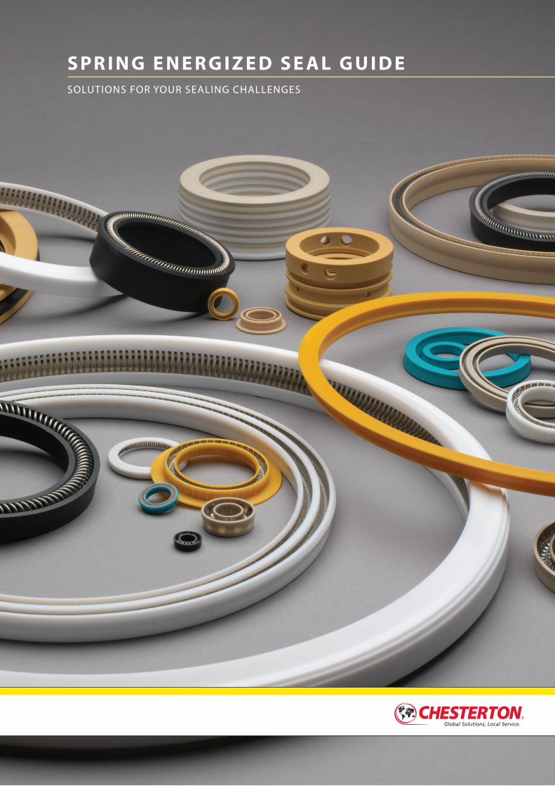
S P R I N G E N E R G I Z E D S E A L G U I D ESOLUTIONS FOR YOUR SEALING CHALLENGES
SECTION 1Providing Value to Industry Since 1884 ...........................................................................................4
Overview Spring Energized Seals ..................................................................................................................................5Product Guidelines .........................................................................................................................................6Legend .................................................................................................................................................................6EPS Series 100 ...................................................................................................................................................7EPS Series 200 ...................................................................................................................................................7EPS Series 300 ...................................................................................................................................................8EPS Series 400 ...................................................................................................................................................8EPS Series 500 ...................................................................................................................................................9EPS Series 600 ...................................................................................................................................................9
SECTION 2 Seal Types and Characteristics
Radial and Face Seals ...................................................................................................................................10Static and Dynamic Sealing .......................................................................................................................10Rotary, Reciprocating, and Oscillating Motion ...................................................................................11 Jacket Sealing Lip Designs .........................................................................................................................11 Negative Lip ................................................................................................................................................11 Neutral Lip ...................................................................................................................................................11 Radius Lip .....................................................................................................................................................11
SECTION 3 Spring Types and Applications
Introduction to Spring Energizer .............................................................................................................12Designing for Friction Loading .................................................................................................................12EPS Series 100, Cantilever Spring ............................................................................................................13EPS Series 200, Elliptical Coil Spring .......................................................................................................13EPS Series 300, Helical Wound Spring ...................................................................................................13EPS Series 600, Continuous Spring .........................................................................................................13Spring Energizer Materials .........................................................................................................................14Spring Usage Guidelines .............................................................................................................................14
SECTION 4 Seal Jacket Materials
Seal Jacket Material ................................................................................................................................15–16Seal Jacket Material As It Relates to Temperature .............................................................................17Seal Jacket Material As It Relates to Operating Speed and Pressure .........................................17
SECTION 5 Engineering Guidelines
Surface Finish ..................................................................................................................................................18Eccentricity and Dynamic Runout for Spring Energized Seals .....................................................19Allowable Diametrical Clearance .............................................................................................................20Miscellaneous Hardware Guidelines—Rotary, Reciprocating, and Static ................................21Seal Application Questionnaire .........................................................................................................22–23
TA B L E O F CO N T E N T S
Providing Value to Industry Since 1884
4
Chesterton® spring energized seals are used in a wide spectrum of applications and are capable of handling extreme conditions. Whether its low friction, aggressive chemicals or extreme temperatures and pressures, Chesterton has the know-how and expertise to develop a sealing solution that meets your specific needs.
■■ Product selection and development ■■ Engineering and design experience ■■ Materials development and manufacturing expertise■■ Market know-how and strong customer relationships
Global SolutionsChesterton has been providing value-driven solutions around the globe with documented success by using high- performance materials and designs to solve your toughest sealing needs.
North America160 Sales Offices and Service Centers
Latin America42 Sales Offices and Service Centers
Europe, Middle-East, Africa234 Sales Offices and Service Centers
Asia Pacific66 Sales Offices and Service Centers
A.W. Chesterton Company is a global manufacturer of spring energized seals and components that is comprised of engineers, technicians and field specialists with years’ experience in the sealing industry. Leveraging our knowledge and experience, we work with our customers to provide solutions that help them operate more reliably, efficiently and economically.
Using these core strengths, Chesterton combines advanced engineered technology, materials development, operational excellence and rapid execution to engineer sealing solutions for our customers’ most demanding sealing challenges.
5
SEC TION 1
Overview
Spring energized seals, used in both rotary and reciprocating applications, cover a very broad range of pressure and velocity characteristics. These include various spring types (i.e., cantilever, helical, elliptical, and continuous spring) and materials used to satisfy the equipment operating parameters.
Chesterton Spring Energized Seals (SES) are used in a wide range of rotary and reciprocating fluid power and handling equipment. Their use is in applications where the operating parameters, equipment envelope, and economics are advantageous over conventional sealing devices.
These sealing devices are generally manufactured from high-performance PTFE compounds and engineered plastics. As these materials are not elastic by nature, they must be mechanically energized to become effective dynamic and static sealing devices. Wide arrays of spring designs are utilized. The spring energizers are manufactured from high-grade metal alloy materials. These materials are optimal where extremely low friction is required and very high or low operating temperatures are experienced. The ability of these seal materials to resist a wide range of chemicals makes them ideal for these applications.
These outstanding attributes make the Chesterton SES products ideally suited for many industrial applications, including:
Spring Energized Seals (SES)
Determining the appropriate sealing device for a particular application is generally determined by operating parameters such as pressure, speed, temperature, fluid compatibility requirements, available envelope, performance life, allowable leakage, and cost. In many instances particular sealing devices are utilized in certain applications due largely to legacy.
A sealing device can be broadly defined as a product that controls and prevents the movement of fluid between adjacent locals within equipment or to the environment.
Sealing products address the interface between two equipment surfaces to create a positive seal. These types of seals can be placed in two categories: static and dynamic.
Static seals represent the largest population of sealing devices: O-Rings, gaskets, sealing compounds, and metal seals. Even though the term implies otherwise, a static seal generally does involve some very small movements. Examples include the expansion and contraction of equipment or pressure cycling within the system influencing the seal itself.
Dynamic sealing is the more challenging of the two categories. Dynamic sealing applications are configurations where system components experience relatively high-speed reciprocating or rotary motion. Such situations have more operating parameters to be considered in order to provide a suitable sealing solution.
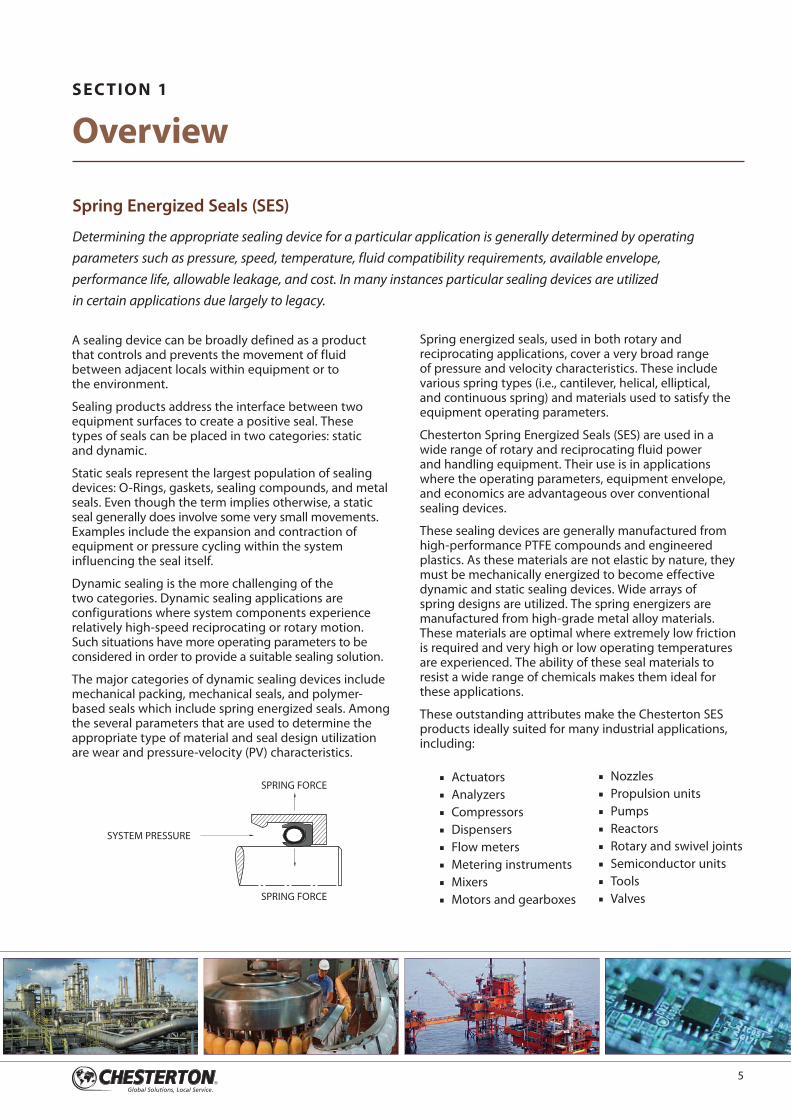
The major categories of dynamic sealing devices include mechanical packing, mechanical seals, and polymer- based seals which include spring energized seals. Among the several parameters that are used to determine the appropriate type of material and seal design utilization are wear and pressure-velocity (PV) characteristics.
SPRING FORCE
SYSTEM PRESSURE
SPRING FORCE■■ Actuators■■ Analyzers■■ Compressors ■■ Dispensers■■ Flow meters■■ Metering instruments■■ Mixers■■ Motors and gearboxes
■■ Nozzles■■ Propulsion units■■ Pumps ■■ Reactors■■ Rotary and swivel joints■■ Semiconductor units■■ Tools ■■ Valves
6
Spring Energized Seal Guide Section 1 — OVERVIEW
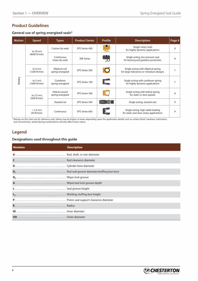
Product Guidelines
General use of spring energized seals*
Motion Speed Types Product Series Profile Description Page #
Rota
ry
to 20 m/s (4000 ft/min)
Custom lip s eals EPS Series 400
Single rotary seals for highly dynamic applications 8
Continuous rotary lip seals 30K Series Single acting, low pressure seal
for bearing and gearbox protection 8
to 6 m/s (1200 ft/min)
Elliptical coil spring energized EPS Series 200 Single acting with elliptical spring
for large tolerances or miniature designs 7
to 5 m/s (1000 ft/min)
Cantilever spring energized EPS Series 100 Single acting with cantilever spring
for highly dynamic applications 7
to 2.5 m/s (500 ft/min)
Helical wound spring energized EPS Series 300 Single acting with helical spring
for static or slow speeds 8
Stacked set EPS Series 500 Single acting, stacked sets 9
< 2.5 m/s (50 ft/min) Continuous EPS Series 600 Single acting, high radial loading
for static and slow rotary applications 9
* Ratings on this chart are for reference only. Values may be higher or lower depending upon the application details such as surface finish, hardness, lubrication, and concentricity. Jacket/Spring combinations will also affect these values.
Legend
Designations used throughout this guide
Notation Description
d ....................................................................................................... Rod, shaft, or ram diameter
C ....................................................................................................... Rod clearance diameter
D ...................................................................................................... Cylinder bore diameter
D1 .................................................................................................... Rod seal groove diameter/stuffing box bore
D5 .................................................................................................... Wiper lock groove
G ...................................................................................................... Wiper/seal lock groove depth
L ....................................................................................................... Seal groove height
L3 ..................................................................................................... Working stuffing box height
P ....................................................................................................... Piston seal support clearance diameter
R ....................................................................................................... Radius
ID .................................................................................................... Inner diameter
OD .................................................................................................. Outer diameter
7
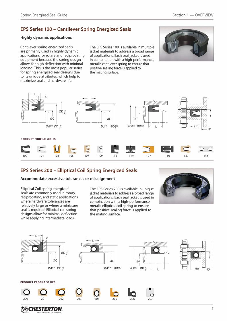
EPS Series 100 – Cantilever Spring Energized Seals
Highly dynamic applications
Cantilever spring energized seals are primarily used in highly dynamic applications for rotary and reciprocating equipment because the spring design allows for high deflection with minimal loading. This is the most popular series for spring energized seal designs due to its unique attributes, which help to maximize seal and hardware life.
Elliptical Coil spring energized seals are commonly used in rotary, reciprocating, and static applications where hardware tolerances are relatively large or where a miniature seal is required. Elliptical coil spring designs allow for minimal deflection while applying intermediate loads.
The EPS Series 100 is available in multiple jacket materials to address a broad range of applications. Each seal jacket is used in combination with a high-performance, metalic cantilever spring to ensure that positive sealing force is applied to the mating surface.
The EPS Series 200 is available in unique jacket materials to address a broad range of applications. Each seal jacket is used in combination with a high-performance, metalic elliptical coil spring to ensure that positive sealing force is applied to the mating surface.
100 101 103 105 107 109 115 130119 132127 144
200 201 202 203 204 205 206 207
EPS Series 200 – Elliptical Coil Spring Energized Seals
Accommodate excessive tolerances or misalignment
PRODUCT PROFILE SERIES
PRODUCT PROFILE SERIES
Section 1 — OVERVIEWSpring Energized Seal Guide
LL
L
G
ØC
Ød h9 Ød h9 ØD H9 1
ØD H9 1
ØD h9 1
ØD H9
L
ODID
ØC ØP
ØD H9 5
L
L
L
ØC
Ød h9 Ød h9 ØD H9 1
ØD H9 1
ØD h9 1
ØD H9 OD ID
ØC ØP
LG
ØD H9 5
8
Spring Energized Seal Guide Section 1 — OVERVIEW
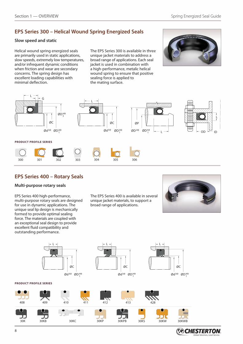
Helical wound spring energized seals are primarily used in static applications, slow speeds, extremely low temperatures, and/or infrequent dynamic conditions when friction and wear are secondary concerns. The spring design has excellent loading capabilities with minimal deflection.
The EPS Series 300 is available in three unique jacket materials to address a broad range of applications. Each seal jacket is used in combination with a high-performance, metalic helical wound spring to ensure that positive sealing force is applied to the mating surface.
300 304 306305301 302 303
EPS Series 300 – Helical Wound Spring Energized Seals
Slow speed and static
EPS Series 400 high-performance, multi-purpose rotary seals are designed for use in dynamic applications. The unique seal lip design is mechanically formed to provide optimal sealing force. The materials are coupled with an exceptional seal design to provide excellent fluid compatibility and outstanding performance.
The EPS Series 400 is available in several unique jacket materials, to support a broad range of applications.
EPS Series 400 – Rotary Seals
Multi-purpose rotary seals
408 409 410 411 412 413 428
30K 30KB 30KC 30KP 30KPB 30KS 30KW 30KWB
PRODUCT PROFILE SERIES
PRODUCT PROFILE SERIES
L
L
L
ØC
Ød h9 Ød h9 ØD H9 1
ØD H9 1
ØD h9 1
ØD H9 OD ID
ØC ØP
LG
ØD H9 5
L
ØC
Ød h9 ØD H9 1
L
ØC
Ød h9 ØD H9 1
L
ØC
Ød h9 ØD H9 1
9
500
600 601
520 521 522 540
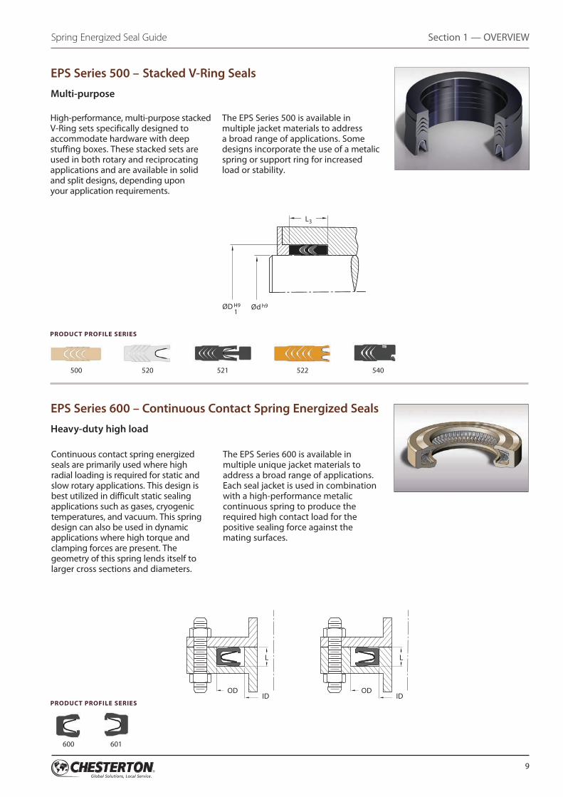
EPS Series 500 – Stacked V-Ring Seals
Multi-purpose
High-performance, multi-purpose stacked V-Ring sets specifically designed to accommodate hardware with deep stuffing boxes. These stacked sets are used in both rotary and reciprocating applications and are available in solid and split designs, depending upon your application requirements.
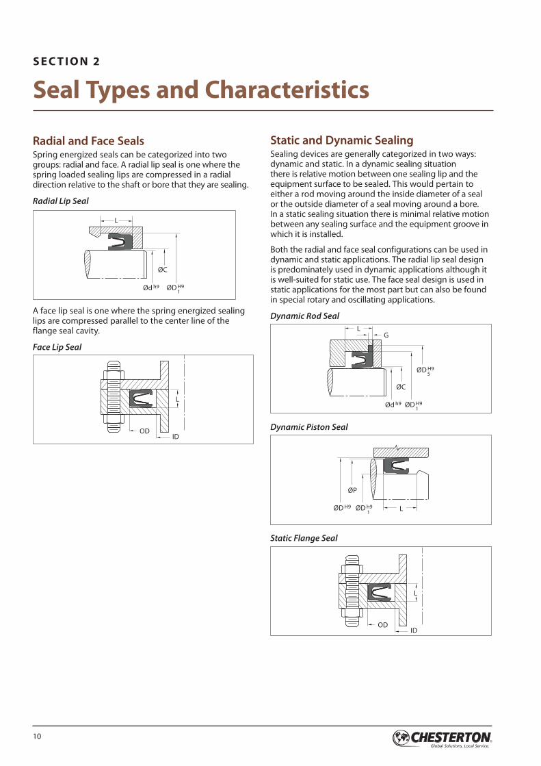
Continuous contact spring energized seals are primarily used where high radial loading is required for static and slow rotary applications. This design is best utilized in difficult static sealing applications such as gases, cryogenic temperatures, and vacuum. This spring design can also be used in dynamic applications where high torque and clamping forces are present. The geometry of this spring lends itself to larger cross sections and diameters.
The EPS Series 500 is available in multiple jacket materials to address a broad range of applications. Some designs incorporate the use of a metalic spring or support ring for increased load or stability.
The EPS Series 600 is available in multiple unique jacket materials to address a broad range of applications. Each seal jacket is used in combination with a high-performance metalic continuous spring to produce the required high contact load for the positive sealing force against the mating surfaces.
EPS Series 600 – Continuous Contact Spring Energized Seals
Heavy-duty high load
PRODUCT PROFILE SERIES
PRODUCT PROFILE SERIES
Section 1 — OVERVIEWSpring Energized Seal Guide
L3
ØD H9 1
Ød h9
L
OD ODID ID
L
10
Radial and Face SealsSpring energized seals can be categorized into two groups: radial and face. A radial lip seal is one where the spring loaded sealing lips are compressed in a radial direction relative to the shaft or bore that they are sealing.
Radial Lip Seal
L
Ød h9 ØD H9 1
ØC
A face lip seal is one where the spring energized sealing lips are compressed parallel to the center line of the flange seal cavity.
Face Lip Seal
L
ODID
Static and Dynamic SealingSealing devices are generally categorized in two ways: dynamic and static. In a dynamic sealing situation there is relative motion between one sealing lip and the equipment surface to be sealed. This would pertain to either a rod moving around the inside diameter of a seal or the outside diameter of a seal moving around a bore. In a static sealing situation there is minimal relative motion between any sealing surface and the equipment groove in which it is installed.
Both the radial and face seal configurations can be used in dynamic and static applications. The radial lip seal design is predominately used in dynamic applications although it is well-suited for static use. The face seal design is used in static applications for the most part but can also be found in special rotary and oscillating applications.
Dynamic Rod Seal
G
ØC
Ød h9 ØD H9 1
ØD H9 5
L
Dynamic Piston Seal
LØD h9 1
ØD H9
ØP
Static Flange Seal
L
ODID
S E C T I O N 2
Seal Types and Characteristics
11
Spring Energized Seal Guide Section 2 — SEAL TYPES AND CHARACTERISTICS
Rotary, Reciprocating, and Oscillating MotionStandard designs of radial lip seals are suited for low pressures and low-to-medium speed with rotary or oscillating movement. To utilize this seal profile in higher speeds or higher pressure applications special design considerations are given to materials and spring loads. These same standard designs are also well-suited for low-to-medium pressures at slow-to-medium speeds with reciprocating movement. For applications requiring higher pressures and speeds special materials and springs are utilized for custom designs. Consult the EPS Engineering group for product recommendations.
Standard designs of face seals are generally the choice for static flange-type applications. They are designed with high spring loads to accommodate a wide range of temperatures and operating pressures. Special designs of face seals can also be used for rotary and oscillating movement. These designs are suitable for low-to-medium pressures and speeds. Custom designs are used for special fluids/gases and cryogenic conditions (reference Spring Usage Guidelines chart, page 14).
Motion
Jacket Sealing Lip DesignsThe design of the sealing lip is an additional factor to consider when selecting the proper seal for the application. They are broken down into four categories. The first is the “Negative” lip angle, second is the “Neutral” lip angle, third is the “Radius” lip, and fourth is a “Hybrid”, where a seal utilizes a combination of lip designs. Hybrid configurations contain more than one of these lip designs, depending upon the desired sealing results.
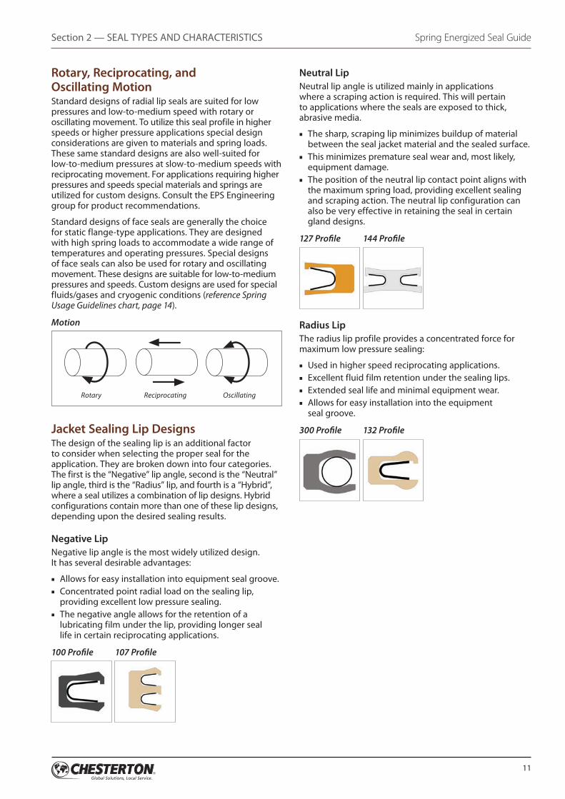
Negative LipNegative lip angle is the most widely utilized design. It has several desirable advantages:
■■ Allows for easy installation into equipment seal groove.■■ Concentrated point radial load on the sealing lip,
providing excellent low pressure sealing.■■ The negative angle allows for the retention of a
lubricating film under the lip, providing longer seal life in certain reciprocating applications.
100 Profile 107 Profile
Neutral LipNeutral lip angle is utilized mainly in applications where a scraping action is required. This will pertain to applications where the seals are exposed to thick, abrasive media.
■■ The sharp, scraping lip minimizes buildup of material between the seal jacket material and the sealed surface.
■■ This minimizes premature seal wear and, most likely, equipment damage.
■■ The position of the neutral lip contact point aligns with the maximum spring load, providing excellent sealing and scraping action. The neutral lip configuration can also be very effective in retaining the seal in certain gland designs.
127 Profile 144 Profile
Radius LipThe radius lip profile provides a concentrated force for maximum low pressure sealing:
■■ Used in higher speed reciprocating applications.■■ Excellent fluid film retention under the sealing lips.■■ Extended seal life and minimal equipment wear.■■ Allows for easy installation into the equipment
seal groove.
300 Profile 132 Profile
Rotary Reciprocating Oscillating
12
S E C T I O N 3
Spring Types and Applications
Introduction to Spring Energizer
The main function of the spring energizer is to provide a radial force at the plastic/polymer jacket sealing points when installed into the seal cavity. This is primarily at low system operating pressures as system pressure adds radial load as it increases. In addition, the spring energizer adds flexibility to the jacket sealing points to compensate for material wear and shaft or bore eccentricity/misalignment. The spring provides a force against the seal jacket and compensates for materials with low memory/elasticity.
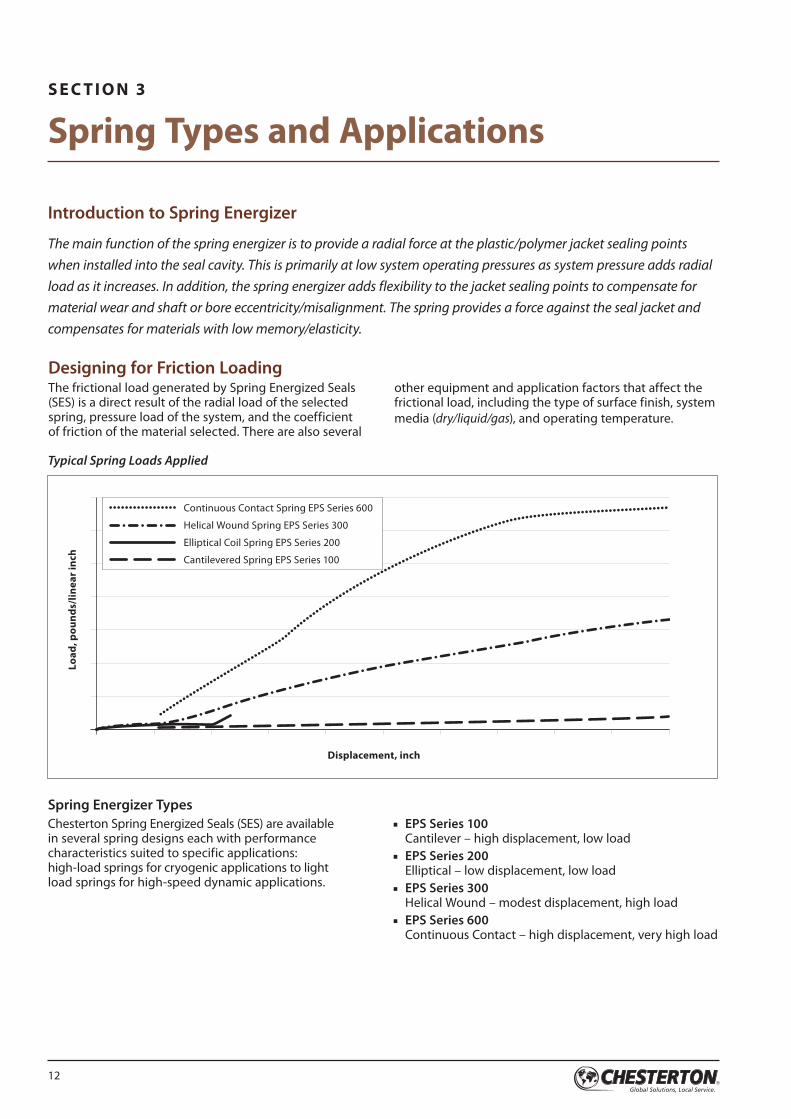
Designing for Friction LoadingThe frictional load generated by Spring Energized Seals (SES) is a direct result of the radial load of the selected spring, pressure load of the system, and the coefficient of friction of the material selected. There are also several
other equipment and application factors that affect the frictional load, including the type of surface finish, system media (dry/liquid/gas), and operating temperature.
Continuous Contact Spring EPS Series 600
Helical Wound Spring EPS Series 300
Elliptical Coil Spring EPS Series 200
Cantilevered Spring EPS Series 100
Displacement, inch
Load
, pou
nds/
linea
r inc
h
Typical Spring Loads Applied
Spring Energizer TypesChesterton Spring Energized Seals (SES) are available in several spring designs each with performance characteristics suited to specific applications: high-load springs for cryogenic applications to light load springs for high-speed dynamic applications.
■■ EPS Series 100 Cantilever – high displacement, low load
■■ EPS Series 200 Elliptical – low displacement, low load
■■ EPS Series 300 Helical Wound – modest displacement, high load
■■ EPS Series 600 Continuous Contact – high displacement, very high load
13
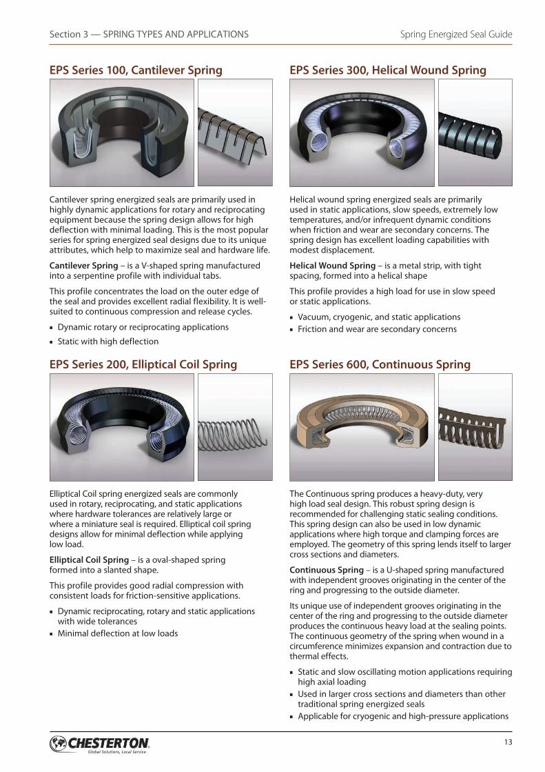
EPS Series 100, Cantilever Spring
Cantilever spring energized seals are primarily used in highly dynamic applications for rotary and reciprocating equipment because the spring design allows for high deflection with minimal loading. This is the most popular series for spring energized seal designs due to its unique attributes, which help to maximize seal and hardware life.
Cantilever Spring – is a V-shaped spring manufactured into a serpentine profile with individual tabs.
This profile concentrates the load on the outer edge of the seal and provides excellent radial flexibility. It is well- suited to continuous compression and release cycles.
■■ Dynamic rotary or reciprocating applications■■ Static with high deflection
EPS Series 200, Elliptical Coil Spring
Elliptical Coil spring energized seals are commonly used in rotary, reciprocating, and static applications where hardware tolerances are relatively large or where a miniature seal is required. Elliptical coil spring designs allow for minimal deflection while applying low load.
Elliptical Coil Spring – is a oval-shaped spring formed into a slanted shape.
This profile provides good radial compression with consistent loads for friction-sensitive applications.
■■ Dynamic reciprocating, rotary and static applications with wide tolerances
■■ Minimal deflection at low loads
EPS Series 300, Helical Wound Spring
Helical wound spring energized seals are primarily used in static applications, slow speeds, extremely low temperatures, and/or infrequent dynamic conditions when friction and wear are secondary concerns. The spring design has excellent loading capabilities with modest displacement.
Helical Wound Spring – is a metal strip, with tight spacing, formed into a helical shape
This profile provides a high load for use in slow speed or static applications.
■■ Vacuum, cryogenic, and static applications■■ Friction and wear are secondary concerns
EPS Series 600, Continuous Spring
The Continuous spring produces a heavy-duty, very high load seal design. This robust spring design is recommended for challenging static sealing conditions. This spring design can also be used in low dynamic applications where high torque and clamping forces are employed. The geometry of this spring lends itself to larger cross sections and diameters.
Continuous Spring – is a U-shaped spring manufactured with independent grooves originating in the center of the ring and progressing to the outside diameter.
Its unique use of independent grooves originating in the center of the ring and progressing to the outside diameter produces the continuous heavy load at the sealing points. The continuous geometry of the spring when wound in a circumference minimizes expansion and contraction due to thermal effects.
■■ Static and slow oscillating motion applications requiring high axial loading
■■ Used in larger cross sections and diameters than other traditional spring energized seals
■■ Applicable for cryogenic and high-pressure applications
Spring Energized Seal Guide Section 3 — SPRING TYPES AND APPLICATIONS
14
Spring Energized Seal Guide Section 3 — SPRING TYPES AND APPLICATIONS
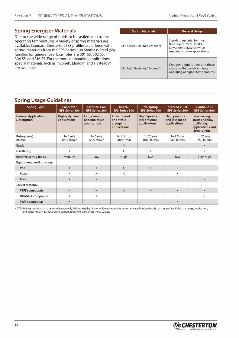
Spring Usage GuidelinesSpring Type Cantilever
EPS Series 100Elliptical Coil
EPS Series 200Helical
EPS Series 300No-spring
EPS Series 400Stacked V-Set EPS Series 500
Continuous EPS Series 600
General Application Description
Highly dynamic applications
Large runout and miniature applications
Lower speed and static cryogenic applications
High Speed and low pressure applications
High pressure and low speed applications
Face Sealing, static and slow oscillating applications and large runout
Rotary (m/s) (ft/min)
To 5 m/s 1000 ft/min
To 6 m/s 1200 ft/min
To 2.5 m/s 500 ft/min
To 20 m/s 4000 ft/min
To 2.5 m/s 500 ft/min
<.25 m/s <50 ft/min
Static X X
Oscillating X X X X X
Relative spring loads Medium Low High N/A N/A Very High
Equipment configuration:
Rod X X X X X
Piston X X X X
Face X X X
Jacket Material:
PTFE compounds X X X X X X
UHMWPE compounds X X X X
PEEK compounds X X
NOTE: Ratings on this chart are for reference only. Values may be higher or lower depending upon the application details such as surface finish, hardness, lubrication, and concentricity. Jacket/Spring combinations will also affect these values.
Spring Energizer MaterialsDue to the wide range of fluids to be sealed at extreme operating temperatures, a variety of spring materials are available. Standard Chesterton SES profiles are offered with spring materials from the EPS Series 300 Stainless Steel (SS) families for general use. Examples are 301 SS, 302 SS, 304 SS, and 316 SS. For the more demanding applications special materials such as Inconel®, Elgiloy®, and Hastelloy® are available.
Spring Materials General Usage
EPS Series 300 Stainless Steel
Standard material for most fluids up to 260°C (500°F). Lower temperatures when used in corrosive applications.
Eligiloy®, Hastelloy®, Inconel®Cryogenic applications and those corrosive fluid environments operating at higher temperatures.
15
S E C T I O N 4
Seal Jacket Materials
Seal Jacket MaterialA seal jacket can be made from various materials including elastomers, engineered plastics, and fluoroplastics. Typically, fluoroplastic (i.e. PTFE-based) materials are most commonly used to improve limits regarding PV, temperature, and chemical compatibility. The use of fillers in these PTFE compounds improves properties related to seal performance (such as wear resistance). Not all properties can be increased significantly; compounding may have adverse effects on some properties (such as abrasiveness to mating surfaces as a result of adding glass fillers).
Chesterton selects the right material for your specific application requirements. These advanced materials have been field tested to withstand extreme pressure and temperature ranges as well as harsh chemical environments in the most challenging applications. The materials listed below are examples used for sealing applications. In addition Chesterton has over 50 custom blended materials for the most demanding environments and operating conditions.
Compound Number Temperature Range °C (°F) General Usage
Aloymer 001, (AWC 520) Virgin PTFE
-268 to 232 (-450 to 450)
■■ Static or slow speed applications with low wear resistance. ■■ Works well in vacuum and low gas permeability applications. ■■ Superior fluid compatibility.■■ Best material for static applications requiring low permeability.■■ FDA Listed.
Aloymer 002, (AWC 400) Carbon/Graphite PTFE
-185 to 260 (-300 to 500)
■■ Water and steam applications. ■■ High PV values. ■■ Excellent all-purpose material for rotary applications. ■■ Good electrical conductivity.
Aloymer 005, (AWC 300) Moly/Glass Fiber PTFE
-130 to 260 (-200 to 500)
■■ Excellent in high-temperature applications.■■ Excellent wear properties, high-pressure and high-speed applications. ■■ High PV values with excellent fluid compatibility. ■■ Excellent in high-viscosity fluids.■■ Good cryogenic properties.
Aloymer 007, (AWC 405) High Carbon/Graphite PTFE
-100 to 260 (-148 to 500)
■■ Water and steam applications. ■■ High PV values. ■■ Excellent all-purpose material for rotary applications. ■■ Good electrical conductivity.
Aloymer 008, (AWC 505) 60% Bronze-filled PTFE
-100 to 260 (-148 to 500)
■■ Good Bearing and extrusion properties. ■■ Bronze provides higher thermal conductivity, allowing higher running velocities. ■■ Chemical resistance is somewhat lowered because bronze is attacked by some
acids and alkalis. ■■ Best used in high-pressure hydraulic applications.
Aloymer 009, (AWC 500) 40% Bronze-filled PTFE
-100 to 260 (-148 to 500)
■■ Good bearing and extrusion properties. ■■ Bronze provides higher thermal conductivity, allowing higher running velocities. ■■ Chemical resistance is somewhat lowered because bronze is attacked by some
acids and alkalis.■■ Best used in high-pressure hydraulic applications.■■ More flexible than Aloymer 008 due to lower concentration of bronze.
16
Compound Number Temperature Range °C (°F) General Usage
Aloymer 015, (AWC 100) Polyimide-filled PTFE
-100 to 260 (-148 to 500)
■■ Dry running or low viscosity petroleum-based applications.■■ Highest PV value, mechanical toughness, and can be used in elevated temperatures with
excellent fluid compatibility.■■ Not to be used in or around water.
Aloymer 020, (AWC 610) Unfilled UHMWPE
-200 to 82 (-325 to 180)
■■ High abrasion resistance in reciprocating or slow rotary applications.■■ Excellent in water-based fluids. ■■ Economical and excellent in cryogenic applications.
Aloymer 021, (AWC 620) Premium UHMWPE
-200 to 82 (-325 to 180)
■■ Better wear and abrasion resistance properties than unfilled UHMWPE.■■ Reciprocating or slow rotary applications. ■■ Excellent in water-based fluids.
Aloymer 024, (AWC 305) Moly-filled PTFE
-100 to 260 (-148 to 500)
■■ Water and steam applications. ■■ High PV values. ■■ Excellent all-purpose material for rotary applications. ■■ Good electrical conductivity.
Aloymer 043, (AWC 410) Carbon-filled PTFE
-185 to 260 (-300 to 500)
■■ Water and steam applications. ■■ High PV values. ■■ Excellent all-purpose material for rotary applications. ■■ Good electrical conductivity.
Aloymer 074, (AWC 600) Polyester TPE
-40 to 110 (-40 to 230)
■■ Applications requiring strong resistance to tear, creep, and abrasion.■■ Some elastic characteristics. Good against rougher surface finishes.
Aloymer 078, (AWC 615) High-Temp UHMWPE
-200 to 110 (-325 to 230)
■■ Wear- and abrasion-resistant properties. ■■ Good in dry applications. ■■ Excellent chemical resistance. ■■ Large ph range and solvents. ■■ Excellent in cryogenic applications. ■■ Good upper temperature limits.
Aloymer 084, (AWC 442) Carbon/PPS-filled TFM
-100 to 230 (-150 to 450)
■■ Higher wear resistance especially in steam and aqueous applications.■■ Good in dry applications. ■■ Excellent chemical resistance.■■ Largest ph range, H2S and solvents. ■■ Good electrical conductivity. ■■ High rotary speed range. ■■ Recommended running against harder mating surfaces.
Aloymer 100, (AWC 630) Injection Molded Unfilled PEEK
-73 to 249 (-100 to 480)
■■ Better wear characteristics.■■ Tough, reliable, and dimensionally stable even under continuous elevated temperatures. ■■ Excellent wear characteristics for seals and bearings. ■■ Compressive strength 124 MPa (18,000 psi).
Aloymer 135, (AWC 445) High Carbon/PPS-filled PTFE
-100 to 230 (-150 to 450)
■■ Higher wear resistance especially in steam and aqueous applications.■■ Good in dry applications. ■■ Excellent chemical resistance: Largest ph range, H2S and solvents. ■■ Good electrical conductivity. ■■ High rotary speed range. ■■ Recommended running against harder mating surfaces.
Spring Energized Seal Guide Section 4 — SEAL JACKET MATERIALS
NOTE: Ratings on this chart are for reference only. Values may be higher or lower depending upon the application details such as surface finish, hardness, lubrication, and concentricity. Jacket/Spring combinations will also affect these values.
17
Section 4 — SEAL JACKET MATERIALSSpring Energized Seal Guide
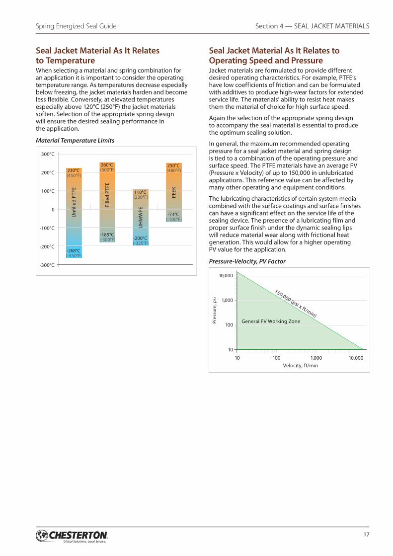
Seal Jacket Material As It Relates to TemperatureWhen selecting a material and spring combination for an application it is important to consider the operating temperature range. As temperatures decrease especially below freezing, the jacket materials harden and become less flexible. Conversely, at elevated temperatures especially above 120°C (250°F) the jacket materials soften. Selection of the appropriate spring design will ensure the desired sealing performance in the application.
Material Temperature Limits
300°C
200°C
100°C
0
-100°C
-200°C
-300°C
Fille
d PT
FE
UH
MW
PE
PEEK
Un
lled
PTFE
230°C (450°F)
260°C (500°F)
110°C (230°F)
250°C (480°F)
-185°C (-300°F) -200°C
(-325°F)
-73°C (-100°F)
-268°C (-450°F)
Seal Jacket Material As It Relates to Operating Speed and PressureJacket materials are formulated to provide different desired operating characteristics. For example, PTFE’s have low coefficients of friction and can be formulated with additives to produce high-wear factors for extended service life. The materials’ ability to resist heat makes them the material of choice for high surface speed.
Again the selection of the appropriate spring design to accompany the seal material is essential to produce the optimum sealing solution.
In general, the maximum recommended operating pressure for a seal jacket material and spring design is tied to a combination of the operating pressure and surface speed. The PTFE materials have an average PV (Pressure x Velocity) of up to 150,000 in unlubricated applications. This reference value can be affected by many other operating and equipment conditions.
The lubricating characteristics of certain system media combined with the surface coatings and surface finishes can have a significant effect on the service life of the sealing device. The presence of a lubricating film and proper surface finish under the dynamic sealing lips will reduce material wear along with frictional heat generation. This would allow for a higher operating PV value for the application.
Pressure-Velocity, PV Factor
10
100
100 1,000 10,00010
1,000
10,000
Pres
sure
, psi
Velocity, ft/min
150,000 (psi x ft/min)General PV Working Zone
18
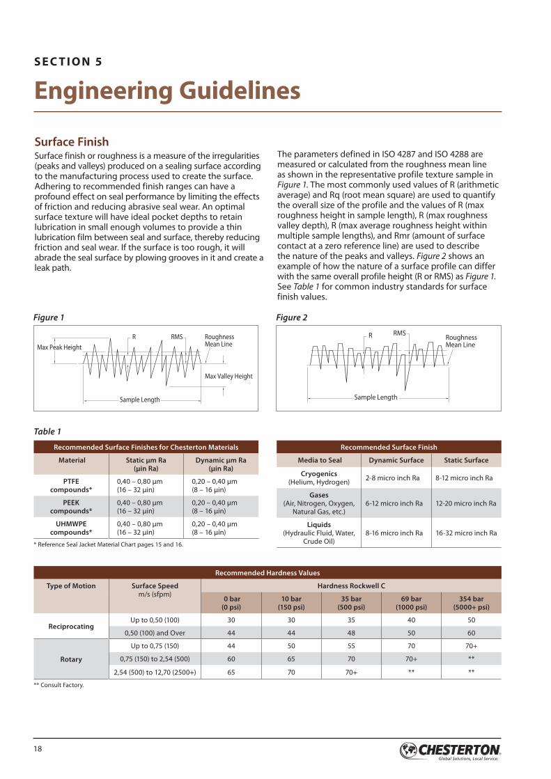
The parameters defined in ISO 4287 and ISO 4288 are measured or calculated from the roughness mean line as shown in the representative profile texture sample in Figure 1. The most commonly used values of R (arithmetic average) and Rq (root mean square) are used to quantify the overall size of the profile and the values of R (max roughness height in sample length), R (max roughness valley depth), R (max average roughness height within multiple sample lengths), and Rmr (amount of surface contact at a zero reference line) are used to describe the nature of the peaks and valleys. Figure 2 shows an example of how the nature of a surface profile can differ with the same overall profile height (R or RMS) as Figure 1. See Table 1 for common industry standards for surface finish values.
Surface FinishSurface finish or roughness is a measure of the irregularities (peaks and valleys) produced on a sealing surface according to the manufacturing process used to create the surface. Adhering to recommended finish ranges can have a profound effect on seal performance by limiting the effects of friction and reducing abrasive seal wear. An optimal surface texture will have ideal pocket depths to retain lubrication in small enough volumes to provide a thin lubrication film between seal and surface, thereby reducing friction and seal wear. If the surface is too rough, it will abrade the seal surface by plowing grooves in it and create a leak path.
S E C T I O N 5
Engineering Guidelines
Figure 2
Max Peak Height
Max Valley Height
Sample Length Sample Length
RoughnessMean Line
RoughnessMean Line
RMS RMSR R
Figure 1
Max Peak Height
Max Valley Height
Sample Length Sample Length
RoughnessMean Line
RoughnessMean Line
RMS RMSR R
Recommended Surface Finishes for Chesterton Materials
Material Static µm Ra (µin Ra)
Dynamic µm Ra (µin Ra)
PTFE compounds*
0,40 – 0,80 µm (16 – 32 µin)
0,20 – 0,40 µm (8 – 16 µin)
PEEK compounds*
0,40 – 0,80 µm (16 – 32 µin)
0,20 – 0,40 µm (8 – 16 µin)
UHMWPE compounds*
0,40 – 0,80 µm (16 – 32 µin)
0,20 – 0,40 µm (8 – 16 µin)
* Reference Seal Jacket Material Chart pages 15 and 16.
Recommended Hardness Values
Type of Motion Surface Speed m/s (sfpm)
Hardness Rockwell C
0 bar (0 psi)
10 bar (150 psi)
35 bar (500 psi)
69 bar (1000 psi)
354 bar (5000+ psi)
ReciprocatingUp to 0,50 (100) 30 30 35 40 50
0,50 (100) and Over 44 44 48 50 60
Rotary
Up to 0,75 (150) 44 50 55 70 70+
0,75 (150) to 2,54 (500) 60 65 70 70+ **
2,54 (500) to 12,70 (2500+) 65 70 70+ ** **
** Consult Factory.
Recommended Surface Finish
Media to Seal Dynamic Surface Static Surface
Cryogenics (Helium, Hydrogen) 2-8 micro inch Ra 8-12 micro inch Ra
Gases (Air, Nitrogen, Oxygen,
Natural Gas, etc.)6-12 micro inch Ra 12-20 micro inch Ra
Liquids (Hydraulic Fluid, Water,
Crude Oil)8-16 micro inch Ra 16-32 micro inch Ra
Table 1
19
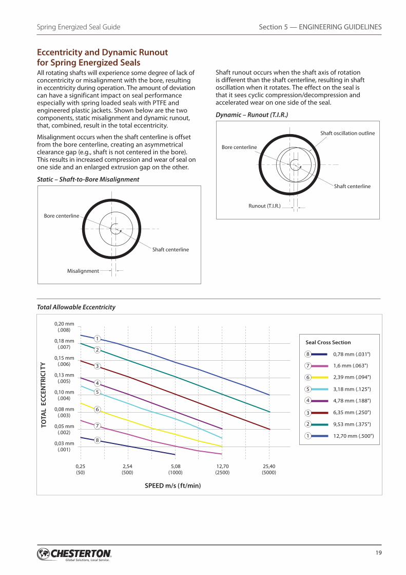
Shaft runout occurs when the shaft axis of rotation is different than the shaft centerline, resulting in shaft oscillation when it rotates. The effect on the seal is that it sees cyclic compression/decompression and accelerated wear on one side of the seal.
Dynamic – Runout (T.I.R.)
Bore centerline
Misalignment
Shaft centerline
Bore centerline
Shaft centerline
Shaft oscillation outline
Runout (T.I.R.)
Eccentricity and Dynamic Runout for Spring Energized SealsAll rotating shafts will experience some degree of lack of concentricity or misalignment with the bore, resulting in eccentricity during operation. The amount of deviation can have a significant impact on seal performance especially with spring loaded seals with PTFE and engineered plastic jackets. Shown below are the two components, static misalignment and dynamic runout, that, combined, result in the total eccentricity.
Misalignment occurs when the shaft centerline is offset from the bore centerline, creating an asymmetrical clearance gap (e.g., shaft is not centered in the bore). This results in increased compression and wear of seal on one side and an enlarged extrusion gap on the other.
Static – Shaft-to-Bore Misalignment
Bore centerline
Misalignment
Shaft centerline
Bore centerline
Shaft centerline
Shaft oscillation outline
Runout (T.I.R.)
Section 5 — ENGINEERING GUIDELINESSpring Energized Seal Guide
0,20 mm(.008)
0,18 mm(.007)
0,15 mm(.006)
0,13 mm(.005)
0,10 mm(.004)
0,08 mm(.003)
0,05 mm(.002)
0,03 mm(.001)
TOTA
L E
CCEN
TRIC
ITY
SPEED m/s ( ft/min)
0,25 2,54 5,08 12,70 25,40(50) (500) (1000) (2500) (5000)
0,78 mm (.031")
Seal Cross Section
1,6 mm (.063")
2,39 mm (.094")
3,18 mm (.125")
4,78 mm (.188")
6,35 mm (.250")
9,53 mm (.375")
12,70 mm (.500")
1
2
3
4
5
6
7
81
2
3
4
5
6
7
8
Total Allowable Eccentricity
20
Spring Energized Seal GuideSection 5 — ENGINEERING GUIDELINES
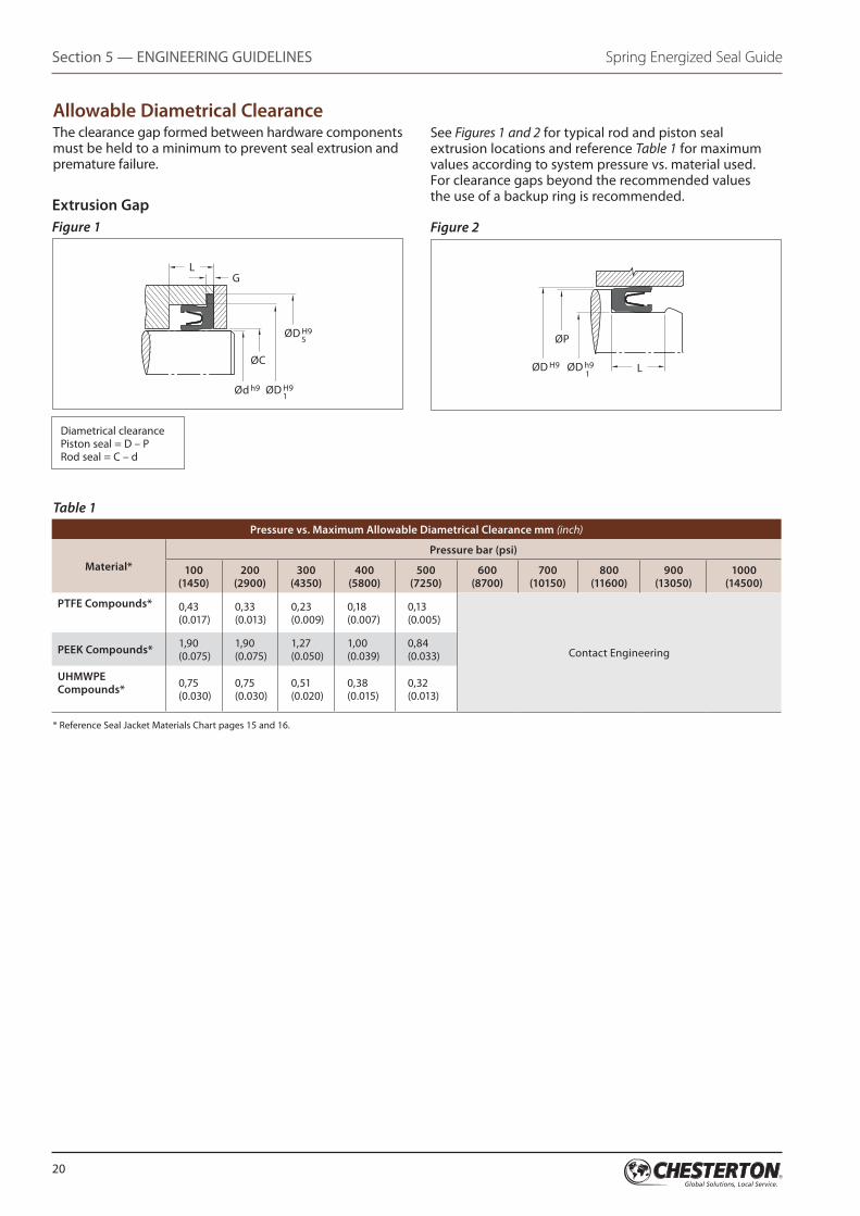
Allowable Diametrical ClearanceThe clearance gap formed between hardware components must be held to a minimum to prevent seal extrusion and premature failure.
See Figures 1 and 2 for typical rod and piston seal extrusion locations and reference Table 1 for maximum values according to system pressure vs. material used. For clearance gaps beyond the recommended values the use of a backup ring is recommended.
* Reference Seal Jacket Materials Chart pages 15 and 16.
Table 1Pressure vs. Maximum Allowable Diametrical Clearance mm (inch)
Material*Pressure bar (psi)
100 (1450)
200 (2900)
300 (4350)
400 (5800)
500 (7250)
600 (8700)
700 (10150)
800 (11600)
900 (13050)
1000 (14500)
PTFE Compounds* 0,43 (0.017)
0,33 (0.013)
0,23 (0.009)
0,18 (0.007)
0,13 (0.005)
Contact EngineeringPEEK Compounds* 1,90 (0.075)
1,90 (0.075)
1,27 (0.050)
1,00 (0.039)
0,84 (0.033)
UHMWPE Compounds* 0,75
(0.030)0,75 (0.030)
0,51 (0.020)
0,38 (0.015)
0,32 (0.013)
Extrusion GapFigure 1 Figure 2
Diametrical clearancePiston seal = D – PRod seal = C – d
LØD h9 1
ØD H9
ØP
LG
ØC
Ød h9 ØD H9 1
ØD H9 5
21
Section 5 — ENGINEERING GUIDELINESSpring Energized Seal Guide
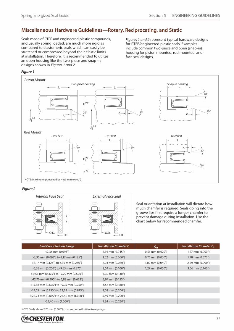
Seals made of PTFE and engineered plastic compounds, and usually spring loaded, are much more rigid as compared to elastomeric seals which can easily be stretched or compressed beyond their elastic limits at installation. Therefore, it is recommended to utilize an open housing like the two-piece and snap-in designs shown in Figures 1 and 2.
Figures 1 and 2 represent typical hardware designs for PTFE/engineered plastic seals. Examples include common two-piece and open (snap-in) housing for piston mounted, rod mounted, and face seal designs
Seal orientation at installation will dictate how much chamfer is required. Seals going into the groove lips first require a longer chamfer to prevent damage during installation. Use the chart below for recommended chamfer.
Seal Cross Section Range Installation Chamfer C CH Installation Chamfer CL
<2,36 mm (0.093") 1,14 mm (0.045") 0,51 mm (0.020") 1,27 mm (0.050")
>2,36 mm (0.093") to 3,17 mm (0.125") 1,52 mm (0.060") 0,76 mm (0.030") 1,78 mm (0.070")
>3,17 mm (0.125") to 6,35 mm (0.250") 2,03 mm (0.080") 1,02 mm (0.040") 2,29 mm (0.090")
>6,35 mm (0.250") to 9,53 mm (0.375") 2,54 mm (0.100") 1,27 mm (0.050") 3,56 mm (0.140")
>9,53 mm (0.375") to 12,70 mm (0.500") 3,30 mm (0.130")
>12,70 mm (0.500") to 5,88 mm (0.625") 3,94 mm (0.155")
>15,88 mm (0.625") to 19,05 mm (0.750") 4,57 mm (0.180")
>19,05 mm (0.750") to 22,23 mm (0.875") 5,08 mm (0.200")
>22,23 mm (0.875") to 25,40 mm (1.000") 5,59 mm (0.220")
>25,40 mm (1.000") 5,84 mm (0.230")
NOTE: Seals above 2,70 mm (0.500") cross section will utilize two springs.
c20° 20°20°
20°
CH
CL
h9d1
h9d1
DH9
L L L
Figure 1
Piston Mount Two-piece housing Snap-in housing
Figure 2
Miscellaneous Hardware Guidelines—Rotary, Reciprocating, and Static
Internal Face Seal External Face Seal
20°
20° 20°20°
C H
h9d
1DH9
LC L
C
L L
Rod Mount Heel first Lips first Heel first
L
O.D. O.D.I.D. I.D.
L
NOTE: Maximum groove radius = 0,3 mm (0.012")
22
Spring Energized Seal GuideSection 5 — ENGINEERING GUIDELINES
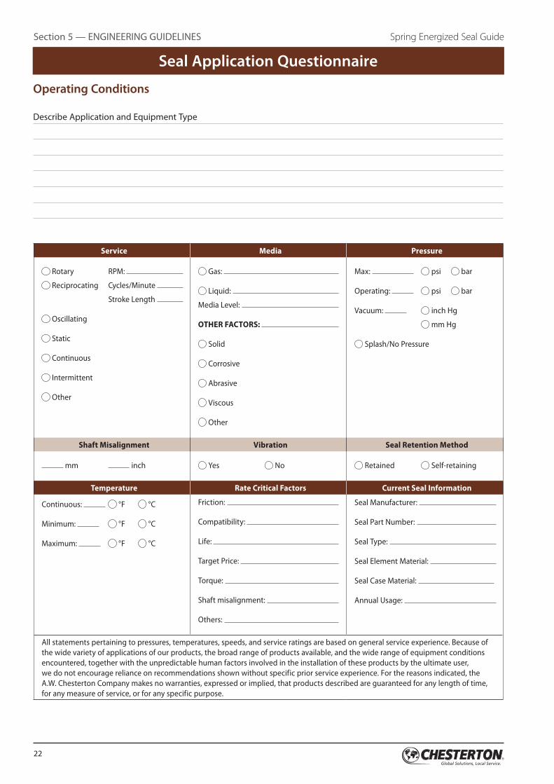
Seal Application Questionnaire
Operating Conditions
Describe Application and Equipment Type
Service Media Pressure
Rotary RPM:
Reciprocating Cycles/Minute
Stroke Length
Oscillating
Static
Continuous
Intermittent
Other
Gas:
Liquid:
Media Level:
OTHER FACTORS:
Solid
Corrosive
Abrasive
Viscous
Other
Max: psi bar
Operating: psi bar
Vacuum: inch Hg
mm Hg
Splash/No Pressure
Shaft Misalignment Vibration Seal Retention Method
mm inch Yes No Retained Self-retaining
Temperature Rate Critical Factors Current Seal Information
Continuous: °F °C
Minimum: °F °C
Maximum: °F °C
Friction:
Compatibility:
Life:
Target Price:
Torque:
Shaft misalignment:
Others:
Seal Manufacturer:
Seal Part Number:
Seal Type:
Seal Element Material:
Seal Case Material:
Annual Usage:
All statements pertaining to pressures, temperatures, speeds, and service ratings are based on general service experience. Because of the wide variety of applications of our products, the broad range of products available, and the wide range of equipment conditions encountered, together with the unpredictable human factors involved in the installation of these products by the ultimate user, we do not encourage reliance on recommendations shown without specific prior service experience. For the reasons indicated, the A.W. Chesterton Company makes no warranties, expressed or implied, that products described are guaranteed for any length of time, for any measure of service, or for any specific purpose.
23
Section 5 — ENGINEERING GUIDELINESSpring Energized Seal Guide
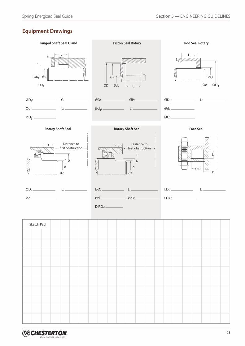
Equipment Drawings
Flanged Shaft Seal Gland Piston Seal Rotary Rod Seal Rotary
ØC
1Ød ØD
L
L
L
ØP
1ØdØD
I.D.O.D.
Ød
d7
d
Distance to�rst obstruction
G
1ØD
D
5ØD
L
L
ØC
1Ød ØD
L
L
L
ØP
1ØdØD
I.D.O.D.
Ød
Ød
G
1ØD
ØD
5ØD
L
L
ØC
1Ød ØD
L
L
L
ØP
1ØdØD
I.D.O.D.
Ød
d7
d
Distance to�rst obstruction
G
1ØD
D
5ØD
L
L
ØD1: G:
Ød: L:
ØD5:
ØD: ØP:
Ød1: L:
ØD1: L:
Ød:
ØC:
Rotary Shaft Seal Rotary Shaft Seal Face Seal
ØC
1Ød ØD
L
L
L
ØP
1ØdØD
I.D.O.D.
Ød
d7
d
Distance to�rst obstruction
G
1ØD
D
5ØD
L
L
d7
d
Distance to�rst obstruction
D
L
ØC
1Ød ØD
L
L
L
ØP
1ØdØD
I.D.O.D.
Ød
d7
d
Distance to�rst obstruction
G
1ØD
D
5ØD
L
L
ØD: L:
Ød:
ØD: L:
Ød: Ød7:
D.F.O.:
I.D.: L:
O.D.:
Sketch Pad
Global Solutions, Local Service
Since its founding in 1884, the A.W. Chesterton Company has successfully met the critical needs of its diverse customer base. Today, as always, customers count on Chesterton solutions to increase equipment reliability, optimize energy consumption, and provide local technical support and service wherever they are in the world.
Chesterton’s global capabilities include:
■■ Servicing plants in over 100 countries
■■ Global manufacturing operations
■■ More than 500 Service Centers and Sales Offices worldwide
■■ Over 1200 trained local Service Specialists and Technicians
Visit our website at www.chesterton.com
Distributed by:
© A.W. Chesterton Company, 2014. All rights reserved.
® Registered trademark owned and licensed by A.W. Chesterton Company in USA and other countries, unless otherwise noted.
A.W. Chesterton Company860 Salem StreetGroveland, MA 01834 USA
Telephone: 781-438-7000Fax: 978-469-6528 www.chesterton.com
Form No. EN23216Spring Energized Seal Guide – English9/14
Chesterton ISO certificates available on www.chesterton.com/corporate/isoElgiloy® is a registered trademark of Elgiloy Ltd. Partnership.Hastelloy® is a registered trademark of Haynes International.Inconel® is a registered trademark of Special Metals Corporation.Technical data reflects results of laboratory tests and is intended to indicate general characteristics only. A.W. Chesterton Company disclaims all warranties express, or implied, including warranties of merchantability and fitness for a particular purpose. Liability, if any, is limited to product replacement only. Any images contained herein are for general illustrative or aesthetic purposes only and are not intended to convey any instructional, safety, handling or usage information or advice respecting any product or equipment. Please refer to relevant Safety Data Sheets, Product Data Sheets, and/or Product Labels for safe use, storage, handling, and disposal of products, or consult with your local Chesterton sales representative.