Embed Size (px)
Citation preview

GRUNDFOS WASTEWATER
SRP range 3.0 – 24 kW60 Hz version

Grundfos Submersible Recirculation Pumps
A range of efficient and reliable submersible recirculation pumps for wastewater treatment plants
>�
Soluti ons for a variety of applications Wastewater treatment plants, pumping return
sludge
Flood control and other applications which require large flows at low heads
Main features Oil-filled gearbox with tapered oil bearings
Rewindable motor
Two radial lip seals protecting the shaft seal
No special tools needed for maintenance or service
Built-in leak sensor
Motor housing in cast iron, protected by a multi-layer two-component epoxy coating
Pumping rack and hydraulic inlet in stainless steel
Propeller in cast stainless steel
Grundfos offers a range of dependable and highly efficient submersible recirculation pumps for wastewater treatment and flood control.
The recirculation pumps are designed for years of continuous use in the toughest environments. The pumps are based on the same modular design and principles as the gear-driven Grundfos mixers and flowmakers, which ensures easier maintenance and service. All parts are manufactured from specially selected materials, and each component is thoroughly tested for reliability and durability before assembly.
The Grundfos range of submersible recirculation pumps is based on planetary-gear driven impellers. The stainless steel hydraulic parts are designed for high efficiency under both light and heavy-duty operating conditions.
The submersible recirculation pumps are available in the following dimensions: DN 300, DN 500 and DN 800 mm with a motor range from 3.0 to 24 kW. This provides the possibility of a capacity of up to 5,130 m3/h and a head up to 2.1 metre.

Details >�
State-of-the-art features and design
Motor bracketCorrosion resistant motor bracket made from stain-less steel, galvanically separated from the motor housing. The motor bracket ensures easy installation and stable operation.
Active electronic leak detectorIndicates possible liq-uid in the gear hous-ing. Even the smallest quantity will be quickly detected. Thus service can be carried out before any damage is done.
ImpellerHydro-dynamic 3-blade impeller made from cast stainless steel.
Two ball bearingsThe rotor shaft rests on two ball bearings, which accommodate both axial and radial forces.
Cable Watertight cable entry with self-shaping seal preventing cable damage.
Motor protectionThe motor is effectively protected against over-load and overheating by three thermal switches or three thermistors placed in each motor winding.
Shaft sealing ringsThe radial shaft sealing rings protect the mecha-nical shaft seal system from abrasive parts. During maintenance, only the less expensive radial shaft sealing rings need to be changed.
Planetary gearThe best and most efficient solution to trans-port axial forces. Slim design provides optimum hydrodynamic shape.

Material specifications and type key
Technical data >�
Material specifications
Corrosion protectionIn order to ensure long and trouble-free operation of the SRP pumps, the cast-iron parts are protected against corrosion with a high-grade epoxy anti-corrosion system. Minimum thickness 320 µ.
Type key
Component Material DIN W.-Nr./EN standard
Bottom fixation Column profile tubeTop fixationConnection flange PN 10 �/� Relief wire Stainless steel 1.��0� �1�LCrane w/winch Aluminium - -Pump rack Stainless steel 1.��01 �0�Motor housing Gear housingHydraulic inlet Stainless steel 1.��01 �0�Impeller Stainless steel 1.���1 -
AISI/ASTM
Stainless steel 1.��01 �0�
Cast iron EN-JL10�0 -
Example SRP .70 .30 .805 .25
Type range SRP, Submersible Recirculation Pump
PN powder output, P2 [kW] x 10
Nominal impeller diameter [cm]
Impeller speed [min-1]
Blade angle [˚]
( ) = standardE = explosion proof

Technical data
Technical data >�
Technical data
Electrical data
SRP.30.30.513.25 3.0 3.5 A07RN-F12G1.5 S1. ∆ 513 6.1 0.88 45 300 96576880
SRP.40.30.607.25 4.0 4.8 A07RN-F12G1.5 2 S1. ∆ 607 8.3 0.90 45 300 25 96576883
SRP.55.30.722.25 5.5 6.5 A07RN-F12G1.5 S1. ∆ 722 11.8 0.84 109 300 96576884
SRP.70.30.805.25 7.0 8.1 A07RN-F12G1.5 S1. ∆ 805 14.3 0.89 109 300 96576886
SRP.35.50.254.27 3.5 4.2 A07RN-F12G1.5 S1. ∆ 254 8.4 0.77 48.3 500 96576887
SRP.50.50.299.27 5.0 6.1 A07RN-F12G1.5 S1. ∆ 299 11.1 0.85 48.3 500 27 96576888
SRP.70.50.363.27 7.0 8.0 A07RN-F12G2.5 S1. ∆ 363 15.9 0.78 153 500 96576889
SRP.100.50.406.27 10.0 11.2 380 A07RN-F12G2.5 S1. ∆ 406 21.0 0.82 203 3 500 96576890
SRP.70.80.260.11 7.0 8.0 A07RN-F12G2.5 S1. ∆ 260 15.9 0.78 153 800 96576891
SRP.120.80.308.11 12.0 13.5 A07RN-F12G2.5 4 S1. ∆ 308 24.0 0.86 203 800 96576892
SRP.150.80.334.11 15.0 16.9 A07RN7G4+4x1 S1. ∆ 334 31.0 0.85 282 800 96576893
SRP.130.80.355.11 13.0 14.6 A07RN-F12G2.5 S1. ∆ 355 25.7 0.87 203 800 11 96576894
SRP.200.80.374.11 20.0 22.2 A07RN7G4+4x1 S1. ∆ 374 42.0 0.82 335 800 96576895
SRP.180.80.381.11 18.0 20.0 A07RN7G4+4x1 S1. ∆ 381 35.0 0.88 282 800 96576896
SRP.240.80.418.11 24.0 26.7 A07RN7G4+4x1 S1. ∆ 418 49.0 0.84 335 800 96576897
SRP.180.80.422.11 18.0 20.0 A07RN7G4+4x1 S1. ∆ 422 35.0 0.88 282 800 96576898
Pum
p t
ype
Pow
er o
utp
ut
P 2 [kW
]
Pow
er in
pu
t P 1 [
kW]
Rat
ed v
olta
ge
Cab
le t
ype
Nu
mb
er o
f p
oles
Op
erat
ing
mod
e
Imp
elle
r R
PM
IN [A
]
Star
tin
g cu
rren
t [A
]
Bla
des
Nom
. im
pel
ler
diam
eter
Bla
de a
ngl
e
Pro
duct
nu
mb
er
Mains voltage � x ��0 VVoltage tolerance [%] +�/–10Mains frequency required [Hz] �0Thermal sensor type PTC or PTOThermal switch cut-out temperature [˚C] 1�0 or 1�0Enclosure class IP ��Insulation class FMax. installation depth [m] �0Max. liquid temperature [˚C] �0Max. number of starts per hour �0Cable length [m] 10

Performance overview
Technical data >�
Performance overview
0 100 200 300 400 500 600 700 800 900 1000 1100 1200 1300 1400 Q [l/s]
0.0
0.2
0.4
0.6
0.8
1.0
1.2
1.4
1.6
1.8
2.0
2.2
H[m]
0 500 1000 1500 2000 2500 3000 3500 4000 4500 5000 Q [m³/h]
SRP60 Hz
SRP.XXX.80.XXX.11SRP.XX.50.XXX.27
SRP.XX.30.XXX.25

SRP.XX.30.XXX.25
Technical data >�
Performance overview
80 100 120 140 160 180 200 220 240 260 280 Q [l/s]
0. 0
0. 2
0. 4
0. 6
0. 8
1. 0
1. 2
1. 4
1. 6
1. 8
H[m]
300 400 500 600 700 800 900 1000 Q [m³/h]
SRP.XX.30.XXX.2560 Hz
70.30.805
55.30.722
40.30.607
30.30.513
80 100 120 140 160 180 200 220 240 260 280 Q [l/s]
0
1
2
3
4
5
6
7
P2[kW]
70.30.805
55.30.722
40.30.607
30.30.513
SRP.30.30.513.25 3.0 96576880SRP.40.30.607.25 4.0 380 96556883SRP.55.30.722.25 5.5 96576884SRP.70.30.805.25 7.0 96576886
Productnumber
P2 [kW]
Permissible motor voltage [V]
Productdesignation

SRP.XX.50.XXX.27
Technical data >�
Performance overview
150 200 250 300 350 400 450 500 550 600 650 700 Q [l/s]
0. 0
0. 2
0. 4
0. 6
0. 8
1. 0
1. 2
1. 4
H[m]
800 1200 1600 2000 2400 Q [m³/h]
SRP.XX.50.XXX.2760 Hz
100.50.406
70.50.363
50.50.299
35.50.254
150 200 250 300 350 400 450 500 550 600 650 700 Q [l/s]
0
1
2
3
4
5
6
7
8
9
10
P2[kW]
100.50.406
70.50.363
50.50.299
35.50.254
SRP.35.50.254.27 3.5 96576887SRP.50.50.299.27 5.0 380 96576888SRP.70.50.363.27 7.0 96576889SRP.100.50.406.27 10.0 96576890
Productnumber
P2 [kW]
Permissible motor voltage [V]
Productdesignation

SRP.XX.80.XXX.11
Technical data >�
Performance overview
200 300 400 500 600 700 800 900 1000 1100 1200 1300 1400 Q [l/s]
0. 0
0. 2
0. 4
0. 6
0. 8
1. 0
1. 2
1. 4
1. 6
1. 8
2. 0
2. 2
H[m]
1000 1500 2000 2500 3000 3500 4000 4500 5000 Q [m³/h]
SRP.XXX.80.XXX.11
60 Hz
180.80.422
240.80.418
180.80.381
200.80.374
130.80.355
150.80.334
120.80.308
70.80.260
200 300 400 500 600 700 800 900 1000 1100 1200 1300 1400 Q [l/s]
0
2
4
6
8
10
12
14
16
18
20
22
24
P2[kW]
180.80.422
240.80.418
180.80.381
200.80.374
130.80.355
150.80.334
120.80.308
70.80.260
SRP.70.80.260.11 7.0 96576891SRP.120.80.308.11 12.0 96576892SRP.150.80.334.11 15.0 96576893SRP.130.80.355.11 13.0 380 96576894SRP.200.80.374.11 20.0 96576895SRP.180.80.381.11 18.0 96576896SRP.240.80.418.11 24.0 96576897SRP.180.80.422.11 18.0 96576898
Productnumber
P2 [kW]
Permissible motor voltage [V]
Productdesignation

>10

Selection guide
Technical data >11
Head loss calculationPump selection is based on determination of flow and head.
The data needed in order to select the SRP with the right specifications are:Required flow, Q – and total head, H.
Calculation of headH = Hgeo + Hsystem, where Hgeo is the geodetic head (Hgeo = H2 - H1) and Hsystem is Head Loss in the system:Hsystem = Hj + Hjn + Hvalve
Hj = Loss in pipe. Hj = x
Hjn = Outlet loss. Hjn = Loss in elbows. Typical value 0.1 – 0.2 m
Hvalve = Loss in valve. Typical value 0.05 – 0.25. Actual data from supplier shall be used.
For more specific calculation please contact Grundfos.
Symbols = Typical value 0.02L = Pipe length [m]V = Velocity [m/sec]D = Pipe diameter [m]g = Gravity 9.81
Example:Q = 475 l/sec
Hgeo = 0.3 m
L = 21 m
V = 2.4 m/sec
D = 0.5 m
There are no valves or elbows in the system.
Calculation of loss in pipe
Hj = 0.02 x = 0.25 m
Calculation of outlet loss
Hjn = = 0.30 m
Determination of Head
H = 0.3 m + 0.25 m + 0.3 m = 0.85 m
By the use of selection curves for SRP.XX.50.XXX.27 (page 8) it can be determined that the SRP.70.50.357.27 meets the requirements and will deliver Q = 475 l/sec at H = 0.85 m.
V2
2g
L x V2
D x 2g( )
2.42
2 x 9.81
21 x 2.42
0.5 x 2 x 9.81()
y
y

SRP installation
Technical data >1�
Installation depth Installation depth
SRP.xx.30.xxx.25 and SRP.xx.50.xxx.27
SRP.xx.30.xxx.25 450 300 300SRP.xx.50.xxx.27 750 500 500SRP.xx.80.xxx.11 1200 800 800
Distance (D) between two pumps D 2 x Dimpeller
Pump type Habove [mm]
HminHabovew/
Vortex shield [mm]
Accessories
Accessories > 1�
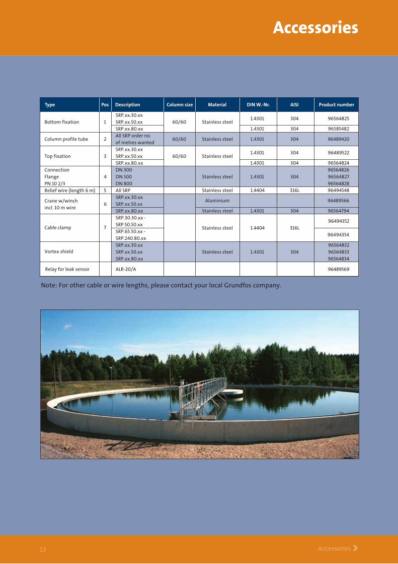
Note: For other cable or wire lengths, please contact your local Grundfos company.
SRP.xx.30.xxSRP.xx.50.xxSRP.xx.80.xxAll SRP order no. of metres wanted
1.4301 304 96564825
1.4301 304 96585482
1.4301 304 96489420
96489569
Pos Description Column size Material DIN W.-Nr. AISI Product numberType
Bottom fixation
Column profile tube
1
2
60/60 Stainless steel
60/60 Stainless steel
SRP.xx.30.xxSRP.xx.50.xxSRP.xx.80.xx
1.4301 304 96489522
1.4301 304 96564824Top fixation 3 60/60 Stainless steel
DN 300DN 500DN 800All SRP
965648261.4301 304 96564827
965648281.4404 316L 96494548
96494352
96494354
ConnectionFlangePN 10 2/3Relief wire (length 6 m)
4
5
Stainless steel
965648321.4301 304 96564833
96564834 Stainless steel
Stainless steel
1.4404 316L Stainless steel
SRP.xx.30.xxSRP.xx.50.xxSRP.xx.80.xx
SRP.xx.30.xxSRP.xx.50.xxSRP.xx.80.xx
SRP.30.30.xx -SRP.50.50.xxSRP.65.50.xx -SRP.240.80.xx
96489566
1.4301 304 96564794
Crane w/winch incl. 10 m wire
Cable clamp
Vortex shield
Relay for leak sensor ALR-20/A
6
7
Aluminium
Stainless steel

Technical data >1�
Dimensions
Dimensional drawing
Dimensions and weight
SRP.30.30.513.25 3.0 848 602 736 571 66 445 220 15 110SRP.40.30.607.25 4.0 848 602 736 571 66 445 220 15 110SRP.55.30.722.25 5.5 848 602 736 571 66 445 220 15 120SRP.70.30.805.25 7.0 848 602 736 571 66 445 220 25 120SRP.35.50.254.27 3.5 910 835 787 824 66 670 230 25 200SRP.50.50.299.27 5.0 910 835 787 824 66 670 230 25 200SRP.70.50.363.27 7.0 1119 855 996 1225 66 670 230 25 240SRP.100.50.406.27 10.0 1119 855 996 1225 66 670 230 25 250SRP.70.80.260.11 7.0 1129 1237 1006 1225 66 1015 267 25 350SRP.120.80.308.11 12.0 1129 1237 1006 1225 66 1015 267 25 360SRP.150.80.334.11 15.0 1181 1257 1058 1225 66 1015 267 25 405SRP.130.80.355.11 13.0 1129 1237 1006 1225 66 1015 267 25 360SRP.200.80.374.11 20.0 1181 1257 1058 1225 66 1015 267 25 430SRP.180.80.381.11 18.0 1181 1257 1058 1225 66 1015 267 25 405SRP.240.80.418.11 24.0 1181 1257 1058 1225 66 1015 267 25 430SRP.180.80.422.11 18.0 1181 1257 1058 1225 66 1015 267 25 405
P2 [kW]
A [mm]
B [mm]
C [mm]
D [mm]
E [mm]
F [mm]
G [mm]
H [mm]
Weightincl. bracket
[kg]Type
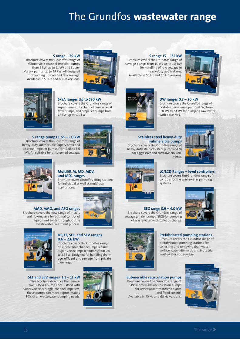
The Grundfos wastewater range
The range > 1�
S range – 29 kWBrochure covers the Grundfos range of
submersible channel-impeller pumps from 5 kW up to 21 kW and Super-
Vortex pumps up to 29 kW. All designed for handling unscreened raw sewage.Available in 50 Hz and 60 Hz versions.
S range 15 – 155 kWBrochure covers the Grundfos range of
sewage pumps from 15 kW up to 155 kW for handling of raw sewage in
heavy-duty applications.Available in 50 Hz and 60 Hz versions.
S/SA ranges Up to 520 kWBrochure covers the Grundfos range of super-heavy-duty channel pumps, axial flow pumps, and propeller pumps from 7.5 kW up to 520 kW.
DW ranges 0.7 – 20 kWBrochure covers the Grundfos range of portable dewatering pumps (DW) from 0.8 kW to 20 kW for pumping raw water with abrasives.
S range pumps 1.65 – 5.0 kW Brochure covers the Grundfos range of
heavy-duty submersible SuperVortex and channel-impeller pumps from 1.65 to 5.0 kW. All suitable for unscreened sewage.
Stainless steel heavy-duty submersible pumps
Brochure covers the Grundfos range of heavy-duty stainless steel pumps (SEN)
for aggressive and corrosive environ-ments.
Multilift M, MD, MDV, and MD1 rangesBrochure covers Grundfos lifting stations for individual as well as multi-user applications.
LC/LCD Ranges – level controllersBrochure covers the Grundfos range of controls for the wastewater pumping systems.
AMD, AMG, and AFG rangesBrochure covers the new range of mixers
and flowmakers for optimal control of liquids and solids throughout the
wastewater treatment process.
SEG range 0.9 – 4.0 kW Brochure covers the Grundfos range of
sewage grinder pumps (SEG)-for pumping of wastewater with toilet discharge.
DP, EF, SE1, and SEV ranges 0.6 – 2.6 kWBrochure covers the Grundfos range of submersible channel-impeller and Super-Vortex-impeller pumps from 0.6 to 2.6 kW. Designed for handling drain-age, effluent and sewage from private dwellings.
Prefabricated pumping stationsBrochure covers the Grundfos range of prefabricated pumping stations for collecting and removing drainwater, surface water, domestic and industrial wastewater and sewage.
SE1 and SEV ranges 1.1 – 11 kWThis brochure describes the innova-
tive SEV/SE1 pump lines. Fitted with SuperVortex or single-channel impellers,
these pumps can meet approximately 80% of all wastewater pumping needs.
Submersible recirculation pumpsBrochure covers the Grundfos range of
SRP submersible recirculation pumps for wastewater treatment plants
and flood control.Available in 50 Hz and 60 Hz versions.

www.grundfos.com
Business with an attitude
Knowledge The sharing of knowledge, experience
and expertise across our global network will always
lead our business forward.
Innovation Combining the best technology with fresh
ways of thinking, we will continue to develop even bet-
ter pumps, systems, services and standards.
Solution With a complete product range, capable
of providing every conceivable water solution, we are
the most complete player on the market.
Being responsible is our foundation Thinking ahead makes it possible
Innovation is the essence
��
�1�
���
0�0
�


