Embed Size (px)
Citation preview
S&S® Cycle, Inc.
14025 Cty Hwy G PO Box 215Viola, Wisconsin 54664
Phone: 608-627-1497 • Fax: 608-627-1488Technical Service Phone: 608-627-TECH (8324)Technical Service Email: [email protected]
Website: www.sscycle.com
Installation Instructions: S&S Complete Chain Drive Cam Chest Kit For 1999-’06 Harley-Davidson® Big Twins
IMPORTANT NOTICE:
Statements in this instruction sheet preceded by the following words are of special significance.
WARNING
Means there is the possibility of injury to yourself or others.
CAUTION
Means there is the possibility of damage to the part or motorcycle.
NOTE
Other information of particular importance has been placed in italic type.
S&S recommends you take special notice of these items.
WARRANTY:All S&S parts are guaranteed to the original purchaser to be free of manufacturing defects in materials and workmanship for a period of twelve (12) months from the date of purchase. Merchandise that fails to conform to these conditions will be repaired or replaced at S&S’s option if the parts are returned to us by the purchaser within the 12 month warranty period or within 10 days thereafter. In the event warranty service is required, the original purchaser must call or write S&S immediately with the problem. Some problems can be rectified by a telephone call and need no further course of action. A part that is suspect of being defective must not be replaced by a Dealer without prior authorization from S&S. If it is deemed necessary for S&S to make an evaluation to determine whether the part was defective, a return authorization number must be obtained from S&S. The parts must be packaged properly so as to not cause further damage and be returned prepaid to S&S with a copy of the original invoice of purchase and a detailed letter outlining the nature of the problem, how the part was used and the circumstances at the time of failure. If after an evaluation has been made by S&S and the part was found to be defective, repair, replacement or refund will be granted.
ADDITIONAL WARRANTY PROVISIONS: (1) S&S shall have no obligation in the event an S&S part is modified by any other person or organization.(2) S&S shall have no obligation if an S&S part becomes defective in whole or in part as a result of improper installation, improper maintenance, improper use, abnormal operation, or any other misuse or mistreatment of the S&S part.(3) S&S shall not be liable for any consequential or incidental damages resulting from the failure of an S&S part, the breach of any warranties, the failure to deliver, delay in delivery, delivery in non-conforming condition, or for any other breach of contract or duty between S&S and a customer.
SAFE INSTALLATION AND OPERATION RULES:
Before installing your new S&S part, it is your responsibility to read and follow the installation and maintenance procedures in these instructions and follow the basic rules below for your personal safety. • Gasoline is extremely flammable and explosive under certain conditions
and toxic when breathed. Do not smoke. Perform installation in a well ventilated area away from open flames or sparks.
• If motorcycle has been running, wait until engine and exhaust pipes have cooled down to avoid getting burned before performing any installation steps.
• Before performing any installation steps, disconnect battery to eliminate potential sparks and inadvertent engagement of starter while working on electrical components.
• Read instructions thoroughly and carefully so all procedures are completely understood before performing any installation steps. Contact S&S with any questions you may have if any steps are unclear or any abnormalities occur during installation or operation of motorcycle with an S&S part on it.
• Consult an appropriate service manual for your motorcycle for correct disassembly and reassembly procedures for any parts that need to be removed to facilitate installation.
• Use good judgment when performing installation and operating motorcycle. Good judgment begins with a clear head. Don’t let alcohol, drugs or fatigue impair your judgment. Start installation when you are fresh.
• Be sure all federal, state and local laws are obeyed with the installation. • For optimum performance and safety and to minimize potential
damage to carb or other components, use all mounting hardware that is provided and follow all installation instructions.
• Motorcycle exhaust fumes are toxic and poisonous and must not be breathed. Run motorcycle in a well ventilated area where fumes can dissipate.
DISCLAIMER:Many S&S parts are designed for high performance, closed course, racing applications and are intended for the very experienced rider only. The installation of S&S parts may void or adversely affect your factory warranty. In addition such installation and use may violate certain federal, state, and local laws, rules and ordinances as well as other laws when used on motor vehicles used on public highways. Always check federal, state, and local laws before modifying your motorcycle. It is the sole and exclusive responsibility of the user to determine the suitability of the product for his or her use, and the user shall assume all legal, personal injury risk and liability and all other obligations, duties, and risks associated therewith.
NOT LEGAL FOR SALE OR USE IN CALIFORNIA ON ANY POLLUTION CONTROLLED MOTOR VEHICLES
Instruction 510-0411 07-25-2016
Copyright © 2016
Version 1
by S&S® Cycle, Inc.
All rights reserved. Printed in the U.S.A.
Failure to install components correctly can result in sudden engine seizure. Engine seizure may result in serious injury to motorcycle operator, passenger, or others.
Special Tools Required
• Magnetic Tappet tool or clip
• Sprocket locking tool H-D® #42314
• Cam chain tensioner unloader H-D® #42313
• Camshaft remover/installer H-D® #43644
• Needle bearing remover/installer H-D® #42325
• Torque wrench – in-lb
• Torque wrench – ft-lb
Disassembly
1. Disconnect negative battery cable to eliminate potential sparks and inadvertent engagement of starter while working on motorcycle.
2. Remove spark plugs and pushrod cover clips. Collapse pushrod covers to expose pushrods.
3. Safely elevate and stabilize rear of motorcycle. Place transmission in high gear. Turn rear wheel to rotate engine until both lifters and pushrods for either cylinder are at lowest point on camshaft (TDCC – Top Dead Center Compression). Both intake and exhaust pushrods for that cylinder will not be under pressure from the valve springs and will rotate with light finger pressure.
NOTE: As a time-saving measure, the stock pushrods can be removed with bolt cutters. Be sure to heed cautions and warnings in these instructions.
4. If you wish to save the stock pushrods, follow the procedure in the Harley-Davidson® service manual for pushrod removal. However, since the Complete Cam Chest Kits include S&S Quickee pushrods, stock pushrods may be cut out of the engine to save time. Cut pushrods for cylinder that is at TDCC with bolt cutter and remove pushrods and pushrod covers from engine. Rotate engine to place pushrods for other cylinder at their lowest point (TDCC). Cut and remove remaining pushrods.
Introduction
The S&S Complete Cam Chest Kit is a one-part-number solution to replace all the components in the cam chest of 1999-’06 Harley-Davidson® big twins, except 2006 Dyna models, and upgrade to S&S performance camshafts at the same time. Complete Cam Chest Kits are available for the most popular S&S cams. Due to the limited lift capability of the valve springs in 1999-’04 engines, some installations will require the installation of high lift valve springs, not included in this kit. See Chart 1.
COMPATIBILITY NOTES:
• S&S® Chain Drive cams are compatible with the stock spring loaded chain tensioners. However, for best performance, we recommend that the engine be upgraded to hydraulic chain tensioners.
• Except for the 509C, and 510C, the S&S® camshaft kits are not compatible with stock valve springs in 1999-’04 engines.
1999-’04 stock valve springs will accommodate cam shafts with up to .510” lift. This includes S&S 509 and 510 cams. 2005 and later stock valve springs can accommodate camshafts with up to .585” lift. If cams are installed that exceed the lift capacity of the stock valve springs, a set of high performance valve springs must be installed that can handle the additional lift.
• When using S&S performance camshafts with stock Harley-Davidson® pistons, valve-to-piston clearance may need to be checked. Clearance should be at least .060” intake and .080” exhaust.
• If stock Harley-Davidson® heads are decked, valve to piston clearance must be checked. If insufficient clearance is found, piston valve pockets must be modified. Clearance should be a minimum of .060”.
Incorrect installation can cause engine damage not covered under warranty.
WARNING
CAUTION
CAUTION
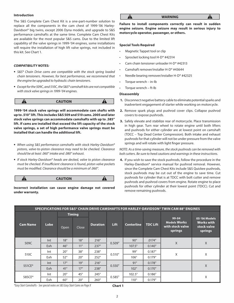
SPECIFICATIONS FOR S&S® CHAIN DRIVE CAMSHAFTS FOR HARLEY-DAVIDSON® TWIN CAM 88® ENGINES
Cam Name Lobe
Timing
Duration Lift Centerline TDC Lift
99-04 Models Works
with stock valve springs
05-'06 Models Works with stock valve
springsOpen Close
509CInt 18° 18° 216°
0.509" 90° .0174"
X XExh 46° 11° 237° 107.5° 0.140"
510CInt 20° 38° 238°
0.510" 99° 0.187"
X XExh 52° 20° 252° 106° 0.179"
551CE*Int 17° 19° 216°
0.550" 91° 0.178"
XExh 41° 17° 238° 102° 0.170"
585CE*Int 20° 45° 245°
0.585" 102.5° 0.186"
XExh 60° 20° 260° 110° 0.179"
*Easy Start Camshafts - See special notes on S&S Easy Start Cams on Page X Chart 1
2
Cutting pushrods with a saw or cutoff wheel may result in debris entering engine, causing extensive engine damage not covered under warranty.
Cutting pushrods when they are under spring pressure can result in pushrod parts being ejected with considerable force, and can cause bodily injury. Make sure piston is at TDCC.
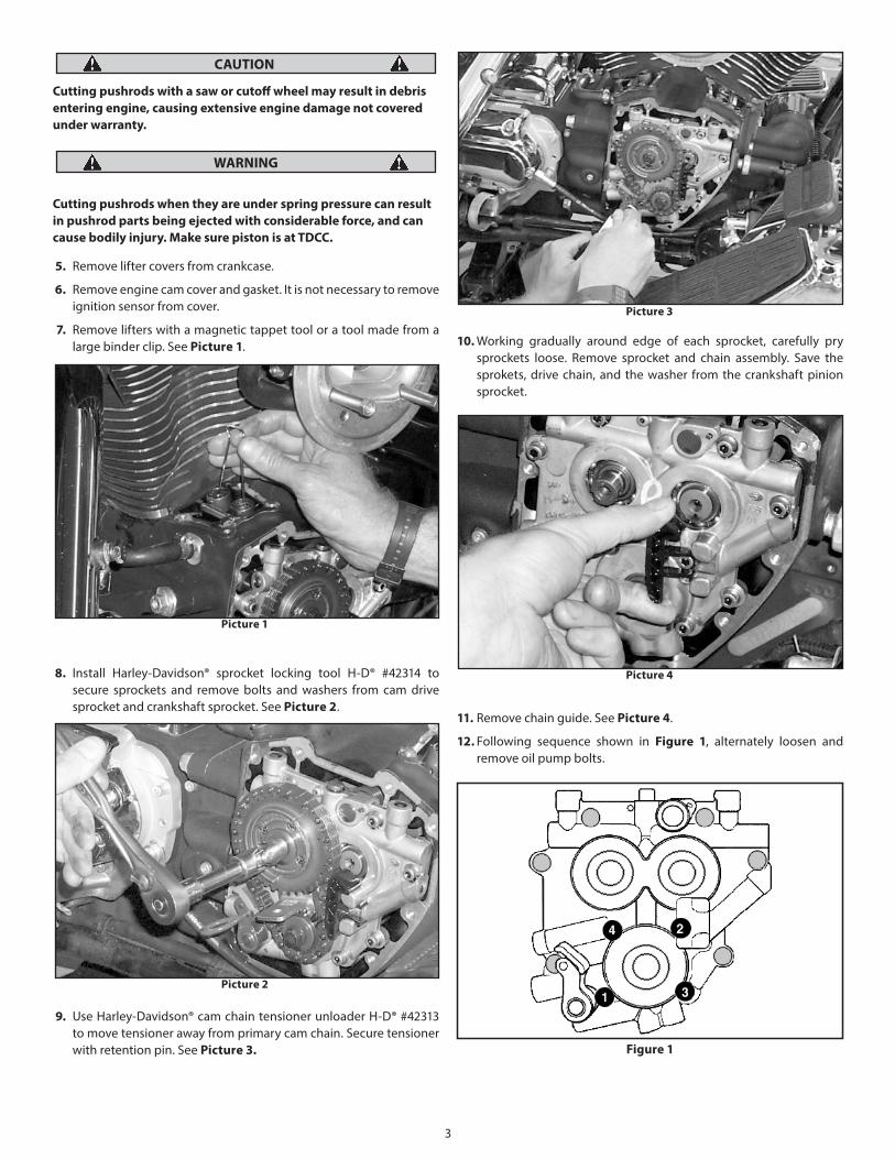
5. Remove lifter covers from crankcase.
6. Remove engine cam cover and gasket. It is not necessary to remove ignition sensor from cover.
7. Remove lifters with a magnetic tappet tool or a tool made from a large binder clip. See Picture 1.
8. Install Harley-Davidson® sprocket locking tool H-D® #42314 to secure sprockets and remove bolts and washers from cam drive sprocket and crankshaft sprocket. See Picture 2.
9. Use Harley-Davidson® cam chain tensioner unloader H-D® #42313 to move tensioner away from primary cam chain. Secure tensioner with retention pin. See Picture 3.
WARNING
CAUTION
10. Working gradually around edge of each sprocket, carefully pry sprockets loose. Remove sprocket and chain assembly. Save the sprokets, drive chain, and the washer from the crankshaft pinion sprocket.
11. Remove chain guide. See Picture 4.
12. Following sequence shown in Figure 1, alternately loosen and remove oil pump bolts.
Picture 1
Picture 2
Picture 3
Picture 4
Figure 1
3
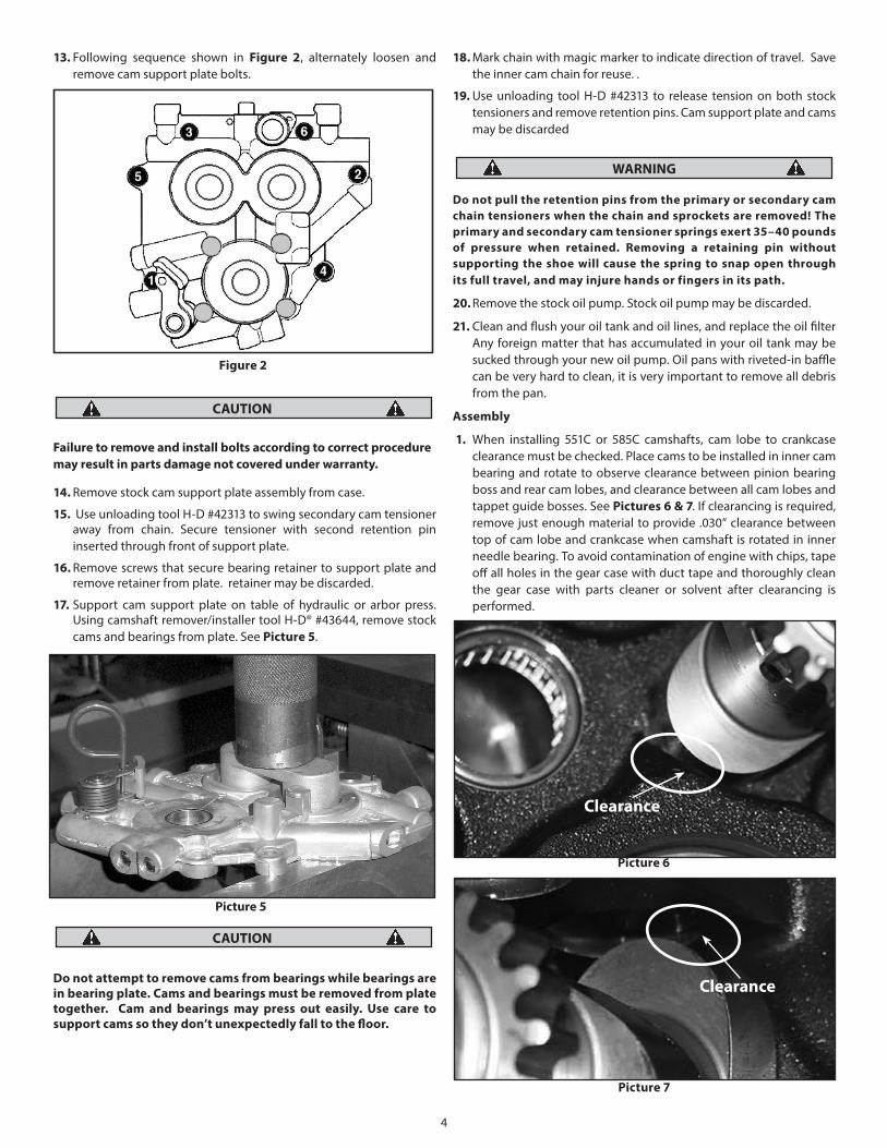
13. Following sequence shown in Figure 2, alternately loosen and remove cam support plate bolts.
Failure to remove and install bolts according to correct procedure may result in parts damage not covered under warranty.
14. Remove stock cam support plate assembly from case.
15. Use unloading tool H-D #42313 to swing secondary cam tensioner away from chain. Secure tensioner with second retention pin inserted through front of support plate.
16. Remove screws that secure bearing retainer to support plate and remove retainer from plate. retainer may be discarded.
17. Support cam support plate on table of hydraulic or arbor press. Using camshaft remover/installer tool H-D® #43644, remove stock cams and bearings from plate. See Picture 5.
Do not attempt to remove cams from bearings while bearings are in bearing plate. Cams and bearings must be removed from plate together. Cam and bearings may press out easily. Use care to support cams so they don’t unexpectedly fall to the floor.
18. Mark chain with magic marker to indicate direction of travel. Save the inner cam chain for reuse. .
19. Use unloading tool H-D #42313 to release tension on both stock tensioners and remove retention pins. Cam support plate and cams may be discarded
Do not pull the retention pins from the primary or secondary cam chain tensioners when the chain and sprockets are removed! The primary and secondary cam tensioner springs exert 35–40 pounds of pressure when retained. Removing a retaining pin without supporting the shoe will cause the spring to snap open through its full travel, and may injure hands or fingers in its path.
20. Remove the stock oil pump. Stock oil pump may be discarded.
21. Clean and flush your oil tank and oil lines, and replace the oil filter Any foreign matter that has accumulated in your oil tank may be sucked through your new oil pump. Oil pans with riveted-in baffle can be very hard to clean, it is very important to remove all debris from the pan.
Assembly
1. When installing 551C or 585C camshafts, cam lobe to crankcase clearance must be checked. Place cams to be installed in inner cam bearing and rotate to observe clearance between pinion bearing boss and rear cam lobes, and clearance between all cam lobes and tappet guide bosses. See Pictures 6 & 7. If clearancing is required, remove just enough material to provide .030” clearance between top of cam lobe and crankcase when camshaft is rotated in inner needle bearing. To avoid contamination of engine with chips, tape off all holes in the gear case with duct tape and thoroughly clean the gear case with parts cleaner or solvent after clearancing is performed.
Figure 2
CAUTION
CAUTION
Picture 5
WARNING
4
Picture 6
Clearance
Picture 7
Clearance
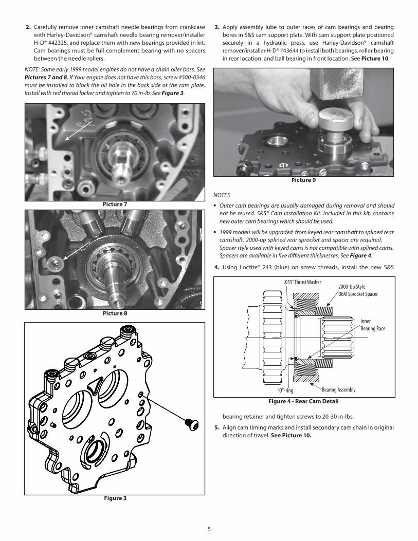
2. Carefully remove inner camshaft needle bearings from crankcasewith Harley-Davidson® camshaft needle bearing remover/installerH-D® #42325, and replace them with new bearings provided in kit.Cam bearings must be full complement bearing with no spacersbetween the needle rollers.
NOTE: Some early 1999 model engines do not have a chain oiler boss. See Pictures 7 and 8. If Your engine does not have this boss, screw #500-0346 must be installed to block the oil hole in the back side of the cam plate. Install with red thread locker and tighten to 70 in-lb. See Figure 3.
3. Apply assembly lube to outer races of cam bearings and bearingbores in S&S cam support plate. With cam support plate positionedsecurely in a hydraulic press, use Harley-Davidson® camshaftremover/installer H-D® #43644 to install both bearings. roller bearing in rear location, and ball bearing in front location. See Picture 10
NOTES
• Outer cam bearings are usually damaged during removal and should not be reused. S&S® Cam Installation Kit. included in this kit, contains new outer cam bearings which should be used.
• 1999 models will be upgraded from keyed rear camshaft to splined rear camshaft. 2000-up splined rear sprocket and spacer are required. Spacer style used with keyed cams is not compatible with splined cams. Spacers are available in five different thicknesses. See Figure 4.
4. Using Loctite® 243 (blue) on screw threads, install the new S&S
bearing retainer and tighten screws to 20-30 in-lbs.
5. Align cam timing marks and install secondary cam chain in original direction of travel. See Picture 10.
Figure 4 - Rear Cam Detail
.055” Thrust Washer2000-Up Style OEM Sprocket Spacer
Inner Bearing Race
Bearing Assembly“O”-ring
5
Picture 9
Picture 8
Picture 7
Figure 3
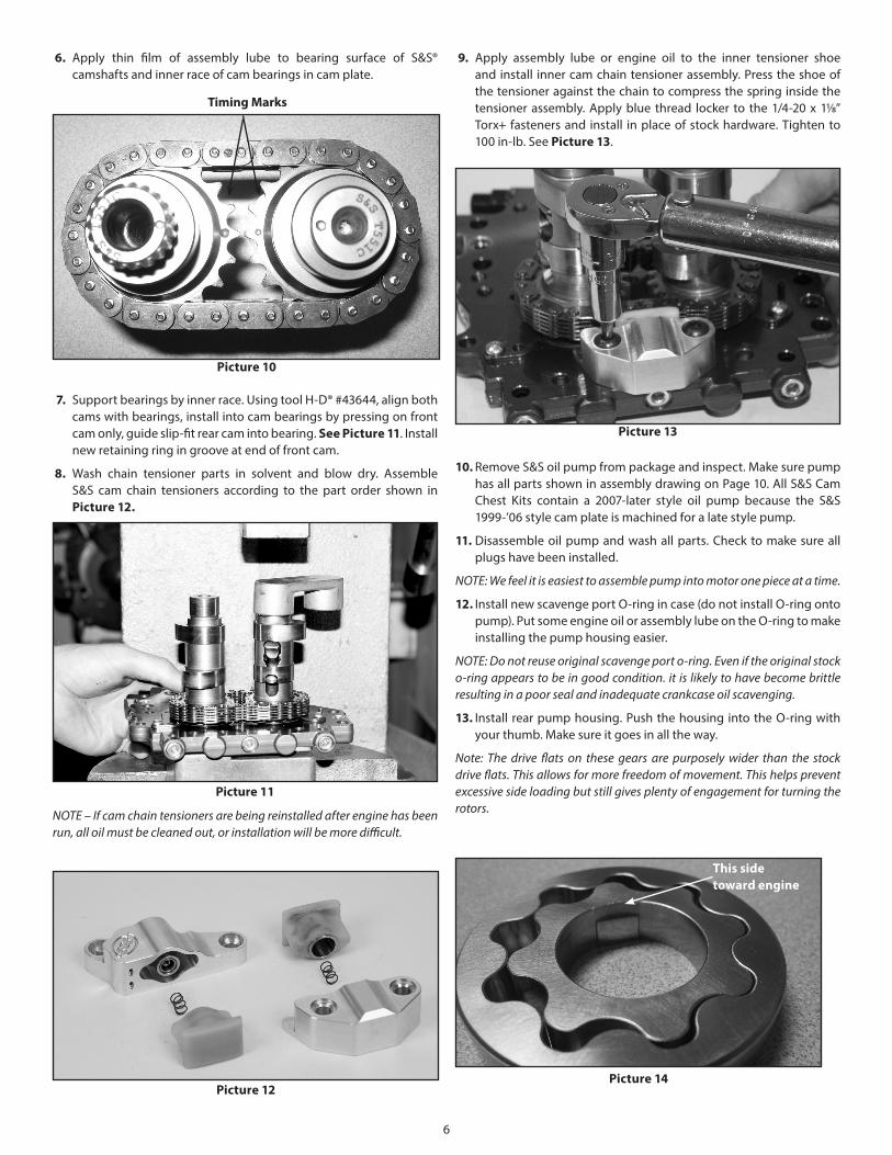
6. Apply thin film of assembly lube to bearing surface of S&S® camshafts and inner race of cam bearings in cam plate.
7. Support bearings by inner race. Using tool H-D® #43644, align both cams with bearings, install into cam bearings by pressing on front cam only, guide slip-fit rear cam into bearing. See Picture 11. Install new retaining ring in groove at end of front cam.
8. Wash chain tensioner parts in solvent and blow dry. Assemble S&S cam chain tensioners according to the part order shown in Picture 12.
NOTE – If cam chain tensioners are being reinstalled after engine has been run, all oil must be cleaned out, or installation will be more difficult.
9. Apply assembly lube or engine oil to the inner tensioner shoe and install inner cam chain tensioner assembly. Press the shoe of the tensioner against the chain to compress the spring inside the tensioner assembly. Apply blue thread locker to the 1/4-20 x 11/8” Torx+ fasteners and install in place of stock hardware. Tighten to 100 in-lb. See Picture 13.
10. Remove S&S oil pump from package and inspect. Make sure pump has all parts shown in assembly drawing on Page 10. All S&S Cam Chest Kits contain a 2007-later style oil pump because the S&S 1999-’06 style cam plate is machined for a late style pump.
11. Disassemble oil pump and wash all parts. Check to make sure all plugs have been installed.
NOTE: We feel it is easiest to assemble pump into motor one piece at a time.
12. Install new scavenge port O-ring in case (do not install O-ring onto pump). Put some engine oil or assembly lube on the O-ring to make installing the pump housing easier.
NOTE: Do not reuse original scavenge port o-ring. Even if the original stock o-ring appears to be in good condition. it is likely to have become brittle resulting in a poor seal and inadequate crankcase oil scavenging.
13. Install rear pump housing. Push the housing into the O-ring with your thumb. Make sure it goes in all the way.
Note: The drive flats on these gears are purposely wider than the stock drive flats. This allows for more freedom of movement. This helps prevent excessive side loading but still gives plenty of engagement for turning the rotors.
Picture 14
This sidetoward engine
Picture 10
Timing Marks
Picture 11
Picture 12
Picture 13
6
14. Apply assembly lube to inner return gear set, and assemble inner gear inside outer gear. Align the inner gear with the flat on the pinon shaft and install gear set into inner pump body as an assembly. Make sure the relief cut side of the inner gear goes toward the engine See Picture 14.
Note: Do not mix and match inner and outer gears keep them as sets as they are shipped in the pump.
15. Install two 1/8” x 3/4” dowels into pump housing. See #7 in line drawing on Page 10.
16. Install divider plate
17. Apply assembly lube to second return gear set. Place gear set into outer pump body and install outer pump body onto inner pump body.
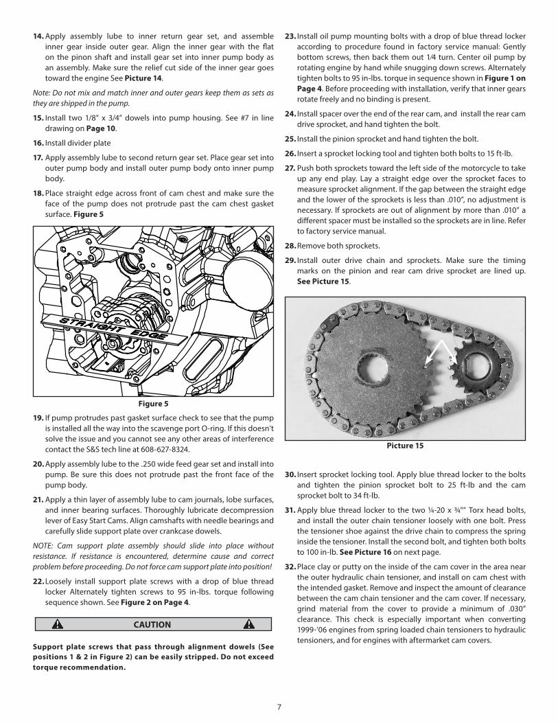
18. Place straight edge across front of cam chest and make sure the face of the pump does not protrude past the cam chest gasket surface. Figure 5
19. If pump protrudes past gasket surface check to see that the pump is installed all the way into the scavenge port O-ring. If this doesn’t solve the issue and you cannot see any other areas of interference contact the S&S tech line at 608-627-8324.
20. Apply assembly lube to the .250 wide feed gear set and install into pump. Be sure this does not protrude past the front face of the pump body.
21. Apply a thin layer of assembly lube to cam journals, lobe surfaces, and inner bearing surfaces. Thoroughly lubricate decompression lever of Easy Start Cams. Align camshafts with needle bearings and carefully slide support plate over crankcase dowels.
NOTE: Cam support plate assembly should slide into place without resistance. If resistance is encountered, determine cause and correct problem before proceeding. Do not force cam support plate into position!
22. Loosely install support plate screws with a drop of blue thread locker Alternately tighten screws to 95 in-lbs. torque following sequence shown. See Figure 2 on Page 4.
Support plate screws that pass through alignment dowels (See positions 1 & 2 in Figure 2) can be easily stripped. Do not exceed torque recommendation.
23. Install oil pump mounting bolts with a drop of blue thread locker according to procedure found in factory service manual: Gently bottom screws, then back them out 1/4 turn. Center oil pump by rotating engine by hand while snugging down screws. Alternately tighten bolts to 95 in-lbs. torque in sequence shown in Figure 1 on Page 4. Before proceeding with installation, verify that inner gears rotate freely and no binding is present.
24. Install spacer over the end of the rear cam, and install the rear cam drive sprocket, and hand tighten the bolt.
25. Install the pinion sprocket and hand tighten the bolt.
26. Insert a sprocket locking tool and tighten both bolts to 15 ft-lb.
27. Push both sprockets toward the left side of the motorcycle to take up any end play. Lay a straight edge over the sprocket faces to measure sprocket alignment. If the gap between the straight edge and the lower of the sprockets is less than .010”, no adjustment is necessary. If sprockets are out of alignment by more than .010” a different spacer must be installed so the sprockets are in line. Refer to factory service manual.
28. Remove both sprockets.
29. Install outer drive chain and sprockets. Make sure the timing marks on the pinion and rear cam drive sprocket are lined up. See Picture 15.
30. Insert sprocket locking tool. Apply blue thread locker to the bolts and tighten the pinion sprocket bolt to 25 ft-lb and the cam sprocket bolt to 34 ft-lb.
31. Apply blue thread locker to the two ¼-20 x 3/4”” Torx head bolts, and install the outer chain tensioner loosely with one bolt. Press the tensioner shoe against the drive chain to compress the spring inside the tensioner. Install the second bolt, and tighten both bolts to 100 in-lb. See Picture 16 on next page.
32. Place clay or putty on the inside of the cam cover in the area near the outer hydraulic chain tensioner, and install on cam chest with the intended gasket. Remove and inspect the amount of clearance between the cam chain tensioner and the cam cover. If necessary, grind material from the cover to provide a minimum of .030” clearance. This check is especially important when converting 1999-’06 engines from spring loaded chain tensioners to hydraulic tensioners, and for engines with aftermarket cam covers.
Figure 5
CAUTION
Picture 15
7
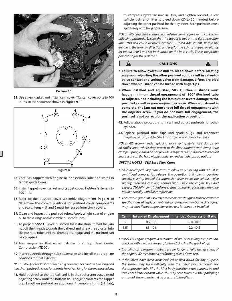
33. Use a new gasket and install cam cover. Tighten cover bolts to 100 in-lbs. in the sequence shown in Figure 9.
34. Coat S&S tappets with engine oil or assembly lube and install in tappet guide bores.
35. Install tappet cover gasket and tappet cover. Tighten fasteners to 100 in-lb.
36. Refer to the pushrod cover assembly diagram on Page 9 to determine the correct positions for pushrod cover components and seals. Items 4, 5, and 6 must be reused from stock covers.
37. Clean and inspect the pushrod tubes. Apply a light coat of engine oil to the o-rings and assemble pushrod tubes.
38. To prepare S&S® Quickee pushrods for installation, thread the jam nut off the threads towards the ball end and screw the adjuster into the pushrod tube until the threads disengage and the pushrod can be collapsed.
39. Turn engine so that either cylinder is at Top Dead Center Compression (TDCC).
40. Insert pushrods through tube assemblies and install in appropriate positions for that cylinder.
NOTE: S&S Quickee Pushrods for all big twin engines contain two long and two short pushrods, short for the intake valves, long for the exhaust valves.
41. Hold pushrod so the top ball end is in the rocker arm cup, extend adjusting screw until the bottom ball end just contacts the tappet cup. Lengthen pushrod an additional 4 complete turns (24 flats),
to compress hydraulic unit in lifter, and tighten locknut. Allow sufficient time for lifter to bleed down (20 to 30 minutes) before adjusting the other pushrod for that cylinder. Both pushrods must spin freely with finger pressure.
NOTE: S&S Easy Start compression release cams require extra care when adjusting pushrods. Ensure that the tappet is not on the decompression lobe. This will cause incorrect exhaust pushrod adjustment. Rotate the engine in the forward direction and feel for the exhaust tappet to slightly lift (about .030”) and set back down on the base circle. This is the proper point to adjust the pushrods.
• Failure to allow hydraulic unit to bleed down before rotating engine or adjusting the other pushrod could result in valve-to-valve contact and serious valve train damage. Lifters are bled down when pushrod can be turned with fingertips.
• When installed and adjusted, S&S Quickee Pushrods must have a minimum thread engagement of .500” (Pushrod tube to Adjuster, not including the jam nut) or severe damage to the pushrod as well as your engine may occur. When adjustment is complete, the jam nut must have full thread engagement with the adjuster screw. If you do not have full engagement, the pushrod is not correct for the application or position.
42. Follow above procedure to install and adjust pushrods for other cylinder.
43. Replace pushrod tube clips and spark plugs, and reconnect negative battery cable. Start motorcycle and check for leaks.
NOTE: S&S recommends replacing stock spring style hose clamps on oil cooler lines, where they attach to the filter adaptor, with crimp style clamps. Spring clamps do not provide adequate clamping force to keep oil lines secure on the hose nipples under extended high rpm operation.
SPECIAL NOTES – S&S Easy Start Cams
• S&S® developed Easy Start cams to allow easy starting with a built in centrifugal compression release. The operation is simple: at cranking speeds, a spring loaded decompression lever opens the exhaust valve slightly, reducing cranking compression. Once the engine fires and exceeds 750 RPM, centrifugal force retracts the lever, allowing the engine to run normally with full compression.
• The various grinds of S&S Easy Start cams are designed to be used with a specific range of displacement and compression ratio. Some EFI engines may not start if the compression is too low for the cams installed.
• Stock EFI engines require a minimum of 80 PSI cranking compression, checked with the throttle open, for the ECU to fire the spark plugs.
• Cranking compression numbers are no longer a valid health check of the engine. We recommend performing a leak down test.
• If the lifters have been disassembled or bled down for any purpose, the starter may have difficulty with the initial start. Although the decompression lobe lifts the lifter body, the lifter is not pumped up and it will not lift the exhaust valve. You may need to remove the spark plugs and crank the engine to get oil pressure to the lifters.
CAUTION
Figure 6
CAUTIONS
Cam Intended Displacement Intended Compression Ratio
551 88–106 9.0–10.0
585 88–106 9.2–10.5
Picture 16
8
• Easy Start cams require no special service. If they are ever removed for any reason however, inspect the mechanism for wear and verify that the lever operates smoothly.
• If your bike is carbureted, the starting routine may be slightly different, allow yourself time to experiment to find the best method.
• When the engine is turned off, you may hear a slight click as the decompression lever resets. This is normal and does no harm.
• If engine speed drops below 900 RPM, you may hear clicking as the decompression lever starts engaging. Idle speed should be adjusted higher. The engine idle should be set at 1000-1100 RPM.
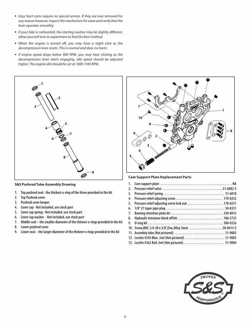
S&S Pushrod Tube Assembly Drawing
1. Top pushrod seal - the thickest o-ring of the three provided in the kit2. Top Pushrod cover3. Pushrod cover keeper4. Cover cap - Not included, use stock part5. Cover cap spring - Not included, use stock part6. Cover cap washer - Not included, use stock part7. Middle seal – the smaller diameter of the thinner o-rings provided in the kit8. Lower pushrod cover9. Lower seal – the larger diameter of the thinner o-rings provided in the kit
1
3
2
45
67
8
9Cam Support Plate Replacement Parts
1. Cam support plate . . . . . . . . . . . . . . . . . . . . . . . . . . . . . . . . . . . . . . . . . . . . . . . NA2. Pressure relief valve . . . . . . . . . . . . . . . . . . . . . . . . . . . . . . . . . . . . . . . .31-6082-S3. Pressure relief spring . . . . . . . . . . . . . . . . . . . . . . . . . . . . . . . . . . . . . . . . 31-60184. Pressure relief adjusting screw . . . . . . . . . . . . . . . . . . . . . . . . . . . . . . . 170-02525. Pressure relief adjusting screw lock nut . . . . . . . . . . . . . . . . . . . . . . . 170-02516. 1/8” 27 taper pipe plug . . . . . . . . . . . . . . . . . . . . . . . . . . . . . . . . . . . . . . 50-83317. Bearing retention plate kit . . . . . . . . . . . . . . . . . . . . . . . . . . . . . . . . . . 330-00158. Hydraulic tensioner block off kit . . . . . . . . . . . . . . . . . . . . . . . . . . . . . . 106-57239. O-ring kit . . . . . . . . . . . . . . . . . . . . . . . . . . . . . . . . . . . . . . . . . . . . . . . . . 500-032610. Screw,BHC,1/4-20 x 3/8”,Zinc,Alloy Steel . . . . . . . . . . . . . . . . . . . . . . .50-0413-S11. Assembly lube (Not pictured) . . . . . . . . . . . . . . . . . . . . . . . . . . . . . . . . . 51-900212. Loctite #243 Blue .5ml (Not pictured) . . . . . . . . . . . . . . . . . . . . . . . . . . 51-900313. Loctite #262 Red .5ml (Not pictured) . . . . . . . . . . . . . . . . . . . . . . . . . . . 51-9004
1
10
7
6
9
54
3
28
9
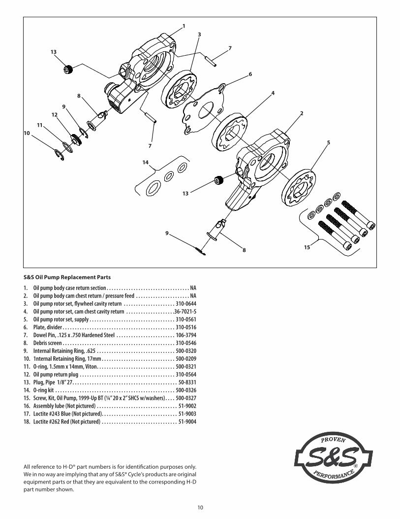
S&S Oil Pump Replacement Parts
1. Oil pump body case return section . . . . . . . . . . . . . . . . . . . . . . . . . . . . . . . . . . NA2. Oil pump body cam chest return / pressure feed . . . . . . . . . . . . . . . . . . . . . . NA3. Oil pump rotor set, flywheel cavity return . . . . . . . . . . . . . . . . . . . . . 310-06444. Oil pump rotor set, cam chest cavity return . . . . . . . . . . . . . . . . . . . .36-7021-S5. Oil pump rotor set, supply . . . . . . . . . . . . . . . . . . . . . . . . . . . . . . . . . . . 310-05616. Plate, divider . . . . . . . . . . . . . . . . . . . . . . . . . . . . . . . . . . . . . . . . . . . . . . 310-05167. Dowel Pin, .125 x .750 Hardened Steel . . . . . . . . . . . . . . . . . . . . . . . . 106-37948. Debris screen . . . . . . . . . . . . . . . . . . . . . . . . . . . . . . . . . . . . . . . . . . . . . . 310-05469. Internal Retaining Ring, .625 . . . . . . . . . . . . . . . . . . . . . . . . . . . . . . . . 500-032010. 1nternal Retaining Ring, 17mm . . . . . . . . . . . . . . . . . . . . . . . . . . . . . . 500-020911. O-ring, 1.5mm x 14mm, Viton . . . . . . . . . . . . . . . . . . . . . . . . . . . . . . . . 500-032112. Oil pump return plug . . . . . . . . . . . . . . . . . . . . . . . . . . . . . . . . . . . . . . . 310-056413. Plug, Pipe 1/8” 27 . . . . . . . . . . . . . . . . . . . . . . . . . . . . . . . . . . . . . . . . . . . 50-833114. O-ring kit . . . . . . . . . . . . . . . . . . . . . . . . . . . . . . . . . . . . . . . . . . . . . . . . . 500-032615. Screw, Kit, Oil Pump, 1999-Up BT (¼” 20 x 2” SHCS w/washers) . . . . 500-032716. Assembly lube (Not pictured) . . . . . . . . . . . . . . . . . . . . . . . . . . . . . . . . . 51-900217. Loctite #243 Blue (Not pictured) . . . . . . . . . . . . . . . . . . . . . . . . . . . . . . . 51-900318. Loctite #262 Red (Not pictured) . . . . . . . . . . . . . . . . . . . . . . . . . . . . . . . 51-9004
13
13
7
6
4
2
5
158
9
13
14
7
1011
129
8
All reference to H-D® part numbers is for identification purposes only. We in no way are implying that any of S&S® Cycle’s products are original equipment parts or that they are equivalent to the corresponding H-D part number shown.
10


