Embed Size (px)
Citation preview

IEEE TRANSACTIONS ON ROBOTICS 1
Stable Precision Grasps by Underactuated FingersGert A. Kragten, Mathieu Baril, Clement Gosselin, and Just L. Herder
Abstract—The ability of underactuated hands to grasp smallobjects is very limited, because the precision grasp is normallyunstable. The goal of this paper is to achieve stable precisiongrasps by means of simple design modifications of the distalphalanges of the fingers. These modifications comprise thecurving of the contact area of the distal phalanx, the applicationof a mechanical limit to prevent hyper-extension of the distalphalanx, and the application of a compliant joint between theproximal and distal phalanges. A model is developed to calculatethe boundary conditions of the finger dimensions in order toachieve stable precisions grasps for different object sizes. Anexperimental setup is used to test the grasp stability and to verifythe calculated results. It is concluded that stable precision graspsexist for the combination of concavely curved distal phalangeswith a mechanical limit or with a compliant joint, if the boundaryconditions of the finger dimensions are satisfied.
I. INTRODUCTION
Underactuated robotic hands can grasp various objects,
because the fingers adapt themselves to the shape of the
objects by their mechanical behavior. Underactuation means
that the number of actuators is less than the degrees of
freedom. Numerous examples in the literature show that this
principle can lead to adaptive hands that are relatively cheap,
lightweight and easy to control compared to fully actuated
hands, e.g. [1], [2], [3]. The adaptation of the fingers to
the objects is especially beneficial to envelope objects in a
so-called power grasp [4]. However, sometimes enveloping
objects is not possible, for instance, when small objects are
grasped, or when objects are approached from above. In such
cases the objects need to be grasped by the distal phalanges
only. In literature this is normally called a precision grasp [4],
[5], a pinch grasp [6], or a palmar or tip grasp [7]. The term
precision grasp will be used throughout this paper to refer to
a grasp equilibrium that is achieved by the distal phalanges
only. It is reported that a precision grasp is difficult to achieve
by underactuated fingers, e.g. [8], [9], [10]. It was shown
in [11] that this is caused by the instability of a precision
grasp equilibrium, where unstable means that the potential
energy of the hand and object at this equilibrium point is
not a local minimum. This means that grasping small objects
by underactuated hands is impossible, unless specific design
modifications are applied.
Generally, a compliant, frictional contact material − like
the skin of a human finger − can improve the capability to
obtain a precision grasp. Some other solutions have been
Gert A. Kragten and Just L. Herder are with the Dept. of BioMechanicalEngineering, Delft University of Technology, Mekelweg 2, 2628 CD Delft,The Netherlands (email: [email protected]; [email protected], fax:0031-15-2784713).
Mathieu Baril and Clement Gosselin are with the Departement degenie mecanique, Pavillon Adrien-Pouliot, 1065 avenue de la MedecineUniversite Laval, Quebec, (Quebec) Canada, G1V 0A6 (email: [email protected]; [email protected], fax: 418-656-7415).
proposed to achieve a precision grasp by underactuated
fingers. The SARAH [8] and the TWIX-hand [12] make
use of an additional mechanism to keep the distal phalanges
parallel to each other as long as no contact with an object is
encountered. The adaptive hand of RobotIQ [13] can actively
switch between a mode for a precision grasp between parallel
distal phalanges, and a mode for a power grasp where the
objects are enveloped. The addition of an extra mechanism to
the fingers or the active switching between modes complicates
the design, which is not desired. Also triggered mechanisms
are proposed as a less complicated solution to keep the distal
phalanges parallel [14], [15]. However, sufficient contact
friction and accurate grasp planning remain necessary to
stably grasp the objects between parallel phalanges. If these
conditions are not satisfied, a stable precision grasp does not
exist.
The goal of this paper is to investigate the achievement of
stable precision grasps by underactuated fingers by means
of simple design modifications. The effect of these design
modifications to the grasp stability is studied by a model that
considers the fingers and object as a conservative system. This
means that the potential energy must be a local minimum
at a precision grasp equilibrium. The results of this model
and the effectiveness of the proposed design modifications
are verified by experiments. The relevance of this work is
that the existence of the precision grasp does not depend on
contact friction anymore. In addition, accurate grasp planning
is not necessary, because there will be a stability area where
the objects are attracted towards the stable precision grasp
equilibrium. Finally, it leads to understanding of the stability
of underactuated fingers and the grasped objects.
The structure of the paper is as follows. Section II introduces
a model to calculate the stability of a precision grip between
straight phalanges. Three design modifications for the underac-
tuated fingers are then proposed, and the stability of precision
grasps between these fingers is calculated as a function of
the design parameters. An experimental setup is described for
measuring the stability. Section III provides the results of the
calculated and measured stable precision configurations. In
addition, it provides a visualization of the boundary conditions
on the design parameters to achieve stable precision grasps.
The effectiveness of the three design modifications is discussed
in Section IV, followed by conclusions in Section V.
II. MATERIALS AND METHODS
A gripper consisting of two underactuated fingers with two
straight phalanges each is taken as a reference to develop a
model to calculate the grasp stability. Then, three design mod-
ifications are proposed, and the model is adapted accordingly

IEEE TRANSACTIONS ON ROBOTICS 2
Fig. 1. Reference gripper consisting of two fingers with two straightphalanges each, driven by a pulley-cable system with a constant tension forceFa. Only the distal phalanges have a contact point with the object.
to calculate the existence of a stable precision grasp and the
expected equilibrium position of the object. In addition, the
model will be used to obtain the boundary conditions for the
design parameters of the design modifications to achieve a
stable precision grasp. An experimental setup that was used
to test the stability and measure the equilibrium position is
described at the end of this section.
A. Reference Gripper and Model
The fingers of the reference gripper are dimensioned as
follows. They consist of a straight proximal phalanx of length
L1, and a straight distal phalanx of length L2. L0 is the
distance between the proximal joint and the center line (i.e.
half of the palm width). These dimensions are shown in Fig. 1.
The phalanges are driven by a pulley-cable system, where the
pulley at the distal joint has a radius r2 and is attached to the
distal phalanx. The pulley at the proximal joint has a radius
r1 and can rotate freely. The tension force in the cable Fa is
constant. The dimensions L0, L1, L2, r2/r1 are regarded as
design parameters. A cylindrical object with a radius Robj is
the reference object, which can freely move in the (x, y)-plane.
Friction and inertia are neglected.
The stability can be determined by the sign of the eigen-
values of the Hessian matrix of the potential energy of the
mechanism [16]. The Hessian is obtained by the second
derivative of the potential energy V of the system. V can
be calculated as follows, assuming a constant input force Fa:
V = −Far1
(
θR,1 + θL,1 +r2r1
(θR,2 + θL,2)
)
(1)
where θi,j is the rotation of the phalanges with the first index
denoting the right (R) or left (L) finger, and the second index
denoting the proximal (1) or distal phalanx (2), see Fig 1. A
minus sign is put in front of the equation, because an increase
of θ1 and θ2 implies a smaller energy level. The constraint
equations that describe contact between the distal phalanx of
the right finger and the object are as follows:
L0 + L1 cos θR,1 + pR,2 cos(θR,1 + θR,2)−Xobj −Robj sin(θR,1 + θR,2) = 0
L1 sin θR,1 + pR,2 sin(θR,1 + θR,2)−Yobj +Robj cos(θR,1 + θR,2) = 0
−L0 − L1 cos θL,1 − pL,2 cos(θL,1 + θL,2)−Xobj +Robj sin(θL,1 + θL,2) = 0
L1 sin θL,1 + pL,2 sin(θL,1 + θL,2)−Yobj +Robj cos(θL,1 + θL,2) = 0
(2)
where pR,2 and pL,2 are the positions of the contact point
with the object on the distal phalanx of right and left finger,
respectively. This mechanism has four degrees of freedom
when only the distal phalanges have a contact point with the
object. Xobj , Yobj , θR,1 or θL,1 are chosen as the generalized
coordinates to obtain the most convenient geometric relations.
To express θR,2 and θL,2 as a function of the generalized
coordinates, it is needed to firstly express pR,2 and pL,2 as a
function of the other variables and coordinates by rearranging
the first and third constraint equation. These functions are
then substituted into the second or fourth constraint equation
and solved to obtain θR,2 and θL,2. Two solutions are found.
The correct solution can be selected after evaluation with real
values for all parameters. These selected formulas of θR,2 and
θL,2 are substituted in Eq. 1 to express the potential energy
V as a function of the generalized coordinates. Subsequently,
the Hessian matrix or second derivative of V to the four
degrees of freedom can be calculated. However the analytical
expression of each matrix element is very large. Therefore,
this (4×4)-matrix is numerically evaluated for a range of
design parameters to be able to calculate the eigenvalues and
check their sign.
To calculate the numerical values of the generalized coordi-
nates at a precision grasp equilibrium, the symmetry properties
of the reference gripper and object are used. This means
that Xobj = 0, pR,2 = pL,2 = p2, θR,1 = θL,1 = θ1,
θR,2 = θL,2 = θ2. The generalized coordinates are reduced to
Yobj and θ1. From static equilibrium equations it follows that
θ1+θ2 = π/2 and L0+L1 cos θ1 = Robj . The contact position
p2 is the only unknown to determine the equilibrium position
Yobj , see Eq. 2. To calculate p2, the moment equilibrium
equation of the finger about the proximal joint can be used:
Far1 = F2 (p2 + L1 cos θ2) (3)
where F2 is the contact force between the distal phalanx and
the object. F2 can be obtained with the free body diagram of
the distal phalanx:
F2 =Far2p2
(4)
Combining Eq. 3 and Eq. 4 and substituting θ2 = π/2 − θ1yields:
p2 =r2r1L1 sin θ1
1− r2r1
(5)
where 0 < p2 ≤ L2 to have a feasible contact point. It can be
checked that substitution of this equilibrium configuration into

IEEE TRANSACTIONS ON ROBOTICS 3
the first derivative of V yields indeed a zero vector. Substi-
tution of the numerical solution into the second derivative of
V yields the Hessian matrix at the equilibrium configuration.
The calculated equilibrium configuration is only stable if the
eigenvalues of this Hessian matrix are positive.
The equilibrium configuration and the four eigenvalues of
the Hessian matrix were calculated for L0 between 10 −
80 mm, L1 between 40−120 mm, and r2/r1 between 0.2−0.8while L2 = 160−L1 (constant finger length), Robj = 20 mm
and Far1 = 1000 Nmm. For all combinations of these values,
one or even two eigenvalues of the Hessian matrix were
negative. This means that no stable precision grasp was found
with two fingers with two straight phalanges. Therefore, design
modifications are needed to achieve stable precision grasps.
B. Design Modifications and Model
Three design modifications to the reference gripper are
proposed. The first modification is to change the shape of the
distal phalanges into concave curved ones. This was inspired
by the shape of, for instance, a spoon that can easily hold
objects. The second modification is to apply a mechanical
limit between the proximal and distal phalanx, which prevents
hyper-extension of the distal joint. This reduces the degrees
of freedom of the fingers at a precision grasp, while it still
allows the possibility to envelope bigger objects. The third
design modification is to apply torsional springs in the joints,
which provides the opportunity to adjust the shape of the
potential energy field of the mechanism. To simplify the
calculations, only the left finger of the gripper is considered,
while the reference object can freely move along the line
of symmetry. Consequently, stability of the object in the
x-direction is not yet considered and Xobj = 0.
1) Curved Distal Phalanges: The constraint equations for
the contact points between the object and the concave curved
phalanges can be obtained with the aid of Fig. 2. It is assumed
that the curve of the phalanges is circular with a radius Rph.
When θ2 = 0, the distal phalanx at the joint is tangential to the
proximal phalanx, but with an offset d to account for material
thickness of the phalanx. The position of the contact point on
the distal phalanx is now determined by angle Ψ (see Fig. 2).
The geometrical constraint equations, projected along x and
y, are formulated as follows:
−L0 + L1 cos θ1 + (Rph + d) cosα−(Rph −Robj) cos(α−Ψ)−Xobj = 0
L1 sin θ1 + (Rph + d) sinα−(Rph −Robj) sin(α−Ψ)− Yobj = 0
(6)
where α = θ1+θ2−π/2, and Xobj = 0. These two constraint
equations can be used to express θ2 as a function of the
generalized coordinates Yobj and θ1. It was needed to firstly
eliminate Ψ before θ2 could be calculated. This elimination
was done by firstly moving the terms containing Ψ to the other
side of the equality sign. Then both equations were squared,
added, and solved to obtain θ2. Two solutions were found,
and the proper solution was selected after evaluation with real
values for all parameters. This θ2 can be substituted into the
Fig. 2. Schematic drawing of the left finger in contact with an object. Thedrawing shows the concave curve of the distal phalanx with radius Rph andthe mechanical limit between the phalanges that applies when θ2 = θ2ML
.The object can freely move in the y-direction, while the finger is actuated bya pulley-cable system that is loaded by a constant force Fa.
potential energy function of the gripper, grasping a cylindrical
object with curved distal phalanges:
V = Far1
(
θ1 +r2r1
θ2
)
(7)
The stability of a precision grasp equilibrium is determined
by evaluation of the two eigenvalues λi of the Hessian of V at
the equilibrium configuration, where the Hessian is as follows:
H(θ1, Yobj) =
∂2V∂θ2
1
∂2V∂θ1∂Yobj
∂2V∂θ1∂Yobj
∂2V∂Y 2
obj
(8)
To determine the value of Yobj and θ1 for which a precision
grasp is achieved, two equilibrium conditions of the object
and the finger are applied. The object is in equilibrium if the
component of the contact force in y-direction is zero:
F2 sin(α−Ψ) = 0 (9)
The finger is in equilibrium if the moment about the proximal
phalanx is zero:
F2 ((Rph + d) sinΨ + L1 cos(Ψ− θ2))− Far1 = 0 (10)
where F2 is equal to:
F2 =r2Fa
(Rph + d) sinΨ(11)
Solving the constraint equations (Eq. 6) and the equilibrium
equations (Eqs. 9, 10) yields the Yobj , θ1, θ2, and Ψ for which
the finger and object are in a precision grasp equilibrium.

IEEE TRANSACTIONS ON ROBOTICS 4
Note that the following inequality must be satisfied to have
the contact point on the physical part of the curved phalanx:
0 < Rph sinΨ ≤ L2 (12)
When Rph is very large, the distal phalanx is almost
straight. It can be verified that the calculated grasp equilibrium
configurations and their stability then approximate the values
as calculated for the reference gripper.
2) Mechanical Limits: It was also proposed to apply a
mechanical limit to the extension of the curved or straight
distal phalanx. The degrees of freedom of the system reduce
to one when the distal phalanx is against the mechanical
limit. Then θ2 is a constant value (i.e. θ2 = θ2ML, see
Fig. 2), where θ2MLis a new design variable. The constraint
equations of Eq. 6 still apply, and are used to express θ1 as a
function of the single generalized coordinate Yobj in a similar
way as described in the previous section. Substitution of this
expression of θ1 into Eq. 7 yields the potential energy V as a
function of Yobj . The stability of a grasp equilibrium is now
verified by the sign of ∂2V/∂Y 2
obj .
The distal phalanx is only pushed against the mechanical
limit if no moment equilibrium about the distal joint can be
achieved, i.e. the actuation torque applied to the distal phalanx
is smaller than the torque applied to the distal phalanx by the
contact force F2:
r2Fa ≤ F2(Rph + d) sinΨ (13)
where F2 is calculated by moment equilibrium of the finger
about the proximal joint:
F2 =r1Fa
(Rph + d) sinΨ + L1 cos(Ψ− θ2)(14)
If the constraint given by Eq. 13 is not satisfied, it means that
the distal phalanx is not against the mechanical limit. Then
Eqs. 10 and 11 apply as if there were no mechanical limit.
For a precision grasp, the equilibrium condition of the
object must also be satisfied (Eq. 9). To calculate the
equilibrium configuration, Eqs. 6 and 9 are solved to obtain
the value of Yobj , θ1 and Ψ. Note that for the calculated
equilibrium configuration, the inequalities Eq. 12 and Eq. 13
must be satisfied. Otherwise, the contact point does not exist
on the physical part of the phalanx, or the distal phalanx is
not against the mechanical limit.
3) Compliant Joints: When springs are mounted at the
joints, the formula of the energy function V is extended. This
study only investigates the effect of a linear torsion spring at
the distal joint, while the distal phalanx is curved or straight.
Assuming that this spring has a torsion stiffness K and an
initial angle θ20 , V is as follows:
V = Far1
(
θ1 +r2r1
θ2
)
+1
2K(θ2 − θ20)
2 (15)
Note that this design modification adds a term to V that is not
dependent on Fa. This means that the effect of the addition of
TABLE ICONSTANT AND THE INTERVAL OF THE VARIABLE PARAMETERS THAT
WERE APPLIED TO DETERMINE THE RELATION BETWEEN THE DESIGN
PARAMETERS AND THE BOUNDARY CONDITIONS TO ACHIEVE STABLE
PRECISION GRASPS FOR OBJECTS WITH A RADIUS OF Robj = 20, 40, AND
55 MM.
Constant Parameters:
L0 40 mm Half of the palm widthL1 80 mm Length of the proximal phalanxL2 85 mm Length of the distal phalanxFa 12.8 N Tension in the cabler2 4.7 mm Radius of the distal pulley
Variable Parameters:
r1 [6 20] mm Radius of the proximal pulleyRph [80, 250] mm Radius of the distal phalanxθ2ML
[-1, 1.5] rad Max extension angle distal phalanxK [0, 200] Nmm/rad Stiffness of the spring at distal jointθ20 [-1, 1.5] rad Initial angle of the spring
a torsion spring with a specific stiffness also depends on the
magnitude of the actuation force.
To determine the value of Yobj and θ1 at a precision
grasp equilibrium, the constraint equations (Eq. 6) and the
equilibrium condition of the object and the finger are applied
(Eqs. 9, 10). Note that for this design modification, the torque
of the spring is now taken into account to calculate the distal
contact force F2:
F2 =r2Fa +K(θ2 − θ20)
(Rph + d) sinΨ(16)
An equilibrium configuration is valid if Eq. 12 is satisfied,
and if F2 is positive (i.e. compressive). An equilibrium
configuration is stable if the Hessian matrix of Eq. 15 is
positive definite.
C. Boundary Conditions for Stable Precision Grasps
It was initially desired to achieve analytic formulas that
express the relation between the design parameters and the size
of the object to achieve stable precision grasps. Although sym-
bolic formulas of the potential energy of the mechanism and
the equilibrium positions were obtained, the desired analytic
formulas are too large to be informative. Therefore, numerical
evaluations of these formulas were used to determine the
precision grasp equilibrium configuration and its stability for
a range of values of the design parameters. The chosen values
of the design parameters are shown in Table I, where the
design parameters that were kept constant are distinguished
from the parameters that were varied. Objects with a radius of
Robj = 20, 40, and 55 mm were taken as reference objects.
These dimensions were chosen to have an object smaller,
equal, and larger than the palm width L0. After an exploration
of the grasp stability for these dimensions of the parameters,
the boundary conditions to obtain stable precision grasps were
obtained. These results are visualized in Section III.
D. Experiments
The goal of the experiments is to verify the equilibrium
configurations and their stability that were calculated with

IEEE TRANSACTIONS ON ROBOTICS 5
Fig. 3. Picture of the experimental setup, where (1) is the actuation cable;(2) is the proximal phalanx; (3) is the curved distal phalanx (Rph = 90 mm);(4) is the object (Robj = 20 mm); and (5) is the force sensor mounted ona linear stage. The mechanical limit and the torsion spring are not shown onthis picture. The proximal pulley is just visible but the distal one is shieldedby the phalanx bodies. The reference frame and the line of symmetry aresuperimposed to this picture.
the grasp model. Furthermore, the setup was used to observe
the causes of unstable grasps and the interpretation of the
potential energy functions. The experimental setup consisted
of one underactuated finger and a cylindrical object that was
able to move along the line of symmetry, see Fig. 3. The
underactuated finger consisted of two phalanges, where the
first phalanx of length L1 = 80 mm was straight. The distal
phalanx could easily be exchanged to get different curvatures
Rph, but with a constant thickness d. A pulley with a radius
r2 = 4.7 mm was fixed to the shaft of the distal phalanx. A
cable was attached to this pulley, and was wrapped around a
free-rotating pulley at the proximal phalanx of radius r1. A
constant tension was applied to the cable by a dead weight
of 12.8 N. The distance from the proximal joint to the line
of symmetry was L0 = 40 mm. A mechanical limit could be
screwed on top of the proximal phalanx to limit the extension
of the second phalanx to θ2ML= 0.78 rad (or 1.22 rad when
the distal phalanx was straight).
The object consisted of a disc of radius Robj that could
freely rotate about a shaft to emulate frictionless contact
between the object and the finger. The shaft of the object was
mounted on a force sensor that was constructed by parallel
leaf springs and four strain gauges (see [17]). It measured the
resultant of the contact forces in the direction of the line of
symmetry with a precision of 0.2 N. The object and sensor
were mounted on a spindle, which was driven with a constant
speed of v = 15.7 mm/s by a DC-motor (Maxon, A-max26,
gear GP26B 3.8:1, and encoder Enc22) and a servo amplifier
(Maxon, LSC30/2).
The following parameters were varied between the experi-
TABLE IIVALUES OF THE VARIABLE PARAMETERS AT THE EXPERIMENTS. FOR AN
EXPLANATION OF THE SYMBOLS AND THE VALUES OF THE CONSTANT
PARAMETERS, SEE TABLE I.
r1 10.0, 15.5 mmRph 80, 90, 140, 200, ∞ mmθ2ML
0.78 radRobj 20, 40, 55 mmK 55 Nmm/radθ20 0.52 rad
ments: the radius of the proximal pulley r1, the curvature of
the distal phalanx Rph, the availability of the mechanical limit
θ2MLand the radius of the objects Robj . The values are shown
in Table II, leading to 60 experiments. For each experiment,
the object was placed at Yobj = 44 mm (or 60 mm for the
object Robj = 55 mm), the finger was actuated by the dead
weight, and then the object was pulled out of the finger. The
force and position were measured at a sample frequency of 20
Hz. All experiments were repeated three times.
The precision grasp stability was also measured for a
finger with a torsional spring at the distal joint of the five
differently curved phalanges. The stiffness of the spring
was approximately K = 55 Nmm/rad, and the initial angle
was approximately θ20 = −0.52 rad, leading to another 30
experiments.
The measured data was analyzed to find the object positions
where the resultant of the contact force Fobj,y was zero, while
only the distal phalanx had a contact point with the object.
At these positions, there was a precision grasp. However, the
force perpendicular to the line of symmetry (i.e. Fobj,x) caused
a small systematic error of 35 mV/N in the reading of the pull
force Fobj,y . Considering the finger and object as one system,
it can be shown that the magnitude of this force Fobj,x is as
follows:
Fobj,x =Far1 − Fobj,yL0
Yobj
(17)
The measured output voltage was first corrected for this
systematic error for all experiments. Then, the mean of the
measured equilibrium positions was calculated for each ex-
periment.
The stability of the measured equilibrium points was
determined by the sign of the contact force difference at the
equilibrium position. This difference is an approximation
of the stiffness. A negative difference means an unstable
precision grasp, while a positive difference means a stable
one. Note that by measuring the resultant of the contact force
while the object was being moved, even unstable equilibrium
points could be observed, as long as the finger itself was stable.
The experimental results were used to verify the grasp
model. The location of stable precision grasp positions were
compared with the positions that were calculated with the
grasp model. In addition, the force needed to pull the object
out of the hand as a function of the object position was also
calculated by the grasp model. This force is equal to the
first derivative of the potential energy to the object position
(Fobj,y = ∂V/∂Yobj).

IEEE TRANSACTIONS ON ROBOTICS 6
100
105
110
115
120
125
1
1.2
1.4
1.6
1.8280
290
300
310
320
Object position Yobj
[mm]Angle of proximal phalanx θ1 [rad]
Pote
ntial E
nerg
y V
[N
mm
]
Fig. 4. Surface plot of the potential energy of an object with a radiusRobj = 20 grasped by a distal phalanx that is curved with a radius of Rph =
140 mm, while the ratio of the pulley radii of the underactuated finger isr2/r1 = 0.30. An equilibrium point is shown at Yobj = 112.6 mm. Thispoint is unstable because the energy surface is a saddle point. The solid lineshows the magnitude of θ1 when the object is displaced in the direction ofYobj . When the position Yobj = 113 mm is reached (marked by the dashedline), θ1 rapidly decreases and the finger cannot be in equilibrium against theobject anymore.
III. RESULTS
A. Potential Energy Curves
Figures 4, 5 and 6 visualize typical potential energy func-
tions of the finger grasping a moving object for the three
cases, namely where the distal phalanx is curved (Fig. 4);
where a mechanical limit applies at the curved distal phalanx
(Fig. 5); and where a torsional spring applies to the joint of
the curved distal phalanx (Fig. 6). The chosen dimensions
of the variable parameters in these figures are as follows:
the object size Robj = 20 mm; the distal phalanx curvature
Rph = 140 mm; and the ratio of the pulley radii r2/r1 = 0.30.
A mechanical limit at θ2ML= π/4 rad applies in Fig. 5. In
Fig. 6 a torsional spring with a stiffness K = 70 Nmm/rad and
an initial angle θ20 = 0.4 rad applies to the distal joint. The
dimensions of the other parameters of the finger correspond
to Table I. The rotation angle of the phalanges changes as
the object is displaced. The calculated angle of the proximal
phalanx as a function of the object position is shown by a
dashed line in these figures. It can be observed that it follows
a trajectory of minimum energy. The asterisks indicate the
calculated equilibrium positions. The equilibrium positions at
a local minimum of the potential energy are stable, while the
positions at a saddle point are unstable. Note that the graph
of the potential energy of Fig. 4 and Fig. 5 are equal, except
for the limitation of θ1 in Fig. 5 due to the mechanical limit
between the distal and proximal phalanx.
B. Experimental and Calculated Results
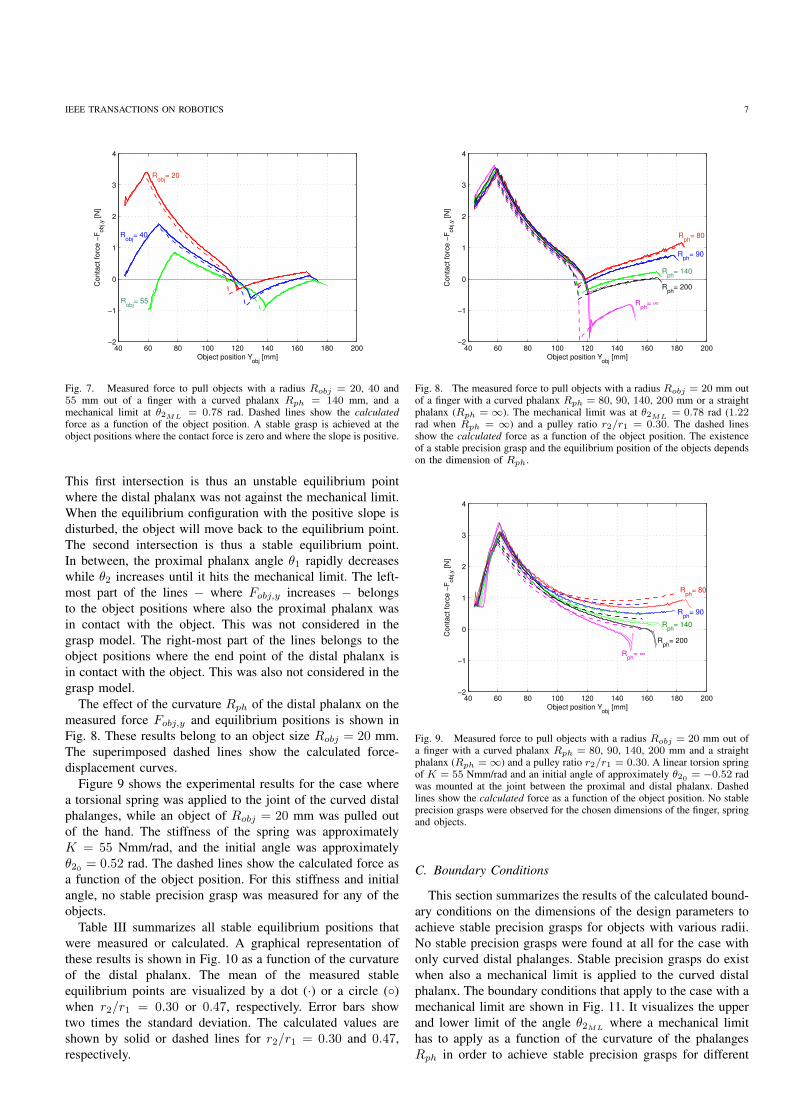
The measured force to pull the three objects of a radius
Robj = 20, 40, and 55 mm out of the finger is shown in
Fig. 7. These results were obtained for the finger with a
curved distal phalanx Rph = 140 mm, a mechanical limit at
105 110 115 120 125 130 135 140 145 1501.2
1.25
1.3
1.35
1.4
1.45
1.5
1.55
1.6
295295
298
298
298
298
298
301
301
301301
304
304
304
307
307
307
310
310
313
313
316
319322
Object position Yobj
[mm]
Angle
of
pro
xim
al phala
nx θ
1 [
rad]
Fig. 5. Contour plot of the potential energy of an object (Robj = 20)grasped by an underactuated finger (Rph = 140 mm, r2/r1 = 0.30) with amechanical limit between the proximal and distal phalanx at θ2ML
= π/4.Two equilibrium points are shown, namely at Yobj = 112.6 mm (unstable)and at Yobj = 140.2 mm (stable). The dashed line shows the magnitude ofθ1 when the object is displaced in the direction of Yobj . A lower limit to θ1is shown, which is caused by the mechanical limit. At the dashed-dotted partof this lower limit, Eq. 13 is not satisfied.
297
297
298
298
298
298
299
299
299
299
299
299
302
302
302
302
302
302
305
305
305
305
310
310
310
315
315
320
3203253303353
40
Object position Yobj
[mm]
Angle
of pro
xim
al phala
nx θ
1 [ra
d]
110 120 130 140 150 1600.95
1
1.05
1.1
1.15
1.2
1.25
1.3
1.35
1.4
1.45
Fig. 6. Contour plot of the potential energy of an object (Robj = 20)grasped by an underactuated finger (Rph = 140 mm, r2/r1 = 0.30) witha torsional spring between the proximal and distal phalanx with a stiffnessK = 70 Nmm/rad and an initial angle θ20 = 0.40 rad. Two equilibriumpoints are shown, namely at Yobj = 116.2 mm (unstable) and at Yobj =
153.6 mm (stable). The dashed line shows the magnitude of θ1 when theobject is displaced in the direction of Yobj .
θ2ML= 0.78 rad, and a pulley ratio r2/r1 = 0.30. Note that
the measured force of the three repetitions per experiment are
plotted, showing the repeatability of the experiments. In ad-
dition, the calculated force-displacement lines are superposed
by dashed lines to show the correlation between the model
and the experiments. Where Fobj,y = 0, it means that the
contact force along the line of symmetry is zero and the system
consisting of the finger and the object is thus in equilibrium.
The lines belonging to Robj = 20 and 40 mm intersect the line
Fobj,y = 0 twice: first with a negative slope and then with a
positive slope. It can be observed that a small disturbance of
the object equilibrium at the point with the negative slope will
result in a large displacement away from the equilibrium point.
IEEE TRANSACTIONS ON ROBOTICS 7
40 60 80 100 120 140 160 180 200−2
−1
0
1
2
3
4
Object position Yobj
[mm]
Conta
ct
forc
e −
Fobj,y [
N]
Robj
= 20
Robj
= 40
Robj
= 55
Fig. 7. Measured force to pull objects with a radius Robj = 20, 40 and55 mm out of a finger with a curved phalanx Rph = 140 mm, and amechanical limit at θ2ML
= 0.78 rad. Dashed lines show the calculated
force as a function of the object position. A stable grasp is achieved at theobject positions where the contact force is zero and where the slope is positive.
This first intersection is thus an unstable equilibrium point
where the distal phalanx was not against the mechanical limit.
When the equilibrium configuration with the positive slope is
disturbed, the object will move back to the equilibrium point.
The second intersection is thus a stable equilibrium point.
In between, the proximal phalanx angle θ1 rapidly decreases
while θ2 increases until it hits the mechanical limit. The left-
most part of the lines − where Fobj,y increases − belongs
to the object positions where also the proximal phalanx was
in contact with the object. This was not considered in the
grasp model. The right-most part of the lines belongs to the
object positions where the end point of the distal phalanx is
in contact with the object. This was also not considered in the
grasp model.
The effect of the curvature Rph of the distal phalanx on the
measured force Fobj,y and equilibrium positions is shown in
Fig. 8. These results belong to an object size Robj = 20 mm.
The superimposed dashed lines show the calculated force-
displacement curves.
Figure 9 shows the experimental results for the case where
a torsional spring was applied to the joint of the curved distal
phalanges, while an object of Robj = 20 mm was pulled out
of the hand. The stiffness of the spring was approximately
K = 55 Nmm/rad, and the initial angle was approximately
θ20 = 0.52 rad. The dashed lines show the calculated force as
a function of the object position. For this stiffness and initial
angle, no stable precision grasp was measured for any of the
objects.
Table III summarizes all stable equilibrium positions that
were measured or calculated. A graphical representation of
these results is shown in Fig. 10 as a function of the curvature
of the distal phalanx. The mean of the measured stable
equilibrium points are visualized by a dot (·) or a circle (◦)
when r2/r1 = 0.30 or 0.47, respectively. Error bars show
two times the standard deviation. The calculated values are
shown by solid or dashed lines for r2/r1 = 0.30 and 0.47,
respectively.
40 60 80 100 120 140 160 180 200−2
−1
0
1
2
3
4
Object position Yobj
[mm]
Conta
ct
forc
e −
Fobj,y [
N]
Rph
= 90
Rph
= 140
Rph
= 200
Rph
= ∞
Rph
= 80
Fig. 8. The measured force to pull objects with a radius Robj = 20 mm outof a finger with a curved phalanx Rph = 80, 90, 140, 200 mm or a straightphalanx (Rph = ∞). The mechanical limit was at θ2ML
= 0.78 rad (1.22rad when Rph = ∞) and a pulley ratio r2/r1 = 0.30. The dashed linesshow the calculated force as a function of the object position. The existenceof a stable precision grasp and the equilibrium position of the objects dependson the dimension of Rph.
40 60 80 100 120 140 160 180 200−2
−1
0
1
2
3
4
Object position Yobj
[mm]
Conta
ct fo
rce −
Fobj,y [N
]
Rph
= 80
Rph
= 90
Rph
= 140
Rph
= 200
Rph
= ∞
Fig. 9. Measured force to pull objects with a radius Robj = 20 mm out ofa finger with a curved phalanx Rph = 80, 90, 140, 200 mm and a straightphalanx (Rph = ∞) and a pulley ratio r2/r1 = 0.30. A linear torsion springof K = 55 Nmm/rad and an initial angle of approximately θ20 = −0.52 radwas mounted at the joint between the proximal and distal phalanx. Dashedlines show the calculated force as a function of the object position. No stableprecision grasps were observed for the chosen dimensions of the finger, springand objects.
C. Boundary Conditions
This section summarizes the results of the calculated bound-
ary conditions on the dimensions of the design parameters to
achieve stable precision grasps for objects with various radii.
No stable precision grasps were found at all for the case with
only curved distal phalanges. Stable precision grasps do exist
when also a mechanical limit is applied to the curved distal
phalanx. The boundary conditions that apply to the case with a
mechanical limit are shown in Fig. 11. It visualizes the upper
and lower limit of the angle θ2MLwhere a mechanical limit
has to apply as a function of the curvature of the phalanges
Rph in order to achieve stable precision grasps for different

IEEE TRANSACTIONS ON ROBOTICS 8
TABLE IIITHE MEAN OF THE MEASURED STABLE EQUILIBRIUM POSITIONS FOR
DIFFERENT OBJECT SIZE Robj , PULLEY RATIO r2/r1 AND CURVATURE OF
THE DISTAL PHALANX Rph . ALL THESE STABLE POSITIONS WERE
OBTAINED WHILE THE DISTAL PHALANX WAS AGAINST THE MECHANICAL
LIMIT AT θ2ML= 0.78 RAD. THE STANDARD DEVIATION WAS SMALLER
THAN 0.58 MM. THE VALUES BETWEEN BRACKETS ARE THE CALCULATED
EQUILIBRIUM POSITIONS.
Rph [mm] Robj = 20 mm Robj = 40 mm Robj = 55 mm
r2/r1 = 0.3080 119 (119.4) 133 (133.6) 140 (141.5)90 124 (123.1) 137 (138.4) 146 (147.0)
140 141 (140.2) 159 (160.2) -200 161 (158.3) - -∞ - - -
r2/r1 = 0.4780 - - -90 - - -
140 - - (160.2) -200 166 (158.3) - -∞ - - -
80 100 120 140 160 180 200 220110
120
130
140
150
160
170
Curvature of the distal phalanx Rph
[mm]
Equili
brium
positio
n Y
obj [
mm
]
Robj
=55
Robj
=20
Robj
=40
Fig. 10. Visualisation of the measured and calculated stable equilibriumpositions as a function of the curvature of the distal phalanx Rph for differentobject sizes Robj . The mean of the measured equilibrium points are visualizedby a dot (·) or a circle (◦) when r2/r1 = 0.30 or 0.47, respectively. Errorbars show two times the standard deviation. The calculated values are shownby solid and dashed lines for r2/r1 = 0.30 and 0.47, respectively.
sizes of objects. At the upper limits of θ2ML, the contact point
on the phalanx with the object is at the tip of the phalanx
(Rph sinΨ = L2, compare to Eq. 12). At the lower limit of
θ2ML, the contact point on the distal phalanx is so close to the
joint, that the phalanx starts to flex (r2Fa = F2(Rph+d) sinΨ,
compare to Eq. 13). At the lower limit of θ2ML, the stable
and unstable equilibrium positions that were shown on the
energy contour lines in Fig. 5 coincide. When the ratio of
r2/r1 increases, the upper limits remain the same, while the
lower limits shift upward.
Stable precision grasps are also possible when a torsional
spring applies to the joint of a curved distal phalanx. Such sta-
ble grasps were not measured, but are obtained by calculation
with stiffer springs than the one applied in the experiments.
Figure 12 visualizes the upper and lower limit of the initial
angle θ20 of the torsion spring as a function of the spring
stiffness K in order to achieve stable precision grasps for
80 100 120 140 160 180 200 220 240−0.2
0
0.2
0.4
0.6
0.8
1
1.2
1.4
Curvature of distal phalanx Rph
[mm]
Angle
of
mechanic
al lim
it θ
2M
L
[ra
d]
Robj
=20
Robj
=40
Robj
=55
Fig. 11. Upper and lower limits to the angle θ2MLwhere the mechanical
limit applies as a function of the curvature of the distal phalanx Rph.The upper and lower limits are shown for different objects sizes, while thedimensions of all other design parameters were kept constant according toTable I.
different sizes of objects. These limits apply to the finger
with a curvature Rph = 140 mm, r2/r1 = 0.30 and all
other dimensions according to Table I. It turned out that
the upper limits of θ20 are attained when the contact point
on the phalanx with the object is at the tip of the phalanx
(Rph sinΨ = L2, compare to Eq. 12). At the lower limits
of θ20 , it turned out that the precision grasp equilibrium was
neutrally stable (i.e. the Hessian was semi positive). In other
words, the position where the force-displacement line is in a
local minimum coincides with the position where the resultant
of the contact force on the object is zero. Alternatively, the
stable and unstable equilibrium positions, which were shown
on the energy contour lines in Fig. 6, coincide at the lower
limit of θ20 . When Rph is smaller, both limits move upwards.
Effectively the vertical distance between the two lines becomes
larger. A comparable effect can be observed when r2/r1becomes larger. This effect is stronger at low stiffness K.
IV. DISCUSSION
It was decided to use the principle of conservation of
energy to investigate the possibilities to achieve stable
precision grasps with underactuated hands. Three typical
plots of the energy V by a surface plot or contour lines
were shown by Figs. 4, 5 and 6. This approach turned
out to be very powerful to firstly understand the boundary
conditions to the dimensions of the design parameters in
order to achieve stable precision grasps, as it was explained
in Section III. Secondly, the stability of the equilibrium
points can easily be visualized by the contour lines of the
potential energy V , or by calculation of the eigenvalues of
the second derivative of V . Unfortunately, calculation of the
equilibrium points by solving the first derivative of V −
which is zero at equilibrium − did not succeed analytically.
However, it was used to check the results by substitution of
the numerical solutions. In some cases, unstable equilibrium
points were calculated that were not observed during the
experiments. Inspection of the potential energy then showed

IEEE TRANSACTIONS ON ROBOTICS 9
20 40 60 80 100 120 140 160 180 200−0.8
−0.6
−0.4
−0.2
0
0.2
0.4
0.6
0.8
1
Spring stiffness K [Nmm/rad]
Initia
l angle
θ2
0
[ra
d]
Robj
=20
Robj
=40
Robj
=55
Fig. 12. Upper and lower limits on the initial angle θ20 of the compliantjoint as a function of its stiffness K. The upper and lower limits are shownfor different objects sizes, while the dimensions of all other design parameterswere kept constant according to Table I. The curvature of the distal phalanxis Rph = 140 mm, and the pulley ratio is r2/r1 = 0.30.
that these equilibrium points were unstable because of the
finger mechanism (∂2V/∂θ21< 0). Indeed, such equilibrium
points can not be observed by the experimental approach of
this study. The unstable ones caused by an unstable object
(∂2V/∂Y 2
obj < 0) are observable, since the displacement of
the object was controlled by the spindle.
A good correlation was found between the experiments
and calculations, as can be observed in Figs. 7, 8, 9. The
measured and calculated force-displacement lines show the
same trends, and the difference between the measured and
calculated resultant of the contact force is generally less than
0.3 N. Especially the difference between the measured and
calculated stable equilibrium positions is small: generally less
than 1 mm, but at most 2.7 mm (see Fig. 10 or Table III).
Two remarkable differences can be observed:
(1) Figures 7 and 8 show a difference in the measured and
calculated object position where the resultant contact force
Fobj,y drops and becomes negative. At this position, θ1 rapidly
decreases, while θ2 increases until it hits the mechanical limit
(compare to the dashed line in Fig. 5 just after the unstable
equilibrium point). We observed that the finger was more
prone to hitting the mechanical limit in the experiments if
a higher cable force Fa was chosen. This means that the
observed difference is caused by friction or inertia of the
system.
(2) Table III shows a calculated stable precision grasp at
Robj = 40 mm, Rph = 140 mm, and r2/r1 = 0.47 which
was not measured. Inspection of the results showed that one
measurement actually does intersect the zero twice shortly
after each other, while the lowest measured contact force of
the other two repetitions remained just above zero (0.02 N).
This equilibrium point might not be observed because of the
precision of the sensor (0.2 N).
It is concluded that the grasp model is valid, and it can
be applied to calculate boundary conditions on the design
parameters of the fingers to achieve stable precision grasps.
A. Effectiveness of the Design Modifications
Three design modifications were proposed to achieve stable
precision grasps with underactuated fingers. Only changing
the curvature of the distal phalanges does not lead to stable
precision grasps. However, it can be achieved when also
a mechanical limit or a compliant joint is added between
the proximal and distal phalanx. Then, certain boundary
conditions have to be respected. This section discusses the
effect of the actual radius of the curvature, the location of
the mechanical limit, or the stiffness and the initial angle of
the compliant joint on the range of object sizes that can be
stably grasped, the equilibrium position of the objects, and
the force-displacement curves.
Curved phalanx and mechanical limit: The curvature Rph
of the distal phalanx itself has a small effect on the resultant
contact force as function of the object position. That can be
observed by the first part of the experimental results that were
shown in Fig. 8. In a previous study [11], the maximum
magnitude of the force-displacement line was related to the
maximal allowable force disturbance on the grasped object.
The curvature does thus not affect this aspect of the grasp
performance. The upper and lower limits on Rph and on the
angle θ2MLwhere the mechanical limit has to apply were
shown in Fig. 11. To achieve a stable precision grasp for a
range of objects, Rph and θ2MLmust be chosen above the
lower limit of the smallest object, and below the upper limit
of the biggest object that has to be grasped. Thus, a feasible
design space for Rph and θ2MLis obtained. Note that collision
between opposing fingers of a hand are not considered. This
can occur when θ2MLis large while L0 is small. Modification
of r2/r1 in the calculations showed that this design space
becomes smaller when r2/r1 increased.
The choice of the dimensions of Rph and θ2MLdetermines
the stable equilibrium position of the objects. To grasp small
objects from, for instance, a flat surface, it might be desired
to have the equilibrium position at the tip of the phalanx.
However, the equilibrium position of smaller objects is more
towards the palm, as it can be observed in Fig. 7 and 10.
Since this equilibrium is stable, the object is attracted to
this position, even if the initial contact with the object is at
the tip of the phalanx. This means that it is not necessary
to accurately position the hand with respect to the object in
order to achieve a precision grasp.
Curved phalanx and compliant joint: Figure 12 shows that
a minimum stiffness K is required to achieve stable precision
grasps. To stably grasp a range of objects, K and the initial
angle θ20 must be chosen above the lower limit of the smallest
object, and below the upper limit of the biggest object that
has to be grasped. It can be observed that a high K is
needed to stably grasp a range of object sizes. However, a
high K negatively affects the possibility to envelope objects,
since the flexion of the distal phalanx becomes limited (i.e.
θ2,min = θ20 − r2Fa/K, compare to Eq. 16). Indeed, the
magnitude of the actuation force can be increased to achieve
power grasps, but the distal contact force will be less than

IEEE TRANSACTIONS ON ROBOTICS 10
without a compliant joint.
The stable equilibrium position of smaller objects is more
towards the palm of the hand, like in the case with the
mechanical limit. In addition, the equilibrium of small objects
is weakly stable, because one of the eigenvalues of the
stiffness matrix for these objects is close to zero. This means
that small force disturbance lead to large position changes of
the object, and it can lead to ejection of the object.
Based on these considerations it is concluded that the
application of curved phalanges and a mechanical limit is more
effective to achieve stable precision grasps than the application
of a compliant joint in combination with curved phalanges. It is
expected that the combination of all three design modifications
lead to an even better precision grasp performance.
B. Extension and Application
This study to achieve stable precision grasps was limited
to a planar case with circular objects having one degree of
freedom. We performed also a preliminary study to investigate
the stability of circular objects of Robj = 20, 40, and 55mm having two degrees of freedom (i.e. moving in x- and y-
direction). In this study, also the right finger was modeled. The
dimensions of the fingers were according to Table I, while they
had a mechanical limit at θ2ML= π/4 rad, distal phalanges
with a curvature Rph = 80, 90, 140 and 200 mm, and a
pulley radius r2/r1 = 0.3. The results showed that whenever
a precision grasp existed with the distal phalanx against the
mechanical limit, it was also stable in the x-direction.
To extend this study to other kind of underactuated finger
mechanisms, the potential energy function (Eq. 1) has to be
generalized. This generalization can be summarized as the
addition of the energy change that is caused by the rotation
θi,j of each ith phalanx of the jth finger:
V =
N∑
j=1
M∑
i=1
∫ θi,j
θi,j,0
Ti,jdθi,j (18)
where N is the total number of fingers, M is the number of
phalanges per finger, θi,j,0 is a reference rotation angle of the
phalanx, and Ti,j is the torque that the actuation mechanism
applies to the (i, j)th phalanx. This torque is generally a
function of θi,j and numerical integration techniques are
needed to obtain V . V can be further extended with terms
that account for compliance in the joints as in Eq. 15, or other
potential energy fields.
Extension of this study to other kind of object shapes
or phalanx shapes requires modification of the geometric
constraint equations like the ones in Eq. 2. However, the
non-linearity and complexity of these equations will strongly
increase for objects that do not have a continuous shape.
The relevance of such detailed calculations are disputable,
considering the goal of this paper. In this study the shape of
the object was convex. Flat or concave objects are normally
easier to hold in a precision grasp. The shape of the object
was also rotation symmetric. For non-symmetric objects, the
stability also depends on the orientation of the object. This
means on the one hand that the results cannot be extrapolated
to any object shape. On the other hand, it is likely that for other
objects there exist an orientation where a stable precision grasp
exists, when the curvature of the phalanx and the location of
the mechanical limit satisfy the design constraints.
Friction was not considered in this study, since the fingers
and object were considered as a conservative system. Friction
hinders the attraction of objects towards the stable grasp
configuration. On the other hand, it also increases the force
that is needed to disturb a stable precision grasp. It is expected
that concavely curved distal phalanges with a moderate friction
coefficient will further improve the ability of underactuated
fingers to stable hold small objects in a precision grasp.
V. CONCLUSIONS
The goal of this paper is to investigate the achievement of
stable precision grasps with underactuated hands by means of
simple design modifications of the fingers. This contribution
allows underactuated hands to grasp and hold small objects
without the necessity of an additional mechanism to the
fingers, high contact friction between the distal phalanges and
the objects, or an accurate grasp planning.
Experiments and calculations show that only curving the
contact area of the distal phalanges is not sufficient to achieve
stable precision grasps. They do exist when curved phalanges
are combined with a mechanical limit between the proximal
and distal phalanx that prevents hyper-extension of the distal
phalanx. Then the curvature of the phalanx must be within an
upper and lower limit, which mainly depends on the relative
actuation torque of the phalanges, the maximum extension
angle of the distal phalanx, the length of the distal phalanx,
and the object size. Stable precision grasps also exist for
the combination of curved phalanges and a compliant joint
between the proximal and distal phalanx. The existence is
strongly dependent on the initial angle of the spring, while
the stiffness must be higher than a lower limit. This limit also
depends on the actuation torque of the fingers.
VI. ACKNOWLEDGMENT
This work was carried out as part of the FALCON project
under responsibility of the Embedded System Institute with
Vanderlande Industries as the industrial partner. This project
is partially supported by the Dutch Ministry of Economic Af-
fairs within the framework of the Embedded System Institute
(BSIK03021) program.
REFERENCES
[1] L. Birglen, T. Laliberte, and C. M. Gosselin, Underactuated Robotic
Hands, ser. Springer Tracts in Advanced Robotics, B. Siciliano,O. Khatib, and F. Groen, Eds. Springer-Verlag Berlin Heidelberg, 2008,vol. 40, ISBN 978-540-77458-7.
[2] A. M. Dollar and R. D. Howe, “The highly adaptive SDM hand: Designand performance evaluation,” The International Journal of Robotics
Research, vol. 29, no. 5, pp. 585–597, 2010.[3] C. Meijneke, G. A. Kragten, and J. L. Herder, “Design and performance
assessment of an underactuated hand for industrial applications,” in Proc.
of the 1st Int. Workshop on Underactuated Grasping, 2010.[4] J. R. Napier, “The prehensile movements of the human hand,” The
Journal of Bone and Joint Surgery, vol. 38B, pp. 902–913, 1956.[5] M. R. Cutkosky and I. Kao, “Computing and controlling the compliance
of a robotic hand,” IEEE Trans. on Robotics and Automation, vol. 5,no. 2, pp. 151–165, 1989.

IEEE TRANSACTIONS ON ROBOTICS 11
[6] W. P. Cooney and E. Y. Chao, “Biomechanical analysis of static forcesin the thumb during hand function,” The Journal of Bone and Joint
Surgery, vol. 59, pp. 27–36, 1977.[7] C. L. Taylor and R. J. Schwarz, “The anatomy and mechanics of the
human hand,” Artificial Limbs, vol. 2, pp. 22–35, 1955.[8] T. Laliberte, L. Birglen, and C. M. Gosselin, “Underactuation in robotic
grasping hands,” Machine Intelligence and Robotic Control, vol. 4, no. 3,pp. 1–11, 2002.
[9] M. C. Carrozza, G. Cappiello, S. Micera, B. B. Edin, L. Beccai, andC. Cipriani, “Design of a cybernetic hand for perception and action,”Biological Cybernetics, vol. 95, pp. 629–644, 2006.
[10] C. M. Gosselin, F. Pelletier, and T. Laliberte, “An anthropomorphicunderactuated robotic hand with 15 dofs and a single actuator,” in Proc.
of the 2008 IEEE Int. Conf. on Robotics and Automation, May 2008,pp. 749–754.
[11] G. A. Kragten and J. L. Herder, “The ability of underactuated handsto grasp and hold objects,” Mechanism and Machine Theory, vol. 45,no. 3, pp. 408–425, 2010.
[12] V. Begoc, S. Krut, E. Dombre, C. Durand, and F. Pierrot, “Mechanicaldesign of a new pneumatically driven underactuated hand,” in Proc. of
the 2007 IEEE Int. Conf. on Robotics and Automation, 2007, pp. 927–933.
[13] RobotIQ, “Robotiq adaptive gripper: specification sheet,” retrieved Oc-tober 13, 2010 from http://www.robotiq.com.
[14] S. J. Bartholet, “Reconfigurable end effector,” 1992, US Patent No.5108140.
[15] L. Birglen, “The kinematic preshaping of triggered self-adaptive linkage-driven robotic fingers,” in Proc. of the 1st Int. Workshop on Underactu-
ated Grasping, 2010.[16] V.-D. Nguyen, “The synthesis of stable grasps in the plane,” in Proc.
of the 1986 IEEE Int. Conf. on Robotics and Automation, vol. 3, 1986,pp. 884–889.
[17] G. A. Kragten and J. L. Herder, “A platform for grasp performanceassessment in compliant or underactuated hands,” Journal of Mechanical
Design, vol. 132, no. 2, pp. 024 502–1–6, 2010.
Gert Kragten received the B.Sc. degree (2004,cum laude) and M.Sc. degree (2006, cum laude)in Mechanical Engineering from Delft Universityof Technology, The Netherlands. His thesis waslaureated with the UfD-StuD Award, Best Graduateof Delft University of Technology, 2005/2006. Heis currently a PhD-candidate at Delft University ofTechnology. His research interests are underactuatedgrasping, prosthetic and robotic hands, and compli-ant mechanisms.
Mathieu Baril received the B. Eng. degree inMechanical Engineering from Universite Laval in2009. He has been awarded an under-graduate and apost-graduate scholarship, both by the Natural Sci-ences and Engineering Research Council of Canada(NSERC). He is currently at Master’s degree in theRobotics Laboratory of the Mechanical EngineeringDepartment at Universite Laval. His research inter-ests are underactuated anthropomorphic prosthetichands and cable-driven mechanisms.
Clement Gosselin received the B. Eng. degreein Mechanical Engineering from the Universite deSherbrooke, in 1985. He then completed a Ph.D. atMcGill University. In 1989 he was appointed by theDepartment of Mechanical Engineering at UniversiteLaval, Quebec where he is now a Full Professorsince 1997. He is currently holding a Canada Re-search Chair on Robotics and Mechatronics sinceJanuary 2001.
His research interests are kinematics, dynamicsand control of robotic mechanical systems with a
particular emphasis on the mechanics of grasping and the kinematics anddynamics of parallel manipulators and complex mechanisms.
His work in the aforementioned areas has been the subject of numerouspublications in International Journals and Conferences as well as of severalpatents. He has been an associate editor of the ASME Journal of MechanicalDesign, the IEEE Transactions on Robotics and Mechanism and MachineTheory. Dr. Gosselin is a fellow of the ASME and he received, in 2008, theASME DED Mechanisms and Robotics Committee Award for his contribu-tions to the field.
Just L. Herder received his M.Sc. degree (1992,cum laude) and his Ph.D. (2001, cum laude) inMechanical Engineering at Delft University of Tech-nology. He is currently part-time full professor atthe University of Twente and part-time associateprofessor at Delft University of Technology. He haspublished over 90 full papers in international peer-reviewed journals and conferences and has receivedseveral international awards. He is or has been boardmember of five international conferences and isassociate editor in three international journals. Three
start-up companies have emerged from his research and he holds a dozeninternational patents in different areas of mechanism design.


