Embed Size (px)
Citation preview
energies
Article
Stable Semi-Transparent Dye-Sensitized Solar Modules andPanels for Greenhouse Application
Jessica Barichello 1, Luigi Vesce 1,* , Paolo Mariani 1 , Enrico Leonardi 2, Roberto Braglia 3 , Aldo Di Carlo 1,4 ,Antonella Canini 3 and Andrea Reale 1,*
Citation: Barichello, J.; Vesce, L.;
Mariani, P.; Leonardi, E.; Braglia, R.;
Di Carlo, A.; Canini, A.; Reale, A.
Stable Semi-Transparent
Dye-Sensitized Solar Modules and
Panels for Greenhouse Application.
Energies 2021, 14, 6393. https://
doi.org/10.3390/en14196393
Academic Editor: Jun-ichi Fujisawa
Received: 19 July 2021
Accepted: 29 September 2021
Published: 6 October 2021
Publisher’s Note: MDPI stays neutral
with regard to jurisdictional claims in
published maps and institutional affil-
iations.
Copyright: © 2021 by the authors.
Licensee MDPI, Basel, Switzerland.
This article is an open access article
distributed under the terms and
conditions of the Creative Commons
Attribution (CC BY) license (https://
creativecommons.org/licenses/by/
4.0/).
1 CHOSE–Centre for Hybrid and Organic Solar Energy, Department of Electronic Engineering, University ofRome “Tor Vergata”, Via del Politecnico 1, 00133 Roma, Italy; [email protected] (J.B.);[email protected] (P.M.); [email protected] (A.D.C.)
2 Greatcell Solar Italia SRL, Viale Castro Pretorio 122, 00185 Roma, Italy; [email protected] Department of Biology, University of Rome “Tor Vergata”, Via della Ricerca Scientifica 1, 00173 Roma, Italy;
[email protected] (R.B.); [email protected] (A.C.)4 ISM-CNR, Istituto di Struttura della Materia, Consiglio Nazionale delle Ricerche, Via del Fosso del Cavaliere
100, 00133 Roma, Italy* Correspondence: [email protected] (L.V.); [email protected] (A.R.)
Abstract: Our world is facing an environmental crisis that is driving scientists to research green andsmart solutions in terms of the use of renewable energy sources and low polluting technologies. Inthis framework, photovoltaic (PV) technology is one of the most worthy of interest. Dye-sensitizedsolar cells (DSSCs) are innovative PV devices known for their encouraging features of low cost andeasy fabrication, good response to diffuse light and colour tunability. All these features make DSSCstechnology suitable for being applied to the so-called agrovoltaic field, taking into account theirdual role of filtering light and supporting energy needs. In this project, we used 40 DSSC Z-seriesconnected modules with the aim of combining the devices’ high conversion efficiency, transparencyand robustness in order to test them in a greenhouse. A maximum conversion efficiency of 3.9% on a221 cm2 active area was achieved with a transparency in the module’s aperture (312.9 cm2) area of35%. Moreover, different modules were stressed at two different temperature conditions, 60 C and85 C, and under light soaking at the maximum power point, showing a strong and robust stabilityfor 1000 h. We assembled the fabricated modules to form ten panels to filter the light from the roof ofthe greenhouse. We carried out panel measurements in outdoor and greenhouse environments inboth sunny and cloudy conditions to find clear trends in efficiency behaviour. A maximum panelefficiency in outdoor conditions of 3.83% was obtained in clear and sunny sky conditions.
Keywords: DSSC; panel; stability; outdoor; semi-transparent; module; greenhouse; BIPV; printing
1. Introduction
Dye-sensitized solar cells (DSSCs) have been a well-known third-generation photo-voltaic (PV) technology since M. Grätzel revealed the potential of these devices [1]. Inrecent years, the interest of scientists has focussed on the device’s structure and on mate-rials optimization in order to increase the power conversion efficiency (PCE) [2–5]. Untilnow, the maximum PCE has been certified as 13% in small area devices (< 1 cm2) [6] and8.8% in modules of approximately 400 cm2 of area [7]. Despite these lower efficiencies,if compared to those of the already consolidated semiconductor technologies—around25% for crystalline silicon (c-Si) and ranging from 14 to 20% for thin film technologies(CdTe, a-SI, CIGS) [6]—DSSCs have been studied for almost 30 years for their peculiarcharacteristics of transparency and colour versatility, that make them an ideal technologyfor indoor applications and advanced architectural integration. Natural light viewing isindeed an important parameter for glazing to create a comfortable indoor environment [8].DSSC technology shows one of the highest transmission rate percentages of solar radiation
Energies 2021, 14, 6393. https://doi.org/10.3390/en14196393 https://www.mdpi.com/journal/energies
Energies 2021, 14, 6393 2 of 16
amongst TPV (transparent photovoltaic) technologies [9]. With common red and orangedyes, devices have obtained a solar transmission rate of 20–30% [10–12], while througha selected dye system that absorbs light in the ultraviolet and near infrared region, anamazing 60% transmission rate was shown [13]. The typical DSSC’s transparency is mainlydue to its intrinsic semi-transparent elements. The active layers are embedded betweentwo transparent glasses that face the coated side of a conductive FTO (fluorine-doped tinoxide) layer. On one glass—the photo-electrode (PE)—there is the dye-sensitized TiO2layer; on the other glass—the counter-electrode (CE)—there is a platinum layer that worksas a catalyst. A liquid electrolyte is sandwiched between the two glasses with the role ofdye recharger. This c-Si solar cell technology is not considered suitable for semi-transparentapplications because of its intrinsic opacity that does not allow natural light to pass through.Moreover, despite a reduction in price over recent years, silicon wafers still present a signif-icant cost [8,14]. Therefore, research investigated second generation thin films (CdTe, a-Si,CIGS) for PV glazing applications due to their possible semi-transparent design, resultingin more homogeneous daylight in interior spaces compared to that with c-SI solar cells.However, the increase in transparency is at the expense of efficiency, which falls precip-itously [15]. Light-induced defects, shortages and materials toxicity have limited theirapplication in building integration. On the contrary, DSSC benefits from low fabricationcosts and environmentally friendly components [16].
1.1. The Transparency Relevance for Greenhouse PV Application
The DSSC’s bifacial transparency and colour tunability allow light entry. Moreover,the dye selection allows choosing of the radiation that passes through [17]. All thesecharacteristics promote this technology as extremely interesting for building integrationand semi-transparent applications [16]. In recent works, the feasibility of DSSC applicationsin greenhouses and its suitability in comparison to other PV technologies has also beendiscussed [18–21]. With the energy crisis that humanity is facing and the urgent needfor use of sustainable energy from renewable sources, ‘agrovoltaic’ is the coined termto indicate the optimization of land use combining solar PV panels and food crops [22].For healthy crop growth inside greenhouses there are many controlling systems withdifferent functions, such as regulating temperature, lighting, fans and monitoring devices.As a consequence, the electricity consumed by technologically advanced greenhousesis estimated to be up to 9 KWh/m2 per year [23]. DSSC technology, with its uniquepeculiarities, is considered for greenhouse application not only for supporting energy needsbut also with the role of selective control of light [19,22,24]. Indeed, DSSC transparencyallow the incident light to be filtered, dividing the spectrum between plant growth andelectricity production. C-Si technologies have demonstrated success in energy supplieswhen positioned on greenhouse roofs, but since they have no light transmission, only aportion of the greenhouse may be cultivated [19]. For maximizing light entry, c-Si wasplaced very high above the crop, increasing greenhouse maintenance costs—but evenin this scenario c-Si was incompatible with crops of high economic importance, suchas tomatoes, or crops that need ‘full sun’ conditions [19,25]. Many studies reported adecreased yield in greenhouse cultivation with integrated c-Si for different crops such asFrench beans, cucumber, wheat, and lettuce [19,26]. These results suggest that c-Si maystill have questionable effects on food production. Despite the impressive PCE reached, thenew-comer perovskite solar cells (PSK) may find limited use for greenhouse applicationdue to the presence of lead and the consequential environmental effects of degradation ofthe cells [27]. PSK can however demonstrate high efficiency combined with transparencyand long stability over a large area [28]. Different results may be found by using semi-transparent PVs as OPVs and DSSCs [29]. Recently [29,30], pepper plant (Capsicum annumL.) growth in a Mediterranean greenhouse has been studied with OPV devices covering22% of the roof. The experiment compared plant growth under OPV panels and outsideunder environmental conditions. Shading plants under OPV panels of 25 × 70 cm2 showeda PCE of 2.1%, and a transparency of 19% produced a better performance in terms of fruit
Energies 2021, 14, 6393 3 of 16
mass and stem height at the end of season. The shading effect of PV devices protectedplants from excessive UV radiation. Roslan et al. [19] have investigated DSSCs’ potentialin greenhouses. However, few experimental works have demonstrated DSSC applicationfeasibility. Recently, the Irakli group [21] investigated the effect of light filtered by theglass cover in DSSC, comparing it to that of a standard greenhouse. By monitoring thephysiological characteristics of the crop, the shading effect of the DSSC cells was evaluatedas satisfactory. The crop presented positive results on the qualitative characteristics of thetomato fruits. A recent study focused on creating a proper dye to meet the demand ofhigh PCE and high transparency [31], with the purpose of a greenhouse application. Dessiet al. focused on improving the light absorption capability in the green part of the visiblespectrum while maintaining a good transparency in the blue and red regions.
1.2. The Role of Filtered Light
The manipulation of light is considered a priority to improve the amount and valueof agricultural products. Chlorophyll molecules do not absorb green light and thus thisis less important for photosynthesis itself; on the other hand, scientific studies reportedthat plant development and physiology are strongly influenced by blue or red light. Yorioet al. reported the same amount of dry weight of lettuce grown under blue and redLED light in comparison to lettuce growth under white light [32]. In addition, anotherstudy demonstrated the advantages of red light for lettuce growth [33]. Blue light inducesbiomass production, and the growth of plants irradiated with green light decreases asthe proportion of green light increases [34,35]. Besides the electrical support and thebenefits from light manipulation, DSSC devices can perform alternative sustainable shadingwith the aim of reducing the air temperature and regulating the microclimate inside thegreenhouse—especially in summertime [36]. Dominiguez, investigating PV application onrooftop surfaces, revealed a significate temperature reduction in comparison to buildingswithout PV. This effect leads to energy savings for the cooling systems [37]. The sameprinciple works on greenhouses, where the light control requirements are better supportedby semi-transparent DSSC devices instead of opaque silicon modules [14]. Garcia et al.have already proved that with the application of external shading by PV systems, thetemperature decreased by 9 C in comparison to the external temperature [38]. PCE, colourand transparency (or light transmittance, LT) are crucial targets to be considered for DSSCapplication in greenhouses.
1.3. Dye Selection
The colour of a DSSC is mainly due to the superposition of the optical spectra of theelectrolyte and of the dye, while the transparency is influenced by the TCO (transparentconductive oxide), the dye, the electrolyte, the platinum and the TiO2 paste formulation(tens or hundreds of nm particle size) and thickness [12]. The selection of the dye isinvolved in light manipulation for plant growth and energy conversion. Artificial dyes canbe divided into two categories: metal–organic dyes, complexes of molecules containing atransition metal, and organic dyes (metal free). Among the organic dyes, D35 (Dyenamo) isan orange dye considered an excellent choice to see through DSSC devices and can reducethe ruthenium cost. D35 absorbs green light at 500 nm, perfectly matching with the needsof greenhouse harvesting. It does not interfere with the main photosynthetic system, whichabsorbs in blue (400–420 nm) and red (680–700) regions [39,40]. Aside from its colourcharacteristics, D35 has shown a significant efficiency of around 5–6%, achieved with agood stability for 1000 h at 85 C. D35 benefits from a particular D-π-A (donor-π-acceptor)structure [41–43].
In this work, we covered a 2 m2 greenhouse area with 40 modules to investigate thetrade-off between energy production for an advanced aquaponic greenhouse, and its effecton filtering light for crop growth. The novelty of this work lies on the combination of highPCE, high transparency and strong robustness to thermal and light tests of a DSSC panelfor greenhouse application. The champion module (70% aspect ratio) has an efficiency of
Energies 2021, 14, 6393 4 of 16
3.9% with a transparency of 35% on the module’s aperture area (312.9 cm2). Moreover,modules showed great stability when stressed for 1000 h at different temperatures (60and 85 C) and under light soaking at MPP. The fabricated modules were assembled toform 10 panels, 4 modules each, to cover the whole area inside the greenhouse. We carriedout measurements of one panel at different sky conditions—sunny and cloudy—andin different environments—outdoor and inside the greenhouse—obtaining a maximumefficiency of 3.83% with an irradiance of 1 SUN (i.e., 1 kW/m2).
2. Materials and Methods
In the scale-up process from lab cells (less than 1 cm2 of active area) to large areadevices (more than 10 cm2 of active area), performances are limited by sheet resistance of thesubstrate and conditioned by the sealing process of the device [44]. Sheet resistance is facedby printing conducting grids on substrates [45] and by making cells of smaller dimensionsconnected in various ways [46]. The cells can be either connected in parallel (currentsof the cells are summed) or in series (voltages of the cells are summed). There are fourpossible module structures related to cell interconnections [47]: parallel connection [48],series monolithic [49], series W-type connection [46] and series Z-type connection. Thebest electric performances were achieved with Z-type structures [50,51]. The advantagesof this design are a high voltage output and facility for eventual pre- and post-treatmentof the electrodes [52]. Z-connections guarantees uniform and reliable output over largeareas in different sun illuminations [53] and temperature conditions [54]. In the Z-typeconfiguration, the DSSM (DSS Module) is composed of identical cells sandwiched betweentwo scribed conducting glass plates, with conducting vertical contacts (typically madeof Ag) that connect adjacent cells [51,55]. The main issue of Z-architecture is its effectiveisolation by sealing of the electrolyte from the vertical connection to avoid the degradationof the silver connections due to chemical reactions. In fact, the rigidity of the verticalinterconnects could affect contacts between the upper and lower finger, lowering ISC and FF.Indeed, the presence of spikes in the Ag layer, or the volume expansion of the electrolyte [56]could impact the sealing, pushing the electrodes to separate with a subsequent electrolyteleakage [57,58]. To be competitive on the market and to protect all components fromenvironmental contamination, DSSMs are assembled in strings and panels [59]. In 2004,Toyoda et al. connected 64 DSSMs in series to realize a panel [60]. In 2008, a 2 m2 panelexhibited an efficiency of 6% on an active area at 0.87 sun [61]. Dye solar panels (DSPs) forBIPV (building-integrated photovoltaics) applications were developed on areas of 1.4 m2
with an efficiency of 3.58% [62] over a whole façade of the École Polytechnique Fédérale–Lausanne (EFPL) campus, Switzerland, as windows [62]. Samsung and Dyepower reportedpanel demonstrations for BIPV and facade applications [44,62]. All materials involved inthe production of DSSMs and panels are commercially available. This aspect fosters a fastdevelopment of DSSC technology towards industrialization of DSSC.
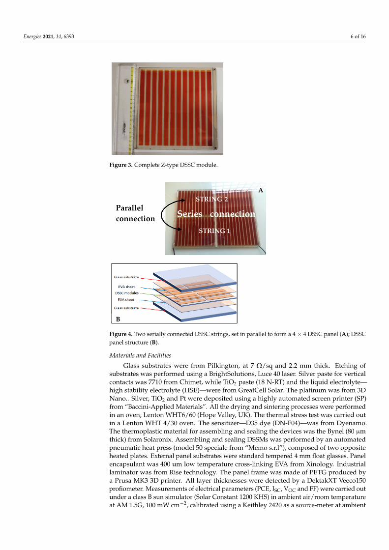
The series-connected DSSM fabrication process occurs completely in ambient air. First,glasses were washed with soap to remove organic products and dust; then, they wererinsed in acetone, ethanol and 2-propanol. For each module, two glasses were etchedby means of a Nd:YVO4, λ = 1064 nm, raster scanning laser in order to isolate 12 cellson them [63] (Figure 1a). The width of the single cell was designed according to well-known compromises between losses in the efficiency of the geometrical area and resistivityof the transparent FTO electrodes [44]. These glasses make up the photoelectrode (PE)and the counter-electrode (CE). On both electrodes, silver contacts were screen-printedand then they were dried at 120 C for 30 min in an oven [Figure 1b]. On the PE, weprinted GreatCell Solar TiO2 paste (Figure 1c1). After printing, the TiO2 layer was dried at120 C and then sintered at 500 C for 30 min with a slow increasing ramp temperature.The resulting layer of TiO2 acting as a wide band-gap semiconductor was 5 µm thickwith an approximately 20 nm particle size (Figure 2), in accordance with a TiO2 layer forsemi-transparent application [64].
Energies 2021, 14, 6393 5 of 16
Energies 2021, 14, 6393 5 of 17
approximately 20 nm particle size (Figure 2), in accordance with a TiO2 layer for semi-transparent application [64].
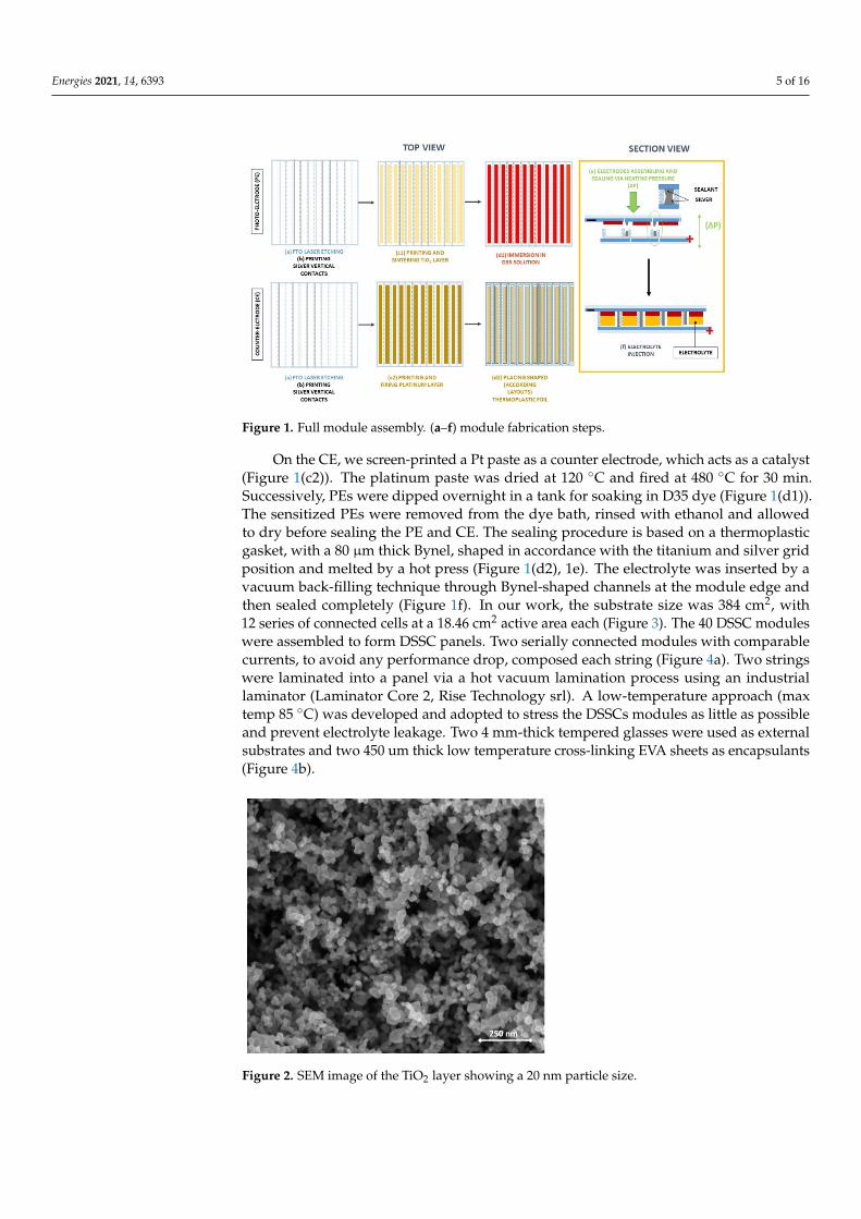
Figure 1. Figure 1. Full module assembly. (a–f) module fabrication steps.
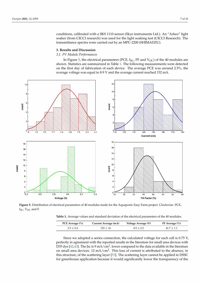
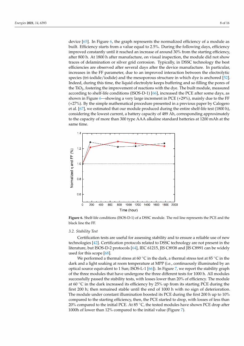
On the CE, we screen-printed a Pt paste as a counter electrode, which acts as a catalyst (Figure 1c2). The platinum paste was dried at 120 °C and fired at 480 °C for 30 min. Suc-cessively, PEs were dipped overnight in a tank for soaking in D35 dye (Figure 1d1). The sensitized PEs were removed from the dye bath, rinsed with ethanol and allowed to dry before sealing the PE and CE. The sealing procedure is based on a thermoplastic gasket, with a 80 μm thick Bynel, shaped in accordance with the titanium and silver grid position and melted by a hot press (Figure 1d2, 1e). The electrolyte was inserted by a vacuum back-filling technique through Bynel-shaped channels at the module edge and then sealed com-pletely (Figure 1f). In our work, the substrate size was 384 cm2, with 12 series of connected cells at a 18.46 cm2 active area each (Figure 3). The 40 DSSC modules were assembled to form DSSC panels. Two serially connected modules with comparable currents, to avoid any performance drop, composed each string (Figure 4a). Two strings were laminated into a panel via a hot vacuum lamination process using an industrial laminator (Laminator Core 2, Rise Technology srl). A low-temperature approach (max temp 85 °C) was devel-oped and adopted to stress the DSSCs modules as little as possible and prevent electrolyte leakage. Two 4 mm-thick tempered glasses were used as external substrates and two 450 um thick low temperature cross-linking EVA sheets as encapsulants (Figure 4b)
Figure 1. Full module assembly. (a–f) module fabrication steps.
On the CE, we screen-printed a Pt paste as a counter electrode, which acts as a catalyst(Figure 1(c2)). The platinum paste was dried at 120 C and fired at 480 C for 30 min.Successively, PEs were dipped overnight in a tank for soaking in D35 dye (Figure 1(d1)).The sensitized PEs were removed from the dye bath, rinsed with ethanol and allowedto dry before sealing the PE and CE. The sealing procedure is based on a thermoplasticgasket, with a 80 µm thick Bynel, shaped in accordance with the titanium and silver gridposition and melted by a hot press (Figure 1(d2), 1e). The electrolyte was inserted by avacuum back-filling technique through Bynel-shaped channels at the module edge andthen sealed completely (Figure 1f). In our work, the substrate size was 384 cm2, with12 series of connected cells at a 18.46 cm2 active area each (Figure 3). The 40 DSSC moduleswere assembled to form DSSC panels. Two serially connected modules with comparablecurrents, to avoid any performance drop, composed each string (Figure 4a). Two stringswere laminated into a panel via a hot vacuum lamination process using an industriallaminator (Laminator Core 2, Rise Technology srl). A low-temperature approach (maxtemp 85 C) was developed and adopted to stress the DSSCs modules as little as possibleand prevent electrolyte leakage. Two 4 mm-thick tempered glasses were used as externalsubstrates and two 450 um thick low temperature cross-linking EVA sheets as encapsulants(Figure 4b).
Energies 2021, 14, 6393 5 of 17
approximately 20 nm particle size (Figure 2), in accordance with a TiO2 layer for semi-transparent application [64].
Figure 1. Figure 1. Full module assembly. (a–f) module fabrication steps.
On the CE, we screen-printed a Pt paste as a counter electrode, which acts as a catalyst (Figure 1c2). The platinum paste was dried at 120 °C and fired at 480 °C for 30 min. Suc-cessively, PEs were dipped overnight in a tank for soaking in D35 dye (Figure 1d1). The sensitized PEs were removed from the dye bath, rinsed with ethanol and allowed to dry before sealing the PE and CE. The sealing procedure is based on a thermoplastic gasket, with a 80 μm thick Bynel, shaped in accordance with the titanium and silver grid position and melted by a hot press (Figure 1d2, 1e). The electrolyte was inserted by a vacuum back-filling technique through Bynel-shaped channels at the module edge and then sealed com-pletely (Figure 1f). In our work, the substrate size was 384 cm2, with 12 series of connected cells at a 18.46 cm2 active area each (Figure 3). The 40 DSSC modules were assembled to form DSSC panels. Two serially connected modules with comparable currents, to avoid any performance drop, composed each string (Figure 4a). Two strings were laminated into a panel via a hot vacuum lamination process using an industrial laminator (Laminator Core 2, Rise Technology srl). A low-temperature approach (max temp 85 °C) was devel-oped and adopted to stress the DSSCs modules as little as possible and prevent electrolyte leakage. Two 4 mm-thick tempered glasses were used as external substrates and two 450 um thick low temperature cross-linking EVA sheets as encapsulants (Figure 4b)
Figure 2. SEM image of the TiO2 layer showing a 20 nm particle size.
Energies 2021, 14, 6393 6 of 16
Energies 2021, 14, 6393 6 of 17
Figure 2. SEM image of the TiO2 layer showing a 20 nm particle size.
Figure 3. Complete Z-type DSSC module.
Figure 4. Two serially connected DSSC strings, set in parallel to form a 4 × 4 DSSC panel (); DSSC panel structure (b).
Materials and Facilities Glass substrates were from Pilkington, at 7 Ω/sq and 2.2 mm thick. Etching of sub-
strates was performed using a BrightSolutions, Luce 40 laser. Silver paste for vertical con-tacts was 7710 from Chimet, while TiO2 paste (18 N-RT) and the liquid electrolyte— high stability electrolyte (HSE)—were from GreatCell Solar. The platinum was from 3D Nano.. Silver, TiO2 and Pt were deposited using a highly automated screen printer (SP) from “Baccini-Applied Materials”. All the drying and sintering processes were performed in an oven, Lenton WHT6/60 (Hope Valley, UK). The thermal stress test was carried out in a Lenton WHT 4/30 oven. The sensitizer—D35 dye (DN-F04)—was from Dyenamo. The thermoplastic material for assembling and sealing the devices was the Bynel (80 μm thick) from Solaronix. Assembling and sealing DSSMs was performed by an automated pneu-matic heat press (model 50 speciale from “Memo s.r.l”), composed of two opposite heated plates. External panel substrates were standard tempered 4 mm float glasses. Panel en-capsulant was 400 um low temperature cross-linking EVA from Xinology. Industrial lam-inator was from Rise technology. The panel frame was made of PETG produced by a Prusa MK3 3D printer. All layer thicknesses were detected by a DektakXT Veeco150 profiome-ter. Measurements of electrical parameters (PCE, ISC, VOC and FF) were carried out under a class B sun simulator (Solar Constant 1200 KHS) in ambient air/room temperature at AM
String STRING 2
Series connection Parallel connection
A
STRING 1
B
Figure 3. Complete Z-type DSSC module.
Energies 2021, 14, 6393 6 of 17
Figure 2. SEM image of the TiO2 layer showing a 20 nm particle size.
Figure 3. Complete Z-type DSSC module.
Figure 4. Two serially connected DSSC strings, set in parallel to form a 4 × 4 DSSC panel (); DSSC panel structure (b).
Materials and Facilities Glass substrates were from Pilkington, at 7 Ω/sq and 2.2 mm thick. Etching of sub-
strates was performed using a BrightSolutions, Luce 40 laser. Silver paste for vertical con-tacts was 7710 from Chimet, while TiO2 paste (18 N-RT) and the liquid electrolyte— high stability electrolyte (HSE)—were from GreatCell Solar. The platinum was from 3D Nano.. Silver, TiO2 and Pt were deposited using a highly automated screen printer (SP) from “Baccini-Applied Materials”. All the drying and sintering processes were performed in an oven, Lenton WHT6/60 (Hope Valley, UK). The thermal stress test was carried out in a Lenton WHT 4/30 oven. The sensitizer—D35 dye (DN-F04)—was from Dyenamo. The thermoplastic material for assembling and sealing the devices was the Bynel (80 μm thick) from Solaronix. Assembling and sealing DSSMs was performed by an automated pneu-matic heat press (model 50 speciale from “Memo s.r.l”), composed of two opposite heated plates. External panel substrates were standard tempered 4 mm float glasses. Panel en-capsulant was 400 um low temperature cross-linking EVA from Xinology. Industrial lam-inator was from Rise technology. The panel frame was made of PETG produced by a Prusa MK3 3D printer. All layer thicknesses were detected by a DektakXT Veeco150 profiome-ter. Measurements of electrical parameters (PCE, ISC, VOC and FF) were carried out under a class B sun simulator (Solar Constant 1200 KHS) in ambient air/room temperature at AM
String STRING 2
Series connection Parallel connection
A
STRING 1
B
Figure 4. Two serially connected DSSC strings, set in parallel to form a 4 × 4 DSSC panel (A); DSSCpanel structure (B).
Materials and Facilities
Glass substrates were from Pilkington, at 7 Ω/sq and 2.2 mm thick. Etching ofsubstrates was performed using a BrightSolutions, Luce 40 laser. Silver paste for verticalcontacts was 7710 from Chimet, while TiO2 paste (18 N-RT) and the liquid electrolyte—high stability electrolyte (HSE)—were from GreatCell Solar. The platinum was from 3DNano.. Silver, TiO2 and Pt were deposited using a highly automated screen printer (SP)from “Baccini-Applied Materials”. All the drying and sintering processes were performedin an oven, Lenton WHT6/60 (Hope Valley, UK). The thermal stress test was carried outin a Lenton WHT 4/30 oven. The sensitizer—D35 dye (DN-F04)—was from Dyenamo.The thermoplastic material for assembling and sealing the devices was the Bynel (80 µmthick) from Solaronix. Assembling and sealing DSSMs was performed by an automatedpneumatic heat press (model 50 speciale from “Memo s.r.l”), composed of two oppositeheated plates. External panel substrates were standard tempered 4 mm float glasses. Panelencapsulant was 400 um low temperature cross-linking EVA from Xinology. Industriallaminator was from Rise technology. The panel frame was made of PETG produced bya Prusa MK3 3D printer. All layer thicknesses were detected by a DektakXT Veeco150profiometer. Measurements of electrical parameters (PCE, ISC, VOC and FF) were carried outunder a class B sun simulator (Solar Constant 1200 KHS) in ambient air/room temperatureat AM 1.5G, 100 mW cm−2, calibrated using a Keithley 2420 as a source-meter at ambient
Energies 2021, 14, 6393 7 of 16
conditions, calibrated with a SKS 1110 sensor (Skye instruments Ltd.). An “Arkeo” lightsoaker (from CICCI research) was used for the light soaking test (CICCI Research). Thetransmittance spectra were carried out by an MPC-2200 (SHIMADZU).
3. Results and Discussion3.1. PV Module Performances
In Figure 5, the electrical parameters (PCE, ISC, FF and VOC) of the 40 modules areshown. Statistics are summarized in Table 1. The following measurements were detectedon the first day of fabrication of each device. The average PCE was around 2.5%, theaverage voltage was equal to 8.9 V and the average current reached 152 mA.
Energies 2021, 14, 6393 8 of 18
Figure 5. Distribution of electrical parameters of 40 modules made for the Aquaponic Easy Farm project. Clockwise: PCE, ISC, VOC and F.
Table 1. Average values and standard deviation of the electrical parameters of the 40 modules.
PCE Average (%) Current Average (mA) Voltage Average (V) FF Average (%) 2.5 ± 0.4 152 ± 16 8.9 ± 0.2 41.7 ± 1.1
Since we adopted a series connection, the calculated voltage for each cell is 0.75 V, perfectly in agreement with the reported results in the literature for small area devices with D35 dye [42,43]. The Jsc is 9 mA/cm2, lower compared to the data available in the literature on small area devices: 12 mA/cm2. This loss of current is attributed to the absence, in this structure, of the scattering layer [53]. The scattering layer cannot be applied in DSSC for greenhouse application because it would significantly lower the transparency of the device [65]. In Figure 6, the graph represents the normalized efficiency of a module as built. Efficiency starts from a value equal to 2.5%. During the following days, efficiency improved constantly until it reached an increase of around 30% from the starting efficiency, after 800 h. At 1800 h after manufacture, on visual inspection, the module did not show traces of delamination or silver grid corrosion. Typically, in DSSC technology the best efficiencies are observed after several days after the device manufacture. In particular, increases in the FF parameter, due to an improved interaction between the electrolytic species (tri-iodide/iodide) and the mesoporous structure in which dye is anchored [52]. Indeed, during this time, the liquid electrolyte keeps buffering and so filling the pores of the TiO2, fostering the improvement of reactions with the dye. The built module, measured according to shelf-life conditions (ISOS-D-1) [66], increased the
Figure 5. Distribution of electrical parameters of 40 modules made for the Aquaponic Easy Farm project. Clockwise: PCE,ISC, VOC and F.
Table 1. Average values and standard deviation of the electrical parameters of the 40 modules.
PCE Average (%) Current Average (mA) Voltage Average (V) FF Average (%)
2.5 ± 0.4 152 ± 16 8.9 ± 0.2 41.7 ± 1.1
Since we adopted a series connection, the calculated voltage for each cell is 0.75 V,perfectly in agreement with the reported results in the literature for small area devices withD35 dye [42,43]. The Jsc is 9 mA/cm2, lower compared to the data available in the literatureon small area devices: 12 mA/cm2. This loss of current is attributed to the absence, inthis structure, of the scattering layer [53]. The scattering layer cannot be applied in DSSCfor greenhouse application because it would significantly lower the transparency of the
Energies 2021, 14, 6393 8 of 16
device [65]. In Figure 6, the graph represents the normalized efficiency of a module asbuilt. Efficiency starts from a value equal to 2.5%. During the following days, efficiencyimproved constantly until it reached an increase of around 30% from the starting efficiency,after 800 h. At 1800 h after manufacture, on visual inspection, the module did not showtraces of delamination or silver grid corrosion. Typically, in DSSC technology the bestefficiencies are observed after several days after the device manufacture. In particular,increases in the FF parameter, due to an improved interaction between the electrolyticspecies (tri-iodide/iodide) and the mesoporous structure in which dye is anchored [52].Indeed, during this time, the liquid electrolyte keeps buffering and so filling the pores ofthe TiO2, fostering the improvement of reactions with the dye. The built module, measuredaccording to shelf-life conditions (ISOS-D-1) [66], increased the PCE after some days, asshown in Figure 6—showing a very large increment in PCE (+29%), mainly due to the FF(+27%). By the simple mathematical procedure presented in a previous paper by Calogeroet al. [67], we estimated that our module produced during the entire shelf-life test (1800 h),considering the lowest current, a battery capacity of 489 Ah, corresponding approximatelyto the capacity of more than 300 type AAA alkaline standard batteries at 1200 mAh at thesame time.
Energies 2021, 14, 6393 8 of 17
in DSSC for greenhouse application because it would significantly lower the transparency of the device [65]. In Figure 6, the graph represents the normalized efficiency of a module as built. Efficiency starts from a value equal to 2.5%. During the following days, efficiency improved constantly until it reached an increase of around 30% from the starting effi-ciency, after 800 h. At 1800 h after manufacture, on visual inspection, the module did not show traces of delamination or silver grid corrosion. Typically, in DSSC technology the best efficiencies are observed after several days after the device manufacture. In particu-lar, increases in the FF parameter, due to an improved interaction between the electrolytic species (tri-iodide/iodide) and the mesoporous structure in which dye is anchored [52]. Indeed, during this time, the liquid electrolyte keeps buffering and so filling the pores of the TiO2, fostering the improvement of reactions with the dye. The built module, meas-ured according to shelf-life conditions (ISOS-D-1) [66], increased the PCE after some days, as shown in Figure 6—showing a very large increment in PCE (+29%), mainly due to the FF (+27%). By the simple mathematical procedure presented in a previous paper by Calogero et al. [67], we estimated that our module produced during the entire shelf-life test (1800 h), considering the lowest current, a battery capacity of 489 Ah, corresponding approximately to the capacity of more than 300 type AAA alkaline standard batteries at 1200 mAh at the same time.
Figure 6. Shelf-life conditions (ISOS-D-1) of a DSSC module. The red line represents the PCE and the black line the FF.
3.2. Stability Test Certification tests are useful for assessing stability and to ensure a reliable use of new
technologies [42]. Certification protocols related to DSSC technology are not present in the literature, but ISOS-D-2 protocols [64], IEC 61215, JIS C8938 and JIS C8991 can be widely used for this scope [68].
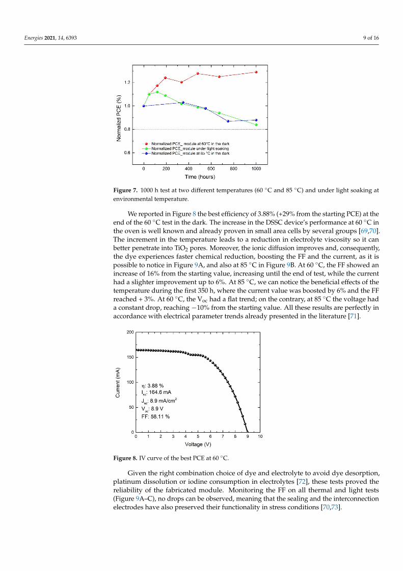
We performed a thermal stress at 60 °C in the dark, a thermal stress test at 85 °C in the dark and a light soaking at room temperature at MPP (i.e., continuously illuminated by an optical source equivalent to 1 Sun; ISOS-L-1 [66]). In Figure 7, we report the stability graph of the three modules that have undergone the three different tests for 1000 h. All modules successfully passed the stability tests, with losses lower than 20% of efficiency. The module at 60 °C in the dark increased its efficiency by 25% up from its starting PCE during the first 200 h; then remained stable until the end of 1000 h with no sign of deteri-oration. The module under constant illumination boosted its PCE during the first 200 h
Figure 6. Shelf-life conditions (ISOS-D-1) of a DSSC module. The red line represents the PCE and theblack line the FF.
3.2. Stability Test
Certification tests are useful for assessing stability and to ensure a reliable use of newtechnologies [42]. Certification protocols related to DSSC technology are not present in theliterature, but ISOS-D-2 protocols [64], IEC 61215, JIS C8938 and JIS C8991 can be widelyused for this scope [68].
We performed a thermal stress at 60 C in the dark, a thermal stress test at 85 C in thedark and a light soaking at room temperature at MPP (i.e., continuously illuminated by anoptical source equivalent to 1 Sun; ISOS-L-1 [66]). In Figure 7, we report the stability graphof the three modules that have undergone the three different tests for 1000 h. All modulessuccessfully passed the stability tests, with losses lower than 20% of efficiency. The moduleat 60 C in the dark increased its efficiency by 25% up from its starting PCE during thefirst 200 h; then remained stable until the end of 1000 h with no sign of deterioration.The module under constant illumination boosted its PCE during the first 200 h up to 10%compared to the starting efficiency, then, the PCE started to drop, with losses of less than20% compared to the initial PCE. At 85 C, the tested modules have shown PCE drop after1000h of lower than 12% compared to the initial value (Figure 7).
Energies 2021, 14, 6393 9 of 16
Energies 2021, 14, 6393 9 of 17
up to 10% compared to the starting efficiency, then, the PCE started to drop, with losses of less than 20% compared to the initial PCE. At 85 °C, the tested modules have shown PCE drop after 1000h of lower than 12% compared to the initial value (Figure 7).
Figure 7. 1000 h test at two different temperatures (60 °C and 85 °C) and under light soaking at environmental temperature.
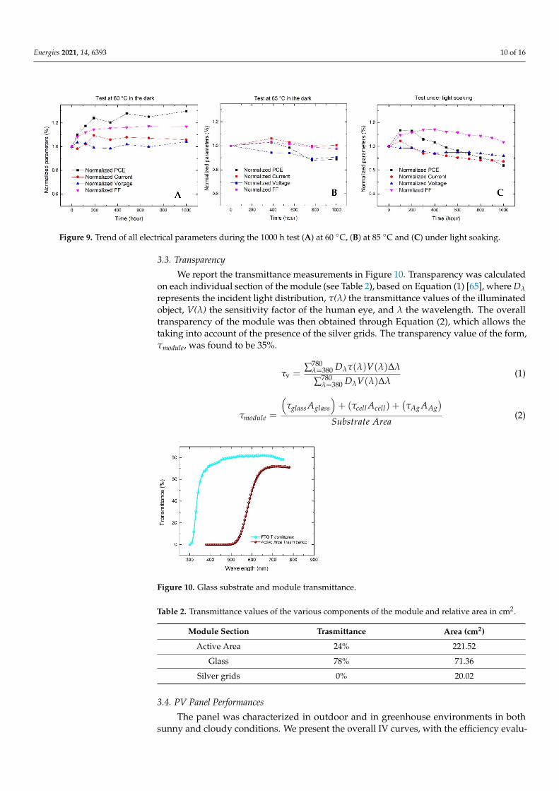
We reported in Figure 8 the best efficiency of 3.88% (+29% from the starting PCE) at the end of the 60 °C test in the dark. The increase in the DSSC device’s performance at 60 °C in the oven is well known and already proven in small area cells by several groups [69,70]. The increment in the temperature leads to a reduction in electrolyte viscosity so it can better penetrate into TiO2 pores. Moreover, the ionic diffusion improves and, conse-quently, the dye experiences faster chemical reduction, boosting the FF and the current, as it is possible to notice in Figure 9A, and also at 85 °C in Figure 9B. At 60 °C, the FF showed an increase of 16% from the starting value, increasing until the end of test, while the current had a slighter improvement up to 6%. At 85 °C, we can notice the beneficial effects of the temperature during the first 350 h, where the current value was boosted by 6% and the FF reached + 3%. At 60 °C, the Voc had a flat trend; on the contrary, at 85 °C the voltage had a constant drop, reaching −10% from the starting value. All these results are perfectly in accordance with electrical parameter trends already presented in the liter-ature [71].
Figure 8. IV curve of the best PCE at 60 °C.
Figure 7. 1000 h test at two different temperatures (60 C and 85 C) and under light soaking atenvironmental temperature.
We reported in Figure 8 the best efficiency of 3.88% (+29% from the starting PCE) at theend of the 60 C test in the dark. The increase in the DSSC device’s performance at 60 C inthe oven is well known and already proven in small area cells by several groups [69,70].The increment in the temperature leads to a reduction in electrolyte viscosity so it canbetter penetrate into TiO2 pores. Moreover, the ionic diffusion improves and, consequently,the dye experiences faster chemical reduction, boosting the FF and the current, as it ispossible to notice in Figure 9A, and also at 85 C in Figure 9B. At 60 C, the FF showed anincrease of 16% from the starting value, increasing until the end of test, while the currenthad a slighter improvement up to 6%. At 85 C, we can notice the beneficial effects of thetemperature during the first 350 h, where the current value was boosted by 6% and the FFreached + 3%. At 60 C, the Voc had a flat trend; on the contrary, at 85 C the voltage hada constant drop, reaching −10% from the starting value. All these results are perfectly inaccordance with electrical parameter trends already presented in the literature [71].
Energies 2021, 14, 6393 9 of 17
up to 10% compared to the starting efficiency, then, the PCE started to drop, with losses of less than 20% compared to the initial PCE. At 85 °C, the tested modules have shown PCE drop after 1000h of lower than 12% compared to the initial value (Figure 7).
Figure 7. 1000 h test at two different temperatures (60 °C and 85 °C) and under light soaking at environmental temperature.
We reported in Figure 8 the best efficiency of 3.88% (+29% from the starting PCE) at the end of the 60 °C test in the dark. The increase in the DSSC device’s performance at 60 °C in the oven is well known and already proven in small area cells by several groups [69,70]. The increment in the temperature leads to a reduction in electrolyte viscosity so it can better penetrate into TiO2 pores. Moreover, the ionic diffusion improves and, conse-quently, the dye experiences faster chemical reduction, boosting the FF and the current, as it is possible to notice in Figure 9A, and also at 85 °C in Figure 9B. At 60 °C, the FF showed an increase of 16% from the starting value, increasing until the end of test, while the current had a slighter improvement up to 6%. At 85 °C, we can notice the beneficial effects of the temperature during the first 350 h, where the current value was boosted by 6% and the FF reached + 3%. At 60 °C, the Voc had a flat trend; on the contrary, at 85 °C the voltage had a constant drop, reaching −10% from the starting value. All these results are perfectly in accordance with electrical parameter trends already presented in the liter-ature [71].
Figure 8. IV curve of the best PCE at 60 °C. Figure 8. IV curve of the best PCE at 60 C.
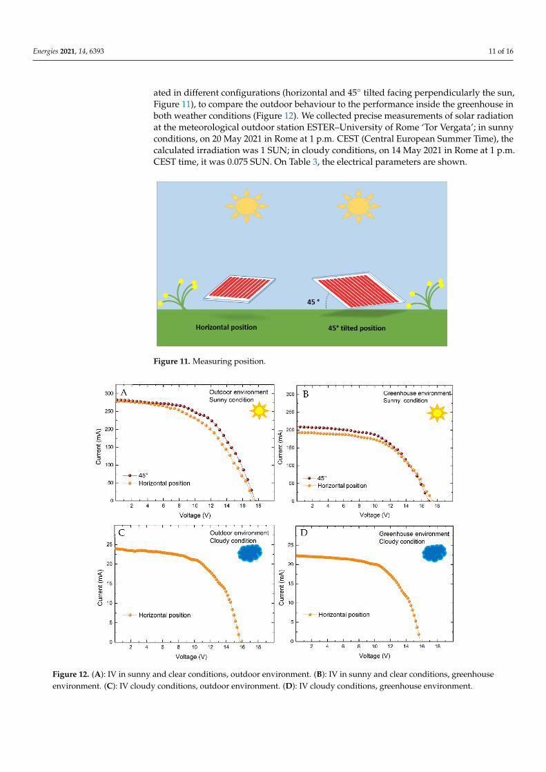
Given the right combination choice of dye and electrolyte to avoid dye desorption,platinum dissolution or iodine consumption in electrolytes [72], these tests proved thereliability of the fabricated module. Monitoring the FF on all thermal and light tests(Figure 9A–C), no drops can be observed, meaning that the sealing and the interconnectionelectrodes have also preserved their functionality in stress conditions [70,73].
Energies 2021, 14, 6393 10 of 16
Energies 2021, 14, 6393 10 of 17
Given the right combination choice of dye and electrolyte to avoid dye desorption, platinum dissolution or iodine consumption in electrolytes [72], these tests proved the reliability of the fabricated module. Monitoring the FF on all thermal and light tests (Fig-ure 9A–C), no drops can be observed, meaning that the sealing and the interconnection electrodes have also preserved their functionality in stress conditions [70,73].
Figure 9. Trend of all electrical parameters during the 1000 h test (A) at 60 °C, (B) at 85 °C and (C) under light soaking.
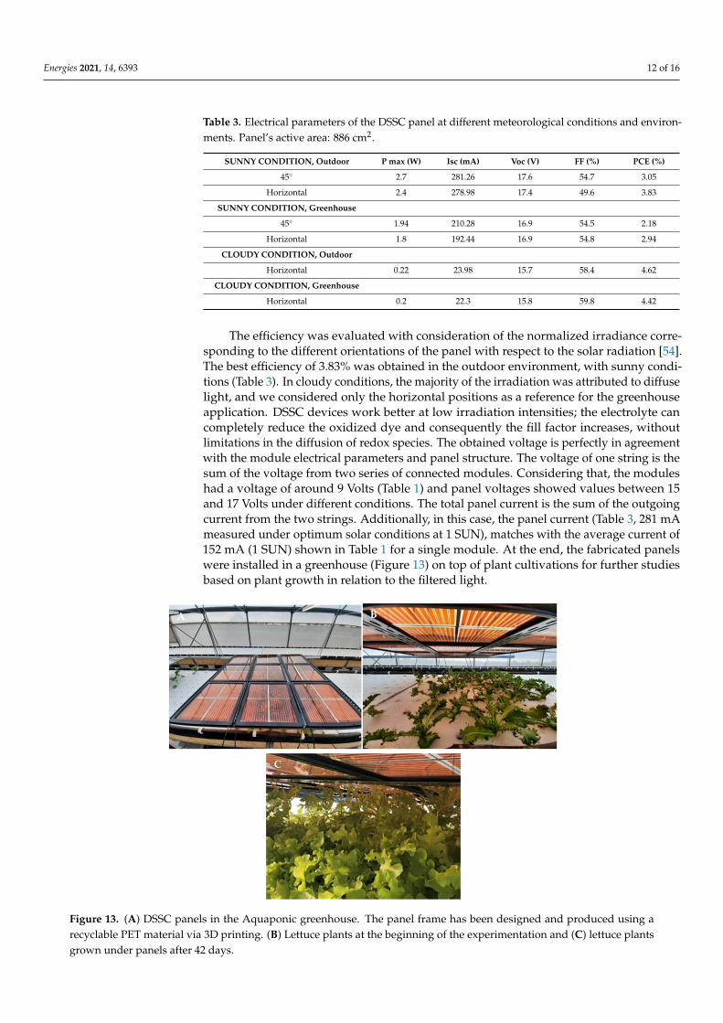
3.3. Transparency We report the transmittance measurements in Figure 10. Transparency was calcu-
lated on each individual section of the module (see Table 2), based on Equation (1) [65], where Dλ represents the incident light distribution, 𝛕 (λ) the transmittance values of the illuminated object, V (λ) the sensitivity factor of the human eye, and λ the wavelength. The overall transparency of the module was then obtained through Equation (2), which allows the taking into account of the presence of the silver grids. The transparency value of the form, 𝛕module, was found to be 35%.
Figure 10. Glass substrate and module transmittance.
Table 2. Transmittance values of the various components of the module and relative area in cm2.
Module Section Trasmittance Area (cm2) Active Area 24% 221.52
Glass 78% 71.36 Silver grids 0% 20.02
𝜏ᵥ = ∑ 𝐷 𝜏(𝜆)𝑉(𝜆)𝛥𝜆∑ 𝐷 𝑉(𝜆)𝛥𝜆 (1)
Figure 9. Trend of all electrical parameters during the 1000 h test (A) at 60 C, (B) at 85 C and (C) under light soaking.
3.3. Transparency
We report the transmittance measurements in Figure 10. Transparency was calculatedon each individual section of the module (see Table 2), based on Equation (1) [65], where Dλ
represents the incident light distribution, τ(λ) the transmittance values of the illuminatedobject, V(λ) the sensitivity factor of the human eye, and λ the wavelength. The overalltransparency of the module was then obtained through Equation (2), which allows thetaking into account of the presence of the silver grids. The transparency value of the form,τmodule, was found to be 35%.
τv =∑780
λ=380 Dλτ(λ)V(λ)∆λ
∑780λ=380 DλV(λ)∆λ
(1)
τmodule =
(τglass Aglass
)+ (τcell Acell) +
(τAg AAg
)Substrate Area
(2)
Energies 2021, 14, 6393 10 of 17
Given the right combination choice of dye and electrolyte to avoid dye desorption, platinum dissolution or iodine consumption in electrolytes [72], these tests proved the reliability of the fabricated module. Monitoring the FF on all thermal and light tests (Fig-ure 9A–C), no drops can be observed, meaning that the sealing and the interconnection electrodes have also preserved their functionality in stress conditions [70,73].
Figure 9. Trend of all electrical parameters during the 1000 h test (A) at 60 °C, (B) at 85 °C and (C) under light soaking.
3.3. Transparency We report the transmittance measurements in Figure 10. Transparency was calcu-
lated on each individual section of the module (see Table 2), based on Equation (1) [65], where Dλ represents the incident light distribution, 𝛕 (λ) the transmittance values of the illuminated object, V (λ) the sensitivity factor of the human eye, and λ the wavelength. The overall transparency of the module was then obtained through Equation (2), which allows the taking into account of the presence of the silver grids. The transparency value of the form, 𝛕module, was found to be 35%.
Figure 10. Glass substrate and module transmittance.
Table 2. Transmittance values of the various components of the module and relative area in cm2.
Module Section Trasmittance Area (cm2) Active Area 24% 221.52
Glass 78% 71.36 Silver grids 0% 20.02
𝜏ᵥ = ∑ 𝐷 𝜏(𝜆)𝑉(𝜆)𝛥𝜆∑ 𝐷 𝑉(𝜆)𝛥𝜆 (1)
Figure 10. Glass substrate and module transmittance.
Table 2. Transmittance values of the various components of the module and relative area in cm2.
Module Section Trasmittance Area (cm2)
Active Area 24% 221.52
Glass 78% 71.36
Silver grids 0% 20.02
3.4. PV Panel Performances
The panel was characterized in outdoor and in greenhouse environments in bothsunny and cloudy conditions. We present the overall IV curves, with the efficiency evalu-
Energies 2021, 14, 6393 11 of 16
ated in different configurations (horizontal and 45 tilted facing perpendicularly the sun,Figure 11), to compare the outdoor behaviour to the performance inside the greenhouse inboth weather conditions (Figure 12). We collected precise measurements of solar radiationat the meteorological outdoor station ESTER–University of Rome ‘Tor Vergata’; in sunnyconditions, on 20 May 2021 in Rome at 1 p.m. CEST (Central European Summer Time), thecalculated irradiation was 1 SUN; in cloudy conditions, on 14 May 2021 in Rome at 1 p.m.CEST time, it was 0.075 SUN. On Table 3, the electrical parameters are shown.
Energies 2021, 14, 6393 11 of 17
𝜏 = 𝜏 𝐴 + (𝜏 𝐴 ) + 𝜏 𝐴𝑆𝑢𝑏𝑠𝑡𝑟𝑎𝑡𝑒 𝐴𝑟𝑒𝑎 (2)
3.4. PV Panel Performances The panel was characterized in outdoor and in greenhouse environments in both
sunny and cloudy conditions. We present the overall IV curves, with the efficiency eval-uated in different configurations (horizontal and 45° tilted facing perpendicularly the sun, Figure 11), to compare the outdoor behaviour to the performance inside the greenhouse in both weather conditions (Figure 12). We collected precise measurements of solar radi-ation at the meteorological outdoor station ESTER–University of Rome ‘Tor Vergata’; in sunny conditions, on 20 May 2021 in Rome at 1 pm CEST (Central European Summer Time), the calculated irradiation was 1 SUN; in cloudy conditions, on 14 May 2021 in Rome at 1 pm CEST time, it was 0.075 SUN. On Table 3, the electrical parameters are shown.
Figure 11. Measuring position.
Figure 11. Measuring position.Energies 2021, 14, 6393 12 of 17
Figure 12. (A): IV in sunny and clear conditions, outdoor environment. (B): IV in sunny and clear conditions, greenhouse environment. (C): IV cloudy conditions, outdoor environment. (D): IV cloudy conditions, greenhouse environment.
Table 3. Electrical parameters of the DSSC panel at different meteorological conditions and envi-ronments. Panel’s active area: 886 cm2.
SUNNY CONDITION, Outdoor
P max (W) Isc (mA) Voc (V) FF (%) PCE (%)
45° 2.7 281.26 17.6 54.7 3.05 Horizontal 2.4 278.98 17.4 49.6 3.83
SUNNY CONDITION, Greenhouse
45° 1.94 210.28 16.9 54.5 2.18 Horizontal 1.8 192.44 16.9 54.8 2.94
CLOUDY CONDITION, Outdoor
Horizontal 0.22 23.98 15.7 58.4 4.62 CLOUDY CONDITION,
Greenhouse
Horizontal 0.2 22.3 15.8 59.8 4.42
The efficiency was evaluated with consideration of the normalized irradiance corre-sponding to the different orientations of the panel with respect to the solar radiation [54]. The best efficiency of 3.83% was obtained in the outdoor environment, with sunny condi-tions (Table 3). In cloudy conditions, the majority of the irradiation was attributed to dif-
Figure 12. (A): IV in sunny and clear conditions, outdoor environment. (B): IV in sunny and clear conditions, greenhouseenvironment. (C): IV cloudy conditions, outdoor environment. (D): IV cloudy conditions, greenhouse environment.
Energies 2021, 14, 6393 12 of 16
Table 3. Electrical parameters of the DSSC panel at different meteorological conditions and environ-ments. Panel’s active area: 886 cm2.
SUNNY CONDITION, Outdoor P max (W) Isc (mA) Voc (V) FF (%) PCE (%)
45 2.7 281.26 17.6 54.7 3.05
Horizontal 2.4 278.98 17.4 49.6 3.83
SUNNY CONDITION, Greenhouse
45 1.94 210.28 16.9 54.5 2.18
Horizontal 1.8 192.44 16.9 54.8 2.94
CLOUDY CONDITION, Outdoor
Horizontal 0.22 23.98 15.7 58.4 4.62
CLOUDY CONDITION, Greenhouse
Horizontal 0.2 22.3 15.8 59.8 4.42
The efficiency was evaluated with consideration of the normalized irradiance corre-sponding to the different orientations of the panel with respect to the solar radiation [54].The best efficiency of 3.83% was obtained in the outdoor environment, with sunny condi-tions (Table 3). In cloudy conditions, the majority of the irradiation was attributed to diffuselight, and we considered only the horizontal positions as a reference for the greenhouseapplication. DSSC devices work better at low irradiation intensities; the electrolyte cancompletely reduce the oxidized dye and consequently the fill factor increases, withoutlimitations in the diffusion of redox species. The obtained voltage is perfectly in agreementwith the module electrical parameters and panel structure. The voltage of one string is thesum of the voltage from two series of connected modules. Considering that, the moduleshad a voltage of around 9 Volts (Table 1) and panel voltages showed values between 15and 17 Volts under different conditions. The total panel current is the sum of the outgoingcurrent from the two strings. Additionally, in this case, the panel current (Table 3, 281 mAmeasured under optimum solar conditions at 1 SUN), matches with the average current of152 mA (1 SUN) shown in Table 1 for a single module. At the end, the fabricated panelswere installed in a greenhouse (Figure 13) on top of plant cultivations for further studiesbased on plant growth in relation to the filtered light.
Energies 2021, 14, 6393 13 of 17
fuse light, and we considered only the horizontal positions as a reference for the green-house application. DSSC devices work better at low irradiation intensities; the electrolyte can completely reduce the oxidized dye and consequently the fill factor increases, without limitations in the diffusion of redox species. The obtained voltage is perfectly in agreement with the module electrical parameters and panel structure. The voltage of one string is the sum of the voltage from two series of connected modules. Considering that, the modules had a voltage of around 9 Volts (Table 1) and panel voltages showed values between 15 and 17 Volts under different conditions. The total panel current is the sum of the outgoing current from the two strings. Additionally, in this case, the panel current (Table 3, 281mA measured under optimum solar conditions at 1 SUN), matches with the average current of 152 mA (1 SUN) shown in Table 1 for a single module. At the end, the fabricated panels were installed in a greenhouse (Figure 13) on top of plant cultivations for further studies based on plant growth in relation to the filtered light.
Figure 13. (A) DSSC panels in the Aquaponic greenhouse. The panel frame has been designed and produced using a recyclable PET material via 3D printing. (B) Lettuce plants at the beginning of the experimentation and (C) lettuce plants grown under panels after 42 days.
4. Conclusions In the “Aquaponic Easy Farm 4.0” project, of the Lazio Region, Italy, we worked on
the production of two square meters of photovoltaic panel to be applied inside an Aqua-ponic greenhouse. In this study, we focused on the development of the panels with con-sideration of the two main parameters for a photovoltaic device inside a greenhouse: transparency and efficiency. We chose DSSC technology for its peculiar characteristic of high ratio between transparency and efficiency, extensively discussed in the introduction. We carefully described the ambitious and demanding engineering procedure of Z-type module and panel fabrication in order to obtain efficient, transparent and stable devices. We measured a module for 1800 h under shelf-life conditions. Modules were deeply stressed under light at high temperatures, retaining at least 80% of their original efficiency after the stress tests. We obtained a maximum PCE of 3.88% in a single module and a transparency of 35% on the aperture area (312.9 cm2). Moreover, the modules survived
Figure 13. (A) DSSC panels in the Aquaponic greenhouse. The panel frame has been designed and produced using arecyclable PET material via 3D printing. (B) Lettuce plants at the beginning of the experimentation and (C) lettuce plantsgrown under panels after 42 days.
Energies 2021, 14, 6393 13 of 16
4. Conclusions
In the “Aquaponic Easy Farm 4.0” project, of the Lazio Region, Italy, we workedon the production of two square meters of photovoltaic panel to be applied inside anAquaponic greenhouse. In this study, we focused on the development of the panels withconsideration of the two main parameters for a photovoltaic device inside a greenhouse:transparency and efficiency. We chose DSSC technology for its peculiar characteristic ofhigh ratio between transparency and efficiency, extensively discussed in the introduction.We carefully described the ambitious and demanding engineering procedure of Z-typemodule and panel fabrication in order to obtain efficient, transparent and stable devices. Wemeasured a module for 1800 h under shelf-life conditions. Modules were deeply stressedunder light at high temperatures, retaining at least 80% of their original efficiency after thestress tests. We obtained a maximum PCE of 3.88% in a single module and a transparencyof 35% on the aperture area (312.9 cm2). Moreover, the modules survived fruitfully in the60 C test, showing an increment in the PCE after 1000 h; no significant drops were detectedon tested modules at 85 C or under light. At the end, we assembled a panel with 4 modulesobtaining a maximum efficiency of 3.83% in sunny conditions in an outdoor environment.The panel presents a voltage between 16–18 Volts and a power capacity between 2–3 Wattsthat can supply part of the energy needs in a greenhouse for temperature and humiditysensors. Preliminary results concerning plant growth under filtered light from DSSCssuggest no differences between the growth of lettuce under natural and DSC-filtered light.Further studies will be the subject of a forthcoming report on plant growth in the DSCgreenhouse environment.
Author Contributions: Conceptualization, A.R. and A.C.; methodology, L.V., P.M., J.B., A.R. and E.L.;validation, A.R., L.V., J.B. and P.M.; formal analysis, J.B., L.V., P.M. and A.R.; investigation, J.B., L.V.,P.M., E.L. and A.R.; resources, A.R., A.C., R.B. and A.D.C.; data curation, J.B.; writing—original draftpreparation, J.B.; writing—review and editing, L.V., P.M., A.R., J.B. and E.L.; visualization, J.B., L.V.,P.M. and A.R.; supervision, A.R.; project administration, A.R., R.B. and A.C.; funding acquisition,A.R. and A.C. All authors have read and agreed to the published version of the manuscript.
Funding: This research was funded by Regione Lazio, POR FESR LAZIO 2014-2020, project name“Aquaponic easy farm 4.0”, project code A0206E0090, and project “COPPER–Celle solari polimericheper applicazioni agrovoltaiche in ortoflorovivaismo” by Regione Lazio (Progetto di Gruppo diRicerca–L.R. Lazio 13/08 n. 85-2017-15266).
Institutional Review Board Statement: Not applicable.
Informed Consent Statement: Not applicable.
Data Availability Statement: The data presented in this study are available on request from thecorresponding authors.
Acknowledgments: We acknowledge the helpful discussion with Cristina Cornaro; ESTER meteo-rological outdoor station, University of Rome ‘Tor Vergata’, and the following companies: DigitalCooking, Agri Island, App To You and ORION Meccanica.
Conflicts of Interest: The authors declare no conflict of interest.
References1. O’Reagan, B.; Grätzel, M. A low-cost, high-efficiency Solar-Cell based on Dye-Sensitized Colloidal TiO2 films. Nature 1991, 353,
737–740. [CrossRef]2. Gong, J.; Sumathy, K.; Qiao, Q.; Zhou, Z. Review on dye-sensitized solar cells (DSSCs): Advanced techniques and research trends.
Renew. Sustain. Energy Rev. 2017, 68, 234–246. [CrossRef]3. Shakeel Ahmada, M.; Pandeya, A.K.; Abd Rahima, N. Advancements in the development of TiO2 photoanodes and its fabrication
methods for dye sensitized solar cell (DSSC) applications. A review. Renew. Sustain. Energy Rev. 2017, 77, 89–108. [CrossRef]4. Selvaraj, P.; Roy, A.; Ullah, H.; Devi, P.S.; Tahir, A.A.; Mallick, T.K.; Sundaram, S. Soft-template synthesis of high surface area
mesoporous titanium dioxide for dye-sensitized solar cells. Int.J. Energy Res. 2019, 43, 523–524. [CrossRef]5. Ullah, H.; Bibi, S.; Tahir, A.; Mallick, T.K. Donor-acceptor polymer for the design of All-Solid-State dye-sensitized solar cells. J.
Alloy. Compd. 2017, 696, 914–922. [CrossRef]
Energies 2021, 14, 6393 14 of 16
6. NREL Site. Available online: https://www.nrel.gov/pv/cell-efficiency.html (accessed on 25 June 2021).7. Green, M.A.; Dunlop, E.D.; Hohl-Ebinger, J.; Yoshita, M.; Kopidakis, N.; Ho-Baillie, A.W.Y. Solar cell efficiency tables (Version 55).
Prog. Photovolt. Res. Appl. 2020, 28, 3–15. [CrossRef]8. Selvaraj, P.; Ghosh, A.; Mallick, T.K.; Sundaram, S. Investigation of semi-transparent dye-sensitized solar cells for fenestration
integration. Renew. Energy 2019, 141, 516–525. [CrossRef]9. Pulli, E.; Rozzi, E.; Bella, F. Transparent photovoltaic technologies: Current trends towards upscaling. Energy Convers. Manag.
2020, 219, 112982. [CrossRef]10. Ren, Y.; Sun, D.; Cao, Y.; Tsao, H.N.; Yuan, Y.; Zakeeruddin, S.M.; Wang, P.; Grätzel, M. A Stable Blue Photosensitizer for Color
Palette of Dye-Sensitized Solar Cells Reaching 12.6% Efficiency. J. Am. Chem. Soc. 2018, 140, 2405–2408. [CrossRef]11. Otaka, H.; Kira, M.; Yano, K.; Ito, S.; Mitekura, H.; Kawata, T.; Matsui, F. Multi-colored dye-sensitized solar cells. J. Photochem.
Photobiol. A Chem. 2004, 164, 67–73. [CrossRef]12. Selvaraj, P.; Baig, H.; Mallick, T.K.; Siviter, J.; Montecucco, A.; Li, W.; Paul, M.; Sweet, T.; Gao, M.; Knox, A.R.; et al. Enhancing
the efficiency of transparent dye-sensitized solar cells using concentrated light. Sol. Energy Mater. Sol. Cells 2018, 175, 29–34.[CrossRef]
13. Zhang, K.; Qin, C.; Yang, X.; Islam, A.; Zhang, S.; Chen, H.; Han, L. High-Performance, transparent, dye-sensitized solar cells forsee-through photovoltaic windows. Adv. Energy Mater. 2014, 4, 1301966. [CrossRef]
14. Biyik, E.; Araz, M.; Hepbasli, A.; Shahrestani, M.; Yao, R.; Shao, L.; Essah, E.; Oliveira, A.; del Caño, T.; Rico, E.; et al. A keyreview of building integrated photovoltaic (BIPV) systems. Eng. Sci. Technol. Int. J. 2017, 20, 833–858. [CrossRef]
15. Skandalos, N.; Karamanis, D. PV glazing technologies. Renew. Sustain. Energy Rev. 2015, 49, 306–322. [CrossRef]16. Parisi, M.L.; Maranghi, S.; Vesce, L.; Sinicropi, A.; di Carlo, A.; Basosi, R. Prospective life cycle assessment of third-generation
photovoltaics at the pre-industrial scale: A long-term scenario approach. Renew. Sustain. Energy Rev. 2020, 121, 109703. [CrossRef]17. Hagfeldt, A.; Boschloo, G.; Sun, L.; Kloo, L.; Pettersson, H. Dye-Sensitized Solar Cells. Chem. Rev. 2010, 110, 6595–6663. [CrossRef]18. Chalkias, D.A.; Charalampopoulos, C.; Aivali, S.; Andreopoulou, A.K.; Karavoti, A.; Stathatos, E. A Di-Carbazole-Based Dye as a
Potential Sensitizer for Greenhouse-Integrated Dye-Sensitized Solar Cells. Energies 2021, 14, 1159. [CrossRef]19. Roslan, N.; Ya’acob, M.E.; Radzi, M.A.M.; Hashimoto, Y.; Jamaludin, D.; Chen, G. Dye Sensitized Solar Cell (DSSC) greenhouse
shading: New insights for solar radiation manipulation. Renew. Sustain. Rev. 2018, 92, 171–186. [CrossRef]20. Allardyce, C.S.; Fankhauser, C.; Zakeeruddin, S.M.; Grätzel, M.; Dyson, P.J. The influence of greenhouse-integrated photovoltaics
on crop production. Sol. Energy 2017, 155, 517–522. [CrossRef]21. Ntinas, G.K.; Kadoglidou, K.; Tsivelika, N.; Krommydas, K.; Kalivas, A.; Ralli, P.; Irakli, M. Performance and Hydroponic
Tomato Crop Quality Characteristics in a Novel Greenhouse Using Dye-Sensitized Solar Cell Technology for Covering Material.Horticulturae 2019, 5, 42. [CrossRef]
22. Dupraz, C.; Marrou, H.; Talbot, G.; Dufour, L.; Nogier, A.; Ferard, Y. Combining solar photovoltaic panels and food crops foroptimising land use: Towards new agrivoltaic schemes. Renew. Energy 2011, 36, 2725–2732. [CrossRef]
23. Campiotti, C.; Dondi, F.; Genovese, A.; Alonzo, G.; Catanese, V.; Incrocci, L.; Bibbiani, C. Photovoltaic as sustainable Energy forgreenhouse and closed plant production system. Acta Hortic. 2008, 797, 373–378. [CrossRef]
24. Narra, V.K.; Ullah, H.; Singh, V.K.; Giribabu, L.; Senthilarasu, S.; Karazhanov, S.Z.; Tahir, A.A.; Mallick, T.K.; Upadhyay, H.M.D–π–A system based on zinc porphyrin dyes for dye-sensitized solar cells: Combined experimental and DFT–TDDFT study.Polyhedron 2015, 100, 313–320. [CrossRef]
25. Ureña-Sánchez, R.; Callejón-Ferre, Á.J.; Pérez-Alonso, J.; Carreño-Ortega, Á. Greenhouse tomato production with electricitygeneration by roof-mounted flexible solar panels. Sci. Agric. 2012, 69, 233–239. [CrossRef]
26. Marrou, H.; Wéry, J.; Dufour, L.; Dupraz, C. Productivity and radiation use efficiency of lettuces grown in the partial shade ofphotovoltaic panels. Eur. J. Agron. 2013, 44, 54–66. [CrossRef]
27. Babayigit, A.; Ethirajan, A.; Muller, M.; Conings, B. Toxicity of organometal halide perovskite solar cells. Nat. Mater. 2016, 15,247–251. [CrossRef]
28. Subhani, W.S.; Wang, K.; Du, M.; Wang, X.; Yuan, N.; Ding, J.; Liu, S. Anti-solvent engineering for efficient semitransparentCH3NH3PbBr 3 perovskite solar cells for greenhouse applications. J. Energy Chem. 2019, 34, 12–19. [CrossRef]
29. La Notte, L.; Giordano, L.; Calabrò, E.; Bedini, R.; Colla, G.; Puglisi, G.; Reale, A. Hybrid and organic photovoltaics for greenhouseapplications. Appl. Energy 2020, 278, 115582. [CrossRef]
30. Zisis, C.; Pechlivani, E.M.; Tsimikli, S.; Mekeridis, E.; Laskarakis, A.; Logothetidis, S. Organic Photovoltaics on GreenhouseRooftops: Effects on Plant Growth. Mater. Today Proc. 2019, 19, 65–72. [CrossRef]
31. Dessì, A.; Calamante, M.; Sinicropi, A.; Parisi, M.L.; Vesce, L.; Mariani, P.; Taheri, B.; Ciocca, M.; Di Carlo, A.; Zani, L.; et al.Thiazolo [5,4-d] thiazole-based organic sensitizers with improved spectral properties for application in greenhouse-integrateddye-sensitized solar cells. Sustain. Energy Fuels 2020, 4, 2309–2321. [CrossRef]
32. Yorio, N.C.; Goins, G.D.; Kagie, H.R.; Wheeler, R.M.; Sager, J.C. Improving Spinach, Radish, and Lettuce Growth under Red LightEmitting Diodes (LEDs) with Blue Light Supplementation. HortScience 2001, 36, 380–383. [CrossRef]
33. Kim, J.; Kang, M.; Kwak, O.K.; Yoon, Y.; Min, K.S.; Chu, M. Fabrication and Characterization of Dye-Sensitized Solar Cells forGreenhouse Application. Int. J. Photoenergy 2014, 2014, 1–7. [CrossRef]
34. McNellis, T.W.; Deng, X.W. Light control of seedling morphogenetic pattern. Plant Cell 1995, 7, 1749–1761.
Energies 2021, 14, 6393 15 of 16
35. Kim, H.H.; Goins, G.D.; Wheeler, R.M.; Sager, J.C. Stomatal conductance of lettuce grown under or exposed to different lightquality. Ann. Bot. 2004, 94, 691–697. [CrossRef]
36. Lu, L.; Ya’acob, M.E.; Anuar, M.S.; Chen, G.; Othman, M.H.; Iskandar, A.N.; Roslan, N. Thermal analysis of a portable DSSC minigreenhouse for botanical drugs cultivation. Energy Rep. 2020, 6, 238–253. [CrossRef]
37. Dominguez, A.; Kleiss, J.; Luvall, J.C. Effect of solar photovoltaic panels on roof heat transfer. Sol. Energy 2011, 85, 2244–2255.[CrossRef]
38. Garcıa, M.L.; Medrano, E.; Sanchez-Guerrero, M.C.; Lorenzo, P. Climatic effects of two cooling systems in greenhouses in theMediterranean area: External mobile shading and fog system. Biosyst. Eng. 2011, 108, 133–143. [CrossRef]
39. Leandri, V.; Ellis, H.; Gabrielsson, E.; Sun, L.; Boschloo, G.; Hagfeldtb, A. Organic hydrophilic dye for water-based dyesensitizedsolar cells. Phys. Chem. Chem. Phys. 2014, 16, 19964–19971. [CrossRef] [PubMed]
40. Vamvounis, G.; Glasson, C.R.; Bieskeb, E.J.; Dryza, V. Modulating electron injection from an organic dye to a titania nanoparticlewith a photochromic energy transfer acceptor. J. Mater. Chem. C 2016, 4, 6215. [CrossRef]
41. Hagberg, D.P.; Jiang, X.; Gabrielsson, E.; Linder, M.; Marinado, T.; Brinck, T.; Hagfeldtbd, A.; Sun, L. Symmetric and unsymmetricdonor functionalization. comparing structural and spectral benefits of chromophores for dye-sensitized solar cells. J. Mater. Chem.2009, 19, 7232–7238. [CrossRef]
42. Jiang, X.; Marinado, T.; Gabrielsson, E.; Hagberg, D.P.; Sun, L.; Hagfeldt, A. Hagfeldt. Structural Modification of Organic Dyes forEfficient Coadsorbent-Free Dye-Sensitized Solar Cells. J. Phys. Chem. C 2010, 114, 2799–2805. [CrossRef]
43. Perganti, D.; Giannouri, M.; Kontos, A.G.; Falaras, P. Cost-efficient platinum-free DSCs using colloidal graphite counter electrodescombined with D35 organic dye and cobalt (II/III) redox couple. Electrochim. Acta 2017, 232, 517–527. [CrossRef]
44. Vesce, L.; Guidobaldi, A.; Mariani, P.; di Carlo, A.; Parisi, M.L.; Maranghi, S.; Baso, R. Scaling-up of Dye Sensitized Solar Modules.In World Scientific Reference of Hybrid Materials; World Scientific: Singapore, 2019; pp. 423–485.
45. Ramasamy, E.; Lee, W.J.; Lee, D.Y.; Song, J.S. Portable, parallel grid dye-sensitized solar cell module prepared by screen printing.J. Power Sources 2007, 165, 446–449. [CrossRef]
46. Zhang, J.; Lin, H.; Li, J.B.; Li, X.; Zhao, X.C. DSCs Modules Fabricated by Screen Printing. Key Eng. Mater. 2010, 434-435, 638–641.[CrossRef]
47. Mariani, P.; Vesce, L.; di Carlo, A. The role of printing techniques for large-area dye sensitized solar cells. Semicond. Sci. Technol.2015, 30, 104003. [CrossRef]
48. Dai, S.; Wang, K.; Weng, J.; Sui, Y.; Huang, Y.; Xiao, S.; Chen, S.; Hu, L.; Kong, F.; Pan, X.; et al. Design of DSC panel with efficiencymore than 6%. Sol. Energy Mater. Sol. Cells 2005, 85, 447–455. [CrossRef]
49. Takeda, Y.; Kato, N.; Higuchi, K.; Takeichi, A.; Motohiro, T.; Fukumoto, S.; Sano, T.; Toyoda, T. Monolithically series-interconnectedtransparent modules of dye-sensitized solar cells. Sol. Energy Mater. Sol. Cells 2009, 93, 808–811. [CrossRef]
50. Fukui, A.; Fuke, N.; Komiya, R.; Koide, N.; Yamanaka, R.; Katayama, H.; Han, L. Dye-Sensitized Photovoltaic Module withConversion Efficiency of 8.4%. Appl. Phys. Express 2009, 2, 082202. [CrossRef]
51. Giordano, F.; Guidobaldi, A.; Petrolati, E.; Vesce, L.; Riccitelli, R.; Reale, A.; Brown, T.M.; di Carlo, A. Realization of highperformance large area Z-series-interconnected opaque dye solar cell modules. Prog. Photovoltaics Res. Appl. 2013, 21, 1653–1658.[CrossRef]
52. Iftikhar, H.; Sonai, G.G.; Hashmi, S.G.; Nogueira, A.F.; Lund, P.D. Progress on Electrolytes Development in Dye-Sensitized SolarCells. Materials 2019, 12, 1998. [CrossRef] [PubMed]
53. Vesce, L.; Riccitelli, R.; Soscia, G.; Brown, T.M.; di Carlo, A.; Reale, A. Optimization of nanostructured titania photoanodes fordye-sensitized solar cells: Study and experimentation of TiCl4 treatment. J. Non-Cryst. Solids 2010, 356, 1958–1961. [CrossRef]
54. Reale, A.; Cinà, L.; Malatesta, A.; de Marco, R.; Brown, T.M.; di Carlo, A. Estimation of Energy Production of Dye-Sensitized SolarCell Modules for Building-Integrated Photovoltaic Applications. Energy Technol. 2014, 2, 531–541. [CrossRef]
55. Sastrawana, R.; Beierb, J.; Belledina, U.; Hemmingc, S.; Hinschd, A.; Kernd, R.; Vetterb, C.; Petrate, F.M.; Prodi-Schwabe, A.;Lechnerf, P.; et al. A glass frit-sealed dye solar cell module with integrated series connections. Sol. Energy Mater. Sol. Cells 2006,90, 1680–1691. [CrossRef]
56. Giordano, F.; Petrolati, E.; Brown, T.M.; Reale, A.; di Carlo, A. Series-connection designs for dye solar cell modules. IEEE Trans.Electron Devices 2011, 58, 2759–2764. [CrossRef]
57. Han, C.; Park, S.; Oh, W. Reliability-based structural optimization of 300 × 300 mm 2 dye-sensitized solar cell module. Sol. Energy2017, 150, 128–135. [CrossRef]
58. Mariani, P.; Agresti, A.; Vesce, L.; Pescetelli, S.; Palma, A.L.; Tomarchio, F.; Karagiannidis, P.; Ferrari, A.C.; di Carlo, A. Graphene-Based Interconnects for Stable Dye-Sensitized Solar Modules. ACS Appl. Energy Mater. 2021, 4, 98–110. [CrossRef]
59. Desilvestro, H.; Bertoz, M.; Tulloch, S.; Tulloch, G.E. Packaging, Scale-up, and Commercialization of Dye Solar Cells. In DyeSensitized Solar Cells; Kalianasundaram, K., Ed.; CRC Press: Boca Raton, FL, USA, 2010; pp. 207–230.
60. Toyoda, T.S.; Nakajima, J.; Doi, S.; Fukumoto, S.; Ito, A.; Tohyama, T.; Yoshida, M.; Kanagawa, T.; Motohiro, T.; Shiga, T.; et al.Outdoor performance of large scale DSC modules. J. Photochem. Photobiol. 2004, 164, 203–207. [CrossRef]
61. Dai, S.; Weng, J.; Sui, Y.; Chen, S.; Xiao, S.; Huang, Y.; Kong, F.; Pan, X.; Hu, L.; Zhang, C.; et al. The design and outdoor applicationof dye-sensitized solar cells. Inorg. Chim. Acta 2008, 361, 786–791.
62. Fakharuddin, A.; Jose, R.; Brown, T.M.; Fabregat-Santiago, F.; Bisquert, J. A perspective on the production of dye-sensitized solarmodules. Energy Environ. Sci. 2014, 7, 3952–3981. [CrossRef]
Energies 2021, 14, 6393 16 of 16
63. Mincuzzi, G.; Vesce, L.; Liberatore, M.; Reale, A.; di Carlo, A.; Brown, T.M. Laser-Sintered TiO2 Films for Dye Solar CellFabrication: An Electrical, Morphological, and Electron Lifetime Investigation. IEEE Trans. Electron Devices 2011, 58, 3179–3188.[CrossRef]
64. Vesce, L.; Riccitelli, R. Processing and characterization of a TiO2 paste based on small particle size powders for dye-sensitizedsolar cell semi-transparent photo-electrodes. Prog. Photovoltaics Res. Appl. 2011, 20, 960–966. [CrossRef]
65. Tagliaferro, R.; Colonna, D.; Brown, T.M.; Reale, A.; di Carlo, A. Interplay between transparency and efficiency in dye sensitizedsolar cells. Opt. Express 2013, 21, 3. [CrossRef] [PubMed]
66. Khenkin, M.V.; Katz, E.A.; Abate, A.; Bardizza, G.; Berry, J.J.; Brabec, C.; Brunetti, F.; Bulovic, V.; Burlingame, Q.; Di Carlo, A.;et al. Consensus statementfor stability assessment and reporting for perovskite photovoltaics based on ISOS procedures. Nat.Energy 2020, 5, 35–49. [CrossRef]
67. Calogero, G.; Barichello, J.; Citro, I.; Mariani, P.; Vesce, L.; Bartolotta, A.; di Carlo, A.; di Marco, G. Photoelectrochemical andspectrophotometric studies on dye-sensitized solar cells (DSCs) and stable modules (DSCMs) based on natural apocarotenoidspigments. Dye. Pigment. 2018, 155, 75–83. [CrossRef]
68. Castro-Hermosa, S.A.; Yadav, S.K.; Vesce, L.; Guidobaldi, A.; Reale, A.; Di Carlo, A.; Brown, T.M. Stability issues pertaining largearea perovskite and dye-sensitized solar cells and modules. J. Phys. D Appl. Phys. 2016, 50, 3. [CrossRef]
69. Hinsh, A.; Kroon, J.M.; Kern, R.; Uhlendorf, I.; Holzbock, J.; Meyer, A.; Ferber, J. Long term stability of Dye Sensitized Solar Cells.Prog. Photovolt. Res. App. 2001, 9, 425–438. [CrossRef]
70. Djurišic, A.B.; Liu, F.; Ng, A.M.; Dong, Q.; Wong, M.K.; Ng, A.; Surya, C. Stability issues of the next generation solar cells. Phys.Status Solidi (RRL) 2016, 10, 281–299. [CrossRef]
71. Bari, D.; Wrachien, N.; Tagliaferro, R.; Penna, S.; Brown, T.M.; Reale, A.; di Carlo, A.; Meneghesso, G. Thermal stress effects onDye-Sensitized Solar Cells (DSSCs). Microelectron. Reliab. 2011, 51, 1762–1766. [CrossRef]
72. Sauvage, F. A Review on Current Status of Stability and Knowledge on Liquid Electrolyte-Based Dye-Sensitized Solar Cells. Adv.Chem. 2014, 2014, 1–23. [CrossRef]
73. Kwak, C.H.; Baeg, J.H.; Yang, I.M.; Giribabu, K.; Lee, S.; Huh, Y.S. Degradation analysis of dye-sensitized solar cell moduleconsisting of 22 unit cells for thermal stability: Raman spectroscopy study. Sol. Energy 2016, 130, 244–249. [CrossRef]