Embed Size (px)
Citation preview
STAINLESS STEEL TUBE FITTINGS,
VALVES AND TUBINGTaiwan Head Office8F., No.201, Sec. 2, Tiding Blvd., Neihu District, Taipei City 114, Taiwan R.O.C.TEL: +886-2-2658-5800 FAX: +886-2-2658-2266 +886-2-2799-7766
Taiwan FactoryNo.350, WangTian Blvd., YongKang Tech. Ind. Park, YongKang City, Tainan County 710, Taiwan R.O.C.TEL: +886-6-203-3939 +886-6-203-3296~7 FAX: +886-6-203-7766
China FactoryNanLang Ind Park, NanLang Town, Zhongshan, Guangdong, ChinaPost Code: 528451TEL: +86-760-8552-8866 FAX: +86-760-8552-8511
Philippines FactoryM.A. Roxas Highway, Clark Freeport Zone, Clarkfield, Pampanga, PhilippinesTEL: +63-917-525-8994
Canada Vancouver Warehouse19057 Unit 104 25 Avenue Surrey, BC Canada V3Z 3V2TEL: +1-604-542-1138 +1-604-818-0368 FAX: +1-604-542-1919
Europe Netherlands WarehouseBlauwwater 23, 5951 DB Belfeld, NetherlandsTEL: +31-77-475-4545 +31-6-5757-6575 FAX: +31-77-475-1535
E-mail : [email protected] : //www.haitima.com.twHAITIMA CORPORATION
E-mail : [email protected] : //www.haitima.com.twHAITIMA CORPORATION
STAINLESS STEEL TUBE FITTINGS,
VALVES AND TUBING
T E
BH
DA
FG
H
ET
DA
G F
T1 T2E
A
H
D2D1
FG1G2
BH
D
A
T
L1
G F1 F
E
T
H
E
D
ABL1
FG F1
E
H
DA
T
L1
G F1 F
T E Tx
DA
H
FG
37.5°
T E J
BD
H
A
FG
B
H
D
A
E K
FG
T
B
A
ET
F
ET
A
BF
T
G
T
H
DA
FG
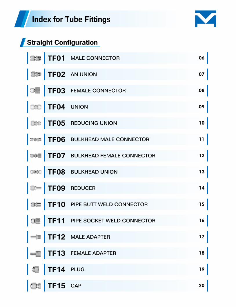
Straight Configuration
TF01
TF02
TF03
TF04
TF05
TF06
TF07
TF08
TF09
TF10
TF11
TF12
TF13
TF14
TF15
MALE CONNECTOR
AN UNION
FEMALE CONNECTOR
UNION
REDUCING UNION
BULKHEAD MALE CONNECTOR
BULKHEAD FEMALE CONNECTOR
BULKHEAD UNION
REDUCER
PIPE BUTT WELD CONNECTOR
PIPE SOCKET WELD CONNECTOR
MALE ADAPTER
FEMALE ADAPTER
PLUG
CAP
06
07
08
09
10
11
12
13
14
15
16
17
18
19
20
Index for Tube Fittings
T
LG
T T1
T
T
H
B
C
T
D
E
A
GF
H
C
T E
D
A
FG
H
E
H
T
D
A
FG
JH
E
H
T
B
A
K
D C
A
FG
J
E
H
T
D
A
K
B
I
FG
H
ET
A
K
D B
A
FG
J
E
H
T
D
A
K
B
FG
T
J
D
A
A
A
K
FG
E
T
A
K
H
H
J
D
E
A
FG
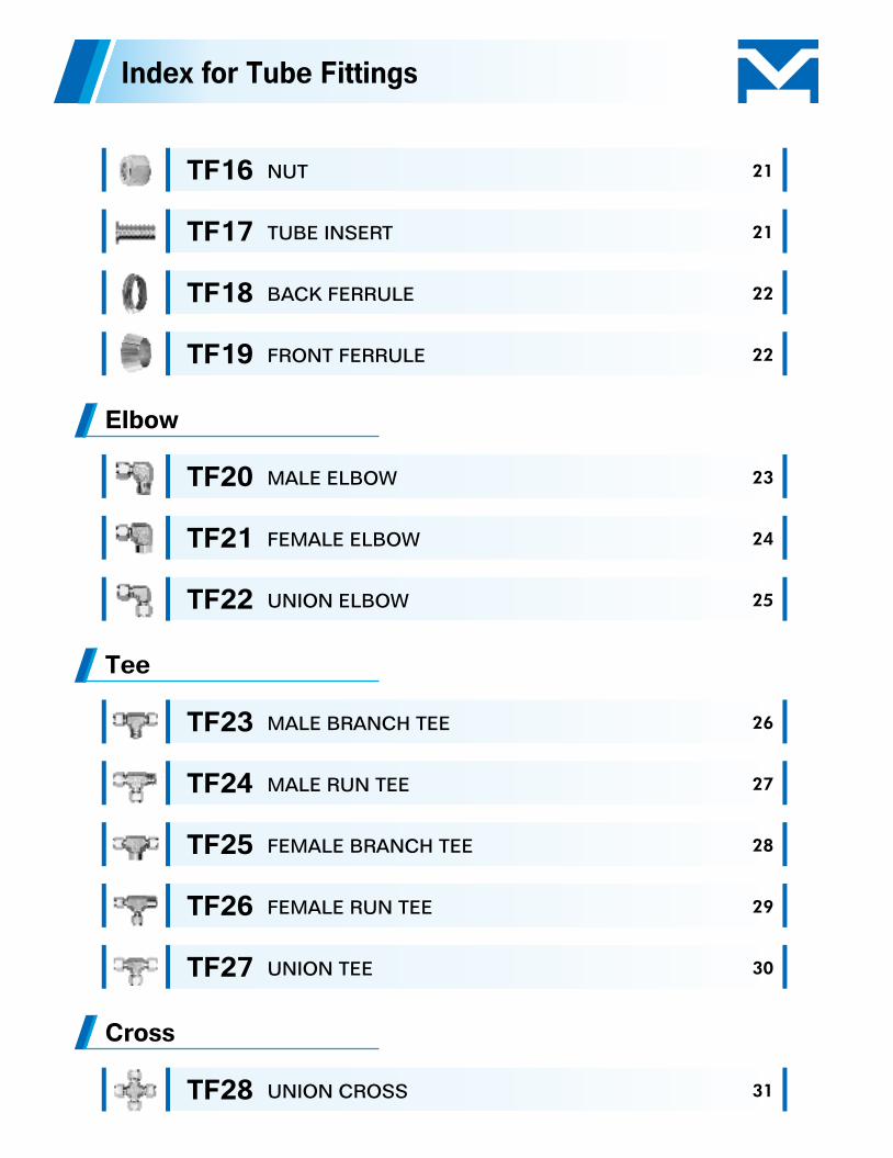
Elbow
Tee
Cross
TF16
TF17
TF18
TF19
TF20
TF21
TF22
TF23
TF24
TF25
TF26
TF27
TF28
NUT
TUBE INSERT
BACK FERRULE
FRONT FERRULE
MALE ELBOW
FEMALE ELBOW
UNION ELBOW
MALE BRANCH TEE
MALE RUN TEE
FEMALE BRANCH TEE
FEMALE RUN TEE
UNION TEE
UNION CROSS
Index for Tube Fittings
21
21
22
22
23
24
25
26
27
28
29
30
31
E
AFP
A
E
FPP1
AF
P
AF
PP1
A
E
F
P1
P
A
EP1
PF
AF
P
E
S
F
P
S
L
L
E
F
P
E
L
S
F
P
P
L
S
E
F
P1
P
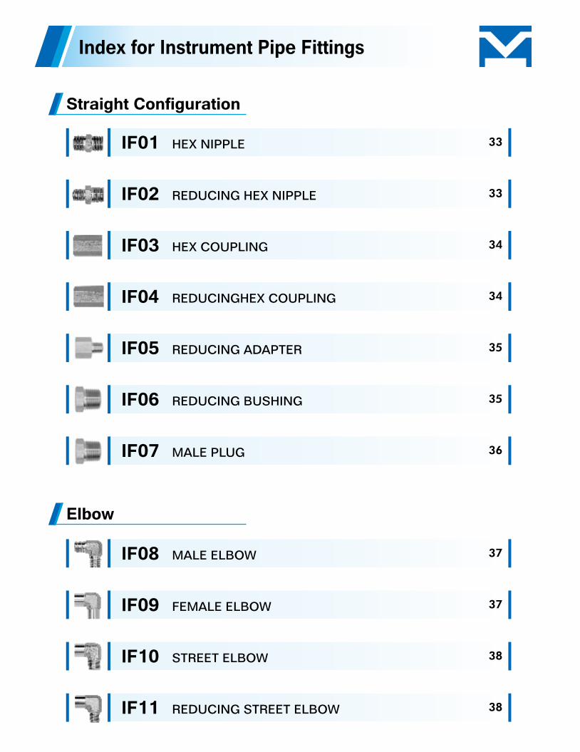
Index for Instrument Pipe Fittings
Straight Configuration
Elbow
IF01
IF02
IF03
IF04
IF05
IF06
IF07
IF08
IF09
IF10
IF11
HEX NIPPLE
REDUCING HEX NIPPLE
HEX COUPLING
REDUCINGHEX COUPLING
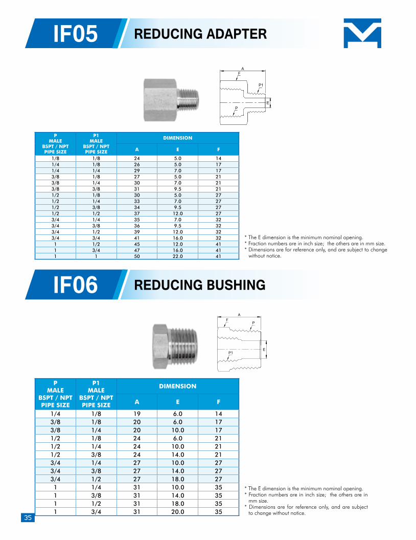
REDUCING ADAPTER
REDUCING BUSHING
MALE PLUG
MALE ELBOW
FEMALE ELBOW
STREET ELBOW
REDUCING STREET ELBOW
33
33
34
34
35
35
36
37
37
38
38
S S
S
E
A
F
P
L L
A
E
F
P
L L
S
A
E
F
P
P
L S
A
E
F
P
P
Tee
Index for Instrument Pipe Fittings
IF12
IF13
IF14
IF15
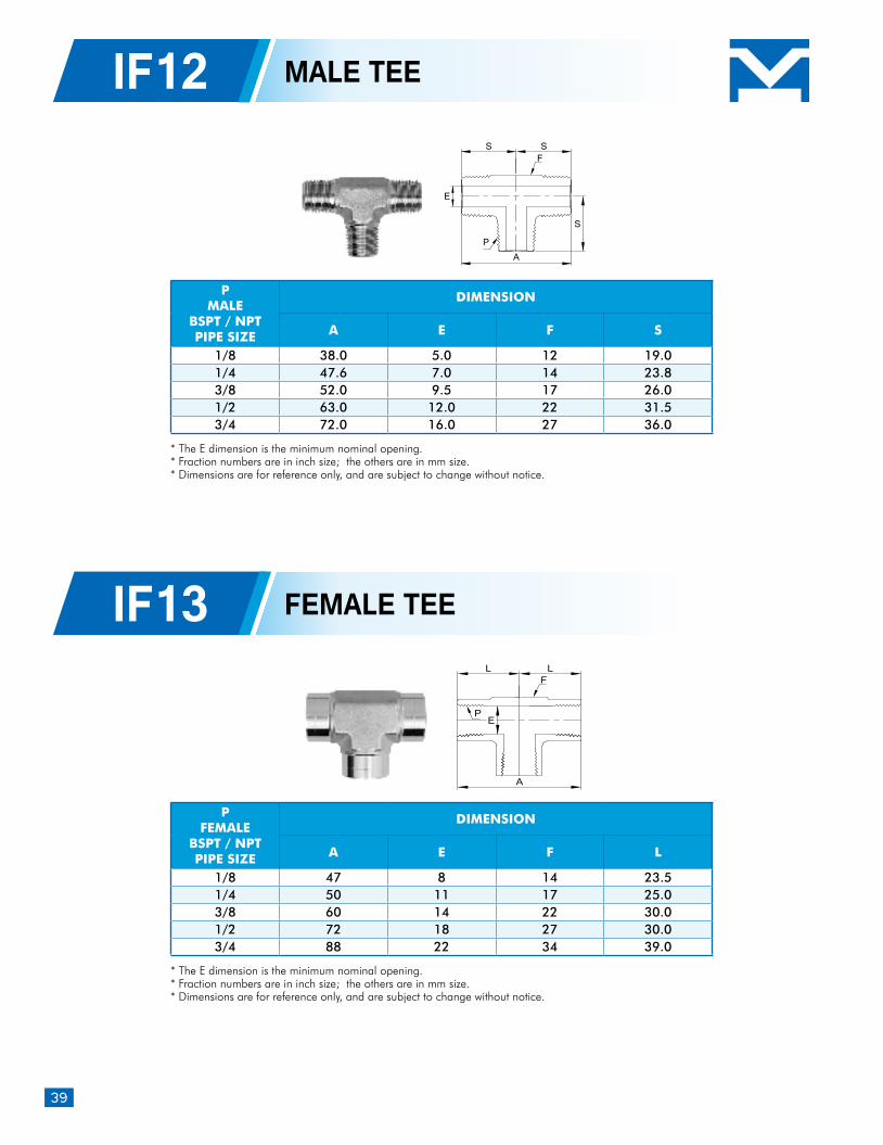
MALE TEE
FEMALE TEE
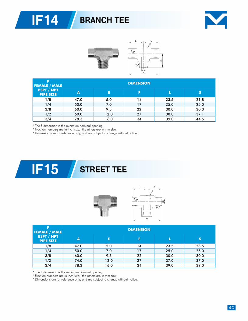
BRANCH TEE
STREET TEE
39
39
40
40
3-piece Instrument Ball Valves
Instrument Needle Valves
Inline Ball Poppet Check Valves
Stainless Steel Tubing
Stainless Steel Tubing
H-3BV
H-3BVT
H-NV/H-NVL
H-NV
H-NVL
H-NVS
H-CV
2-Way Pattern: 2000 psig / 725 psig
3-Way Pattern: 2000 psig
Integral Bonnet Instrument Needle Valves
Straight Pattern
Angle Pattern
Union Bonnet Instrument Needle Valves
Inline Ball Poppet Check Valves
43
44
45
47
48
49
52
54
Index for Valves
01
Compression Tube Fittings
IntroductionHAITIMA Tube Fittings are designed to provide a reliable leak-tight connection and suitable for petrochemical, chemical processing, oil refineries, laboratory, power generation, electronic, semiconductor, shipbuilding, as well as other major industries. With precision machined and strict quality control, HAITIMA Tube Fittings achieve torque-free installation and leak-free performance.
Selecting and handling the tubing properly is necessary to achieve reliable tubing system. The following 4 factors should be considered when you order the tubing for HAITIMA tube fittings.
Features Two-ferrule design Silver-plated nut threads eliminate the attrition of body threads. A variety of configurations increase system versatility Each body is stamped with size and material Easy to assembly and no speical tools required Designed for use on instrumentation, process and control systems, and analyzer
Tubing Selection and Handling
Wall thickness: Please refer to "tubing working pressure table" for suitable wall thicknss.For gas service, do not use thin wall tubing.
Hardness: Metal tubing material must be softer than the fitting material. When tubing and fittings are made of the same material, tubing must be fully annealed.In general, it is recommended to a fully annealed 304 or 316 stainless steel tubing meeting ASTM A269 , A213 , A249 or equivalent with hardness HRB 90 or less.Always use an insert in extremely soft or flexible plastic tubing.
Surface: Tubing with any depression, scratch, raised portion, or other surface defect will be difficult to seal, especially in gas service.Oval tubing which is not easily fit through fitting nuts, ferrults, and bodies should never be forced into the fitting
Handling: During transportation and storage, cap the tubing end to prevent from dirt.Do not haul tubing since it will cause surface damage on tubing.Deburr the tube ends before installation.
02
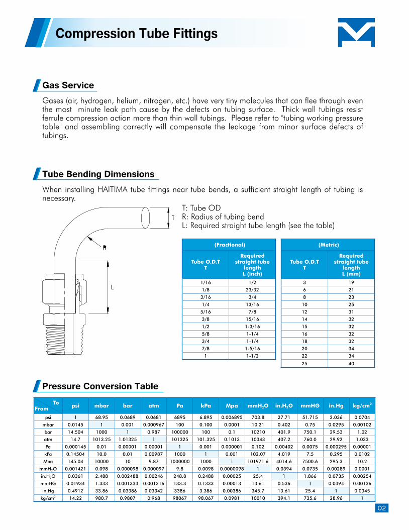
Compression Tube Fittings
Tube Bending Dimensions
Pressure Conversion Table
When installing HAITIMA tube fittings near tube bends, a sufficient straight length of tubing is necessary.
T: Tube ODR: Radius of tubing bendL: Required straight tube length (see the table)
(Fractional)
Tube O.D.TT
Required straight tube
lengthL (inch)
1/16 1/2
1/8 23/32
3/16 3/4
1/4 13/16
5/16 7/8
3/8 15/16
1/2 1-3/16
5/8 1-1/4
3/4 1-1/4
7/8 1-5/16
1 1-1/2
(Metric)
Tube O.D.TT
Required straight tube
lengthL (mm)
3 19
6 21
8 23
10 25
12 31
14 32
15 32
16 32
18 32
20 34
22 34
25 40
Gas ServiceGases (air, hydrogen, helium, nitrogen, etc.) have very tiny molecules that can flee through even the most minute leak path cause by the defects on tubing surface. Thick wall tubings resist ferrule compression action more than thin wall tubings. Please refer to "tubing working pressure table" and assembling correctly will compensate the leakage from minor surface defects of tubings.
ToFrom psi mbar bar atm Pa kPa Mpa mmH2O in.H2O mmHG in.Hg kg/cm2
psi 1 68.95 0.0689 0.0681 6895 6.895 0.006895 703.8 27.71 51.715 2.036 0.0704
mbar 0.0145 1 0.001 0.000967 100 0.100 0.0001 10.21 0.402 0.75 0.0295 0.00102
bar 14.504 1000 1 0.987 100000 100 0.1 10210 401.9 750.1 29.53 1.02
atm 14.7 1013.25 1.01325 1 101325 101.325 0.1013 10343 407.2 760.0 29.92 1.033
Pa 0.000145 0.01 0.00001 0.00001 1 0.001 0.000001 0.102 0.00402 0.0075 0.000295 0.00001
kPa 0.14504 10.0 0.01 0.00987 1000 1 0.001 102.07 4.019 7.5 0.295 0.0102
Mpa 145.04 10000 10 9.87 1000000 1000 1 101971.6 4014.6 7500.6 295.3 10.2
mmH2O 0.001421 0.098 0.000098 0.000097 9.8 0.0098 0.0000098 1 0.0394 0.0735 0.00289 0.0001
in.H2O 0.0361 2.488 0.002488 0.00246 248.8 0.2488 0.00025 25.4 1 1.866 0.0735 0.00254
mmHG 0.01934 1.333 0.001333 0.001316 133.3 0.1333 0.00013 13.61 0.536 1 0.0394 0.00136
in.Hg 0.4912 33.86 0.03386 0.03342 3386 3.386 0.00386 345.7 13.61 25.4 1 0.0345
kg/cm2 14.22 980.7 0.9807 0.968 98067 98.067 0.0981 10010 394.1 735.6 28.96 1
03
Compression Tube Fittings
Safety in Product Selection
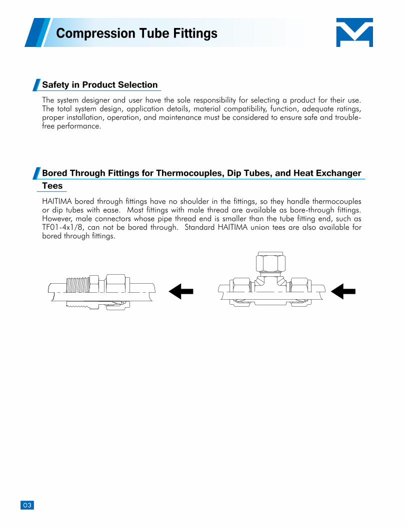
Bored Through Fittings for Thermocouples, Dip Tubes, and Heat Exchanger Tees
The system designer and user have the sole responsibility for selecting a product for their use. The total system design, application details, material compatibility, function, adequate ratings, proper installation, operation, and maintenance must be considered to ensure safe and trouble-free performance.
HAITIMA bored through fittings have no shoulder in the fittings, so they handle thermocouples or dip tubes with ease. Most fittings with male thread are available as bore-through fittings. However, male connectors whose pipe thread end is smaller than the tube fitting end, such as TF01-4x1/8, can not be bored through. Standard HAITIMA union tees are also available for bored through fittings.
04
Compression Tube Fittings
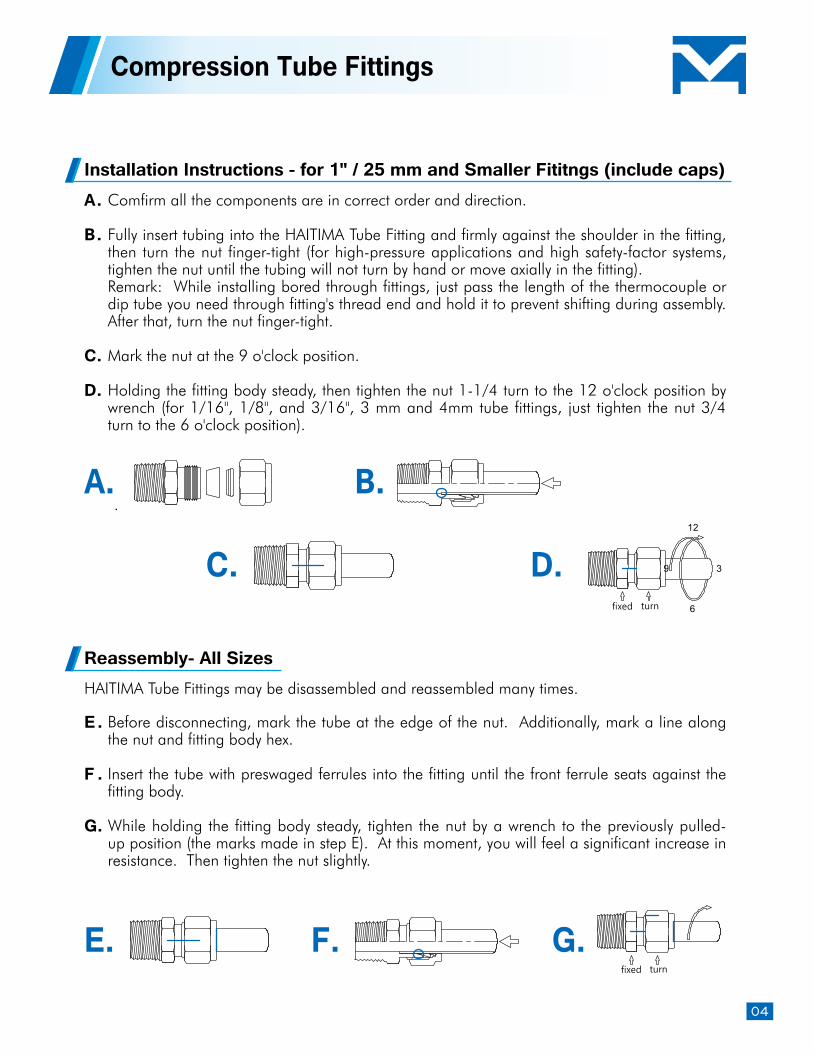
Installation Instructions - for 1" / 25 mm and Smaller Fititngs (include caps)
Reassembly- All Sizes
Comfirm all the components are in correct order and direction.
Fully insert tubing into the HAITIMA Tube Fitting and firmly against the shoulder in the fitting, then turn the nut finger-tight (for high-pressure applications and high safety-factor systems, tighten the nut until the tubing will not turn by hand or move axially in the fitting). Remark: While installing bored through fittings, just pass the length of the thermocouple or dip tube you need through fitting's thread end and hold it to prevent shifting during assembly. After that, turn the nut finger-tight. Mark the nut at the 9 o'clock position.
Holding the fitting body steady, then tighten the nut 1-1/4 turn to the 12 o'clock position by wrench (for 1/16", 1/8", and 3/16", 3 mm and 4mm tube fittings, just tighten the nut 3/4 turn to the 6 o'clock position).
Before disconnecting, mark the tube at the edge of the nut. Additionally, mark a line along the nut and fitting body hex. Insert the tube with preswaged ferrules into the fitting until the front ferrule seats against the fitting body.
While holding the fitting body steady, tighten the nut by a wrench to the previously pulled-up position (the marks made in step E). At this moment, you will feel a significant increase in resistance. Then tighten the nut slightly.
HAITIMA Tube Fittings may be disassembled and reassembled many times.
A.
B.
C.
D.
E.
F .
G.
C. D.
B.A.
E. F. G.
05
Install PlugsHold fitting body steady, then tighten the plug 1/4 turn from the finger-tight position with wrench (for 1/16", 1/8", and 3/16", 3 mm and 4 mm fittings, tighten the plug 1/8 turn).
You can disassemble and reassemble HAITIMA plugs many times. Just make slightly tightening by a wrench after fastening the plug by hand.
Reassembly Plugs
Do not bleed system by releasing nut or plug. Do not mix materials or fitting parts from various manufacturers, including tubing, ferrules, nuts, and fitting bodies.
Do not assemble, tighten, or disamble fittings when system is pressurized. Before fastening the nut, make sure the tubing rests firmly on the shoulder in the tube fitting body
Never turn fitting body during assembly and disassembly. Instead, hold fitting body and turn nut.
Always use proper thread sealants on threads. Avoid unnecessary disassembly of unused fitting.
Safety Precautions
Compression Tube Fittings
06
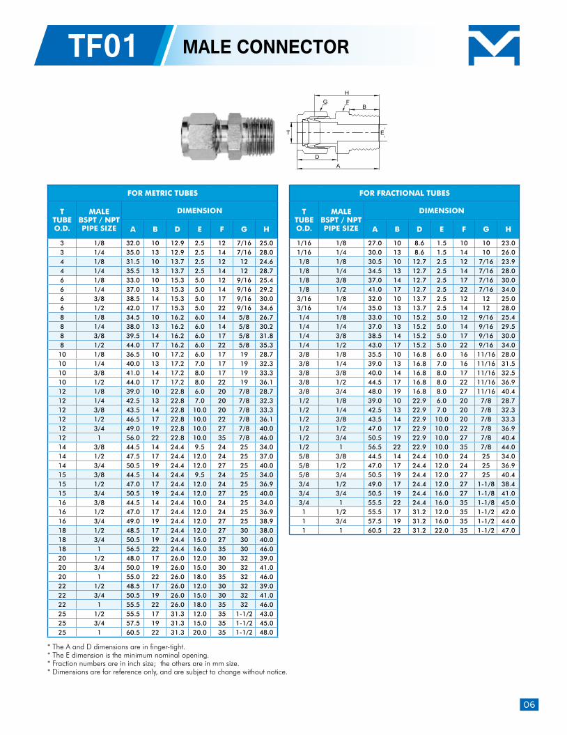
TF01 MALE CONNECTOR
* The A and D dimensions are in finger-tight.* The E dimension is the minimum nominal opening.* Fraction numbers are in inch size; the others are in mm size. * Dimensions are for reference only, and are subject to change without notice.
FOR METRIC TUBES
TTUBEO.D.
MALEBSPT / NPTPIPE SIZE
DIMENSION
A B D E F G H
3 1/8 32.0 10 12.9 2.5 12 7/16 25.0 3 1/4 35.0 13 12.9 2.5 14 7/16 28.0 4 1/8 31.5 10 13.7 2.5 12 12 24.6 4 1/4 35.5 13 13.7 2.5 14 12 28.7 6 1/8 33.0 10 15.3 5.0 12 9/16 25.4 6 1/4 37.0 13 15.3 5.0 14 9/16 29.2 6 3/8 38.5 14 15.3 5.0 17 9/16 30.0 6 1/2 42.0 17 15.3 5.0 22 9/16 34.6 8 1/8 34.5 10 16.2 6.0 14 5/8 26.7 8 1/4 38.0 13 16.2 6.0 14 5/8 30.2 8 3/8 39.5 14 16.2 6.0 17 5/8 31.8 8 1/2 44.0 17 16.2 6.0 22 5/8 35.3
10 1/8 36.5 10 17.2 6.0 17 19 28.7 10 1/4 40.0 13 17.2 7.0 17 19 32.3 10 3/8 41.0 14 17.2 8.0 17 19 33.3 10 1/2 44.0 17 17.2 8.0 22 19 36.1 12 1/8 39.0 10 22.8 6.0 20 7/8 28.7 12 1/4 42.5 13 22.8 7.0 20 7/8 32.3 12 3/8 43.5 14 22.8 10.0 20 7/8 33.3 12 1/2 46.5 17 22.8 10.0 22 7/8 36.1 12 3/4 49.0 19 22.8 10.0 27 7/8 40.0 12 1 56.0 22 22.8 10.0 35 7/8 46.0 14 3/8 44.5 14 24.4 9.5 24 25 34.0 14 1/2 47.5 17 24.4 12.0 24 25 37.0 14 3/4 50.5 19 24.4 12.0 27 25 40.0 15 3/8 44.5 14 24.4 9.5 24 25 34.0 15 1/2 47.0 17 24.4 12.0 24 25 36.9 15 3/4 50.5 19 24.4 12.0 27 25 40.0 16 3/8 44.5 14 24.4 10.0 24 25 34.0 16 1/2 47.0 17 24.4 12.0 24 25 36.9 16 3/4 49.0 19 24.4 12.0 27 25 38.9 18 1/2 48.5 17 24.4 12.0 27 30 38.0 18 3/4 50.5 19 24.4 15.0 27 30 40.0 18 1 56.5 22 24.4 16.0 35 30 46.0 20 1/2 48.0 17 26.0 12.0 30 32 39.0 20 3/4 50.0 19 26.0 15.0 30 32 41.0 20 1 55.0 22 26.0 18.0 35 32 46.0 22 1/2 48.5 17 26.0 12.0 30 32 39.0 22 3/4 50.5 19 26.0 15.0 30 32 41.0 22 1 55.5 22 26.0 18.0 35 32 46.0 25 1/2 55.5 17 31.3 12.0 35 1-1/2 43.0 25 3/4 57.5 19 31.3 15.0 35 1-1/2 45.0 25 1 60.5 22 31.3 20.0 35 1-1/2 48.0
FOR FRACTIONAL TUBES
TTUBEO.D.
MALEBSPT / NPTPIPE SIZE
DIMENSION
A B D E F G H
1/16 1/8 27.0 10 8.6 1.5 10 10 23.0 1/16 1/4 30.0 13 8.6 1.5 14 10 26.0 1/8 1/8 30.5 10 12.7 2.5 12 7/16 23.9 1/8 1/4 34.5 13 12.7 2.5 14 7/16 28.0 1/8 3/8 37.0 14 12.7 2.5 17 7/16 30.0 1/8 1/2 41.0 17 12.7 2.5 22 7/16 34.0
3/16 1/8 32.0 10 13.7 2.5 12 12 25.0 3/16 1/4 35.0 13 13.7 2.5 14 12 28.0 1/4 1/8 33.0 10 15.2 5.0 12 9/16 25.4 1/4 1/4 37.0 13 15.2 5.0 14 9/16 29.5 1/4 3/8 38.5 14 15.2 5.0 17 9/16 30.0 1/4 1/2 43.0 17 15.2 5.0 22 9/16 34.0 3/8 1/8 35.5 10 16.8 6.0 16 11/16 28.0 3/8 1/4 39.0 13 16.8 7.0 16 11/16 31.5 3/8 3/8 40.0 14 16.8 8.0 17 11/16 32.5 3/8 1/2 44.5 17 16.8 8.0 22 11/16 36.9 3/8 3/4 48.0 19 16.8 8.0 27 11/16 40.4 1/2 1/8 39.0 10 22.9 6.0 20 7/8 28.7 1/2 1/4 42.5 13 22.9 7.0 20 7/8 32.3 1/2 3/8 43.5 14 22.9 10.0 20 7/8 33.3 1/2 1/2 47.0 17 22.9 10.0 22 7/8 36.9 1/2 3/4 50.5 19 22.9 10.0 27 7/8 40.4 1/2 1 56.5 22 22.9 10.0 35 7/8 44.0 5/8 3/8 44.5 14 24.4 10.0 24 25 34.0 5/8 1/2 47.0 17 24.4 12.0 24 25 36.9 5/8 3/4 50.5 19 24.4 12.0 27 25 40.4 3/4 1/2 49.0 17 24.4 12.0 27 1-1/8 38.4 3/4 3/4 50.5 19 24.4 16.0 27 1-1/8 41.0 3/4 1 55.5 22 24.4 16.0 35 1-1/8 45.0 1 1/2 55.5 17 31.2 12.0 35 1-1/2 42.0 1 3/4 57.5 19 31.2 16.0 35 1-1/2 44.0 1 1 60.5 22 31.2 22.0 35 1-1/2 47.0
07
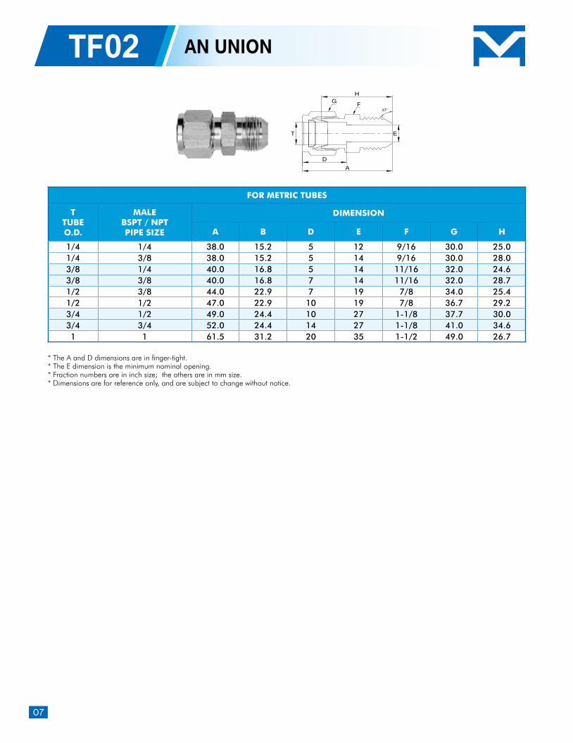
TF02 AN UNION
* The A and D dimensions are in finger-tight.* The E dimension is the minimum nominal opening.* Fraction numbers are in inch size; the others are in mm size. * Dimensions are for reference only, and are subject to change without notice.
FOR METRIC TUBES
TTUBEO.D.
MALEBSPT / NPTPIPE SIZE
DIMENSION
A B D E F G H
1/4 1/4 38.0 15.2 5 12 9/16 30.0 25.0 1/4 3/8 38.0 15.2 5 14 9/16 30.0 28.0 3/8 1/4 40.0 16.8 5 14 11/16 32.0 24.6 3/8 3/8 40.0 16.8 7 14 11/16 32.0 28.7 1/2 3/8 44.0 22.9 7 19 7/8 34.0 25.4 1/2 1/2 47.0 22.9 10 19 7/8 36.7 29.2 3/4 1/2 49.0 24.4 10 27 1-1/8 37.7 30.0 3/4 3/4 52.0 24.4 14 27 1-1/8 41.0 34.6 1 1 61.5 31.2 20 35 1-1/2 49.0 26.7
08
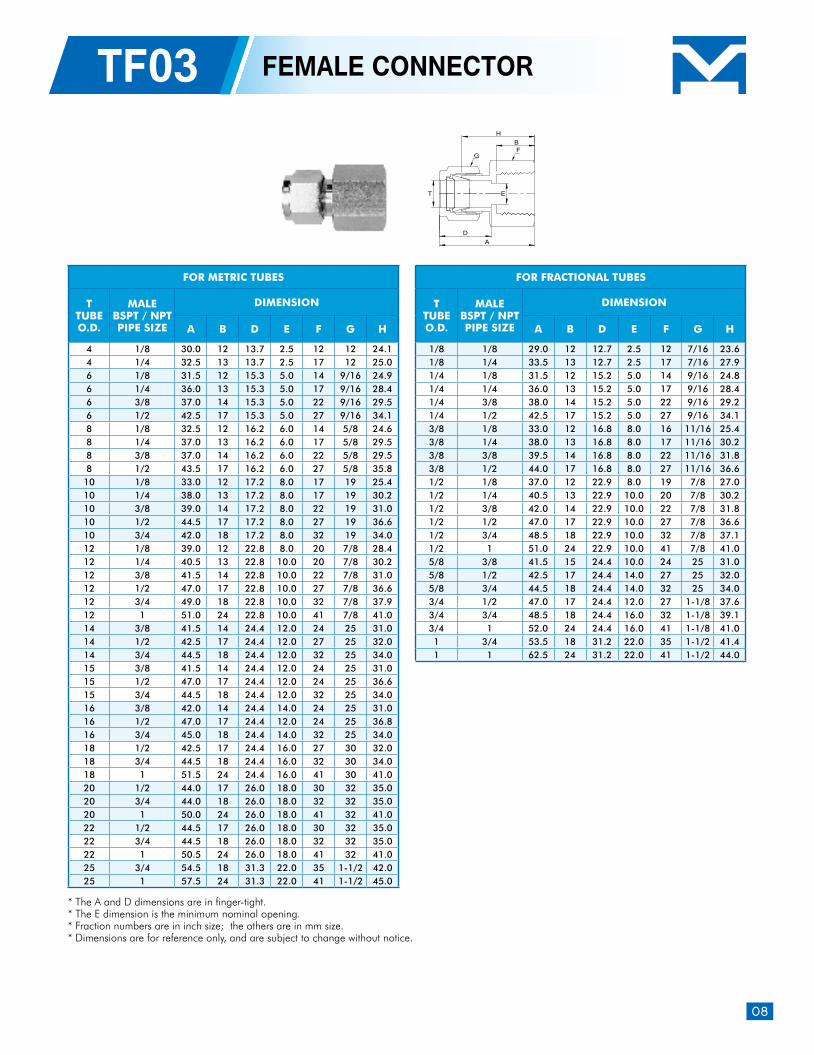
TF03 FEMALE CONNECTOR
* The A and D dimensions are in finger-tight.* The E dimension is the minimum nominal opening.* Fraction numbers are in inch size; the others are in mm size. * Dimensions are for reference only, and are subject to change without notice.
FOR METRIC TUBES
TTUBEO.D.
MALEBSPT / NPTPIPE SIZE
DIMENSION
A B D E F G H
4 1/8 30.0 12 13.7 2.5 12 12 24.1 4 1/4 32.5 13 13.7 2.5 17 12 25.0 6 1/8 31.5 12 15.3 5.0 14 9/16 24.9 6 1/4 36.0 13 15.3 5.0 17 9/16 28.4 6 3/8 37.0 14 15.3 5.0 22 9/16 29.5 6 1/2 42.5 17 15.3 5.0 27 9/16 34.1 8 1/8 32.5 12 16.2 6.0 14 5/8 24.6 8 1/4 37.0 13 16.2 6.0 17 5/8 29.5 8 3/8 37.0 14 16.2 6.0 22 5/8 29.5 8 1/2 43.5 17 16.2 6.0 27 5/8 35.8
10 1/8 33.0 12 17.2 8.0 17 19 25.4 10 1/4 38.0 13 17.2 8.0 17 19 30.2 10 3/8 39.0 14 17.2 8.0 22 19 31.0 10 1/2 44.5 17 17.2 8.0 27 19 36.6 10 3/4 42.0 18 17.2 8.0 32 19 34.0 12 1/8 39.0 12 22.8 8.0 20 7/8 28.4 12 1/4 40.5 13 22.8 10.0 20 7/8 30.2 12 3/8 41.5 14 22.8 10.0 22 7/8 31.0 12 1/2 47.0 17 22.8 10.0 27 7/8 36.6 12 3/4 49.0 18 22.8 10.0 32 7/8 37.9 12 1 51.0 24 22.8 10.0 41 7/8 41.0 14 3/8 41.5 14 24.4 12.0 24 25 31.0 14 1/2 42.5 17 24.4 12.0 27 25 32.0 14 3/4 44.5 18 24.4 12.0 32 25 34.0 15 3/8 41.5 14 24.4 12.0 24 25 31.0 15 1/2 47.0 17 24.4 12.0 24 25 36.6 15 3/4 44.5 18 24.4 12.0 32 25 34.0 16 3/8 42.0 14 24.4 14.0 24 25 31.0 16 1/2 47.0 17 24.4 12.0 24 25 36.8 16 3/4 45.0 18 24.4 14.0 32 25 34.0 18 1/2 42.5 17 24.4 16.0 27 30 32.0 18 3/4 44.5 18 24.4 16.0 32 30 34.0 18 1 51.5 24 24.4 16.0 41 30 41.0 20 1/2 44.0 17 26.0 18.0 30 32 35.0 20 3/4 44.0 18 26.0 18.0 32 32 35.0 20 1 50.0 24 26.0 18.0 41 32 41.0 22 1/2 44.5 17 26.0 18.0 30 32 35.0 22 3/4 44.5 18 26.0 18.0 32 32 35.0 22 1 50.5 24 26.0 18.0 41 32 41.0 25 3/4 54.5 18 31.3 22.0 35 1-1/2 42.0 25 1 57.5 24 31.3 22.0 41 1-1/2 45.0
FOR FRACTIONAL TUBES
TTUBEO.D.
MALEBSPT / NPTPIPE SIZE
DIMENSION
A B D E F G H
1/8 1/8 29.0 12 12.7 2.5 12 7/16 23.6 1/8 1/4 33.5 13 12.7 2.5 17 7/16 27.9 1/4 1/8 31.5 12 15.2 5.0 14 9/16 24.8 1/4 1/4 36.0 13 15.2 5.0 17 9/16 28.4 1/4 3/8 38.0 14 15.2 5.0 22 9/16 29.2 1/4 1/2 42.5 17 15.2 5.0 27 9/16 34.1 3/8 1/8 33.0 12 16.8 8.0 16 11/16 25.4 3/8 1/4 38.0 13 16.8 8.0 17 11/16 30.2 3/8 3/8 39.5 14 16.8 8.0 22 11/16 31.8 3/8 1/2 44.0 17 16.8 8.0 27 11/16 36.6 1/2 1/8 37.0 12 22.9 8.0 19 7/8 27.0 1/2 1/4 40.5 13 22.9 10.0 20 7/8 30.2 1/2 3/8 42.0 14 22.9 10.0 22 7/8 31.8 1/2 1/2 47.0 17 22.9 10.0 27 7/8 36.6 1/2 3/4 48.5 18 22.9 10.0 32 7/8 37.1 1/2 1 51.0 24 22.9 10.0 41 7/8 41.0 5/8 3/8 41.5 15 24.4 10.0 24 25 31.0 5/8 1/2 42.5 17 24.4 14.0 27 25 32.0 5/8 3/4 44.5 18 24.4 14.0 32 25 34.0 3/4 1/2 47.0 17 24.4 12.0 27 1-1/8 37.6 3/4 3/4 48.5 18 24.4 16.0 32 1-1/8 39.1 3/4 1 52.0 24 24.4 16.0 41 1-1/8 41.0 1 3/4 53.5 18 31.2 22.0 35 1-1/2 41.4 1 1 62.5 24 31.2 22.0 41 1-1/2 44.0
T E
BH
DA
FG
09
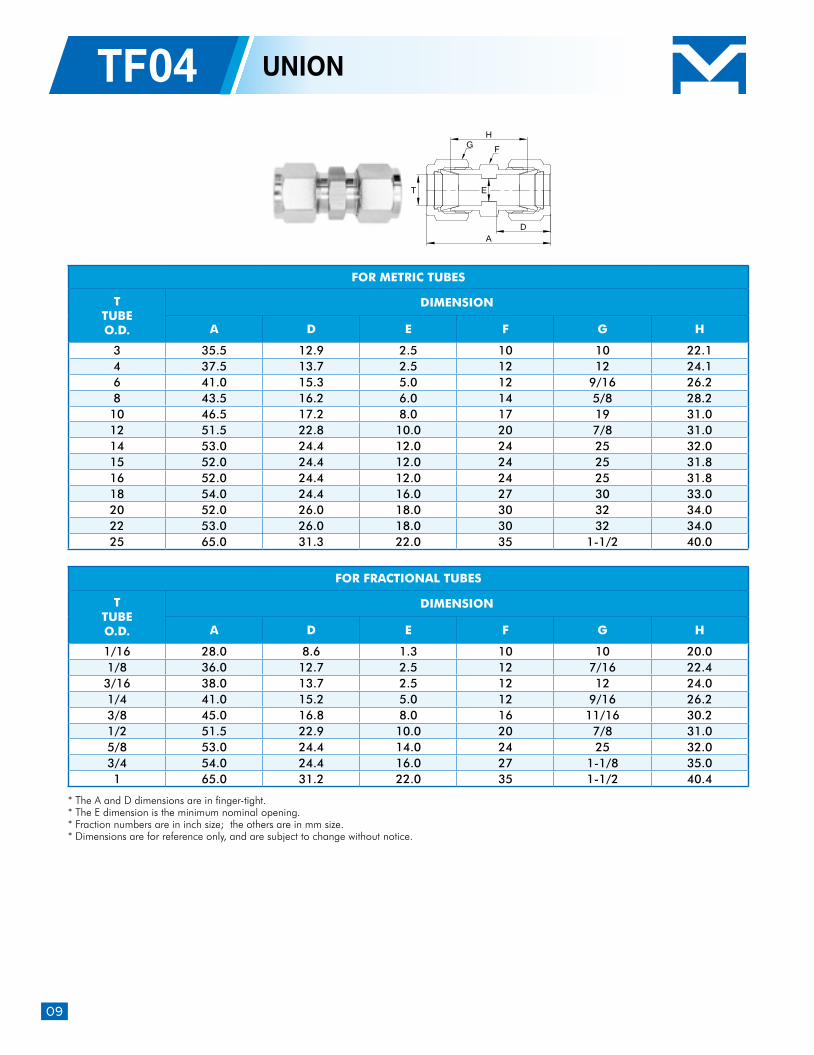
TF04 UNION
H
ET
DA
G F
* The A and D dimensions are in finger-tight.* The E dimension is the minimum nominal opening.* Fraction numbers are in inch size; the others are in mm size. * Dimensions are for reference only, and are subject to change without notice.
FOR METRIC TUBES
TTUBEO.D.
DIMENSION
A D E F G H
3 35.5 12.9 2.5 10 10 22.1 4 37.5 13.7 2.5 12 12 24.1 6 41.0 15.3 5.0 12 9/16 26.2 8 43.5 16.2 6.0 14 5/8 28.2
10 46.5 17.2 8.0 17 19 31.0 12 51.5 22.8 10.0 20 7/8 31.0 14 53.0 24.4 12.0 24 25 32.0 15 52.0 24.4 12.0 24 25 31.8 16 52.0 24.4 12.0 24 25 31.8 18 54.0 24.4 16.0 27 30 33.0 20 52.0 26.0 18.0 30 32 34.0 22 53.0 26.0 18.0 30 32 34.0 25 65.0 31.3 22.0 35 1-1/2 40.0
FOR FRACTIONAL TUBES
TTUBEO.D.
DIMENSION
A D E F G H
1/16 28.0 8.6 1.3 10 10 20.0 1/8 36.0 12.7 2.5 12 7/16 22.4 3/16 38.0 13.7 2.5 12 12 24.0 1/4 41.0 15.2 5.0 12 9/16 26.2 3/8 45.0 16.8 8.0 16 11/16 30.2 1/2 51.5 22.9 10.0 20 7/8 31.0 5/8 53.0 24.4 14.0 24 25 32.0 3/4 54.0 24.4 16.0 27 1-1/8 35.0 1 65.0 31.2 22.0 35 1-1/2 40.4
10
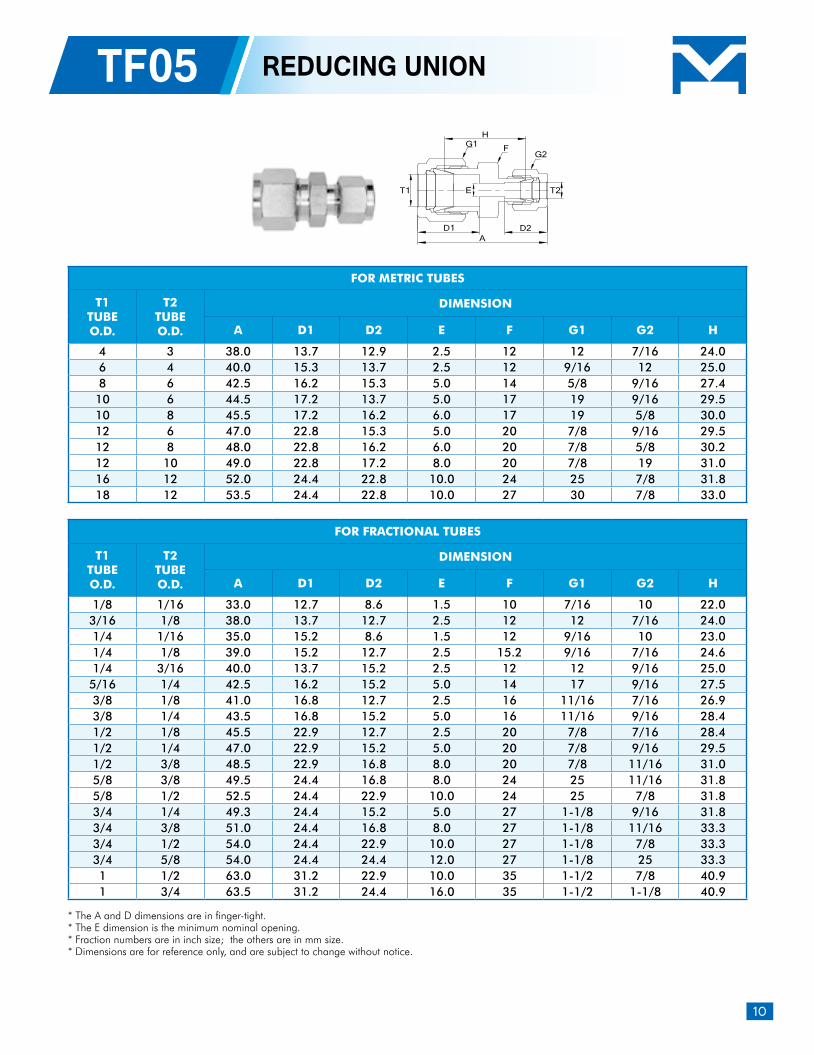
TF05 REDUCING UNION
* The A and D dimensions are in finger-tight.* The E dimension is the minimum nominal opening.* Fraction numbers are in inch size; the others are in mm size. * Dimensions are for reference only, and are subject to change without notice.
T1 T2E
A
H
D2D1
FG1G2
FOR METRIC TUBES
T1TUBEO.D.
T2TUBEO.D.
DIMENSION
A D1 D2 E F G1 G2 H
4 3 38.0 13.7 12.9 2.5 12 12 7/16 24.0 6 4 40.0 15.3 13.7 2.5 12 9/16 12 25.0 8 6 42.5 16.2 15.3 5.0 14 5/8 9/16 27.4 10 6 44.5 17.2 13.7 5.0 17 19 9/16 29.5 10 8 45.5 17.2 16.2 6.0 17 19 5/8 30.0 12 6 47.0 22.8 15.3 5.0 20 7/8 9/16 29.5 12 8 48.0 22.8 16.2 6.0 20 7/8 5/8 30.2 12 10 49.0 22.8 17.2 8.0 20 7/8 19 31.0 16 12 52.0 24.4 22.8 10.0 24 25 7/8 31.8 18 12 53.5 24.4 22.8 10.0 27 30 7/8 33.0
FOR FRACTIONAL TUBES
T1TUBEO.D.
T2TUBEO.D.
DIMENSION
A D1 D2 E F G1 G2 H
1/8 1/16 33.0 12.7 8.6 1.5 10 7/16 10 22.0 3/16 1/8 38.0 13.7 12.7 2.5 12 12 7/16 24.0 1/4 1/16 35.0 15.2 8.6 1.5 12 9/16 10 23.0 1/4 1/8 39.0 15.2 12.7 2.5 15.2 9/16 7/16 24.6 1/4 3/16 40.0 13.7 15.2 2.5 12 12 9/16 25.0 5/16 1/4 42.5 16.2 15.2 5.0 14 17 9/16 27.5 3/8 1/8 41.0 16.8 12.7 2.5 16 11/16 7/16 26.9 3/8 1/4 43.5 16.8 15.2 5.0 16 11/16 9/16 28.4 1/2 1/8 45.5 22.9 12.7 2.5 20 7/8 7/16 28.4 1/2 1/4 47.0 22.9 15.2 5.0 20 7/8 9/16 29.5 1/2 3/8 48.5 22.9 16.8 8.0 20 7/8 11/16 31.0 5/8 3/8 49.5 24.4 16.8 8.0 24 25 11/16 31.8 5/8 1/2 52.5 24.4 22.9 10.0 24 25 7/8 31.8 3/4 1/4 49.3 24.4 15.2 5.0 27 1-1/8 9/16 31.8 3/4 3/8 51.0 24.4 16.8 8.0 27 1-1/8 11/16 33.3 3/4 1/2 54.0 24.4 22.9 10.0 27 1-1/8 7/8 33.3 3/4 5/8 54.0 24.4 24.4 12.0 27 1-1/8 25 33.3 1 1/2 63.0 31.2 22.9 10.0 35 1-1/2 7/8 40.9 1 3/4 63.5 31.2 24.4 16.0 35 1-1/2 1-1/8 40.9
11
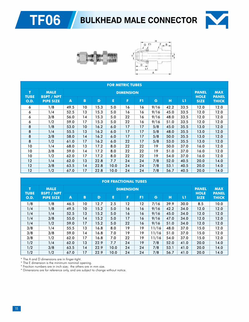
TF06 BULKHEAD MALE CONNECTOR
* The A and D dimensions are in finger-tight.* The E dimension is the minimum nominal opening.* Fraction numbers are in inch size; the others are in mm size. * Dimensions are for reference only, and are subject to change without notice.
FOR METRIC TUBES
TTUBEO.D.
MALEBSPT / NPTPIPE SIZE
DIMENSION PANELHOLESIZE
MAXPANELTHICKA B D E F F1 G H L1
6 1/8 49.5 10 15.3 5.0 16 16 9/16 42.2 33.5 12.0 12.0 6 1/4 52.5 13 15.3 5.0 16 16 9/16 45.0 33.5 12.0 12.0 6 3/8 56.0 14 15.3 5.0 22 16 9/16 48.0 33.5 12.0 12.0 6 1/2 59.0 17 15.3 5.0 22 16 9/16 51.0 33.5 12.0 12.0 8 1/8 53.0 10 16.2 6.0 17 17 5/8 45.0 35.5 13.0 12.0 8 1/4 55.5 13 16.2 6.0 17 17 5/8 48.0 35.5 13.0 12.0 8 3/8 58.0 14 16.2 6.0 17 17 5/8 50.0 35.5 13.0 12.0 8 1/2 61.0 17 16.2 6.0 22 17 5/8 53.0 35.5 13.0 12.0 10 1/4 68.0 13 17.2 8.0 22 22 19 50.0 37.0 16.0 12.0 10 3/8 59.0 14 17.2 8.0 22 22 19 51.0 37.0 16.0 12.0 10 1/2 62.0 17 17.2 8.0 22 22 19 54.0 37.0 16.0 12.0 12 1/4 62.0 13 22.8 7.7 24 24 7/8 52.0 40.5 20.0 14.0 12 3/8 63.5 14 22.8 10.0 24 24 7/8 53.1 40.5 20.0 14.0 12 1/2 67.0 17 22.8 10.0 24 24 7/8 56.7 40.5 20.0 14.0
FOR FRACTIONAL TUBES
TTUBEO.D.
MALEBSPT / NPTPIPE SIZE
DIMENSION PANELHOLESIZE
MAXPANELTHICKA B D E F F1 G H L1
1/8 1/8 46.5 10 12.7 2.5 12 12 7/16 39.9 30.0 8.5 10.0 1/4 1/8 49.5 10 15.2 5.0 16 16 9/16 42.2 34.0 12.0 12.0 1/4 1/4 52.5 13 15.2 5.0 16 16 9/16 45.0 34.0 12.0 12.0 1/4 3/8 55.0 14 15.2 5.0 17 16 9/16 47.0 34.0 12.0 12.0 1/4 1/2 59.0 17 15.2 5.0 22 16 9/16 51.0 34.0 12.0 12.0 3/8 1/4 55.5 13 16.8 8.0 19 19 11/16 48.0 37.0 15.0 12.0 3/8 3/8 59.0 14 16.8 7.0 19 19 11/16 51.0 37.0 15.0 12.0 3/8 1/2 62.0 17 16.8 7.0 22 19 11/16 54.0 37.0 15.0 12.0 1/2 1/4 62.0 13 22.9 7.7 24 19 7/8 52.0 41.0 20.0 14.0 1/2 3/8 63.5 14 22.9 10.0 24 24 7/8 53.1 41.0 20.0 14.0 1/2 1/2 67.0 17 22.9 10.0 24 24 7/8 56.7 41.0 20.0 14.0
BH
D
A
T
L1
G F1 F
E
12
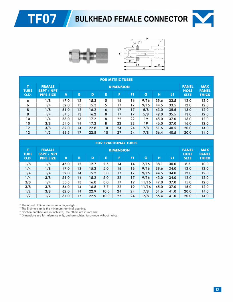
TF07 BULKHEAD FEMALE CONNECTOR
* The A and D dimensions are in finger-tight.* The E dimension is the minimum nominal opening.* Fraction numbers are in inch size; the others are in mm size. * Dimensions are for reference only, and are subject to change without notice.
FOR METRIC TUBES
TTUBEO.D.
FEMALEBSPT / NPTPIPE SIZE
DIMENSION PANELHOLESIZE
MAXPANELTHICKA B D E F F1 G H L1
6 1/8 47.0 12 15.3 5 16 16 9/16 39.6 33.5 12.0 12.0 6 1/4 52.0 13 15.3 5 17 17 9/16 44.5 33.5 12.0 12.0 8 1/8 51.0 12 16.2 6 17 17 5/8 43.0 35.5 13.0 12.0 8 1/4 54.5 13 16.2 8 17 17 5/8 49.0 35.5 13.0 12.0
10 1/4 53.0 13 17.2 8 22 22 19 45.0 37.0 16.0 12.0 10 3/8 54.0 14 17.2 8 22 22 19 46.0 37.0 16.0 12.0 12 3/8 62.0 14 22.8 10 24 24 7/8 51.6 40.5 20.0 14.0 12 1/2 66.5 17 22.8 10 27 24 7/8 56.4 40.5 20.0 14.0
FOR FRACTIONAL TUBES
TTUBEO.D.
FEMALEBSPT / NPTPIPE SIZE
DIMENSION PANELHOLESIZE
MAXPANELTHICKA B D E F F1 G H L1
1/8 1/8 45.0 12 12.7 2.5 14 14 7/16 38.1 30.0 8.5 10.0 1/4 1/8 47.0 13 15.2 5.0 16 16 9/16 39.6 34.0 12.0 12.0 1/4 1/4 52.0 14 15.2 5.0 17 17 9/16 44.5 34.0 12.0 12.0 1/4 3/8 51.0 14 15.2 5.0 22 17 9/16 43.0 34.0 12.0 12.0 3/8 1/4 55.5 13 16.8 8.0 17 19 11/16 47.8 37.0 15.0 12.0 3/8 3/8 54.0 14 16.8 7.7 22 19 11/16 45.0 37.0 15.0 12.0 1/2 3/8 62.0 14 22.9 10.0 24 24 7/8 51.6 41.0 20.0 14.0 1/2 1/2 67.0 17 22.9 10.0 27 24 7/8 56.4 41.0 20.0 14.0
T
H
E
D
ABL1
FG F1
13
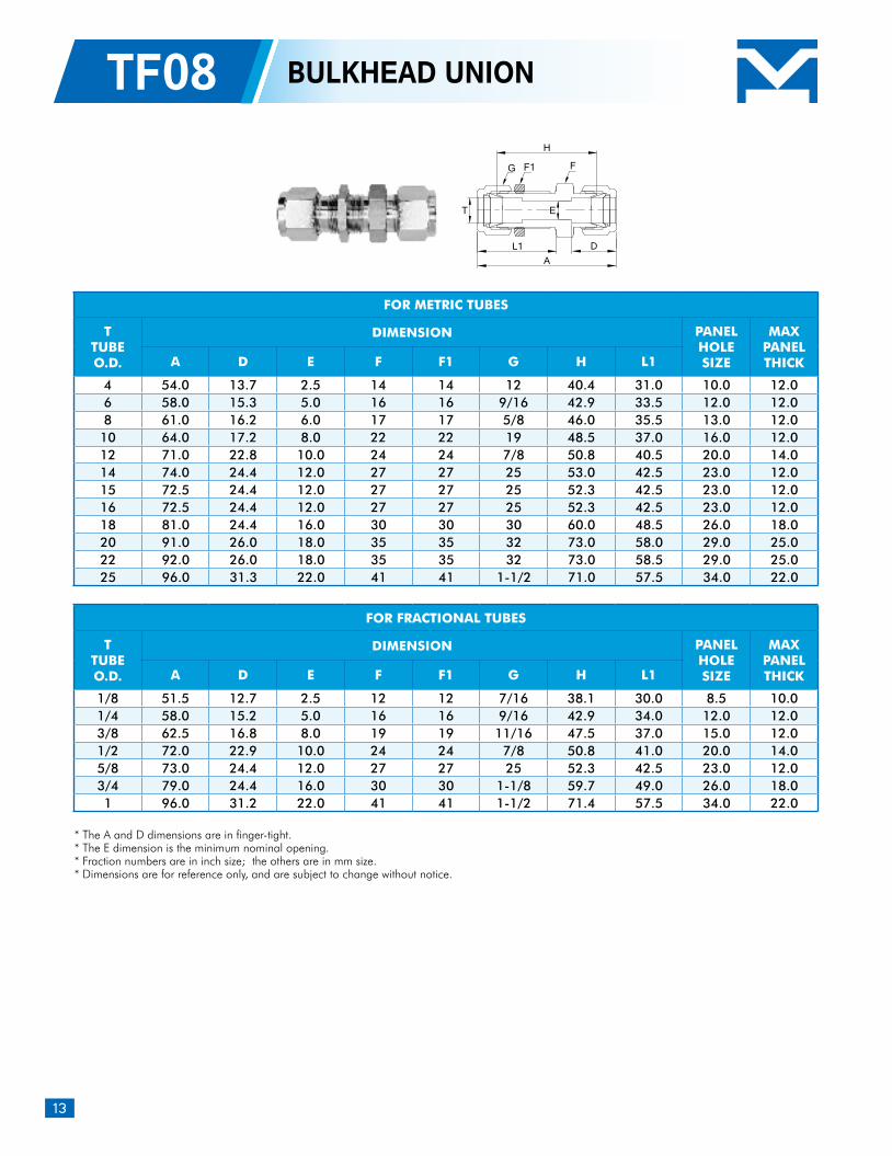
TF08 BULKHEAD UNION
* The A and D dimensions are in finger-tight.* The E dimension is the minimum nominal opening.* Fraction numbers are in inch size; the others are in mm size. * Dimensions are for reference only, and are subject to change without notice.
FOR METRIC TUBES
TTUBEO.D.
DIMENSION PANELHOLESIZE
MAXPANELTHICKA D E F F1 G H L1
4 54.0 13.7 2.5 14 14 12 40.4 31.0 10.0 12.0 6 58.0 15.3 5.0 16 16 9/16 42.9 33.5 12.0 12.0 8 61.0 16.2 6.0 17 17 5/8 46.0 35.5 13.0 12.0 10 64.0 17.2 8.0 22 22 19 48.5 37.0 16.0 12.0 12 71.0 22.8 10.0 24 24 7/8 50.8 40.5 20.0 14.0 14 74.0 24.4 12.0 27 27 25 53.0 42.5 23.0 12.0 15 72.5 24.4 12.0 27 27 25 52.3 42.5 23.0 12.0 16 72.5 24.4 12.0 27 27 25 52.3 42.5 23.0 12.0 18 81.0 24.4 16.0 30 30 30 60.0 48.5 26.0 18.0 20 91.0 26.0 18.0 35 35 32 73.0 58.0 29.0 25.0 22 92.0 26.0 18.0 35 35 32 73.0 58.5 29.0 25.0 25 96.0 31.3 22.0 41 41 1-1/2 71.0 57.5 34.0 22.0
FOR FRACTIONAL TUBES
TTUBEO.D.
DIMENSION PANELHOLESIZE
MAXPANELTHICKA D E F F1 G H L1
1/8 51.5 12.7 2.5 12 12 7/16 38.1 30.0 8.5 10.0 1/4 58.0 15.2 5.0 16 16 9/16 42.9 34.0 12.0 12.0 3/8 62.5 16.8 8.0 19 19 11/16 47.5 37.0 15.0 12.0 1/2 72.0 22.9 10.0 24 24 7/8 50.8 41.0 20.0 14.0 5/8 73.0 24.4 12.0 27 27 25 52.3 42.5 23.0 12.0 3/4 79.0 24.4 16.0 30 30 1-1/8 59.7 49.0 26.0 18.0 1 96.0 31.2 22.0 41 41 1-1/2 71.4 57.5 34.0 22.0
E
H
DA
T
L1
G F1 F
14
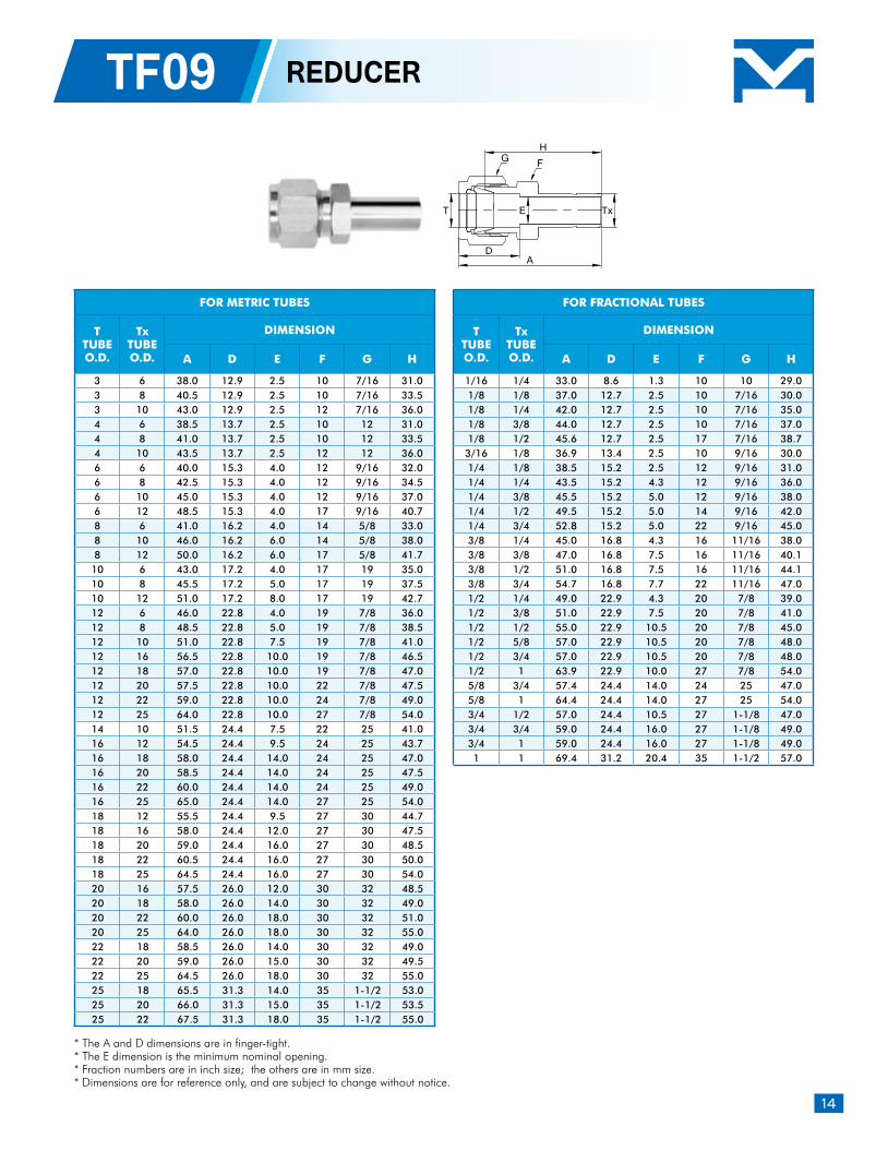
TF09 REDUCER
* The A and D dimensions are in finger-tight.* The E dimension is the minimum nominal opening.* Fraction numbers are in inch size; the others are in mm size. * Dimensions are for reference only, and are subject to change without notice.
FOR METRIC TUBES
TTUBEO.D.
TxTUBEO.D.
DIMENSION
A D E F G H
3 6 38.0 12.9 2.5 10 7/16 31.0 3 8 40.5 12.9 2.5 10 7/16 33.5 3 10 43.0 12.9 2.5 12 7/16 36.0 4 6 38.5 13.7 2.5 10 12 31.0 4 8 41.0 13.7 2.5 10 12 33.5 4 10 43.5 13.7 2.5 12 12 36.0 6 6 40.0 15.3 4.0 12 9/16 32.0 6 8 42.5 15.3 4.0 12 9/16 34.5 6 10 45.0 15.3 4.0 12 9/16 37.0 6 12 48.5 15.3 4.0 17 9/16 40.7 8 6 41.0 16.2 4.0 14 5/8 33.0 8 10 46.0 16.2 6.0 14 5/8 38.0 8 12 50.0 16.2 6.0 17 5/8 41.7 10 6 43.0 17.2 4.0 17 19 35.0 10 8 45.5 17.2 5.0 17 19 37.5 10 12 51.0 17.2 8.0 17 19 42.7 12 6 46.0 22.8 4.0 19 7/8 36.0 12 8 48.5 22.8 5.0 19 7/8 38.5 12 10 51.0 22.8 7.5 19 7/8 41.0 12 16 56.5 22.8 10.0 19 7/8 46.5 12 18 57.0 22.8 10.0 19 7/8 47.0 12 20 57.5 22.8 10.0 22 7/8 47.5 12 22 59.0 22.8 10.0 24 7/8 49.0 12 25 64.0 22.8 10.0 27 7/8 54.0 14 10 51.5 24.4 7.5 22 25 41.0 16 12 54.5 24.4 9.5 24 25 43.7 16 18 58.0 24.4 14.0 24 25 47.0 16 20 58.5 24.4 14.0 24 25 47.5 16 22 60.0 24.4 14.0 24 25 49.0 16 25 65.0 24.4 14.0 27 25 54.0 18 12 55.5 24.4 9.5 27 30 44.7 18 16 58.0 24.4 12.0 27 30 47.5 18 20 59.0 24.4 16.0 27 30 48.5 18 22 60.5 24.4 16.0 27 30 50.0 18 25 64.5 24.4 16.0 27 30 54.0 20 16 57.5 26.0 12.0 30 32 48.5 20 18 58.0 26.0 14.0 30 32 49.0 20 22 60.0 26.0 18.0 30 32 51.0 20 25 64.0 26.0 18.0 30 32 55.0 22 18 58.5 26.0 14.0 30 32 49.0 22 20 59.0 26.0 15.0 30 32 49.5 22 25 64.5 26.0 18.0 30 32 55.0 25 18 65.5 31.3 14.0 35 1-1/2 53.0 25 20 66.0 31.3 15.0 35 1-1/2 53.5 25 22 67.5 31.3 18.0 35 1-1/2 55.0
FOR FRACTIONAL TUBES
TTUBEO.D.
TxTUBEO.D.
DIMENSION
A D E F G H
1/16 1/4 33.0 8.6 1.3 10 10 29.0 1/8 1/8 37.0 12.7 2.5 10 7/16 30.0 1/8 1/4 42.0 12.7 2.5 10 7/16 35.0 1/8 3/8 44.0 12.7 2.5 10 7/16 37.0 1/8 1/2 45.6 12.7 2.5 17 7/16 38.7
3/16 1/8 36.9 13.4 2.5 10 9/16 30.0 1/4 1/8 38.5 15.2 2.5 12 9/16 31.0 1/4 1/4 43.5 15.2 4.3 12 9/16 36.0 1/4 3/8 45.5 15.2 5.0 12 9/16 38.0 1/4 1/2 49.5 15.2 5.0 14 9/16 42.0 1/4 3/4 52.8 15.2 5.0 22 9/16 45.0 3/8 1/4 45.0 16.8 4.3 16 11/16 38.0 3/8 3/8 47.0 16.8 7.5 16 11/16 40.1 3/8 1/2 51.0 16.8 7.5 16 11/16 44.1 3/8 3/4 54.7 16.8 7.7 22 11/16 47.0 1/2 1/4 49.0 22.9 4.3 20 7/8 39.0 1/2 3/8 51.0 22.9 7.5 20 7/8 41.0 1/2 1/2 55.0 22.9 10.5 20 7/8 45.0 1/2 5/8 57.0 22.9 10.5 20 7/8 48.0 1/2 3/4 57.0 22.9 10.5 20 7/8 48.0 1/2 1 63.9 22.9 10.0 27 7/8 54.0 5/8 3/4 57.4 24.4 14.0 24 25 47.0 5/8 1 64.4 24.4 14.0 27 25 54.0 3/4 1/2 57.0 24.4 10.5 27 1-1/8 47.0 3/4 3/4 59.0 24.4 16.0 27 1-1/8 49.0 3/4 1 59.0 24.4 16.0 27 1-1/8 49.0 1 1 69.4 31.2 20.4 35 1-1/2 57.0
T E Tx
DA
H
FG
15
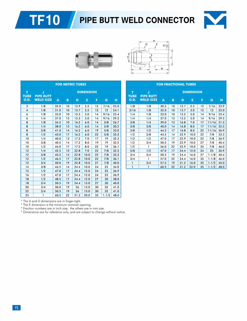
TF10 PIPE BUTT WELD CONNECTOR
* The A and D dimensions are in finger-tight.* The E dimension is the minimum nominal opening.* Fraction numbers are in inch size; the others are in mm size. * Dimensions are for reference only, and are subject to change without notice.
FOR METRIC TUBES
TTUBEO.D.
JPIPE BUTTWELD SIZE
DIMENSION
A B D E F G H
3 1/8 32.0 10 12.9 2.5 12 7/16 25.0 4 1/8 31.0 10 13.7 2.5 12 12 24.1 6 1/8 33.0 10 15.3 5.0 14 9/16 25.4 6 1/4 37.0 13 15.3 5.0 14 9/16 29.2 8 1/8 34.5 10 16.2 6.0 14 5/8 26.7 8 1/4 38.0 13 16.2 6.0 14 5/8 30.2 8 3/8 41.0 14 16.2 6.0 19 5/8 33.0 8 1/2 43.0 17 16.2 6.0 22 5/8 35.3
10 1/4 40.0 13 17.2 7.0 17 19 32.3 10 3/8 40.5 14 17.2 8.0 19 19 32.5 10 1/2 44.0 17 17.2 8.0 22 19 36.1 12 1/4 42.5 13 22.8 7.0 22 7/8 32.3 12 3/8 43.5 14 22.8 10.0 22 7/8 33.3 12 1/2 46.5 17 22.8 10.0 22 7/8 36.1 12 3/4 50.0 19 22.8 10.0 27 7/8 40.0 14 3/8 44.5 14 24.4 10.0 24 25 34.0 15 1/2 47.0 17 24.4 12.0 24 25 36.9 16 1/2 47.0 17 24.4 12.0 24 25 36.9 18 1/2 48.5 17 24.4 12.0 27 30 38.0 18 3/4 50.5 19 24.4 15.0 27 30 40.0 20 3/4 50.0 19 26 15.0 30 32 41.0 22 3/4 50.5 19 26 15.0 30 32 41.0 25 1 60.5 22 31.3 20.0 35 1-1/2 48.0
FOR FRACTIONAL TUBES
TTUBEO.D.
JPIPE BUTTWELD SIZE
DIMENSION
A B D E F G H
1/8 1/8 30.5 10 12.7 2.5 12 7/16 23.9 3/16 1/8 32.0 10 13.7 3.0 12 12 25.0 1/4 1/8 33.0 10 15.2 5.0 14 9/16 25.4 1/4 1/4 37.0 13 15.2 5.0 14 9/16 29.5 3/8 1/4 39.0 13 16.8 7.0 17 11/16 31.5 3/8 3/8 40.0 14 16.8 8.0 17 11/16 32.5 3/8 1/2 44.5 17 16.8 8.0 22 11/16 36.9 1/2 3/8 43.5 14 22.9 10.0 22 7/8 33.3 1/2 1/2 47.0 17 22.9 10.0 22 7/8 36.9 1/2 3/4 50.5 19 22.9 10.0 27 7/8 40.4 1/2 1 56.0 22 22.9 10.0 35 7/8 46.0 5/8 1/2 47.0 17 24.4 12.0 24 25 36.9 3/4 3/4 50.5 19 24.4 16.0 27 1-1/8 40.4 3/4 1 57.0 22 24.4 16.0 35 1-1/8 46.0 1 3/4 57.5 19 31.2 16.0 35 1-1/2 45.0 1 1 60.5 22 31.2 22.0 35 1-1/2 48.0
37.5°
T E J
BD
H
A
FG
16
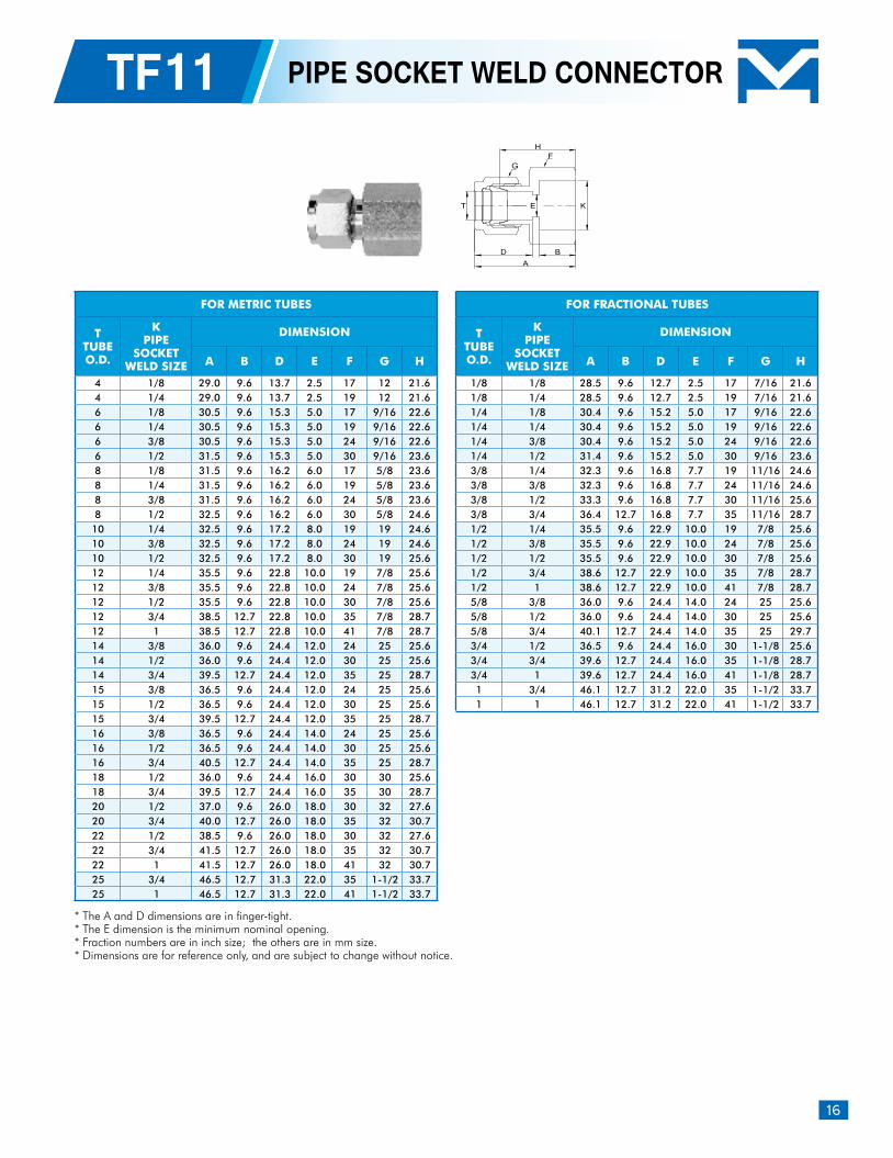
TF11 PIPE SOCKET WELD CONNECTOR
* The A and D dimensions are in finger-tight.* The E dimension is the minimum nominal opening.* Fraction numbers are in inch size; the others are in mm size. * Dimensions are for reference only, and are subject to change without notice.
FOR METRIC TUBES
TTUBEO.D.
KPIPE
SOCKETWELD SIZE
DIMENSION
A B D E F G H
4 1/8 29.0 9.6 13.7 2.5 17 12 21.64 1/4 29.0 9.6 13.7 2.5 19 12 21.66 1/8 30.5 9.6 15.3 5.0 17 9/16 22.66 1/4 30.5 9.6 15.3 5.0 19 9/16 22.66 3/8 30.5 9.6 15.3 5.0 24 9/16 22.66 1/2 31.5 9.6 15.3 5.0 30 9/16 23.68 1/8 31.5 9.6 16.2 6.0 17 5/8 23.68 1/4 31.5 9.6 16.2 6.0 19 5/8 23.68 3/8 31.5 9.6 16.2 6.0 24 5/8 23.68 1/2 32.5 9.6 16.2 6.0 30 5/8 24.610 1/4 32.5 9.6 17.2 8.0 19 19 24.610 3/8 32.5 9.6 17.2 8.0 24 19 24.610 1/2 32.5 9.6 17.2 8.0 30 19 25.612 1/4 35.5 9.6 22.8 10.0 19 7/8 25.612 3/8 35.5 9.6 22.8 10.0 24 7/8 25.612 1/2 35.5 9.6 22.8 10.0 30 7/8 25.612 3/4 38.5 12.7 22.8 10.0 35 7/8 28.712 1 38.5 12.7 22.8 10.0 41 7/8 28.714 3/8 36.0 9.6 24.4 12.0 24 25 25.614 1/2 36.0 9.6 24.4 12.0 30 25 25.614 3/4 39.5 12.7 24.4 12.0 35 25 28.715 3/8 36.5 9.6 24.4 12.0 24 25 25.615 1/2 36.5 9.6 24.4 12.0 30 25 25.615 3/4 39.5 12.7 24.4 12.0 35 25 28.716 3/8 36.5 9.6 24.4 14.0 24 25 25.616 1/2 36.5 9.6 24.4 14.0 30 25 25.616 3/4 40.5 12.7 24.4 14.0 35 25 28.718 1/2 36.0 9.6 24.4 16.0 30 30 25.618 3/4 39.5 12.7 24.4 16.0 35 30 28.720 1/2 37.0 9.6 26.0 18.0 30 32 27.620 3/4 40.0 12.7 26.0 18.0 35 32 30.722 1/2 38.5 9.6 26.0 18.0 30 32 27.622 3/4 41.5 12.7 26.0 18.0 35 32 30.722 1 41.5 12.7 26.0 18.0 41 32 30.725 3/4 46.5 12.7 31.3 22.0 35 1-1/2 33.725 1 46.5 12.7 31.3 22.0 41 1-1/2 33.7
FOR FRACTIONAL TUBES
TTUBEO.D.
KPIPE
SOCKETWELD SIZE
DIMENSION
A B D E F G H
1/8 1/8 28.5 9.6 12.7 2.5 17 7/16 21.61/8 1/4 28.5 9.6 12.7 2.5 19 7/16 21.61/4 1/8 30.4 9.6 15.2 5.0 17 9/16 22.61/4 1/4 30.4 9.6 15.2 5.0 19 9/16 22.61/4 3/8 30.4 9.6 15.2 5.0 24 9/16 22.61/4 1/2 31.4 9.6 15.2 5.0 30 9/16 23.63/8 1/4 32.3 9.6 16.8 7.7 19 11/16 24.63/8 3/8 32.3 9.6 16.8 7.7 24 11/16 24.63/8 1/2 33.3 9.6 16.8 7.7 30 11/16 25.63/8 3/4 36.4 12.7 16.8 7.7 35 11/16 28.71/2 1/4 35.5 9.6 22.9 10.0 19 7/8 25.61/2 3/8 35.5 9.6 22.9 10.0 24 7/8 25.61/2 1/2 35.5 9.6 22.9 10.0 30 7/8 25.61/2 3/4 38.6 12.7 22.9 10.0 35 7/8 28.71/2 1 38.6 12.7 22.9 10.0 41 7/8 28.75/8 3/8 36.0 9.6 24.4 14.0 24 25 25.65/8 1/2 36.0 9.6 24.4 14.0 30 25 25.65/8 3/4 40.1 12.7 24.4 14.0 35 25 29.73/4 1/2 36.5 9.6 24.4 16.0 30 1-1/8 25.63/4 3/4 39.6 12.7 24.4 16.0 35 1-1/8 28.73/4 1 39.6 12.7 24.4 16.0 41 1-1/8 28.71 3/4 46.1 12.7 31.2 22.0 35 1-1/2 33.71 1 46.1 12.7 31.2 22.0 41 1-1/2 33.7
B
H
D
A
E K
FG
T
17
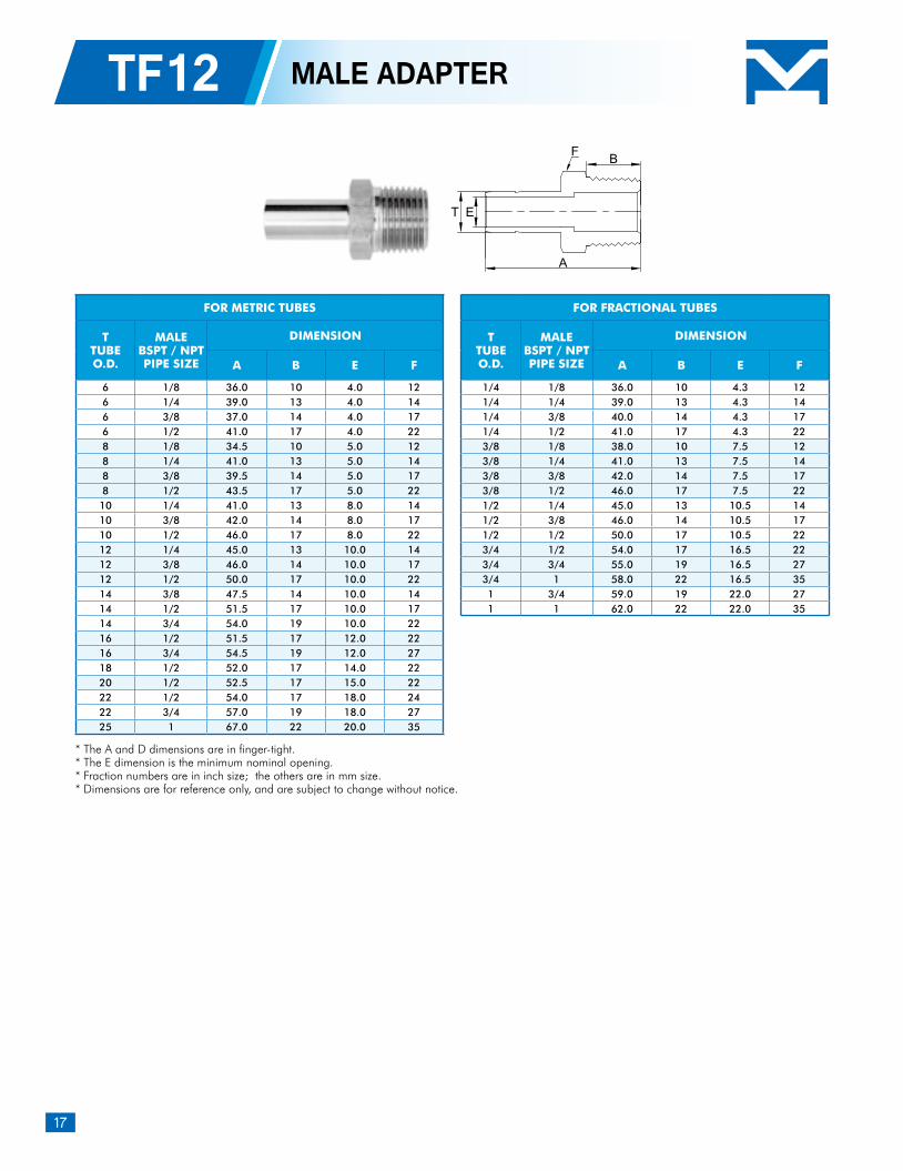
TF12 MALE ADAPTER
* The A and D dimensions are in finger-tight.* The E dimension is the minimum nominal opening.* Fraction numbers are in inch size; the others are in mm size. * Dimensions are for reference only, and are subject to change without notice.
FOR METRIC TUBES
TTUBEO.D.
MALEBSPT / NPTPIPE SIZE
DIMENSION
A B E F
6 1/8 36.0 10 4.0 126 1/4 39.0 13 4.0 146 3/8 37.0 14 4.0 176 1/2 41.0 17 4.0 228 1/8 34.5 10 5.0 128 1/4 41.0 13 5.0 148 3/8 39.5 14 5.0 178 1/2 43.5 17 5.0 2210 1/4 41.0 13 8.0 1410 3/8 42.0 14 8.0 1710 1/2 46.0 17 8.0 2212 1/4 45.0 13 10.0 1412 3/8 46.0 14 10.0 1712 1/2 50.0 17 10.0 2214 3/8 47.5 14 10.0 1414 1/2 51.5 17 10.0 1714 3/4 54.0 19 10.0 2216 1/2 51.5 17 12.0 2216 3/4 54.5 19 12.0 2718 1/2 52.0 17 14.0 2220 1/2 52.5 17 15.0 2222 1/2 54.0 17 18.0 2422 3/4 57.0 19 18.0 2725 1 67.0 22 20.0 35
FOR FRACTIONAL TUBES
TTUBEO.D.
MALEBSPT / NPTPIPE SIZE
DIMENSION
A B E F
1/4 1/8 36.0 10 4.3 121/4 1/4 39.0 13 4.3 141/4 3/8 40.0 14 4.3 171/4 1/2 41.0 17 4.3 223/8 1/8 38.0 10 7.5 123/8 1/4 41.0 13 7.5 143/8 3/8 42.0 14 7.5 173/8 1/2 46.0 17 7.5 221/2 1/4 45.0 13 10.5 141/2 3/8 46.0 14 10.5 171/2 1/2 50.0 17 10.5 223/4 1/2 54.0 17 16.5 223/4 3/4 55.0 19 16.5 273/4 1 58.0 22 16.5 351 3/4 59.0 19 22.0 271 1 62.0 22 22.0 35
B
A
ET
F
18
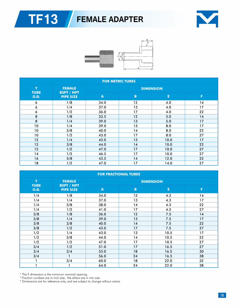
TF13 FEMALE ADAPTER
* The E dimension is the minimum nominal opening.* Fraction numbers are in inch size; the others are in mm size. * Dimensions are for reference only, and are subject to change without notice.
FOR METRIC TUBES
TTUBEO.D.
FEMALEBSPT / NPTPIPE SIZE
DIMENSION
A B E F
6 1/8 34.0 12 4.0 146 1/4 37.0 13 4.0 176 1/2 36.0 17 4.0 228 1/8 33.5 12 5.0 148 1/4 39.0 13 5.0 17
10 1/4 39.0 13 8.0 1710 3/8 40.0 14 8.0 2210 1/2 43.0 17 8.0 2712 1/4 43.0 13 10.0 1712 3/8 44.0 14 10.0 2212 1/2 47.0 17 10.0 2714 1/2 46.5 17 10.0 2716 3/8 43.5 14 12.0 2218 1/2 47.0 17 14.0 27
FOR FRACTIONAL TUBES
TTUBEO.D.
FEMALEBSPT / NPTPIPE SIZE
DIMENSION
A B E F
1/4 1/8 34.0 12 4.3 141/4 1/4 37.0 13 4.3 171/4 3/8 38.0 14 4.3 221/4 1/2 41.0 17 4.3 273/8 1/8 36.0 12 7.5 143/8 1/4 39.0 13 7.5 173/8 3/8 40.0 14 7.5 223/8 1/2 43.0 17 7.5 271/2 1/4 43.0 13 10.5 171/2 3/8 44.0 14 10.5 221/2 1/2 47.0 17 10.5 273/4 1/2 51.0 17 16.5 273/4 3/4 53.0 18 16.5 303/4 1 56.0 24 16.5 381 3/4 60.0 18 22.0 321 1 64.0 24 22.0 38
ET
A
BF
19
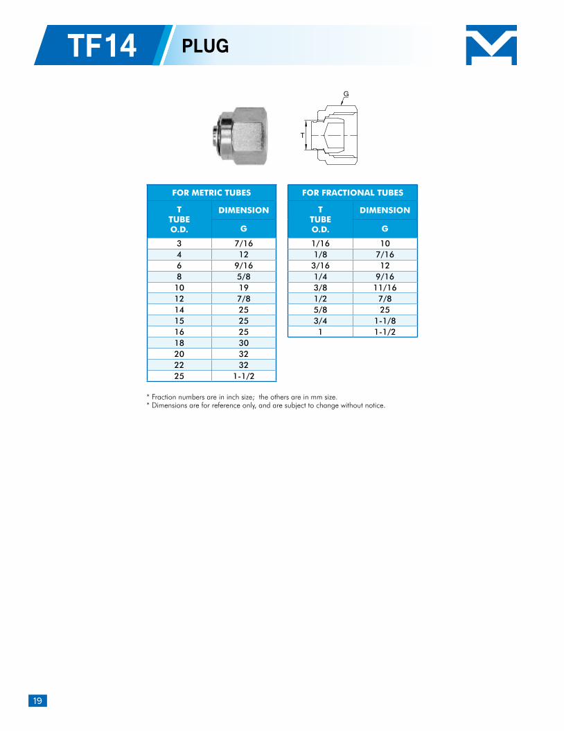
TF14 PLUG
* Fraction numbers are in inch size; the others are in mm size. * Dimensions are for reference only, and are subject to change without notice.
FOR METRIC TUBES
TTUBEO.D.
DIMENSION
G
3 7/164 126 9/168 5/8
10 1912 7/814 2515 2516 2518 3020 3222 3225 1-1/2
FOR FRACTIONAL TUBES
TTUBEO.D.
DIMENSION
G
1/16 101/8 7/16
3/16 121/4 9/163/8 11/161/2 7/85/8 253/4 1-1/81 1-1/2
T
G
20
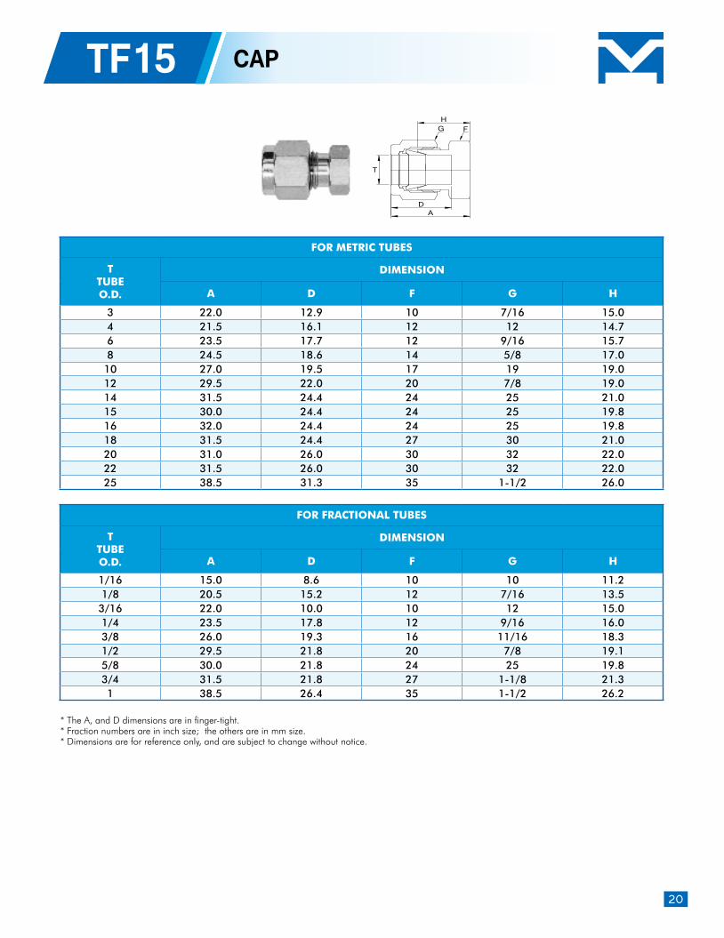
TF15 CAP
* The A, and D dimensions are in finger-tight.* Fraction numbers are in inch size; the others are in mm size. * Dimensions are for reference only, and are subject to change without notice.
FOR METRIC TUBES
TTUBEO.D.
DIMENSION
A D F G H
3 22.0 12.9 10 7/16 15.0 4 21.5 16.1 12 12 14.7 6 23.5 17.7 12 9/16 15.7 8 24.5 18.6 14 5/8 17.0
10 27.0 19.5 17 19 19.0 12 29.5 22.0 20 7/8 19.0 14 31.5 24.4 24 25 21.0 15 30.0 24.4 24 25 19.8 16 32.0 24.4 24 25 19.8 18 31.5 24.4 27 30 21.0 20 31.0 26.0 30 32 22.0 22 31.5 26.0 30 32 22.0 25 38.5 31.3 35 1-1/2 26.0
FOR FRACTIONAL TUBES
TTUBEO.D.
DIMENSION
A D F G H
1/16 15.0 8.6 10 10 11.2 1/8 20.5 15.2 12 7/16 13.5
3/16 22.0 10.0 10 12 15.0 1/4 23.5 17.8 12 9/16 16.0 3/8 26.0 19.3 16 11/16 18.3 1/2 29.5 21.8 20 7/8 19.1 5/8 30.0 21.8 24 25 19.8 3/4 31.5 21.8 27 1-1/8 21.3 1 38.5 26.4 35 1-1/2 26.2
T
H
DA
FG
21
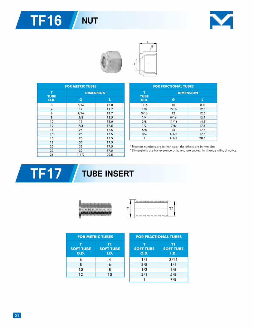
TF16
TF17
NUT
TUBE INSERT
* Fraction numbers are in inch size; the others are in mm size. * Dimensions are for reference only, and are subject to change without notice.
FOR METRIC TUBES
TTUBEO.D.
DIMENSION
G L
3 7/16 12.0 4 12 11.7 6 9/16 12.7 8 5/8 13.5
10 19 15.0 12 7/8 17.5 14 25 17.5 15 25 17.5 16 25 17.5 18 30 17.5 20 32 17.5 22 32 17.5 25 1-1/2 20.5
FOR FRACTIONAL TUBES
TTUBEO.D.
DIMENSION
G L
1/16 10 8.0 1/8 7/16 12.0
3/16 12 12.0 1/4 9/16 12.73/8 11/16 14.31/2 7/8 17.55/8 25 17.53/4 1-1/8 17.51 1-1/2 20.6
T
LG
FOR METRIC TUBES
TSOFT TUBE
O.D.
T1SOFT TUBE
I.D.
6 48 6
10 812 10
FOR FRACTIONAL TUBES
TSOFT TUBE
O.D.
T1SOFT TUBE
I.D.
1/4 3/163/8 1/41/2 3/83/4 5/81 7/8
T T1
22
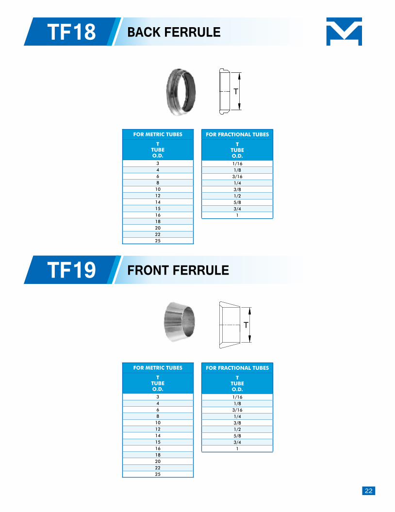
TF18 BACK FERRULE
TF19 FRONT FERRULE
FOR METRIC TUBES
TTUBEO.D.
3468101214151618202225
FOR METRIC TUBES
TTUBEO.D.
3468101214151618202225
FOR FRACTIONAL TUBES
TTUBEO.D.1/161/8
3/161/43/81/25/83/41
FOR FRACTIONAL TUBES
TTUBEO.D.1/161/8
3/161/43/81/25/83/41
T
T
23
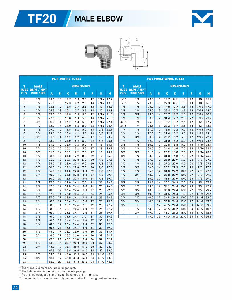
TF20 MALE ELBOW
* The A and D dimensions are in finger-tight.* The E dimension is the minimum nominal opening.* Fraction numbers are in inch size; the others are in mm size. * Dimensions are for reference only, and are subject to change without notice.
FOR METRIC TUBES
TTUBEO.D.
MALEBSPT / NPTPIPE SIZE
DIMENSION
A B C D E F G H
3 1/8 24.5 10 18.7 12.9 2.5 12 7/16 17.73 1/4 25.0 13 22.3 12.9 2.5 14 7/16 18.34 1/8 25.5 10 18.8 13.7 2.5 12 12 18.84 1/4 25.5 13 22.4 13.7 2.5 14 12 18.86 1/8 27.0 10 18.8 15.3 5.0 12 9/16 21.56 1/4 27.0 13 23.0 15.3 5.0 14 9/16 21.56 3/8 30.0 14 26.2 15.3 5.0 17 9/16 22.46 1/2 32.0 17 31.0 15.3 5.0 23 9/16 24.48 1/8 29.0 10 19.8 16.2 5.0 14 5/8 22.98 1/4 29.0 13 23.4 16.2 5.0 14 5/8 22.98 3/8 31.5 14 26.2 16.2 6.0 17 5/8 23.98 1/2 33.0 17 31.0 16.2 6.0 22 5/8 25.1
10 1/8 31.5 10 23.6 17.2 5.0 17 19 23.910 1/4 31.5 13 25.2 17.2 5.0 17 19 23.910 3/8 31.5 14 26.2 17.2 7.0 17 19 23.910 1/2 33.5 17 31.0 17.2 8.0 22 19 25.812 1/8 36.0 10 23.6 22.8 5.0 20 7/8 27.512 1/4 36.0 13 28.0 22.8 5.0 20 7/8 27.512 3/8 36.0 14 29.5 22.8 7.0 20 7/8 27.512 1/2 36.0 17 31.0 22.8 10.0 22 7/8 27.512 3/4 40.0 19 36.8 22.8 10.0 27 7/8 29.712 1 50.0 22 45.5 22.8 10.0 34 7/8 39.914 3/8 37.0 14 28.0 24.4 7.0 24 25 26.514 1/2 37.0 17 31.0 24.4 10.0 24 25 26.514 3/4 40.0 19 36.6 24.4 12.0 27 25 29.615 3/8 37.0 14 28.0 24.4 7.0 24 25 26.515 1/2 37.0 17 31.0 24.4 10.0 24 25 26.515 3/4 40.5 19 36.6 24.4 12.0 27 25 29.616 3/8 38.0 14 30.2 24.4 7.0 22 25 27.916 1/2 38.0 17 33.1 24.4 10.0 22 25 27.916 3/4 40.0 19 36.8 24.4 12.0 27 25 29.718 3/8 40.0 14 31.6 24.4 7.0 27 30 29.618 1/2 40.0 17 34.6 24.4 10.0 27 30 29.618 3/4 40.0 19 36.6 24.4 12.0 27 30 29.618 1 50.5 22 45.5 24.4 16.0 34 30 39.920 1/2 44.0 17 38.7 26.0 10.0 30 32 34.720 3/4 44.0 19 38.7 26.0 16.0 30 32 34.720 1 49.0 22 45.5 26.0 18.0 34 32 39.922 1/2 44.0 17 38.7 26.0 10.0 30 32 34.722 3/4 44.0 19 38.7 26.0 16.0 30 32 34.722 1 49.5 22 45.5 26.0 18.0 34 32 39.925 1/2 53.0 17 43.0 31.3 10.0 34 1-1/2 40.525 3/4 53.0 19 45.0 31.3 16.0 34 1-1/2 40.525 1 53.0 22 45.5 31.3 22.0 34 1-1/2 40.5
FOR FRACTIONAL TUBES
TTUBEO.D.
MALEBSPT / NPTPIPE SIZE
DIMENSION
A B C D E F G H
1/16 1/8 20.0 10 18.7 8.6 1.5 12 10 15.7 1/16 1/4 20.5 13 22.3 8.6 1.5 14 10 16.3 1/8 1/8 24.0 10 17.8 12.7 2.5 12 7/16 17.0 1/8 1/4 25.0 13 22.4 12.7 2.5 14 7/16 18.0 1/8 3/8 28.0 14 25.7 12.7 2.5 17 7/16 20.7 1/8 1/2 30.5 17 31.4 12.7 2.5 22 7/16 23.4
3/16 1/8 25.0 10 18.7 13.7 2.5 12 12 17.7 3/16 1/4 25.5 13 22.3 13.7 2.5 14 12 18.3 1/4 1/8 27.0 10 18.8 15.2 5.0 12 9/16 19.6 1/4 1/4 27.0 13 22.4 15.2 5.0 14 9/16 19.6 1/4 3/8 30.0 14 26.2 15.2 5.0 17 9/16 22.4 1/4 1/2 32.0 17 31.0 15.2 5.0 22 9/16 24.4 3/8 1/8 30.5 10 20.8 16.8 5.0 14 11/16 23.1 3/8 1/4 30.5 13 24.4 16.8 7.0 14 11/16 23.1 3/8 3/8 31.5 14 26.2 16.8 7.0 17 11/16 23.9 3/8 1/2 33.5 17 31.0 16.8 7.0 22 11/16 25.9 1/2 1/8 37.0 10 25.0 22.9 5.0 20 7/8 27.0 1/2 1/4 36.5 13 27.2 22.9 5.0 20 7/8 27.5 1/2 3/8 36.5 14 28.2 22.9 7.0 20 7/8 27.5 1/2 1/2 36.5 17 31.0 22.9 10.0 22 7/8 27.5 1/2 3/4 40.0 19 36.8 22.9 10.0 27 7/8 29.7 1/2 1 50.0 22 45.5 22.9 10.0 34 7/8 39.9 5/8 3/8 38.5 14 30.2 24.4 7.0 24 25 27.9 5/8 1/2 38.5 17 33.1 24.4 10.0 24 25 27.9 5/8 3/4 40.0 19 36.8 24.4 12.0 27 25 29.7 3/4 3/8 40.0 14 31.6 24.4 7.0 27 1-1/8 29.6 3/4 1/2 40.0 17 34.8 24.4 10.0 27 1-1/8 32.0 3/4 3/4 40.0 19 36.8 24.4 12.0 27 1-1/8 32.0 3/4 1 51.0 22 45.5 24.4 16.0 34 1-1/8 39.9 1 1/2 53.0 17 43.5 31.2 10.0 34 1-1/2 40.5 1 3/4 49.0 19 41.7 31.2 16.0 34 1-1/2 36.8 1 1 49.0 22 44.5 31.2 22.0 34 1-1/2 36.8
H
B
C
T
D
E
A
GF
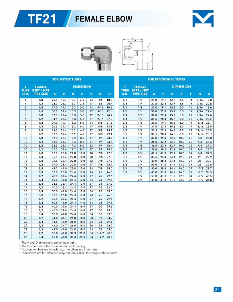
24
TF21 FEMALE ELBOW
* The A and D dimensions are in finger-tight.* The E dimension is the minimum nominal opening.* Fraction numbers are in inch size; the others are in mm size. * Dimensions are for reference only, and are subject to change without notice.
FOR METRIC TUBES
TTUBEO.D.
FEMALEBSPT / NPTPIPE SIZE
DIMENSION
A C D E F G H
4 1/8 25.5 19.1 13.7 2.5 14 12 18.8 4 1/4 28.0 23.7 13.7 2.5 17 12 20.7 6 1/8 27.0 19.1 15.3 5.0 14 9/16 19.6 6 1/4 30.0 22.4 15.3 5.0 17 9/16 22.4 6 3/8 32.0 22.4 15.3 5.0 22 9/16 24.4 6 1/2 34.5 28.4 15.3 5.0 27 9/16 27.2 8 1/8 29.0 19.1 16.2 6.0 14 5/8 21.3 8 1/4 30.5 22.4 16.2 6.0 17 5/8 23.1 8 3/8 34.0 26.4 16.2 6.0 22 5/8 25.9 8 1/2 37.0 32.6 16.2 6.0 27 5/8 29.1 10 1/8 32.0 23.7 17.2 8.0 17 19 23.7 10 1/4 32.0 23.7 17.2 8.0 17 19 23.7 10 3/8 34.5 26.4 17.2 8.0 22 19 26.4 10 1/2 37.5 32.6 17.2 8.0 27 19 29.6 12 1/8 37.0 25.0 22.8 10.0 20 7/8 27.0 12 1/4 36.5 22.4 22.8 10.0 20 7/8 27.3 12 3/8 36.5 22.4 22.8 10.0 22 7/8 27.3 12 1/2 39.0 28.4 22.8 10.0 27 7/8 28.7 12 3/4 49.5 41.0 22.8 10.0 34 7/8 39.5 14 3/8 37.0 26.0 24.4 12.0 24 25 26.5 14 1/2 40.0 32.6 24.4 12.0 27 25 29.6 14 3/4 50.0 41.0 24.4 12.0 34 25 39.5 15 3/8 38.5 22.4 24.4 12.0 27 25 27.9 15 1/2 40.0 28.4 24.4 12.0 27 25 32.0 15 3/4 50.0 41.0 24.4 12.0 34 25 39.5 16 3/8 37.5 26.0 24.4 14.0 24 25 26.5 16 1/2 40.5 32.6 24.4 14.0 27 25 29.6 16 3/4 50.5 41.0 24.4 14.0 34 25 39.5 18 3/8 40.0 32.6 24.4 16.0 27 30 29.6 18 1/2 40.0 32.6 24.4 16.0 27 30 29.6 18 3/4 50.0 41.0 24.4 16.0 34 30 39.5 20 1/2 44.0 34.7 26.0 18.0 30 32 34.7 20 3/4 48.5 41.0 26.0 18.0 34 32 39.5 22 1/2 44.0 34.7 26.0 18.0 30 32 34.7 22 3/4 49.0 41.0 26.0 18.0 34 32 39.5 25 1/2 53.0 41.0 31.3 22.0 34 1-1/2 40.5 25 3/4 53.0 41.0 31.3 22.0 34 1-1/2 40.5
FOR FRACTIONAL TUBES
TTUBEO.D.
FEMALEBSPT / NPTPIPE SIZE
DIMENSION
A C D E F G H
1/8 1/8 25.0 19.1 12.7 2.5 14 7/16 18.0 1/8 1/4 27.5 22.4 12.7 2.5 14 7/16 20.8 1/4 1/8 27.0 19.1 15.2 5.0 14 9/16 19.6 1/4 1/4 30.0 22.4 15.2 5.0 17 9/16 22.4 1/4 3/8 32.0 22.4 15.2 5.0 22 9/16 24.4 1/4 1/2 34.5 28.4 15.2 5.0 27 9/16 27.2 3/8 1/8 30.5 19.1 16.8 8.0 14 11/16 23.1 3/8 1/4 31.5 22.4 16.8 8.0 17 11/16 23.9 3/8 3/8 33.5 22.4 16.8 8.0 22 11/16 25.9 3/8 1/2 36.5 28.4 16.8 8.0 27 11/16 28.7 1/2 1/8 37.0 25.0 22.9 10.0 20 7/8 27.0 1/2 1/4 36.5 22.4 22.9 10.0 20 7/8 27.3 1/2 3/8 36.5 22.4 22.9 10.0 22 7/8 27.3 1/2 1/2 39.0 28.4 22.9 10.0 27 7/8 28.7 1/2 3/4 49.5 41.0 22.9 10.0 34 7/8 39.5 5/8 3/8 38.5 22.4 24.4 12.0 24 25 27.9 5/8 1/2 40.0 28.4 24.4 12.0 27 25 29.7 5/8 3/4 50.0 41.0 24.4 14.0 34 25 39.5 3/4 1/2 40.0 28.4 24.4 16.0 27 1-1/8 29.7 3/4 3/4 45.0 31.8 24.4 16.0 34 1-1/8 34.5 1 1/2 53.0 41.0 31.2 22.0 34 1-1/2 40.5 1 3/4 49.0 31.8 31.2 22.0 34 1-1/2 36.8
H
C
T E
D
A
FG
25
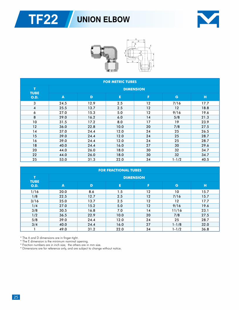
* The A and D dimensions are in finger-tight.* The E dimension is the minimum nominal opening.* Fraction numbers are in inch size; the others are in mm size. * Dimensions are for reference only, and are subject to change without notice.
TF22 UNION ELBOW
FOR METRIC TUBES
TTUBEO.D.
DIMENSION
A D E F G H
3 24.5 12.9 2.5 12 7/16 17.7 4 25.5 13.7 2.5 12 12 18.8 6 27.0 15.3 5.0 12 9/16 19.6 8 29.0 16.2 6.0 14 5/8 21.3 10 31.5 17.2 8.0 17 19 23.9 12 36.0 22.8 10.0 20 7/8 27.5 14 37.0 24.4 12.0 24 25 26.5 15 39.0 24.4 12.0 24 25 28.7 16 39.0 24.4 12.0 24 25 28.7 18 40.0 24.4 16.0 27 30 29.6 20 44.0 26.0 18.0 30 32 34.7 22 44.0 26.0 18.0 30 32 34.7 25 53.0 31.3 22.0 34 1-1/2 40.5
FOR FRACTIONAL TUBES
TTUBEO.D.
DIMENSION
A D E F G H
1/16 20.0 8.6 1.5 12 10 15.7 1/8 22.5 12.7 2.5 12 7/16 15.7 3/16 25.0 13.7 2.5 12 12 17.7 1/4 27.0 15.2 5.0 12 9/16 19.6 3/8 30.5 16.8 7.0 14 11/16 23.1 1/2 36.5 22.9 10.0 20 7/8 27.5 5/8 39.0 24.4 12.0 24 25 28.7 3/4 40.0 24.4 16.0 27 1-1/8 32.0 1 49.0 31.2 22.0 34 1-1/2 36.8
H
E
H
T
D
A
FG
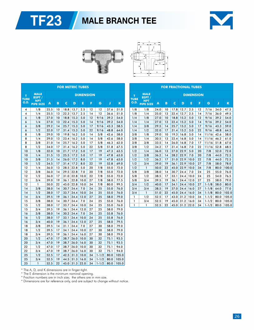
26
TF23 MALE BRANCH TEE
* The A, D, and K dimensions are in finger-tight.* The E dimension is the minimum nominal opening.* Fraction numbers are in inch size; the others are in mm size. * Dimensions are for reference only, and are subject to change without notice.
FOR METRIC TUBES
TTUBEO.D.
MALEBSPT / NPT
PIPE SIZE
DIMENSION
A B C D E F G J K
4 1/8 25.5 10 18.8 13.7 2.5 12 12 37.6 51.0 4 1/4 25.5 13 22.3 13.7 2.5 14 12 36.6 51.0 6 1/8 27.0 10 18.8 15.3 5.0 12 9/16 39.2 54.0 6 1/4 27.0 13 22.4 15.3 5.0 14 9/16 39.2 54.0 6 3/8 29.2 14 25.7 15.3 5.0 17 9/16 43.3 58.5 6 1/2 32.0 17 31.4 15.3 5.0 22 9/16 48.8 64.0 8 1/8 29.0 10 19.8 16.2 5.0 14 5/8 42.6 58.0 8 1/4 29.0 13 23.4 16.2 5.0 14 5/8 42.6 58.0 8 3/8 31.0 14 25.7 16.2 5.0 17 5/8 46.3 62.0 8 1/2 34.0 17 31.4 16.2 5.0 22 5/8 51.8 67.5 10 1/8 32.0 10 21.7 17.2 5.0 17 19 47.3 63.5 10 1/4 31.5 13 25.5 17.2 5.0 17 19 47.8 63.0 10 3/8 31.5 14 26.0 17.2 8.0 17 19 47.8 63.0 10 1/2 34.5 17 31.4 17.2 8.0 22 19 52.8 69.0 12 1/4 36.0 13 28.5 22.8 5.0 20 7/8 55.0 72.0 12 3/8 36.0 14 29.5 22.8 7.0 20 7/8 55.0 72.0 12 1/2 36.0 17 31.0 22.8 10.0 22 7/8 55.0 72.0 12 3/4 39.0 19 36.1 22.8 10.0 27 7/8 58.0 77.5 12 1 50.0 22 45.0 22.8 10.0 34 7/8 80.0 99.5 14 3/8 38.0 14 30.7 24.4 7.0 24 25 55.0 76.0 14 1/2 38.0 17 33.7 24.4 10.0 24 25 55.0 76.0 14 3/4 39.5 19 36.1 24.4 12.0 27 25 58.0 79.0 15 3/8 38.0 14 30.7 24.4 7.0 24 25 55.0 76.0 15 1/2 38.0 17 33.7 24.4 10.0 24 25 55.0 76.0 15 3/4 39.5 19 36.1 24.4 12.0 27 25 58.0 79.0 16 3/8 38.0 14 30.2 24.4 7.0 24 25 55.8 76.0 16 1/2 38.0 17 33.1 24.4 10.0 24 25 55.8 76.0 16 3/4 40.0 19 36.1 24.4 12.0 27 25 58.0 79.5 18 3/8 39.5 14 31.1 24.4 7.0 27 30 58.0 79.0 18 1/2 39.5 17 34.1 24.4 10.0 27 30 58.0 79.0 18 3/4 39.5 19 36.1 24.4 16.0 27 30 58.0 79.0 20 1/2 47.0 17 38.7 26.0 10.0 30 32 75.1 93.5 20 3/4 47.0 19 38.7 26.0 16.0 30 32 75.1 93.5 22 1/2 47.0 17 38.7 26.0 10.0 30 32 75.1 94.0 22 3/4 47.0 19 38.7 26.0 16.0 30 32 75.1 94.0 25 1/2 52.5 17 42.5 31.3 10.0 34 1-1/2 80.0 105.0 25 3/4 52.5 19 44.5 31.3 16.0 34 1-1/2 80.0 105.0 25 1 52.5 22 45.0 31.3 22.0 34 1-1/2 80.0 105.0
FOR FRACTIONAL TUBES
TTUBEO.D.
MALEBSPT / NPT
PIPE SIZE
DIMENSION
A B C D E F G J K
1/8 1/8 24.0 10 17.8 12.7 2.5 12 7/16 34.0 47.5 1/8 1/4 25.0 13 22.4 12.7 2.5 14 7/16 36.0 49.5 1/4 1/8 27.0 10 18.8 15.2 5.0 12 9/16 39.2 54.0 1/4 1/4 27.0 13 22.4 15.2 5.0 14 9/16 39.2 54.0 1/4 3/8 29.5 14 25.7 15.2 5.0 17 9/16 43.3 59.0 1/4 1/2 32.0 17 31.4 15.2 5.0 22 9/16 48.8 64.5 3/8 1/8 29.0 10 19.3 16.8 5.0 14 11/16 42.6 58.0 3/8 1/4 30.5 13 22.4 16.8 5.0 14 11/16 46.2 61.0 3/8 3/8 33.5 14 26.0 16.8 7.0 17 11/16 51.8 67.0 3/8 1/2 34.2 17 31.4 16.8 7.0 22 11/16 52.8 68.5 1/2 1/4 36.0 13 27.0 22.9 5.0 20 7/8 52.0 72.0 1/2 3/8 36.2 14 28.2 22.9 7.0 20 7/8 44.0 72.5 1/2 1/2 36.2 17 31.0 22.9 10.0 22 7/8 44.0 72.5 1/2 3/4 39.0 19 36.1 22.9 10.0 27 7/8 58.0 78.0 1/2 1 50.0 22 45.0 22.9 10.0 34 7/8 80.0 100.0 5/8 3/8 38.0 14 30.7 24.4 7.0 24 25 55.0 76.0 5/8 1/2 38.5 17 33.1 24.4 10.0 24 25 54.0 76.5 5/8 3/4 39.5 19 36.1 24.4 12.0 27 25 58.0 79.0 3/4 1/2 40.0 17 34.1 24.4 10.0 27 1-1/8 58.0 80.0 3/4 3/4 38.5 19 37.0 24.4 16.0 27 1-1/8 64.0 77.0 3/4 1 51.0 22 45.0 24.4 16.0 34 1-1/8 80.0 102.0 1 1/2 52.5 17 43.0 31.2 10.0 34 1-1/2 80.0 105.0 1 3/4 52.5 19 45.0 31.2 16.0 34 1-1/2 80.0 105.0 1 1 52.5 22 45.0 31.2 22.0 34 1-1/2 80.0 105.0
JH
E
H
T
B
A
K
D C
A
FG
27
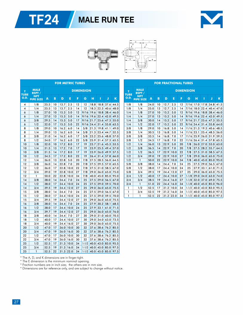
* The A, D, and K dimensions are in finger-tight.* The E dimension is the minimum nominal opening.* Fraction numbers are in inch size; the others are in mm size. * Dimensions are for reference only, and are subject to change without notice.
TF24 MALE RUN TEE
FOR METRIC TUBES
TTUBEO.D.
MALEBSPT / NPT
PIPE SIZE
DIMENSION
A B D E F G H I J K
4 1/8 25.5 10 13.7 2.5 12 12 18.8 18.8 37.6 44.5 4 1/4 25.5 13 13.7 2.5 14 12 18.3 22.3 40.6 48.0 6 1/8 27.0 10 15.3 5.0 12 9/16 19.6 18.8 38.4 46.0 6 1/4 27.0 13 15.3 5.0 14 9/16 19.6 22.4 42.0 49.5 6 3/8 29.5 14 15.3 5.0 17 9/16 21.7 25.6 47.3 55.0 6 1/2 32.0 17 15.3 5.0 22 9/16 24.4 31.4 55.8 63.5 8 1/8 29.0 10 16.2 6.0 14 5/8 21.3 19.8 41.1 49.0 8 1/4 29.0 13 16.2 6.0 14 5/8 21.3 23.4 44.7 52.5 8 3/8 31.0 14 16.2 6.0 17 5/8 23.2 25.6 48.8 57.0 8 1/2 34.0 17 16.2 6.0 22 5/8 25.9 31.4 57.3 65.5 10 1/8 32.0 10 17.2 8.0 17 19 23.7 21.6 45.3 53.5 10 1/4 31.5 13 17.2 7.0 17 19 23.9 25.5 49.4 57.0 10 3/8 31.5 14 17.2 8.0 17 19 23.9 26.0 49.9 57.5 10 1/2 34.5 17 17.2 8.0 22 19 26.4 31.4 57.8 66.0 12 1/4 36.0 13 22.8 5.0 20 7/8 27.5 28.5 56.0 64.5 12 3/8 36.0 14 22.8 7.0 20 7/8 27.5 29.5 57.0 65.5 12 1/2 36.0 17 22.8 10.0 22 7/8 27.5 31.0 58.5 67.0 12 3/4 39.0 19 22.8 10.0 27 7/8 29.0 36.0 65.0 75.0 12 1 50.0 22 22.8 10.0 34 7/8 40.0 45.0 85.0 95.0 14 3/8 38.0 14 24.4 7.0 24 25 27.5 29.0 56.5 67.0 14 1/2 38.0 17 24.4 10.0 24 25 27.5 29.0 59.5 70.0 14 3/4 39.5 19 24.4 12.0 27 25 29.0 36.0 65.0 75.5 15 3/8 38.0 14 24.4 7.0 24 25 27.5 29.0 56.5 67.0 15 1/2 38.0 17 24.4 10.0 24 25 27.5 29.0 59.5 70.0 15 3/4 39.5 19 24.4 12.0 27 25 29.0 36.0 65.0 75.5 16 3/8 38.0 14 24.4 7.0 24 25 27.9 30.2 58.1 68.5 16 1/2 38.0 17 24.4 10.0 24 25 27.9 33.1 61.0 71.5 16 3/4 39.7 19 24.4 12.0 27 25 29.0 36.0 65.0 76.0 18 3/8 40.0 14 24.4 7.0 27 30 29.0 31.0 60.0 70.5 18 1/2 40.0 17 24.4 10.0 27 30 29.0 34.0 63.0 73.5 18 3/4 40.0 19 24.4 16.0 27 30 29.0 36.0 65.0 75.5 20 1/2 47.0 17 26.0 10.0 30 32 37.6 38.6 76.2 85.5 20 3/4 47.0 19 26.0 16.0 30 32 37.6 38.6 76.2 85.5 22 1/2 47.0 17 26.0 10.0 30 32 37.6 38.6 76.2 85.5 22 3/4 47.0 19 26.0 16.0 30 32 37.6 38.6 76.2 85.5 25 1/2 52.5 17 31.3 10.0 34 1-1/2 40.0 43.0 83.0 95.5 25 3/4 52.5 19 31.3 16.0 34 1-1/2 40.0 45.0 85.0 97.5 25 1 52.5 22 31.3 22.0 34 1-1/2 40.0 45.0 85.0 97.5
FOR FRACTIONAL TUBES
TTUBEO.D.
MALEBSPT / NPT
PIPE SIZE
DIMENSION
A B D E F G H I J K
1/8 1/8 24.0 10 12.7 2.5 12 7/16 17.0 17.8 34.8 41.5 1/8 1/4 25.0 13 12.7 2.5 14 7/16 18.0 22.4 40.4 47.0 1/4 1/8 27.0 10 15.2 5.0 12 9/16 19.6 18.8 38.4 46.0 1/4 1/4 27.0 13 15.2 5.0 14 9/16 19.6 22.4 42.0 49.5 1/4 3/8 30.0 14 15.2 5.0 17 9/16 21.7 25.6 47.3 55.5 1/4 1/2 32.0 17 15.2 5.0 22 9/16 24.4 31.4 55.8 64.0 3/8 1/8 29.0 10 16.8 5.0 14 11/16 21.3 19.3 40.6 48.5 3/8 1/4 30.5 13 16.8 5.0 14 11/16 23.1 25.4 48.5 56.0 3/8 3/8 33.5 14 16.8 7.0 17 11/16 25.9 26.0 51.9 59.5 3/8 1/2 34.5 17 16.8 7.0 22 11/16 26.4 31.4 57.8 65.5 1/2 1/4 36.0 13 22.9 5.0 20 7/8 26.0 27.0 53.0 63.0 1/2 3/8 36.5 14 22.9 7.0 20 7/8 27.5 28.2 55.7 64.5 1/2 1/2 36.5 17 22.9 10.0 22 7/8 27.5 31.0 58.5 67.5 1/2 3/4 39.0 19 22.9 10.0 27 7/8 29.0 36.0 65.0 75.0 1/2 1 50.0 22 22.9 10.0 34 7/8 40.0 45.0 85.0 95.0 5/8 3/8 38.0 14 24.4 7.0 24 25 27.5 29.0 56.5 67.0 5/8 1/2 38.0 17 24.4 10.0 24 25 27.9 33.1 61.0 71.5 5/8 3/4 39.5 19 24.4 12.0 27 25 29.0 36.0 65.0 75.5 3/4 1/2 40.0 17 24.4 10.0 27 1-1/8 29.0 34.0 63.0 74.0 3/4 3/4 38.5 19 24.4 16.0 27 1-1/8 32.0 37.0 69.0 75.5 3/4 1 51.0 22 24.4 16.0 34 1-1/8 40.0 45.0 85.0 96.0 1 1/2 52.5 17 31.2 10.0 34 1-1/2 40.0 43.0 83.0 95.5 1 3/4 52.5 19 31.2 16.0 34 1-1/2 40.0 45.0 85.0 97.5 1 1 52.5 22 31.2 22.0 34 1-1/2 40.0 45.0 85.0 97.5
J
E
H
T
D
A
K
B
I
FG
28
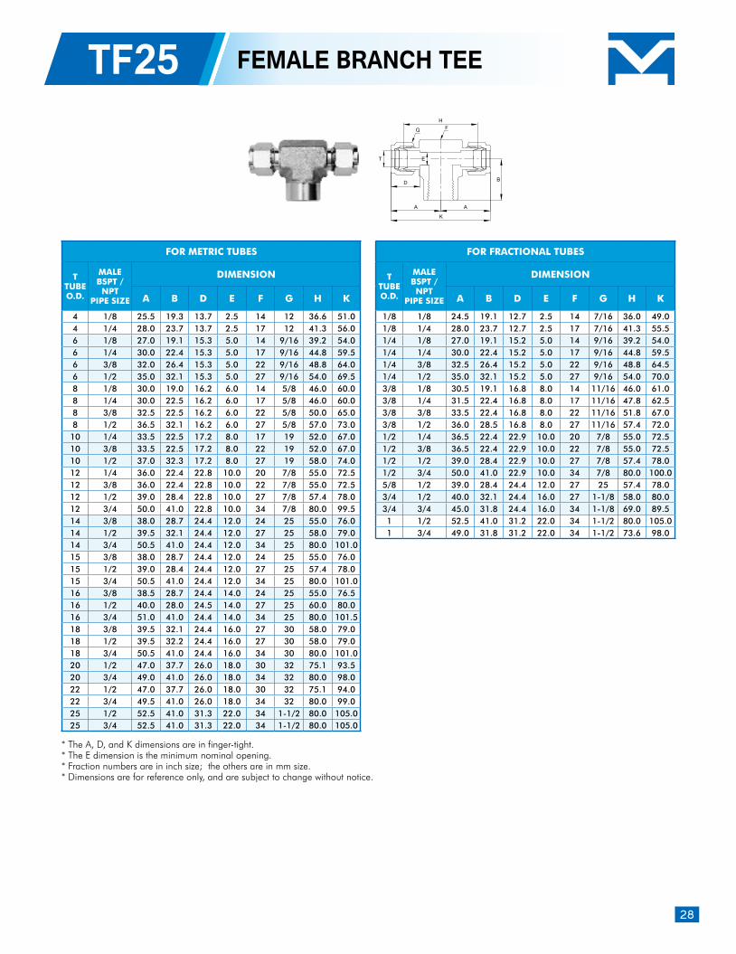
TF25 FEMALE BRANCH TEE
* The A, D, and K dimensions are in finger-tight.* The E dimension is the minimum nominal opening.* Fraction numbers are in inch size; the others are in mm size. * Dimensions are for reference only, and are subject to change without notice.
FOR METRIC TUBES
TTUBEO.D.
MALEBSPT / NPT
PIPE SIZE
DIMENSION
A B D E F G H K
4 1/8 25.5 19.3 13.7 2.5 14 12 36.6 51.0 4 1/4 28.0 23.7 13.7 2.5 17 12 41.3 56.0 6 1/8 27.0 19.1 15.3 5.0 14 9/16 39.2 54.0 6 1/4 30.0 22.4 15.3 5.0 17 9/16 44.8 59.5 6 3/8 32.0 26.4 15.3 5.0 22 9/16 48.8 64.0 6 1/2 35.0 32.1 15.3 5.0 27 9/16 54.0 69.5 8 1/8 30.0 19.0 16.2 6.0 14 5/8 46.0 60.0 8 1/4 30.0 22.5 16.2 6.0 17 5/8 46.0 60.0 8 3/8 32.5 22.5 16.2 6.0 22 5/8 50.0 65.0 8 1/2 36.5 32.1 16.2 6.0 27 5/8 57.0 73.0 10 1/4 33.5 22.5 17.2 8.0 17 19 52.0 67.0 10 3/8 33.5 22.5 17.2 8.0 22 19 52.0 67.0 10 1/2 37.0 32.3 17.2 8.0 27 19 58.0 74.0 12 1/4 36.0 22.4 22.8 10.0 20 7/8 55.0 72.5 12 3/8 36.0 22.4 22.8 10.0 22 7/8 55.0 72.5 12 1/2 39.0 28.4 22.8 10.0 27 7/8 57.4 78.0 12 3/4 50.0 41.0 22.8 10.0 34 7/8 80.0 99.5 14 3/8 38.0 28.7 24.4 12.0 24 25 55.0 76.0 14 1/2 39.5 32.1 24.4 12.0 27 25 58.0 79.0 14 3/4 50.5 41.0 24.4 12.0 34 25 80.0 101.0 15 3/8 38.0 28.7 24.4 12.0 24 25 55.0 76.0 15 1/2 39.0 28.4 24.4 12.0 27 25 57.4 78.0 15 3/4 50.5 41.0 24.4 12.0 34 25 80.0 101.0 16 3/8 38.5 28.7 24.4 14.0 24 25 55.0 76.5 16 1/2 40.0 28.0 24.5 14.0 27 25 60.0 80.0 16 3/4 51.0 41.0 24.4 14.0 34 25 80.0 101.5 18 3/8 39.5 32.1 24.4 16.0 27 30 58.0 79.0 18 1/2 39.5 32.2 24.4 16.0 27 30 58.0 79.0 18 3/4 50.5 41.0 24.4 16.0 34 30 80.0 101.0 20 1/2 47.0 37.7 26.0 18.0 30 32 75.1 93.5 20 3/4 49.0 41.0 26.0 18.0 34 32 80.0 98.0 22 1/2 47.0 37.7 26.0 18.0 30 32 75.1 94.0 22 3/4 49.5 41.0 26.0 18.0 34 32 80.0 99.0 25 1/2 52.5 41.0 31.3 22.0 34 1-1/2 80.0 105.0 25 3/4 52.5 41.0 31.3 22.0 34 1-1/2 80.0 105.0
FOR FRACTIONAL TUBES
TTUBEO.D.
MALEBSPT / NPT
PIPE SIZE
DIMENSION
A B D E F G H K
1/8 1/8 24.5 19.1 12.7 2.5 14 7/16 36.0 49.0 1/8 1/4 28.0 23.7 12.7 2.5 17 7/16 41.3 55.5 1/4 1/8 27.0 19.1 15.2 5.0 14 9/16 39.2 54.0 1/4 1/4 30.0 22.4 15.2 5.0 17 9/16 44.8 59.5 1/4 3/8 32.5 26.4 15.2 5.0 22 9/16 48.8 64.5 1/4 1/2 35.0 32.1 15.2 5.0 27 9/16 54.0 70.0 3/8 1/8 30.5 19.1 16.8 8.0 14 11/16 46.0 61.0 3/8 1/4 31.5 22.4 16.8 8.0 17 11/16 47.8 62.5 3/8 3/8 33.5 22.4 16.8 8.0 22 11/16 51.8 67.0 3/8 1/2 36.0 28.5 16.8 8.0 27 11/16 57.4 72.0 1/2 1/4 36.5 22.4 22.9 10.0 20 7/8 55.0 72.5 1/2 3/8 36.5 22.4 22.9 10.0 22 7/8 55.0 72.5 1/2 1/2 39.0 28.4 22.9 10.0 27 7/8 57.4 78.0 1/2 3/4 50.0 41.0 22.9 10.0 34 7/8 80.0 100.0 5/8 1/2 39.0 28.4 24.4 12.0 27 25 57.4 78.0 3/4 1/2 40.0 32.1 24.4 16.0 27 1-1/8 58.0 80.0 3/4 3/4 45.0 31.8 24.4 16.0 34 1-1/8 69.0 89.5 1 1/2 52.5 41.0 31.2 22.0 34 1-1/2 80.0 105.0 1 3/4 49.0 31.8 31.2 22.0 34 1-1/2 73.6 98.0
H
ET
A
K
D B
A
FG
29
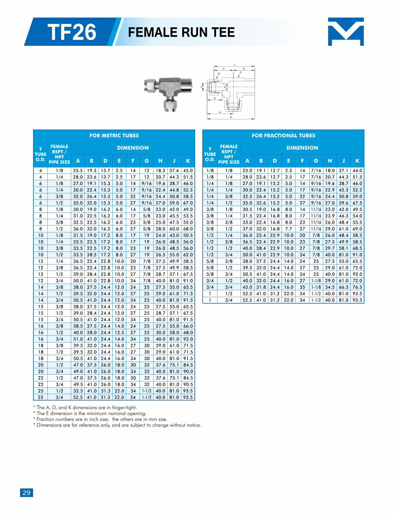
TF26 FEMALE RUN TEE
* The A, D, and K dimensions are in finger-tight.* The E dimension is the minimum nominal opening.* Fraction numbers are in inch size; the others are in mm size. * Dimensions are for reference only, and are subject to change without notice.
FOR METRIC TUBES
TTUBEO.D.
FEMALEBSPT / NPT
PIPE SIZE
DIMENSION
A B D E F G H J K
4 1/8 25.5 19.3 13.7 2.5 14 12 18.3 37.6 45.0 4 1/4 28.0 23.6 13.7 2.5 17 12 20.7 44.3 51.5 6 1/8 27.0 19.1 15.3 5.0 14 9/16 19.6 38.7 46.0 6 1/4 30.0 22.4 15.3 5.0 17 9/16 22.4 44.8 52.5 6 3/8 32.0 26.4 15.3 5.0 22 9/16 24.4 50.8 58.5 6 1/2 35.0 32.0 15.3 5.0 27 9/16 27.0 59.0 67.0 8 1/8 30.0 19.0 16.2 6.0 14 5/8 23.0 42.0 49.0 8 1/4 31.0 22.5 16.2 6.0 17 5/8 23.0 45.5 53.5 8 3/8 32.5 22.5 16.2 6.0 23 5/8 25.0 47.5 55.0 8 1/2 36.0 32.0 16.2 6.0 27 5/8 28.0 60.0 68.0 10 1/8 31.5 19.0 17.2 8.0 17 19 24.0 43.0 50.5 10 1/4 33.5 22.5 17.2 8.0 17 19 26.0 48.5 56.0 10 3/8 33.5 22.5 17.2 8.0 23 19 26.0 48.5 56.0 10 1/2 33.5 28.5 17.2 8.0 27 19 26.5 55.0 62.0 12 1/4 36.5 22.4 22.8 10.0 20 7/8 27.5 49.9 58.5 12 3/8 36.5 22.4 22.8 10.0 23 7/8 27.5 49.9 58.5 12 1/2 39.0 28.4 22.8 10.0 27 7/8 28.7 57.1 67.5 12 3/4 50.0 41.0 22.8 10.0 34 7/8 40.0 81.0 91.0 14 3/8 38.0 27.5 24.4 12.0 24 25 27.5 55.0 65.5 14 1/2 39.5 32.0 24.4 12.0 27 25 29.0 61.0 71.5 14 3/4 50.5 41.0 24.4 12.0 34 25 40.0 81.0 91.5 15 3/8 38.0 27.5 24.4 12.0 24 25 27.5 55.0 65.5 15 1/2 39.0 28.4 24.4 12.0 27 25 28.7 57.1 67.5 15 3/4 50.5 41.0 24.4 12.0 34 25 40.0 81.0 91.5 16 3/8 38.5 27.5 24.4 14.0 24 25 27.5 55.0 66.0 16 1/2 40.0 28.0 24.4 12.5 27 25 30.0 58.0 68.0 16 3/4 51.0 41.0 24.4 14.0 34 25 40.0 81.0 92.0 18 3/8 39.5 32.0 24.4 16.0 27 30 29.0 61.0 71.5 18 1/2 39.5 32.0 24.4 16.0 27 30 29.0 61.0 71.5 18 3/4 50.5 41.0 24.4 16.0 34 30 40.0 81.0 91.5 20 1/2 47.0 37.5 26.0 18.0 30 32 37.6 75.1 84.5 20 3/4 49.0 41.0 26.0 18.0 34 32 40.0 81.0 90.0 22 1/2 47.0 37.5 26.0 18.0 30 32 37.6 75.1 84.5 22 3/4 49.5 41.0 26.0 18.0 34 32 40.0 81.0 90.5 25 1/2 52.5 41.0 31.3 22.0 34 1-1/2 40.0 81.0 93.5 25 3/4 52.5 41.0 31.3 22.0 34 1-1/2 40.0 81.0 93.5
FOR FRACTIONAL TUBES
TTUBEO.D.
FEMALEBSPT / NPT
PIPE SIZE
DIMENSION
A B D E F G H J K
1/8 1/8 25.0 19.1 12.7 2.5 14 7/16 18.0 37.1 44.0 1/8 1/4 28.0 23.6 12.7 2.5 17 7/16 20.7 44.3 51.5 1/4 1/8 27.0 19.1 15.2 5.0 14 9/16 19.6 38.7 46.0 1/4 1/4 30.0 22.4 15.2 5.0 17 9/16 22.9 45.3 52.5 1/4 3/8 32.5 26.4 15.2 5.0 22 9/16 24.4 50.8 59.0 1/4 1/2 35.0 32.6 15.2 5.0 27 9/16 27.0 59.6 67.5 3/8 1/8 30.5 19.0 16.8 8.0 14 11/16 23.0 42.0 49.5 3/8 1/4 31.5 22.4 16.8 8.0 17 11/16 23.9 46.3 54.0 3/8 3/8 33.0 22.4 16.8 8.0 23 11/16 26.0 48.4 55.5 3/8 1/2 37.0 32.0 16.8 7.7 27 11/16 29.0 61.0 69.0 1/2 1/4 36.0 22.4 22.9 10.0 20 7/8 26.0 48.4 58.5 1/2 3/8 36.5 22.4 22.9 10.0 23 7/8 27.5 49.9 58.5 1/2 1/2 40.0 28.4 22.9 10.0 27 7/8 29.7 58.1 68.5 1/2 3/4 50.0 41.0 22.9 10.0 34 7/8 40.0 81.0 91.0 5/8 3/8 38.0 27.5 24.4 14.0 24 25 27.5 55.0 65.5 5/8 1/2 39.5 32.0 24.4 14.0 27 25 29.0 61.0 72.0 5/8 3/4 50.5 41.0 24.4 14.0 34 25 40.0 81.0 92.0 3/4 1/2 40.0 32.0 24.4 16.0 27 1-1/8 29.0 61.0 72.0 3/4 3/4 45.0 31.8 24.4 16.0 35 1-1/8 34.5 66.3 76.5 1 1/2 52.5 41.0 31.2 22.0 34 1-1/2 40.0 81.0 93.5 1 3/4 52.5 41.0 31.2 22.0 34 1-1/2 40.0 81.0 93.5
J
E
H
T
D
A
K
B
FG
30
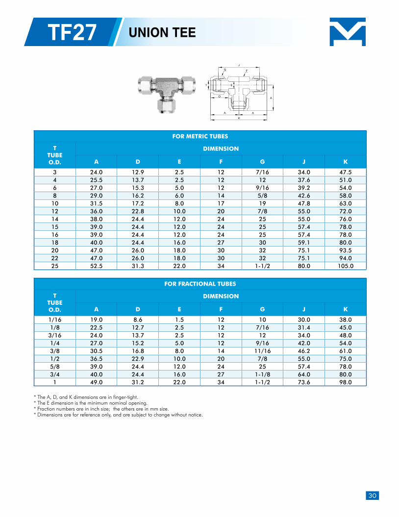
TF27 UNION TEE
* The A, D, and K dimensions are in finger-tight.* The E dimension is the minimum nominal opening.* Fraction numbers are in inch size; the others are in mm size. * Dimensions are for reference only, and are subject to change without notice.
FOR METRIC TUBES
TTUBEO.D.
DIMENSION
A D E F G J K
3 24.0 12.9 2.5 12 7/16 34.0 47.5 4 25.5 13.7 2.5 12 12 37.6 51.0 6 27.0 15.3 5.0 12 9/16 39.2 54.0 8 29.0 16.2 6.0 14 5/8 42.6 58.0 10 31.5 17.2 8.0 17 19 47.8 63.0 12 36.0 22.8 10.0 20 7/8 55.0 72.0 14 38.0 24.4 12.0 24 25 55.0 76.0 15 39.0 24.4 12.0 24 25 57.4 78.0 16 39.0 24.4 12.0 24 25 57.4 78.0 18 40.0 24.4 16.0 27 30 59.1 80.0 20 47.0 26.0 18.0 30 32 75.1 93.5 22 47.0 26.0 18.0 30 32 75.1 94.0 25 52.5 31.3 22.0 34 1-1/2 80.0 105.0
FOR FRACTIONAL TUBES
TTUBEO.D.
DIMENSION
A D E F G J K
1/16 19.0 8.6 1.5 12 10 30.0 38.0 1/8 22.5 12.7 2.5 12 7/16 31.4 45.0 3/16 24.0 13.7 2.5 12 12 34.0 48.0 1/4 27.0 15.2 5.0 12 9/16 42.0 54.0 3/8 30.5 16.8 8.0 14 11/16 46.2 61.0 1/2 36.5 22.9 10.0 20 7/8 55.0 75.0 5/8 39.0 24.4 12.0 24 25 57.4 78.0 3/4 40.0 24.4 16.0 27 1-1/8 64.0 80.0 1 49.0 31.2 22.0 34 1-1/2 73.6 98.0
T
J
D
A
A
A
K
FG
E
31
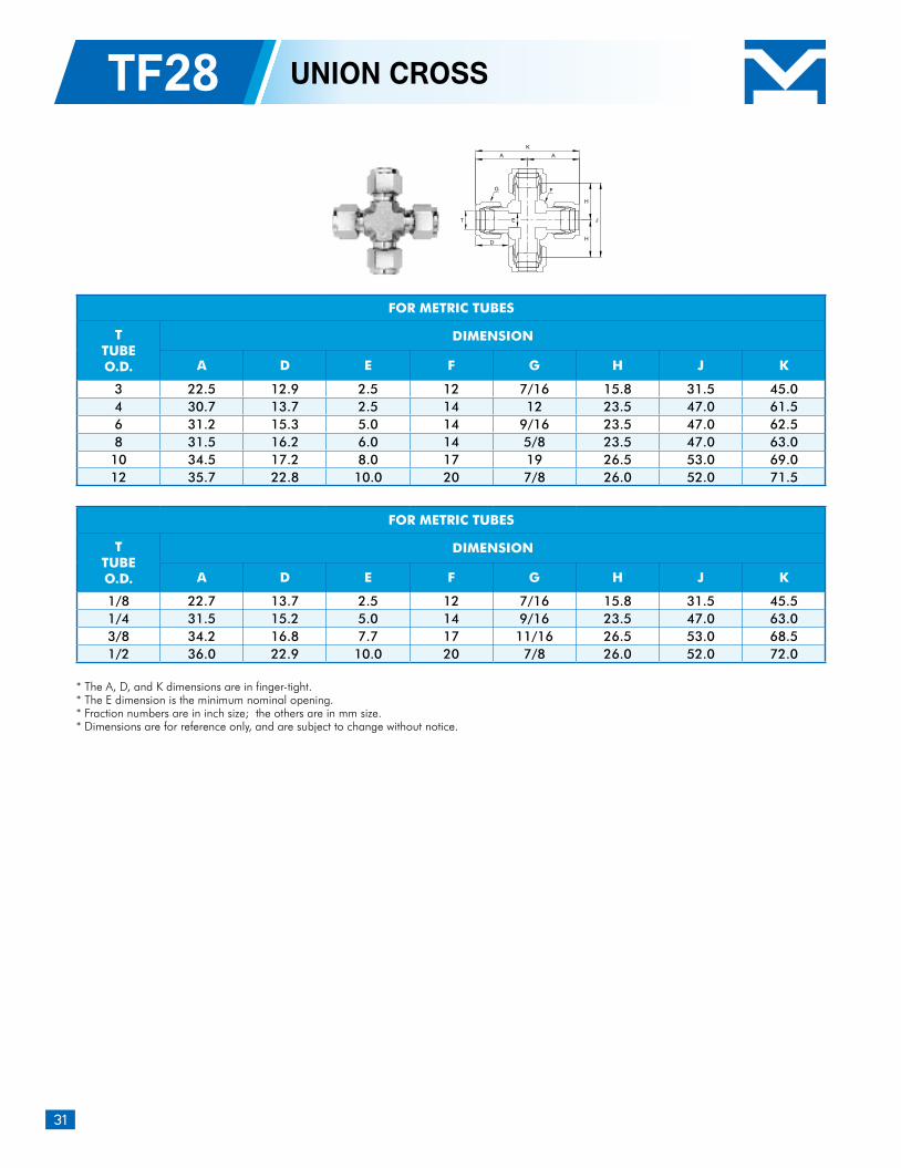
* The A, D, and K dimensions are in finger-tight.* The E dimension is the minimum nominal opening.* Fraction numbers are in inch size; the others are in mm size. * Dimensions are for reference only, and are subject to change without notice.
TF28 UNION CROSS
FOR METRIC TUBES
TTUBEO.D.
DIMENSION
A D E F G H J K
3 22.5 12.9 2.5 12 7/16 15.8 31.5 45.0 4 30.7 13.7 2.5 14 12 23.5 47.0 61.5 6 31.2 15.3 5.0 14 9/16 23.5 47.0 62.5 8 31.5 16.2 6.0 14 5/8 23.5 47.0 63.0 10 34.5 17.2 8.0 17 19 26.5 53.0 69.0 12 35.7 22.8 10.0 20 7/8 26.0 52.0 71.5
FOR METRIC TUBES
TTUBEO.D.
DIMENSION
A D E F G H J K
1/8 22.7 13.7 2.5 12 7/16 15.8 31.5 45.5 1/4 31.5 15.2 5.0 14 9/16 23.5 47.0 63.0 3/8 34.2 16.8 7.7 17 11/16 26.5 53.0 68.5 1/2 36.0 22.9 10.0 20 7/8 26.0 52.0 72.0
T
A
K
H
H
J
D
E
A
FG
32
Instrument Pipe Fittings
IntroductionHAITIMA Instrument Pipe Fittings are precision machined, and the quality threads provide dependable leak-free connections. The fittings are designed for widely application in petrochemical processing plants, chemical factories, instrumentation and process control purpose.
The system designer and user have the sole responsibility for selecting a product for their use. The total system design, application details, material compatibility, function, adequate ratings, proper installation, operation, and maintenance must be considered to ensure safe and trouble-free performance.
Features Bar stock body for straight configuration, and forging body for elbows and tees. A variety of configurations increase system versatility Rolled male thread enhance the strength Each body is stamped with size and material Male thread are capped to prevenet damage Size range: 1/8" ~ 1" Designed for use on instrumentation, process and control systems, and analyzer
Safety in Product Selection
33
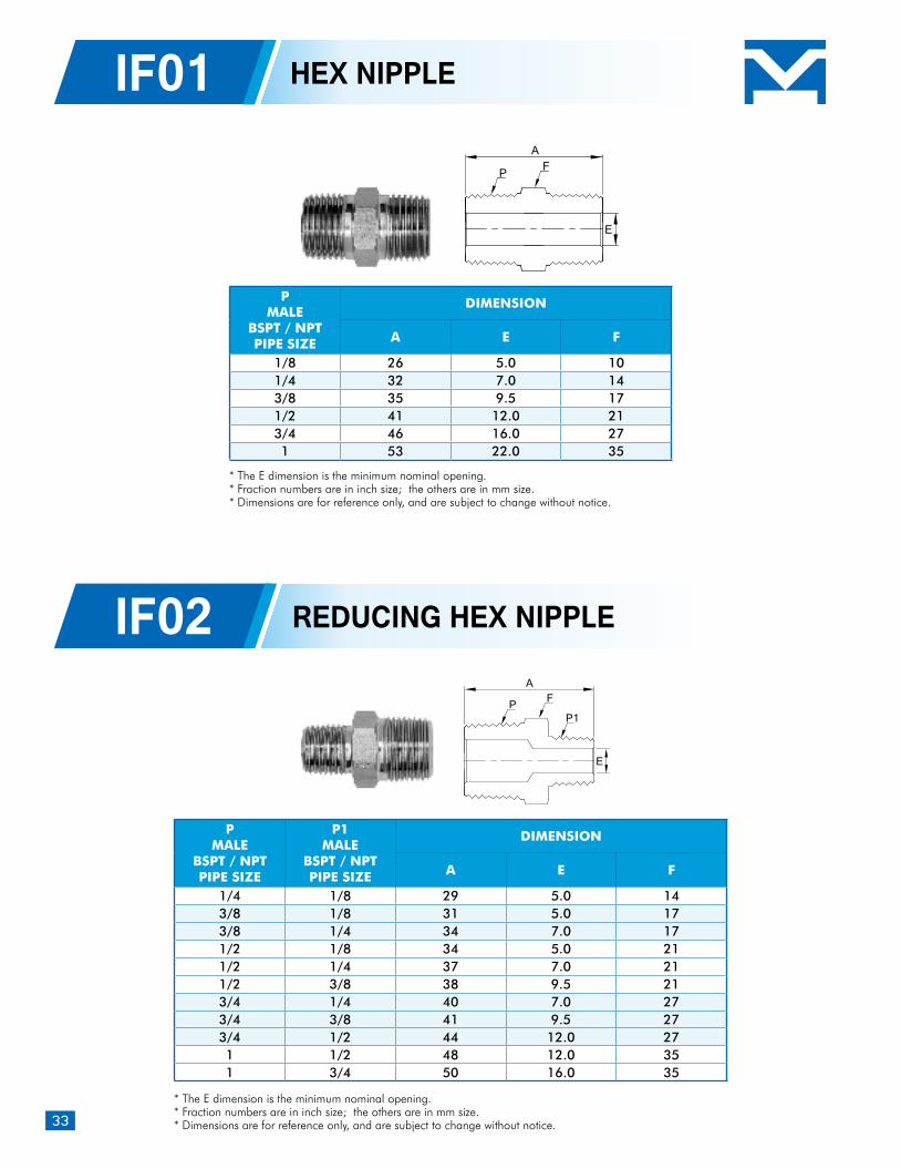
IF01 HEX NIPPLE
IF02 REDUCING HEX NIPPLE
PMALE
BSPT / NPTPIPE SIZE
DIMENSION
A E F
1/8 26 5.0 101/4 32 7.0 143/8 35 9.5 171/2 41 12.0 213/4 46 16.0 271 53 22.0 35
PMALE
BSPT / NPTPIPE SIZE
P1MALE
BSPT / NPTPIPE SIZE
DIMENSION
A E F
1/4 1/8 29 5.0 143/8 1/8 31 5.0 173/8 1/4 34 7.0 171/2 1/8 34 5.0 211/2 1/4 37 7.0 211/2 3/8 38 9.5 213/4 1/4 40 7.0 273/4 3/8 41 9.5 273/4 1/2 44 12.0 271 1/2 48 12.0 351 3/4 50 16.0 35
E
AFP
A
E
FPP1
* The E dimension is the minimum nominal opening.* Fraction numbers are in inch size; the others are in mm size. * Dimensions are for reference only, and are subject to change without notice.
* The E dimension is the minimum nominal opening.* Fraction numbers are in inch size; the others are in mm size. * Dimensions are for reference only, and are subject to change without notice.
34
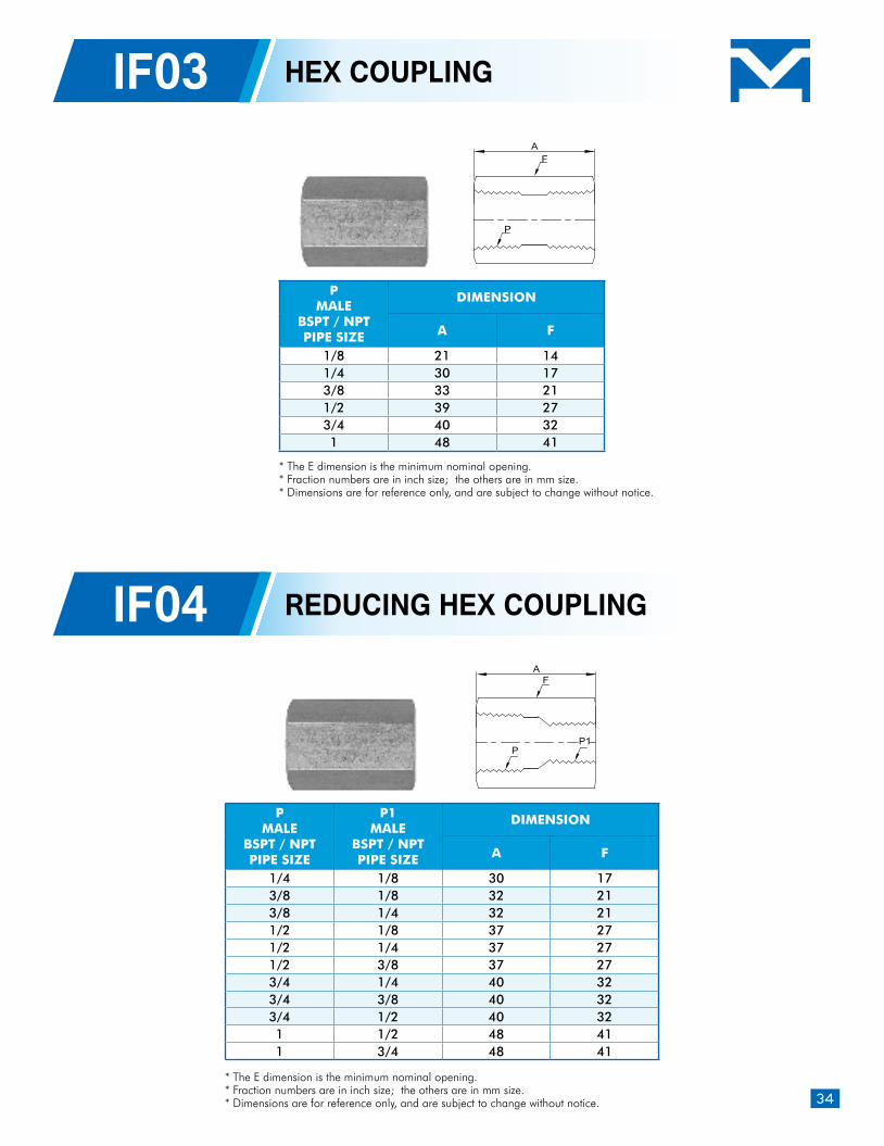
IF03 HEX COUPLING
IF04 REDUCING HEX COUPLING
PMALE
BSPT / NPTPIPE SIZE
DIMENSION
A F
1/8 21 141/4 30 173/8 33 211/2 39 273/4 40 321 48 41
PMALE
BSPT / NPTPIPE SIZE
P1MALE
BSPT / NPTPIPE SIZE
DIMENSION
A F
1/4 1/8 30 173/8 1/8 32 213/8 1/4 32 211/2 1/8 37 271/2 1/4 37 271/2 3/8 37 273/4 1/4 40 323/4 3/8 40 323/4 1/2 40 321 1/2 48 411 3/4 48 41
AF
P
AF
PP1
* The E dimension is the minimum nominal opening.* Fraction numbers are in inch size; the others are in mm size. * Dimensions are for reference only, and are subject to change without notice.
* The E dimension is the minimum nominal opening.* Fraction numbers are in inch size; the others are in mm size. * Dimensions are for reference only, and are subject to change without notice.
35
PMALE
BSPT / NPTPIPE SIZE
P1MALE
BSPT / NPTPIPE SIZE
DIMENSION
A E F
1/4 1/8 19 6.0 143/8 1/8 20 6.0 173/8 1/4 20 10.0 171/2 1/8 24 6.0 211/2 1/4 24 10.0 211/2 3/8 24 14.0 213/4 1/4 27 10.0 273/4 3/8 27 14.0 273/4 1/2 27 18.0 271 1/4 31 10.0 351 3/8 31 14.0 351 1/2 31 18.0 351 3/4 31 20.0 35
IF05 REDUCING ADAPTER
IF06 REDUCING BUSHING
PMALE
BSPT / NPTPIPE SIZE
P1MALE
BSPT / NPTPIPE SIZE
DIMENSION
A E F
1/8 1/8 24 5.0 141/4 1/8 26 5.0 171/4 1/4 29 7.0 173/8 1/8 27 5.0 213/8 1/4 30 7.0 213/8 3/8 31 9.5 211/2 1/8 30 5.0 271/2 1/4 33 7.0 271/2 3/8 34 9.5 271/2 1/2 37 12.0 273/4 1/4 35 7.0 323/4 3/8 36 9.5 323/4 1/2 39 12.0 323/4 3/4 41 16.0 321 1/2 45 12.0 411 3/4 47 16.0 411 1 50 22.0 41
A
E
F
P1
P
A
EP1
PF
* The E dimension is the minimum nominal opening.* Fraction numbers are in inch size; the others are in mm size. * Dimensions are for reference only, and are subject to change
without notice.
* The E dimension is the minimum nominal opening.* Fraction numbers are in inch size; the others are in
mm size. * Dimensions are for reference only, and are subject
to change without notice.
36
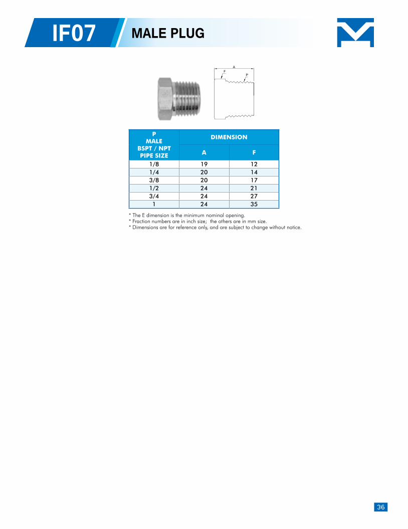
IF07 MALE PLUG
PMALE
BSPT / NPTPIPE SIZE
DIMENSION
A F
1/8 19 121/4 20 143/8 20 171/2 24 213/4 24 271 24 35
* The E dimension is the minimum nominal opening.* Fraction numbers are in inch size; the others are in mm size. * Dimensions are for reference only, and are subject to change without notice.
AF
P
37
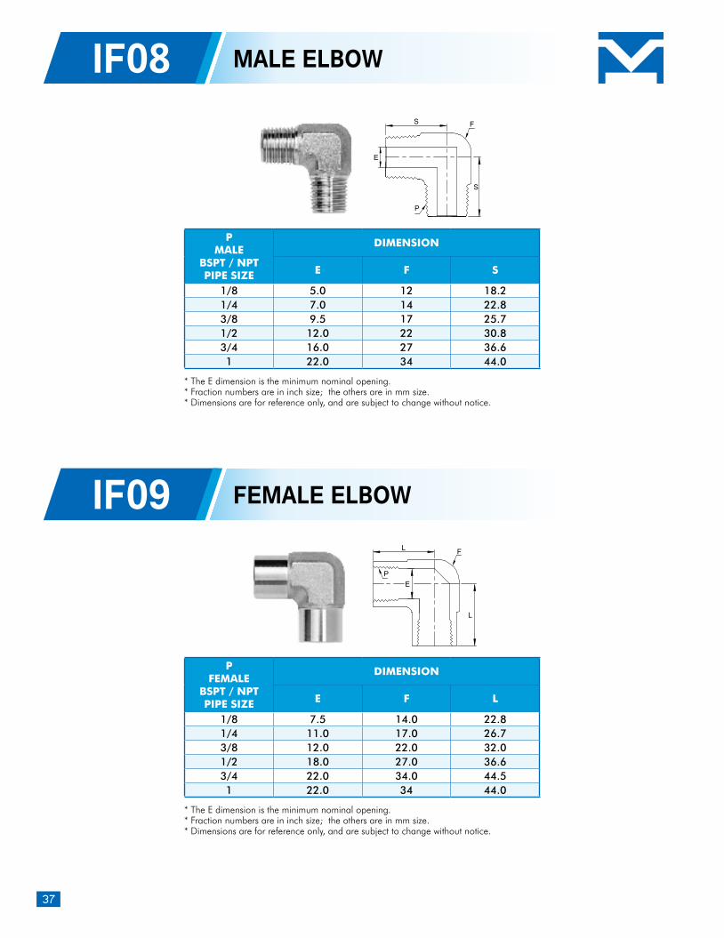
IF08 MALE ELBOW
PMALE
BSPT / NPTPIPE SIZE
DIMENSION
E F S
1/8 5.0 12 18.2 1/4 7.0 14 22.8 3/8 9.5 17 25.7 1/2 12.0 22 30.8 3/4 16.0 27 36.6 1 22.0 34 44.0
* The E dimension is the minimum nominal opening.* Fraction numbers are in inch size; the others are in mm size. * Dimensions are for reference only, and are subject to change without notice.
E
S
F
P
S
PFEMALE
BSPT / NPTPIPE SIZE
DIMENSION
E F L
1/8 7.5 14.0 22.8 1/4 11.0 17.0 26.7 3/8 12.0 22.0 32.0 1/2 18.0 27.0 36.6 3/4 22.0 34.0 44.5 1 22.0 34 44.0
IF09 FEMALE ELBOW
* The E dimension is the minimum nominal opening.* Fraction numbers are in inch size; the others are in mm size. * Dimensions are for reference only, and are subject to change without notice.
L
L
E
F
P
38
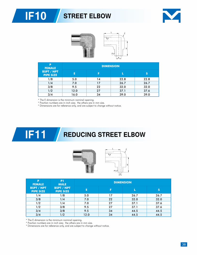
PFEMALE
BSPT / NPTPIPE SIZE
P1MALE
BSPT / NPTPIPE SIZE
DIMENSION
E F L S
1/4 1/8 5.0 17 26.7 26.7 3/8 1/4 7.0 22 32.0 32.0 1/2 1/4 7.0 27 37.1 37.6 1/2 3/8 9.5 27 37.1 37.6 3/4 3/8 9.5 34 44.5 44.5 3/4 1/2 12.0 34 44.5 44.5
IF11 REDUCING STREET ELBOW
* The E dimension is the minimum nominal opening.* Fraction numbers are in inch size; the others are in mm size. * Dimensions are for reference only, and are subject to change without notice.
L
S
E
F
P1
P
IF10 STREET ELBOW
PFEMALE
BSPT / NPTPIPE SIZE
DIMENSION
E F L S
1/8 5.0 14 22.8 22.8 1/4 7.0 17 26.7 26.7 3/8 9.5 22 32.0 32.0 1/2 12.0 27 37.1 37.6 3/4 16.0 34 39.0 39.0
* The E dimension is the minimum nominal opening.* Fraction numbers are in inch size; the others are in mm size. * Dimensions are for reference only, and are subject to change without notice.
E
L
S
F
P
P
39
IF12 MALE TEE
PFEMALE
BSPT / NPTPIPE SIZE
DIMENSION
A E F L
1/8 47 8 14 23.5 1/4 50 11 17 25.0 3/8 60 14 22 30.0 1/2 72 18 27 30.0 3/4 88 22 34 39.0
* The E dimension is the minimum nominal opening.* Fraction numbers are in inch size; the others are in mm size. * Dimensions are for reference only, and are subject to change without notice.
PMALE
BSPT / NPTPIPE SIZE
DIMENSION
A E F S
1/8 38.0 5.0 12 19.0 1/4 47.6 7.0 14 23.8 3/8 52.0 9.5 17 26.0 1/2 63.0 12.0 22 31.5 3/4 72.0 16.0 27 36.0
IF13 FEMALE TEE
* The E dimension is the minimum nominal opening.* Fraction numbers are in inch size; the others are in mm size. * Dimensions are for reference only, and are subject to change without notice.
S S
S
E
A
F
P
L L
A
E
F
P
40
PFEMALE / MALE
BSPT / NPTPIPE SIZE
DIMENSION
A E F L S
1/8 47.0 5.0 14 23.5 23.51/4 50.0 7.0 17 25.0 25.0 3/8 60.0 9.5 22 30.0 30.0 1/2 74.0 12.0 27 37.0 37.0 3/4 78.3 16.0 34 39.0 39.0
IF15 STREET TEE
* The E dimension is the minimum nominal opening.* Fraction numbers are in inch size; the others are in mm size. * Dimensions are for reference only, and are subject to change without notice.
L S
A
E
F
P
P
IF14 BRANCH TEE
PFEMALE / MALE
BSPT / NPTPIPE SIZE
DIMENSION
A E F L S
1/8 47.0 5.0 14 23.5 21.8 1/4 50.0 7.0 17 25.0 25.0 3/8 60.0 9.5 22 30.0 30.0 1/2 60.0 12.0 27 30.0 37.1 3/4 78.3 16.0 34 39.0 44.5
* The E dimension is the minimum nominal opening.* Fraction numbers are in inch size; the others are in mm size. * Dimensions are for reference only, and are subject to change without notice.
L L
S
A
E
F
P
P
41
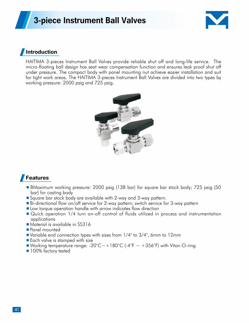
IntroductionHAITIMA 3-pieces Instrument Ball Valves provide reliable shut off and long-life service. The micro-floating ball design has seat wear compensation function and ensures leak proof shut off under pressure. The compact body with panel mounting nut achieve easier installation and suit for tight work areas. The HAITIMA 3-pieces Instrument Ball Valves are divided into two types by working pressure: 2000 psig and 725 psig.
Features BMaximum working pressure: 2000 psig (138 bar) for square bar stock body; 725 psig (50 bar) for casting body
Square bar stock body are available with 2-way and 3-way pattern. Bi-directional flow on/off service for 2-way pattern; switch service for 3-way pattern Low torque operation handle with arrow indicates flow direction Quick operation 1/4 turn on-off control of fluids utilized in process and instrumentation applications
Material is available in SS316 Panel mounted Variable end connection types with sizes from 1/4" to 3/4", 6mm to 12mm Each valve is stamped with size Working temperature range: -20°C~+180°C (-4°F ~ +356°F) with Viton O-ring 100% factory tested
3-piece Instrument Ball Valves
42
The system designer and user have the sole responsibility for selecting a product for their use. The total system design, application details, material compatibility, function, adequate ratings, proper installation, operation, and maintenance must be considered to ensure safe and trouble-free performance.
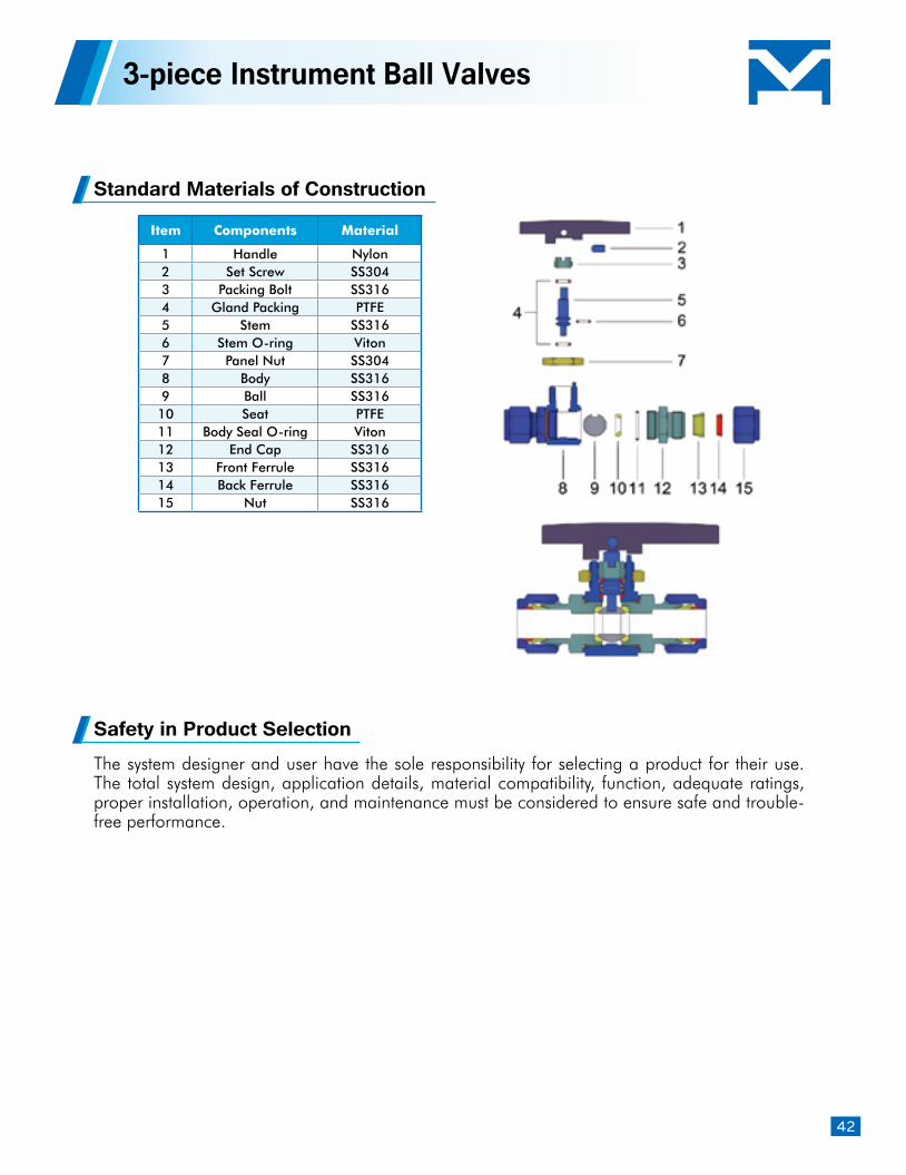
Standard Materials of Construction
Safety in Product Selection
3-piece Instrument Ball Valves
Item Components Material
1 Handle Nylon2 Set Screw SS3043 Packing Bolt SS3164 Gland Packing PTFE5 Stem SS3166 Stem O-ring Viton7 Panel Nut SS3048 Body SS3169 Ball SS316
10 Seat PTFE11 Body Seal O-ring Viton12 End Cap SS31613 Front Ferrule SS31614 Back Ferrule SS31615 Nut SS316
43
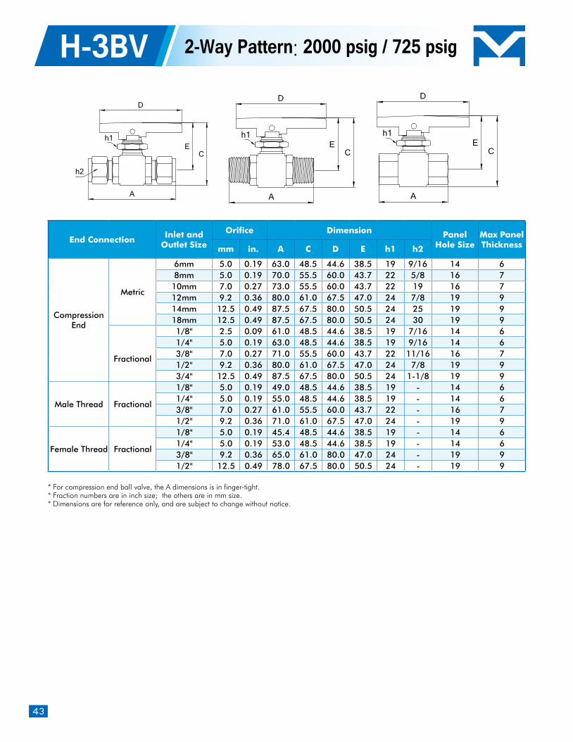
H-3BV 2-Way Pattern: 2000 psig / 725 psig
* For compression end ball valve, the A dimensions is in finger-tight.* Fraction numbers are in inch size; the others are in mm size. * Dimensions are for reference only, and are subject to change without notice.
End ConnectionInlet and
Outlet Size
Orifice Dimension Panel Hole Size
Max Panel Thicknessmm in. A C D E h1 h2
Compression End
Metric
6mm 5.0 0.19 63.0 48.5 44.6 38.5 19 9/16 14 68mm 5.0 0.19 70.0 55.5 60.0 43.7 22 5/8 16 710mm 7.0 0.27 73.0 55.5 60.0 43.7 22 19 16 712mm 9.2 0.36 80.0 61.0 67.5 47.0 24 7/8 19 914mm 12.5 0.49 87.5 67.5 80.0 50.5 24 25 19 918mm 12.5 0.49 87.5 67.5 80.0 50.5 24 30 19 9
Fractional
1/8" 2.5 0.09 61.0 48.5 44.6 38.5 19 7/16 14 61/4" 5.0 0.19 63.0 48.5 44.6 38.5 19 9/16 14 63/8" 7.0 0.27 71.0 55.5 60.0 43.7 22 11/16 16 71/2" 9.2 0.36 80.0 61.0 67.5 47.0 24 7/8 19 93/4" 12.5 0.49 87.5 67.5 80.0 50.5 24 1-1/8 19 9
Male Thread Fractional
1/8" 5.0 0.19 49.0 48.5 44.6 38.5 19 - 14 61/4" 5.0 0.19 55.0 48.5 44.6 38.5 19 - 14 63/8" 7.0 0.27 61.0 55.5 60.0 43.7 22 - 16 71/2" 9.2 0.36 71.0 61.0 67.5 47.0 24 - 19 9
Female Thread Fractional
1/8" 5.0 0.19 45.4 48.5 44.6 38.5 19 - 14 61/4" 5.0 0.19 53.0 48.5 44.6 38.5 19 - 14 63/8" 9.2 0.36 65.0 61.0 80.0 47.0 24 - 19 91/2" 12.5 0.49 78.0 67.5 80.0 50.5 24 - 19 9
EC
D
A
h1
h2
D
A
CE
h1
D
A
CE
h1
44
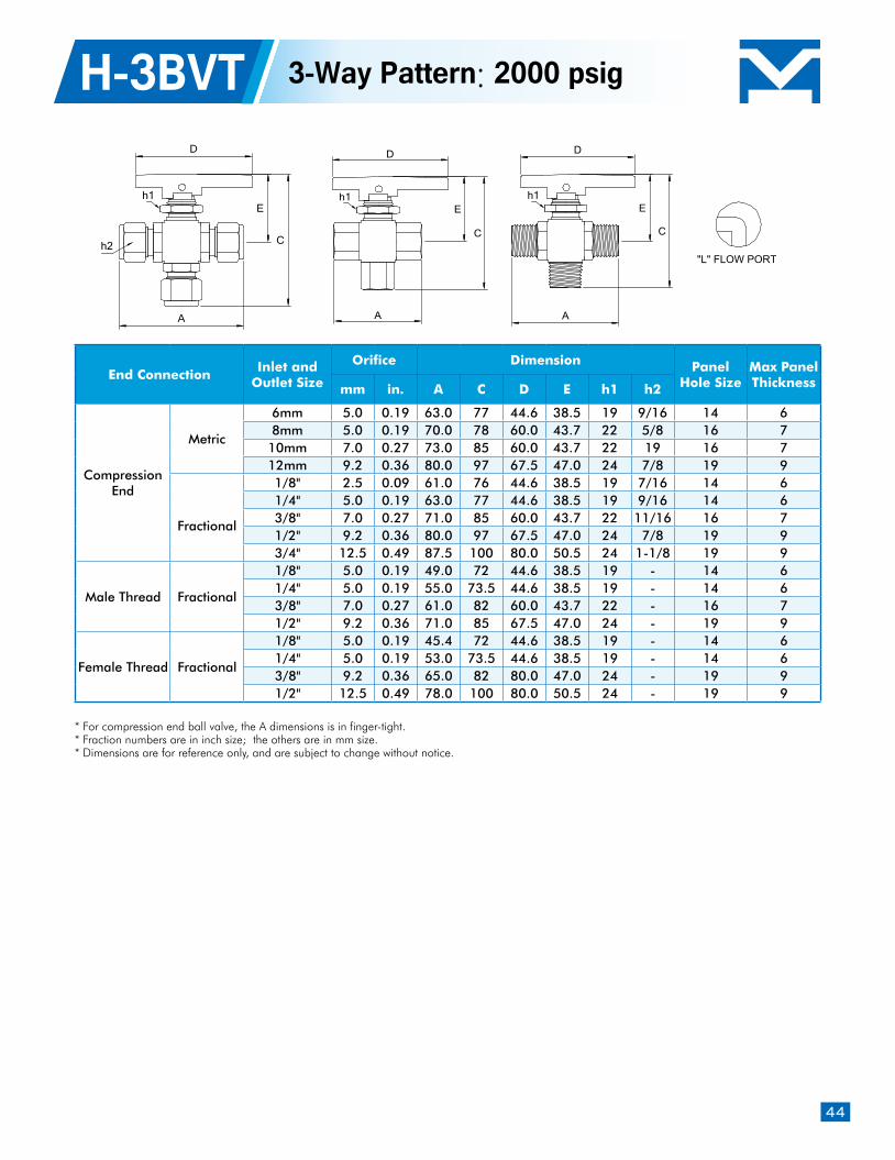
* For compression end ball valve, the A dimensions is in finger-tight.* Fraction numbers are in inch size; the others are in mm size. * Dimensions are for reference only, and are subject to change without notice.
End ConnectionInlet and
Outlet Size
Orifice Dimension Panel Hole Size
Max Panel Thicknessmm in. A C D E h1 h2
Compression End
Metric
6mm 5.0 0.19 63.0 77 44.6 38.5 19 9/16 14 68mm 5.0 0.19 70.0 78 60.0 43.7 22 5/8 16 710mm 7.0 0.27 73.0 85 60.0 43.7 22 19 16 712mm 9.2 0.36 80.0 97 67.5 47.0 24 7/8 19 9
Fractional
1/8" 2.5 0.09 61.0 76 44.6 38.5 19 7/16 14 61/4" 5.0 0.19 63.0 77 44.6 38.5 19 9/16 14 63/8" 7.0 0.27 71.0 85 60.0 43.7 22 11/16 16 71/2" 9.2 0.36 80.0 97 67.5 47.0 24 7/8 19 93/4" 12.5 0.49 87.5 100 80.0 50.5 24 1-1/8 19 9
Male Thread Fractional
1/8" 5.0 0.19 49.0 72 44.6 38.5 19 - 14 61/4" 5.0 0.19 55.0 73.5 44.6 38.5 19 - 14 63/8" 7.0 0.27 61.0 82 60.0 43.7 22 - 16 71/2" 9.2 0.36 71.0 85 67.5 47.0 24 - 19 9
Female Thread Fractional
1/8" 5.0 0.19 45.4 72 44.6 38.5 19 - 14 61/4" 5.0 0.19 53.0 73.5 44.6 38.5 19 - 14 63/8" 9.2 0.36 65.0 82 80.0 47.0 24 - 19 91/2" 12.5 0.49 78.0 100 80.0 50.5 24 - 19 9
H-3BVT 3-Way Pattern: 2000 psig
D
A
E
C
h1
D
A
E
C
"L" FLOW PORT
h1
D
A
E
C
h1
h2
45
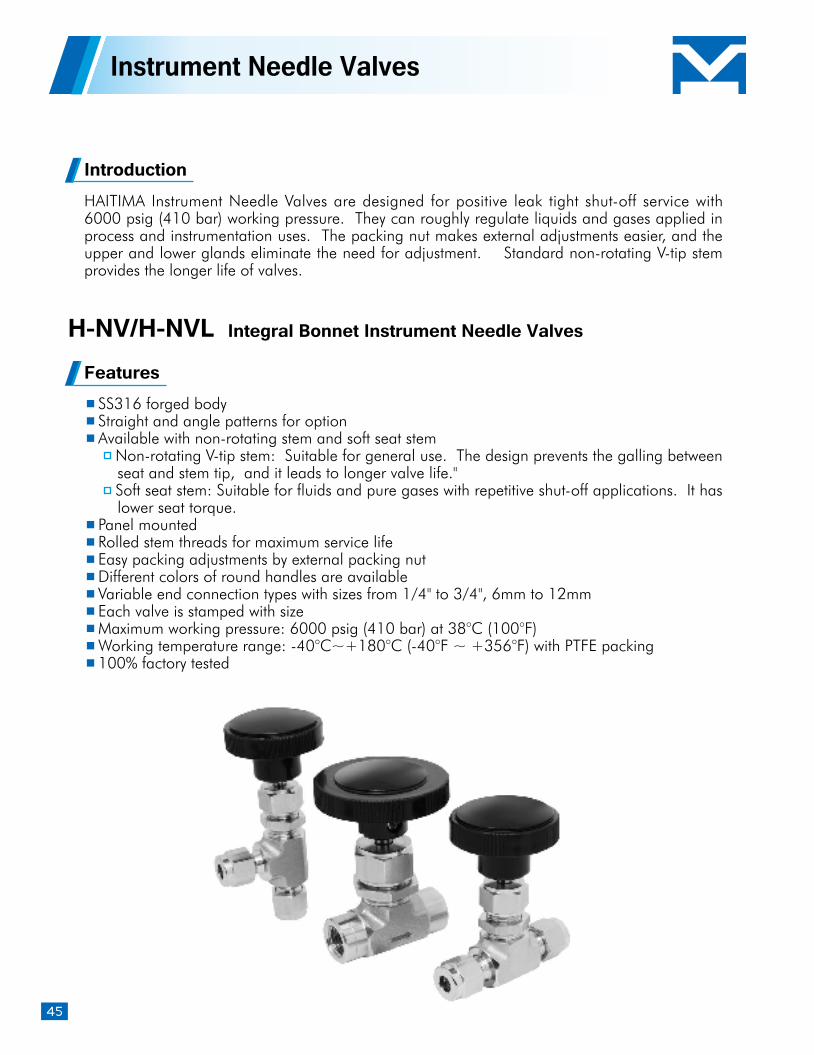
IntroductionHAITIMA Instrument Needle Valves are designed for positive leak tight shut-off service with 6000 psig (410 bar) working pressure. They can roughly regulate liquids and gases applied in process and instrumentation uses. The packing nut makes external adjustments easier, and the upper and lower glands eliminate the need for adjustment. Standard non-rotating V-tip stem provides the longer life of valves.
Features SS316 forged body Straight and angle patterns for option Available with non-rotating stem and soft seat stem
Non-rotating V-tip stem: Suitable for general use. The design prevents the galling between seat and stem tip, and it leads to longer valve life." Soft seat stem: Suitable for fluids and pure gases with repetitive shut-off applications. It has lower seat torque.
Panel mounted Rolled stem threads for maximum service life Easy packing adjustments by external packing nut Different colors of round handles are available Variable end connection types with sizes from 1/4" to 3/4", 6mm to 12mm Each valve is stamped with size Maximum working pressure: 6000 psig (410 bar) at 38°C (100°F) Working temperature range: -40°C~+180°C (-40°F ~ +356°F) with PTFE packing 100% factory tested
Instrument Needle Valves
H-NV/H-NVL Integral Bonnet Instrument Needle Valves
46
The system designer and user have the sole responsibility for selecting a product for their use. The total system design, application details, material compatibility, function, adequate ratings, proper installation, operation, and maintenance must be considered to ensure safe and trouble-free performance.
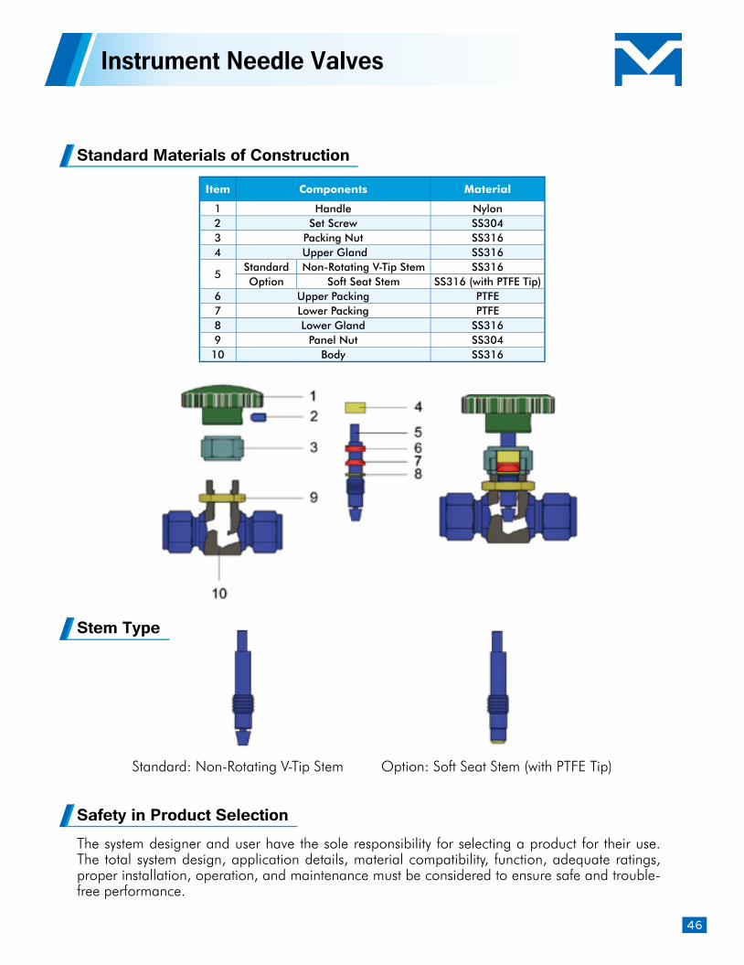
Standard Materials of Construction
Stem Type
Safety in Product Selection
Instrument Needle Valves
Item Components Material
1 Handle Nylon2 Set Screw SS3043 Packing Nut SS3164 Upper Gland SS316
5Standard Non-Rotating V-Tip Stem SS316Option Soft Seat Stem SS316 (with PTFE Tip)
6 Upper Packing PTFE7 Lower Packing PTFE8 Lower Gland SS3169 Panel Nut SS30410 Body SS316
Standard: Non-Rotating V-Tip Stem Option: Soft Seat Stem (with PTFE Tip)
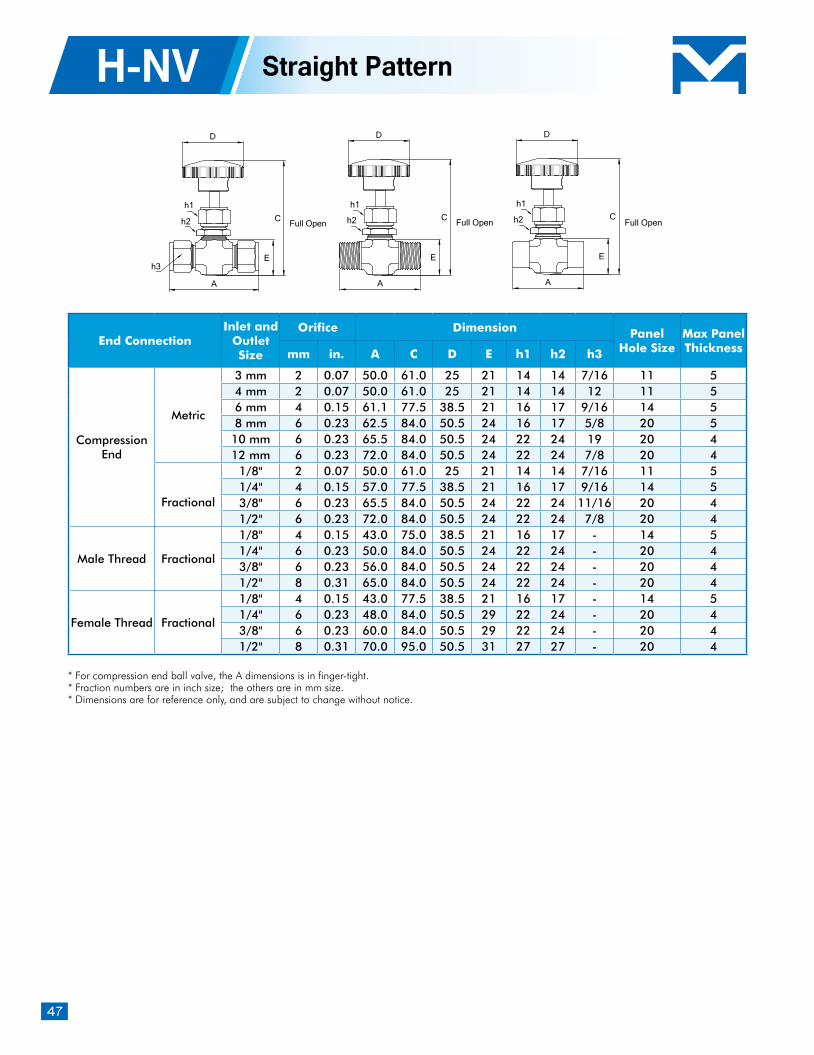
47
H-NV
* For compression end ball valve, the A dimensions is in finger-tight.* Fraction numbers are in inch size; the others are in mm size. * Dimensions are for reference only, and are subject to change without notice.
End ConnectionInlet and
Outlet Size
Orifice Dimension Panel Hole Size
Max Panel Thicknessmm in. A C D E h1 h2 h3
Compression End
Metric
3 mm 2 0.07 50.0 61.0 25 21 14 14 7/16 11 54 mm 2 0.07 50.0 61.0 25 21 14 14 12 11 56 mm 4 0.15 61.1 77.5 38.5 21 16 17 9/16 14 58 mm 6 0.23 62.5 84.0 50.5 24 16 17 5/8 20 5
10 mm 6 0.23 65.5 84.0 50.5 24 22 24 19 20 412 mm 6 0.23 72.0 84.0 50.5 24 22 24 7/8 20 4
Fractional
1/8" 2 0.07 50.0 61.0 25 21 14 14 7/16 11 51/4" 4 0.15 57.0 77.5 38.5 21 16 17 9/16 14 53/8" 6 0.23 65.5 84.0 50.5 24 22 24 11/16 20 41/2" 6 0.23 72.0 84.0 50.5 24 22 24 7/8 20 4
Male Thread Fractional
1/8" 4 0.15 43.0 75.0 38.5 21 16 17 - 14 51/4" 6 0.23 50.0 84.0 50.5 24 22 24 - 20 43/8" 6 0.23 56.0 84.0 50.5 24 22 24 - 20 41/2" 8 0.31 65.0 84.0 50.5 24 22 24 - 20 4
Female Thread Fractional
1/8" 4 0.15 43.0 77.5 38.5 21 16 17 - 14 51/4" 6 0.23 48.0 84.0 50.5 29 22 24 - 20 43/8" 6 0.23 60.0 84.0 50.5 29 22 24 - 20 41/2" 8 0.31 70.0 95.0 50.5 31 27 27 - 20 4
Straight Pattern
D
A
C
Eh3
h2
h1
Full Open
D
C
E
h1
h2
A
Full Open
D
A
C
E
h1
h2 Full Open
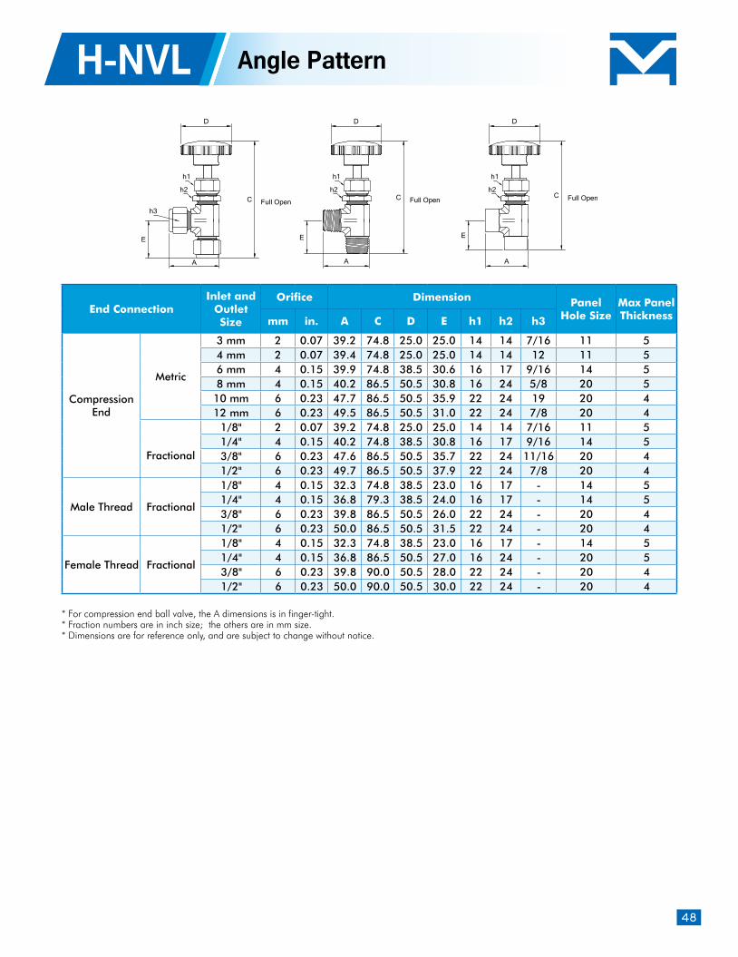
48
* For compression end ball valve, the A dimensions is in finger-tight.* Fraction numbers are in inch size; the others are in mm size. * Dimensions are for reference only, and are subject to change without notice.
End ConnectionInlet and
Outlet Size
Orifice Dimension Panel Hole Size
Max Panel Thicknessmm in. A C D E h1 h2 h3
Compression End
Metric
3 mm 2 0.07 39.2 74.8 25.0 25.0 14 14 7/16 11 54 mm 2 0.07 39.4 74.8 25.0 25.0 14 14 12 11 56 mm 4 0.15 39.9 74.8 38.5 30.6 16 17 9/16 14 58 mm 4 0.15 40.2 86.5 50.5 30.8 16 24 5/8 20 510 mm 6 0.23 47.7 86.5 50.5 35.9 22 24 19 20 412 mm 6 0.23 49.5 86.5 50.5 31.0 22 24 7/8 20 4
Fractional
1/8" 2 0.07 39.2 74.8 25.0 25.0 14 14 7/16 11 51/4" 4 0.15 40.2 74.8 38.5 30.8 16 17 9/16 14 53/8" 6 0.23 47.6 86.5 50.5 35.7 22 24 11/16 20 41/2" 6 0.23 49.7 86.5 50.5 37.9 22 24 7/8 20 4
Male Thread Fractional
1/8" 4 0.15 32.3 74.8 38.5 23.0 16 17 - 14 51/4" 4 0.15 36.8 79.3 38.5 24.0 16 17 - 14 53/8" 6 0.23 39.8 86.5 50.5 26.0 22 24 - 20 41/2" 6 0.23 50.0 86.5 50.5 31.5 22 24 - 20 4
Female Thread Fractional
1/8" 4 0.15 32.3 74.8 38.5 23.0 16 17 - 14 51/4" 4 0.15 36.8 86.5 50.5 27.0 16 24 - 20 53/8" 6 0.23 39.8 90.0 50.5 28.0 22 24 - 20 41/2" 6 0.23 50.0 90.0 50.5 30.0 22 24 - 20 4
H-NVL Angle Pattern
C
D
C
D
C
D
AAA
h1
h2
h3
h1
h2
h1
h2
E E E
Full OpenFull OpenFull Open
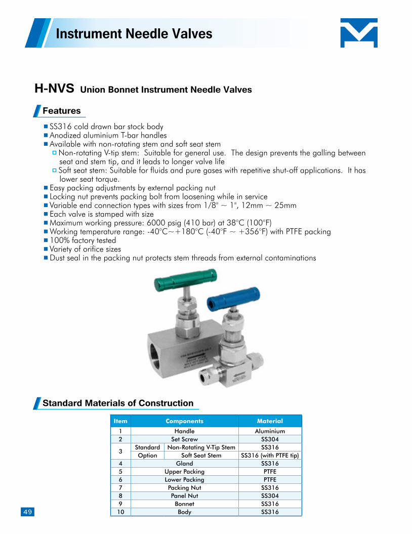
49
H-NVS Union Bonnet Instrument Needle Valves
Features SS316 cold drawn bar stock body Anodized aluminium T-bar handles Available with non-rotating stem and soft seat stem
Non-rotating V-tip stem: Suitable for general use. The design prevents the galling between seat and stem tip, and it leads to longer valve life
Soft seat stem: Suitable for fluids and pure gases with repetitive shut-off applications. It has lower seat torque.
Easy packing adjustments by external packing nut Locking nut prevents packing bolt from loosening while in service Variable end connection types with sizes from 1/8" ~ 1", 12mm ~ 25mm Each valve is stamped with size Maximum working pressure: 6000 psig (410 bar) at 38°C (100°F) Working temperature range: -40°C~+180°C (-40°F ~ +356°F) with PTFE packing 100% factory tested Variety of orifice sizes Dust seal in the packing nut protects stem threads from external contaminations
Instrument Needle Valves
Item Components Material
1 Handle Aluminium2 Set Screw SS304
3Standard Non-Rotating V-Tip Stem SS316Option Soft Seat Stem SS316 (with PTFE tip)
4 Gland SS3165 Upper Packing PTFE6 Lower Packing PTFE7 Packing Nut SS3168 Panel Nut SS3049 Bonnet SS31610 Body SS316
Standard Materials of Construction
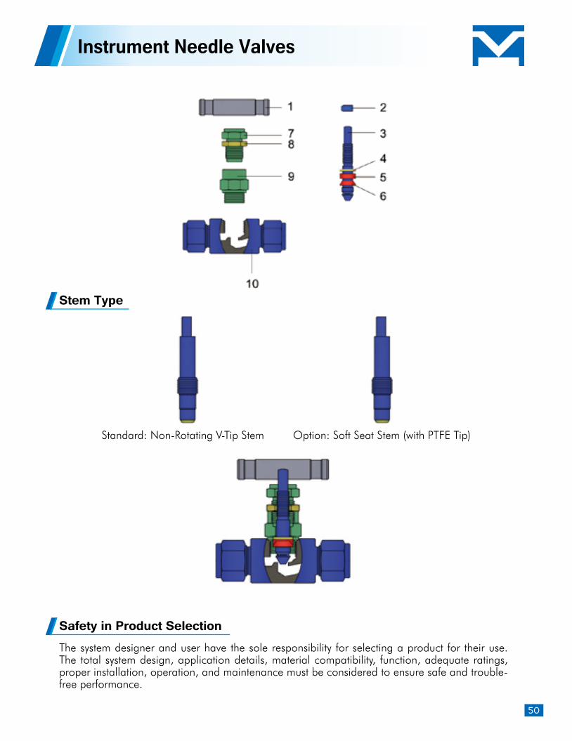
50
The system designer and user have the sole responsibility for selecting a product for their use. The total system design, application details, material compatibility, function, adequate ratings, proper installation, operation, and maintenance must be considered to ensure safe and trouble-free performance.
Safety in Product Selection
Instrument Needle Valves
Stem Type
Standard: Non-Rotating V-Tip Stem Option: Soft Seat Stem (with PTFE Tip)
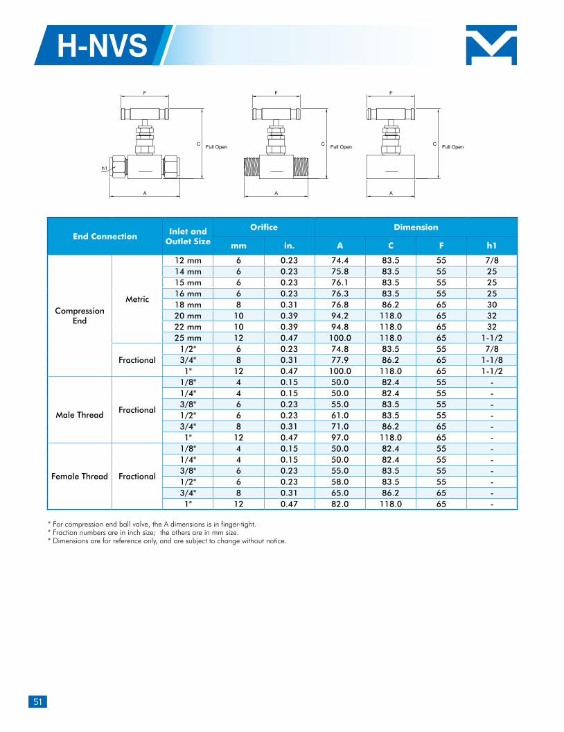
51
H-NVS
* For compression end ball valve, the A dimensions is in finger-tight.* Fraction numbers are in inch size; the others are in mm size. * Dimensions are for reference only, and are subject to change without notice.
End ConnectionInlet and
Outlet Size
Orifice Dimension
mm in. A C F h1
Compression End
Metric
12 mm 6 0.23 74.4 83.5 55 7/814 mm 6 0.23 75.8 83.5 55 2515 mm 6 0.23 76.1 83.5 55 2516 mm 6 0.23 76.3 83.5 55 2518 mm 8 0.31 76.8 86.2 65 3020 mm 10 0.39 94.2 118.0 65 3222 mm 10 0.39 94.8 118.0 65 3225 mm 12 0.47 100.0 118.0 65 1-1/2
Fractional1/2" 6 0.23 74.8 83.5 55 7/83/4" 8 0.31 77.9 86.2 65 1-1/81" 12 0.47 100.0 118.0 65 1-1/2
Male Thread
Fractional
1/8" 4 0.15 50.0 82.4 55 -1/4" 4 0.15 50.0 82.4 55 -3/8" 6 0.23 55.0 83.5 55 -1/2" 6 0.23 61.0 83.5 55 -3/4" 8 0.31 71.0 86.2 65 -1" 12 0.47 97.0 118.0 65 -
Female Thread Fractional
1/8" 4 0.15 50.0 82.4 55 -1/4" 4 0.15 50.0 82.4 55 -3/8" 6 0.23 55.0 83.5 55 -1/2" 6 0.23 58.0 83.5 55 -3/4" 8 0.31 65.0 86.2 65 -1" 12 0.47 82.0 118.0 65 -
A
F
C
FF
C
AA
C
h1
Full OpenFull OpenFull Open
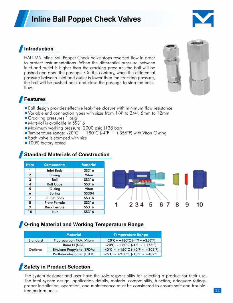
52
Inline Ball Poppet Check Valves
IntroductionHAITIMA Inline Ball Poppet Check Valve stops reversed flow in order to protect instrumentations. When the differential pressure between inlet and outlet is higher than the cracking pressure, the ball will be pushed and open the passage. On the contrary, when the differential pressure between inlet and outlet is lower than the cracking pressure, the ball will be pushed back and close the passage to stop the back-flow.
Features Ball design provides effective leak-free closure with minimum flow resistance Variable end connection types with sizes from 1/4" to 3/4", 6mm to 12mm Cracking pressures 1 psig Material is available in SS316 Maximum working pressure: 2000 psig (138 bar) Temperature range: -20°C~+180°C (-4°F ~ +356°F) with Viton O-ring Each valve is stamped with size 100% factory tested
Standard Materials of Construction
Item Components Material
1 Inlet Body SS3162 O-ring Viton3 Ball SS3164 Ball Cage SS3165 O-ring Viton6 Spring SS3047 Outlet Body SS3168 Front Ferrule SS3169 Back Ferrule SS316
10 Nut SS316
O-ring Material and Working Temperature Range
Material Temperature Range
Standard Fluorocarbon FKM (Viton) -20°C~+180°C (-4°F~+356°F)
OptionalBuna N (NBR) -20°C ~ +80°C (-4°F ~ +176°F)
Ethylene Propylene (EPDM) -40°C ~ +150°C (-40°F ~ +302°F)Perfluoroelastomer (FFKM) -25°C ~ +250°C (-13°F ~ +482°F)
Safety in Product SelectionThe system designer and user have the sole responsibility for selecting a product for their use. The total system design, application details, material compatibility, function, adequate ratings, proper installation, operation, and maintenance must be considered to ensure safe and trouble-free performance.
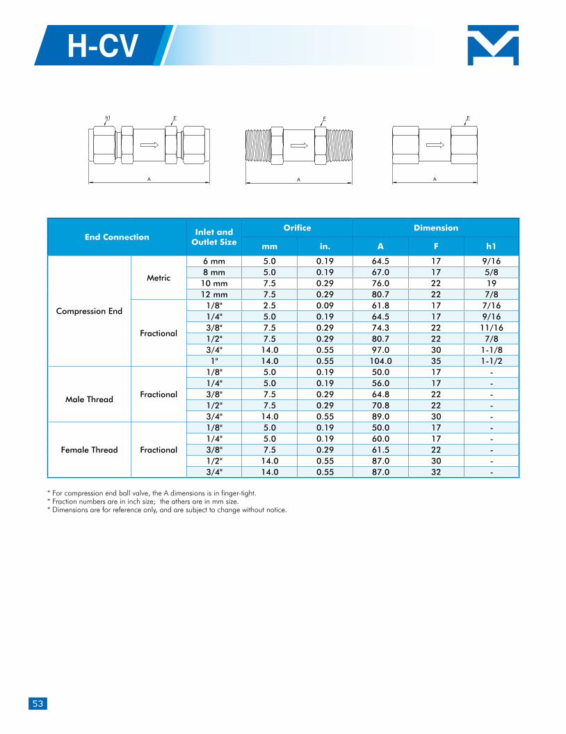
53
H-CV
* For compression end ball valve, the A dimensions is in finger-tight.* Fraction numbers are in inch size; the others are in mm size. * Dimensions are for reference only, and are subject to change without notice.
End ConnectionInlet and
Outlet Size
Orifice Dimension
mm in. A F h1
Compression End
Metric
6 mm 5.0 0.19 64.5 17 9/168 mm 5.0 0.19 67.0 17 5/810 mm 7.5 0.29 76.0 22 1912 mm 7.5 0.29 80.7 22 7/8
Fractional
1/8" 2.5 0.09 61.8 17 7/161/4" 5.0 0.19 64.5 17 9/163/8" 7.5 0.29 74.3 22 11/161/2" 7.5 0.29 80.7 22 7/83/4" 14.0 0.55 97.0 30 1-1/81" 14.0 0.55 104.0 35 1-1/2
Male Thread
Fractional
1/8" 5.0 0.19 50.0 17 -1/4" 5.0 0.19 56.0 17 -3/8" 7.5 0.29 64.8 22 -1/2" 7.5 0.29 70.8 22 -3/4" 14.0 0.55 89.0 30 -
Female Thread Fractional
1/8" 5.0 0.19 50.0 17 -1/4" 5.0 0.19 60.0 17 -3/8" 7.5 0.29 61.5 22 -1/2" 14.0 0.55 87.0 30 -3/4" 14.0 0.55 87.0 32 -
A AA
F FFh1
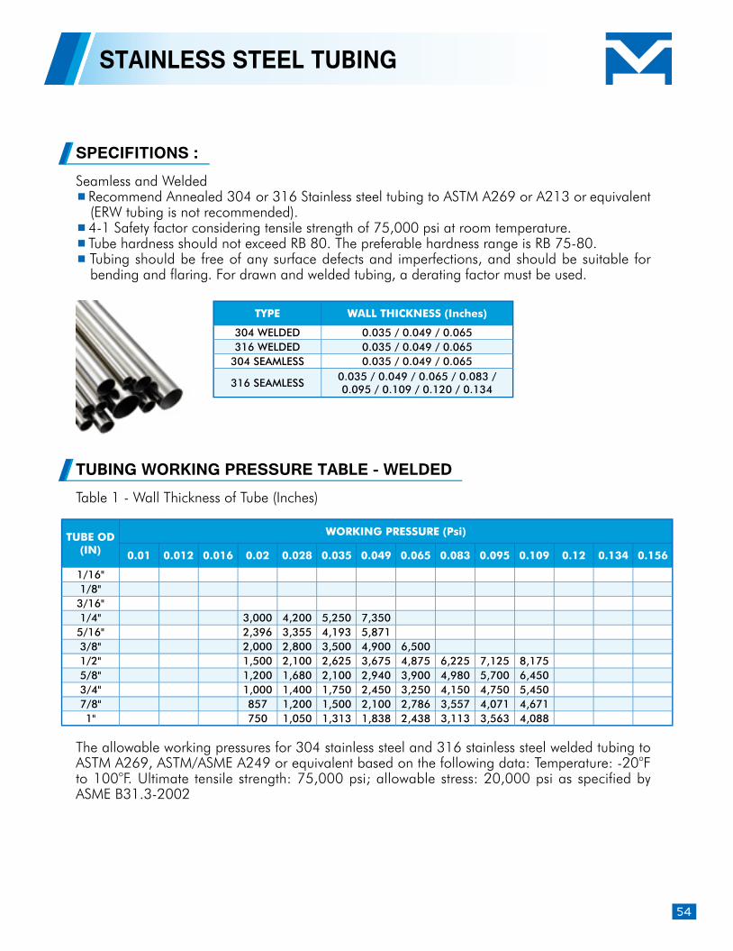
54
TUBING WORKING PRESSURE TABLE - WELDED
STAINLESS STEEL TUBING
Table 1 - Wall Thickness of Tube (Inches)
The allowable working pressures for 304 stainless steel and 316 stainless steel welded tubing to ASTM A269, ASTM/ASME A249 or equivalent based on the following data: Temperature: -20oF to 100oF. Ultimate tensile strength: 75,000 psi; allowable stress: 20,000 psi as specified by ASME B31.3-2002
Seamless and Welded Recommend Annealed 304 or 316 Stainless steel tubing to ASTM A269 or A213 or equivalent (ERW tubing is not recommended).
4-1 Safety factor considering tensile strength of 75,000 psi at room temperature. Tube hardness should not exceed RB 80. The preferable hardness range is RB 75-80. Tubing should be free of any surface defects and imperfections, and should be suitable for bending and flaring. For drawn and welded tubing, a derating factor must be used.
SPECIFITIONS :
TYPE WALL THICKNESS (Inches)
304 WELDED 0.035 / 0.049 / 0.065 316 WELDED 0.035 / 0.049 / 0.065
304 SEAMLESS 0.035 / 0.049 / 0.065
316 SEAMLESS0.035 / 0.049 / 0.065 / 0.083 / 0.095 / 0.109 / 0.120 / 0.134
TUBE OD (IN)
WORKING PRESSURE (Psi)
0.01 0.012 0.016 0.02 0.028 0.035 0.049 0.065 0.083 0.095 0.109 0.12 0.134 0.156
1/16"1/8"
3/16"1/4" 3,000 4,200 5,250 7,3505/16" 2,396 3,355 4,193 5,8713/8" 2,000 2,800 3,500 4,900 6,5001/2" 1,500 2,100 2,625 3,675 4,875 6,225 7,125 8,1755/8" 1,200 1,680 2,100 2,940 3,900 4,980 5,700 6,4503/4" 1,000 1,400 1,750 2,450 3,250 4,150 4,750 5,4507/8" 857 1,200 1,500 2,100 2,786 3,557 4,071 4,6711" 750 1,050 1,313 1,838 2,438 3,113 3,563 4,088
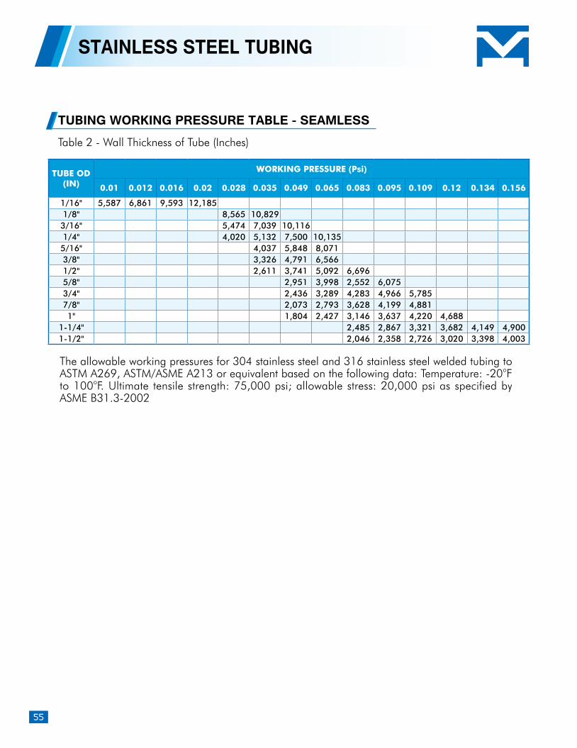
55
STAINLESS STEEL TUBING
TUBING WORKING PRESSURE TABLE - SEAMLESSTable 2 - Wall Thickness of Tube (Inches)
The allowable working pressures for 304 stainless steel and 316 stainless steel welded tubing to ASTM A269, ASTM/ASME A213 or equivalent based on the following data: Temperature: -20oF to 100oF. Ultimate tensile strength: 75,000 psi; allowable stress: 20,000 psi as specified by ASME B31.3-2002
TUBE OD (IN)
WORKING PRESSURE (Psi)
0.01 0.012 0.016 0.02 0.028 0.035 0.049 0.065 0.083 0.095 0.109 0.12 0.134 0.156
1/16" 5,587 6,861 9,593 12,1851/8" 8,565 10,8293/16" 5,474 7,039 10,1161/4" 4,020 5,132 7,500 10,1355/16" 4,037 5,848 8,0713/8" 3,326 4,791 6,5661/2" 2,611 3,741 5,092 6,6965/8" 2,951 3,998 2,552 6,0753/4" 2,436 3,289 4,283 4,966 5,7857/8" 2,073 2,793 3,628 4,199 4,8811" 1,804 2,427 3,146 3,637 4,220 4,688
1-1/4" 2,485 2,867 3,321 3,682 4,149 4,9001-1/2" 2,046 2,358 2,726 3,020 3,398 4,003