Embed Size (px)
Citation preview
Star 224 Star M 224 SWING GATE CONTROL UNIT – MANUALControl unit for 1 or 2 24 V motors Jet, Linear, Couper, Intro, Modus motors Version 01E
KINGgates srlVia A. Malignani, 42 - 33077 Sacile (PN) ITALYTel. +39 0434 737082 - Fax +39 0434 783382
web:www.king-gates.com Email:[email protected]
Allegro Gate Automation Pty. Ltd.122 Croyden Rd. Roleystone W.A. Australia
1300 980 [email protected] www.allegrogateautomation.com.au
Main Menu
1 - SAFETY NOTICE
- This Instructions Manual (Instructions) contains important information regarding safety- Read the entire document before you install any of the equipment - Installation must be carried out by qualified installers- Installation must be in accordance with all state and federal laws and regulations relating to Electrical Safetyin your area- Make sure that all cabling and wiring are in accordance with Wiring Rules AS 3000:2007- Do not modify the equipment unless directed to by the Instructions. Modifications may cause irreversible damage to the equipment and result in malfunction. King-Gates and LiteStart disclaim any liability for damage resulting from modified equipment.- Ensure that no damage will be caused by automating the gate. Pay particular attention to any damage that may be caused by impact, crushing, shearing, dragging, etc. as well as other general dangers. Before installing any of the equipment ensures that the gate can move freely through its motion and that nothingis blocking or interfering with its path of travel.- During installation and use, ensure that solid objects or liquids cannot enter the control box.Before connecting the control box to the mains power1 - Verify that all wirings done as described in section 2 above2 - Ensure that the gate can move freely through its motion and that nothing is blocking or interfering with its path of travel 3 - Ensure that no damage will be caused by automating the gate4 - Motor’s terminals MUST be plugged in before powering the box1
1 - Safety notice
2 - Electrical connection
3 - DIPSWITCHES Setting
4 - Linear adjustment Potentiometers
5 - Remote Control Programming - Main, Vehicle access
6 - Remote Control Programming - Pedestrian access
7 - Remote Control - Deleting all remote codes from control unit memory
8 - POWER, SPEED, OBSTACLE Adjustments
9 - Automatic Gate Travel learning
ADVANCED PROGRAMMING
10 - SLOWDOWN points - Changing the factory default setting
11 - PEDESTRIAN opening adjustment
12 - PEDESTRIAN opening – cancelling gap adjustment
13 - PEDESTRIAN access deleting all remote control codes
ADVANCE FEATURES
14 - Safety devices – detailed descriptions
15 - Accessories, Optional
16 - Status LED’s
17 - Inside the control unit (ADVANCED ONLY)
18 - TROUBLE SHOOTING
Page 2
3
4
4
5
5
5
5
6
6
6
6
7
7
8
8
9
10
Section
2
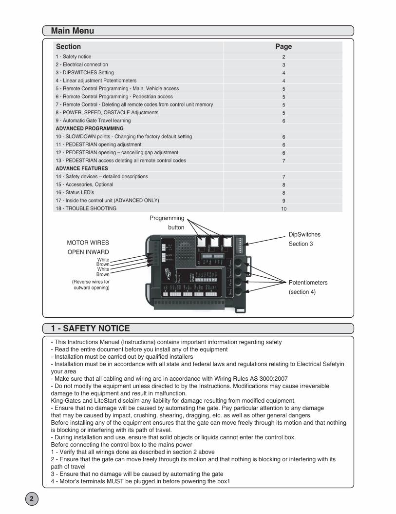
MOTOR WIRES
OPEN INWARD
DipSwitches
Section 3
Programming
button
Potentiometers
(section 4)
White Brown White Brown
(Reverse wires foroutward opening)
2 - ELECTRICAL CONNECTIONS
3
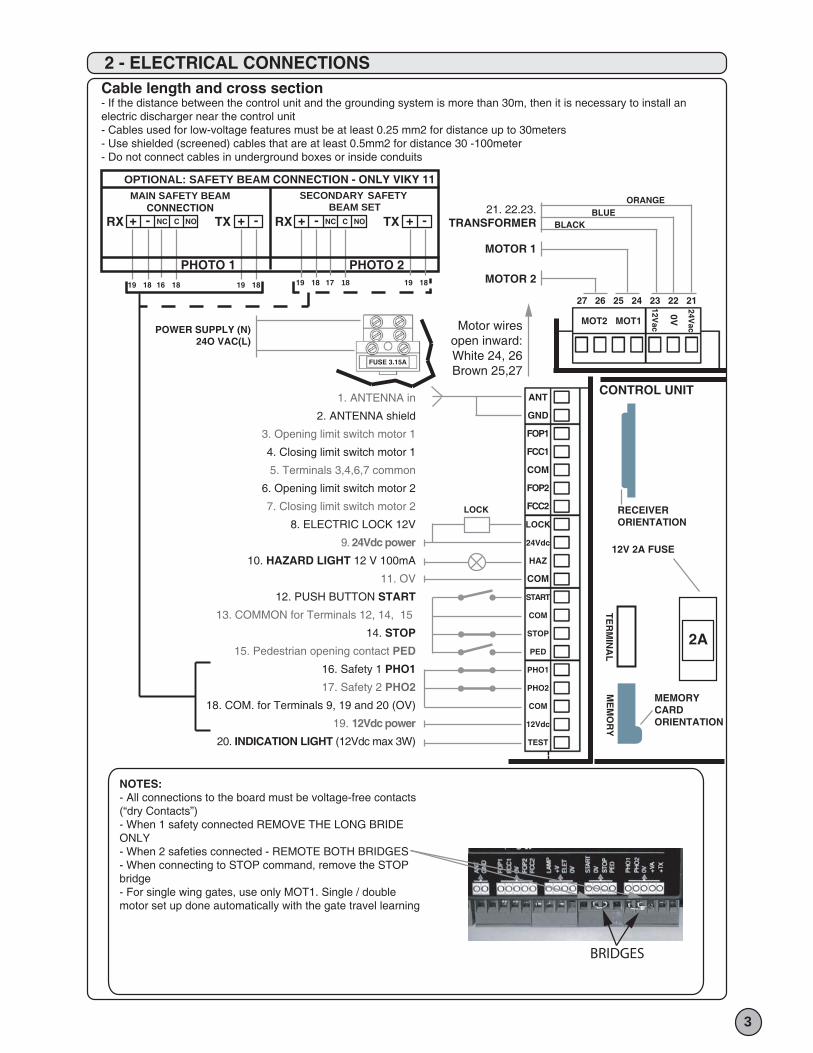
NOTES:- All connections to the board must be voltage-free contacts (“dry Contacts”)- When 1 safety connected REMOVE THE LONG BRIDE ONLY- When 2 safeties connected - REMOTE BOTH BRIDGES- When connecting to STOP command, remove the STOP bridge- For single wing gates, use only MOT1. Single / doublemotor set up done automatically with the gate travel learning
Motor wiresopen inward:White 24, 26Brown 25,27
Cable length and cross section- If the distance between the control unit and the grounding system is more than 30m, then it is necessary to install anelectric discharger near the control unit- Cables used for low-voltage features must be at least 0.25 mm2 for distance up to 30meters- Use shielded (screened) cables that are at least 0.5mm2 for distance 30 -100meter- Do not connect cables in underground boxes or inside conduits
POWER SUPPLY (N)24O VAC(L)
MOTOR 1
MOTOR 2
21. 22.23.TRANSFORMER
1. ANTENNA in
2. ANTENNA shield
3. Opening limit switch motor 1
4. Closing limit switch motor 1
5. Terminals 3,4,6,7 common
6. Opening limit switch motor 2
7. Closing limit switch motor 2
8. ELECTRIC LOCK 12V
9. 24Vdc power
10. HAZARD LIGHT 12 V 100mA
11. OV
12. PUSH BUTTON START
13. COMMON for Terminals 12, 14, 15
14. STOP
15. Pedestrian opening contact PED
16. Safety 1 PHO1
17. Safety 2 PHO2
18. COM. for Terminals 9, 19 and 20 (OV)
19. 12Vdc power
20. INDICATION LIGHT (12Vdc max 3W)
FUSE 3.15A
ANT
GND
FOP1
FCC1
COM
FOP2
FCC2
LOCK
24Vdc
HAZ
COM
START
COM
STOP
PED
PHO1
PHO2
COM
12Vdc
TEST
24Vac
0V
12VacMOT1MOT2
27 26 25 24 23 22 21
BLACKBLUE
ORANGEM
EM
OR
YT
ER
MIN
AL
MEMORYCARDORIENTATION
12V 2A FUSE
RECEIVERORIENTATION
CONTROL UNIT
2A
LOCK
BRIDGES
+
19 18 1816 19 18
RX TXNC NOC-
PHOTO 1 PHOTO 2
+ - +RX TXC ONCN- + -
SECONDARY SAFETY BEAM SET
MAIN SAFETY BEAMCONNECTION
19 18 17 18 19 18
OPTIONAL: SAFETY BEAM CONNECTION - ONLY VIKY 11
3 - SETTING THE DIPSWITCHES
4 - LINEAR POTENTIOMETERS
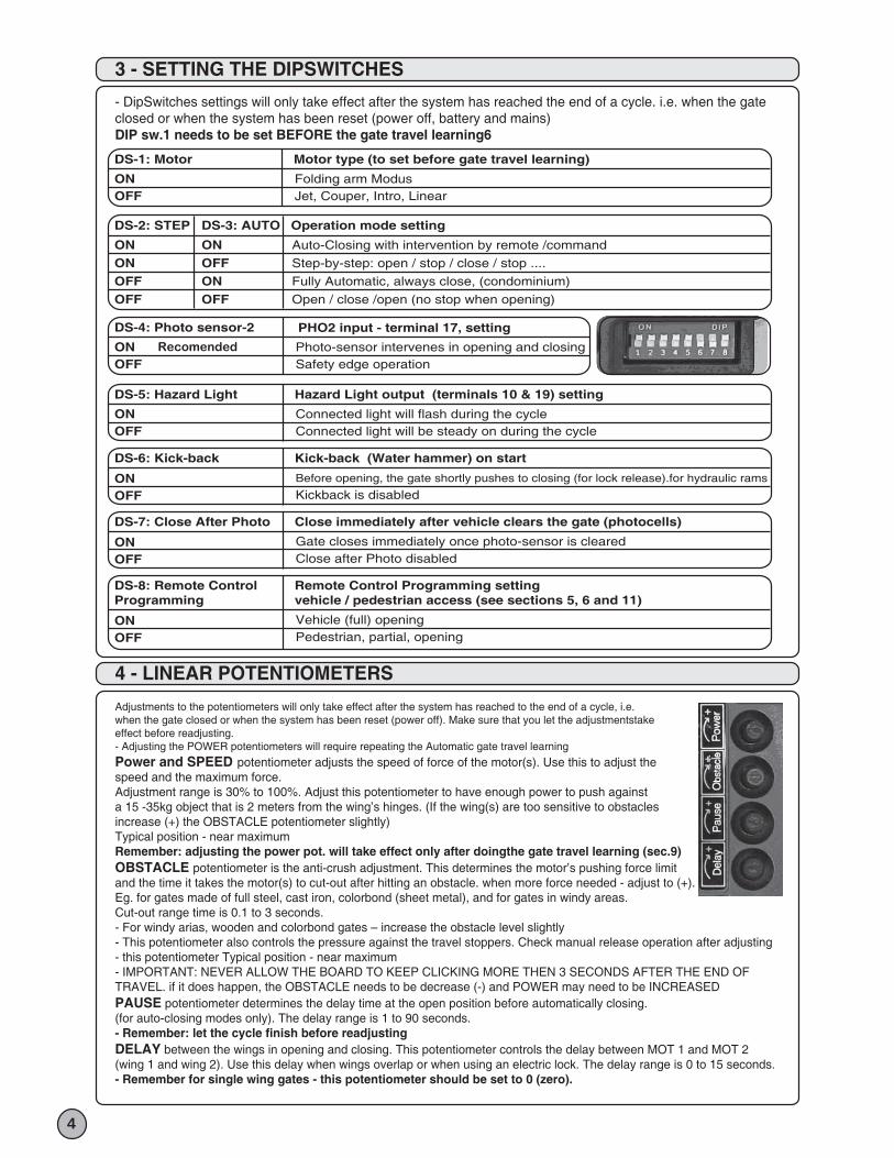
Adjustments to the potentiometers will only take effect after the system has reached to the end of a cycle, i.e. when the gate closed or when the system has been reset (power off). Make sure that you let the adjustmentstake effect before readjusting.- Adjusting the POWER potentiometers will require repeating the Automatic gate travel learning
Power and SPEED potentiometer adjusts the speed of force of the motor(s). Use this to adjust thespeed and the maximum force.Adjustment range is 30% to 100%. Adjust this potentiometer to have enough power to push againsta 15 -35kg object that is 2 meters from the wing’s hinges. (If the wing(s) are too sensitive to obstaclesincrease (+) the OBSTACLE potentiometer slightly)Typical position - near maximumRemember: adjusting the power pot. will take effect only after doingthe gate travel learning (sec.9)OBSTACLE potentiometer is the anti-crush adjustment. This determines the motor’s pushing force limit and the time it takes the motor(s) to cut-out after hitting an obstacle. when more force needed - adjust to (+).Eg. for gates made of full steel, cast iron, colorbond (sheet metal), and for gates in windy areas.Cut-out range time is 0.1 to 3 seconds.- For windy arias, wooden and colorbond gates – increase the obstacle level slightly- This potentiometer also controls the pressure against the travel stoppers. Check manual release operation after adjusting- this potentiometer Typical position - near maximum- IMPORTANT: NEVER ALLOW THE BOARD TO KEEP CLICKING MORE THEN 3 SECONDS AFTER THE END OFTRAVEL. if it does happen, the OBSTACLE needs to be decrease (-) and POWER may need to be INCREASEDPAUSE potentiometer determines the delay time at the open position before automatically closing.(for auto-closing modes only). The delay range is 1 to 90 seconds.- Remember: let the cycle finish before readjustingDELAY between the wings in opening and closing. This potentiometer controls the delay between MOT 1 and MOT 2(wing 1 and wing 2). Use this delay when wings overlap or when using an electric lock. The delay range is 0 to 15 seconds.- Remember for single wing gates - this potentiometer should be set to 0 (zero).
- DipSwitches settings will only take effect after the system has reached the end of a cycle. i.e. when the gateclosed or when the system has been reset (power off, battery and mains)DIP sw.1 needs to be set BEFORE the gate travel learning6
4
DS-1: Motor
ON OFF
Folding arm ModusJet, Couper, Intro, Linear
Motor type (to set before gate travel learning)
DS-4: Photo sensor-2
ON OFF
Photo-sensor intervenes in opening and closingSafety edge operation
DS-5: Hazard Light
ON OFF
ON OFF
Connected light will flash during the cycleConnected light will be steady on during the cycle
Hazard Light output (terminals 10 & 19) setting
DS-6: Kick-back
Before opening, the gate shortly pushes to closing (for lock release).for hydraulic rams
Kickback is disabled
Kick-back (Water hammer) on start
ON OFF
DS-7: Close After Photo
Gate closes immediately once photo-sensor is clearedClose after Photo disabled
Close immediately after vehicle clears the gate (photocells)
ON OFF
DS-8: Remote Control Programming
Vehicle (full) openingPedestrian, partial, opening
Remote Control Programming setting vehicle / pedestrian access (see sections 5, 6 and 11)
DS-2: STEP
ON ONOFFOFF
DS-3: AUTO
ON OFFON OFF
Auto-Closing with intervention by remote /command
Step-by-step: open / stop / close / stop ....
Fully Automatic, always close, (condominium)
Open / close /open (no stop when opening)
Operation mode setting
PHO2 input - terminal 17, setting
Recomended
6 - PROGRAMMING THE REMOTE CONTROL FOR MAIN VEHICLE ACCESS - FULL OPENING
5
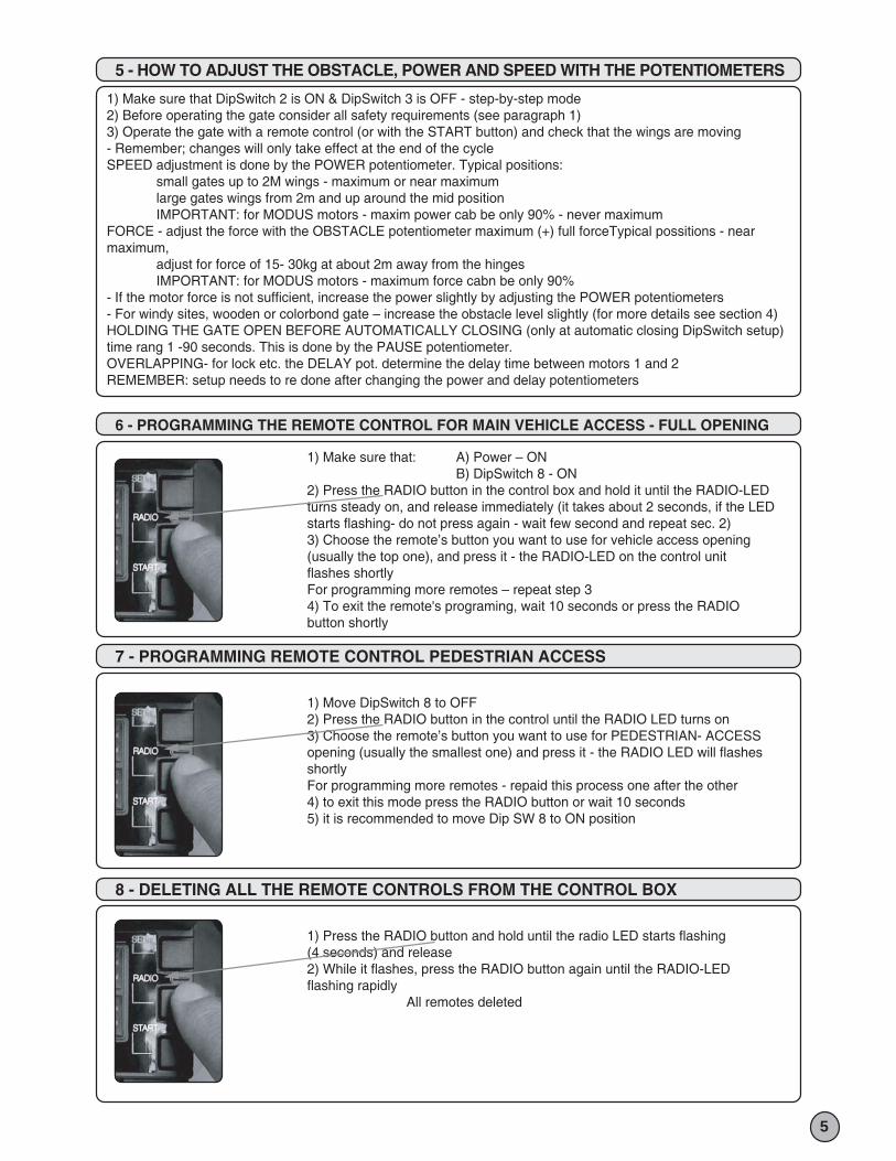
1) Make sure that: A) Power – ON B) DipSwitch 8 - ON2) Press the RADIO button in the control box and hold it until the RADIO-LEDturns steady on, and release immediately (it takes about 2 seconds, if the LEDstarts flashing- do not press again - wait few second and repeat sec. 2)3) Choose the remote’s button you want to use for vehicle access opening(usually the top one), and press it - the RADIO-LED on the control unitflashes shortlyFor programming more remotes – repeat step 34) To exit the remote's programing, wait 10 seconds or press the RADIObutton shortly
7 - PROGRAMMING REMOTE CONTROL PEDESTRIAN ACCESS
1) Move DipSwitch 8 to OFF2) Press the RADIO button in the control until the RADIO LED turns on3) Choose the remote’s button you want to use for PEDESTRIAN- ACCESSopening (usually the smallest one) and press it - the RADIO LED will flashesshortlyFor programming more remotes - repaid this process one after the other4) to exit this mode press the RADIO button or wait 10 seconds5) it is recommended to move Dip SW 8 to ON position
8 - DELETING ALL THE REMOTE CONTROLS FROM THE CONTROL BOX
1) Press the RADIO button and hold until the radio LED starts flashing(4 seconds) and release2) While it flashes, press the RADIO button again until the RADIO-LEDflashing rapidly All remotes deleted
5 - HOW TO ADJUST THE OBSTACLE, POWER AND SPEED WITH THE POTENTIOMETERS
1) Make sure that DipSwitch 2 is ON & DipSwitch 3 is OFF - step-by-step mode2) Before operating the gate consider all safety requirements (see paragraph 1)3) Operate the gate with a remote control (or with the START button) and check that the wings are moving - Remember; changes will only take effect at the end of the cycleSPEED adjustment is done by the POWER potentiometer. Typical positions: small gates up to 2M wings - maximum or near maximum large gates wings from 2m and up around the mid position IMPORTANT: for MODUS motors - maxim power cab be only 90% - never maximumFORCE - adjust the force with the OBSTACLE potentiometer maximum (+) full forceTypical possitions - near maximum, adjust for force of 15- 30kg at about 2m away from the hinges IMPORTANT: for MODUS motors - maximum force cabn be only 90%- If the motor force is not sufficient, increase the power slightly by adjusting the POWER potentiometers- For windy sites, wooden or colorbond gate – increase the obstacle level slightly (for more details see section 4)HOLDING THE GATE OPEN BEFORE AUTOMATICALLY CLOSING (only at automatic closing DipSwitch setup) time rang 1 -90 seconds. This is done by the PAUSE potentiometer.OVERLAPPING- for lock etc. the DELAY pot. determine the delay time between motors 1 and 2REMEMBER: setup needs to re done after changing the power and delay potentiometers
9 - AUTOMATIC GATE TRAVEL SETUP
6
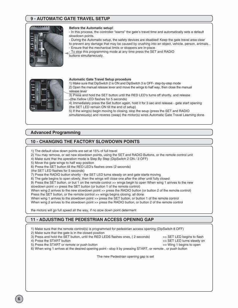
Before the Automatic setup!- In this process, the controller “learns” the gate’s travel time and automatically sets a defaultslowdown points.- During the Automatic setup, the safety devices are disabled! Keep the gate travel area clearto prevent any damage that may be caused by crushing into an object, vehicle, person, animals...- Ensure that the mechanical limits or stoppers are in-place- To stop this programming mode at any time press the SET and RADIObuttons simultaneously.
Automatic Gate Travel Setup procedure1) Make sure that DipSwitch 2 is ON and DipSwitch 3 is OFF- step-by-step mode2) Open the manual release lever and move the wings to half way, then close the manualrelease lever3) Press and hold the SET button until the RED LED's turns off shortly, and release-(the Yellow LED flashes for 5 seconds)4) Immediately press the Set button again, hold it for 3 sec and release - gate start opening(the SET LED remain ON till the end of setup)5) If the wing(s) begin moving to closing, stop the seup (press the SET and RADIO simultaneously) and reveres (swap) the motor(s) wires.Automatic Gate Travel Learning done
Advanced Programming
10 - CHANGING THE FACTORY SLOWDOWN POINTS
1) The default slow down points are set at 15% of full travel2) You may remove, or set new slowdown points, using the SET and RADIO Buttons, or the remote control unit4) Make sure that the operation mode is Step By Step (DipSwitch 2 ON / 3 OFF)5) Move the gate wings to half way position 6) Press the SET button till the RED LED's flashes ones (2 seconds)(the SET LED flashes for 5 seconds) 7) Press the RADIO button shortly - the SET LED turns steady on and gate starts moving8) The gate begins to open slowly, then the wings will close one after the other until fully closed9) Press the SET button, or but 1 on the remote control >> wings begin to open When wing 1 arrives to the new slowdown point >> press the SET button (or button 1 of the remote control)When wing 2 arrives to the new slowdown point >> press the RADIO button (or button 2 of the remote control)Press the SET button, or the remote control >> wings begins closing. all doneWhen wing 1 arrives to the slowdown point >> press the SET button, or button 1 of the remote controlWhen wing 2 arrives to the slowdown point >> press the RADIO button, or button 2 of the remote control
the motors will go full speed all the way, if no slow down point determent
11 - ADJUSTING THE PEDESTRIAN ACCESS OPENING GAP
1) Make sure that the remote control(s) is programmed for pedestrian access opening (DipSwitch 8 OFF)2) Make sure that the gate is in the closed position3) Press and hold the SET button, until the RED LEDS flashes ones, ( 2 seconds) >> SET LED begins to flash 4) Press the START button >> SET LED turns steady on5) Press the START or remote or push button >> Wing 1 begins to open 6) When wing 1 arrives at the desired opening point - stop it by pressing START, or remote , or push button
The new Pedestrian opening gap is set
7
ADVANCE FEATURES
14 - SAFETY DEVICES DETAILED DESCRIPTION
Crossing safety receivers& transmitters
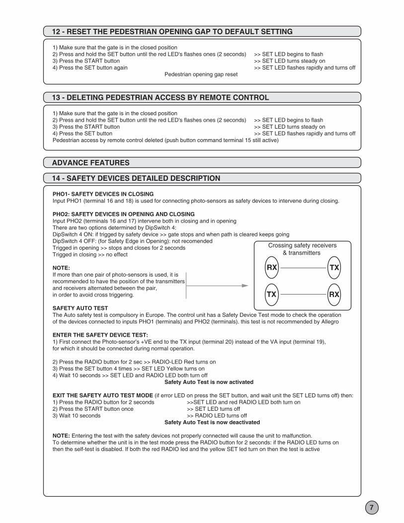
PHO1- SAFETY DEVICES IN CLOSINGInput PHO1 (terminal 16 and 18) is used for connecting photo-sensors as safety devices to intervene during closing.
PHO2: SAFETY DEVICES IN OPENING AND CLOSINGInput PHO2 (terminals 16 and 17) intervene both in closing and in openingThere are two options determined by DipSwitch 4:DipSwitch 4 ON: if trigged by safety device >> gate stops and when path is cleared keeps goingDipSwitch 4 OFF: (for Safety Edge in Opening): not recomendedTrigged in opening >> stops and closes for 2 secondsTrigged in closing >> no effect
NOTE:If more than one pair of photo-sensors is used, it isrecommended to have the position of the transmittersand receivers alternated between the pair,in order to avoid cross triggering.
SAFETY AUTO TESTThe Auto safety test is compulsory in Europe. The control unit has a Safety Device Test mode to check the operationof the devices connected to inputs PHO1 (terminals) and PHO2 (terminals). this test is not recommended by Allegro
ENTER THE SAFETY DEVICE TEST:1) First connect the Photo-sensor’s +VE end to the TX input (terminal 20) instead of the VA input (terminal 19), for which it should be connected during normal operation.
2) Press the RADIO button for 2 sec >> RADIO-LED Red turns on3) Press the SET button 4 times >> SET LED Yellow turns on4) Wait 10 seconds >> SET LED and RADIO LED both turn off Safety Auto Test is now activated
EXIT THE SAFETY AUTO TEST MODE (if error LED on press the SET button, and wait unit the SET LED turns off) then:1) Press the RADIO button for 2 seconds >>SET LED and red RADIO LED both turn on2) Press the START button once >> SET LED turns off3) Wait 10 seconds >> RADIO LED turns off Safety Auto Test is now deactivated
NOTE: Entering the test with the safety devices not properly connected will cause the unit to malfunction.To determine whether the unit is in the test mode press the RADIO button for 2 seconds: if the RADIO LED turns onthen the self-test is disabled. If both the red RADIO led and the yellow SET led turn on then the test is active
12 - RESET THE PEDESTRIAN OPENING GAP TO DEFAULT SETTING
1) Make sure that the gate is in the closed position2) Press and hold the SET button until the red LED's flashes ones (2 seconds) >> SET LED begins to flash3) Press the START button >> SET LED turns steady on4) Press the SET button again >> SET LED flashes rapidly and turns off Pedestrian opening gap reset
13 - DELETING PEDESTRIAN ACCESS BY REMOTE CONTROL
1) Make sure that the gate is in the closed position2) Press and hold the SET button until the red LED's flashes ones (2 seconds) >> SET LED begins to flash3) Press the START button >> SET LED turns steady on 4) Press the SET button >> SET LED flashes rapidly and turns offPedestrian access by remote control deleted (push button command terminal 15 still active)
RX TX
TX RX
15 - OPTIONAL ACCESSORIES
8
HAZ – HAZARD LIGHT output: terminals 10, 19; 12 VDC Max 15W. (0.6Amp); for connection of hazard light.Turns on a second before the wings move. DipSwitch-5 setting: ON: Flashing / / OFF: steady on
ANTENNA input : terminals 1,2 - for increasing reception range connect an external antenna (Item code: ANT 433) and remove internal antenna (the wire from the terminal)
TX – MOTION INDICATION LIGHT output: terminal 8, 9 – 12 Vdc Max 3W (0.25A)Gate opening >> Light flashesGate closing >> Fast flashingGate open or closed (stand still) >> no outputalso used for the Safety Auto Test mode (section 14).
ELECTRIC LATCH LOCK output – terminals 10, 11; 12Vdc MAX 15W (1.25Amp)
BACKUP BATTERY KITBackup battery kit available in two options: 2 x 2.3 A/H (Buffer) internal batteries and charger provide emergency power for about 3 hours 2 x 7 A/H batteries and charger provide emergency power for about 8 hours.
COURTESY LIGHT output –optional card connected to HAZ terminals 10,11 Voltage free (dry) contact Max 250Vac 500W ** Time range: (0) to 120 SecondsNOTES
16 - STATUS LED’S
SET Yellow LED FLASHING for 5 seconds when power is turned on. Flashing 5 secondes when the SET pressed for 2 seconds. ON > during Gate Travel Learning OFF>when unit operates normally
RADIO Red LED OFF >the control unit is functioning normally. FLASHING briefly when a remote transmits. ON > the unit is ready to store a new remote to memory FLASHING fast while deleting all remotes from memory. FLASHING continuously fast > memory card is faulty. FLASHES continuously slowly >memory card is full.PHOTO Red LED ON > OK photo-sensor (s) connected properly (if safety devices are not connected, the wire bridge(s) must be in place, Section 2) OFF> KO Safety (photocell) sensor is triggered (or not correctly installed) this indication is for both photo 1 and photo 2.
START Green LED ON >START command received contact close (shorted) terminal 12 OFF> no START command
SET Red LED ON > OK the STOP input (terminal 14) is closed (shorted) OFF> KO the STOP input (terminal 14) is openedEROR red LED ON or FLASHING > an error occurs (see Trouble shooting section 18) ON or FLASHING > Travel learning needs to be done see sec.9 OFF > the control unit is working normally
9
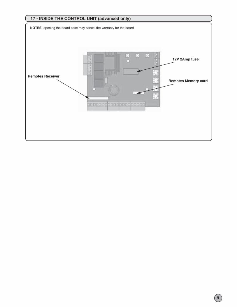
NOTES: opening the board case may cancel the warranty for the board
17 - INSIDE THE CONTROL UNIT (advanced only)
12V 2Amp fuse
Remotes Memory card Remotes Receiver
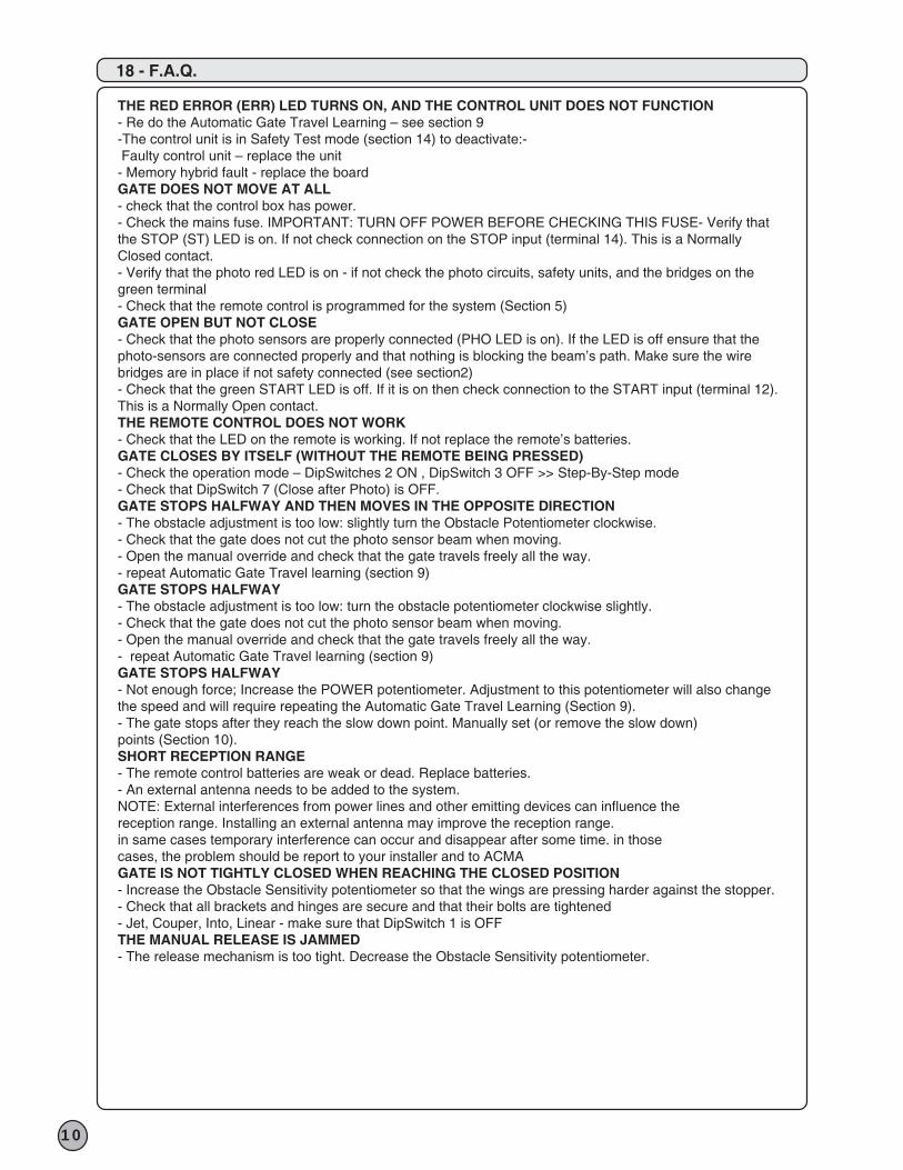
18 - F.A.Q.
10
THE RED ERROR (ERR) LED TURNS ON, AND THE CONTROL UNIT DOES NOT FUNCTION- Re do the Automatic Gate Travel Learning – see section 9-The control unit is in Safety Test mode (section 14) to deactivate:- Faulty control unit – replace the unit- Memory hybrid fault - replace the boardGATE DOES NOT MOVE AT ALL- check that the control box has power.- Check the mains fuse. IMPORTANT: TURN OFF POWER BEFORE CHECKING THIS FUSE- Verify thatthe STOP (ST) LED is on. If not check connection on the STOP input (terminal 14). This is a NormallyClosed contact.- Verify that the photo red LED is on - if not check the photo circuits, safety units, and the bridges on thegreen terminal- Check that the remote control is programmed for the system (Section 5)GATE OPEN BUT NOT CLOSE- Check that the photo sensors are properly connected (PHO LED is on). If the LED is off ensure that the photo-sensors are connected properly and that nothing is blocking the beam’s path. Make sure the wirebridges are in place if not safety connected (see section2)- Check that the green START LED is off. If it is on then check connection to the START input (terminal 12).This is a Normally Open contact.THE REMOTE CONTROL DOES NOT WORK- Check that the LED on the remote is working. If not replace the remote’s batteries.GATE CLOSES BY ITSELF (WITHOUT THE REMOTE BEING PRESSED)- Check the operation mode – DipSwitches 2 ON , DipSwitch 3 OFF >> Step-By-Step mode- Check that DipSwitch 7 (Close after Photo) is OFF.GATE STOPS HALFWAY AND THEN MOVES IN THE OPPOSITE DIRECTION- The obstacle adjustment is too low: slightly turn the Obstacle Potentiometer clockwise.- Check that the gate does not cut the photo sensor beam when moving.- Open the manual override and check that the gate travels freely all the way. - repeat Automatic Gate Travel learning (section 9)GATE STOPS HALFWAY- The obstacle adjustment is too low: turn the obstacle potentiometer clockwise slightly.- Check that the gate does not cut the photo sensor beam when moving.- Open the manual override and check that the gate travels freely all the way. - repeat Automatic Gate Travel learning (section 9) GATE STOPS HALFWAY- Not enough force; Increase the POWER potentiometer. Adjustment to this potentiometer will also change the speed and will require repeating the Automatic Gate Travel Learning (Section 9).- The gate stops after they reach the slow down point. Manually set (or remove the slow down) points (Section 10).SHORT RECEPTION RANGE- The remote control batteries are weak or dead. Replace batteries.- An external antenna needs to be added to the system.NOTE: External interferences from power lines and other emitting devices can influence thereception range. Installing an external antenna may improve the reception range.in same cases temporary interference can occur and disappear after some time. in thosecases, the problem should be report to your installer and to ACMAGATE IS NOT TIGHTLY CLOSED WHEN REACHING THE CLOSED POSITION- Increase the Obstacle Sensitivity potentiometer so that the wings are pressing harder against the stopper. - Check that all brackets and hinges are secure and that their bolts are tightened- Jet, Couper, Into, Linear - make sure that DipSwitch 1 is OFFTHE MANUAL RELEASE IS JAMMED- The release mechanism is too tight. Decrease the Obstacle Sensitivity potentiometer.

11

King Gates S.r.l.Via A. Malignani, 42 - 33077 Sacile (PN) ITALYTel. +39 0434 737082 - Fax +39 0434 783382
e-mail: [email protected] web: www.king-gates.com


