Embed Size (px)
Citation preview
STATIC ANALYSIS OF CONNECTING ROD USING FORGED STEE L
K.Karthick1, . John paneer selvam2 1,2Department of Mechanical Engineering, PSNA College of Engineering and Technology,
Dindigul, India 1 [email protected], [email protected]
ABSTRACT
This project deals with design and analysis of connecting rod. The existing connecting rod is manufactured using carbon steel. The model of connecting rod is carried out using pro E software and analysis is carried out using ansys 14 software. Finite element analysis of connecting rod is done using forged steel. The parameters like von mises stress, strain, deformation and weight reduction were done in ansys software. Forged steel has increased stiffness, reduced weight and reduce stress and stiffer than other material.
Keywords: connecting Rod, Analysis of connecting rod, forged steel connecting rod, design and analysis of connecting rod.
1. INTRODUCTION The connecting rod connects the piston to the
crankshaft and they form a simple mechanism that converts linear motion into rotary motion. In
modern automotive internal combustion engines,
the connecting rods are most usually made of steel
for production engines, but can be made of
aluminium or titanium. The tensile and compressive stresses are produced due to gas pressure, and bending stresses are produced due to centrifugal effect & eccentricity. So the connecting rods are designed generally of I-section to provide maximum rigidity with minimum weight.Connecting rods for automotive applications are typically manufactured by forging from either wrought steel or powdered metal. They could also be cast. However, castings could have blow-holes which are detrimental from durability and fatigue points of view. The fact that forgings produce blow-hole-free and better rods gives them an advantage over cast rods (Gupta, 1993). Between the forging processes, powder forged or drop forged, each process has its own pros and cons. Powder metal manufactured blanks have the advantage of being near net shape, reducing material waste. However, the cost of the blank is high due to the high material cost and sophisticated manufacturing techniques (Repgen, 1998). With steel forging, the material is inexpensive and the rough part manufacturing process is cost effective. Bringing the part to final dimensions under tight tolerance results in high expenditure for machining,
as the blank usually contains more excess material (Repgen, 1998). A major source of engine wear is the sideways force exerted on the piston through the con rod by the crankshaft, which typically wears the cylinder into an oval cross-section rather than circular, making it impossible for piston rings to correctly seal against the cylinder walls. Geometrically, it can be seen that longer connecting rods will reduce the amount of this sideways force, and therefore lead to longer engine life. However, for a given engine block, the sum of the length of the con rod plus the piston stroke is a fixed number, determined by the fixed distance between the crankshaft axis and the top of the cylinder block where the cylinder head fastens; thus, for a given cylinder block longer stroke, giving greater engine displacement and power, requires a shorter connecting rod (or a piston with smaller compression height), resulting in accelerated cylinder wear. M Rasekh et al. have obtained the Maximum Stresses in Different Parts of Tractor (Mf-285) Connecting Rods Using Finite Element Method. In this study, detailed load analysis was performed for a MF-285 Connecting rod,followed by finite element method. In this regard, in order to calculate Stress in connecting rod, the total forces exerted connecting rod were Calculated and then it was modeled, meshed and loaded in ANSYSv9, software. The maximum stresses in Different parts of M F-285 connecting rod were determined. The maximum pressure Stress was between pin end and rod linkages and between bearing cup and connecting rod Linkage. The maximum tensile stress was obtained in lower half of pin end and between Pin end and rod linkages.
2. PROBLEM DEFINITION
The objective of the present work is
to design and analyses of connecting rod made of Forged steel. Steel materials are used to design the connecting rod. In this project the material (carbon steel) of connecting rod replaced with Forged steel. Connecting rod was created in CATIAV5 R19. Model is imported in ANSYS 13.0 for analysis. After analysis a comparison is made between existing steel connecting rod viz., Forged steel in terms of weight, factor of safety, stiffens, deformation and stress.
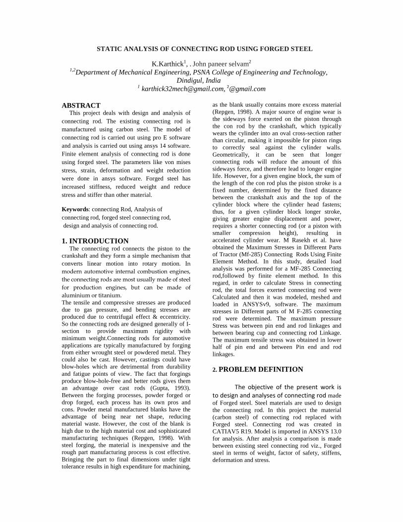
SCHEMATIC DIAGRAM OF CONNECTING ROD
DESIGN OF CONNECTING ROD
A connecting rod is a machine member which is subjected to alternating direct compressive and tensile forces. Since the compressive forces are much higher than the tensile force, therefore the cross-section of the connecting rod is designed as a strut and the rankine formula is used. A connecting rod subjected to an axial load W may buckle with x-axis as neutral axis in the plane of motion of the connecting rod,{or} y-axis is a neutral axis. The connecting rod is considered like both ends hinged for buckling about x-axis and both ends fixed for buckling about y-axis. A connecting rod should be equally strong in buckling about either axis.
K2xx = 4K2yy [or] I xx = 4Iyy [∴�=�×�2]
This shows that the connecting rod is four times strong in buckling about y-axis than about-axis. If I xx > 4Iyy, Then buckling will occur about y-axis and if I xx < 4Iyy, then buckling will occur about x-axis .In Actual practice I xx is kept slightly less than 4Iyy. It is usually taken between 3 and 3.5 and the Connecting rod is designed for buckling about x-axis. The design will always be satisfactory for buckling about y-axis. The most suitable section for the connecting rod is I-section with the proportions shown mfg. Area of the cross section = 2[4t x t] + 3t x t=11t2 Moment of inertia about x-axis = 2[4txt]+3txt=11t2
Moment of inertia about x-axis
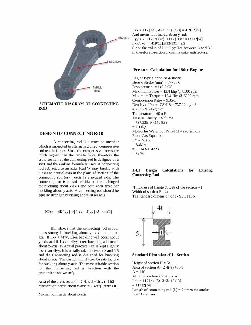
I xx = 112 [4� {5�}3−3� {3�}3] = 41912[�4] And moment of inertia about y-axis I yy = 2×112×t×{4t}3+112{3t}t3 =13112[t4] I xx/I yy = [419/12]x[12/131]=3.2 Since the value of I xx/I yy lies between 3 and 3.5 m therefore I-section chosen is quite satisfactory.
Pressure Calculation for 150cc Engine
Engine type air cooled 4-stroke Bore x Stroke (mm) = 57×58.6 Displacement = 149.5 CC Maximum Power = 13.8 bhp @ 8500 rpm Maximum Torque = 13.4 Nm @ 6000 rpm Compression Ratio = 9.35/1 Density of Petrol C8H18 = 737.22 kg/m3 = 737.22E-9 kg/mm3 Temperature = 60 o F Mass = Density × Volume = 737.22E-9 x149.5E3 = 0.11kg Molecular Weight of Petrol 114.228 g/mole From Gas Equation, PV = Mrt R = RxMw = 8.3143/114228 = 72.76
1.4.1 Design Calculations for Existing Connecting Rod
Thickness of flange & web of the section = t Width of section B= 4t The standard dimension of I - SECTION.
Standard Dimension of I – Section
Height of section H = 5t Area of section A= 2(4t×t) +3t×t A = 11t² M.O.I of section about x axis: I xx = 112 [4� {5�}3−3� {3�}3] = 41912[�4] Length of connecting rod (L) = 2 times the stroke L = 117.2 mm
��= compressive yield stress = 415MPa
K xx = I xxA
K xx = 1.78t
a = ���2
a = 0.0002
By substituting ��, A, a, L, Kxx on WB then
= 4565t4-37663t2-81639.46 = 0
t2 = 10.03
t = 3.167mm
t = 3.2mm
Width of section B = 4t = 4×3.2 = 12.8mm Height of section H = 5t = 5×3.2 = 16mm Area A = 11t2 =11×3.2×3.2
= 112.64mm2 Height at the big end (crank end) = H2 = 1.1H to 1.25H = 1.1×16 H2 =17.6mm Height at the small end (piston end) = 0.9H to 0.75H = 0.9×16 H1 =12mm Stroke length (l) =117.2mm Diameter of piston (D) =57mm P=15.5N/mm2 Radius of crank(r) =stroke length/2 =58.6/2 =29.3 Maximum force on the piston due to pressure Fl = π4xD2xp =π/4 x (57)2x15.469 =39473.16N Maximum angular speed Wmax= [2πNmax]60 = [2π×8500]60�=�2 =768 rad/sec Ratio of the length of connecting rod to the radius of crank N= lr =112/ (29.3) = 3.8 Maximum Inertia force of reciprocating parts F im = Mr (Wmax) 2 r (cosθ + COS2θn) (Or) F im = Mr (Wmax)2 r (1+1n) = 0.11x (768)2 x (0.0293) x (1+ (1/3.8)) F im = 2376.26N Inner diameter of the small end d1 = ��⁄ �� ×�� = 6277.16712.5×1.5d1
= 17.94mm
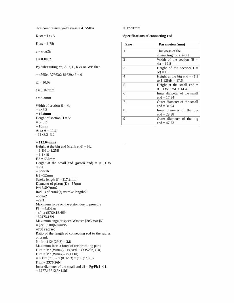
Specifications of connecting rod S.no Parameters(mm)
1
Thickness of the connecting rod (t)=3.2
2 Width of the section (B = 4t) = 12.8
3 Height of the section(H = 5t) = 16
4 Height at the big end = (1.1 to 1.125)H = 17.6
5 Height at the small end = 0.9H to 0.75H= 14.4
6 Inner diameter of the small end = 17.94
7 Outer diameter of the small end = 31.94
8 Inner diameter of the big end = 23.88
9 Outer diameter of the big end = 47.72
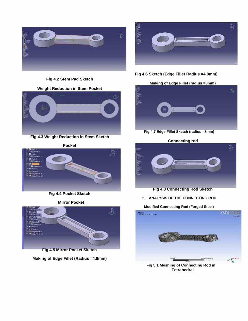
Fig 4.6 Sketch (Edge Fillet Radius =4.8mm) Fig 4.2 Stem Pad Sketch
Making of Edge Fillet (radius =8mm) Weight Reduction in Stem Pocket
Fig 4.7 Edge Fillet Sketch (radius =8mm) Fig 4.3 Weight Reduction in Stem Sketch
Connecting rod Pocket
Fig 4.8 Connecting Rod Sketch Fig 4.4 Pocket Sketch
5. ANALYSIS OF THE CONNECTING ROD Mirror Pocket
Modified Connecting Rod (Forged Steel)
Fig 4.5 Mirror Pocket Sketch Making of Edge Fillet (Radius =4.8mm)
Fig 5.1 Meshing of Connecting Rod in Tetrahedral
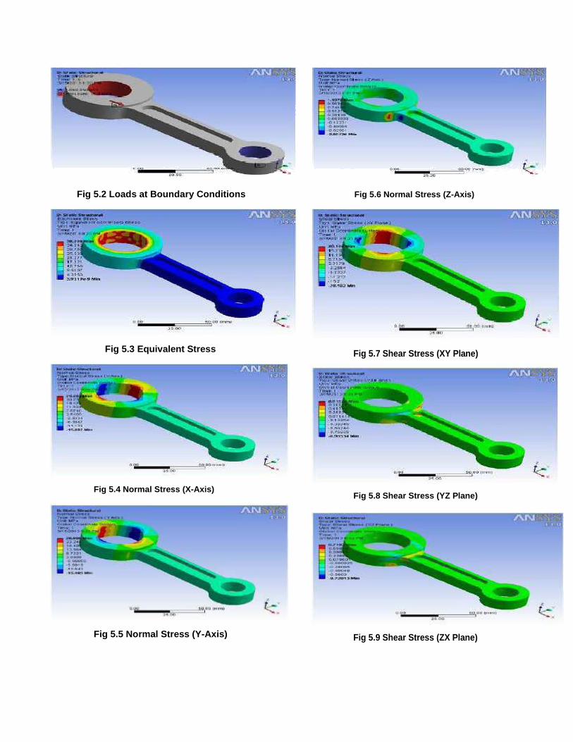
Fig 5.2 Loads at Boundary Conditions Fig 5.6 Normal Stress (Z-Axis)
Fig 5.3 Equivalent Stress Fig 5.7 Shear Stress (XY Plane)
Fig 5.4 Normal Stress (X-Axis)
Fig 5.8 Shear Stress (YZ Plane)
Fig 5.5 Normal Stress (Y-Axis) Fig 5.9 Shear Stress (ZX Plane)
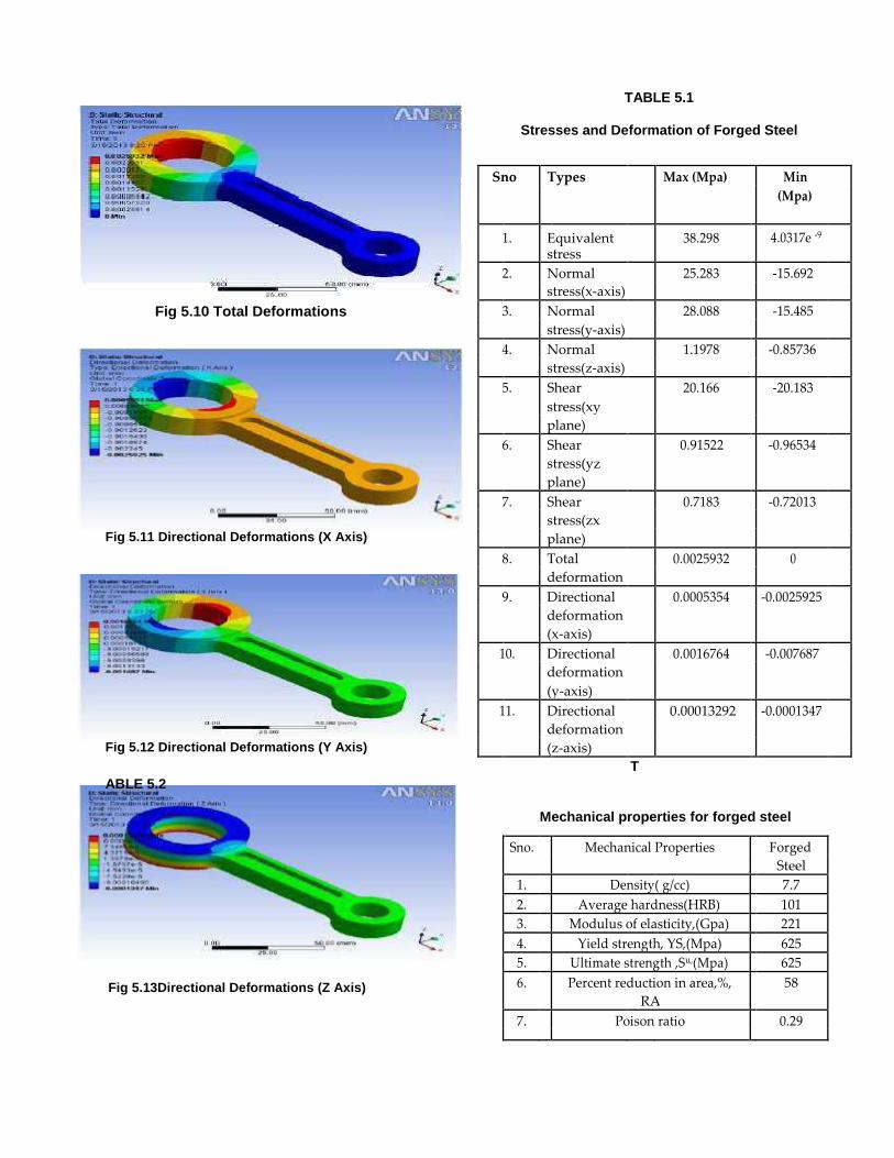
Fig 5.10 Total Deformations Fig 5.11 Directional Deformations (X Axis) Fig 5.12 Directional Deformations (Y Axis) ABLE 5.2
Fig 5.13Directional Deformations (Z Axis)
TABLE 5.1
Stresses and Deformation of Forged Steel
Sno Types Max (Mpa) Min
(Mpa)
1. Equivalent 38.298 4.0317e -9 stress
2. Normal 25.283 -15.692 stress(x-axis)
3. Normal 28.088 -15.485 stress(y-axis)
4. Normal 1.1978 -0.85736 stress(z-axis)
5. Shear 20.166 -20.183 stress(xy plane)
6. Shear 0.91522 -0.96534 stress(yz plane)
7. Shear 0.7183 -0.72013 stress(zx plane)
8. Total 0.0025932 0 deformation
9. Directional 0.0005354 -0.0025925 deformation (x-axis)
10. Directional 0.0016764 -0.007687 deformation (y-axis)
11. Directional 0.00013292 -0.0001347 deformation (z-axis) T
Mechanical properties for forged steel
Sno. Mechanical Properties Forged Steel 1. Density( g/cc) 7.7 2. Average hardness(HRB) 101 3. Modulus of elasticity,(Gpa) 221 4. Yield strength, YS,(Mpa) 625 5. Ultimate strength ,Su,(Mpa) 625 6. Percent reduction in area,%, 58 RA 7. Poison ratio 0.29
CONCLUSION
By checking and comparing the results of materials in
finalizing the results are shown in below.
Considering the parameters,
1. ANSYS Equivalent stress for the both the
materials are same.
2. The weight of the forged steel material is less
than the existing carbon steel.
3. From the fatigue analysis life time of the
connecting rod can be determined.
4. And also no. of cycles for forged steel
is more than the existing connecting rod.
5. When compared to both materials, forged steel is
cheaper than the existing connecting rod materials.
REFERENCES
[1] Afzal, A. and A. Fatemi, 2004. "A comparative study
of fatigue behavior and life predictions of
forged steel and PM connecting rods". SAE Technical
Paper
[2] Chen, N., L. Han, W. Zhang and X. Hao, 2006.
"Enhancing Mechanical Properties and Avoiding
Cracks by Simulation of Quenching Connecting Rod".
Material Letters, 61: 3021-3024.
[3] El –
Sayed, M.E.M. and E.H. Lund, 1990. “Structural
optimization with fatigue life constraints,”
Engineering Fracture Mechanics, 37(6): 1149-1156.
[4] Jahed Motlagh, H.M. Nouban and M.H. Ashraghi,
2003. "Finite Element ANSYS". University of Tehran
Publication, PP: 990.
[5] Khanali, M., 2006. "Stress analysis of frontal axle o
f JD
955 combines". M.Sc. Thesis. Thran University, 124.
[6] Repgen, B., 1998. “Optimized Connecting Rods to
Enable Higher Engine Performance and Cost
Reduction,” SAE Technical Paper Series, Paper No.
980882.
Books
1. Machine design by R.S. KHURMI, J.K GUPTA.
2. Design data by PSG.
3. A text book of Machine Design by S.Md. Jalaludeen


