Embed Size (px)
Citation preview

Steel Bridge Design Handbook
U.S. Department of Transportation
Federal Highway Administration
Splice DesignPublication No. FHWA-HIF-16-002 - Vol. 14
December 2015

FOREWORD
This handbook covers a full range of topics and design examples intended to provide bridge
engineers with the information needed to make knowledgeable decisions regarding the selection,
design, fabrication, and construction of steel bridges. Upon completion of the latest update, the
handbook is based on the Seventh Edition of the AASHTO LRFD Bridge Design Specifications.
The hard and competent work of the National Steel Bridge Alliance (NSBA) and prime
consultant, HDR, Inc., and their sub-consultants, in producing and maintaining this handbook is
gratefully acknowledged.
The topics and design examples of the handbook are published separately for ease of use, and
available for free download at the NSBA and FHWA websites: http://www.steelbridges.org, and
http://www.fhwa.dot.gov/bridge, respectively.
The contributions and constructive review comments received during the preparation of the
handbook from many bridge engineering processionals across the country are very much
appreciated. In particular, I would like to recognize the contributions of Bryan Kulesza with
ArcelorMittal, Jeff Carlson with NSBA, Shane Beabes with AECOM, Rob Connor with Purdue
University, Ryan Wisch with DeLong’s, Inc., Bob Cisneros with High Steel Structures, Inc.,
Mike Culmo with CME Associates, Inc., Mike Grubb with M.A. Grubb & Associates, LLC, Don
White with Georgia Institute of Technology, Jamie Farris with Texas Department of
Transportation, and Bill McEleney with NSBA.
Jose
Dire
ph L. Hartmann, PhD, P.E.
ctor, Office of Bridges and Structures
Notice
This document is disseminated under the sponsorship of the U.S. Department of Transportation in
the interest of information exchange. The U.S. Government assumes no liability for use of the
information contained in this document. This report does not constitute a standard, specification,
or regulation.
Quality Assurance Statement
The Federal Highway Administration provides high-quality information to serve Government,
industry, and the public in a manner that promotes public understanding. Standards and policies
are used to ensure and maximize the quality, objectivity, utility, and integrity of its information.
FHWA periodically reviews quality issues and adjusts its programs and processes to ensure
continuous quality improvement.

Technical Report Documentation Page
1. Report No. 2. Government Accession No. 3. Recipient’s Catalog No. FHWA-HIF-16-002 -Vol. 14
4. Title and Subtitle 5. Report Date
Steel Bridge Design Handbook: Splice Design December 2015
6. Performing Organization Code
7. Author(s) 8. Performing Organization Report No. Matthew Bunner, PE (HDR)
9. Performing Organization Name and Address 10. Work Unit No.
HDR, Inc.
11 Stanwix Street
Suite 800
Pittsburgh, PA 15222
11. Contract or Grant No.
DTFH6114D00049
12. Sponsoring Agency Name and Address 13. Type of Report and Period Covered
Office of Bridges and Structures Technical Report
Federal Highway Administration Final Report
1200 New Jersey Avenue, SE December 2014 – November 2015
Washington, D.C. 20590
14. Sponsoring Agency Code
15. Supplementary Notes
The previous version of this Handbook was published as FHWA-IF-12-052 and was developed to be current with the AASHTO
LRFD Bridge Design Specifications, 5th Edition with the 2010 Interims. FHWA-HIF-16-002 was updated in 2015 by HDR,
Inc., to be current with the AASHTO LRFD Bridge Design Specifications, 7th Edition.
16. Abstract
Typically it is not possible to fabricate, handle, ship or erect the entire length of a girder in one piece. In these cases, provisions
must be made to splice multiple pieces of the girder together in the field to provide the required length. These splices must be
capable of transmitting the shear and moment in the girder at the point of the splice.
This module focuses on the factors which influence and the principles of the design of bolted field splices. Factors that influence
field splice design and layout are presented, including span layout, curvature, and girder properties. General design provisions
are also addressed in this module, including flexural resistance provided by a bolted field splice at the Strength and Service limit
states, as well as detailing considerations. Lastly, a thorough design example of a bolted field splice for a steel I-girder is
provided, illustrating calculations for flange and web stress, splice plate design, and bolt design. Strength, Service, and Fatigue
limit states are considered, and design checks are provide for tension, compression, and shear resistance of splice plates, fracture
and bearing resistance of splice plates, and strength and slip resistances of the bolted connections.
17. Key Words 18. Distribution Statement
Bolted Field Splices, Welded Splices, Steel Girders, Bolts, No restrictions. This document is available to the public through
Splice Plates, Steel Bridges the National Technical Information Service, Springfield, VA
22161.
19. Security Classif. (of this report) 20. Security Classif. (of this page) 21. No of Pages 22. Price
Unclassified Unclassified
Form DOT F 1700.7 (8-72) Reproduction of completed pages authorized
i
Steel Bridge Design Handbook:
Splice Design
Table of Contents
1.0 INTRODUCTION ................................................................................................................. 1
2.0 SHOP SPLICES ..................................................................................................................... 2
3.0 FIELD SPLICES .................................................................................................................... 7
4.0 FACTORS INFLUENCING FIELD SPLICE DESIGN ....................................................... 8
4.1 Span/Structure Length ..................................................................................................... 8
4.2 Span Layout ..................................................................................................................... 8
4.3 Curvature.......................................................................................................................... 9
4.4 Girder Properties ............................................................................................................ 10
4.5 Coordination of Details .................................................................................................. 11
4.6 Other Factors .................................................................................................................. 11
5.0 FIELD SPLICE DESIGN – GENERAL CONSIDERATIONS .......................................... 13
5.1 Current Splice Design Provisions .................................................................................. 13
5.2 “Smaller” Girder Section ............................................................................................... 14
5.3 Controlling Flange ......................................................................................................... 14
5.4 Effective Flange Area .................................................................................................... 14
5.5 Minimum Flexural Resistance: Strength Limit State..................................................... 15
5.5.1 Flange Splices (Article 6.13.6.1.4c)...................................................................... 15
5.5.2 Web Splices (Article 6.13.6.1.4b) ......................................................................... 17
5.6 Minimum Flexural Resistance: Permanent Deflection Service Limit State .................. 18
5.6.1 Flange Splices ....................................................................................................... 18
5.6.2 Web Splices .......................................................................................................... 18
5.7 Shear .............................................................................................................................. 19
5.7.1 Strength Limit State .............................................................................................. 19
5.7.2 Permanent Deflection Service Limit State ............................................................ 20
ii
5.8 Detailing Considerations ................................................................................................ 20
6.0 HOMOGENEOUS PLATE-GIRDER EXAMPLE INTRODUCTION .............................. 24
7.0 LOADS FOR SPLICE DESIGN ......................................................................................... 27
8.0 CONTROLLING SPLICE DESIGN SECTION ................................................................. 28
9.0 SECTION PROPERTIES FOR SPLICE DESIGN ............................................................. 31
10.0 FLANGE SPLICE DESIGN ................................................................................................ 33
10.1 Calculation of Stresses ................................................................................................... 33
10.1.1 Bottom-Flange Stresses ........................................................................................ 33
10.1.2 Top-Flange Stresses .............................................................................................. 35
10.2 Determination of Controlling Flange ............................................................................. 37
10.3 Bottom-Flange Splice Design ........................................................................................ 37
10.3.1 Minimum Flexural Resistance: Strength Limit State............................................ 37
10.3.2 Flange Bolts .......................................................................................................... 39
10.3.2.1 Shear Resistance: Strength Limit State ............................................... 39
10.3.2.2 Slip Resistance: Permanent Deflection Service Limit State and for
Constructability ..................................................................................................... 41
10.3.3 Tensile Resistance of Splice Plates: Strength Limit State .................................... 43
10.3.3.1 Minimum Spacing (Article 6.13.2.6) .................................................. 43
10.3.3.2 Maximum Spacing for Sealing (Article 6.13.2.6.2) ............................ 44
10.3.3.3 Edge Distance (Article 6.13.2.6.6) ...................................................... 44
10.3.3.4 End Distance (Article 6.13.2.6.5) ....................................................... 45
10.3.3.5 Fracture Check .................................................................................... 45
10.3.4 Compressive Resistance of Splice Plates: Strength Limit State ........................... 46
10.3.5 Bearing Resistance at Bolt Holes: Strength Limit State ....................................... 47
10.3.6 Fatigue Resistance of Splice Plates: Fatigue and Fracture Limit State ................ 48
10.3.7 Permanent Deflection Service Limit State: Splice Plates ..................................... 49
10.4 Top-Flange Splice Design.............................................................................................. 50
10.4.1 Minimum Flexural Resistance: Strength Limit State............................................ 50
10.4.2 Flange Bolts .......................................................................................................... 52
10.4.2.1 Shear Resistance: Strength Limit State ............................................... 52
iii
10.4.2.2 Slip Resistance: Permanent Deflection Service Limit State & for
Constructibility ..................................................................................................... 52
10.4.3 Tensile Resistance of Splice Plates: Strength Limit State .................................... 53
10.4.3.1 Minimum spacing (Article 6.13.2.6)................................................... 53
10.4.3.2 Maximum spacing for sealing (Article 6.13.2.6.2) ............................. 53
10.4.3.3 Edge distance (Article 6.13.2.6.6) ...................................................... 53
10.4.3.4 Fracture check: .................................................................................... 54
10.4.4 Compressive Resistance of Splice Plates: Strength Limit State ........................... 55
10.4.5 Bearing Resistance at Bolt Holes: Strength Limit State ....................................... 55
10.4.6 Fatigue Resistance of Splice Plates: Fatigue and Fracture Limit State ................ 56
10.4.7 Permanent Deflection Service Limit State: Splice Plates ..................................... 57
11.0 WEB SPLICE DESIGN ....................................................................................................... 58
11.1 Web Bolts....................................................................................................................... 63
11.1.1 Shear Resistance: Strength Limit State ................................................................. 63
11.1.2 Slip Resistance: Permanent Deflection Service Limit State and for
Constructability: ................................................................................................................ 65
11.2 Shear Resistance of Splice Plates: Strength Limit State ................................................ 68
11.3 Flexural Resistance of Splice Plates: Strength Limit State ............................................ 69
11.4 Bearing Resistance at Bolt Holes: Strength Limit State ................................................ 70
11.5 Fatigue Resistance of Splice Plates: Fatigue and Fracture Limit State ......................... 71
11.6 Permanent Deflection Service Limit State: Splice Plates .............................................. 73
12.0 HYBRID PLATE-GIRDER SPLICE DESIGN DIFFERENCES ....................................... 75
13.0 ROLLED BEAM SPLICE DESIGN ................................................................................... 76
14.0 BOX GIRDER SPLICE DESIGN ....................................................................................... 77
14.1 Web Splice Design ......................................................................................................... 77
14.2 Flange Splice Design ..................................................................................................... 77
15.0 REFERENCES .................................................................................................................... 79

iv
List of Figures
Figure 1 Photograph of a Steel Plate I-Girder Field Splice ........................................................... 1
Figure 2 Photograph of a Steel Plate I-Girder Field Splice at a Flange Width Transition ............ 2
Figure 3 Sketch Illustrating Slabbing and Stripping of Flanges .................................................... 3
Figure 4 NSBA Recommended Welded Splice Details (3) ........................................................... 5
Figure 5 AASHTO LRFD (7th Edition, 2014) Recommended Welded Splice Details ................ 6
Figure 6 Photograph of a Field Splice for a Long Simple Span Steel I-Girder ............................. 9
Figure 7 Sketch of a Curved Girder Sweep ................................................................................. 10
Figure 8 Sketch of a Handrail Detail at Field Splice ................................................................... 11
Figure 9 Photograph of a Typical Flange Splice ......................................................................... 15
Figure 10 Photograph of a Girder Web Splice............................................................................. 17
Figure 11 Sketch of a Bottom Flange Bolt Head Orientation ...................................................... 22
Figure 12 Sketch of the Preferable Bolt Edge Distance .............................................................. 23
Figure 13 Sketch of the Superstructure Framing Plan ................................................................. 25
Figure 14 Sketch of the Girder Elevation .................................................................................... 25
Figure 15 Sketch of the Girder Flange – Left Side of Splice....................................................... 29
Figure 16 Sketch of the Bottom Flange Splice ............................................................................ 39
Figure 17 Sketch of the Outside Splice Plate Fracture Chains .................................................... 45
Figure 18 Sketch of the End Span Field Splice ........................................................................... 61
Figure 19 Sketch of the Shear Planes for Bearing Resistance ..................................................... 70
Figure 20 Photograph of a Rolled Beam Field Splice ................................................................. 76
Figure 21 Photograph of a Box Girder Field Splice .................................................................... 78

v
List of Tables
Table 1 AASHTO LRFD Table 6.13.2.6.6-1 Specifying Minimum Edge Distances ................. 21
Table 2 Summary of Girder Plate Dimensions ............................................................................ 26
Table 3 Summary of STRENGTH I Flange Stresses................................................................... 37

1
1.0 INTRODUCTION
Often, it is not possible to fabricate, handle, ship or erect the entire length of a girder in one
piece. In these cases, provisions must be made to join, or splice, multiple pieces of the girder
together to provide the required length. These splices must be capable of transmitting the shear
and moment in the girder at the point of the splice.
When done in the fabrication shop, the splice is defined as a shop splice as opposed to a field
splice which is performed at the project site. Field splices can be performed either on the ground
prior to erection or in the erected position.
After a brief description of welded shop splices, this volume focuses on the factors which
influence and the principles of the design of bolted field splices. Following this discussion, a
design example is provided which demonstrates the current bolted splice design provisions of the
AASHTO LRFD Bridge Design Specifications, 7th Edition, (2014) (referred to herein as
AASHTO LRFD (7th Edition, 2014)), (1). Throughout this volume, specific provisions of these
Specifications are referred to by Article number.
Figure 1 Photograph of a Steel Plate I-Girder Field Splice
2
2.0 SHOP SPLICES
The steel plates which are used for the webs and flanges of girders are available in limited
lengths and widths. Availability of plate thicknesses, widths and lengths may vary by plate
manufacturer, and are typically listed in “plate availability tables” available from the
manufacturers.
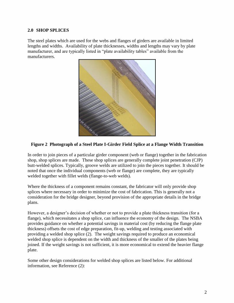
Figure 2 Photograph of a Steel Plate I-Girder Field Splice at a Flange Width Transition
In order to join pieces of a particular girder component (web or flange) together in the fabrication
shop, shop splices are made. These shop splices are generally complete joint penetration (CJP)
butt-welded splices. Typically, groove welds are utilized to join the pieces together. It should be
noted that once the individual components (web or flange) are complete, they are typically
welded together with fillet welds (flange-to-web welds).
Where the thickness of a component remains constant, the fabricator will only provide shop
splices where necessary in order to minimize the cost of fabrication. This is generally not a
consideration for the bridge designer, beyond provision of the appropriate details in the bridge
plans.
However, a designer’s decision of whether or not to provide a plate thickness transition (for a
flange), which necessitates a shop splice, can influence the economy of the design. The NSBA
provides guidance on whether a potential savings in material cost (by reducing the flange plate
thickness) offsets the cost of edge preparation, fit-up, welding and testing associated with
providing a welded shop splice (2). The weight savings required to produce an economical
welded shop splice is dependent on the width and thickness of the smaller of the plates being
joined. If the weight savings is not sufficient, it is more economical to extend the heavier flange
plate.
Some other design considerations for welded shop splices are listed below. For additional
information, see Reference (2):
3
Per AASHTO LRFD Article 6.6.1.2.4, “Transversely loaded partial penetration groove
welds shall not be used,” except for certain orthotropic steel deck applications, therefore
only complete joint penetration (CJP) welds are employed, and designed in accordance
with Article 6.13.3.
Since the CJP weld develops the full-strength of the connected plates, actual welded shop
splice design by the bridge designer is not required.
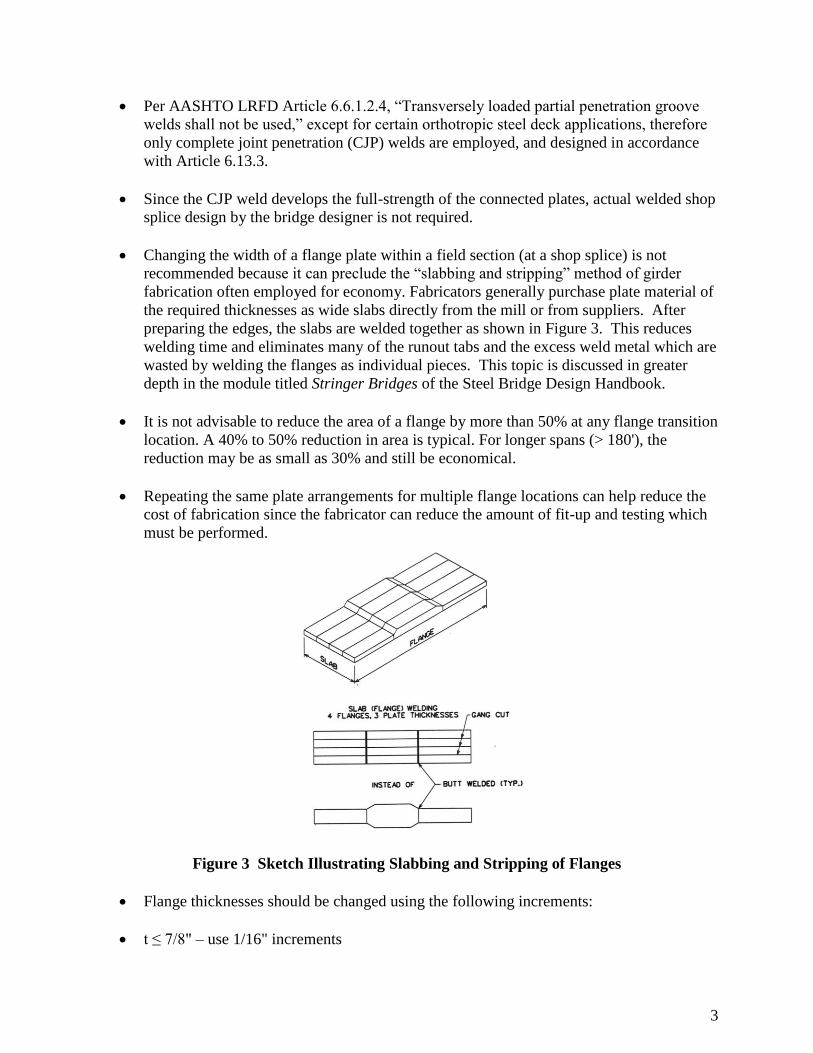
Changing the width of a flange plate within a field section (at a shop splice) is not
recommended because it can preclude the “slabbing and stripping” method of girder
fabrication often employed for economy. Fabricators generally purchase plate material of
the required thicknesses as wide slabs directly from the mill or from suppliers. After
preparing the edges, the slabs are welded together as shown in Figure 3. This reduces
welding time and eliminates many of the runout tabs and the excess weld metal which are
wasted by welding the flanges as individual pieces. This topic is discussed in greater
depth in the module titled Stringer Bridges of the Steel Bridge Design Handbook.
It is not advisable to reduce the area of a flange by more than 50% at any flange transition
location. A 40% to 50% reduction in area is typical. For longer spans (> 180'), the
reduction may be as small as 30% and still be economical.
Repeating the same plate arrangements for multiple flange locations can help reduce the
cost of fabrication since the fabricator can reduce the amount of fit-up and testing which
must be performed.
Figure 3 Sketch Illustrating Slabbing and Stripping of Flanges
Flange thicknesses should be changed using the following increments:
t ≤ 7/8" – use 1/16" increments

4
7/8" < t < 2" – use 1/8" increments
2" ≤ t – use 1/4" increments
The minimum length for any flange plate should be limited to 10'.
Top and bottom flange transitions do not have to be placed at the same locations along
the girder. Placing them at different locations will result in additional design effort (more
sections to check), but may result in more efficient plates since the top and bottom
flanges are governed by different requirements.
Flange transitions in positive moment sections are typically uneconomical except for very
long spans. The top flange is usually governed by the b/t ratios and lateral buckling
stresses in the flange prior to the hardening of the concrete slab. Therefore, the stresses
in the top flange only reach 35 to 50 percent of the flange capacity under full factored
loads. A bottom flange transition may be economical in the end spans near the end
support due to the small live load and fatigue load force effects that must be carried by
the section, but bottom flange transitions between the points of maximum positive
moment and points of dead load contraflexure are generally not economical due to the
large fatigue stresses and possible compressive stresses in the bottom flange.
Flange transitions in negative moment sections are common, and the following guidelines
can be used to provide economical transitions:
For spans up to approximately 150', one top flange plate transition between an interior
pier and the adjacent field splice is generally economical.
For spans over 150', two top flange plate transitions between an interior pier and the
adjacent field splice may be economical.
Except for very long spans, one bottom flange plate transition between an interior pier
and the adjacent field splice is usually economical.
Longitudinal web splices are costly due to the welding associated with joining the plates
together. Some points to remember when designing deep girders are:
Web depths in excess of 144" (assuming 6" for camber cuts and 150" maximum
commonly available plate width) may necessitate a longitudinal web splice, which can
significantly increase the cost of the girder.
Girders that are haunched to depths greater than 144" may also require a longitudinal web
splice (typically welded, but sometimes bolted).
5
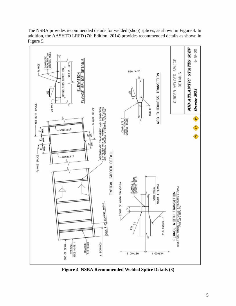
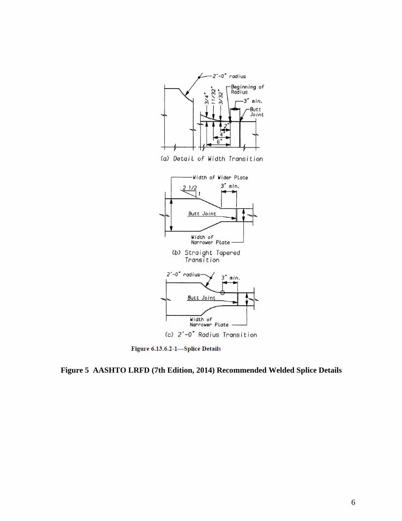
The NSBA provides recommended details for welded (shop) splices, as shown in Figure 4. In
addition, the AASHTO LRFD (7th Edition, 2014) provides recommended details as shown in
Figure 5.
Figure 4 NSBA Recommended Welded Splice Details (3)
6
Figure 5 AASHTO LRFD (7th Edition, 2014) Recommended Welded Splice Details

7
3.0 FIELD SPLICES
Field splices are the connection of separate sections of the girders (field sections) which occur in
the field. Generally these splices are bolted connections as field welding is usually discouraged
due to the high cost of field welding and problems associated with welding in less than ideal
conditions, such as inclement weather. It should be noted that some agencies do permit welded
field splices, although their use is becoming less frequent.
The majority of bridges that exceed 120 to 140 feet in length will require at least one field splice
somewhere in the girder. Numerous design constraints must be satisfied during the design of the
splices. In addition, the intent of the AASHTO LRFD (7th Edition, 2014) must be kept in mind
during the design process.
Introducing a bolted field splice in the girder also introduces a region where stresses may be
significantly higher than in the areas which are immediately adjacent due to the reduced area of
the flange plates. The area of the web and girder flange plates is reduced by the holes for the
connection bolts; these areas also produce stress concentrations around the holes themselves
which are not easily quantified. To account for the uncertainty in the behavior of bolted girder
splices, the underlying design philosophy behind splice design ensures that the capacity of the
splice is well in excess of the maximum force in the web or flanges.
The behavior of the girder must be kept in mind when designing the splice. It must be
remembered that the girder properties are different depending on when the girder is examined.
The basic girder section starts out as a non-composite section prior to hardening of the deck slab,
and then becomes a composite section. In the positive moment regions, the composite section
properties are different for long-term composite dead loads and short-term composite live loads.
Thus, the splice design must be based on the stresses in the flanges and the web and not on the
moments for the non-composite and composite girder sections.
Field splices can be made between girder sections (or components) which are either similar in
size or of different width and/or thickness.
The remainder of this module will focus on the factors which influence and the principles of the
design of bolted field splices.
8
4.0 FACTORS INFLUENCING FIELD SPLICE DESIGN
Many factors influence the design of steel beam and girder field splices. Some of the more
important factors are described below. While this list may not be all-encompassing (there are
often unforeseen or project-specific issues that could also influence the design), the factors
discussed generally play an important role in the field splice design process.
4.1 Span/Structure Length
Perhaps the most important factor influencing the locations and design of field splices is the
length and the span arrangement of a bridge structure. If the overall structure length is less than
the length of girder that can reasonably be fabricated, shipped, handled and erected, then field
splices are not necessary, and should not be included in the design. Many agencies have
limitations on shipping dimensions and weights. Designers should investigate local regulations
prior to making decisions on girder lengths.
If the overall girder length must be longer than can reasonably be fabricated, shipped, handled
and erected, then at least one field splice will be required. Selecting the appropriate locations of
field splices is influenced by other factors, as described in the following sections.
Often, based on perceived shipping, handling and erection considerations, the designer may
provide for field splices in the design. However, it is often possible that a contractor may be able
to utilize some other mode of transportation to ship the girder pieces or employ an unanticipated
method to erect them, which may eliminate the need for certain field splices. In recognition of
this fact, some agencies stipulate that either all or certain field splices should be designated as
“optional”. Such requirements should be verified with the particular agency during the design
process.
4.2 Span Layout
Continuous Spans – On continuous structures, it is normal for the designer to attempt to
locate field splices near the points of dead-load contraflexure (where dead load bending
effects change from positive to negative and are therefore zero). By doing so, the design
forces for the splice are minimized. Web and flange splices in areas of stress reversal
(which is likely to be the case near the points of dead load contraflexure) should be
investigated for both positive and negative flexure (Article 6.13.6.1.4a). Sometimes, if
the span lengths are large enough, field splices may be required at additional locations.
The design of the splices away from the point of dead load contraflexure will typically be
heavier due to the higher forces in the girder.
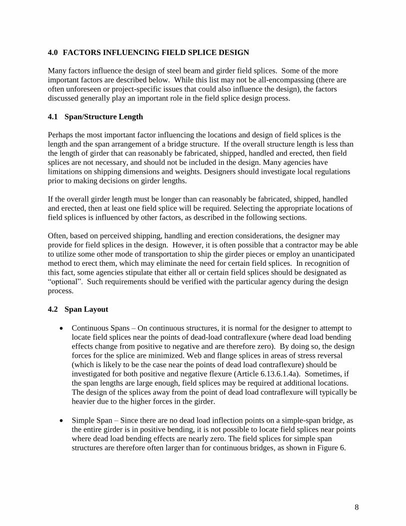
Simple Span – Since there are no dead load inflection points on a simple-span bridge, as
the entire girder is in positive bending, it is not possible to locate field splices near points
where dead load bending effects are nearly zero. The field splices for simple span
structures are therefore often larger than for continuous bridges, as shown in Figure 6.

9
Figure 6 Photograph of a Field Splice for a Long Simple Span Steel I-Girder
Continuous for Live Load – Occasionally it is possible to provide field sections for a multi-span
structure which can span from support to support. This option can minimize the need for
erection devices (such as falsework or pier brackets) and can reduce the impact on traffic beneath
the structure. In these cases a girder splice is often made at the supports to provide continuity of
the girder (and thereby eliminate the need for a deck expansion joint, which is desirable). These
splices are often made after the majority of the deck has been cast and therefore the splice need
only be designed for live load effects. These types of splices are somewhat unique, and are not
discussed in further detail in this module.
4.3 Curvature
If a girder is curved in plan, it can influence both the location chosen for (frequency of) and
design of the field splices. The radius of the curvature determines the amount of sweep of a
particular length (arc length) of girder. If the sweep is too large then the section cannot be
reasonably shipped and an additional field splice may be required. Typically this will only
control for relatively tight radii. This is demonstrated in Figure 7. For example, a 120 ft long
piece with a radius of 400 ft has a sweep, S = 4.5 ft.
10
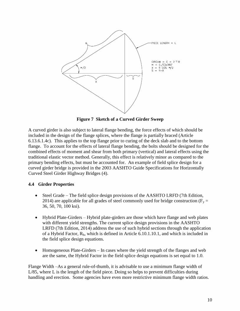
Figure 7 Sketch of a Curved Girder Sweep
A curved girder is also subject to lateral flange bending, the force effects of which should be
included in the design of the flange splices, where the flange is partially braced (Article
6.13.6.1.4c). This applies to the top flange prior to curing of the deck slab and to the bottom
flange. To account for the effects of lateral flange bending, the bolts should be designed for the
combined effects of moment and shear from both primary (vertical) and lateral effects using the
traditional elastic vector method. Generally, this effect is relatively minor as compared to the
primary bending effects, but must be accounted for. An example of field splice design for a
curved girder bridge is provided in the 2003 AASHTO Guide Specifications for Horizontally
Curved Steel Girder Highway Bridges (4).
4.4 Girder Properties
Steel Grade – The field splice design provisions of the AASHTO LRFD (7th Edition,
2014) are applicable for all grades of steel commonly used for bridge construction (Fy =
36, 50, 70, 100 ksi).
Hybrid Plate-Girders – Hybrid plate-girders are those which have flange and web plates
with different yield strengths. The current splice design provisions in the AASHTO
LRFD (7th Edition, 2014) address the use of such hybrid sections through the application
of a Hybrid Factor, Rh, which is defined in Article 6.10.1.10.1, and which is included in
the field splice design equations.
Homogeneous Plate-Girders – In cases where the yield strength of the flanges and web
are the same, the Hybrid Factor in the field splice design equations is set equal to 1.0.
Flange Width –As a general rule-of-thumb, it is advisable to use a minimum flange width of
L/85, where L is the length of the field piece. Doing so helps to prevent difficulties during
handling and erection. Some agencies have even more restrictive minimum flange width ratios.
11
4.5 Coordination of Details
Crossframe Connection Plates/Transverse Stiffeners – Field splices should be located far
enough away from crossframe connection plates/transverse stiffeners that there will be no
interference between the connection plates/stiffeners and the splice plates. In preparing
preliminary layouts for the framing, it is advisable to leave a minimum of 3' (and
preferably 4') between proposed crossframe or stiffener locations and the centerlines of
proposed field splices to provide adequate length for the flange splice plates. On rare
occasions, girders are kinked at field splice locations to accommodate complex (curved
or flaring) framing; in these cases, providing a crossframe as close as possible (but not
interfering) with the splice is advisable to help resist lateral loads on the girder due to the
kink.
Longitudinal Stiffeners – Two options are possible where longitudinal stiffeners intersect
field splices. Termination of the longitudinal stiffener at the splice location (if acceptable
by design) can be accomplished by providing a radiused end treatment at the end of the
longitudinal stiffener, or the longitudinal stiffener can be spliced at the field splice
location. The termination point of longitudinal stiffeners is known to be a fatigue
sensitive detail. Designers should verify the fatigue resistance of the details chosen.
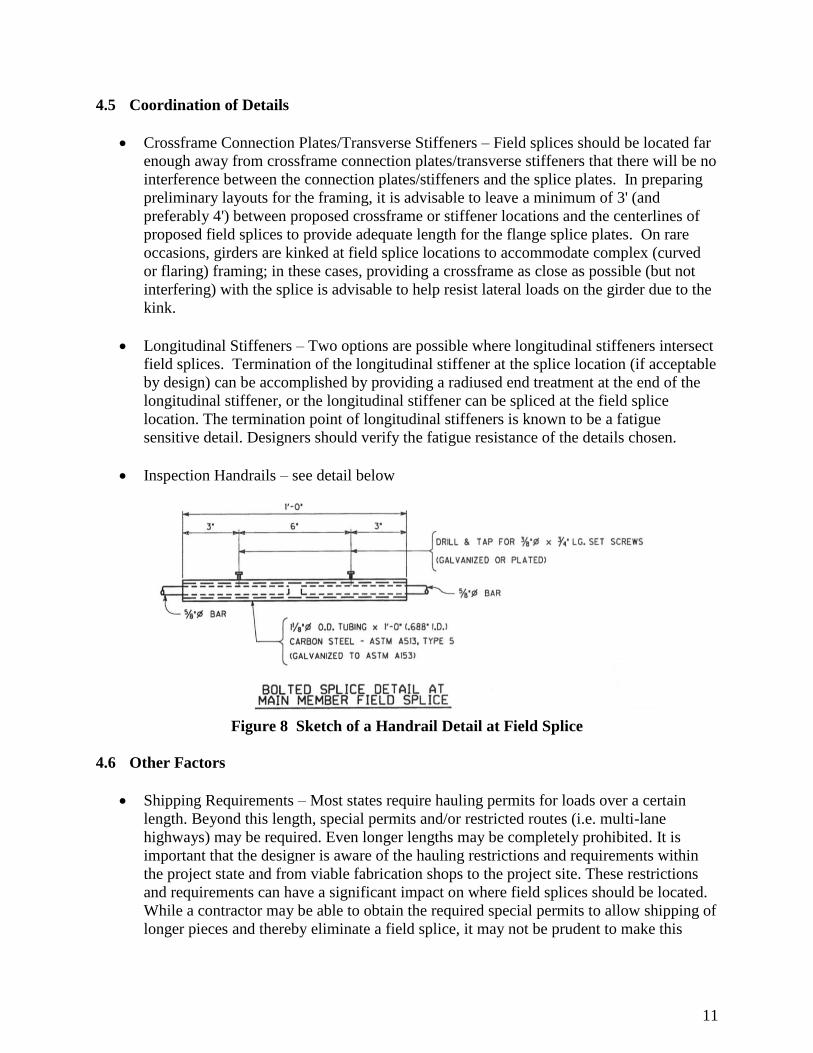
Inspection Handrails – see detail below
Figure 8 Sketch of a Handrail Detail at Field Splice
4.6 Other Factors
Shipping Requirements – Most states require hauling permits for loads over a certain
length. Beyond this length, special permits and/or restricted routes (i.e. multi-lane
highways) may be required. Even longer lengths may be completely prohibited. It is
important that the designer is aware of the hauling restrictions and requirements within
the project state and from viable fabrication shops to the project site. These restrictions
and requirements can have a significant impact on where field splices should be located.
While a contractor may be able to obtain the required special permits to allow shipping of
longer pieces and thereby eliminate a field splice, it may not be prudent to make this
12
assumption. Some agencies require that shipping requirements for a particular design be
included in the contract documents.
Project Site Accessibility – This factor may drive or go hand-in-hand with the shipping
requirements. Remote locations which are accessible by minor roadways (which may be
winding) may prevent field piece lengths that would normally be acceptable. In addition,
a site which requires girder picks which are very tall or at a long reach may limit the
weight of individual girder pieces unless a prohibitively large crane is used.
Erection Requirements – Girder pick limitations discussed previously are a consideration. Also,
longer or imbalanced field sections can force the erector to utilize additional falsework, pier
brackets, stiffening trusses and other types of erection devices. These factors can influence the
decision on limiting or establishing an appropriate field piece length and layout.
13
5.0 FIELD SPLICE DESIGN – GENERAL CONSIDERATIONS
5.1 Current Splice Design Provisions
The splice design provisions in the AASHTO LRFD (7th Edition, 2014) specification were
developed in an attempt to eliminate confusion regarding the application of the previous
provisions, to extend the previous provisions to cover the design of splices in all regions of
composite girders, and to provide for a more consistent application of the provisions at all limit
states.
These current provisions are discussed in this and the following sections and implemented in the
example field splice design which follows.
According to Article 6.13.1, splices for primary members shall be designed at the strength limit
state for not less than the larger of:
The average of the flexural moment-induced stress, shear, or axial force due to the
factored loadings at the point of the splice or connection and the factored flexural, shear,
or axial resistance of the member or element at the same point, or
75 percent of the factored flexural, shear, or axial resistance of the member or element.
Note, as stated in Article C6.13.1, where the girder section changes at a splice, which is
frequently the case, the “smaller” section is to be used for these requirements.
These statements can be expressed in an equation of generic form:
½ (Q + Rr) ≥ 0.75Rr (1)
where:
Q = The factored force effect
Rr = The factored resistance
This requirement has existed in a similar form in the AASHTO Standard Specifications for
Highway Bridges, 17th
Edition, 2002 (referred to herein as Standard Specification) (5) since the
days of riveted girders. Thus, in essence, it was originally developed to handle the case of
symmetrical non-composite, non-compact girders.
In the case of flexure, the splice is designed to provide this minimum flexural resistance to
ensure that a stiffness consistent with the flexural stiffness of the member at the splice is
provided and to allow for possible shifts in the girder moment at the splice. The minimum
flexural resistance is used to check the flexural resistance of the splice plates and the bearing
resistance at bolt holes, and to check the shear resistance of high-strength bolts assuming the
bolts have slipped and gone into bearing at the strength limit state.
14
Following similar reasoning, splices should also be designed to provide a minimum flexural
resistance at the permanent deflection service limit state (i.e., when checking for slip of the bolts
and localized yielding of the splice plates). A minimum flexural resistance at the permanent
deflection service limit state (a lower value than the strength limit state) is defined in order to be
consistent with the philosophy used to check the splice at the strength limit state and to again
allow for possible shifts in the girder moment at the splice.
The proposed minimum flexural resistances that must be provided by the splice at the strength
limit state and at the permanent deflection service limit state are reviewed below.
5.2 “Smaller” Girder Section
Often, where the girder section changes at a splice, and the “smaller” section must be used, it is
obvious by inspection which side of the splice is smaller because all of the section components
are of lesser dimension (width and/or thickness) and have the same yield stress as the “larger”
section. When a hybrid girder with smaller flanges is connected to a girder with a larger
homogeneous section (all plates of the same yield strength), it is not obvious which section is the
“smaller” section. When this is the case (as illustrated in the numerical splice design example
which follows) it is appropriate to determine the “smaller” section as the side of the splice which
has lower flange forces.
5.3 Controlling Flange
In the design of flange splices, determination of the controlling flange is critical. The definition
of controlling flange is provided in Article C6.13.6.1.4c, but is included here for completeness.
“The controlling flange is defined as either the top or bottom flange for the smaller
section at the point of splice, whichever flange has the maximum ratio of the elastic
flexural stress at its midthickness due to the factored loads for the loading condition
under investigation to its factored flexural resistance. The other flange is termed the
noncontrolling flange.”
Article C6.13.6.1.4c also indicates that in areas of stress reversal (which is likely if the splice is
located near the point of dead load contraflexure), the splice must be checked independently for
both positive and negative flexure.
5.4 Effective Flange Area
In the design of flange splices, the required minimum design resistance (the design force) is
determined by finding the product of the minimum flexural design stress (as described in the
following sections) and the smaller effective flange area, Ae, on either side of the splice. For
compression flanges, Ae shall be taken as the gross area of the flange. For tension flanges, Ae
shall be taken as defined in Equation (6.13.6.1.4c-2).

15
It is possible that the smaller girder section at the splice (as designated by having the smaller
moment of inertia) may have a larger effective flange area for the controlling flange than the
section on the opposite side of the splice. In such case, the effective flange area on the opposite
side of the splice should be used.
5.5 Minimum Flexural Resistance: Strength Limit State
Typically, splices have been designed by treating the flanges and the web of the girder as
individual components and then proportioning the total moment in the girder at the splice to each
component. The determination of the proportion of the total moment carried by the web is not
necessarily straightforward for an unsymmetrical composite girder. Many different approaches
have been used, which have not always led to consistent results.
For a composite girder, dead- and live-load moments due to the factored loads are applied to
different sections and should not be directly summed when at elastic stress levels (up to and
including Fyf). In addition, the factored flexural resistance of a composite section is different in
positive and negative flexure. In areas of stress reversal, it is not always clear which flexural
resistance should be used in Equation (1). For these reasons, it becomes more convenient to
express the minimum flexural resistance of each member component (flanges and web) that must
be provided by the splice in terms of stress rather than moment, which is the approach taken in
the current provisions.
5.5.1 Flange Splices (Article 6.13.6.1.4c)
Once the smaller girder section at the point of splice and the controlling and non-controlling
flanges have been determined, the flange splice plates and their connections can be proportioned
to provide a flexural resistance to satisfy the strength limit state. The required flexural resistance
is obtained by providing splice plates and connections that produce a factored resistance greater
than the design force described in the following paragraphs.
Figure 9 Photograph of a Typical Flange Splice
16
For the controlling flange, the design force is calculated as the product of the smaller effective
flange area, Ae, on either side of the splice and the minimum flexural design stress for the
controlling flange, Fcf, which follows the form of Equation (1) as follows:
gyffgyffh
cfcf RF0.75αRFα
R
f
2
1F
(2)
where:
fcf = maximum flexural stress due to the factored loads at the mid-thickness of the controlling
flange at the point of splice (ksi)
Rh = hybrid factor
α = 1.0, except that a lower value equal to (Fn/Fyf) may be used for flanges where Fn is less
than Fyf
Fn = nominal flexural resistance of the flange (ksi)
f = resistance factor for flexure specified in Article 6.5.4.2
Fyf = specified minimum yield strength of the flange (ksi)
Rg= flange resistance modification factor
The flange resistance modification factor, Rg, ensures that the flange splice is not designed for a
force larger than the minimum design force for the weaker flange on either side of the splice. The
factor, Rg, also takes into account the fact that the specified minimum yield strengths of the
adjacent flange plates or the factor, α, or a combination thereof, may potentially differ on either
side of the splice. The flange resistance modification factor, Rg, was introduced in the 7th
edition
of the AASHTO LRFD Bridge Design Specifications (1), and is computed in accordance with
Equation 6.13.6.1.4c-3 of the specification.
For the non-controlling flange, the required design force is calculated as the product of the
smaller effective flange area, Ae, on either side of the splice and the minimum flexural design
stress for the non-controlling flange, Fncf, as follows:
gyfy
h
ncfcfncf RF0.75α
R
fRF
(3)
where:
Rcf = the absolute value of the ratio of Fcf to fcf for the controlling flange
17
fncf = flexural stress due to the factored loads at the midthickness of the noncontrolling flange
at the point of splice concurrent with fcf (ksi)
Use of the Rcf factor results in the flexural stress in the noncontrolling flange being factored up in
the same proportion as the flexural stress in the controlling flange producing a consistent design.
However, as a minimum, the factored-up stress must be equal to or greater than 0.75αφfFyfRg.
Once the appropriate design forces have been determined, the splice plates and connections are
designed as follows:
For splice plates subject to tension, the design force shall not exceed the factored
resistance in tension specified in Article 6.13.5.2
For splice plates subject to compression, the design force shall not exceed the factored
resistance, Rr, in compression taken as, Rr = φcFyAs
At the strength limit state, the design force shall not exceed the factored resistance
(bearing, shear and tensile), Rr or Tr of the bolted connections of the flange splice plates
(Article 6.13.2.2). Note that the bolted connections must be designed as slip-critical,
proportioned to prevent slip under Load Combination SERVICE II, as discussed later.
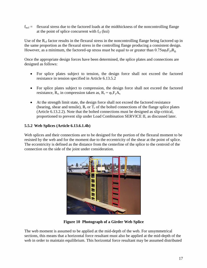
5.5.2 Web Splices (Article 6.13.6.1.4b)
Web splices and their connections are to be designed for the portion of the flexural moment to be
resisted by the web and for the moment due to the eccentricity of the shear at the point of splice.
The eccentricity is defined as the distance from the centerline of the splice to the centroid of the
connection on the side of the joint under consideration.
Figure 10 Photograph of a Girder Web Splice
The web moment is assumed to be applied at the mid-depth of the web. For unsymmetrical
sections, this means that a horizontal force resultant must also be applied at the mid-depth of the
web in order to maintain equilibrium. This horizontal force resultant may be assumed distributed
18
equally to all web bolts. The following equations are suggested to determine a design moment,
Muw, and a design horizontal force resultant, Huw, to be applied at the mid-depth of the web for
designing the web splice plates and their connections at the strength limit state:
ncfcfcfh
2
w
uw fRFR12
DtM (4)
ncfcfcfh
w
uw fRFR2
DtH (5)
where:
tw = web thickness (in)
D = web depth (in)
Rh, Fcf, Rcf and fncf are as previously defined.
For sections where the neutral axis is located at the mid-depth of the web, Huw will equal zero.
For all other sections, Muw and Huw applied together will yield a combined stress distribution
equivalent to the unsymmetrical stress distribution in the web.
5.6 Minimum Flexural Resistance: Permanent Deflection Service Limit State
The proposed minimum flexural resistance of the flanges and web that must be provided by the
flange and web splices to satisfy the permanent deflection service limit state is given below. The
minimum flexural resistance at the permanent deflection service limit state is used to check for
slip of high-strength bolts and to check for localized yielding of the splice plates.
5.6.1 Flange Splices
In the Load Factor Design method given in the Standard Specifications (5), the ratio of the
maximum design loads (used to check strength) to the Overload (used to control permanent
deformations) is 1.3. In the AASHTO LRFD (7th Edition, 2014) (1), the ratio of the live load
used in the STRENGTH I load combination to the live load used in the SERVICE II load
combination is approximately equal to 1.3. Therefore, the proposed minimum flexural resistance
of the flange at the splice, Ffs, that must be provided by the flange splice plates and their
connections to satisfy the permanent deflection service limit state (i.e. to prevent slip of the bolts,
etc.) is taken as the minimum flexural resistance of the flange at the splice at the strength limit
state, Fcf or Fncf, divided by 1.3:
Ffs = (Fcf or Fncf)/1.3 ≈ 0.80(Fcf or Fncf) (6)
The resistance factor is not applied since this is a serviceability check.
5.6.2 Web Splices
19
In order to determine a design moment and a design horizontal force resultant to be applied at the
mid-depth of the web for designing the web splice plates and their connections at the permanent
deflection service limit state, Equations (4) and (5) can be utilized with the following
substitutions. This design moment and horizontal force is then utilized to check the web bolts for
slip:
Replace Fcf with the maximum flexural stress, fs, due to load combination SERVICE II at
the midthickness of the flange under consideration for the smaller section at the point of
splice
Replace fncf with the flexural stress, fos, due to load combination SERVICE II at the
midthickness of the other flange at the point of splice concurrent with fs in the flange
under consideration
Set the factors Rh and Rcf equal to 1.0
This results in the following equations:
oss
2
w ff12
DtM (7)
ossw ff2
DtH (8)
5.7 Shear
5.7.1 Strength Limit State
Since the maximum shear is not actually concurrent with the maximum moment at the splice and
the shear at the splice is unlikely to shift to the degree that the moment at the splice may shift, it
is felt that the splice need not be designed to resist the larger of 75 percent of the factored shear
resistance of the member at the splice or the average of the applied shear and the factored shear
resistance. Instead, the proposed minimum shear resistance of the web at the splice, Vuw, that
must be provided by the web splice plates and their connections to satisfy the strength limit state
is taken as follows:
If Vu < 0.50vVn, then:
Vuw = 1.50Vu (9)
If Vu ≥ 0.50vVn, then:
Vuw = 1/2 (Vu+vVn) (10)
where:
20
Vu = sum of the maximum calculated shears at the splice due to the factored loads at the
strength limit state
Vn = nominal shear resistance of the web of the splice
v = resistance factor for shear (Article 6.5.4.2)
5.7.2 Permanent Deflection Service Limit State
The proposed minimum shear resistance of the web at the splice, Vws, that must be provided by
the web splice plates and their connections to satisfy the permanent deflection service limit state
is taken as:
Vws = Vwr/1.3 ≈ 0.80Vwr (11)
5.8 Detailing Considerations
The following detailing requirements are stipulated in the AASHTO LRFD (7th Edition, 2014):
In both web and flange splices, there shall not be less than two rows of bolts on each side
of the joint (Article 6.13.6.1.4a).
Oversize or slotted holes shall not be used in either the member or the splice plates at
bolted splices (Article 6.13.6.1.4a).
Web splice plates are to be symmetrical on each side of the web and are to extend as near
as practical to the full depth of the web between flanges without impinging on bolt
assembly clearances. The required bolt assembly clearances are given in the AISC Steel
Construction Manual (Tables 7-16 and 7-17) (6).
The minimum mandatory edge distances used for bolted connections are provided in the
table below (from Article 6.13.2.6.6)
The minimum spacing between centers of bolts in standard holes shall be no less than
three times the diameter of the bolt (Article 6.13.2.6.1)

21
Table 1 AASHTO LRFD Table 6.13.2.6.6-1 Specifying Minimum Edge Distances
The maximum spacing between bolts in a single line adjacent to a free edge of an outside
plate or shape shall satisfy (Article 6.13.2.6.2):
s ≤ (4.0 + 4.0t) ≤ 7.0 inches
If there is a second line of fasteners uniformly staggered with those in the line adjacent to
the free edge, at a gage less than 1.5 + 4.0t, the staggered spacing, s, in two such lines,
considered together, shall satisfy (Article 6.13.2.6.2):
s ≤ 4.0 + 4.0t – [(3.0g) / 4.0] ≤ 7.0 inches
For bolted web splices with thickness differences of 1/16" or less, no filler plates are
required (Article 6.13.6.1.5).
Fillers 1/4" or more in thickness shall consist of not more than two plates (Article
6.13.6.1.5)
The specified minimum yield strength of fillers 1/4" or greater in thickness should not be
less than the larger of 70% of the specified minimum yield strength of the connected
plate and 36.0 ksi (Article 6.13.6.1.5)
For fillers less than 1/4" in thickness, no such provisions are stipulated.
For applications involving the use of weathering steels, a weathering grade product
should be specified for the filler plate material.
Hole sizes for design should be assumed to be 1/8" larger than the nominal diameter of
the bolt (Article 6.8.3).
In addition, the following detailing recommendations should be considered:
The orientation of the bolt heads for field splices should be designated as shown in Figure
11.

22
Figure 11 Sketch of a Bottom Flange Bolt Head Orientation
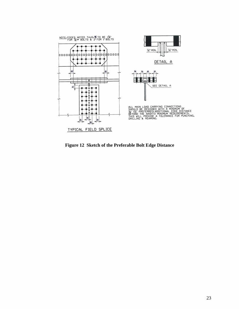
In order to provide a tolerance for punching, drilling and reaming of bolt holes, additional
edge distance (beyond that required by AASHTO LRFD (7th Edition, 2014)) should be
used as shown in Figure 12.
Minimum bolt spacings in excess of 3 times the diameter are preferable:
For 7/8-inch fasteners, 3 inches
For 1-inch fasteners, 3-1/2 inches
For 1-1/8-inch fasteners, 4 inches
Using the preceding recommended criteria, a minimum flange width of approximately
15" is required to accommodate 4 lines of 7/8” diameter high-strength bolts spaced
across the width of the flange (not staggered).
A non-varying (repeating) bolt pattern should be used for economy during fabrication.
23
Figure 12 Sketch of the Preferable Bolt Edge Distance
24
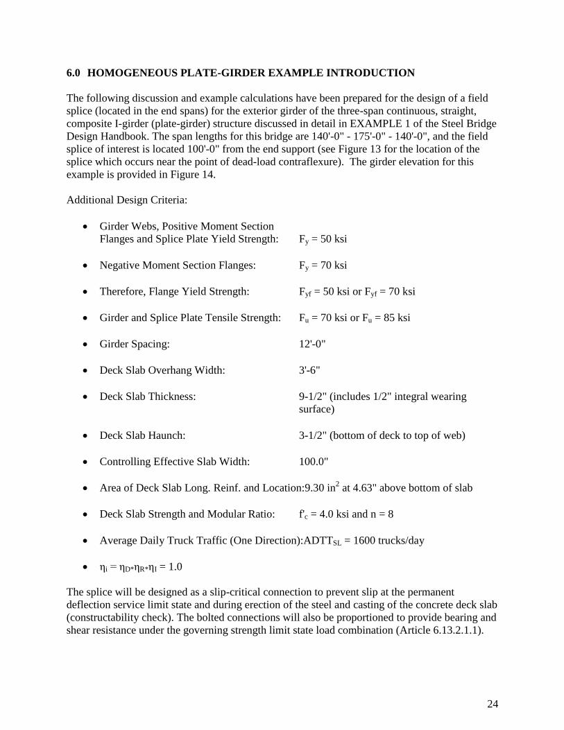
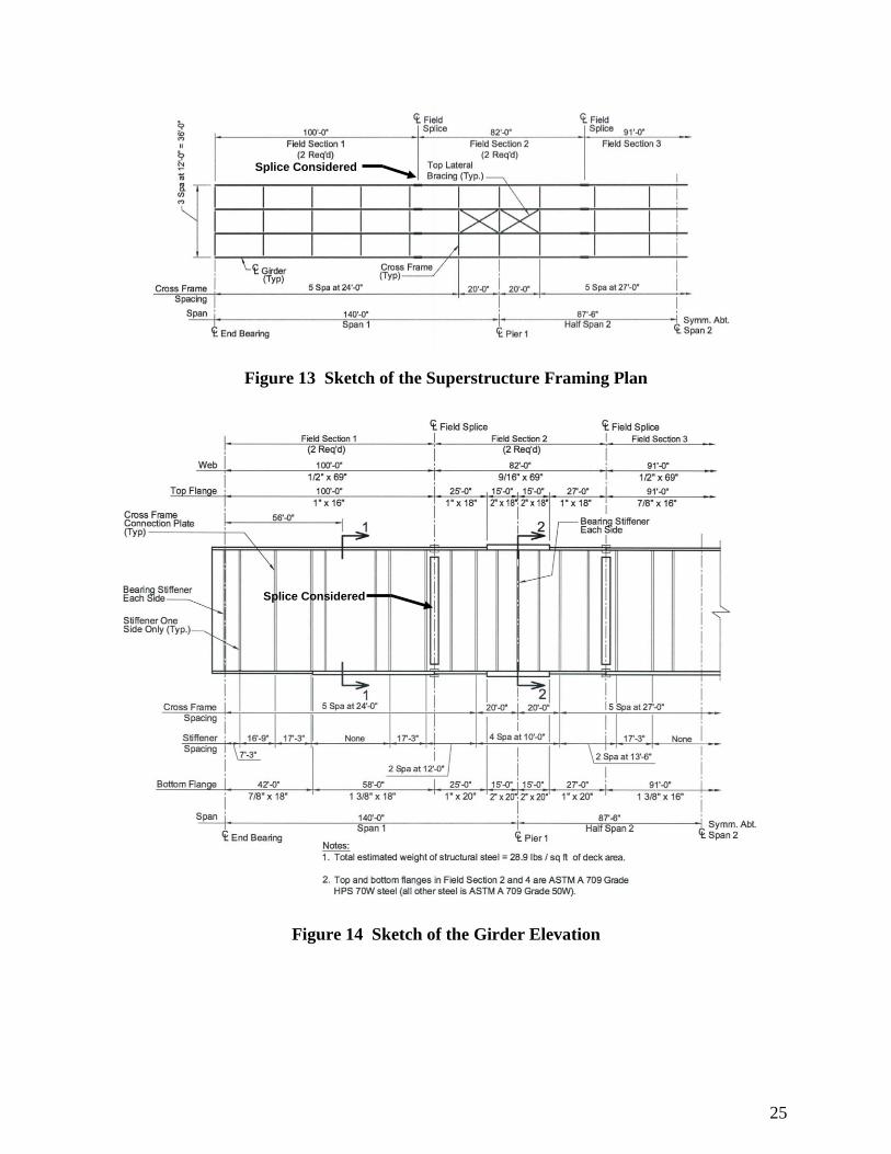
6.0 HOMOGENEOUS PLATE-GIRDER EXAMPLE INTRODUCTION
The following discussion and example calculations have been prepared for the design of a field
splice (located in the end spans) for the exterior girder of the three-span continuous, straight,
composite I-girder (plate-girder) structure discussed in detail in EXAMPLE 1 of the Steel Bridge
Design Handbook. The span lengths for this bridge are 140'-0" - 175'-0" - 140'-0", and the field
splice of interest is located 100'-0" from the end support (see Figure 13 for the location of the
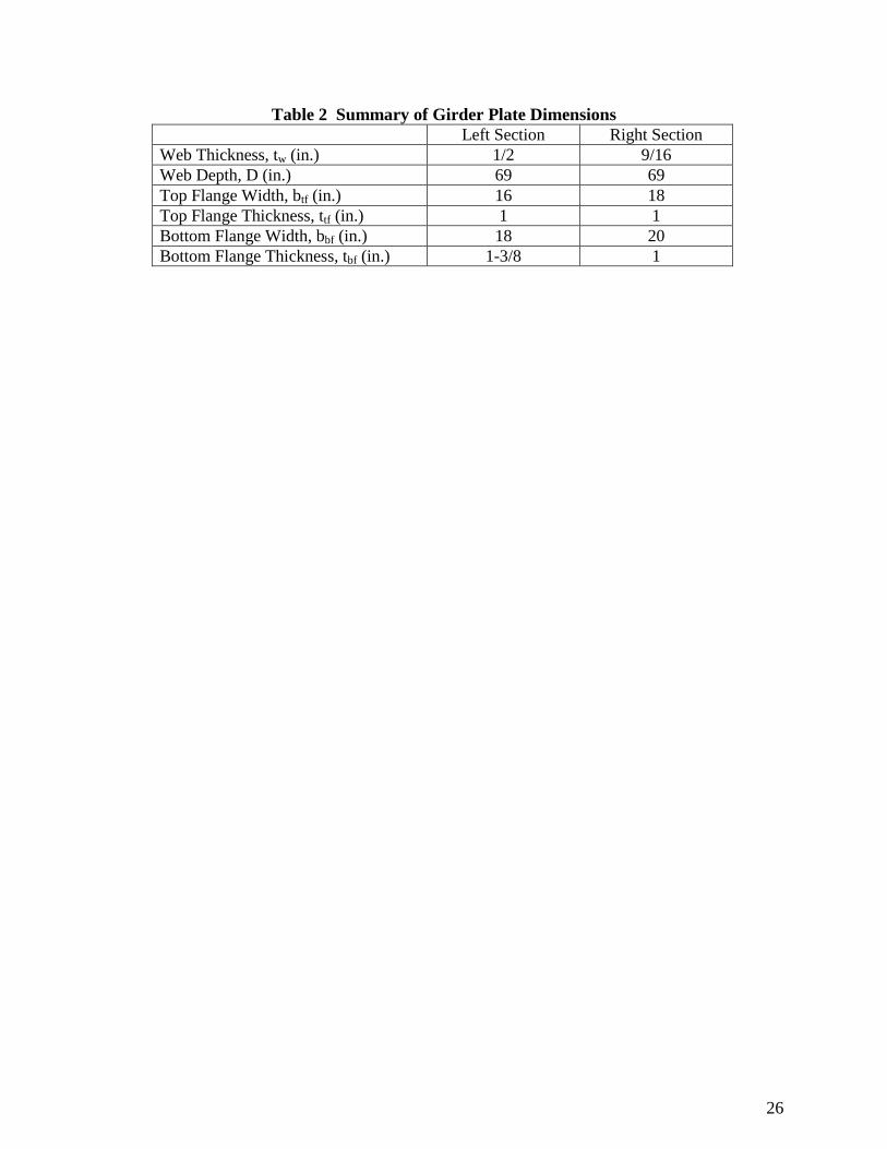
splice which occurs near the point of dead-load contraflexure). The girder elevation for this
example is provided in Figure 14.
Additional Design Criteria:
Girder Webs, Positive Moment Section
Flanges and Splice Plate Yield Strength: Fy = 50 ksi
Negative Moment Section Flanges: Fy = 70 ksi
Therefore, Flange Yield Strength: Fyf = 50 ksi or Fyf = 70 ksi
Girder and Splice Plate Tensile Strength: Fu = 70 ksi or Fu = 85 ksi
Girder Spacing: 12'-0"
Deck Slab Overhang Width: 3'-6"
Deck Slab Thickness: 9-1/2" (includes 1/2" integral wearing
surface)
Deck Slab Haunch: 3-1/2" (bottom of deck to top of web)
Controlling Effective Slab Width: 100.0"
Area of Deck Slab Long. Reinf. and Location:9.30 in2 at 4.63" above bottom of slab
Deck Slab Strength and Modular Ratio: f'c = 4.0 ksi and n = 8
Average Daily Truck Traffic (One Direction):ADTTSL = 1600 trucks/day
ηi = ηD*ηR*ηI = 1.0
The splice will be designed as a slip-critical connection to prevent slip at the permanent
deflection service limit state and during erection of the steel and casting of the concrete deck slab
(constructability check). The bolted connections will also be proportioned to provide bearing and
shear resistance under the governing strength limit state load combination (Article 6.13.2.1.1).
25
Figure 13 Sketch of the Superstructure Framing Plan
Splice Considered
Figure 14 Sketch of the Girder Elevation
Splice Considered
26
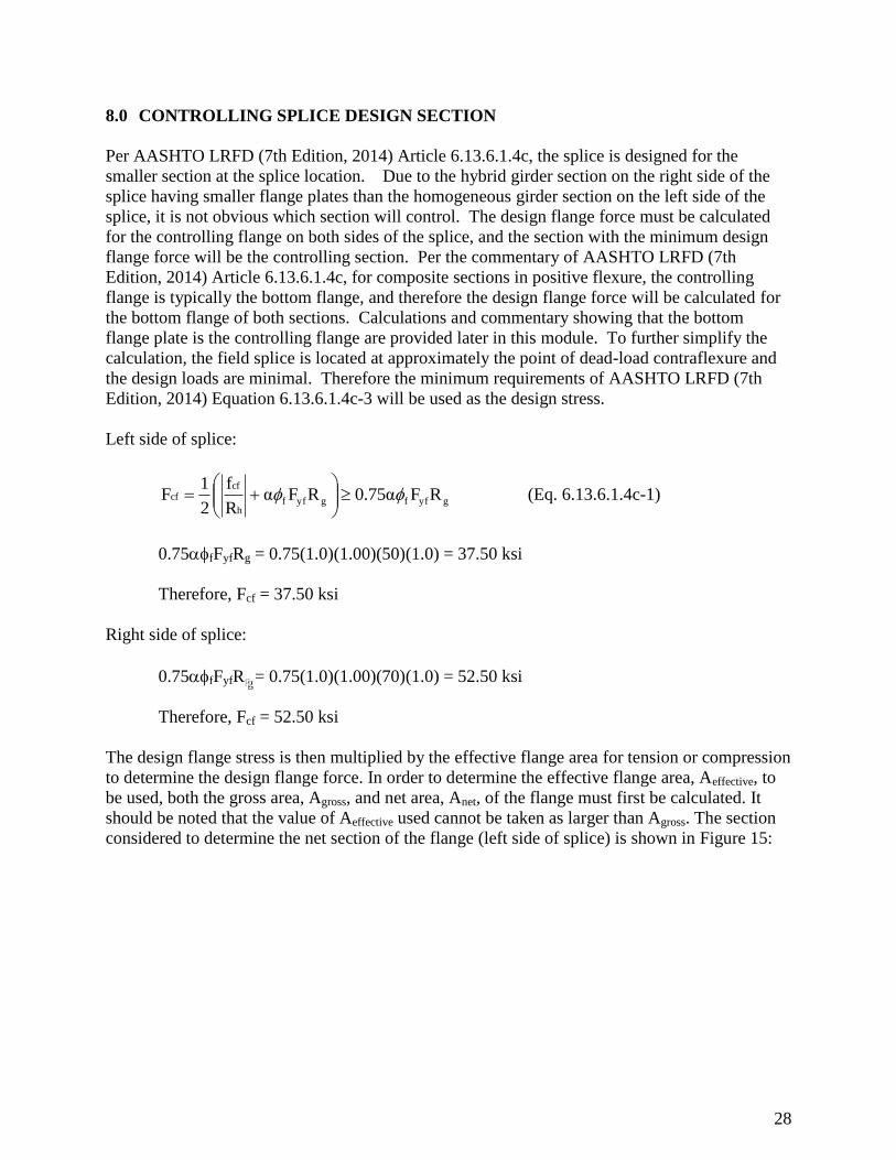
Table 2 Summary of Girder Plate Dimensions
Left Section Right Section
Web Thickness, tw (in.) 1/2 9/16
Web Depth, D (in.) 69 69
Top Flange Width, btf (in.) 16 18
Top Flange Thickness, ttf (in.) 1 1
Bottom Flange Width, bbf (in.) 18 20
Bottom Flange Thickness, tbf (in.) 1-3/8 1

27
7.0 LOADS FOR SPLICE DESIGN
The moments and shears due to the unfactored loads at the splice in the end spans as calculated
in EXAMPLE 1 of the Steel Bridge Design Handbook are:
MDC1 = 74 kip-ft VDC1 = -85 kips
Mdeck casting = 1,279 kip-ft Vdeck casting = -77 kips
MDC2 = 26 kip-ft VDC2 = -12 kips
MDW = 25 kip-ft VDW = -12 kips
M+LL+IM = 2,339 kip-ft V+LL+IM = 18 kips
M-LL+IM = -1,832 kip-ft V-LL+IM = -114 kips
28
8.0 CONTROLLING SPLICE DESIGN SECTION
Per AASHTO LRFD (7th Edition, 2014) Article 6.13.6.1.4c, the splice is designed for the
smaller section at the splice location. Due to the hybrid girder section on the right side of the
splice having smaller flange plates than the homogeneous girder section on the left side of the
splice, it is not obvious which section will control. The design flange force must be calculated
for the controlling flange on both sides of the splice, and the section with the minimum design
flange force will be the controlling section. Per the commentary of AASHTO LRFD (7th
Edition, 2014) Article 6.13.6.1.4c, for composite sections in positive flexure, the controlling
flange is typically the bottom flange, and therefore the design flange force will be calculated for
the bottom flange of both sections. Calculations and commentary showing that the bottom
flange plate is the controlling flange are provided later in this module. To further simplify the
calculation, the field splice is located at approximately the point of dead-load contraflexure and
the design loads are minimal. Therefore the minimum requirements of AASHTO LRFD (7th
Edition, 2014) Equation 6.13.6.1.4c-3 will be used as the design stress.
Left side of splice:
gyffgyffh
cfcf RF0.75αRFα
R
f
2
1F
(Eq. 6.13.6.1.4c-1)
0.75fFyfRg = 0.75(1.0)(1.00)(50)(1.0) = 37.50 ksi
Therefore, Fcf = 37.50 ksi
Right side of splice:
0.75fFyfR ggg = 0.75(1.0)(1.00)(70)(1.0) = 52.50 ksi
Therefore, Fcf = 52.50 ksi
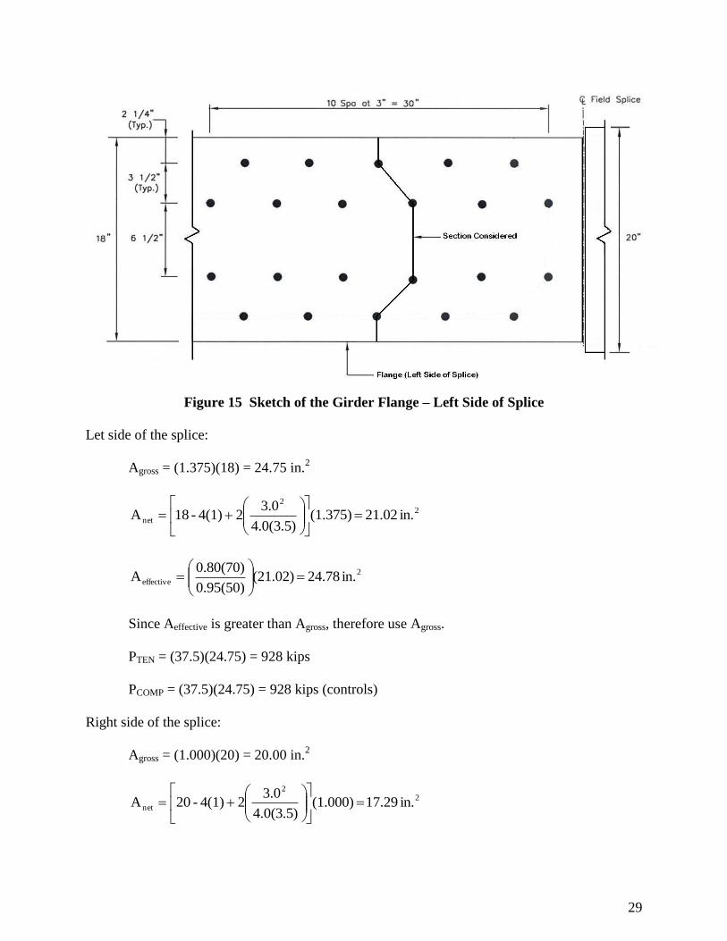
The design flange stress is then multiplied by the effective flange area for tension or compression
to determine the design flange force. In order to determine the effective flange area, Aeffective, to
be used, both the gross area, Agross, and net area, Anet, of the flange must first be calculated. It
should be noted that the value of Aeffective used cannot be taken as larger than Agross. The section
considered to determine the net section of the flange (left side of splice) is shown in Figure 15:
29
Figure 15 Sketch of the Girder Flange – Left Side of Splice
Let side of the splice:
Agross = (1.375)(18) = 24.75 in.2
22
net in. 21.02 (1.375))5.3(0.4
3.024(1)-18A
2
effective in. 24.78 (21.02)0.95(50)
0.80(70)A
Since Aeffective is greater than Agross, therefore use Agross.
PTEN = (37.5)(24.75) = 928 kips
PCOMP = (37.5)(24.75) = 928 kips (controls)
Right side of the splice:
Agross = (1.000)(20) = 20.00 in.2
22
net in. 17.29 (1.000))5.3(0.4
3.024(1)-20A

30
2
effective in. 17.68 (17.29)0.95(70)
0.80(85)A
PTEN = (52.5)(17.68) = 928 kips
PCOMP = (52.5)(20.00) = 1050 kips (controls)
31
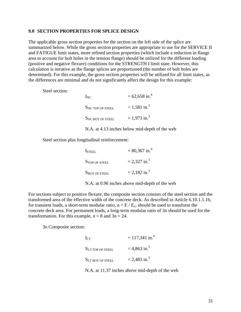
9.0 SECTION PROPERTIES FOR SPLICE DESIGN
The applicable gross section properties for the section on the left side of the splice are
summarized below. While the gross section properties are appropriate to use for the SERVICE II
and FATIGUE limit states, more refined section properties (which include a reduction in flange
area to account for bolt holes in the tension flange) should be utilized for the different loading
(positive and negative flexure) conditions for the STRENGTH I limit state. However, this
calculation is iterative as the flange splices are proportioned (the number of bolt holes are
determined). For this example, the gross section properties will be utilized for all limit states, as
the differences are minimal and do not significantly affect the design for this example:
Steel section:
INC = 62,658 in.4
SNC TOP OF STEEL = 1,581 in.3
SNC BOT OF STEEL = 1,973 in.3
N.A. at 4.13 inches below mid-depth of the web
Steel section plus longitudinal reinforcement:
ISTEEL = 80,367 in.4
STOP OF STEEL = 2,327 in.3
SBOT OF STEEL = 2,182 in.3
N.A. at 0.96 inches above mid-depth of the web
For sections subject to positive flexure, the composite section consists of the steel section and the
transformed area of the effective width of the concrete deck. As described in Article 6.10.1.1.1b,
for transient loads, a short-term modular ratio, n = E / Ec, should be used to transform the
concrete deck area. For permanent loads, a long-term modular ratio of 3n should be used for the
transformation. For this example, n = 8 and 3n = 24.
3n Composite section:
ILT = 117,341 in.4
SLT TOP OF STEEL = 4,863 in.3
SLT BOT OF STEEL = 2,483 in.3
N.A. at 11.37 inches above mid-depth of the web

32
n Composite section:
IST = 161,518 in.4
SST TOP OF STEEL = 13,805 in.3
SST BOT OF STEEL = 2,706 in.3
N.A. at 23.80 inches above mid-depth of the web

33
10.0 FLANGE SPLICE DESIGN
10.1 Calculation of Stresses
For the section on the left side of the splice in Figure 14, determine the average unfactored
flexural stress on the gross section of the bottom and top flange.
10.1.1 Bottom-Flange Stresses
In the following, negative live-load moments are assumed to be applied to the section consisting
of the steel girder plus the longitudinal reinforcement.
In this example, the DC2 and DW moments are positive at the splice location. However, the DC2
and DW moments are relatively small since the splice is located near the point of dead-load
contraflexure. From inspection, it is apparent that the DC2 and DW flexural compressive stresses
in the concrete slab are overcome by the negative live-load flexural tensile stress due to the
factored loads. When this is the case, the flexural stresses due to DC2 and DW moments are
combined with the live-load stress at the splice by assuming that these dead-load moments are
applied to the appropriate section for the live-load moment under consideration. For this
example, the flexural compressive stresses due to DC2 and DW at the splice are computed
assuming that these moments act on the 3n composite section for combination with the positive
live-load flexural stress or the steel girder plus longitudinal reinforcement for combination with
the negative live-load flexural stress.
The unfactored flexural stresses at the bottom of the bottom flange are computed for the various
moments acting on the appropriate sections. These equations are in the general form of f =
Moment/SBOT OF STEEL, with Moment with units of kip-ft (converted to kip-in by a factor of 12)
and S with units of cubic inches:
fDC1 = 74(12) ÷ 1973 = 0.45 ksi (tension)
fdeck casting = 1279(12) ÷ 1973 = 7.78 ksi (tension)
fDC2 = 26(12) ÷ 2483 = 0.13 ksi (tension)
or fDC2 = 26(12) ÷ 2182 = 0.14 ksi (tension)
fDW = 25(12) ÷ 2483 = 0.12 ksi (tension)
or fDW = 25(12) ÷ 2182 = 0.14 ksi (tension)
f +(LL+I) = 2339(12) ÷ 2706 = 10.37 ksi (tension)
|f -(LL+I)| = |-1832(12) ÷ 2182| = 10.08 ksi (compression)

34
The unfactored flexural stresses at the bottom of the web are then computed. These equations are
in the general form of f = (Moment x C)/I, with Moment in terms of kip-in, and C, the distance
from the neutral axis to the bottom of the web:
fDC1 = 74(12)(30.37) ÷ 62658 = 0.43 ksi (tension)
fdeck casting = 1279(12)(30.37) ÷ 62658 = 7.44 ksi (tension)
fDC2 = 26(12)(45.87) ÷ 117341 = 0.12 ksi (tension)
or fDC2 = 26(12)(35.46) ÷ 80367 = 0.14 ksi (tension)
fDW = 25(12)(45.87) ÷ 117341 = 0.12 ksi (tension)
or fDW = 25(12)(35.46) ÷ 80367 = 0.13 ksi (tension)
f +(LL+I) = 2339(12)(58.30) ÷ 161518 = 10.13 ksi (tension)
|f -(LL+I)| = |-1832(12)(35.46) ÷ 80367| = 9.70 ksi (compression)
Therefore, the average flexural stresses in the bottom flange (to be used in the design of the
splice) are taken as the average of the calculated stresses at the bottom and top of the bottom
flange:
(fDC1)avg = (0.45 + 0.43) ÷ 2 = 0.44 ksi (tension)
(fdeck casting)avg = (7.78 + 7.44) ÷ 2 = 7.61 ksi (tension)
(fDC2)avg = (0.13 + 0.12) ÷ 2 = 0.13 ksi (tension)
or (fDC2)avg = (0.14 + 0.14) ÷ 2 = 0.14 ksi (tension)
(fDW)avg = (0.12 + 0.12) ÷ 2 = 0.12 ksi (tension)
or (fDW)avg = (0.14 + 0.13) ÷ 2 = 0.14 ksi (tension)
(f +(LL+I))avg = (10.37 + 10.13) ÷ 2 = 10.25 ksi (tension)
(f -(LL+I))avg = (10.08 + 9.70) ÷ 2 = 9.89 ksi (compression)
For the controlling strength limit state load combination (STRENGTH I), determine the
maximum average bending stress in the bottom flange at the splice due to the factored loads. The
maximum permanent-load load factor γp (Table 3.4.1-2) is applied to permanent-load effects
having the same sign as the live-load effects. For permanent-load effects with a sign opposite to
the live-load effects, the minimum permanent-load load factor (Table 3.4.1-2) is applied, and the
effect of the future wearing surface is conservatively ignored. In both cases, η is taken equal to
35
1.0. If it is known with certainty that the future wearing surface will eventually be applied,
consideration should be given to including the effect of the wearing surface and applying the
minimum permanent-load load factor of 0.65 specified in Table 3.4.1-2 to the wearing surface
stress.
ffu = 1.0 [1.25(0.44+0.13) + 1.50(0.12) + 1.75(10.25)] = 18.83 ksi (governs)
ffu = 1.0 [0.90(0.44+0.14) + 1.75(-9.89)] = -16.79 ksi
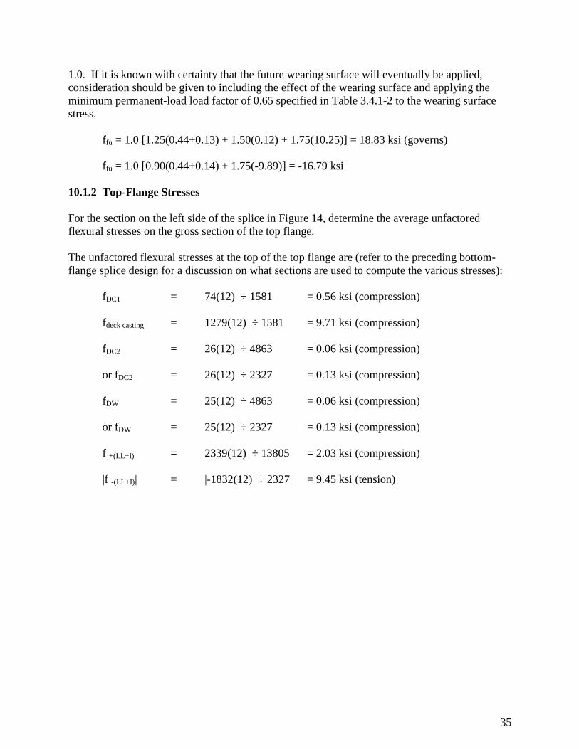
10.1.2 Top-Flange Stresses
For the section on the left side of the splice in Figure 14, determine the average unfactored
flexural stresses on the gross section of the top flange.
The unfactored flexural stresses at the top of the top flange are (refer to the preceding bottom-
flange splice design for a discussion on what sections are used to compute the various stresses):
fDC1 = 74(12) ÷ 1581 = 0.56 ksi (compression)
fdeck casting = 1279(12) ÷ 1581 = 9.71 ksi (compression)
fDC2 = 26(12) ÷ 4863 = 0.06 ksi (compression)
or fDC2 = 26(12) ÷ 2327 = 0.13 ksi (compression)
fDW = 25(12) ÷ 4863 = 0.06 ksi (compression)
or fDW = 25(12) ÷ 2327 = 0.13 ksi (compression)
f +(LL+I) = 2339(12) ÷ 13805 = 2.03 ksi (compression)
|f -(LL+I)| = |-1832(12) ÷ 2327| = 9.45 ksi (tension)
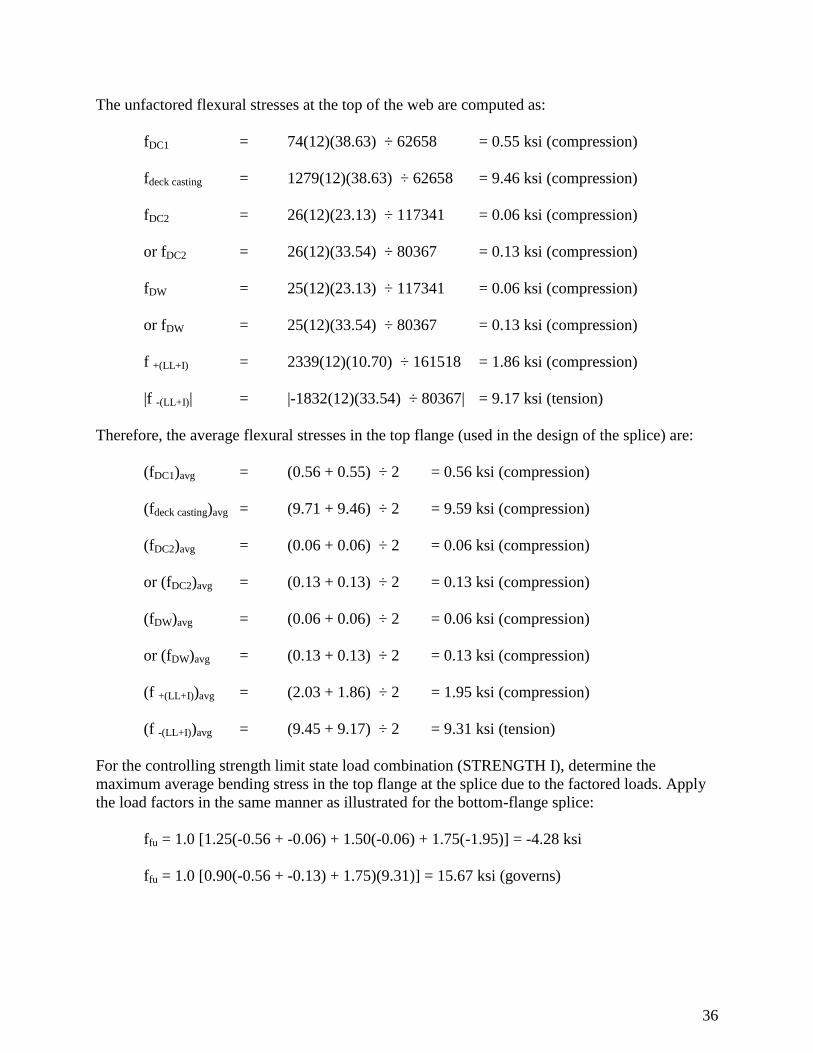
36
The unfactored flexural stresses at the top of the web are computed as:
fDC1 = 74(12)(38.63) ÷ 62658 = 0.55 ksi (compression)
fdeck casting = 1279(12)(38.63) ÷ 62658 = 9.46 ksi (compression)
fDC2 = 26(12)(23.13) ÷ 117341 = 0.06 ksi (compression)
or fDC2 = 26(12)(33.54) ÷ 80367 = 0.13 ksi (compression)
fDW = 25(12)(23.13) ÷ 117341 = 0.06 ksi (compression)
or fDW = 25(12)(33.54) ÷ 80367 = 0.13 ksi (compression)
f +(LL+I) = 2339(12)(10.70) ÷ 161518 = 1.86 ksi (compression)
|f -(LL+I)| = |-1832(12)(33.54) ÷ 80367| = 9.17 ksi (tension)
Therefore, the average flexural stresses in the top flange (used in the design of the splice) are:
(fDC1)avg = (0.56 + 0.55) ÷ 2 = 0.56 ksi (compression)
(fdeck casting)avg = (9.71 + 9.46) ÷ 2 = 9.59 ksi (compression)
(fDC2)avg = (0.06 + 0.06) ÷ 2 = 0.06 ksi (compression)
or (fDC2)avg = (0.13 + 0.13) ÷ 2 = 0.13 ksi (compression)
(fDW)avg = (0.06 + 0.06) ÷ 2 = 0.06 ksi (compression)
or (fDW)avg = (0.13 + 0.13) ÷ 2 = 0.13 ksi (compression)
(f +(LL+I))avg = (2.03 + 1.86) ÷ 2 = 1.95 ksi (compression)
(f -(LL+I))avg = (9.45 + 9.17) ÷ 2 = 9.31 ksi (tension)
For the controlling strength limit state load combination (STRENGTH I), determine the
maximum average bending stress in the top flange at the splice due to the factored loads. Apply
the load factors in the same manner as illustrated for the bottom-flange splice:
ffu = 1.0 [1.25(-0.56 + -0.06) + 1.50(-0.06) + 1.75(-1.95)] = -4.28 ksi
ffu = 1.0 [0.90(-0.56 + -0.13) + 1.75)(9.31)] = 15.67 ksi (governs)
37
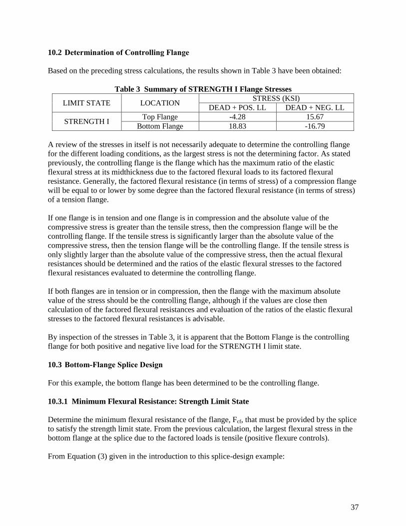
10.2 Determination of Controlling Flange
Based on the preceding stress calculations, the results shown in Table 3 have been obtained:
Table 3 Summary of STRENGTH I Flange Stresses
LIMIT STATE LOCATION STRESS (KSI)
DEAD + POS. LL DEAD + NEG. LL
STRENGTH I Top Flange -4.28 15.67
Bottom Flange 18.83 -16.79
A review of the stresses in itself is not necessarily adequate to determine the controlling flange
for the different loading conditions, as the largest stress is not the determining factor. As stated
previously, the controlling flange is the flange which has the maximum ratio of the elastic
flexural stress at its midthickness due to the factored flexural loads to its factored flexural
resistance. Generally, the factored flexural resistance (in terms of stress) of a compression flange
will be equal to or lower by some degree than the factored flexural resistance (in terms of stress)
of a tension flange.
If one flange is in tension and one flange is in compression and the absolute value of the
compressive stress is greater than the tensile stress, then the compression flange will be the
controlling flange. If the tensile stress is significantly larger than the absolute value of the
compressive stress, then the tension flange will be the controlling flange. If the tensile stress is
only slightly larger than the absolute value of the compressive stress, then the actual flexural
resistances should be determined and the ratios of the elastic flexural stresses to the factored
flexural resistances evaluated to determine the controlling flange.
If both flanges are in tension or in compression, then the flange with the maximum absolute
value of the stress should be the controlling flange, although if the values are close then
calculation of the factored flexural resistances and evaluation of the ratios of the elastic flexural
stresses to the factored flexural resistances is advisable.
By inspection of the stresses in Table 3, it is apparent that the Bottom Flange is the controlling
flange for both positive and negative live load for the STRENGTH I limit state.
10.3 Bottom-Flange Splice Design
For this example, the bottom flange has been determined to be the controlling flange.
10.3.1 Minimum Flexural Resistance: Strength Limit State
Determine the minimum flexural resistance of the flange, Fcf, that must be provided by the splice
to satisfy the strength limit state. From the previous calculation, the largest flexural stress in the
bottom flange at the splice due to the factored loads is tensile (positive flexure controls).
From Equation (3) given in the introduction to this splice-design example:
38
gyffgyffh
cfcf RF0.75αRFα
R
f
2
1F
(Eq. 6.13.6.1.4c-1)
fcf = ffu = 18.83 ksi
= 1.0 (Article C6.13.6.1.4c)
Rh = 1.0
Rg = 1.0
ksi 34.42)0.1)(50)(00.1(0.11.0
18.83
2
1
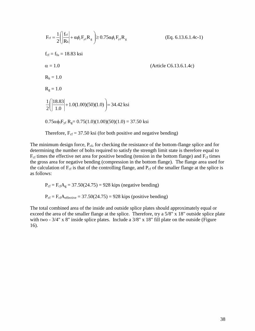
0.75fFyf Rg= 0.75(1.0)(1.00)(50)(1.0) = 37.50 ksi
Therefore, Fcf = 37.50 ksi (for both positive and negative bending)
The minimum design force, Pcf, for checking the resistance of the bottom-flange splice and for
determining the number of bolts required to satisfy the strength limit state is therefore equal to
Fcf times the effective net area for positive bending (tension in the bottom flange) and Fcf times
the gross area for negative bending (compression in the bottom flange). The flange area used for
the calculation of Fcf is that of the controlling flange, and Pcf of the smaller flange at the splice is
as follows:
Pcf = FcfAg = 37.50(24.75) = 928 kips (negative bending)
Pcf = FcfAeffective = 37.50(24.75) = 928 kips (positive bending)
The total combined area of the inside and outside splice plates should approximately equal or
exceed the area of the smaller flange at the splice. Therefore, try a 5/8" x 18" outside splice plate
with two - 3/4" x 8" inside splice plates. Include a 3/8" x 18" fill plate on the outside (Figure
16).
39
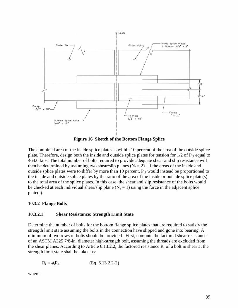
Figure 16 Sketch of the Bottom Flange Splice
The combined area of the inside splice plates is within 10 percent of the area of the outside splice
plate. Therefore, design both the inside and outside splice plates for tension for 1/2 of Pcf equal to
464.0 kips. The total number of bolts required to provide adequate shear and slip resistance will
then be determined by assuming two shear/slip planes (Ns = 2). If the areas of the inside and
outside splice plates were to differ by more than 10 percent, Pcf would instead be proportioned to
the inside and outside splice plates by the ratio of the area of the inside or outside splice plate(s)
to the total area of the splice plates. In this case, the shear and slip resistance of the bolts would
be checked at each individual shear/slip plane (Ns = 1) using the force in the adjacent splice
plate(s).
10.3.2 Flange Bolts
10.3.2.1 Shear Resistance: Strength Limit State
Determine the number of bolts for the bottom flange splice plates that are required to satisfy the
strength limit state assuming the bolts in the connection have slipped and gone into bearing. A
minimum of two rows of bolts should be provided. First, compute the factored shear resistance
of an ASTM A325 7/8-in. diameter high-strength bolt, assuming the threads are excluded from
the shear planes. According to Article 6.13.2.2, the factored resistance Rr of a bolt in shear at the
strength limit state shall be taken as:
Rr = sRn (Eq. 6.13.2.2-2)
where:

40
Rn = the nominal resistance of the bolt in shear as specified in Article 6.13.2.7
s = the resistance factor for an A325 bolt in shear (Article 6.5.4.2)
Since the length between extreme fasteners measured parallel to the line of action of the force is
assumed to be less than 50 in. (measured between the extreme bolts on only one side of the
splice per Article C6.13.2.7), the factored shear resistance in double shear (Ns = 2) is computed
as follows:
Rn = 0.48AbFubNs (Eq. 6.13.2.7-1)
Fub = tensile strength of the bolt = 120 ksi (Article 6.4.3.1)
kips69.27(120)(2)4
π(0.875)0.48R
2
n
Rr = sRn
s = 0.80 for bolts in shear (Article 6.5.4.2)
Rr = 0.80(69.27) = 55.42 kips/bolt
Once the bolts slip and go into bearing, the fill plate must be developed to distribute the total
stress uniformly over the combined section of the member and the fill plate. Rather than
extending the fill plate beyond the splice and providing additional bolts to develop the fill plate,
Article 6.13.6.1.5 provides a reduction factor to be applied to the bolt shear strength for fill plates
1/4 in. or more in thickness. The factor is given as:
2γ(1
γ1R
Where:
= Af / Ap
Af = sum of the area of the fillers on the top and bottom of the connected plate
Ap = sum of either the connected plate area or the sum of the splice plate areas on
the top and bottom of the connected plate
Af = (0.375)(18) = 6.75 in.2
Ap = (1.375)(18) = 24.75 in.2
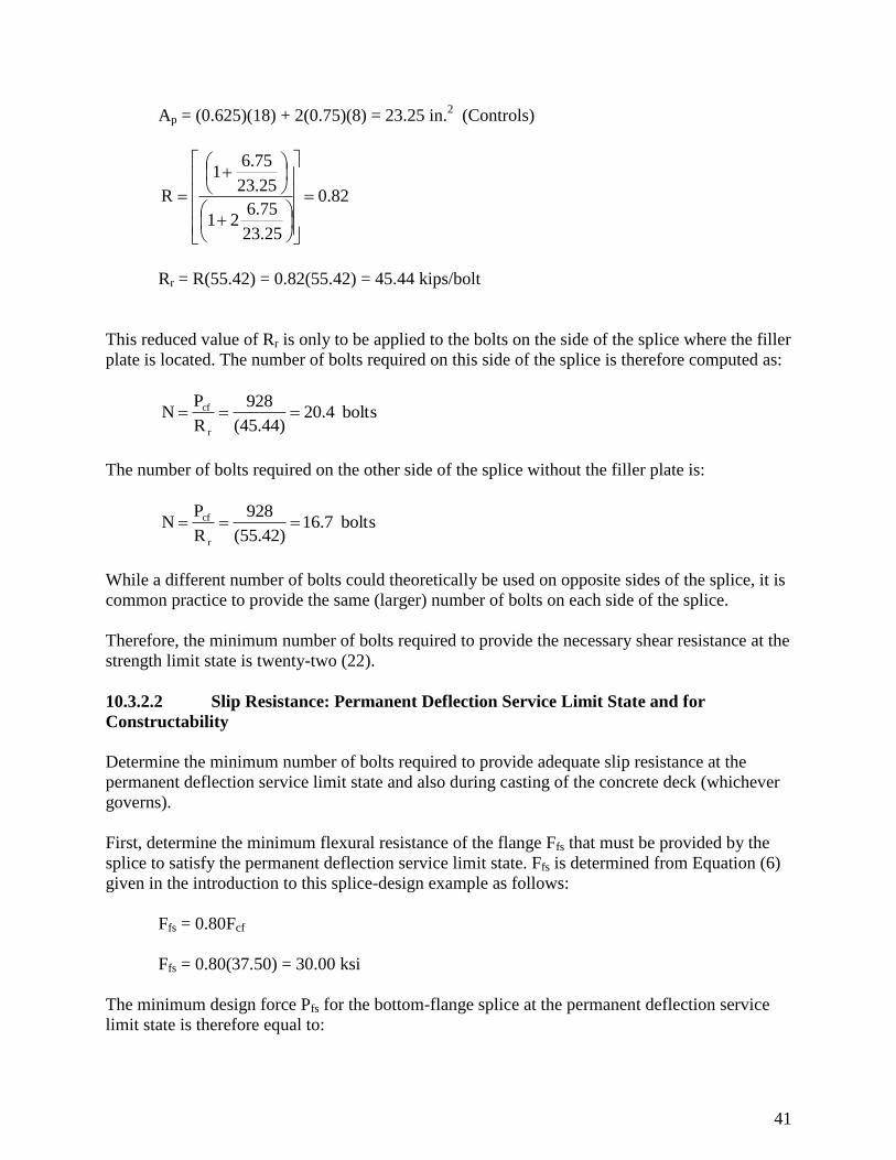
41
Ap = (0.625)(18) + 2(0.75)(8) = 23.25 in.2 (Controls)
82.0
23.25
6.7521
25.23
75.61
R
Rr = R(55.42) = 0.82(55.42) = 45.44 kips/bolt
This reduced value of Rr is only to be applied to the bolts on the side of the splice where the filler
plate is located. The number of bolts required on this side of the splice is therefore computed as:
bolts 20.4(45.44)
928
R
PN
r
cf
The number of bolts required on the other side of the splice without the filler plate is:
bolts 16.7(55.42)
928
R
PN
r
cf
While a different number of bolts could theoretically be used on opposite sides of the splice, it is
common practice to provide the same (larger) number of bolts on each side of the splice.
Therefore, the minimum number of bolts required to provide the necessary shear resistance at the
strength limit state is twenty-two (22).
10.3.2.2 Slip Resistance: Permanent Deflection Service Limit State and for
Constructability
Determine the minimum number of bolts required to provide adequate slip resistance at the
permanent deflection service limit state and also during casting of the concrete deck (whichever
governs).
First, determine the minimum flexural resistance of the flange Ffs that must be provided by the
splice to satisfy the permanent deflection service limit state. Ffs is determined from Equation (6)
given in the introduction to this splice-design example as follows:
Ffs = 0.80Fcf
Ffs = 0.80(37.50) = 30.00 ksi
The minimum design force Pfs for the bottom-flange splice at the permanent deflection service
limit state is therefore equal to:
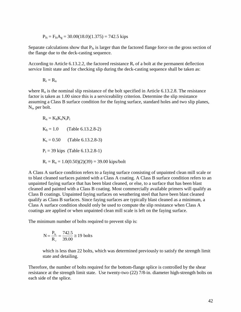
42
Pfs = FfsAg = 30.00(18.0)(1.375) = 742.5 kips
Separate calculations show that Pfs is larger than the factored flange force on the gross section of
the flange due to the deck-casting sequence.
According to Article 6.13.2.2, the factored resistance Rr of a bolt at the permanent deflection
service limit state and for checking slip during the deck-casting sequence shall be taken as:
Rr = Rn
where Rn is the nominal slip resistance of the bolt specified in Article 6.13.2.8. The resistance
factor is taken as 1.00 since this is a serviceability criterion. Determine the slip resistance
assuming a Class B surface condition for the faying surface, standard holes and two slip planes,
Ns, per bolt.
Rn = KhKsNsPt
Kh = 1.0 (Table 6.13.2.8-2)
Ks = 0.50 (Table 6.13.2.8-3)
Pt = 39 kips (Table 6.13.2.8-1)
Rr = Rn = 1.0(0.50)(2)(39) = 39.00 kips/bolt
A Class A surface condition refers to a faying surface consisting of unpainted clean mill scale or
to blast cleaned surfaces painted with a Class A coating. A Class B surface condition refers to an
unpainted faying surface that has been blast cleaned, or else, to a surface that has been blast
cleaned and painted with a Class B coating. Most commercially available primers will qualify as
Class B coatings. Unpainted faying surfaces on weathering steel that have been blast cleaned
qualify as Class B surfaces. Since faying surfaces are typically blast cleaned as a minimum, a
Class A surface condition should only be used to compute the slip resistance when Class A
coatings are applied or when unpainted clean mill scale is left on the faying surface.
The minimum number of bolts required to prevent slip is:
bolts1939.00
742.5
R
P N
r
fs
which is less than 22 bolts, which was determined previously to satisfy the strength limit
state and detailing.
Therefore, the number of bolts required for the bottom-flange splice is controlled by the shear
resistance at the strength limit state. Use twenty-two (22) 7/8-in. diameter high-strength bolts on
each side of the splice.
43
10.3.3 Tensile Resistance of Splice Plates: Strength Limit State
Check the tensile resistance of the bottom flange splice plates at the strength limit state:
As specified in Article 6.13.6.1.4c, the tensile resistance of the splice plate is determined
according to the provisions of Article 6.13.5.2. The factored resistance Rr in tension is taken as
the lesser of the values given by either Equation 6.8.2.1-1 for yielding, Equation 6.8.2.1-2 for
fracture, or the block shear rupture resistance specified in Article 6.13.4. Block shear rupture and
fracture on the net section of the smaller girder flange plate at the splice are also checked.
For yielding on the gross section of the inside and outside splice plates (Article 6.8.2.1-
1):
Rr = Pr = yPny = yFyAg
y = 0.95 (Article 6.5.4.2)
Outside: Pr = 0.95(50)(0.625)(18.0) = 534.4 kips > Pcf/2 = 464.0 kips ok
Inside: Pr = 0.95(50)(2)(0.75)(8.0) = 570.0 kips > Pcf/2 = 464.0 kips ok
For fracture on the net section of the inside and outside splice plates (Article 6.8.2.1-2):
Rr = Pr = uPnu = uFuAnU
Fu = 70 ksi (Table 6.4.1-1)
u = 0.80 (Article 6.5.4.2)
U = reduction factor to account for shear lag = 1.0 for splice plates
(Article 6.13.5.2)
To compute the net area An of the splice plates, assume four 7/8-in. bolts across the width of the
splice plate. The bolt pattern is staggered in this case because of the need to increase the
resistance of the splice plates and the smaller girder flange at the splice to fracture on the net
section. A separate check is made to ensure that the splice plates do not interfere with any
stiffeners or connection plates. First, check the indicated spacing of the bolts on the outside
splice plate according to the requirements of Article 6.13.2.6:
10.3.3.1 Minimum Spacing (Article 6.13.2.6)
The minimum spacing between centers of bolts in standard holes shall not be less than three
times the diameter of the bolt. For this example:
ok in. 4.61(3.5)(3.0)in. 2.633(0.875)3ds 22
min
44
10.3.3.2 Maximum Spacing for Sealing (Article 6.13.2.6.2)
The maximum spacing of the bolts along the free edges of the splice plates is limited to prevent
the penetration of moisture in the joint.
First, check for sealing along the edges of the plate parallel to the applied force. The gage, g, or
distance between adjacent uniformly staggered lines of bolts adjacent to a free edge, is limited as
follows:
g < 1.5 + 4.0t
3.5 in. < 1.5 + 4.0(0.625) = 4.0 in. ok
The staggered spacing s between two adjacent lines of staggered bolt holes is limited as follows:
s ≤ 4.0 + 4.0t - (3.0g / 4.0) (Eq. 6.13.2.6.2-2)
but not less than one-half the requirement for a single line of bolts = 4.0 + 4.0t.
okin. 7.0in.3.8754.0
3.0(3.5)4.0(0.625)4.0in.3.0
okin.3.254.0(0.625)4.02
1in.3.875
Next, check for sealing along the free edge at the end of the outside splice plate:
s < 4.0 + 4.0t < 7.0
6.5 in.= 4.0 + 4.0(0.625) = 6.5 in. < 7.0 in. ok
Note that the maximum pitch requirements for stitch bolts in the current Articles 6.13.2.6.3 and
6.13.2.6.4 apply only to the connection of plates in mechanically fastened built-up members and
would not apply here.
10.3.3.3 Edge Distance (Article 6.13.2.6.6)
The edge distance is defined as the distance perpendicular to the line of force between the center
of the outermost line of holes and the edge of the plate. The specified edge distance of 2-1/4 in.
satisfies the minimum edge distance of 1-1/2 in. specified for 7/8-in. diameter bolts (Table
6.13.2.6.6-1), and also satisfies the maximum edge distance requirement of 8.0t (not to exceed
5.0 in.) = 8.0(0.625) = 5.0 in.
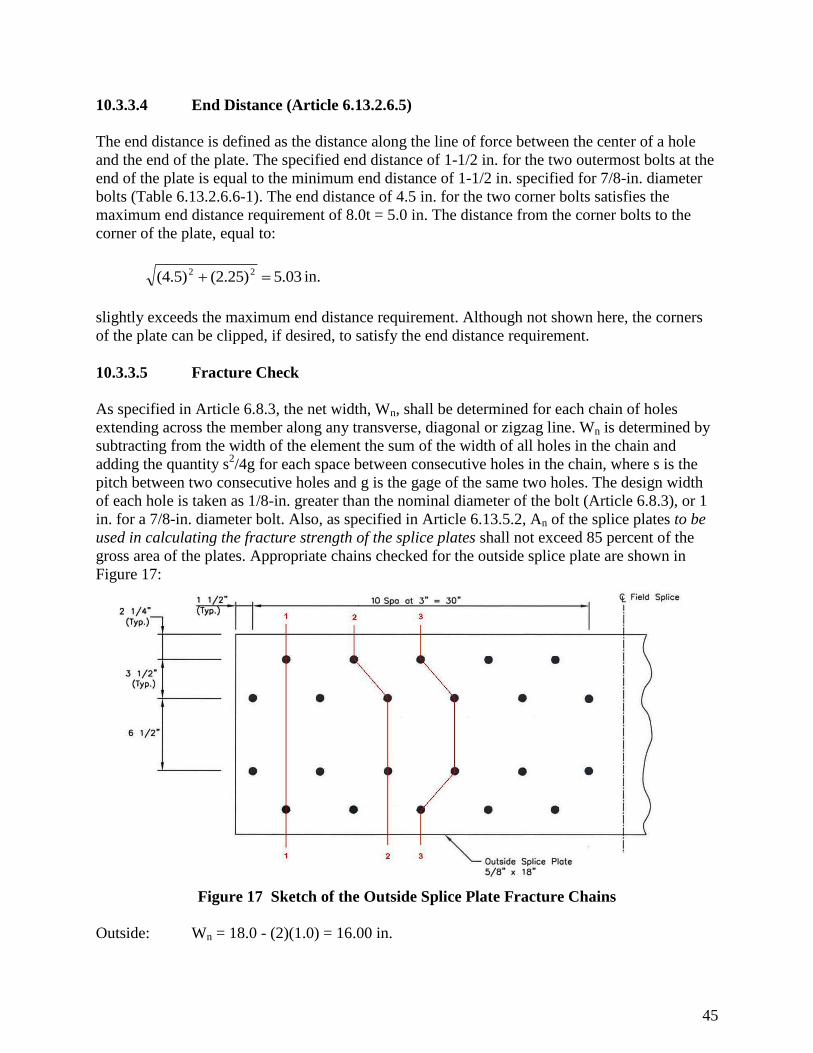
45
10.3.3.4 End Distance (Article 6.13.2.6.5)
The end distance is defined as the distance along the line of force between the center of a hole
and the end of the plate. The specified end distance of 1-1/2 in. for the two outermost bolts at the
end of the plate is equal to the minimum end distance of 1-1/2 in. specified for 7/8-in. diameter
bolts (Table 6.13.2.6.6-1). The end distance of 4.5 in. for the two corner bolts satisfies the
maximum end distance requirement of 8.0t = 5.0 in. The distance from the corner bolts to the
corner of the plate, equal to:
03.5(2.25) (4.5) 22 in.
slightly exceeds the maximum end distance requirement. Although not shown here, the corners
of the plate can be clipped, if desired, to satisfy the end distance requirement.
10.3.3.5 Fracture Check
As specified in Article 6.8.3, the net width, Wn, shall be determined for each chain of holes
extending across the member along any transverse, diagonal or zigzag line. Wn is determined by
subtracting from the width of the element the sum of the width of all holes in the chain and
adding the quantity s2/4g for each space between consecutive holes in the chain, where s is the
pitch between two consecutive holes and g is the gage of the same two holes. The design width
of each hole is taken as 1/8-in. greater than the nominal diameter of the bolt (Article 6.8.3), or 1
in. for a 7/8-in. diameter bolt. Also, as specified in Article 6.13.5.2, An of the splice plates to be
used in calculating the fracture strength of the splice plates shall not exceed 85 percent of the
gross area of the plates. Appropriate chains checked for the outside splice plate are shown in
Figure 17:
Figure 17 Sketch of the Outside Splice Plate Fracture Chains
Outside: Wn = 18.0 - (2)(1.0) = 16.00 in.
46
Wn = 18.0 - 3(1.0) + (3.0)2 ÷ [(4)(3.5)] = 15.64 in.
Wn = 18.0 - 4(1.0) + (2)(3.0)2 ÷ [(4)(3.5)] = 15.29 in. (governs)
Note: Other chains do not govern by inspection.
An = 15.29(0.625) = 9.56 in.2
0.85Ag = 0.85(0.625)(18.0) = 9.56 in.2 (ok)
Therefore, An = 9.56 in.2
Pr = 0.80(70)(9.56)(1.0) = 535.4 kips > Pcf/2 = 464.0 kips (ok)
Inside: Wn = 8.0 - (1.0) = 7.00 in.
Wn = 8.0 - 2(1.0) + (3.0)2 ÷ [(4)(3.5)] = 6.64 in. (governs)
An = (2)(6.64)(0.75) = 9.96 in.2
0.85Ag = 0.85[(2)(0.75)(8.0)] = 10.20 in.2 > 9.96 in.
2
Therefore, An = 9.96 in.2
Pr = 0.80(70)(9.96)(1.0) = 557.84 kips > Pcf/2 = 464.0 kips (ok)
For block shear rupture on the inside and outside splice plates (Article 6.13.4): Block
shear rupture will typically not govern except for short compact connections. Therefore,
the block shear checks will not be illustrated in this example.
For fracture on the net section of the girder flange at the splice (Article 6.8.2.1), both
sides were checked and the right side controls:
An = {20.0 - 4(1.0) + (2)(3.0)2 ÷ [(4)(3.5)]}(1.00) = 17.29 in.
2
Pr = 0.80(85)(17.29)(1.0) = 1176 kips > Pfc = 928 kips ok
10.3.4 Compressive Resistance of Splice Plates: Strength Limit State
Since the splice plates are subject to stress reversal, check the compressive resistance of the
bottom flange splice plates at the strength limit state.
The maximum calculated compressive stress in the bottom flange at the splice due to the factored
loads was computed earlier to be -16.79 ksi, and the minimum compressive design flange force
(Pcf) was computed previously as 928 kips.
47
According to the Commentary to Article 6.13.6.1.4c, for compression, an unbraced length of
zero may be assumed for the splice plates. Therefore, the factored compressive resistance of the
splice plates can be computed as follows:
Pr = cPn = cFyAs (Articles 6.9.2.1-1 and 6.9.4.1-1)
c = 0.95 (Article 6.5.4.2)
Outside: Pr = 0.95(50)(0.625)(18.0) = 534.4 kips > (Pfcr)bf/2 = 928/2 = 464 kips ok
Inside: Pr = 0.95(50)(2)(0.75)(8.0) = 570.0 kips > (Pfcr)bf/2 = 928/2 = 464 kips ok
10.3.5 Bearing Resistance at Bolt Holes: Strength Limit State
Check bearing of the bolts on the flange material at the strength limit state (Article 6.13.2.9). The
nominal bearing resistance of the flange is calculated as the sum of the resistance of the
individual bolt holes parallel to the line of the applied force.
The nominal bearing resistance for standard holes is taken as (Article 6.13.2.9):
For Lc > 2.0d: Rn = 2.4dtFu
Otherwise: Rn = 1.2LctFu
where:
Lc = the clear distance between holes or between the hole and the end of the member in the
direction of the applied bearing force (in.)
Fu = tensile strength of the connected material = 70 ksi for the left side of the splice and 85
ksi for the right side of the splice (Table 6.4.1-1)
d = nominal diameter of the bolt (in.)
t = thickness of the connected material (in.)
As specified in Article 6.8.3, the design width for standard bolt holes to be used in design shall
be taken as 1/8-in. greater than the nominal diameter of the bolt.
For the outer lines of bolts, the end distance is 4-1/2 in. Therefore, the clear end distance between
the edge of the first hole and the end of the splice plate is:
Lc1 = 4.5 - 1.0/2 = 4.0 in. > 2.0d = 2.0(0.875) = 1.75 in.
For the inner two lines of bolts, the end distance is 1-1/2 in. Therefore, the clear end distance is:
48
Lc1 = 1.5 - 1.0/2 = 1.0 in. > 2.0d = 1.75 in.
The center-to-center distance between bolts in the direction of the force in both the outer and
inner lines of bolts is 6 in. Therefore, the clear distance between edges of adjacent holes is
computed as:
Lc2 = 6.0 - 1.0 = 5.0 in. > 2.0d = 1.75 in.
Therefore, the nominal bearing resistance of an outer line of bolt holes in the bottom flange at the
right side of the splice is taken as:
Rn_outer = 5(2.4dtFu) = 5[2.4(0.875)(1.00)(85)] = 892.5 kips
The nominal bearing resistance of an inner line of bolt holes is taken as:
Rn_inner = 1(1.2LctFu) + 5(2.4dtFu) = 1[1.2(1.0)(1.00)(85)] + 892.5 = 994.5 kips
Rn_TOTAL = 2(892.5) + 2(994.5) = 3774 kips
Rr = bbRn = 0.80(3774) = 3019 kips
Pfr = 928 kips < Rr = 3019 kips ok
10.3.6 Fatigue Resistance of Splice Plates: Fatigue and Fracture Limit State
Check the fatigue stresses in the base metal of the bottom flange splice plates adjacent to the
slip-critical connections.
By inspection, the bottom flange is subject to a net tensile stress. The moments at the splice due
to the fatigue load plus the 15 percent dynamic load allowance specified in Table 3.6.2.1-1 and
factored by the 0.75 load factor specified for the FATIGUE load combination are:
M+LL+IM = 0.75(905) = 679 kip-ft
M-LL+IM = 0.75(-687) = -515 kip-ft
The maximum flange stresses rather than the average flange stresses will be used in the fatigue
check. The maximum bottom-flange stresses computed on the gross section are (negative
fatigue-load moments are assumed to be applied to the section consisting of the steel girder plus
the longitudinal reinforcement since the maximum composite dead-load compressive stresses in
the slab at the splice are overcome by the maximum tensile stress in the slab at the splice due to
the factored negative fatigue-load moment):
f+(LL+IM) = 679(12) ÷ 2706 = 3.01 ksi (tension)
49
f-(LL+IM) = -515(12) ÷ 2182 = -2.83 ksi (compression)
(f) = f+(LL+IM) + |f-(LL+IM) | = 3.01 + |-2.83| = 5.84 ksi
From Equation (6.6.1.2.5-1), the nominal fatigue resistance is specified as:
TH
3/1
n ΔF2
1
N
AF)(
Earlier computations showed that the 75-year (ADTT)SL is 1600 trucks per day. Using the table
presented in Example 1, the 75-year (ADTT)SL equivalent to infinite fatigue life for a Category B
detail (with n = 1.0) is 865 trucks per day < 1600 trucks per day.
Thus:
THn ΔF2
1F)(
For a Category B detail, (ΔF)TH = 16.0 ksi (Table 6.6.1.2.5-3). Therefore:
(F)n = 16.0 / 2 = 8.00 ksi
Calculate the range of flange force from the computed stress range in the flange:
ΔPFLG = 5.84(1.375)(18.0) = 144.5 kips
Since the combined area of the inside splice plates is within 10 percent of the area of the outside
splice plate, check both the inside and outside splice plates for 1/2 of the total range of flange
force. The range of fatigue force and stress in the outside splice plate is:
P = 144.5 / 2 = 72.3 kips
okksi8.00ksi42.6.0)(0.625)(18
72.3 Δf
The range of fatigue force and stress in the inside splice plates is:
P = 72.3 kips
okksi8.00ksi03.60)2(0.75)(8.
72.3Δf
10.3.7 Permanent Deflection Service Limit State: Splice Plates
To satisfy the permanent deflection service limit state, check the stress in the bottom flange
splice plates to control local yielding of the plates.
50
The following criterion will be used to make this check (refer to Article 6.10.3.2):
fbu<fRhFyf (Eq. 6.10.3.2.3-1)
The resistance factor is equal to 1.0.
The minimum design force on the gross section of the bottom flange, Pfs, at the permanent
deflection service limit state was computed earlier to be 742.5 kips.
For reasons discussed previously, the force on the inside and outside splice plates is taken as
(742.5/2) = 371.3 kips. The resulting stress in the outside splice plate is then computed as:
okksi0.500)1.0(1.0)(5ksi00.33.0)(0.625)(18
371.3fbu
The stress in the inside splice plates is computed as:
okksi0.5050)1.0(1.00)(ksi94.300)2(0.75)(8.
371.3fbu
10.4 Top-Flange Splice Design
For this example, the top flange has been determined to be the non-controlling flange.
10.4.1 Minimum Flexural Resistance: Strength Limit State
Determine the minimum flexural resistance of the non-controlling flange Fncf that must be
provided by the splice to satisfy the strength limit state. From the previous calculation, the
largest flexural stress in the top flange at the splice due to the factored loads is tensile (negative
flexure controls). However, this is not concurrent with the largest flexural stress in the
controlling (bottom) flange (fcf = 18.83 ksi), that was used in the determination of Fcf. Therefore,
two separate checks will be made to determine which loading condition controls for the top
flange (assuming fcf = 18.83 ksi concurrent with fncf = -4.28 ksi and assuming fcf = -16.79 ksi
concurrent with fncf = 15.67 ksi).
Equation (3) presented in the introduction to this splice-design example will be used to compute
Fncf:
gyfy
h
ncfcfncf RF0.75α
R
fRF
Check #1:
for fcf = 18.83 ksi and Fcf = 37.50 ksi, Rcf = (37.50/18.83) = 1.99
51
fncf = ffu = -4.28 ksi
= 1.0 (Article C6.13.6.1.4c)
Rh = 1.0
ksi 52.81.0
4.28-99.1
0.75fFyf Rg= 0.75(1.0)(1.00)(50)(1.0) = 37.50 ksi (governs)
Therefore, Fncf = 37.50 ksi
Check #2:
for fcf = -16.79 ksi and Fcf = 37.50 ksi, Rcf = (37.50/16.79) = 2.23
fncf = ffu = 15.67 ksi
= 1.0 (Article C6.13.6.1.4c)
Rh = 1.0
ksi 94.391.0
15.6725.2
0.75fFyf Rg= 0.75(1.0)(1.00)(50)(1.0) = 37.50 ksi (governs)
Therefore, Fncf = 37.50 ksi
For either case, the design stress for the non-controlling flange, Fncf, is taken as 37.50 ksi. The
minimum design force, Pncf, for checking the resistance of the top-flange splice and for
determining the number of bolts required to satisfy the strength limit state is therefore equal to
Fncf times the effective net area for negative bending (tension in the top flange) and Fcf times the
gross area for positive bending (compression in the top flange). The maximum force for the non-
controlling flange will be the product of the design stress and the gross area of the smaller plate.
The design flange force is as follows:
Pncf = FncfAg = 37.50(16.0)(1.00) = 600.0 kips
The total combined area of the inside and outside splice plates should approximately equal or
exceed the area of the smaller flange at the splice. The width of the outside splice plate should be
at least as wide as the width of the narrowest flange at the splice. Therefore, try a 9/16" x 16"
52
outside plate with two - 5/8" x 7" inside plates. The combined area of the inside plates is within
10 percent of the area of the outside splice plate. Therefore, design both the inside and outside
splice plates for tension for 1/2 of Pncf equal to 300.0 kips.
10.4.2 Flange Bolts
Following the procedures demonstrated earlier for the design of the bolts for the bottom-flange
splice:
10.4.2.1 Shear Resistance: Strength Limit State
Since no filler plate is required, Rr is taken as 55.42 kips/bolt on both sides of the splice. Thus,
the number of bolts required for the top-flange splice to satisfy the factored shear resistance at
the strength limit state is:
N = Pncf / Rr = 600.0 / 55.42 = 10.8 bolts
Therefore, the minimum number of bolts required to provide the necessary shear resistance at the
strength limit state is twelve (12).
10.4.2.2 Slip Resistance: Permanent Deflection Service Limit State & for
Constructibility
Determine the minimum number of bolts required to provide adequate slip resistance at the
permanent deflection service limit state and also during casting of the concrete deck (whichever
governs).
First, determine the minimum flexural resistance of the flange, Ffs, that must be provided by the
splice to satisfy the permanent deflection service limit state. Ffs is determined from Equation (6)
given in the introduction to this splice-design example as follows:
Ffs = 0.80Fncf
Ffs = 0.80(37.50) = 30.00 ksi
The minimum design force, Pfs, for the top-flange splice at the permanent deflection service limit
state is therefore equal to:
Pfs = FfsAg = 30.00(16.0)(1.0) = 480.0 kips
Separate calculations show that Pfs is larger than the factored flange force on the gross section of
the flange due to the deck-casting sequence.
The factored slip resistance of a bolt in double shear, Rr, was computed earlier to be 39.00 kips.
Thus, the minimum number of bolts required to provide adequate slip resistance is computed as:
53
N = Pfs / Rr = 12.3 bolts > N = 12 bolts determined previously for STRENGTH limit state
Therefore, the number of bolts required for the top-flange splice is controlled by the slip
resistance at the permanent deflection service limit state. Use fourteen (14) 7/8-in. diameter high-
strength bolts (7 rows of 2 bolts at 3-in. spacing – staggered) on each side of the splice.
10.4.3 Tensile Resistance of Splice Plates: Strength Limit State
Check the tensile resistance of the top-flange splice plates at the strength limit state. Block shear
rupture and fracture on the net section of the girder flange plate at the splice are also checked.
For yielding on the gross section of the inside and outside splice plates (Article 6.8.2.1-1)
Outside: Pr = 0.95(50)(0.5625)(16.0) = 427.5 kips > Pncf/2 = 300.0 kips ok
Inside: Pr = 0.95(50)(2)(0.625)(7.0) = 415.6 kips > Pncf/2 = 300.0 kips ok
For fracture of the net section of the inside and outside splice plates (Article 6.8.2.1):
Rr = Pr = uFuAnRpU (6.8.2.1-2)
10.4.3.1 Minimum spacing (Article 6.13.2.6)
ok in.4.61(3.5)(3.0)in. 2.63 3(0.875) 3d s 22
min
10.4.3.2 Maximum spacing for sealing (Article 6.13.2.6.2)
g < 1.5 + 4.0t
3.5 in. < 1.5 + 4.0(0.5625) = 3.75 in.
Therefore, s ≤ 4.0 +4.0t - [3.0g / 4.0] ≤ 7.0, but s shall not be less than one-half the
requirement for single line of bolts (6.13.2.6.2-2).
3.0 in. < 4.0 + 4.0(0.5625) - [(3.0)(3.5)/4.0] = 3.625 in. < 7.0 in. ok
3.625 in. > (1/2)[4.0 + 4.0(0.5625)] = 3.125 in. ok
Check for sealing along the free edge at the end of the splice plate:
s ≤ 4.0 + 4.0t ≤ 7.0
4.5 in. = 4.0 + 4.0(0.5625) = 6.25 in. < 7.0 in. ok
10.4.3.3 Edge distance (Article 6.13.2.6.6)
54
Edge distance > 1-1/2 in. (Table 6.13.2.6.6-1)
1-3/4 in. > 1-1/2 in. ok
Edge distance < 8.0t < 5.0
4.5 < 8.0(0.5625) < 5.0
4.5 in. < 4.5 in. < 5.0 in. ok
Distance from the corner bolts to the corner of the plate < 5.0
in.5.00in.5.03(2.25)(4.5) 22
Therefore, clip the corners of the plate.
10.4.3.4 Fracture check:
Outside: Wn = 16.0 - (2)(1.0) = 14.00 in.
Wn = 16.0 - 3(1.0) + (3.0)2 ÷ [(4)(3.5)] = 13.64 in.
Wn = 16.0 - 4(1.0) + (2)(3.0)2 ÷ [(4)(3.5)] = 13.29 in. (governs)
Note: Other chains do not govern by inspection.
An = 13.29(0.5625) = 7.48 in.2
0.85Ag = 0.85(0.5625)(16.0) = 7.65 in.2 (ok)
Therefore, An = 7.48 in.2
Pr = 0.80(70)(7.48)(1.0)(1.0) = 418.9 kips > Pncf/2 = 300.0 kips (ok)
Inside: Wn = 7.0 - (1.0) = 6.00 in.
Wn = 7.0 - 2(1.0) + (3.0)2 ÷ [(4)(3.5)] = 5.64 in. (governs)
An = (2)(5.64)(0.625) = 7.05 in.2
0.85Ag = 0.85[(2)(0.625)(7.0)] = 7.44 in.2 (ok)
Therefore, An = 7.05 in.2
Pr = 0.80(70)(7.05)(1.0)(1.0) = 394.8 kips > Pcf/2 = 300.0 kips (ok)
Block shear rupture on the inside and outside splice plates (Article 6.13.4):
55
Block shear rupture will typically not govern except for short compact connections.
Therefore, the block shear checks will not be illustrated in this example.
For fracture on the net section of the smaller girder flange at the splice (Article 6.8.2.1):
An = {16.0 - 4(1.0) + (2)(3.0)2 ÷ [(4)(3.5)]}(1.00) = 13.29 in.
2
Pr = 0.80(85)(13.29)(1.0) = 744 kips > Pfc = 600 kips ok
10.4.4 Compressive Resistance of Splice Plates: Strength Limit State
Since the splice plates are subject to stress reversal, check the compressive resistance of the top
flange splice plates at the strength limit state.
The maximum calculated compressive stress in the top flange at the splice due to the factored
loads was computed earlier to be -4.28 ksi, and the minimum compressive design flange force,
Pncf, was computed previously as 600 kips.
According to the Commentary to Article 6.13.6.1.4c, for compression, an unbraced length of
zero may be assumed for the splice plates. Therefore, the factored compressive resistance of the
splice plates can be computed as follows:
Pr = cPn = cFyAs (Articles 6.9.2.1-1 and 6.13.6.1.4c-5)
c = 0.95 (Article 6.5.4.2)
Outside: Pr = 0.95(50)(0.5625)(16.0) = 427.5 kips > (Pfcr)tf/2 = 600.0/2 = 300.0 kips ok
Inside: Pr = 0.95(50)(2)(0.625)(7.0) = 415.6 kips > (Pfcr)tf/2 = 600.0/2 = 300.0 kips ok
For composite sections, the compressive resistance of the top-flange splice plates should not
govern in most cases.
10.4.5 Bearing Resistance at Bolt Holes: Strength Limit State
Check bearing of the bolts on the flange material at the strength limit state:
For bolts with a 1-1/2 in. end distance, the clear distance between the edge of the hole and the
left edge of the splice plate is:
Lc1 = 1.5 - 1.0 / 2 = 1.0 in. < 2.0d = 2.0(0.875) = 1.75 in.
Therefore, Rn_HOLE1 = 1.2LctFu = 1.2(1.0)(1.00)(70) = 84.0 kips (6.13.2.9-2)
For bolts with a 4-1/2 in. end distance, the clear distance between the edge of the hole and the
edge of the splice plate is:
56
Lc2 = 4.5 - 1.0 / 2 = 4.0 in. > 2.0d = 2.0(0.875) = 1.75 in.
Therefore, Rn_HOLE2 = 2.4dtFu = 2.4(0.875)(1.00)(70) = 147.0 kips (6.13.2.9-1)
The center-to-center distance between bolts in the direction of force is equal to 6 in. Therefore,
the clear distance between edges of adjacent holes is computed as:
Lc3 = 6.0 - 1.0 = 5.0 in. > 2.0d = 1.75 in.
Therefore, Rn_HOLE3 = Rn_HOLE2 = 147.0 kips
Rn_TOTAL = 2[84.00 + 6(147.0)] = 1932 kips
Rr = bbRn = 0.80(1932) = 1546 kips (6.13.2.2-2)
Pncf = 600.0 kips < Rr = 1546 kips ok
10.4.6 Fatigue Resistance of Splice Plates: Fatigue and Fracture Limit State
Check fatigue stresses in the base metal of the top-flange splice plates adjacent to the slip-critical
connections.
The maximum flange stresses rather than the average flange stresses will be used in the fatigue
check. The maximum top-flange stresses computed on the gross section due to the factored
fatigue load plus the 15 percent dynamic load allowance (Table 3.6.2.1-1) are (as discussed
previously, negative fatigue-load moments are assumed to be applied to the section consisting of
the steel girder plus the longitudinal reinforcement):
f+(LL+IM) = 679(12) ÷ 13805 = 0.59 ksi (tension)
f-(LL+IM) = -515(12) ÷ 2327 = -2.66 ksi (compression)
By inspection, the compressive force in the top flange due to the unfactored permanent loads is
less than twice the tensile flange force due to the negative factored fatigue-load moment. Thus,
fatigue must be checked.
(f) = f+(LL+IM) + |f-(LL+IM) | = 0.59 + |-2.66| = 3.25 ksi
From the previous calculations: (ΔF)n = 8.00 ksi for a fatigue Category B detail.
Calculate the range of flange force from the computed stress range in the flange:
ΔPFLG = 3.25(1.00)(16.0) = 52.00 kips
57
Since the combined area of the inside splice plates is within 10 percent of the area of the outside
splice plate, check both the inside and outside splice plates for 1/2 of the total range of flange
force. The range of fatigue force and stress in the outside splice plate is:
P = 52.00 / 2 = 26.00 kips
f = 26.00 / [(0.5625)(16.0)] = 2.89 ksi < 8.00 ksi ok
The range of fatigue force and stress in the inside splice plates is:
P = 26.00 kips
f = 26.00 / [2(0.5625)(7.0)] = 2.97 ksi < 8.00 ksi ok
10.4.7 Permanent Deflection Service Limit State: Splice Plates
To satisfy the permanent deflection service limit state, check the stress in the top-flange splice
plates to control local yielding of the plates.
The following criterion will be used to make this check (refer to Article 6.10.3.2):
fbu<fRhFyf (Eq. 6.10.3.2.3-1)
The resistance factor is equal to 1.0.
The minimum design force on the gross section of the top flange, Pfs, at the permanent deflection
service limit state was computed earlier to be 480.0 kips.
For reasons discussed previously, the force on the inside and outside splice plates is taken as
(480.0/2) = 240.0 kips. The resulting stress in the outside splice plate is then computed as:
f = 240.00 / [(0.5625)(16.0)] = 26.67 ksi < 1.0(1.00)(50) = 50.0 ksi ok
The stress in the inside splice plates is computed as:
f = 240.00 / [2(0. 625)(7.0)] = 27.43 ksi < 1.0(1.00)(50) = 50.0 ksi ok
NOTE: In many instances, it may be possible to deduce that the fatigue and permanent deflection
service limit state checks illustrated above for the top- and bottom-flange splice plates do not
govern, and thus, need not be made. However, the checks have been included here for
completeness and to illustrate a suggested methodology for application to those situations where
the checks are deemed to be necessary.
58
11.0 WEB SPLICE DESIGN
In this example, the web splice is designed under the conservative assumption that the maximum
moment and shear at the splice will occur under the same loading condition.
Determine the minimum shear resistance of the web at the splice, Vwr, that must be provided by
the web splice plates and their connections to satisfy the strength limit state. For the controlling
strength limit state load combination (STRENGTH I), first determine the maximum shear at the
splice due to the factored loads. The maximum permanent-load load factor, γp, (Table 3.4.1-2) is
applied to permanent-load effects having the same sign as the live-load effects. For permanent-
load effects with a sign opposite to the live-load effects, the minimum permanent-load load
factor (Table 3.4.1-2) is applied and the effect of the future wearing surface is conservatively
ignored. In both cases, η is taken equal to 1.0.
Vu = 1.0[1.25(-85-12) + 1.50(-12) + 1.75(-114)] = -339 kips governs
Vu = 1.0[0.9(-85-12) + 1.75(18)] = -56 kips
The nominal shear resistance of the web at the splice for a 12.00 ft (144.0 in) transverse-stiffener
spacing (see Figure 14) is computed as follows (Article 6.10.9.3.2):
2.5
tbtb
2Dt
ftftfcfc
w
2.51.69)(18)(1.375(16)(1.0)
)2(69)(0.50
Therefore:
2o
pn
D
d1
C)0.87(1CVV (Eq. 6.10.9.3.2-2)
do / D = 144 / 69.0 = 2.1
6.13(2.1)
55
D
d
55k
22o
(Eq. 6.10.9.3.2-7)
D / tw = 69.0 / 0.5 = 138.0
59
83.550
3)29,000(6.11.40
F
Ek1.40
yw
83.5F
Ek1.400.138
t
D
yww
Therefore:
yw2
w
F
Ek
t
D
1.57C (Eq. 6.10.9.3.2-6)
29.050
13)(29000)(6.
138.0
1.57C
2
Vp = 0.58FywDtw = 0.58(50)(69.0)(0.500) = 1001 kips (Eq. 6.10.9.3.2-3)
2o
pn
D
d1
C)0.87(1CVV
kips556
2.11
0.29)0.87(10.291,001V
2n
The factored shear resistance Vr at the strength limit state is therefore equal to:
Vr = vVn = 1.00(556) = 556 kips
The proposed minimum shear resistance of the web Vwr that must be provided by the web splice
to satisfy the strength limit state is taken from either Equation (9) or Equation (10) given earlier
in the introduction to this splice-design example. The equation to use depends on the value of Vu
with respect to Vr as follows:
0.5vVn = 0.5Vr = 0.5(556) = 278 kips
|Vu| = |-339 kips| = 339 kips > 278 kips
Therefore: Vwr = (1/2) (Vu + vVn) (Eq. 6.13.6.1.4b-2)
60
Vwr = (1/2)(339 + 556) = 448 kips
Two vertical rows of bolts with 22 bolts per row will be investigated (Figure 18). The bolts are
spaced horizontally and vertically as indicated in Figure 18. The outermost rows of bolts are
located 4 5/16 in. from the flanges to provide clearance for assembly (see the AISC Manual of
Steel Construction for required bolt assembly clearances). The web is spliced symmetrically by
plates on each side with a thickness not less than one-half the thickness of the web. Assume 3/8"
x 64" splice plates on each side of the web. A fill plate is not included since the difference in
thickness of the web plates on either side of the splice is only 1/16".
Using the equations given for web splices in the introduction to this splice design example,
determine the portion of the flexural moment to be resisted by the web, Muw, and the horizontal
force resultant, Huw, in the web.
For these calculations (for the strength checks), Muw and Huw will be computed by conservatively
using the stresses at the mid-thickness of the flanges per Article C6.13.6.1.4b. By doing so, the
same stress values that were used for the flange splice design can be utilized, thereby simplifying
the calculations. Alternatively, the stresses at the inner fibers of the flanges can be used (which
will be illustrated in the SERVICE II checks for slip of the web bolts, later in this example).
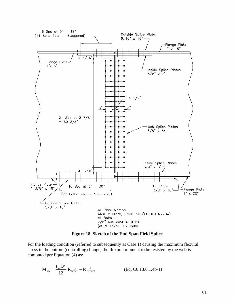
61
Figure 18 Sketch of the End Span Field Splice
For the loading condition (referred to subsequently as Case 1) causing the maximum flexural
stress in the bottom (controlling) flange, the flexural moment to be resisted by the web is
computed per Equation (4) as:
ncfcfcfh
2
wuw fRFR
12
DtM (Eq. C6.13.6.1.4b-1)

62
RhFcf = 1.0(37.50) = 37.50 ksi
Rcffncf = |Fcf / fcf| (fncf) = |37.50 / 18.83|(-4.28) = -8.52 ksi
ft-kip 761in-kip 91298.52)(37.5012
0)(0.50)(69.M
2
uw
Because Muw is to be applied at the centroid of the web, a horizontal force resultant Huw must
also be applied at the centroid of the web to maintain equilibrium. For this case, Huw can be
computed from the average of the maximum flexural stresses in the web from Equation (5) as
follows:
ncfcfcfhw
uw fRFR2
DtH
kips 5008.52)(37.502
.0)(0.500)(69Huw
Similarly, for the loading condition (referred to subsequently as Case 2) causing the maximum
flexural stress in the top flange, Muw is computed as:
ncfcfcfh
2
wuw fRFR
12
DtM (Eq. C6.13.6.1.4b-1)
RhFcf = 1.0(37.50) = 37.50 ksi
Rcffncf = |Fcf / fcf| (fncf) = |37.50 / -16.79|(15.67) = 35.00 ksi
ft-kip 41in-kip 96400.3537.5012
0)(0.50)(69.M
2
uw
The horizontal force resultant Huw for this case is computed as:
kips125100.3537.502
)0.500(69.0Huw
The moment due to the eccentricity of Vwr from the centerline of the splice to the center of
gravity of the web-splice bolt group is:
Me = Vwr(e) = (448)(2.25 + 3.0/2)(1/12) = 140 kip-ft
Therefore:
63
MTOTAL_CASE1 = Muw + Me = 761 +140 = 901 kip-ft (Case 1)
or, MTOTAL_CASE2 = Muw + Me = 41 +140 = 181 kip-ft (Case 2)
11.1 Web Bolts
Web-splice bolts are to be designed for the effects of the moment due to the eccentric shear in
addition to the effects of the flexural moment in the web and the horizontal force resultant, which
are all applied at the centroid of the web.
Calculate the polar moment of inertia, Ip, of the bolts with respect to the centroid of the web:
The polar moment of inertia of the web bolts about the centroid of the web can be computed
from the following equation (for a completely filled rectangular bolt group):
1)(mg1)(ns12
nmI 2222
p (Eq. C6.13.6.1.4b-3)
where: m = number of vertical rows of bolts
n = number of bolts in one vertical row
s = the vertical pitch
g = the horizontal pitch
Therefore:
22222
p in. 14,7371)(2(3.0)1)(22(2.875)12
22(2)I
11.1.1 Shear Resistance: Strength Limit State
For the strength limit state checks:
Determine the vertical bolt force due to the design shear assuming two vertical rows with 22
bolts per row (Figure 18) for a total number of bolts, Nb, equal to 44:
Ps = Vwr / Nb = 448 / 44 = 10.18 kips/bolt
For Case 1:
Determine the bolt force due to the horizontal force resultant:
PH = Huw / Nb = 500 / 44 = 11.36 kips/bolt

64
Determine the horizontal and vertical components of the force on the extreme bolt due to the
total moment on the splice:
PMy = (MTOTAL)(x) / Ip = (901)(12)(3.0 / 2) / 14737 = 1.10 kips
PMx = (MTOTAL)(y) / Ip = (901)(12)(30.19) / 14737 = 22.15 kips
The resultant bolt force is:
2
MH
2
Msr )P(P)P(PPhv
kips35.36)15.22(11.361.10)(10.18P 22
r (governs)
For Case 2:
Determine the bolt force due to the horizontal force resultant:
PH = Huw / Nb = 1251 / 44 = 28.43 kips/bolt
Determine the horizontal and vertical components of the force on the extreme bolt due to the
total moment on the splice:
PMy = (MTOTAL)(x) / Ip = (181)(12)(3.0 / 2) / 14737 = 0.22 kips
PMx = (MTOTAL)(y) / Ip = (181)(12)(30.19) / 14737 = 4.45 kips
The resultant bolt force is:
2
MH
2
Msr )P(P)P(PPhv
kips34.49)45.4(28.43)22.0(10.18P 22
r
At the strength limit state, it is assumed that the bolts in the connection have slipped and gone
into bearing. The factored shear resistance of an ASTM A325 7/8-in. diameter high-strength bolt
in double shear, assuming the threads are excluded from the shear planes, was computed earlier
to be:
Rr = 55.42 kips
Pr = 35.36 kips < Rr = 55.42 kips ok
Since the bolt shear strength for both the flange and web splices is based on the assumption that
the threads are excluded from the shear planes, an appropriate note should be placed on the
drawings to ensure that the splice is detailed to exclude the bolt threads from the shear planes.
65
11.1.2 Slip Resistance: Permanent Deflection Service Limit State and for Constructability:
Determine the minimum number of bolts required to provide adequate slip resistance at the
permanent deflection service limit state and also during the casting of the concrete deck
(constructability check), whichever governs.
For the constructability check, the maximum shear force at the splice factored by γp equal to
1.25, with η taken equal to 1.0, is computed as:
Vu = (1.00)(1.25)|-77| = 96 kips
The minimum shear resistance of the web at the splice, Vws, that must be provided by the web
splice plates and their connections to satisfy the permanent deflection service limit state is taken
from Equation (11) given in the introduction to this splice design example as follows:
Vws = 0.80Vwr = 0.80(448) = 358 kips (governs)
For the SERVICE II load combination, the flexural stresses at the top of the web are combined as
follows:
(fws)tw = 1.00(-0.55) + 1.00(-0.06) + 1.00(-0.06) + 1.30(-1.86) = -3.09 ksi (Case 1)
(fws)tw = 1.00(-0.55) + 1.00(-0.13) + 1.00(-0.13) + 1.30(9.17) = 11.11 ksi (Case 2)
For the SERVICE II load combination at the bottom of the web:
(fws)bw = 1.00(0.43) + 1.00(0.12) + 1.00(0.12) + 1.30(10.13) = 13.84 ksi (Case 1)
(fws)bw = 1.00(0.43) + 1.00(0.14) + 1.00(0.13)+ 1.30( -9.70) = -11.91 ksi (Case 2)
For the constructability check, the deck-casting flexural stress at the top of the web factored by
γp equal to 1.25, with η taken equal to 1.0, is computed as:
ftw = (1.0)(1.25)(-9.46) = -11.83 ksi (Case 3)
For the constructability check at the bottom of the web:
fbw = (1.0)(1.25)(7.44) = 9.30 ksi (Case 3)
For these 3 cases, the values for ftw and fbw will be substituted for fs and fos in Equations (7) and
(8). As discussed previously, the stresses at the inner fiber of the flanges are used in lieu of the
stresses at the midthickness of the flanges for illustrative purposes, which is permitted by the
Specifications:

66
Case 1:
ft.kip280in.kip,3583)09.3(13.8412
)0.500(69.0M
2
kips185)09.3(13.842
0.5000(69)H
Case 2:
ftkip381in.kip567,4)91.11(11.1112
)0.500(69.0M
2
kips14)91.11(11.112
0.500(69)H
Case 3:
ftkip349in.kip192,4)83.11(9.3012
)0.500(69.0M
2
kips44)83.11(9.302
0.500(69)H
The moment due to the eccentricity of Vws from the centerline of the splice to the center of
gravity of the web-splice bolt group is:
Me = Vwr(e) = (358)(2.25 + 3.0/2)(1/12) = 112 kip-ft
Therefore:
MTOTAL_CASE1 = Muw + Me = 280 +112 = 392 kip-ft (Case 1)
or, MTOTAL_CASE2 = Muw + Me = 381 +112 = 493 kip-ft (Case 2)
or, MTOTAL_CASE3 = Muw + Me = 349 +112 = 461 kip-ft (Case 3)
Determine the vertical bolt force due to Vws:
Ps = Vws / Nb = 358 / 44 = 8.13 kips/bolt
For Case 1:
Determine the bolt force due to the horizontal force resultant:

67
PH = H / Nb = 185 / 44 = 4.20 kips/bolt
Determine the horizontal and vertical components of the force on the extreme bolt due to
the total moment on the splice:
PMy = (MTOTAL)(x) / Ip = (392)(12)(3.0 / 2) / 14737 = 0.48 kips
PMx = (MTOTAL)(y) / Ip = (392)(12)(30.19) / 14737 = 9.64 kips
The resultant bolt force is:
2
MH
2
Msr )P(P)P(PPhv
kips0.361)64.9(4.20)48.0(8.13P 22
r
For Case 2:
Determine the bolt force due to the horizontal force resultant:
PH = H / Nb = 14 / 44 = 0.32 kips/bolt
Determine the horizontal and vertical components of the force on the extreme bolt due to
the total moment on the splice:
PMy = (MTOTAL)(x) / Ip = (493)(12)(3.0 / 2) / 14737 = 0.60 kips
PMx = (MTOTAL)(y) / Ip = (493)(12)(30.19) / 14737 = 12.12 kips
The resultant bolt force is:
2
MH
2
Msr )P(P)P(PPhv
kips20.51)12.12(0.32)60.0(8.13P 22
r
For Case 3:
Determine the bolt force due to the horizontal force resultant:
PH = H / Nb = 44 / 44 = 1.00 kips/bolt
Determine the horizontal and vertical components of the force on the extreme bolt due to
the total moment on the splice:
PMy = (MTOTAL)(x) / Ip = (461)(12)(3.0 / 2) / 14737 = 0.56 kips
68
PMx = (MTOTAL)(y) / Ip = (461)(12)(30.19) / 14737 = 11.33 kips
The resultant bolt force is:
2
MH
2
Msr )P(P)P(PPhv
kips08.51)33.11(1.00)56.0(8.13P 22
r
The nominal slip resistance for a Class B surface and standard holes was determined previously
for two shear planes to be:
Rr = 39.00 kips/bolt
16.30 kips < 39.00 kips ok
Therefore, the number of bolts detailed for the web splice (44) is adequate for slip resistance at
the permanent deflection service limit state. Given that the slip resistance is significantly greater
than the calculated design force in the bolts and the factored shear resistance is significantly
greater than the calculated design force at the STRENGTH I load combination, it is likely that
the number of bolts in the web splice could be reduced somewhat.
11.2 Shear Resistance of Splice Plates: Strength Limit State
Check the factored shear resistance of the plates at the strength limit state:
For yielding on the gross section:
According to Article 6.13.5.3, the factored shear resistance of the web splice plates is taken
as the following for checking yielding on the gross section:
Rr = vRn
Rn = 0.58AgFy
v = 1.00 for shear (Article 6.5.4.2)
Rr = 1.00(0.58)(0.375)(64.0)(50)(2) = 1,392 kips
Vwr = 448 kips < Rr = 1,392 kips ok
For fracture on the net section:
For checking fracture on the net section of the web splice plates, the following
relationship is used for the factored shear resistance (assume 1 in. diameter bolt holes):
69
Rr = uRn
Rn = 0.58FuAnU
Fu = 70 ksi (Table 6.4.1-1)
u = 0.80 (Article 6.5.4.2)
U = reduction factor to account for shear lag = 1.0 for splice plates (Article 6.13.5.2)
An = 2[64.0 – 22(1.0)](0.375) = 31.50 in.2
As specified in Article 6.13.5.2, An of the splice plates to be used in calculating the fracture
strength of the splice plates cannot exceed 85 percent of the gross area of the plates =
0.85(2)(0.375)(64.0) = 40.80 in.2 > 31.50 in.
2 ok.
Rr = 0.80(0.58)(70)(31.50)(1.0) = 1,023 kips
Vwr = 448 kips < Rr = 1,023 kips ok
For block shear rupture of the web splice plates (Article 6.13.4):
Block shear is unlikely to govern for the web splice plates. Therefore, the block shear
checks will not be illustrated in this example.
11.3 Flexural Resistance of Splice Plates: Strength Limit State
Check the maximum normal stress on the gross section of the web splice plates at the strength
limit state due to the total web moment and the horizontal force resultant applied at the centroid
of the web:
APL = 2(0.375)(64.0) = 48.00 in.2
SPL = (1/6)(2)(0.375)(64.0)2 = 512.0 in.
3
f = (MTOTAL / SPL) + (H / APL)
For Case 1: f = (901)(12) / (512) + (500)/(48.00) = 31.53 ksi
31.53 ksi < fFy = 1.00(50) = 50.0 ksi ok
For Case 2: f = (200)(12) / (512) + (1251)/(48.00) = 30.75 ksi
30.75 ksi < fFy = 1.00(50) = 50.0 ksi ok
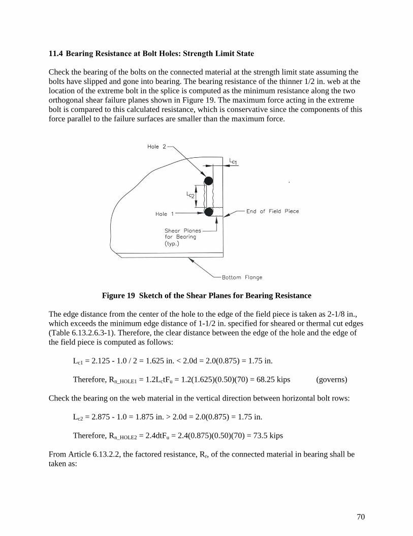
70
11.4 Bearing Resistance at Bolt Holes: Strength Limit State
Check the bearing of the bolts on the connected material at the strength limit state assuming the
bolts have slipped and gone into bearing. The bearing resistance of the thinner 1/2 in. web at the
location of the extreme bolt in the splice is computed as the minimum resistance along the two
orthogonal shear failure planes shown in Figure 19. The maximum force acting in the extreme
bolt is compared to this calculated resistance, which is conservative since the components of this
force parallel to the failure surfaces are smaller than the maximum force.
Figure 19 Sketch of the Shear Planes for Bearing Resistance
The edge distance from the center of the hole to the edge of the field piece is taken as 2-1/8 in.,
which exceeds the minimum edge distance of 1-1/2 in. specified for sheared or thermal cut edges
(Table 6.13.2.6.3-1). Therefore, the clear distance between the edge of the hole and the edge of
the field piece is computed as follows:
Lc1 = 2.125 - 1.0 / 2 = 1.625 in. < 2.0d = 2.0(0.875) = 1.75 in.
Therefore, Rn_HOLE1 = 1.2LctFu = 1.2(1.625)(0.50)(70) = 68.25 kips (governs)
Check the bearing on the web material in the vertical direction between horizontal bolt rows:
Lc2 = 2.875 - 1.0 = 1.875 in. > 2.0d = 2.0(0.875) = 1.75 in.
Therefore, Rn_HOLE2 = 2.4dtFu = 2.4(0.875)(0.50)(70) = 73.5 kips
From Article 6.13.2.2, the factored resistance, Rr, of the connected material in bearing shall be
taken as:
71
Rr = bbRn
where bb is the resistance factor for bolts bearing on material (Article 6.5.4.2) equal to:
bb = 0.80
Therefore: Rr = 0.80(68.25) = 54.60 kips
The maximum force on the extreme bolt at the strength limit state, Pr, was computed earlier to be
35.36 kips.
Pr = 35.36 kips < Rr = 54.60 kips ok
11.5 Fatigue Resistance of Splice Plates: Fatigue and Fracture Limit State
Check the fatigue stress in the base metal of the web splice plates (Article 6.13.6.1.4a). The
nominal fatigue resistance of uncoated weathering steel base metal is determined for fatigue
detail Category B (Table 6.6.1.2.3-1). The same category is used to check the base metal
adjacent to slip-critical bolted connections. Since the edges of the splice plates are further from
the neutral axis than the outermost bolt lines, fatigue of the base metal at the edges of the plates
will be checked. The splice plates will be checked for the portion of the fatigue load moment to
be resisted by the web, the horizontal force resultant of the elastic flexural fatigue-load stresses
in the web, and the moment due to the eccentricity of the fatigue-load shear at the splice.
The factored moments at the splice due to the fatigue load (factored by the 0.75 load factor
specified for the FATIGUE load combination) plus the dynamic load allowance of 15 percent
are:
M+(LL+IM) = 679 kip-ft
M-(LL+IM) = -515 kip-ft
The flexural stresses at the top and bottom of the web, ftw and fbw, due to the fatigue-load
moments are first computed. In computing the stresses, positive fatigue-load moments are
assumed to be applied to the short-term composite section and negative fatigue-load moments
are assumed to be applied to the section consisting of the steel girder plus the longitudinal
reinforcement (since the maximum composite dead-load compressive stresses in the slab are
overcome by the maximum tensile stress in the slab due to the factored negative fatigue-load
moment).
The fatigue stresses at the top of the web are:
ftw_+(LL+IM) = (679)(12)(10.7) / 161518 = 0.54 ksi (compression)
|ftw_-(LL+IM) |= |(-515)(12)(10.7) / 161518| = 2.58 ksi (tension)

72
The fatigue stresses at the bottom of the web are:
ftw_+(LL+IM) = (679)(12)(58.30) / 161518 = 2.94 ksi (tension)
|ftw_-(LL+IM) |= |(-515)(12)(35.46) / 161518| = 2.73 ksi (compression)
Under the positive fatigue-load moment, the portion of the moment to be resisted by the web and
the horizontal force resultant are computed from Equations (7) and (8), respectively, as (Note:
absolute value signs are removed from the equations to keep track of the signs):
ftkip53.57in.kip3.690)]54.0([2.9412
)0.500(69.0M
2
w
kips.40410.54)]([2.942
)0.500(69.0Hw
Under the negative fatigue-load moment, the portion of the moment to be resisted by the web
and the horizontal force resultant are computed as:
ftkip78.87in.kip053,1)58.2(-2.7312
)0.500(69.0M
2
w
kips59.2)58.2(-2.732
)0.500(69.0Hw
The factored shears at the splice due to the fatigue load (factored by the specified 0.75 load
factor) plus the dynamic load allowance of 15 percent are:
V+(LL+IM) = 5 kips
V-(LL+IM) = -31 kips
The moments due to the eccentricity of the factored fatigue-load shear forces from the centerline
of the splice to the center of gravity of the web-splice bolt group are:
ftkip1.56(1/12)2
3.02.255Me
ftkip69.9(1/12)2
3.02.2531Me
+MTOTAL = +Mw + Me = 7.53 +1.56 = 59.09 kip-ft
-MTOTAL = -Mw + (-Me) = -87.78 +(-9.69) = -97.47 kip-ft
73
From separate calculations, it is determined that the stress range at the bottom edge of the splice
plate controls. As a reminder, fatigue at the top edge of the splice plates would only need to be
checked if the compressive stress at the top of the plates due to the unfactored permanent-load
moments (conservatively ignoring the future wearing surface) is less than twice the maximum
tensile stress at the top of plates due to the negative factored fatigue-load moment (Article
6.6.1.2.1), which happens to be the case in this example.
The normal stresses at the bottom edge of the splice plates due to the total positive and negative
fatigue-load web moments and the corresponding horizontal force resultants are as follows:
f = MTOTAL / SPL + Hw / APL
f+(LL+IM) = (59.09)(12) / (512.0) + 41.40 / 48.00 = 2.25 ksi (tension)
f-(LL+IM) = (-97.47)(12) / (512.0) + -2.59 / 48.00 = -2.34 ksi (compression)
The total fatigue-load stress range at the bottom edge of the web splice plates is therefore:
(f) = f+(LL+IM) + |f-(LL+IM)|
(f) = 2.25 + |-2.34| = 4.59 ksi
From previous calculations: (ΔF)n = 8.0 ksi for a Category B detail.
From Equation (6.6.1.2.2-1):
(f) ≤ (F)n
4.59 ksi < 8.00 ksi ok
11.6 Permanent Deflection Service Limit State: Splice Plates
To satisfy the permanent deflection service limit state, check the maximum normal stress on the
web splice plates to control local yielding of the plates.
Calculate the maximum normal stress on the gross section of the web splice plates at the
permanent deflection service limit state due to the total web moment and the corresponding
horizontal force resultant applied at the centroid of the web as follows:
f = (MTOTAL / SPL) + (H / APL)
For Case 1: f = (392)(12) / (512) + (185)/(48.00) = 13.04 ksi
13.04 ksi < 0.95Fyf = 0.95(50) = 47.5 ksi ok
For Case 2: f = (493)(12) / (512) + (14)/(48.00) = 11.85 ksi

74
11.85 ksi < 0.95Fyf = 0.95(50) = 47.5 ksi ok
For Case 3: f = (461)(12) / (512) + (44)/(48.00) = 11.72 ksi
11.72 ksi < 0.95Fyf = 0.95(50) = 47.5 ksi ok

75
12.0 HYBRID PLATE-GIRDER SPLICE DESIGN DIFFERENCES
In general, the basic procedures provided in the previous example are the same when designing a
splice for a hybrid plate-girder. The AASHTO LRFD (7th Edition, 2014) have addressed the
differences in design through the use of the hybrid factor, Rh, discussed in detail in AASHTO
Articles 6.10.1.10.1 and C6.10.1.10.1.
This hybrid factor appears in the splice design equations previously presented. For rolled shapes,
homogeneous built-up sections and built-up sections with a higher strength steel in the web than
in both flanges, the hybrid factor is set equal to 1.0.

76
13.0 ROLLED BEAM SPLICE DESIGN
The procedure for the design of field splices for rolled beams is similar to the procedure
illustrated in the design example previously presented for plate girders.
In the past, based on outdated code provisions which required that web splices be designed for a
minimum of 75 percent of the shear capacity of the web, rolled beam web splices tended to have
significantly more bolts in the web splice, a function of the stocky webs and subsequently
significantly higher design shear strength.
Figure 20 Photograph of a Rolled Beam Field Splice
Current design provisions, which require that the minimum shear resistance is determined based
on Equations (8) and (9), should not result in overly conservative designs. However, given the
stocky nature of rolled beam webs, the webs will tend to carry a larger portion of the flexural
moment than plate girders, which may result in somewhat larger (relatively) web splices.
77
14.0 BOX GIRDER SPLICE DESIGN
The primary differences between the design of bolted field splices for plate-girders (as illustrated
in the previous example) and box girders are listed below:
14.1 Web Splice Design
In the following cases, the shear used in the design of the web splices should be taken as the sum
of the flexural and St. Venant torsional shears in the web which is subjected to additive shears, in
accordance with Article 6.13.6.1.4b:
All single box sections
Multiple box sections in bridges which do not satisfy the requirements (including
geometric restrictions and no skew) of Article 6.11.2.3
Multiple box sections whose flanges are not fully effective according to the provisions of
Article 6.11.1.1
Curved box sections
It is also noted, that for box sections with inclined webs, the web splice should be designed for
the component of the vertical shear in the plane of the web.
14.2 Flange Splice Design
For box girders, it is likely that for the calculation of the minimum flexural design stress for the
controlling flange Fcf (which was previously provided in Equation (2)), taking the term α = 1.0
may be overly conservative. Article C6.13.6.1.4c indicates that a lower value equal to (Fn/Fyf)
may be appropriate for bottom box flanges in compression or tension, where the the calculated Fn
of the flange may be significantly below Fyf.
In accordance with Article 6.13.6.1.4c, for the following cases, the longitudinal warping stresses
due to cross-section distortion must be considered when checking bolted flange splices for slip
and for fatigue. As described in Article C6.13.6.1.4c, for box sections, these longitudinal
warping stresses can be significant under construction and service conditions. Once the deck has
cured, and the top flange can be considered continuously braced, these warping stresses can
typically be ignored. In addition, the warping stresses can be ignored in the flanges at the
strength limit state. For these cases, the St. Venant torsional shear must also be considered in the
design of the box girder flange bolted splices at all limit states:
All single box sections
Multiple box sections in bridges which do not satisfy the requirements (including
geometric restrictions and no skew) of Article 6.11.2.3
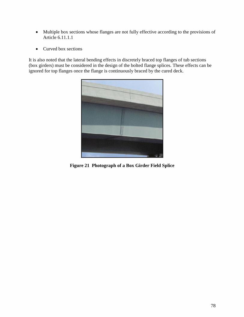
78
Multiple box sections whose flanges are not fully effective according to the provisions of
Article 6.11.1.1
Curved box sections
It is also noted that the lateral bending effects in discretely braced top flanges of tub sections
(box girders) must be considered in the design of the bolted flange splices. These effects can be
ignored for top flanges once the flange is continuously braced by the cured deck.
Figure 21 Photograph of a Box Girder Field Splice

79
15.0 REFERENCES
1. American Association of State Highway Transportation Officials (AASHTO), LRFD
Bridge Design Specifications, 7th
Edition, 2014.
2. AASHTO/NSBA Steel Bridge Collaboration, G12.1-2003, Guidelines for Design for
Constructability, AASHTO Publication Code NSBAGDC-2, 2003.
3. Mid Atlantic States Structural Committee for Economic Fabrication (SCEF), Standards –
Typical Girder Details, 2000.
4. American Association of State Highway Transportation Officials (AASHTO), Guide
Specifications for Horizontally Curved Steel Girder Highway Bridges, 2003.
5. American Association of State Highway Transportation Officials (AASHTO), Standard
Specifications for Highway Bridges, 17th
Edition, 2002.
6. American Institute of Steel Construction (AISC), Steel Construction Manual 13th
Edition,
2005.


![Clotilde Rosa [Entrevista]](https://img.pdfslide.net/doc/110x75/63605fdf5e6ba0ceb50ed63e/clotilde-rosa-entrevista.jpg)


