Embed Size (px)
Citation preview

Engineering Geology 116 (2010) 21–31
Contents lists available at ScienceDirect
Engineering Geology
j ourna l homepage: www.e lsev ie r.com/ locate /enggeo
Stiffening of smectite buffer clay by hydrothermal effects
Roland Pusch a,⁎, A.B. Drawrite a, Raymond N. Yong b, Masashi Nakano c
a Lund, Swedenb North Saanich, Canadac Masashi Nakano Tokyo University, Japan
⁎ Corresponding author.E-mail address: [email protected] (R
0013-7952/$ – see front matter © 2010 Elsevier B.V. Aldoi:10.1016/j.enggeo.2010.07.002
a b s t r a c t
a r t i c l e i n f oArticle history:Received 16 February 2010Received in revised form 30 June 2010Accepted 6 July 2010Available online 24 July 2010
Keywords:BufferCementationClayHydrothermalPrecipitationStiffening
Smectite clay is a major engineered “buffer” barrier in repositories for high-level radioactive waste since itprovides thewaste canisters with a low-permeable embedment thatminimizes canister stresses caused by earthshocks and tectonics by being ductile and homogeneous. The hydrothermal conditions prevailing in deeprepositories cause some loss and degradation of the buffer and stiffening by precipitation of cementing matter,like quartz, cristobalite and iron compounds emanating from the clay or from the canisters. Thus, chemicalreactions leading to cementation can prevent self-sealing of fissures caused by desiccation in the early stage ofmaturation of the buffer and increase its stiffness so that critical stress conditions may be generated in thecanisters.
. Pusch).
l rights reserved.
© 2010 Elsevier B.V. All rights reserved.
1. Scope of study
The primary function of the smectite clay, i.e. the buffer surround-ing heat-producing canisters with highly radioactive waste (Fig. 1) isto be less permeable than the surrounding rock and to have a capacityto adsorb possibly released radionuclides. It must also be sufficientlyductile to prevent build-up of critically high stresses in the canisters incase of seismically, tectonically or thermally induced shearing alongfractures that intersect the deposition holes. The ductility is associatedwith a high creep potential that can cause settlement of the heavycanisters but it is also a requisite for self-sealing of voids and gapsformed at the clay/canister contacts (Fig. 2). If the gaps remain open orare filled with clay with low density they represent permeable pathsthat can cause fast transport of water carrying radionuclides. Forclosing or compressing them the swelling pressure and creep potentialmust be sufficient. If cementation takes place these properties candeteriorate so much that the waste-isolation capacity of the buffer islargely lost.
2. Cementation mechanisms
2.1. Basics
Geology and geotechnical sciences offer numerous examples ofcementation. A classical geological example is the transformation of
clastic sediments to sedimentary rock by precipitation of elementsfrom percolating solutions. Overconsolidation of shallow clay layersby precipitation of carbonates and iron compounds is a well-knownphenomenon in Scandinavia and Canada.Whilemany of the processesdo not require elevated temperature stiffening of deep smectitic claysediments is known to be related to heat-induced illitization (Weaver,1979; Velde, 1991). The cementing agent is quartz, cristobalite orother silicious compounds (Savage et al., 2010). Stiffening of this typeis also expected to take place in the buffer as described in the presentpaper, which is a synthesis of geological evidence and experiencefrom hydrothermal experiments.
2.2. Evidence of silicious precipitation in nature
We will use geological analogues and hydrothermal experimentsto demonstrate that clay buffer can undergo precipitation of siliciouscompounds serving as cement and causing stiffening. An almostclassic example of this phenomenon is the Kinnekulle case, a carefullyinvestigated Ordovician series of sedimentary rocks in Swedencontaining shales, limestones, sandstones and bentonite beds thatwere affected by Permian magma that penetrated some hundredmeters above the clay. Detailed analysis of core samples has shownthat quartz had been formed in conjunction with conversion ofsmectite (montmorillonite) to illite. (Thorslund, 1945, Pusch, 1983).The temperature evolution of the clay beds has been determined byanalytical calculation and Conodont analysis and found to be 120–140 °C in the first 500 years after the magma intrusion, followed by asuccessive drop to about 90 °C after 1000 years. The average thermalgradient was 0.02 °C/cm in the first hundreds of years (Pusch and

Fig. 1. SKB's concept for isolating highly radioactive waste, KBS-3V (Svemar, 2005).
22 R. Pusch et al. / Engineering Geology 116 (2010) 21–31
Madsen, 1995). The present content of montmorillonite in expand-able form (mixed-layer smectite/illite) in the main bentonite bed isabout 25%, while illite represents about 50%. Chlorite/kaolinite,carbonates, quartz, and feldspars make up the rest. The silicificationis manifested by the presence of quartz precipitates on larger particlesas seen in SEM micrographs (Fig. 3) and by the dispersion caused byultrasonic treatment (Mueller von-Moos et al., 1990).
Fig. 2. Strain and displacement of SKB canister. Left: Schematic illustration of FEM-calculatedalong a fracture intersecting the deposition hole. Right: Formation of heterogeneities in tleadshots in the clay to show the strain pattern. The bright center is the shear box arrange
An example of stronger cementation associated with conversion ofsmectite to illite is Silurian clay presently exposed at the southwest-ern coastline of the Swedish island Gotland and called “bentonite” bygeologists 50 years ago. Much later the smectite-like microstructurewas identified by transmission electron microscopy showing thetypical wavy interwoven network of very thin lamellae (Fig. 4)(Pusch, 1968). The unique transmission electron micrographs of theclay with porewater contained in the clay were taken by use of the1.5 MV microscope of the Laboratoire d'Optique Electronique (CNRS),Toulouse, France. The clay is presently devoid of smectite and consistsof illite (40%), quartz (20%), chlorite (15%), feldspars (10%) and calcite(10%), hence suggesting that it has undergone largely isomorphoustransformation although numerous well crystallized illite laths pointto neoformation of this mineral. The clay has a content of minus 2 mmparticles of 28%. The water content is 21%, meaning that the density atwater saturation is about 2250 kg/m3, which would correspond to aswelling pressure of about 30 MPa for pure Na smectite (Pusch andYong, 2006). This is in fact also the effective pressure exerted by thepresumed overlying 2 km of Devonian sediments causing consolida-tion of the young Burgsvik clay but being eroded later. Thetemperature at this depth, 90–100 °C, prevailed for at least tenmillion years, starting when the compression had become significant.
Examples of more recent, i.e. Tertiary, cases of silicious precipita-tion generated by magma intrusion in the form of diabase dikes thatintersect the smectite beds, are known from Montana, Sardinia(Busachi) and Libya (Pusch and Yong, 2006).
2.3. Geochemical modelling
All these cases of heat-induced cementation by precipitation ofsilicious matter are in agreement with observations from a number ofstudies of deep-sea sediments performed in conjunction with oil andgas prospection. They were performed in the last 50 years and haveled to the conclusion that smectite clay, exposed to pressure and heat,undergoes conversion to illite in conjunction with uptake ofpotassium and release of silicons that form silica commonly assumedto be quartz (Pusch and Yong, 2006). A number of analyses of deep-sea sediments and other examples of heat- and pressure-exposedsmectites have yielded the following simplified reaction model(Weaver, 1979):
S + Fk + Mið Þ = I + Q + Chl ð1Þ
deformation of ductile clay-embedded canister by tectonically induced instant shearinghe clay (dark wedges) by shearing of a stiff canister. X-ray image of model test withment (Pusch, 2008).
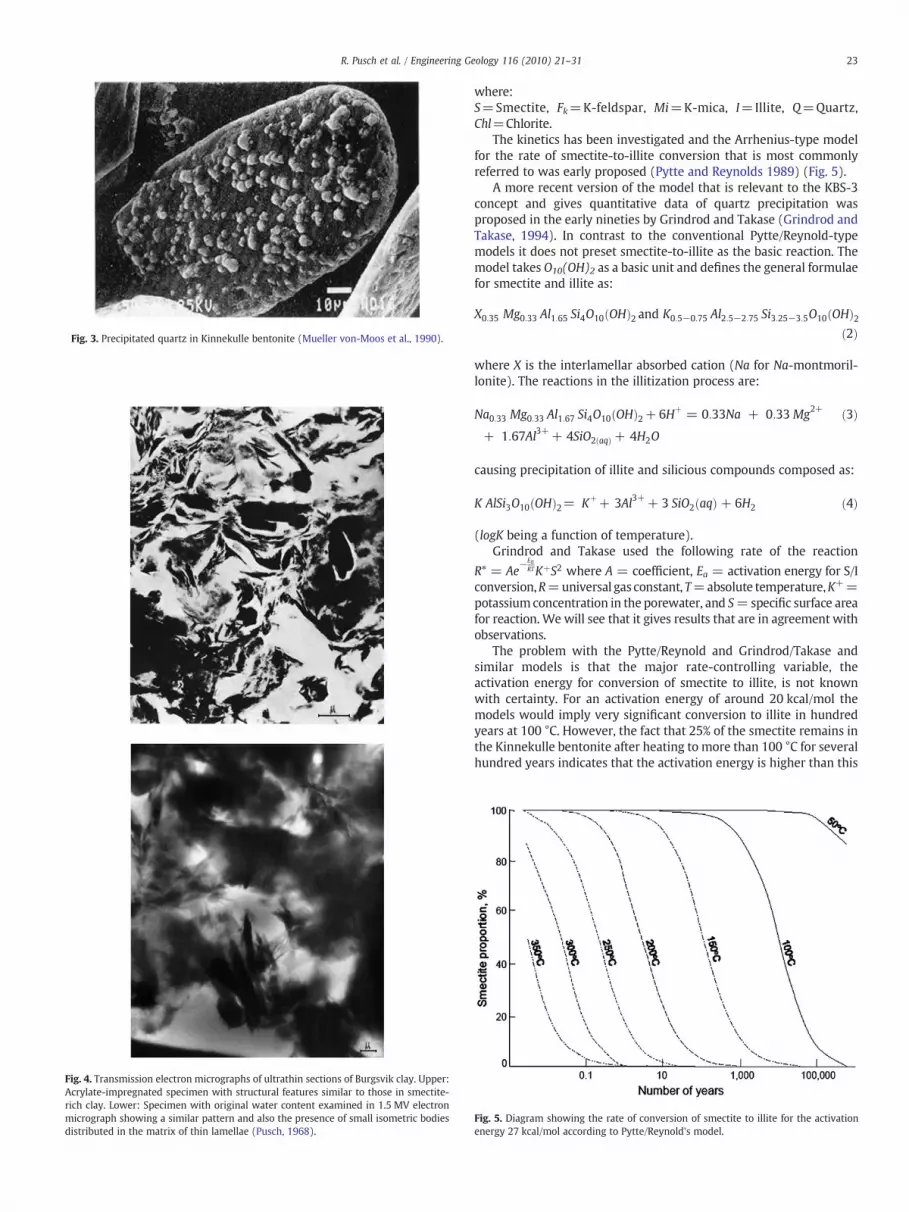
Fig. 3. Precipitated quartz in Kinnekulle bentonite (Mueller von-Moos et al., 1990).
Fig. 4. Transmission electron micrographs of ultrathin sections of Burgsvik clay. Upper:Acrylate-impregnated specimen with structural features similar to those in smectite-rich clay. Lower: Specimen with original water content examined in 1.5 MV electronmicrograph showing a similar pattern and also the presence of small isometric bodiesdistributed in the matrix of thin lamellae (Pusch, 1968).
23R. Pusch et al. / Engineering Geology 116 (2010) 21–31
where:S=Smectite, Fk=K-feldspar, Mi=K-mica, I=Illite, Q=Quartz,Chl=Chlorite.
The kinetics has been investigated and the Arrhenius-type modelfor the rate of smectite-to-illite conversion that is most commonlyreferred to was early proposed (Pytte and Reynolds 1989) (Fig. 5).
A more recent version of the model that is relevant to the KBS-3concept and gives quantitative data of quartz precipitation wasproposed in the early nineties by Grindrod and Takase (Grindrod andTakase, 1994). In contrast to the conventional Pytte/Reynold-typemodels it does not preset smectite-to-illite as the basic reaction. Themodel takes O10(OH)2 as a basic unit and defines the general formulaefor smectite and illite as:
X0:35 Mg0:33 Al1:65 Si4O10 OHð Þ2 and K0:5−0:75 Al2:5−2:75 Si3:25−3:5O10 OHð Þ2ð2Þ
where X is the interlamellar absorbed cation (Na for Na-montmoril-lonite). The reactions in the illitization process are:
Na0:33 Mg0:33 Al1:67 Si4O10 OHð Þ2+ 6Hþ = 0:33Na + 0:33Mg2+
+ 1:67Al3++ 4SiO2 aqð Þ + 4H2O
ð3Þ
causing precipitation of illite and silicious compounds composed as:
K AlSi3O10 OHð Þ2= Kþ+ 3Al3++ 3 SiO2 aqð Þ+ 6H2 ð4Þ
(logK being a function of temperature).Grindrod and Takase used the following rate of the reaction
R* = Ae−Ea
RTKþS2 where A = coefficient, Ea = activation energy for S/Iconversion,R=universal gas constant, T=absolute temperature,K+=potassium concentration in the porewater, and S=specific surface areafor reaction. We will see that it gives results that are in agreement withobservations.
The problem with the Pytte/Reynold and Grindrod/Takase andsimilar models is that the major rate-controlling variable, theactivation energy for conversion of smectite to illite, is not knownwith certainty. For an activation energy of around 20 kcal/mol themodels would imply very significant conversion to illite in hundredyears at 100 °C. However, the fact that 25% of the smectite remains inthe Kinnekulle bentonite after heating to more than 100 °C for severalhundred years indicates that the activation energy is higher than this
Fig. 5. Diagram showing the rate of conversion of smectite to illite for the activationenergy 27 kcal/mol according to Pytte/Reynold's model.

Fig. 7. Creep behaviour of Kinnekulle bentonite. The stepped strain for 95 kPa shearstress under 300 kPa normal stress is concluded to indicate breakage of larger cementedaggregates.
24 R. Pusch et al. / Engineering Geology 116 (2010) 21–31
figure. The complexity of the conversion process, exemplified by thedifficulty in distinguishing between smectite and illite particles and bythe impact of clay density (Gueven, 1990) and contemporaryformation of other silicates (Marty et al., 2010) makes prediction ofthe illitization rate and hence also of the rate of the associatedprecipitation of silicious compounds uncertain.
2.4. Identification of cementing silicious compounds in nature
Eqs. (1) and (4) indicate that silica is a reaction product of theconversion of smectite to illite and of the nature illustrated by Fig. 3.The precipitates are often very small as in the Burgsvik clay; they havethe form of dense silica nodules centered in clay particle aggregates asdemonstrated by the micrographs in Fig. 4. It is reasonable to assumethat the physical size of the precipitations in fact ranges between afew tens of nanometers to micrometers.
The following methods have been used for identifying possiblecementation of smectite by comparing untreated and hydrothermallytreated materials (Pusch and Yong, 2006):
1. Change in quartz and cristobalite content by XRD,2. Examination of STEM and EDX electron micrographs for direct
identification and analysis of precipitates,3. Determination of swelling pressure, which drops by cementation,4. Determination of shear strain and creep, which are both reduced by
cementation.
While XRD and electron microscopy are valuable tools for com-parison of virgin and hydrothermally treated clay the swelling pressureand shear strain and creep are themost practically useful parameters ininvestigation of natural analogues. Examples are offered by the Busachi,Kinnekulle, and Burgsvik cases for which shear box testing have givenrelationships between time and strain (Pusch and Yong, 2006). TheTertiary Busachi bentonite from Sardinia, which is estimated to havebeenexposed to a temperature of 500 °C for 5 days, 200 °C for 2 months,and 60 °C for 1 year by impact of magma outflow (Pusch et al., 1993),gave the jerky strain pattern in Fig. 6. This behaviour was noticed for allthe sampleswithin 2 mdistance from the samples from the hot contact.
The Kinnekulle bentonite show the same jerky strain leading tocreep failure as the Busachi clay. Thewell manifested silica cementationof the Kinnekulle clay is the reason for the stepped strain at the highestshear stress leading to creep failure as for the Busachi clay (Fig. 7).
The Burgsvik clay with no smectite left is more strongly cementedthan the other two reference clays. Thus, the creep test illustrated inFig. 8 shows that almost no strain occurred for shear stresses up toabout 80 kPa, while 95 kPa shear stress under 300 kPa normal stressinitiated significant strain (Pusch, 2002).
Fig. 6. Creep behaviour of smectite-rich bentonite from Busachi. Curve for 222 kPashear in linear time scale showing stepped strain rate behaviour related to breakage ofcementation bonds (Pusch et al., 1987).
2.5. Precipitation of silicious compounds in hydrothermal experiments
2.5.1. Autoclave testsThe indications of silicification and conversion of smectites
provided by natural analogues have called for validation of theassumed hydrothermally induced process by laboratory investigationof smectite clay buffer exposed to hydrothermal conditions inrepositories. Such tests have therefore been conducted in Swedenand France and they support the hypothesis of precipitation ofcementing agents in the cooling phase that follows the severalthousand years long hot period. A few of these tests will be referred tohere for illustrating the changes in microstructural organization andmineral composition as well as their practical significance.
2.5.1.1. First series — chemically closed conditions. In the eighties aseries of autoclave tests weremade with purified SWY-1 smectite clayfrom Crook County (Newcastle Formation), Wyoming, USA, withnearly 100% montmorillonite with the following chemical composi-tion in percent units: SiO2:69.2, Al2O3:19.6, Fe2O3:3.35, FeO:0.32,MnO:0.006, MgO:3.05, CaO:1.68, Na2O:1.53, K2O:0.53, P2O5:0.049,S:0.05, F:0.111 (Pusch, 1993). The 4.6 ml hydrothermal cells, contain-ing nearly completely water saturated samples of clay, were gold-coated copper tubes that could resist an internal heat-generatedpressure of about 100 MPa by slight yielding. Samples that hadundergone heating up to 200 °C had densities of 2000 kg/m3 and1300 kg/m3 at water saturation giving the rates of compression
Fig. 8. Creep behaviour of Silurian bentonite from Gotland. Almost no strain occurredfor shear stresses up to about 80 kPa, while 95 kPa shear stress under 300 kPa normalstress gave sudden, accelerating strain leading to brittle failure.

Fig. 9. Unconfined compression test of SWY-1 clay heated for 0.5 years. Dry density1590 kg/m3 corresponding to 2000 kg/m3 after cooling (Pusch and Karnland, 1988).
Fig. 11. Rectified XRD of EG-treated SWY-1 samples representing unheated clay, andclay autoclaved at 150 and 200 °C, respectively. The samples were saturated withdistilled water before being autoclaved (Pusch and Karnland, 1988).
25R. Pusch et al. / Engineering Geology 116 (2010) 21–31
shown in Figs. 9 and 10. The significant drop in compressibility byhydrothermal treatment is very obvious and a measure of theincreased stiffness and strength.
XRD analysis of the materials treated with ethylene glycol gave astronger and sharper 2Θ=5o reflection for 200 °C treatment than for150 °C, and, in turn, stronger than for 20 °C specimens (Fig. 11). Theincreased intensity of the 001 reflections for higher temperaturesindicates improved orientation of the stacks of lamellae. The sametendency has been observed in various tests of hydrothermallytreated clays and indicates creation of dense stacked aggregates thatcan have an effect on the deformability and strength of themicrostructural network. The temperature 200 °C is higher thanimplied by some repository concepts but has been considered byorganizations like ANDRA.
2.5.1.2. Second series — chemically closed conditions. Experiments withautoclaved SWY-1 smectite clay was made for identifying processesinvolving Fe, which is present in octahedral positions in the purifiedclay and can be present in buffer clay also in the form of accessoryminerals. Hydrothermal treatment in autoclaves of this very puremontmorillonite gel with a density of 1300 kg/m3 at saturation withdistilled water has been conducted at the Geological Dept. of TexasTech University at Lubbock for investigating physico/chemical effects(Gueven and Huang, 1990). The work was intended to test the
Fig. 10. Unconfined compression test of SWY-1 clay heated for 0.5 years. Dry density480 kg/m3 corresponding to 1300 kg/m3 after water saturation (Pusch and Karnland,1988).
hypothesis that heating of Na-montmorillonite to more than 100 °Ccauses convergence of stacks of lamellae (Gueven, 1990) andinversion of the crystal lattice from trans- to cis-coordination of Si,i.e. from the conventionally assumed crystal atom arrangement withoxygens in hexagonal patterns exposed on the basal planes of thesmectite lamellae to one with equally spaced hydroxyls (Pusch andYong, 2006). This study, which has not been fully evaluated untilrecently, shows that such conversion could explain the relative easewith which Si is released from the lattice tetrahedrons (cf. Lee andKang, 2010), yielding an increase in precipitated silica on subsequentcooling. Fig. 12 shows a transmission electron micrograph (JEOL 100STEM microscope) of untreated SWY-1 clay exhibiting a softmontmorillonite gel with typical elemental composition in all parts.
Autoclave treatment of the SWY-1 clay saturated with distilledwater was made for 8 h at 150 °C and 315 °C under 20 MPa waterpressure. STEM analysis of the gel that had been heated to 150 °Cshowed the presence of larger aggregated bodies, sized up to 2 μm, asexemplified by Fig. 13. As demonstrated by the element analysis overthe entire surface area of individual aggregates, they consisted ofprecipitated silica with some very minor amount of Fe. The Al peakrepresents montmorillonite lamellae underlying the aggregate. Byincreasing the penetration power of the electron radiation the interiorof the dense aggregates could be investigated and it turned out to bevery rich in iron (Fig. 14).
The 150 °C treatment tended to cause some coagulation of themontmorillonite particle system leading to alignment of the stacks oflamellae that is indicated by the change in XRD peak shape asdescribed in the preceding text. This process was even stronger in thesample autoclaved at 315 °C. These temperature ranges are notpresently foreseen for buffers but may be reconsidered and theobservations are therefore still of interest. It is important to realizethat the autoclave experiments involved heating of fully watersaturated clay under isothermal conditions, i.e. without any thermalgradient. This condition is different from that in a repository.
2.5.1.3. Third series — hydrothermal tests of MX-80 with and withoutgamma radiation. Cylindrical 7 cm long MX-80 samples with a drydensity of 1650 kg/m3 were confined in cells with an iron plate at theheated end and a water saturated filter at the opposite one (Pusch etal., 1993). Weakly brackish water with Na as dominant cation andvery little potassium (b10 ppm) was circulated through the filter thatwas kept at 90 °C. The iron plate was heated to 130 °C during the

Fig. 12. Untreated very pure montmorillonite. Left: STEM picture of untreated clay. Right: Elements of the gel with Si, Al and O as major lattice constituents. Cu and Pt originate fromthe grids. The Mg and Fe contents were judged to be largely intracrystalline.
26 R. Pusch et al. / Engineering Geology 116 (2010) 21–31
1 year experiments, yielding a thermal gradient of about 6 °C/cm. Thesolution was pressurized to 1.5 MPa. In one of the tests a gammaradiation dose of about 3E7 Gy acted on the iron plate, the adsorbedradiation dose being 3972 Gy/h at the hot plate contact, around700 Gy/h at half length of the sample, and 456 Gy/h at the coldest end.The investigation of the samples comprised XRD analysis (Fig. 15),electron microscopy with EDX, chemical analysis, infrared spectrom-etry IR, and CEC determination, the main mineral data being collectedin Table 1.
The analyses showed that there was nearly no difference betweenthe sample exposed to γ radiation and the one that was not irradiatedexcept that Fe migrated from the iron plate into the clay somewhatquicker under radiation. Comparison with virgin MX-80 clay showedthat hydrothermal treatment with and without radiation gaveinsignificant chemical changes, which was also supported by CECdata. They showed that untreated MX-80 had CEC=99 meq/100 gwhile the most strongly heated and radiated clay had CEC=93 meq/100 g. However, creep testing at room temperature of samples fromvarious distances from the hottest end gave witness of significantstiffening (Fig. 16), (Pusch et al., 1993). Thus, the shear strain ofsamples exposed to 130 °C was about 3 times smaller than of the oneheated to 90 °C.
Fig. 13. STEM picture of large and dense silica particle in mo
3. Evolution of buffers
3.1. Macrostructural processes
Buffer clay is manufactured by compaction of clay granules under100–200 MPa pressure leaving only small voids between them. Thevoids have the form of channels of varying aperture. At wetting thetightest parts become completely filled with capillary water andwater films sorbed on the basal surfaces of the stacks while widerones still contain air unless the piezometric pressure becomessufficiently high to dissolve it. In the initial “isothermal” state whenno water has yet been taken up by the buffer from the rock, drying ofthe hot part of the buffer takes place causing migration of water inliquid and vapour forms towards the rock. In the hottest part thestacks of lamellae contract, by which the individual voids and thechannels formed by them become wider. Full-scale tests havedemonstrated that steep, radial fractures are formed to severalcentimetres distance from the hot canister (Pusch et al. 1985). Oncethis part has ultimately become water saturated the fractures andwidened channels will be closed by the swelling pressure exerted bythe colder part of the buffer, and by self-sealing through redistributionof clay material if the heated clay has not lost its expandability.
ntmorillonite sample hydrothermally treated at 150 °C.

Fig. 14. Dense Fe nuclei in Si-rich aggregates recorded under low electron penetration power (lower micrograph) and high penetration power. Oxygen is abundant according to theelement analysis, indicating that the nucleus is iron hydroxide.
27R. Pusch et al. / Engineering Geology 116 (2010) 21–31
3.2. Microstructural processes
Smectite clay consists of stacks of 10 Å lamellae separated by up to3 water hydrates depending on the bulk density and adsorbed cations(Pusch and Yong, 2006). The assembly of stacks is coherent for bulkdensities higher than about 1050 kg/m3 if the porewater is poor inelectrolytes, but must exceed about 1600 kg/m3 if the porewater issaltier than strongly brackish with calcium as dominant cation.Consolidation, implying an increase from lower to higher density,
Fig. 15. Schematic diffractograms of the reference MX-80 sample (20 °C) and the most heatequartz and smectite disappeared in the hot part (Gueven and Huang, 1990).
takes place on compressionwhile expansion takes place on unloading.Unlike non-expandable clay types compression/expansion is a nearlyreversible process for smectite, except that expansion is delayed byinternal friction. Voids in the buffer caused by imposed strain as inFig. 2, or by heat-induced desiccation early after installation of thecanisters, would have to be closed or sealed for acceptableperformance. Closing of larger voids by expansion of the buffer isexpected while sealing of small voids and fissures can take place byprecipitation of silica or iron compounds. Expansion involves
d part of the hydrothermally tested sample (130 °C). Feldspars, amphibole, some of the

Table 1Changes in one year long hydrothermal tests of MX-80. M=Montmorillonite,F=Feldspars, G=Gypsum, Q=Quartz, K=Kaolinite, Chl=Chlorite, I=Illite. +++means strong increase, ++ significant increase, + slight increase, −−− strong loss,−− significant loss, − slight loss. 0 means no change.
Treatment 125–130 °C 115–120 °C 105–110 °C 90–95 °C
Hydrothermal withoutradiation
M − M − M 0 M 0F −−− F −− F − F −Chl+ Chl + Chl 0 Chl 0G ++ G +++ G + G+K ++ K + K 0 K −Q + Q + Q 0 Q 0I + I 0 I 0 I 0
28 R. Pusch et al. / Engineering Geology 116 (2010) 21–31
exfoliation of clay particles from the dense buffer followed byreorganization of the released particles to form clay gels that becomeconsolidated under the swelling pressure exerted by adjacent, denserclay (Pusch and Yong, 2006). Two mechanisms can cause loss ofexpandability: strong draught causing permanent collapse of thestacks of lamellae, and precipitation of cementing agents. Combina-tion of the two can make the collapse permanent. It will be shownhere how dissolution of smectite and accessory minerals andprecipitation of cementing agents like in nature can affect theperformance of buffer clay.
3.3. Cementation of the buffer
3.3.1. ProcessesTemporary accumulation of precipitated matter from the ground-
water in the hottest part of the buffer early after installation of thebuffer and canisters, i.e. formation of anhydrite and chlorides, is wellknown from field and mock-up tests (Pusch, 2008) but the process isexpected to be reversible and of little concern in a long timeperspective. In contrast, irreversible reactions caused by dissolutionof clay and accessory minerals and precipitation of the solutes areprocesses that can cause permanent stiffening and reduced expand-ability. They are in focus in this paper.
Application of the chemical model of Grindrod/Takase to KBS-3repository conditions (SKB's KBS-3V concept) requires coupling witha transport model based on diffusion-dominated migration ofaqueous species like silica, aluminium, sodium, magnesium, andpotassium to form a set of quasi-nonlinear partial differentialequations. The ones valid for aqueous species and minerals wereused for calculating precipitation of silica in the direction of thethermal gradient by these investigators. It was found that almost noillite will be formed in the first 500 years despite the conservativeassumption of a constant temperature of 90 °C at the buffer/canister
Fig. 16. Shear strain of specimens hydrothermally treated for 1 year without radiation.Shear box testing under 6 MPa normal effective pressure (Pusch et al., 1993).
contact, and 50 °C at the buffer/rock contact. However, for thesubsequent period of time with a linear temperature drop with timeto 25 °C after 10,000 years, the model predicts precipitation of quartzin the coldest part of the buffer, i.e. within about 0.1 m from the rockwall as shown in Fig. 17. The Grindrod/Takase model appears toadequately describe the chemical evolution with respect both toillitization and silicification. Quartz precipitates in the buffer and inopen fractures in the walls of the deposition holes, which tends to sealthem off (Pusch and Yong, 2006).
3.3.1.1. The Äspö Retrieval Test. Carefully conducted and interpretedlarge-scale experiments simulating the conditions in a KBS-3Vrepository have indicated the major chemical processes in buffer ofsmectite clay. Wyoming bentonite (MX-80) with 75–85% montmo-rillonite and Na as dominant adsorbed cation, and quartz (8–15%),feldspars (2–5%) and chlorite and micas (2–5%) as accessory mineralshas been used in a number of laboratory and field experiments.Similar clays from Spain, France, Switzerland and the Czech Republichave been investigated in the same type of tests in the respectivecountries. A few of them have been conducted for determiningphysico-chemical and mineralogical changes that take place underrepository-like conditions. MX-80 has been investigated in SKB'ssimulated KBS-3V repository at Äspö, some 300 km south of Stock-holm, samples being taken from the buffer in a 5 year full-scale testcalled Äspö Retrieval Test (Eng 2008). The buffer was artificiallywetted by being surrounded by a filter that was saturated with saltwater (6000 ppmwith Na/Ca ratio 1.0). The buffer in contact with thehot canister had been exposed to 78–85 °C for a couple of years andthen to less than 60 °C because of malfunctioning electrical heaters.This part of the clay had a density of 1970 kg/m3 (1540 kg/m3 drydensity).
Geotechnical tests (Table 2) and extensive EDX and XRD analysesled to the following conclusions:
• The hydrothermally treated clay had undergone substitution of Al3+
by Fe3+ in the octahedral layer causing higher lattice stressesbecause of the larger ion radius of Fe3+ than of Al3+ therebyreducing the resistance of the montmorillonite to dissolution,
• Montmorillonite was the dominating mineral phase in both virginand hydrothermally treated clay, the total number of samples ofeach type being at least 3,
• The lower interlayer charge of the heated clay than of virgin MX-80would mean that it should have a higher swelling pressure, butcementation dominated and gave the opposite effect.
Fig. 17. Evolution of quartz abundance profile (~10,000 y). Precipitation leading tocementation takes place in the outer, colder, 0.1 m part of the buffer (Pusch and Yong,2006).

Fig. 18. Main features of the Czech Mock-up test. M1, M2 etc. are samples taken inconjunction with or after the experiment.
Table 2Geotechnical data of oedometer-tested samples at saturation with distilled water. Thedata ρsat=density at water saturation, and hydraulic conductivity=K, representequilibrium reached after about 40 days (Pusch, 2008).
Distance from heater, cm T, °C ρsat, kg/m3 ps, kPa
12–14 54–56 1945 6500–2 85–95 1925 310
29R. Pusch et al. / Engineering Geology 116 (2010) 21–31
3.3.1.2. The Czech mock-up test. A 3 year mock-up experimentsimulating the conditions in a KBS-3V hole was conducted for theCzech organization RAWRA in the years 2001 to 2004 (Pacovsky et al.,2005). The rock was simulated by a steel tube with an inner diameterof 800 mm and the canister by a heated steel cylinder with 360 mmdiameter (Fig. 18). The buffer consisted of highly compacted blocks of85% montmorillonite mixed with 10% finely ground quartz and 5%well crystallized graphite, the dry density being 1800 kg/m3. Granulesof the samematerial were filled in the 50 mmwide space between thesteel tube and the buffer, which had unlimited access to Na-dominated brackish groundwater through a surrounding filter(Pusch, 2008). The temperature at mid-height of the canister surface
Fig. 19. XRD spectra of the samples M2 to M4. Oriented mounts, air dried and ethylene glycpeak fitting, (Pacovsky et al., 2005) (After Jörn Kasbohm, Greifswald University, Germany).
was maintained at 95 °C causing a radial temperature gradient ofabout 2 °C/cm.
As shown by Table 2 testing of samples taken at different distancesfrom the canister showed obvious differences. One finds that theswelling pressure of the sample that had been exposed to 54–56 °Cand representing the least heat-affected clay was more than twice thepressure of the more strongly heated sample. Additional samplestaken in radial direction from the hot canister had physical propertiesintermediate to those of the most and least heated ones.
The differences in mineral composition between the untreatedbuffer clay and the hydrothermally treated samples can be explainedby 1) partial dissolution of the montmorillonite, 2) obvious formationof illite, and 3) neoformation of talc and kaolinite (cf. Fig. 19).
In summary, the major mineralogical processes in the most heatedsmectite-rich clay mixed with graphite and quartz particles were:
• Intergrowth of illite and kaolinite was obvious in the dioctahedralvermiculite in the untreated clay. In these aggregates illitedominated over kaolinite but in the heated sample most of theintergrowths of illite/kaolinite were dissolved,
• Fe set free by the dissolution of the montmorillonite can haveformed iron complexes resulting in cementation in the entire buffermass, especially in the most heated part,
• The quartz content, which was determined by XRD and numerousEDX analyses, increased in the direction towards the canister and isjudged to be the main cementing agent,
• Replacement of octahedral Al by Fe can have caused a drop incoherence of the montmorillonite crystals, thereby promotingeasier dissolution,
• Formation of illite in the hottest part of the buffer (sample M4) mayhave been triggered by uptake of K from dissolved vermiculite.
Mineralogical characterization of the natural clay component wasmade by use of TEMwith EDX and Coherent Scattering Domain (CSD)data for determining the thickness of particles or stacks of lamellae.The Koester diagrams in Fig. 20 show the charge distribution in thevarious layers in the natural clay component and in the most heatedsample M4. The figure shows that very obvious changes in chargedistribution took place in the heated sample. Significant dissolution ofthe Fe-rich montmorillonite and complete disappearance of theintergrowth of illite and kaolinite had taken place, suggestingmigration and precipitation of released elements at different distancesfrom the heater.
The significantly lower swelling pressure of the heated sample canbe explained by the formation of illite in combination withcementation by precipitated silicious compounds. The associated
ol-treated (SEIFERT, Co Kα-radiation) with peak-area distribution by means of WinFit-
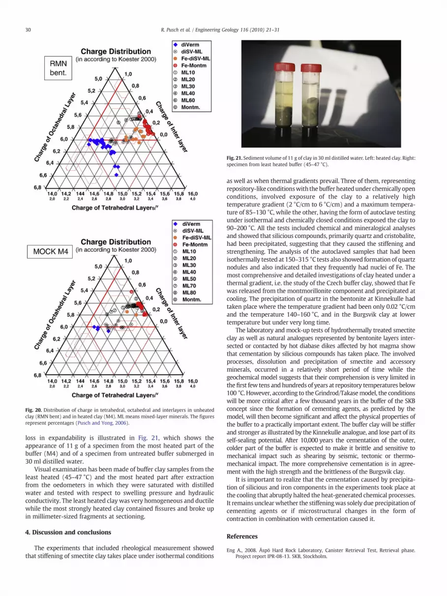
Fig. 20. Distribution of charge in tetrahedral, octahedral and interlayers in unheatedclay (RMN bent) and in heated clay (M4). ML means mixed-layer minerals. The figuresrepresent percentages (Pusch and Yong, 2006).
Fig. 21. Sediment volume of 11 g of clay in 30 ml distilled water. Left: heated clay. Right:specimen from least heated buffer (45–47 °C).
30 R. Pusch et al. / Engineering Geology 116 (2010) 21–31
loss in expandability is illustrated in Fig. 21, which shows theappearance of 11 g of a specimen from the most heated part of thebuffer (M4) and of a specimen from untreated buffer submerged in30 ml distilled water.
Visual examination has been made of buffer clay samples from theleast heated (45–47 °C) and the most heated part after extractionfrom the oedometers in which they were saturated with distilledwater and tested with respect to swelling pressure and hydraulicconductivity. The least heated clay was very homogeneous and ductilewhile the most strongly heated clay contained fissures and broke upin millimeter-sized fragments at sectioning.
4. Discussion and conclusions
The experiments that included rheological measurement showedthat stiffening of smectite clay takes place under isothermal conditions
as well as when thermal gradients prevail. Three of them, representingrepository-like conditionswith thebuffer heatedunder chemically openconditions, involved exposure of the clay to a relatively hightemperature gradient (2 °C/cm to 6 °C/cm) and a maximum tempera-ture of 85–130 °C, while the other, having the form of autoclave testingunder isothermal and chemically closed conditions exposed the clay to90–200 °C. All the tests included chemical and mineralogical analysesand showed that silicious compounds, primarily quartz and cristobalite,had been precipitated, suggesting that they caused the stiffening andstrengthening. The analysis of the autoclaved samples that had beenisothermally tested at 150–315 °C tests also showed formation of quartznodules and also indicated that they frequently had nuclei of Fe. Themost comprehensive and detailed investigations of clay heated under athermal gradient, i.e. the study of the Czech buffer clay, showed that Fewas released from the montmorillonite component and precipitated atcooling. The precipitation of quartz in the bentonite at Kinnekulle hadtaken place where the temperature gradient had been only 0.02 °C/cmand the temperature 140–160 °C, and in the Burgsvik clay at lowertemperature but under very long time.
The laboratory and mock-up tests of hydrothermally treated smectiteclay as well as natural analogues represented by bentonite layers inter-sected or contacted by hot diabase dikes affected by hot magma showthat cementation by silicious compounds has taken place. The involvedprocesses, dissolution and precipitation of smectite and accessoryminerals, occurred in a relatively short period of time while thegeochemical model suggests that their comprehension is very limited inthefirst few tens and hundreds of years at repository temperatures below100 °C. However, according to the Grindrod/Takasemodel, the conditionswill be more critical after a few thousand years in the buffer of the SKBconcept since the formation of cementing agents, as predicted by themodel, will then become significant and affect the physical properties ofthe buffer to a practically important extent. The buffer clay will be stifferand stronger as illustrated by the Kinnekulle analogue, and lose part of itsself-sealing potential. After 10,000 years the cementation of the outer,colder part of the buffer is expected to make it brittle and sensitive tomechanical impact such as shearing by seismic, tectonic or thermo-mechanical impact. The more comprehensive cementation is in agree-ment with the high strength and the brittleness of the Burgsvik clay.
It is important to realize that the cementation caused by precipita-tion of silicious and iron components in the experiments took place atthe cooling that abruptly halted the heat-generated chemical processes.It remains unclearwhether the stiffeningwas solely due precipitation ofcementing agents or if microstructural changes in the form ofcontraction in combination with cementation caused it.
References
Eng A., 2008. Äspö Hard Rock Laboratory, Canister Retrieval Test, Retrieval phase.Project report IPR-08-13. SKB, Stockholm.

31R. Pusch et al. / Engineering Geology 116 (2010) 21–31
Grindrod, P., Takase, H., 1994. Reactive chemical transport within engineered barriers.Proc. 4th Int. Conf. on the Chemistry and Migration Behaviour of Actinides andFission Products in the Geosphere, Charleston, SC USA, 12–17 Dec. OldenburgVerlag, pp. 773–779.
Gueven, N., 1990. Longevity of bentonite as buffer material in a nuclear-wasterepository. Engineering Geology. 28, 233–247.
Gueven, N., Huang, W.-L., 1990. Effects of Mg2+ and Fe3+ substitutions on thecrystallization of discrete illite and illite/smectite mixed layers. Int. rep. Dept.Geosciences Texas Tech University, Exxon Production research Co, Houston, Texas,USA.
Lee, J.O., Kang, I.M., 2010. Smectite alteration and its influence on the barrier propertiesof smectite clay for a repository. Applied Clay Science 47 (1–2), 99–104.
Marty, N.C.M., Fritz, B., Clément, A., Michau, N., 2010. Modelling the long term alterationof the engineered bentonite barrier in an underground radioactive wasterepository. Applied Clay Science 47 (1–2), 82–90.
Mueller von-Moos, M., Kahr, G., Bucher, F., Madsen, F.T., 1990. Investigations of themetabentonites aimed at assessing the long-term stability of bentonites underrepository conditions. In: Pusch, R. (Ed.), Artificial Clay Barriers for Hih LevelRadioactive Waste Repositories: Engineering Geology, Vol.28, Nos.3–4, pp. 269–280.Special Issue.
Pacovsky, J., Svoboda, J., Zapletal, L., 2005. Saturation development in the bentonitebarrier of theMock-up CZ geotechnical experiment. Clay in Natural and EngineeredBarriers for Radioactive Waste Confinement — Part 2: Physics and Chemistry of theEarth, 32/8-14. Elsevier Publ. Co, pp. 767–779.
Pusch, R., 1968. A technique for investigation of clay microstructure. Journal deMicroscopie 6, 963–986.
Pusch, R., 1983. Stability of deep-sited smectite minerals in crystalline rock — chemicalaspects. SKB, Stockholm. SKB Technical Report TR-83-16.
Pusch, R., 1993. Evolution of models for conversion of smectite to non-expandableminerals. SKB, Stockholm. Technical Report TR-93-33.
Pusch, R., 2002. The Buffer and Backfill Handbook. Part 2, Materials and Techniques.SKB, Stockholm. SKB Technical Report TR-02-12.
Pusch, R., 2008. Geological Storage of Radioactive Waste. Springer Verlag978-3-540-77332-0.
Pusch, R., Karnland, O., 1988. Hydrothermal effects on montmorillonite. A preliminarystudy. SKB, Stockholm. SKB Technical Report TR-88-15.
Pusch, R., Madsen, F., 1995. Aspects on the illitization of the Kinnekulle bentonites.Clays and Clay Minerals 43 (3), 261–270.
Pusch, R., Yong, R.N., 2006. Microstructure of smectite clays and engineeringperformance. Taylor & Francis, London and New York. ISBN10: 0-415-36863-4.
Pusch, R., Nilsson, J., Ramqvist, G., 1985. Final Report of the Buffer Mass Test— Volume I:Scope, preparative field work, and test arrangement. SKB, Stockholm. TechnicalReport TR-85-211.
Pusch, R., Börgesson, L., Erlström, 1987. Alteration of isolating properties of densesmectite clay in repository environment as exemplified by seven pre-Quaternaryclays. SKB, Stockholm. Technical Report TR-87-29.
Pusch, R., Karnland, O., Lajudie, A., Decarreau, A., 1993. MX-80 Exposed to HighTemperatures andGammaRadiation. SKB, Stockholm. SKBTechnical ReportTR-93-03.
Pytte, A.M., Reynolds, R.C., 1989. The thermal transformation of smectite to illite. In:Naeser, N.D., McCulloh, T.H. (Eds.), Thermal History of Sedimentary Basins.Springer-Verlag, New York, pp. 133–140.
Savage, D., Benbow, S., Watson, C., Takase, H., Ono, K., Oda, C., Honda, A., 2010. Naturalsystems for the alteration of clay under alkaline conditions: an example fromSearles Lake, California. Applied Clay Science 47 (1–2), 72–81.
Svemar, C., 2005. Cluster Repository Project (CROP). Final Report of EuropeanCommission Contract FIR1-CT-2000–20023, Brussels, Belgium.
Thorslund, P., 1945. Om bentonitlager i Sveriges kambrosilur. Geologiska Föreningens IStockholm Förhandlingar 67, 286.
Velde, B., 1991. Kinetics of I/S (illite/smectite) transformations. MRS. (Resumé NoB-II,Invited paper).
Weaver, C.E., 1979. Geothermal alteration of clay minerals and shales: diagenesis.Batelle-Office on Nuclear Waste Isolation. Technical Report ONWI-21, ET-76-C06-1830 Contract.


